8LV320 8LV350 8LV370 8LV320Z 8LV350Z 8LV370Z - Yanmar
84
8LV320 8LV350 8LV370 8LV320Z 8LV350Z 8LV370Z 0A8LV-G00100 PRINTED IN JAPAN
-
Upload
khangminh22 -
Category
Documents
-
view
3 -
download
0
Transcript of 8LV320 8LV350 8LV370 8LV320Z 8LV350Z 8LV370Z - Yanmar

8LV320
8LV350
8LV370
8LV320Z
8LV350Z
8LV370Z
0A8LV-G00100PRINTED IN JAPAN

Issued by : YANMAR CO.,LTD. Marine Operations Division Edited by : YANMAR TECHNICAL SERVICE CO.,LTD.
8LV SeriesModelOPERATION MANUAL
0A8LV-G00100Code
All Rights Reserved, Copyright
Date of issue: Jun. 2011
CaliforniaProposition 65 Warning
Diesel engine exhaust and some of itsconstituents are known to the state ofCalifornia to cause cancer, birthdefects, and other reproductive harm.
CaliforniaProposition 65 Warning
Battery posts, terminals, and relatedaccessories contain lead and leadcompounds, chemicals known to thestate of California to cause cancer andreproductive harm.Wash hands after handling.
Disclaimers:All information, illustrations and specifications in this manual are based on the latest information available at the time of publishing. The illustrations used in this manual are intended as representative reference views only. Moreover, because of our continuous product improvement policy, we may modify information, illustrations and/or specifications to explain and/or exemplify a product, service or maintenance improvement. We reserve the right to make any change at any time without notice. Yanmar and are registered trademarks of YANMAR CO., LTD. in Japan, the United States and/or other countries.
All Rights Reserved:No part of this publication may be reproduced or used in any form by any means - graphic, electronic, or mechanical, including photocopying, recording, taping, or informa-tion storage and retrieval systems - without the written permission of YANMAR CO., LTD.
8LV Series
1st Edition : Jun. 2011
OPERATION MANUAL
Overseas Office
■Yanmar (Head office)1-32, Chayamachi, Kita-ku, Osaka, Japan 530-8311
■Yanmar Europe B.V. (YEU)Brugplein 11, 1332 BS Almere-de Vaart, NetherlandsPhone: 31-36-5493200 Fax: 31-36-5493209
■Yanmar Asia (Singapore) Corporation Pte Ltd. (YASC)4 Tuas Lane, Singapore 638613Phone: 65-6595-4200 Fax: 65-6862-5189
Marine Operations DivisionProduction Dept. Tsukaguchi Plant Quality Assurance Dept. 3-1, 5-Chome, Tsukaguchi-honmachi, Amagasaki,Hyogo, Japan 661-0001Phone: 81-6-6428-3251 Fax: 81-6-6421-5549
■
■Yanmar Engine (Shanghai). Co., Ltd.18F, North Tower, Shanghai Stock Exchange Building528 South Pudong Road, Pu Dong Shanghai, China 200120Phone: 86-21-6880-5090 Fax: 86-21-6880-8090
■Yanmar America Corporation (YA) 101 International Parkway
Adairsville, GA 30103, U.S.A.Phone: 1-770-877-9894 Fax: 1-770-877-9009

8LV_OPM.book i ページ 2011年1月11日 火曜日 午後12時8分
TABLE OFCONTENTS
8LV Series Operation Manual
Page
Introduction ............................................................................................. 1
Record of Ownership........................................................................... 2
Safety........................................................................................................ 3
Safety Precautions .............................................................................. 4General Information....................................................................... 4Before You Operate....................................................................... 4During Operation and Maintenance............................................... 4
Location of Safety Decals.................................................................... 9
Product Overview.................................................................................. 11
Yanmar 8LV Features and Applications............................................ 11New Engine Break-In................................................................... 12
Component Identification................................................................... 13Service Side ................................................................................ 13Non-Service Side......................................................................... 13
Location of Nameplate ...................................................................... 14
Function of Major Components ......................................................... 15
Vessel Control System (VCS) ........................................................... 16Display......................................................................................... 17
Before You Operate............................................................................... 19
Diesel Fuel ........................................................................................ 20Diesel Fuel Specifications ........................................................... 20Filling the Fuel Tank .................................................................... 22Bleeding the Fuel System............................................................ 22
Engine Oil .......................................................................................... 23Engine Oil Specifications ............................................................ 23Engine Oil Viscosity..................................................................... 23Checking the Engine Oil .............................................................. 24Adding Engine Oil........................................................................ 24
8LV Series Operation Manual i

TABLE OF CONTENTS
8LV_OPM.book ii ページ 2011年1月11日 火曜日 午後12時8分
Engine Coolant.................................................................................. 25Engine Coolant Specifications..................................................... 25Coolant (Closed Cooling System) ............................................... 25Checking and Adding Coolant..................................................... 25
Checking the Engine Oil and Engine Coolant ................................... 26
Engine Operation .................................................................................. 27
Starting the Engine(Start Up) ............................................................ 28If the Engine Fails to Start ........................................................... 29After the Engine has Started ....................................................... 29
Warm Up Mode (Shift Disconnect).................................................... 29
Throttle and Shift Control .................................................................. 30Neutral......................................................................................... 30Forward ....................................................................................... 30Reverse ....................................................................................... 30Forward (Reverse) to Reverse (Forward) ................................... 30
Cautions During Operation................................................................ 31
Shut-Down the Engine (Stopping)..................................................... 32Normal Stopping.......................................................................... 32Emergency Stop.......................................................................... 33
Control the Backup Panel ................................................................. 33
Checking the Engine After Operation................................................ 34
Periodic Maintenance ........................................................................... 35
Precautions ....................................................................................... 36The Importance of Periodic Maintenance.................................... 36Performing Periodic Maintenance ............................................... 36The Importance of Daily Checks ................................................. 36Keep a Log of Engine Hours and Daily Checks .......................... 36Yanmar Replacement Parts ........................................................ 36Tools Required ............................................................................ 36Ask Your Authorized Yanmar Marine Dealer or Distributor for Help ...................................................................... 36Tightening Fasteners................................................................... 37
EPA Maintenance Requirements ...................................................... 39EPA Requirements for USA and Other Applicable Countries ..... 39EPA Requirements...................................................................... 39Conditions to Ensure Compliance with EPA Emission Standards.... 39Inspection and Maintenance ....................................................... 39
Periodic Maintenance Schedule........................................................ 40Inspection and Maintenance of EPA Emission-Related Parts..... 41
Periodic Maintenance Procedures .................................................... 42Daily Checks ............................................................................... 42After Initial 50 Hours of Operation ............................................... 43Every 50 Hours of Operation....................................................... 44Every 250 Hours of Operation..................................................... 46Every 500 Hours of Operation..................................................... 51Every 1000 Hours of Operation................................................... 52
Long-Term Storage ............................................................................... 53
Preparing the Engine for Long-Term Storage ................................... 54Draining the Seawater Cooling System....................................... 54
ii 8LV Series Operation Manual

TABLE OF CONTENTS
8LV_OPM.book iii ページ 2011年1月11日 火曜日 午後12時8分
Troubleshooting .................................................................................... 57
Troubleshooting After Starting........................................................... 58
Troubleshooting Information.............................................................. 59
Troubleshooting Chart....................................................................... 60
Failsafe Diagnosis Functional Specification Chart ............................ 65
Specifications ........................................................................................ 67
Principal Engine Specifications ......................................................... 678LV Series Engine Specifications................................................ 678LV Series Marine Gear Specifications....................................... 68
System Diagrams .................................................................................. 69
Wiring Diagram.................................................................................. 698LV Wiring Diagram .................................................................... 70
EPA Warranty USA Only....................................................................... 73
YANMAR CO., LTD. Limited Emission Control System Warranty - USA Only........................................................................................... 73
Your Warranty Rights and Obligations ........................................ 74Warranty Period........................................................................... 74Warranty Coverage ..................................................................... 74Exclusions ................................................................................... 74Owner’s Responsibility ................................................................ 74Customer Assistance................................................................... 75Maintenance Log......................................................................... 76
8LV Series Operation Manual iii

TABLE OF CONTENTS
8LV_OPM.book iv ページ 2011年1月11日 火曜日 午後12時8分
This Page Intentionally Left Blank
iv 8LV Series Operation Manual

8LV_OPM.book 1 ページ 2011年1月11日 火曜日 午後12時8分
8LV Series Operation Manual
INTRODUCTION
Welcome to the world of Yanmar Marine! Yanmar Marine offers engines, drive systems and accessories for all types of boats, from runabouts to sailboats, and from cruisers to mega yachts. In marine leisure boating, the worldwide reputation of Yanmar Marine is second to none. We design our engines to respect nature. This means quieter engines, with minimal vibrations, cleaner than ever. All of our engines meet applicable regulations, including emissions, at the time of manufacture.To help you enjoy your Yanmar 8LV series engine for many years to come, please follow these recommendations:
• Read and understand this Operation Manual before you operate the machine to ensure that you follow safe operating practices and maintenance procedures.
• Keep this Operation Manual in a convenient place for easy access.
• If this Operation Manual is lost or damaged, order a new one from your authorized Yanmar Marine dealer or distributor.
• Make sure this manual is transferred to subsequent owners. This manual should be considered a permanent part of the engine and remain with it.
• Constant efforts are made to improve the quality and performance of Yanmar products, so some details included in this Operation Manual may differ slightly from your engine. If you have any questions about these differences, please contact your authorized Yanmar Marine dealer or distributor.
• The specifications and components (instrument panel, fuel tank, etc.) described in this manual may differ from ones installed on your vessel. Please refer to the manual provided by the manufacturer of these components.
• Refer to the Yanmar Limited Warranty Handbook for a complete warranty description.
8LV Series Operation Manual 1

INTRODUCTION
8LV_OPM.book 2 ページ 2011年1月11日 火曜日 午後12時8分
RECORD OF OWNERSHIPTake a few moments to record the information you need when you contact Yanmar for service, parts or literature.
Engine Model: _______________________________________________________________________
Engine Serial No.: ____________________________________________________________________
Date Purchased: _____________________________________________________________________
Dealer: _____________________________________________________________________________
Dealer Phone: _______________________________________________________________________
2 8LV Series Operation Manual

8LV_OPM.book 3 ページ 2011年1月11日 火曜日 午後12時8分
8LV Series Operation Manual
SAFETY
Yanmar considers safety of great importance and recommends that anyone that comes into close contact with its products, such as those who install, operate, maintain or service Yanmar products, exercise care, common sense and comply with the safety information in this manual and on the machine’s safety decals. Keep the labels from becoming dirty or torn and replace them if they are lost or damaged. Also, if you need to replace a part that has a label attached to it, make sure you order the new part and label at the same time.DANGERDANGER indicates a hazardous situation which, if not avoided, will result in death or serious injury.
WARNINGWARNING indicates a hazardous situation which, if not avoided, could result in death or serious injury.
CAUTIONCAUTION indicates a hazardous situation which, if not avoided, could result in minor or moderate injury.
NOTICENOTICE indicates a situation which can cause damage to the machine, personal property and/or the environment or cause the equipment to operate improperly.
AThis safety alert symbol appears with most safety statements. It means attention, become alert, your safety is involved! Please read and abide by the message that follows the safety alert symbol.
8LV Series Operation Manual 3

SAFETY
8LV_OPM.book 4 ページ 2011年1月11日 火曜日 午後12時8分
SAFETY PRECAUTIONS
General InformationThere is no substitute for common sense and careful practices. Improper practices or carelessness can cause burns, cuts, mutilation, asphyxiation, other bodily injury or death. This information contains general safety precautions and guidelines that must be followed to reduce risk to personal safety. Special safety precautions are listed in specific procedures. Read and understand all of the safety precautions before operation or performing repairs or maintenance.
Before You Operate
WARNING• Never permit anyone to install or
operate the engine without proper training.
• Read and understand this Operation Manual before you operate or service the engine to ensure that you follow safe operating practices and maintenance procedures.
• Safety signs and labels are additional reminders for safe operating and maintenance techniques.
• Contact your authorized Yanmar Marine dealer or distributor for additional training.
During Operation and Maintenance
DANGERCRUSH HAZARD
• Never stand under hoisted engine. If the hoist mechanism fails, the engine will fall on you.
• If the engine needs to be transported for repair, have a helper assist you attach it to a hoist and load it on a truck.
• The engine lifting eyes are engineered to lift the weight of the marine engine only. Always use the engine lifting eyes when lifting the engine.
• Additional equipment is necessary to lift the marine engine and marine gear together. Always use lifting equipment with sufficient capacity to lift the marine engine.
WARNINGEXPLOSION HAZARD
• While the engine is running or the battery is charging, hydrogen gas is being produced and can be easily ignited. Keep the area around the battery well-ventilated and keep sparks, open flames and any other form of ignition out of the area.
4 8LV Series Operation Manual

SAFETY
8LV_OPM.book 5 ページ 2011年1月11日 火曜日 午後12時8分
WARNINGFIRE AND EXPLOSION HAZARD
• Diesel fuel is flammable and explosive under certain conditions.
• Never use a shop rag to catch the fuel.
• Wipe up all spills immediately.
• Never refuel with the engine running.
• Never use diesel fuel as a cleaning agent.
• Store any containers containing fuel or other flammable products in a well-ventilated area, away from any combustibles or sources of ignition.
• Never jump-start the engine. Sparks caused by shorting the battery to the starter terminals may cause a fire or explosion. Only use the key switch to start the engine.
WARNINGFIRE HAZARD
• Undersized wiring systems can cause an electrical fire.
• Store any equipment in a designated area away from moving parts.
• Never use the engine compartment for storage.
WARNINGSEVER HAZARD
• Rotating parts can cause severe injury or death. Never wear jewelry, unbuttoned cuffs, ties or loose fitting clothing and Always tie long hair back when working near moving/rotating parts such as the flywheel or PTO shaft. Keep hands, feet and tools away from all moving parts. Never operate the engine without the guards in place.
• Before you start the engine make sure that all bystanders are clear of the area. Keep children and pets away while the engine is operating.
• Check the engine that any tools or shop rags used during maintenance have been removed from the area.
WARNINGALCOHOL AND DRUG HAZARD
• Never operate the engine while under the influence of alcohol or drugs or feeling ill.
WARNINGEXPOSURE HAZARD• Always wear personal protective
equipment including appropriate clothing, gloves, work shoes, eye and hearing protection as required by the task at hand.
WARNINGENTANGLEMENT HAZARD
• Never leave the key in the key switch when you are servicing the engine. Someone may accidentally start the engine and not realize you are servicing it.
• Never operate the engine while wearing a headset to listen to music or radio because it will be difficult to hear the warning signals.
8LV Series Operation Manual 5

SAFETY
8LV_OPM.book 6 ページ 2011年1月11日 火曜日 午後12時8分
WARNINGPIERCING HAZARD• Avoid skin contact with
high-pressure diesel fuel spray caused by a fuel system leak such as a broken fuel injection line. High-pressure fuel can penetrate your skin and result in serious injury. If you are exposed to high-pressure fuel spray, obtain prompt medical treatment.
• Never check for a fuel leak with your hands. Always use a piece of wood or cardboard. Contact your authorized Yanmar Marine dealer or distributor repair the damage.
WARNINGBURN HAZARD
• Some of the engine surfaces become very hot during operation and shortly after shut-down. Keep hands and other body parts away from hot engine surfaces.
WARNINGSUDDEN MOVEMENT HAZARD
• Always stop the engine before beginning service.
• Be sure the boat is in open water away from other boats, docks or other obstructions before increasing rpm. Avoid unexpected equipment movement. Shift the marine gear into the NEUTRAL position any time the engine is at idle.
• To prevent accidental equipment movement, Never start the engine in gear.
WARNINGEXHAUST HAZARD• Never block windows, vents or
other means of ventilation if the engine is operating in an enclosed area. All internal combustion engines create carbon monoxide gas during operation and special precautions are required to avoid carbon monoxide poisoning.
• Always ensure that all connections are tightened to specifications after repair is made to the exhaust system. All internal combustion engines create carbon monoxide gas during operation and special precautions are required to avoid carbon monoxide poisoning.
WARNINGWELDING HAZARD
• Always turn off the battery switch (if equipped) or disconnect the negative battery cable and the leads to the alternator when welding on the equipment.
• Remove the engine control unit multi-pin connector. Connect the weld clamp to the component to be welded and as close as possible to the welding point.
• Never connect the weld clamp to the engine or in a manner which would allow current to pass through a mounting bracket.
• When welding is completed, reconnect the alternator and engine control unit prior to reconnecting the batteries.
WARNINGSHOCK HAZARD
• Always turn off the battery switch (if equipped) or disconnect the negative battery cable before servicing the equipment.
• Always keep the electrical connectors and terminals clean. Check the electrical harnesses for cracks, abrasions, and damaged or corroded connectors.
• Never use undersized wiring for the electrical system.
6 8LV Series Operation Manual

SAFETY
8LV_OPM.book 7 ページ 2011年1月11日 火曜日 午後12時8分
WARNINGNever remove the coolant filler cap if the engine is hot. Steam and hot engine coolant will spray out and seriously burn you. Allow the engine to cool down before you attempt to remove the cap.
CAUTIONPOOR LIGHTING HAZARD
• Ensure that the work area is adequately illuminated. Always install wire cages on portable safety lamps.
CAUTIONTOOL HAZARD
• Always use tools appropriate for the task at hand and use the correct size tool for loosening or tightening machine parts.
CAUTIONFLYING OBJECT HAZARD
• Always wear eye protection when servicing the engine or when using compressed air or high-pressure water. Dust, flying debris, compressed air, pressurized water or steam may injure your eyes.
CAUTIONCOOLANT HAZARD
• Wear eye protection and rubber gloves when you handle Long Life engine coolant. If contact with the eyes or skin should occur, flush eyes and wash immediately with clean water.
CAUTION• DO NOT drain the coolant system. A full
coolant system will prevent corrosion and frost damage.
• If seawater is left inside of the engine, it may freeze and damage parts of the cooling system when the ambient temperature is below 0 °C (32 °F).
NOTICEIt is important to perform daily checks as listed in the Operation Manual. Periodic maintenance prevents unexpected downtime, reduces the number of accidents due to poor engine performance and helps extend the life of the engine.
NOTICEContact your authorized Yanmar Marine dealer or distributor if you need to operate the engine at high altitudes. At high altitudes the engine will lose power, run rough and produce exhaust gases that exceed the design specifications.
NOTICENOTICEAlways be environmentally responsible.
Follow the guidelines of the EPA or other governmental agencies for the proper disposal of hazardous materials such as engine oil, diesel fuel and engine coolant. Consult the local authorities or reclamation facility.
NOTICENever dispose of hazardous materials by dumping them into a sewer, on the ground or into ground water or waterways.
NOTICEIf a Yanmar Marine Engine is installed at an angle that exceeds the specifications stated in the Yanmar Marine Installation manuals, engine oil may enter the combustion chamber causing excessive engine speed, white exhaust smoke and serious engine damage. This applies to engines that run continuously or those that run for short periods of time.
8LV Series Operation Manual 7

SAFETY
8LV_OPM.book 8 ページ 2011年1月11日 火曜日 午後12時8分
NOTICEIf you have an installation with two or three engines, and only one engine is operating, please note that if the propeller shaft thru-hull (stuffing box) is lubricated by engine water pressure and the engines are interconnected, care must be taken that water from the running engine does not enter the exhaust of the non-running engine(s). This water could cause seizure of the non-running engine(s). Contact your authorized Yanmar Marine dealer or distributor for a complete explanation of this condition.
NOTICEIf you have an installation with two or three engines, and only one engine is operating, the water pickup (thru-hull) of the non-running engine(s) should be closed. This will prevent water from being forced past the seawater pump and eventually finding its way into the engine. The result of water entering the engine could cause seizure or other serious problems.
NOTICEIf you have an installation with two or three engines, and only one engine is operating, it is important to limit the amount of throttle applied to the running engine. If you observe black smoke or movement of the throttle does not increase engine rpm, you are overloading the engine that is running. Immediately throttle back to approximately 2/3 throttle or to a setting where the engine performs normally. Failure to do so may cause the running engine to overheat or cause excess carbon buildup which may shorten the engine's life.
NOTICENew Engine Break In: On the initial engine start-up, check for proper engine oil pressure, diesel fuel leaks, engine oil leaks, coolant leaks, and for proper operation of the indicators and/or gauges. During the first 50 hours of operation operate your new engine under a substantial load at all times. For best break-in results operate the engine at various speeds. Operating the engine in NEUTRAL must be avoided. During the first 50 hours, avoid operation below 2000 min-1 (rpm). During the break-in period, carefully observe the engine oil pressure and engine temperature. During the break-in period, check the engine oil and coolant levels frequently.
NOTICEIf any indicator illuminates during engine operation, stop the engine immediately. Determine the cause and repair the problem before you continue to operate the engine. Contact your authorized Yanmar Marine dealer or distributor for service before operating the engine.
NOTICEObserve the following environmental operating conditions to maintain engine performance and avoid premature engine wear:
• Avoid operating in extremely dusty conditions.
• Avoid operating in the presence of chemical gases or fumes.
• Never run the engine if the ambient temperature is above +40 °C (+104 °F) or below -16 °C (+3 °F).
• If the ambient temperature exceeds +40 °C (+104 °F), the engine may overheat and cause the engine oil to break down.
• If the ambient temperature is below -16 °C (+3 °F), rubber components such as gaskets and seals will harden causing premature engine wear and damage.
• Contact your authorized Yanmar Marine engine dealer or distributor if the engine will be operated outside of this standard temperature range.
NOTICENever engage the starter motor while the engine is running. Damage to the starter motor pinion and/or ring gear will result.
NOTICEAny part which is found defective as a result of inspection, or any part whose measured value does not satisfy the standard or limit, must be replaced.
NOTICEModifications may impair the engine’s safety and performance characteristics and shorten the engine’s life. Any alterations to this engine may void its warranty. Be sure to use Yanmar genuine replacement parts.
8 8LV Series Operation Manual

SAFETY
8LV_OPM.book 9 ページ 2011年1月11日 火曜日 午後12時8分
LOCATION OF SAFETY DECALSFigure 1 and Figure 2 show the location of safety decals on Yanmar 8LV series marine engines.
Figure 1
DO NOT STEPON COVERS.POSSIBILITYOF A FALL.
119578-07890
CAUTION : Overcrankingengine with water liftmuffler can cause damage.
128171-07150
456
321
037426-00X00
No. Part Number
1 128296-07260
2 128171-07150
3 128296-07300
4 128296-07350
5 196630-12980
6 119578-07890
8LV Series Operation Manual 9

SAFETY
8LV_OPM.book 10 ページ 2011年1月11日 火曜日 午後12時8分
Figure 2
037427-00X00
1 2
No. Part Number
1 120324-07240
2 128296-07300
10 8LV Series Operation Manual

8LV_OPM.book 11 ページ 2011年1月11日 火曜日 午後12時8分
8LV Series Operation Manual
PRODUCT OVERVIEW
YANMAR 8LV FEATURES AND APPLICATIONSThe 8LV series are four-stroke direct injection diesel engines equipped with liquid coolant systems.
The 8LV series is V-8-cylinder and turbocharged with an air cooler and equipped a common rail fuel injection system.
This engine is designed for pleasure craft use.
It is recommended that new vessels be propped so the engines can operate at 95 % load at 3800 min-1 (rpm).
Failure to do so can lead to reduced vessel performance, lead to increased smoke levels and cause permanent damage to your engine.
The engine must be installed correctly with coolant lines, exhaust gas lines and electrical wiring. Any auxiliary equipment attached to the engine should be easy to use and accessible for service. To handle the drive equipment, propulsion systems (including the propeller) and other onboard equipment, always observe the instructions and cautions given in the operation manuals supplied by the shipyard and equipment manufacturers.
The 8LV series engines are designed to be operated at maximum throttle (3600 to 3800 min-1 (rpm)) for less than 5 % of total engine time (30 minutes out of every 10 hours) and cruising speed (3600 min-1 (rpm) or less) for less than 90 % of total engine time (9 hours out of every 10 hours).
The laws of some countries may require hull and engine inspections, depending on the use, size and cruising area of the boat. The installation, fitting and surveying of this engine all require specialized knowledge and engineering skills. See Yanmar’s local subsidiary in your region or your authorized Yanmar Marine dealer or distributor.
8LV Series Operation Manual 11

PRODUCT OVERVIEW
8LV_OPM.book 12 ページ 2011年1月11日 火曜日 午後12時8分
New Engine Break-InAs with all reciprocating engines, the way your engine is operated during its first 50 hours of operation plays a very significant role in determining how long it will last and how well the engine will perform over its lifetime.
A new Yanmar diesel engine must be operated at suitable speeds and power settings during the break-in period to make the sliding parts, such as piston rings, break-in properly and to stabilize engine combustion.
During the break-in period, the engine coolant temperature gauge should be monitored, temperature should be lower than 80 °C (176 °F).
During the first 10 hours of operation, the engine should be run at maximum min-1 (rpm) minus 400 to 500 min-1 (rpm) (approximately 60 to 70 % of load) most of the time. This will ensure the sliding parts break in properly. During this period, avoid operating at maximum engine speed and load to avoid damaging or scoring sliding parts.
NOTICEDo not operate at WOT (wide open throttle) for more than a minute at a time during the first 10 hours of operation.
Do not operate the engine at low idle or at low speed and light load for more than 30 minutes at a time. Since unburned fuel and engine oil will adhere to the piston rings when operating at low speeds for long periods, this will interfere with proper movement of the rings and the lube oil consumption may increase. Low idle speed does not allow break-in of sliding parts.
If operating engine at low speed and light load, you must rev up the engine (i.e. increase the engine speed for a short time) to clean the carbon from the cylinders and fuel injection valve.
Perform this procedure in seawaters:
• With the position of marine gear in NEUTRAL, accelerate from the low speed position to the high speed position briefly.
• Repeat this process five times.
Once past the initial 10 hours until 50 hours, the engine should be used over its full operating range, with special emphasis on running at relatively high power settings. This is not the time for an extended cruise at idle or low speed. The boat should be run at maximum speed minus 400 min-1 (rpm) most of the time (approximately 70 % load), with a 10 minute run at maximum minus 300 min-1 (rpm) (approximately 80 % load) every 30 minutes and a 4 - 5 minute period of operation at WOT (wide open throttle) once each 30 minutes. During this period, be sure not to operate your engine at low speed and light load for more than 30 minutes. If operating engine at low speed and light load by necessity, just after the low idle operation, be sure to rev up the engine.
To complete engine break-in, perform After Initial 50 Hours of Operation maintenance procedures on page 43.
12 8LV Series Operation Manual

PRODUCT OVERVIEW
8LV_OPM.book 13 ページ 2011年1月11日 火曜日 午後12時8分
COMPONENT IDENTIFICATION
Service SideFigure 1 and Figure 2 illustrate a typical version of a 8LV series engine. Your engine may have different equipment from that illustrated.
Figure 1
Non-Service Side
Figure 2
037423-00E00
Dipstick
Lubricating oil feeding port
Fuel filter
Fuel oil cooler
Fuel priming pump
Lubricating oil filter
Alternator
Turbo-charger
Mixing elbow
Turbo-charger
Silencer
Silencer
037424-00E00
ECU box
Heat exchanger
Engine lubricating oil cooler Seawater pump
Air cooler
8LV Series Operation Manual 13

PRODUCT OVERVIEW
8LV_OPM.book 14 ページ 2011年1月11日 火曜日 午後12時8分
LOCATION OF NAMEPLATEThe nameplate of Yanmar 8LV series engines are shown in Figure 3. Check the engine’s model, output, rpm and serial number on the nameplate. Please replace if damaged or lost.
The engine nameplate is attached to the top surface of the engine air cooler (Figure 4).
Figure 3
Figure 4
/
/
Gear Model
ENG.No.
MFG. DATE
/
Model
min-1
min-1
min-1
Continuous power kW
Speed of prop. shaft
Fuel stop power kW
129670-07200
037425-00X00
/
/
Gear Model
ENG.No.
MFG. DATE
/
Model
min-1
min-1
min-1
Continuous power kW
Speed of prop. shaft
Fuel stop power kW
14 8LV Series Operation Manual

PRODUCT OVERVIEW
8LV_OPM.book 15 ページ 2011年1月11日 火曜日 午後12時8分
FUNCTION OF MAJOR COMPONENTS
Name of Component Function
Fuel Filter Removes dirt and water from the fuel. Drain the filter periodically. The filter element should be replaced periodically. The fuel/water separator (if equipped) should be drained periodically. See Draining the Fuel/Water Separator on page 44.
Fuel Supply Pump Pumps fuel from the tank to the fuel injection system.
Fuel Priming PumpThis is a manual fuel pump. Pushing the knob on the top of the fuel filter feeds the fuel. The pump is also used to bleed air from the fuel system.
Fuel Cooler Cool the fuel with seawater to reduce the high temperature of the fuel circuit.
Engine Oil Filler Port Filler port for engine oil.
Engine Oil Filter
Filters fine metal fragments and carbon from the engine oil. Filtered engine oil is distributed to the engine’s moving parts. The filter is a cartridge type and the element should be replaced periodically. See Changing the Engine Oil and Replacing the Engine Oil Filter Element on page 47.
Cooling System
There are two cooling systems: closed cooling with coolant (freshwater) and seawater. The engine is cooled by the closed cooling circuit. The closed circuit is cooled by seawater using a heat exchanger. The seawater also cools the marine gear oil and intake air through the air cooler(s) in an open circuit.
Closed Cooling Circulation Pump
The centrifugal water pump circulates coolant inside the engine. The circulating pump is driven by a belt.
Seawater Pump Pumps seawater from outside vessel to the engine. The seawater pump is belt-driven and has a replaceable rubber impeller. Never operate it without seawater, as this will damage the impeller.
Coolant Filler Cap
When the coolant temperature rises, the pressure inside the coolant tank increases and opens the pressure valve in the filler cap. When the pressure valve in the filler cap is opened, hot water and steam pass through a rubber hose to the coolant reservoir tank. When the engine cools and the pressure inside the coolant tank drops, the vacuum valve in the filler cap opens and the coolant in the coolant reservoir tank returns to the coolant tank through the pipe and filler cap. This minimizes coolant consumption.
Coolant Reservoir Tank
The pressure valve in the filler cap releases vapor and hot water overflow to the coolant reservoir tank. When the engine stops and the coolant cools, the pressure in the coolant tank drops. The filler cap vacuum valve then opens to send water back from the coolant reservoir tank. This minimizes coolant consumptions. The closed cooling system coolant level can easily be checked and refilled in this tank.
Oil Cooler - Engine A heat exchanger that cools high temperature engine oil using coolant.
Turbo-chargerThe turbo-charger pressurizes the air coming into the engine. It is driven by a turbine that is energized by exhaust gases.
Charge Air CoolerThis heat exchanger cools the pressurized charging air from the turbo-charger with seawater to increase the charging air quantity.
Intake Silencer (Air Cleaner)
The intake silencer guards against dirt in the air and reduces the noise of air intake.
Nameplates Nameplates are provided on the engine and the marine gear and have the model, serial number and other data.
Starter Starter motor for the engine. Powered by the battery.
Alternator Driven by belt and generates electricity and charges the battery.
Engine Oil Dipstick Gauge stick for checking the engine oil level.
8LV Series Operation Manual 15

PRODUCT OVERVIEW
8LV-03-Profuct Overview.fm 16 ページ 2011年1月27日 木曜日 午後4時56分
VESSEL CONTROL SYSTEM (VCS)8LV series engine is a fully electric engine, which is controlled by Yanmar’s original “Vessel Control System (VCS)”.
The control equipment consists of the Switch Panel, the Display, the Drive & Helm ECU, the Control Head and the Backup Panel, which are connected by the cable harness to the engine and marine gear or stern drive for remote control operation.
Note: The Yanmar Vessel Control System (VCS) was designed to operate the 8LV engine and drive system. There are many control functions and diagnostic functions that are integrated together to insure safe operation. If this system is not utilized in specific accordance with the instructions in this manual or the system is modified in any way, Yanmar will not be responsible for any warranty failures in the operation of the system or the vessel utilizing the system.Yanmar has designed the Vessel Control System (VCS) in conjunction with the 8LV engine. The system has many functions that must be configured and calibrations must be made before the vessel can be operated. Please arrange to have a Yanmar trained technician inspect the vessel prior to the vessels operation.
Figure 5
SELNEUTRAL TROL
NTRL
To engine
M/G or Stern drive
To engine
1
8
2 3 4 5
6 7
037618-00E00
No. Description
1 Shift and Throttle Control Head
2 Switch Panel (to start and stop the engine)
3 VCS Digital Display
4 Helm ECU
5 Drive ECU
6 Backup Panel
7 Cable Harness Set
8 Adapter, Terminal
16 8LV Series Operation Manual

PRODUCT OVERVIEW
8LV_OPM.book 17 ページ 2011年1月11日 火曜日 午後12時8分
DisplayThe multi-function information display has the following functions.
■ Display Function
Runtime Engine Data Tri-Screen
Figure 6
This screen displays real time engine data and alarm indications.
Alarm Indicators
Figure 7
The alarm window appears with an audible alarm when abnormal engine activity occurs.
Note: When starting the engine, make it a rule to check that when the switch panel is pressed to the power switch, the welcome screen appears on the display and goes out. If the system does not function normally, contact your authorized Yanmar Marine dealer or distributor and ask for diagnostics.
Diag Codes Screen
Figure 8
Alarm Indicator FunctionsThe alarm indicators and buzzer are activated when sensors detect an abnormality during engine operation. The alarm indicators are off during normal operation, but are activated as follows when an abnormality arises:
• The coolant temperature alarm indicator activates when the coolant gets too hot.
• The engine oil pressure alarm indicator activates when the engine oil pressure drops.
• The electric charge alarm indicator activates when there is a charging failure.
037635-00X00
037635-01X00
ALARM!
CANCEL
MAINTENANCE ENGINE
OK
037635-02X00
Diag codes PO
RT
STB
D
8LV Series Operation Manual 17

PRODUCT OVERVIEW
8LV_OPM.book 18 ページ 2011年1月11日 火曜日 午後12時8分
■ Switch Panel (to start and stop the engine)The switch panel has the following functions.
Figure 9
To start and stop the engine:Press the START/STOP switch.
■ Emergency Stop SwitchUse this switch only in an emergency.
NOTICEUnder normal circumstances, do not use the Emergency stop switch to stop the engine.The engine shuts down suddenly when the Emergency stop switch is pressed. After the engine has stopped, press the Emergency stop switch to release the emergency stop.
Eng. START/STOP switch
Check Eng. indicator
Emergency stop switch
Power switch
037627-00E04
18 8LV Series Operation Manual

8LV_OPM.book 19 ページ 2011年1月11日 火曜日 午後12時8分
8LV Series Operation Manual
BEFORE YOU OPERATE
This section of the Operation Manual describes the diesel fuel, engine oil, and engine coolant specifications and how to replenish them. It also describes the daily engine checks.
Before performing any operations within this section, review the Safety section on page 3.
8LV Series Operation Manual 19

BEFORE YOU OPERATE
8LV_OPM.book 20 ページ 2011年1月11日 火曜日 午後12時8分
DIESEL FUEL
DANGERDiesel fuel is flammable and explosive under certain conditions. See Safety on page 3.
Diesel Fuel Specifications
NOTICEOnly use diesel fuels recommended by Yanmar Marine for the best engine performance, to prevent engine damage and to comply with EPA warranty requirements. Only use clean diesel fuel.
Diesel fuel should comply with the following specifications. The table lists several worldwide specifications for diesel fuels.
■ Bio-Diesel FuelsYanmar approves the use of biodiesel fuels that do not exceed a blend of 5 % non-mineral oil based fuel with 95 % standard diesel fuel. Such biodiesel fuels are known in the marketplace as B5 biodiesel fuels. B5 biodiesel fuel can reduce particulate matter and the emission of “greenhouse” gases compared to standard diesel fuel.
CAUTIONIf the B5 biodiesel fuel used does not meet the approved specifications, it will cause abnormal wear of injectors, reduce the life of the engine and it may affect the warranty coverage of your engine.
B5 diesel fuels must meet certain specificationsThe biodiesel fuels must meet the minimum specifications for the country in which they are used:
• In Europe, biodiesel fuels must comply with the European Standard EN14214.
• In the United States, biodiesel fuels must comply with the American Standard ASTM D-6751.
Biodiesel should be purchased only from recognized and authorized diesel fuel suppliers.
Precautions and concerns regarding the use of bio-fuels:• Biodiesel fuels have a higher content of
methyl-esters, which may deteriorate certain metal, rubber and plastic components of the fuel system. The customer and/or boat builder are responsible to verify the usage of biodiesel compatible components on the vessel fuel supply and return systems.
• Free water in biodiesel may result in plugging of fuel filters and increased bacterial growth.
• High viscosity at low temperatures may result in fuel delivery problems, injection pump seizures, and poor injection nozzle spray atomization.
• Biodiesel may have adverse effects on some elastomers (seal materials) and may result in fuel leakage and dilution of the engine lubricating oil.
• Even biodiesel fuels that comply with a suitable standard as delivered, will require additional care and attention to maintain the quality of the fuel in the equipment or other fuel tanks. It is important to maintain a supply of clean, fresh fuel. Regular flushing of the fuel system, and/or fuel storage containers, may be necessary.
• The use of biodiesel fuels that do not comply with the standards as agreed to by the diesel engine manufacturers and the diesel fuel injection equipment manufacturers, or biodiesel fuels that have degraded as per the precautions and concerns above, may affect the warranty coverage of your engine.
Diesel Fuel Specification Location
No. 2-D, No. 1-D, ASTM D975 USA
EN590:96 European Union
ISO 8217 DMX International
BS 2869-A1 or A2 United Kingdom
JIS K2204 Grade No. 2 Japan
20 8LV Series Operation Manual

BEFORE YOU OPERATE
8LV_OPM.book 21 ページ 2011年1月11日 火曜日 午後12時8分
■ Additional Technical Fuel Requirements• The fuel cetane number should be 45 or higher.
• The sulfur content must not exceed 0.5 % by volume. Less than 0.05 % is preferred.
• Never mix kerosene, used engine oil, or residual fuels with the diesel fuel.
• Water and sediment in the fuel should not exceed 0.05 % by volume.
• Keep the fuel tank and fuel-handling equipment clean at all times.
• Ash content not to exceed 0.01 % by volume.
• Carbon residue content not to exceed 0.35 % by volume. Less than 0.1 % is preferred.
• Total aromatics content should not exceed 35 % by volume. Less than 30 % is preferred.
• PAH (polycyclic aromatic hydrocarbons) content should be below 10 % by volume.
• Do not use Biocide.
• Do not use kerosene or residual fuels.
■ Handling of Diesel Fuel1. Water and dust in the fuel may cause engine
failure. When fuel is stored, be sure that the inside of the storage container is clean and dry, and that the fuel is stored away from dirt or rain.
Figure 1
2. Keep the fuel container stationary for several hours to allow any dirt or water to settle to the bottom of the container. Use a pump to extract the clear, filtered fuel from the top of the container.
■ Fuel Tank (Option)
Figure 2
Install a drain cock (2, Figure 2) at the bottom of the fuel tank to remove water and contaminants from the sediment bowl (1, Figure 2).
The fuel outlet should be positioned 20 to 30 mm (0.8 to 1.2 in.) above the bottom of the tank so that only clean fuel is distributed to the engine (3, Figure 2).
011213-00X
002875-02X01
3
12
8LV Series Operation Manual 21

BEFORE YOU OPERATE
8LV_OPM.book 22 ページ 2011年1月11日 火曜日 午後12時8分
Filling the Fuel Tank
DANGERNever refuel with the engine running. See Safety on page 3.
Before filling the fuel tank for the first time, rinse the fuel tank with kerosene or diesel fuel. Dispose of waste properly.
■ To Fill the Fuel Tank
WARNINGOperate the bilge ventilation (blowers) for a minimum of 5 minutes to purge fumes from engine compartment after refueling. Never operate the bilge blower(s) while refueling. Doing so can pump explosive fumes into the engine compartment and result in an explosion.
1. Clean the area around the fuel cap.
2. Remove the fuel cap from the fuel tank.
3. Fill the tank with clean fuel free of oil and dirt.
WARNINGHold the hose nozzle firmly against the filler port while filling. This prevents static electricity buildup which could cause sparks and ignite fuel vapors.
4. Stop fueling when the gauge shows the fuel tank is full.
CAUTIONNever overfill the fuel tank.
5. Replace the fuel cap and hand-tighten. Over-tightening the fuel cap will damage it.
Bleeding the Fuel SystemBleeding must be done if any fuel system maintenance has been performed (replacement of fuel filter, etc.) or if the engine does not start after several attempts.
Figure 3
1. Check the fuel level in the fuel tank. Refill if necessary.
2. Open the fuel cock of the fuel tank.
WARNINGAlways wear safety glasses when bleeding the fuel system.
3. Loosen the air bleed screw (2, Figure 3).
4. Push up and down on the priming pump (1, Figure 3) to release air out of the air bleed screw.
5. Continue pumping until a solid stream of fuel with no air bubbles begins to flow.
6. Tighten the air bleed screw.
1 2
037429-00X00
22 8LV Series Operation Manual

BEFORE YOU OPERATE
8LV_OPM.book 23 ページ 2011年1月11日 火曜日 午後12時8分
ENGINE OIL
Engine Oil Specifications
NOTICEUsing engine oil that does not meet or exceed the following guidelines or specifications may cause seizure of parts, abnormal wear and shorten engine life.
■ Service CategoriesUse an engine oil that meets or exceeds the following guidelines and classifications:
• API Service Categories: CD, CF, CF-4, CI, CI-4
• AECA: E3, E4, E5
• JASO: DH2, DL-1
• SAE Viscosity: 15W40. Engine oil 15W40 can be used throughout the year
NOTICE• Make sure that the engine oil, engine oil storage
containers, and engine oil filling equipment are free of sediment or water.
• Change the engine oil after the first 50 hours of operation and then at every 250 hours thereafter.
• Yanmar does not recommend the use of engine oil “additives”.
■ Handling Engine Oil1. When handling and storing engine oil, be
careful not to allow dust and water to contaminate the oil. Clean around the filler port before filling.
2. Do not mix lubrication oils of different types or brands. Mixing may cause the chemical characteristics of the oil to change and lubricating performance to decrease, reducing the engine’s life.
3. Engine oil should be replaced at the specified intervals, regardless if the engine has been operated.
Engine Oil ViscositySAE15W40 is the recommended oil viscosity.
If you operate your equipment below -15 °C (5 °F) or above 40 °C (104 °F), consult your authorized Yanmar Marine dealer or distributor for special lubricants or starting aids.
The 8LV series engine has an oil filler port for rocker arm cover.
The engine has a dipstick on the right side.
An additional dipstick on the left side is available as an option (Figure 1 on page 13).
Figure 4
037779-00E00Ambient Temperature
SAE 10W-30
SAE 15W-40
8LV Series Operation Manual 23

BEFORE YOU OPERATE
8LV_OPM.book 24 ページ 2011年1月11日 火曜日 午後12時8分
Checking the Engine Oil
Figure 5
1. Make sure the engine is level.
2. Remove dipstick (2, Figure 5) and wipe with clean cloth.
3. Fully reinsert dipstick.
4. Remove dipstick. The oil level should be between upper and lower lines on the dipstick.
5. Add oil if necessary. See Adding Engine Oil on page 24.
6. Fully reinsert dipstick.
Adding Engine Oil1. Remove the yellow oil filler port cap from filler
port (1, Figure 5) and fill with engine oil.
NOTICEPrevent dirt and debris from contaminating the engine oil. Carefully clean the dipstick and the surrounding area before you remove the cap.
2. Fill with oil to the upper limit on the dipstick (2, Figure 5).
NOTICENever overfill the engine with engine oil.
3. Insert the dipstick fully to check the level.
NOTICEAlways keep the oil level between upper and lower lines on the dipstick.
4. Hand-tighten the filler port cap securely.
Up
Low
1
2037414-00X00
24 8LV Series Operation Manual

BEFORE YOU OPERATE
8LV_OPM.book 25 ページ 2011年1月11日 火曜日 午後12時8分
ENGINE COOLANT
Engine Coolant Specifications• Texaco Long Life Coolant (LLC), both standard
and premixed, product code 7997 and 7998
• Havoline Extended Life Antifreeze/Coolant, product code 7994
Note: In the U.S., LLC is required for the warranty to be valid.
NOTICEFollowing the manufacturer’s recommendations, use a proper LLC which will not have any adverse effects on the materials (cast iron, aluminum, copper, etc.) of the engine’s cooling system.
Always use the mixing ratios specified by the antifreeze manufacturer for the temperature range.
Coolant (Closed Cooling System)
NOTICEAlways add LLC to soft water–especially when operating in cold weather. Never use hard water. Water should be clean and free from sludge or particles. Without LLC, cooling performance will decrease due to scale and rust in the coolant system. Water alone may freeze and form ice; it expands approximately 9 % in volume. Use the proper amount of coolant concentrate for the ambient temperature as specified by the LLC manufacturer. LLC concentration should be a minimum of 30 % to a maximum of 60 %. Too much LLC will decrease the cooling efficiency. Excessive use of antifreeze also lowers the cooling efficiency of the engine. Never mix different types or brands of LLC, as a harmful sludge may form. Mixing different brands of antifreeze may cause chemical reactions, and may make the antifreeze useless or cause engine problems.
Checking and Adding Coolant
NOTICEThe 8LV series engine has filter port on the coolant tank.
1. Ensure all drain cocks are closed.
Note: The drain cocks are opened before shipping from the factory.
2. Loosen the filler cap (1, Figure 6) of the coolant tank to relieve the pressure, then remove the filler cap.
DANGERNever remove the coolant filler cap if the engine is hot. Steam and hot engine coolant will spray out and seriously burn you. Allow the engine to cool down before you attempt to remove the cap.
Figure 6
3. Pour coolant slowly into the coolant tank (2, Figure 6) to avoid air bubbles. Fill until coolant overflows from the filler port.
NOTICENever pour cold coolant into a hot engine.
12
037415-00X00
8LV Series Operation Manual 25

BEFORE YOU OPERATE
8LV_OPM.book 26 ページ 2011年1月11日 火曜日 午後12時8分
4. Tighten filler cap.
WARNINGAlways tighten the coolant tank cap securely after checking the coolant tank. Steam can spray out during engine operation if the cap is loose.
NOTICEThe coolant level rises in the coolant reservoir tank during operation. After stopping the engine, the coolant will cool down and the extra coolant will return to the coolant tank.
5. Check the coolant level in the coolant reservoir tank. The level should be at the FULL mark. Add coolant if necessary.
NOTICENever pour cold coolant into a hot engine.
Figure 7
6. Remove coolant reservoir tank cap to add coolant if necessary.
7. Replace filler cap and tighten it firmly. Failure to do so will cause water leakage.
8. Check the rubber hose connecting the coolant reservoir tank to the coolant tank/heat exchanger. Replace if damaged.
Note:
• The level of the coolant tank often decrease.• The level of the reservoir tank does not change.
In these cases, there may be water or air leaks in the cooling system.Contact your authorized Yanmar Marine dealer or distributor.
CHECKING THE ENGINE OIL AND ENGINE COOLANTWhen engine oil or coolant is supplied for the first time or when they must be replaced, conduct a trial operation of the engine and check the quantity of engine oil and coolant. The trial engine operation will send the engine oil and coolant to the passages, so the engine oil and coolant levels will drop. Check and resupply as necessary:
1. Approximately 5 minutes after stopping the engine, remove the oil dipstick (2, Figure 5) and check the oil level. Add oil if the level is too low.
2. Add coolant to the coolant reservoir tank to stay within the upper or lower limit (Figure 7).
Coolant Reservoir Tank Capacity
1.25 l (2.6 pt)
FULL
LOW
F
L
002637-01X01
26 8LV Series Operation Manual

8LV_OPM.book 27 ページ 2011年1月11日 火曜日 午後12時8分
8LV Series Operation Manual
ENGINE OPERATION
This section of the Operation Manual describes the diesel fuel, engine oil, and engine coolant specifications and how to replenish them. It also describes the daily engine checkout.
Before performing any operations within this section, review the Safety section on page 3.
8LV Series Operation Manual 27

ENGINE OPERATION
8LV_OPM.book 28 ページ 2011年1月11日 火曜日 午後12時8分
STARTING THE ENGINE(START UP)1. Open the seacock.
2. Open the fuel tank cock.
3. Turn the battery switch on for engine and VCS.
4. Press the Power switch on the switch panel of the selected station (1, Figure 1).
• The switch panel lamp will come on, and the control head (Figure 2) “SEL” lamp (Figure 3) will come on or flash.
• To use the Engine START/STOP switch, be sure to turn the Power switch ON.
5. Press the control head “SEL” switch.
• Wait until the display shows the engine data. The display is shown.
6. If engine start owner ID has been set, enter the password into the display.
• Engine start owner ID has been set, the engine can be started in 10 seconds after entering the password into the display.
7. Move the control head handle to the N (Neutral) position.
8. For stern drives, check that it is not aligned with the trailer position.
9. Press the Engine START/STOP switch (2, Figure 1) and power on the starter.
• When the engine starts, the VCS display will show the screen with engine conditions (Figure 4).
Note:
1. Concerning the control head “SEL” lamp. For Multi-Station: the “SEL” lamp will flash and for Single Station: the “SEL” lamp will come on.
2. Pressing the Engine START/STOP switch when the “SEL” lamp is flashing allows the station to be selected as the engine is started.
3. The engine will not start or stop if the Power switch is OFF. The Power switch must be ON at all times when the engine is running.
4. Do not press the engine START/STOP switch except for stopping the engine.
5. If the stern drive is in the trailer position, the buzzer sounds and the engine does not start.
Figure 1
Figure 2
Figure 3
Figure 4
2
4
3
1
037627-00X01
SELNEUTRAL
PORT STBO NTRL
SYNC TROL
037639-00E00
Neutral
Control head panel
037638-00X00
037635-00X00
28 8LV Series Operation Manual

ENGINE OPERATION
8LV_OPM.book 29 ページ 2011年1月11日 火曜日 午後12時8分
If the Engine Fails to StartBefore pressing the Start switch again, confirm that the engine has stopped completely. If the starter motor is operated before the engine has completely stopped, the starter motor pinion gear will be damaged.
NOTICEThe starter will run continuously for 15 seconds and then stop.If the engine does not start the first time, wait for about 15 seconds before trying again.
NOTICEIf the vessel is equipped with a water lift (water lock) muffler, excessive cranking could cause seawater to enter the cylinders and damage the engine. If the engine does not start after cranking 15 seconds, close the thru-hull water intake valve to avoid filling the muffler with water. Crank for 15 seconds or until the engine starts. When the engine does start, stop the engine immediately and press the stop switch. Be sure to re-open the seacock and restart the engine. Operate the engine normally.
After the Engine has StartedAfter the engine has started, check the following items at a low engine speed:
1. Check that the indicators on the display and the control head are normal.
2. Check for water or oil leakage from the engine.
3. Check that exhaust color, engine vibrations, and sound are normal.
4. When there are no problems, keep the engine at low speed to send engine oil to all parts of the engine.
5. Check that sufficient seawater is discharged from the seawater outlet pipe. Operation with inadequate seawater discharge will damage the impeller of the seawater pump. If seawater discharge is too small, stop the engine immediately. Identify the cause and repair.
• Is the seacock open?
• Is the inlet of the seacock on the hull bottom clogged?
• Is the seawater suction hose broken, or does the hose suck in air due to a loose joint?
NOTICEThe engine will seize if it is operated when seawater discharge is too small or if load is applied without any warming up operation.
WARM UP MODE (SHIFT DISCONNECT)1. Move the control head handle to the N (Neutral)
position. (The NEUTRAL lamp will come on)
2. Press the “NTRL” switch of the selected station control head.
3. The NEUTRAL lamp will come on, and the NEUTRAL lamp will flash.
4. Move the Throttle Handle. The engine speed can be controlled while the gear shift is in neutral.
5. Move the control head handle to the N (Neutral) position, press the “NTRL” switch and cancel warm up mode.
Figure 5
037638-00X03
Control head panel
8LV Series Operation Manual 29

ENGINE OPERATION
8LV_OPM.book 30 ページ 2011年1月11日 火曜日 午後12時8分
THROTTLE AND SHIFT CONTROL
WARNINGSUDDEN MOVEMENT HAZARD
The boat will start to move when the marine gear is engaged:
• Ensure the boat is clear of all obstacles forward and aft.
• Quickly shift to the FORWARD position then back to the NEUTRAL position.
• Observe whether the boat moves in the direction you expect.
Neutral1. Move the control head handle to the N (Neutral)
position. (The NEUTRAL lamp will come on)
2. When switching between forward and reverse, move the handle slowly between the forward and reverse positions. Move the handle firmly into either the forward or reverse position.
ForwardMove the handle toward F (forward) to the forward-side notch position. The engine will remain idling. Moving the handle forward further will increase the engine speed.
ReverseMove the handle toward R (reverse) to the reverse-side notch position. The engine will remain idling. Pulling the handle back further will increase the engine speed.
Forward (Reverse) to Reverse (Forward)Moving the handle quickly and switching from forward (reverse) to reverse (forward) will activate the gear shift delay (astern delay). The engine speed to decrease to idle speed for several seconds.
Note: The force required to move the throttle or shift handles can be adjusted with the Adjusting Screw.
Figure 6
Panel
Forward Idle
Adjusting screw
NeutralReverse Idle
Full speedreverse
Full speedforward
037634-00E00
30 8LV Series Operation Manual

ENGINE OPERATION
8LV_OPM.book 31 ページ 2011年1月11日 火曜日 午後12時8分
CAUTIONS DURING OPERATION
NOTICE• Engine trouble can arise if the engine is operated
for a long time under overloaded conditions with the control lever in the full throttle position (maximum engine speed position), exceeding the continuous rated output engine speed. Operate the engine at about 100 min-1 (rpm) lower than the full throttle engine speed.
• If the engine is in the first 50 hours of operation, see New Engine Break-In on page 12.
Always be on the lookout for problems during engine operation.
Pay particular attention to the following:
1. Is sufficient seawater being discharged from the exhaust and seawater outlet pipe?
If the discharge is small, stop the engine immediately; identify the cause and repair.
2. Is the exhaust color normal?
The continuous emission of black exhaust smoke indicates engine overloading. This shortens the engine’s life and should be avoided.
3. Are there abnormal vibrations or noise?
NOTICEExcessive vibration may cause damage to the engine, marine gear, hull and onboard equipment. In addition, it causes noticeable passenger and crew discomfort.
Depending on the hull structure, engine and hull resonance may suddenly become great at a certain engine speed range, causing heavy vibrations. Avoid operation in this speed range. If you hear any abnormal sounds, stop the engine and inspect.
4. Alarm buzzer sounds during operation.
NOTICEIf any alarm indicator with audible alarm sound appears on the display during engine operation, stop the engine immediately. Determine the cause and repair the problem before you continue to operate the engine.
5. Is there water, oil, or fuel leakage, or are there any loose bolts? Check the engine room periodically for any problems.
6. Is there sufficient diesel fuel in the diesel fuel tank? Replenish diesel fuel before leaving the dock to avoid running out of fuel during operation.
7. When operating the engine at low speed for long periods of time, rev up the engine once every 2 hours.
NOTICERevving up the engine: With the gear in NEUTRAL, accelerate from the low speed position to the high speed position and repeat this process about 5 times. This is done to clean out carbon from the cylinders and the fuel injection valve. Neglecting to rev up the engine will result in poor exhaust color and reduce engine performance.
8. If possible, periodically operate the engine at near maximum rpm, while underway.
This will generate higher exhaust temperatures, which will help clean out hard carbon deposits, maintaining engine performance and prolonging the life of the engine.
NOTICENever turn off the battery switch (if equipped) or short the battery cables during operation. Damage to the electric system will result.
8LV Series Operation Manual 31
ENGINE OPERATION
8LV_OPM.book 32 ページ 2011年1月11日 火曜日 午後12時8分
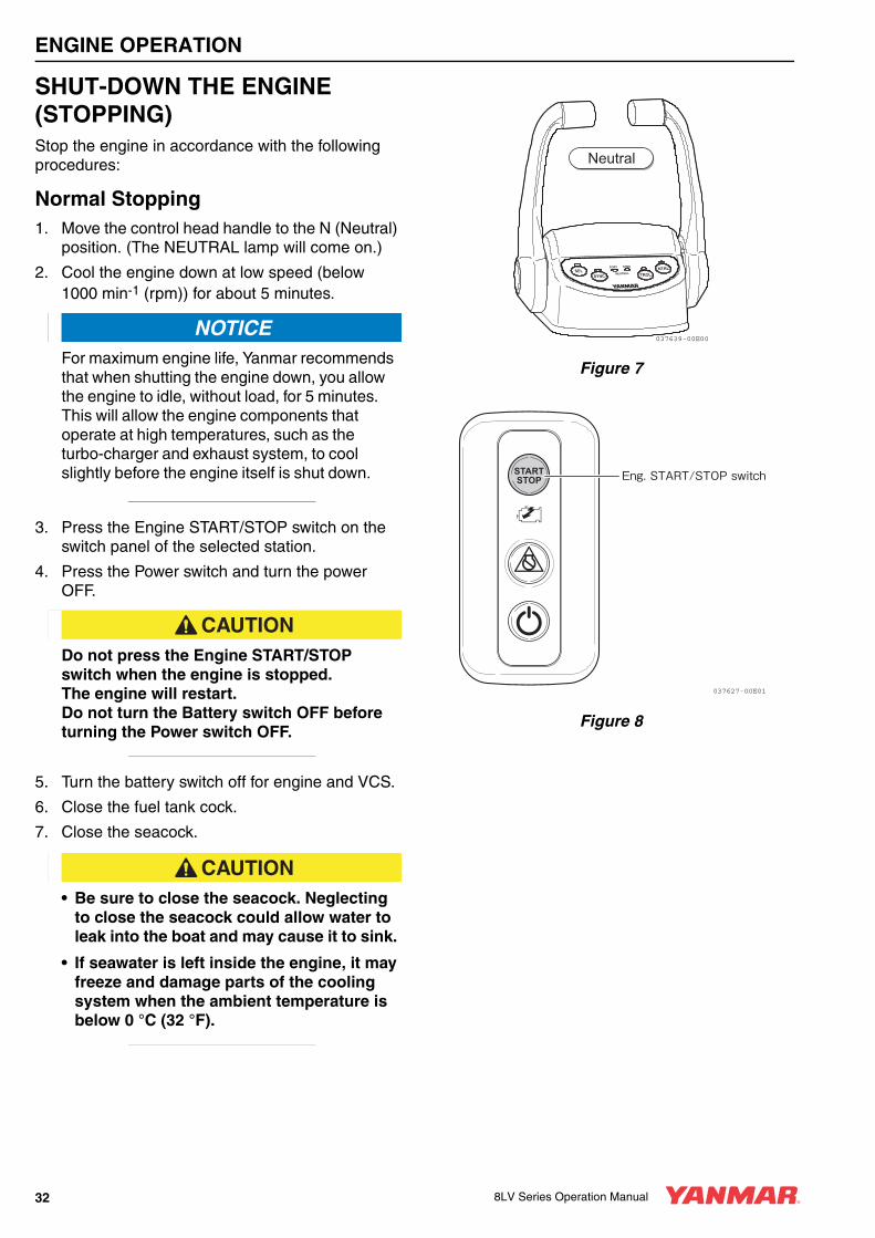
SHUT-DOWN THE ENGINE (STOPPING)Stop the engine in accordance with the following procedures:
Normal Stopping1. Move the control head handle to the N (Neutral)
position. (The NEUTRAL lamp will come on.)
2. Cool the engine down at low speed (below 1000 min-1 (rpm)) for about 5 minutes.
NOTICEFor maximum engine life, Yanmar recommends that when shutting the engine down, you allow the engine to idle, without load, for 5 minutes. This will allow the engine components that operate at high temperatures, such as the turbo-charger and exhaust system, to cool slightly before the engine itself is shut down.
3. Press the Engine START/STOP switch on the switch panel of the selected station.
4. Press the Power switch and turn the power OFF.
CAUTIONDo not press the Engine START/STOP switch when the engine is stopped. The engine will restart. Do not turn the Battery switch OFF before turning the Power switch OFF.
5. Turn the battery switch off for engine and VCS.
6. Close the fuel tank cock.
7. Close the seacock.
CAUTION• Be sure to close the seacock. Neglecting
to close the seacock could allow water to leak into the boat and may cause it to sink.
• If seawater is left inside the engine, it may freeze and damage parts of the cooling system when the ambient temperature is below 0 °C (32 °F).
Figure 7
Figure 8
SELNEUTRAL
PORT STBO NTRL
SYNC TROL
037639-00E00
Neutral
Eng. START/STOP switch
037627-00E01
32 8LV Series Operation Manual

ENGINE OPERATION
8LV-05-Engine Operation.fm 33 ページ 2011年1月19日 水曜日 午前9時14分
Emergency Stop
■ Electric Emergency Stop
NOTICENever use the Emergency Stop switch for a normal engine shutdown. Use this switch only when stopping the engine suddenly in an emergency.
1. Pressing the Emergency Stop switch on the switch panel will stop the engine immediately.
2. The Emergency Stop screen will be shown on the display, and the buzzer will sound.
3. After the engine has stopped, press the Emergency Stop switch to release the emergency stop. After releasing, it may take sometime to restart.
Note:
1. The Emergency Stop switch should only be used in emergencies. Use the Engine START/STOP switch to stop the engine normally.
2. The engine cannot be started while the Emergency Stop switch is pressed (emergency stop mode not canceled).
Figure 9
CONTROL THE BACKUP PANEL
WARNINGDo not use unless there is an emergency.
1. Check that the Power switch on the switch panel is OFF and that the control head handle and backup panel’s shift switch are in the N (Neutral) position.
2. Push the Power switch to the “ON” position on the backup panel. The lamp will come on, and enabling control by the backup panel.
3. The engine can be started or stopped with the START/STOP switch.
4. Pull out the protect bar.
5. Shift gears using the Shift switch. (FWD: forward, NTRL: neutral, REV: reverse)
6. Adjust the engine speed using the sub throttle control volume. (anti-clockwise: lower engine speed, clockwise: raise engine speed)
When controlling the throttle, first move it fully anti-clockwise to adjust before the engine speed controlling.
NOTICE• The throttle and gear shift of the engine that has
been turned on can be controlled.
• When controlling the throttle, always move it fully anti-clockwise first.
Figure 10
Emergency stop switch
037627-00E02
FWD
NTRL
REV
START
STOP
ON
Shift switchProtect bar
Eng. START/STOP switch
Sub throttle volume
Power switchLamp
037636-00E00
8LV Series Operation Manual 33

ENGINE OPERATION
8LV_OPM.book 34 ページ 2011年1月11日 火曜日 午後12時8分
CHECKING THE ENGINE AFTER OPERATION• Check that battery switch is turned to OFF.
• Fill the fuel tank. See Filling the Fuel Tank on page 22.
• Close seacock(s).
• If there is a risk of freezing, check that the cooling system contains enough coolant. See Engine Coolant Specifications on page 25.
• If there is a risk of freezing, drain the seawater system. See Draining the Seawater Cooling System on page 54.
• At temperatures below 0 °C (32 °F), drain seawater system and connect the engine heater (if equipped).
34 8LV Series Operation Manual

8LV_OPM.book 35 ページ 2011年1月11日 火曜日 午後12時8分
8LV Series Operation Manual
PERIODIC MAINTENANCE
This section of the Operation Manual describes the procedures for proper care and maintenance of the engine.
Before performing any maintenance procedures within this section, read the following safety information and review the Safety section on page 3.
8LV Series Operation Manual 35

PERIODIC MAINTENANCE
8LV_OPM.book 36 ページ 2011年1月11日 火曜日 午後12時8分
PRECAUTIONS
The Importance of Periodic MaintenanceEngine deterioration and wear occur in proportion to the length of time the engine has been in service and the conditions the engine is subjected to during operation. Periodic maintenance prevents unexpected downtime, reduces the number of accidents due to poor machine performance and helps extend the life of the engine.
Performing Periodic Maintenance
WARNINGNever block windows, vents, or other means of ventilation if the engine is operating in an enclosed area. All internal combustion engines create carbon monoxide gas during operation. Accumulation of this gas within an enclosure could cause illness or even death. Make sure that all connections are tightened to specifications after repair is made to the exhaust system. Failure to comply could result in death or serious injury.
The Importance of Daily ChecksThe Periodic Maintenance Schedule assumes that the daily checks are performed on a regular basis. Make it a habit of performing daily checks before the start of each operating day. See Daily Checks on page 42.
Keep a Log of Engine Hours and Daily ChecksKeep a log of the number of hours the engine is run each day and a log of the daily checks performed. Also note the date, type of repair (e.g., replaced alternator), and parts used for any service needed between the periodic maintenance intervals. Periodic maintenance intervals are every 50, 250, 500, and 1000 engine hours. Failure to perform periodic maintenance will shorten the life of the engine.
NOTICEFailure to perform periodic maintenance will shorten the life of the engine and may void the warranty.
Yanmar Replacement PartsYanmar recommends that you use genuine Yanmar parts when replacement parts are needed. Genuine replacement parts help ensure long engine life.
Tools RequiredBefore you start any periodic maintenance procedure, make sure you have the tools you need to perform all of the required tasks.
Ask Your Authorized Yanmar Marine Dealer or Distributor for HelpOur professional service technicians have the expertise and skills to help you with any maintenance or service related procedures you need help with.
36 8LV Series Operation Manual

PERIODIC MAINTENANCE
8LV_OPM.book 37 ページ 2011年1月11日 火曜日 午後12時8分
Tightening FastenersUse the correct amount of torque when you tighten fasteners on the machine. Applying excessive torque may damage the fastener or component and not enough torque may cause a leak or component failure.
■ Main Bolt and Nut Tightening Torque
No. Tightening PartsThread
Dia. × PitchMaterial Lubricant
Tightening Torque N·m (kgf-m)
1 Exhaust Manifold M10 × 1.25 S45C – 36 ± 4 (3.7 ± 0.4)
2 Mounting Foot M12 × 1.25 SCM435 – 80 ± 10 (8.2 ± 1.0)
3Union, Lubricating Oil Filter
3/4 - 16 UNF Apply lubricating oil 43.1 (4.4)
4 Lubricating Oil Filter 3/4 - 16 UNF Apply lubricating oil 14.7 - 19.6 (1.5 - 2.0)
5Bolts, Installation of Seawater Pump
M8 × 1.25 S45C – 20 ± 3 (2.0 ± 0.3)
6Support, Lubricating Pipe (Lubricating Oil Filter in/out)
M8 × 1.25 S45C – 5 ± 1 (0.5 ± 0.1)
7 Nut, Starter B Terminal M8 × 1.25 S45C – 21 ± 2 (2.1 ± 0.2)
8Bracket, EDU (Head Cover Insert of Resin)
M6 × 1 S45C – 10 ± 1 (1.0 ± 0.1)
9Battery Terminal (Head Cover Insert of Resin)
M6 × 1 S45C – 10 ± 1 (1.0 ± 0.1)
10 Nut, Battery Terminal M8 × 1.25 – 10 ± 1 (1.0 ± 0.1)
11V Band, Turbo-charger and Mixing Elbow
Apply Molybdenum Coat on the threads
After tightening at 6 ± 1 (0.6 ± 0.1), hit the outer circumference with a plastic hammer (3 times evenly at 3 places or more), and retighten at 6 ± 1 (0.6 ± 0.1).
12Bolts, Installation of Vibration Isolator
M16 × 2 SMC435 – 196 ± 10 (20.0 ± 1.0)
8LV Series Operation Manual 37

PERIODIC MAINTENANCE
8LV_OPM.book 38 ページ 2011年1月11日 火曜日 午後12時8分
■ Standard Tightening Torque
NOTICENOTICEThe tightening torque in the Standard Torque Chart should be applied only to the bolts with a “7” head (JIS strength classification: 7T). Apply 60 % torque to bolts that are not listed. Apply 80 % torque when tightened to aluminum alloy.
■ Torque for Pipe Joint Bolts
Note: Do not apply oil on bolts.
■ Torque for Piping Taper Screw
Thread Diameter M6 M8 M10 M12 M10 M12
Pitch mm 1.0 1.25 1.5 1.75 1.25 1.25
Width across flat mm 10 12 14 17 14 17
Tightening torqueN·m
(kgf·m)10.8 ± 1
(1.1 ± 0.1)25.5 ± 3
(2.6 ± 0.3)49 ± 5
(5.0 ± 0.5)88.2 ± 10 (9.0 ± 1.0)
52 ± 5 (5.3 ± 0.5)
93 ± 10 (9.5 ± 1.0)
Thread Diameter M8 M10 M12 M14 M16
Pitch mm 1.25 1.25 1.25 1.5 1.5
Width across flat mm 14 14 17 19 22
Tightening torqueN·m
(kgf·m)14.7 ± 2
(1.5 ± 0.2)22.5 ± 3
(2.3 ± 0.3)29.4 ± 5
(3.0 ± 0.5)44.1 ± 5
(4.5 ± 0.5)53.9 ± 5
(5.5 ± 0.5)
Thread Diameter 1/8 1/4 3/8 1/2
Tightening torqueN·m
(kgf·m)9.8
(1.0)19.6 (2.0)
29.4 (3.0)
58.8 (6.0)
38 8LV Series Operation Manual

PERIODIC MAINTENANCE
8LV_OPM.book 39 ページ 2011年1月11日 火曜日 午後12時8分
EPA MAINTENANCE REQUIREMENTSTo maintain optimum engine performance and compliance with the Environmental Protection Agency (EPA) Regulations for Engines, it is essential that you follow the Periodic Maintenance Schedule on page 40 and the Periodic Maintenance Procedures on page 42.
EPA Requirements for USA and Other Applicable CountriesThe following are the requirements for the EPA. Unless these requirements are met, the exhaust gas emissions will not be within the limits specified by the EPA.
See Conditions to Ensure Compliance with EPA Emission Standards on page 39. Clean or replace the air cleaner element if the air intake restriction exceeds the referenced specifications.
EPA RequirementsThe EPA emission regulation is applicable only in the USA and other countries that have adapted the EPA requirements in part or in whole. Determine and follow the emission regulations in the country where your engine will be operating to assist you in specified compliance.
Conditions to Ensure Compliance with EPA Emission StandardsThe 8LV series is an EPA-certified engine.
The following are the conditions that must be met in order to ensure that the emissions during operation meet the EPA standards.
The operating conditions should be as follows:
• Ambient temperature: -20 °C to +40 °C (-4 °F to +104 °F)
• Relative humidity: 80 % or lower
The diesel fuel should be:
• ASTM D975 No. 1-D or No. 2-D, or equivalent (minimum cetane No. 45)
The lubricating oil should be:
• Type API, Class CD, CF, CF-4, CI, CI-4
Be sure to perform inspections as outlined in Periodic Maintenance Procedures on page 42 and keep a record of the results.
Pay particular attention to these important points:
• Replacing the engine oil
• Replacing the engine oil filter
• Replacing the fuel filter
• Cleaning the intake silencer (air cleaner)
Note: Inspections are divided into two sections in accordance with who is responsible for performing the inspection: the user or the manufacturer.
Inspection and MaintenanceSee Inspection and Maintenance of EPA Emission-Related Parts on page 41 for the EPA emission-related parts. Inspection and maintenance procedures not shown in the Inspection and Maintenance of EPA Emission-Related Parts section are covered in Periodic Maintenance Schedule on page 40.
This maintenance must be performed to keep the emission values of your engine in the standard values during the warranty period. The warranty period is determined by the age of the engine or the number of hours of operation.
8LV Series Operation Manual 39

PERIODIC MAINTENANCE
8LV_OPM.book 40 ページ 2011年1月11日 火曜日 午後12時8分
PERIODIC MAINTENANCE SCHEDULEDaily and periodic maintenance is important to keep the engine in good operating condition. The following is a summary of maintenance items by periodic maintenance intervals. Periodic maintenance intervals vary depending on engine application, loads, diesel fuel and engine oil used and are hard to establish definitively. The following should be treated only as a general guideline.
NOTICEEstablish a periodic maintenance plan according to the engine application and make sure to perform the required periodic maintenance at the intervals indicated. Failure to follow these guidelines will impair the engine’s safety and performance characteristics, shorten the engine’s life and may affect the warranty coverage on your engine. Contact your authorized Yanmar Marine dealer or distributor for assistance when checking items marked with a ●.
: Check or Clean : Replace ●: Contact your authorized Yanmar Marine dealer or distributor
System Item
Periodic Maintenance Interval
Daily See Daily
Checks on page 42.
Every 50 Hours or Monthly
Whichever Comes
First
Every 250 Hours or One Year
Whichever Comes
First
Every 500 Hours or
Two Years Whichever
Comes First
Every 1000 Hours or
Four Years Whichever
Comes First
Whole Visual inspection of engine exterior
Fuel System
Check fuel level and refill if necessary
Drain water and sediment from fuel tank
Initial 50
Drain fuel filter/water separator
Replace fuel filter element
Lubricating System
Check engine oil level
Engine
Marine Gear
Replace engine oil
EngineInitial 50
Marine Gear (if equipped)
Initial 50
Replace oil filter element
Engine
Initial 50
Marine Gear (if equipped)
Initial 50
Cooling System
Seawater outlet
During operation
Check coolant level
Check or replace seawater pump impeller
Replace coolant Every year
Clean and check seawater passages
●
Replace zinc anode
40 8LV Series Operation Manual
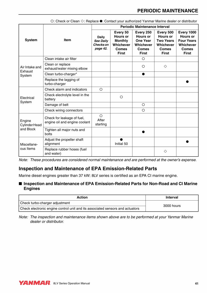
PERIODIC MAINTENANCE
8LV_OPM.book 41 ページ 2011年1月11日 火曜日 午後12時8分
Note: These procedures are considered normal maintenance and are performed at the owner’s expense.
Inspection and Maintenance of EPA Emission-Related PartsMarine diesel engines greater than 37 kW: 8LV series is certified as an EPA CI marine engine.
■ Inspection and Maintenance of EPA Emission-Related Parts for Non-Road and CI Marine Engines
Note: The inspection and maintenance items shown above are to be performed at your Yanmar Marine dealer or distributor.
Air Intake and Exhaust System
Clean intake air filter
Clean or replace exhaust/water mixing elbow
Clean turbo-charger* ●
Replace the lagging of turbo-charger
●
Electrical System
Check alarm and indicators
Check electrolyte level in the battery
Damage of belt
Check wiring connectors
Engine Cylinder Head and Block
Check for leakage of fuel, engine oil and engine coolant
After
starting
Tighten all major nuts and bolts
●
Miscellane- ous Items
Adjust the propeller shaft alignment
● Initial 50
●
Replace rubber hoses (fuel and water)
: Check or Clean : Replace ●: Contact your authorized Yanmar Marine dealer or distributor
System Item
Periodic Maintenance Interval
Daily See Daily
Checks on page 42.
Every 50 Hours or Monthly
Whichever Comes
First
Every 250 Hours or One Year
Whichever Comes
First
Every 500 Hours or
Two Years Whichever
Comes First
Every 1000 Hours or
Four Years Whichever
Comes First
Action Interval
Check turbo-charger adjustment3000 hours
Check electronic engine control unit and its associated sensors and actuators
8LV Series Operation Manual 41

PERIODIC MAINTENANCE
8LV_OPM.book 42 ページ 2011年1月11日 火曜日 午後12時8分
PERIODIC MAINTENANCE PROCEDURES
WARNINGAlways wear personal protective equipment. Refer to Explosion Hazard on page 4.
Daily ChecksBefore you head out for the day, make sure the Yanmar engine is in good operating condition.
NOTICEIt is important to perform the daily checks as listed in this Operation Manual. Periodic maintenance prevents unexpected downtime, reduces the number of accidents due to poor engine performance and helps extend the life of the engine.
Make sure you check the following items.
■ Visual Checks1. Check for engine oil leaks.
2. Check for fuel leaks.
WARNINGAvoid skin contact with the high-pressure diesel fuel spray caused by a fuel system leak, such as a broken fuel injection line. High-pressure fuel can penetrate your skin and result in serious injury. If you are exposed to high-pressure fuel spray, obtain prompt medical treatment. Never check for a fuel leak with your hands. Always use a piece of wood or cardboard. Contact your authorized Yanmar Marine dealer or distributor and repair any damage.
3. Check for engine coolant leaks.
4. Check for damaged or missing parts.
5. Check for loose, missing or damaged fasteners.
6. Check the electrical harnesses for cracks, abrasions, and damaged or corroded connectors.
7. Check hoses for cracks, abrasions, and damaged, loose or corroded clamps.
8. Check the fuel filter/water separator for presence of water and contaminants. If you find any water or contaminants, drain the fuel filter/water separator. See Draining the Fuel/Water Separator on page 44. If you have to drain the fuel filter/water separator frequently, drain the fuel tank and check for the presence of water in your fuel supply. See Draining the Fuel Tank on page 43.
NOTICEIf any problem is noted during the visual check, the necessary corrective action should be taken before operating the engine.
■ Checking Diesel Fuel, Engine Oil and Engine Coolant Levels
Follow the procedures in Diesel Fuel on page 20, Engine Oil on page 23 and Engine Coolant on page 25 to check these levels.
■ Checking and Refilling Marine Gear OilRefer to the Operation Manual for the marine gear.
■ Checking the Battery Electrolyte LevelCheck the battery electrolyte level before use. See Checking the Battery Electrolyte Level (Serviceable Batteries Only) on page 45.
■ Checking the Alternator Belt Check the belt tension before use. See Damage of Belt on page 50.
■ Checking the Alarm IndicatorsWhen operating the start switch on the rocker switch panel, check that there is no alarm message on the display and the alarm indicators work normally. See Vessel Control System (VCS) on page 16.
■ Preparing Fuel, Oil, and Coolant in Reserve
Prepare sufficient fuel for the day’s operation. Always store engine oil and coolant in reserve (for at least one refill) onboard, to be prepared for emergencies.
42 8LV Series Operation Manual

PERIODIC MAINTENANCE
8LV_OPM.book 43 ページ 2011年1月11日 火曜日 午後12時8分
Perform the following maintenance after the initial 50 hours of operation.
• Draining the Fuel Tank
• Changing the Engine Oil and Replacing the Engine Oil Filter Element
• Changing the Marine Gear Oil and Cleaning the Marine Gear Oil Filter (if equipped)
• Adjusting the Propeller Shaft Alignment
■ Draining the Fuel Tank
Figure 1
1. Put a pan (1, Figure 1) under the drain cock to catch fuel.
2. Open the drain cock and drain water and sediment. Close the drain cock when the fuel is clean and free of air bubbles.
■ Changing the Engine Oil and Replacing the Engine Oil Filter Element
The engine oil on a new engine becomes contaminated from the initial break-in of internal parts. It is very important that the initial oil replacement is performed as scheduled.
It is easiest and most effective to drain the engine oil after operation while the engine is still warm.
WARNINGIf you must drain the engine oil while it is still hot, stay clear of the hot engine oil to avoid being burned. Always wear eye protection.
1. Remove the yellow oil filler port cap from filler port (1, Figure 5 on page 24). Remove the drain plugs (both in the right and left) in the lower portion of the oil pan and drain the engine oil.
NOTICE• Prevent dirt and debris from contaminating
engine oil. Carefully clean the oil filler cap on the cylinder block side cover plate and the surrounding area before you remove the oil filler cap.
• Always be environmentally responsible.
2. Turn the engine oil filter counterclockwise with a filter wrench.
Figure 2
3. Remove the engine oil filter.
4. Install new engine oil filter and tighten by hand until the seal touches the housing.
After Initial 50 Hours of Operation
1010156-00X02
037416-00X00
8LV Series Operation Manual 43

PERIODIC MAINTENANCE
8LV_OPM.book 44 ページ 2011年1月11日 火曜日 午後12時8分
5. Turn the filter an additional 3/4 to one turn with a filter wrench.
6. Fill with new engine oil. See Adding Engine Oil on page 24.
NOTICE• Never mix different types of engine oil. This
may adversely affect the lubricating properties of the engine oil.
• Never overfill. Overfilling may result in white exhaust smoke, engine overspeed or internal damage.
7. Perform a trial run and check for oil leaks.
8. Approximately 10 minutes after stopping the engine, remove the oil dipstick and check the oil level. Add oil if the level is too low.
■ Changing the Engine Oil and Replacing the Engine Oil Filter Element
See Changing the Engine Oil and Replacing the Engine Oil Filter Element on page 43.
■ Adjusting the Propeller Shaft AlignmentThe flexible engine mounts are compressed a little during initial engine operation and may cause misalignment between the engine and the propeller shaft.
After the first 50 hours of operation, the alignment should be checked and readjusted if necessary. This is considered normal maintenance and the adjustment requires specialized knowledge and techniques. Consult your authorized Yanmar Marine dealer or distributor.
Check for any unusual noise and vibration in the engine/boat hull, while gradually increasing and decreasing the engine speed.
If there is unusual noise and/or vibration, this maintenance requires specialized knowledge and techniques. Contact your authorized Yanmar Marine dealer or distributor to adjust the propeller shaft alignment.
Perform the following maintenance every 50 hours or monthly of operation, whichever comes first.
• Draining the Fuel/Water Separator
• Checking the Battery Electrolyte Level (Serviceable Batteries Only)
■ Draining the Fuel/Water Separator
WARNINGWhen removing any fuel system component to perform maintenance (such as changing the fuel filter), put an approved container under the opening to catch the fuel. Never use a shop rag to catch the fuel. Vapors from the rag are flammable and explosive. Wipe up any spills immediately. Wear eye protection. The fuel system is under pressure and fuel could spray out when removing any fuel system component.
The 8LV series engine already have the optional fuel/water separator installed. If not, the customer should install a fuel/water separator attached to the hull.
Water Separator (Option)1. Draining the separator:
• Remove the plug at the bottom of the water separator and drain any water and dirt.
• After draining the separator, reinstall the plug securely.
Figure 3
2. Replacing the element:
• Remove the center separator bolt, then the filter case and element.
• Wash the separator case and replace the element and O-ring with new ones.
• Do not forget to reinstall the spring and washer. Fasten the center bolt securely.
Every 50 Hours of Operation
002620-01X
44 8LV Series Operation Manual

PERIODIC MAINTENANCE
8LV_OPM.book 45 ページ 2011年1月11日 火曜日 午後12時8分
• Always make sure to bleed the air after the element has been replaced.
Figure 4
■ Checking the Battery Electrolyte Level (Serviceable Batteries Only)
WARNINGBatteries contain sulfuric acid. Never allow battery fluid to come in contact with clothing, skin or eyes. Severe burns could result. Always wear safety goggles and protective clothing when servicing the battery. If battery fluid contacts the eyes and/or skin, immediately flush the affected area with a large amount of clean water and obtain prompt medical treatment.
NOTICE• Never turn off the battery switch (if equipped) or
short the battery cables during operation. Damage to the electric system will result.
• Never operate with insufficient battery electrolyte. Operating with insufficient electrolyte will destroy the battery.
• Battery fluid tends to evaporate in high temperatures, especially in summer. In such conditions, inspect the battery earlier than specified.
1. Turn the battery master switch to OFF or disconnect the negative (-) battery cable.
2. Do not operate with insufficient battery electrolyte as the battery will be destroyed.
3. Remove the plugs and check the electrolyte level in all cells.
NOTICENever attempt to remove the covers or fill a maintenance-free battery.
4. If the level is lower than the minimum, fill level (3, Figure 5), fill with distilled water (1, Figure 5) (available in the grocery store) up to the upper limit (2, Figure 5) of the battery.
Figure 5
Note: The maximum fill level is approximately 10 to 15 mm (3/8 to 9/16 in.) above the plates.
Center bolt
Drain plug
Element
022359-00E00
UPPER LEVELLOWER LEVEL
033952-00X01
1
23
8LV Series Operation Manual 45

PERIODIC MAINTENANCE
8LV_OPM.book 46 ページ 2011年1月11日 火曜日 午後12時8分
Perform the following maintenance every 250 hours or one year of operation, whichever comes first.
• Draining the Fuel Tank
• Replacing the Fuel Filter Element
• Changing the Engine Oil and Replacing the Engine Oil Filter Element
• Checking or Replacing the Seawater Impeller
• Replacing the Zinc Anode
• Changing the Coolant
• Cleaning the Intake Silencer (Air Cleaner) Element
• Cleaning the Turbo-charger
• Cleaning the Exhaust/Seawater Mixing Elbow
• Damage of Belt
• Checking the Wiring Connectors
• Tightening All Major Nuts and Bolts
■ Draining the Fuel TankSee Draining the Fuel Tank on page 43.
■ Replacing the Fuel Filter Element
WARNING• When removing any fuel system component
to perform maintenance (such as replacing the fuel filter), put an approved container under the opening to catch the fuel. Never use a shop rag to catch the fuel. Vapors from the rag are flammable and explosive. Wipe up any spills immediately. Wear eye protection. The fuel system is under pressure and fuel could spray out when removing any fuel system component.
• Perform this check with engine off and key removed to avoid contact with moving parts.
Figure 6
1. Close the fuel cock of the fuel tank.
Every 250 Hours of Operation
033657-00X01
4
3
21
46 8LV Series Operation Manual

PERIODIC MAINTENANCE
8LV_OPM.book 47 ページ 2011年1月11日 火曜日 午後12時8分
2. Remove the two mounting screws (1, Figure 6) and the housing (2, Figure 6).
3. Drain the fuel from the fuel drain cock on the bottom of the fuel/water separator.
4. Disconnect the alarm switch harness.
Figure 7
5. Remove the alarm switch ((3, Figure 6) and (Figure 7)) with a wrench.
6. Remove the filter element (4, Figure 6) with a filter wrench.
7. Install the alarm switch to the new fuel filter.
8. Apply a thin film of clean diesel fuel to the sealing surface of the new filter gasket.
9. Install new filter and hand-tighten. Use a filter wrench and tighten to 14.7 - 19.6 N·m (130.1 - 173.5 in.-lb).
10. Connect the alarm switch harness.
11. Install the housing and mounting screws.
12. Bleed the fuel system. See Bleeding the Fuel System on page 22. Dispose of waste properly.
■ Changing the Engine Oil and Replacing the Engine Oil Filter Element
See Changing the Engine Oil and Replacing the Engine Oil Filter Element on page 43.
■ Checking and Replacing the Seawater Pump Impeller
1. Loosen the side cover bolts and remove the side cover.
2. Inspect the inside of the seawater pump with a flashlight. If any of the following are found, disassembly and maintenance are required:
• Impeller blades are cracked or nicked. Edges or surfaces of the blades are marred or scratched.
• Wear plate is damaged.
3. If no damage is found when inspecting the inside of the pump, install the O-ring and side cover.
4. If a large amount of water leaks continuously from the water drain line below the seawater pump during operation, replace the mechanical seal. Contact your authorized Yanmar Marine dealer or distributor.
Replacing the Seawater Pump ImpellerNote: The impeller must be replaced periodically
(every 1000 hours) even if there is no damage.
Figure 8
Component Part No.
Fuel Filter Element 119798-55110
033658-00X
Rotation Direction
037418-00E00
8LV Series Operation Manual 47

PERIODIC MAINTENANCE
8LV_OPM.book 48 ページ 2011年1月11日 火曜日 午後12時8分
There are two types of special service tools for removing the impeller:
NOTICEThe seawater pump turns counterclockwise as viewed from the side cover, so the impeller must be installed as shown in Figure 8. If the impeller has been removed it must be installed in the correct direction. Additionally, if the engine is being turned over manually, be careful to turn it in the correct direction. Incorrect turning will twist the impeller blades and cause damage.
Puller A (Standard)
Figure 9
1. Remove the side cover of the seawater pump.
2. Install the puller (A, Figure 9) in the impeller.
Figure 10
3. Turn the jack screw (B, Figure 9) clockwise to remove the impeller from the pump body.
Figure 11
Note: When replacing a used impeller with a new one, the impeller must have an M22 × 1.5 thread (1, Figure 10). Turn the M18 screw-side of the impeller to the cover side and install (Figure 11).
Puller B (Option) Part No. 129671-92100
Figure 12
Puller A Jack Screw B
120325-92110 26116-100504
M18 × 1.5 M10 × 50
B
A
020133-00X
A B
1
037419-00X00
A B
110 mm (4.33 in.) 140 mm (5.51 in.)
037526-00X00
K0004502-00X
A
B
48 8LV Series Operation Manual

PERIODIC MAINTENANCE
8LV_OPM.book 49 ページ 2011年1月11日 火曜日 午後12時8分
■ Replacing the Zinc AnodeThe timing for replacing zinc anode varies depending on the characteristics of the seawater and operational conditions. Inspect the zinc periodically and remove the corroded area on the surface. Replace the zinc anode when it has decreased to less than 1/2 of the original volume. If replacement of zinc is neglected and operation is continued with a small volume of zinc anode, corrosion of the seawater cooling system will occur and water leakage or parts breakage will result. The label shown in the figure is stamped on the plugs which have the zinc anode. Be sure to close the seacock before removing the plug to replace the zinc anode.
1 - Sticker2 - Zinc Anode3 - Plug
Figure 13
1 - Heat Exchanger Zinc Anode
Figure 14
■ Changing the Coolant
CAUTIONWear eye protection and rubber gloves when you handle engine coolant. If contact with the eyes or skin should occur, flush eyes and wash immediately with clean water.
Replace coolant every year.
NOTICENever mix different types and/or colors of coolants.
Discard old coolant in an approved manner according to environmental laws.
Note: The drain cocks are opened before shipping from the factory.
1. Open all coolant drain cocks.
2. Allow the coolant to drain completely. Dispose of waste properly.
3. Close all the drain cocks.
4. Fill coolant tank and coolant reservoir tank with appropriate coolant. See Engine Coolant Specifications on page 25 and See Checking and Adding Coolant on page 25.
■ Location of Coolant Drain Cocks (Colored Gray)
Lubricating Oil Cooler
Figure 15
ZINCZINC
2
3
1
002719-01X
1
037449-00X00
037432-00X00
8LV Series Operation Manual 49

PERIODIC MAINTENANCE
8LV_OPM.book 50 ページ 2011年1月11日 火曜日 午後12時8分
Exhaust Manifold (RH Side)
Figure 16
Exhaust Manifold (LH Side)
Figure 17
Coolant Piping
Figure 18
■ Cleaning the Intake Silencer (Air Cleaner) Element
Refer to (Figure 1 on page 13) for the illustration.
1. Disassemble the intake silencer (air cleaner).
2. Remove the element. Clean the element and housing with a neutral detergent.
3. Dry completely and reassemble.
■ Cleaning the Exhaust/Seawater Mixing Elbow
The mixing elbow (Figure 1 on page 13) is attached to the turbo-charger (Figure 1 on page 13). The exhaust gas is mixed with seawater in the mixing elbow.
1. Remove the mixing elbow.
2. Clean any dirt and scale out of the exhaust and seawater passages.
3. If the mixing elbow is damaged, repair or replace.
4. Inspect the gasket and replace if necessary.
■ Cleaning the Turbo-chargerContamination of the turbo-charger causes revolutions to drop and engine output to fall.
If a significant drop in engine output is noted (10 % or more), clean the turbo-charger.
This should be done only by a trained and qualified technician. Contact your authorized Yanmar Marine dealer or distributor.
■ Damage of Belt
WARNINGPerform this check while engine and system power are turned off, to prevent from rolling into the belt and pulleys. Otherwise you may get seriously injured.
NOTICE• Never get any oil on the belt(s). Oil on the belt
causes slipping and stretching.
037431-00X00
037430-00X00
037433-00X00
50 8LV Series Operation Manual

PERIODIC MAINTENANCE
8LV_OPM.book 51 ページ 2011年1月11日 火曜日 午後12時8分
Inspecting V-Ribbed Belt1. Visually check the belt for excessive wear,
frayed cords, etc.If any defects are found, replace the V-ribbed belt.
NOTICEChecks on the rib side of the belt are considered acceptable. If the belt has chunks missing from the ribs, it should be replaced.
2. Check that the belt fits properly in the ribbed grooves.
NOTICEConfirm by hand that the belt has not slipped out of the grooves on the bottom of the pulley.
Figure 19
Figure 20
■ Checking the Wiring ConnectorsContact your authorized Yanmar Marine dealer or distributor to check the wiring connectors.
■ Tightening All Major Nuts and BoltsSee Tightening Fasteners on page 37 or contact your authorized Yanmar Marine dealer or distributor.
Perform the following maintenance every 500 hours or 2 years of operation, whichever comes first.
• Replacing the Rubber Hoses
• Replacing the Exhaust/Water Mixing Elbow
■ Replacing the Rubber HosesReplace the rubber hoses every 500 hours or 2 years, whichever comes first.
Contact your authorized Yanmar Marine dealer or distributor.
■ Replacing the Exhaust/Water Mixing Elbow
Replace the mixing elbow with a new one every 500 hours or 2 years, whichever comes first, even if no damage is found.
037421-00X00
CORRECT
INCORRECT037422-00E00
Every 500 Hours of Operation
8LV Series Operation Manual 51

PERIODIC MAINTENANCE
8LV_OPM.book 52 ページ 2011年1月11日 火曜日 午後12時8分
Perform the following maintenance every 1000 hours or 4 years of operation, whichever comes first.
• Replacing the Seawater Pump Impeller• Cleaning and Checking the Seawater
Passages• Adjusting the Propeller Shaft Alignment• Replacing the Lagging of Turbo-charger
■ Replacing the Seawater Pump ImpellerThe seawater impeller must be replaced every 1000 hours even if it is not damaged.
See Checking and Replacing the Seawater Pump Impeller on page 47.
■ Cleaning and Checking the Seawater Passages
After prolonged use, clean the seawater passages to remove trash, scale, rust and other contaminants that collect in the cooling water passages. This can cause declining cooling performance. The following items need to be inspected:
• Heat Exchanger
• Pressure Cap
Contact your authorized Yanmar Marine dealer or distributor.
■ Adjusting the Propeller Shaft AlignmentContact your authorized Yanmar Marine dealer or distributor.
■ Replacing the Lagging of Turbo-chargerContact your authorized Yanmar Marine dealer or distributor.
Every 1000 Hours of Operation
Component Part No.
Lagging of turbo-charger 119798-18340
52 8LV Series Operation Manual

8LV_OPM.book 53 ページ 2011年1月11日 火曜日 午後12時8分
8LV Series Operation Manual
LONG-TERM STORAGE
If the engine will not be used for an extended period of time, special measures should be taken to protect the cooling system, fuel system and combustion chamber from corrosion and the exterior from rusting.
The engine can normally stand idle for up to 6 months. If it remains unused for longer than this, please contact your authorized Yanmar Marine dealer or distributor.
Before performing any storage procedures within this section, review the Safety section on page 3.
In cold temperatures or before long-term storage, be sure to drain the seawater from the cooling system.
8LV Series Operation Manual 53

LONG-TERM STORAGE
8LV_OPM.book 54 ページ 2011年1月11日 火曜日 午後12時8分
PREPARING THE ENGINE FOR LONG-TERM STORAGE
NOTICEDo not drain closed cooling system for long-term storage. Antifreeze must be used to avoid freezing and damaging of components. Antifreeze will prevent rusting during long-term storage.
Note: If the engine is close to a periodic maintenance interval, perform those maintenance procedures before putting the engine into long-term storage.
1. Wipe off any dust or oil from the outside of engine.
2. Drain the water from fuel filter.
3. Drain the fuel tank completely or fill the tank to prevent condensation.
4. Seal the intake silencer, exhaust pipe, etc. to prevent moisture or contamination from entering engine.
5. Completely drain the bilge in hull bottom.
6. Waterproof the engine room to prevent rain or seawater from entering.
7. Charge the battery once a month to compensate for battery’s self-discharge.
8. Remove the key from the key switch and cover the key switch with moisture cap.
Draining the Seawater Cooling System
■ Location of Seawater Drain Plug (Colored Gray)
Fuel Oil Cooler
1 - Drain Plug
Figure 1
Remove the 5 bolts that secure the side cover of the seawater pump to drain the seawater from inside.
Figure 2
1037448-00X00
037450-00X00
54 8LV Series Operation Manual

LONG-TERM STORAGE
8LV_OPM.book 55 ページ 2011年1月11日 火曜日 午後12時8分
1 - Condensed Water Drain Plug
Figure 3
In cold temperatures or before long term storage, be sure to drain the seawater from the seawater cooling system.
WARNING• Drain the seawater from the seawater cooling
system after the engine has cooled down. Be careful to avoid burns.
• If seawater is left inside, it may freeze and damage parts of the cooling system (heat exchanger, seawater pump, etc.) when ambient temperature is below 32 °F (0 °C).
1. Loosen the seawater drain plug and drain off the seawater inside the engine. If no liquid comes from the drain plug, it may be necessary to use a stiff wire to remove any debris to allow drainage.
2. Loosen the 5 bolts attaching the side cover of the seawater pump, remove the cover and drain the water from inside. Retighten the bolts when finished.
3. Close the drain plug.
Do not drain the freshwater/coolant in the cold season or before long-term storage. If LLC (Long Life Coolant) has not been added to the cooling freshwater, be sure to add LLC or drain off the freshwater from the cooling system daily after use.
NOTICEIf the freshwater without LLC is not removed, it may freeze and damage parts of the cooling water system (heat exchanger, cylinder block, cylinder head, etc.) when ambient temperature is below 0 °C (32 °F).
When draining the freshwater:
• Open the freshwater drain cocks (2 positions) and drain the freshwater from inside the engine.
• Close the drain cocks after draining the freshwater.
Carry out the following periodic inspection before placing the engine in storage:
1. Clean the outside of the engine wiping off any dust or oil.
2. To prevent condensation inside the fuel tank, either drain off the fuel or fill the tank.
3. Cover the turbo-charger, exhaust pipe, etc. with vinyl sheets and seal them to prevent moisture from entering.
4. Drain bilge in the hull bottom completely. Water may leak into the boat when it is moored, and whenever possible it should be hauled out, covered and blocked.
5. Waterproof the engine room to prevent rain and seawater from entering.
During long-term storage, charge the battery once a month to compensate for the battery’s self-discharge.
When storing an engine for a long time, run the engine periodically according to the following procedure to prevent rust inside the engine:
• Change the engine oil and the filters before running the engine.
• Supply fuel if the fuel in the fuel tank was removed, and bleed the fuel system of air.
• Confirm that there is the coolant in the engine.
• Operate the engine at the low idling speed for about 5 minutes (if possible, once a month).
1 037420-00X00
8LV Series Operation Manual 55

LONG-TERM STORAGE
8LV_OPM.book 56 ページ 2011年1月11日 火曜日 午後12時8分
This Page Intentionally Left Blank
56 8LV Series Operation Manual

8LV_OPM.book 57 ページ 2011年1月11日 火曜日 午後12時8分
8LV Series Operation Manual
TROUBLESHOOTING
Before performing any troubleshooting procedures within this section, review the Safety section on page 3.If a problem occurs, stop the engine immediately. Refer to the Symptom column in the Troubleshooting Chart to identify the problem.
8LV Series Operation Manual 57

TROUBLESHOOTING
8LV_OPM.book 58 ページ 2011年1月11日 火曜日 午後12時8分
TROUBLESHOOTING AFTER STARTINGJust after the engine has started, check the following items at a low engine speed:
Is sufficient water being discharged from the seawater outlet pipe?
If the discharge is low, stop the engine immediately. Identify the cause and repair.
Is the exhaust color normal?
The continuous emission of black exhaust smoke indicates engine overloading. This shortens the engine’s life and should be avoided.
Are there abnormal vibrations or noise?
Depending on the hull structure, engine and hull resonance may suddenly increase at certain engine speed ranges, causing heavy vibrations. Avoid operation in this speed range. If any abnormal sounds are heard, stop the engine and inspect for cause.
Alarm sounds during operation.
If the alarm sounds during operation, lower the engine speed immediately, check the warning lamps and stop the engine for repairs.
Is there water, oil or fuel leakage? Are there any loose bolts or connections?
Check the engine room daily for any leaks or loose connections.
Is there sufficient fuel in the fuel tank?
Refill fuel in advance to avoid running out of fuel. If the tank runs out of fuel, bleed the fuel system. See Bleeding the Fuel System on page 22.
When operating the engine at low speed for long periods of time, rev up the engine once every 2 hours. Revving up the engine with the marine gear in NEUTRAL, accelerate from the low speed position to the high speed position and repeat this process about five times. This is done to clean out carbon from the cylinders and the fuel injection valves.
NOTICENeglecting to rev up the engine will result in poor exhaust color and reduce engine performance.
Periodically operate the engine near maximum speed while underway. This will generate higher exhaust temperatures, which will help clean out hard carbon deposits, maintain engine performance and prolong the life of the engine.
58 8LV Series Operation Manual

TROUBLESHOOTING
8LV_OPM.book 59 ページ 2011年1月11日 火曜日 午後12時8分
TROUBLESHOOTING INFORMATIONIf the engine does not operate properly, refer to the Troubleshooting Chart on page 60 or contact your authorized Yanmar Marine dealer or distributor.
Supply the authorized Yanmar Marine dealer or distributor with the following information:
• Model name and serial number of your engine
• Boat model, hull material, size (tons)
• Use, type of boating, number of hours run
• Total number of operation hours (refer to hourmeter), age of boat
• The operating conditions when the problem occurs:
• Engine rpm
• Color of exhaust smoke
• Type of diesel fuel
• Type of engine oil
• Any abnormal noises or vibration
• Operating environment such as high altitude or extreme ambient temperatures, etc.
• Information indicated on digital display.
• Engine maintenance history and previous problems
• Other factors that contribute to the problem
8LV Series Operation Manual 59

TROUBLESHOOTING
8LV_OPM.book 60 ページ 2011年1月11日 火曜日 午後12時8分
TROUBLESHOOTING CHART
Symptom Probable Cause Measure
Indicators light on the instrument panel and alarm sounds during operation
Shift to low speed operation immediately, and check which indicator has come on. Stop the engine and inspect. If no abnormality is identified and there is no problem with operation, return to port at lowest speed and request repairs.
Engine does not start or starts with difficulty
Pinion gear does not engage
Loose terminal of battery/engage magnet Tighten
Poor contact of starting switch Correct with sandpaper or replace
Open coil of magnet switch Replace
Burr at gear tooth tip Correct
Poor clearance between pinion and ring gear Correct
Pinion gear is engaged with ring gear, but does not rotate
Loose battery/starter terminal Tighten
Poor contact of starting switch Correct with sandpaper or replace
Worn brush Replace
Open circuit of starter coil Replace
Slippage of starter/clutch Replace
Excessive resistance of cable between battery and starter
Increase the cable size or shorten
Insufficient battery charge Charge
No fuel injection Incomplete priming of fuel system Carry out sufficient priming
Clogged fuel inlet filter Replace
Fuel level in fuel tank is low Add fuel
Closed cock of fuel tank Open cock
Clogged fuel pipe Clean
Failure of fuel supply pump Repair or replace
Failure of fuel injector Faulty valve seat Replace
Sticking of nozzle Replace
Worn nozzle Replace
Clogged injection hole Replace
Failure in fuel injection system
Loose fuel injection pipe joint Tighten
Broken fuel injection pipe Replace
Air trapped in fuel injection pipe Bleed air from pipe
Engine compressed air leak
Air leak from exhaust valve Carry out fitting of valve and seat
Faulty gasket/packing Replace
Worn upper portion of cylinder Replace
Worn piston ring Replace
Sticking piston ring Overhaul or replace
Broken valve spring Replace
Other Failure of engine system Conduct servicing
Clogged intake or exhaust pipe Clean
Controller defects system error Check DTC and conduct servicing
60 8LV Series Operation Manual

TROUBLESHOOTING
8LV_OPM.book 61 ページ 2011年1月11日 火曜日 午後12時8分
Engine is not running smoothly
Operation failure of injection valve
Nozzle operation failure Replace
Broken fuel valve spring Replace
Uneven fuel injection quantities
Clogged fuel filter Replace
Faulty operation of regulator valve Replace
Air trapped in fuel injection system Bleed air from system and prime system
Faulty operation of fuel supply pump Repair
Other Overload operation Reduce load
Moving parts seized Disassemble, inspect and conduct servicing
Slippage of gear box Inspect and repair
Engine stops suddenly
No fuel feed Fuel level in fuel tank is low Add fuel and prime
Air trapped in fuel system or fuel injection Bleed air
Water trapped in fuel tank Drain water from drain cock and fuel pipe, conduct priming
Fuel cock closed Inspect and repair as necessary
Clogged fuel filter Replace
Broken fuel pipe Replace
Failure of fuel supply pump Replace
Other Moving parts seized Disassemble and repair, or replace
Controller defects system error Inspect DTC and conduct servicing
Abnormal exhaust color
Failure of fuel injector Clogged injection nozzle Replace
Sticking needle valve Replace
Reduction in injection pressure Replace
Poor atomization Replace
Carbon deposit Clean
Turbo-charger failure Clogged air filter Clean
Dirty compressor side Clean
Clogged turbine side Clean
Damaged bearing Replace
Other Overload operation Reduce load
Lubricant level too high Lower the oil level
Accumulated carbon deposit at intake/exhaust valve
Clean
Dirty air cooler Clean
Improper fuel Replace with proper fuel
Clogged intake/exhaust valve Clean
Symptom Probable Cause Measure
8LV Series Operation Manual 61

TROUBLESHOOTING
8LV_OPM.book 62 ページ 2011年1月11日 火曜日 午後12時8分
Insufficient output
Insufficient fuel injection
Oil leak from fuel injection pipe joint Tighten
Faulty operation of regulator valve Replace
Clogged fuel filter Replace
Clogged fuel pipe Clean
Failure of fuel supply pump Repair
Insufficient injection by fuel injection nozzle
Clogged injection hole Replace
Faulty valve seat Replace
Sticking nozzle Replace
Loose fuel injection pipe joint Tighten
Worn nozzle Replace
Compressed gas leak in the engine cylinder
Gas leak from intake/exhaust valve Conduct fitting of the valve
Worn upper portion of cylinder bore Lap or replace
Worn piston ring Replace
Sticking piston ring Overhaul or replace
Turbo-charger failure Clogged air filter Clean
Dirty compressor side Clean
Clogged turbine nozzle Clean
Damaged bearing Replace
Other Improper fuel Replace with correct fuel
Clogged exhaust duct Clean
Seized or overheated moving parts Disassemble and conduct servicing
Insufficient seawater Inspect seawater pump
Insufficient feed of engine oil Disassemble and clean engine oil pump and filter
Controller defects system error Inspect DTC and conduct servicing
Knocking
Failure of fuel injector Broken fuel valve spring Replace
Sticking nozzle Replace
Poor atomization Replace
Fuel regulator valve failure
Faulty operation of regulator valve Repair
Other Insufficient seawater Replace seawater pump impeller
Piston clearance excessive Replace
Bearing clearance excessive Replace
Improper fuel Replace with correct fuel
Water trapped in fuel Replace fuel
Poor compression Inspect and service
Symptom Probable Cause Measure
62 8LV Series Operation Manual

TROUBLESHOOTING
8LV_OPM.book 63 ページ 2011年1月11日 火曜日 午後12時8分
Breakdown of turbo-charger
Drop in intake pressure Dirty air filter Clean
Leak from intake piping Repair
Leak of exhaust gas Repair
High intake air temperature Complete thermal insulation of exhaust pipe
Ensure intake air path is unrestricted from outside air
Clean air filter
Drop in air pressure in engine room Ensure intake air path is unrestricted from outside air
Broken seal ring Replace
Broken turbine impeller Replace
Broken nozzle ring Replace
Dirty turbine impeller Clean
Clogged nozzle Clean
Clogged exhaust pipe Clean
Increased intake pressure
Exhaust gas leak Re-mount turbo-charger
Failure in fuel injection system Overhaul injection pump, repair or replace any defective parts
Disassemble and inspect injection valve, replace injection valve
Deformed turbine nozzle Replace
Abnormal vibration Broken turbine impeller Replace
Broken compressor impeller Replace
Deposit of carbon or oxides on turbine Remove and repair or replace
Broken bearing Replace
Bent turbine shaft Replace
Loose parts or fasteners Tighten
Noise Damaged bearing Replace
Contact by revolving parts Repair or replace
Dirty or carbon deposit on turbine and compressor Clean
Entrapment of foreign matter (at turbine entrance) Repair or replace
Rapid change in load (surging) Stabilize the load or replace turbine nozzle
Quick contamination of engine oil
Gas trapped in bearing housing Repair
Clogged seal air path Clean
Damaged seal ring Replace
Clogged pressure balance path Clean
Symptom Probable Cause Measure
8LV Series Operation Manual 63

TROUBLESHOOTING
8LV_OPM.book 64 ページ 2011年1月11日 火曜日 午後12時8分
Pulsation of intake air pressure
Uneven cylinder combustion Adjust for uniform combustion
Rapid change in load Operate correctly
Excessively dirty compressor side Clean
Intake temperature too high Clean cooling fin
Complete thermal insulation of exhaust pipe
Ensure intake air path is unrestricted from outside air
Other Bearing seizure Replace
Corrosion in compressor/turbine impeller or bearing housing
Increase the coolant temperature
Other malfunctions
Noise generation Loose flywheel set bolts Tighten bolts
Loose connecting rod bolts Tighten bolts
Worn crank pin Replace
Excessive gear backlash Inspect the gear; replace worn gear, shaft, and/or bushing with new ones
Low lubrication oil pressure
Clogged engine oil filter Replace
Engine oil temperature too high Check the seawater level
Failure of oil pump Overhaul or replace
Faulty operation of oil pump relief valve Tighten the adjusting valve
Replace the safety valve
Low viscosity of engine oil used Replace the engine oil
Insufficient engine oil quantity Add oil
Faulty pressure gauge or sender unit Replace
Coolant temperature too high
Insufficient seawater Replace seawater pump impeller
Faulty thermostat Replace
Loose drive belt of coolant pump Adjust the belt tension
Overloaded operation Decrease the load
Other Controller defects system error Inspect and conduct servicing
Symptom Probable Cause Measure
64 8LV Series Operation Manual

TROUBLESHOOTING
8LV_OPM.book 65 ページ 2011年1月11日 火曜日 午後12時8分
FAILSAFE DIAGNOSIS FUNCTIONAL SPECIFICATION CHART
Failsafe ActionLevel 1: Derate engine speed and limit it to 2000 min-1 or lessLevel 2: Derate engine speed and limit it to 1000 min-1 or less
DTC FMI DTC DescriptionFailsafe Action
Warning Level 1 Level 2ENG Stop
Others
P0087 10 Fuel Rail Pressure - Too Low Change ×P0088 0 Fuel Rail Pressure - Too High × ×
P0093 1 Fuel System Leak Detected - Large Leak × × ×Speed derating for 30 sec & Engine stop
P01103 Intake Air Temperature Sensor Circuit - High Input × Operation with fixed
value4 Intake Air Temperature Sensor Circuit - Low Input ×
P01153 Engine Coolant Temperature Sensor Circuit - High Input × Operation with fixed
value4 Engine Coolant Temperature Sensor Circuit - Low Input ×
P0120
3 Main Analog Throttle Position Sensor Circuit - High Input × Engine speed is down to switch to sub throttle sensor.
4 Main Analog Throttle Position Sensor Circuit - Low Input ×12 CAN Throttle Position Sensor Circuit Failure ×
P0168 0 Fuel Temperature - Too High ×
P01803 Fuel Temperature Sensor Circuit - High Input × Operation with fixed
value4 Fuel Temperature Sensor Circuit - Low Input ×
P01903 Fuel Rail Pressure Sensor Circuit - High Input × ×4 Fuel Rail Pressure Sensor Circuit - Low Input × ×
P0201 5 Injection Circuit/Open - Cylinder 1 × ×
Pertinent EDU's power relay OFF
P0202 5 Injection Circuit/Open - Cylinder 2 × ×P0203 5 Injection Circuit/Open - Cylinder 3 × ×P0204 5 Injection Circuit/Open - Cylinder 4 × ×P0205 5 Injection Circuit/Open - Cylinder 5 × ×P0206 5 Injection Circuit/Open - Cylinder 6 × ×P0207 5 Injection Circuit/Open - Cylinder 7 × ×P0208 5 Injection Circuit/Open - Cylinder 8 × ×P0217 0 Engine Coolant Temperature - Too High × ×P0219 0 Engine Overspeed Condition × ×
P0220
3 Sub Throttle Position Sensor Circuit - High Input × Engine speed fixed at 1000 min-14 Sub Throttle Position Sensor Circuit - Low Input ×
6 Sub Throttle Lamp Circuit Over Current × Sub throttle lamp OFF
P0234 0 Turbocharger Overboost Condition × ×
P0235
1 Manifold Absolute Pressure Sensor - Too Low ×Operation with fixed value
3 Manifold Absolute Pressure Sensor Circuit - High Input ×4 Manifold Absolute Pressure Sensor Circuit - Low Input ×
P03352 Crankshaft Position Sensor Circuit Incorrect × × Throttle position 0 %
5 Crankshaft Position Sensor Circuit Low Input × × Throttle position 0 %
P0340
2 Camshaft Position Sensor Circuit Intermitted × ×5 Camshaft Position Sensor Circuit Low Input (STA ON) × ×8 Camshaft Position Sensor Circuit Incorrect × ×
P03805 Glow Plug Circuit “A” Relay Coil Open ×
Glow 1 relay OFF6 Glow Plug Circuit “A” Relay Coil Shorted Ground ×
P03825 Glow Plug Circuit “B” Relay Coil Open ×
Glow 2 relay OFF6 Glow Plug Circuit “B” Relay Coil Shorted Ground ×
P0512 3 Starter Interlock ×
P05203 Engine Oil Pressure Sensor Circuit - High Input ×4 Engine Oil Pressure Sensor Circuit - Low Input ×
P0524 1 Engine Oil Pressure - Too Low × ×
8LV Series Operation Manual 65

TROUBLESHOOTING
8LV_OPM.book 66 ページ 2011年1月11日 火曜日 午後12時8分
P05600 System Voltage - High × ×1 System Voltage - Low ×
P06125 EDU1 Power Relay Coil Open × ×
EDU1 power relay OFF6 EDU1 Power Relay Coil Shorted Ground × ×
P16125 EDU2 Power Relay Coil Open × ×
EDU2 power relay OFF6 EDU2 Power Relay Coil Shorted Ground × ×
P06155 Starter Relay Coil Circuit Open ×
Starter relay OFF6 Starter Relay Coil Circuit Shorted Ground ×
P06275 Fuel Pump Control Circuit Open × ×6 Fuel Pump Control Circuit Shorted Ground × ×
P062A0 Pump Voltage - Too High × ×1 Pump Voltage - Too Low ×
P062D 5 Fuel Injector Driver Circuit Performance Bank 1 × × EDU1 power relay OFF
P062E 5 Fuel Injector Driver Circuit Performance Bank 2 × × EDU2 power relay OFF
P062F 12 EEPROM Error ×
P06410 Sensor VOLT1 (+5 V) Above Normal or Short High ×1 Sensor VOLT1 (+5 V) Below Normal or Short Low ×
P0650 6 Warning Lamp Circuit Over Current × Warning lamp OFF
P06855 ECU Main Relay Coil Open ×
ECU main relay OFF6 ECU Main Relay Coil Shorted Ground ×
P1000 14 Emergency Switch Active × ×P1001 6 ACC Relay Coil Shorted Ground × Acc relay OFF
P1229 7 Fuel Pump Pressure Exceed the Target × ×
P16275 Pump Power Relay Coil Open ×
Pump power relay OFF6 Pump Power Relay Coil Shorted Ground ×
P1628 6 Alarm Relay Coil Shorted Ground × Alarm relay OFF
P1630 12 QR Code Checksum Error ×P1631 12 QR Code Data Not Written ×P1632 13 QR Code Invalid Failure ×P2269 0 Water In Fuel Condition ×P2502 1 Charging System Failure ×
U0146 9 CAN Communication Error ×Engine speed is down to switch to sub throttle sensor.
Failsafe ActionLevel 1: Derate engine speed and limit it to 2000 min-1 or lessLevel 2: Derate engine speed and limit it to 1000 min-1 or less
DTC FMI DTC DescriptionFailsafe Action
Warning Level 1 Level 2ENG Stop
Others
66 8LV Series Operation Manual

8LV_OPM.book 67 ページ 2011年1月11日 火曜日 午後12時8分
8LV Series Operation Manual
SPECIFICATIONS
PRINCIPAL ENGINE SPECIFICATIONS
8LV Series Engine Specifications
Engine Model 8LV320(Z) 8LV350(Z) 8LV370(Z)
Use Pleasure use
Type V, 4-Cycle, water-cooled diesel engine
Crankshaft rotation (viewed from flywheel) Counterclockwise
Combustion system Direct injection
Aspiration Turbo-charger with air cooler
Number of cylinders V-8
Firing order 1-2-7-3-4-5-6-8
Bore × stroke 86 mm × 96 mm (3.4 in. × 3.8 in.)
Displacement 4.461 l (272 Cu in.)
High idling speed 4000 ± 25 min-1
Low idling speed 550 ± 25 min-1
Continuous rating output at crankshaft (at 3683 min-1 (rpm))
214 kW (291 PS metric)
234 kW (318 PS metric)
248 kW (337 PS metric)
Maximum output at crankshaft (at 3800 min-1 (rpm))
235 kW (320 PS metric)
257 kW (350 PS metric)
272 kW (370 PS metric)
Installation Flexible mounting
Main power take off At flywheel end
Cooling system Freshwater cooling with heat exchanger
Engine lubrication system Enclosed, forced with gear pump
Engine oil capacity at rake angle 0° (Effective/total)
3.5/10 l (3.7/10.6 qt)
Oil pressure max rating 400 ± 50 kPa (58 ± 7.3 PSI)
Oil pressure low idle at 550 min-1 (rpm) ≥ 60 kPa (≥ 8.7 PSI)
8LV Series Operation Manual 67

SPECIFICATIONS
8LV_OPM.book 68 ページ 2011年1月11日 火曜日 午後12時8分
Cylinder Arrangement
Figure 1
8LV Series Marine Gear Specifications
Turbo-charger MHI TD04
Starter motor DC 12 V - 2.7 kW
Alternator 12 V - 180 A
Engine dimension without marine gear
Overall length 1133 mm (44.61 in.)
Overall width 884 mm (34.80 in.)
Overall height 783.5 mm (30.85 in.)
Dry weight (without gear) 435 kg (960 lb)
Minimum battery capacity 12 V - 120 Ah (5 hours rate, JIS 145G51 or equivalent)
Engine Model 8LV320(Z) 8LV350(Z) 8LV370(Z)
1
Right bank
Left bank
Flyw
heel
Bel
t
3 5 7
2 4 6 8
037754-00E00
Engine Model
8LV320 8LV320Z
8LV350 8LV350Z
8LV370 8LV370Z
Marine gear model KMH50A KMH52V ZT370
Specification8 deg. down angle with hydraulic shift
12 deg. down angle with hydraulic shift
Stern drive
Gear ratio (Ahead/Astern) 1.67, 2.13, 2.43 1.22, 1.58, 2.08, 2.47 1.65, 1.78
Lubricating oil capacity (Effective/Maximum) 0.4/2.0 l (0.4/2.1 qt) 0.4/5.4 l (0.4/5.7 qt) 2.5 l (2.6 qt)
Dry weight 41 kg (90 lb) 59 kg (130 lb) 100 kg (221 lb)
68 8LV Series Operation Manual

8LV_OPM.book 69 ページ 2011年1月11日 火曜日 午後12時8分
8LV Series Operation Manual
SYSTEM DIAGRAMS
WIRING DIAGRAM8LV series-Type Instrument Panel8LV series Instrument Panel are available for 12 V standard.
8LV Series Operation Manual 69

SYSTEM DIAGRAMS
8LV_OPM.book 70 ページ 2011年1月11日 火曜日 午後12時8分
8LV Wiring Diagram
Figure 1
G-
G+
NE
-N
E+
E04
8/G
(0.7
5f)
E05
4/L(
0.75
f)
E04
2/G
(0.7
5f)
E03
5/L(
0.75
f)S
LD9
Cra
nk p
os S
SLD
10G
ear p
os S
SL SK
SY
IGS
W2
E08
3/B
r(0.
85)
Diode 3
THR
VC
P2
VPA
2E
PA2
E11
4/G
(0.8
5)E
055/
P(0
.85)
E04
0/Lg
(0.8
5)E
050/
Gr(
0.85
)
EC
WA
LMR
EL
VC
PAV
PAE
PA
E10
8/LY
(0.8
5)E
120/
V(0
.85)
E05
6/R
Y(0
.85)
E03
9/G
Y(0
.85)
E05
1/B
Y(0
.85)
VPA
2SW
E07
6/LY
(0.8
5)J1
939H
J193
9LE
047/
Y(0
.75f
)E
041/
G(0
.75f
)
RA
NM
EA
HN
ME
A L
E05
3/W
(0.7
5f)
E06
0/L(
0.75
f)
RB
PC
V-P
CV
+E
001/
LB(1
.25)
E02
6/LW
(1.2
5)E
045/
B(0
.85)
E07
2/G
B(0
.85)
ETH
FTH
F
PC
V
F TE
MP
S
Air
TEM
P S
E04
4/B
W(0
.85)
E06
5/G
W(0
.85)
ETH
IATH
IA
E04
6/B
L(0.
85)
Wat
er T
EM
P S
E07
4/G
L(0.
85)
ETH
WTH
W
E04
3/B
R(0
.85)
Air
Pre
s S
E06
4/G
R(0
.85)
EP
IMP
IMV
CP
ME
081/
R(0
.85)
E07
7/B
Y(0
.85)
Rai
l Pre
s S
E07
3/G
Y(0
.85)
EP
CR
1P
CR
1V
CM
E08
2/R
Y(0
.85)
E05
2/V
G(0
.85)
Oil
Pre
s S
E06
3/G
(0.8
5)E
PO
PLO
VC
PO
E05
7/R
G(0
.85)
Eng earthGND
62
Nmea LNmea H
Can power 134
Eng earthGND
64
SX
123
Can powerJ1939 HJ1939 L CB
CA
M TH GNDM TH Signal6
4
123
Main C SYS-ONMain stop
Buzzer5
7
M TH Power
Check ENG lamp
Res
ista
nce
1
ACC FS
10A96101112
Can powerCan GNDJ1939 HJ1939 LEng earth
PEMain GND8
2 E-stop
VE
B/U RL(N/C)
VB
3 Bup active
7 Main START4 Main SYS-ON51 SYS Power
Diode 2
Diode 1
16
234758910 S TH GND
S TH SIGS TH PowerS TH Lamp
Bup activeBup stopBup start
Bup GNDBup power
Vessel Control System(Unlimited)
1st station
10A
VC
S F
S
10A
BU
P FS
B/U Panel
Diag tool
Nmea
ShieldWire sizeAWG10 <==> 5mm2
AWG16 <==> 1.25mm2
AWG18 <==> 0.85mm2
AWG20 <==> 0.5mm2
MarkBRLWGGrYBrOLgPV
ColorBlackRedBlueWhiteGreenGray
YellowBrownOrange
Light GreenPink
Purple
B013/WBr(1.25)G013/BY(1.25)E047/Y(0.75f)E041/G(0.75f)S001/B(1.25)
V007/V(1.25)G010H/BW(1.25)
V001/WL(1.25)
V003/YR(1.25)
E076A/LY(1.25)
V002/WB(1.25)V006/BrW(1.25)E108/LY(0.85)E120/V(0.85)E056/RY(0.85)E039/GY(0.85)E051/BY(0.85)
B013A/WBr(1.25)E047A/Y(0.75f)E041A/G(0.75f)
G013A/BY(1.25)S001A/B(0.85)
B013B/WBr(1.25)E053/W(0.75f)E060/L(0.75f)
G013B/BY(1.25)S001B/B(0.85)
ECU
B041/W(1.25)G010F/BW(1.25)
E066A/YR(1.25)E083A/BrW(1.25)E075B/WL(1.25)
E114/G(0.85)E055/P(0.85)E040/Lg(0.85)E050/Gr(0.85)
E07
6B/L
Y(1
.25)
B041/W(1.25)
S00
1DB
(0.8
5)
ED
U1
FS
20A
EC
U F
S20
A
20A
ED
U2
FS
B040/R(3)
B02
1/R
B(2
)
B01
1/W
R(2
)
B02
4/R
L(2)
E07
5B/W
L(1.
25)
E06
6A/Y
R(1
.25)
V001WL(1.25)
E04
7B/Y
(0.8
5)E
041B
/G(0
.85)
E08
3/B
r(0.
85)
E075
A/W
G(1
.25)
DeutschDT04-6P-CE02
DeutschDTM06-6S
Bup active SW
Start/stop SW
Sub throttle
DeutschDT04-12PC-C015
S00
1C/B
(0.8
5)
S00
1E/B
(0.8
5)
SJ
11 Bup shift F12 Bup shift R
8 Shift F9 Shift R10 PWM+11 PWM-12
V010/Y(1.25)V011/W(1.25)V012/P(0.85)V013/L(0.85) P valve
V015/WB(1.25)V014/YB(1.25)
12
16
23475891011
D-ECU
H-ECU
E-stopSYSon
Start/Stop
Panel
Helmharness
TerminalAdapter
Res
ista
nce
Drive harness
56
4
123
7
8
11
910
12
96101112
82
3
7
451
Bup shift SW
Main SYS-ON V001A/WG(1.25)B043/W(1.25)
VA
V001BWL(1.25)
1 2 3 4 5 612 11 10 9 8 7
1 62 53 4
6 15 24 3
1 2 3 4 5 612 11 10 9 8 7
VCS 2
DeutschDT04-12PB-C015
1 2 3 4 5 612 11 10 9 8 7
DeutschDT04-12PA-C015
VCS 1
TWIST
037501-00E00
70 8LV Series Operation Manual

SYSTEM DIAGRAMS
8LV_OPM.book 71 ページ 2011年1月11日 火曜日 午後12時8分
Figure 2
EDU2RL
EDU1RL
IG RL
MainRL
E-stopRL
STA RL
PCEA
PCV RL
Eng earth
PF
E06
1/W
R(1
.25)
E07
9/W
R(1
.25)
E07
0/R
W(1
.25)
E07
8/R
W(1
.25)
+B1
+B1
+B2
+B2
PB PG
E00
9/R
Y(1
.25)
E01
7/R
Y(1
.25)
E09
6/Y
R(0
.85)
+B P
CV
+B P
CV
ER
EL
E09
4/LG
(0.8
5)E
098/
LB(0
.85)
GR
EL
GR
L2
E11
2/W
(0.8
5)E
111/
P(0
.85)
NS
WFW
SW
Fuel filter SW
Neutral SW
E07
1/Y
(0.8
5)E
084/
LB(0
.85)
ALT
MA
LTL
Alternator
Eng earth
INJ2
INJ3
INJ5
INJ8
SHSESCSB
SLD
2
SLD
3
SLD
5
SLD
8
SA SD SF
SLD
7
SG
SLD
6
SLD
4
SLD
1
INJ7
INJ6
INJ4
INJ1
EDU2
#2 #3 #5 #8IN
F2
E01
4/B
(0.5
)E
005/
W(0
.5)
E00
4/R
(0.5
)E
011/
B(0
.5)
E01
5/W
(0.5
)
EDU1
#1 #4 #6 #7IN
JF
E00
6/B
(0.5
)E
013/
W(0
.5)
E01
2/R
(0.5
)E
003/
B(0
.5)
E00
7/W
(0.5
)
E01
E01 E1
E1
E2
FG FG FG FG E02
E02
E01
E01
E01
E01
E09
2/B
Y(0
.85)
E09
3/B
Y(0
.85)
E02
5/LO
(1.2
5)E
034/
LO(1
.25)
E08
5/LO
(0.8
5)E
028/
LO(0
.85)
E02
9/LO
(0.8
5)E
116/
LO(0
.85)
E11
7/LO
(0.8
5)E
002/
BR
(1.2
5)E
010/
BR
(1.2
5)E
018/
BR
(1.2
5)E
027/
BR
(0.8
5)E
107/
BR
(1.2
5)E
113/
BR
(1.2
5)
ED EE EF
ST RL
ST FS
50A
ALT FS300A
Starter
Eng earth
GLOW2 FS
80A
GLOW1 FS
80A
Eng earth
Eng earth
Glow 2
Glow 1
IRE
L2IR
EL
MR
EL
EM
GS
WS
TAR
STA
IGS
W1
E09
5/LW
(0.8
5)E
068/
LR(0
.85)
E09
7/Y
(0.8
5)E
069/
WL(
0.85
)E
102/
YB
(0.8
5)E
066/
Y(0
.85)
E07
5/W
G(0
.85)
GB
GC
GA
GD
GE
Battery SW
BATTERYSW
Eng earth
SW
Glow2 RL
Glow1 RL
G017/B(0.85)E111/P(0.85)
B
E
B02
5/R
L(2)
G01
0K/B
W(2
)
P02
0/LW
(1.2
5)P
021/
LB(1
.25)
P03
0/LW
(1.2
5)P
031/
LB(1
.25)
P05
0/LW
(1.2
5)P
051/
LB(1
.25)
P08
0/LW
(1.2
5)P
081/
LB(1
.25)
B02
2/R
B(2
)G
010J
/BW
(2)
P01
0/LW
(1.2
5)P
011/
LB(1
.25)
P04
0/LW
(1.2
5)P
041/
LB(1
.25)
P06
0/LW
(1.2
5)P
061/
LB(1
.25)
P07
0/LW
(1.2
5)P
071/
LB(1
.25)
SV
B00
5/R
W(5
)G
010G
/BW
(1.2
5)
Jointconnector
+ -
V004/Y(1.25) V005/Y(1.25)
B010/R(5)
G010/B(5)
G010F/BW(1.25)
G01
0K/B
W(2
)G
010J
/BW
(2)
G01
0G/B
W(1
.25)
G01
0H/B
W(1
.25)
G01
0A/B
W(0
.85)
G01
0C/B
W(1
.25)
G01
0B/B
W(1
.25)
G01
0D/B
W(1
.25)
G01
0E/B
W(1
.25)
B00
0/R
(20)
B00
1/R
(20)
B007/R(8)E094/LG(0.85)
B006/R(8)G014/B(0.85)
B009/RW(8)E098/LB(0.85)
B008/RW(8)G015/B(0.85)
B000A/R(8)
B001A/RW(8)
V005/Y(1.25)
B004/RW(5) B000B/RW(5)
B005/RW(5)
G01
6/B
(0.8
5)G
017/
B(0
.85) B002/R(20)
B003/R(20)
B03
1/R
G(0
.85)
B01
4A/W
R(0
.85)
E07
1/Y
R(0
.85)
E08
4/LB
(0.8
5)
G01
0C/B
W(1
.25)
G01
0B/B
W(1
.25)
G01
0D/B
W(1
.25)
G01
0E/B
W(1
.25)
G013/BY(1.25)
E112/W(0.85)
G016/B(0.85)
G03
1/B
(0.8
5)B
033/
RY
(2)
E096
/YR(
0.85)
B03
4/R
Y(2
)10
A
PC
V F
S
B030/R(3)
E102/YB(0.85) G011/B(0.85)
G012/B(0.85)
E069/WL(0.85) B012A/GR(0.85)B012B/GW(0.85)
B012C/WBr(1.25)
B011A/RW(2) B012/RW(2)G010A/BW (0.85)
G02
1/B
(0.8
5)G
022/
B(0
.85)
G02
3/B
(0.8
5)
B022/RB(2)
B025/RL(2)
B01
4/W
R(2
)B
014A
/WR
(0.8
5)B
012/
RW
(2)
B03
4/R
Y(2
)B
033/
RY
(2)
B
E
Battery
G011
/B(0
.85)
AB
3Section of cable(mm2)
50
Allowable LengthL=1+2+3(m)
<5.0
1
2
AA
S00
3A/B
(0.8
5)
S00
3B/B
(0.8
5)
S00
3C/B
(0.8
5)
S00
3D/B
(0.8
5)
S00
2A/B
(0.8
5)
S00
2B/B
(0.8
5)
S00
2C/B
(0.8
5)
S00
2D/B
(0.8
5)
S003/B(1.25)S002/B(1.25)
E066/Y(0.85)
G01
8/B
(1.2
5)
Shift F
Shift REG
V010/Y(1.25)G018A/B(1.25)
G018B/B(1.25)V011/W(1.25)
VG
VF
ALT.S FS
7.5AB004A/RW(3)BA
Harness(A119798-77070
Harness(B119798-77080
Bat terminal1E8230-84490
OEMResponsibilty
037544-00E00
8LV Series Operation Manual 71

SYSTEM DIAGRAMS
8LV_OPM.book 72 ページ 2011年1月11日 火曜日 午後12時8分
This Page Intentionally Left Blank
72 8LV Series Operation Manual

8LV_OPM.book 73 ページ 2011年1月11日 火曜日 午後12時8分
8LV Series Operation Manual
EPA WARRANTY USA ONLY
YANMAR CO., LTD. LIMITED EMISSION CONTROL SYSTEM WARRANTY - USA ONLYThe following EPA Warranty only applies to engines built on or after November 21, 2010 and labeled with the proper nameplate (Figure 1).
Figure 1
Figure 1
MARINE ENGINE EMISSION CONTROL INFORMATION
REFER TO OWNER'S MANUAL FOR MAINTENANCESPECIFICATIONS AND ADJUSTMENTS.
YANMAR CO.,LTD.
ENGINE FAMILY : BYDXN4.46D8H APPLICATION:RECREATIONAL
THIS ENGINE COMPLIES TO U.S.EPA REGULATIONS40 CFR PART 94 WHICH APPLY TO MARINE ENGINES
DISPLACEMENT PER CYLINDER : 0.558 LITERS
STANDARDS THC+NOx:7.5g/kWh CO:5.0g/kWh PM:0.40g/kWh
MODEL YEAR : 2011 ENGINE MODEL
1
037532-00X00
No. Part Number Engine Model
1
119798-07600 8LV370
119798-07610 8LV350
119798-07620 8LV320
119799-07700 8LV370Z
119799-07710 8LV350Z
119799-07720 8LV320Z
8LV Series Operation Manual 73

EPA WARRANTY USA ONLY
8LV_OPM.book 74 ページ 2011年1月11日 火曜日 午後12時8分
THIS EMISSION WARRANTY APPLIES TO THE ENGINES CERTIFIED TO UNITED STATES EPA 40 CFR 94 AND SOLD BY YANMAR THAT ARE INSTALLED IN VESSELS FLAGGED OR REGISTERED IN THE UNITED STATES.
Your Warranty Rights and ObligationsYanmar warrants to the first user and each subsequent purchaser the emission control system on your engine for periods of time listed below provided the engine has been installed according to Yanmar installation requirements and there has been no abuse, neglect, or improper maintenance of your Yanmar Marine engine.
Yanmar warrants that the engine is designed, built and tested using genuine parts and equipped so as to conform to all applicable emission requirements of the U.S. Environmental Protection Agency and is free from defects in material and workmanship which would cause this engine to fail to conform to the applicable emission regulations over its limited emission control system warranty period.
Where a warrantable emissions condition exists, Yanmar will repair your engine at no charge to you for diagnosis, parts, and labor. Warranty service or repair will be provided at authorized Yanmar Marine dealers or distributors.
It is recommended that any replacement parts used for maintenance, repair or replacement of emission control systems are Yanmar parts. The owner may elect to have maintenance, replacement or repair of the emission control components and systems performed by any repair establishment or individual and may elect to use parts other than Yanmar parts for such maintenance, replacement or repair. However, the cost of such service or parts and subsequent failures from such service or parts will not be covered under this emission control system warranty.
Warranty PeriodThe warranty starts on either the date of delivery to the first end-user, or the date the unit is first leased, rented, or loaned.
For Pleasure Use: The warranty period is five (5) years or 2000 hours of use, whichever occurs first. In the absence of a device to measure hours of use, the engine has a warranty period of five (5) years.
Warranty CoverageRepair or replacement of any warranted parts will be performed at an authorized Yanmar Marine dealer or distributor. This limited emission control system warranty covers engine components that are a part of the emission control system of the engine as delivered by Yanmar to the original retail purchaser. Such components may include the following:
1. Fuel Injection System
2. Turbo-charger System
3. Aftercooler
4. Electronic Engine Control Units and its associated Sensor and Actuators
ExclusionsFailures other than those arising from defects in material and/or workmanship are not covered by this limited emissions warranty. This warranty does not extend to the following: malfunction caused by abuse, misuse, improper adjustment, modification, alteration, tampering, disconnection, improper or inadequate maintenance, improper storage or use of non-recommended fuels and lubricating oils, accident-caused damage, and replacement of expendable and/or consumable items made in connection with scheduled maintenance.
Yanmar disclaims any responsibility for incidental or consequential damages such as loss of time, inconvenience, loss of use of marine vessel/engine or commercial loss.
Owner’s ResponsibilityAs the Yanmar Marine engine owner, you are responsible for the performance of the required maintenance listed in your Operation Manual. Yanmar recommends that you retain all documentation, including receipts, covering maintenance on your marine engine, but Yanmar cannot deny warranty solely for the lack of receipts or for your failure to ensure the performance of all scheduled maintenance.
Your engine is designed to operate on diesel fuel only. Use of any other fuel may result in your engine no longer operating in compliance with applicable emission requirements. You are responsible for initiating the warranty process. You must present your marine engine to an authorized Yanmar Marine dealer or distributor as soon as a problem exists.
74 8LV Series Operation Manual

EPA WARRANTY USA ONLY
8LV_OPM.book 75 ページ 2011年1月11日 火曜日 午後12時8分
Customer AssistanceIf you have any questions regarding your warranty rights and responsibilities or would like information on the nearest authorized Yanmar Marine dealer or distributor, you should contact Yanmar America Corporation for assistance.
Yanmar America Corp. (YA)(Marine Business Unit)101 International ParkwayAdairsville, GA 30103, U.S.A. Phone: 1-770-877-9894Fax: 1-770-877-9009
8LV Series Operation Manual 75

EPA WARRANTY USA ONLY
8LV_OPM.book 76 ページ 2011年1月11日 火曜日 午後12時8分
Maintenance Log
Date Operating Hours Maintenance Performed Dealer NameStamp or Signature
76 8LV Series Operation Manual

EPA WARRANTY USA ONLY
8LV_OPM.book 77 ページ 2011年1月11日 火曜日 午後12時8分
Date Operating Hours Maintenance Performed Dealer NameStamp or Signature
8LV Series Operation Manual 77

EPA WARRANTY USA ONLY
8LV_OPM.book 78 ページ 2011年1月11日 火曜日 午後12時8分
Date Operating Hours Maintenance Performed Dealer NameStamp or Signature
78 8LV Series Operation Manual