7100 Series
17
GAMEWELL-FCI 12 Clintonville Road, Northford, CT 06472-1610 USA • Tel: (203) 484-7161 • Fax: (203) 484-7118 Specifications are for information only, are not intended for installation purposes, and are subject to change without notice. No responsibility is assumed by Gamewell-FCI for their use. ©2015 by Honeywell International Inc. All rights reserved. www.gamewell-fci.com 9020-0466 Rev. N page 1 of 3 7100 Series Compact Analog Addressable Fire Alarm Control Panel SIGNALING S1869 3003549 APPROVED FM 6911-1703:0116 (Non-High Rise) 6911-1703:0118 (High Rise) 7300-1703:0106 (LCD-7100) FDNY COA #s 307-99-E 307-99-E Vol. II MEA Approved Reference Certificate of Compliance VMA-45894-02C (Revision 1) Description The Gamewell-FCI, 7100 Series fire alarm control panel is a multi processor-based, analog addressable system. The control panel is a compact, yet expandable, platform. Intended for commercial, industrial and institutional instal- lations, the 7100 Series is ideal for life safety and property protection fire alarm applications. The basic 7100 Series control panel provides one analog addressable Signaling Line Circuit (SLC), whether sup- ports up to 99 analog addressable sensors, as well as sup- porting up to 98 addressable monitor modules and/or control points, totaling 197 addresses. The 7100 uses an advanced protocol that ensures an almost instant response to events while at the same time suppressing nuisance alarms. The system may be programmed with the CAMWorks™ programming utility tool or configured through a compre- hensive set of intuitive, secure password-protected, front- panel programming options. This important feature allows the system to quickly adapt to any future requirements due to changes in occupancies, building remodels, or other contingencies. The sophisticated circuitry and powerful analog software enables the 7100 Series fire alarm control panel to read the specific sensitivity level of each sensor and compen- sate for changes due to age, dust accumulation or other environmental factors. The 7100 incorporates the Gamewell-FCI Listed Integrated Sensitivity Testing (LIST) which meets NFPA 72 sensitivity testing and maintenance requirements. The LIST testing allows substantial savings in both maintenance and service while eliminating nui- sance alarms. The Model 7100-1D features an integral Digital Alarm Communicator Transmitter (DACT) with all popular trans- mission formats and a 16-digit telephone number field. It is 8-digit Carrier Information Code (CIC) compliant and also prevents “dialer-runaway” in the event of intermittent sys- tem faults. The 7100-1D is UL Listed for Remote Station, Proprietary, and Central Station fire alarm systems. It allows ample space for wiring and room for batteries up to 12 A/H capacity. CAMWorks™ is a trademark of Honeywell International, Inc. Microsoft® Word® is a registered trademark of Microsoft® Corporation. UL® is a registered trademark of Underwriter’s Laboratories Inc. Features • Listed under ANSI/UL ® Standard 864 9th Edition. • IBC Seismic Certified. • 120 or 240 VAC (optional) input line voltage. • Front panel programming with day/night sensitivity adjustments. • 80-character alpha-numeric display. • One Style 4 (Class “B”) signaling line circuit. Style 6 (Class “A”) with optional CAOM Module. • Two Style Y (Class “B”) regulated notification appliance circuits rated for 1.5 amp each. Style Z (Class “A”) with optional CAOM Module. • FM/UL ® Listed for Pre-action/Deluge with optional MCOM Module. • Periodic trouble reminder. • Individual sensor drift compensation. • Dual-stage maintenance alerts (“dirty” and “very dirty”). • Multilevel sensor sensitivity adjustments (front panel programmable). • Alarm verification per individual sensor. • Positive alarm sequence for sensors or monitor modules. continued on the next page 7100 Series
-
Upload
khangminh22 -
Category
Documents
-
view
5 -
download
0
Transcript of 7100 Series

GAMEWELL-FCI12 Clintonville Road, Northford, CT 06472-1610 USA • Tel: (203) 484-7161 • Fax: (203) 484-7118
Specifications are for information only, are not intended for installation purposes, and are subject to change without notice. No responsibility is assumed by Gamewell-FCI for their use.©2015 by Honeywell International Inc. All rights reserved. www.gamewell-fci.com 9020-0466 Rev. N page 1 of 3
7100 Series
Compact Analog AddressableFire Alarm Control Panel
SIGNALING
S1869 3003549APPROVED
FM
6911-1703:0116 (Non-High Rise)6911-1703:0118 (High Rise)7300-1703:0106 (LCD-7100)
FDNYCOA #s 307-99-E307-99-E Vol. II
MEAApproved
Reference Certificate of Compliance
VMA-45894-02C(Revision 1)
Description
The Gamewell-FCI, 7100 Series fire alarm control panel isa multi processor-based, analog addressable system. Thecontrol panel is a compact, yet expandable, platform.Intended for commercial, industrial and institutional instal-lations, the 7100 Series is ideal for life safety and propertyprotection fire alarm applications.
The basic 7100 Series control panel provides one analogaddressable Signaling Line Circuit (SLC), whether sup-ports up to 99 analog addressable sensors, as well as sup-porting up to 98 addressable monitor modules and/orcontrol points, totaling 197 addresses. The 7100 uses anadvanced protocol that ensures an almost instantresponse to events while at the same time suppressingnuisance alarms.
The system may be programmed with the CAMWorks™programming utility tool or configured through a compre-hensive set of intuitive, secure password-protected, front-panel programming options. This important feature allowsthe system to quickly adapt to any future requirements dueto changes in occupancies, building remodels, or othercontingencies.
The sophisticated circuitry and powerful analog softwareenables the 7100 Series fire alarm control panel to readthe specific sensitivity level of each sensor and compen-sate for changes due to age, dust accumulation or otherenvironmental factors. The 7100 incorporates theGamewell-FCI Listed Integrated Sensitivity Testing (LIST)which meets NFPA 72 sensitivity testing and maintenancerequirements. The LIST testing allows substantial savingsin both maintenance and service while eliminating nui-sance alarms.
The Model 7100-1D features an integral Digital AlarmCommunicator Transmitter (DACT) with all popular trans-mission formats and a 16-digit telephone number field. It is8-digit Carrier Information Code (CIC) compliant and alsoprevents “dialer-runaway” in the event of intermittent sys-tem faults. The 7100-1D is UL Listed for Remote Station,Proprietary, and Central Station fire alarm systems. Itallows ample space for wiring and room for batteries up to12 A/H capacity.
CAMWorks™ is a trademark of Honeywell International, Inc.Microsoft® Word® is a registered trademark of Microsoft® Corporation.UL® is a registered trademark of Underwriter’s Laboratories Inc.
Features• Listed under ANSI/UL® Standard 864 9th Edition.• IBC Seismic Certified.• 120 or 240 VAC (optional) input line voltage.• Front panel programming with day/night sensitivity
adjustments.• 80-character alpha-numeric display.• One Style 4 (Class “B”) signaling line circuit. Style 6
(Class “A”) with optional CAOM Module.• Two Style Y (Class “B”) regulated notification appliance
circuits rated for 1.5 amp each. Style Z (Class “A”) with optional CAOM Module.
• FM/UL® Listed for Pre-action/Deluge with optional MCOM Module.
• Periodic trouble reminder.• Individual sensor drift compensation.• Dual-stage maintenance alerts (“dirty” and “very dirty”).• Multilevel sensor sensitivity adjustments (front panel
programmable).• Alarm verification per individual sensor.• Positive alarm sequence for sensors or monitor
modules.continued on the next page
7100 Series
mcnelson
Permit Number Batch
GAMEWELL-FCI12 Clintonville Road, Northford, CT 06472-1610 USA • Tel: (203) 484-7161 • Fax: (203) 484-7118
9020-0466 Rev. N page 2 of 3 www.gamewell-fci.com
•
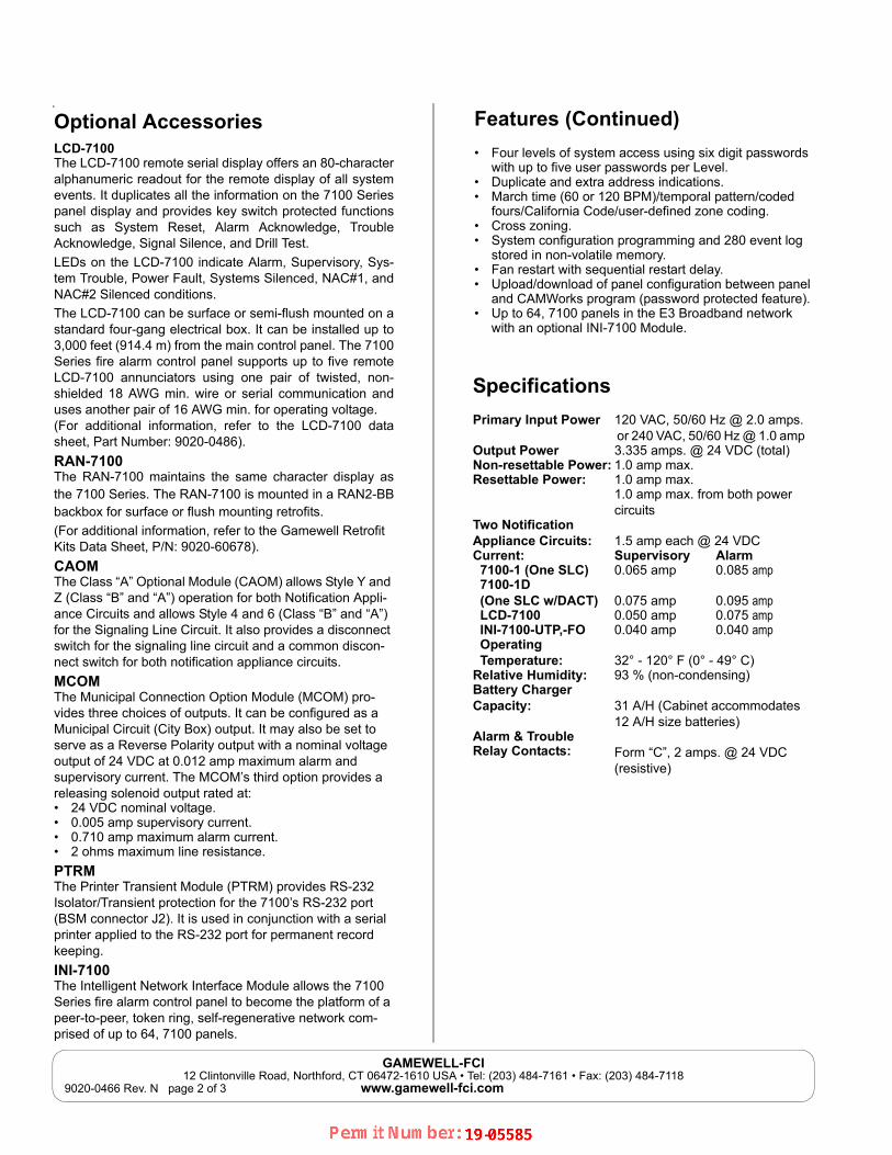
Optional AccessoriesLCD-7100The LCD-7100 remote serial display offers an 80-characteralphanumeric readout for the remote display of all systemevents. It duplicates all the information on the 7100 Seriespanel display and provides key switch protected functionssuch as System Reset, Alarm Acknowledge, TroubleAcknowledge, Signal Silence, and Drill Test.
LEDs on the LCD-7100 indicate Alarm, Supervisory, Sys-tem Trouble, Power Fault, Systems Silenced, NAC#1, andNAC#2 Silenced conditions.
The LCD-7100 can be surface or semi-flush mounted on astandard four-gang electrical box. It can be installed up to3,000 feet (914.4 m) from the main control panel. The 7100Series fire alarm control panel supports up to five remoteLCD-7100 annunciators using one pair of twisted, non-shielded 18 AWG min. wire or serial communication anduses another pair of 16 AWG min. for operating voltage. (For additional information, refer to the LCD-7100 datasheet, Part Number: 9020-0486).
RAN-7100The RAN-7100 maintains the same character display asthe 7100 Series. The RAN-7100 is mounted in a RAN2-BBbackbox for surface or flush mounting retrofits.
(For additional information, refer to the Gamewell Retrofit Kits Data Sheet, P/N: 9020-60678).
CAOMThe Class “A” Optional Module (CAOM) allows Style Y and Z (Class “B” and “A”) operation for both Notification Appli-ance Circuits and allows Style 4 and 6 (Class “B” and “A”) for the Signaling Line Circuit. It also provides a disconnect switch for the signaling line circuit and a common discon-nect switch for both notification appliance circuits.
MCOMThe Municipal Connection Option Module (MCOM) pro-vides three choices of outputs. It can be configured as a Municipal Circuit (City Box) output. It may also be set to serve as a Reverse Polarity output with a nominal voltage output of 24 VDC at 0.012 amp maximum alarm and supervisory current. The MCOM’s third option provides a releasing solenoid output rated at:• 24 VDC nominal voltage.• 0.005 amp supervisory current.• 0.710 amp maximum alarm current.• 2 ohms maximum line resistance.
PTRMThe Printer Transient Module (PTRM) provides RS-232 Isolator/Transient protection for the 7100’s RS-232 port (BSM connector J2). It is used in conjunction with a serial printer applied to the RS-232 port for permanent record keeping.
INI-7100The Intelligent Network Interface Module allows the 7100 Series fire alarm control panel to become the platform of a peer-to-peer, token ring, self-regenerative network com-prised of up to 64, 7100 panels.
Features (Continued)
• Four levels of system access using six digit passwords with up to five user passwords per Level.
• Duplicate and extra address indications.• March time (60 or 120 BPM)/temporal pattern/coded
fours/California Code/user-defined zone coding.• Cross zoning.• System configuration programming and 280 event log
stored in non-volatile memory.• Fan restart with sequential restart delay.• Upload/download of panel configuration between panel
and CAMWorks program (password protected feature).• Up to 64, 7100 panels in the E3 Broadband network
with an optional INI-7100 Module.
Specifications
Primary Input Power 120 VAC, 50/60 Hz @ 2.0 amps. or 240 VAC, 50/60 Hz @ 1.0 amp
Output Power 3.335 amps. @ 24 VDC (total)Non-resettable Power: 1.0 amp max. Resettable Power: 1.0 amp max.
1.0 amp max. from both power circuits
Two NotificationAppliance Circuits: 1.5 amp each @ 24 VDCCurrent: Supervisory Alarm 7100-1 (One SLC) 0.065 amp 0.085 amp 7100-1D (One SLC w/DACT) 0.075 amp 0.095 amp LCD-7100 0.050 amp 0.075 amp INI-7100-UTP,-FO 0.040 amp 0.040 amp Operating Temperature: 32° - 120° F (0° - 49° C)Relative Humidity: 93 % (non-condensing)Battery Charger Capacity: 31 A/H (Cabinet accommodates
12 A/H size batteries)Alarm & TroubleRelay Contacts: Form “C”, 2 amps. @ 24 VDC
(resistive)
mcnelson
Permit Number Batch

GAMEWELL-FCI12 Clintonville Road, Northford, CT 06472-1610 USA • Tel: (203) 484-7161 • Fax: (203) 484-7118
www.gamewell-fci.com 9020-0466 Rev. N page 3 of 3
Ordering Information
SystemsPart Number Description7100-1-PNL 7100 Addressable FACP, 1 SLC mounted
in the 7100-CAB enclosure, red7100-1D-PNL 7100 Addressable FACP w/DACT, One
SLC mounted in 7100-CAB enclosure, red
Basic Kits1100-1313 Basic System Kit, 2 SLC, 240 VAC
Optional ModulesLCD-7100 Remote Serial Annunciator, LCD Display
(80-character). Dimensions: 4.25” H x 8.25” W x 1.90”
(43 H x 37 W x 7.7 D cm)RAN-7100 Remote Series Annunciator, LCD Display
(80-character). Dimensions: 10” W x 5 1/4” H x 2 7/16” D
(25 1/4 W x 13 1/3 H x 6 9/10 D cm)CAOM Class A Option Combination Module with
disconnect switches for both signaling line circuits and notification appliance circuits.
MCOM Municipal Connection Option Module for local energy city box reverse polarity sig-naling, or releasing solenoid.
PTRM Printer Transient Module.INI-7100-FO Intelligent Network Interface Module,
Fiber-Optic.INI-7100-UTP Intelligent Network Interface Module,
Unshielded, Twisted-Pair.
Ordering Information (Continued)
Replacement PartsPart Number DescriptionBSM-7100-1 Replacement board for 7100-1 BSM-7100-1D Replacement board for 7100-1D BSM-7100-2 Replacement board for 7100-2BSM-7100-2D Replacement board for 7100-2D
Seismic Battery Bracket Kits90516 7100-Slim 7 A/H Seismic Battery
Bracket kit E3 B-Slim 7 A/H Seismic Battery Bracket Kit
90517 7100-Slim 12 A/H Seismic Battery Bracket Kit E3 B-Slim 12 A/H SeismicBattery Bracket Kit
90518 NetSOLO 7100 7 A/H Seismic Battery Bracket Kit
For additional information on the Seismic Battery Brackets, refer to the following documents:• Seismic Battery Bracket Installation Guide, P/N: 53839• E3 Series Cabinets Data Sheet, P/N: 9020-0649
mcnelson
Permit Number Batch

MS-7 Series
MS-7 SeriesManual Fire Alarm Pull Stations
Addressable Devices
GeneralThe Gamewell-FCI, MS-7 Series manual fire alarm pull stations are available in a wide
variety of configurations. The pull stations comply with the Americans with Disabilities
Act (ADA) 5-lb. maximum pull force requirement. Operating instructions and Braille
text are engraved in the handle. All pull stations include a key lock/reset which is keyed
alike with the Gamewell-FCI fire alarm control panels and other manual fire alarm pull
stations.
MS-7AF Velociti Addressable Station
The MS-7AF Velociti® Series addressable station is a double action pull station
designed for installation in the signaling line circuit of Gamewell-FCI analog
addressable control panels. Activation of the pull station causes its assigned address
to register at the fire alarm control panel. The door contains an LED which flashes
green in normal condition and lights steady red when the station has been activated.*
The station features screw terminals.
MS-7ASF Velociti Addressable Station
The MS-7ASF Velociti® Series addressable pull station is a single action station
designed for installation in the signaling line circuit of Gamewell-FCI analog
addressable control panels. Activation of the station causes its assigned address to
register at the control panel. The door contains an LED which flashes green in normal condition and lights steady red when the pull station is
activated.* The station features screw terminals.
The Velociti® Series pull stations use a communication protocol that substantially increases the speed of communication between the sensors
and certain Gamewell-FCI analog addressable fire alarm controls. These devices operate in a grouped fashion. If one of the devices in the
group has a status change, the panel’s microprocessor stops the group poll and focuses on the single device. The net effect offers a response
speed up to five times greater than earlier designs.
MS-7 Double Action Station
The MS-7 double action pull station is used with conventional fire alarm control panels. It features a set of single pole contacts and screw
terminals for connection to an initiating circuit.
FEATURES & BENEFITS
• Addressable stations compatible with all Gamewell-FCI analog addressable fire alarm controls
• Conventional stations suitable for use with
any UL® Listed control panel
• The pull stations (MS-7LOB) are Listed for outdoor applications
• Complies with ADA pull force requirements
• Offers surface or semi-flush mounting
• Shock and vibration resistant
• Both single and double action pull stations available
• Includes a tumbler lock for test and reset keyed alike with analog addressable fire alarm controls
*Only the red LED is operative in panels that do not operate in Velociti mode
mcnelson
Permit Number Batch

2
MS-7S Single Action Station
The MS-7S single action pull station is used with
conventional fire alarm control panels. It features a set
of single pole contacts and wire leads for connection to
an initiating circuit.
MS-7SP Double Action Station
The MS-7SP is a double action pull station similar to
the MS-7 station, with the additional feature of
including both English and Spanish instructions
molded into the unit.
MS-7LR Dual-action Agent Release Station
The MS-7LR is designed for use with the Gamewell-FCI
fire alarm control panels with releasing capabilities
and Flex Series releasing systems. It features a set of
single pole contacts and screw terminals used to
connect to an initiating circuit.
MS-7LRA Agent Release Station with Abort
The MS-7LRA is designed for use with the Gamewell-
FCI fire alarm control panels with releasing capabilities
and Flex Series releasing systems where system abort
capabilities are required. It consists of the following:
• An MS-7LR mounted on a plate with an abort switch
• LED indicators that signal system normal and
system activated status
MS-7LOB Double Action Station (Listed for Outdoor Applications)
The MS-7LOB station must be mounted on a Model
SB-I/O backbox. In retrofit applications, the pull
station is UL Listed for use with the WP-10 backbox. It
is intended for use with conventional control panels
and has a set of single pole contacts and screw
terminals.
Mounting
The MS-7 interior pull stations may be surface
mounted or semi-flush mounted on a standard
double-gang, or 4-inch (10.2 cm) square electrical box.
An optional trim ring (BG12TR) may also be used for
semi-flush mounting.
NYC-Plate
The NYC-Plate provides the backplate for the manual
pull station. (See Figure 1).
Figure 1 NYC-Plate
Ordering InformationMS-7: Double action station
MS-7AF**: Velociti addressable double action station
MS-7ASF**: Velociti addressable single action station
MS-7S: Single action station, wire leads
MS-7SP: Double action station, English and Spanish
instructions
MS-7LR: Agent release station, dual-action
MS-7LRA: Agent release station with abort switch,
LED indicators, dual- action
MS-7LOB: Double action station, outdoor use
(Includes SB-I/O - Indoor/outdoor use backbox)
SB-I/O: Indoor/outdoor use backbackbox
SB-10: Surface backbox
BG12TR: Trim ring for semi-flush mount, plastic
NY-PLATE: NYC backplate for manual pull station
**For use with the Gamewell-FCI analog addressable
control panels only.
mcnelson
Permit Number Batch
MS-7 Series Technical Specifications
9020-0616 | F | 11/17©2017 Honeywell International Inc.
For a complete listing of all compliance approvals and certifications, please visit: http://www.gamewell-fci.com/en-US/documentation/Pages/Listings.aspx
LEXAN® is a registered trademark of GE Plastics, a subsidiary of General Electric Company.
Velociti® and Gamewell-FCI are registered trademarks of Honeywell International Inc.
UL® is a registered trademark of Underwriter’s Laboratories Inc.
This document is not intended to be used for installation purposes. We try to keep our product information up-to-date and accurate. We cannot cover all specific applications or anticipate all requirements. All specifications are subject to change without notice.
Honeywell Gamewell-FCI12 Clintonville Road
Northford, CT 06472-1610
203.484.7161
www.honeywell.com
For more informationLearn more about Gamewell-FCI’s MS-7 Series and other
products available by visiting www.Gamewell-FCI.com
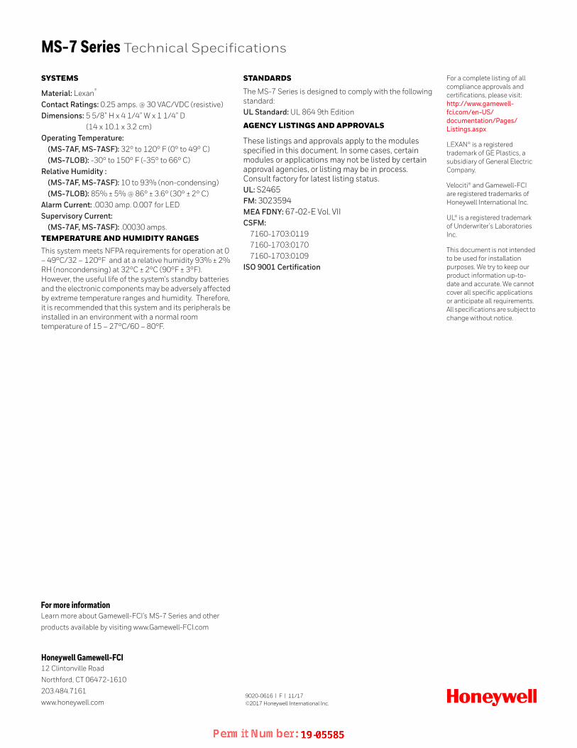
SYSTEMS
Material: Lexan®
Contact Ratings: 0.25 amps. @ 30 VAC/VDC (resistive)Dimensions: 5 5/8” H x 4 1/4” W x 1 1/4” D
(14 x 10.1 x 3.2 cm)Operating Temperature:
(MS-7AF, MS-7ASF): 32° to 120° F (0° to 49° C)(MS-7LOB): -30° to 150° F (-35° to 66° C)
Relative Humidity : (MS-7AF, MS-7ASF): 10 to 93% (non-condensing)(MS-7LOB): 85% ± 5% @ 86° ± 3.6° (30° ± 2° C)
Alarm Current: .0030 amp. 0.007 for LEDSupervisory Current:
(MS-7AF, MS-7ASF): .00030 amps.TEMPERATURE AND HUMIDITY RANGES
This system meets NFPA requirements for operation at 0 – 49°C/32 – 120°F and at a relative humidity 93% ± 2% RH (noncondensing) at 32°C ± 2°C (90°F ± 3°F). However, the useful life of the system's standby batteries and the electronic components may be adversely affected by extreme temperature ranges and humidity. Therefore, it is recommended that this system and its peripherals be installed in an environment with a normal room temperature of 15 – 27°C/60 – 80°F.
STANDARDS
The MS-7 Series is designed to comply with the following standard:UL Standard: UL 864 9th Edition
AGENCY LISTINGS AND APPROVALS
These listings and approvals apply to the modules specified in this document. In some cases, certain modules or applications may not be listed by certain approval agencies, or listing may be in process. Consult factory for latest listing status.UL: S2465FM: 3023594MEA FDNY: 67-02-E Vol. VIICSFM:
7160-1703:01197160-1703:01707160-1703:0109
ISO 9001 Certification
mcnelson
Permit Number Batch

ASD-PL2F/ASD-PTL2F
ASD-PL2FR
Velociti® Series ASD-PL2F, ASD-PTL2F and ASD-PL2FRAnalog, Addressable Photoelectronic Smoke Sensor
Addressable Devices
GeneralThe Gamewell-FCI Velociti® Series, analog addressable plug-in smoke sensors with integral communication provide features that surpass conventional sensors. Sensitivity can be programmed in the control panel software, and is continuously monitored and reported to the panel. Point ID capability allows each sensor’s address to be set, providing exact locations for selective maintenance when the chamber contamination reaches an unacceptable level.
The ASD-PL2F photoelectric sensor’s unique optical sensing chamber is engineered to sense smoke produced by a wide range of combustion sources. Dual electronic thermistors add 135°F (57°C) fixed-temperature thermal sensing on the ASD-PTL2F model.
The Velociti® Series use a communication protocol that substantially increases the speed of communication between the sensors and certain Gamewell-FCI analog addressable fire alarm controls. These devices operate in a grouped fashion. If one of the devices in the group has a status change, the panel’s microprocessor stops the group poll and concentrates on the single device. The net effect is a response speed up to five times greater than earlier designs.
InstallationThe ASD-PL2F plug-in sensors use a separate base to simplify installation, service, and maintenance. A special tool allows maintenance personnel to plug-in and remove sensors without using a ladder.
Mount the base on a box which is at least 1.5" (3.8 cm) deep. Suitable mounting base boxes include:
• 4.0" (10.2 cm) square box.
• 3.5" (8.9 cm) or 4.0" (10.2 cm) octagonal box.
• Single-gang box (except relay or isolator bases).
With B200S or B200SR base, mounted on a 4.0" (10.2 cm) octagonal or square box.
With B224RB or B224BI base, mounted on a 3.5" (8.9 cm) octagonal box, or a 4.0" (10.2 cm) octagonal or square box.
NOTE: Because of the inherent supervision provided by the SLC, end-of-line resistors are not required. Wiring “T-taps” or branches are permitted for Style 4 (Class “B”) wiring.
Sensor SpacingGamewell-FCI recommends that the spacing sensors be used in compliance with NFPA 72.
FEATURES & BENEFITS
• Offers a sleek, low-profile design
• Includes visual rotary, decimal switch addressing (01-159)
• Has a built-in functional test switch activated by an external magnet
• Displays bi-color LEDs flash green whenever the sensor is addressed, and light steady red on alarm*
• Supports a low standby current
• Includes an optional relay, isolator, or sounder bases
• Contains an optional remote, single-gang LED Indicator (RA100Z)
• Designed with an analog addressable communication
• Provides a stable communication technique with noise immunity
• Compatible with Gamewell-FCI analog addressable panels
Note: *Only the red LED is operative in panels that do not operate in Velociti® mode.
mcnelson
Permit Number Batch

2
Ordering InformationBases and OptionsB501: Plug-in sensor base without flange
Dimensions: : 4.1” (10.4 cm) diameterB210LP: Flanged mounting base
Dimensions: : 6.1” (15.5 cm) diameterB210LPBP: Flanged mounting base bulk pack
Dimensions: : 6.1” (15.5 cm) diameterB224RB: Relay Base Plug-in sensor base with auxiliary relay, SPDT, rated 2 amps @ 30 VDC (resistive).Screw terminals: Up to 14 AWG (2.0 mm2)2 coil latching relay 1 Form C contact UL/CSA Rating:
0.9 A @ 125 VAC, inductive0.9 A @ 110 VDC, inductive3 A @ 30 VDC, resistive
Dimensions: : 6.1” (15.5 cm) diameterMaximum: 25 devices between isolator bases.B200S: Intelligent sensor sounder base
Dimensions: : 6.875” (17.5 cm) diameterB200SR: Standard sounder base, UL 8649th Edition compliant, ULC Listed
Dimensions: : 6.875” (17.5 cm) diameterRA100Z: Remote LED AnnunciatorBCK-200: Black detector covers (box of 10)DNR: Duct smoke housing
mcnelson
Permit Number Batch

Velociti® Series ASD-PL2F, ASD-PTL2F and ASD-PL2FR Technical
9020-0617 | K | 11/17©2017 Honeywell International Inc.
For a complete listing of all compliance approvals and certifications, please visit: http://www.gamewell-fci.com/en-US/documentation/Pages/Listings.aspx
E3 Series®, Velociti® and Gamewell-FCI® are registered trademarks of Honeywell International Inc.
UL® is a registered trademark of Underwriter’s Laboratories Inc.
This document is not intended to be used for installation purposes. We try to keep our product information up-to-date and accurate. We cannot cover all specific applications or anticipate all requirements. All specifications are subject to change without notice.
Honeywell Gamewell-FCI12 Clintonville Road
Northford, CT 06472-1610
203.484.7161
www.honeywell.com
For more informationLearn more about Gamewell-FCI’s Velociti® Series ASD-PL2F,
ASD-PTL2F and ASD-PL2FR and other products available by
visiting www.Gamewell-FCI.com
SYSTEMS
ASD-PL2F, ASD-PTL2F, ASD-PL2FR: Dimensions: 2.1” (5.1 cm) heightDiameter: 4.1” (10.4 cm) installed in the B501 base
6.1” (15.5 cm) installed in the B210LP baseShipping Weight: 5.2 oz. (147 g)Operating Temperature:
ASD-PL2F: 32° F to 120° F (0° C to 49° C)ASD-PTL2F: 32° F to 100° F (0° C to 38° C)
UL®-Listed Velocity Range: 0-4000 ft./min. (1,219.2 m/min.), suitable for installation in ducts.Relative Humidity: 10-93% (non-condensing)Thermal Ratings: Fixed-temperature setpoint 135° F (57° C)Electrical SpecificationsVoltage Range: 15 – 32 volts DC peakStandby Current: (max. avg.): .0003 A @ 24 VDC (One communication every 5 seconds with LED blink enabled)Maximum Alarm-Current: .0065 A @ 24 VDC (LED) lit).TEMPERATURE AND HUMIDITY RANGES
This system meets NFPA requirements for operation at 0 – 49°C/32 – 120°F and at a relative humidity 93% ± 2% RH (noncondensing) at 32°C ± 2°C (90°F ± 3°F). However, the useful life of the system's standby batteries and the electronic components may be adversely affected by extreme temperature ranges and humidity. Therefore, it is recommended that this system and its peripherals be installed in an environment with a normal room temperature of 15 – 27°C/60 – 80°F.
StandardsThe Velociti Series, ASD-PL2F/PTL2F/PLSFR are designed to comply with the following standard:
UL Standard: 864 9th Edition
Agency Listings and ApprovalsThese listings and approvals apply to the modules specified in this document. In some cases, certain modules or applications may not be listed by certain approval agencies, or listing may be in process. Consult factory for latest listing status.
UL: S1913
FM: 3023594
MEA FDNY: COA-219-02-E Vol. VI
CSFM: 7272-1703-0121
ISO 9001 Certification
mcnelson
Permit Number Batch

AOM-2SF
Velociti® Series AOM-2SFAddressable Output Relay Supervised Control Module
Addressable Devices
General
The Gamewell-FCI Velociti® Series addressable output supervised control module (AOM-2SF) allows a Gamewell-FCI analog addressable fire alarm control panel to switch an external power supply, such as a DC supply or audio amplifier (up to 80 VRMS) to notification appliances. The AOM-2SF notification appliance circuit can be
wired either Class A (Style Z) or Class B (Style Y). It also supervises the wiring to the connected loads and reports their status to the panel as NORMAL, OPEN or SHORT CIRCUIT. The module contains a panel controlled LED.
The Velociti® Series use a communication protocol that substantially increases the speed of communication between the SLC devices and certain Gamewell-FCI analog addressable fire alarm control panels. These devices operate in a grouped fashion. If one of the devices in the group has a status change, the panel’s microprocessor stops the group poll and concentrates on the single device. The net result is a superior response speed up to five times greater than the earlier designs.
The AOM-2SF module is designed for installation in the signaling line circuit of any Gamewell-FCI analog addressable fire alarm control panel. The signaling line circuits of Gamewell-FCI analog addressable fire alarm control panels are designed to accommodate up to 159 modules per circuit. The AOM-2SF is designed to mount in a 4” (10.16 cm) square junction box 2 1/8” (5.5 cm) deep.
Table 1 lists the relay contact ratings.
Ordering Information
AOM-2SF: Addressable output supervised control module
FEATURES & BENEFITS
• Listed under UL® Standard 864 and UL2572 for Mass Notification
• Designed as a compact size to allow easy installation
• Includes Class A, Style Z, or Class B, Style Y notification appliance circuit
• Accommodates audio amplifiers up to 80 VRMS
• FM Listed as suitable for a releasing device service
• Includes a bi-color LED that flashes green whenever the module is addressed, and lights steady red upon activation*
*Note 1: Only the red LED is operative in panels that do not operate in Velociti® mode*Note 2: The bi-color LED functionality is not available on the GWF-7075 panel.
Current Rating
Maximum Voltage
Load Description Application
3A 30 VDC Resistive Non-Coded2A 30 VDC Resistive Coded0.9A 110 VDC Resistive Non-Coded0.5A 125 VAC Resistive Non-Coded0.5A 30 VDC Inductive (L/R=5ms) Coded1A 30 VDC Inductive (L/R=2ms) Coded0.5A 125 VAC Inductive (PF=.35) Non-Coded0.7A 75 VAC Inductive Non-Coded
Table 1: Relay Contact Ratings
mcnelson
Permit Number Batch

Velociti® Series AOM-2SF Technical Specifications
9020-0627 | I | 08/18©2018 Honeywell International Inc.
For a complete listing of all compliance approvals and certifications, please visit: http://www.gamewell-fci.com/en-US/documentation/Pages/Listings.aspxVelociti® and Gamewell-FCI® are registered trademarks of Honeywell International Inc.UL® is a registered trademark of Underwriters Laboratories Inc.
This document is not intended to be used for installation purposes. We try to keep our product information up-to-date and accurate. We cannot cover all specific applications or anticipate all requirements. All specifications are subject to change without notice.
Honeywell Gamewell-FCI12 Clintonville Road
Northford, CT 06472-1610
203.484.7161
www.honeywell.com
For more informationLearn more about Gamewell-FCI’s Velociti® Series AOM-2SF and
other products available by visiting www.Gamewell-FCI.com
SYSTEM
Supervisory Current: 0.00375 ampsAlarm Current: .0065 ampsOperating Temperature: 32° to 120° F (0° to 49° C) Relative Humidity: 10 to 93% relative humidity (non-condensing)Dimensions: 4 1/2” H x 4” W x 1 1/4” D (11.4 H x 10.2 W x 3.2 D cm)TEMPERATURE AND HUMIDITY RANGES
This system meets NFPA requirements for operation at 0 – 49°C/32 – 120°F and at a relative humidity 93% ± 2% RH (noncondensing) at 32°C ± 2°C (90°F ± 3°F). However, the useful life of the system's standby batteries and the electronic components may be adversely affected by extreme temperature ranges and humidity. Therefore, it is recommended that this system and its peripherals be installed in an environment with a normal room temperature of 15 – 27°C/60 – 80°F.
STANDARDS
The Velociti Series AOM-2SF are designed to comply with the following standard:UL Standards: UL 864 9th Edition
AGENCY LISTINGS AND APPROVALS
These listings and approvals apply to the modules specified in this document. In some cases, certain modules or applications may not be listed by certain approval agencies, or listing may be in process. Consult factory for latest listing status.UL: S1949FM: 3023594MEA FDNY: 227-03-E Vol. IVCSFM: 7300-1703:0102ISO 9001 Certification
mcnelson
Permit Number Batch

F E AT U R E S & B E NE F I T S• UL Listed for 6 amps
of notification power
• Power supply’s advanced switch mode design reduces damaging heat and manages power up to 50% more efficiently than other systems
• Dip switches allow for easy reconfiguration
• 24 VDC filtered output voltage
• Four power-limited notification outputs; 2 Class A or 4 Class B, or 1 Class A and 2 Class B
• Additional continuous auxiliary output
• 3 amps per output circuit
• 2 inputs; 2 Class B or 2 Class A
• Ground fault detector/indicator
• Independent trouble relay
• AC loss delay option shuts off power to non-essential high-current accessories like magnetic door holders
• Built-in synchronization for appliances from System Sensor®, Gentex®, AMSECO®, and Wheelock
• Stand alone operation
• Lightweight design adds to ease of installation and reduces shipping costs
• Operates with most polarized, UL Listed notification devices
• ANSI Cadence pattern output capability built-in
5495Distributed Power Module
The 5495 Distributed Power Module is the most powerful and cost-
effective power supply available today. It delivers 6 amps of notification
appliance circuit power and built-in synchronization for appliances from
System Sensor®,Gentex®, AMSECO®, and Wheelock. The 5495’s switch
mode power supply design is up to 50% more efficient than competitive
linear mode power supplies. Also, ADA retrofits are easier and less
expensive with the 5495 because it integrates into current systems
without the costly investment in new components.
The 5495 is a 6 amp notification power expander that provides its own AC
power connection, battery charging circuit, and backup battery. The 5495
is the costeffective solution for powering notification appliances required
by the Americans with Disabilities Act (ADA). The 5495 has built-in ANSI
cadence pattern, which can upgrade older control panels that lack
cadence capability.
CONNECTION TO LOCAL FIRE CONTROL
The 5495 may be connected to a local fire control which utilizes Class A or
Class B type notification circuits operating between 9 and 32 VDC. The
control panel’s notification circuit is connected to one of the inputs on the
5495. The control panel’s notification circuit end-of-line resistor is also
connected across two terminals on the 5495, which provides supervision
between the 5495 and the fire control panel. Polarized audible and/or
visual notification devices are then connected to the 5495 signal circuits
using the 4.7kW end-of-line resistors provided. Since the 5495 draws very
little power from the control, it is possible to connect one 5495 to each
notification circuit on the control panel and still provide full supervision of
the notification circuits all the way back to the control panel.
5495
mcnelson
Permit Number Batch

For a complete listing of all compliance approvals and certifications, please visit www.silentknight.com.
Microsoft, Windows, and the Windows Logo are registered trademarks or trademarks of Microsoft Corporation.
System Sensor® and Honeywell® are registered trademarks of Honeywell International, Inc
This document is not intended to be used for installation purposes. We try to keep our product information up-to date and accurate. We cannot cover all specific applications or anticipate all requirements. All specifications are subject to change without notice.
For Technical Support, call 800-446-6444.
5495 Technical Specifications
SUPERVISIONThe 5495 supervises a variety of functions including:• Low AC power
• Low battery condition
• Earth ground fault
• Auxiliary output power limit condition
• EOL supervision trouble or power limited condition at an output
When a trouble condition occurs, the 5495 creates a trouble condition on the host control signal circuits to which it is connected. the 5495 still maintains the ability to be activated by the host control. In addition, the 5495 provides a Form C trouble relay output as an alternative to using the notification circuit trouble.
PHYSICALDimensions: 12.25”W x 16”H x 3”D (30.88 cm W x 40.64 cm H x 7.62 cm D)
ENVIRONMENTAL Operating Temperature: 32°F to 120°F (0°C to 49°C)Humidity: 10% - 93% non-condensing)
ELECTRICAL AC input: 120 VAC at 2AOutput: 24 VDC at 6ACurrent: Standby 75mA; Alarm 205mAAuxiliary power circuit: 1Notification circuits: 4Output configuration:2 Class A (Style Z); 4 Class B (Style Y) (1 Class A & 2 Class B)
Amps per output circuit: 3.0 (6.0 amps total)Notification circuit output: Alarm Current (for typical voltages) drawn from main panel’s notification appliance circuits.
12 VDC 6.5 mA24 VDC One input circuit: 15 mA; Both input circuits: 0 mA
No. of inputs: 2Input configuration: 2 Class B or 2 Class AInput voltage range: 9 - 32VDCBattery charging capacity: 35.0AH
INDICATOR LIGHTSAC power on : GreenBattery trouble: YellowGround fault: YellowAux trouble: YellowOutput troubles (1-4): Yellow
ORDERING INFORMATION5495: Distributed Power Module
ACCESSORIESSK-SCK: Seismic Compliance Kit
AGENCY LISTINGS
• UL listed
• CSFM 7300-0559:123
• Meets NFPA 72 requirements
• MEA 429-92-E Vol XII
• OSHPD (CA) OSP-0065-10
Doc 350395| Rev H| 11/17 © 2017 Honeywell International Inc.
For more informationLearn more about Honeywell Silent Knight and other
products by visiting www.silentknight.com
Honeywell Silent Knight 12 Clintonville Road
Northford, CT 06472
800-328-0103
mcnelson
Permit Number Batch

Agency Listings
Features• Plug-in design with minimal intrusion into the back box
• Tamper-resistant construction
• Automatic selection of 12- or 24-volt operation at 15 and 15/75 candela
• Field-selectable candela settings on wall and ceiling units: 15, 15/75, 30, 75, 95, 110, 115, 135, 150, 177, and 185
• Horn rated at 88+ dBA at 16 volts
• Rotary switch for horn tone and three volume selections
• Universal mounting plate for wall and ceiling units
• Mounting plate shorting spring checks wiring continuity before device installation
• Electrically compatible with existing SpectrAlert products
• Compatible with MDL sync module
The SpectrAlert Advance series offers the most versatile and easy-to-use line of horns, strobes, and horn strobes in the industry. With white and red plastic housings, wall and ceiling mounting options, and plain and FIRE-printed devices, SpectrAlert Advance can meet virtually any application requirement.
Like the entire SpectrAlert Advance product line, horns, strobes, and horn strobes include a variety of features that increase their application versatility while simplifying installation. All devices feature plug-in designs with minimal intrusion into the back box, which make installations fast and foolproof while virtually eliminating costly and time-consuming ground faults. Furthermore, a universal mounting plate with an onboard shorting spring tests wiring continuity before the device is installed, protecting devices from damage.
In addition, field-selectable candela settings, automatic selection of 12- or 24-volt operation, and a rotary switch for horn tones with three volume selections enables installers to easily adapt devices to suit a wide range of application requirements.
Selectable-OutputHorns, Strobes, andHorn Strobes
SpectrAlert® Advance selectable-output horns, strobes,
and horn strobes are rich with features guaranteed to
cut installation times and maximize profits.
MEA452-05-E3023572
7125-1653:186 (indoor strobes)7125-1653:188 (horn strobes,
chime strobes)7135-1653:189 (horns, chimes)
S4011 (chimes, horn strobes, horns)S5512 (strobes)
mcnelson
Permit Number Batch

A05-0395-007
SpectrAlert Advance SpecificationsArchitect/Engineer SpecificationsGeneralSpectrAlert Advance horns, strobes, and horn strobes shall mount to a standard 4 × 4 × 1½-inch back box, 4-inch octagon back box, or double-gang back box. Two-wire products shall also mount to a single-gang 2 × 4 × 17⁄8-inch back box. A universal mounting plate shall be used for mounting ceiling and wall products. The notification appliance circuit wiring shall terminate at the universal mounting plate. Also, SpectrAlert Advance products, when used with the Sync•Circuit™ Module accessory, shall be powered from a non-coded notification appliance circuit output and shall operate on a nominal 12 or 24 volts. When used with the Sync•Circuit Module, 12-volt-rated notification appliance circuit outputs shall operate between 9 and 17.5 volts; 24-volt-rated notification appliance circuit outputs shall operate between 17 and 33 volts. Indoor SpectrAlert Advance products shall operate between 32 and 120 degrees Fahrenheit from a regulated DC or full-wave rectified unfiltered power supply. Strobes and horn strobes shall have field-selectable candela settings including 15, 15/75, 30, 75, 95, 110, 115, 135, 150, 177, and 185.
StrobeThe strobe shall be a System Sensor SpectrAlert Advance Model _______ listed to UL 1971 and shall be approved for fire protective service. The strobe shall be wired as a primary-signaling notification appliance and comply with the Americans with Disabilities Act requirements for visible signaling appliances, flashing at 1 Hz over the strobe’s entire operating voltage range. The strobe light shall consist of a xenon flash tube and associated lens/reflector system.
Horn Strobe CombinationThe horn strobe shall be a System Sensor SpectrAlert Advance Model _______ listed to UL 1971 and UL 464 and shall be approved for fire protective service. The horn strobe shall be wired as a primary-signaling notification appliance and comply with the Americans with Disabilities Act requirements for visible signaling appliances, flashing at 1 Hz over the strobe’s entire operating voltage range. The strobe light shall consist of a xenon flash tube and associated lens/reflector system. The horn shall have three audibility options and an option to switch between a temporal three-pattern and a non-temporal (continuous) pattern. These options are set by a multiple position switch. On four-wire products, the strobe shall be powered independently of the sounder. The horn on horn strobe models shall operate on a coded or non-coded power supply.
Synchronization ModuleThe module shall be a System Sensor Sync•Circuit model MDL listed to UL 464 and shall be approved for fire protective service. The module shall synchronize SpectrAlert strobes at 1 Hz and horns at temporal three. Also, while operating the strobes, the module shall silence the horns on horn strobe models over a single pair of wires. The module shall mount to a 411⁄16 × 411⁄16 × 21⁄8-inch back box. The module shall also control two Style Y (class B) circuits or one Style Z (class A) circuit. The module shall synchronize multiple zones. Daisy chaining two or more synchronization modules together will synchronize all the zones they control. The module shall not operate on a coded power supply.
Physical/Electrical SpecificationsStandard Operating Temperature 32°F to 120°F (0°C to 49°C)
Humidity Range 10 to 93% non-condensing
Strobe Flash Rate 1 flash per second
Nominal Voltage Regulated 12 DC/FWR or regulated 24 DC/FWR1
Operating Voltage Range2 8 to 17.5 V (12 V nominal) or 16 to 33 V (24 V nominal)
Input Terminal Wire Gauge 12 to 18 AWG
Ceiling-Mount Dimensions (including lens) 6.8˝ diameter × 2.5˝ high (173 mm diameter × 64 mm high)
Wall-Mount Dimensions (including lens) 5.6˝ L × 4.7˝ W × 2.5˝ D (142 mm L × 119 mm W × 64 mm D)
Horn Dimensions 5.6˝ L × 4.7˝ W × 1.3˝ D (142 mm L × 119 mm W × 33 mm D)
Wall-Mount Back Box Skirt Dimensions (BBS-2, BBSW-2) 5.9˝ L × 5.0˝ W × 2.2˝ D (151 mm L × 128 mm W × 56 mm D)
Ceiling-Mount Back Box Skirt Dimensions (BBSC-2, BBSCW-2) 7.1˝ diameter × 2.2˝ high (180 mm diameter × 57 mm high)
Wall-Mount Trim Ring Dimensions (sold as a 5 pack) (TR-HS, TRW-HS) 5.7˝ L × 4.8˝ W × 0.35˝ D (145 mm L × 122 mm W × 9 mm D)
Ceiling-Mount Trim Ring Dimensions (sold as a 5 pack) (TRC-HS, TRCW-HS) 6.9˝ diameter × 0.35˝ high (175 mm diameter × 9 mm high)
Notes:1. Full Wave Rectified (FWR) voltage is a non-regulated, time-varying power source that is used on some power supply and panel outputs.2. P, S, PC, and SC products will operate at 12 V nominal only for 15 and 15/75 cd.
mcnelson
Permit Number Batch

A05-0395-007
Horn and Horn Strobe Output (dBA)
Switch Position Sound Pattern dB
8–17.5 Volts
16–33Volts
24-Volt NominalReverberant Anechoic
DC FWR DC FWR DC FWR DC FWR1 Temporal High 78 78 84 84 88 88 99 98
2 Temporal Medium 74 74 80 80 86 86 96 96
3 Temporal Low 71 73 76 76 83 80 94 89
4 Non-Temporal High 82 82 88 88 93 92 100 100
5 Non-Temporal Medium 78 78 85 85 90 90 98 98
6 Non-Temporal Low 75 75 81 81 88 84 96 92
7† Coded High 82 82 88 88 93 92 101 101
8† Coded Medium 78 78 85 85 90 90 97 98
9† Coded Low 75 75 81 81 88 85 96 92 †Settings 7, 8, and 9 are not available on 2-wire horn strobe.
UL Max. Strobe Current Draw (mA RMS)
Candela8–17.5 Volts 16–33 VoltsDC FWR DC FWR
Standard Candela Range
15 123 128 66 71
15/75 142 148 77 81
30 NA NA 94 96
75 NA NA 158 153
95 NA NA 181 176
110 NA NA 202 195
115 NA NA 210 205
HighCandela Range
135 NA NA 228 207
150 NA NA 246 220
177 NA NA 281 251
185 NA NA 286 258
UL Max. Current Draw (mA RMS), 2-Wire Horn Strobe, Standard Candela Range (15–115 cd)
DC Input8–17.5 Volts 16–33 Volts15 15/75 15 15/75 30 75 95 110 115
Temporal High 137 147 79 90 107 176 194 212 218
Temporal Medium 132 144 69 80 97 157 182 201 210
Temporal Low 132 143 66 77 93 154 179 198 207
Non-Temporal High 141 152 91 100 116 176 201 221 229
Non-Temporal Medium 133 145 75 85 102 163 187 207 216
Non-Temporal Low 131 144 68 79 96 156 182 201 210
FWR InputTemporal High 136 155 88 97 112 168 190 210 218
Temporal Medium 129 152 78 88 103 160 184 202 206
Temporal Low 129 151 76 86 101 160 184 194 201
Non-Temporal High 142 161 103 112 126 181 203 221 229
Non-Temporal Medium 134 155 85 95 110 166 189 208 216
Non-Temporal Low 132 154 80 90 105 161 184 202 211
UL Max. Horn Current Draw (mA RMS)
Sound Pattern dB8–17.5 Volts 16–33 VoltsDC FWR DC FWR
Temporal High 57 55 69 75
Temporal Medium 44 49 58 69
Temporal Low 38 44 44 48
Non-temporal High 57 56 69 75
Non-temporal Medium 42 50 60 69
Non-temporal Low 41 44 50 50
Coded High 57 55 69 75
Coded Medium 44 51 56 69
Coded Low 40 46 52 50
UL Current Draw Data
Horn Tones and Sound Output Data
UL Max. Current Draw (mA RMS), 2-Wire Horn Strobe, High Candela Range (135–185 cd)
DC Input16–33 Volts
FWR Input16–33 Volts
135 150 177 185 135 150 177 185Temporal High 245 259 290 297 Temporal High 215 231 258 265
Temporal Medium 235 253 288 297 Temporal Medium 209 224 250 258
Temporal Low 232 251 282 292 Temporal Low 207 221 248 256
Non-Temporal High 255 270 303 309 Non-Temporal High 233 248 275 281
Non-Temporal Medium 242 259 293 299 Non-Temporal Medium 219 232 262 267
Non-Temporal Low 238 254 291 295 Non-Temporal Low 214 229 256 262
mcnelson
Permit Number Batch

3825 Ohio Avenue • St. Charles, IL 60174 Phone: 800-SENSOR2 • Fax: 630-377-6495
©2009 System Sensor.Product specifications subject to change without notice. Visit systemsensor.com for
current product information, including the latest version of this data sheet.A05-0395-007 • 4/09 • #2132
SpectrAlert Advance Dimensions
Model DescriptionWall Horn StrobesP2R*† 2-Wire Horn Strobe, Standard cd‡, Red
P2RH* 2-Wire Horn Strobe, High cd, Red
P2W* 2-Wire Horn Strobe, Standard cd, White
P2WH* 2-Wire Horn Strobe, High cd, White
P4R* 4-Wire Horn Strobe, Standard cd, Red
P4RH 4-Wire Horn Strobe, High cd, Red
P4W 4-Wire Horn Strobe, Standard cd, White
Wall StrobesSR*† Strobe, Standard cd, Red
SRH*† Strobe, High cd, Red
SW* Strobe, Standard cd, White
SWH* Strobe, High cd, White
Ceiling Horn StrobesPC2R* 2-Wire Horn Strobe, Standard cd, Red
PC2RH 2-Wire Horn Strobe, High cd, Red
PC2W*† 2-Wire Horn Strobe, Standard cd, White
PC2WH* 2-Wire Horn Strobe, High cd, White
PC4R 4-Wire Horn Strobe, Standard cd, Red
PC4RH 4-Wire Horn Strobe, High cd, Red
PC4W 4-Wire Horn Strobe, Standard cd, White
SpectrAlert Advance Ordering Information
Notes:* Add “-P” to model number for plain housing (no “FIRE” marking on cover), e.g., P2R-P.† Add “-SP” to model number for “FUEGO” marking on cover, e.g., P2R-SP.‡ “Standard cd” refers to strobes that include 15, 15/75, 30, 75, 95, 110, and 115 candela settings. “High cd” refers to strobes that include 135, 150, 177, and 185 candela settings.
4.7˝
5.6˝
6.8˝Dia.
2.5˝
2.5˝
2.23˝5.05˝
5.98˝
7.1˝Dia.
2.25˝
5.1˝
2.0˝
5.7˝
7.1˝Dia.
2.0˝
Wall-mount horn strobes Ceiling-mount horn strobes
Wall back box skirt Ceiling back box skirt
Model DescriptionCeiling StrobesSCR Strobe, Standard cd, Red
SCRH Strobe, High cd, Red
SCW* Strobe, Standard cd, White
SCWH Strobe, High cd, White
HornsHR Horn, Red
HW Horn, White
AccessoriesBBS-2 Back Box Skirt, Wall, Red
BBSW-2 Back Box Skirt, Wall, White
BBSC-2 Back Box Skirt, Ceiling, Red
BBSCW-2 Back Box Skirt, Ceiling, White
TR-HS Trim Ring, Wall, Red
TRW-HS Trim Ring, Wall White
TRC-HS Trim Ring, Ceiling, Red
TRCW-HS Trim Ring, Ceiling, White
mcnelson
Permit Number Batch