JMA-7100 series RADAR Instruction Manual - Handyman
558
MARINE RADAR MARINE RADAR EQUIPMENT EQUIPMENT INSTRUCTION INSTRUCTION MANUAL MANUAL JMA-7133-SA JMA-7133-SA JMA-7132-SA JMA-7132-SA JMA-7123-7XA/9XA JMA-7123-7XA/9XA JMA-7122-6XA/9XA/6XAH JMA-7122-6XA/9XA/6XAH JMA-7110-6XA/6XAH JMA-7110-6XA/6XAH
-
Upload
khangminh22 -
Category
Documents
-
view
0 -
download
0
Transcript of JMA-7100 series RADAR Instruction Manual - Handyman

MARINE RADARMARINE RADAREQUIPMENTEQUIPMENT
INSTRUCTIONINSTRUCTIONMANUALMANUAL
JMA-7133-SAJMA-7133-SAJMA-7132-SAJMA-7132-SAJMA-7123-7XA/9XAJMA-7123-7XA/9XAJMA-7122-6XA/9XA/6XAHJMA-7122-6XA/9XA/6XAHJMA-7110-6XA/6XAHJMA-7110-6XA/6XAH
01ETM ISO 9001, ISO 14001 Certified
Printed in Japan
Marine Service [email protected]
Telephone :Facsimile :e-mail :
AMSTERDAM BranchTelephone :Facsimile :e-mail :
SEATTLE BranchTelephone :Facsimile :e-mail :
CODE No.7ZPRD0680CODE No.7ZPRD0680
APR. 2008 Edition 1 JRCAPR. 2008 Edition 1 JRC
Not use the asbestos
For further information,contact:
URL http://www.jrc.co.jp


◆◆◆ PRECAUTIONS BEFORE OPERATION ◆◆◆
■ Cautions for high voltageHigh voltages from hundreds volts to tens of thousands volts are to be applied to the electronic equipment such radio and radar devices. You do not face any danger during normal operation, but sufficient cares are required for maintenance, inspection and adjustment of their internal components. (Maintenance, check-up and adjustment of the inside of the equipment are prohibited except by maintenance specialists.)
High voltages of tens of thousands volts are so dangerous as to bring an instantaneous death from electric shock, but even voltages of hundred volts may sometimes lead to a death from electric shock. To prevent such an accident, make it a rule to turn off the power switch, discharge capacitors with a wire surely earthed on an end make sure that internal parts are no longer charged before you touch any parts inside these devices. At the time, wearing dry cotton gloves ensures you further to prevent such danger. It is also a necessary caution to put one of your hands in the pocket and not to use your both hands at the same time.
It is also important to select a stable foothold always to prevent additional injuries once you were shocked by electricity. If you were injured from electric shock, disinfect the burn sufficiently and get it taken care of promptly.
■ What to do in case of electric shockWhen finding a victim of electric shock, turn off the power source and earth the circuit immediately.
If it is impossible to turn off the circuit, move the victim away promptly using insulators such as dry wood plate and cloth without touching the victim directly.
In case of electric shock, breathing may stop suddenly if current flows to the respiration center in the brain. If the shock is not so strong, artificial respiration may recover breathing. When shocked by electricity, the victim will come to look very bad with weak pulse or without beating, resulting in unconsciousness and rigidity. In this case, it is necessary to perform an emergency measure immediately.
i

◆◆◆ FIRST-AID TREATMENTS ◆◆◆
☆ First-aid treatmentsAs far as the victim of electric shock is not in dangerous condition, do not move him and practice artificial respiration on him immediately. Once started, it should be continued rhythmically.
(1) Do not touch the victim confusedly as a result of the accident, but the rescuer may also get an electric shock.
(2) Turn off the power source calmly and move the victim away quietly from the electric line.
(3) Call a physician or ambulance immediately or ask someone to call a doctor.
(4) Lay the victim on this back and loosen his necktie, clothes, belt, etc.
(5)
a. Examine the victim's pulse.
b. Examine his heartbeat bringing your ear close to his heart.
c. Examine his breathing bringing the back of your hand or your face close to his face.
d. Check the size of the pupils of his eyes.
(6) Open the victim's mouth and take out artificial teeth, cigarette or chewing gum if any. Keep his mouth open, stretch his tongue and insert a towel or the like in his mouth to prevent the tongue from suffocating. (If it is hard to open his mouth due to set teeth, open it with a screwdriver and insert a towel in this mouth.)
(7) Then, wipe his mouth so that foaming mucus does not accumulate inside.
ii

☆ When pulse is beating but breathing has stopped(Mouth-to-mouth respiration) Fig 1.
(1) Tilt the victim's head back as far as this face looks back. (A pillow may be inserted his neck.)
(2) Push his jaw upward to open his throat wide (to spread his airway).
(3) Pinch the victim's nostrils and take a deep breath, block his mouth completely with yours and blow into his mouth strongly. Take a deep breath again and blow into his mouth. Continue this 10 to 15 times a minutes (blocking his nostrils).
(4) Carefully watch that he has recovered his natural breathing and atop practicing artificial respiration.
(5) If it is difficult to open the victim's mouth, insert a rubber or vinyl tube into one of his nostrils and blow into it blocking the other nostril and his mouth completely.
(6) When the victim recovers consciousness, he may try to stand up suddenly, but let him lie calmly and serve him with a cup of hot coffee or tea and keep him warm and quiet. (Never give him alcoholic drinks.)
Method of mouth-to-mouth respiration by raising hea
Fig 1. Mouth-to mouth respiration
(1)Raise the victim's head. Supporthis forehead with one of your handand his neck with the other hand.
When you tilt his head backward, thevictim, in most cases, opens hismouth to the air. This makes mouth-to mouth respiration easy.
(2)Cover his mouth as widely aspossible with yours and press yourcheek against his nose
or, pinch his nostrils with your fingersto prevent air from leaking.
(3)Blow into his lungs. Continueblowing into his mouth until his breastswells. Blow into his mouth as quicklyas possible for the first 10 times.
1
2
3
iii

☆ When both pulse and breathing have stoppedPerform the (Cardiac massage) Fig 2. and (Mouth-to-mouth respiration) Fig 1.
When no pulse has come not to be felt, his pupils are open and no heartbeat is heard, cardiac arrest is supposed to have occurred and artificial respiration must be performed.
(1) Place your both hands, one hand on the other, on the lower one third area of his breastbone and compress his breast with your elbows applying your weight on his breast so that it is dented about 2cm (Repeat compressing his breast 50 times or so a minutes). (Cardiac massage)
(2) In case of one rescuer,
Repeat cardiac massages about 15 times and blow into his mouth 2 times quickly, and repeat this combination.
In case of two rescuers,
One person repeats cardiac massages 15 times while the other person blow into his mouth twice, and they shall repeat this combination. (Perform the cardiac massage and mouth-to-mouth respiration)
(3) Examine his pupils and his pulse sometimes. When the both have returned to normal, stop the artificial respiration, serve him with a cup of hot coffee or tea and keep him warm and calm while watching him carefully. Commit the victim to a medical specialist depending on his condition. (Never give him alcoholic drinks.) To let him recover from the mental shock, it is necessary for persons concerned to understand his situations and the necessary treatment.
Fig 2. Cardiac massage
iv

PREFACEThank you very much for purchasing the JRC marine radar equipment, JMA-7100 series.
This equipment is a marine radar equipment designed to obtain safe operation of marine ships.
This equipment consists of a radar signal transmitter-receiver unit, a LCD display unit and a scanner unit as its main units.
• Before operating the equipment, be sure to read this instruction manual carefully for correct operation.
• Maintain this instruction manual so that operators can refer to it at anytime.
Refer to this manual when any inconvenience or defect occurs.
v

● Before Operation ●
Pictorial Indication
Various pictorial indications are included in this manual and are shown on these equipment so that you can operate them safety and correctly and prevent any danger to you and/or to other persons and any damage to your property during operation. Such indications and their meanings are as follows.
Please understand them before you read this manual:
Examples of Pictorial Indication
Warning Label
There is a warning label on the top cover of the equipment.
Do not try to remove, break or modify the label.
This indication is shown where incorrect equipment operation due to negligence may cause death or serious injuries.
This indication is shown where any person is supposed to be in danger of being killed or seriously injured if this indication is neglected and these equipment are not operated correctly.
This indication is shown where any person is supposed to be injured or any property damage is supposed to occur if this indication is neglected and these equipment are not operated correctly.
Electric Shock
The △ mark represents CAUTION (including DANGER andWARNING).Detailed contents of CAUTION ("ElectricShock" in the example on the left.) is shown in the mark.
Disassembling Prohibited
Prohibited
The mark represents prohibition. Detailed contents of theprohibited action (“Disassembling Prohibited” in the exampleon the left.) is shown in the mark.
Disconnect the power plug
Instruction
The mark represents instruction.
Detailed contents of the instruction (“Disconnect the powerplug “ in the example on the left.) is shown in the mark.
!
vi

● PRECAUTIONS ●
Never conduct inspection or repair work of equipment components.Inspection or repair work by uncertified personnel may result in fire hazard or electrocution.For inspection and repair work of equipment components, consult with our branch office, branch shop, sales office, or our distributor in your district.
!When conducting maintenance, make sure to turn the main power off.Failure to comply may result in electrocution.
!Turn off the main power before cleaning the equipment. Especially when a rectifier is used, make sure to turn it off since voltage is still outputted from the rectifier even after the indicator and the radar are turned off. Failure to comply may result in equipment failure, or death or serious injury due to electric shock.
!When conducting maintenance work on the scanner, make sure to turn its main power off.Failure to comply may result in electrocution or injuries.
vii

!Make sure to turn off the scanner safety switch. Failure to comply may result in injuries caused by physical contact with the rotating scanner.
Never directly touch the internal components of the scanner or indicator. Direct contact with these high-voltage components may cause electrocution. For maintenance, inspection, or adjustment of equipment components, consult with our branch office, branch shop, sales office, or our distributor in your district.To contact our sales department, branch offices, branch shops, and sales offices:Please refer to the "Office List" at the end of the document.
Do not get close to the radiant section of the scanner. It is a rotating part, and it may cause injuries if it suddenly starts rotating and consequently hits the body. It is recommended that the radiant section be installed at a high place such as on the roof of the wheelhouse, on the flying bridge, on the trestle, or on the radar mast so that no one can get close to it. When any work must be done on the scanner, make sure to turn the safety switch off.
viii

Microwave radiation level:Keep out from a distance closer than that specified below for each type of scanner when it is transmitting. Being within the specified distance from the center of the front face of the scanner may cause microwave exposure which could result in injuries (especially of the eyes).NKE-2103 (radiation levels: 10 W/m2): 0.6 mNKE-2254 (radiation levels: 10 W/m2): 0.6 mNKE-1125/1129 (radiation levels: 10 W/m2): 0.7mNKE-1130/1139 (radiation levels: 10 W/m2): 1.1 cm
!Make sure to install the scanner at a place higher than human height.Direct exposure to electromagnetic waves at close range will have adverse effects on the human body.
!Direct exposure to electromagnetic waves at close range will have adverse effects on the human body. When it is necessary to get close to the scanner for maintenance or inspection purposes, make sure to turn the indicator power switch to "OFF" or "STBY."Direct exposure to electromagnetic waves at close range will have adverse effects on the human body.
!When conducting maintenance work, make sure to turn off the power so that the power supply to the equipment is completely cut off.Some equipment components can carry electrical current even after the power switch is turned off, and conducting maintenance work without unplugging the power connector may result in electrocution, equipment failure, or accidents.
ix
When cleaning the display screen, do not wipe it too strongly with a dry cloth. Also, do not use gasoline or thinner to clean the screen. Failure to comply will result in damage to the screen surface.
!Do not change MBS Level/Area unless absolutely necessary.Incorrect adjustment will result in deletion of nearby target images and thus collisions may occur resulting in death or serious injuries.
!When disposing of used lithium batteries, be sure to insulate the batteries by attaching a piece of adhesive tape on the + and - terminals. Failure to comply may cause heat generation, explosion, or fire when the batteries get shorted out.
!Use the radar only as a navigation aid. The final navigation decision must always be made by the operator him/herself. Making the final navigation decision based only on the radar display may cause accidents such as collisions or running aground.
x

!Use Target Tracking (TT) function only as a navigation aid. The final navigation decision must always be made by the operator him/herself. Making the final navigation decision based only on tracking target information may cause accidents.Tracking target information such as vector, target numerical data, and alarms may contain some errors. Also, targets that are not detected by the radar cannot be acquired or tracked.Making the final navigation decision based only on the radar display may cause accidents such as collisions or running aground.
!A malfunction may occur if the power in the ship is instantaneously interrupted during operation of the radar. In this case, the power should be turned on again.
When using the [AUTO SEA] function, never set the suppression level too high canceling out all image noises from the sea surface at close range.Detection of not only echoes from waves but also targets such as other ships or dangerous objects will become inhibited.When using the [AUTO SEA] function, make sure to choose the most appropriate image noise suppression level.
When using the [AUTO RAIN] function, never set the suppression level too high canceling out all image noises from the rain or snow at close range.Detection of not only echoes from the rain or snow but also targets such as other ships or dangerous objects will become inhibited.When using the [AUTO RAIN] function, make sure to choose the most appropriate image noise suppression level.
xi

!When setting a guard zone, make sure to properly adjust gain, sea-surface reflection suppression level, and rain/snow reflection suppression level so that the optimal target images are always on the radar screen. The guard zone alarm will not be activated for targets undetected by the radar, and it may result in accidents such as collisions.
!The simulation function is used exclusively for deciding whether or not target tracking is properly operating. Therefore, never use this function unless you wish to check target tracking operations.Note especially that, if this function is used during actual navigation, simulated targets are displayed and may become confused with other actual targets. Therefore, never use this function during actual navigation.
Optimal values have been set for VD LEVEL and CONSTANT; therefore, never change their values unless absolutely necessary. Failure to comply may result in accidents that would lower target tracking performance.
Make sure to shut off the main power before replacing parts. Failure to comply may result in electrocution or equipment failure.
!When replacing magnetrons, make sure to shut off the main power and let the equipment stand for more than 5 minutes to discharge the high-voltage circuit. Failure to comply may result in electrocution.
xii

!Make sure to take off your watch when your hand must get close to the magnetron.Failure to comply may result in damage to the watch since the magnetron is a strong magnet.
!Make sure that two or more staff member work together when replacing the LCD. If only one person attempts to replace the LCD, he/she may drop it and become injured.
Do not directly touch the inverter circuit of the LCD display with a bare hand since high voltage temporarily remains in the circuit even after the main power is shut off.Failure to comply may result in electrocution.
Any adjustments must be made by specialized service personnel.Incorrect settings may result in unstable operation.
Do not make any adjustments during navigation. Failure to comply may result in adverse effects on the radar function which may lead to accidents or equipment failure.
Any adjustments must be made by specialized service personnel.Failure to comply may result in accidents or equipment failure.
Do not make any adjustments during navigation. Failure to comply may result in adverse effects on the radar function which may lead to accidents or equipment failure.
xiii

Do not change the quantization level settings unless absolutely necessary. If set at an inappropriate value, the target acquisition or target tracking function deteriorates, and this may lead to accidents.
xiv

The Mounting Point of the Warning Label
NCD-4790 Display Unit
Warning Label
NWZ-173 LCD Monitor
Front face Back face
Warning Label
xv

NBA-5135 AC/DC Converter(Desktop Type)
NDC-1399-7 Radar Process Unit(Desktop Type)
Warning Label
Warning Label
xvi

NQE-3141-4A/8A Interswitch Unit
NQE-3167 Power Control Unit
Warning Label
Warning Label
xvii

NKE-2103-6/6HS Scanner Unit
NKE-1129-7/9 Scanner UnitNKE-1125-6/9 Scanner Unit
NKE-2254-6HS Scanner Unit
Warning Label
Warning Label
xviii

NKE-1139/1130 Scanner Unit
NTG-3230/3225 Transmitter Receiver Unit
Warning Label
Warning Label
xix

EQUIPMENT APPEARANCE
Scanner Unit Type NKE-1130 (12 feet)
Scanner Unit Type NKE-1139 (12 feet)
Transmitter Receiver Unit Type NTG-3230(30kW)
xx

Scanner Unit Type NKE-1129-7 (7 feet)
Scanner Unit Type NKE-1129-9 (9 feet)
Transmitter Receiver Unit Type NTG-3225(25kW)
xxi
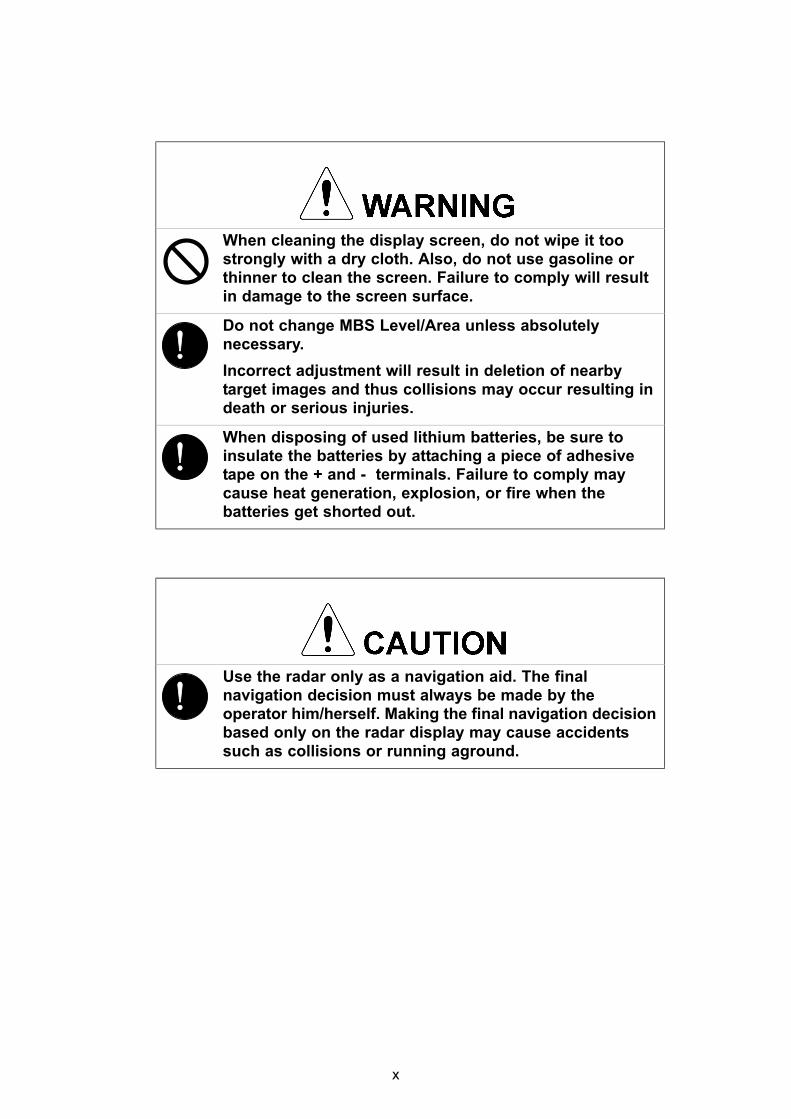
Scanner Unit Type NKE-1125-6 (6 feet)
Scanner Unit Type NKE-1125-9 (9 feet)
Scanner Unit Type NKE-2254-6HS (6 feet)
xxii

Scanner Unit Type NKE-2103-6 (6 feet)
Scanner Unit Type NKE-2103-6HS (6 feet)
Power Control Unit Type NQE-3167
xxiii

Display Unit Type NCD-4790 (Stand alone type)
Interswitch Unit Type NQE-3141-4A
xxiv

Monitor Unit Type NWZ-173 (Desktop type)
Operation Unit Type NCE-5163 (Desktop type)
Radar Process Unit Type NDC-1399-7 (Desktop type)DISPLAY UNIT TYPE NCD-4790T (DESKTOP TYPE)
xxv

GLOSSARY
This section describes the main terms used for this equipment and general related maritime terms.
AAZ Acquisition/Activation zone
A zone set up by the operator in which the system shouldautomatically acquire radar targets and activate reported AIS targetswhen entering the zone.
Activated target A target representing the automatic or manual activation of asleeping target for the display of additional information.
AIS Automatic Identification System
A system which enables ships and shore stations to obtainidentifying and navigation information about other ships at sea,using an automated transponder.
Anti-clutter rain Rain/snow clutter suppression.
Anti-clutter sea Sea clutter suppression.
Associated target A target simultaneously representing a tracked target and a reportedAIS target having similar parameters (position, course, speed)which comply with an association algorithm.
AZI AZImuth stabilization mode
BBCR/BCT Bow Crossing Range/Bow Crossing Time
CC up Course up
Own ship's course is pointed to the top center of the radar display.
CCRP Consistent Common Reference PointA location on own ship, to which all horizontal measurements suchas target range, bearing, relative course, relative speed, CPA orTCPA are referenced, typically the conning position of the bridge.
Clutter Unwanted reflections on a radar screen, from sea surface, rain orsnow.
COG Course Over Ground
The direction of the ship's movement relative to the earth, measuredon board the ship, expressed in angular units from true north
CORREL CORRELation
xxvi

CPA/TCPA The distance to the Closest Point of Approach/Time to the ClosestPoint of Approach.Limits are set by the operator and are related to own ship.
CTW Course Through WaterThe direction of the ship's movement through the water
DDRIFT The current velocity for manual correction or the current speed on
the horizontal axis of the 2-axis log is displayed.
EEBL Electronic Bearing Line
An electronic bearing line originated from own ship's position.
ETA Estimated Time of Arrival
GGround stabilization
A display mode in which speed and course information are referredto the ground, using ground track input data.
HHDG Heading
The horizontal direction that the bow of a ship is pointing at anyinstant, expressed in angular units from a reference direction.
HL Heading lineA graphic line on a radar presentation drawn from the consistentcommon reference point to the bearing scale to indicate the headingof the ship .
HSC High Speed CraftVessels which comply with the definition in SOLAS for high speedcraft
H up Head upOwn ship's heading line is always pointed to the top center of theradar display.
IIMO International Maritime Organisation
IR RADAR Interference Rejector
ISW A device to switch over two or more radar display units and two ormore scanners.
L
xxvii

Lost AIS target A target symbol representing the last valid position of an AIS targetbefore the reception of its data was lost, or its last dead-reckonedposition.
Lost tracked target
One for which target information is no longer available due to poor,lost or obscured signals.
LP Long Pulse
MMMSI Maritime Mobile Service Identity
MOB Man OverBoard
MON Performance monitor
MP Medium Pulse
NNM 1nm=1852m
N up North up
PPI Parallel Index line
Past positions Equally time-spaced past position marks of a tracked or AIS targetand own ship.
POSN POSitioN
PRF Pulse Repetition FrequencyThe number of radar pulses transmitted each second.
PROC PROCessRadar signal processing function
RRadar beacon A navigation aid which responds to the radar transmission by
generating a radar signal to identify its position and identity
Radar cross-section
Radar cross-section of a target determines the power densityreturned to the radar for a particular power density incident on thetarget
Range Rings A set of concentric circles labeled by distance from CCRP.
Reference target A symbol indicating that the associated tracked stationary target isused as a speed reference for the ground stabilisation
Relative speed The speed of a target relative to own ship's speed data
Relative vector A predicted movement of a target relative to own ship's motion
xxviii

RM Relative MotionA display on which the position of own ship remains fixed, and alltargets move relative to own ship.
RM(R) Relative Motion. Relative Trails.
RM(T) Relative Motion. True Trails.
ROT Rate Of TurnChange of heading per time unit.
Route A set of waypoints.
RR Range Rings
SSART Search And Rescue Transponder
Radar transponder capable of operating in the 9GHz band
Sea stabilization A display mode in which speed and course information are referredto the sea.
Sea state Status of the sea condition due to the weather environment,expressed as a sea state 0 for flat conditions with minimal wind, tosea state 8 for very rough sea conditions.
SET The current direction for manual correction or the current speed onthe horizontal axis of the 2-axis log is displayed.
Sleeping AIS target
A target indicating the presence and orientation of a vesselequipped with AIS in a certain location.
SOG Speed Over the GroundThe speed of the ship relative to the earth, measured on board of theship.
SP Short Pulse
STAB STABilization
STW Speed Through WaterThe speed of the ship relative to the water surface.
TTCPA Time to Closest Point of Approach to own ship
Test target Radar target of known characteristics used for test requirement
TM True MotionA display across which own ship moves with its own true motion.
Trails Tracks displayed by the radar echoes of targets in the form of anafterglow.
xxix

Trial manoeuvre A graphical simulation facility used to assist the operator toperform a proposed maneuver for navigation and collisionavoidance purposes.
True course The direction of motion relative to ground or to sea, of a targetexpressed as an angular displacement from north
True speed The speed of a target relative to ground, or to sea
True vector A vector representing the predicted true motion of a target, showingcourse and speed with reference to the ground or sea
TT Target Tracking.A computer process of observing the sequential changes in theposition of a radar target in order to establish its motion. Such atarget is a Tracked Target.
TTG Time To Go.Time to next waypoint.
TXRX Transmitter Receiver Unit
UUTC Universal Time Coordinated.
The international standard of time, kept by atomic clocks aroundthe world.
VVRM Variable Range Marker
An adjustable range ring used to measure the distance to a target.
WWaypoint A geographical location on a route indicating a event.
xxx

Index
◆◆◆ PRECAUTIONS BEFORE OPERATION ◆◆◆ .............................................. i◆◆◆ FIRST-AID TREATMENTS ◆◆◆ .................................................................. iiPREFACE ................................................................................................................... vThe Mounting Point of the Warning Label ................................................................. xvEQUIPMENT APPEARANCE ................................................................................... xxGLOSSARY ............................................................................................................ xxvi
SECTION 1GENERAL AND EQUIPMENT COMPOSITION1.1 FUNCTIONS ...........................................................................................1-1
1.1.1 Function of This System .................................................................1-11.2 FEATURES .............................................................................................1-21.3 CONFIGURATION ..................................................................................1-41.4 EXTERIOR DRAWINGS .........................................................................1-61.5 GENERAL SYSTEM DIAGRAMS ........................................................1-26
SECTION 2NAMES AND FUNCTIONS OF CONTROL PANEL KEYS AND FUNCTIONS OF SOFTWARE BUTTONS
2.1 NAMES OF DISPLAY .............................................................................2-12.2 NAMES AND FUNCTIONS OF CONTROL PANEL KEYS ..................2-112.3 FUNCTIONS OF SOFTWARE BUTTONS ...........................................2-16
SECTION 3BASIC OPERATION3.1 OPERATION FLOW ...............................................................................3-1
3.1.1 Power ON and Start the System ....................................................3-23.1.2 Observe and Adjust Video ..............................................................3-43.1.3 Acquire and Measure Data .............................................................3-43.1.4 Display and Measure with Reference to CCRP ............................3-43.1.5 End the Operation and Stop the System .......................................3-5
3.2 OBSERVE AND ADJUST VIDEO ..........................................................3-63.2.1 Adjust Monitor Brilliance [BRILL] ..................................................3-63.2.2 Change Observation Range [RANGE+/-] ......................................3-63.2.3 Tune ..................................................................................................3-73.2.4 Adjust Gain [GAIN] .........................................................................3-83.2.5 Suppress Sea Clutter [SEA] ..........................................................3-93.2.6 Suppress Rain/Snow Clutter [RAIN] ...........................................3-11

3.2.7 Reset Alarm Buzzer [ALARM ACK] .............................................3-123.2.8 To get the appropriate image that targets can be easily observed ...3-13
3.3 OPERATION PROCEDURES ..............................................................3-143.3.1 Move Cross Cursor Mark by Trackball ........................................3-143.3.2 Operate Software Buttons ...........................................................3-153.3.3 Basic Menu Operation ..................................................................3-163.3.4 Operation on Numeric Value, Latitude / Longitude and Character
Input menu .....................................................................................3-173.3.5 Overview of Menu Structure .........................................................3-22
3.4 GENERAL RADAR OPERATION ........................................................3-233.4.1 Interference Rejection (IR) ............................................................3-233.4.2 Switch Transmitter Pulse Length [GAIN] ....................................3-243.4.3 Target Enhance (ENH) ..................................................................3-253.4.4 Use Video Processing (PROC) .....................................................3-263.4.5 Switch Azimuth Display Mode (AZI MODE) ................................3-273.4.6 Switch True/Relative Motion Display Mode (TM/RM) .................3-283.4.7 Move Own Ship’s Display Position (Off Center) .........................3-293.4.8 Display Radar Trails (Trails) .........................................................3-303.4.9 Zoom (x2) .......................................................................................3-333.4.10 Hide/Display Range Rings [HL OFF] ...........................................3-343.4.11 Hide Graphics Information on Radar Display [DATA OFF] .......3-343.4.12 Switch Day/Night Mode [DAY/NIGHT] .........................................3-353.4.13 Adjust Operation Panel Brilliance [PANEL] ................................3-353.4.14 Set True Bearing ............................................................................3-363.4.15 Set Own Ship Speed .....................................................................3-363.4.16 Magnet Compass Correction (MAG Compass Setting) .............3-37
3.5 USE OWN SHIP'S TRACK ...................................................................3-393.5.1 Display Own Ship's Track (Display Own Track) .........................3-393.5.2 Set Display Color of Own Ship's Track (Display Own Track Color) .3-403.5.3 Save Own Ship's Track (Own Track Memory) ............................3-413.5.4 Cancel Saving of Own Ship's Track (Own Track Memory) ........3-413.5.5 Clear Own Ship's Track (Clear Own Track) ................................3-423.5.6 Use Expanded Own Ship's Track (Own Track Type) .................3-423.5.7 Use Water Depth Track (Water Depth Track) ..............................3-443.5.8 Use Water Temperature Track (Water TEMP Track) ..................3-45

3.5.9 Use Tidal Current Track (Current Vector Track) .........................3-463.6 DISPLAY USER MAP ...........................................................................3-47
3.6.1 Create User Map (Mark/Line) ........................................................3-473.6.2 Set User Map Display (Mark Display Setting) .............................3-503.6.3 Edit User Map (Edit User Map) .....................................................3-523.6.4 Correct Position on User Map (Shift User Map) .........................3-603.6.5 Save User Map ...............................................................................3-613.6.6 Set and Display Geodetic System (Geodetic) .............................3-65
3.7 USE ROUTE FUNCTION ......................................................................3-673.7.1 Display Route/Destination Mark (Select Route) .........................3-673.7.2 Edit Route (Set Route Sequence) ................................................3-683.7.3 Edit Route Make with Latitude and Longitude (Waypoint Input) 3-753.7.4 Use Route Monitoring Function (Waypoint/Route Alarm) .........3-793.7.5 Method of Using Route .................................................................3-813.7.6 Detailed Route Settings ................................................................3-823.7.7 Clear Waypoint/Route Data (Clear WPT/Route Data) .................3-863.7.8 Operate Route Data File ................................................................3-87
3.8 APPLIED OPERATIONS ......................................................................3-913.8.1 Set Radar Signal Processing (Process Setting) .........................3-913.8.2 Set Radar Trails (RADAR Trails Setting) .....................................3-953.8.3 Set Scanner Unit (TXRX Setting) .................................................3-973.8.4 Set Cursor (Cursor Setting) ..........................................................3-983.8.5 Set Radar Display (Display Setting) ............................................3-993.8.6 Adjust Sound Volume (Buzzer Volume) ....................................3-1023.8.7 Set User Option Keys [OPTION 1/2] ..........................................3-1033.8.8 Set Navigation Data Display (Multi Window Setting) ...............3-1053.8.9 AUTO Backup ..............................................................................3-110
3.9 USE FUNCTION KEY [USER] ...........................................................3-1113.9.1 Operation Procedures .................................................................3-1113.9.2 Function Setting Menu Items .....................................................3-1123.9.3 Overview of Function Operations (User Function Setting) .....3-1133.9.4 Overview of saved Function Setting Data .................................3-117
3.10 USE USER SETTING .........................................................................3-1183.10.1 Save Operating State (Save User Setting) ................................3-1183.10.2 Load Operating State (Load User Setting) ................................3-119

3.10.3 Delete Operating State (Delete User Setting) ...........................3-1193.11 USING CARD .....................................................................................3-120
3.11.1 Operate File on the Card (File Manager) ...................................3-120
SECTION 4MEASUREMENT OF RANGE AND BEARING4.1 USE OF NAVIGATION TOOLS ..............................................................4-1
4.1.1 Using Cursor (Cursor) ....................................................................4-24.1.2 Using Range Rings (Range Rings) ................................................4-24.1.3 Using Electronic Bearing Line (EBL1/EBL2) ................................4-34.1.4 Using Parallel Index Lines (PI Menu) .............................................4-84.1.5 Operating EBL Maneuver Function (EBL Maneuver Setting) ....4-144.1.6 Operating EBL, VRM, and PI with Cursor ...................................4-16
4.2 MEASUREMENT OF RANGE AND BEARING ....................................4-194.2.1 Measurement with Cursor Position (Cursor) ..............................4-194.2.2 Measurement with Electronic Bearing Line and Variable Range
Marker [EBL] [VRM] .....................................................................4-204.2.3 Measurement with Two Arbitrary Points .....................................4-21
SECTION 5OPERATION OF TARGET TRACKING AND AIS5.1 PREPARATION ......................................................................................5-1
5.1.1 Collision Avoidance ........................................................................5-25.1.2 Definitions of Symbols ...................................................................5-55.1.3 Radar Display ..................................................................................5-85.1.4 Cursor Modes (Cursor) .................................................................5-105.1.5 Setting Collision Decision Criteria ..............................................5-125.1.6 Setting Vectors (Vector Time) ......................................................5-135.1.7 Setting the GPS antenna location ................................................5-13
5.2 TARGET TRACKING OPERATION .....................................................5-145.2.1 Acquiring Target [ACQ] ................................................................5-145.2.2 Canceling Unwanted Tracked Targets [ACQ CANCEL] .............5-165.2.3 Tracked Target Data Display [TGT DATA] ..................................5-175.2.4 Displaying Target ID No.(Target Number Display) .....................5-185.2.5 Adding Tracked Target ID Name (Name) .....................................5-195.2.6 Reference Target (Reference) ......................................................5-20

5.2.7 Operation Test (TT Test Menu) ...................................................5-215.3 AIS OPERATION ..................................................................................5-26
5.3.1 Restrictions ....................................................................................5-265.3.2 Setting AIS Display Function (AIS Function) ..............................5-265.3.3 Activate AIS Targets (Activate AIS) .............................................5-275.3.4 Deactivate AIS Targets (Deactivate AIS) .....................................5-275.3.5 Displaying AIS Information [TGT DATA] .....................................5-285.3.6 Displaying Target ID No. (Target Number Display) ....................5-315.3.7 Setting AIS Filter (AIS Filter Setting) ...........................................5-325.3.8 Conditions for Deciding AIS Target to be Lost ..........................5-355.3.9 Setting Conditions for AIS Alarm (AIS Alarm Setting) ...............5-36
5.4 DECISION OF TARGETS AS IDENTICAL (Association) ...................5-375.4.1 Setting of Function to Decide Targets as Identical (Association) ..5-375.4.2 Setting of Conditions for Deciding AIS and Tracked Targets as
Identical (Association Setting) .....................................................5-375.4.3 Types of Decision Conditions to be Set ......................................5-38
5.5 ALARM DISPLAY .................................................................................5-395.5.1 CPA / TCPA Alarm .........................................................................5-405.5.2 Alarm for New Target Acquired in Automatic Acquisition Zone
(New Target) ...................................................................................5-415.5.3 Lost Target Alarm (Lost) ...............................................................5-415.5.4 Gyro Set Alarm ..............................................................................5-42
5.6 TRACK FUNCTION ..............................................................................5-435.6.1 Past Position (Past POSN) ...........................................................5-435.6.2 Target Ship's Tracks (Target Track) ............................................5-44
5.7 TRIAL MANEUVERING (Trial Maneuver) ..........................5-535.7.1 Trial Maneuvering in the True Vector Mode ................................5-545.7.2 Trial Maneuvering in the Relative Vector Mode ..........................5-555.7.3 Operation of Trial Maneuvering Function ...................................5-56
SECTION 6TRUE AND FALSE ECHOES ON DISPLAY6.1 RADAR WAVE WITH THE HORIZON ...................................................6-16.2 STRENGTH OF REFLECTION FROM THE TARGET ...........................6-36.3 SEA CLUTTER AND RAIN AND SNOW CLUTTER ..............................6-56.4 FALSE ECHOES ....................................................................................6-9

6.5 DISPLAY OF RADAR TRANSPONDER (SART) ................................6-12
SECTION 7SETTINGS FOR SYSTEM OPERATION7.1 SETTINGS AT INSTALLATION .............................................................7-1
7.1.1 How to Open the Serviceman Menu(Service Man Menu) .........7-17.1.2 GYRO I/F Setting .............................................................................7-27.1.3 Tuning (Tune Adjustment) .............................................................7-57.1.4 Bearing Adjustment ........................................................................7-77.1.5 Range Adjustment ...........................................................................7-77.1.6 Navigator Setting (Device) .............................................................7-87.1.7 Setting of True Bearing Value ........................................................7-97.1.8 Antenna Height Setting (Antenna Height) .....................................7-97.1.9 Setting of CCRP (CCRP Setting) ..................................................7-10
7.2 SETTINGS ............................................................................................7-127.2.1 Communication Port Setting (COM Port Setting) .......................7-127.2.2 Sector Blank Setting (Sector Blank) ............................................7-167.2.3 TNI Blank Setting (TNI Blank) ......................................................7-177.2.4 Setting of Bearing Pulses from Scanner Unit (Output Pulse) ...7-187.2.5 Slave Mode Setting (Master/Slave) ..............................................7-197.2.6 Language Setting (Language) ......................................................7-207.2.7 Date Time Setting ..........................................................................7-207.2.8 Input Installation Information .......................................................7-217.2.9 Setting the Alarm System .............................................................7-22
7.3 ADJUSTMENT ......................................................................................7-267.3.1 Noise Level Adjustment (Noise Level) ........................................7-267.3.2 Adjustment of Target Tracking Function (TT) ............................7-277.3.3 Main Bang Suppression Level Adjustment (MBS) .....................7-297.3.4 Adjustment of Performance Monitor ...........................................7-31
7.4 MAINTENANCE MENU ........................................................................7-337.4.1 Antenna Safety Switch (Safety Switch) .......................................7-337.4.2 Initialization of Memory Area(Area Initial) ...................................7-347.4.3 Save of Internal Memory Data (Card1/2) .....................................7-357.4.4 Restoration of Scanner Unit Operation Time (TXRX Time) ......7-367.4.5 Update of Character String Data (String Data Update) .............7-38

SECTION 8COUNTERMEASURES FOR TROUBLE AND ADJUSTMENT8.1 ROUTINE MAINTENANCE ....................................................................8-18.2 MAINTENANCE ON EACH UNIT ...........................................................8-2
8.2.1 Scanner Unit NKE-1125/1129/1130/1139/2103/2254 ....................8-28.2.2 Wave Guide Tube (JMA-7123-7XA/9XA) ........................................8-48.2.3 Coaxial Cable (JMA-7133-SA) ........................................................8-48.2.4 Transmitter Receiver Unit (NTG-3225/3230) ................................8-58.2.5 Display Unit (NCD-4790) ................................................................8-5
8.3 PERFORMANCE CHECK ......................................................................8-68.3.1 Check Performance on Test Menu ...............................................8-6
8.4 REPLACEMENT OF MAJOR PARTS ..................................................8-128.4.1 Parts Required for Periodic Replacement ..................................8-138.4.2 Replacement of magnetron ..........................................................8-138.4.3 Replacement of Motor ...................................................................8-288.4.4 Replacement of LCD Monitor .......................................................8-338.4.5 Replacement of Backup Battery ..................................................8-35
SECTION 9TROUBLE SHOOTING AND AFTER-SALES SERVICE9.1 FAULT FINDING .....................................................................................9-1
9.1.1 List of Alarms and other Indications .............................................9-19.1.2 Operation Checking ........................................................................9-59.1.3 Fuse Checking .................................................................................9-5
9.2 TROUBLE SHOOTING ...........................................................................9-69.2.1 Special Parts ....................................................................................9-79.2.2 Circuit Block to be Repaired ..........................................................9-8
9.3 AFTER-SALES SERVICE ....................................................................9-149.3.1 Keeping period of maintenance parts .........................................9-149.3.2 When you Request for Repair ......................................................9-149.3.3 Recommended Maintenance ........................................................9-14
SECTION 10DISPOSAL10.1 DISPOSAL OF THE UNIT ....................................................................10-110.2 DISPOSAL OF USED BATTERIES .....................................................10-110.3 DISPOSAL OF USED MAGNETRON ..................................................10-2

10.4 DISPOSAL OF TR-TUBE .....................................................................10-210.5 ABOUT THE CHINA ROHS .................................................................10-3
SECTION 11SPECIFICATION11.1 JMA-7133-SA TYPE RADAR ...............................................................11-111.2 JMA-7132-SA TYPE RADAR............................................................... 11-211.3 JMA-7123-7XA/9XA TYPE RADAR ....................................................11-311.4 JMA-7122-6XA/9XA TYPE RADAR ....................................................11-411.5 JMA-7122-6XAH TYPE RADAR .........................................................11-511.6 JMA-7110-6XA TYPE RADAR ............................................................11-611.7 JMA-7110-6XAH TYPE RADAR .........................................................11-711.8 SCANNER UNIT (NKE-1139) ...............................................................11-811.9 SCANNER UNIT (NKE-1130) ...............................................................11-911.10 SCANNER UNIT (NKE-1129-7/9) ......................................................11-1011.11 SCANNER UNIT (NKE-1125-6/9) .......................................................11-1111.12 SCANNER UNIT (NKE-2254-6HS) .....................................................11-1211.13 SCANNER UNIT (NKE-2103-6) ..........................................................11-1311.14 SCANNER UNIT (NKE-2103-6HS) .....................................................11-1411.15 TRANSMITTER RECEIVER UNIT (NTG-3230) .................................11-1511.16 TRANSMITTER RECEIVER UNIT (NTG-3225) .................................11-1611.17 DISPLAY UNIT (NCD-4790) ...............................................................11-1711.18 Target Tracking Function .................................................................11-2011.19 AIS FUNCTION ...................................................................................11-2111.20 PERFORMANCE MONITOR (NJU-84) ..............................................11-2211.21 PERFORMANCE MONITOR (NJU-85) ..............................................11-2211.22 AC-DC CONVERTER (NBA-5135) .....................................................11-22
Appendix ANQE-3141 Interswitch UnitA.1 OVERVIEW ............................................................................................A-1
A.1.1 Overview .........................................................................................A-1A.1.2 Interswitch Setup ...........................................................................A-1
A.2 INTERSWITCH OPERATION ................................................................A-3A.2.1 Operation Flow ...............................................................................A-3A.2.2 Inter Switch Menu ...........................................................................A-4

A.2.3 Change of Connection Pattern (with 2 Display Units) ................A-6A.2.4 Change of Connection Pattern (with 3 or More Display Units) ..A-7A.2.5 Operating Connection Pattern Files (File Operations) ...............A-8A.2.6 Names of Display Units and Scanner Units .................................A-9
A.3 REFERENCE .......................................................................................A-10A.3.1 Preheat Time after Change of Connection Pattern ...................A-10A.3.2 Notes on Changing Connection Pattern ....................................A-10A.3.3 Notes on Connecting Slave Display Unit ...................................A-10A.3.4 Setting at Installation ...................................................................A-11
Appendix BDRAWINGSB.1 Interconnection Diagram of Display Unit ...........................................B-1
B.1.1 NCD-4790 ........................................................................................B-2B.1.2 NCD-4790 w/NBA-5135 ...................................................................B-3B.1.3 NCD-4790T ......................................................................................B-4B.1.4 NCD-4790T w/NBA-5135 ................................................................B-5B.1.5 NCE-5163-R .....................................................................................B-6B.1.6 NCE-5163-RT ...................................................................................B-7B.1.7 NBA-5135 ........................................................................................B-8
B.2 Power System Daigram of Display Unit .............................................B-9B.3 Signal Flow Diagram of Display Unit ................................................B-10B.4 Primary Power System Diagram .......................................................B-11B.5 Block Diagram of Scanner Unit ........................................................B-12
B.5.1 NKE-2103 ......................................................................................B-13B.5.2 NKE-2254 ......................................................................................B-14B.5.3 NKE-1125/NKE-1130 .....................................................................B-15B.5.4 NKE-1129, NTG-3225 / NKE-1139, NTG-3230 .............................B-16
B.6 Interconnection Diagram of Scanner Unit .......................................B-17B.6.1 NKE-2103 ......................................................................................B-18B.6.2 NKE-2254 ......................................................................................B-19B.6.3 NKE-1125 (AC110V) ......................................................................B-20B.6.4 NKE-1125 (AC220V) ......................................................................B-21B.6.5 NKE-1129 (AC110V) ......................................................................B-22B.6.6 NKE-1129 (AC220V) ......................................................................B-23B.6.7 NTG-3225 ......................................................................................B-24

B.6.8 NKE-1130 (AC110V) ......................................................................B-25B.6.9 NKE-1130 (AC220V) ......................................................................B-26B.6.10 NKE-1139 (AC110V) ......................................................................B-27B.6.11 NKE-1139 (AC220V) ......................................................................B-28B.6.12 NTG-3230 ......................................................................................B-29
B.7 Terminal Board Connection Diagram ...............................................B-30B.7.1 JMA-7110-6XA/JMA-7110-6XAH ..................................................B-31B.7.2 JMA-7110-6XA/JMA-7110-6XAH (desktop) .................................B-32B.7.3 JMA-7122-6XAH ............................................................................B-33B.7.4 JMA-7122-6XAH (desktop) ...........................................................B-34B.7.5 JMA-7122-6XA/9XA ......................................................................B-35B.7.6 JMA-7123-7XA/9XA ......................................................................B-36B.7.7 JMA-7132-SA ................................................................................B-37B.7.8 JMA-7133-SA ................................................................................B-38B.7.9 NCD-4790T ....................................................................................B-39
B.8 GYRO I/F .............................................................................................B-40B.9 Inter Switch Unit .................................................................................B-42
B.9.1 Terminal Board Connection Diagram .........................................B-42B.9.2 Interconnection Diagram .............................................................B-44
Appendix CMenu IndexC.1 Main .......................................................................................................C-1C.2 PI ............................................................................................................C-5C.3 TT ...........................................................................................................C-7C.4 AIS .........................................................................................................C-8C.5 AZ ..........................................................................................................C-9C.6 Track ....................................................................................................C-10C.7 Route ...................................................................................................C-11C.8 U.Map ..................................................................................................C-12C.9 Serviceman Menu ...............................................................................C-14

1234567891011A
1 GENERAL AND EQUIPMENT COMPOSITION
2 NAMES AND FUNCTIONS OF CONTROL PANELKEYS AND FUNCTIONS OF SOFTWARE BUTTONS
3 BASIC OPERATION
4 MEASUREMENT OF RANGE AND BEARING
5 OPERATION OF TARGET TRACKING AND AIS
6 TRUE AND FALSE ECHOES ON DISPLAY
7 SETTINGS FOR SYSTEM OPERATION
8 COUNTERMEASURES FOR TROUBLE ANDADJUSTMENT
9 TROUBLE SHOOTING AND AFTER-SALESSERVICE
10 DISPOSAL
11 SPECIFICATIONS
Appendix


GENERAL AND EQUIPMENT COMPOSITION1.1 FUNCTIONS ...........................................................................................1-1
1.1.1 Function of This System .................................................................1-11.2 FEATURES .............................................................................................1-21.3 CONFIGURATION ..................................................................................1-41.4 EXTERIOR DRAWINGS .........................................................................1-61.5 GENERAL SYSTEM DIAGRAMS ........................................................1-26
SECTION 1GENERAL AND EQUIPMENT COMPOSITION


JMA-7100 Instruction Manual > 1.GENERAL AND EQUIPMENT COMPOSITION > 1.1 FUNCTIONS
1
1.1 FUNCTIONSThis equipment is a high-performance radar equipment consisting of a scanner unit, a transmitter-receiver unit and a high resolution color LCD display unit.
This equipment complies with the performance standard of IMO.
1.1.1 Function of This System
The JMA-7100 series is a color radar system designed to comply with the international standards of the IMO.The main functions include:
• sensitivity adjustment• sea clutter and rain/snow clutter suppression• interference rejection• bearing and range measurement using a cursor, fixed/variable range markers,
and electronic bearing line• colored own track display(7 colors)• NAV line and marker displays• TM (True Motion) presentation• self-diagnostic facilities• radar performance monitoring (Performance Monitor)• Target Tracking functions (manual/automatic, target acquisition and tracking,
vector and trail displays, Trial maneuver and alarm displays)• 8-unit switchover (Interswitch) function (option)
1-1

JMA-7100 Instruction Manual > 1.GENERAL AND EQUIPMENT COMPOSITION > 1.2 FEATURES
1.2 FEATURES
Realization of Large, Easy-to-see Screen with High Resolution
The 19-inch color LCD with high resolution of 1280 1024 pixels can display radar images of 250 mm or more in diameter. Even short-range targets can also be displayed as high-resolution images.
Target Detection by Latest Signal Processing Technology
The system employs the latest digital signal processing technology to eliminate undesired clutter from the radar video signals that are obtained from the receiver with a wide dynamic range, thus improving the target detection.
Target Tracking (TT) Function based on Advanced Technology
The target acquisition and tracking performance is enhanced by the use of the fastest DSP and tracking algorithm. So stable operation in target tracking under clutter is ensured.
• Acquisition and tracking of 100 targets.• Hazardous conditions are represented by shapes and colors of symbols as well
as sounds.• Trial maneuvering functions provided.• Tracks of up to 20 target ships can be stored with a maximum of 1,500 points
for each of them, and displayed distinguished by using seven different colors.
Overlay of Radar Images, Coastlines, and Own Ship's Track
As well as operator-created NAV lines and own ship's tracks/ARPA tracks, which is stored on the memory card can be superimpose-displayed with radar images and radar trails in all display modes including the head-up mode.
Easy Operation with GUI
All the radar functions can be easily controlled by simply using the trackball and two switches to operate the buttons shown on the radar display.
1-2
JMA-7100 Instruction Manual > 1.GENERAL AND EQUIPMENT COMPOSITION > 1.2 FEATURES
1
Improved Day/Night ModeFive types of background colors are available in Day/Dusk/Night mode (total 5 background colors). Each background color can be reproduced to be suited for the user's operating environment by simple key operation. The radar echoes and a variety of graphics can also be represented in different colors, ensuring easy-to-see displays.
Compact Design and Low Power Consumption
Since an LCD has been implemented as the display device, the weight of the display is greatly reduced and the power consumption is lowered in comparison with the conventional radar equipment.
Self-diagnostic Program Incorporated
The Self-diagnostic program always monitors all the functions of the system. If any function deteriorates, an alarm message will appear on the radar display and an alarm sounds at the same time. Even when the system is operating, the functionality test can be carried out. (except on some functions)
Performance Monitor
The radar performance (transmitted output power and receiving sensitivity) can appear on the radar display.
Easy Interswitch Operation (Option)
If an interswitch unit (option) is connected, up to eight JMA-7100 radars can be switched over by performing simple operation.
Various Functions
• RADAR Trails (Other ship's track display)• TM (True Motion) display• Head-up/North-up/Course-up display• Own ship's track display• Auto-acquisition Zone function
Up to 2 radars: NQA-3141-2A is needed in Display Unit.
Up to 4 radars: NQA-3141-4A is needed separately.
Up to 8 radars: NQA-3141-8A is needed separately.
1-3

JMA-7100 Instruction Manual > 1.GENERAL AND EQUIPMENT COMPOSITION > 1.3 CONFIGURATION
1.3 CONFIGURATION
※The class of emission: P0N (All scanner types)
Table1-1:Specified of scanner, and categories of ship/craft for SOLAS V
Radar model Antenna type Transmitted Output Power
Band Rate of rotation
Category
JMA-7133-SA 12ft Slotted Antenna 30kW S 24rpm CAT 2
JMA-7132-SA 12ft Slotted Antenna 30kW S 24rpm CAT 2
JMA-7123-7XA 7ft Slotted Antenna 25kW X 24rpm CAT 2
JMA-7123-9XA 9ft Slotted Antenna 25kW X 24rpm CAT 2
JMA-7122-6XA 6ft Slotted Antenna 25kW X 24rpm CAT 2
JMA-7122-9XA 9ft Slotted Antenna 25kW X 24rpm CAT 2
JMA-7122-6XAH 6ft Slotted Antenna 25kW X 48rpm CAT 2H
JMA-7110-6XA 6ft Slotted Antenna 10kW X 27rpm CAT 2
JMA-7110-6XAH 6ft Slotted Antenna 10kW X 48rpm CAT 2H
Table1-2:Radar Configuration and Ship's Mains
Radar model Scanner Unit PerformanceMonitor
Transmitter ReceiverUnit
D i s p l a yUnit
Ship’s Main
JMA-7133-SA NKE-1139 NJU-84 NTG-3230 NCD-4790 AC100 to 115V, orAC220 to 240V 50/60Hz1φJMA-7132-SA NKE-1130 NJU-84 ――― NCD-4790
JMA-7123-7XA NKE-1129-7 NJU-85 NTG-3225 NCD-4790
JMA-7123-9XA NKE-1129-9 NJU-85 NTG-3225 NCD-4790
JMA-7122-6XA NKE-1125-6 NJU-85 ――― NCD-4790
JMA-7122-9XA NKE-1125-9 NJU-85 ――― NCD-4790
JMA-7122-6XAH NKE-2254-6HS NJU-85 ――― NCD-4790 AC100 to 115V, orAC220 to 240V 50/60Hz1φJMA-7110-6XA NKE-2103-6 NJU-85 ――― NCD-4790
JMA-7110-6XAH NKE-2103-6HS NJU-85 ――― NCD-4790
1-4

JMA-7100 Instruction Manual > 1.GENERAL AND EQUIPMENT COMPOSITION > 1.3 CONFIGURATION
1
Notes:1) The drive motor for the scanner unit is available in AC100-115V or AC220-240V type for NKE-1139/1130/1125/1129 series. Please specify the motor type when ordering.
2) The motor of NKE-2254/2103 can operate under both AC100-115V and AC220-240V, then need not to specify the motor type.
3) When using NKE-2254/2103, they need AC/DC Converter Unit NBA-5135 (Option) in display unit.
4) The scanner unit except NKE-2103 series can be equipped with a deicing heater as an option, and '-D' shall be suffixed to the type name. (e.g. NKE-1139-D, NKE-1125-6D).
5) When using the ship's mains of AC440V as the radar power source, a step-down transformer shall be used.
6) The desktop option is available for display NCD-4790. It has a separate structure consisting of the following:
7) In JMA-7123, the following type name of JRC is used for the waveguide between the scanner unit and the transmitter receiver unit.
8) In JMA-7133, the following type name of JRC is used for the RF coaxial cable between the scanner unit and the transmitter receiver unit.
Monitor Unit NWZ-173
Radar Processor Unit NDC-1399-7
Operation unit NCE-5163
Type of Radar Waveguide Length(m) Type name of JRC
JMA-7123-7XA/9XA FR-9 20MT H-7AWRD0003
JMA-7123-7XA/9XA FR-9 30MT H-7AWRD0004
Type of Radar RF COAX cable Length(m) Type name of JRC
JMA-7133-SA HF-20D 30MT HF-20D (30MT)
1-5

JMA-7100 Instruction Manual > 1.GENERAL AND EQUIPMENT COMPOSITION > 1.4 EXTERIOR DRAWINGS
1.4 EXTERIOR DRAWINGS
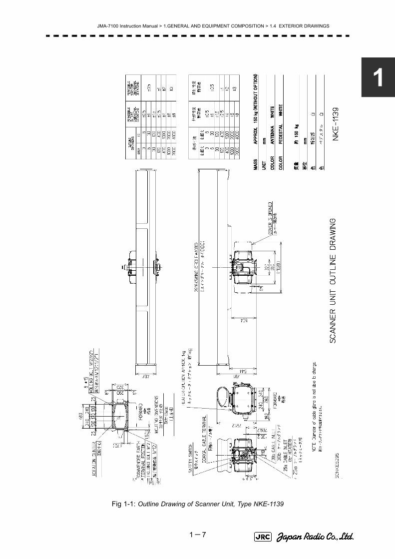
Fig 1-1: Outline Drawing of Scanner Unit, Type NKE-1139
Fig 1-2: Outline Drawing of Scanner Unit, Type NKE-1130
Fig 1-3: Outline Drawing of Scanner Unit, Type NKE-1129-7
Fig 1-4: Outline Drawing of Scanner Unit, Type NKE-1129-9
Fig 1-5: Outline Drawing of Scanner Unit, Type NKE-1125-6
Fig 1-6: Outline Drawing of Scanner Unit, Type NKE-1125-9
Fig 1-7: Outline Drawing of Scanner Unit, Type NKE-2254-6HS
Fig 1-8: Outline Drawing of Scanner Unit, Type NKE-2103-6
Fig 1-9: Outline Drawing of Scanner Unit, Type NKE-2103-6HS
Fig 1-10: Outline Drawing of Transmitter Receiver Unit, Type NTG-3230
Fig 1-11: Outline Drawing of Transmitter Receiver Unit, Type NTG-3225
Fig 1-12: Outline Drawing of Display Unit, Type NCD-4790
Fig 1-13: Outline Drawing of Monitor Unit, Type NWZ-173 (Desktop type option)
Fig 1-14: NDOutline Drawing of Radar Process Unit, Type NDC-1399-7 (Desktop type option)
Fig 1-15: Outline Drawing of Operation Unit, Type NCE-5163 (Desktop type option)
Fig 1-16: Outline Drawing of AC/DC Converter Unit, Type NBA-5135 (Desktop type option)
Fig 1-17: Outline Drawing of Interswitch Unit, Type NQE-3141-4A (Option)
Fig 1-18: Outline Drawing of Interswitch Unit, Type NQE-3141-8A (Option)
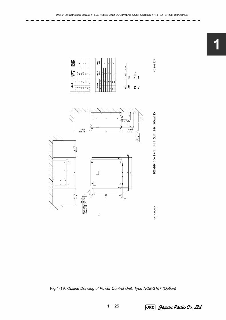
Fig 1-19: Outline Drawing of Power Control Unit, Type NQE-3167 (Option)
1-6
JMA-7100 Instruction Manual > 1.GENERAL AND EQUIPMENT COMPOSITION > 1.4 EXTERIOR DRAWINGS
1
Fig 1-1: Outline Drawing of Scanner Unit, Type NKE-1139
1-7

JMA-7100 Instruction Manual > 1.GENERAL AND EQUIPMENT COMPOSITION > 1.4 EXTERIOR DRAWINGS
Fig 1-2: Outline Drawing of Scanner Unit, Type NKE-1130
1-8

JMA-7100 Instruction Manual > 1.GENERAL AND EQUIPMENT COMPOSITION > 1.4 EXTERIOR DRAWINGS
1
Fig 1-3: Outline Drawing of Scanner Unit, Type NKE-1129-7
1-9

JMA-7100 Instruction Manual > 1.GENERAL AND EQUIPMENT COMPOSITION > 1.4 EXTERIOR DRAWINGS
Fig 1-4: Outline Drawing of Scanner Unit, Type NKE-1129-9
1-10

JMA-7100 Instruction Manual > 1.GENERAL AND EQUIPMENT COMPOSITION > 1.4 EXTERIOR DRAWINGS
1
Fig 1-5: Outline Drawing of Scanner Unit, Type NKE-1125-6
1-11

JMA-7100 Instruction Manual > 1.GENERAL AND EQUIPMENT COMPOSITION > 1.4 EXTERIOR DRAWINGS
Fig 1-6: Outline Drawing of Scanner Unit, Type NKE-1125-9
1-12

JMA-7100 Instruction Manual > 1.GENERAL AND EQUIPMENT COMPOSITION > 1.4 EXTERIOR DRAWINGS
1
Fig 1-7: Outline Drawing of Scanner Unit, Type NKE-2254-6HS
1-13

JMA-7100 Instruction Manual > 1.GENERAL AND EQUIPMENT COMPOSITION > 1.4 EXTERIOR DRAWINGS
Fig 1-8: Outline Drawing of Scanner Unit, Type NKE-2103-6
1-14

JMA-7100 Instruction Manual > 1.GENERAL AND EQUIPMENT COMPOSITION > 1.4 EXTERIOR DRAWINGS
1
Fig 1-9: Outline Drawing of Scanner Unit, Type NKE-2103-6HS
1-15

JMA-7100 Instruction Manual > 1.GENERAL AND EQUIPMENT COMPOSITION > 1.4 EXTERIOR DRAWINGS
Fig 1-10: Outline Drawing of Transmitter Receiver Unit, Type NTG-3230
1-16

JMA-7100 Instruction Manual > 1.GENERAL AND EQUIPMENT COMPOSITION > 1.4 EXTERIOR DRAWINGS
1
Fig 1-11: Outline Drawing of Transmitter Receiver Unit, Type NTG-3225
1-17

JMA-7100 Instruction Manual > 1.GENERAL AND EQUIPMENT COMPOSITION > 1.4 EXTERIOR DRAWINGS
Fig 1-12: Outline Drawing of Display Unit, Type NCD-4790
1-18

JMA-7100 Instruction Manual > 1.GENERAL AND EQUIPMENT COMPOSITION > 1.4 EXTERIOR DRAWINGS
1
Fig 1-13: Outline Drawing of Monitor Unit, Type NWZ-173 (Desktop type option)
1-19

JMA-7100 Instruction Manual > 1.GENERAL AND EQUIPMENT COMPOSITION > 1.4 EXTERIOR DRAWINGS
Fig 1-14: NDOutline Drawing of Radar Process Unit, Type NDC-1399-7 (Desktop type option)
1-20

JMA-7100 Instruction Manual > 1.GENERAL AND EQUIPMENT COMPOSITION > 1.4 EXTERIOR DRAWINGS
1
Fig 1-15: Outline Drawing of Operation Unit, Type NCE-5163 (Desktop type option)
1-21

JMA-7100 Instruction Manual > 1.GENERAL AND EQUIPMENT COMPOSITION > 1.4 EXTERIOR DRAWINGS
Fig 1-16: Outline Drawing of AC/DC Converter Unit, Type NBA-5135 (Desktop type option)
1-22

JMA-7100 Instruction Manual > 1.GENERAL AND EQUIPMENT COMPOSITION > 1.4 EXTERIOR DRAWINGS
1
Fig 1-17: Outline Drawing of Interswitch Unit, Type NQE-3141-4A (Option)
1-23

JMA-7100 Instruction Manual > 1.GENERAL AND EQUIPMENT COMPOSITION > 1.4 EXTERIOR DRAWINGS
Fig 1-18: Outline Drawing of Interswitch Unit, Type NQE-3141-8A (Option)
1-24
JMA-7100 Instruction Manual > 1.GENERAL AND EQUIPMENT COMPOSITION > 1.4 EXTERIOR DRAWINGS
1
Fig 1-19: Outline Drawing of Power Control Unit, Type NQE-3167 (Option)
1-25

JMA-7100 Instruction Manual > 1.GENERAL AND EQUIPMENT COMPOSITION > 1.5 GENERAL SYSTEM DIAGRAMS
1.5 GENERAL SYSTEM DIAGRAMS
Fig 1-21: General System Diagram of Radar, Type JMA-7132-SA
Fig 1-22: General System Diagram of Radar, Type JMA-7123-7XA
Fig 1-23: General System Diagram of Radar, Type JMA-7123-9XA
Fig 1-24: General System Diagram of Radar, Type JMA-7122-6XA
Fig 1-25: General System Diagram of Radar, Type JMA-7122-9XA
Fig 1-26: General System Diagram of Radar, Type JMA-7122-6XAH
Fig 1-27: General System Diagram of Radar, Type JMA-7110-6XA
Fig 1-28: General System Diagram of Radar, Type JMA-7110-6XAH
1-26

JMA-7100 Instruction Manual > 1.GENERAL AND EQUIPMENT COMPOSITION > 1.5 GENERAL SYSTEM DIAGRAMS
1
Fig 1-20: General System Diagram of Radar, Type JMA-7133-SA
Eliminating the interference on frequencies used for marine communications and navigation due to operation of the radar. All cables of the radar are to be run away from the cables of radio equipment.(Ex. Radiotelephone. Communications receiver and direction finder, etc. ) Especially inter-wiring cables between scanner unit and display unit of the radar should not be run parallel with the cables of radio equipment.
NCD-4790 DISPLAY UNIT
NJU-84 PERFORMANCE UNIT
250 V -MPYCYS -7250 V -TTYCS-1
3 C-2V x5 (MAX 30 m)
250 V -TTYCS-1
1 8 C O R E S C O M P O S I T E C A B L EH -2 6 9 5 1 1 1 1 5 3M A X 1 8. 0φ (J R C S U P P L Y)
250 V -TTYCS-4
H-2695110006 (JRC SUPPLY )H -2 6 6 8 5 1 0 0 1 9 ( J R C S U P P L Y) S P A R E
250 V -MPYC -4250 V -TTYCS-4
250 V -TTYCS-4
GYROLOG(NMEA 0183)
DGPSVDR
RADAR(INTER SWITCH)
ECDIS(JAN-901M)
ALERM MONITORING SYSTEM(NEAREST APPROACH)
(POWER FAIL)
CONNING DISPLAY(JAN-701-CON)
AIS
0 .6/1 kV-DPYCY -6
0 .6/1 kV-DPYCYS -1 .5
SHIP’S MAINAC220V,60Hz,1φ,800VA
SHIP’S MAINfor POWER FAIL ALARMDC24V(BATTERY ),1W
(5A)
NBL-175SHIP’S MAINfor HEATERAC220V,60Hz,1φ
AC100V,60Hz1φ,200 W
CIRCUIT BREAKER(SHIP YARD SUPPLY)
( W I TH P M U N I T)
NKE-1139SCANNER UNIT
1 4 C O R E S C O M P O S I T E C A B L EH - 2 6 9 5 1 1 0 0 5 6M A X 2 3φ ( J R C S U P P L Y)
STEPDOWN TRANSFORMER
NTG-3230TRANSCEIVER UNIT
1 4 C O R E S C O M P O S I T E C A B L EH - 2 6 9 5 1 1 0 0 5 6M A X 2 3φ (J R C S U P P L Y)
C O A X I A L C A B L EH F -2 0D ( J R C S U P P L Y)
0 .6 /1 kV - D P Y C Y S- 1 .5
1-27

JMA-7100 Instruction Manual > 1.GENERAL AND EQUIPMENT COMPOSITION > 1.5 GENERAL SYSTEM DIAGRAMS
Fig 1-21: General System Diagram of Radar, Type JMA-7132-SA
Eliminating the interference on frequencies used for marine communications and navigation due to operation of the radar. All cables of the radar are to be run away from the cables of radio equipment.(Ex. Radiotelephone. Communications receiver and direction finder, etc. ) Especially inter-wiring cables between scanner unit and display unit of the radar should not be run parallel with the cables of radio equipment.
NCD-4790 DISPLAY UNIT
NJU-84 PERFORMANCE UNIT
250 V -MPYCYS -7250 V -TTYCS-1
3 C-2V x5 (MAX 30 m)
250 V -TTYCS-1
1 8 C O R E S C O M P O S I T E C A B L EH -2 6 9 5 1 1 1 1 5 3M A X 1 8. 0φ (J R C S U P P L Y)
250 V -TTYCS-4
H-2695110006 (JRC SUPPLY )H -2 6 6 8 5 1 0 0 1 9 ( J R C S U P P L Y) S P A R E
250 V -MPYC -4250 V -TTYCS-4
250 V -TTYCS-4
GYROLOG(NMEA 0183)
DGPSVDR
RADAR(INTER SWITCH)
ECDIS(JAN-901M)
ALERM MONITORING SYSTEM(NEAREST APPROACH)
(POWER FAIL)
CONNING DISPLAY(JAN-701-CON)
AIS
0 .6/1 kV-DPYCY -6
0 .6/1 kV-DPYCYS -1 .5
SHIP’S MAINAC220V,60Hz,1φ,800VA
SHIP’S MAINfor POWER FAIL ALARMDC24V(BATTERY),1W
(5A)
NBL-175SHIP’S MAINfor HEATERAC220V,60Hz,1φ
AC100V,60Hz1φ,200 W
CIRCUIT BREAKER(SHIP YARD SUPPLY)
( W I TH P M U N I T)
NKE-1130SCANNER UNIT
1 4 C O R E S C O M P O S I T E C A B L EH -2 6 9 5 1 1 0 0 5 6M A X 2 3φ ( J R C S U P P L Y)
STEPDOWN TRANSFORMER
0. 6 /1 kV - D P Y C Y S- 1 .5
1-28

JMA-7100 Instruction Manual > 1.GENERAL AND EQUIPMENT COMPOSITION > 1.5 GENERAL SYSTEM DIAGRAMS
1
Fig 1-22: General System Diagram of Radar, Type JMA-7123-7XA
Eliminating the interference on frequencies used for marine communications and navigation due to operation of the radar. All cables of the radar are to be run away from the cables of radio equipment.(Ex. Radiotelephone. Communications receiver and direction finder, etc. ) Especially inter-wiring cables between scanner unit and display unit of the radar should not be run parallel with the cables of radio equipment.
NCD-4790 DISPLAY UNIT
NJU-85 PERFORMANCE UNIT
250 V -MPYCYS -7250 V -TTYCS-1
3 C-2V x5 (MAX 30 m)
250 V -TTYCS-1
1 8 C O R E S C O M P O S I T E C A B L EH -2 6 9 5 1 1 1 1 5 3M A X 1 8. 0φ (J R C S U P P L Y)
250 V -TTYCS-4
H-2695110006 (JRC SUPPLY )H -2 6 6 8 5 1 0 0 1 9 ( J R C S U P P L Y) S P A R E
250 V -MPYC -4250 V -TTYCS-4
250 V -TTYCS-4
GYROLOG(NMEA 0183)
DGPSVDR
RADAR(INTER SWITCH)
ECDIS(JAN-901M)
ALERM MONITORING SYSTEM(NEAREST APPROACH)
(POWER FAIL)
CONNING DISPLAY(JAN-701-CON)
AIS
0 .6/1 kV-DPYCY -6
0 .6/1 kV-DPYCYS -1 .5
SHIP’S MAINAC220V,60Hz,1φ,800VA
SHIP’S MAINfor POWER FAIL ALARMDC24V(BATTERY ),1W
(5A)
NBL-175SHIP’S MAINfor HEATERAC220V,60Hz,1φ
AC100V,60Hz1φ,200 W
CIRCUIT BREAKER(SHIP YARD SUPPLY)
( W I TH P M U N I T)
NKE-1129-7SCANNER UNIT
1 4 C O R E S C O M P O S I T E C A B L EH - 2 6 9 5 1 1 0 0 5 6M A X 2 3φ ( J R C S U P P L Y)
STEPDOWN TRANSFORMER
NTG-3225TRANSCEIVER UNIT
1 4 C O R E S C O M P O S I T E C A B L EH - 2 6 9 5 1 1 0 0 5 6M A X 2 3φ (J R C S U P P L Y)
F L E X I B L E W A V E G U I D EF R -9 (J R C S U P P L Y)
0 .6 /1 kV - D P Y C Y S- 1 .5
1-29

JMA-7100 Instruction Manual > 1.GENERAL AND EQUIPMENT COMPOSITION > 1.5 GENERAL SYSTEM DIAGRAMS
Fig 1-23: General System Diagram of Radar, Type JMA-7123-9XA
Eliminating the interference on frequencies used for marine communications and navigation due to operation of the radar. All cables of the radar are to be run away from the cables of radio equipment.(Ex. Radiotelephone. Communications receiver and direction finder, etc. ) Especially inter-wiring cables between scanner unit and display unit of the radar should not be run parallel with the cables of radio equipment.
NCD-4790 DISPLAY UNIT
NJU-85 PERFORMANCE UNIT
250 V -MPYCYS -7250 V -TTYCS-1
3 C-2V x5 (MAX 30 m)
250 V -TTYCS-1
1 8 C O R E S C O M P O S I T E C A B L EH -2 6 9 5 1 1 1 1 5 3M A X 1 8. 0φ (J R C S U P P L Y)
250 V -TTYCS-4
H-2695110006 (JRC SUPPLY )H -2 6 6 8 5 1 0 0 1 9 ( J R C S U P P L Y) S P A R E
250 V -MPYC -4250 V -TTYCS-4
250 V -TTYCS-4
GYROLOG(NMEA 0183)
DGPSVDR
RADAR(INTER SWITCH)
ECDIS(JAN-901M)
ALERM MONITORING SYSTEM(NEAREST APPROACH)
(POWER FAIL)
CONNING DISPLAY(JAN-701-CON)
AIS
0 .6/1 kV-DPYCY -6
0 .6/1 kV-DPYCYS -1 .5
(5A)
NBL-175SHIP’S MAINfor HEATERAC220V,60Hz,1φ
AC100V,60Hz1φ,200 W
CIRCUIT BREAKER(SHIP YARD SUPPLY)
( W I TH P M U N I T)
NKE-1129-9SCANNER UNIT
1 4 C O R E S C O M P O S I T E C A B L EH - 2 6 9 5 1 1 0 0 5 6M A X 2 3φ ( J R C S U P P L Y)
STEPDOWN TRANSFORMER
NTG-3225TRANSCEIVER UNIT
1 4 C O R E S C O M P O S I T E C A B L EH - 2 6 9 5 1 1 0 0 5 6M A X 2 3φ (J R C S U P P L Y)
F L E X I B L E W A V E G U I D EF R -9 (J R C S U P P L Y)
0. 6 /1 kV - D P Y C Y S- 1 .5
1-30

JMA-7100 Instruction Manual > 1.GENERAL AND EQUIPMENT COMPOSITION > 1.5 GENERAL SYSTEM DIAGRAMS
1
Fig 1-24: General System Diagram of Radar, Type JMA-7122-6XA
Eliminating the interference on frequencies used for marine communications and navigation due to operation of the radar. All cables of the radar are to be run away from the cables of radio equipment.(Ex. Radiotelephone. Communications receiver and direction finder, etc. ) Especially inter-wiring cables between scanner unit and display unit of the radar should not be run parallel with the cables of radio equipment.
NCD-4790 DISPLAY UNIT
NJU-85PERFORMANCE UNIT
250 V -MPYCYS -7250 V -TTYCS-1
3 C-2V x5 (MAX 30 m)
250 V -TTYCS-1
1 8 C O R E S C O M P O S I T E C A B L EH -2 6 9 5 1 1 1 1 5 3M A X 1 8. 0φ (J R C S U P P L Y)
250 V -TTYCS-4
H-2695110006 (JRC SUPPLY )H -2 6 6 8 5 1 0 0 1 9 ( J R C S U P P L Y) S P A R E
250 V -MPYC -4250 V -TTYCS-4
250 V -TTYCS-4
GYROLOG(NMEA 0183)
DGPSVDR
RADAR(INTER SWITCH)
ECDIS(JAN-901M)
ALERM MONITORING SYSTEM(NEAREST APPROACH)
(POWER FAIL)
CONNING DISPLAY(JAN-701-CON)
AIS
0 .6/1 kV-DPYCY -6
0 .6/1 kV-DPYCYS -1 .5
SHIP’S MAINAC220 V,60Hz,1φ,800VA
SHIP’S MAINfor POWER FAIL ALARMDC24V(BATTERY),1W
(5A)
NBL-175SHIP’S MAINfor HEATERAC220V,60Hz,1φ
AC100V,60Hz1φ,200 W
CIRCUIT BREAKER(SHIP YARD SUPPLY)
( W I T H P M U N I T)
NKE-2254-6HSSCANNER UNIT
1 4 C O R E S C O M P O S I T E C A B L EH -2 6 9 5 1 1 0 0 5 6M A X 2 3φ ( J R C S U P P L Y)
STEPDOWN TRANSFORMER
0 .6 /1 kV - D P Y C Y S- 1 .5
1-31

JMA-7100 Instruction Manual > 1.GENERAL AND EQUIPMENT COMPOSITION > 1.5 GENERAL SYSTEM DIAGRAMS
Fig 1-25: General System Diagram of Radar, Type JMA-7122-9XA
Eliminating the interference on frequencies used for marine communications and navigation due to operation of the radar. All cables of the radar are to be run away from the cables of radio equipment.(Ex. Radiotelephone. Communications receiver and direction finder, etc. ) Especially inter-wiring cables between scanner unit and display unit of the radar should not be run parallel with the cables of radio equipment.
NCD-4790 DISPLAY UNIT
NJU-85PERFORMANCE UNIT
250 V -MPYCYS -7250 V -TTYCS-1
3 C-2V x5 (MAX 30 m)
250 V -TTYCS-1
1 8 C O R E S C O M P O S I T E C A B L EH -2 6 9 5 1 1 1 1 5 3M A X 1 8. 0φ (J R C S U P P L Y)
250 V -TTYCS-4
H-2695110006 (JRC SUPPLY )H -2 6 6 8 5 1 0 0 1 9 ( J R C S U P P L Y) S P A R E
250 V -MPYC -4250 V -TTYCS-4
250 V -TTYCS-4
GYROLOG(NMEA 0183)
DGPSVDR
RADAR(INTER SWITCH)
ECDIS(JAN-901M)
ALERM MONITORING SYSTEM(NEAREST APPROACH)
(POWER FAIL)
CONNING DISPLAY(JAN-701-CON)
AIS
0 .6/1 kV-DPYCY -6
0 .6/1 kV-DPYCYS -1 .5
SHIP’S MAINAC220V,60Hz,1φ,800VA
SHIP’S MAINfor POWER FAIL ALARMDC24V(BATTERY),1W
(5A)
NBL-175SHIP’S MAINfor HEATERAC220V,60Hz,1φ
AC100V,60Hz1φ,200 W
CIRCUIT BREAKER(SHIP YARD SUPPLY)
( W I TH P M U N I T)
NKE-1125-9SCANNER UNIT
1 4 C O R E S C O M P O S I T E C A B L EH -2 6 9 5 1 1 0 0 5 6M A X 2 3φ ( J R C S U P P L Y)
STEPDOWN TRANSFORMER
0. 6 /1 kV - D P Y C Y S- 1 .5
1-32

JMA-7100 Instruction Manual > 1.GENERAL AND EQUIPMENT COMPOSITION > 1.5 GENERAL SYSTEM DIAGRAMS
1
Fig 1-26: General System Diagram of Radar, Type JMA-7122-6XAH
Eliminating the interference on frequencies used for marine communications and navigation due to operation of the radar. All cables of the radar are to be run away from the cables of radio equipment.(Ex. Radiotelephone. Communications receiver and direction finder, etc. ) Especially inter-wiring cables between scanner unit and display unit of the radar should not be run parallel with the cables of radio equipment.
NCD-4790 DISPLAY UNIT
NJU-85PERFORMANCE UNIT
250 V -MPYCYS -7250 V -TTYCS-1
3 C-2V x5 (MAX 30 m)
250 V -TTYCS-1
1 8 C O R E S C O M P O S I T E C A B L EH -2 6 9 5 1 1 1 1 5 3M A X 1 8. 0φ (J R C S U P P L Y)
250 V -TTYCS-4
H-2695110006 (JRC SUPPLY )H -2 6 6 8 5 1 0 0 1 9 ( J R C S U P P L Y) S P A R E
250 V -MPYC -4250 V -TTYCS-4
250 V -TTYCS-4
GYROLOG(NMEA 0183)
DGPSVDR
RADAR(INTER SWITCH)
ECDIS(JAN-901M)
ALERM MONITORING SYSTEM(NEAREST APPROACH)
(POWER FAIL)
CONNING DISPLAY(JAN-701-CON)
AIS
0 .6/1 kV-DPYCY -6
0 .6/1 kV-DPYCYS -1 .5
SHIP’S MAINAC220 V,60Hz,1φ,800VA
SHIP’S MAINfor POWER FAIL ALARMDC24V(BATTERY),1W
(5A)
NBL-175SHIP’S MAINfor HEATERAC220V,60Hz,1φ
AC100V,60Hz1φ,200 W
CIRCUIT BREAKER(SHIP YARD SUPPLY)
( W I T H P M U N I T)
NKE-2254-6HSSCANNER UNIT
1 4 C O R E S C O M P O S I T E C A B L EH -2 6 9 5 1 1 0 0 5 6M A X 2 3φ ( J R C S U P P L Y)
STEPDOWN TRANSFORMER
0 .6 /1 kV - D P Y C Y S- 1 .5
1-33

JMA-7100 Instruction Manual > 1.GENERAL AND EQUIPMENT COMPOSITION > 1.5 GENERAL SYSTEM DIAGRAMS
Fig 1-27: General System Diagram of Radar, Type JMA-7110-6XA
Eliminating the interference on frequencies used for marine communications and navigation due to operation of the radar. All cables of the radar are to be run away from the cables of radio equipment.(Ex. Radiotelephone. Communications receiver and direction finder, etc. ) Especially inter-wiring cables between scanner unit and display unit of the radar should not be run parallel with the cables of radio equipment.
NCD-4790 DISPLAY UNIT
250 V-MPYCYS -7
250 V-TTYCS -1
3C-2 V x5 (MAX 30m )
250 V-TTYCS -1
1 8 C O R E S C O M P O S I T E C A B L EH - 2 6 9 5 1 1 1 1 5 3M A X 1 8. 0 φ ( J R C S U P P L Y)
250 V-TTYCS -4
H-2695110006 (JRC SUPPLY )
H - 2 6 6 8 5 1 0 0 1 9 (J R C S U P P L Y) S P A R E
250 V-MPYC -4
250 V-TTYCS -4
250 V-TTYCS -4
GYROLOG(NMEA 0183)
DGPSVDR
RADAR(INTER SWITCH)
ECDIS(JAN-901M)
ALERM MONITORING SYSTEM(NEAREST APPROACH)
(POWER FAIL)
CONNING DISPLAY(JAN-701-CON)
AIS
0. 6/1kV-DPYCY -6
0. 6/1kV-DPYCYS -1. 5
SHIP’S MAINAC220 V,60Hz,1φ,800VA
SHIP’S MAINfor POWER FAIL ALARMDC24V(BATTERY),1W
NKE-2103-6SCANNER UNIT
1 9 C O R E S C O M P O S I T E C A B L EC F Q- 6 9 1 2-* *M A X 1 4. 5φ (J R C S U P P L Y)
NJU-85 PERFORMANCE UNIT
1-34

JMA-7100 Instruction Manual > 1.GENERAL AND EQUIPMENT COMPOSITION > 1.5 GENERAL SYSTEM DIAGRAMS
1
Fig 1-28: General System Diagram of Radar, Type JMA-7110-6XAH
Eliminating the interference on frequencies used for marine communications and navigation due to operation of the radar. All cables of the radar are to be run away from the cables of radio equipment.(Ex. Radiotelephone. Communications receiver and direction finder, etc. ) Especially inter-wiring cables between scanner unit and display unit of the radar should not be run parallel with the cables of radio equipment.
NCD-4790 DISPLAY UNIT
250 V-MPYCYS -7
250 V-TTYCS -1
3C-2V x 5 (MAX 30m )
250 V-TTYCS -1
1 8 C O R E S C O M P O S I T E C A B L EH - 2 6 9 5 1 1 1 1 5 3M A X 1 8. 0 φ ( J R C S U P P L Y)
250 V-TTYCS -4
H-2695110006 (JRC SUPPLY )
H - 2 6 6 8 5 1 0 0 1 9 (J R C S U P P L Y) S P A R E
250 V-MPYC -4
250 V-TTYCS -4
250 V-TTYCS -4
GYROLOG(NMEA 0183)
DGPSVDR
RADAR(INTER SWITCH)
ECDIS(JAN-901M)
ALERM MONITORING SYSTEM(NEAREST APPROACH)
(POWER FAIL)
AIS
0. 6/1kV-DPYCY -6
0. 6/1kV-DPYCYS -1. 5
SHIP’S MAINAC220V,60Hz,1φ,800 VA
SHIP’S MAINfor POWER FAIL ALARMDC24V(BATTERY),1W
NKE-2103-6HSSCANNER UNIT
1 9 C O R E S C O M P O S I T E C A B L EC F Q- 6 9 1 2-* *M A X 1 4. 5φ (J R C S U P P L Y)
NJU-85 PERFORMANCE UNIT
1-35

JMA-7100 Instruction Manual > 1.GENERAL AND EQUIPMENT COMPOSITION > 1.5 GENERAL SYSTEM DIAGRAMS
1-36

NAMES AND FUNCTIONS OF CONTROL PANEL KEYS AND FUNCTIONS OF SOFTWARE BUTTONS
SECTION 2NAMES AND FUNCTIONS OF CONTROL
PANEL KEYS AND FUNCTIONS OFSOFTWARE BUTTONS
2.1 NAMES OF DISPLAY .............................................................................2-12.2 NAMES AND FUNCTIONS OF CONTROL PANEL KEYS ..................2-112.3 FUNCTIONS OF SOFTWARE BUTTONS ...........................................2-16


JMA-7100 Instruction Manual > 2.CONTROL PANEL KEYS and SOFTWARE BUTTONS> 2.1 NAMES OF DISPLAY
2
2.1 NAMES OF DISPLAY
Example of screen display
In this example, the screen is divided into a number of areas and the names in each area are indicated.
PPIUpper left
of the display
Lower leftof the display
Upper rightof the display
Lower rightof the display
Own ship's information
Digital information
Targettracking (TT) /
AIS information
Menu
Brilliance /Display information
Alarm
2-1

JMA-7100 Instruction Manual > 2.CONTROL PANEL KEYS and SOFTWARE BUTTONS > 2.1 NAMES OF DISPLAY
PPI
Tracked target vector
Own ship's symbolAutomatic acquisition /
activation zone
Cursor mark
EBL2
Tracked target symbol
AIS target vector
AIS target symbol
EBL1VRM1
VRM2
Ship's heading line
Other ship's track
Past position
Association target
Tracked target number
AIS target number
Ship's heading marker
Parallel index lines
Radar trails
CPA ring
2-2

JMA-7100 Instruction Manual > 2.CONTROL PANEL KEYS and SOFTWARE BUTTONS> 2.1 NAMES OF DISPLAY
2
Upper left of the display
About ground and sea stabilization
Lower left of the display
Speed sensor source is , ,
If Set/Drift Setting menu is on :GND (Ground stabilization)
If Set/Drift Setting menu is off :Sea (Sea stabilization)
Speed sensor source is , :GND (Ground stabilization)
Range scale
Range rings display On / OffRange rings interval
Motion mode true / relativeRadar trail true / relative
Off centerOn / Off
Transmission / standby
X / S band
Interswitch connection status
Tuning indication
Transmission pulse length
Stability mode
Azimuth display mode
MAN LOG 2AXW
GPS 2AXG
Target enhance (ENH) modeRadar video processing (PROC) mode
Function (FUNC) mode
Double zoom On / OffInterference rejection (IR) mode
Sea clutter uppression (Sea) dial position
Rain / snow cluttersuppression (Rain)
dial positionTune dial position
Sea clutter suppression (Sea) mode
Rain / snow clutter suppression (Rain) mode
Gain dial position
Tune mode
2-3

JMA-7100 Instruction Manual > 2.CONTROL PANEL KEYS and SOFTWARE BUTTONS > 2.1 NAMES OF DISPLAY
Upper right of the display
Lower right of the display
Own ship's information
Cursor bearingnumeric value indication
true / relative
EBL1 bearing
VRM1 range
EBL1starting point mode
EBL2starting point mode
Parallel index linestarting point mode
EBL2 numeric value indicationtrue / relative VRM2 rangeEBL2 bearing
EBL1 numeric value indicationtrue / relative
Cursor longitude
Cursor latitudeCursor mode
Cursor range
Cursor bearing
Consistent Common Reference Point (CCRP)
Own ship's track color
Own ship's track interval
Map displayOn / Off
Own ship's track interval unit
Map position correctionindication
CPA ring displayOn / Off
Mark color
Graphic displayOn / Off
Ship's heading lineOn / Off
Own ship's latitude
Heading device
Speed sensor
Time display mode
Own ship's speed
Ship's heading bearing
Own ship'sspeed over ground
Own ship'scourse over ground
Own ship's longitude
Date and time
Operation status
Positioning system(example: GPS, DGPS )
Geodetic positioning system
2-4

JMA-7100 Instruction Manual > 2.CONTROL PANEL KEYS and SOFTWARE BUTTONS> 2.1 NAMES OF DISPLAY
2
Target tracking (TT) / AIS information
Numeric information: AIS target information
Past position displayinterval
Target tracking (TT) /EPA / AIS
Association On / Off
Radar trails display time
Radar trails remaining time
Radar trails true / relative
Target vector true / relative Target vector length
Past position true / relative
Past position displayinterval unit
CPA limit
TCPA limit
AIS On / Off
AIS target symbol displayOn / Off
Tracked target symbol display On / Off
AIS filter mode
Ship's name
Call signMMSI
Course
SpeedCPA
TCPA
Bearing
Range
Ship's heading bearing
Rate of turn
Latitude
Longitude
DestinationNavigation status
Latitude / longitude error
Simple display item
AIS target number
Unread message
2-5

JMA-7100 Instruction Manual > 2.CONTROL PANEL KEYS and SOFTWARE BUTTONS > 2.1 NAMES OF DISPLAY
Numeric information: Tracked target information
Numeric information: Enhancement of cursor position numeric value indication
Bearing
RangeTrue course
True speed
CPA
TCPABCR
BCT
Tracked target number
No information is displayed if digital information value is
not displayed
Cursor longitude
Cursor latitude
Cursor bearing numeric value indication
true / relativeCursor bearing
Cursor range
2-6
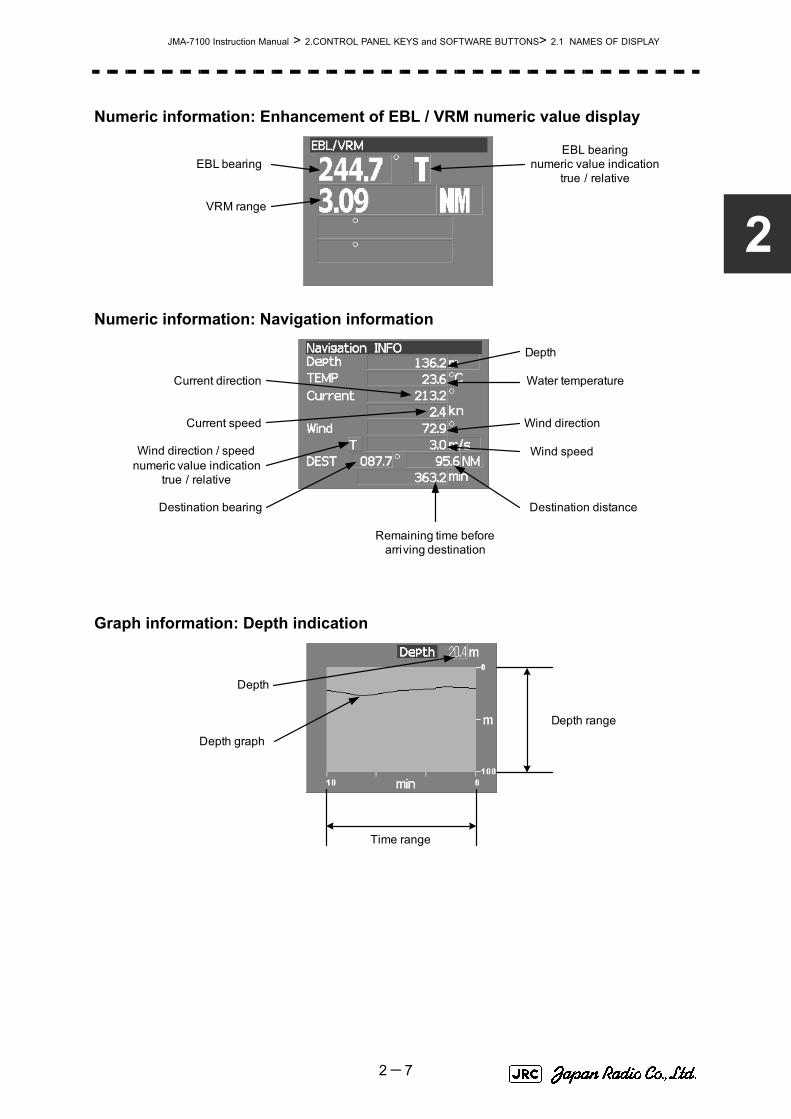
JMA-7100 Instruction Manual > 2.CONTROL PANEL KEYS and SOFTWARE BUTTONS> 2.1 NAMES OF DISPLAY
2
Numeric information: Enhancement of EBL / VRM numeric value display
Numeric information: Navigation information
Graph information: Depth indication
VRM range
EBL bearingEBL bearing
numeric value indicationtrue / relative
Wind direction / speednumeric value indication
true / relative
Depth
Water temperatureCurrent direction
Current speed
Destination bearing
Remaining time beforearriving destination
Destination distance
Wind direction
Wind speed
Depth
Depth graph
Depth range
Time range
2-7

JMA-7100 Instruction Manual > 2.CONTROL PANEL KEYS and SOFTWARE BUTTONS > 2.1 NAMES OF DISPLAY
Graph information: Water temperature indication
Graph information: Wind direction / speed
Graph information: Course bar
Water temperature
Water temperature graph
Water temperature range
Time range
Wind speed
Wind direction / speedtrue / relative
Wind direction
Ship's heading bearing
Auto pilot course
Rudder Rate of turn
2-8

JMA-7100 Instruction Manual > 2.CONTROL PANEL KEYS and SOFTWARE BUTTONS> 2.1 NAMES OF DISPLAY
2
Numeric information: Marker
Menu
Brilliance
Display information
Marker longitude
Marker latitude
Marker range
Marker bearing
Arrival time
Digital information
Target Tracking (TT) menu
User map menu
Parallel index line menu
Own Track menu
Route menu
Main menu
AIS menu
Automatic acquisition /activation zone (AZ) menu
Digital information
Target Tracking (TT) menu
User map menu
Parallel index line menu
Own Track menu
Route menu
Main menu
AIS menu
Automatic acquisition /activation zone (AZ) menu
Panel lighting brilliance
Radar video brilliance
Day / night mode
Tracked target / AIS target symbol brilliance
2-9

JMA-7100 Instruction Manual > 2.CONTROL PANEL KEYS and SOFTWARE BUTTONS > 2.1 NAMES OF DISPLAY
Alarm
Alarm indication(The system alarm indicated in red .
Other information indicated in blue or yellow.)
2-10

JMA-7100 Instruction Manual > 2.CONTROL PANEL KEYS and SOFTWARE BUTTONS> 2.2 NAMES AND FUNCTIONS OFCONTROL PANEL KEYS
2
2.2 NAMES AND FUNCTIONS OF
CONTROL PANEL KEYS
The name of each button is described from the following page. See below.
12
34
56
78
9
1011
12
14
15
1316
1718
19
2021
2223
2425
2627
28
2930
PW
RA
CK
PW
R F
AIL
ALA
RM
AC
K
EB
L1
EB
L2
PAN
EL
DAY
NIG
HT
TG
TD
ATA
AC
QM
AN
UA
L
AC
QC
AN
CEL
AIS
/AR
PA
H L
OFF
DA
TA
OFF
USER
OP
TIO
N
1O
PTIO
N
2
VRM
1V
RM
2
TU
NE
RA
INSEA
GAIN
PO
WER
TX
STB
Y
T/R
VEC
T
RA
NG
E
2-11

JMA-7100 Instruction Manual > 2.CONTROL PANEL KEYS and SOFTWARE BUTTONS > 2.2 NAMES AND FUNCTIONS OF CONTROL PANEL KEYS
[POWER] (Power supply) switch
The lamp is lit and the equipment is activated.If this switch is pressed while the equipment is running, the power of the equipment is shut down.
→3.1.1 on page 3-2
[PWR ACK] (Power alarm acknowledgement) key
Use this function to acknowledge the alarm when power supply abnormality occurs.To enable this key, an external battery (separate power from normal AC) is required.
[TX/STBY] (Transmission/Standby) keyWhen the [POWER] switch is pressed, the "STANDBY" message is displayed in the top-left corner of the screen in about 3 minutes. If this key is pressed, transmission starts. If this key is pressed during transmission, the equipment is set to a standby state.
→3.1.1 on page 3-2
[ALARM ACK] (Alarm acknowledgement) key
Use this function to acknowledge alarms such as failure alarm, approaching target alarm, and collision alarm.By pressing this key at the occurrence of an alarm, the alarm sound can be stopped.If multiple alarms occur, press this key same time as the alarms.
→3.2.7 on page 3-12
[TUNE] (Tuning) dial
Use his function to tune a transmitter.The mode is switched to manual/automatic whenever this dial is pressed.
→3.2.3 on page 3-7
[RAIN] (Rain / snow clutter suppression) dial
This function suppresses rain / snow clutters.To increase the effect of suppression, turn the dial clockwise.The mode can be switched to manual or automatic by pressing the dial.
→3.2.6 on page 3-11
[SEA] (Sea clutter suppression) dial
This function suppresses sea clutter.To increase the effect of suppression, turn the dial clockwise.The mode can be switched to manual or automatic by pressing the dial.
→3.2.5 on page 3-9
1
2
3
4
5
6
7
2-12

JMA-7100 Instruction Manual > 2.CONTROL PANEL KEYS and SOFTWARE BUTTONS> 2.2 NAMES AND FUNCTIONS OFCONTROL PANEL KEYS
2
[GAIN] (Gain/pulse length) dial
This function adjusts the reception sensitivity of the radar.To increase the sensitivity, turn the dial clockwise.The transmission pulse width can be switched by pressing the dial.
gain→3.2.4 on page 3-8pulse width→3.4.2 on page 3-24
[RANGE +/- ] (Range switching) keyThis function switches the range.Press [+] to increase the observation range.Press [-] to reduce the observation range.
→3.2.2 on page 3-6
[EBL1] (Electronic Bearing Line 1) key
Use this function to display and select EBL1.If the key is pressed for 2 seconds or more, the menu for setting EBL1 is displayed.
→4.1.3 on page 4-3
[EBL2] (Electronic Bearing Line 2) key
Use this function to display and select EBL2.If the key is pressed for 2 seconds or more, the menu for setting EBL2 is displayed.
→4.1.3 on page 4-3
[EBL] (Electronic Bearing Line) dial
This function rotates the azimuth of the EBL that is selected in EBL1/2.
By pressing the dial, the selected EBL can be switched to Center fixing → Floating → Center fixing.
→4.1.3 on page 4-3
[VRM1] (Variable Range Marker 1) key
This function selects VRM1. The On/Off and dial use right are switched.
→ on page 4-6
[VRM2] (Variable Range Marker 2) key
This function selects VRM2. The On/Off and dial use right are switched.
→ on page 4-6
8
9
10
11
12
13
14
2-13

JMA-7100 Instruction Manual > 2.CONTROL PANEL KEYS and SOFTWARE BUTTONS > 2.2 NAMES AND FUNCTIONS OF CONTROL PANEL KEYS
[VRM] (Variable Range Marker) dial
This function changes the range of the VRM that is selected by VRM1/2.By pressing the dial, the parallel line cursor function can be switched to Operation → Fixed → Off → Operation.
→ on page 4-6
[T/R VECT] (True vector display / Relative vector display) keyThis function switches the display mode (true/relative) of the tracked target and AIS target vector.
→5.1.6 on page 5-13
[TGT DATA] (Target data display) key
This function displays the digital data of the tracked target or AIS target at the cursor position.
the tracked target→5.2.3 on page 5-17the AIS target→5.3.5 on page 5-28
[ACQ MANUAL] (Manual acquisition) key
This function enables manual acquisition of the target at the cursor position.
→5.2.1 on page 5-14
[ACQ CANCEL] (Tracked target cancellation) key
This function cancels the symbol and vector of the target that is being tracked and stops the tracking of the target.If this key is pressed for 2 seconds or more, all the targets that are being tracked are cancelled.
→5.2.2 on page 5-16
[DAY/NIGHT] (Day/night mode) keyThis function switches the color and brightness of the screen that was preset.
→3.4.12 on page 3-35
[AIS/TT] (AIS On/Off) key
This function switches the AIS function to ON/OFF when the AIS function is enabled.
→5.3.2 on page 5-26
[HL OFF] (Ship's heading line Off) key
HL (ship's heading highlight line) can be set to Off only while this key is pressed.
→3.4.10 on page 3-34
15
16
17
18
19
20
21
22
2-14

JMA-7100 Instruction Manual > 2.CONTROL PANEL KEYS and SOFTWARE BUTTONS> 2.2 NAMES AND FUNCTIONS OFCONTROL PANEL KEYS
2
[DATA OFF] (DATA Off) key
This function sets the graphics other than HL, range ring, EBL, and VRM to OFF temporarily while this key is pressed.
→3.4.11 on page 3-34 [PANEL] (Operator panel brilliance) key
This function adjusts the lighting brilliance of various switches and dial positions on the operator panel. The brightness changes cyclically whenever this key is pressed.
→3.4.13 on page 3-35 [USER] key
By pressing this key, the signal processing setting that is preset can be called.The setting changes to FUNC OFF ==> FUNC1 ==> FUNC2 ==> FUNC3 ==> FUNC4 whenever this key is pressed.If this key pressed for 2 seconds or more, the function setting menu is displayed.
→3.9 on page 3-111 [OPTION1] key
By pressing this key, the pre-registered menu position can be directly displayed. At factory shipment, the calling of [Main Menu] is assigned.
→3.8.7 on page 3-103 [OPTION2] key
By pressing this key, the pre-registered menu position can be directly displayed. At factory shipment, the calling of [Sub Menu] is assigned.
→3.8.7 on page 3-103 Track ball
This function moves the cursor mark to any position. Use this function for setting in each mode.Use this function to specify a center position of floating EBL and an off-center position.
→3.3.1 on page 3-14 [Track ball left button]
Use this function to confirm menu selection and numeric value input.
[Track ball right button]
Use this function to reset menu selection and numeric value input.
[BRILL] (Brilliance dial)
This dial is provided at the right of the monitor. Use this function to adjust the brilliance of the monitor.
→3.2.1 on page 3-6
23
24
25
26
27
28
29
30
31
2-15

JMA-7100 Instruction Manual > 2.CONTROL PANEL KEYS and SOFTWARE BUTTONS> 2.3 FUNCTIONS OF SOFTWARE BUTTONS
2.3 FUNCTIONS OF SOFTWARE
BUTTONS
In this radar, the frequently used functions can be directly set from the screen without opening the menu by using the software buttons on the screen for quick handling. The screen is divided into a number of areas and each area is named.
The name of each button is described from the next page. The function can be used by left-clicking while setting the arrow cursor on the button position.
PPIUpper left
of the display
Lower leftof the display
Upper rightof the display
Lower rightof the display
Own ship's information
Digital information
Targettracking (TT) /
AIS information
Menu
Brilliance /Display information
Alarm
2-16

JMA-7100 Instruction Manual > 2.CONTROL PANEL KEYS and SOFTWARE BUTTONS> 2.3 FUNCTIONS OF SOFTWAREBUTTONS
2
Upper left of the display
Range scale switching
To increase the observation range scale (maximum 96NM), click and to reduce the range (minimum 0.125NM), click .
Range rings display On / Off
The display of range rings are set to On / Off whenever this button is clicked.When the display is set to On, the interval of the fixed range marker is displayed.
Motion mode true / relative switching
The screen motion mode is switched whenever the button is clicked.
(true motion) ⇒ (relative motion) ⇒ indicates that the radar trails is a relative trail. indicates that the radar trails is a true trail.
Off center switching
If this button is clicked, the cursor is moved, and left-clicked, the ship's position can be moved to the cursor position. The moving range is within 66% of the radius.If the button is clicked for 2 seconds, the off-center is set to Off and the ship's position is returned to the center of the screen.
Transmission / standby switching
At expiration of the pre-heat time after the power is turned on, changes to .
:Indicates a standby state. If this button is clicked in this state, theequipment is set to a transmission state.
:Indicates a transmission state. If this button is clicked in this state,the equipment is set to a standby state.
① Range scale switching
② Range rings displayOn /Off
③ Motion mode true / relative switching
④ Off center switching
⑤ Transmission / Standby switching
⑥ Interswitch connect ion change
⑦ Transmission pulse lengthswitching
⑧ Azimuth display mode switching
1
+
-
2
3
TM RM TM
RM(R)
RM(T)
4
5
PreheatStandby
Standby
Transmit
2-17

JMA-7100 Instruction Manual > 2.CONTROL PANEL KEYS and SOFTWARE BUTTONS > 2.3 FUNCTIONS OF SOFTWARE BUTTONS
Interswitch connection change
This button is displayed when the interswitch is connected. This button indicates the connection status of the scanner unit that is connected to the indicator.If the button is clicked in the transmission standby state, the menu for changing the connection state between the scanner unit and the indicator is displayed. The connection state of the scanner unit and indicator cannot be changed unless the master indicator is in a standby state. Refer to the Appendix A NQE-3141 Interswitch Unit Interswitch (Optional) Instruction Manual that is attached for the setting method. This button is not displayed if the interswitch is not connected.
Transmission pulse length switching
The transmission pulse length is switched whenever this button is clicked. Three types of pulses are available, short pulse (SP), middle pulse (MP), and long pulse (LP). The pulse length and repetition frequency vary even for the same short pulse, according to the range that is used and it is displayed as , .
Azimuth display mode switching
The azimuth display is switched whenever this button is clicked. (Head Up) ⇒ (North Up) ⇒ (Course Up) ⇒
If the button is clicked for 2 seconds, the GYTO Setting menu is displayed.
Lower left of the display
Double zoom switching
Use this function to enlarge to double the size the display screen of the position specified by the cursor. If this button is clicked, the zoom mode is set. When the cursor is moved to the radar screen and left-clicked, the screen is enlarged to double the size so that the middle of the cursor and the own ship's position is set to the center of the screen. This function cannot be used when the range is 0.125NM.
6
7
SP1 SP2
8
H Up N Up C Up H Up
③ Target enhance (ENH) mode switching
④ Radar video processing (PROC) mode switching
⑤ Function (FUNC) mode switching
① Double zoom switching② Interference rejection (IR)
mode switching
⑦ Sea clutter suppression (Sea) adjustment
⑧ Rain / snow cluttersuppression (Rain)
adjustment ⑨ Tune adjustment
⑩ Sea clutter suppression (Sea) mode switching
⑪ Rain and snow cluttersuppression (Rain)
mode switching
⑥ Gain adjustment
⑫ Tune mode switching
1
2-18

JMA-7100 Instruction Manual > 2.CONTROL PANEL KEYS and SOFTWARE BUTTONS> 2.3 FUNCTIONS OF SOFTWAREBUTTONS
2
Interference rejection (IR) mode switching
The interference rejection mode is switched whenever this button is clicked.
⇒ ⇒ ⇒ ⇒
Target enhance (ENH) mode switching
The target enhance mode is switched whenever this button is clicked.
⇒ ⇒ ⇒ ⇒
Radar video processing (PROC) mode switching
The radar video processing mode is switched whenever this button is clicked.
⇒ ⇒ ⇒
⇒ ⇒ ⇒
Function (FUNC) mode switching
The function mode is switched whenever this button is clicked.
⇒ ⇒ ⇒
⇒ ⇒
If the button is clicked for 2 seconds, the function registration menu (User Function Setting) is opened.
, , and Gain, Sea clutter suppression(Sea)、Rain / snow clutter suppression (Rain), Tune adjustment (Tune)
Adjust the gain, sea clutter suppression, rain / snow clutter suppression and tune using the track ball.If the button is clicked on, the adjustment value is shown at the upper-right of the cursor. Make adjustments by moving the track ball to the left and right. Determine the adjustment by left-clicking.
, and Sea clutter suppression (Sea) mode, Rain and snow clutter suppression (Rain) mode, and Tune mode switching
Use these functions to switch to the manual or automatic mode of sea clutter suppression, rain and snow clutter suppression, and tune. The bar on the left side indicates the position of the dial.The mode is switched to (manual) / (automatic) whenever the button is clicked. If rain and snow clutter suppression is switched to an automatic mode, sea clutter suppression is switched to an automatic mode also.
2
IR Off IR Low IR Meddle IR High IR Off
3
ENH Off ENH Level1 ENH Level2 ENH Level3 ENH Off
4
PROC Off 3Scan CORREL 4Scan CORREL 5Scan CORREL
Remain Peak Hold PROC Off
5
FUNC Off Coast Deep Sea Fishnet
Storm FUNC Off
6 7 8 9
10 11 12
MAN AUTO
2-19

JMA-7100 Instruction Manual > 2.CONTROL PANEL KEYS and SOFTWARE BUTTONS > 2.3 FUNCTIONS OF SOFTWARE BUTTONS
Upper Right of the display
Cursor mode switching
The mode of the function that uses the cursor is switched whenever this button is pressed.
⇒ ⇒ ⇒ ⇒ ⇒
⇒ ⇒ ⇒ ⇒ ⇒
Mark font / line pattern switching
This function switches a mark font / line pattern. If this button is clicked while the cursor mode is (mark) or (line), the mark font / line pattern is changed.
Mark color / line color switching
This function switches a mark color / line color. If this button is clicked while the cursor mode is (mark) or (line), the mark color / line color is changed.
Cursor bearing numeric value display true / relative switching
The bearing numeric value display (true bearing) / (relative bearing) of the cursor is switched whenever this button is clicked.
④ Cursor bearingnumeric value displaytrue / relative switching
⑤ EBL1 adjustment
⑥ VRM1 adjustment
⑪ EBL1 starting point mode switching
① Cursor mode switching
⑫ EBL2 starting point mode switching
⑬ Parallel index linesetting
⑭ Parallel index linestarting point mode
switching
⑩ EBL2 numeric value indicationtrue / relative switching
③ Mark color / line color switching
⑧ VRM2 adjustment
⑦ EBL2 adjustment
⑨ EBL1 numeric value indicationtrue / relative switching
② Mark font / line pattern switching
1
AUTO ACQ TT ACT AIS TGT Data CNCL TT
DEACT AIS CNCL Data □ - - - - - - - Property
AUTO
2
□ - - - - - - -
3
□ - - - - - - -
4
T R
2-20
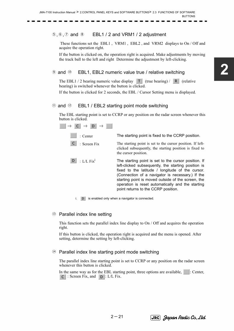
JMA-7100 Instruction Manual > 2.CONTROL PANEL KEYS and SOFTWARE BUTTONS> 2.3 FUNCTIONS OF SOFTWAREBUTTONS
2
, , and EBL1 / 2 and VRM1 / 2 adjustment
These functions set the EBL1 , VRM1 , EBL2 , and VRM2 displays to On / Off and acquire the operation right.If the button is clicked on, the operation right is acquired. Make adjustments by moving the track ball to the left and right Determine the adjustment by left-clicking.
and EBL1, EBL2 numeric value true / relative switching
The EBL1 / 2 bearing numeric value display (true bearing) / (relative bearing) is switched whenever the button is clicked.If the button is clicked for 2 seconds, the EBL / Cursor Setting menu is displayed.
and EBL1 / EBL2 starting point mode switching
The EBL starting point is set to CCRP or any position on the radar screen whenever this button is clicked.
⇒ ⇒ ⇒
Parallel index line setting
This function sets the parallel index line display to On / Off and acquires the operation right.If this button is clicked, the operation right is acquired and the menu is opened. After setting, determine the setting by left-clicking.
Parallel index line starting point mode switching
The parallel index line starting point is set to CCRP or any position on the radar screen whenever this button is clicked.In the same way as for the EBL starting point, three options are available, : Center,
: Screen Fix, and : L/L Fix.
:Center The starting point is fixed to the CCRP position.
:Screen Fix The starting point is set to the cursor position. If left-clicked subsequently, the starting position is fixed tothe cursor position.
:L/L Fixi
i. is enabled only when a navigator is connected.
The starting point is set to the cursor position. Ifleft-clicked subsequently, the starting position isfixed to the latitude / longitude of the cursor.(Connection of a navigator is necessary.) If thestarting point is moved outside of the screen, theoperation is reset automatically and the startingpoint returns to the CCRP position.
5 6 7 8
9 10
T R
11 12
_ C D _
_
C
D
D
13
14
_C D
2-21

JMA-7100 Instruction Manual > 2.CONTROL PANEL KEYS and SOFTWARE BUTTONS > 2.3 FUNCTIONS OF SOFTWARE BUTTONS
Lower right of the display
Mark color switching
The color of the mark is switched whenever this button is clicked.If the button is clicked for 2 seconds, the Mark Setting menu is opened.
Own ship's track color switching
The own ship's track color is switched whenever this button is clicked.
Own ship's track interval switching
The own ship's track interval is switched whenever this button is clicked.
Own ship's track interval unit switching
The unit of the own ship's track interval is switched whenever this button is clicked.
⇒ ⇒ ⇒
Map display On / Off
The map display is set to On / Off whenever this button is clicked.Map information must be inserted in the card slot of the radar process unit in advance.If the button is clicked for 2 seconds, the Map Setting menu is opened.
Graphic display Off
While the button is clicked, the graphic display other than VRM, EBL, HL, a cursor, and range rings on the radar screen is cleared temporarily.
Ship's heading line Off
The ship's heading line (HL) display is set to Off while this button is clicked.Since the ship's heading line is cleared while the button is clicked, the target in the ship's heading bearing can be clearly seen.
③ Own ship's track interval switching
⑤ Map displayOn / Off
⑥ Graphic display Off
⑦ Ship's heading line Off
④ Own ship's track interval unit switching
⑧ CPA ring displayOn / Off
① Mark color switching
② Own ship’s track colorswitching
1
2
3
4
sec min NM sec
5
6
7
2-22

JMA-7100 Instruction Manual > 2.CONTROL PANEL KEYS and SOFTWARE BUTTONS> 2.3 FUNCTIONS OF SOFTWAREBUTTONS
2
CPA ring display On / Off
The CPA ring display is switched to On / Off whenever the button is clicked.When the target vector display mode is (true vector), the CPA ring cannot be set to On.
Own ship's information
Heading device switching
The heading device is switched whenever this button is clicked.
⇒ (Electronic compass)⇒ When the selected heading device is not connected to the equipment, an alarm is issued.
Speed sensor switching
The speed sensor is switched whenever the button is clicked.
(Manual) ⇒ (Single-axis water log) ⇒ (Dual-axis water log)⇒ (Dual-axis ground log) ⇒ ⇒
When the selected speed device is not connected to the equipment, an alarm is issued.
Time display mode switching
The time display mode (universal time clock) / (local mean time) is switched whenever this button is clicked.
Manual own ship's speed setting
When selection of the speed sensor is set to , enter the own ship's speed manually.If this button is clicked, the numeric value input screen is opened. After setting a value, determine the entry by clicking .
8
T
① Heading deviceswitching
② Speed sensorswitching
③ Time display mode switching
④ Manual own ship's speed setting
1
GYRO CMPS GYRO
2
MAN LOG 2AXW
2AXG GPS MAN
3
UTC LMT
4
MAN
ENT
2-23

JMA-7100 Instruction Manual > 2.CONTROL PANEL KEYS and SOFTWARE BUTTONS > 2.3 FUNCTIONS OF SOFTWARE BUTTONS
Target tracking (TT) / AIS information
Target vector display true / relative switching
The tracked target / AIS target vector display is switched to (true vector) / (relative vector) whenever this button is clicked.This setting is switched together with the past position display true / relative switching.
Target vector length setting
Set a vector length of the tracked target / AIS target.If this button is clicked, the numeric value input screen is opened. After setting the length, determine the setting by clicking .
CPA limit setting
Set a CPA limit.If this button is clicked, the numeric value input screen is opened. After setting the limit, determine the setting by clicking .
TCPA limit setting
Set a TCPA limit.If this button is clicked, the numeric value input screen is opened. After setting the limit, determine the setting by clicking .
Past position display true / relative switching
The tracked target / AIS target past position display is switched to (true past position) / (relative past position) whenever the button is clicked.
This setting is switched together with the target vector display true / relative switching.
⑥ Past position displayinterval switching
⑪ AssociationOn / Off
⑭ Radar trails display time switching
⑬ Radar trails display true / relative switching
① Target vector display true / relative switching ② Target vector length setting
⑤ Past position display true / relative switching ⑦ Past position display
interval unit switching
④ TCPA limit setting
③ CPA limit setting
⑧ AISOn / Off
⑩ AIS target symbol display On / Off
⑨ Tracked target symbol display On / Off
⑫ AIS filter mode switching
1
T R
2
ENT
3
ENT
4
ENT
5
TR
2-24

JMA-7100 Instruction Manual > 2.CONTROL PANEL KEYS and SOFTWARE BUTTONS> 2.3 FUNCTIONS OF SOFTWAREBUTTONS
2
Past position display interval switching
The past position display interval is switched whenever the button is clicked.
Past position display interval unit switching
The past position display interval unit is switched whenever the button is clicked.
⇒ ⇒
AIS On / Off
The AIS display is switched to On / Off whenever the button is clicked.
Tracked target symbol display On / Off
The tracked target symbol display is switched to On / Off whenever the button is clicked. Use this function to avoid confusion with the AIS symbol.
AIS target symbol display On / Off
The AIS target symbol display is switched to On / Off whenever the button is clicked. Use this function to avoid confusion with the tracked target symbol.
Association On / Off
The tracked target / AIS target association is switched to On / Off whenever the button is clicked.
AIS filter mode switching
The AIS filter is switched whenever the button is clicked.
⇒ ⇒ ⇒
Radar trails display true / relative switching
Radar trails are switched to (true motion trail) / (relative motion trail) whenever this button is clicked.This setting is restricted by the radar display motion mode.In relative motion display mode (RM), switching to / is possible.In true motion display mode (TM), only can be set.
Radar trails display time switching
The radar trails display time is switched whenever the button is clicked.If the time does not reach the radar trails time that was set, the remaining time is displayed on the right-hand side.If the button is clicked for 2 seconds, the RADAR Trails Setting menu is opened.
6
7
min NM min
8
9
10
11
12
Range Sector Zone Range
13
T R
T R
T
14
2-25

JMA-7100 Instruction Manual > 2.CONTROL PANEL KEYS and SOFTWARE BUTTONS > 2.3 FUNCTIONS OF SOFTWARE BUTTONS
Numeric information: AIS target information
Detail / simple display switching
This function switches the display mode to detail / simple display when AIS target information is displayed.
Unread message display
When there is an unread message from the AIS target that is displayed, the message is displayed. If this button is clicked, the message is displayed.
①:Detail / simple display switching
②:Unread message display
simple display
1
2
2-26

JMA-7100 Instruction Manual > 2.CONTROL PANEL KEYS and SOFTWARE BUTTONS> 2.3 FUNCTIONS OF SOFTWAREBUTTONS
2
Numeric information: Tracked target information
Tracked target numeric value indication scroll
This function scrolls the target numbers that are indicated in the tracked target information.
Numeric information: Navigation information
Wind direction / speed numeric value indication true / relative switching
The wind direction / speed numeric value indication is switched to (true) / (relative) whenever this button is clicked.
① Tracked targetnumeric value indication
scroll
1
① Wind direction / speednumeric value indicationtrue / relative switching
1
T R
2-27

JMA-7100 Instruction Manual > 2.CONTROL PANEL KEYS and SOFTWARE BUTTONS > 2.3 FUNCTIONS OF SOFTWARE BUTTONS
Graph information: Wind direction / speed
Wind direction / speed numeric value indication true / relative switching
The wind direction / speed numeric value indication is switched to (true) / (relative) whenever this button is clicked.
Menu
Digital information display
If this button is clicked while the menu screen is open, the menu is closed and control returns to the digital information display.This function switches between the tracked target / AIS target display and navigation information or the course bar, and so on.
Target Tracking (TT) menu
If this button is clicked, the TT Menu is opened.
Own track menu
If this button is clicked, the Own Track Menu is opened.
Main menu
If this button is clicked, the Main Menu is opened.
① Wind direction / speednumeric value indicationtrue / relative switching
1
T R
① Digital information display
② Target Tracking (TT) menu
⑨ User map menu
⑦ Parallel index line menu
③ Own ship’s track menu
⑧ Automatic acquisition /activation zone (AZ) menu
⑥ Route menu
④ Main menu
⑤ AIS menu
1
2
3
4
2-28

JMA-7100 Instruction Manual > 2.CONTROL PANEL KEYS and SOFTWARE BUTTONS> 2.3 FUNCTIONS OF SOFTWAREBUTTONS
2
AIS menu
If the button is clicked, the AIS Menu is opened.
Route menu
If this button is clicked, the Route Menu is opened.
Parallel index line menu
If this button is clicked, the PI Menu is opened.
Automatic acquisition / activation zone menu
If this button is clicked, the AZ Menu is opened.
User map menu
If the button is clicked, the User Map Menu is opened.
Brilliance
Display information
5
6
7
8
9
① Display item switching
② Panel lighting brillianceswitching
③ Radar video brillianceswitching
⑤ Day / night modeswitching
④ Tracked target / AIS target symbolbrilliance switching
⑦ User setting load
⑥ User map load
① Display item switching
2-29

JMA-7100 Instruction Manual > 2.CONTROL PANEL KEYS and SOFTWARE BUTTONS > 2.3 FUNCTIONS OF SOFTWARE BUTTONS
Display item switching
The brilliance adjustment screen and display information setting screen interchange whenever this button is clicked.
Panel lighting brilliance switching
This function enables the setting of the brilliance of the lighting of the control panel.The brilliance changes whenever this button is clicked. Five levels of settings are available.
Radar video brilliance switching
Adjust the brightness of the radar video (echo).The brilliance changes whenever this button is clicked. Four levels of settings are available.
Tracked target / AIS target symbol brilliance switching
Use this function to adjust the brilliance of the tracked target / AIS target symbol.The brilliance changes whenever this button is clicked. Five levels of settings are available.
Day / night mode switching
The day / night mode is switched whenever this button is clicked.
→ → →
← ← ←
User map load
If this button is clicked, the user created map read menu is opened.
User setting load
If this button is clicked, the user setting read menu is opened.
1
⇔
2
3
4
5
Day1 Day2 Day3 Dusk
Day2 Day3 Dusk Night
6
7
2-30

JMA-7100 Instruction Manual > 2.CONTROL PANEL KEYS and SOFTWARE BUTTONS> 2.3 FUNCTIONS OF SOFTWAREBUTTONS
2
Alarm
Alarm acknowledgment
If this button is clicked, the buzzer sound of the alarm that is currently issued is stopped and the alarm lamp stops blinking. If multiple alarms are issued, the next alarm to be acknowledged is displayed.If the button is clicked, the alarm displayed on the top is acknowledged.The alarms that are currently issued are displayed at the bottom one by one.
Error log display
If this button is clicked, the error log is display.
① Alarm acknowridgement
② Error log display
1
2
2-31

JMA-7100 Instruction Manual > 2.CONTROL PANEL KEYS and SOFTWARE BUTTONS > 2.3 FUNCTIONS OF SOFTWARE BUTTONS
2-32

SECTION 3BASIC OPERATION
BASIC OPERATION3.1 OPERATION FLOW ...............................................................................3-1
3.1.1 Power ON and Start the System ....................................................3-23.1.2 Observe and Adjust Video ..............................................................3-43.1.3 Acquire and Measure Data .............................................................3-43.1.4 Display and Measure with Reference to CCRP ............................3-43.1.5 End the Operation and Stop the System .......................................3-5
3.2 OBSERVE AND ADJUST VIDEO ..........................................................3-63.2.1 Adjust Monitor Brilliance [BRILL] ..................................................3-63.2.2 Change Observation Range [RANGE+/-] ......................................3-63.2.3 Tune ..................................................................................................3-73.2.4 Adjust Gain [GAIN] .........................................................................3-83.2.5 Suppress Sea Clutter [SEA] ..........................................................3-93.2.6 Suppress Rain/Snow Clutter [RAIN] ...........................................3-113.2.7 Reset Alarm Buzzer [ALARM ACK] .............................................3-123.2.8 To get the appropriate image that targets can be easily observed ...3-13
3.3 OPERATION PROCEDURES ..............................................................3-143.3.1 Move Cross Cursor Mark by Trackball ........................................3-14

3.3.2 Operate Software Buttons ...........................................................3-153.3.3 Basic Menu Operation ..................................................................3-163.3.4 Operation on Numeric Value, Latitude / Longitude and Character Input menu .......3-173.3.5 Overview of Menu Structure .........................................................3-22
3.4 GENERAL RADAR OPERATION ........................................................3-233.4.1 Interference Rejection (IR) ............................................................3-233.4.2 Switch Transmitter Pulse Length [GAIN] ....................................3-243.4.3 Target Enhance (ENH) ..................................................................3-253.4.4 Use Video Processing (PROC) .....................................................3-263.4.5 Switch Azimuth Display Mode (AZI MODE) ................................3-273.4.6 Switch True/Relative Motion Display Mode (TM/RM) .................3-283.4.7 Move Own Ship’s Display Position (Off Center) .........................3-293.4.8 Display Radar Trails (Trails) .........................................................3-303.4.9 Zoom (x2) .......................................................................................3-333.4.10 Hide/Display Range Rings [HL OFF] ...........................................3-343.4.11 Hide Graphics Information on Radar Display [DATA OFF] .......3-343.4.12 Switch Day/Night Mode [DAY/NIGHT] .........................................3-353.4.13 Adjust Operation Panel Brilliance [PANEL] ................................3-353.4.14 Set True Bearing ............................................................................3-363.4.15 Set Own Ship Speed .....................................................................3-363.4.16 Magnet Compass Correction (MAG Compass Setting) .............3-37
3.5 USE OWN SHIP'S TRACK ...................................................................3-393.5.1 Display Own Ship’s Track (Display Own Track) ......................3-393.5.2 Set Display Color of Own Ship's Track (Display Own Track Color) ..3-403.5.3 Save Own Ship's Track (Own Track Memory) ............................3-413.5.4 Cancel Saving of Own Ship's Track (Own Track Memory) ........3-413.5.5 Clear Own Ship's Track (Clear Own Track) ................................3-423.5.6 Use Expanded Own Ship's Track (Own Track Type) .................3-423.5.7 Use Water Depth Track (Water Depth Track) ..............................3-443.5.8 Use Water Temperature Track (Water TEMP Track) ..................3-453.5.9 Use Tidal Current Track (Current Vector Track) .........................3-46
3.6 DISPLAY USER MAP ...........................................................................3-473.6.1 Create User Map (Mark/Line) ........................................................3-473.6.2 Set User Map Display (Mark Display Setting) .............................3-503.6.3 Edit User Map (Edit User Map) .....................................................3-523.6.4 Correct Position on User Map (Shift User Map) .........................3-603.6.5 Save User Map ...............................................................................3-613.6.6 Set and Display Geodetic System (Geodetic) .............................3-65
3.7 USE ROUTE FUNCTION ......................................................................3-673.7.1 Display Route/Destination Mark (Select Route) .........................3-673.7.2 Edit Route (Set Route Sequence) ................................................3-683.7.3 Edit Route Make with Latitude and Longitude (Waypoint Input) .......3-753.7.4 Use Route Monitoring Function (Waypoint/Route Alarm) .........3-793.7.5 Method of Using Route .................................................................3-81

3.7.6 Detailed Route Settings ................................................................3-823.7.7 Clear Waypoint/Route Data (Clear WPT/Route Data) .................3-863.7.8 Operate Route Data File ................................................................3-87
3.8 APPLIED OPERATIONS ......................................................................3-913.8.1 Set Radar Signal Processing (Process Setting) .........................3-913.8.2 Set Radar Trails (RADAR Trails Setting) .....................................3-953.8.3 Set Scanner Unit (TXRX Setting) .................................................3-973.8.4 Set Cursor (Cursor Setting) ..........................................................3-983.8.5 Set Radar Display (Display Setting) ............................................3-993.8.6 Adjust Sound Volume (Buzzer Volume) ....................................3-1023.8.7 Set User Option Keys [OPTION 1/2] ..........................................3-1033.8.8 Set Navigation Data Display (Multi Window Setting) ...............3-1053.8.9 AUTO Backup ..............................................................................3-110
3.9 USE FUNCTION KEY [USER] ...........................................................3-1113.9.1 Operation Procedures .................................................................3-1113.9.2 Function Setting Menu Items .....................................................3-1123.9.3 Overview of Function Operations (User Function Setting) .....3-1133.9.4 Overview of saved Function Setting Data .................................3-117
3.10 USE USER SETTING .........................................................................3-1183.10.1 Save Operating State (Save User Setting) ................................3-1183.10.2 Load Operating State (Load User Setting) ................................3-1193.10.3 Delete Operating State (Delete User Setting) ...........................3-119
3.11 USING CARD .....................................................................................3-1203.11.1 Operate File on the Card (File Manager) ...................................3-120


JMA-7100 Instruction Manual > 3.BASIC OPERATION > 3.1 OPERATION FLOW
3
3.1 OPERATION FLOW
Each operation is described in detail below.
• Do not put anything on the operation panel.If you put anything hot on it, it may be deformed.
• Do not give any impact to the operation panel, trackball, or controls.
Otherwise, any failure or damage may result.
Attention
POWER ON ANDSTART THE SYSTEM
OBSERVE AND ADJUST VIDEO
ACQUIRE AND MEASURE DATA
END THE OPERATION AND STOP THE SYSTEM
3-1

JMA-7100 Instruction Manual > 3.BASIC OPERATION > 3.1 OPERATION FLOW
3.1.1 Power ON and Start the System
!• A malfunction may occur if the power in the ship is
instantaneously interrupted during operation of the radar. In this case, the power should be turned on again.
• Wait for about 2 seconds before turning on the power again.
• Immediately after the radar is installed, at start of the system after it has not been used for a long time, or after the magnetron is replaced, preheat the equipment in the standby state for 20 to 30 minutes before setting it into the transmit state.
• If the preheating time is short, the magnetron causes sparks, resulting in its unstable oscillation.
Start transmission on a short-pulse range and change the range to the longer pulse ranges in turn. If the transmission is unstable in the meantime, immediately place the system back into the standby state and maintain it in the standby state for 5 to 10 minutes before restarting the operation.
Repeat these steps until the operation is stabilized.
Attention
3-2

JMA-7100 Instruction Manual > 3.BASIC OPERATION > 3.1 OPERATION FLOW
3
Procedures1) Check that the ship’s mains are turned on.
2) Press [POWER] key.
The system is turned on, and the preheating time is displayed.
is indicated at the upper left of the radar display.
3) Wait until the preheating time is over.
When the preheating time is over, the preheating time screen disappears, and at the upper left of the radar display changes to .
4) Press [TX/STBY] key.
The radar will start transmission and the antenna will start rotating.
at the upper left of the radar display changes to .
NOTE:The radar does not start transmission if you press [TX/STBY]
key while is indicated.
Preheat
PreheatStandby
Standby Transmit
Preheat
3-3

JMA-7100 Instruction Manual > 3.BASIC OPERATION > 3.1 OPERATION FLOW
3.1.2 Observe and Adjust Video
Procedures1) Press [RANGE+] key or [RANGE-] key to set the range to the
scale required for target observation.
2) [GAIN] [SEA] and [RAIN] to obtain the clearest targets.
For how to adjust video, see Section 3.2 "OBSERVE AND ADJUST VIDEO"
3.1.3 Acquire and Measure Data
For details on how to acquire data and measure, see the SECTION 4"MEASUREMENT OF RANGE AND BEARING".
3.1.4 Display and Measure with Reference to CCRPThe radar video, range, bearing, Target Tracking and AIS data display etc... are displayed with reference to CCRP (Consistent Common Reference Point).
If scanner is switched, these data are measured from CCRP.
If some kind of functions set scanner position to outside of the PPI range, these data except Target Tracking and AIS data are displayed with reference to scanner position.
For how to setting CCRP, see the Section 7.1.9 "Setting of CCRP (CCRP Setting)".
Refer to
[GAIN] dial→Section 3.2.4 "Adjust Gain [GAIN]"
[SEA] dial→Section 3.2.5 "Suppress Sea Clutter [SEA]"
[RAIN] dial→Section 3.2.6 "Suppress Rain/Snow Clutter [RAIN]"
for how to use each dial.
3-4

JMA-7100 Instruction Manual > 3.BASIC OPERATION > 3.1 OPERATION FLOW
3
3.1.5 End the Operation and Stop the System
Exit1) Press [TX/STBY] key.
The radar will stop transmission and the antenna will stop rotating.
at the upper left of the radar display changes to .
2) Press [POWER] key.
The system will be turned off.
Maintain the standby state if radar observation is restarted in arelatively short time.Only pressing the [TX/STBY] key startsobservation.
!• When conducting maintenance work, make sure to turn
off the power and make the main breaker OFF so that the power supply to the equipment is completely cut off.
• Some equipment components can carry electrical current even after the power switch is turned off, and conducting maintenance work without unplugging the power connector may result in electrocution, equipment failure, or accidents.
Transmit Standby
i
3-5

JMA-7100 Instruction Manual > 3.BASIC OPERATION > 3.2 OBSERVE AND ADJUST VIDEO
3.2 OBSERVE AND ADJUST VIDEO
3.2.1 Adjust Monitor Brilliance [BRILL]
Procedures1) Obtain the best-to-see display with optimum brilliance by turning
the [BRILL] dial at the lower right of the monitor unit.
Turning the [BRILL] dial clockwise increases the brilliance of the entire display.
Conversely, turning the [BRILL] dial counterclockwise decreases the brilliance of the entire display.
In consideration of the ambient brightness, adjust display brilliance that is high enough to easily observe the radar display but does not glare.
3.2.2 Change Observation Range [RANGE+/-]
Procedures1) Pressing the [RANGE+] key will increase the observation range,
enabling the wider area to be observed.
Increasing the observation range will enable a wider range to be observed.
However, a video image is small and the ability to detect targets near own ship decreases. Therefore, when observing the vicinity of own ship, use the smaller observation range.
2) Pressing the [RANGE-] key will decrease the observation range, reducing the area that can be observed.
Decreasing the observation range will enable the vicinity of own ship to be enlarged. However, caution must be taken because video images of the area beyond the observation range cannot be displayed.
3-6

JMA-7100 Instruction Manual > 3.BASIC OPERATION > 3.2 OBSERVE AND ADJUST VIDEO
3
3.2.3 Tune
This radar system provides the automatic tune mode and the manual tune mode. The automatic tune mode automatically adjusts the tuning of the transmitting frequency and the receiving frequency, and the manual tune mode enables tuning to be adjusted by using the dial located on the operation panel. Normally use the automatic tune mode. Only when the best tuning is not possible by the automatic tune mode due to the deterioration of magnetron, use the manual tune mode.
The currently used tune mode is displayed in the area at the lower left of the display.
3.2.3.1 When using the automatic tune mode
Procedures1) Press the [TUNE] dial to set the automatic tune mode.
Tune adjustment is automatically conducted in the automatic tune mode. Tune is adjusted at the start of transmission, at the change of the range or pulse width. Tune adjustment is completed within several seconds.
3.2.3.2 When using the manual tune mode
Procedures1) Press the [TUNE] dial to set the manual tune mode.
2) Turn the [TUNE] dial to make adjustments so that the tuning bar is maximized. The tuning bar is displayed in the area at the upper left of the display.
Normally, use the automatic tune mode.
Use the manual tune mode only when best tuning is not possible in the automatic tune mode due to deterioration of magnetron.
3-7

JMA-7100 Instruction Manual > 3.BASIC OPERATION > 3.2 OBSERVE AND ADJUST VIDEO
3.2.4 Adjust Gain [GAIN]
See also the Section 3.2.8 "To get the appropriate image that targets can be easily observed".
Procedures1) Adjust noise on the radar display by turning the [GAIN] dial until
targets can be easily observed.
Turning [GAIN] dial clockwise increases gain.
Turning [GAIN] dial counterclockwise decreases gain.
If the gain is too high, unnecessary signals including receiver noise and false images increase resulting in reduction of visibility of targets.
On the contrary, if the gain is too low, targets including ships and dangerous objects may not be clearly indicated.
Be sure to always adjust for the best gain.
Turning the [GAIN] dial clockwise will increase the receiving gain, and therange to observe radar video is widened. However, if the gain is too high,unnecessary signals including receiver noise and false images increaseresulting in reduction of targets' visibility.
To observe densely crowded targets or short-range targets, turning the[GAIN] dial counterclockwise will decrease the receiving gain, whichenables targets to be easily observed. However, caution must be taken soas not to overlook a small and important target.
iIt is recommended to restore the setting tothe factory default, if you lost the appropriatesettings.The factory default level is shown onthe bar chart as a green line.
The factory defafult level is assigned byevery function mode. See the Section 3.9"USE FUNCTION KEY [USER]"
Current Level
Factory Default
3-8

JMA-7100 Instruction Manual > 3.BASIC OPERATION > 3.2 OBSERVE AND ADJUST VIDEO
3
3.2.5 Suppress Sea Clutter [SEA]
See also the Section 3.2.8 "To get the appropriate image that targets can be easily observed".
3.2.5.1 Using the manual sea clutter suppression mode
Procedures1) Adjust the sea clutter returns on the radar display by turning the
[SEA] dial until targets can be easily observed.
Turning [SEA] dial clockwise suppresses sea clutter returns.
Turning [SEA] dial counterclockwise intensifies sea clutter returns.
When using the [AUTO SEA] function, never set the suppression level too high canceling out all image noises from the sea surface at close range.
Detection of not only echoes from waves but also targets such as other ships or dangerous objects will become inhibited.
When using the [AUTO SEA] function, make sure to choose the most appropriate image noise suppression level.
The sea clutter suppression function suppresses sea clutter returns bydecreasing the receiving gain on a short range.
Turning the [SEA] dial clockwise heightens the effect of sea cluttersuppression. However, be careful that excessive suppression causeslow signal-strength targets such as buoys and boats to disappear fromthe radar display.
3-9

JMA-7100 Instruction Manual > 3.BASIC OPERATION > 3.2 OBSERVE AND ADJUST VIDEO
3.2.5.2 Using the automatic sea clutter suppression mode
The sea clutter suppression in accordance with the intensity of sea clutter is possible. Use this mode when the sea clutter's intensity differs according to directional orientation.
Procedures1) Press the [SEA] dial. Alternatively, Left-click the Sea MAN
button located at the lower left of the display.
The automatic sea clutter suppression mode is selected, and Sea AUTO is displayed in the lower left of the radar display.
2) Make adjustments by turning the [SEA] dial.
Even when the automatic sea clutter suppression mode is selected, turning the [SEA] dial can make fine adjustments manually.
Cancel1) ress the [SEA] dial. Alternatively, Left-click the Sea AUTO
button located at the lower left of the display.
The automatic sea clutter suppression mode is cancelled, and Sea MAN is displayed in the lower left of the radar display.
iIt is recommended to restore the setting tothe factory default, if you lost the appropriatesettings.The factory default level is shown onthe bar chart as a green line.
The factory defafult level is assigned byevery function mode. See the Section 3.9"USE FUNCTION KEY [USER]"
NOTE:When the automatic sea clutter suppression mode is selected, the automatic rain/snow suppression mode is switched to the manual mode.
To select both the sea clutter suppression function and the rain/snow suppression function in the automatic mode, use the automatic rain/snow suppression mode.
Current Level
Factory Default
3-10

JMA-7100 Instruction Manual > 3.BASIC OPERATION > 3.2 OBSERVE AND ADJUST VIDEO
3
3.2.6 Suppress Rain/Snow Clutter [RAIN]
See also the Section 3.2.8 "To get the appropriate image that targets can be easily observed".
3.2.6.1 Using the manual rain / snow clutter suppression mode
Procedures1) Adjust the rain / snow clutter returns of the display by turning the
[AUTO-RAIN] dial until targets can be easily observed.
Turning [RAIN] dial clockwise suppresses rain / snow clutter returns.
Turning [RAIN] dial counterclockwise intensifies rain / snow clutter returns.
When using the [AUTO RAIN] function, never set the suppression level too high canceling out all image noises from the rain or snow at the close range.
Detection of not only echoes from the rain or snow but also targets such as other ships or dangerous objects will become inhibited.
When using the [AUTO RAIN] function, make sure to choose the most appropriate image noise suppression level.
When the [RAIN] dial is turned clockwise, the rain / snow cluttersuppression function suppresses rain / snow clutter returns and getstargets hidden by rain / snow clutter returns to appear of the display.However, be careful that excessive suppression may cause smalltargets to be overlooked. Since the rain / snow clutter suppressionfunction also has the effect of suppressing sea clutter, the suppressionefficiency improves when the [RAIN] dial is used with the [SEA] dial. Ingeneral, turn the [RAIN] dial fully to the left.
iIt is recommended to restore the setting tothe factory default, if you lost the appropriatesettings.The factory default level is shown onthe bar chart as a green line.
The factory defafult level is assigned byevery function mode. See the Section 3.9"USE FUNCTION KEY [USER]"
Current Level
Factory Default
3-11

JMA-7100 Instruction Manual > 3.BASIC OPERATION > 3.2 OBSERVE AND ADJUST VIDEO
3.2.6.2 Using the automatic rain / snow clutter suppression mode
The rain / snow clutter suppression in accordance with the intensity of rain / snow clutter is possible. Use this mode when the rain / snow clutter's intensity differs according to directional orientation.
Procedures1) Press the [RAIN] dial. Alternatively, Left-click the Rain MAN
button located at the lower left of the display.
The automatic rain / snow clutter suppression mode is selected, and Sea AUTO, Rain AUTO is displayed in the lower left of the radar display.
2) Make adjustments by turning the [RAIN] dial and the [SEA] dial.
Even when the automatic rain / snow clutter suppression mode is selected, turning the [RAIN] dial and the [SEA] dial can make fine adjustments manually.
Cancel1) Press the [RAIN] dial. Alternatively, Left-click the Rain AUTO
button located at the lower left of the display.
The automatic rain / snow clutter suppression mode is cancelled, and Sea AUTO, Rain AUTO is changed to Sea MAN ,Rain MAN in the lower left of the radar display.
3.2.7 Reset Alarm Buzzer [ALARM ACK] When an audible alarm is issued, use ALARM ACK to acknowledge the alarm information, stop the alarm buzzing, and stop the alarm lamp flashing. (If more than one alarm has occurred, press the switch for each alarm indication.) The alarm stops buzzing, but the alarm indication does not disappear.
Procedures1) Press [ALARM ACK] key. Alternatively, Left-click the Alarm
Acknowridge button located at the lower right of the display.
The alarm will stop buzzing.
NOTE:When the automatic rain / snow clutter suppression mode is selected, the automatic sea clutter suppression mode is also activated.
It is not possible to set only the rain / snow clutter suppression function to the automatic mode.
3-12

JMA-7100 Instruction Manual > 3.BASIC OPERATION > 3.2 OBSERVE AND ADJUST VIDEO
3
3.2.8 To get the appropriate image that targets can be easilyobservedTo get the appropriate image that targets can be easily observed which requires an understanding for RADAR signal processing features and an adjustment for the sea state. All of the parameter can be set indivisually and manually, but it may by difficult for even expert person.
The sets of signal processing parameters for the general using condition are stored in FUNC as factory default settings. In most cases, to select the FUNC mode which fit in the current sea state is lead to get the appropriate image easily and quickly. So It is recommended to enable the FUNC mode.
Procedures1) Press [USER] key / Press
FUNC mode switch button and select the mode which fit in the current sea state.
The four preset modes is assigned on the FUNC mode. For details, refer to the Section 3.9 "USE FUNCTION KEY [USER]".
2) Make adjustments by turning the [GAIN] dial, the [SEA] dial and the [RAIN] dial when it is necessary.
In most cases, it may be get the appropriate image.
: Use this mode to monitor a relatively short range, for example,bays and coasts where many boats and ships arerunning.(Importance is attached to resolution.)
: Use this mode to monitor a relatively long range, for example,the open sea. (Importance is attached to long-range gain.)
: Use this mode when many rain / snow clutter returns or seaclutter returns are detected in stormy weather. (Importance isattached to rain / snow clutter and sea clutter suppression, andgain slightly lowers.)
: Use this mode when sea clutter is not strong but rain / snowclutter is strong. (Importance is attached to rain / snow cluttersuppression, and gain slightly lowers.)
iIt is recommended to restore the setting tothe factory default, if you lost the appropriatesettings.The factory default level is shown onthe bar chart as a green line.
The factory defafult level is assigned forevery function mode. See the Section 3.9"USE FUNCTION KEY [USER]"
Function (FUNC) mode
Coast
Deep Sea
Storm
Rain
Current Level
Factory Default
3-13

JMA-7100 Instruction Manual > 3.BASIC OPERATION > 3.3 OPERATION PROCEDURES
3.3 OPERATION PROCEDURES
3.3.1 Move Cross Cursor Mark by Trackball
The cross cursor mark + is used for position designation and other purposes in various operating procedures. The cross cursor mark + moves in coupling with the trackball. If the trackball is rotated up and down or right and left, the cross cursor mark follows the move of the trackball.
Operators must be familiar with trackball operation before running the system.
3.3.1.1 Operation inside Radar Video PPI
The cross cursor mark as shown at right is displayed inside the radar video PPI.
• The distance, bearing, and latitude/longitude are digitally indicated in the cursor bearing, distance, latitude, and longitude fields (located at the upper right of the radar display.)
• When moving the current center position, use the cross cursor mark to designate a new center position.
• Use the cross cursor mark to create marks and lines.• Use the cross cursor mark to manually acquire a target in the target tracking /
AIS display functions.
3.3.1.2 Operation outside Radar Video PPI
As shown at right, the cursor mark changes into the cursor outside the radar video PPI.
• Use the cursor to operate software buttons.• Use the cursor to select menu items.
iThe EBL / VRM dial is available for operating the cursor mark.Pressing the EBL dial for 2 seconds can perform switching tothe trackball operation. For details, refer to Section 3.8.4 "SetCursor (Cursor Setting)".
3-14

JMA-7100 Instruction Manual > 3.BASIC OPERATION > 3.3 OPERATION PROCEDURES
3
3.3.2 Operate Software Buttons
Software buttons are provided on the radar display so as to easily switch functions without operating menu items.
For software buttons that can be operated and their locations, see Section 2.3 "FUNCTIONS OF SOFTWARE BUTTONS".
Procedures1) Put the pointer on the software button on the radar display.
The software button indicated by the cursor will be shown in reverse video, which indicates that the button is specified.
2) Press the left button of the trackball.
The operating state changes according to the function of the software button.
In this instruction manual, this manual operation is described as "left-clicking."
• On/Off settings
Each time the left button is pressed, the operating state switches as follows:
→ → →
• Multiple settings
For example, each time the left button is pressed, the operating state switches as follows:
→ → → →
On Off On Off
IR Off IR Low IR Meddle IR High IR Off
3-15

JMA-7100 Instruction Manual > 3.BASIC OPERATION > 3.3 OPERATION PROCEDURES
3.3.3 Basic Menu Operation
3.3.3.1 To open the menu
By left-clicking the button located at the lower right of the radar display, the main menu will open
By left-clicking the buttons, , , and , adjacent to , each function's exclusive menu will open.
For the arrangement of software buttons, see Section 2.3 "FUNCTIONS OF SOFTWARE BUTTONS".
3.3.3.2 To close the menu
By left-clicking the button, the menu will close and the target data display screen will appear.
Alternatively, left-click located at the bottom of the menu until the menu will close.
3.3.3.3 To move to a lower level of the menu
The menu is in hierarchical structure. By left-clicking the software button for a desired menu item, it is possible to move to the lower level of the menu.
Alternatively, Click items corresponding to the desired menu item number, and the mark will appear at the right end of a menu item having a lower level.
3.3.3.4 To move to a higher level of the menu
By left-clicking at the bottom of the menu while the menu is open, it is possible to return to the upper level of the menu.
3.3.3.5 To determine an item
By left-clicking the software button for a menu item for which settings are to be changed, the selected item will be displayed.
3.3.3.6 To determine the selected item
Left-click the software button for an item you want to set, and then the selected item will be determined.
If you do not change the setting, right-click the button. The selected item will close without changing the setting.
Main
TT AIS AZ
Main
Target
0.Exit
>
0.Exit
3-16

JMA-7100 Instruction Manual > 3.BASIC OPERATION > 3.3 OPERATION PROCEDURES
3
3.3.3.7 Menu Operation with the Trackball
3.3.4 Operation on Numeric Value, Latitude / Longitude andCharacter Input menu
When a numeric value must be entered while operating this radar system, the numeric value input screen will appear. In that case, enter a numeric value according to the following operation method.
Press numeric keys corresponding to the desired item number to display the
selected item.
Press numeric keys corresponding to the
desired item number to select a set value.
Software button
Press the [0] key to move to the higher level.
When the [ > ] mark appears at the right end of a menu item, press numeric keys
corresponding to the selected item number to move to a
lower level.
ItemSelected item
Cursor
Present state
3-17

JMA-7100 Instruction Manual > 3.BASIC OPERATION > 3.3 OPERATION PROCEDURES
3.3.4.1 Numeric value input screen
3.3.4.2 Directly entering a numeric value
Procedures1) On the numeric value input screen, sequentially left-click the
software number keys located on the radar screen, and enter a desired numeric value.
For example, when entering → → → for a bearing value, sequentially left-click the software number keys as shown below.
2) Make sure that the entered value is correct, and left-click the button.
The set value is reflected to the operating state.
3) To stop entering a value, right-click the [ENT] button. Alternatively, left-click the button.
The numeric value input screen will close without reflecting the set value to the operating state.
Entered value
+ button
Enter buttonClear button
- button
Numeric button
1 2 3 4
ENT
CLR
3-18

JMA-7100 Instruction Manual > 3.BASIC OPERATION > 3.3 OPERATION PROCEDURES
3
3.3.4.3 Increasing or decreasing a numeric value
Procedures1) On the numeric value input screen, sequentially left-click the
software button or located on the radar screen, and enter a desired numeric value.
For example, when adjusting 123.0° to 123.4° for a bearing value, sequentially left-click the software number keys as shown below.
→ → →
2) Make sure that the entered value is correct, and left-click the button.
The set value is reflected to the operating state.
3) To stop entering a value, right-click the button. Alternatively, left-click the button.
The numeric value input screen will close without reflecting the set value to the operating state.
3.3.4.4 Latitude/longitude input screen
+ -
+ + + +
ENT
ENT
CLR
Entered latitude /longitude
+ button (north latitude /east longitude )
ENT buttonCLR button
- button (south latitude /west longitude)
Numeric button
3-19

JMA-7100 Instruction Manual > 3.BASIC OPERATION > 3.3 OPERATION PROCEDURES
3.3.4.5 Entering latitude/longitude
Procedures1) On the latitude/longitude input screen, sequentially click numeric
buttons to enter latitude (XX°XX.XXX').
For example, to enter 12°34.567', sequentially click numeric buttons as follows.
→ → → → → →
2) To make change between north latitude and south latitude, use and .
North latitude:Left-click the button.
South latitude:Left-click the button.
3) Left-click the button.
The manually entered latitude value is determined. Then, enter the longitude value.
4) Sequentially click numeric buttons to enter longitude (XXX°XX.XXX').
5) To make change between east longitude and west longitude, use and .
East longitude: Left-click the button.
West longitude: Left-click the button.
6) Left-click the button.
The manually entered longitude value is determined.
7) To cancel input, put the cursor on and then left-click the button.
The latitude/longitude input screen will close without reflecting the set value to the operating state.
1 2 3 4 5 6 7
+ -
+
-
ENT
+ -
+
-
ENT
CLR
3-20

JMA-7100 Instruction Manual > 3.BASIC OPERATION > 3.3 OPERATION PROCEDURES
3
3.3.4.6 Character input screen
3.3.4.7 Entering a character
Procedures1) On the character input screen, use trackball to select alphabet
from A to Z, numbers from 0 to 9, or symbols (only comments for mark/line), and then left-click the ENT button to enter one character of the name to be inputted.
For example, JRC for a name, click button as follows:
→ →
2) Make sure that the entered character is correct, left-click the button.
The character has been entered.
3) To cancel input, left-click the button.
The character input screen will be closed without entering the character.
Enter button
Back Space button
Delete button
Character/Number button Entered character
Exit button
J R C
ENT
Exit
3-21

JMA-7100 Instruction Manual > 3.BASIC OPERATION > 3.3 OPERATION PROCEDURES
3.3.5 Overview of Menu Structure
The menu structure of this radar system consists of eight frequently used function menus, one main menu, and one service man menu used for the installation settings.
Software buttons for opening those menus are displayed in the menu area located at the bottom ten of the display.
For each menu item and structure, see the menu list in the appendix.
To prevent incorrect use, enter the special code to open the service man menu. For operating the service man menu, see Section 7.1.1 "How to Open the Serviceman Menu(Service Man Menu)"
Frequently used functions
Main menu
Serviceman menu
TT Used for operating and setting the target tracking function.Track Used for operating and setting the other ship trails function.AIS Used for operating and setting the AIS display function.Route Used for operating and setting the route function.PI Used for operating and setting the parallel-index-line function.AZ Used for operating and setting the automatic acquisition /
activate function.U.MAP Used for operating and setting the user map function.
Main Used for operating and setting the functions.
This menu is used for operation and settings when a system isinstalled.
It is not used during normal operation.The special code must beentered to open the service man menu.
3-22

JMA-7100 Instruction Manual > 3.BASIC OPERATION > 3.4 GENERAL RADAR OPERATION
3
3.4 GENERAL RADAR OPERATION
3.4.1 Interference Rejection (IR)Interference by other radars is rejected.
Procedures1) Left-click the IR button located at the lower left of the radar
display.
The interference rejection modes are switched.
→ → → →
When a high interference rejection level is selected, the radar’s ability of detecting small targets such as buoys and small boats lowers.
In general, should be selected.
• When viewing a radar beacon or SART signal, select (Interference Rejector OFF) because IR
processing suppresses the video.
Rejection levels of the interference rejector
IR Off : Interference rejector off
IR Low : Interference rejection level - low
IR Middle : Interference rejection level - moderate
IR High : Interference rejection level - high
Attention
IR Off
IR Off IR Low IR Meddle IR High IR Off
IR Low
3-23

JMA-7100 Instruction Manual > 3.BASIC OPERATION > 3.4 GENERAL RADAR OPERATION
3.4.2 Switch Transmitter Pulse Length [GAIN]
Procedures1) Press [GAIN] dial
Values of the transmitter pulse width are switched.
Usable transmitter pulse width differs according to the type of antenna being used and the observation range being used. For usable pulse width, see Section 11.8 "SCANNER UNIT (NKE-1139)"~Section 11.14 "SCANNER UNIT (NKE-2103-6HS)".
Effects of transmitter pulse width
With selected: The transmitter pulse becomes shorter, and therange resolution improves. The effect ofsuppressing sea clutter returns and rain/snowclutter returns heightens.
Recommended condition for selection: In bays/harbors where targets are denselycrowded. Rough sea state due to torrential rain orstormy weather.
With selected: The normal transmitter pulse length is set. Bothrange resolution and gain are appropriately set.
Recommended condition for selection: General navigation
With selected: The transmitter pulse becomes longer, and gainimproves. Small targets are zoomed and are easyto observe. When the sea state is bad, detectionperformance decreases.
Recommended condition for selection: Detection of small targets in good weatherconditions.
MP1 MP2 LP1 LP2
SP
MP
LP
3-24

JMA-7100 Instruction Manual > 3.BASIC OPERATION > 3.4 GENERAL RADAR OPERATION
3
3.4.3 Target Enhance (ENH)
The dimension of video display is enlarged to enhance a target.
Procedures1) Left-click the ENH button located at the lower left of the radar
display.
The target enlargement levels are switched.
⇒ ⇒ ⇒ ⇒
In general, ENH Level1 or ENH Level2 should be selected.
Effect of target enlargement
:Expansion off Select this mode particularly whenresolution is required.
:Expansion small Select this mode in general. Radar echoesare expanded by 1 scale in all directions.
:Expansion medium Select this mode to easily view the radarvideo. Radar echoes are expanded by 2scales in all directions on the display.
Expansion large Select this mode to detect small targetssuch as buoys. The expansion near ascreen center is added to ENH Level2.
NOTE:When ENH Level3 is selected, sea clutter returns and rain/snow clutter returns are apt to be expanded. When using thisexpansion mode, operate [SEA] dial and [RAIN] dial tosuppress sea clutter returns and rain/snow clutter returns.
ENH Off ENH Level1 ENH Level2 ENH Level3 ENH Off
ENH Off
ENH Level1
ENH Level2
ENH Level3
3-25

JMA-7100 Instruction Manual > 3.BASIC OPERATION > 3.4 GENERAL RADAR OPERATION
3.4.4 Use Video Processing (PROC)
This function reduces unnecessary noise to highlight targets.
Procedures1) Left-click the PROC button located at the lower left of the
display.
The video processing modes are switched.
→ →
← ←
• When viewing a radar beacon, SART signal, or fast moving target on the radar display, select
(video process off).
• If video processing mode is set to CORREL , it may be difficult to detect high speed target.
Video process modes
: Select this mode in general.
: Select this mode when many rain/snow clutter returns are detected.
: Select this mode to highlight targets while suppressing sea clutterreturns.
: Select this mode to detect small targets hidden by sea clutterreturns.
: Select this mode when own ship yaws wildly.
: Select this mode to detect small targets of which detectionprobability is low.
Attention
PROC Off
PROC Off 3Scan CORREL 4Scan CORREL
Peak Hold Remain 5Scan CORREL
PROC Off
3Scan CORREL
4Scan CORREL
5Scan CORREL
Remain
Peak Hold
3-26

JMA-7100 Instruction Manual > 3.BASIC OPERATION > 3.4 GENERAL RADAR OPERATION
3
3.4.5 Switch Azimuth Display Mode (AZI MODE)Select the bearing for the radar video to be displayed on the radar display.
Procedures1) Left-click the AZI Mode button located at the lower left of the
display.
The bearing display modes are switched.
→ →
True Bearing Mode [North Up]
The video is displayed so that the zenith of the PPI (0° on range rings) points to the due north. Fixed targets do not flicker and are easily identified on the chart, and the true bearing of a target can easily be read out.
Relative Bearing Mode [Head Up]
The video is displayed so that the ship’s heading line points to the zenith of the PPI (0° on range rings). Since targets are displayed in their directions relative to the ship’s heading line, the operator can view the video in the same field of view as in operating the ship at sea. This mode is suitable for watching over other ships.
Course-up Bearing Mode [Course Up]
By setting the course-up mode, own ship's course is fixed so that it is located on the zenith of the radar display (0° on range rings). In the same way as in the North-up mode, fixed targets do not flicker, and are stabilized even if the ship is yawing. The bearing of the heading line varies by the same shift of own ship’s course. To change the course, press the [AZI MODE] key several times again to select the course-up mode so as to set a new course.
H Up N Up C Up
HL
North-up mode Head-up mode Course-up mode
HLNorth HL
North
3-27
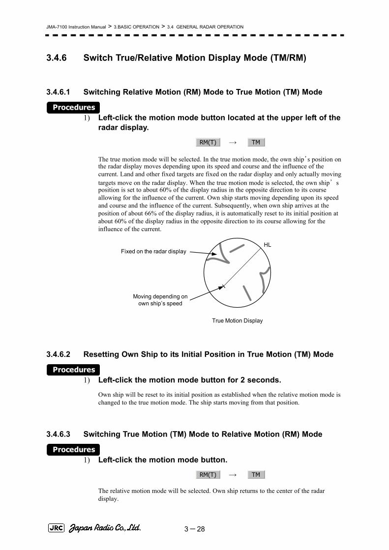
JMA-7100 Instruction Manual > 3.BASIC OPERATION > 3.4 GENERAL RADAR OPERATION
3.4.6 Switch True/Relative Motion Display Mode (TM/RM)
3.4.6.1 Switching Relative Motion (RM) Mode to True Motion (TM) Mode
Procedures1) Left-click the motion mode button located at the upper left of the
radar display.
→
The true motion mode will be selected. In the true motion mode, the own ship’s position on the radar display moves depending upon its speed and course and the influence of the current. Land and other fixed targets are fixed on the radar display and only actually moving targets move on the radar display. When the true motion mode is selected, the own ship’s position is set to about 60% of the display radius in the opposite direction to its course allowing for the influence of the current. Own ship starts moving depending upon its speed and course and the influence of the current. Subsequently, when own ship arrives at the position of about 66% of the display radius, it is automatically reset to its initial position at about 60% of the display radius in the opposite direction to its course allowing for the influence of the current.
3.4.6.2 Resetting Own Ship to its Initial Position in True Motion (TM) Mode
Procedures1) Left-click the motion mode button for 2 seconds.
Own ship will be reset to its initial position as established when the relative motion mode is changed to the true motion mode. The ship starts moving from that position.
3.4.6.3 Switching True Motion (TM) Mode to Relative Motion (RM) Mode
Procedures1) Left-click the motion mode button.
→
The relative motion mode will be selected. Own ship returns to the center of the radar display.
RM(T) TM
HL
True Motion Display
Fixed on the radar display
Moving depending on own ship’s speed
RM(T) TM
3-28

JMA-7100 Instruction Manual > 3.BASIC OPERATION > 3.4 GENERAL RADAR OPERATION
3
3.4.7 Move Own Ship’s Display Position (Off Center)
The own ship’s position can be moved from the display center to any position within 66% of the display radius. This function is convenient for observing a wide coverage in any direction.
If Off Center functions set to scanner position is outside of the PPI range, when function switching display with reference to scanner position.
Procedures1) Left-click the Off Center button located at the upper left of the
display.
The cross cursor mark will appear at the own ship’s position on the radar display.
2) Move the cross cursor mark (own ship’s display position) to a desired position by using the trackball.
While the cross cursor mark is moving, the own ship’s display position moves following the cross cursor mark.
When it moves to a position outside 66% of the display radius, the center position is limited to a position within 66% of the display radius.
3) Press the trackball button on the left key.
The own ship’s display position will be fixed to the cross cursor mark.
3.4.7.1 Returning Own Ship's Position to the Center
Procedures1) Left-click the Off Center button for 2 seconds.
The own ship position is returned to the center of the display.
This function is not available on the 96 NM range.i
Move the cursor mark toa desired position
HL
Press the [ENT] keyThe own ship’s display position will be fixed.
HL
3-29

JMA-7100 Instruction Manual > 3.BASIC OPERATION > 3.4 GENERAL RADAR OPERATION
3.4.8 Display Radar Trails (Trails)Other ship's movements and speeds can be monitored from the lengths and directions of their trails, serving for collision avoidance. The trail length varies according to setting.
3.4.8.1 Changing the length of the trail
Procedures1) Left-click the Trails button located at the upper left of the
display.
Values of the length of the radar trails are switched.
Trails length setting: Short mode
→ → →
← ← ←
Saved trails cannot be erased even when the trail lengths are changed by using Trails button. Even after the trails display is turned off, the past trails can be displayed traced back by setting a desired time.
The radar system is start transmission, trails is start plot.
The system is plotting trails even while the trails display is off.
If the transmit time is short, the indicated trails duration may not have achieved the specified time. The radar trails remaining time is indicated at the right of the trails length setting.
3.4.8.2 Erasing Trails Data
Procedures1) Hold down the Trails button for five seconds located at the
upper right of the display.
All the saved trails data will be erased. The system starts plotting trails in initial state.When Trails button is clicked for 2 seconds, a RADAR Trails Setting menu will be displayed. Furthermore, data will be erased if it continues pushing.
Short : 15秒、30秒、1分、3分、6分、10分、15分
Middle : 30秒、1分、3分、6分、10分、15分、30分
Long : 1分、3分、6分、10分、15分、30分、60分
RADAR trails display time
Off 15sec 30sec 1min
15min 10min 6min 3min
3-30

JMA-7100 Instruction Manual > 3.BASIC OPERATION > 3.4 GENERAL RADAR OPERATION
3
3.4.8.3 Trails Motion ModeThere are two types of trails: relative motion trails and true motion trails.
Trails modes provided with this system vary depending on the motion mode.
While the true motion trails mode is active, this system enables the continuous use of true motion trails even if any of the following operations is performed:• Motion display mode change (TM/RM)• TM reset• Bearing display mode change• Center move (Off Center)• MAP display on/off (Map)
Relative motiontrails:
The system plots the trails of a target at a position relative tothe own ship. The operator can easily judge whether the targetis approaching the own ship. While the own ship is moving, thesystem also plots the trails of land and other fixed targets.
True motiontrails:
The system plots the absolute motion trails of a target,irrespective of the own ship’s position. The operator can easilyjudge the course and speed of the target. The system does notplot the trails of land and other fixed targets.
With true motion (TM)mode:
Only the true motion trails mode is available.
With relative motion(RM) mode:
The relative motion trails mode or true motion trailsmode isselectable.
is indicated while the relative motiontrails mode is active.
is indicated while the true motion trailsmode is active.
iAccurate true bearing signals and speed signals are necessaryfor using the true motion trails mode.
True Motion Trails
HL
Land
Relative Motion Trails
HL
Ship
Trails
Trails
RM(R)
RM(T)
3-31

JMA-7100 Instruction Manual > 3.BASIC OPERATION > 3.4 GENERAL RADAR OPERATION
3.4.8.4 Changing Motion Mode of Trails (Trails Mode)
Procedures1) Click the Trails Mode located at the upper right of the radar
display.
The trails motion modes are switched.
⇔
RADAR trails true/relative
T R
3-32
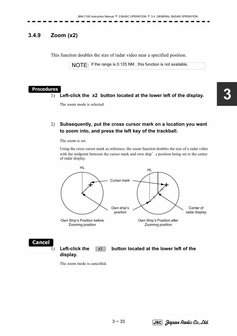
JMA-7100 Instruction Manual > 3.BASIC OPERATION > 3.4 GENERAL RADAR OPERATION
3
3.4.9 Zoom (x2)
This function doubles the size of radar video near a specified position.
Procedures1) Left-click the x2 button located at the lower left of the display.
The zoom mode is selected.
2) Subsequently, put the cross cursor mark on a location you want to zoom into, and press the left key of the trackball.
The zoom is set.
Using the cross cursor mark as reference, the zoom function doubles the size of a radar video with the midpoint between the cursor mark and own ship’s position being set to the center of radar display.
Cancel1) Left-click the button located at the lower left of the
display.
The zoom mode is cancelled.
NOTE: If the range is 0.125 NM , this function is not available.
Own Ship’s Position before Zooming position
HL
Cursor mark
Own Ship’s Position after Zooming position
HL
Own ship’s position
Center of radar display
x2
3-33

JMA-7100 Instruction Manual > 3.BASIC OPERATION > 3.4 GENERAL RADAR OPERATION
3.4.10 Hide/Display Range Rings [HL OFF]
Procedures1) Press the [HL OFF] key. Alternatively, Left-click the
button located at the lower right of the display.
The ship's heading line (HL) is hidden while the [HL OFF] key is held down.
The ship's heading line that indicates the course of own ship is always shown on the radar display. The heading line is hidden while the [HL OFF] key is held down, so the targets on the heading line can be easily observed.
3.4.11 Hide Graphics Information on Radar Display [DATA OFF]
Various graphics information such as target tracking TT/AIS symbols, NAV lines, and MAP information is shown on the radar display of this radar system, and may make it difficult to view the radar video. In that case, use this function to temporarily hide unnecessary graphics information.
Procedures1) Press the [DATA OFF] key. Alternatively, Left-click the
button located at the lower right of the display.
While the key is pressed, graphics data other than VRM, EBL, HL, cross cursor mark, and range rings on the radar display is temporarily hidden.
HLOff
DataOff
3-34

JMA-7100 Instruction Manual > 3.BASIC OPERATION > 3.4 GENERAL RADAR OPERATION
3
3.4.12 Switch Day/Night Mode [DAY/NIGHT]
Several combinations of the display color and brilliance according to the ambient lighting conditions are provided. The display color setting is easily changed.
Procedures1) Press the [DAY/NIGHT] key. Alternatively, left-click the Day/Night
button located at the lower right of the radar display.
The DAY/NIGHT modes are switched.
→ → →
← ← ←
The current mode is displayed at the lower right of the radar display.
For how to set the display color and brilliance for each mode, see Section 3.8.5 "Set Radar Display (Display Setting)"
3.4.13 Adjust Operation Panel Brilliance [PANEL]
Adjust brilliance of the operation panel according to the ambient lighting conditions.
Procedures1) Press the [PANEL] key. Alternatively, left-click the
button located at the lower right of the radar display.
In consideration of the ambient brightness, adjust panel brilliance that is high enough to read the characters on the operation panel but does not glare.
The [PANEL] key lamp lights up irrespective of panel brilliance adjustment.
Day1 Day2 Day3 Dusk
Day2 Day3 Dusk Night
Panel○
3-35

JMA-7100 Instruction Manual > 3.BASIC OPERATION > 3.4 GENERAL RADAR OPERATION
3.4.14 Set True Bearing
When the GYRO I/F is used to enter a gyro signal, there is a rare case in which a true bearing value indicated by the master gyro does not match the true bearing value indicated by this radar system.
In that case, adjust the true bearing value of this system so that it matches the value indicated by the master gyro.
Procedures1) Open the numeric value input screen to enter a true bearing
value by performing the menu operation below.
→
→
2) Enter a value indicated by the master gyro on the numeric value input screen.
For how to input numeric data on the numeric value input screen, see Section 3.3.4 "Operation on Numeric Value, Latitude / Longitude and Character Input menu".
3.4.15 Set Own Ship Speed
3.4.15.1 Switch the own ship speed device
Procedures1) Left-click the own ship speed device button in the Own Ship
Information area located at the upper right of the display.
The speed sensor is switched whenever the button is clicked.
(Manual) → (Single-axis water log) → (Dual-axis water log)
(GPS) ← (Dual-axis ground log)
Main
6.NAV Equipment Setting
1. Gyro Setting
MAN LOG 2AXW
GPS 2AXG
3-36

JMA-7100 Instruction Manual > 3.BASIC OPERATION > 3.4 GENERAL RADAR OPERATION
3
3.4.15.2 Input the own ship speed (Manual Speed)
If the ship-speed system, such as LOG, etc., connected to this radar system malfunctions, it is possible to manually enter own ship speed by the method described below to use the target tracking (TT) and true motion display functions.
Procedures1) Left-click the own ship speed device button in the Own Ship
Information area located at the upper right of the display, and select the manual mode .
2) Left-click the value of the speed.
The numeric value input screen will open to enter the own ship speed.
3) Enter the value for the own ship speed on the numeric value input screen.
For how to input numeric data on the numeric value input screen, see Section 3.3.4 "Operation on Numeric Value, Latitude / Longitude and Character Input menu".
3.4.16 Magnet Compass Correction (MAG Compass Setting)Set the correction value, when the radar receive HDM sentence from magnet compass or the variation of HDG is NULL.
Procedures1) Open the MAG Compass Setting menu by performing the
following menu operation.
→
→
NOTE: •If the single axis water log display can present the speed ofthe ship in other than the forward direction, the direction ofmovement should be indicated unambiguously. Thereforesingle axis water logs cannot detect the effect of leeway.•If ships in shallow water, when the accuracy of the dual-axislog may be decreased. If ships in deep sea area, when theaccuracy of the dual-axis log error may be occurred.•The accuracy of GPS's COG is ±3° when own ships speedno fewer than 1kn, no more than 17kn. The accuracy ofGPS's COG is ±1° when own ships speed over 17kn.
MAN
Main
6.NAV Equipment Setting
2. MAG Compass Setting
3-37

JMA-7100 Instruction Manual > 3.BASIC OPERATION > 3.4 GENERAL RADAR OPERATION
2) Set whether to make corrections or not.
⇔
3) Input the correction value.
Press the or button to select south and north for latitude or the east and west for longitude.
For how to input numeric data on the numeric value input screen, see Section 3.3.4 "Operation on Numeric Value, Latitude / Longitude and Character Input menu".
3.4.16.1 Set Drift Correction
The direction and speed of the drift are set.
This function can be used only when or is selected for ship-speed data.
Procedures1) Open the Set/Drift Setting menu by performing the menu
operation below.
→
→
2) Set whether to make corrections or not.
⇔
For menu operation, see Section 3.3.3 "Basic Menu Operation".
3) Enter the correction value for tidal current.
For how to input numeric data on the numeric value input screen, see Section 3.3.4 "Operation on Numeric Value, Latitude / Longitude and Character Input menu".
: Direction of tidal current (true bearing)
: Speed of tidal current
1. Heading Correction
Off On
+ -
MAN LOG
Main
6.NAV Equipment Setting
3. Set/Drift Setting
1. Correction
Off On
2.Set
3.Drift
3-38
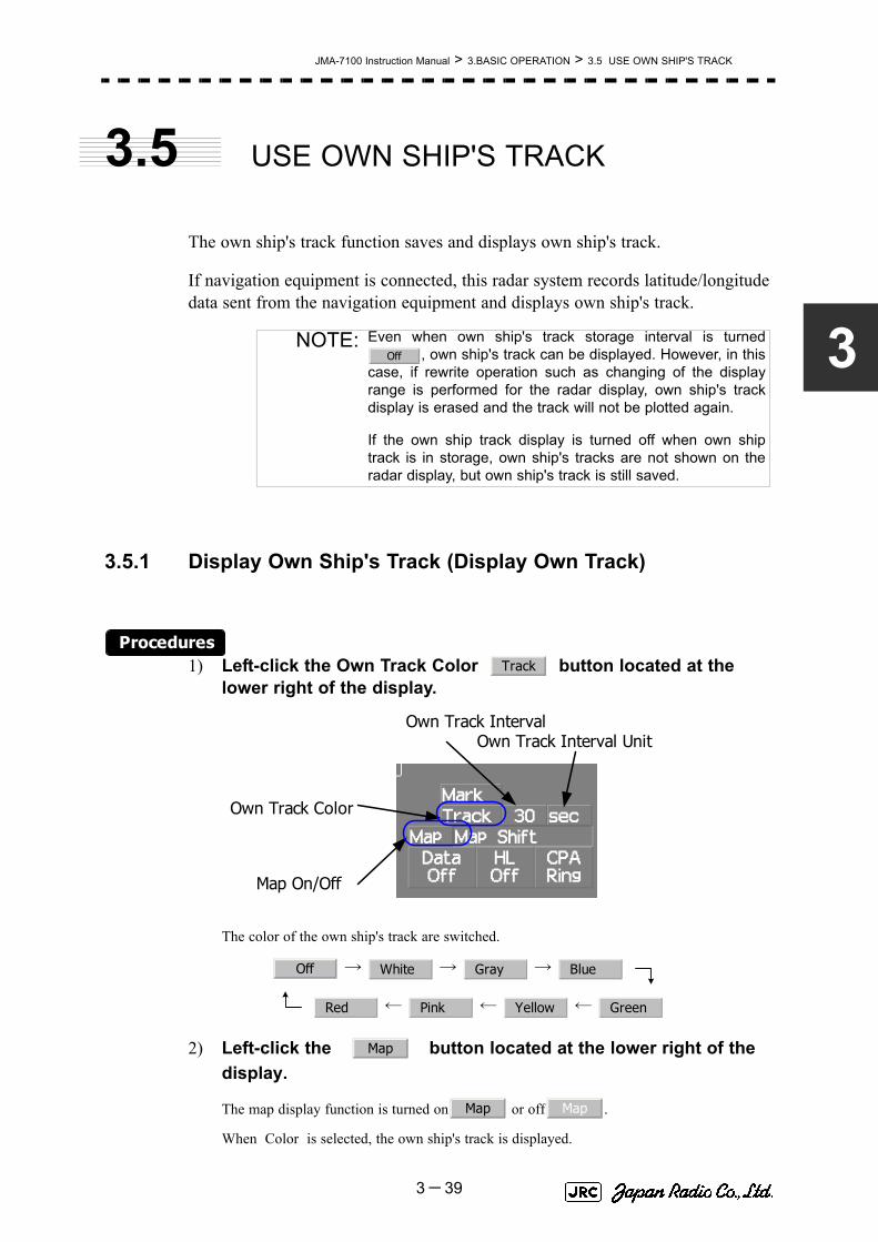
JMA-7100 Instruction Manual > 3.BASIC OPERATION > 3.5 USE OWN SHIP'S TRACK
3
3.5 USE OWN SHIP'S TRACK
The own ship's track function saves and displays own ship's track.
If navigation equipment is connected, this radar system records latitude/longitude data sent from the navigation equipment and displays own ship's track.
3.5.1 Display Own Ship's Track (Display Own Track)
Procedures1) Left-click the Own Track Color button located at the
lower right of the display.
The color of the own ship's track are switched.
→ → →
← ← ←
2) Left-click the button located at the lower right of the display.
The map display function is turned on or off .
When Color is selected, the own ship's track is displayed.
NOTE: Even when own ship's track storage interval is turned, own ship's track can be displayed. However, in this
case, if rewrite operation such as changing of the displayrange is performed for the radar display, own ship's trackdisplay is erased and the track will not be plotted again.
If the own ship track display is turned off when own shiptrack is in storage, own ship's tracks are not shown on theradar display, but own ship's track is still saved.
Off
Track
Own Track Interval
Map On/Off
Own Track Color
Own Track Interval Unit
Off White Gray Blue
Red Pink Yellow Green
Map
Map Map
3-39

JMA-7100 Instruction Manual > 3.BASIC OPERATION > 3.5 USE OWN SHIP'S TRACK
3.5.2 Set Display Color of Own Ship's Track (Display Own TrackColor)Own ship's track can be saved in seven different colors.
Own ship's track can be displayed or not displayed individually by color.
Procedures1) Open the Display Own Track Setting menu by performing the
menu operation
→
The Display Own Track Setting menu will open.
Operations differ according to the following set modes.。
2) Left-click the color button for the desired display setting which is to be changed.
Display of each item is switched between and
When is set to All of own ship's tracks are displayed.
When is set to All of own ship's tracks are not displayed.
When is set to Settings are made by color by performing theoperation below.
On : Own ship's track plotted by the color is displayed.
Off : Own ship's track plotted by the color is not displayed.
Track
1. DISP Own Track Color
1. All On
1. All Off
1. All Individual
On Off
3-40
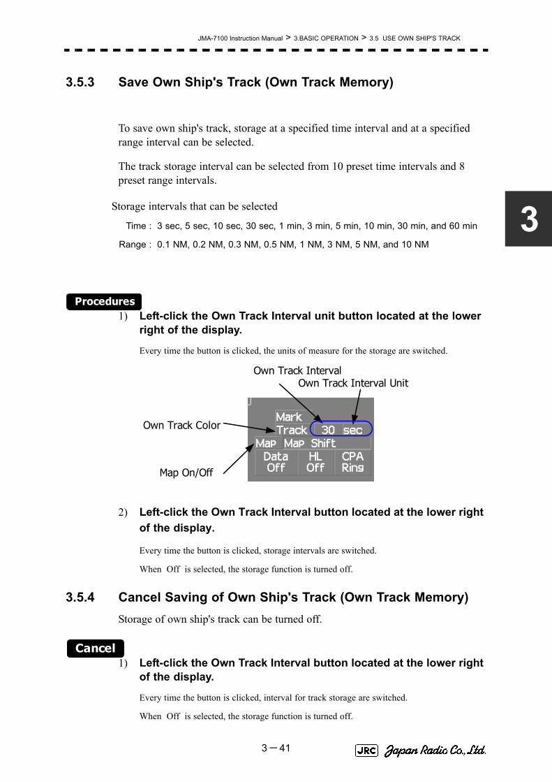
JMA-7100 Instruction Manual > 3.BASIC OPERATION > 3.5 USE OWN SHIP'S TRACK
3
3.5.3 Save Own Ship's Track (Own Track Memory)
To save own ship's track, storage at a specified time interval and at a specified range interval can be selected.
The track storage interval can be selected from 10 preset time intervals and 8 preset range intervals.
Procedures1) Left-click the Own Track Interval unit button located at the lower
right of the display.
Every time the button is clicked, the units of measure for the storage are switched.
2) Left-click the Own Track Interval button located at the lower right of the display.
Every time the button is clicked, storage intervals are switched.
When Off is selected, the storage function is turned off.
3.5.4 Cancel Saving of Own Ship's Track (Own Track Memory)Storage of own ship's track can be turned off.
Cancel1) Left-click the Own Track Interval button located at the lower right
of the display.
Every time the button is clicked, interval for track storage are switched.
When Off is selected, the storage function is turned off.
Storage intervals that can be selected
Time : 3 sec, 5 sec, 10 sec, 30 sec, 1 min, 3 min, 5 min, 10 min, 30 min, and 60 min
Range : 0.1 NM, 0.2 NM, 0.3 NM, 0.5 NM, 1 NM, 3 NM, 5 NM, and 10 NM
Own Track Interval
Map On/Off
Own Track Color
Own Track Interval Unit
3-41

JMA-7100 Instruction Manual > 3.BASIC OPERATION > 3.5 USE OWN SHIP'S TRACK
3.5.5 Clear Own Ship's Track (Clear Own Track)
This function cancels the storing of own ship's track.
Procedures1) Open the Clear Own Track Color menu by performing the menu
operation below.
→
The Clear Own Track Color menu will appear.
2) Left-click the button for the color to be deleted.
: All tracks are deleted
/ / / / / / : Only track of specified color is deleted.
After the item has been selected, Clear Own Track Confirmation Window will appear.
3) Left-click the Yes button.
Own ship's track indicated by the specified color will be deleted.
3.5.6 Use Expanded Own Ship's Track (Own Track Type)
The following expanded track functions can be used for this radar system.
Only one type of expanded own ship's track can be used at a time. Multiple types of expanded tracks cannot be used at the same time.
Specify the type of the expanded own ship's tracks to be used by performing the operation below.
Water temperature track : The water temperature value at the latitude/longitude isrecorded.
Water depth track : The water depth value at the latitude/longitude is recorded.
Tidal current track : The tidal current vector at the latitude/longitude is recorded.
Track
2. Clear Own Track Color
All
White Gray Blue Red Pink Yellow Green
3-42

JMA-7100 Instruction Manual > 3.BASIC OPERATION > 3.5 USE OWN SHIP'S TRACK
3
Procedures1) Left-click the button located at the lower right of the
display.
The Own Track Menu will appear.
2) Left-click the item button of .
The numeric value of the navigation data can be shown by the color of own ship's track.
3) Select the function to be used.
4) Left-click the item button of
Numeric value or vector of navigation data can be added to own ship's track.
5) Select the function to be used.
: The expanded own ship's track function is not used.
: The color of the tracks is changed according to the waterdepth value
:The color of the tracks is changed according to the watertemperature value.
: Numeric value and vector are not added.
: Water depth value is added.
: Water temperature value is added.
:current vector is added.
NOTE: To use the expanded own ship's track function, the trackmust be entered from the special navigation equipmentinto this radar system.
Track
Track menu
3. Track Type
Normal
Depth
Temperature
4. Num Vector Display
Off
Depth
Temperature
Current
3-43

JMA-7100 Instruction Manual > 3.BASIC OPERATION > 3.5 USE OWN SHIP'S TRACK
3.5.7 Use Water Depth Track (Water Depth Track)
Set the corresponding conditions for the water depth value and the color of own ship's track by performing the operation below.
Procedures1) Open the Water Depth Setting menu by performing the menu
operation below.
→
The Water Depth Setting menu will appear.
Enter a value of the boundary water depth for each item according to the table below to set up the corresponding conditions for the water depth value and the color of own ship's track.
For example, if 10m is entered for 1. , 30m is entered for 2. , and 50m is entered for 3. , the area with a water depth of less than 10 meters is indicated by white tracks, the area with a water depth of 10 to 30 meters is indicated by light blue tracks, and the area with a water depth of 30 to 50 meters is indicated by blue tracks.
Water depthvalue
Color of track
White
1. xxxx m Min
Gray
2. xxxx m
Blue
3. xxxx m
Green
4. xxxx m
Yellow
5. xxxx m
Pink
6. xxxx m Max
Red
Track
6. Water Depth Setting
3-44

JMA-7100 Instruction Manual > 3.BASIC OPERATION > 3.5 USE OWN SHIP'S TRACK
3
3.5.8 Use Water Temperature Track (Water TEMP Track)
Set the corresponding conditions for the water temperature value and the color of own ship's track by performing the operation below.
Procedures1) Open the Water TEMP. Setting menu by performing the menu
operation below
→
The Water TEMP. Setting menu will appear.
Enter a value of the boundary water temperature for each item according to the table below to set up the corresponding conditions for the water temperature value and the color of own ship's track.
For example, if 10.0 ~ is entered for 1. , 13.0 ~ is entered for 2. , and 15.0 ~ is entered for 3. , the area with a water temperature of less than 10.0 ?? is indicated by white tracks, the area with a water depth of 10.0 ~ to 13.0~ is indicated by light blue tracks, and the area with a water depth of 13.0 ~ to 15.0 ~ is indicated by blue tracks.
Water temperaturevalue
Color of track
White
1. xx.x ℃ Min
Gray
2. xx.x ℃
Blue
3. xx.x ℃
Green
4. xx.x ℃
Yellow
5. xx.x ℃
Pink
6. xx.x ℃ Max
Red
Track
7. Water TEMP. Setting
3-45

JMA-7100 Instruction Manual > 3.BASIC OPERATION > 3.5 USE OWN SHIP'S TRACK
3.5.9 Use Tidal Current Track (Current Vector Track)
Set the conditions for adding tidal current vectors to own ship's track by performing the operation below.
Procedures1) Open the Current Setting menu by performing the menu
operation below.
→
The Current Setting menu will appear.
Set the tidal current vector display conditions.
[1]Length of the tidal current vector (Current Size)• Set the length of the tidal current vector.• The unit of measure is kn/cm.• If 1.0kn/cm is set, a tidal current of 1.0kn is shown as a one-centimeter line
on the radar display.
[2]Color of the vector for tidal current layer A (Layer A)• Set the vector's display color for tidal current layer A.• Choose one of the following colors
White、Gray、Blue、Green、Yellow、Pink、Red
[3]Color of the vector for tidal current layer B (Layer B)• Set the vector's display color for tidal current layer B.• Choose one of the following colors
White、Gray、Blue、Green、Yellow、Pink、Red
[4]Color of the vector for tidal current layer C (Layer C)• Set the vector's display color for tidal current layer C.• Choose one of the following colors
White、Gray、Blue、Green、Yellow、Pink、Red
Track
8. Current Setting
3-46

JMA-7100 Instruction Manual > 3.BASIC OPERATION > 3.6 DISPLAY USER MAP
3
3.6 DISPLAY USER MAP
Up to 20,000 items of NAV lines, coastlines, depth contours, and NAV marks can be created, displayed, loaded, and saved. (This function is available only when navigation equipment is connected to this radar system.)
3.6.1 Create User Map (Mark/Line)In this system, when the radar is in the transmission state, the user map is displayed all the time. However, valid latitude/longitude data and true bearing data must be entered into the system.
The user map can be created and edited by performing the following operation.
3.6.1.1 Plotting a mark
Procedures1) Left-click the button located at the upper right
of the display to set the Mark mode.
The mark font to be used is displayed to the right of the button.
Marks that can be used : 29 types
Lines that can be used : 3 types (solid, broken, and dashed-dotted line)
Color of mark and linesthat can be used
: 7 colors
iIf radar video is poor visibility caused by user map function,press the [DATA OFF] key to map displays temporarily off.
Cursor
Cursor mode switchingMark color / line color
switchingMark font / line pattern
switching
Cursor
3-47

JMA-7100 Instruction Manual > 3.BASIC OPERATION > 3.6 DISPLAY USER MAP
2) Left-click the mark font button to select a font for the mark.
The mark fonts are switched.
3) Left-click the button located to the right of the mark font to select a color for the mark.
The color for the mark font located to the right of the button will change.
4) Left-click at a desired location on the radar display.
The specified mark will be displayed in the specified color.
To create another mark, repeat the above procedures.
3.6.1.2 Plotting a line
Procedures1) Left-click the button located at the upper right
of the display to select the line mode.
The line pattern to be used is displayed to the right of the button.
2) Left-click the button located at the upper right of the display to select the line pattern.
The line pattern to be used is displayed to the right of the button.
3) Left-click the button located to the right of the line pattern to select a color for the line.
The color for the line pattern located to the right of the button will change.
4) Left-click at a desired location on the radar display.
Line colors are switched.
□
C
Cursor
Cursor
Cursor
- - - - - - -
Cursor
C
Cursor
3-48

JMA-7100 Instruction Manual > 3.BASIC OPERATION > 3.6 DISPLAY USER MAP
3
5) Move the cursor to a desired location on the radar display and left-click.
A line is plotted between the previous point and the end point. Repeat this procedure so that sequential lines can be plotted.
6) When you want to finish plotting the line, left-click at the previous point.
Line plotting will be terminated. To plot another line, repeat procedures 3.
3.6.1.3 Plotting a mark / line make with latitude and longitude
Procedures1) Open the Edit User Map menu by performing the following menu
operation.
→
→
2) Left-click the button.
The Mark Input menu and the Line Input menu are switched.
3) Left-click the item button of to select the type of mark font or line pattern to be created.
The desired mark font or line pattern is selected.
To add a line, select midpoint --O-- .
4) Left-click the item button of to select the color of mark or line to be created.
The desired mark or line color is selected.
U.Map
2. Edit User Map
2. Make with L/L
9. New Mark Input
1. Type
2. Color
3-49

JMA-7100 Instruction Manual > 3.BASIC OPERATION > 3.6 DISPLAY USER MAP
5) Left-click the button to input the latitude / longitude.
For the input method on the latitude / longitude input screen, see Section 3.3.4.5 "Entering latitude/longitude"
6) Left-click the button to input the comment.
For the input method on the character input screen, see Section 3.3.4.7 "Entering a character"
The window will not be open when the system is in the transmission state.
7) Left-click the button.
Mark / Line plotting will be terminated.
To create another mark or line, repeat procedures 4 to 7.
3.6.2 Set User Map Display (Mark Display Setting)
The user map can be individually displayed (On) or hidden (Off).
The mark font display size can be selected.
3.6.2.1 Setting display by type
Procedures1) Open the Display Mark Type menu by performing the menu
operation below.
→
→
The Display Mark Type menu will open.
Setting by type : Setting can be made by mark font and line pattern.
Setting by color : Setting can be made by color of mark or line.
Normal: The mark is displayed in normal size.
Small: The mark is displayed in a size smaller than usual.
3. L/L
4. Comment
5. Enter
U.Map
5. Mark Display Setting
1. Display Mark Type
3-50

JMA-7100 Instruction Manual > 3.BASIC OPERATION > 3.6 DISPLAY USER MAP
3
2) Specify whether to turn on or off the display for each type of mark and line.
When is selected, the setting will reflect to all types of marks and lines.
3.6.2.2 Setting display by color
Procedures1) Open the Display Mark Color Type menu by performing the menu
operation below.
→
→
The Display Mark Color Type menu will open.
2) Specify whether to turn on or off the display for each color type of mark and line.
When is selected, the setting will reflect to all color types of marks and lines.
3.6.2.3 Setting the mark font size
Procedures1) Open the Mark Size menu by performing the menu operation
below.
→
→
The Mark Size menu will appear.
Off : All types are not displayed.
Individual : All types are displayed.
On : Setting by type is activated.
Off : All color types are not displayed.
Individual : Setting by color type is activated.
On : All color types are displayed.
1. All
U.Map
5. Mark Display Setting
2. Display Mark Color
1. All
U.Map
5. Mark Display Setting
3. Mark Size
3-51

JMA-7100 Instruction Manual > 3.BASIC OPERATION > 3.6 DISPLAY USER MAP
2) Specify the mark font size.
3.6.2.4 Setting the character size for comments
Procedures1) Open the Comment Font Size menu by performing the menu
operation below.
→
→
The Comment Font Size menu will appear.
2) Specify the comment font size.
3.6.3 Edit User Map (Edit User Map)
3.6.3.1 Manually entering the own ship position (Own Ship Position)Use this function when editing navigation data for a location different from the own ship position.
Procedures1) Open the Own Ship Position menu by performing the menu
operation below.
→
The number key screen for entering the latitude/longitude of the Own Ship Position will appear.
Normal : The mark is displayed in normal size.
Small : The mark is displayed in a size smaller than usual.
Normal : The characters for comments are displayed in normal size.
Small : The characters for comments are displayed in a size smallerthan usual.
U.Map
5. Mark Display Setting
4. Comment Font Size
U.Map
1. Own Ship Position
3-52

JMA-7100 Instruction Manual > 3.BASIC OPERATION > 3.6 DISPLAY USER MAP
3
2) Use the number buttons to to enter a value of latitude (xx°xxx.xxx').
3) To make changes between north latitude and south latitude, use the and buttons.
4) Left-click the button.
The manually entered latitude will be determined. Then, enter the value of longitude.
5) Use the number buttons to to enter a value of longitude (xx°xxx.xxx').
6) To make changes between east longitude and west longitude, use the and buttons.
7) Left-click the button.
The manually entered longitude will be determined.
3.6.3.2 Moving a mark or line (Move)With regard to the created user map, a mark or line is moved individually.
Procedures1) Open the Edit User Map menu by performing the following menu
operation.
→
The Edit User Map menu will appear.
2) Left-click the button.
North latitude : Left-click the button.
South latitude : Left-click the button.
East longitude: Left-click the button.
West longitude: Left-click the button.
NOTE: The own ship's position manually entered by using thefunction above is valid only in the navigation data settingmenu. After exiting from the menu, the manually enteredposition data is invalidated.
0 9
+ -
+
-
ENT
0 9
+ -
+
-
ENT
U.Map
2. Edit User Map
3. Move
3-53

JMA-7100 Instruction Manual > 3.BASIC OPERATION > 3.6 DISPLAY USER MAP
The user map move mode is selected.
is displayed in the cursor mode located at the upper right of the display.
3) Put the cursor on a mark or line, and left-click.
When a mark or line to be moved is selected, the cursor mark will appear.
4) Move the cursor mark to the destination, and left-click.
The selected mark or line is moved to the destination.
To move another mark or line, repeat procedures 3 and 4.
5) When finished with the correction of all items, left-click the button.
The cursor mode changes to the normal operation mode, terminating the user map move mode.
(Example)
Move Map
0.Exit
3-54

JMA-7100 Instruction Manual > 3.BASIC OPERATION > 3.6 DISPLAY USER MAP
3
3.6.3.3 Deleting a mark or line (Delete)With regard to the created user map, a mark or line is deleted individually.
Procedures1) Open the Edit User Map menu by performing the following menu
operation.
→
The Edit User Map menu will appear.
2) Left-click the button.
The user map delete mode is selected.
is displayed in the cursor mode located at the upper right of the display.
3) Put the cursor on a mark or line, and left-click.
The entire selected mark or line is deleted.
To delete another mark or line, repeat procedures 3 and 4.
4) When finished with the correction of all items, left-click the button.
The cursor mode changes to the normal operation mode, terminating the user map delete mode.
U.Map
2. Edit User Map
4. Delete
Delete
0.Exit
3-55

JMA-7100 Instruction Manual > 3.BASIC OPERATION > 3.6 DISPLAY USER MAP
3.6.3.4 Inserting a vertex into a line (Insert/Move Vertex)With regard to the created user map, a vertex is inserted into a line.
Procedures1) Open the Edit User Map menu by performing the following menu
operation.
→
The Edit User Map menu will appear.
2) Left-click the button.
The user map insert/correction mode is selected.
is displayed in the cursor mode lacated the upper right of the display.
3) Put the cursor to a side line into which a vertex will be inserted, and left-click.
A vertex is inserted into the selected line, and the cursor mark will be displayed.
4) Move the cursor mark to the newly inserted vertex, and left-click.
To insert another vertex, repeat procedures 3 and 4.
5) When finished with the correction of all items, left-click the button.
The cursor mode changes to the normal operation mode, terminating the user map insertion/correction mode.
U.Map
2. Edit User Map
5. Insert/Move Vertex
Insert/Move
0.Exit
3-56

JMA-7100 Instruction Manual > 3.BASIC OPERATION > 3.6 DISPLAY USER MAP
3
(Example)
3.6.3.5 Correcting the mark or vertex of a line (Insert/Move Vertex)With regard to the created user map, a mark or line is corrected.
Procedures1) Open the Edit User Map menu by performing the following menu
operation.
→
The Edit User Map menu will appear.
2) Left-click the button.
The user map insertion/correction mode is selected.
is displayed in the cursor mode located at the upper right of the display.
3) Put the cursor on the mark or vertex of a line, and left-click.
When the mark or vertex of a line to be corrected is selected, the cursor mark will appear.
4) Move the cursor mark to the destination, and left-click.
The selected mark or vertex of the line is moved to the destination.
To correct another mark or vertex of a line, repeat procedures 3 and 4.
5) When finished with the correction of all items, left-click the button.
The side line into which a vertex is inserted
Inserted vertex
U.Map
2. Edit User Map
5. Insert/Move Vertex
Insert/Move
0.Exit
3-57

JMA-7100 Instruction Manual > 3.BASIC OPERATION > 3.6 DISPLAY USER MAP
The cursor mode changes to the normal operation mode, terminating the user map insertion/correction mode.
(Example)
3.6.3.6 Deleting a mark or vertex from a line (Delete Vertex)With regard to the created user map, a vertex is deleted individually from a mark or line.
Procedures1) Open the Edit User Map menu by performing the following menu
operation.
→
The Edit User Map menu will appear.
2) Left-click the button.
The user map delete mode is selected.
is displayed in the cursor mode located at the upper right of the radar display.
3) Put the cursor on the vertex of a mark or line, and left-click.
The selected mark or vertex of the line is deleted.
All of the lines drawn by joining two points are deleted.
To delete another mark or vertex of a line, repeat procedure 3.
4) When finished with the correction of all items, left-click the button.
Original vertex
New vertex
U.Map
2. Edit User Map
6. Delete Vertex
Delete
0.Exit
3-58

JMA-7100 Instruction Manual > 3.BASIC OPERATION > 3.6 DISPLAY USER MAP
3
The cursor mode changes to the normal operation mode, terminating the user map delete mode.
(Example)
3.6.3.7 Batch clearing marks or lines (Clear)With regard to the created user map, marks or lines are batch cleared by type or by color.
Procedures1) Open the Edit User Map menu by performing the following menu
operation.
→
The Edit User Map menu will appear.
2)-1 Left-click the item button of
Select the type of marks or lines to be deleted.
To select all types, select .
For example, to delete "red ○" marks, select .
2)-2 Left-click the item button of
Select the color of marks or lines to be deleted.
To select all colors, select .
For example, to clear "red ○" marks, select .
After the items have been selected, Confirmation Window will appear.
The vertex to be deleted
U.Map
2. Edit User Map
7. Delete by Type
All
○
7. Delete
All
Red
3-59

JMA-7100 Instruction Manual > 3.BASIC OPERATION > 3.6 DISPLAY USER MAP
3) Left-click the button.
The selected mark will be deleted.
3.6.4 Correct Position on User Map (Shift User Map)
3.6.4.1 Correcting the display position on the user map (Shift)If the display position on the user map is different from an actual position, it can be changed to the correct position in manual mode.
Procedures1) Open the [Shift] menu by performing the menu operation below.
→
is displayed for the Cursor mode, indicating that the user map shift mode is selected.
2) Put the pointer on a mark or end of a line, coastline, or depth contour line, and left-click.
3) Move the cross cursor mark to the location to be corrected, and left-click.
Positions of all marks and lines currently displayed will be corrected.
At this time, Map Shift is displayed in the map position correction (lower right of the display), indicating that the position is being corrected.
NOTE: If data is not copied on the flash memory card (option), the datais not be reloaded.
: Heading correction is conducted
: Heading correction is not conducted
1. Yes
U.Map
3. Shift
Shift
Map Shift
Map Shift
3-60

JMA-7100 Instruction Manual > 3.BASIC OPERATION > 3.6 DISPLAY USER MAP
3
3.6.4.2 Restoring the corrected user map to its original state (Shift Clear)
Procedures1) Open the Mark Operations menu by performing the following
menu operation.
→
Only the most recently corrected data (for a single input) will be cleared, and the data will be displayed at its original position.
At this time, Map Shift is not displayed in the map position correction (lower right of the display).
3.6.5 Save User Map
3.6.5.1 Loading navigation data (Load User Map)
Procedures1) Insert a flash memory card into the card slot.
Flash memory card (option) is necessary.
2) Open the File Operations menu by performing the following menu operation.
→
3) Left-click the item button of and select the card slot.
Slot1 and Slot2 of the Select Card Slot items are switched.
4) Left-click the item button of and select / .
and of the Load Mode items are switched.
When [Add] is selected, new data is added to the savedd data. When [Overwrite] is selected, the saved data is overwritten.
: Heading correction is conducted
: Heading correction is not conducted
U.Map
4. Shift Clear
Map Shift
Map Shift
U.Map
7. File Operation
1. Select Card Slot
2. Load Mode
Add Overwrite
Add Overwrite
3-61

JMA-7100 Instruction Manual > 3.BASIC OPERATION > 3.6 DISPLAY USER MAP
5) Left-click the button.
The list of navigation data saved in the system will be displayed.
6) Left-click the button for the file to be loaded.
Confirmation Window will appear.
7) Left-click the button.
The selected navigation data will be loaded and displayed on the radar display.
3.6.5.2 Discarding navigation data (Unload User Map)
Procedures1) Open the File Operations menu by performing the following
menu operation.
→
2) Left-click the button.
Unload Confirmation Window will appear.
3) Left-click the button.
The saved navigation data will be discarded.
3.6.5.3 Storing navigation data (Save User Map)Navigation data can be saved when navigation equipment is connected, or the own ship position on the user map is entered in the manual mode.
Procedures1) Insert a flash memory card into the card slot.
Flash memory card (option) is necessary.
3. Load
1. Yes
U.Map
7. File Operation
4. Unload
1. Yes
3-62

JMA-7100 Instruction Manual > 3.BASIC OPERATION > 3.6 DISPLAY USER MAP
3
2) Open the File Operations menu by performing the following menu operation.
→
3) Left-click the item button of and select the card slot.
Slot1 and Slot2 of the Select Card Slot items are switched.
4) Left-click the button.
The Input File Name screen will appear.
5) Enter the file name to be saved.
Up to 10 characters can be entered.For the input method on the character input screen, see Section 3.3.4.7 "Entering a character".
After the data has been entered, Confirmation Window will appear.
6) Left-click the button.
Navigation data currently being displayed is saved.
3.6.5.4 Clearing the saved navigation data (Erase User Map)
Procedures1) Insert a flash memory card into the card slot.
Flash memory card (option) is necessary.
2) Open the File Operations menu by performing the following menu operation.。
→
3) Left-click the item button of and select the card slot.
Slot1 and Slot2 of the Select Card Slot items are switched.
U.Map
7. File Operation
1. Select Card Slot
5. Save
1. Yes
U.Map
7. File Operation
1. Select Card Slot
3-63

JMA-7100 Instruction Manual > 3.BASIC OPERATION > 3.6 DISPLAY USER MAP
4) Left-click the button.
The Erace screen will appear.
The list of navigation data saved in the card will be displayed.
5) Click numeric buttons corresponding to the number for the file to be deleted.
Confirmation Window will appear.
6) Left-click the button.
The selected navigation data is deleted and the name of the file is deleted from the list.
3.6.5.5 Displaying saved navigation data (Card Mark Display)
Procedures1) Insert a flash memory card into the card slot.
Flash memory card (option) is necessary.
2) Open the File Operations menu by performing the following menu operation.
→
3) Left-click the item button of and select the card slot.
Slot1 and Slot2 of the Select Card Slot items are switched.
4) Left-click the button.
The Card Mark Display screen will appear.
The list of navigation data saved in the card will be displayed.
5) Left-click the button corresponding to the number for the file to be displayed.
Confirmation Window will appear.
6) Left-click the button.
The selected navigation data will be displayed.
6. Erase
1. Yes
U.Map
7. File Operation
1. Select Card Slot
7. Card Mark Display
1. Yes
3-64

JMA-7100 Instruction Manual > 3.BASIC OPERATION > 3.6 DISPLAY USER MAP
3
3.6.6 Set and Display Geodetic System (Geodetic)To create navigation information, set the geodetic system that is used with the connected navigation equipment. When navigation information is loaded, the geodetic system used when the navigation information was saved, is displayed. Make sure that the displayed geodetic system is identical to the one used with the navigation equipment. If the two geodetic systems are different, the positions of navigation information on the radar display will be shifted. Therefore, it is important to set the geodetic system of the navigation equipment.
[1] Setting the geodetic system for navigation data to be saved (Geodetic)
Procedures1) Open the Geodetic menu by performing the following menu
operation.
→
The numeric value input screen for Geodetic will appear.
2) Enter the desired geodetic system number.
The geodetic system is determined.
For how to input numeric datas on the numeric value input screen, see Section 3.3.4 "Operation on Numeric Value, Latitude / Longitude and Character Input menu".
[2] Displaying the geodetic system of the navigation data being displayed (Geodetic)
Procedures1) Load navigation data by referring to Section 3.6.5.1 "Loading
navigation data (Load User Map)".
2) Open the Mark Operations menu by performing the following menu operation.
The geodetic system will be displayed in the field.
U.Map
6. Geodetic
U.Map
6. Geodetic
3-65

JMA-7100 Instruction Manual > 3.BASIC OPERATION > 3.6 DISPLAY USER MAP
Table3-1: Geodetic System List# NAME0 WGS-841 WGS-722 Japan3 North American 1927(U.S)4 North American 1927(Canada & Alaska)5 European 1950 (Europe)6 Australian geodetic 1966 (Australia)7 Ordnance Survey of Great Britain (England)8 NAD-839 - (No Use)
10 - (No Use)11 ADINDAN (Ethiopia & Sudan)12 ARC 1950 (Botswana)13 AUSTRALIAN GEODETIC 1984 (Australia)14 BERMUDA 1957 (Bermuda islands)15 BOGOTA OBSERVATORY (Colombia)16 CAMPO INCHAUSPE (Argentine)17 CHATHAM 1971 (Chatham Islands)18 CHUA ASTRO (Paraguay)19 CORREGO ALEGRE (Brazil)20 DJAKARTA (VATAVIA) (Sumatra)21 EUROPEAN 1979 (Europe)22 GEODETIC DATUM 1949 (New Zealand)23 GUAM 1963 (Guam)24 HAYFORD 1910 (Finland)25 HJORSEY 1955 (Iceland)26 INDIAN (India & Nepal)27 IRELAND1965 (Ireland)28 KERTAU 1948 (West Malaysia)29 L.C.5 ASTRO (Cayman Brac Island)30 LIBERIA 1964 (Liberia)31 LUZON (Philippines)32 MERCHICH (Morocco)33 MINNA (Nigeria)34 NAHRWAN (Oman)35 NAPARIMA, BWI (Trinidad & Tobago)36 OLD EGYPTIAN (Egypt)37 OLD HAWAIIAN (Hawaii)38 PICO DE LAS NIEVES (Canary Islands)39 PROVISIONAL SOUTH AMERICAN 1956 (South America)40 PROVISIONAL SOUTH CHILEAN 1963 (South Chile)41 PUERTO RICO (Puerto Rico & Virgin Islands)42 QORNOQ (South Greenland)43 RT90 (Sweden)44 SANTA BRAZ (San Miguel island & Santa Maria islands)45 SOUTH AMERICAN 1969 (South America)46 SOUTHWEST BASE (Faial & Sao Jorge & Pico & Graciosa & Terceira island)
47 TIMBALAI 1948 (Brunei & East Malaysia)48 - (No Use)49 - (No Use)
3-66

JMA-7100 Instruction Manual > 3.BASIC OPERATION > 3.7 USE ROUTE FUNCTION
3
3.7 USE ROUTE FUNCTION
In this radar system, a destination mark set by navigation equipment can be displayed, and a simple route can be created, displayed, loaded and saved. (To use this function, navigation equipment must be connected to this system)
3.7.1 Display Route/Destination Mark (Select Route)
In this radar system, the following route and destination marks can be displayed.
Procedures1) Left-click the button located at the lower right of the
radar display.
The Route Menu will appear.
2) Set the item.
The following route/destination mark display modes can be selected.
iIf radar video is poor visibility caused by route function, click theMap button to turn off the Map function. Otherwise, press the[DATA OFF] key to map displays temporarily off.
Route : Route created in the radar system are displayed.
Destination mark : Destination marks sent from outside navigation equipment aredisplayed.
: Route and destination marks are not displayed.
: Route saved in the system are displayed.
: Destination marks are displayed by using WPT data sentfrom outside navigation equipment.
iTo display the mark on the radar display, selectNMEA .
The destination mark is displayed only when the Waypoint datais received from outside by using the NMEA sentence(RMB,BWC,BWR).
Route
1. Select Route
Off
Internal
NMEA
○WP
3-67

JMA-7100 Instruction Manual > 3.BASIC OPERATION > 3.7 USE ROUTE FUNCTION
3.7.1.1 Displaying route created by the radar system (Internal)In this radar system, route created by the radar system are displayed as shown below.
The following rout data is displayed.
3.7.2 Edit Route (Set Route Sequence)
In this radar system, it is possible to easily create and correct route by performing operation on the radar display.
3.7.2.1 Initializing route data (New Monitor Route)Route data saved in the radar system is initialized.
Waypoint : Up to 512 points (number: 000 to 511), comments can be entered.
To Waypoint : Next Waypoint is displayed in a light blue circle.
Route : A route line that connects Waypoints.
Planned Courese : Scheduled route between Waypoints (automatically calculated).
Planned Speed : Scheduled sailing speed between Waypoints (entered by user).
Waypoint alarm circle : The circle that shows the distance to judge arrival in Waypoint.
Route alarm line : The line that shows the distance width to judge route alarm.
Waypoint bearing vector : A vector line that shows next destination from own ship's CCRP.
NOTE:Once route data is initialized, route data saved in theradar system's storage section is deleted. If there isnecessary route data, save the route data on the flashmemory card before initializing it.
000 ABCDE
001
002 FGJK
003 OPQRS
004Waypoint
To Waypoint
Waypoint bearing vector
Waypoint alarm circle
Route
Waypoint number
Comments
Route alarm line
Route alarm line
070T
2.50kn
062T
074T
Planned Course
Planned Speed
135T5.00kn
10.0kn
12.5kn
3-68

JMA-7100 Instruction Manual > 3.BASIC OPERATION > 3.7 USE ROUTE FUNCTION
3
Procedures1) Open the Set Route Sequence menu by performing the menu
operation below.
→
→
2) Left-click the button.
Confirmation Window will appear.
3) Left-click the button.
The saved route data will be deleted.
3.7.2.2 Adding a Waypoint (Add Waypoint)New Waypoint data is added to the route data saved in the radar system.
Procedures1) Open the Set Route Sequence menu by performing the menu
operation below.
→
→
2) Left-click the button.
The Waypoint adding mode is selected.
The rubber band from the last Waypoint to the cursor position will be displayed on the radar display.
3) Left-click the location at which you want to add a Waypoint.
A Waypoint will be added.
When a Waypoint is added, the value of the Planned Speed in the section up to the menu is used for the Planned Speed value up to the added Waypoint.
Route
2. WPT/Route Setting
3. Set Route Sequence
7. New Monitor Route
1. Yes
Route
2. WPT/Route Setting
3. Set Route Sequence
2. Add
3-69

JMA-7100 Instruction Manual > 3.BASIC OPERATION > 3.7 USE ROUTE FUNCTION
4) To add another Waypoint, repeat procedure 3.
5) To finish adding a Waypoint, left-click twice at the last Waypoint.
The Waypoint adding mode is cancelled.
(Example)
3.7.2.3 Correcting coordinates of a Waypoint (Correct Position)The coordinates of a Waypoint in the route data saved in the radar system are corrected.
Procedures1) Open the Set Route Sequence menu by performing the menu
operation below.
→
→
2) Left-click the button.
The Waypoint correcting mode is selected.
3) On the radar display, put the cursor on the Waypoint that is to have its coordinates corrected, and left-click.
The Waypoint to be corrected is specified.
The cursor display becomes a cursor mark, and a rubber band is displayed.
062T
12.0kn
Last Waypoint
Rubber band
023
024
Route
2. WPT/Route Setting
3. Set Route Sequence
3. Correct Position
3-70

JMA-7100 Instruction Manual > 3.BASIC OPERATION > 3.7 USE ROUTE FUNCTION
3
4) Move the cursor to new coordinates, and left-click.
The coordinates of the Waypoint are corrected, and then the Waypoint correcting mode is cancelled.
(Example)
3.7.2.4 Correcting Planned Speed (Correct Planned Speed)Planned Speed of the route data saved in the radar system is corrected.
Procedures1) Open the Set Route Sequence menu by performing the menu
operation below.
→
→
2) Left-click the button.
The Planned Speed correcting mode is selected.
3) Left-click the button.
The Planned Speed input screen will appear.
Enter a numeric value of new Planned Speed.
025
Waypoint that is to have its position corrected
Rubber band
Cross cursor mark
Click at this position
064T12.0kn
8.00kn
108T064T
108T
064T108T
106T060T
Planned Course
024
025
026
024
025
026
026
024024
025
026
12.0kn8.00kn
12.0kn8.00kn
12.0kn 8.00kn
Route
2. WPT/Route Setting
3. Set Route Sequence
4. Correct Planned Speed
1. Planned Speed
3-71

JMA-7100 Instruction Manual > 3.BASIC OPERATION > 3.7 USE ROUTE FUNCTION
4) On the radar display, put the cursor on the line extending between Waypoints that is to have its Planned Speed corrected.
The section that is to have its Planned Speed corrected is specified, and the new Planned Speed is applied to the section.
5) To correct the Planned Speed of another section, repeat procedures 3 and 4.
6) To finish correcting Planned Speed, left-click the button.
The Planned Speed correcting mode will be cancelled.
(Example)
3.7.2.5 Deleting a Waypoint (Delete Waypoint)The specified Waypoint in the route data saved in the radar system is deleted.
Procedures1) Open the Set Route Sequence menu by performing the menu
operation below.
→
→
2) Left-click the button.
The Waypoint deleting mode is selected.
4. Correct Planned Speed
000
001
002
003
004
005
064T8.00kn 9.00kn 10.0kn 11.0kn 12.0kn
113T 113T 064T113T
Planned speed: 10.00kn
Section that is to have its Planned Speed corrected
Route
2. WPT/Route Setting
3. Set Route Sequence
5. Delete
3-72

JMA-7100 Instruction Manual > 3.BASIC OPERATION > 3.7 USE ROUTE FUNCTION
3
3) On the radar display, put the cursor on a Waypoint to be deleted, and left-click.
The specified Waypoint is deleted, and the previous and following Waypoints are then connected by a line.
4) To delete another Waypoint, repeat procedure 3.
5) To finish deleting a Waypoint, left-click the button.
The Waypoint deleting mode will be cancelled.
(Example)
3.7.2.6 Inserting a Waypoint (Insert Waypoint)A Waypoint is inserted at a specific location of the route data saved in the radar system.
Procedures1) Open the Set Route Sequence menu by performing the menu
operation below.
→
→
5. Delete
000
001
002
003
004
005
064T113T 113T 064T113T
Waypoints are re-numbered.
000
001 002
003
004
113T
090T
064T113T
Left-click Planned speed
Waypoint to be deleted
Calculated again
8.00kn 10.0kn 11.0kn12.0kn
9.00kn
8.00kn
10.0kn
11.0kn12.0kn
Route
2. WPT/Route Setting
3. Set Route Sequence
3-73

JMA-7100 Instruction Manual > 3.BASIC OPERATION > 3.7 USE ROUTE FUNCTION
2) Left-click the button.
The Waypoint inserting mode is selected.
3) On the radar display, put the cursor on the section line into which a Waypoint is to be inserted, and left-click.
The section is specified, the cursor becomes a cross cursor mark, and the cross cursor mark is connected to the previous and following Waypoints by a rubber band.
4) On the radar display, put the cursor on the location at which a Waypoint is to be inserted, and left-click.
The coordinates of the new Waypoint are specified, and the new Waypoint is connected to the previous and following Waypoints by a line.
5) To insert another Waypoint, repeat procedures 3 and 4.
6) To finish inserting a Waypoint, left-click the button.
The Waypoint inserting mode will be cancelled.
(Example)
6. Insert
6. Insert
00110.0kn
090T
Waypoint is inserted into this section.
001090T
Waypoint is inserted into this section.
Rubber band
10.0kn
3-74

JMA-7100 Instruction Manual > 3.BASIC OPERATION > 3.7 USE ROUTE FUNCTION
3
3.7.3 Edit Route Make with Latitude and Longitude (WaypointInput)In this radar system, it is possible to create and correct route by performing operation on the Waipoint Input menu.
3.7.3.1 Open the Waipoint Input Menu
Procedures1) Open the Waypoint Input menu by performing the menu
operation below.
→
→
When transmitting, it can not be open.
Waypoint CommentWaypoint
Latitude/LongitudeWaypoint Number
Input CharacterExit
Planned SpeedWaypoint Scroll
Waypoint Scroll Waypoint Insert
Waypoint Addition
Waypoint Delete
Route
2. WPT/Route Setting
6. Waypoint Input
3-75
JMA-7100 Instruction Manual > 3.BASIC OPERATION > 3.7 USE ROUTE FUNCTION
3.7.3.2 Adding a Waypoint (Add)New Waypoint data is added to the route data saved in the radar system.
Procedures1) Open the Waipoint Input menu.
2) Left-click the button.
The new latitude of waypoint is reversed.
3) Enter a latitude / longitude and a planned speed.
A Waypoint will be added.
For the input method on the latitude / longitude and numeric value input screen, see Section 3.3.4.5 "Entering latitude/longitude" and Section 3.3.4.7 "Entering a character".
3.7.3.3 Adding a Comment (Comment)New Waypoint data is added to the route data saved in the radar system.
Procedures1) Open the Waipoint Input menu.
2) Left-click the Waypoint Scroll button.
Left-click to show the desired comment.
3) Left-click the Comment button to be added.
The comment of waypoint is reversed.
4) Enter a comment.
A comment will be added.
For the input method on the character input screen, see Section 3.3.4.7 "Entering a character".
ADD
3-76

JMA-7100 Instruction Manual > 3.BASIC OPERATION > 3.7 USE ROUTE FUNCTION
3
3.7.3.4 Correcting latitude / longitude of a Waypoint (LAT/LON)The latitude / longitude of a Waypoint in the route data saved in the radar system are corrected.
Procedures1) Open the Waipoint Input menu.
2) Left-click the Waypoint Scroll button.
Left-click to show the desired latitude / longitude.
3) Left-click the Latitude / Longitude button to be corrected.
The latitude of waypoint is reversed.
4) Enter a latitude / longitude.
A Waypoint will be corrected.
For the input method on the latitude / longitude input screen, see Section 3.3.4.5 "Entering latitude/longitude".
3.7.3.5 Correcting Planned Speed (Planned Speed)Planned Speed of the route data saved in the radar system is corrected.
Procedures1) Open the Waipoint Input menu.
2) Left-click the Waypoint Scroll button.
Left-click to show the desired planned speed.
3) Left-click the Planned Speed button to be corrected.
The planned speed of waypoint is reversed.
4) Enter a planned speed.
A Planned Speed will be corrected.
For the input method on the numeric value input screen, see Section 3.3.4 "Operation on Numeric Value, Latitude / Longitude and Character Input menu".
3-77
JMA-7100 Instruction Manual > 3.BASIC OPERATION > 3.7 USE ROUTE FUNCTION
3.7.3.6 Deleting a Waypoint (DEL)The specified Waypoint in the route data saved in the radar system is deleted.
Procedures1) Open the Waipoint Input menu.
2) Left-click the Waypoint Scroll button.
Left-click to show the desired waypoint.
3) Left-click the button to be corrected.
Confirmation Window will appear.
4) Left-click the button.
The specified Waypoint is deleted, and the previous and following Waypoints are then connected by a line.
3.7.3.7 Inserting a Waypoint (INS)A Waypoint is inserted at a specific location of the route data saved in the radar system.
Procedures1) Open the Waipoint Input menu.
2) Left-click the Waypoint Scroll button.
Left-click to show the desired waypoint.
3) Left-click the button to be corrected.
The new latitude of waypoint is reversed.
4) Enter a latitude / longitude and a planned speed.
A Waypoint will be inserted.
For the input method on the latitude / longitude and numeric value input screen, see Section 3.3.4 "Operation on Numeric Value, Latitude / Longitude and Character Input menu".
DEL
1. Yes
INS
3-78

JMA-7100 Instruction Manual > 3.BASIC OPERATION > 3.7 USE ROUTE FUNCTION
3
3.7.4 Use Route Monitoring Function (Waypoint/Route Alarm)
This radar system can monitor the movement of own ship with regard to its route and activate a variety of alarms.
3.7.4.1 Destination alarm (Waypoint Alarm)The destination alarm is activated when own ship has reached next Waypoint or own ship has deviated from the scheduled route.
A Waypoint alarm circle with a specified radius distance is displayed.
Waypoint Alarm has the following two types of alarms:
Procedures1) Open the WPT/Route Setting menu by performing the menu
operation below.
→
2) Left-click the set value of the item, and select
an operation mode.
Destination alarm(Waypoint Alarm):
When own ship arrives at next Waypoint, an alarm willbe activated.
Route alarm: When own ship deviates from the specified route, analarm will be activated.
Arrival: An alarm is activated when own ship has entered the circle from outside.
Break Off: An alarm is activated when own ship has left the circle to the outside.
To Waypoint
Waypoint alarm circle
Own ship position
Route
2. WPT/Route Setting
Arrival 0.00nm
1. Waypoint Alarm
Operation mode Radius of the Waypoint alarm
circle
1. Waypoint Alarm
3-79

JMA-7100 Instruction Manual > 3.BASIC OPERATION > 3.7 USE ROUTE FUNCTION
3.7.4.2 Route AlarmThe route alarm is activated when own ship deviates from the specified width of the route.
The route alarm lines are displayed with a specified width provided.
Route Alarm has the following two types of operations:
Procedures1) Open the WPT/Route Setting menu by performing the menu
operation below.
→
2) Left-click the set value of the item, and select an
operation mode.
/ : Set the operation mode.
: Set the radius of the Waypoint alarm circle. If0.00nm is set, alarm operation will be turned off.
Approach: An alarm is activated when own ship enters the route range fromoutside.
XTE(CrossTrack Error):
An alarm is activated when own ship leaves the route range.
/ : Set the operation mode.
: Set the width of the route (one side). If0.00nm is set, an alarm operation will beturned off.
Arrival Break Off
0.00nm
To Waypoint
Own ship position
Route alarm line
Route alarm line
Break Off alarm is activated when own ship is outside the
specified range.
Route
2. WPT/Route Setting
Approach 0.00nm
2. Route Alarm
Operation mode Width of the route(one side)
2. Route Alarm
Approach XTE
0.00nm
3-80

JMA-7100 Instruction Manual > 3.BASIC OPERATION > 3.7 USE ROUTE FUNCTION
3
3.7.5 Method of Using Route
The method of using the route will be described.
3.7.5.1 Selecting the forward or backward of the route (Route Sequence)
Select whether Waypoints in route data are used in the forward direction or backward direction.
Procedures1) Open the WPT/Route Operations menu by performing the menu
operation below.
→
2 Left-click the set value of the item, and select an operation mode.
Displaying the route(Route Alarm Color):
The internal route is displayed according to the procedures inSection 3.7.1 "Display Route/Destination Mark (Select Route)".
Selecting the forward orbackward of the route
(Route Sequence):
Whether to use Waypoints forward or backward is selected.
Skipping of route(Waypoint Skip):
The Waypoint which is after next Waypoint is set as the nextWaypoint.
Skipping back of the route(Waypoint Back Skip):
The previous Waypoint is set as the next Waypoint.
:Waypoints are used in the forward direction (ascending order).
:Waypoints are used in the reverse direction (descending order).
001
002
003
004
005
006
007
000
: Forward
: Backward
Route
3. WPT/Route Operations
1. Route Sequence
Forward
Reverse
3-81

JMA-7100 Instruction Manual > 3.BASIC OPERATION > 3.7 USE ROUTE FUNCTION
3.7.5.2 Skipping/Back-skipping of the route (Waypoint Skip/ Waypoint BackSkip)
Next Waypoint of the route can be changed by user manually.
Procedures1) Open the WPT/Route Operations menu by performing the menu
operation below.
→
2) To execute Waypoint Skip, left-click the button.
The Waypoint which is after the next Waypoint is set as the next Waypoint.
3) To execute Waypoint Back Skip, left-click the Skip button.
The previous Waypoint is set as the next Waypoint.
3.7.6 Detailed Route SettingsMake detailed settings of the route.
Skipping of route(Waypoint Skip):
The Waypoint which is after the next Waypoint is set as thenext Waypoint.
Skipping back the route(Waypoint Back Skip):
The previous Waypoint is set as the next Waypoint.
Color for the route alarm line(SEL NUM/Comment Size)
Set the display color for the route alarm line.
001
002
003
004
005
006
007
000
: Forward
:Backward
Waypoint SkipWaypoint Back Skip
Waypoint SkipWaypoint Back Skip
Route
3. WPT/Route Operations
3. Waypoint Skip
4. Waypoint Back Skip
3-82

JMA-7100 Instruction Manual > 3.BASIC OPERATION > 3.7 USE ROUTE FUNCTION
3
3.7.6.1 Color for the route alarm line (Off-Track Limit Line)Route alarm lines are displayed on both sides of the center line of the route.
For this item, set which color is used to display each line.
Procedures1) Open the WPT/Route Setting menu by performing the menu
operation below.
→
2) Left-click the set value of the item, and select an operation mode.
3.7.6.2 Display character size (SEL NUM/Comment Size)Specify the size of the numeric value and character displayed on the radar display.
Display character size(SEL NUM/Comment Size)
:Specify the size of the numeric value and character displayed onthe radar display.
Waypoint bearing vector(Waypoint Vector)
:Set the method to display line between next Waypoint and ownship.
Display of bearing distance to thedestination(Status of Origin/DEST)
:Select the start point to be used for the bearing/distance display inthe Waypoint data display area.
ON/OFF of Waypoint number display(WPT Number Display)
:Set whether or not to display Waypoint number next to theWaypoint mark.
Waypoint update (Waypoint Switch Mode)
:Set how to update Waypoint number when one Waypoint has beenreached.
Area A (IALA-A): The port-side is red and the bow-side is greenalong the traveling direction.
Area B (IALA-B): The port-side is green and the bow-side is redalong the traveling direction.
: Area A
: Area B
Route alarm lineRoute alarm line
Traveling direction Traveling direction
Route Alarm Color: Area A Route Alarm Color: Area B
Route
2. WPT/Route Setting
8. Off-Track Limit Line
IALA-A
IALA-B
3-83

JMA-7100 Instruction Manual > 3.BASIC OPERATION > 3.7 USE ROUTE FUNCTION
Procedures1) Open the Next menu by performing the menu operation below.
→
→
2) Left-click the set value of the item, and select an operation mode.
3.7.6.3 Waypoint bearing vector (Waypoint Vector)Set how to display a line between next Waypoint and own ship.
Procedures1) Open the Next menu by performing the menu operation below.
→
→
2) Left-click the set value of the item, and select an operation mode.
:Numbers and characters are displayed in normal size.
:Numbers and characters are displayed in a size smaller thanusual.
: The Waypoint bearing vector is not displayed.
: A line is displayed from the previous Waypoint to next Waypoint.
: A line is displayed from own ship to next Waypoint.
Route
2. WPT/Route Setting
9. Next
1. SEL NUM/Comment Size
Normal
Small
Route
2. WPT/Route Setting
9. Next
2. Waypoint Vector
Off
From Origin
Waypoint bearing vector
To Waypoint
From CURR
To Waypoint
Waypoint bearing vector
3-84

JMA-7100 Instruction Manual > 3.BASIC OPERATION > 3.7 USE ROUTE FUNCTION
3
3.7.6.4 Displaying bearing distance to the Waypoint (Status of Origin/DEST)Select a start point used to display bearing/distance in the Waypoint data display area.
Procedures1) Open the Next menu by performing the menu operation below.
→
→
2) Left-click the set value of the item, and select an operation mode.
3.7.6.5 ON/OFF of Waypoint number display (WPT Number Display)Set whether to display a Waypoint number next to the Waypoint mark.
Procedures1) Open the Next menu by performing the menu operation below.
→
→
2) Left-click the set value of the item, and select an operation mode.
:The bearing distance from the own ship positionto next Waypoint is displayed.
:The bearing distance from the previous Waypointto next Waypoint is displayed.
: The Waypoint number is not displayed.
: The Waypoint number is displayed.
Route
2. WPT/Route Setting
9. Next
3. Status of Origin/DEST
From CURR POSN
Fix
Route
2. WPT/Route Setting
9. Next
4. WPT Number Display
Off
On
3-85

JMA-7100 Instruction Manual > 3.BASIC OPERATION > 3.7 USE ROUTE FUNCTION
3.7.6.6 Updating Waypoint data (Waypoint Switch Mode)Set how to update the Waypoint number when one Waypoint has been reached.
Procedures1) Open the WPT/Route Operations menu by performing the menu
operation below.
→
2) Left-click the set value of the item, and select an operation mode.
3.7.7 Clear Waypoint/Route Data (Clear WPT/Route Data)This function clears waypoint/route data from memory.
Procedures1) Open the WPT/Route Operations menu by performing the menu
operation below.
→
2) Left-click the button.
Confirmation Window will appear.
3) Left-click the button.
A route data will be cleared.
: When next Waypoint has been reached, user updates thefollowing Waypoint.
: When next Waypoint has been reached, the followingWaypoint is automatically updated.
NOTE:If data is not copied on the flash memory card (option),the data is not be reloaded.
Route
3. WPT/Route Operations
2. Waypoint Switch Mode
Manual
AUTO
Route
3. WPT/Route Operations
6. Clear WPT/Route Data
1. Yes
3-86

JMA-7100 Instruction Manual > 3.BASIC OPERATION > 3.7 USE ROUTE FUNCTION
3
3.7.8 Operate Route Data File
Route data saved in the radar system can be saved onto a flash memory card, and data can be loaded from a flash memory card into the radar system.
With regard to this item, only route data can be saved and loaded. To save or load own ship's track, target track data, and mark/line data, see Section 3.11 "USING CARD".
3.7.8.1 Selecting a card slot (Select Card Slot)Specify the card slot to be used for accessing a route data file
Flash memory card (option) is necessary.
Procedures1) Insert a flash memory card into the card slot.
2) Open the File Operations menu by performing the menu operation below.
→
3) Left-click the set value of the item, and select a card slot.
Slot1 and Slot2 of the Select Card Slot items are switched.
3.7.8.2 Saving route data (Save)Route data saved in the radar system is saved onto a flash memory card.
Flash memory card (option) is necessary.
Selecting a card slot (Select Card Slot):
Specify the card slot to be used for operating aroute data file.
Saving route data (Save): Route data saved in the radar system is savedonto a flash memory card.
Loading route data (Load): Route data saved on a flash memory card isloaded into the radar system.
Erasing route data file (Erase):
A route data file saved in a flash memory cardis erased.
Route
4. File Operation
1. Select Card Slot
3-87

JMA-7100 Instruction Manual > 3.BASIC OPERATION > 3.7 USE ROUTE FUNCTION
Procedures1) Insert a flash memory card into the card slot.
2) Open the File Operations menu by performing the menu operation below.
→
3) Left-click the button.
The file name input screen will appear.
For the input method on the character input screen, see Section 3.3.4.7 "Entering a character".
4) After having entered a file name, left-click the button.
The entry of the file name will be finished.
Confirmation Window will appear.
5) Left-click the button.
The route data will be saved with the specified file name.
3.7.8.3 Loading route data (Load)Route data is loaded into the radar system from a flash memory card.
Flash memory card (option) is necessary.
NOTE:Once route data has been loaded into the radar system from aflash memory card, the route data that has been saved in theradar system is overwritten and erased. Route data that hasbeen erased cannot be resaved. Note that important route datashould be saved in a flash memory card.
Route
4. File Operation
3. Save
ENT
1. Yes
3-88

JMA-7100 Instruction Manual > 3.BASIC OPERATION > 3.7 USE ROUTE FUNCTION
3
Procedures1) Insert a flash memory card into the card slot.
2) Open the File Operations menu by performing the menu operation below.
→
3) Left-click the button.
Contents of the specified memory card (file list) will be displayed.
4) Left-click the button for the desired file name.
Confirmation Window will appear.
5) Left-click the button.
The route data with the specified file name will be loaded.
3.7.8.4 Erasing route data (Erase)An unnecessary route data file saved on a flash memory card is erased.
Flash memory card (option) is necessary.
Procedures1) Insert a flash memory card into the card slot.
2) Open the File Operations menu by performing the menu operation below.
→
NOTE:Once route data files that have been saved on a flashmemory card is erased, the erased data cannot beresaved. Note that important files should not be erased.
Route
4. File Operation
2. Load
1. Yes
Route
4. File Operation
3-89
JMA-7100 Instruction Manual > 3.BASIC OPERATION > 3.7 USE ROUTE FUNCTION
3) Left-click the button.
Contents of the specified memory card (file list) will be displayed.
4) Left-click the button for the desired file name.
Confirmation Window will appear.
5) Left-click the button.
A route data file with the specified file name will be erased.
4. Erase
1. Yes
3-90

JMA-7100 Instruction Manual > 3.BASIC OPERATION > 3.8 APPLIED OPERATIONS
3
3.8 APPLIED OPERATIONS
3.8.1 Set Radar Signal Processing (Process Setting)This function enables the setting of detail information about radar signal processing.
Procedures1) Open the Process Setting menu by performing the menu
operation below.
→
→
The Process Setting menu will appear.
Detail information about radar signal processing can be set by changing the settings of the menu items.
3.8.1.1 Video Latitude• Select the dynamic range in which receiving signals are to be shown on the
radar display.• Select in standard, and in rainy weather.• clearly displays short-range videos when STC is used in manual
mode.
NOTE:After the settings for radar signal processing arechanged, small targets may not be displayed orunwanted waves may not be suppressed. Thus, do notmake a significant change in the settings.
: Narrows the dynamic range at short range.
: Standard settingThe dynamic range varies depending on the actual range:Short distance: wide Long distance: narrow
: Use this mode when rainy weather intensifies unwantedwaves.The dynamic range is about twice as wide as when
is selected.
: Use this mode when rain cloud remain at mode.
Main
3. RADAR Menu
1. Process Setting
Normal Wide
Narrow
Narrow
Normal
Wide
Normal
Super Wide Wide
3-91

JMA-7100 Instruction Manual > 3.BASIC OPERATION > 3.8 APPLIED OPERATIONS
3.8.1.2 Video Noise Rejection• This function rejects signals that assumed as noise and clutter in radar videos.• Select to display radar videos like analog signals.• Select or to suppress noise and clutter.• Select or to superimpose-display the chart.
3.8.1.3 Auto Dynamic Range• When the automatic sea clutter suppression mode and the automatic rain/snow
clutter suppression mode are in use, the dynamic range is automatically controlled.
• When the automatic sea clutter suppression mode is in use, this function improves gain by widening the dynamic range of only areas where sea clutter is strong and narrowing the dynamic range of areas where sea clutter is not detected.
• When the automatic rain/snow clutter suppression mode is in use, this function improves gain by widening the dynamic range of areas where sea clutter and rain/snow clutter are strong and narrowing the dynamic range of the other areas.
• Land videos become obscure when the automatic rain/snow clutter suppression mode is in use.
: Turns off the noise rejection function, and displays allsignals. Targets are popped up from noise and displayedlike analog signals.
: Rejects the signals of definitely unwanted waves (noise andclutter). When detection of targets or unwanted waves is notdefinite, the signals are displayed.
: Rejects the signals of definitely unwanted waves (noise andclutter). When detection of targets or unwanted waves is notdefinite, the signals are rejected. Only when detection oftargets is definite, the signals are displayed.
: Does not control the dynamic range automatically.(Standard setting) The dynamic range is set in the samemanner as when the manual sea clutter suppression modeor the manual rain/snow clutter suppression mode is in use.
: Automatically controls the dynamic range.
Off
Level1 Level2
Level1 Level2
Off
Level1
Level2
Off
On
3-92
JMA-7100 Instruction Manual > 3.BASIC OPERATION > 3.8 APPLIED OPERATIONS
3
3.8.1.4 Process Switch• This function sets a specific area and switches the video process mode between
the inside and outside of the area.• In Section 3.8.1.5 "2nd Porcess Mode" 2nd Process Mode, set the second video
process mode for the area outside the boundary.• In [2] PROCESS of Main Menu , set the first video process mode for the area
inside the boundary.• Gain at a distance can be improved by suppressing near sea clutter through the
correlative process.• There are two methods for setting an area:
3.8.1.5 2nd Porcess Mode• Set the second video process mode for the outside of a specific area.• This function is enabled when or is selected in Section
3.8.1.4 "Process Switch".
3.8.1.6 Process Switch Range• Set the boundary range of a specific area.• This function is enabled when is selected in Section 3.8.1.4
"Process Switch".• The specific area turns out to be a circle with the own ship’s position as the
center.• The boundary range can be set in units of 0.1 nm, ranging 0.1 to 25.5 nm.
: Disables the Process Switching function. (Standardsetting)
: Sets a boundary at a constant range from the center. Setthe boundary range in Section 3.8.1.6 "Process SwitchRange". The specific area turns out to be a circle with theown ship’s position as the center.
: Automatically sets a specific area. The area subject tomany clutter returns is inside the boundary, and the arealess subject to clutter returns is outside the boundary.
Video process modes
: Select this mode in general.
: Select this mode when many rain/snow clutter returns are detected.
: Select this mode to highlight targets while suppressing sea clutter returns.
: Select this mode to detect small targets hidden by sea clutter returns.
: Select this mode when own ship yaws wildly.
: Select this mode to detect small targets of which detection probability is low.
Off
Range Fix
AUTO
Range Fix AUTO
PROC Off
3Scan CORREL
4Scan CORREL
5Scan CORREL
Remain
Peak Hold
Range Fix
3-93

JMA-7100 Instruction Manual > 3.BASIC OPERATION > 3.8 APPLIED OPERATIONS
3.8.1.7 Fast Target Detection• This function displays fast moving targets that are suppressed in scan-
correlative process mode.• This function is enabled when , , or
is selected as the video process mode. • If unwanted waves remain on the radar display, suppress them by using the
[SEA], [RAIN], or [GAIN] dial, or adjusting the interference rejection mode.
: Disables the Fast Target Detection function.
: Enables the Fast Target Detection function.
3Scan CORREL 4Scan CORREL5Scan CORREL
Off
On
3-94

JMA-7100 Instruction Manual > 3.BASIC OPERATION > 3.8 APPLIED OPERATIONS
3
3.8.2 Set Radar Trails (RADAR Trails Setting)
This function enables the setting of detail information about radar trails processing.
Procedures1) Open the RADAR Trails Setting menu by performing the menu
operation below.
→
→
The RADAR Trails Setting menu will appear.
Detail data about radar trails processing can be set by changing the settings of each menu item.
3.8.2.1 Trails Mode• Set the radar trail display mode.• For details on the trail mode, see Section 3.4.8 "Display Radar Trails (Trails)"
3.8.2.2 Trails REF Level• Select a radar video level required for plotting radar trails.• The radar video threshold level increases in order of →
→ → .• To plot radar trails with unwanted waves, change to a higher level.• To thin radar trails, change to a higher level.• If radar trails are plotted in snatches, change to a lower level.
NOTE:After the settings for radar trails processing are changed,targets’ trails may not be displayed or trails may be plotted withunwanted waves. Thus, do not make a significant change in thesettings.
Main
3. RADAR Menu
2. RADAR Trails Setting
Level1 Level2
Level3 Level4
3-95

JMA-7100 Instruction Manual > 3.BASIC OPERATION > 3.8 APPLIED OPERATIONS
3.8.2.3 Trails Reduction• Make a setting for thinning radar trails.• The effect of thinning increases in order of → →
.• Radar videos do not become obscure because of the thinning of radar trails.
3.8.2.4 Trails Process• Determine whether to use the video process with radar signals for plotting
radar trails.• When Trails Process is , radar trails are never plotted with unwanted
waves, but the radar trails of moving targets may not be plotted.• When Trails Process is , radar trails may be plotted with unwanted
waves, but the radar trails of moving targets are always plotted.
3.8.2.5 MAX Interval• Select the maximum time for displaying radar trails.• Select when short radar trails are often used in bays and the likes.• Select when long radar trails are necessary for ocean navigation.
: Disables the Trails Reduction function.
: Enables the Trails Reduction function. (Effect: Low)
: Enables the Trails Reduction function. (Effect: Modest)
: Enables the Trails Reduction function. (Effect: High)
: Disables the Trails Process function.
: Enables the Trails Process function.
: Sets 15 minutes as the maximum time for radar trails display.
: Sets 30 minutes as the maximum time for radar trails display.
: Sets 60 minutes as the maximum time for radar trails display.
Level1 Level2Level3
Off
Level1
Level2
Level3
On
Off
Off
On
Short
Long
Short
Middle
Long
3-96

JMA-7100 Instruction Manual > 3.BASIC OPERATION > 3.8 APPLIED OPERATIONS
3
3.8.3 Set Scanner Unit (TXRX Setting)
This function enables the setting of detail information about an antenna.
Procedures1) Open the TXRX Setting menu by performing the menu operation
below.
→
→
The TXRX Setting menu will appear.
Detail information about antenna operation can be set by changing the settings of the menu items.
3.8.3.1 PRF Fine Tuning• Fine-tune the transmitting repetition frequency of the transmitter in the range
90 to 100%.• If radar’s interference patterns are concentrically displayed, increment or
decrement the set value by 3 to 4 in order to heighten the effect of interference rejection.
• One of 32 levels 0-31 can be set.
3.8.3.2 Stagger Trigger• The interference reduction function is activated by using the transmission
repetition frequency control of the transmitter.• This function is effective when radar interference does not go away.
3.8.3.3 PRF• Select the operation mode the transmitting repetition frequency of the
transmitter.
: Stagger Trigger is not used.
: Stagger Trigger is used.
:Standard mode Both appropriate gain and magnetron's lifeexpectancy are maintained.
:Power saving mode Gain slightly lowers, but the service life ofmagnetron is prolonged when short pulsesare used.
:High gain mode Gain improves when long pulses are used,but the service life of magnetron is slightlyshortened.
Main
3. RADAR Menu
3. TXRX Setting
Off
On
Normal
Economy
High Power
3-97

JMA-7100 Instruction Manual > 3.BASIC OPERATION > 3.8 APPLIED OPERATIONS
3.8.3.4 Ice Class Standby Mode• In this mode, the antenna is rotated when transmission is in the standby state.• This mode is effective to prevent the antenna's rotating shaft from freezing.
3.8.4 Set Cursor (Cursor Setting)
This function enables the setting of detail information about cursor operation and display.
Procedures1) Open the Cursor Setting menu by performing the menu operation
below.
→
→
→
The Cursor Setting menu will appear.
Detail information about cursor operation and display can be set by changing the settings of the menu items.
3.8.4.1 EBL/VRM Control CURS• The EBL/VRM Control Cursor is switched between Valid and Invalid.• The trackball is provided as a standard device. If the trackball malfunctions, the
cursor can be moved by using the [EBL] dial and [VRM] dial.• The cursor moves horizontally when [EBL] is operated, and moves vertically
when [VRM] is operated.• To switch between EBL/VRM operation and cursor operation while ON is
selected, hold down the [EBL] dial for 2 seconds.
:The ice class standby mode is not used. When transmission isin the standby state, the antenna also stops rotating.
:The ice class standby mode is used. When transmission is inthe standby state, the antenna rotates.
: Cursor is operated using a [EBL] [VRM] dial.
: Cursor is operated using a trackball.
Off
On
Main
7. Sub Menu
9. EBL/Cursor Setting
3. Cursor Setting
On
Off
3-98

JMA-7100 Instruction Manual > 3.BASIC OPERATION > 3.8 APPLIED OPERATIONS
3
3.8.4.2 Cursor Length• Set the length of the cross cursor mark on the radar display.
3.8.4.3 Cursor Pattern• The type of the cross cursor mark displayed of the display is selected.
3.8.5 Set Radar Display (Display Setting)
This system can save combinations of display color and brilliance in accordance with ambient lighting conditions and the radar display can be easily switched.
Follow the procedures below to set display color and brilliance to be saved before hand.
3.8.5.1 Setting display color (Display Color Setting)
Procedures1) Open the Color Setting menu by performing the menu operation
below.
→
→
Display Color Setting menu will appear.
Cuts the cross cursor mark in length.
: Makes the cross cursor mark twice as long as whenShort is selected.
: Type 1 is selected for the cross cursor mark 1 displayed in the radar display.
: Type 2 is selected for the cross cursor mark 2 displayed in the radar display.
: Type 3 is selected for the cross cursor mark 3 displayed in the radar display.
: Type 4 is selected for the cross cursor mark 4 displayed in the radar display.
Short
Long
Main
7. Sub Menu
1. Display Color Setting
3-99

JMA-7100 Instruction Manual > 3.BASIC OPERATION > 3.8 APPLIED OPERATIONS
3.8.5.2 Day/Night• Specify the mode to be changed.• The following modes are available:
Setting color of each element
• Specify the color for the element.• The color for the following elements can be specified.
3.8.5.3 Setting display brilliance (Brilliance Setting)
For each Day/Night mode, background color outside the bearing scale, background color inside the bearing scale, and color for characters, radar echo and radar trails can be selected.
: Day mode 1 : Used under bright lighting conditions.
: Day mode 2 : Used under bright lighting conditions.
: Day mode 3 : Used under bright lighting conditions.
: Dusk mode : Used under dim lighting conditions.
: Night mode : Used under dark lighting conditions.
: The color of the background outside radar video PPI isselected.
: The color of the background inside radar video PPI isselected.
: The color of the character and bearing scale is selected.
: The color of the radar video is selected.
: The color of the time radar trails is selected.
: The color of the time radar trails is selected.
: The color of the target symbol is selected.
: The color of the cursor is selected.
: The color of the range rings is selected.
: The color of the EBL / VRM / PI is selected.
: The color of the own ship symbol, heading line, ownship vector is selected.
iThose selected color can be saved for each Day/Night mode.
Day1
Day2
Day3
Dusk
Night
Outer PPI
Inner PPI
Character
RADAR Video
RADAR Trails(Time)
RADAR Trails(All)
Target Symbol
Cursor
Range Rings
EBL/VRM/PI
Own Symbol /HL/Vector
3-100

JMA-7100 Instruction Manual > 3.BASIC OPERATION > 3.8 APPLIED OPERATIONS
3
Procedures1) Open the Brilliance Setting menu by performing the menu
operation below.
→
→
Display Brilliance Setting menu will appear.
Setting brilliance of each element
• Specify the brilliance for the element.• Level4 indicates maximum brilliance and Level1 indicates minimum brilliance.• The brilliance for the following elements can be specified.
3.8.5.4 Setting radar video brilliance (VID)The brilliance of the video on the radar display is adjusted.
Procedures1) Left-click the button located at the lower right of the
radar display, and adjust the brilliance of the radar video so as to get the best view of the video display.
The brilliance of the radar video can be adjusted on four stages without opening the Brilliance Setting menu.
Adjust the radar display to obtain the best-to-view video.
: The brilliance of the radar video is selected.
: The brilliance of the radar trails is selected.
: The brilliance of the target symbol is selected.
: The brilliance of the range rings is selected.
: The brilliance of the EBL / VRM / PI is selected.
: The brilliance of the character and bearing scale isselected.
: The brilliance of the own ship symbol, heading line, andown ship vector is selected.
: The brilliance of the operation panel is selected.
iThose selected brilliance can be saved for each Day/Night mode.
Main
7. Sub Menu
2. Brilliance Setting
RADAR Video
RADAR Trails
Target Symbol
Range Rings
EBL/VRM/PI
Character
Own Symbol /HL/Vector
Keyboard
VID○
3-101

JMA-7100 Instruction Manual > 3.BASIC OPERATION > 3.8 APPLIED OPERATIONS
3.8.5.5 Setting target symbol brilliance (TT)The brilliance of the target symbol on the radar display is adjusted.
Procedures1) Left-click the button located at the lower right of the
radar display, and adjust the brilliance of the target symbol so as to get the best view of the video display.
The brilliance of the target symbol can be adjusted on four stages without opening the Brilliance Setting menu.
Adjust the radar display to obtain the best-to-view video.
3.8.6 Adjust Sound Volume (Buzzer Volume)When an alarm is activated, the operation panel issues an alarm audible to inform user of the change of the condition.
The alarm sound can be adjusted by performing the following procedures.
Procedures1) Open the Buzzer Volume menu by performing the menu
operation below.
→
→
Display Buzzer Volume menu will appear.
The volume of the alarm sound can be specified for each cause for alarm.
indicates maximum volume and indicates minimum volume.
: The operation key acknowledgement is set.
: The incorrect operation alarm is set.
: The dangerous ship alarm is set.
: The automatic acquisition target alarm is set.
: The target lost alarm is set.
: The navigation data abnormality alarm is set.
: The system abnormality alarm is set.
: The inter switch switching alarm is set.
TT○
Main
7. Sub Menu
2. Brilliance Setting
Level4 Level1
Key ACK
OPE Miss
CPA/TCPA Alarm
New Target Alarm
Lost Alarm
Navigation Alarm
System Alarm
Inter Switch
3-102

JMA-7100 Instruction Manual > 3.BASIC OPERATION > 3.8 APPLIED OPERATIONS
3
3.8.7 Set User Option Keys [OPTION 1/2]
Users can freely make settings with [OPTION 1] key and [OPTION 2] key.
By using the keys, users can open a frequently used menu by only single operation, or assign special functions, to the user key switches.
3.8.7.1 Initial Setting (Option Key Setting)
Set functions that can be performed with the option key switches.
Procedures1) Open the Option Key Setting menu by performing the menu
operation below.
→
→
The Option Key Setting menu will appear.
This system provides two user keys: [OPTION 1] and [OPTION 2]. Different functions can be allocated to each key.
Functions that can be allocated to each key are as follows:
: A specific menu is directly displayed.
: The zoom display function is switched between on and off.
: Set/Cancel Waypoint menu key
: Start-point, Pass-point key in simple route operating
: End-point key in simple route operating
: Screen capture key (This function is enabled only when thecard (optional) is connected.)
Main
7. Sub Menu
4. Option Key Setting
Menu
Zoom
DEST
->○
○->
Capture Screen
3-103

JMA-7100 Instruction Manual > 3.BASIC OPERATION > 3.8 APPLIED OPERATIONS
3.8.7.2 Using Option Keys (Directly displaying a specified )
Preset the that is to be displayed with the option key switch.
Procedures1) Perform the general menu open procedure to open the menu that
is to be directly displayed with Option Key.
2) While the menu is open, hold down [OPTION 1] key or [OPTION 2] key for 2 seconds.
The menu currently being displayed is saved for the pressed option key.
3.8.7.3 How to use the Optin key ( Display)
Preset whether to execute the display by operating the user key.
Procedures1) Press either [OPTION 1] key or [OPTION 2] key for which
has been set.
The zoom mode is activated.
2) Put the cursor on a location that is to be zoomed, and left-click.
Zoom is set.
Cancel1) Press either [OPTION 1] key or [OPTION 2] key for which
has been set.
The zoom mode is cancelled and a normal display will appear.
iThe menu set for the pressed option key will open.Subsequently, general menu operation can be performed.
Menu
Menu
Zoom
Zoom
Zoom
Zoom
3-104

JMA-7100 Instruction Manual > 3.BASIC OPERATION > 3.8 APPLIED OPERATIONS
3
3.8.8 Set Navigation Data Display (Multi Window Setting)
By performing the following operation, it is possible to display navigation data of the wind direction / velocity, water depth and the like, as a graph on the radar display.
Procedures1) Open the Multi Window Setting menu by performing the menu
operation below.
→
The Multi Window Setting menu will appear.
Detailed settings of the display are possible by changing the settings of each item.
3.8.8.1 DIR/DIST EXP Display• Determine whether to expand the value display of cursor, EBL, and VRM.• The value display is expanded in digital information area 2.• When the cursor mark moves on the PPI, the display of cursor information is
expanded.• When an EBL or VRM is operated, the value display of each marker is
expanded.• While the menu is open, any display is not expanded.
3.8.8.2 Numeric NAV INFO• Determine whether to display the numeric values of received navigation
information.• One of two digital information areas is used to display data.• When navigation data is displayed, the sizes of the target tracking (TT)/AIS
numeric data display areas are exclusively decreased.
: Does not expand any display.
: Expands the display in digital information area 2. Theexpanded display remains for 5 seconds after theoperation of each marker, and then it will disappear.
: Expands the display in digital information area 2.
Main
4. Multi Window Setting
Off
On
Always On
3-105

JMA-7100 Instruction Manual > 3.BASIC OPERATION > 3.8 APPLIED OPERATIONS
• Navigation information of the water depth, water temperature, tidal current, wind direction/velocity, and destination is displayed with numeric values.
• Left-click the button located at thelower righit of the display. The navigation data display function is switched between On and Off.
3.8.8.3 Depth Graph Setting • The Depth Graph Setting menu will appear.
[1] Depth Graph Display
• Determine whether to display received water depth information with a graph.• One of two digital information areas is used to display data.• When the water-depth graph is displayed, the sizes of the target tracking (TT)/
AIS numeric data display areas are exclusively decreased.• Left-click the button located at thelower righit of the display. The
water-depth graph display function is switched between On and Off.
[2] Depth Range
• Select the depth range on the water depth graph.
[3] Time Range
• Select the time range on the water depth graph.
: Does not display the numeric values of navigation information.
: Displays the numeric values of navigation information in digital information area 1.
: Displays the numeric values of navigation information in digital information area 2.
: Does not display a water depth graph.
: Displays the water depth graph in digital information area 1.
: Displays the water depth graph in digital information area 2.
: Sets 50 m as the depth range.
: Sets 100 m as the depth range.
: Sets 250 m as the depth range.
: Uses the depth range in the DPT sentence included inreceived data.
Target
Off
Area1
Area2
Target
Off
Area1
Area2
50m
100m
250m
AUTO
3-106

JMA-7100 Instruction Manual > 3.BASIC OPERATION > 3.8 APPLIED OPERATIONS
3
[4] Depth Unit
• Set the unit of water depth for the water-depth graph.
3.8.8.4 Wind Graph Setting • The Wind Graph Setting menu will appear.
[1] Wind Graph Display
• Determine whether to display received wind direction/velocity information with a graph.
• One of two digital information areas is used to display data.• When the wind direction / speed graph is displayed, the sizes of the target
tracking (TT) / AIS numeric data display areas are exclusively decreased.• Left-click the button located at thelower righit of the display. The
wind direction / speed graph display function is switched between On and Off.
[2] Wind Speed Unit
• Set the unit of wind velocity for the wind direction / speed graph.
: Sets 10 minutes as the time range.
: Sets 15 minutes as the time range.
: Sets 30 minutes as the time range.
: Sets 60 minutes as the time range.
: Sets 12 hours as the time range.
: The foot is used as the unit of water depth.
: The fathom is used as the unit of water depth.
: The meter is used as the unit of water depth.
: Does not display the wind direction / speed graph.
: Displays the wind direction / speed graph in digital information area 1.
: Displays the wind direction / speed graph in digital information area 2.
: Meters per second are used as the unit of wind speed.
: Kirometers per hour are used as the unit of wind speed.
: Knots are used as the unit of wind speed.
10min
15min
30min
60min
12hour
Feet
Fathom
Meters
Target
Off
Area1
Area2
m/s
km/h
kn
3-107

JMA-7100 Instruction Manual > 3.BASIC OPERATION > 3.8 APPLIED OPERATIONS
3.8.8.5 TEMP Graph Setting • The TEMP Graph Setting menu will appear.
[1] TEMP Graph Display
• Determine whether to display the graph of the water-temperature data that has been received on the radar display.
• One of two digital information areas is used to display data.• When the water-temperature graph is displayed, the sizes of the target tracking
(TT)/AIS numeric data display areas are exclusively decreased.• Left-click the button located at thelower righit of the display. The
water-temperature graph display function is switched between On and Off.
[2] TEMP Graph Color
• Set the color for the water-temperature graph.• There are eight selection items:
, , , , , ,
[3] TEMP Range
• When Color is selected for the display color for the water-temperature graph, set the temperature range of each color.
[4] Time Range
• Set the time range for the water-temperature graph.
: The water-temperature graph is not displayed.
: The water-temperature graph is displayed in digital information area 1.
: The water-temperature graph is displayed in digital information area 2.
: The time range is set at 10 minutes.
: The time range is set at 15 minutes.
: The time range is set at 30 minutes.
: The time range is set at 60 minutes.
: The time range is set at 12 hours.
Target
Off
Area1
Area2
White Gray Blue Green Yellow Pink Red
10min
15min
30min
60min
12hour
3-108

JMA-7100 Instruction Manual > 3.BASIC OPERATION > 3.8 APPLIED OPERATIONS
3
3.8.8.6 Course Bar Setting• The Course Bar Setting menu will appear.
[1] Course Bar Display
• Determine whether to display the bar graph for the course data that has been received on the radar display.
• One of two digital information areas is used to display data.• When the course-bar graph is displayed, the sizes of the target tracking (TT)/
AIS numeric data display areas are exclusively decreased.• Left-click the button located at the lower righit of the display. The
course bar display function is switched between On and Off.
[2] Autopilot Course
• Determine which field of the APB sentence that has been received is used to display AP course.
[3] ROT Scale
• Set the maximum scale for the TURN Rate graph.
: The course bar graph is not displayed.
: The course bar graph is displayed in digital information area 1.
: The course bar graph is displayed in digital information area 2.
:Heading to Steer to Destination
:Bearing Origin to Destination
:Bearing, Present Postion to Destination
: The scale is set at ±30°/min.
: The scale is set at ±60°/min.
: The scale is set at ±90°/min.
: The scale is set at ±120°/min.
: The scale is set at ±150°/min.
: The scale is set at ±300°/min.
Target
Off
Area1
Area2
Course to Steer
From Origin
From CURR POSN
30-0-30
60-0-60
90-0-90
120-0-120
150-0-150
300-0-300
3-109

JMA-7100 Instruction Manual > 3.BASIC OPERATION > 3.8 APPLIED OPERATIONS
3.8.9 AUTO Backup
Data can be automatically backed up when the power supply is turned on.
Procedures1) Insert a flash memory card into the card slot.
Flash memory card (option) is necessary.
2) Open the Plot Setting menu by performing the following menu operation.
→
3) Left-click the item button of Backup button.
The AUTO Backup menu will appear.
4) Select the number for the card slot to back up data.
Data that can be backed up includes own ship's track (Own Track), other ships' trails data (Target Track), mark/line data (Mark/Line), destination data (WPT), and route data (Route).
The file name to be saved is either 9998 or 9999. Every time the power supply is turned on, those numbers are alternately displayed.
: The automatic backup function is turned off.
: Data is automatically backed up on the compact flashmemory card inserted into slot 1.
: Data is automatically backed up on the compact flashmemory card inserted into slot 2.
Main
8. Plot Setting
5. AUTO Backup
Off
Slot1
Slot2
3-110

JMA-7100 Instruction Manual > 3.BASIC OPERATION > 3.9 USE FUNCTION KEY [USER]
3
3.9 USE FUNCTION KEY [USER]
"Radar Function Setting" is provided for easily obtaining the best radar video by storing complex radar signal processing settings in the optimum status by use, and calling the setting in accordance with the conditions for using the function.
Functions are factory-set for general use, and the settings can be fine adjusted by operating the menu.
Four function modes are available, and they are factory-set as follows:
3.9.1 Operation Procedures
3.9.1.1 Calling a Function
Procedures1) Press the [USER] key.
Each time the [USER] key is pressed, the selection changes cyclically as follows:
Function Off→Function1→Function2→Function3→Function4→Function Off
The name of the current function mode is displayed at the lower left of the display.
Alternatively, left-clicking the function button located at the lower left of the radar display will enable the same operation.
3.9.1.2 Changing Function Setting (temporary change)When radar signal processing setting is changed by using the menu or button on the radar display while function 1 to 4 is called, the change is temporarily reflected to the operating state.
Since this method does not change the memory contents, the new setting is discarded as soon as another function is called.
When the previous function is called again, operation is performed according to the memory contents.
Function 1: Useful for observing short-range videos.
Function 2: Suitable for general ocean navigation.
Function 3: Useful for observing videos in stormy weather.
Function 4: Use this mode when sea clutter is not strong butrain / snow clutter is strong.
Coast
Deep Sea
Storm
Rain
Function (FUNC) mode
3-111

JMA-7100 Instruction Manual > 3.BASIC OPERATION > 3.9 USE FUNCTION KEY [USER]
3.9.1.3 Changing Function Setting (memory contents change)To change the memory contents of functions 1 to 4, use the function setting menu.
For how to operate the function setting menu, see Section 3.9.3 "Overview of Function Operations (User Function Setting)".
3.9.2 Function Setting Menu ItemsThe function setting menu has the items below.
page 1 Option1. Mode Name of the mode to be used Coast/Deepsea/....2. IR Radar interference rejection Off/Low/Middle/High3. Process Video process PROC Off/3Scan CORREL/....4. Target Enhance Target expansion Off/Level1/Level2/Level35. AUTO Sea/Rain Automatic clutter suppression Off / AUTO Sea / AUTO Sea/Rain6. Save Present State Saving the present state
page 2 Option1. Pulse Length 0.75NM Standard pulse length for 0.75nm range SP1/MP12. Pulse Length 1.5NM Standard pulse length for 1.5nm range SP1/MP1/MP2/MP33. Pulse Length 3/4NM Standard pulse length for 3nm range MP1/MP2/MP3/LP14. Pulse Length 6/8NM Standard pulse length for 6nm range MP1/MP2/MP3/LP1/LP25. Pulse Length 12NM Standard pulse length for 12nm range MP1/MP2/MP3/LP1/LP26. Pulse Length 16NM Standard pulse length for 16nm range MP1/MP2/MP3/LP1/LP2
page 3 Option1. Video Latitude Dynamic range of radar video Narrow/ Normal /Wide/Super Wide
2. Video Noise Rejection Radar video noise rejection Off/Level1/Level23. AUTO Dynamic Range Automatic dynamic range control Off/On4. Process Switch Radar video process switching Off/Range FIX/AUTO5. 2nd Process Mode 2nd video process mode PROC Off/3Scan CORREL/....6. Process Switch Range Video process switching range
7. Fast Target Detection Off/On
page 4 Option1. Trails Interval Radar trails length Off/15sec/....2. Trails Mode True/Relative3. Trails Reference Level Radar trails plotting threshold Level1-44. Trails Reduction Thinning of radar trails Off/Level1-36. Trails Process Superimpose-display of time radar trails and
continuous radar trails.Off/On
7. Max Interval Maximum time for radar trails display Short/Middle/Long
page 5 Option1. Gain Offset Gain correction
2. PRF Transmitting repetition frequency Normal/Economy/High Power3. Small Buoy Detection Small target detection mode Off/On4. Fishnet Detection Fishnet detection mode Off/On5. Antenna Height Default/-5m/5-10m/10-20m/20m
8. Set Mode Default9. Initialize
3-112

JMA-7100 Instruction Manual > 3.BASIC OPERATION > 3.9 USE FUNCTION KEY [USER]
3
3.9.3 Overview of Function Operations (User Function Setting)
The following outlines the operation of each function selected from the function setting menu:
Procedures1) Open the Process Setting menu by performing the menu
operation below.
→
→
→
The User Function Setting menu will appear.
Specify the number for the function for which the settings are to be changed.
The following are the operation overviews of each function setting item.
page 1-[1] Mode• Selects the function name to be indicated at the lower left of the radar display
when the function is selected.• When the setting is changed back to the factory setting, the initial value of the
selected mode is called.• The following 11 modes are provided:
: Use this mode to monitor a relatively short range, for example, baysand coasts where many boats and ships are running. (Importance isattached to resolution.): Use this mode to monitor a relatively long range, for example, the opensea. (Importance is attached to long-range gain.): Use this mode to detect small targets such as fishnets of round haulnetters hidden by sea clutter returns. (Importance is attached to seaclutter suppression, and gain to moving targets lowers.): Use this mode when many rain / snow clutter returns or sea clutterreturns are detected in stormy weather. (Importance is attached to rain /snow clutter and sea clutter suppression, and gain slightly lowers.)
: Use this mode when only a few rain / snow clutter returns or sea clutterreturns are detected.
: Use this mode when sea clutter is not strong but rain / snow clutter isstrong. (Importance is attached to rain / snow clutter suppression, andgain slightly lowers.): Use this mode to detect flocks of sea birds.
: Use this mode to monitor utmost distances in the broad ocean.: Use this mode to detect small targets like radio buoys in areas outsidethe sea clutter area. (This mode displays targets of which detectionprobability is low.)
: General mode used when the nine modes above are not applicable. : General mode used when the nine modes above are not applicable.
Main
3. RADAR Menu
1. Process Setting
8. User Function Setting
Coast
Deep Sea
Fish Net
Storm
Calm
Rain
Bird
Long
Buoy
User1
User2
3-113

JMA-7100 Instruction Manual > 3.BASIC OPERATION > 3.9 USE FUNCTION KEY [USER]
page 1-[2] IR (Radar interference rejection)• Same function as IR Setting described in Section 3.4.1 "Interference Rejection
(IR)".
page 1-[3] Process (Video process)• Same function as PROCESS Setting described in Section 3.4.4 "Use Video
Processing (PROC)"
page 1-[4] Target Enhance• Same function as TARGET ENHANCE Setting described in Section 3.4.3
"Target Enhance (ENH)".
page 1-[5] Auto STC/FTC (Auto Sea/Rain)• Detects unwanted waves such as rain/snow clutter and sea clutter and
automatically suppresses them.• When the sea state or weather changes, this function automatically performs
suppression processing in accordance with the situation.• Suppression processing is not full automatic, and requires the operator to adjust
the afterimages of unwanted waves.• To adjust the afterimage of sea clutter, use the [SEA] dial.• To adjust the afterimage of rain/snow clutter, use the [RAIN] dial.• In areas where the density of unwanted waves is low, unwanted waves may
remain being judged as targets. Thus, use the automatic clutter suppression mode together with the video process mode.
• Characteristics of the automatic clutter suppression function:
: Disables the automatic clutter suppression function. Select offwhen rain / snow clutter and sea clutter are not strong or when theship is in a bay.
: Automatically detects the strength of sea clutter, and performs themost suitable sea clutter suppression processing.
Even when the strength of sea clutter varies depending on the winddirection, AUTO Sea performs the most suitable suppressionprocessing. Land like islands can be displayed naturally.
Since rain clouds outside sea clutter areas are recognized as land,there is no effect of suppressing rain / snow clutter.
: Along with AUTO Sea, AUTO Rain automatically detects thestrength of rain / snow clutter, and performs the most suitable rain /snow clutter suppression processing.
When rain clouds are scattered about, AUTO Rain performs rain /snow clutter suppression processing for only the rain-cloud areas.
Since land is recognized as rain clouds, land videos becomeobscure.
Off
AUTO Sea
AUTO Sea/Rain
3-114

JMA-7100 Instruction Manual > 3.BASIC OPERATION > 3.9 USE FUNCTION KEY [USER]
3
page 2-[1]~[7] PL (Pulse Length)• Sets the standard transmitter pulse length in each range.• When the range is called, the pulse range is used.
page 3-[1]~[7] Video setting menu (Process Setting)• Operation is the same as that of the Process Setting menu described in Section
3.8.1 "Set Radar Signal Processing (Process Setting)".
page 4-[1]~[7] Radar trails settings (Trails Setting)• Same functions as in the Trails Setting of the RADAR Menu described in
Section 3.8.2 "Set Radar Trails (RADAR Trails Setting)".
page 5-[1] Gain Offset• Corrects gain while the function mode is called.• Since the displayed noise level varies depending on the combination of the
video process mode and the interference rejection level, gain needs fine adjustment for always obtaining the highest level.
• The gain correction function saves the correction value set by the gain adjust in each function mode, so it can obtain the highest gain without the gain adjust being operated when the function mode is changed.
• To set high gain, set a value on the “+” side.• To set low gain, set a value on the “-” side.• When the radar interference rejection level is increased, the noise level is
lowered. Thus, set a gain correction value to the “+” side.• When the video process mode , , or
is used, the noise level is lowered. Thus, set a gain correction value to the “+” side.
• When the video process mode or is used, noise is hard to disappear. Thus, set a gain correction value to the “-” side.
page 5-[2] PRF• Same function as in the TXRX Setting described in Section 3.8.3 "Set Scanner
Unit (TXRX Setting)".
3Scan CORREL 4Scan CORREL
5Scan CORREL
Remain Peak Hold
3-115

JMA-7100 Instruction Manual > 3.BASIC OPERATION > 3.9 USE FUNCTION KEY [USER]
page 5-[3] Small Buoy Detection• Reduces the loss of signal processing during detection of small targets.
page 5-[4] FishNet Detection• Use this mode to detect small targets hidden by sea clutter returns.• This function becomes more effective when the AUTO RAIN clutter
suppression function is used together.
page 5-[5] Antenna Height• Set the height of radar antenna above sea level.• The STC/FTC curve is changed.
:Activates the general signal processing mode.
:Activates the small buoy detection mode that reduces the lossof signal processing.
:Activates the general signal processing mode.
:Activates the fishnet detection mode.
: Set default
: Set the antenna height under 5m.
: Set the antenna height 5m to 10m.
: Set the antenna height 10m to 20m.
: Set the antenna height over 20m.
Off
On
Off
On
Default
~5m
5m~10m
10m~20m
20m~
3-116

JMA-7100 Instruction Manual > 3.BASIC OPERATION > 3.9 USE FUNCTION KEY [USER]
3
3.9.4 Overview of saved Function Setting DataThe overview of saved function setting data is as follows:
Procedures1) Open the User Function Setting menu by performing the menu
operation below.
→
→
→
page 1-[1] Mode• Calls the default value of the mode, and saves it for the function number.
page 1-[6] Save Present State• The currently operating state can be saved for the function number.• Use this function to save the state of good setting that will be frequently used.
page 5-[8] Set Mode Default• Saves the setting of the current function number, as the default setting of the
mode.page 5-[9] Initialize
• Changes the memory contents of the mode, which is used with the current function number, back to the factory setting.
Factory-set data: : Saved data that general operation cannot change
Default data: : Standard data of each function mode that users can change
Data that can be called:
: Saved data that can be called by pressing the [USER] key
Main
3. RADAR Menu
1. Process Setting
8. User Function Setting
CoastDeepseaFishnetStormCalmRainBirdLongBuoyUser1User2
CoastDeepseaFishnetStormCalmRainBirdLongBuoyUser1User2
FUNC1FUNC2FUNC3FUNC4
Present【 USER】
FUNCTION SETTING
Factory-set dataFUNCTION SETTING
Default dataFUNCTION SETTING
Data that can be called Current data
5-[8
1-[15-[9
1-[6
3-117

JMA-7100 Instruction Manual > 3.BASIC OPERATION > 3.10 USE USER SETTING
3.10 USE USER SETTING
The operation status of the radar is recorded. If the system is operated by more than one operator, the operators can register operation status as suitable for them and call the status. Operation status for up to five operations can be registered, and a name can be assigned to each status. (Up to 10 alphanumeric characters)
3.10.1 Save Operating State (Save User Setting)The system's current operating state can be saved in the system by performing the operation below.
Procedures1) Open the Save User Setting menu by performing the menu
operation below.
→
→
→
The Save User Setting menu will appear.
2) Left-click the button for the file to be saved.
The file name input screen will appear.
3) Enter a file name to be saved.
The Input File Name menu will appear.
On the numeric value input screen, enter a file name.
After the file name has been entered, the operating conditions will be saved.
Data saved by the user setting
Display Color Setting
Buzzer Volume
Option Key Setting
Date Display Style
EBL/VRM Control CURS
Cursor Length
Main
7. Sub Menu
3. User Setting
2. Save User Setting
3-118

JMA-7100 Instruction Manual > 3.BASIC OPERATION > 3.10 USE USER SETTING
3
3.10.2 Load Operating State (Load User Setting)The operating state saved in the system can be loaded by performing the operation below.
When the operating state is loaded, the previous operating state data is discarded. Therefore, if you do not want to discard the operating state data, save the operating state by performing the operation described in Section 3.10.1 "Save Operating State (Save User Setting)".
Procedures1) Open the Load User Setting menu by performing the menu
operation below.
→
→
→
The Load User Setting menu will appear.
2) Left-click the button for the file to be loaded.
Confirmation Window will appear.
To load the file, left-click the button.
3.10.3 Delete Operating State (Delete User Setting)The operating state saved in the system can be deleted by performing the operation below.
Use this function to delete unnecessary operating state data.
Procedures1) Open the Delete User Setting menu by performing the menu
operation below.
→
→
→
The Delete User Setting menu will appear.
2) Left-click the button for the file to be deleted.
Confirmation Window will appear.
To delete the file, left-click the button.
Main
7. Sub Menu
3. User Setting
1. Load User Setting
1. Yes
Main
7. Sub Menu
3. User Setting
1. Load User Setting
1. Yes
3-119

JMA-7100 Instruction Manual > 3.BASIC OPERATION > 3.11 USING CARD
3.11 USING CARD
This radar has two card slots. Inserting a flash memory card (option) into a card slot, you can save the following contents, saved in the processor, in the card or can load data from the card to the processor.
These pieces of information can be saved in a flash memory card as a file. The internal capacity is as large as only a file. An internally created file can be saved until the flash memory card is full.
3.11.1 Operate File on the Card (File Manager)
Procedures1) Insert a flash memory card into the card slot.
Flash memory card (option) is necessary.
2) Set the radar in the standby state.
While the radar is in the transmission state, the File Manager screen cannot be opened.
3) Open the File Manager window by performing the menu operation below.
→
Trails of own ship: 7000 points maximum
Track of other ship: 20 target X 500 points
Mark/Line: 20000 points maximum
WPT: 512 points maximum
Route: 1 route maximum
Main
2. File Manager
3-120

JMA-7100 Instruction Manual > 3.BASIC OPERATION > 3.11 USING CARD
3
The File Manager window will appear.
• The file name and data saved in the selected device will be displayed.• Pressing the arrows located at the upper right and lower right of the file name
list will scroll the list.
Information saved in the processor is displayed in the Memory Content.
Own Track : Number of data points for own ship's track (7000 points maximum)
Remain : Number of remaining data points of own ship's track that can be saved
Target Track : The number of other ships' trails (up to 20 targets)
Remain : The remaining number of other ships' trails to be saved
Mark/Line : Number of mark and line points made with user map (up to 20000 items)
Remain : Number of remaining data points of marks and lines that can be saved
WPT : Number of data points of created waypoints (512 points maximum)
Remain : Remaining waypoints that can be saved
Route : Number of data points of created routes (1 route maximum)
Remain : Remaining routes that can be saved
Internal Total : Total number of data points
Exit
Device 2 file list scroll
Device 2selected
Device 2 formatCopy file from
device 1 to device 2
Copy file fromdevice 2 to device 1
Device 2 eraseselected file
Device 1 select and
cancel all files
Device 1 eraseselected file
Device 1 selected
Type of file displayed
Device 2 select and
cancel all filesDevice 1 file list
scroll
Device 2 device type
Device 1 device type
Device 1 format
Processor savedinformation
Device 1 savedinformation
Device 1 savedinformation
Message
3-121

JMA-7100 Instruction Manual > 3.BASIC OPERATION > 3.11 USING CARD
3.11.1.1 Copy Internal Information to Card (Copy Internal -> Card)
Procedures1) While the File Manager window is open, left-click the device 1
selection button.
Selected items for Device1 will be displayed.
2) Left-click the button among the selection items.
Internal is selected.
3) Left-click the device 2 selection button.
Selected items for Device2 will be displayed.
4) Left-click button corresponding to the device to which data is to be copied.
The list of files saved in the selected device will be displayed.
5) Put the cursor on the data to be copied, and Left-click button.
Left-click button one more time will cancel the selection.
6) Left-click the button.
The character input screen for the Input File Name menu will appear.
7) Enter the file name to be saved.
Up to 10 characters can be entered.For the input method on the character input screen, see Section 3.3.4.7 "Entering a character".
After the data has been entered, Confirmation Window will appear.
8) Left-click the button.
The entered name is written into the selected device as a file name.
Up to the maximum number of items, described on the previous page, can be saved in the device. With regard to the capacity for saving data, data can be saved on a flash memory card as a file, and those files can be saved until the flash memory card is full.
1. Internal
COPY
1. Yes
3-122

JMA-7100 Instruction Manual > 3.BASIC OPERATION > 3.11 USING CARD
3
3.11.1.2 Load Information from Card to Internal Portion (Copy Card ->Internal)
Procedures1) While the File Manager window is open, left-click the device 1
selection button.
Selected items for Device1 will be displayed.
2) Left-click the button among the selection items.
Internal is selected.
3) Left-click the device 2 selection button.
Selected items for Device2 will be displayed.
4) Left-click button corresponding to the device in which data to be loaded is saved.
The list of files saved in the selected device will be displayed.
5) Select the desired data.
Left-click button one more time will cancel the selection.
6) Left-click the button.
Confirmation Window will appear.
7) Left-click the button to overwrite data, or Left-click the button to add new data.
When Overwrite is selected, internally saved data is deleted and new data is loaded. When Add is selected, new data is added to the saved data.
8) Left-click the button.
The selected file is loaded into the system from the card.
When adding data saved on the card to the data saved in the system, data can be copied from multiple files. However, when the maximum number of units of data is reached, additional data cannot be loaded. Even in the ADD mode, WPT data and Route data are overwritten.
1. Internal
COPY
1. Overwrite
2. Add
1. Yes
3-123

JMA-7100 Instruction Manual > 3.BASIC OPERATION > 3.11 USING CARD
3.11.1.3 Copy Information (Copy)
Procedures1) While the File Manager window is open, left-click the device 1
selection button.
Selected items for Device1 will be displayed.
2) Left-click the button corresponding to the device from which data is to be copied.
The list of files saved in the selected device will be displayed.
3) Left-click the device 2 selection button.
Selected items for Device2 will be displayed.
4) Left-click button corresponding to the device to which data is to be copied.
The list of files saved in the selected device will be displayed.
5) Put the cursor on the data to be copied, and Left-click button.
Left-click button one more time will cancel the selection.
6) Left-click the button.
The character input screen for the Input File Name menu will appear.If there is a file having the same name, the file selection window will appear.
7) When deleting saved data and copying new data, left-click to select Overwrite. When adding data to a
destination file, left-click to select Add. Even in the Add mode, WPT data and Route data are overwritten. When selection has been made, Confirmation Window will appear.
8) Enter the file name to be saved.
Up to 10 characters can be entered. For the input method on the character input screen, see Section 3.3.4.7 "Entering a character"
After the data has been entered, Confirmation Window will appear.
9) Left-click the button.
The entered name is written into the selected device as a file name.
COPY
1. Overwrite
2. Add
1. Yes
3-124

JMA-7100 Instruction Manual > 3.BASIC OPERATION > 3.11 USING CARD
3
3.11.1.4 Erase File (Erase)
Procedures1) While the File Manager window is open, left-click the device 1
selection button.
Selected items for Device1 will be displayed.
2) Left-click button corresponding to the device in which data to be erased is saved.
The list of files saved in the selected device will be displayed.
3) Select data to be erased.
Left-click button one more time will cancel the selection.
4) Left-click button.
Confirmation Window will appear.
5) Left-click the button.
The selected file will be erased.
3.11.1.5 Initializing a card (Format)
Procedures1) While the File Manager window is open, left-click the device 1
selection button or the device 2 selection button.
Selection items for Device1 or Device2 will appear.
2) Left-click the button which corresponds to the system (device) where data to be displayed is saved.
The File Manager window will appear.
3) Put the cursor on for the device to be initialized, and Left-click button.
Confirmation Window will appear.
4) Left-click the button.
Initialization will be executed.
Erase
1. Yes
Format
1. Yes
3-125

JMA-7100 Instruction Manual > 3.BASIC OPERATION > 3.11 USING CARD
3.11.1.6 Showing data saved on the card (Show Card)
Procedures1) While the File Manager window is open, left-click the device 1
selection button.
Selected items for Device1 or Device2 will be displayed.
2) Left-click button corresponding to the device in which data to be displayed is saved.
The list of files saved in the selected device will be displayed.
Exit1) Left-click the button.
The File Manager menu will close.
1. Exit
3-126

SECTION 4MEASUREMENT OF RANGE AND
BEARING
MEASUREMENT OF RANGE AND BEARING4.1 USE OF NAVIGATION TOOLS ..............................................................4-1
4.1.1 Using Cursor (Cursor) ....................................................................4-24.1.2 Using Range Rings (Range Rings) ................................................4-24.1.3 Using Electronic Bearing Line (EBL1/EBL2) ................................4-34.1.4 Using Parallel Index Lines (PI Menu) .............................................4-84.1.5 Operating EBL Maneuver Function (EBL Maneuver Setting) ....4-144.1.6 Operating EBL, VRM, and PI with Cursor ...................................4-16
4.2 MEASUREMENT OF RANGE AND BEARING ....................................4-194.2.1 Measurement with Cursor Position (Cursor) ..............................4-194.2.2 Measurement with Electronic Bearing Line and Variable Range
Marker [EBL] [VRM] .....................................................................4-204.2.3 Measurement with Two Arbitrary Points .....................................4-21


JMA-7100 Instruction Manual > 4.MEASUREMENT OF RANGE AND BEARING > 4.1 USE OF NAVIGATION TOOLS
4
4.1 USE OF NAVIGATION TOOLS
The system is equipped with the navigation tools below.
Cursor: Specifies an arbitrary point, and measures the range and bearingfrom the own ship.
Range Rings: Displays concentric circles with own ship's position as the center atspecified intervals, and the rings are used as rough guides for rangemeasurement.
Electronic Bearing Line(EBL1/2):
Displays a straight line for specifying an arbitrary bearing, andmeasures the bearing from the own ship.The process unit isequipped with two electronic bearing lines.
Variable Range Marker(VRM1/2):
Displays a circle for specifying an arbitrary range, and measures therange from the own ship.The process unit is equipped with twovariable range markers.
Parallel Index Line (PI): Displays straight lines at even intervals, and the lines are used asrough guides for complex measurement or ship courses.
EBL Maneuver: Displays the course by steering the own ship, and it is used as arough guide for ship maneuvering.
Man Overboard: Stores the latitude and longitude where the own ship was at thepoint of storing the markers, and shows an anchor symbol on theradar display. When the own ship has moved, the system displaysthe range and bearing to the position. Use this tool when the ship isanchored or man overboard.
EBL/VRM/PI Operation withCursor (Cursor AUTO):
Operates EBL, VRM, or PI on the radar display by using the cursor.
EBL1 starting point mode
EBL2 starting point mode
Parallel index linestarting point mode
Cursor longitude
Cursor latitude
Consistent Common Reference Point (CCRP)
Cursor mode
Cursor bearing
Cursor bearingnumeric value indication
true / relative
EBL1 bearing
VRM1 range
EBL2numeric value indication
true / relative
EBL1numeric value indication
true / relative
Cursor range
VRM2 range
EBL2 bearingEBL1 On / Off
VRM1 On / Off
VRM2 On / Off
EBL2 On / Off
Parallel index lineOn / Off
4-1

JMA-7100 Instruction Manual > 4.MEASUREMENT OF RANGE AND BEARING > 4.1 USE OF NAVIGATION TOOLS
4.1.1 Using Cursor (Cursor)
Procedures1) Move the cursor onto the PPI display by moving the trackball.
When the cursor is moved onto the PPI display, the arrow cursor turns into a cross cursor.
4.1.2 Using Range Rings (Range Rings)
Procedures1) Left-click the button on upper left area on the display.
The range ring display switches disappear and appear between display and non-display each time the button is clicked. The range ring interval is shown in the button.
The range between the target and own ship can be determined by visually measuring the target's position that lies between two range rings.
For change of the brilliance of range rings, refer to Section 3.8.5 "Set Radar Display (Display Setting)".
Rings
Range rings display On / Off Range rings interval
Rings Rings
4-2

JMA-7100 Instruction Manual > 4.MEASUREMENT OF RANGE AND BEARING > 4.1 USE OF NAVIGATION TOOLS
4
4.1.3 Using Electronic Bearing Line (EBL1/EBL2)
Electronic bearing lines (EBL) are indispensable to the measurement of bearings.
Operators must be familiar with the operation of EBL beforehand.
The system is equipped with two EBL. The bearing and starting point of an EBL can be operated separately from the other EBL.
An intersection marker is displayed at the intersection point of the EBL and VRM of the same number.
EBL Bearing Display
The bearing value of the current or on the PPI display is shown in the upper right of the display.
The currently operable or is highlighted in the upper right of the display.
Starting Point of EBL
The starting point of the currently operating EBL can be switched from the center of the radar display to any offset position . The offset position of the EBL starting point can be fixed on the radar display or at the latitude and longitude. (The setting of the navigator is necessary for fixing the offset position at the latitude and longitude.)
Intersection markers shown on EBL:
○ : EBL1, VRM1
● : EBL2, VRM2
VRM2
EBL2
VRM1
EBL1
EBL1 EBL2
EBL1 EBL2
4-3

JMA-7100 Instruction Manual > 4.MEASUREMENT OF RANGE AND BEARING > 4.1 USE OF NAVIGATION TOOLS
4.1.3.1 Operating EBL (EBL)
Procedures1) Press the [EBL1] or [EBL2] key.
The EBL button (located at the upper right of the display) will be highlighted, and the selected EBL becomes operable.
Turn the [EBL] dial.
To turn the [EBL] dial to the right, turn the EBL control clockwise; to turn the [EBL] dial to the left, turn the EBL control counterclockwise.
Cancel1) Press the [EBL1] or [EBL2] key again.
The selected EBL display will disappear.
4.1.3.2 Moving the Starting Point of EBL
The system provides three types of EBL starting points. Select one of them in accordance with purpose.
[1] To move the starting point of EBL
Procedures1) Make EBL1 or EBL2 operable.
2) Press the [EBL] dial to set or for the EBL1 / EBL2 starting point mode switching located at the upper right of the display.
The selected EBL starting point mode is switched as shown below each time the dial is pressed.
⇒ ⇒ ⇒
3) Put the cursor on the EBL starting point is to be moved, and left-click.
The selected EBL starting point will be determined.
: The EBL starting point is defined as the own ship's position.
: The EBL starting point is moved and fixed on the radar display.
: The EBL starting point is moved and fixed at the latitude andlongitude. (The navigator needs to be connected.)
_
C
D
C D
_ C D _
4-4

JMA-7100 Instruction Manual > 4.MEASUREMENT OF RANGE AND BEARING > 4.1 USE OF NAVIGATION TOOLS
4
[2] To return the EBL starting point to own ship's position
Procedures1) Make EBL1 or EBL2 operable.
2) Press the [EBL] dial to set for the EBL1 / EBL2 starting point mode switching located at the upper right of the display.
The selected EBL starting point will be set as the own ship's position.
4.1.3.3 Setting EBL Operation Mode
[1] To set the numeric value display mode of EBL (EBL Bearing REF)
Determine whether to display EBL in true bearing mode or relative bearing mode.
Procedures1) Put the cursor on the EBL1/2 numeric value indication true /
relative switching (located at the upper right of the display), and left-click.
The selected mode is switched as shown below each time the left button is clicked. ⇒ ⇒
[2] To set a mode for fixing EBL display (EBL Bearing Fix)
When this function is set to Angle , an EBL is fixed to the preset bearing. For example, if a true bearing of 020° is preset, the EBL is fixed to the true bearing 020° even when the own ship turns.
When the function is set to Screen , the EBL is fixed on the radar display. In this case, the EBL is always fixed to the same bearing on the display when the own ship turns.
:EBL bearing is displayed in true bearing mode.
:EBL bearing is displayed in relative bearing mode.
_
T R T
T
R
4-5

JMA-7100 Instruction Manual > 4.MEASUREMENT OF RANGE AND BEARING > 4.1 USE OF NAVIGATION TOOLS
Procedures1) Open the EBL/Cursor Setting menu by performing the following
menu operation.
→
→
2) Left-click at the item button of or .
Variable range markers (VRM) are indispensable to the measurement of ranges. Operators must be familiar with the operation of VRM beforehand.
The system is equipped with two VRM. The VRM can be operated separately from each other.
An intersection marker is displayed at the intersection point of the VRM and EBL of the same number.
When the starting point of an EBL is offset, the center of the VRM is defined as the offset EBL starting point.
:EBL bearing is fixed to the preset value.
:EBL bearing is fixed on the radar display.
iCourse data is necessary for turning on thisfunction.
Intersection markers shown on VRM:
○ : EBL1, VRM1
● : EBL2, VRM2
Main
7. Sub Menu
9. EBL/Cursor Setting
1. EBL1 Bearing FIX 2. EBL2 Bearing FIX
Angle
Screen
4-6

JMA-7100 Instruction Manual > 4.MEASUREMENT OF RANGE AND BEARING > 4.1 USE OF NAVIGATION TOOLS
4
VRM OperationThe range value of the current or on the PPI display is shown in the VRM1/2 range located at the upper right of the display. The currently operable VRM1 or VRM2 is highlighted in the button located at the upper right of the display.
4.1.3.4 To operate VRM (VRM)
Procedures1) Press the [VRM1] or [VRM2] key.
The and buttons (located at the upper right of the display) will be highlighted, and the selected VRM becomes operable.
2) Turn the [VRM] dial.
To turn the [VRM] dial to the right, the VRM control wide, to turn the [VRM] dial to the left, the VRM control narrow.
Cancel1) Press the [VRM1] or [VRM2] key again.
The selected EBL display will disappear.
VRM2
EBL2
VRM1
EBL1
VRM1 VRM2
VRM1 VRM2
VRM1 VRM2
4-7

JMA-7100 Instruction Manual > 4.MEASUREMENT OF RANGE AND BEARING > 4.1 USE OF NAVIGATION TOOLS
4.1.4 Using Parallel Index Lines (PI Menu)
Parallel index lines can be displayed.
4.1.4.1 Operating Parallel Index Lines (PI)
Procedures1) Press the [VRM] dial.
Parallel index lines and the PI Menu will appear.
To change the bearing of parallel index lines, turn the [EBL] dial, to change the line interval, turn the [VRM] dial.
The bearing and interval of parallel index lines are displayed in the PI Menu.
2) Press the [VRM] dial again.
The parallel index lines will be fixed.
Cancel1) Press the [VRM] dial again.
The parallel index line display will disappear.
4.1.4.2 Operation of Parallel Index Lines
• Parallel index lines rotate in the same direction as you turn the [EBL] dial.(1, 2)
• The intervals of parallel index lines narrow when you turn the [VRM] dial counterclockwise (3), and widen when you turn the [VRM] dial clockwise (4).
• When the [VRM] dial is pressed, the PI Menu closes and the parallel index lines are fixed.
iParallel index lines are operable only while the PI Menu isdisplayed. When the menu is closed, the parallel index linedisplay remains, but the settings of the bearing and intervalcannot be adjusted any more. To adjust the bearing andinterval after closing the menu, press the [VRM] dial twice toopen the PI Menu.
4-8

JMA-7100 Instruction Manual > 4.MEASUREMENT OF RANGE AND BEARING > 4.1 USE OF NAVIGATION TOOLS
4
During the operation of parallel index lines, pressing the [EBL1] or [EBL2] key disables operation for rotation directions. Pressing the [VRM1] or [VRM2] key disables operation for parallel index line intervals.
4.1.4.3 Settings in PI Menu (PI Menu)
The operation of parallel index lines can be set in the PI Menu.
Procedures1) Left-click the button to open the PI menu.
[1] Display for All Lines
Sets the parallel index line display to on or off.
:Parallel index lines are displayed.
:Parallel index lines are not displayed.
HL
②
①
③
④
②① ④③
EBL1 EBL2 VRM1 VRM2
PI
On
Off
4-9

JMA-7100 Instruction Manual > 4.MEASUREMENT OF RANGE AND BEARING > 4.1 USE OF NAVIGATION TOOLS
[2] Operation Mode
Sets an operation mode for parallel index lines.
a. Operation if is selected• A line perpendicular to the own ship and the intersection marker "----○" are
displayed on an operable line.• Turning the [EBL] dial changes the direction.• Pressing the [VRM] dial changes the range, end point 1, or end point 2 to be
operated.• An operable point is displayed with "● " and can be operated by turning the
[VRM] dial.• If Sequential is selected for [3] Control, the parallel index lines of the next
number can be displayed by pressing the [EBL] dial.• To close the menu, left click software button.
b. Operation if is selected• Select a group of lines to be operated according to the setting of [3] Control.• Pressing the [EBL] dial switches between the direction change mode and
elevation-angle change mode. Turning the [EBL] dial changes the direction or elevation angle.
:All the parallel lines are operated at the same time.
:The bearing of each line is operated individually.
:Equally spaced lateral lines are displayed on both sides.
:Two lines intersecting at the center of a circle are displayed.
All
PI
Individual
PI
Track
PI
Equiangular
PI
All
Individual
Track
Equiangular
Individual
0.Exit
Equiangular
4-10

JMA-7100 Instruction Manual > 4.MEASUREMENT OF RANGE AND BEARING > 4.1 USE OF NAVIGATION TOOLS
4
[3] Control
Determines whether to operate all the lines at the same time. The setting items are determined by the setting of Section [2] "Operation Mode".
a. If is selected
The setting cannot be changed.
b. If is selected
Determine whether to set consecutive lines or individual lines.
c. If or is selected
Select a group of lines to be operated.
[4] Floating
Moves the center point of parallel index lines.
[5] Heading Link
Determines whether to operate parallel index lines following the heading bearing.
:All the lines are operated at the same time.
:Lines are operated sequentially.
to :A specified line is operated.
to :A specified group is operated.
:The starting point of parallel index lines is defined asthe own ship's position.
:The center of parallel index lines is moved and fixed onthe radar display.
:The center of parallel index lines is moved and fixed atthe latitude and longitude. (The navigator needs to beconnected.)
:Parallel index lines are operated following the headingbearing.
:Parallel index lines are not operated following theheading bearing.
All
All
Individual
Sequential
Index Line1 Line8
Track Equiangular
Group1 Group4
Off
Screen Fix
L/L Fix
On
Off
4-11

JMA-7100 Instruction Manual > 4.MEASUREMENT OF RANGE AND BEARING > 4.1 USE OF NAVIGATION TOOLS
[6] Next
Moves to the next page.
[7] Range Scale Link
Determines the operation of parallel index line intervals when the range is changed.
[8] Reference Bearing
Sets a reference bearing for the numeric data display of parallel index lines. The setting items are determined by the setting of Section [2] "Operation Mode"
a. If is selected
b. If is selected
:The intervals are fixed with the actual range (nm). Theappearance of parallel index line intervals changeswhen the range is changed.
:The intervals are fixed with the display range. Theparallel index line intervals (nm) change when therange is changed.
:Displayed with true bearing (with North as reference).
:Displayed with the heading line as reference.
:Displayed with true bearing (with North asreference).
:Displayed with the heading line as reference.
to :Displayed with a specified line as reference.
On
Off
All
True
HL
Individual
True
HL
Index Line1 Line8
4-12

JMA-7100 Instruction Manual > 4.MEASUREMENT OF RANGE AND BEARING > 4.1 USE OF NAVIGATION TOOLS
4
c. If is selected
d. If is selected
The setting cannot be changed.
[9] Operation Area
If All is selected for Section [2] "Operation Mode", this function sets an area for displaying parallel index lines.
[10]Display for Individual Line
Determines whether to turn on / off the parallel index line display of a selected number.
: Displayed with true bearing (with North asreference).
: Displayed with the heading line as reference.
to : Displayed with a specified line as reference.
Line1, Line3, Line5 andLine7 correspond toGroup1, Group2, Group3and Group4, respectively.
:Parallel index lines are displayed only on one side.
:Parallel index lines are displayed on both sides.
On :The line of the selected number is displayed.
Off :The line of the selected number is not displayed.
If is selected for Section [2] "Operation Mode", theline near the own ship is .
If or is selectedfor Section [2] "Operation Mode",Line1, Line3, Line5 and Line7correspond to Group1, Group2,Group3 and Group4, respectively.
Track
True
HL
Index Line1 Line8
Line1Line3Line5Line7
Group1Group2Group3Group4
⇔⇔⇔⇔
Equiangular
One Side
Both Side
All
Index Line1
Line1Line3Line5Line7
Group1Group2Group3Group4
⇔⇔⇔⇔
Track Equiangular
4-13

JMA-7100 Instruction Manual > 4.MEASUREMENT OF RANGE AND BEARING > 4.1 USE OF NAVIGATION TOOLS
4.1.5 Operating EBL Maneuver Function (EBL Maneuver Setting)
4.1.5.1 Initial Setting (EBL Maneuver Setting)
Procedures1) Open the EBL Maneuver Setting menu by performing the
following menu operation.
→
2) Set the following parameters.
For inputs to the value input screen, refer to Section 3.3.4 "Operation on Numeric Value, Latitude / Longitude and Character Input menu".
:Set the range from when the rudder is steered to whenthe ship beings to turn.
:Select a turn mode.
:Turning radius (NM)
:Rate of turn (deg/min)
:Select the setting for turning.
If is selected :Turning radius (NM)
If is selected :Rate of turn (deg/min)
iA wrong initial setting affects the maneuver curve functionexplained below.
Main
1. EBL Maneuver Setting
Reach
Turn Mode
Radius
Rate
Turn Set
Radius
Rate
4-14

JMA-7100 Instruction Manual > 4.MEASUREMENT OF RANGE AND BEARING > 4.1 USE OF NAVIGATION TOOLS
4
4.1.5.2 Creation of Maneuver Curve (EBL Maneuver)
Procedures1) Left-click the item button of while the EBL
Maneuver Setting menu is open.
The EBL maneuver function will be set to on or off.
A auxiliary line for maneuver curve creation, a maneuver curve, and a WOL will appear on the radar display.
2) Put the cursor on the starting point of the auxiliary line, and set the bearing of the auxiliary line by operating the [EBL] dial.
The bearing of the auxiliary line is the final bearing in which the own ship is to move.
The WOL position varies depending on the bearing of the auxiliary line.
If the WOL is behind the CCRP, the line color of WOL will change.
3) Left-click.
The setting will be determined. However, if the WOL is behind the CCRP position at this point, left-clicking is rejected, and the setting is not determined.
1. EBL Maneuver
Scheduled route
Maneuver curve
Auxiliary line
Own ship’s position
WOL : Steering pointReach : Range from when the rudder
is steered to when the shipbegins to turn
Radius : Turning radius
HL
Radius
WOL
Reach
4-15

JMA-7100 Instruction Manual > 4.MEASUREMENT OF RANGE AND BEARING > 4.1 USE OF NAVIGATION TOOLS
4.1.6 Operating EBL, VRM, and PI with Cursor
When the cursor mode is set to (located at the upper right of the display), EBL, VRM, and PI can be operated simply by using the trackball.
4.1.6.1 Operating Electronic Bearing Line (EBL)
Procedures1) Put the cursor on EBL1 or EBL2, and left-click.
When the cursor is moved to it, EBL1 or EBL2 is shown at the upper right of the cursor. The EBL becomes operable when left-clicking.カーソルを合わせるとカーソル右上に
または が表示されます。左クリックすると操作状態になります。
2) Move the cursor to the bearing to be set.
The EBL will move as the cursor moves.
3) Left-click.
The EBL will be fixed.
4.1.6.2 Operating Variable Range Marker (VRM)
Procedures1) Put the cursor on VRM1 or VRM2, and left-click.
When the cursor is moved to it, or is shown at the upper right of the cursor. The VRM becomes operable when left-clicking.
2) Move the cursor to the range to be set.
The VRM will move as the cursor moves.
3) Left-click.
The VRM will be fixed.
AUTO
EBL1 EBL2
VRM1 VRM2
4-16

JMA-7100 Instruction Manual > 4.MEASUREMENT OF RANGE AND BEARING > 4.1 USE OF NAVIGATION TOOLS
4
4.1.6.3 Operating EBL and VRM Concurrently (EBL・VRM)
Procedures1) Put the cursor on the intersection marker ( ○ or ● ), and left-
click.
When the cursor is moved to it, or is shown at the upper right of the cursor. The EBL and VRM become operable when left-clicking.
2) Move the cursor to the bearing / range to be set.
The EBL and VRM will move as the cursor moves.
3) Left-click.
The EBL and VRM will be fixed.
4.1.6.4 Operating Parallel Index Lines (PI)
[1] To change the direction of parallel index lines
Procedures1) Put the cursor on near the center of line, and left-click.
When the cursor is moved there, it will turn into and will be displayed at the upper right of the cursor. The parallel index lines become operable when left-clicking.
2) Move the cursor to the direction to be set.
The parallel index lines will change the direction as the cursor moves.
3) Left-click.
The parallel index lines will be fixed.
EBL1 VRM1 EBL2 VRM2
PI
4-17

JMA-7100 Instruction Manual > 4.MEASUREMENT OF RANGE AND BEARING > 4.1 USE OF NAVIGATION TOOLS
[2] To change parallel index line intervals
Procedures1) Put the cursor on near the end of line, and left-click.
When the cursor is moved there, it will turn into and will be displayed at the upper right of the cursor. The parallel index lines become operable when left-clicking.
2) Move the cursor to the interval to be set.
The parallel index lines interval will change as the cursor moves.
If Individual is selected for Operation Mode, the parallel index lines move.
3) Left-click.
The parallel index lines will be fixed.
[3] To change the end points of parallel index lines
If Individual is selected for Operation Mode, the length of parallel index lines can be changed.
Procedures1) Put the cursor on the end point of parallel index lines, and left-
click.
When the cursor is moved there, it will turn into and will be displayed at the upper right of the cursor. The parallel index lines become operable when left-clicking.
2) Move the cursor to the position to be set.
The position of the end point will change as the cursor moves.
3) Left-click.
The parallel index lines will be fixed.
PI
PI
4-18

JMA-7100 Instruction Manual > 4.MEASUREMENT OF RANGE AND BEARING > 4.2 MEASUREMENT OF RANGE AND BEARING
4
4.2 MEASUREMENT OF RANGE AND
BEARING
4.2.1 Measurement with Cursor Position (Cursor)
Procedures1) Make sure of the target echoes on the radar display.
2) Move the cursor to the target.
The bearing and range of the target will be shown in the Cursor bearing / range located at the upper right of the display. The range is a distance from the own ship's position.
4.2.1.1 To set a cursor bearing numeric value mode
Determine whether to display a cursor bearing in true or relative bearing mode.
Procedures1) Put the cursor on the Cursor bearing numeric value indication
true / relative switching (located at the upper right of the display), and left-click.
The selected mode is switched as shown below each time left-clicking. ⇒ ⇒
:Cursor bearing is displayed in true bearing mode.
:Cursor bearing is displayed in relative bearing mode.
Target
Cursor
45.0°
180
0
902706.00NM
Bearing and range from theown ship’s position to target in this figure :
True bearing 45.0 °Range 6.00 NM
Own ship’s position
T R T
T
R
4-19

JMA-7100 Instruction Manual > 4.MEASUREMENT OF RANGE AND BEARING > 4.2 MEASUREMENT OF RANGE AND BEARING
4.2.2 Measurement with Electronic Bearing Line and VariableRange Marker [EBL] [VRM]
Procedures1) Press the [EBL1] key.
The (located at the upper right of the display) will be highlighted, and EBL1 will be shown with a dotted line on the PPI display.
2) Move the EBL1 to the target by turning the [EBL] dial.
The EBL1 bearing will be shown in the EBL1 bearing (located at the upper right of the display). The EBL1 bearing is the bearing of the target.
3) Press the [VRM1] key.
The (located at the upper right of the display) will be highlighted, and VRM1 will be shown with a dotted line on the PPI display.
4) Move the VRM1 to the target by turning the [VRM] dial.
The range of VRM1 from the own ship's position will be shown in the VRM1 range located at the upper right of the display.
EBL1 adjustment
VRM1 adjustment
EBL1 numeric value indication true / relative switching
EBL1 starting point mode switching
EBL1
VRM1
Target
EBL1
180
0
90270
VRM1
5.00NM
Bearing and range from theown ship’s position to target in this figure :
True bearing 45.0 °Range 5.00 NM
45.0°
Own ship’s position
4-20

JMA-7100 Instruction Manual > 4.MEASUREMENT OF RANGE AND BEARING > 4.2 MEASUREMENT OF RANGE AND BEARING
4
4.2.3 Measurement with Two Arbitrary Points
Procedures1) Press the [EBL2] key.
The ( located at the upper right of the display) will be highlighted, and EBL2 will be shown on the PPI display.
2) Press the [EBL] dial to select C for the EBL2 starting point mode switching located at the upper right of the display.
3) Put the cursor on the point A of the two points between which measurement is made, and left-click.
Refer to the figure below.
4) Move the EBL2 to the other point B by turning the [EBL] dial.
5) Press the [VRM2] key.
When VRM2 is selected, ● (intersection marker) will appear on the dotted line of EBL2.
6) Move the intersection marker on the dotted line to point B by turning the [VRM] dial.
The range and bearing between the two points will be shown in the VRM2 range and EBL2 bearing (located at the upper right of display).
Similarly, EBL1 can also be used for measuring the bearing and range between two points. In this case, perform the above procedure reading EBL2 as EBL1 and VRM2 as VRM1.
EBL2
Cape
EBL290.0°
180
0
90270
VRM2
6.00NM
Bearing and range between pointsA and B in this figure:
True bearing 90.0 °Range 6.00 NM
Cape
A B
Own ship’s position
4-21

JMA-7100 Instruction Manual > 4.MEASUREMENT OF RANGE AND BEARING > 4.2 MEASUREMENT OF RANGE AND BEARING
4-22

SECTION 5OPERATION OF TARGET TRACKING
AND AIS
OPERATION OF TARGET TRACKING AND AIS5.1 PREPARATION ......................................................................................5-1
5.1.1 Collision Avoidance ........................................................................5-25.1.2 Definitions of Symbols ...................................................................5-55.1.3 Radar Display ..................................................................................5-85.1.4 Cursor Modes (Cursor) .................................................................5-105.1.5 Setting Collision Decision Criteria ..............................................5-125.1.6 Setting Vectors (Vector Time) ......................................................5-135.1.7 Setting the GPS antenna location ................................................5-13
5.2 TARGET TRACKING OPERATION .....................................................5-145.2.1 Acquiring Target [ACQ] ................................................................5-145.2.2 Canceling Unwanted Tracked Targets [ACQ CANCEL] .............5-165.2.3 Tracked Target Data Display [TGT DATA] ..................................5-175.2.4 Displaying Target ID No.(Target Number Display) .....................5-185.2.5 Adding Tracked Target ID Name (Name) .....................................5-195.2.6 Reference Target (Reference) ......................................................5-205.2.7 Operation Test (TT Test Menu) ...................................................5-21
5.3 AIS OPERATION ..................................................................................5-26
5.3.1 Restrictions ....................................................................................5-265.3.2 Setting AIS Display Function (AIS Function) ..............................5-265.3.3 Activate AIS Targets (Activate AIS) .............................................5-275.3.4 Deactivate AIS Targets (Deactivate AIS) .....................................5-275.3.5 Displaying AIS Information [TGT DATA] .....................................5-285.3.6 Displaying Target ID No. (Target Number Display) ....................5-315.3.7 Setting AIS Filter (AIS Filter Setting) ...........................................5-325.3.8 Conditions for Deciding AIS Target to be Lost ..........................5-355.3.9 Setting Conditions for AIS Alarm (AIS Alarm Setting) ...............5-36
5.4 DECISION OF TARGETS AS IDENTICAL (Association) ...................5-375.4.1 Setting of Function to Decide Targets as Identical (Association) ..5-375.4.2 Setting of Conditions for Deciding AIS and Tracked Targets as
Identical (Association Setting) .....................................................5-375.4.3 Types of Decision Conditions to be Set ......................................5-38
5.5 ALARM DISPLAY .................................................................................5-395.5.1 CPA / TCPA Alarm .........................................................................5-405.5.2 Alarm for New Target Acquired in Automatic Acquisition Zone
(New Target) ...................................................................................5-415.5.3 Lost Target Alarm (Lost) ...............................................................5-415.5.4 Gyro Set Alarm ..............................................................................5-42
5.6 TRACK FUNCTION ..............................................................................5-435.6.1 Past Position (Past POSN) ...........................................................5-435.6.2 Target Ship's Tracks (Target Track) ............................................5-44
5.7 TRIAL MANEUVERING (Trial Maneuver) ..........................5-535.7.1 Trial Maneuvering in the True Vector Mode ................................5-545.7.2 Trial Maneuvering in the Relative Vector Mode ..........................5-555.7.3 Operation of Trial Maneuvering Function ...................................5-56

JMA-7100 Instruction Manual > 5.OPERATION OF TARGET TRACKING AND AIS > 5.1 PREPARATION
5
5.1 PREPARATION
This section explains the features of the target tracking and AIS functions, and the initial setting for using each function.
Target Tracking Function
The target tracking function calculates the course and speed of a target by automatically tracking the target's move.
The target tracking function enables the automatic acquisition of targets by using the automatic acquisition zone function.
The target tracking function also enables the simulation of the ship maneuvering method to avoid collisions by using the trial maneuver function.
• There are the following limitations on use of the target acquisition and target tracking functions.
[I] Resolution between adjacent targets and swapping during automatic target tracking
Depending on the particular distance and echo size, resolution between adjacent targets during automatic target tracking usually ranges somewhere between 0.03 to 0.05 NM. If multiple targets approach each other, resolution will become about 0.05 NM and this may cause the system to regard them as one target and thus to swap them or lose part of them. Such swapping or less of targets may also occur if the picture of the target being tracked is affected by rain/snow clutter returns or sea clutter returns or moves very close to land.
[II] Intensity of echoes and the target tracking function
The intensity of echoes and the tracking function have a correlationship, and thus the target will be lost if no echoes are detected during six scans in succession. If a lost target exists, therefore, radar gain must be increased to support detection of the target. If, however, radar gain is increased too significantly, sea clutter returns or other noise may be erroneously detected and tracked as a target, and resultingly, a false alarm may be issued.
[III]Adverse effects of error sources on automatic tracking
To execute accurate tracking, it becomes necessary first to appropriately adjust the [GAIN], [SEA] and [RAIN] dials of the radar so that the target to be acquired and tracked id clearly displayed on the radar display. Inappropriate settings of these adjustments reduce the reliability / accuracy of automatic tracking.
Attention
5-1

JMA-7100 Instruction Manual > 5.OPERATION OF TARGET TRACKING AND AIS > 5.1 PREPARATION
If the mode is ground stabilization, SOG/COG used for own ship's information in target tracking. If the mode is sea stabilization, SPD (speed through the water) / HDG (heading) used for own ship's information in target tracking.
AIS (Automatic Identification System) function
The AIS function shows the target’s information on the radar display, using other ship's information sent out from the AIS unit.
5.1.1 Collision Avoidance
5.1.1.1 Problems of Collision Avoidance in Navigation
Marine collision avoidance is one of the problems that have been recognized from of old. Now, it will be described briefly who the collision avoidance is positioned among the navigational aid problems.
The navigation pattern of all mobile craft constitutes a system with some closed loops regardless of the media through which the mobile craft travels, whether air, water, the boundary between air and water, or space. This pattern consists of two closed loops in principle, one of which is a collision with another mobile craft and the other is a loop of finding a right and safe way to reach a predeterminate destination. Fig. 5-1 shows the conceptual diagram of navigation pattern by MR. E.W. Anderson. The closed loop of collision avoidance is shown on the left side and the closed loop of finding a right course on the right side.
Fig 5-1: Navigation Pattern
Destination
Mancuver
Cource and speed
Course
Ship traveling in controlled condition
Insrument or judgement
Control loop
Compass and log
Caluculation
Fixing by radio wave , visual and celestial
observation
Judgement
Visual and radio watch
Traffic rule
Cllisionavoidance loop
Vessel’s Spacing loop
Collision avoidance Decision of cource
Guide loop
Dead reckoning
5-2

JMA-7100 Instruction Manual > 5.OPERATION OF TARGET TRACKING AND AIS > 5.1 PREPARATION
5
5.1.1.2 Marine Accidents and Collisions
Among marine accidents, collision accidents have been highlighted as the tonnages and speeds of ships become higher along with the increase in traffic at sea. If a tanker carrying dangerous articles such as crude oil collides with any other vessel, then not only the vessels involved with the accident but other vessels in the vicinity, port facilities, inhabitants in the coastal area as well as marine resources may also suffer immeasurable damages and troubles. Collision accidents have a high percentage of the marine accidents that have occurred in recent years. To cope with these problems, any effective measures are needed and some equipment to achieve collision avoidance requirements have been developed at rapid strides.
5.1.1.3 Basic Concept of Collision Avoidance
There are two aspects in collision avoidance: collision prediction and avoidance. Collision prediction is to predict that two or more vessels will happen to occupy the same point at the same time, while collision avoidance is to maneuver vessels not to occupy the same point at the same time.
In practical operation of vessels, a spot of collision has to be deemed to be a single point but a closed zone. This closed zone is conceptually defined as a CPA (Closest Point of Approach). In collision prediction, the time to be taken until a ship reaches the CPA is defined as a TCPA (Time to CPA).
Fig. 5-2 shows a diagram caked "Collision Triangle".
Fig 5-2: Collision Triangle
Own ship
CPA TCPA(Time to CPA)
Target vessel
CPA ring
Relative vector
Collision triangle
5-3

JMA-7100 Instruction Manual > 5.OPERATION OF TARGET TRACKING AND AIS > 5.1 PREPARATION
5.1.1.4 Relative Vector and True Vector
From two points of view, collision prediction and avoidance, it is necessary to obtain the relative vector of other ship for prediction and the true vector of other ship for collision avoidance in order to grasp other ship’s aspect. The relationship between the relative vector and true vector is shown in Fig. 5-3.
Both rough CPA and TCPA can be obtained easily from the relative speed vector of other ship. This method has an advantage that the risks of collision with all other ships within the radar range can be seen at a glance. On the other hand, the course and speed of other ship can easily be obtained from its true speed vector, enabling other ship’s aspect to be seen at a glance. Thus, the aspects of other ships (transverse, outsail, parallel run, reverse run, etc. ) as described in the act of prevention of collision at sea can be readily grasped. If there is a risk of collision with other ship, the operator can determine which rule to be applied and how to operate own ship.
Fig 5-3: Relative Vector and True vector
5.1.1.5 Radar and Collision Avoidance
Radar is still playing an important roll for collision prevention and positioning.
A plotter is used to further enhance the radar functionality. The plotter is capable of plotting other positions of other ships in 3 to 6 minute intervals to monitor their movement. The plots of other ships represent their tracks relative to own ship, and it is shown whether there is a risk of collision, namely CPA and TCPA can be obtained. This method using a plotter is fairly effective, but the number of target ship, which is manually plotted, is limited and it takes several minutes to measure those.
N
θ T
θ R
θ A
θ O
Vo
VR
VT
VO: Own ship's speedθ O: Own ship's courseVT: Other ship's true speedθ T: Target ship's true courseVR: Target ship's relative speedθ R: Target ship's relative courseθ A: Aspect
Relative vector
Target ship true vector
N
CPA
Own ship true vector
5-4

JMA-7100 Instruction Manual > 5.OPERATION OF TARGET TRACKING AND AIS > 5.1 PREPARATION
5
5.1.2 Definitions of Symbols
5.1.2.1 Types and Definitions of Target Tracking Symbols
Vector/Symbol
Definition Remarks
Initial acquisitiontarget
This symbol is displayed until the vector isdisplayed after target acquisition.
Target acquired in automatic acquisition zone
The alarm sounds.
The alarm message (New Target) turns red andblinks.The symbol is red colored.
Tracked target
Dangerous target The alarm sounds.
The alarm message (CPA/TCPA) turns red andblinks.The symbol turns red and enlarges.
Numeric displayed target
When the numeric data is displayed, the targetsymbol is enclosed in a square.
Lost target The alarm sounds.
The alarm message (Lost) turns red andblinks.The symbol turns red, and indicates withX mark.
Past position The past positions of an AIS target are displayedas well as the target tracking symbol.
Target track The track of another ship as an AIS target isdisplayed as well as the target tracking symbol.
12
12
12
12
12
12
12
12
5-5

JMA-7100 Instruction Manual > 5.OPERATION OF TARGET TRACKING AND AIS > 5.1 PREPARATION
5.1.2.2 Types and Definitions of AIS Target Symbols
Up to 300 targets can be displayed in total of activated and sleeping AIS targets. Up to 100 activated AIS targets can be included in the total.
• If there are more AIS targets than the allowable maximum, they are displayed in the following priority order:
• If the number of targets at the same priority level exceeds the allowable maximum, they are displayed in the following priority order:
Vector/Symbol
Definition Remarks
Sleeping target This symbol is displayed when received data isvalid.The direction of the triangle's vertexindicates the target's bow or course.
Activated target The heading direction is displayed with a solidline, and the course vector is displayed with adotted line. The line perpendicular to theheading direction indicates the direction towhich the course is to be changed. This linemay not be displayed.
Target acquired in automatic acquisition zone
The alarm sounds.
The alarm message (New Target) turns redand blinks.
Outline display The outlines of ships are displayed scaleddown.
Numeric displayedtarget
When the numeric data is displayed, the targetsymbol is enclosed in a square.
Dangerous target The alarm sounds.
The alarm message (CPA/TCPA) turns redand blinks.The symbol turns red and enlarges.
Lost target The alarm sounds.
The symbol turns red, and indicates with Xmark.
1. Numeric displayed target2. Target of which CPA / TCPA is lower than the set
value(Target as a dangerous ship for which an alarmhas occurred)
3. Target in automatic activation zone4. Activated AIS target5. Target inside AIS filter6. Target outside AIS filter
1. Association target2. Activated AIS target
AIS12
AIS12
AIS12
AIS12
AIS12
AIS12
5-6

JMA-7100 Instruction Manual > 5.OPERATION OF TARGET TRACKING AND AIS > 5.1 PREPARATION
5
The vector of an AIS target is to be displayed with a vector over ground or over water, depending on the speed sensor setting and current offset setting. The type of the currently displayed vector can be confirmed by viewing the setting of the stable mode.
When the vector of an AIS target is displayed with a vector over water, the system has converted the AIS target's vector over ground to the vector over water according to the data received from the AIS and the own ship's information.
5.1.2.3 Types and Definitions of Association Target Symbols
When a tracked target and an AIS target are decided as identical, it is displayed with either of the following symbols:
a. Setting of Tracked Target Symbol Display
This function switches the tracking target symbol display between on and off.Even if the tracking target symbol display is turned off, the data is retained.
Procedures1) Left-click the button in the Target Information located at the
upper right of the display.
The tracking target symbol display will be set to on or off.
b. Setting of AIS Target Symbol Display
This function switches the AIS target symbol display between on and off.
3. Sleeping AIS target
When is displayed forthe stability mode (Upper left ofthe display on page 2-3):
Vector over ground
When is displayed forthe stability mode (Upper left ofthe display on page 2-3):
Vector over water
NOTE:When the AIS target's symbol is activated but the vector is notdisplayed, the following are probable causes of the trouble:
• COG/SOG is not yet input from the GPS.• The selected speed sensor is malfunctioning.
Vector/Symbol
Definition Remarks
Priority for tracked target
Association target
Priority for AIS target
Association target
GND
Sea
5-7

JMA-7100 Instruction Manual > 5.OPERATION OF TARGET TRACKING AND AIS > 5.1 PREPARATION
Procedures1) Left-click the button in the Target Information located at the
upper right of the display.
The AIS target symbol display will be set to on or off.
5.1.3 Radar Display
5.1.3.1 Vector Display
A vector to represent a target’s predicted position can be presented in the True vector or Relative vector mode. In each mode, a vector length can be freely changed for a time interval of 1 to 60 minutes.
To switch between the true vector mode and relative vector mode, press the [T/R VECT] key.
5.1.3.2 Vector Mode Selection[1] True Vector Mode
In the true vector mode, the direction of a target vector indicates the true course of the target and its vector length is proportional to its speed.
In this mode, own ship's vector is displayed as shown Fig 5-4.
In this mode, the movements of other ships around own ship can be accurately and easily monitored.
However, CPA Ring cannot appear in this mode.
Fig 5-4: True Vector
The relative vector isnot displayed
True vector
Own ship’s position HL
5-8

JMA-7100 Instruction Manual > 5.OPERATION OF TARGET TRACKING AND AIS > 5.1 PREPARATION
5
[2] Relative Vector Mode
The relative vector does not represent the true motion of the target, but its relative relation with own ship. This means that a target with its relative vector directed to own ship (passing through the CPA Limit ring) will be a dangerous target. In the Relative Vector mode, it can be seen at a glance where the CPA Limit of the dangerous target is.
Therefore, the True / Relative mode shall optionally be used for the purpose of observation: the True vector mode for grasping the true aspect of a target, and the Relative vector mode for grasping a target’s closest point of approach (CPA).
Fig 5-5: Relative Vector
5.1.3.3 Vector Length (Vector Time)
The vector length of a target is proportional to its speed, and the vector time can be switched in a range of 1 to 60 minutes.
The diagram below illustrates a vector length of a target for 6 minutes, and the tip of the vector represents the target's position expected to reach 6 minutes later.
Fig 5-6: Vector Length
Refer to Section 5.1.6 "Setting Vectors (Vector Time)".
The true vector isnot displayed
Relative vector
CPA ring
HL
Current position
Future predicted position(6 min later in this example)
HL
5-9

JMA-7100 Instruction Manual > 5.OPERATION OF TARGET TRACKING AND AIS > 5.1 PREPARATION
5.1.4 Cursor Modes (Cursor)
5.1.4.1 Types and Functions of Cursor Modes
The types of cursor modes are listed in the table below. To use the function of a cursor mode, move the cursor onto the PPI object and left-click.
5.1.4.2 Change of Cursor Mode
Procedures1) Left-click the Cursor button located at the upper right of the
display. Alternatively, on the PPI, right-click and select a desired cursor mode from the list.
The selected cursor mode will be shown at the cursor mode (Upper right of the display on page 2-4).
5.1.4.3 Operation of AUTO Mode
Mode Function
ACQ TT Enables the target tracking function to acquire a target in manualmode.
ACT AIS Activates AIS targets, and sets a point filter.
TGT Data Displays the numeric data of a tracking target or AIS target.
CNCL TT Cancels a tracking target.
DEACT AIS Deactivates AIS target.
Data CNCL Hides the displayed numeric data of a tracked target or AIS target.
Mark Puts a temporary mark.
Property Displays the information of tracked targets, AIS targets, and marks.
AUTO Changes operation in accordance with the object at the cursorposition.
If the function of a selected cursor mode is not used for oneminute or more, the cursor mode is automatically changed toAUTO .
i
5-10

JMA-7100 Instruction Manual > 5.OPERATION OF TARGET TRACKING AND AIS > 5.1 PREPARATION
5
As shown below, the AUTO mode performs operation in accordance with the object at the cursor position when left-clicked.
The AUTO mode permits to access that you want by intuitive operation.
Object at Cursor Position Operation
None Acquires a target.
EBL EBL operation.
VRM VRM operation.
Intersection point of EBL and VRM
Performs EBL operation and VRM operation atthe same time.
Parallel index line Operates the parallel index line.
Tracked target Displays the numeric data of the tracked target.
Tracked target with numeric data displayed
Hides the numeric data.
Sleeping AIS target Activates the AIS target.
Activated AIS target Displays the AIS target information.
AIS target with numeric data displayed
Hides the AIS target information.
Automatic acquisition / activation zone
Operates the automatic acquisition / activationzone.
AIS filter Operates the AIS filter zone.
5-11

JMA-7100 Instruction Manual > 5.OPERATION OF TARGET TRACKING AND AIS > 5.1 PREPARATION
5.1.5 Setting Collision Decision Criteria
5.1.5.1 Input of CPA Limit
Procedures1) Left-click the CPA limit setting button in the Target Information
located at the upper right of the display.
The CPA Limit value input screen will appear.
2) Enter the value to be set as a CPA limit.
For inputs to the value input screen, refer to Section 3.3.4 "Operation on Numeric Value, Latitude / Longitude and Character Input menu".
5.1.5.2 Input of TCPA Limit
Procedures1) Left-click the TCPA limit setting button in the Target Information
located at the upper right of the display.
The TCPA Limit value input screen will appear.
2) Enter the value to be set as a TCPA limit.
For inputs to the value input screen, refer to Section 3.3.4 "Operation on Numeric Value, Latitude / Longitude and Character Input menu".
5.1.5.3 Setting CPA Ring (CPA Ring)
While the distance of the specified CPA Limit value is used as the radius, the CPA ring is displayed with a red circle.
Procedures1) Left-click the CPA Ring button located at the lower right of the
display.
The CPA ring will be displayed.
• Set the optimum values of collision decision conditions, depending upon vessel type, water area, weather and oceanographic conditions. (For the relations between those conditions and alarms, refer to Section 5.5 "ALARM DISPLAY". )
NOTE:The CPA ring is not displayed when the true vector mode isselected.
Attention
5-12

JMA-7100 Instruction Manual > 5.OPERATION OF TARGET TRACKING AND AIS > 5.1 PREPARATION
5
5.1.6 Setting Vectors (Vector Time)Vector time can be set in minutes in the range 1 to 60 min.
A true vector mode or relative vector mode can be selected.
5.1.6.1 Setting vector time on the display (Vector)
Procedures1) Left-click the target vector time setting button in the Target
Information located at the lower right of the display.
The Vector Time value input screen will appear.
2) Enter the value to be set as vector time.
For inputs to the value input screen, refer to Section 3.3.4 "Operation on Numeric Value, Latitude / Longitude and Character Input menu".
5.1.6.2 Setting vector mode [T/R VECT]
Procedures1) Press the [T/R VECT] key.
The current vector mode (true vector) or (relative vector) will be displayed in the target vector display true / relative switching in Target Information located at the upper right of the display.
5.1.7 Setting the GPS antenna locationSet the GPS antenna location. Set offset ranges in longitudinal direction and latitudinal direction from the own ship's reference position.
For the setting procedure, refer to Section 7.1.9 "Setting of CCRP (CCRP Setting)".
• If offset ranges are not set correctly, AIS symbols and radar echoes may be displayed shifted.
• When offset ranges are set, latitude and longitude data received from the GPS is offset, and the offset data is displayed as the latitude and longitude of own ship’s position.
T R
Attention
5-13

JMA-7100 Instruction Manual > 5.OPERATION OF TARGET TRACKING AND AIS > 5.2 TARGET TRACKING OPERATION
5.2 TARGET TRACKING OPERATION
This section explains how to use the target tracking function.
The target tracking function automatically tracks a target, and displays the target's course and speed as vectors. The target tracking function calculates CPA and TCPA, and issues an alarm as needed.
The tracking data is erased from memory when the power is turned off or during transmission standby.
5.2.1 Acquiring Target [ACQ] Target acquisition can be performed on two modes, Automatic and Manual, and both modes can be used at the same time.
5.2.1.1 Automatic acquisition
[1] Turning On / Off the automatic acquisition and AIS activation (AZ Menu)
Procedures1) Open the AZ menu by following menu operations.
The AZ Menu will appear.
2) Left-click the item button of or .
The acquisition / activation zone 1 (AZ1) or acquisition / activation zone 2 (AZ2) will be set to on or off.
NOTE:If the number of targets being tracked has reached theallowable maximum and other targets (not being tracked) gointo the acquisition/activation zone, automatically acquiredtargets are canceled in ascending order of danger.
The position of the scanner shall be at the centre of the azimuthor range in the acquisition/activation zone.
:The acquisition / activation zone is turned on. The mark and target ID number are put to an acquired target and
move with the target. The vectors are displayed within 1minute. AIS targets are activated.
:The acquisition/activation zone is turned off. Theacquisition/activation zone will disappear from the radardisplay, but the system continues to track the acquiredtarget. The activated AIS targets remain activate.
AZ
1. AZ1 2. AZ2
On12
Off
5-14

JMA-7100 Instruction Manual > 5.OPERATION OF TARGET TRACKING AND AIS > 5.2 TARGET TRACKING OPERATION
5
[2] Creating the automatic acquisition and AIS activation Zone (Make AZ)
Procedures1) Open the AZ menu by following menu operations.
=捕捉・活性化メニュー (AZ Menu)が開きます。
2) Left-click the item button of or .
The range setting of the acquisition / activation zone 1 (AZ1) or acquisition / activation zone 2 (AZ2) will be started.
3) Set the starting azimuth and range by turning the [EBL] dial and [VRM] dial, and left-click.
4) Set the ending azimuth and range by turning the [EBL] dial and [VRM] dial, and left-click.
The acquisition / activation zone will be determined.
5.2.1.2 Manual Acquisition [ACQ MANUAL]
Procedures1) Move the cursor onto the target to be acquired, and press the
[ACQ MANUAL] key.
The target will be acquired and the initial acquisition symbol will be displayed.
The vector will be displayed within one minute.
To perform operation only in the manual acquisition mode without automatic acquisition/activation, turn off the automatic acquisition/activation function.
NOTE:If more targets are acquired manually in the condition that themaximum number of targets are under tracking, the targetscannot acquired.
AZ
3. Make AZ1 4. Make AZ2
Target manually acquired .The initial acquisition symbol is displayed .
Target that has passed for 1 min.The acquisition symbol and vector are displayed .
5-15

JMA-7100 Instruction Manual > 5.OPERATION OF TARGET TRACKING AND AIS > 5.2 TARGET TRACKING OPERATION
[1] Use of Automatic and Manual Acquisition Modes
Use the manual acquisition mode while the automatic acquisition mode is on.
Manually acquire the target to which particular attention should be paid, and get the other targets automatically acquired. If a new target appears exceeding the maximum number of targets, the manually acquired target is displayed even in the background until it gets out of the display. However, automatically acquired targets are canceled starting far distance from own ship.
5.2.2 Canceling Unwanted Tracked Targets [ACQ CANCEL] Unwanted tracked targets can be canceled one by one in the following cases:
• Tracking is no longer necessary for targets with which vectors/symbols are displayed after being acquired and tracked.
• The number of vectors on the radar display needs to be reduced for easy observation.
When targets are to be re-acquired from the beginning, all the current vectors can also be canceled.
5.2.2.1 Canceling targets one by one [ACQ CANCEL]
Procedures1) Put the cursor on the tracked target to the desired for canceling
target, and press the [ACQ CANCEL] key.
The vectors and symbols of the tracked targets will disappear, and only the radar video remain.
5.2.2.2 Canceling all targets collectively [ACQ CANCEL]
Procedures1) Press the [ACQ CANCEL] key for 5 seconds.
The vectors and symbols of all the targets will disappear, and only the radar videos remain.
NOTE:When all the targets have been canceled, the system stopstracking them. Thus, you need to re-acquire targets in manualor automatic acquisition mode. Do not cancel all the targetsunless otherwise required.
5-16

JMA-7100 Instruction Manual > 5.OPERATION OF TARGET TRACKING AND AIS > 5.2 TARGET TRACKING OPERATION
5
5.2.3 Tracked Target Data Display [TGT DATA]
5.2.3.1 Type of Data Display (Target Information)
The target for which its numeric data is displayed is marked with a symbol to distinguish from other targets.
If a target's data is displayed, but without the symbol , such a target exists outside the currently displayed radar display.
5.2.3.2 Method of Displaying Numeric Data [TGT DATA]
Procedures1) Put the cursor on the tracked target for which numeric data is to
be displayed, and press the [TGT DATA] key.
Then, the data of the designated target will appear, it will be marked with a symbol . The target data will remain on the radar display until the target is lost and its vector disappears, or until another target is designated.
If a target with the mark is designated, only its true bearing and range will appear until its vector appears.
When a target or own ship changes its course, or when a new target is acquired, its vector may not reach a given level of accuracy until 3 minutes or more has passed after such course change or target acquisition.
Even if 3 minutes or more has passed, the vector may include an error depending upon the tracking conditions.
Target DataTarget identification (TT ID) ID number of the targetTrue bearing(BRG) 0.1° unitRange 0.01NM untiCource 0.1° unitSpeed 0.1knot unitClosest point of approach (CPA)
0.01NM unit
Time to CPA (TCPA) 0.1min unitBow crossing range (BCR) 0.01NM unitBow crossing time (BCT) 0.1min unit
Attention
12
12
12
12
5-17
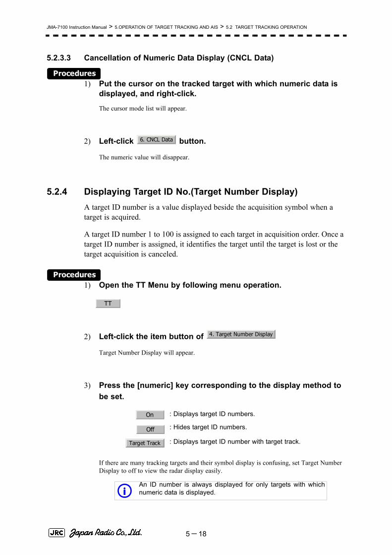
JMA-7100 Instruction Manual > 5.OPERATION OF TARGET TRACKING AND AIS > 5.2 TARGET TRACKING OPERATION
5.2.3.3 Cancellation of Numeric Data Display (CNCL Data)
Procedures1) Put the cursor on the tracked target with which numeric data is
displayed, and right-click.
The cursor mode list will appear.
2) Left-click button.
The numeric value will disappear.
5.2.4 Displaying Target ID No.(Target Number Display)A target ID number is a value displayed beside the acquisition symbol when a target is acquired.
A target ID number 1 to 100 is assigned to each target in acquisition order. Once a target ID number is assigned, it identifies the target until the target is lost or the target acquisition is canceled.
Procedures1) Open the TT Menu by following menu operation.
2) Left-click the item button of
Target Number Display will appear.
3) Press the [numeric] key corresponding to the display method to be set.
If there are many tracking targets and their symbol display is confusing, set Target Number Display to off to view the radar display easily.
: Displays target ID numbers.
: Hides target ID numbers.
: Displays target ID number with target track.
An ID number is always displayed for only targets with whichnumeric data is displayed.
6. CNCL Data
TT
4. Target Number Display
On
Off
Target Track
i
5-18

JMA-7100 Instruction Manual > 5.OPERATION OF TARGET TRACKING AND AIS > 5.2 TARGET TRACKING OPERATION
5
5.2.5 Adding Tracked Target ID Name (Name)The system can enter a name for each of tracking targets that have been acquired.
Procedures1) Put the cursor on the tracked target, and right-click.
The cursor mode list will appear.
2) Left-click
The Property will appear.
3) Left-click the item button of .
The setting items for ship name (Name) will be displayed.
4) Select the input method.
5.2.5.1 Entering a new ship name (Input)
5) Input a new ship name.
Up to 8 characters can be input as a ship name.For the input method on the character input screen, see Section 3.3.4.7 "Entering a character".
The input name by selecting is saved in Data Base .
5.2.5.2 Selecting one of previously input ship names (Data Base)
5) Press the [numeric] key corresponding to the ship name to be selected.
The selected ship name will be entered.
:Selection of one of previously input shipnames.When this method is selected, a list of shipnames that have been input by selecting will be displayed.
:Input of a new ship name. When this method isselected, the ship name (Name) input window willopen.
i Data Base can contain 30 ship names.
8. Property
1. Name
Data Base
Input
Input
Input
5-19

JMA-7100 Instruction Manual > 5.OPERATION OF TARGET TRACKING AND AIS > 5.2 TARGET TRACKING OPERATION
5.2.6 Reference Target (Reference)
The system can display the own ship's speed. To do so, it sets a reference target by tracking a target for which ground fixed.
Procedures1) Tracking a target for which ground fixed.
2) Put the cursor on the tracked target, and right-click.
The cursor mode list will appear.
• The reference target function is to be used if the own ship's speed cannot be displayed normally due to trouble such as a speed sensor malfunction. Do not use the reference target function except in emergencies.
• If the speed or course of the own ship is changed or a new reference target is set, the displayed speed may take 3 minutes or more to reach the specified speed after the speed / course change or the setting.
• Even after 3 minutes or more has passed, the speed may differ from the specified speed depending on the tracking condition.
• If a large radar echo such as a land target is set as a reference target, the vectors of the speed and other tracking targets will not be displayed correctly and may cause an accident.
• If a sailing ship is set as a reference target, the vectors of the speed and other tracking targets will not be displayed correctly and may cause an accident.
• If the is selected for the speed sensor, the AIS function cannot be turned on.
• If the reference target is lost or the target tracking function is stopped, the speed sensor is placed in manual mode .
• The loss of a reference target may have a major impact on the accuracy of the results for true speed and true course of the target and that own speed will be degraded.
• The reference targets are only used for the calculation of true speed.
Attention
REF.
MAN
5-20

JMA-7100 Instruction Manual > 5.OPERATION OF TARGET TRACKING AND AIS > 5.2 TARGET TRACKING OPERATION
5
3) Left-click
The Property will appear.
4) Left-click the item button of
The reference target function will be set to on or off.
5) Left-click the speed sensor switching button in the Own Ship Information located at the upper right of the display, and select
.
The speed of own ship calculated from the reference target will be displayed.
When a reference target is set, the symbol display is changed to .
Only one target can be set as a reference target.When a new reference target is set, the previously set reference target is canceled.
5.2.7 Operation Test (TT Test Menu)
The following functions are available for testing the target tracking function:
:A reference target is set.
:The reference target is canceled.
This function is provided to test if the target tracking function is operating normally. Thus, do not use the function except when you test the target tracking function.
In particular, if the operation test mode is used during navigation, pseudo targets appear on the radar display and they are confused with actual targets.
Do not use the mode during navigation. Otherwise, an accident may result.
Test Video Makes an operation check on the target detection circuit.
TT Simulator Generates pseudo targets on the radar display in order to testif the target tracking function is operating normally.
Status Displays the status of the target tracking function.
Gate Display Displays the gate size for acquiring / tracking a target.
8. Property
3. Reference
On
Off
REF.
R
5-21

JMA-7100 Instruction Manual > 5.OPERATION OF TARGET TRACKING AND AIS > 5.2 TARGET TRACKING OPERATION
5.2.7.1 Test Video (Test Video)
Test Video is used to check whether the video signals under target acquisition and tracking are inputted to and processed in the target detection circuit normally.
However, it is sufficient to check that VDH in Test Video is displayed.
Procedures1) Open the TT test menu by following menu operation.
→
2) Left-click the item button of .
The setting items for Test Video will be displayed.
3) Select the test video to be displayed.
In general, is sufficient for target display checks in test video mode.
Cancel1) Left-click the item button of while the TT Test Menu is
displayed.
The setting items for Test Video will be displayed.
2) Left-click button.
The test video display will be turned off.
NOTE:Test Video may not be displayed for a target which is not yetacquired or tracked. Test Video may not be displayed either ifthe [GAIN] dial or [SEA] dial is not properly adjusted.
iIf any target displayed clearly in the radar display is notdisplayed in the Test Video mode, the target detection circuit ofthe Target Tracking unit may have a trouble.
TT
9. TT Test Menu
1. Test Video
VDH
1. Test Video
Off
5-22

JMA-7100 Instruction Manual > 5.OPERATION OF TARGET TRACKING AND AIS > 5.2 TARGET TRACKING OPERATION
5
5.2.7.2 Target Tracking Simulator (Target Tracking Simulator)
Pseudo targets can be generated in certain known positions to check whether the target tracking units are operating normally. Since the pseudo targets move depending on known parameters, the values for these pseudo targets can be compared with the known value if the pseudo targets are acquired and tracked, and displayed. Thus, it can be checked if the system is operating normally.
Procedures1) Press the [TX/STBY] key to stop the transmitting.
The equipment will enter the transmission standby state.
2) Open the TT Test Menu by performing the following menu operation.
→
3) Left-click the item button of .
The setting items for TT Simulator will be displayed.
4) Select the scenario to be set.
5) Press the [TX/STBY] key to transmit.
The simulator will be activated and generate pseudo targets. The characters "X" at the bottom of the radar display blinks indicating that the simulation mode is active.
Target tracking simulator / scenario
Scenario Target start point Target end point Pseudo- targetspeed
Distance Bearing Distance Bearing
1 3.2NM 20° 1NM 90° 20kn
2 6NM 0° 0NM 0° 10kn
3 6NM 18° every 1NM 18° every 10kn
4 6NM 45° 1NM 45° 105kn
5 6NM 45° 6NM 150° 20kn
6 6NM 45° 6NM 150° 20kn
iWhen the simulator is operating, set 0° as the heading bearing,and 0 kn as the speed of own ship.When the range betweenown ship and the pseudo target is 0, the target will disappear.
TT
9. TT Test Menu
2. TT Simulator
5-23

JMA-7100 Instruction Manual > 5.OPERATION OF TARGET TRACKING AND AIS > 5.2 TARGET TRACKING OPERATION
Exit1) Press the [TX/STBY] key to stop the transmitting.
The equipment will enter the transmission standby state.
2) Left-click the item button of while the TT Test Menu is displayed.
The setting items for TT Simulator will be displayed.
3) Left-click .
The TT Simulator display will be turned off.
5.2.7.3 Status display (Status)
The current Target Tracking status will appear.
Procedures1) Open the TT Test Menu by performing the following menu
operation.
→
2) Left-click the item button of .
The setting items for Status will be displayed.
: Vector response
: Threshold value used for automatic acquisition
: Threshold value used for tracking
: Unused
: Size of gate used for tracking
: Number of targets currently acquired
2. TT Simulator
Off
TT
9. TT Test Menu
3. Status
*Constant
*VID Level TD
*VID Level HIGH
*VID Level LOW
*Gate Size
*Tracking
5-24

JMA-7100 Instruction Manual > 5.OPERATION OF TARGET TRACKING AND AIS > 5.2 TARGET TRACKING OPERATION
5
5.2.7.4 Gate Display
The gate displays an area monitoring a target using the Target Tracking function. This radar equipment allows the gate size to change automatically according to target range and size. User can check the gate size using the following function.
Procedures1) Open the TT Test Menu by performing the following menu
operation.
→
2) Left-click the item button of .
The gate display mode is switched.
3) Display the numeric value of a target according to Section 5.2.3 "Tracked Target Data Display [TGT DATA]" .
The numeric value of the target will be displayed, and the tracked target symbol will be enclosed in a green gate.
: Gate is displayed
: Gate is not displayed
iThe Target Tracking can display the gate of two targetssimultaneously.
TT
9. TT Test Menu
4. Gate Display
On
Off
Tracked Target symbol
Echo Gate (displayed in green )
Vector
5-25

JMA-7100 Instruction Manual > 5.OPERATION OF TARGET TRACKING AND AIS > 5.3 AIS OPERATION
5.3 AIS OPERATION
5.3.1 RestrictionsThe following restrictions are placed on use of the AIS function.
The AIS function is unavailable in the following cases:
• or is selected for the speed sensor.The current offset (Set/Drift Setting) is set while or is selected for the speed sensor.
or cannot be selected for the speed sensor in the following case:
• The AIS function is turned on and the current offset (Set/Drift Setting) is selected.
cannot be selected for the speed sensor in the following case:
• The AIS function is On.
Current offset (Set/Drift Setting) cannot be turned On in the following case:
• or is selected for the speed sensor while the AIS function is on.
5.3.2 Setting AIS Display Function (AIS Function)
Procedures1) Press the [AIS/TT] key. Alternatively, left-click the button
in the Target Information located at the upper right of the display.
The received AIS information will be shown on the radar display.
• When the AIS function is set to Off, the AIS display function is turned off and AIS symbols are no longer displayed.
• Once the AIS display function is set to Off, it is not automatically switched to On even if a dangerous target exists.
MAN REF.
LOG 2AXW
LOG 2AXW
MAN
LOG 2AXW
Attention
AIS
5-26

JMA-7100 Instruction Manual > 5.OPERATION OF TARGET TRACKING AND AIS > 5.3 AIS OPERATION
5
5.3.3 Activate AIS Targets (Activate AIS)
Activate an AIS target, and display the target’s vector and make a collision decision.
5.3.3.1 Manual activation (ACT AIS)
Activate an AIS target in manual mode to display the vector and heading line.
Procedures1) Put the cursor on the AIS symbol to be activated, and right-click.
The setting items for cursor modes will be displayed.
2) Left-click .
The selected AIS target will be activated.
5.3.3.2 Automatic activation
Activate an AIS target in automatic mode to display the vector and heading line.
When the automatic activation function is used, AIS targets are automatically activated when they go into the automatic activation zone. The automatic activation zone is identical to the automatic acquisition zone (AZ) used for target tracking. For the zone setting, refer to Section 5.2.1 "Acquiring Target [ACQ]"
The position of the scanner shall be at the centre of the azimuth or range in the acquisition/activation zone.
If there are more AIS targets than the allowable maximum, they are deactivated in the low-priority (See the Section 5.1.2 "Definitions of Symbols").
5.3.4 Deactivate AIS Targets (Deactivate AIS)Deactivate an AIS target and clear the display of the vector and heading line.
Procedures1) Put the cursor on the AIS target to be deactivated, and right-click.
The setting items for cursor modes will be displayed.
2) Left-click
The selected AIS target will be deactivated.
iIf an AIS target is activated but the vector is not displayed, referto Section 5.3.6 "Displaying Target ID No. (Target NumberDisplay)".
iThis operation is available only for an activated AIS target.
2. ACT AIS
5. DEACT AIS
5-27

JMA-7100 Instruction Manual > 5.OPERATION OF TARGET TRACKING AND AIS > 5.3 AIS OPERATION
5.3.5 Displaying AIS Information [TGT DATA]
5.3.5.1 Types of information displayed
There are two modes (simple and detail) to display AIS target information. The display items are determined by the selected mode.
The detail mode displays the numeric data of only a single ship, the simple mode can display the numeric data of up to two ships.
For NAV Status, one of the following statuses is displayed in accordance with Navigation Status:
Display Item Detail mode Simple mode
NAME (ship name) Up to 20 characters
Call Sign Up to 7 characters
MMSI Up to 9 charactersCOG (course over ground) or CTW (course through water) 0.1° unitSOG (speed over ground) or STW (speed through water) 0.1kn unit
CPA (closest point of approach) 0.01NM unit
TCPA (time to CPA) 0.1min unit
BRG (true bearing) 0.1° unit Not displayedRange 0.01NM unit
HDG (heading bearing) 0.1° unit
ROT (rate of turn) 0.01° /min
POSN (latitude / longitude) 0.001' unit
Destination (waypoint) Up to 20 characters
NAV Status Status (number)
No. Status0 Under Way Using Engine1 at Anchor2 Not Under Command3 Restricted Manoeuvrability4 Constrained by Her Draft5 Moored6 Aground7 Engaged in Fishing8 Under Way Sailing9 Reserved
10 Reserved11-14 Reserved
15 Not Defined
5-28

JMA-7100 Instruction Manual > 5.OPERATION OF TARGET TRACKING AND AIS > 5.3 AIS OPERATION
5
5.3.5.2 Displaying AIS Target Information [TGT DATA]
Procedures1) Put the cursor on the AIS target of which information is to be
displayed , and press the [TGT DATA] key.
The information of the selected AIS target will be displayed.
5.3.5.3 Canceling AIS Target Information Display (CNCL Data)
Procedures1) Put the cursor on the activated AIS target of which information
display is to be cancelled, and right-click.
The setting items for cursor modes will be displayed.
2) Left-click .
The information display of the selected AIS target will be cleared.
5.3.5.4 Selecting Detail / Simple Mode for AIS Target Information Display
Procedures1) Left-click the or button in the Digital Information located
at the center right of the display.
The detail or simple mode display for AIS target information will be selected.
5.3.5.5 Message
Received AIS messages can be displayed.
Up to 10 messages of addressed message and up to 10 messages of broadcast message can be displayed.
If the number of messages exceeds 10, the oldest received messages are sequentially deleted.
[1] Displaying Message Selected from List (Message)
Procedures1) Open the Message menu by performing the following menu
operation.
iWhen the numeric data of a target is displayed but the mark
is not on the radar display, the target is outside thedisplay.
AIS12
6. CNCL Data
□ _
5-29

JMA-7100 Instruction Manual > 5.OPERATION OF TARGET TRACKING AND AIS > 5.3 AIS OPERATION
→
2) Left-click or .
Addressed messages list or broadcast messages list are displayed.
Each list shows ship names and message-received time.
For an unread message, is displayed to the left of the item number.
3) Left-click the item button to display the message.
The message will appear.
[2] Displaying Specified Target's Message
Procedures1) Display AIS target information.
If there are messages from the target, a message mark will be displayed in the Digital Information located at the center right of the display.
2) Left-click the unread message display button in the Digital Information located at the center right of the display.
The message will appear.
[3] Deleting Message (Delete)
Procedures1) Left-click while the message is displayed.
The Confirmation Window will appear.
2) Left-click to delete the message.
The message will be deleted, and the ship name and message-received time will disappear from the list.
AIS
9. TT Test Menu
Addressed Message Broadcast Message
*
1. Delete
1. Yes
5-30

JMA-7100 Instruction Manual > 5.OPERATION OF TARGET TRACKING AND AIS > 5.3 AIS OPERATION
5
5.3.5.6 Displaying Data of Lost AIS Target (Display Lost TGT Data)
The data of the last-lost AIS target can be displayed.
The data of only one target that has been lost most recently can be displayed.
Procedures1) Open the Display Lost Target Data menu by performing the
following menu operation.
→
The data of the last-lost AIS target will be displayed.
5.3.5.7 Displaying Own Ship's AIS Data (Own Ship's AIS Data)
The AIS data of own ship can be displayed.
Procedures1) Open the Own Ship's AIS Data menu by performing the following
menu operation.
→
The own ship's AIS data will be displayed.
5.3.6 Displaying Target ID No. (Target Number Display)When an AIS target is activated, a target ID number is displayed next to the AIS target symbol.
A target ID number 1 to 100 is assigned to each target in activation order. Once a target ID number is assigned, it identifies the target until the target is lost or deactivated.
Procedures1) Open the Target Number Display menu by performing the
following menu operation.
→
AIS
8. Display Lost Target Data
AIS
9. Own Ship’s AIS Data
AIS
4. AIS Filter Setting
5-31

JMA-7100 Instruction Manual > 5.OPERATION OF TARGET TRACKING AND AIS > 5.3 AIS OPERATION
2) Left-click the item button corresponding to the display method to be set.
If there are many tracking targets and their symbol display is confusing, set Target Number Display to off to view the radar display easily.
5.3.7 Setting AIS Filter (AIS Filter Setting)
5.3.7.1 About an AIS filter
By setting an AIS filter, an AIS target in the area can be displayed by priority or only the targets in the area can be displayed. An AIS filter is initially set in a circle having a radius of 20 [nm] from the CCRP. If 301 or more AIS targets exist in the filter range, they are displayed in the priority order explained in Section 5.1.2 "Definitions of Symbols".
5.3.7.2 Types of AIS Filters (Filter Type)
There are the following 3 types of AIS filters:
Procedures1) Left-click the AIS filter mode switching in Target Information
located at the upper right of the display, and select the filter to be set.
The AIS filter will be selected.
: Displays target ID numbers.
: Hides target ID numbers.
: Displays target ID number with AIS track.
: Displays the ship's name.
iAn ID number or ship's name is always displayed for onlytargets with which numeric value is displayed.
: A filter is set in a circle with a set range as the radius.
: A filter is set in a sector formed by two bearings with thebow as reference.
: A filter is set in a zone formed by two bearings and tworanges with the bow as reference.
On
Off
Target Track
Ship’s Name
Range
Sector
Zone
5-32

JMA-7100 Instruction Manual > 5.OPERATION OF TARGET TRACKING AND AIS > 5.3 AIS OPERATION
5
5.3.7.3 Creation of AIS Filter (Make AIS Filter)
Procedures1) Open the AIS Filter Setting menu by performing the following
menu operation.
→
2) Left-click .
The mode to make an AIS filter will be activated.
[1] Setting Range Filter
3) Set a filter range by turning the [VRM] dial, and left-click.
[2] Setting Sector Filter
3) Set a starting bearing by turning the [EBL] dial, and left-click.
4) Set an ending bearing by turning the [EBL] dial, and left-click.
[3] Setting Zone Filter
3) Set a starting bearing and range by turning the [EBL] dial and [VRM] dial, and left-click.
4) Set an ending bearing and range by turning the [EBL] dial and [VRM] dial, and left-click.
iWhen the automatic activation function is enabled, the filterrange is automatically changed for covering the automaticactivation zone. Thus, the automatic activation zone is alwayswithin the filter range.
AIS
4. AIS Filter Setting
2. Make AIS Filter
5-33

JMA-7100 Instruction Manual > 5.OPERATION OF TARGET TRACKING AND AIS > 5.3 AIS OPERATION
5.3.7.4 AIS Filter Display On/Off (Filter Display)
Procedures1) Open the AIS Filter Setting menu by performing the following
menu operation.
→
2) Left-click the item button of .
Filter Display will be set to on or off.
5.3.7.5 Display of Targets outside AIS Filter (Filter Mode)
Procedures1) Open the Filter Mode menu by performing the following menu
operation.
→
2) Left-click the item button of .
: Displays only AIS targets in the AIS filter.
: Displays AIS targets in the AIS filter by priority, and alsodisplays targets outside the AIS filter.
iActivated AIS targets can be displayed even when they areoutside the AIS filter.
AIS
4. AIS Filter Setting
3. Filter Display
AIS
4. AIS Filter Setting
6. Filter Mode
Display
Priority
5-34

JMA-7100 Instruction Manual > 5.OPERATION OF TARGET TRACKING AND AIS > 5.3 AIS OPERATION
5
5.3.7.6 Point Filter
AIS targets which are not displayed because they are outside the AIS filter or at low priority levels can be activated by giving a higher priority to them.
Procedures1) Put the cursor on the position where a point filter is to be set,
and right-click to select the filter to be set.
The setting items for cursor modes will be displayed.
2) Left-click .
A point filter will be set at the cursor position.
If an AIS target is in the point filter, it will be activated.
When an AIS target is activated or an AIS target is not found within one minute, the point filter will be cleared.
5.3.8 Conditions for Deciding AIS Target to be LostAbout a lost target
When the data of an AIS target cannot be received for a specified time, the target is decided to be lost and the target data is deleted. As shown in the table below, the time until target data is deleted varies depending on the class of receive data and the target status.
If the [ALARM ACK] key is pressed, the symbol is cleared.
iThe point filter's range is 1 nm, and cannot be changed.
Deciding AIS Target to be Lost
Target status Time until data deletion
SOLAS ship (Class A) SOLAS ship (Class B)
Vessel below 3 knots (Class A) or 2 knots (Class B) and it is now at anchor or on the berth
18 min 18 min
Vessel of 3 knots or more and it is now at anchor or on the berth
60 sec 18 min
Vessel of 0 to 14 knots (Class B: 0 to 14 knots) 60 sec 180 sec
Vessel of 14 to 23 knots 36 sec 180 sec
Vessel of 23 knots or more 30 sec 180 sec
iWhen a dangerous target ship is lost, a lost alarm is issued andthe symbol changes to a lost symbol. The system calculatesthe current position from the last-received data and continuesdisplaying the symbol for eternity.
2. ACT AIS
5-35

JMA-7100 Instruction Manual > 5.OPERATION OF TARGET TRACKING AND AIS > 5.3 AIS OPERATION
5.3.9 Setting Conditions for AIS Alarm (AIS Alarm Setting)Conditions for issuing a Lost alarm and CPA/TCPA alarm for AIS targets can be set.
5.3.9.1 Setting of Condition for Lost Alarm
Procedures1) Open the AIS Alarm Setting menu by performing the following
menu operation.
→
2) Left-click the item button of .
The setting items for Lost Alarm will be displayed.
3) Left-click the item button corresponding to the condition to be set.
5.3.9.2 Setting of Condition for CPA/TCPA Alarm
Procedures1) Open the AIS Alarm Setting menu by performing the following
menu operation.
→
2) Left-click the item button of .
The setting items for CPA/TCPA Alarm is switched.
: A lost alarm is not issued.
: A lost alarm is issued only for AIS targets for which adangerous target alarm has been issued.
: A lost alarm is issued only for activated AIS targets andAIS targets for which a dangerous target alarm has beenissued.
iA lost alarm is not issued for sleeping AIS targets.
: A CPA/TCPA alarm is issued only for activated AIS targets.
: A CPA/TCPA alarm is issued for all AIS targets on the radardisplay.
AIS
6. AIS Alarm Setting
1. Lost Alarm
Off
Danger
ACT&Danger
AIS
6. AIS Alarm Setting
CPA/TCPA Alarm
ACT
ACT&Sleep
5-36

JMA-7100 Instruction Manual > 5.OPERATION OF TARGET TRACKING AND AIS > 5.4 DECISION OF TARGETS AS IDENTICAL(Association)
5
5.4 DECISION OF TARGETS AS
IDENTICAL (Association)
5.4.1 Setting of Function to Decide Targets as Identical (Association)When an AIS target and a tracking target are decided to be identical, an association symbol is displayed for the targets regarded as identical. In this case, the AIS target symbol is automatically activated.
Procedures1) Left-click the in Target Information located at the
upper right of the display.
Association will be set to on or off.
5.4.2 Setting of Conditions for Deciding AIS and Tracked Targetsas Identical (Association Setting)
Procedures1) Open the Association Setting menu by performing the following
menu operation.
→
The Association Setting menu will appear.
2) Select and enter the item to be set.
Conditions for deciding targets as identical will be set. When the differences of all item between AIS and tracked target are under the set conditions..
• Turn off in order not to make a decision on if targets are identical, or in order to display symbols that have disappeared.
Attention
Association
Association
AIS
1. Association Setting
5-37

JMA-7100 Instruction Manual > 5.OPERATION OF TARGET TRACKING AND AIS > 5.4 DECISION OF TARGETS AS IDENTICAL (Association)
Once regard as identical, when one of the differences exceed 125% of the set condition, they are regarded as dissidence.
5.4.3 Types of Decision Conditions to be Set
iThe setting for this function is common to Association Setting inthe AIS Menu.
Decision conditions
1. Association On / Off (Function to decide targets asidentical)
2. Priority AIS / TT (Symbol to be displayed)
3. Bearing 0.0~9.9°
4. Range 0~999m
5. Cource 0~99°
6. Speed 0~99kn
7.Applicable AIS Target ACT or ACT&Sleep (activated AIS target orall AIS target)
If a great value is set as a condition for deciding targets as identical, a tracking target near an AIS target is regarded as identical to the AIS target and it may not be displayed any more.
For example, when a pilot boat (which is a small target not being tracked) equipped with an AIS function approaches a cargo ship as a tracking target not equipped with an AIS function, the tracking target symbol of the cargo ship may not be displayed any more.
5-38

JMA-7100 Instruction Manual > 5.OPERATION OF TARGET TRACKING AND AIS > 5.5 ALARM DISPLAY
5
5.5 ALARM DISPLAY
Alarm messages for Target Tracking (TT) and AIS functions:
Error message and alarm are displayed in the lower right of the display.
Error message DescriptionCPA/TCPA There is a dangerous target.New Target A new target is acquired in the automatic acquisition zone.Lost There is a lost target.REF Target The accuracy of the reference target may be decreased.95% Capacity The number of targets being tracked by the Target Tracking
function has reached 95% of the maximum.MAX Target The number of targets being tracked by the Target Tracking
function has reached the maximum.AIS 95% Capacity The number of displayed AIS target symbols has reached 95%
of the maximum.AIS MAX Target The number of received data items exceeds the maximum
number of AIS target symbols that can be displayed.AIS ACT 95% Capacity The number of activated AIS targets by the AIS function has
reached 95% of the maximum.AIS ACT MAX The number of activated AIS targets by the AIS function has
reached the maximum.AIS Alarm *** Alarm information issued with the ALR sentence by the AIS.
*** is a 3-digit number which is Local Alarm No in the ALRsentence.
AIS Alarm 001 Tx malfunctionAIS Alarm 002 Antenna VSWR exceeds limitAIS Alarm 003 Rx channel 1 malfunctionAIS Alarm 004 Rx channel 2 malfunctionAIS Alarm 005 Rx channel 70 malfunctionAIS Alarm 006 general failureAIS Alarm 008 MKD connection lostAIS Alarm 025 external EPFS lostAIS Alarm 026 no sensor position in useAIS Alarm 029 no valid SOG informationAIS Alarm 030 no valid COG information AIS Alarm 032 Heading lost/invalidAIS Alarm 035 no valid ROT information
5-39

JMA-7100 Instruction Manual > 5.OPERATION OF TARGET TRACKING AND AIS > 5.5 ALARM DISPLAY
5.5.1 CPA / TCPA Alarm
In the system, targets are categorized into two types: tracked / activate AIS targets and dangerous targets.
The grade of danger can easily be recognized on the display at a glance. So the officer can easily decide which target he should pay attention to.
It is not possible to switch off the tracked target visual alarm, unless tracking is ceased, or the alarm condition no longer applies.
The types of target and alarm are shown below.
CPA Limit and TCPA Limit: The Setting Values
Since these alarms may include some errors depending on the target tracking conditions, the navigation officer himself should make the final decision for ship operations such as collision avoidance.
Making the final navigation decision based only on the alarm may cause accidents such as collisions.
CPA / TCPA Alarm
Status Symbol ondisplay
A l a r mcharacters
A l a r msound
Conditions
Tracked target (Off) (Off) ・CPA>CPA LIMIT
・0>TCPA
・TCPA>TCPA LIMIT
The symbol is displayedwhen one of the aboveconditions is met.
Activated AIS target
Dangerous target
Red blinking
CPA/TCPA Beep sound (pee-poh)
Alarm acknowledgeable
・CPA≦CPA LIMIT
・0≦TCPA≦TCPA LIMIT
An alarm is issued when allthe conditions are met.
The AIS targets that issuesalarm refer to 5.3.9
Red blinking
12
AIS12
12
AIS12
5-40

JMA-7100 Instruction Manual > 5.OPERATION OF TARGET TRACKING AND AIS > 5.5 ALARM DISPLAY
5
5.5.2 Alarm for New Target Acquired in Automatic AcquisitionZone (New Target)
The automatic acquisition function sets a zone in a range and issues an alarm when a new target (which is not yet acquired) goes into this zone.
For the setting of an automatic acquisition zone, refer to " Acquiring Target " in Section 5.2.1.1 "Automatic acquisition".
5.5.3 Lost Target Alarm (Lost)
In setting an automatic acquisition zone, it is necessary to adjust the gain, sea clutter suppression and rain / snow clutter suppression to ensure that target echoes are displayed in the optimum conditions. No automatic acquisition zone alarms will be issued for targets undetected
Alarm for New Target Acquired in Automatic Acquisition Zone
Status Symbol ondisplay
A l a r mcharacters
Alarm sound Conditions
New target in automatic acquisition zone
Red Blinking
New Target Beep sound (pipi-pipi)
Alarm acknowledge
able
The alarm is issuedwhen a new target isacquired in theautomatic acquisitionzone.
iWhen an already acquired target goes into automaticacquisition zone, the alarm message is not displayed and thebuzzer does not sound either.
• If the gain, sea clutter suppression, rain/snow clutter suppression are not adjusted adequately, the lost target alarm may be easily generated. So such adjustments should be mad carefully.
12
Attention
5-41

JMA-7100 Instruction Manual > 5.OPERATION OF TARGET TRACKING AND AIS > 5.5 ALARM DISPLAY
When it is impossible to continue tracking any acquired and tracked target, or the data of AIS target cannot received for a specified time, the will be generated. The typical causes for alarm generation are shown below, but not limited to the following:
• The target echo is very weak.• The target is shadowed by a shore or a large ship and its echo is not received.• The target echo is blurred by sea clutter returns.
If a target under tracking goes out of a range of 32 nm and can no longer be tracked, it is canceled without a lost target alarm.
5.5.4 Gyro Set AlarmThe GYRO I/F in this system receives signals from a gyro. Even if the power is turned off, the system will follow up the gyro. However, the system stops the follow-up operation when the power of the master gyro is turned off or when any trouble occurs to the line. When the power of the master gyro is recovered, the
alarm will be generated.
If this alarm occurs, set the gyro.
Lost Target Alarm
Status Symbol on display
Alarm characters
Alarm sound
Conditions
Lost Target
Red Blinking
Lost Beep sound (pee)
Alarm acknowledge
able
The alarm will soundonce when a losttarget symbol isdisplayed.
Red Blinking
Gyro Set Alarm
A l a r mcharacters
Alarm sound Conditions
Set Gyro Beep sound (pipi-pipi) The signals from the gyro are stopped, but thegyro is recovered.
Lost Alarm
12
AIS12
Set Gyro
5-42
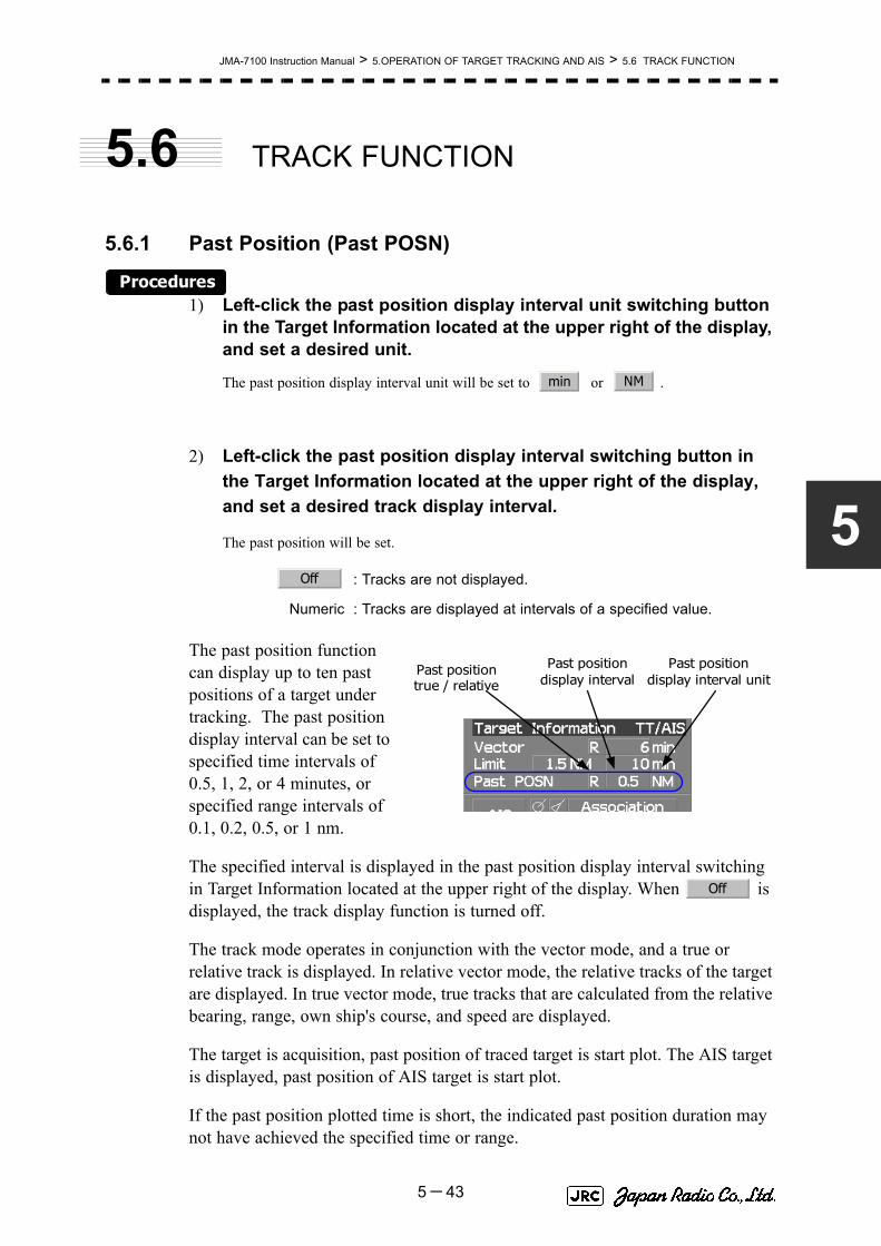
JMA-7100 Instruction Manual > 5.OPERATION OF TARGET TRACKING AND AIS > 5.6 TRACK FUNCTION
5
5.6 TRACK FUNCTION
5.6.1 Past Position (Past POSN)
Procedures1) Left-click the past position display interval unit switching button
in the Target Information located at the upper right of the display, and set a desired unit.
The past position display interval unit will be set to or .
2) Left-click the past position display interval switching button in the Target Information located at the upper right of the display, and set a desired track display interval.
The past position will be set.
The past position function can display up to ten past positions of a target under tracking. The past position display interval can be set to specified time intervals of 0.5, 1, 2, or 4 minutes, or specified range intervals of 0.1, 0.2, 0.5, or 1 nm.
The specified interval is displayed in the past position display interval switching in Target Information located at the upper right of the display. When is displayed, the track display function is turned off.
The track mode operates in conjunction with the vector mode, and a true or relative track is displayed. In relative vector mode, the relative tracks of the target are displayed. In true vector mode, true tracks that are calculated from the relative bearing, range, own ship's course, and speed are displayed.
The target is acquisition, past position of traced target is start plot. The AIS target is displayed, past position of AIS target is start plot.
If the past position plotted time is short, the indicated past position duration may not have achieved the specified time or range.
: Tracks are not displayed.
Numeric : Tracks are displayed at intervals of a specified value.
min NM
Off
Past position display interval
Past position true / relative
Past position display interval unit
Off
5-43

JMA-7100 Instruction Manual > 5.OPERATION OF TARGET TRACKING AND AIS > 5.6 TRACK FUNCTION
5.6.2 Target Ship's Tracks (Target Track)This function makes settings for the tracks of tracked targets and AIS targets.
The system can display the tracks of up to 20 target ships.
5.6.2.1 Track Color Setting (Target Track Color)
Procedures1) Put the cursor on the tracked target or activated AIS target, and
right-click.
The setting items for cursor modes will be displayed.
2) Left-click .
The Property will appear.
3) Left-click the item button of .
The setting items for Track Color will be displayed.
4) Left-click the button corresponding to the track color to be set.
Colors set by performing the procedure in Section 5.6.2.3 "Setting of Target Ship's Track Colors (Target Track Color)" can be selected.
Individual colors can be set for up to 10 ships. The same color is set for 11 to 20 ships.
5.6.2.2 Target Ship's Track Function On/Off (Target Track Function)
Procedures1) Open the T.TRK menu by performing the following menu
operation.
→
2) Left-click the item button of .
The Target Track Function will be set to on or off.
: Target Track Function is turned on.
: Target Track Function is turned off.
iNote that when this function is turned off, all the other ship'strack functions are turned off. In this case, the track data ofother ships is not saved, so they cannot be traced later.
Property
2. Track Color
TT
2. Target Track Setting
1. Target Track Function
On
Off
5-44

JMA-7100 Instruction Manual > 5.OPERATION OF TARGET TRACKING AND AIS > 5.6 TRACK FUNCTION
5
5.6.2.3 Setting of Target Ship's Track Colors (Target Track Color)
You can set either one track color for all targets under tracking, or individual colors for the ships of track numbers 1 to 10. The tracks of ships 11 to 20 are displayed in the same color.
Procedures1) Open the Target Track Color menu by performing the following
menu operation.
→
→
→
The setting items for All will be displayed.
2) Left-click the button corresponding to the track display to be set.
Individual setting
3) Left-click the button corresponding to the track number to be set.
The setting items for the selected track number will be displayed.
4) Left-click the button corresponding to the track color to be set.
The track color of the selected track number will be set.
When is selected, the track numbers to and the individual setting for are valid. Select a color for each target.
The color list is displayed by left-clicking the button corresponding to the item number to be set. Select a desired color. There are 8 color choices: ,
, , , , , , and .
iIf the other ship's track function (Target Track Function) isturned off, the track data of other ships is not saved.
: Track color is set individually for ships.color name : One color is set for all ships.
~ : Setting for 1 to 10 ships
: Setting for 11 to 20 ships
iNote that the individual setting is not enabled unless Individualis selected.
TT
2. Target Track Setting
2. Target Track Color
1. All
Individual
Individual Target Track No.1 No.10
Other
Off
White Gray Blue Green Yellow Pink Red
Target Track No.1 No.10
Other
5-45

JMA-7100 Instruction Manual > 5.OPERATION OF TARGET TRACKING AND AIS > 5.6 TRACK FUNCTION
5.6.2.4 Setting of Target Ship's Track Display (Target Track Display)
The target track display function can be turned on / off. Choices for track display are displaying / hiding the tracks of all ships and Individual (displaying the tracks of individual ships).
Procedures1) Open the Target Track Display menu by performing the following
menu operation.
→
→
→
The setting items for All will be displayed.
2) Left-click the button corresponding to the track display to be set.
Individual setting
3) Left-click the button corresponding to the track number to be set.
The selected track number display will be set to on or off.
When is selected, the track numbers to and the individual setting for are valid. Select on / off for each target.
: Track display is set for individual ships.
: The tracks of all ships are hidden.
: The tracks of all ships are displayed.
iEven when Target Track Display is turned off, the track data ofother ships is saved if Track Memory Interval is set.
:The track number display is turned on.
:The track number display is turned off.
~ : Setting for 1 to 10 ships
: Setting for 11 to 20 ships
iNote that the individual setting is not enabled unless Individualis selected.
TT
2. Target Track Setting
3. Target Track Display
1. All
Individual
Off
On
On
Off
Individual Target Track No.1 No.10
Other
Target Track No.1 No.10
Other
5-46
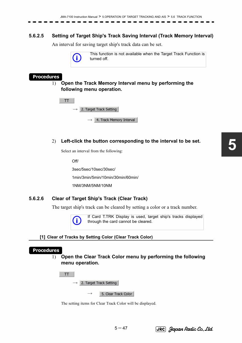
JMA-7100 Instruction Manual > 5.OPERATION OF TARGET TRACKING AND AIS > 5.6 TRACK FUNCTION
5
5.6.2.5 Setting of Target Ship's Track Saving Interval (Track Memory Interval)
An interval for saving target ship's track data can be set.
Procedures1) Open the Track Memory Interval menu by performing the
following menu operation.
→
→
2) Left-click the button corresponding to the interval to be set.
Select an interval from the following:
5.6.2.6 Clear of Target Ship's Track (Clear Track)
The target ship's track can be cleared by setting a color or a track number.
[1] Clear of Tracks by Setting Color (Clear Track Color)
Procedures1) Open the Clear Track Color menu by performing the following
menu operation.
→
→
The setting items for Clear Track Color will be displayed.
iThis function is not available when the Target Track Function isturned off.
Off/
3sec/5sec/10sec/30sec/
1min/3min/5min/10min/30min/60min/
1NM/3NM/5NM/10NM
iIf Card T.TRK Display is used, target ship's tracks displayedthrough the card cannot be cleared.
TT
2. Target Track Setting
4. Track Memory Interval
TT
2. Target Track Setting
5. Clear Track Color
5-47

JMA-7100 Instruction Manual > 5.OPERATION OF TARGET TRACKING AND AIS > 5.6 TRACK FUNCTION
2) Left-click the button corresponding to the color of the target tracks to be cleared.
The Confirmation Window will appear.
3) Left-click to clear the track line.
All the tracks of the selected color will be cleared.[2] Clear of Tracks by Setting Track Number (Clear Track Number)
Procedures1) Open the T.TRK menu by performing the following menu
operation.
→
→
The setting items for Clear Track Number will be displayed.
2) Left-click the button corresponding to the number of the tracks to be cleared.
The Confirmation Window will appear.
3) Left-click to clear the track line.
The tracks of the selected number will be cleared.
5.6.2.7 Operation of Target Ship's Track Data Saved on Card (FileOperations)
Target ship's track data can be saved on a flash memory card and read from the card.
[1] Loading File (Load)
Procedures1) Insert a flash memory card into the card slot
Flash memory card (option) is necessary.
iData can be saved to a flash memory card until the cardbecomes full, but the number of files that can be read anddisplayed is limited to 64 in alphanumeric order. When thenumber of files has reached 64, delete unnecessary files.
1. Yes
TT
2. Target Track Setting
6. Clear Track Number
1. Yes
5-48

JMA-7100 Instruction Manual > 5.OPERATION OF TARGET TRACKING AND AIS > 5.6 TRACK FUNCTION
5
2) Open the File Operations menu by performing the following menu operation.
→
→
3) Left-click the item button of to select a card slot.
The setting item for Select Card Slot is switched between Slot1 and Slot2.
4) Left-click the item button of to select Add or Overwrite.
The setting item for Load Mode is switched between and .
When is selected, new data is added to the current data on the card. When is selected, new data is saved over the current data on the card.
5) Left-click .
Currently saved target ship's track data will be listed.
6) Left-click the button corresponding to the file to be loaded.
The Confirmation Window will appear.
7) Left-click to load the file.
The selected target track data will be loaded and shown on the radar display.[2] Saving File (Save)
Procedures1) Insert a flash memory card into the card slot.
Flash memory card (option) is necessary.
TT
2. Target Track Setting
7. File Operations
1. Select Card Slot
2. Load Mode
Add
Overwrite
Add
Overwrite
3. Load
1. Yes
5-49

JMA-7100 Instruction Manual > 5.OPERATION OF TARGET TRACKING AND AIS > 5.6 TRACK FUNCTION
2) Open the File Operations menu by performing the following menu operation.
→
→
3) Left-click the item button of to select a card slot.
The setting item for Select Card Slot is switched between Slot1 and Slot2.
4) Left-click .
The Input File Name menu will appear.
5) Input the file name to be saved.
Up to ten characters can be input as a file name.
For inputs to the characters input screen, refer to Section 3.3.4.7 "Entering a character". After the input, the Confirmation Window will appear.
6) Left-click to save the file.
The currently displayed target track data will be saved.
TT
2. Target Track Setting
7. File Operations
1. Select Card Slot
4. Save
1. Yes
5-50

JMA-7100 Instruction Manual > 5.OPERATION OF TARGET TRACKING AND AIS > 5.6 TRACK FUNCTION
5
[3] Erasing File (Erase)
Procedures1) Insert the flash memory card into the card slot.
Flash memory card (option) is necessary.
2) Open the File Operations menu by performing the following menu operation.
→
→
3) Left-click the item button of to select a card slot.
The setting item for Select Card Slot is switched between Slot1 and Slot2.
4) Left-click .
The Erase menu will appear.
Currently saved target ship's track data on the card will be listed.
5) Left-click the button corresponding to the file to be erased.
The Confirmation Window will appear.
6) Left-click to erase the file.
The selected target track data will be erased and the file name will disappear from the list.
TT
2. Target Track Setting
7. File Operations
1. Select Card Slot
5. Erase
1. Yes
5-51

JMA-7100 Instruction Manual > 5.OPERATION OF TARGET TRACKING AND AIS > 5.6 TRACK FUNCTION
[4] Displaying File (Card Target Track Display)
Procedures1) Insert the flash memory card into the card slot.
Flash memory card (option) is necessary.
2) Open the File Operations menu by performing the following menu operation.
→
→
3) Left-click the item button of to select a card slot.
The setting item for Select Card Slot is switched between Slot1 and Slot2.
4) Left-click .
The Card T.TRK Display menu will appear.
Currently saved target ship's track data on the card will be listed.
5) Left-click the button corresponding to the file to be displayed.
The Confirmation Window will appear.
6) Left-click to display the T.TRK line.
The selected file will be highlighted, and the currently saved target track data will be displayed.
Cancel1) Open the Card T.TRK Display window.
The displayed file is highlighted.
2) Left-click the button corresponding to the displayed file.
The file will be deselected and returned to normal display.
TT
2. Target Track Setting
7. File Operations
1. Select Card Slot
6. Card T.TRK Display
1. Yes
5-52

JMA-7100 Instruction Manual > 5.OPERATION OF TARGET TRACKING AND AIS > 5.7 TRIAL MANEUVERING (Trial Maneuver)
5
5.7 TRIAL MANEUVERING
(Trial Maneuver)
The trial maneuvering is the function of simulating own ship’s course and speed for collision avoidance when a dangerous target appears. When the own ship's course and speed are entered in manual mode, the trial maneuvering function checks if pre-acquired or pre-activated targets are dangerous.
The ranges of course and speed to be entered manually:
• Trial maneuvering is to simulate own ship’s course and speed in the conditions that the course and speed of a target ship are unchanged as they are. As the situation is different from any actual ship maneuvering, set values with large margins to CPA Limit and TCPA Limit.
Course: 360° (in 0.1° intervals) ............................................... [EBL] dial
Speed: 0 to 100kn (in 0.1kn step)........................................ [VRM] dial
Attention
5-53

JMA-7100 Instruction Manual > 5.OPERATION OF TARGET TRACKING AND AIS > 5.7 TRIAL MANEUVERING (Trial Maneuver)
5.7.1 Trial Maneuvering in the True Vector ModeIn the True Vector mode, calculations are performed according to the values set by Trial Speed, Trial Course and other features, and the result is displayed as a bold-line that represents the change of own ship's vector as shown in the Fig 5-7 below (an example of the course changed to the right).
In this Fig 5-7, the dangerous target forward left becomes safe as a result of simulation.
The tracked target information indicates the current CPA and TCPA values regardless of the result of simulation.
Fig 5-7: True Vector Mode
Dangerous target
HL
Change of symbolas a result of
trial maneuver
HL
T
TRIAL
NORMAL
Route
Own ship’s vector
5-54

JMA-7100 Instruction Manual > 5.OPERATION OF TARGET TRACKING AND AIS > 5.7 TRIAL MANEUVERING (Trial Maneuver)
5
5.7.2 Trial Maneuvering in the Relative Vector ModeThe result of Trial maneuvering in the Relative Vector mode is shown by a change in target vector. In the Fig 5-8 below (in the same conditions as in the True Vector mode in the previous page), it is seen that the acquired target is a dangerous one because its vector is crossing the CPA RING.
Fig 5-8: Relative Vector Mode
The above Fig 5-8 shows that the relative vector of the target has changed as shown in the figure as a result of simulation (course and speed), so that the symbol color is changed into “White”, a safe target.
Irrespective of the simulation results, the current CPA and TCPA values are shown in the tracked target information just like when the true vector mode is active.
The course change of own ship is displayed as a dotted-line.
Better information is provided by using relative motion and sea stabilization.
CPA Ring
Change of symbolas a result of
trial maneuver
TRIAL
NORMAL
Dangerous target
CPA Ring
HL
HL
T
5-55

JMA-7100 Instruction Manual > 5.OPERATION OF TARGET TRACKING AND AIS > 5.7 TRIAL MANEUVERING (Trial Maneuver)
5.7.3 Operation of Trial Maneuvering Function
Procedures1) Open the Trial Maneuver menu by performing the following menu
operation.
→
2) Left-click the item button of .
The Trial Function will be set to on or off.
When Trial Function is set to on, the character " T " indicating trial maneuvering blinks in the own ship display field of the radar display.
3) Set values for Course by turning the [EBL] dial, and for Speed by turning the [VRM] dial.
4) Set other characteristics.
For inputs to the value input screen, refer to Section 3.3.4.2 "Directly entering a numeric value".
Dangerous target symbols are displayed in red and safe target symbols in white.
: The trial maneuvering function is turned on.
: The trial maneuvering function is turned off.
: Vector time (1 to 60 min)
: Time until trial maneuvering is started (0 to 30 min)
: Dynamic trait of the own ship
→ : Range from when steered to when the shipbeings to turn (0 to 2000 m)
→ : Turning radius (0.10 to 2.00 nm)
→ : Acceleration (0.0 to 100 knots/min)
→ : Deceleration (0.0 to 100 knots/min)
iVector Time is valid only when Trial Function is set to on. If it is off, the vector timebefore trial maneuvering is displayed.
Time until the start of trial maneuvering is counted down immediately after the input.The acceleration and deceleration are influenced depending on the relationshipbetween the current speed and the input speed for trial maneuvering.
If 0.0 kn/min is set for Acceleration when the speed for trial maneuvering is fasterthan the current speed, or for Deceleration when the speed for trial maneuvering isslower than the current speed, the system performs simulation on the assumptionthat the speed is changed immediately after the time set for Time to Maneuver .
TT
3. Trial Maneuver
1. Trial Function
On
Off
Vector Time
Time to Maneuver
Own Ship Dynamic Trait
Reach
Turn Radius
Acceleration
Decceleration
5-56

JMA-7100 Instruction Manual > 5.OPERATION OF TARGET TRACKING AND AIS > 5.7 TRIAL MANEUVERING (Trial Maneuver)
5
Cancel1) Open the Trial Maneuver menu by performing the following
menu operation.
→
2) Left-click the item button of .
The Trial Function will be set to on or off.
: The Trial Function will be set to off.
TT
3. Trial Maneuver
1. Trial Function
Off
5-57

JMA-7100 Instruction Manual > 5.OPERATION OF TARGET TRACKING AND AIS > 5.7 TRIAL MANEUVERING (Trial Maneuver)
5-58
SECTION 6TRUE AND FALSE ECHOES ON DISPLAY
TRUE AND FALSE ECHOES ON DISPLAY6.1 RADAR WAVE WITH THE HORIZON ...................................................6-16.2 STRENGTH OF REFLECTION FROM THE TARGET ...........................6-36.3 SEA CLUTTER AND RAIN AND SNOW CLUTTER ..............................6-56.4 FALSE ECHOES ....................................................................................6-96.5 DISPLAY OF RADAR TRANSPONDER (SART) ................................6-12


JMA-7100 Instruction Manual > 6.TRUE AND FALSE ECHOES ON DISPLAY > 6.1 RADAR WAVE WITH THE HORIZON
6
The radar operator has a role of interpreting the radar displays to provide his best aid in maneuvering the ship. For this purpose, the operator has to observe the radar displays after fully understanding the advantages and disadvantages that the radar has. For better interpretation of radar display, it is important to gain more experiences by operating the radar equipment in fair weathers and comparing the target ships watched with the naked eyes and their echoes on the radar display.
The radar is mainly used to monitor the courses of own ship and other ships in open seas, to check buoys and other nautical marks when entering a port, to measure own ship’s position in the coastal waters relative to the bearings and ranges of the shore or islands using a chart, and to monitor the position and movement of a heavy rain if it appears on the radar display.
Various types of radar display will be explained below.
6.1 RADAR WAVE WITH THE HORIZON
Radar beam radiation has the nature of propagating nearly along the curved surface of the earth. The propagation varies with the property of the air layer through which the radar beam propagates. In the normal propagation, the distance (D) of the radar wave to the horizon is approximately 10% longer than the distance to the optical horizon. The distance (D) is given by the following formula:
[NM]
: Height (m) of radar scanner above sea level
: Height (m) of a target above sea level
Fig 6-2 is a diagram for determining the maximum detection range of a target that is limited by the curve of the earth surface in the normal propagation.
Fig 6-1: RADAR wave with the horizon
D 2.23 h1 h2+( )=
h1
h2
D
Earth
h1
h2
Radar Targets
6-1

JMA-7100 Instruction Manual > 6.TRUE AND FALSE ECHOES ON DISPLAY > 6.1 RADAR WAVE WITH THE HORIZON
Fig 6-2: Maximum detection range of a target
When the height of own ship’s scanner is 10 m for instance,
i. A target that can be detected at the radar range of 64 nm on the radar displayis required to have a height of 660 m or more.
ii. If the height of a target is 10 m, the radar range has to be approx. 15 nm.However, the maximum radar range at which a target can be detected on theradar display depends upon the size of the target and the weather conditions,that is, the radar range may increase or decrease depending upon thoseconditions.
Height of RADAR Scanner Detective RangeHeight of Target
D[NM]
6-2

JMA-7100 Instruction Manual > 6.TRUE AND FALSE ECHOES ON DISPLAY > 6.2 STRENGTH OF REFLECTION FROM THETARGET
6
6.2 STRENGTH OF REFLECTION FROM
THE TARGET
The signal intensity reflected from a target depends not only on the height and size of the target but also on its material and shape. The echo intensity from a higher and larger target is not always higher in general.
In particular, the echo from a coast line is affected by the geographic conditions of the coast. If the coast has a very gentle slop, the echo from a mountain of the inland appears on the radar display.(Fig 6-3) Therefore, the distance to the coast line should be measured carefully.
Fig 6-3: Sea shore line which is not displayed
Table 6-1 shows the graph indicating the relation between the target detection distance and the radar reflection cross-sectional area (RCS) with regard to the type and the height of the target in a situation in which the weather is good, the sea state is calm and the radio wave propagation is normal. As revealed by this table, even on the same sea shore line, detection distance greatly differs depending on the height of the target from the surface of the sea. Furthermore, because the target detection distance is greatly influenced by the shape and material of the target and environmental conditions, such as the sea state, weather, and radio wave propagation, caution should be taken when detecting distance of target.
Mountain displayedon the radar display
Sea shore line not displayed
HL
6-3

JMA-7100 Instruction Manual > 6.TRUE AND FALSE ECHOES ON DISPLAY > 6.2 STRENGTH OF REFLECTION FROM THE TARGET
Table 6-1: Relation between type and height of target and detection distance and RCS
Type of target Height from sea surface
(m)
Detection distance (NM)
RCS
X band S band X band S band
Sea shore line 60 20 20 50,000 50,000
Sea shore line 6 8 8 5000 5000
Sea shore line 3 6 6 2500 2500
SOLAS target ship (>5000GT) 10 11 11 50,000 30,000
SOLAS target ship (>500GT) 5 8 8 1800 1000
Small boat with IMO standard compatible radar reflector
4 5.0 3.7 7,5 0,5
Marine buoy with corner reflector
3,5 4.9 3.6 10 1
Standard marine buoy 3,5 4.6 3.0 5 0,5
10-meter small boat without radar reflector
2 3.4 3.0 2,5 1,4
Waterway location beacon 1 2.0 1.0 1 0,1
Detection distance shown in the above table may greatlydecrease depending on the shape of the target, sea state,weather and radio wave propagation conditions.
m2[ ]
i
6-4

JMA-7100 Instruction Manual > 6.TRUE AND FALSE ECHOES ON DISPLAY > 6.3 SEA CLUTTER AND RAIN AND SNOWCLUTTER
6
6.3 SEA CLUTTER AND RAIN AND SNOW
CLUTTER
In addition to the echo required for observing ships and land, radar video image also includes unnecessary echo, such as reflection from waves on the sea surface and reflection from rain and snow. Reflection from the sea surface is called "sea clutter," and reflection from rain and snow is called "rain and snow clutter," and those spurious waves must be eliminated by the clutter rejection function.
a. Sea clutter
Sea clutter appears as an image radiating outwardly from the center of the radar display and changing depending on the size and the shape of waves. Generally, as waves become larger, image level of the sea clutter is intensified and the clutter far away is also displayed. When waves are large and the sea clutter level is high, it is difficult to distinguish sea clutter from a small boat whose reflection intensity is weak. Accordingly, it is necessary to properly adjust the sea clutter rejection function. Table 6-2 shows the relation between the sea state (SS) showing the size of waves generated by wind and the radar's detection probability.
Table 6-2: Sea state and probability of target detection
S band radar (probability to detect a target at a distance of 0.4 NM)
RCS SS1~2 SS2~3 SS3~4 SS4~5
0.1m2 Vi
i. V: Detection probability of 80 %
V-Mii
ii. M: Detection probability of 50 %
M-NViii
iii. NV: Detection probability of less than 50 %
0.5 m2 V V V-M M-NV
1 m2 V V V V-M
X band radar (probability to detect a target at a distance of 0.7 NM)
RCS SS1~2 SS2~3 SS3~4 SS4~5
1m2 V-M M-NV
5 m2 V V-M M-NV
10 m2 V V V V-M
6-5

JMA-7100 Instruction Manual > 6.TRUE AND FALSE ECHOES ON DISPLAY > 6.3 SEA CLUTTER AND RAIN AND SNOW CLUTTER
As shown in Table 6-2, the number of SS increases as the wind speed becomes high and the waves become large. Table 6.2 reveals that detection probability decreases from V (80 %) to NV (less than 50 %) as the number of SS increases. Therefore, even if the sea state is calm and a target clearly appears on the radar display, when the sea state becomes rough, target detection probability decreases resulting in difficulty of target detection by the radar.
For example, in the case of a standard marine buoy, RCS of X band radar is 5 m2 as shown in Table 6-1. When observing such a target in the sea state (SS3) in which significant wave height exceeds 1.2 meters, detection probability is M-NV, as shown in Table 6-2, which indicates 50 % or less.
b. Rain and snow clutter
Rain and snow clutter is a video image that appears in a location where rain or snow is falling. The image changes according to the amount of rain (or the amount of snowfall). As precipitation increases, the image of rain and snow clutter becomes intensified on the radar display, and in the case of localized heavy rain, an image similar to the image indicating land is displayed in some cases. Furthermore, because radio waves tend to attenuate due to rain and snow, the ability to detect a target in the rain and snow clutter or a target beyond the rain and snow clutter may decrease. The amount of attenuation depends on the transmission frequency, antenna beam width, and the pulse length. Fig 6-4 and Fig 6-5 show examples in which detection distance is reduced due to the influence of precipitation. Because of this, a target, which clearly appeared up to 10 NM by an X band radar (pulse width of 0.8μs) when it was not raining, may become dimly visible up to 5 NM when the amount of rain becomes 4 millimeters per hour. Furthermore, when comparing the X band radar with the S band radar, target detection distance decreases less when an S band radar is used, which means it is influenced less by precipitation.
Table 6-3: Relation between Douglas sea state and average wind speed and significant wave height
Sea state Average windspeed (kn)
Significant waveheight (m)i
i. Significant wave height: an average of top N/3 higher waves whenthe number of waves detected within a constant time duration is N
0 <4 <0,2
1 5-7 0,6
2 7-11 0,9
3 12-16 1,2
4 17-19 2,0
5 20-25 3,0
6 26-33 4,0
6-6

JMA-7100 Instruction Manual > 6.TRUE AND FALSE ECHOES ON DISPLAY > 6.3 SEA CLUTTER AND RAIN AND SNOWCLUTTER
6
0
2
4
6
8
10
12
14
16
0 2 4 6 8 10 12 14 16
降
雨
時
の
検
出
距
離
(NM)
雨の降っていないときの検出距離(NM)
16mm/hr の降雨時 パルス幅 0.05us4mm/hr の降雨時 パルス幅 0.05us
16mm/hr の降雨時 パルス幅 0.8us4mm/hr の降雨時 パルス幅 0.8us
Detection distance while it is not rainning[NM]
Det
ectio
n di
stan
ce w
hile
it is
rai
ning
[N
M]
Precipitation of 16 mm/hr Pulse width 0.8us
Precipitation of 4 mm /hr Pulse width 0.8us
Precipitation of 4 mm /hr Pulse width 0.05us
Precipitation of 16 mm/hr Pulse width 0.05us
Fig 6-4: Decreased target detection distance by S band radar due to precipitation
0
2
4
6
8
10
12
14
16
0 2 4 6 8 10 12 14 16
降
雨
時
の
検
出
距
離
(NM)
16mm/hr の降雨時 パルス幅 0.05us4mm/hr の降雨時 パルス幅 0.05us
16mm/hr の降雨時 パルス幅 0.8us4mm/hr の降雨時 パルス幅 0.8us
雨の降っていないときの検出距離(NM) Detection distance while it is not rainning[NM]
Det
ectio
n di
stan
ce w
hile
it is
rai
ning
[N
M]
Precipitation of 16 mm /hr Pulse width 0.8us
Precipitation of 4 mm /hr Pulse width 0.8us
Precipitation of 4 mm /hr Pulse width 0.05us
Precipitation of 16 mm /hr Pulse width 0.05us
Fig 6-5: Decreased target detection distance by X band radar due to precipitation
6-7

JMA-7100 Instruction Manual > 6.TRUE AND FALSE ECHOES ON DISPLAY > 6.3 SEA CLUTTER AND RAIN AND SNOW CLUTTER
c. Coping with sea clutter and rain and snow clutter
When the weather is bad and the ocean is rough, the use of an S band radar is effective because the radar is not influenced by sea clutter so much and attenuation due to rain drops is small. When an X band radar is used, reducing the pulse width will reduce the influence by spurious waves, and also the spurious wave rejection function effectively works; therefore, the use of short pulse is effective when the weather is bad. By using image processing functions PROCl 1 to 3, it is expected that spurious waves are further suppressed. Since optimal settings for those items can be automatically made by using the function mode, it is recommended that STORM or RAIN be used by selecting the function mode when the weather is bad. For details of the function mode, see Section 3.9 "USE FUNCTION KEY [USER]".
However, these functions may make some targets invisible, particularly targets with higher speeds.
6-8
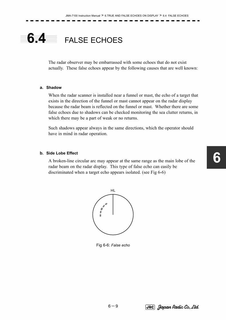
JMA-7100 Instruction Manual > 6.TRUE AND FALSE ECHOES ON DISPLAY > 6.4 FALSE ECHOES
6
6.4 FALSE ECHOES
The radar observer may be embarrassed with some echoes that do not exist actually. These false echoes appear by the following causes that are well known:
a. Shadow
When the radar scanner is installed near a funnel or mast, the echo of a target that exists in the direction of the funnel or mast cannot appear on the radar display because the radar beam is reflected on the funnel or mast. Whether there are some false echoes due to shadows can be checked monitoring the sea clutter returns, in which there may be a part of weak or no returns.
Such shadows appear always in the same directions, which the operator should have in mind in radar operation.
b. Side Lobe Effect
A broken-line circular arc may appear at the same range as the main lobe of the radar beam on the radar display. This type of false echo can easily be discriminated when a target echo appears isolated. (see Fig 6-6)
Fig 6-6: False echo
HL
6-9
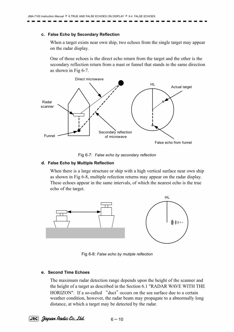
JMA-7100 Instruction Manual > 6.TRUE AND FALSE ECHOES ON DISPLAY > 6.4 FALSE ECHOES
c. False Echo by Secondary Reflection
When a target exists near own ship, two echoes from the single target may appear on the radar display.
One of those echoes is the direct echo return from the target and the other is the secondary reflection return from a mast or funnel that stands in the same direction as shown in Fig 6-7.
Fig 6-7: False echo by secondary reflection
d. False Echo by Multiple Reflection
When there is a large structure or ship with a high vertical surface near own ship as shown in Fig 6-8, multiple refection returns may appear on the radar display. These echoes appear in the same intervals, of which the nearest echo is the true echo of the target.
Fig 6-8: False echo by mutiple reflection
e. Second Time Echoes
The maximum radar detection range depends upon the height of the scanner and the height of a target as described in the Section 6.1 "RADAR WAVE WITH THE HORIZON". If a so-called “duct” occurs on the sea surface due to a certain weather condition, however, the radar beam may propagate to a abnormally long distance, at which a target may be detected by the radar.
Radar scanner
Funnel
HLDirect microwave
Secondary reflectionof microwave
Actual target
False echo from funnel
HL
6-10

JMA-7100 Instruction Manual > 6.TRUE AND FALSE ECHOES ON DISPLAY > 6.4 FALSE ECHOES
6
For instance, assuming that the pulse length is MP3 (on the repetition frequency of 1400 Hz), the first pulse is reflected from a target at about 58 NM or more and received during the next pulse repetition time. In this case, a false echo (second time echo) appears at a position that is about 58 NM shorter than the actual distance. If the false echo appears at 5 NM on the radar display, the true distance of the target is 5+58=63 NM. On the pulse length is SP1 (on the repetition frequency of 2250 Hz), a false echo may appear at a position that is about 36 NM shorter than the actual distance.
This type of false echo can be discriminated by changing over the range scale (the repetition frequency), because the distance of the target changes accordingly.
If second time echo is appeared, the use of Economy mode in PRF menu is effective. Otherwise, Stagger Trigger menu set to on. (See Section 3.8.3 "Set Scanner Unit (TXRX Setting)").
f. Radar Interference
When another radar equipment using the same frequency band as that on own ship is near own ship, a radar interference pattern may appear on the radar display. This interference pattern consists of a number of spots which appear in various forms. In many cases, these spots do not always appear at the same places, so that they can be discriminated from the target echoes. (See Fig 6-9)
Fig 6-9: Radar interference
If radar equipment causing an interference pattern and this radar are of the same model, their transmitting repetition frequency is nearly the same. As a result, interference patterns may be displayed concentrically.
In this case, the interference patterns cannot be eliminated by using only the interference reflector function, so ine-tune the transmitting repetition frequency.( See Section 3.8.3 "Set Scanner Unit (TXRX Setting)")
An interference suppressing effect can be heightened by applying a different transmitting repetition frequency to the interference pattern source radar and this radar.
HL HL
6-11

JMA-7100 Instruction Manual > 6.TRUE AND FALSE ECHOES ON DISPLAY > 6.5 DISPLAY OF RADAR TRANSPONDER (SART)
6.5 DISPLAY OF RADAR
TRANSPONDER (SART)
The SART (Search and rescue Radar Transponder) is a survival device authorized by the GMDSS (Global Maritime Distress and Safety System), which is used for locating survivors in case that a distress accident occurs at sea. The SART is designed to operate in the 9 GHz frequency band.
When receiving the 9 GHz radar signal (interrogating signal) transmitted from the radar equipment on a rescue ship or search aircraft, the SART transmit a series of response signals to inform the distress position to the rescue and search party.
Procedures1) Press [RANGE +] or [RANGE -] key to set the radar range to 6 NM
or 12 NM.
2) Set the SART display mode according to the procedures below.
→
→
→
With the SART display mode set to ON, settings as shown below are made automatically.
This radar provides a shortcut item to make settings for SARTsignal reception. Execution of this item automatically switchesto the setting for SART reception.It also functions for detect thebeacon or target enhancer.
: SART ON
: SART OFF
Sea clutter control : Minimum (Most counterclockwise)
AUTO SEA function : OFFRain and Snow Clutter Control (RAIN) : Minimum
Auto Rain and Snow Clutter function(AUTO RAIN)
: OFF
TUNE control : No tuning (to weaken clutterechoes)
Interference rejection (IR) : OFFPROCESS : OFF
i
Main
3. RADAR Menu
1. Process Setting
9. SART
On
Off
6-12

JMA-7100 Instruction Manual > 6.TRUE AND FALSE ECHOES ON DISPLAY > 6.5 DISPLAY OF RADAR TRANSPONDER (SART)
6
[Example of Display]
• When the SART function is set to ON, small targets around own ship will disappear from the radar display. So it is necessary to exercise full surveillance over the conditions around own ship by visual watch in order to avoid any collision or stranding.
If two or more sets of radar equipment are installed on own ship, use one set of 9 GHz band radar for detection of the SART signal and operate others as normal radars for avoiding collision, monitoring targets around own ship, and checking on own ship’s position and avoidance of stranding.
After end of detecting the START signal, turn the START display off. Then the radar returns normally to the nautical mode.
Other Ships
Land
SART code
Position of SART
Attention
6-13

JMA-7100 Instruction Manual > 6.TRUE AND FALSE ECHOES ON DISPLAY > 6.5 DISPLAY OF RADAR TRANSPONDER (SART)
6-14

SECTION 7SETTINGS FOR SYSTEM OPERATION
SETTINGS FOR SYSTEM OPERATION7.1 SETTINGS AT INSTALLATION .............................................................7-1
7.1.1 How to Open the Serviceman Menu(Service Man Menu) .........7-17.1.2 GYRO I/F Setting .............................................................................7-27.1.3 Tuning (Tune Adjustment) .............................................................7-57.1.4 Bearing Adjustment ........................................................................7-77.1.5 Range Adjustment ...........................................................................7-77.1.6 Navigator Setting (Device) .............................................................7-87.1.7 Setting of True Bearing Value ........................................................7-97.1.8 Antenna Height Setting (Antenna Height) .....................................7-97.1.9 Setting of CCRP (CCRP Setting) ..................................................7-10
7.2 SETTINGS ............................................................................................7-127.2.1 Communication Port Setting (COM Port Setting) .......................7-127.2.2 Sector Blank Setting (Sector Blank) ............................................7-167.2.3 TNI Blank Setting (TNI Blank) ......................................................7-177.2.4 Setting of Bearing Pulses from Scanner Unit (Output Pulse) ...7-187.2.5 Slave Mode Setting (Master/Slave) ..............................................7-197.2.6 Language Setting (Language) ......................................................7-20

7.2.7 Date Time Setting ..........................................................................7-207.2.8 Input Installation Information .......................................................7-217.2.9 Setting the Alarm System .............................................................7-22
7.3 ADJUSTMENT ......................................................................................7-267.3.1 Noise Level Adjustment (Noise Level) ........................................7-267.3.2 Adjustment of Target Tracking Function (TT) ............................7-277.3.3 Main Bang Suppression Level Adjustment (MBS) .....................7-297.3.4 Adjustment of Performance Monitor ...........................................7-31
7.4 MAINTENANCE MENU ........................................................................7-337.4.1 Antenna Safety Switch (Safety Switch) .......................................7-337.4.2 Initialization of Memory Area(Area Initial) ...................................7-347.4.3 Save of Internal Memory Data (Card1/2) .....................................7-357.4.4 Restoration of Scanner Unit Operation Time (TXRX Time) ......7-367.4.5 Update of Character String Data (String Data Update) .............7-38

JMA-7100 Instruction Manual > 7.SETTINGS FOR SYSTEM OPERATION > 7.1 SETTINGS AT INSTALLATION
7
7.1 SETTINGS AT INSTALLATION
This section describes the electrical adjustment procedures to be performed by service engineers during system installation.
The bearing adjustment value is saved to non-volatile memory in the scanner. Other settings are saviedto non-volatile memory in the radar process unit.
7.1.1 How to Open the Serviceman Menu(Service Man Menu)Procedures
1) Hold down the button at the lower right of the display together with the left key.
The Code Input menu will appear.
2) Left-click the button.
3) Left-click the button.
The Serviceman Menu will appear.
• Do not carry out the adjustments of the equipment except authorized service persons. If wrong setting is carried out, this may cause unstable operation.
• Do not carry out the adjustments during navigation. Otherwise, the radar performance may be affected, resulting in an accident or trouble.
Fig 7-1: Code Input
Main
0
ENT
7-1

JMA-7100 Instruction Manual > 7.SETTINGS FOR SYSTEM OPERATION > 7.1 SETTINGS AT INSTALLATION
7.1.2 GYRO I/F Setting
a. Gyro Settings (STEP or SYNC)
The GYRO I/F circuit of the system is designed to be compatible with most types of gyro compasses by simply setting the switches.
Before power-on operation can be performed, the switches S1, S2, S5, S6, S7 and jumper TB105 on the gyro interface circuit (PC4201) must be set in accordance with the type of your gyro compass by performing the procedure below.
The switches are factory-set for a gyration ratio of 180X and the step motor type. Make sure of the type of the gyro compass installed on the own ship before starting the procedure below.
Procedures1) Set S5 to "OFF".
The gyro compass and GYRO I/F are breaked off.
2) Set S6 and S7 in accordance with the type of your gyro compass.
There are two types of gyro compasses: one type outputs a step signal, and the other type outputs a synchro signal. Make sure of the type of the gyro compass installed on the own ship before setting the switches S6 and S7.
3) Set the DIP switch S1 in accordance with the type of the compass.
The items to be set are listed below. For the settings, refer to Table 7-1: Gyro and Log Select Switches (S1 DIP Switch).
Step motor type: DC24V to DC100V
Synchro-motor type: Primary excitation voltage 50 to 115 VAC
Synchro signal: Set the switches to [SYNC].
Step signal: Set the switches to [STEP].
S1-1: Type of gyro signal (step/synchro)
S1-2/3: Gyration ratio of gyro compass
S1-4: Gyration direction of gyro compass
S1-5: Type of log signal (pulse/synchro)
S1-7/8: Ratio of log signal
7-2

JMA-7100 Instruction Manual > 7.SETTINGS FOR SYSTEM OPERATION > 7.1 SETTINGS AT INSTALLATION
7
4) Set the DIP switch S2.
The items to be set are listed below. For the setting, refer to Table 7-2: Gyro and Log Select Switches (S2 DIP Switch).
5) Confirm the settings of the DIP switch S10.
The DIP switch must be set as shown below. Do not change any of the settings.
6) Set the jumper TB105.
The TB105 is set for using a low-voltage step signal.
7) Connect the gyro signal and log signal cables to the terminal block.
8) Set S5 to "ON".
The gyro compass and GYRO I/F are connected.
9) After power-on operation, make sure of the radar video and the operation with the true bearing value.
See the Section 7.1.7 "Setting of True Bearing Value".
10) If the true bearing value of the radar equipment is reversed, change the setting of the switch S1-4.
1 2 3 4 5 6 7 8
ON OFF OFF OFF ON OFF ON OFF
1 2 3 4 5 6 7 8
OFF OFF OFF OFF OFF OFF OFF OFF
1-2 connected: Setting for normal use
2-3 connected: Setting for a step signal of 22 V or less
7-3

JMA-7100 Instruction Manual > 7.SETTINGS FOR SYSTEM OPERATION > 7.1 SETTINGS AT INSTALLATION
Table 7-1: Gyro and Log Select Switches (S1 DIP Switch)
1 2 3 4 5 6 7 8
GY
RO
SIG
STEP ON
SYNC OFF
360X OFF OFF
180X ON OFF
90X OFF ON
36X ON ON
DIRECTION REV ON
NOR OFF
LOG
SIG
TYPE SYNC ON
PULSE OFF
P U L S E /NM
Don't care OFF
100P/30X ON ON
200P/90X OFF ON
400P/180X ON OFF
800P/360X OFF OFF
Table 7-2: Gyro and Log Select Switches (S2 DIP Switch)
S2 SETTING TABLE 1 2 3 4 5 6 7 8
OTH
ER
SE
TTIN
G
LOG ALARM ON
OFF
GYRO SIMULATOR ON
OFF
LOG SIMULATOR ON
OFF
N.A. Don't care any
GYRO ALARM TIME 5s ON
0.2s OFF
HEADING SENSOR SOURCE NMEA(HDT/THS) ON
GYRO SIGNAL OFF
NMEA BAUDRATE SETTING 4800 OFF OFF
9600 ON OFF
19200 OFF ON
38400 ON ON
7-4

JMA-7100 Instruction Manual > 7.SETTINGS FOR SYSTEM OPERATION > 7.1 SETTINGS AT INSTALLATION
7
7.1.3 Tuning (Tune Adjustment)Adjust the tuning control for the transmitter and receiver.
The turning control should be adjusted when the system is installed or when the magnetron is replaced.
Procedures1) Set a range of 48 NM or more.
2) Open the Serviceman Menu.
3) Perform the following menu open procedure to open the Tune Adjustment menu.
→
4) Adjust the tune adjustment value so that the tune indicator bar at the upper left of the display is maximized.
For inputs to the value input screen, refer to Section 3.3.4.3 "Increasing or decreasing a numeric value".
5) Move the cursor onto the button, and left-click .
7.1.3.1 Tune Indicator Adjustment)
Set the scale mark when the tune indicator bar reaches the maximum point.
Procedures1) Set a range of 48 NM or more.
2) Open the Serviceman Menu.
3) Perform the following menu open procedure to open the Tune Indicator Adjust menu.
→
→
1. Adjust Menu
1. Tune Adjustment
ENT
1. Adjust Menu
4. TXRX Adjustment
3. Tune Indicator Adjust
7-5
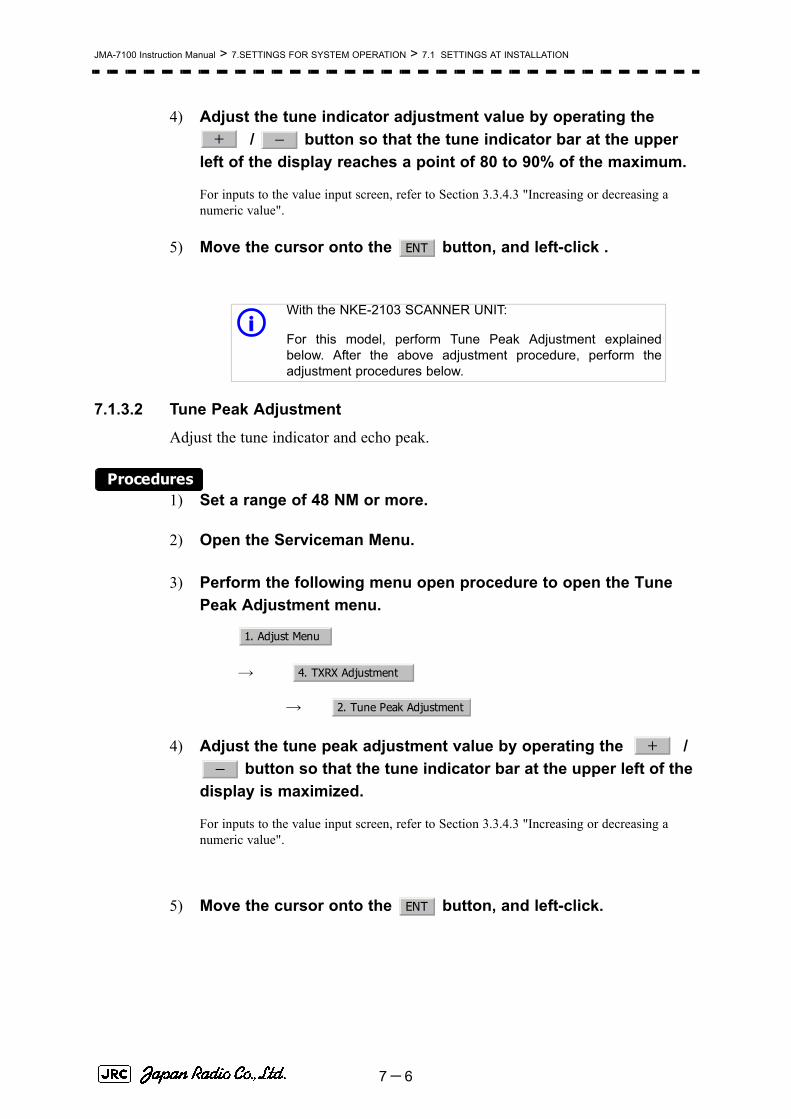
JMA-7100 Instruction Manual > 7.SETTINGS FOR SYSTEM OPERATION > 7.1 SETTINGS AT INSTALLATION
4) Adjust the tune indicator adjustment value by operating the / button so that the tune indicator bar at the upper
left of the display reaches a point of 80 to 90% of the maximum.
For inputs to the value input screen, refer to Section 3.3.4.3 "Increasing or decreasing a numeric value".
5) Move the cursor onto the button, and left-click .
7.1.3.2 Tune Peak Adjustment
Adjust the tune indicator and echo peak.
Procedures1) Set a range of 48 NM or more.
2) Open the Serviceman Menu.
3) Perform the following menu open procedure to open the Tune Peak Adjustment menu.
→
→
4) Adjust the tune peak adjustment value by operating the / button so that the tune indicator bar at the upper left of the
display is maximized.
For inputs to the value input screen, refer to Section 3.3.4.3 "Increasing or decreasing a numeric value".
5) Move the cursor onto the button, and left-click.
With the NKE-2103 SCANNER UNIT:
For this model, perform Tune Peak Adjustment explainedbelow. After the above adjustment procedure, perform theadjustment procedures below.
+ -
ENT
i
1. Adjust Menu
4. TXRX Adjustment
2. Tune Peak Adjustment
+
-
ENT
7-6

JMA-7100 Instruction Manual > 7.SETTINGS FOR SYSTEM OPERATION > 7.1 SETTINGS AT INSTALLATION
7
7.1.4 Bearing Adjustment
Make adjustment so that the bearing of the target measured with the ship’s compass matches the bearing of the target echo on the radar display.
Procedures1) Select for the bearing presentation. Set video processing
(PROC) to .
2) Measure the bearing of an adequate target (e.g., a ship at anchor, a breakwater, or a buoy) relative to own ship's heading.
3) Open the Serviceman Menu.
4) Perform the following menu open procedure to open the Bearing Adjustment menu.
→
For inputs to the value input screen, refer to Section 3.3.4.3 "Increasing or decreasing a numeric value".
Make adjustment by the 0.1°.
5) Adjust the bearing adjustment value by operating the / button so that the target measured in step 2) is adjusted to
the correct bearing.
6) Left-click the button to determine the value.
7.1.5 Range AdjustmentMake adjustment so that the range of a target on the radar display is shown correctly.
Procedures1) Search the radar display for a target of which range is already
known.
2) Open the Serviceman Menu.
H Up
PROC Off
1. Adjust Menu
2. Bearing Adjustment
+
-
ENT
7-7

JMA-7100 Instruction Manual > 7.SETTINGS FOR SYSTEM OPERATION > 7.1 SETTINGS AT INSTALLATION
3) Perform the following menu open procedure to open the Range Adjustment menu.
→
For inputs to the value input screen, refer to Section 3.3.4.3 "Increasing or decreasing a numeric value".
4) Adjust the range adjustment value by operating the / button so that the target measured in step 1) falls in the correct range.
5) Left-click the button to determine the value.
7.1.6 Navigator Setting (Device)Determine whether to connect navigators to the radar equipment.
Only the navigators set to ON here can be used.
Procedures1) Open the Serviceman Menu.
2) Perform the following menu open procedure to open the Device Installation menu.
→
→
3) Select for navigators connected to the radar equipment, and for navigators not connected.
Gyro: Gyro (via GYRO I/F)
Compass: Compass (Compliant with IEC61162)
GPS Compass: GPS Compass (JRC)
LOG: Log (via GYRO I/F)
2AXW: 2-axis log (Speed over water: Compliant with IEC61162)
2AXG: 2-axis log (Speed over ground: Compliant with IEC61162)
GPS: GPS (Compliant with IEC61162)
1. Adjust Menu
3. Range Adjustment
+ -
ENT
1. Adjust Menu
9. Next
3. Device Installation
On
Off
7-8

JMA-7100 Instruction Manual > 7.SETTINGS FOR SYSTEM OPERATION > 7.1 SETTINGS AT INSTALLATION
7
7.1.7 Setting of True Bearing ValueIf GYRO I/F is used to input a gyro signal, the true bearing value indicated by the master gyro does not match the value indicated by the radar equipment only in a rare case. In this case, perform the following procedure to adjust the true bearing value of the radar equipment to the value of the master gyro.
Procedures1) Perform the following menu open procedure to open the true
bearing value setting menu.
→
→
2) Input the master gyro value to the value input screen.
For inputs to the value input screen, refer to Section 3.3.4.3 "Increasing or decreasing a numeric value".
7.1.8 Antenna Height Setting (Antenna Height)Set the height of radar antenna above sea level. Do not change this setting carelessly.
Procedures1) Measure the height of radar antenna above sea level in advance.
2) Open the Serviceman Menu.
3) Perform the following menu open procedure to open the Antenna Height setting menu.
→
→
The Antenna Height menu will open.
4) Select the setting that matches the antenna height measured in step 1).
Main
6. NAV Equipment Setting
1. Gyro Setting
1. Adjust Menu
4. TXRX Adjustment
1. Antenna Height
7-9

JMA-7100 Instruction Manual > 7.SETTINGS FOR SYSTEM OPERATION > 7.1 SETTINGS AT INSTALLATION
7.1.9 Setting of CCRP (CCRP Setting)Set the own ship's CCRP location, radar antenna installation location, and GPS installation location.
Procedures1) Measure the CCRP location, radar antenna location, and GPS
antenna location in advance.
2) Open the Serviceman Menu.
3) Perform the following menu open procedure to open the CCRP Setting menu.
→
4) Specify the ship length for Length at the upper right of the CCRP Setting Menu, and the ship width for Beam.
5) Move the cursor onto the X, Y value, and left-click to input the CCRP1 location.
When X > 0, the CCRP is on the starboard side of the ship.
When X < 0, it is on the port side.
6) To input the second CCRP, click the button to display the CCRP2 X,Y value, and input the value in the same manner for step 5).
Similarly, input the third and subsequent CCRPs.
7) Repeat the above steps to input the GPS location(s) and radar antenna location(s).
8) If multiple CCRP locations and GPS locations are input, select the CCRP location and GPS location to be used by pressing the buttons at the upper left of the menu.
9) Click the to close the CCRP Setting menu.
CCRP: Up to four locations can be input. (One location selected when used)
Radar antenna: Up to eight radar antennas can be input. (Automatically selected inresponse to ISW operation)
GPS: Up to four locations can be input. (One location selected when used)
2. Installation Menu
4. CCRP Setting
CCRP1
CCRP2
0.Exit
7-10

JMA-7100 Instruction Manual > 7.SETTINGS FOR SYSTEM OPERATION > 7.1 SETTINGS AT INSTALLATION
7
Length 300m
Beam 30m
RADAR Antenna1X 0m, Y 15m
GPS1X -10m, Y 30m
RADAR Antenna2X 5m, Y 250m
30m
250m
15m
10m
5m
25m
CCRP1X 0m, Y 25m
Example:
7-11

JMA-7100 Instruction Manual > 7.SETTINGS FOR SYSTEM OPERATION > 7.2 SETTINGS
7.2 SETTINGS
This section describes the electrical adjustment procedures to be performed by service engineers during system installation.
7.2.1 Communication Port Setting (COM Port Setting)External sensor signals are input to the radar equipment through a communication port. The radar equipment has ten communication ports. For signals to be input from sensors or to be output to the sensors, communication ports need to be set in accordance with the sensors.
7.2.1.1 Baud Rate Setting (Baud Rate)
Set the baud rate of the signal to be input to the COM port.
Procedures1) Open the Serviceman Menu.
2) Perform the following menu open procedure to open the Baud Rate setting menu.
→
→
• Do not carry out the adjustments of the equipment except authorized service persons. If wrong setting is carried out, this may cause unstable operation.
• Do not carry out the adjustments during navigation. Otherwise, the radar performance may be affected, resulting in an accident or trouble.
2. Installation Menu
5. COM Port Setting
1. Baud Rate
7-12

JMA-7100 Instruction Manual > 7.SETTINGS FOR SYSTEM OPERATION > 7.2 SETTINGS
7
3) Set the baud rate of the port to be set.
7.2.1.2 Reception Port Setting(RX Port)
Set the numbers of ports for receiving signals from sensors.
There are two methods for receiving signals: specifying a port for each sensor, or using the automatic recognition function without specifying ports.
Procedures1) Open the Serviceman Menu.
2) Perform the following menu open procedure to open the RX Port setting menu.
→
→
3) Set a port for each sensor.
1. COMPASSa:
a. The compass port is a receive-only port that is dedicated to COMPASS signals.
4800(NMEA)/9600(NSK)/38400(fast NMEA)b bps
b. The bold values are factory-set.
2. MAINTENANCE/LOG: 1200/4800/9600/38400 bps
3. NAV1: 1200/4800/9600/38400 bps
4. NAV2: 1200/4800/9600/38400 bps
5. ALARM: 1200/4800/9600/38400 bps
6. JARPAc:
c. The JARPA port is a transmit-only port that is dedicated to JRC ARPA signals.
1200/4800/9600/38400 bps
7. AIS: 1200/4800/9600/38400 bps
8. ARPAd:
d. The ARPA port is a transmit-only port.
1200/4800/9600/38400 bps
9. COM: 1200/4800/9600/38400/115200 bps
Settable sensorsignals
GPS、DLOG、Alarm、Depth、Temperature、Wind、Current、ROT、RSA
Selectable ports When the automatic recognitionfunction is used:
AUTO
When ports are specified: L O G 、N AV 1 、N AV 2 、ALARM、ARPA、COM
2. Installation Menu
5. COM Port Setting
2. RX Port
7-13

JMA-7100 Instruction Manual > 7.SETTINGS FOR SYSTEM OPERATION > 7.2 SETTINGS
7.2.1.3 Reception Sentence Setting (RX Sentence)
Set signal sentences to be received from sensors.
The system is factory-set for using all sentences. To receive only specified sentences, select for sentences which are not necessary.
Procedures1) Open the Serviceman Menu.
2) Perform the following menu open procedure to open the RX Sentence setting menu.
→
→
3) Select the sentences to be used by the sensors to be set.
Selection value: or can be set for each sentence.
1. GPS(LL/COG/SOG): GGA/RMC/RMA/GNS/GLL/VTG
2. GPS(WPT/Time): GGA/RMC/RMB/BWC/BWR/ZDA
3. Depth: DPT/DBK/DBT/DBS
4. Wind: MWV/MWD
5. Current:
→Data Set Number: 0-9. Set the number of the sentence to be used by DataSet Number. (Initial value 0)
→Layer A: Set the number of the sentence to be used with layer Aby Layer Number. (Initial value 3)
→Layer B: Set the number of the sentence to be used with layer Bby Layer Number. (Initial value 4)
→Layer C: Set the number of the sentence to be used with layer Cby Layer Number. (Initial value 5)
No Use
2. Installation Menu
5. COM Port Setting
3. RX Sentence
Use No Use
7-14

JMA-7100 Instruction Manual > 7.SETTINGS FOR SYSTEM OPERATION > 7.2 SETTINGS
7
7.2.1.4 Transmission Port Setting (TX Port)
For each sentence, set a communication port through which signals are transmitted to sensors.
Procedures1) Open the Serviceman Menu.
2) Perform the following menu open procedure to open the TX Port setting menu
→
→
3) Select the communication port through which the sentence to be set is output.
4) Select the output format, talker, and transmission interval.
Signals for which the above items can be set:
Settable sentences TTM(TT)、TLL(TT)、TTD(TT)、TLB(TT)、OSD、RSD、ALR、ACK、TTM(AIS)、TLL(AIS)、TTD(AIS)、TLB(AIS)、RemoteMaintenance、JRC-ARPA、APB、BOD、GGA、GLL、RMC、RMB、VTG、XTE、BWC、HDT、THS
Selectable ports MAINTENANCE、NAV1、NAV2、ALARM、JARPA、ARPA、COM
Item Name Option
NMEA0183 Output Format
APB, BOD, GGA, GLL, RMC, RMB,VTG, XTE, BWC, HDT
V1.5
V2.0
V2.3a
a. The bold values are factory-set.
NMEA0183 Talkerb
b. For TTM, TLL, OSD, RSD, and ALR, the talker is always RA .For GGA, GLL, RMC, and VTG, the talker is always GP.
APB, BOD,RMB, XTE, BWC, HDT, THS
STANDARD:The talker is RA .GP:The talker is GP.
NMEA0183 TX Interval
APB, BOD, GGA, GLL, RMC, RMB,VTG, XTE, BWC, HDT, THS
Set an interval in the range 1 to 9 seconds.
2. Installation Menu
5. COM Port Setting
4. TX Port
7-15

JMA-7100 Instruction Manual > 7.SETTINGS FOR SYSTEM OPERATION > 7.2 SETTINGS
7.2.2 Sector Blank Setting (Sector Blank)In order not to display radar echoes, set a sector range and stop transmission in the bearing range. Three types of sectors can be created.
The sector blank function operates in the relative bearing with the bow as the benchmark.
7.2.2.1 Sector Blank Function On/Off (Sector1,2 and 3)
Procedures1) Open the Serviceman Menu.
2) Perform the following menu open procedure to open the Sector Blank setting menu.
→
3) Set the sector blank number , , or with which the sector blank function operates.
The system allows the use of up to three sector blank areas.
Set each sector blank area to on or off.
7.2.2.2 Sector Blank Area Creation (Make Sector 1,2,3)
Procedures1) Open the Serviceman Menu.
2) Perform the following menu open procedure to open the Sector Blank setting menu.
→
3) Select the sector blank number ( to ) for sector creation, and click the Make Sector button in the menu.
The selected sector blank will be made.
: The sector blank function of the number is operated.
: The sector blank function of the number is stopped.
2. Installation Menu
3. Sector Blank
Sector 1 Sector 2 Sector 3
On
Off
2. Installation Menu
3. Sector Blank
Make Sector 1 Make Sector 3
7-16

JMA-7100 Instruction Manual > 7.SETTINGS FOR SYSTEM OPERATION > 7.2 SETTINGS
7
4) Set the starting azimuth of the sector blank by operating the [EBL] dial, and left-click the button.
The start angle of the sector blank will be set.
5) Set the ending azimuth of the sector blank by operating the [EBL] dial, and left-click the button.
The end angle of the sector blank will be set.
7.2.3 TNI Blank Setting (TNI Blank)Set a sector range and stop tuning operation in the bearing range.
If a structure such as the mast is close to the radar antenna, automatic tuning operation may become unstable. In this case, set a TNI blank in the direction of the structure in order to stabilize the tuning operation.
Only one type of a sector can be created. The TNI blank function operates in the relative bearing with the bow as the benchmark.
7.2.3.1 TNI Blank Function On/Off (Sector)
Procedures1) Open the Serviceman Menu.
2) Perform the following menu open procedure to open the TNI Blank setting menu.
→
→
3) Select the item in the menu, and turn on or off the TNI blank function.
7.2.3.2 TNI Blank Area Creation (Make Sector)
Procedures1) Open the Serviceman Menu.
: The TNI blank function is operated.
: The TNI blank function is stopped.
ENT
ENT
2. Installation Menu
9. Next
2. TNI Blank
1. TNI Blank
On
Off
7-17

JMA-7100 Instruction Manual > 7.SETTINGS FOR SYSTEM OPERATION > 7.2 SETTINGS
2) Perform the following menu open procedure to open the Sector Blank setting menu.
→
→
3) Left-click the button in the menu.
The selected sector blank will be made.
4) Set the starting azimuth of the TNI blank by operating the [EBL] dial, and left-click the button.
The start angle of the TNI blank will be set.
5) Set the ending azimuth of the TNI blank by operating the [EBL] dial, and left-click the button.
The end angle of the TNI blank will be set.
7.2.4 Setting of Bearing Pulses from Scanner Unit (Output Pulse)Set the output value of bearing pulses from the scanner unit. The system can set 2048 pulses or 4096 pulses. This setting is enabled only when the scanner unit of 25 or 30 kW is used.
Procedures1) Open the Serviceman Menu.
2) Perform the following menu open procedure to open the Output Pulse setting menu.
→
→
3) Set the number of pulses to be output by the scanner unit.
a
a. If a 10 kW antenna is used, 2048 is always set.
:2048 pulses per antenna rotation (Recommended value)
:4096 pulses per antenna rotation
2. Installation Menu
9. Next
2. TNI Blank
2. Make Sector
ENT
ENT
1. Adjust Menu
4. TXRX Adjustment
6. Output Pulse
2048
4096
7-18

JMA-7100 Instruction Manual > 7.SETTINGS FOR SYSTEM OPERATION > 7.2 SETTINGS
7
7.2.5 Slave Mode Setting (Master/Slave)Place the system in the Slave mode when it is to be operated as the sub-display that displays radar echoes by using radar signals from other radar equipment.
The input value of externally input bearing pulses can be set. The system can set 2048 pulses or 4096 pulses.
7.2.5.1 Slave Mode Setting (Master/Slave)
Procedures1) Open the Serviceman Menu.
2) Perform the following menu open procedure to open the installation setting menu.
3) Select Slave for the item in the menu.
7.2.5.2 Setting of Input Bearing Pulse (Input BP Pulse)
Procedures1) Open the Serviceman Menu.
2) Perform the following menu open procedure to open the second page of the installation setting menu.
→
3) Set the number of pulses for the item in the menu.
:The system operates as radar equipment while the ownantenna is connected.
:The system operates as a sub-display while the signalcable of other radar equipment is connected.
: 2048 pulses per antenna rotation
: 4096 pulses per antenna rotation
2. Installation Menu
2. Master Slave
Master
Slave
2. Installation Menu
9. Next
1. Input BP Count
2048
4096
7-19

JMA-7100 Instruction Manual > 7.SETTINGS FOR SYSTEM OPERATION > 7.2 SETTINGS
7.2.6 Language Setting (Language)The system is designed to switch between display languages, Japanese and English.
Procedures1) Open the Serviceman Menu.
2) Perform the following menu open procedure to open the language setting menu.
→
3) Select the language to be used.
7.2.7 Date Time SettingTo display time, the local time, local date, and time-zone difference must be set.
However, if the "ZDA" sentence of NMEA0183 is received, time can be automatically displayed.
Procedures1) Perform the following menu open procedure to open the
language setting menu.
→
→
The Date Time Setting menu will open.
2) Set information about date and time
2)-1. UTC/LMT (Time display system)
a
a. Other is an option to display character strings created by our overseas agents.Ask the overseas agent or our sales department if your language is supported. Todetermine the selected language, turn the power off, and then turn it on.
: Universal Time Coordinate
: Local Mean Time
2. Installation Menu
8. Language
1. English
2. Japanese
3. Other
Main
7. Sub Menu
6. Date Time Setting
UTC
LMT
7-20

JMA-7100 Instruction Manual > 7.SETTINGS FOR SYSTEM OPERATION > 7.2 SETTINGS
7
2)-2. LMT Date
Input the date in local time.2)-3. LMT Time
Input the date in local time.2)-4. Time Zone
Input the time-zone difference between the universal time and local time.
2)-5. Display Style
2)-6. Synchronize with GPS
7.2.8 Input Installation InformationThe system can input installation information.
Procedures1) Open the Serviceman Menu.
2) Perform the following menu open procedure to open the language setting menu.
→
3) Input the installation information.
For the input method on the numeric value and character input screens, see Section 3.3.4 "Operation on Numeric Value, Latitude / Longitude and Character Input menu".
Set one of the following date display formats.
例:2007-12-31
例:DEC 31, 2007
例:31 DEC, 2007
A ZDA sentence sent by the GPS is used, thereby displaying time synchronized with the GPS time.
a:
a. If On is selected for this item but a ZDA sentence is not input, the systeminternal clock function is used to display the date and time.
Time synchronized with the GPS time
: Time not synchronized with the GPS time
Input the date of installed system.
Input the name of installation personel.
Input the name of radar installer.
YYYY-MM-DD
MMM DD, YYYY
DD MMM, YYYY
On
Off
Main
1. Installation Information
Date
Name
Company
7-21

JMA-7100 Instruction Manual > 7.SETTINGS FOR SYSTEM OPERATION > 7.2 SETTINGS
7.2.9 Setting the Alarm System
7.2.9.1 Setting the reset interval (Reset Interval)
This function enables the control of WMRST terminal (on the terminal board circuit).The reset signal is turned on when operation in a set period of time.
Procedures1) Open the Serviceman Menu.
2) Perform the following menu open procedure to open the Reset Interval menu.
→
→
→
3) Input the value to be set.
For how to input numeric data on the numeric value input screen, see Section 3.3.4 "Operation on Numeric Value, Latitude / Longitude and Character Input menu".
7.2.9.2 Setting the Trackball Threshold
This function enables the control of WMRST terminal (on the terminal board circuit).
The reset signal is turned off when trackball is moved, that caused by vibration.If trackball move distance go over the threshold (dot unit) when reset signal is turned on.
Procedures1) Open the Serviceman Menu.
2) Perform the following menu open procedure to open the Trackball Threshold menu.
→
→
→
3) Input the value to be set.
For how to input numeric data on the numeric value input screen, see Section 3.3.4 "Operation on Numeric Value, Latitude / Longitude and Character Input menu".
2. Installation Menu
6. Alarm System
1. Watch Alarm
1. Reset Interval
2. Installation Menu
6. Alarm System
1. Watch Alarm
2. Trackball Threshold
7-22

JMA-7100 Instruction Manual > 7.SETTINGS FOR SYSTEM OPERATION > 7.2 SETTINGS
7
7.2.9.3 Setting the relay output (Relay Output)
This function enables the control of ARPAALM terminal (on the terminal board circuit).
Procedures1) Open the Serviceman Menu.
2) Perform the following menu open procedure to open the Relay Output menu.
→
→
3) Left-click the button in the menu.
The Relay Output mode is switched.
4) Click the item button corresponding to the item to be changed.
The item can be turned on / off.
7.2.9.4 Setting the ALR output (ALR Output)
This function enables the control of ALR port (See Section 7.2.1 "Communication Port Setting (COM Port Setting)").
Procedures1) Open the Serviceman Menu.
: The output is continuously controlled.
: The output is intermittenly controlled.
: The relay output is turned on when alarm have issued.
: The relay output is not turned on when alarm have issued.
: There is a dangerous target. (tracked target)
: There is a dangerous target. (AIS target)
: A new target is acquired in the automatic acquisition zone.
: There is a lost target. (Target Tracking / AIS).
2. Installation Menu
6. Alarm System
2. Relay Output
1. Relay Output Mode
Continuous
Intermittent
On
Off
2. TT CPA/TCPA
3. AIS CPA/TCPA
4. New Target
5. Lost
7-23

JMA-7100 Instruction Manual > 7.SETTINGS FOR SYSTEM OPERATION > 7.2 SETTINGS
2) Perform the following menu open procedure to open the ALR Output menu.
→
→
3) Click the item button corresponding to the item to be changed.
The item is turned on / off.
7.2.9.5 Setting the External Acknowledgement (External ACK Setting)
This function enables the control of system when ACK sentence have received.
Procedures1) Open the Serviceman Menu.
2) Perform the following menu open procedure to open the External ACK Setting menu.
→
→
3) Click the item button corresponding to the menu to be changed.
: The ALR sentence is output when alarm have issued.
: The ALR sentence is not output when alarm have issued.
: The internal alarm.
: Target Tracking Alarms and AIS Function Alarms.
:CPA/TCPA alarm.
:Exept Critical Alarm.
2. Installation Menu
6. Alarm System
2. Relay Output
On
Off
1. System Alarm
2. TT/AIS Alarm
2. Installation Menu
6. Alarm System
5. External ACK Setting
Critical Alarm
Normal Alarm
7-24

JMA-7100 Instruction Manual > 7.SETTINGS FOR SYSTEM OPERATION > 7.2 SETTINGS
7
4) Click the item button corresponding to the item to be changed.
The item is switched.
7.2.9.6 Setting the Alarm Buzzer (Sound Output Mode)
This function enables the control of alarm buzzer.
Procedures1) Open the Serviceman Menu.
2) Perform the following menu open procedure to open the External ACK Setting menu.
→
→
3) Select the function to be used.
, and
Setting and Ararm Function
① : Followed by Buzzer Volume menu setting.② : Alarm Buzzer is turned off.③ : If Relay Output menu is turned on when Alam Buzzer is turned off. If Relay Output menu is turned off when Alam
Buzzer is turned on. For how to setting Buzzer Volume menu, see Section 3.8.6 "Adjust Sound Volume (Buzzer Volume)".
: Setting of alarm sound.
→ : The alarm sound is not stopped whenacknowridgement have received.
→ : The alarm sound is stopped whenacknowridgement have received.
: Setting of alarm indication.
→ : The alarm indication brinking is stopped whenacknowridgement have received.
→ : The alarm indication brinking is not stoppedwhen acknowridgement have received.。
: Setting of ALR sentence.
→ : Add acknowridgement to ALR sentence.
→ : Add no acknowridgement (unrecognized) to ALRsentence.
Alarm Setting Operation Operation Miss
CPA/ TCPA
New Target
Lost NAV System ISW
①
① ②
① ③ ① ② ①
Audio
On
Off
Indication
Lightning
Brinking
Acknowledge State
A;ACK
V;UNACK
2. Installation Menu
6. Alarm System
4. Sound Output Mode
On Off1 Off2
On
Off1
Off2
7-25

JMA-7100 Instruction Manual > 7.SETTINGS FOR SYSTEM OPERATION > 7.3 ADJUSTMENT
7.3 ADJUSTMENT
This section describes the electrical adjustment procedures to be performed by service engineers during system installation.
7.3.1 Noise Level Adjustment (Noise Level)
7.3.1.1 Noise Level Adjustment for Signal Processing
Procedures1) Open the Serviceman Menu.
2) Perform the following menu open procedure to open the noise level adjustment menu.
→
→
3) Increase/decrease the noise level adjustment value.
The noise level is factory-set. (Initial value: 140)
After system installation, a great change in the noise level adjustment value should be avoided; it should be fine adjusted within ±5.
Do not carry out the adjustments of the equipment except authorized service persons. If wrong setting is carried out, this may cause unstable operation.
Do not carry out the adjustments during navigation. Otherwise, the radar performance may be affected, resulting in an accident or trouble.
9. RADAR/TT Initial Setup
1. Signal Processing
1. Echo Noise Level
7-26

JMA-7100 Instruction Manual > 7.SETTINGS FOR SYSTEM OPERATION > 7.3 ADJUSTMENT
7
7.3.1.2 Noise Level Adjustment Mode (Setting Mode)
A noise level is factory-adjusted while this mode is turned on.
Procedures1) Open the Serviceman Menu.
2) Perform the following menu open procedure to open the noise level adjustment menu.
→
→ The noise level adjustment mode is switched between on and off.
7.3.2 Adjustment of Target Tracking Function (TT)
7.3.2.1 Vector Constant Adjustment (Vector Constant)
Adjust the vector follow-up performance of the target tracking function.
The vector constant is adjusted to an optimal value, so do not change it carelessly.
Procedures1) Open the Serviceman Menu.
2) Perform the following menu open procedure to open the Vector Constant adjustment menu.
Factory-adjustment method
・ The noise level adjustment value is once decreased to about 130.
・ While the noise level adjustment value is gradually increased, the valuewith which radar echoes start turning yellow is determined as the setvalue.
・ The noise level adjustment mode is turned off when the adjustment isfinished.
Do not change the set value carelessly.
The vector constant shall be set to 5 normally. If the vector constant value is higher, a target’s vector will be better followed up when the target and own ship change their course or speed, but the vector accuracy will be lower on the contrary.
9. RADAR/TT Initial Setup
1. Signal Processing
2. Setting Mode
Attention
7-27

JMA-7100 Instruction Manual > 7.SETTINGS FOR SYSTEM OPERATION > 7.3 ADJUSTMENT
→
→ The window for setting vector constants will appear.
3) Input the value to be set.
For how to input numeric data on the numeric value input screen, see Section 3.3.4 "Operation on Numeric Value, Latitude / Longitude and Character Input menu".
7.3.2.2 Quantization Level Adjustment (Video TD Level)
Use the target tracking function (TT) to adjust the level of the signal to be recognized as a target. If a small value is set, even weak target signals will be input to the target detection circuit of the target tracking function. However, many unnecessary signals are also input, which may cause unstable target acquisition or tracking. It is important to set a value four or five greater than the value with which unnecessary signals are detected.
The quantization level is adjusted to an optimal value, so do not change it carelessly.
Procedures1) Open the Serviceman Menu.
2) Perform the following menu open procedure to open the target tracking setting menu.
→
3) To change the quantization level of the automatic acquisition area, specify the item in the menu. To change the quantization level of tracking and manual acquisition, specify the item .
4) Input the value to be set.
Do not change the set quantization level carelessly. If the level deviates from the proper value, the target acquisition and tracking functions will deteriorate. Otherwise, this may cause accidents.
9. RADAR/TT Initial Setup
2. TT
1. Vector Constant
9. RADAR/TT Initial Setup
2. TT
2. Video TD Level
3. Video High Level
7-28

JMA-7100 Instruction Manual > 7.SETTINGS FOR SYSTEM OPERATION > 7.3 ADJUSTMENT
7
7.3.3 Main Bang Suppression Level Adjustment (MBS)Main Bang Suppression is adjusted to suppress main bang, a reflection signal from 3D circuit including wave guide tube, that generally appears as a circular image focusing on the center of the radar display. Optimum adjustment allows main bang image to remain lightly on the display.
7.3.3.1 Adjustment of Main Bang Suppression Level (MBS Level)
Procedures1) Open the Serviceman Menu.
2) Perform the following menu open procedure to open the MBS level adjustment menu.
→
→
3) Set the radar as follows:• Set the radar range to 0.125 NM.• Set the radar video enhance function (ENH) to OFF.• Set the image processing (PROC) to OFF.• Turn the [RAIN] control to the minimum position (fully to the left).• Turn the [GAIN] control to the maximum position (fully to the right).• Turn the [SEA] control to achieve the strength with which main bang can be judged.
4) Adjust the value so that the main bang can be erased.
Do not change this adjusted level carelessly.
Incorrect adjustment may erase targets in point-blank range and cause collision, resulting in death or serious injury.
9. RADAR/TT Initial Setup
3. MBS
1. MBS Level
7-29

JMA-7100 Instruction Manual > 7.SETTINGS FOR SYSTEM OPERATION > 7.3 ADJUSTMENT
7.3.3.2 Adjustment of Main Bang Suppression Area (MBS Area)
Procedures1) Open the Serviceman Menu.
2) Perform the following menu open procedure to open the MBS Area adjustment menu.
→
→
3) Set the radar as follows:• Set the radar range to 0.125 NM.• Set the radar video enhance function (ENH) to OFF.• Set the image processing (PROC) to OFF.• Turn the [RAIN] control to the minimum position (fully to the left).• Turn the [GAIN] control to the maximum position (fully to the right).• Turn the [SEA] control to achieve the strength with which main bang can be judged.
4) Adjust the value so that the main bang can be erased.
9. RADAR/TT Initial Setup
3. MBS
2. MBS Area
7-30

JMA-7100 Instruction Manual > 7.SETTINGS FOR SYSTEM OPERATION > 7.3 ADJUSTMENT
7
7.3.4 Adjustment of Performance MonitorAfter replacement of either of the following units, adjust the performance monitor according to the procedures in this section:
• Performance monitor• Antenna unit
7.3.4.1 Transmission Monitor Adjustment (MON Adjustment)
Adjust the circuit for monitoring the transmission performance of the radar equipment.
Procedures1) If the performance monitor is equipped with an inter-switch
function, set it as the master display unit.
2) Open the Serviceman Menu.
3) Perform the following menu open procedure to open the Performance Monitor Adjustment menu.
→
→
4) Increase or decrease the adjustment value so that the farthest point of the performance monitor pattern touches the 18.0 nm line on the chart.
Fig 7-2: MON Adjustment
1. Adjust Menu
4. TXRX Adjustment
4. MON Adjustment
18.00NMIncrease or decrease the adjustment value so that the farthest point of the Performance Monitor pattern contacts the 18.0 nm line.
Performance Monitor pattern
7-31

JMA-7100 Instruction Manual > 7.SETTINGS FOR SYSTEM OPERATION > 7.3 ADJUSTMENT
7.3.4.2 Reception Monitor Adjustment (MON Indicator Adjustment)
Adjust the circuit for monitoring the reception performance of the radar equipment.
Procedures1) If the performance monitor is equipped with an inter-switch
function, set it as the master display unit.
2) Open the Serviceman Menu.
3) Perform the following menu open procedure to open the performance monitor Indicator Adjustment menu.
→
→
4) Increase or decrease the adjustment value so that the performance monitor level indicator will be adjusted to "8".
5) Attach the INFORMATION LABEL provided with the performance monitor to an appropriate position on the display unit.
6) Write the performance monitor bar value check date to the INFORMATION LABEL.
During performance monitor adjustment, all acquisitions by thetarget tracking function are released.
The released target acquisitions are not recovered.
1. Adjust Menu
4. TXRX Adjustment
4. MON Adjustment
MON
7-32

JMA-7100 Instruction Manual > 7.SETTINGS FOR SYSTEM OPERATION > 7.4 MAINTENANCE MENU
7
7.4 MAINTENANCE MENU
This item is provided for equipment maintenance, including settings of antenna safety switch, master reset, etc.
7.4.1 Antenna Safety Switch (Safety Switch)Use this switch to measure the transmission/reception performance while the antenna is in stopped state.
Procedures1) Open the Serviceman Menu.
2) Perform the following menu open procedure to open the Safety Switch setting menu.
→
3) Select the item to be set.
Set operation when the antenna safety switch is turned off.
4) Change the setting back to when the work is finished.
Only our service engineers are to make the adjustment. Neglecting this caution may cause accidents and failures.
Do not make the adjustments during navigation. Otherwise, adjustments may affect the radar functions, causing accidents and failures.
: The transmitter stops transmission. The screen on thedisplay unit remains in transmission state.
: (Normal setting) The transmitter stops transmission. Thescreen on the display unit is placed in standby state.
: The transmitter continues transmission. The screen on thedisplay unit remains in transmission state. In this case,however, an error such as a bearing signal failure occursbecause the safety switch is turned off.
3. Maintenance Menu
1. Safety Switch
1. TX-OFF
2. Standy
3. TX-ON
2. Standy
7-33

JMA-7100 Instruction Manual > 7.SETTINGS FOR SYSTEM OPERATION > 7.4 MAINTENANCE MENU
7.4.2 Initialization of Memory Area(Area Initial)If system operation is unstable, it may be stabilized by initializing the memory area. To initialize the memory area, follow the procedure in this section. The memory area is reset to the factory setting when initialized.
7.4.2.1 Partial Master Reset
Procedures1) Open the Serviceman Menu.
2) Perform the following menu open procedure to open the Partial Master Rest operation menu for the memory area.
→ →
3) Select the items to be initialized.
4) Select in the Confirmation Menu.
The memory areas of specified items are initialized, and the system is restarted.
7.4.2.2 All Master Reset
Procedures1) Open the Serviceman Menu.
2) Perform the following menu open procedure to open the All Master Rest operation menu for the memory area.
→ →
3) Select in the Confirmation Menu.
The whole memory area is initialized, and the system is restarted.
: The set values in the Serviceman menu are initialized.
: The set values not in the Serviceman menu are initialized.
: The user-set values are initialized.
: The set values for the target tracking function are initialized.
: The set values for the AIS display function are initialized.
: The color scheme and brilliance setting for the day/nightmode are initialized.
3. Maintenance Menu
2. Area Initial
1. Partial Master Reset
1. Serviceman Menu
2. Except Serviceman Menu
3. User Setting
4. TT Setting
5. AIS Setting
6. Day/Night
1. Yes
3. Maintenance Menu
2. Area Initial
2. All Master Reset
1. Yes
7-34

JMA-7100 Instruction Manual > 7.SETTINGS FOR SYSTEM OPERATION > 7.4 MAINTENANCE MENU
7
7.4.3 Save of Internal Memory Data (Card1/2)The system can save internal memory data such as item settings in all menus onto a flash memory card. If the radar processing circuit in the system has been replaced, the set values before the circuit replacement can be restored by reading the set values you saved before the replacement.
To save the internal memory data onto a flash memory card (option), the card must be inserted in card slot beforehand.
7.4.3.1 Copying of Internal Settings onto Card (Internal To Card1/2)Save the internal memory data, such as item settings in menus, onto a flash memory card.
The internal memory data should be saved at completion of system setting, and the operation condition should be saved periodically.
Procedures1) Open the Serviceman Menu.
2) Perform the following menu open procedure to open the Internal to Card2 menu.
→
3) Select in the Confirmation Menu.
The internal memory data is saved on the flash memory card.
7.4.3.2 Reading of Internal Settings from Card (Card1/2 To Internal)Read the saved memory data from the flash memory card into the system memory.
Perform the read operation in order to return the system to the previous operation condition after replacement of the radar processing circuit in the system.
Procedures1) Open the Serviceman Menu.
2) Perform the following menu open procedure to open the Card2 to Internal menu.
→
3) Select in the Confirmation Menu.
The memory data is read from the flash memory card into the system memory.
After the internal memory area is updated, the system is restarted.
3. Maintenance Menu
3. Internal To Card2
1. Yes
3. Maintenance Menu
4. Card2 To Internal
1. Yes
7-35

JMA-7100 Instruction Manual > 7.SETTINGS FOR SYSTEM OPERATION > 7.4 MAINTENANCE MENU
7.4.4 Restoration of Scanner Unit Operation Time (TXRX Time)The system adds up the following operation time and contains it in the scanner unit:
• Transmission time• Motor run time
Clear the above total time when the magnetron or scanner unit motor is replaced.
7.4.4.1 Clear of Motor Run Time (Clear TX Time)Clear the scanner's motor run time.
Perform the following procedure to clear the motor run time when the scanner motor is replaced.
Procedures1) Open the Serviceman Menu.
2) Perform the following menu open procedure to open the Clear Motor Time menu.
→ →
3) Select in the Confirmation Menu.
The motor run time in the TXRX's internal control circuit is cleared to 0.
7.4.4.2 Save of Antenna Time (Clear Motor Time)Save the following scanner unit time data from the scanner unit into the display unit.
Perform the following procedure to inherit the scanner unit time data when the TXRX's internal control circuit is replaced.
Procedures1) Open the Serviceman Menu.
2) Perform the following menu open procedure to open the Clear Motor Time menu.
→ →
3) Select in the Confirmation Menu.
The motor run time in the TXRX's internal control circuit is cleared to 0.
3. Maintenance Menu
5. TXRX Time
1. Clear TX Time
1. Yes
3. Maintenance Menu
5. TXRX Time
2. Clear Motor Time
1. Yes
7-36

JMA-7100 Instruction Manual > 7.SETTINGS FOR SYSTEM OPERATION > 7.4 MAINTENANCE MENU
7
7.4.4.3 Save of Scanner Unit Time (TXRX To Display Unit)Save the following scanner unit time data from the scanner unit into the display unit.
Perform the following procedure of 7.4.4.4 to inherit the scanner unit time data when the TXRX's internal control circuit is replaced.
Procedures1) Open the Serviceman Menu.
2) Perform the following menu open procedure to open the TXRX to Display Unit menu.
→ →
3) Select in the Confirmation Menu.
The scanner unit time data in the TXRX's internal control circuit is saved transferred to the
display unit.
7.4.4.4 Restoration of Antenna Time (Display Unit To TXRX)Restore the antenna time data from the display unit into the antenna's internal control circuit.
Perform the above procedure of 7.4.4.3 to inherit the antenna time data when the antenna's internal control circuit is replaced.
Procedures1) Open the Serviceman Menu.
2) Perform the following menu open procedure to open the Display Unit to TXRX menu.
→ →
3) Select in the Confirmation Menu.実行確認画面で、 を選択
する。
The scanner unit time data in the display unit is restored transferred to the antenna's internal control circuit.
3. Maintenance Menu
5. TXRX Time
3. TXRX To Display Unit
1. Yes
3. Maintenance Menu
5. TXRX Time
4. Display Unit To TXRX
1. Yes
7-37

JMA-7100 Instruction Manual > 7.SETTINGS FOR SYSTEM OPERATION > 7.4 MAINTENANCE MENU
7.4.5 Update of Character String Data (String Data Update)The system is designed to transfer and display external character strings as the second language display. The second language is factory-set to "Japanese."
Ask our agent or sales department for the supply of character strings to be updated.
To update character strings, the flash memory card (option) containing the character string file must be inserted in card slot 2.
Procedures1) Open the Serviceman Menu.
2) Perform the following menu open procedure to open the String Data Update menu.
→
3) Select in the Confirmation Menu.
The character string file on the flash memory card is read into the system, and the second language area is updated.
To display the read character strings in the second language, select Other in the menu shown in Section 7.2.6 "Language Setting (Language)".
3. Maintenance Menu
6. String Data Update
1. Yes
7-38
SECTION 8COUNTERMEASURES FOR TROUBLE
AND ADJUSTMENT
COUNTERMEASURES FOR TROUBLE AND ADJUSTMENT8.1 ROUTINE MAINTENANCE ....................................................................8-18.2 MAINTENANCE ON EACH UNIT ...........................................................8-2
8.2.1 Scanner Unit NKE-1125/1129/1130/1139/2103/2254 ....................8-28.2.2 Wave Guide Tube (JMA-7123-7XA/9XA) ........................................8-48.2.3 Coaxial Cable (JMA-7133-SA) ........................................................8-48.2.4 Transmitter Receiver Unit (NTG-3225/3230) ................................8-58.2.5 Display Unit (NCD-4790) ................................................................8-5
8.3 PERFORMANCE CHECK ......................................................................8-68.3.1 Check Performance on Test Menu ...............................................8-6
8.3.1.1 Self-diagnosis function (Self Test) ............................................8-78.3.1.2 Monitor Test ................................................................................8-98.3.1.3 Operation Unit Test (Keyboard Test) .......................................8-98.3.1.4 Check of the Performance Monitor (MON Display) ...............8-108.3.1.5 System Alarm Log display .......................................................8-108.3.1.6 System Information ..................................................................8-118.3.1.7 Magnetron Current ....................................................................8-11
8.4 REPLACEMENT OF MAJOR PARTS ..................................................8-12

8.4.1 Parts Required for Periodic Replacement ..................................8-138.4.2 Replacement of magnetron ..........................................................8-13
8.4.2.1 Scanner Unit NKE-1130 ............................................................8-148.4.2.2 Scanner Unit NKE-2254, NKE-1125 .......................................8-168.4.2.3 Scanner Unit NKE-2103 .........................................................8-198.4.2.4 Transmitter Receiver Unit NTG-3230 ....................................8-218.4.2.5 Transmitter Receiver Unit NTG-3225 ....................................8-24
8.4.3 Replacement of Motor ...................................................................8-288.4.3.1 Scanner Unit NKE-1139/1130 ................................................8-288.4.3.2 Scanner Unit NKE-1125/2254 ................................................8-308.4.3.3 Scanner Unit NKE-2103 .........................................................8-31
8.4.4 Replacement of LCD Monitor .......................................................8-338.4.4.1 Display Unit NCD-4790 .............................................................8-33
8.4.5 Replacement of Backup Battery ..................................................8-358.4.5.1 About the Battery Alarm ...........................................................8-368.4.5.2 How to Replacement of Backup Battery .................................8-36

JMA-7100 Instruction Manual > 8.COUNTERMEASURE FOR TROUBLE ... > 8.1 ROUTINE MAINTENANCE
8
8.1 ROUTINE MAINTENANCE
For operating the radar equipment in the good conditions, it is necessary to make the maintenance work as described below. If maintenance is made properly, troubles will reduce. It is recommended to make regular maintenance work.
Common points of maintenance for each unit are as follow:
• Clean the equipment.
Remove the dust, dirt, and sea water rest on the equipment cabinet with a piece of dry cloth.
Especially, clean the air vents with a brush for good ventilation.
• Never carry out internal inspection or repair work of the equipment by users. Inspection or repair work by unauthorized personnel may result in fire hazard or electric shock. Ask the nearest branch, business office or a dealer for inspection and repair.
• Turn off the main power before maintenance work. Otherwise, an electric shock may result.
• Turn off the main power before cleaning the equipment. Especially, make sure to turn off the indicator if a rectifier is used. Otherwise, equipment failure, or death or serious injury due to electric shock may result, because voltage is outputted from the rectifier even when the radar is not operating.
8-1

JMA-7100 Instruction Manual > 8.COUNTERMEASURE FOR TROUBLE ... > 8.2 MAINTENANCE ON EACH UNIT
8.2 MAINTENANCE ON EACH UNIT
8.2.1 Scanner Unit NKE-1125/1129/1130/1139/2103/2254
a. Precautions in Mounting the Cover
When the cover is removed for regular checkup and replacement of parts and refitted after such work, the procedures of fastening bolts shall be taken with the following precautions:
1) The proper fastening torque of the fitting bolts (M8) is 1176 to 1470 N/cm (120 to 150kgf/cm) (which makes the inside water-tight and protects the packings against permanent compressive strain).The packings start producing from the cover at a torque of approximately 1470N/cm (150kgf/cm). Do not fasten the bolts with a torque exceeding the specified value. Otherwise, the screws may be broken.
2) Use an offset wrench of 11 mm X 13 mm or a double-ended wrench of 13 mm X 17 mm (not longer than 200 mm).
3) Screw all the bolts by hand first to prevent them playing, then fasten them evenly in order not to cause one-sided fastening. (Fasten the bolts with 25% of the required torque at the first step.)
• Turn off the main power source before starting maintenance. Otherwise, an electric shock or injury may be caused.
• Do not touch the radiator. Even if the power is turned off, the radiator may be rotated by the wind.
• Turn "OFFi" the safety switch to stop the scanner unit. (Refer to Section 1.4 "EXTERIOR DRAWINGS".) Otherwise, you may be injured if touching the rotating scanner unit by accident.
i. After the work, turn "ON" the scanner unit safety switch.
• Do not touch the radiator. Even if the power is turned off, the radiator may be rotated by the wind.
*Fasten the bolts in the diagonal order.
8-2
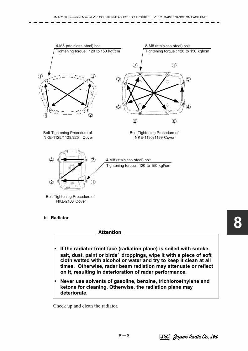
JMA-7100 Instruction Manual > 8.COUNTERMEASURE FOR TROUBLE ... > 8.2 MAINTENANCE ON EACH UNIT
8
b. Radiator
Check up and clean the radiator.
• If the radiator front face (radiation plane) is soiled with smoke, salt, dust, paint or birds’ droppings, wipe it with a piece of soft cloth wetted with alcohol or water and try to keep it clean at all times. Otherwise, radar beam radiation may attenuate or reflect on it, resulting in deterioration of radar performance.
• Never use solvents of gasoline, benzine, trichloroethylene and ketone for cleaning. Otherwise, the radiation plane may deteriorate.
②
①
③
④
⑤
⑥
⑦
⑧
Tightening torque : 120 to 150 kgf/cm4-M8 (stainless steel) bolt
Tightening torque : 120 to 150 kgf/cm8-M8 (stainless steel) bolt
②
① ③
④
② ①
③④
Bolt Tightening Procedure of NKE-1125/1129/2254 Cover
Bolt Tightening Procedure of NKE-1130 /1139 Cover
Bolt Tightening Procedure of NKE-2103 Cover
Tightening torque : 120 to 150 kgf/cm4-M8 (stainless steel) bolt
Attention
8-3

JMA-7100 Instruction Manual > 8.COUNTERMEASURE FOR TROUBLE ... > 8.2 MAINTENANCE ON EACH UNIT
c. Rotating sectionc-1 Supply Oil Seal
When there is not a grease nipple, the replenishment of grease oil is unnecessary.
Remove the cap on the grease nipple located on the side of the X band radar or on the front of S band radar at which the radiator is supported, and grease with a grease gun.Make the oiling every six months. The oil quantity shall be approximately 100 g, which is as much as the grease comes out of the oil seal. Use the grease of Mobilux 2 of Mobil Oil.
c-2 Oiling gears
Apply grease evenly to the tooth surfaces of the main shaft drive gear and the encoder drive gear with a spreader or brush. Oiling in short intervals is more effective to prevent the gears from wear and tear and extend their service life, but oil at least every six months.
Use Mobilux2 of Mobile Oil.
c-3 Mounting legs
Check the mounting legs and mounting bolts of the antenna unit case for corrosion at intervals and maintain them to prevent danger. Apply paint to them once a half year because painting is the best measure against corrosion.
8.2.2 Wave Guide Tube (JMA-7123-7XA/9XA)
8.2.3 Coaxial Cable (JMA-7133-SA)The coaxial tube gland of a coaxial cable terminal is fully waterproofed when installed. To prevent a water leakage accident, periodically inspect the coaxial tube gland. In particular, the coaxial tube gland should be repainted every six months.
• Install wave guide tubes without any clearance. Leaving a clearance may cause water leakage or corrosion later.
Attention
8-4

JMA-7100 Instruction Manual > 8.COUNTERMEASURE FOR TROUBLE ... > 8.2 MAINTENANCE ON EACH UNIT
8
For details, refer to the coaxial cable installation procedure for S-band radars.
8.2.4 Transmitter Receiver Unit (NTG-3225/3230)Wipe dust off the transmitter and receiver with a dry cloth or feather duster.
8.2.5 Display Unit (NCD-4790)
Dust accumulated on the screen will reduce clarity and darken the video. For cleaning it, wipe it with a piece of soft cloth (flannel or cotton).
Do not wipe it strongly with a piece of dry cloth nor use gasoline or thinner.
• Do not apply strong shock to the coaxial cable by striking it with a tool or hammering it. Otherwise, an open circuit failure may result.
• Do not place anything heavy on the coaxial cable.Otherwise, an open circuit failure may result.
• Do not twist or pull the coaxial cable.
• When cleaning the screen, do not wipe it too strongly with a dry cloth. Also, do not use gasoline or thinner to clean the screen. Otherwise the screen surface may be damaged
8-5

JMA-7100 Instruction Manual > 8.COUNTERMEASURE FOR TROUBLE ... > 8.3 PERFORMANCE CHECK
8.3 PERFORMANCE CHECK
Make operational check on the radar equipment regularly and if any problem is found, investigate it immediately. Pay special attention to the high voltage sections in checking and take full care that no trouble is caused by any error or carelessness in measurement. Take note of the results of checking, which can be used effectively in the next check work.
Operational check shall be made in accordance with Table 8-1 Function Check List in the order as specified in it.
8.3.1 Check Performance on Test MenuThe radar operating state can be checked by opening the Test Menu.
Table8-1: Performance Check List
Equipment Item to be checked Criteria Remarks
Transmitter Receiver Unit
Tuning LED of Receiver The LED is lighting during operation 48NM range
Display Unit Video and echoes on the screen SensitivityLCD brilliance can be controlled correctlyVarious markersVarious numerical indicationsLighting
Can be correctly controlled
Memory See the Section [1] "Memory Test"
Communications Lines See the Section [3] "Check ofCommunication Lines (Line Test)"
Power Supply, Backup Battery See the Section [4] "Supply Voltage"
Monitor See the Section 8.3.1.2 "Monitor Test"
Operation Unit See the Section 8.3.1.3 "Operation UnitTest (Keyboard Test)"
System Alarm Log Display See the Section 8.3.1.5 "System AlarmLog display"
System Information Display See the Section 8.3.1.6 "SystemInformation"
Magnetron current See the Section 8.3.1.7 "MagnetronCurrent"
Target Tracking See the Section 5.2.7 "Operation Test(TT Test Menu)"
Scanner Unit Signals from the Scanner Unit See the Section [2] "TXRX Test"
Performance Monitor See the Section 8.3.1.4 "Check of thePerformance Monitor (MON Display)"
8-6

JMA-7100 Instruction Manual > 8.COUNTERMEASURE FOR TROUBLE ... > 8.3 PERFORMANCE CHECK
8
Procedures1) Perform the following menu open procedure to open the Test
Menu.
→
2) Select the items to be checked.
The list of check items will appear.
8.3.1.1 Self-diagnosis function (Self Test)
Check of memory, scanner unit, and communications Lines
[1] Memory Test
Checks for the performance of built-in memory.
When no abnormality is found, OK is displayed. When an abnormality is found, NG is displayed.
8.3.1.1Self-diagnosis function (Self Test)
8.3.1.2Monitor Test
8.3.1.3Operation Unit Test (Keyboard Test)
8.3.1.4Check of the Performance Monitor (MON Display)
8.3.1.5System Alarm Log display
8.3.1.6System Information
8.3.1.7Magnetron Current
[1]Memory Test
[2]TXRX Test
[3]Check of Communication Lines (Line Test)
[4]Supply Voltage
SDRAM Check
SRAM Check
FLASH ROM Check
GRAPHIC Check
Main
9. Test Menu
1. Self Test
2. Monitor Test
3. Keyboard Test
4. MON Display
5. System Alarm Log
6. System Information
Magnetron Current
1. Memory Test
2. TXRX Test
3. Line Test
4. Supply Voltage
1. SDRAM
2. SRAM
3. FLASH ROM
4. GRAPHIC
8-7

JMA-7100 Instruction Manual > 8.COUNTERMEASURE FOR TROUBLE ... > 8.3 PERFORMANCE CHECK
[2] TXRX Test
Checks for signals from the scanner.
When no abnormality is found, OK is displayed. When an abnormality is found, NG is displayed.
In standby, ** will appear.
[3] Check of Communication Lines (Line Test)
Check the status of communications with options.
When no abnormality is found, OK is displayed. When an abnormality is found, NG is displayed.
The status display field of equipment not connected is left blank.
[4] Supply Voltage
Check the voltage of internal power supply.
Scanner's safety switch check
Scanner rotation signal check
Heading line signal check
Check on the load current of high voltage inthe modulator
Radar trigger signal check
Radar video check
Check on connection with the transmitter-receiver
Check on connection with the signal processing circuit
Check on connection with the target tracking unit
Check on connection with the GYRO I/F unit
Check on connection with the interswitch
Item Normal value
12V 11.4 to 12.6V
5V 4.75 to 5.25V
3.3V 3.14 to 3.46V
Battery 2.5V or more
Safety Switch
AZI Pulse
HL Pulse
MH Current
Trigger
Video
TXRX
SIG. PROC
TT
GYRO I/F
ISW
8-8

JMA-7100 Instruction Manual > 8.COUNTERMEASURE FOR TROUBLE ... > 8.3 PERFORMANCE CHECK
8
8.3.1.2 Monitor Test
Checks for the display.
The test pattern will be shown on the display.
To return to the normal display, press any key.
If errors occur in the monitor, no test pattern will appear.
8.3.1.3 Operation Unit Test (Keyboard Test)
Checks for the controls and switches of the operation panel.
[1] Key Test
Checks for the controls and switches of the operation panel.
Each key on the operation panel on the display is shown in reverse video at the same time the key is pressed, and the name of the pressed key is displayed.
[2] Buzzer Test
Checks for the operation panel buzzer.
The buzzer will sound. The buzzer automatically stops after it sounds for a specified length of time.
[3] Light Test
Checks for the control panel light.
The brightness of the operation panel is gradually intensified at four levels.
: All colors are filled with white.
: A white box is displayed on the black background of 1280×1024dot.
: Displays rectangle X 2, circle X 2, and cross-shape X13(white lines on the black background).
: Displays “H” of 9 dots X 9 dots on the entire screen (whitecharacter on the black background).
: Gray scale display (16 levels)
: Displays a color bar.
: Displays the VDR test pattern.
: Displays the specified color.
[1]Key Test
[2]Buzzer Test
[3]Light Test
1. Pattern1
2. Pattern2
3. Pattern3
4. Pattern4
5. Pattern5
6. Pattern6
7. Pattern7
8. Pattern8
1. Key Test
2. Buzzer Test
3. Light Test
8-9

JMA-7100 Instruction Manual > 8.COUNTERMEASURE FOR TROUBLE ... > 8.3 PERFORMANCE CHECK
8.3.1.4 Check of the Performance Monitor (MON Display)
Displays the performance monitor status.
Procedures1) Turn the [VRM] dial to make adjustments so that the farthest
point of the performance monitor pattern.
The of is displayed.
8.3.1.5 System Alarm Log display
Displays previously occurred system errors with the dates and times when they occurred.
The current error is displayed at the lower right of the radar display. For details, refer to Section 9.1.1 "List of Alarms and other Indications".
The Error log display button (page2-31 Alarm) is clicked, in the same way as that one.
To erase the alarm logs, press the button in the log display window.
Transmitter system attenuation value check.
→
Receiver system attenuation value check.
→
→
*Transmitter System
Attenuation Value
*Receiver System
MON Pattern Range
Attenuation Value
Attenuation Value *Receiver System
All Clear
8-10

JMA-7100 Instruction Manual > 8.COUNTERMEASURE FOR TROUBLE ... > 8.3 PERFORMANCE CHECK
8
8.3.1.6 System Information
Displays the current system information.
8.3.1.7 Magnetron Current
マDisplays the Magnetron Current bar indicating the magnetron current to check.
When a 48 NM range is set, the magnetron current is normal if the Magnetron Current bar reads the value below.
Processor software version information
Scanner software version information
System number
Total magnetron transmitting time (Total timeduring which radar was transmitted)
→
→
Total operating time (Total power-on time)
Total operating time of the scanner unit (Totalpower-on time of the scanner unit)
Total operating time of the display unit (Totalpower-on time of the display unit)
10kW : 4 to 6 scale marks
25/30kW : 6 to 9 scale marks
Indicator
TXRX
System No.
TX Time
X-Band
S-Band
Motor Time
TXRX Total Time
Total Time
8-11

JMA-7100 Instruction Manual > 8.COUNTERMEASURE FOR TROUBLE ... > 8.4 REPLACEMENT OF MAJOR PARTS
8.4 REPLACEMENT OF MAJOR PARTS
The system includes parts that need periodic replacement. The parts should be replaced as scheduled. Use of parts over their service life can cause a system failure.
• Turn off the main power source before replacing parts. Otherwise, an electric shock or trouble may be caused.
• Before replacing the magnetron, turn off the main power source and wait for 5 minutes or more until the high voltage circuits are discharged. Otherwise, an electric shock may be caused.
• Take off your wrist watch when bringing your hands close to the magnetron. Otherwise, your watch may be damaged because the magnetron is a strong magnet.
• Two or more persons shall replace the liquid crystal monitor. If only one person does this work, he may drop the LCD, resulting in injury.
• Even after the main power source is turned off, some high voltages remain for a while. Do not contact the inverter circuit in the LCD with bare hands. Otherwise, an electric shock may be caused.
8-12

JMA-7100 Instruction Manual > 8.COUNTERMEASURE FOR TROUBLE ... > 8.4 REPLACEMENT OF MAJOR PARTS
8
8.4.1 Parts Required for Periodic ReplacementHere are parts required for periodic replacement
8.4.2 Replacement of magnetron
When mounting a new magnetron, do not touch the magnet with a screwdriver or put it on an iron plate. After replacement, connect the lead wire correctly.
Handling of Magnetron under Long-Time Storage
The magnetron that has been kept in storage for a long time may cause sparks and operate unstably when its operation is started. Perform the aging in the following procedures:
1) Warm up the cathode for a longer time than usually. (20 to 30 minutes in the STBY state.)
2) Start the operation from the short pulse range and shift it gradually to the longer pulse ranges. If the operation becomes unstable during this process, return it to the standby mode immediately. Keep the state for 5 to 10 minutes until the operation is restarted.
Part name Interval Radar model Part type Part code
1. Magnetron 4,000 hours JMA-7110-6XA/6XAH 5VMAA00102 5VMAA00102JMA-7122-6XA/9XA/6XAH
JMA-7123-7XA/9XA
5VMAA00106 5VMAA00106
JMA-7132-SA
JMA-7133-SA
5VMAA00104 5VMAA00104
2. Motor 10,000 hours JMA-7110-6XA/6XAH 7BDRD0048 7BDRD0048JMA-7122-6XA/9XA
JMA-7123-7XA/9XA
MDBW10822 MDBW10822
JMA-7122-6XAH 7BDRD0045A 7BDRD0045AJMA-7132-SA
JMA-7133-SA
MDBW10823 MDBW10823
3. Fan (Scanner Unit) 20,000 hours JMA-7110-6XA/6XAH
JMA-7122-6XA/9XA/6XAH
JMA-7132-SA
7BFRD0002 7BFRD0002
4. LCD PANEL 50,000 hours CML-771 CML-771
5. Fan (Radar Process Circuit) 20,000 hours 109R0612S4D13 5BFAB00588
(Power Supply) 20,000 hours H-7BFRD0006 7BFRD0006
7. Backup battery 5 years 5ZBCJ00012 5ZBCJ00012
Replacement of magnetron must be made by specializedservice personnel.
For details, refer to Service Manual.
8-13

JMA-7100 Instruction Manual > 8.COUNTERMEASURE FOR TROUBLE ... > 8.4 REPLACEMENT OF MAJOR PARTS
8.4.2.1 Scanner Unit NKE-1130
[Required tools]
• A Phillips screwdriver for 4 mm screw
• A Phillips screwdriver for 6 mm screw
• A wrench (width across flats 13 mm, for M8 screws)
[Replacement procedure]
1) Before starting part replacement work, turn
off the safety switch of the scanner unit.
The safety switch is located on the rear
(stern) side. Remove the cover and turn off
(to the lower side) the safety switch.
2) Remove the pedestal cover.
Make sure that there is no foreign matter or
dust adhered to the gasket when you put
the cover on.
Bow side
Turn off the safety switch.
Remove the eight hexagonal screws.
Removing the port side cover
8-14

JMA-7100 Instruction Manual > 8.COUNTERMEASURE FOR TROUBLE ... > 8.4 REPLACEMENT OF MAJOR PARTS
8
3) Remove the cover on the left
(port) side and check that there
is no remaining electric charge in
the modulation high-voltage
circuit board.
Remove the two screws (M4)
holding the magnetron cables
(both yellow and green).
4) Remove the eight screws (M6) to
remove the fixture holding the
magnetron. The screws cannot be
removed from the fixture, so loosen
the all eight screws and remove the magnetron together with the fixture.
The magnetron is held by a hook, but be careful not to let it fall.
Use a non-magnetic screwdriver. If the magnetron comes into contact with any metal (tool), its performance may deteriorate.
5) Install the new magnetron together with the fixture and tighten the screws to hold
the cables.
Follow the removal procedure in the reverse order.
Do not forget to tighten the screws and connect the cables.
[Operation check]
After you have completed the replacement work, follow the procedure below to check the operation.
Magnetron
Remove the yellow cable.
Remove the green cable.
Remove the two screws.
Remove the magnetron.
Remove the metal fixture.
Loosen the eight screws.
8-15
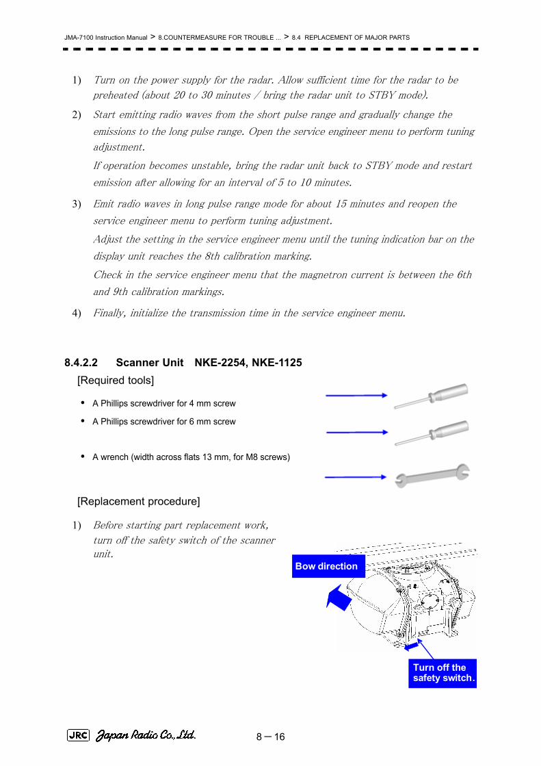
JMA-7100 Instruction Manual > 8.COUNTERMEASURE FOR TROUBLE ... > 8.4 REPLACEMENT OF MAJOR PARTS
1) Turn on the power supply for the radar. Allow sufficient time for the radar to be
preheated (about 20 to 30 minutes / bring the radar unit to STBY mode).
2) Start emitting radio waves from the short pulse range and gradually change the
emissions to the long pulse range. Open the service engineer menu to perform tuning
adjustment.
If operation becomes unstable, bring the radar unit back to STBY mode and restart
emission after allowing for an interval of 5 to 10 minutes.
3) Emit radio waves in long pulse range mode for about 15 minutes and reopen the
service engineer menu to perform tuning adjustment.
Adjust the setting in the service engineer menu until the tuning indication bar on the
display unit reaches the 8th calibration marking.
Check in the service engineer menu that the magnetron current is between the 6th
and 9th calibration markings.
4) Finally, initialize the transmission time in the service engineer menu.
8.4.2.2 Scanner Unit NKE-2254, NKE-1125[Required tools]
• A Phillips screwdriver for 4 mm screw
• A Phillips screwdriver for 6 mm screw
• A wrench (width across flats 13 mm, for M8 screws)
[Replacement procedure]
1) Before starting part replacement work,
turn off the safety switch of the scanner unit.
Bow direction
Turn off the safety switch.
8-16

JMA-7100 Instruction Manual > 8.COUNTERMEASURE FOR TROUBLE ... > 8.4 REPLACEMENT OF MAJOR PARTS
8
2) Loosen the hexagonal bolts (4) and
remove the pedestal cover.
Make sure that there is no foreign
matter or dust adhered to the gasket
when you put the cover on.
3) Loosen the screws (four M4 screws) to
remove the magnetron cover.
4) Make sure there is no charge remaining
in the modulation high-voltage circuit
board, and then remove the screws
(two M4 screws) holding the magnetron
cables (yellow and green) in place.
5) Remove the screws (four M4 screws)
holding the magnetron in place, then
replace the magnetron after cutting the
leads (yellow and green) for the
replacement magnetron to an
appropriate length.
When the starboard side cover is removed
( 4Loosen the four hexagonal bolts.
Loosen the four screws.
Magnetron cover
Remove the green cable.
Remove the yellow cable.
Magnetron
Remove the four screws.
Remove the two screws.
8-17

JMA-7100 Instruction Manual > 8.COUNTERMEASURE FOR TROUBLE ... > 8.4 REPLACEMENT OF MAJOR PARTS
Use a non-magnetic screwdriver. If the magnetron comes into contact with any metal (tool), its performance may deteriorate.
6) After having replaced the magnetron, reassemble the unit by following the
disassembly procedure in the reverse order.
Do not forget to tighten the bolts and screws, and do not forget to reconnect the
cables.
Extreme care should be taken to connect the leads (yellow and green) to the magnetron for prevention of contact with other parts or the casing. Contact may cause them to discharge.
[Operation check]
After you have completed the replacement work, follow the procedure below to check the operation.
1) Turn on the power supply for the radar. Allow sufficient time for the radar to be
preheated (about 20 to 30 minutes / bring the radar unit to STBY mode).
2) Start emitting radio waves from the short pulse range and gradually change the
emissions to the long pulse range. Open the service engineer menu to perform tuning
adjustment.
If operation becomes unstable, bring the radar unit back to STBY mode and restart
emission after allowing for an interval of 5 to 10 minutes.
3) Emit radio waves in long pulse range mode for about 15 minutes and reopen the
service engineer menu to perform tuning adjustment.
Adjust the setting in the service engineer menu until the tuning indication bar on the
display unit reaches the 8th calibration marking.
Check in the service engineer menu that the magnetron current is between the 6th
and 9th calibration markings.
4) Finally, initialize the transmission time in the service engineer menu.
8-18

JMA-7100 Instruction Manual > 8.COUNTERMEASURE FOR TROUBLE ... > 8.4 REPLACEMENT OF MAJOR PARTS
8
8.4.2.3 Scanner Unit NKE-2103[Required tools]
• A Phillips screwdriver for 4 mm screw• A Phillips screwdriver for 6 mm screw
• A wrench (width across flats 13 mm, for M8 screws)
1) Before starting part replacement work,
turn off the safety switch on the bottom of the scanner unit.
2) Loosen the hexagonal bolts (four bolts)
and open the upper cover until the stopper of the
stay operates.
When closing the upper cover, release the stay stopper and then tighten the cover.
Bow direction
Turn off the safety switch.
Loosen the four hexagonal bolts.
Stay
8-19

JMA-7100 Instruction Manual > 8.COUNTERMEASURE FOR TROUBLE ... > 8.4 REPLACEMENT OF MAJOR PARTS
1) Loosen the screws (four M4 screws), remove the
transmitter-receiver unit cover, and remove the cables connected to the transmitter-receiver unit (ten cables). Slide the cover of the transmitter-receiver unit to remove it.
2) Loosen the bolts (five M5 bolts) and
remove the transmitter-receiver unit.
Slide the transmitter-receiver unit
upward to remove it.
3) Remove the screws (six M4 screws)
holding the magnetron in place and replace
the magnetron.
Use a non-magnetic screwdriver. If the magnetron comes into contact with any metal (tool), its performance may deteriorate.
4) Cut the leads (yellow and green) for the
replacement magnetron to an appropriate
length, then tighten the screws and fix the
cables in place.
After having replaced the magnetron, reassemble the unit by following the
disassembly procedure in the reverse order.
Loosen the four screws.
Slide the cover.
Tighten the five bolts.
Slide the unit.
Magnetron
Nut plateRemove the six screws.
Yellow cable
Green cable
8-20

JMA-7100 Instruction Manual > 8.COUNTERMEASURE FOR TROUBLE ... > 8.4 REPLACEMENT OF MAJOR PARTS
8
Do not forget to tighten the bolts and screws, and do not forget to reconnect the cables.
Extreme care should be taken to connect the leads (yellow and green) to the magnetron for prevention of contact with other parts or the casing.
[Operation check]
After you have completed the replacement work, follow the procedure below to check the operation.
1) Turn on the power supply for the radar. Allow sufficient time for the radar to be
preheated (about 20 to 30 minutes / bring the radar unit to STBY mode).
2) Start emitting radio waves from the short pulse range and gradually change the
emissions to the long pulse range. Open the service engineer menu to perform tuning
adjustment.
If operation becomes unstable, bring the radar unit back to STBY mode and restart
emission after allowing for an interval of 5 to 10 minutes.
3) Emit radio waves in long pulse range mode for about 15 minutes and reopen the
service engineer menu to perform tuning adjustment.
Adjust the setting in the service engineer menu until the tuning indication bar on the
display unit reaches the 8th calibration marking.
Check in the service engineer menu that the magnetron current is between the 4th
and 6th calibration markings.
4) Finally, initialize the transmission time in the service engineer menu.
8.4.2.4 Transmitter Receiver Unit NTG-3230[Required tools]
A flatblade screwdriver for 6 mm screws
• A Phillips screwdriver for 4 mm screw
• A Phillips screwdriver for 6 mm screw
8-21

JMA-7100 Instruction Manual > 8.COUNTERMEASURE FOR TROUBLE ... > 8.4 REPLACEMENT OF MAJOR PARTS
[Replacement procedure]
1) Loosen the four screws and remove the cover.
The screws are slotted captive screws.Use a
flatblade screwdriver.
2) Remove the screws (six M4 screws) and slide
the modulator cover to the right to remove
it.
Remove the four screws.
Loosen the six screws.
Modulator cover
8-22
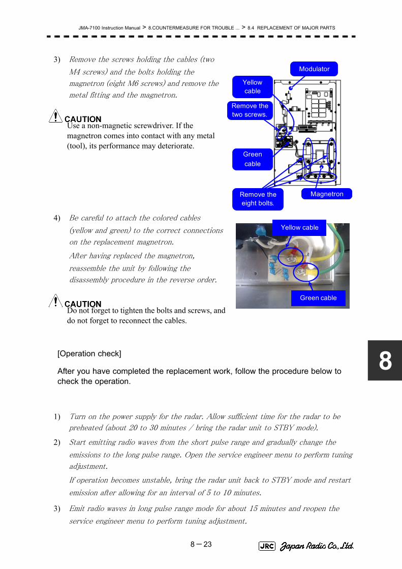
JMA-7100 Instruction Manual > 8.COUNTERMEASURE FOR TROUBLE ... > 8.4 REPLACEMENT OF MAJOR PARTS
8
3) Remove the screws holding the cables (two
M4 screws) and the bolts holding the
magnetron (eight M6 screws) and remove the
metal fitting and the magnetron.
Use a non-magnetic screwdriver. If the magnetron comes into contact with any metal (tool), its performance may deteriorate.
4) Be careful to attach the colored cables
(yellow and green) to the correct connections
on the replacement magnetron.
After having replaced the magnetron,
reassemble the unit by following the
disassembly procedure in the reverse order.
Do not forget to tighten the bolts and screws, and do not forget to reconnect the cables.
[Operation check]
After you have completed the replacement work, follow the procedure below to check the operation.
1) Turn on the power supply for the radar. Allow sufficient time for the radar to be
preheated (about 20 to 30 minutes / bring the radar unit to STBY mode).
2) Start emitting radio waves from the short pulse range and gradually change the
emissions to the long pulse range. Open the service engineer menu to perform tuning
adjustment.
If operation becomes unstable, bring the radar unit back to STBY mode and restart
emission after allowing for an interval of 5 to 10 minutes.
3) Emit radio waves in long pulse range mode for about 15 minutes and reopen the
service engineer menu to perform tuning adjustment.
Yellow cable
Magnetron
Modulator
Greencable
Remove the eight bolts.
Remove the two screws.
Green cable
Yellow cable
8-23

JMA-7100 Instruction Manual > 8.COUNTERMEASURE FOR TROUBLE ... > 8.4 REPLACEMENT OF MAJOR PARTS
Adjust the setting in the service engineer menu until the tuning indication bar on the
display unit reaches the 8th calibration marking.
Check in the service engineer menu that the magnetron current is between the 6th
and 9th calibration markings.
4) Finally, initialize the transmission time in the service engineer menu.
8.4.2.5 Transmitter Receiver Unit NTG-3225[Required tools]
A flatblade screwdriver for 6 mm screws
・A Phillips screwdriver for 4 mm screw
[Replacement procedure]
1) Loosen the four screws and remove the cover.
The screws are slotted captive screws.Use a flatblade
screwdriver.
Loosen the four screws .
8-24

JMA-7100 Instruction Manual > 8.COUNTERMEASURE FOR TROUBLE ... > 8.4 REPLACEMENT OF MAJOR PARTS
8
2) Loosen the upset head bolt (one M4 bolt),
and slide the tightening metal fitting,
located between the modulator and the
circulator, to remove it.
The magnetron is installed within the
modulator.
3) Loosen the inside screws of the modulator
(four M4 screws).
Removing the outside screws makes it
possible to slide the modulator.
Tightening metal fitting Circulator
Modulator
Remove the screw.
Loosen the four screws.
Tightening metal fitting
Modulator
8-25
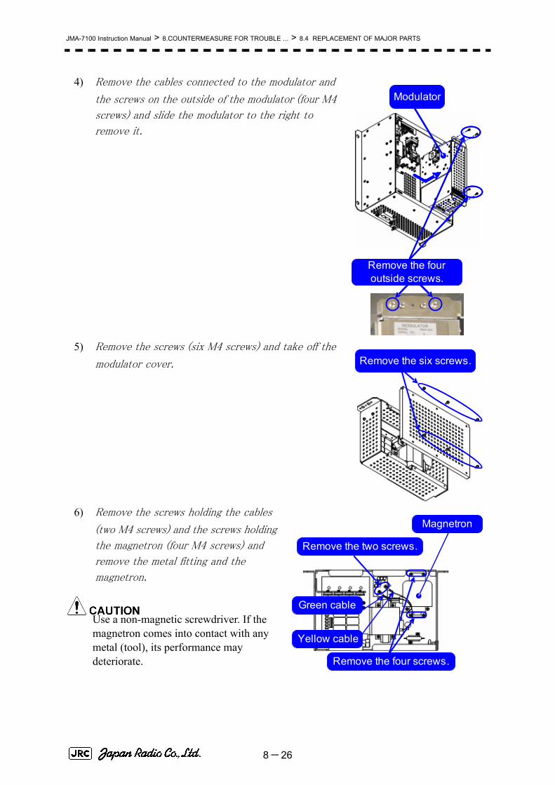
JMA-7100 Instruction Manual > 8.COUNTERMEASURE FOR TROUBLE ... > 8.4 REPLACEMENT OF MAJOR PARTS
4) Remove the cables connected to the modulator and
the screws on the outside of the modulator (four M4
screws) and slide the modulator to the right to
remove it.
5) Remove the screws (six M4 screws) and take off the
modulator cover.
6) Remove the screws holding the cables
(two M4 screws) and the screws holding
the magnetron (four M4 screws) and
remove the metal fitting and the
magnetron.
Use a non-magnetic screwdriver. If the magnetron comes into contact with any metal (tool), its performance may deteriorate.
Remove the four outside screws.
Modulator
Remove the six screws.
Remove the four screws.
Magnetron
Remove the two screws.
Green cable
Yellow cable
8-26

JMA-7100 Instruction Manual > 8.COUNTERMEASURE FOR TROUBLE ... > 8.4 REPLACEMENT OF MAJOR PARTS
8
7) Be careful to attach the colored cables
(yellow and green) to the correct
connections on the replacement
magnetron.
After having replaced the magnetron,
reassemble the unit by following the
disassembly procedure in the reverse
order.
Do not forget to tighten the bolts and screws, and do not forget to reconnect the cables.
[Operation check]
After you have completed the replacement work, follow the procedure below to check the operation.
1) Turn on the power supply for the radar. Allow sufficient time for the radar to be
preheated (about 20 to 30 minutes / bring the radar unit to STBY mode).
2) Start emitting radio waves from the short pulse range and gradually change the
emissions to the long pulse range. Open the service engineer menu to perform tuning
adjustment.
If operation becomes unstable, bring the radar unit back to STBY mode and restart
emission after allowing for an interval of 5 to 10 minutes.
3) Emit radio waves in long pulse range mode for about 15 minutes and reopen the
service engineer menu to perform tuning adjustment.
Adjust the setting in the service engineer menu until the tuning indication bar on the
display unit reaches the 8th calibration marking.
Check in the service engineer menu that the magnetron current is between the 6th
and 9th calibration markings.
4) Finally, initialize the transmission time in the service engineer menu.
Magnetron
Pulse transformer
Yellow cable
Green cable
8-27

JMA-7100 Instruction Manual > 8.COUNTERMEASURE FOR TROUBLE ... > 8.4 REPLACEMENT OF MAJOR PARTS
8.4.3 Replacement of Motor
8.4.3.1 Scanner Unit NKE-1139/1130[Required tools]
• A wrench (width across flats 17 mm, for M10 screws)
• A Phillips screwdriver for 4 mm screw
• Tools for removing the cover from the scanner unit.(Refer to the 8.4.2.1)
[Replacement procedure]
1) Remove the cover on the right (starboard)
side (see 8.4.2.1) and loosen the four screws (M4) to remove the driver unit, which has the motor driver circuit board on its back side.
Disconnect the cables connecting the motor
to the motor driver circuit board.
Replacement of motor must be made by specialized servicepersonnel.
For details, refer to Service Manual.
Driver unit (driver circuit board at the back side)
Remove the four screws.
Driver circuit board
Disconnect the cables.
8-28

JMA-7100 Instruction Manual > 8.COUNTERMEASURE FOR TROUBLE ... > 8.4 REPLACEMENT OF MAJOR PARTS
8
2) Remove the cover on the left (port) side and
remove the five screws (M5) to remove the
fixture.
3) Remove the four hexagonal screws (M10x40,
SW10, and W10) that hold the motor from both the
right and left sides to remove the motor.
4) Apply grease to the gear wheel of the new
motor.
5) Install the new motor in the scanner unit and
secure it using the hexagonal screws. Tighten
the screws with the specified torque (380 kgf-
cm).
6) After replacing the motor, assemble the unit
in the reverse order of the disassembly procedure.
Do not forget to tighten the screws and connect the cables.
Remove the metal fixture.
Remove the five screws.
Remove the four hexagonal screws (two screws on each side)
Remove the motor.
Apply grease.
Motor gear wheel
8-29

JMA-7100 Instruction Manual > 8.COUNTERMEASURE FOR TROUBLE ... > 8.4 REPLACEMENT OF MAJOR PARTS
[Operation check]
After you have completed the replacement work, follow the procedure below to check the operation.
1) Turn on the radar power supply. After the countdown is completed, start emission
and check that the radar image appears without error. Check that you do not hear any unusual sound when the motor starts, rotates, and stops.
2) Open the service engineer menu to initialize the motor rotation time.
8.4.3.2 Scanner Unit NKE-1125/2254[Required tools]
• Single-ended wrench (width across flats 17 mm for M8 bolts)
• Tools for removing the cover from the scanner unit.(Refer to the 8.4.2.2)
[Replacement procedure]
1) Remove the cover on the left (port) side
(see Section 8.4.2.2) and remove the cables connected to the motor driver circuit board.
2) Remove the hexagonal bolts (four M8
bolts) and remove the motor.
3) Remove the hexagonal bolts (four M8
bolts) and remove the installation plate from the
motor.
Motor
Motor driver circuit
Remove the four bolts.
Remove the two cables.
Motor
Motor driver circuit board
Remove the four bolts.
8-30

JMA-7100 Instruction Manual > 8.COUNTERMEASURE FOR TROUBLE ... > 8.4 REPLACEMENT OF MAJOR PARTS
8
4) Attach the installation plate to the replacement
motor. Do not forget to tighten the hexagonal
bolts to an appropriate torque (210 kgf-cm) so
they are free of looseness.
5) Install the motor into the scanner unit. Press the
motor against the protrusions of the arm fixed to
the motor on which the arm extends through the
wall of the casing, adjust it to minimize backlash,
and fix it in place.
Do not forget to tighten the hexagonal bolts, to an appropriate torque (140 kgf-cm)
so they are free of looseness.
6) After having installed the motor, grease the
gear wheel.
7) After having replaced the motor, reassemble
the unit by following the disassembly
procedure in the reverse order.
Do not forget to tighten the bolts and screws, and do not forget to reconnect the cables.
8)
8.4.3.3 Scanner Unit NKE-2103[Required tools]
• A Phillips screwdriver for 4 mm screw
• A Phillips screwdriver for 5 mm screw
• Single-ended wrench (width across flats 10 mm for M6 bolts)
• Tools for removing the cover from the scanner unit.(Refer to the 8.4.2.3)
Arm protrusions
Press
Tighten the four bolts.
Grease here.
8-31

JMA-7100 Instruction Manual > 8.COUNTERMEASURE FOR TROUBLE ... > 8.4 REPLACEMENT OF MAJOR PARTS
[Replacement procedure]
1) Open the upper cover (see Section 8.4.2.3) to
remove the transmitter-receiver unit.
2) Remove the hexagonal bolts (four M6 bolts) and
remove the motor. Grease the gear wheel of the
replacement motor and place it in the casing. Do
not forget to tighten the hexagonal bolts to an
appropriate torque (72 kgf-cm) so they are free of
looseness.
3) After having replaced the motor, reassemble the unit by following the disassembly
procedure in the reverse order.
Do not forget to tighten the bolts and screws, and do not forget to reconnect the cables.
Clamp the cables so they do not interfere with the rotation of the motor's rotors.
[Operation check]
After you have completed the replacement work, follow the procedure below to check the operation.
1) Turn on the radar and emit radar waves once the countdown is finished, and check
that the radar image is correctly displayed. Check that the motor does not make any abnormal sound when it starts to rotate, while it is rotating, or when it stops.
Remove the four bolts.
8-32

JMA-7100 Instruction Manual > 8.COUNTERMEASURE FOR TROUBLE ... > 8.4 REPLACEMENT OF MAJOR PARTS
8
8.4.4 Replacement of LCD Monitor
8.4.4.1 Display Unit NCD-4790
Do not touch the LCD screen directly with your fingers.
Do not touch the AR filter directly with your fingers.
Perform the replacement work on a soft cloth to avoid damage to the LCD screen and other parts.
[Required tools]
A Phillips screwdriver for 4 mm screws
A Phillips screwdriver for 6 mm screws
A pair of nippers
[Disassembly]
1) Remove the screws (M6) from the four
corners and displace the face cover. Remove the LCD operation circuit cables and remove the face cover
Replacement of LCD monitor must be made by specializedservice personnel.
For details, refer to Service Manual.
Remove
8-33

JMA-7100 Instruction Manual > 8.COUNTERMEASURE FOR TROUBLE ... > 8.4 REPLACEMENT OF MAJOR PARTS
2) Remove ten M4 screws.
3) Displace the module and remove the three
cables.
4) Remove the LCD module.
Note that the cables are connected .
Remove
Note that the cables are connected .
Power cable
DVI cable
D-sub 9p cable
8-34

JMA-7100 Instruction Manual > 8.COUNTERMEASURE FOR TROUBLE ... > 8.4 REPLACEMENT OF MAJOR PARTS
8
(You will need to cut the cable band.)
[Assembly]
1) Assemble the module in the reverse order
of disassembly.
2) Check that the module is placed in the
proper position and a proper space is
maintained under the module. Also check
the pull-out position for the brightness
adjustment cables. Tighten the ten M4
screws evenly.
3) Attach the LCD operation circuit cable.
Check the gasket position. Make sure the
brightness adjustment cables are not pinched before attaching the face cover.
4) Tighten the screws at the four corners.
[Operation Check]
1) After completing the replacement procedures, start the system to make sure that
images are displayed properly.
2) Turn the brightness knob to make sure the brightness can be changed between the
minimum and the maximum levels.
8.4.5 Replacement of Backup Battery
A coin-cell battery maintains radar system configuration, date, and time information while power off condition. Radar system configuration is saving to non-volatile memory at fixed intervals.
Replacement of backup battery must be made by specializedservice personnel.
For details, refer to Service Manual.
Cut the cable band .
Cable pull-out position
8-35

JMA-7100 Instruction Manual > 8.COUNTERMEASURE FOR TROUBLE ... > 8.4 REPLACEMENT OF MAJOR PARTS
8.4.5.1 About the Battery Alarm
If is appeared at the lower-right of the display when start up the radar system, the battery has not enough time left to live. We recommend to replace the battery.
If is appeared at the lower-right of the display when start up the radar system, the battery has no time left to live. There is a necessary to replace the battery. In This condition, this radar system is restored configuration information from flash memory and normal operation is available. However, you turned of the radar system before saving to flash memory, the configuration information is maybe lost. In this case, you must setup the configuration again.
8.4.5.2 How to Replacement of Backup Battery
[Required tools]
• A flat tip screwdriver for 6 mm screws
• A Phillips screwdriver for 4 mm screws
• A flat tip nonconductive screwdriver for 3 mm screws
About disposal of used battery, refer to Section 10.2.
Battery Low
Battery Dead
8-36

JMA-7100 Instruction Manual > 8.COUNTERMEASURE FOR TROUBLE ... > 8.4 REPLACEMENT OF MAJOR PARTS
8
[Disassembly]
1) Remove the four fixing screws to remove
the cover from the display unit (NCD-4790).
(A flat tip screwdriver for 6 mm screws)
For standalone type NCD-4790
For tabletop type: NDC-1399-7
2) Remove the cable connected to the radar
processing circuit board.
The radar processing circuit is the first board
from the left.
3) Remove the two fixing screws (M4).
4) Pull out the board to the front.
5) Insert the flat tip nonconductive screwdriver
for adjustment or some stick between the
battery and the battery holder and lift the
battery up.
Remove
Remove
Remove
8-37

JMA-7100 Instruction Manual > 8.COUNTERMEASURE FOR TROUBLE ... > 8.4 REPLACEMENT OF MAJOR PARTS
6) Insert the flat tip nonconductive sscrewdriver
for adjustment or some stick to the location
shown in the figure below and slide the battery
sideways to remove the battery.
[Assembly]
1) Check the polarity of the battery. Make sure
that the battery's positive (+) side is facing up.
2) Slide the battery sideways into the battery
holder.
3) Make sure that the battery is inserted fully.
[Check Item]
1) Check that no error message comes up.
2) Check that the system starts up normally.
[Notes]
8-38

JMA-7100 Instruction Manual > 8.COUNTERMEASURE FOR TROUBLE ... > 8.4 REPLACEMENT OF MAJOR PARTS
8
If you installed the battery with the wrong polarity, remove the battery immediately and do not use the same battery again.
During the procedures, do not put the battery on any circuit board or conductive item.
To dispose of a used battery, follow the instructions provided in Section 10.2 "DISPOSAL OF USED BATTERIES".
To disassemble of a used battery, have to use non-conductive tool.
8-39

JMA-7100 Instruction Manual > 8.COUNTERMEASURE FOR TROUBLE ... > 8.4 REPLACEMENT OF MAJOR PARTS
8-40

SECTION 9TROUBLE SHOOTING AND
AFTER-SALES SERVICE
TROUBLE SHOOTING AND AFTER-SALES SERVICE9.1 FAULT FINDING .....................................................................................9-1
9.1.1 List of Alarms and other Indications .............................................9-19.1.2 Operation Checking ........................................................................9-59.1.3 Fuse Checking .................................................................................9-5
9.2 TROUBLE SHOOTING ...........................................................................9-69.2.1 Special Parts ....................................................................................9-79.2.2 Circuit Block to be Repaired ..........................................................9-8
9.3 AFTER-SALES SERVICE ....................................................................9-149.3.1 Keeping period of maintenance parts .........................................9-149.3.2 When you Request for Repair ......................................................9-149.3.3 Recommended Maintenance ........................................................9-14


JMA-7100 Instruction Manual > 9.TROUBLE SHOOTING AND AFTER-SALES SERVICE > 9.1 FAULT FINDING
9
9.1 FAULT FINDING
In case of semiconductor circuits, it is deemed that there are few cases in which the used semiconductor devices have inferior quality or performance deterioration except due to insufficient design or inspection or by other external and artificial causes. In general, the relatively many causes are disconnection in a high-value resistor due to moisture, a defective variable resistor and poor contact of a switch or relay.
Some troubles are caused by defective parts, imperfect adjustment (such as tuning adjustment) or insufficient service (such as poor cable contact). It will also be effective to check and readjust these points.
9.1.1 List of Alarms and other IndicationsThe system automatically recognizes an internal alarm and displays the alarm message. If an event which is not trouble but must be reported to the operator occurs, the system notifies the operator of the event.
Error message and alarm are displayed in the lower right of the display. For more details refer to page2-31 Alarm.
This section gives the list of alarms displayed by the system and other display lists.
Table9-1: List of System Error Message
Message DescriptionTXRX (SSW Off) Scanner: Safety switch OFF.TXRX (AZI) Scanner: BP error.TXRX (HL) Scanner: HL error.TXRX (MHV) Scanner: Modulator's high voltage alarm.TXRX (Data) Scanner: No communication, communication mismatched,
checksum error, or collision.TXRX (Heater) Scanner: Magnetron heater voltage error.TXRX (Reverse) Scanner: Reverse rotation.
9-1

JMA-7100 Instruction Manual > 9.TROUBLE SHOOTING AND AFTER-SALES SERVICE > 9.1 FAULT FINDING
TXRX (Video) Scanner: VIDEO error.TXRX (Trigger) Scanner: TRIGGER error..TXRX (Fan 1) Scanner: FAN 1 error.TXRX (Fan 2) Scanner: FAN 2 error.TXRX (Motor) Scanner: Motor current error.Keyboard (Data) Operation unit: Communication error or checksum error.Keyboard2 (Data) Second operation unit: Communication error or checksum error.
GYRO I/F (Data) GYRO I/F: No communication or checksum error.GYRO I/F (GYRO) GYRO I/F: GYRO error (error bit detected).GYRO I/F (Log) GYRO I/F: Log error (error bit detected).GPS (Status) GPS status error.Position (Data) Latitude / longitude data: No communication or data error.Date (Data) Date data: No communication or data error.Speed (Log) 1-axis log: No communication or data error.Speed (2AXW) 2-axis log (speed over water): No communication or data error.Speed (2AXG) 2-axis log (speed over ground): No communication or data error.
Speed (GPS) GPS speed: No communication or data error.PROC (Interrupt) Process unit: Interrupt error.PROC (AZI) Process unit: AZI error.PROC (HL) Process unit: HL error.Error during interrupt from ASIC1 to
RADAR DSP.ASIC1 to RADAR VIDEO error.PROC (Video) Trigger error.PROC (Trigger) Heading data: No communication or data error.Heading (Data) Water depth: No communication or data error.Depth (Data) Water temperature: No communication or data error.TEMP. (Data) Wind direction/velocity: No communication or data error.Wind (Data) Tidal current: No communication or data error.Current (Data) Rate of Turn: No communication or data error.ROT (Data) Rudder Sensor Angle: No communication or data error.RSA (Data) APB: No communication or data error.Autopilot (Data) LCD monitor: Fan error.Fan (LCD) RADAR Process Unit Interconnection: Fan error.Fan (Power) Power Supply: Fan error.Fan (PROC) Scanner: Safety switch OFF.
Table9-2: List of Notification
Message DescriptionCCRP Changed CCRP is automatic changed.Weather INFO Weather information is received.Copying Display is capturing to file.
Table9-1: List of System Error Message
Message Description
9-2

JMA-7100 Instruction Manual > 9.TROUBLE SHOOTING AND AFTER-SALES SERVICE > 9.1 FAULT FINDING
9
Set GYRO Requires setting of true bearing.TM Reset Use care of resetting TM.POSN Reset Change the latitude and longitude sentence.
Table9-3: List of Target Tracking Alarms and AIS Function Alarms
メッセージ 内 容
CPA/TCPA There is a dangerous target.Trial There is a dangerous target, when trial maneuver is active.New Target Acquisition or activation of a target in the automatic acquisition
/ activation zone.Lost Failure in tracking the target that has been under tracking.
Failure in receiving AIS target data for a specified time.REF Target Decrease in the reference target accuracy.MAX Target The maximum number of targets is under acquisition.95% Capacity Over 95% of the maximum number of targets to be tracked.AIS Max Target Maximum number of AIS targets.AIS 95% Capacity Over 95% of the maximum number of AIS targets.AIS ACT MAX Maximum number of AIS targets to be activated.AIS ACT 95% Capacity
Over 95% of the maximum number of AIS targets to be activated.
TT (Boot) Target tracking unit start failure.TT (Data) The target tracking unit is malfunctioning.AIS (Data) AIS: No communication or communication error.AIS PROC (Data) AIS processing circuit: No communication or communication error.
AIS Alarm ***i
i. *** is a 3-digit number which is Local Alarm No in the ALR sentence.
AIS alarm (Up to 10 alarm messages can be displayed.).
Table9-4: List of Route Messages and Warnings
Message DescriptionArrival Arrive at way point.Break Off(WPT) Out of the way point.Approach Approach the route.Cross Track Error Go off the route.
Table9-5: List of Operational Error Messages and Warnings
Message DescriptionNo Position Data Mark or line input when the latitude and longitude is invalid.No Heading Data Target tracking operation or TM selection when bearing data is
invalid.Out of Range Out of target acquisition range.
Table9-2: List of Notification
9-3

JMA-7100 Instruction Manual > 9.TROUBLE SHOOTING AND AFTER-SALES SERVICE > 9.1 FAULT FINDING
Invalid Range TM selection due to TM-disabled range (96 nm).Zooming in a ZOOM-disabled range (0.125 nm).
MAX Point Tried to enter navigation information beyond the specified.Can't Transmit Tried to transmit within 5 second after standby or when the
transmitter-receiver has any trouble.Invalid Data Tried to enter any data beyond its range.Invalid Connection The operator set performance monitor to on without selecting
straight.No Card Card not detected yet.Card Full Card capacity insufficient.Format Card Unformatted card.Invalid Card Invalid card.Read Failed Read failure.Write Failed Write failure.Delete Failed Deletion failure.Format Failed Format failure.Copy Failed Copy failure.Not Allowed General operation error.No Object No object at the cursor-specified position.Slave Mode Operation of a menu for the scanner unit when the slave mode
is active.
Table9-6: List of Conditions Messages
Message DescriptionGPS (HDOP) The HDOP level is increased (Decrease in the GPS accuracy.).
MON Test Performance monitor is active.Scanner Rotating The scanner is rotating (When transmitter is standby state.).Battery Low battery is weakening.Battery Dead The battery is dead.
Table9-7: List of Interswitch Alarms and Messages
Message DescriptionMaster Range CHG The range of the own display unit has changed due to
change in the range of the master display unit.ISW Complete The switchover of the Interswitch ended normally.ISW Busy Access to the ISW menu was made during interswitching.
TXRX Standby The scanner unit is in the standby mode.ISW Straight Failed in straight connection when the Interswitch
system stops operating.ISW Standby The Interswitch recovered normally.ISW Time Out Failed in switching.ISW Error The interswitch is disabled.
Table9-5: List of Operational Error Messages and Warnings
9-4

JMA-7100 Instruction Manual > 9.TROUBLE SHOOTING AND AFTER-SALES SERVICE > 9.1 FAULT FINDING
9
9.1.2 Operation CheckingWhen the system is operating, the operation status (located at the upper right of the screen) is changing pictures.
If picture freeze occurred, turn off the system and restart the system.
9.1.3 Fuse CheckingMelted fuses are caused by any clear cause. When a fuse is replaced, it is necessary to check the related circuits even if there is no trouble. In checking, note that there is some dispersion in the fusing characteristics. Table 9-8 shows a list of fuses used in the equipment.
Pattern CHG Failed Connection change failed.Connection Masked Inhibition of control / connection is set.Master Standby The master display unit does not transmit any signals.ISW (Data) No communication, data mismatched, or checksum error.
Update ISW Software Tried to enter new TXRX function, when interswitch software used old version.
Table9-8: Fuse List
Location Parts# C u r r e n tRating
P r o t e c t i o nCircuit
Type
AC/DC Converter F501 10A Motor ST6-10AN1
GYRO Interface circuit
F1~F4 0.5A GYRO Interface circuit
MF60NR250V0.5
Table9-7: List of Interswitch Alarms and Messages
Operation Status
9-5

JMA-7100 Instruction Manual > 9.TROUBLE SHOOTING AND AFTER-SALES SERVICE > 9.2 TROUBLE SHOOTING
9.2 TROUBLE SHOOTING
As this radar equipment includes complicated circuits, it is necessary to request a specialist engineer for repair or instructions for remedy if any circuit is defective.
There are also troubles by the following causes, which should be referred to in checking or repair work.
1 Poor Contact in Terminal Board of Inter-Unit Cables
a. Poor contact in terminal boardb. The cable end is not fully connected, that it, contacted with earthed another
terminal.c. Disconnected cable wire
2 Poor Contact of Connector within Unit
This radar equipment is provided with Table 9-9 standardspares.
Table9-9: 7ZXRD0025
Name Type/Code Shape (mm) In use
Spare Parts # Location
Fuse MF60NR250V0.5
(5ZFGD00006)
4 12 F1~F4 GYRO I/F
CMJ-462E
Fuse ST6-10AN1
(5ZFCA00053)
1 3 F501 AC/DC Converter
NBA-5135
i
30 Φ6.4
31.8 Φ6.35
9-6

JMA-7100 Instruction Manual > 9.TROUBLE SHOOTING AND AFTER-SALES SERVICE > 9.2 TROUBLE SHOOTING
9
9.2.1 Special Parts
NKE-2103
NKE-1125/2254
NTG-3225
NKE-1130
NTG-3230
Table9-10: NKE-2103 (JMA-9110-6XA/6XAH、JMA-7110-6XA/6XAH)
Parts No. Name Type Manufacture Location CodeV101 Magnetron MAF1565N NJRC Scanner Unit 5VMAA00102
A101/A102 Circulator FCX68 Toshiba Scanner Unit 6AJRD00001
A301 Diode Limiter NJS6930 NJRC Scanner Unit 5ATBT00006
Table9-11: NKE-1125/2254 (JMA-9122-6XAH/9XA/6XAH、JMA-7122-6XA/9XA/6XAH)
Parts No. Name Type Manufacture Location CodeV101 Magnetron M1568BS NJRC Scanner Unit 5VMAA00106
A101/A102 Circulator NJC3901M NJRC Scanner Unit 5AJBV00007
A301 Diode Limiter NJS6930 NJRC Scanner Unit 5ATBT00006
Table9-12: NTG-3225 (JMA-9123-7XA/9XA、JMA-7123-7XA/9XA)
Parts No. Name Type Manufacture Location CodeV101 Magnetron M1568BS NJRC T r a n s m i t t e r
Receiver Unit5VMAA00106
A101/A102 Circulator NJC3901M NJRC T r a n s m i t t e rReceiver Unit
5AJBV00007
A301 Diode Limiter NJS6930 NJRC T r a n s m i t t e rReceiver Unit
5ATBT00006
Table9-13: NKE-1130 (JMA-9132-SA、JMA-7132-SA)
Parts No. Name Type Manufacture Location CodeV101 Magnetron M1555 NJRC Scanner Unit 5VMAA00106
A101/A102 Circulator NJC3316 NJRC Scanner Unit 5AJBV00007
A301 Diode Limiter NJS6318 NJRC Scanner Unit 5ATBT00006
Table9-14: NTG-3230 (JMA-9133-SA、JMA-7133-SA)
Parts No. Name Type Manufacture Location CodeV101 Magnetron M1555 NJRC T r a n s m i t t e r
Receiver Unit5VMAA00104
A101 Circulator NJC3317 NJRC T r a n s m i t t e rReceiver Unit
5AJBV00009
A301 TR Limiter TL378A NJRC T r a n s m i t t e rReceiver Unit
5VLAA00037
9-7

JMA-7100 Instruction Manual > 9.TROUBLE SHOOTING AND AFTER-SALES SERVICE > 9.2 TROUBLE SHOOTING
9.2.2 Circuit Block to be Repaired
Table9-15: Circuit Block to be Repaired (JMA-7110-6XA/6XAH)
Location Circuit Block Type RemarksSCANNER UNIT GEARED MOTOR 7BDRD0048 DC brushless motor (common
with HS)SCANNER UNIT MODULATOR CIRCUIT CME-363 Excluding MagnetronSCANNER UNIT RECEIVER UNIT NRG-610 Including CAE-529-1SCANNER UNIT POWER SUPPLY CIRCUIT CBD-1783SCANNER UNIT ENCODER CHT-71ASCANNER UNIT MOTOR CONTROL POWER
SUPPLYCBD-1779
SCANNER UNIT FAN 7BFRD0002RADAR PROCESS UNIT
RADAR PROCESS CIRCUIT MDLW11900 With mounting bracket
RADAR PROCESS UNIT
AIS PROCESS CIRCUIT CDC-1325
RADAR PROCESS UNIT
ARPA PROCESS CIRCUIT CDC-1186D
RADAR PROCESS UNIT
GYRO I/F CIRCUIT CMJ-462E
RADAR PROCESS UNIT
TERMINALBOARD CIRCUIT CQD-2097
RADAR PROCESS UNIT
MOTHERBOARD CIRCUIT CQC-1192
RADAR PROCESS UNIT
FAN (RPU) 109R0612S4D13
RADAR PROCESS UNIT
POWER SUPPLY CBD-1661
RADAR PROCESS UNIT
FAN (PSU) 7BFRD0006
OPERATION UNIT
OPERATION CIRCUIT A CCK-973
OPERATION UNIT
OPERATION CIRCUIT B CCK-974
OPERATION UNIT
OPERATION CIRCUIT D CCK-976
OPERATION UNIT
TRACKBALL 5EZLY00003
MONITOR UNIT FAN (MNU) CBP-173AMONITOR UNIT LCD INTERFACE CIRCUIT CMH-2227MONITOR UNIT INVERTER CIRCUIT CBF-38MONITOR UNIT LCD OPERATION CIRCUIT CCK-989MONITOR UNIT LCD PANEL CML-771 19inch LCDMONITOR UNIT MONITOR POWER SUPPLY CBA-389
9-8

JMA-7100 Instruction Manual > 9.TROUBLE SHOOTING AND AFTER-SALES SERVICE > 9.2 TROUBLE SHOOTING
9
Table9-16: Circuit Block to be Repaired (JMA-7122-6XA/9XA)
Location Circuit Block Type RemarksSCANNER UNIT GEARED MOTOR MDBW10822 For 100/220VACSCANNER UNIT ENCODER CHT-71ASCANNER UNIT AC220V MOTOR DRIVER 7EPRD0034 For 220VACSCANNER UNIT AC100V MOTOR DRIVER 7EPRD0035 For 100VACSCANNER UNIT PERFORMANCE MONITOR NJU-85SCANNER UNIT HEATER CONTROL PART CHG-216 Option (AC100V)SCANNER UNIT BREAK CIRCUIT CFA-253SCANNER UNIT BREAK CONTROL CIRCUIT CCB-655SCANNER UNIT BREAK CIRCUIT A CFA-259SCANNER UNIT BREAK CIRCUIT B CFA-260SCANNER UNIT T/R CONTROL CIRCUIT CMC-1205RSCANNER UNIT MODULATOR UNIT NMA-550 Including CPA-264
Including CMB-404Including CFR-229Excluding Magnetron
SCANNER UNIT MODULATOR CIRCUIT CPA-264SCANNER UNIT RECEIVER UNIT NRG-162A Including CMA-866ASCANNER UNIT POWER SUPPLY CIRCUIT CBD-1682ASCANNER UNIT RELAY FILTER CIRCUIT CSC-656SCANNER UNIT FAN 7BFRD0002RADAR PROCESS UNIT RADAR PROCESS CIRCUIT MDLW11900 With mounting bracketRADAR PROCESS UNIT AIS PROCESS CIRCUIT CDC-1325RADAR PROCESS UNIT ARPA PROCESS CIRCUIT CDC-1186DRADAR PROCESS UNIT GYRO I/F CIRCUIT CMJ-462ERADAR PROCESS UNIT TERMINALBOARD CIRCUIT CQD-2097RADAR PROCESS UNIT MOTHERBOARD CIRCUIT CQC-1192RADAR PROCESS UNIT FAN (RPU) 109R0612S4D13RADAR PROCESS UNIT POWER SUPPLY CBD-1661RADAR PROCESS UNIT FAN (PSU) 7BFRD0006OPERATION UNIT OPERATION CIRCUIT A CCK-973OPERATION UNIT OPERATION CIRCUIT B CCK-974OPERATION UNIT OPERATION CIRCUIT D CCK-976OPERATION UNIT TRACKBALL 5EZLY00003MONITOR UNIT FAN (MNU) CBP-173AMONITOR UNIT LCD INTERFACE CIRCUIT CMH-2227MONITOR UNIT INVERTER CIRCUIT CBF-38MONITOR UNIT LCD OPERATION CIRCUIT CCK-989MONITOR UNIT LCD PANEL CML-771 19inch LCDMONITOR UNIT MONITOR POWER SUPPLY CBA-389
9-9

JMA-7100 Instruction Manual > 9.TROUBLE SHOOTING AND AFTER-SALES SERVICE > 9.2 TROUBLE SHOOTING
Table9-17: Circuit Block to be Repaired (JMA-7122-6XAH)
Location Circuit Block Type RemarksSCANNER UNIT GEARED MOTOR 7BDRD0045A For 100/220VACSCANNER UNIT ENCODER CHT-71ASCANNER UNIT MOTOR CONTROL POWER
CIRCUITCBD-1779
SCANNER UNIT BREAK CIRCUIT CFA-257SCANNER UNIT PERFORMANCE MONITOR NJU-85SCANNER UNIT HEATER CONTROL PART CHG-216 Option (AC100V)SCANNER UNIT POWER SUPPLY CIRCUIT CBD-1682ASCANNER UNIT T/R CONTROL CIRCUIT CMC-1205RSCANNER UNIT MODULATOR UNIT NMA-550 Including CPA-264
Including CMB-404Including CFR-229Excluding Magnetron
SCANNER UNIT MODULATOR CIRCUIT CPA-264SCANNER UNIT RECEIVER UNIT NRG-162A Including CMA-866ASCANNER UNIT FAN 7BFRD0002RADAR PROCESS UNIT RADAR PROCESS CIRCUIT MDLW11900 With mounting bracketRADAR PROCESS UNIT AIS PROCESS CIRCUIT CDC-1325RADAR PROCESS UNIT ARPA PROCESS CIRCUIT CDC-1186DRADAR PROCESS UNIT GYRO I/F CIRCUIT CMJ-462ERADAR PROCESS UNIT TERMINALBOARD CIRCUIT CQD-2097RADAR PROCESS UNIT MOTHERBOARD CIRCUIT CQC-1192RADAR PROCESS UNIT FAN (RPU) 109R0612S4D13RADAR PROCESS UNIT POWER SUPPLY CBD-1661RADAR PROCESS UNIT FAN (PSU) 7BFRD0006OPERATION UNIT OPERATION CIRCUIT A CCK-973OPERATION UNIT OPERATION CIRCUIT B CCK-974OPERATION UNIT OPERATION CIRCUIT D CCK-976OPERATION UNIT TRACKBALL 5EZLY00003MONITOR UNIT FAN (MNU) CBP-173AMONITOR UNIT LCD INTERFACE CIRCUIT CMH-2227MONITOR UNIT INVERTER CIRCUIT CBF-38MONITOR UNIT LCD OPERATION CIRCUIT CCK-989MONITOR UNIT LCD PANEL CML-771 19inch LCDMONITOR UNIT MONITOR POWER SUPPLY CBA-389
9-10

JMA-7100 Instruction Manual > 9.TROUBLE SHOOTING AND AFTER-SALES SERVICE > 9.2 TROUBLE SHOOTING
9
Table9-18: Circuit Block to be Repaired (JMA-7123-7XA/9XA)
Location Circuit Block Type RemarksSCANNER UNIT GEARED MOTOR MDBW10822 For 100/220VACSCANNER UNIT ENCODER CHT-71ASCANNER UNIT AC220V MOTOR DRIVER 7EPRD0034 For 220VACSCANNER UNIT AC100V MOTOR DRIVER 7EPRD0035 For 100VACSCANNER UNIT PERFORMANCE MONITOR NJU-85SCANNER UNIT HEATER CONTROL PART CHG-216 Option (AC100V)SCANNER UNIT BREAK CIRCUIT CFA-253SCANNER UNIT BREAK CONTROL CIRCUIT CCB-655SCANNER UNIT BREAK CIRCUIT A CFA-259SCANNER UNIT BREAK CIRCUIT B CFA-260TRANSMITTER RECEIVER UNIT
T/R CONTROL CIRCUIT CMC-1205R
TRANSMITTER RECEIVER UNIT
MODULATOR UNIT NMA-552 Including CPA-264Including CMB-405Including CFR-229Excluding Magnetron
TRANSMITTER RECEIVER UNIT
MODULATOR CIRCUIT CPA-264
TRANSMITTER RECEIVER UNIT
RECEIVER UNIT NRG-162A Including CMA-866A
TRANSMITTER RECEIVER UNIT
POWER SUPPLY CIRCUIT CBD-1682A
TRANSMITTER RECEIVER UNIT
RELAY FILTER CIRCUIT CSC-656
RADAR PROCESS UNIT RADAR PROCESS CIRCUIT MDLW11900 With mounting bracketRADAR PROCESS UNIT AIS PROCESS CIRCUIT CDC-1325RADAR PROCESS UNIT ARPA PROCESS CIRCUIT CDC-1186DRADAR PROCESS UNIT GYRO I/F CIRCUIT CMJ-462ERADAR PROCESS UNIT TERMINALBOARD CIRCUIT CQD-2097RADAR PROCESS UNIT MOTHERBOARD CIRCUIT CQC-1192RADAR PROCESS UNIT FAN (RPU) 109R0612S4D13RADAR PROCESS UNIT POWER SUPPLY CBD-1661RADAR PROCESS UNIT FAN (PSU) 7BFRD0006OPERATION UNIT OPERATION CIRCUIT A CCK-973OPERATION UNIT OPERATION CIRCUIT B CCK-974OPERATION UNIT OPERATION CIRCUIT D CCK-976OPERATION UNIT TRACKBALL 5EZLY00003MONITOR UNIT FAN (MNU) CBP-173AMONITOR UNIT LCD INTERFACE CIRCUIT CMH-2227MONITOR UNIT INVERTER CIRCUIT CBF-38MONITOR UNIT LCD OPERATION CIRCUIT CCK-989MONITOR UNIT LCD PANEL CML-771 19inch LCDMONITOR UNIT MONITOR POWER SUPPLY CBA-389
9-11

JMA-7100 Instruction Manual > 9.TROUBLE SHOOTING AND AFTER-SALES SERVICE > 9.2 TROUBLE SHOOTING
Table9-19: Circuit Block to be Repaired (JMA-7132-SA)
Location Circuit Block Type RemarksSCANNER UNIT GEARED MOTOR MDBW10823 For 100/220VACSCANNER UNIT ENCODER CHT-71A1SCANNER UNIT AC220V MOTOR DRIVER 7EPRD0034 For 220VACSCANNER UNIT AC100V MOTOR DRIVER 7EPRD0035 For 100VACSCANNER UNIT PERFORMANCE MONITOR NJU-84SCANNER UNIT HEATER CONTROL PART CHG-215 Option (AC100V)SCANNER UNIT BREAK CIRCUIT CFA-255SCANNER UNIT BREAK CONTROL CIRCUIT CCB-655SCANNER UNIT BREAK CIRCUIT A CFA-261SCANNER UNIT BREAK CIRCUIT B CFA-262SCANNER UNIT T/R CONTROL CIRCUIT CMC-1205RSCANNER UNIT MODULATOR UNIT NMA-551 Including CPA-264
Including CMB-406Including CFR-229Exluding Magnetron
SCANNER UNIT MODULATOR CIRCUIT CPA-264SCANNER UNIT RECEIVER UNIT NRG-229SCANNER UNIT POWER SUPPLY CIRCUIT CBD-1682ASCANNER UNIT RELAY FILTER CIRCUIT CSC-656SCANNER UNIT FAN 7BFRD0002RADAR PROCESS UNIT RADAR PROCESS CIRCUIT MDLW11900 With mounting bracketRADAR PROCESS UNIT AIS PROCESS CIRCUIT CDC-1325RADAR PROCESS UNIT ARPA PROCESS CIRCUIT CDC-1186DRADAR PROCESS UNIT GYRO I/F CIRCUIT CMJ-462ERADAR PROCESS UNIT TERMINALBOARD CIRCUIT CQD-2097RADAR PROCESS UNIT MOTHERBOARD CIRCUIT CQC-1192RADAR PROCESS UNIT FAN (RPU) 109R0612S4D13RADAR PROCESS UNIT POWER SUPPLY CBD-1661RADAR PROCESS UNIT FAN (PSU) 7BFRD0006OPERATION UNIT OPERATION CIRCUIT A CCK-973OPERATION UNIT OPERATION CIRCUIT B CCK-974OPERATION UNIT OPERATION CIRCUIT D CCK-976OPERATION UNIT TRACKBALL 5EZLY00003MONITOR UNIT FAN (MNU) CBP-173AMONITOR UNIT LCD INTERFACE CIRCUIT CMH-2227MONITOR UNIT INVERTER CIRCUIT CBF-38MONITOR UNIT LCD OPERATION CIRCUIT CCK-989MONITOR UNIT LCD PANEL CML-771 19inch LCDMONITOR UNIT MONITOR POWER SUPPLY CBA-389
9-12

JMA-7100 Instruction Manual > 9.TROUBLE SHOOTING AND AFTER-SALES SERVICE > 9.2 TROUBLE SHOOTING
9
Table9-20: Circuit Block to be Repaired (JMA-7133-SA)
Location Circuit Block Type RemarksSCANNER UNIT GEARED MOTOR MDBW10823 For 100/220VACSCANNER UNIT ENCODER CHT-71A1SCANNER UNIT AC220V MOTOR DRIVER 7EPRD0034 For 220VACSCANNER UNIT AC100V MOTOR DRIVER 7EPRD0035 For 100VACSCANNER UNIT PERFORMANCE MONITOR NJU-84SCANNER UNIT HEATER CONTROL PART CHG-215 Option (AC100V)SCANNER UNIT BREAK CIRCUIT CFA-255SCANNER UNIT BREAK CONTROL CIRCUIT CCB-655SCANNER UNIT BREAK CIRCUIT A CFA-261SCANNER UNIT BREAK CIRCUIT B CFA-262TRANSMITTER RECEIVER UNIT
T/R CONTROL CIRCUIT CMC-1205R
TRANSMITTER RECEIVER UNIT
MODULATOR UNIT NMA-553 Including CPA-264Including CMB-407Including CFR-229Exluding Magnetron
TRANSMITTER RECEIVER UNIT
MODULATOR CIRCUIT CPA-264
TRANSMITTER RECEIVER UNIT
RECEIVER UNIT NRG-229
TRANSMITTER RECEIVER UNIT
POWER SUPPLY CIRCUIT CBD-1682A
TRANSMITTER RECEIVER UNIT
RELAY FILTER CIRCUIT CSC-656
RADAR PROCESS UNIT RADAR PROCESS CIRCUIT MDLW11900 With mounting bracketRADAR PROCESS UNIT AIS PROCESS CIRCUIT CDC-1325RADAR PROCESS UNIT ARPA PROCESS CIRCUIT CDC-1186DRADAR PROCESS UNIT GYRO I/F CIRCUIT CMJ-462ERADAR PROCESS UNIT TERMINALBOARD CIRCUIT CQD-2097RADAR PROCESS UNIT MOTHERBOARD CIRCUIT CQC-1192RADAR PROCESS UNIT FAN (RPU) 109R0612S4D13RADAR PROCESS UNIT POWER SUPPLY CBD-1661RADAR PROCESS UNIT FAN (PSU) 7BFRD0006OPERATION UNIT OPERATION CIRCUIT A CCK-973OPERATION UNIT OPERATION CIRCUIT B CCK-974OPERATION UNIT OPERATION CIRCUIT D CCK-976OPERATION UNIT TRACKBALL 5EZLY00003MONITOR UNIT FAN (MNU) CBP-173AMONITOR UNIT LCD INTERFACE CIRCUIT CMH-2227MONITOR UNIT INVERTER CIRCUIT CBF-38MONITOR UNIT LCD OPERATION CIRCUIT CCK-989MONITOR UNIT LCD PANEL CML-771 19inch LCDMONITOR UNIT MONITOR POWER SUPPLY CBA-389
9-13

JMA-7100 Instruction Manual > 9.TROUBLE SHOOTING AND AFTER-SALES SERVICE > 9.3 AFTER-SALES SERVICE
9.3 AFTER-SALES SERVICE
9.3.1 Keeping period of maintenance partsKeeping period of maintenance parts is ten years from the production is discontinued.
9.3.2 When you Request for Repair If you suppose the product may be out of order, read the description in Section 9 carefully and check the suspected point again.
If it is still out of order, you are recommended to stop operation of the equipment and consult with the dealer from whom you purchased the product, or our branch office in your country or district, the sales department in our main office in Tokyo.
Repair within the Warranty Period
If any failure occurs in the product during its normal operation in accordance with the instruction manual, the dealer or JRC will repair free of charge. In case that any failure is caused due to misuse, faulty operation, negligence or force major such as natural disaster and fire, the product will be repaired with charges.
Repair after the Warranty Period
If any defective function of the product is recoverable by repair, the repair of it will be made at your own charge upon your request.
Necessary Information for Repair
• Product name, model, manufacturing date and serial number• Trouble conditions (as detailed as possible. Refer to "Radar Failure Check
List" on page 9-15• Name of company/organization, address and telephone number
9.3.3 Recommended MaintenanceThe performance of the product may deteriorate due to the secular change of the parts used in it, though such deterioration depends upon the conditions of operation. So checkup and maintenance is recommendable for the product in addition to your daily care.
For maintenance, consult with the near-by dealer or our sales department.Such maintenance will be made with charges.
For further details of after-sale service, contact the JRC Offices.
9-14

JMA-7100 Instruction Manual > 9.TROUBLE SHOOTING AND AFTER-SALES SERVICE > 9.3 AFTER-SALES SERVICE
9
Radar Failure Check List
Check the following items in the order of the number, and check the applicable answer between YES or NO.
If the item cannot be determined as YES or NO, explain in detail in the item (18), others.
iWhen placing an order for repair of the product, it is requested that you couldconfirm the check items and fill the results and sent the sheet to our contact.If there is any unclear items, contact the ship on which the product isinstalled, and give the correct information on the product.
Ship name: Phone: Fax:i Radar general model name :JMA-
i. Write the full model name correctly
iSerial No. :
No. Check Item Result(1) Power can be turned on. (The lamp on the Operation unit is lit) YES NO(2)i
i. If result is NO, then check the fuse. (Refer to Section 9.1.2 "Operation Checking" and Section 9.2 "TROUBLESHOOTING")
A few minutes after powering-on, it will become standby status. YES NO(3)i When powering-on (or TX ON), LCD monitor something is lit. YES NO(4)i,ii The antenna rotates at the transmission (TX) ON. YES NO(5)i,ii Current is supplied to the magnetron. (Refer to the instruction manual) YES NO(6)ii
ii. Check these items while transmission is ON.
Turning is enabled. (Check with the range of 6 NM or more) YES NO(7)ii Fixed marker is displayed. YES NO(8)ii VRM is displayed. YES NO(9)ii While noise is displayed while set at SEA and RAIN minimum, GAIN
maximum, IR-OFF and range 48 NM.YES NO
(10)ii Target reflection echo is displayed. YES NO(11)ii Sensitivity of reflection echo is normal. YES NO(12)ii EBL is displayed. YES NO(13)ii Cursor mark moves. YES NO(14)ii,iii
iii. Functions mentioned in the items (14), (15) and (17) may be optional, answer is not necessary.
GYRO course can be set and normally displayed. YES NO(15)ii,iii LOG speed can be normally displayed. YES NO(16)ii Target tracking function works normally. YES NO(17)ii,iii If equipped with an interswitch, when switching from the straight mode (II) to
(X), the failures (items marked NO) in the above (1) to (16), are switched overto the other unit.
YES NO
(18) Others (Error message, etc. )
9-15

JMA-7100 Instruction Manual > 9.TROUBLE SHOOTING AND AFTER-SALES SERVICE > 9.3 AFTER-SALES SERVICE
9-16

SECTION 10DISPOSAL
DISPOSAL10.1 DISPOSAL OF THE UNIT ....................................................................10-110.2 DISPOSAL OF USED BATTERIES .....................................................10-110.3 DISPOSAL OF USED MAGNETRON ..................................................10-210.4 DISPOSAL OF TR-TUBE .....................................................................10-210.5 ABOUT THE CHINA ROHS .................................................................10-3


JMA-7100 Instruction Manual > 10.DISPOSAL > 10.1 DISPOSAL OF THE UNIT
10
10.1 DISPOSAL OF THE UNIT
When disposing of this unit, be sure to follow the local laws and regulations for the place of disposal.
10.2 DISPOSAL OF USED BATTERIES
In this unit, Lithium batteries are used for the following parts:
Radar Processing circuit (CDC-1324): BT1 (Maxell: CR2032)
• Do not store used lithium batteries. Dispose of them in accordance with regulations of local government.
• When disposing of used lithium batteries be sure to insulate the batteries by taping the terminals. For disposal of batteries, be sure to follow the local laws and regulations. For detail, consult with the dealer you purchased the product our business office, or local government.
When disposing of used lithium batteries, be sure to insulate the batteries by taping the terminals.
Otherwise, heat generation, explosion or a fire may occur.
+ -
+ -
10-1

JMA-7100 Instruction Manual > 10.DISPOSAL > 10.3 DISPOSAL OF USED MAGNETRON
10
10.3 DISPOSAL OF USED MAGNETRON
Magnetron is used in the Scanner (NKE-2103/2254/1125/1130)and Transmitter Receiver Unit (NTG-3225/3230).
• When the magnetron is replaced with a new one, return the used magnetron to our dealer or business office.For detail, consult with our dealer or business office.
10.4 DISPOSAL OF TR-TUBE
In the case that either mark shown in Fig 10-1 is on the expired TR-tube, Radioisotopes are in the TR-tube.
• Disposal of TR-tube with these marks must be done in accordance with the laws and regulations of the pertaining country. For detail, consult with our dealer or business office.
• Radiation from TR-tube has no effect on the human body.• Don't take apart TR-tube.
Fig 10-1: Radioisotopes Marks
10-2
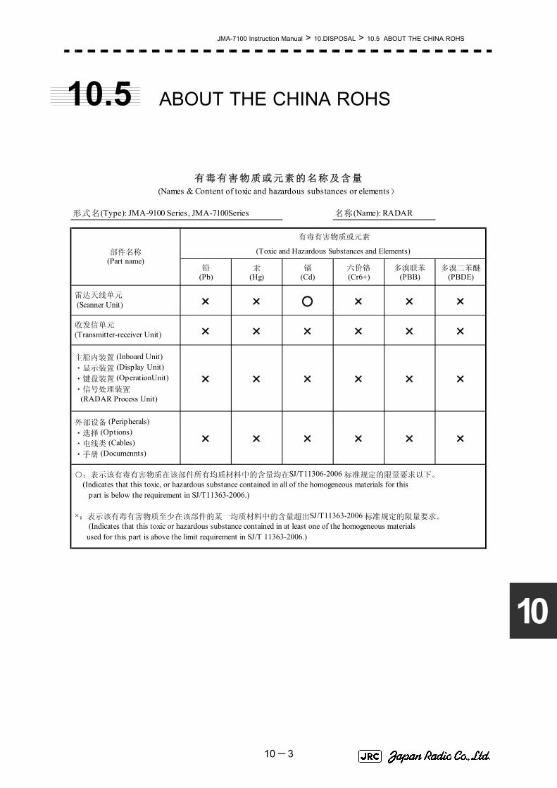
JMA-7100 Instruction Manual > 10.DISPOSAL > 10.5 ABOUT THE CHINA ROHS
10
10.5 ABOUT THE CHINA ROHS
形式名(Type): JMA-9100 Series, JMA-7100Series 名称(Name): RADAR
铅 汞 镉 六价铬 多溴联苯 多溴二苯醚(Pb) (Hg) (Cd) (Cr6+) (PBB) (PBDE)
雷达天线单元 (Scanner Unit) × × ○ × × ×
收发信单元 (Transmitter-receiver Unit) × × × × × ×
主船内装置 (Inboard Unit) ・显示装置 (Display Unit) ・键盘装置 (OperationUnit) ・信号处理装置 (RADAR Process Unit)
× × × × × ×
外部设备 (Peripherals) ・选择 (Options) ・电线类 (Cables) ・手册 (Documennts)
× × × × × ×
有毒有害物质或元素的名称及含量(Names & Content of toxic and hazardous substances or elements)
(Toxic and Hazardous Substances and Elements)
×:表示该有毒有害物质至少在该部件的某一均质材料中的含量超出SJ/T11363-2006 标准规定的限量要求。
(Indicates that this toxic or hazardous substance contained in at least one of the homogeneous materials used for this part is above the limit requirement in SJ/T 11363-2006.)
○:表示该有毒有害物质在该部件所有均质材料中的含量均在SJ/T11306-2006 标准规定的限量要求以下。 (Indicates that this toxic, or hazardous substance contained in all of the homogeneous materials for this part is below the requirement in SJ/T11363-2006.)
部件名称(Part name)
有毒有害物质或元素
10-3

JMA-7100 Instruction Manual > 10.DISPOSAL > 10.5 ABOUT THE CHINA ROHS
10-4

SECTION 11SPECIFICATION
SPECIFICATION11.1 JMA-7133-SA TYPE RADAR ...............................................................11-111.2 JMA-7132-SA TYPE RADAR............................................................... 11-211.3 JMA-7123-7XA/9XA TYPE RADAR ....................................................11-311.4 JMA-7122-6XA/9XA TYPE RADAR ....................................................11-411.5 JMA-7122-6XAH TYPE RADAR .........................................................11-511.6 JMA-7110-6XA TYPE RADAR ............................................................11-611.7 JMA-7110-6XAH TYPE RADAR .........................................................11-711.8 SCANNER UNIT (NKE-1139) ...............................................................11-811.9 SCANNER UNIT (NKE-1130) ...............................................................11-911.10 SCANNER UNIT (NKE-1129-7/9) ......................................................11-1011.11 SCANNER UNIT (NKE-1125-6/9) .......................................................11-1111.12 SCANNER UNIT (NKE-2254-6HS) .....................................................11-1211.13 SCANNER UNIT (NKE-2103-6) ..........................................................11-1311.14 SCANNER UNIT (NKE-2103-6HS) .....................................................11-1411.15 TRANSMITTER RECEIVER UNIT (NTG-3230) .................................11-1511.16 TRANSMITTER RECEIVER UNIT (NTG-3225) .................................11-1611.17 DISPLAY UNIT (NCD-4790) ...............................................................11-17

11.18 Target Tracking Function .................................................................11-2011.19 AIS FUNCTION ...................................................................................11-2111.20 PERFORMANCE MONITOR (NJU-84) ..............................................11-2211.21 PERFORMANCE MONITOR (NJU-85) ..............................................11-2211.22 AC-DC CONVERTER (NBA-5135) .....................................................11-22

JMA-7100 Instruction Manual > 11.SPECIFICATION > 11.1 JMA-7133-SA TYPE RADAR
11
11.1 JMA-7133-SA TYPE RADAR
GENERAL SPECIFICATIONClass of emission P0N
Display Color Raster ScanScreen 19inch LCD (Effective diameter of Radar: more than 250mm)
Range Scale 0.125、0.25、0.5、0.75、1.5、3、6、12、24、48、96NMRange Resolution less than 30m
Minimum Detection Range less than 40mBearing Accuracy less than 1°Bearing Indication Relative motion mode : N-UP, C-UP and H-UP
True motion mode : N-UP and C-UPAmbient Condition Temperature
SCANNER UNIT -25 to +55℃ (Storage -25 to +70℃ ) Other Unit -15 to +55℃Relative humidity 93% at +40℃
Vibration 2 to 13.2Hz Amplitude +/-1mm +/-10%13.2 to 100Hz Acceleration 7m/s2
Power Supply Input AC100 to 115V, 50/60Hz, 1φ orAC220 to 240V, 50/60Hz, 1φ
Power Consumption Approx.400VA typicalApprox. 2000VA at Maximum wind speed
PS Voltage Fluctuation +/-10% (at the maximum cable length)Pre Heating Time Within 4 minuteFrom STBY to TX Within 5 sec.
SCANNER UNIT (NKE-1139)
See 11.8TRANSMITTER RECEIVER UNIT (NTG-3230)
See 11.15DISPLAY UNIT (NCD-4790)
See 11.17PERFORMANCE MONITOR (NJU-84)
See 11.20OPTION
Scanner with Deicing Heater NKE-1139-D (Only heater collar)Radar Inter switch NQE-3141-2A (Maximum 2 Radars)
NQE-3141-4A (Maximum 4 Radars)DISPLAY UNIT (Desktop type) NCD-4790T
Maximum Cable Length
SCANNER UNIT toTRANSMITTER RECEIVER UNIT
30m
DISPLAY UNIT toTRANSMITTER RECEIVER UNIT 35m
SAFE DISTANCE FOR STANDARD COMPASS
SCANNER UNIT 1.4mTRANSMITTER RECEIVER UNIT 3.9m
DISPLAY UNIT 3.1m
11-1
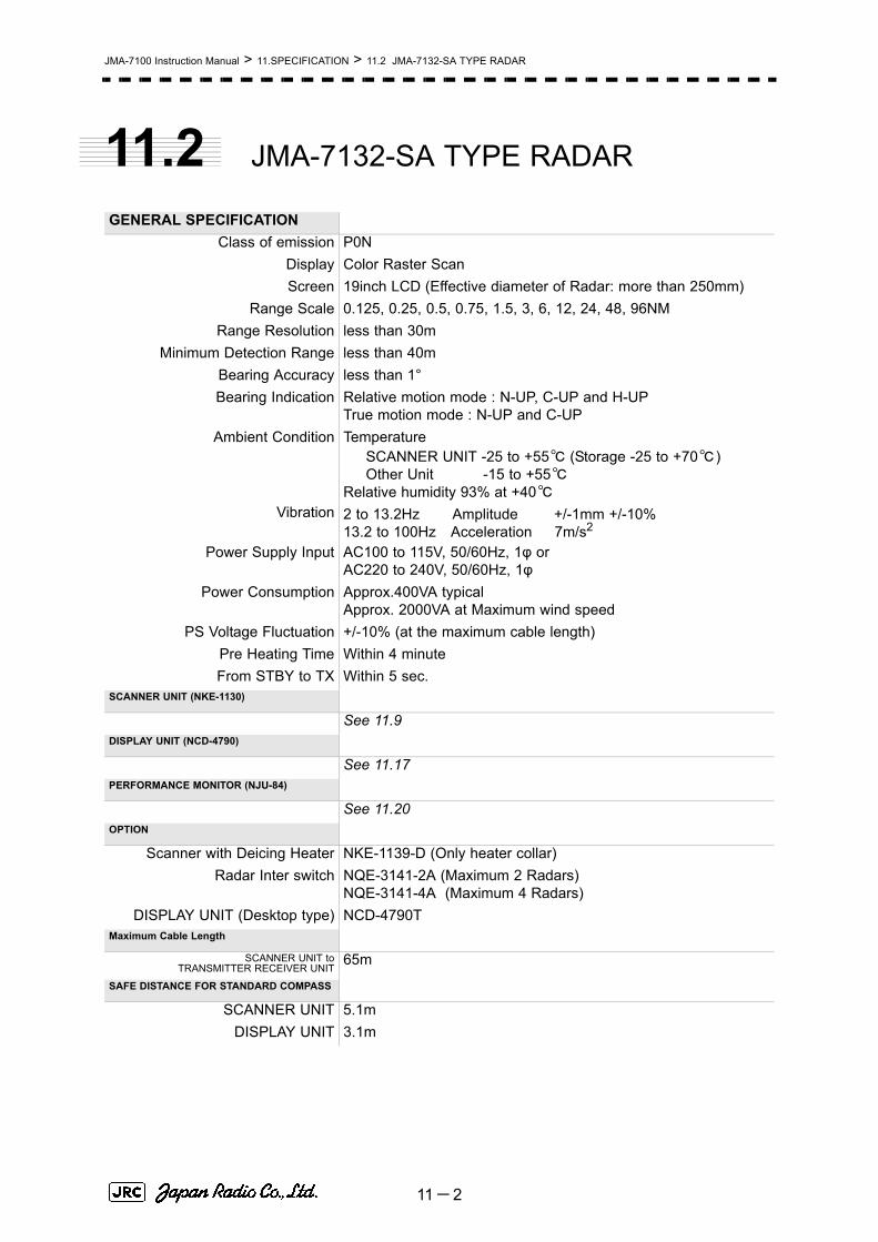
JMA-7100 Instruction Manual > 11.SPECIFICATION > 11.2 JMA-7132-SA TYPE RADAR
11.2 JMA-7132-SA TYPE RADAR
GENERAL SPECIFICATIONClass of emission P0N
Display Color Raster ScanScreen 19inch LCD (Effective diameter of Radar: more than 250mm)
Range Scale 0.125, 0.25, 0.5, 0.75, 1.5, 3, 6, 12, 24, 48, 96NMRange Resolution less than 30m
Minimum Detection Range less than 40mBearing Accuracy less than 1°Bearing Indication Relative motion mode : N-UP, C-UP and H-UP
True motion mode : N-UP and C-UPAmbient Condition Temperature
SCANNER UNIT -25 to +55℃ (Storage -25 to +70℃ ) Other Unit -15 to +55℃Relative humidity 93% at +40℃
Vibration 2 to 13.2Hz Amplitude +/-1mm +/-10%13.2 to 100Hz Acceleration 7m/s2
Power Supply Input AC100 to 115V, 50/60Hz, 1φ orAC220 to 240V, 50/60Hz, 1φ
Power Consumption Approx.400VA typicalApprox. 2000VA at Maximum wind speed
PS Voltage Fluctuation +/-10% (at the maximum cable length)Pre Heating Time Within 4 minuteFrom STBY to TX Within 5 sec.
SCANNER UNIT (NKE-1130)
See 11.9DISPLAY UNIT (NCD-4790)
See 11.17PERFORMANCE MONITOR (NJU-84)
See 11.20OPTION
Scanner with Deicing Heater NKE-1139-D (Only heater collar)Radar Inter switch NQE-3141-2A (Maximum 2 Radars)
NQE-3141-4A (Maximum 4 Radars)DISPLAY UNIT (Desktop type) NCD-4790T
Maximum Cable Length
SCANNER UNIT toTRANSMITTER RECEIVER UNIT
65m
SAFE DISTANCE FOR STANDARD COMPASS
SCANNER UNIT 5.1mDISPLAY UNIT 3.1m
11-2

JMA-7100 Instruction Manual > 11.SPECIFICATION > 11.3 JMA-7123-7XA/9XA TYPE RADAR
11
11.3 JMA-7123-7XA/9XA TYPE RADAR
GENERAL SPECIFICATIONClass of emission P0N
Display Color Raster ScanScreen 19inch LCD (Effective diameter of Radar: more than 250mm)
Range Scale 0.125, 0.25, 0.5, 0.75, 1.5, 3, 6, 12, 24, 48, 96NMRange Resolution less than 30m
Minimum Detection Range less than 40mBearing Accuracy less than 1°Bearing Indication Relative motion mode : N-UP, C-UP and H-UP
True motion mode : N-UP and C-UPAmbient Condition Temperature
SCANNER UNIT -25 to +55℃ (Storage -25 to +70℃ ) Other Unit -15 to +55℃Relative humidity 93% at +40℃
Vibration 2 to 13.2Hz Amplitude +/-1mm +/-10%13.2 to 100Hz Acceleration 7m/s2
Power Supply Input AC100 to 115V, 50/60Hz, 1φ orAC220 to 240V, 50/60Hz, 1φ
Power Consumption Approx.350VA typicalApprox. 1700VA at Maximum wind speed
PS Voltage Fluctuation +/-10% (at the maximum cable length)Pre Heating Time Within 4 minuteFrom STBY to TX Within 5 sec.
SCANNER UNIT (NKE-1129-7/9)
See 11.10TRANSMITTER RECEIVER UNIT (NTG-3225)
See 11.16DISPLAY UNIT (NCD-4790)
See 11.17PERFORMANCE MONITOR (NJU-85)
See 11.21OPTION
Scanner with Deicing Heater NKE-1139-D (Only heater collar)Radar Inter switch NQE-3141-2A (Maximum 2 Radars)
NQE-3141-4A (Maximum 4 Radars)DISPLAY UNIT (Desktop type) NCD-4790T
Maximum Cable Length
SCANNER UNIT toTRANSMITTER RECEIVER UNIT
30m
DISPLAY UNIT toTRANSMITTER RECEIVER UNIT 35m
SAFE DISTANCE FOR STANDARD COMPASS
SCANNER UNIT 1.05mTRANSMITTER RECEIVER UNIT 2.8m
DISPLAY UNIT 3.1m
11-3

JMA-7100 Instruction Manual > 11.SPECIFICATION > 11.4 JMA-7122-6XA/9XA TYPE RADAR
11.4 JMA-7122-6XA/9XA TYPE RADAR
GENERAL SPECIFICATIONClass of emission P0N
Display Color Raster ScanScreen 19inch LCD (Effective diameter of Radar: more than 250mm)
Range Scale 0.125, 0.25, 0.5, 0.75, 1.5, 3, 6, 12, 24, 48, 96NMRange Resolution less than 30m
Minimum Detection Range less than 40mBearing Accuracy less than 1°Bearing Indication Relative motion mode : N-UP, C-UP and H-UP
True motion mode : N-UP and C-UPAmbient Condition Temperature
SCANNER UNIT -25 to +55℃ (Storage -25 to +70℃ ) Other Unit -15 to +55℃Relative humidity 93% at +40℃
Vibration 2 to 13.2Hz Amplitude +/-1mm +/-10%13.2 to 100Hz Acceleration 7m/s2
Power Supply Input AC100 to 115V, 50/60Hz, 1φ orAC220 to 240V, 50/60Hz, 1φ
Power Consumption Approx.350VA typicalApprox. 1700VA at Maximum wind speed
PS Voltage Fluctuation +/-10% (at the maximum cable length)Pre Heating Time Within 4 minuteFrom STBY to TX Within 5 sec.
SCANNER UNIT (NKE-1125-6/9)
See 11.11DISPLAY UNIT (NCD-4790)
See 11.17PERFORMANCE MONITOR (NJU-85)
See 11.21OPTION
Scanner with Deicing Heater NKE-1139-D (Only heater collar)Radar Inter switch NQE-3141-2A (Maximum 2 Radars)
NQE-3141-4A (Maximum 4 Radars)DISPLAY UNIT (Desktop type) NCD-4790T
Maximum Cable Length
SCANNER UNIT toTRANSMITTER RECEIVER UNIT
65m
SAFE DISTANCE FOR STANDARD COMPASS
SCANNER UNIT 2.4mDISPLAY UNIT 3.1m
11-4

JMA-7100 Instruction Manual > 11.SPECIFICATION > 11.5 JMA-7122-6XAH TYPE RADAR
11
11.5 JMA-7122-6XAH TYPE RADAR
GENERAL SPECIFICATIONClass of emission P0N
Display Color Raster ScanScreen 19inch LCD (Effective diameter of Radar: more than 250mm)
Range Scale 0.125, 0.25, 0.5, 0.75, 1.5, 3, 6, 12, 24, 48, 96NMRange Resolution less than 30m
Minimum Detection Range less than 40mBearing Accuracy less than 1°Bearing Indication Relative motion mode : N-UP, C-UP and H-UP
True motion mode : N-UP and C-UPAmbient Condition Temperature
SCANNER UNIT -25 to +55℃ (Storage -25 to +70℃ ) Other Unit -15 to +55℃Relative humidity 93% at +40℃
Vibration 2 to 13.2Hz Amplitude +/-1mm +/-10%13.2 to 100Hz Acceleration 7m/s2
Power Supply Input AC100 to 115V, 50/60Hz, 1φ orAC220 to 240V, 50/60Hz, 1φ
Power Consumption Approx.350VA typicalApprox. 1000VA at Maximum wind speed
PS Voltage Fluctuation +/-10% (at the maximum cable length)Pre Heating Time Within 4 minuteFrom STBY to TX Within 5 sec.
SCANNER UNIT (NKE-2254-6HS)
See 11.11DISPLAY UNIT (NCD-4790)
See 11.17PERFORMANCE MONITOR (NJU-85)
See 11.21AC-DC CONVERTER (NBA-5135)
See 11.22OPTION
Scanner with Deicing Heater NoneRadar Inter switch NQE-3141-2A (Maximum 2 Radars)
NQE-3141-4A (Maximum 4 Radars)DISPLAY UNIT (Desktop type) NCD-4790T
Maximum Cable LengthSCANNER UNIT to
TRANSMITTER RECEIVER UNIT65m
SAFE DISTANCE FOR STANDARD COMPASS
SCANNER UNIT 2.4mDISPLAY UNIT 3.1m
11-5

JMA-7100 Instruction Manual > 11.SPECIFICATION > 11.6 JMA-7110-6XA TYPE RADAR
11.6 JMA-7110-6XA TYPE RADAR
GENERAL SPECIFICATIONClass of emission P0N
Display Color Raster ScanScreen 19inch LCD (Effective diameter of Radar: more than 250mm)
Range Scale 0.125, 0.25, 0.5, 0.75, 1.5, 3, 6, 12, 24, 48, 96NMRange Resolution less than 30m
Minimum Detection Range less than 40mBearing Accuracy less than 1°Bearing Indication Relative motion mode : N-UP, C-UP and H-UP
True motion mode : N-UP and C-UPAmbient Condition Temperature
SCANNER UNIT -25 to +55℃ (Storage -25 to +70℃ ) Other Unit -15 to +55℃Relative humidity 93% at +40℃
Vibration 2 to 13.2Hz Amplitude +/-1mm +/-10%13.2 to 100Hz Acceleration 7m/s2
Power Supply Input AC100 to 115V, 50/60Hz, 1φ orAC220 to 240V, 50/60Hz, 1φ
Power Consumption Approx.350VA typicalApprox. 1000VA at Maximum wind speed
PS Voltage Fluctuation +/-10% (at the maximum cable length)Pre Heating Time Within 4 minuteFrom STBY to TX Within 5 sec.
SCANNER UNIT (NKE-2103-6)See 11.13
DISPLAY UNIT (NCD-4790)See 11.17
PERFORMANCE MONITOR (NJU-85)
See 11.21AC-DC CONVERTER (NBA-5135)
See 11.22OPTION
Scanner with Deicing Heater NoneRadar Inter switch NQE-3141-2A (Maximum 2 Radars)
NQE-3141-4A (Maximum 4 Radars)DISPLAY UNIT (Desktop type) NCD-4790T
Maximum Cable LengthSCANNER UNIT to
TRANSMITTER RECEIVER UNIT65m
SAFE DISTANCE FOR STANDARD COMPASS
SCANNER UNIT 2.4mDISPLAY UNIT 3.1m
11-6

JMA-7100 Instruction Manual > 11.SPECIFICATION > 11.7 JMA-7110-6XAH TYPE RADAR
11
11.7 JMA-7110-6XAH TYPE RADAR
GENERAL SPECIFICATIONClass of emission P0N
Display Color Raster ScanScreen 19inch LCD (Effective diameter of Radar: more than 250mm)
Range Scale 0.125, 0.25, 0.5, 0.75, 1.5, 3, 6, 12, 24, 48, 96NMRange Resolution less than 30m
Minimum Detection Range less than 40mBearing Accuracy less than 1°Bearing Indication Relative motion mode : N-UP, C-UP and H-UP
True motion mode : N-UP and C-UPAmbient Condition Temperature
SCANNER UNIT -25 to +55℃ (Storage -25 to +70℃ ) Other Unit -15 to +55℃Relative humidity 93% at +40℃
Vibration 2 to 13.2Hz Amplitude +/-1mm +/-10%13.2 to 100Hz Acceleration 7m/s2
Power Supply Input AC100 to 115V, 50/60Hz, 1φ orAC220 to 240V, 50/60Hz, 1φ
Power Consumption Approx.350VA typicalApprox. 1000VA at Maximum wind speed
PS Voltage Fluctuation +/-10% (at the maximum cable length)Pre Heating Time Within 4 minuteFrom STBY to TX Within 5 sec.
SCANNER UNIT (NKE-2103-6HS)
See 11.14DISPLAY UNIT (NCD-4790)
See 11.17PERFORMANCE MONITOR (NJU-85)
See 11.21AC-DC CONVERTER (NBA-5135)
See 11.22OPTION
Scanner with Deicing Heater NoneRadar Inter switch NQE-3141-2A (Maximum 2 Radars)
NQE-3141-4A (Maximum 4 Radars)DISPLAY UNIT (Desktop type) NCD-4790T
Maximum Cable Length
SCANNER UNIT~DISPLAYUNIT
65m
SAFE DISTANCE FOR STANDARD COMPASS
SCANNER UNIT 2.4mDISPLAY UNIT 3.1m
11-7
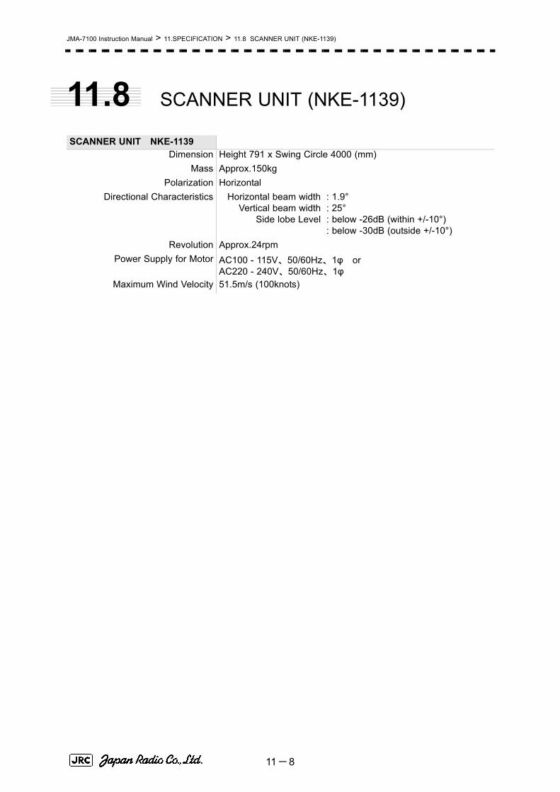
JMA-7100 Instruction Manual > 11.SPECIFICATION > 11.8 SCANNER UNIT (NKE-1139)
11.8 SCANNER UNIT (NKE-1139)
SCANNER UNIT NKE-1139Dimension Height 791 x Swing Circle 4000 (mm)
Mass Approx.150kgPolarization Horizontal
Directional Characteristics Horizontal beam widthVertical beam width
Side lobe Level
: 1.9°: 25°: below -26dB (within +/-10°): below -30dB (outside +/-10°)
Revolution Approx.24rpmPower Supply for Motor AC100 - 115V、50/60Hz、1φ or
AC220 - 240V、50/60Hz、1φ Maximum Wind Velocity 51.5m/s (100knots)
11-8

JMA-7100 Instruction Manual > 11.SPECIFICATION > 11.9 SCANNER UNIT (NKE-1130)
11
11.9 SCANNER UNIT (NKE-1130)
SCANNER UNIT NKE-1130Dimension Height 791 x Swing Circle 4000 (mm)
Mass Approx.180kgPolarization Horizontal
Directional Characteristics Horizontal beam widthVertical beam width
Side lobe Level
: 1.9°: 25°: below -26dB (within +/-10°): below -30dB (outside +/-10°)
Revolution Approx.24rpmPower Supply for Motor AC100 - 115V、50/60Hz、1φ or
AC220 - 240V、50/60Hz、1φMaximum Wind Velocity 51.5m/s (100knots)Transmitting Frequency 3050±20MHz
Transmitting Power 30kWTransmitting Tube Magnetron[M1555]
TX Pulse width / RepetitionFrequency
SP1:0.07μs/2250HzMP1:0.2μs/2250Hz MP2:0.3μs/1900Hz、MP3:0.4μs/1400Hz LP1:0.8μs/750Hz、LP2:1.0μs/650Hz LP3:1.2μs/510Hz
0.125、0.25、0.5NM :SP1 0.75NM :SP1/MP1
1.5NM :SP1/MP1/MP2/MP3 3NM :MP1/MP2/MP3/LP1 6NM :MP1/MP2/MP3/LP1/LP2
12NM :MP1/MP2/MP3/LP1/LP2 24NM :MP3/LP1/LP2 48NM :LP2 96NM :LP3
Modulator Solid State Modulator CircuitDuplexer Circulator + Diode Limiter
Front End Module Built-inIntermediate Frequency Amplifier Intermediate Frequency
Band WidthGain
Amplifying Characteristics
: 60MHz: 25/8/3MHz: more than 90dB: Logarithmic Amplifier
Overall Noise Figure 7.5dB ( Typical)Tuning Manual/AUTO
11-9

JMA-7100 Instruction Manual > 11.SPECIFICATION > 11.10 SCANNER UNIT (NKE-1129-7/9)
11.10 SCANNER UNIT (NKE-1129-7/9)
SCANNER UNIT NKE-1129-7/9Dimension 7ft Height 536 x Swing Circle 2270 (mm)
9ft Height 536 x Swing Circle 2825 (mm)Mass 7ft Approx.51kg
9ft Approx.53kgPolarization Horizontal
Directional Characteristics Horizontal beam width
Vertical beam widthSide lobe Level
: 1.0° (7ft): 0.8° (9ft): 20°: below -26dB (within +/-10°): below -30dB (outside +/-10°)
Revolution Approx.24rpmPower Supply for Motor AC100 - 115V、50/60Hz、1φ or
AC220 - 240V、50/60Hz、1φ Maximum Wind Velocity 51.5m/s (100knots)
11-10

JMA-7100 Instruction Manual > 11.SPECIFICATION > 11.11 SCANNER UNIT (NKE-1125-6/9)
11
11.11 SCANNER UNIT (NKE-1125-6/9)
SCANNER UNIT NKE-1125-6/9Dimension 6ft Height 536 x Swing Circle 1910 (mm)
9ft Height 536 x Swing Circle 2825 (mm)Mass 6ft Approx. 55kg
9ft Approx. 60kgPolarization Horizontal
Directional Characteristics Horizontal beam width
Vertical beam widthSide lobe Level
: 1.2° (6ft): 0.8° (9ft): 20°: below -26dB (within +/-10°): below -30dB (outside +/-10°)
Revolution Approx.24rpmPower Supply for Motor AC100 - 115V、50/60Hz、1φ or
AC220 - 240V、50/60Hz、1φMaximum Wind Velocity 51.5m/s (100knots)Transmitting Frequency 9410±30MHz
Transmitting Power 25kWTransmitting Tube Magnetron[M1568BS]
TX Pulse width / RepetitionFrequency
SP1:0.07μs/2250HzMP1:0.2μs/2250Hz MP2:0.3μs/1900Hz、MP3:0.4μs/1400Hz LP1:0.8μs/750Hz、LP2:1.0μs/650Hz LP3:1.2μs/510Hz
0.125、0.25、0.5NM :SP1 0.75NM :SP1/MP1
1.5NM :SP1/MP1/MP2/MP3 3NM :MP1/MP2/MP3/LP1 6NM :MP1/MP2/MP3/LP1/LP2
12NM :MP1/MP2/MP3/LP1/LP2 24NM :MP3/LP1/LP2 48NM :LP2 96NM :LP3
Modulator Solid State Modulator CircuitDuplexer Circulator + Diode Limiter
Front End Module Built-inIntermediate Frequency Amplifier Intermediate Frequency
Band WidthGain
Amplifying Characteristics
: 60MHz: 25/8/3MHz: more than 90dB: Logarithmic Amplifier
Overall Noise Figure 7.5dB ( Typical)Tuning Manual/AUTO
11-11
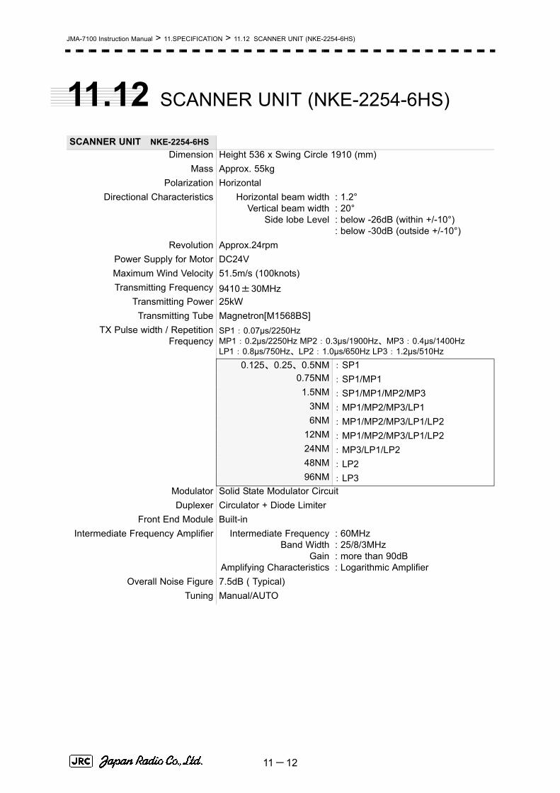
JMA-7100 Instruction Manual > 11.SPECIFICATION > 11.12 SCANNER UNIT (NKE-2254-6HS)
11.12 SCANNER UNIT (NKE-2254-6HS)
SCANNER UNIT NKE-2254-6HSDimension Height 536 x Swing Circle 1910 (mm)
Mass Approx. 55kgPolarization Horizontal
Directional Characteristics Horizontal beam widthVertical beam width
Side lobe Level
: 1.2°: 20°: below -26dB (within +/-10°): below -30dB (outside +/-10°)
Revolution Approx.24rpmPower Supply for Motor DC24VMaximum Wind Velocity 51.5m/s (100knots)Transmitting Frequency 9410±30MHz
Transmitting Power 25kWTransmitting Tube Magnetron[M1568BS]
TX Pulse width / RepetitionFrequency
SP1:0.07μs/2250HzMP1:0.2μs/2250Hz MP2:0.3μs/1900Hz、MP3:0.4μs/1400Hz LP1:0.8μs/750Hz、LP2:1.0μs/650Hz LP3:1.2μs/510Hz
0.125、0.25、0.5NM :SP1 0.75NM :SP1/MP1
1.5NM :SP1/MP1/MP2/MP3 3NM :MP1/MP2/MP3/LP1 6NM :MP1/MP2/MP3/LP1/LP2
12NM :MP1/MP2/MP3/LP1/LP2 24NM :MP3/LP1/LP2 48NM :LP2 96NM :LP3
Modulator Solid State Modulator CircuitDuplexer Circulator + Diode Limiter
Front End Module Built-inIntermediate Frequency Amplifier Intermediate Frequency
Band WidthGain
Amplifying Characteristics
: 60MHz: 25/8/3MHz: more than 90dB: Logarithmic Amplifier
Overall Noise Figure 7.5dB ( Typical)Tuning Manual/AUTO
11-12

JMA-7100 Instruction Manual > 11.SPECIFICATION > 11.13 SCANNER UNIT (NKE-2103-6)
11
11.13 SCANNER UNIT (NKE-2103-6)
SCANNER UNIT NKE-2103-6HSDimension Height 458 x Swing Circle 1910 (mm)
Mass Approx. 40kgPolarization Horizontal
Directional Characteristics Horizontal beam widthVertical beam width
Side lobe Level
: 1.2°: 20°: below -26dB (within +/-10°): below -30dB (outside +/-10°)
Revolution Approx.24rpmPower Supply for Motor DC24VMaximum Wind Velocity 51.5m/s (100knots)Transmitting Frequency 9410±30MHz
Transmitting Power 10kWTransmitting Tube Magnetron[MAF1565N]
TX Pulse width / RepetitionFrequency
SP1:0.08μs/2250HzMP1:0.25μs/1700Hz MP2:0.5μs/1200HzLP1:0.8μs/750Hz、LP2:1.0μs/650Hz
0.125、0.25、0.5NM :SP1 0.75NM :SP1/MP1
1.5NM :SP1/MP1/MP2 3NM :MP1/MP2LP1 6NM :MP1/MP2/LP1/LP2
12NM :MP1/MP2/LP1/LP2 24NM :MP2/LP1/LP2 48NM :LP2 96NM :LP2
Modulator Solid State Modulator CircuitDuplexer Circulator + Diode Limiter
Front End Module Built-inIntermediate Frequency Amplifier Intermediate Frequency
Band WidthGain
Amplifying Characteristics
: 60MHz: 20/6/3MHz: more than 90dB: Logarithmic Amplifier
Overall Noise Figure 7.5dB ( Typical)Tuning Manual/AUTO
11-13
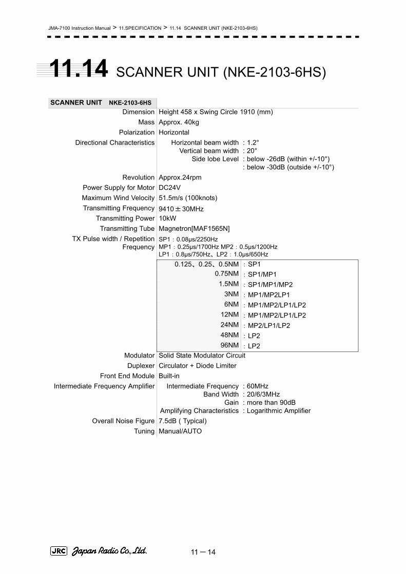
JMA-7100 Instruction Manual > 11.SPECIFICATION > 11.14 SCANNER UNIT (NKE-2103-6HS)
11.14 SCANNER UNIT (NKE-2103-6HS)
SCANNER UNIT NKE-2103-6HSDimension Height 458 x Swing Circle 1910 (mm)
Mass Approx. 40kgPolarization Horizontal
Directional Characteristics Horizontal beam widthVertical beam width
Side lobe Level
: 1.2°: 20°: below -26dB (within +/-10°): below -30dB (outside +/-10°)
Revolution Approx.24rpmPower Supply for Motor DC24VMaximum Wind Velocity 51.5m/s (100knots)Transmitting Frequency 9410±30MHz
Transmitting Power 10kWTransmitting Tube Magnetron[MAF1565N]
TX Pulse width / RepetitionFrequency
SP1:0.08μs/2250HzMP1:0.25μs/1700Hz MP2:0.5μs/1200HzLP1:0.8μs/750Hz、LP2:1.0μs/650Hz
0.125、0.25、0.5NM :SP1 0.75NM :SP1/MP1
1.5NM :SP1/MP1/MP2 3NM :MP1/MP2LP1 6NM :MP1/MP2/LP1/LP2
12NM :MP1/MP2/LP1/LP2 24NM :MP2/LP1/LP2 48NM :LP2 96NM :LP2
Modulator Solid State Modulator CircuitDuplexer Circulator + Diode Limiter
Front End Module Built-inIntermediate Frequency Amplifier Intermediate Frequency
Band WidthGain
Amplifying Characteristics
: 60MHz: 20/6/3MHz: more than 90dB: Logarithmic Amplifier
Overall Noise Figure 7.5dB ( Typical)Tuning Manual/AUTO
11-14

JMA-7100 Instruction Manual > 11.SPECIFICATION > 11.15 TRANSMITTER RECEIVER UNIT (NTG-3230)
11
11.15 TRANSMITTER RECEIVER UNIT
(NTG-3230)
SCANNER UNIT NTG-3230Dimension :Width 615 x Depth 365 x Height 615 (mm)
構造 Wall Mount, Drip ProofMass Approx.33kg
Transmitting Frequency 3050±20MHzTransmitting Power 30kW
Transmitting Tube Magnetron [M1555]TX Pulse width / Repetition
FrequencySP1:0.07μs/2250HzMP1:0.2μs/2250Hz MP2:0.3μs/1900Hz、MP3:0.4μs/1400Hz LP1:0.8μs/750Hz、LP2:1.0μs/650Hz LP3:1.2μs/510Hz
0.125、0.25、0.5NM :SP1 0.75NM :SP1/MP1
1.5NM :SP1/MP1/MP2/MP3 3NM :MP1/MP2/MP3/LP1 6NM :MP1/MP2/MP3/LP1/LP2
12NM :MP1/MP2/MP3/LP1/LP2 24NM :MP3/LP1/LP2 48NM :LP2 96NM :LP3
Modulator Solid State Modulator CircuitDuplexer Circulator + TRHPL
Front End Module Built-inIntermediate Frequency Amplifier Intermediate Frequency
Band WidthGain
Amplifying Characteristics
: 60MHz: 25/8/3MHz: more than 90dB: Logarithmic Amplifier
Overall Noise Figure 7.5dB ( Typical)Tuning Manual/AUTO
11-15

JMA-7100 Instruction Manual > 11.SPECIFICATION > 11.16 TRANSMITTER RECEIVER UNIT (NTG-3225)
11.16 TRANSMITTER RECEIVER UNIT
(NTG-3225)
SCANNER UNIT NTG-3225Dimension :Width 460 x Depth 227 x Height 461 (mm)
構造 Wall Mount, Drip ProofMass Approx.15kg
Transmitting Frequency 9410±30MHzTransmitting Power 25kW
Transmitting Tube Magnetron[M1568BS]TX Pulse width / Repetition
FrequencySP1:0.07μs/2250HzMP1:0.2μs/2250Hz MP2:0.3μs/1900Hz、MP3:0.4μs/1400Hz LP1:0.8μs/750Hz、LP2:1.0μs/650Hz LP3:1.2μs/510Hz
0.125、0.25、0.5NM :SP1 0.75NM :SP1/MP1
1.5NM :SP1/MP1/MP2/MP3 3NM :MP1/MP2/MP3/LP1 6NM :MP1/MP2/MP3/LP1/LP2
12NM :MP1/MP2/MP3/LP1/LP2 24NM :MP3/LP1/LP2 48NM :LP2 96NM :LP3
Modulator Solid State Modulator CircuitDuplexer Circulator + Diode Limiter
Front End Module Built-inIntermediate Frequency Amplifier Intermediate Frequency
Band WidthGain
Amplifying Characteristics
: 60MHz: 25/8/3MHz: more than 90dB: Logarithmic Amplifier
Overall Noise Figure 7.5dB ( Typical)Tuning Manual/AUTO
11-16

JMA-7100 Instruction Manual > 11.SPECIFICATION > 11.17 DISPLAY UNIT (NCD-4790)
11
11.17 DISPLAY UNIT (NCD-4790)
DISPLAY UNIT NCD-4790
Dimension Width 580 x Depth 850 x Height 1100 (mm)Structure Self-Standing, Drip Proof
Mass Approx.99kg Screen 19inch Color LCD (Effective Diameter, more than 250mm)
Viewing Distance 1m from the center of DisplayRange Scale 0.125, 0.25, 0.5, 0.75, 1.5, 3, 6, 12, 24, 48, 96NM
Range Marker 0.025, 0.05, 0.1, 0.25, 0.5, 1, 2, 4, 8, 16NMRange Accuracyr Less than 1% of the Range Scale in use, or 30m whichever is larger
Variable Range Marker 2 (VRM1/VRM2)VRM Scale 0.000 to 100.0nm, Numerical Indication in 4 digits
Bearing Scale 360° in 1° stepOff Center Within 66% of Radius, except 96nm range
Trackball Cursor Built-in (Target Range, Relative/True bearing Presentation)Electronic Bearing Lines 2 (EBL1/EBL2) (on Center/Floating)
EBLBearing Indication 000.0° to 359.9°Numerical Indication in 4 digitsTuning Indication Bar graphMarking Function Electronic Mark (Maximum 20 points)
Heading Line Indication ElectronicTrue Motion Unit Built in (0.25, 0.5, 0.75, 1.5, 3, 6, 12, 24 and 48nm)
Anti Sea Clutter (SEA) Manual/AUTOAnti Rain Clutter (SEA) Manual/AUTO
Display mode North-up / Head-up / Course-upTrails Indication Off/0.25/0.5/1/3/6/10/15min and Continues
Video Process (PROC) Built in (Scan correlation / Remain)Interference Rejection (IR) Built in ( Off / Low / Middle / High)Auto-acquisition Zone (AZ) Sector (2)
User Mapi Built in, Mark and Line (20,000 points)Self diagnostic function Built inOwn Ship's Track Indicationi Built inParallel Index Line (PI) Built in
AIS Indication Built in DisplayActivate
300100 Association function:Built in
Interfacing Slave Display (TRG, VD, BP, BZ)GPS IEC61162-1(NMEA0183)LOG GYRO AIS IEC61162-2 Inter Switch (OPTION)Radar Buoy External Alarm output
Receivable Signal
11-17

JMA-7100 Instruction Manual > 11.SPECIFICATION > 11.17 DISPLAY UNIT (NCD-4790)
Receive capability Port:
NAV1/ALM/ARPA/JARPA at terminal board TB4501 COM port (D-Sub 9 PIN)
Navigation equipment IEC61162-1/2
Longitude/Latitude GGA>RMC>RMA>GNS>GLL
Waypoint RMB>BWC(BWR) COG/SOG RMC>RMA>VTG
SPEED VBWDay/Time information ZDA
Alarm acknowledge ACKRate of Turn ROT
Rudder RSABearing signal GYRO-SYNC 360x, 180x, 90x, 36x(GYRO I/F)
GYRO-STEP 360x, 180x, 90x, 36x(GYRO I/F)
IEC61162-2 38400bps THS>HDT over 40Hz(HDG port at terminal board TB4501)
IEC61162-1ii HDT>HDG>HDM>VHW (HDG port at terminal board TB4501)
Speed signal LOG-SYNC 360x, 180x, 90x, 30x(GYRO I/F)
LOG-PULSE 800, 400, 200, 100(GYRO I/F)
External event mark Contact input (EVENT port at terminal board TB4601)Radar buoy Negative input (RBVD port at terminal board TB4401)Depth IEC61162-1/JRC DPT>DBS>DBT>DBK,
JRC formatWater temperature IEC61162-1/JRC MTW, JRC formatTendency IEC61162-1/JRC CUR, JRC formatWind IEC61162-1 MWV>MWDAIS IEC61162-2 VDM,VDO(AIS port at terminal
board TB4601)Acknowledge Contact input (SYSACK, ARPAACK, PWRACK port
at terminal board TB4601)Sendable Signal
Slave video Radar video: TIY, VD, BP(2048p), BZ(Terminal board TB4401)
Send capability Port
NAV1, NAV2, ALM, ARPA, JARPA port at terminal board TB4303. COM port (D-Sub 9 PIN)
Navigation information IEC61162-1/2
Radar system data RSD
Own ship data OSDTracking target data TTM,TLL,TTD,TLB,JRC-ARPA
AIS target data TTM,TLL,TTD,TLBAlarm ALR
Auto pilot APBBearing of destination BODLatitude/Longitude data GGA,GLL,RMC
Waypoint RMB,BWCCOG/SOG VTG
Cross track error XTEHeading data HDT,THS
External alarm Default setting normally closed contact
11-18

JMA-7100 Instruction Manual > 11.SPECIFICATION > 11.17 DISPLAY UNIT (NCD-4790)
11
Maximum current 200mA (SYSALM, ALPAALM, PWRALM port at terminal board TB4601)
Acknowledge Contact output (ACKOUT port at terminal board TB4401)
Watchman reset Contact output (WMRST port at terminal board TB4401)Remote maintenance JRC format (MNT port at terminal board TB4601)AIS alarm acknowledge ACK (AIS port at terminal board TB4601)External monitor Multi scan monitor Analog RGB, HD15pin Connector 2 port
i. Only with Navigation Equipment is connected.The Speed measuring accuracy of speed sensor shall confirm to IMO Resolution MSC.96(72).The measuring accuracy of GPS shall confirm to IMO Resolution MSC.112(73).
ii. Can't be use for target tracking.
11-19

JMA-7100 Instruction Manual > 11.SPECIFICATION > 11.18 Target Tracking Function
11.18 Target Tracking Function
Target Tracking Function
Available range scale All rangeAcquisition Acquisition mode Manual/AUTO(AUTO mode uses Auto-acquisition Zone)
Manual Cancellation Any one Target or All targets at onceTracking Number of Target 100 Targets (AUTO Tracking)
Maximum tracking range 32nm (Available all range scale)Presentation Display mode TM (True Motion) / RM (Relative Motion)
Azimuth mode North-up / Head-up / Course-upVector mode True/Relative Display
Vector Length Variable, 1 to 60 min. (1min. step)Past Position True/Relative Display
Number of Dots…10 points Display Interval Time…0.5 / 1 / 2/ 4 min
Time to Display Vector Within 1minTime to Stabilize Vector Within 3min
Alarm Auto-acquisition Zone 2 (sector)Setting Range AZ1 (0.5~32NM),AZ2 (0.5~32NM)
Alarm Indication Symbol on Display, Visible / Audible AlarmSafe Limits Setting Condition CPA LIMIT 0.1 to 9.9NM
(CPA/TCPA) TCPA LIMIT 1 to 99 minuteSetting Condition Safe Target CPA>CPA LIMIT
0>TCPATCPA>TCPA LIMIT
Danger Target CPA≦CPA LIMIT0≦TCPA≦TCPA LIMIT
Alarm Indication Status Symbol Alarm AudibleSafe Target 〇 (wht) OFF OFF
Danger Target ○ (red) CPA/TCPA ONLost Target Symbol on Display
Visible / Audible AlarmData Indication Target Data Simultaneous and Continuous Display for 4 Targets
True Bearing, Range, True Course, True Speed,CPA,TCPA,BCR,BCT
Own Ship's Data Course and SpeedTrial Maneuver Manual Setting
Trial Course 0°to 359.9°Trial Speed 0 to 100 kn
Accuracy of Display Complied with IMO RequirementSystem Failure Alarm Visible / Audible Alarm
Speed Input Manual/AUTO (LOG)
11-20
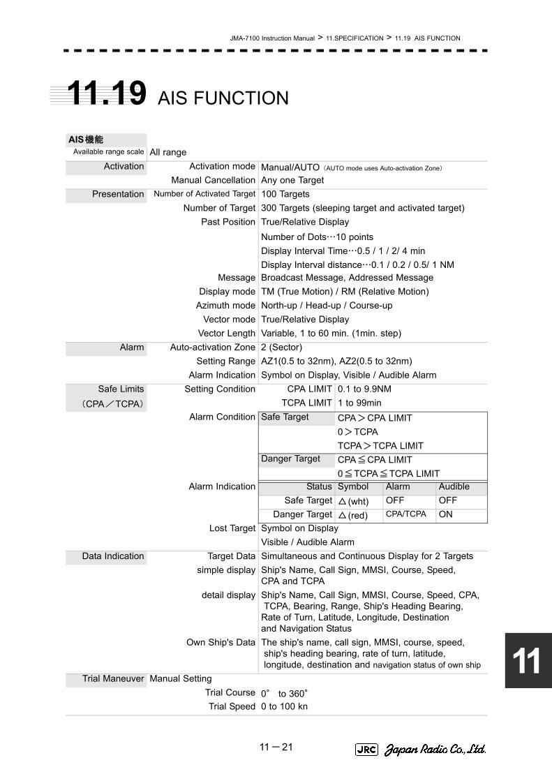
JMA-7100 Instruction Manual > 11.SPECIFICATION > 11.19 AIS FUNCTION
11
11.19 AIS FUNCTION
AIS機能Available range scale All range
Activation Activation mode Manual/AUTO(AUTO mode uses Auto-activation Zone)
Manual Cancellation Any one TargetPresentation Number of Activated Target 100 Targets
Number of Target 300 Targets (sleeping target and activated target)Past Position True/Relative Display
Number of Dots…10 pointsDisplay Interval Time…0.5 / 1 / 2/ 4 minDisplay Interval distance…0.1 / 0.2 / 0.5/ 1 NM
Message Broadcast Message, Addressed MessageDisplay mode TM (True Motion) / RM (Relative Motion)
Azimuth mode North-up / Head-up / Course-upVector mode True/Relative Display
Vector Length Variable, 1 to 60 min. (1min. step)Alarm Auto-activation Zone 2 (Sector)
Setting Range AZ1(0.5 to 32nm), AZ2(0.5 to 32nm)Alarm Indication Symbol on Display, Visible / Audible Alarm
Safe Limits Setting Condition CPA LIMIT 0.1 to 9.9NM(CPA/TCPA) TCPA LIMIT 1 to 99min
Alarm Condition Safe Target CPA>CPA LIMIT0>TCPATCPA>TCPA LIMIT
Danger Target CPA≦CPA LIMIT0≦TCPA≦TCPA LIMIT
Alarm Indication Status Symbol Alarm AudibleSafe Target △ (wht) OFF OFF
Danger Target △ (red) CPA/TCPA ONLost Target Symbol on Display
Visible / Audible AlarmData Indication Target Data Simultaneous and Continuous Display for 2 Targets
simple display Ship's Name, Call Sign, MMSI, Course, Speed, CPA and TCPA
detail display Ship's Name, Call Sign, MMSI, Course, Speed, CPA, TCPA, Bearing, Range, Ship's Heading Bearing, Rate of Turn, Latitude, Longitude, Destination and Navigation Status
Own Ship's Data The ship's name, call sign, MMSI, course, speed, ship's heading bearing, rate of turn, latitude, longitude, destination and navigation status of own ship
Trial Maneuver Manual SettingTrial Course 0° to 360°Trial Speed 0 to 100 kn
11-21

JMA-7100 Instruction Manual > 11.SPECIFICATION > 11.20 PERFORMANCE MONITOR (NJU-84)
11.20 PERFORMANCE MONITOR (NJU-84)
11.21 PERFORMANCE MONITOR (NJU-85)
11.22 AC-DC CONVERTER (NBA-5135)
Accuracy of Display Complied with IMO RequirementSystem Failure Alarm Visible / Audible Alarm
Speed Input Auto (LOG)
PERFORMANCE MONITORNJU-84
Dimension Width 130 x Depth 180 x Height 70 (mm)Mass Approx.0.7kg
Operating Frequency 3050±30MHz
PERFORMANCE MONITORNJU-85
Dimension Width 130 x Depth 149 x Height 70 (mm)Mass Approx.0.7kg
Operating Frequency 9410±30MHz
AC-DC CONVERTERNBA-5135Dimension Width 315 x Depth 385 x Height 99 (mm)
Mass Approx.5kgPower supply Input AC100 to 240V, 50/60Hz, 1φ
Output Voltage DC24V +/-5%Output Current 12A max
11-22

Appendix ANQE-3141 Interswitch Unit
NQE-3141 Interswitch UnitA.1 OVERVIEW ............................................................................................A-1
A.1.1 Overview .........................................................................................A-1A.1.2 Interswitch Setup ...........................................................................A-1
A.2 INTERSWITCH OPERATION ................................................................A-3A.2.1 Operation Flow ...............................................................................A-3A.2.2 Inter Switch Menu ...........................................................................A-4A.2.3 Change of Connection Pattern (with 2 Display Units) ................A-6A.2.4 Change of Connection Pattern (with 3 or More Display Units) ..A-7A.2.5 Operating Connection Pattern Files (File Operations) ...............A-8A.2.6 Names of Display Units and Scanner Units .................................A-9
A.3 REFERENCE .......................................................................................A-10A.3.1 Preheat Time after Change of Connection Pattern ...................A-10A.3.2 Notes on Changing Connection Pattern ....................................A-10A.3.3 Notes on Connecting Slave Display Unit ...................................A-10A.3.4 Setting at Installation ...................................................................A-11


JMA-7100 Instruction Manual > A.NQE-3141 Interswitch Unit > A.1 OVERVIEW
A
A.1 OVERVIEW
A.1.1 OverviewInterswitch NQE-3141 is equipment that enables free changeover between radar display units installed on the bridge and antenna units having different characteristics.
If display unit is turned off or malfunctioned, the scanner unit can be controlled by other display unit.
If interswitch unit had malfunctioned, the radar system is switched to standalone mode.
Up to 8 units can be changed over.
When the connected scanner is changed, following setting values are automatically loaded.
A.1.2 Interswitch SetupConnection modes can be changed simply by changing the interswitch connection (upper left of the display).
Tune Adjustment Section 7.1.3 "Tuning (Tune Adjustment)"
Bearing Adjustment Section 7.1.4 "Bearing Adjustment"
Range Adjustment Section 7.1.5 "Range Adjustment"
Antenna Height Section 7.1.8 "Antenna Height Setting (AntennaHeight)"
Antenna installation location Section 7.1.9 "Setting of CCRP (CCRP Setting)"
Sector Blank Section 7.2.2 "Sector Blank Setting (Sector Blank)"
TNI Blank Section 7.2.3 "TNI Blank Setting (TNI Blank)"
Performance monitoradjustment
Section 7.3.4 "Adjustment of Performance Monitor"
PRF Fine Tuning Section 3.8.3 "Set Scanner Unit (TXRX Setting)"
A master display unit is always necessary for establishing a slaveconnection.
Before a slave display unit can be placed in transmission state, themaster display unit must be placed in transmission state.
i
A-1
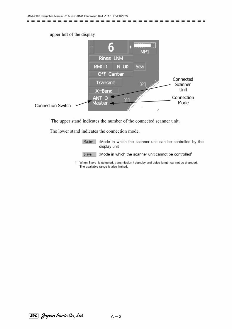
JMA-7100 Instruction Manual > A.NQE-3141 Interswitch Unit > A.1 OVERVIEW
upper left of the display
The upper stand indicates the number of the connected scanner unit.
The lower stand indicates the connection mode.
:Mode in which the scanner unit can be controlled by thedisplay unit
:Mode in which the scanner unit cannot be controlledi
i. When Slave is selected, transmission / standby and pulse length cannot be changed.The available range is also limited.
Connection Switch
ConnectedScanner
Unit
ConnectionMode
Master
Slave
A-2

JMA-7100 Instruction Manual > A.NQE-3141 Interswitch Unit > A.2 INTERSWITCH OPERATION
A
A.2 INTERSWITCH OPERATION
Follow the flowchart below to change the current interswitch connection pattern.
A.2.1 Operation Flow
Close the Inter Switch Menu .
Change the connection pattern .
Place the transmission standby state .
Open the Inter Switch Menu .
A-3

JMA-7100 Instruction Manual > A.NQE-3141 Interswitch Unit > A.2 INTERSWITCH OPERATION
A.2.2 Inter Switch MenuThe Inter Switch Menu can be opened only when the transmission standby state.
Procedures1) Press the [TX/STBY] key to stop transmitting.
The transmission standby state will be placed.
2) Move the cursor onto the Interswitch connection change (upper left of the display), and left-click.
The Inter Switch Menu will appear.
Exit1) Left-click the button.
The Inter Switch Menu will close.
Inter Switch Menu (with 2 Display Units)
0.Exit
b. Set c.Exit
Current connection
status
a. Connection pattern
Display unit in operation
A-4

JMA-7100 Instruction Manual > A.NQE-3141 Interswitch Unit > A.2 INTERSWITCH OPERATION
A
a. Connection pattern
If this button is clicked, the connection pattern is selected.
The display unit in operation is enclosed in a square □ .
The background of the current connection pattern display is highlighted.
b. Set
If this button is clicked, the change of connection is determined.
c. Exit
If this button is clicked, the Inter Switch Menu is closed .
Inter Switch Menu (with 3 or More Display Units)
a. Connected scanner unit
In mode for naming a display unit or antenna unit, clicking on a unit opens the name input window.
If only 2 display units are installed but the interswitch is set for 3or more display units, the Inter Switch Menu for 3 or moredisplay units will appear.
i
b. Display unit connected as
master
d. Name
e. File Operations
c. Display unit connected as
slave
f. Set
g. Exit
a. Connectedscanner unit
A-5

JMA-7100 Instruction Manual > A.NQE-3141 Interswitch Unit > A.2 INTERSWITCH OPERATION
b. Display unit connected as masterc. Display unit connected as slave
If this button is clicked, select / cancel the display unit.
If this button is clicked in the naming a display unit or scanner unit mode , the name input window is opened .
d. Name
If this button is clicked, set to the display or scanner unit rename mode.
e. File Operations
If this button is clicked, the File Operations menu is opened.。
f. Set
If this button is clicked, the change of connection is determined.
g. Exit
If this button is clicked, the Inter Switch Menu is closed .
A.2.3 Change of Connection Pattern (with 2 Display Units)If two display units are installed, a connection pattern needs to be selected.
Procedures1) Open the Inter Switch menu (with 2 Display Units).
2) Move the cursor onto the Connection pattern (see Section A.2.2 "Inter
Switch Menu" and Section a. "Connection pattern") to be changed , and left-click.
The connection pattern will be selected, and (Section b. "Set") will blink.
3) Left-click the button.
The connection pattern will be changed.
3. Set
3. Set
A-6

JMA-7100 Instruction Manual > A.NQE-3141 Interswitch Unit > A.2 INTERSWITCH OPERATION
A
A.2.4 Change of Connection Pattern (with 3 or More DisplayUnits)If three or more display units are installed, the layout of connection patterns needs to be set.
Procedures1) Open the Inter Switch Menu (with 3 or More Display Units).
2) Move the cursor onto the display unit (Section b. "Display unit connected as
master" or Section c. "Display unit connected as slave") to be changed , and left-click.
The selected display unit will be highlighted.
To deselect the display unit, left-click key again.
3) Move the cursor to the change-destination display unit, and left-click.
he selected display unit in step 2 will be switched to the change-destination display unit, and (Section f. "Set") will blink.
If the change destination is empty, control will move and will blink.
4) Left-click the button.
The connection pattern will be changed.
A master display unit is always necessary for establishing aslave connection.
3. Set
3. Set
3. Set
i
A-7

JMA-7100 Instruction Manual > A.NQE-3141 Interswitch Unit > A.2 INTERSWITCH OPERATION
A.2.5 Operating Connection Pattern Files (File Operations)Frequently used connection patterns can be read easily by saving interswitch connection patterns.
[1] Loading connection patterns (Load)
Procedures1) Open the Inter Switch Menu (with 3 or More Display Units).
2) Left-click the button.
The File Operations menu will appear.
3) Left-click the button.
Currently saved connection patterns in memory will be listed.
4) Left-click the button corresponding to the file to be loaded.
Confirmation Window will appear.
5) Left-click the to load.
The connection pattern will be changed.
[2] Saving connection patterns (Save)
Procedures1) Open the Inter Switch Menu (with 3 or More Display Units).
2) Left-click the button.
The File Operations window will appear.
3) Left-click the button.
The Save menu will appear.
Currently saved connection patterns in memory will be listed.
4) Left-click the button corresponding to the file to be saved.
The Input File Name window will appear.
5) Enter the file name to be saved.
Up to 8 characters can be entered.For the input method on the character input screen, see Section 3.3.4.7 "Entering a character".
The connection pattern will be saved when the name is input.
2. File Operation
3. Load
1. Yes
2. File Operation
2. Save
A-8

JMA-7100 Instruction Manual > A.NQE-3141 Interswitch Unit > A.2 INTERSWITCH OPERATION
A
[3] Erasing a connection pattern (Erase)
Procedures1) Open the Inter Switch Menu (with 3 or More Display Units).
2) Left-click the button.
The File Operations window will appear.
3) Left-click the button. The Erase menu will appear.
The list of connection patterns stored in the memory will be displayed.
4) Left-click the button corresponding to the file to be erased.
Confirmation Window will appear.
5) Left-click the to load.
The selected connection pattern is erased and the file name is deleted from the list.
A.2.6 Names of Display Units and Scanner UnitsThe display units and antenna units can be named.
Procedures1) Open the Inter Switch Menu (with 3 or More Display Units).
2) Left-click the button. "Name" will be highlighted, indicating that the rename mode is activated.
3) Move the cursor to the display unit (Section b. "Display unit connected as
master" or Section c. "Display unit connected as slave") or scanner unit (Section a.
"Connected scanner unit") to be renamed , and left-click.
he Input IND Name or the Input TXRX Name window will appear.
4) Input a new unit name.
Up to 8 characters can be input as a unit name. For the input method on the character input menu, see Section 3.3.4.7 "Entering a character".
The selected display unit or antenna unit will be renamed when the new name is input.
2. File Operation
3. Erase
1. Yes
1. Name
A-9

JMA-7100 Instruction Manual > A.NQE-3141 Interswitch Unit > A.3 REFERENCE
A.3 REFERENCE
A.3.1 Preheat Time after Change of Connection PatternAfter the current interswitch connection pattern has been changed, operation needs to wait until the system is ready. This is because the preheat time varies depending on the previous connection of the scanner unit and display unit.
The wait time is necessary for protecting the electronic tubes that emit radio waves.
A.3.2 Notes on Changing Connection PatternAn attempt to change to another connection pattern immediately after the completion of connection pattern change may fail.
This is because internal processing still needs some preparation time upon completion of connection pattern change. Let several seconds pass between connection pattern change operations.
A.3.3 Notes on Connecting Slave Display UnitBefore a slave display unit can be placed in transmission state, the master display unit must be placed in transmission state. If the master display unit is moved from the transmission state to the transmission standby state, the slave display unit is forcibly placed in transmission standby state. When they are in transmission standby state, is shown in the alarm indication (lower right of the display), and the alarm sounds.
A slave display unit cannot control tune. Tune is controlled by the master display unit. is shown in the transmitter pulse length (upper left of the display).
Range change for a slave display unit is limited by the range and pulse length / repetition frequency of the master display unit. As a rule, a greater range than the range of the master display unit cannot be set for a slave display unit. However, if the transmitter pulse length of a slave display unit is identical to the master display unit's and the repetition frequency is within the master display unit's, a greater range than the master display unit's can be selected for the slave display unit. When the master display unit narrows the range or changes the transmitter
a) When not changed to a new connection pattern Preheating not required
b) When changed to a new connection pattern and an scanner unit had been used before the change
Preheating not required
c) When changed to a new connection pattern and an scanner unit had not been used before the change
Preheating required
TXRX Standby
Slave
A-10

JMA-7100 Instruction Manual > A.NQE-3141 Interswitch Unit > A.3 REFERENCE
A
pulse length, the range of the slave display unit may be forcibly changed. In this case, is shown in the alarm indication (lower right of the display), and the alarm sounds.
A.3.4 Setting at InstallationSetting of the interswitch circuit (CCL-304*)
The settings of the DIP switches SW11 to SW13 are shown below.
1) SW11 setting (extension mode and master/slave settings)
Master Range CHG
SW 11 SW 13 SW 12
Interswitch circuit PCBCCL-304*
4 Description
Extension mode setting
ON Extension mode
OFF Normal mode
3 Description
ON Slave
OFF Master
1, 2 Description
ON Unused
OFF Unused
Unused
Master/slave setting
Set the switch to OFF if the number of connected display units is four or less.
Set the switch to ON if the slave ISW PCB is selected in extension mode.
Set the switch to OFF in normal state.
1 2 3 4
ON
OFF
A-11

JMA-7100 Instruction Manual > A.NQE-3141 Interswitch Unit > A.3 REFERENCE
2) SW12 setting (radar connection settings)
3) SW13 (unused)
Before the DIP switches of the interswitch circuit can be set, theinterswitch breaker must be turned off in order to ensure safetyoperation.
1 2 3 4
ON
OFF
8
Radar connection settings
ON No.8 display unit connected
OFF No.8 display unit not connected
5 6 7 8
7ON No.7 display unit connected
OFF No.7 display unit not connected
6ON No.6 display unit connected
OFF No.6 display unit not connected
5ON No.5 display unit connected
OFF No.5 display unit not connected
4ON No.4 display unit connected
OFF No.4 display unit not connected
3ON No.3 display unit connected
OFF No.3 display unit not connected
2ON No.2 display unit connected
OFF No.2 display unit not connected
1ON No.1 display unit connected
OFF No.1 display unit not connected
1,2,3,4 Unused (All OFF)
1 2 3 4
ON
OFF
A-12

Appendix BDRAWINGS
DRAWINGSB.1 Interconnection Diagram of Display Unit ...........................................B-1
B.1.1 NCD-4790 ........................................................................................B-2B.1.2 NCD-4790 w/NBA-5135 ...................................................................B-3B.1.3 NCD-4790T ......................................................................................B-4B.1.4 NCD-4790T w/NBA-5135 ................................................................B-5B.1.5 NCE-5163-R .....................................................................................B-6B.1.6 NCE-5163-RT ...................................................................................B-7B.1.7 NBA-5135 ........................................................................................B-8
B.2 Power System Daigram of Display Unit .............................................B-9B.3 Signal Flow Diagram of Display Unit ................................................B-10B.4 Primary Power System Diagram .......................................................B-11B.5 Block Diagram of Scanner Unit ........................................................B-12
B.5.1 NKE-2103 ......................................................................................B-13B.5.2 NKE-2254 ......................................................................................B-14B.5.3 NKE-1125/NKE-1130 .....................................................................B-15B.5.4 NKE-1129, NTG-3225 / NKE-1139, NTG-3230 .............................B-16
B.6 Interconnection Diagram of Scanner Unit .......................................B-17

B.6.1 NKE-2103 ......................................................................................B-18B.6.2 NKE-2254 ......................................................................................B-19B.6.3 NKE-1125 (AC110V) ......................................................................B-20B.6.4 NKE-1125 (AC220V) ......................................................................B-21B.6.5 NKE-1129 (AC110V) ......................................................................B-22B.6.6 NKE-1129 (AC220V) ......................................................................B-23B.6.7 NTG-3225 ......................................................................................B-24B.6.8 NKE-1130 (AC110V) ......................................................................B-25B.6.9 NKE-1130 (AC220V) ......................................................................B-26B.6.10 NKE-1139 (AC110V) ......................................................................B-27B.6.11 NKE-1139 (AC220V) ......................................................................B-28B.6.12 NTG-3230 ......................................................................................B-29
B.7 Terminal Board Connection Diagram ...............................................B-30B.7.1 JMA-7110-6XA/JMA-7110-6XAH ..................................................B-31B.7.2 JMA-7110-6XA/JMA-7110-6XAH (desktop) .................................B-32B.7.3 JMA-7122-6XAH ............................................................................B-33B.7.4 JMA-7122-6XAH (desktop) ...........................................................B-34B.7.5 JMA-7122-6XA/9XA ......................................................................B-35B.7.6 JMA-7123-7XA/9XA ......................................................................B-36B.7.7 JMA-7132-SA ................................................................................B-37B.7.8 JMA-7133-SA ................................................................................B-38B.7.9 NCD-4790T ....................................................................................B-39
B.8 GYRO I/F .............................................................................................B-40B.9 Inter Switch Unit .................................................................................B-42
B.9.1 Terminal Board Connection Diagram .........................................B-42B.9.2 Interconnection Diagram .............................................................B-44

JMA-7100 Instruction Manual > B.DRAWINGS > B.1 Interconnection Diagram of Display Unit
B
B.1 Interconnection Diagram of Display
Unit
B-1

JMA-7100 Instruction Manual > B.DRAWINGS > B.1 Interconnection Diagram of Display Unit
B.1.1 NCD-4790
Fig B-1: Interconnection Diagram of NCD-4790
2PJ4308
26PJ4307
26PJ4306
50PJ4301
18PJ4304
8PJ4305
3PJ4313
3PJ4314
9PJ4309
14PTB4101
TO TRU
TO ISW26P
TB4201
TO EXT-RA
DAR30P
TB4401
TO SEN
SOR22P
TB4501
TO A
LARM
SYSTEM22P
TB4601
TO GYRO6P
TB4701
TO LOG
12PTB4801
TO PC9P
J4310
TERMINA
L BOARD
CQ
D-2097
PC430
50PJ4302
50PJ4303
30PJ4311
TO O
PU
30PJ4312
TO SUB O
PU
6PJ6411
6PJ64106PJ6409
6PJ64082PJ6406
7PJ640514PJ6404
14PJ6403
15PJ6402
30PJ6401
OPERA
TION
CIRC
UIT D C
CK-976
PC640
14PJ6101
15PJ6102
OPERA
TION
C
IRCUIT A
CC
K-973 PC
610
7PJ6201
OPERA
TION
CIRC
UIT B C
CK-974
PC620
SP1
A1
*PS/2 EXTENSIO
N CABLE
(USER SU
PPLY)
OPERA
TION
UNIT
NCE-5163-R
2m H
-7ZCRD
1337 (NCE-5163-R
)JR
C SUPPLY
B101
B102
PC900
11PTB914
15PTB913
11PTB912
15PTB911
2PTB905
INTERSWITCH UNITNQE-3141-2A
CH
1
CH
2
50PJ4105
50PJ4106
50PJ4107
*OPTIO
N
W401 H
-7ZCRD1339
W402 H
-7ZCRD1339
W403 H
-7ZCRD1339
64PJ4103
64PJ4104
64PJ4102
64PJ4101
64PJ4401
64PJ4402
64PJ1
GYRO
INTERFA
CE
CIRC
UIT
CM
J-462EPC
420
RAD
AR PRO
CESS
CIRC
UIT
CD
C-1324
PC440
MO
THERBOA
RD
CQ
C-1192
PC410
64PJ4403
64PJ4404
AIS PRO
CESS
CIRC
UIT
CD
C-1325
PC460
64PJ4601
64PJ4501
ARPA
PROC
ESSC
IRCU
IT
CD
C-1186D
PC450
15PJ4409V
GA
15PJ4405V
GA
28PJ4406D
VI-D
8PJ4407R
J-45
50PJ4408C
F-card
20PJ4108
8P
POWER SUPPLYCBD-166118P
20P
*PS/2 MO
USE/TRKBALL
(USER SUPPLY)
*OPT
ION
(USER
SUPPLY
)
2P 2PAC O
UT2
+ーUVW
BATTERY
INAC OUT2
AC IN
UWV
UWV
4351A07335 FILTER
INO
UT
RED
WHT
BLU
RED
WHT
BLUAC
100-115V 50/60Hz
AC220-240V 50/60H
z
SCANN
ER MO
TORPO
WER
NCD
-4790(自
立型
) 機
内接
続図
Interco
nnection d
iag
ram
of D
ISPLAY U
NIT typ
e NC
D-4790(se
lf stand
ing)
JMA
-7122-6/9XA
,JMA
-7123-7/9XA,JM
A-7132-S
A,JM
A-7133-SA
RAD
AR PRO
CESS UNIT
ND
C-1399-7
MO
NITO
R UNIT
NW
Z-173-RT
DBD-121A
AC IN
DC OU
T
B-2

JMA-7100 Instruction Manual > B.DRAWINGS > B.1 Interconnection Diagram of Display Unit
B
B.1.2 NCD-4790 w/NBA-5135
Fig B-2: Interconnection Diagram of NCD-4790 w/NBA-5135
2PJ4308
26PJ4307
26PJ4306
50PJ4301
18PJ4304
8PJ4305
3PJ4313
3PJ4314
9PJ4309
14PTB4101
TO TRU
TO ISW26P
TB4201
TO EXT-RA
DAR30P
TB4401
TO SEN
SOR22P
TB4501
TO A
LARM
SYSTEM22P
TB4601
TO GYRO6P
TB4701
TO LOG
12PTB4801
TO PC9P
J4310
TERMINA
L BOARD
CQ
D-2097
PC430
50PJ4302
50PJ4303
30PJ4311
TO O
PU
30PJ4312
TO SUB O
PU
6PJ6411
6PJ64106PJ6409
6PJ64082PJ6406
7PJ640514PJ6404
14PJ6403
15PJ6402
30PJ6401
OPERA
TION
CIRC
UIT D C
CK-976
PC640
14PJ6101
15PJ6102
OPERA
TION
C
IRCUIT A
CC
K-973 PC
610
7PJ6201
OPERA
TION
CIRC
UIT B C
CK-974
PC620
SP1
A1
*PS/2 EXTENSIO
N CABLE
(USER SU
PPLY)
OPERA
TION
UNIT
NCE-5163-R
2m H
-7ZCRD
1337 (NCE-5163-R
)JR
C SUPPLY
B101
B102
PC900
11PTB914
15PTB913
11PTB912
15PTB911
2PTB905
INTERSWITCH UNITNQE-3141-2A
CH
1
CH
2
50PJ4105
50PJ4106
50PJ4107
*OPTIO
N
W401 H
-7ZCRD1339
W402 H
-7ZCRD1339
W403 H
-7ZCRD1339
64PJ4103
64PJ4104
64PJ4102
64PJ4101
64PJ4401
64PJ4402
64PJ1
GYRO
INTERFA
CE
CIRC
UIT
CM
J-462EPC
420
RAD
AR PRO
CESS
CIRC
UIT
CD
C-1324
PC440
MO
THERBOA
RD
CQ
C-1192
PC410
64PJ4403
64PJ4404
AIS PRO
CESS
CIRC
UIT
CD
C-1325
PC460
64PJ4601
64PJ4501
ARPA
PROC
ESSC
IRCU
IT
CD
C-1186D
PC450
15PJ4409V
GA
15PJ4405V
GA
28PJ4406D
VI-D
8PJ4407R
J-45
50PJ4408C
F-card
MO
NITO
R UNIT
NW
Z-173-R
20PJ4108
8P
POWER SUPPLYCBD-166118P
20P
*PS/2 MO
USE/TRKBALL
(USER SUPPLY)
*OPT
ION
(USER
SUPPLY
)
2P 2PAC O
UT2
+ーUVW
BATTERY
INAC OUT2
AC IN
UWV
UWV
4351A07335 FILTER
INO
UT
RED
WHT
BLU
RED
WHT
BLU
UV
FG
+ー
FG
TB522
AC IN
TB52
1DC24V
OUT
AC/DC CONVERTER UNITNBA-5135
AC100-115V 50/60H
zAC
220-240V 50/60Hz
SCANNER
MO
TOR
POW
ER D
C24V
NCD
-4790(自
立型
) 機
内接
続図
Interco
nnection d
iag
ram
of D
ISPLAY U
NIT typ
e NC
D-4790(se
lf stand
ing)
JMA
-7110-6XA,JM
A-7110-6X
AH,JM
A-7122-6XA
H
RAD
AR PRO
CESS UNIT
ND
C-1399-7
W406 H-7ZCRD1342A
RED
WHT
RED
WHT
DBD-121A
AC IN
DC O
UT
B-3

JMA-7100 Instruction Manual > B.DRAWINGS > B.1 Interconnection Diagram of Display Unit
B.1.3 NCD-4790T
Fig B-3: Interconnection Diagram of NCD-4790T
2PJ4308
26PJ4307
26PJ4306
50PJ4301
18PJ4304
8PJ4305
3PJ4313
3PJ4314
9PJ4309
14PTB4101
TO TRU
TO ISW26P
TB4201
TO EXT-RA
DAR30P
TB4401
TO SEN
SOR22P
TB4501
TO A
LARM
SYSTEM22P
TB4601
TO GYRO6P
TB4701
TO LOG
12PTB4801
TO PC9P
J4310
TERMINA
L BOARD
CQ
D-2097
PC430
50PJ4302
50PJ4303
30PJ4311
TO O
PU
30PJ4312
TO SUB O
PU
6PJ6411
6PJ64106PJ6409
6PJ64082PJ6406
7PJ640514PJ6404
14PJ6403
15PJ6402
30PJ6401
OPERA
TION
CIRC
UIT D C
CK-976
PC640
14PJ6101
15PJ6102
OPERA
TION
C
IRCUIT A
CC
K-973 PC
610
7PJ6201
OPERA
TION
CIRC
UIT B C
CK-974
PC620
SP1
A1
*PS/2 EXTENSIO
N CABLE
(USER SU
PPLY)
OPERA
TION
UNIT
NCE-5163-RT
5m H
-7ZCRD
1338 (NCE-5163-R
T)JR
C SUPPLY
B101
B102
PC900
11PTB914
15PTB913
11PTB912
15PTB911
2PTB905
INTERSWITCH UNITNQE-3141-2A
CH
1
CH
2
50PJ4105
50PJ4106
50PJ4107
*OPTIO
N
W401 H
-7ZCRD1339
W402 H
-7ZCRD1339
W403 H
-7ZCRD1339
64PJ4103
64PJ4104
64PJ4102
64PJ4101
64PJ4401
64PJ4402
64PJ1
GYRO
INTERFA
CE
CIRC
UIT
CM
J-462EPC
420
RAD
AR PRO
CESS
CIRC
UIT
CD
C-1324
PC440
MO
THERBOA
RD
CQ
C-1192
PC410
64PJ4403
64PJ4404
AIS PRO
CESS
CIRC
UIT
CD
C-1325
PC460
64PJ4601
64PJ4501
ARPA
PROC
ESSC
IRCU
IT
CD
C-1186D
PC450
15PJ4409V
GA
15PJ4405V
GA
28PJ4406D
VI-D
8PJ4407R
J-45
50PJ4408C
F-card
20PJ4108
8P
POWER SUPPLYCBD-166118P
20P
*PS/2 MO
USE/TRKBALL
(USER SUPPLY)
*OPT
ION
(USER
SUPPLY
)
2P 2PAC O
UT2
+ーUVW
BATTERY
INAC OUT2
AC IN
UWV
UWV
4351A07335 FILTER
INO
UT
RED
WHT
BLU
RED
WHT
BLUAC
100-115V 50/60Hz
AC220-240V 50/60H
z
SCANNER M
OTO
RPOW
ER
NCD
-4990T(卓
上型
) 機
内接
続図
Interc
onnec
tion d
iag
ram
of D
ISPLAY UN
IT type
NC
D-4990T(d
eskto
p)
RAD
AR PRO
CESS UNIT
ND
C-1399-7T
12
3
12
3
RED
BLU
WHT
W405 H
-7ZCRD1341A
TB402
JMA
-9122-6/9XA,JM
A-9123-7/9X
A,JM
A-9132-SA
,JMA
-9133-SA
MO
NITO
R UNIT
NW
Z-173-RT
DBD-121A
AC IN
DC OU
T
B-4

JMA-7100 Instruction Manual > B.DRAWINGS > B.1 Interconnection Diagram of Display Unit
B
B.1.4 NCD-4790T w/NBA-5135
Fig B-4: Interconnection Diagram of NCD-4790T w/NBA-5135
2PJ4308
26PJ4307
26PJ4306
50PJ4301
18PJ4304
8PJ4305
3PJ4313
3PJ4314
9PJ4309
14PTB4101
TO TRU
TO ISW26P
TB4201
TO EXT-RA
DAR30P
TB4401
TO SEN
SOR22P
TB4501
TO A
LARM
SYSTEM22P
TB4601
TO GYRO6P
TB4701
TO LOG
12PTB4801
TO PC9P
J4310
TERMINA
L BOARD
CQ
D-2097
PC430
50PJ4302
50PJ4303
30PJ4311
TO O
PU
30PJ4312
TO SUB O
PU
6PJ6411
6PJ64106PJ6409
6PJ64082PJ6406
7PJ640514PJ6404
14PJ6403
15PJ6402
30PJ6401
OPERA
TION
CIRC
UIT D C
CK-976
PC640
14PJ6101
15PJ6102
OPERA
TION
C
IRCUIT A
CC
K-973 PC
610
7PJ6201
OPERA
TION
CIRC
UIT B C
CK-974
PC620
SP1
A1
*PS/2 EXTENSIO
N CABLE
(USER SU
PPLY)
OPERA
TION
UNIT
NCE-5163-RT
5m H
-7ZCRD
1338 (NCE-5163-R
T)JR
C SUPPLY
B101
B102
PC900
11PTB914
15PTB913
11PTB912
15PTB911
2PTB905
INTERSWITCH UNITNQE-3141-2A
CH
1
CH
2
50PJ4105
50PJ4106
50PJ4107
*OPTIO
N
W401 H
-7ZCRD1339
W402 H
-7ZCRD1339
W403 H
-7ZCRD1339
64PJ4103
64PJ4104
64PJ4102
64PJ4101
64PJ4401
64PJ4402
64PJ1
GYRO
INTERFA
CE
CIRC
UIT
CM
J-462EPC
420
RAD
AR PRO
CESS
CIRC
UIT
CD
C-1324
PC440
MO
THERBOA
RD
CQ
C-1192
PC410
64PJ4403
64PJ4404
AIS PRO
CESS
CIRC
UIT
CD
C-1325
PC460
64PJ4601
64PJ4501
ARPA
PROC
ESSC
IRCU
IT
CD
C-1186D
PC450
15PJ4409V
GA
15PJ4405V
GA
28PJ4406D
VI-D
8PJ4407R
J-45
50PJ4408C
F-card
20PJ4108
8P
POWER SUPPLYCBD-166118P
20P
*PS/2 MO
USE/TRKBALL
(USER SUPPLY)
*OPT
ION
(USER
SUPPLY
)
2P 2PAC O
UT2
+ーUVW
BATTERY
INAC OUT2
AC IN
UWV
UWV
4351A07335 FILTER
INO
UT
RED
WHT
BLU
RED
WHT
BLU
UV
FG
+ー
FG
TB522
AC IN
TB52
1DC24V
OUT
AC/DC CONVERTER UNITNBA-5135
AC100-115V 50/60H
zAC
220-240V 50/60Hz
SCANNER
MO
TOR
POW
ER D
C24V
NCD
-4790T(卓
上型
) 機
内接
続図
Interc
onnec
tion d
iag
ram
of D
ISPLAY UN
IT type
NC
D-4790T(d
eskto
p)
JMA
-7110-6XA,JM
A-7110-6X
AH,JM
A-7122-6XA
H
RAD
AR PRO
CESS UNIT
ND
C-1399-7T
12
3
12
3
RED
BLU
WHT
W405 H
-7ZCRD1341A
TB402
12
3
12
3
TB401
W408 H
-7ZCRD
1344A
GRN
GRN
W407 H-7ZCRD1343A
WHT
BLK
GRN
WHT
BLK
GRN
MO
NITO
R UNIT
NW
Z-173-RT
DBD-121A
AC IN
DC OU
T
B-5

JMA-7100 Instruction Manual > B.DRAWINGS > B.1 Interconnection Diagram of Display Unit
B.1.5 NCE-5163-R
Fig B-5: Interconnection Diagram of NCE-5163-R
6PJ6411
6PJ6410
6PJ6409
6PJ6408
2PJ6406
7PJ6405
14PJ6404
14PJ6403
15PJ6402
30PJ6401
OPERATION CIRCUIT D CCK -976 PC 640
14PJ6101
15PJ6102
OPERATION CIRCUIT A CCK-973 PC610
7PJ6201
OPERATION CIRCUIT B CCK-974 PC620
SP1
A1
OPERATION UNITNCE-5163-R
W67 2m H-7ZCRD1337
W62
H-7
ZCRD
1332
W65
H-7
ZCR
D13
35
W63
H-7
ZCRD
1333
A
W64
H-7
ZCRD
1334
FL1
2PJ6407
Operation Unit Interconnection
CMD-996-R (NCE-5163-R)
B-6

JMA-7100 Instruction Manual > B.DRAWINGS > B.1 Interconnection Diagram of Display Unit
B
B.1.6 NCE-5163-RT
Fig B-6: Interconnection Diagram of NCE-5163-RT
6PJ6411
6PJ6410
6PJ6409
6PJ6408
2PJ6406
7PJ6405
14PJ6404
14PJ6403
15PJ6402
30PJ6401
OPERATION CIRCUIT D CCK -976 PC 640
14PJ6101
15PJ6102
OPERATION CIRCUIT A CCK-973 PC610
7PJ6201
OPERATION CIRCUIT B CCK-974 PC620
SP1
A1
OPERATION UNITNCE-5163-RT
W68 5m H-7ZCRD1338
W62
H-7
ZCRD
1332
W65
H-7
ZCR
D13
35
W63
H-7
ZCRD
1333
A
W64
H-7
ZCRD
1334
FL1
2PJ6407
Operation Unit Interconnection
CMD-996-RT (NCE-5163-RT)
B-7

JMA-7100 Instruction Manual > B.DRAWINGS > B.1 Interconnection Diagram of Display Unit
B.1.7 NBA-5135
Fig B-7: Interconnection Diagram of NBA-5135
AC/DC Converter Interconnection
CBD-1684A (NBA-5135)
FL1LF-210
FS11 2 3
1 2 3
TB521
1 2 3
1 2 3
TB 522
A1AES300-24B
U V
W1 H-7ZCRD1495
W2 H-7ZCRD1496
BLK
WHT
RED
Twisted
u vFG
RED WHT
N L FG
+ + + - - -
RED WHTBLK
BLK
BLK
BLK
WHTWHT
BLK
WHT
RED
W6 H-7ZCRD1499
W5 H-7ZCRD1499
W4 H-7ZCRD1498
W3 H-7ZCRD1497
Twisted
B-8

JMA-7100 Instruction Manual > B.DRAWINGS > B.2 Power System Daigram of Display Unit
B
B.2 Power System Daigram of Display Unit
Fig B-8: Power System Diagram of NCD-4790/T
2PJ4308
26PJ4307
26PJ4306
50PJ4301
18PJ4304
8PJ4305
3PJ4313
3PJ4314
9PJ4309
14PTB4101
TO TRU
TO ISW26P
TB4201
TO EXT-RA
DAR30P
TB4401
TO SEN
SOR22P
TB4501
TO A
LARM
SYSTEM22P
TB4601
TO GYRO6P
TB4701
TO LOG
12PTB4701
TO PC9P
J4310
TERMINA
L BOARD
CQ
D-2097
PC430
50PJ4302
50PJ4303
30PJ4311
TO O
PU
30PJ4312
TO SUB O
PU
6PJ6411
6PJ64106PJ6409
6PJ64082PJ6406
7PJ640514PJ6404
14PJ6403
15PJ6402
30PJ6401
OPERA
TION
CIRC
UIT D C
CK-976
PC640
14PJ6101
15PJ6102
OPERA
TION
C
IRCUIT A
CC
K-973 PC
610
7PJ6201
OPERA
TION
CIRC
UIT B C
CK-974
PC620
SP1
A1
*PS/2 EXTENSIO
N CABLE
(USER SU
PPLY)
OPERA
TION
UNIT
NCE-5163-R
2m H
-7ZCRD
1337 (NCE-5163-R
)5m
H-7ZC
RD1338 (N
CE-5163-RT)
JRC SU
PPLY
B101
B102
PC900
11PTB914
15PTB913
11PTB912
15PTB911
2PTB905
INTERSWITCH UNITNQE-3141-2
CH
1
CH
2
50PJ4105
50PJ4106
50PJ4107
*OPTIO
N
W401 H
-7ZCRD1339
W402 H
-7ZCRD1339
W403 H
-7ZCRD1339
64PJ4103
64PJ4104
64PJ4102
64PJ4101
64PJ4401
64PJ4402
64PJ1
GYRO
INTERFA
CE
CIRC
UIT
CM
J-462EPC
420
RAD
AR PRO
CESS
CIRC
UIT
CD
C-1324
PC440
MO
THERBOA
RD
CQ
C-1192
PC410
64PJ4403
64PJ4404
AIS PRO
CESS
CIRC
UIT
CD
C-1325
PC460
64PJ4601
64PJ4501
ARPA
PROC
ESSC
IRCU
IT
CD
C-1186D
PC450
15PJ4409V
GA
15PJ4405V
GA
28PJ4406D
VI-D
8PJ4407R
J-45
50PJ4408C
F-card
LCDOPERATIONCIRCUITCCK -972 PC710
8PJ711
MO
NITO
R UNIT
NW
Z-170-RLCD
PAN
ELH
-7WSRD
0002A
8PH-7ZCRD1328
9P 2m H
-7ZCRD1329A
(NW
Z-170-R)
DVI 2m H-7ZCRD1345 (NWZ-170-R)
20PJ4108
8P
POWER SUPPLYCBD-166118P
20P
*PS/2 MO
USE/TRKBALL
(USER SUPPLY)
*OPTIO
N(US
ER SUPPLY)
2P 2PAC O
UT2
+ーUVW
BATTERY
INAC OUT2
AC IN
UWV
UWV
4351A07335 FILTER
INO
UT
RED
WHT
BLU
RED
WHT
BLU
AC 2m 5ZCGH00285 (NWZ-170-R )
UV
FG
+ー
FG
TB522
AC IN
TB52
1DC2
4V OU
T
AC/DC CONVERTER UNITNBA-5135
AC100-115V 50/60H
zAC
220-240V 50/60Hz
SCANNER
MO
TOR
POW
ER D
C24V
NCD
-4990 電源
系統
図
Pow
er su
pp
ly system
dia
gra
m o
f DISPLA
Y UN
IT type N
CD
-4990(self sta
nding
)
RAD
AR PRO
CESS UNIT
ND
C-1399-9
W406 H-7ZCRD1342A
RED
WHT
RED
WHT
INPU
T V
OLTA
GE
SELEC
T S
WIT
CH
3.3V,5V
,12V,-12V
P+5V
P+12V
3.3V,5V,12V,-12V
+48V
,DC+
24V
+24V
P+5V
P+12V
DC
+24V
+5V
U,V
AC
100
-11
5V
AC
220
-24
0V
50/
60H
z,1φ
U,V
AC
100-
115V
AC
220-
240V
50/60
Hz,1φ
U,V
AC
100-11
5V
AC
220-24
0V
50/
60H
z,1
φ
3.3V
5V
DC
+24V
+48V
(to SCAN
NER
UN
IT)
3.3V,5V,12V,-12V
3.3V,5V,12V,-12V
+48V,D
C+24V
JMA
-9110
-6XA
JMA
-9110
-6XA
HJM
A-9
122-6X
AH
only
B-9

JMA-7100 Instruction Manual > B.DRAWINGS > B.3 Signal Flow Diagram of Display Unit
B.3 Signal Flow Diagram of Display Unit
Fig B-9: Signal Flow Diagram of NCD-4790/T
2PJ4308
26PJ4307
26PJ4306
50PJ4301
18PJ4304
8PJ4305
3PJ4313
3PJ4314
9PJ4309
14PTB4101
TO TRU
TO ISW26P
TB4201
TO EXT-RA
DAR30P
TB4401
TO SEN
SOR22P
TB4501
TO A
LARM
SYSTEM22P
TB4601
TO GYRO6P
TB4701
TO LOG
12PTB4701
TO PC9P
J4310
TERMINA
L BOARD
CQ
D-2097
PC430
50PJ4302
50PJ4303
30PJ4311
TO O
PU
30PJ4312
TO SUB O
PU
6PJ6411
6PJ64106PJ6409
6PJ64082PJ6406
7PJ640514PJ6404
14PJ6403
15PJ6402
30PJ6401
OPERA
TION
CIRC
UIT D C
CK-976
PC640
14PJ6101
15PJ6102
OPERA
TION
C
IRCUIT A
CC
K-973 PC
610
7PJ6201
OPERA
TION
CIRC
UIT B C
CK-974
PC620
SP1
A1
*PS/2 EXTENSIO
N CABLE
(USER SU
PPLY)
OPERA
TION
UNIT
NCE-5163-R
2m H
-7ZCRD
1337 (NCE-5163-R
)5m
H-7ZC
RD1338 (N
CE-5163-RT)
JRC SU
PPLY
B101
B102
PC900
11PTB914
15PTB913
11PTB912
15PTB911
2PTB905
INTERSWITCH UNITNQE-3141-2
CH
1
CH
2
50PJ4105
50PJ4106
50PJ4107
*OPTIO
N
W401 H
-7ZCRD1339
W402 H
-7ZCRD1339
W403 H
-7ZCRD1339
64PJ4103
64PJ4104
64PJ4102
64PJ4101
64PJ4401
64PJ4402
64PJ1
GYRO
INTERFA
CE
CIRC
UIT
CM
J-462EPC
420
RAD
AR PRO
CESS
CIRC
UIT
CD
C-1324
PC440
MO
THERBOA
RD
CQ
C-1192
PC410
64PJ4403
64PJ4404
AIS PRO
CESS
CIRC
UIT
CD
C-1325
PC460
64PJ4601
64PJ4501
ARPA
PROC
ESSC
IRCU
IT
CD
C-1186D
PC450
15PJ4409V
GA
15PJ4405V
GA
28PJ4406D
VI-D
8PJ4407R
J-45
50PJ4408C
F-card
LCDOPERATIONCIRCUITCCK -972 PC710
8PJ711
MO
NITO
R UNIT
NW
Z-170-RLCD
PAN
ELH
-7WSRD
0002A
8PH-7ZCRD1328
9P 2m H
-7ZCRD1329A
(NW
Z-170-R)
DVI 2m H-7ZCRD1345 (NWZ-170-R)
20PJ4108
8P
POWER SUPPLYCBD-166118P
20P
*PS/2 MO
USE/TRKBALL
(USER SUPPLY)
*OPT
ION
(USER
SUPPLY)
2P 2PAC O
UT2
+ーUVW
BATTERY
INAC OUT2
AC IN
UWV
UWV
4351A07335 FILTER
INO
UT
RED
WHT
BLU
RED
WHT
BLU
AC 2m 5ZCGH00285 (NWZ-170-R )
UV
FG
+ー
FG
TB522
AC IN
TB52
1DC2
4V OU
T
AC/DC CONVERTER UNITNBA-5135
AC100-115V 50/60H
zAC
220-240V 50/60Hz
SCANNER
MO
TOR
POW
ER D
C24V
NCD
-4990 信号
系統
図
Signa
l flow d
iag
ram
of D
ISPLAY U
NIT typ
e N
CD
-4990
RAD
AR PRO
CESS UNIT
ND
C-1399-9
W406 H-7ZCRD1342A
RED
WHT
RED
WHT
SerialRadar video
Trigger,Rota
Serial
Radar video,
Trigger,Rotati o
Radar video,
Trigger,R
otati o
Serial
Dry Contact
GYRO
(STEP/SYN
LOG
(PULSE/SY N
Serial
Rada
r video,T
rigger,Rotation
Rada
r video,T
rigger,Rotation
GYR
O/LO
G
Serial,GPIO
Rada
r video,Trigger,Ro
tation
GYRO
/LOG
Rad
ar video,T
rigger,Rotation
Serial,GPIO
Analog R
GB
Analog R
GB
Degital V
ideo Inte
rface
Eth
ernetLCD
Fan Alarm
Powe
r supply C
ontro
lPow
er supp
ly Fan alarm
PS/2
I/FPS/2 I/F
AudioK
EY matrix
Encoder
Power SW
Power supply Control
Power supply Fa
n alarm
Dimm
er
B-10
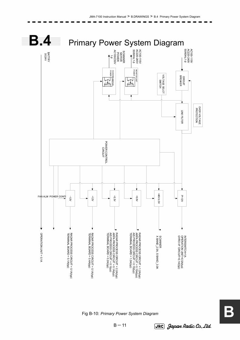
JMA-7100 Instruction Manual > B.DRAWINGS > B.4 Primary Power System Diagram
B
B.4 Primary Power System Diagram
Fig B-10: Primary Power System Diagram
POW
ER CO
NTRO
LC
IRCU
IT
FAN ALM POWER CONTROL
INTER
SWITC
H=1A
OPER
ATION
UNIT=0.5A(typ)
GYR
O I/F CIR
CUIT=0.1A(typ)
SCAN
NER
X
BAND_2.5A, S BAN
D_3.0A
RAD
AR PRO
CESS CIR
CU
IT = 1.2A(typ)AR
PA PRO
CESS C
IRC
UIT = 0.15A(typ)AIS P
ROCES
S CIRC
UIT = 0.15(typ)TER
MIN
AL BOARD
= 1.0A(typ)
AC100-115VAC220-240V50/60H
z,1φ
SCAN
NER
MO
TOR
POW
ERAC
100/230V1φ
OV
ER
VO
LT
AG
EPR
OT
EC
TIO
N
AC100-115V
AC220-240V
50/60Hz,1
φ
RAD
AR PRO
CESS CIR
CU
IT = 2.2A(typ)AR
PA PRO
CESS C
IRC
UIT = 0.1A(typ)AIS P
ROCES
S CIRC
UIT = 0.1(typ)TER
MIN
AL BOARD
= 0.2A(typ)
RADAR
PRO
CESS C
IRCU
IT = 0.1A(typ)TER
MIN
AL BOAR
D = 0.4A(typ)
RADAR
PRO
CESS C
IRCU
IT = 0.1A(typ)TER
MIN
AL BOAR
D = 0.1A(typ)
BATTRY
DC
24V
OPER
ATION
UN
IT = 0.1A
P+12V
+48V±
3V
+5.0V
+3.3V
-12V
+12V
CIR
CU
ITB
REAK
ER
LINE F
ILTER
VO
LTA
GE S
ELC
TSW
ITC
H
MO
NIT
OR
UN
IT
PO
WE
R
SC
AN
NER
MO
TO
R
PO
WER
B-11

JMA-7100 Instruction Manual > B.DRAWINGS > B.5 Block Diagram of Scanner Unit
B.5 Block Diagram of Scanner Unit
B-12

JMA-7100 Instruction Manual > B.DRAWINGS > B.5 Block Diagram of Scanner Unit
B
B.5.1 NKE-2103
Fig B-11: Block Diagram of NKE-2103
SLOT ANTENNA
MOTORB101
SAFETY SWITCHS101
MAGV101
PULSETRANS
SWITCHINGCIRCUIT
PC201
MHGENERATOR
AVR
INTERFACE CIRCUIT
PC1001
MIC
IF AMP
VIDEO AMP
RECEIVER
Receiver BandwidthControl
Tune Control
ΦA,ΦB,ΦZ
FILTER
DUMMYLOAD
DC+24V
Serial Com, BP, BZ, VD, TRIG
NKE-2103 Scanner Unit
POWER SUPPLYCIRCUIT
MOTOR CONTROLPOWERPC1501
Rotation Control
Speed control
Status
DC+24V
Tx Trigger/Pulse Width
DC+24V
DIODELIMITER
ENCODERROTARYJOINT
B-13

JMA-7100 Instruction Manual > B.DRAWINGS > B.5 Block Diagram of Scanner Unit
B.5.2 NKE-2254
Fig B-12: Block Diagram of NKE-2254
SLOT ANTENNA
MOTORB101
SAFETY SWITCHS101
MAGV101
PULSETRANS
SWITCHINGCIRCUIT
PC201
MHGENERATOR
AVR
PC1001
ΦA,ΦB,ΦZ
FILTER
DUMMYLOAD
DC+24V
Serial Com, BP, BZ, VD, TRIG
NKE-2254 Scanner Unit
POWER SUPPLYCIRCUIT
MOTOR CONTROLPOWERPC1501
Rotation Control
Speed control
Status
DC+24V
Tx Trigger/Pulse Width
DC+24V
ENCODERROTARYJOINT
INTERFACE CIRCUITPC1101
RF AMP
IF AMP
VIDEO AMP
RECEIVER
Receiver BandwidthControl
Tune Control
DIODELIMITER
B-14

JMA-7100 Instruction Manual > B.DRAWINGS > B.5 Block Diagram of Scanner Unit
B
B.5.3 NKE-1125/NKE-1130
Fig B-13: Block Diagram of NKE-1125/NKE-1130
SLOT ANTENNA
ROTARYJOINT ENCODERMOTOR
B101
SAFETY SWITCHS101
MAGV101
PULSETRANS
SWITCHINGCIRCUIT
PC201
MHGENERATOR
AVRINTERFACE CIRCUIT
PC1101
PC1001
DIODELIMITER
RF AMP
IF AMP
VIDEO AMP
RECEIVER
Receiver BandwidthControl
Tune Control
Tx Trigger/Pulse Width
ΦA,ΦB,ΦZ
FILTER
DUMMYLOAD
MOTORDRIVERPC1501
AC100/110/220 /230V50/60Hz,1φ
DC+48V
Serial Com, BP, BZ, VD, TRIG
NKE-1130/NKE-1125 Scanner Unit
POWER SUPPLYCIRCUIT
MOTOR RELAYPC1201
Relay Control
ERROR
Status
B-15

JMA-7100 Instruction Manual > B.DRAWINGS > B.5 Block Diagram of Scanner Unit
B.5.4 NKE-1129, NTG-3225 / NKE-1139, NTG-3230
Fig B-14: Block Diagram of NKE-1129, NTG-3225 / NKE-1139, NTG-3230
SLOT ANTENNA
ENCODERMOTORB101
SAFETY SWITCHS101
MAGV101
PULSETRANS
INTERFACE CIRCUITPC1101
DIODE LIMITER/ TRHPL
PIN ATT(X-band)
RF AMP
IF AMP
VIDEO AMP
Receiver BandwidthControl
Tune Control
ΦA,ΦB,ΦZ
DUMMYLOAD
MOTOR DRIVER
PC1501
AC100/110 /220/230V50/60Hz,1φ
DC+48V
Serial Com, BP, BZ, VD, TRIG
NKE-1139/NKE-1129 Scanner Unit
NTG-3230 /NTG-3225Transceiver Unit
SWITCHINGCIRCUIT
PC201
MHGENERATOR
PC1001
POWER SUPPLYCIRCUIT
RECEIVER
ERROR
MOTOR RELAYPC1201
Relay Control
AC100/110/220/230V50/60Hz,1φ
ROTARYJOINT
Status
FILTER
AVR
Tx Trigger/Pulse Width
B-16

JMA-7100 Instruction Manual > B.DRAWINGS > B.6 Interconnection Diagram of Scanner Unit
B
B.6 Interconnection Diagram of Scanner Unit
B-17

JMA-7100 Instruction Manual > B.DRAWINGS > B.6 Interconnection Diagram of Scanner Unit
B.6.1 NKE-2103
Fig B-15: Interconnection Diagram of NKE-2103
NKE-21
03 / 2
103H
S空
中線
機内
接続
図S
CA
NN
ER
UN
IT IN
TER
CO
NN
EC
TIO
N
CA
X-10
E10
1N
JT
1969
A301
NJS
693
0
AN
TEN
NA
NA
X-16
B-4
/6
FIL
TE
RD
UM
MY
A10
11.T
UN
E2.+
5V
3.GN
D
4.NC
5.IF
IF A
MP C
IRC
UIT
(PC
301)
CA
E-529-
1
MA
G
MA
GN
ETRO
NV
101
MA
F15
65N
PO
WE
R S
UP
PLY
C
IRC
UIT
(PC
1001)
CB
D-1
783
1.2A
2.1A
J10
01
J201
15.NC
4.PW1
5.MCT
6.MBK
7.+15V
8.AGND
9.-7V
10.BP
11.HSP
1.MPS
2.PW3
3.PW2
12.TI
13.+8V
14.MOD ID
T201
-16
T201
-15
1.M
H
3.M
N
J100
3
J202
4.HTER
1.TIY2.AGND
3.MAG.I
5.HVER
6.C2
7.BZ
J203
4.PMS
1.PTI
2.PTE
3.LVR
5.GND
6.TXI
7.TXE1.2A2.1A
J3
6.AGND
J1
4.AGND
1.ETIY
2.AGND
3.EXBP
5.EXBZ
SAFET
Y S
WIT
CH
WS
101
MO
DU
LA
TO
R C
IRC
UIT
(P
C201)
CM
E-3
63
J301
15.NC
4.PW1
5.MCT
6.MBK
7.+15V
8.AGND
9.-7V
10.BP
11.HSP
1.MPS
2.PW3
3.PW2
12.TI
13.+8V
14.MOD ID
J302
4.HTER
1.TIY
2.AGND
3.MAG.I
5.HVER
6.C2
7.BZ
J303
4.PMS
1.PTI
2.PTE
3.LVR
5.GND
6.TXI
7.TXE
4.COM-
1.VD
2.VDE
3.COM+
J2
J18
1.HMCNT
2.+15V
3.GND
SE
B102
J8
4.P
MS
1.P
TI
2.P
TE
3.L
VR
5.E
6.T
XI
7.TX
E
4.ΦB
1.Φ
Z
2.E
3.Φ
A
5.+
12V
6.F
.G.
YEL
BLK
BLU
WH
T
RED
SH
IELD
DIS
PLAY
U
NIT
P8
1.P
TI
2.P
TE
1.L
VR
2.P
MS
3.E
3.T
XI
4.T
XE J81J
82
P81
P82 W
HT
BL
K
BL
U
RE
D
BL
K
WH
T
BR
N
PM
NJU
-85 7ZCRD1280※
DIS
PLA
Y
UN
IT
DIS
PLA
Y
UN
IT
1.2A
2.1A
J15
03
1.MPS
2.MCT
J1501
3.MBK
1.HM
CN
T
2.+
15V
J15
05
3.AG
ND1.2
A
2.1A J4
1.2A
2.1A J5
1.MPS
2.MCT
J209
3.MBK
1.C2G
2.C2
J210
1.2
A
2.1
A
J204
J206
1.M
H
3.M
N
MO
TO
R C
ON
TR
OL P
OW
ER
CIR
CUIT
(PC
1501
)C
BD
-1779
1.M
CN
T+
J12
5
3.NC
1.M+
2.NC
J150
2
3.M-
4.NC
2.MC
NT-
MO
TO
R
B101
H-7BDRD
004
8
MO
RTO
RCB
P-2
02
BREA
K C
IRC
UIT
CFA
-252
YEL
GRN
A10
3
REC
EIV
ER U
NIT
N
RG
-6
10
MIC
S.G
.
S.G
.
(W20
4)
ZC
RD
1312※
(W110)
ZC
RD
130
7※
(W107)
ZC
RD
1304
※
(W103
)
ZC
RD
1306
※
(W105)
ZC
RD
130
0※
ZC
RD
1302※
(W101)ZCRD1289※
(W102)ZCRD1290※
(W106)ZCRD1303※
(W111)ZCRD1308※
(W108)
ZC
RD
1305
※
(OP
TIO
N)
54
21
J208
D.L
1.MS
12.N
C J150
4
3.MS
2
TR
AN
SM
ITTER
/REC
EIV
ER
UN
IT
NZT-
21
03
TRA
NSM
ITTER/R
EC
EIVER U
NIT
IN
TER
CO
NNEC
TIO
NC
MK-5
99
8.N
C
(W104)
ZC
RD
1301
※J2
05
1.+
15V
2.+1
2V
3.+
8V4.A
GN
D5.-
15V
6.X1
7.X2
8.+
5V9.H
TE
R10.H
VE
R
J1002
1.+15V
2.+12
V3.+8
V4.A
GN
D5.-
15V
6.X
1
7.X
2
8.+5V
9.HT
ER
10.H
VER
WV
101
A10
2
(REC
EIV
ER U
NIT
INT
ERC
ON
NEC
TIO
NC
MA-823
)
ENCODER CHT-71A
NJC
4002
FC
X68
FC
X68
S.G
.
CFR-234
MA
G F
ILTER
CIR
CU
IT100p
F×
3
A104
NJC
9952
TB
11-
2sho
rt : Nom
al S
peed
2-3sho
rt : High S
peed
H-7
ZC
RD
####
*:“#
” means spe
cification do
cum
ent N
o.“*
” means revision of th
e specfication
docum
ent.
B-18

JMA-7100 Instruction Manual > B.DRAWINGS > B.6 Interconnection Diagram of Scanner Unit
B
B.6.2 NKE-2254
Fig B-16: Interconnection Diagram of NKE-2254
NK
E-2254 /
2254H
S空
中線
機内
接続
図
14.VDE
12.VD_DC
15.VD
9.TGT10.TGTE
13.TNL
11.TNI
1.BS3
2.BS2
3.BS14.TNC
5.+5V6.-15V
7.+15V
REC
EIV
ER
UN
IT N
RG
-162
A
REC
EIV
ER
CIR
CU
IT
CM
A-8
66A
J101B
M15B
-X
AS
S-T
ET/R
CO
NTR
OL C
IRC
UIT
CM
C-120
5R
1.MONI
2.GS3.GSE4.TGT
5.TGTE6.TNL
7.-15V8.TNI9.+15V
10.GND11.TRG2
1.BS32.BS2
3.BS14.TNC
5.MicPS6.VDINE7.VDIN
8.+5V
1.RXD
2.TXD3.+5V4.GND
1.S
HO
RT
2.MA
GI
3.X1
4.X2
5.TI
6.TIE
7.+
15V
8.G
ND
9.NC
10.N
C11.N
C12.N
C
1.H
MC
NT
2.+
15V
3.G
ND
1.+
15V
2.+
12V
3.G
ND
4.G
ND
5.-
15V
6.1
0V
7.10V
E
8.+
5V
1.MC
T
2.M
BK
3.T
ISTO
P4.G
ND
5.MP
S6.M
IER
1.TIY
2.T
IYE
3.B
P4.B
PE
5.B
Z6.B
ZE
1.+12V
2.GND3.FAN_ERR1
1.HTER1
2.HVGATE13.TISTOP14.GND
5.CNT6.+5V
7.+15V8.STABY_REQ9.NC
1.PW1
2.PW23.PW3
4.+24V5.GND
1.B
P+
2.B
P-
3.B
Z+
4.B
Z-
5.T
RIG
+
6.T
RIG
-7.M
TR+
8.M
TR-
9.M
TR
E10.V
D+
11.V
D-
1.VD
2.VD
E
3.M
TR
+4.M
TR
-
J1118J1103J1104 J1111
J119
1J111
0J110
9
TB
101J
8J1106
J1112
J11
13
IL-G-12P
IL-G
-8P
IL-G
-11
P
B6P-SHF
IL-G
-9P
MST
BA
2.5/
11-G
IL-G
-5P
B3P-SHF
IL-4P
B8P-SHF
IL-G
-3P
MA
G
PO
WER
SU
PP
LY
CIR
CU
ITC
BD
-16
82A
1.+
15V
2.+
12V
3.+
8V4.G
ND
5.-
15V
6.X
17.X
2
8.+
5V
1.MC
T2.M
BK
3.HS
P
4.HT
ER
5.T
ISTO
P6.C
2
7.G
ND
8.MP
S
9.MIE
R
2.1A1.2A
2.1A1.2A
2.1A1.2A
1.MH2.NC3.MN
1.MH2.NC3.MN
1.X1
2.X2
No.2
No.1
21
435 6
FIL
TER
J1004 J1003
J 5
J 4
J 3
J100
1
J1002
J2102
J2101
J210
3
AN
TEN
NA
1.SH
OR
T2.M
AG
I3.X
1
4.X2
5.TI
6.TIE
7.+
15V
B9P-SHF B8P-SHF
158
6514
-2
3502
09-
1
IL-10P
35020
9-2
3502
09-1
350428
-1
MO
DU
LA
TO
R
CIR
CU
ITC
PA
-26
4
MO
DULA
TO
R U
NIT
IN
TER
CO
NN
EC
TIO
N
CM
B-40
4
D.L
①②
③
①②
③
ミト ゙リ
キ
C201
0.01U
F 1K
V
C202
0.22
UF 2
00V
R202 2.7KΩ1/2W
C2030.22UF200V
T1
R201150Ω8W
H-7L
PR
D0122
CD202 CD201MD-12N1MD-12N1
A10
1A
102
M1568
BS
V10
1
P3001
P110
9P
1110
P11
04
P1103
P10
03
P1004
P1111
PU
LSE T
AN
S
P2103
DU
MM
Y
A103
(W001
)
(W003)
P1002
1.+12V
2.GND3.FAN _ERR2
J1114
IL-G
-3P
1.+12V
2.C2
J1105
IL-G
-2PP11
05
MO
DU
LA
TO
R U
NIT
NM
A-550
SC
AN
NE
R U
NIT
INT
ER
CO
NN
EC
TIO
N
CA
X-1
5
(W106)
(W103)(W
104)
(W105)
ZC
RD
125
5※
ZCRD1257※
P150
5
J1
IL-G
-6P
J2IL
-G
-4P
ZC
RD
125
6※
A301
NJS693
0
ZC
RD
1252
※
ZC
RD
1258※
ZC
RD
1251
※
ZC
RD
1253※
(W004)
(W207
)Z
CR
D144
8※
ZC
RD
1254
※
1.φ
Z2.φ
ZE
3.φA
4.φ
B
5.+
12V
6.G
ND
J13
IL-6P
50/60k
W
RED
WHT
DISPLAY UNIT
P210
1
P2102
8.GND
1.M
+2.M
-
1586
514-
2
NJC
4002
9.N
C10.N
C
B02
P-N
V(LF
)(SN
)
S.G.
S.G
.S
.G.
8.GN
D
12345678910
12345678910
WH
TB
LK
P111
8B
LU
WH
T
BLK
BLU
P1301
J1301
(W006)
1234
123456
56
7878
SE
YE
LB
LK
BLU
WH
TR
ED
SH
IELD
B102
ENCODER CHT-71A
P13
(W017)
FA
N
RED
BLUYEL
B20
1
B202
FA
N
REDBLU
YEL
(W009)
(W010)
P1113
P1114
RED
WH
T
ZC
RD
1447※
(W206
)
シロ
クロ
アオ
1 2
BLK.T
21 3
3
BLK.T
(W10
7)
ZC
RD
1259
※
J1303
P1303
P1302
J1302
(W201)
ZC
RD
1260
※
1.PTI
2.PTE3.LVR4.PMS
5.GND6.TXI
7.TXE8.NC
IL-8P
1.PTI2.PTE
1.LVR2.PMS
3.E
3.TXI
4.TXE
J82
J81
PM
P81
P82
WHT
BLK
BLURED
BLK
WHT
BRN
NJU
-85
ZC
RD
1280
※
(W018
)Z
CR
D1277
※
S.G
.
S101
S-32
217
54
8
CB
D-17
79
IL-3
P-S3EN2
J150
5
1.HM
CN
T
2.+15V
3.E
J1504
1.MS1
2.NC3.MS2
アカ太P1504
B3P-VH
P1501 J1501
1.MPS
2.MCT
IL-G
-3P-S3T2-S
A
(W302)
ZC
RD
1449※
(W307)
J15
03IL
-2P
-S
3EN
2
R1 10Ω,10W
P1503ZC
RD
1450※
GR
N
BR
N
BLU
.T
MO
TO
R C
BP
-168
A /
CB
P-182
YE
L
1.M+
2.NC
3.M-
4.NC
B4P
-V
HP
150
2
J125
1.MC
NT
-2.M
CN
T+
3.N
C
P125
B3P
-S
HF-1A
A
P1502
B101
MO
TO
R C
ON
TR
OL
PO
WER
CIR
CU
IT
(W305)
(W301)
BLK
.T
DIS
PLAY U
NIT
MO
TO
R
BR
EA
K C
IRC
UIT
CFA
-257
NJC
3901M
NJ
C390
1M
H-7B
FR
D00
02
H-7B
FR
D0002
NJC
9952
A104
SA
FE
TY
SW
ITC
HC
SD
-653
1.2A2.1A
1.2A2.1A
J4350209-1
J5350209-1
3.MBK
ZCRD1451※(W208)
ZCRD1494※(W308
※N
KE-225
4H
S・M
OT
OR
CB
P-18
2
UVUTH
UVUTH
TH101
WH
T.T
TR101(100W)
シロ太
HEA
TER C
ON
TRO
L
PA
RT
CH
G-21
6(O
PTIO
N)
TB105
S.G
.
CFR
-229
MA
G F
ILTER
C
IRC
UIT
220pF
×5
ZC
RD
1508
※(W
401)
H-7Z
CR
D###
#*:“#”
means sp
ecification doc
ument N
o.
“*” m
eans revision
of the specficatio
n docu
ment.
B-19

JMA-7100 Instruction Manual > B.DRAWINGS > B.6 Interconnection Diagram of Scanner Unit
B.6.3 NKE-1125 (AC110V)
Fig B-17: Interconnection Diagram of NKE-1125 (AC110V)
NK
E-1125P
M (A
C100V
)空
中線
機内
接続
図
14.VDE
12.VD_DC
15.VD
9.TGT10.TGTE
13.TNL
11.TNI
1.BS3
2.BS2
3.BS14.TNC
5.+5V6.-15V
7.+15V
REC
EIV
ER U
NIT
NR
G-16
2A
REC
EIV
ER
CIR
CU
IT C
MA
-86
6A
J101
BM
15B
-X
AS
S-T
E
T/R
CO
NTR
OL C
IRC
UIT
CM
C-1
205R
1.MONI
2.GS3.GSE4.TGT
5.TGTE6.TNL
7.-15V8.TNI9.+15V
10.GND11.TRG2
1.BS32.BS2
3.BS14.TNC
5.MicPS6.VDINE7.VDIN
8.+5V
1.RXD
2.TXD3.+5V4.GND
1.S
HO
RT
2.MA
GI
3.X1
4.X2
5.TI
6.TIE
7.+
15V
8.G
ND
9.NC
10.N
C11.N
C12.N
C
1.H
MC
NT
2.+
15V
3.G
ND
1.+
15V
2.+
12V
3.G
ND
4.G
ND
5.-
15V
6.1
0V
7.10V
E
8.+
5V
1.MC
T
2.M
BK
3.T
ISTO
P4.G
ND
5.MP
S6.M
IER
1.TIY
2.T
IYE
3.B
P4.B
PE
5.B
Z6.B
ZE
1.+12V
2.GND3.FAN_ERR1
1.HTER1
2.HVGATE13.TISTOP14.GND
5.CNT6.+5V
7.+15V8.STABY_REQ9.NC
1.PW1
2.PW23.PW3
4.+24V5.GND
1.B
P+
2.B
P-
3.B
Z+
4.B
Z-
5.T
RIG
+
6.T
RIG
-7.M
TR+
8.M
TR-
9.M
TR
E10.V
D+
11.V
D-
1.VD
2.VD
E
3.M
TR
+4.M
TR
-
J1118J1103J1104 J1111
J1191
J1110
J110
9
TB
101J8
J1106
J1112
J111
3
IL-G-12P
IL-G
-8P
IL-G
-11
P
B6P-SHF
IL-G
-9P
MST
BA
2.5/
11-G
IL-G
-5P
B3P-SHF
IL-4P
B8P-SHF
IL-G
-3P
MA
G
PO
WER
SU
PP
LY
CIR
CU
ITC
BD
-16
82A
1.+
15V
2.+
12V
3.+
8V4.G
ND
5.-
15V
6.X
17.X
2
8.+
5V
1.MC
T2.M
BK
3.HS
P
4.HT
ER
5.T
ISTO
P6.C
2
7.G
ND
8.MP
S
9.MIE
R
2.1A1.2A
2.1A1.2A
2.1A1.2A
1.MH2.NC3.MN
1.MH2.NC3.MN
1.X1
2.X2
No.2
No.1
21
435 6
FILT
ER
J1004 J1003
J 5
J 4
J 3
J1001
J100
2
J21
02
J210
1
J2103
AN
TEN
NA
1.SH
OR
T2.M
AG
I3.X
1
4.X2
5.TI
6.TIE
7.+
15V
B9P-SHF B8P-SHF
158
6514
-2
3502
09-
1
IL-10P
35020
9-2
3502
09-1
350428
-1
MO
DU
LAT
OR
C
IRC
UIT
CP
A-264
MO
DU
LAT
OR
UN
IT
INT
ERC
ON
NEC
TIO
N
CM
B-404
D.L
①②
③
①②
③
GRN
YEL
C201
0.01U
F 1K
V
C202
0.22
UF 2
00V
R202 2.7KΩ1/2W
C2030.22UF200V
T1
R201150Ω8W
H-7LP
RD
0122
CD202 CD201MD-12N1MD-12N1
NJC
3901M
A101
A102
P3001
P110
9P
1110
P11
04
P1103
P10
03
P1004
P1111
PU
LSE
TR
AN
S
P3
P2103
DU
MM
Y
A10
3
(W001
)
(W003)
P1002
1.+12V
2.GND3.FAN _ERR2
J111
4IL
-G
-3P
1.+12V
2.C2
J11
05IL
-G
-2P
P1105
MO
DU
LA
TO
R U
NIT
NM
A-550
SC
AN
NER
UN
IT IN
TE
RC
ON
NEC
TIO
N
CA
X-11
(W106)
(W103)(W
104)
(W105)
ZC
RD
125
5※
ZCRD1257※
J1
IL-G
-6P
J2IL
-G
-4P
ZC
RD
125
6※
A301
NJS693
0
ZC
RD
1252
※
ZC
RD
1258※
ZC
RD
1251
※
ZC
RD
1253※
(W004)
(W207
)Z
CR
D126
3※
ZC
RD
1254
※
1.φ
Z2.φ
ZE
3.φA
4.φ
B
5.+
12V
6.G
ND
J13
IL-6P
50/60k
W
アカ
シロ
DISPLAY UNIT
P210
1
P2102
8.GND
1.M
+2.M
-
1586
514-
2
NJC
4002
9.N
C10.N
C
B02
P-N
V(L
F)(SN
)
S.G
.
S.G
.S
.G.
8.GN
D
12345678910
12345678910
WH
TB
LK
P111
8B
LU
WH
T
BLK
BL
U
P1301
J1301
(W006)
1234
123456
56
78
78
SE
YEL
BLK
BLU
WH
TR
ED
SH
IELD
B102
ENCODER CHT-71A
P13
(W017)
FA
N
REDBLUYEL
B20
1
B202
FA
N
REDBLU
YEL
P1113
P1114
RE
D
WH
T
ZC
RD
1262※
(W206
)
1 2
BLK.T
21 3
3
BLK.T
(W10
7)
ZC
RD
1259
※
J1303
P1303
P1302
J1302
(W201)
ZC
RD
1260
※
W101
W10
1
1.PTI
2.PTE3.LVR4.PMS
5.GND6.TXI
7.TXE8.NC
IL-8P
1.PTI2.PTE
1.LVR2.PMS
3.E
3.TXI
4.TXE
J82
J81
PM
P81
P82
WHT
BLK
BLURED
BLK
WHT
BRN
NJU
-85
ZC
RD
1280
※
(W018
)Z
CR
D1277
※
X25k
W,2
ユニ
ット
S.G
.
NJ
C390
1M
H-7B
FR
D00
02
H-7B
FR
D0002
M156
8B
SV
101
NJC
9952
A104
CFR
-229
MAG
FIL
TE
R
CIR
CU
IT
S.G
.
220pF
×5
HEA
TER
C
ON
TRO
L P
AR
T
CH
G-216
(O
PT
ION
)
+48V
+48VG
U1
V1
W1
U1
W1
V1
DIS
PLA
Y U
NIT
TB
102
+48V
+48VG
(W30
1)
S101
S-32F
2 1
7
5 4
8
RED.TRED.T
BLK.TBLK.T
ZC
RD
1264
※
(W302)
ZC
RD
1265※
+12V
ZC
RD
1261※
(W203
)
SAFET
Y S
WIT
CH
CSD
-654
to CC
B-655
J19
41
ZC
RD
1537※
(W308)
UV
UT
H
UV
UTH
TH
101
W401
7ZC
RD
150
8※
TR
101
(100W
)
TB
105
WHT.T
WH
T.T WH
TB
LK
BLU
ZC
RD
145
4※
(W305)
P1212
BRA
KE C
IRC
UIT
CFA
-253
J1501
1.VERR2.E
H-7EP
RD
0035
B201 J
1505
PC
1501
P1501
B2P
-VH
P1505
P1201
RELA
Y FIL
TER
C
IRC
UIT
CSC
-65
6P
C12
01
IL-3P
1.H
MC
NT
2.+15V
3.GN
D
P1211
J1212
1.V
ER
R1
2.E
J1201
J1211
1.U1
3.V12.NC
4.NC
B4P
-V
H
IL-2P
1.V
ER
R1
2.E
1.VERR2.E
1.P2.NC3.N
1.P
2.N1.BKH1
3.BKH1
1.BKS12.BKS2
1.+
12V
2.N
C3.+1
2V
E
P194
1J1941
J1903
P19
03
J1905
P1905
J19
12
P191
2
BR
AKE C
ONTR
OL C
IRC
UIT
CC
B-655
P1502
J192
1
P192
1
J1911
P19
11
to T
B10
2
RED
BLK
IL-2P
B2P
S-V
H
S3B
-X
H-A
1-35
0210
-01-
350
209-
0
1-48
0700
-0
ZC
RD
1537※
(W30
8)
ZC
RD
153
6※
(W307
)
ZC
RD
1452※
(W303)
WC
1
ZC
RD
153
8※
(W30
9)
ZC
RD
1539※
(W310)C
BP
-203
H-7B
DR
D0050
2.NC
4.NC
1.S12.S23.S3
4.S45.S56.S6
J1502
J1503
3.M2
1.M1
5.M3
P1503
MO
TO
R
MO
TO
R
B10
1
BRA
KE C
IRC
UIT
BC
FA
-260
BR
AK
E C
IRC
UIT
AC
FA-2
59
R1
R2
R3
R4
R1
120Ω
30W
330
Ω30W
×4
×1
2.NC
3.M
V2
1.M
U2
2.N
C
4.N
C5.N
C6.G
ND
B6P-VH
(W30
4)Z
CR
D131
4※
R1
R2
P1504
1.R
1
3.R2
J1504
B3P
-V
H
2.N
C
P12
02
1.M
U2
3.M
V2 J12
02
2.G
ND
B3P
-N
V
1.2kΩ30W
×2
AC
100V
MO
TO
R D
RIV
ER
CB
D-2
001
B-20

JMA-7100 Instruction Manual > B.DRAWINGS > B.6 Interconnection Diagram of Scanner Unit
B
B.6.4 NKE-1125 (AC220V)
Fig B-18: Interconnection Diagram of NKE-1125 (AC220V)
NK
E-1125P
M (A
C220V
)空
中線
機内
接続
図
14.VDE
12.VD_DC
15.VD
9.TGT10.TGTE
13.TNL
11.TNI
1.BS3
2.BS2
3.BS14.TNC
5.+5V6.-15V
7.+15V
REC
EIV
ER U
NIT
NR
G-16
2A
REC
EIV
ER
CIR
CU
IT C
MA
-86
6A
J101
BM
15B
-X
AS
S-T
E
T/R
CO
NTR
OL C
IRC
UIT
CM
C-1
205R
1.MONI
2.GS3.GSE4.TGT
5.TGTE6.TNL
7.-15V8.TNI9.+15V
10.GND11.TRG2
1.BS32.BS2
3.BS14.TNC
5.MicPS6.VDINE7.VDIN
8.+5V
1.RXD
2.TXD3.+5V4.GND
1.S
HO
RT
2.MA
GI
3.X1
4.X2
5.TI
6.TIE
7.+
15V
8.G
ND
9.NC
10.N
C11.N
C12.N
C
1.H
MC
NT
2.+
15V
3.G
ND
1.+
15V
2.+
12V
3.G
ND
4.G
ND
5.-
15V
6.1
0V
7.10V
E
8.+
5V
1.MC
T
2.M
BK
3.T
ISTO
P4.G
ND
5.MP
S6.M
IER
1.TIY
2.T
IYE
3.B
P4.B
PE
5.B
Z6.B
ZE
1.+12V
2.GND3.FAN_ERR1
1.HTER1
2.HVGATE13.TISTOP14.GND
5.CNT6.+5V
7.+15V8.STABY_REQ9.NC
1.PW1
2.PW23.PW3
4.+24V5.GND
1.B
P+
2.B
P-
3.B
Z+
4.B
Z-
5.T
RIG
+
6.T
RIG
-7.M
TR+
8.M
TR-
9.M
TR
E10.V
D+
11.V
D-
1.VD
2.VD
E
3.M
TR
+4.M
TR
-
J1118J1103J1104 J1111
J1191
J1110
J110
9
TB
101J8
J1106
J1112
J111
3
IL-G-12P
IL-G
-8P
IL-G
-11
P
B6P-SHF
IL-G
-9P
MST
BA
2.5/
11-G
IL-G
-5P
B3P-SHF
IL-4P
B8P-SHF
IL-G
-3P
MA
G
PO
WER
SU
PP
LY
CIR
CU
ITC
BD
-16
82A
1.+
15V
2.+
12V
3.+
8V4.G
ND
5.-
15V
6.X
17.X
2
8.+
5V
1.MC
T2.M
BK
3.HS
P
4.HT
ER
5.T
ISTO
P6.C
2
7.G
ND
8.MP
S
9.MIE
R
2.1A1.2A
2.1A1.2A
2.1A1.2A
1.MH2.NC3.MN
1.MH2.NC3.MN
1.X1
2.X2
No.2
No.1
21
435 6
FILT
ER
J1004 J1003
J 5
J 4
J 3
J1001
J100
2
J21
02
J210
1
J2103
AN
TEN
NA
1.SH
OR
T2.M
AG
I3.X
1
4.X2
5.TI
6.TIE
7.+
15V
B9P-SHF B8P-SHF
158
6514
-2
3502
09-
1
IL-10P
35020
9-2
3502
09-1
350428
-1
MO
DU
LAT
OR
C
IRC
UIT
CP
A-264
MO
DU
LAT
OR
UN
IT
INT
ERC
ON
NEC
TIO
N
CM
B-404
D.L
①②
③
①②
③
GRN
YEL
C201
0.01U
F 1K
V
C202
0.22
UF 2
00V
R202 2.7KΩ1/2W
C2030.22UF200V
T1
R201150Ω8W
H-7LP
RD
0122
CD202 CD201MD-12N1MD-12N1
NJC
3901M
A101
A102
P3001
P110
9P
1110
P11
04
P1103
P10
03
P1004
P1111
PU
LSE
TR
AN
S
P3
P2103
DU
MM
Y
A10
3
(W001
)
(W003)
P1002
1.+12V
2.GND3.FAN _ERR2
J111
4IL
-G
-3P
1.+12V
2.C2
J11
05IL
-G
-2P
P1105
MO
DU
LA
TO
R U
NIT
NM
A-550
SC
AN
NER
UN
IT IN
TE
RC
ON
NEC
TIO
N
CA
X-11
(W106)
(W103)(W
104)
(W105)
ZC
RD
125
5※
ZCRD1257※
J1
IL-G
-6P
J2IL
-G
-4P
ZC
RD
125
6※
A301
NJS693
0
ZC
RD
1252
※
ZC
RD
1258※
ZC
RD
1251
※
ZC
RD
1253※
(W004)
(W207
)Z
CR
D126
3※
ZC
RD
1254
※
1.φ
Z2.φ
ZE
3.φA
4.φ
B
5.+
12V
6.G
ND
J13
IL-6P
50/60k
W
アカ
シロ
DISPLAY UNIT
P210
1
P2102
8.GND
1.M
+2.M
-
1586
514-
2
NJC
4002
9.N
C10.N
C
B02
P-N
V(L
F)(SN
)
S.G
.
S.G
.S
.G.
8.GN
D
12345678910
12345678910
WH
TB
LK
P111
8B
LU
WH
T
BLK
BL
U
P1301
J1301
(W006)
1234
123456
56
78
78
SE
YEL
BLK
BLU
WH
TR
ED
SH
IELD
B102
ENCODER CHT-71A
P13
(W017)
FA
N
REDBLUYEL
B20
1
B202
FA
N
REDBLU
YEL
P1113
P1114
RE
D
WH
T
ZC
RD
1262※
(W206
)
1 2
BLK.T
21 3
3
BLK.T
(W10
7)
ZC
RD
1259
※
J1303
P1303
P1302
J1302
(W201)
ZC
RD
1260
※
W101
W10
1
1.PTI
2.PTE3.LVR4.PMS
5.GND6.TXI
7.TXE8.NC
IL-8P
1.PTI2.PTE
1.LVR2.PMS
3.E
3.TXI
4.TXE
J82
J81
PM
P81
P82
WHT
BLK
BLURED
BLK
WHT
BRN
NJU
-85
ZC
RD
1280
※
(W018
)Z
CR
D1277
※
X25k
W,2
ユニ
ット
S.G
.
NJ
C390
1M
H-7B
FR
D00
02
H-7B
FR
D0002
M156
8B
SV
101
NJC
9952
A104
CFR
-229
MAG
FIL
TE
R
CIR
CU
IT
S.G
.
220pF
×5
HEA
TER
C
ON
TRO
L P
AR
T
CH
G-216
(O
PT
ION
)
+48V
+48VG
U1
V1
W1
U1
W1
V1
DIS
PLA
Y U
NIT
TB
102
+48V
+48VG
(W30
1)
S101
S-32F
2 1
7
5 4
8
RED.TRED.T
BLK.TBLK.T
ZC
RD
1264
※
(W302)
ZC
RD
1265※
+12V
ZC
RD
1261※
(W203
)
SAFET
Y S
WIT
CH
CSD
-654
to CC
B-655
J19
41
ZC
RD
1537※
(W308)
UV
UT
H
UV
UTH
TH
101
W401
7ZC
RD
150
8※
TR
101
(100W
)
TB
105
WHT.T
WH
T.T
WH
TB
LK
BLU
ZC
RD
145
4※
(W305)
P1212
BRA
KE C
IRC
UIT
CFA
-253
J1501
1.VERR2.E
H-7EP
RD
0034
B201 J
1505
PC
1501
P1501
B2P
-VH
P1505
P1201
RELA
Y FIL
TER
C
IRC
UIT
CSC
-65
6P
C12
01
IL-3P
1.H
MC
NT
2.+15V
3.GN
D
P1211
J1212
1.V
ER
R1
2.E
J1201
J1211
1.U1
3.V12.NC
4.NC
B4P
-V
H
IL-2P
1.V
ER
R1
2.E
1.VERR2.E
1.P2.NC3.N
1.P
2.N1.BKH1
3.BKH2
1.BKS12.BKS2
1.+
12V
2.N
C3.+1
2V
E
P194
1J1941
J1903
P19
03
J1905
P1905
J19
12
P191
2
BR
AKE C
ONTR
OL C
IRC
UIT
CC
B-655
P1502
J192
1
P192
1
J1911
P19
11
to T
B10
2
RED
BLK
IL-2P
B2P
S-V
H
S3B
-XH
-A
1-35
0210
-01-
350
209-
0
1-48
0700
-0
ZC
RD
1537※
(W30
8)
ZC
RD
153
6※
(W307
)
ZC
RD
1452※
(W303)
WC
1
ZC
RD
153
8※
(W30
9)
ZC
RD
1539※
(W310)C
BP
-203
H-7B
DR
D0050
2.NC
4.NC
1.S12.S23.S3
4.S45.S56.S6
J1502
J1503
3.M2
1.M1
5.M3
P1503
MO
TO
R
MO
TO
R
B10
1
BRA
KE C
IRC
UIT
BC
FA
-260
BR
AK
E C
IRC
UIT
AC
FA-2
59
R1
R2
R3
R4
R1
120Ω
30W
330
Ω30W
×4
×1
2.NC
3.M
V2
1.M
U2
2.N
C
4.N
C5.N
C6.G
ND
B6P-VH
(W30
4)Z
CR
D131
4※
R1
R2
P1504
1.R
1
3.R2
J1504
B3P
-V
H
2.N
C
P12
02
1.M
U2
3.M
V2 J12
02
2.G
ND
B3P
-N
V
1.2kΩ30W
×2
AC
220V
MO
TO
R D
RIV
ER
CB
D-20
00
B-21

JMA-7100 Instruction Manual > B.DRAWINGS > B.6 Interconnection Diagram of Scanner Unit
B.6.5 NKE-1129 (AC110V)
Fig B-19: Interconnection Diagram of NKE-1129 (AC110V)
NK
E-1129P
M (A
C100V
)
空中
線機
内接
続図
SC
AN
NER
UN
IT IN
TER
CO
NN
EC
TIO
N
CA
X-12
J82
J81
P81
P82 W
HT
BLK
BLU
RED
BLK
WH
T
BR
N
U1
V1
W1
+12V
C2
ΦZE
ΦZ
ΦAE
ΦB
RED
SH
IELD
YEL
BLU
WH
T
SE
B10
2
BLK
BLK
EN
CO
RD
ER
CH
T-71
A1
C102
C101
2200
p50
V100
0μ16
V
+
S10
1S
-32
217
54
8
RED
.T
BLK
.T
RED
PTI
PT
ELV
RP
MS
ETX
IT
XE
VER
R1
E
WH
T
RED.T
BLK
.T
TRANSCEIVER UNITTRANSCEIVER UNIT
11B
LU
RE
D
BLK
PM
NJ
U-85
ZCRD1280※
TB10
3
TB10
4
(W301
)ZC
RD12
85※
(W303)
ZC
RD
1278※
SAFET
Y S
WIT
CH
CSD
-655
(W302)
ZCR
D12
86※
S.G
.S
.G.
S.G
.
S.G
.
Xハ
゙ンド, 3
ユニ
ット
TRANSCEIVER UNIT
(W305)
ZC
RD
1455※
TH101
TR101
(100W)
WHT.T
HE
AT
ER
CO
NT
RO
L P
AR
TC
HG
-216
(OP
TIO
N)
UVU
TH
AC100V
TB
105
W401 7
ZC
RD
150
8※ WHT.T
WH
T.T
ZC
RD
1548※
1.V
ER
R1
2.E
1.VERR2.E
1.P2.NC3.N
1.BKH1
3.BKH2
1.BKS12.BKS2
1.+
12V
2.N
C3.+
12V
E
P1941
J19
41
J19
03
P190
3J
1905
P190
5J1912
P1912
BRA
KE C
ON
TR
OL C
IRC
UIT
CC
B-655
J1921
P1921
J19
11
P19
11
1.RED
3.BLK
IL-2
P
S3B
-XH
-A
1-3
502
10-0
1-35
0209
-0
ZC
RD
1547
※(W
307
)
ZC
RD
1538
※(W
309)
ZC
RD
1539※
(W310
)
CB
D-2
001
BR
AK
E C
IRC
UIT
CFA-253
J1501
1.VERR2.E
H-7E
PRD
0035
B20
1
J15
05
PC
1501
P1501
B2P
-VH
1.P
2.N
P150
2
AC
100V
WC
1
CB
P-203
H-7B
DR
D00
50
2.NC
4.NC
1.S12.S23.S34.S45.S56.S6
J1502
J1503
3.M2
1.M1
5.M3
P150
3
MO
TO
R
MO
TO
R
B101
(W308)
MO
TO
R D
RIV
ER
BR
AKE C
IRC
UIT
BC
FA-260
BR
AKE C
IRC
UIT
AC
FA
-259
R1
R2
R3R4
R1
120
Ω
30W
330
Ω30
W
×4
×1
2.NC
3.MV
2
1.M
U2
2.NC
4.NC
5.NC
6.G
ND
B6P-VH
1.2
kΩ30
W1.2
kΩ
30W
(W30
4)Z
CR
D131
4※
R1
R2
P1504
1.R1
3.R
2
J1504
B3P
-VH
2.N
C
B-22

JMA-7100 Instruction Manual > B.DRAWINGS > B.6 Interconnection Diagram of Scanner Unit
B
B.6.6 NKE-1129 (AC220V)
Fig B-20: Interconnection Diagram of NKE-1129 (AC220V)
NK
E-1129P
M (A
C220V
)
空中
線機
内接
続図
SC
AN
NER
UN
IT IN
TER
CO
NN
EC
TIO
N
CA
X-12
J82
J81
P81
P82 W
HT
BLK
BLU
RED
BLK
WH
T
BR
N
U1
V1
W1
+12V
C2
ΦZE
ΦZ
ΦAE
ΦB
RED
SH
IELD
YEL
BLU
WH
T
SE
B10
2
BLK
BLK
EN
CO
RD
ER
CH
T-71
A1
C102
C101
2200
p50
V100
0μ16
V
+
S10
1S
-32
217
54
8
RED
.T
BLK
.T
RED
PTI
PT
ELV
RP
MS
ETX
IT
XE
VER
R1
E
WH
T
RED.T
BLK
.T
TRANSCEIVER UNITTRANSCEIVER UNIT
11B
LU
RE
D
BLK
PM
NJ
U-85
ZCRD1280※
TB10
3
TB10
4
(W301
)ZC
RD12
85※
(W303)
ZC
RD
1278※
SAFET
Y S
WIT
CH
CSD
-655
(W302)
ZCR
D12
86※
S.G
.S
.G.
S.G
.
S.G
.
Xハ
゙ンド, 3
ユニ
ット
TRANSCEIVER UNIT
(W305)
ZC
RD
1455※
TH101
TR101
(100W)
WHT.T
HE
AT
ER
CO
NT
RO
L P
AR
TC
HG
-216
(OP
TIO
N)
UVU
TH
AC100V
TB
105
W401 7
ZC
RD
150
8※ WHT.T
WH
T.T
ZC
RD
1548※
1.V
ER
R1
2.E
1.VERR2.E
1.P2.NC3.N
1.BKH1
3.BKH2
1.BKS12.BKS2
1.+
12V
2.N
C3.+
12V
E
P1941
J19
41
J19
03
P190
3J
1905
P190
5J1912
P1912
BRA
KE C
ON
TR
OL C
IRC
UIT
CC
B-655
J1921
P1921
J19
11
P19
11
1.RED
3.BLK
IL-2
P
S3B
-XH
-A
1-3
502
10-0
1-35
0209
-0
ZC
RD
1547
※(W
307
)
ZC
RD
1538
※(W
309)
ZC
RD
1539※
(W310
)
CB
D-2
000
BR
AK
E C
IRC
UIT
CFA-253
J1501
1.VERR2.E
H-7E
PRD
0034
B20
1
J15
05
PC
1501
P1501
B2P
-VH
1.P
2.N
P150
2
AC
220V
WC
1
CB
P-203
H-7B
DR
D00
50
2.NC
4.NC
1.S12.S23.S34.S45.S56.S6
J1502
J1503
3.M2
1.M1
5.M3
P150
3
MO
TO
R
MO
TO
R
B101
(W308)
MO
TO
R D
RIV
ER
BR
AKE C
IRC
UIT
BC
FA-260
BR
AKE C
IRC
UIT
AC
FA
-259
R1
R2
R3R4
R1
120
Ω
30W
330
Ω30
W
×4
×1
2.NC
3.MV
2
1.M
U2
2.NC
4.NC
5.NC
6.G
ND
B6P-VH
1.2
kΩ30
W1.2
kΩ
30W
(W30
4)Z
CR
D131
4※
R1
R2
P1504
1.R1
3.R
2
J1504
B3P
-VH
2.N
C
B-23

JMA-7100 Instruction Manual > B.DRAWINGS > B.6 Interconnection Diagram of Scanner Unit
B.6.7 NTG-3225
Fig B-21: Interconnection Diagram of NTG-3225
NT
G-3225
送受
信機
機内
接続
図
14.VDE
12.VD_DC
15.VD
9.TGT10.TGTE
13.TNL
11.TNI
1.BS32.BS2
3.BS14.TNC5.+5V6.-15V
7.+15V
REC
EIV
ER
UN
IT N
RG
-162
A
REC
EIV
ER
CIR
CU
IT
CM
A-866
AJ101
BM
15B
-X
ASS
-TE
T/R
CO
NT
RO
L CIR
CU
ITC
MC
-120
5R
1.MONI2.GS
3.GSE4.TGT
5.TGTE6.TNL7.-15V
8.TNI9.+15V
10.GND11.TRG2
1.BS32.BS2
3.BS14.TNC5.MicPS
6.VDINE7.VDIN8.+5V
1.RXD2.TXD
3.+5V4.GND
1.SH
ORT
2.MA
GI
3.X1
4.X2
5.TI
6.TIE
7.+15V
8.G
ND
9.NC
10.N
C
11.N
C12
.NC
1.HM
CN
T
2.+15V
3.G
ND
1.+15V
2.+12V
3.GN
D
4.G
ND
5.-15V
6.10V
7.10V
E8.+
5V
1.MC
T
2.MB
K3.T
ISTO
P4.G
ND
5.MP
S6.M
IER
1.T
IY
2.TIY
E3.B
P4.B
PE
5.BZ
6.B
ZE
1.+12V
2.GND3.FAN _ERR1
1.HTER12.HVGATE1
3.TISTOP14.GND
5.CNT6.+5V7.+15V
8.STABY_REQ9.NC
1.PW1
2.PW23.PW34.+24V
5.GND
1.PTI2.PTE
3.LVR4.PMS
5.GND6.TXI7.TXE
8.NC
1.BP
+2.B
P-
3.BZ
+4.B
Z-
5.T
RIG
+6.T
RIG
-7.M
TR
+
8.M
TR
-9.M
TR
E10
.VD
+
11.V
D-
1.V
D
2.V
DE
3.MT
R+
4.MT
R-
J1118J1103J1104 J1111
J1191
J1110
J1109
TB101J
8J1106
J1112
J111
3
IL-G-12P
IL-8P
IL-G
-8P
IL-G
-11P
B6P-SHF
IL-G
-9P
MS
TB
A2.5
/11
-G
IL-G
-5P
B3P-SHF
IL-4P
B8P-SHF
IL-G
-3P
MA
G
PO
WER
SU
PP
LY C
IRC
UIT
CB
D-1
682A
1.+1
5V
2.+1
2V
3.+8
V
4.G
ND
5.-1
5V
6.10
V7.10
VE
8.+5
V
1.MC
T
2.MB
K3.H
SP
4.HT
ER
5.TIS
TO
P6.C
2
7.GN
D8.M
PS
9.MIE
R
2.1A1.2A
2.1A1.2A
2.1A1.2A
1.MH2.NC3.MN
1.MH2.NC
3.MN
1.X1
2.X2
No.2
No.1
21
435 6
FIL
TER
J1004 J1003
J 5
J 4
J 3 J10
01
J1002
J2102
J21
01
J21
03
AN
TEN
NA
1.SH
OR
T
2.MA
GI
3.X1
4.X2
5.TI
6.TIE
7.+
15V
B9P-SHF B8P-SHF
1586
514-
2
35020
9-1
IL-10
P
35020
9-2
35020
9-1
350428
-1
MO
DU
LA
TO
R
CIR
CU
ITC
PA
-264
MO
DU
LAT
OR
UN
IT
INT
ERC
ON
NEC
TIO
N
CM
B-4
05
D.L
①②
③
①②
③
ミト ゙リ
キ
C201
0.01U
F 1K
V
C20
20.22
UF 2
00V
R202 2.7KΩ1/2W
C2030.22UF200V
T1
R201150Ω8W
H-7L
PR
D0122
CD202 CD201MD-12N1MD-12N1
NJC
3901M
NJC
3901M
A101
A102
P300
1
P11
09
P1110
P1104
P11
03
P1003
P100
4
P1111
PULSE T
RA
NS
W201
BLK.T
P3
P2103
P11
18
DU
MM
Y
A10
3
(W00
1)
(W003
)
(W006
)
P10
02
1.+12V2.GND3.FAN_ERR2
J1114
IL-G
-3P
1.+12V
2.C2
J110
5IL
-G
-2PP1105
MO
DU
LA
TO
R U
NIT
NM
A-55
2
P8
TR
AN
SC
EIV
ER
UN
IT IN
TE
RC
ON
NEC
TIO
NC
MK-593
(W106)
(W103)(W
104)
(W105)
ZC
RD
124
2※
ZCRD1244※P1212
J1IL
-G
-6P
J2
IL-G
-4P
PTIPTE
LVRPMS
ETXITXE
EVERR
VD+VD-TRIG+
TRIG-
BP+BP -/BZ-
BZ+
MTREMTR-MTR+
TB201
TB
204
(W30
1)
ZC
RD
1248※
ZC
RD
124
3※
(W302)
ZC
RD
1249
※
A301
NJS693
0
PIN
A30
2N
JS692
6
ZC
RD
1234※
ZC
RD
1245※
ZC
RD
1233
※
ZC
RD
1246※
ZC
RD
1235※
(W004)
(W00
5)
ZC
RD
123
6※
ZC
RD
1237
※
1.φZ
2.φ
ZE
3.φ
A4.φ
B
5.+1
2V
6.G
ND
J13
IL-6P
50/60
kW
BLK
RED
BLK
RED
U1
V1
U0
V0
U1
U0
V1
V0
+12V
C2φZE
φZ
φAE
φB
+48V
+48V
+48VG
RED.T
WHT.T
RED
WHT
(W008)
ZC
RD
1239※
AN
TEN
NA
AN
TENN
AD
ISP
LAY U
NIT
AN
TEN
NA
DIS
PLA
Y
UN
IT
(W203
)ZC
RD
1247
※
(W007)
ZC
RD
123
8※
HC
3L2
3L1
3L1
3L2
TB20
3
TB202
P2101
P2102
P101
8.GND
(W014)
ZC
RD
1241
※
1.M
+2.M
-
(W01
3)
ZC
RD
1240※
1586
514-2
NJC
4002
9.N
C10.N
C
B02P
-N
V(L
F)(S
N)
S.G
.
S.G
.S
.G.
8.GN
D
DIS
PLA
Y U
NIT
(W303)
ZC
RD
148
3※
RE
LA
Y F
ILTER
CIR
CU
ITC
SC
-65
6
PC
120
1
IL-3P1.H
MC
NT
2.+
15V
3.G
ND
P1211
P12
02
1.MU2
J1212
1.V
ER
R2.E
3.MV2
J12
02
J1201
J 1211
1.U1
3.V12.NC
4.NC
2.GND
B4P
-V
H
B3P
-N
V
IL-3P
IL-2P
P1201
S.G
.
M15
68B
S
V101
NJC
9952
A104
CFR
-229
MA
G F
ILTER
C
IRC
UIT
S.G
.
220p
F×
5
+48VG
H-7
ZC
RD
####
*:“#
” mea
ns specification
docum
ent N
o.“*
” mea
ns revision of the spe
cfication do
cumen
t.
B-24

JMA-7100 Instruction Manual > B.DRAWINGS > B.6 Interconnection Diagram of Scanner Unit
B
B.6.8 NKE-1130 (AC110V)
Fig B-22: Interconnection Diagram of NKE-1130 (AC110V)
NK
E-1130P
M
(A
C100V
)空
中線
機内
接続
図
1.TGT2.TGTE
3.TNL4.-15V
5.TNI6.+15V7.GND
1.BS3
2.BS23.BS1
4.TNC5.MPS
6.VDE7.VD
REC
EIV
ER
UN
IT N
RG
-229
IF C
IRC
UIT
CA
E-4
99
J101
IL-9P
J102
IL-7
P
T/R
CO
NTR
OL C
IRC
UIT
CM
C-1
205
R
1.MONI
2.GS3.GSE
4.TGT5.TGTE6.TNL
7.-15V8.TNI
9.+15V10.GND11.TRG2
1.BS32.BS23.BS14.TNC
5.MicPS
6.VDINE
7.VDIN8.+5V
1.RXD2.TXD3.+5V
4.GND
1.SH
OR
T2.M
AG
I
3.X1
4.X2
5.TI
6.TIE
7.+15V
8.G
ND
9.N
C10.N
C
11.N
C12.N
C
1.HM
CN
T
2.+15V
3.G
ND
1.+15V
2.+12V
3.GN
D
4.GN
D5.-
15V
6.10V
7.10VE
8.+5V
1.MC
T2.M
BK
3.TIS
TO
P4.G
ND
5.M
PS
6.MIE
R
1.T
IY
2.TIY
E3.B
P4.B
PE
5.BZ
6.B
ZE
1.+12V2.GND
3.FAN_ERR1
1.HTER12.HVGATE1
3.TISTOP14.GND5.CNT
6.+5V7.+15V
8.STABY_REQ9.NC
1.PW1
2.PW23.PW34.+24V
5.GND
1.PTI2.PTE
3.LVR4.PMS
5.GND6.TXI7.TXE
8.NC
1.BP
+2.B
P-
3.BZ
+4.B
Z-
5.T
RIG
+
6.T
RIG
-7.M
TR
+8.M
TR
-
9.MT
RE
10.V
D+
11.V
D-
1.V
D
2.V
DE
3.MT
R+
4.MT
R-
J1118J1103J1104 J1111
J1191
J1110
J1109
TB101J
8J1106
J11
12J1
113
IL-G-12P
IL-8
P
IL-G
-8P
IL-G
-11P
B6P-SHF
IL-G
-9P
MS
TB
A2.5
/11
-G
IL-G
-5P
B3P-SHF
IL-4P
B8P-SHF
IL-G
-3P
MA
G
PO
WER
SU
PP
LY
CIR
CU
IT
CB
D-168
2A
1.+1
5V
2.+1
2V
3.+
8V
4.G
ND
5.-1
5V
6.1
0V
7.1
0V
E8.+
5V
1.M
CT
2.M
BK
3.H
SP
4.H
TER
5.T
ISTO
P6.C
2
7.G
ND
8.M
PS
9.M
IER
2.1A1.2A
2.1A1.2A
2.1A
1.2A
1.MH2.NC3.MN
1.MH2.NC
3.MN
1.X
12.X
2
No.2
No.1
21
435 6
FIL
TER
J1004 J1003
J 5
J 4
J 3
J100
2
J2102
J2101
J210
3
AN
TTEN
A
1.SH
OR
T
2.MA
GI
3.X1
4.X2
5.TI
6.TIE
7.+15V
8.G
ND
9.N
C
10.N
C
B9P-SHF B8P-SHF
B02P
-N
V(LF
)(SN
)3502
09-1
IL-10
P
35020
9-2
3502
09-1 M
OD
ULA
TO
R
CIR
CU
ITC
PA
-264
MO
DU
LAT
OR
UN
IT
INT
ERC
ON
NEC
TIO
NC
MB
-40
6
D.L
①
②③
①
②③
GRN
YEL
C201
0.0
1UF
1K
V
C202
0.22
UF 2
00V
R202 2.7KΩ1/2W
C2030.22UF200V
T201
R201150Ω8W
H-7
LP
RD
0122
CD202 CD201MD-12N1MD-12N1
NJC
3316
A101
M1555
V101
REC
EIR
VE
R U
NIT
IN
TER
CO
NN
ECT
ION
P3001
P30
02
P1109
P111
0
P1104
P11
03
P100
3
P10
04
P111
1
PU
LSE
TR
ANS
(W
201)
BLK.T
P3
P2103
P1118
DUM
MY
A102
H-7A
NR
D00
18
(W001)
(W002
)
(W003)
(W006
)
P10
02
1.+12V2.GND3.FAN_ERR2
J1114
IL-G
-3P
1.+12V2.C2
J1105
IL-G
-2PP
110
5
MO
DU
LA
TO
R U
NIT
NM
A-5
51
SC
AN
NER
INTER
CO
NN
EC
TIO
NC
AX
-13
(W106
)
ZC
RD
1321
※
(W10
3)
ZC
RD
131
8※
(W104)
ZC
RD
1319※
(W105)
ZCRD1320※
ZC
RD
1267
※
J1IL
-G
-6P
J2
IL-G
-4P
A301
NJS631
8
ZC
RD
1268※
CM
A-90
2ZC
RD
1266※
ZC
RD
127
3※
ZC
RD
1269※
(W
004)
(W00
5)
ZC
RD
127
0※
ZC
RD
127
1※
50/6
0k
W
P2101
P2102
8.+5V
9.NC
RF C
IRC
UIT
CA
F-595
J1001
350
428
-1
1.M
+2.M
-1586
514-
2
158
6514-
2
S.G
.
S.G
.S
.G.
1.φ
Z2.φ
ZE
3.φA
4.φ
B5.+
12V
6.G
ND
J13
IL-6P
SE
YE
LB
LK
BLU
WH
TR
ED
SH
IELD
B102
ENCODER CHT-71A
P13
(W017)DISPLAY UNIT
FA
N
REDBLUYEL
B10
4
B10
3FA
N
(W010
)
P11
13
P111
4
(W301
)
TB
102
S101
S-32F
2 3
9
5 6
8
SAFETY S
WIT
CH
CS
D-656
(W20
3)
ZC
RD
1274※
RED
WH
T
REDBLUYEL
ZC
RD
1272
※
P111
2
J11
12
1.PTI2.PTE
1.LVR2.PMS
3.E
3.TXI4.TXE
J82
J81
PM
P81
P82
WHT
BLK
BLURED
BLK
WHTBRN
NJU
-84
7ZC
RD
127
9※
(W01
8)
ZC
RD
127
5※
(W00
8)
ZC
RD
1283
※
S.G
.S
30kw
, 2ユ
ニット
RED.T
RED .T
BLK.TBLK.T
ZC
RD
1322※
(W30
2)
ZC
RD
145
3※
S.G
.
CFR-229
MA
G F
ILTER
CIR
CU
IT22
0pF
×5
P1201
+48V
+48VG
U1
V1
W1
U1
W1
V1
DIS
PLAY U
NIT
+48V
+48VG
1
2
V
U
1
2
3
4
3
4
V
U
UTHUTH
TH101
TR
101
(200
W)
HEA
TER
CO
NT
RO
L P
AR
TC
HG
-21
5(O
PT
ION
)W
HT
.T
WH
T.T
W401 7
ZC
RD
1509
to CM
C-1
205R J
1112
(W308)
ZC
RD
1542
※
WH
T
BLK
BLU
MO
TO
R D
RIV
ER
CBD
-2001
ZC
RD
1456※
(W305
)
P1212
BR
AK
E C
IRC
UIT
CFA
-255
J1501
1.VERR2.E
H-7
EP
RD
003
5B
201
J15
05
PC
1501
P1501
B2P
-VH
P15
05
RELA
Y F
ILTER
C
IRC
UIT
CS
C-6
56PC
1201
IL-3P1.H
MC
NT
2.+
15V
3.G
ND
P1211
P120
21.M
U2
J12
12
1.V
ER
R1
2.E
3.M
V2
J1202
J120
1
J1211
1.U1
3.V12.NC
4.NC 2.GN
D
B4P
-V
H
B3P
-N
V
IL-3P
IL-2P
1.V
ER
R1
2.E
1.VERR2.E
1.P2.NC3.N
1. P
2. N
1.BKH1
3.BKH2
1.BKS12.BKS2
1.+
15V
2.NC
3.+15V
E
P1941
J19
41
J1903
P19
03
J19
05
P190
5
J19
12
P191
2
BRA
KE C
ON
TR
OL C
IRC
UIT
CC
B-655
P1502
J1921
P19
21
J19
11
P19
11
1.RED
3.BLK
J1511
P151
1
IL-2
P
S3B
-XH
-A
1-35
0210
-01-
3502
09-0
1-4
8070
0-0
ZC
RD
1542※
(W308)
ZC
RD
1545
※(W
311)
ZC
RD
1541
※(W
307)
ZC
RD
1284※
(W303)
AC
100V
WC
1
ZC
RD
1543
※(W
309)
ZC
RD
1544
※(W
310)
BLA
KE C
IRC
UIT
BC
FA
-262
BR
AKE C
IRC
UIT
AC
FA-261
R1
R2
R3R4
R1
120
Ω30W
330
Ω3
0W
×4
×12.NC
4.NC
1.S12.S23.S34.S45.S56.S6
J1502
J1503
3.M2
1.M1
5.M3
P150
3
MO
TO
R
MO
TO
R
B101
CB
P-205
H-7B
DR
D00
49
2.NC
(W30
4)ZC
RD
1316
※
R1
R2
1.2kΩ
30W
P1504
1.R1
3.R
2
J1504
B3P
-VH
2.NC
3.MV
2
1.MU
2
2.NC
4.N
C5.N
C6.G
ND
B6P-VH
to C
CB
-655 J
1941
B-25

JMA-7100 Instruction Manual > B.DRAWINGS > B.6 Interconnection Diagram of Scanner Unit
B.6.9 NKE-1130 (AC220V)
Fig B-23: Interconnection Diagram of NKE-1130 (AC220V)
NK
E-1130P
M
(A
C220V
)空
中線
機内
接続
図
1.TGT2.TGTE
3.TNL4.-15V
5.TNI6.+15V7.GND
1.BS3
2.BS23.BS1
4.TNC5.MPS
6.VDE7.VD
REC
EIV
ER
UN
IT N
RG
-229
IF C
IRC
UIT
CA
E-4
99
J101
IL-9P
J102
IL-7
P
T/R
CO
NTR
OL C
IRC
UIT
CM
C-1
205
R
1.MONI
2.GS3.GSE
4.TGT5.TGTE6.TNL
7.-15V8.TNI
9.+15V10.GND11.TRG2
1.BS32.BS23.BS14.TNC
5.MicPS
6.VDINE
7.VDIN8.+5V
1.RXD2.TXD3.+5V
4.GND
1.SH
OR
T2.M
AG
I
3.X1
4.X2
5.TI
6.TIE
7.+15V
8.G
ND
9.N
C10.N
C
11.N
C12.N
C
1.HM
CN
T
2.+15V
3.G
ND
1.+15V
2.+12V
3.GN
D
4.GN
D5.-
15V
6.10V
7.10VE
8.+5V
1.MC
T2.M
BK
3.TIS
TO
P4.G
ND
5.M
PS
6.MIE
R
1.T
IY
2.TIY
E3.B
P4.B
PE
5.BZ
6.B
ZE
1.+12V2.GND
3.FAN_ERR1
1.HTER12.HVGATE1
3.TISTOP14.GND5.CNT
6.+5V7.+15V
8.STABY_REQ9.NC
1.PW1
2.PW23.PW34.+24V
5.GND
1.PTI2.PTE
3.LVR4.PMS
5.GND6.TXI7.TXE
8.NC
1.BP
+2.B
P-
3.BZ
+4.B
Z-
5.T
RIG
+
6.T
RIG
-7.M
TR
+8.M
TR
-
9.MT
RE
10.V
D+
11.V
D-
1.V
D
2.V
DE
3.MT
R+
4.MT
R-
J1118J1103J1104 J1111
J1191
J1110
J1109
TB101J
8J1106
J11
12J1
113
IL-G-12P
IL-8
P
IL-G
-8P
IL-G
-11P
B6P-SHF
IL-G
-9P
MS
TB
A2.5
/11
-G
IL-G
-5P
B3P-SHF
IL-4P
B8P-SHF
IL-G
-3P
MA
G
PO
WER
SU
PP
LY
CIR
CU
IT
CB
D-168
2A
1.+1
5V
2.+1
2V
3.+
8V
4.G
ND
5.-1
5V
6.1
0V
7.1
0V
E8.+
5V
1.M
CT
2.M
BK
3.H
SP
4.H
TER
5.T
ISTO
P6.C
2
7.G
ND
8.M
PS
9.M
IER
2.1A1.2A
2.1A1.2A
2.1A
1.2A
1.MH2.NC3.MN
1.MH2.NC
3.MN
1.X
12.X
2
No.2
No.1
21
435 6
FIL
TER
J1004 J1003
J 5
J 4
J 3
J100
2
J2102
J2101
J210
3
AN
TTEN
A
1.SH
OR
T
2.MA
GI
3.X1
4.X2
5.TI
6.TIE
7.+15V
8.G
ND
9.N
C
10.N
C
B9P-SHF B8P-SHF
B02P
-N
V(LF
)(SN
)3502
09-1
IL-10
P
35020
9-2
3502
09-1 M
OD
ULA
TO
R
CIR
CU
ITC
PA
-264
MO
DU
LAT
OR
UN
IT
INT
ERC
ON
NEC
TIO
NC
MB
-40
6
D.L
①
②③
①
②③
GRN
YEL
C201
0.0
1UF
1K
V
C202
0.22
UF 2
00V
R202 2.7KΩ1/2W
C2030.22UF200V
T201
R201150Ω8W
H-7
LP
RD
0122
CD202 CD201MD-12N1MD-12N1
NJC
3316
A101
M1555
V101
REC
EIR
VE
R U
NIT
IN
TER
CO
NN
ECT
ION
P3001
P30
02
P1109
P111
0
P1104
P11
03
P100
3
P10
04
P111
1
PU
LSE
TR
ANS
(W
201)
BLK.T
P3
P2103
P1118
DUM
MY
A102
H-7A
NR
D00
18
(W001)
(W002
)
(W003)
(W006
)
P10
02
1.+12V2.GND3.FAN_ERR2
J1114
IL-G
-3P
1.+12V2.C2
J1105
IL-G
-2PP
110
5
MO
DU
LA
TO
R U
NIT
NM
A-5
51
SC
AN
NER
INTER
CO
NN
EC
TIO
NC
AX
-13
(W106
)
ZC
RD
1321
※
(W10
3)
ZC
RD
131
8※
(W104)
ZC
RD
1319※
(W105)
ZCRD1320※
ZC
RD
1267
※
J1IL
-G
-6P
J2
IL-G
-4P
A301
NJS631
8
ZC
RD
1268※
CM
A-90
2ZC
RD
1266※
ZC
RD
127
3※
ZC
RD
1269※
(W
004)
(W00
5)
ZC
RD
127
0※
ZC
RD
127
1※
50/6
0k
W
P2101
P2102
8.+5V
9.NC
RF C
IRC
UIT
CA
F-595
J1001
350
428
-1
1.M
+2.M
-1586
514-
2
158
6514-
2
S.G
.
S.G
.S
.G.
1.φ
Z2.φ
ZE
3.φA
4.φ
B5.+
12V
6.G
ND
J13
IL-6P
SE
YE
LB
LK
BLU
WH
TR
ED
SH
IELD
B102
ENCODER CHT-71A
P13
(W017)DISPLAY UNIT
FA
N
REDBLUYEL
B10
4
B10
3FA
N
(W010
)
P111
3P
1114
(W301
)
TB
102
S101
S-32F
2 3
9
5 6
8
SAFETY S
WIT
CH
CS
D-656
(W20
3)
ZC
RD
1274※
RED
WH
T
REDBLUYEL
ZC
RD
1272
※
P111
2
J11
12
1.PTI2.PTE
1.LVR2.PMS
3.E
3.TXI4.TXE
J82
J81
PM
P81
P82
WHT
BLK
BLURED
BLK
WHTBRN
NJU
-84
7ZC
RD
127
9※
(W01
8)
ZC
RD
127
5※
(W00
8)
ZC
RD
1283
※
S.G
.S
30kw
, 2ユ
ニット
RED.T
RED .T
BLK.TBLK.T
ZC
RD
1322※
(W30
2)
ZC
RD
145
3※
S.G
.
CFR-229
MA
G F
ILTER
CIR
CU
IT22
0pF
×5
P1201
+48V
+48VG
U1
V1
W1
U1
W1
V1
DIS
PLAY U
NIT
+48V
+48VG
1
2
V
U
1
2
3
4
3
4
V
U
UTHUTH
TH101
TR
101
(200
W)
HEA
TER
CO
NT
RO
L P
AR
TC
HG
-21
5(O
PT
ION
)W
HT
.T
WH
T.T
W401 7
ZC
RD
1509
to CM
C-1
205R J
1112
WH
T
BLK
BLU
MO
TO
R D
RIV
ER
CBD
-2000
ZC
RD
1456※
(W305
)
P1212
BR
AK
E C
IRC
UIT
CFA
-255
J1501
1.VERR2.E
H-7
EP
RD
003
4B
201
J15
05
PC
1501
P1501
B2P
-VH
P15
05
RELA
Y F
ILTER
C
IRC
UIT
CS
C-6
56PC
1201
IL-3P1.H
MC
NT
2.+
15V
3.G
ND
P1211
P120
21.M
U2
J12
12
1.V
ER
R1
2.E
3.M
V2
J1202
J120
1
J1211
1.U1
3.V12.NC
4.NC 2.GN
D
B4P
-V
H
B3P
-N
V
IL-3P
IL-2P
1.V
ER
R1
2.E
1.VERR2.E
1.P2.NC3.N
1. P
2. N
1.BKH1
3.BKH2
1.BKS12.BKS2
1.+
15V
2.NC
3.+15V
E
P1941
J19
41
J1903
P19
03
J19
05
P190
5
J19
12
P191
2
BRA
KE C
ON
TR
OL C
IRC
UIT
CC
B-655
P1502
J1921
P19
21
J19
11
P19
11
1.RED
3.BLK
J1511
P151
1
IL-2
P
S3B
-XH
-A
1-35
0210
-01-
3502
09-0
1-4
8070
0-0
ZC
RD
1542※
(W308)
ZC
RD
1545
※(W
311)
ZC
RD
1541
※(W
307)
ZC
RD
1284※
(W303)
AC
220V
WC
1
ZC
RD
1543
※(W
309)
ZC
RD
1544
※(W
310)
BLA
KE C
IRC
UIT
BC
FA
-262
BR
AKE C
IRC
UIT
AC
FA-261
R1
R2
R3R4
R1
120
Ω30W
330
Ω3
0W
×4
×12.NC
4.NC
1.S12.S23.S34.S45.S56.S6
J1502
J1503
3.M2
1.M1
5.M3
P150
3
MO
TO
R
MO
TO
R
B101
CB
P-205
H-7B
DR
D00
49
2.NC
(W30
4)ZC
RD
1316
※
R1
R2
1.2kΩ
30W
P1504
1.R1
3.R
2
J1504
B3P
-VH
2.NC
3.MV
2
1.MU
2
2.NC
4.N
C5.N
C6.G
ND
B6P-VH
to C
CB
-655 J
1941
(W30
8)
ZC
RD
1542
※
B-26

JMA-7100 Instruction Manual > B.DRAWINGS > B.6 Interconnection Diagram of Scanner Unit
B
B.6.10 NKE-1139 (AC110V)
Fig B-24: Interconnection Diagram of NKE-1139 (AC110V)
NK
E-1139P
M (A
C100V
)
空中
線機
内接
続図
SC
AN
NER
INT
ER
CO
NN
EC
TIO
N
CA
X-14
U1
V1
S10
1S-32
239
56
8
RED.T
BLK
.T (W301)
ZCR
D12
87※R
ED
WH
T
RED
.T
BLK.T
(W302)
ZCR
D12
88※
SA
FETY
SW
ITC
HC
SD
-657
HE
ATER
CO
NT
RO
L
PA
RT
CH
G-2
15
(OP
TIO
N)
TRANSCEIVER UNIT
WH
T+1
2V
C2
ΦZE
ΦZ
ΦA
EΦ
B
RED
SHIE
LD
YEL
BLU
WH
T
SE
B102
EN
CO
DER
CH
T-71
A1
C10
2C
101
2200
p50
V10
00μ16V
+
BLK
TB103
BLK
BLK
AC100V
UTH
UVT
H10
1
TR
101
(100W
)
WH
T.T
TX
ITX
E
VERR
1
E
LV
RP
MS
E
TB
104
RED
S.G
.S
.G.
S.G
.
Sハ
゙ンド, 3
ユニ
ット
(W305)
ZC
RD145
7※
PTE
PT
I
W401
7ZC
RD
150
9WH
T.T
J82
J81
P81
P82 W
HT
BLK
BL
URE
D
BLK
WH
TB
RN
11
PM
NJU
-84
ZCRD1179※
(W
303)
ZC
RD1276※
S.G
.
TRANSCEIVER UNIT TRANSCEIVER UNIT
1.V
ER
R1
2.E
1.VERR2.E
1.P2.NC3.N
1.BKH1
3.BKH2
1.BKS12.BKS2
1.+
12V
2.NC
3.+12V
E
P1941
J19
41
J1903
P190
3J19
05
P190
5J1912
P1912
BRA
KE C
ON
TR
OL C
IRC
UIT
CC
B-6
55
J1921
P19
21
J19
11
P1911
1.RED
3.BLK
IL-2
P
B2P
S-V
H
S3B
-X
H-A
1-3
5021
0-0
1-35
0209
-0
ZC
RD
1553※
ZC
RD
1552
※(W
307)
ZC
RD
1543※
(W309)
ZC
RD
1544※
(W310)
CBD
-2001
(W304
)Z
CR
D13
16※
BR
AK
E C
IRC
UIT
CFA
-255
R1
R2
1.2kΩ
30W
1.2kΩ
30W
P1504
J1501
1.R1
3.R2
H-7
EP
RD
0035
B201
J 1504
J15
05
PC
1501
P1501
B3P
-V
H
2.NC
B2P
-VH
1.P
2.N
P150
2
AC
100V
WC
1
CB
P-205
H-7B
DR
D00
49
2.NC
4.NC
1.S12.S23.S34.S45.S56.S6
J1502
J1503
3.M2
1.M1
5.M3
P150
3
MO
TO
R
MO
TO
R
B101
(W308)
MO
TO
R D
RIV
ER
BR
AKE C
IRC
UIT
BC
FA
-262
BR
AK
E C
IRC
UIT
AC
FA-261
R1
R2
R3
R4
R1
120
Ω
30W
330
Ω
30W
×4
×1
2.NC
3.M
V2
1.MU
22.N
C
4.N
C5.N
C
6.G
ND
B6P-VH
1.VERR2.E
B-27

JMA-7100 Instruction Manual > B.DRAWINGS > B.6 Interconnection Diagram of Scanner Unit
B.6.11 NKE-1139 (AC220V)
Fig B-25: Interconnection Diagram of NKE-1139 (AC220V)
NK
E-1139P
M (A
C220V
)
空中
線機
内接
続図
SC
AN
NER
INT
ER
CO
NN
EC
TIO
N
CA
X-14
U1
V1
S10
1S-32
239
56
8
RED.T
BLK
.T (W301)
ZCR
D12
87※R
ED
WH
T
RED
.T
BLK.T
(W302)
ZCR
D12
88※
SA
FETY
SW
ITC
HC
SD
-657
HE
ATER
CO
NT
RO
L
PA
RT
CH
G-2
15
(OP
TIO
N)
TRANSCEIVER UNIT
WH
T+1
2V
C2
ΦZE
ΦZ
ΦA
EΦ
B
RED
SHIE
LD
YEL
BLU
WH
T
SE
B102
EN
CO
DER
CH
T-71
A1
C10
2C
101
2200
p50
V10
00μ16V
+
BLK
TB103
BLK
BLK
AC100V
UTH
UVT
H10
1
TR
101
(100W
)
WH
T.T
TX
ITX
E
VERR
1
E
LV
RP
MS
E
TB
104
RED
S.G
.S
.G.
S.G
.
Sハ
゙ンド, 3
ユニ
ット
(W305)
ZC
RD145
7※
PTE
PT
I
W401
7ZC
RD
150
9WH
T.T
J82
J81
P81
P82 W
HT
BLK
BL
URE
D
BLK
WH
TB
RN
11
PM
NJU
-84
ZCRD1179※
(W
303)
ZC
RD1276※
S.G
.
TRANSCEIVER UNIT TRANSCEIVER UNIT
1.V
ER
R2.E
1.VERR2.E
1.P2.NC3.N
1.BKH1
3.BKH2
1.BKS12.BKS2
1.+
12V
2.NC
3.+12V
E
P1941
J19
41
J1903
P190
3J19
05
P190
5J1912
P1912
BRA
KE C
ON
TR
OL C
IRC
UIT
CC
B-6
55
J1921
P19
21
J19
11
P1911
1.RED
3.BLK
IL-2
P
B2P
S-V
H
S3B
-X
H-A
1-3
5021
0-0
1-35
0209
-0
ZC
RD
1553※
ZC
RD
1552
※(W
307)
ZC
RD
1543※
(W309)
ZC
RD
1544※
(W310)
CBD
-2000
(W304
)Z
CR
D13
16※
BR
AK
E C
IRC
UIT
CFA
-255
R1
R2
1.2kΩ
30W
1.2kΩ
30W
P1504
J1501
1.R1
3.R2
H-7
EP
RD
0034
B201
J 1504
J15
05
PC
1501
P1501
B3P
-V
H
2.NC
B2P
-VH
1.P
2.N
P150
2
AC
220V
WC
1
CB
P-205
H-7B
DR
D00
49
2.NC
4.NC
1.S12.S23.S34.S45.S56.S6
J1502
J1503
3.M2
1.M1
5.M3
P150
3
MO
TO
R
MO
TO
R
B101
(W308)
MO
TO
R D
RIV
ER
BR
AKE C
IRC
UIT
BC
FA
-262
BR
AK
E C
IRC
UIT
AC
FA-261
R1
R2
R3
R4
R1
120
Ω
30W
330
Ω
30W
×4
×1
2.NC
3.M
V2
1.MU
22.N
C
4.N
C5.N
C
6.G
ND
B6P-VH
1.VERR2.E
B-28

JMA-7100 Instruction Manual > B.DRAWINGS > B.6 Interconnection Diagram of Scanner Unit
B
B.6.12 NTG-3230
Fig B-26: Interconnection Diagram of NTG-3230
NTG
-3230
送受
信機
機内
接続
図
1.TGT2.TGTE3.TNL
4.-15V5.TNI
6.+15V7.GND
1.BS32.BS2
3.BS14.TNC
5.MPS6.VDE
7.VD
REC
EIV
ER
UN
IT N
RG
-22
9
IF C
IRC
UIT
CA
E-49
9
J101
IL-9P
J102
IL-7P
T/R C
ON
TR
OL C
IRC
UIT
CM
C-12
05R
1.MONI2.GS
3.GSE4.TGT
5.TGTE6.TNL7.-15V
8.TNI9.+15V10.GND
11.TRG2
1.BS32.BS23.BS1
4.TNC5.MicPS
6.VDINE
7.VDIN8.+5V
1.RXD2.TXD
3.+5V4.GND
1.S
HO
RT
2.M
AG
I
3.X
14.X
2
5.T
I6.T
IE7.+1
5V
8.G
ND
9.N
C
10.N
C11.N
C12.N
C
1.H
MC
NT
2.+1
5V
3.G
ND
1.+1
5V
2.+1
2V
3.G
ND
4.G
ND
5.-1
5V
6.10
V7.10
VE
8.+5
V
1.M
CT
2.M
BK
3.T
IST
OP
4.G
ND
5.M
PS
6.M
IER
1.T
IY
2.T
IYE
3.B
P4.B
PE
5.B
Z6.B
ZE
1.+12V
2.GND3.FAN _ERR1
1.HTER1
2.HVGATE13.TISTOP1
4.GND5.CNT6.+5V
7.+15V8.STABY_REQ
9.NC
1.PW12.PW2
3.PW34.+24V5.GND
1.PTI2.PTE3.LVR
4.PMS
5.GND6.TXI7.TXE8.NC
1.B
P+
2.B
P-
3.B
Z+
4.B
Z-
5.T
RIG
+6.T
RIG
-7.M
TR
+
8.M
TR
-9.M
TR
E10.V
D+
11.V
D-
1.V
D
2.V
DE
3.M
TR
+4.M
TR
-
J1118J1103J1104 J1111
J11
91J111
0J110
9
TB
101J8
J11
06
J1112
J111
3
IL-G-12P
IL-8P
IL-G
-8P
IL-G
-11P
B6P-SHF
IL-G
-9P
MST
BA
2.5/
11-G
IL-G
-5P
B3P-SHF
IL-4P
B8P-SHF
IL-G
-3P
MA
G
PO
WER
SU
PP
LY C
IRC
UIT
CB
D-168
2A
1.+15V
2.+12V
3.+8V
4.GN
D5.-
15V
6.10V
7.10VE
8.+5V
1.M
CT
2.M
BK
3.H
SP
4.H
TE
R
5.T
IST
OP
6.C
2
7.G
ND
8.M
PS
9.M
IER
2.1A
1.2A
2.1A1.2A
2.1A
1.2A
1.MH
2.NC3.MN
1.MH
2.NC3.MN
1.X
12.X
2
No.2
No.1
21
435 6
FIL
TE
R
J1004 J1003
J 5
J 4J 3
J1002
J21
02
J2101
J2103
ANT
EN
NA
1.S
HO
RT
2.M
AG
I3.X
1
4.X
25.T
I6.T
IE
7.+
15V
8.GN
D9.N
C
10.N
C
B9P-SHF B8P-SHF
B02P
-NV
(LF)(S
N)
350
209
-1
IL-10P
350
209-
2
350
209-
1
MO
DU
LA
TO
R C
IRC
UIT
CP
A-264
MO
DU
LA
TO
R U
NIT
IN
TER
CO
NN
EC
TIO
N
CM
B-4
07
TRHPL
①
③
②①
③
GRN
C201
0.01U
F 1K
V
C202
0.22U
F 20
0V
R202 2.7KΩ1/2W
C2030.22UF200V
T1
R201150Ω8W
H-7LP
RD
0122
CD202 CD201MD-12N1MD-12N1
NJC
3317
A201
M155
5V
101
REC
EIVE
R U
NIT
INT
ER
CO
NN
EC
TIO
NP
300
1P
3002
P11
09
P1110
P110
4
P1103
P100
3
P1004
P11
11
PU
LS
E T
RA
NS
W20
1
BLK.T
P3
P2103
P1118
DU
MM
Y
A205
(W001
)(W
002)
(W00
3)
(W00
6)
P1002
1.+12V
2.GND3.FAN_ERR2
J111
4IL
-G
-3P
1.+12V2.C2
J110
5IL
-G-2PP
1105
MO
DU
LA
TO
R U
NIT
NM
A-553
P8
TR
AN
SC
EIV
ER
UN
IT IN
TER
CO
NN
EC
TIO
NC
MK
-594
(W10
6)
(W10
3)(W
104)
(W105)
ZC
RD
1218※
ZC
RD
1227※
ZCRD1229※
P12
01
J1
IL-G
-6P
J2IL
-G-4P
PTIPTELVR
PMSE
TXI
TXE
EVERR
VD+VD-TRIG+
TRIG-
BP+BP -/BZ-
BZ+
MTREMTR-
MTR+
TB
201
TB204
(W301
)ZC
RD
121
5※
ZC
RD
1228※
(W30
2)
ZC
RD
1216
※
A203
TL37
8A
ZC
RD
121
9※
ZC
RD
123
0※
CM
A-9
02ZC
RD
1217※
ZC
RD
123
1※
ZC
RD
1220
※(W
004)
(W005)
ZC
RD
1221※
ZC
RD
1222※
1.φ
Z2.φ
ZE
3.φ
A4.φ
B
5.+12V
6.G
ND
J13
IL-6P
BLK
RED
BLK
RED
+12VC2
φZEφZ
φAGND
φB
+48VG
+48V
+48V
+48VG
RED.T
WHT.T
RED
WHT
(W00
8)
ZC
RD
1224
※
SC
AN
NER
UN
ITSC
AN
NER U
NIT
DIS
PLAY U
NIT
SC
AN
NER
UN
ITD
ISPLAY
U
NIT
(W203)
ZC
RD
1232※
(W00
7)
ZC
RD
1223
※
HC
3L2
3L1
3L1
3L2
TB
203
TB
202
P210
1
P210
2
P10
1
8.+5V9.NC
RF C
IRC
UIT
CA
F-595
(W014)
ZC
RD
1226
※
J1001
35042
8-1
1.M+
2.M
-15
86514
-2
(W013
)ZC
RD
1225
※
1586
514-2
S.G
.
S.G
.S
.G.
U1
V1
U0
V0
U1
U0
V1
V0
DIS
PLAY
UN
IT
H-7A
NR
D0018
②
(W303)
ZC
RD
148
4※
RELA
Y F
ILT
ER
CIR
CU
ITC
SC
-656
PC
1201
IL-3
P1.HM
CN
T2.+1
5V
3.GN
D
P1211
P1202
1.MU2
J121
21.V
ER
R2.E
3.MV2
J120
2
J12
01
J 1211
1.U1
3.V12.NC
4.NC
2.GND
B4P
-V
H
B3P
-N
V
IL-3P
IL-2P
P1212
S.G
.
CFR-229
MAG
FIL
TER C
IRC
UIT
220
pF×
5
YEL
S.G
.
H-7
ZC
RD
####
*:“#” m
eans spe
cification d
ocum
ent N
o.“*” m
eans revision of th
e specficatio
n docum
ent.
B-29

JMA-7100 Instruction Manual > B.DRAWINGS > B.7 Terminal Board Connection Diagram
B.7 Terminal Board Connection Diagram
B-30

JMA-7100 Instruction Manual > B.DRAWINGS > B.7 Terminal Board Connection Diagram
B
B.7.1 JMA-7110-6XA/JMA-7110-6XAH
Fig B-27: Terminal Board Connection Diagram of JMA-7110-6XA/JMA-7110-6XAH
1VD
+
2VD
-3
TRIG
+
4TR
IG-
5BP
+
6BP
-7
BZ+
8BZ
-
9M
TR+
10M
TR-
11M
TRE
12(N
C)
13+4
8V14
+48V
G
TB41
01(A
NT)
1NA
V1TX
+
2NA
V1TX
-
3NA
V1RX
+4
NAV1
RX-
5NA
V2TX
+6
NAV2
TX-
7NA
V2RX
+8
NAV2
RX-
9LO
GRX
+10
LOG
RX-
11AL
MTX
+12
ALM
TX-
13AL
MRX
+
14AL
MRX
-15
ARPA
TX+
16AR
PAT
X-17
JAR
PATX
+
18JA
RPA
TX-
19NS
KTX+
20NS
KTX-
21HD
GRX
+
22HD
GRX
-
TB45
01(O
PTIO
N)1
ARPA
ALM
+
2AR
PAAL
M-
3SY
SALM
+4
SYSA
LM+
5PW
RAL
M+
6PW
RAL
M-
7AR
PAAC
K+8
ARPA
ACK-
9SY
SACK
+10
SYSA
CK-
11PW
RAC
K+
12PW
RAC
K-13
EXEV
T+
14EX
EVT-
15AI
STX+
16AI
STX-
17AI
S_TG
18AI
SRX+
19AI
SRX-
20AI
S_RG
21M
NTTX
+22
MNT
TX-
TB46
01(A
LARM
)TB
4401
(EXT
RAD
AR)
1RB
VD
2RB
VDE
3ET
IY3
4ET
IY3E
5SV
D1
6SV
D1E
7ET
IY1
8ET
IY1E
9EX
φA1
10EX
φA1
E11
EXφ
B1
12EX
φB1
E13
EXφ
Z1
14EX
φZ1
E15 16 17 18 19 20 21 22 23 24 25
(NC
)26
(NC
)
27AC
KOU
T+
28AC
KOU
T-29
WM
RST+
30W
MRS
T-
SVD
2
SVD
2EET
IY2
ETIY
2E
EXφ
A2EX
φA2
E
EXφ
B2EX
φB2
E
EXφ
Z2EX
φZ2
E
1(N
C)2 3 4 5
P1+
6P1
-7 8 9
S1+
10S2
-11 12TB
4801
(LO
G)
(NC)
(NC)
(NC)
(NC)
(NC)
(NC)
(NC)
U W V
FILT
ER A
CIN
1U
2V
3FG
CBD
-168
4A T
B521
1+
2ー
3FG
CBD
-168
4A T
B522
CDC-1324J4409(DSUB-15P)
R
CQD-
1891
(JRC
SUP
PLY)
G B H V
RED
GRN
BLU
GRY
BLK
11/
R1
22/
S13
3/S2
4S3
55/
R2
6(N
C)
TB4
701(
GYR
O)
2A
1A
J4 J5 J22A
1A
VD
VD
E
CO
M+
CO
M-
2A 1AJ3 J1
ETIY
AG
ND
EXB
P
AG
ND
EXB
Z
AG
ND
PTI
PTE
TXI
TXE
LVR
PMS
EP82
P81
PTI
PTE
TXI
TXE
LVR
PMS
EP2P1
SCA
NN
ER U
NIT
NKE
-210
3-6/
6HS
PERF
ORM
AN
CE
MO
NITO
RN
JU-8
5
DIS
PLA
Y UN
IT N
CD
-479
0
BLU
1 YEL
GRN
WHT-BLU
WHT-WHT
ORG
BLK
PNK
BRN
2 RED
PUR
WHT-YEL
WHT-WHT
H-2
6951
1115
3(J
RC S
UPPL
Y)
1VD
IN1
2VD
IN1E
3TR
IGIN
14
TRIG
IN1E
5BP
IN1
6BP
IN1E
7BZ
IN1
8BZ
IN1E
9M
TRIN
1+
10M
TRIN
1-11
MTR
IN1E
12PW
RIN
113
PWR
IN1E
14PW
ROU
T1
15PW
ROU
T1E
16VD
OU
T1
17VD
OU
T1E
18TR
IGOU
T1
19TR
IGOU
T1E
20BP
OUT1
21BP
OUT1
E22
BZO
UT1
23BZ
OUT
1E
24M
TRO
UT1+
25M
TRO
UT1-
26M
TRO
UT1E
TB4
201(
ISW
IN/
OU
T)
RAD
AR
(INTE
RSW
ITCH)
WHT
RED
WH
T
BLK
ECD
ISH
-269
5110
006
(JRC
SUP
PLY)
250V
-TTY
CS-1
250V
-TTY
CS-1
CO
NN
ING
DIS
PLA
Y
VDR
3C-2
V x5
(M
AX 3
0m)
250V
-TTY
CS-1
250V
-TTY
CS-1
250V
-TTY
CS-1
250V
-TTY
CS-1
DG
PS
ECH
O
SOU
ND
ER
LOG
(NM
EA01
83)
250V
-TTY
CS-4
AIS
0.6/
1kV-
DPY
CYS-
1.5
250V
-MPY
CYS-
7G
YRO
LOG
(200
P/N
M)
0.6/
1kV-
DPY
CYS-
1.5
ALA
RM M
ON
ITORI
NGSY
STEM
(NEA
REST
AP
PRO
AC
H)
YEL
.T/P
NK.
T
BLK
.T/S
KY.
T
OR
N
BLK
GR
N
YEL
WH
T
WH
T.T/
ORN
.TR
ED.T
/GR
N.T
PUR
.T/B
RN.T
BLU
.T/G
RY.T
SHIP
’S
MAI
NS
AC
100-
115V
/AC
220-
240V
50/
60H
z 1φ
W40
6 H-
7ZC
RD13
42A
(Wir
ing
is c
ompl
eted
.)
(X-B
AND
10k
W R
ADAR)
JMA-7
110-6
XA/6
XAH
レー
ダー
盤間
接続
図
INTE
RCO
NN
ECTI
ON
DIA
GRA
M O
F RA
DA
R TY
PE J
MA
-711
0-6X
A/6
XAH
WH
T
BLK
WH
T
BRN
BLU
RED
BLK
WHT
BRN
BLU
RED
BLK
BLK
.T/S
KY.T
YEL.
T/PN
K.T
ORN
GRN
BLK
WH
T
YEL
PUR.
T/BR
N.T
RED
.T/G
RN.
T
WHT
.T/O
RN.T
BLU
.T/G
RY.T
19-C
ORE
S CO
MPO
SITE
CAB
LE (J
RC S
UPPL
Y)C
FQ-6
912-
**
CQD-
2097
TER
MIN
AL B
OAR
D
Wiri
ng o
f PE
RFO
RM
ANC
E M
ON
ITO
Ris
com
plet
ed.
0.6/
1kV-
DPY
CY-6
J440
7RJ
-45
LAN
U V W
CBD
-166
1 AC
OU
T1
BATT
IN
-BA
TT I
N +
SHIE
LD
CO
AXIA
L
COA
XIAL
SHIE
LD
B-31

JMA-7100 Instruction Manual > B.DRAWINGS > B.7 Terminal Board Connection Diagram
B.7.2 JMA-7110-6XA/JMA-7110-6XAH (desktop)
Fig B-28: Terminal Board Connection Diagram of JMA-7110-6XA/JMA-7110-6XAH (desktop)
1VD
+
2VD
-3
TRIG
+
4TR
IG-
5BP
+
6BP
-7
BZ+
8BZ
-
9M
TR+
10M
TR-
11M
TRE
12(N
C)
13+4
8V14
+48V
G
TB41
01(A
NT)
1NA
V1TX
+
2NA
V1TX
-
3NA
V1RX
+4
NAV1
RX-
5NA
V2TX
+6
NAV2
TX-
7NA
V2RX
+8
NAV2
RX-
9LO
GRX
+10
LOG
RX-
11AL
MTX
+12
ALM
TX-
13AL
MRX
+
14AL
MRX
-15
ARPA
TX+
16AR
PAT
X-17
JAR
PATX
+
18JA
RPA
TX-
19NS
KTX+
20NS
KTX-
21HD
GRX
+
22HD
GRX
-
TB45
01(O
PTIO
N)1
ARPA
ALM
+
2AR
PAAL
M-
3SY
SALM
+4
SYSA
LM+
5PW
RAL
M+
6PW
RAL
M-
7AR
PAAC
K+8
ARPA
ACK-
9SY
SACK
+10
SYSA
CK-
11PW
RAC
K+
12PW
RAC
K-13
EXEV
T+
14EX
EVT-
15AI
STX+
16AI
STX-
17AI
S_TG
18AI
SRX+
19AI
SRX-
20AI
S_RG
21M
NTTX
+22
MNT
TX-
TB46
01(A
LARM
)TB
4401
(EXT
RAD
AR)
1RB
VD
2RB
VDE
3ET
IY3
4ET
IY3E
5SV
D1
6SV
D1E
7ET
IY1
8ET
IY1E
9EX
φA1
10EX
φA1
E11
EXφ
B1
12EX
φB1
E13
EXφ
Z1
14EX
φZ1
E15 16 17 18 19 20 21 22 23 24 25
(NC
)26
(NC
)
27AC
KOU
T+
28AC
KOU
T-29
WM
RST+
30W
MRS
T-
SVD
2
SVD
2EET
IY2
ETIY
2E
EXφ
A2EX
φA2
E
EXφ
B2EX
φB2
E
EXφ
Z2EX
φZ2
E
1(N
C)2 3 4 5
P1+
6P1
-7 8 9
S1+
10S2
-11 12TB
4801
(LO
G)
(NC)
(NC)
(NC)
(NC)
(NC)
(NC)
(NC)
U W V
FILT
ER A
CIN
1+
2ー
3FG
TB40
1
CDC-1324J4409(DSUB-15P)
R
CQD-
1891
(JRC
SUP
PLY)
G B H V
RED
GRN
BLU
GRY
BLK
11/
R1
22/
S13
3/S2
4S3
55/
R2
6(N
C)
TB4
701(
GYR
O)
2A
1A
J4 J5 J22A
1A
VD
VD
E
CO
M+
CO
M-
2A 1AJ3 J1
ETIY
AG
ND
EXB
P
AG
ND
EXB
Z
AG
ND
PTI
PTE
TXI
TXE
LVR
PMS
EP82
P81
PTI
PTE
TXI
TXE
LVR
PMS
EP2P1
SCA
NN
ER U
NIT
NKE
-210
3-6/
6HS
PERF
ORM
AN
CE
MO
NITO
RN
JU-8
5
DIS
PLA
Y U
NIT
NC
D-4
790T
BLU
1 YEL
GRN
WHT-BLU
WHT-WHT
ORG
BLK
PNK
BRN
2 RED
PUR
WHT-YE
L
WHT-WHT
H-2
6951
1115
3(J
RC S
UPPL
Y)
1VD
IN1
2VD
IN1E
3TR
IGIN
14
TRIG
IN1E
5BP
IN1
6BP
IN1E
7BZ
IN1
8BZ
IN1E
9M
TRIN
1+
10M
TRIN
1-11
MTR
IN1E
12PW
RIN
113
PWR
IN1E
14PW
ROU
T1
15PW
ROU
T1E
16VD
OU
T1
17VD
OU
T1E
18TR
IGOU
T1
19TR
IGOU
T1E
20BP
OUT1
21BP
OUT1
E22
BZO
UT1
23BZ
OUT
1E
24M
TRO
UT1+
25M
TRO
UT1-
26M
TRO
UT1E
TB4
201(
ISW
IN/
OU
T)
RAD
AR
(INTE
RSW
ITCH)
WHT
RED
WH
T
BLK
ECD
ISH
-269
5110
006
(JRC
SUP
PLY)
250V
-TTY
CS-1
250V
-TTY
CS-1
CO
NN
ING
DIS
PLA
Y
VDR
3C-2
V x5
(M
AX 3
0m)
250V
-TTY
CS-1
250V
-TTY
CS-1
250V
-TTY
CS-1
250V
-TTY
CS-1
DG
PS
ECH
O
SOU
ND
ER
LOG
(NM
EA01
83)
250V
-TTY
CS-4
AIS
0.6/
1kV-
DPY
CYS-
1.5
250V
-MPY
CYS-
7G
YRO
LOG
(200
P/N
M)
0.6/
1kV-
DPY
CYS-
1.5
ALA
RM M
ON
ITORI
NGSY
STEM
(NEA
REST
AP
PRO
AC
H)
YEL
.T/P
NK.
T
BLK
.T/S
KY.
T
OR
N
BLK
GR
N
YEL
WH
T
WH
T.T/
ORN
.TR
ED.T
/GR
N.T
PUR
.T/B
RN.T
BLU
.T/G
RY.T
SHIP
’S
MAI
NS
AC
100-
115V
/AC
220-
240V
50/
60H
z 1φ
W40
7 H-
7ZC
RD13
43A
(JRC
SU
PPLY
)
(X-B
AND
10k
W R
ADAR)
JMA-7
110-
6XA/
6XAH
レー
ダー
(卓
上型
) 盤
間接
続図
INTE
RCO
NN
ECTIO
N D
IAG
RAM
OF
RA
DA
R TY
PE J
MA
-711
0-6X
A/6
XAH
(de
skto
p)
WH
T
BLK
WH
T
BRN
BLU
RED
BLK
WHT
BRN
BLU
RED
BLK
BLK
.T/S
KY.T
YEL.
T/PN
K.T
ORN
GRN
BLK
WH
T
YEL
PUR.
T/BR
N.T
RED
.T/G
RN.
T
WHT
.T/O
RN.T
BLU
.T/G
RY.T
19-C
ORE
S CO
MPO
SITE
CAB
LE (J
RC S
UPPL
Y)C
FQ-6
912-
**
CQD-
2097
TER
MIN
AL B
OAR
D
Wiri
ng o
f PE
RFO
RM
ANC
E M
ON
ITO
Ris
com
plet
ed.
1U
2V
3WTB4
02
W40
5 H
-7ZC
RD13
41A(
JRC
SUPP
LY)
Wiri
ng is
com
plet
ed.
1U
2V
3FG
CBD
-168
4A T
B52
1
W40
8 H-
7ZC
RD13
44A
(JRC
SU
PPLY
)
WHT
BLK
GRN
GRN
BLK-
BLK
WH
T-BL
K
1+
2ー
3FG
CBD
-168
4A T
B52
2
AC
/DC
CO
NV
ERTE
R UN
IT
NBA
-513
5
GRN
BLK
WHT
GRN
BLK
-BLK
WHT
-BLK
WH
T
BLK
RED
RED
WH
T
BLK
0.6/
1kV-
DPY
CY-6
J440
7RJ
-45
LAN
U V W
CBD
-166
1 AC
OU
T1
BATT
IN
-BA
TT I
N +
SHIE
LD
CO
AXIA
L
COA
XIAL
SHIE
LD
B-32

JMA-7100 Instruction Manual > B.DRAWINGS > B.7 Terminal Board Connection Diagram
B
B.7.3 JMA-7122-6XAH
Fig B-29: Terminal Board Connection Diagram of JMA-7122-6XAH
1VD
+
2VD
-3
TRIG
+
4TR
IG-
5BP
+
6BP
-7
BZ+
8BZ
-
9M
TR+
10M
TR-
11M
TRE
12(N
C)
13+4
8V14
+48V
G
TB41
01(A
NT)
1NA
V1TX
+
2NA
V1TX
-
3NA
V1RX
+4
NAV1
RX-
5NA
V2TX
+6
NAV2
TX-
7NA
V2RX
+8
NAV2
RX-
9LO
GRX
+10
LOG
RX-
11AL
MTX
+12
ALM
TX-
13AL
MRX
+
14AL
MRX
-15
ARPA
TX+
16AR
PAT
X-17
JAR
PATX
+
18JA
RPA
TX-
19NS
KTX+
20NS
KTX-
21HD
GRX
+
22HD
GRX
-
TB45
01(O
PTIO
N)1
ARPA
ALM
+
2AR
PAAL
M-
3SY
SALM
+4
SYSA
LM+
5PW
RAL
M+
6PW
RAL
M-
7AR
PAAC
K+8
ARPA
ACK-
9SY
SACK
+10
SYSA
CK-
11PW
RAC
K+
12PW
RAC
K-13
EXEV
T+
14EX
EVT-
15AI
STX+
16AI
STX-
17AI
S_TG
18AI
SRX+
19AI
SRX-
20AI
S_RG
21M
NTTX
+22
MNT
TX-
TB46
01(A
LARM
)TB
4401
(EXT
RAD
AR)
1RB
VD
2RB
VDE
3ET
IY3
4ET
IY3E
5SV
D1
6SV
D1E
7ET
IY1
8ET
IY1E
9EX
φA1
10EX
φA1
E11
EXφ
B1
12EX
φB1
E13
EXφ
Z1
14EX
φZ1
E15 16 17 18 19 20 21 22 23 24 25
(NC
)26
(NC
)
27AC
KOU
T+
28AC
KOU
T-29
WM
RST+
30W
MRS
T-
SVD
2
SVD
2EET
IY2
ETIY
2E
EXφ
A2EX
φA2
E
EXφ
B2EX
φB2
E
EXφ
Z2EX
φZ2
E
1(N
C)2 3 4 5
P1+
6P1
-7 8 9
S1+
10S2
-11 12TB
4801
(LO
G)
(NC)
(NC)
(NC)
(NC)
(NC)
(NC)
(NC)
U W V
FILT
ER A
CIN
1+
2ー
3FG
CBD
-168
4A T
B522
CDC-1324J4409(DSUB-15P)
R
CQD-
1891
(JRC
SUP
PLY)
G B H V
RED
GRN
BLU
GRY
BLK
11/
R1
22/
S13
3/S2
4S3
55/
R2
6(N
C)
TB4
701(
GYR
O)
2A
1A
J4 J5 J22A
1A
VD
VD
E
CO
M+
CO
M-
2A 1AJ3 J1
TR
IG+
TR
IG-
BP+
BP-
BZ+
BZ-
PTI
PTE
TXI
TXE
LVR
PMS
EP82
P81
PTI
PTE
TXI
TXE
LVR
PMS
EP2P1
SCA
NN
ER U
NIT
NKE
-225
4-6H
S
PERF
ORM
AN
CE
MO
NITO
RN
JU-8
5
DIS
PLA
Y UN
IT N
CD
-479
0
BLU
1 YEL
GRN
WHT-BLU
WHT-WHT
ORG
BLK
PNK
BRN
2 RED
PUR
WHT-YE
L
WHT-WHT
H-2
6951
1115
3(J
RC S
UPPL
Y)
1VD
IN1
2VD
IN1E
3TR
IGIN
14
TRIG
IN1E
5BP
IN1
6BP
IN1E
7BZ
IN1
8BZ
IN1E
9M
TRIN
1+
10M
TRIN
1-11
MTR
IN1E
12PW
RIN
113
PWR
IN1E
14PW
ROU
T1
15PW
ROU
T1E
16VD
OU
T1
17VD
OU
T1E
18TR
IGOU
T1
19TR
IGOU
T1E
20BP
OUT1
21BP
OUT1
E22
BZO
UT1
23BZ
OUT
1E
24M
TRO
UT1+
25M
TRO
UT1-
26M
TRO
UT1E
TB4
201(
ISW
IN/
OU
T)
RAD
AR
(INTE
RSW
ITCH)
WHT
RED
WH
T
BLK
ECD
ISH
-269
5110
006
(JRC
SUP
PLY)
250V
-TTY
CS-1
250V
-TTY
CS-1
CO
NN
ING
DIS
PLA
Y
VDR
3C-2
V x5
(M
AX 3
0m)
250V
-TTY
CS-1
250V
-TTY
CS-1
250V
-TTY
CS-1
250V
-TTY
CS-1
DG
PS
ECH
O
SOU
ND
ER
LOG
(NM
EA01
83)
250V
-TTY
CS-4
AIS
0.6/
1kV-
DPY
CYS-
1.5
250V
-MPY
CYS-
7G
YRO
LOG
(200
P/N
M)
0.6/
1kV-
DPY
CYS-
1.5
ALA
RM M
ON
ITORI
NGSY
STEM
(NEA
REST
AP
PRO
AC
H)
YEL
.T/P
NK.
T
BLK
.T/S
KY.
T
OR
N
BLK
GR
N
YEL
WH
T
WH
T.T/
ORN
.TR
ED.T
/GR
N.T
PUR
.T/B
RN.T
BLU
.T/G
RY.T
SHIP
’S
MAI
NS
AC
100-
115V
/AC
220-
240V
50/
60H
z 1φ
(X-B
AND
25k
W R
ADAR)
JMA-7
122-
6XAH
レー
ダー
盤間
接続
図
INTE
RCO
NN
ECTIO
N D
IAG
RAM
OF
RA
DA
R TY
PE J
MA
-712
2-6X
AH
WH
T
BLK
WH
T
BRN
BLU
RED
BLK
WHT
BRN
BLU
RED
BLK
BLK
.T/S
KY.T
YEL.
T/PN
K.T
ORN
GRN
BLK
WH
T
YEL
PUR.
T/BR
N.T
RED
.T/G
RN.
T
WHT
.T/O
RN.T
BLU
.T/G
RY.T
19-C
ORE
S CO
MPO
SITE
CAB
LE (J
RC S
UPPL
Y)C
FQ-6
912-
**
CQD-
2097
TER
MIN
AL B
OAR
D
1 2 3
U V UTH
TB10
5
CIR
CUIT
BR
EAKE
R5A
(SH
IP Y
ARD
SUPP
LY)
0.6/
1kV-
DPYC
YS-
1.5
AC10
0V,1
φ,1
00W
NBL
-175
STE
P-D
OWN
T
RANS
FOR
MER
0.6/
1kV-
DPY
CYS-
1.5
0.6/
1kV-
DPY
CYS-
1.5
SHIP
’S
MA
INS
AC
220V
, 1φ
,for H
EATE
R
“D
” H
EA
TER O
PTIO
N
Wiri
ng o
f PE
RFO
RM
ANC
E M
ON
ITO
Ris
com
plet
ed.
1U
2V
3FG
CBD
-168
4A T
B521
W40
6 H-
7ZC
RD13
42A
(Wir
ing
is c
ompl
eted
.)
0.6/
1kV-
DPY
CY-6
J440
7RJ
-45
LAN
U V W
CBD
-166
1 AC
OU
T1
BATT
IN
-BA
TT I
N +
SHIE
LD
CO
AXIA
L
COA
XIAL
SHIE
LD
B-33

JMA-7100 Instruction Manual > B.DRAWINGS > B.7 Terminal Board Connection Diagram
B.7.4 JMA-7122-6XAH (desktop)
Fig B-30: Terminal Board Connection Diagram of JMA-7122-6XAH (desktop)
1VD
+
2VD
-3
TRIG
+
4TR
IG-
5BP
+
6BP
-7
BZ+
8BZ
-
9M
TR+
10M
TR-
11M
TRE
12(N
C)
13+4
8V14
+48V
G
TB41
01(A
NT)
1NA
V1TX
+
2NA
V1TX
-
3NA
V1RX
+4
NAV1
RX-
5NA
V2TX
+6
NAV2
TX-
7NA
V2RX
+8
NAV2
RX-
9LO
GRX
+10
LOG
RX-
11AL
MTX
+12
ALM
TX-
13AL
MRX
+
14AL
MRX
-15
ARPA
TX+
16AR
PAT
X-17
JAR
PATX
+
18JA
RPA
TX-
19NS
KTX+
20NS
KTX-
21HD
GRX
+
22HD
GRX
-
TB45
01(O
PTIO
N)1
ARPA
ALM
+
2AR
PAAL
M-
3SY
SALM
+4
SYSA
LM+
5PW
RAL
M+
6PW
RAL
M-
7AR
PAAC
K+8
ARPA
ACK-
9SY
SACK
+10
SYSA
CK-
11PW
RAC
K+
12PW
RAC
K-13
EXEV
T+
14EX
EVT-
15AI
STX+
16AI
STX-
17AI
S_TG
18AI
SRX+
19AI
SRX-
20AI
S_RG
21M
NTTX
+22
MNT
TX-
TB46
01(A
LARM
)TB
4401
(EXT
RAD
AR)
1RB
VD
2RB
VDE
3ET
IY3
4ET
IY3E
5SV
D1
6SV
D1E
7ET
IY1
8ET
IY1E
9EX
φA1
10EX
φA1
E11
EXφ
B1
12EX
φB1
E13
EXφ
Z1
14EX
φZ1
E15 16 17 18 19 20 21 22 23 24 25
(NC
)26
(NC
)
27AC
KOU
T+
28AC
KOU
T-29
WM
RST+
30W
MRS
T-
SVD
2
SVD
2EET
IY2
ETIY
2E
EXφ
A2EX
φA2
E
EXφ
B2EX
φB2
E
EXφ
Z2EX
φZ2
E
1(N
C)2 3 4 5
P1+
6P1
-7 8 9
S1+
10S2
-11 12TB
4801
(LO
G)
(NC)
(NC)
(NC)
(NC)
(NC)
(NC)
(NC)
1+
2ー
3FG
TB40
1
CDC-1324J4409(DSUB-15P)
R
CQD-
1891
(JRC
SUP
PLY)
G B H V
RED
GRN
BLU
GRY
BLK
11/
R1
22/
S13
3/S2
4S3
55/
R2
6(N
C)
TB4
701(
GYR
O)
2A
1A
J4 J5 J22A
1A
VD
VD
E
CO
M+
CO
M-
2A 1AJ3 J1
TR
IG+
TR
IG-
BP+
BP-
BZ+
BZ-
PTI
PTE
TXI
TXE
LVR
PMS
EP82
P81
PTI
PTE
TXI
TXE
LVR
PMS
EP2P1
SCA
NN
ER U
NIT
NKE
-225
4-6H
S
PERF
ORM
AN
CE
MO
NITO
RN
JU-8
5
DIS
PLA
Y U
NIT
NC
D-4
790T
BLU
1 YEL
GRN
WHT-BLU
WHT-WHT
ORG
BLK
PNK
BRN
2 RED
PUR
WHT-YE
L
WHT-WHT
H-2
6951
1115
3(J
RC S
UPPL
Y)
1VD
IN1
2VD
IN1E
3TR
IGIN
14
TRIG
IN1E
5BP
IN1
6BP
IN1E
7BZ
IN1
8BZ
IN1E
9M
TRIN
1+
10M
TRIN
1-11
MTR
IN1E
12PW
RIN
113
PWR
IN1E
14PW
ROU
T1
15PW
ROU
T1E
16VD
OU
T1
17VD
OU
T1E
18TR
IGOU
T1
19TR
IGOU
T1E
20BP
OUT1
21BP
OUT1
E22
BZO
UT1
23BZ
OUT
1E
24M
TRO
UT1+
25M
TRO
UT1-
26M
TRO
UT1E
TB4
201(
ISW
IN/
OU
T)
RAD
AR
(INTE
RSW
ITCH)
WHT
RED
WH
T
BLK
ECD
ISH
-269
5110
006
(JRC
SUP
PLY)
250V
-TTY
CS-1
250V
-TTY
CS-1
CO
NN
ING
DIS
PLA
Y
VDR
3C-2
V x5
(M
AX 3
0m)
250V
-TTY
CS-1
250V
-TTY
CS-1
250V
-TTY
CS-1
250V
-TTY
CS-1
DG
PS
ECH
O
SOU
ND
ER
LOG
(NM
EA01
83)
250V
-TTY
CS-4
AIS
0.6/
1kV-
DPY
CYS-
1.5
250V
-MPY
CYS-
7G
YRO
LOG
(200
P/N
M)
0.6/
1kV-
DPY
CYS-
1.5
ALA
RM M
ON
ITORI
NGSY
STEM
(NEA
REST
AP
PRO
AC
H)
YEL
.T/P
NK.
T
BLK
.T/S
KY.
T
OR
N
BLK
GR
N
YEL
WH
T
WH
T.T/
ORN
.TR
ED.T
/GR
N.T
PUR
.T/B
RN.T
BLU
.T/G
RY.T
SHIP
’S
MAI
NS
AC
100-
115V
/AC
220-
240V
50/
60H
z 1φ
(X-B
AND
25k
W R
ADAR)
JMA-7
122-
6XAH
レー
ダー
(卓
上型
) 盤
間接
続図
INTE
RC
ON
NEC
TION
DIA
GRA
M O
F RA
DA
R TY
PE J
MA
-712
2-6X
AH
(de
skto
p)
WH
T
BLK
WH
T
BRN
BLU
RED
BLK
WHT
BRN
BLU
RED
BLK
BLK
.T/S
KY.T
YEL.
T/PN
K.T
ORN
GRN
BLK
WH
T
YEL
PUR.
T/BR
N.T
RED
.T/G
RN.
T
WHT
.T/O
RN.T
BLU
.T/G
RY.T
19-C
ORE
S CO
MPO
SITE
CAB
LE (J
RC S
UPPL
Y)C
FQ-6
912-
**
CQD-
2097
TER
MIN
AL B
OAR
D
1 2 3
U V UTH
TB10
5
CIR
CUIT
BR
EAKE
R5A
(SH
IP Y
ARD
SUPP
LY)
0.6/
1kV-
DPYC
YS-1
.5AC
100V
,1φ
,100
W
NBL
-175
STE
P-D
OWN
T
RANS
FOR
MER
0.6/
1kV-
DPY
CYS-
1.5
0.6/
1kV-
DPY
CYS-
1.5
SHIP
’S
MA
INS
AC
220V
, 1φ
,for H
EATE
R
“D
” H
EA
TER O
PTIO
N
Wiri
ng o
f PE
RFO
RM
ANC
E M
ON
ITO
Ris
com
plet
ed.
U W V
FILT
ER A
CIN
1U
2V
3WTB4
02
W40
5 H
-7ZC
RD13
41A(
JRC
SUPP
LY)
Wiri
ng is
com
plet
ed.
WH
T
BLK
RED
RED
WH
T
BLK
W40
7 H-
7ZC
RD13
43A
(JRC
SU
PPLY
)
1U
2V
3FG
CBD
-168
4A T
B52
1
W40
8 H
-7ZC
RD13
44A
(JRC
SU
PPLY
)
WHT
BLK
GRN
BLK-
BLK
WH
T-BL
K
1+
2ー
3FG
CBD
-168
4A T
B52
2
AC
/DC
CO
NVE
RTER
UN
IT
NBA
-513
5
GRN
BLK
WHT
GRN
BLK
-BLK
WHT
-BLK
GRN
0.6/
1kV-
DPY
CY-6
J440
7RJ
-45
LAN
U V W
CBD
-166
1 AC
OU
T1
BATT
IN
-BA
TT I
N +
SHIE
LD
CO
AXIA
L
COA
XIAL
SHIE
LD
B-34

JMA-7100 Instruction Manual > B.DRAWINGS > B.7 Terminal Board Connection Diagram
B
B.7.5 JMA-7122-6XA/9XA
Fig B-31: Terminal Board Connection Diagram of JMA-7122-6XA/9XA
1VD
+
2VD
-3
TRIG
+
4TR
IG-
5BP
+
6BP
-7
BZ+
8BZ
-
9M
TR+
10M
TR-
11M
TRE
12(N
C)
13+4
8V14
+48V
G
TB41
01(A
NT)
1NA
V1TX
+
2NA
V1TX
-
3NA
V1RX
+4
NAV1
RX-
5NA
V2TX
+6
NAV2
TX-
7NA
V2RX
+8
NAV2
RX-
9LO
GRX
+10
LOG
RX-
11AL
MTX
+12
ALM
TX-
13AL
MRX
+
14AL
MRX
-15
ARPA
TX+
16AR
PAT
X-17
JAR
PATX
+
18JA
RPA
TX-
19NS
KTX+
20NS
KTX-
21HD
GRX
+
22HD
GRX
-
TB45
01(O
PTIO
N)1
ARPA
ALM
+
2AR
PAAL
M-
3SY
SALM
+4
SYSA
LM+
5PW
RAL
M+
6PW
RAL
M-
7AR
PAAC
K+8
ARPA
ACK-
9SY
SACK
+10
SYSA
CK-
11PW
RAC
K+
12PW
RAC
K-13
EXEV
T+
14EX
EVT-
15AI
STX+
16AI
STX-
17AI
S_TG
18AI
SRX+
19AI
SRX-
20AI
S_RG
21M
NTTX
+22
MNT
TX-
TB46
01(A
LARM
)TB
4401
(EXT
RAD
AR)
1RB
VD
2RB
VDE
3ET
IY3
4ET
IY3E
5SV
D1
6SV
D1E
7ET
IY1
8ET
IY1E
9EX
φA1
10EX
φA1
E11
EXφ
B1
12EX
φB1
E13
EXφ
Z1
14EX
φZ1
E15 16 17 18 19 20 21 22 23 24 25
(NC
)26
(NC
)
27AC
KOU
T+
28AC
KOU
T-29
WM
RST+
30W
MRS
T-
SVD
2
SVD
2EET
IY2
ETIY
2E
EXφ
A2EX
φA2
E
EXφ
B2EX
φB2
E
EXφ
Z2EX
φZ2
E
1(N
C)2 3 4 5
P1+
6P1
-7 8 9
S1+
10S2
-11 12TB
4801
(LO
G)
(NC)
(NC)
(NC)
(NC)
(NC)
(NC)
(NC)
U W V
FILT
ER A
CIN
CDC-1324J4409(DSUB-15P)
R
CQD-
1891
(JRC
SUP
PLY)
G B H V
RED
GRN
BLU
GRY
BLK
11/
R1
22/
S13
3/S2
4S3
55/
R2
6(N
C)
TB4
701(
GYR
O)
PTI
PTE
TXI
TXE
LVR
PMS
EP82
P81
PTI
PTE
TXI
TXE
LVR
PMS
EP2P1
SCA
NN
ER U
NIT
NKE
-112
5-61
/62/
91/9
2
PERF
ORM
AN
CE
MO
NITO
RN
JU-8
5
DIS
PLA
Y UN
IT N
CD
-479
0
BLU
1 YEL
GRN
WHT-BLU
WHT-WHT
ORG
BLK
PNK
BRN
2 RED
PUR
WHT-YE
L
WHT-WHT
H-2
6951
1115
3(J
RC S
UPPL
Y)
1VD
IN1
2VD
IN1E
3TR
IGIN
14
TRIG
IN1E
5BP
IN1
6BP
IN1E
7BZ
IN1
8BZ
IN1E
9M
TRIN
1+
10M
TRIN
1-11
MTR
IN1E
12PW
RIN
113
PWR
IN1E
14PW
ROU
T1
15PW
ROU
T1E
16VD
OU
T1
17VD
OU
T1E
18TR
IGOU
T1
19TR
IGOU
T1E
20BP
OUT1
21BP
OUT1
E22
BZO
UT1
23BZ
OUT
1E
24M
TRO
UT1+
25M
TRO
UT1-
26M
TRO
UT1E
TB4
201(
ISW
IN/
OU
T)
RAD
AR
(INTE
RSW
ITCH)
WHT
RED
WH
T
BLK
ECD
ISH
-269
5110
006
(JRC
SUP
PLY)
250V
-TTY
CS-1
250V
-TTY
CS-1
CO
NN
ING
DIS
PLA
Y
VDR
3C-2
V x5
(M
AX 3
0m)
250V
-TTY
CS-1
250V
-TTY
CS-1
250V
-TTY
CS-1
250V
-TTY
CS-1
DG
PS
ECH
O
SOU
ND
ER
LOG
(NM
EA01
83)
250V
-TTY
CS-4
AIS
0.6/
1kV-
DPY
CYS-
1.5
250V
-MPY
CYS-
7G
YRO
LOG
(200
P/N
M) 0.
6/1k
V-D
PYCY
S-1.
5
ALA
RM M
ON
ITORI
NGSY
STEM
(NEA
REST
AP
PRO
AC
H)
RED
BLU3 OR
N
WH
T
SHIP
’S
MAI
NS
AC
100-
115V
/AC
220-
240V
50/
60H
z 1φ
(X-B
AND
25k
W R
ADAR)
JMA-
7122
-6XA
/9XA
レー
ダー
盤間
接続
図
INTE
RCO
NN
ECTI
ON
DIA
GRA
M O
F RA
DA
R TY
PE J
MA
-712
2-6X
A/9
XA
WH
T
BLK
WH
T
BRN
BLU
RED
BLK
WHT
BRN
BLU
RED
BLK
19-C
ORES
CO
MPO
SITE
CAB
LE (
JRC
SUPP
LY)
H-2
695
110
056
CQD-
2097
TER
MIN
AL B
OAR
D
1 2 4 YEL
GRN
1
VD+
2
VD-
3
TRIG
+
4
TRIG
-
5
BP+
6
BP-
7
BZ+
8
BZ-
9
MTR
+
10
MTR
-
11
MTR
E
TB1
01
1 2 3
V1
4
W1
5
+48
V
6
+48
VG
U1
TB10
2
ORN
WHT 1243
GRN
YEL
BLU
RED
1 2 3
U V UTH
TB10
5
CIR
CUIT
BR
EAKE
R5A
(SH
IP Y
ARD
SUPP
LY)
0.6/
1kV-
DPYC
YS-
1.5
AC10
0V,1
φ,1
00W
NBL
-175
STE
P-D
OWN
T
RANS
FOR
MER
0.6/
1kV-
DPY
CYS-
1.5 0.
6/1k
V-D
PYCY
S-1.
5SH
IP’S
MA
INS
AC
220V
, 1φ
,for H
EATE
R
“D
” H
EA
TER O
PTIO
N
Wiri
ng o
f PE
RFO
RM
ANC
E M
ON
ITO
Ris
com
plet
ed.
0.6/
1kV-
DPY
CY-6
J440
7RJ
-45
LAN
U V W
CBD
-166
1 AC
OU
T1
BATT
IN
-BA
TT I
N +
B-35

JMA-7100 Instruction Manual > B.DRAWINGS > B.7 Terminal Board Connection Diagram
B.7.6 JMA-7123-7XA/9XA
Fig B-32: Terminal Board Connection Diagram of JMA-7123-7XA/9XA
1VD
+
2VD
-3
TRIG
+
4TR
IG-
5BP
+
6BP
-7
BZ+
8BZ
-
9M
TR+
10M
TR-
11M
TRE
12(N
C)
13+4
8V14
+48V
G
TB41
01(A
NT)
1NA
V1TX
+
2NA
V1TX
-
3NA
V1RX
+4
NAV1
RX-
5NA
V2TX
+6
NAV2
TX-
7NA
V2RX
+8
NAV2
RX-
9LO
GRX
+10
LOG
RX-
11AL
MTX
+12
ALM
TX-
13AL
MRX
+
14AL
MRX
-15
ARPA
TX+
16AR
PAT
X-17
JAR
PATX
+
18JA
RPA
TX-
19NS
KTX+
20NS
KTX-
21HD
GRX
+
22HD
GRX
-
TB45
01(O
PTIO
N)1
ARPA
ALM
+
2AR
PAAL
M-
3SY
SALM
+4
SYSA
LM+
5PW
RAL
M+
6PW
RAL
M-
7AR
PAAC
K+8
ARPA
ACK-
9SY
SACK
+10
SYSA
CK-
11PW
RAC
K+
12PW
RAC
K-13
EXEV
T+
14EX
EVT-
15AI
STX+
16AI
STX-
17AI
S_TG
18AI
SRX+
19AI
SRX-
20AI
S_RG
21M
NTTX
+22
MNT
TX-
TB46
01(A
LARM
)TB
4401
(EXT
RAD
AR)
1RB
VD
2RB
VDE
3ET
IY3
4ET
IY3E
5SV
D1
6SV
D1E
7ET
IY1
8ET
IY1E
9EX
φA1
10EX
φA1
E11
EXφ
B1
12EX
φB1
E13
EXφ
Z1
14EX
φZ1
E15 16 17 18 19 20 21 22 23 24 25
(NC
)26
(NC
)
27AC
KOU
T+
28AC
KOU
T-29
WM
RST+
30W
MRS
T-
SVD
2
SVD
2EET
IY2
ETIY
2E
EXφ
A2EX
φA2
E
EXφ
B2EX
φB2
E
EXφ
Z2EX
φZ2
E
1(N
C)2 3 4 5
P1+
6P1
-7 8 9
S1+
10S2
-11 12TB
4801
(LO
G)
(NC)
(NC)
(NC)
(NC)
(NC)
(NC)
(NC)
U W V
FILT
ER A
CIN
CDC-1324J4409(DSUB-15P)
R
CQD-
1891
(JRC
SUP
PLY)
G B H V
RED
GRN
BLU
GRY
BLK
11/
R1
22/
S13
3/S2
4S3
55/
R2
6(N
C)
TB4
701(
GYR
O)
PTI
PTE
TXI
TXE
LVR
PMS
EP82
P81
PTI
PTE
TXI
TXE
LVR
PMS
EP2P1
SCA
NN
ER U
NIT
NKE
-112
9-71
/72/
91/9
2
PERF
ORM
AN
CE
MO
NITO
RN
JU-8
5
DIS
PLA
Y UN
IT N
CD
-479
0
BLU
1 YEL
GRN
WHT-BLU
WHT-WHT
ORG
BLK
PNK
BRN
2 RED
PUR
WHT-YE
L
WHT-WHT
H-2
6951
1115
3(J
RC S
UPPL
Y)
1VD
IN1
2VD
IN1E
3TR
IGIN
14
TRIG
IN1E
5BP
IN1
6BP
IN1E
7BZ
IN1
8BZ
IN1E
9M
TRIN
1+
10M
TRIN
1-11
MTR
IN1E
12PW
RIN
113
PWR
IN1E
14PW
ROU
T1
15PW
ROU
T1E
16VD
OU
T1
17VD
OU
T1E
18TR
IGOU
T1
19TR
IGOU
T1E
20BP
OUT1
21BP
OUT1
E22
BZO
UT1
23BZ
OUT
1E
24M
TRO
UT1+
25M
TRO
UT1-
26M
TRO
UT1E
TB4
201(
ISW
IN/
OU
T)
RAD
AR
(INTE
RSW
ITCH)
WHT
RED
WH
T
BLK
ECD
ISH
-269
5110
006
(JRC
SUP
PLY)
250V
-TTY
CS-1
250V
-TTY
CS-1
CO
NN
ING
DIS
PLA
Y
VDR
3C-2
V x5
(M
AX 3
0m)
250V
-TTY
CS-1
250V
-TTY
CS-1
250V
-TTY
CS-1
250V
-TTY
CS-1
DG
PS
ECH
O
SOU
ND
ER
LOG
(NM
EA01
83)
250V
-TTY
CS-4
AIS
0.6/
1kV-
DPY
CYS-
1.5
250V
-MPY
CYS-
7G
YRO
LOG
(200
P/N
M)
0.6/
1kV-
DPY
CYS-
1.5
ALA
RM M
ON
ITORI
NGSY
STEM
(NEA
REST
AP
PRO
AC
H)
RED
BLU3 OR
N
WH
T
SHIP
’S
MAI
NS
AC
100-
115V
/AC
220-
240V
50/
60H
z 1φ
(X-B
AND
25k
W R
ADAR)
JMA-
7123
-7XA
/9XA
レー
ダー
盤間
接続
図
INTE
RCO
NN
ECTI
ON
DIA
GRA
M O
F RA
DA
R TY
PE J
MA
-712
3-7X
A/9
XA
WH
T
BLK
WH
T
BRN
BLU
RED
BLK
WHT
BRN
BLU
RED
BLK
19-C
ORES
CO
MPO
SITE
CAB
LE (
JRC
SUPP
LY)
H-2
695
110
056
CQD-
2097
TER
MIN
AL B
OAR
D
1 2 4 YEL
GRN
1 2 3
U V UTH
TB10
5
CIRC
UIT
BRE
AKER
5A (S
HIP
YA
RD S
UPP
LY)
0.6/
1kV-
DPY
CYS-
1.5
AC1
00V,
1φ,1
00W
NBL-
175
STEP
-DO
WN
TR
AN
SFO
RME
R
0.6/
1kV-
DPY
CYS-
1.5 0.
6/1k
V-D
PYCY
S-1.
5SH
IP’S
MA
INS
AC
220V
, 1φ
,for
HEA
TER
“D
” H
EATER
OPTI
ON
PTI
PTE
LVR
PMS
(NC
)
E
TB10
4 TXI
TXE
1 2 3 4 5 6 7 8
E9 10
VER
R
1
ΦB
2 3
C2
4
ΦZE
5
U1
6
V1
7
W1
8
+12
v
9
ΦZ
10
ΦA
E
TB10
3
1 2 3
V0
4 5
U1
6
V1 U0
TB2
02
1
GRN
YEL
FR
-9 F
LEX
IBLE
WA
VEGUID
E(J
RC
SUPP
LY)
19-C
ORE
S CO
MPO
SIT
E CA
BLE
(JR
C SU
PPLY
)
H-2
69511
0056
1
MTR
E
2 3
BP+
4
BP-/
BZ-
5
VD+
6
VD-
7
TRIG
+
8
TRIG
-
9
BZ+
10
MTR
+M
TR-
TB20
1
1
+48
VG
2 3
ΦA
4
E
5
+12
V
6
C2
7
ΦZE
8
ΦZ
9
ΦB
10
(NC
)+
48V
TB2
03
1 2 3 4 5 6 7 8 9 10
TB20
4
PTI
PTE
LVR
PMS
(NC)
E TXI
TXE
EVER
R
2 3
GRN
YEL
RED
BLU
4
ORN
WHT
OR
N
WH
T 3 1 2
4
GR
Y
BLU
RED
TRA
NSC
EIV
ER U
NIT
NTG
-322
5
4
GRY BLU
RED
213
WH
T
OR
N
YEL
GRN
Wiri
ng o
f PE
RFO
RM
ANC
E M
ON
ITO
Ris
com
plet
ed.
0.6/
1kV-
DPY
CY-6
PUR BLK
PUR
BLK
J440
7RJ
-45
LAN
U V W
CBD
-166
1 AC
OU
T1
BATT
IN
-BA
TT I
N +
B-36

JMA-7100 Instruction Manual > B.DRAWINGS > B.7 Terminal Board Connection Diagram
B
B.7.7 JMA-7132-SA
Fig B-33: Terminal Board Connection Diagram of JMA-7132-SA
1VD
+
2VD
-3
TRIG
+
4TR
IG-
5BP
+
6BP
-7
BZ+
8BZ
-
9M
TR+
10M
TR-
11M
TRE
12(N
C)
13+4
8V14
+48V
G
TB41
01(A
NT)
1NA
V1TX
+
2NA
V1TX
-
3NA
V1RX
+4
NAV1
RX-
5NA
V2TX
+6
NAV2
TX-
7NA
V2RX
+8
NAV2
RX-
9LO
GRX
+10
LOG
RX-
11AL
MTX
+12
ALM
TX-
13AL
MRX
+
14AL
MRX
-15
ARPA
TX+
16AR
PAT
X-17
JAR
PATX
+
18JA
RPA
TX-
19NS
KTX+
20NS
KTX-
21HD
GRX
+
22HD
GRX
-
TB45
01(O
PTIO
N)1
ARPA
ALM
+
2AR
PAAL
M-
3SY
SALM
+4
SYSA
LM+
5PW
RAL
M+
6PW
RAL
M-
7AR
PAAC
K+8
ARPA
ACK-
9SY
SACK
+10
SYSA
CK-
11PW
RAC
K+
12PW
RAC
K-13
EXEV
T+
14EX
EVT-
15AI
STX+
16AI
STX-
17AI
S_TG
18AI
SRX+
19AI
SRX-
20AI
S_RG
21M
NTTX
+22
MNT
TX-
TB46
01(A
LARM
)TB
4401
(EXT
RAD
AR)
1RB
VD
2RB
VDE
3ET
IY3
4ET
IY3E
5SV
D1
6SV
D1E
7ET
IY1
8ET
IY1E
9EX
φA1
10EX
φA1
E11
EXφ
B1
12EX
φB1
E13
EXφ
Z1
14EX
φZ1
E15 16 17 18 19 20 21 22 23 24 25
(NC
)26
(NC
)
27AC
KOU
T+
28AC
KOU
T-29
WM
RST+
30W
MRS
T-
SVD
2
SVD
2EET
IY2
ETIY
2E
EXφ
A2EX
φA2
E
EXφ
B2EX
φB2
E
EXφ
Z2EX
φZ2
E
1(N
C)2 3 4 5
P1+
6P1
-7 8 9
S1+
10S2
-11 12TB
4801
(LO
G)
(NC)
(NC)
(NC)
(NC)
(NC)
(NC)
(NC)
U W V
FILT
ER A
CIN
CDC-1324J4409(DSUB-15P)
R
CQD-
1891
(JRC
SUP
PLY)
G B H V
RED
GRN
BLU
GRY
BLK
11/
R1
22/
S13
3/S2
4S3
55/
R2
6(N
C)
TB4
701(
GYR
O)
PTI
PTE
TXI
TXE
LVR
PMS
EP82
P81
PTI
PTE
TXI
TXE
LVR
PMS
EP2P1
SCA
NN
ER U
NIT
NKE
-113
0-1/
2
PERF
ORM
AN
CE
MO
NITO
RN
JU-8
4
DIS
PLA
Y UN
IT N
CD
-479
0
BLU
1 YEL
GRN
WHT-BLU
WHT-WHT
ORG
BLK
PNK
BRN
2 RED
PUR
WHT-YE
L
WHT-WHT
H-2
6951
1115
3(J
RC S
UPPL
Y)
1VD
IN1
2VD
IN1E
3TR
IGIN
14
TRIG
IN1E
5BP
IN1
6BP
IN1E
7BZ
IN1
8BZ
IN1E
9M
TRIN
1+
10M
TRIN
1-11
MTR
IN1E
12PW
RIN
113
PWR
IN1E
14PW
ROU
T1
15PW
ROU
T1E
16VD
OU
T1
17VD
OU
T1E
18TR
IGOU
T1
19TR
IGOU
T1E
20BP
OUT1
21BP
OUT1
E22
BZO
UT1
23BZ
OUT
1E
24M
TRO
UT1+
25M
TRO
UT1-
26M
TRO
UT1E
TB4
201(
ISW
IN/
OU
T)
RAD
AR
(INTE
RSW
ITCH)
WHT
RED
WH
T
BLK
ECD
ISH
-269
5110
006
(JRC
SUP
PLY)
250V
-TTY
CS-1
250V
-TTY
CS-1
CO
NN
ING
DIS
PLA
Y
VDR
3C-2
V x5
(M
AX 3
0m)
250V
-TTY
CS-1
250V
-TTY
CS-1
250V
-TTY
CS-1
250V
-TTY
CS-1
DG
PS
ECH
O
SOU
ND
ER
LOG
(NM
EA01
83)
250V
-TTY
CS-4
AIS
0.6/
1kV-
DPY
CYS-
1.5
250V
-MPY
CYS-
7G
YRO
LOG
(200
P/N
M)
0.6/
1kV-
DPY
CYS-
1.5
ALA
RM M
ON
ITORI
NGSY
STEM
(NEA
REST
AP
PRO
AC
H)
RED
BLU3 OR
N
WH
T
SHIP
’S
MAI
NS
AC
100-
115V
/AC
220-
240V
50/
60H
z 1φ
(S-B
AND
30k
W R
ADAR)
JMA-
713
2-SA
レー
ダー
盤間
接続
図
INTE
RCO
NN
ECTIO
N D
IAG
RAM
OF
RA
DA
R TY
PE J
MA
-713
2-SA
WH
T
BLK
WH
T
BRN
BLU
RED
BLK
WHT
BRN
BLU
RED
BLK
19-C
ORES
CO
MPO
SITE
CAB
LE (
JRC
SUPP
LY)
H-2
695
110
056
CQD-
2097
TER
MIN
AL B
OAR
D
1 2 4 YEL
GRN
1
VD+
2
VD-
3
TRIG
+
4
TRIG
-
5
BP+
6
BP-
7
BZ+
8
BZ-
9
MTR
+
10
MTR
-
11
MTR
E
TB1
01
1 2 3V1
4
W1
5
+48
V
6
+48
VG
U1
TB10
2
ORN
WHT 1243
GRN
YEL
BLU
RED
UTH
CIR
CUIT
BR
EAKE
R5A
(SH
IP Y
ARD
SUPP
LY)
0.6/
1kV-
DPYC
YS-
1.5
AC10
0V,1
φ,1
00W
NBL
-175
STE
P-D
OWN
T
RANS
FOR
MER
0.6/
1kV-
DPYC
YS-1
.5 0.6/
1kV-
DPY
CYS-
1.5
SHIP
’S
MA
INS
AC
220V
, 1φ
,for H
EATE
R
“D
” H
EA
TER O
PTIO
N
7 8 9 10
Wiri
ng o
f PE
RFO
RM
ANC
E M
ON
ITO
Ris
com
plet
ed.
0.6/
1kV-
DPY
CY-6
U V
11 12
J440
7RJ
-45
LAN
U V W
CBD
-166
1 AC
OU
T1
BATT
IN
-BA
TT I
N +
B-37

JMA-7100 Instruction Manual > B.DRAWINGS > B.7 Terminal Board Connection Diagram
B.7.8 JMA-7133-SA
Fig B-34: Terminal Board Connection Diagram of JMA-7133-SA
1VD
+
2VD
-3
TRIG
+
4TR
IG-
5BP
+
6BP
-7
BZ+
8BZ
-
9M
TR+
10M
TR-
11M
TRE
12(N
C)
13+4
8V14
+48V
G
TB41
01(A
NT)
1NA
V1TX
+
2NA
V1TX
-
3NA
V1RX
+4
NAV1
RX-
5NA
V2TX
+6
NAV2
TX-
7NA
V2RX
+8
NAV2
RX-
9LO
GRX
+10
LOG
RX-
11AL
MTX
+12
ALM
TX-
13AL
MRX
+
14AL
MRX
-15
ARPA
TX+
16AR
PAT
X-17
JAR
PATX
+
18JA
RPA
TX-
19NS
KTX+
20NS
KTX-
21HD
GRX
+
22HD
GRX
-
TB45
01(O
PTIO
N)1
ARPA
ALM
+
2AR
PAAL
M-
3SY
SALM
+4
SYSA
LM+
5PW
RAL
M+
6PW
RAL
M-
7AR
PAAC
K+8
ARPA
ACK-
9SY
SACK
+10
SYSA
CK-
11PW
RAC
K+
12PW
RAC
K-13
EXEV
T+
14EX
EVT-
15AI
STX+
16AI
STX-
17AI
S_TG
18AI
SRX+
19AI
SRX-
20AI
S_RG
21M
NTTX
+22
MNT
TX-
TB46
01(A
LARM
)TB
4401
(EXT
RAD
AR)
1RB
VD
2RB
VDE
3ET
IY3
4ET
IY3E
5SV
D1
6SV
D1E
7ET
IY1
8ET
IY1E
9EX
φA1
10EX
φA1
E11
EXφ
B1
12EX
φB1
E13
EXφ
Z1
14EX
φZ1
E15 16 17 18 19 20 21 22 23 24 25
(NC
)26
(NC
)
27AC
KOU
T+
28AC
KOU
T-29
WM
RST+
30W
MRS
T-
SVD
2
SVD
2EET
IY2
ETIY
2E
EXφ
A2EX
φA2
E
EXφ
B2EX
φB2
E
EXφ
Z2EX
φZ2
E
1(N
C)2 3 4 5
P1+
6P1
-7 8 9
S1+
10S2
-11 12TB
4801
(LO
G)
(NC)
(NC)
(NC)
(NC)
(NC)
(NC)
(NC)
U W V
FILT
ER A
CIN
CDC-1324J4409(DSUB-15P)
R
CQD-
1891
(JRC
SUP
PLY)
G B H V
RED
GRN
BLU
GRY
BLK
11/
R1
22/
S13
3/S2
4S3
55/
R2
6(N
C)
TB4
701(
GYR
O)
PTI
PTE
TXI
TXE
LVR
PMS
EP82
P81
PTI
PTE
TXI
TXE
LVR
PMS
EP2P1
SCA
NN
ER U
NIT
NKE
-113
9-1/
2
PERF
ORM
AN
CE
MO
NITO
RN
JU-8
4
DIS
PLA
Y UN
IT N
CD
-479
0
BLU
1 YEL
GRN
WHT-BLU
WHT-WHT
ORG
BLK
PNK
BRN
2 RED
PUR
WHT-YE
L
WHT-WHT
H-2
6951
1115
3(J
RC S
UPPL
Y)
1VD
IN1
2VD
IN1E
3TR
IGIN
14
TRIG
IN1E
5BP
IN1
6BP
IN1E
7BZ
IN1
8BZ
IN1E
9M
TRIN
1+
10M
TRIN
1-11
MTR
IN1E
12PW
RIN
113
PWR
IN1E
14PW
ROU
T1
15PW
ROU
T1E
16VD
OU
T1
17VD
OU
T1E
18TR
IGOU
T1
19TR
IGOU
T1E
20BP
OUT1
21BP
OUT1
E22
BZO
UT1
23BZ
OUT
1E
24M
TRO
UT1+
25M
TRO
UT1-
26M
TRO
UT1E
TB4
201(
ISW
IN/
OU
T)
RAD
AR
(INTE
RSW
ITCH)
WHT
RED
WH
T
BLK
ECD
ISH
-269
5110
006
(JRC
SUP
PLY)
250V
-TTY
CS-1
250V
-TTY
CS-1
CO
NN
ING
DIS
PLA
Y
VDR
3C-2
V x5
(M
AX 3
0m)
250V
-TTY
CS-1
250V
-TTY
CS-1
250V
-TTY
CS-1
250V
-TTY
CS-1
DG
PS
ECH
O
SOU
ND
ER
LOG
(NM
EA01
83)
250V
-TTY
CS-4
AIS
0.6/
1kV-
DPY
CYS-
1.5
250V
-MPY
CYS-
7G
YRO
LOG
(200
P/N
M)
0.6/
1kV-
DPY
CYS-
1.5
ALA
RM M
ON
ITORI
NGSY
STEM
(NEA
REST
AP
PRO
AC
H)
RED
BLU3 OR
N
WH
T
0.6/
1kV-
DPY
CY-6
SHIP
’S
MAI
NS
AC
100-
115V
/AC
220-
240V
50/
60H
z 1φ
(S-B
AND
30k
W R
ADAR)
JMA-
713
3-SA
レー
ダー
盤間
接続
図
INTE
RCO
NN
ECTIO
N D
IAG
RAM
OF
RA
DA
R TY
PE J
MA
-713
3-SA
WH
T
BLK
WH
T
BRN
BLU
RED
BLK
WHT
BRN
BLU
RED
BLK
19-C
ORES
CO
MPO
SITE
CAB
LE (
JRC
SUPP
LY)
H-2
695
110
056
CQD-
2097
TER
MIN
AL B
OAR
D
1 2 4 YEL
GRN
CIRC
UIT
BRE
AKER
5A (S
HIP
YA
RD S
UPP
LY)
0.6/
1kV-
DPY
CYS-
1.5
AC1
00V,
1φ,1
00W
NBL-
175
STEP
-DO
WN
TR
AN
SFO
RME
R
0.6/
1kV-
DPY
CYS-
1.5 0.
6/1k
V-D
PYCY
S-1.
5SH
IP’S
MA
INS
AC
220V
, 1φ
,for
HEA
TER
“D
” H
EATER
OPTI
ON
PTI
PTE
LVR
PMS
(NC
)
E
TB10
4 TXI
TXE
1 2 3 4 5 6 7 8 9 1011
ΦB
123
C2
4
ΦZE
5
U
6
V
7
UTH
8
+12
v
9Φ
Z
10Φ
AE
TB1
03
1 2 3
V0
4
W1
5
U1
6
V1 W1
U0
TB2
02
1
GRN
YEL
HF-
20D
CO
AXIA
L CABLE
(JRC
SUPP
LY)
19-C
ORE
S CO
MPO
SIT
E CA
BLE
(JR
C SU
PPLY
)
H-2
69511
0056
1
MTR
E
2 3
BP+
4
BP-/
BZ-
5
VD+
6
VD-
7
TRIG
+
8
TRIG
-
9
BZ+
10
MTR
+M
TR-
TB20
1
1 2 3
ΦA
4
E
5
+12
V
6
C2
7
ΦZE
8
ΦZ
9
ΦB
10
+48
V
+48
VG
TB2
03
1 2 3 4 5 6 7 8 9 10
TB20
4
PTI
PTE
LVR
PMS
(NC)
E TXI
TXE
EVERR
2 3
GRN
YEL
RED
BLU
4
ORN
WHT
OR
N
WH
T 3 1 2
4
GR
Y
BLU
RED
TRA
NSC
EIV
ER U
NIT
NTG
-323
0
4
GRY BLU
RED
213
WH
T
ORN
YEL
GRN
Wiri
ng o
f PE
RFO
RM
ANC
E M
ON
ITO
Ris
com
plet
ed.
E11 12
VER
R
(NC
)(N
C)
1 2U
1V
1
PUR BLK
PUR
BLK
J440
7RJ
-45
LAN
U V W
CBD
-166
1 AC
OU
T1
BATT
IN
-BA
TT I
N +
B-38

JMA-7100 Instruction Manual > B.DRAWINGS > B.7 Terminal Board Connection Diagram
B
B.7.9 NCD-4790T
Fig B-35: Inter-Unit Connection Diagram of NCD-4790T
DISPLAY UNIT NCD-4790T
MONITOR UNITNWZ-173
OPERATION UNITNCE-5163
SUB OPERATION UNITNCE-5163
1 U
2 V3 FG
CBD-1684A TB521
1 +2 ー
3 FG
CBD-1684A TB522
RADAR PROCESS UNITNDC-1399-7
AC/DC CONVERTER UNIT
NBA-5135
Option for X-band 10kW and X-band 25kW-HS.Used with NKE-2103-6,NKE-2103-6HS and NKE-
2254-6HS
1 +2 ー
3 FG
TB 402
1 U
2 V3 W
CBD-1661 AC OUT 1
J4311
J4312
CBD-1661AC OUT 2
Option
Main
Sub
J4406 DVI-D J4309DSUB -9PFEMALE
RADAR PROCESSCIRCUITCDC-1324
TERMINAL BOARDCQD-2097
POWER SUPPLYCBD-1661
NCD-4790T 卓上型レーダー指示機 ユニット間接続図
INTERCONNECTION DIAGRAM OF DISPLAY UNIT TYPE NCD-4790T(desktop)
JMA-7100 Series RADAR
B-39

JMA-7100 Instruction Manual > B.DRAWINGS > B.8 GYRO I/F
B.8 GYRO I/F
Fig B-36: Parts Location of CMJ-462E
TableB-1: Setting Table of CMJ-462E S1/S2
GYRO INPUT SIGNALINDICATOR LEDジャイロ入力信号LED
GYRO SIGNAL PROCESSINDICATOR LEDジャイロ信号処理表示LED
LOG PULSE INDICATOR LEDログパルス表示LED
ERROR INDICATOR LEDエラー表示LED
GYRO LOW-VOLTAGEALERT LEDジャイロ低電圧警告LED
SERIAL SIGNAL INDICATOR LEDシリアル信号表示LED
OPENプラグ無し
KEEP DEFAULT設定不要
LOW-VOLTAGE GYRO SETTINGジャイロ低電圧時に設定
S1 SETTING 1 2 3 4 5 6 7 8 S2 SETTING 1 2 3 4 5 6 7 8
STEP ON ON
SYNC OFF
BSHLOG ALM
OFF
36X ON ON ON
90X OFF ON GYRO SIMULATOR
OFF
180X ON OFF ONRAT
IO
360X OFF OFF
LOG SIMULATOR
OFF
逆/REV ON N.C. (No Connection) OFF
ジャイロ
信号
G
YR
O S
ETT
ING
回転方向 DIRECTION 正/NOR OFF
5 SEC ON シンクロ/SYNC ON
GYRO ALM TIME 0.2 SEC OFF
パルス/PULSE OFF
HDT ( NMEA (HDT/THS) ) ON 未接続/NC OFF
GYRO SRC (Heading Sensor Source) GYRO OFF
100P/30X ON ON 4800 BPS OFF OFF 200P/90X OFF ON 9600 BPS ON OFF 400P/180X ON OFF 19200 BPS OFF ON
ログ信号
LO
G S
ETTI
NG
パルス PULSE/NM
800P/360X OFF OFF
NMEA BAUDRATE
38400 BPS ON ON
B-40

JMA-7100 Instruction Manual > B.DRAWINGS > B.8 GYRO I/F
B
TableB-2: Gyro, Log Settings
B-41

JMA-7100 Instruction Manual > B.DRAWINGS > B.9 Inter Switch Unit
B.9 Inter Switch Unit
B.9.1 Terminal Board Connection Diagram
Fig B-37: Terminal Board Connetion Diagram of NQE-3141-2A
VDIN 1
VDIN 1E
TRIGIN 1
TRIGIN 1E
BPIN 1
BPIN 1E
BZIN 1
MTRIN 1+
MTRIN 1-
BZIN 1E
MTRIN 1E
PWRIN 1+
PWRIN 1E
PWROUT 1
PWROUT 1E
VDOUT 1
VDOUT 1E
TRIGOUT 1
TRIGOUT 1E
BPOUT 1
BPOUT 1E
BZOUT 1E
MTROUT 1+
BZOUT 1
MTROUT 1-
MTORUT 1E
1
2
3
4
5
6
7
8
9
10
11
12
13
14
15
16
17
18
19
20
21
22
23
24
25
26
VDIN 1
VDIN 1E
TRIGIN 1
TRIGIN 1E
BPIN 1
BPIN 1E
BZIN 1
MTRIN 1+
MTRIN 1-
BZIN 1E
MTRIN 1E
PWRIN 1+
PWRIN 1E
PWROUT 1
PWROUT 1E
VDOUT 1
VDOUT 1E
TRIGOUT 1
TRIGOUT 1E
BPOUT 1
BPOUT 1E
BZOUT 1E
MTROUT 1+
BZOUT 1
MTROUT 1-
MTORUT 1E
1
2
3
4
5
6
7
8
9
10
11
12
13
14
15
16
17
18
19
20
21
22
23
24
25
26
TB4201ISW IN/OUT
TB4201ISW IN/OUT
DISPLAY 1 DISPLAY 2
1
2
BLUE
YELLOW
GREEN
WHITE-BLUE
WHITE-WHITE
ORANGE
BLACK
PINK
BROWN
RED
PURPLE
CLEAR
WHITE-YELLOW
WHITE-WHITE
NCD-4790 NCD-4790
H-2695111153(JRC SUPPLY )
B-42

JMA-7100 Instruction Manual > B.DRAWINGS > B.9 Inter Switch Unit
B
Fig B-38: Terminal Board Connection Diagram of NQE-3141-4ACH-1
TB91
1TB9
12
DIS
PLA
Y1NCD
-479
0TB
4201
1 2 3 4 5 6 7 8 9 10 11 12 13 14 15
1 2 3 4 5 6 7 8 9 10 11
DIS
PLA
Y2NCD
-479
0TB
4201
VDIN
1VDIN
1E
TRIG
IN 1
TRIG
IN 1
EBPI
N 1
BPI
N 1
EBZI
N 1
MTRIN
1+
MT
RIN
1-
BZIN
1E
MTR
IN 1
EPW
RIN
1+
PWRIN
1E
PWRO
UT 1
PW
RO
UT 1
EVD
OUT 1
VDO
UT
1ETRIG
OUT 1
TRIG
OU
T 1E
BP
OUT 1
BPO
UT 1
E
BZO
UT 1
EM
TR
OUT 1
+
BZ
OUT 1
MTR
OUT 1
-M
TORU
T 1E
1 2 3 4 5 6 7 8 9 10 11 12 13 14 15 16 17 18 19 20 21 22 23 24 25 26
DIS
PLA
Y3
NCD
-479
0TB
4201
CH
-2TB
913
TB9
141 2 3 4 5 6 7 8 9 10 11 12 13 14 15
1 2 3 4 5 6 7 8 9 10 11
CH
-3TB
915
TB9
161 2 3 4 5 6 7 8 9 10 11 12 13 14 15
1 2 3 4 5 6 7 8 9 10 11
NKE-
314
1-4
CCL-
304
R
VDIN
1VD
IN 1
ETR
IGIN
1TRIG
IN 1
EBPI
N 1
BPI
N 1
EBZI
N 1
MTRIN
1+
MTR
IN 1
-
BZI
N 1
E
MTR
IN 1
EPW
RIN
1+
PW
RIN
1E
PWRO
UT 1
PWRO
UT 1
EVDO
UT 1
VDO
UT 1
ETRIG
OUT 1
TRI
GO
UT
1E
BPOU
T 1
BPO
UT 1
E
BZO
UT 1
EM
TRO
UT 1
+
BZOU
T 1
MTRO
UT 1
-M
TORU
T 1E
1 2 3 4 5 6 7 8 9 10 11 12 13 14 15 16 17 18 19 20 21 22 23 24 25 26
VDIN
1VD
IN 1
ETR
IGIN
1TR
IGIN
1E
BPI
N 1
BPI
N 1
EBZI
N 1
MTRIN
1+
MTR
IN 1
-
BZI
N 1
E
MTR
IN 1
EPW
RIN
1+
PW
RIN
1E
PWRO
UT 1
PWRO
UT 1
EVDO
UT 1
VDO
UT
1E
TRIG
OUT 1
TRIG
OUT
1E
BPOU
T 1
BPO
UT 1
E
BZO
UT 1
EM
TRO
UT 1
+
BZOU
T 1
MTROU
T 1-
MTO
RUT
1E
1 2 3 4 5 6 7 8 9 10 11 12 13 14 15 16 17 18 19 20 21 22 23 24 25 26
1 2
BLU YEL
GRN
WH
T-BLU
WHT-W
HT
ORG
BLK
PNK
BRN
RED
PUR
CLR
WHT-Y
EL
WH
T-W
HT
1 2
BLU
YEL
GRN
ORG
BLK
PNK
BRN
RED
PUR
1 2
BLU
YEL
GR
N
ORG
BLK
PNK
BR
N
RED
PUR
2
RED
PUR
WHT
1
BLU
YEL
GRN
ORG BLK
PNK
BRN
2
RED
PUR
WH
T
1
BLU
YEL
GRN OR G BLK
PNK
BRN
2
RED
PUR
CLR
WHT
-YEL
WH
T-W
HT
1
BLU
YEL
GRN
WH
T-BL
U
WH
T-W
HT
ORG BLK
PNK
BRN
H-2695111153 (JRC SUPPLY )
H-2695111153 (JRC SUPPLY )
H-2695111153 (JRC SUPPLY )
VD
IN 1
VDIN
1E
TRIG
IN 1
TRIG
IN 1
EBPI
N 1
BPIN
1E
BZI
N 1
MTRIN
1+
MTRIN
1-
BZIN
1E
MTR
IN 1
EPW
RIN
1+
PWRIN
1E
PWRO
UT
1PW
RO
UT 1
EVDO
UT 1
VDOU
T 1E
TRIG
OUT
1TR
IGOU
T 1E
BPO
UT 1
BPO
UT 1
E
BZO
UT 1
EM
TRO
UT
1+
BZOUT 1
MTR
OUT 1
-M
TORUT 1
E
1 2 3 4 5 6 7 8 9 10 11 12 13 14 15 16 17 18 19 20 21 22 23 24 25 26
DIS
PLA
Y4
NCD-4
790
TB42
01
CH
-4TB91
5TB
916
1 2 3 4 5 6 7 8 9 10 11 12 13 14 15
1 2 3 4 5 6 7 8 9 10 11
1 2
BLU
YEL
GRN
ORG
BLK
PNK
BRN
RED
PUR
2
RED
PUR
WHT
1
BLU YEL
GRN
ORG
BLK
PNK
BRN
H-2695111153 (JRC SUPPLY )
WHT
-YEL
WH
T-W
HT
WH
T-BL
U
WH
T-W
HT
WHT
-YEL
WH
T-W
HT
WH
T-BL
U
WH
T-W
HT
WHT
-YEL
WH
T-W
HT
WH
T-BL
U
WH
T-W
HT
WHT-B
LUW
HT-
WH
T
CLR
WHT-Y
ELW
HT-W
HT
WHT-B
LUW
HT-
WHT
CLR
WH
T-YEL
WHT-W
HT
WHT-B
LUW
HT-
WH
T
CLR
WH
T-Y
ELW
HT-W
HT
B-43

JMA-7100 Instruction Manual > B.DRAWINGS > B.9 Inter Switch Unit
B.9.2 Interconnection Diagram
Fig B-39: Interconnection Diagram of NQE-3141-2A
Term
inal
boa
rdJ4308 IS
W
J903
1 2 3 4 5 6
-15V
GN
D
GN
D
GN
D
5 V
+15V
P903
1 2 3 4 5 6
-15V
GN
D
GN
D
GN
D
5 V
+15V
1 2
1 2
VIN + VIN -
TB912
TB914
TB916
TB918
TB911
TB913
TB915
TB917
CH
-4C
H-3
CH
-2
CH
-1 J3
J3
1
1
26
26CC
L-304
P902
J2
J1
CB
D-1675
H-7ZC
RD
0971
H-7ZC
RD
0972
1
26
1
26
CQ
D-1973
CQ
D-1973
H-7ZCRD0970A
H-7ZCRD0970A
Term
inal boa
rd
J4306
(IS
W-1C
H)
Term
inal
boa
rd
J4307
(ISW
-1C
H)
B-44

JMA-7100 Instruction Manual > B.DRAWINGS > B.9 Inter Switch Unit
B
Fig B-40: Interconnection Diagram of NQE-3141-4A11
.MTRO
UT
E10
.MTRO
UT
-9.M
TR
OU
T+
8.B
ZOU
TE
7.B
ZOU
T
5.B
PO
UT
6.B
PO
UTE
2.V
DO
UTE
3.T
RGO
UT
4.T
RGO
UTE
1.V
DO
UT
15.P
WR
OU
TE14
.PW
ROU
T
13.R
WR
INE
12.P
WR
IN
11.M
TR
INE
9.M
TRIN
+
10.M
TR
IN-
6.B
PIN
E
7.B
ZIN
8.B
ZIN
E
5.B
PIN
4.T
RG
INE
3.T
RG
IN
2.V
DIN
E
1.V
DIN
CH
-1
TB
911
TB
912
TB
913
TB
914
TB
915
TB 9
16
TB 9
17
TB
918
1 2
CC
L-304
TO
DIS
PLA
Y1
NC
D-49
90
TB
4201
TO
DIS
PLA
Y2
NC
D-4
990
TB
4201
TO
DIS
PLAY
3N
CD
-499
0TB
4201
CH
-2
CH
-3
CH
-4
3
J903
1 2 3 4 5 6 1 2 3 4 5 6 7 8 9 10
J904
J905
1 2
J909
-15V
GN
D
GN
D
GN
D
5 V
+15V
AC
(L)
AC
(N)
TR
TP+ E
PO
WLED
TR
TP-
FA
NV
FA
NE
FA
NP
LS
1 2 3 4 5 6
-15V
GN
D
GN
D
GN
D
5 V
+15V
P903
P902
1 3 5
AC
(L)
AC
(N)
FG
S
P904
P905
P909
CN
2
CN
1P
901
LO
AD
B C D
A
LIN
E
12
34
UV
E
TB
901
AC
100V
-240V
TE9
01
FG
CD
901
R901
H-7Z
CR
D0920
H-7ZC
RD
0921
H-7ZC
RD
0919
CB
A-357
B901
CB
901
C901
C902
C903
LF
901
B-45

JMA-7100 Instruction Manual > B.DRAWINGS > B.9 Inter Switch Unit
B-46

Appendix CMenu Index
Menu IndexC.1 Main .......................................................................................................C-1C.2 PI ............................................................................................................C-5C.3 TT ...........................................................................................................C-7C.4 AIS .........................................................................................................C-8C.5 AZ ..........................................................................................................C-9C.6 Track ....................................................................................................C-10C.7 Route ...................................................................................................C-11C.8 U.Map ..................................................................................................C-12C.9 Serviceman Menu ...............................................................................C-14


JMA-7100 Instruction Manual > C.Menu Index > C.1 Main
C
C.1 Main
├ 1. EBL Maneuver Setting- - - - - - - - - - - - - - - - - - - - - - - - - section 4.1.5 on page 4-14│ ├ 1. EBL Maneuver│ ├ 2. Reach│ ├ 3. Turn Mode│ └ 4. Turn Set├ 2. File Manager - - - - - - - - - - - - - - - - - - - - - - - - - - - - section 3.11.1 on page 3-120├ 3. RADAR Menu│ ├ 1. Process Setting - - - - - - - - - - - - - - - - - - - - - - - - section 3.8.1 on page 3-91│ │ ├ 1. Video Latitude - - - - - - - - - - - - - - - - - - - - section 3.8.1.1 on page 3-91│ │ ├ 2. Video Noise Rejection - - - - - - - - - - - - - - - - section 3.8.1.2 on page 3-92│ │ ├ 3. AUTO Dynamic Range - - - - - - - - - - - - - - - section 3.8.1.3 on page 3-92│ │ ├ 4. Process Switch - - - - - - - - - - - - - - - - - - - section 3.8.1.4 on page 3-93│ │ ├ 5. 2nd Process Mode- - - - - - - - - - - - - - - - - - section 3.8.1.5 on page 3-93│ │ ├ 6. Process Switch Rrange - - - - - - - - - - - - - - - section 3.8.1.6 on page 3-93│ │ ├ 7. Fast Target Detection - - - - - - - - - - - - - - - - section 3.8.1.7 on page 3-94│ │ ├ 8. User Function Setting - - - - - - - - - - - - - - - - - section 3.9.3 on page 3-113│ │ │ ├ 1. Function1 Setting│ │ │ │ ├ 1. Mode - - - - - - - - - - - - - - - - - - - - - - - - page 3-113│ │ │ │ ├ 2. IR│ │ │ │ ├ 3. Process│ │ │ │ ├ 4. Target Enhance│ │ │ │ ├ 5. AUTO Sea/Rain│ │ │ │ ├ 6. Save Present State│ │ │ │ ├ 9. Next│ │ │ │ ├ 1. Pulse Length 0.75nm - - - - - - - - - - - - - - - - page 3-115│ │ │ │ ├ 2. Pulse Length 1.5nm│ │ │ │ ├ 3. Pulse Length 3/4nm│ │ │ │ ├ 4. Pulse Length 6/8nm│ │ │ │ ├ 5. Pulse Length 12nm│ │ │ │ ├ 6. Pulse Length 16nm│ │ │ │ ├ 9. Next│ │ │ │ ├ 1. Video Latitude - - - - - - - - - - - - - - - - - - - - page 3-115│ │ │ │ ├ 2. Video Noise Rejection│ │ │ │ ├ 3. AUTO Dynamic Range│ │ │ │ ├ 4. Process Switch│ │ │ │ ├ 5. 2nd Process Mode│ │ │ │ ├ 6. Process Switch Range│ │ │ │ ├ 7. Fast Target Detection│ │ │ │ ├ 9. Next│ │ │ │ ├ 1. Trails Interval - - - - - - - - - - - - - - - - - - - - page 3-115│ │ │ │ ├ 2. Trails Mode│ │ │ │ ├ 3. Trails Reference Level│ │ │ │ ├ 4. Trails Reduction│ │ │ │ ├ 6. Trails Process│ │ │ │ ├ 7. Max Interval│ │ │ │ ├ 9. Next│ │ │ │ ├ 1. Gain Offset - - - - - - - - - - - - - - - - - - - - - page 3-115│ │ │ │ ├ 2. PRF│ │ │ │ ├ 3. Small Buoy Detection│ │ │ │ ├ 4. Fishnet Detection│ │ │ │ ├ 5. Antenna Height│ │ │ │ ├ 8. Set Mode Default│ │ │ │ └ 9. Initialize│ │ │ ├ 2. Function2 Setting│ │ │ ├ 3. Function3 Setting│ │ │ └ 4. Function4 Setting│ │ └ 9. SART - - - - - - - - - - - - - - - - - - - - - - - - - - section 6.5 on page 6-12│ ├ 2. RADAR Trails Setting│ │ ├ 1. Trails Mode - - - - - - - - - - - - - - - - - - - - - section 3.8.2.1 on page 3-95│ │ ├ 2. Trails Ref Level - - - - - - - - - - - - - - - - - - - section 3.8.2.2 on page 3-95│ │ ├ 3. Trails Reduction - - - - - - - - - - - - - - - - - - - section 3.8.2.3 on page 3-96│ │ ├ 5. Trails Process - - - - - - - - - - - - - - - - - - - - section 3.8.2.4 on page 3-96
C-1

JMA-7100 Instruction Manual > C.Menu Index > C.1 Main
│ │ └ 6. Max Interval - - - - - - - - - - - - - - - - - - - - - section 3.8.2.5 on page 3-96│ └ 3. TXRX Setting│ │ ├ 1. PRF Fine Tuning - - - - - - - - - - - - - - - - - - section 3.8.3.1 on page 3-97│ │ ├ 2. Stagger Trigger - - - - - - - - - - - - - - - - - - - section 3.8.3.2 on page 3-97│ │ ├ 4. PRF - - - - - - - - - - - - - - - - - - - - - - - - - section 3.8.3.3 on page 3-97│ │ └ 5. Ice Class Standby Mode - - - - - - - - - - - - - - - section 3.8.3.4 on page 3-98├ 4. Multi Window Setting│ ├ 1. DIR/DIST EXP Display- - - - - - - - - - - - - - - - - - - - section 3.8.8.1 on page 3-105│ ├ 2. Numeric NAV INFO - - - - - - - - - - - - - - - - - - - - - section 3.8.8.2 on page 3-105│ ├ 3. Depth Graph Setting- - - - - - - - - - - - - - - - - - - - - section 3.8.8.3 on page 3-106│ │ ├ 1. Depth Graph Display│ │ ├ 2. Depth Range│ │ ├ 3. Time Range│ │ └ 4. Depth Unit│ ├ 4. Wind Graph Setting - - - - - - - - - - - - - - - - - - - - - section 3.8.8.4 on page 3-107│ │ ├ 1. Wind Graph Display│ │ └ 2. Wind Speed Unit│ ├ 5. TEMP Graph Setting- - - - - - - - - - - - - - - - - - - - - section 3.8.8.5 on page 3-108│ │ ├ 1. TEMP Graph Display│ │ ├ 2. TEMP Graph Color│ │ ├ 3. TEMP Range│ │ │ ├ 1. Temperature setting (MIN)│ │ │ ├ 2. Temperature setting │ │ │ ├ 3. Temperature setting │ │ │ ├ 4. Temperature setting │ │ │ ├ 5. Temperature setting │ │ │ └ 6. Temperature setting (MAX)│ │ └ 4. Time Range│ └ 6. Course Bar Setting - - - - - - - - - - - - - - - - - - - - - section 3.8.8.6 on page 3-109│ │ ├ 1. Course Bar Display│ │ ├ 2. Autopilot Course│ │ └ 3. ROT Scale├ 5. Map Setting│ ├ 3. JRC/ERC Setting│ │ ├ 1. Day/Night│ │ ├ 2. Color of Land│ │ ├ 3. Bright of Land│ │ ├ 4. Color of Sea│ │ ├ 5. Bright of Sea│ │ ├ 6. Color of Name│ │ ├ 7. Bright of Name│ │ ├ 8. Bright of Track/Mark/Line│ │ ├ 9. Next│ │ ├ 1. LAT/LON Line│ │ ├ 2. Color of L/L Line│ │ └ 3. Bright of L/L Line│ ├ 5. Map Display Setting│ │ └ 3. LAT/LON Correction│ └ 7. Map Draw AZI Mode├ 6. NAV Equipment Setting│ ├ 1. GYRO Setting - - - - - - - - - - - - - section 3.4.14 on page 3-36, section 7.1.7 on page 7-9│ ├ 2. MAG Compass Setting - - - - - - - - - - - - - - - - - - - -section 3.4.16 on page 3-37│ │ ├ 1. Heading Correction│ │ └ 2. Correct Value│ └ 3. Set/Drift Setting - - - - - - - - - - - - - - - - - - - - - - - section 3.4.16.1 on page 3-38│ │ ├ 1. Correction│ │ ├ 2. Set│ │ └ 3. Drift├ 7. Sub Menu│ ├ 1. Display Color Setting - - - - - - - - - - - - - - - - - - - - section 3.8.5.1 on page 3-99│ │ ├ 1. Day/Night - - - - - - - - - - - - - - - - - - - - - - section 3.8.5.2 on page 3-100│ │ ├ 2. Outer PPI│ │ ├ 3. Inner PPI│ │ ├ 4. Character│ │ ├ 5. RADAR Video│ │ ├ 6. RADAR Trails(Time)│ │ ├ 8. Target Symbol│ │ ├ 9. Next│ │ ├ 1. Cursor│ │ ├ 2. Range Rings
C-2

JMA-7100 Instruction Manual > C.Menu Index > C.1 Main
C
│ │ ├ 3. EBL/VRM/PI│ │ └ 4. Own Symbol/HL/Vector│ ├ 2. Brilliance Setting- - - - - - - - - - - - - - - - - - - - - - - section 3.8.5.3 on page 3-100│ │ ├ 1. RADAR Video - - - - - - - - - - - - - - - - - - - - section 3.8.5.4 on page 3-101│ │ ├ 2. RADAR Trails│ │ ├ 3. Target Symbol - - - - - - - - - - - - - - - - - - - - section 3.8.5.5 on page 3-102│ │ ├ 4. Range Rings│ │ ├ 5. EBL/VRM/PI│ │ ├ 6. Character│ │ ├ 7. Own Symbol/HL/Vector│ │ └ 8. Keyboard│ ├ 3. User Setting│ │ ├ 1. Load User Setting - - - - - - - - - - - - - - - - - - section 3.10.1 on page 3-118│ │ ├ 2. Save User Setting - - - - - - - - - - - - - - - - - - section 3.10.2 on page 3-119│ │ └ 3. Delete User Setting - - - - - - - - - - - - - - - - - section 3.10.3 on page 3-119│ ├ 4. Option Key Setting│ │ ├ 1. Option1 - - - - - - - - - - - - - - - - - - - - - - - -section 3.8.7 on page 3-103│ │ └ 2. Option2 - - - - - - - - - - - - - - - - - - - - - - - -section 3.8.7 on page 3-103│ ├ 5. Buzzer Volume - - - - - - - - - - - - - - - - - - - - - - - -section 3.8.6 on page 3-102│ │ ├ 1. Key ACK│ │ ├ 2. OPE Miss│ │ ├ 3. CPA/TCPA Alarm│ │ ├ 4. New Target Alarm│ │ ├ 5. Lost Alarm│ │ ├ 6. Navigation Alarm│ │ ├ 7. System Alarm│ │ └ 8. Inter Switch│ ├ 6. Date/Time Setting - - - - - - - - - - - - - - - - - - - - - - - section 7.2.7 on page 7-20│ │ ├ 1. UTC/LMT│ │ ├ 2. LMT Date│ │ ├ 3. LMT Time│ │ ├ 4. Time Zone│ │ ├ 5. Display Style│ │ └ 6. Synchronize with GPS│ ├ 7. Screen Capture Setting│ │ ├ 1. Select Item│ │ │ ├ 1. Graphic│ │ │ ├ 2. RADAR Video│ │ │ ├ 3. RADAR Trails│ │ │ └ 4. Map│ │ ├ 2. Select Card Slot│ │ ├ 3. File Erase│ │ ├ 4. AUTO Capture Interval│ │ └ 5. AUTO File Erase│ ├ 9. EBL/Cursor Setting - - - - - - - - - - - - - - - - - - - - - - - section 4.1.3 on page 4-3│ │ ├ 1. EBL1 Bearing Fix│ │ ├ 2. EBL2 Bearing Fix│ │ └ 3. Cursor Setting - - - - - - - - - - - - - - - - - - - - - section 4.1.3.3 on page 4-5│ │ │ ├ 1. EBL/VRM Control CURS│ │ │ ├ 2. Cursor Length│ │ │ └ 4. Cursor Pattern├ 8. Plot Setting│ └ 6. AUTO Backup - - - - - - - - - - - - - - - - - - - - - - - - - section 3.8.9 on page 3-110├ 9. Test Menu - - - - - - - - - - - - - - - - - - - - - - - - - - - - - - - - section 8.3.1 on page 8-6│ ├ 1. Self Test- - - - - - - - - - - - - - - - - - - - - - - - - - - - section 8.3.1.1 on page 8-7│ │ ├ 1. Memory Test│ │ │ ├ 1. SDRAM│ │ │ ├ 2. SRAM│ │ │ ├ 3. FLASH ROM│ │ │ └ 4. GRAPHIC│ │ ├ 2. TXRX Test│ │ ├ 3. Line Test│ │ └ 4. Supply Voltage│ ├ 2. Monitor Test - - - - - - - - - - - - - - - - - - - - - - - - - - section 8.3.1.2 on page 8-9│ │ ├ 1. Pattern 1│ │ ├ 2. Pattern 2│ │ ├ 3. Pattern 3│ │ ├ 4. Pattern 4│ │ ├ 5. Pattern 5│ │ ├ 6. Pattern 6
C-3

JMA-7100 Instruction Manual > C.Menu Index > C.1 Main
│ │ ├ 7. Pattern 7│ │ └ 8. Pattern 8│ ├ 3. Keyboard Test - - - - - - - - - - - - - - - - - - - - - - - - - section 8.3.1.3 on page 8-9│ │ ├ 1. Key Test│ │ ├ 2. Buzzer Test│ │ └ 3. Light Test│ ├ 4. MON Display - - - - - - - - - - - - - - - - - - - - - - - - section 8.3.1.4 on page 8-10│ ├ 5. System Alarm Log - - - - - - - - - - - - - - - - - - - - - - section 8.3.1.5 on page 8-10│ └ 6. System Information - - - - - - - - - - - - - - - - - - - - - section 8.3.1.6 on page 8-11└ 0. EXIT
C-4
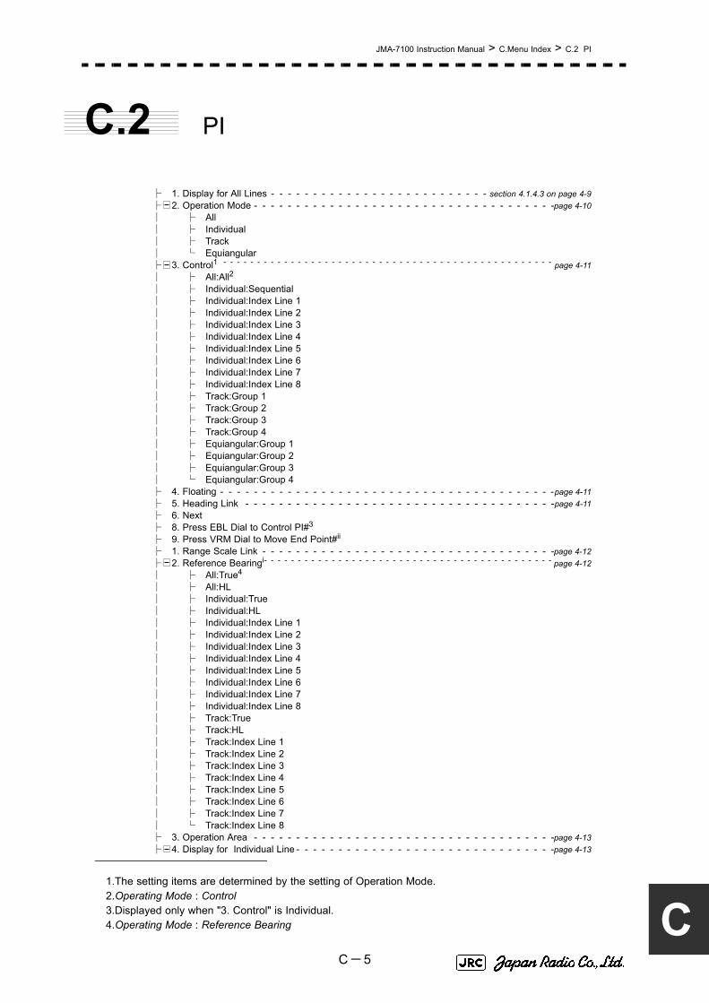
JMA-7100 Instruction Manual > C.Menu Index > C.2 PI
C
C.2 PI
├ 1. Display for All Lines - - - - - - - - - - - - - - - - - - - - - - - - - - section 4.1.4.3 on page 4-9├ 2. Operation Mode - - - - - - - - - - - - - - - - - - - - - - - - - - - - - - - - - - - -page 4-10│ ├ All│ ├ Individual│ ├ Track│ └ Equiangular├ 3. Control1 - - - - - - - - - - - - - - - - - - - - - - - - - - - - - - - - - - - - - - - - - - - - - - - - - page 4-11│ ├ All:All2│ ├ Individual:Sequential│ ├ Individual:Index Line 1│ ├ Individual:Index Line 2│ ├ Individual:Index Line 3│ ├ Individual:Index Line 4│ ├ Individual:Index Line 5│ ├ Individual:Index Line 6│ ├ Individual:Index Line 7│ ├ Individual:Index Line 8│ ├ Track:Group 1│ ├ Track:Group 2│ ├ Track:Group 3│ ├ Track:Group 4│ ├ Equiangular:Group 1│ ├ Equiangular:Group 2│ ├ Equiangular:Group 3│ └ Equiangular:Group 4├ 4. Floating - - - - - - - - - - - - - - - - - - - - - - - - - - - - - - - - - - - - - - - -page 4-11├ 5. Heading Link - - - - - - - - - - - - - - - - - - - - - - - - - - - - - - - - - - - - -page 4-11├ 6. Next├ 8. Press EBL Dial to Control PI#3
├ 9. Press VRM Dial to Move End Point#ii
├ 1. Range Scale Link - - - - - - - - - - - - - - - - - - - - - - - - - - - - - - - - - - -page 4-12├ 2. Reference Bearingi- - - - - - - - - - - - - - - - - - - - - - - - - - - - - - - - - - - - - - - - - - - page 4-12│ ├ All:True4
│ ├ All:HL│ ├ Individual:True│ ├ Individual:HL│ ├ Individual:Index Line 1│ ├ Individual:Index Line 2│ ├ Individual:Index Line 3│ ├ Individual:Index Line 4│ ├ Individual:Index Line 5│ ├ Individual:Index Line 6│ ├ Individual:Index Line 7│ ├ Individual:Index Line 8│ ├ Track:True│ ├ Track:HL│ ├ Track:Index Line 1│ ├ Track:Index Line 2│ ├ Track:Index Line 3│ ├ Track:Index Line 4│ ├ Track:Index Line 5│ ├ Track:Index Line 6│ ├ Track:Index Line 7│ └ Track:Index Line 8├ 3. Operation Area - - - - - - - - - - - - - - - - - - - - - - - - - - - - - - - - - - - -page 4-13├ 4. Display for Individual Line - - - - - - - - - - - - - - - - - - - - - - - - - - - - - - -page 4-13
1.The setting items are determined by the setting of Operation Mode.2.Operating Mode : Control3.Displayed only when "3. Control" is Individual.4.Operating Mode : Reference Bearing
C-5

JMA-7100 Instruction Manual > C.Menu Index > C.2 PI
│ ├ 1. Index Line 1│ ├ 2. Index Line 2│ ├ 3. Index Line 3│ ├ 4. Index Line 4│ ├ 5. Index Line 5│ ├ 6. Index Line 6│ ├ 7. Index Line 7│ └ 8. Index Line 8├ 8. Press EBL Dial to Control PI#ii
└ 9. Press VRM Dial to Move End Point#ii
C-6

JMA-7100 Instruction Manual > C.Menu Index > C.3 TT
C
C.3 TT├ 1. Association Setting - - - - - - - - - - - - - - - - - - - - - - - - - - - section 5.4 on page 5-37│ ├ 1. Association│ ├ 2. Proprity│ ├ 3. Bearing│ ├ 4. Range│ ├ 5. Course│ ├ 6. Speed│ └ 7. Applicable AIS Target├ 2. Target Track Setting - - - - - - - - - - - - - - - - - - - - - - - - - - section 5.6.2 on page 5-44│ ├ 1. Target Track Function - - - - - - - - - - - - - - - - - - - - section 5.6.2.2 on page 5-44│ ├ 2. Target Track Color - - - - - - - - - - - - - - - - - - - - - - section 5.6.2.1 on page 5-44│ │ ├ 1. All│ │ ├ 2. Target Track No.1│ │ ├ 3. Target Track No.2│ │ ├ 4. Target Track No.3│ │ ├ 5. Target Track No.4│ │ ├ 6. Target Track No.5│ │ ├ 7. Target Track No.6│ │ ├ 8. Target Track No.7│ │ ├ 9. Next│ │ ├ 1. Target Track No.8│ │ ├ 2. Target Track No.9│ │ ├ 3. Target Track No.10│ │ └ 4. Other│ ├ 3. Target Track Display - - - - - - - - - - - - - - - - - - - - - section 5.6.2.4 on page 5-46│ │ ├ 1. All│ │ ├ 2. Target Track No.1│ │ ├ 3. Target Track No.2│ │ ├ 4. Target Track No.3│ │ ├ 5. Target Track No.4│ │ ├ 6. Target Track No.5│ │ ├ 7. Target Track No.6│ │ ├ 8. Target Track No.7│ │ ├ 9. Next│ │ ├ 1. Target Track No.8│ │ ├ 2. Target Track No.9│ │ ├ 3. Target Track No.10│ │ └ 4. Other│ ├ 4. Track Memory Interval - - - - - - - - - - - - - - - - - - - - section 5.6.2.5 on page 5-47│ ├ 5. Clear Track Color - - - - - - - - - - - - - - - - - - - - - - section 5.6.2.6 on page 5-47│ ├ 6. Clear Track Number│ └ 7. File Operations - - - - - - - - - - - - - - - - - - - - - - - section 5.6.2.7 on page 5-48│ │ ├ 1. Select Card Slot│ │ ├ 2. Load Mode│ │ ├ 3. Load - - - - - - - - - - - - - - - - - - - - - - - - - - - - - - - - -page 5-48│ │ ├ 4. Save - - - - - - - - - - - - - - - - - - - - - - - - - - - - - - - - -page 5-49│ │ ├ 5. Erase - - - - - - - - - - - - - - - - - - - - - - - - - - - - - - - - -page 5-51│ │ └ 6. Card T.TRK Display - - - - - - - - - - - - - - - - - - - - - - - - - -page 5-52├ 3. Trial Maneuver - - - - - - - - - - - - - - - - - - - - - - - - - - - - - section 5.7 on page 5-53│ ├ 1. Trial Function│ ├ 2. Course(EBL)│ ├ 3. Speed(VRM)│ ├ 4. Vector Time│ ├ 5. Time to Maneuver│ └ 6. Own Ship's Dynamic Trait│ │ ├ 1. Reach│ │ ├ 3. Turn Radius│ │ ├ 4. Acceleration│ │ └ 5. Deceleration├ 4. Target Number Display - - - - - - - - - - - - - - - - - - - - - - - - section 5.2.4 on page 5-18└ 9. TT Test Menu - - - - - - - - - - - - - - - - - - - - - - - - - - - - - section 5.2.7 on page 5-21
│ ├ 1. Test Video - - - - - - - - - - - - - - - - - - - - - - - - - - section 5.2.7.1 on page 5-22│ ├ 2. TT Simulator - - - - - - - - - - - - - - - - - - - - - - - - section 5.2.7.2 on page 5-23│ ├ 3. Status - - - - - - - - - - - - - - - - - - - - - - - - - - - - section 5.2.7.3 on page 5-24│ └ 4. Gate Display - - - - - - - - - - - - - - - - - - - - - - - - section 5.2.7.4 on page 5-25
C-7

JMA-7100 Instruction Manual > C.Menu Index > C.4 AIS
C.4 AIS
├ 1. Association Setting - - - - - - - - - - - - - - - - - - - - - - - - - - section 5.4.2 on page 5-37│ ├ 1. Association│ ├ 2. Proprity│ ├ 3. Bearing│ ├ 4. Range│ ├ 5. Course│ ├ 6. Speed│ └ 7. Applicable AIS Target├ 2. Target Track Setting - - - - - - - - - - - - - - - - - - - - - - - - - - section 5.6.2 on page 5-44│ ├ 1. Target Track Function - - - - - - - - - - - - - - - - - - - - section 5.6.2.2 on page 5-44│ ├ 2. Target Track Color - - - - - - - - - - - - - - - - - - - - - - section 5.6.2.1 on page 5-44│ │ ├ 1. All│ │ ├ 2. Target Track No.1│ │ ├ 3. Target Track No.2│ │ ├ 4. Target Track No.3│ │ ├ 5. Target Track No.4│ │ ├ 6. Target Track No.5│ │ ├ 7. Target Track No.6│ │ ├ 8. Target Track No.7│ │ ├ 9. Next│ │ ├ 1. Target Track No.8│ │ ├ 2. Target Track No.9│ │ ├ 3. Target Track No.10│ │ └ 4. Other│ ├ 3. Target Track Display - - - - - - - - - - - - - - - - - - - - - section 5.6.2.4 on page 5-46│ │ ├ 1. All│ │ ├ 2. Target Track No.1│ │ ├ 3. Target Track No.2│ │ ├ 4. Target Track No.3│ │ ├ 5. Target Track No.4│ │ ├ 6. Target Track No.5│ │ ├ 7. Target Track No.6│ │ ├ 8. Target Track No.7│ │ ├ 9. Next│ │ ├ 1. Target Track No.8│ │ ├ 2. Target Track No.9│ │ ├ 3. Target Track No.10│ │ └ 4. Other│ ├ 4. Track Memory Interval - - - - - - - - - - - - - - - - - - - - section 5.6.2.5 on page 5-47│ ├ 5. Clear Track Color - - - - - - - - - - - - - - - - - - - - - - section 5.6.2.6 on page 5-47│ ├ 6. Clear Track Number│ └ 7. File Operations - - - - - - - - - - - - - - - - - - - - - - - section 5.6.2.7 on page 5-48│ │ ├ 1. Select Card Slot│ │ ├ 2. Load Mode│ │ ├ 3. Load - - - - - - - - - - - - - - - - - - - - - - - - - - - - - - - - -page 5-48│ │ ├ 4. Save - - - - - - - - - - - - - - - - - - - - - - - - - - - - - - - - -page 5-49│ │ ├ 5. Erase - - - - - - - - - - - - - - - - - - - - - - - - - - - - - - - - -page 5-51│ │ └ 6. Card T.TRK Display - - - - - - - - - - - - - - - - - - - - - - - - - -page 5-52├ 3. Trial Maneuver - - - - - - - - - - - - - - - - - - - - - - - - - - - - - section 5.7 on page 5-53│ ├ 1. Trial Function│ ├ 2. Course(EBL)│ ├ 3. Speed(VRM)│ ├ 4. Vector Time│ ├ 5. Time to Maneuver│ └ 6. Own Ship's Dynamic Trait│ │ ├ 1. Reach│ │ ├ 2. Turn Radius│ │ ├ 3. Acceleration│ │ └ 4. Deceleration├ 4. AIS Filter Setting - - - - - - - - - - - - - - - - - - - - - - - - - - - section 5.3.7 on page 5-32│ ├ 1. Filter Type - - - - - - - - - - - - - - - - - - - - - - - - - - section 5.3.7.2 on page 5-32│ ├ 2. Make AIS Filter - - - - - - - - - - - - - - - - - - - - - - - section 5.3.7.3 on page 5-33
C-8

JMA-7100 Instruction Manual > C.Menu Index > C.5 AZ
C
│ ├ 3. Filter Display - - - - - - - - - - - - - - - - - - - - - - - - section 5.3.7.4 on page 5-34│ ├ 4. ENT│ └ 6. Filter Mode - - - - - - - - - - - - - - - - - - - - - - - - - section 5.3.7.5 on page 5-34├ 5. Target Number Display - - - - - - - - - - - - - - - - - - - - - - - - section 5.3.6 on page 5-31├ 6. AIS Alarm Setting - - - - - - - - - - - - - - - - - - - - - - - - - - - section 5.3.9 on page 5-36│ ├ 1. Lost Alarm- - - - - - - - - - - - - - - - - - - - - - - - - - section 5.3.9.1 on page 5-36│ └ 2. CPA/TCPA Alarm - - - - - - - - - - - - - - - - - - - - - - section 5.3.9.2 on page 5-36├ 7. Message - - - - - - - - - - - - - - - - - - - - - - - - - - - - - - section 5.3.5.5 on page 5-29│ ├ 1. Addressed Message│ └ 2. Broadcast Message├ 8. Display Lost TGT Data - - - - - - - - - - - - - - - - - - - - - - - section 5.3.5.6 on page 5-31└ 9. Own Ship's AIS Data - - - - - - - - - - - - - - - - - - - - - - - - section 5.3.5.7 on page 5-31
C.5 AZ
├ 1. AZ 1- - - - - - - - - - - - - - - - - - - - - - - - - - - - - - - - - section 5.2.1.1 on page 5-14├ 2. AZ 2- - - - - - - - - - - - - - - - - - - - - - - - - - - - - - - - - section 5.2.1.1 on page 5-14├ 3. Make AZ 1 - - - - - - - - - - - - - - - - - - - - - - - - - - - - - section 5.2.1.1 on page 5-14├ 4. Make AZ 2 - - - - - - - - - - - - - - - - - - - - - - - - - - - - - section 5.2.1.1 on page 5-14└ 5. ENT
C-9

JMA-7100 Instruction Manual > C.Menu Index > C.6 Track
C.6 Track
├ 1. DISP Own Track Color- - - - - - - - - - - - - - - - - - - - - - - - - section 3.5.2 on page 3-40│ ├ 1. All│ ├ 2. White│ ├ 3. Cyan│ ├ 4. Blue│ ├ 5. Green│ ├ 6. Yellow│ ├ 7. Pink│ └ 8. Red├ 2. Clear Own Track Color - - - - - - - - - - - - - - - - - - - - - - - - section 3.5.5 on page 3-42├ 3. Track Type - - - - - - - - - - - - - - - - - - - - - - - - - - - - - - section 3.5.6 on page 3-42├ 4. Num/Vector Display - - - - - - - - - - - - - - - - - - - - - - - - - - section 3.5.6 on page 3-42├ 5. File Operations│ ├ 1. Select Card Slot│ ├ 2. Load Mode│ ├ 3. Load│ ├ 4. Save│ ├ 5. Erase│ └ 6. Card Own Track Display├ 6. Water Depth Setting - - - - - - - - - - - - - - - - - - - - - - - - - - section 3.5.7 on page 3-44│ ├ 1. Depth setting (MIN)│ ├ 2. Depth setting│ ├ 3. Depth setting│ ├ 4. Depth setting│ ├ 5. Depth setting│ └ 6. Depth setting (MAX)├ 7. Water TEMP Setting - - - - - - - - - - - - - - - - - - - - - - - - - - section 3.5.8 on page 3-45│ ├ 1. Temperature setting (MIN)│ ├ 2. Temperature setting │ ├ 3. Temperature setting │ ├ 4. Temperature setting │ ├ 5. Temperature setting │ └ 6. Temperature setting (MAX)├ 8. Current Setting - - - - - - - - - - - - - - - - - - - - - - - - - - - - section 3.5.9 on page 3-46│ ├ 1. Current Size│ ├ 2. Layer A│ ├ 3. Layer B│ └ 4. Layer C
C-10

JMA-7100 Instruction Manual > C.Menu Index > C.7 Route
C
C.7 Route
├ 1. Select Route - - - - - - - - - - - - - - - - - - - - - - - - - - - - - section 3.7.1 on page 3-67├ 2. WPT/Route Settig│ ├ 1. Waypoint Alarm - - - - - - - - - - - - - - - - - - - - - - - section 3.7.4.1 on page 3-79│ ├ 2. Route Alarm - - - - - - - - - - - - - - - - - - - - - - - - - section 3.7.4.2 on page 3-80│ ├ 3. Set Route Sequence- - - - - - - - - - - - - - - - - - - - - - section 3.7.2 on page 3-68│ │ ├ 1. Planned Speed - - - - - - - - - - - - - - - - - - - section 3.7.3.5 on page 3-77│ │ ├ 2. Add - - - - - - - - - - - - - - - - - - - - - - - - - section 3.7.2.2 on page 3-69│ │ ├ 3. Correct Position - - - - - - - - - - - - - - - - - - - section 3.7.2.3 on page 3-70│ │ ├ 4. Correct Planned Speed - - - - - - - - - - - - - - - section 3.7.2.4 on page 3-71│ │ ├ 5. Delete - - - - - - - - - - - - - - - - - - - - - - - - section 3.7.2.5 on page 3-72│ │ ├ 6. Insert - - - - - - - - - - - - - - - - - - - - - - - - section 3.7.2.6 on page 3-73│ │ └ 7. New Monitor Route - - - - - - - - - - - - - - - - - section 3.7.2.1 on page 3-68│ ├ 6. Waypoint Input - - - - - - - - - - - - - - - - - - - - - - - - section 3.7.3 on page 3-75│ ├ 7. Save Temporary Route│ ├ 8. Off-Track Limit Line - - - - - - - - - - - - - - - - - - - - - section 3.7.6.1 on page 3-83│ ├ 9. Next│ ├ 1. SEL. NUM/Comment Size - - - - - - - - - - - - - - - - - - section 3.7.6.2 on page 3-83│ ├ 2. Waypoint Vector - - - - - - - - - - - - - - - - - - - - - - - section 3.7.6.3 on page 3-84│ ├ 3. Status of Origin/DEST - - - - - - - - - - - - - - - - - - - - section 3.7.6.4 on page 3-85│ └ 4. WPT Number Display - - - - - - - - - - - - - - - - - - - - section 3.7.6.5 on page 3-85├ 3. WPT/Route Operations - - - - - - - - - - - - - - - - - - - - - - - - section 3.7.5 on page 3-81│ ├ 1. Route Sequence- - - - - - - - - - - - - - - - - - - - - - - section 3.7.5.1 on page 3-81│ ├ 2. Waypoint Switch Mode- - - - - - - - - - - - - - - - - - - - section 3.7.6.6 on page 3-86│ ├ 3. Waypoint Skip - - - - - - - - - - - - - - - - - - - - - - - - section 3.7.5.2 on page 3-82│ ├ 4. Waypoint Back Skip - - - - - - - - - - - - - - - - - - - - - section 3.7.5.2 on page 3-82│ ├ 5. Set/Cancel Waypoint│ └ 6. Clear WPT/Route Data├ 4. File Operations - - - - - - - - - - - - - - - - - - - - - - - - - - - - section 3.7.8 on page 3-87│ ├ 1. Select Card Slot - - - - - - - - - - - - - - - - - - - - - - - section 3.7.8.1 on page 3-87│ ├ 2. Load - - - - - - - - - - - - - - - - - - - - - - - - - - - - section 3.7.8.3 on page 3-88│ ├ 3. Save - - - - - - - - - - - - - - - - - - - - - - - - - - - - section 3.7.8.2 on page 3-87│ └ 4. Erase - - - - - - - - - - - - - - - - - - - - - - - - - - - - section 3.7.8.4 on page 3-89
C-11

JMA-7100 Instruction Manual > C.Menu Index > C.8 U.Map
C.8 U.Map
├ 1. Own Ship Position - - - - - - - - - - - - - - - - - - - - - - - - - - section 3.6.3.1 on page 3-52├ 2. Edit User Map - - - - - - - - - - - - - - - - - - - - - - - - - - - - - section 3.6.3 on page 3-52│ ├ 1. Make with Cursor - - - - - - - - - - - - - - - - - - - - - - section 3.6.1.1 on page 3-47│ │ ├ 1. Type│ │ └ 2. Color│ ├ 2. Make with L/L - - - - - - - - - - - - - - - - - - - - - - - - section 3.6.1.3 on page 3-49│ │ ├ 1. Type│ │ ├ 2. Color│ │ ├ 3. L/L│ │ ├ 4. Comment│ │ ├ 5. Enter│ │ └ 9. New Line Input/9.New Mark Input│ ├ 3. Move - - - - - - - - - - - - - - - - - - - - - - - - - - - - section 3.6.3.2 on page 3-53│ ├ 4. Delete - - - - - - - - - - - - - - - - - - - - - - - - - - - - section 3.6.3.3 on page 3-55│ ├ 5. Insert/Move Vertex- - - - - - - - - - - - - - - - - - - - - - section 3.6.3.4 on page 3-56│ ├ 6. Delete Vertex - - - - - - - - - - - - - - - - - - - - - - - - section 3.6.3.6 on page 3-58│ └ 7. Delete by Type by Color - - - - - - - - - - - - - - - - - - - section 3.6.3.7 on page 3-59├ 3. Shift - - - - - - - - - - - - - - - - - - - - - - - - - - - - - - - - - section 3.6.4.1 on page 3-60├ 4. Shift Clear - - - - - - - - - - - - - - - - - - - - - - - - - - - - - - section 3.6.4.2 on page 3-61├ 5. Mark Display Setting- - - - - - - - - - - - - - - - - - - - - - - - - - section 3.6.2 on page 3-50│ ├ 1. Display Mark Type- - - - - - - - - - - - - - - - - - - - - - section 3.6.2.1 on page 3-50│ │ ├ 1. All│ │ ├ 2. ○│ │ ├ 3. △│ │ ├ 4. ▽│ │ ├ 5. □│ │ ├ 6. ◇│ │ ├ 7. Wreck (mark)│ │ ├ 8. △△│ │ ├ 9. Next│ │ ├ 1. ▽▽
│ │ ├ 2. △▽
│ │ ├ 3. ▽△
│ │ ├ 4. +│ │ ├ 5. ×│ │ ├ 6. Y│ │ ├ 7. Hand drum (mark)│ │ ├ 8. Light house (mark)│ │ ├ 9. Next│ │ ├ 1. Trapezoid(mark)│ │ ├ 2. filled Trapezoid(mark)│ │ ├ 3. Hat(mark)│ │ ├ 4. ●●
│ │ ├ 5. ●│ │ ├ 6. Filled Triangle(mark)│ │ ├ 7. !│ │ ├ 8. anchor(mark)│ │ ├ 9. Next│ │ ├ 1. slash-anchor(mark)│ │ ├ 2. circle-dotted line(mark)│ │ ├ 3. non-dangerous wreck(mark)│ │ ├ 4. ◎│ │ ├ 5. mariner's event mark(mark)│ │ ├ 6. ・│ │ ├ 7. Wavy line (mark)│ │ ├ 8. Solid line (mark)│ │ └ 9. Dashed-dotted line (mark)│ ├ 2. Display Mark Color - - - - - - - - - - - - - - - - - - - - - section 3.6.2.2 on page 3-51│ │ ├ 1. All│ │ ├ 2. White│ │ ├ 3. Cyan│ │ ├ 4. Blue
C-12

JMA-7100 Instruction Manual > C.Menu Index > C.8 U.Map
C
│ │ ├ 5. Green│ │ ├ 6. Yellow│ │ ├ 7. Pink│ │ └ 8. Red│ ├ 3. Mark Size - - - - - - - - - - - - - - - - - - - - - - - - - - section 3.6.2.3 on page 3-51│ └ 4. Comment Font Size - - - - - - - - - - - - - - - - - - - - - section 3.6.2.4 on page 3-52├ 6. Geodetic - - - - - - - - - - - - - - - - - - - - - - - - - - - - - - - section 3.6.6 on page 3-65└ 7. File Operations - - - - - - - - - - - - - - - - - - - - - - - - - - - - section 3.6.5 on page 3-61
│ ├ 1. Select Card Slot│ ├ 2. Load Mode - - - - - - - - - - - - - - - - - - - - - - - - - section 3.6.5.1 on page 3-61│ ├ 3. Load - - - - - - - - - - - - - - - - - - - - - - - - - - - - section 3.6.5.1 on page 3-61│ ├ 4. Unload - - - - - - - - - - - - - - - - - - - - - - - - - - - section 3.6.5.2 on page 3-62│ ├ 5. Save - - - - - - - - - - - - - - - - - - - - - - - - - - - - section 3.6.5.3 on page 3-62│ ├ 6. Erase - - - - - - - - - - - - - - - - - - - - - - - - - - - - section 3.6.5.4 on page 3-63│ └ 7. Card Mark Display - - - - - - - - - - - - - - - - - - - - - - section 3.6.5.5 on page 3-64
C-13

JMA-7100 Instruction Manual > C.Menu Index > C.9 Serviceman Menu
C.9 Serviceman Menu
├Serviceman Menu - - - - - - - - - - - - - - - - - - - - - - - - - - - - - - section 7.1.1 on page 7-1├ 1. Adjust Menu│ ├ 1. Tune Adjustment - - - - - - - - - - - - - - - - - - - - - - - - section 7.1.3 on page 7-5│ ├ 2. Bearing Adjustment - - - - - - - - - - - - - - - - - - - - - - - section 7.1.4 on page 7-7│ ├ 3. Range Adjustment - - - - - - - - - - - - - - - - - - - - - - - - section 7.1.5 on page 7-7│ └ 4. TXRX Adjustment│ │ ├ 1. Antenna Height - - - - - - - - - - - - - - - - - - - - - section 7.1.8 on page 7-9│ │ ├ 2. Tune Peak Adjustment- - - - - - - - - - - - - - - - - section 7.1.3.1 on page 7-5│ │ ├ 3. Tune Indicator Adjust - - - - - - - - - - - - - - - - - section 7.1.3.2 on page 7-6│ │ ├ 4. MON Adjustment - - - - - - - - - - - - - - - - - - section 7.3.4.1 on page 7-31│ │ ├ 5. MON Indicator Adjustment - - - - - - - - - - - - - - section 7.3.4.2 on page 7-32│ │ └ 6. Output Pulse - - - - - - - - - - - - - - - - - - - - - section 7.2.4 on page 7-18├ 2. Installation Menu│ ├ 1. Installation Information- - - - - - - - - - - - - - - - - - - - - section 7.2.8 on page 7-21│ │ ├ 1. Date│ │ ├ 2. Name│ │ └ 3. Company│ ├ 2. Master/Slave - - - - - - - - - - - - - - - - - - - - - - - - section 7.2.5.1 on page 7-19│ ├ 3. Sector Blank- - - - - - - - - - - - - - - - - - - - - - - - - - section 7.2.2 on page 7-16│ │ ├ 1. Sector1 - - - - - - - - - - - - - - - - - - - - - - - section 7.2.2.1 on page 7-16│ │ ├ 2. Sector2 - - - - - - - - - - - - - - - - - - - - - - - section 7.2.2.1 on page 7-16│ │ ├ 3. Sector3 - - - - - - - - - - - - - - - - - - - - - - - section 7.2.2.1 on page 7-16│ │ ├ 4. Make Sector1 - - - - - - - - - - - - - - - - - - - - section 7.2.2.2 on page 7-16│ │ ├ 5. Make Sector2 - - - - - - - - - - - - - - - - - - - - section 7.2.2.2 on page 7-16│ │ └ 6. Make Sector3 - - - - - - - - - - - - - - - - - - - - section 7.2.2.2 on page 7-16│ ├ 4. CCRP Setting - - - - - - - - - - - - - - - - - - - - - - - - - section 7.1.9 on page 7-10│ ├ 5. COM Port Setting - - - - - - - - - - - - - - - - - - - - - - - section 7.2.1 on page 7-12│ │ ├ 1. Baud Rate- - - - - - - - - - - - - - - - - - - - - - section 7.2.1.1 on page 7-12│ │ │ ├ 1. COMPASS│ │ │ ├ 2. MAINTENANCE/LOG│ │ │ ├ 3. NAV1│ │ │ ├ 4. NAV2│ │ │ ├ 5. ALARM│ │ │ ├ 6. JARPA│ │ │ ├ 7. AIS│ │ │ ├ 8. BRIDGE NET│ │ │ ├ 9. Next│ │ │ ├ 1. ARPA│ │ │ └ 2. COM│ │ ├ 2. RX Port - - - - - - - - - - - - - - - - - - - - - - - section 7.2.1.2 on page 7-13│ │ │ ├ 1. GPS│ │ │ ├ 2. DLOG│ │ │ ├ 3. Alarm│ │ │ ├ 4. Depth│ │ │ ├ 5. Temperature│ │ │ ├ 6. Wind│ │ │ ├ 7. Current│ │ │ ├ 8. ROT│ │ │ ├ 9. Next│ │ │ └ 1. RSA│ │ ├ 3. RX Sentence - - - - - - - - - - - - - - - - - - - - section 7.2.1.3 on page 7-14│ │ │ ├ 1. GPS(LL/COG/SOG)│ │ │ ├ 2. GPS(WPT/TIME)│ │ │ ├ 3. Depth│ │ │ ├ 4. Wind│ │ │ └ 5. Current│ │ │ │ ├ 1. Data Set Number│ │ │ │ ├ 2. Layer A│ │ │ │ ├ 3. Layer B│ │ │ │ └ 4. Layer C│ │ ├ 4. TX Port - - - - - - - - - - - - - - - - - - - - - - - section 7.2.1.4 on page 7-15│ │ │ ├ 1. TTM(TT)
C-14

JMA-7100 Instruction Manual > C.Menu Index > C.9 Serviceman Menu
C
│ │ │ ├ 2. TLL(TT)│ │ │ ├ 3. TTD(TT)│ │ │ ├ 4. TLB(TT)│ │ │ ├ 5. OSD│ │ │ ├ 6. RSD│ │ │ ├ 7. ALR│ │ │ ├ 8. ACK│ │ │ ├ 9. Next│ │ │ ├ 1. TTM(AIS)│ │ │ ├ 2. TLL(AIS)│ │ │ ├ 3. TTD(AIS)│ │ │ ├ 4. TLB(AIS)│ │ │ ├ 5. Remote Maintenance│ │ │ ├ 6. JRC-ARPA│ │ │ ├ 7. NMEA0183 Output Format│ │ │ ├ 8. NMEA0183 Talker│ │ │ ├ 9. Next│ │ │ ├ 1. NMEA0183 TX Interval│ │ │ ├ 2. APB│ │ │ ├ 3. BOD│ │ │ ├ 4. GGA│ │ │ ├ 5. GLL│ │ │ ├ 6. RMC│ │ │ ├ 7. RMB│ │ │ ├ 8. VTG│ │ │ ├ 9. Next│ │ │ ├ 1. XTE│ │ │ ├ 2. BWC│ │ │ ├ 3. HDT│ │ │ └ 4. THS│ │ ├ 7. Line Monitor│ │ │ ├ 1. COMPASS│ │ │ ├ 2. MAINTENANCE/LOG│ │ │ ├ 3. NAV1│ │ │ ├ 4. NAV2│ │ │ ├ 5. ALARM│ │ │ ├ 6. JARPA│ │ │ ├ 7. AIS│ │ │ ├ 8. BRIDGE NET│ │ │ ├ 9. Next│ │ │ ├ 1. ARPA│ │ │ ├ 2. COM│ │ │ ├ 3. TXRX/ISW│ │ │ ├ 4. KEYBOARD1│ │ │ └ 5. KEYBOARD2│ ├ 6. Alarm System - - - - - - - - - - - - - - - - - - - - - - - - - section 7.2.9 on page 7-22│ │ ├ 1. Watch Alarm│ │ │ ├ 1. Reset Interval - - - - - - - - - - - - - - - - section 7.2.9.1 on page 7-22│ │ │ └ 2. Trackball Threshold - - - - - - - - - - - - - section 7.2.9.2 on page 7-22│ │ ├ 2. Relay Output - - - - - - - - - - - - - - - - - - - - section 7.2.9.3 on page 7-23│ │ │ ├ 1. Relay Output Mode│ │ │ ├ 2. TT CPA/TCPA│ │ │ ├ 3. AIS CPA/TCPA│ │ │ ├ 4. New Target│ │ │ ├ 5. Lost│ │ │ └ 6. RADAR Alarm│ │ ├ 3. ALR Output - - - - - - - - - - - - - - - - - - - - - section 7.2.9.4 on page 7-23│ │ │ ├ 1. System Alarm│ │ │ └ 2. TT/AIS Alarm│ │ ├ 4. Sound Output Mode - - - - - - - - - - - - - - - - - section 7.2.9.6 on page 7-25│ │ ├ 5. External ACK Setting - - - - - - - - - - - - - - - - section 7.2.9.5 on page 7-24│ │ │ ├ 1. Critical Alarm│ │ │ │ ├ 1. Audio│ │ │ │ ├ 2Indication│ │ │ │ └ 3. Acknowledge State│ │ │ ├ 2. Normal Alarm│ │ │ │ ├ 1. Audio│ │ │ │ ├ 2. Indication│ │ │ │ └ 3. Acknowledge State│ ├ 7. Inter Switch
C-15

JMA-7100 Instruction Manual > C.Menu Index > C.9 Serviceman Menu
│ │ ├ 1. ISW Install│ │ ├ 2. Mask Setting│ │ │ ├ 1. No.1 Connection/No.1 Master│ │ │ ├ 2. No.2 Connection/No.2 Master│ │ │ ├ 3. No.3 Connection/No.3 Master│ │ │ ├ 4. No.4 Connection/No.4 Master│ │ │ ├ 5. No.5 Connection/No.5 Master1│ │ │ ├ 6. No.6 Connection/No.6 Masteri│ │ │ ├ 7. No.7 Connection/No.7 Masteri│ │ │ └ 8. No.8 Connection/No.8 Masteri│ │ └ 3. S-ISW TXRX Power Supply│ ├ 8. Language - - - - - - - - - - - - - - - - - - - - - - - - - - - section 7.2.6 on page 7-20│ ├ 9. Next│ ├ 1. Input BP Count - - - - - - - - - - - - - - - - - - - - - - - section 7.2.5.2 on page 7-19│ ├ 2. TNI Blank - - - - - - - - - - - - - - - - - - - - - - - - - - - section 7.2.3 on page 7-17│ │ ├ 1. TNI Blank - - - - - - - - - - - - - - - - - - - - - - section 7.2.3.1 on page 7-17│ │ └ 2. Make Sector - - - - - - - - - - - - - - - - - - - - - section 7.2.3.2 on page 7-17│ ├ 3. Device Installation - - - - - - - - - - - - - - - - - - - - - - - - section 7.1.6 on page 7-8│ │ ├ 1. Gyro│ │ ├ 2. Compass│ │ ├ 3. GPS Compass│ │ ├ 4. LOG│ │ ├ 5. 2AXW│ │ ├ 6. 2AXG│ │ └ 7. GPS│ ├ 4. Network│ │ ├ 1. Network Function│ │ └ 2. IP Address├ 3. Maintenance Menu│ ├ 1. Safety Switch - - - - - - - - - - - - - - - - - - - - - - - - - section 7.4.1 on page 7-33│ ├ 2. Area Initial - - - - - - - - - - - - - - - - - - - - - - - - - - - section 7.4.2 on page 7-34│ │ └ 1. Partial Master Reset - - - - - - - - - - - - - - - - - section 7.4.2.1 on page 7-34│ │ │ ├ 1. Serviceman Menu│ │ │ ├ 2. Except Serviceman Menu│ │ │ ├ 3. User Setting│ │ │ ├ 4. TT Setting│ │ │ ├ 5. AIS Setting│ │ │ ├ 6. Day/Night│ │ │ └ 7. JRC Card Copy Record│ │ └ 2. All Master Reset - - - - - - - - - - - - - - - - - - - section 7.4.2.2 on page 7-34│ ├ 3. Internal To Card2 - - - - - - - - - - - - - - - - - - - - - - section 7.4.3.1 on page 7-35│ ├ 4. Card2 To Internal - - - - - - - - - - - - - - - - - - - - - - section 7.4.3.2 on page 7-35│ ├ 5. TXRX Time - - - - - - - - - - - - - - - - - - - - - - - - - - section 7.4.4 on page 7-36│ │ ├ 1. Clear TX Time - - - - - - - - - - - - - - - - - - - - section 7.4.4.1 on page 7-36│ │ ├ 2. Clear Motor Time - - - - - - - - - - - - - - - - - - section 7.4.4.2 on page 7-36│ │ ├ 3. TXRX to Display Unit - - - - - - - - - - - - - - - - section 7.4.4.3 on page 7-37│ │ └ 4. Display Unit to TXRX - - - - - - - - - - - - - - - - section 7.4.4.4 on page 7-37│ └ 6. String Data Update - - - - - - - - - - - - - - - - - - - - - - section 7.4.5 on page 7-38└ 9. RADAR/TT Initial Setup│ ├ 1. Signal Processing - - - - - - - - - - - - - - - - - - - - - - - section 7.3.1 on page 7-26│ │ ├ 1. Echo Noise Level - - - - - - - - - - - - - - - - - - section 7.3.1.1 on page 7-26│ │ └ 2. Setting Mode - - - - - - - - - - - - - - - - - - - - section 7.3.1.2 on page 7-27│ ├ 2. TT- - - - - - - - - - - - - - - - - - - - - - - - - - - - - - - section 7.3.2 on page 7-27│ │ ├ 1. Vector Constant - - - - - - - - - - - - - - - - - - - section 7.3.2.1 on page 7-27│ │ ├ 2. Video TD Level - - - - - - - - - - - - - - - - - - - section 7.3.2.2 on page 7-28│ │ ├ 3. Video High Level│ │ ├ 4. Video Low Level│ │ ├ 5. Gate Size│ │ └ 6. Limit Ring│ └ 3. MBS- - - - - - - - - - - - - - - - - - - - - - - - - - - - - - section 7.3.3 on page 7-29│ │ ├ 1. MBS Level- - - - - - - - - - - - - - - - - - - - - - section 7.3.3.1 on page 7-29│ │ └ 2. MBS Area - - - - - - - - - - - - - - - - - - - - - - section 7.3.3.2 on page 7-30
1.Only for ISW Extended Mode
C-16


MARINE RADARMARINE RADAREQUIPMENTEQUIPMENT
INSTRUCTIONINSTRUCTIONMANUALMANUAL
JMA-7133-SAJMA-7133-SAJMA-7132-SAJMA-7132-SAJMA-7123-7XA/9XAJMA-7123-7XA/9XAJMA-7122-6XA/9XA/6XAHJMA-7122-6XA/9XA/6XAHJMA-7110-6XA/6XAHJMA-7110-6XA/6XAH
01ETM ISO 9001, ISO 14001 Certified
Printed in Japan
Marine Service [email protected]
Telephone :Facsimile :e-mail :
AMSTERDAM BranchTelephone :Facsimile :e-mail :
SEATTLE BranchTelephone :Facsimile :e-mail :
CODE No.7ZPRD0680CODE No.7ZPRD0680
MAY. 2008 Edition 2 JRCMAY. 2008 Edition 2 JRC
Not use the asbestos
For further information,contact:
URL http://www.jrc.co.jp