YUTAKI SERIES
264
Air to water Heat pump • RHUE-3AVHN • RHUE-4AVHN • RHUE-5A(V)HN • RHUE-6A(V)HN YUTAKI SERIES RHUE-A(V)HN
-
Upload
khangminh22 -
Category
Documents
-
view
3 -
download
0
Transcript of YUTAKI SERIES

Air to water Heat pump
• RHUE-3AVHN• RHUE-4AVHN• RHUE-5A(V)HN• RHUE-6A(V)HN
YUTAKI SERIESRHUE-A(V)HN


Specifications in this manual are subject to change without notice in order that HITACHI may bring the
latest innovations to their customers.
Whilst every effort is made to ensure that all specifications are correct, printing errors are beyond Hitachi’s control; Hitachi cannot be held responsible
for these errors.


3
Contents
Service Manual
0
1
2
3
4
5
6
7
8
9
C o n t e n t s
SMGB0066 rev.1 - 03/2010
C o n t e n t s
Units installation
Spare parts
Water pipe installation
Available optional functions
Servicing
Electrical wiring connections and diagram
Test run
Model codification and accessory codes
Control system
Troubleshooting


5General index
SMGB0066 rev.1 - 03/2010
Contents
Service Manual
0GENERAl INdEx
1. Units installation .............................................................................................................................15
1.1. RHUE-(3~6)A(V)HN ....................................................................................................................17
1.1.1. Transportation ........................................................................................................................................171.1.2. Center of gravity .....................................................................................................................................181.1.3. Installation space ...................................................................................................................................191.1.4. Place provision .......................................................................................................................................201.1.5. Optional parts .........................................................................................................................................22
1.2. Accessories Installation ...............................................................................................................27
1.2.1. Pump kit ................................................................................................................................................271.2.2. WEH - Water Electric Heater ..................................................................................................................281.2.3. DHWT - Domestic Hot Water Tank .........................................................................................................30
2. Water pipe installation....................................................................................................................33
2.1 General notes ..............................................................................................................................34
2.2. Piping work connection considerations .......................................................................................35
2.2.1. Minimum water volume description ........................................................................................................352.2.2. Correction factor due to use of glycol .....................................................................................................37
2.3. Water control ...............................................................................................................................37
2.4. Water check valve .......................................................................................................................38
2.5. Accessories hydraulic installation................................................................................................39
2.5.1. Pump kit .................................................................................................................................................392.5.2. WEH- Water Electric Heater ...................................................................................................................402.5.3. DHWT- Domestic Hot Water Tank ..........................................................................................................422.5.4. Water drain discharge connection ..........................................................................................................44
3. Electrical wiring connections and diagram .....................................................................................45
3.1. General check .............................................................................................................................46
3.2. Electrical wiring connection .........................................................................................................47
3.2.1. Field minimum wire sizes for the power source .....................................................................................483.2.2. Main switches and fuses ........................................................................................................................49
3.3. Setting the DIP switches .............................................................................................................49
3.4. LED indication .............................................................................................................................53
3.5. Accessories electrical installation ................................................................................................54
3.5.1. Pump kit .................................................................................................................................................543.5.2. WEH- Water Electric Heater ...................................................................................................................573.5.3. DHWT- Domestic Hot Water Tank ..........................................................................................................59
Contents
Service Manual
6MountingSMGB0066 rev.1 - 03/2010
3.6. Electrical wiring diagrams............................................................................................................65
3.6.1. Electrical wiring diagram for models RHUE-(3~6)AVHN ........................................................................663.6.2. Electrical wiring diagram for RHUE-(5/6)AHN ........................................................................................67
4. Control system ...............................................................................................................................69
4.1. System configuration, settings and control system .....................................................................73
4.1.1. Description .............................................................................................................................................734.1.2. Software version.....................................................................................................................................734.1.3. System controller overview ....................................................................................................................744.1.4. Contents of the controller pack ..............................................................................................................744.1.5. Quick-start installation steps ..................................................................................................................744.1.6. Abbreviations & terminology ..................................................................................................................75
4.2. Mounting......................................................................................................................................75
4.2.1. Fitting or removing the front cover .........................................................................................................754.2.2. Wall Mounting .........................................................................................................................................764.2.3. Mounting on a DIN-rail ...........................................................................................................................76
4.3. Mounting the Sensors .................................................................................................................77
4.3.1. Water Temperature Sensor ....................................................................................................................774.3.2. Outside Temperature Sensor .................................................................................................................77
4.4. Electrical wiring ...........................................................................................................................78
4.4.1. Wiring access ports ................................................................................................................................794.4.2. Wiring connections .................................................................................................................................794.4.3 System component connections ............................................................................................................804.4.4. System configurations ............................................................................................................................84
4.5. Application configurations ...........................................................................................................87
4.5.1. Principle of bi-valent or mono-energetic operation .................................................................................884.5.2. Mono-Valent Systems (CONF 1) ............................................................................................................894.5.3. Mono-Energetic Systems (CONF 2).......................................................................................................904.5.4. Bi-valent Systems - Parallel Operation (CONF3) ...................................................................................914.5.5. Bi-Valent System - Parallel Operation - Mixing Loop (CONF 4) .............................................................914.5.6. Bi-Valent System - Serial Operation (CONF 5) ......................................................................................92
4.6. Supply setpoint calculation ..........................................................................................................93
4.7. Heating control functions .............................................................................................................94
4.7.1. Heating Circuit – General .......................................................................................................................944.7.2. Heating Characteristic Curve (OTC Control) ..........................................................................................94
4.7.2.1. Room Setpoint Parallel Shift ..................................................................................................................................954.7.2.2. Room Temperature Compensation ........................................................................................................................95
4.7.3. Heating Circuit Minimum/Maximum Temperature Limits ........................................................................964.7.4. Heating Circuit (Secondary) Pump ........................................................................................................964.7.5. Automatic No-Load Function ..................................................................................................................97

7Mounting
SMGB0066 rev.1 - 03/2010
Contents
Service Manual
04.8. DHW control functions.................................................................................................................97
4.8.1. DHW Storage Tank Loading ...................................................................................................................974.8.2. DHW Control ..........................................................................................................................................984.8.3. Maximum DHW Loading Time................................................................................................................994.8.4. DHW Electric Heater ............................................................................................................................1004.8.5. Using the Boiler for DHW loading ........................................................................................................1024.8.6. Response of the Heat pump to a DHW demand ..................................................................................1024.8.7. DHW Time Program .............................................................................................................................103
4.9. Heatpump control functions.......................................................................................................104
4.9.1. Heatpump Control ................................................................................................................................1044.9.2. Heatpump Setting Control Signal .........................................................................................................1044.9.3. Heatpump Sensor Offset ......................................................................................................................1054.9.4. Heatpump Maximum Return High Limit ...............................................................................................1054.9.5. Heatpump Operating Limits .................................................................................................................1064.9.6. Tariff Switch (Heat Pump blocking) Input .............................................................................................106
4.10. Boiler control functions ..............................................................................................................107
4.10.1. Boiler Control........................................................................................................................................1074.10.2. Supply-Return Difference Check ..........................................................................................................1084.10.3. Boiler Minimum On / Off Times ............................................................................................................1094.10.4. Boiler Waiting Time ..............................................................................................................................1094.10.5. Maximum Outdoor Temperature for Boiler Operation .......................................................................... 110
4.11. Electric heater control functions ................................................................................................ 110
4.11.1. Electric Heater Control ......................................................................................................................... 1104.11.2. Supply-Return Difference Check .......................................................................................................... 1124.11.3. Electric Heater Waiting Time ................................................................................................................ 1124.11.4. Electric Heater Return High Limit Check .............................................................................................. 1134.11.5. Maximum Outdoor Temperature for Electrical Heater Operation ......................................................... 113
4.12. Mixing valve control functions ................................................................................................... 114
4.12.1. Mixing Valve Control ............................................................................................................................ 1144.12.2. Mixing / Bypass Valve Control .............................................................................................................. 1144.12.3. Mixed Heating Circuit Maximum Temperature Limit Protection ............................................................ 1154.12.4. Mixing Valve Opening Delay ................................................................................................................ 115
4.13. General functions ...................................................................................................................... 116
4.13.1. System Frost Protection ....................................................................................................................... 1164.13.2 Automatic Summer Switch-Off ............................................................................................................. 1164.13.3. Pump and Valve Seizure Protection ..................................................................................................... 1164.13.4. Screed Function (Drying for New Floors) ............................................................................................. 116
4.14. Parameter tables ....................................................................................................................... 117
4.14.1 Installer Parameters ............................................................................................................................. 1174.14.2. Engineering Parameters ...................................................................................................................... 119
4.15. Conversion table: heat pump supply temperature to mA ..........................................................120

Contents
Service Manual
8MountingSMGB0066 rev.1 - 03/2010
4.16. R resistance tables ....................................................................................................................121
4.17. Technical data ...........................................................................................................................121
4.17.1. System Controller (XEK23232 A) .........................................................................................................1214.17.2. Water Temperature Sensor (XEK35524 A) ..........................................................................................1224.17.3. Outdoor Temperature Sensor (XEK35438 A) .......................................................................................122
4.18. User interface ............................................................................................................................122
4.18.1. Display..................................................................................................................................................1224.18.2. Controls ................................................................................................................................................123
4.19. Installation configuration settings ..............................................................................................124
4.20. System testing ...........................................................................................................................124
4.20.1. System start-up ....................................................................................................................................1244.20.2. SYSTEM TEST ....................................................................................................................................1254.20.3. REVIEWING THE OPERATIONAL DATA.............................................................................................1254.20.4. MANUALLY OVERRIDING THE OUTPUTS ........................................................................................126
4.21. Expanding the system ...............................................................................................................127
4.21.1. Additional mixing zone .........................................................................................................................1274.21.2. Binding RF components together .........................................................................................................127
4.22. System MMI Pack (Room unit and RF receiver) .......................................................................128
4.22.1. Room Unit installation guide ................................................................................................................1284.22.1.1. Description ..........................................................................................................................................................1284.22.1.2. Installation information ........................................................................................................................................1284.22.1.3. Installing the System MMI Pack ...........................................................................................................................1294.22.1.4. Installing the RF Receiver ....................................................................................................................................129
4.22.2. Installing the Room Unit .......................................................................................................................1304.22.2.1. Power up ..............................................................................................................................................................1304.22.2.2. RF Communication check (test mode) .................................................................................................................1314.22.2.3. Locating the Room Unit ........................................................................................................................................131
4.22.3. Communication loss .............................................................................................................................1324.22.4. Installer mode .......................................................................................................................................132
4.22.4.1. Entering installer mode.........................................................................................................................................1334.22.4.2. Fail-Safe mode setup ...........................................................................................................................................1334.22.4.3. Using the Room Unit for specific applications ......................................................................................................1334.22.4.4. Using the special features of the Room Unit ........................................................................................................134
4.22.5. Installer parameters table .....................................................................................................................1344.22.5.1. Category 1 - Room Unit settings ..........................................................................................................................1344.22.5.2. Category 2 - System settings ...............................................................................................................................135
4.22.6. Binding / Rebinding procedure .............................................................................................................1364.22.7. Room Unit user guide ..........................................................................................................................137
4.22.7.1. Setting-up .............................................................................................................................................................1384.22.7.2. Programming ........................................................................................................................................................1404.22.7.3. Operating..............................................................................................................................................................142
4.23. Device control system ...............................................................................................................143
4.24. Yutaki unit PCB .........................................................................................................................144
4.25. Safety and control device setting ..............................................................................................145

9Mounting
SMGB0066 rev.1 - 03/2010
Contents
Service Manual
04.25.1. Defrost operation control ......................................................................................................................1474.25.2. Control of expansion valve ...................................................................................................................149
5. Available optional functions .........................................................................................................151
5.1. Freeze protection ......................................................................................................................152
5.2. Restart after power failure .........................................................................................................152
5.3. Compressor ON/OFF control ....................................................................................................153
5.4. 3 Minutes guard control .............................................................................................................154
5.5. Power save mode......................................................................................................................154
6. Test run ........................................................................................................................................155
6.1. Checking procedure before the test run ....................................................................................156
6.2. Test run procedure for Yutaki ....................................................................................................158
6.2.1. System controller testing ......................................................................................................................160
7. Troubleshooting ...........................................................................................................................165
7.1. Initial troubleshooting ................................................................................................................166
7.1.1. Unit and System controller - Power Supply failure ...............................................................................1667.1.2. Abnormal operation of the devices .......................................................................................................1687.1.3. Incidents of operation ...........................................................................................................................174
7.2. Troubleshooting procedure .......................................................................................................175
7.2.1. Alarm code ...........................................................................................................................................177
7.3. Failure diagnosis method ..........................................................................................................216
7.4. Checking procedure for main parts ...........................................................................................218
7.4.1. RHUE-(3~6)AVHN. Procedure for checking the DIP-IPM. ...................................................................2187.4.2. RHUE-(5/6)AHN. Procedure for checking the ISPM. ...........................................................................2207.4.3. Checking capacitors CB1 & CB2. ........................................................................................................2227.4.4. Fault diagnosis of DC fan motor. ..........................................................................................................223
7.5. Troubleshooting of control system ............................................................................................225
7.5.1. System controller..................................................................................................................................2257.5.2. System MMI Pack ................................................................................................................................226
7.6. Troubleshooting of accessories .................................................................................................227
7.6.1. Pump kit ...............................................................................................................................................2277.6.2. WEH - Water Electric Heater ................................................................................................................228

Contents
Service Manual
10MountingSMGB0066 rev.1 - 03/2010
7.6.3. DHWT - Domestic Hot Water Tank .......................................................................................................228
8. Spare parts ..................................................................................................................................229
8.1. Spare parts of Yutaki .................................................................................................................230
8.1.1. Cycle and estructural parts ..................................................................................................................2308.1.2. Electrical parts ......................................................................................................................................231
8.2. Spare parts of accessories ........................................................................................................233
8.2.1. WEH - Water Electric Heater ................................................................................................................2338.2.2. DHWT - Domestic Hot Water Tank .......................................................................................................234
9. Servicing ......................................................................................................................................237
9.1. RHUE-(3~6)A(V)HN ..................................................................................................................239
9.1.1. Removing service cover .......................................................................................................................2399.1.2. Removing air outlet grille ......................................................................................................................2399.1.3. Removing upper cover .........................................................................................................................2409.1.4. Removing the lower part of service panel and rear panel ....................................................................2409.1.5. Removing Yutaki fan motor .................................................................................................................2419.1.7. Removing the compressor ...................................................................................................................2429.1.6. Mounting Yutaki fan motor ....................................................................................................................2429.1.8. Removing high pressure switch ...........................................................................................................2459.1.9. Opening electrical box (P-mounting plate) ...........................................................................................2469.1.10. Removing the coils for the reversing and solenoid valves ...................................................................2479.1.11. Removing electronic expansion valve coils ..........................................................................................2489.1.12. Removing pressure switches ...............................................................................................................2499.1.13. Removing reversing valve ....................................................................................................................2509.1.14. Removing expansion valves ................................................................................................................2509.1.15. Removing solenoid valve .....................................................................................................................2519.1.16. Removing electrical components .........................................................................................................2529.1.17. Removing inverter components ...........................................................................................................2539.1.18. Removing the ISPM .............................................................................................................................2549.1.19. Removing the DIP-IPM.........................................................................................................................2559.1.20. Removing the electrical-noise filter ......................................................................................................2569.1.21. Removing other electrical components ................................................................................................257
11Unit code list
SMGB0066 rev.1 - 03/2010
Contents
Service Manual
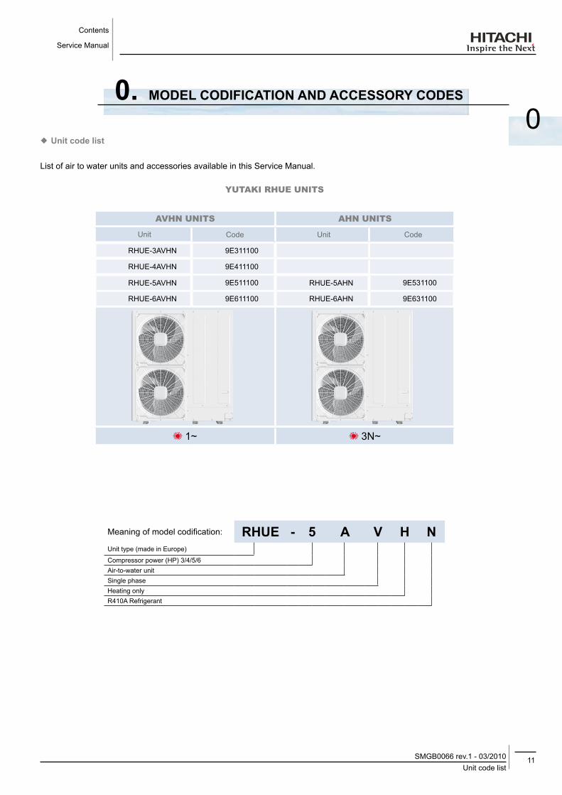
0List of air to water units and accessories available in this Service Manual.
YUTAKI RHUE UNITS
AVHN UNITS AHN UNITS
Unit Code Unit Code
RHUE-3AVHN 9E311100
RHUE-4AVHN 9E411100
RHUE-5AVHN 9E511100 RHUE-5AHN 9E531100
RHUE-6AVHN 9E611100 RHUE-6AHN 9E631100
1~ 3N~
Meaning of model codification: RHUE - 5 A V H NUnit type (made in Europe)
Compressor power (HP) 3/4/5/6Air-to-water unitSingle phaseHeating onlyR410A Refrigerant
0. ModEl CodIfICATIoN ANd ACCESSoRy CodES
¡ Unit code list
Contents
Service Manual
12List of accessory codesSMGB0066 rev.1 - 03/2010
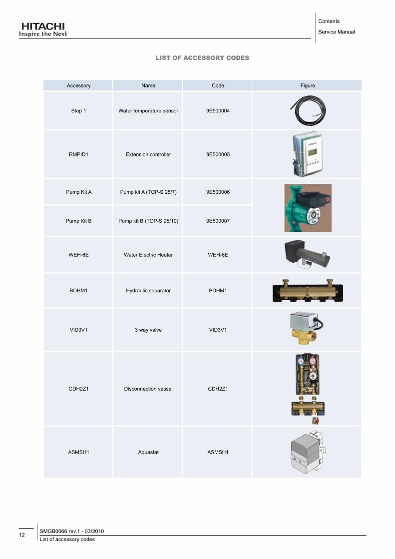
LIST of AccESSoRY codES
Accessory Name Code Figure
Step 1 Water temperature sensor 9E500004
RMPID1 Extension controller 9E500005
Pump Kit A Pump kit A (TOP-S 25/7) 9E500006
Pump Kit B Pump kit B (TOP-S 25/10) 9E500007
WEH-6E Water Electric Heater WEH-6E
BDHM1 Hydraulic separator BDHM1
VID3V1 3 way valve VID3V1
CDH2Z1 Disconnection vessel CDH2Z1
ASMSH1 Aquastat ASMSH1

13List of accessory codes
SMGB0066 rev.1 - 03/2010
Contents
Service Manual
0LIST of AccESSoRY codES (cont.)
Accessory Name Code Figure
DHWT200E-2.5H1EDomestic Hot Water Tank
Enamelled / 200 L.70544000
DHWT300E-2.5H1EDomestic Hot Water Tank
Enamelled / 300 L.70544001
DHWT200S-2.5H1EDomestic Hot Water Tank
Stainless / 200 L.70544100
DHWT300S-2.5H1EDomestic Hot Water Tank
Stainless / 300 L.70544101
DHWT-CP-01Permanent cathode
protection for enamelled tank
70544900
DHWT-CP-02 Permanent cathode protection for stainless tank 70544901
DHWT-SWG-01 Security valve 70544902


15Contents
SMGB0066 rev.1 - 03/2010
Unit installation
Service Manual
1
1. UNITS INSTAllATIoN
This chapter provides information concerning the installation of Yutaki units.
CoNTENTS
1.1. RHUE-(3~6)A(V)HN ....................................................................................................................17
1.1.1. Transportation ........................................................................................................................................171.1.2. Center of gravity .....................................................................................................................................181.1.3. Installation space ...................................................................................................................................191.1.4. Place provision .......................................................................................................................................201.1.5. Optional parts .........................................................................................................................................22
1.2. Accessories Installation ...............................................................................................................27
1.2.1. Pump kit ................................................................................................................................................271.2.2. WEH - Water Electric Heater ..................................................................................................................281.2.3. DHWT - Domestic Hot Water Tank .........................................................................................................30
Unit installation
Service Manual
16ContentsSMGB0066 rev.1 - 03/2010
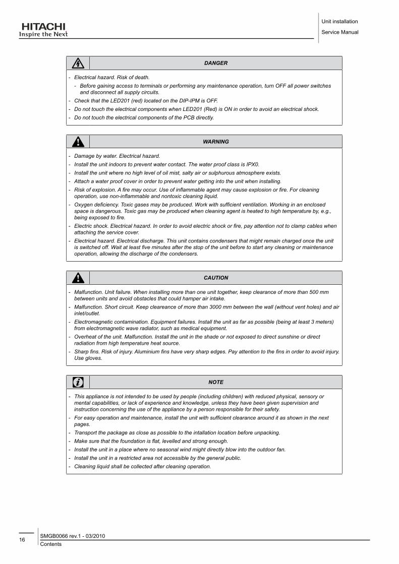
danger
-- Electrical-hazard.-Risk-of-death.--- Before-gaining-access-to-terminals-or-performing-any-maintenance-operation,-turn-OFF-all-power-switches-and-disconnect-all-supply-circuits.
-- Check-that-the-LED201-(red)-located-on-the-DIP-IPM-is-OFF.-- Do-not-touch-the-electrical-components-when-LED201-(Red)-is-ON-in-order-to-avoid-an-electrical-shock.-- Do-not-touch-the-electrical-components-of-the-PCB-directly.
warning
-- Damage-by-water.-Electrical-hazard.-- Install-the-unit-indoors-to-prevent-water-contact.-The-water-proof-class-is-IPX0.-- Install-the-unit-where-no-high-level-of-oil-mist,-salty-air-or-sulphurous-atmosphere-exists.-- Attach-a-water-proof-cover-in-order-to-prevent-water-getting-into-the-unit-when-installing.-- Risk-of-explosion.-A-fire-may-occur.-Use-of-inflammable-agent-may-cause-explosion-or-fire.-For-cleaning-operation,-use-non-inflammable-and-nontoxic-cleaning-liquid.
-- Oxygen-deficiency.-Toxic-gases-may-be-produced.-Work-with-sufficient-ventilation.-Working-in-an-enclosed-space-is-dangerous.-Toxic-gas-may-be-produced-when-cleaning-agent-is-heated-to-high-temperature-by,-e.g.,-being-exposed-to-fire.
-- Electric-shock.-Electrical-hazard.-In-order-to-avoid-electric-shock-or-fire,-pay-attention-not-to-clamp-cables-when-attaching-the-service-cover.
-- Electrical-hazard.-Electrical-discharge.-This-unit-contains-condensers-that-might-remain-charged-once-the-unit-is-switched-off.-Wait-at-least-five-minutes-after-the-stop-of-the-unit-before-to-start-any-cleaning-or-maintenance-operation,-allowing-the-discharge-of-the-condensers.
caution
-- Malfunction.-Unit-failure.-When-installing-more-than-one-unit-together,-keep-clearance-of-more-than-500-mm-between-units-and-avoid-obstacles-that-could-hamper-air-intake.
-- Malfunction.-Short-circuit.-Keep-cleareance-of-more-than-3000-mm-between-the-wall-(without-vent-holes)-and-air-inlet/outlet.
-- Electromagnetic-contamination.-Equipment-failures.-Install-the-unit-as-far-as-possible-(being-at-least-3-meters)-from-electromagnetic-wave-radiator,-such-as-medical-equipment.-
-- Overheat-of-the-unit.-Malfunction.-Install-the-unit-in-the-shade-or-not-exposed-to-direct-sunshine-or-direct-radiation-from-high-temperature-heat-source.
-- Sharp-fins.-Risk-of-injury.-Aluminium-fins-have-very-sharp-edges.-Pay-attention-to-the-fins-in-order-to-avoid-injury.--Use-gloves.
note
-- This-appliance-is-not-intended-to-be-used-by-people-(including-children)-with-reduced-physical,-sensory-or-mental-capabilities,-or-lack-of-experience-and-knowledge,-unless-they-have-been-given-supervision-and-instruction-concerning-the-use-of-the-appliance-by-a-person-responsible-for-their-safety.
-- For-easy-operation-and-maintenance,-install-the-unit-with-sufficient-clearance-around-it-as-shown-in-the-next-pages.
-- Transport-the-package-as-close-as-possible-to-the-intallation-location-before-unpacking.-- Make-sure-that-the-foundation-is-flat,-levelled-and-strong-enough.-- Install-the-unit-in-a-place-where-no-seasonal-wind-might-directly-blow-into-the-outdoor-fan.-- Install-the-unit-in-a-restricted-area-not-accessible-by-the-general-public.-- Cleaning-liquid-shall-be-collected-after-cleaning-operation.

17RHUE-(3~6)A(V)HN
SMGB0066 rev.1 - 03/2010
Unit installation
Service Manual
1
1.1. RHUE-(3~6)A(V)HN
1.1.1. Transportation
warning
-- Malfunction.-Unit-failure.-Do-not-put-any-foreign-material-into-the-unit-and-make-sure-that-none-exists-inside-the-unit-before-the-installation-or-test-run.
• Hanging method
When hanging the unit, ensure its balance and lift it up smoothly and safely. Do not remove any packing materials until the unit is positioned and hang the unit under packing condition with two ropes, as shown in the figure below.
Over 60º
0.7 to 1.0 m
Do not remove the plastic band or the corrugate paper frame
Pass the wire ropes through each lifting hole in the wooden base as shown
Wire rope
warning
-- Crush-hazard.-Can-cause-seriour-injury.--- Lift-the-unit-with-2-wire-ropes-and-without-removing-its-factory-packaging.-Make-sure-that-the-unit-is-lifted-smoothly-and-does-not-lean.
-- Do-not-attach-lifting-equipment-to-the-plastic-band-or-the-corrugated-paper-frame,-since-the-ropes-might-slip-or-break-the-materials.
note
-- Make-sure-that-the-exterior-of-the-unit-is-adequately-protected-with-cloth-or-paper.-- Do-not-hold-the-unit-with-the-handles-or-the-air-outlet-parts.-Steel-plates-may-be-deformed.-Use-gloves.

Unit installation
Service Manual
18RHUE-(3~6)A(V)HNSMGB0066 rev.1 - 03/2010
1.1.2. Center of gravity
When the unit is lifted manually (using the handles), pay attention to the following: do not remove the wooden base from the unit to prevent its overturning. Pay attention to the center of gravity shown in the below figure.
Center of gravity
Unit model operation weight (kg)
Center of gravity position (mm)
a b h
RHUE-3AVHN 130 705 223 545
RHUE-4AVHN 130 705 223 545
RHUE-5AVHN 135 695 228 560
RHUE-5AHN 140 695 228 560
RHUE-6AVHN 139 695 228 560
RHUE-6AHN 144 695 228 560
note
-- It-is-recommended-that-at-least-two-people-participate-when-lifting-is-done-manually.

19RHUE-(3~6)A(V)HN
SMGB0066 rev.1 - 03/2010
Unit installation
Service Manual
1
1.1.3. Installation space
Single installationAround sides are open Around sides are open with obstacles above
0<L≤1/2H→A≥3501/2H<L≤H→A≥450
H=1380
0<L≤1/2H→A≥6001/2H<L≤H→A≥1200
H=1380 H=13800<L≤1/2H→A≥600
1/2H<L≤H→A≥1200H=1380
Around sides are closed
500 50050
500
Around sides are open with obstacles above
Around sides are open Around sides are open with obstacles above
0<L≤1/2H→A≥3501/2H<L≤H→A≥450H=1380
0<L≤1/2H→A≥6001/2H<L≤H→A≥1200H=1380
(Unit: mm)
note
-- All-measuring-units-are-in-milimetres-(mm).
Unit installation
Service Manual
20RHUE-(3~6)A(V)HNSMGB0066 rev.1 - 03/2010
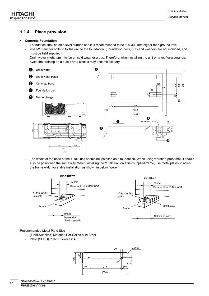
1.1.4. Place provision
• Concrete foundation - Foundation shall be on a level surface and it is recommended to be 100-300 mm higher than ground level. - Use M10 anchor bolts to fix the unit to the foundation. (Foundation bolts, nuts and washers are not included, and
must be field supplied). - Drain water might turn into ice on cold weather areas. Therefore, when installing the unit on a roof or a veranda,
avoid the draining on a public area since it may become slippery.
Drain water
900
1250
1450
174
410
440
640
Drain water place
Concrete base
Foundation bolt
Mortar charge
- The whole of the base of the Yutaki unit should be installed on a foundation. When using vibration-proof mat, it should also be positioned the same way. When installing the Yutaki unit on a fieldsupplied frame, use metal plates to adjust the frame width for stable installation as shown in below figure.
57 mm
Base width of Yutaki unit
Yutaki unit is unstable
Frame
60mmFrame with (Field supplied)
INCoRRECT CoRRECT
Yutaki unit is stable
57 mm
Base width of Yutaki unit
Frame
100mm or more
Metal plate
Recommended Metal Plate Size - (Field-Supplied) Material: Hot-Rolled Mild Steel - Plate (SPHC) Plate Thickness: 4.5 T
21RHUE-(3~6)A(V)HN
SMGB0066 rev.1 - 03/2010
Unit installation
Service Manual
1
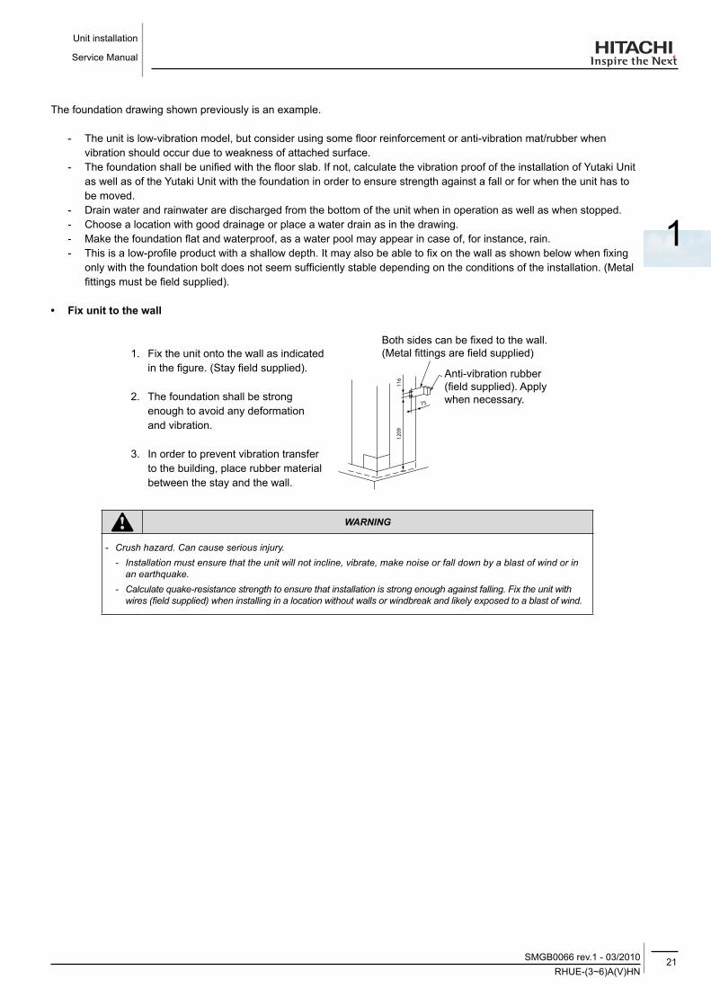
The foundation drawing shown previously is an example.
- The unit is low-vibration model, but consider using some floor reinforcement or anti-vibration mat/rubber when vibration should occur due to weakness of attached surface.
- The foundation shall be unified with the floor slab. If not, calculate the vibration proof of the installation of Yutaki Unit as well as of the Yutaki Unit with the foundation in order to ensure strength against a fall or for when the unit has to be moved.
- Drain water and rainwater are discharged from the bottom of the unit when in operation as well as when stopped. - Choose a location with good drainage or place a water drain as in the drawing. - Make the foundation flat and waterproof, as a water pool may appear in case of, for instance, rain. - This is a low-profile product with a shallow depth. It may also be able to fix on the wall as shown below when fixing
only with the foundation bolt does not seem sufficiently stable depending on the conditions of the installation. (Metal fittings must be field supplied).
• fix unit to the wall
1. Fix the unit onto the wall as indicated in the figure. (Stay field supplied).
2. The foundation shall be strong enough to avoid any deformation and vibration.
3. In order to prevent vibration transfer to the building, place rubber material between the stay and the wall.
Anti-vibration rubber (field supplied). Apply when necessary.
Both sides can be fixed to the wall. (Metal fittings are field supplied)
warning
-- Crush-hazard.-Can-cause-serious-injury.--- Installation-must-ensure-that-the-unit-will-not-incline,-vibrate,-make-noise-or-fall-down-by-a-blast-of-wind-or-in-an-earthquake.-
-- Calculate-quake-resistance-strength-to-ensure-that-installation-is-strong-enough-against-falling.-Fix-the-unit-with-wires-(field-supplied)-when-installing-in-a-location-without-walls-or-windbreak-and-likely-exposed-to-a-blast-of-wind.

Unit installation
Service Manual
22RHUE-(3~6)A(V)HNSMGB0066 rev.1 - 03/2010
• Installing location where the unit will be exposed to strong wind
Strong winds against the unit´s air outlet causes short circuits and these can be the consequences:
- Lack of air flow and adversely affect to normal function.
- Frequent frost acceleration. - Fan can rotating very fast until it breaks.
Follow the instructions below to install on a rooftop or a location without surrounding buildings, where strong wind is expected against the unit.
1. Choose a location where the outlet or inlet side of the product will not be exposed to strong wind.
2. In case the fulfillment of point 1 is not possible, it is recommended to use the optional parts (see section Optional parts and installation for RHUE-(3~6)A(V)HN).
Adverse strong wind
Air flow
Adverse strong wind
caution
-- Strong-wind.-Damage-to-fan-motor.-Excessive-strong-wind-against-the-unit-outlet-may-cause-inverse-rotation-and-damage-the-fan-motor.
1.1.5. optional parts
• Air flow guide, wind guard and snow protection hood
optional parts HP ModelAir flow guide
(3~6)
AG-335A X 2Wind guard WSP-335A X 2
Snow protection hood
Stainless plate (SUS304)
Air outlet ASG-NP335F X 2Air inlet of rear side ASG-NP335BAir inlet of side face ASG-NP335LAir outlet ASG-NP335F X 2Air inlet of rear side ASG-NP335BAir inlet of rear side ASG-NP335L
Zinc plate
Air outlet ASG-NP335FS X 2Air inlet of rear side ASG-335BSAir inlet of side face ASG-NP335LSAir outlet ASG-NP335FS X 2Air inlet of rear side ASG-NP335BSAir inlet of rear side ASG-NP335LS

23RHUE-(3~6)A(V)HN
SMGB0066 rev.1 - 03/2010
Unit installation
Service Manual
1
• Air flow guide
Specifications
Model AG-335AView from A
Air flow guide
Mounting dimension
Mou
ntin
g di
men
sion
Quantity 2 per unit
Air discharge direction Upward (downward), left & right
Material Weather proof polypropylene resin
Color Gray
Weight 1.9 kg
AccessoriesFixing screw x 4 [M5 (SUS) x 20]Installation manual
Installation restriction
“Wind Guard” or “Snow protection hood” is not available to install with air flow guide. (“Guard net” is available to be installed together.)
• Attaching example of air flow guide
- Attach the air flow guide to the air discharge grille with four (4) screws (supplied).- The fixing holes are located at 4 positions on the grille. (Screw tightening torque 2.4~3.1N.m)- Do not remove the air discharge grille for air flow guide installation.
warning
-- Rotating-fan-blades.-Risk-of-cut.-If-the-air-guide-is-installed-without-discharge-grille,-it-may-cause-injury-due-to-rotating-fan.
Two windbreak covers installation
Outdoor unitM5 fixing screw x4
M5 fixing screw x4
(Accessories)
(Accessories)
Air discharge grilleAir flow
Air flow
Air flow guide (*)
Air flow guide (*)
(*) Air flow direction of both air flow guides should be the same
Service space (In case of upward air discharge)
- In case of right and left sides air discharge, enough space for air discharge is required.
- The downward air discharge is also available. In such case, install the base under the unit to secure enough space for air discharge.
- In case of serial units installation, air discharge should be upward.
UnitAir flow guide
Passage side

Unit installation
Service Manual
24RHUE-(3~6)A(V)HNSMGB0066 rev.1 - 03/2010
• Wind guard
SpecificationsModel WSP-335A
(Mounting dimension)
Air flow
Air flow
Air flowAir flow
(Mou
ntin
g di
men
sion
)
Quantity 2 per unit
Material Galvanized sheet metal + baked painting
Color Gray (1.oY8.5/0.5)
Weight 5.5 kg
Accessories Fixing screw x 4 [M5 (SUS) x 20]Installation manual
Installation restriction “Guard net”, “Air flow guide” or “Snow protection hood” is not available to install with Wind guard
• Attaching example of air wind guard
- Attach the air flow guide to the air discharge grille with four (4) screws (supplied).- The fixing holes are located at 4 positions on the grille. (Screw tightening torque 2.4~3.1N.m)- Do not remove the air discharge grille for air flow guide installation.
caution
-- Rotating-fan-blades.-Risk-of-cut.-If-the-air-guide-is-installed-without-discharge-grille,-it-may-cause-injury-due-to-rotating-fan.
Two windguard covers installation
Air discharge grille
Air discharge grille
Wind guard
Wind guard
Yutaki
M5 fixing screw x4(Accessories)
Service space
- Both sides of the unit should be open.- No obstacles should be placed in the air
discharge side.
Unit
Wind guard

25RHUE-(3~6)A(V)HN
SMGB0066 rev.1 - 03/2010
Unit installation
Service Manual
1
• Snow protection hood
Air discharge hoodNo. Part name Qty.
Fixing screw(Accessories)
Hole for safety wire rope to prevent overturning
Right side plate
1
Left side plate
1
Front panel 1
Stay 4
Rear suction hoodNo. Part name Qty.
< >
Fixing screw(Accessories)
Hole for safety wire rope to prevent overturning
Fixing screw
(Accessories)
Upper right side plate
1
Upper left side plate
1
Upper front panel (Upside)
1
Upper front panel (Downside)
1
Lower right side plate
1
Lower left side plate
1
Upper front panel (Upside)
1
Upper front panel (Downside)
1
Left suction hoodNo. Part name Qty.
Fixing hole x 2
Fixing screw(Accessories)
Enlarged view of A (Fixing hole)
Right side plate
1
Left side plate
1
Front panel (Upside)
1
Front panel (Downside)
1
Unit

Unit installation
Service Manual
26RHUE-(3~6)A(V)HNSMGB0066 rev.1 - 03/2010
• Attaching example of snow protection hood
Left suction hoodFixing screw
Fixing screw
Fixing screw
Fixing screw
Fixing screw
(Accessories)
(Accessories)
(Accessories)
(Accessories)
(Accessories)
Front side
Rear side
Rear suction hood
Rear suction hoodLower side
Upper side
Wire rope
(Optional. For overturning protection)
Left side
Air discharge hood
Air discharge hood
Air discharge grille
Air discharge grille
Specifications of snow protection hoodProduct name Air discharge hood Rear suction hood left suction hood
Model ASG-NP335F ASG-NP335FS ASG-NP335B ASG-NP335BS ASG-NP335L ASG-NP335LS
Quantity 2 per unit 1 per unit
MaterialBonderized steel sheetIron
Stainless (SUS304)
Bonderized steel sheetIron
Stainless (SUS304)
Bonderized steel sheetIron
Stainless (SUS304)
ColorGray (1.0Y8.5/0.5 or approximation)
-Gray (1.0Y8.5/0.5 or approximation)
Gray (1.0Y8.5/0.5 or approximation)
-
Weight 3 kg 14 kg 8 kg
Assembling Knockingdown parts (assembled at field)
Components Hood For air discherge part x 1 For rear side air intake x 1(Upper side x 1, lowe side x 1) For left side air intake x 1
Fixing screw 8 (M5x12 tapping screw) 10 (M5x14 tapping screw) 8 (M5x12 tapping screw)
Fixing screw (SUS)
6 (M5x12 tapping screw) 6 (M5x14) 24 (M5x12
tapping screw) 24 (M5x14) 14 (M5x12 tapping screw) 14 (M5x14)
Installation manual
Installation restrictionInstallation with “Guard net”, “Wind guard” or “Air flow guide” is not available
Installation with “Guard net” is not available
Safety wire rope for overturning prevention (optional parts) ASG-SW20A
27Accessories Installation
SMGB0066 rev.1 - 03/2010
Unit installation
Service Manual
1
1.2. ACCESSoRIES INSTAllATIoN
1.2.1. Pump kit
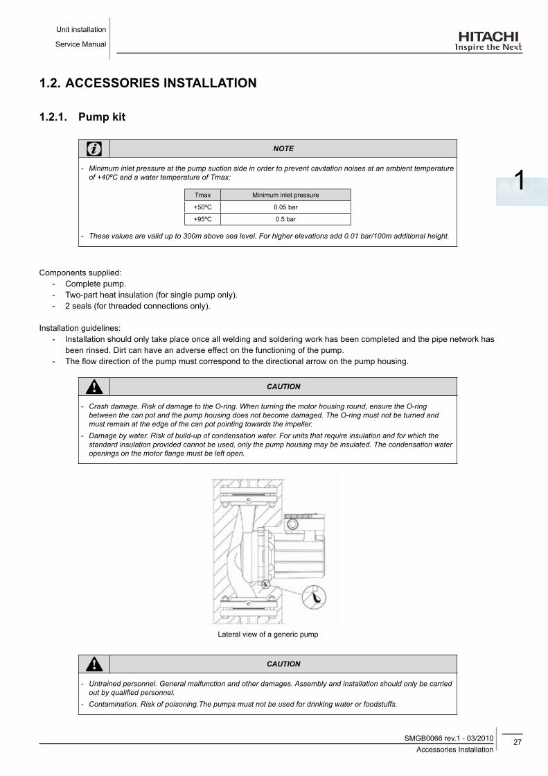
note
-- Minimum-inlet-pressure-at-the-pump-suction-side-in-order-to-prevent-cavitation-noises-at-an-ambient-temperature-of-+40ºC-and-a-water-temperature-of-Tmax:
Tmax Minimum inlet pressure
+50ºC 0.05 bar
+95ºC 0.5 bar
-- These-values-are-valid-up-to-300m-above-sea-level.-For-higher-elevations-add-0.01-bar/100m-additional-height.
Components supplied:- Complete pump.- Two-part heat insulation (for single pump only).- 2 seals (for threaded connections only).
Installation guidelines:- Installation should only take place once all welding and soldering work has been completed and the pipe network has
been rinsed. Dirt can have an adverse effect on the functioning of the pump.- The flow direction of the pump must correspond to the directional arrow on the pump housing.
caution
-- Crash-damage.-Risk-of-damage-to-the-O-ring.-When-turning-the-motor-housing-round,-ensure-the-O-ring-between-the-can-pot-and-the-pump-housing-does-not-become-damaged.-The-O-ring-must-not-be-turned-and-must-remain-at-the-edge-of-the-can-pot-pointing-towards-the-impeller.
-- Damage-by-water.-Risk-of-build-up-of-condensation-water.-For-units-that-require-insulation-and-for-which-the-standard-insulation-provided-cannot-be-used,-only-the-pump-housing-may-be-insulated.-The-condensation-water-openings-on-the-motor-flange-must-be-left-open.
Lateral view of a generic pump
caution
-- Untrained-personnel.-General-malfunction-and-other-damages.-Assembly-and-installation-should-only-be-carried-out-by-qualified-personnel.
-- Contamination.-Risk-of-poisoning.The-pumps-must-not-be-used-for-drinking-water-or-foodstuffs.

Unit installation
Service Manual
28Accessories InstallationSMGB0066 rev.1 - 03/2010
1.2.2. WEH - Water Electric Heater
Name of parts
Ref. Qty. Name Ref. Qty. Name
1 Tank body 1 PSW
1 Front E-casing 2 3-pole contactor
1 Back E-casing 1 Thermostat
1 Tank in-connection 1 Terminal board
1 Wall support 1 Packing gland
1 Tank front cover 2 Packing gland
1 Tank out-connection 1 PSW protector
1 Resistance 1 Caution label
1 Tank body insulation 1 Wiring label
1 Tank body insulation
Unit installation
Transport the products as close as possible to the installation location before unpacking.Check the contents of the package: - WEH-6E - Installation and Operation Manual - (2) M6x15 screw and (2) M6 washers - Wall fixing support
Selection procedure for yUTAKI units
note
-- WEH-appliance-must-be-installed-in-an-indoor-place.-- WEH-installation-must-be-done-by-professional-installers.-- Install-the-WEH-with-sufficient-clearance-around-it-for-operation-and-maintenance-as-shown-in-the-following-figures.
-- Install-the-WEH-where-good-ventilation-is-available.-Do-not-install-the-WEH-where-there-is-a-high-level-of-oil-mist,-salty-air-or-sulphurous-atmosphere.
-- When-installing-some-device-next-to-WEH,--keep-clearance-between-WEH-and-any-other-obstacle-of-more-than-500mm.

29Accessories Installation
SMGB0066 rev.1 - 03/2010
Unit installation
Service Manual
1
caution
-- Insufficient-ventilation.-Can-cause-oxygen-deficiency.-- Working-with-insufficient-ventilation,-in-an-enclosed-space,-can-produce-toxic-gas,-especially-when-cleaning-agent-is-heated-to-high-temperature-by,-e.g.,-being-exposed-to-fire.
-- Do-not-install-WEH-near-any-flammable-substance.
Place provision
Drill 2 holes Ø 8mm on the wall for fixing WEH according to the dimensions of the Wall Support attached.
- Fixed supplied support to the wall by using previous drill holes. - Use attached screws for fixing WEH to the supplied support. - Check that WEH are installed horizontally. - For cleaning, use non flammable and non toxic cleaning liquid. The use of flammable agents should cause explosion
or fire. - Cleaning liquid shall be collected after cleaning. - Pay attention do not trapp cables when closing the electrical box cover. It could cause a electric shock.
Unit installation
Service Manual
30Accessories InstallationSMGB0066 rev.1 - 03/2010
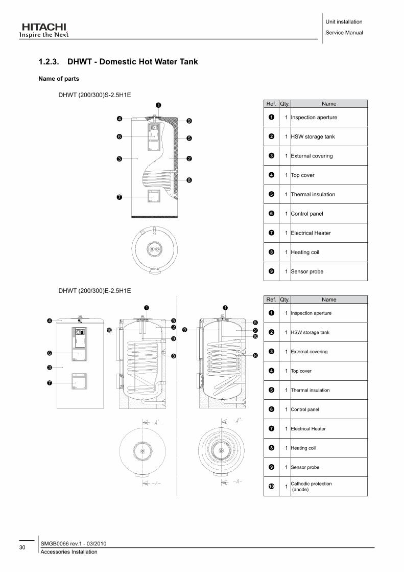
1.2.3. dHWT - domestic Hot Water Tank
Name of parts
DHWT (200/300)S-2.5H1ERef. Qty. Name
1 Inspection aperture
1 HSW storage tank
1 External covering
1 Top cover
1 Thermal insulation
1 Control panel
1 Electrical Heater
1 Heating coil
1 Sensor probe
DHWT (200/300)E-2.5H1ERef. Qty. Name
1 Inspection aperture
1 HSW storage tank
1 External covering
1 Top cover
1 Thermal insulation
1 Control panel
1 Electrical Heater
1 Heating coil
1 Sensor probe
1 Cathodic protection (anode)
31Accessories Installation
SMGB0066 rev.1 - 03/2010
Unit installation
Service Manual
1
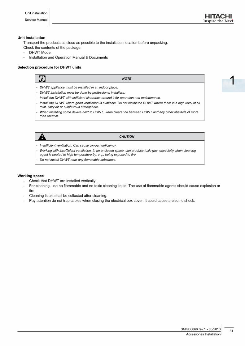
Unit installationTransport the products as close as possible to the installation location before unpacking.Check the contents of the package: - DHWT Model - Installation and Operation Manual & Documents
Selection procedure for dHWT units
note
-- DHWT-appliance-must-be-installed-in-an-indoor-place.-- DHWT-installation-must-be-done-by-professional-installers.-- Install-the-DHWT-with-sufficient-clearance-around-it-for-operation-and-maintenance.-- Install-the-DHWT-where-good-ventilation-is-available.-Do-not-install-the-DHWT-where-there-is-a-high-level-of-oil-mist,-salty-air-or-sulphurous-atmosphere.
-- When-installing-some-device-next-to-DHWT,--keep-clearance-between-DHWT-and-any-other-obstacle-of-more-than-500mm.
caution
-- Insufficient-ventilation.-Can-cause-oxygen-deficiency.-- Working-with-insufficient-ventilation,-in-an-enclosed-space,-can-produce-toxic-gas,-especially-when-cleaning-agent-is-heated-to-high-temperature-by,-e.g.,-being-exposed-to-fire.
-- Do-not-install-DHWT-near-any-flammable-substance.
Working space - Check that DHWT are installed vertically . - For cleaning, use no flammable and no toxic cleaning liquid. The use of flammable agents should cause explosion or
fire. - Cleaning liquid shall be collected after cleaning. - Pay attention do not trap cables when closing the electrical box cover. It could cause a electric shock.

33Contents
SMGB0066 rev.1 - 03/2010
Water pipe installation
Service Manual
2
2. WATER PIPE INSTAllATIoN
This chapter provides information about the procedures to perform water piping work connections for Yutaki units.
CoNTENTS
2.1 General notes ..............................................................................................................................34
2.2. Piping work connection considerations .......................................................................................35
2.2.1. Minimum water volume description ........................................................................................................352.2.2. Correction factor due to use of glycol .....................................................................................................37
2.3. Water control ...............................................................................................................................37
2.4. Water check valve .......................................................................................................................38
2.5. Accessories hydraulic installation................................................................................................39
2.5.1. Pump kit .................................................................................................................................................392.5.2. WEH- Water Electric Heater ...................................................................................................................402.5.3. DHWT- Domestic Hot Water Tank ..........................................................................................................422.5.4. Water drain discharge connection ..........................................................................................................44

Water pipe installation
Service Manual
34General notesSMGB0066 rev.1 - 03/2010
2.1 GENERAl NoTES1. Connect all pipes as close as possible to the unit, so that disconnection can be easily performed when required.
2. It is recommended to use flexible joints for the piping of water inlet and outlet, so vibration will not be transmited.
3. Whenever possible, sluice valves should be installed for water piping, in order to minimise flow resistance and to maintain sufficient water flow.
4. Proper leak inspection should be performed to check for leaking parts inside and outside the system, by completely opening the hot water inlet and outlet valves to the water condenser. Additionally, install equip valves to the inlet and outlet piping.
5. This unit is equipped with an air purge at the highest position of the water system. If this position is not the highest one within the whole water installation, equip another air purge.
Also, equip a drain cock on the outlet piping. The cock handle should be removed so that the cock can not be opened under normal circumstances. If this cock is opened during operation, trouble will occur due to water blow-off.
6. When necessary, put insulation on the pipes in order to avoid heat losses.
7. When the unit is stopped during shutdown periods and the ambient temperature is very low, it is possible that the water in the pipes and in the circulating pump freeze, thus damaging the pipes and the water pump. In order to prevent this, during shutdown periods it is useful to empty the water from the installation.
note
-- In-that-case,-open-the-unit-by-removing-the-service-cover-and-unscrew-the-water-inlet-thermistor-in-order-to-drain-the-water-of-the-circuit-(as-shown-below)
Water inlet thermistor
Otherwise, it is recommended to maintain the power supply to the installation, since an electric cord could prevent the freezing of the water contained in the circuit. Additionally, in cases where water drainage is difficult, an antifreeze mixture of glycol (ethylene or propylene) should be used (content between 10 % and 40 %).The performance of the unit working with glycol may decrease in proportion to the percentage of glycol used, since the density of glycol is higher than that of water. (For more information, see chapter 4 of Technical Catalogue).

35Piping work connection considerations
SMGB0066 rev.1 - 03/2010
Water pipe installation
Service Manual
2
5 1
13 4
42 3 Pressure gauge
Strainer
Flexible joint
Valve
Check valve
caution
-- Malfunction.-Damage-by-clogging.-- This-product-is-equipped-with-plate-heat-exchanger-type.-In-the-heat-exchanger,-water-flows-through-a-narrow-space-between-the-plates.-Therefore,-there-is-a-possibility-that-freezing-may-occur-if-foreign-particles-or-dust-are-clogged.-In-order-to-avoid-this-clogging,-mesh-water-strainer-shall-be-installed-in-the-water-inlet-pipe-and-as-close-as-possible-to-the-plate-heat-exchanger.-In-case-of-punching-metal-type-strainer,-mesh-hole-size-shall-be-Ø-1.5mm-or-less.-
-- Never-use-the-salt-type-antifreeze-mixture,-since-it-possesses-strong-corrosion-characteristics,-and-water-equipment-might-be-damaged.
-- When-connecting-several-units-to-a-common-pipe,-its-design-should-ensure-that-the-water-flow-on-each-unit-is-the-same-(see-below-figure).-Imbalance-of-water-distribution-may-cause-a-serious-damage-like-water-freezing-in-the-plate-heat-exchanger.
2.2. PIPING WoRK CoNNECTIoN CoNSIdERATIoNS
2.2.1. Minimum water volume description
• Necessity of water in system and summary of its calculation
The following problems may occur when the quantity of water in the forced circulation system(1) on water side is insufficient.
- Compressor in operation repeats numerous "start/stop" when light-loaded, which may result in shorter life or failure.
- Low temperature in water circulation during defrost operation, which may cause an alarm (freeze protection) at the stop of the unit.
note
-- (1)-The-shaded-part-of-the-pipe-system-below.-(Excluding-the-expansion-tank-(cistern))

Water pipe installation
Service Manual
36Piping work connection considerationsSMGB0066 rev.1 - 03/2010
Calculate and ensure that the water volume in the system is equal or greater than the larger value obtained from:
1. Protective water volume for product
2. Minimum water volume for temperature drop during defrost operation
When the minimum water volume can not be ensured, use a Buffer tank to compensate the shortage (<0) of water (2). See figure below.
Expansion tank
PumpYutaki unit
Load system
Expansion tank
Pump
Yutaki unit
Buffer tank
Load system
note
-- (2)-Shortage-=-Minimum-water-volume-–-Water-volume-in-circulation-system
The following part shows the minimum water volume in the system for product protection and temperature drop during defrost operation.
1. Protective water volume for product
Ensure that the water volume is equal or greater than those shown below, in order to reduce ON/OFF frequency of the unit at no load or extreme light load. When water volume is less than the volume indicated (minimum water volume), compressor operation frequently stops at light load, which may result in shorter life or failure.
ModelON/OFF Temp. differential
RHUE-3AVHN RHUE-4AVHN RHUE-5A(V)HN RHUE-6A(V)HN
4ºC 28 38 46 56
3ºC 36 48 58 70
2ºC 50 65 80 96
1ºC 80 107 130 156
(Units are in ltrs.)

37Water control
SMGB0066 rev.1 - 03/2010
Water pipe installation
Service Manual
2
note
-- The-factory-default-ON/OFF-temperature-differential-is-“4-°C”.-Note-that-the-minimum-water-volume-varies-for-different-setting-for-each-purpose-as-shown-in-the-table-above.
2. Minimum required water volume during defrosting
The following table shows the minimum water volume needed in each YUTAKI unit in case of a permitted drop intemperature of 10ºC.
ModelWatertemperature drop
RHUE-3AVHN RHUE-4AVHN RHUE-5A(V)HN RHUE-6A(V)HN
5ºC 212 276 342 410
10ºC 106 138 171 205
15ºC 71 92 114 137
20ºC 53 69 86 103
25ºC 42 55 68 82(Units are in ltrs.)
note
-- The-values-shown-on-the-table-are-based-on-theoretical-installation-conditions,-and-therefore,-it-rests-with-the-client-to-recalculate-these-values-depending-on-the-real-conditions-of-the-installation.
2.2.2. Correction factor due to use of glycol
When the ambient temperature is low in winter, it is possible that the unit will be damaged by freezing water in the pipes and in the circulating pump during the shutdown periods.
In order to prevent this, it is useful to empty the water from the installation or to maintain the supply to the installation, as an electric cord can prevent the water from freezing in the circuit.
Additionally, in cases where water drainage is difficult, an antifreeze mixture of ethylene glycol or propylene should be used (Between 10 % and 40 %).
The performance of the unit when working with glycol may decrease in proportion to the percentage of glycol used, as the density of glycol is higher than that of water. (For more information, see TCGB0066)
2.3. WATER CoNTRol
caution
-- Malfunction.-Damage-by-poor-quality-water.-Industrial-water-rarely-causes-deposits-of-scales-or-other-foreign-substances-on-equipment-and-the-most-vulnerable-components-are-plate-heat-exchangers.-However,-well-water-or-river-water-may-in-most-cases-contain-suspended-solid-matter,-organic-matter,-and-scales-in-great-quantities.-Therefore,-such-water-should-be-subjected-to-filtration-or-softening-treatment-with-chemicals-before-its-use-as-heat-transporter-in-Yutaki-unit.-

Water pipe installation
Service Manual
38Water check valveSMGB0066 rev.1 - 03/2010
The following table shows the reference values fo the most important parameters concerning the quality of the water:
ItemWater System Tendency
Circulating Water (20 C less than) Supply Water Corrosion deposits of scales
Standard quality pH (25 °C) 6.8 ~ 8.0 6.8 ~ 8.0
Electrical conductivity (mS/m) (25°C) µS/cm (25 °C) (2)
Less than 40 Less than 400
Less than 30 Less than 300
Chlorine Ion (mg CI¯/I) Less than 50 Less than 50
Sulphur acid Ion (mg SO42¯/I) Less than 50 Less than 50
The amount of acid consumption (pH 4.8) (mg CaCO3/I) Less than 50 Less than 50
Total hardness (mg CaCO3 /I) Less than 70 Less than 70
Calcium hardness (mg CaCO3 /I) Less than 50 Less than 50
Silica L (mg SIO2 /I) Less than 30 Less than 30
Reference quality total iron (mg Fe/I) Less than 1.0 Less than 0.3
Total copper (mg Cu/I) Less than 1.0 Less than 0.1
Sulphur ion (mg S2¯/I) It shall not be detected.
Ammonium ion (mg NH4+/I) Less than 1.0 Less than 0.1
Remaining chlorine (mg CI/I) Less than 0.3 Less than 0.3
Floating carbonic acid (mg CO2/I) Less than 4.0 Less than 4.0
Index of stability 6.8 ~ 8.0 -
note
-- The-mark-“ ”-in-the-table-means-the-factor-concerned-with-the-tendency-of-corrosion-or-deposits-of-scales.-- The-value-showed-in-“"-are-for-reference-only-according-to-the-former-unit.-- As-the-the-well-water-should-not-fulfil-the-above-limits,-the-use-of-industrial-water-or-other-water-sources-should-be-considered.
2.4. WATER CHECK VAlVEAttached to the unit there is a water check valve (non return valve). This component is a safety device to protect the system against back pressure, back flow and back syphonage of non-potable water into service pipe, plants and equipments.
This valve shall be installed at site.
Main Characteristics:Maximum working pressure: 16barMaximum working temperature: 70ºC (short term 90ºC)Threaded connection R1/2”Available test and drain plugs 1/4”Length: 137mmKvs value: 6Weight: 0.24kg

39Accessories hydraulic installation
SMGB0066 rev.1 - 03/2010
Water pipe installation
Service Manual
2
Installation guidelines:
1. Note flow direction (indicated by arrow) when installing the check valve.
2. In a drinking water supply the check valves are fitted immediately after water meter. This position ensures optimum protection for the drinking water supply.
3. Install in horizontal pipework with test plugs directed downwards. This position ensures optimum protection efficiency and is the best for testing the valve.
4. Shutt off valves should be fitted on each side of the check valve for easier and faster valve testing.
5. The installation location should be protected against frost and be easily accessible.
2.5. ACCESSoRIES HydRAUlIC INSTAllATIoN
2.5.1. Pump kit ¡ Pump kit assembly
Ref. Name Ref. Name
Service Cover 1 Packing (Qty. 2)
Service Cover 2 Water pipe 1
Plate Heat Exchanger Assembly Water pipe 2 Assembly
Water Pump

Water pipe installation
Service Manual
40Accessories hydraulic installationSMGB0066 rev.1 - 03/2010
- Remove service cover 1 (item 1) and service cover 2 (item 2). - Unscrew the nut of the plate heat exchanger assembly (item 3) and the nut of the water pipe 2 assembly (item 6) in
order to disassemble water pipe1 (item 5) from the Yutaki unit. - Separate the packings (item 4) to make possible to remove the water pipe1 (item 5). - Put the packings and connect the water pump (item 7) to the Yutaki unit and screw again the nut of the plate heat
exchanger assembly (item 3) and the nut of the water pipe 2 assembly (item 6). - Connect the pump wiring from the electrical box to the pump according to the detail. - Assemble the service cover 2 (item 2) and service cover 1 (item 1) to finish the installation.
¡ Installation out of the yutaki unit
Additionally, when the pump is installed out of the Yutaki unit, the installation must be in accordance with the following guidelines:
- The pump must be installed in an easily accesible place to facilitate inspection and replacement. - Assemble the pump such that water can not drip into the pump motor or terminal box. - Carry out stress- free installation with the pump motor shift in horizontal plane (see installation position in the next
figure):
- The motor terminal box must not point downwards (see admissible installation position in previous figure). It may be necessary to turn the motor hoosing round after loosening the hexagon socket screws.
2.5.2. WEH- Water Electric Heater ¡ Hydraulic circuit
General notes
When Piping connections are performed: 1. Connect all pipes as close as possible to the unit, so that disconnection can be easily performed when required.2. It is recommended to use flexible joints for the piping of water inlet and outlet, so vibration will not be transmitted.3. Whenever possible, sluice valves should be installed for water piping, in order to minimise flow resistance and to
maintain sufficient water flow.4. It is recommended to apply ball valves in both water pipe connections to make easier any maintenance work.5. Proper inspection should be performed to check for leaking parts inside and outside the system, by completely
opening the hot water inlet and outlet valves to the water condenser.6. This WEH must be fully air purged to avoid heating elements radiating the tank case without water.
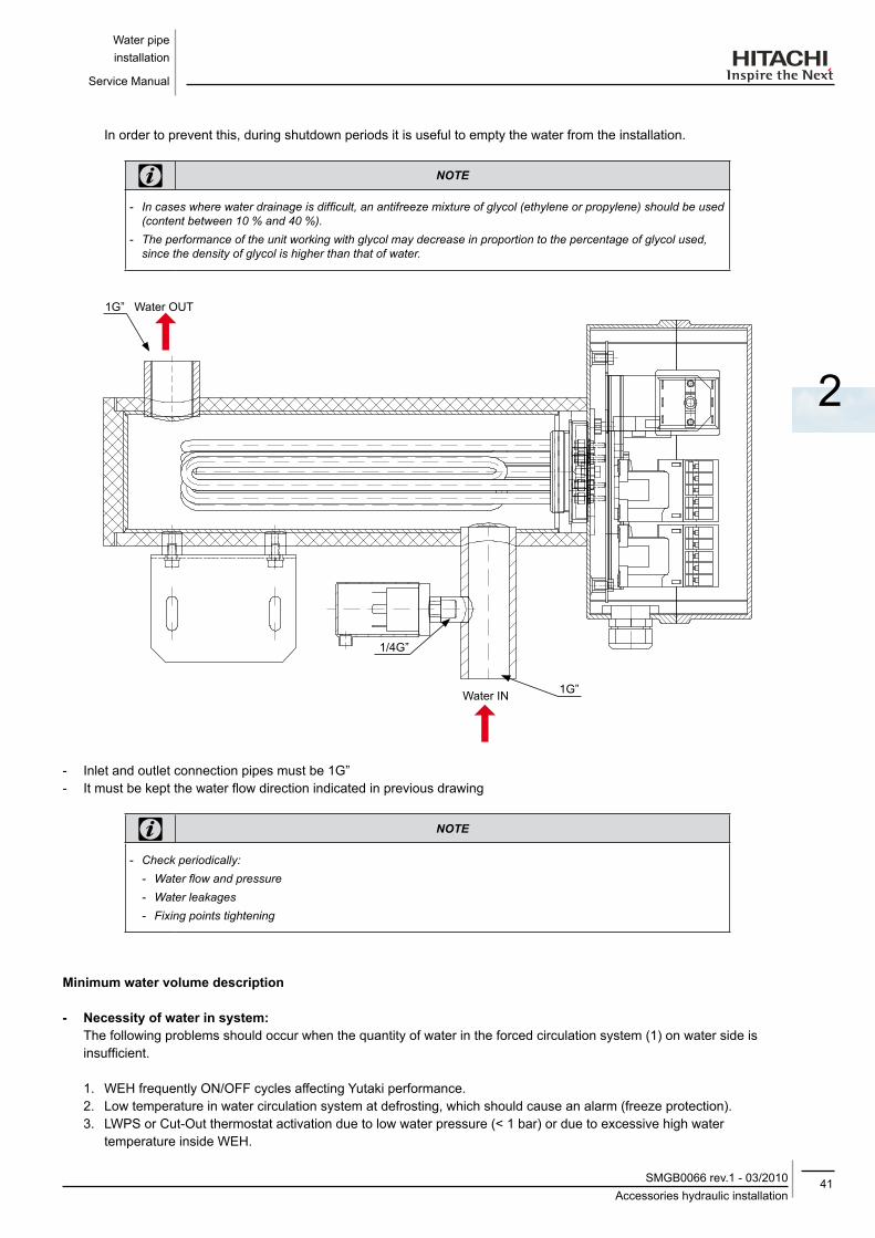
Install WEH as shows on the following drawing in order to allow a natural purge on the WEH (inlet pipe in the bottom side, and outlet pipe in the upper side, both vertically oriented). It is recommended to install an air purge after outlet piping in the highest position of the hydraulic installation. Previous recommendation is a must when there are other parts of hydraulic system that could be installed in a higher position than WEH.
7. Apply thermal insulation on the hydraulic system pipes in order to avoid accidental injure due to excessive heat on piping surfaces and also to avoid heat losses.
8. When the unit is stopped during shutdown periods and the ambient temperature is very low, it is possible that the water in the pipes and in the circulating pump freeze, thus damaging the pipes and the water pump.
41Accessories hydraulic installation
SMGB0066 rev.1 - 03/2010
Water pipe installation
Service Manual
2
In order to prevent this, during shutdown periods it is useful to empty the water from the installation.
note
-- In-cases-where-water-drainage-is-difficult,-an-antifreeze-mixture-of-glycol-(ethylene-or-propylene)-should-be-used-(content-between-10-%-and-40-%).
-- The-performance-of-the-unit-working-with-glycol-may-decrease-in-proportion-to-the-percentage-of-glycol-used,-since-the-density-of-glycol-is-higher-than-that-of-water.
1G” Water OUT
Water IN 1G”
1/4G”
- Inlet and outlet connection pipes must be 1G”- It must be kept the water flow direction indicated in previous drawing
note
-- Check-periodically:-- Water-flow-and-pressure--- Water-leakages-- Fixing-points-tightening
Minimum water volume description
- Necessity of water in system:The following problems should occur when the quantity of water in the forced circulation system (1) on water side is insufficient.
1. WEH frequently ON/OFF cycles affecting Yutaki performance.2. Low temperature in water circulation system at defrosting, which should cause an alarm (freeze protection).3. LWPS or Cut-Out thermostat activation due to low water pressure (< 1 bar) or due to excessive high water
temperature inside WEH.

Water pipe installation
Service Manual
42Accessories hydraulic installationSMGB0066 rev.1 - 03/2010
note
-- Calculate-and-ensure-that-the-water-volume-in-the-system-is-enough-(see-Yutaki-product-manual-for-recommendations).
Water control
caution
-- Malfunction.-Damage-by-poor-quality-water.-- When-it-is-used-industrial-water-inside-hydraulic-system,-it-rarely-causes-deposits-of-scales-or-other-foreign-substances-on-the-equipment.-However,-well-water-or-river-water-should-in-most-cases-contain-suspended-solid-matter,-organic-matter,-and-scales-in-great-quantities.-Therefore,-such-water-should-be-subjected-to-filtration-or-to-a-softening-treatment-with-chemicals-before-application-as-chilled-water.
-- It-is-also-necessary-to-analyse-the-quality-of-water-by-checking-pH,-electrical-conductivity,-ammonia-ion-content,-sulphur-content,-and-others.-Should-the-results-of-the-analysis-be-not-good,-the-use-of-industrial-water-would-be-recommended.
2.5.3. dHWT- domestic Hot Water Tank
• Hydraulic circuit
When Piping connections are performed:1. Connect all pipes as close as possible to the unit, so that disconnection can be easily performed when required.2. It is recommended to use flexible joints for the piping of water inlet and outlet, so vibration will not be transmitted.3. Whenever possible, sluice valves should be installed for water piping, in order to minimise flow resistance and to
maintain sufficient water flow.4. It is recommended to apply ball valves in both water pipe connections to make easier any maintenance work.5. Proper inspection should be performed to check for leaking parts inside and outside the system, by completely
opening the hot water inlet and outlet valves to the water condenser.6. This DHWT must be fully air purged to avoid heating elements radiating the tank case without water.7. Apply thermal insulation on the hydraulic system pipes in order to avoid accidental injure due to excessive heat on
piping surfaces and also to avoid heat losses.8. When the unit is stopped during shutdown periods and the ambient temperature is very low, it is possible that the
water in the pipes and in the circulating pump freeze, thus damaging the pipes and the water pump. In order to prevent this, during shutdown periods it is useful to empty the water from the installation.
note
-- Check-periodically:-- Water-flow-and-pressure-- Water-leakage’s-- Fixing-points-tightening-- Inlet-and-outlet-connection-pipes-must-be-1G”

43Accessories hydraulic installation
SMGB0066 rev.1 - 03/2010
Water pipe installation
Service Manual
2
dHWT(200/300)(E/S)-2.5H1E
Return
Input
Mainswater input
Recirculation
H.S.W.Ref. Name
Sanitary safety valve unit
Non-return valve
Heating coil
Recirculation pump
Shutoff cock
Drain
Drain valve
• Pressure drop
DHWT(200/300)E-2.5H1E DHWT(200/300)S-2.5H1E
0 10.2 0.5
10
100
20
50
200
500
5
102 5 Cp= m3/h
mba
r
0 10.2 0.5
10
100
20
50
200
500
5
102 5 Cp= m3/h
mba
r
• General standard for hydraulic installation
- The safety valve unit will fitted at the sanitary water installation.
- A pressure reducer must be placed in the DHWT installation. The nominal pressure of the safety unit will be 8 bar.
- When the main pressure is more than 6 bar a pressure reducer should be installed.
- The water discharge during heating (expansion) is normal. The volume of this discharge can be up to 3% of the storage tank’s capacity.
- The pressure regulator device must be working regularly , depending on the quality of water, in order to remove the lime’s deposits and verify that it is not blockade.
- A water leakage in the pressure protection device can exist. The discharge pipe should be always open to the atmosphere, free of frost and in continuous slope to the down side.
- Dielectric bushes must be fitted at the input and output sanitary water and at the tank circuit connections.
- Emptying the DHWT: Close the main inlet water valve and open the relief valve of the security water group.

Water pipe installation
Service Manual
44Accessories hydraulic installationSMGB0066 rev.1 - 03/2010
Ref Name
Main inlet water
DHWT inlet connection
Security valve and manual empty
Emptying connection
Check valve
Close valve
2.5.4. Water drain discharge connection
• drain discharging boss
When the base of the Yutaki is temporarily used as a drain receiver, the drain boss should be connected to the drain pipe. See the below figure for further details.
Rubber cap
Drain pipe
Drain pipe
Extruded portion
Drain BossDrain hole of Base
Model Applicable ModelDBS-26 RHUE(3-6)A(V)HN
• Connection procedure
1. Insert the rubber cap into the drain boss up to the extruded portions.
2. Insert the boss into the unit base and turn approximately 40 degree counterclockwise.
3. The outer diameter section of the drain boss is 32 mm.
4. A drain pipe should be field-supplied.
note
-- Do-not-use-this-drain-boss-set-in-a-cold-area,-since-the-drain-water-may-freeze.-- This-drain-boss-may-not-be-sufficient-to-collect-drain-water.-In-such-a-case,-a-bigger-drain-pan-should-be-fieldsupplied-and-installed-under-the-unit.

45Contents
SMGB0066 rev.1 - 03/2010
Electrical wiring
Service Manual
3
3. ElECTRICAl WIRING CoNNECTIoNS ANd dIAGRAM
This chapter describes the procedures to carry out the electrical wiring connections for the Yutaki and its control system.
CoNTENTS
3.1. General check .............................................................................................................................46
3.2. Electrical wiring connection .........................................................................................................47
3.2.1. Field minimum wire sizes for the power source .....................................................................................483.2.2. Main switches and fuses ........................................................................................................................49
3.3. Setting the DIP switches .............................................................................................................49
3.4. LED indication .............................................................................................................................53
3.5. Accessories electrical installation ................................................................................................54
3.5.1. Pump kit .................................................................................................................................................543.5.2. WEH- Water Electric Heater ...................................................................................................................573.5.3. DHWT- Domestic Hot Water Tank ..........................................................................................................59
3.6. Electrical wiring diagrams............................................................................................................65
3.6.1. Electrical wiring diagram for models RHUE-(3~6)AVHN ........................................................................663.6.2. Electrical wiring diagram for RHUE-(5/6)AHN ........................................................................................67
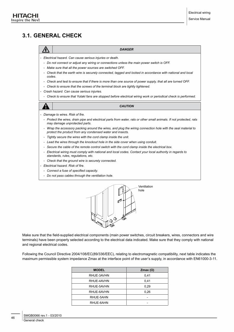
Electrical wiring
Service Manual
46General checkSMGB0066 rev.1 - 03/2010
3.1. GENERAl CHECK
danger
-- Electrical-hazard.-Can-cause-serious-injuries-or-death.-- Do-not-connect-or-adjust-any-wiring-or-connections-unless-the-main-power-switch-is-OFF.-- Make-sure-that-all-the-power-sources-are-switched-OFF.-- Check-that-the-earth-wire-is-securely-connected,-tagged-and-locked-in-accordance-with-national-and-local-codes.
-- Check-and-test-to-ensure-that-if-there-is-more-than-one-source-of-power-supply,-that-all-are-turned-OFF.-- Check-to-ensure-that-the-screws-of-the-terminal-block-are-tightly-tightened.
-- Crash-hazard.-Can-cause-serious-injuries.-- Check-to-ensure-that-Yutaki-fans-are-stopped-before-electrical-wiring-work-or-periodical-check-is-performed.
caution
-- Damage-to-wires.-Risk-of-fire.--- Protect-the-wires,-drain-pipe-and-electrical-parts-from-water,-rats-or-other-small-animals.-If-not-protected,-rats-may-damage-unprotected-parts.
-- Wrap-the-accessory-packing-around-the-wires,-and-plug-the-wiring-connection-hole-with-the-seal-material-to-protect-the-product-from-any-condensed-water-and-insects.
-- Tightly-secure-the-wires-with-the-cord-clamp-inside-the-unit.-- Lead-the-wires-through-the-knockout-hole-in-the-side-cover-when-using-conduit.-- Secure-the-cable-of-the-remote-control-switch-with-the-cord-clamp-inside-the-electrical-box.-- Electrical-wiring-must-comply-with-national-and-local-codes.-Contact-your-local-authority-in-regards-to-standards,-rules,-regulations,-etc.
-- Check-that-the-ground-wire-is-securely-connected.--- Electrical-hazard.-Risk-of-fire.--- Connect-a-fuse-of-specified-capacity.-- Do-not-pass-cables-through-the-ventilation-hole.
Ventilation hole
Make sure that the field-supplied electrical components (main power switches, circuit breakers, wires, connectors and wire terminals) have been properly selected according to the electrical data indicated. Make sure that they comply with national and regional electrical codes.
Following the Council Directive 2004/108/EC(89/336/EEC), relating to electromagnetic compatibility, next table indicates the maximum permissible system impedance Zmax at the interface point of the user’s supply, in accordance with EN61000-3-11.
ModEl Zmax (Ω)RHUE-3AVHN 0,41
RHUE-4AVHN 0,41
RHUE-5AVHN 0,29
RHUE-6AVHN 0,26
RHUE-5AHN -
RHUE-6AHN -

47Electrical wiring connectionSMGB0066 rev.1 - 03/2010
Electrical wiring
Service Manual
3
Harmonics situation of each model regarding IEC 61000-3-2 and IEC 61000-3-12 is as follows:
ModElS SITUATIoN REGARdING IEC 61000-3-2 ANd IEC 61000-3-12 Ssc “xx” ModElS Ssc “xx” (kVA)
Equipment complying with IEC 61000-3-2 (Professional use) RHUE-5AHNRHUE-6AHN -
Equipment complying with IEC 61000-3-12
RHUE-3AVHN RHUE-4AVHN RHUE-5AVHNRHUE-6AVHN
-
Check that the power supply voltage is within +/-10 % of the rated voltage. And that power supply has an impedance low enough to avoid reducing the starting voltage more than 85% of the rated voltage.
3.2. ElECTRICAl WIRING CoNNECTIoN
Main controller
Non-voltage
Power supply:1~230V 50 Hz (3N~400V 50 Hz for RHUE-(5/6)AHN)
Earth wiring
Power supply
Pump ON/OFF contactor
Water pump
230 V 230 V
Power supply
Remote ON/OFF wiring
Alarm
YUTAKI unit
Temperature setting wiring (4-20mA)
Remote indication wiring

Electrical wiring
Service Manual
48Electrical wiring connectionSMGB0066 rev.1 - 03/2010
note
-- The-heater-and-the-3-way-valve-are-accessories.-(Their-codes-are-EH61-and-VID3V1-respectively).-- Refer-to-chapter-"4"-for-more-information.
The correct electrical wiring connection for the unit is shown below.
1. Connect the three-phase power supply source wires L1, L2, L3 and N (for 400V 50Hz) to the terminal board in case of RHUE-(5/6)AHN unit, and L1 and N in case of RHUE-(3~6)AVHN units. Connect the ground wire to the plate in the electrical box.
Power supply cables
Control cables
U00B
U00A
U04A
U04BU13
U14
U16
U17
U65BU65A
U72B
U72A
U74A U74B
U75
U82A
U82B
U85AU85B U85C U85D
U85E
NK5
NK4NK3NK2
BSON
C1
47C
PWB5
TB2
TB1
NK1
PWB2
PWB1
XP
Tr2Tr1
CSBSOFF
52P
EFP
NFC1
PWB4PWB3
CB1,2
52C
R1 R2
DCL
ISPM
IC3
IC1
IC2
IC4
IC5
Y1Y2Y3Y4
PCN4 PCN3 PCN2 PCN1
PCN6
PCN5
PCN7
PC
N8
PC
N9
CN8
C2
9
C3
0
PC
1
PC
2
PC
3
PC
4
R1
R2
R3
R4
CN7CN6CN5
CN
4C
N1
CN9 CN10 CN11 CN12 CN13 CN14 CN15 CN16
CN
3C
N2
C2
8
C2
7
PC
N2
01
CN
20
2
CN
20
1
CN
20
1
CN
20
2
PC
N2
01
PF1
PF2
L1'
N'
L3'
L2'
L1N
EL3
L2
CN8PC208
C
PC207
CN9
CN206CN207
R200
R201
ZN202
LED201ZN201
R215R216
TB2
TB3
P1
P
N
RB
PPD NUT V
RBWSR
CN8PC208
C
PC207
CN9
CN206CN207
R200
R201
ZN202
LED201ZN201
R215R216
TB2
TB3
P1
P
N
RB
PPD NUT V
RBWSR
201918171514131211109875 63 4 161 2
IC3
IC2
IC8
IC7
IC6
IC5
IC4
PC10
PC
9P
C8
PC
7
PC6 PC5
PC
4P
C3
PC
2P
C1
21
87654321
43214321
4321DSW2 DSW4DSW3
DSW1 DSW5
4321
DSW
6
RS1
RS2
YRS
Y20L
YP
R
YA YE2 Y20A Y20B YE1Y52CS Y52C
PSW1PSW2
SSW
0987
654321
0987
654321
0987
654321
0987
654321
RSW4RSW3
RSW2RSW1
SEG5SEG4SEG3
SEG2SEG1
LED8
LED7
LED6
LED5
LED4LED3LED2LED1
OSC
DSA
Z5
Z4
Z3Z2
Z1
EF3
EF2
EF1
ZD9
R2
R3
R1
3
R1
4
R12
R11
R15
R16
R17
R10
R9
R143
R138
R137
R1
35
R113
R110
R107
R88R87R86R85R84R83R82R81
C4C1
C2 C6C5
C7
C8
C21
C20
C19
C18
C17
C16
C15
C14
C13
C12
C11
C10
C9
DM4
DM5
DM8
DM1
DM6
DM
7
REG
4
REG2
REG9REG8
REG1
REG
7
REG6
REG3
CN
6
PC
N3
B
PC
N3
AC
N1
0B
CN
10
A
PCN12 PCN8
PC
N2
PC
N1
PC
N1
0P
CN
4P
CN
5
PCN6PCN7PCN9
PC
N1
1
CN
13
CN
12
CN
11
CN
5C
N4
CN
3
CN8 CN1 CN2CN9 CN7
RS T
87
BA1 L3 NL12 L2
+-
NFC3
NFC2
W
VU
V
W
U
U13
U00A
U00B
U04A
U04B U16
U17
U65BU65A
U72A
U72B
U75
U82A
U82BU85AU85B
PWB1
TB2
Y2
PCN2PCN3PCN4
PCN
8PC
N9
PCN6
PCN5
Y4 Y3
PCN7
PC3
PC2
PC4
PC1
CN6PCN1 CN5
R1
CN8CN7
R3R2
CN
4
R4
IC5
Y1
IC4
C27
IC1
IC2
C28
C29 C
N1
C30
IC3
CN
2C
N3
NK
NK 5
CN9
PWB2CN10 CN11
1NK
CN13CN12 CN14 CN16CN15
NK2 3 NK
L1 N
A1
B2
SEG3 SEG4 SEG5
6
DM4
CN9 CN7 CN8 CN1 CN2
1
LED8
CN
4C
N3
CN
5
OSC
IC7
C21
CN
6C
N11
C8
C9
R107
C19IC4
2
LED7
IC8
1
EF3Z5
DSW
6
PC10IC2 R137
ZD9
R135
R143R138
REG7
C20
C4
3
REG4
DSW2
DSW5DSW1
IC3 IC5
PSW2
22 3 4 1
2PSW1
3 4
1
REG3
44 1 2DSW3
3 51 2 3 4DSW4
REG6
R3R2
REG8 REG9
DM1
DM6
C2
DM8
C5
C6
C1
REG2 REG1
DM5 CN
10B
C7
DM
7C
N10A
7 8 Z2
PCN
3B
PCN
3A
Z3
PCN
2X P
Tr 1
PCN7
Y52CS
RSW4
RSW2
YE1YA Y20AYE2 Y20B
Y20L
CN
13C
N12
R110
C10
C11R86
R81R82R83R84R85
R87
R113R88
YRS
4
PCN
11YPR
LED3
SEG2
LED5
LED1
SEG1
RS1
LED2
4 56
23
RSW3
SSW
1 890
7
C12
C13
C16
RSW1
LED4
LED6
RS2
IC6C14
C15
PC6 PC5
R13
R14
PCN12
U
PCN9 PCN8
PC1 R10
Z1 Z4
PC2
EF1
R9
EF2
DSA
PCN
1
PC7
PC8
PC9
C17
C18
R17
R16
R15
PC3
PC4
Y52C
R11
R12
PCN
10PC
N4
PCN
5
OFFBS
PCN6
TB1
Tr 2
CSONBS
U
W
V
DCL
PF1
52C
EF P
52P
V
L11 N1
NF C1
N2L12
ZD5
R18
R16
CN206
CP9
D2
HT2
PC201
1CN203
CP16PC203
PC202
1
BK
1CN204 PC205
PC206PC204BL
1
C19 D9
D10
R205
C201
CP17
C17
C202
L1
OF
F
R30 R301
1
1CN2
WH
12
3
1
Q202
R214C206
GN
YEON
R87R88
O
IC4
GI
CP11CP12
CP30
DSW1
X1
80
C4
R210
C38C39C203
CP6 C5
CP820
CP7CP10
1
ZD2
C
S
D
IC3
1
1
CN202
C55
R13
HT1
C100
JP9
1
C16
D14
1
1
CN201PCN202
1
1
C208
Z2
C105
C109
LED202
R14
C101
C102C53
R15
C54
CP15
C21
ZD3
JP10
C47
C6
R20
C2
21
ZD4
V
R23
R24
C11C10
D5
D6
22
U
D7
R25
C12 W
NF C2
PCN201
1
1
CB1CB2
-17B35740A
S
R86C40
CN4
PC207Q
201
1CN207
PC209 R303
RD
1
PC208
1PCN401
1
CP28JP14
D25BK
1
CP24
CP29R304
1IC8
8
61IC1
54
R211
CP5 CP26
CP25
41
5 8
60
R93
1CN1WH
4
WH
D19
1
CP27
R110
D13
IC9
PV051-1
~T +
~-
DM3
+ -
JP1
JP3
RD
CP23
R113
R109R114
CP4
CP18
R1740
C50C51
C52
C30
C104
21
R54
CP2
D22
D20D21
D18D11
D12
D3D8
D24D23
1
JP8
4
R7R59R58
CP3CP1
R43
IC6
R34
R22
C25
26
C24
JP7
R35C44
R39R40
85
LED201
IC5
CP13R53
C33
DANGER HIGH VOLTAGE
R111
Lot No.F
CP20
CP14
R27
R1
Z1
R89
QN2
CP19
JP2
R2
QN1
QP1
R48R46
CP22
R3
R96
R112
RY2
C108
R67
R65
R66
DIP-IPM
HY
-20
0-1
01 CMC
~ ~DM2
R
+
~DM
1
JP11
JP12
RY1
C112
R26
CB3
DCL2
CP21R28
R29Q204
Q203
C110
R118
R117
JP5
JP4
JP6
DCL1R115
J1
D15
R116
W
4 56
23
1 890
7
4 56
23
1 8907
4 56
23
1 890
7
No DESCRIPTION PART Qty. REMARKSU00A Terminal Board E01818 1 U00B Terminal Board EC00494 1 U04A Fuse EC00496 1 50AU04B Fuse P90713 1 3A, Power Fuse for PumpU13 Electrical Wiring Diagram EC00499 1 Assembly (Steel Plates+Components+Harness)U16 Noise Filter P26446 1 30AU17 Inverter Fin Assy E01822 1 DIP-IPM (25A)U65A Spacer EC00510 4 U65B Spacer EC00511 6 U72A Magnetic Contactor P24721 1 U72B Magnetic Contactor EC00515 1 Contactor for PumpU75 Aux Relay C3950 1 U82A Transformer EC00516 2 U82B Reactor E01828 1 U85A Printed Circuit Board EC00517 1 PCB Main (CO041 Assy)U85B Printed Circuit Board EC00518 1 I/O PCB (CO011 Assy)
1 532 4 6 7 8 129 10 11 1413 15 1916 17 18 20
RHUE-(5/6)AHN RHUE-(3~6)AVHN
danger
-- Electrical-hazard.-Can-cause-serious-injuries-or-death.-Allways-connect-ground-wires-to-the-respective-terminals-or-plates-to-avoid-electrical-hazard.
3.2.1. field minimum wire sizes for the power source
Model Power source Max. current (A)Power source cable size Signal cable size
EN60 335-1
EN60 335-1
RHUE-3AVHN
1~ 230V 50Hz
18 4.0 mm2
0.75 mm2
RHUE-4AVHN 18 4.0 mm2
RHUE-5AVHN 26 6.0 mm2
RHUE-6AVHN 29 6.0 mm2
RHUE-5AHN3N~ 400V 50Hz
11 2.5 mm2
RHUE-6AHN 15 4.0 mm2

49Setting the DIP switches
SMGB0066 rev.1 - 03/2010
Electrical wiring
Service Manual
3
3.2.2. Main switches and fuses
Select the main switches (current breaker) according to the next table:
Model Power source CB (Circuit Break) (A)
ElB (Earth leakage Breaker) (Number of poles/A/mA)
RHUE-3AVHN
1~ 230V 50Hz
32
2/40/30RHUE-4AVHN 32
RHUE-5AVHN 32
RHUE-6AVHN 32
RHUE-5AHN3N~ 400V 50Hz
204/40/30
RHUE-6AHN 20
3.3. SETTING THE dIP SWITCHES• Number and position of dIP switches
The PCB of the Yutaki unit contains 9 DIP switches.DIP switches location on the PCB:
Upper side shows unit status
Lower side shows discharge and suction pressure value alternatively
1. Status indicationPress the PSW2 more than 3 seconds to change the status display mode
2. Alarm historyPress the PSW1 and PSW2 together more than 3 seconds to switch to alarm history mode
note
-- The-mark-““-indicates-the-position-of-dips-switches.-- No-mark-“”-or-"not-available"-indicates-pin-position-is-not-affecting.-- The-figures-show-the-settings-before-shipment-or-after-selection.-- "Not-used"-means-that-the-pin-must-not-be-changed.-A-malfunction-might-happen-if-changed.
note
-- Before-setting-dips-switches,-first-turn-the-power-source-off.-Otherwise,-the-changes-will-not-be-taken-into-account.

Electrical wiring
Service Manual
50Setting the DIP switchesSMGB0066 rev.1 - 03/2010
• dIP switch factory set for all units:
dSW RHUE-3AVHN RHUE-4AVHN RHUE-5AVHN RHUE-5AHN RHUE-6AVHN RHUE-6AHN
DSW1
DSW2
DSW3
DSW41 2 3 4 5 76 8 1 2 3 4 5 76 8 1 2 3 4 5 76 8 1 2 3 4 5 76 8 1 2 3 4 5 76 8 1 2 3 4 5 76 8
DSW5
DSW61 2 1 2 1 2 1 2 1 2 1 2
DSW7
DSW8
DSW9
• Rotary switches
RSW1 & RSW2: heating temperature setting
RSW3 & RSW4 & SSW: not used
• dSW1: optional functions
function Set PINs
Factory setting
PCB self checking
Pump / High cut test
Optional functions setting mode
Compressor enable

51Setting the DIP switches
SMGB0066 rev.1 - 03/2010
Electrical wiring
Service Manual
3
• dSW2: unit control configuration / unit HP
function Set PINs
Remote ON/OFF signal
Pulse signal commissioning
Level signal (System controller)
PHEX flow direction
(Not used)
Counter flow (Yutaki)
function Set PINs
3HP unit
4HP unit
5 HP unit
6 HP unit
• dSW3: unit control configuration
function Set PINs
Yutaki unit
Available low ambient for cooling mode (Not available)
Heating only (Not used)
Set temp by rotary switch (Commissioning)
Set temp by system controller (4 to 20 mA)
• dSW4: unit model confgurations
function Set PINs
(Not used)1 2 3 4 5 76 8
(Not used)1 2 3 4 5 76 8
Heat pump1 2 3 4 5 76 8
Yutaki heat pump1 2 3 4 5 76 8
(Not used)1 2 3 4 5 76 8
(Not used)1 2 3 4 5 76 8
(Not used)1 2 3 4 5 76 8
(Not used)1 2 3 4 5 76 8
function Set PINs
(Not used)1 2 3 4 5 76 8
(Not used)1 2 3 4 5 76 8
R410A1 2 3 4 5 76 8
CO2 (Not used)1 2 3 4 5 76 8
Power save (Max Hz=Nominal)1 2 3 4 5 76 8
(Not available)1 2 3 4 5 76 8
230 V1 2 3 4 5 76 8
400 V1 2 3 4 5 76 8

Electrical wiring
Service Manual
52Setting the DIP switchesSMGB0066 rev.1 - 03/2010
• dSW5: H-lINK available / settings
function Set PINs
Not used
Not used
• dSW6: end resistance / fuse recovery
function Set PINs
Not used1 2
Not used1 2
• dSW7: unit control configuration
function Set PINs
Three phase
Single phase
Not used
Inverter compresor
Cancel zero-reset expansion valve
Liquid injection enable
• dSW8 (Pd) / dSW9 (Ps): setting Pd / Ps pressure sensor type
function Set PINs
Not used
Pressure sensor R410A

53LED indication
SMGB0066 rev.1 - 03/2010
Electrical wiring
Service Manual
3
Jumper lead setting (JP2): Automatic restart after power failure
Keep the same status as before. Setting before shipment: JP21
0 = open; 1 = Short circuit
The function selection using the jumper lead setting is shown in the table below.
Setting function details
0 Enable If this function is 'Enable', in case of power failure the unit will restart automatically once the power is recovered1 Disable
3.4. lEd INdICATIoN• lEd1, lEd2 and lEd3: Power supply indication
Status lEd1 lEd2 lEd3
Power supply ON ON OFF OFF
Power supply OFF OFF OFF OFF
Not available for Yutaki
• lEd4: operation status indication
Status lEd4
Unit stopped OFF
Unit running ON
Alarm OFF
• lEd5: Alarm indication
Status lEd5
Normal OFF
Alarm ON
• lEd6: Setting mode indication
Status lEd6
Setting mode disable OFF
Setting mode enable(DSW1#3: ON) ON

Electrical wiring
Service Manual
54Accessories electrical installationSMGB0066 rev.1 - 03/2010
3.5. ACCESSoRIES ElECTRICAl INSTAllATIoN
3.5.1. Pump kit
Yutaki is controlling the pump by itself. The pump kits A or B must be always connected according to the wiring below:
Only for TOP-S 25/10To pump
Model Protection type (Cut-out) Connection terminals
TOP-S 25/7 Auto reset
1~ 230 V, 50 Hz
TOP-S 25/10 Manual reset

55Accessories electrical installation
SMGB0066 rev.1 - 03/2010
Electrical wiring
Service Manual
3
note
-- The-generic-pump-must-be-connected-to-terminals-17-and-18-in-the-terminal-board-(TB2).-- Terminals-17-and-18-were-designed-for-230V/3A.-Take-it-into-account-when-installing-the-pump.-An-external-relay-might-be-necessary.-Do-not-install-a-pump-with-more-than-3A-consumption.
-- Earth-screw-terminal-is-used-for-both-pump-and-power-supply-wiring-connection.-- Install-a-pump-accordingly-to-the-necessary-supply-water-delivery.-- Hitachi-recomends-the-use-of-accessory-pump-kits-A-or-B.-- For-TOP-S-25/10,-connect-wires-from-WSK-to-terminal-2-and-16-in-the-terminal-board-(TB2).
Follow the procedure described in "water pipe installation" to assemble the pump kit. Remove the front cover according to the procedures described in "main parts".
caution
-- Contamination.-Risk-of-poisoning.-The-pumps-must-not-be-used-for-drinking-water-or-food-stuffs.
Electrical connection
danger
-- Electrical-hazard.-Can-cause-serious-injuries-or-death.--- All-electrical-connections-must-be-completed-by-a-qualified-and-licensed-electrician-in-strict-compliance-with-local-regulations.
-- Before-working-on-the-pump,-switch-OFF-all-the-terminals-of-the-supply-voltage-and-wait-five-minutes-due-to-the-presence-of-a-hazardous-contact-voltage-(capacitors).
-- Check-that-all-connections-including-potential-free-contacts-are-neutral.
- According to Part 1 of VDE 0730, the pump must be connected to the electrical supply by a solid wire equipped with a plug or an all-pole switch. The width of the contact gap must be at least 3 mm.
- Main fuse: 3.3 A, time-lag.
- The pump/ installation must be earthed in compliance with the applicable regulations.
- Check that the mains current and connection voltage comply with the data on the rating plate.

Electrical wiring
Service Manual
56Accessories electrical installationSMGB0066 rev.1 - 03/2010
note
-- The-motor-may-become-damaged-by-overvoltage.-- Before-applying-voltage-to-the-motor,-double-check-the-voltage.
- Connect to the mains and connect the SK 602/ SK 622 and SK-C2 tripping unit (observe rating plate data) in accordance with the switching diagrams.
ToP-S - To guarantee protection against dripping water and to ensure strain relief of the cable gland (PG 13.5), a connecting
cable with an external diameter of 10 - 12 mm is to be used and assembled. In addition, the cables in the vicinity of the cable gland are to be bent into a run-off loop to drain off any dripping water.
¡ Motor protection
PumpMax. power
consumption P1max(see rating plate data)
Tripping Reset Speed switching
TOP-S 25/71~230V P1max ≤ 245W Internal switch off of the motor
main power supply
Auto-reset-once the motor has cooled down the pump
will automatically switch back on
Speed adjustment switch, 3 settings
TOP-S 25/101~230V 330W ≤ P1max ≤ 400W
WSK and external switch (SK602/ SK622, C-SK or other
control unit)
Manually at the external switch box once the motor
has cooled down
Speed adjustment switch, 3 settings
¡ operation
The system must be filled and vented properly. The pump rotor chamber will vent automatically after a short running period. Brief dry running will not damage the pump. The pumps wich are equipped with vent screws can be ventilated as follows if necessary.
1. Switch off the pump.2. Close the shut-off valve on the discharge side.
caution
-- Risk-of-scalding.-- Depending-on-the-fluid-temperature-and-the-system-presssure,-if-the-vent-screw-is-completely-loosened-hot-liquid-or-gas-should-escape-or-even-shoot-out-at-high-pressure.-Protect-all-electrical-parts-against-the-water-released-from-the-unit.

57Accessories electrical installation
SMGB0066 rev.1 - 03/2010
Electrical wiring
Service Manual
3
3.5.2. WEH- Water Electric Heater ¡ General check
1. Ensure that the field-supplied electrical components (main power switches, circuit breakers, wires, connectors and wire terminals) have been properly selected according to the electrical data indicated. Make sure that they comply with national and regional electrical codes.
2. Electrical connection must be done by professional installers.3. Make sure that the power supply voltage is within +/-10% of the rated voltage.4. Make sure that power supply has an impedance low enough to warranty not reduce the starting voltage more than
85% of the rated voltage.5. Check that the earth wire is securely connected, tagged and locked in accordance with national and local codes.6. Connect a fuse of specified capacity.7. Check periodically the electrical connection tightening
danger
-- Electrical-hazard.-Can-cause-serious-injuries-or-death.-- Do-not-connect-or-adjust-any-wiring-or-connections-unless-the-main-power-switch-is-OFF.-- Make-sure-that-all-the-power-sources-are-switched-OFF.-- Check-that-the-earth-wire-is-securely-connected,-tagged-and-locked-in-accordance-with-national-and-local-codes.
-- Check-and-test-to-ensure-that-if-there-is-more-than-one-source-of-power-supply,-that-all-are-turned-OFF.-- Check-to-ensure-that-the-screws-of-the-terminal-block-are-tightly-tightened.
caution
-- Damage-to-wires.-Risk-of-fire.--- Protect-the-wires,-drain-pipe-and-electrical-parts-from-water,-rats-or-other-small-animals.-If-not-protected,-rats-may-damage-unprotected-parts.
-- Wrap-the-accessory-packing-around-the-wires,-and-plug-the-wiring-connection-hole-with-the-seal-material-to-protect-the-product-from-any-condensed-water-and-insects.
-- Tightly-secure-the-wires-with-the-cord-clamp-inside-the-unit.-- Electrical-wiring-must-comply-with-national-and-local-codes.-Contact-your-local-authority-in-regards-to-standards,-rules,-regulations,-etc.
-- Check-that-the-ground-wire-is-securely-connected.
¡ Electrical installation - Install the unit in a restricted area not accessible by the general public. - Follow local codes and regulations when selecting field wires, circuit breakers and earth Leakage breakers. (See
Heater manual).
Customer connection:
The electrical wiring connection between WEH, Yutaki system controller and the electrical power installation is as follows:

Electrical wiring
Service Manual
58Accessories electrical installationSMGB0066 rev.1 - 03/2010
Alimentation/Supply3N~400V 50 Hz
N.O. (1bar)
System Controller
note
-- This-connection-is-only-for-the-electric-heater-WEH-6E.
¡ Wiring size
• Connection wiring
The minimum thickness of the wiring that must be used in the installation.
Power source Max. current (A)Power source cable size Control cable size
EN 60335-1 EN 60335-11~230V, 50Hz 30 6mm2 0.75mm2
3N~400V, 50Hz 10 2.5mm2 0.75mm2
• Main switch protection
Power source Max. current (A) CB (A) ECB Number of poles/A/mA
1~230V, 50Hz 30 32 2/40/30
3N~400V, 50Hz 10 10 4/40/30
Alimentation/Supply1~230V 50 Hz
59Accessories electrical installation
SMGB0066 rev.1 - 03/2010
Electrical wiring
Service Manual
3
note
-- Follow-local-codes-and-regulations-when-selecting-field-wires,-Circuit-Breakers-and-Earth-Leakage-Breakers-- Use-the-wires-which-are-not-lighter-than-de-ordinary-polychloroprene-sheated-flexible-cord-(code-designation-H05RN-F).
3.5.3. dHWT- domestic Hot Water Tank ¡ General check
1. Ensure that the field-supplied electrical components (mains power switches, circuit breakers, wires, connectors and wire terminals) have been properly selected according to the electrical data indicated. Make sure that they comply with national and regional electrical codes.
2. Electrical connection must be done by professional installer.
3. Check to ensure that the power supply voltage is within +/-10% of the rated voltage.
4. Make ensure that power supply has an impedance low enough to warranty not reduce the starting voltage more than 85% of the rated voltage.
5. Check that the earth wire is securely connected, tagged and locked in accordance with national and local codes.
6. Connect a fuse of specified capacity.
7. Check periodically the electrical connection tightening.
danger
-- Electrical-hazard.-Can-cause-serious-injuries-or-death.-- Do-not-connect-or-adjust-any-wiring-or-connections-unless-the-main-power-switch-is-OFF.-- Make-sure-that-all-the-power-sources-are-switched-OFF.-- Check-that-the-earth-wire-is-securely-connected,-tagged-and-locked-in-accordance-with-national-and-local-codes.
-- Check-and-test-to-ensure-that-if-there-is-more-than-one-source-of-power-supply,-that-all-are-turned-OFF.-- Check-to-ensure-that-the-screws-of-the-terminal-block-are-tightly-tightened.
caution
-- Damage-to-wires.-Risk-of-fire.--- Protect-the-wires,-drain-pipe-and-electrical-parts-from-water,-rats-or-other-small-animals.-If-not-protected,-rats-may-damage-unprotected-parts.
-- Wrap-the-accessory-packing-around-the-wires,-and-plug-the-wiring-connection-hole-with-the-seal-material-to-protect-the-product-from-any-condensed-water-and-insects.
-- Tightly-secure-the-wires-with-the-cord-clamp-inside-the-unit.-- Electrical-wiring-must-comply-with-national-and-local-codes.-Contact-your-local-authority-in-regards-to-standards,-rules,-regulations,-etc.
-- Check-that-the-ground-wire-is-securely-connected.

Electrical wiring
Service Manual
60Accessories electrical installationSMGB0066 rev.1 - 03/2010
¡ Electrical wiring connection
The electrical wiring connection between DHWT, AquaFREE or Yutaki system controller and the electrical power installation is as follows:
Customer connection:
¡ Wire size
Recommended minimum sizes for field provided
• Connection wiring
Power Source
Max. Current (A)
Power source cable size
Control cable size
EN60 335-1 EN60 335-1
1˜ 230V 50Hz 15 2,5mm² 1mm²
• Main switch protection
Power Source
Max. Current (A) CB (A)
ElB(Number of poles/A/mA)
1˜ 230V 50Hz 15 20 2/40/30
notice
-- Follow-local-codes-and-regulations-when-selecting-field-wires,-Circuit-Breakers-and-Earth-Leakage-Breakers-- Use-the-wires-which-are-not-lighter-than-de-ordinary-polychloroprene-sheated-flexible-cord-(code-designation-H05RN-F).

61Accessories electrical installation
SMGB0066 rev.1 - 03/2010
Electrical wiring
Service Manual
3
¡ Electrical wiring connection diagram
Power cable Control cable(To system control unit)
Main switch
Ref. NameWT Regulating and Safety thermostatRe Auxiliary Relay
SW1 Operating Mode switchR 123 Electrical HeaterLD1 LED1: POWER ONLD2 LED2: AUTO MODE ONLD3 LED3: Electrical Heater ManualTB Terminal Board
L/N/T Power supply3/4 Control Heater Input5/6 Electrical Heater Connection

Electrical wiring
Service Manual
62Accessories electrical installationSMGB0066 rev.1 - 03/2010
¡ Internal wiring
Control EH cable
Power cable
Detail D
Internal Wiring Connection
¡ Cathodic protection
2
10
9
-
+
3Test
Anode-Control
OK
8
5
1-4
23
7 6
In order to protect the inside of the vessel from corrosion all the enamelled DHWT can be equipped whit a cathodic protection unit, comprising magnesium sacrifice anodes, charge gauges and wiring of connection.
It basically comprises a magnesium anode (1) mounted on the storage tank’s connection plate (2), connected to the external anode load measured (3) which allow to know the anode consumption rate without having to dismantle it.

63Accessories electrical installation
SMGB0066 rev.1 - 03/2010
Electrical wiring
Service Manual
3
The electrical connection of the load measured (3) to the anode (1), is made through the wiring of connection (6):
- To the anode: U shaped terminal M10 (4)
- To the load measured: female Faston terminal 2.8 (10)
The electrical connection of the load measured (3) to the earth, is made through the wiring of connection (7):
-To earth: U shaped terminal M10 (5)
- To the load measured: female Faston terminal 6.3 (10)
caution
-- Check-the-magnesium-anode-load-periodically-by-pushing-the-button.-If-the-gauge-is-in-the-red-zone,-the-magnesium-anode-must-be-replaced.
-- Do-not-install-the-permanent-cathode-protection-and-the-cathodic-protection-together.
¡ Titanium protection accessory
61524
7
8
910
311
All the Hitachi DHWT can be equipped with the permanent cathode protection system which is totally automatic and maintenance free.
It basically comprises a titanium anode (1) mounted on the storage tank’s connection plate (2) and connected to a potentiostat (3) which automatically regulates the input current to the anode, constantly measuring the potential of the storage tank), through the leads (4).Wiring the anode to the potentiostat by means of leads (4) is carried out in the following way:
-To the anode: connection (5), female Faston terminal.

Electrical wiring
Service Manual
64Accessories electrical installationSMGB0066 rev.1 - 03/2010
-To earth: connection (6), U shaped terminal.
-To the potentiostat: connections at (9) and (10), pins (7) and (8) respectively.
note
-- Use-original-wires-only.-To-avoid-any-risk-of-corrosion-due-to-reverse-polarity-do-not-lengthen-nor-shorten-the-wires.
-- Use-a-socket-base-near-to-the-storage-heater-for-this-purpose.The-protective-anode-starts-comes-into-operation-when-the-storage-heater-is-full-of-water.-When-there-is-no-water-the-control-pilot-light-(11)-lights-up-red-and-blinks-on-and-off.
-- lf-the-pilot-light-(11)-is-green,-this-shows-that-the-storage-heater-is-receiving-a-protective-current.-lf-the-pilot-light-is-not-on-or-lights-up-red-and-blinks,-check-the-connections,-contacts-and-mains-supply.-lf-this-anomaly-continues,-contact-the-fitter-or-our-Customer-Technical-Service-Department.
-- In-the-case-of-vertically-installed-storage-heaters-from-which-water-is-not-going-to-be-extracted-for-periods-of-more-than-3-months,-we-recommend-fitting-an-automatic-purger-at-the-D.H.W.-outlet.
-- lf-the-storage-heater-is-installed-horizontally,-we-recommend-the-extraction-of-water-at-least-once-every-3-months.
-- The-potentiostat-(3)-and-connecting-wires-(4)-must-not-be-disconnected,-except-when-the-storage-heater-is-emptied.
-- Do-not-disconnect-the-protection-system-during-periods-of-absense-(holidays,-etc.).-- Occasionally-check-that-the-pilot-light-is-working-correctly-(11).
¡ Electric heater
The electric heater is made of Incoloy alloy 825 and complies with the European Low Voltage Directive 2006/95/EC.
It comprises a flange that holds three U-Shaped heating elements for 2.5kw power resistances.
• Replace electric heater
The steps to be followed are:
1. Totally disconnect the unit from the main power supply.
2. With the help of a tool remove the heater to be replaced. Be careful not to damage the enamel surface in case of enamelled tanks.
3. Insert the new heater in the same position as the old one.
4. Connect again and plug into the main power supply.
• Safety measures
Before any intervention, totally disconnect the DHWT from the main power supply. All the connections circuits must be disconnected.
Installation, configuration, start up and maintenance of heating elements must be carried out by an authorised electrical fitter. All standards and regulations must be observed.
The user is responsible of ensuring that the essential requirements of the European Low Voltage Directive are respected.
Electric heating elements generates high temperatures. Precautions should be taken to protect goods and persons from accidental burns during the operation and after the equipment has been disconnected or installed.
Note minimum cable section: Resistances of 2.5kW recommended cable: H05SJ-K accordance with UNE 21027, and will have at least 2.5mm² section.

65Accessories electrical installation
SMGB0066 rev.1 - 03/2010
Electrical wiring
Service Manual
3
The tanks must be with a DHWT temperature control thermostat and an all-pole limiter thermostat (the setting of these two components must be compatible with the design parameters of storage tanks). The sensors must always be located at a higher level than the electric heater element.
We recommend installing appropriate safety devices (temperature safety device, safety level for heating liquids by natural convection, flow safety device for liquids in circulation, etc.).
DHWT(200/300)S-2.5H1E Ref. Name
To terminal 5 and 6 of the control panelTo the top flangeTo earth terminal of the control panel
Flange
Heater
Seal
Washers
Screws
Studs
Nuts
Metal protective casing
Screws M6
Panel
Screws M4
Wires
Earth Wire
DHWT(200/300)E-2.5H1E Ref. Name
Heater connection
To terminal 5 and 6 of the control panelTo the top flangeTo earth terminal of the control panel Flange
Heater
Seal
Nuts
Nylon bushing
Nylon washers
Metalic washers
Metal protective casing
Screws M6
Panel
Screws M4
Wires
Earth Wire
3.6. ElECTRICAl WIRING dIAGRAMSThis sub-chapter shows the electrical wiring diagram for each unit of the Yutaki series.

Electrical wiring
Service Manual
66Electrical wiring diagram for models RHUE-(3~6)AVHNSMGB0066 rev.1 - 03/2010
32
11
25
43
12
3
32
15
43
21
54
32
1
(A)5
3
52C
(B) (A)
DCL
DCL
1
(B)
CMC
DCL
2
2
SR
N2
(B) E
6
L2,N 4
1TB1
L1
N1
PF
L11
C1
(A)
L12
NF
1
C2
MF1
(Blac
k)CN
203
DIP
-IPM
THM
W
31
UV
NF
MF2
3
(Red
)PC
N202
VU
MC
W
(Whi
te)
CN20
6
(Red
)CN
202
(Whi
te)
CN20
1
(Blu
e)CN
204
45
(Whi
te)
PCN2
01(G
reen
)CN
2
21
CN8
21
43
(Red
)CN
15
52
31
45
13
24
(Whi
te)
CN14
Term
inal
Bo
ard
(fo
r Po
wer
Su
pp
ly. H
-Lin
k)M
P
Prin
ted
Wir
ing
Bo
ard
(fo
r Mai
n C
on
tro
l)
Nam
e o
f Par
tsM
ark
Nam
e o
f Par
tsM
ark
Pilo
t La
mp
Au
xilia
ry R
elay
Pow
er F
use
for P
um
pC
on
tact
or (
for P
um
p)
Mo
tor (
for P
um
p)
Eart
h
Push
Bu
tto
n S
wit
ch (f
or S
top
pag
e)Pu
sh B
utt
on
Sw
itch
(fo
r Sta
rtin
g)
Resi
stan
ce (f
or 4
-20m
AD
C S
ign
al)
Co
nn
ecto
r (Re
lay
Co
nn
ecto
r)C
on
nec
tor (
Term
inat
ing
Co
nn
ecto
r)C
on
nec
tor (
Term
inat
ing
Co
nn
ecto
r)Lo
w P
ress
ure
Sen
sor
Hig
h P
ress
ure
Sen
sor
Ther
mis
tor (
for A
mb
ien
t Te
mp
erat
ure
)Th
erm
isto
r (fo
r Su
ctio
n G
as T
emp
erat
ure
)Th
erm
isto
r (fo
r Liq
uid
Ref
rig
eran
t Tem
per
atu
re)
Ther
mis
tor (
for E
vap
ora
tin
g G
as T
emp
erat
ure
)Th
erm
isto
r (fo
r Dis
char
ge
Gas
Tem
per
atu
re)
Ther
mis
tor (
for O
utl
et W
ater
Tem
per
atu
re)
Ther
mis
tor (
for I
nle
t W
ater
Tem
per
atu
re)
Ch
ang
eove
r Sw
itch
Push
Bu
tto
n S
wit
ch (f
or S
top
pag
e)Pu
sh B
utt
on
Sw
itch
(fo
r Sta
rtin
g)
Froz
en P
reve
nti
on
Hea
ter f
or P
ipin
gEl
ectr
ical
Exp
ansi
on
Val
veM
agn
etic
4-W
ay V
alve
Sole
no
id V
alve
(fo
r Liq
uid
Inje
ctio
n)
Sole
no
id V
alve
(fo
r Ho
t G
as B
y-p
ass)
Term
inal
Bo
ard
(fo
r Co
ntr
ol C
ircu
it (1
) to
(20)
)
Tran
sfo
mer
Fuse
for C
on
tro
l Cir
cuit
No
ise
Filt
erN
ois
e Fi
lter
No
ise
Filt
erIn
vert
er M
od
ule
Reac
tor
Prin
ted
Wir
ing
Bo
ard
(fo
r I/O
)
Oil
Hea
ter
Hig
h P
ress
ure
Sw
itch
Pow
er F
use
for C
om
pre
sso
rC
on
tact
or (
for C
om
pre
sso
r)M
oto
r (fo
r Fan
)M
oto
r (fo
r Co
mp
ress
or)
1,2,
C2
NF
DIP
-IPM
1PF
52P P
EF
OFF
BSR
RL, O
LON
BSR
EP
X
DC
R
21~
30C
E
WH
20IR1
EFPWB
11,
2,3,
4O
H
1~14
DC
L C1
NF
MV,
MV
C21
2,M
F1
DS
1~10
CS
ON
BS
OFF
BS
1~2
Tr
aTH
M
ec sTH
MTH
M
d ehTH
MTH
M
1~5
NK
52C
20G
PS(L
)PS
(H)
THM
THM
PWB
2
Wo
Wi
21
63H
TBTB
CE
MC
Earth
Line
Con
nect
ion
Lin
e C
on
nec
tio
n
Line
Con
nect
ion
Lin
e C
on
nec
tio
n
Line
Con
nect
ion
Line
Con
nect
ion
Line
Con
nect
ion
Lin
e C
on
nec
tio
nLi
ne
Co
nn
ecti
on
Earth
Line C
onne
ctio
n
DCR
2019
DS9
DS10
WH
DS1
DS5
DS2
DS3
DS4
OH
1
DS8
OH
2O
H4
OH
3
DS6
DS7
98
1615
1817
1214
for Remote IndicationPower Supply
REM
OTE
LOCA
L
EP
(B)(A) 1
4
PEF 52
P
PX
2
3
N
8
MP
7
L
NF1
PC4
PCN
1
7
PC3
31R1
EF
5
PWB1
PCN
7
13
PCN
8
1PC
N6
13
55
3
1
PCN
51PC
N9
5
3
3
45
12
31
63
24
6
CN7B
CE1
5
52P
1
CN7A
11
2
CE27
CE28
CE12
NK4
CE11
21
53
CE13
PX
13
CE1
OFF
675
2
BS
A1 A2
MM
VCM
MV
3 11
BSR
1
9BS
RON
BS
ON
2 4
OFF
CS
20 LY
Y
Y2
AE
Y
AY
6
PR
CN1
3
1
6
PRY
3
1
2
52
C52
C
CN6
Y
E1Y
Y
E1
CN5
1
220V
Y
5PC
N9
3
53
PCN
7
1
3
2
31
PCN
81
3
1 2
NK1
A2A1
5
CE2
31
PCN
63
63H
1PC
N5
A20
20Y A
PCN
45
PCN
10
B20
B
YY
L20E2
YY
1
Y
13
55
20
13
PCN
23
CS52
Y
Y
52CS
4
CE24
CE23
CE14
11
RL
32
CN13
NK3
CE10
CE25
CE29
CE9
CE30
CE26
CE6
CE5
CE8
CE7
NK5
Tr2
240V
240V
220V
1320
I
14
NK2
PCN
3B
5
CN10
B
13
CN2
CN3
11
CE3
20G
CE4
12
Y
2
1 2 2
CN2
CN4
PCN
12
Tr1
61
1
CN10
APC
N3A
PWB2
OL
CE21
CE22
3 4
3 4
~
52C
52P
33
12
CN12
1Y
21
CN11
CN5
CN7
CN6
22
23
Y4
Y
1CN
8
11 12 2
CN9
PS(L)
31
33
11
CN9
2 Y2
CN1 1
Y
PCN
4
THMWi
1
3 Y
4 Y
PCN
3PC
N2
91
NF2
19
CN4
1PC
N1
3
CN3
23
31PS(H)
12
CN13
Wo
1
THM
42
CN14
2
CN12
1
A
10
THMeh
4
B
ec
13
3
CN162
THM
11
23
THM
CN11
2
THM CN15
a
1
CN10
12
42
d
33
THM
4
s
NF3
3.6.
1.
Elec
tric
al w
iring
dia
gram
for m
odel
s R
HU
E-(3
~6)A
VHN

67Electrical wiring diagram for RHUE-(5/6)AHN
SMGB0066 rev.1 - 03/2010
Electrical wiring
Service Manual
3
CN14
CN15
CN8
21
43
(B)(A)
MF1
MF2
NF1
52C
EP
CN20
1
51 1
PCN2
033 24 3
E3
52
31
45
3
13
2
2
4
41
5
CN20
2
4PW
B5 1341 2
CN20
1
PCN2
033
3
203
PCN
35
51
PCN2
014
CN20
2
21
1CB
2
PCN2
015
2
(+)
CB1 (-)
WV
R1 R2(+
)
(-)
C3
U
NF
3PW
B
MC
NP
3
C
3CN
206
E2
1C
WU
1
V
NF
ISPM
R
L3L1
E
6
C2
T
(B)DC
L
5
NF
(A)
1
N
C1
N'
(B)(A)
L2
L3'
L2'
CE17
CE16
E'
E1L1
'
3
S
42
RBTB3(
PD)
RS
CE18
P1
TB1 L1 L2 NL3
(A)
(B)
PWB5
47C
PFPF
(B)2
T
(A) 1
SR
NF3
MP
Nam
e o
f Par
ts
Co
nta
cto
r (fo
r Pu
mp
)M
oto
r (fo
r Pu
mp
)
Mar
k
52P
Ther
mis
tor (
for A
mb
ien
t Te
mp
erat
ure
)
Co
nn
ecto
r (Te
rmin
atin
g C
on
nec
tor)
Resi
stan
ce (f
or 4
-20m
AD
C S
ign
al)
Low
Pre
ssu
re S
enso
r
Froz
en P
reve
nti
on
Hea
ter f
or P
ipin
g
Co
nn
ecto
r (Te
rmin
atin
g C
on
nec
tor)
Ther
mis
tor (
for S
uct
ion
Gas
Tem
per
atu
re)
Hig
h P
ress
ure
Sen
sor
Ther
mis
tor (
for E
vap
ora
tin
g G
as T
emp
erat
ure
)
Co
nn
ecto
r (Re
lay
Co
nn
ecto
r)
Ther
mis
tor (
for L
iqu
id R
efri
ger
ant T
emp
erat
ure
)
Ther
mis
tor (
for I
nle
t W
ater
Tem
per
atu
re)
Ther
mis
tor (
for D
isch
arg
e G
as T
emp
erat
ure
)
Push
Bu
tto
n S
wit
ch (f
or S
top
pag
e)
Sole
no
id V
alve
(fo
r Ho
t G
as B
y-p
ass)
Ch
ang
eove
r Sw
itch
Elec
tric
al E
xpan
sio
n V
alve
Push
Bu
tto
n S
wit
ch (f
or S
tart
ing
)
Sole
no
id V
alve
(fo
r Liq
uid
Inje
ctio
n)
Ther
mis
tor (
for O
utl
et W
ater
Tem
per
atu
re)
Mag
net
ic 4
-Way
Val
ve
Mar
k
Rev
erse
Pro
tect
ion
Rel
ayRe
sist
ance
(fo
r Sta
rtin
g)
Cap
acit
or
Cap
acit
or
Prin
ted
Wir
ing
Bo
ard
(fo
r Re
vers
e Pr
ote
ctio
n)
Prin
ted
Wir
ing
Bo
ard
(fo
r Fan
Po
wer
Su
pp
ly)
Mar
kM
oto
r (fo
r Co
mp
ress
or)
Prin
ted
Wir
ing
Bo
ard
(fo
r I/O
)
Oil
Hea
ter
Inve
rter
Mo
du
le
Reac
tor
Co
nta
cto
r (fo
r Co
mp
ress
or)
Mo
tor (
for F
an)
Hig
h P
ress
ure
Sw
itch
Pow
er F
use
for C
om
pre
sso
r
No
ise
Filt
er
Term
inal
Bo
ard
(fo
r Co
ntr
ol C
ircu
it (1
) to
(20)
)
Nam
e o
f Par
ts
Prin
ted
Wir
ing
Bo
ard
(fo
r Mai
n C
on
tro
l)
No
ise
Filt
er
No
ise
Filt
er
Tran
sfo
mer
Fuse
for C
on
tro
l Cir
cuit
DC
R
21~
30C
E
WH
20IR1
EF
47C
1,2
RC1
1,2
CB
PWB
5PW
B3,
4
PWB
11,
2,3,
4O
H1~
18
ISPM
DC
L C1
NF
MV,
MV
C21
1,2,
C2,
C3
NF
2,M
F1
DS
1~10
CS
ON
BS
OFF
BS
1~2
Tra
THM
ec sTH
MTH
M
d ehTH
MTH
M1~5
NK
52C 1.
2PF
20G
PS (L
)PS
(H)
THM
THM
PWB
2
Wo
Wi
21
63H
TBTB
CE
MC
Nam
e o
f Par
ts
Term
inal
Bo
ard
(fo
r Po
wer
Su
pp
ly. H
-Lin
k)
RL, O
LOFF
BS
E
ON
BS
EFP
XP
Pilo
t La
mp
Pow
er F
use
for P
um
p
Push
Bu
tto
n S
wit
ch (f
or S
top
pag
e)Pu
sh B
utt
on
Sw
itch
(fo
r Sta
rtin
g)
Au
xilia
ry R
elay
Eart
h
Line
Con
nect
ion
Line
Con
nect
ion
Line
Con
nect
ion
Lin
e C
on
nec
tio
n
Lin
e C
on
nec
tio
n
Line
Con
nect
ion
Line
Con
nect
ion
Line
Con
nect
ion
Lin
e C
on
nec
tio
n
87
1
N
3
87
MP
PEF
4
52P
2
PX
L
DCR
2019
DS9
DS10
WH
DS1
DS5
DS2
DS3
DS4
OH
1
DS8
OH
2O
H4
OH
3
DS6
DS7
1214
3
PX
5
52P
1413
1516
1718
(Red
)
for Remote IndicationPower Supply
REM
OTE
LOCA
L
(Whi
te)
(Red
)
(Red
)
(Red
)
(Blac
k)
(Whi
te)
(Whi
te)
(Whi
te)
(Red
)(W
hite
)
CE15
CE13
13
A2A1
CE1
5
6
BS
2
OFF
7
CS
OFF
42
9 11
BSR
31
BSR
BS ON
ON
47C
MV
MM
MVC
CN7B3
56
14
21
26
34
CN7A
5
11
CE1
12
5PC
N6
35
13
15
PCN
53
3 1
PCN
9
1
1
PCN
7
PCN
8
3
CE28
CE27 N
K4
21
CE11
CE12
98
240V
220V
Tr2
240V
NK5
CE30
CE29
CE9
CE10
CE8
CE7
CE6
CE5
CE26
CE25
NK3
20I
CS52
52CSY
Y
32
1
CN13
CE14
RL
14
CE24
CE23
CE22
CE21
2
CN121
44
33
33
52C
52P
~OL
PWB2
PWB1
CN111
2
1CN
822 21 1 1 2
CN7
CN6
CN5
4Y
3Y
2Y
1Y
2121
CN2
CN4
2 21 1
CN2
CN3
NK2
20G
CE4
CE3
7
Eart
h
PCN
3B13
5
CN10
BCN
10A
PCN
3A16
1
Tr1
Eart
h
PCN
121
23
CN1
6
PRY
PRY
1
PCN
1
63
1
CN5
CN6
C52
C52Y
E1
E1Y
YA
Y
LY20
EY 2
AY
E2Y
L20Y
A20Y
A20B20
B
5PC
N10
PCN
43
1PC
N6
31
PCN
5
63H
55
13
1PC
N2
31
3
20Y
YY
Y
220V
53
PCN
93
5
21 21
3PC
N7
13
1PC
N8
35
R1EF
CE2
A2A1N
K1
531PC
3 PC4
10
THMeh
BA
43
2
CN16
1
THM
1
ec
34
CN142
2
CN13
1
Wo THM
CN12
12
34
THMs
43
d THM
2
CN15
13
2
CN11
1
CN102
1
THMa
CN92
THM
1
Wi
4 Y
3 Y
2 Y
1 YCN
1
PCN
4PC
N3
PCN
21
33
11
3
CN9
PS(L)
PS(H)
21 CN
33
21
3
CN4
13
PCN
1
9
NF2
11
9
3.6.
2.
Elec
tric
al w
iring
dia
gram
for R
HU
E-(5
/6)A
HN


69Mounting
SMGB0066 rev.1 - 03/2010
Controller pack
Service Manual
4
This chapter presents the system configuration, settings and control system for the Yutaki series.
4. CoNTRollER PACK
CoNTENTS
4.1. System configuration, settings and control system .....................................................................73
4.1.1. Description .............................................................................................................................................734.1.2. Software version.....................................................................................................................................734.1.3. System controller overview ....................................................................................................................744.1.4. Contents of the controller pack ..............................................................................................................744.1.5. Quick-start installation steps ..................................................................................................................744.1.6. Abbreviations & terminology ..................................................................................................................75
4.2. Mounting......................................................................................................................................75
4.2.1. Fitting or removing the front cover .........................................................................................................754.2.2. Wall Mounting .........................................................................................................................................764.2.3. Mounting on a DIN-rail ...........................................................................................................................76
4.3. Mounting the Sensors .................................................................................................................77
4.3.1. Water Temperature Sensor ....................................................................................................................774.3.2. Outside Temperature Sensor .................................................................................................................77
4.4. Electrical wiring ...........................................................................................................................78
4.4.1. Wiring access ports ................................................................................................................................794.4.2. Wiring connections .................................................................................................................................794.4.3 System component connections ............................................................................................................804.4.4. System configurations ............................................................................................................................84
4.5. Application configurations ...........................................................................................................87
4.5.1. Principle of bi-valent or mono-energetic operation .................................................................................884.5.2. Mono-Valent Systems (CONF 1) ............................................................................................................894.5.3. Mono-Energetic Systems (CONF 2).......................................................................................................904.5.4. Bi-valent Systems - Parallel Operation (CONF3) ...................................................................................914.5.5. Bi-Valent System - Parallel Operation - Mixing Loop (CONF 4) .............................................................914.5.6. Bi-Valent System - Serial Operation (CONF 5) ......................................................................................92
4.6. Supply setpoint calculation ..........................................................................................................93
4.7. Heating control functions .............................................................................................................94
4.7.1. Heating Circuit – General .......................................................................................................................944.7.2. Heating Characteristic Curve (OTC Control) ..........................................................................................94
4.7.2.1. Room Setpoint Parallel Shift ..................................................................................................................................954.7.2.2. Room Temperature Compensation ........................................................................................................................95
4.7.3. Heating Circuit Minimum/Maximum Temperature Limits ........................................................................964.7.4. Heating Circuit (Secondary) Pump ........................................................................................................964.7.5. Automatic No-Load Function ..................................................................................................................97

Controller pack
Service Manual
70MountingSMGB0066 rev.1 - 03/2010
4.8. DHW control functions.................................................................................................................97
4.8.1. DHW Storage Tank Loading ...................................................................................................................974.8.2. DHW Control ..........................................................................................................................................984.8.3. Maximum DHW Loading Time................................................................................................................994.8.4. DHW Electric Heater ............................................................................................................................1004.8.5. Using the Boiler for DHW loading ........................................................................................................1024.8.6. Response of the Heat pump to a DHW demand ..................................................................................1024.8.7. DHW Time Program .............................................................................................................................103
4.9. Heatpump control functions.......................................................................................................104
4.9.1. Heatpump Control ................................................................................................................................1044.9.2. Heatpump Setting Control Signal .........................................................................................................1044.9.3. Heatpump Sensor Offset ......................................................................................................................1054.9.4. Heatpump Maximum Return High Limit ...............................................................................................1054.9.5. Heatpump Operating Limits .................................................................................................................1064.9.6. Tariff Switch (Heat Pump blocking) Input .............................................................................................106
4.10. Boiler control functions ..............................................................................................................107
4.10.1. Boiler Control........................................................................................................................................1074.10.2. Supply-Return Difference Check ..........................................................................................................1084.10.3. Boiler Minimum On / Off Times ............................................................................................................1094.10.4. Boiler Waiting Time ..............................................................................................................................1094.10.5. Maximum Outdoor Temperature for Boiler Operation .......................................................................... 110
4.11. Electric heater control functions ................................................................................................ 110
4.11.1. Electric Heater Control ......................................................................................................................... 1104.11.2. Supply-Return Difference Check .......................................................................................................... 1124.11.3. Electric Heater Waiting Time ................................................................................................................ 1124.11.4. Electric Heater Return High Limit Check .............................................................................................. 1134.11.5. Maximum Outdoor Temperature for Electrical Heater Operation ......................................................... 113
4.12. Mixing valve control functions ................................................................................................... 114
4.12.1. Mixing Valve Control ............................................................................................................................ 1144.12.2. Mixing / Bypass Valve Control .............................................................................................................. 1144.12.3. Mixed Heating Circuit Maximum Temperature Limit Protection ............................................................ 1154.12.4. Mixing Valve Opening Delay ................................................................................................................ 115
4.13. General functions ...................................................................................................................... 116
4.13.1. System Frost Protection ....................................................................................................................... 1164.13.2 Automatic Summer Switch-Off ............................................................................................................. 1164.13.3. Pump and Valve Seizure Protection ..................................................................................................... 1164.13.4. Screed Function (Drying for New Floors) ............................................................................................. 116
4.14. Parameter tables ....................................................................................................................... 117
4.14.1 Installer Parameters ............................................................................................................................. 1174.14.2. Engineering Parameters ...................................................................................................................... 119
4.15. Conversion table: heat pump supply temperature to mA ..........................................................120

71Mounting
SMGB0066 rev.1 - 03/2010
Controller pack
Service Manual
4
4.16. R resistance tables ....................................................................................................................121
4.17. Technical data ...........................................................................................................................121
4.17.1. System Controller (XEK23232 A) .........................................................................................................1214.17.2. Water Temperature Sensor (XEK35524 A) ..........................................................................................1224.17.3. Outdoor Temperature Sensor (XEK35438 A) .......................................................................................122
4.18. User interface ............................................................................................................................122
4.18.1. Display..................................................................................................................................................1224.18.2. Controls ................................................................................................................................................123
4.19. Installation configuration settings ..............................................................................................124
4.20. System testing ...........................................................................................................................124
4.20.1. System start-up ....................................................................................................................................1244.20.2. SYSTEM TEST ....................................................................................................................................1254.20.3. REVIEWING THE OPERATIONAL DATA.............................................................................................1254.20.4. MANUALLY OVERRIDING THE OUTPUTS ........................................................................................126
4.21. Expanding the system ...............................................................................................................127
4.21.1. Additional mixing zone .........................................................................................................................1274.21.2. Binding RF components together .........................................................................................................127
4.22. System MMI Pack (Room unit and RF receiver) .......................................................................128
4.22.1. Room Unit installation guide ................................................................................................................1284.22.1.1. Description ..........................................................................................................................................................1284.22.1.2. Installation information ........................................................................................................................................1284.22.1.3. Installing the System MMI Pack ...........................................................................................................................1294.22.1.4. Installing the RF Receiver ....................................................................................................................................129
4.22.2. Installing the Room Unit .......................................................................................................................1304.22.2.1. Power up ..............................................................................................................................................................1304.22.2.2. RF Communication check (test mode) .................................................................................................................1314.22.2.3. Locating the Room Unit ........................................................................................................................................131
4.22.3. Communication loss .............................................................................................................................1324.22.4. Installer mode .......................................................................................................................................132
4.22.4.1. Entering installer mode.........................................................................................................................................1334.22.4.2. Fail-Safe mode setup ...........................................................................................................................................1334.22.4.3. Using the Room Unit for specific applications ......................................................................................................1334.22.4.4. Using the special features of the Room Unit ........................................................................................................134
4.22.5. Installer parameters table .....................................................................................................................1344.22.5.1. Category 1 - Room Unit settings ..........................................................................................................................1344.22.5.2. Category 2 - System settings ...............................................................................................................................135
4.22.6. Binding / Rebinding procedure .............................................................................................................1364.22.7. Room Unit user guide ..........................................................................................................................137
4.22.7.1. Setting-up .............................................................................................................................................................1384.22.7.2. Programming ........................................................................................................................................................1404.22.7.3. Operating..............................................................................................................................................................142
4.23. Device control system ...............................................................................................................143
4.24. Yutaki unit PCB .........................................................................................................................144
Controller pack
Service Manual
72MountingSMGB0066 rev.1 - 03/2010
4.25. Safety and control device setting ..............................................................................................145
4.25.1. Defrost operation control ......................................................................................................................1474.25.2. Control of expansion valve ...................................................................................................................149

73System configuration, settings and control system
SMGB0066 rev.1 - 03/2010
Controller pack
Service Manual
4
4.1. SySTEM CoNfIGURATIoN, SETTINGS ANd CoNTRol SySTEM
4.1.1. description
The System Controller is a configurable outdoor-temperature-compensated heating controller.
The System Controller is a part of the Heat Pump Controller Pack and is linked to the other components of the hydronic control system, such as the wireless Room Unit, RF Receiver, Water Temperature Sensor and Outside Sensor.
The Room Unit is connected to the System Controller via radio signals, enabling simpler installation and offering the end user a choice to operate the system.
The System Controller operates the heat pump, electric heater or boiler, valves and pumps to ensure optimal operation of the heating system.
The System Controller has an LCD display with a simple menu structure operated by five buttons, so that it can easily be configured to many different applications with specific installation settings.
note
-- When-performing-any-work-with-this-product-(installation,-mounting,-start-up),-all-instructions-given-by-the-manufacturer-and-in-particular-the-safety-instructions-provided-in-the-installation-instructions-must-be-followed.
-- The-System-Controller-may-only-be-installed-and-mounted-by-authorised-and-suitably-trained-personnel.-- If-the-unit-is-modified-in-any-way,-except-by-the-manufacturer,-all-warranties-concerning-operation-and-safety-are-invalidated.
-- Make-sure-that-local-standards-and-regulations-are-respected-at-all-times.-- Use-only-accessory-equipment-that-comes-from-or-has-been-approved-by-Honeywell-or-Hitachi.
caution
-- Electrical-hazard.-Can-cause-serious-injuries-or-death.--- Disconnect-the-mains-power-supply-before-the-installation-of-the-System-Controller.-Do-not-reconnect-the-power-supply-until-all-installation-work-is-completed.
-- Before-the-controller-is-dismantled,-disconnect-the-main-power-supply.
4.1.2. Software version
This documentation refers to the functionality of software version v9 of the System Controller. The software version is shown on the display for 2 seconds during the power-up sequence. The software and hardware version numbers are also printed on the product label on the top side of the System Controller.
note
-- The-specification-on-the-version-of-System-Controller-is--subject-to-change-without-notice.
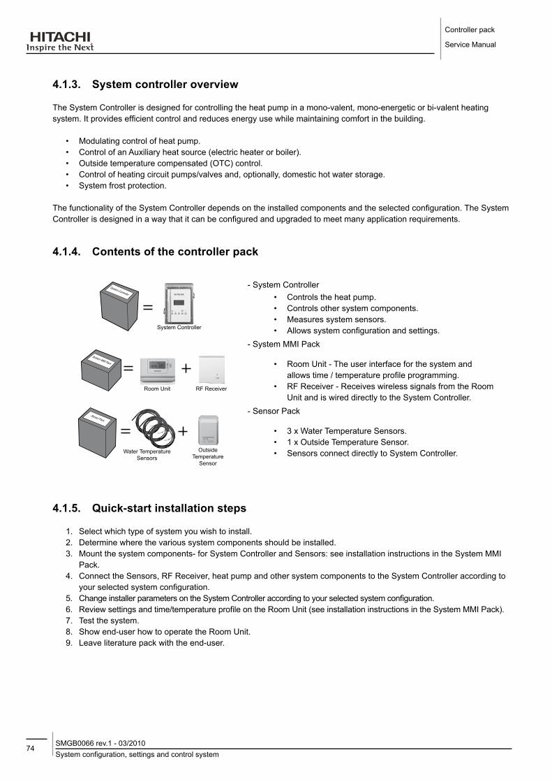
Controller pack
Service Manual
74System configuration, settings and control systemSMGB0066 rev.1 - 03/2010
4.1.3. System controller overview
The System Controller is designed for controlling the heat pump in a mono-valent, mono-energetic or bi-valent heating system. It provides efficient control and reduces energy use while maintaining comfort in the building.
• Modulating control of heat pump.• Control of an Auxiliary heat source (electric heater or boiler).• Outside temperature compensated (OTC) control.• Control of heating circuit pumps/valves and, optionally, domestic hot water storage.• System frost protection.
The functionality of the System Controller depends on the installed components and the selected configuration. The System Controller is designed in a way that it can be configured and upgraded to meet many application requirements.
4.1.4. Contents of the controller pack
System Controller
System Controller
- System Controller• Controls the heat pump.• Controls other system components.• Measures system sensors.• Allows system configuration and settings.
Room Unit RF Receiver
System MMI Pack
- System MMI Pack
• Room Unit - The user interface for the system and allows time / temperature profile programming.
• RF Receiver - Receives wireless signals from the Room Unit and is wired directly to the System Controller.
Water Temperature Sensors
Outside Temperature
Sensor
Sensor Pack
- Sensor Pack
• 3 x Water Temperature Sensors.• 1 x Outside Temperature Sensor.• Sensors connect directly to System Controller.
4.1.5. Quick-start installation steps
1. Select which type of system you wish to install.2. Determine where the various system components should be installed.3. Mount the system components- for System Controller and Sensors: see installation instructions in the System MMI
Pack.4. Connect the Sensors, RF Receiver, heat pump and other system components to the System Controller according to
your selected system configuration.5. Change installer parameters on the System Controller according to your selected system configuration.6. Review settings and time/temperature profile on the Room Unit (see installation instructions in the System MMI Pack).7. Test the system.8. Show end-user how to operate the Room Unit.9. Leave literature pack with the end-user.
75Mounting
SMGB0066 rev.1 - 03/2010
Controller pack
Service Manual
4
4.1.6. Abbreviations & terminology
Mono-ValentOne heating source (electric Heat Pump)Mono-EnergeticOne energy source (electric Heat Pump and electric heater)Bi-ValentTwo heating sources (electric Heat Pump and gas/oil Boiler)oTCOutside Temperature Compensated ControldHWDomestic Hot WaterZone 1The main heating loop controlled by the System Controller.Zone 2The extension mixed heating loop controlled by the Extension Controller.
TSUPSupply Water TemperatureTRETReturn Water TemperatureTdHWDHW TemperatureTExTOutside (external) Air TemperatureTMIxMixed Water TemperatureTR1Room TemperatureVMixing Valve PositionfAUlFault statusSSUPOverall system supply setpointS1Zone 1 supply setpointSR1Zone 1 room temperature setpointS2Zone 2 supply setpointdSETDHW setpointSdHWDHW supply setpoint
4.2. MoUNTINGThe System Controller is designed to be mounted either directly onto the wall or on a DIN-rail.
caution
-- Incorrect-wall-mounting.-Reduction-of-the-IP-protection-degree.-Perform-the-installation-of-the-System-Controller-without-damaging-the-unit.
4.2.1. fitting or removing the front cover
To remove the front cover from the mounting base
1. Unscrew the two retaining screws .
2. Pull the front cover off the mounting base .
caution
-- Crash-hazard.-Wire-damage.-Make-sure-that-all-connector-pins-and-blocks-are-correctly-located-before-pushing-the-front-cover-onto-the-base,-otherwise,-damage-may-occur.

Controller pack
Service Manual
76MountingSMGB0066 rev.1 - 03/2010
To fit the front cover onto the mounting base:
1. Line up the mounting base and front cover.
2. Push the front cover firmly onto the mounting base.
3. Secure the front cover using the two retaining screws.
4.2.2. Wall Mounting
- Four 4.0 mm holes for installation are located on the System Controller mounting base for wall mounting.- Before wall mounting, remove the four break-outs (A) in the case as necessary.
- For wire entry, remove the appropriate break-outs in the mounting box (B).- Use screws (max diameter 4mm) and wall plugs suitable for the wall material (not included in the delivery).
4.2.3. Mounting on a dIN-rail
- The system controller can easily be clicked on to a DIN-rail via the locating clips on both sides of the mounting base.1. Hold the system controller at an angle, and hook onto the top of the DIN-rail.2. Push the system controller straight and against the DIN-rail.3. The locating clips will snap on the bottom of the DIN-rail.4. For removal, bend the clips and pull off the system controller from the DIN-rail .

77Mounting the Sensors
SMGB0066 rev.1 - 03/2010
Controller pack
Service Manual
4
4.3. MoUNTING THE SENSoRS
4.3.1. Water Temperature Sensor
The water temperature sensor can be inserted into a suitable immersion well or strapped on to a pipe using the supplied metal clip.
note
-- For-strap-on-mounting,-the-metal-clip-must-be-used-and-tightened-firmly-to-provide-a-good-thermal-connection.-A-badly-mounted-sensor-can-cause-control-problems.
The best location for measuring the temperature and, therefore, inserting the sensor, is the immersion well for boiler temperature displays, boiler thermostat, and safe temperature guard. There is usually space for the sensor in this well (sensor cartridge: 6.5 mm Ø, 50 mm long).
In order to have good heat transmission between the sensor cartridge and the immersion well, the contact strip supplied must be inserted along with the cartridge. If there is no space in the well for the sensor, another separate well can be used near the aforementioned immersion well.
4.3.2. outside Temperature Sensor
• location of device
The most important rule for locating the Outdoor Temperature Sensor is that it should have the same temperature, wind, and solar conditions as the occupied rooms. In most cases, the Outdoor Temperature Sensor is to be mounted on the coldest side of the building (N–NW side) so as not to be affected by direct sunshine. This is to ensure that it will be warm enough in each room of the house. Only when the windows of all the rooms to be regulated face in the same direction can the sensor element be mounted onto the outside of this same wall. This can also be the south side of the house. The Outdoor Temperature Sensor’s protective housing prevents the sun’s rays from affecting the sensor. If the sensor has been mounted on the south

Controller pack
Service Manual
78Electrical wiringSMGB0066 rev.1 - 03/2010
side of a house with large windows facing in this direction, it is recommended that you remove the sun guard. Do not mount the Outdoor Temperature Sensor in a protected area, such as a wall niche or under the balcony. It should be put on an open façade so that it can detect all weather conditions. Avoid mounting the sensor above doors and windows since warm air movements may otherwise influence the measurement results. The Temperature Sensor should be mounted about 2/3 the way up the wall on buildings of not more than 3 stories; on taller buildings, between the second and third stories.
• Mounting
Press in the clasp (R) and pull off the top (H). Pull the clip (B) out of the housing (G). Screw on the clip (B) and put on the housing. To wire, unscrew the lid. Slide the top (H) over the housing until the clasp is firmly attached.
4.4. ElECTRICAl WIRING
caution
-- Electrical-hazard.-Can-cause-serious-injuries-or-death.-- Do-not-connect-or-adjust-any-wiring-or-connections-unless-the-main-power-switch-is-OFF.-- Make-sure-that-all-the-power-sources-are-switched-OFF.-- Isolate-the-mains-power-supply-before-installing-the-System-Controller.-Do-not-reconnect-the-mains-power-supply-until-the-installation-is-completed.
-- The-system-controller-must-be-intalled-by-a-suitably-qualified-person,-in-accordance-with-local-standards-and-guidelines.
The mounting base has two options for wiring: wall or surface-wiring, with wires from the rear or wiring from the bottom or sides. For safety reasons, the power source wiring and signal wires are separated and in different compartments of the mounting base
- On the left side the signal wiring is laid out (inputs, mainly sensors).
- On the right side, the power source and earth wiring are situated (power and output relay contacts).
note
-- It-is-important-that-power-supply-lines-are-kept-separate-from-signal/-data-communications-lines.-This-is-to-minimise-the-risk-of-electrical-interference.

79Electrical wiring
SMGB0066 rev.1 - 03/2010
Controller pack
Service Manual
4
4.4.1. Wiring access ports
• Wiring holes for wall or surface-wiring
When wiring through the back of the mounting base remove the breakout ports from the wiring holes at the rear base.
• Wiring holes for side- or bottom-wiring
When wiring through the bottom or side of the mounting base, insulated cables must be used. To ensure safety, appropriate cable glands (not included with the System Controller) must be used.
To install the cable glands, remove the breakout ports from the wiring holes at the required location in the base.
note
-- That-cable-glands-will-fit-a-range-of-cable-diameters;-therefore-check-to-ensure-that-the-proper-combination-is-used.
4.4.2. Wiring connections
caution
-- Static-electricity.-Malfunction.The-electronic-components-within-the-System-Controller-are-susceptible-to-damage-caused-by-static-electricity.-When-handling-the-device:-- Do-not-touch-internal-components.-- Touch-an-earthed-piece-of-metal-to-discharge-static-electricity-from-your-body.
-- Incorret-wiring.-Electrical-damage.-A-short-circuit-or-incorrect-installation-will-damage-the-system-controller.
• The terminal blocks
The terminal blocks (A, B and C) have the same terminals and are suitable for wires from 0.3 to 1.6mm2. The earth connector block D is suitable for wires from 0.3 to 2.7mm2.
note
-- In-some-applications,-there-may-be-several-input-and-output-cables-that-cannot-be-connected-directly-within-the-system-controller-terminal-blocks.-In-such-cases,-it-is-recommended-that-a-separate-wiring-centre-is-used,-with-an-appropriate-cover-as-necessary.

Controller pack
Service Manual
80Electrical wiringSMGB0066 rev.1 - 03/2010
• Mains power supply – Terminal block BThe mains power connection (230VAC) is wired to connector block B, terminals 13 and 15. Terminal 13 and 14 are internally connected.
NNL 15
1413
• Earth terminals – Terminal block dThe earth wires coming from the mains power cable and the pump, mixing valve, heat pump and boiler, can be combined and connected to connector block D. All three terminals are internally connected.
4.4.3 System component connections
• Heat pumpThe System Controller controls the heat pump outlet water temperature by a 4-20mA signal. When there is no demand for the heat pump to be on, the System Controller directly switches the heat pump off. The heat pump can signal to the System Controller when it has a fault so that a fault code can be displayed and appropriate action taken.
216
531
TERMINALBLOCK C
4-20mA
TERMINAL BLOCK A
Heat Pump
/N
OFF
O
21

81Electrical wiring
SMGB0066 rev.1 - 03/2010
Controller pack
Service Manual
4
note
-- The-4-20mA-signal-is-polarity-sensitive.-Connect-the-wires-as-shown.-Please-refer-to-heat-pump-installation-manual-for-terminal-connections.
• Three- stage electric heaterIn a mono-energetic system (CONF 2), the electric heater is used if required to increase the supply water temperature.
P19 Waiting time for boiler/electric heater
987TERMINAl BloCK A
Output 1Electric Heater
NOutput 2
• BoilerIn a Bi-Valent System (CONF 3,4,5), the boiler is used when the heat pump cannot achieve the desired supply temperature on its own. Set the minimum on and off times (P17 and P18), according to boiler type, to prevent inefficient short-cycling.
P17 Boiler Minimum ON TimeP18 Boiler Minimum OFF TimeP19 Waiting time for boiler/electric heater
12111098765
Boiler ON/OFF
Boiler Pump (CONF3)
Boiler Pump (CONF4)
TERMINAL BLOCK A
• Mixing valveIn a mixing system (CONF 4,5), the mixing valve is controlled to maintain the required supply temperature. Set the parameter (P9) according to the running time of the actuator used.
P9 Actuator Run Time for Mixing Valve
987TERMINAL BLOCK A
CloseMixing Valve
NOpen
• Secondary pumpThe secondary pump is the circulating pump for the main heating loop. In mono-valent and mono-energetic systems (CONF 1, 2), a secondary pump is only required if a hydraulic separator or buffer tank is used and in this case it is necessary to set the parameter (P2) to 1. Before the heating is switched off, the pump continues to run for a short time - pump overrun time (P3) – to distribute the energy through the system.
P2 Secondary Pump Selection (CONF 1,2)P3 Pump Overrun Time
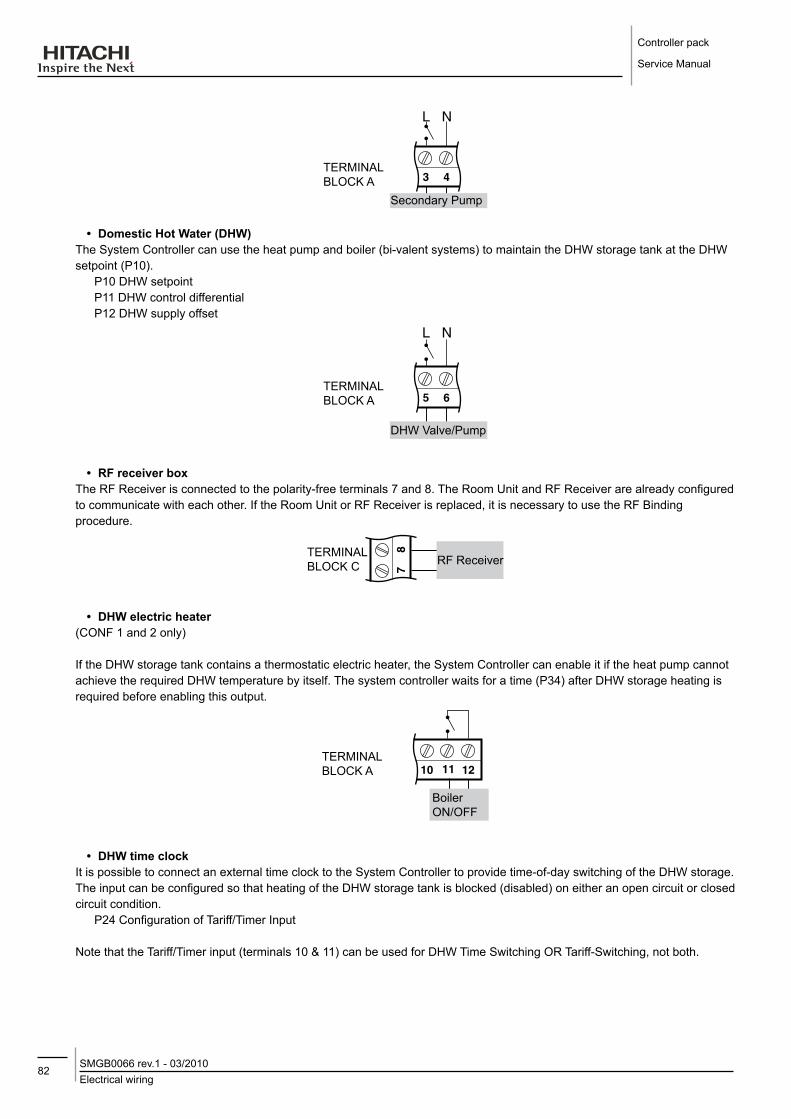
Controller pack
Service Manual
82Electrical wiringSMGB0066 rev.1 - 03/2010
TERMINAL BLOCK A
Secondary Pump
43
• domestic Hot Water (dHW)The System Controller can use the heat pump and boiler (bi-valent systems) to maintain the DHW storage tank at the DHW setpoint (P10).
P10 DHW setpointP11 DHW control differentialP12 DHW supply offset
TERMINAL BLOCK A
DHW Valve/Pump
65
• Rf receiver boxThe RF Receiver is connected to the polarity-free terminals 7 and 8. The Room Unit and RF Receiver are already configured to communicate with each other. If the Room Unit or RF Receiver is replaced, it is necessary to use the RF Binding procedure.
TERMINAL BLOCK C RF Receiver
87
• dHW electric heater(CONF 1 and 2 only)
If the DHW storage tank contains a thermostatic electric heater, the System Controller can enable it if the heat pump cannot achieve the required DHW temperature by itself. The system controller waits for a time (P34) after DHW storage heating is required before enabling this output.
121110
Boiler ON/OFF
TERMINAL BLOCK A
• dHW time clockIt is possible to connect an external time clock to the System Controller to provide time-of-day switching of the DHW storage. The input can be configured so that heating of the DHW storage tank is blocked (disabled) on either an open circuit or closed circuit condition.
P24 Configuration of Tariff/Timer Input
Note that the Tariff/Timer input (terminals 10 & 11) can be used for DHW Time Switching OR Tariff-Switching, not both.

83Electrical wiring
SMGB0066 rev.1 - 03/2010
Controller pack
Service Manual
4
P24 open Circuit on terminals 10/11 Closed Circuit on terminals 10/11
0 Tariff/Timer Input is ignored1 Tariff/Timer input is used for Heat Pump blocking2 Tariff/Timer input is used for Heat Pump blocking3 DHW is blocked DHW is enabled4 DHW is enabled DHW is blocked
TERMINAl BloCK C Timer input
1110
• Tariff-switching deviceIf a tariff-switching device (load shedding management) is provided by the electricity utility, it can be used to prevent the heat pump switching on, and the System Controller will use the boiler instead to satisfy the heating requirements (bi-valent systems only). The input can be configured so that the heat pump is blocked (disabled) on either an open circuit or closed circuit condition.
P24 Configuration of Tariff/Timer Input
Note that the Tariff/Timer input (terminals 10 & 11) can be used for DHW Time Switching OR Tariff-Switching, not both.
P24 open Circuit on terminals 10/11 Closed Circuit on terminals 10/11
0 Tariff/Timer Input is ignored1 Heat Pump is enabled Heat Pump is blocked2 Heat Pump is blocked Heat Pump is enabled3 Tariff/Timer input is used for DHW time clock4 Tariff/Timer input is used for DHW time clock
TERMINAL BLOCK C Tariff input
1110
• Temperature sensorsAll sensors used are of type NTC 20K (at 25°C).
• The outdoor sensor (T EXT) is used for the OTC control, frost protection, summer switch-off, and bi-valent system management.
• The DHW sensor (T DHW) is used to control the domestic hot water storage tank.• The supply sensor (T SUP) is used to control the water temperature from the heat sources. Please see hydraulic
diagrams for sensor positioning.• The mixed supply sensor (T MIX) is used in systems with a mixing valve (CONF 4 & 5 only) and should be positioned
after the mixing valve and the circulation pump.• The return water sensor (T RET) is used to control the heat pump return temperature protection and should be
positioned on the return pipe to the heat pump.
TERMINAL BLOCK C
TERMINAL BLOCK C
TERMINAL BLOCK C
T MIX
T DHW
T RET
T SUP
T EXT
109
54
32
115
14

Controller pack
Service Manual
84System configurationsSMGB0066 rev.1 - 03/2010
4.4.4 System configurations
In this sub-chapter, it’s shown the different terminal connections used for all the hydraulic system configurations of the System Controller.
¡ Mono-valent systems ‘conf 1’
Terminal block C (inputs) Terminal block A (outputs) Terminal block B (Power Supply)
Return sensor
Supply sensorOutdoor sensor
Heat pump control output
Heat pump fault
Tariff/ Timer inputDHW sensor
RF Receiver
-
+
T RET
4-20mA
T SUP
T DHW
T EXT
1211
109
87
65
43
21
1514
13
DH
W H
eater enable
DH
W
Valve/Pum
pS
econdary pum
pH
eat pump
remote on/off
ON
/O
FF
121110987654321
NNL
1514
13
¡ Mono-energetic systems ‘conf 2’

85System configurations
SMGB0066 rev.1 - 03/2010
Controller pack
Service Manual
4
Terminal block C (inputs) Terminal block A (outputs) Terminal block B (Power Supply)
Return sensor
Supply sensor
Outdoor sensor
Heat pump control output
Heat pump fault
Tariff/ Timer input
DHW sensor
RF receiver
-
+
T RET
4-20mA
T SUP
T DHW
T EXT
1211
109
87
65
43
21
1514
13
DH
W H
eater enable
Electric heater
output 2E
lectric heater output 1D
HW
Valve/P
ump
Secondary
Pum
p
Heat pum
p rem
ote on/offO
N/
OFF
21
121110987654321
NNL
1514
13
¡ Bi-Valent parallel systems - direct ‘conf 3’
Terminal block C (inputs) Terminal block A (outputs) Terminal block B (Power Supply)
Return sensor
Supply sensorOutdoor sensor
Heat pump control output
Heat pump fault
Tariff/ Timer inputDHW Sensor
RF Receiver
-+
T RET
4-20mA
T SUP
T DHW
T EXT
1211
109
87
65
43
21
1514
13
Boiler on/off
Boiler prim
ary pum
p
DH
W
Valve/Pum
pS
econdary pum
pH
eat pump
remote on/off
ON
/O
FF
121110987654321
NNL
1514
13

Controller pack
Service Manual
86System configurationsSMGB0066 rev.1 - 03/2010
¡ Bi-Valent system - parallel operation - mixing loop ‘conf 4’
Terminal block C (inputs) Terminal block A (outputs) Terminal block B (Power Supply)
Mixed supply sensor
Return sensor
Supply sensorOutdoor sensor
Heat pump control output
Heat pump fault
Tariff/ Timer input
RF Receiver
-
+
T MIX
T RET
4-20mA
T SUPT EXT
1211
109
87
65
43
21
1514
13
Boiler on/off
Secondary pum
p
Heat pum
p rem
ote on/offO
N/
OFF
Mixing valve close
Mixing valve open
Boiler prim
ary pump
121110987654321
NNL
1514
13
¡ Bi-Valent system - serial operation ‘conf 5’

87System configurations
SMGB0066 rev.1 - 03/2010
Controller pack
Service Manual
4
Terminal block C (inputs) Terminal block A (outputs) Terminal block B (Power Supply)
Mixed supply sensor
Return sensor
Supply sensorOutdoor sensor
Heat pump control output
Heat pump fault
Tariff/ Timer inputDHW Sensor
RF Receiver
-
+
T MIX
T RET
4-20mA
T SUP
T DHW
T EXT
1211
109
87
65
43
21
1514
13
Boiler on/off
Secondary pum
p
Heat pum
p rem
ote on/offO
N/
OFF
Mixing valve close
Mixing valve open
121110987654321
DH
W
Valve/Pum
p
NNL
1514
13
4.5. APPlICATIoN CoNfIGURATIoNSThe System Controller can be used for several different hydraulic system configurations, including mono-valent systems, mono-energetic systems with auxiliary electric heater, and bi-valent systems with gas/oil boiler. The hydraulic system configuration should be selected by setting the parameter CONF.
Hydraulic Configuration description Heat
Pump Electric Heater Boiler dHW direct Circuit Mixing Circuit
CONF 1
Mono-valent System
() Heat Pump only
Direct Circuit
CONF 2
Mono-Energetic System
() Heat Pump and Electric Heater
Direct Circuit
CONF 3
Bi-Valent Parallel System
() Heat Pump and Boiler
Direct Circuit
CONF 4
Bi-Valent Parallel System
Heat Pump and Boiler
Mixing Circuit
CONF 5
Bi-Valent Serial System
() Heat Pump and Boiler
Mixing By-pass Circuit
• dHW StorageThe System Controller can be used in a system which has a DHW storage tank, with either a diverting valve or pump. If the system has a separate DHW pump, then a hydraulic separator or buffer tank has to be used to ensure proper hydraulic balancing of the system.The DHW system type is selected by an installer parameter (P1)
• Buffer Tank or Hydraulic SeparatorWhen a hydraulic separator or buffer tank is used in CONF 1 & 2, the system will contain a secondary pump on the distribution side of the separator/buffer. In this case it is necessary to set installer parameter P2 to 1.In bi-valent systems (CONF 3,4,5) a hydraulic separator or buffer tank is always needed.

Controller pack
Service Manual
88System configurationsSMGB0066 rev.1 - 03/2010
4.5.1. Principle of bi-valent or mono-energetic operation
• functionBi-valent and mono-energetic systems use an auxiliary heat source (boiler or electric heater respectively) in addition to the heat pump.
At higher outdoor temperatures, the heat pump can provide all the heating requirements of the system, and it is not necessary to switch on the auxiliary heat source. However at lower outdoor temperatures, the electric heater or boiler is used to provide the increased heating demand. The changeover point for bi-valent or mono-energetic operation is called the balance point. A +/-0.5K control differential is applied to the switching between the operating modes.
Outdoor temperature (TEXT) > Balance Point (BP)+0.5K, the boiler or electric heater is not used. (Exception is that the boiler can be used for DHW loading.)Outdoor temperature (TEXT) < Balance point (BP)-0.5K, the system controller determines whether to switch on the boiler or electric heater depending on the heating requirements. Refer to the sections on Boiler Control and Electric Heater Control for more details.
• Installer ParametersP15 Maximum Outdoor Temperature for Boiler/Electric Heater Operation = Balance Point (BP) (default 0°C)P14 Minimum Outdoor Temperature for Heat Pump Operation (CONF 3,4,5 only) (default -20°C)
note
-- Parameter-P15-can-be-set-to-OFF,-in-which-case-the-boiler-or-electric-heater-is-allowed-to-operate-at-all-outdoor-temperatures
-- Parameter-P14-can-be-set-to-OFF,-in-which-case-the-heat-pump-is-allowed-to-operate-at-all-outdoor-temperatures.
• Configuration Specific - CONF 2 Mono-Energetic Systems
The electric heater is used to “top-up” the energy required for the system. The System Controller tries to ensure that the heat pump is always running when the electric heater is used, but there may be some circumstances where the electric heater is providing all the energy for the heating system.
Heating Zone
Heat Pump Capacity (kW)Heat Demand (kW)
Electric Heater
Heat Pump Only Heat Pump
20ºC P15 -20ºC Outside TempHeat Pump operates on it’s own down to the balance point (installer parameter P15)
Heat Pump plus Electric Heater operate together
- CONF 3,4 Bi-Valent Parallel SystemsThe normal operation in these systems is that when the heat pump cannot meet the heating load, the boiler will take over the full energy requirements of the system (alternative operation). Alternative Operation can be achieved by setting P14=P15. This means that either the heat pump or the boiler operate but not the two together (exception is during DHW demand).
iMPortant note
-- P14-should-never-be-set-higher-than-P15,-otherwise-incorrect-operation-will-result.

89System configurations
SMGB0066 rev.1 - 03/2010
Controller pack
Service Manual
4
- CONF 5 Bi-Valent Series SystemThe boiler is used to top-up the energy required for the system, but when the heat pump is outside it’s operating limits, the boiler will provide all of the heating requirements.
Heat Pump Capacity (kW)
Heating Zone
Heat Pump Only
Heat Demand (kW)
Boiler
Heat Pump
Boiler Only
20ºC p15 p14 outside temp. ºC
Heat Pump operates alone
Boiler and Heat Pump operate together when
needed
Boiler operates alone
default value 0C
default value -20C
4.5.2. mono-Valent systems (Conf 1)
• summary
In mono-valent systems, the heat pump is the sole provider of heating energy to the system. The Heat Pump is sized to provide 100% of the heating requirements on the coldest day of the year. It is recommended for low-energy houses and for moderate climates without severe winters. Used in new builds or in boiler-replacement applications.
This configuration is suitable for low-temperature radiators and underfloor heating systems.
• important parameter settingsCONF = 1P1 = 0,1,2 according to DHW system type.P2 = 0,1 according to whether a buffer tank/hydraulic separator and secondary pump is installed.P4 = heating curve according to building and system characteristics.It is also recommended to review all parameter settings, and make modifications as required by the installation.In order to achieve higher DHW temperatures, the system can operate with an auxiliary DHW electric heater.
• exampleMono-Valent System with DHW.DHW controlled by diverting valveAuxiliary DHW electric heater.
CONF=1 Mono-valent systemP1=1 DHW valveP2=0 no secondary pump
• exampleMono-Valent System with DHW.Hydraulic separator or buffer tank.Secondary pump for heating system.DHW controlled by separate pump.Auxiliary DHW electric heater.
CONF=1 Mono-valent systemP1=2 DHW pumpP2=1 Secondary pump

Controller pack
Service Manual
90System configurationsSMGB0066 rev.1 - 03/2010
4.5.3. mono-energetic systems (Conf 2)
• summaryIn mono-energetic systems, the heat pump is supplemented by a 3-stage electric heater to provide additional heating energy to the system. The Heat Pump is sized to provide around 60% of the heating requirements on the coldest day of the year, and will typically provide 90-95% of the heating requirements over the whole heating season. An electric auxiliary heater is used to provide the additional heating required on cold days. Used in new builds or in boiler-replacement applications.
• important parameter settingsCONF = 2P1 = 0,1,2 according to DHW system type.P2 = 0,1 according to whether a buffer tank/hydraulic separator and secondary pump is installed.P4 = heating curve according to building and system characteristics.P33 = 5K (electric heater return high limit offset)
The Electric Heater Return High Limit is an important check to help ensure that the heat pump operates as much as possible even when higher supply temperatures are required, thus emphasising energy economy operation. To enable this feature parameter P33 (return temperature limit offset) should be set to a value of 5K. Refer to the section on Electric Heater Control for more information.
It is also recommended to review all parameter settings, and make modifications as required by the installation.In order to achieve higher DHW temperatures, the system can operate with an auxiliary DHW electric heater.
• exampleMono-Energetic System with DHW.DHW controlled by diverting valveAuxiliary DHW electric heater.
CONF=2 Mono-energetic systemP1=1 DHW valveP2=0 no secondary pump
• exampleMono-Energetic System with DHW.Hydraulic separator or buffer tank.Secondary pump for heating system.DHW controlled by separate pump.Auxiliary DHW electric heater.
CONF=1 Mono-energetic systemP1=2 DHW pumpP2=1 Secondary pump

91System configurations
SMGB0066 rev.1 - 03/2010
Controller pack
Service Manual
4
4.5.4. Bi-valent Systems - Parallel operation (CoNf3)
• SummaryThis is a bivalent system where the boiler is configured in parallel with the heat pump. A hydraulic separator or buffer tank has to be used to ensure proper hydraulic balancing. This system is recommended for retrofit (upgrade) applications where an existing gas/oil boiler will be retained to provide the full heating requirements on the coldest days of the year
• Important Parameter SettingsCONF = 3P1 = 0,1,2 according to DHW system type.P4 = heating curve according to building and system characteristics.
It is also recommended to review all parameter settings, and make modifications as required by the installation.
• ExampleBi-Valent System with DHW.DHW controlled by diverting valveHydraulic separator or buffer tank.
CONF=3 Bi-valent Parallel systemP1=1 DHW valve
• ExampleBi-Valent System with DHW.Hydraulic separator or buffer tank.DHW controlled by separate pump.
CONF=3 Bi-Valent Parallel systemP1=2 DHW pump
4.5.5. Bi-Valent System - Parallel operation - Mixing loop (CoNf 4)
• SummaryThis is a bivalent system where the boiler is configured in parallel with the heat pump. A hydraulic separator or buffer tank has to be used to ensure proper hydraulic balancing. This system is recommended for retrofit (upgrade) applications where an existing gas/oil boiler will be retained to provide the full heating requirements on the coldest days of the year.
• Important Parameter SettingsCONF = 4P4 = heating curve according to building and system characteristics.DHW tank control is not possible with this system.It is also recommended to review all parameter settings, and make modifications as required by the installation.
• ExampleBi-Valent System with DHW & mixed heating loop.Hydraulic separator or buffer tank.
CONF=4 Bi-valent Parallel system

Controller pack
Service Manual
92System configurationsSMGB0066 rev.1 - 03/2010
4.5.6. Bi-Valent System - Serial operation (CoNf 5)
• SummaryThis is a bivalent system where the boiler is configured in series with the heat pump. A hydraulic separator or buffer tank has to be used to ensure proper hydraulic balancing. This system is also used for retrofit (upgrade) applications, but operates like the mono-energetic system using the gas/oil boiler, similarly to the electric heater, in series with the heat-pump. The boiler only needs to provide the additional peak load capacity
• Important Parameter SettingsCONF = 5P1 = 0,1,2 according to DHW system type.P4 = heating curve according to building and system characteristics.It is also recommended to review all parameter settings, and make modifications as required by the installation.
• ExampleBi-Valent System with DHW.Serial operation with bypass/mixing valve.DHW controlled by diverting valveHydraulic separator or buffer tank.
CONF=5 Bi-valent Parallel systemP1=1 DHW valve
• ExampleBi-Valent System with DHW.Serial operation with bypass/mixing valve.DHW controlled by separate pump.Hydraulic separator or buffer tank.
CONF=5 Bi-Valent Parallel systemP1=2 DHW pump

93Supply setpoint calculationSMGB0066 rev.1 - 03/2010
Controller pack
Service Manual
4
4.6. SUPPly SETPoINT CAlCUlATIoN• Calculation
The System Controller uses the “zone of greatest demand” strategy for calculating the supply water temperature required from the Heat Pump (and/or 3-stage electric heater or boiler).
The system controller recognises three “zones”:Zone 1: The normal heating loop controlled directly by the System Controller (direct or mixed depending on the
system configuration).Zone 2: The mixed heating loop controlled by the Extension Controller.DHW zone: The DHW storage tank loading loop.
Each zone can generate a demand to the heat pump (and/or boiler/electric heater) for a particular supply water temperatureS1: The supply setpoint water temperature required by the “zone 1” heating loop.S2: The supply setpoint water temperature required by the “zone 2” heating loop.SDHW: The supply setpoint water temperature required by the DHW loop.
The actual supply setpoint used at any time is the maximum of the three zone supply setpoints.
SSUP = maximum (S1, S2, SDHW)
It is the objective of the system controller to manage the Heat Pump, 3-stage electric heater and boiler appropriately to control the supply water temperature (TSUP) to this setpoint (SSUP).
• IllustrationThe diagram below shows the three possible “zones” and illustrates the required water temperatures (S1, S2, SDHW) for each zone, and the resulting overall supply setpoint (SSUP).
Devices controlled by the System Controller
DHW Zone 1 Zone 2
Devices controlled by the Extension Controler
• ExampleHeating zone 1 requires 50°C (calculated from OTC heating curve)Heating zone 2 requires 35°C (calculated by extension controller)DHW loading not required
S1 = 50°C, S2 = 35°C, SDHW = 0°CTherefore SSUP = maximum of (50°C, 35°C, 0°C) = 50°C
Note that the extension controller will then control the mixing circuit to achieve comfort conditions in zone 2.
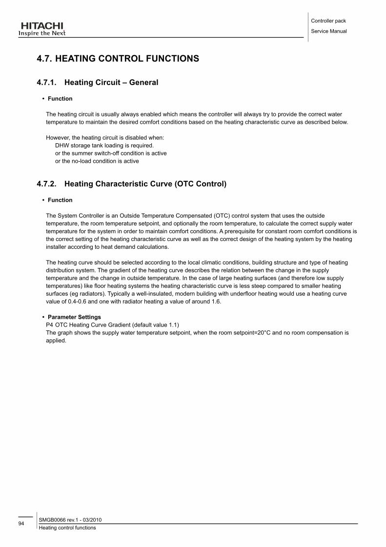
Controller pack
Service Manual
94Heating control functionsSMGB0066 rev.1 - 03/2010
4.7. HEATING CoNTRol fUNCTIoNS
4.7.1. Heating Circuit – General
• function
The heating circuit is usually always enabled which means the controller will always try to provide the correct water temperature to maintain the desired comfort conditions based on the heating characteristic curve as described below.
However, the heating circuit is disabled when: DHW storage tank loading is required. or the summer switch-off condition is active or the no-load condition is active
4.7.2. Heating Characteristic Curve (oTC Control)
• function
The System Controller is an Outside Temperature Compensated (OTC) control system that uses the outside temperature, the room temperature setpoint, and optionally the room temperature, to calculate the correct supply water temperature for the system in order to maintain comfort conditions. A prerequisite for constant room comfort conditions is the correct setting of the heating characteristic curve as well as the correct design of the heating system by the heating installer according to heat demand calculations.
The heating curve should be selected according to the local climatic conditions, building structure and type of heating distribution system. The gradient of the heating curve describes the relation between the change in the supply temperature and the change in outside temperature. In the case of large heating surfaces (and therefore low supply temperatures) like floor heating systems the heating characteristic curve is less steep compared to smaller heating surfaces (eg radiators). Typically a well-insulated, modern building with underfloor heating would use a heating curve value of 0.4-0.6 and one with radiator heating a value of around 1.6.
• Parameter SettingsP4 OTC Heating Curve Gradient (default value 1.1)The graph shows the supply water temperature setpoint, when the room setpoint=20°C and no room compensation is applied.

95Heating control functions
SMGB0066 rev.1 - 03/2010
Controller pack
Service Manual
4
• ExampleP4 = 1.1,TEXT (outside temperature) = 0°C,SR1 (room setpoint) = 20°C=> From graph, S1 (supply setpoint) = 49°C
4.7.2.1. Room Setpoint Parallel Shift
• function
At different times of the day, according to the time programme in the Room Unit, the room temperature setpoint will cause a parallel shift of the heating curve. The change in supply setpoint due to the room setpoint is dependant on the actual value of the outside temperature and the selected heating curve.
• ExampleP4 = 1.1TEXT (outside temperature) = 0°CSR1 (room setpoint) = 18°C=> S1 (supply setpoint) = 45°CIn this case, for a 2K change in room setpoint, the supply setpoint is changed by 4 K
note
-- The-room-setpoint-value-is-sent-from-the-Room-Unit-to-the-System-Controller-by-a-wireless-signal.-There-can-be-a-short-delay-in-response-between-a-room-setpoint-change-and-the-system-controller-changing-the-supply-setpoint.
4.7.2.2. Room Temperature Compensation
• functionIf room compensation is enabled, the calculated OTC supply setpoint is adjusted based on the difference between room temperature and room setpoint in order to reduce the room error. The amount of room influence can be adjusted by the room temperature compensation factor setting.
• Parameter SettingP7 Room Compensation Factor (default value 2)
To increase or decrease the amount of room compensation, adjust the room compensation factor. A higher value will give more priority to the room temperature error, and a lower value will mean the controller follows more closely the selected heating curve.

Controller pack
Service Manual
96Heating control functionsSMGB0066 rev.1 - 03/2010
• ExampleP7 = 2,SR1 (room setpoint) = 20,TR1 (room temperature) = 23=> S1 (supply setpoint) reduced by 2 * (23 – 20) = 6K
• Enable/disableTo disable room compensation completely, set P7=0. It is also recommended to change the setting 8:Su=1 on the room unit. This will prevent the room temperature being transmitted to the System Controller and the room temperature will not be displayed to the end-user on the Room Unit. Please refer to the System MMI Pack Installation and Operation Manual for further details.
note
-- Room-compensation-should-not-be-used-when-the-room-unit-is-located-in-a-position-unrepresentative-of-the-desired-temperature-in-the-living-spaces,-for-example-in-a-warm-cupboard
-- The-room-setpoint-and-room-temperature-values-are-sent-from-the-Room-Unit-to-the-System-Controller-by-a-wireless-signal.-There-can-be-a-short-delay-in-response-between-a-room-setpoint-or-temperature-change-and-the-system-controller-changing-the-supply-setpoint.
4.7.3. Heating Circuit Minimum/Maximum Temperature limits
• functionThe calculated supply water temperature setpoint is limited between the minimum supply temperature and the maximum supply temperature settings. The maximum temperature limit can be used for example to prevent high temperatures going to floor heating systems. The minimum temperature limit can be used when it is desired to keep a minimum level of heating in the heating circuit.
• Parameter SettingP5 Minimum Supply Temperature (default 15°C)P6 Maximum Supply Temperature (default 55°C)
• Configuration SpecificCONF 1: P6 can be set up to a maximum value of 55°CCONF 2: P6 can be set up to a maximum value of 65°CCONF 3,4,5: P6 can be set up to a maximum value of 90°C
4.7.4. Heating Circuit (Secondary) Pump
• functionWhen the heating circuit is enabled, the secondary pump will be switched on. When the heating circuit is disabled, the secondary pump is switched off after a pump overrun time.
If the screed function is activated or system frost protection is active, the secondary pump continues to run.
If the system uses a DHW diverting valve and DHW storage tank loading is active, then the secondary pump continues to run, since it is also used for the DHW loading.
• Parameter SettingsP2 Secondary Pump Selection (default 0 – no secondary pump)P3 Pump Overrun Time (default 2 min)

97DHW control functions
SMGB0066 rev.1 - 03/2010
Controller pack
Service Manual
4
• Configuration SpecificCONF 1,2: If a buffer tank or hydraulic separator is used between the Heat Pump and the heating circuit, it is
necessary to set parameter P2=1 to enable control of the secondary pump.CONF 3,4,5: Secondary pump control is always enabled.CONF 4,5: If the mixed circuit maximum temperature limit is active, then the secondary pump is switched off.
4.7.5. Automatic No-load function
• functionWhen the calculated supply temperature setpoint (from OTC heating curve + room setpoint shift + room compensation shift) is less than the room temperature, then the heating circuit can be switched off to save energy. A switching differential of +/- 1K is applied.
• AlgorithmOTC supply setpoint < room temperature (TR1) – 1K => No-Load condition is activeOTC supply setpoint > room temperature (TR1) + 1K => No-Load condition is not active.
When the No-Load condition is active, the heating circuit is switched off.
• Parameter SettingsP30 No-Load Function enable/disable (default 1)= 0 disabled= 1 enabled
4.8. dHW CoNTRol fUNCTIoNS
4.8.1. dHW Storage Tank loading
• Configuration SpecificThe DHW control function is available for configurations CONF1,2,3, and 5.
• Enable/disableTo enable DHW control, parameter P1 should be set according to whether the system uses a diverting valve or separate pump for the DHW circuit.
dHW Circuit
Heating Circuit
dHW Circuit
Heating Circuit
DHW diverting valve system DHW pumped system
• functionThe DHW function has priority over the Heating Circuit, which means that when the DHW storage tank is being loaded, the heating circuit will be switched off.
The DHW function will be blocked (temporarily disabled) when the Tariff/Timer input is configured for DHW and the input
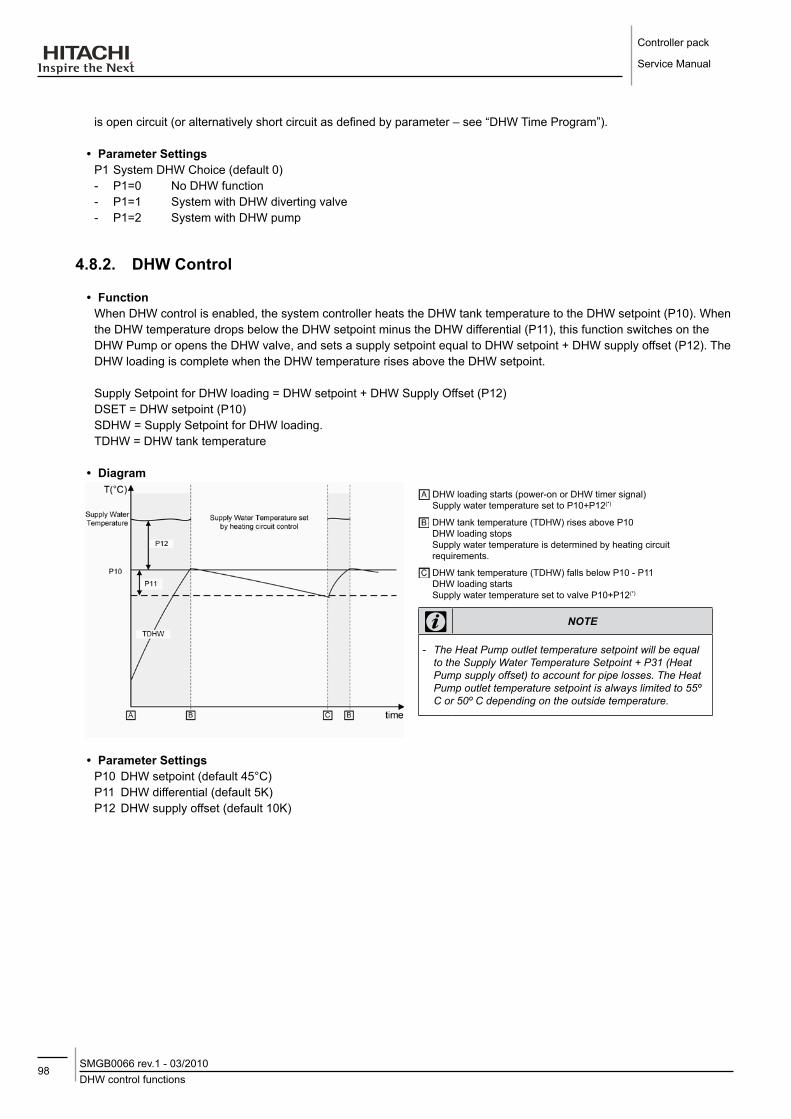
Controller pack
Service Manual
98DHW control functionsSMGB0066 rev.1 - 03/2010
is open circuit (or alternatively short circuit as defined by parameter – see “DHW Time Program”).
• Parameter SettingsP1 System DHW Choice (default 0) - P1=0 No DHW function - P1=1 System with DHW diverting valve - P1=2 System with DHW pump
4.8.2. dHW Control
• functionWhen DHW control is enabled, the system controller heats the DHW tank temperature to the DHW setpoint (P10). When the DHW temperature drops below the DHW setpoint minus the DHW differential (P11), this function switches on the DHW Pump or opens the DHW valve, and sets a supply setpoint equal to DHW setpoint + DHW supply offset (P12). The DHW loading is complete when the DHW temperature rises above the DHW setpoint.
Supply Setpoint for DHW loading = DHW setpoint + DHW Supply Offset (P12)DSET = DHW setpoint (P10)SDHW = Supply Setpoint for DHW loading.TDHW = DHW tank temperature
• diagram DHW loading starts (power-on or DHW timer signal)Supply water temperature set to P10+P12(*)
DHW tank temperature (TDHW) rises above P10DHW loading stops Supply water temperature is determined by heating circuit requirements.
DHW tank temperature (TDHW) falls below P10 - P11DHW loading starts Supply water temperature set to valve P10+P12(*)
note
-- The-Heat-Pump-outlet-temperature-setpoint-will-be-equal-to-the-Supply-Water-Temperature-Setpoint-+-P31-(Heat-Pump-supply-offset)-to-account-for-pipe-losses.-The-Heat-Pump-outlet-temperature-setpoint-is-always-limited-to-55º-C-or-50º-C-depending-on-the-outside-temperature.
• Parameter SettingsP10 DHW setpoint (default 45°C)P11 DHW differential (default 5K)P12 DHW supply offset (default 10K)

99DHW control functions
SMGB0066 rev.1 - 03/2010
Controller pack
Service Manual
4
• Configuration SpecificCONF 1,2: Heat Pump heats the DHW storage tank directly. If the storage tank also has an internal DHW electric
heater this can also be used if necessary.CONF 2: The 3-stage electric heater cannot be used for DHW loading. When DHW loading starts, the 3-stage
electric heater is switched off.CONF 3,5: If the Heat Pump is not able to reach the DHW supply setpoint by itself, the boiler may also be used to
raise the temperature of the DHW tank (see “Using the Boiler for DHW loading”).
• Parameter NotesP10: DHW setpoint CONF 1,2: If there is no internal DHW electric heater, setting the DHW setpoint higher than 45°C may result in very
long DHW loading times, and the desired temperature may not be reached. This is because the maximum outlet temperature from the Heat Pump is normally 55°C, and at low outdoor temperatures 50°C.
CONF 3,5: The DHW setpoint may be set higher since the boiler will also be used to heat the DHW storage tank.
P11: DHW differentialA small DHW differential will increase the frequency of the DHW loading periods while making them shorter. A large DHW differential will reduce the frequency of the DHW loading periods, while making each period longer, and will cause larger swings in DHW temperatures.
P12: DHW supply offsetCONF 1,2: setting a value higher than 10K will not affect the DHW loading period since the maximum outlet
temperature from the Heat Pump is 55°C.CONF 3,5: setting a value higher than 10K will allow faster DHW loading times since the boiler can be used.
4.8.3. Maximum dHW loading Time
• function
In case there is a continuous high demand for DHW over a very long period, or the DHW setpoint is set too high, the Heat Pump may not be able to reach the desired temperature. In this case, to ensure that heat is provided in the living space (heating circuit), the DHW loading is stopped after a preset time (parameter P27) and the system controller returns to satisfy the demand from the heating circuit.
• diagram DHW loading starts (power-on or DHW timer signal)Supply water temperature set to P10+P12(*)
DHW setpoint not reached after time P27DHW loading stopped

Controller pack
Service Manual
100DHW control functionsSMGB0066 rev.1 - 03/2010
• Parameter SettingP27 Maximum allowed DHW loading time (default 1.5hr)
note
-- After-the-DHW-loading-has-stopped,-the-DHW-electric-heater-(if-connected)-will-continue-to-be-enabled-until-the-DHW-setpoint-temperature-is-reached
• Automatic Reset
Only after 24hrs, or at the next time clock enable period (if an external DHW time clock is used), the system controller will use the Heat Pump once again to load the DHW tank.
4.8.4. dHW Electric Heater
Configuration Specific This function is only available in configurations 1 and 2 (CONF 1,2).function The DHW tank may have an internal electric heater for situations when the
heatpump is unable to fully load the DHW tankThe Heat Pump is not able to heat the DHW tank to high temperatures by itself because its output is limited. The maximum temperature to which the heat pump can raise the DHW tank is defined as :DSET_HP = the maximum temperature to which the heat pump can heat the DHW tank = Heat Pump maximum supply temperature (EP29 or EP33) – EP39IF DSET (P10) is set less than this value then the DHW electric heater operates as in situation 1 below.IF DSET (P10) is greater than this value then the DHW electric heater operates as in situation 2 below... .
Situation 1:P10 < dSET_HP
If, after the DHW electric heater waiting time, the DHW temperature has not reached the DHW setpoint, the DHW electrical heater enable output is switched on. The electrical heater operates on its own thermostat to raise the temperature of the DHW tank.

101DHW control functions
SMGB0066 rev.1 - 03/2010
Controller pack
Service Manual
4
Situation 2:P10 > dSET_HP
The Heat Pump is used to heat the DHW tank to the temperature DSET_HP. Then the DHW electric heater is switched on to heat the DHW tank to the temperature DSET. With slow reductions in DHW temperature, the DHW electric heater is switched on again when the DHW temperature falls below DSET minus P11. With a large reductions in DHW temperature (for example, a large draw-off from the tank, or after a period of DHW blocking), when the DHW temperature falls below DSET_HP minus P11, the heat pump is again used to heat the DHW tank to DSET_HP before the DHW electric heater is switched on again.
If, after the DHW electric heater waiting time (P34), the DHW temperature has not reached the DHW setpoint, the DHW electric heater enable output is switched on. The electric heater operates on its own thermostat to raise the temperature of the DHW tank.
Parameter Setting: P10 DHW setpointP34 DHW Electric Heater Waiting Time (default 45 min)EP39 DHW offset for maximum heat pump supply temperature (default 7K)Engineering Parameters (EP) are only available for service engineers.
Note The electric heater should have its own thermostat set to a higher value than the DHW setpoint of the System Controller. Please take care about the type of DHW storage tank fitted and the position of the electric heater.

Controller pack
Service Manual
102DHW control functionsSMGB0066 rev.1 - 03/2010
4.8.5. Using the Boiler for dHW loading
Configuration Specific Applies only to configurations CONF 3,5function The boiler may also be used to raise the temperature of the DHW tank if the Heat
Pump is not able to reach the DHW supply setpoint by itself. The boiler will only start after a time delay defined by parameter P19 (waiting time for boiler) in order to allow the Heat Pump time to satisfy the DHW loading demand by itself.The maximum temperature to which the heat pump can heat the DHW tank is defined as:
DSET_HP = the maximum temperature to which the heat pump can heat the DHW tank = Heat Pump maximum supply temperature (EP29 or EP33) – EP39
If DSET (P10) is set less than this value then the Boiler operates as in situation 1 below.If DSET (P10) is set greater than this value then the Boiler operates as in situation 2 below.
Situation 1 P10 < DSET_HP If, after the boiler waiting time (P19), the DHW temperature has not reached the DHW setpoint, the boiler is switched on.
Situation 2 P10 > DSET_HP The Heat Pump is used to heat the DHW tank to the temperature DSET_HP. Then the Boiler is switched on to heat the DHW tank to the temperature DSET. This action is similar to the action for the DHW electric heater (section 5.4).
If, after the boiler waiting time (P19), the DHW temperature has not reached the DHW setpoint, the boiler is anyway switched on.
Parameter Setting P10 DHW setpointP19 Waiting Time for Boiler (default 30 min)EP39 DHW offset for maximum heat pump supply temperature (default 7K)Engineering Parameters (EP) are only available for service engineers.
4.8.6. Response of the Heat pump to a dHW demand
• function
Since the heat pump only reads the control signal (mA) once every 20 minutes there can be a delay before the system responds to the DHW request. In order to improve this response time, the System Controller uses a feature of the heat pump that when the control signal is set to its highest value, it responds immediately. So if the supply setpoint has to be increased due to a DHW demand, then the supply setpoint is set to the parameter EP29 (Heat Pump maximum supply temperature) for a certain time. This time is the Heat Pump Max Time High Setpoint (EP35). When this time period expires, the Supply Setpoint is set to the normal calculated DHW supply setpoint.
• Parameter Setting
EP35 Heat Pump Max Time High Setpoint (default 180sec)
note
-- Engineering-Parameters-(EP)-are-only-available-for-service-engineers

103DHW control functions
SMGB0066 rev.1 - 03/2010
Controller pack
Service Manual
4
4.8.7. dHW Time Program
• functionA DHW time program is not provided inside the controller. An external timer can be used by itself or together with a tariff-switch device. For example, with an external timer it is possible to block DHW loading during daytime periods.It is possible to use1. only a external timer. Operates according to EP24 setting.2. an external timer in series with a tariff-switch device. In this case:
if EP24=3 both the external timer and the tariff-switch contacts must be closed to allow DHW loading if EP24=4 either of the external timer or the tariff-switch contacts can be open to allow DHW loading.
3. an external timer in parallel with a tariff-switch device. In this case: if EP24=3 either of the external timer or the tariff-switch contacts can be open to allow DHW loading if EP24=4 both the external timer and the tariff-switch contacts must be closed to allow DHW loading.
4. only a tariff switch device. Operates according to EP24 setting.
Depending on the setting of the configuration of tariff/timer input parameter (EP24), DHW loading can be blocked according to the status of the input (open or closed).
• diagram
• Parameter Setting
P24 Configuration of Tariff/Timer Input (default 4)
P24 open Circuit on terminals 10/11 Closed Circuit on terminals 10/11
0 Tariff/Timer input is ignored
1 Tariff/Timer input is used for Heat Pump blocking
2 Tariff/Timer input is used for Heat Pump blocking
3 DHW is blocked DHW is enabled
4 DHW is enabled DHW is blocked
note
-- The-tariff/timer-input-can-be-used-for-DHW-time-switching-OR-Heat-Pump-blocking,-not-both
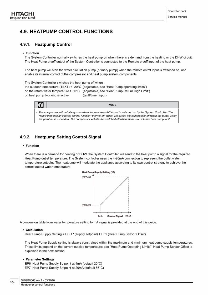
Controller pack
Service Manual
104Heatpump control functionsSMGB0066 rev.1 - 03/2010
4.9. HEATPUMP CoNTRol fUNCTIoNS
4.9.1. Heatpump Control
• functionThe System Controller normally switches the heat pump on when there is a demand from the heating or the DHW circuit. The Heat Pump on/off output of the System Controller is connected to the Remote on/off input of the heat pump.
The heat pump will start the water circulation pump (primary pump) when the remote on/off input is switched on, and enable its internal control of the compressor and heat pump system components.
The System Controller switches the heat pump off when :the outdoor temperature (TEXT) < -20°C (adjustable, see “Heat Pump operating limits”)or, the return water temperature > 60°C (adjustable, see “Heat Pump Return High Limit”)or, heat pump blocking is active (tariff/timer input)
note
-- The-compressor-will-not-always-run-when-the-remote-on/off-signal-is-switched-on-by-the-System-Controller.-The-Heat-Pump-has-an-internal-control-function-“thermo-off”-which-will-switch-the-compressor-off-when-the-target-water-temperature-is-exceeded.-The-compressor-will-also-be-switched-off-when-there-is-an-internal-heat-pump-fault.
4.9.2. Heatpump Setting Control Signal
• function
When there is a demand for heating or DHW, the System Controller will send to the heat pump a signal for the required Heat Pump outlet temperature. The System controller uses the 4-20mA connection to represent the outlet water temperature setpoint. The heatpump will modulate the appliance according to its own control strategy to achieve the correct output water temperature.
A conversion table from water temperature setting to mA signal is provided at the end of this guide.
• CalculationHeat Pump Supply Setting = SSUP (supply setpoint) + P31 (Heat Pump Sensor Offset)
The Heat Pump Supply setting is always constrained within the maximum and minimum heat pump supply temperatures. These limits depend on the current outside temperature; see “Heat Pump Operating Limits”. Heat Pump Sensor Offset is explained in the next section.
• Parameter SettingsEP6 Heat Pump Supply Setpoint at 4mA (default 20°C)EP7 Heat Pump Supply Setpoint at 20mA (default 55°C)
105Heatpump control functionsSMGB0066 rev.1 - 03/2010
Controller pack
Service Manual
4
These parameters should only be changed with the approval of the manufacturer.
note
-- Engineering-Parameters-(EP)-are-only-available-for-service-engineers.
4.9.3. Heatpump Sensor offset
• functionIn practice, there may be a difference between the heat pump outlet temperature (measured by the Heat Pump) and the supply temperature (measured by the system controller). This can be caused by:1. Different measuring position. The Heat Pump is outside and some loss of heat is possible between the heat pump
and the supply pipes inside the house.2. Different types of sensor. The Heat Pump measures the outlet temperature using an immersion-type sensor directly
in the water flow after the condenser. The System Controller uses a strap-on type sensor, which depending on the ambient conditions, will typically measure a lower temperature than an immersion-type in the same location.
This difference needs to be taken into account for optimum control performance, and parameter P31 is provided so this can be adjusted according to the installation.
• Parameter SettingsP31 Heat Pump Sensor Offset (default 3K)
note
-- It-is-important-to-minimise-this-effect-as-much-as-possible-during-installation.-The-following-precautions-should-be-taken-- 1.-Fully-insulate-the-supply-and-return-pipes.-- 2.-Ensure-that-the-supply-temperature-sensor-is-tightly-strapped-on-to-the-pipe-with-the-metal-clip-provided.
-- The-metal-clip-should-be-used-directly-around-the-sensor-element-itself-(since-it-itself-improves-the-heat-transfer)-and-then-insulation-should-be-placed-around-the-sensor-and-fixed-securely-in-place.
4.9.4. Heatpump Maximum Return High limit
• functionThe Heat Pump itself ensures good control of the outlet water temperature, and switches off the compressor when the return water temperature gets too high. However, in some circumstances with bi-valent systems, the boiler may be operating at high supply and return temperatures. If the return water temperature to the Heat Pump rises above 65°C it will generate a system fault (“excessively high water temperature”). To prevent this happening, the System Controller will directly switch off the heat pump if the return temperature rises above a set limit.Return water temperature (TRET) > EP13 + 0.5K Heat Pump is switched offReturn water temperature (TRET) < EP13 - 0.5K Heat Pump may be switched on.
• Parameter SettingsEP13 Heat Pump Maximum Return Temperature (default 60°C)This value should not normally need to be changed.
note
-- Engineering-Parameters-(EP)-are-only-available-for-service-engineers.

Controller pack
Service Manual
106Heatpump control functionsSMGB0066 rev.1 - 03/2010
4.9.5. Heatpump operating limits
• functionHeat Pump operation is only possible within certain temperature ranges as defined below. Parameters are provided in order to adjust the working area if required to do so by Hitachi.The Heat Pump water temperature setting sent by the System Controller is always constrained to lie between the maximum and minimum limits defined by the operating limits.
If the outdoor temperature is below -20°C (P14 in Config 3,4,5 / EP14 in Config 1,2), the heat pump will always be switched off.
• Heat Pump Working Area
• Parameter SettingsP14 / EP14 Heat Pump minimum outdoor temperature (default -20°C)EP28 Heat Pump minimum supply temperature below outdoor temperature of EP32 (default 35°C)EP29 Heat Pump maximum supply temperature above outdoor temperature of EP34 (default 55°C)EP32 Heat Pump minimum supply inflexion point (default 0°C)EP33 Heat Pump maximum supply temperature below outdoor temperature of EP34 (default 50°C)
EP34 Heat Pump maximum supply changing point (default -10°C)
note
-- Engineering-Parameters-(EP)-are-only-available-for-service-engineers.
4.9.6. Tariff Switch (Heat Pump blocking) Input
• Configuration Specific
The tariff switch input (heat pump blocking) is only allowed for Bi-Valent systems. For mono-valent or mono-energetic systems the heat pump can never be blocked by this input.
• function
This function allows an external tariff-switch device to switch off the heat pump during times of peak electricity demand. When the controller is working in bi-valent mode, the boiler will be switched on to provide the necessary heating.
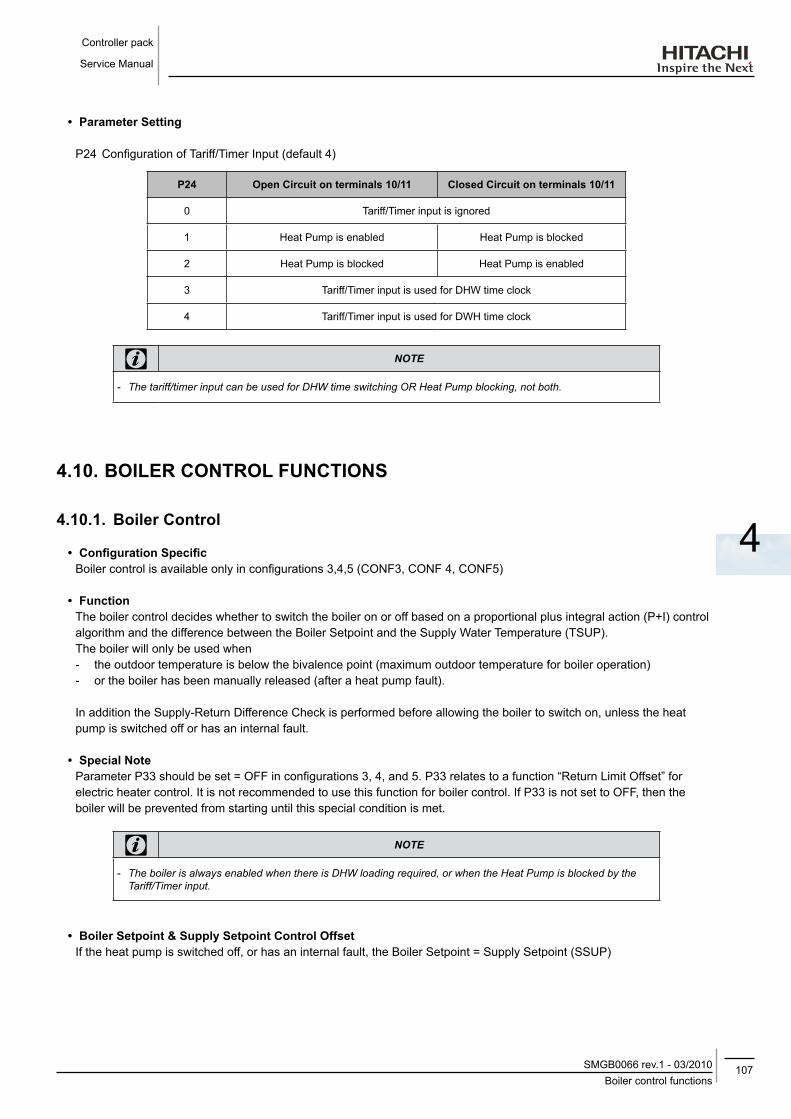
107Boiler control functions
SMGB0066 rev.1 - 03/2010
Controller pack
Service Manual
4
• Parameter Setting
P24 Configuration of Tariff/Timer Input (default 4)
P24 open Circuit on terminals 10/11 Closed Circuit on terminals 10/11
0 Tariff/Timer input is ignored
1 Heat Pump is enabled Heat Pump is blocked
2 Heat Pump is blocked Heat Pump is enabled
3 Tariff/Timer input is used for DHW time clock
4 Tariff/Timer input is used for DWH time clock
note
-- The-tariff/timer-input-can-be-used-for-DHW-time-switching-OR-Heat-Pump-blocking,-not-both.
4.10. BoIlER CoNTRol fUNCTIoNS
4.10.1. Boiler Control
• Configuration SpecificBoiler control is available only in configurations 3,4,5 (CONF3, CONF 4, CONF5)
• functionThe boiler control decides whether to switch the boiler on or off based on a proportional plus integral action (P+I) control algorithm and the difference between the Boiler Setpoint and the Supply Water Temperature (TSUP).The boiler will only be used when - the outdoor temperature is below the bivalence point (maximum outdoor temperature for boiler operation) - or the boiler has been manually released (after a heat pump fault).
In addition the Supply-Return Difference Check is performed before allowing the boiler to switch on, unless the heat pump is switched off or has an internal fault.
• Special NoteParameter P33 should be set = OFF in configurations 3, 4, and 5. P33 relates to a function “Return Limit Offset” for electric heater control. It is not recommended to use this function for boiler control. If P33 is not set to OFF, then the boiler will be prevented from starting until this special condition is met.
note
-- The-boiler-is-always-enabled-when-there-is-DHW-loading-required,-or-when-the-Heat-Pump-is-blocked-by-the-Tariff/Timer-input.
• Boiler Setpoint & Supply Setpoint Control offsetIf the heat pump is switched off, or has an internal fault, the Boiler Setpoint = Supply Setpoint (SSUP)
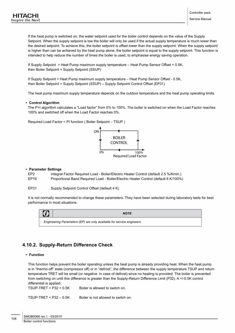
Controller pack
Service Manual
108Boiler control functionsSMGB0066 rev.1 - 03/2010
If the heat pump is switched on, the water setpoint used for the boiler control depends on the value of the Supply Setpoint. When the supply setpoint is low the boiler will only be used if the actual supply temperature is much lower than the desired setpoint. To achieve this, the boiler setpoint is offset lower than the supply setpoint. When the supply setpoint is higher than can be achieved by the heat pump alone, the boiler setpoint is equal to the supply setpoint. This function is intended to help reduce the number of times the boiler is used, to emphasise energy saving operation.
If Supply Setpoint > Heat Pump maximum supply temperature – Heat Pump Sensor Offset + 0.5K, then Boiler Setpoint = Supply Setpoint (SSUP)
If Supply Setpoint < Heat Pump maximum supply temperature – Heat Pump Sensor Offset - 0.5K, then Boiler Setpoint = Supply Setpoint (SSUP) – Supply Setpoint Control Offset (EP31)
The heat pump maximum supply temperature depends on the outdoor temperature and the heat pump operating limits.
• Control AlgorithmThe P+I algorithm calculates a “Load factor” from 0% to 100%. The boiler is switched on when the Load Factor reaches 100% and switched off when the Load Factor reaches 0%.
Required Load Factor = PI function ( Boiler Setpoint – TSUP )
ON
BOILERCONTROL
100%0%Required Load Factor
• Parameter SettingsEP2 Integral Factor Required Load - Boiler/Electric Heater Control (default 2.5 %/Kmin.)EP16 Proportional Band Required Load - Boiler/Electric Heater Control (default 6 K/100%)
EP31 Supply Setpoint Control Offset (default 4 K)
It is not normally recommended to change these parameters. They have been selected during laboratory tests for best performance in most situations.
note
-- Engineering-Parameters-(EP)-are-only-available-for-service-engineers.
4.10.2. Supply-Return difference Check
• function
This function helps prevent the boiler operating unless the heat pump is already providing heat. When the heat pump is in “thermo-off” state (compressor off) or in “defrost”, the difference between the supply temperature TSUP and return temperature TRET will be small (or negative in case of defrost) since no heating is provided. The boiler is prevented from switching on until this difference is greater than the Supply-Return Difference Limit (P32). A +/-0.5K control differential is applied.TSUP-TRET > P32 + 0.5K Boiler is allowed to switch on.
TSUP-TRET < P32 – 0.5K Boiler is not allowed to switch on.

109Boiler control functions
SMGB0066 rev.1 - 03/2010
Controller pack
Service Manual
4
When the boiler starts from cold, the supply temperature can drop for a small time as the cold water in the heat exchanger is pumped into the system. This function would then cause the boiler to be switched off. In order to prevent this, this function does not operate when the boiler is switched on until a certain time has passed from the boiler starting. This delay time is defined by a parameter Boiler Delay Time (EP36).
• Enable/disableThis function can be disabled by setting parameter P32=OFF.
• Parameter SettingsP32 Supply-Return Difference Limit (default 3K)
EP36 Boiler Delay Time (default 5min)
A high value of P32 will prevent the boiler switching on until a large temperature difference is seen by the System Controller. With a low value of P32 or with the function disabled, the boiler may start more often, for example during defrost cycles.
note
-- This-check-is-ignored-if-the-Heat-Pump-is-switched-off-or-has-a-fault-- Engineering-Parameters-(EP)-are-only-available-for-service-engineers.
4.10.3. Boiler Minimum on / off Times
• function
In order to prevent inefficient short-cycling of the boiler, this function prevents the boiler from switching on or switching off until either the boiler-minimum-off-time or boiler-minimum-on-time, respectively, has elapsed.
• Parameter SettingsP17 Boiler minimum ON time (default 2 min.)
P18 Boiler minimum OFF time (default 5 min.)
High values of minimum ON and OFF times may cause large fluctuations in water temperature and should usually be avoided.
note
-- If-the-boiler-is-disabled,-rather-than-off-due-to-normal-control-(load=0%),-then-the-boiler-minimum-ON-time-does-not-apply
4.10.4. Boiler Waiting Time
• function
It is important with bi-valent systems that the Heat pump should first try to satisfy the heating demand by itself. For this reason a boiler waiting time applies. This means that when the heatpump cannot meet the heating demand, then the boiler is switched on only after the waiting time has elapsed.The waiting time starts: - When the heat pump is switched on, or - When the boiler switches off (but only also when the Supply Setpoint SSUP < heat pump maximum temperature –
heat pump sensor offset).

Controller pack
Service Manual
110Electric heater control functionsSMGB0066 rev.1 - 03/2010
This means that when the heatpump should normally be able to meet the heating demand on its own, the boiler waiting time applies, but when the supply setpoint is so high that the heat pump cannot meet the heating demand on its own, the waiting time does not apply.
• Parameter Settings
P19 Waiting Time for Boiler (default 30min.)
A higher value of P19 will reduce the number of times that the boiler is used at lower supply setpoints, but the desired supply temperature may not be reached quickly if there is a high heating load (slower response). Conversely, a lower value of P19 will increase the number of times the boiler is used at lower supply setpoints, but ensure that the desired supply temperature is reached more quickly (better response).
4.10.5. Maximum outdoor Temperature for Boiler operation
• function
This function disables the boiler control when the outdoor temperature is above the boiler maximum outdoor temperature setting. Above this setting it is assumed that the heat-pump is able to deliver all the requested heat by itself and the boiler is therefore not required.
• Parameter SettingP15 Maximum Outdoor Temperature for Boiler Operation (default 0°C)
• Enable/disableTo disable this function and allow boiler operation at all outdoor temperatures, set the parameter P15=OFF.
note
-- The-boiler-is-always-available-for-DHW-loading,-independent-of-outdoor-temperature.
4.11. ElECTRIC HEATER CoNTRol fUNCTIoNS
4.11.1. Electric Heater Control
• Configuration SpecificElectric Heater control is available only in configuration 2 (CONF 2).
• functionWhen the heatpump cannot meet the heating demand the 3-stage electric heater can be switched on to raise the supply temperature up to a maximum of 65°C. The electric heater control decides whether to switch on one or more of the electric heater stages based on a proportional plus integral action (P+I) control algorithm and the difference between the Electric Heater Setpoint and the Supply Water Temperature (TSUP).
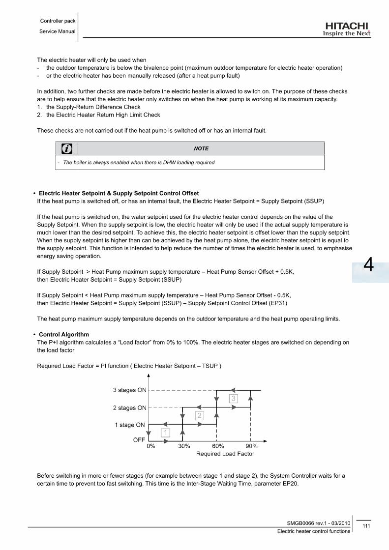
111Electric heater control functions
SMGB0066 rev.1 - 03/2010
Controller pack
Service Manual
4
The electric heater will only be used when - the outdoor temperature is below the bivalence point (maximum outdoor temperature for electric heater operation) - or the electric heater has been manually released (after a heat pump fault)
In addition, two further checks are made before the electric heater is allowed to switch on. The purpose of these checks are to help ensure that the electric heater only switches on when the heat pump is working at its maximum capacity. 1. the Supply-Return Difference Check 2. the Electric Heater Return High Limit Check
These checks are not carried out if the heat pump is switched off or has an internal fault.
note
-- The-boiler-is-always-enabled-when-there-is-DHW-loading-required
• Electric Heater Setpoint & Supply Setpoint Control offsetIf the heat pump is switched off, or has an internal fault, the Electric Heater Setpoint = Supply Setpoint (SSUP)
If the heat pump is switched on, the water setpoint used for the electric heater control depends on the value of the Supply Setpoint. When the supply setpoint is low, the electric heater will only be used if the actual supply temperature is much lower than the desired setpoint. To achieve this, the electric heater setpoint is offset lower than the supply setpoint. When the supply setpoint is higher than can be achieved by the heat pump alone, the electric heater setpoint is equal to the supply setpoint. This function is intended to help reduce the number of times the electric heater is used, to emphasise energy saving operation.
If Supply Setpoint > Heat Pump maximum supply temperature – Heat Pump Sensor Offset + 0.5K, then Electric Heater Setpoint = Supply Setpoint (SSUP)
If Supply Setpoint < Heat Pump maximum supply temperature – Heat Pump Sensor Offset - 0.5K, then Electric Heater Setpoint = Supply Setpoint (SSUP) – Supply Setpoint Control Offset (EP31)
The heat pump maximum supply temperature depends on the outdoor temperature and the heat pump operating limits.
• Control AlgorithmThe P+I algorithm calculates a “Load factor” from 0% to 100%. The electric heater stages are switched on depending on the load factor
Required Load Factor = PI function ( Electric Heater Setpoint – TSUP )
Before switching in more or fewer stages (for example between stage 1 and stage 2), the System Controller waits for a certain time to prevent too fast switching. This time is the Inter-Stage Waiting Time, parameter EP20.

Controller pack
Service Manual
112Electric heater control functionsSMGB0066 rev.1 - 03/2010
• Parameter SettingsEP2 Integral Factor Required Load - Boiler/Electric Heater Control (default 2.5 %/Kmin.)EP16 Proportional Band Required Load - Boiler/Electric Heater Control (default 6 K/100%)EP20 Inter-Stage Waiting Time (default 10 sec.)EP31 supply Setpoint Control Offset (default 4 K)
It is not normally recommended to change these parameters. They have been selected during laboratory tests for best performance in most situations. Correct positioning of the Supply Temperature Sensor close to the outlet of the Electric Heater should result in good control performance. If necessary, adjusting these parameters can correct unstable control behaviour in certain circumstances.
note
-- Engineering-Parameters-(EP)-are-only-available-for-service-engineers
4.11.2. Supply-Return difference Check
• functionThis function helps prevent the electric heater operating unless the heat pump is already providing heat. When the heat pump is in “thermo-off” state (compressor off) or in “defrost”, the difference between the supply temperature TSUP and return temperature TRET will be small (or negative in case of defrost) since no heating is provided. The electric heater is prevented from switching on until this difference is greater than the Supply-Return Difference Limit (P32). A +/-0.5K control differential is applied.TSUP-TRET > P32 + 0.5K Electric Heater is allowed to switch on.TSUP-TRET < P32 – 0.5K Electric Heater is not allowed to switch on.
• Enable/disableThis function can be disabled by setting parameter P32=OFF.
• Parameter SettingsP32 Supply-Return Difference Limit (default 3K)
A high value will prevent the electric heater switching on until a large temperature difference is seen by the System Controller. With a low value or with the function disabled, the electric heater may start more often, for example during defrost cycles.
note
-- This-check-is-ignored-if-the-Heat-Pump-is-switched-off-or-has-an-internal-fault.
4.11.3. Electric Heater Waiting Time
• functionIt is important with mono-energetic systems that the Heat pump should first try to satisfy the heating demand by itself. For this reason an electric heater waiting time applies. This means that when the heatpump cannot meet the heating demand, then the electric heater is switched on only after the waiting time has elapsed.

113Electric heater control functions
SMGB0066 rev.1 - 03/2010
Controller pack
Service Manual
4
The waiting time starts:When the heat pump is switched on, or
When the electric heater switches off (but only also when the Supply Setpoint SSUP < heat pump maximum temperature – heat pump sensor offset).
This means that when the heatpump should normally be able to meet the heating demand on its own, the electric heater waiting time applies, but when the supply setpoint is so high that the heat pump cannot meet the heating demand on its own, the waiting time does not apply.
• Parameter SettingsP19 Waiting Time for Electric Heater (default 30min.)
A higher value of P19 will reduce the number of times that the electric heater is used at lower supply setpoints, but the desired supply temperature may not be reached quickly if there is a high heating load (slower response). Conversely, a lower value of P19 will increase the number of times the electric heater is used at lower supply setpoints, but ensure that the desired supply temperature is reached more quickly (better response).
4.11.4. Electric Heater Return High limit Check
• functionThe return high limit check is used to help ensure that the heat pump operates as much as possible even when higher supply temperatures are required, thus emphasising energy economy operation. The electric heater is disabled when the return water temperature (TRET) rises above the maximum heat pump outlet temperature minus the return limit offset (P33). A +/-0.5K control differential applies.TRET > Heat Pump maximum supply temperature – P33 + 0.5K Electric Heater disabledTRET < Heat Pump maximum supply temperature – P33 - 0.5K Electric Heater enabled
Since the electric heater is switched off then the return temperature rises too high, the effect will be that in some system conditions it will not be possible to reach 65°C supply temperature. If it is important to allow 65°C operation, then the parameter can be reduced or set to OFF, but the result is that in some situations the electric heater will operate on its own and the heat pump will not be used. This will cause higher energy costs.
• Parameter SettingsP33 Return Temperature Limit Offset (default OFF)
• Special NoteIt is highly recommended for CONF 2, that the parameter P33 is not left in the default OFF state.
Recommended setting is 5K.
• Enable/ disableThis function can be disabled by setting the parameter P33=OFF.
4.11.5. Maximum outdoor Temperature for Electrical Heater operation
• functionThis function disables the electric heater control when the outdoor temperature is above the electric heater maximum outdoor temperature setting. Above this setting it is assumed that the heat-pump is able to deliver all the requested heat by itself and the electric heater is therefore not required.
• Parameter SettingP15 Maximum Outdoor Temperature for Electric Heater Operation (default 0°C)
• Enable/disableTo disable this function and allow electric heater operation at all outdoor temperatures, set the parameter P15=OFF.
Controller pack
Service Manual
114Mixing valve control functionsSMGB0066 rev.1 - 03/2010
4.12. MIxING VAlVE CoNTRol fUNCTIoNS
4.12.1. Mixing Valve Control
• Configuration SpecificThis function only applies to configuration 4 (CONF 4)
• functionWhen heating is required, the System Controller controls the mixing valve so that the mixed water temperature is close to the Supply Setpoint. The mixing valve position is calculated with a proportional plus integral action (P+I) control algorithm based on the difference between the Supply Setpoint and mixed water temperature (TMIX).
Desired Mixing Valve Position = PI function ( Supply Setpoint – TRET )
The System Controller then decides how much to open or close the mixing valve to achieve the desired position of the valve. This is dependent on the running time of the actuator used on the valve. The running time is defined as the time it takes to drive the valve from the fully closed to the fully open position. Typically this can be between 1 and 4 minutes.
• Parameter SettingP9 Mixing Valve Runtime (default 120 sec)
EP1 Mixing Valve Integral factor (default 2.5)The installer should set the parameter p9 based on his selection of actuator and mixing valve.
The value for EP1 has been chosen based on laboratory tests and it is not recommended to change it.
note
-- Engineering-Parameters-(EP)-are-only-available-for-service-engineers.
4.12.2. Mixing / Bypass Valve Control
• Configuration SpecificThis function only applies to configuration 5 (CONF 5)
• functionWhen the boiler is switched on, the mixing valve control is enabled and operates in the same manner as described above (Mixing Valve Control).
When the boiler is switched off, and the difference between the supply water temperature (TSUP) and mixed supply temperature (TMIX) is small (less than EP3), the mixing valve is always closed (by-pass operation) so that the hot supply water from the heat Pump does not circulate through the boiler heat exchanger, which may cause unnecessary heat loss and reduction in system efficiency. While the water from the boiler (TSUP) is much hotter than the mixed supply temperature (TSUP), the mixing control continues to operate.
• Parameter SettingP9 Mixing Valve Runtime (default 120 sec)
EP3 Difference Supply water temperature (default 1.5K)
115Mixing valve control functions
SMGB0066 rev.1 - 03/2010
Controller pack
Service Manual
4
The value for EP3 has been chosen based on laboratory tests and it is not recommended to change it.
note
-- Engineering-Parameters-(EP)-are-only-available-for-service-engineers.
4.12.3. Mixed Heating Circuit Maximum Temperature limit Protection
• Configuration SpecificThis function only applies to configurations 4 and 5 (CONF 4,5)
• functionThe secondary circulation pump is switched off and the mixing valve closed when the maximum supply temperature (mixing circuit) setting is exceeded. This function helps prevent damage to floor heating systems by very high temperatures.TMIX > P6 Pump switched off, mixing valve closed.TMIX < P6 – 5K Returns to normal control.
• Parameter SettingP6 Maximum Supply Temperature
note
-- A-fault-code-is-displayed-when-the-maximum-limit-is-exceeded.
4.12.4. Mixing Valve opening delay
• Configuration SpecificThis function only applies to configurations 4 and 5 (CONF 4,5)
• functionWith some boilers, especially oil boilers, there is a risk of unwanted liquid condensation on the gas side of the boiler heat exchanger if the temperature falls below the water condensation temperature. This can cause reduced boiler life. In these situations, it is desirable to allow the boiler heat exchanger to warm up before the heating circuit water is circulated through the heat exchanger. This function prevents the mixing valve opening until after the boiler has been switched on for a set period of time (parameter P35).
The recommended setting will depend on the size and type of boiler. (delay time can be set between 1 and 20 minutes).
• Parameter SettingP35 Mixing Valve Opening Delay Time (default OFF)
note
-- If-P35-is-set-to-OFF,-this-function-is-disabled.

Controller pack
Service Manual
116General functionsSMGB0066 rev.1 - 03/2010
4.13. GENERAl fUNCTIoNS
4.13.1. System frost Protection
• functionThe System Controller has a frost protection function to help prevent the heating system pipe-work freezing. When the actual outside temperature falls below the parameter (P22) , the supply water temperature will be maintained at least at the parameter value (P21). A switching differential of 1K is applied.Outside temperature (TEXT) < P22 Supply Setpoint (SSUP) determined by heating or DHW demand but always >= P21Outside temperature (TEXT) > P22+1K Supply Setpoint (SSUP) determined by heating or DHW demand.
• Parameter SettingsP21 Frost Protection minimum Supply Temperature (default 20°C)P22 Frost Protection Activation Temperature (default 2°C)
• Enable/ disableTo disable the system frost protection function, set P22=OFF.
4.13.2 Automatic Summer Switch-off
• functionAt higher outside temperatures it doesn’t make sense to keep heating the building. The System Controller will switch the heating off when the average daily outdoor temperature (averaged over 24hrs) rises above the parameter (P26). A control differential of +/-0.5K is applied.
• AlgorithmAverage Outside Temperature > P26 Summer Switch-Off condition is active.Average Outside Temperature < P26-0.5K Summer Switch-Off condition is not active.
When the Summer Switch-Off condition is active, the heating is switched off.
• Parameter SettingsP26 Summer Switch-off Temperature (default 20°C)
• Enable/disableTo disable the automatic summer switch-off function, set P26=OFF.
4.13.3. Pump and Valve Seizure Protection
• functionThe System Controller has an anti-seize protection function for valves and pumps which helps to prevent these components sticking during long periods of inactivity. Every 24hrs the components which have not been used will be run for a short period.
4.13.4. Screed function (drying for New floors)
• functionThe screed function is used exclusively for the required drying of newly applied screed on floor heating systems. The process is based on EN 1264 part 4. When the screed function is activated :1. The flow temperature is kept constant at 25°C for 3 days, 2. Heating is set at the maximum supply setpoint (P6) for 4 days
(water temperature is always limited to 55°C)

117Parameter tables
SMGB0066 rev.1 - 03/2010
Controller pack
Service Manual
4
On completion of the screed function, the controller returns to normal operation.
• To ActivateThe function is activated by setting parameter P25 to 1. The screed function can be deactivated at any time by setting the parameter P25 to 0.
• diagram
[ºC]
eg Maximum temperature setting = 40 ºC
[Days]
• Parameter SettingsP25 Start Screed-Drying Function (default 0)
note
-- If-there-is-a-power-interruption,-the-screed-function-will-continue-when-the-power-is-restored.
4.14. PARAMETER TABlES
4.14.1 Installer Parameters
• Setting Instructions
Please refer to the System Controller Installation & Operation Manual for instructions on how to set the installer parameters.
Id Parameter CoNf description Min Max Step default
CONF System Configuration 12345 Set according to the type of hydraulic configuration installed.
1 5 1 3
P1 DHW Configuration 123-5 Set to 0=No DHW, 1=DHW valve, 2=DHW pump 0 2 1 0
P2 Secondary Pump 12---Set to 1 if a buffer/hydraulic separator and a secondary pump is used (CONF 1 or CONF 2 only)
0 1 1 0
P3 Pump Overrun Time 12345 Sets how long the pumps run after the heating is switched off. 1 10 1 2 min.
P4 OTC Heating Curve Gradient 12345 Sets the heating curve for OTC control function 0.2 2.2 0.1 1.1
P5 Minimum Supply Temperature 12345 Sets the minimum supply water temperature for
the heating. 5 40 1 15°C
P6 Zone 1: Maximum Supply Temperature 12345 Sets the maximum supply water temperature for
the heating (zone 1) 20 55/65/ 90* 1 55°C
P7 Room Compensation Factor 12345 Sets the room temperature influence for the OTC
control function 0 5 0.5 2
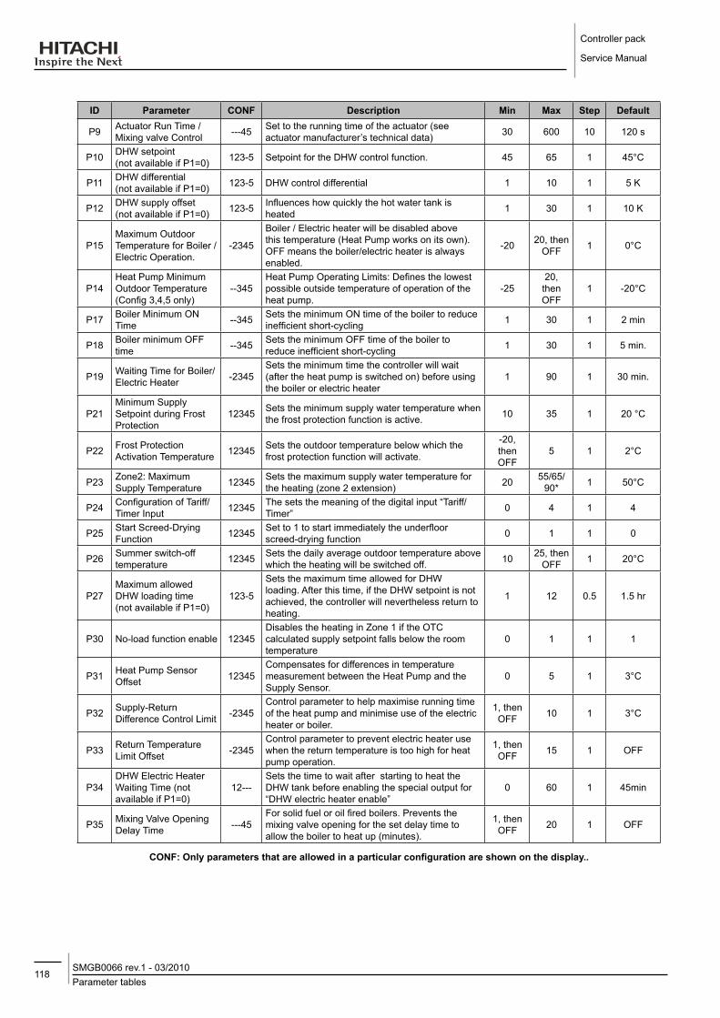
Controller pack
Service Manual
118Parameter tablesSMGB0066 rev.1 - 03/2010
Id Parameter CoNf description Min Max Step default
P9 Actuator Run Time / Mixing valve Control ---45 Set to the running time of the actuator (see
actuator manufacturer’s technical data) 30 600 10 120 s
P10 DHW setpoint (not available if P1=0) 123-5 Setpoint for the DHW control function. 45 65 1 45°C
P11 DHW differential (not available if P1=0) 123-5 DHW control differential 1 10 1 5 K
P12 DHW supply offset (not available if P1=0) 123-5 Influences how quickly the hot water tank is
heated 1 30 1 10 K
P15Maximum Outdoor Temperature for Boiler /Electric Operation.
-2345
Boiler / Electric heater will be disabled above this temperature (Heat Pump works on its own). OFF means the boiler/electric heater is always enabled.
-20 20, then OFF 1 0°C
P14Heat Pump Minimum Outdoor Temperature(Config 3,4,5 only)
--345Heat Pump Operating Limits: Defines the lowest possible outside temperature of operation of the heat pump.
-2520,then OFF
1 -20°C
P17 Boiler Minimum ON Time --345 Sets the minimum ON time of the boiler to reduce
inefficient short-cycling 1 30 1 2 min
P18 Boiler minimum OFF time --345 Sets the minimum OFF time of the boiler to
reduce inefficient short-cycling 1 30 1 5 min.
P19 Waiting Time for Boiler/Electric Heater -2345
Sets the minimum time the controller will wait (after the heat pump is switched on) before using the boiler or electric heater
1 90 1 30 min.
P21Minimum Supply Setpoint during Frost Protection
12345 Sets the minimum supply water temperature when the frost protection function is active. 10 35 1 20 °C
P22 Frost Protection Activation Temperature 12345 Sets the outdoor temperature below which the
frost protection function will activate.
-20, then OFF
5 1 2°C
P23 Zone2: Maximum Supply Temperature 12345 Sets the maximum supply water temperature for
the heating (zone 2 extension) 20 55/65/ 90* 1 50°C
P24 Configuration of Tariff/Timer Input 12345 The sets the meaning of the digital input “Tariff/
Timer” 0 4 1 4
P25 Start Screed-Drying Function 12345 Set to 1 to start immediately the underfloor
screed-drying function 0 1 1 0
P26 Summer switch-off temperature 12345 Sets the daily average outdoor temperature above
which the heating will be switched off. 10 25, then OFF 1 20°C
P27Maximum allowed DHW loading time (not available if P1=0)
123-5
Sets the maximum time allowed for DHW loading. After this time, if the DHW setpoint is not achieved, the controller will nevertheless return to heating.
1 12 0.5 1.5 hr
P30 No-load function enable 12345Disables the heating in Zone 1 if the OTC calculated supply setpoint falls below the room temperature
0 1 1 1
P31 Heat Pump Sensor Offset 12345
Compensates for differences in temperature measurement between the Heat Pump and the Supply Sensor.
0 5 1 3°C
P32 Supply-Return Difference Control Limit -2345
Control parameter to help maximise running time of the heat pump and minimise use of the electric heater or boiler.
1, then OFF 10 1 3°C
P33 Return Temperature Limit Offset -2345
Control parameter to prevent electric heater use when the return temperature is too high for heat pump operation.
1, then OFF 15 1 OFF
P34DHW Electric Heater Waiting Time (not available if P1=0)
12---Sets the time to wait after starting to heat the DHW tank before enabling the special output for “DHW electric heater enable”
0 60 1 45min
P35 Mixing Valve Opening Delay Time ---45
For solid fuel or oil fired boilers. Prevents the mixing valve opening for the set delay time to allow the boiler to heat up (minutes).
1, then OFF 20 1 OFF
CoNf: only parameters that are allowed in a particular configuration are shown on the display..

119Parameter tables
SMGB0066 rev.1 - 03/2010
Controller pack
Service Manual
4
4.14.2. Engineering Parameters
• function
Engineering Parameters (EP) are provided for service engineers or the manufacturer to make adjustments that may be required to fix difficult or unusual problems. They are accessed in a similar way to the installer parameters via the front panel keypad.
• Setting Instructions
To enter Engineering Parameter Display mode from the Normal Operation mode, press the SET , SEl and buttons together for at least one second. The display will show “EP1” (or “EP2” or “EP5” depending on the system configuration) to indicate that the System Controller is in Engineering Parameter Display mode, and shows the parameter abbreviation and its current setting.1. Use the + and - buttons to move up or down the parameter list according to the table.2. To change a parameter setting, use the SET button to enter Parameter Setting Mode. The value of the parameter will
flash to show that it can now be changed. Use the + and - buttons to change the value to the desired setting.3. To store the parameter setting, press the SET button. The flashing will stop to show the value has been saved. Instead,
to cancel the change, and retain the previously stored value, press the SEl button.4. Continue to change the parameters as required. When finished, or at any time, pressing the button will return the
display to Normal Operation mode.
Id Parameter CoNf description Min Max Step default
EP1 Mixing Valve Integral Factor ---45 Mixing Valve Control: the integral reset factor of
the P+I control algorithm. 0.0 20.0 0.1 2.5 %/Kmin
EP2 Integral Factor Required Load -2345 Electric Heater or Boiler Control: the integral
reset factor of the P+I control algorithm. 0.0 20.0 0.1 2.5 %K/min
EP3 Difference Supply Water Temperature ----5 Mixing / Bypass Valve Control: offset to decide
when to start the mixing control. 0.0 5.0 0.1 1.5 K
EP5 Show Entire Menu 12345 Setting EP5=1 shows all installer and engineering parameters independent of configuration. 0 1 1 0
EP6 Heat Pump supply setpoint at 4mA 12345 Heat Pump Control: the outlet supply setpoint of
the Heat Pump for a 4mA control signal. 10 30 1 20°C
EP7 Heat Pump supply setpoint at 20mA 12345 Heat Pump Control: the outlet supply setpoint of
the Heat Pump for a 20mA control signal. 40 70 1 55°C
EP8 Mixing Valve Proportional Band ---45 Mixing Valve Control: the proportional band of the
P+I control algorithm. 0.2 20.0 0.2 6.0K
EP13 Heat Pump Maximum Return Temperature 12345 Heat Pump Control: the maximum return
temperature allowed while the heat pump is on. 20 70 1 60°C
EP14Heat Pump Minimum Outdoor Temperature(Config 1,2 only)
12---Heat Pump Operating Limits: Defines the lowest possible outside temperature of operation of the heat pump.
-25 20,then OFF 1 -20°C
EP16 P band Required Load -2345 Electric Heater or Boiler Control: the proportional band of the P+I control algorithm. 0.2 20.0 0.2 6.0K
EP20 Inter-Stage Waiting Time -2--- Electric Heater Control: The minimum time
between switching stages of the electric heater. 10 250 10 10sec
EP28 Heat Pump Minimum Supply Temperature. 12345 Heat Pump Operating Limits: minimum supply
temperature below outside temperature of EP32 10 40 1 35°C
EP29 Heat Pump Maximum Supply Temperature 12345 Heat Pump Operating Limits: maximum supply
above outdoor temperature of EP34. 40 70 1 55°C
EP31 Offset Supply Setpoint -2345Electric Heater or Boiler Control: reduced supply setpoint offset for control of electric heater or boiler.
0 10 1 4K
EP32 Heat Pump Minimum Supply Inflexion Point 12345
Heat Pump Operating Limits: parameter to define shape of minimum supply temperature operating curve.
-25 20 1 0°C

Controller pack
Service Manual
120Conversion table: heat pump supply temperature to mASMGB0066 rev.1 - 03/2010
Id Parameter CoNf description Min Max Step default
EP33 Heat Pump Maximum Supply Temperature 12345 Heat Pump Operating Limits: maximum supply
temperature below outside temperature of EP34 40 70 1 50°C
EP34 Heat Pump Maximum Supply Changing Point 12345
Heat Pump Operating Limits: parameter to define point at which maximum supply temperature changes.
-25 20 1 -10°C
EP35 Heat Pump Max Time High Setpoint 12345 DHW Control: time that supply setpoint is held at
maximum when DHW demand occurs. 0 180 1 180sec
EP36 Boiler Delay Time --345Boiler Control: Inhibits the Supply-Return Difference Check until this time has expired after the boiler is switched on.
1 15 1 5min
EP37DHW offset for Heat Pump maximum supply temperature.
12345
The maximum DHW temperature able to be supplied by the heat pump is the Heat Pump maximum supply temperature minus this EP37 value
0 20 1 7 K
CoNf: only parameters that are allowed in a particular configuration are shown on the display..
4.15. CoNVERSIoN TABlE: HEAT PUMP SUPPly TEMPERATURE To mAThe following table converts the Heat Pump supply temperature setting in °C to current (I) in mA.
mA Setting (°C) mA Setting (°C) mA Setting (°C)2.0 ≤ I < 2.2 15.5 8.1 ≤ I < 8.4 29.0 14.1 ≤ I < 14.3 42.02.2 ≤ I < 2.4 16.0 8.4 ≤ I < 8.6 29.5 14.3 ≤ I < 14.5 42.52.4 ≤ I < 2.7 16.5 8.6 ≤ I < 8.8 30.0 14.5 ≤ I < 14.8 43.02.7 ≤ I < 2.9 17.0 8.8 ≤ I < 9.1 30.5 14.8 ≤ I < 15.0 43.52.9 ≤ I < 3.1 17.5 9.1 ≤ I < 9.3 31.0 15.0 ≤ I < 15.2 44.03.1 ≤ I < 3.3 18.0 9.3 ≤ I < 9.5 31.5 15.2 ≤ I < 15.5 44.53.3 ≤ I < 3.6 18.5 9.5 ≤ I < 9.7 32.0 15.5 ≤ I < 15.7 45.03.6 ≤ I < 3.8 19.0 9.7 ≤ I < 10.0 32.5 15.7 ≤ I < 15.9 45.53.8 ≤ I < 4.0 19.5 10.0 ≤ I < 10.2 33.0 15.9 ≤ I < 16.1 46.04.0 ≤ I < 4.3 20.0 10.2 ≤ I < 10.4 33.5 16.1 ≤ I < 16.4 46.54.3 ≤ I < 4.5 20.5 10.4 ≤ I < 10.7 34.0 16.4 ≤ I < 16.6 47.04.5 ≤ I < 4.7 21.0 10.7 ≤ I < 10.9 34.5 16.6 ≤ I < 16.8 47.54.7 ≤ I < 4.9 21.5 10.9 ≤ I < 11.1 35.0 16.8 ≤ I < 17.1 48.04.9 ≤ I < 5.2 22.0 11.1 ≤ I < 11.3 35.5 17.1 ≤ I < 17.3 48.55.2 ≤ I < 5.4 22.5 11.3 ≤ I < 11.6 36.0 17.3 ≤ I < 17.5 49.05.4 ≤ I < 5.6 23.0 11.6 ≤ I < 11.8 36.5 17.5 ≤ I < 17.7 49.55.6 ≤ I < 5.9 23.5 11.8 ≤ I < 12.0 37.0 17.7 ≤ I < 18.0 50.05.9 ≤ I < 6.1 24.0 12.0 ≤ I < 12.3 37.5 18.0 ≤ I < 18.2 50.56.1 ≤ I < 6.3 24.5 12.3 ≤ I < 12.5 38.0 18.2 ≤ I < 18.4 51.06.3 ≤ I < 6.5 25.0 12.5 ≤ I < 12.7 38.5 18.4 ≤ I < 18.7 51.56.5 ≤ I < 6.8 25.5 12.7 ≤ I < 12.9 39.0 18.7 ≤ I < 18.9 52.06.8 ≤ I < 7.0 26.0 12.9 ≤ I < 13.2 39.5 18.9 ≤ I < 19.1 52.57.0 ≤ I < 7.2 26.5 13.2 ≤ I < 13.4 40.0 19.1 ≤ I < 19.3 53.07.2 ≤ I < 7.5 27.0 13.4 ≤ I < 13.6 40.5 19.3 ≤ I < 19.6 53.57.5 ≤ I < 7.7 27.5 13.6 ≤ I < 13.9 41.0 19.6 ≤ I < 19.8 54.07.7 ≤ I < 7.9 28.0 13.9 ≤ I < 14.1 41.5 19.8 ≤ I < 20.0 54.57.9 ≤ I < 8.1 28.5 20.0 ≤ I < 20.3 55.0

121Technical data
SMGB0066 rev.1 - 03/2010
Controller pack
Service Manual
4
4.16. R RESISTANCE TABlESNTC 20k Celsius Temperature Characteristic
temp. (°C) resist. (Ω) temp. (°C) resist. (Ω) temp. (°C) resist. (Ω) temp. (°C) resist. (Ω) temp. (°C) resist. (Ω)-50.0 1659706 -9.0 115575 31.0 15180 71.0 2989 111.0 793.7-49.0 1541379 -8.0 109189 32.0 14511 72.0 2882 112.0 770.3-48.0 1432919 -7.0 103194 33.0 13875 73.0 2779 113.0 747.7-47.0 1332091 -6.0 97564 34.0 13270 74.0 2681 114.0 725.8-46.0 1238358 -5.0 92274 35.0 12695 75.0 2587 115.0 704.7-45.0 1153525 -4.0 87303 36.0 12148 76.0 2496 116.0 684.2-44.0 1073429 -3.0 82628 37.0 11627 77.0 2409 117.0 664.5-43.0 999894 -2.0 78232 38.0 11131 78.0 2325 118.0 645.3-42.0 932327 -1.0 74094 39.0 10659 79.0 2245 119.0 626.9-41.0 869327 0.0 70200 40.0 10210 80.0 2168 120.0 609.0-40.0 814000 1.0 66515 41.0 9781 81.0 2094 121.0 591.7-39.0 759391 2.0 63046 42.0 9373 82.0 2022 122.0 575.0-38.0 708806 3.0 59777 43.0 8983 83.0 1954 123.0 558.8-37.0 661924 4.0 56697 44.0 8612 84.0 1888 124.0 543.2-36.0 618451 5.0 53793 45.0 8258 85.0 1824 125.0 528.0-35.0 578119 6.0 51055 46.0 7920 86.0 1763 126.0 513-34.0 540677 7.0 48472 47.0 7598 87.0 1705 127.0 499-33.0 505902 8.0 46034 48.0 7291 88.0 1648 128.0 485-32.0 473588 9.0 43733 49.0 6998 89.0 1594 129.0 472-31.0 443546 10.0 41560 50.0 6718 90.0 1542 130.0 459-30.0 415600 11.0 39500 51.0 6450 91.0 1491-29.0 389298 12.0 37553 52.0 6195 92.0 1443-28.0 364833 13.0 35714 53.0 5951 93.0 1396-27.0 342063 14.0 33975 54.0 5718 94.0 1351-26.0 320860 15.0 32331 55.0 5495 95.0 1308-25.0 301107 16.0 30775 56.0 5282 96.0 1266-24.0 282696 17.0 29303 57.0 5078 97.0 1226-23.0 265528 18.0 27909 58.0 4883 98.0 1187-22.0 249511 19.0 26590 59.0 4696 99.0 1150-21.0 234561 20.0 25340 60.0 4518 100.0 1114-20.0 220600 21.0 24155 61.0 4347 101.0 1079-19.0 207607 22.0 23032 62.0 4184 102.0 1046-18.0 195459 23.0 21967 63.0 4027 103.0 1014-17.0 184096 24.0 20958 64.0 3877 104.0 982.8-16.0 173463 25.0 20000 65.0 3734 105.0 952.8-15.0 163508 26.0 19089 66.0 3596 106.0 923.9-14.0 154185 27.0 18224 67.0 3464 107.0 896.0-13.0 145450 28.0 17404 68.0 3338 108.0 869.1-12.0 137262 29.0 16624 69.0 3216 109.0 843.1-11.0 129583 30.0 15884 70.0 3100 110.0 818.0-10.0 122380
4.17. TECHNICAl dATA
4.17.1. System Controller (xEK23232 A)Power supply 230Vac +10%, -15%, 50Hz
Power Consumption Max 5VAAmbient operating
Temperature 0 to 50°C
Storage Temperature -20 to 55°CHumidity 0 to 90% RH non-condensing
dimensions 121 x 161.5 x 46mm (WxHxD)Material Base PA-GF 25-FR
Material Cover PC-FR (VO certified)degree of Protection IP20 (IP30 with cable glands)
fire Class V0Protection class Class I (according to EN60730-1)
Emissions Standards Complies with EN61000-6-3Immunity Standards Complies with EN61000-6-1

Controller pack
Service Manual
122User interfaceSMGB0066 rev.1 - 03/2010
Safety Standards Complies with EN60730-1:2007CE Compliance 93/68/EEC
WEEE Compliance 2002/96/ECRoHS Compliance 2002/95/EC
Heat Pump Control Signal 0-20mA, (max 10V @ 20mA), cable length max 20m (with wire cross-section 0.5mm²)Boiler output relay Potential free contacts (24V-230Vac 0.5A)
dHW electric heater enable output relay Potential-free contacts (230Vac 1A)
All other output relays 230Vac 1A (3A total)Tariff / Timer Input Input for potential-free contact (rated 5Vdc, switching current 1mA)
Heat Pump fault Input Input for potential-free contact (rated 5Vdc, switching current 100mA)
Rf Receiver connection Serial communications according to OpenTherm® technical specification v2.3 (max 18V, 23mA, 1000 baud)
diagnostic Interface I²C Bus Specification v2.1. An I²C to RS232 interface is required for connection to a PC.
4.17.2. Water Temperature Sensor (xEK35524 A)Element Type NTC 20k @ 25°C
Mounting Insertion well, or strap-on pipe with provided metal clipRange, Precision +5 to +90°C, +/-1K
Cable length 2m cable, 2 core. (max cable length 100m)dimensions (cartridge) 6.5mm Ø, 50mm long
Protection class IP62
4.17.3. outdoor Temperature Sensor (xEK35438 A)Element Type NTC 20k @ 25°C
Mounting Outside wall mountingRange, Precision -30 to +40°C, +/-1K
dimensions 95 x 65 x 70mm (HxWxD)Housing Plastic (ABS)
Electric Connection Terminals for 2 x 1.5mm² cableCable length Max 100m
Protection Class IP30
4.18. USER INTERfACE
4.18.1. display
The display of the System Controller is simple to understand and has extra segments to indicate the operating mode, failures and status.
Frost Protection SymbolDisplayed when the frost protection feature is active.

123User interface
SMGB0066 rev.1 - 03/2010
Controller pack
Service Manual
4
Heat Pump SymbolIndicates that the Heat Pump is switched on by the controller.
Boiler SymbolDisplayed when the boiler (bi-valent system) is switched on to provide additional heating.
Electric Heater SymbolDisplayed when the electric heater (mono-energetic system) is switched on to provide additional heating.
Tariff/Timer SymbolDisplayed when external tariff/timer blocking function is activated.
DHW SymbolDisplayed when the system is heating the DHW storage tank.
Pump I SymbolDisplayed when the primary boiler pump (bi-valent systems) is running.
Pump II SymbolDisplayed when the secondary pump (if connected) is running.
Fault SymbolDisplayed in case of a fault. The display will show the text “FAUL” and the fault number.
4.18.2. Controls
The System Controller has a simple five buttons interface with an user friendly display.
Select button• Used to leave setting mode.• Used to cancel a new setting and retain old value.
Increase button• Used to select the next parameter.• Used to increase the value of the selected parameter.
Decrease button• Used to select the previous parameter.• Use to decrease the value of the selected parameter.
Set button• Used to enter setting mode• Used to accept new value for a parameter.
Info button• Used to enter Operational Data Display mode.• Used to select next operational data item
Pressing particular combinations of these buttons will allow display or alteration of the various operating parameters.

Controller pack
Service Manual
124System testingSMGB0066 rev.1 - 03/2010
4.19. INSTAllATIoN CoNfIGURATIoN SETTINGSThe configuration of the System Controller is performed using the 5 buttons on the front cover. Via these buttons, a simple menu structure can be accessed to adjust all the controller parameters.
All menus use the 4 characters in the left of the display to show an abbreviated name, and the three digits in the right for the value. Units are shown in the far right of the display next to the value.
If no button is pressed for 10 minutes, the display will return to the default menu, or the relevant fault code.
The System Controller is delivered with a set of pre-programmed parameters to allow a quick start-up procedure. The factory default settings are shown in the table on the next page. Should it be necessary to adjust any of these parameter settings, please refer to the table and follow the instructions below.
To enter Parameter Display mode from the Normal Operation mode, press and buttons together for at least one second. The display will show “CONF” to indicate that the System Controller is in Parameter Display mode, and shows the first parameter CONF (Hydraulic Configuration) and its current setting.
1. Use the and buttons to move up or down the parameter list according to the table.
2. To change a parameter setting, use the SET button to enter Parameter Setting mode. The value of the parameter will flash to show that it can now be changed. Use the and buttons to change the value to the desired setting.
3. To store the parameter setting, press the SET button. The flashing will stop to show the value has been saved. Instead, to cancel the change, and retain the previously stored value, press the SEL button.
4. Continue to change the parameters as required. When finished, or at any time, pressing the button will return the display to Normal Operation mode.
Normal Operation mode Output Display mode Output Setting mode
& > 1 sec.
SET
SET
SEL
4.20. SySTEM TESTING
4.20.1. System start-up
After the installation of sensors and outputs, the System Controller controller can be started for the first time.
Switch on the mains power supply.
The controller will be initialised with the default configuration stored in the internal memory.

125System testing
SMGB0066 rev.1 - 03/2010
Controller pack
Service Manual
4
A test procedure is performed to check the validity of the data in the internal memory, and the various inputs are tested. All sensors and communications devices are automatically detected. All faults and warnings are automatically reset and the software version is displayed for reference.
4.20.2. SySTEM TEST
Once the system has been installed, it is recommended that the following tests are carried out:
1. Check that you have selected the correct configuration, and that the necessary installation parameters have been set.
2. Check the wiring of the inputs and outputs. Use the procedure in 7.3 to view the temperature sensor values. Using the procedure in 4.20.4, it is possible to manually override the outputs to test the system operation.
3. Check that the Room Unit is communicating with the RF Receiver. To do this, change the temperature setpoint on the Room Unit to the maximum or minimum value and check that the heat pump reacts appropriately
4.20.3. REVIEWING THE oPERATIoNAl dATA
The table below shows the values that are available to be viewed during Normal Operation mode. These can be shown by pressing the button
Abbr. operational data Units CoNf Normal Operation mode
Sen
sor
Tem
pera
ture
s
TEXT Outdoor temperature °C 12345TSUP Supply water temperature °C 12345TMIX Zone1: Mixed supply temperature °C ---45TRET Return temperature °C 12345TDHW DHW temperature °C 123-5TR1 Room temperature °C 12345
V Mixing valve position - ---45FAUL Fault status - 12345
Con
trolle
r Set
poin
ts SSUP Overall system supply setpoint °C 12345S1 Zone1: supply setpoint °C 12345
SR1 Zone1: room setpoint °C 12345S2 Zone2: supply setpoint °C 12345
DSET DHW setpoint °C 123-5SDHW DHW supply setpoint °C 123-5
note
-- Operational-data-shown-depends-on-the-system-configuration-(CONF)-setting.-- Zone-1-is-the-heating-loop-controlled-by-the-System-Controller.-- Zone-2-is-the-heating-loop-controlled-by-the-Extension-Controller.

Controller pack
Service Manual
126System testingSMGB0066 rev.1 - 03/2010
4.20.4. MANUAlly oVERRIdING THE oUTPUTS
This feature allows the status of the outputs to be changed in order to test the electrical connections.
To enter Output Display mode from Normal Operating mode, press the SEL and SET buttons together for at least one second. The display will show “HPS” to indicate that the controller is in Output Display mode and shows the first output “HPS” and its current status.
1. Use the and buttons to move up or down the output list according to the table.
2. To change an output, use the SET button to enter Output Setting mode. The value of the output will flash to show that it can now be changed. To change the output value, use the and buttons.
3. To save the output setting, press the SET button. The flashing will stop to show the value has been saved, and the letter F (Fixed) will appear to show that the output is being overridden. Note that the value must be saved before it takes effect. Instead, to cancel the change, and retain the previously stored value, press the SEL button.
To cancel the manual override of an output, enter the Output Setting mode and then press and together for one second. The “F” disappears from the display to show that the output is no longer overridden.
At any time, pressing the button will return the display to Normal Operation mode.
Please refer to the electrical wiring connections to identify which relays should be connected to which output for a particular system configuration
Normal operation mode output display mode output Setting mode
& > 1 sec.
SET
SET
SEL

127Expanding the system
SMGB0066 rev.1 - 03/2010
Controller pack
Service Manual
4
ID Output Min Max CONFHPS Heat Pump setting (mA) 2 20 12345HP Heat Pump remote on/off 0 1 12345
PO2 Secondary pump (not displayed if P2=0) 0 1 12345DHWV DHW valve/pump (not shown if P1=0) 0 1 123-5EHS1 Electric heater output 1 0 1 -2---EHS2 Electric heater output 2 0 1 -2---DHWE DHW electric heater enable (not shown if P1=0) 0 1 12---PO1 Boiler pump 0 1 --34BLR Boiler on/off 0 1 --345
V Mixing valve position (%) 0 99 ---45Operational-data-shown-depends-on-the-system-configuration-(CONF)-setting.
4.21. ExPANdING THE SySTEM
4.21.1. Additional mixing zone
The system controller is designed so that it can be expanded when necessary to control heating systems with an additional mixed heating zone. The extension controller will control a mixing circuit, consisting of a mixing valve and pump as shown below. It is possible to use one room unit for the entire system, or have one room unit in each heating zone with separate time programmes.
Installation instructions are included with the extension controller.
4.21.2. Binding Rf components together
The Room Unit and RF receiver included in the system pack are already factory configured to work together. If either of these units have to be replaced, please follow the instructions below for the method of binding RF components together.
To enter the RF Binding procedure, press and hold the button on the RF Receiver for 5 seconds. The red LED will begin to flash.
When binding the RF Receiver to the Room Unit, the System Controller display will show a flashing “ZONE 1”, meaning that the system will bind to the first heating zone by default. Zone 1 is the zone controlled directly by the System Controller.
To bind Zone 2 (the extension system), press the + button on the System Controller. “ZONE 2” will be displayed, and the RF system will be bound to that zone. The bound zone can be changed by following the re-binding procedure on the RF

Controller pack
Service Manual
128System MMI Pack (Room unit and RF receiver)SMGB0066 rev.1 - 03/2010
Receiver/Room Unit and adjusting the zone selected on the System Controller display.
4.22. SySTEM MMI PACK (RooM UNIT ANd Rf RECEIVER)
4.22.1. Room Unit installation guide
4.22.1.1. description
The Room Unit communicates with the RF Receiver on an 868MHz Radio Frequency (RF) band to control the Heat Pump System Controller. Neither product will communicate with other RF products that use different frequencies or communication protocols.
note
-- The-RF-link-between-the-Room-Unit-and-RF-Receiver-in-system-packs-is-pre-configured-at-the-factory-and-therefore-should-be-installed-at-the-same-site.-This-makes-the-installation-process-fast-and-easy,-but-if-products-from-individual-system-packs-are-separated,-or-mixed-with-other-pre-configured-system-packs-during-installations-please-refer-to-the-section-Binding-/-Rebinding-procedure-to-bind-the-desired-units-together-and-allow-them-to-communicate-with-each-other.
4.22.1.2. Installation information
As these products communicate using RF technology special care must be taken during installation. The location of the RF components as well as the building structure may influence performance of the RF system. To assure system reliability, please review and apply the information given below.
Within a typical residential building the two products should communicate reliably within a 30m range. It is important to take into consideration that walls and ceilings will reduce the RF signal. The strength of the RF signal reaching the RF Receiver depends on the number of walls and ceilings separating it from the Room Unit, as well as the building construction - the diagram below illustrates an example of typical signal strength reduction. Walls and ceilings reinforced with steel or plasterboard walls lined with metal foil reduce the RF signal significantly more.
Once a position is selected for the Room Unit this can be checked using the RF Communication Test mode as described in section Locating the Room Unit. If the position is unsuitable the RF Receiver will not respond and an alternative position for the Room Unit must be selected.

129System MMI Pack (Room unit and RF receiver)
SMGB0066 rev.1 - 03/2010
Controller pack
Service Manual
4
Typical example of building fabric signal losses
Wall Wall Wall
Ceiling
Max. Signal Length 30 metres
= Signal Strength
4.22.1.3. Installing the System MMI Pack
Please follow the illustrations and information below in sequence to install the RF Receiver and Room Unit correctly. To enable special features and see what other system options are available refer to section Installer Mode.
4.22.1.4. Installing the Rf Receiver
note
-- The-RF-Receiver-contains-no-user-serviceable-parts.-It-should-be-opened-and-installed-by-qualified-installer-only.
caution
-- Static-electricity.-Malfunction.-Do-not-touch-the-circuit-board.

Controller pack
Service Manual
130System MMI Pack (Room unit and RF receiver)SMGB0066 rev.1 - 03/2010
max. 30m. 2 x 0.5mm2 ; 2 x 0.8mm2
RF Receiver
System Controller
78
System Controller
The RF Receiver can be connected to other Open therm appliances. For the correct wiring connections refer to the installation manual of the Open therm device.
note
-- All-wiring-must-be-in-accordance-with-IEE-regulations.-- Observe-ambient-temperature-and-current-limits-(see-the-RF-Receiver-wiring-label).
4.22.2. Installing the Room Unit
4.22.2.1. Power up
IInstalling the Batteries:a. Lift up the front cover of the Room Unit to reveal the battery cover and product controls.b. Remove the battery cover by pressing down and sliding out.c. Insert the 2 x AA LR6 Alkaline Batteries supplied with the Room Unit, ensuring the correct orientation.d. After a short pause the Room Unit will display information on the screen and is now ready for use.e. Replace the battery cover by sliding it firmly back into the front of the Room Unit.

131System MMI Pack (Room unit and RF receiver)
SMGB0066 rev.1 - 03/2010
Controller pack
Service Manual
4
Setting the date and time:
a. Press the button to begin setting the date. When you set the date for the first time after the batteries are inserted, the display will show:
Press the or buttons to set the current day of the month (e.g. d 01 = 1st day of the month) then press the green button to confirm.
b. Press the or buttons to set the current month of the year (e.g. m 01 = January) then press the green button to confirm.
c. Press the or buttons to set the current year (e.g. yr 07 = 2007) then press the green button to confirm.
The date is now stored and the Day Indicator will be displayed under the current day of the week (e.g. 1 = Monday, 2 = Tue sday, etc.)
d. Use the or buttons to set the correct time then press the green button to confirm. Each press of the buttons will change the time
by one minute and holding them down will change the time slowly at first and get progressively quicker.
note
-- If-this-mode-is-entered-accidentally-then-press-the- ,- -or- -buttons-to-exit.
AM
4.22.2.2. Rf Communication check (test mode)
To check the RF communication, hold the Room Unit about 2-3 metres from the installed RF Receiver. Set the Room Unit to off by pressing the button. then press the and buttons together with the button for 3 seconds. The unit will display “test” and it will send test signals to the Rf Receiver. If the test signals are received the LED on the RF Receiver will flash between 1 and 5 times. The number of flashes indicates the strength of the radio signal. The higher the number of flashes, the stronger the signal is.
note
-- If-the-LED-does-not-flash-or-if-you-are-installing-a-replacement-RF-Receiver-or-Room-Unit,-follow-the-procedures-described-in-section-Binding-/-Rebinding-Procedure.
4.22.2.3. locating the Room Unit
While still in the Test Mode, the Room Unit should be located taking the following into consideration and reviewing the illustrations below:
1. Find a suitable location where the signal transmission is reliable. Reliable transmission is indicated when the RF Receiver is flashing the green LED every 6 seconds.
2. Install the Room Unit EITHER on the wall using the wall bracket OR attach the optional table stand as shown in below.
3. Exit the Test Mode by pressing the or button.

Controller pack
Service Manual
132System MMI Pack (Room unit and RF receiver)SMGB0066 rev.1 - 03/2010
Wall bracket Table stand
• The Room Unit should be installed in an open space for best performance as it is a radio frequency device.
• Leave at least 30cm distance from any metal objects including wall boxes and at least 1 meter from any other electrical equipment as radio, TV, PC etc.
• Do not mount onto metal wall boxes.
• It is recommended that the RF Receiver is fully installed.
4.22.3. Communication loss
In the event of an RF communications loss, the LED on the RF Receiver will indicate which type of fault has occurred.
• If there is a communications fault between the RF Receiver and the Room Unit, then the LED on the RF Receiver will flash red for 0.1 sec ON every three seconds.
• If there is a fault in communications between the boiler or System Controller, then the LED on the RF Receiver will flash 3 times quickly and then be off for three seconds.
• If there is more than one Room Unit installed, as in multi-zone systems for example, and communications is lost with one zone, then the red LED on the RF Receiver will flash two times quickly and then be off for two seconds.
• If there is more than one Room Unit installed, as in multi-zone systems for example, and communications is lost with both zones, then the red LED on the RF Receiver will flash once for 0.1 sec ON, and 0.9 sec OFF.
Once the faulty device has been identified, replace as necessary and follow the re-binding procedure as described in section Binding / Rebinding Procedure.
4.22.4. Installer mode
Installer Mode is used to alter the system settings for specific applications, to use the special features of the Room Unit in a different way or to alter the factory preset parameters. Parameters are divided into two groups:
- Category 1 parameters – Room Unit Setup
- Category 2 parameters – System Setup. (These are all listed in section Installer Parameters Table.).

133System MMI Pack (Room unit and RF receiver)
SMGB0066 rev.1 - 03/2010
Controller pack
Service Manual
4
4.22.4.1. Entering installer mode
1..6
MANAUTO
1 2 3 4 5 6 7
1
2
2
Press the button.Press and hold the button and the PROGRAM & buttons together.
The unit will display the first parameter of installer parameter group category 1 (from Parameter n.1 to n.19) as shown
Press the or to change factory setting.The display will flash indicating that a change has been made.
Press the green button to confirm the change.The display will stop flashing.(Continues in the next page)
Press button to go to the next parameter.
Press the button to go to Installer parameter group category 2 ( ) (from Parameter nº 4 to nº 14)
To exit the installer mode press the or buttons.
4.22.4.2. fail-Safe mode setup
The fail-safe mode defines the system status if the RF communication is lost (e.g. when the Room Unit stops communicating due to discharged batteries). If the system is a direct (radiator one), then the factory setting will make the system revert to a set point of 10°C for frost protection. If indirect loops are added, the system will continue to operate at the last communicated setpoint.
4.22.4.3. Using the Room Unit for specific applications
The Room Unit is a versatile controller that can be used to control many different applications. Please note that when the Room Unit is installed in conjunction with a System Controller, the functionality will differ to that when installed with a standard boiler system. Most of the functions shown below will be controlled by the System Controller and be set within its parameters. Therefore, some of the system parameters within the Room Unit menu will not apply. Please also note other changes to the setting of the optimisation and proportional band settings as shown in the the next tables.

Controller pack
Service Manual
134System MMI Pack (Room unit and RF receiver)SMGB0066 rev.1 - 03/2010
note
-- In-order-for-the-Room-Unit-to-send-the-heating-demand-signal-to-the-RF-Receiver,-it-is-essential-that-the-Category-2-parameter-8:Su-is-set-to-the-correct-value-(see-Installer-Parameters-Table,-Category-2-–-System-Settings).-Failure-to-do-this-will-mean-that-the-heating-system-will-not-respond-to-changes-in-the-setpoint-on-the-Room-Unit.-Under-these-circumstances-the-system-will-operate-with-no-input-from-the-Room-Unit-and-may-not-therefore-provide-adequate-temperature-control.
4.22.4.4. Using the special features of the Room Unit
Special feature description: Enable/disable
Heating operation
(This feature is not available with the system) This product can be used for heating applications. You can independently modify the profile.
To enable: Set parameter 4:HC (category 2) to 1.
Summer/winter auto time change
This feature moves time automatically on the last Sunday of March and the last Sunday of October. The feature is factory enabled.
To enable: Set parameter 3:tC (category 1) to 1.
Temperature offset
If the Room Unit is located in a particularly hot/cold location for reliable signal transmission reasons then the measured/displayed temperature can be adjusted by +/- 3°C. This is useful if the homeowner wants the reading to match another appliance temperature display.
Set parameter 12:tO (category 1) to the required offset value.
Upper/lower temperature limit
The normal upper temperature limit of 35°C can be reduced to 21°C to save the homeowner energy. The normal lower limit of 5°C can be increased up to 21°C to protect inhabitants from cold.
Set parameter 6:uL (category 1) to the desired upper limit.Set parameter 7:LL (category 1) to the desired lower limit.
4.22.5. Installer parameters table
4.22.5.1. Category 1 - Room Unit settings
Parameter Parameter No. factory default Setting optional SettingCategory 1 Parameters – Room Unit Settings
Display Description Display Description
AM-PM / 24hr Display 1:CL 24 24 hr clock display
format 12 12 hr – AM/PM clock display format
Reset Time/ Temp Program 2:rP 1
Time / Temp profile set to
factory defaultChanges to 0
when one of the time/temp profiles
are changed
0
Time / Temperature are as programmed
To restore the factory profile set to 1
Auto Summer/Winter Time
Change3:tC 1
Auto Summer/Winter Time
Change Enabled0 Auto Summer/Winter Time
Change Disabled
LCD Backlighting 5:bL 1 Backlighting
Enable 0 Backlighting Disabled
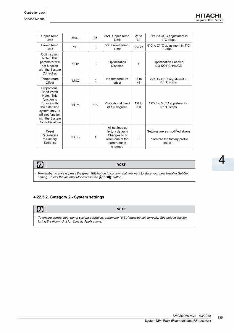
135System MMI Pack (Room unit and RF receiver)
SMGB0066 rev.1 - 03/2010
Controller pack
Service Manual
4
Upper Temp Limit 6:uL 35 35°C Upper Temp.
Limit21 to 34
21°C to 34°C adjustment in 1°C steps
Lower Temp Limit 7:LL 5 5°C Lower Temp.
Limit 5 to 21 6°C to 21°C adjustment in 1°C steps
OptimisationNote: This
parameter will not function
with the System Controller.
8:OP 0 Optimisation Disabled 1 Optimisation Enabled
DO NOT CHANGE
Temperature Offset 12:tO 0 No temperature
offset-3 to +3
-3°C to +3°C adjustment in 0.1°C steps
Proportional Band WidthNote: This function is
for use with the extension
system only. It will not function with the System Controller alone
13:Pb 1.5 Proportional band of 1.5 degrees
1.6 to 3.0
1.6°C to 3.0°C adjustment in 0.1°C steps
Reset Parameters to Factory Defaults
19:FS 1
All settings at factory defaultsChanges to 0
when one of the parameter is
changed
0
Settings are as modified above
To restore the factory profile set to 1
note
-- Remember-to-always-press-the-green- -button-to-confirm-that-you-want-to-store-your-new-Installer-Set-Up-setting.-To-exit-the-Installer-Mode-press-the- -or- -button.
4.22.5.2. Category 2 - System settings
note
-- To-ensure-correct-heat-pump-system-operation,-parameter-“8:Su”-must-be-set-correctly.-See-note-in-section-Using-the-Room-Unit-for-Specific-Applications.

Controller pack
Service Manual
136System MMI Pack (Room unit and RF receiver)SMGB0066 rev.1 - 03/2010
Parameter Parameter No. factory default Setting optional SettingCategory 2 Parameters – System Settings (press the button to access this category)
Heat/Cool selection enable
/ disable4:HC 0 Disabled 1 Enabled
DO NOT CHANGE
Room Temperature Sensor Use
8:Su 0Programmer
and room compensation unit
1Programmer only. Transmits
demand and room setpoint (no temperature displayed)
Maximum Flow Setpoint
(extension systems only)
11:uF 55 55°C Maximum Flow Temp.
0 to 99
0°C to 99°C adjustment in 1°C steps
Minimum Flow Setpoint
(extension systems only)
12:LF 15 15°C Minimum Flow Temp.
0 to 50
0°C to 50°C adjustment in 1°C steps
Mixing Value Run Time (extension
systems only)
13:Ar 150 150 seconds 0 to 240
0 to 240 sec. adjustment in 1sec steps
Pump Overrun Run Time (extension
systems only)
14:Pr 15 15 minutes 0 to 99
0 to 99 mins adjustment in 1min steps
note
-- Remember-to-always-press-the-green- -button-to-confirm-that-you-want-to-store-your-new-Installer-Set-Up-setting.-To-exit-the-Installer-Mode-press-the- -or- -button.
4.22.6. Binding / Rebinding procedure
The binding operation described below is required if:
• Any of the system components (Room Unit or RF Receiver) are replaced.
• The RF Receiver has incorrect or no binding data stored (e.g. when pre-bound system pack components have been mismatched).
note
-- During-the-binding-procedure-keep-approximately-1m-distance-between-the-Room-Unit-and-the-RF-Receiver.

137System MMI Pack (Room unit and RF receiver)
SMGB0066 rev.1 - 03/2010
Controller pack
Service Manual
4
To bind/rebind:
1. Hold button on RF Receiver for 15 seconds. LED will flash red 0.1 sec ON, and 0.9 sec OFF.
2. Hold button on RF Receiver for 5 seconds. LED will flash red for 0.5 sec ON, and 0.5 sec OFF.
3. Press the button on the Room Unit.
4. Hold , and buttons for 2 seconds. Display will show “InSt CO”. The boiler and RF signal icons will be displayed.
5. Press the green button.
6. When Red LED on the RF Receiver goes off, the devices are bound.
7. If binding is unsuccessful, then the LED will stay on. In this case, move the Room Unit and repeat the procedure from the beginning.
8. The LED on the RF Receiver will flash green every 10 seconds to indicate that the device is live.
9. Now go to Section 2. Installing the System MMI Pack to setup the system.
4.22.7. Room Unit user guide
• description
The Hitachi programmable wireless room unit is designed to control your heating system efficiently, providing comfortable temperatures when you are at home and energy savings when you are away. The following instructions explain how to program and use the Hitachi room unit to provide the highest home comfort with a minimum cost.
• features
• Ergonomic user interface featuring an ‘OK-button’.
• Large LCD (Liquid Crystal Display) Screen with backlight.
• 7-day heating program to match your lifestyle, whilst maximising energy savings.
• 6 independent temperature levels per day (from 5°C to 35°C).
• Holiday button saves energy by letting you reduce the temperature for 1 to 99 days.
• Built-in Memory holds the user program indefinitely.
• Controls layout

Controller pack
Service Manual
138System MMI Pack (Room unit and RF receiver)SMGB0066 rev.1 - 03/2010
OFFMAN
PROGRAM
AUTO
1..6
1 2 3 4 5 6 7
LCD screen Temperature change buttons Holiday function button
Battery low indicator Temperature enquiry button Program buttons
Time display Operating mode buttons Copy day button
Burner on indicator Green OK button Set date/Day button
Day indicator Battery compartment Time change buttons
Temperature display Battery cover
4.22.7.1. Setting-up
This section shows you how to setup and run the Hitachi room unit in 3 simple steps:
STEP 1: Installing the batteries
note
-- Please-follow-the-instructions-in-this-section-only-if-the-Hitachi-room-unit-screen-is-blank-(no-symbols-or-digits-are-displayed).-If-the-room-temperature-is-already-displayed-move-on-to-Step-2:-Setting-the-date-and-time.

139System MMI Pack (Room unit and RF receiver)
SMGB0066 rev.1 - 03/2010
Controller pack
Service Manual
4
To install the batteries:
a. Lift up the front cover of the Hitachi room unit to reveal the battery cover and product controls.
b. Remove the battery cover by pressing down and sliding out.
c. Insert the 2 x AA LR6 Alkaline Batteries supplied with the Hitachi room unit, ensuring the correct orientation (see ‘Controls Layout’).
d. After a short pause the Hitachi room unit will display information on the screen and is now ready for use.
e. Replace the battery cover by sliding it firmly back into the front of the Hitachi room unit.
STEP 2: Setting the date and time
To set the Date and Time:
a. Press the button to begin setting the date.
b. Press the or buttons to set the current day of the month (e.g. d01 = 1st day of the month) then press the green button to confirm.
c. Press the or buttons to set the current month of the year (e.g. m01 = January) then press the green button to confirm.
d. Press the or buttons to set the current year (e.g. yr08 = 2008) then press the green button to confirm. The date is now stored and the Day Indicator will be displayed under the current day of the week (e.g. 1 = Monday, 2 = Tuesday, etc.)
e. Use the or buttons to set the correct time then press the green button to confirm. Each press of the buttons will change the time by one minute and holding them down will change the time slowly at first and get progressively quicker.
note
-- If-this-mode-is-entered-accidentally-then-press-the- , -or- -buttons-to-exit.
STEP 3: Running the built-in heating program
The Hitachi room unit is now ready for operation. Press the button and the built-in heating program will start running.
note
-- The-built-in-heating-program-has-been-designed-to-provide-normal-comfort-requirements,-but-if-you-want-to-customise-the-settings-please-see-the-next-section-‘Programming-the-Hitachi-room-unit’.

Controller pack
Service Manual
140System MMI Pack (Room unit and RF receiver)SMGB0066 rev.1 - 03/2010
4.22.7.2. Programming
• The built-in heating programThe built-in heating program has 6 temperature level changes per day that can be set between 3.00am and 2.50am the following day - allowing you to maintain the evening temperature after midnight. Each temperature level can be set between 5°C and 35°C, and adjusted in 0.5°C increments. The factory default program for heating is as follows.
Monday to friday Period 1 2 3 4 5 6(Day 1 to 5) Time 6:30 8:00 12:00 14:00 18:00 22:30
Temperature 21ºC 18ºC 21ºC 18ºC 21ºC 16ºC
Saturday to Sunday Period 1 2 3 4 5 6(Day 6 to 7) Time 8:00 10:00 12:00 14:00 18:00 23:00
Temperature 21ºC 21ºC 21ºC 21ºC 21ºC 16ºC
• Reviewing the heating program
To review or edit the heating program use the PROGRAM or buttons to navigate between the 6 individual programming periods for that day. Use the button to step through each day of the week, so the complete 7 day heating program can be reviewed or edited.
• Modifying the heating program
To change the heating program:
a. Press either of the PROGRAM or buttons to enter the programming mode. The time / temperature settings for period 1 on Monday (Day 1) will be flashing as shown. The active period is highlighted by a flashing square around the numbers at the bottom of the screen and the selected day is shown with the day indicator.
4321 65
1 2 3 4 5 6 7
b. To adjust the period start time use the or buttons, the ‘OK?’ indicator will be displayed to confirm the change. Holding the button down will change the time quickly.
note
-- If-you-are-pressing-the- - -or- -buttons-and-the-display-flashes-the-next-period,-it-means-the-next-period-will-be-pushed-forward.
c. Once the required time is reached press the green button to confirm.
note
-- If-the-original-time-setting-did-not-require-adjustment-press-the-green- -button-to-move-to-step-‘d’.

141System MMI Pack (Room unit and RF receiver)
SMGB0066 rev.1 - 03/2010
Controller pack
Service Manual
4
d. The temperature setting for period 1 on Monday (Day 1) will now be flashing. To adjust this press the or buttons and confirm the setting again by pressing the green button.
e. The next time and temperature period will now be active. Adjust this by repeating steps b - d above until all 6 periods are set for Monday or press the button to run the program as set, at any time.
You now have a choice of how to set the program for the next day:
f. i) Press the button to copy Monday’s program into Tuesday. The display will go blank apart from the ‘non flashing’ day indicator, which indicates the day copied and the ‘flashing’ target day to copy the program to. To accept this day press the green button. To select a different target day press the button until the ‘flashing’ day indicator is under the required day, then accept it by pressing the green button.
note
-- Once-the-target-day-is-confirmed-it-becomes-the-day-that-is-copied-if-the- -button-is-pressed-again.
OR ii) Press the button to move the day indicator to Tuesday (Day 2). The program for that day can then be adjusted by following steps b to e. Programs for the remaining days can be set in the same way, using the button to move to the next day. To exit the programming mode select the desired operating mode by pressing the , or
buttons.
note
-- To-run-the-adjusted-program-select-the-AUTO-mode.
disabling / Enabling time periods
The Hitachi room unit has 6 periods each day that can be programmed, but you may not need all of these switch points for your heating requirements. Therefore, any period from 2 to 4 can be removed from (or returned to) the heating program profile.
To disable or enable time periods:
a. To disable unwanted periods go to the desired period ( 2 to 6 ) using the PROGRAM or buttons to navigate, ensure the correct period is highlighted with the flashing square symbol. Press and hold the button for at least 2 seconds and the display will indicate the period has been removed from the program.
b. To enable periods again follow the same procedure as above, navigating to the already disabled period. To enable this period again press and hold the button for at least 2 seconds.

Controller pack
Service Manual
142System MMI Pack (Room unit and RF receiver)SMGB0066 rev.1 - 03/2010
4.22.7.3. operating
• Choosing the operating mode
The Hitachi room unit can operate in three different modes: Automatic, Manual or Off. To set the operating mode press either of the , or buttons. The screen indicates which mode is currently active by displaying AUTO, MAN or OFF.
• AUTOMATIC ( ) mode sets the Hitachi room unit to follow the built-in temperature program (default or personalised). Operating the Hitachi room unit in this mode is the best way to maintain a high level of temperature comfort whilst maximising your energy savings.
• MANUAL ( ) mode sets the Hitachi room unit to act as a simple thermostat with a fixed setpoint throughout the day. The setpoint can be adjusted from 5°C to 35°C by using the or buttons. The Hitachi room unit will continue to maintain this temperature until another operating mode or temperature is selected.
• OFF ( ) mode sets the Hitachi room unit to control to a minimum temperature setting of 5°C (default) that acts as a frost protection measure for your home.
• during normal operation
• Temperature Override
During normal operation (AUTO ( ) or mode) the programmed temperature can be adjusted manually by pressing the or buttons or the button. The ‘target’ temperature will be displayed and flash for 5 seconds - during this time the or buttons can be used to modify the set value. Note: This temperature override is cancelled at the next programmed
temperature change.
• Temperature Enquiry
When the Hitachi room unit is configured to control the room temperature directly it will display the current room temperature. To review the programmed ‘target’ temperature (the temperature which the Hitachi room unit is trying to maintain) press the button. This ‘target’ temperature value will be displayed flashing for 5 seconds before returning to the current room temperature value.
• Using the special functions
HOLIDAY Function
The holiday function allows you to set a constant temperature (default = 10°C) for a specified number of days (from 1 - 99 days). This lets you save energy and related costs when you are away from home, but resumes normal operation on the day of your return.
To set the Holiday function:
a. Ensure the Hitachi room unit is running in AUTO ( ) or MAN ( ) operating modes.
b. Press the holiday button to display the holiday days counter and temperature setting, along with the holiday indicator .
c. Press the or time buttons to set the holiday time (1 to 99 days) and press the green button to confirm.
d. Press the or buttons to set the holiday temperature (5°C to 35°C) and press the green button to confirm.

143Device control system
SMGB0066 rev.1 - 03/2010
Controller pack
Service Manual
4
The Hitachi room unit will now control to the new temperature for the set number of days that your home is vacant. At midnight the holiday counter will be reduced by one until the selected number of days have passed. The Hitachi room unit will then return to normal operation as set by the AUTO ( ) or MAN ( ) mode. To cancel the HOLIDAY function or to exit the function at any time press the button a second time.
• Adjusting the time
To adjust only the time during normal operation use the or buttons to adjust the time and press the green button again to confirm any changes.
4.23. dEVICE CoNTRol SySTEM
Control subjectPurpose
Heating operation defrost operation
Control frequency of inverter compressor
The frequency control is determined by PI control, through the next parameters:∆ outlet temperature and water target
temperature.
Fixed frequency
Opening degree expansion valve for main circuit
- Control range of expansion valve opening degree is determined to
optimize TsSH.Fully open
Opening degree expansion valve for liquid injection
- Specified opening degree controlled by temp. on the top of compressor (Td.). -
Fan - Fan Step is controlled according to PS (Suction pressure) Fan stop.
4-Way valve (RVR) ON OFFSolenoid valve (SVG)
(Hot gas bypass)- Turn ON at starting before 4-way valve
ON.Turn ON for 1 minute
at defrostingSolenoid valve (SVI)
(Liquid injection) - Turn ON if Td≥90ºC continue 3 seconds OFF
Temp.:TemperatureTd: discharge temperatureTsSH: Suction gas super heatPs: suction pressure

Controller pack
Service Manual
144Yutaki unit PCBSMGB0066 rev.1 - 03/2010
4.24. yUTAKI UNIT PCB
• PCB drawing
The PCB in the Yutaki unit operates with nine DIP switches, six LEDs and two rotary switches. The location is as follows:
lEd indication functionLED 1
Power supply indicationLED 2LED 3LED 4 Operation status indicationLED 5 Alarm indicationLED 6 Setting mode indication
Switch indicationDSW1 Optional functions
DSW2 Unit control configuration / Unit HP
DSW3 Unit control configuration
DSW4 Unit model configuration
DSW5 Not used
DSW6 End resistance / Fuse recovery
DSW7 Unit control configuration
DSW8 Setting Pd Pressure Sensor Type
DSW9 Setting Ps Pressure Sensor Type
Rotatory switchRSW1 & RSW2 Heating setting temperature
RSW3 & RSW4 Not used
SSW UP=”+ Temp.” / DOWN=”-Temp.”
Jumper setting
JP2 Cut ⇒ Re-Start after power failure
note
-- The-mark-“”-indicates-position-of-dips-switches.-Figures-show-setting-before-shipment-or-after-selection.
-- Not-mark-“”-indicates-pin-position-is-not-affecting.
note
-- Before-setting-dips-switches,-firstly-turn-off-power-source-and-set-the-position-of-the-dips-switches.-If-the-switches-are-set-without-turning-off-the-power-source,-the-contents-of-the-setting-are-invalid.
Segment IndicationSEG1 / SEG2 Unit Status
SEG3, SEG4, SEG5 Discharge and Suction pressure value alternatively
1. Status indication. Press the PSW2 more than three seconds to change the status display mode.
2. Alarm history Press the PSW1 and PSW2 together more than three seconds to switch to alarm history mode.

145Safety and control device setting
SMGB0066 rev.1 - 03/2010
Controller pack
Service Manual
4
4.25. SAfETy ANd CoNTRol dEVICE SETTING
ModEl RHUE3AVHN RHUE4AVHN RHUE5A(V)HN RHUE6A(V)HNfor compressor
Pressure switches Automatic Reset, Non-Adjustable (one per unit)
HIGH Cut-Out MPa 4.15 -0.05
-0.154.15 -0.05
-0.154.15 -0.05
-0.154.15 -0.05
-0.15
Cut-In MPa 3.20±0.15 3.20±0.15 3.20±0.15 3.20±0.15Fuse
1~ 230V 50Hz A 40 40 50 503N~ 400V 50Hz A - - 2x20 2x20Oil Heater Capacity W 40 40 40 40
for condenser fan motorInternal thermostat Automatic Reset, Non-Adjustable (one per each fan)
Cut-Out ºC - - - -for control circuit
Fuse (on PCBw1) A 5 5 5 5Fuse (on PCBw3) A 5 5 5 5Fuse (on PCBw4) A 5 5 5 5
for water pump circuitFuse A 3.15 3.15 3.15 3.15
• Compressor protection
The following devices and their combinations protect the compressor
device ProtectionHigh- Pressure switch This switch cuts out the operation of the compressor when the discharge pressure exceeds the setting.
oil heater This band heater protects against the oil carry-over during the cold starting, as the band heater is energized while the compressor is stopped.
fan motor protection Internal thermostat that is embedded in the fan motor winding: this internal thermostat cuts out the operation of the fan motor when the temperature of the fan motorr widing exceeds the settings.

Controller pack
Service Manual
146Safety and control device settingSMGB0066 rev.1 - 03/2010
The figure below shows the outline of the control system
Remote control MCU
Wireless remote control switch
System controller
Wireless transmission circuit
A+D conversion circuit
YUTAKI unit Inverter control MCU Inverter power section
Protection circuit
Relay drive circuit Inverter control MCUElectrical control expansion valve drive circuit
Tran
sver
.ci
rcui
t
Thermistor for water inletThermistor for water outlet
Thermistor for outdoor temperatureThermistor for evaporation in heating
Thermistor for evaporation in boligDisharge gas thermistor
Suction gas thermistorSuction gas pressue sensor
Discharge gas pressure sensor
2xSVA4xCH1 WH RVR WP
MOFMOFMVMV
CT1 MC
Multiple signals
Single signals
Operation signals
Power source
PSC
MC Motor (Camp) CT1 Current transformer
MOF Motor for outdoor fan RVR 4-Way valve
MV Elec.Exap. Valve SVA Solenoid valve
CH Crankase heater PSC Pressure switch for control
WH Water heater WP Water pump

147Safety and control device setting
SMGB0066 rev.1 - 03/2010
Controller pack
Service Manual
4
Hot Gas Bypass OFF
Hot gas Bypass OFF
Compressor Frequency 70 Hz Output
Compressor Frequency 60 Hz Output
Defrosting Finish Condition Fulfilled
60 sec passed after (*1)?
6 min passed from desfrosting start?
Pd ≥ 3.6 MPa?
4.25.1. defrost operation control
Compressor Frequency 40 Hz Output (*1)
10 Sec Count
Hot Gas bypass Solenoid Valve (20G ON)
1 Sec Count
Fan stop, 4-way valve switching Main expansion valve “a pulse” *2
10 Sec Count
Compressor Frequency Retention
* Fan 1 step operation start
Defrosting Conditions Fulfilled
Compressor Real Frequency = 40 Hz?
Tr ≤ - 2ºC?
Tr ≥ - 2ºC?
Ps ≥ 1.0 MPa ?
1 min passed from defrosting start?
3 min passed from defrosting start?
Tr ≤ - 10ºC?
Fan in operation?
Pd ≥3.0 MPa?
Yes
Yes
Yes
Yes
Yes
Yes
Yes
Yes
YesYes
Yes
No
<Start Defrosting>
<Anti-Defrosting at Liquefaction>
* At operation start, 6-step operation for 10 seconds and 1-step operation thereafter
<Prevent Ps Over-increase by Hot Gas>
<Anti-Defrosting when Empty>
<Anti-Defrosting at Liquefaction>
No
No
No
No
No
No
No
No
No
No
No
Fan OFF if in operation
note
-- For-desfrosting,-operate-at-the-compressor-frequency-shown-in-the-defrosting-flow-chart-(without-applying-upper/lower-limit).
-- Liquid-injection-shall-be-OFF-at-desfrosting.

Controller pack
Service Manual
148Safety and control device settingSMGB0066 rev.1 - 03/2010
Compressor Frequency 30 Hz Output (Order Frequency)
Start Expansion Valve Startup Control I
(Cold Start Opening)
Shift to Expansion Valve Startup Control II
Shift to Fan Revolution Control
Release Defrosting Control*
4-way valve switching YDEF OFF
Fan: 25-step Operation (Full-speed)
10 Sec Count
50 Sec Count
Defrosting Finish Conditions Fulfilled
Pd ≤ 2.3 MPa ?
10 sec passed from fan 25-step?
Yes
Yes
No
No
<Defrosting Finish>

149Safety and control device setting
SMGB0066 rev.1 - 03/2010
Controller pack
Service Manual
4
Yes
Yes
Yes
No
No
No
1. Zero Reset Control
Expansion Valve 100 Pulse
2. Startup Control I(operation with Fixed Opening)
5. Stop Control
3. Startup Control II(TdSH Control Operation)
6. Zero Point Control
4. Normal Control(TsSH Control Operation)
Fo > 0
F > 0
F = 0
7. Forced Opening Control to Protect Product
4.25.2. Control of expansion valve
Abasic flow for the expansion valve drive assuming long compressor operation time.
See sections from the next page for details in each procedure (Details of Performance, Shifting Conditions).
F: INV (Compressor) Real Operation Frequency (Hz)
Fo: INV (Compressor) Order Frequency (Hz)

Controller pack
Service Manual
150Safety and control device settingSMGB0066 rev.1 - 03/2010
• Zero Reset Control
The purpose of this control is to correct the discrepancy of opening, if any, before a trouble occurs in the refrigerant cycle.
If first fully closes the expansion valve opening and then recovers to the predetermined opening.
• Startup Control I (operation with fixed initial opening)
Selects the initial opening by determining between hot start or cold start from the state of discharge gas temperature (Td) and outdoor air temperature (Ta) upon compressor startup.
• Startup Control II (TdSH control operation)
This is a drive control to prioritize the closing operation in order to ensure the discharge super heat (TdSH) calculated From discharge pressure (Pd) and discharge gas temperature (Td) after compressor startup.
• Normal control (TsSH control)
Controls the expansion valve opening to achieeve the target TsSH (SH set) by performig Pl calculation based on the inlet gas super heat (TsSH) calculated by suction pressure (Ps) and inlet gas temperature (Ts).
• Stop control
After compressor stop (real operation frequency = 0 Hz), retain for one three seconds the expansion valve opening immediately before the stop, and then make the expansion valve opening “o” pulse.
• Zero point control
This is a control to fully close the expansion valve opening during normal operation.

151Contents
SMGB0066 rev.1 - 03/2010
Available Optional functions
Service Manual
5
5. AVAIlABlE oPTIoNAl fUNCTIoNS
CoNTENTS
5.1. Freeze protection ......................................................................................................................152
5.2. Restart after power failure .........................................................................................................152
5.3. Compressor ON/OFF control ....................................................................................................153
5.4. 3 Minutes guard control .............................................................................................................154
5.5. Power save mode......................................................................................................................154

Available Optional functions
Service Manual
152Restart after power failureSMGB0066 rev.1 - 03/2010
5.1. fREEZE PRoTECTIoNUsing setting point =1. The unit is controlling the pump in order to avoid water circuit freeze as the following graphic indicates:
Intermitent 5’ ON / 50’ OFF
Permanent
Ambient temperature (Ta)(ºC)
Yutaki water temperature (Tw)(ºC)
When in operation in winter in the outdoor air temperature at 2 ºC or lower, the water pump operates to protect Yutaki unit from freezing. When the outlet water temperature is 15 ºC higher, the pump performs without interruptions, i.e., runs for five minutes and stops for 55 minutes. The segment displays shows “PU” when the pump is running for five minutes, and “88” when at stop for 55 minutes. This control is released when the outdoor temperature becomes 4 ºC or higher.
Winter antifreezing control (pump intermittent operation) becomes inactive when OFF is selected in the setting mode. When run operation is performed during this control, release the control and run the pump.
The winter antifreezing control is not performed in any abnormality such as when wiring of outlet water thermistor or outdoor air thermistor is broken or short-circuitted (Alarm display “12” or “22”). The pump turns off after 10 seconds following the fulfillment of winter antifreezing control release conditions.
5.2. RESTART AfTER PoWER fAIlUREJumper JP2 forces the unit to maintain the status before the failure.
If the unit was running, once the power is recovered the unit will run again. On the other hand, if the unit was stopped, it will remain stopped.

153Compressor ON/OFF control
SMGB0066 rev.1 - 03/2010
Available Optional functions
Service Manual
5
• Jumper lead setting (JP2): Automatic restart after power failure
Keep the same status as before. Setting before shipment: JP21
0 = open; 1 = Short circuit
The function selection using the jumper lead setting is shown in the table below.
Setting function details
0 Enable If this function is 'Enable', in case of power failure the unit will restart automatically once the power is recovered1 Disable
5.3. CoMPRESSoR oN/off CoNTRolON/OFF Temperature Differential (Thermo-ON/OFF Difference) is configurable by 1 ºC, i.e., “1, 2, 3, 4” by setting mode operation. The factory setting (default) is “4 ºC”.
This mode is activated by turning pin 3 of DSW1 ON.
Pressing PSW2 and PSW1 for more than three seconds at the same time allows changing from each item displayed. To finish changing, press PSW2 and PSW1 for more than three seconds again after changing to predetermined setting.
The chart of setting operation is shown below.
PSW1 PSW1 PSW1
PSW2
PSW1 ( ) PSW2 ( )
PSW2 PSW2
PSW1: Value upPSW2: Value down

Available Optional functions
Service Manual
154Power save modeSMGB0066 rev.1 - 03/2010
5.4. 3 MINUTES GUARd CoNTRolCompressor startup by thermo recovery shall always to ensure 3 minutes of compressor OFF status. However, the standard upon operation startup is 3 minutes but it can be, changed by the setting mode in the following chart. The time available for setting is 30 seconds, and by 1 minute between 1 and 10 minutes.
This mode is activated by turning pin 3 of DSW1 to ON.
Pressing PSW2 and PSW1 for more than three seconds at the same time allows changing from each item displayed. To finish changing to predetermined setting.
The chart of setting operation is shown below.
PSW1
PSW1
PSW1 PSW1
PSW1
PSW1
PSW2
PSW2PSW2
PSW2
PSW2 PSW2
PSW1
PSW2
PSW1: Value upPSW2: Value down
5.5. PoWER SAVE ModEWhen power save mode is selected with “DSW4-6” ON, the frequency upper limit for each HP changes from “Standard” --> “Power Saver” (i.e., frequency upper limit lowers by 10%).
This mode only changes the frequency upper limit of the compressor, and does not affect to other configurations. DSW ON/OFF determination is performed only immediately after the Power activation.

155Contents
SMGB0066 rev.1 - 03/2010
Test run
Service Manual
6
CoNTENTS
6.1. Checking procedure before the test run ....................................................................................156
6.2. Test run procedure for Yutaki ....................................................................................................158
6.2.1. System controller testing ......................................................................................................................160
6. TEST RUN

Test run
Service Manual
156Checking procedure before the test runSMGB0066 rev.1 - 03/2010
6.1. CHECKING PRoCEdURE BEfoRE THE TEST RUNWhen you have finished the installation, perform the test run according to the following procedure. After performing the test run, hand over the system to the customer.
- Perform the test run of the Yutaki one by one.- Make sure that the electrical wiring and the refrigerant piping are correctly connected.- You should perform the test run according to the “Test Run Procedure for Yutaki” on the next pages.
danger
-- Electrical-hazard.-Risk-of-death.-Do-not-push-the-button-of-the-magnetic-switch(es).-If-you-do-so,-you-will-cause-a-serious-accident.
warning
-- Several-dangers.-Can-cause-injuries-or-malfunction.-Do-not-operate-the-system-until-all-the-check-points-have-been-cleared.-- Measure-the-resistance-between-the-ground-and-the-terminal-of-the-electrical-components.-Make-sure-that-the-electrical-resistance-is-more-than-1-MΩ.-Otherwise,-do-not-operate-the-system-until-you-find-the-electrical-leakage-and-you-repair-it.-Do-not-impress-the-voltage-on-the-terminals-for-transmission-1-and-2.
-- Make-sure-that-the-terminals-for-the-power-supply-wiring-(“L1”-to-“L1”,-“L2”-to-“L2”-,-“L3”-to-“L3”-and-“N”-to-“N”-of-each-terminal-board-for-AC230V-or-AC400V-match-correctly.-Otherwise,-you-may-damage-some-components.
-- Make-sure-that-the-stop-valves-of-the-Yutaki-are-fully-open.-Then,-start-the-system.-- Make-sure-that-the-switch-on-the-main-power-source-has-been-ON-for-more-than-twelve-hours-in-order-to-warm-the-compressor-oil-by-the-oil-heater.-The-operation-is-not-available-within-4-hours-after-turning-ON-the-power-supply.
-- Pay-attention-to-the-following-items-while-the-system-is-running:-- Do-not-touch-any-of-the-parts-at-the-discharge-gas-side-with-your-hands-because-the-compressor-chamber-and-the-pipes-at-the-discharge-gas-side-are-hot-at-a-temperature-that-is-higher-than-90°C.
-- Do-not-touch-any-electrical-components-for-more-than-three-minutes-after-turning-OFF-the-main-switch.-Make-sure-that-the-stop-valve-of-the-gas-line-and-the-stop-valve-of-the-liquid-line-are-fully-open.
• Checking procedure
1. Make sure that the stop valve of the gas line and the stop valve of the liquid line are fully open.
2. Make sure that there is no refrigerant leakage. (The flare nuts sometimes loosen because of the vibration during the transportation).
3. Make sure that the switch on the main power source has been ON for more than twelve hours in order to warm the compressor oil by means of the oil heater.
4. Check whether or not the electrical wiring of the Yutaki is connected as shown in chapter "3" Electrical Wiring.
5. Make sure that each wire terminal is correctly connected at the power source.
note
-- Make-sure-that-the-field-supplied-electrical-components-(main-switch-fuse,-fuse-free-breaker,-earth-leakage-breaker,-wires-and-terminals)-have-been-properly-selected-according-to-the-electrical-data-in-the-technical-catalog-of-the-unit.-Also,-make-sure-that-the-field-supplied-electrical-components-comply-with-both-national-and-local-codes.
-- Use-the-shielded-cables-for-the-field-wiring-in-order-to-avoid-electrical-noise.-(The-length-of-the-shielded-cable-should-be-less-than-1000m.-The-size-of-shielded-cable-should-comply-with-local-codes.)

157Checking procedure before the test run
SMGB0066 rev.1 - 03/2010
Test run
Service Manual
6
• Check before start up
- Check that the hydraulic connections are tight.
- Check that water pressure is 1 bar minimum.
- Check that the water flow is constant and that the purge of the circuit is correct.
- Check that the protections and electrical connections are in line with the electrical patterns and this leaflet.
- Turning on the heat pump YUTAKI
- Turning on the electric heater EH 6 1. (If necessary)
- The power relays for heater are controlled by the Yutaki controller.
- Set the temperature for water (on YUTAKI) to a value of 55ºC to ensure the engagement of the resistance, whatever the temperature outside.
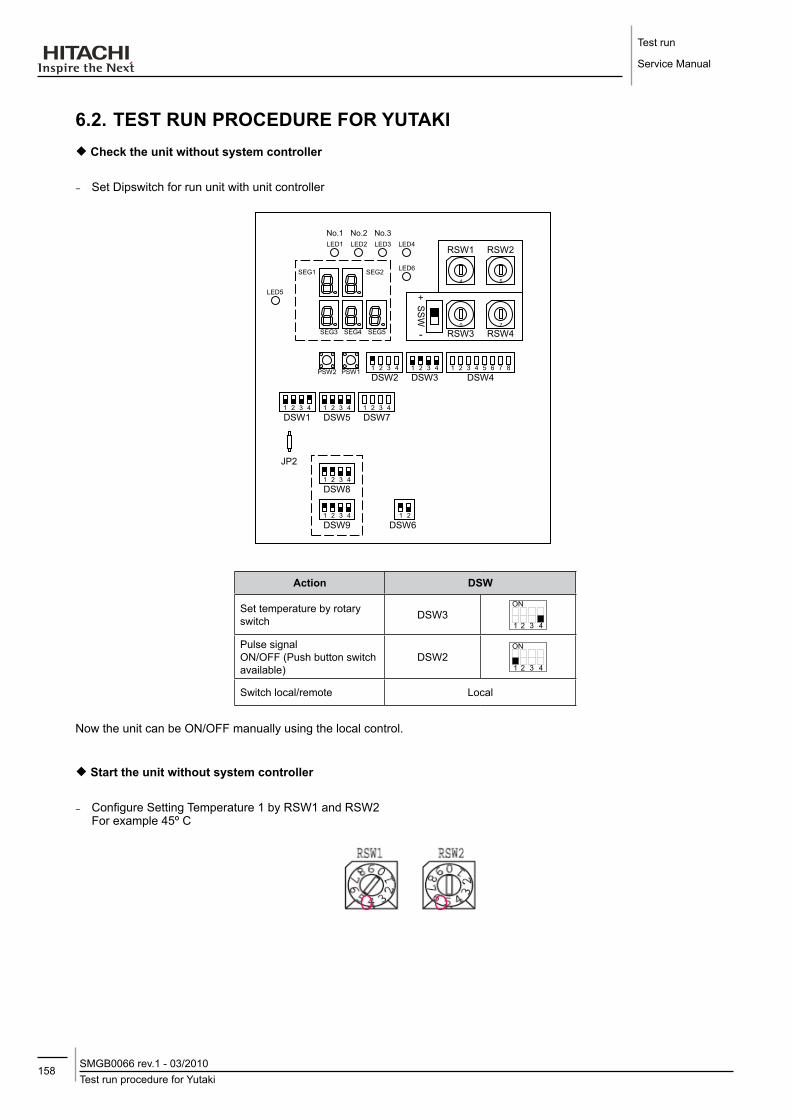
Test run
Service Manual
158Test run procedure for YutakiSMGB0066 rev.1 - 03/2010
6.2. TEST RUN PRoCEdURE foR yUTAKI¡¡ Check the unit without system controller
¡− Set Dipswitch for run unit with unit controller
1 2
DSW6
JP2
1 2
DSW8
3 4
1 2
DSW4
3 4 5 6 7 8
1 2
DSW9
3 4
1 2
DSW5
3 41 2
DSW1
3 4 1 2
DSW7
3 4
1 2
DSW3
3 41 2
DSW2
3 4PSW1PSW2
SEG3 SEG4 SEG5
SEG1 SEG2
LED5
LED1 LED2 LED3 LED4
No.1 No.2 No.3
LED6
0 7
4 5
RSW3 RSW4
RSW1 RSW2
SS
W
+
-
Action dSW
Set temperature by rotary switch DSW3
Pulse signalON/OFF (Push button switch available)
DSW2
Switch local/remote Local
Now the unit can be ON/OFF manually using the local control.
¡¡ Start the unit without system controller
¡− Configure Setting Temperature 1 by RSW1 and RSW2 For example 45º C
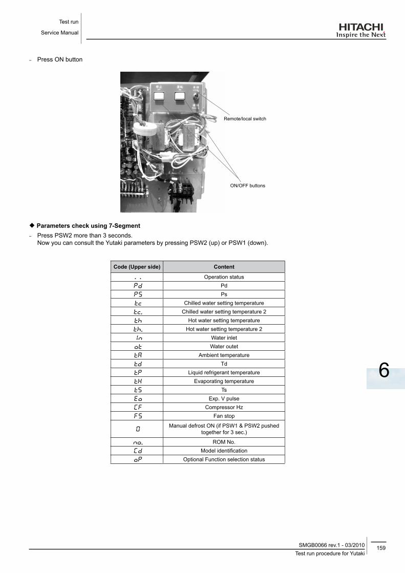
159Test run procedure for Yutaki
SMGB0066 rev.1 - 03/2010
Test run
Service Manual
6
¡− Press ON button
Remote/local switch
ON/OFF buttons
¡¡ Parameters check using 7-Segment¡− Press PSW2 more than 3 seconds.
Now you can consult the Yutaki parameters by pressing PSW2 (up) or PSW1 (down).
Code (Upper side) Content
. . Operation status
Pd
Ps
Chilled water setting temperature
. Chilled water setting temperature 2
Hot water setting temperature
. Hot water setting temperature 2
Water inlet
Water outet
Ambient temperature
Td
Liquid refrigerant temperature
Evaporating temperature
Ts
Exp. V pulse
Compressor Hz
Fan stop
Manual defrost ON (if PSW1 & PSW2 pushed
together for 3 sec.)
. ROM No.
Model identification
Optional Function selection status

Test run
Service Manual
160Test run procedure for YutakiSMGB0066 rev.1 - 03/2010
¡¡ Pump & high cut test (optional)Set DSW1 as:
7-Segment (1&2) shows: PU
Pushing PSW1 (down) &/or PSW2 (up) select the Test function
- PU: Pump test (only run Pump) - HH: High Cut test in Heating Mode - HC: High Cut test in Cooling Mode (Not used)
- Push PSW1 & PSW2 more than 3” and selected test is activated -Push PSW1 & PSW2 more than 3” and test is finished
6.2.1. System controller testing
6.2.1.1. System start-up
After the installation of sensors and outputs, the System Controller can be started for the first time.
Switch on the mains power supply.
The controller will be initialised with the default configuration stored in the internal memory.
A test procedure is performed to check the validity of the data in the internal memory, and the various inputs are tested. All sensors and communications devices are automatically detected. All faults and warnings are automatically reset and the software version is displayed for reference.
6.2.1.2. System test
Once the system has been installed, it is recommended that the following tests are carried out:
1. Check that you have selected the correct configuration, and that the necessary installation parameters have been set.
2. Check the wiring of the inputs and outputs. Use the procedure in 7.3 to view the temperature sensor values. It is possible to manually override the outputs to test the system operation.
3. Check that the Room Unit is communicating with the RF Receiver. To do this, change the temperature setpoint on the Room Unit to the maximum or minimum value and check that the heat pump reacts appropriately.
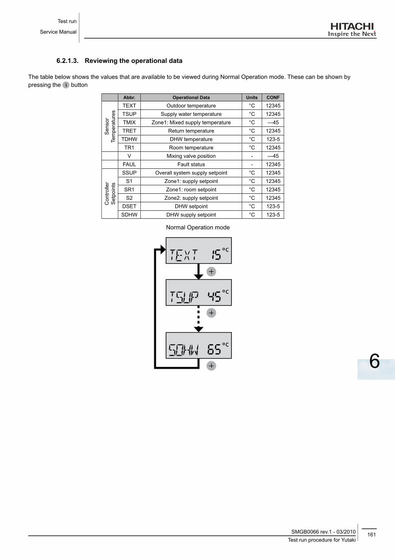
161Test run procedure for Yutaki
SMGB0066 rev.1 - 03/2010
Test run
Service Manual
6
6.2.1.3. Reviewing the operational data
The table below shows the values that are available to be viewed during Normal Operation mode. These can be shown by pressing the button
Abbr. operational data Units CoNf
Sen
sor
Tem
pera
ture
sTEXT Outdoor temperature °C 12345TSUP Supply water temperature °C 12345TMIX Zone1: Mixed supply temperature °C ---45TRET Return temperature °C 12345TDHW DHW temperature °C 123-5TR1 Room temperature °C 12345
V Mixing valve position - ---45FAUL Fault status - 12345
Con
trolle
r S
etpo
ints
SSUP Overall system supply setpoint °C 12345S1 Zone1: supply setpoint °C 12345
SR1 Zone1: room setpoint °C 12345S2 Zone2: supply setpoint °C 12345
DSET DHW setpoint °C 123-5SDHW DHW supply setpoint °C 123-5
Normal Operation mode

Test run
Service Manual
162Test run procedure for YutakiSMGB0066 rev.1 - 03/2010
note
-- Operational-data-shown-depends-on-the-system-configuration-(CONF)-setting.-- Zone-1-is-the-heating-loop-controlled-by-the-System-Controller.-- Zone-2-is-the-heating-loop-controlled-by-the-Extension-Controller.
6.2.1.4. Manually overriding the outputs
This feature allows the status of the outputs to be changed in order to test the electrical connections.
To enter Output Display mode from Normal Operating mode, press the SEL and SET buttons together for at least one second. The display will show “HPS” to indicate that the controller is in Output Display mode and shows the first output “HPS” and its current status.
1. Use the and buttons to move up or down the output list according to the table.
2. To change an output, use the SET button to enter Output Setting mode. The value of the output will flash to show that it can now be changed. To change the output value, use the and buttons.
3. To save the output setting, press the SET button. The flashing will stop to show the value has been saved, and the letter F (Fixed) will appear to show that the output is being overridden. Note that the value must be saved before it takes effect. Instead, to cancel the change, and retain the previously stored value, press the SEL button.
To cancel the manual override of an output, enter the Output Setting mode and then press and together for one second. The “F” disappears from the display to show that the output is no longer overridden.
At any time, pressing the button will return the display to normal operation mode.
Please refer to the electrical wiring connections to identify which relays should be connected to which output for a particular system configuration.
Normal operation mode output display mode output setting mode
& > 1 sec.
SET
SET
SEL
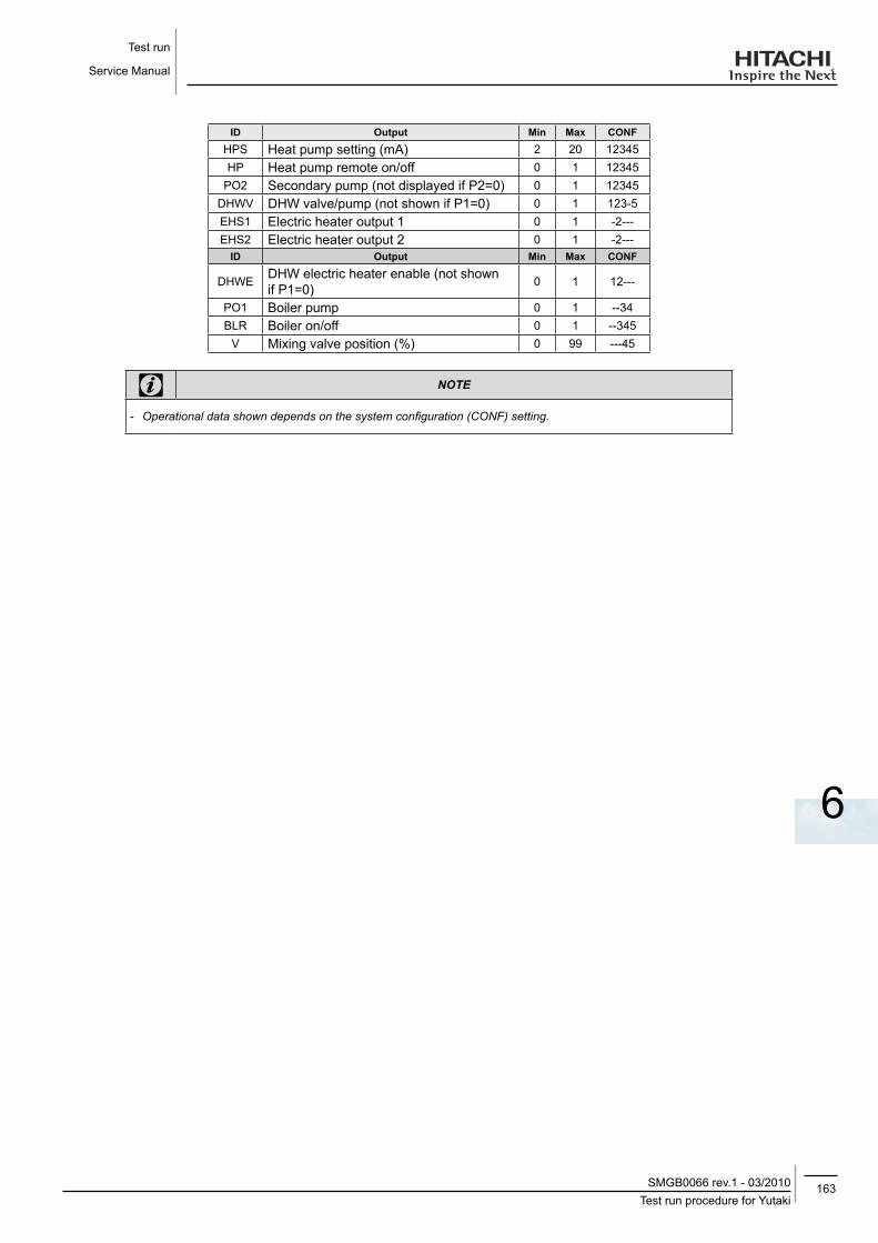
163Test run procedure for Yutaki
SMGB0066 rev.1 - 03/2010
Test run
Service Manual
6
Id output Min Max CoNfHPS Heat pump setting (mA) 2 20 12345HP Heat pump remote on/off 0 1 12345
PO2 Secondary pump (not displayed if P2=0) 0 1 12345DHWV DHW valve/pump (not shown if P1=0) 0 1 123-5EHS1 Electric heater output 1 0 1 -2---EHS2 Electric heater output 2 0 1 -2---
Id output Min Max CoNf
DHWE DHW electric heater enable (not shown if P1=0) 0 1 12---
PO1 Boiler pump 0 1 --34BLR Boiler on/off 0 1 --345
V Mixing valve position (%) 0 99 ---45
note
-- Operational-data-shown-depends-on-the-system-configuration-(CONF)-setting.

165Contents
SMGB0066 rev.1 - 03/2010
Troubleshooting
Service Manual
7
7. TRoUBlESHooTING
CoNTENTS
7.1. Initial troubleshooting ................................................................................................................166
7.1.1. Unit and System controller - Power Supply failure ...............................................................................1667.1.2. Abnormal operation of the devices .......................................................................................................1687.1.3. Incidents of operation ...........................................................................................................................174
7.2. Troubleshooting procedure .......................................................................................................175
7.2.1. Alarm code ...........................................................................................................................................177
7.3. Failure diagnosis method ..........................................................................................................216
7.4. Checking procedure for main parts ...........................................................................................218
7.4.1. RHUE-(3~6)AVHN. Procedure for checking the DIP-IPM. ...................................................................2187.4.2. RHUE-(5/6)AHN. Procedure for checking the ISPM. ...........................................................................2207.4.3. Checking capacitors CB1 & CB2. ........................................................................................................2227.4.4. Fault diagnosis of DC fan motor. ..........................................................................................................223
7.5. Troubleshooting of control system ............................................................................................225
7.5.1. System controller..................................................................................................................................2257.5.2. System MMI Pack ................................................................................................................................226
7.6. Troubleshooting of accessories .................................................................................................227
7.6.1. Pump kit ...............................................................................................................................................2277.6.2. WEH - Water Electric Heater ................................................................................................................2287.6.3. DHWT - Domestic Hot Water Tank .......................................................................................................228

Troubleshooting
Service Manual
166Initial troubleshootingSMGB0066 rev.1 - 03/2010
7.1. INITIAl TRoUBlESHooTING
7.1.1. Unit and System controller - Power Supply failure
• The lEd and the 7-segment display are not indicated.
• Not operated.
If the fuses are blown out or a circuit breaker is activated, investigate the cause of the overcurrent and take the necessary action.
observed failure Cause Check item Action (Turn off the main switch)
Power failure or power is not ON Measure the voltage using a voltmeter Supply the power
Blown out fuse or activation of the breaker at the power source
Accidental grounding for live cables Measure the insulation resistance
Remove the cause of the short circuit and replace the fuse
Failure of compressor motor Measure the interphase resistance, insulation
resistance
Replace compressor and fuse
Failure of fan motor Replace fan motor and fuse
Blown out fuse at the control circuit
Live cables short circuit Check for any un-insulated part of the wires
Remove the cause of the short circuit and replace the fuse
Short circuit of the control circuit to earth
Measure the insulation resistance
Remove the cause of the short circuit and replace the fuse
Failure of the magnetothermic
switch for the compressor
Insufficient contact
Check for magnetothermic switch to activate correctly Replace magnetothermic
switch and fuseCoil failure Measure coil resistance
Failure of the magnetothermic
switch for the pump
Insufficient contact
Check for magnetothermic switch to activate correctly
Replace magnetothermic switch and fuse
Coil failure Measure coil resistance
Failure of auxiliary relay
Insufficient contact
Check for magnetothermic switch to activate correctly
Replace auxiliary relay and fuse
Coil failure Measure coil resistance
Failure of solenoid valve coil Coil failure Measure coil resistance Replace coil and fuse
Short circuit in PCB Check for the existance of any conductive contaminants
Remove the particles and replace fuse
Oil heater failure Meassure resistance Replace heater and fuse
Failure of freeze protection heater for water piping Meassure resistance Replace heater and fuse
Failure of the transformer Check the transformer voltage output Replace the transformer

167Initial troubleshooting
SMGB0066 rev.1 - 03/2010
Troubleshooting
Service Manual
7
observed failure Cause Check itemAction
(Turn off the main switch)
System controller cable disconnected Connect the cable Replace the cable or repair the cable
One (or several) phase failure, or inverted phase order ("” alarm). Only in three phase unit.
Check the connection of R,S and T phase. Reorder the phases
Failure of remote/local switch or remote/local switch set at “local” Check remote/local switch Turn the switch to “remote” or replace switch
Deficient contact at terminal controller connectors
Insufficient connection or incorrect connection of the Yutaki unit PCB
Check the connectors and terminals
Remove rust, dust or any contaminants, check the correct tightening of the
terminalsInsufficient connection or incorrect connection of the terminal
in remote controller
Failure of the system controller Refer to “Troubleshooting of system controller”
Undefined PCB failure
Unconnected wires to PCB Check the connectors Correctly connect the wires
Failure of PCB Check PCB through its self-diagnostic mode Replace PCB if it failed
Incorrect wiring connection Take action according to the procedure that is displayed in "TEST RUN"

Troubleshooting
Service Manual
168Initial troubleshootingSMGB0066 rev.1 - 03/2010
7.1.2. Abnormal operation of the devices
observed failure Cause Check itemAction
(Turn off the main switch)
Cooling mode(1 minute power on)
Excessively high discharge
pressure (high pressure switch
activated)
Insufficient air flow to the heat exchanger
clogging of the air side heat exchanger? Remove the clogging
Obstacles at the inlet or the outlet of the airside heat exchanger Remove the obstacles
Is the service area for the unit sufficient?
Make sure the service area
correct fan speed? Replace the fan motor
Excesive inlet air temperature at the airside exchanger
Short circuited air to the unit? Remove the cause of the shor-circuit air
Any heating source near to the unit? Remove the heat source
Excessively charged refrigerant Expansion valve opening & sub cool Correctly charge the
refrigerant
Non -condensed gas during the cycle
Check each temperature and each pressure
Charge the refrigerant after the vacuum pumping
Discharge pipe clogged Check the clogging Remove the clogging
Clogging of the strainerCheck for clogging (Symptom: You
can appreciate a temperature gradient between strainer inlet and outlet)
Clean or replace the strainer
Clogging of the heat exchanger Check for clogging Remove the clogging
Failure or malfunction of the expansion valve
Check the connection cord and the connector Replace the connector
Is there an operation sound from the coil? Replace the coil
Is the thermistor for the compressor normal?
Replace the themistor or pressure sensor
Is the thermistor correctly installed on the suction pipe?
Install correctly the thermistor
Excessively high water inlet temperature Check water temperature Refer to the customer
Failure fan motor (not running) Measure the motor´s terminals resistance Replace fan motor
Excessively high suction pressure
Malfunction or internal leakage of the 4-way
valve
Check the temperature difference between the inlet and outlet of the
4-way valveReplace the 4-way valve
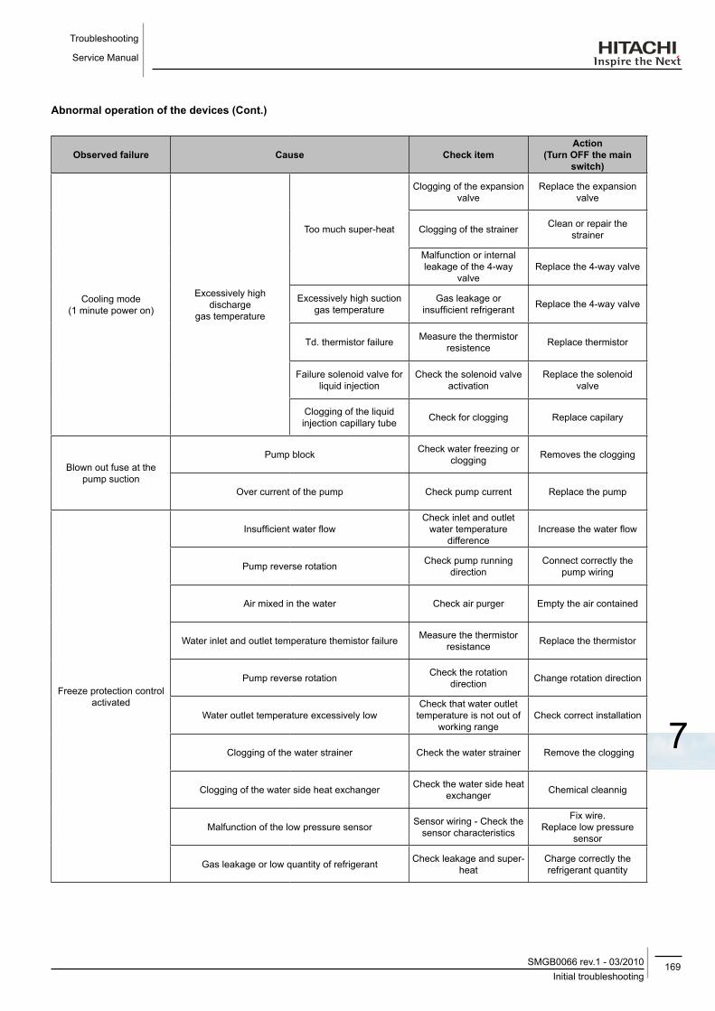
169Initial troubleshooting
SMGB0066 rev.1 - 03/2010
Troubleshooting
Service Manual
7
Abnormal operation of the devices (Cont.)
observed failure Cause Check itemAction
(Turn off the main switch)
Cooling mode(1 minute power on)
Excessively high discharge
gas temperature
Too much super-heat
Clogging of the expansion valve
Replace the expansion valve
Clogging of the strainer Clean or repair the strainer
Malfunction or internal leakage of the 4-way
valveReplace the 4-way valve
Excessively high suction gas temperature
Gas leakage or insufficient refrigerant Replace the 4-way valve
Td. thermistor failure Measure the thermistor resistence Replace thermistor
Failure solenoid valve for liquid injection
Check the solenoid valve activation
Replace the solenoid valve
Clogging of the liquid injection capillary tube Check for clogging Replace capilary
Blown out fuse at the pump suction
Pump block Check water freezing or clogging Removes the clogging
Over current of the pump Check pump current Replace the pump
Freeze protection control activated
Insufficient water flowCheck inlet and outlet
water temperature difference
Increase the water flow
Pump reverse rotation Check pump running direction
Connect correctly the pump wiring
Air mixed in the water Check air purger Empty the air contained
Water inlet and outlet temperature themistor failure Measure the thermistor resistance Replace the thermistor
Pump reverse rotation Check the rotation direction Change rotation direction
Water outlet temperature excessively lowCheck that water outlet
temperature is not out of working range
Check correct installation
Clogging of the water strainer Check the water strainer Remove the clogging
Clogging of the water side heat exchanger Check the water side heat exchanger Chemical cleannig
Malfunction of the low pressure sensor Sensor wiring - Check the sensor characteristics
Fix wire. Replace low pressure
sensor
Gas leakage or low quantity of refrigerant Check leakage and super-heat
Charge correctly the refrigerant quantity
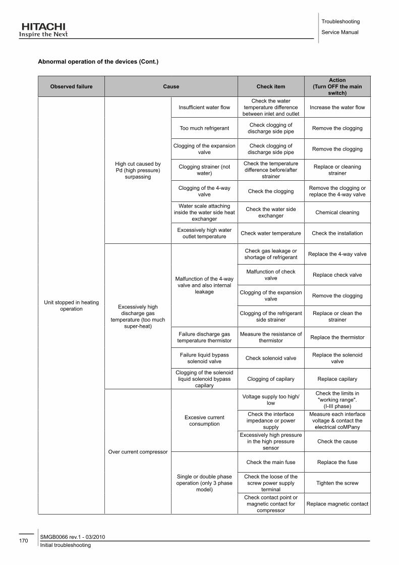
Troubleshooting
Service Manual
170Initial troubleshootingSMGB0066 rev.1 - 03/2010
Abnormal operation of the devices (Cont.)
observed failure Cause Check itemAction
(Turn off the main switch)
Unit stopped in heating operation
High cut caused by Pd (high pressure)
surpassing
Insufficient water flowCheck the water
temperature difference between inlet and outlet
Increase the water flow
Too much refrigerant Check clogging of discharge side pipe Remove the clogging
Clogging of the expansion valve
Check clogging of discharge side pipe Remove the clogging
Clogging strainer (not water)
Check the temperature difference before/after
strainer
Replace or cleaning strainer
Clogging of the 4-way valve Check the clogging Remove the clogging or
replace the 4-way valve
Water scale attaching inside the water side heat
exchanger
Check the water side exchanger Chemical cleaning
Excessively high water outlet temperature Check water temperature Check the installation
Excessively high discharge gas
temperature (too much super-heat)
Malfunction of the 4-way valve and also internal
leakage
Check gas leakage or shortage of refrigerant Replace the 4-way valve
Malfunction of check valve Replace check valve
Clogging of the expansion valve Remove the clogging
Clogging of the refrigerant side strainer
Replace or clean the strainer
Failure discharge gas temperature thermistor
Measure the resistance of thermistor Replace the thermistor
Failure liquid bypass solenoid valve Check solenoid valve Replace the solenoid
valve
Clogging of the solenoid liquid solenoid bypass
capilaryClogging of capilary Replace capilary
Over current compressor
Excesive current consumption
Voltage supply too high/low
Check the limits in "working range".
(I-III phase)Check the interface impedance or power
supply
Measure each interface voltage & contact the electrical coMPany
Excessively high pressure in the high pressure
sensorCheck the cause
Single or double phase operation (only 3 phase
model)
Check the main fuse Replace the fuse
Check the loose of the screw power supply
terminalTighten the screw
Check contact point or magnetic contact for
compressorReplace magnetic contact

171Initial troubleshooting
SMGB0066 rev.1 - 03/2010
Troubleshooting
Service Manual
7
Abnormal operation of the devices (Cont.)
observed failure Cause Check itemAction
(Turn off the main switch)
Over current compressor
Failure compressor bearing Check bearing seal state Replace the compressor
Failure in the compressor motor insulation
Check insulation resistance
Replace the compressor (option "replace the
insulation")
Failure current sensor for compressor Check the connector
Repair the wiring connection or replace
the current sensor
Blown out fuse at the pump circuit
Blocked pump Check if there exist any solid particle, or iced water
Chemical cleaning of the foreign particle
Failure of the magnetic contact of the pump
Check the magnetic contact
replace the magnetic contact
A lot of ice is attached on the airside
(heating mode heat exchanger)
Automatic defrost is de-activated
Failure of the thermistor Measure the resistance of the thermistor Replace the thermistor
Failure of the 4-way valve Check the activation 4-way valve Replace the 4-way valve
Short circuited Check obstacles around the unit Remove the obstacles
Failure of the low pressure sensorCheck the display
pressure and actual pressure
Remove the low pressure sensor
Unit is in ice condition - Perform manual defrosting
Unit is stopped by highcut in defrost operation Failure of high pressure sensor
Check the pressure & actual value of the high
pressure sensor
Replace high pressure sensor

Troubleshooting
Service Manual
172Initial troubleshootingSMGB0066 rev.1 - 03/2010
Abnormal operation of the devices (Cont.)
observed failure Cause Check itemAction
(Turn off the main switch)
Insufficient heating process
Heating load is higher than heating capacity Check the heating load Install an adequate size unit
Excessively low suction pressure Gas leakage Check gas leakage &
super-heatCharge correctly the quantity of refrigerant
Clogging of the expansion valve Check the clogging of expansion valve Remove clogging
Clogging of the strainerCheck temperature
difference before/after strainer
Clean or replace the strainer
Clogging of side low pressure pipe Check the temperature difference of each pipe Remove the clogging
Malfunction of the check valveCheck the difference
temperature before/after check valve
Replace the check valve
Shortage air flow in the air side heat exchanger
Excessively dust in airside heat exchanger
Remove itClogging of the inlet/
outlet at the air side heat exchanger is clock
Shortage the service space for Yutake unit Secure service space
Device rotation fan motor Correct wiring of the fan motor
Air temperature through heat exchanger air flow Check the air short circuit Repair short circuit
Defrosting it is not enough
Check the evaporating thermistor Replace the thermistor
Check the 4-way valve Replay 4-way valve
Excessively high discharge pressure
Shortage of waterflowCheck the difference of temperature between inelet/outlet of the unit
Increase the water flow
Pump reverse rotation Check the rotation direction Correct the direction
Air mixing in the water Check air purger Empty the air contained
Excessively high hot water temperature
Check the water thermistor of the unit
Replace the water thermistor or PCB
Refrigerant excessively discharged
Check refrigerant cycle temperature Charge the correct quantity

173Initial troubleshooting
SMGB0066 rev.1 - 03/2010
Troubleshooting
Service Manual
7
Abnormal operation of the devices (Cont.)
observed failure Cause Check itemAction
(Turn off the main switch)
Insufficient heating process
Excessively high discharge pressure
Non-condensable gas in the refrigerant cycle
Turn off the unit & check the relation between
temperature and pressure
Evacuate and charge refrigerant again
Clogging of the high pressure pipe Check the clogging Remove ghe clogging
Clogging of the expansion valve Check the clogging Remove the clogging
Clogging of the strainerCheck the difference
temperature before/after strainer
Replace the strainer
Water scale is attached in the water side heat
exchangerCheck the heat exchanger Chemical cleaning
Malfunction or internal leakage of the 4-way
valve
Check the difference temp. between inlet &
outlet of the 4-way valveReplace the 4-way valve
Wiring failure of the 4-way valve
Check the electrical continuity at the termilnals
Repair wiring or replace 4-way valve
Failure compressorCheck pressure cycle temperature & running
currentReplace the compressor
Unit is running but does not make any sound
Unit propeller fan is hitting the shroud Visually inspect it Adjust the position of the propeller fan
Abnormal sound form the compressor
Faulty installation Check that each part is tightly fixed Tightly fix each part
Liquid ref. compression Adjust the suction gas temperature and pressure Ensure super-heat
Wear or breakage of the internal compressor parts
Abnormal sound from the inside of the compressor Replace the compressor
No heat by the oil heater Check the resistance of the oil heater and it´s fuse
Replace the oil heater and the fuse
Humming sound from the magnetic conductor Check the surface of the contacts
Replace the magnetothermic switch
Abnormal vibration of the cabinets Check each fixing screw Tightly fix each screw

Troubleshooting
Service Manual
174Incidents of operationSMGB0066 rev.1 - 03/2010
7.1.3. Incidents of operation
The operation of the heater is bonded to the Yutaki heat pump.
(If that is in default, the heater can be activated only if specific programming controller Yutaki is done). The heater can be activated by the controller Yutaki under request for additional power or temperature.
In case of non-functioning heater should check:
- That signals to the heat pump function.
- That fuse protection heater in a state.
- That the water pressure is at least 1 bar.
- That the water flow is assured permanently.
If the above checks are correct:
- Turn off the heater isolating fuses.
- Open the hood of connecting the heater.
- Check the good son tightening supply and command.
Press firmly on the push rearmament security heat between the 2 relays electrical power to rearm security heat. (It is possible that safety heater thermal be triggered due to a stoppage of water flow).
- Close the door connecting the heater.
- Switch on the power and restart the heat pump.
In case of non-functioning heater, remove the heater and demand its replacement.

175Troubleshooting procedureSMGB0066 rev.1 - 03/2010
Troubleshooting
Service Manual
7
7.2. TRoUBlESHooTING PRoCEdURE Checking using the 7-segment display.
7-seg. display info.
Upper side
Lower side
(See the following table for details)
General Indication Content
88 Proceeding Initialization
88 Power ON (During unit stoppage)
U Pump Operation (During unit stoppage)
U Waiting of pump feedback (During unit operation)
Stoppage by Thermo-OFF
Heating operation (Normal operation)
↔Heating operation (Activation of forced compressor frequency control due to low pressure difference:forced up)
↔Heating operation (Activation of forced compressor frequency control due to high pressure difference:forced down)
↔Heating operation (Activation of forced compressor frequency control due to excessively high discharge pressure: forced down)
↔Heating operation (Activation of forced compressor frequency control due to excessively high current :forced down)
↔Heating operation (Activation of forced compressor frequency control due to excessively high inverter fin temperature: forced down)
↔ Retry operation (by alarm 02-91, t1)
↔11 Retry operation (by alarm 02-e1)
↔1 Retry operation (by alarm 02-h1)
↔1 Retry operation (by alarm 51, 52, 53, 54)
↔1 Retry operation (by alarm 04, 06)
(Flickering) Initializing electronic expansion valve
Fan manual operation
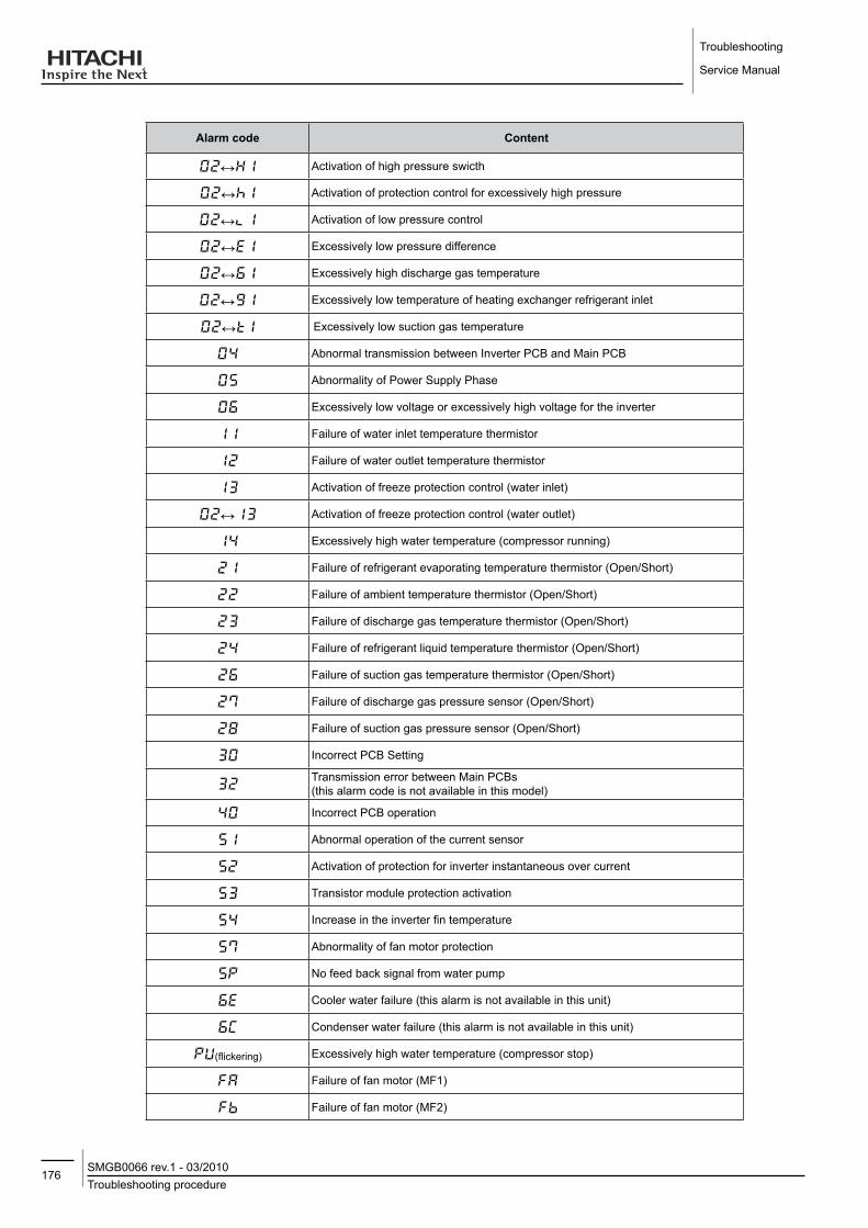
Troubleshooting
Service Manual
176Troubleshooting procedureSMGB0066 rev.1 - 03/2010
Alarm code Content
↔1 Activation of high pressure swicth
↔1 Activation of protection control for excessively high pressure
↔1 Activation of low pressure control
↔1 Excessively low pressure difference
↔1 Excessively high discharge gas temperature
↔1 Excessively low temperature of heating exchanger refrigerant inlet
↔1 Excessively low suction gas temperature
Abnormal transmission between Inverter PCB and Main PCB
Abnormality of Power Supply Phase
Excessively low voltage or excessively high voltage for the inverter
11 Failure of water inlet temperature thermistor
1 Failure of water outlet temperature thermistor
1 Activation of freeze protection control (water inlet)
↔1 Activation of freeze protection control (water outlet)
1 Excessively high water temperature (compressor running)
1 Failure of refrigerant evaporating temperature thermistor (Open/Short)
Failure of ambient temperature thermistor (Open/Short)
Failure of discharge gas temperature thermistor (Open/Short)
Failure of refrigerant liquid temperature thermistor (Open/Short)
Failure of suction gas temperature thermistor (Open/Short)
Failure of discharge gas pressure sensor (Open/Short)
8 Failure of suction gas pressure sensor (Open/Short)
Incorrect PCB Setting
Transmission error between Main PCBs (this alarm code is not available in this model)
Incorrect PCB operation
1 Abnormal operation of the current sensor
Activation of protection for inverter instantaneous over current
Transistor module protection activation
Increase in the inverter fin temperature
Abnormality of fan motor protection
No feed back signal from water pump
Cooler water failure (this alarm is not available in this unit)
Condenser water failure (this alarm is not available in this unit)
U(flickering) Excessively high water temperature (compressor stop)
Failure of fan motor (MF1)
b Failure of fan motor (MF2)

177Troubleshooting procedureSMGB0066 rev.1 - 03/2010
Troubleshooting
Service Manual
7
7.2.1. Alarm code
Alarm code description
↔ Activation of high pressure switch
• The alarm code is displayed on the PCB´s display. – This alarm code is displayed when the high pressure (Pd) is incresed to more than 4.15 MPa, and high pressure
switch (63H) is activated.
PCB monitoring position: PCB1, PCN5 (See next page)

Troubleshooting
Service Manual
178Troubleshooting procedureSMGB0066 rev.1 - 03/2010
Is High Pressure Sensor Output character and
Low Pressure Sensor display value "Ps" proper during
compressor Stop?
YesReplace PCB
Is the voltage betweenVCC12 and GND1 12V on
PCB1?
NoReplace PCB
Yes
No
Replace High Pressure Sensor
A
Is Securely Connected PCN´s on PCB1 and High pressure switch (63H)?
Wiring Check and Repair(disconnecting wiring Error)
No
Yes
No
Yes
Pull out connector PCN5, Check continuity of High Pressure Switch (63H).
Is continuity OK?
Replace High Pressure Switch (63H)
Is alarm activated justafter compressor running?
NoReplace PCB
Yes
Is high pressure switch(63H) activated?(Is Pd reached
activated value?
No Replace High Pressure Switch (63H)
Yes
Is securely connectedCN202 on PCB3,4 and
CN15?CN14 on PCB1
No Wiring Check and Repair(Disconnecting, Wiring Error)
Yes
Is securely connectedCN4 on PCB1 and High
Pressure sensor?
No Wiring Check and Repair(Disconnecting, Wiring Error)
Yes
Are High Pressure and Low Presure shown in segment as "Pd" and "Ps" coincident
during compressor stop?
YesClogging of air side heat exchanger
NoCheck of high pressure
Cycle check
Shortage of Water
Pump reverse rotation
Air mixed
Expansion valve malfunction
Water stain in water side heat exchanger
Clogging of Water Strainer
<CoolING>
<HEATING>
note
-- In-case-that-the-low-pressure-is-higher-than-2.2-MPa,-segment-shows-2.2-MPa.-- In-this-case,-connect-a-pressure-gauge-to-high-pressure-check-joint,-check-the-pressure-shown-in-the-gauge.
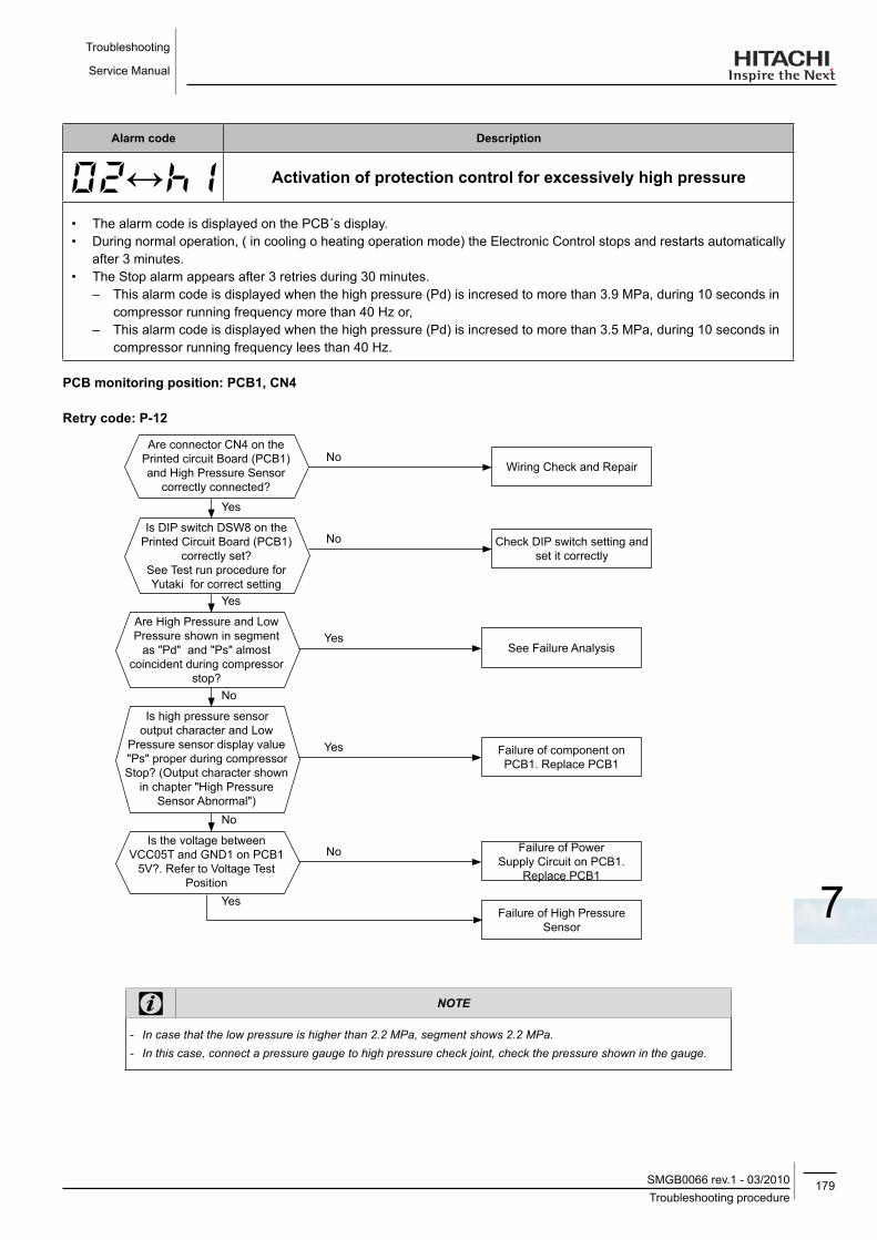
179Troubleshooting procedureSMGB0066 rev.1 - 03/2010
Troubleshooting
Service Manual
7
Alarm code description
↔ Activation of protection control for excessively high pressure
• The alarm code is displayed on the PCB´s display. • During normal operation, ( in cooling o heating operation mode) the Electronic Control stops and restarts automatically
after 3 minutes.• The Stop alarm appears after 3 retries during 30 minutes.
– This alarm code is displayed when the high pressure (Pd) is incresed to more than 3.9 MPa, during 10 seconds in compressor running frequency more than 40 Hz or,
– This alarm code is displayed when the high pressure (Pd) is incresed to more than 3.5 MPa, during 10 seconds in compressor running frequency lees than 40 Hz.
PCB monitoring position: PCB1, CN4
Retry code: P-12
note
-- In-case-that-the-low-pressure-is-higher-than-2.2-MPa,-segment-shows-2.2-MPa.-- In-this-case,-connect-a-pressure-gauge-to-high-pressure-check-joint,-check-the-pressure-shown-in-the-gauge.
Are connector CN4 on the Printed circuit Board (PCB1) and High Pressure Sensor
correctly connected?
Wiring Check and RepairNo
Yes
No
Yes
Is DIP switch DSW8 on the Printed Circuit Board (PCB1)
correctly set?See Test run procedure for Yutaki for correct setting
Check DIP switch setting and set it correctly
Are High Pressure and Low Pressure shown in segment
as "Pd" and "Ps" almost coincident during compressor
stop?
YesSee Failure Analysis
No
Is high pressure sensor output character and Low
Pressure sensor display value "Ps" proper during compressor Stop? (Output character shown
in chapter "High Pressure Sensor Abnormal")
Yes Failure of component on PCB1. Replace PCB1
No
Is the voltage between VCC05T and GND1 on PCB1
5V?. Refer to Voltage Test Position
No Failure of Power Supply Circuit on PCB1.
Replace PCB1
YesFailure of High Pressure
Sensor

Troubleshooting
Service Manual
180Troubleshooting procedureSMGB0066 rev.1 - 03/2010
Alarm code description
↔ Activation of low pressure control
• The alarm code is displayed on the PCB´s display. • It appears The electronic control displays the alarm during the operation in heathing or cooling mode. – This alarm code is displayed when the suction pressure (Ps) is less than 0.1 MPa during 3 seconds.
PCB monitoring position: PCB1, CN3
note
-- In-case-that-the-low-pressure-is-higher-than-2.0-MPa,-segment-shows-2.0-MPa.--- In-this-case,-check-if-the-high-pressure-value-"Pd"-shown-in-segment-is-higher-than-1.0-MPa.
Is connector CN3 on the Printed circuit Board (PCB1)
correctly connected?
Wiring Check (Breaking of wire, wrong
wiring)
No
Yes
Is High Pressure and Low Presure shown in segment
as "Pd" and "Ps" coincident,during compressor Stop?
YesShortage of Refrigerant/ Gas leakage
NoClogging of expansion valve
Clogging of low pressure side piping
Not enough air going through heat exchanger
Malfunction of check valve
Air flow is not suficient
Defrost incomplete
Is Low Pressure Sensor Output character and
High Pressure Sensor display value "Pd" proper during
compressor Stop?
YesReplace PCB
Is the voltage betweenVCC12 and GND1 12V on
PCB1?.
YesReplace Low Pressure sensor
No
No
Replace PCB

181Troubleshooting procedureSMGB0066 rev.1 - 03/2010
Troubleshooting
Service Manual
7
Alarm code description
↔ Excessively low pressure difference
• The alarm code is displayed on the PCB´s display. • The compressor stops and restarts automatically in 3 minutes. • The Stop alarm appears after 3 retries during 30 minutes.
– This alarm code is displayed when the Pressure Ratio calculated from High Pressure "Pd" and Low Pressure "Ps" is less than 1.8 MPa during 3 minutes.
PCB monitoring position: PCB1, CN3 and CN4
Retry code: P-11
Calculation formula for Pressure Ratio:
Pressure Ratio=High Pressure "Pd" + 0.1Low Pressure "Ps" + 0.1
Example:
Pd= 1.6 MPa
Ps= 0.7 MPa
1.6 + 0.10.7 + 0.1
= 2.13Pressure Ratio =
Are connectors CN3, CN4 on the Printed Circuit Board
(PCB1), Low pressure Sensor and High Pressure Sensor
correctly connected?
Wiring Check and RepairNo
Yes
No
Yes
Are DIP switch DSW8 and DSW9 on PCB1 correctly
connected?(See setting of DIP switch for
correct setting).
Check DIP switch setting and set it correctly
Are High Pressure and Low Pressure shown in segment
as "Pd" and "Ps" almost coincident, during compressor
Stop?
Yes PCB1 and Pressure Sensor for Pd, Ps are normal.See Failure Analysis
No Failure of Pressure Sensor.(Check the Pressure Sensor,
according the checking procedure shown in alarm
code "27" and "28").
note
-- In-case-that-the-low-pressure-is-higher-than-2.2-MPa,-segment-shows-2.2-MPa.--- In-this-case,-connect-a-pressure-gauge-to-high-pressure-check-joint,-check-the-pressure-shown-in-the-gauge.

Troubleshooting
Service Manual
182Troubleshooting procedureSMGB0066 rev.1 - 03/2010
Alarm code description
↔ Excessively high discharge gas temperature
• The alarm code is displayed on the PCB´s display. – This alarm code is displayed when the discharge gas temperature is increased to 120ºC and continues for 10
minutes. – The discharge gas, temperature is increased over 140 ºC during more than 5 seconds.
PCB monitoring position: PCB2, CN15
Is connector CN15 on the PCB2 correctly connected?
Plug correctly and repair wiring
No
Yes
Measure the temperature of the position where the discharge gas thermistor
attached, by surface thermometer.
Is the temperature measured and shown in segment
proper?
YesShortage of Refrigerant/ Gas leakage
No
Check valve malfunction
Clogging of expansion valve
Expansion valve opening check
Expansion valve malfunction
Are the connectors between PCB1 and PCB2
correctly connected?
PCB1
CN9-CN1
PCB2CN5-CN2
CN6-CN3
CN2-CN4
No Wiring check, Repair.(Breaking of wire, wrong
wiring)
Pull out connector and measure thermistor
resistance.Is resistance correct?
NoReplace thermistor
Yes
Yes
Check Printed Circuit Board(PCB2)
4-way valve malfunction
Clogging Strainer
Check liquid injection

183Troubleshooting procedureSMGB0066 rev.1 - 03/2010
Troubleshooting
Service Manual
7
Alarm code description
↔ Excessively low temperature of heat exchanger refrigerant inlet
• The alarm code is displayed on the PCB´s display. • The compressor stops and restarts automatically in 3 minutes.• The alarm appears after 3 retries during 30 minutes. – This alarm code is displayed when the Refrigerant temperature in water side heat exchanger inlet (Tp) is less than
-6ºC during 3 seconds. (Only for cooling operation). – The Refrigerant temperature in water side heat exchanger inlet (Tp) is less than -20ºC during 10 seconds. (Only for
defrosting operation). No retry during defrosting operation. Alarm stop immediately.
PCB monitoring position: PCB2, CN14
Retry code: P- 06
Is the connector CN14 on the PCB2 correctly connected?
Plug correctly and repair wiring
No
Yes
Measure the temperature of the position where the
water side heat enchanger refrigerant inlet thermistor
attached, by surface thermometer.
Is the temperature measured and shown in segment
proper?
Yes Check the water flow rate (Check temperature of inlet and outlet)
No
Clogging of water strainer
Check pump reverse rotation
Check the air mixing
Are the connectors between PCB1 and PCB2 correctly
connected?
PCB1
CN9-CN1
PCB2CN5-CN2
CN6-CN3
CN2-CN4
No Wiring check, Repair.(Breaking of wire, wrong
wiring)
Yes
Shortage of Refrigerant/ Gas leakage
Clogging of plate heat exchanger
Clogging of expansion valve and strainer
Pull out connector and measure thermistor
resistance.Is resistance correct?
NoReplace thermistor
YesCheck PCB2
Check water temperature (Not excessively Low)
Malfundtion of check valve
Malfunction of expansion valve

Troubleshooting
Service Manual
184Troubleshooting procedureSMGB0066 rev.1 - 03/2010
Alarm code description
↔ Excessively low suction gas temperature
• The alarm code is displayed on the PCB´s display. • The compressor stops and restarts automatically in 3 minutes. • The alarm appears after 3 retries during 30 minutes. – This alarm code is displayed when the suction gas temperature (Ts) is lower than -5ºC during 10 seconds. (Only
cooling operation).
PCB monitoring position: PCB2, CN11
Retry code: P-06
Are the connector CN11 on the PCB2 and suction
gas temperature thermistor correctly connected?
Wiring check and repairNo
Yes
Measure the temperature of the position where the
suction gas thermistor attached, by surface
thermometer.Is the temperature measured
and shown in segment proper?
Yes Check the water flow rate (Check temperature of inlet and outlet)
No
Clogging of water strainer
Pump reverse rotating check
Check the air mixing
Are the connectors between PCB1 and PCB2
correctly connected?
PCB1
CN9-CN1
PCB2CN5-CN2
CN6-CN3
CN2-CN4
No Wiring check, Repair.(Breaking of wire, wrong
wiring)
Yes
Shortage of Refrigerant/ Gas leakage
Clogging of low pressure pipe
Clogging of expansion valve
Pull out connector and measure thermistor
resistance.Is resistance correct?
NoReplace thermistor
YesCheck PCB2
Check water temperature (not excessively low)
Malfundtion of check valve
Malfunction of expansion valve

185Troubleshooting procedureSMGB0066 rev.1 - 03/2010
Troubleshooting
Service Manual
7
Alarm code description
Abnormal transmission between Inverter PCB and Main PCB
• The alarm code is displayed on the PCB´s display. – This alarm code is displayed when the communication between Main PCB (PCB1) and Inverter (DIP- IPM/ISPM) is
not performed correctly during 30 seconds.
PCB monitoring position: PCB1, CN8
Is wiring between CN8 of the PCB1 and CN2,6 on the
Inverter PCB (DIP-IPM/ISPM) correctly connected?
Wiring check and Repair (Breaking of wire, wrong wiring)
No
Yes
Check the wiring again , PCB1, Inverter PCB (DIP-
IPM/ISPM) are normal.
Power Supply ON after disconnecting CN8 on PCB1
Is LED 7 (Green) on PCB1 flashing?
No
Yes
Reconnect CN8 on PCB1
NoFailure of Inverter PCB (DIP-IPM/ISPM)
Disconnecting of the wiring between inverter PCB (DIP-IPM/ISPM) and PCB1
Does LED 7 (Green) flashing speed become faster than
before?
NoFailure of Inverter PCB (DIP-IPM/ISPM)
Failure of the DC Fan Motor
Yes
Yes
Failure of transmission circuit on PCB1
Is LED 7 (Green) on PCB1 flashing?
Disconnecting or insufficient contact of the wiring between Inverter PCB(DIP-IPM/ISPM)
and PCB1

Troubleshooting
Service Manual
186Troubleshooting procedureSMGB0066 rev.1 - 03/2010
Alarm code description
Abnormality of Power Supply Phase
• The alarm code is displayed on the PCB´s display. – This alarm code is displayed when the power source phases are reversely connected or one phase is not connected.
PCB monitoring position: PCB1, PCN1
Reverse phase connection?(Only 3 phases model)
Yes
No
Failure of PCB1 or the power source voltage too much low
Connect correctly each phase of the power source
Is there any phase unconnected?
Yes
No
Connect correctly each phase of the power sourcePCB1 is normal
PCB1 is normal
• RHUE-(5/6)AHN (Three phase) • RHUE-(3~6)AHN (Single phase)
Voltage for unit to be suspended
Running voltage:342 to 456V
Setting voltage:Less than 323V
Voltage for unit to be suspended
Running voltage:207 to 253V
Setting voltage:Less than 187V
See below:
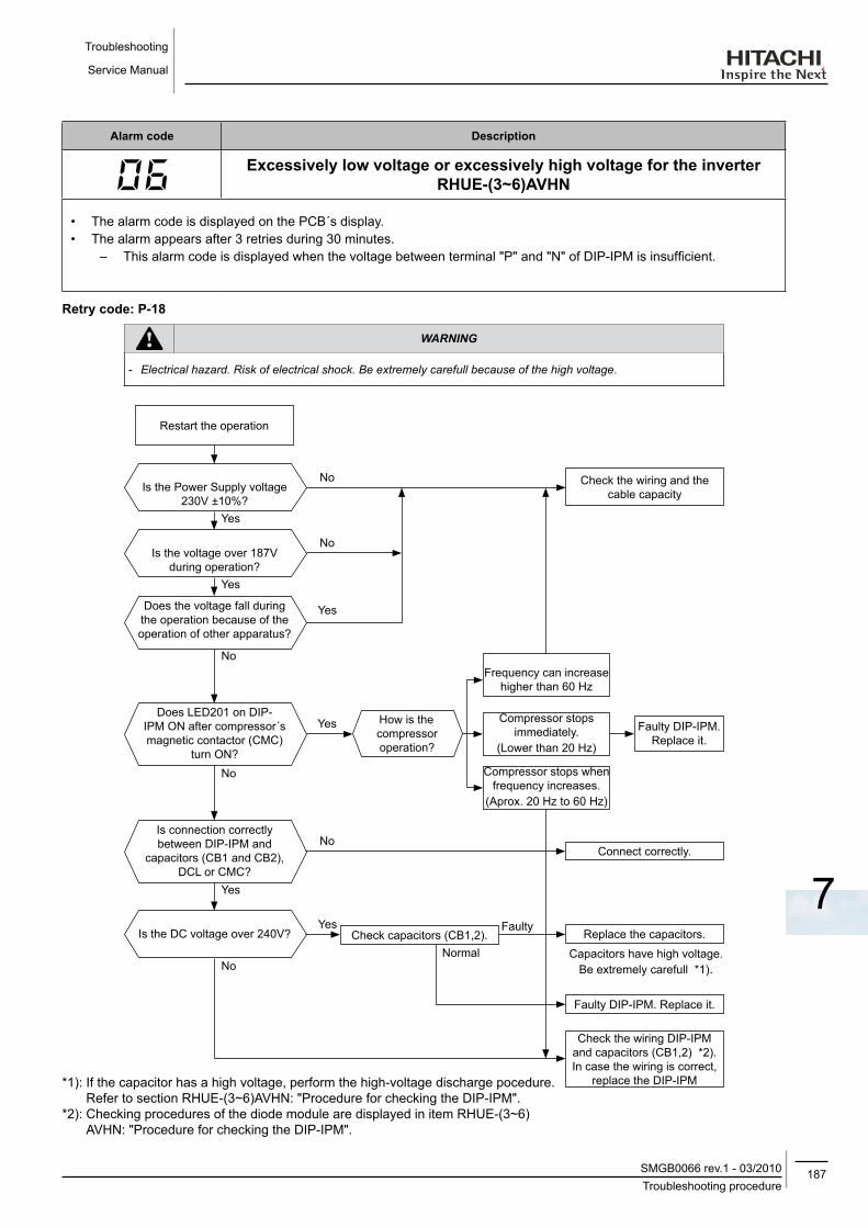
187Troubleshooting procedureSMGB0066 rev.1 - 03/2010
Troubleshooting
Service Manual
7
Alarm code description
Excessively low voltage or excessively high voltage for the inverter
RHUE-(3~6)AVHN
• The alarm code is displayed on the PCB´s display. • The alarm appears after 3 retries during 30 minutes.
– This alarm code is displayed when the voltage between terminal "P" and "N" of DIP-IPM is insufficient.
Retry code: P-18
warning
-- Electrical-hazard.-Risk-of-electrical-shock.-Be-extremely-carefull-because-of-the-high-voltage.
Is the Power Supply voltage 230V ±10%?
No
Yes
No
Yes
Is connection correctly between DIP-IPM and
capacitors (CB1 and CB2), DCL or CMC?
No
No
Yes
Does LED201 on DIP-IPM ON after compressor´s magnetic contactor (CMC)
turn ON?
*1): If the capacitor has a high voltage, perform the high-voltage discharge pocedure. Refer to section RHUE-(3~6)AVHN: "Procedure for checking the DIP-IPM".
*2): Checking procedures of the diode module are displayed in item RHUE-(3~6)AVHN: "Procedure for checking the DIP-IPM".
Restart the operation
Is the voltage over 187V during operation?
Yes
Does the voltage fall during the operation because of the operation of other apparatus?
Yes
No
No
Is the DC voltage over 240V?
Check the wiring and the cable capacity
Check the wiring DIP-IPM and capacitors (CB1,2) *2).In case the wiring is correct,
replace the DIP-IPM
Faulty DIP-IPM. Replace it.
Check capacitors (CB1,2).Yes
Normal
FaultyReplace the capacitors.
Capacitors have high voltage. Be extremely carefull *1).
Connect correctly.
How is the compressor operation?
Faulty DIP-IPM.Replace it.
Compressor stops when frequency increases.
(Aprox. 20 Hz to 60 Hz)
Compressor stops immediately.
(Lower than 20 Hz)
Frequency can increase higher than 60 Hz
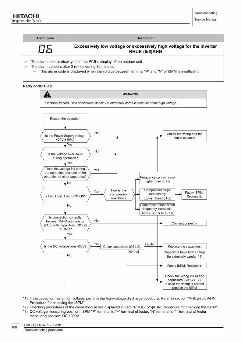
Troubleshooting
Service Manual
188Troubleshooting procedureSMGB0066 rev.1 - 03/2010
Alarm code description
Excessively low voltage or excessively high voltage for the inverter
RHUE-(5/6)AHN
• The alarm code is displayed on the PCB´s display of the outdoor unit. • The alarm appears after 3 retries during 30 minutes.
– This alarm code is displayed when the voltage between terminal "P" and "N" of ISPM is insufficient.
Retry code: P-18
warning
-- Electrical-hazard.-Risk-of-electrical-shock.-Be-extremely-carefull-because-of-the-high-voltage.
*1): If the capacitor has a high voltage, perform the high-voltage discharge pocedure. Refer to section "RHUE-(5/6)AHN: Procedure for checking the ISPM".
*2): Checking procedures of the diode module are displayed in item "RHUE-(5/6)AHN: Procedure for checking the ISPM".*3): DC voltage measuring position: ISPM "P" terminal to "+" terminal of tester, "N" terminal to "-" terminal of tester
measuring position: DC 1000V.
Is the Power Supply voltage 400V ±10%?
No
Yes
No
Yes
Is connection correctly between ISPM and reactor
(PCL) with capacitors (CB1,2)or CMC?
No
No
Yes
Is the LED201 on ISPM ON?
Restart the operation
Is the voltage over 340V during operation?
Yes
Does the voltage fall during the operation because of the operation of other apparatus?
Yes
No
No
Is the DC voltage over 460V?
Check the wiring and the cable capacity
Check the wiring ISPM and capacitors (CB1,2) *2).
In case the wiring is correct, replace the ISPM
Faulty ISPM. Replace it.
Check capacitors (CB1,2).Yes
Normal
FaultyReplace the capacitors.
Capacitors have high voltage. Be extremely careful *1).
Connect correctly.
How is the compressor operation?
Faulty ISPM.Replace it.
Compressor stops when frequency increases.
(Aprox. 30 Hz to 60 Hz)
Compressor stops immediately.
(Lower than 30 Hz)
Frequency can increase higher than 60 Hz

189Troubleshooting procedureSMGB0066 rev.1 - 03/2010
Troubleshooting
Service Manual
7
Alarm code description
11 failure of water inlet temperature thermistor
• The alarm code is displayed on the PCB´s display. – This alarm code is displayed when the water inlet temperature thermistor is short circuited or cut.
PCB monitoring position: PCB2, CN9
Are the connectors between PCB1 and PCB2 correctly
connected?
PCB1
CN9-CN1
PCB2CN5-CN2
CN6-CN3
CN2-CN4
No
YesPull out connector
and measure thermistor resistance.
Is resistance correct?
NoReplace thermistor
Yes
Is connector CN9 on PCB2 correctly connected?
No
Yes
Wiring check, Repair.(Breaking of wire, wrong wiring)
Wiring check, Repair.(Breaking of wire, wrong wiring)
Check PCB1 and PCB2
Measuring the thermistor resistance value:
Thermistor characteristics
Temperature (ºC)
Thermistor Resistance (kΩ)
note
-- Measure-the-resistance-at-least-in-2-different-points-which-the-temperature-is-different-more-than-10-ºC.

Troubleshooting
Service Manual
190Troubleshooting procedureSMGB0066 rev.1 - 03/2010
Alarm code description
1 failure of water outlet temperature thermistor
• The alarm code is displayed on the PCB´s display. – This alarm code is displayed when the water outlet temperature thermistor is short circuited or cut.
PCB monitoring position: PCB2, CN13
Are the connectors between PCB1 and PCB2 correctly
connected?
PCB1
CN9-CN1
PCB2CN5-CN2
CN6-CN3
CN2-CN4
No
Yes
Pull out connector and measure thermistor
resistance.Is resistance correct?
NoReplace thermistor
Yes
Is connector CN13 on PCB2 correctly connected?
No
Yes
Wiring check, Repair.(Breaking of wire, wrong wiring)
Wiring check, Repair.(Breaking of wire, wrong wiring)
Check PCB1 and PCB2
Measuring the thermistor resistance value:
Thermistor characteristics
Temperature (ºC)
Thermistor Resistance (kΩ)
note
-- Measure-the-resistance-at-least-in-2-different-points-which-the-temperature-is-different-more-than-10-ºC.

191Troubleshooting procedureSMGB0066 rev.1 - 03/2010
Troubleshooting
Service Manual
7
Alarm code description
1 Activation of freeze protection control (water inlet)
• The alarm code is displayed on the PCB´s display. – This alarm code is displayed when the chilled water temperature is lower than 2ºC.
PCB monitoring position: PCB2, CN9
Is connector CN9 on the PCB2 correctly connected?
Wiring Check (Breaking of wire, wrong
wiring)
No
Yes
Is the actual water temperature and the
temperature shown in segment proper?
Yes
NoCheck pump reverse rotation
Check water strainer clogging
Check air mixing
Are the connectors between PCB1 and PCB2
correctly connected?
PCB1
CN9-CN1
PCB2CN5-CN2
CN6-CN3
CN2-CN4
No Wiring check, Repair.(Breaking of wire, wrong
wiring)
Yes
Pull out connector and measure thermistor
resistance.Is resistance correct?
NoReplace thermistor
Yes
Check PCB1 and PCB2
Check the water flow rate (Check temperature of Inlet)
Check 4-way valve

Troubleshooting
Service Manual
192Troubleshooting procedureSMGB0066 rev.1 - 03/2010
Alarm code description
↔1 Activation of freeze protection control (water outlet)
• The alarm code is displayed on the PCB´s display. – This alarm code is displayed when the chilled water temperature is lower than 2ºC.
PCB monitoring position: PCB2, CN13
Is connector CN13 on the PCB2 correctly connected?
Wiring Check (Breaking of wire, wrong
wiring)
No
Yes
Is the actual water temperature and the
temperature shown in segment proper?
Yes
NoCheck pump reverse rotation
Check water strainer clogging
Check air mixing
Are the connectors between PCB1 and PCB2 correctly
connected?
PCB1
CN9-CN1
PCB2CN5-CN2
CN6-CN3
CN2-CN4
No Wiring check, Repair.(Breaking of wire, wrong
wiring)
Yes
Pull out connector and measure thermistor
resistance.Is resistance correct?
NoReplace thermistor
YesCheck PCB1 and PCB2
Check the water flow rate (Check temperature of Outlet)
Check 4-way valve

193Troubleshooting procedureSMGB0066 rev.1 - 03/2010
Troubleshooting
Service Manual
7
Alarm code description
1 Excessively high water temperature (compressor running)
• The alarm code is displayed on the PCB´s display. – This alarm code is displayed when the water temperature is above 59ºC during compressor operation. (Only heating
operation).
PCB monitoring position: PCB2, CN9 (Water Inlet)PCB2, CN13 (Water outlet)
Are connectors CN9 and CN13 on the PCB2 correctly
connected?
Wiring Check (Breaking of wire, wrong
wiring)
No
Yes
Is the actual water temperature and the
temperature shown in segment proper?
Yes
NoCheck pump reverse rotation
Check water strainer clogging
Check air mixing
Are the connectors between PCB1 and PCB2
correctly connected?
PCB1
CN9-CN1
PCB2CN5-CN2
CN6-CN3
CN2-CN4
No Wiring check, Repair.(Breaking of wire, wrong
wiring)
Yes
Pull out connector and measure thermistor
resistance.Is resistance correct?
NoReplace thermistor
Yes
Check PCB1 and PCB2
Check the water flow rate (Check temperature of inlet and outlet)
Check chilled water thermostat setting value (It shall be within the working range)

Troubleshooting
Service Manual
194Troubleshooting procedureSMGB0066 rev.1 - 03/2010
Alarm code description
failure of refrigerant liquid temperature thermistor (open/Short)
• The alarm code is displayed on the PCB´s display. – This alarm code is displayed when the thermistor is short circuited or cut.
PCB monitoring position: PCB2, CN14
Are the connectors between PCB1 and PCB2
correctly connected?
PCB1
CN9-CN1
PCB2CN5-CN2
CN6-CN3
CN2-CN4
No
Yes
Pull out connector and measure thermistor
resistance.Is resistance correct?
NoReplace thermistor
Yes
Is connector CN14 on PCB2 correctly connected?
No
Yes
Wiring check, Repair.(Breaking of wire, wrong wiring)
Wiring check, Repair.(Breaking of wire, wrong wiring)
Check PCB1 and PCB2
Measuring the thermistor resistance value:
Thermistor characteristics
Temperature (ºC)
Thermistor Resistance (kΩ)
note
-- Measure-the-resistance-at-least-in-2-different-points-which-the-temperature-is-different-more-than-10-ºC.

195Troubleshooting procedureSMGB0066 rev.1 - 03/2010
Troubleshooting
Service Manual
7
Alarm code description
failure of ambiente temperature thermistor (open/short)
• The alarm code is displayed on the PCB´s display. – This alarm code is displayed when the thermistor is short circuited or cut.
PCB monitoring position: PCB2, CN10
Are the connectors between PCB1 and PCB2
correctly connected?
PCB1
CN9-CN1
PCB2CN5-CN2
CN6-CN3
CN2-CN4
No
Yes
Pull out connector and measure thermistor
resistance.Is resistance correct?
NoReplace thermistor
Yes
Is connector CN10 on PCB2 correctly connected?
No
Yes
Wiring check, Repair.(Breaking of wire, wrong wiring)
Wiring check, Repair.(Breaking of wire, wrong wiring)
Check PCB1 and PCB2
Measuring the thermistor resistance value:
Thermistor characteristics
Temperature (ºC)
Thermistor Resistance (kΩ)
note
-- Measure-the-resistance-at-least-in-2-different-points-which-the-temperature-is-different-more-than-10-ºC.

Troubleshooting
Service Manual
196Troubleshooting procedureSMGB0066 rev.1 - 03/2010
Alarm code description
failure of discharge gas temperature thermistor (open/Short)
• The alarm code is displayed on the PCB´s display. – This alarm code is displayed when the thermistor is short circuited or cut.
PCB monitoring position: PCB2, CN15
Are the connectors between PCB1 and PCB2
correctly connected?
PCB1
CN9-CN1
PCB2CN5-CN2
CN6-CN3
CN2-CN4
No
Yes
Pull out connector and measure thermistor
resistance.Is resistance correct?
NoReplace thermistor
Yes
Is connector CN15 on PCB2 correctly connected?
No
Yes
Wiring check, Repair.(Breaking of wire, wrong wiring)
Wiring check, Repair.(Breaking of wire, wrong wiring)
Check PCB1 and PCB2
Measuring the thermistor resistance value:
Thermistor characteristics
Temperature (ºC)
Thermistor Resistance (kΩ)
note
-- Measure-the-resistance-at-least-in-2-different-points-which-the-temperature-is-different-more-than-10-ºC.

197Troubleshooting procedureSMGB0066 rev.1 - 03/2010
Troubleshooting
Service Manual
7
Alarm code description
failure of refrigerant evaporating temperature thermistor (open/Short)
• The alarm code is displayed on the PCB´s display. – This alarm code is displayed when the thermistor is short circuited or cut.
PCB monitoring position: PCB2, CN12
Are the connectors between PCB1 and PCB2 correctly
connected?
PCB1
CN9-CN1
PCB2CN5-CN2
CN6-CN3
CN2-CN4
No
Yes
Pull out connector and measure thermistor
resistance.Is resistance correct?
NoReplace thermistor
Yes
Is connector CN12 on PCB2 correctly connected?
No
Yes
Wiring check, Repair.(Breaking of wire, wrong wiring)
Wiring check, Repair.(Breaking of wire, wrong wiring)
Check PCB1 and PCB2
Measuring the thermistor resistance value:
Thermistor characteristics
Temperature (ºC)
Thermistor Resistance (kΩ)
note
-- Measure-the-resistance-at-least-in-2-different-points-which-the-temperature-is-different-more-than-10-ºC.
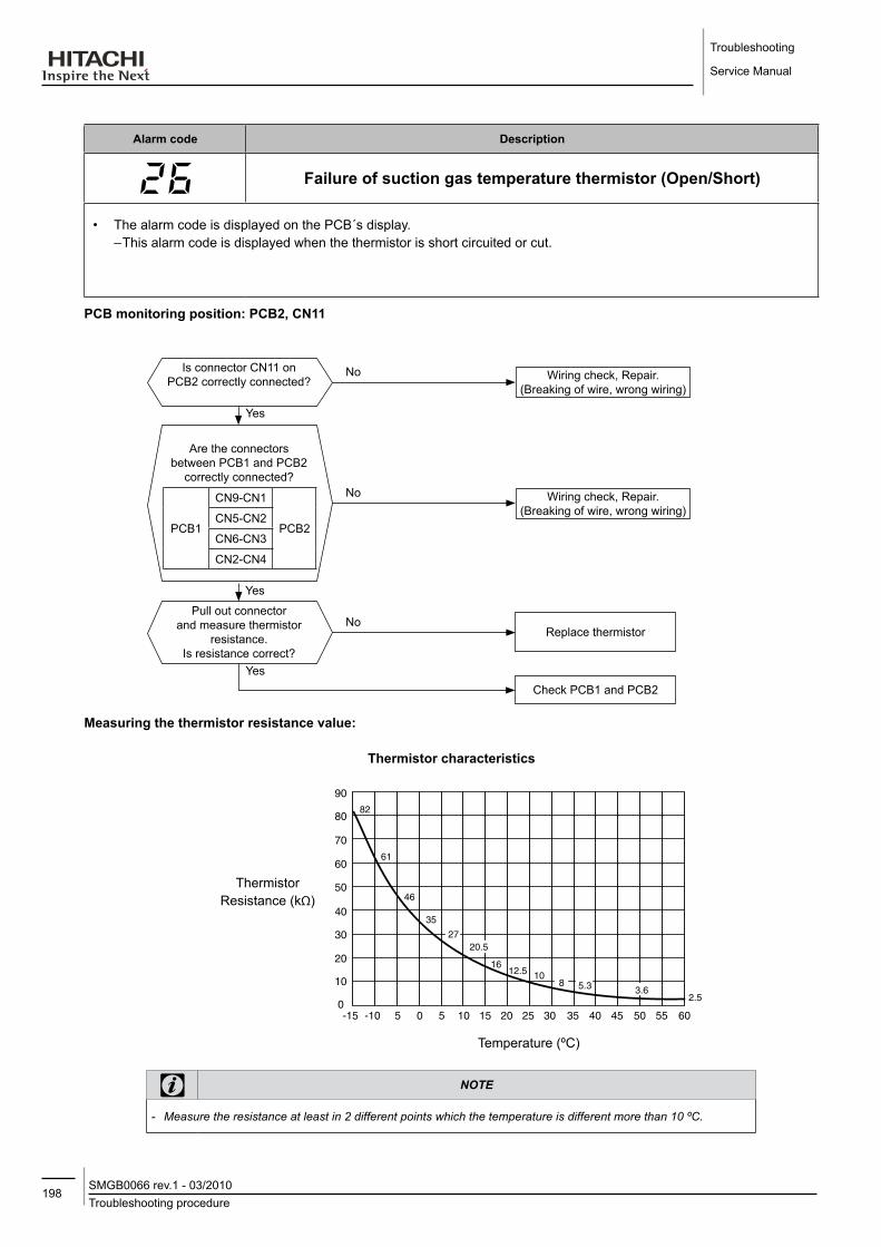
Troubleshooting
Service Manual
198Troubleshooting procedureSMGB0066 rev.1 - 03/2010
Alarm code description
failure of suction gas temperature thermistor (open/Short)
• The alarm code is displayed on the PCB´s display. – This alarm code is displayed when the thermistor is short circuited or cut.
PCB monitoring position: PCB2, CN11
Are the connectors between PCB1 and PCB2
correctly connected?
PCB1
CN9-CN1
PCB2CN5-CN2
CN6-CN3
CN2-CN4
No
Yes
Pull out connector and measure thermistor
resistance.Is resistance correct?
NoReplace thermistor
Yes
Is connector CN11 on PCB2 correctly connected?
No
Yes
Wiring check, Repair.(Breaking of wire, wrong wiring)
Wiring check, Repair.(Breaking of wire, wrong wiring)
Check PCB1 and PCB2
Measuring the thermistor resistance value:
Thermistor characteristics
Temperature (ºC)
Thermistor Resistance (kΩ)
note
-- Measure-the-resistance-at-least-in-2-different-points-which-the-temperature-is-different-more-than-10-ºC.

199Troubleshooting procedureSMGB0066 rev.1 - 03/2010
Troubleshooting
Service Manual
7
Alarm code description
failure of discharge gas pressure sensor (open/Short)
• The alarm code is displayed on the PCB´s display. – This alarm code is displayed when the high pressure sensor is short circuited or cut.
PCB monitoring position: PCB1, CN4
Is the high pressure sensor correctly connected to
connector CN4 on PCB1?No
Yes
Yes
No
Is high pressure sensor output character and low
pressure sensor display value "Ps" proper during compressor
stop?. (See table about sensor characteristics)
Is the voltage between VCC05T and GND1 on
PCB1 5V?(Refer to voltage test position)
Yes
NoFailure of power supply circuit
on PCB1. Replace PCB1.
Wiring check, Repair.(Breaking of wire, wrong wiring)
Failure of high pressure sensor. Replace high pressure sensor.
Failure of component on PCB1. Replace PCB1.
Characteristics of high pressure sensor
DCV
1 2 3CN4
Pressure (MPa)
Out
put
(PCB1)
High Pressure Sensor(0~5V) Voltage meter
Red
(+
Pow
er
Sup
ply)
Whi
te (O
ut)
Bla
ck (G
nd)
note
-- In-case-that-the-low-pressure-is-higher-than-2.2-MPa,-segment-shows-2.2-MPa.--- In-this-case,-connect-a-pressure-gauge-to-high-pressure-check-joint,-check-the-pressure-shown-in-the-gauge.

Troubleshooting
Service Manual
200Troubleshooting procedureSMGB0066 rev.1 - 03/2010
Alarm code description
8 failure of suction gas pressure sensor (open/Short)
• The alarm code is displayed on the PCB´s display. – This alarm code is displayed when the low pressure sensor is short circuited or cut.
PCB monitoring position: PCB1, CN3
Is the high pressure sensor correctly connected to
connector CN4 on the PCB1?No
Yes
Yes
No
Is low pressure sensor output character and high
pressure sensor display value "Pd" proper during compressor
stop?. (See table about sensor characteristics)
Is the voltage between VCC05T and GND1 on
PCB1 5V?(Refer to voltage test position)
Yes
NoFailure of power supply circuit
on PCB1. Replace PCB1.
Wiring check, Repair.(Breaking of wire, wrong wiring)
Failure of low pressure sensor. Replace low pressure sensor.
Failure of component on PCB1. Replace PCB1.
Is the low pressure sensor correctly connected to
connector CN3 on the PCB1?No
Yes
Wiring check, Repair.(Breaking of wire, wrong wiring)
Characteristics of low pressure sensor
DCV
1 2 3CN3
Pressure (MPa)
Out
put
(PCB1)
Low Pressure Sensor(0~5V) Voltage meter
Red
(+
Pow
er
Sup
ply)
Whi
te (O
ut)
Bla
ck (G
nd)
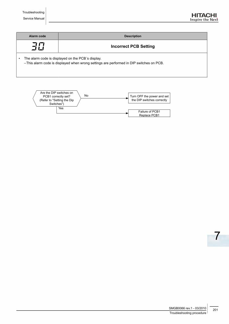
201Troubleshooting procedureSMGB0066 rev.1 - 03/2010
Troubleshooting
Service Manual
7
Alarm code description
Incorrect PCB Setting
• The alarm code is displayed on the PCB´s display. – This alarm code is displayed when wrong settings are performed in DIP switches on PCB.
Are the DIP switches on PCB1 correctly set?
(Refer to "Setting the Dip Switches")
No Turn OFF the power and set the DIP switches correctly
YesFailure of PCB1Replace PCB1

Troubleshooting
Service Manual
202Troubleshooting procedureSMGB0066 rev.1 - 03/2010
Alarm code description
Transmission error between Main PCBs
(this alarm code is not available in this unit)
• The alarm code is displayed on the PCB´s display.
No Turn OFF the power and set the DIP switches correctly
YesFailure of PCB1Replace PCB1
Are the DIP switches on PCB1 correctly set?
(Refer to "Setting the Dip Switches")

203Troubleshooting procedureSMGB0066 rev.1 - 03/2010
Troubleshooting
Service Manual
7
Alarm code description
Incorrect operation
• The alarm code is displayed on the PCB´s display – This alarm code is displayed when wrong settings is performed in DIP switch on PCB or prohibited operation is
performed.
No
Is the alarm activated and unit stopped during operation?
Turn OFF the power and set the DIP switches correctly
YesDue to incorrect operation, the unit gets stopped by the
alarm action.Do not perform it.
No
It is changed to setting mode during operation?
Unit is normal.Do not change to setting mode during operation
Failure of PCB1
Yes
Is the setting of DIP switches correct?
Failure of DIP switch on PCB1
Is the alarm activated just after the Power Supply is
turned ON?
Is the alarm reseted by the stop operation?
No
No
Yes
Yes
Yes
No
Failure of PCB1

Troubleshooting
Service Manual
204Troubleshooting procedureSMGB0066 rev.1 - 03/2010
Alarm code description
failure of the current sensor for "Inverter" (0 A detection)
• The alarm code is displayed on the PCB´s display • The compressor stops and restarts automatically in 3 minutes. • The alarm appears after 3 retries during 30 minutes. – This alarm code is displayed when the frequency of the compressor is maintained at 15~18 Hz after the compressor
is started, one of the absolute values of the running current at each phase U+, U-, V+ and V- is less than 1.5A (including 1.5A).
Retry code: P-17
warning
-- Electrical-hazard.-Risk-of-electrical-shock.-Before-checking-and-replacing-the-inverter-parts-perform-the-high-voltage-discharge-procedure-by-referring-to-section-"Checking-procedure-for-main-parts".
How is the compressor operation when you restart
the compressor?
No
Are the outputs of the ISPM and/or DIP-IPM correct?
No
Yes
Is the coil resistance of the compressor normal?
Restart the operation
Replace the ISPM or DIP-IPM
Replace the ISPM or DIP-IPM
Compressor does not operate.
P17 is displayed
The compressor stops inmediatelly.(nearly 18Hz)
Power supply cables for the compressor are not passing through CT. Pass the wires
through CT.
Replace the compressor

205Troubleshooting procedureSMGB0066 rev.1 - 03/2010
Troubleshooting
Service Manual
7
Alarm code description
Activation of protection for inverter instantaneous over current (1)
• The alarm code is displayed on the PCB´s display.• The compressor stops and restarts automatically in 3 minutes. • The alarm appears after 6 retries during 30 minutes. – This alarm code is displayed when the compressor current is higher than the set value. Totally 3 minutes during 10
minutes.
Retry code: P-17
Replace ISPM or Dip-IPMNo
Yes
Is the current value which activating ,more
than setting value (47.2A)?
Yes(Inverter components are normal.)
No (Lower than setting value)
Is discharge pressure excessively high?
Check discharge, suction pressure and refrigerant cycle status
Check clogging of air-side heat exchanger
Check Fan
Install ISPM or Dip-IPM correctly
No
Yes
Replace ISPM or Dip-IPM
Restart the operation
Check ISPM or Dip-IPM?
Check ISPM or Dip-IPM correctly installed?
caution
-- Electrical-hazard.-Risk-of-electrical-shock.-Before-checking-and-replacing-the-inverter-parts-perform-the-high-voltage-discharge-procedure-by-referring-to-section-"Checking-procedure-for-main-parts".

Troubleshooting
Service Manual
206Troubleshooting procedureSMGB0066 rev.1 - 03/2010
Alarm code description
Activation of protection for inverter instantaneous over current (2)
• The alarm code is displayed on the PCB´s display.• The compressor stops and restarts automatically in 3 minutes. • The alarm appears after 6 retries during 30 minutes. – This alarm code is displayed when the compressor current is higher than the set value.
Retry code: P-17
Restart the operation. Does it trip immediately?
Check ISPM or Dip-IPM?
Turn off power, disconnect U,V,W from
compressor terminals and restart. Does the protecting
function activate?
Check compressor
Check power supply and wiring capacity.
Check compressor
Replace ISPM or Dip-IPM
Yes
No
NoNo
Yes
No
Check ISPMYes
No Check power supply.
Is the current value which activating, more than
setting value (70.5A)?
Is there any factor which
instantaneous voltage drop happened?
Is the input current of each phase almost same
in all 3 phase?
No(Trip after while)
No
Yes
Check power supply and wiring capacity
No
Yes Replace ISPM or Dip-IPM
Is the power supply voltage higher than 170V
during operation?
Is the power supply voltage higher than
170V during operation, even if the other appliance starts?
No
Yes
Is the power supply voltage 230V±10% ?
Yes(Trip immediately)
No(Trip happen sometimes)
caution
-- Electrical-hazard.-Risk-of-electrical-shock.-Before-checking-and-replacing-the-inverter-parts-perform-the-high-voltage-discharge-procedure-by-referring-to-section-"Checking-procedure-for-main-parts".

207Troubleshooting procedureSMGB0066 rev.1 - 03/2010
Troubleshooting
Service Manual
7
Turn OFF power, diconnect U,V,W from compressor
terminals and restart. Does the protecting function activate?
*1)Yes
Yes
Yes
Replace ISPM or DIP-IPMCheck ISPM or DIP-IPM
Has been there any instantaneous drop of
voltage?
No
No
NoCheck compressor
Check power supply and wiring capacity
Replace ISPM or DIP-IPM
A
*1): Turn ON the No.1 switch of the DIP switch on ISPM when restarting with disconnecting the terminals of the compressor. After troubleshooting, turn OFF the No.1 switch of the DIP switch on ISPM.

Troubleshooting
Service Manual
208Troubleshooting procedureSMGB0066 rev.1 - 03/2010
Alarm code description
ISPM or dIP-IPM protection activation
– IPM or Dip IPM have detecting function of abnormality. This alarm is indicated when the transistor module detect the abnormality 3 times in 30 minutes including 3. Retry
operation is performed up to the occurrence of 2 times. (The compressor restarts automatically in 3 min.)
Conditions: Abnormal current to the transistor module such asShort circuited or groundedorAbnormal temperature of the IPM or Dip IPMorControl voltage decrease
Retry code: P-17
*1) Perform the high voltage discharge work by referring to the section "Checking procedure for main parts". before checking and replacing the inverter components.
*2) Turn ON the No.1 switch of the dip switch DSW1 on Inverter PCB when restarting with disconnecting the terminals of the compressor. After troubleshooting, turn OFF the No.1 switch of the dip switch DSW1 on Inverter PCB.
*3) Use the silicon grease provided as accessory (Service parts No. P22760).
note
-- When-alarm-code-“53”-is-indicated,-the-fan-motor-(DC-motor)-ensure-that-DC-fan-motor-is-checked-according-to-the-section-"Fault-diagnosis-of-DC-fan-motor".
Turn off power, disconnect U, V, W from compressor
terminals and restart.Does the protecting function
activate? *2)
No
Check the ISPM or Dip IPM. *1)
Check the compressor.(If there is a short-circuit
between phase lines, replace the compressor.)
Yes
Yes
Faulty
No
No
Replace ISPM or Dip IPM
Coat the silicon grease to all the touched face between
the ISPM or DIP-IPM and the radiated fin fully. *3)
Is the silicon grease coated all over between the ISPM or Dip
IPM and the radiated fin?
Good
Yes
Is the air side heat exchanger of outdoor unit
clogged?Remove clogging.
Replace the ISPM or Dip IPM

209Troubleshooting procedureSMGB0066 rev.1 - 03/2010
Troubleshooting
Service Manual
7
Alarm code description
Increase in the inverter fin temperature
• The compressor stops when the temperature of the thermistor for inverter fin excess 100ºC, and restarts automatically in 3 minuntes.
• The alarm appears after 3 retries during 30 minutes.
Retry code: P-17
1*): Perform the high voltage discharge work by referring to the section "Checking procedure for main parts" before checking and replacing the inverter components.
No
Replace the dipIPM or ISPM. *1)
Restart the operation.Does it trip soon?
Yes
Remove the clogging
Is the air side heat exchanger of the
outdoor unit clogged?
Faulty Dip IPM or ISPM, or thermistor.Replace it.
No
Is thermistor short circuit or faulty?
NoYes
Replace the thermistor
Yes
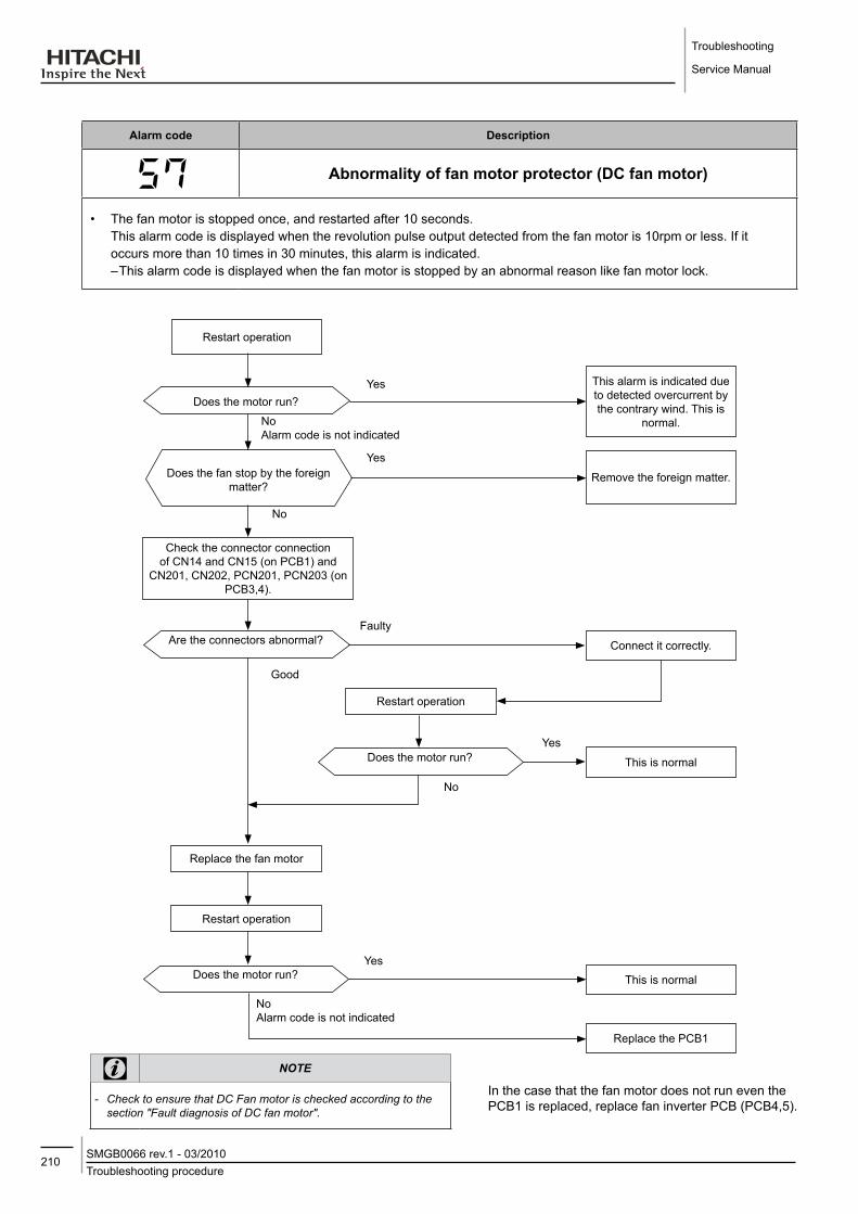
Troubleshooting
Service Manual
210Troubleshooting procedureSMGB0066 rev.1 - 03/2010
Alarm code description
Abnormality of fan motor protector (dC fan motor)
• The fan motor is stopped once, and restarted after 10 seconds. This alarm code is displayed when the revolution pulse output detected from the fan motor is 10rpm or less. If it occurs more than 10 times in 30 minutes, this alarm is indicated.
– This alarm code is displayed when the fan motor is stopped by an abnormal reason like fan motor lock.
Yes This alarm is indicated due to detected overcurrent by the contrary wind. This is
normal.
Does the motor run?
Remove the foreign matter.Does the fan stop by the foreign matter?
Check the connector connection of CN14 and CN15 (on PCB1) and
CN201, CN202, PCN201, PCN203 (on PCB3,4).
Faulty
Restart operation
NoAlarm code is not indicated
Yes
No
Are the connectors abnormal? Connect it correctly.
Restart operation
Does the motor run? This is normal
Replace the fan motor
Restart operation
Does the motor run?
Yes
Good
This is normalYes
NoAlarm code is not indicated
Replace the PCB1
No
note
-- Check-to-ensure-that-DC-Fan-motor-is-checked-according-to-the-section-"Fault-diagnosis-of-DC-fan-motor".
In the case that the fan motor does not run even the PCB1 is replaced, replace fan inverter PCB (PCB4,5).

211Troubleshooting procedureSMGB0066 rev.1 - 03/2010
Troubleshooting
Service Manual
7
Alarm code description
No feed back signal from water pump
• The alarm code is displayed on the PCB´s display.• It is available once feedback signal confirmed. – This alarm code is displayed when the Pump operation feedback signal (terminals 1-2) is OFF during pump interlock
(CMp) ON (terminals 3-4).
PCB monitoring position: PCB1, PCN4
Is thermal relay for pump (TRP) activated?. (If used a
field supplied pump)
Yes
No
Is 220-240V the voltage between connector PCN4 PIN1 and PIN3 on PCB1?
No
Yes
Check Printed Circuit Board(PCB1)
Check the Pump Lock
Check thermal relay for pump
Check wiring around pump and thermal relay for pump

Troubleshooting
Service Manual
212Troubleshooting procedureSMGB0066 rev.1 - 03/2010
Alarm code description
Cooler water failure (this alarm is not available in this unit)
– This alarm code is displayed when the contact between #1 and #2 of CN6 is not closed.
PCB monitoring position: PCB1, CN6
Are the connectors between PCB1 and PCB2 correctly
connected?
PCB1 CN9-CN1 PCB2CN5-CN2
CN6-CN3
CN2-CN4
No
Yes
Is the voltage between VCC24N and GND2 on PCB1
24V?(refer to voltage test position)
YesReplace PCB1
Is the connector CN6 on PCB1 correctly connected?
No
Yes
Wiring check, Repair.(Breaking of wire, wrong wiring)
Wiring check, Repair.(Breaking of wire, wrong wiring)
Replace transformerYes
No
Check wiring and connector
Is the wiring of transformer breaking?
Failure of power supply circuit on PCB1
Yes
Yes
Is the voltage output of the transformer secondary side
correctly output?
No
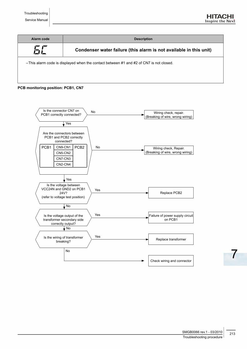
213Troubleshooting procedureSMGB0066 rev.1 - 03/2010
Troubleshooting
Service Manual
7
Alarm code description
Condenser water failure (this alarm is not available in this unit)
– This alarm code is displayed when the contact between #1 and #2 of CN7 is not closed.
PCB monitoring position: PCB1, CN7
Are the connectors between PCB1 and PCB2 correctly
connected?
PCB1 CN9-CN1 PCB2CN5-CN2
CN7-CN3
CN2-CN4
No
Yes
Is the voltage between VCC24N and GND2 on PCB1
24V?(refer to voltage test position)
YesReplace PCB2
Is the connector CN7 on PCB1 correctly connected?
No
Yes
Wiring check, repair.(Breaking of wire, wrong wiring)
Wiring check, Repair.(Breaking of wire, wrong wiring)
Replace transformerYes
No
Check wiring and connector
Is the wiring of transformer breaking?
Failure of power supply circuit on PCB1
Yes
No
Is the voltage output of the transformer secondary side
correctly output?
No

Troubleshooting
Service Manual
214Troubleshooting procedureSMGB0066 rev.1 - 03/2010
Alarm code description
U(flickering) Excessively high water temperature (compressor stop)
• Water temperature is increased to 65ºC by heat generation in pump or other heat source during only pump running (during compressor stop: during thermo off or during pump automatic operation in winter).
• If water temperature is decreased less than 6ºC due to pump stop, it becomes normal status automatically.• Since this is not an abnormality of unit, it is not saved in alarm history.
When this alarm happen, check the water system first. If any cause can not be detected, check the unit according to the following procedure.
note
-- Measure-the-resistance-at-least-in-2-different-points-which-is-different-more-than-10-ºC.
Are the connectors between PCB1 and PCB2 correctly
connected?
PWB1 CN9-CN1 PWB2CN5-CN2
CN6-CN3
CN2-CN4
No
Yes
Pull out connector and measure thermistor
resistance.Is resistance correct?
NoReplace thermistor
Yes
Are connectors CN3 and CN9 on PCB2 correctly connected?
No
Yes
Wiring check, Repair.(Breaking of wire, wrong wiring)
Wiring check, Repair.(Breaking of wire, wrong wiring)
Failure of PCB1.Replace PCB1.
Is the actual water temperature and the water temperature shown
in segment proper?Yes
No
Check water system of heat load side
PCB monitoring position: PCB2, CN3 and CN9
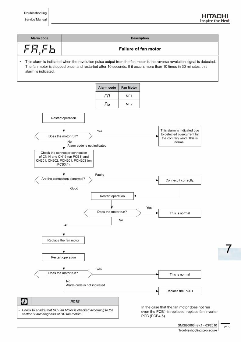
215Troubleshooting procedureSMGB0066 rev.1 - 03/2010
Troubleshooting
Service Manual
7
Alarm code description
,b failure of fan motor
• This alarm is indicated when the revolution pulse output from the fan motor is the reverse revolution signal is detected. The fan motor is stopped once, and restarted after 10 seconds. If it occurs more than 10 times in 30 minutes, this alarm is indicated.
Alarm code fan Motor
MF1
b MF2
note
-- Check-to-ensure-that-DC-Fan-Motor-is-checked-according-to-the-section-"Fault-diagnosis-of-DC-fan-motor".
In the case that the fan motor does not run even the PCB1 is replaced, replace fan inverter PCB (PCB4,5).
Yes This alarm is indicated due to detected overcurrent by the contrary wind. This is
normal.
Does the motor run?
Check the connector connection of CN14 and CN15 (on PCB1) and
CN201, CN202, PCN201, PCN203 (on PCB3,4).
Faulty
Restart operation
NoAlarm code is not indicated
Are the connectors abnormal? Connect it correctly.
Restart operation
Does the motor run? This is normal
Replace the fan motor
Restart operation
Does the motor run?
Yes
Good
This is normalYes
NoAlarm code is not indicated
Replace the PCB1
No

Troubleshooting
Service Manual
216Failure diagnosis methodSMGB0066 rev.1 - 03/2010
7.3. fAIlURE dIAGNoSIS METHod General check of failure diagnosis.
In the case of no segment indication, unit can not operate.
Is 380-415V (3N~) or 220-240V (1~) supplied
to the unit?
Check the power source switch
Yes
No
Is fuse broken?
No
Yes
No
Yes
Is 220-240V supplied to transformer primary side? Replace fuse
Yes
No
Is R phase or S phase failure?
Wiring check and repair
Wiring check Connector check
Yes
No
Check the powersource switch
Replace transformer
Wiring check Connector check
Is 28.3V in PIN 1-PIN2,17.6V in PIN3-PIN4,
17.6V in PIN5-PIN6 of theprinted circuit board forCPU (PCB) connector
CN10A,B?
No
Power Source Circuit Malfunction
Replace Printed CircuitBoard for CPU (PDBc)
No
Yes
Is DIP switch PSW1 PIN4 OFF?
(Compressor Manual Stop)
PSW1 PIN 4 SET ONYes
No
Yes
Is voltage 5V in Test Pins VCC05-GND1 and
VCC05T-GND1 on PCB1?
Is voltage 12V in Test Pins VCC12-GND1 and
VCC12T-GND1 on PCB1?
Is voltage 24V in Test Pins VCC24-GND1 and
VCC24N-GND2 on PCB1?
Initialize PCBIf initialization can not
proceed, or segment shows nothing after initialization,
replace PCB

217Failure diagnosis method
SMGB0066 rev.1 - 03/2010
Troubleshooting
Service Manual
7
Voltage test position:
VCC05
IC6 IC7
IC4
C70
C72
C71
C22
C3
87654321
43214321
4321DSW2 DSW4
VCC24
GND1
VCC05
VCC12T
VCC12
GND2
VCC24N
VCC05T
DSW3
DSW1 DSW54321
DSW7
4321
DSW94321
DSW84321
PSW1PSW2
LED8
LED7
JP1
Z3Z2
C3 C111 C5
C4
IC1 C28C33
C31C38
OSC
C21
EF1
C36
C19
DM5
DM2DM1
DM4DM3
REG3
CN
6
PCN
3B
PCN
3AC
N10B
CN
10APC
N2
CN
5C
N4
CN
3
CN1CN8
CN14 CN15
CN2CN9 CN7A
CN7B
IC8
IC3
DSW6
21Z5 Z6
C62 C68
C7
R81
D6 D7D1
L1
C20
C2
C1
REG2
REG4
REG1
REG5
REG7
VCC24N GND2GND1
VCC24/VCC05T VCC12VCC12T
Inicialization procedurePower Supply OFF, and set DSW1-1, DSW5-2,3 ON, and DSW 5-1,4 OFF on PCB (Record original DIP switch setting)
Power Supply ON, and confirm segment shows as follows:
<Initialization successfully done>
If segment shows as follows, Power Supply OFF once, and Power ON again:
<Initialization failure>
If segment shows as "Initialization Successfully Done", Initialization Succeed. Power Supply OFF, and DSW1-1, DSW5-2,3 set original setting again. Initialization is finished. In other case, if segment shows nothing even if doing Initialization procedure, or shown Initialization Failure, PCB1 is broken and replace PCB1.
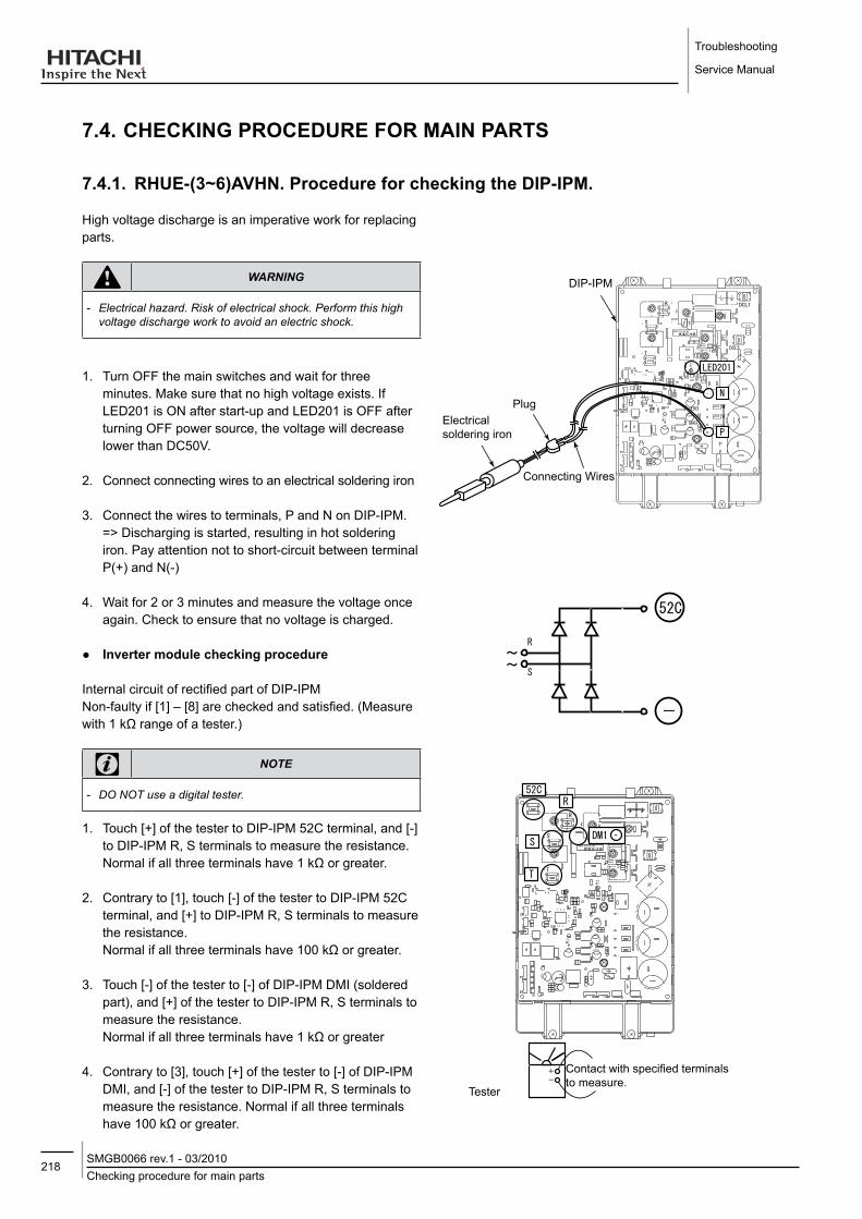
Troubleshooting
Service Manual
218Checking procedure for main partsSMGB0066 rev.1 - 03/2010
DIP-IPM
Connecting Wires
Electrical soldering iron
Plug
7.4. CHECKING PRoCEdURE foR MAIN PARTS
7.4.1. RHUE-(3~6)AVHN. Procedure for checking the dIP-IPM.
High voltage discharge is an imperative work for replacing parts.
warning
-- Electrical-hazard.-Risk-of-electrical-shock.-Perform-this-high-voltage-discharge-work-to-avoid-an-electric-shock.
1. Turn OFF the main switches and wait for three minutes. Make sure that no high voltage exists. If LED201 is ON after start-up and LED201 is OFF after turning OFF power source, the voltage will decrease lower than DC50V.
2. Connect connecting wires to an electrical soldering iron
3. Connect the wires to terminals, P and N on DIP-IPM. => Discharging is started, resulting in hot soldering iron. Pay attention not to short-circuit between terminal P(+) and N(-)
4. Wait for 2 or 3 minutes and measure the voltage once again. Check to ensure that no voltage is charged.
Inverter module checking procedure
Internal circuit of rectified part of DIP-IPMNon-faulty if [1] – [8] are checked and satisfied. (Measure with 1 kΩ range of a tester.)
note
-- DO-NOT-use-a-digital-tester.
1. Touch [+] of the tester to DIP-IPM 52C terminal, and [-] to DIP-IPM R, S terminals to measure the resistance. Normal if all three terminals have 1 kΩ or greater.
2. Contrary to [1], touch [-] of the tester to DIP-IPM 52C terminal, and [+] to DIP-IPM R, S terminals to measure the resistance. Normal if all three terminals have 100 kΩ or greater.
3. Touch [-] of the tester to [-] of DIP-IPM DMI (soldered part), and [+] of the tester to DIP-IPM R, S terminals to measure the resistance. Normal if all three terminals have 1 kΩ or greater
4. Contrary to [3], touch [+] of the tester to [-] of DIP-IPM DMI, and [-] of the tester to DIP-IPM R, S terminals to measure the resistance. Normal if all three terminals have 100 kΩ or greater.
Contact with specified terminals to measure.
Tester

219Checking procedure for main parts
SMGB0066 rev.1 - 03/2010
Troubleshooting
Service Manual
7
5. Touch [+] of the tester to [P] of DIP-IPM (soldered part), and [-] to DIP-IPM U, V, W terminals to measure the resistance. Normal if all three terminals have 1 kΩ or greater.
6. Contrary to [5], touch [-] of the tester to [P] of DIP-IPM (soldered part), and [+] to DIP-IPM U, V, W terminals to measure the resistance. Normal if all three terminals have 30 kΩ or greater. (Resistance gradually increases during measurement.)
7. Touch [-] of the tester to [N] of ISPM (soldered part), and [+] to ISPM U, V, W terminals to measure the resistance. Normal if all three terminals have 1 kΩ or greater.
8. Contrary to [7], touch [+] of the tester to [N] ofDIP-IPM (soldered part), and [-] to DIP-IPM U, V, W terminals to measure the resistance. Normal if all three terminals have 30 kΩ or greater. (Resistance gradually increases during measurement.)
Internal circuit of ACT part of inverter module
Non-faulty if [9] – [13] are checked and satisfied.
(Measure with 1 kΩ range of a tester.)
note
-- DO-NOT-use-a-digital-tester
9. Check items [1] – [8].
10. Touch [+] of the tester to DIP-IPM DCL2 terminal, and [-] to [P] of ISPM/DIP-IPM (soldered part) to measure the resistance. Normal if all three terminals have 100 kΩ or greater
11. Contrary to [10], touch [-] of the tester to DIP-IPM DCL2 terminal, and [+] to [P] of DIP-IPM (soldered part) to measure the resistance. Normal if all three terminals have 1 kΩ or greater.
12. Touch [+] of the tester to DIP-IPM DCL2 terminal, and [-] to [N] of DIP-IPM (soldered part) to measure the resistance. Normal if all three terminals have 100 kΩ or greater.
13. Contrary to [12], touch [-] of the tester to DIP-IPM DCL2 terminal, and [+] to [N] of DIP-IPM (soldered part) to measure the resistance. Normal if all three terminals have 10 kΩ or greater. (Resistance gradually increases during measurement.)
Contact with specified terminals to measure.Tester
Contact with specified terminals to measure.
Tester
External Appearance and Internal Circuit of Transistor Module

Troubleshooting
Service Manual
220Checking procedure for main partsSMGB0066 rev.1 - 03/2010
7.4.2. RHUE-(5/6)AHN. Procedure for checking the ISPM.
Procedure using an analog tester:
Checking the diode module:
1. By touching the + side of the tester to the P1 terminal of ISPM and the - side of the tester to R and S of ISPM, measure the resistance. If all the resistances are more than 1 kΩ, it is normal.
2. By touching the - side of the tester to the P1 terminal of ISPM and the + side of the tester to R and S of ISPM, measure the resistance. If all the resistances are more than 100 kΩ, it is normal.
3. By touching the - side of the tester to the N terminal of ISPM and the + side of the tester to R and S of ISPM, measure the resistance. If all the resistances are more than 1 kΩ, it is normal.
4. By touching the + side of the tester to the N terminal of ISPM and the - side of the tester to R and S of ISPM, measure the resistance. If all the resistances are more than 100 kΩ, it is normal.
Remove all the terminals of the ISPM before check. If items (a) to (h) are performed and the results are satisfactory, ISPM is normal. Measure it under 1 kΩ range of a tester.
warning
-- Electrical-hazard.-Risk-of-electrical-shock.-Perform-the-high-voltage-discharge-procedure-as-described.
Capacitors
LED 201
Noise filter PCB
FusesReactor
Magnetic contactor
Magnetic contactor Inverter module ISPM
Rectification parts of internal circuit of ISPM (common)
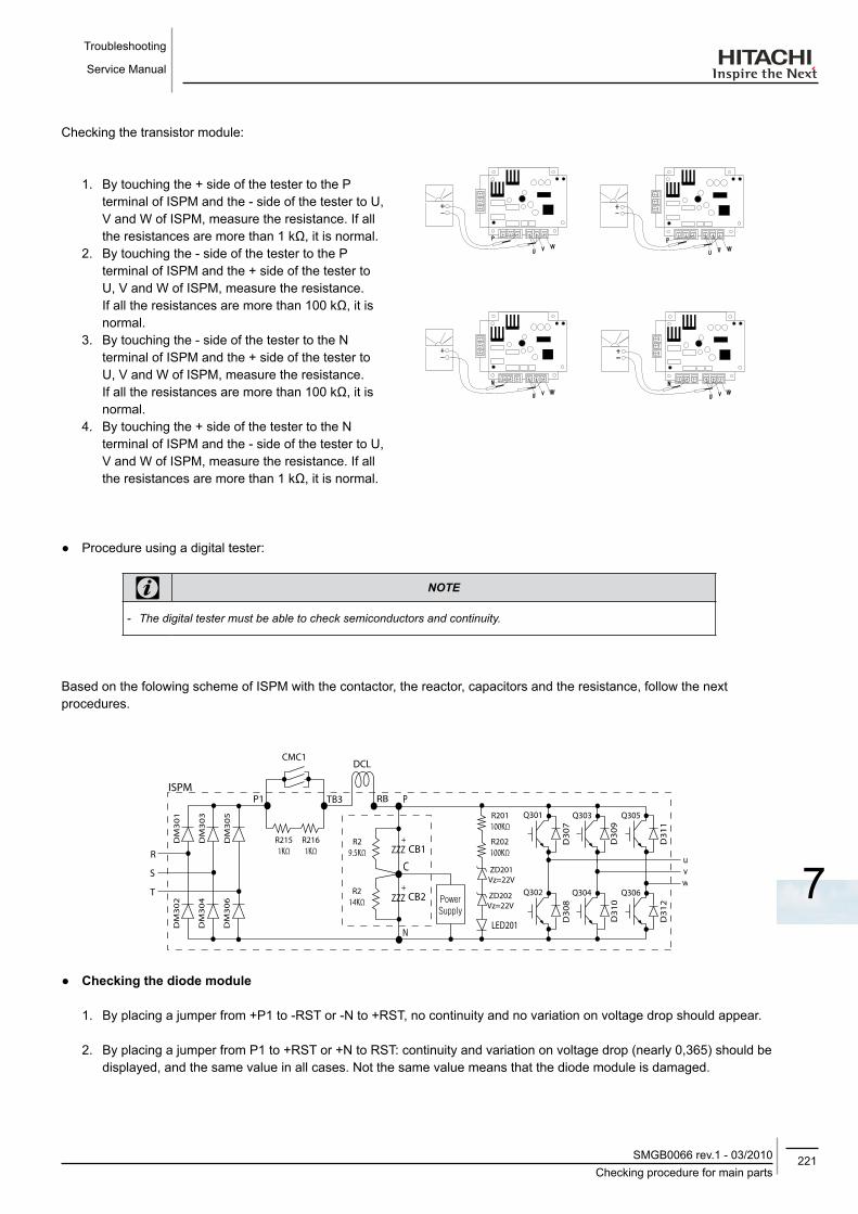
221Checking procedure for main parts
SMGB0066 rev.1 - 03/2010
Troubleshooting
Service Manual
7
Checking the transistor module:
1. By touching the + side of the tester to the P terminal of ISPM and the - side of the tester to U, V and W of ISPM, measure the resistance. If all the resistances are more than 1 kΩ, it is normal.
2. By touching the - side of the tester to the P terminal of ISPM and the + side of the tester to U, V and W of ISPM, measure the resistance. If all the resistances are more than 100 kΩ, it is normal.
3. By touching the - side of the tester to the N terminal of ISPM and the + side of the tester to U, V and W of ISPM, measure the resistance. If all the resistances are more than 100 kΩ, it is normal.
4. By touching the + side of the tester to the N terminal of ISPM and the - side of the tester to U, V and W of ISPM, measure the resistance. If all the resistances are more than 1 kΩ, it is normal.
Procedure using a digital tester:
note
-- The-digital-tester-must-be-able-to-check-semiconductors-and-continuity.
Based on the folowing scheme of ISPM with the contactor, the reactor, capacitors and the resistance, follow the next procedures.
Checking the diode module
1. By placing a jumper from +P1 to -RST or -N to +RST, no continuity and no variation on voltage drop should appear.
2. By placing a jumper from P1 to +RST or +N to RST: continuity and variation on voltage drop (nearly 0,365) should be displayed, and the same value in all cases. Not the same value means that the diode module is damaged.

Troubleshooting
Service Manual
222Checking procedure for main partsSMGB0066 rev.1 - 03/2010
Checking the transistor module
1. By bonding +P to -UVW or -N to +UVW, no continuity and no variation on voltage drop should appear.
2. By bonding -P to +UVW or +N to -UVW: continuity and variation on voltage drop (nearly 0,405) should be displayed, and the same value in all cases. Not the same value means that the diode module is damaged.
7.4.3. Checking capacitors CB1 & CB2.
danger
-- Electrical-hazard.-Risk-of-serious-injuries-or-death.--- Before-installing-the-electrical-wiring-or-before-performing-a-periodical-check,-turn-OFF-the-main-switch-of-the-unit.-For-safety-reasons,-be-sure-that-the-fan-is-stopped.
-- Prevent-from-touching-the-capacitors’-terminals.-High-voltage-should-be-present-before-discharging-them.-- Turn-off-the-unit-and-wait-for-the-LED-201-to-be-off-before-touching-the-components.
If it’s possible, check the capacitance of each capacitor : 4700μF ± 20% (between 3760μF to 5640μF).
A visual check of the pressure valve of capacitors must be done to ensure it’s integrity:
It is not recommended to check tension.
PN = Power source x √2, PC=CN is nearly equal to PN/2.
R1 & R2:
1) If the value is different:
- Capacitor could be damaged by overload.
- 04 alarm could be displayed if low supply voltage (CN) for ISPM control part is present.
2) R1 = 9.5Ω & R2 = 14.0Ω. If these values are different, the capacitors will be not properly charged.
Resistance between P1 & TB3 = 2kΩ (white resistance in the ISPM).
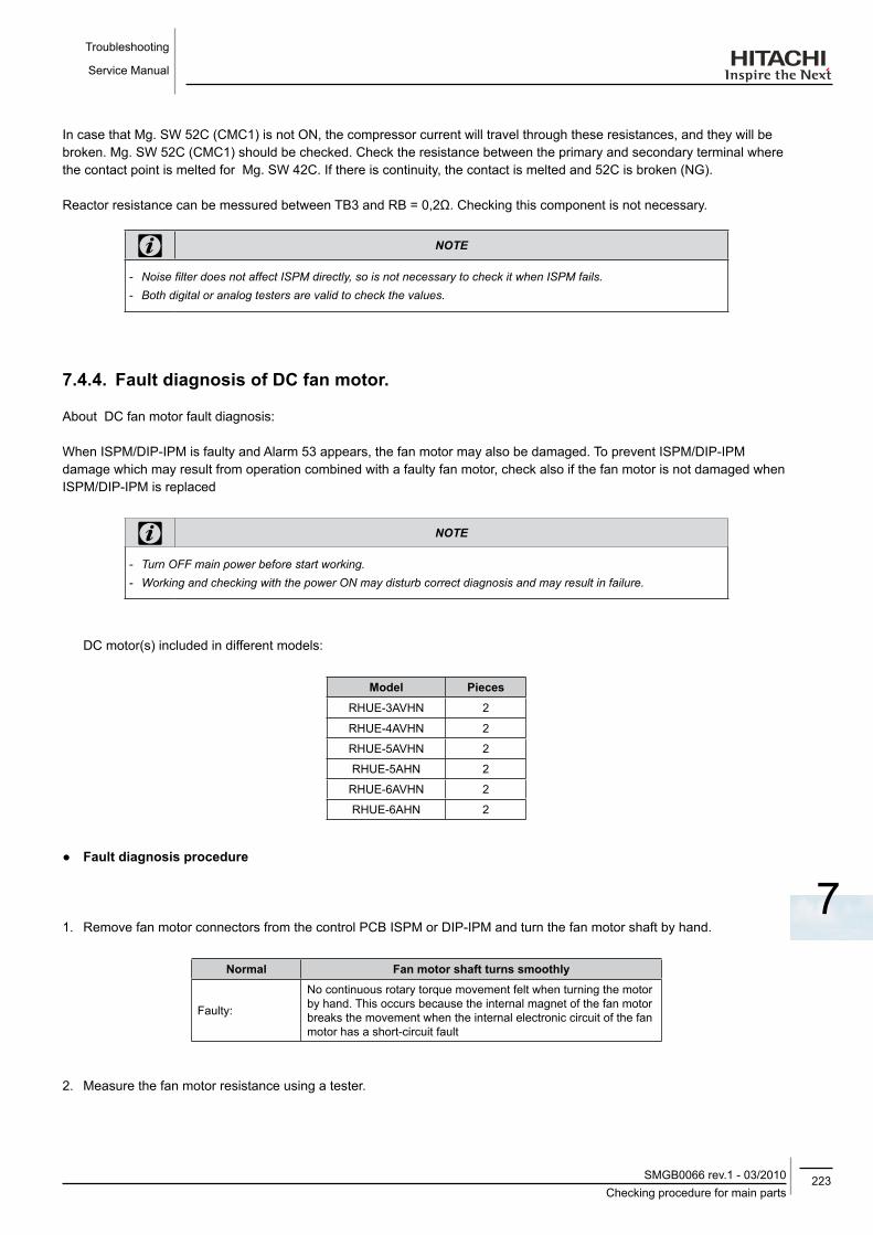
223Checking procedure for main parts
SMGB0066 rev.1 - 03/2010
Troubleshooting
Service Manual
7
In case that Mg. SW 52C (CMC1) is not ON, the compressor current will travel through these resistances, and they will be broken. Mg. SW 52C (CMC1) should be checked. Check the resistance between the primary and secondary terminal where the contact point is melted for Mg. SW 42C. If there is continuity, the contact is melted and 52C is broken (NG).
Reactor resistance can be messured between TB3 and RB = 0,2Ω. Checking this component is not necessary.
note
-- Noise-filter-does-not-affect-ISPM-directly,-so-is-not-necessary-to-check-it-when-ISPM-fails.-- Both-digital-or-analog-testers-are-valid-to-check-the-values.
7.4.4. fault diagnosis of dC fan motor.
About DC fan motor fault diagnosis:
When ISPM/DIP-IPM is faulty and Alarm 53 appears, the fan motor may also be damaged. To prevent ISPM/DIP-IPM damage which may result from operation combined with a faulty fan motor, check also if the fan motor is not damaged when ISPM/DIP-IPM is replaced
note
-- Turn-OFF-main-power-before-start-working.-- Working-and-checking-with-the-power-ON-may-disturb-correct-diagnosis-and-may-result-in-failure.
DC motor(s) included in different models:
Model Pieces
RHUE-3AVHN 2
RHUE-4AVHN 2
RHUE-5AVHN 2
RHUE-5AHN 2
RHUE-6AVHN 2
RHUE-6AHN 2
fault diagnosis procedure
1. Remove fan motor connectors from the control PCB ISPM or DIP-IPM and turn the fan motor shaft by hand.
Normal fan motor shaft turns smoothly
Faulty:
No continuous rotary torque movement felt when turning the motor by hand. This occurs because the internal magnet of the fan motor breaks the movement when the internal electronic circuit of the fan motor has a short-circuit fault
2. Measure the fan motor resistance using a tester.
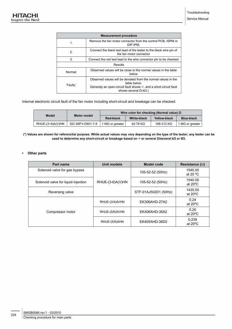
Troubleshooting
Service Manual
224Checking procedure for main partsSMGB0066 rev.1 - 03/2010
Measurement procedure
1. Remove the fan motor connector from the control PCB, ISPM or DIP-IPM.
2. Connect the black test lead of the tester to the black wire pin of the fan motor connector
3. Connect the red test lead to the wire connector pin to be checked
Results
Normal: Observed values will be close to the normal values in the table below
Faulty:
Observed values will be deviated from the normal values in the table below.
Generaly an open-circuit fault shows ∞, and a short-circuit fault shows several Ω-kΩ.)
Internal electronic circuit fault of the fan motor including short-circuit and breakage can be checked.
Model Motor modelWire color for checking (Normal value) Ω
Red-black White-black yellow-black Blue-black
RHUE-(3~6)A(V)HN SIC-68FV-D851-7.8 1 MΩ or greater 42-78 KΩ 168-312 KΩ 1 MΩ or greater
(*) Values are shown for referenctial purpose. While actual values may vary depending on the type of the tester; any tester can be used to determine any short-circuit or breakage based on ∞ or several Ω/several kΩ or 0Ω.
• other parts
Part name Unit models Model code Resistance (W)Solenoid valve for gas bypass
RHUE-(3-6)A(V)HN
105-52-52 (50Hz) 1540.00at 20 ºC
Solenoid valve for liquid injection 105-52-52 (50Hz) 1540.00at 20ºC
Reversing valve STF-01AJ502D1 (50Hz) 1435.00at 20ºC
Compressor motor
RHUE-(3/4)AVHN EK306AHD-27A2 0.24at 20ºC
EK406AHD-36A2 0.20at 20ºCRHUE-(5/6)AVHN
RHUE-(5/6)AHN EK405AHD-36D2 0.239at 20ºC
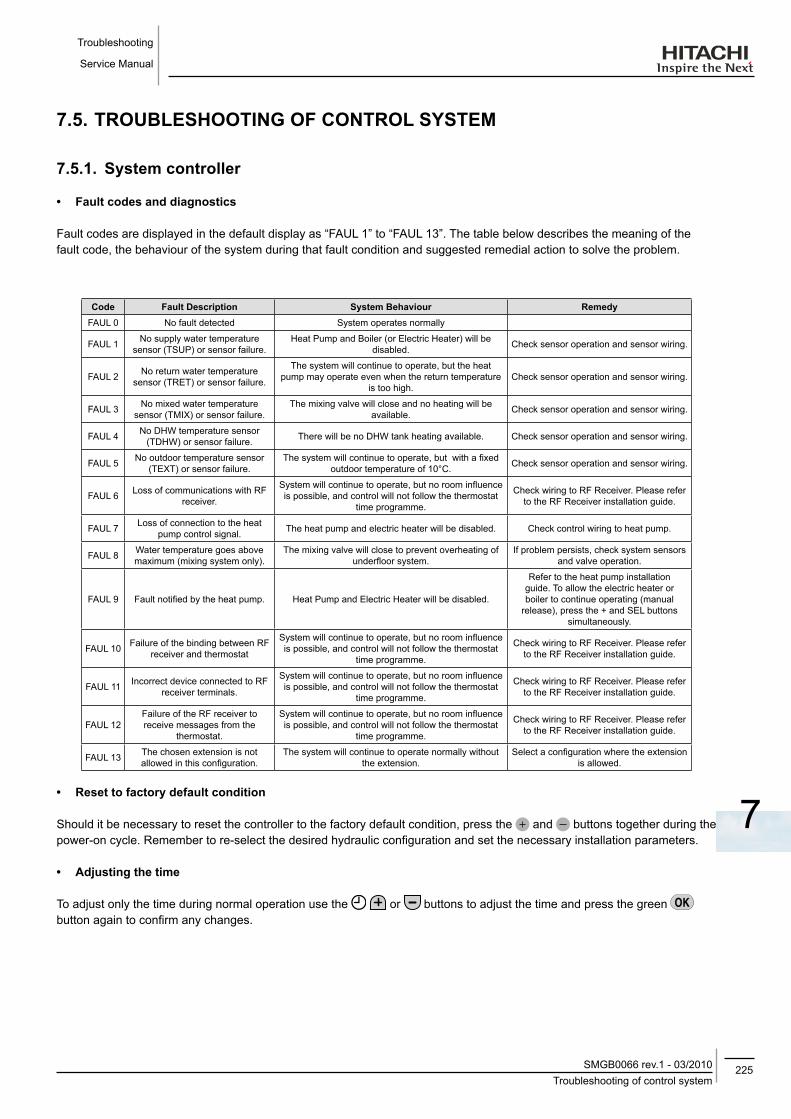
225Troubleshooting of control system
SMGB0066 rev.1 - 03/2010
Troubleshooting
Service Manual
7
7.5. TRoUBlESHooTING of CoNTRol SySTEM
7.5.1. System controller
• fault codes and diagnostics
Fault codes are displayed in the default display as “FAUL 1” to “FAUL 13”. The table below describes the meaning of the fault code, the behaviour of the system during that fault condition and suggested remedial action to solve the problem.
Code fault description System Behaviour RemedyFAUL 0 No fault detected System operates normally
FAUL 1 No supply water temperature sensor (TSUP) or sensor failure.
Heat Pump and Boiler (or Electric Heater) will be disabled. Check sensor operation and sensor wiring.
FAUL 2 No return water temperature sensor (TRET) or sensor failure.
The system will continue to operate, but the heat pump may operate even when the return temperature
is too high.Check sensor operation and sensor wiring.
FAUL 3 No mixed water temperature sensor (TMIX) or sensor failure.
The mixing valve will close and no heating will be available. Check sensor operation and sensor wiring.
FAUL 4 No DHW temperature sensor (TDHW) or sensor failure. There will be no DHW tank heating available. Check sensor operation and sensor wiring.
FAUL 5 No outdoor temperature sensor (TEXT) or sensor failure.
The system will continue to operate, but with a fixed outdoor temperature of 10°C. Check sensor operation and sensor wiring.
FAUL 6 Loss of communications with RF receiver.
System will continue to operate, but no room influence is possible, and control will not follow the thermostat
time programme.
Check wiring to RF Receiver. Please refer to the RF Receiver installation guide.
FAUL 7 Loss of connection to the heat pump control signal. The heat pump and electric heater will be disabled. Check control wiring to heat pump.
FAUL 8 Water temperature goes above maximum (mixing system only).
The mixing valve will close to prevent overheating of underfloor system.
If problem persists, check system sensors and valve operation.
FAUL 9 Fault notified by the heat pump. Heat Pump and Electric Heater will be disabled.
Refer to the heat pump installation guide. To allow the electric heater or boiler to continue operating (manual
release), press the + and SEL buttons simultaneously.
FAUL 10 Failure of the binding between RF receiver and thermostat
System will continue to operate, but no room influence is possible, and control will not follow the thermostat
time programme.
Check wiring to RF Receiver. Please refer to the RF Receiver installation guide.
FAUL 11 Incorrect device connected to RF receiver terminals.
System will continue to operate, but no room influence is possible, and control will not follow the thermostat
time programme.
Check wiring to RF Receiver. Please refer to the RF Receiver installation guide.
FAUL 12Failure of the RF receiver to receive messages from the
thermostat.
System will continue to operate, but no room influence is possible, and control will not follow the thermostat
time programme.
Check wiring to RF Receiver. Please refer to the RF Receiver installation guide.
FAUL 13 The chosen extension is not allowed in this configuration.
The system will continue to operate normally without the extension.
Select a configuration where the extension is allowed.
• Reset to factory default condition
Should it be necessary to reset the controller to the factory default condition, press the and buttons together during the power-on cycle. Remember to re-select the desired hydraulic configuration and set the necessary installation parameters.
• Adjusting the time
To adjust only the time during normal operation use the or buttons to adjust the time and press the green button again to confirm any changes.
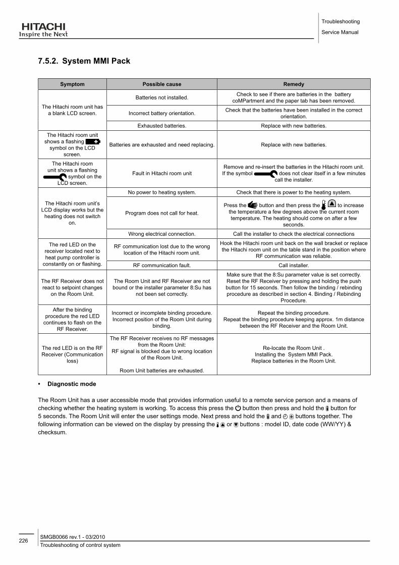
Troubleshooting
Service Manual
226Troubleshooting of control systemSMGB0066 rev.1 - 03/2010
7.5.2. System MMI Pack
Symptom Possible cause Remedy
The Hitachi room unit has a blank LCD screen.
Batteries not installed. Check to see if there are batteries in the battery coMPartment and the paper tab has been removed.
Incorrect battery orientation. Check that the batteries have been installed in the correct orientation.
Exhausted batteries. Replace with new batteries.
The Hitachi room unit shows a flashing
symbol on the LCD screen.
Batteries are exhausted and need replacing. Replace with new batteries.
The Hitachi room unit shows a flashing
symbol on the LCD screen.
Fault in Hitachi room unitRemove and re-insert the batteries in the Hitachi room unit. If the symbol does not clear itself in a few minutes
call the installer.
The Hitachi room unit’s LCD display works but the
heating does not switch on.
No power to heating system. Check that there is power to the heating system.
Program does not call for heat.Press the button and then press the to increase
the temperature a few degrees above the current room temperature. The heating should come on after a few
seconds.
Wrong electrical connection. Call the installer to check the electrical connections
The red LED on the receiver located next to heat pump controller is
constantly on or flashing.
RF communication lost due to the wrong location of the Hitachi room unit.
Hook the Hitachi room unit back on the wall bracket or replace the Hitachi room unit on the table stand in the position where
RF communication was reliable.
RF communication fault. Call installer.
The RF Receiver does not react to setpoint changes
on the Room Unit.
The Room Unit and RF Receiver are not bound or the installer parameter 8:Su has
not been set correctly.
Make sure that the 8:Su parameter value is set correctly. Reset the RF Receiver by pressing and holding the push button for 15 seconds. Then follow the binding / rebinding procedure as described in section 4. Binding / Rebinding
Procedure.
After the binding procedure the red LED
continues to flash on the RF Receiver.
Incorrect or incomplete binding procedure.Incorrect position of the Room Unit during
binding.
Repeat the binding procedure.Repeat the binding procedure keeping approx. 1m distance
between the RF Receiver and the Room Unit.
The red LED is on the RF Receiver (Communication
loss)
The RF Receiver receives no RF messages from the Room Unit:
RF signal is blocked due to wrong location of the Room Unit.
Room Unit batteries are exhausted.
Re-locate the Room Unit .Installing the System MMI Pack.
Replace batteries in the Room Unit.
• diagnostic mode
The Room Unit has a user accessible mode that provides information useful to a remote service person and a means of checking whether the heating system is working. To access this press the button then press and hold the button for 5 seconds. The Room Unit will enter the user settings mode. Next press and hold the and buttons together. The following information can be viewed on the display by pressing the or buttons : model ID, date code (WW/YY) & checksum.

227Troubleshooting of accessories
SMGB0066 rev.1 - 03/2010
Troubleshooting
Service Manual
7
7.6. TRoUBlESHooTING of ACCESSoRIES
7.6.1. Pump kit
Problem Cause Remedy
The unit is making noises
There is air in the unit. Vent the unit.
The pump volume rate is too strong. Decrease the pump output by switching to a lower speed.
The pump lift is too high. Decrease the pump output by switching to a lower speed.
The pump is making noises
Cavitation noise has occured in the pump due to insufficient inlet pressure.
Check the pressure level/system admission pressure and increase to the admissible range.
There is a foreign body inside the pump housing or impeller. Disassemble the pump head and remove the foreign body.
There is air in the pump. Vent the pump/unit.
Shut-off valves are not fully open. Open the shut-off valves fully.
Pump output too low
There is a foreign body inside the pump housing or impeller. Disassemble the pump head and remove the foreign body.
Wrong pumping direction. Exchange the pump pressure and suction sides. Observe the arrow indicating direction on the pump housing.
Shut-off valves are not fully open. Open the shut-off valves fully.
Wrong direction of rotation. Correct the electrical connection in the terminal box:
Motor is switched on but fails to run
Elektrical fuse faulty/has switched off.
Change fuse/switch on electrical connection.Should the fuse blow several times in a row:- Check the pump for electrical faults.- Check the pump mains cable and electrical connection.
Residual current operated circuit-breaker has tiggered.
Switch residual current operated circuit-breakes back on. Should the circuit-breaker trip several times in arow:- Check the pump for electrical faults.- Check the pump mains cable and electrical connection.
Undervoltage Check the voltage at the pump (observe rating plate data).
Winding damage Call customer Services.
Faulty terminal box Call customer Services.
Faulty capacitor Replace the capacitor.
Problem Motor is switched on but fails to run.
CauseMotor protection has switched the pump off as a result of:
a) Hydraulic overloading b) A blockage c) An excessive pump medium temperature.
d) An excessive ambient temperature.
Remedy
a) Reduce the pump on the pressure side to an operationg point which is on the characteristic line.
b) Fully remove the pump vent screw, check and rectify free runnig of pump rotor by turning the slotted end of the shaft with a screwdriver.
Alternative:Disassemble the motor head and check; unblock by turning the impeller where necessary. If the blockage cannot be removed, contact Customer Services.
c) Decrease the pump medium temperature in accordance with the rating plate.
d) Decrease the ambient temperature, e.g. by insulating the pipes and fittings.

Troubleshooting
Service Manual
228Troubleshooting of accessoriesSMGB0066 rev.1 - 03/2010
7.6.2. WEH - Water Electric Heater
observed failure Cause Check item Action
Electric power supply problems in WEH
Control signals from Systems Controls miss-connected or wrongly connected
Check connections between System Controller and WEH
Terminals 7, 8, 9 from System Controller connected to Terminals 7, 8, 9 WEH respectively
Check Voltage (230V) between terminals 8/9 and 8/7 in WEH and also in System Controller
Check Power Supply in System Controller
Check Voltage (230V) between Terminals A1 & A2 in Contactor Coils of WEH
Repair connections if required
WEH has no Power Terminals L1~L3 have no voltage (440V/230V)
ELB, CB or Fuse protecting WEH are activated. There is some short-circuit, wrong connection or any earth leak
Check cable connections in WEH power circuit. Repair circuit and replace Fuse or Switch ON ELB/CB
Check possible miss connections in WEH power circuit
Check cable connections in WEH power circuit. Repair circuit.
Check Electric Resistances: 26,5 Ohms (5% Tolerance) Replace Resistances if required
Problems in Water Circuit due to low Water Pressure or no Water in Water Circuit
LWPS is OFF [Water Pressure < 0,1 MPa]
Check Water Pressure (must be >0,1MPa)
Fill Water Circuit with enough pressure (< 0.1MPa)
Check if Water Circuit is locked Check Valves and Water Circuit to ensure water circulation
Check if there is Water leaks Check Water circuit and repair leaks if exist
Problems in Water Circuit due to excesive Water Temperature in Water Circuit
Thermostat Cut-Out activated [Excesive water temperature (<85ºC)]
Check Water Temperature and Thermostat state Push reset button for thermostat re-start
7.6.3. dHWT - domestic Hot Water Tank
observed failure Cause Check item Action
"Electric power supply problems in DHWT"
"Control signals from Systems Controls miss-connected or wrongly connected"
"Check connections between System Controller and DHWT"
Terminals 11, 12 from System Controller connected to Terminals 3, 4 DHWT respectively
"Check Voltage (230V) between terminals N/3 and N/4 in DHWT"
"Check Power Supply in System Controller"
Check Voltage (230V) between Terminals 7 & 8 in Relay coils of DHWT Repair connections if required
"DHWT has no Power Terminals L~N have no voltage (230V)"
"ELB, CB or Fuse protecting DHWT are activated. There is some short-circuit, wrong connection or any earth leak"
"Check cable connections in DHWT power circuit. Repair circuit and replace Fuse or Switch ON ELB/CB"
Check possible miss connections in DHWT power circuit
"Check cable connections in DHWT power circuit. Repair circuit."
"Check Electric Resistances: 17,7 Ohms (5% Tolerance)" Replace Resistances if required
"Problems in Water Circuit due to low Water Pressure or no Water in Water Circuit"
[Water Pressure < 0,1 MPa]
"Check Water Pressure (must be >0,1MPa)"
Fill Water Circuit with enough pressure (< 0.1MPa)
Check if Water Circuit is locked Check Valves and Water Circuit to ensure water circulation
Check if there is Water leaks "Check Water circuit and repair leaks if exist"
"Problems in Water Circuit due to excesive Water Temperature in Water Circuit"
"Thermostat Cut-Out activated [Excesive water temperature (<90ºC)]"
"Check Water Temperature and Thermostat state" "Push reset button for thermostat re-start"

229Contents
SMGB0066 rev.1 - 03/2010
Spare parts
Service Manual
8
8. SPARE PARTS
CoNTENTS8.1. Spare parts of Yutaki .................................................................................................................230
8.1.1. Cycle and estructural parts ..................................................................................................................2308.1.2. Electrical parts ......................................................................................................................................231
8.2. Spare parts of accessories ........................................................................................................233
8.2.1. WEH - Water Electric Heater ................................................................................................................2338.2.2. DHWT - Domestic Hot Water Tank .......................................................................................................234

Spare parts
Service Manual
230Spare parts of YutakiSMGB0066 rev.1 - 03/2010
8.1. SPARE PARTS of yUTAKI
8.1.1. Cycle and estructural parts ¡ RHUE-(3~6)A(V)HN
U98C
U40
U15C
U15D
U15E
U15G
U19B
U28
U30A
U32A
U32B
U34A
U34A
U34B
U51
U51
U58A
U58B
U70
U78
U71A
U71B
U98A
U98B
U98D
U98E
U98F
U98G
U98L
U65C
U65C
U65CU65D
U98M
U65E
U65F
U00G
U00DU00E
U15F
U21A
U21B
U21CU21D
U28
U30B
U30CU77C
U77B
U21E
U01
U19A
U28
U77C
U77A
U79
U81
U92
U41 U15A
U15B
U99
U98G
U38A
U38B
OPT
ION
AL
AC
CES
SORY
: PU
MP
KIT
A &
B
Model Name
RHUE3AVHN, 1~ 230V 50Hz
RHUE4AVHN, 1~ 230V 50Hz
RHUE5AVHN, 1~ 230V 50Hz
RHUE5AHN, 3~ 400V 50Hz
RHUE6AVHN, 1~ 230V 50Hz
RHUE6AHN, 3~ 400V 50Hz
No
DE
SC
RIP
TIO
NQ
ty.
Qty
.Q
ty.
Qty
.Q
ty.
Qty
.R
EM
AR
KS
U00
DP
ump
11
11
11
Acc
esso
ry (P
ump
Kit
A)
U00
EP
ump
11
11
11
Acc
esso
ry (P
ump
Kit
B)
U00
GA
cous
tical
Cov
er 4
61
11
11
1C
ompr
esso
r Jac
ket
U01
Pre
ssur
e S
W1
11
11
1P
rote
ctio
n
U15
ATh
erm
isto
r1
11
11
1TH
Mw
i
U15
BTh
erm
isto
r1
11
11
1TH
Mw
o
U15
CTh
erm
isto
r1
11
11
1TH
Ma
U15
DTh
erm
isto
r1
11
11
1TH
Md
U15
ETh
erm
isto
r1
11
11
1TH
Meh
U15
FTh
erm
isto
r1
11
11
1TH
Mec
U15
GTh
erm
isto
r1
11
11
1TH
Ms
U19
AH
igh
Pre
ssur
e S
enso
r1
11
11
1P
d
U19
BLo
w P
ress
ure
Sen
sor
11
11
11
Ps
U21
AE
xpan
sion
Val
ve1
11
11
1B
y-pa
ss li
ne
U21
BE
XP
V C
oil
11
11
11
U21
CE
xpan
sion
Val
ve1
11
11
1M
ain
line
U21
DE
XP
V C
oil
11
11
11
U21
EC
apill
ary
Ass
y1
11
11
1
U28
Che
ck J
A3
33
33
3
U30
AS
train
er1
11
11
1
U30
BS
train
er2
22
22
2
U30
CS
ilenc
er1
11
11
1
U32
AV
P-R
UB
BE
R 2
22
22
22
U32
BV
P-R
UB
BE
R 1
44
44
44
U34
AFr
ont P
rote
ctor
Net
22
22
22
Out
let (
for F
an)
U34
BP
rote
ctor
Net
L A
ssy
11
11
11
Inle
t (fo
r Con
dens
er)
U38
AW
pipe
in 1
11
11
11
U38
BW
pipe
in 2
11
11
11
U40
Air
Hea
t Exc
hang
er1
1A
ssem
bly
U40
Air
Hea
t Exc
hang
er1
11
1A
ssem
bly
U41
Wat
er H
eat E
xcha
nger
11
11
11
Ass
embl
y
U51
Pro
pelle
r Fan
22
22
22
U58
AA
ccum
ulat
or1
11
11
1
U58
BL-
Tank
11
11
11
U65
CH
andl
e3
33
33
3
U65
DH
Cov
er1
11
11
1
U65
ER
ubbe
r Cap
11
11
11
U65
FTH
Pla
te1
11
11
1
U70
Com
pres
sor
11
11
11
EK
306A
HD
-27A
2
U71
AFa
n M
otor
11
11
11
74W
U71
BFa
n M
otor
11
11
11
74W
U77
AS
olen
oid
Valv
e1
11
11
1
U77
BS
olen
oid
Valv
e1
11
11
1
U77
CC
oil f
or S
olen
oide
val
ve2
22
22
2
U78
Oil
Hea
ter
44
44
44
40W
U79
4 W
ay V
alve
11
11
11
U81
Coi
l for
4 W
ay V
alve
11
11
11
U92
Air
Pur
ge1
11
11
1
U98
AS
ervi
ce C
over
L A
ssy
11
11
11
Ass
embl
y
U98
BR
ear C
over
L A
ssy
11
11
11
Ass
embl
y
U98
CU
pper
Cov
er A
ssy
11
11
11
Ass
embl
y
U98
DS
hrou
d L
11
11
11
U98
ES
Cov
er B
1
11
11
1
U98
FP
ipe
Cov
er B
11
11
11
U98
GB
-Bas
e A
ssy
11
11
11
Ass
embl
y
U98
LP
artit
ion
Ass
y1
11
11
1A
ssem
bly
U98
MM
otor
Cla
mp
L A
ssy
11
11
11
Ass
embl
y
U99
Wat
er H
eate
r1
11
11
1

231Spare parts of Yutaki
SMGB0066 rev.1 - 03/2010
Spare parts
Service Manual
8
8.1.2. Electrical parts ¡ RHUE-(3~6)AVHN
U00A
U00B
U04A
U04B
U16
U17
U65B
U65A
U72A
U72B
U75
U82A
U82B
U85A
U85B
U62
U09
U02A
U02B
U13
PWB1
TB2
1
Y2
PCN
2PC
N3
PCN
4
PCN8PCN9
PCN
6
PCN
5
Y4Y3
PCN
7
PC3
PC2
PC4
PC1
CN6
PCN
1CN
5R1
CN8
CN7R3
R2
CN4
R4
IC5
Y1
IC4
C27
IC1
IC2
C28
C29
CN1
C30
IC3
CN2CN3
NK
NK
5
CN9
PWB2
CN10
CN11
1N
K
CN13
CN12
CN14
CN16
CN15
NK
23
NK
L1NL2
A1
B2
SEG3
SEG4
SEG5
6 DM
4
53
24
67
8
CN9
129
1011
1413
15
CN7
CN8
CN1
CN2
1 LED
8
CN4 CN3CN5
OSC
IC7
C21
CN6CN11
C8C9
R107
C19
IC4
2
LED7
IC8
1
EF3
Z5
DSW6
PC10
IC2
R137
ZD9
R135
R143
R138
REG7
C20
C4
3
REG4
DSW
2
DSW
5D
SW1
IC3
IC5
PSW2 2
23
41
2PS
W1
34
1
REG
3
44
12
DSW
335
12
34
DSW
4
1916
1718
20
REG
6
R3
R2
REG
8RE
G9
DM
1
DM
6
C2DM
8
C5C6
C1RE
G2
REG
1
DM
5
CN10B
C7
DM7CN10A
78
Z2
PCN3B
PCN3A
Z3
PCN2
XP
Tr1
PCN
7
Y52C
S
44
RSW
4
RSW
2
YE1
YAY
20
AY
E2
Y2
0B
Y20L
CN13 CN12
R110
C10
C11
R86
R81
R82
R83
R84
R85
R87
R113
R88YR
S
4
PCN11YPR
LED3 SEG
2
LED5
LED1
SEG1RS
1
LED2
456
2 233
RSW
3
SSW
12 1233
1
8
1456789090
7
C12
C13
C16
RSW
1
LED4
LED6
RS2
IC6
C14
C15
PC6
PC5
R13
R14
PCN
12
U
PCN
9PC
N8
PC1
R10
5 6
Z1
8 5 6789090
7
Z4
PC2
EF1
R9 EF2
DSA
PCN1
PC7 PC8 PC9
C17
C18
R17
R16
R15
PC3PC4
Y52C
R11
R12
PCN10PCN4PCN5
PCN
6
TB1
Tr2CS
DCL
PF1
52C
EFP
52P
V
L11
N1
NF
C1
N2
L12
ZD5
R18
R16
CN206
CP9
D2
HT2
PC201
1CN203
CP16PC203PC202
1
BK
1CN204
PC205PC206PC204
BL
1
C19
D9 D10
R205
C201
CP17
C17
C202
L1
OFF
R30
R301
1
1CN2WH
1 2 3
1
Q202 R214
C206
GN
YE
ON
R87R88
O
IC4
G I
CP11
CP12
CP30
DSW1
X1
80
C4
R210
C38
C39
C203
CP6
C5
CP820
CP7CP101
ZD2
C
S
D
IC3
1
1
CN202
C55
R13
HT1
C100
JP9
1
C16
D14
1
1
CN201
PCN2
02
1
1C208
Z2
C105
C109
LED202
R14
C101
C102
C53
R15
C54
CP15
C21
ZD3
JP10C47
C6
R20
C2
21
ZD4
V
R23
R24
C11 C10
D5
D6
22U
D7
R25
C12
W
NFC2
PCN2
01
1
1
CB1CB2
-
17B35740A
S
R86C40
CN4 PC207Q201
1CN207PC209
R303
RD
1
PC20
8
1PCN401
1CP28
JP14
D25BK
1
CP24
CP29
R3041
IC8
8
61IC1
5
4
R211
CP5
CP26
CP25
41
5
8
60
R93
1CN
1W
H
4
WH D19
1CP27
R110
D13
IC9
PV051-1
~T
+
~-
DM3
+-
JP1
JP3
RD
CP23
R113R109
R114CP4
CP18
R17
40
C50 C51
C52
C30
C104
21
R54
CP2
D22
D20D21
D18 D11
D12D3D8
D24 D23
1
JP8
4
R7
R59R58
CP3CP1
R43
IC6
R34
R22C25
26
C24
JP7
R35
C44
R39R40
8 5
LED201
IC5
CP13R53
C33
DANG
ER H
IGH
VOLT
AGE
R111
Lot No.F
CP20 CP14
R27
R1
Z1
R89
QN2
CP19
JP2
R2 QN1
QP1
R48
R46
CP22
R3 R96
R112
RY2
C108
R67
R65
R66
DIP
-IPM
HY-200-101
CMC
~~
DM2
R
+
~DM1
JP11
JP12
RY1
C112
R26
CB3
DCL2
CP21 R28 R29Q204Q203
C110
R118
R117
JP5
JP4
JP6
DCL1
R115
J1
D15
R116
W
UV W
Model Name
RHUE3AVHN, 1~ 230V 50Hz
RHUE4AVHN, 1~ 230V 50Hz
RHUE5AVHN, 1~ 230V 50Hz
RHUE5AHN, 3~ 400V 50Hz
RHUE6AVHN, 1~ 230V 50Hz
RHUE6AHN, 3~ 400V 50Hz
No
DE
SC
RIP
TIO
NQ
ty.
Qty
.Q
ty.
Qty
.Q
ty.
Qty
.R
EM
AR
KS
U00
ATe
rmin
al B
oard
11
11
11
U00
BTe
rmin
al B
oard
11
11
11
U02
AP
ush
But
ton
Sw
itch
11
11
11
ON
(whi
te)
U02
BP
ush
But
ton
Sw
itch
11
11
11
OFF
(bla
ck)
U04
AFu
se1
11
21
240
A
U04
BFu
se1
11
11
13A
, Pow
er F
use
for P
ump
U09
Sna
p S
witc
h1
11
11
1
U13
Ele
ctric
al W
iring
Dia
gram
11
11
11
Ass
embl
y (S
teel
Pla
tes+
Com
pone
nts+
Har
ness
)
U16
AN
oise
Filt
er1
11
130
A
U16
AN
oise
Filt
er1
130
A
U17
Inve
rter F
in A
ssy
11
11
11
DIP
-IPM
(25A
)
U62
Spa
rk K
iller
55
55
55
U65
AS
pace
r4
44
44
4
U65
BS
pace
r6
66
66
6
U72
AM
agne
tic C
onta
ctor
11
11
11
U72
BM
agne
tic C
onta
ctor
11
11
11
Con
tact
or fo
r Pum
p
U75
Aux
Rel
ay1
11
11
1
U82
ATr
ansf
orm
er2
22
22
2
U82
BR
eact
or1
11
11
1
U85
AP
rinte
d C
ircui
t Boa
rd1
11
11
1P
CB
Mai
n (C
O04
1 A
ssy)
U85
BP
rinte
d C
ircui
t Boa
rd1
11
11
1I/O
PC
B (C
O01
1 A
ssy)

Spare parts
Service Manual
232Spare parts of YutakiSMGB0066 rev.1 - 03/2010
U00B
U00A
U04A
U04B
U14
U16
U17
U65B
U65A
U72B
U72A
U74A
U74B
U75
U82A
U82B
U85A
U85B
U85C
U85D
U85E
U62
U09
U02A
U02B
U13
NK
5
NK
4N
K3
NK
2
C1
47C
PWB
5
TB2
TB1
NK
1
PWB
2
PWB
1
XP
Tr2
Tr1
CS
52P EF
P
NFC
1
PWB
4PW
B3
CB
1,2
52C
R1R2
DC
L
ISPM
IC3
IC1
IC2 IC4
IC5
Y1
Y2
Y3
Y4
PCN
4PC
N3
PCN
2PC
N1
PCN
6
PCN
5
PCN
7
PCN8PCN9
CN
8
C29
C30
PC1
PC2
PC3
PC4
R1
R2
R3
R4
CN
7C
N6
CN
5
CN4CN1
CN
9C
N10
CN
11C
N12
CN
13C
N14
CN
15C
N16
CN3 CN2
C28
C27
PCN201
CN202
CN201
CN201
CN202
PCN201
PF1
PF2
L1'N' L3' L2'
L1NE L3 L2
CN
8PC
208
C
PC20
7
CN
9
CN
206
CN
207
R200
R201
ZN
202
LED
201
ZN
201
R215
R216
TB2
TB3
P1PNRB
PPD
N UT
VRB
WS
R
CN
8PC
208
C
PC20
7
CN
9
CN
206
CN
207
R200
R201
ZN
202
LED
201
ZN
201
R215
R216
TB2
TB3
P1PNRB
PPD
N UT
VRB
WS
R
2019
1817
1514
1312
1110
98
75
63
416
12
IC3
IC2
IC8
IC7
IC6
IC5
IC4 PC
10
PC9PC8PC7
PC6
PC5
PC4 PC3
PC2PC1
21
87
65
43
21
43
21
43
21
43
21
DSW
2D
SW4
DSW
3
DSW
1D
SW5
43
21
DSW6
RS1
RS2
YRS
Y20
L
YPR
YAY
E2Y
20A
Y20
BY
E1Y
52C
SY
52C
PSW
1PS
W2
SSW
0987654321
0987654321 098
7654321
0987654321
RSW
4RS
W3
RSW
2RS
W1
SEG
5SE
G4
SEG
3
SEG
2SE
G1
LED
8
LED
7
LED
6
LED
5
LED
4LE
D3
LED
2LE
D1
OSC
DSA
Z5
Z4
Z3
Z2
Z1
EF3
EF2
EF1
ZD
9
R2
R3
R13
R14
R12
R11
R15
R16
R17
R10 R9
R143
R138
R137
R135
R113
R110
R107R8
8R8
7R8
6R8
5R8
4R8
3R8
2R8
1
C4
C1
C2
C6
C5
C7
C8
C21
C20
C19
C18
C17
C16
C15
C14
C13
C12
C11
C10
C9
DM
4
DM
5
DM
8
DM
1
DM
6
DM7
REG4
REG
2
REG
9RE
G8
REG
1
REG7
REG
6
REG
3
CN6
PCN3B
PCN3A CN10BCN10A
PCN
12PC
N8
PCN2PCN1PCN10PCN4PCN5
PCN
6PC
N7
PCN
9
PCN11
CN13 CN12 CN11 CN5 CN4 CN3
CN
8C
N1
CN
2C
N9
CN
7
RS
T
87
BA1
L3N
L12
L2
+-
NFC
3
NFC
2
W
VU
UV
W
PCN203
PCN203
¡ RHUE-(5/6)AHN
Model Name
RHUE3AVHN, 1~ 230V 50Hz
RHUE4AVHN, 1~ 230V 50Hz
RHUE5AVHN, 1~ 230V 50Hz
RHUE5AHN, 3~ 400V 50Hz
RHUE6AVHN, 1~ 230V 50Hz
RHUE6AHN, 3~ 400V 50Hz
No
DE
SC
RIP
TIO
NQ
ty.
Qty
.Q
ty.
Qty
.Q
ty.
Qty
.R
EM
AR
KS
U00
ATe
rmin
al B
oard
11
11
U00
ATe
rmin
al B
oard
11
U00
BTe
rmin
al B
oard
11
11
11
U02
AP
ush
But
ton
Sw
itch
11
11
11
ON
(whi
te)
U02
BP
ush
But
ton
Sw
itch
11
11
11
OFF
(bla
ck)
U04
AFu
se1
140
A
U04
AFu
se1
150
A
U04
AFu
se2
220
A
U04
BFu
se1
11
11
13A
, Pow
er F
use
for P
ump
U09
Sna
p S
witc
h1
11
11
1
U13
Ele
ctric
al W
iring
Dia
gram
1A
ssem
bly
(Ste
el P
late
s+C
ompo
nent
s+H
arne
ss)
U13
Ele
ctric
al W
iring
Dia
gram
1A
ssem
bly
(Ste
el P
late
s+C
ompo
nent
s+H
arne
ss)
U13
Ele
ctric
al W
iring
Dia
gram
11
Ass
embl
y (S
teel
Pla
tes+
Com
pone
nts+
Har
ness
)
U13
Ele
ctric
al W
iring
Dia
gram
11
Ass
embl
y (S
teel
Pla
tes+
Com
pone
nts+
Har
ness
)
U14
Cap
acito
r2
227
00µf
U16
AN
oise
Filt
er1
11
130
A
U16
AN
oise
Filt
er1
130
A
U17
Inve
rter F
in A
ssy
11
DIP
-IPM
(17A
)
U17
Inve
rter F
in A
ssy
11
DIP
-IPM
(25A
)
U17
Inve
rter M
odul
e1
1IS
PM
U62
Spa
rk K
iller
55
55
55
U65
AS
pace
r4
44
44
4
U65
BS
pace
r6
66
66
6
U72
AM
agne
tic C
onta
ctor
11
11
11
U72
BM
agne
tic C
onta
ctor
11
11
11
Con
tact
or fo
r Pum
p
U74
AR
esis
tor
11
U74
BR
esis
tor
11
U75
Aux
Rel
ay1
11
11
1
U82
ATr
ansf
orm
er2
22
22
2
U82
BR
eact
or1
1
U82
BR
eact
or1
1
U82
BR
eact
or1
1
U85
AP
rinte
d C
ircui
t Boa
rd1
11
11
1P
CB
Mai
n (C
O04
1 A
ssy)
U85
BP
rinte
d C
ircui
t Boa
rd1
11
11
1I/O
PC
B (C
O01
1 A
ssy)
U85
CP
rinte
d C
ircui
t Boa
rd1
1P
CB
2 Fo
r Fan
Mot
or 1
(PO
024
Ass
y)
U85
DP
rinte
d C
ircui
t Boa
rd1
1P
CB
2 Fo
r Fan
Mot
or 2
(PO
024
Ass
y)
U85
ER
PP
Rel
ay1
1R
ever
sing
Pha
se P
rote
ctio
n

233Spare parts of Yutaki
SMGB0066 rev.1 - 03/2010
Spare parts
Service Manual
8
8.2. SPARE PARTS of ACCESSoRIES
8.2.1. WEH - Water Electric Heater
LOCATION OF ELECTRICAL EQUIPMENT IN THE ELECTRICAL BOX
LOCATION OF SPARE PARTS IN THE UNIT FOR MODEL:
WEH-6E
1
1
2
3
3
4
MO
DE
L N
AM
E
WE
H-6
E
No. DESCRIPTION Qty REMARKS1 CONTACTOR 2 AS09-30-10-26M (20A AC1)2 PRESSURE SWITCH 1 XP600 (1 bar set)3 THERMOSTAT 1 85°C Cut Out4 RESISTOR 1 2000W +5-10% 230V

Spare parts
Service Manual
234Spare parts of YutakiSMGB0066 rev.1 - 03/2010
8.2.2. dHWT - domestic Hot Water Tank
• loCATIoN of SPARE PARTS

235Spare parts of Yutaki
SMGB0066 rev.1 - 03/2010
Spare parts
Service Manual
8
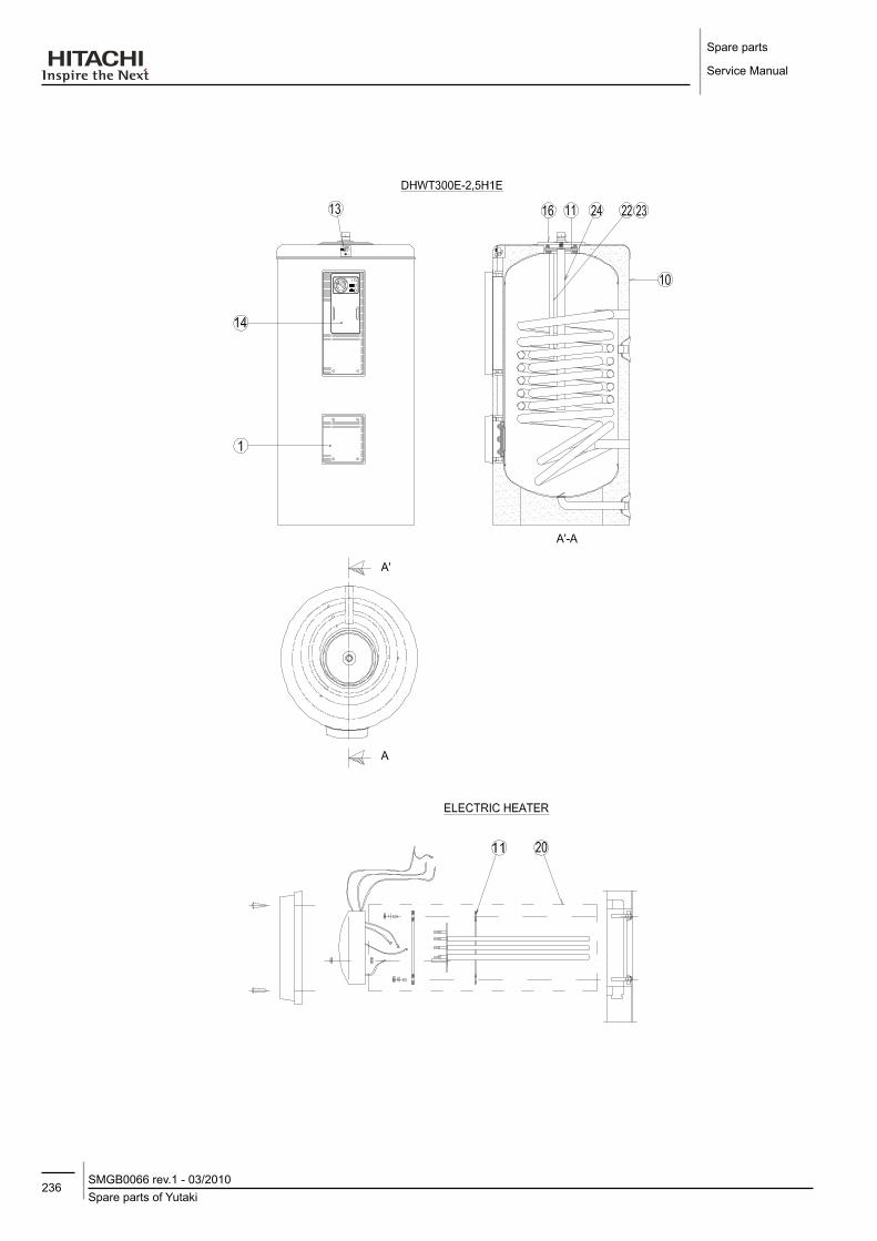
Spare parts
Service Manual
236Spare parts of YutakiSMGB0066 rev.1 - 03/2010

237Spare parts of Yutaki
SMGB0066 rev.1 - 03/2010
Spare parts
Service Manual
8
Mo
dEl
NA
ME
dH
WT2
00E-
2.5H
1E
dH
WT3
00E-
2.5H
1E
dH
WT2
00S-
2.5H
1E
dH
WT3
00S-
2.5H
1E
No. dESCRIPTIoN Qty Qty Qty Qty REMARKS1 Side Cover 1 1 1 1
2 Thermometer 1 1 1 1
3 Green LED 1 1 1 1 Power ON
4 Orange LED 1 1 1 1 Automatic ON
5 Red LED 1 1 1 1 Manual ON
6 Relay 1 1 1 1 220/240 VAC
7 Bipolar Switch 1 1 1 1 Switch (Auto/Manual)
8 Thermostat 1 1 1 1
9 External Covering 1 1
10 External Covering 1 1
11 Side Mouth Seal 1 1
12 Side Mouth Seal 1 1
13 Anode Load Meter 1 1
14 Panel Control KIT 1 1 1 1 E-Box Assembly
15 Upper Side KIT 1 Assembly
16 Upper Side KIT 1 Assembly
17 Upper Side KIT 1 Assembly
18 Upper Side KIT 1 Assembly
19 Magnesium anodes KIT 1 Assembly
20 Electric Heater 1 1
21 Electric Heater 1 1
22 Water Sensor Yutaki 1 1 1 1
23 Water Sensor AquaFree 1 1 1 1
24 Magnesium anodes KIT 1
25 Upper Mouth Seal 1 1

Spare parts
Service Manual
238Spare parts of YutakiSMGB0066 rev.1 - 03/2010

239Contents
SMGB0066 rev.1 - 03/2010
Servicing
Service Manual
9
9. SERVICING
CoNTENTS
9.1. RHUE-(3~6)A(V)HN ..................................................................................................................239
9.1.1. Removing service cover .......................................................................................................................2399.1.2. Removing air outlet grille ......................................................................................................................2399.1.3. Removing upper cover .........................................................................................................................2409.1.4. Removing the lower part of service panel and rear panel ....................................................................2409.1.5. Removing Yutaki fan motor .................................................................................................................2419.1.7. Removing the compressor ...................................................................................................................2429.1.6. Mounting Yutaki fan motor ....................................................................................................................2429.1.8. Removing high pressure switch ...........................................................................................................2459.1.9. Opening electrical box (P-mounting plate) ...........................................................................................2469.1.10. Removing the coils for the reversing and solenoid valves ...................................................................2479.1.11. Removing electronic expansion valve coils ..........................................................................................2489.1.12. Removing pressure switches ...............................................................................................................2499.1.13. Removing reversing valve ....................................................................................................................2509.1.14. Removing expansion valves ................................................................................................................2509.1.15. Removing solenoid valve .....................................................................................................................2519.1.16. Removing electrical components .........................................................................................................2529.1.17. Removing inverter components ...........................................................................................................2539.1.18. Removing the ISPM .............................................................................................................................2549.1.19. Removing the DIP-IPM.........................................................................................................................2559.1.20. Removing the electrical-noise filter ......................................................................................................2569.1.21. Removing other electrical components ................................................................................................257

Servicing
Service Manual
240ContentsSMGB0066 rev.1 - 03/2010
danger
-- Electrical-hazard.-Risk-of-death.--- Before-performing-any-of-the-service-operations-described-in-this-chapter,-turn-all-the-main-switches-off-and-place-security-lockers-or-convenient-warning-indicators-in-order-to-prevent-them-from-turning-on-accidentally.
-- Check-and-be-sure-that-the-LED201-(Red)-on-the-inverter-PCB-is-OFF-for-all-electrical-maintenance.-- Do-NOT-touch-the-electrical-components-when-the-LED201-(Red)-on-the-inverter-PCB-is-ON-to-avoid-electrical-shock.
warning
-- Crush-hazards.-Can-cause-serious-injuries.--- In-case-of-sharped-edged-parts,-as-covers,-use-security-gloves-to-avoid-getting-injured.-- In-case-of-blocked-or-stucked-parts,-use-appropiated-tools-and-eventually-lubricants-to-release-them.-- When-performing-brazing-work,-besides-security-gloves-it-is-a-must-to-wear-convenient-eye-protection.-- Do-not-put-any-strange-material-(sticks,-etc)-into-the-air-inlet-and-outlet.-These-units-have-high-speed-rotating-fans-and-it-is-dangerous-that-any-object-touches-them.
-- Electrical-hazard.-Can-cause-serious-injuries.--- Do-not-pour-water-into-the-unit.-These-products-are-equipped-with-electrical-parts.-If-water-contacts-with-electrical-components-then-it-will-cause-a-serious-electrical-shock.
-- Do-not-open-the-service-cover-or-access-the-unit-without-disconnecting-the-main-power-supply.-- In-case-of-fire-turn-OFF-the-main-switch,-put-out-the-fire-at-once-and-contact-your-service-contractor.
-- Flamable-liquids-and-objects.-Fire-risk.--- Check-to-ensure-whether-there-are-flammable-things-around-or-not-when-using-a-burner-for-pipe-connections,-if-not,-oil-existing-pipe-inside-may-ignite.
-- Do-not-use-any-sprays-such-as-insecticide,-lacquer,-hair-spray-or-other-flammable-gases-within-approximately-one-(1)-meter-from-the-system.
note
-- Do-not-expose-the-refrigerant-cycle-to-the-atmosphere-for-a-long-period-in-order-to-avoid-mixing-the-water-and-foreign-particles-into-the-refrigerant-cycle.-After-removing-compressor,-replace-it-quickly.-If-exposed-for-a-long-period,-seal-the-suction-pipe-and-discharge-pipe.
-- Remove-the-cap-for-the-compressor-just-before-replacing-the-compressor.-Before-mounting-the-compressor,-seal-the-suction-pipe-and-discharge-pipe-with-a-tape-to-protect-the-compressor-from-foreign-particles.-Remove-the-tape-at-pipe-connection.
-- Do-not-expose-the-refrigerant-cycle-to-the-atmosphere-for-a-long-period-in-order-to-avoid-mixing-the-water-and-foreign-particles-into-the-refrigerant-cycle.-After-removing-compressor,-replace-it-quickly.-If-exposed-for-a-long-period,-seal-the-suction-pipe-and-discharge-pipe.
-- If-circuit-breaker-or-fuse-is-often-activated,-stop-the-system-and-contact-your-service-contractor.

241RHUE-(3~6)A(V)HN
SMGB0066 rev.1 - 03/2010
Servicing
Service Manual
9
9.1. RHUE-(3~6)A(V)HN
9.1.1. Removing service cover
Remove the main parts according to the following procedures.
note
-- Screws-are-represented-as-black-points-in-the-figure-besides.To-reassemble,-perform-the-procedures-in-reverse.-
-- To-prevent-contamination-of-the-refrigerant-with-water-or-foreign-particles,-do-not-expose-open-pipes-to-atmosphere-for-long-periods.
-- If-necessary,-seal-pipe-ends-using-caps-or-tape.
1. Remove the nine (9) fixing screws of the upper cover.
2. Remove the fourteen (14) fixing screws of the front cover.
3. Slide the service cover downward and remove it.
4. Pay attention of not falling off the service cover.
9.1.2. Removing air outlet grille
1. Remove the eight (8) fixing screws.
2. Lift the air outlet grille holding the lower parts.
3. Release the extruded hook of the air outlet grille from the shroud.
Air outlet grille
Screws
Screw
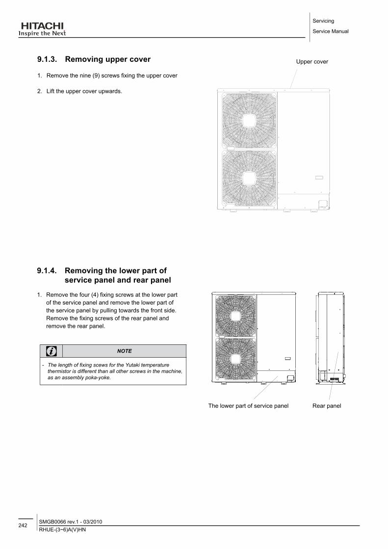
Servicing
Service Manual
242RHUE-(3~6)A(V)HNSMGB0066 rev.1 - 03/2010
9.1.3. Removing upper cover
1. Remove the nine (9) screws fixing the upper cover
2. Lift the upper cover upwards.
9.1.4. Removing the lower part of service panel and rear panel
1. Remove the four (4) fixing screws at the lower part of the service panel and remove the lower part of the service panel by pulling towards the front side. Remove the fixing screws of the rear panel and remove the rear panel.
note
-- The-length-of-fixing-scews-for-the-Yutaki-temperature-thermistor-is-different-than-all-other-screws-in-the-machine,-as-an-assembly-poka-yoke.
Upper cover
The lower part of service panel Rear panel

243RHUE-(3~6)A(V)HN
SMGB0066 rev.1 - 03/2010
Servicing
Service Manual
9
9.1.5. Removing yutaki fan motor
1. Remove the service cover according to the section “Removing service cover” in this chapter.
2. Remove the air outlet grille according to the section “Removing air outlet grille” in this chapter.
3. Remove the upper cover according to the section “Removing upper cover” in this chapter.
4. Disassembly the fan blade by removing the cap nuts and washers fixing the fan blade onto the motor shaft.
fan components and technical features
Power supply 380-415V/50Hz
Fan motor comp.No.
DC fan motorPCB5
PCN203 (1, 3)CN201 (2, 3, 4)
AC fan motor PCB3PCN404(White)
Screw for motor fixing
DC Fan Motor M6 Screw with spacer x 4
AC Fan Motor M8 Screw x 4
Motor clamp and wiring fixing position
Motor clamp
Fan motor lead wire
DC fan motor
AC fan motor
Cable tie
Fan motor lead wireUpper cover
Fan motor
Motor clamp

Servicing
Service Manual
244RHUE-(3~6)A(V)HNSMGB0066 rev.1 - 03/2010
9.1.6. Mounting yutaki fan motor
1. Remove the service cover according to the section “Removing service cover” in this chapter.
2. Remove the air outlet grille according to the section “Removing air outlet grille” in this chapter.
3. Remove the upper cover according to the section “Removing upper cover” in this chapter.
4. Disassembly the fan blade by removing the cap nuts and washers fixing the fan blade onto the motor shaft.
If the fan blade get stuck when trying to remove it, use a puller to disassembly the fan.
5. Remove the fan motor connector from the PCB3 and PCB5 at the electrical box. - Cut off the cable tie that fixes the lead wire of the
fan motor. - Remove the four (4) screws that fix the motor to the
motor clamp.
6. Fix the motor wire with the cable tie or the cord clamp. If not, it may cause the disconnection of the fan motor’s lead wire.
7. In order to avoid cutting edges, mount the rubber bush at the partition plate when inserting the motor wire through it. If not, it may cause the disconnection to the fan motor’s lead wire.
9.1.7. Removing the compressor
1. Remove the service cover and the lower part of the service panel according to the section “Removing service cover” and the section “Removing lower part of service panel and rear panel”. In case that the Yutaki is installed close to a wall closely, sepparate first the Yutaki from the wall.
2. Collect the refrigerant from the liquid stop valve, the gas stop valve and the check joint at the piping.
3. Open the sound insulation cover wrapped around the compressor and remove the terminal box cover at the compressor fixed by one (1) screw. Disconnect the compressor wires in the terminal box and remove the sound insulation cover.
note
-- Check-and-take-note-of-each-terminal-number-and-indications-for-its-correct-connection-at-the-reasembling-process.-If-wires-are-connected-in-incorrect-order,-it-will-lead-to-a-compressor-failure.
4. Remove the rubber cap and the thermistor on the top of the compressor.
note
-- When-assembling-the-motor,-ensure-the-cables-section-directly-downwards.-Fix-the-protection-tube-edge-end-downwards-to-ensure--water-from-keeping-inside-it
-- Fix-the-motor-wires-onto-the-motor-clamp-with-a-cable-tie-to-prevent-them-from-collisioning-the-fan-blades.
-- Assembling-the-fan-blade:-Insert-the-skidding-protection-part-of-fan-boss-in-accordance-with-the-cutting-part-of-the-motor-shaft,-and-fix-the-screw-after-dismounting-the-screwed-part-of-the-shaft.-(Tightening-Torque-of-20-N.m)
-- When-connecting-the-motor-wire,-check-to-ensure-that-the-colors-of-the-connectors-on-the-PCB3-and-PCB5-are-matched-with-the-wires.
-- Fix-the-air-outlet-grille-firmly-to-the-shroud.
Direction to remove the cover
Sound-proof cover
Cut part
Oil heater
Rubber bushPartition plate Cord holder or cable tie
Install DC motor to this position facing down the trap

245RHUE-(3~6)A(V)HN
SMGB0066 rev.1 - 03/2010
Servicing
Service Manual
9
Thermistor holder Holder
TdThermistor
Thermistor fixing plate
Indication of terminal number
Terminal box cover
Rubber cap Th Thermistor
Compressor
Compressor wires
Details for compressor terminals
Fix it with screw Compressor wires (3 wires)
note
-- Do-not-expose-the-refrigerant-cycle-to-the-atmosphere-for-a-long-period-in-order-to-avoid-water-and-foreign-particles-entering-into-the-refrigerant-cycle.-After-removing-the-compressor,-replace-it-quickly.-If-it-is-exposed-to-the-ambiance-for-a-long-period,-seal-both-suction-and-discharge-pipes.
-- Remove-the-cap-for-the-compressor-just-before-replacing-the-compressor.-Before-assembling-the-compressor,-seal-the-suction-pipe-and-discharge-pipe-with-tape-to-protect-the-compressor-interior-from-foreign-particles.-Remove-the-tape-when-connecting-the-pipes.
warning
-- Flamable-objects.-Fire-risk.-All-compressor-pipes-must-be-brazed-to-be-connected-to-the-refrigerant-circuit.-Ensure-that-all-the-sourrounding-is-free-of-flammable-objects-and-liquids-when-performing-piping-brazing-work.

Servicing
Service Manual
246RHUE-(3~6)A(V)HNSMGB0066 rev.1 - 03/2010
5. Remove the crankcase heater.(Oil heater on the lower case).
6. Remove the suction pipe and the discharge pipe from the compressor. Isolate the wires and electrical components to protect them from the burner flame when brazing the connection pipes.
7. Remove the two (2) nuts fixing the compressor and remove the compressor from the unit by lifting it. Slightly incline it forward and lift.
8. For brazing the compressor connection pipes, first cool down the compresor piping side covering it with wet cloth. Then brazing material will not enter into the compressor. If the brazing material enters the compressor, it will cause compressor failures.
fixation of the compressor to the bottom plate
Compressor position 1 2 3 4
Vibration-proof rubber 1
Vibration-proof rubber 2 – –
Nut – –
9. Reassemble the parts in the reverse order of the indicated removing procedures. - Tighten the screws (U, V and W) for compressor
wires with 2.5N.m. - Fix the lead wire firmly.
note
-- Fix-the-lead-wire-for-the-compressor-firmly-using-a-cable-tie-to-avoid-the-contact-between-the-metal-sheet-sharp-edges-and-the-high-temperature-piping.
Suction pipe
Cover pipes with wet cloth
Discharge pipe
Vibration-Proof rubber 1
Vibration-Proof rubber 2
Nut and washer
See compressor position table below

247RHUE-(3~6)A(V)HN
SMGB0066 rev.1 - 03/2010
Servicing
Service Manual
9
9.1.8. Removing high pressure switch
1. Remove the service cover according to the section “Removing service cover” in this chapter.
2. Collect the refrigerant from the check joint according to the section “Removing the compressor” in this chapter.
3. Disconnect the faston terminals from the pressure switch. - Cut the high pressure switch from the brazing neck
using a burner.
warning
-- High-pressures.-Explosion-risk.--- Do-not-change-the-high-pressure-switch-locally-or-change-the-high-pressure-cut-out-set-value-locally.-If-changed,-it-will-cause-serious-injury-or-death-due-to-explosion.
-- Do-not-attempt-to-turn-service-valve-rod-beyond-its-stop.
High pressure switch
Terminals
High pressure switch structure
Contact point Pressure detection
Faston terminals

Servicing
Service Manual
248RHUE-(3~6)A(V)HNSMGB0066 rev.1 - 03/2010
9.1.9. opening electrical box (P-mounting plate)
1. Remove the service cover according to the section “Removing the service cover” in this chapter. - Remove the five (5) screws fixing the electrical
box. Open the P-mounting plate by rotating it 90 degrees to the left.
danger
-- Electrical-hazard.-Risk-of-death.-- Check-that-the-LED201-(red)-located-on-the-inverter-module-is-OFF-when-opening-the-P-mounting-plate.
-- Do-not-touch-the-electrical-components-when-LED201-(Red)-located-on-the-inverter-module-is-ON-in-order-to-avoid-an-electrical-shock.
2 screws
1 screw
2 screws
P-Mounting plate
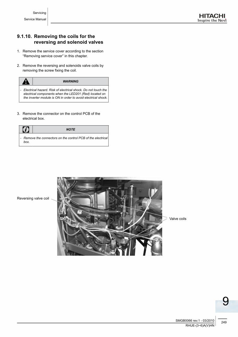
249RHUE-(3~6)A(V)HN
SMGB0066 rev.1 - 03/2010
Servicing
Service Manual
9
9.1.10. Removing the coils for the reversing and solenoid valves
1. Remove the service cover according to the section “Removing service cover” in this chapter.
2. Remove the reversing and solenoids valve coils by removing the screw fixing the coil.
warning
-- Electrical-hazard.-Risk-of-electrical-shock.-Do-not-touch-the-electrical-components-when-the-LED201-(Red)-located-on-the-inverter-module-is-ON-in-order-to-avoid-electrical-shock.
3. Remove the connector on the control PCB of the electrical box.
note
-- Remove-the-connectors-on-the-control-PCB-of-the-electrical-box.
Reversing valve coil
Valve coils

Servicing
Service Manual
250RHUE-(3~6)A(V)HNSMGB0066 rev.1 - 03/2010
9.1.11. Removing electronic expansion valve coils
1. Remove the service cover according to the section “Removing service cover”.
danger
-- Electrical-hazard.-Risk-of-death.-- Check-that-the-LED201-(red)-located-on-the-inverter-module-is-OFF-when-opening-the-P-mounting-plate.
-- Do-not-touch-the-electrical-components-when-LED201-(Red)-located-on-the-inverter-module-is-ON-in-order-to-avoid-an-electrical-shock.
2. Remove the connector on the control PCB of the electrical box.
3. Hold the electronic expansion valve coil and slightly rotate, then pull it up. Refer to the figure below to replace the electrical valve. The lock mechanism is equipped with the expansion valve coil. Check to ensure that the expansion valve coil is locked.
Electronic expansion valve coils

251RHUE-(3~6)A(V)HN
SMGB0066 rev.1 - 03/2010
Servicing
Service Manual
9
9.1.12. Removing pressure switches
1. Remove the service cover according to the section “Removing service cover” in this chapter.
2. There are two pressure switches: one green (low pressure) and one black (high pressure).
3. Remove the pressure switches
warning
-- Electrical-hazard.-Risk-of-electrical-shock.-Do-not-touch-the-electrical-components-when-the-LED201-(Red)-located-on-the-inverter-module-is-ON-in-order-to-avoid-electrical-shock.
4. Remove the connector on the control PCB of the electrical box.
note
-- Remove-the-connectors-on-the-control-PCB-of-the-electrical-box.
Pressure switch (Black, high pressure) Pressure switch (Green, low pressure)
Pressure switches

Servicing
Service Manual
252RHUE-(3~6)A(V)HNSMGB0066 rev.1 - 03/2010
9.1.13. Removing reversing valve
1. Remove the service cover and the rear service panel according to the section “Removing Service Cover” and the section “Removing lower part of service panel and rear service panel”in this chapter.
2. Collect the refrigerant from the check joint according to the section “Removing compressor”.
3. Remove the reversing valve coil according to the section “Removing reversing valve coil”.
4. Remove one (1) fixing screw for the valve-mounting plate.
5. Remove the stop valve at the gas side from the valve-mounting plate by removing the two (2) screws.
6. Remove the reversing valve assemblies from the 4 brazed parts where it is fixed. Remove the brazing of the reversing valve and the stop valve at the gas using a blowtorch. Cool down the piping side covering it with wet cloth, in order to avoid brazing material entering the reversing valve. Protect the connecting wires and pipe insulation from the brazing frame.
7. Remove the reversing valves from its assemblies 4 brazed parts .
Cover by wet cloth
Reversing valve
9.1.14. Removing expansion valves
1. Remove the service cover and rear service panel according to the section “Removing Service Cover” and the section “Removing Lower Part of Service Panel and Rear Service Panel”.
2. Collect the refrigerant from the check joint according to the section “Removing Compressor”.
3. Remove the coils according to the section “Removing Electronic Expansion Valve Coil”.
4. Remove the brazing as shown in the figure below.
Electronic Expansion Valve: 2 brazing parts.
Perform the brazing to remove and reassemble the electronic expansion valve by cooling with wet cloth.
Protect the connecting wires and pipe insulation from brazing flame.
5. Reassemble the parts in the reverse order of removing procedures.
Expansion valves
Brazing part
Perform the brazing with a blowtorchto remove and reassemble the reversing valve by cooling the pipes first with wet cloth in order to avoid brazing material entering the reversing valve.
8. Reassemble the parts in the reverse order of removing procedures contained in this chapter. When SFV is removed, fix it according to the section “Removing the Reversing Valve and the Solenoid Valve”contained in this chapter.
4 way valve
Pressure switch
High pressure switch

253RHUE-(3~6)A(V)HN
SMGB0066 rev.1 - 03/2010
Servicing
Service Manual
9
9.1.15. Removing solenoid valve
1. Remove the service cover and the rear service panel according to the sections “Removing Service Cover” and “Removing lower part of service panel and rear panel”, described in this chapter .
2. Collect the refrigerant from the check joint according to the section “Removing compressor” in this chapter.
3. Remove the solenoid valve coil according to the section “Removing coils for reversing valve and solenoid valve (SVA1, SVA2 and SVF)” in this chapter.
4. Remove the brazing and flare nuts as shown in the figure below. Using a blowtorch and previously cooling the pipe side with wet cloth in order to avoid brazing material entering the reversing valve.
- Solenoid Valve (SVA1): 2 brazing parts - Solenoid Valve (SVA2): 2 brazing parts
5. Perform the brazing to remove and reassemble the solenoid valve.
6. Protect the connecting wires and pipe insulation from the brazing flame.
7. Remove the flare nuts with two spanners to avoid twisting.
8. Reassemble the parts in the reverse order of removing order of removing procedures.
Fix the solenoid valve SVF as shown in the figure below.
Brazing
Brazing

Servicing
Service Manual
254RHUE-(3~6)A(V)HNSMGB0066 rev.1 - 03/2010
9.1.16. Removing electrical components
danger
-- Electrical-hazard.-Risk-of-death.-- Check-that-the-LED201-(red)-located-on-the-inverter-module-is-OFF-when-opening-the-P-mounting-plate.
-- Do-not-touch-the-electrical-components-when-LED201-(Red)-located-on-the-inverter-module-is-ON-in-order-to-avoid-an-electrical-shock.
1. Remove the service cover according to section “Removing service cover” in this chapter. - Disconnect all the connectors in the PCB. - Remove the PCB by sliding four (4) holders in the
arrow direction. - Remove the PCB for power distribution of the
compressor and the motor.
2. Removing the relay PCB
Transformers Control
Terminal board for power supply wires
Relay PCB
Terminal board for power signal wires
Main PCB
- Remove the service cover according to the section “Removing Service Cover” in this chapter.
- Disconnect all the wires connected to the relay PCB.
Extraction of the PCB from the holders
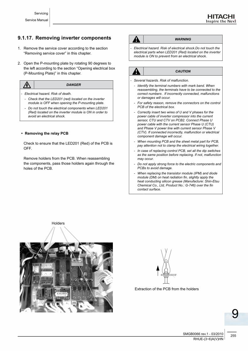
255RHUE-(3~6)A(V)HN
SMGB0066 rev.1 - 03/2010
Servicing
Service Manual
9
9.1.17. Removing inverter components
1. Remove the service cover according to the section “Removing service cover” in this chapter.
2. Open the P-mounting plate by rotating 90 degrees to the left according to the section “Opening electrical box (P-Mounting Plate)” in this chapter.
danger
-- Electrical-hazard.-Risk-of-death.-- Check-that-the-LED201-(red)-located-on-the-inverter-module-is-OFF-when-opening-the-P-mounting-plate.
-- Do-not-touch-the-electrical-components-when-LED201-(Red)-located-on-the-inverter-module-is-ON-in-order-to-avoid-an-electrical-shock.
• Removing the relay PCB
Check to ensure that the LED201 (Red) of the PCB is OFF.
Remove holders from the PCB. When reassembling the components, pass those holders again through the holes of the PCB.
warning
-- Electrical-hazard.-Risk-of-electrical-shock.Do-not-touch-the-electrical-parts-when-LED201-(Red)-located-on-the-inverter-module-is-ON-to-prevent-from-an-electrical-shock.
caution
-- Several-hazards.-Risk-of-malfunction.-- Identify-the-terminal-numbers-with-mark-band.-When-reassembling,-the-terminals-have-to-be-connected-to-the-correct-numbers-.-If-incorrectly-connected,-malfunctions-or-damages-will-occur.
-- For-safety-reason,-remove-the-connectors-on-the-control-PCB-of-the-electrical-box.
-- Correctly-insert-two-wires-of-U-and-V-phases-for-the-power-cable-of-inverter-compressor-into-the-current-sensor,-CTU-and-CTV-on-PCB2.-Connect-Phase-U-power-cable-with-the-current-sensor-Phase-U-(CTU)-and-Phase-V-power-line-with-current-sensor-Phase-V-(CTV).-If-connected-incorrectly,-malfunction-or-electrical-component-damage-will-occur.
-- When-mounting-PCB-and-the-sheet-metal-part-for-PCB,-pay-attention-not-to-clamp-the-electrical-wiring-together.
-- In-case-of-replacing-control-PCB,-set-all-the-dip-switches-as-the-same-position-before-replacing.-If-not,-malfunction-may-occur.-
-- Do-not-apply-strong-force-to-the-electric-components-and-PCBs-to-avoid-damage.
-- When-replacing-the-transistor-module-(IPM)-and-diode-module-(DM)-on-heat-radiation-fin,-slightly-apply-the-heat-conducting-silicon-grease-(Manufacture:-Shin-Etsu-Chemical-Co.,-Ltd,-Product-No.:-G-746)-over-the-fin-contact-surface.
Extraction of the PCB from the holders
Holders

Servicing
Service Manual
256RHUE-(3~6)A(V)HNSMGB0066 rev.1 - 03/2010
9.1.18. Removing the ISPM
The ISPM is equiped in the RHUE-(5/6)AHN unit.
danger
-- Electrical-hazard.-Risk-of-death.-- Check-that-the-LED201-(red)-located-on-the-inverter-module-is-OFF-when-opening-the-P-mounting-plate.
-- Do-not-touch-the-electrical-components-when-LED201-(Red)-located-on-the-inverter-module-is-ON-in-order-to-avoid-an-electrical-shock.
1. Disconnect all the wirings connected to the module. - Disconnect the wirings of the terminals +,- , U, V, W
2. Disconnect all the wirings connected to the transistor module as shown below. - Disconnect the wirings of connector CN2, CN206
and CN207. - Disconnect the wirings from P, N, U, V, W on the
transistor module. - Remove the four (4) fixing screws on the ISPM
module to remove it..
note
-- Several-hazards.-Risk-of-malfunction.-- Identify-the-terminal-numbers-with-mark-band.-When-reassembling,-the-terminals-have-to-be-connected-to-the-correct-numbers-.-If-incorrectly-connected,-malfunctions-or-damages-will-occur.
-- Check-to-ensure-that-the-electrical-wires-will-not-be-caught-between-the-mounting-electrical-components-and-the-mounting-plates-when-the-PCB-is-remounted.
-- Apply-silicon-grease-evenly-on-the-whole-rear-side-of-the-diode-module-and-the-transistor-module-when-mounting.-Silicon-grease-is-available-as-a-field-supplied-accessory.
ISPM moduleLED201
4 fixing screws

257RHUE-(3~6)A(V)HN
SMGB0066 rev.1 - 03/2010
Servicing
Service Manual
9
9.1.19. Removing the dIP-IPM
The DIP-IPM is equiped in the RHUE-(3~6)AVHN units.
danger
-- Electrical-hazard.-Risk-of-death.-- Check-that-the-LED201-(red)-located-on-the-inverter-module-is-OFF-when-opening-the-P-mounting-plate.
-- Do-not-touch-the-electrical-components-when-LED201-(Red)-located-on-the-inverter-module-is-ON-in-order-to-avoid-an-electrical-shock.
1. Disconnect all the wirings connected to the module.
- Disconnect the wirings of the terminals +,- , U, V, W
2. Disconnect all the wirings connected to the module.
- Remove the four (4) fixing screws on the DIP-IPM module to remove it.
note
-- Several-hazards.-Risk-of-malfunction.-- Identify-the-terminal-numbers-with-mark-band.-When-reassembling,-the-terminals-have-to-be-connected-to-the-correct-numbers-.-If-incorrectly-connected,-malfunctions-or-damages-will-occur.
-- Check-to-ensure-that-the-electrical-wires-will-not-be-caught-between-the-mounting-electrical-components-and-the-mounting-plates-when-the-PCB-is-remounted.
-- Apply-silicon-grease-evenly-on-the-whole-rear-side-of-the-diode-module-and-the-transistor-module-when-mounting.-Silicon-grease-is-available-as-a-field-supplied-accessory.
DIP-IPM module
4 fixing screws
LED201

Servicing
Service Manual
258RHUE-(3~6)A(V)HNSMGB0066 rev.1 - 03/2010
9.1.20. Removing the electrical-noise filter
All RHUE Yutaki units are equiped with electrical-noise filter PCB.
danger
-- Electrical-hazard.-Risk-of-death.-- Check-that-the-LED201-(red)-located-on-the-inverter-module-is-OFF-when-opening-the-P-mounting-plate.
-- Do-not-touch-the-electrical-components-when-LED201-(Red)-located-on-the-inverter-module-is-ON-in-order-to-avoid-an-electrical-shock.
1. Disconnect all the wirings (9 in total) connected to the electrical-noise filter.
2. Remove the six (6) holders from the PCB. When reassembling the components, pass those holders again through the holes of the PCB.
6 plastic holders
Extraction of the PCB from the holders

259RHUE-(3~6)A(V)HN
SMGB0066 rev.1 - 03/2010
Servicing
Service Manual
9
9.1.21. Removing other electrical components
1. Remove the service cover according to the section “Removing service cover” in this chapter.
2. Open the P-mounting plate by rotating it 90 degrees to the left according to the section “Opening electrical box (P-Mounting Plate)” in this chapter.
3. Check to ensure the LED201 (Red) of the inverter PCB is off when opening P-mounting plate.
4. Remove other electrical components according to the procedure below, and the figures on chapter 9.
danger
-- Electrical-hazard.-Risk-of-death.-- Check-that-the-LED201-(red)-located-on-the-inverter-module-is-OFF-when-opening-the-P-mounting-plate.
-- Do-not-touch-the-electrical-components-when-LED201-(Red)-located-on-the-inverter-module-is-ON-in-order-to-avoid-an-electrical-shock.
Disconnect all the wires connected with the smoothing capacitor (CB, CB1, CB2, CA).
If the wire has polar characters. Identify the wire mark band and the indication on the smoothing capacitor when wire connecting.
Remove the two (2) screws fixing the smoothing capacitor and remove the smoothing capacitor.
Disconnect all the wires connecting with the magnetic contactor (CMC1).
Remove the two (2) screws fixing the magnetic contactor and remove the magnetic contactor.
Remove the four (4) screws fixing the reactor and remove the reactor (DCL).
Disconnect all the wires connected with the electrical-noise filter (NF1).
Remove the noise filter by clamping the top of the holder (6 portions) with a pincher.
note
-- Identify-the-terminal-numbers-with-mark-band.-When-reassembling,-the-terminals-have-to-be-connected-to-the-correct-numbers-.-If-incorrectly-connected,-malfunctions-or-damages-will-occur.


SMGB0066 rev.1 - 03/2010 - Printed in Spain
Hitachi Air Conditioning Products Europe, S.A. is certified with:
ISO 9001 by AENOR; Spain for its Quality Management accordance
with the standard
ISO 14001 by AENOR, Spain for its Environmental Management
systems accordance with the standard.
Hitachi fulfills with the Certification NF-PAC that recognize the
quality requirements for this heat pumps systems.
Hitachi units certifies that our product have fulfilled EU consumer
safety, health and environmental requirements.
HitachiAir Conditioning Products Europe, S.A.
Ronda Shimizu,1 - Políg. Ind. Can Torrella
08233 Vacarisses (Barcelona) España