Series AXK
29
Series AXK Non-Rotating Piston Rod Type/Double Acting:Single Rod Bore Size(mm) : Ø20, Ø25, Ø32, Ø40 143 www.TPCpage.com www.tpcpneumatics.com AQ ADQ ACP APM AS AX AM2 AM AL ALX AQ2 ADQ2 AJ AJM ABK ACK1 NSK AG NGQ AGX GX NP ADR AMR NDM ARD NST AST ASTH NLCD NLCS 5 ● NUMEROUS MOUNTING OPTIONS ● MAGNET STANDARD FOR AUTO SWITCH ● BUMPERS STANDARD ● DESIGNED FOR NON-LUBRICATED SERVICE ● COMPACT LIGHT DESIGN ● REPLACEABLE ROD GLAND ● CUSTOM DESIGNED PISTON ROD FOR NON-ROTATION Double Acting/Single Rod How to Order AXK 1 2 3 4 7 8 6 Bore size(mm) ф40 ф32 ф25 ф20 ※Axial foot TCM-L020B TCM-L032B TCM-L040B Flange TCM-F020B TCM-F032B TCM-F040B Single clevis TCM-C020B TCM T -C032B CM-C040B Double clevis TCM-D020B TCM-D032B TCM-D040B Trunnion(With nut) TCM-T020B TCM-T032B TCM-T040B PART No. of Mounting Bracket Auto Switch Bore size(mm) Model ф40 ф32 ф25 ф20 W5 TBM2-032 TBM2-025 TBM2-020 TBM2-040 PART No. of Auto Switch Mounting Band 150 W5 L J 40 1 Non-Rotating Piston Rod Type ※Built-in Magnet Standard 2 Mounting B : Basic Type L : Axial Foot Type F : Rod Side Flange Type G : Head Side Flange Type C : Single Clevis Type D : Double Clevis Type T : Head Side Trunnion Type U : Rod Side Trunnion Type E : Integrated Clevis Type BZ: Boss-Cut Basic Type FZ: Boss-Cut Flange Type UZ: Boss-Cut Trunnion Type 3 Bore size(mm) 20 : ф20 25 : ф25 32 : ф32 40 : ф40 4 Stroke (mm) ф20 : 25, 50, 75, 100, 125, 150, 200, 250, 300 J : Nylon Tarpaulin K : Neoprene Cloth 7 Auto Switch (Band mounted type) [Grommet] Blank : None W5 : Reed Switch, 0.5m Lead Wire W5L : Reed Switch, 3m Lead Wire 8 Number of Auto Switches Blank : 2 pcs S : 1 pc N : N pcs ※ 2 pcs. Required Per Cylinder Blank : None 5 Rod Boot Option ф40 : 25, 50, 75, 100, 125, 150, 200, 250, 300 ф32 : 25, 50, 75, 100, 125, 150, 200, 250, 300 ф25 : 25, 50, 75, 100, 125, 150, 200, 250, 300 6 F : Rod end female thread Blank : Rod end male thread Rod end thread type
-
Upload
khangminh22 -
Category
Documents
-
view
0 -
download
0
Transcript of Series AXK

SeriesAXKNon-Rotating Piston Rod Type/Double Acting:Single Rod
Bore Size(mm) : Ø20, Ø25, Ø32, Ø40
143www.TPCpage.com
www.tpcpneumatics.com
AQADQ
ACP
APM
AS
AX
AM2
AM
ALALX
AQ2ADQ2
AJAJM
ABK
ACK1
NSK
AG
NGQ
AGXGX
NP
ADR
AMR
NDM
ARD
NST
AST
ASTH
NLCD
NLCS
5
●NUMEROUS MOUNTING OPTIONS
●MAGNET STANDARD FOR AUTO SWITCH
● BUMPERS STANDARD
● DESIGNED FOR NON-LUBRICATED
SERVICE
● COMPACT LIGHT DESIGN
● REPLACEABLE ROD GLAND
●CUSTOM DESIGNED PISTON ROD FOR
NON-ROTATION
Double Acting/Single Rod
How to Order
AXK1 2 3 4 7 86
Bore size(mm) ф40ф32ф25ф20
※Axial foot TCM-L020B TCM-L032B TCM-L040B
Flange TCM-F020B TCM-F032B TCM-F040B
Single clevis TCM-C020B TCM T-C032B CM-C040B
Double clevis TCM-D020B TCM-D032B TCM-D040B
Trunnion(With nut) TCM-T020B TCM-T032B TCM-T040B
PART No. of Mounting Bracket
Auto Switch Bore size(mm)
Model ф40ф32ф25ф20
W5 TBM2-032TBM2-025TBM2-020 TBM2-040
PART No. of Auto Switch Mounting Band
150 W5L J40
1⃞Non-Rotating PistonRod Type※Built-in Magnet Standard
2⃞MountingB : Basic Type
L : Axial Foot Type
F : Rod Side Flange Type
G : Head Side Flange Type
C : Single Clevis Type
D : Double Clevis Type
T : Head Side Trunnion Type
U : Rod Side Trunnion Type
E : Integrated Clevis Type
BZ: Boss-Cut Basic Type
FZ: Boss-Cut Flange Type
UZ: Boss-Cut Trunnion Type
3⃞Bore size(mm)20 : ф20
25 : ф25
32 : ф32
40 : ф40
4⃞Stroke (mm) ф20 : 25, 50, 75, 100, 125, 150, 200, 250, 300
J : Nylon Tarpaulin
K : Neoprene Cloth
7⃞Auto Switch(Band mounted type)
[Grommet]
Blank : None
W5 : Reed Switch, 0.5m Lead Wire
W5L : Reed Switch, 3m Lead Wire
8⃞Number of Auto SwitchesBlank : 2 pcs
S : 1 pc
N : N pcs
※ 2 pcs. Required Per Cylinder
143-171-AXK 2012.9.7 2:31 PM 페이지143 한국원색인쇄사
Blank : None
5⃞ Rod Boot Option
ф40 : 25, 50, 75, 100, 125, 150, 200, 250, 300
ф32 : 25, 50, 75, 100, 125, 150, 200, 250, 300
ф25 : 25, 50, 75, 100, 125, 150, 200, 250, 300
6⃞
F : Rod end female thread
Blank : Rod end male thread
Rod end thread type

Series AXK
144
Mounting Lead Wire Entry Reed Switch
Band Mounting Type Grommet W5
Auto Switch Specifications
Bore Size(mm) ф20 ф25 ф32 ф40
Action Double Acting Single Rod
Cushion Rubber Cushion (Standard)
Piping Method Rc(PT)1/8 Rc(PT)1/8 Rc(PT)1/8 Rc(PT)1/4
Model
Bore Size(mm) ф20 ф25 ф32 ф40
Piston Speed(mm/sec) 50 ~ 500
Allowable Kinetic Energy(kgf/cm) 2.7 4 6.5 12
Piston Speed
Symbol Material of Boot Max. Ambient Temperature
J Nylon Tarpaulin 60℃ (140°F)
K Neoprene Cloth ※110℃ (230°F)
Material of Boot
※ The max. ambient temperature of gaitersonly.
Specifications
+1.40
Mounting
Action Double Acting Single Rod
Fluid Air
Proof pressure 1.5 MPa (213psi)
Max. Operating Pressure 1.0 MPa (140psi)
Min. Operating Pressure 0.05 MPa (7psi)
Ambient and Fluid Temperature -10℃~+70℃ (14~ 158°F)
Lubrication None (Non-Lube)
Stroke Tolerance mm
Basic Type, Axial Foot Type, Rod Side Flange
Type, Head Side Flange Type, Single Clevis Type,
Head Side Trunnion Type, Rod Side Trunnion
Type, Integrated Clevis, Type Boss-Cut Type
Non-Rotating ф20, ф25 ±0.8°Accuracy
ф32, ф40 ±0.5°
143-171-AXK 2012.9.7 2:31 PM 페이지144 한국원색인쇄사

Series AXK
145www.TPCpage.com
www.tpcpneumatics.com
AQADQ
ACP
APM
AS
AX
AM2
AM
ALALX
AQ2ADQ2
AJAJM
ABK
ACK1
NSK
AG
NGQ
AGXGX
NP
ADR
AMR
NDM
ARD
NST
AST
ASTH
NLCD
NLCS
Boss-Cut Type
(mm)
Calculation ExampleAXKL 32-100•Basic weight : 0.44(Foot type ф32)•Additional weight : 0.09/50 stroke•Cylinder stroke : 100 stroke0.44+0.09×100/50=0.62kgf
Standard Option
Mounting Rod End Clevis Knuckle Double Kn-
Nut Nut Pin Joint uckle Joint
Basic Type ◦(1pc.) ◦ - ◦ ◦ ◦
Axial Foot Type ◦(2) ◦ - ◦ ◦ ◦
Rod Side Flange Type ◦(1) ◦ - ◦ ◦ ◦
Head Side Flange Type ◦(1) ◦ - ◦ ◦ ◦
Intergrated Clevis Type - ◦ - ◦ ◦ ◦
Single Clevis Type - ◦ - ◦ ◦ ◦
Double Clevis Type - ◦ ◦ ◦ ◦ ◦
Head Side Trunnion Type ◦(1) ◦ - ◦ ◦ ◦
Rod Side Trunnion Type ◦(1) ◦ - ◦ ◦ ◦
Boss-Cut Basic Type ◦(1) ◦ - ◦ ◦ ◦
Boss-Cut Flange Type ◦(1) ◦ - ◦ ◦ ◦
Boss-Cut Trunnion Type ◦(1) ◦ - ◦ ◦ ◦
Note With pin
Mounting and Accessories
Mounting Boot
Accessories
Bore Size(mm) ф20 ф25 ф32 ф40
Basic Type 0.14(0.31) 0.21(0.46) 0.28(0.62) 0.58(1.26)
Axial Foot Type 0.29(0.64) 0.38(0.82) 0.44(0.97) 0.84(1.85)
Flange Type 0.20(0.44) 0.30(0.66) 0.37(0.82) 0.69(1.52)
Integrated Clevis Type 0.12(0.26) 0.19(0.42) 0.27(0.60) 0.53(1.17)
Single Clevis Type 0.18(0.40) 0.26(0.55) 0.32(0.71) 0.66(1.46)
Double Clevis Type 0.19(0.42) 0.27(0.60) 0.33(0.73) 0.70(1.54)
Trunnion Type 0.18(0.40) 0.28(0.62) 0.34(0.75) 0.67(1.48)
Boss-Cut Basic Type 0.13(0.29) 0.19(0.42) 0.26(0.57) 0.54(1.19)
Boss-Cut Flange Type 0.19(0.42) 0.29(0.62) 0.35(0.77) 0.66(1.46)
Boss-Cut Trunnion Type 0.17(0.37) 0.26(0.57) 0.32(0.71) 0.64(1.41)
Additional weight for each 50 mm of stroke 0.04(0.09) 0.08(0.15) 0.09(0.20) 0.14(0.31)
Accessories Single Knuckle joint 0.06(0.13) 0.06(0.13) 0.06(0.13) 0.23(0.51)
Weight Double Knuckle Joint (with pin) 0.08(0.15) 0.08(0.15) 0.08(0.15) 0.20(0.44)
Weight Table
MorntingBracketWeight
Boss for the head cover
bracket is eliminated and the
total length of the cylinder is
shortened.
Compared to the total length of cylinder
kgf(lbf)
Mounting : ●Boss-Cut Basic Type(BZ) ●Boss-Cut Flange Type(FZ)
●Boss-Cut Trunnion Type(UZ)
ф20 ф25 ф32 ф40
▼13 ▼13 ▼13 ▼16
Basic weight
143-171-AXK 2012.9.7 2:31 PM 페이지145 한국원색인쇄사

Series AXK
146
Construction / Parts List
ф25~ф40ф20
❻ ❺❽ ❼ ❶ ❻ ❸ ❿ ❹ 2A
2C ❾
Boss-Cut Type Integrated Clevis Type
2B
No Description Material Remarks
❶ Rod Cover Alluminum Alloy White Alumite
Head Cover-A 〃 〃
Head Cover-B 〃 〃
Head Cover-C 〃 〃
❸ Cylinder Tube stainless steel -
❹ Piston Alluminum Alloy Chromate
❺ Pistan Rod Stainless steel
❻ Guide Bush Sintered Metal
❼ Retaining Ring Rolled steel Nickel Plated
❽ Stopper Ring Carbon Tool steel 〃
❾ Guide Bush Sintered Metal
❿ DAMPER A Urethane
DAMPER B 〃
Parts
No Description Material Remarks
Stopper Ring Carbon Tool steel
Piston Packing NBR
Piston Gasket NBR
Wear Ring Resin
Bush Brass
Rod End Nut Nickel Plated
Bore Size (mm)
20 25 32 40
Rod Packing NBR SORA-10 SORA-10 SORA-12 SORA-16
Packing List
2A
2B
2C
No MaterialDescription
143-171-AXK 2012.9.7 2:31 PM 페이지146 한국원색인쇄사

Series AXK
147www.TPCpage.com
www.tpcpneumatics.com
AQADQ
ACP
APM
AS
AX
AM2
AM
ALALX
AQ2ADQ2
AJAJM
ABK
ACK1
NSK
AG
NGQ
AGXGX
NP
ADR
AMR
NDM
ARD
NST
AST
ASTH
NLCD
NLCS
Basic Type(B)
Bore SizeAXKB Stroke
Boss-cut type
Standard Type
With Rod Boot
AcrossFlats B2 2-NN
□NA
2-Rc(PT) PAcrossFlats B1
Rod CrossSection LG+Stroke
LT+Stroke
LT+Stroke
фe
фD
2-фEh8
H1
H
F N
1.5ATMM
A
K
H2
1.5
фI
FN
G
G
With Rod Boot (mm)
h ℓ
1~50st̀ 51~100st 101~150st 151~200st 201~300st 1~50st 51~100st 101~150st 151~200st 201~300st
ф20 30 16 68 81 93 106 131 12.5 25 37.5 50 75
ф25 30 16 72 85 97 110 135 12.5 25 37.5 50 75
ф32 30 16 72 85 97 110 135 12.5 25 37.5 50 75
ф40 40 18 77 90 102 115 140 12.5 25 37.5 50 75
Bore Size LT
ф20 103
ф25 107
ф32 109
ф40 138
Boss-Cut Type
Bore Size e f
143-171-AXK 2012.9.7 2:31 PM 페이지147 한국원색인쇄사
Rod end female thread type
Rod end female thread type
K1 H1 MM1 LT1
20 5 20 M4x0.7 dp:8 95
25 5.5 20 M5x0.8 dp:8 95
32 5.5 20 M6x1.0 dp:12 97
40 7 21 M8x1.25 dp:13 125
Bore Size
8
h
ℓ f
Bore Size A AT B1 B2 D E F G H H1 H2 I K MM N
ф20 18 15.5 13 26 10 20 13 8 41 5 8 27 8 M8×1.25 15
ф25 22 19.5 17 32 10 26 13 8 45 6 8 33 8 M8×1.25 15
ф32 22 19.5 17 32 12 26 13 8 45 6 8 37.5 10 M10×1.25 15
ф40 24 21 22 41 16 32 16 11 50 8 10 46.5 14 M14×1.5 21.5
NA NN P LG LT
24 M20×1.5 1/8 62 116
30 M26×1.5 1/8 62 120
34.5 M26×1.5 1/8 64 122
42.5 M32×2 1/4 88 154
(mm)
-0.01-0.05-0.01-0.05-0.01-0.05-0.01-0.05
-0.01-0.05-0.01-0.05-0.01-0.05-0.01-0.05
0 -0.033
0 -0.033
0 -0.033 0 -0.039

Series AXK
148
Axial Foot Type(L)
Rod Side Flange Type(F)
Bore SizeAXKL Stroke
Bore SizeAXKF Stroke
фD
BFL
фI
LH
B
фD
LA
фEh8
K
YT
N NX YX
MM
AAT
F GG F
H1
H
H2AcrossFlats B1
2-Rc(PT)P
LG+Stroke
4-фLD2-фLC
2-NN
LKLM
LS+StrokeLT+Stroke
Across flats□NA
4-фFD
C2
2-фFD FKFM
H1
AT
NN
AT
FT
N
G
N1.5
FH
H2 G
Mounting Hole
Mounting Hole
AcrossFlats B2
AcrossFlats B1
MM Across Flats □NA
LG+StrokeLT+Stroke
LT+Stroke
Rc(PT)2-P
ф40ф20 ~ф32
Boss-cut type
Rod CrossSection
Bore Size A AT B B1 B2 D F G H H1 H2 I K LC
ф20 18 15.5 40 13 26 10 13 8 41 5 8 27 8 4
ф25 22 19.5 47 17 32 10 13 8 45 6 8 33 8 4
ф32 22 19.5 47 17 32 12 13 8 45 6 8 37.5 10 4
ф40 24 21 54 22 41 16 16 1150 8 10 46.5 14 4
LD LH LS LA LK LM MM N NA NN P LG X Y T LT
6.8 25 102 3.2 40 55 M8×1.25 15 24 M20×1.5 1/8 62 20 8 21 131
6.8 28 102 3.2 40 55 M8×1.25 15 30 M26×1.5 1/8 62 20 8 25 135
6.8 28 104 3.2 40 55 M10×1.25 15 34.5 M26×1.5 1/8 64 20 8 25 137
7 30 134 3.2 55 75 M14×1.5 21.542.5 M32×2 1/4 88 23 10 27 171
(mm)
-0.01-0.05-0.01-0.05-0.01-0.05-0.01-0.05
-0.01-0.05-0.01-0.05-0.01-0.05-0.01-0.05
Bore Size A AT B B1 B2 C2 D E F FD FT
ф20 18 15.5 34 13 26 30 10 20 13 7 4
ф25 22 19.5 40 17 32 37 10 26 13 7 4
ф32 22 19.5 40 17 32 37 12 26 13 7 4
ф40 24 21 52 22 41 47.3 16 32 16 7 5
FK FL FM G H H1 H2 I K MM
60 - 75 8 41 5 8 27 8 M8×1.25
60 - 75 8 45 6 8 33 8 M8×1.25
60 - 75 8 45 6 8 37.5 10 M10×1.25
66 36 82 11 50 8 10 46.5 14 M14×1.5
(mm)
Bore Size LT
ф20 103
ф25 107
ф32 109
ф40 138
Boss-Cut Type
0 -0.033 0 -0.033 0 -0.033 0 -0.039
-0.01-0.05-0.01-0.05-0.01-0.05-0.01-0.05
-0.01-0.05-0.01-0.05-0.01-0.05-0.01-0.05
Bore Size N NA NN P LG T LT
ф20 15 24 M20×1.5 1/8 62 37 116
ф25 15 30 M26×1.5 1/8 62 41 120
ф32 15 34.5 M26×1.5 1/8 64 41 122
ф40 21.5 42.5 M32×2 1/4 88 45 154
(mm)
143-171-AXK 2012.9.7 2:31 PM 페이지148 한국원색인쇄사

Series AXK
149www.TPCpage.com
www.tpcpneumatics.com
AQADQ
ACP
APM
AS
AX
AM2
AM
ALALX
AQ2ADQ2
AJAJM
ABK
ACK1
NSK
AG
NGQ
AGXGX
NP
ADR
AMR
NDM
ARD
NST
AST
ASTH
NLCD
NLCS
Single Clevis Type (C)
Head Side Flange Type(G)
Bore SizeAXKG Stroke
Rod Cross Section
фD
фEh8
фI
KAcrossFlatsB1
AcrossFlatsB2
2-фFD
4-фFD
Mounting hole
Mountinghole
H1 NN
ATAH
MMF N1.5 N
B FL
FT
FKFM
C2G G H2
2-Rc(PT)P
LG+StrokeT+StrokeLT+Stroke
Across Flats □NA
ф20 ~ф32ф40
(mm)
Bore Size A AT B B1 B2 C2 D E F FD FT FK
ф20 18 15.5 34 13 26 30 10 20 13 7 4 60
ф25 22 19.5 40 17 32 37 10 26 13 7 4 60
ф32 22 19.5 40 17 32 37 12 26 13 7 4 60
ф40 24 21 52 22 41 47.3 16 32 16 7 5 66
FL FM G H H1 H2 I K MM
- 75 8 41 5 8 27 8 M8×1.25
- 75 8 45 6 8 33 8 M8×1.25
- 75 8 45 6 8 37.5 10 M10×1.25
36 82 10 50 8 10 46.5 14 M14×1.5
(mm)
0 -0.033 0 -0.033 0 -0.033 0 -0.039
-0.01-0.05-0.01-0.05-0.01-0.05-0.01-0.05
Bore Size N NA NN P LG T LT
ф20 15 24 M20×1.5 1/8 62 107 116
ф25 15 30 M26×1.5 1/8 62 111 120
ф32 15 34.5 M26×1.5 1/8 64 113 122
ф40 21.5 42.5 M32×2 1/4 88 143 154
-0.01-0.05-0.01-0.05-0.01-0.05-0.01-0.05
Bore Size A AT B1 CD CX D E F G H H1 I
ф20 18 15.5 13 9 10 10 20 13 8 41 5 27
ф25 22 19.5 17 9 10 10 26 13 8 45 6 33
ф32 22 19.5 17 9 10 12 26 13 8 45 6 37.5
ф40 24 21 22 10 15 16 32 16 11 50 8 46.5
K L MM N NA NN P RR
8 30 M8×1.25 15 24 M20×1.5 1/8 9
8 30 M8×1.25 15 30 M26×1.5 1/8 9
10 30 M10×1.25 15 34.5 M26×1.5 1/8 9
14 39 M14×1.5 21.5 42.5 M32×2 1/4 11
0 -0.033 0 -0.033 0 -0.033 0 -0.039
-0.01-0.05-0.01-0.05-0.01-0.05-0.01-0.05
-0.01-0.05-0.01-0.05-0.01-0.05-0.01-0.05
Bore Size LG W T LT
ф20 62 14 133 142
ф25 62 14 137 146
ф32 64 14 139 148
ф40 88 18 177 188
Rod Cross Section
Bore SizeAXKC Stroke
фD
фEh8
K
2- Rc(PT) P
LG+Stroke
фCDH10+0.0580
CX+0.1+0.2
T+StrokeLT+Stroke
NN G
N
L
NAW
RR
MM AT
AH
F N1.5
H1AcrossFlats B1 G
фI
143-171-AXK 2012.9.7 2:31 PM 페이지149 한국원색인쇄사

Series AXK
150
Rod Side Trunnion Type(U)
Double Clevis Type(D)
Bore SizeAXKU Stroke
Boss-Cut Type
LT+Stroke
фD
K
Bore Size A AT B1 CD CX CZ D E F G H H1 I K L MM
ф20 18 15.5 13 9 10 19 10 20 13 8 41 5 27 8 30 M8×1.25
ф25 22 19.5 17 9 10 19 10 26 13 8 45 6 33 8 30 M8×1.25
ф32 22 19.5 17 9 10 19 12 26 13 8 45 6 37.5 10 30 M10×1.25
ф40 24 21 22 10 15 30 16 32 16 11 50 8 46.5 14 39 M14×1.5
N NA NN P RR LG W T LT
15 24 M20×1.5 1/8 9 62 14 133 142
15 30 M26×1.5 1/8 9 62 14 137 146
15 34.5 M26×1.5 1/8 9 64 14 139 148
21.5 42.5 M32×2 1/4 11 88 18 177 188
0 -0.033 0 -0.033 0 -0.033 0 -0.039
-0.01-0.05-0.01-0.05-0.01-0.05-0.01-0.05
-0.01-0.05-0.01-0.05-0.01-0.05-0.01-0.05
(mm)
фD
фEh8
K
AcrossFlats B1
MM AT
A
1.5
NF
H
H1 NN G G
N W
CZ□NAL
RR
2-Rc(PT) P
LG+StrokeT+Stroke
LT+Stroke
Bore SizeAXKD Stroke
Bore Size A AT B1 B2 D E F G H H1 I K MM
ф20 18 15.5 13 26 10 20 13 8 41 5 27 8 M8×1.25
ф25 22 19.5 17 32 10 26 13 8 45 6 33 8 M8×1.25
ф32 22 19.5 17 32 12 26 13 8 45 6 37.5 10 M10×1.25
ф40 24 21 22 41 16 32 16 11 50 8 46.5 14 M14×1.5
N NA NN P LG TD TF
15 24 M20×1.5 1/8 62 8 10
15 30 M26×1.5 1/8 62 9 10
15 34.5 M26×1.5 1/8 64 9 10
21.5 42.5 M32×2 1/4 88 10 11
Bore Size TK TL TM T LT
ф20 32 32 52 36 116
ф25 40 40 60 40 120
ф32 40 40 60 40 122
ф40 53 53 77 44.5 154
(mm)
Bore Size LT
ф20 103
ф25 107
ф32 109
ф40 138
Boss-Cut Type
0 -0.033 0 -0.033 0 -0.033 0 -0.039
-0.01-0.05-0.01-0.05-0.01-0.05-0.01-0.05
-0.01-0.05-0.01-0.05-0.01-0.05-0.01-0.05
Rod CrossSection
Rod CrossSection
CDH10 +0.0580
CX+0.1+0.2
фI
фIфTL
фEh8фTDe9
TKTM
H1
MMAT Across Flats □NAA
T
H LG+Stroke
LT+Stroke
G G NN
N NF
1.5TF
AcrossFlats B2
Across Flats B12-Rc(PT) P
143-171-AXK 2012.9.7 2:31 PM 페이지150 한국원색인쇄사

Series AXK
151www.TPCpage.com
www.tpcpneumatics.com
AQADQ
ACP
APM
AS
AX
AM2
AM
ALALX
AQ2ADQ2
AJAJM
ABK
ACK1
NSK
AG
NGQ
AGXGX
NP
ADR
AMR
NDM
ARD
NST
AST
ASTH
NLCD
NLCS
Rod CrossSection
Integrated Clevis Type(E)
Head Side Trunnion Type(T)
Bore sizeAXKT Stroke
Bore SizeAXKE Stroke
фD
фTL
фD
фI
фEh8
фEh8
CX -0.1-0.2+0.058+0фCDH10
фI
KMM AT 1.5 Across Flats □NA
ALG+StrokeT+StrokeLT+Stroke
F NH
AcrossFlats B1 H1
NN G
NTKTM
TF
G Across Flats B22-Rc(PT) P
фTDe9-0.025
-0.061
LT+Stroke
T+StrokeLG+Stroke
LV
H
A FN N
L RR
2-Rc(PT) P
1.5
K
MM NN
H1
Across Flats B1
ATGG W
□NA
Bore Size A AT B1 B2 D E F G H H1 I
ф20 18 15.5 13 26 10 20 13 8 41 5 27
ф25 22 19.5 17 32 10 26 13 8 45 6 33
ф32 22 19.5 17 32 12 26 13 8 45 6 37.5
ф40 24 21 22 41 16 32 16 11 50 8 46.5
K MM N NA NN P LG TD TF
8 M8×1.25 15 24 M20×1.5 1/8 62 8 10
8 M8×1.25 15 30 M26×1.5 1/8 62 9 10
10 M10×1.25 15 34.5 M26×1.5 1/8 64 9 10
14 M14×1.5 21.5 42.5 M32×2 1/4 88 10 11
(mm)
0 -0.033 0 -0.033 0 -0.033 0 -0.039
-0.01-0.05-0.01-0.05-0.01-0.05-0.01-0.05
Bore Size TK TL TM T LT
ф20 32 32 52 108 118
ф25 40 40 60 112 122
ф32 40 40 60 114 124
ф40 53 53 77 143.5 154
-0.01-0.05-0.01-0.05-0.01-0.05-0.01-0.05
Bore Size A AT B1 CD CX D E F G H H1
ф20 18 15.5 13 8 12 10 20 13 8 41 5
ф25 22 19.5 17 8 12 10 26 13 8 45 6
ф32 22 19.5 17 10 20 12 26 13 8 45 6
ф40 24 21 22 10 20 16 32 16 11 50 8
I K L MM N NA NN P RR
27 8 12 M8×1.25 15 24 M20×1.5 1/8 9
33 8 12 M8×1.25 15 30 M26×1.5 1/8 9
37.5 10 15 M10×1.25 15 34.5 M26×1.5 1/8 12
46.5 14 15 M14×1.5 21.5 42.5 M32×2 1/4 12
(mm)
0 -0.033 0 -0.033 0 -0.033 0 -0.039
-0.01-0.05-0.01-0.05-0.01-0.05-0.01-0.05
-0.01-0.05-0.01-0.05-0.01-0.05-0.01-0.05
Bore Size LG W T LT LV
ф20 62 11.5 115 124 18.4
ф25 62 11.5 119 128 18.4
ф32 64 14.5 124 136 28
ф40 88 14.5 153 165 28
Rod CrossSection
143-171-AXK 2012.9.7 2:31 PM 페이지151 한국원색인쇄사

SeriesAXKS(T)Non-Rotating Piston Rod Type/Single Acting:Spring Return, Spring Extended
Bore Size(mm) : Ø20, Ø25, Ø32, Ø40
152
Bore Size(mm) 4025, 3220
TCM-L040BTCM-L032BTCM-L020B※Axial foot
TCM-F040BTCM-F032BTCM-F020BFlange
TCM-C040BTCM-C032BTCM-C020BSingle Clevis
TCM-D040BTCM-D032BTCM-D020BDouble Clevis
Trunnion (With nut) TCM-T040BTCM-T032BTCM-T020B
PART No. of Mounting Bracket
2pcs. Required per one cylinder.
Bore Size(mm)Auto Switch
40322520Model
TBM2-040TBM2-032TBM2-025TBM2-020W5
PART No. of Auto swich Mounting Band
●NUMEROUS MOUNTING OPTIONS
●MAGNET STANDARD FOR AUTO SWITCH
● BUMPERS STANDARD
● DESIGNED FOR NON-LUBRICATED
SERVICE
● COMPACT LIGHT DESIGN
● REPLACEABLE ROD GLAND
● CUSTOM DESIGNED PISTON ROD FOR
NON-ROTATION AND LONG ROD SEAL
LIFE
Symbol
How to Order
AXK21 6
1⃞Non-Rotating Piston Rod Type※Built-in Magnet Standard
2⃞MountingB : Basic TypeL : Axial Foot TypeF : Rod Side Flange TypeG : Head Side Flange TypeC : Single Clevis TypeD : Double Clevis TypeT : Head Side Trunnion TypeU : Rod Side Trunnion TypeE : Integrated Clevis TypeBZ : Boss-Cut Basic TypeFZ : Boss-Cut Flange TypeUZ : Boss-Cut Trunnion Type
3⃞Bore Size(mm)20: ф2025: ф2532: ф3240: ф40
4⃞ Stroke/mmф20 : 25, 50, 75, 100, 125, 150ф25 : 25, 50, 75, 100, 125, 150
7⃞Auto Switch(Band mounted type)[Grommet]
Blank : NoneW5 : Reed Switch, 0.5m Lead WireW5L : Reed Switch, 3m Lead Wire
8⃞Number of Auto SwitchesBlank : 2 pcs
S : 1 pc
N : N pcs
L3
325
S4
508
Single ActingSpring Return
Single ActingSpring Extended
7
W5
143-171-AXK 2012.9.7 2:31 PM 페이지152 한국원색인쇄사
6⃞
T : Single Acting Spring ExtendS : Single Acting Spring Return
5⃞ Action
40 : 25, 50, 75, 100, 125, 150, 200, 25032 : 25, 50, 75, 100, 125, 150, 200
F : Rod end female thread
Blank : Rod end male thread
Rod end thread type

Series AXKS(T)
153www.TPCpage.com
www.tpcpneumatics.com
AQADQ
ACP
APM
AS
AX
AM2
AM
ALALX
AQ2ADQ2
AJAJM
ABK
ACK1
NSK
AG
NGQ
AGXGX
NP
ADR
AMR
NDM
ARD
NST
AST
ASTH
NLCD
NLCS
Model
Bore Size(mm) Ø20 Ø25 Ø32 Ø40
Type Air Cylinder
Cushion Rubber Cushion (Standard)
Piping Method Screwed Type Rc(PT)1/8 Rc(PT)1/8 Rc(PT)1/8 Rc(PT)1/4
Auto Switch (Band Mounted Type) Reed Auto Switch /W5
Specifications
Action Spring Return Spring Extended
Fluid Air
Proof Pressure 1.5 MPa (213psi)
Max. Operating Pressure 1.0 MPa (140psi)
Min. Operating Pressure 0.18Mpa (25psi) 0.23Mpa (32psi)
Ambient and Fluid Temperature -10~+70℃ (14~158℉)
Lubrication None (Non-Lube)
Thread Tolerance KS 2 Class
Stroke Tolerance mm
Basic Type, Axial Foot Type, Rod Side Flange
Type, Head Side Flange Type, Single Clevis
Mounting Type, Double Clevis Type, Rod Side Trunnion
Type, Head Side Trunnion Type, Integrated
Clevis Type, Boss-Cut Type.
+1.40
Piston Speed
Bore Size (mm) Ø20 Ø25 Ø32 Ø40
Piston Speed (mm/sec) 50~500
Allowable Kinetic Energy (kgf-cm) 2.7 4 6.5 12
Auto Switch Specifications
Mounting Lead Wire Entry Reed Switch
Band Mounting Type Grommet W5
Non-RotatingAccuracy
Ø20, Ø25
Ø32, Ø40
±0.8˚
±0.5˚
143-171-AXK 2012.9.7 2:31 PM 페이지153 한국원색인쇄사

Series AXKS(T)
154
Mounting and Accessories
Accessories Standard Option
Mounting Rod End Clevis Single Knuckle Double Knuckle
Mounting Nut Nut Pin Joint Joint
Basic Type ◦(1pc.) ◦ - ◦ ◦
Axial Foot Type ◦(2) ◦ - ◦ ◦
Rod Side Flange Type ◦(1) ◦ - ◦ ◦
Head Side Flange Type ◦(1) ◦ - ◦ ◦
Integrated Clevis Type - ◦ - ◦ ◦
Single Clevis Type - ◦ - ◦ ◦
Double Clevis Type - ◦ ◦ ◦ ◦
Head Side Trunnion Type ◦(1) ◦ - ◦ ◦
Rod Side Trunnion Type ◦(1) ◦ - ◦ ◦
Boss-Cut Basic Type ◦(1) ◦ - ◦ ◦
Boss-Cut Flange Type ◦(1) ◦ - ◦ ◦
Boss-Cut Trunnion Type ◦(1) ◦ - ◦ ◦
Note With pin
Single Acting Spring Return(Spring Extended)
Bore Size(mm)
25 Stroke
50 Stroke
75 Stroke
100 Stroke
125 Stroke
150 Stroke
175 Stroke
200 Stroke
Foot type
Flange type
Single clevis type
Double Knuckle Joint(with PIN) type
Double clevis type
Trunnion type
Intergrated clevis type
Boss-cut basic type
Boss-cut flange type
Boss-cut trunnion type
Single knuckle joint type
Boss for the head coverbracket is eliminated andthe total length of the cylinderis shortened.
Mounting●Boss-Cut Basic Type(BZ)●Boss-Cut Flange Type(FZ)●Boss-Cut Trunnion Type(UZ)
ф20 ф25 ф32 ф40
▼13 ▼13 ▼13 ▼16
(Compared to the basic type) (mm)
※ Spring return/( ):spring exlended
CalculationExample:AXKL32-100S(Bore size ф32, Foot type, 100st)Basic weight…0.66+(Mounting bracket weight)0.16=0.82kgf
Boss-Cut Type
Compared to the Total Length of Cylinder
Basic
Weight
Mounting
Bracket
Weight
Accessories
0.21(0.20)
0.23(0.21)
0.29(0.25)
0.31(0.27)
0.38(0.33)
0.39(0.34)
-(-)
-(-)
0.15(0.15)
0.06(0.06)
0.04(0.04)
0.05(0.05)
0.04(0.05)
-0.02(-0.02)
-0.01(-0.01)
0.05(0.05)
0.03(0.03)
0.06(0.06)
0.07(0.07)
0.43(0.41)
0.48(0.45)
0.61(0.56)
0.66(0.60)
0.81(0.73)
0.85(0.76)
1.04(0.93)
-(-)
0.16(0.16)
0.09(0.09)
0.04(0.04)
0.06(0.06)
0.07(0.07)
-0.01(-0.01)
-0.02(-0.02)
0.07(0.07)
0.05(0.05)
0.06(0.06)
0.07(0.07)
0.31(0.30)
0.34(0.33)
0.43(0.41)
0.47(0.44)
0.56(0.52)
0.59(0.55)
-(-)
-(-)
0.16(0.16)
0.09(0.09)
0.04(0.04)
0.06(0.06)
0.07(0.07)
-0.02(-0.02)
-0.02(-0.02)
0.07(0.07)
0.05(0.05)
0.06(0.06)
0.07(0.07)
0.78(0.75)
0.86(0.83)
1.08(0.99)
1.14(1.06)
1.34(1.23)
1.39(1.31)
1.71(1.54)
2.00(1.78)
0.27(0.28)
0.12(0.12)
0.09(0.09)
0.13(0.13)
0.10(0.11)
-0.04(-0.04)
-0.03(-0.03)
0.09(0.09)
0.07(0.07)
0.23(0.23)
0.20(0.21)
ф20 ф25 ф32 ф40
kgf
143-171-AXK 2012.9.7 2:31 PM 페이지154 한국원색인쇄사

Construction / Parts List
Series AXKS(T)
155www.TPCpage.com
www.tpcpneumatics.com
AQADQ
ACP
APM
AS
AX
AM2
AM
ALALX
AQ2ADQ2
AJAJM
ABK
ACK1
NSK
AG
NGQ
AGXGX
NP
ADR
AMR
NDM
ARD
NST
AST
ASTH
NLCD
NLCS
Handling•Avoid using the air cylinder in such a way that rotaional
torque would be applied to the piston rod.
If rotational torque is applied, the non-rotation guide will
become deformed, thus affecting the non-roating
accuracy.
Refer to table bellow for the approximate values of the
allowable range of rotational forque.
•The cyilnder has been lubricated for life at the factory and
can be used without any further lubrication.
•Howerer, in the event that it will be lubricated, use class 1
turbine oil (with no additives) ISO VG32.
Mounting/Piping•To screw a bracket or a nut onto the threaded portion at
the tip of the piston rod, make sure to retract the pistion
rod entirely, and place a wrench over the flat portion of
the rod that protrades. To tighten, take precautions to
prevent the tightening torque from being applied to the
non-roating guide.
•Before piping is connected, it should be thoroughly
blown out with air (flushing) or washed to remove
cutting chips, cutting oil and other debris from inside the
pipe.
Allowable rotational torque ф20 ф25 ф32 ф40
kg·f·cm 2.0 2.5 2.5 4.5
No. Description Material Remarks
➊ Rod Cover Alluminum Alloy White Alumite
Head Cover-A Alluminum Alloy White Alumite
Head Cover-B Alluminum Alloy White Alumite
Head Cover-C Alluminum Alloy White Alumite
➌ Cylinder Tube Stainless Steel
➍ Piston Alluminum Alloy Chromate
➎ Piston Rod Stainless Steel
➏ Guide Bush Lead Bronze Casting
➐ Retaining Ring Rolled Steel Nickel Plated
➑ Spring return Steel Wire Zinc Chromate
➒ Spring Guide Alluminum Alloy Chromate
➓ Spring maintenance Alluminum Alloy Chromate
Fixed orifice mounted plug Alloy Steel Black Zinc Chromate
Stopper ring Carbon Tool Steel Nickel Plated
Bush for clevis Lead Bronze Casting
Parts List
No. Description Material Remarks
DAMPER A Urethome
DAMPER B Urethome
Stopper ring Carbon Tool steel
Piston Paeking NBR
Piston Gasket NBR
Wear ring Resin
(22) Rod End Nut Carbon steel Nickel Plated
(23) Bush
SPARE Parts
No. Description MaterialBore Size(mm)
20 25 32 40
(21) Rod Packing NBR SORA-10 SORA-10 SORA-12 SORA-16
Spring Return Type
Spring Extended Type
(22)❺ ❼(21) (23) ❶ ❾❽ ❸ ❿ ❹
(22) ❺ ❼(21)(23)❶ ❹❿❸ ❽❾
Boss-Cut Type Integrated clevis Type
2A
2B
2C
2A 2B
2A 2B 2C
2C
Precautions
Be sure to read before handling. Refer to P A-2 for safetyinstructions and common precautions.
143-171-AXK 2012.9.7 2:31 PM 페이지155 한국원색인쇄사

Series AXKS(T)
156
Basic Type (B)
Basic Type
Boss-Cut Type
2-NN
□NA
Rc(PT)P Spring Extended Spring Returns
Rc(PT)P
Across Flats B1
Across Flats B2
LG+StrokeSpring Return LT+Stroke
(Spring Extended LT+2×Stroke)
Spring Return LT+Stroke
(Spring Extended LT+2×Stroke)
фD
2-фEh8
H1
Spring Return H(Spring Extended H+Stroke)
F N
1.5ATMM
A
K
H2
1.5
фI
FN
G
G
Rod CrossSection
Stroke Dimension Adder
1~50 51~100 101~150 151~200 201~250
LG LT LG LT LG LT LG LT LG LT
ф20 87 141 112 166 137 191 - - - -
ф25 87 145 112 170 137 195 - - -
ф32 89 147 114 172 139 197 164 222 - -
ф40 113 179 138 204 163 229 188 254 213 279
Bore Size
StrokeSymbol
Boss-Cut Type
1~50 51~100 101~150 151~200 201~250
LT LT LT LT LT
ф20 128 153 178 - -
ф25 132 157 182 - -
ф32 134 159 184 209 -
ф40 163 188 213 238 263
(mm)
(mm)(mm)
Bore Size
StrokeSymbol
AXKB ST
Bore Size Stroke
※ This drawing is spring extended
143-171-AXK 2012.9.7 2:31 PM 페이지156 한국원색인쇄사
Spring return : H1
Spring extended : H1+STROKE
Spring return : L1+STROKE
Spring extended : L1+2xSTROKE
Rod end female thread type
A AT B1 B2 D E F G H H1 H2 I K MM N NA NN P
20 18 15.5 13 26 10 -0.01-0.05 20 0
-0.033 13 8 41 5 8 27 8 -0.01-0.05 M8x1.25 15 24 M20x1.5 ⅛
25 22 19.5 17 32 10 -0.01-0.05 26 0
-0.033 13 8 45 6 8 33 8 -0.01-0.05 M8x1.25 15 30 M26x1.5 ⅛
32 22 19.5 17 32 12 -0.01-0.05 26 0
-0.033 13 8 45 6 8 37.5 10 -0.01-0.05 M10x1.25 15 34.5 M26x1.5 ⅛
40 24 21 22 41 16 -0.01-0.05 32 0
-0.039 16 11 50 8 10 46.5 14 -0.01-0.05 M14x1.5 21.5 42.5 M32x2 ¼
Bore Size
H1 MM11~50 51~100 101~150 151~200 201~250
LT1 LT1 LT1 LT1 LT1
20 20 M4x0.7 dp:8 120 145 170 - -
25 20 M5x0.8 dp:8 120 145 170 - -
32 20 M6x1.0 dp:12 122 147 172 197 -
40 21 M8x1.25 dp:13 150 175 200 225 250
Rod end female thread type
Bore Size

Series AXKS(T)
157www.TPCpage.com
www.tpcpneumatics.com
AQADQ
ACP
APM
AS
AX
AM2
AM
ALALX
AQ2ADQ2
AJAJM
ABK
ACK1
NSK
AG
NGQ
AGXGX
NP
ADR
AMR
NDM
ARD
NST
AST
ASTH
NLCD
NLCS
Head Side Flange Type(G)
Foot Type(L)
фI
LH
фD
B
LA
YN N
X YX
MM
Rod Cross Section
Rod Cross Section
Spring Return T+ StrokeSpring Extended T + Stroke
Spring Return HSpring Extended H+Stroke
A
K
ATF G
Rc(PT)P
Spring Extended Spring Extended
Rc(PT)P G FH1
H
H2Across FlatsB1
Across Flats B2
Spring Return LT + Stroke
4-фLD2-фLC
2-NN
LKLM
(Spring Extended LT + 2× Stroke)
фEh8
фI
Across Flats B1Across Flats B2
2-фFD
4-фFD
Mounting hole
Mounting hole
H1 NN
ATA
MMF N1.5 N
B FL
FT
FKFM
C2
G G H22-Rc(PT) P
LG+Stroke
Spring Return T+StrokeSpring Return LT+Stroke(Spring Extended T +2+ Stroke)
(Spring Extended LT+2×Stroke)
Width Square Flats □NA
ф20~ф32ф40
Bore Size A AT B B1 B2 D F G H H1 H2 I K LC
ф20 18 15.5 40 13 26 10 13 8 41 5 8 27 8 4
ф25 22 19.5 47 17 32 10 13 8 45 6 8 33 8 4
ф32 22 19.5 47 17 32 12 13 8 45 6 8 37.5 10 4
ф40 24 21 54 22 41 16 16 11 50 8 10 46.5 14 4
LD LH LA LK LM MM N NA NN P X Y T
6.8 25 3.2 40̀ 55 M8×1.25 15 24 M20×1.5 1/8 20 8 21
6.8 28 3.2 40 55 M8×1.25 15 30 M26×1.5 1/8 20 8 25
6.8 28 3.2 40 55 M10×1.25 15 34.5 M26×1.5 1/8 20 8 25
7 30 3.2 55 75 M14×1.5 21.5 42.5 M32×2 1/4 23 10 27
(mm)
-0.01-0.05-0.01-0.05-0.01-0.05-0.01-0.05
-0.01-0.05-0.01-0.05-0.01-0.05-0.01-0.05
Stroke Dimension Adder
1~50 51~100 101~150 151~200 201~250
LG LS LT LG LS LT LG LS LT LG LS LT LG LS LT
ф20 87 127 156 112 152 181 137 177 206 - - - - - -
ф25 87 127 160 112 152 185 137 177 210 - - - - - -
ф32 89 129 162 114 154 187 139 179 212 164 204 237 - - -
ф40 113 159 196 138 184 221 163 209 246 188 234 271 213 259 296
Bore Size A AT B B1 B2 C2 D E F FD FT FK FL
ф20 18 15.5 34 13 26 30 10 20 13 7 4 60 -
ф25 22 19.5 40 17 32 37 10 26 13 7 4 60 -
ф32 22 19.5 40 17 32 37 12 26 13 7 4 60 -
ф40 24 21 52 22 41 47.3 16 32 16 7 5 66 36
FM G H H1 H2 I K MM N NA NN P T
75 8 41 5 8 27 8 M8×1.25 15 24 M20×1.5 1/8 37
75 8 45 6 8 33 8 M8×1.25 15 30 M26×1.5 1/8 41
75 8 45 6 8 37.5 10 M10×1.25 15 34.5 M26×1.51/8 41
82 11 50 8 11 46.5 14 M14×1.5 21.5 42.5 M30×2 1/4 45
(mm)
- 0- 0.0330- 0.0330- 0.0330- 0.039
-0.01-0.05-0.01-0.05-0.01-0.05-0.01-0.05
- 0.01- 0.05
Stroke Dimension Adder
1~50 51~100 101~150 151~200 201~250
LG T LT LG T LT LG T LT LG T LT LG T LTф20 87 132 141 112 157 166 137 182 191 - - - - - -ф25 87 136 145 112 161 170 137 186 195 - - - - - -ф32 89 138 147 114 163 172 139 188 197 164 213 222 - - -ф40 113 168 179 138 193 204 163 218 229 188 243 254 213 268 279
(Unit : mm)
- 0.01- 0.05- 0.01- 0.05- 0.01- 0.05
Bore Size
StrokeSymbol
Bore Size
StrokeSymbol
AXKL ST
ST
Bore Size Stroke
AXKG Bore Size Stroke
LG+ StrokeLS+ Stroke
фD
K
※ This drawing is spring extended
※ This drawing is spring extended
Width Square Flats □NA
143-171-AXK 2012.9.7 2:31 PM 페이지157 한국원색인쇄사

Series AXKS(T)
158
Rod Side Flange Type(F)
ф1
BFL
фEh8
4-фFD
C2
2-фFD FKFM
H1
AT
NN
A FTN
G
N1.5F
H2 G
Mounting hole
Mounting hole
AcrossFlats B2
Across Flats B1
MM
Spring Return
Spring Return H(Spring Extended T+Stroke)
Across Flats □NA
Spring return LT+Stroke(Spring extended H+Stroke)
LG+Stroke
(Spring extended LT+2×Stroke)
Rc(PT) P
ф40 ф20~ф32
Boss-Cut type
Stroke Dimension Adder
1~50 51~100 101~150 151~200 201~250
LG LT LG LT LG LT LG LT LG LT
ф20 87 141 112 166 137 191 - - - -
ф25 87 145 112 170 137 195 - - -
ф32 89 147 114 172 139 197 164 222 - -
ф40 113 179 138 204 163 229 188 254 213 279
(mm) Boss-Cut Type/Distinction of Stroke
1~50 51~100 101~150 151~200 201~250
LT LT LT LT LT
ф20 128 153 178 - -
ф25 132 157 182 - -
ф32 134 159 184 209 -
ф40 163 188 213 238 263
(mm)
Bore Size A AT B B1 B2 C2 D E F FD FT FK FL FM
ф20 18 15.5 34 13 26 30 10 20 13 7 4 60 - 75
ф25 22 19.5 40 17 32 37 10 26 13 7 4 60 - 75
ф32 22 19.5 40 17 32 37 12 26 13 7 4 60 - 75
ф40 24 21 52 22 41 47.3 16 32 16 7 5 66 36 82
G H H1 H2 I K MM N NA NN P T
8 41 5 8 27 8 M8×1.25 15 24 M20×1.5 1/8 37
8 45 6 8 33 8 M8×1.25 15 30 M26×1.5 1/8 41
8 45 6 8 37.5 10 M10×1.25 15 34.5 M26×1.5 1/8 41
11 50 8 10 46.5 14 M14×1.5 21.5 42.5 M32×2 1/4 45
(mm)
-0.01-0.05-0.01-0.05-0.01-0.05-0.01-0.05
0-0.0330-0.0330-0.0330-0.039
-0.01-0.05
-0.01-0.05-0.01-0.05-0.01-0.05
Spring return LT+Stroke
(Spring extended LT+2×Stroke)Rod CrossSection
Bore Size
StrokeSymbol Bore Size
StrokeSymbol
STAXKF Bore Size Stroke
※ This drawing is spring extended
143-171-AXK 2012.9.7 2:31 PM 페이지158 한국원색인쇄사

Series AXKS(T)
159www.TPCpage.com
www.tpcpneumatics.com
AQADQ
ACP
APM
AS
AX
AM2
AM
ALALX
AQ2ADQ2
AJAJM
ABK
ACK1
NSK
AG
NGQ
AGXGX
NP
ADR
AMR
NDM
ARD
NST
AST
ASTH
NLCD
NLCS
Single Clevis Type (C)
Double Clevis Type (D)
фCDH10
CX
фI
+0.0580
+0.2+0.1
фEh8
Across Flats B1
MM AT
A1.5NF
Spring Return LT+Stroke(Spring Return T+2×Stroke)
H1 NN G G
N W
CZ□NAL
RR
LG+StrokeSpring Return T+Stroke(Spring Return H+Stroke)
Spring Return H
(Spring Extended LT+2×Stroke)
Bore Size A AT B1 CD CX D E F G H H1
ф20 18 15.5 13 9 10 10 20 13 8 41 5
ф25 22 19.5 17 9 10 10 26 13 8 45 6
ф32 22 19.5 17 9 10 12 26 13 8 45 6ф40 24 21 22 10 15 16 32 16 11 50 8
I K L MM N NA NN P RR W
27 8 30 M8×1.25 15 24 M20×1.5 1/8 9 14
33 8 30 M8×1.25 15 30 M26×1.5 1/8 9 14
37.5 10 30 M10×1.25 15 34.5 M26×1.5 1/8 9 1446.5 14 39 M14×1.5 21.5 42.5 M32×2 1/4 11 18
(mm)
-0.01-0.05
-0.01-0.05
0-0.033
Stroke Dimension Adder
1~50 51~100 101~150 151~200 201~250
LG T LT LG T LT LG T LT LG T LT LG T LT
ф20 87 158 167 112 183 192 137 208 217 - - - - - -
ф25 87 162 171 112 187 196 137 212 221 - - - - - -
ф32 89 164 173 114 189 198 139 214 223 164 239 248 - - -
ф40 113 202 213 138 227 238 163 252 263 188 277 288 213 302 313
-0.01-0.05-0.01-0.05-0.01-0.05
0-0.0330-0.0330-0.039
-0.01-0.05-0.01-0.05-0.01-0.05
Bore Size
StrokeSymbol
Stroke Dimension Adder
1~50 51~100 101~150 151~200 201~250
LG T LT LG T LT LG T LT LG T LT LG T LT
ф20 87 158 167 112 183 192 137 208 217 - - - - - -
ф25 87 162 171 112 187 196 137 212 221 - - - - - -
ф32 89 164 173 114 189 198 139 214 223 164 239 248 - - -
ф40 113 202 213 138 227 238 163 252 263 188 277 288 213 302 313
Bore Size A AT B1 CD CX CZ D E F G H
ф20 18 15.5 13 9 10 19 10 20 13 8 41
ф25 22 19.5 17 9 10 19 10 26 13 8 45
ф32 22 19.5 17 9 10 19 12 26 13 8 45
ф40 24 21 22 10 15 30 16 32 16 11 50
H1 I K L MM N NA NN P RR W
5 27 8 30 M8×1.25 15 24 M20×1.5 1/8 9 14
6 33 8 30 M8×1.25 15 30 M26×1.5 1/8 9 14
6 37.5 10 30 M10×1.25 15 34.5 M26×1.5 1/8 9 14
8 46.5 14 39 M14×1.5 21.5 42.5 M32×2 1/4 11 18
(mm)
-0.01-0.05
-0.01-0.05
0-0.033
-0.01-0.05-0.01-0.05-0.01-0.05
0-0.0330-0.0330-0.039
-0.01-0.05-0.01-0.05-0.01-0.05
(Unit : mm)
Bore Size
StrokeSymbol
фD
K
Rod Cross Section
фD
K
Rod Cross Section
STAXKG Bore Size Stroke
STAXKG Bore Size Stroke
фEh8
Rc(PT) P
Spring Extended Spring Return
Rc(PT) P
LG+Stroke
NN G
NL
□NAW
RR
MM AT
A F N1.5
H1Across Flats B1G
Spring Return LT+Stroke
Spring Return T+Stroke(Spring Return H+Stroke)Spring Return H
(Spring Extended LT+2×Stroke)
(Spring Extended T+2×Stroke)
※ This drawing is spring extended
※ This drawing is spring extended
фCDH10
CX
фI
+0.0580
+0.2+0.1
Rc(PT) P
Spring Extended Spring Return
Rc(PT) P
143-171-AXK 2012.9.7 2:31 PM 페이지159 한국원색인쇄사

Series AXKS(T)
160
Rod Side Trunnion Type(U)
фI
ØEh8
фTL
фTDe9
TK
TM
H1
MMAT
Across Flats □NAASpring Return T
(Spring Extended T+Stroke)Spring Return H
Spring Extended+H+Stroke
LG+Stroke
(Spring return LT+Stroke)
(Spring extended LT+2×Stroke)
(Spring extended LT+2×Stroke)
Spring return LT+Stroke
G G NN
N
NF
1.5TF
AcrossFlats B2-0
.025
-0.061
AcrossFlats B1
Rc(PT) P
Spring Exterded Spring Return
Bore SizeAXKU STStroke
Bore Size A AT B1 B2 D E F G H H1 I K
ф20 18 15.5 13 26 10 20 13 8 41 5 27 8
ф25 22 19.5 17 32 10 26 13 8 45 6 33 8
ф32 22 19.5 17 32 12 26 13 8 45 6 37.5 10
ф40 24 21 22 41 16 32 16 11 50 8 46.5 14
MM N NA NN P TD TF TK TL TM T
M8×1.25 15 24 M20×1.5 1/8 8 10 32 32 52 36
M8×1.25 15 30 M26×1.5 1/8 9 10 40 40 60 40
M10×1.25 15 34.5 M26×1.5 1/8 9 10 40 40 60 40
M14×1.5 21.5 42.5 M32×2 1/4 10 11 53 53 77 44.5
(mm)
-0.01-0.05-0.01-0.05-0.01-0.05-0.01-0.05
0-0.0330-0.0330-0.0330-0.039
-0.01-0.05-0.01-0.05-0.01-0.05-0.01-0.05
Stroke Dimension Adder
1~50 51~100 101~150 151~200 201~250
LG LT LG LT LG LT LG LT LG LT
ф20 87 141 112 166 137 191 - - - -
ф25 87 145 112 170 137 195 - - -
ф32 89 147 114 172 139 197 164 222 - -
ф40 113 179 138 204 163 229 188 254 213 279
(mm) Boss-Cut Type
1~50 51~100 101~150 151~200 201~250
LT LT LT LT LT
ф20 128 153 178 - -
ф25 132 157 182 - -
ф32 134 159 184 209 -
ф40 163 188 213 238 263
(mm)
Bore Size
StrokeSymbol Bore Size
StrokeSymbol
Boss-cut type
※ This drawing is spring extended
Rc(PT) P
фD
K
Rod Cross Section
143-171-AXK 2012.9.7 2:31 PM 페이지160 한국원색인쇄사

Series AXKS(T)
161www.TPCpage.com
www.tpcpneumatics.com
AQADQ
ACP
APM
AS
AX
AM2
AM
ALALX
AQ2ADQ2
AJAJM
ABK
ACK1
NSK
AG
NGQ
AGXGX
NP
ADR
AMR
NDM
ARD
NST
AST
ASTH
NLCD
NLCS
Head Side Trunnion Type (T)
Single Clevis Type(E)
Across flats □NA
Across Flats B1
Bore SizeAXKT STStroke
1~50 51~100 101~150 151~200 201~250
LG T LT LG T LT LG T LT LG T LT LG T LT
87 140 149 112 165 174 137 190 199 - - - - - -
87 144 153 112 169 178 137 194 203 - - - - - -
89 149 161 114 174 186 139 199 211 164 224 236 - - -
113 178 190 138 203 215 163 228 240 188 253 265 213 278 290
Bore Size A AT B1 CD CX D E F G H H1
18 15.5 13 8 12 10 20 13 8 41 5
22 19.5 17 8 12 10 26 13 8 45 6
22 19.5 17 10 20 12 26 13 8 45 6
24 21 22 10 20 16 32 16 11 50 8
Stroke Dimension Adder
1~50 51~100 101~150 151~200 201~250
LG T LT LG T LT LG T LT LG T LT LG T LT
ф20 87 133 143 112 158 168 137 183 193 - - - - - -
ф25 87 137 147 112 162 172 137 187 197 - - - - - -
ф32 89 139 149 114 164 174 139 189 199 164 214 224 - - -
ф40 113 168.5 179 138 193.5 204 163 218.5 229 188 243.5 254 213 268.5 279
(mm)
Bore Size A AT B1 B2 D E F G H H1 I
18 15.5 13 26 10 20 13 8 41 5 27
22 19.5 17 32 10 26 13 8 45 6 33
22 19.5 17 32 12 26 13 8 45 6 37.5
24 21 22 41 16 32 16 11 50 8 46.5
K MM N NA NN P TD TF TK TL TM
8 M8×1.25 15 24 M20×1.5 1/8 8 10 32 32 52
8 M8×1.25 15 30 M26×1.5 1/8 9 10 40 40 60
10 M10×1.25 15 34.5 M26×1.5 1/8 9 10 40 40 60
14 M14×1.5 21.5 42.5 M32×2 1/4 10 11 53 53 77
(mm)
0-0.033
0-0.033
0-0.033
0-0.039
-0.01-0.05
-0.01-0.05
-0.01-0.05
-0.01-0.05
-0.01-0.05
-0.01-0.05
-0.01-0.05
-0.01-0.05
0-0.033
0-0.033
0-0.033
0-0.039
-0.01-0.05
-0.01-0.05
-0.01-0.05
-0.01-0.05
ф20
ф25
ф32
ф40
ф20
ф25
ф32
ф40
ф20
ф25
ф32
ф40
Stroke Dimension Adder (mm)
I K L LV MM N NA NN P RR W
27 8 12 18.4 M8×1.25 15 24 M20×1.5 1/8 9 11.5
33 8 12 18.4 M8×1.25 15 30 M26×1.5 1/8 9 11.5
37.5 10 15 28 M10×1.25 15 34.5 M26×1.5 1/8 12 14.5
46.5 14 15 28 M14×1.5 21.5 42.5 M32×2 1/4 12 14.5
(mm)
K
фD фEh8
MM AT
A
(Spring Extended H+Stroke)
F N
1.5
NNH1
Rc(PT)PRc(PT)P
Spring Extended Spring Return
G G
NTFLG+Stroke
Spring Return T+Stroke(Spring Extended T+2×Stroke)
Spring Return LT+Stroke (Spring Extended LT+2×Stroke)
TKTM
фTL
фTDe9-0.025
-0.061
фEh8
NNMM 1.5
AATH1
F GN
Spring Extended H
(Spring Return H+Stroke)
Rc(PT)P Rc(PT)P
Spring Extended
Spring Return
Spring Extended LT+Stroke
Spring Extended T+Stroke(Spring Return LT+2XStroke)
(Spring Return T+2×Stroke) LG+Stroke RR□NA
LV
NG W
фI
CX 0-0.1
фCDH10+0.058+0
Bore Size STStrokeAXKE
-0.01-0.05
-0.01-0.05
-0.01-0.05
-0.01-0.05
фD
K
Bore Size
StrokeSymbol
Bore Size
StrokeSymbol
Rod CrossSection
Rod CrossSection
Across Flats B1
Spring Extended H
143-171-AXK 2012.9.7 2:31 PM 페이지161 한국원색인쇄사
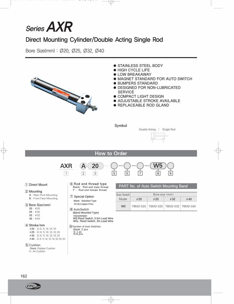
SeriesAXRDirect Mounting Cylinder/Double Acting Single Rod
Bore Size(mm) : Ø20, Ø25, Ø32, Ø40
162
●STAINLESS STEEL BODY● HIGH CYCLE LIFE● LOW BREAKAWAY●MAGNET STANDARD FOR AUTO SWITCH● BUMPERS STANDARD ● DESIGNED FOR NON-LUBRICATEDSERVICE
● COMPACT LIGHT DESIGN● ADJUSTABLE STROKE AVAILABLE● REPLACEABLE ROD GLAND
How to Order
AXR1 2 3
Bore size (mm)
ф20 ф25 ф32 ф40
W5 TBM2-040TBM2-032TBM2-025TBM2-020
Auto Switch
Model
PART No. of Auto Switch Mounting Band
20A
SymbolDouble Acting / Single Rod
143-171-AXK 2012.9.7 2:31 PM 페이지162 한국원색인쇄사
ф40 : 25, 50, 75, 100, 125, 150, 200, 250, 300
ф32 : 25, 50, 75, 100, 125, 150, 200
ф25 : 25, 50, 75, 100, 125, 150, 200
ф20 : 25, 50, 75, 100, 125, 150
4⃞ Stroke/mm
40 : ф40
32 : ф32
25 : ф25
20 : ф20
3⃞ Bore Size(mm)
B : Front Face Mounting
A : Rear Pivot Mounting
2⃞ Mounting
1⃞ Direct Mount
A : Air Cushion Blank: Rubber Cushion
� Cushion
7⃞
F : Rod end female threadBlank: Rod end male thread
6⃞ Rod end thread type
Special OptionBlank: Standard TypeXC16:Copper-Free
� AutoSwitch
�Number of Auto Switches
(Band Mounted Type)<Grommet>W5:Reed Switch, 0.5m Lead WireW5L: Reed Switch, 3m Lead Wire
Blank :2 pcsS: 1 pcN:N pcs

Series AXR
163www.TPCpage.com
www.tpcpneumatics.com
AQADQ
ACP
APM
AS
AX
AM2
AM
ALALX
AQ2ADQ2
AJAJM
ABK
ACK1
NSK
AG
NGQ
AGXGX
NP
ADR
AMR
NDM
ARD
NST
AST
ASTH
NLCD
NLCS
●Using the square rod cover, it ispreferred to install the AXR Seriesdirect mounting cylinder.
● Configuration with space savingIts overall length is shorter, and itsinstallation pitch can be madesmaller since a directly mountedstyle can be possible without usingbrackets, so that the space neededfor installation is significantlyreduced.
● Installstion with enhanced accuracyand strengthThe installation accuracy can beimproved using a centering bosssince it is the directly mountedstyle, and the strength has beenincreased.
●Two different styles in installationThe installation may be providedwith two styles and may beselected based on the purpose :Thus, the front mounting style or thebottom mounting style.
Specifications
Piston Speed
Auto Switch Specifications
Mounting and Accessories
Action Double Acting Single Rod
Fluid Air
Proof Pressure 1.5MPa (213psi)
Max. Operating Pressure 1.0MPa (140psi)
Min. Operating Pressure 0.05MPa (7psi)
Ambient and Fluid Temperature -50~158°F (-10°C~+70°C)
Lubricant None(Non-Lube)
Stroke Tolerance mm
Mounting Flush Mounting, Front Face Mounting
+1.40
Bore Size(mm) ф20 ф25 ф32 ф40
Piston Speed(mm/sec) 50~750
Allowable Kinetic Energy(kgf-cm) 2.7 4 6.5 12
Mounting Lead Wire Entry Reed Switch
Band Mounting Type Grommet W5
Accessories Standard Option
Mounting Rod End Nut Single Knuckle Joint Double Knuckle Joint
Rear Pivot Mounting
Front Face Mounting
Weight Table
Bore size(mm) ф20 ф25 ф32 ф40
Basic Rear Pivot Mounting 0.14 (0.31) 0.24 (0.51) 0.33 (0.7) 0.62 (1.36)
Weight Front Face Mounting 0.14 (0.31) 0.22 (0.48) 0.33 (0.7) 0.61 (1.34)
Additional Weight For Each 50 mm of Stroke 0.04 (0.09) 0.06 (0.13) 0.08 (0.17) 0.14 (0.28)
Calculation Example : AXRA 32-100•Basic weight … 0.32kgf •Additional weight … 0.08/50 stroke •Cylinder stroke … 100 stroke
0.32+0.08×100/50=0.48 kgf
kgf(lb)
143-171-AXK 2012.9.7 2:31 PM 페이지163 한국원색인쇄사

Construction/Parts List
Series AXR
164
No. Description Material Remarks
❶ Rod Cover Aluminum Alloy White Alumite
❷ Head Cover Aluminum Alloy White Alumite
❸ Cylinder Tube Stainless Steel
❹ Piston Aluminum Alloy Chromate
❺ Piston Rod Carbon Steel Hard Chrome Plated
❻ Bushing Sintered BR
Packing NBR Nickel Plated
❽ Retaining Ring Carbon Steel Nickel Plated
❾ Bumper A Urethane
❿ Bumper B Urethane
Retaining Ring Carbon Tool Steel
Piston Packing NBR
Piston Packing NBR
Wear Ring
Rod End Nut Carbon Steel Nickel Plated
Parts List
❺ ❽ ❻ ❶ ❸ ❾ ❹ ❿ ❷BA
A
Rubber Cushion / Air Cushion
Packing List
No.Decription
Rod Packing NBR
Material TypeBore Size
Rubber Cushion
Air Cushion
20
PDU-8LZ
PDU-8Z
25
PDU-10LZ
PDU-10Z
32
PDU-12LZ
PDU-12Z
40
PDU-14LZ
PDU-14ZB
143-171-AXK 2012.9.7 2:31 PM 페이지164 한국원색인쇄사

Rod end female thread type

Series AXR
166
①Adjustable Stroke Cylinder/Extension Adjustable Type
Bore Size MA MH MI MK ML MM MT LT
ф20 12 47 15 8 18 M8×1.25 16.5 150
ф25 17 49 20 10 18 M8×1.25 17.5 156
ф32 17 49 20 10 18 M10×1.25 17.5 158
ф40 22 60 25 12 22 M14×1.5 21.5 198
Dimensions
MountingAXR
The extended stroke of the cylinder can be adjusted
by the stopper on the head side from full stroke
(0~25) mm or (0~50) mm. Type Air Cylinder
Applicable Bore Size ф20, ф25, ф32, ф40
Action Double Acting Single Rod
Piston Speed(mm/sec) 50~750
Cushion Rubber Cushion(Standard)
Stroke Adjusting System Stopper Adjustment
Stroke Adjusting Range A:0~25 mm, B : 0~50 mm
Mounting Rear Pivot Mounting, Front Nose Mounting
Specifications
Rear Pilot Mounting
Front FaceMounting
Across Flats MA
MM
MT Stroke
MK3
ML+Adjusting Range
MH+Stroke+Adjusting RangeLT+2 Stroke+Adjusting Range(A : 25 mm, B : 50 mm)
MT Stroke
3 MK
ML+Adjusting Range
MH+Stroke+Adjusting RangeLT+2 Stroke+Adjusting Range(A : 25 mm, B : 50 mm)
Across Flats MA
MM
фMI
фMI
※ Other dimensions are the same asfor standard type.
Symbol
B
Adjustable Range
◀▶
A
WWW
Bore Size Stroke Stroke Adjusting Symbol XC8
Stroke adjusting symbol
A-Stroke Adjusting Range 0~25 mm
B-Stroke Adjusting Range 0~50 mm
●
(mm)
143-171-AXK 2012.9.7 2:31 PM 페이지166 한국원색인쇄사

Series AXR
167www.TPCpage.com
www.tpcpneumatics.com
AQADQ
ACP
APM
AS
AX
AM2
AM
ALALX
AQ2ADQ2
AJAJM
ABK
ACK1
NSK
AG
NGQ
AGXGX
NP
ADR
AMR
NDM
ARD
NST
AST
ASTH
NLCD
NLCS
②Adjustable Stroke Cylinder/Retraction Adjustable Type
MountingAXR Bore Size Stroke Stroke Adjusting Symbol XC9
Stroke Adjusting Symbol
A-Stroke Adjusting Range 0~25 mm
B-Stroke Adjusting Range 0~50 mm
●
The retracted stroke of the cylinder can be adjusted
from (0~25) mm or (0~50) mm by the adjusting bolt.
Dimensions
Rear Pilot Mounting
Front Face Mounting
NN BM
MF
MH+Adjustable Range
MH+Adjustable RangeLT+Stroke+Adjustable Range(A : 25 mm, B : 50 mm)
LT+Stroke+Adjustable Range(A:25 mm, B:50 mm)
NN BM
MF
※ Other dimensions are the same forstandard type.
Symbol
A
Adjustable Range
◀▶
B
WWWW
Type Air Cylinder
Applicable Bore Size ф20, ф25, ф32, ф40
Action Double Acting Single Rod
Piston Speed(mm/sec) 50~750
Cushion Rubber Cushion(Standard)
Stroke Adjusting System Stopper Adjustment
Stroke Adjusting Range A:0~25 mm, B : 0~50 mm
Mounting Rear Pivot Mounting, Front Nose Mounting
Specifications
Bore Size BM MF MH NN LT
ф20 M8×1.25 13 20 M20×1.5 136
ф25 M8×1.25 13 20 M26×1.5 140
ф32 M10×1.25 13 20 M26×1.5 142
ф40 M12×1.75 16 24 M30×2 178
(Unit : mm)
143-171-AXK 2012.9.7 2:31 PM 페이지167 한국원색인쇄사

SeriesAXRKNon-Rotating Piston Rod Direct Mounting type
Bore Size(mm) : Ø20, Ø25, Ø32, Ø40
168
●DIRECT MOUNT CYLINDER
● HIGH ANTI-ROTATING ACCURACY
● SPACE SAVING CYLINDER
● SQUARE ROD COVER MAKES DIRECT
MOUNTING POSSIBLE
Symbol
How to Order
AXRK1 2 3 4 75
Auto Switch Bore size(mm)
Model 20 25 32 40
W5 TBM2-020 TBM2-025 TBM2-032 TBM2-040
PART No. of Auto Switch Mounting Band
W5A 20
1⃞ TypeNon-Rotating/Direct Pivot
2⃞ MountingA : Rear Pilot mounting
B : Front side mounting
3⃞Bore Size(mm)20 : ф20
25 : ф25
32 : ф32
40 : ф40
4⃞Stroke(mm)ф20 : 25, 50, 75, 100, 125, 150
ф25 : 25, 50, 75, 100, 125, 150, 200
ф32 : 25, 50, 75, 100, 125, 150, 200
ф40 : 25, 50, 75, 100, 125, 150, 200,
250, 300
5⃞
6⃞`
Number of Auto SwitchesBlank : 2 pcs
S : 1 pc
N : N pcs
6
50
Double acting/Single rodNon-rotating Piston rod
143-171-AXK 2012.9.7 2:31 PM 페이지168 한국원색인쇄사
Rod end thread typeBlank: Rod end male threadF : Rod end female thread
Special OptionBlank: Standard TypeXC16:Copper-Free
�
�
AutoSwitch(Band Mounted Type)<Grommet>W5:Reed Switch, 0.5m Lead WireW5L: Reed Switch, 3m Lead Wire

Series AXRK
169www.TPCpage.com
www.tpcpneumatics.com
AQADQ
ACP
APM
AS
AX
AM2
AM
ALALX
AQ2ADQ2
AJAJM
ABK
ACK1
NSK
AG
NGQ
AGXGX
NP
ADR
AMR
NDM
ARD
NST
AST
ASTH
NLCD
NLCS
Specifications
Action Double acting single rod
Fluid Air
Proof Pressure 1.5MPa (213psi)
Max. Operating Pressure 1.0MPa (140psi)
Min. Operating Pressure 0.05MPa 7psi)
Ambient and Fluid Temperature -10℃~+70°C (-50~153°F)
Cushion Rubber Cushion (Standard)
Stroke Tolerance mm
Non-Rotating Accuracy ф20, ф25:±0.8°, ф32, ф40:±5°
Mounting Rear Pivot Mounting, Front Face mounting
+1.40
Specifications
Bore Size(mm) ф20 ф25 ф32 ф40
Basic Rear Pivot Mounting 0.14 0.24 0.33 0.63
Weight Front Face Mounting 0.14 0.23 0.32 0.62
Additional weight for each 50 of stroke 0.04 0.07 0.09 0.15
Weight Table kgf(lbf)
Standard Option
Rod End Nut Single Knuckel Joint Double Knuckel Joint
Rear Pivot Mounting ○○ ○○ ○○
Front Face Mounting ○○ ○○ ○○
Mounting and Accessaries
Mounting
Accessaries
Bore Size(mm) ф20 ф25 ф32 ф40
Piston Speed 50~500 mm/sec
Allowable Kinetic Energy(kgf/cm) 2.7 4 6.5 12
Piston Speed
Mounting Lead Wire Entry Reed Switch
Band Mounting Type Grommet W5
Auto Switch Specifications
●AXRK Series
● The Driect mounting of AXRK SeriesØ20, Ø25 - ±0.8。Ø32, Ø40 - ±0.5。
●Accuracy with high non-rotationf20, f25 - ±0.8。f32, f40 - ±0.5。
●Configuration featuring space savingadvantageSince a directly mounted style isadapted with no use of brackets, itsentire length is shorter, and itsinstallation pitch may be set smaller.So, the space required for installationis significanfly reduced.
●Enhanced accuracy and strength forinstallatinThe installation accuracy isenhanced using a centering bossbased on its directly mounted style,and the strength has also beenenhanced.
●Two different installation available Two different installations areavailable and selectable based ontheir purpose of use : the frontmounting method or the bottommounting method.
•Mounting Autoswitch : Existing Plug point
•Calculation Example : AXRKA 32-100
•Basic Weigut … 0.32kgf
•Additional Weight … 0.09kgf
•Cylmder stroke … 100mm
0.32+0.09×100/50=0.50kgf
Front Face Mounting
Rear Pivot Mounting
143-171-AXK 2012.9.7 2:31 PM 페이지169 한국원색인쇄사

Series AXRK
170
Front Face Mounting
Rear Pirot Mounting
Bore size A AT B B1 GA GB H H1 I L LD LH LK MM N
ф20 18 15.5 30.3 13 22 8 27 5 27 33.5 ф5.5,ф9.5C-BORE Dp6.5 15 21 M8×1.25 24
ф25 22 19.5 36.3 17 22 8 31 6 33 39 ф6.6,ф11C-BORE Dp7.5 18 25 M8×1.25 30
ф32 22 19.5 42.3 17 22 8 31 6 37.5 47 ф9,ф14C-BORE Dp10 21 30 M10×1.25 34.5
ф40 24 21 52.3 22 27 11 34 8 46.5 58.5 ф11,ф17.5C-BORE Dp12.5 26 38 M14×1.5 42.5
Bore size D K Stroke range
ф20 10 8 ~150
ф25 10 8 ~200
ф32 12 10 ~200
ф40 16 14 ~300
-0.01-0.05-0.01-0.05-0.01-0.05-0.01-0.05
(mm)
NA NB ND P LG X Y LT
29 15 20 1/8 76 39 12 103
29 15 26 1/8 76 43 12 107
29 15 26 1/8 78 43 12 109
37.521.5 32 1/4 104 49 15 138
-0-0.033-0-0.033-0-0.033-0-0.039
(mm)
-0.01-0.05-0.01-0.05-0.01-0.05-0.01-0.05
Bore size A AT B1 F FF FK GA GB H H1 I MM
ф20 18 15.5 13 30.4 M5×0.8Dp9 22 22 8 27 5 27 M8×1.25
ф25 22 19.5 17 36.4 M6×1Dp11 26 22 8 31 6 33 M8×1.25
ф32 22 19.5 17 42.4 M6×1Dp11 30 22 8 31 6 37.5 M10×1.25
ф40 24 21 22 52.4 M8×1.25Dp14 36 27 11 34 8 46.5 M14×1.5
AXRKA
2 - ØLD
X2-P Rc(PT)
LK
LH фNDh8
B
L
K
ATA NA
H1
AcrossFlats B1
GA
MM
NB
GB
□N
LG+StrokeLT+Stroke
H
3
ØD
ØI
Rod CrossSection
Bore Size Stroke
2-Rc(PT) P
ATA NA
GA GB
NB
H1
AcrossFlats B1
MM
□FKF
4-FF
LG+StrokeLT+Stroke
H 3
K
ØD
ØNDh8
□N
ØI
Rod CrossSection
AXRKB Bore Size Stroke
N NA NB ND P LG LT
24 29 15 20 1/8 76 103
30 29 15 26 1/8 76 107
34.5 29 15 26 1/8 78 109
42.5 37.5 21.5 32 1/4 104 138
-0-0.033-0-0.033-0-0.033-0-0.039
(mm)
-0.01-0.05-0.01-0.05-0.01-0.05-0.01-0.05
-0.01-0.05-0.01-0.05-0.01-0.05-0.01-0.05
D K Stroke range
10 8 ~150
10 8 ~200
12 10 ~200
16 14 ~300
143-171-AXK 2012.9.7 2:31 PM 페이지170 한국원색인쇄사
Rod end female thread type
K1 H1 MM1 LT1
20 5 10 M4x0.7 dp:8 86
25 5.5 10 M5x0.8 dp:8 86
32 5.5 10 M6x1.0 dp:12 88
40 7 10 M8x1.25 dp:13 114
Rod end female thread type
Bore size
Rod end female thread type
K1 H1 MM1 LT1
20 5 10 M4x0.7 dp:8 86
25 5.5 10 M5x0.8 dp:8 86
32 5.5 10 M6x1.0 dp:12 88
40 7 10 M8x1.25 dp:13 114
Rod end female thread type
Bore size

Series AXRK
171www.TPCpage.com
www.tpcpneumatics.com
AQADQ
ACP
APM
AS
AX
AM2
AM
ALALX
AQ2ADQ2
AJAJM
ABK
ACK1
NSK
AG
NGQ
AGXGX
NP
ADR
AMR
NDM
ARD
NST
AST
ASTH
NLCD
NLCS
Specifications W5 (With indicator lamp)
Auto Switch DimensionsAuto Switch/Internal Circuit
Auto Switch Model W5
Application Relay, Sequence Control
Load Voltage DC24V AC100V
Max. Load Current/Range of Load Current 5~40mA 5~20mA
Protection Circuit for Contact Breaker Point None
Internal Voltage Drop 2.4V or less
Indicator Lamp ON:Red light emitting diode
•Leakage Current - None•Response Time - 1.2ms•Lead Wire - Oil proof vinyl, ф3.4 0.2㎟, 2 Wire(red, black),0.5m(18in)•Impact Resistance- 30G•Insulation Resistance - 50MΩ or more under the test voltage DC500V(Between case and cable)•Withstand Voltage - AC1500V 1min (between case and cable)•Ambient Temperature - 14~140°F (-10~60℃)•Protection Structure - IEC spec IP67, Water-proof(JISCO920), oil-proof.※ If 3m lead wire is required, L is put at the end of numbers.
Example : W5L
26
4.3
9.5
11.5
8
Ø3.5
0.13(Ø3)
ℓ Operating Range(See List Below)
Most Sensitive Position
6.58
2
9
Indicator Lamp
Light emitting diodeRed
Black
Resistor
Zener Diode
Reed switch
(mm)
Operating Range(ℓ Dimension)
Bore size
ф20 ф25 ф32 ф40
7 8 8 8
Series
AX
(mm)
143-171-AXK 2012.9.7 2:31 PM 페이지171 한국원색인쇄사