Cummins ISL-G - Advanced Transportation and Logistics
81
Technical Resource Guide Cummins ISL-G Fuel Systems Level Two
-
Upload
khangminh22 -
Category
Documents
-
view
0 -
download
0
Transcript of Cummins ISL-G - Advanced Transportation and Logistics
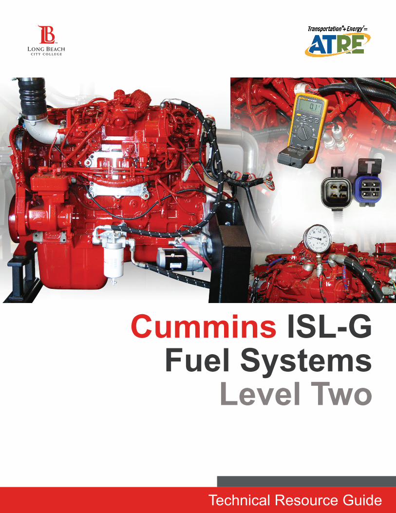
Technical Resource Guide
Cummins ISL-G Fuel Systems
Level Two
ISL-G Fuel Systems Level TwoRevision 1October 1, 2014
This material is based upon work supported by the California Energy Commission under Grant No. 12-041-008
Project Director/Editor Cal Macy
Development team of Subject Matter Experts Cal MacyBob VannixRich MenselPete Sparks
PhotographyCal MacyBob Vannix
Doing what matters for jobs and the economy with funding provided by the California Energy Commission (senate bill AB118) through a partnership with the California Community Colleges, Offi ce of Workforce Development, Advanced Transportation and Renewable Energy sector.
Created by:Long Beach City CollegeAdvanced Transportation Technology Center1305 E. Pacifi c Coast HighwayLong Beach, CA 90806562-938-3067http://www.lbcc.edu/attc/[email protected]
1ISL-G Fuel Systems Level Two
COURSE INTRODUCTION
Course Title
Cummins ISL-G Level II
Course Length 16 hours
Course DescriptionThis is an expansion of the lessons learned in the Level I and INSITE™ courses to further the tech-nician’s understanding of diagnostic procedures. Technicians are given training in the hands-on skills needed to diagnose and repair the 8.9L Cummins ISL-G CNG fuel system. The 105 PIDs for the sen-sors and actuators are covered with an emphasis on known values and real world diagnostic applications using Cummins Electronic Service Tools.
The course includes advanced analysis of:
▪ Computerized engine management system modes of operation
▪ Sensor fault analysis
▪ Actuator fault analysis
▪ Cummins Electronic Service Tools utilization in diagnosis
Technicians are encouraged to bring a USB Memory drive to obtain the Reference Materials provided upon completion of Levels I and II.
Course BenefitsStudents will learn the proper and safe methods of working with the high pressure Natural Gas fuel systems using the laptop diagnostic software specific to the Cummins controllers. This class is a must for technicians involved with diagnosis and repair of Natural Gas engine management and fuel delivery systems. The latest in information regarding known good readings, common failures, and technical service bulletins is included.
PrerequisitesLevel I and INSITE™ is our recommended sequence.
ObjectivesUpon completion of the course, students will be able to:
▪ Diagnose faults using INSITE™ to analyze:
▪ Ignition Systems
▪ Temperature Sensors
▪ Pressure Sensors
▪ Position Sensors
▪ Voltage Producing Sensors
▪ Mass Gas and Airflow Sensors
▪ Compare fault code enabling criteria
▪ Inspect components for proper operation
▪ Use INSITE™ to assess parameters and formulate diagnostic strategies
Competence
Competence will be measured by both lab demonstration, pre and post tests.
ISL-G Fuel Systems Level Two2
Course Introduction
ImportantThe materials presented in this training are informational in design and not intended to replace ANY manufacturer or fleet-established procedures. All manufacturer or fleet-established procedures, TSBs and recommendations shall be followed as they supersede this material.
Agenda ▪ Coil-on-Plug Ignition
▪ INSITE™ Diagnostics
▪ Temperature Sensors
▪ Pressure Sensors
▪ Position Sensors
▪ Voltage Producing Sensors
▪ Mass Gas and Airflow Sensors
3ISL-G Fuel Systems Level Two
Course Introduction
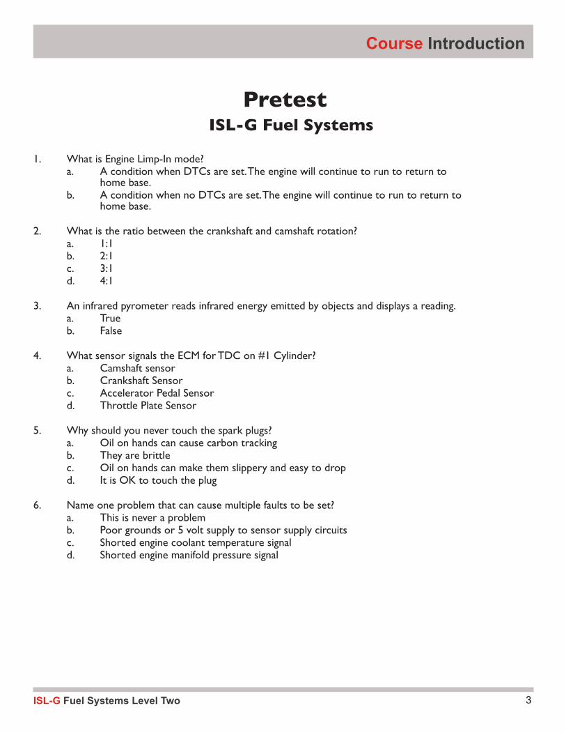
PretestISL-G Fuel Systems
1. What is Engine Limp-In mode? a. A condition when DTCs are set. The engine will continue to run to return to home base. b. A condition when no DTCs are set. The engine will continue to run to return to home base.
2. What is the ratio between the crankshaft and camshaft rotation? a. 1:1 b. 2:1 c. 3:1 d. 4:1 3. An infrared pyrometer reads infrared energy emitted by objects and displays a reading. a. True b. False
4. What sensor signals the ECM for TDC on #1 Cylinder? a. Camshaft sensor b. Crankshaft Sensor c. Accelerator Pedal Sensor d. Throttle Plate Sensor
5. Why should you never touch the spark plugs? a. Oil on hands can cause carbon tracking b. They are brittle c. Oil on hands can make them slippery and easy to drop d. It is OK to touch the plug
6. Name one problem that can cause multiple faults to be set? a. This is never a problem b. Poor grounds or 5 volt supply to sensor supply circuits c. Shorted engine coolant temperature signal d. Shorted engine manifold pressure signal

ISL-G Fuel Systems Level Two4
A. Introduction ▪ Pretest
1. Ignition Systems ▪ ISL-G Coil On Plug Ignition Systems ▪ Ignition Control Module (ICM) ▪ Inputs ▪ Outputs ▪ ICM Spark Voltage and Misfire Signals ▪ ICM Module / Harness Checks ▪ Activity 2.1
2. Diagnostics Utilizing INSITE™ ▪ Diagnosis
3. Sensors ▪ Temperature Sensors ▪ Activity 2.2 ▪ Activity 2.2.5
▪ Activity 2.3 ▪ Activity 2.4 ▪ Position Sensors ▪ Signal Producing Sensors ▪ Other Sensors and Switches ▪ Activity 2.5 ▪ Activity 2.6 ▪ Mass Gas Sensor ▪ Mass Airflow Sensor ▪ Turbocharger Compressor Inlet Humidity Sensor ▪ Coolant Level Sensor
4. Outputs, Actuators, Solenoids and Signals ▪ Outputs, Actuators, Solenoids and Signals ▪ Fuel Control Valve ▪ Wastegate Control Valve ▪ Throttle Actuator ▪ Activity 2.7
Table of Contents
5ISL-G Fuel Systems Level Two
Natural Gas Safety ConsiderationsTestReferences
ISL-G Fuel Systems Level Two6
Module One1
7ISL-G Fuel Systems Level Two
ISL-G Ignition SystemsIn Level 1, we discussed how the various system components work and how to manually test them. Level 2 will revisit these systems with an emphasis on diagnosis and repair. Technical Service Bulletins and diagnostic strategies will be discussed as they apply. This advanced level will be lab dominant utilizing INSITE™ and advanced diagnostic strategies learned in the INSITE™ class.
The capacitive discharge ignition stores electrons in a capacitor and shoots them off to ground through the primary of the coil. When the spark plug fires, the air around the spark plug is ionized and primed to ignite. As long as there is enough voltage stored in the capacitor and the ICM switch is closed, the spark plug will continue to fire until the capacitor dissipates or the circuit is broken. The additional closed switch time and stored voltage allows multiple sparks to occur as long as the switch is closed. As engine RPM increases, the possibility of multi-spark decreases as this switched on time is shortened.
Multiple spark discharge can occur at all times on the ISL-G engines. It cannot be measured or seen with a meter. It is induced by increasing the on time spark signal from the ECM.
Spark PlugsA spark plug works very hard to make the engine run with the higher ignition temperature required for natural gas. The ignition system is challenged repeatedly to ignite the natural gas under very difficult circumstances and with extreme speed. The amount of time needed for the coil to saturate and discharge has required the use of coil on plug designs. Using 600 rpm on these 4-stroke engines as an example, how many times would ONE coil fire per
Ignition Systems
second? This would be near idle speed and doubles when cruising. At freeway speed, the coils must fire 4 times faster per second. Hint: the answer relies on 4-stroke theory. Now, imagine a 6-cylinder engine with only one coil. It would have to fire 6 times for each 4-stroke cycle, working 6 times as hard and fast. We drive thousands of miles with the coil working this hard under varying load conditions that are a challenge for the plug. When a misfire is isolated to a cylinder, the plug and coils are likely suspects that should be checked out carefully. Perform standard diagnostics by checking the resistance across the coils and inspecting the coils for cracks where sparks could arc to the engine block. When in doubt, change them out as the standard visual checks will not usually reveal issues.
Ignition Control ModuleThe Ignition Control Module (ICM) contains a DC-to-DC converter and a separate coil driver for each spark plug. The
DC-to-DC converter steps up the 12-volt battery supply voltage to 300 to 400 volts. Overheating of the Coil on Plug (COP) ignition coils is minimized by an increased primary voltage and filled coils. The higher voltage allows the current requirement to be reduced, which creates less heat.
This voltage can provide a dangerous jolt on the primary side of the coil that can cause bodily injury. It discharges when shut down but the capacitors can always provide a jolt if they become energized with the key on.
Ignition Control Module

ISL-G Fuel Systems Level Two8
Module One
This voltage charges the capacitor in each of the coil drivers. It is important to never disconnect the ICM harness with engine running or damage can occur.
The ICM has misfire detection and kV per cylinder tracking. Kilovolt detection is performed by monitoring the primary current drawn as 300+ volts is supplied to the coils. This voltage is then applied across the spark plug gap. The current across the spark plug gap is then analyzed.
Misfire detection is performed through ion sensing of the positively charged electrons that have been disassociated from atoms during heat of combustion. Good combustion generates a current peak. Misfire is indicated by a low current, which is a flat response. Late combustion reduces and delays the current waveform. These ECM inputs are beneficial to diagnostics but if they malfunction, will not usually affect engine operation.
Ignition SystemThe ignition system begins with the Electronic Control Module (ECM) sending ignition information to the Ignition Control Module (ICM) as it receives engine position and engine speed signals from the camshaft and crankshaft position sensors, respectively. The ICM then sends the appropriate firing signals to the individual coils based upon the firing order in its memory. The ICM is both a processor and the ignition coil driver, but remains dependent upon the ECM for its timing commands. It only knows the firing order.
Coil On Plug IgnitionThere is one coil per cylinder that is direct fired by the ICM. The coil can induce a total voltage to the plugs of 40Kv. The average spark is
approximately 15 – 20Kv, depending upon engine load and conditions. This is the required voltage which leaves a reserve voltage to accommodate changing engine conditions and component deterioration without a misfire.
ISL-G Ignition SystemThe ECM and ICM are located on the same side of the engine as the fuel control housing and air intake manifold. The ECM and ICM on the ISL-G is similar to ECMs and ICMs of previous Cummins Westport engines but they are not interchangeable. Failure to use an ICM with the correct part number for the engine will result in misfire faults and other intermittent behavior. Once load and speed are determined, the ECM then commands the ICM to fire its capacitors through the grounded coils. This is different from most conventional systems as they ground the coils through the computer to charge them and break this ground to fire the plug.
The primary resistance on the Coil on Plug (COP) is measured between pins “A” and “B”. This measurement should be approximately 3 ohms.
The secondary winding measurement for the COP resistance is taken between the spark plug connection and either pins B or C of the 4-pin connector.
Coil On Plug (COP) Ignition

9ISL-G Fuel Systems Level Two
Ignition Systems
Ignition Inputs to ECMThe primary inputs to the Engine Control Module (ECM) for spark timing are the Engine Camshaft Position (ECP) Sensor and the Manifold Absolute Pressure (MAP) Sensor. The MAP is the load sensing element that the ECM uses to adjust the base timing and as an input for air mass calculation. This is equivalent to the vacuum advance systems in 1980 vintage vehicles. Because of the
throttle plate, the manifold pressure before and after the throttle plate may be different due to turbocharger boost pressure. Intake manifold vacuum leaks can reduce the reading and cause extra fueling to occur.
The Engine Camshaft Speed/Position Sensor measures the position of the camshaft by the use of a Hall-effects sensor and seven cast protrusions on the camshaft gear. Whenever the camshaft gear protrusions pass the Engine Camshaft Speed/Position Sensor, a signal is produced. These sensors produce a digital on-off signal that is used to determine engine position (#1 cylinder) and speed. The engine will not run without a tachometer signal but may run without a reference by the camshaft sensor. A Digital Storage Oscilloscope is required to see these signals.
Camshaft GearThe Camshaft gear has protrusions that when passed across the camshaft Hall-Effect sensor, sends a signal to the ICM when to start the firing order. In turn, the crankshaft sensor receives signals from protrusions
on the crankshaft for when to send commands to the respective coils to fire the spark plugs for each cylinder.
The ECM interprets the 7th signal input as the beginning of a new cycle in the firing order and generates a timing reference signal for the ICM to restart the sequence. Any interruption of this signal can lead to the ECM starting over on the firing order, causing drivability problems. Radio Frequency Interference (RFI) and Electromagnetic Field Interference (EFI) can cause havoc with the signal in the ECM so special protection is used. The protrusions can be damaged by prying on or dropping them during repair operations so care must be taken.
Camshaft/Speed SensorInterruptions in the frequency of the signal would cause misfires and tachometer problems. If this sensor fails, you can have a no-start condition and the lock-off solenoid may not open. These sensors can fail intermittently under certain conditions caused by connector resistance or winding shorts or opens that will usually show up with the heat of operation.
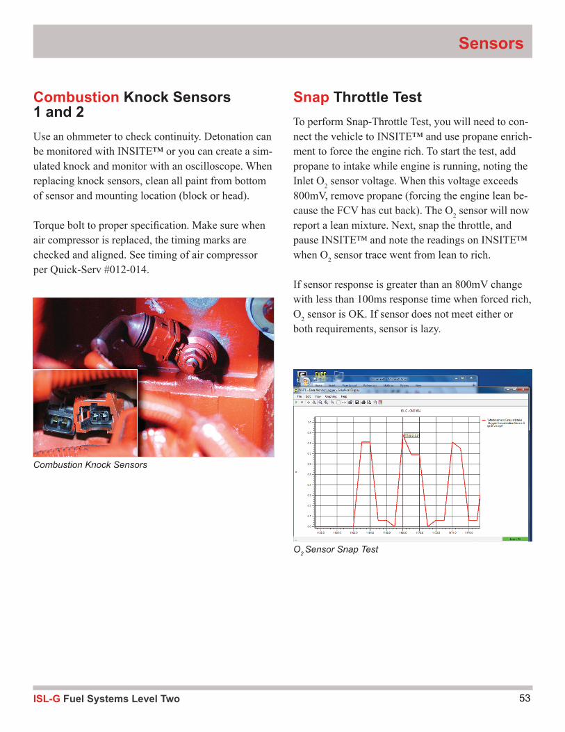
Knock SensorsKnock sensors sense engine detonation that occurs under load. Knock sensor 1 monitors the front three cylinders and knock sensor 2 monitors the three rear cylinders. There are three levels of knock.
Light knock is the lowest of the three thresholds. It is designed to guard against damage from light to mild knock. The ECM will retard ignition timing and slightly de-rate the throttle. A yellow lamp will illuminate to warn the operator that light knock has
Manifold Absolute Pressure
CAM Sensor
ISL-G Fuel Systems Level Two10
been detected. Heavy knock warning will be activated if the light knock protection fails to eliminate the problem or a knock is detected that crosses the heavy knock threshold. The ECM will trigger a severe throttle de-rate and illuminate the red warning lamp. A cold knock threshold provides severe protection while the engine is reaching a stable operating temperature. Time at this threshold is a function of coolant temperature at startup. The cold knock threshold is disabled when the engine temperature reaches 160 °F (71°C).
When testing sensors, use an ohmmeter and check for continuity. A frequency counting DVOM can also be used with the engine running providing a load can be created.
Detonation percentages can also be monitored with INSITE™ as it is hard to get it to react during an idle or stall test.
Paint on the bottom of the sensor or its mounting location (block or head) can cause a dampening of the signal. If Cummins paint is interfering, clean the areas and torque the bolt to proper spec.
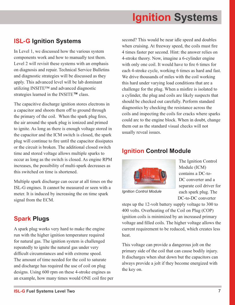
ICM OutputsExternal testing of the coil should be done carefully. The coil is oil filled, so it must be mounted 45° to vertical if fired. If this is not done, coils will prematurely fail. Shorting or disconnecting coils to do a cylinder balance test is not recommended, as the resulting misfire can damage the expensive catalyst substrate. Swapping of coils or plugs from one cylinder to another can be time consuming but will confirm the misfire culprit if done. Swapping of connectors on the coils will cause misfires on the incorrectly driven coil.
When checking plugs, always check for cracks and wear to the electrodes. Natural gas is a dry, low-carbon gas that will not usually leave residue or wetness if fouled. It is difficult to determine a rich running engine by plug inspection alone. Coils can be easily damaged when removing and reinstalling. Install all coils and their brackets loosely before torqueing them down.
Multiple Spark DischargeThis engine incorporates multiple spark discharge at all times to fire the spark plug. The capacitor keeps discharging until the available voltage drops enough below required voltage that the ionization trail is broken and the plug stops discharging. This is similar to Mallory ignition from the 1970s. The rapid firing of the coil helps to overcome high ignition temperature requirements, increasing dependability and performance.
Module One
Coil and Spark Plug

11ISL-G Fuel Systems Level Two
ICM Spark Voltage and Misfire SignalsCoils can be checked for output using several commercially available hand-held testers or INSITE™. Disabling coils while the engine is running during a cylinder balance test can damage the catalyst so this ECM test is not available.
The ICM sends signals for spark plug voltages and misfires back to the ECM that can be monitored in INSITE™. This is for diagnostic purposes only.
False reading for cylinder Kv voltages are possible from time to time with no misfires - this is caused by the diagnostic side of the ICM. This has no effect on carrying out the basic ignition control as it is for diagnostic purposes only.
Coil Over Plug IgnitionA new design plug incorporating 3 electrodes is being utilized to help prevent misfires. The spark plugs perform under extreme dry conditions that tax their abilities when they fire. Three electrodes ensure that the plug will be able to find a ground path under all operating loads. The proper plug should always be used without substitution for best performance and comes with a new pre-greased boot.
The plugs in the ISL-G are triple ground-electrode plugs which are different than the Cummins 12L. Always use the Cummins replacement procedures when changing spark plugs to avoid carbon tracking and premature spark plug failure. These procedures include the use of a 5/8 deep well magnetic socket to install plugs without a rubber insert. In addition, do not touch the spark plugs as fingerprints cause carbon tracking on the plug. If touched, clean plugs
with denatured alcohol. Plugs should be torqued to the proper manufacturer specification (28-32 ft lbs) to dissipate heat which is critical to plug life.
It is imperative that the maintenance intervals are kept in accordance to the ISL-G, per Cummins. These levels are based upon an average speed of 15mph.
It is difficult to test the ignition system with an ignition scope due to the multiple coils. Firing of coils without proper grounding can damage a coil. INSITE™ shows ignition spark voltages and misfires but won’t test a coil to prevent catalyst damage. In order to check ignition coil operation, a coil tester is recommended. The Cummins ignition coil tester part number is #3164486.
Ignition Systems
3-Electrode Plug Design
Coil Over Plug (COP) Ignition
ISL-G Fuel Systems Level Two12
Module One
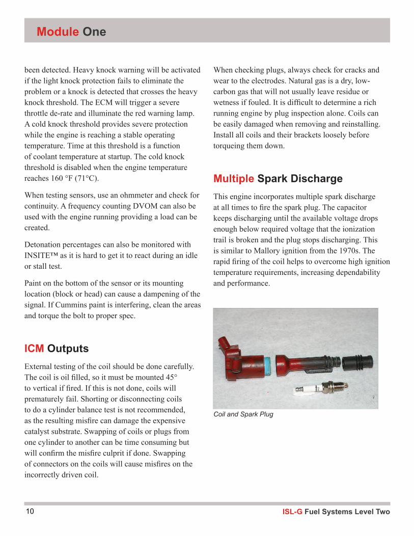
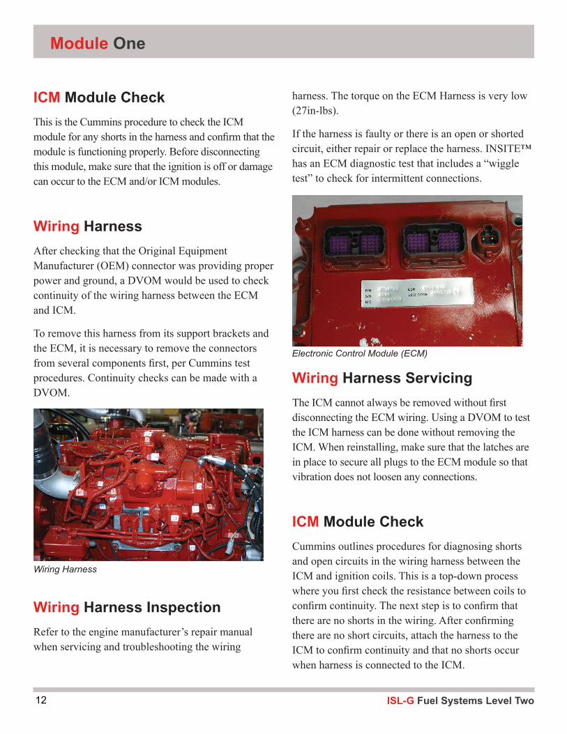
ICM Module CheckThis is the Cummins procedure to check the ICM module for any shorts in the harness and confirm that the module is functioning properly. Before disconnecting this module, make sure that the ignition is off or damage can occur to the ECM and/or ICM modules.
Wiring HarnessAfter checking that the Original Equipment Manufacturer (OEM) connector was providing proper power and ground, a DVOM would be used to check continuity of the wiring harness between the ECM and ICM.
To remove this harness from its support brackets and the ECM, it is necessary to remove the connectors from several components first, per Cummins test procedures. Continuity checks can be made with a DVOM.
Wiring Harness InspectionRefer to the engine manufacturer’s repair manual when servicing and troubleshooting the wiring
harness. The torque on the ECM Harness is very low (27in-lbs).
If the harness is faulty or there is an open or shorted circuit, either repair or replace the harness. INSITE™ has an ECM diagnostic test that includes a “wiggle test” to check for intermittent connections.
Wiring Harness ServicingThe ICM cannot always be removed without first disconnecting the ECM wiring. Using a DVOM to test the ICM harness can be done without removing the ICM. When reinstalling, make sure that the latches are in place to secure all plugs to the ECM module so that vibration does not loosen any connections.
ICM Module CheckCummins outlines procedures for diagnosing shorts and open circuits in the wiring harness between the ICM and ignition coils. This is a top-down process where you first check the resistance between coils to confirm continuity. The next step is to confirm that there are no shorts in the wiring. After confirming there are no short circuits, attach the harness to the ICM to confirm continuity and that no shorts occur when harness is connected to the ICM.
Wiring Harness
Electronic Control Module (ECM)
13ISL-G Fuel Systems Level Two
Ignition Systems
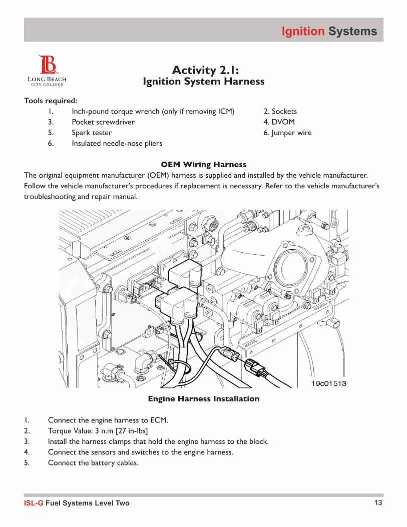
Tools required: 1. Inch-pound torque wrench (only if removing ICM) 2. Sockets 3. Pocket screwdriver 4. DVOM 5. Spark tester 6. Jumper wire 6. Insulated needle-nose pliers
OEM Wiring HarnessThe original equipment manufacturer (OEM) harness is supplied and installed by the vehicle manufacturer. Follow the vehicle manufacturer’s procedures if replacement is necessary. Refer to the vehicle manufacturer’s troubleshooting and repair manual.
Engine Harness Installation
1. Connect the engine harness to ECM.2. Torque Value: 3 n.m [27 in-lbs]3. Install the harness clamps that hold the engine harness to the block. 4. Connect the sensors and switches to the engine harness.5. Connect the battery cables.
Activity 2.1: Ignition System Harness
ISL-G Fuel Systems Level Two14
Module One
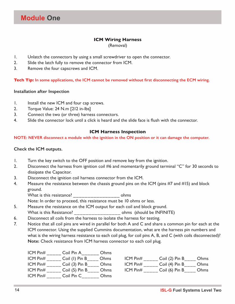
ICM Wiring Harness(Removal)
1. Unlatch the connectors by using a small screwdriver to open the connector.2. Slide the latch fully to remove the connector from ICM.3. Remove the four capscrews and ICM.
Tech Tip: In some applications, the ICM cannot be removed without first disconnecting the ECM wiring.
Installation after Inspection
1. Install the new ICM and four cap screws.2. Torque Value: 24 N.m [212 in-lbs]3. Connect the two (or three) harness connectors.4. Slidetheconnectorlockuntilaclickisheardandtheslidefaceisflushwiththeconnector.
ICM Harness InspectionNOTE: NEVER disconnect a module with the ignition in the ON position or it can damage the computer. Check the ICM outputs.
1. Turn the key switch to the OFF position and remove key from the ignition. 2. Disconnect the harness from ignition coil #6 and momentarily ground terminal “C” for 30 seconds to dissipate the Capacitor.3. Disconnect the ignition coil harness connector from the ICM. 4. Measure the resistance between the chassis ground pins on the ICM (pins #7 and #15) and block ground. What is this resistance? ________________ ohms Note: In order to proceed, this resistance must be 10 ohms or less. 5. Measure the resistance on the ICM output for each coil and block ground. What is this Resistance? ________________ ohms (should be INFINITE)6. Disconnect all coils from the harness to isolate the harness for testing.7. Notice that all coil pins are wired in parallel for both A and C and share a common pin for each at the ICM connector. Using the supplied Cummins documentation, what are the harness pin numbers and what is the wiring harness resistance to each coil plug, for coil pins A, B, and C (with coils disconnected)? Note: Check resistance from ICM harness connector to each coil plug.
ICM Pin# _____ Coil Pin A______ Ohms ICM Pin# _____ Coil (1) Pin B____ Ohms ICM Pin# _____ Coil (2) Pin B____ Ohms ICM Pin# _____ Coil (3) Pin B____ Ohms ICM Pin# _____ Coil (4) Pin B____ Ohms ICM Pin# _____ Coil (5) Pin B____ Ohms ICM Pin# _____ Coil (6) Pin B____ Ohms ICM Pin# _____ Coil Pin C______ Ohms
15ISL-G Fuel Systems Level Two
Ignition Systems
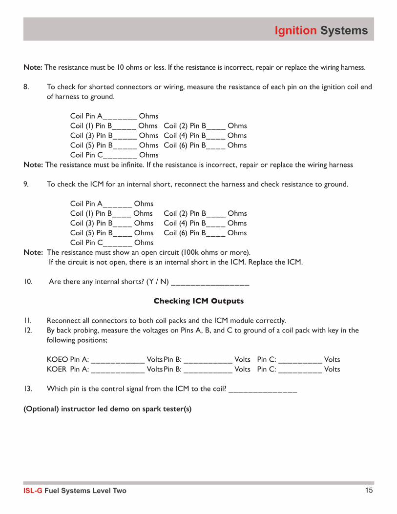
Note: The resistance must be 10 ohms or less. If the resistance is incorrect, repair or replace the wiring harness.
8. To check for shorted connectors or wiring, measure the resistance of each pin on the ignition coil end of harness to ground.
Coil Pin A_______ Ohms Coil (1) Pin B_____ Ohms Coil (2) Pin B____ Ohms Coil (3) Pin B_____ Ohms Coil (4) Pin B____ Ohms Coil (5) Pin B_____ Ohms Coil (6) Pin B____ Ohms Coil Pin C_______ OhmsNote:Theresistancemustbeinfinite.Iftheresistanceisincorrect,repairorreplacethewiringharness
9. To check the ICM for an internal short, reconnect the harness and check resistance to ground.
Coil Pin A______ Ohms Coil (1) Pin B____ Ohms Coil (2) Pin B____ Ohms Coil (3) Pin B____ Ohms Coil (4) Pin B____ Ohms Coil (5) Pin B____ Ohms Coil (6) Pin B____ Ohms Coil Pin C______ OhmsNote: The resistance must show an open circuit (100k ohms or more). If the circuit is not open, there is an internal short in the ICM. Replace the ICM.
10. Are there any internal shorts? (Y / N) ________________
Checking ICM Outputs
11. Reconnect all connectors to both coil packs and the ICM module correctly.12. By back probing, measure the voltages on Pins A, B, and C to ground of a coil pack with key in the following positions;
KOEO Pin A: ___________ Volts Pin B: __________ Volts Pin C: _________ Volts KOER Pin A: ___________ Volts Pin B: __________ Volts Pin C: _________ Volts
13. Which pin is the control signal from the ICM to the coil? ______________
(Optional) instructor led demo on spark tester(s)

ISL-G Fuel Systems Level Two16
Module Two2
17ISL-G Fuel Systems Level Two
Diagnostics Utilizing INSITE™™
DiagnosisWhen engine faults occur due to failed sensor/components, the ECM will attempt to keep the engine running with Engine Limp-in Mode to get the vehicle back to home base. In this mode, the ECM will either assign default values or substitute another sensor’s values to start or keep the engine running. The method used by the ECM to attempt limp-in will depend on which sensor is failing. When a sensor fails, the engine protection is lost through that sensor as the ECM no longer has reliable data from this failed sensor.
The ECM uses the 90/10 concept to determine whether or not a sensor is providing good data to the ECM. This concept states that if the signal voltage is within 10% - 90% of the reference voltage (5V), the ECM believes that the data is correct. If that data is less than 10% or greater than 90% of the reference voltage, the ECM considers the data to be unacceptable and out of range, which sets a fault. The 90/10 is a concept to understand what determines if a sensor is providing accurate data and may fluctuate in actual minimum and maximum percentages, depending upon the system component design.
There are three de-rate methods available that provide engine protection when faults are set. They are torque, RPM, and/or shutdown methods. Depending on the fault, INSITE™ may incorporate multiple methods sequentially if the fault continues to provide engine protection. An example of this would be an engine fault for low oil pressure.
The de-rate thresholds can be found in INSITE™ under the Advanced ECM Data section. They include time-delay effects on the engine and light functions for each de-rate method.
There are 6 different voltage supplies and each has its assignments. Sources from 5-15v are assigned to these supply circuits with the Gas Mass Meter requiring 15V to operate. If multiple faults are noted in INSITE™, it may be due to sensors powered by the same Sensor Voltage Supply Line from the ECM. If this is the case, the problem may be due to wiring harness problems for the group of sensors, either on the common voltage supply side or through the common return.

ISL-G Fuel Systems Level Two18
Module Three3
19ISL-G Fuel Systems Level Two
Sensors
Sensor TypesThe types of sensors that are on this engine are:
▪ Temperature
▪ Pressure
▪ Position
▪ Voltage Producing
▪ Mass Gas
▪ Mass Airflow
▪ Switches and Miscellaneous Signals
We will review sensors that are on this engine and cover new information.
Temperature SensorsThere are 8 temperature sensors to help maintain a Stoichiometric air/fuel ratio:
▪ Engine Coolant Temperature Sensor
▪ Intake Manifold Temperature Sensor
▪ Compressor Inlet Humidity/Temperature Sensor
▪ Turbine Inlet Temperature Sensor
▪ EGR Temperature Sensor
▪ Fuel Outlet Pressure/Temperature Sensor
▪ Catalyst Temperature Sensor
▪ Mass Airflow Temperature Sensor
Temperature sensors of either the pyrometer or thermistor type are tested similarly.
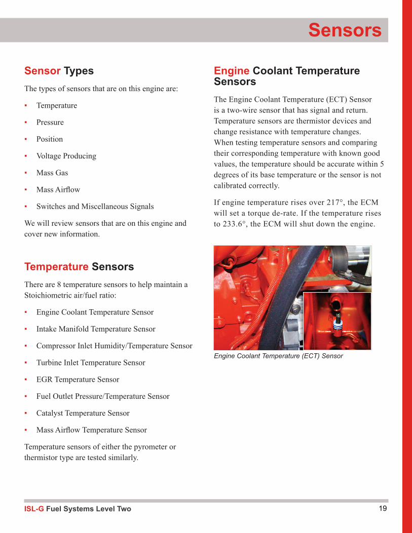
Engine Coolant Temperature SensorsThe Engine Coolant Temperature (ECT) Sensor is a two-wire sensor that has signal and return. Temperature sensors are thermistor devices and change resistance with temperature changes. When testing temperature sensors and comparing their corresponding temperature with known good values, the temperature should be accurate within 5 degrees of its base temperature or the sensor is not calibrated correctly.
If engine temperature rises over 217°, the ECM will set a torque de-rate. If the temperature rises to 233.6°, the ECM will shut down the engine.
Engine Coolant Temperature (ECT) Sensor
ISL-G Fuel Systems Level Two20
Module Three
Turbocharger Compressor Inlet Humidity/Temperature SensorThe temperature portion of the Compressor Inlet Humidity/Temperature Sensor is a thermistor subject to voltage drops with intake air temperature changes. The temperature of the charged air varies the amount of oxygen charge being introduced into the engine, which changes the ratio. Driveability issues can occur in hot environments with these variations so the ECM will make slight adjustments to lean out the
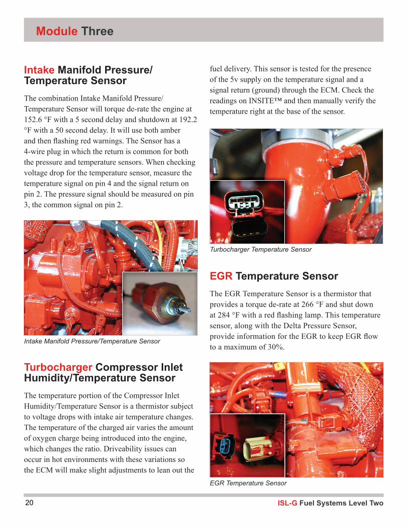
Intake Manifold Pressure/Temperature SensorThe combination Intake Manifold Pressure/Temperature Sensor will torque de-rate the engine at 152.6 °F with a 5 second delay and shutdown at 192.2 °F with a 50 second delay. It will use both amber and then flashing red warnings. The Sensor has a 4-wire plug in which the return is common for both the pressure and temperature sensors. When checking voltage drop for the temperature sensor, measure the temperature signal on pin 4 and the signal return on pin 2. The pressure signal should be measured on pin 3, the common signal on pin 2.
Intake Manifold Pressure/Temperature Sensor
EGR Temperature Sensor
fuel delivery. This sensor is tested for the presence of the 5v supply on the temperature signal and a signal return (ground) through the ECM. Check the readings on INSITE™ and then manually verify the temperature right at the base of the sensor.
EGR Temperature SensorThe EGR Temperature Sensor is a thermistor that provides a torque de-rate at 266 °F and shut down at 284 °F with a red flashing lamp. This temperature sensor, along with the Delta Pressure Sensor, provide information for the EGR to keep EGR flow to a maximum of 30%.
Turbocharger Temperature Sensor

21ISL-G Fuel Systems Level Two
Sensors
If the EGR cooler is replaced, make sure that the cooling system is purged of air pockets. Refer to TSB 110056 for the procedures on refilling coolant and bleeding system. When refilling cooling system always fill until coolant comes out at bleeder fitting on top of the EGR cooler and/or hose to recovery tank at top of radiator. Run engine with radiator cap off and heater turned on for 10-20 minutes, depending on vehicle, to make sure cooling system is free or air pockets.
Fuel Outlet Pressure/Temperature SensorThe Fuel Outlet Pressure/Temp Sensor is before the Fuel Control Valve and just after the secondary regulator. This sensor has a common return with other sensors and can set multiple fault if the return has problems.
Always reset Fuel tables in INSITE™ whenever replacing any fuel system component.
Catalyst Temperature SensorThe Catalyst temperature is a pyrometer. The ECM will provide a torque de-rate if the catalyst temperature exceeds 1247° and an RPM de-rate if the temperature exceeds 1337°.
Fuel Outlet Pressure/Temperature Sensor
Catalyst Temperature Sensor
ISL-G Fuel Systems Level Two22
Module Three
Engine Coolant Temperature (ECT) Sensor
Tools and equipment:
1. Classroom handouts 2. INSITE™
Step 1:
Using your classroom materials, locate the ECT wiring diagram.
ECT – Temperature signal wire terminal _________
Sensor return wire terminal _________
Step 2:
Connect INSITE™.
CLEAR all inactive fault codes.
Start engine and View the Temperature Sensor parameters.
A. Record the Parameters with the sensor harness connected.
Temp _______ Volts ________ Are these default values? Yes/No
B. Record the Parameters with the sensor harness disconnected.
Temp _______ Volts ________ Are these default values? Yes/No
View Fault codes and record the Fault Code information
MIL light status _______ Fault Code _______ Lamp color ________ PID/SID _______
C. Record the Parameter with the sensor signal/return shorted.
Temp _______ Volts ________ Are these default values? Yes/No
View Fault codes and record the Fault Code information.
MIL light status ______ Fault Code _______ Lamp color _______ PID/SID _______
STOP DO NOT GO ANY FURTHER
Activity 2.2: Cummins ISL-G Temperature Sensor

23ISL-G Fuel Systems Level Two
Sensors
Step 3
Go to the classroom and look up the fault codes for steps B and C on the classroom computers using INSITE™. Answer the following questions for B and C below.
Referring to B. What conditions must be present to run the diagnostics and set this code?
How do you validate the repair?
What conditions must be present for the ECM to turn off the check engine/MIL light?
AMBER
RED
When does the ECM reset the inactive fault codes?
Is there any engine protection or de-rating available?
Referring to C. What conditions must be present to run the diagnostics and set this code?
How do you validate the repair?
What conditions must be present for the ECM to turn off the check engine/MIL light?
AMBER
RED
When does the ECM reset the inactive fault codes?
Is there any engine protection or de-rating available?
Are the fault codes numbered sequentially?
Are there other fault codes for this sensor?
Is so, what fault codes?
ISL-G Fuel Systems Level Two24
EGR Temperature Sensor
Tools and equipment:
1. Classroom handouts 2. INSITE™
Step 1:
Using your classroom materials locate the EGRT wiring diagram.
EGRT – Temperature signal wire terminal _________
Sensor return wire terminal _________
Step 2:
Connect INSITE™.
CLEAR all inactive fault codes
Start engine and View the Temperature Sensor parameters
A. Record the Parameters with the sensor harness connected.
Temp _______ Volts ________ Are these default values? Yes/No
B. Record the Parameters with the sensor harness disconnected.
Temp _______ Volts ________ Are these default values? Yes/No
View Fault codes and record the Fault Code information.
MIL light status _______ Fault Code_______ Lamp color _______ PID/SID ______
C. Record the Parameter with the sensor signal/return shorted.
Temp _______ Volts ________ Are these default values? Yes/No
View fault codes and record the fault code information.
MIL light status _______ Fault Code ______ Lamp color _________ PID/SID ________
STOP DO NOT GO ANY FURTHER
Module Three

25ISL-G Fuel Systems Level Two
Sensors
Step 3
Go to the classroom and look up the fault codes for steps B and C on the classroom computers using INSITE™ Answer the following questions for B and C below.
Referring to B. What conditions must be present to run the diagnostics and set this code?
How do you validate the repair?
What conditions must be present for the ECM to turn off the check engine/MIL light?
AMBER
RED
When does the ECM reset the inactive fault codes?
Is there any engine protection or de-rating available?
Referring to C. What conditions must be present to run the diagnostics and set this code?
How do you validate the repair?
What conditions must be present for the ECM to turn off the check engine/MIL light?
AMBER
RED
When does the ECM reset the inactive fault codes?
Is there any engine protection or de-rating available?
Are the fault codes numbered sequentially?
Are there other fault codes for this sensor?
Is so, what fault codes?
ISL-G Fuel Systems Level Two26
Catalyst Outlet Temperature Sensor
Tools and equipment:
1. Classroom handouts 2. INSITE™
Step 1:
Using your classroom materials, locate the CAT TEMP wiring diagram.
CAT TEMP – 5-volt supply wire terminal _________
Sensor return wire terminal _________
Step 2:
Connect INSITE™
CLEAR all inactive fault codes
Start engine and View the Temperature Sensor parameters.
A. Record the Parameters with the sensor harness connected.
Temp _______ Volts ________ Are these default values? Yes/No
B. Record the Parameters with the sensor harness disconnected.
Temp _______ Volts ________ Are these default values? Yes/No
View Fault codes and record the Fault Code information.
MIL light status _______ Fault Code_______ Lamp color _______ PID/SID ______
C. Record the Parameter with the sensor signal/return shorted.
Temp _______ Volts ________ Are these default values? Yes/No
View Fault codes and record the fault code information.
MIL light status _______ Fault Code ______ Lamp color _________ PID/SID ________
STOP DO NOT GO ANY FURTHER
Module Three

27ISL-G Fuel Systems Level Two
Sensors
Step 3
Go to the classroom and look up the fault codes for steps B and C on the classroom computers using INSITE™. Answer the following questions for B and C below.
Referring to B. What conditions must be present to run the diagnostics and set this code?
How do you validate the repair?
What conditions must be present for the ECM to turn off the check engine/MIL light?
AMBER
RED
When does the ECM reset the inactive fault codes?
Is there any engine protection or de-rating available?
Referring to C. What conditions must be present to run the diagnostics and set this code?
How do you validate the repair?
What conditions must be present for the ECM to turn off the check engine/MIL light?
AMBER
RED
When does the ECM reset the inactive fault codes?
Is there any engine protection or de-rating available?
Are the fault codes numbered sequentially?
Are there other fault codes for this sensor?
Is so, what fault codes?
ISL-G Fuel Systems Level Two28
Fuel Temperature/Outlet Pressure Sensor
Tools and equipment:
1. Classroom handouts 2. INSITE™
Step 1:
Using your classroom materials locate the CAT TEMP wiring diagram. FOP/T – 5-volt supply wire terminal _________ Pressure Signal terminal__________ Signal return wire terminal__________ Temperature Signal terminal__________
Step 2:
Connect INSITE™.
CLEAR all inactive fault codes.
Start engine and View the Temperature Sensor parameters.
A. Record the Parameters with the sensor harness connected.
Temp _______ Volts ________ Are these default values? Yes/No
B. Record the Parameters with the sensor harness disconnected.
Temp _______ Volts ________ Are these default values? Yes/No
View Fault codes and record the Fault Code information.
MIL light status _______ Fault Code_______ Lamp color _______ PID/SID ______
C. Record the Parameter with the sensor signal/return shorted.
Temp _______ Volts ________ Are these default values? Yes/No
View Fault codes and record the fault code information.
MIL light status _______ Fault Code ______ Lamp color _________ PID/SID ________
STOP DO NOT GO ANY FURTHER
Module Three

29ISL-G Fuel Systems Level Two
Sensors
Step 3
Go to the classroom and look up the fault codes for steps B and C on the classroom computers using INSITE™. Answer the following questions for B and C below.
Referring to B. What conditions must be present to run the diagnostics and set this code?
How do you validate the repair?
What conditions must be present for the ECM to turn off the check engine/MIL light?
AMBER
RED
When does the ECM reset the inactive fault codes?
Is there any engine protection or de-rating available?
Referring to C. What conditions must be present to run the diagnostics and set this code?
How do you validate the repair?
What conditions must be present for the ECM to turn off the check engine/MIL light?
AMBER
RED
When does the ECM reset the inactive fault codes?
Is there any engine protection or de-rating available?
Are the fault codes numbered sequentially?
Are there other fault codes for this sensor?
Is so, what fault codes?
ISL-G Fuel Systems Level Two30
Turbine Intake Temperature Sensor
Tools and equipment:
1. Classroom handouts 2. INSITE™
Step 1:
Using your classroom materials locate the Turbine Inlet Temp Senor wiring diagram
Turbine Inlet Temp sensor – 5-volt supply wire terminal _________
Sensor return wire terminal _________
Step 2:
Connect INSITE™.
CLEAR all inactive fault codes.
Start engine and View the Temperature Sensor parameters.
A. Record the Parameters with the sensor harness connected.
Temp _______ Volts ________ Are these default values? Yes/No
B. Record the Parameters with the sensor harness disconnected.
Temp _______ Volts ________ Are these default values? Yes/No
View Fault codes and record the Fault Code information.
MIL light status _______ Fault Code_______ Lamp color _______ PID/SID ______
C. Record the Parameter with the sensor signal/return shorted.
Temp _______ Volts ________ Are these default values? Yes/No
View Fault codes and record the Fault Code information.
MIL light status _______ Fault Code ______ Lamp color _________ PID/SID ________
STOP DO NOT GO ANY FURTHER
Module Three

31ISL-G Fuel Systems Level Two
Sensors
Step 3
Go to the classroom and look up the fault codes for steps B and C on the classroom computers using INSITE™. Answer the following questions for B and C below.
Referring to B. What conditions must be present to run the diagnostics and set this code?
How do you validate the repair?
What conditions must be present for the ECM to turn off the check engine/MIL light?
AMBER
RED
When does the ECM reset the inactive fault codes?
Is there any engine protection or de-rating available?
Referring to C. What conditions must be present to run the diagnostics and set this code?
How do you validate the repair?
What conditions must be present for the ECM to turn off the check engine/MIL light?
AMBER
RED
When does the ECM reset the inactive fault codes?
Is there any engine protection or de-rating available?
Are the fault codes numbered sequentially?
Are there other fault codes for this sensor?
Is so, what fault codes?
ISL-G Fuel Systems Level Two32
Intake Manifold (Air) Temperature Sensor
Tools and equipment:
1. Classroom handouts 2. INSITE™
Step 1:
Locate the IMT sensor IMT –5-volt supply wire terminal _________ Sensor signal wire terminal _________ Sensor return wire terminal _________
Step 2:
Connect INSITE™.
CLEAR all inactive fault codes.
Start engine and View the Temperature Sensor parameters.
A. Record the Parameters with the sensor harness connected.
Temp _______ Volts ________ Are these default values? Yes/No
B. Record the Parameters with the sensor harness disconnected.
Temp _______ Volts ________ Are these default values? Yes/No
View Fault codes and record the Fault Code information.
MIL light status _______ Fault Code_______ Lamp color _______ PID/SID ______
C. Record the Parameter with the sensor signal/return shorted.
Temp _______ Volts ________ Are these default values? Yes/No
View Fault codes and record the fault code information.
MIL light status _______ Fault Code ______ Lamp color _________ PID/SID _________
STOP DO NOT GO ANY FURTHER
Module Three

33ISL-G Fuel Systems Level Two
Sensors
Step 3
Go to the classroom and look up the fault codes for steps B and C on the classroom computers using INSITE™. Answer the following questions for B and C below.
Referring to B. What conditions must be present to run the diagnostics and set this code?
How do you validate the repair?
What conditions must be present for the ECM to turn off the check engine/MIL light?
AMBER
RED
When does the ECM reset the inactive fault codes?
Is there any engine protection or de-rating available?
Referring to C. What conditions must be present to run the diagnostics and set this code?
How do you validate the repair?
What conditions must be present for the ECM to turn off the check engine/MIL light?
AMBER
RED
When does the ECM reset the inactive fault codes?
Is there any engine protection or de-rating available?
Are the fault codes numbered sequentially?
Are there other fault codes for this sensor?
Is so, what fault codes?
ISL-G Fuel Systems Level Two34
Compressor Intake Temperature and Humidity Sensor
Tools and equipment:
1. Classroom handouts 2. INSITE™
Step 1:Locate the Temperature side of the HAT sensor Temp Sensor – Wire Terminal _________ Function__________ Wire Terminal _________Function__________
Step 2:
Connect INSITE™.
CLEAR all inactive fault codes
Start engine and View the Temperature Sensor parameters.
A. Record the Parameters with the sensor harness connected.
Temp _______ Volts ________ Are these default values? Yes/No
B. Record the Parameters with the sensor harness disconnected.
Temp _______ Volts ________ Are these default values? Yes/No
View Fault codes and record the Fault Code information.
MIL light status _______ Fault Code_______ Lamp color _______ PID/SID ______
C. Record the Parameter with the sensor signal/return shorted.
Temp _______ Volts ________ Are these default values? Yes/No
View fault codes and record the fault code information.
MIL light status _______ Fault Code ______ Lamp color _________ PID/SID _________
STOP DO NOT GO ANY FURTHER
Module Three
35ISL-G Fuel Systems Level Two
Sensors
Step 3
Go to the classroom and look up the fault codes for steps B and C on the classroom computers using INSITE™. Answer the following questions for B and C below.
Referring to B. What conditions must be present to run the diagnostics and set this code?
How do you validate the repair?
What conditions must be present for the ECM to turn off the check engine/MIL light?
AMBER
RED
When does the ECM reset the inactive fault codes?
Is there any engine protection or de-rating available?
Referring to C. What conditions must be present to run the diagnostics and set this code?
How do you validate the repair?
What conditions must be present for the ECM to turn off the check engine/MIL light?
AMBER
RED
When does the ECM reset the inactive fault codes?
Is there any engine protection or de-rating available?
Are the fault codes numbered sequentially?
Are there other fault codes for this sensor?
Is so, what fault codes?
ISL-G Fuel Systems Level Two36
Module Three
Activity 2.2.5:Cummins ISL-G Pressure Sensors
Tools and equipment:
1. Classroom handouts 2. INSITE™
Step 1:
Using your classroom materials locate the pressure sensor on the wiring diagram
5 Volt Supply____________
Pressure signal wire terminal _________
Sensor return wire terminal _________
Step 2:
Connect INSITE™.
CLEAR all inactive fault codes.
Start engine and View the Pressure Sensor parameters.
A. Record the Parameters with the sensor harness connected.
Pressure _______ Volts ________ Are these default values? Yes/No
B. Record the Parameters with the sensor harness disconnected.
Pressure _______ Volts ________ Are these default values? Yes/No
View Fault codes and record the Fault Code information.
MIL light status _______ Fault Code_______ Lamp color _______ PID/SID ______
C. Record the Parameter with the sensor signal/return shorted.
Pressure _______ Volts ________ Are these default values? Yes/No
View fault codes and record the fault code information.
MIL light status _______ Fault Code ______ Lamp color _________ PID/SID _________
STOP DO NOT GO ANY FURTHER

37ISL-G Fuel Systems Level Two
Sensors
Step 3
Go to the classroom and look up the fault codes for steps B and C on the classroom computers using INSITE™. Answer the following questions for B and C below.
Referring to B. What conditions must be present to run the diagnostics and set this code?
How do you validate the repair?
What conditions must be present for the ECM to turn off the check engine/MIL light?
AMBER
RED
When does the ECM reset the inactive fault codes?
Is there any engine protection or de-rating available?
Referring to C. What conditions must be present to run the diagnostics and set this code?
How do you validate the repair?
What conditions must be present for the ECM to turn off the check engine/MIL light?
AMBER
RED
When does the ECM reset the inactive fault codes?
Is there any engine protection or de-rating available?
Are the fault codes numbered sequentially?
Are there other fault codes for this sensor?
Is so, what fault codes

ISL-G Fuel Systems Level Two38
Module Three
ISL-G ElectronicsThe ECM is the brains behind the system. The cal-ibration for each engine is installed and compliant with EPA and CARB regulations to meet the emis-sion requirements in effect. There are 27 sensor inputs and 8 switched inputs to the ECM that drive 9 outputs. The slightest variance in the components can cause an engine to have drivability issues. In some cases issues can be caused by calibrations that need to be changed by downloading from the factory. Always look in QuickServ for possible bulletins and updates that may need to be applied to resolve symp-toms. The system has 2 Communication protocols (J1587 and J1939) to network the computer with its inputs and outputs, as well as, to allow calibration changes. The higher number J1939 is preferred as it is the fastest and contains the most data available.
Emissions and Operation ModesWhen an engine is not up to operating temperature, fuel enrichment is necessary. It takes about 1 ½ min-utes to go from open loop to closed loop each time the ISL-G is started. The system can enter closed loop during this cold enrichment mode.
In closed loop, the catalytic converter reduces oxides of nitrogen (NOx), hydrocarbons (HC) and carbon monoxide (CO). Misfires result in no combustion which allows HC and oxygen (O2) to pass to the catalyst unburned. Both gasses re-burn in the 3-way catalyst (TWC), causing excessive heat which can drastically shorten its life. During closed loop the system must vary between rich and lean evenly for proper catalyst operation. During the rich cycle CO reacts with the rhodium to reduce NOx in the front bed or reduction section. During the lean cycle, the
rear bed absorbs O2 in the platinum and palladium, which oxidizes the HC and COs. An engine that is biased excessively rich will overheat the Catalytic converter just like misfires.
Because of the BTU and density of natural gas, the stoi-chiometric A/F ratio is adjusted to around 16.5:1, which is leaner than gasoline or diesel. This varies with operat-ing conditions and is calculated using mass airflow and gas mass flow calculations along with the input sensors.
39ISL-G Fuel Systems Level Two
Sensors
Activity 2.3Fuel Control Valve and Closed Loop Analysis
Tools and Equipment:
1. Cummins Troubleshooting and Repair Manual 2. Tool Set 3. INSITE™ 4. Propane Enrichment 5. Classroom handouts
Step 1: Closed Loop Analysis
Note: Every time engine is started a timer is set for approximately 1½ minutes before engine goes into closed loop operation.
Procedure: In the following steps, we are going to record the values from INSITE™ (at 30-second intervals) as the engine warms up and goes from “Open Loop” mode of operation to “Closed Loop” operation. We will also estimate how long it takes for the engine to go into “Closed Loop” mode.
a) Turn Cummins engine ignition to the on position (do not start).
b) Connect INSITE™ and establish communication with engine.
c) Add the following parameters to INSITE™:• Mass Gas Sensor• Fuel Control Valve• Input and Output O2 Sensor voltages• Engine Coolant Temperature
d) Connect DVOM to O2 and monitor when sensor starts cross-counting (approximately 1 ½ minutes).
ISL-G Fuel Systems Level Two40
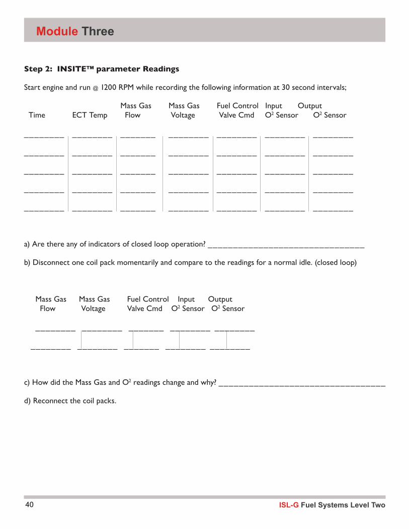
Step 2: INSITE™ parameter Readings
Start engine and run @ 1200 RPM while recording the following information at 30 second intervals;
Mass Gas Mass Gas Fuel Control Input Output Time ECT Temp Flow Voltage Valve Cmd O2 Sensor O2 Sensor
________ ________ _______ ________ ________ ________ ________
________ ________ _______ ________ ________ ________ ________
________ ________ _______ ________ ________ ________ ________
________ ________ _______ ________ ________ ________ ________
________ ________ _______ ________ ________ ________ ________
a) Are there any of indicators of closed loop operation? _______________________________
b) Disconnect one coil pack momentarily and compare to the readings for a normal idle. (closed loop)
Mass Gas Mass Gas Fuel Control Input Output Flow Voltage Valve Cmd O2 Sensor O2 Sensor
________ ________ _______ ________ ________
________ ________ _______ ________ ________
c) How did the Mass Gas and O2 readings change and why? _________________________________
d) Reconnect the coil packs.
________ ________ _______ ________ ________ ________ ________
________ ________ _______ ________ ________ ________ ________
________ ________ _______ ________ ________ ________ ________
________ ________ _______ ________ ________ ________ ________
________ ________ _______ ________ ________ ________ ________
________ ________ _______ ________ ________ ________ ________
________ ________ _______ ________ ________ ________ ________
________ ________ _______ ________ ________ ________ ________
________ ________ _______ ________ ________ ________ ________
________ ________ _______ ________ ________ ________ ________
________ ________ _______ ________ ________ ________ ________
________ ________ _______ ________ ________ ________ ________
________ ________ _______ ________ ________ ________ ________
________ ________ _______ ________ ________ ________ ________
________ ________ _______ ________ ________ ________ ________
________ ________ _______ ________ ________ ________ ________
________ ________ _______ ________ ________ ________ ________
________ ________ _______ ________ ________ ________ ________
________ ________ _______ ________ ________ ________ ________
________ ________ _______ ________ ________ ________ ________
________ ________ _______ ________ ________ ________ ________
________ ________ _______ ________ ________ ________ ________
________ ________ _______ ________ ________ ________ ________
________ ________ _______ ________ ________ ________ ________
________ ________ _______ ________ ________ ________ ________
________ ________ _______ ________ ________ ________ ________
________ ________ _______ ________ ________ ________ ________
________ ________ _______ ________ ________ ________ ________
________ ________ _______ ________ ________ ________ ________
________ ________ _______ ________ ________ ________ ________
________ ________ _______ ________ ________
________ ________ _______ ________ ________
________ ________ _______ ________ ________
________ ________ _______ ________ ________
________ ________ _______ ________ ________
________ ________ _______ ________ ________
________ ________ _______ ________ ________
________ ________ _______ ________ ________
Module Three

41ISL-G Fuel Systems Level Two
Sensors
Step 3: Locate the Fuel Control Valve
Visually locate the Fuel Control Valve and identify the power and ground wires:
#1 ground Wire terminal ________________________
#1 power Wire terminal ________________________
Step 4:
Connect the laptop to the diagnostic connector and view the Fuel Control Valve data parameters.
Run the engine at the following speeds and record the appropriate data:
INSITE™ INSITE™ Lowest Value Highest Value
KOEO _____________ ______________
KOER @ Idle _____________ ______________
Snap the throttle and observe any changes _____________ ______________
Step 5:
Note the Mass Gas Flow Compensation and Fuel Control Valve prior to propane enrichment and record the value.
KOER @ 1000 RPM Compensation + / - ________ FCV _____________
Note the HO2S PID ______________
Step 6:
Note the Mass Gas Flow Compensation and Fuel Control Valve while performing the propane enrichment and record the value.
KOER @ 1000 RPM Compensation + / - ________ FCV _____________
Note the HO2S PID ______________
KOEO _____________ ______________
KOER @ Idle _____________ ______________
Snap the throttle and observe any changes _____________ ______________
ISL-G Fuel Systems Level Two42
Step 7:
a) With KOER, disconnect Fuel Control Valve.
b) Note if a code is set and what fault code through INSITE™. Fault Code ____________
Fault Description:______________________________________________
c) According to INSITE™, what are the effects of this set fault?: ______________________________
d) What are the conditions to set? ________________________________________________
e) When do the conditions for setting this code take place?________________________________
f) What are the possible causes for setting this code?____________________________________
g) What are the conditions for clearing this fault? ______________________________________
h) What is the action taken when the fault is active? _____________________________________
i) Is there an “Engine De-rate” for this sensor? (Y / N) What is the de-rate? _____________________
j) In Step 6, we have forced the Gas Mass Sensor (high, low)
Reconnect Sensor and clear fault codes.
Module Three
43ISL-G Fuel Systems Level Two
Sensors
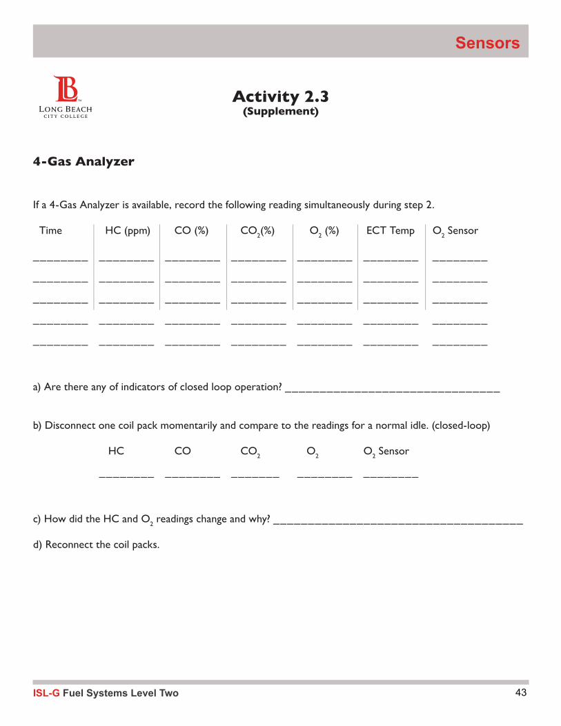
Activity 2.3 (Supplement)
4-Gas Analyzer
If a 4-Gas Analyzer is available, record the following reading simultaneously during step 2.
Time HC (ppm) CO (%) CO2(%) O2 (%) ECT Temp O2 Sensor
________ ________ ________ ________ ________ ________ ________
________ ________ ________ ________ ________ ________ ________
________ ________ ________ ________ ________ ________ ________
________ ________ ________ ________ ________ ________ ________
________ ________ ________ ________ ________ ________ ________
a) Are there any of indicators of closed loop operation? _______________________________
b) Disconnect one coil pack momentarily and compare to the readings for a normal idle. (closed-loop)
HC CO CO2 O2 O2 Sensor
________ ________ _______ ________ ________
c) How did the HC and O2 readings change and why? ____________________________________
d) Reconnect the coil packs.
Time HC (ppm) CO (%) CO
________ ________ ________ ________ ________ ________ ________
________ ________ ________ ________ ________ ________ ________
________ ________ ________ ________ ________ ________ ________
Time HC (ppm) CO (%) CO
________ ________ ________ ________ ________ ________ ________
________ ________ ________ ________ ________ ________ ________
________ ________ ________ ________ ________ ________ ________
Time HC (ppm) CO (%) CO
________ ________ ________ ________ ________ ________ ________
________ ________ ________ ________ ________ ________ ________
________ ________ ________ ________ ________ ________ ________
(%) O
________ ________ ________ ________ ________ ________ ________
________ ________ ________ ________ ________ ________ ________
________ ________ ________ ________ ________ ________ ________
(%) ECT Temp O
________ ________ ________ ________ ________ ________ ________
________ ________ ________ ________ ________ ________ ________
________ ________ ________ ________ ________ ________ ________
(%) ECT Temp O
________ ________ ________ ________ ________ ________ ________
________ ________ ________ ________ ________ ________ ________
________ ________ ________ ________ ________ ________ ________
ISL-G Fuel Systems Level Two44
Module Three
Pressure SensorsThere are 8 pressure sensors to help maintain a Stoi-chiometric air/fuel ratio: ▪ Intake Manifold Pressure/Temp
▪ EGR Differential Pressure
▪ Mixer Inlet (Boost Pressure)
▪ Fuel Inlet Pressure
▪ Fuel Outlet Pressure
▪ Engine Oil Pressure
These are pressure transducers that are 3-wire compo-nents with a 5V source voltage that increases corre-sponding to pressure increases.
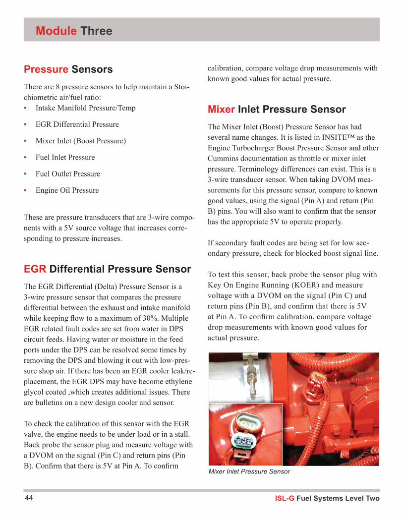
EGR Differential Pressure SensorThe EGR Differential (Delta) Pressure Sensor is a 3-wire pressure sensor that compares the pressure differential between the exhaust and intake manifold while keeping flow to a maximum of 30%. Multiple EGR related fault codes are set from water in DPS circuit feeds. Having water or moisture in the feed ports under the DPS can be resolved some times by removing the DPS and blowing it out with low-pres-sure shop air. If there has been an EGR cooler leak/re-placement, the EGR DPS may have become ethylene glycol coated ,which creates additional issues. There are bulletins on a new design cooler and sensor.
To check the calibration of this sensor with the EGR valve, the engine needs to be under load or in a stall. Back probe the sensor plug and measure voltage with a DVOM on the signal (Pin C) and return pins (Pin B). Confirm that there is 5V at Pin A. To confirm
calibration, compare voltage drop measurements with known good values for actual pressure.
Mixer Inlet Pressure SensorThe Mixer Inlet (Boost) Pressure Sensor has had several name changes. It is listed in INSITE™ as the Engine Turbocharger Boost Pressure Sensor and other Cummins documentation as throttle or mixer inlet pressure. Terminology differences can exist. This is a 3-wire transducer sensor. When taking DVOM mea-surements for this pressure sensor, compare to known good values, using the signal (Pin A) and return (Pin B) pins. You will also want to confirm that the sensor has the appropriate 5V to operate properly.
If secondary fault codes are being set for low sec-ondary pressure, check for blocked boost signal line.
To test this sensor, back probe the sensor plug with Key On Engine Running (KOER) and measure voltage with a DVOM on the signal (Pin C) and return pins (Pin B), and confirm that there is 5V at Pin A. To confirm calibration, compare voltage drop measurements with known good values for actual pressure.
Mixer Inlet Pressure Sensor

45ISL-G Fuel Systems Level Two
Sensors
Fuel Inlet Pressure SensorThe Fuel Inlet Pressure Sensor is a 3-wire sensor. The pressure from the chassis to this sensor is in the 110 to 120 PSIA range as required by Cummins. Low pressures on the chassis side can cause second-ary fault codes to be set as the fuel supplied from the chassis will not be able to keep up under load. Check the primary regulator for sticking. Contam-inated filters can be a cause of this low volume resulting in a pressure drop. The mixer inlet fitting at the mixer housing and in front of the mass airflow sensor can have debris blocking the boost signal pressure to the secondary regulator.
When checking the sensor calibration, measure the voltage across signal and return, compare to known good values, and then to the pressure gauge. To test this sensor, @KOER back probe sensor plug and measure voltage with a DVOM on the signal (Pin C) and return pins (Pin B). Confirm that there is 5 volts at Pin A. To confirm calibration, compare voltage drop measurements with known good values for actual pressure.
Fuel Outlet Pressure SensorThe Fuel Outlet Pressure Sensor is a 4-wire combina-tion sensor. This sensor monitors the fuel temperature and pressure. The pressure from the secondary regu-lator must be 65 - 73 PSIA under load or the engine will run lean and lack power. Check secondary and primary regulators for sticking and contaminated fil-ters if fault codes are being set and/or low on power.
When checking sensor calibration, measure voltage across signal and return, compare to known good val-ues, and then to pressure gauge. To test this sensor, @ KOER, back probe sensor plug and measure volt-age with a DVOM on the signal (Pin 3) and return pins (Pin 2), and confirm that there is 5V at Pin 1. To confirm calibration, compare voltage drop measure-ments with known good values for actual pressure.
Fuel Inlet Pressure Sensor
Fuel Outlet Pressure Sensor

ISL-G Fuel Systems Level Two46
Module Three
Engine Oil Pressure SensorThe oil pressure sensor is a three-wire pressure sensor/transducer device. The ECM uses input from the oil pressure sensor for engine protection. If the oil pressure is too low, engine de-rate and possible shutdown will occur.
The oil pressure should read ZERO with the Key On Engine Off (KOEO). If the transducer sticks it could be reporting that there is oil pressure when there is none. An engine failure could occur due to lack of registered oil pressure. If the pressure is above 0, then replace sensor. Cummins Engineering is working to change software to recognize whatever pressure is at startup to be zero baseline and read from there as a sensor check. If the pressure does not increase from baseline – engine shut down should occur.
To test this sensor, @KOER back probe sensor plug and measure voltage with a DVOM on the signal (Pin C) and return pins (Pin B). Confirm that there is 5 volts at Pin A. To confirm calibration, compare voltage drop measurements with known good values for actual pressure.
ISL-G System PressuresFuel pressure readings should be taken when the engine is under load to ensure enough volume to keep the engine running. Use either a mechanical or electric gauge on the port to see absolute read-ings. Gauge readings will be 14.7 PSI different from INSITE™ at sea level. Cummins uses quick disconnect couplings and nipples on the engine for this purpose. Part numbers are Quick Disconnect # 3376859 and Coupling Nipple # 3042619.
Manual Gauge on Secondary Pressure
Electronic Transducer on Meter
Engine Oil Pressure Sensor
47ISL-G Fuel Systems Level Two
Sensors
Activity 2.4INSITE™ Diagnostics
Tools and equipment:
1. INSITE™
Condition: Driver states bus doesn’t run as well as the others he drives.
TheServiceTechnicianconfirmedandperformedthefollowing:
When taken out for test drive and Service Tech noticed that bus lacks power on hills;
After- Treatment System was checked for blockage - Good
EGR Checked - Good
Accelerator Pedal (App1 and App2) Checked Good
Throttle Plate and Accelerator Pedal- In-sync and No Glitches
Turbo Boost and Waste Gate Operation- Normal
Forthepurposesofanalyzingalogfile,wewanttolimitourparameterlisttoonlythepossibleareasofconcern.UsethefollowingparametersandgeneratealogfilethroughINSITE™:
Amber Warning Lamp StatusRed Stop Lamp StatusEngine Speed (RPM)Fuel Control Valve Int. Pressure (psi)Fuel Control Valve Int. Pressure Sensor Signal VoltFuel Supply Pressure Sensor (In Hg)Fuel Supply Pressure Sensor Voltage (V)Intake Manifold Pressure (In Hg)Mass Gas Flow Compensation (Percent)Throttle Plate Position 1 (Percent)
Procedure:
Step 1: Start engine and launch INSITE™. Consider the above parameters in determining your parameterlistfortheINSITE™logfile.Youmaywanttoviewtheaboveparametersbeforethe actualrecordingofyourlogfile.
ISL-G Fuel Systems Level Two48
Step 2: Warm-up engine and then follow procedure below to diagnose possible causes.
Run a diagnostic sequence by recording a snapshot to determine if there are any drivability concerns. Record a drive cycle data log of the following sequence of events:
1. Idle for 30 seconds
2. 1000 rpm for 10 seconds
3. Snap the throttle once
4. Idle for 10 seconds
5. 1500 rpm for 10 seconds
6. Back to idle - Drive Cycle Complete
SavethedrivecycledatalogtoafileandprintitinanExcelformatforuseintheclassroom.
Step 3: Use your data log info to diagnose the symptoms. Look at the drive cycle parameters, referencingthespecificframes,todetermineifaconditionexistsandwhatsymptomsare present.Recordyourfindingsbelow.
Symptomatic analysis of snapshot:
Time Seq:___________ symptom________________________________________________
Time Seq:___________ symptom________________________________________________
Time Seq:___________symptom________________________________________________
Time Seq:___________symptom________________________________________________
Time Seq:___________symptom________________________________________________
Time Seq:___________symptom________________________________________________
Time Seq:___________symptom________________________________________________
Time Seq:___________symptom________________________________________________
Time Seq:___________symptom________________________________________________
Time Seq:___________symptom________________________________________________
Cause:
Correction:
Module Three

49ISL-G Fuel Systems Level Two
Sensors
Camshaft Speed/Position SensorThe camshaft speed sensor is a three-wire Hall-Effect sensor. Crankahaft and camshaft sensors are not in-terchangeable, as the reach is different between them. When testing this sensor, check the output across the signal and return pins. These Hall-Effect sensors can be intermittent or fail completely. If this sensor fails, the ECM will switch to the crankshaft sensor as need-ed to limp-in. When testing, check for signal on pins B and C, along with 5V reference on Pin A. Testing can be performed using a DVOM to measure both voltage and frequency. The preferred method is to use an Automotive Oscilloscope.
Camshaft Speed/Position Sensor Crankshaft Speed/Position Sensor
Crankshaft Speed/Position SensorThe crankshaft speed sensor is also a three-wire Hall-Effect sensor. Camshaft and crankshaft sensors are not interchangeable, as the reach is different between them. When testing this sensor, check output across the signal and return pins. These Hall-Effect sensors can be intermittent or fail completely. If this senor fails, the ECM will switch to the camshaft sensor as needed to limp-in. When testing, check for signal on pins B and C, along with 5V reference on Pin A. Testing can be performed using a DVOM to measure both voltage and frequency. The preferred method is to use an Automotive Oscilloscope.
ISL-G Fuel Systems Level Two50
Module Three
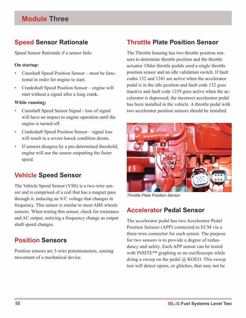
Throttle Plate Position SensorThe Throttle housing has two throttle position sen-sors to determine throttle position and the throttle actuator. Older throttle pedals used a single throttle position sensor and an idle validation switch. If fault codes 132 and 1241 are active when the accelerator pedal is in the idle position and fault code 132 goes inactive and fault code 1239 goes active when the ac-celerator is depressed, the incorrect accelerator pedal has been installed in the vehicle. A throttle pedal with two accelerator position sensors should be installed.
Accelerator Pedal SensorThe accelerator pedal has two Accelerator Pedal Position Sensors (APP) connected to ECM via a three-wire connector for each sensor. The purpose for two sensors is to provide a degree of redun-dancy and safety. Each APP sensor can be tested with INSITE™ graphing or an oscilloscope while doing a sweep on the pedal @ KOEO. This sweep test will detect opens, or glitches, that may not be
Speed Sensor RationaleSpeed Sensor Rationale if a sensor fails:
On startup:
▪ Camshaft Speed Position Sensor – must be func-tional in order for engine to start.
▪ Crankshaft Speed Position Sensor – engine will start without a signal after a long crank.
While running;
▪ Camshaft Speed Sensor Signal - loss of signal will have no impact to engine operation until the engine is turned off.
▪ Crankshaft Speed Position Sensor – signal loss will result in a severe knock condition derate.
▪ If sensors disagree by a pre-determined threshold, engine will use the sensor outputting the faster speed.
Vehicle Speed SensorThe Vehicle Speed Sensor (VSS) is a two-wire sen-sor and is comprised of a coil that has a magnet pass through it, inducing an A/C voltage that changes in frequency. This sensor is similar to most ABS wheels sensors. When testing this sensor, check for resistance and AC output, noticing a frequency change as output shaft speed changes.
Position SensorsPosition sensors are 3-wire potentiometers, sensing movement of a mechanical device.
Throttle Plate Position Sensor
51ISL-G Fuel Systems Level Two
Sensors
Remote Accelerator Pedal AssemblyThe remote throttle is switched by the ECM to con-trol the main or remote accelerator pedal sensors. This is performed by switching the wiper from the main accelerator pedal to the wiper on the remote.
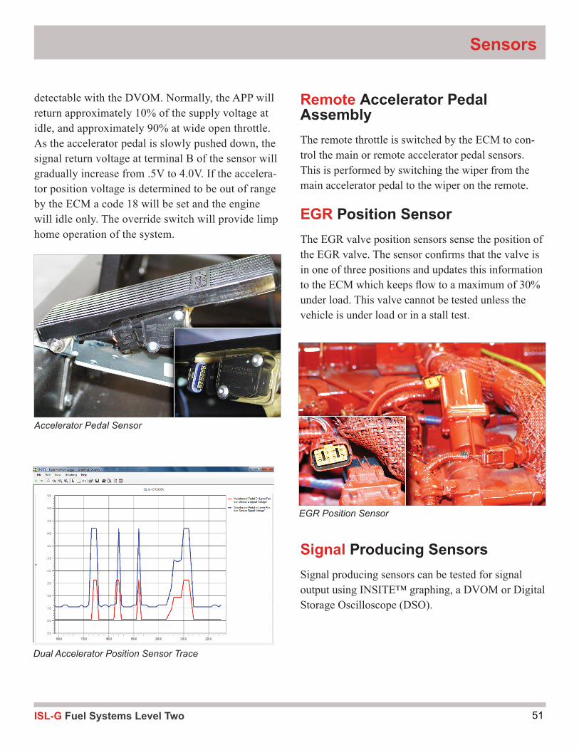
EGR Position SensorThe EGR valve position sensors sense the position of the EGR valve. The sensor confi rms that the valve is in one of three positions and updates this information to the ECM which keeps fl ow to a maximum of 30% under load. This valve cannot be tested unless the vehicle is under load or in a stall test.
Signal Producing SensorsSignal producing sensors can be tested for signal output using INSITE™ graphing, a DVOM or Digital Storage Oscilloscope (DSO).
Dual Accelerator Position Sensor Trace
Accelerator Pedal Sensor
EGR Position Sensor
detectable with the DVOM. Normally, the APP will return approximately 10% of the supply voltage at idle, and approximately 90% at wide open throttle. As the accelerator pedal is slowly pushed down, the signal return voltage at terminal B of the sensor will gradually increase from .5V to 4.0V. If the accelera-tor position voltage is determined to be out of range by the ECM a code 18 will be set and the engine will idle only. The override switch will provide limp home operation of the system.

ISL-G Fuel Systems Level Two52
Catalyst Inlet Oxygen SensorThe catalyst inlet oxygen sensor zirconia element is sensitive to contamination. The element can become coated by contaminants such as silicone so care must be taken to use only O2 sensor safe products.
The oxygen sensing portion of the sensor should never be tested with an ohmmeter like how the heater is checked. The voltage output of the sensor is read using an electronic service tool such as INSITE™. If this sensor becomes coated, for example, with eth-ylene glycol from an EGR cooler leak it can provide false readings. This sensor should also be tested for slow response (lazy O2 response) as it can cause poor mileage and performance. To test for this perform a “Snap Throttle Test” using propane and INSITE™.
Module Three
Catalyst Outlet Oxygen SensorCummins has removed the blue seal to allow ambi-ent air to travel up between the wire and insulation passing through the connector and to the O2 sensor to prevent false readings. The zircon element must be able to read the ambient oxygen and compare it to the exhaust stream O2 to function properly.
Blue Seal is Removed
Catalyst Inlet Oxygen Sensor
53ISL-G Fuel Systems Level Two
Sensors
Snap Throttle TestTo perform Snap-Throttle Test, you will need to con-nect the vehicle to INSITE™ and use propane enrich-ment to force the engine rich. To start the test, add propane to intake while engine is running, noting the Inlet O2 sensor voltage. When this voltage exceeds 800mV, remove propane (forcing the engine lean be-cause the FCV has cut back). The O2 sensor will now report a lean mixture. Next, snap the throttle, and pause INSITE™ and note the readings on INSITE™ when O2 sensor trace went from lean to rich.
If sensor response is greater than an 800mV change with less than 100ms response time when forced rich, O2 sensor is OK. If sensor does not meet either or both requirements, sensor is lazy.
O2 Sensor Snap Test
Combustion Knock Sensors
Combustion Knock Sensors1 and 2Use an ohmmeter to check continuity. Detonation can be monitored with INSITE™ or you can create a sim-ulated knock and monitor with an oscilloscope. When replacing knock sensors, clean all paint from bottom of sensor and mounting location (block or head).
Torque bolt to proper specifi cation. Make sure when air compressor is replaced, the timing marks are checked and aligned. See timing of air compressor per Quick-Serv #012-014.

ISL-G Fuel Systems Level Two54
Activity 2.5Accelerator Pedal Position Sensor
Tools and equipment:
1. Classroom materials 2. INSITE™ 3. Hand tool Set 4. DVOM
Step 1: Locate terminals on the APPS wiring diagram.
APPS Sensor 1 Return Wire terminal _______________ APPS Sensor 1 Signal Wire terminal _______________ APPS Sensor 1 5-volt Supply Wire terminal _______________ APPS Sensor 2 Return Wire terminal _______________ APPS Sensor 2 Signal Wire terminal _______________ APPS Sensor 2 5-volt Supply Wire terminal _______________
Using the wiring diagram locate the APP wiring diagram.
Step 2: Back probe the throttle actuator APPS2 signal wire with DVOM. Make sure the ignition is turned off. Turn ignition on (KOEO). Turn on INSITE™ and monitor APP2 in graph mode. Press “FREEZE” when the pattern appears full screen. Draw the wave-form in the space provided. Have the instructor demonstrate open and short issues.
Module Three
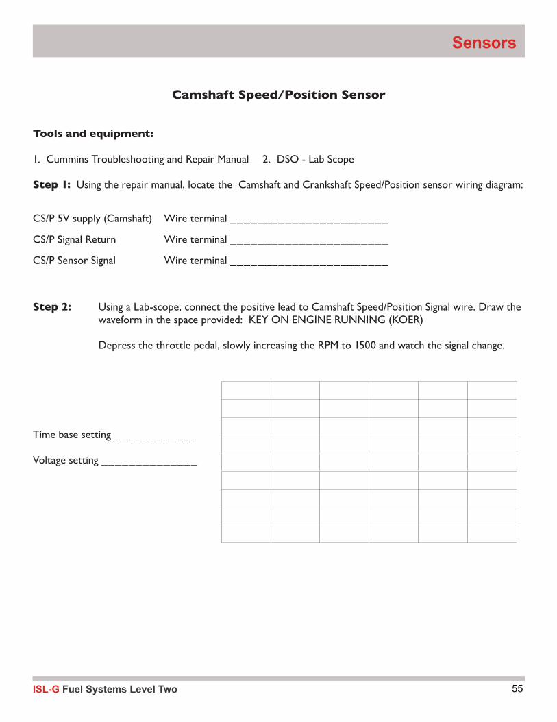
55ISL-G Fuel Systems Level Two
Camshaft Speed/Position Sensor
Tools and equipment:
1. Cummins Troubleshooting and Repair Manual 2. DSO - Lab Scope
Step 1: Using the repair manual, locate the Camshaft and Crankshaft Speed/Position sensor wiring diagram:
CS/P 5V supply (Camshaft) Wire terminal _______________________
CS/P Signal Return Wire terminal _______________________
CS/P Sensor Signal Wire terminal _______________________
Step 2: Using a Lab-scope, connect the positive lead to Camshaft Speed/Position Signal wire. Draw the waveform in the space provided: KEY ON ENGINE RUNNING (KOER)
Depress the throttle pedal, slowly increasing the RPM to 1500 and watch the signal change.
Time base setting ____________
Voltage setting ______________
Sensors

ISL-G Fuel Systems Level Two56
Crankshaft Speed/Position Sensor
Tools and equipment:
1. Cummins Troubleshooting and Repair Manual 2. DSO - Lab Scope
Step 1: Using the repair manual, locate the Camshaft and Crankshaft Speed/Position sensor wiring diagram:
CS/P 5V supply (Camshaft) Wire terminal _______________________
CS/P Signal Return Wire terminal _______________________
CS/P Sensor Signal Wire terminal _______________________
Step 2: Using a Lab-scope, connect the positive lead to Crankshaft Speed/Position Signal wire. Draw the waveform in the space provided: KEY ON ENGINE RUNNING (KOER).
Depress the throttle pedal slowly increasing the RPM to 1500 and watch the signal change.
Time base setting ____________
Voltage setting ______________
Module Three
57ISL-G Fuel Systems Level Two
Knock Sensor
Tools and equipment:
1. Cummins Troubleshooting and Repair Manual 2. DSO - Lab Scope
Step 1: Locate the knock sensor wiring diagram:
Knock 2 signal Wire terminal _______________________
Knock 2 Signal return Wire terminal _______________________
Step 2: Using a Lab-scope, connect the positive lead to Knock Signal wire and the negative to the return. Draw the waveform in the space provided: KEY ON ENGINE RUNNING (KOER). Watch knock signal in INSITE™ using graph mode if available.
Increase the RPM to 1000 and tap on a head bolt with a rattling wrench.
Time base setting ____________
Voltage setting ______________
Sensors
ISL-G Fuel Systems Level Two58
Activity 2.6O2 Sensor Testing
Tools and equipment:
1. Cummins Troubleshooting and Repair Manual 2. INSITE™
3. Propane Enrichment Tool
Step 1: Using the Classroom manual, locate the Catalyst Inlet and Outlet Oxygen Sensor wiring diagram:
Inlet Outlet
HO2S signal Wire terminal ___________ ____________
HO2S signal return Wire terminal ___________ ____________
12V heater supply Wire terminal ___________ ____________
12V heater return Wire terminal ___________ ____________
If the oxygen sensor is working properly, it must be able to:
Rise to at least 800 mV.
Drop to at least 175 mV.
Rise from a minimum to maximum voltage in less than 100 milliseconds.
What is the Catalytic Converter outlet temperature? _____________________
Set INSITE™ to graph output voltages of Inlet Oxygen Sensor @ 20 ms sample rate:
Step 1: Let the engine idle, in closed loop – remember not all vehicles will maintain closed loop at idle. For those vehicles you may have to hold just above idle. Use INSITE™ to monitor the oxygen sensor waveform.
What are the O2 sensors Min and Max voltages?
Minimum Voltage:_________ Maximum Voltage:__________
Step 2: Put the hose from the propane enrichment tool into the air intake or intake manifold vacuum port and slowly begin adding propane.
Step 3: Keep adding propane in small increments until the computer can no longer compensate for the extra fuel enrichment. The oxygen sensor voltage should be at its highest voltage output and at least 800 mV. What was the highest voltage? _________mV
Module Three

59ISL-G Fuel Systems Level Two
Step 4: Quickly shut the propane off. The oxygen sensor voltage should drop to its minimum output below 175 mV. What was the lowest voltage? __________________ mV
Step 5: While the oxygen sensor is at minimum voltage, snap the throttle all the way open. The mixture should jump full rich and the oxygen sensor voltage should also jump. The rise time should be less than 100 milliseconds. Use the freeze feature of INSITE™ to freeze the display during this test. Then measure the rise time in milliseconds. What was the actual rise time in milliseconds? ____________________
Step 6: What is the average O2 sensor voltage? __________
Step 7: Repeat step 1-4 with the Catalyst Outlet Oxygen Sensor.
Step 8: (optional) View the Inlet and Outlet O2 sensor data parameters.
Run the engine at the following speeds and record the appropriate data for the “Inlet Sensor”
INSITE™ INSITE™ Low Voltage High Voltage KOEO _______ _______ KOER @ Idle _______ _______ KOER @ 1000 RPM _______ _______ KOER @ 1500 RPM _______ _______ KOER @ Idle (w/ propane enrichment) _______ _______
Run the engine at the following speeds and record the appropriate data for the “Outlet Sensor”.
INSITE™ INSITE™
Low Voltage High Voltage
KOEO _______ _______ KOER @ Idle _______ _______ KOER @ 1000 RPM _______ _______ KOER @ 1500 RPM _______ _______ KOER @ Idle (w/ propane enrichment) _______ _______
Snap the throttle and observe any changes ___________________________________________
Sensors
ISL-G Fuel Systems Level Two60
Step 9: With KOER, disconnect the O2 Sensor and note if a fault code is set through INSITE™.
a) Fault Code and Fault Description:_____________________________________________
b) According to INSITE™, what are the effects of this set fault?: ____________________________
c) When do the conditions for setting this code take place?______________________________
d) What are the conditions for clearing this fault? ____________________________________
e) What is the action taken when the fault is active ?__________________________________
f) Is there an “Engine De-rate” for this sensor? (Y / N) What is the de-rate? __________________
g) Reconnect sensor and clear fault codes.
Step 10: With KOER, disconnect and short the O2 Sensor connector signal to return.
Note what fault code is set through INSITE™.
a) Fault Code and Fault Description:_____________________________________________
b) What are the conditions to set? _______________________________________
c) When do the conditions for setting this code take place?______________________________
d) What are the possible causes for setting this code? _________________________________
e) What is the action taken when the fault is active? __________________________________
f) In Step 4, we have forced the O2 Mass Sensor (high, low)
Remove the short from connector; reconnect the sensor and clear fault codes.
Step 11: Using INSITE™, set the parameters to monitor the following:
Fuel Control Valve (FCV) Mass Gas Sensor (GMS)
Mass Air Sensor (AMS) Catalyst Inlet and Outlet Oxygen Sensors
Module Three
61ISL-G Fuel Systems Level Two
Run the engine at the following speeds and record the appropriate data for the “Inlet Sensor”:
HOS Input HOS Output Mass Gas Mass Air Fuel Control Valve
Low/High Volts Low/High Volts Low/High Volts Low/High lbs/hr Low/High Command
KOEO _____/_____ _____/_____ _____/_____ _____/______ _____%/_____%
KOER @ Idle _____/_____ _____/_____ _____/_____ _____/______ _____%/_____%
KOER @ Idle _____/_____ _____/_____ _____/_____ _____/______ _____%/_____%
with Coil-Pack #6 disconnected
Reconnect Coil Pack #6
KOER @ 1000 RPM _____/_____ _____/_____ _____/_____ _____/______ _____%/_____%
KOER @ 1500 RPM _____/_____ _____/_____ _____/_____ _____/______ _____%/_____%
KOER @ Idle _____/_____ _____/_____ _____/_____ _____/______ _____%/_____%
(with propane enrichment)
Step 12: What happens to each sensor voltage when the system is made rich?
Fuel Control Valve (FCV) _____________________________%
Mass Gas Sensor (MGS) ______________________________
Mass Air Sensor (MAS)______ _____________________lbs/hr
Catalyst Inlet Oxygen Sensor (HO2S)_____________________
Outlet Oxygen Sensor (HO2S) __________________________
What is the reading of the FUEL CONTROL VALVE while performing the propane enrichment test?
___________________
What is the reading of the FUEL CONTROL VALVE at idle. Write the value in the space provided.
___________________
Sensors
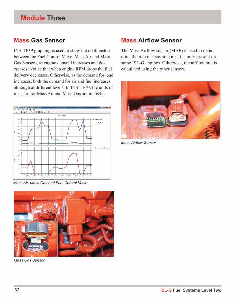
ISL-G Fuel Systems Level Two62
Mass Gas SensorINSITE™ graphing is used to show the relationship between the Fuel Control Valve, Mass Air and Mass Gas Sensors, as engine demand increases and de-creases. Notice that when engine RPM drops the fuel delivery decreases. Otherwise, as the demand for load increases, both the demand for air and fuel increases although at different levels. In INSITE™, the units of measure for Mass Air and Mass Gas are in lbs/hr.
Mass Air, Mass Gas and Fuel Control Valve
Module Three
Mass Gas Sensor
Mass Airfl ow SensorThe Mass Airfl ow sensor (MAF) is used to deter-mine the rate of incoming air. It is only present on some ISL-G engines. Otherwise, the airfl ow rate is calculated using the other sensors.
Mass Airfl ow Sensor
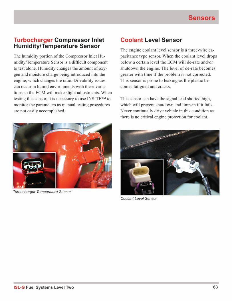
63ISL-G Fuel Systems Level Two
Coolant Level SensorThe engine coolant level sensor is a three-wire ca-pacitance type sensor. When the coolant level drops below a certain level the ECM will de-rate and/or shutdown the engine. The level of de-rate becomes greater with time if the problem is not corrected. This sensor is prone to leaking as the plastic be-comes fatigued and cracks.
This sensor can have the signal lead shorted high, which will prevent shutdown and limp-in if it fails. Never continually drive vehicle in this condition as there is no critical engine protection for coolant.
Sensors
Coolant Level Sensor
Turbocharger Temperature Sensor
Turbocharger Compressor Inlet Humidity/Temperature SensorThe humidity portion of the Compressor Inlet Hu-midity/Temperature Sensor is a difficult component to test alone. Humidity changes the amount of oxy-gen and moisture charge being introduced into the engine, which changes the ratio. Drivability issues can occur in humid environments with these varia-tions so the ECM will make slight adjustments. When testing this sensor, it is necessary to use INSITE™ to monitor the parameters as manual testing procedures are not easily accomplished.

ISL-G Fuel Systems Level Two64
Module Four4
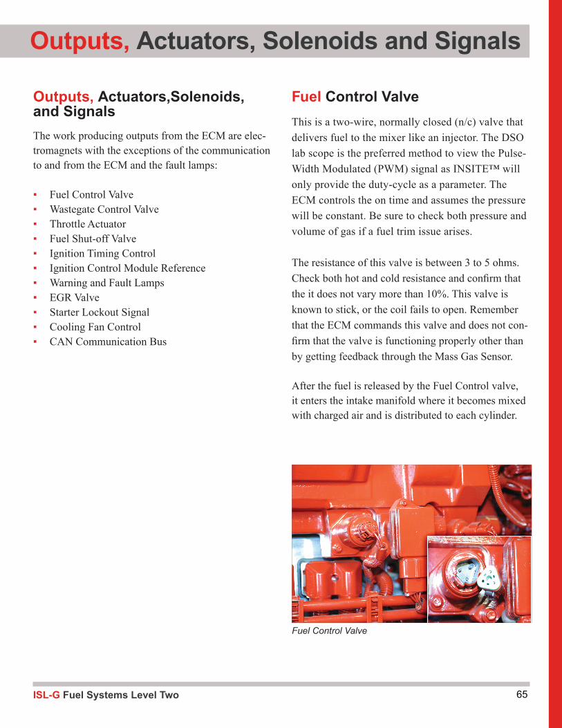
65ISL-G Fuel Systems Level Two
Outputs, Actuators, Solenoids and Signals
Outputs, Actuators,Solenoids, and SignalsThe work producing outputs from the ECM are elec-tromagnets with the exceptions of the communication to and from the ECM and the fault lamps:
▪ Fuel Control Valve ▪ Wastegate Control Valve ▪ Throttle Actuator ▪ Fuel Shut-off Valve ▪ Ignition Timing Control ▪ Ignition Control Module Reference ▪ Warning and Fault Lamps ▪ EGR Valve ▪ Starter Lockout Signal ▪ Cooling Fan Control ▪ CAN Communication Bus
Fuel Control ValveThis is a two-wire, normally closed (n/c) valve that delivers fuel to the mixer like an injector. The DSO lab scope is the preferred method to view the Pulse-Width Modulated (PWM) signal as INSITE™ will only provide the duty-cycle as a parameter. The ECM controls the on time and assumes the pressure will be constant. Be sure to check both pressure and volume of gas if a fuel trim issue arises.
The resistance of this valve is between 3 to 5 ohms. Check both hot and cold resistance and confirm that the it does not vary more than 10%. This valve is known to stick, or the coil fails to open. Remember that the ECM commands this valve and does not con-firm that the valve is functioning properly other than by getting feedback through the Mass Gas Sensor.
After the fuel is released by the Fuel Control valve, it enters the intake manifold where it becomes mixed with charged air and is distributed to each cylinder.
Fuel Control Valve
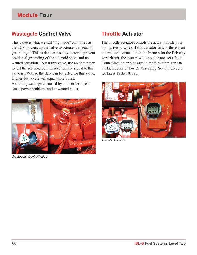
ISL-G Fuel Systems Level Two66
Module Four
Wastegate Control ValveThis valve is what we call “high-side” controlled as the ECM powers up the valve to actuate it instead of grounding it. This is done as a safety factor to prevent accidental grounding of the solenoid valve and un-wanted actuation. To test this valve, use an ohmmeter to test the solenoid coil. In addition, the signal to this valve is PWM so the duty can be tested for this valve. Higher duty cycle will equal more boost.A sticking waste gate, caused by coolant leaks, can cause power problems and unwanted boost.
Throttle ActuatorThe throttle actuator controls the actual throttle posi-tion (drive by wire). If this actuator fails or there is an intermittent connection in the harness for the Drive by wire circuit, the system will only idle and set a fault. Contamination or blockage in the fuel-air mixer can set fault codes or low RPM surging. See Quick-Serv. for latest TSB# 101120.
Wastegate Control Valve
Throttle Actuator
67ISL-G Fuel Systems Level Two
Outputs, Actuators, Solenoids and Signals
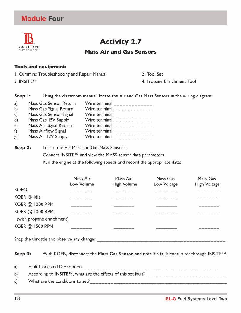
ISL-G Fuel Systems Level Two68
Activity 2.7Mass Air and Gas Sensors
Tools and equipment: 1. Cummins Troubleshooting and Repair Manual 2. Tool Set
3. INSITE™ 4. Propane Enrichment Tool
Step 1: Using the classroom manual, locate the Air and Gas Mass Sensors in the wiring diagram:
a) Mass Gas Sensor Return Wire terminal _____________b) Mass Gas Signal Return Wire terminal _____________c) Mass Gas Sensor Signal Wire terminal _ ___________d) Mass Gas 15V Supply Wire terminal _ ___________e) Mass Air Signal Return Wire terminal _____________f) MassAirflowSignal Wireterminal_____________g) Mass Air 12V Supply Wire terminal _ ___________
Step 2: Locate the Air Mass and Gas Mass Sensors.
Connect INSITE™ and view the MASS sensor data parameters.
Run the engine at the following speeds and record the appropriate data:
Mass Air Mass Air Mass Gas Mass Gas Low Volume High Volume Low Voltage High VoltageKOEO _______ _______ _______ _______
KOER @ Idle _______ _______ _______ _______
KOER @ 1000 RPM _______ _______ _______ _______
KOER @ 1000 RPM _______ _______ _______ _______
(with propane enrichment)
KOER @ 1500 RPM _______ _______ _______ _______
Snap the throttle and observe any changes ___________________________________________
Step 3: With KOER, disconnect the Mass Gas Sensor, and note if a fault code is set through INSITE™.
a) Fault Code and Description:_____________________________________________
b) According to INSITE™, what are the effects of this set fault? ___________________________
c) What are the conditions to set?______________________________________________
Module Four
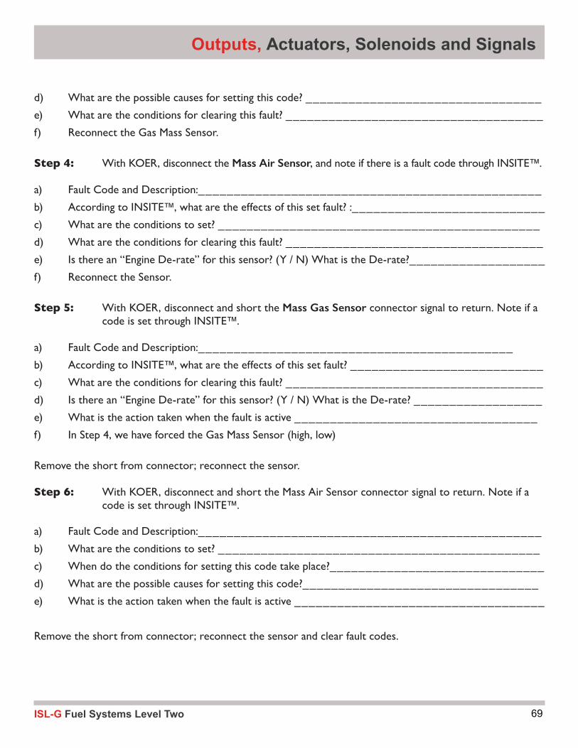
69ISL-G Fuel Systems Level Two
d) What are the possible causes for setting this code? _________________________________
e) What are the conditions for clearing this fault? ____________________________________
f) Reconnect the Gas Mass Sensor.
Step 4: With KOER, disconnect the Mass Air Sensor, and note if there is a fault code through INSITE™.
a) Fault Code and Description:________________________________________________
b) According to INSITE™, what are the effects of this set fault? :___________________________
c) What are the conditions to set? _____________________________________________
d) What are the conditions for clearing this fault? ____________________________________
e) Is there an “Engine De-rate” for this sensor? (Y / N) What is the De-rate?___________________
f) Reconnect the Sensor.
Step 5: With KOER, disconnect and short the Mass Gas Sensor connector signal to return. Note if a code is set through INSITE™.
a) Fault Code and Description:____________________________________________
b) According to INSITE™, what are the effects of this set fault? ___________________________
c) What are the conditions for clearing this fault? ____________________________________
d) Is there an “Engine De-rate” for this sensor? (Y / N) What is the De-rate? __________________
e) What is the action taken when the fault is active __________________________________
f) In Step 4, we have forced the Gas Mass Sensor (high, low)
Remove the short from connector; reconnect the sensor.
Step 6: With KOER, disconnect and short the Mass Air Sensor connector signal to return. Note if a code is set through INSITE™.
a) Fault Code and Description:________________________________________________
b) What are the conditions to set? _____________________________________________
c) When do the conditions for setting this code take place?______________________________
d) What are the possible causes for setting this code?_________________________________
e) What is the action taken when the fault is active ___________________________________
Remove the short from connector; reconnect the sensor and clear fault codes.
Outputs, Actuators, Solenoids and Signals

70 ISL-G Fuel Systems Level Two
TOXICITY: Nontoxic - it is not a poison like Carbon Monoxide but it does displace Oxygen.
FLAMMABILITY: Flammability range is narrow 5-15% - below 5 is too lean to burn, above 15 too rich. Edges of a cloud could be right mixture. Heaters and other spark producing items must be relocated.
VENTILATION: Must be trapped vertically to be dangerous--- look up for traps at ceiling/false ceilings, etc. Lighter than air so most shops are equipped with auto vents on the methane detection circuit.
LEAK DETECTION: Mercaptin NOT present in LNG unless infused so it will have no odor. Methane detectors and hand held combustible gas detectors available along with commercial bubble style leak detectors. CG detectors will go off on many substances such as glycol, silicone, diesel, hyd.fluidsoitisjustagrossindicator.
Natural Gas Safety Considerations
COLLISION: Cylinders must have a Detailed Visual Inspection and hardware should be carefully inspected for damage. Cylinders should be closed and ¼ turn valve closed if vehicle is involved in an accident.
STORAGE: LNG vehicles should be stored outside due to venting of tank. CNG system is sealed and will not leak to atmosphere.
SHOP SAFETY/EQUIPMENT: Methane detectors and ceiling ventilation should be reviewed by engineering. Special tools kit being provided to perform defueling, etc.

71ISL-G Fuel Systems Level Two
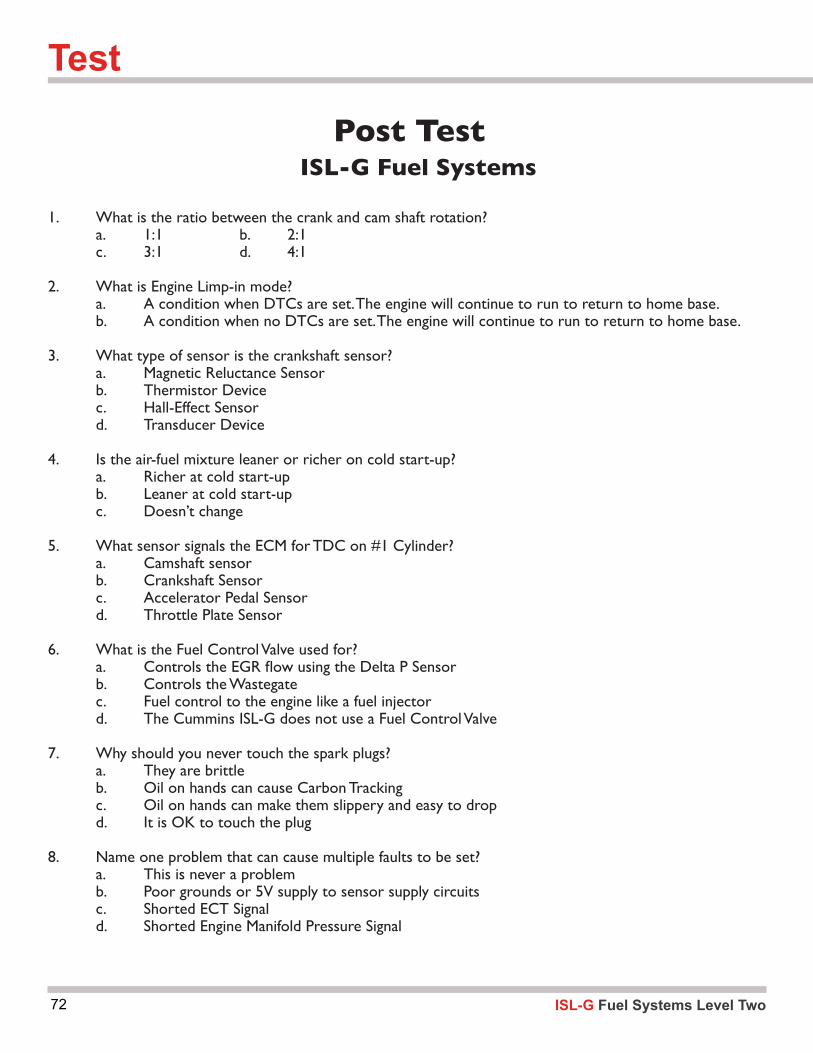
72
Post TestISL-G Fuel Systems
1. What is the ratio between the crank and cam shaft rotation? a. 1:1 b. 2:1 c. 3:1 d. 4:1 2. What is Engine Limp-in mode? a. A condition when DTCs are set. The engine will continue to run to return to home base. b. A condition when no DTCs are set. The engine will continue to run to return to home base.
3. What type of sensor is the crankshaft sensor? a. Magnetic Reluctance Sensor b. Thermistor Device c. Hall-Effect Sensor d. Transducer Device
4. Is the air-fuel mixture leaner or richer on cold start-up? a. Richer at cold start-up b. Leaner at cold start-up c. Doesn’t change
5. What sensor signals the ECM for TDC on #1 Cylinder? a. Camshaft sensor b. Crankshaft Sensor c. Accelerator Pedal Sensor d. Throttle Plate Sensor
6. What is the Fuel Control Valve used for? a. ControlstheEGRflowusingtheDeltaPSensor b. Controls the Wastegate c. Fuel control to the engine like a fuel injector d. The Cummins ISL-G does not use a Fuel Control Valve
7. Why should you never touch the spark plugs? a. They are brittle b. Oil on hands can cause Carbon Tracking c. Oil on hands can make them slippery and easy to drop d. It is OK to touch the plug
8. Name one problem that can cause multiple faults to be set? a. This is never a problem b. Poor grounds or 5V supply to sensor supply circuits c. Shorted ECT Signal d. Shorted Engine Manifold Pressure Signal
ISL-G Fuel Systems Level Two
Test

73ISL-G Fuel Systems Level Two

74
Sources:
Compressed Gas Association1725 Jefferson Davis Highway,#1004 Arlington, VA 22202-4102 Telephone: 703-412-0900
Gas Research Institute 8600 W. Bryn Mawr Avenue Chicago, IL 60631-3652 Telephone: 773-399-8352
American National Standards Institute 11 W. 42nd Street New York, NY 10036 Telephone: 212-642-4900
National Fire Protection Association 11 Tracy Drive Avon, MA 02322 Telephone: 800-593-6372
Natural Gas Vehicle Coalition1515 Wilson Blvd. Suite 1030Arlington, VA 22209 Telephone: 703-527-3022
Department of Transportation 400 Seventh Street, SW Washington, DC 20590 Telephone: 202-366-4000
Publications:
CGA C-6.4, “Methods for External Visual Inspection of Natural Gas Vehicle Fuel Containers and Their Installations,” 1st Edition (1997)
NFPA 52, “Standards for Compressed Natural Gas Vehicular Fuel Systems” National Fire Protection Association, 1 Batterymarch Park, Box 9101, Quincy, MA 02269-9101
ANSI/AGA-NGV2, “ Basic Requirements for Compressed Natural Gas Vehicle Fuel Containers,” American Gas Association Laboratories, 8501 East Pleasant Valley Road, Cleveland, OH 44131
FMVSS304, “Compressed Natural Gas Fuel Container Integrity,” Federal Motor Vehicle Safety Standards, US DOT, NHTSA
Gas Research Institute, “ Natural Gas Vehicle Cylinder Care and Maintenance Handbook” (1997)
CHP Title 13
ISL-G Fuel Systems Level Two
References

75ISL-G Fuel Systems Level Two
ISL-G Fuel Systems Level Two76
Notes

77ISL-G Fuel Systems Level Two
Notes
ISL-G Fuel Systems Level Two78
Notes
79ISL-G Fuel Systems Level Two
Notes