Chinook Elementary School Fire Alarm Submittals
66
Chinook Elementary School Fire Alarm Submittals SAFE consulting services 1800 Bickford Ave. Suite #214 Snohomish, WA 98290 Voice (800) 742-8960 Fax (206) 363 -3291 E-Mail [email protected]
-
Upload
khangminh22 -
Category
Documents
-
view
0 -
download
0
Transcript of Chinook Elementary School Fire Alarm Submittals

Chinook Elementary School
Fire Alarm Submittals
SAFE consulting services
1800 Bickford Ave. Suite #214
Snohomish, WA 98290
Voice (800) 742-8960
Fax (206) 363 -3291
E-Mail [email protected]
Bookmark Summary
1-Notifier_NFS2-30302-Notifier-PSE-6-PSE-10-Power-Supply-Expander-Data-Sheet3-Notifier_DAA2-75254-Notifier_lcd-1605-Notifier_FSP-9516-Notifier_FST-9517-Notifier_FCO-8518-System Sensor_B200S_B200S-LF9-Notifier-NBG-12LX-Pull-Station10-Notifier_OSI-R-SS11-Notifier_Duct Detectors datasheet12-NOTIFIER_FDM-113-Notifier-FRM-1-Relay-Control-Module14-Notifier_FCM-1
FCM, FRMFCM-1-RELAFMM-1A, FMM-101A
15-System Sensor_L-Series_Spkrs_SpkrStrobes16-System Sensor_L-Series_Speakers_Strobes_Wall17-System Sensor_Outdoor_Wall_Speakers_SpeakerStrobes18-System Sensor_SSM_SSV
6/8/2021
DN-7070:R • 12/20/2020 — Page 1 of 8
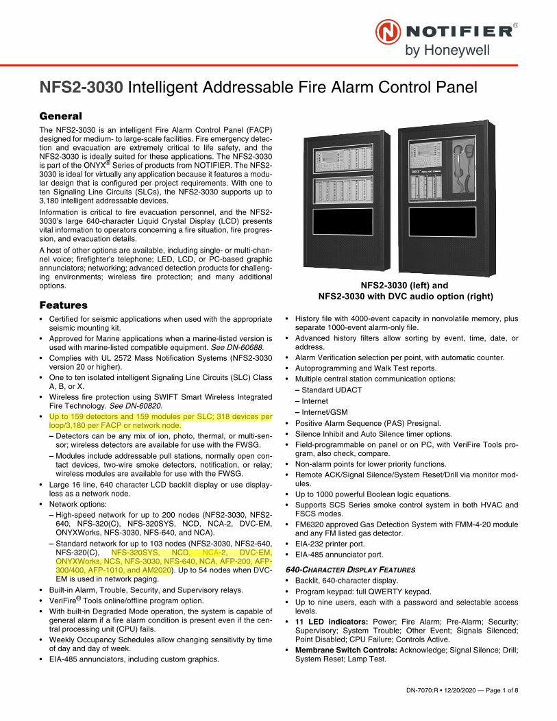
NFS2-3030 (left) and NFS2-3030 with DVC audio option (right)
NFS2-3030 Intelligent Addressable Fire Alarm Control Panel
General The NFS2-3030 is an intelligent Fire Alarm Control Panel (FACP)designed for medium- to large-scale facilities. Fire emergency detec-tion and evacuation are extremely critical to life safety, and theNFS2-3030 is ideally suited for these applications. The NFS2-3030is part of the ONYX® Series of products from NOTIFIER. The NFS2-3030 is ideal for virtually any application because it features a modu-lar design that is configured per project requirements. With one toten Signaling Line Circuits (SLCs), the NFS2-3030 supports up to3,180 intelligent addressable devices.
Information is critical to fire evacuation personnel, and the NFS2-3030’s large 640-character Liquid Crystal Display (LCD) presentsvital information to operators concerning a fire situation, fire progres-sion, and evacuation details.
A host of other options are available, including single- or multi-chan-nel voice; firefighter’s telephone; LED, LCD, or PC-based graphicannunciators; networking; advanced detection products for challeng-ing environments; wireless fire protection; and many additionaloptions.
Features• Certified for seismic applications when used with the appropriate
seismic mounting kit. • Approved for Marine applications when a marine-listed version is
used with marine-listed compatible equipment. See DN-60688. • Complies with UL 2572 Mass Notification Systems (NFS2-3030
version 20 or higher).• One to ten isolated intelligent Signaling Line Circuits (SLC) Class
A, B, or X.• Wireless fire protection using SWIFT Smart Wireless Integrated
Fire Technology. See DN-60820.• Up to 159 detectors and 159 modules per SLC; 318 devices per
loop/3,180 per FACP or network node. – Detectors can be any mix of ion, photo, thermal, or multi-sen-
sor; wireless detectors are available for use with the FWSG. – Modules include addressable pull stations, normally open con-
tact devices, two-wire smoke detectors, notification, or relay;wireless modules are available for use with the FWSG.
• Large 16 line, 640 character LCD backlit display or use display-less as a network node.
• Network options:– High-speed network for up to 200 nodes (NFS2-3030, NFS2-
640, NFS-320(C), NFS-320SYS, NCD, NCA-2, DVC-EM,ONYXWorks, NFS-3030, NFS-640, and NCA).
– Standard network for up to 103 nodes (NFS2-3030, NFS2-640,NFS-320(C), NFS-320SYS, NCD, NCA-2, DVC-EM,ONYXWorks, NCS, NFS-3030, NFS-640, NCA, AFP-200, AFP-300/400, AFP-1010, and AM2020). Up to 54 nodes when DVC-EM is used in network paging.
• Built-in Alarm, Trouble, Security, and Supervisory relays. • VeriFire® Tools online/offline program option. • With built-in Degraded Mode operation, the system is capable of
general alarm if a fire alarm condition is present even if the cen-tral processing unit (CPU) fails.
• Weekly Occupancy Schedules allow changing sensitivity by timeof day and day of week.
• EIA-485 annunciators, including custom graphics.
• History file with 4000-event capacity in nonvolatile memory, plusseparate 1000-event alarm-only file.
• Advanced history filters allow sorting by event, time, date, oraddress.
• Alarm Verification selection per point, with automatic counter.• Autoprogramming and Walk Test reports. • Multiple central station communication options:
– Standard UDACT– Internet– Internet/GSM
• Positive Alarm Sequence (PAS) Presignal.• Silence Inhibit and Auto Silence timer options.• Field-programmable on panel or on PC, with VeriFire Tools pro-
gram, also check, compare.• Non-alarm points for lower priority functions.• Remote ACK/Signal Silence/System Reset/Drill via monitor mod-
ules.• Up to 1000 powerful Boolean logic equations.• Supports SCS Series smoke control system in both HVAC and
FSCS modes. • FM6320 approved Gas Detection System with FMM-4-20 module
and any FM listed gas detector. • EIA-232 printer port.• EIA-485 annunciator port.
640-CHARACTER DISPLAY FEATURES
• Backlit, 640-character display.• Program keypad: full QWERTY keypad.• Up to nine users, each with a password and selectable access
levels.• 11 LED indicators: Power; Fire Alarm; Pre-Alarm; Security;
Supervisory; System Trouble; Other Event; Signals Silenced;Point Disabled; CPU Failure; Controls Active.
• Membrane Switch Controls: Acknowledge; Signal Silence; Drill;System Reset; Lamp Test.
RMViney
Highlight
, NCA-
RMViney
Highlight
NFS-320SYS, NCD, NCA-2, DVC-EM, ONYXWorks, NCS, NFS-3030, NFS-640, NCA, AFP-200, AFP-300/400, AFP-1010, and AM2020
RMViney
Highlight
Up to 159 detectors and 159 modules per SLC; 318 devices per loop/3,180 per FACP or network node.
Page 2 of 8 — DN-7070:R • 12/20/2020
• LCD Display: 640 characters (16 lines x 40 characters) withlong-life LED backlight.
SWIFT WIRELESS
• Self-healing mesh wireless protocol.• Each SWIFT Gateway supports up to 50 devices: 1 wireless gate-
way and up to 49 SWIFT devices. • Up to 4 wireless gateways can be installed with overlapping net-
work coverage.
RELEASING FEATURES
• Ten independent hazards.• Sophisticated cross-zone (three options).• Delay timer and Discharge timers (adjustable).• Abort (four options).
VOICE AND TELEPHONE FEATURES
• Up to eight channels of digital audio.• 35 watt, 50 watt, 75 watt, and 100/125 watt digital amplifiers
(DAA2/DAX series and DS series).• Solid state message generation.• Hard-wired voice control module options.• Firefighter telephone option.• 30- to 120-watt analog amplifiers (AA Series).• Backup tone generator and amplifier option.
FLASHSCAN® INTELLIGENT FEATURES
• Polls up to 318 devices on each loop in less than two seconds.• Activates up to 159 outputs in less than five seconds.• Multicolor LEDs blink device address during Walk Test.
• Fully digital, high-precision protocol (U.S. Patent 5,539,389).• Manual sensitivity adjustment — up to nine levels.• Pre-alarm ONYX intelligent sensing — up to nine levels.• Sensitivity levels:
– Photo – 0.5 to 2.35%/foot obscuration.
– High-Sensitivity Photoelectric (VIEW®) – Open Air Protection(0.5% - 2.0%/ft. obscuration), Special Applications (0.02%-0.5%/ft. obscuration)
– Multi-Criteria Detector – Open Air Protection (2.52-3.89%/ft.obscuration), Special Applications (1.13-2.52%/ft. obscuration)
• Drift compensation (U.S. Patent 5,764,142). • Multi-detector algorithm involves nearby detectors in alarm deci-
sion (U.S. Patent 5,627,515).• Automatic detector sensitivity testing (NFPA-72 compliant).• Maintenance alert (two levels).• Self-optimizing pre-alarm.• Programmable activation of sounder/relay bases during alarm or
pre-alarm.• Read Status displays the level of detector cleanliness.
FSV-951 SERIES VIEW® (VERY INTELLIGENT EARLY WARNING)HIGH-SENSITIVITY SMOKE DETECTOR • Advanced ONYX intelligent sensing algorithms differentiate
between smoke and non-smoke signals.• Addressable operation pinpoints the fire location.• Ivory models (-IV) support CLIP mode as well as FlashScan.• ULC listed models available; “A” models are ULC Listed.• -R is retrofit, backwards compatible for use with older panels.
FRM-1 Relay Contact
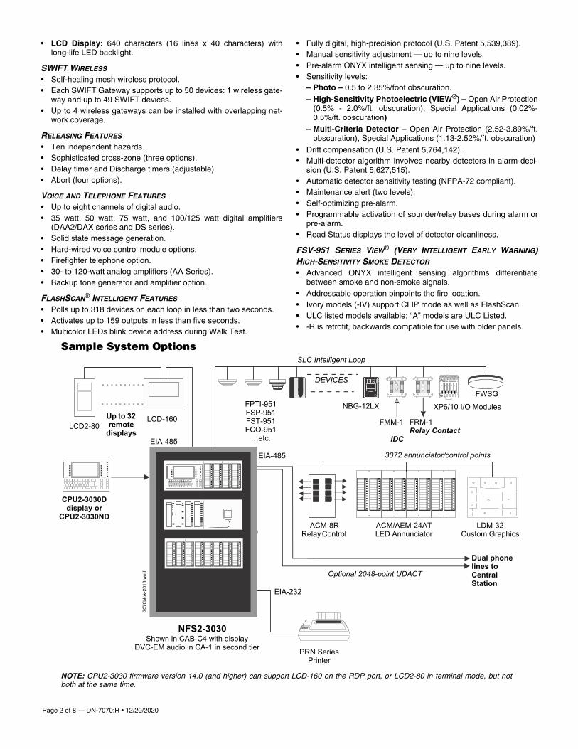
NOTE: CPU2-3030 firmware version 14.0 (and higher) can support LCD-160 on the RDP port, or LCD2-80 in terminal mode, but notboth at the same time.
CPU2-3030D display or
CPU2-3030ND
PRN Series Printer
NFS2-3030
Sample System Options
FPTI-951 FSP-951 FST-951 FCO-951
…etc.
Shown in CAB-C4 with displayDVC-EM audio in CA-1 in second tier
7070
blok
-201
3.w
mf
LCD-160LCD2-80
Up to 32 remote
displaysEIA-485
EIA-485
SLC Intelligent Loop
3072 annunciator/control points
Optional 2048-point UDACT
Dual phone lines to Central Station
EIA-232
DEVICES
ACM/AEM-24AT LED Annunciator
LDM-32 Custom Graphics
ACM-8R Relay Control
NBG-12LX XP6/10 I/O Modules
FMM-1
IDC
FWSG
DN-7070:R • 12/20/2020 — Page 3 of 8
FCO-951(A)/-IV ADVANCED MULTI-CRITERIA FIRE/CO DETECTOR
• Detects all four major elements of a fire (smoke, heat, CO, andflame).
• 135°F (57.2°C) fixed-temperature heat detector.• Transmits an alarm signal due to heat.• Separate signal for life-safety CO detection.• Optional addressable sounder base for Temp-3 (fire) or Temp-4
(CO) tone. • Automatic drift compensation of smoke sensor and CO cell.• High nuisance-alarm immunity.• ULC listed models available; “A” models are ULC Listed.
FPTI-951(A) INTELLIGENT MULTI-CRITERIA DETECTOR
• Combined Photoelectric Thermal and Infrared Sensor• UL 268 7th Edition and UL 521 Listed; Canadian models CAN/
ULC S529 and CAN/ULC S530 • Microprocessor-based technology; combination photo, thermal,
and infrared technology.
FPC-951(A) PHOTOELECTRIC/CO SENSOR
• Combined photoelectric and carbon monoxide sensor
FSCO-951(A) INTELLIGENT CO SENSOR
• Carbon monoxide sensor
FS-OSI-RI(A) ADDRESSABLE INTELLIGENT SINGLE-ENDED BEAM
SMOKE DETECTOR
• Intelligent addressable reflector-type linear optical beam smokedetector
• Fast, easy, and intuitive beam alignment indicated by directionalLED arrows
• Long range coverage of 16-328 ft (5-100 m) is standard; no sepa-rate long-range kit required
FMM-4-20 GAS DETECTION MODULE
• Interface to industry-standard linear scale 4-20 mA sensors.• Five programmable thresholds.• FM Approved, Class 6320 (Stationary Gas Sensors/Detectors).
INTELLIGENT VESDA® DETECTORS • Intelligent aspiration smoke detectors connect directly to the SLC
loop of compatible ONYX® Series panels:– VEA-040-A00-NTF, VEA-040-A10-NTF
– VEP-A00-P-NTF, VEP-A10-P-NTF, VEP-A00-1P-NTF– VEU-A00-NTF, VEU-A10-NTF
• Models offer LED display, LCD display, or both• Coverage options for spaces up to 69,965 square feet
FlashScan® Exclusive World-Leading Detector ProtocolAt the heart of the NFS2-3030 is a set of detection devices anddevice protocol — FlashScan (U.S. Patent 5,539,389). FlashScan isan all-digital protocol that gives superior precision and high noiseimmunity.
As well as giving quick identification of an active input device, thisprotocol can also activate many output devices in a fraction of thetime required by competitive protocols. This high speed also allowsthe NFS2-3030 to have the largest device per loop capacity in theindustry — 318 points — yet every input and output device is sam-pled in less than two seconds. The microprocessor-basedFlashScan® detectors have bicolor LEDs that can be coded to pro-vide diagnostic information, such as device address during WalkTest.
ONYX Intelligent SensingONYX Intelligent Sensing is a set of software algorithms that providethe NFS2-3030 with industry-leading smoke detection capability.These complex algorithms require many calculations on each read-ing of each detector, and are made possible by the very high-speedmicrocomputer used by the NFS2-3030.
Drift Compensation and Smoothing. Drift compensation allowsthe detector to retain its original ability to detect actual smoke, andresist false alarms, even as dirt accumulates. It reduces mainte-nance requirements by allowing the system to automatically performthe periodic sensitivity measurements required by NFPA 72.Smoothing filters are also provided by software to remove transientnoise signals, usually caused by electrical interference.
Maintenance Warnings. When the drift compensation performedfor a detector reaches a certain level, the performance of the detec-tor may be compromised, and special warnings are given. There arethree warning levels: (1) Low Chamber value; (2) Maintenance Alert,indicative of dust accumulation that is near but below the allowedlimit; (3) Maintenance Urgent, indicative of dust accumulation abovethe allowed limit.
Sensitivity Adjust. Nine sensitivity levels are provided for alarmdetection. These levels can be set manually, or can change automat-ically between day and night. Nine levels of pre-alarm sensitivity canalso be selected, based on predetermined levels of alarm. Pre-alarmoperation can be latching or self-restoring, and can be used to acti-vate special control functions.
Self-Optimizing Pre-Alarm. Each detector may be set for “Self-Optimizing” pre-alarm. In this special mode, the detector “learns” itsnormal environment, measuring the peak analog readings over along period of time, and setting the pre-alarm level just above thesenormal peaks.
Cooperating Multi-Detector Sensing. A patented feature of ONYXIntelligent Sensing is the ability of a smoke sensor to consider read-ings from nearby sensors in making alarm or pre-alarm decisions.Without statistical sacrifice in the ability to resist false alarms, itallows a sensor to increase its sensitivity to actual smoke by a factorof almost two to one.
Field Programming OptionsAutoprogram is a timesaving feature. The FACP “learns” whatdevices are physically connected and automatically loads them inthe program with default values for all parameters. Requiring lessthan one minute to run, this routine allows the user to have almostimmediate fire protection in a new installation, even if only a portionof the detectors are installed.
Keypad Program Edit. The NFS2-3030, like all NOTIFIER intelli-gent panels, has the exclusive feature of program creation and edit-ing capability from the front panel keypad, while continuing toprovide fire protection. The architecture of the NFS2-3030 softwareis such that each point entry carries its own program, including con-trol-by-event links to other points. This allows the program to beentered with independent per-point segments, while the NFS2-3030simultaneously monitors other (already installed) points for alarmconditions.
VeriFire® Tools is an offline programming and test utility that cangreatly reduce installation programming time, and increase confi-dence in the site-specific software. It is Windows® based and pro-vides technologically advanced capabilities to aid the installer. Theinstaller may create the entire program for the NFS2-3030 in thecomfort of the office, test it, store a backup file, then bring it to thesite and download from a laptop into the panel.
Page 4 of 8 — DN-7070:R • 12/20/2020
Product Line Information• “Configuration Guidelines” on page 4• “Main System Components” on page 4
• “Networking Options” on page 4• “Auxiliary Power Supplies and Batteries” on page 4• “Audio Options” on page 4
• “Compatible Devices, EIA-232 Ports” on page 5• “Compatible Devices, EIA-485 Ports” on page 5• “Compatible Intelligent Devices” on page 5
• “Enclosures, Chassis, and Dress Plates” on page 6• “Backboxes” on page 7• “Other Options” on page 7
CONFIGURATION GUIDELINES
Stand-alone and network systems require a main display. On single-FACP systems (one NFS2-3030D), the display option is the CPU2-3030D. On network systems (two or more networked fire panelnodes), at least one NCD, NCA-2, NCS, or ONYXWorks annuncia-tion device is required. Options listed as follows.
MAIN SYSTEM COMPONENTS
CPU2-3030D: NFS2-3030 Primary Display. CPU2-3030D ships withkeypad/display installed; includes 640-character backlit LCD display,QWERTY programming and control keypad. CPU2-3030 is a centralprocessing unit and requires an AMPS-24(E) power supply. ForEnglish ULC applications, use CPU2-3030DC. Non-English versionsare available: CPU2-3030D-FR, CPU2-3030D-HE, CPU2-3030D-KO, CPU2-3030D-PO, CPU2-3030D-SC, CPU2-3030D-SP, CPU2-3030D-TC, and CPU2-3030D-TH. For English Marine applicationsorder CPU2-3030D-M; for non-English Marine applications orderCPU2-3030D-M and the appropriate KP-KIT-XX. (See DN-60688.)
CPU2-3030ND: CPU2-3030 without display. Non-English versionsare available: CPU2-3030ND-FR, CPU2-3030ND-HE, CPU2-3030ND-KO, CPU2-3030ND-PO, CPU2-3030ND-SC, CPU2-3030ND-SP, CPU2-3030ND-TC.
AMPS-24(E): One required for each NFS2-3030. Addressablepower supply and battery charger with two 24 VDC outputs.Addressable by any FlashScan® or CLIP mode FACP. Charges 7 to200 AH batteries. Occupies up to five addresses on an SLC,depending on configuration. Primary input power for panel. See DN-6883.
LCM-320: Loop Control Module. Provides one SLC. NFS2-3030supports up to five LCM-320s and five LEM-320 expanders for atotal of ten SLCs. See DN-6881.
LEM-320: Loop Expander Module. Expands an LCM-320. See DN-6881.
SAMPLE SYSTEM: Four-loop NFS2-3030 with display: CPU2-3030D, DP-DISP, two BMP-1s, CHS-M3, two LCM-320s, two LEM-320s, AMPS-24, SBB-A4, DR-A4, BP2-4, BB-100, batteries.
NETWORKING OPTIONS NCA-2: Network Control Annunciator, 640 characters. An alternateprimary display for CPU2-3030 can be provided by the NCA-2, NCS,or ONYXWorks. Using NCA-2 as primary display enables non-English languages. On network systems (two or more networked firepanel nodes), one network display (either NCA-2, NCS, or ONYX-Works) is required for every system. On network systems, the NCA-2 connects (and requires) a standard Network Communication Mod-ule or High-Speed Network Communication Module. Mounts in a rowof FACP node or in two annunciator positions. Mounting optionsinclude the DP-DISP, ADP-4B, or in an annunciator box, such as theABS-2D. In CAB-4 top-row applications, a DP-DISP and two BMP-1blank modules are required for mounting. Non-English versions areavailable: NCA-2-FR, NCA-2-HE, NCA-2-KO, NCA-2-PO, NCA-2-SC, NCA-2-SP, NCA-2-TC, NCA-2-TH. For English ULC applica-tions, order NCA-2C; for marine applications, order NCA-2-M; for
non-English marine applications order NCA-2-M and appropriateKP-KIT-XX. See DN-7047.
NCD: Network control display, with a high-definition 10” touchscreen. As part of a standalone NFS2-3030 system, the NCD canserve as Primary Display for the panel, to provide control and statuscapabilities on displayless nodes. On network systems, the NCDconnects to (and requires) a standard Network Communication Mod-ule or High-Speed Network Communication Module. Mountingoptions include the ABS-TD for standalone applications. In theCAB-4 series the NCD can be mounted in the top row with aDP-GDIS1 or lower rows using a DP-GDIS2. See DN-60974.
NCM-W, NCM-F: Standard Network Communications Modules. Wireand multi-mode fiber versions available. See DN-6861.
HS-NCM-W(-2), HS-NCM-MF, HS-NCM-SF, HS-NCM-WMF(-2),HS-NCM-WSF(-2), HS-NCM-MFSF: High-speed Network Commu-nications Modules that can connect to two nodes. Wire, single-modefiber, multi-mode fiber, and media conversion models are available.See DN-60454.
RPT-W, RPT-F, RPT-WF: Standard-network repeater board with wireconnection (RPT-W), multi-mode fiber connection (RPT-F), or allow-ing a change in media type between wire and fiber (RPT-WF). Notused with high-speed networks. See DN-6971.
ONYXWorks: UL/ULC-listed graphics PC workstation, ONYXWorksGUI software, and computer hardware. See DN-7048 for specificpart numbers.
NFN-GW-EM-3: NFN Gateway, embedded. (Replaces NFN-GW-EM.) See DN-60499.
NWS-3: NOTI•FIRE•NET™ Web Server. See DN-6928.
CAP-GW: Common Alerting Protocol Gateway. See DN-60756.
VESDA-HLI-GW: VESDAnet high-level interface gateway. See DN-60753.
LEDSIGN-GW: UL-listed sign gateway. Interfaces with classic andhigh-speed NOTI•FIRE•NET networks through the NFN Gateway.See DN-60679.
OAX2-24V: UL-listed LED sign, used with LEDSIGN-GW. See DN-60679.
AUXILIARY POWER SUPPLIES AND BATTERIES APS2-6R: Auxiliary Power Supply. Provides up to 6.0 amperes ofpower for peripheral devices. Includes battery input and transferrelay, and overcurrent protection. Mounts on two of four positions ona CHS-4L or CHS-4 chassis. See DN-5952.
ACPS-610: 6.0 A or 10.0 A addressable charging power supply. SeeDN-60244.
FCPS-24S6/-24S8: Remote 6 A and 8 A power supplies with batterycharger. See DN-6927.
BAT Series: Batteries. AMPS-24 uses two 12 volt, 7 to 200 AH bat-teries. See DN-6933.
AUDIO OPTIONS NOTE: See “Enclosures, Chassis, and Dress Plates” on page 6 formounting hardware.
DVC-EM: Digital Voice Command, digital audio processor with mes-sage storage for up to 32 minutes of standard quality (4 minutes athigh quality) digital audio. See DN-7045.
DVC-RPU: Digital Voice Command Remote Paging Unit for use withDVC-EM. Includes the keypad/display. See DN-60726.
DS-DB: Digital Series Distribution Board, provides bulk amplificationcapabilities to the DVC-EM while retaining digital audio distributioncapabilities. Can be configured with up to four DS-AMPs, supplyinghigh-level risers spread throughout an installation. See DN-60565.
DVC-KD: DVC-EM keypad for local annunciation and controls; sta-tus LEDs and 24 user-programmable buttons. See DN-7045.
DN-7070:R • 12/20/2020 — Page 5 of 8
DS-AMP/E: 125W, 25 VRMS, or 100W, 70VRMS. 70VRMS requiresDS-XF70V step-up transformer. Digital Series Amplifier, part of theDS-DB system. See DN-60663.
DS-RFM, DS-FM, DS-SFM: Fiber conversion modules for DVC-EM,DS-DB distribution board, and DAA2/DAX Series amplifiers. SeeDN-60633.
DAA2-5025(E): 50W, 25 Vrms Digital Audio Amplifier assembly withpower supply; includes chassis. See DN-60556.
DAA2-5070(E): 50W, 70.7 Vrms Digital Audio Amplifier assemblywith power supply; includes chassis. See DN-60556.
DAA2-7525(E): 75W, 25 Vrms digital audio amplifier assembly withpower supply; includes chassis. See DN-60556.
DAX-3525(E): 35W, 25 Vrms Digital Audio Amplifier assembly withpower supply, includes chassis. See DN-60561.
DAX-3570(E): 35W, 70.7 Vrms Digital Audio Amplifier assembly withpower supply, includes chassis. See DN-60561.
DAX-5025(E): 50W, 25 Vrms Digital Audio Amplifier assembly withpower supply, includes chassis. See DN-60561.
DAX-5070(E): 50W, 70.7 Vrms Digital Audio Amplifier assembly withpower supply, includes chassis. See DN-60561.
TELH-1: Firefighter’s Telephone Handset for use with the DVC-EMwhen mounted in the CA-2 chassis. See DN-7045.
CMIC-1: Microphone used with DVC/DVC-EM. Included with CA-2chassis assembly. See DN-7045.
RM-1/RM-1SA: Remote microphone assemblies, mount on ADP-4(RM-1) dress panel or CAB-RM/-RMR (RM-1SA) stand-alone cabi-nets. See DN-6728.
AA-30: Audio Amplifier, 30 watts, 25 Vrms. Includes amplifier andaudio input supervision, backup input, and automatic switchover,power supply, cables. See DN-3224.
AA-120/AA-100: Audio Amplifier. AA-120 is 120 watts, 25 Vrms. AA-100 is 100 watts, 70.7 Vrms. The amplifier contains an integral chas-sis for mounting to a CAB-B4, -C4, or -D4 backbox (consumes onerow). Includes audio input and amplified output supervision, backupinput, and automatic switchover to backup tone. See DN-3224.
DAA Series Digital Audio Amplifiers: Legacy DAA Series amplifi-ers are compatible with DVC systems running SR4.0. For specificinformation on DAA-50 series amplifiers, refer to DN-7046. For infor-mation on DAA-7525 Series, refer to DN-60257.
COMPATIBLE DEVICES, EIA-232 PORTS PRN-7: 80-column printer. See DN-60897
VS4095/5: Printer, 40-column, 24 V. Order from Keltron, Inc. SeeDN-3260.
DPI-232: Direct Panel Interface, specialized modem for extendingserial data links to remotely located FACPs and/or peripherals. SeeDN-6870.
COMPATIBLE DEVICES, EIA-485 PORTS
ACM-24AT: ONYX® Series ACS annunciator – up to 96 points ofannunciation with Alarm or Active LED, Trouble LED, and switch percircuit. Active/Alarm LEDs can be programmed (by powered-upswitch selection) by point to be red, green, or yellow; the TroubleLED is always yellow. See DN-6862.
AEM-24AT: Same LED and switch capabilities as ACM-24AT;expands the ACM-24AT to 48, 72, or 96 points. See DN-6862.
ACM-48A: ONYX® Series ACS annunciator – up to 96 points ofannunciation with Alarm or Active LED per circuit. Active/AlarmLEDs can be programmed (by powered-up switch selection) ingroups of 24 to be red, green, or yellow. Expandable to 96 pointswith one AEM-48A. See DN-6862.
AEM-48A: Same LED capabilities as ACM-48A; expands the ACM-48A to 96 points. See DN-6862.
ACM-8R: Remote Relay Module with eight Form-C contacts. Can belocated up to 6,000 ft. (1828.8 m) from panel on four wires. See DN-3558.
LCD-160: Liquid Crystal Display annunciator, 160-character backlit.Can store character sets for multiple languages. LCD-160C is usedfor ULC applications. See DN-6940.
LCD2-80: Terminal and ACS mode. 80-character, backlit LCD dis-play. Mounts up to 6,000 ft. (1828.8 m) from panel. Up to 32 perFACP. See LCD2-80 (DN-60548).
SCS Series: Smoke control station; eight (expandable to 16) cir-cuits. See DN-4818.
TM-4: Transmitter Module. Includes three reverse-polarity circuitsand one municipal box circuit. Mounts in panel module position (asin single-address mode applications) or in CHS-M3 position. SeeDN-6860.
UDACT-2: Universal Digital Alarm Communicator Transmitter, 636channel. See DN-60686.
UZC-256: Programmable Universal Zone Coder provides positivenon-interfering successive zone coding. Microprocessor-controlled,field-programmable from IBM®-compatible PCs (requires optionalprogramming kit). Mounts on a CHS-4 series chassis within NFS2-3030.
COMPATIBLE INTELLIGENT DEVICES
NOTE: “A” suffix indicates ULC-Listed model.
FWSG Wireless SWIFT Gateway: Addressable gateway supportswireless SLC devices. Not appropriate for ULC applications. SeeDN-60820.
FCO-951/-IV FlashScan, Addressable intelligent multi-criteria smokesensors, photo, carbon monoxide, fixed temperature heat detectorand infra-red (IR). ULC: FCO-951A/-IV
FPC-951. FlashScan, Combined photoelectric and carbon monoxidesensor. ULC: FPC-951A.
FSCO-951. FlashScan, Addressable carbon monoxide sensor.ULC: FSCO-951A.
FPTI-951, FPTI-951-IV: Addressable intelligent multi-criteria photo-electric, thermal and IR sensors. ULC: FPTI-951A, FPTI-951A-IV.
FS-OSI-RI: Addressable intelligent single-ended beam smokedetector. ULC: FS-OSI-RIA. .
FSP-951: White, low-profile intelligent photoelectric sensor,FlashScan only. ULC: FSP-951A.
FSP-951-IV: Ivory, low-profile intelligent photoelectric sensor.ULC: FSP-951A-IV
FSP-951T: White, same as FSP-951 but includes a built-in 135°F(57°C) fixed-temperature thermal device. FlashScan only.ULC: FSP-951TA.
FSP-951T-IV: Ivory, same as FSP-951T but includes a built-in 135°F(57°C) fixed-temperature thermal device. ULC: FSP-951TA-IV.
FSP-951R: White, low-profile intelligent photoelectric sensor, remotetest capable. For use with DNR/DNRW. FlashScan only. ULC: FSP-95RA
FSP-951R-IV: Ivory, low-profile intelligent photoelectric sensor,remote test capable. FlashScan only. ULC: FSP-95RA-IV, for usewith DNRA.
FST-951: White, low-profile intelligent 135°F fixed thermal sensor,FlashScan only. Must be mounted to one of the bases listed below.ULC: FST-951A. See DN-60975.
FST-951-IV: Ivory, low-profile intelligent 135°F fixed thermal sensor,FlashScan and CLIP. Must be mounted to one of the bases listedbelow. ULC: FST-951A-IV.
FST-951R: White, low-profile intelligent rate-of-rise thermal sensor,FlashScan only. Must be mounted to one of the bases listed below.ULC: FST-951A
Page 6 of 8 — DN-7070:R • 12/20/2020
FSP-951R-IV: Ivory, low-profile intelligent photoelectric sensor,remote test capable. FlashScan only. ULC: FSP-95RA-IV, for usewith DNRA.
FST-951H: White, low-profile intelligent 190°F fixed thermal sensor,FlashScan only. Must be mounted to one of the bases listed below.ULC: FST-951HA.
FST-951H-IV: Ivory, low-profile intelligent 190°F thermal sensor,FlashScan and CLIP. Must be mounted to one of the bases listedbelow. ULC: FST-951HA-IV.
FSV-951, FSV-951R:White, intelligent high-sensitivity photoelectricsmoke detector. ULC: FSV-951A, FSV-951RA
FSV-951-IV, FSV-951R-IVIvory, intelligent high-sensitivity photoelec-tric smoke detector. ULC: FSV-951A-IV, FSV-951RA-IV.
VEP-A00-P-NTF: Intelligent aspiration smoke detector with LED dis-play, 4 pipes, covers up to 21,520 square feet. UL/ULC. See DN-61029. UL/ULC Listed.
VEP-A10-P-NTF: Intelligent aspiration smoke detector with LED andLCD display, 4 pipes, covers up to 21,520 square feet. UL/ULC. SeeDN-61029. UL/ULC Listed.
VEP-A00-1P-NTF: Intelligent aspiration smoke detector with LEDdisplay, single pipe, covers up to 10,760 square feet. UL/ULC. SeeDN-61029. UL/ULC Listed.
VEU-A00-NTF: Intelligent aspiration smoke detector with LED dis-play, 4 pipes, covers up to 69,965 square feet. UL/ULC. See DN-61034. UL/ULC Listed.
VEU-A10-NTF: Intelligent aspiration smoke detector with LED andLCD display, 4 pipes, covers up to 69,965 square feet. UL/ULC. SeeDN-61034. UL/ULC Listed.
VEA-040-A00-NTF: Intelligent aspiration with LED display, 40 point-addressable detection points. Covers 36,000 square feet. UL/ULC.See DN-61036. UL/ULC Listed.
VEA-040-A10-NTF: Intelligent aspiration with LED and LCD display,40 point-addressable detection points. Covers 36,000 square feet.UL/ULC. See DN-61036. UL/ULC Listed.
DNR: InnovairFlex low-flow non-relay duct-detector housing.ULC: DNRA. (Order FSP-951R(A) separately.) See DN-60429.
DNRW: Same as above with NEMA-4 rating, watertight. See DN-60429.
B224RB-WH: White, low-profile relay base. See DN-60054. ULC:B224RBA-WH.
B224RB-IV: Ivory, plug-in System Sensor relay base. ULC:B224RBA-IV.
B224BI-WH: White, isolator base for low-profile detectors. See DN-60054. ULC: B224BIA-WH.
B224BI-IV: Ivory isolator detector base. ULC: B224BIA-IV.
B300-6: White, standard flanged low-profile mounting base. (For 10-pack order B300-6-BP.) ULC: B300A-6.
B300-6-IV: Ivory, standard flanged low-profile mounting base. ULC:B300A-6-IV.
B501-WHITE: European-style, 4" (10.16 cm) base. See DN-60054.(For 10-pack order B501-WHITE-BP.) UL/ULC listed.
B501-BL: Black, 4” standard European flangeless mounting base.UL/ULC listed.
B501-IV: Ivory color, 4” standard European flangeless mountingbase. UL/ULC listed.
B200S-WH: White, intelligent programmable sounder base, capableof producing a variety of tone patterns including ANSI Temporal 3.Compatible with synchronization protocol. See DN-60054. ULC:B200SA-WH.
B200S-IV: Ivory intelligent, programmable sounder base. ULC:B200SA-IV.
B200SCOA-WH: White intelligent, programmable sounder base inEnglish/French (required in Canada for ULC applications with COdetectors. Based on B200SA. ULC listed.
B200SCOA-IV: Ivory intelligent, programmable sounder base inEnglish/French (required in Canada for ULC applications with COdetectors. Based on B200SA. ULC listed.
B200S-LF-WH: White, low-frequency version of B200S. See DN-60054.
B200S-LF-IV: Ivory, low-frequency version of B200S.
B200SR-WH: White intelligent programmable sounder base, Tem-poral 3 or Continuous tone. For retrofit installations replacingB501BH series bases. See DN-60054. ULC: B200SRA-WH.
B200SR-IV: Ivory intelligent programmable sounder base, Temporal3 or Continuous tone. For retrofit installations replacing B501BHseries bases. ULC: B200SRA-IV.
B200SR-LF-WH: White, low-frequency version of B200SR. See DN-60054.
B200SR-LF-IV: Ivory, low-frequency version of B200SR.
FMM-1(A): FlashScan monitor module. See DN-6720.
FDM-1(A): FlashScan dual monitor module. See DN-6720.
FZM-1(A): FlashScan two-wire detector monitor module. See DN-6720.
FMM-101(A): FlashScan miniature monitor module. See DN-6720.
FMM-4-20: FlashScan 4-20 mA protocol monitor module. See DN-60411.
FTM-1(A): Firephone Telephone Module connects a remote fire-fighter telephone to a centralized telephone console. Reports statusto panel. Wiring to jacks and handsets is supervised. See DN-6989.
FCM-1(A): FlashScan control module. See DN-6724.
FCM-1-REL(A): FlashScan releasing control module. See DN-60390.
FRM-1(A): FlashScan relay module. See DN-6724.
FDRM-1(A): FlashScan dual monitor/dual relay module. See DN-60709.
NBG-12LX: Manual pull station, addressable. See DN-6726.
N-MPS series: Manual pull stations, addressable and conventional.ULC-listed; for use in Canada only. See DN-5497 and DN-60629.ISO-X(A): Isolator module. See DN-2243.
ISO-6(A): Six fault isolator module. See DN-60844.
XP6-C(A): FlashScan six-circuit supervised control module. SeeDN-6924.
XP6-MA(A): FlashScan six-zone interface module; connects intelli-gent alarm system to two-wire conventional detection zone. See DN-6925.
XP6-R(A): FlashScan six-relay (Form-C) control module. See DN-6926.
XP10-M(A): FlashScan ten-input monitor module. See DN-6923.
ENCLOSURES, CHASSIS, AND DRESS PLATES
CAB-4 Series Enclosure: NFS2-3030 mounts in a standard CAB-4Series enclosure (available in four sizes, “A” through “D”). Backboxand door ordered separately; requires BP2-4 battery plate. A trimring option is available for semi-flush mounting. See DN-6857.
EQ Series Cabinets: EQ series cabinets will house amplifiers,power supplies, battery chargers and control modules. EQ cabinetsare available in three sizes, “B” through “D”. See DN-60229.
CAB-BM Marine System: Protects equipment in shipboard andwaterfront applications. Order CPU2-3030D-M; for non-Englishmarine applications order CPU2-3030D and appropriate KP-KIT-XX.Also order BB-MB for systems using 100 AH batteries. For a full listof required and optional equipment, see DN-60688.
CHS-M3: Mounting chassis for CPU2-3030. One required for eachCPU2-3030D/3030ND.
DN-7070:R • 12/20/2020 — Page 7 of 8
DP-DISP: Dress panel for top row in cabinet with CPU2-3030Dinstalled.
DP-1B: Blank dress panel. Provides dead-front panel for unusedtiers; covers DAA2/DAX series or AA-series amplifier. See DN-7046.
CHS-BH1: Battery chassis; holds two 12.0 AH batteries. Mounts onthe left side of DAA2 chassis. See DN-7046.
CA-1: Chassis, occupies one tier of a CAB-4 Series enclosure. Theleft side accommodates one DVC-EM and a DVC-KD (optional); andthe right side houses a CMIC-1 microphone and its well (optional).See DN-7045.
CA-2: Chassis assembly, occupies two tiers of a CAB-4 Seriesenclosure. The left side accommodates one DVC-EM mounted on ahalf-chassis and one NFS2-3030 or NCA-2 mounted on a half-chas-sis. The right side houses a microphone/handset well. The CA-2assembly includes CMIC-1 microphone. ADDR Series doors withtwo-tier visibility are available for use with the CA-2 configuration:ADDR-B4, ADDR-C4, ADDR-D4 (below).
ADDR-B4*: Two-tier-sized door designed for use with the CA-2chassis configuration. ADDR Series doors are similar to CAB-4Series “DR” doors, but a clear window space exposes the top twotiers of the CAB-4 enclosure. Use an SBB-B4 backbox with theADDR-B4. See DN-7045, DN-6857.
ADDR-C4*: Three-tier-sized door designed for use with the CA-2chassis configuration. ADDR Series doors are similar to CAB-4Series “DR” doors, but a clear window space exposes the top twotiers of the CAB-4 enclosure. Use an SBB-C4 backbox with theADDR-C4. See DN-7045, DN-6857.
ADDR-D4*: Four-tier-sized door designed for use with the CA-2chassis configuration. ADDR Series doors are similar to CAB-4Series “DR” doors, but a clear window space exposes the top twotiers of the CAB-4 enclosure. Use an SBB-D4 backbox with theADDR-D4. See DN-7045, DN-6857.
* Note: Use ADDR-B4/C4/D4 when CA-2 chassis is installed in toptwo rows with NCA-2 or BP-CA2. Use standard door when CA-2 isnot installed in top two rows. For additional configuration information,see the DVC application guide on http://esd.notifier.com.
DPA-1: Dress panel, used with the CA-1 chassis when configuredwith a DVC-EM, DVC-KD, and CMIC-1. See DN-7045.
DPA-2: Dress Panel used with the CA-2 chassis assembly.
DPA-1A4: Dress panel, used with the CA-1 chassis when the CMIC-1 is not used. Provides mounting options on right two bays for twoACS annunciators, or for blank plates. See DN-7045.
ADP-4B: Annunciator dress plate. Mounts in rows 2, 3 or 4 of aCAB-4 series enclosure. Used with ACS series annunciators.
BMP-1: Blank module for unused module positions.
DP-1B: Blank dress panel. Provides dead-front panel for unusedtiers; covers DAA2/DAX series or AA-series amplifier.
BP2-4: Battery plate, required.
CHS-4L: Low-profile four-position Chassis. Mounts two AA-30amplifiers.
CHS-4N: Chassis for mounting up to four APS-6Rs.
CHS-6: Chassis used with the XP6 and XP10 Multi-Modules.Mounts up to six modules in any CAB-4 series row.
NFS-LBB: Battery Box. The NFS-LBB is used to mount up to two 55AH batteries. Dimensions: Box: 24" (610 mm) wide x 14" (356 mm)high x 7.75" (197 mm) deep. Door: 24.125" (613 mm) wide x 14.25"(362 mm) high; door adds 0.0625" (approx. 1.6 mm) to depth.
BACKBOXES
NOTE: “C” suffix indicates ULC-Listed model.
ABF-1B(C) Annunciator Flush Box
ABF-1DB(C) Annunciator Flush Box with Door. UL/ULC Listed.
ABF-2B Annunciator Flush Box
ABF-2DB(C) Annunciator Flush Box with Door
ABF-4B Annunciator Flush Box
ABS-1TB(C) Annunciator Surface Box
ABS-1B(C) Annunciator Surface Box
ABS-2B Annunciator Surface Box
ABS-2D(C) Annunciator Surface Box
ABS-4D(C) Annunciator Surface Box
BB-100: Backbox for batteries and power supplies. The BB-100mounts up to two 100 AH batteries and power supply, if needed. 30"(76.20 cm) wide x 25" (63.50 cm) high x 7.5" (19.05 cm) deep; depthincludes door.
BB-200: Backbox for batteries and power supplies. Holds up to four100 AH batteries (200 AH capacity) and power supply. 30" (76.20cm) wide x 36" (91.44 cm) high x 7.5" (19.05 cm) deep; depthincludes door.
BB-UZC: Backbox for housing the UZC-256 for applications wherethe UZC will not fit in panel enclosure. Black; for red, order BB-UZC-R. See DN-3404.
SEISKIT-CAB: Seismic mounting kit. Required for seismic-certifiedapplications with NFS2-3030 and other equipment in CAB-4 SeriesEnclosures. Includes battery bracket for two 26 AH batteries.
SEISKIT-LBB: Seismic kit for the NFS-LBB. Includes battery bracketfor two 55 AH batteries.
OTHER OPTIONS
411: Slave digital alarm communicator. See DN-6619.
411UDAC: Digital alarm communicator. See DN-6746.
IPDACT-2, IPDACT Internet Monitoring Module: Connects to pri-mary and secondary DACT telephone output ports for internet com-munications over customer-provided Ethernet connection. Requirescompatible Teldat VisorALARM Central Station Receiver. Can useDHCP or static IP. See DN-60408.
IPCHSKIT: IP Communicator Chassis Mounting Kit. For mountingan IPDACT-2/2UD onto the panel chassis or CHS-4 series chassis.Use IPENC for external mounting applications.
IPSPLT: Y-adapter option allow connection of both panel dialer out-puts to one IPDACT-2/2UD cable input.
IPENC: External enclosure for IPDACT, includes IPBRKT mountingbracket; Red; for black, order IPENC-B.
HWF2V-COM: LTE Digital Cellular Fire Alarm Communicator andInternet Panel, Verizon LTE / IP. Provides selectable configurablepaths: cellular only, IP only, or IP primary with cellular backup. Con-nects to the primary and secondary ports of a DACT. See DH-62010.(For Canadian applications order IPGSM-4GC. See DH-60771.)
HWF2A-COM: LTE Digital Cellular Fire Alarm Communicator andInternet Panel, AT&T LTE / IP. Provides selectable configurablepaths: cellular only, IP only, or IP primary with cellular backup. Con-nects to the primary and secondary ports of a DACT. (For Canadianapplications order IPGSM-4GC. See DH-60771.)
NOTE: For other options including compatibility with retrofit equipment,refer to the panel's installation manual, the SLC manual, and the DeviceCompatibility Document.
NOTI•FIRE•NET™ and ONYXWorks™ are trademarks; and FlashScan®, NOTIFIER®,ONYX®, SWIFT®, VeriFire® Tools, VESDA®, and VIEW® are all registered trademarksof Honeywell International Inc.
©2019 by Honeywell International Inc. All rights reserved. Unauthorized use of thisdocument is strictly prohibited.
This document is not intended to be used for installation purposes.
We try to keep our product information up-to-date and accurate.
We cannot cover all specific applications or anticipate all requirements.
All specifications are subject to change without notice.
Country of Origin: USA
NOTIFIER12 Clintonville Road
Northford, CT 06472
203.484.7161
www.notifier.com
SPECIFICATIONS
SYSTEM CAPACITY
• Intelligent Signaling Line Circuits........... 1 expandable to 10• Intelligent detectors ..........................................159 per loop• Addressable monitor/control modules ..............159 per loop• Programmable software zones.............................over 2000• ACS annunciators
per CPU2-3030....................... 32 address x 64 or 96 pointsNOTE: The CPU2-3030 can support up to 96 annunciator addresspoints per ACM-24AT/-48A.
ELECTRICAL SPECIFICATIONS Primary Input Power:
– AMPS-24: 110-120 VAC, 50/60 Hz, 4.5 A maximum.– AMPS-24E: 240 VAC, 50/60 Hz, 2.25 A maximum.
DC Output:
– Main 24 VDC: Up to 5.0 A– Aux 24 VDC: Up to 5.0 A
– 5 VDC: Up to 0.15 A. Current draw (Standby/Alarm):
– CPU2-3030D board: 0.340 A.
– CPU2-3030ND board: 0.120 A. – LCM-320: 0.130 A.– LEM-320: 0.100 A.
– AMPS-24(E)*: 0.13 A. (Draws power from secondary power source only.)
NOTE: See AMPS-24(E) Manual 51907 for a complete current draw cal-culation sheet and details of input and output values.
Battery charger range: 7 AH – 200 AH. Use separate cabinet forbatteries over 26 AH.
Float Rate: 27.6 V.
SHIPPING WEIGHT
• CPU2-3030D: 5.95 lb (2.70 kg).
• CPU2-3030ND: 2.90 lb (1.32 kg).
TEMPERATURE AND HUMIDITY RANGES
This system meets NFPA requirements for operation at 0 – 49°C/32– 120°F and at a relative humidity 93% ± 2% RH (noncondensing) at32°C ± 2°C (90°F ± 3°F). However, the useful life of the system'sstandby batteries and the electronic components may be adverselyaffected by extreme temperature ranges and humidity. Therefore, itis recommended that this system and its peripherals be installed inan environment with a normal room temperature of 15 – 27°C/60 –80°F.
AGENCY LISTINGS AND APPROVALS
These listings and approvals apply to the modules specified in thisdocument. In some cases, certain modules or applications may notbe listed by certain approval agencies, or listing may be in process.Consult factory for latest listing status.
• UL Listed: S635.• ULC Listed: S527-11.• MEA: 232-06-E.• Fire Dept. of New York: COA#6211. • CSFM: 7165-0028:0224 (Commercial). • FM Approved.• FM6320 Approved. Class 6320 for Gas Detection.• City of Chicago.• City of Denver.• Singapore Productivity and Standards Board (PSB).• CCCF listed.• Fire Services Department (Hong Kong).Marine Applications: Marine approved systems must be configuredusing components itemized in this document. (See Main SystemComponents, in “Product Line Information.) Specific connectionsand requirements for those components are described in the instal-lation document, PN 54756. When these requirements are followed,systems are approved by the following agencies:
• US Coast Guard 161.002/55/0 (Standard 46 CFR and 161.002).• Lloyd's Register 11/600013 (ENV 3 category).• American Bureau of Shipping (ABS) Type Approval. NOTE: For information on marine applications, see DN-60688.
STANDARDS
The NFS2-3030 complies with the following UL Standards andNFPA 72, International Building Code (IBC), and California BuildingCode (CBC) Fire Alarm Systems requirements:
• UL 864 (Fire).• UL 1076 (Burglary).• UL 2572 (Mass Notification Systems). (NFS2-3030 version 20 or
higher)• ULC-S527-11 Standard for the Installation of Fire Alarm Sys-
tems.• LOCAL (Automatic, Manual, Waterflow and Sprinkler Supervi-
sory).• AUXILIARY (Automatic, Manual and Waterflow) (requires TM-4).• REMOTE STATION (Automatic, Manual, Waterflow and Sprinkler
Supervisory) (requires TM-4).• PROPRIETARY (Automatic, Manual, Waterflow and Sprinkler
Supervisory). Not applicable for FM.• EMERGENCY VOICE/ALARM.• OT, PSDN (Other Technologies, Packet-switched Data Network). • IBC 2012, IBC 2009, IBC 2006, IBC 2003, IBC 2000 (Seismic).• CBC 2007 (Seismic).
DN-61092:B • 10/8/2020 — Page 1 of 2
PSE-6/PSE-10 Series 6/10 Amp, 24 Volt Power Supply Expanders
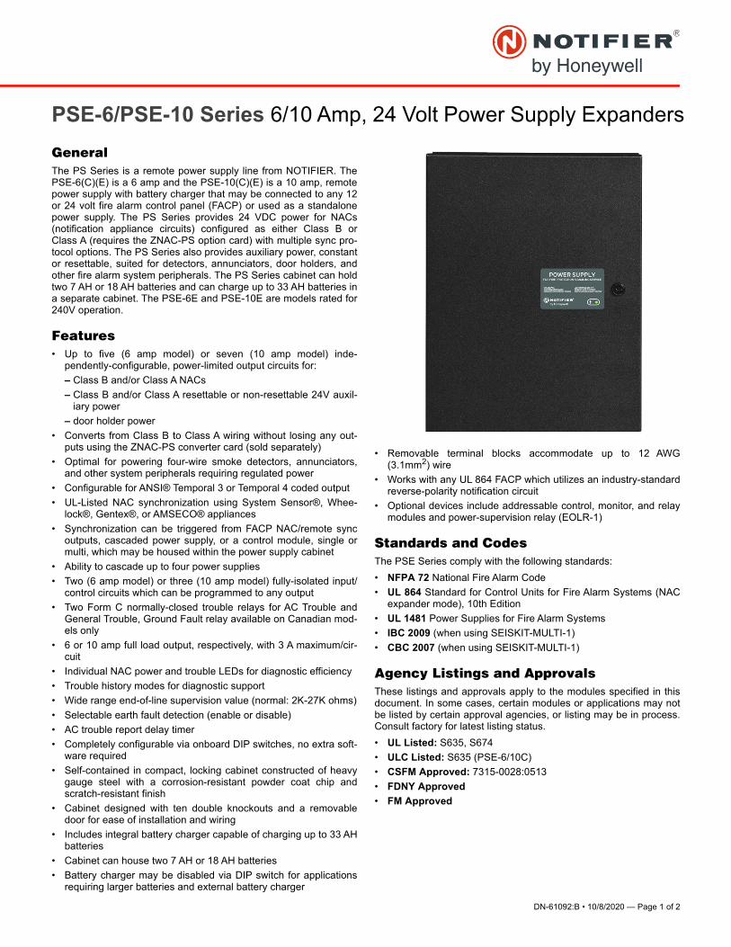
GeneralThe PS Series is a remote power supply line from NOTIFIER. ThePSE-6(C)(E) is a 6 amp and the PSE-10(C)(E) is a 10 amp, remotepower supply with battery charger that may be connected to any 12or 24 volt fire alarm control panel (FACP) or used as a standalonepower supply. The PS Series provides 24 VDC power for NACs(notification appliance circuits) configured as either Class B orClass A (requires the ZNAC-PS option card) with multiple sync pro-tocol options. The PS Series also provides auxiliary power, constantor resettable, suited for detectors, annunciators, door holders, andother fire alarm system peripherals. The PS Series cabinet can holdtwo 7 AH or 18 AH batteries and can charge up to 33 AH batteries ina separate cabinet. The PSE-6E and PSE-10E are models rated for240V operation.
Features• Up to five (6 amp model) or seven (10 amp model) inde-
pendently-configurable, power-limited output circuits for:
– Class B and/or Class A NACs
– Class B and/or Class A resettable or non-resettable 24V auxil-iary power
– door holder power
• Converts from Class B to Class A wiring without losing any out-puts using the ZNAC-PS converter card (sold separately)
• Optimal for powering four-wire smoke detectors, annunciators,and other system peripherals requiring regulated power
• Configurable for ANSI® Temporal 3 or Temporal 4 coded output
• UL-Listed NAC synchronization using System Sensor®, Whee-lock®, Gentex®, or AMSECO® appliances
• Synchronization can be triggered from FACP NAC/remote syncoutputs, cascaded power supply, or a control module, single ormulti, which may be housed within the power supply cabinet
• Ability to cascade up to four power supplies
• Two (6 amp model) or three (10 amp model) fully-isolated input/control circuits which can be programmed to any output
• Two Form C normally-closed trouble relays for AC Trouble andGeneral Trouble, Ground Fault relay available on Canadian mod-els only
• 6 or 10 amp full load output, respectively, with 3 A maximum/cir-cuit
• Individual NAC power and trouble LEDs for diagnostic efficiency
• Trouble history modes for diagnostic support
• Wide range end-of-line supervision value (normal: 2K-27K ohms)
• Selectable earth fault detection (enable or disable)
• AC trouble report delay timer
• Completely configurable via onboard DIP switches, no extra soft-ware required
• Self-contained in compact, locking cabinet constructed of heavygauge steel with a corrosion-resistant powder coat chip andscratch-resistant finish
• Cabinet designed with ten double knockouts and a removabledoor for ease of installation and wiring
• Includes integral battery charger capable of charging up to 33 AHbatteries
• Cabinet can house two 7 AH or 18 AH batteries
• Battery charger may be disabled via DIP switch for applicationsrequiring larger batteries and external battery charger
• Removable terminal blocks accommodate up to 12 AWG(3.1mm2) wire
• Works with any UL 864 FACP which utilizes an industry-standardreverse-polarity notification circuit
• Optional devices include addressable control, monitor, and relaymodules and power-supervision relay (EOLR-1)
Standards and CodesThe PSE Series comply with the following standards:
• NFPA 72 National Fire Alarm Code
• UL 864 Standard for Control Units for Fire Alarm Systems (NACexpander mode), 10th Edition
• UL 1481 Power Supplies for Fire Alarm Systems
• IBC 2009 (when using SEISKIT-MULTI-1)
• CBC 2007 (when using SEISKIT-MULTI-1)
Agency Listings and ApprovalsThese listings and approvals apply to the modules specified in thisdocument. In some cases, certain modules or applications may notbe listed by certain approval agencies, or listing may be in process.Consult factory for latest listing status.
• UL Listed: S635, S674
• ULC Listed: S635 (PSE-6/10C)
• CSFM Approved: 7315-0028:0513
• FDNY Approved
• FM Approved

NOTIFIER12 Clintonville Road
Northford, CT 06472
203.484.7161
www.notifier.com
NOTIFIER® and System Sensor® are registered trademarks of Honeywell
International, Inc. Wheelock® is a registered trademark of Cooper Tech-
nologies Company. Gentex® is a registered trademark of Gentex Corpora-
tion. AMSECO® is a registered trademark of Potter Electric Signal
Company, LLC. ANSI® is a registered trademark of the American National
Standards Institute, Inc.
©2020 by Honeywell International Inc. All rights reserved. Unauthorized
use of this document is strictly prohibited.
This document is not intended to be used for installation purposes.
We try to keep our product information up-to-date and accurate.
We cannot cover all specific applications or anticipate all requirements.
All specifications are subject to change without notice.
Country of Origin: USA
SPECIFICATIONS
Primary (AC) Power:
• PSE-6(C): 120 VAC, 50/60 Hz, 5.0A maximum
• PSE-10(C): 120VAC, 50/60 Hz, 6.2 A maximum
• PSE-6E: 240 VAC, 50/60 Hz, 2.7A maximum
• PSE-10E: 240 VAC, 50/60 Hz, 3.5A maximum
• Wire Size: #12-14 AWG with 600 V insulation
Command Input Circuit:
• Trigger Input Voltage: 9 to 32 VDC
• Trigger Current: 2.0 mA (16 - 32 V); Per Input: 1.0 mA (9 - 16 V)
Trouble Contact Rating: 4 A at 24 VDC
Output Circuits:
• 24 VDC filtered, regulated
• PSE-6: TB8-TB9 – 1A Regulated, 3A special applications; TB10-TB12 – 0.3A Regulated, 3A special applications
• PSE-10: TB8-TB11 – 1.5A Regulated, 3A special applications;TB12-TB14 – 0.3A Regulated, 3A special applications
• 6.0 A (PSE-6) or 10.0 A (PSE-10) maximum total continuous cur-rent for all outputs
Secondary Power (Battery) Charging Circuit:
• Supports lead-acid batteries only
• Float-charge voltage: 27.6 VDC
• Maximum current charge: 1.5 A
• Maximum battery capacity: 18 AH (inside cabinet)
• Maximum battery charging capacity: 33 AH (external cabinet)
Physical:
• Dimensions: 20.0”H x 14.5”W x 3.5”D (cm: 50.8H x 36.83W x8.9D)
• Weight: with two 7Ah batteries is 24 pounds (10.9 kg), with two18 AH batteries is 39 pounds (17.7 kg)
Ordering InformationPSE-6: 6.0 A, 120 VAC remote charger power supply in a lockable,metal enclosure
PSE-6C: Same as above, ULC-listed model
PSE-6R: Same as PSE-6 with red enclosure
PSE-6E: 6.0 A, 240 VAC remote charger power supply in a lock-able, metal enclosure
PSE-10: 10.0 A, 120 VAC remote charger power supply in a lock-able, metal enclosure
PSE-10C: Same as above, ULC-listed model
PSE-10R: Same as PSE-10 with red enclosure
PSE-10E: 10.0 A, 240 VAC remote charger power supply in a lock-able, metal enclosure
ZNAC-PS: Optional Class A output converter module
FCM-1: Addressable Control Module for one Class B or Class Azone of supervised, polarized Notification Appliances. NotificationAppliance Circuit option requires external 24 VDC to power notifica-tion appliances.
FRM-1: Addressable relay module containing two isolated sets ofForm-C contacts, which operate as a DPDT switch
FMM-1: Addressable Monitor Module for one zone of normally opendry-contact initiating devices. Includes plastic cover plate and end-of-line resistor. Module may be configured for either a Class B orClass A IDC.
FDM-1: Dual Monitor Module. Same as FMM-1 except it providestwo inputs for Class B wiring only
FDRM-1: Provides two monitored inputs and two Form-C relays.Functions in Class B wiring only.
XP6-C: Six-circuit supervised control module
XP6-R: Six Form-C relay control module
EOLR-1: 12/24 VDC end-of-line relay for monitoring four-wiresmoke detector power
BAT-1270: Battery, 12 volt, 7.0 AH (two required, see BAT Seriesdata sheet DN-6933).
BAT-12180: Battery, 12 volt, 18AH
BAT-12330: Battery, 12 volt, 33AH
SEISKIT-MULTI-1: Seismic kit for the FL-PSE Series. Includesbracket and hardware for two 7AH or two 18AH batteries.
DN-60556:C • 7/19/17 — Page 1 of 4
DAA2 SeriesDigital Audio Amplifiers
Voice Control Systems
DN-60556:C
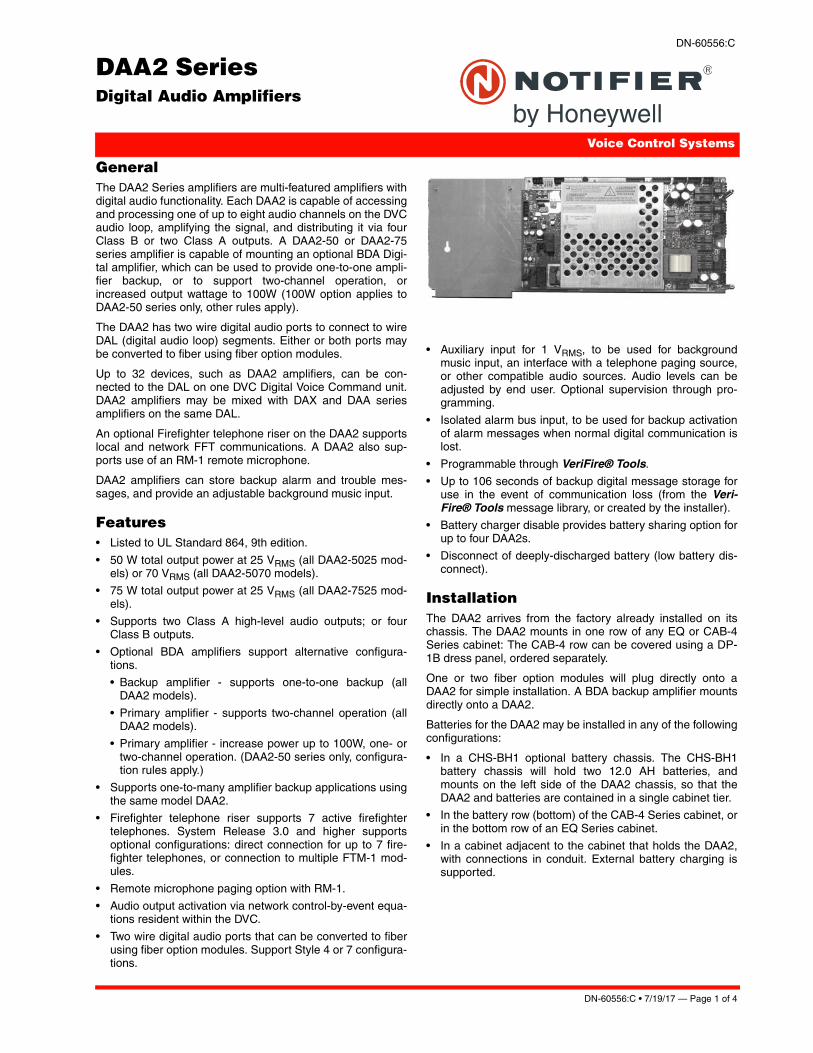
GeneralThe DAA2 Series amplifiers are multi-featured amplifiers withdigital audio functionality. Each DAA2 is capable of accessingand processing one of up to eight audio channels on the DVCaudio loop, amplifying the signal, and distributing it via fourClass B or two Class A outputs. A DAA2-50 or DAA2-75series amplifier is capable of mounting an optional BDA Digi-tal amplifier, which can be used to provide one-to-one ampli-fier backup, or to support two-channel operation, orincreased output wattage to 100W (100W option applies toDAA2-50 series only, other rules apply).
The DAA2 has two wire digital audio ports to connect to wireDAL (digital audio loop) segments. Either or both ports maybe converted to fiber using fiber option modules.
Up to 32 devices, such as DAA2 amplifiers, can be con-nected to the DAL on one DVC Digital Voice Command unit.DAA2 amplifiers may be mixed with DAX and DAA seriesamplifiers on the same DAL.
An optional Firefighter telephone riser on the DAA2 supportslocal and network FFT communications. A DAA2 also sup-ports use of an RM-1 remote microphone.
DAA2 amplifiers can store backup alarm and trouble mes-sages, and provide an adjustable background music input.
Features• Listed to UL Standard 864, 9th edition.
• 50 W total output power at 25 VRMS (all DAA2-5025 mod-els) or 70 VRMS (all DAA2-5070 models).
• 75 W total output power at 25 VRMS (all DAA2-7525 mod-els).
• Supports two Class A high-level audio outputs; or fourClass B outputs.
• Optional BDA amplifiers support alternative configura-tions.
• Backup amplifier - supports one-to-one backup (allDAA2 models).
• Primary amplifier - supports two-channel operation (allDAA2 models).
• Primary amplifier - increase power up to 100W, one- ortwo-channel operation. (DAA2-50 series only, configura-tion rules apply.)
• Supports one-to-many amplifier backup applications usingthe same model DAA2.
• Firefighter telephone riser supports 7 active firefightertelephones. System Release 3.0 and higher supportsoptional configurations: direct connection for up to 7 fire-fighter telephones, or connection to multiple FTM-1 mod-ules.
• Remote microphone paging option with RM-1.
• Audio output activation via network control-by-event equa-tions resident within the DVC.
• Two wire digital audio ports that can be converted to fiberusing fiber option modules. Support Style 4 or 7 configura-tions.
• Auxiliary input for 1 VRMS, to be used for backgroundmusic input, an interface with a telephone paging source,or other compatible audio sources. Audio levels can beadjusted by end user. Optional supervision through pro-gramming.
• Isolated alarm bus input, to be used for backup activationof alarm messages when normal digital communication islost.
• Programmable through VeriFire® Tools.
• Up to 106 seconds of backup digital message storage foruse in the event of communication loss (from the Veri-Fire® Tools message library, or created by the installer).
• Battery charger disable provides battery sharing option forup to four DAA2s.
• Disconnect of deeply-discharged battery (low battery dis-connect).
InstallationThe DAA2 arrives from the factory already installed on itschassis. The DAA2 mounts in one row of any EQ or CAB-4Series cabinet: The CAB-4 row can be covered using a DP-1B dress panel, ordered separately.
One or two fiber option modules will plug directly onto aDAA2 for simple installation. A BDA backup amplifier mountsdirectly onto a DAA2.
Batteries for the DAA2 may be installed in any of the followingconfigurations:
• In a CHS-BH1 optional battery chassis. The CHS-BH1battery chassis will hold two 12.0 AH batteries, andmounts on the left side of the DAA2 chassis, so that theDAA2 and batteries are contained in a single cabinet tier.
• In the battery row (bottom) of the CAB-4 Series cabinet, orin the bottom row of an EQ Series cabinet.
• In a cabinet adjacent to the cabinet that holds the DAA2,with connections in conduit. External battery charging issupported.
Page 2 of 4 — DN-60556:C • 7/19/17
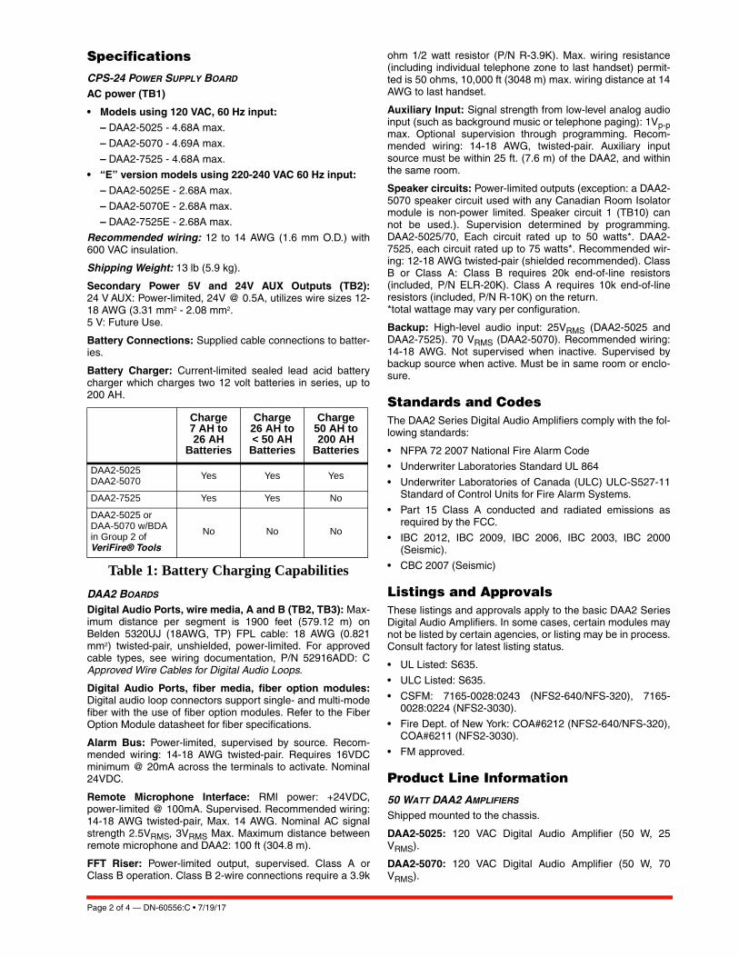
Specifications
CPS-24 POWER SUPPLY BOARD
AC power (TB1)
• Models using 120 VAC, 60 Hz input:
– DAA2-5025 - 4.68A max.
– DAA2-5070 - 4.69A max.
– DAA2-7525 - 4.68A max.
• “E” version models using 220-240 VAC 60 Hz input:
– DAA2-5025E - 2.68A max.
– DAA2-5070E - 2.68A max.
– DAA2-7525E - 2.68A max.
Recommended wiring: 12 to 14 AWG (1.6 mm O.D.) with600 VAC insulation.
Shipping Weight: 13 lb (5.9 kg).
Secondary Power 5V and 24V AUX Outputs (TB2):24 V AUX: Power-limited, 24V @ 0.5A, utilizes wire sizes 12-18 AWG (3.31 mm2 - 2.08 mm2.5 V: Future Use.
Battery Connections: Supplied cable connections to batter-ies.
Battery Charger: Current-limited sealed lead acid batterycharger which charges two 12 volt batteries in series, up to200 AH.
Table 1: Battery Charging Capabilities
DAA2 BOARDS
Digital Audio Ports, wire media, A and B (TB2, TB3): Max-imum distance per segment is 1900 feet (579.12 m) onBelden 5320UJ (18AWG, TP) FPL cable: 18 AWG (0.821mm2) twisted-pair, unshielded, power-limited. For approvedcable types, see wiring documentation, P/N 52916ADD: CApproved Wire Cables for Digital Audio Loops.
Digital Audio Ports, fiber media, fiber option modules:Digital audio loop connectors support single- and multi-modefiber with the use of fiber option modules. Refer to the FiberOption Module datasheet for fiber specifications.
Alarm Bus: Power-limited, supervised by source. Recom-mended wiring: 14-18 AWG twisted-pair. Requires 16VDCminimum @ 20mA across the terminals to activate. Nominal24VDC.
Remote Microphone Interface: RMI power: +24VDC,power-limited @ 100mA. Supervised. Recommended wiring:14-18 AWG twisted-pair, Max. 14 AWG. Nominal AC signalstrength 2.5VRMS, 3VRMS Max. Maximum distance betweenremote microphone and DAA2: 100 ft (304.8 m).
FFT Riser: Power-limited output, supervised. Class A orClass B operation. Class B 2-wire connections require a 3.9k
ohm 1/2 watt resistor (P/N R-3.9K). Max. wiring resistance(including individual telephone zone to last handset) permit-ted is 50 ohms, 10,000 ft (3048 m) max. wiring distance at 14AWG to last handset.
Auxiliary Input: Signal strength from low-level analog audioinput (such as background music or telephone paging): 1Vp-pmax. Optional supervision through programming. Recom-mended wiring: 14-18 AWG, twisted-pair. Auxiliary inputsource must be within 25 ft. (7.6 m) of the DAA2, and withinthe same room.
Speaker circuits: Power-limited outputs (exception: a DAA2-5070 speaker circuit used with any Canadian Room Isolatormodule is non-power limited. Speaker circuit 1 (TB10) cannot be used.). Supervision determined by programming.DAA2-5025/70, Each circuit rated up to 50 watts*. DAA2-7525, each circuit rated up to 75 watts*. Recommended wir-ing: 12-18 AWG twisted-pair (shielded recommended). ClassB or Class A: Class B requires 20k end-of-line resistors(included, P/N ELR-20K). Class A requires 10k end-of-lineresistors (included, P/N R-10K) on the return. *total wattage may vary per configuration.
Backup: High-level audio input: 25VRMS (DAA2-5025 andDAA2-7525). 70 VRMS (DAA2-5070). Recommended wiring:14-18 AWG. Not supervised when inactive. Supervised bybackup source when active. Must be in same room or enclo-sure.
Standards and CodesThe DAA2 Series Digital Audio Amplifiers comply with the fol-lowing standards:
• NFPA 72 2007 National Fire Alarm Code
• Underwriter Laboratories Standard UL 864
• Underwriter Laboratories of Canada (ULC) ULC-S527-11Standard of Control Units for Fire Alarm Systems.
• Part 15 Class A conducted and radiated emissions asrequired by the FCC.
• IBC 2012, IBC 2009, IBC 2006, IBC 2003, IBC 2000(Seismic).
• CBC 2007 (Seismic)
Listings and ApprovalsThese listings and approvals apply to the basic DAA2 SeriesDigital Audio Amplifiers. In some cases, certain modules maynot be listed by certain agencies, or listing may be in process.Consult factory for latest listing status.
• UL Listed: S635.
• ULC Listed: S635.
• CSFM: 7165-0028:0243 (NFS2-640/NFS-320), 7165-0028:0224 (NFS2-3030).
• Fire Dept. of New York: COA#6212 (NFS2-640/NFS-320),COA#6211 (NFS2-3030).
• FM approved.
Product Line Information
50 WATT DAA2 AMPLIFIERS
Shipped mounted to the chassis.
DAA2-5025: 120 VAC Digital Audio Amplifier (50 W, 25VRMS).
DAA2-5070: 120 VAC Digital Audio Amplifier (50 W, 70VRMS).
Charge 7 AH to 26 AH
Batteries
Charge 26 AH to < 50 AH
Batteries
Charge 50 AH to 200 AH
Batteries
DAA2-5025DAA2-5070 Yes Yes Yes
DAA2-7525 Yes Yes No
DAA2-5025 or DAA-5070 w/BDA in Group 2 of VeriFire® Tools
No No No
DN-60556:C • 7/19/17 — Page 3 of 4
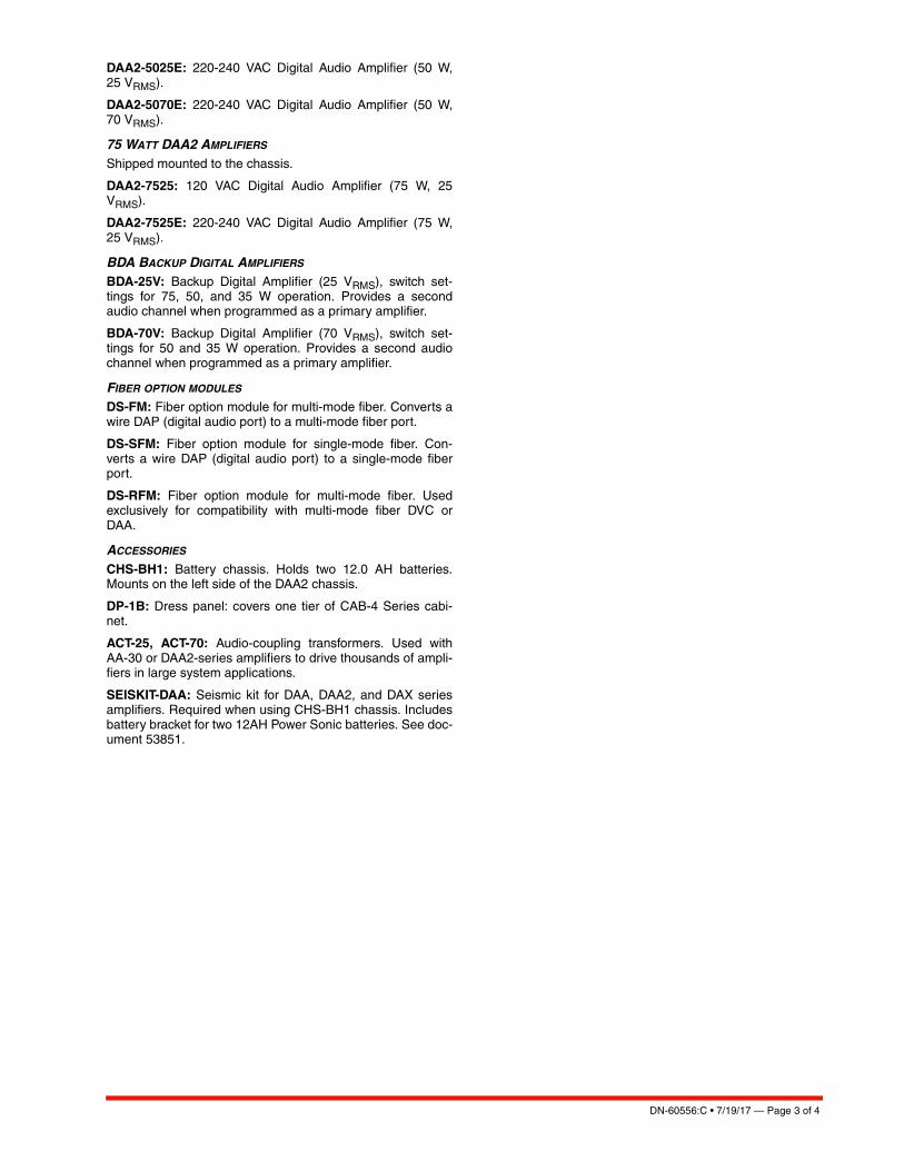
DAA2-5025E: 220-240 VAC Digital Audio Amplifier (50 W,25 VRMS).
DAA2-5070E: 220-240 VAC Digital Audio Amplifier (50 W,70 VRMS).
75 WATT DAA2 AMPLIFIERS
Shipped mounted to the chassis.
DAA2-7525: 120 VAC Digital Audio Amplifier (75 W, 25VRMS).
DAA2-7525E: 220-240 VAC Digital Audio Amplifier (75 W,25 VRMS).
BDA BACKUP DIGITAL AMPLIFIERS
BDA-25V: Backup Digital Amplifier (25 VRMS), switch set-tings for 75, 50, and 35 W operation. Provides a secondaudio channel when programmed as a primary amplifier.
BDA-70V: Backup Digital Amplifier (70 VRMS), switch set-tings for 50 and 35 W operation. Provides a second audiochannel when programmed as a primary amplifier.
FIBER OPTION MODULES
DS-FM: Fiber option module for multi-mode fiber. Converts awire DAP (digital audio port) to a multi-mode fiber port.
DS-SFM: Fiber option module for single-mode fiber. Con-verts a wire DAP (digital audio port) to a single-mode fiberport.
DS-RFM: Fiber option module for multi-mode fiber. Usedexclusively for compatibility with multi-mode fiber DVC orDAA.
ACCESSORIES
CHS-BH1: Battery chassis. Holds two 12.0 AH batteries.Mounts on the left side of the DAA2 chassis.
DP-1B: Dress panel: covers one tier of CAB-4 Series cabi-net.
ACT-25, ACT-70: Audio-coupling transformers. Used withAA-30 or DAA2-series amplifiers to drive thousands of ampli-fiers in large system applications.
SEISKIT-DAA: Seismic kit for DAA, DAA2, and DAX seriesamplifiers. Required when using CHS-BH1 chassis. Includesbattery bracket for two 12AH Power Sonic batteries. See doc-ument 53851.

Page 4 of 4 — DN-60556:C • 7/19/17
NOTIFIER® and VeriFire® Tools are registered trademarks of HoneywellInternational Inc.©2017 by Honeywell International Inc. All rights reserved. Unauthorized useof this document is strictly prohibited.
This document is not intended to be used for installation purposes. We try to keep our product information up-to-date and accurate.
We cannot cover all specific applications or anticipate all requirements. All specifications are subject to change without notice.
For more information, contact Notifier. Phone: (203) 484-7161, FAX: (203) 484-7118.www.notifier.com
Country of Origin: USA.
DN-6940:C • 3/10/17 — Page 1 of 4
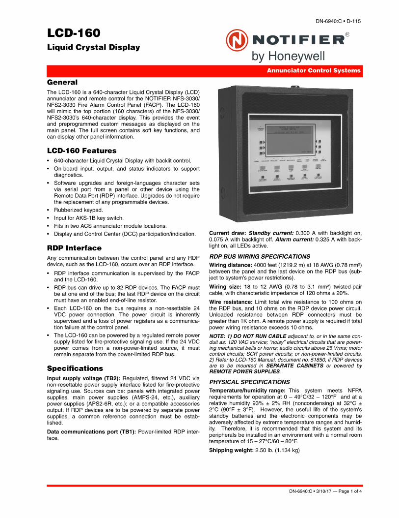
LCD-160Liquid Crystal Display
Annunciator Control Systems
DN-6940:C • D-115
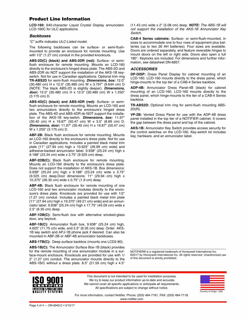
GeneralThe LCD-160 is a 640-character Liquid Crystal Display (LCD)annunciator and remote control for the NOTIFIER NFS-3030/NFS2-3030 Fire Alarm Control Panel (FACP). The LCD-160will mimic the top portion (160 characters) of the NFS-3030/NFS2-3030’s 640-character display. This provides the eventand preprogrammed custom messages as displayed on themain panel. The full screen contains soft key functions, andcan display other panel information.
LCD-160 Features• 640-character Liquid Crystal Display with backlit control.
• On-board input, output, and status indicators to supportdiagnostics.
• Software upgrades and foreign-languages character setsvia serial port from a panel or other device using theRemote Data Port (RDP) interface. Upgrades do not requirethe replacement of any programmable devices.
• Rubberized keypad.• Input for AKS-1B key switch.
• Fits in two ACS annunciator module locations.• Display and Control Center (DCC) participation/indication.
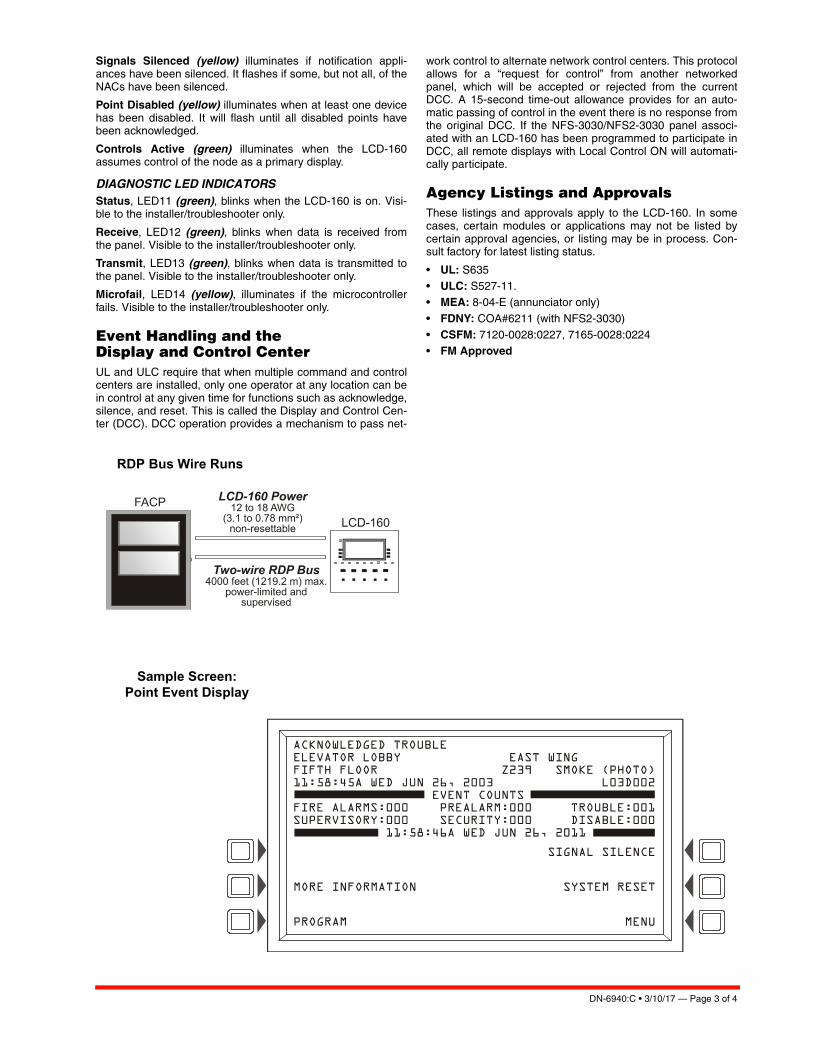
RDP InterfaceAny communication between the control panel and any RDPdevice, such as the LCD-160, occurs over an RDP interface.
• RDP interface communication is supervised by the FACPand the LCD-160.
• RDP bus can drive up to 32 RDP devices. The FACP mustbe at one end of the bus; the last RDP device on the circuitmust have an enabled end-of-line resistor.
• Each LCD-160 on the bus requires a non-resettable 24VDC power connection. The power circuit is inherentlysupervised and a loss of power registers as a communica-tion failure at the control panel.
• The LCD-160 can be powered by a regulated remote powersupply listed for fire-protective signaling use. If the 24 VDCpower comes from a non-power-limited source, it mustremain separate from the power-limited RDP bus.
SpecificationsInput supply voltage (TB2): Regulated, filtered 24 VDC vianon-resettable power supply interface listed for fire-protectivesignaling use. Sources can be: panels with integrated powersupplies, main power supplies (AMPS-24, etc.), auxiliarypower supplies (APS2-6R, etc.); or a compatible accessoriesoutput. If RDP devices are to be powered by separate powersupplies, a common reference connection must be estab-lished.
Data communications port (TB1): Power-limited RDP inter-face.
Current draw: Standby current: 0.300 A with backlight on,0.075 A with backlight off. Alarm current: 0.325 A with back-light on, all LEDs active.
RDP BUS WIRING SPECIFICATIONSWiring distance: 4000 feet (1219.2 m) at 18 AWG (0.78 mm²)between the panel and the last device on the RDP bus (sub-ject to system’s power restrictions).
Wiring size: 18 to 12 AWG (0.78 to 3.1 mm²) twisted-paircable, with characteristic impedance of 120 ohms ± 20%.
Wire resistance: Limit total wire resistance to 100 ohms onthe RDP bus, and 10 ohms on the RDP device power circuit.Unloaded resistance between RDP connectors must begreater than 1K ohm. A remote power supply is required if totalpower wiring resistance exceeds 10 ohms.
NOTE: 1) DO NOT RUN CABLE adjacent to, or in the same con-duit as: 120 VAC service; “noisy” electrical circuits that are power-ing mechanical bells or horns; audio circuits above 25 Vrms; motorcontrol circuits; SCR power circuits; or non-power-limited circuits.2) Refer to LCD-160 Manual, document no. 51850, if RDP devicesare to be mounted in SEPARATE CABINETS or powered byREMOTE POWER SUPPLIES.
PHYSICAL SPECIFICATIONSTemperature/humidity range: This system meets NFPArequirements for operation at 0 – 49°C/32 – 120°F and at arelative humidity 93% ± 2% RH (noncondensing) at 32°C ±2°C (90°F ± 3°F). However, the useful life of the system'sstandby batteries and the electronic components may beadversely affected by extreme temperature ranges and humid-ity. Therefore, it is recommended that this system and itsperipherals be installed in an environment with a normal roomtemperature of 15 – 27°C/60 – 80°F.
Shipping weight: 2.50 lb. (1.134 kg)
Page 2 of 4 — DN-6940:C • 3/10/17
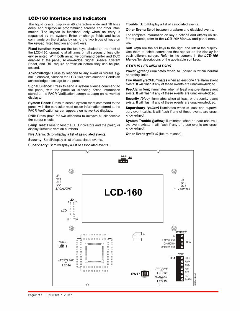
LCD-160 Interface and Indicators The liquid crystal display is 40 characters wide and 16 linesdeep, and displays all programming screens and other infor-mation. The keypad is functional only when an entry isrequested by the system. Enter or change fields and issuecommands on the display by using the two types of keys onthe keypad: fixed function and soft keys.
Fixed function keys are the ten keys labeled on the front ofthe LCD-160, operating at all times on all screens unless oth-erwise noted. With both an active command center and DCCenabled at the panel, Acknowledge, Signal Silence, SystemReset, and Drill require permission before they can be pro-cessed.
Acknowledge: Press to respond to any event or trouble sig-nal. If enabled, silences the LCD-160 piezo sounder. Sends anacknowledge message to the panel.
Signal Silence: Press to send a system silence command tothe panel, with the particular silencing action informationstored at the FACP. Verification screen appears on networkeddisplays.
System Reset: Press to send a system reset command to thepanel, with the particular reset action information stored at theFACP. Verification screen appears on networked displays.
Drill: Press (hold for two seconds) to activate all silenceablefire output circuits.
Lamp Test: Press to test the LED indicators and the piezo, ordisplay firmware version numbers.
Fire Alarm: Scroll/display a list of associated events.
Security: Scroll/display a list of associated events.
Supervisory: Scroll/display a list of associated events.
Trouble: Scroll/display a list of associated events.
Other Event: Scroll between prealarm and disabled events.
For complete information on key functions and effects on dif-ferent panels, refer to the LCD-160 Manual and panel manu-als.
Soft keys are the six keys to the right and left of the display.Use them to select commands that appear on the display foreach different screen. Refer to the screens in the LCD-160Manual for descriptions of the applicable soft keys.
STATUS LED INDICATORSPower (green) illuminates when AC power is within normaloperating limits.
Fire Alarm (red) illuminates when at least one fire alarm eventexists. It will flash if any of these events are unacknowledged.
Pre-Alarm (red) illuminates when at least one pre-alarm eventexists. It will flash if any of these events are unacknowledged.
Security (blue) illuminates when at least one security eventexists. It will flash if any of these events are unacknowledged.
Supervisory (yellow) illuminates when at least one supervi-sory event exists. It will flash if any of these events are unac-knowledged.
System Trouble (yellow) illuminates when at least one trou-ble event exists. It will flash if any of these events are unac-knowledged.
Other Event (yellow) (future release).
6940bord.wmf
LCD-160
DN-6940:C • 3/10/17 — Page 3 of 4
Signals Silenced (yellow) illuminates if notification appli-ances have been silenced. It flashes if some, but not all, of theNACs have been silenced.
Point Disabled (yellow) illuminates when at least one devicehas been disabled. It will flash until all disabled points havebeen acknowledged.
Controls Active (green) illuminates when the LCD-160assumes control of the node as a primary display.
DIAGNOSTIC LED INDICATORSStatus, LED11 (green), blinks when the LCD-160 is on. Visi-ble to the installer/troubleshooter only.
Receive, LED12 (green), blinks when data is received fromthe panel. Visible to the installer/troubleshooter only.
Transmit, LED13 (green), blinks when data is transmitted tothe panel. Visible to the installer/troubleshooter only.
Microfail, LED14 (yellow), illuminates if the microcontrollerfails. Visible to the installer/troubleshooter only.
Event Handling and the Display and Control CenterUL and ULC require that when multiple command and controlcenters are installed, only one operator at any location can bein control at any given time for functions such as acknowledge,silence, and reset. This is called the Display and Control Cen-ter (DCC). DCC operation provides a mechanism to pass net-
work control to alternate network control centers. This protocolallows for a “request for control” from another networkedpanel, which will be accepted or rejected from the currentDCC. A 15-second time-out allowance provides for an auto-matic passing of control in the event there is no response fromthe original DCC. If the NFS-3030/NFS2-3030 panel associ-ated with an LCD-160 has been programmed to participate inDCC, all remote displays with Local Control ON will automati-cally participate.
Agency Listings and ApprovalsThese listings and approvals apply to the LCD-160. In somecases, certain modules or applications may not be listed bycertain approval agencies, or listing may be in process. Con-sult factory for latest listing status.
• UL: S635 • ULC: S527-11.• MEA: 8-04-E (annunciator only)
• FDNY: COA#6211 (with NFS2-3030) • CSFM: 7120-0028:0227, 7165-0028:0224 • FM Approved
RDP Bus Wire Runs
Sample Screen:Point Event Display
Page 4 of 4 — DN-6940:C • 3/10/17
NOTIFIER® is a registered trademark of Honeywell International Inc. ©2017 by Honeywell International Inc. All rights reserved. Unauthorized useof this document is strictly prohibited.
This document is not intended to be used for installation purposes. We try to keep our product information up-to-date and accurate.
We cannot cover all specific applications or anticipate all requirements. All specifications are subject to change without notice.
For more information, contact Notifier. Phone: (203) 484-7161, FAX: (203) 484-7118.www.notifier.com
Country of Origin: USA
Product Line InformationLCD-160: 640-character Liquid Crystal Display annunciator.LCD-160C for ULC applications.
Backboxes“C” suffix indicates ULC-Listed model.
The following backboxes can be surface- or semi-flush-mounted to provide an enclosure for remote mounting. Usewith 1/2" (1.27 cm) conduit in the provided knockouts.
ABS-2D(C) (black) and ABS-2DR (red): Surface- or semi-flush enclosure for remote mounting. Mounts an LCD-160directly to the enclosure’s hinged dress plate. The ABS-2D andABS-2DR do NOT support the installation of the AKS-1B key-switch. Not for use in Canadian applications. Optional trim ringTR-ABS2D for semi-flush mounting. Dimensions, box: 12.0"(30.480 cm) H x 12.0" (30.480 cm) W x 3.797" (9.644 cm) D(NOTE: The black ABS-2D is slightly deeper). Dimensions,door: 12.0" (30.480 cm) H x 12.0" (30.480 cm) W x 1.250"(3.175 cm) D.
ABS-4D(C) (black) and ABS-4DR (red): Surface- or semi-flush enclosure for remote mounting. Mounts an LCD-160 andtwo annunciators directly to the enclosure’s hinged dressplate. The ABS-4D and ABS-4DR do NOT support the installa-tion of the AKS-1B key-switch. Dimensions, box: 11.97"(30.40 cm) H x 19.87" (50.47 cm) W x 3.5" (8.89 cm) D.Dimensions, door: 11.97" (30.40 cm) H x 19.87" (50.47 cm)W x 1.250" (3.175 cm) D.
ABF-2B: Black flush enclosure for remote mounting. Mountsan LCD-160 directly to the enclosure’s dress plate. Not for usein Canadian applications. Includes a painted black metal trimplate [11" (27.94 cm) high x 10.625" (26.99 cm) wide] andadhesive-backed annunciator label. 9.938" (25.24 cm) high x9.188" (23.34 cm) wide x 3.75" (9.525 cm) deep.
ABF-2DB(C): Black flush enclosure for remote mounting.Mounts an LCD-160 directly to the enclosure’s dress plate.Does not support the installation of AKS-1B. Box dimensions:9.938" (25.24 cm) high x 9.188" (23.24 cm) wide x 3.75"(9.525 cm) deep.Door dimensions: 11" (29.94 cm) high x10.375" (26.35 cm) wide x 0.75" (1.9 cm) deep.
ABF-4B: Black flush enclosure for remote mounting of oneLCD-160 and two annunciator modules directly to the enclo-sure’s dress plate. Knockouts are provided for use with 1/2"(1.27 cm) conduit. Includes a painted black metal trim plate[11" (27.94 cm) high x 19.375" (49.21 cm) wide] and an annun-ciator label. 9.938" (25.24 cm) high x 17.75" (45.09 cm) wide x2.5" (6.35 cm) deep.
ABF-1DB(C): Semi-flush box with alternative smoked-glassdoor, any keylock.
ABF-1B(C): Annunciator flush box, 9.938" (25.24 cm) high,4.625" (11.75 cm) wide, and 2.5" (6.35 cm) deep. Order AKS-1B key switch and APJ-1B phone jack if desired. Can also bemounted in ABF-2B or ABF-4B annunciator backboxes.
ABS-1TB(C): Deep surface backbox (mounts one LCD2-80).
ABS-1B(C): The Annunciator Surface Box-1B (black) providesfor the remote mounting of one annunciator module in a sur-face-mount enclosure. Knockouts are provided for use with 1/2" (1.27 cm) conduit. The annunciator mounts directly to theABS-1B/C without a dress plate. 8.5" (21.59 cm) high x 4.5"
(11.43 cm) wide x 2" (5.08 cm) deep. NOTE: The ABS-1B willnot support the installation of the AKS-1B Annunciator KeySwitch.
CAB-4 Series cabinets: Surface- or semi-flush-mounted, insizes to accommodate one to four rows of equipment plus bat-teries (up to two 26 AH batteries). Four sizes are available.Doors are ordered separately, and feature reversible hinges tomount doors on the left or right side. Doors also open a full180°. Keylocks are included. For dimensions and further infor-mation, see datasheet DN-6857.
ACCESSORIESDP-DISP: Dress Panel Display for cabinet mounting of anLCD-160. LCD-160 mounts directly to the dress panel, whichhinge-mounts to the top tier of a CAB-4 Series backbox.
ADP-4B: Annunciator Dress Panel-4B (black) for cabinetmounting of an LCD-160. LCD-160 mounts directly to thedress panel, which hinge-mounts to the tier of a CAB-4 Seriesbackbox.
TR-ABS2D: Optional trim ring for semi-flush mounting ABS-2D(R).
VP-2B: Vented Dress Panel for use with the ADP-4B dresspanel installed in the top tier of a NOTIFIER cabinet. It coversthe gap between the dress panel and top of the cabinet.
AKS-1B: Annunciator Key Switch provides access security forthe control switches on the LCD-160. Key-switch kit includeskey, hardware, and an annunciator label.

DN-60977:B • 7/1/2019 — Page 1 of 3
FSP-951 Series Addressable Photoelectric Smoke Detectors
The NOTIFIER® FSP-951 Series intelligent plug-in smoke detectorsare designed for both performance and aesthetics, and are directreplacements for the FSP-851 Series. A new modern, sleek, con-temporary design and enhanced optical sensing chamber is engi-neered to sense smoke produced by a wide range of combustionsources in accordance with more stringent code standards.
The FSP-951 Series detector sensitivity can be programmed in thecontrol panel software. Sensitivity is continuously monitored andreported to the panel. Point ID capability allows each detector’saddress to be set with rotary, decimal address switches, providingexact detector location for selective maintenance when chambercontamination reaches an unacceptable level. Dual electronicthermistors add 135°F (57°C) fixed temperature thermal sensing onthe FSP-951T. The FSP-951R is a remote test capable detector foruse with DNR Series duct detector housings. FSP-951 series detec-tors are available for both FlashScan® and CLIP applications asdesignated.
FeaturesSLC LOOP:
• Two-wire SLC loop connection
• Unit uses base for wiring
• Compatible with FlashScan® and CLIP protocol systems
• Stable communication technique with noise immunity
ADDRESSING:
• Addressable by device
• Rotary, decimal addressing(Refer to the NOTIFIER panel manuals for device capacity.)
ARCHITECTURE:
• Sleek, low-profile, stylish design
• Unique single-source design to respond quickly and dependablyto a broad range of fires
• Integral communications and built-in device-type identification
• Built-in tamper resistant feature
• Remote test feature from the panel
• Walk test with address display (an address on 121 will blink thedetector LED: 12-[pause]-1(FlashScan systems only)
• Built-in functional test switch activated by external magnet
• Removable cover and insect-resistant screen for simple fieldcleaning
• Expanded color options
OPERATION:
• Designed to meet UL 268 7th Edition
• Factory preset at 1.5% nominal sensitivity for panel alarm thresh-old level
• LED “blinks” when the unit is polled (communicating with the firepanel) and latches in alarm.
• Low standby current
MECHANICALS:
• Sealed against back pressure
• SEMS screws for wiring of the separate base
• Designed for direct-surface or electrical-box mounting
• Plugs into separate base for ease of installation and maintenance
• Separate base allows interchange of photoelectric, ionization andthermal sensors
OPTIONS:
• Optional relay, isolator, and sounder bases
InstallationFSP-951 Series plug-in intelligent smoke detectors use a detach-able base to simplify installation, service and maintenance. Installa-tion instructions are shipped with each detector.
Mount detector base (all base types) on an electrical backbox which is at least 1.5" (3.81 cm) deep. For a chart of compatible junction boxes, see DN-60054.
NOTE: Because of the inherent supervision provided by the SLC loop, end-of-line resistors are not required. Wiring “T-taps” or branches are permitted for Style 4 (Class “B”) wiring only.When using relay or sounder bases, consult the ISO-X(A) installation sheet I56-1380 for device limitations between isolator modules and iso-lator bases.
ConstructionThese detectors are constructed of fire-resistant plastic. The FSP-951 Series plug-in intelligent smoke detectors are designed to com-mercial standards and offer an attractive appearance.
OperationEach FSP-951 Series detector uses one of the panel’s addresses (total limit is panel dependent) on the NOTIFIER Signaling Line Cir-cuit (SLC). It responds to regular polls from the control panel and reports its type and the status. If it receives a test command from the panel (or a local magnet test), it stimulates its electronics and reports an alarm. It blinks its LEDs when polled and turns the LEDs on when commanded by the panel. The FSP-951 Series offers fea-tures and performance that represent the latest in smoke detector technology.
Page 2 of 3 — DN-60977:B • 7/1/2019
Product Line InformationNOTE: “-IV” suffix indicates CLIP and FlashScan device.
FSP-951: White, low-profile intelligent photoelectric sensor, FlashS-can only
FSP-951A: Same as FSP-951 but with ULC listing
FSP-951-IV: Ivory, low-profile intelligent photoelectric sensor
FSP-951A-IV: Same as FSP-951-IV but with ULC listing
FSP-951T: White, same as FSP-951 but includes a built-in 135°F(57°C) fixed-temperature thermal device, FlashScan only
FSP-951TA: Same as FSP-951T but with ULC listing
FSP-951T-IV: Ivory, same as FSP-951T but includes a built-in 135°F(57°C) fixed-temperature thermal device
FSP-951TA-IV: Same as FSP-951T-IV but with ULC listing
FSP-951R: White, low-profile intelligent photoelectric sensor,remote test capable, for use with DNR/DNRW, FlashScan only
FSP-951RA: Same as FSP-951R but with ULC listing, for use withDNRA
FSP-951R-IV: Ivory, low-profile intelligent photoelectric sensor,remote test capable, for use with DNR/DNRW
FSP-951RA-IV: Same as FSP-951R-IV but with ULC listing, for usewith DNRA
INTELLIGENT BASESNOTE: For details on intelligent bases, see DN-60981.
B300-6: White, 6” base, standard flanged low-profile mounting base(CSFM: 7300-1653:0109)
B300-6-IV: Ivory,6” base, standard flanged low-profile mountingbase (CSFM: 7300-1653:0109)
B300A-6: Same as B300-6, ULC listed
B300A-6-IV: Ivory, 6” standard flanged low-profile mounting base,ULC listed
B300-6-BP: Bulk pack of B300-6, package contains 10
B501-WHITE: White, 4” standard European flangeless mountingbase. UL/ULC listed (CSFM: 7300-1653:0109)
B501-BL: Black, 4” standard European flangeless mounting base.UL/ULC listed (CSFM: 7300-1653:0109)
B501-IV: Ivory color, 4” standard European flangeless mountingbase. UL/ULC listed (CSFM: 7300-1653:0109)
B501-WHITE-BP: Bulk pack of B501-WHITE contains 10
B224RB-WH: White, relay base (CSFM: 7300-1653:0216)
B224RB-IV: Ivory, relay base (CSFM: 7300-1653:0216)
B224RBA-WH: White, relay base, ULC listing
B224RBA-IV: Ivory, relay base, ULC listing
B224BI-WH: White, isolator detector base (CSFM: 7300-1653:0216)
B224BI-IV: Ivory isolator detector base (CSFM: 7300-1653:0216)
B224BIA-WH: White, isolator detector base, ULC listing
B224BIA-IV: Ivory isolator detector base, ULC listing
B200S-WH: White, Intelligent addressable sounder base capable ofproducing sound output in high or low volume with ANSI Temporal 3,ANSI Temporal 4, continuous tone, marching tone, and custom tone.Uses FlashScan protocol. (CSFM: 7300-1653:0213)
B200S-IV: Ivory, Intelligent addressable sounder base capable ofproducing sound output in high or low volume with ANSI Temporal 3,ANSI Temporal 4, continuous tone, marching tone, and custom tone.Uses FlashScan protocol. (CSFM: 7300-1653:0213)
B200SA-WH: Same as B200S-WH, ULC listing
B200SA-IV: Same as B200S-IV, ULC listing
B200SCOA-WH: White, Intelligent, programmable sounder base inEnglish/French (required in Canada for ULC applications with COSeries detector applications
B200SCOA-IV: Ivory Intelligent, programmable sounder base inEnglish/French (required in Canada for ULC applications with COSeries detector applications, ULC listing
B200S-LF-WH: White, Low Frequency Intelligent, programmablesounder base. Produces a fundamental frequency of 520 Hz +/-10% with a square wave or its equivalent; designed to meet theNFPA 72 sleeping space requirement. (CSFM: 7300-1653:0238)
B200S-LF-IV: Ivory, Low Frequency Intelligent, programmablesounder base. Produces a fundamental frequency of 520 Hz +/-10% with a square wave or its equivalent; designed to meet theNFPA 72 sleeping space requirement. (CSFM: 7300-1653:0238)
B200SR-WH: White, Intelligent sounder base capable of producingsound output with ANSI Temporal 3 or continuous tone. Intended forretrofit applications. (CSFM: 7300-1653:0213)
B200SR-IV: Ivory, Intelligent sounder base capable of producingsound output with ANSI Temporal 3 or continuous tone. Intended forretrofit applications. (CSFM: 7300-1653:0213)
B200SRA-WH: Same as B200SR-WH with, ULC listing
B200SRA-IV: Same as B200SR-IV in Ivory color, ULC listing
B200SR-LF-WH: White, Low Frequency Intelligent, programmablesounder base. Produces a fundamental frequency of 520 Hz +/-10% with a square wave or its equivalent; designed to meet theNFPA 72 sleeping space requirement. Intended for retrofit applica-tions. (CSFM: 7300-1653:0238)
B200SR-LF-IV: Ivory, Low Frequency Intelligent, programmablesounder base. Produces a fundamental frequency of 520 Hz +/-10% with a square wave or its equivalent; designed to meet theNFPA 72 sleeping space requirement. Intended for retrofit applica-tions. (CSFM: 7300-1653:0238)
MOUNTING KITS AND ACCESSORIES
TR300: White, replacement flange for B210LP(A) base
TR300-IV: Ivory, replacement flange for B210LP(A) base
RA100Z(A): Remote LED annunciator. 3-32 VDC. Mounts to a U.S.single-gang electrical box. For use with B501(A) and B300-6(A).
M02-04-00: Test magnet
M02-09-00: Test magnet with telescoping handle
CK300: Color Kit (includes cover and trim ring), white, 10-pack
CK300-IV: Color Kit (includes cover and trim ring), ivory, 10-pack
CK300-BL: Color Kit (includes cover and trim ring), black, 10-pack
FlashScan® NOTIFIER®, and System Sensor® are registered trademarks
of Honeywell International, Inc.
©2019 by Honeywell International Inc. All rights reserved. Unauthorized
use of this document is strictly prohibited.
This document is not intended to be used for installation purposes.
We try to keep our product information up-to-date and accurate.
We cannot cover all specific applications or anticipate all requirements.
All specifications are subject to change without notice.
Country of Origin: Mexico
NOTIFIER12 Clintonville Road
Northford, CT 06472
203.484.7161
www.notifier.com
SPECIFICATIONS
Sensitivity:
• UL Applications: 0.5% to 4.0% per foot obscuration.
• ULC Applications: 0.5% to 3.5% per foot obscuration
Size: 2.0" (5.3 cm) high; base determines diameter
– B300-6: 6.1" (15.6 cm) diameter
– B501: 4" (10.2 cm) diameter
For a complete list of detector bases see DN-60981
Shipping weight: 3.4 oz. (95 g)
Operating temperature range:
• FSP-951: 32°F to 122°F (0°C to 50°C)
• FSP-951T Series: 32°F to 100°F(0°C to 38°C)
• FSP-951R Series installed in a DNR/DNRW, -4°F to 158°F (-20°C to 70°C)
UL/ULC Listed Velocity Range: 0-4000 ft/min. (1219.2 m/min.),suitable for installation in ducts
Relative humidity: 10% – 93% non-condensing
Thermal ratings: fixed-temperature set point 135°F (57°C), rate-of-rise detection 15°F (8.3°C) per minute, high temperature heat 190°F(88°C)
ELECTRICAL SPECIFICATIONS
Voltage range: 15 - 32 volts DC peak
Standby current (max. avg.): 200µA @ 24 VDC (one communica-tion every 5 seconds with LED enabled)
Max current: 4.5 mA @ 24 VDC (“ON”)
DETECTOR SPACING AND APPLICATIONS
NOTIFIER recommends spacing detectors in compliance with NFPA72. In low airflow applications with smooth ceiling, space detectors30 feet (9.1m). For specific information regarding detector spacing,placement, and special applications refer to NFPA 72. A SystemSmoke Detector Application Guide, document A05-1003, is avail-able at www.systemsensor.com.
Listings and ApprovalsListings and approvals below apply to the FSP-951 Series detectors.In some cases, certain modules may not be listed by certainapproval agencies, or listing may be in process. Consult factory forlatest listing status.
• UL/ULC Listing: S1115
• FM Approved
• CSFM: 7272-0028:0503
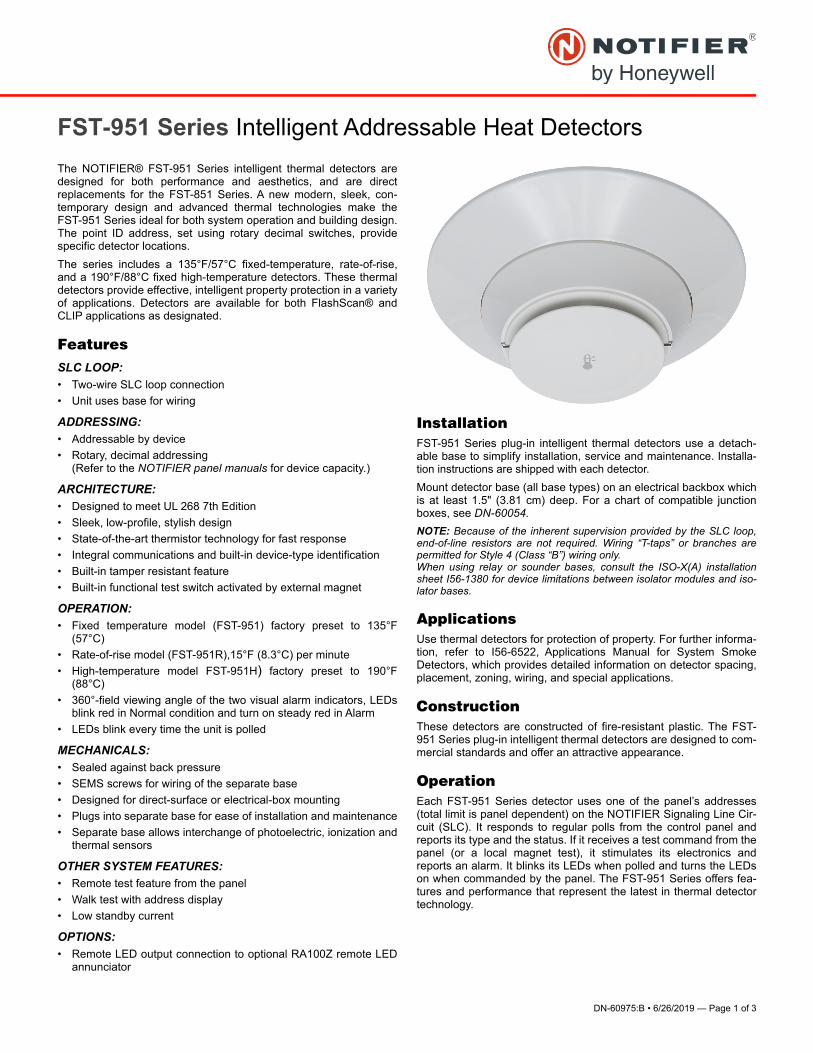
DN-60975:B • 6/26/2019 — Page 1 of 3
FST-951 Series Intelligent Addressable Heat Detectors
The NOTIFIER® FST-951 Series intelligent thermal detectors aredesigned for both performance and aesthetics, and are directreplacements for the FST-851 Series. A new modern, sleek, con-temporary design and advanced thermal technologies make theFST-951 Series ideal for both system operation and building design.The point ID address, set using rotary decimal switches, providespecific detector locations.
The series includes a 135°F/57°C fixed-temperature, rate-of-rise,and a 190°F/88°C fixed high-temperature detectors. These thermaldetectors provide effective, intelligent property protection in a varietyof applications. Detectors are available for both FlashScan® andCLIP applications as designated.
FeaturesSLC LOOP:
• Two-wire SLC loop connection
• Unit uses base for wiring
ADDRESSING:
• Addressable by device
• Rotary, decimal addressing (Refer to the NOTIFIER panel manuals for device capacity.)
ARCHITECTURE:
• Designed to meet UL 268 7th Edition
• Sleek, low-profile, stylish design
• State-of-the-art thermistor technology for fast response
• Integral communications and built-in device-type identification
• Built-in tamper resistant feature
• Built-in functional test switch activated by external magnet
OPERATION:
• Fixed temperature model (FST-951) factory preset to 135°F(57°C)
• Rate-of-rise model (FST-951R),15°F (8.3°C) per minute
• High-temperature model FST-951H) factory preset to 190°F(88°C)
• 360°-field viewing angle of the two visual alarm indicators, LEDsblink red in Normal condition and turn on steady red in Alarm
• LEDs blink every time the unit is polled
MECHANICALS:
• Sealed against back pressure
• SEMS screws for wiring of the separate base
• Designed for direct-surface or electrical-box mounting
• Plugs into separate base for ease of installation and maintenance
• Separate base allows interchange of photoelectric, ionization andthermal sensors
OTHER SYSTEM FEATURES:
• Remote test feature from the panel
• Walk test with address display
• Low standby current
OPTIONS:
• Remote LED output connection to optional RA100Z remote LEDannunciator
InstallationFST-951 Series plug-in intelligent thermal detectors use a detach-able base to simplify installation, service and maintenance. Installa-tion instructions are shipped with each detector.
Mount detector base (all base types) on an electrical backbox whichis at least 1.5" (3.81 cm) deep. For a chart of compatible junctionboxes, see DN-60054.
NOTE: Because of the inherent supervision provided by the SLC loop,end-of-line resistors are not required. Wiring “T-taps” or branches arepermitted for Style 4 (Class “B”) wiring only.When using relay or sounder bases, consult the ISO-X(A) installationsheet I56-1380 for device limitations between isolator modules and iso-lator bases.
ApplicationsUse thermal detectors for protection of property. For further informa-tion, refer to I56-6522, Applications Manual for System SmokeDetectors, which provides detailed information on detector spacing,placement, zoning, wiring, and special applications.
ConstructionThese detectors are constructed of fire-resistant plastic. The FST-951 Series plug-in intelligent thermal detectors are designed to com-mercial standards and offer an attractive appearance.
OperationEach FST-951 Series detector uses one of the panel’s addresses(total limit is panel dependent) on the NOTIFIER Signaling Line Cir-cuit (SLC). It responds to regular polls from the control panel andreports its type and the status. If it receives a test command from thepanel (or a local magnet test), it stimulates its electronics andreports an alarm. It blinks its LEDs when polled and turns the LEDson when commanded by the panel. The FST-951 Series offers fea-tures and performance that represent the latest in thermal detectortechnology.
Page 2 of 3 — DN-60975:B • 6/26/2019
Product Line InformationNOTE: “-IV” suffix indicates CLIP and FlashScandevice.
FST-951: White, low-profile intelligent 135°F fixed thermal sensor,FlashScan only
FST-951A: Same as FST-951 but with ULC listing
FST-951-IV: Ivory, low-profile intelligent 135°F fixed thermal sensor,FlashScan and CLIP
FST-951A-IV: Same as FST-951-IV but with ULC listing
FST-951R: White, low-profile intelligent rate-of-rise thermal sensor,FlashScan only
FST-951RA: Same as FST-951 but with ULC listing
FST-951R-IV: Ivory, low-profile intelligent rate-of-rise fixed thermalsensor, FlashScan and CLIP
FST-951RA-IV: Same as FST-951R-IV but with ULC listing
FST-951H: White, low-profile intelligent 190°F fixed thermal sensor,FlashScan only
FST-951HA: Same as FST-951H but with ULC listing
FST-951H-IV: Ivory, low-profile intelligent 190°F thermal sensor,FlashScan and CLIP
FST-951HA-IV Same as FST-951 but with ULC listing
INTELLIGENT BASESNOTE: For details on intelligent bases, see DN-60981.
B300-6: White, 6” base, standard flanged low-profile mounting base(CSFM: 7300-1653:0109)
B300-6-IV: Ivory,6” base, standard flanged low-profile mountingbase (CSFM: 7300-1653:0109)
B300A-6: Same as B300-6, ULC listed
B300A-6-IV: Ivory, 6” standard flanged low-profile mounting base,ULC listed
B300-6-BP: Bulk pack of B300-6, package contains 10
B501-WHITE: White, 4” standard European flangeless mountingbase. UL/ULC listed (CSFM: 7300-1653:0109)
B501-BL: Black, 4” standard European flangeless mounting base.UL/ULC listed (CSFM: 7300-1653:0109)
B501-IV: Ivory color, 4” standard European flangeless mountingbase. UL/ULC listed (CSFM: 7300-1653:0109)
B501-WHITE-BP: Bulk pack of B501-WHITE contains 10
B224RB-WH: White, relay base (CSFM: 7300-1653:0216)
B224RB-IV: Ivory, relay base (CSFM: 7300-1653:0216)
B224RBA-WH: White, relay base, ULC listing
B224RBA-IV: Ivory, relay base, ULC listing
B224BI-WH: White, isolator detector base (CSFM: 7300-1653:0216)
B224BI-IV: Ivory isolator detector base (CSFM: 7300-1653:0216)
B224BIA-WH: White, isolator detector base, ULC listing
B224BIA-IV: Ivory isolator detector base, ULC listing
B200S-WH: White, Intelligent addressable sounder base capable ofproducing sound output in high or low volume with ANSI Temporal 3,ANSI Temporal 4, continuous tone, marching tone, and custom tone.Uses FlashScan protocol. (CSFM: 7300-1653:0213)
B200S-IV: Ivory, Intelligent addressable sounder base capable ofproducing sound output in high or low volume with ANSI Temporal 3,ANSI Temporal 4, continuous tone, marching tone, and custom tone.Uses FlashScan protocol. (CSFM: 7300-1653:0213)
B200SA-WH: Same as B200S-WH, ULC listing
B200SA-IV: Same as B200S-IV, ULC listing
B200SCOA-WH: White, Intelligent, programmable sounder base inEnglish/French (required in Canada for ULC applications with COSeries detector applications
B200SCOA-IV: Ivory Intelligent, programmable sounder base inEnglish/French (required in Canada for ULC applications with COSeries detector applications, ULC listing
B200S-LF-WH: White, Low Frequency Intelligent, programmablesounder base. Produces a fundamental frequency of 520 Hz +/-10% with a square wave or its equivalent; designed to meet theNFPA 72 sleeping space requirement. (CSFM: 7300-1653:0238)
B200S-LF-IV: Ivory, Low Frequency Intelligent, programmablesounder base. Produces a fundamental frequency of 520 Hz +/-10% with a square wave or its equivalent; designed to meet theNFPA 72 sleeping space requirement. (CSFM: 7300-1653:0238)
B200SR-WH: White, Intelligent sounder base capable of producingsound output with ANSI Temporal 3 or continuous tone. Intended forretrofit applications. (CSFM: 7300-1653:0213)
B200SR-IV: Ivory, Intelligent sounder base capable of producingsound output with ANSI Temporal 3 or continuous tone. Intended forretrofit applications. (CSFM: 7300-1653:0213)
B200SRA-WH: Same as B200SR-WH with, ULC listing
B200SRA-IV: Same as B200SR-IV in Ivory color, ULC listing
B200SR-LF-WH: White, Low Frequency Intelligent, programmablesounder base. Produces a fundamental frequency of 520 Hz +/-10% with a square wave or its equivalent; designed to meet theNFPA 72 sleeping space requirement. Intended for retrofit applica-tions. (CSFM: 7300-1653:0238)
B200SR-LF-IV: Ivory, Low Frequency Intelligent, programmablesounder base. Produces a fundamental frequency of 520 Hz +/-10% with a square wave or its equivalent; designed to meet theNFPA 72 sleeping space requirement. Intended for retrofit applica-tions. (CSFM: 7300-1653:0238)
MOUNTING KITS AND ACCESSORIES
TR300: White, replacement flange for B210LP(A) base
TR300-IV: Ivory, replacement flange for B210LP(A) base
RA100Z(A): Remote LED annunciator. 3-32 VDC. Mounts to a U.S.single-gang electrical box. For use with B501(A) and B300-6(A).
M02-04-00: Test magnet
M02-09-00: Test magnet with telescoping handle
CK300: Color Kit (includes cover and trim ring), white, 10-pack
CK300-IV: Color Kit (includes cover and trim ring), ivory, 10-pack
CK300-BL: Color Kit (includes cover and trim ring), black, 10-pack

FlashScan® and NOTIFIER® are registered trademarks of Honeywell
International, Inc.
©2019 by Honeywell International Inc. All rights reserved. Unauthorized
use of this document is strictly prohibited.
This document is not intended to be used for installation purposes.
We try to keep our product information up-to-date and accurate.
We cannot cover all specific applications or anticipate all requirements.
All specifications are subject to change without notice.
Country of Origin: Mexico
NOTIFIER12 Clintonville Road
Northford, CT 06472
203.484.7161
www.notifier.com
SPECIFICATIONS
Sensitivity: UL Applications: 0.5% to 4.0% per foot obscuration.ULC is 0.5% to 3.5%
Size: 2.0" (5.3 cm) high; base determines diameter
– B300-6: 6.1" (15.6 cm) diameter
– B501: 4" (10.2 cm) diameter
For a complete list of detector bases see DN-60981
Shipping weight: 3.4 oz. (95 g)
Operating temperature range:
• FST-951, FST-951R Series: –4°F to 100°F (–20°C to 38°C)
• FST-951H Series: –4°F to 150°F (–20°C to 66°C)
Detector spacing: UL approved for 50 ft. (15.24 m) center-to-cen-ter, FM approved for 25 x 25 ft. (7.62 x 7.62 m) spacing
Relative humidity: 10% – 93% non-condensing
Thermal ratings: fixed-temperature set point 135°F (57°C), rate-of-rise detection 15°F (8.3°C) per minute, high temperature heat 190°F(88°C)
Mounting: B300-6(A) flanged base, included
See “Product Line Information: Intelligent Bases,” if using a dif-ferent base.
ELECTRICAL SPECIFICATIONS
Voltage range: 15 - 32 volts DC peak
Standby current (max. avg.): 200µA @ 24 VDC (one communica-tion every 5 seconds with LED enabled)
Max current: 4.5 mA @ 24 VDC (“ON”)
Listings and ApprovalsListings and approvals below apply to the FST-951 Series detectors.In some cases, certain modules may not be listed by certainapproval agencies, or listing may be in process. Consult factory forlatest listing status.
• UL/ULC Listing: S747
• FM Approved
• CSFM: 7270-0028:0502
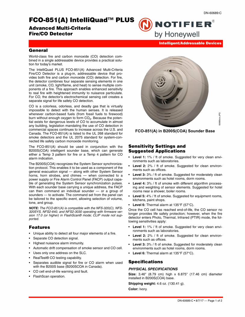
DN-60689:C • 8/7/17 — Page 1 of 2
FCO-851(A) IntelliQuad™ PLUSAdvanced Multi-Criteria Fire/CO Detector
Intelligent/Addressable Devices
DN-60689:C
GeneralWorld-class fire and carbon monoxide (CO) detection com-bined in a single addressable device provides a practical solu-tion for today’s market.
The IntelliQuad PLUS FCO-851(A) Advanced Multi-CriteriaFire/CO Detector is a plug-in, addressable device that pro-vides both fire and carbon monoxide (CO) detection. For fire,the detector combines four separate sensing elements in oneunit (smoke, CO, light/flame, and heat) to sense multiple com-ponents of a fire. This approach enables enhanced sensitivityto real fire with heightened immunity to nuisance particulate.For CO, the detector’s electrochemical sensing cell creates aseparate signal for life safety CO detection.
CO is a colorless, odorless, and deadly gas that is virtuallyimpossible to detect with the human senses. It is releasedwhenever carbon-based fuels (from fossil fuels to firewood)burn without enough oxygen to form CO2. Because the poten-tial exists for dangerous levels of CO to accumulate in almostany building, legislation mandating the use of CO detection incommercial spaces continues to increase across the U.S. andCanada. The FCO-851(A) is listed to the UL 268 standard forsmoke detectors and the UL 2075 standard for system-con-nected life safety carbon monoxide monitoring.
The FCO-851(A) should be used in conjunction with theB200S(COA) intelligent sounder base, which can generateeither a Temp 3 pattern for fire or a Temp 4 pattern for COalarm indication.
The B200S(COA) recognizes the System Sensor synchroniza-tion protocol. This enables it to be used as a component of thegeneral evacuation signal — along with other System Sensorhorns, horn strobes, and chimes — when connected to apower supply or Fire Alarm Control Panel (FACP) output capa-ble of generating the System Sensor synchronization pulses.With each sounder base carrying a unique address, the FACPcan then command an indvidual sounder — or a group ofsounders — to activate. The command set from the panel canbe tailored to the specific event, allowing selection of volume,tone, and group.
NOTE: The FCO-851(A) is compatible with the NFS-320(C), NFS-320SYS, NFS2-640, and NFS2-3030 operating with firmware ver-sion 17.0 (or higher) in FlashScan® mode; CLIP mode not sup-ported.
Features• Unique ability to detect all four major elements of a fire.
• Separate CO detection signal.• Highest nuisance alarm immunity.• Automatic drift compensation of smoke sensor and CO cell.
• Uses only one address on the SLC.• RealTest® CO testing capability.• Separates audible signal for fire or CO alarm when used
with the B200S base (B200SCOA in Canada).• CO cell end-of-life warning and fault.
• FlashScan operation.
Sensitivity Settings and Suggested Applications• Level 1: 1% / ft of smoke. Suggested for very clean envi-
ronments such as laboratories.• Level 2: 2% / ft of smoke. Suggested for clean environ-
ments such as offices.• Level 3: 3% / ft of smoke. Suggested for moderately clean
environments such as hotel rooms, dorm rooms.• Level 4: 3% / ft of smoke with different algorithm process-
ing and weighting of sensor elements. Suggested for hotelrooms near a shower, boiler rooms.
• Level 5: 4% / ft of smoke. Suggested for equipment rooms,kitchens, paint shops.
• Level 6: Thermal alarm at 135°F (57°C).Once the CO cell has reached end-of-life, the CO sensor nolonger provides life safety protection; however, when the firedetector enters Photo, Thermal, Infrared (PTIR) mode, the fol-lowing sensitivities apply:
• Level 1: 1% / ft of smoke. Suggested for very clean envi-ronments such as laboratories.
• Level 2: 2% / ft of smoke. Suggested for clean environ-ments such as offices.
• Level 3: 3% / ft of smoke. Suggested for moderately cleanenvironments such as hotel rooms, dorm rooms.
• Level 6: Thermal alarm at 135°F (57°C).
Specifications
PHYSICAL SPECIFICATIONSSize: 3.46" (8.79 cm) high x 6.875" (17.46 cm) diameterinstalled in B200S(COA) base.
Shipping weight: 4.6 oz. (130.41 g).
Color: Ivory.
6068
9cov
.JP
G
FCO-851(A) in B200S(COA) Sounder Base
Page 2 of 2 — DN-60689:C • 8/7/17
IntelliQuad™ is a trademark and NOTIFIER®, RealTest® and FlashScan® are registered trademarks of Honeywell International Inc.©2017 by Honeywell International Inc. All rights reserved. Unauthorized use of this document is strictly prohibited.
This document is not intended to be used for installation purposes. We try to keep our product information up-to-date and accurate.
We cannot cover all specific applications or anticipate all requirements. All specifications are subject to change without notice.
For more information, contact Notifier. Phone: (203) 484-7161, FAX: (203) 484-7118.www.notifier.com
Country of Origin: USA
Operating humidity range: 15% – 90% relative humidity(noncondensings).
Operating temperature: 0°C to 38°C (32°F to 100°F).
Air velocity: 0 – 4000 ft./min. (0 to 20 m/sec.).
ELECTRICAL SPECIFICATIONSOperating Voltage range: 15 – 32 volts VDC.
Standby current (max. avg.): 300 µA at 24 VDC (one com-munication every 5 seconds with LED blink enabled).
Maximum Alarm Current (LED on): 7.2 mA at 24 VDC.
CO ALARM ACTIVATION LEVELS Alarm activation levels as defined by UL Standard 2034:
Ordering InformationNOTE: “A suffix indicates ULC listed model.
FCO-851: IntelliQuad PLUS Advanced Multi-Criteria Fire/CODetector.
FCO-851A: IntelliQuad PLUS Advanced Multi-Criteria Fire/CODetector, ULC listed.
BX-501 Intelligent Detectors/Sensors Base.
B501 Intelligent base.
B501BH Sounder base.
B501BH-2 Sounder base, steady tone.
B501BHT-2 Sounder base, temporal tone.
B200S/A Intelligent programmable, addressable sounderbase.
B200SR/A Sounder base.
B200S-LF Addressable Low Frequency sounder base.
B200SR-LF Low Frequency sounder base.
B210LP/A Intelligent detector base.
B200SCOA: Intelligent programmable sounder base, ULClisted. Includes CO detector markings in English and French.
M02-04-00: Detector Test Magnet.
M02-09-00: Telescoping Test Magnet.
Agency Listings and ApprovalsThe listings and approvals below apply to the primary product.In some cases, certain modules may not be listed by certainapproval agencies, or listing may be in process. Consult fac-tory for latest listing status.
• UL: S1115 (FCO-851).
• ULC: SS527-11 (FCO-851A).• CSFM: 7275-0028:0264.
Concentration of CO
Maximum Alarm Time Response
70 (+/- 5) PPM 240 min (not less than 60 min)
150 (+/- 5) PPM 50 min (not less than 10 min)
400 (+/- 10) PPM 15 min (not less than 4 min)
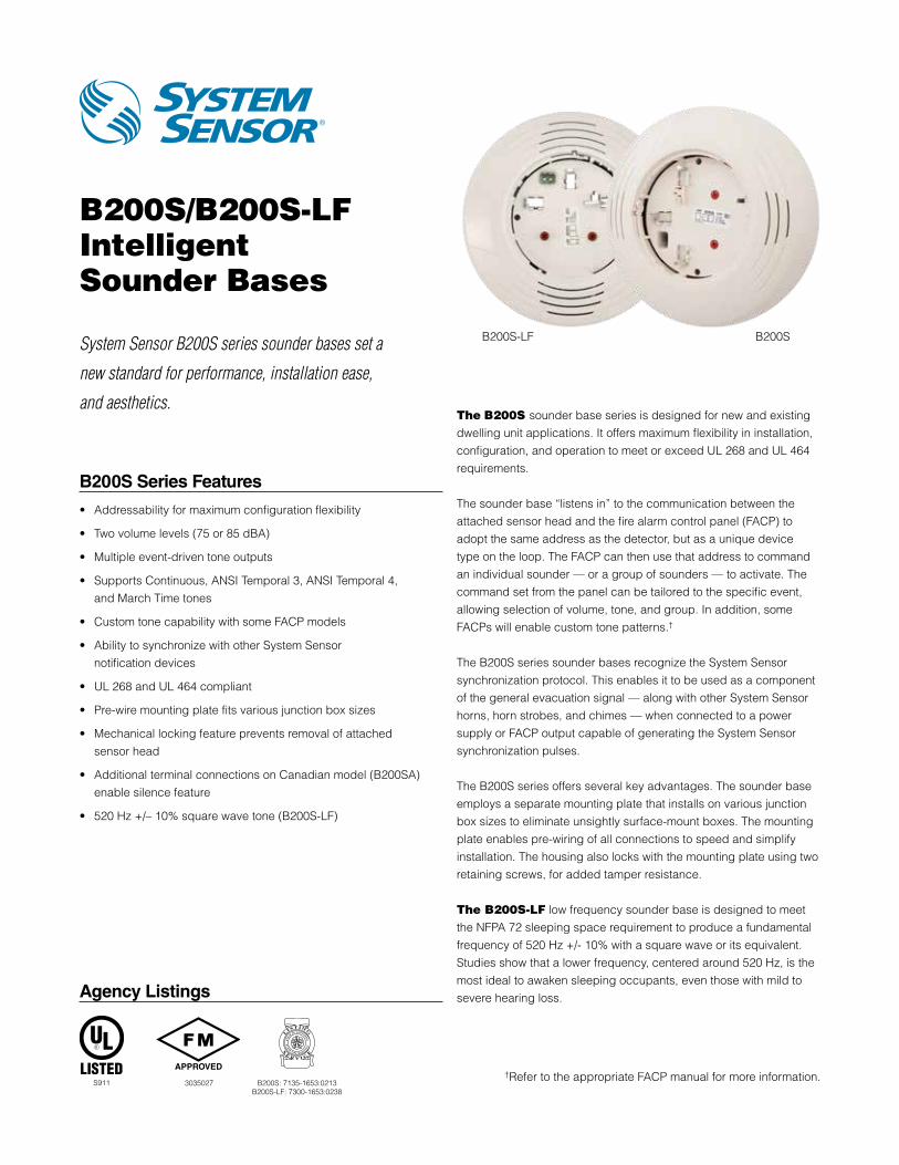
B200S/B200S-LF Intelligent Sounder Bases
System Sensor B200S series sounder bases set a
new standard for performance, installation ease,
and aesthetics.
B200S Series Features
• Addressability for maximum configuration flexibility
• Two volume levels (75 or 85 dBA)
• Multiple event-driven tone outputs
• Supports Continuous, ANSI Temporal 3, ANSI Temporal 4, and March Time tones
• Custom tone capability with some FACP models
• Ability to synchronize with other System Sensor notification devices
• UL 268 and UL 464 compliant
• Pre-wire mounting plate fits various junction box sizes
• Mechanical locking feature prevents removal of attached sensor head
• Additional terminal connections on Canadian model (B200SA) enable silence feature
• 520 Hz +/– 10% square wave tone (B200S-LF)
The B200S sounder base series is designed for new and existing dwelling unit applications. It offers maximum flexibility in installation, configuration, and operation to meet or exceed UL 268 and UL 464 requirements.
The sounder base “listens in” to the communication between the attached sensor head and the fire alarm control panel (FACP) to adopt the same address as the detector, but as a unique device type on the loop. The FACP can then use that address to command an individual sounder — or a group of sounders — to activate. The command set from the panel can be tailored to the specific event, allowing selection of volume, tone, and group. In addition, some FACPs will enable custom tone patterns.†
The B200S series sounder bases recognize the System Sensor synchronization protocol. This enables it to be used as a component of the general evacuation signal — along with other System Sensor horns, horn strobes, and chimes — when connected to a power supply or FACP output capable of generating the System Sensor synchronization pulses.
The B200S series offers several key advantages. The sounder base employs a separate mounting plate that installs on various junction box sizes to eliminate unsightly surface-mount boxes. The mounting plate enables pre-wiring of all connections to speed and simplify installation. The housing also locks with the mounting plate using two retaining screws, for added tamper resistance.
The B200S-LF low frequency sounder base is designed to meet the NFPA 72 sleeping space requirement to produce a fundamental frequency of 520 Hz +/- 10% with a square wave or its equivalent. Studies show that a lower frequency, centered around 520 Hz, is the most ideal to awaken sleeping occupants, even those with mild to severe hearing loss.
†Refer to the appropriate FACP manual for more information.
B200S-LF B200S
Agency Listings
S911 3035027 B200S: 7135-1653:0213B200S-LF: 7300-1653:0238
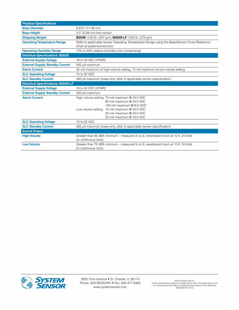
3825 Ohio Avenue • St. Charles, IL 60174 Phone: 800-SENSOR2 • Fax: 630-377-6495
www.systemsensor.com
©2015 System Sensor.Product specifications subject to change without notice. Visit systemsensor.com
for current product information, including the latest version of this data sheet.SPDS53602 • 02/15
Physical Specifications
Base Diameter 6.875˝ (17.46 cm)Base Height 2.0˝ (5.08 cm) less sensorShipping Weight B200S: 0.50 lb. (227 gm); B200S-LF: 0.60 lb. (272 gm)Operating Temperature Range Refer to applicable sensor Operating Temperature Range using the Base/Sensor Cross Reference
Chart at systemsensor.comOperating Humidity Range 10% to 93% relative humidity (non-condensing)Electrical Specifications: B200S
External Supply Voltage 16 to 33 VDC (VFWR)External Supply Standby Current 500 µA maximumAlarm Current 35 mA maximum at high-volume setting; 15 mA maximum at low-volume settingSLC Operating Voltage 15 to 32 VDCSLC Standby Current 300 µA maximum (base only, refer to applicable sensor specification)Electrical Specifications: B200S-LFExternal Supply Voltage 16 to 33 VDC (VFWR)External Supply Standby Current 550 μA maximumAlarm Current High volume setting: 70 mA maximum @ 33.0 VDC
90 mA maximum @ 24.0 VDC 140 mA maximum @16.0 VDC
Low volume setting: 15 mA maximum @ 33.0 VDC 20 mA maximum @ 24.0 VDC 25 mA maximum @ 16.0 VDC
SLC Operating Voltage 15 to 32 VDCSLC Standby Current 300 μA maximum (base only, refer to applicable sensor specification)Sound OutputHigh Volume Greater than 85 dBA minimum – measured in a UL reverberant room at 10 ft. 24 Volts
(in continuous tone)Low Volume Greater than 75 dBA minimum – measured in a UL reverberant room at 10 ft. 24 Volts
(in continuous tone)
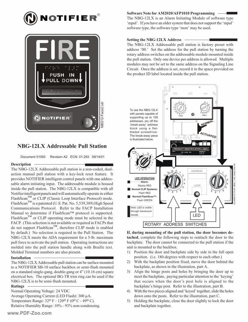
����
��
�������
4 3 2 1
� �
��
��
��
����
��� �
� �
� �
� �
�� ��
� � � �� �� �
������������� ���12345678901231234567890123123456789012312345678901231234567890123
�������
����
�
�
�
���
�
�
�
�
���
�
�
�
�
�����������
�� ���
��������
���� ��������������
��� ���
���� ���� ���� ���
��� �����
������������� ��
�������������������
�������
�������������� �����������
����������� ���������������� �������� ��� �������������������
����������� !� �"���������������������������������������������#����
�������������������������������������������$������$�������������
���������������� ��%����������&�������������������������� ��'�������
$�������$�����������������������$�����������������"�#�����#�����
(������ ��%����������������������)���������������������������&�������
������������*+��������������������������������������
�� ����������������������������
�����������
����������� ��������������������������������������)������
������� $������ ����� �������� ����� �� ,������,� ������ ������� � � *�
���&������%�*-*./��������#�����������������������������������
����������$����������#������ ������������������$���������������
����������������������� ������������������$����������������
����������������#������������������������$��������������������������
-����"���0����(�*1�2(������������*���������1�������3�$���
-����"���0���������������24 " �1�� ��� �5)567)6873�9�#��"����
(�$$����������� 1������� � � /����� ��� ���� - (1� *�����������
'������ ��� �����$���� ��� -����"���0� ��������� ��� ���������
-����"���0����(�*1���������#�$����$����������������������
- (1 ��2�����������������������&�������������:���������- (1������
���������������-����"���0)�����������(�*1�$��������������
���������� 3��������������������:�������������1����"������ �����
�������$��������� + ���:����$����������5��� �$�;�$�$
������������������&�������������������� ��%�������#�����������������
$������ ����� ���� ����� �������� ������� ����#� ����� �������� ��;�
'���������$�������$���������������������
�������
���$���%�������#�<����#�=�>�<+(
&���#��%�������#�(�������2�.+�-����3=�6���?
��$���������/��#�=�6��-������-�2���(���>7��(3
/�����&��9�$������/��#�=��@���76@��������������#
����������������������� ����������� ���!��������"�#"��
������������
����������� ���������������������������������������$������������%�*-*./�"���������������,��;������$��������$������
�����������������#���#��#)��������#��#����>A�2� B��$3��:����
�������������; �������������������/����$����#�������������������
������������������$��������$������
�� �!�������� ����"�#�#$�%� # #�������&&���
����������������� ���$�*��������#�'����������������������
�$���! ��*��������&����������������$����������������������������$���!
�������������)��������������������$��!�$����������
� '��������&��������� �����������������'��������������&������
������)���$������������������#����������������������������������
���,����� ���������������������������������������������������������
��������$�����������������,��;
3 1������������������������,�����������������������������������
�������� ��2� � �8����#������������������������������� 3
3 C�����������,�����������������;��)�$�&���������������������
���,�����)�����������������������������)������
63 ��#�� �������#�������������������������#��#� ������������ ��
$�����������,�����)�������#������������������������������,����#!
����� ������� ����� ���� ����!�� ����� ����� ��� ���#���� ��� ���
���,�����!�����#������ ��/������������������������)�������
>3 C����������������������#���������,����!���#�����)����������������
������������������� ��/������������������������)������(
53 9�����#��������,�����)�������������������#�����������,���������
�������,��������#�����
$��� �������%�!��&'
(����)���� ���)�*����+
�))�,���-� �)� ��� ���
���,� � .�),���++����
/*,��0!�(��1� ���,�
*���0� � ��-� �� +���!
*������ �,�(�,���,2
$���*,��0!�(���)����
� ����� �,�����*���(2
�3$��4���������56$�7�
&
����
� � � � � � � �
����������������� ����
����� � �� ������
�����
�����
������������ ���
�������
����
�
� �����
��������������� ����� ���
,��� (
������
!��2�
�,.���*��8
�2�
�,.�,
���
,��*
�92�
�,
�%
���!�
����2�
�,
www.PDF-Zoo.com
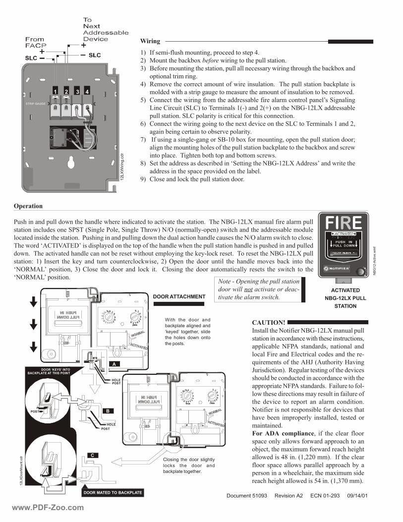
�������������
���������������
����� ��� �����
���� �������
��
��
��
��
�������������
������ ���������
����� ��� �����
���� �������
��
��
��
����
�
�
�
�
����
���������� ���
������������� ���� ��
����
����
���
���
(��������
1�������������������������������������������������������&��������������� �������������$���������������$�����
���������������������"1"��2"��#���1���)�"��#��������3��D%�2���$���������3����������������������������$�����
�������������������������� ��1�����#��������������#�����������������������������������������D%�����$����������������
���������� (�*< �.+!�������������������������������������������������������������������������������������������
���� ����������&��������������������������������������$������#�����,������,������ ��������������������������
�������=� 3� *������ ���� ,��� ���� ����� �����������,����)� 3� %���� ���� ����� ������ ���� ������� $�&��� ���,� ����� ���
��%/' �!� ��������)� 63� (����� ���� ����� ���� ���,� �� � � (�����#� ���� ����� ����$��������� ������� ���� ������� ��� ���
��%/' �!���������
������
��� !"�#��$��
����
)�*+�(,
*���������������������������$����������
���������������������������������������������)
����������� �-1 � ���������)� ��������� ���
������-��������.���������������������������
:����$������������ 9E�2 ���������9�&��#
E�����������3 ��/�#�����������#����������&����
������������������������������������������
�������������-1 ���������� ��-��������������
���������������������$�����������������������
���� ��&���� ��� ������� ��� ����$� ���������
����������������������������������&���������
��&������� �$��������� ���������)� ���������
$���������
%���������&�������)� ��� ���� ������ �����
����������������������������������������
��F���)�����$�;�$�$������������������#��
�����������>8��� �2)��$$3 ��*�����������
�����������������������������������������
����������������������)�����$�;�$�$�����
���������#��������������5>��� �2)6G��$$3
����������������������� ����������������!����������"�#"��
����������������� ��������
����������������������������
������������������������������%���
���������������&����
��� ������
������������������
��
���
���
��
�
5���� ���� ���,� ���
*��0)��������-�������
/0����1� ��-����,.� ����
���� ���� � ��(�� ����
����)� � 2
��� ��-� ���� ���,� ��-����
���0 � ���� ���,� ���
*��0)�������-����,2
3 *����$��������$������#)�����������������>
3 '������������,��;�������������#��������������������
63 �������$������#������������)�������������������������#������#���������,��;����
������������$����#
>3 /�$�&���������������$����������������������� ����������������������,��������
$�������������������#��#�����$������������$���������������������������$�&��
53 (����������������#����$��������������������������$��������������!��"�#�����#
�����(�������2"�(3�������$������2�3�����2H3��������������������������
������������ �"�(�����������������������������������������
B3 (����������������#�#���#����������;����&�����������"�(�������$�����������)
�#��������#�����������������&����������
G3 �*������#������#���#��#����"������;�����$������#)���������������������������I
���#������$������#������������������������������,����������������,��;����������
���������� ����#�����������������������$�������
83 "��������������������������������"�����#������������ ������!��������������
������������������������&�����������������
73 (������������,����������������������
-�����
��&'
5�,��
-2�
�,
��&'
��,:
����2��,
�%
���!�
�����2(
�+
www.PDF-Zoo.com

DN-61073:B • 1/16/2019 — Page 1 of 2
The single-ended beam smoke detector is easy to install andadjust. Only the head unit needs to be wired, and the “eyeball” canbe aimed without adjusting the detector mounting.
OSI-R-SS and OSI-RA-SS Conventional Single-ended Reflective Imaging Beam Smoke Detector
GeneralThe OSI-R-SS is a reflector-type linear optical beam smoke detec-tor that is uniquely suited for protecting large open areas with highceilings, where spot-type smoke detectors are difficult to install andmaintain. Ideal applications are warehouses, atriums, aircrafthangers, sporting arenas and concert halls. The beam operatesprimarily on the principle of light obscuration using infrared.
FAST AND EASY ALIGNMENTAligning the imager to the reflector is extremely intuitive, fast, andaccurate. Both the infrared transmitter and the CMOS imager arecontained in a movable “eyeball” – an adjustable lens assemblythat can move +/- 20° in the vertical direction and 50° in the hori-zontal direction.
Four LED directional arrows indicate the direction to move the lens,guiding the user to find the imager’s perfect alignment with thereflector.
Once the optimum alignment is found, indicated by all greenarrows, the lens is locked with a slide lever. A paintable cover isthen placed over the front to secure the lever in locked position.
RESISTANT TO BUILDING MOVEMENT The infrared transmitter and receiver imager generates a beam oflight towards a high-efficiency reflector. The reflector returns thebeam to the receiver where the received signal is analyzed. Thechange in the strength of the received signal when smoke entersthe area between the unit and the reflector is used to determinethe alarm condition. The receiver imager has a wide 12° field ofview that automatically tracks the reflector in case of buildingmovement or support structure movement. This allows theOSI-R-SS to be highly resistant to movement, eliminating the num-ber one cause of false alarms and/or faults with traditional beamdetectors.
RESISTANT TO SUNLIGHT Optical filtering, high-speed image acquisition and intelligent soft-ware algorithms provide the OSI-R-SS system with higher levels ofstability and greater resistance to high level lighting variability. Thisprovides better resistance to sunlight in its field of view, helping toprevent false alarms when saturated by sunlight, reflected sunlightor any other very bright light sources.
RESISTANT TO FOREIGN OBJECT INTRUSIONAdvanced smoke imaging techniques allow the detector to avoidfalse alarms from partial and sudden blockage from foreign objectintrusion.
TIME-SAVING AUTOMATIC SENSITIVITY SETTINGUnique in the market, the sensitivity of the detector is selected andset automatically at the optimum sensitivity based on the size ofthe reflector measured in the field of view.
DRIFT COMPENSATIONThe detector incorporates automatic drift compensation, wherebythe detector will adjust its detection thresholds in line with anylong-term signal reduction of the beam caused by dust or othercontamination of the optical surfaces.
EQUIPPED WITH BUILT-IN IMAGER HEATER The imager ships standard with an internal heating option to pre-vent condensation on the optical surface. (External power supplyrequired.)
Features• Combined transmitter/receiver unit • Wide 12° field of view
• Fast, easy, and intuitive beam alignment indicated by directionalLED arrows
• Long range coverage of 16-328 ft (5-100 m) is standard; no sepa-rate long-range kit required
• Highly resistant to building movement; tolerates +/- 1° movement• Resistant to strong light sources; does not alarm when saturated
by sunlight• Resistant to solid object intrusion
• Automatic sensitivity threshold level setting • 50° horizontal and 20° vertical beam adjustment• Built-in imager heater
• Remote test station capable for electronic simulated smoke testfrom ground level
• Status LED indicators visible from the front and bottom• Paintable housing/cover• Removable plug-in terminal blocks
• Optional heater kit available for the reflector
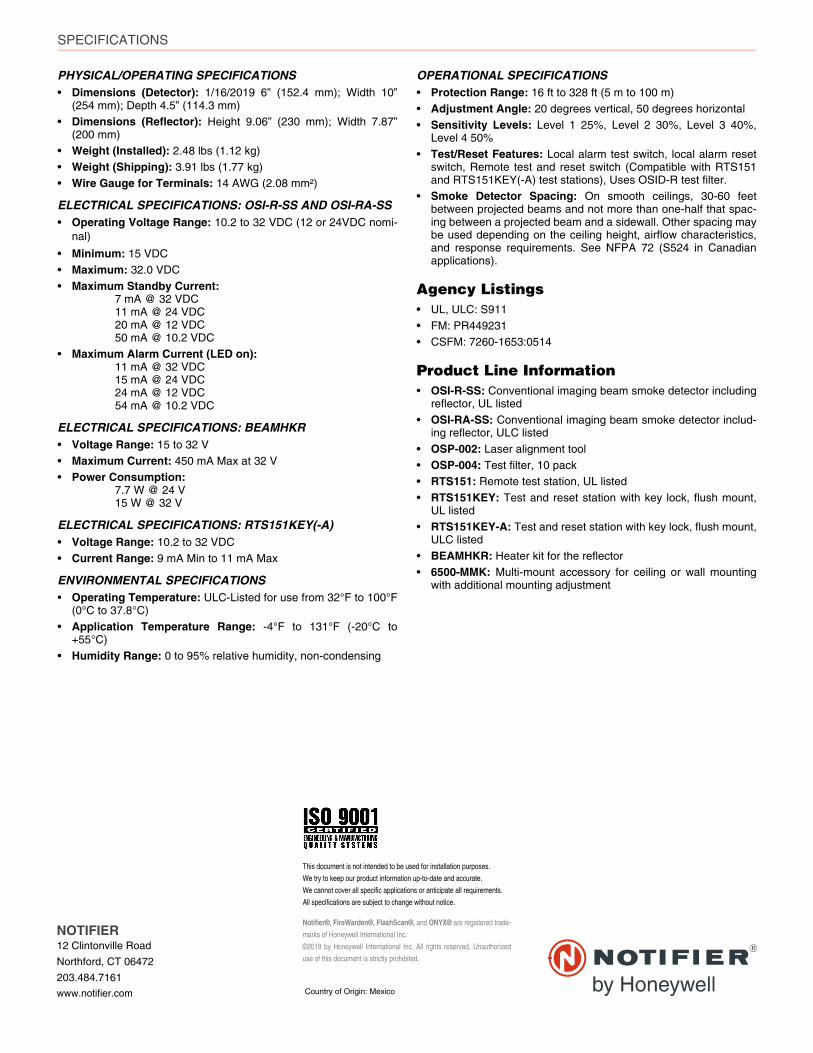
Notifier®, FireWarden®, FlashScan®, and ONYX® are registered trade-
marks of Honeywell International Inc.
©2019 by Honeywell International Inc. All rights reserved. Unauthorized
use of this document is strictly prohibited.
This document is not intended to be used for installation purposes.
We try to keep our product information up-to-date and accurate.
We cannot cover all specific applications or anticipate all requirements.
All specifications are subject to change without notice.
Country of Origin: Mexico
NOTIFIER12 Clintonville Road
Northford, CT 06472
203.484.7161
www.notifier.com
SPECIFICATIONS
PHYSICAL/OPERATING SPECIFICATIONS• Dimensions (Detector): 1/16/2019 6” (152.4 mm); Width 10”
(254 mm); Depth 4.5” (114.3 mm)• Dimensions (Reflector): Height 9.06” (230 mm); Width 7.87”
(200 mm)• Weight (Installed): 2.48 lbs (1.12 kg)• Weight (Shipping): 3.91 lbs (1.77 kg)
• Wire Gauge for Terminals: 14 AWG (2.08 mm²)
ELECTRICAL SPECIFICATIONS: OSI-R-SS AND OSI-RA-SS • Operating Voltage Range: 10.2 to 32 VDC (12 or 24VDC nomi-
nal)
• Minimum: 15 VDC• Maximum: 32.0 VDC
• Maximum Standby Current: 7 mA @ 32 VDC11 mA @ 24 VDC20 mA @ 12 VDC50 mA @ 10.2 VDC
• Maximum Alarm Current (LED on): 11 mA @ 32 VDC15 mA @ 24 VDC 24 mA @ 12 VDC54 mA @ 10.2 VDC
ELECTRICAL SPECIFICATIONS: BEAMHKR• Voltage Range: 15 to 32 V
• Maximum Current: 450 mA Max at 32 V• Power Consumption:
7.7 W @ 24 V15 W @ 32 V
ELECTRICAL SPECIFICATIONS: RTS151KEY(-A)• Voltage Range: 10.2 to 32 VDC
• Current Range: 9 mA Min to 11 mA Max
ENVIRONMENTAL SPECIFICATIONS• Operating Temperature: ULC-Listed for use from 32°F to 100°F
(0°C to 37.8°C) • Application Temperature Range: -4°F to 131°F (-20°C to
+55°C)
• Humidity Range: 0 to 95% relative humidity, non-condensing
OPERATIONAL SPECIFICATIONS• Protection Range: 16 ft to 328 ft (5 m to 100 m)• Adjustment Angle: 20 degrees vertical, 50 degrees horizontal
• Sensitivity Levels: Level 1 25%, Level 2 30%, Level 3 40%,Level 4 50%
• Test/Reset Features: Local alarm test switch, local alarm resetswitch, Remote test and reset switch (Compatible with RTS151and RTS151KEY(-A) test stations), Uses OSID-R test filter.
• Smoke Detector Spacing: On smooth ceilings, 30-60 feetbetween projected beams and not more than one-half that spac-ing between a projected beam and a sidewall. Other spacing maybe used depending on the ceiling height, airflow characteristics,and response requirements. See NFPA 72 (S524 in Canadianapplications).
Agency Listings• UL, ULC: S911
• FM: PR449231• CSFM: 7260-1653:0514
Product Line Information• OSI-R-SS: Conventional imaging beam smoke detector including
reflector, UL listed
• OSI-RA-SS: Conventional imaging beam smoke detector includ-ing reflector, ULC listed
• OSP-002: Laser alignment tool• OSP-004: Test filter, 10 pack• RTS151: Remote test station, UL listed
• RTS151KEY: Test and reset station with key lock, flush mount,UL listed
• RTS151KEY-A: Test and reset station with key lock, flush mount,ULC listed
• BEAMHKR: Heater kit for the reflector• 6500-MMK: Multi-mount accessory for ceiling or wall mounting
with additional mounting adjustment
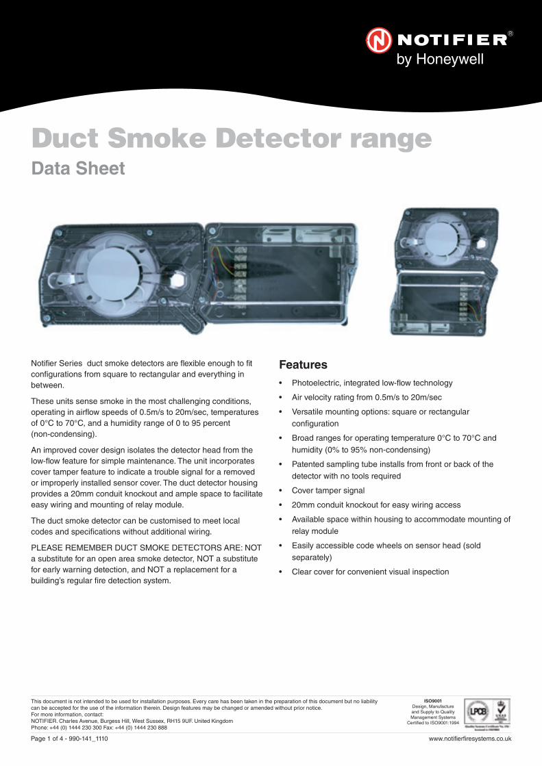
This document is not intended to be used for installation purposes. Every care has been taken in the preparation of this document but no liability can be accepted for the use of the information therein. Design features may be changed or amended without prior notice. For more information, contact: NOTIFIER. Charles Avenue, Burgess Hill, West Sussex, RH15 9UF. United KingdomPhone: +44 (0) 1444 230 300 Fax: +44 (0) 1444 230 888
ISO9001Design, Manufacture and Supply to Quality Management Systems
Certi� ed to ISO9001:1994
Page 1 of 4 - 990-141_1110 www.noti� er� resystems.co.uk
Noti� er Series duct smoke detectors are � exible enough to � t con� gurations from square to rectangular and everything in between.
These units sense smoke in the most challenging conditions, operating in air� ow speeds of 0.5m/s to 20m/sec, temperatures of 0°C to 70°C, and a humidity range of 0 to 95 percent (non-condensing).
An improved cover design isolates the detector head from the low-� ow feature for simple maintenance. The unit incorporates cover tamper feature to indicate a trouble signal for a removed or improperly installed sensor cover. The duct detector housing provides a 20mm conduit knockout and ample space to facilitate easy wiring and mounting of relay module.
The duct smoke detector can be customised to meet local codes and speci� cations without additional wiring.
PLEASE REMEMBER DUCT SMOKE DETECTORS ARE: NOT a substitute for an open area smoke detector, NOT a substitute for early warning detection, and NOT a replacement for a building’s regular � re detection system.
Features• Photoelectric, integrated low-fl ow technology
• Air velocity rating from 0.5m/s to 20m/sec
• Versatile mounting options: square or rectangular con� guration
• Broad ranges for operating temperature 0°C to 70°C and humidity (0% to 95% non-condensing)
• Patented sampling tube installs from front or back of the detector with no tools required
• Cover tamper signal
• 20mm conduit knockout for easy wiring access
• Available space within housing to accommodate mounting of relay module
• Easily accessible code wheels on sensor head (sold separately)
• Clear cover for convenient visual inspection
Duct Smoke Detector rangeData Sheet

Page 2 of 4 - 990-141_1110 www.noti� er� resystems.co.uk
DNRE intelligent non-relay photoelectric duct smoke detectorThe DNRE intelligent non-relay photoelectric duct smoke detector features a pivoting housing that � ts both square and rectangular footprints capable of mounting to a round or rectangular duct.
Mechanical Speci� cation• Size: (Rectangular) 37 cm L; 12.7 cm W; 6.36 cm D
(Square) 19.7 cm L; 22.9 cm W; 6.35 cm D
• Weight: 0.82 kg
• Operating Temperature Range: 0°C to 70°C
• Storage Temperature Range: 0° to 70°C
• Operating Humidity Range: 0% to 95% relative humidity non-condensing
• Air Duct Velocity: 0.5 to 20 m/sec
Installing the Sampling Tube • The sampling tube may be installed from the front or back of the
detector
• The tube locks securely into place and can be removed by releasing
the front or rear locking tab
Electrical Speci� cation• Please see detector head installation manual for electrical
speci� cations
Accessory Current Loads at 24 VDCDevice Standby AlarmRI/W/3V 0 mA 12 mA Max.
Wiring for intelligent non-relay duct smoke detector• Please refer to DNRE installation manual for more information
System wiring diagram for DNRE
DNRE to RI/W/3V
Speci� cationsDNRE non-relay duct smoke detector
COMM. LINE (+)
NOTIFIERCONTROL PANEL
1ST DETECTORIN LOOP
2ND DETECTORIN LOOP
COMM. LINE (–)
COMM. LINE
(+)
(-)
RA400Z– RA
+ RA
REMOTE ALARM LED OPTION 1 PER UNIT
EXTERNAL(-) POWER (+)
SUPPLY
*
RTS451/RTS451KEY
4 5
321
TEST COIL +
TEST COIL –
COMM +
OUT (CONV ONLY) +
DNR to RTS451/RTS451KEY:
EXTERNAL(-) POWER (+)
SUPPLY
*
RTS151/RTS151KEY
REMOTE TEST STATION
LED OPTION1 PER UNIT
TEST COIL OPTION1 PER UNIT
95mA CURRENT DRAW
4 5
321
TEST COIL +
TEST COIL –
COMM +
OUT (CONV ONLY) +
COMM –
RA/RTS –
RA +
RTS +Installing the InnovairFlex Sampling TubeThe InnovairFlex sampling tube may be installed from the front or back of the detector. The tube locks securely into place and can be removed by releasing the front or rear locking tab (front locking tab shown below right).

Page 3 of 4 - 990-141_1110 www.noti� er� resystems.co.uk
D2E conventional duct smoke detectorThe D2E 2-wire photoelectric duct smoke detector features a pivoting housing that � ts various applications: both square and rectangular footprints mount to round or rectangular duct work.
Mechanical Speci� cation• Size: (Rectangular) 37 cm L; 12.7 cm W; 6.36 cm D
(Square) 19.7 cm L; 22.9 cm W; 6.35 cm D
• Weight: 0.82 kg
• Operating Temperature Range: 0°C to 70°C
• Storage Temperature Range: 0° to 70°C
• Operating Humidity Range: 0% to 95% relative humidity non-condensing
• Air Duct Velocity: 0.5 to 20 m/sec
Installing the Sampling Tube • The sampling tube may be installed from the front or back of the
detector
• The tube locks securely into place and can be removed by releasing
the front or rear locking tab
Electrical Speci� cation• Power supply voltage: 8.5-35 VDC
• Input capacitance: 0.1 μF max.
• Reset voltage: 2.5 VDC min.
• Reset time: (with RTS451) 0.03 to 0.3 sec.
• Reset time: (by power down) 0.3 sec. max.
• Power up time: 35 sec. max.
• Alarm response time: 15 sec.
• Sensitivity Test: See detector label
Current Requirements: (Using No Accessories)
• Peak standby current: 120μA
• Max. standby current: 60 μA (average)
• Max. alarm current: 130 mA
Accessory Current Loads at 24 VDC
Device Standby AlarmRI/W/3V 0 mA 12 mA Max.
Wiring for intelligent non-relay duct smoke detector• Please refer to the D2E installation manual for more information
System wiring diagram for 2-wire duct smoke detectors (powered from initiating device circuit)
Speci� cationsD2E conventional duct smoke detector
D2E-09
Wiring for Intelligent Non-Relay Duct Smoke Detector *
Product RangeD2E 2-wire photoelectric low-�ow duct smoke detector DCOIL 2-wire remote test coil required with RTS451/RTS451KEYDST1 Metal sampling tube duct width up to 0.3mDST1.5 Metal sampling tube duct widths 0.3 to 0.6 mDST3 Metal sampling tube duct widths 0.6 to 1.2 mDST5 Metal sampling tube duct widths 1.2 to 2.4 m
DST10 Metal sampling tube duct widths 2.4 to 3.6 m* Important Notes: The use of either RTS451 or RTS451KEY requires the installation of an accessory coil, DCOIL, sold separately. Please refer to the D2E installation manual for more information
Charles AvenueBurgess HillRH15 9TQUnited Kingdom
Tel: +44 (0)1444 238820Fax: +44 (0)1444 248123Email: [email protected]
System Sensor Europe (Technical Services)
Copyright © 2010 System Sensor. All rights reserved. All technical data is correct at time of publication and is subject to change without notice. All trademarks acknowledged.
Installation information: in order to ensure full functionality, refer to the installation instructions as supplied.
Part No. DescriptionRA400Z Remote annunciator alarm LEDRTS451 Remote test stationRTS451KEY Remote test station with key lock
System wiring diagram for 2-wire duct smoke detectors (powered from initiating device circuit): Wiring diagram for 2-wire duct smoke detector to RTS451/RTS451KEY Remote Test Station
(+) IN (+) OUT
(+)(+)
(–)
(–)
1ST DETECTORIN LOOP D2
(–)
RI/W/3V (OPTIONAL)REMOTE ALARM LED
4.4 VDC NOM.IN ALARM
(+) IN (+) OUT
(+)(+)
(–)
LAST DETECTORIN LOOP D2
(–)
RI/W/3V (OPTIONAL)REMOTE ALARM LED
4.4 VDC NOM.IN ALARM
EOLR
STYLE D OPTIONAL WIRING
NOTIFIERCONTROL PANEL
ALARMINITIATIONLOOP
(+)
(–)
EOL RESISTOR
RA
RA
RA
RA
(–)
~~
~~
(+) IN (+) OUT
(+)(+)
(–)
(–)
2ND DETECTORIN LOOP D2
(–)
RI/W/3V (OPTIONAL)REMOTE ALARM LED
4.4 VDC NOM.IN ALARM
RA
RA
~~
~~
A05-0421-000
Wiring for 2-wire Duct Smoke DetectorSystem wiring diagram for 2-wire duct smoke detectors (powered from initiating device circuit):
24 VAC (+10%, –15%)FULL WAVE RECTIFIED,UNFILTERED POWER
MAY BE USED
RTS451/RTS451KEY(OPTIONAL) REMOTE
TEST STATION
MAGNETTESTSWITCH
ALARMLED (RED)
4
5
2
1 (+)
(–)
+ RA
+ RTS
– RA
+ TEST COIL
– TEST COIL
+ IN
+ OUT
–
(–)
(+)
D2
24 VDCAUX POWER
SUPPLIEDBY USER(100mA
SUPPLY)
RTS451/RTS451KEY(OPTIONAL) REMOTE
TEST STATION
24 VAC (+10%, –15%)FULL WAVE RECTIFIED,UNFILTERED POWER
MAY BE USED
MAGNETTESTSWITCH
ALARMLED (RED)
4
5
2
1 (+)
(–)
+ RA
+ RTS
– RA
+ TEST COIL
– TEST COIL
+ IN
+ OUT
–
24 VDCAUX POWER
SUPPLIEDBY USER(100mA
SUPPLY)
D2METHOD #1 - AUX POWER LOCATED
AT DUCT DETECTORMETHOD #2 - AUX POWER LOCATED
AT TEST STATION
Important NoteThe use of either RTS451 or RTS451KEY requires the installation of an accessory coil, DCOIL, sold separately. Please refer to the D2 installation manual for more information
Wiring diagram for 2-wire duct smoke detector to RTS451/RTS451KEY Remote Test Station
(+) IN (+) OUT
(+)(+)
(–)
(–)
1ST DETECTORIN LOOP D2
(–)
RI/W/3V (OPTIONAL)REMOTE ALARM LED
4.4 VDC NOM.IN ALARM
(+) IN (+) OUT
(+)(+)
(–)
LAST DETECTORIN LOOP D2
(–)
RI/W/3V (OPTIONAL)REMOTE ALARM LED
4.4 VDC NOM.IN ALARM
EOLR
STYLE D OPTIONAL WIRING
NOTIFIERCONTROL PANEL
ALARMINITIATIONLOOP
(+)
(–)
EOL RESISTOR
RA
RA
RA
RA
(–)
~~
~~
(+) IN (+) OUT
(+)(+)
(–)
(–)
2ND DETECTORIN LOOP D2
(–)
RI/W/3V (OPTIONAL)REMOTE ALARM LED
4.4 VDC NOM.IN ALARM
RA
RA
~~
~~
A05-0421-000
InnovairFlex Duct Smoke Detector Speci�cations
The air duct smoke detector shall be a System Sensor InnovairFlex™ D2 Photoelectric Duct Smoke Detector. The detector housing shall be UL listed per UL
shall operate at air velocities of 100 ft/min to 4000 ft/min (0.5 m/sec to 20.32 m/sec). The unit shall be capable of providing a trouble signal in the event that the sensor cover is removed or improperly installed. It shall be capable of local testing via magnetic switch or remote testing using the RTS451KEY remote test station. Terminal connections shall be of the strip and clamp method suitable for 12–18 AWG wiring.
Size: (Rectangular) (Square)
14.38 in (37 cm) Length; 5 in (12.7 cm) Width; 2.5 in (6.36 cm) Depth7.75 in (19.7 cm) Length; 9 in (22.9 cm) Width; 2.5 in (6.35 cm) Depth
1.8 lb (0.82 kg)
Operating Temperature Range: -4°F to 158°F (-20°C to 70°C)
Storage Temperature Range: –22°F to 158°F (–30° to 70°C)
Operating Humidity Range: 0% to 95% relative humidity non-condensing
Air Duct Velocity: 100 to 4000 ft/min (0.5 to 20.32 m/sec)
Wiring for 2-wire Duct Smoke DetectorSystem wiring diagram for 2-wire duct smoke detectors (powered from initiating device circuit):
Electrical Ratings
Power supply voltage: 8.5-35 VDC
Input capacitance: 0.1 µF max.
Reset voltage: 2.5 VDC min.
Reset time: (with RTS451) 0.03 to 0.3 sec.
Reset time: (by power down) 0.3 sec. max.
Power up time: 35 sec. max.
Alarm response time: 15 sec.
Sensitivity Test: See detector label
Current Requirements: (Using No Accessories)
Peak standby current: 120µA
Max. standby current: 60 µA (average)
Max. alarm current: 130 mA
Accessory Current Loads at 24 VDC
Standby Alarm
0 mA 12 mA Max.
0 mA 12 mA Max.
RTS451KEY 12 mA 12 mA Max.
24 VAC (+10%, –15%)FULL WAVE RECTIFIED,UNFILTERED POWER
MAY BE USED
RTS451/RTS451KEY(OPTIONAL) REMOTE
TEST STATION
MAGNETTESTSWITCH
ALARMLED (RED)
4
5
2
1 (+)
(–)
+ RA
+ RTS
– RA
+ TEST COIL
– TEST COIL
+ IN
+ OUT
–
(–)
(+)
D2
24 VDCAUX POWER
SUPPLIEDBY USER(100mA
SUPPLY)
RTS451/RTS451KEY(OPTIONAL) REMOTE
TEST STATION
24 VAC (+10%, –15%)FULL WAVE RECTIFIED,UNFILTERED POWER
MAY BE USED
MAGNETTESTSWITCH
ALARMLED (RED)
4
5
2
1 (+)
(–)
+ RA
+ RTS
– RA
+ TEST COIL
– TEST COIL
+ IN
+ OUT
–
24 VDCAUX POWER
SUPPLIEDBY USER(100mA
SUPPLY)
D2METHOD #1 - AUX POWER LOCATED
AT DUCT DETECTORMETHOD #2 - AUX POWER LOCATED
AT TEST STATION
Installing the InnovairFlex Sampling TubeThe InnovairFlex sampling tube may be installed from the front or back of the detector. The tube locks securely into place and can be removed by releasing the front or rear locking tab (front locking tab shown below right).
Important NoteThe use of either RTS451 or RTS451KEY requires the installation of an accessory coil, DCOIL, sold separately. Please refer to the D2 installation manual for more information
Wiring diagram for 2-wire duct smoke detector to RTS451/RTS451KEY Remote Test Station
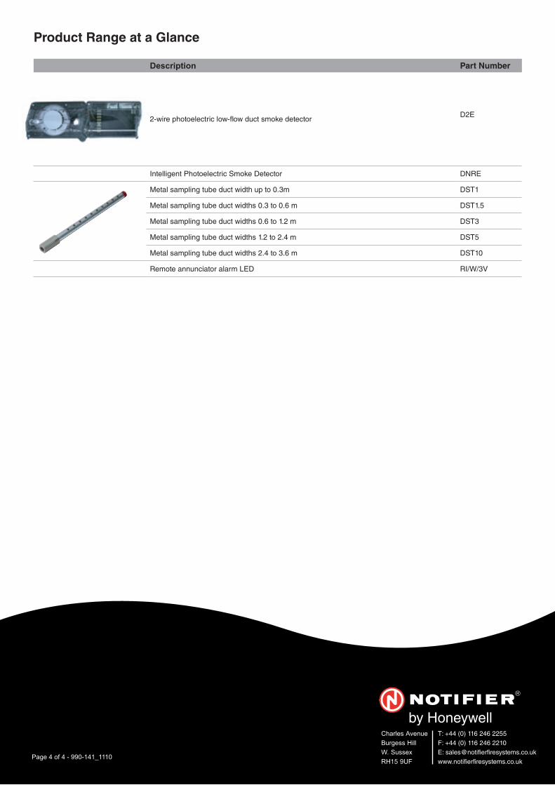
Charles AvenueBurgess HillW. SussexRH15 9UF
T: +44 (0) 116 246 2255F: +44 (0) 116 246 2210E: [email protected]
Page 4 of 4 - 990-141_1110
Product Range at a Glance
Description Part Number
2-wire photoelectric low-� ow duct smoke detectorD2E
Intelligent Photoelectric Smoke Detector DNRE
Metal sampling tube duct width up to 0.3m DST1
Metal sampling tube duct widths 0.3 to 0.6 m DST1.5
Metal sampling tube duct widths 0.6 to 1.2 m DST3
Metal sampling tube duct widths 1.2 to 2.4 m DST5
Metal sampling tube duct widths 2.4 to 3.6 m DST10
Remote annunciator alarm LED RI/W/3V

DN-6720:E • 07/30/2015 — Page 1 of 4
FMM-1(A), FMM-101(A),FZM-1(A) & FDM-1(A)Monitor Modules with FlashScan®
Intelligent/Addressable Devices
DN-6720:E
GeneralFour different monitor modules are available for Notifier’sintelligent control panels for a variety of applications. Monitormodules supervise a circuit of dry-contact input devices,such as conventional heat detectors and pull stations, ormonitor and power a circuit of two-wire smoke detectors(FZM-1(A)).
FMM-1(A) is a standard-sized module (typically mounts to a4" [10.16 cm] square box) that supervises either a Style D(Class A) or Style B (Class B) circuit of dry-contact inputdevices.
FMM-101(A) is a miniature monitor module a mere 1.3"(3.302 cm) H x 2.75" (6.985 cm) W x 0.65" (1.651 cm) D thatsupervises a Style B (Class B) circuit of dry-contact inputdevices. Its compact design allows the FMM-101(A) to bemounted in a single-gang box behind the device it monitors.
FZM-1(A) is a standard-sized module that monitors andsupervises compatible two-wire, 24 volt, smoke detectors ona Style D (Class A) or Style B (Class B) circuit.
FDM-1(A) is a standard-sized dual monitor module that mon-itors and supervises two independent two-wire Style B (ClassB) dry-contact initiating device circuits (IDCs) at two separate,consecutive addresses in intelligent, two-wire systems.
FlashScan® (U.S. Patent 5,539,389) is a communicationprotocol developed by NOTIFIER that greatly increases thespeed of communication between analog intelligent devices.Intelligent devices communicate in a grouped fashion. If oneof the devices within the group has new information, thepanel CPU stops the group poll and concentrates on singlepoints. The net effect is response speed greater than fivetimes that of other communication protocols.
FMM-1(A) Monitor Module• Built-in type identification automatically identifies this
device as a monitor module to the control panel.• Powered directly by two-wire SLC loop. No additional
power required.• High noise (EMF/RFI) immunity.• SEMS screws with clamping plates for ease of wiring.• Direct-dial entry of address: 01 – 159 on FlashScan loops;
01 – 99 on CLIP loops. • LED flashes green during normal operation (programma-
ble option) and latches on steady red to indicate alarm.The FMM-1(A) Monitor Module is intended for use in intelli-gent, two-wire systems, where the individual address of eachmodule is selected using the built-in rotary switches. It pro-vides either a two-wire or four-wire fault-tolerant InitiatingDevice Circuit (IDC) for normally-open-contact fire alarm andsupervisory devices. The module has a panel-controlled LEDindicator. The FMM-1(A) can be used to replace MMX-1(A)modules in existing systems.
FMM-1(A) APPLICATIONS
Use to monitor a zone of four-wire smoke detectors, manualfire alarm pull stations, waterflow devices, or other normally-
open dry-contact alarm activation devices. May also be usedto monitor normally-open supervisory devices with specialsupervisory indication at the control panel. Monitored circuitmay be wired as an NFPA Style B (Class B) or Style D (ClassA) Initiating Device Circuit. A 47K Ohm End-of-Line Resistor(provided) terminates the Style B circuit. No resistor isrequired for supervision of the Style D circuit.
FMM-1(A) OPERATION
Each FMM-1(A) uses one of the available module addresseson an SLC loop. It responds to regular polls from the controlpanel and reports its type and the status (open/normal/short)of its Initiating Device Circuit (IDC). A flashing LED indicatesthat the module is in communication with the control panel.The LED latches steady on alarm (subject to current limita-tions on the loop).
FMM-1(A) SPECIFICATIONS
Nominal operating voltage: 15 to 32 VDC.
Maximum current draw: 5.0 mA (LED on).
Average operating current: 375 μA (LED flashing), 1 com-munication every 5 seconds, 47k EOL.
Maximum IDC wiring resistance: 1500 Ohms.
Maximum IDC Voltage: 11 Volts.
EOL resistance: 47K Ohms.
Temperature range: 32°F to 120°F (0°C to 49°C).
Humidity range: 10% to 93% noncondensing.
Dimensions: 4.5" (11.43 cm) high x 4" (10.16 cm) wide x1.25" (3.175 cm) deep. Mounts to a 4" (10.16 cm) square x2.125" (5.398 cm) deep box.
FMM-1(A) (Type H)
6999
cov.
jpg
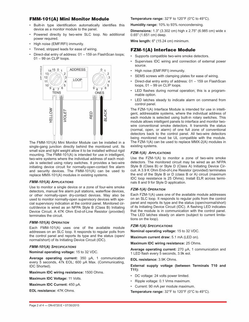
Page 2 of 4 — DN-6720:E • 07/30/2015
FMM-101(A) Mini Monitor Module• Built-in type identification automatically identifies this
device as a monitor module to the panel.• Powered directly by two-wire SLC loop. No additional
power required.• High noise (EMF/RFI) immunity.• Tinned, stripped leads for ease of wiring.• Direct-dial entry of address: 01 – 159 on FlashScan loops;
01 – 99 on CLIP loops.
The FMM-101(A) Mini Monitor Module can be installed in asingle-gang junction directly behind the monitored unit. Itssmall size and light weight allow it to be installed without rigidmounting. The FMM-101(A) is intended for use in intelligent,two-wire systems where the individual address of each mod-ule is selected using rotary switches. It provides a two-wireinitiating device circuit for normally-open-contact fire alarmand security devices. The FMM-101(A) can be used toreplace MMX-101(A) modules in existing systems.
FMM-101(A) APPLICATIONS
Use to monitor a single device or a zone of four-wire smokedetectors, manual fire alarm pull stations, waterflow devices,or other normally-open dry-contact devices. May also beused to monitor normally-open supervisory devices with spe-cial supervisory indication at the control panel. Monitored cir-cuit/device is wired as an NFPA Style B (Class B) InitiatingDevice Circuit. A 47K Ohm End-of-Line Resistor (provided)terminates the circuit.
FMM-101(A) OPERATION
Each FMM-101(A) uses one of the available moduleaddresses on an SLC loop. It responds to regular polls fromthe control panel and reports its type and the status (open/normal/short) of its Initiating Device Circuit (IDC).
FMM-101(A) SPECIFICATIONS
Nominal operating voltage: 15 to 32 VDC.
Average operating current: 350 μA, 1 communicationevery 5 seconds, 47k EOL; 600 μA Max. (Communicating,IDC Shorted).
Maximum IDC wiring resistance: 1500 Ohms.
Maximum IDC Voltage: 11 Volts.
Maximum IDC Current: 450 μA.
EOL resistance: 47K Ohms.
Temperature range: 32°F to 120°F (0°C to 49°C).
Humidity range: 10% to 93% noncondensing.
Dimensions: 1.3" (3.302 cm) high x 2.75" (6.985 cm) wide x0.65" (1.651 cm) deep.
Wire length: 6" (15.24 cm) minimum.
FZM-1(A) Interface Module• Supports compatible two-wire smoke detectors.• Supervises IDC wiring and connection of external power
source.• High noise (EMF/RFI) immunity.• SEMS screws with clamping plates for ease of wiring.• Direct-dial entry entry of address: 01 – 159 on FlashScan
loops, 01 – 99 on CLIP loops.• LED flashes during normal operation; this is a program-
mable option.• LED latches steady to indicate alarm on command from
control panel.The FZM-1(A) Interface Module is intended for use in intelli-gent, addressable systems, where the individual address ofeach module is selected using built-in rotary switches. Thismodule allows intelligent panels to interface and monitor two-wire conventional smoke detectors. It transmits the status(normal, open, or alarm) of one full zone of conventionaldetectors back to the control panel. All two-wire detectorsbeing monitored must be UL compatible with the module.The FZM-1(A) can be used to replace MMX-2(A) modules inexisting systems.
FZM-1(A) APPLICATIONS
Use the FZM-1(A) to monitor a zone of two-wire smokedetectors. The monitored circuit may be wired as an NFPAStyle B (Class B) or Style D (Class A) Initiating Device Cir-cuit. A 3.9 K Ohm End-of-Line Resistor (provided) terminatesthe end of the Style B or D (class B or A) circuit (maximumIDC loop resistance is 25 Ohms). Install ELR across termi-nals 8 and 9 for Style D application.
FZM-1(A) OPERATION
Each FZM-1(A) uses one of the available module addresseson an SLC loop. It responds to regular polls from the controlpanel and reports its type and the status (open/normal/short)of its Initiating Device Circuit (IDC). A flashing LED indicatesthat the module is in communication with the control panel.The LED latches steady on alarm (subject to current limita-tions on the loop).
FZM-1(A) SPECIFICATIONS
Nominal operating voltage: 15 to 32 VDC.
Maximum current draw: 5.1 mA (LED on).
Maximum IDC wiring resistance: 25 Ohms.
Average operating current: 270 μA, 1 communication and1 LED flash every 5 seconds, 3.9k eol.
EOL resistance: 3.9K Ohms.
External supply voltage (between Terminals T10 andT11):• DC voltage: 24 volts power limited. • Ripple voltage: 0.1 Vrms maximum. • Current: 90 mA per module maximum.Temperature range: 32°F to 120°F (0°C to 49°C).
6720m101.w
mf
DN-6720:E • 07/30/2015 — Page 3 of 4
Humidity range: 10% to 93% noncondensing.
Dimensions: 4.5" (11.43 cm) high x 4" (10.16 cm) wide x1.25" (3.175 cm) deep. Mounts to a 4" (10.16 cm) square x2.125" (5.398 cm) deep box.
FDM-1(A) Dual Monitor ModuleThe FDM-1(A) Dual Monitor Module is intended for use in intelli-gent, two-wire systems. It provides two independent two-wireinitiating device circuits (IDCs) at two separate, consecutiveaddresses. It is capable of monitoring normally open contact firealarm and supervisory devices; or either normally open or nor-mally closed security devices. The module has a single panel-controlled LED.NOTE: The FDM-1(A) provides two Style B (Class B) IDC circuitsONLY. Style D (Class A) IDC circuits are NOT supported in anyapplication.
FDM-1(A) SPECIFICATIONS
Normal operating voltage range: 15 to 32 VDC.
Maximum current draw: 6.4 mA (LED on).
Average operating current: 750 μA (LED flashing).
Maximum IDC wiring resistance: 1,500 Ohms.
Maximum IDC Voltage: 11 Volts.
Maximum IDC Current: 240 μA
EOL resistance: 47K Ohms.
Temperature range: 32° to 120°F (0° to 49°C).
Humidity range: 10% to 93% (non-condensing).
Dimensions: 4.5" (11.43 cm) high x 4" (10.16 cm) wide x1.25" (3.175 cm) deep. Mounts to a 4" (10.16 cm) square x2.125" (5.398 cm) deep box.
FDM-1(A) AUTOMATIC ADDRESSING
The FDM-1(A) automatically assigns itself to two address-able points, starting with the original address. For example, ifthe FDM-1(A) is set to address “26”, then it will automaticallyassign itself to addresses “26” and “27”.
NOTE: “Ones” addresses on the FDM-1(A) are 0, 2, 4, 6, or 8 only.Terminals 6 and 7 use the first address, and terminals 8 and 9 usethe second address.
InstallationFMM-1(A), FZM-1(A), and FDM-1(A) modules mount directlyto a standard 4" (10.16 cm) square, 2.125" (5.398 cm) deep,electrical box. They may also be mounted to the SMB500surface-mount box. Mounting hardware and installationinstructions are provided with each module. All wiring mustconform to applicable local codes, ordinances, and regula-tions. These modules are intended for power-limited wiringonly.
The FMM-101(A) module is intended to be wired andmounted without rigid connections inside a standard electri-cal box. All wiring must conform to applicable local codes,ordinances, and regulations.
Agency Listings and ApprovalsIn some cases, certain modules may not be listed by certainapproval agencies, or listing may be in process. Consult fac-tory for latest listing status.
• UL: S635.• ULC: S635.• FM Approved. • CSFM: 7300-0028:0219, 7165-0028:0224,
7165-0028:0243.• MEA: 457-99-E.• U.S. Coast Guard: 161.002/50/0 (NFS2-640, NFS2-320,
NFS2-3030).• Lloyd’s Register: 11/600013 (NFS2-640, NFS2-320,
NFS2-3030).• Fire Dept. of New York: COA #6121 (NFS2-640, NFS-
320), COA# 6114 (NFS2-3030).
Product Line InformationNOTE: “A” suffix indicates ULC-listed model.
FMM-1(A): Monitor module.
FMM-101(A): Monitor module, miniature.
FZM-1(A): Monitor module, two-wire detectors.
FDM-1(A): Monitor module, dual, two independent Class Bcircuits.
SMB500: Optional surface-mount backbox.
NOTE: See installation instructions and refer to the SLC WiringManual, PN 51253.
! CAUTION: Avoid duplicating addresses on the system.

Page 4 of 4 — DN-6720:E • 07/30/2015
FlashScan® and NOTIFIER® are registered trademarks and FireWatch™ isa trademark of Honeywell International Inc.©2015 by Honeywell International Inc. All rights reserved. Unauthorized useof this document is strictly prohibited.
This document is not intended to be used for installation purposes. We try to keep our product information up-to-date and accurate.
We cannot cover all specific applications or anticipate all requirements. All specifications are subject to change without notice.
For more information, contact Notifier. Phone: (203) 484-7161, FAX: (203) 484-7118.www.notifier.com
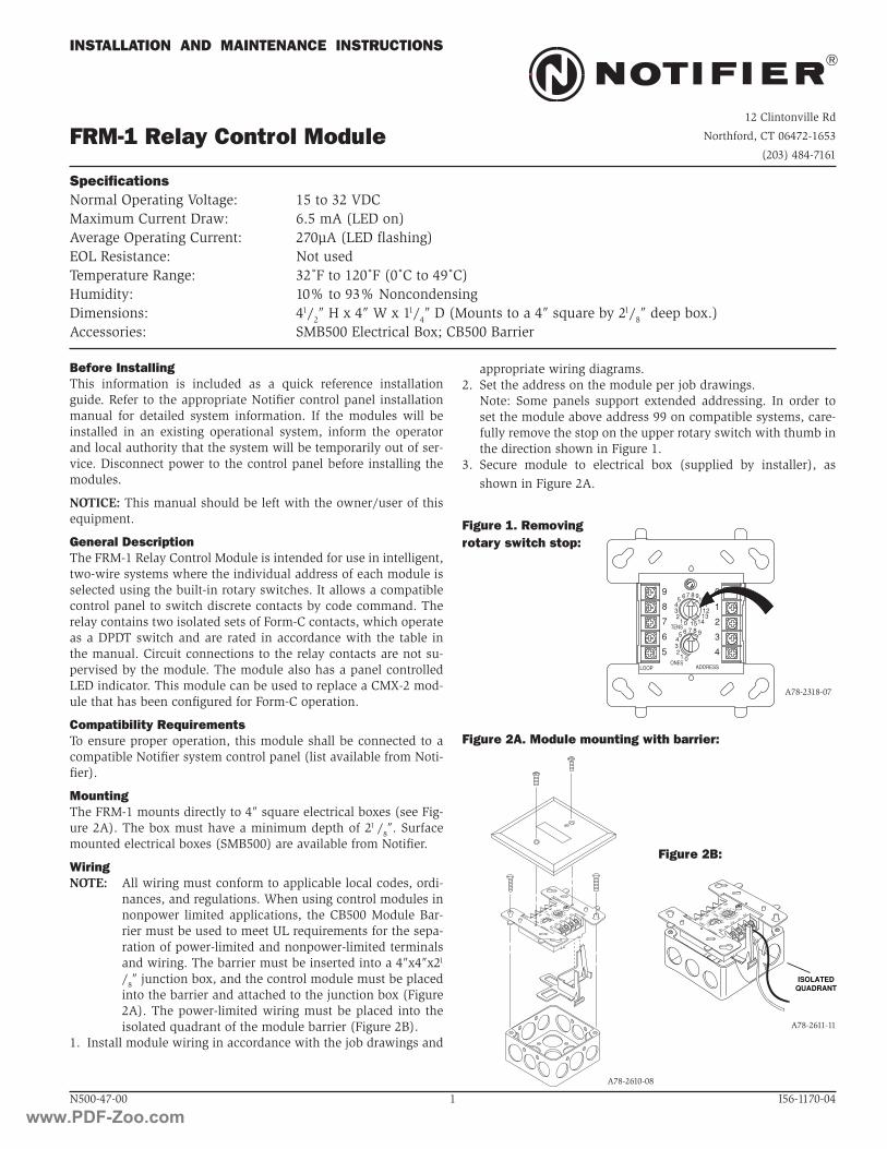
01
23
4
98
76
5
0
TENS
ONES
ADDRESS
LOOP9
87654321
09
87654321 101112131415
ISOLATEDQUADRANT
01
23
4
98
76
5
0
TENS
ONES
ADDRESS
LOOP9
87654321
09
87654321 101112131415
N500-47-00 1 I56-1170-04
FRM-1 Relay Control Module
INSTALLATION AND MAINTENANCE INSTRUCTIONS
Before InstallingThis information is included as a quick reference installation guide. Refer to the appropriate Notifier control panel installation manual for detailed system information. If the modules will be installed in an existing operational system, inform the operator and local authority that the system will be temporarily out of ser-vice. Disconnect power to the control panel before installing the modules.
NOTICE: This manual should be left with the owner/user of this equipment.
General DescriptionThe FRM-1 Relay Control Module is intended for use in intelligent, two-wire systems where the individual address of each module is selected using the built-in rotary switches. It allows a compatible control panel to switch discrete contacts by code command. The relay contains two isolated sets of Form-C contacts, which operate as a DPDT switch and are rated in accordance with the table in the manual. Circuit connections to the relay contacts are not su-pervised by the module. The module also has a panel controlled LED indicator. This module can be used to replace a CMX-2 mod-ule that has been configured for Form-C operation.
Compatibility RequirementsTo ensure proper operation, this module shall be connected to a compatible Notifier system control panel (list available from Noti-fier).
MountingThe FRM-1 mounts directly to 4″ square electrical boxes (see Fig-ure 2A). The box must have a minimum depth of 21 /8″. Surface mounted electrical boxes (SMB500) are available from Notifier.
WiringNOTE: All wiring must conform to applicable local codes, ordi-
nances, and regulations. When using control modules in nonpower limited applications, the CB500 Module Bar-rier must be used to meet UL requirements for the sepa-ration of power-limited and nonpower-limited terminals and wiring. The barrier must be inserted into a 4″x4″x21
/8″ junction box, and the control module must be placed into the barrier and attached to the junction box (Figure 2A). The power-limited wiring must be placed into the isolated quadrant of the module barrier (Figure 2B).
1. Install module wiring in accordance with the job drawings and
Figure 1. Removingrotary switch stop:
Figure 2A. Module mounting with barrier:
A78-2611-11
Figure 2B:
A78-2610-08
A78-2318-07
SpecificationsNormal Operating Voltage: 15 to 32 VDCMaximum Current Draw: 6.5 mA (LED on)Average Operating Current: 270µA (LED flashing)EOL Resistance: Not usedTemperature Range: 32˚F to 120˚F (0˚C to 49˚C)Humidity: 10% to 93% NoncondensingDimensions: 41/2″ H x 4″ W x 11/4″ D (Mounts to a 4″ square by 21/8″ deep box.)Accessories: SMB500 Electrical Box; CB500 Barrier
appropriate wiring diagrams.2. Set the address on the module per job drawings. Note: Some panels support extended addressing. In order to
set the module above address 99 on compatible systems, care-fully remove the stop on the upper rotary switch with thumb in the direction shown in Figure 1.
3. Secure module to electrical box (supplied by installer), as shown in Figure 2A.
12 Clintonville Rd
Northford, CT 06472-1653
(203) 484-7161
9
8
7
6
5 4
3
2
1
0
012345 6 7 8 9
TENS
ONESADDRESSLOOP
0
7 865432
1
910111213
1415
www.PDF-Zoo.com
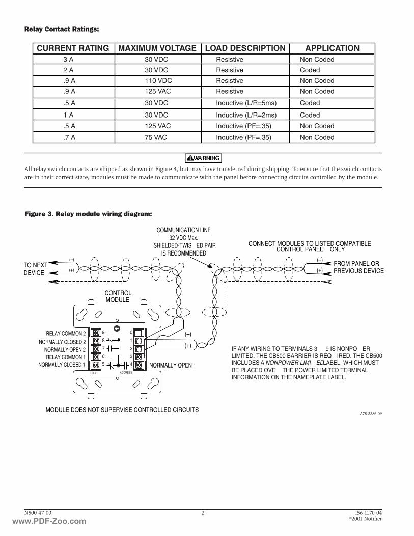
MODULE
FROM PANEL OR(+)
(–)TO NEXT
(+)
(–)
DEVICE
(+)
(–)
CONTROL
CONNECT MODULES TO LISTED COMPATIBLE
RELAY COMMON 1
RELAY COMMON 2
NORMALLY CLOSED 1
NORMALLY OPEN 2NORMALLY CLOSED 2
MODULE DOES NOT SUPERVISE CONTROLLED CIRCUITS
NORMALLY OPEN 1
CONTROL PANELS ONLY
PREVIOUS DEVICE
COMMUNICATION LINE32 VDC Max.
SHIELDED-TWISTED PAIRIS RECOMMENDED
9
8
7
6
5 4
3
2
1
0
ADDRESSLOOP
N500-47-00 2 I56-1170-04 ©2001 Notifier
All relay switch contacts are shipped as shown in Figure 3, but may have transferred during shipping. To ensure that the switch contacts are in their correct state, modules must be made to communicate with the panel before connecting circuits controlled by the module.
Relay Contact Ratings:
Figure 3. Relay module wiring diagram:
A78-2286-09
CURRENT RATING MAXIMUM VOLTAGE LOAD DESCRIPTION APPLICATION3 A
2 A
.9 A
.9 A
.5 A
1 A
.5 A
.7 A
30 VDC
30 VDC
110 VDC
125 VAC
30 VDC
30 VDC
125 VAC
75 VAC
Resistive
Resistive
Resistive
Resistive
Inductive (L/R=5ms)
Inductive (L/R=2ms)
Inductive (PF=.35)
Inductive (PF=.35)
Non Coded
Coded
Non Coded
Non Coded
Coded
Coded
Non Coded
Non Coded
IF ANY WIRING TO TERMINALS 3 – 9 IS NONPOWERLIMITED, THE CB500 BARRIER IS REQUIRED. THE CB500INCLUDES A NONPOWER LIMITED LABEL, WHICH MUSTBE PLACED OVER THE POWER LIMITED TERMINALINFORMATION ON THE NAMEPLATE LABEL.
www.PDF-Zoo.com

DN-6724:B3 • 2/17/2011 — Page 1 of 2
FCM-1(A) & FRM-1(A) SeriesControl and Relay Modules
Intelligent / Addressable Devices
DN-6724:B3
GeneralFCM-1(A) Control Module: The FCM-1(A) Addressable Con-trol Module provides Notifier intelligent fire alarm control pan-els a circuit for Notification Appliances (horns, strobes,speakers, etc.). Addressability allows the FCM-1(A) to be acti-vated, either manually or through panel programming, on aselect (zone or area of coverage) basis.
FRM-1(A) Relay Module: The FRM-1(A) Addressable RelayModule provides the system with a dry-contact output for acti-vating a variety of auxiliary devices, such as fans, dampers,control equipment, etc. Addressability allows the dry contact tobe activated, either manually or through panel programming,on a select basis.
FlashScan® (U.S. Patent 5,539,389) is a communication pro-tocol developed by NOTIFIER Engineering that greatlyenhances the speed of communication between analog intelli-gent devices. Intelligent devices communicate in a groupedfashion. If one of the devices within the group has new infor-mation, the panel CPU stops the group poll and concentrateson single points. The net effect is response speed greater thanfive times that of other designs.
Features• Built-in type identification automatically identifies these
devices to the control panel.
• Internal circuitry and relay powered directly by two-wireSLC loop. The FCM-1(A) module requires power (for horns,strobes, etc.), or audio (for speakers).
• Integral LED “blinks” green each time a communication isreceived from the control panel and turns on in steady redwhen activated.
• LED blink may be deselected globally (affects all devices).• High noise immunity (EMF/RFI).
• The FCM-1(A) may be used to switch 24-volt NAC power,audio (up to 70.7 Vrms).
• Wide viewing angle of LED.• SEMS screws with clamping plates for wiring ease.
• Direct-dial entry of address 01– 159 for FlashScan loops,01 – 99 for CLIP mode loops.
• Speaker, and audible/visual applications may be wired forClass B or A (Style Y or Z).
ApplicationsThe FCM-1(A) is used to switch 24 VDC audible/visual power,high-level audio (speakers). The FRM-1(A) may be pro-grammed to operate dry contacts for applications such as doorholders or Air Handling Unit shutdown, and to reset four-wiresmoke detector power.
NOTE: Refer to the SLC Manual (PN 51253) for details regardingreleasing applications with the FCM-1(A). Refer to the FCM-1-RELdatasheet (DN-60390) for new FlashScan® releasing applications.
Construction• The face plate is made of off-white heat-resistant plastic.• Controls include two rotary switches for direct-dial entry of
address (01-159).
• The FCM-1(A) is configured for a single Class B (Style Y) orClass A (Style Z) Notification Appliance Circuit.
• The FRM-1(A) provides two Form-C dry contacts thatswitch together.
OperationEach FCM-1(A) or FRM-1(A) uses one of 159 possible moduleaddresses on a SLC loop (99 on CLIP loops). It responds toregular polls from the control panel and reports its type andstatus, including the open/normal/short status of its Notifica-tion Appliance Circuit (NAC). The LED blinks with each pollreceived. On command, it activates its internal relay. TheFCM-1(A) supervises Class B (Style Y) or Class A (Style Z)notification or control circuits.
Upon code command from the panel, the FCM-1(A) will dis-connect the supervision and connect the external power sup-ply in the proper polarity across the load device. Thedisconnection of the supervision provides a positive indicationto the panel that the control relay actually turned ON. Theexternal power supply is always relay isolated from the com-munication loop so that a trouble condition on the externalpower supply will never interfere with the rest of the system.
Rotary switches set a unique address for each module. Theaddress may be set before or after mounting. The built-inTYPE CODE (not settable) will identify the module to the con-trol panel, so as to differentiate between a module and a sen-sor address.
Specifications for FCM-1(A)Normal operating voltage: 15 to 32 VDC.
Maximum current draw: 6.5 mA (LED on).
Average operating current: 350 μA direct poll, 375 μA grouppoll with LED flashing, 485 μA Max. (LED flashing, NACshorted.)
FCM-1(A)
7000
cov.
JPG
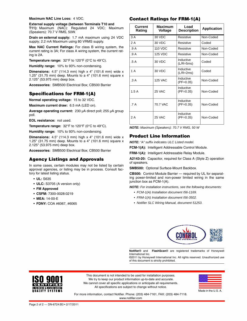
Page 2 of 2 — DN-6724:B3 • 2/17/2011
Notifier® and FlashScan® are registered trademarks of HoneywellInternational Inc. ©2011 by Honeywell International Inc. All rights reserved. Unauthorized useof this document is strictly prohibited.
This document is not intended to be used for installation purposes. We try to keep our product information up-to-date and accurate.
We cannot cover all specific applications or anticipate all requirements. All specifications are subject to change without notice.
For more information, contact Notifier. Phone: (203) 484-7161, FAX: (203) 484-7118.www.notifier.com
Made in the U.S. A.
Maximum NAC Line Loss: 4 VDC.
External supply voltage (between Terminals T10 and T11): Maximum (NAC): Regulated 24 VDC; Maximum(Speakers): 70.7 V RMS, 50W.
Drain on external supply: 1.7 mA maximum using 24 VDCsupply; 2.2 mA Maximum using 80 VRMS supply.
Max NAC Current Ratings: For class B wiring system, thecurrent rating is 3A; For class A wiring system, the current rat-ing is 2A.
Temperature range: 32°F to 120°F (0°C to 49°C).
Humidity range: 10% to 93% non-condensing.
Dimensions: 4.5" (114.3 mm) high x 4" (101.6 mm) wide x1.25" (31.75 mm) deep. Mounts to a 4" (101.6 mm) square x2.125" (53.975 mm) deep box.
Accessories: SMB500 Electrical Box; CB500 Barrier
Specifications for FRM-1(A)Normal operating voltage: 15 to 32 VDC.
Maximum current draw: 6.5 mA (LED on).
Average operating current: 230 μA direct poll; 255 μA grouppoll.
EOL resistance: not used.
Temperature range: 32°F to 120°F (0°C to 49°C).
Humidity range: 10% to 93% non-condensing.
Dimensions: 4.5" (114.3 mm) high x 4" (101.6 mm) wide x1.25" (31.75 mm) deep. Mounts to a 4" (101.6 mm) square x2.125" (53.975 mm) deep box.
Accessories: SMB500 Electrical Box; CB500 Barrier
Agency Listings and ApprovalsIn some cases, certain modules may not be listed by certainapproval agencies, or listing may be in process. Consult fac-tory for latest listing status.
• UL: S635• ULC: S3705 (A version only)• FM Approved• CSFM: 7300-0028:0219• MEA: 14-00-E
• FDNY: COA #6067, #6065
Contact Ratings for FRM-1(A)
NOTE: Maximum (Speakers): 70.7 V RMS, 50 W
Product Line InformationNOTE: “A” suffix indicates ULC Listed model.
FCM-1(A): Intelligent Addressable Control Module.
FRM-1(A): Intelligent Addressable Relay Module.
A2143-20: Capacitor, required for Class A (Style Z) operationof speakers.
SMB500: Optional Surface-Mount Backbox.
CB500: Control Module Barrier — required by UL for separat-ing power-limited and non-power limited wiring in the samejunction box as FCM-1(A).
NOTE: For installation instructions, see the following documents:
• FCM-1(A) Installation document I56-1169.
• FRM-1(A) Installation document I56-3502.
• Notifier SLC Wiring Manual, document 51253.
Current Rating
Maximum Voltage
Load Description Application
3 A 30 VDC Resistive Non-Coded
2 A 30 VDC Resistive Coded
.9 A 110 VDC Resistive Non-Coded
.9 A 125 VDC Resistive Non-Coded
.5 A 30 VDCInductive(L/R=5ms)
Coded
1 A 30 VDCInductive(L/R=2ms)
Coded
.3 A 125 VACInductive(PF=0.35)
Non-Coded
1.5 A 25 VACInductive(PF=0.35) Non-Coded
.7 A 70.7 VACInductive(PF=0.35) Non-Coded
2 A 25 VACInductive(PF=0.35) Non-Coded

DN-60390:B • 05/20/2009 — Page 1 of 2
FCM-1-REL(A)Releasing Control Module
Intelligent/Addressable Devices
DN-60390:B • H-235
GeneralThe FCM-1-REL Releasing Control Module is specificallydesigned for fire suppression releasing applications in Flash-Scan® systems. Power to the release agent solenoid(s) runsthrough the module for full-time monitoring and supervision.
The FCM-1-REL Releasing Control Module uses a redun-dant protocol; the module must be armed with a pair of sig-nals in order to activate. It will then enter a 3-second windowawaiting a pair of confirmation signals. If no confirmation isreceived, the module will automatically reset. It also super-vises the wiring to the connected load and reports the statusto the panel as NORMAL, OPEN, or SHORT CIRCUIT. Themodule has two pairs of output termination points availablefor fault-tolerant wiring and a panel-controlled LED indicator.The module may be connected to either one 24VDC solenoidor up to two 12VDC solenoids (in series). To ensure properoperation, this module shall be connected to a compatibleNotifier system control panel only (list available from Notifier).In addition, please refer to Notifier Device Compatibility Doc-ument PN 15378 for the list of compatible solenoids.
NOTE: FCM-1-REL is required for all new FlashScan-modereleasing applications with NFS2-3030 (version 14.0 or higher),NFS2-640 (version 12.0 or higher) and NFS-320(E)(C) (version12.0 or higher) panels. Use FCM-1 for releasing applications onNFS-640, NFS-3030, and all CLIP mode panels.
Features• Redundant protocol for added protection
• Configurable for Class A or Class B operation
• External supply voltage monitoring
• Can power one 24V or two 12V solenoids
• SEMS screws for easing wiring
• Panel controlled status LED
• Analog communications
• Rotary address switches
• Low standby current
• Mounts in standard 4" (10.16 cm) junction box
• FlashScan operation
Specifications
GENERAL SPECIFICATIONS• Operating Voltage: 15 to 32 VDC
• Communication Line Loop Impedance: 40 Ohm max.
• Temperature Range: 14°F to 140°F (-10° to 60°C)
• Relative Humidity: 10% to 95% noncondensing
• Shipping Weight: 5.5 oz (156 g)
• Dimensions: 4.275" W × 4.675" H × 1.400" D(10.86 cm W × 11.87 cm H × 3.56 cm D)
SLC• Average Operating Current: 700 µA max @ 24 VDC
(one communication every 5 sec. with LED enabled)
• Maximum Activation Current: 9.0 mA (LED on)
EXTERNAL SUPPLY• Normal Operating Voltage: 24 VDC Nominal
• Maximum Line Loss: 2.3 VDC (total allowable loss frompower supply to module and from module to solenoid)
• Minimum Operating Voltage to Activate Solenoid:18 VDC (at solenoid)
• Standby Current: 6.4 mA
• Activation Current: 10 mA
SOLENOID• Supervisory Loop Voltage: 3.3 V
• Supervisory Loop Current (Normal): 30 mA
• Maximum Activation Current: 2 A
Product Line Information NOTE: “A” suffix indicates ULC Listed model.FCM-1-REL(A): Releasing Control Module.
SMB500: Optional Surface-Mount Backbox.
CB500: Control Module Barrier — required by UL for sepa-rating power-limited and non-power limited wiring in thesame junction box as FCM-1-REL.
FCM-1-REL
6039
0cov
.jpg

Page 2 of 2 — DN-60390:B • 05/20/2009
Notifier® and FlashScan® are registered trademarks of HoneywellInternational Inc. ©2009 by Honeywell International Inc. All rights reserved. Unauthorized useof this document is strictly prohibited.
This document is not intended to be used for installation purposes. We try to keep our product information up-to-date and accurate.
We cannot cover all specific applications or anticipate all requirements. All specifications are subject to change without notice.
For more information, contact Notifier. Phone: (203) 484-7161, FAX: (203) 484-7118.www.notifier.com
Made in the U.S. A.
Agency Listings and ApprovalsThese listings and approvals apply to the modules specifiedin this document. In some cases, certain modules or applica-tions may not be listed by certain approval agencies, or list-ings may be in process. Consult factory for latest listingstatus.
• UL Listed: S635
• ULC Listed: (FCM-1-RELA)
• FM Approved
• CSFM: 7300-0028:249

DN-6720:C • 10/06/2010 — Page 1 of 4
FMM-1(A), FMM-101(A),FZM-1(A) & FDM-1(A)Monitor Modules with FlashScan®
Intelligent/Addressable Devices
DN-6720:C • H-220
GeneralFour different monitor modules are available for Notifier’s intel-ligent control panels for a variety of applications. Monitor mod-ules supervise a circuit of dry-contact input devices, such asconventional heat detectors and pull stations, or monitor andpower a circuit of two-wire smoke detectors (FZM-1(A)).
FMM-1(A) is a standard-sized module (typically mounts to a 4"[10.16 cm] square box) that supervises either a Style D (ClassA) or Style B (Class B) circuit of dry-contact input devices.
FMM-101(A) is a miniature monitor module a mere 1.3" (3.302cm) H x 2.75" (6.985 cm) W x 0.5" (1.270 cm) D that super-vises a Style B (Class B) circuit of dry-contact input devices.Its compact design allows the FMM-101(A) to be mounted in asingle-gang box behind the device it monitors.
FZM-1(A) is a standard-sized module that monitors and super-vises compatible two-wire, 24 volt, smoke detectors on a StyleD (Class A) or Style B (Class B) circuit.
FDM-1(A) is a standard-sized dual monitor module that moni-tors and supervises two independent two-wire Style B (ClassB) dry-contact initiating device circuits (IDCs) at two separate,consecutive addresses in intelligent, two-wire systems.
FlashScan® (U.S. Patent 5,539,389) is a communication pro-tocol developed by NOTIFIER that greatly increases the speedof communication between analog intelligent devices. Intelli-gent devices communicate in a grouped fashion. If one of thedevices within the group has new information, the panel CPUstops the group poll and concentrates on single points. Thenet effect is response speed greater than five times that ofother designs.
FMM-1(A) Monitor Module• Built-in type identification automatically identifies this device
as a monitor module to the control panel.• Powered directly by two-wire SLC loop. No additional power
required.• High noise (EMF/RFI) immunity.
• SEMS screws with clamping plates for ease of wiring.• Direct-dial entry of address: 01 – 159 on FlashScan loops;
01 – 99 on CLIP loops. • LED flashes green during normal operation (this is a pro-
grammable option) and latches on steady red to indicatealarm.
The FMM-1(A) Monitor Module is intended for use in intelli-gent, two-wire systems, where the individual address of eachmodule is selected using the built-in rotary switches. It pro-vides either a two-wire or four-wire fault-tolerant InitiatingDevice Circuit (IDC) for normally-open-contact fire alarm andsupervisory devices. The module has a panel-controlled LEDindicator. The FMM-1(A) can be used to replace MMX-1(A)modules in existing systems.
FMM-1(A) APPLICATIONSUse to monitor a zone of four-wire smoke detectors, manualfire alarm pull stations, waterflow devices, or other normally-open dry-contact alarm activation devices. May also be usedto monitor normally-open supervisory devices with specialsupervisory indication at the control panel. Monitored circuitmay be wired as an NFPA Style B (Class B) or Style D (Class
A) Initiating Device Circuit. A 47K ohm End-of-Line Resistor(provided) terminates the Style B circuit. No resistor isrequired for supervision of the Style D circuit.
FMM-1(A) OPERATIONEach FMM-1(A) uses one of the available module addresseson an SLC loop. It responds to regular polls from the controlpanel and reports its type and the status (open/normal/short)of its Initiating Device Circuit (IDC). A flashing LED indicatesthat the module is in communication with the control panel.The LED latches steady on alarm (subject to current limita-tions on the loop).
FMM-1(A) SPECIFICATIONSNominal operating voltage: 15 to 32 VDC.
Maximum current draw: 5.0 mA (LED on).
Average operating current: 350 μA (LED flashing), 1 com-munication every 5 seconds, 47k EOL.
Maximum IDC wiring resistance: 40 ohms.
EOL resistance: 47K ohms.
Temperature range: 32°F to 120°F (0°C to 49°C).
Humidity range: 10% to 93% noncondensing.
Dimensions: 4.5" (11.43 cm) high x 4" (10.16 cm) wide x1.25" (3.175 cm) deep. Mounts to a 4" (10.16 cm) square x2.125" (5.398 cm) deep box.
FMM-1(A) (Type H)
6999
cov.
jpg
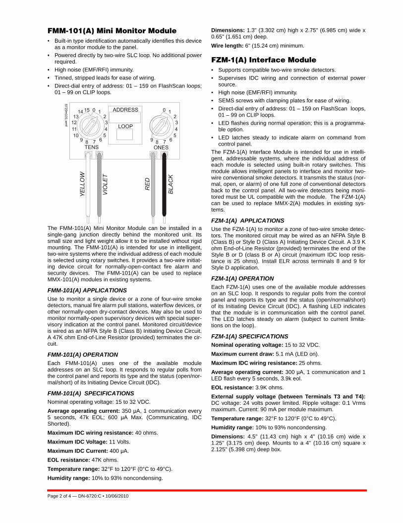
Page 2 of 4 — DN-6720:C • 10/06/2010
FMM-101(A) Mini Monitor Module• Built-in type identification automatically identifies this device
as a monitor module to the panel.• Powered directly by two-wire SLC loop. No additional power
required.• High noise (EMF/RFI) immunity.• Tinned, stripped leads for ease of wiring.
• Direct-dial entry of address: 01 – 159 on FlashScan loops;01 – 99 on CLIP loops.
The FMM-101(A) Mini Monitor Module can be installed in asingle-gang junction directly behind the monitored unit. Itssmall size and light weight allow it to be installed without rigidmounting. The FMM-101(A) is intended for use in intelligent,two-wire systems where the individual address of each moduleis selected using rotary switches. It provides a two-wire initiat-ing device circuit for normally-open-contact fire alarm andsecurity devices. The FMM-101(A) can be used to replaceMMX-101(A) modules in existing systems.
FMM-101(A) APPLICATIONSUse to monitor a single device or a zone of four-wire smokedetectors, manual fire alarm pull stations, waterflow devices, orother normally-open dry-contact devices. May also be used tomonitor normally-open supervisory devices with special super-visory indication at the control panel. Monitored circuit/deviceis wired as an NFPA Style B (Class B) Initiating Device Circuit.A 47K ohm End-of-Line Resistor (provided) terminates the cir-cuit.
FMM-101(A) OPERATIONEach FMM-101(A) uses one of the available moduleaddresses on an SLC loop. It responds to regular polls fromthe control panel and reports its type and the status (open/nor-mal/short) of its Initiating Device Circuit (IDC).
FMM-101(A) SPECIFICATIONSNominal operating voltage: 15 to 32 VDC.
Average operating current: 350 μA, 1 communication every5 seconds, 47k EOL; 600 μA Max. (Communicating, IDCShorted).
Maximum IDC wiring resistance: 40 ohms.
Maximum IDC Voltage: 11 Volts.
Maximum IDC Current: 400 μA.
EOL resistance: 47K ohms.
Temperature range: 32°F to 120°F (0°C to 49°C).
Humidity range: 10% to 93% noncondensing.
Dimensions: 1.3" (3.302 cm) high x 2.75" (6.985 cm) wide x0.65" (1.651 cm) deep.
Wire length: 6" (15.24 cm) minimum.
FZM-1(A) Interface Module• Supports compatible two-wire smoke detectors.• Supervises IDC wiring and connection of external power
source.• High noise (EMF/RFI) immunity.
• SEMS screws with clamping plates for ease of wiring.• Direct-dial entry of address: 01 – 159 on FlashScan loops,
01 – 99 on CLIP loops.• LED flashes during normal operation; this is a programma-
ble option.• LED latches steady to indicate alarm on command from
control panel.The FZM-1(A) Interface Module is intended for use in intelli-gent, addressable systems, where the individual address ofeach module is selected using built-in rotary switches. Thismodule allows intelligent panels to interface and monitor two-wire conventional smoke detectors. It transmits the status (nor-mal, open, or alarm) of one full zone of conventional detectorsback to the control panel. All two-wire detectors being moni-tored must be UL compatible with the module. The FZM-1(A)can be used to replace MMX-2(A) modules in existing sys-tems.
FZM-1(A) APPLICATIONSUse the FZM-1(A) to monitor a zone of two-wire smoke detec-tors. The monitored circuit may be wired as an NFPA Style B(Class B) or Style D (Class A) Initiating Device Circuit. A 3.9 Kohm End-of-Line Resistor (provided) terminates the end of theStyle B or D (class B or A) circuit (maximum IDC loop resis-tance is 25 ohms). Install ELR across terminals 8 and 9 forStyle D application.
FZM-1(A) OPERATIONEach FZM-1(A) uses one of the available module addresseson an SLC loop. It responds to regular polls from the controlpanel and reports its type and the status (open/normal/short)of its Initiating Device Circuit (IDC). A flashing LED indicatesthat the module is in communication with the control panel.The LED latches steady on alarm (subject to current limita-tions on the loop).
FZM-1(A) SPECIFICATIONSNominal operating voltage: 15 to 32 VDC.
Maximum current draw: 5.1 mA (LED on).
Maximum IDC wiring resistance: 25 ohms.
Average operating current: 300 μA, 1 communication and 1LED flash every 5 seconds, 3.9k eol.
EOL resistance: 3.9K ohms.
External supply voltage (between Terminals T3 and T4):DC voltage: 24 volts power limited. Ripple voltage: 0.1 Vrmsmaximum. Current: 90 mA per module maximum.
Temperature range: 32°F to 120°F (0°C to 49°C).
Humidity range: 10% to 93% noncondensing.
Dimensions: 4.5" (11.43 cm) high x 4" (10.16 cm) wide x1.25" (3.175 cm) deep. Mounts to a 4" (10.16 cm) square x2.125" (5.398 cm) deep box.
6720m101.w
mf
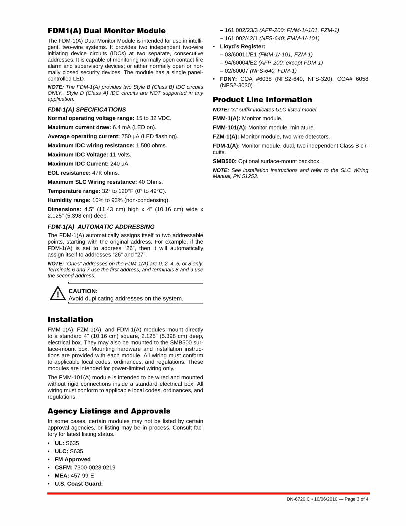
DN-6720:C • 10/06/2010 — Page 3 of 4
FDM1(A) Dual Monitor ModuleThe FDM-1(A) Dual Monitor Module is intended for use in intelli-gent, two-wire systems. It provides two independent two-wireinitiating device circuits (IDCs) at two separate, consecutiveaddresses. It is capable of monitoring normally open contact firealarm and supervisory devices; or either normally open or nor-mally closed security devices. The module has a single panel-controlled LED.
NOTE: The FDM-1(A) provides two Style B (Class B) IDC circuitsONLY. Style D (Class A) IDC circuits are NOT supported in anyapplication.
FDM-1(A) SPECIFICATIONSNormal operating voltage range: 15 to 32 VDC.
Maximum current draw: 6.4 mA (LED on).
Average operating current: 750 μA (LED flashing).
Maximum IDC wiring resistance: 1,500 ohms.
Maximum IDC Voltage: 11 Volts.
Maximum IDC Current: 240 μA
EOL resistance: 47K ohms.
Maximum SLC Wiring resistance: 40 Ohms.
Temperature range: 32° to 120°F (0° to 49°C).
Humidity range: 10% to 93% (non-condensing).
Dimensions: 4.5" (11.43 cm) high x 4" (10.16 cm) wide x2.125" (5.398 cm) deep.
FDM-1(A) AUTOMATIC ADDRESSINGThe FDM-1(A) automatically assigns itself to two addressablepoints, starting with the original address. For example, if theFDM-1(A) is set to address “26”, then it will automaticallyassign itself to addresses “26” and “27”.
NOTE: “Ones” addresses on the FDM-1(A) are 0, 2, 4, 6, or 8 only.Terminals 6 and 7 use the first address, and terminals 8 and 9 usethe second address.
InstallationFMM-1(A), FZM-1(A), and FDM-1(A) modules mount directlyto a standard 4" (10.16 cm) square, 2.125" (5.398 cm) deep,electrical box. They may also be mounted to the SMB500 sur-face-mount box. Mounting hardware and installation instruc-tions are provided with each module. All wiring must conformto applicable local codes, ordinances, and regulations. Thesemodules are intended for power-limited wiring only.
The FMM-101(A) module is intended to be wired and mountedwithout rigid connections inside a standard electrical box. Allwiring must conform to applicable local codes, ordinances, andregulations.
Agency Listings and ApprovalsIn some cases, certain modules may not be listed by certainapproval agencies, or listing may be in process. Consult fac-tory for latest listing status.
• UL: S635• ULC: S635• FM Approved• CSFM: 7300-0028:0219• MEA: 457-99-E• U.S. Coast Guard:
– 161.002/23/3 (AFP-200: FMM-1/-101, FZM-1)
– 161.002/42/1 (NFS-640: FMM-1/-101)• Lloyd’s Register:
– 03/60011/E1 (FMM-1/-101, FZM-1)
– 94/60004/E2 (AFP-200: except FDM-1)– 02/60007 (NFS-640: FDM-1)
• FDNY: COA #6038 (NFS2-640, NFS-320), COA# 6058(NFS2-3030)
Product Line InformationNOTE: “A” suffix indicates ULC-listed model.
FMM-1(A): Monitor module.
FMM-101(A): Monitor module, miniature.
FZM-1(A): Monitor module, two-wire detectors.
FDM-1(A): Monitor module, dual, two independent Class B cir-cuits.
SMB500: Optional surface-mount backbox.
NOTE: See installation instructions and refer to the SLC WiringManual, PN 51253.
! CAUTION:Avoid duplicating addresses on the system.

Page 4 of 4 — DN-6720:C • 10/06/2010
FlashScan® and NOTIFIER® are registered trademarks and FireWatch™ isa trademark of Honeywell International Inc.©2010 by Honeywell International Inc. All rights reserved. Unauthorized useof this document is strictly prohibited.
This document is not intended to be used for installation purposes. We try to keep our product information up-to-date and accurate.
We cannot cover all specific applications or anticipate all requirements. All specifications are subject to change without notice.
For more information, contact Notifier. Phone: (203) 484-7161, FAX: (203) 484-7118.www.notifier.com
Made in the U.S. A.
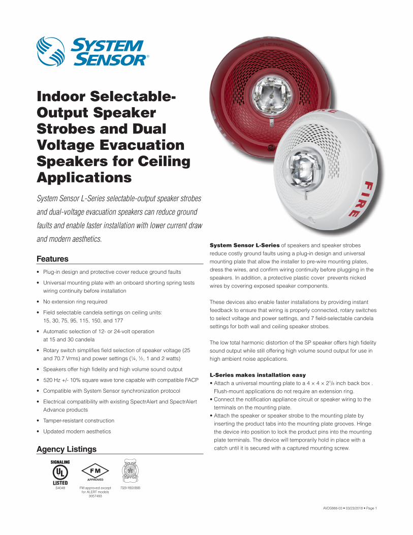
AVDS866-03 • 03/23/2018 • Page 1
Indoor Selectable-Output Speaker Strobes and Dual Voltage Evacuation Speakers for Ceiling ApplicationsSystem Sensor L-Series selectable-output speaker strobes
and dual-voltage evacuation speakers can reduce ground
faults and enable faster installation with lower current draw
and modern aesthetics.
Features
• Plug-in design and protective cover reduce ground faults
• Universal mounting plate with an onboard shorting spring tests wiring continuity before installation
• No extension ring required
• Field selectable candela settings on ceiling units: 15, 30, 75, 95, 115, 150, and 177
• Automatic selection of 12- or 24-volt operation at 15 and 30 candela
• Rotary switch simplifies field selection of speaker voltage (25 and 70.7 Vrms) and power settings (¼, ½, 1 and 2 watts)
• Speakers offer high fidelity and high volume sound output
• 520 Hz +/- 10% square wave tone capable with compatible FACP
• Compatible with System Sensor synchronization protocol
• Electrical compatibility with existing SpectrAlert and SpectrAlert Advance products
• Tamper-resistant construction
• Updated modern aesthetics
System Sensor L-Series of speakers and speaker strobes reduce costly ground faults using a plug-in design and universal mounting plate that allow the installer to pre-wire mounting plates, dress the wires, and confirm wiring continuity before plugging in the speakers. In addition, a protective plastic cover prevents nicked wires by covering exposed speaker components.
These devices also enable faster installations by providing instant feedback to ensure that wiring is properly connected, rotary switches to select voltage and power settings, and 7 field-selectable candela settings for both wall and ceiling speaker strobes.
The low total harmonic distortion of the SP speaker offers high fidelity sound output while still offering high volume sound output for use in high ambient noise applications.
L-Series makes installation easy• Attach a universal mounting plate to a 4 × 4 × 21/8 inch back box .
Flush-mount applications do not require an extension ring.• Connect the notification appliance circuit or speaker wiring to the
terminals on the mounting plate.• Attach the speaker or speaker strobe to the mounting plate by
inserting the product tabs into the mounting plate grooves. Hinge the device into position to lock the product pins into the mounting plate terminals. The device will temporarily hold in place with a catch until it is secured with a captured mounting screw.Agency Listings
7320-1653:0505S4048 FM approved except for ALERT models
3057493
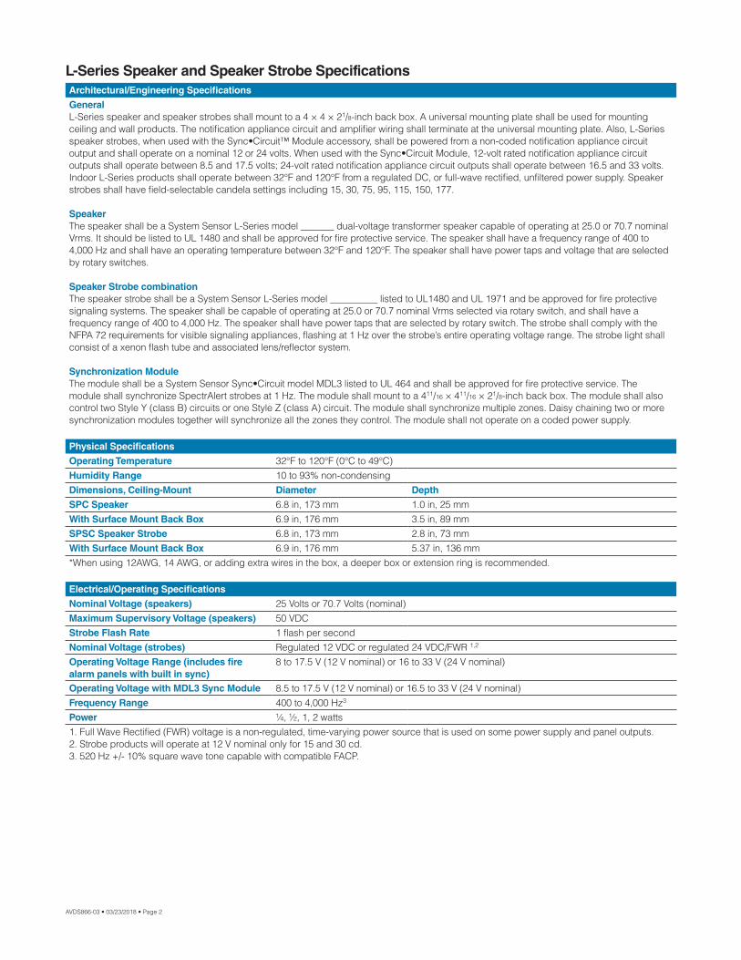
L-Series Speaker and Speaker Strobe SpecificationsArchitectural/Engineering Specifications
GeneralL-Series speaker and speaker strobes shall mount to a 4 × 4 × 21/8-inch back box. A universal mounting plate shall be used for mounting ceiling and wall products. The notification appliance circuit and amplifier wiring shall terminate at the universal mounting plate. Also, L-Series speaker strobes, when used with the Sync•Circuit™ Module accessory, shall be powered from a non-coded notification appliance circuit output and shall operate on a nominal 12 or 24 volts. When used with the Sync•Circuit Module, 12-volt rated notification appliance circuit outputs shall operate between 8.5 and 17.5 volts; 24-volt rated notification appliance circuit outputs shall operate between 16.5 and 33 volts. Indoor L-Series products shall operate between 32°F and 120°F from a regulated DC, or full-wave rectified, unfiltered power supply. Speaker strobes shall have field-selectable candela settings including 15, 30, 75, 95, 115, 150, 177.
SpeakerThe speaker shall be a System Sensor L-Series model _______ dual-voltage transformer speaker capable of operating at 25.0 or 70.7 nominal Vrms. It should be listed to UL 1480 and shall be approved for fire protective service. The speaker shall have a frequency range of 400 to 4,000 Hz and shall have an operating temperature between 32°F and 120°F. The speaker shall have power taps and voltage that are selected by rotary switches.
Speaker Strobe combinationThe speaker strobe shall be a System Sensor L-Series model __________ listed to UL1480 and UL 1971 and be approved for fire protective signaling systems. The speaker shall be capable of operating at 25.0 or 70.7 nominal Vrms selected via rotary switch, and shall have a frequency range of 400 to 4,000 Hz. The speaker shall have power taps that are selected by rotary switch. The strobe shall comply with the NFPA 72 requirements for visible signaling appliances, flashing at 1 Hz over the strobe’s entire operating voltage range. The strobe light shall consist of a xenon flash tube and associated lens/reflector system.
Synchronization ModuleThe module shall be a System Sensor Sync•Circuit model MDL3 listed to UL 464 and shall be approved for fire protective service. The module shall synchronize SpectrAlert strobes at 1 Hz. The module shall mount to a 411/16 × 411/16 × 21/8-inch back box. The module shall also control two Style Y (class B) circuits or one Style Z (class A) circuit. The module shall synchronize multiple zones. Daisy chaining two or more synchronization modules together will synchronize all the zones they control. The module shall not operate on a coded power supply.
Physical Specifications
Operating Temperature 32°F to 120°F (0°C to 49°C)Humidity Range 10 to 93% non-condensingDimensions, Ceiling-Mount Diameter Depth
SPC Speaker 6.8 in, 173 mm 1.0 in, 25 mmWith Surface Mount Back Box 6.9 in, 176 mm 3.5 in, 89 mmSPSC Speaker Strobe 6.8 in, 173 mm 2.8 in, 73 mmWith Surface Mount Back Box 6.9 in, 176 mm 5.37 in, 136 mm*When using 12AWG, 14 AWG, or adding extra wires in the box, a deeper box or extension ring is recommended.
Electrical/Operating Specifications
Nominal Voltage (speakers) 25 Volts or 70.7 Volts (nominal)Maximum Supervisory Voltage (speakers) 50 VDCStrobe Flash Rate 1 flash per secondNominal Voltage (strobes) Regulated 12 VDC or regulated 24 VDC/FWR 1,2
Operating Voltage Range (includes fire alarm panels with built in sync)
8 to 17.5 V (12 V nominal) or 16 to 33 V (24 V nominal)
Operating Voltage with MDL3 Sync Module 8.5 to 17.5 V (12 V nominal) or 16.5 to 33 V (24 V nominal)Frequency Range 400 to 4,000 Hz3
Power ¼, ½, 1, 2 watts1. Full Wave Rectified (FWR) voltage is a non-regulated, time-varying power source that is used on some power supply and panel outputs.2. Strobe products will operate at 12 V nominal only for 15 and 30 cd.3. 520 Hz +/- 10% square wave tone capable with compatible FACP.
AVDS866-03 • 03/23/2018 • Page 2
System Sensor copypaste shortcuts7/8 11/161/8¼

UL Current Draw DataUL Max. Strobe Current Draw (mA RMS)
Candela
8 to 17.5 Volts 16 to 33 Volts
DC DC FWR
15 87 41 6030 153 63 8675 NA 111 14295 NA 134 164115 NA 158 191150 NA 189 228177 NA 226 264
Ceiling-Mount Speaker Sound OutputSetting UL Reverberant (dBA @10 ft) UL Anechoic (dBA @10 ft)1/4 W 79 791/2 W 82 821 W 85 852 W 88 88
Ceiling-Mount Speaker Strobe Sound OutputSetting UL Reverberant (dBA @10 ft) UL Anechoic (dBA @10 ft)1/4 W 77 771/2 W 80 801 W 83 832 W 86 86
L-Series Dimensions
Ceiling Speaker
Ceiling Speaker Strobe
AVDS866-03 • 03/23/2018 • Page 3
1.0"(25.4 mm)
1.63" (41.66 mm)6.8" dia.
(173 mm)
1.63" (41.66 mm)6.8" dia.
(173 mm)
2.87" (72.9 mm)
1.76" (44.7 mm)
A0543-00
A0544-00
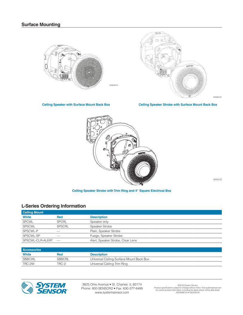
3825 Ohio Avenue • St. Charles, IL 60174 Phone: 800-SENSOR2 • Fax: 630-377-6495
www.systemsensor.com
©2018 System Sensor.Product specifications subject to change without notice. Visit systemsensor.com
for current product information, including the latest version of this data sheet.AVDS866-03 • 03/23/2018
L-Series Ordering InformationCeiling MountWhite Red DescriptionSPCWL SPCRL Speaker onlySPSCWL SPSCRL Speaker StrobeSPSCWL-P — Plain, Speaker StrobeSPSCWL-SP — Fuego, Speaker StrobeSPSCWL-CLR-ALERT — Alert, Speaker Strobe, Clear Lens
AccessoriesWhite Red DescriptionSBBCWL SBBCRL Universal Ceiling Surface Mount Back BoxTRC-2W TRC-2 Universal Ceiling Trim Ring
Surface Mounting
Ceiling Speaker with Surface Mount Back Box Ceiling Speaker Strobe with Surface Mount Back Box
Ceiling Speaker Strobe with Trim Ring and 4" Square Electrical Box
A0542-00
A0520-01
A0504-01
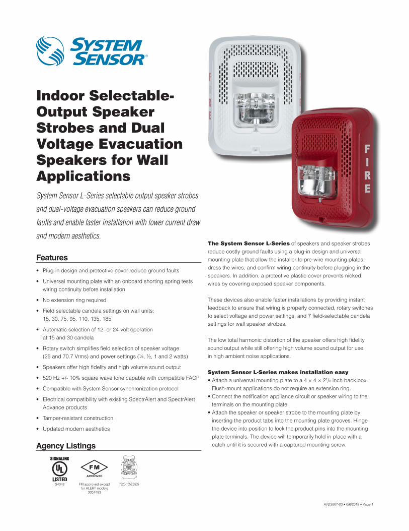
Agency Listings
7320-1653:0505S4048 FM approved except for ALERT models
3057493
AVDS867-03 • 6/6/2019 • Page 1
Indoor Selectable- Output Speaker Strobes and Dual Voltage Evacuation Speakers for WallApplicationsSystem Sensor L-Series selectable output speaker strobes
and dual-voltage evacuation speakers can reduce ground
faults and enable faster installation with lower current draw
and modern aesthetics.
Features
• Plug-in design and protective cover reduce ground faults
• Universal mounting plate with an onboard shorting spring tests wiring continuity before installation
• No extension ring required
• Field selectable candela settings on wall units: 15, 30, 75, 95, 110, 135, 185
• Automatic selection of 12- or 24-volt operation at 15 and 30 candela
• Rotary switch simplifies field selection of speaker voltage (25 and 70.7 Vrms) and power settings (¼, ½, 1 and 2 watts)
• Speakers offer high fidelity and high volume sound output
• 520 Hz +/- 10% square wave tone capable with compatible FACP
• Compatible with System Sensor synchronization protocol
• Electrical compatibility with existing SpectrAlert and SpectrAlert Advance products
• Tamper-resistant construction
• Updated modern aesthetics
The System Sensor L-Series of speakers and speaker strobes reduce costly ground faults using a plug-in design and universal mounting plate that allow the installer to pre-wire mounting plates, dress the wires, and confirm wiring continuity before plugging in the speakers. In addition, a protective plastic cover prevents nicked wires by covering exposed speaker components.
These devices also enable faster installations by providing instant feedback to ensure that wiring is properly connected, rotary switches to select voltage and power settings, and 7 field-selectable candela settings for wall speaker strobes.
The low total harmonic distortion of the speaker offers high fidelity sound output while still offering high volume sound output for use in high ambient noise applications.
System Sensor L-Series makes installation easy• Attach a universal mounting plate to a 4 × 4 × 21/8 inch back box.
Flush-mount applications do not require an extension ring.• Connect the notification appliance circuit or speaker wiring to the
terminals on the mounting plate.• Attach the speaker or speaker strobe to the mounting plate by
inserting the product tabs into the mounting plate grooves. Hinge the device into position to lock the product pins into the mounting plate terminals. The device will temporarily hold in place with a catch until it is secured with a captured mounting screw.
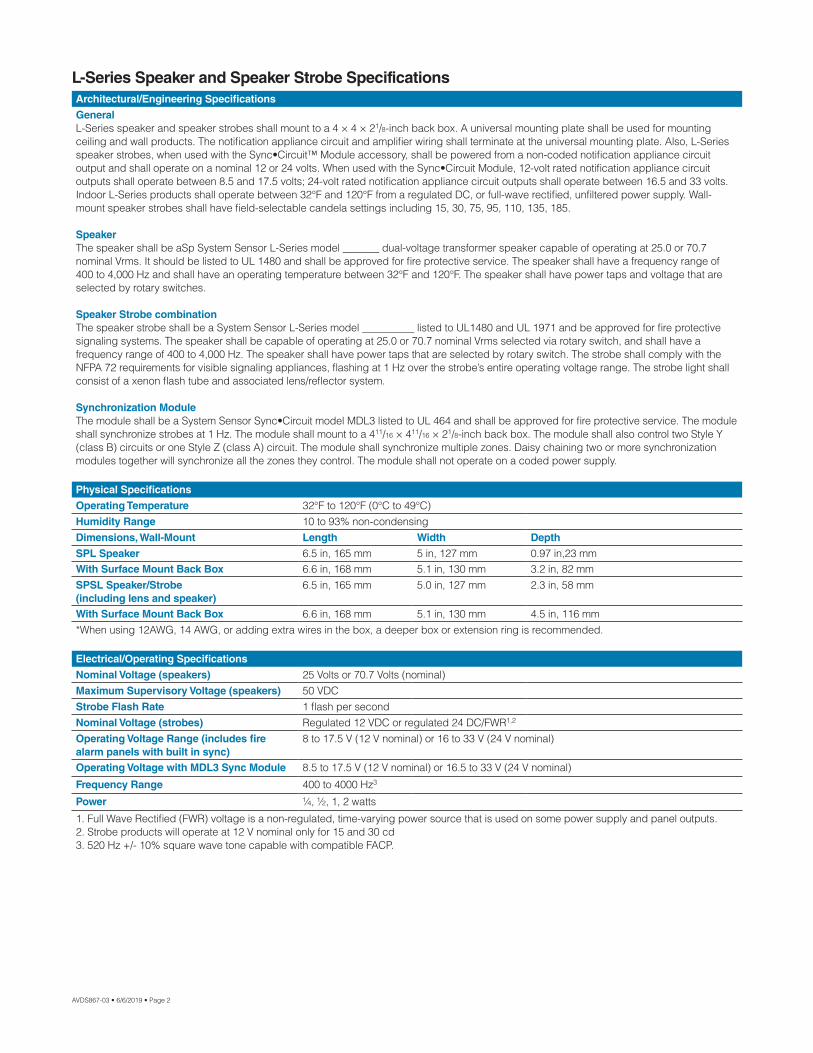
AVDS867-03 • 6/6/2019 • Page 2
L-Series Speaker and Speaker Strobe SpecificationsArchitectural/Engineering Specifications
GeneralL-Series speaker and speaker strobes shall mount to a 4 × 4 × 21/8-inch back box. A universal mounting plate shall be used for mounting ceiling and wall products. The notification appliance circuit and amplifier wiring shall terminate at the universal mounting plate. Also, L-Series speaker strobes, when used with the Sync•Circuit™ Module accessory, shall be powered from a non-coded notification appliance circuit output and shall operate on a nominal 12 or 24 volts. When used with the Sync•Circuit Module, 12-volt rated notification appliance circuit outputs shall operate between 8.5 and 17.5 volts; 24-volt rated notification appliance circuit outputs shall operate between 16.5 and 33 volts. Indoor L-Series products shall operate between 32°F and 120°F from a regulated DC, or full-wave rectified, unfiltered power supply. Wall-mount speaker strobes shall have field-selectable candela settings including 15, 30, 75, 95, 110, 135, 185.
SpeakerThe speaker shall be aSp System Sensor L-Series model _______ dual-voltage transformer speaker capable of operating at 25.0 or 70.7 nominal Vrms. It should be listed to UL 1480 and shall be approved for fire protective service. The speaker shall have a frequency range of 400 to 4,000 Hz and shall have an operating temperature between 32°F and 120°F. The speaker shall have power taps and voltage that are selected by rotary switches.
Speaker Strobe combinationThe speaker strobe shall be a System Sensor L-Series model __________ listed to UL1480 and UL 1971 and be approved for fire protective signaling systems. The speaker shall be capable of operating at 25.0 or 70.7 nominal Vrms selected via rotary switch, and shall have a frequency range of 400 to 4,000 Hz. The speaker shall have power taps that are selected by rotary switch. The strobe shall comply with the NFPA 72 requirements for visible signaling appliances, flashing at 1 Hz over the strobe’s entire operating voltage range. The strobe light shall consist of a xenon flash tube and associated lens/reflector system.
Synchronization ModuleThe module shall be a System Sensor Sync•Circuit model MDL3 listed to UL 464 and shall be approved for fire protective service. The module shall synchronize strobes at 1 Hz. The module shall mount to a 411/16 × 411/16 × 21/8-inch back box. The module shall also control two Style Y (class B) circuits or one Style Z (class A) circuit. The module shall synchronize multiple zones. Daisy chaining two or more synchronization modules together will synchronize all the zones they control. The module shall not operate on a coded power supply.
Physical Specifications
Operating Temperature 32°F to 120°F (0°C to 49°C)Humidity Range 10 to 93% non-condensingDimensions, Wall-Mount Length Width Depth
SPL Speaker 6.5 in, 165 mm 5 in, 127 mm 0.97 in,23 mmWith Surface Mount Back Box 6.6 in, 168 mm 5.1 in, 130 mm 3.2 in, 82 mmSPSL Speaker/Strobe (including lens and speaker)
6.5 in, 165 mm 5.0 in, 127 mm 2.3 in, 58 mm
With Surface Mount Back Box 6.6 in, 168 mm 5.1 in, 130 mm 4.5 in, 116 mm*When using 12AWG, 14 AWG, or adding extra wires in the box, a deeper box or extension ring is recommended.
Electrical/Operating Specifications
Nominal Voltage (speakers) 25 Volts or 70.7 Volts (nominal)Maximum Supervisory Voltage (speakers) 50 VDCStrobe Flash Rate 1 flash per secondNominal Voltage (strobes) Regulated 12 VDC or regulated 24 DC/FWR1,2
Operating Voltage Range (includes fire alarm panels with built in sync)
8 to 17.5 V (12 V nominal) or 16 to 33 V (24 V nominal)
Operating Voltage with MDL3 Sync Module 8.5 to 17.5 V (12 V nominal) or 16.5 to 33 V (24 V nominal)
Frequency Range 400 to 4000 Hz3
Power ¼, ½, 1, 2 watts
1. Full Wave Rectified (FWR) voltage is a non-regulated, time-varying power source that is used on some power supply and panel outputs.2. Strobe products will operate at 12 V nominal only for 15 and 30 cd3. 520 Hz +/- 10% square wave tone capable with compatible FACP.
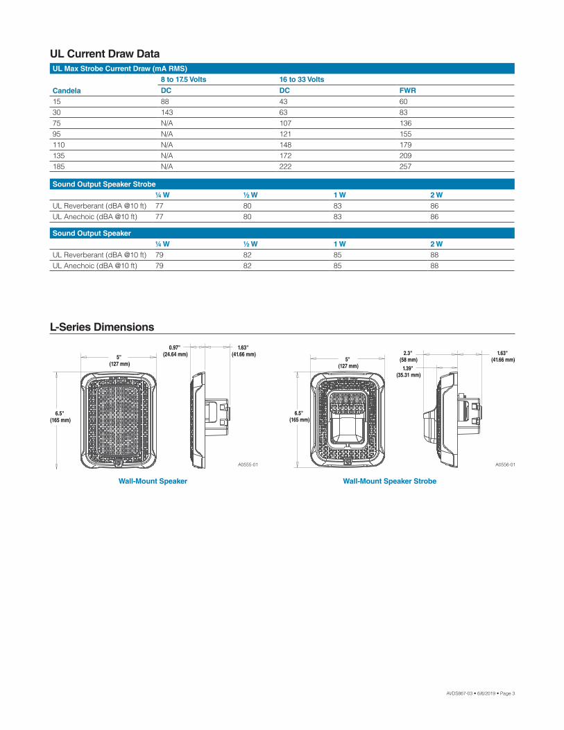
AVDS867-03 • 6/6/2019 • Page 3
UL Current Draw DataUL Max Strobe Current Draw (mA RMS)
Candela
8 to 17.5 Volts 16 to 33 Volts
DC DC FWR
15 88 43 6030 143 63 8375 N/A 107 13695 N/A 121 155110 N/A 148 179135 N/A 172 209185 N/A 222 257
Sound Output Speaker Strobe¼ W ½ W 1 W 2 W
UL Reverberant (dBA @10 ft) 77 80 83 86UL Anechoic (dBA @10 ft) 77 80 83 86
Sound Output Speaker¼ W ½ W 1 W 2 W
UL Reverberant (dBA @10 ft) 79 82 85 88UL Anechoic (dBA @10 ft) 79 82 85 88
L-Series Dimensions
Wall-Mount Speaker Wall-Mount Speaker Strobe
5" (127 mm)
0.97" (24.64 mm)
1.63" (41.66 mm)
6.5" (165 mm)
1.39" (35.31 mm)
6.5" (165 mm)
5" (127 mm)
1.63" (41.66 mm)
2.3" (58 mm)
A0555-01 A0556-01
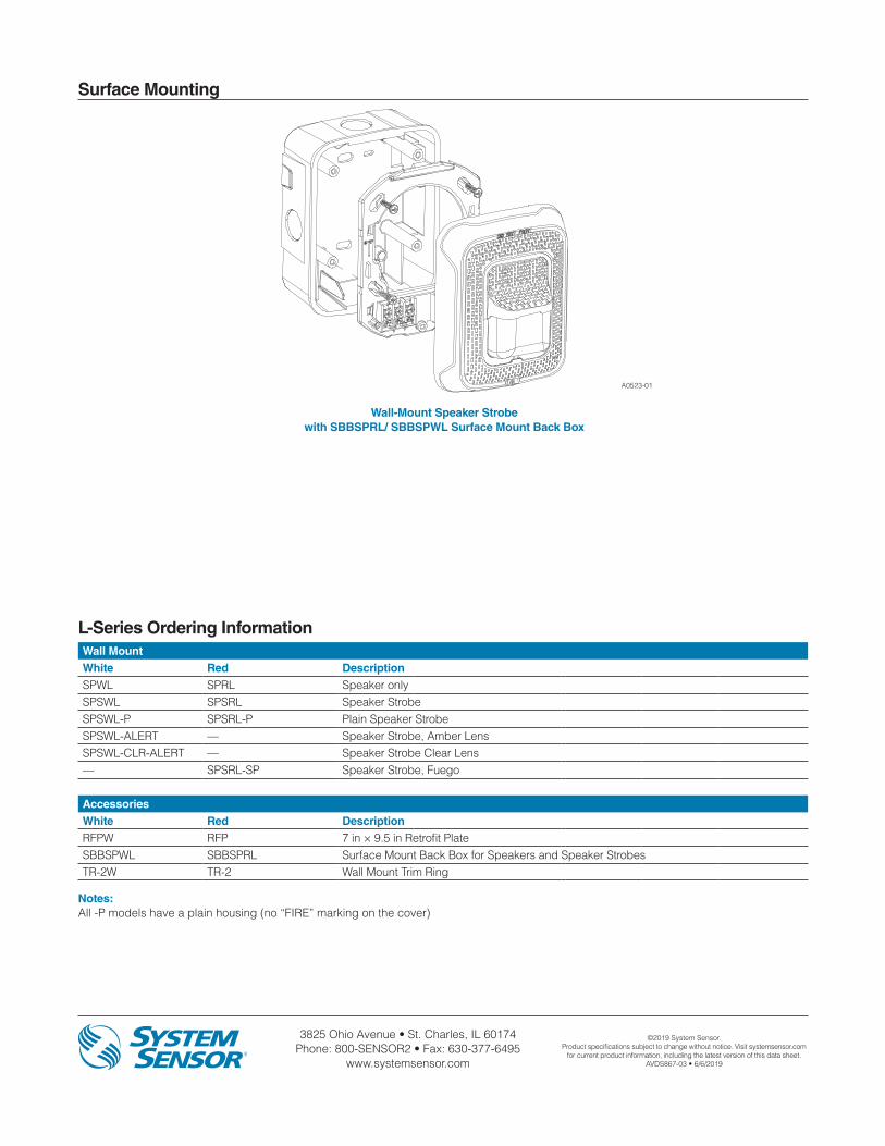
3825 Ohio Avenue • St. Charles, IL 60174 Phone: 800-SENSOR2 • Fax: 630-377-6495
www.systemsensor.com
©2019 System Sensor.Product specifications subject to change without notice. Visit systemsensor.com
for current product information, including the latest version of this data sheet.AVDS867-03 • 6/6/2019
L-Series Ordering InformationWall MountWhite Red DescriptionSPWL SPRL Speaker onlySPSWL SPSRL Speaker StrobeSPSWL-P SPSRL-P Plain Speaker StrobeSPSWL-ALERT — Speaker Strobe, Amber LensSPSWL-CLR-ALERT — Speaker Strobe Clear Lens— SPSRL-SP Speaker Strobe, Fuego
AccessoriesWhite Red DescriptionRFPW RFP 7 in × 9.5 in Retrofit PlateSBBSPWL SBBSPRL Surface Mount Back Box for Speakers and Speaker StrobesTR-2W TR-2 Wall Mount Trim Ring
Notes:All -P models have a plain housing (no “FIRE” marking on the cover)
Surface Mounting
Wall-Mount Speaker Strobe with SBBSPRL/ SBBSPWL Surface Mount Back Box
A0523-01

Agency Listings
Outdoor, Selectable- Output Speaker Strobes and Dual-Voltage Evacuation Speakers for WallApplicationsSpectrAlert® Advance outdoor, selectable-output speaker
strobes and dual-voltage evacuation speakers meet
virtually any outdoor application requirement.
Features
• Weatherproof per NEMA 4X, IP56
• Rated from -40°F to 151°F
• Plug-in design reduces ground faults
• Universal mounting plate with onboard shorting spring that tests wiring continuity before devices are installed
• Field-selectable candela settings: 15, 15/75, 30, 75, 95, 110, 115, 135, 150, 177, and 185
• Automatic selection of 12- or 24-volt operation at 15 and 15/75 candela
• Rotary switch for speaker voltage (25 and 70.7 Vrms) and power settings (1/4, 1/2, 1 and 2 watts)
• Compatible with System Sensor synchronization protocol and legacy SpectrAlert products
• Tamper-resistant construction
• Listed for ceiling or wall mounting
SpectrAlert Advance offers the broadest line of outdoor speakers and speaker strobes in the industry. From metal and plastic outdoor back boxes, to white and red plastic housings, to wall and ceiling mounting options, SpectrAlert Advance can meet virtually any application requirement.
Wall-mount outdoor speakers and speaker strobes can be used indoors or outdoors in wet or dry applications, and can provide reliable operation from −40°F to 151°F. These speakers provide a broad frequency response range, low harmonic distortion and maintain a high sound pressure level at all tap settings to provide accurate and intelligible broadcast of evacuation messages.
Like the entire SpectrAlert Advance line, wall-mount outdoor speakers and speaker strobes include a variety of features that increase application flexibility and simplify installation. First, field-selectable settings, including candela, speaker voltage and power settings, and automatic selection of 12- or 24-volt operation enable installers to easily adapt devices to meet requirements.
Next, these devices use a universal mounting plate with an onboard shorting spring that ensures wiring continuity before devices are installed, so installers can verify proper wiring without mounting the devices and exposing them to potential construction damage. Once the plates are mounted, all SpectrAlert Advance devices utilize a plug-in design with a single captured screw to speed installation and virtually eliminate costly ground faults.
Outdoor devices ship with weatherproof plastic back boxes (metal back boxes are available separately) that accommodate in-and-out wiring for daisy chaining devices. Plastic back boxes feature removable side flanges and improved resistance to saltwater corrosion. Knock-outs located on the back eliminate the need to drill holes for screw-in mounting. Plastic and metal weatherproof back boxes come with ¾-inch top and bottom conduit entries and ¾-inch knock-outs at the back. A screw-in NPT plug with an O-ring gasket for a watertight seal is included with each back box.10-08-E7320-1653:20175S0
AVDS11301
SpectrAlert® Advance Outdoor Speaker and Speaker Strobe SpecificationsArchitectural/Engineering Specifications
GeneralSpectrAlert Advance outdoor speakers and speaker strobes shall mount to a weatherproof back box. A universal mounting plate shall be used for mounting ceiling and wall products. The notification appliance circuit and amplifier wiring shall terminate at the universal mounting plate. Also, SpectrAlert Advance speaker strobes, when used with the Sync•Circuit™ Module accessory, shall be powered from a non-coded notification appliance circuit output and shall operate on a nominal 12 or 24 volts. When used with the Sync•Circuit Module, 12-volt-rated notification appliance circuit outputs shall operate between 8.5 and 17.5 volts; 24-volt-rated notification appliance circuit outputs shall operate between 16.5 and 33 volts. Outdoor SpectrAlert Advance products shall operate between –40°F and 151°F from a regulated DC, or full-wave rectified, unfiltered power supply.
SpeakerSpeaker shall be a System Sensor SpectrAlert Advance Model ______ dual-voltage transformer speaker capable of operating at 25.0 or 70.7 nominal Vrms. Speaker shall be listed to Underwriters Laboratories Standard S4048 for outdoor fire protective signaling systems. Speaker shall have a frequency range of 400 to 4,000 Hz and shall have an operating temperature from –40°F to 150.8°F. Speaker shall have power taps and wattage settings that are selected by rotary switches. The speaker must be installed with its weatherproof back box in order to remain outdoor approved per UL listing S4048. The speaker shall be suitable for use in air handling spaces and wet environments.
Speaker Strobe CombinationThe speaker strobe shall be a System Sensor Model _____ listed to UL 1638 and UL 1480 and be approved for fire protective signaling systems. Speaker shall be capable of operating at 25.0 or 70.7 nominal Vrms and shall have a frequency range of 400 to 4,000 Hz. Speaker shall have power taps that are selected by rotary switch. The strobe shall consist of a xenon flash tube with associated lens/reflector system and operate on either 12 or 24 volts. The strobe shall also feature selectable candela output, providing options for 15 or 15/75 candela when operating on 12 volts and 15, 15/75, 30, 75, 110, 115, 135, 150, 177 or 185 candela when operating on 24 volts. The strobe shall comply with the Americans with Disabilities Act requirement for visible signaling appliances, flashing at 1 Hz over the strobe’s entire operating voltage range. The speaker strobe must be installed with its weatherproof back box in order to remain outdoor approved per UL. The speaker strobe shall be suitable for use in wet environments.
Physical Specifications
Operating Temperature –40°F to 151°F (–40°C to 66°C)Dimensions, Wall-Mount
SPS Speaker Strobe 6.0˝ L × 5.0˝ W × 4.7˝ D (including lens and speaker)SP Speaker 6.0˝ L × 5.0˝ W × 2.9˝ D
Dimensions, Wall-Mount Weatherproof Back Box 6.5˝ L × 5.5˝ H × 2.9˝ DElectrical/Operating Specifications
Nominal Voltage (speakers) 25 V or 70.7 V (nominal)Maximum Supervisory Voltage (speakers) 50 VDCStrobe Flash Rate 1 flash per secondNominal Voltage (strobes) Regulated 12 VDC/FWR or regulated 24 DC/FWROperating Voltage Range (includes fire alarm panels with built in sync)
8 to 17.5 V (12 V nominal) or 16 to 33 V (24 V nominal)
Operating Voltage with MDL3 Sync Module 8.5 to 17.5 V (12 V nominal) or 16.5 to 33 V (24 V nominal)Frequency Range 400 to 4,000 HzPower ¼, ½, 1, 2 watts
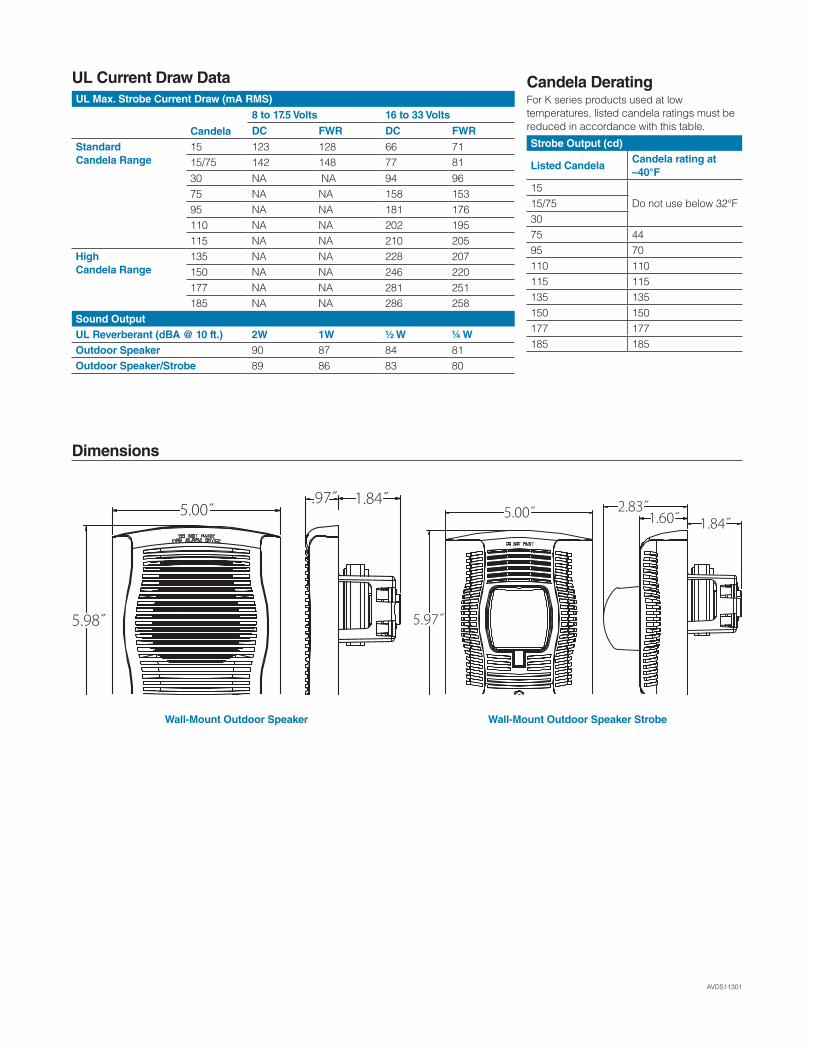
AVDS11301
UL Current Draw DataUL Max. Strobe Current Draw (mA RMS)
Candela
8 to 17.5 Volts 16 to 33 Volts
DC FWR DC FWR
StandardCandela Range
15 123 128 66 7115/75 142 148 77 8130 NA NA 94 9675 NA NA 158 15395 NA NA 181 176110 NA NA 202 195115 NA NA 210 205
HighCandela Range
135 NA NA 228 207150 NA NA 246 220177 NA NA 281 251185 NA NA 286 258
Sound OutputUL Reverberant (dBA @ 10 ft.) 2W 1W ½ W ¼ WOutdoor Speaker 90 87 84 81Outdoor Speaker/Strobe 89 86 83 80
Dimensions
Candela DeratingFor K series products used at low temperatures, listed candela ratings must be reduced in accordance with this table.
Strobe Output (cd)
Listed CandelaCandela rating at –40°F
15Do not use below 32°F15/75
3075 4495 70110 110115 115135 135150 150177 177185 185
5.00˝.97˝ 1.84˝
5.98˝
5.00˝ 2.83˝1.84˝1.60˝
5.97˝
Wall-Mount Outdoor Speaker Wall-Mount Outdoor Speaker Strobe
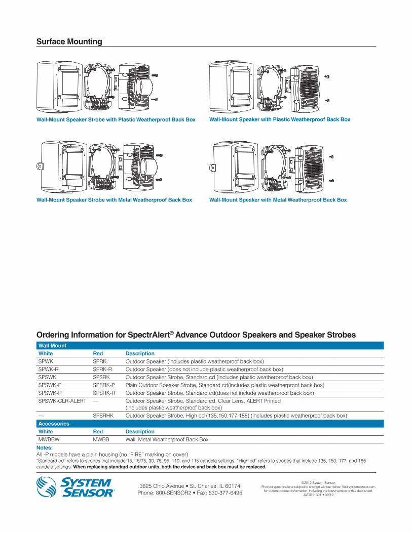
3825 Ohio Avenue • St. Charles, IL 60174 Phone: 800-SENSOR2 • Fax: 630-377-6495
©2012 System Sensor.Product specifications subject to change without notice. Visit systemsensor.com
for current product information, including the latest version of this data sheet.AVDS11301 • 09/12
Ordering Information for SpectrAlert® Advance Outdoor Speakers and Speaker StrobesWall MountWhite Red DescriptionSPWK SPRK Outdoor Speaker (includes plastic weatherproof back box)SPWK-R SPRK-R Outdoor Speaker (does not include plastic weatherproof back box)SPSWK SPSRK Outdoor Speaker Strobe, Standard cd (includes plastic weatherproof back box)SPSWK-P SPSRK-P Plain Outdoor Speaker Strobe, Standard cd(includes plastic weatherproof back box)SPSWK-R SPSRK-R Outdoor Speaker Strobe, Standard cd(does not include weatherproof back box)SPSWK-CLR-ALERT — Outdoor Speaker Strobe, Standard cd, Clear Lens, ALERT Printed
(includes plastic weatherproof back box)— SPSRHK Outdoor Speaker Strobe, High cd (135,150,177,185) (includes plastic weatherproof back box)AccessoriesWhite Red DescriptionMWBBW MWBB Wall, Metal Weatherproof Back Box
Notes: All -P models have a plain housing (no “FIRE” marking on cover)“Standard cd” refers to strobes that include 15, 15/75, 30, 75, 95, 110, and 115 candela settings. “High cd” refers to strobes that include 135, 150, 177, and 185 candela settings. When replacing standard outdoor units, both the device and back box must be replaced.
Surface Mounting
Wall-Mount Speaker Strobe with Plastic Weatherproof Back Box
Wall-Mount Speaker Strobe with Metal Weatherproof Back Box
Wall-Mount Speaker with Plastic Weatherproof Back Box
Wall-Mount Speaker with Metal Weatherproof Back Box
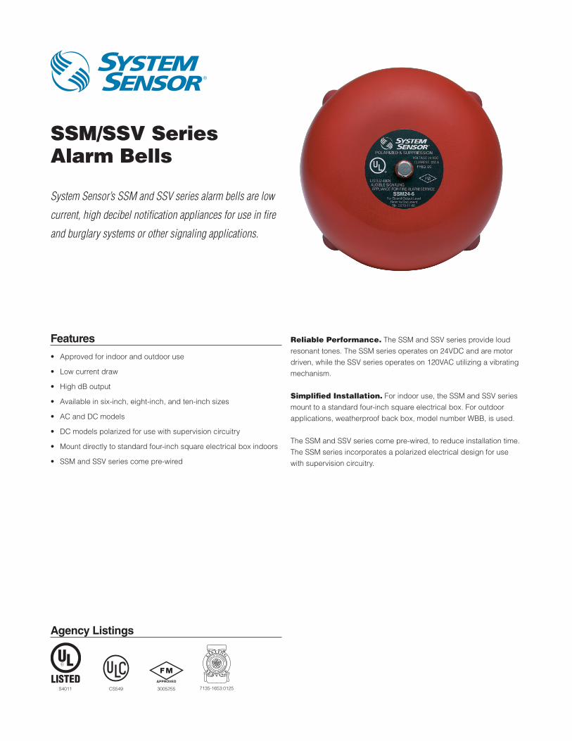
Agency Listings
SSM/SSV SeriesAlarm Bells
System Sensor’s SSM and SSV series alarm bells are low
current, high decibel notification appliances for use in fire
and burglary systems or other signaling applications.
Features
• Approved for indoor and outdoor use
• Low current draw
• High dB output
• Available in six-inch, eight-inch, and ten-inch sizes
• AC and DC models
• DC models polarized for use with supervision circuitry
• Mount directly to standard four-inch square electrical box indoors
• SSM and SSV series come pre-wired
Reliable Performance. The SSM and SSV series provide loud resonant tones. The SSM series operates on 24VDC and are motor driven, while the SSV series operates on 120VAC utilizing a vibrating mechanism.
Simplified Installation. For indoor use, the SSM and SSV series mount to a standard four-inch square electrical box. For outdoor applications, weatherproof back box, model number WBB, is used.
The SSM and SSV series come pre-wired, to reduce installation time. The SSM series incorporates a polarized electrical design for use with supervision circuitry.
S4011 7135-1653:0125CS549 3005255
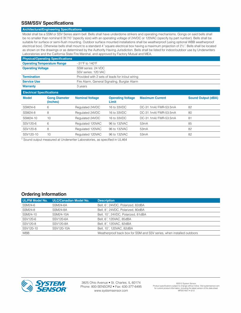
3825 Ohio Avenue • St. Charles, IL 60174 Phone: 800-SENSOR2 • Fax: 630-377-6495
www.systemsensor.com
©2012 System Sensor.Product specifications subject to change without notice. Visit systemsensor.com
for current product information, including the latest version of this data sheet.WFDS74501 • 3/12
Ordering InformationUL/FM Model No. ULC/Canadian Model No. DescriptionSSM24-6 SSM24-6A Bell, 6˝, 24VDC, Polarized, 82dBASSM24-8 SSM24-8A Bell, 8˝, 24VDC, Polarized, 80dBASSM24-10 SSM24-10A Bell, 10˝, 24VDC, Polarized, 81dBASSV120-6 SSV120-6A Bell, 6˝, 120VAC, 85dBASSV120-8 SSV120-8A Bell, 8˝, 120VAC, 82dBASSV120-10 SSV120-10A Bell, 10˝, 120VAC, 82dBAWBB Weatherproof back box for SSM and SSV series, when installed outdoors
SSM/SSV SpecificationsArchitectural/Engineering Specifications
Model shall be a SSM or SSV Series alarm bell. Bells shall have underdome strikers and operating mechanisms. Gongs on said bells shall be no smaller than nominal 6˝/8˝/10˝ (specify size) with an operating voltage of 24VDC or 120VAC (specify by part number). Bells shall be suitable for surface or semi-flush mounting. Outdoor surface mounted installations shall be weatherproof (using optional WBB weatherproof electrical box). Otherwise bells shall mount to a standard 4˝ square electrical box having a maximum projection of 2½˝. Bells shall be located as shown on the drawings or as determined by the Authority Having Jurisdiction. Bells shall be listed for indoor/outdoor use by Underwriters Laboratories and the California State Fire Marshal, and approved by Factory Mutual and MEA.Physical/Operating Specifications
Operating Temperature Range –31°F to 140°FOperating Voltage SSM series: 24 VDC
SSV series: 120 VACTermination Provided with 2 sets of leads for in/out wiringService Use Fire Alarm, General Signaling, Burglar AlarmWarranty 3 years
Electrical Specifications
Model Gong Diameter (inches)
Nominal Voltage Operating Voltage Limit
Maximum Current Sound Output (dBA)
SSM24-6 6 Regulated 24VDC 16 to 33VDC DC-31.1mA/ FWR-53.5mA 82
SSM24-8 8 Regulated 24VDC 16 to 33VDC DC-31.1mA/ FWR-53.5mA 80
SSM24-10 10 Regulated 24VDC 16 to 33VDC DC-31.1mA/ FWR-53.5mA 81
SSV120-6 6 Regulated 120VAC 96 to 132VAC 53mA 85
SSV120-8 8 Regulated 120VAC 96 to 132VAC 53mA 82
SSV120-10 10 Regulated 120VAC 96 to 132VAC 53mA 82
* Sound output measured at Underwriter Laboratories, as specified in UL464