REPLACE FACILITY FIRE ALARM SYSTEM - VA Vendor Portal
201
REPLACE FACILITY FIRE ALARM SYSTEM PROJECT #623‐12‐104 JACK C. MONTGOMERY VETERANS AFFAIRS MEDICAL CENTER MUSKOGEE, OKLAHOMA
-
Upload
khangminh22 -
Category
Documents
-
view
2 -
download
0
Transcript of REPLACE FACILITY FIRE ALARM SYSTEM - VA Vendor Portal
REPLACEFACILITYFIREALARMSYSTEM
PROJECT#623‐12‐104
JACKC.MONTGOMERYVETERANSAFFAIRSMEDICALCENTER
MUSKOGEE,OKLAHOMA

TableofContentsSECTION 00 01 15 LIST OF DRAWING SHEETS..................................... 3
SECTION 01 00 00 GENERAL REQUIREMENTS....................................... 6
SECTION 01 32 16.13 NETWORK ANALYSIS SCHEDULES............................. 26
SECTION 01 33 23 SHOP DRAWINGS, PRODUCT DATA, AND SAMPLES.................. 41
SECTION 01 42 19 REFERENCE STANDARDS....................................... 45
SECTION 01 57 19 TEMPORARY ENVIRONMENTAL CONTROLS.......................... 48
SECTION 01 74 19 CONSTRUCTION WASTE MANAGEMENT............................. 53
SECTION 01 91 00 GENERAL COMMISSIONING REQUIREMENTS........................ 58
SECTION 02 41 00 DEMOLITION................................................ 88
SECTION 07 92 00 JOINT SEALANTS............................................ 92
SECTION 09 91 00 PAINTING................................................. 101
SECTION 26 05 11 REQUIREMENTS FOR ELECTRICAL INSTALLATIONS................ 113
SECTION 26 05 21 LOW-VOLTAGE ELECTRICAL POWER CONDUCTORS AND CABLES (600 VOLTS AND BELOW)................................................................ 122
SECTION 26 05 33 RACEWAY AND BOXES FOR ELECTRICAL SYSTEMS................. 127
SECTION 26 08 00 COMMISSIONING OF ELECTRICAL SYSTEMS...................... 138
SECTION 26 27 26 WIRING DEVICES........................................... 142
SECTION 28 05 13 CONDUCTORS AND CABLES FOR ELECTRONIC SAFETY AND SECURITY. 146
SECTION 28 05 28.33 CONDUITS AND BACKBOXES FOR ELECTRONIC SAFETY AND SECURITY.......................................................................... 158
SECTION 28 08 00 COMMISSIONING OF ELECTRONIC SAFETY AND SECURITY SYSTEMS.. 169
SECTION 28 31 00 FIRE DETECTION AND ALARM................................. 173
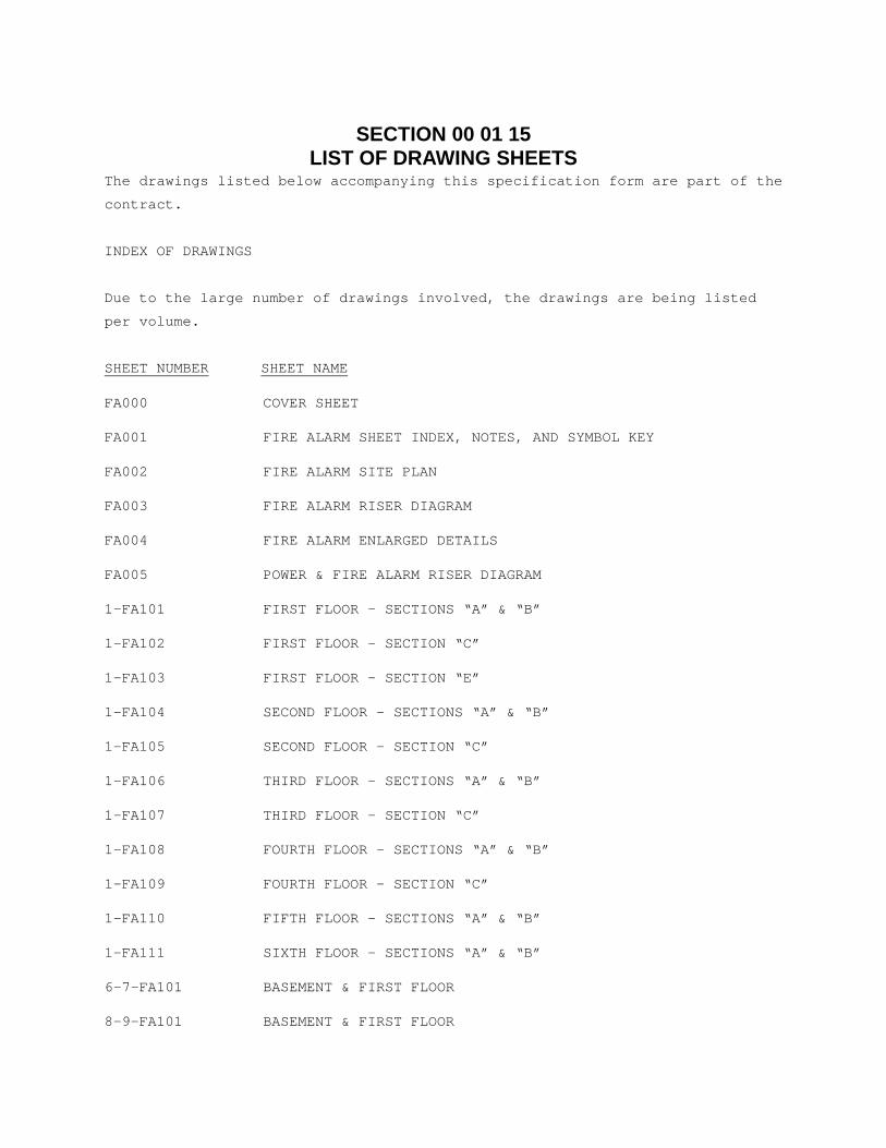
SECTION 00 01 15 LIST OF DRAWING SHEETS
The drawings listed below accompanying this specification form are part of the
contract.
INDEX OF DRAWINGS
Due to the large number of drawings involved, the drawings are being listed
per volume.
SHEET NUMBER SHEET NAME
FA000 COVER SHEET
FA001 FIRE ALARM SHEET INDEX, NOTES, AND SYMBOL KEY
FA002 FIRE ALARM SITE PLAN
FA003 FIRE ALARM RISER DIAGRAM
FA004 FIRE ALARM ENLARGED DETAILS
FA005 POWER & FIRE ALARM RISER DIAGRAM
1-FA101 FIRST FLOOR – SECTIONS “A” & “B”
1-FA102 FIRST FLOOR – SECTION “C”
1-FA103 FIRST FLOOR – SECTION “E”
1-FA104 SECOND FLOOR – SECTIONS “A” & “B”
1-FA105 SECOND FLOOR – SECTION “C”
1-FA106 THIRD FLOOR – SECTIONS “A” & “B”
1-FA107 THIRD FLOOR – SECTION “C”
1-FA108 FOURTH FLOOR – SECTIONS “A” & “B”
1-FA109 FOURTH FLOOR – SECTION “C”
1-FA110 FIFTH FLOOR – SECTIONS “A” & “B”
1-FA111 SIXTH FLOOR – SECTIONS “A” & “B”
6-7-FA101 BASEMENT & FIRST FLOOR
8-9-FA101 BASEMENT & FIRST FLOOR
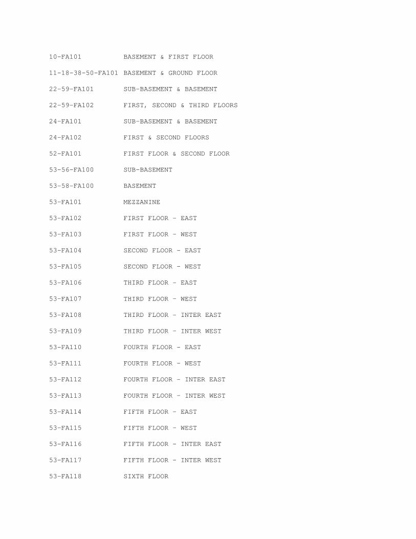
10-FA101 BASEMENT & FIRST FLOOR
11-18-38-50-FA101 BASEMENT & GROUND FLOOR
22-59-FA101 SUB-BASEMENT & BASEMENT
22-59-FA102 FIRST, SECOND & THIRD FLOORS
24-FA101 SUB-BASEMENT & BASEMENT
24-FA102 FIRST & SECOND FLOORS
52-FA101 FIRST FLOOR & SECOND FLOOR
53-56-FA100 SUB-BASEMENT
53-58-FA100 BASEMENT
53-FA101 MEZZANINE
53-FA102 FIRST FLOOR – EAST
53-FA103 FIRST FLOOR – WEST
53-FA104 SECOND FLOOR – EAST
53-FA105 SECOND FLOOR – WEST
53-FA106 THIRD FLOOR – EAST
53-FA107 THIRD FLOOR – WEST
53-FA108 THIRD FLOOR – INTER EAST
53-FA109 THIRD FLOOR – INTER WEST
53-FA110 FOURTH FLOOR – EAST
53-FA111 FOURTH FLOOR – WEST
53-FA112 FOURTH FLOOR – INTER EAST
53-FA113 FOURTH FLOOR – INTER WEST
53-FA114 FIFTH FLOOR – EAST
53-FA115 FIFTH FLOOR – WEST
53-FA116 FIFTH FLOOR – INTER EAST
53-FA117 FIFTH FLOOR – INTER WEST
53-FA118 SIXTH FLOOR
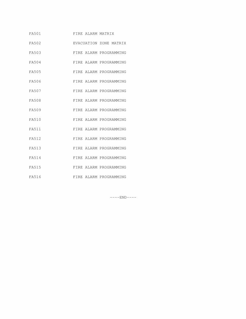
FA501 FIRE ALARM MATRIX
FA502 EVACUATION ZONE MATRIX
FA503 FIRE ALARM PROGRAMMING
FA504 FIRE ALARM PROGRAMMING
FA505 FIRE ALARM PROGRAMMING
FA506 FIRE ALARM PROGRAMMING
FA507 FIRE ALARM PROGRAMMING
FA508 FIRE ALARM PROGRAMMING
FA509 FIRE ALARM PROGRAMMING
FA510 FIRE ALARM PROGRAMMING
FA511 FIRE ALARM PROGRAMMING
FA512 FIRE ALARM PROGRAMMING
FA513 FIRE ALARM PROGRAMMING
FA514 FIRE ALARM PROGRAMMING
FA515 FIRE ALARM PROGRAMMING
FA516 FIRE ALARM PROGRAMMING
----END----

SECTION 01 00 00 GENERAL REQUIREMENTS
1.1 GENERAL INTENTION
A. Contractor shall completely prepare site for building operations,
including required demolition, all electrical work, and furnish labor
and materials and perform work for Replace Facilities Fire Alarm Systems
as required by drawings and specifications.
B. Visits to the site by Bidders may be made only by appointment with the
Medical Center Contracting Officer.
C. Offices of 303rd Engineering Group, L.L.C., as Architect-Engineers, will
render certain technical services during construction. Such services
shall be considered as advisory to the Government and shall not be
construed as expressing or implying a contractual act of the Government
without affirmations by Contracting Officer or his duly authorized
representative.
D. Before placement and installation of work subject to tests by testing
laboratory retained by Department of Veterans Affairs, the Contractor
shall notify the C.O.R. in sufficient time to enable testing laboratory
personnel to be present at the site in time for proper taking and
testing of specimens and field inspection. Such prior notice shall be
not less than three work days unless otherwise designated by the C.O.R..
E. All employees of general contractor and subcontractors shall comply with
VA security management program and obtain permission of the VA police,
be identified by project and employer, and restricted from unauthorized
access.
F. Prior to commencing work, general contractor shall provide proof that a
OSHA certified “competent person” (CP) (29 CFR 1926.20(b)(2) will
maintain a presence at the work site whenever the general or
subcontractors are present.
G. Training:
1. All employees of general contractor or subcontractors shall have the
10-hour OSHA certified Construction Safety course and /or other
relevant competency training, as determined by VA CP with input from
the ICRA team.
2. Submit training records of all such employees for approval before the
start of work.
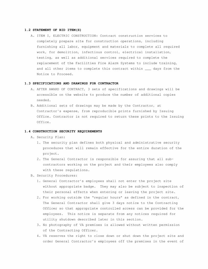
1.2 STATEMENT OF BID ITEM(S)
A. ITEM I, ELECTRIC CONSTRUCTION: Contract construction services to
completely prepare site for construction operations, including
furnishing all labor, equipment and materials to complete all required
work, for demolition, infectious control, electrical installation,
testing, as well as additional services required to complete the
replacement of the Facilities Fire Alarm Systems to include training,
and all other items to complete this contract within ___ days from the
Notice to Proceed.
1.3 SPECIFICATIONS AND DRAWINGS FOR CONTRACTOR
A. AFTER AWARD OF CONTRACT, 3 sets of specifications and drawings will be
accessible on the website to produce the number of additional copies
needed.
B. Additional sets of drawings may be made by the Contractor, at
Contractor's expense, from reproducible prints furnished by Issuing
Office. Contractor is not required to return these prints to the Issuing
Office.
1.4 CONSTRUCTION SECURITY REQUIREMENTS
A. Security Plan:
1. The security plan defines both physical and administrative security
procedures that will remain effective for the entire duration of the
project.
2. The General Contractor is responsible for assuring that all sub-
contractors working on the project and their employees also comply
with these regulations.
B. Security Procedures:
1. General Contractor’s employees shall not enter the project site
without appropriate badge. They may also be subject to inspection of
their personal effects when entering or leaving the project site.
2. For working outside the “regular hours” as defined in the contract,
The General Contractor shall give 3 days notice to the Contracting
Officer so that appropriate controlled access can be provided for the
employees. This notice is separate from any notices required for
utility shutdown described later in this section.
3. No photography of VA premises is allowed without written permission
of the Contracting Officer.
4. VA reserves the right to close down or shut down the project site and
order General Contractor’s employees off the premises in the event of
a national emergency. The General Contractor may return to the site
only with the written approval of the Contracting Officer.
E. Document Control:
1. Before starting any work, the General Contractor/Sub Contractors
shall submit an electronic security memorandum describing the
approach to following goals and maintaining confidentiality of
“sensitive information”.
2. The General Contractor is responsible for safekeeping of all
drawings, project manual and other project information. This
information shall be shared only with those with a specific need to
accomplish the project.
4. Certain documents, sketches, videos or photographs and drawings may
be marked “Law Enforcement Sensitive” or “Sensitive Unclassified”.
Secure such information in separate containers and limit the access
to only those who will need it for the project. Return the
information to the Contracting Officer upon request.
5. These security documents shall not be removed or transmitted from the
project site without the written approval of Contracting Officer.
6. All paper waste or electronic media such as CD’s and diskettes shall
be shredded and destroyed in a manner acceptable to the VA.
7. Notify Contracting Officer and Site Security Officer immediately when
there is a loss or compromise of “sensitive information”.
8. All electronic information shall be stored in specified location
following VA standards and procedures using an Engineering Document
Management Software (EDMS).
a. Security, access and maintenance of all project drawings, both
scanned and electronic shall be performed and tracked through the
EDMS system.
b. “Sensitive information” including drawings and other documents may
be attached to e-mail provided all VA encryption procedures are
followed.
F. Motor Vehicle Restrictions
1. Vehicle authorization request shall be required for any vehicle
entering the site and such request shall be submitted 24 hours before
the date and time of access. Access shall be restricted to picking up
and dropping off materials and supplies.
2. Separate permits shall be issued for General Contractor and its
employees for parking in designated areas only.
1.5 FIRE SAFETY
A. Applicable Publications: Publications listed below form part of this
Article to extent referenced. Publications are referenced in text by
basic designations only.
1. American Society for Testing and Materials (ASTM):
E84-2009.............Surface Burning Characteristics of Building
Materials
2. National Fire Protection Association (NFPA):
10-2010..............Standard for Portable Fire Extinguishers
30-2008..............Flammable and Combustible Liquids Code
51B-2009.............Standard for Fire Prevention During Welding,
Cutting and Other Hot Work
70-2011..............National Electrical Code
241-2009.............Standard for Safeguarding Construction,
Alteration, and Demolition Operations
3. Occupational Safety and Health Administration (OSHA):
29 CFR 1926..........Safety and Health Regulations for Construction
B. Fire Safety Plan: Establish and maintain a fire protection program in
accordance with 29 CFR 1926. Prior to start of work, prepare a plan
detailing project-specific fire safety measures, including periodic
status reports, and submit to C.O.R. for review for compliance with
contract requirements in accordance with Section 01 33 23, SHOP
DRAWINGS, PRODUCT DATA AND SAMPLES Prior to any worker for the
contractor or subcontractors beginning work, they shall undergo a safety
briefing provided by the general contractor’s competent person per OSHA
requirements. This briefing shall include information on the
construction limits, VAMC safety guidelines, means of egress, break
areas, work hours, locations of restrooms, use of VAMC equipment, etc.
Documentation shall be provided to the C.O.R. that individuals have
undergone contractor’s safety briefing.
C. Site and Building Access: Maintain free and unobstructed access to
facility emergency services and for fire, police and other emergency
response forces in accordance with NFPA 241.
D. Separate temporary facilities, such as trailers, storage sheds, and
dumpsters, from existing buildings and new construction by distances in
accordance with NFPA 241. For small facilities with less than 6 m (20
feet) exposing overall length, separate by 3m (10 feet).
F. G. Means of Egress: Do not block exiting for occupied buildings,
including paths from exits to roads. Minimize disruptions and coordinate
with C.O.R.H. Egress Routes for Construction Workers: Maintain free
and unobstructed egress. Inspect daily. Report findings and corrective
actions weekly to C.O.R.
I. Fire Extinguishers: Provide and maintain extinguishers in construction
areas and temporary storage areas in accordance with 29 CFR 1926, NFPA
241 and NFPA 10.
J. Flammable and Combustible Liquids: Store, dispense and use liquids in
accordance with 29 CFR 1926, NFPA 241 and NFPA 30.
M. Existing Fire Protection: Do not impair automatic sprinklers, smoke and
heat detection, and fire alarm systems, except for portions immediately
under construction, and temporarily for connections. Provide fire watch
for impairments more than 4 hours in a 24-hour period. Request
interruptions in accordance with Article, OPERATIONS AND STORAGE AREAS,
and coordinate with C.O.R. All existing or temporary fire protection
systems (fire alarms, sprinklers) located in construction areas shall be
tested as coordinated with the medical center. Parameters for the
testing and results of any tests performed shall be recorded by the
medical center and copies provided to the C.O.R..
N. Smoke Detectors: Prevent accidental operation. Remove temporary covers
at end of work operations each day. Coordinate with C.O.R.
O. Hot Work: Perform and safeguard hot work operations in accordance with
NFPA 241 and NFPA 51B. Coordinate with C.O.R. Obtain permits from C.O.R.
at least 24 hours in advance. Designate contractor's responsible
project-site fire prevention program manager to permit hot work.
P. Fire Hazard Prevention and Safety Inspections: Inspect entire
construction areas weekly. Coordinate with, and report findings and
corrective actions weekly to C.O.R.
Q. Smoking: Smoking is prohibited in and adjacent to construction areas
inside existing buildings and additions under construction. In separate
and detached buildings under construction, smoking is prohibited except
in designated smoking rest areas.
R. Dispose of waste and debris in accordance with NFPA 241. Remove from
buildings daily.
S. Perform other construction, alteration and demolition operations in
accordance with 29 CFR 1926.
T. If required, submit documentation to the C.O.R. that personnel have been
trained in the fire safety aspects of working in areas with impaired
structural or compartmentalization features.
1.6 OPERATIONS AND STORAGE AREAS
A. The Contractor shall confine all operations (including storage of
materials) on Government premises to areas authorized or approved by the
Contracting Officer. The Contractor shall hold and save the Government,
its officers and agents, free and harmless from liability of any nature
occasioned by the Contractor's performance.
B. Temporary buildings (e.g., storage sheds, shops, offices) and utilities
may be erected by the Contractor only with the approval of the
Contracting Officer and shall be built with labor and materials
furnished by the Contractor without expense to the Government. The
temporary buildings and utilities shall remain the property of the
Contractor and shall be removed by the Contractor at its expense upon
completion of the work. With the written consent of the Contracting
Officer, the buildings and utilities may be abandoned and need not be
removed.
C. The Contractor shall, under regulations prescribed by the Contracting
Officer, use only established roadways, or use temporary roadways
constructed by the Contractor when and as authorized by the Contracting
Officer. When materials are transported in prosecuting the work,
vehicles shall not be loaded beyond the loading capacity recommended by
the manufacturer of the vehicle or prescribed by any Federal, State, or
local law or regulation. When it is necessary to cross curbs or
sidewalks, the Contractor shall protect them from damage. The Contractor
shall repair or pay for the repair of any damaged curbs, sidewalks, or
roads.
(FAR 52.236-10)
D. Working space and space available for storing materials shall be as
determined by the C.O.R.
E. Workmen are subject to rules of Medical Center applicable to their
conduct.
F. Execute work so as to interfere as little as possible with normal
functioning of Medical Center as a whole, including operations of
utility services, fire protection systems and any existing equipment,
and with work being done by others. Use of equipment and tools that
transmit vibrations and noises through the building structure, are not
permitted in buildings that are occupied, during construction, jointly
by patients or medical personnel, and Contractor's personnel, except as
permitted by C.O.R. where required by limited working space.
1. Do not store materials and equipment in other than assigned areas.
2. Schedule delivery of materials and equipment to immediate
construction working areas within buildings in use by Department of
Veterans Affairs in quantities sufficient for not more than two work
days. Provide unobstructed access to Medical Center areas required to
remain in operation.
3. Where access by Medical Center personnel to vacated portions of
buildings is not required, storage of Contractor's materials and
equipment will be permitted subject to fire and safety requirements.
F. Utilities Services: Where necessary to cut existing pipes, electrical
wires, conduits, cables, etc., of utility services, or of fire
protection systems or communications systems (except telephone), they
shall be cut and capped at suitable places where shown; or, in absence
of such indication, where directed by C.O.R.. All such actions shall be
coordinated with the Utility Company involved:
1. Whenever it is required that a connection fee be paid to a public
utility provider for new permanent service to the construction
project, for such items as water, sewer, electricity, gas or steam,
payment of such fee shall be the responsibility of the Government and
not the Contractor.
G. Phasing: To insure such executions, Contractor shall furnish the C.O.R.
with a schedule of approximate dates on which the Contractor intends to
accomplish work in each specific area of site, building or portion
thereof. In addition, Contractor shall notify the C.O.R. two weeks in
advance of the proposed date of starting work in each specific area of
site, building or portion thereof. Arrange such dates to insure
accomplishment of this work in successive phases mutually agreeable to
Medical Center Director, C.O.R. and Contractor, as follows:
H. All Buildings will be occupied during performance of work.
1. Contractor shall take all measures and provide all material necessary
for protecting existing equipment and property in affected areas of
construction against dust and debris, so that equipment and affected
areas to be used in the Medical Centers operations will not be
hindered. Contractor shall permit access to Department of Veterans
Affairs personnel and patients through other construction areas which
serve as routes of access to such affected areas and equipment.
Coordinate alteration work in areas occupied by Department of
Veterans Affairs so that Medical Center operations will continue
during the construction period.
2. Contractor shall maintain in operating condition existing fire
protection system. Fire alarm system shall be replaced in segments so
as to remain operational in In connection with fire alarm equipment,
Contractor shall make arrangements for pre-inspection of site with
Fire Department or Company (Department of Veterans Affairs or
municipal) whichever will be required to respond to an alarm from
Contractor's employee or watchman.
I. Utilities Services: Maintain existing utility services for Medical
Center at all times. Provide temporary facilities, labor, materials,
equipment, connections, and utilities to assure uninterrupted services.
Where necessary to cut existing water, steam, gases, sewer or air pipes,
or conduits, wires, cables, etc. of utility services or of fire
protection systems and communications systems (including telephone),
they shall be cut and capped at suitable places where shown; or, in
absence of such indication, where directed by C.O.R..
1. No utility service such as water, gas, steam, sewers or electricity,
or fire protection systems and communications systems may be
interrupted without prior approval of C.O.R.. Electrical work shall
be accomplished with all affected circuits or equipment de-energized.
When an electrical outage cannot be accomplished, work on any
energized circuits or equipment shall not commence without the
Medical Center Director’s prior knowledge and written approval. Refer
to specification Sections 26 05 11, REQUIREMENTS FOR ELECTRICAL
INSTALLATIONS, 27 05 11 REQUIREMENTS FOR COMMUNICATIONS INSTALLATIONS
and 28 05 11, REQUIREMENTS FOR ELECTRONIC SAFETY AND SECURITY
INSTALLATIONS for additional requirements.
2. Contractor shall submit a request to interrupt any such services to
C.O.R., in writing, 48 hours in advance of proposed interruption.
Request shall state reason, date, exact time of, and approximate
duration of such interruption.
3. Contractor will be advised (in writing) of approval of request, or of
which other date and/or time such interruption will cause least
inconvenience to operations of Medical Center. Interruption time
approved by Medical Center may occur at other than Contractor's
normal working hours.
4. Major interruptions of any system must be requested, in writing, at
least 15 calendar days prior to the desired time and shall be
performed as directed by the C.O.R..
5. In case of a contract construction emergency, service will be
interrupted on approval of C.O.R.. Such approval will be confirmed in
writing as soon as practical.
6. Whenever it is required that a connection fee be paid to a public
utility provider for new permanent service to the construction
project, for such items as water, sewer, electricity, gas or steam,
payment of such fee shall be the responsibility of the Government and
not the Contractor.
J. Abandoned Lines: All service lines such as wires, cables, conduits,
ducts, pipes and the like, and their hangers or supports, which are to
be abandoned but are not required to be entirely removed, shall be
sealed, capped or plugged. The lines shall not be capped in finished
areas, but shall be removed and sealed, capped or plugged in ceilings,
within furred spaces, in unfinished areas, or within walls or
partitions; so that they are completely behind the finished surfaces.
K. To minimize interference of construction activities with flow of Medical
Center traffic, comply with the following:
1. Keep roads, walks and entrances to grounds, to parking and to
occupied areas of buildings clear of construction materials, debris
and standing construction equipment and vehicles. 2
L. Coordinate the work for this contract with other construction operations
as directed by C.O.R. This includes the scheduling of traffic and the
use of roadways, as specified in Article, USE OF ROADWAYS.
1.7 ALTERATIONS
A. Survey: Before any work is started, the Contractor shall make a thorough
survey with the C.O.R. areas of buildings in which alterations occur and
areas which are anticipated routes of access, and furnish a report,
signed by both, to the Contracting Officer. This report shall list by
rooms and spaces:
1. Existing condition and types of resilient flooring, doors, windows,
walls and other surfaces not required to be altered throughout
affected areas of buildings.
2. Existence and conditions of items such as plumbing fixtures and
accessories, electrical fixtures, equipment, venetian blinds, shades,
etc., required by drawings to be either reused or relocated, or both.
3. Shall note any discrepancies between drawings and existing conditions
at site.
4. Shall designate areas for working space, materials storage and routes
of access to areas within buildings where alterations occur and which
have been agreed upon by Contractor and C.O.R..
B. Any items required by drawings to be either reused or relocated or both,
found during this survey to be nonexistent, or in opinion of C.O.R.
and/or Supply Representative, to be in such condition that their use is
impossible or impractical, shall be furnished and/or replaced by
Contractor with new items in accordance with specifications which will
be furnished by Government. Provided the contract work is changed by
reason of this subparagraph B, the contract will be modified
accordingly, under provisions of clause entitled "DIFFERING SITE
CONDITIONS" (FAR 52.236-2) and "CHANGES" (FAR 52.243-4 and VAAR
852.236-88).
C. Re-Survey: Thirty days before expected partial or final inspection date,
the Contractor and C.O.R. together shall make a thorough re-survey of
the areas of buildings involved. They shall furnish a report on
conditions then existing, of resilient flooring, doors, windows, walls
and other surfaces as compared with conditions of same as noted in first
condition survey report:
1. Re-survey report shall also list any damage caused by Contractor to
such flooring and other surfaces, despite protection measures; and,
will form basis for determining extent of repair work required of
Contractor to restore damage caused by Contractor's workmen in
executing work of this contract.
D. Protection: Provide the following protective measures:
1. Wherever existing roof surfaces are disturbed they shall be protected
against water infiltration. In case of leaks, they shall be repaired
immediately upon discovery.
2. Temporary protection against damage for portions of existing
structures and grounds where work is to be done, materials handled
and equipment moved and/or relocated.
3. Protection of interior of existing structures at all times, from
damage, dust and weather inclemency. Wherever work is performed,
floor surfaces that are to remain in place shall be adequately
protected prior to starting work, and this protection shall be
maintained intact until all work in the area is completed.
1.8 INFECTION PREVENTION MEASURES
A. Implement the requirements of VAMC’s Infection Control Risk Assessment
(ICRA) team. ICRA Group may monitor dust in the vicinity of the
construction work and require the Contractor to take corrective action
immediately if the safe levels are exceeded.
B. Establish and maintain a dust control program as part of the
contractor’s infection preventive measures in accordance with the
guidelines provided by ICRA Group or as specified here. Prior to start
of work, prepare a plan detailing project-specific dust protection
measures, including periodic status reports, and submit to C.O.R. and
Facility ICRA team for review for compliance with contract requirements
in accordance with Section 01 33 23, SHOP DRAWINGS, PRODUCT DATA AND
SAMPLES.
1. All personnel involved in the construction or renovation activity
shall be educated and trained in infection prevention measures
established by the medical center.
C. Medical center Infection Control personnel shall monitor for airborne
disease (e.g. aspergillosis) as appropriate during construction. A
baseline of conditions may be established by the medical center prior to
the start of work and periodically during the construction stage to
determine impact of construction activities on indoor air quality. In
addition:
1. The RE and VAMC Infection Control personnel shall review pressure
differential monitoring documentation to verify that pressure
differentials in the construction zone and in the patient-care rooms
are appropriate for their settings. The requirement for negative air
pressure in the construction zone shall depend on the location and
type of activity. Upon notification, the contractor shall implement
corrective measures to restore proper pressure differentials as
needed.
2. In case of any problem, the medical center, along with assistance
from the contractor, shall conduct an environmental assessment to
find and eliminate the source.
D. In general, following preventive measures shall be adopted during
construction to keep down dust and prevent mold.
1. Dampen debris to keep down dust and provide temporary construction
partitions in existing structures where directed by C.O.R.. Blank-off
ducts and diffusers to prevent circulation of dust into occupied
areas during construction.
2. Do not perform dust producing tasks within occupied areas without the
approval of the C.O.R..
a. HEPA filtration is required where the exhaust dust may reenter the
breathing zone. Contractor shall verify that construction exhaust
to exterior is not reintroduced to the medical center through
intake vents, or building openings. Install HEPA (High Efficiency
Particulate Accumulator) filter vacuum system rated at 95% capture
of 0.3 microns including pollen, mold spores and dust particles.
Insure continuous negative air pressures occurring within the work
area. HEPA filters should have ASHRAE 85 or other prefilter to
extend the useful life of the HEPA. Provide both primary and
secondary filtrations units. Exhaust hoses shall be heavy duty,
flexible steel reinforced and exhausted so that dust is not
reintroduced to the medical center.
b. Adhesive Walk-off/Carpet Walk-off Mats, minimum 600mm x 900mm (24”
x 36”), shall be used at all interior transitions from the
construction area to occupied medical center area. These mats
shall be changed as often as required to maintain clean work areas
directly outside construction area at all times.
c. Vacuum and wet mop all transition areas from construction to the
occupied medical center at the end of each workday. Vacuum shall
utilize HEPA filtration. Maintain surrounding area frequently.
Remove debris as they are created. Transport these outside the
construction area in containers with tightly fitting lids.
d. The contractor shall not haul debris through patient-care areas
without prior approval of the C.O.R. and the Medical Center. When,
approved, debris shall be hauled in enclosed dust proof containers
or wrapped in plastic and sealed with duct tape. No sharp objects
should be allowed to cut through the plastic. Wipe down the
exterior of the containers with a damp rag to remove dust. All
equipment, tools, material, etc. transported through occupied
areas shall be made free from dust and moisture by vacuuming and
wipe down.
e. Using a HEPA vacuum, clean inside the barrier and vacuum ceiling
tile prior to replacement. Any ceiling access panels opened for
investigation beyond sealed areas shall be sealed immediately when
unattended.
f. There shall be no standing water during construction. This
includes water in equipment drip pans and open containers within
the construction areas. All accidental spills must be cleaned up
and dried within 12 hours. Remove and dispose of porous materials
that remain damp for more than 72 hours.
g. At completion, remove construction barriers and ceiling protection
carefully, outside of normal work hours. Vacuum and clean all
surfaces free of dust after the removal.
E. Final Cleanup:
1. Upon completion of project, or as work progresses, remove all
construction debris from above ceiling, vertical shafts and utility
chases that have been part of the construction.
2. Perform HEPA vacuum cleaning of all surfaces in the construction
area. This includes walls, ceilings, cabinets, furniture (built-in or
free standing), partitions, flooring, etc.
3. All new air ducts shall be cleaned prior to final inspection.
1.9 DISPOSAL AND RETENTION
A. Materials and equipment accruing from work removed and from demolition
of buildings or structures, or parts thereof, shall be disposed of as
follows:
1. Reserved items which are to remain property of the Government are
noted on drawings or in specifications as items to be stored. Items
that remain property of the Government shall be removed or dislodged
from present locations in such a manner as to prevent damage which
would be detrimental to re-installation and reuse. Store such items
where directed by C.O.R..
2. Items not reserved shall become property of the Contractor and be
removed by Contractor from Medical Center.
3. Items of portable equipment and furnishings located in rooms and
spaces in which work is to be done under this contract shall remain
the property of the Government. When rooms and spaces are vacated by
the Department of Veterans Affairs during the alteration period, such
items which are NOT required by drawings and specifications to be
either relocated or reused will be removed by the Government in
advance of work to avoid interfering with Contractor's operation.
1.10 PROTECTION OF EXISTING VEGETATION, STRUCTURES, EQUIPMENT, UTILITIES, AND IMPROVEMENTS
A. The Contractor shall preserve and protect all structures, equipment, and
vegetation (such as trees, shrubs, and grass) on or adjacent to the work
site, which are not to be removed and which do not unreasonably
interfere with the work required under this contract. The Contractor
shall only remove trees when specifically authorized to do so, and shall
avoid damaging vegetation that will remain in place. If any limbs or
branches of trees are broken during contract performance, or by the
careless operation of equipment, or by workmen, the Contractor shall
trim those limbs or branches with a clean cut and paint the cut with a
tree-pruning compound as directed by the Contracting Officer.
B. The Contractor shall protect from damage all existing improvements and
utilities at or near the work site and on adjacent property of a third
party, the locations of which are made known to or should be known by
the Contractor. The Contractor shall repair any damage to those
facilities, including those that are the property of a third party,
resulting from failure to comply with the requirements of this contract
or failure to exercise reasonable care in performing the work. If the
Contractor fails or refuses to repair the damage promptly, the
Contracting Officer may have the necessary work performed and charge the
cost to the Contractor.
(FAR 52.236-9)
C. Refer to Section 01 57 19, TEMPORARY ENVIRONMENTAL CONTROLS, for
additional requirements on protecting vegetation, soils and the
environment. Refer to Articles, "Alterations", "Restoration", and
"Operations and Storage Areas" for additional instructions concerning
repair of damage to structures and site improvements.
D. Refer to FAR clause 52.236-7, "Permits and Responsibilities," which is
included in General Conditions. A National Pollutant Discharge
Elimination System (NPDES) permit is required for this project. The
Contractor is considered an "operator" under the permit and has
extensive responsibility for compliance with permit requirements. VA
will make the permit application available at the (appropriate medical
center) office. The apparent low bidder, contractor and affected
subcontractors shall furnish all information and certifications that are
required to comply with the permit process and permit requirements. Many
of the permit requirements will be satisfied by completing construction
as shown and specified. Some requirements involve the Contractor's
method of operations and operations planning and the Contractor is
responsible for employing best management practices. The affected
activities often include, but are not limited to the following:
- Designating areas for equipment maintenance and repair;
- Providing waste receptacles at convenient locations and provide
regular collection of wastes;
- Locating equipment wash down areas on site, and provide appropriate
control of wash-waters;
- Providing protected storage areas for chemicals, paints, solvents,
fertilizers, and other potentially toxic materials; and
- Providing adequately maintained sanitary facilities.
1.11 RESTORATION
A. Remove, cut, alter, replace, patch and repair existing work as necessary
to install new work. Except as otherwise shown or specified, do not cut,
alter or remove any structural work, and do not disturb any ducts,
plumbing, steam, gas, or electric work without approval of the C.O.R.
Existing work to be altered or extended and that is found to be
defective in any way, shall be reported to the C.O.R. before it is
disturbed. Materials and workmanship used in restoring work, shall
conform in type and quality to that of original existing construction,
except as otherwise shown or specified.
B. Upon completion of contract, deliver work complete and undamaged.
Existing work (walls, ceilings, partitions, floors, mechanical and
electrical work, lawns, paving, roads, walks, etc.) disturbed or removed
as a result of performing required new work, shall be patched, repaired,
reinstalled, or replaced with new work, and refinished and left in as
good condition as existed before commencing work.
C. At Contractor's own expense, Contractor shall immediately restore to
service and repair any damage caused by Contractor's workmen to existing
piping and conduits, wires, cables, etc., of utility services or of fire
protection systems and communications systems (including telephone)
which are indicated on drawings and which are not scheduled for
discontinuance or abandonment.
D. Expense of repairs to such utilities and systems not shown on drawings
or locations of which are unknown will be covered by adjustment to
contract time and price in accordance with clause entitled "CHANGES"
(FAR 52.243-4 and VAAR 852.236-88) and "DIFFERING SITE CONDITIONS" (FAR
52.236-2).
1.12 PHYSICAL DATA
A. Data and information furnished or referred to below is for the
Contractor's information. The Government shall not be responsible for
any interpretation of or conclusion drawn from the data or information
by the Contractor.
1. The indications of physical conditions on the drawings and in the
specifications are the result of site investigations by 303rd
Engineering Group, L.L.C.
D. Government does not guarantee that other materials will not be
encountered nor that proportions, conditions or character of several
materials will not vary from those indicated by explorations. Bidders
are expected to examine site of work and, after investigation, decide
for themselves character of materials and make their bids accordingly.
Upon proper application to Department of Veterans Affairs, bidders will
be permitted to make subsurface explorations of their own at site.
1.15 AS-BUILT DRAWINGS
A. The contractor shall maintain two full size sets of as-built drawings
which will be kept current during construction of the project, to
include all contract changes, modifications and clarifications.
B. All variations shall be shown in the same general detail as used in the
contract drawings. To insure compliance, as-built drawings shall be made
available for the C.O.R.'s review, as often as requested.
C. Contractor shall deliver two approved completed sets of as-built
drawings to the C.O.R. within 15 calendar days after each completed
phase and after the acceptance of the project by the C.O.R..
D. Paragraphs A, B, & C shall also apply to all shop drawings.
1.16 USE OF ROADWAYS
A. For hauling, use only established public roads and roads on Medical
Center property and, when authorized by the C.O.R., such temporary roads
which are necessary in the performance of contract work.
1.19 TEMPORARY USE OF EXISTING ELEVATORS
A. Use of existing elevators for handling building materials and
Contractor's personnel will be permitted subject to following
provisions:
1. Contractor makes all arrangements with the C.O.R. for use of
elevators. The C.O.R. will ascertain that elevators are in proper
condition. Contractor may use elevators daily and for special
nonrecurring time intervals when permission is granted. Personnel for
operating elevators will not be provided by the Department of
Veterans Affairs.
2. Contractor covers and provides maximum protection of following
elevator components:
a. Entrance jambs, heads soffits and threshold plates.
b. Entrance columns, canopy, return panels and inside surfaces of car
enclosure walls.
c. Finish flooring.
3. Government will accept hoisting ropes of elevator and rope of each
speed governor if they are worn under normal operation. However, if
these ropes are damaged by action of foreign matter such as sand,
lime, grit, stones, etc., during temporary use, they shall be removed
and replaced by new hoisting ropes.
4. If brake lining of elevators are excessively worn or damaged during
temporary use, they shall be removed and replaced by new brake
lining.
5. All parts of main controller, starter, relay panel, selector, etc.,
worn or damaged during temporary use shall be removed and replaced
with new parts, if recommended by elevator inspector after elevator
is released by Contractor.
6. Place elevator in condition equal, less normal wear, to that existing
at time it was placed in service of Contractor as approved by
Contracting Officer.
1.21 TEMPORARY TOILETS
A. Provide where directed, (for use of all Contractor's workmen) ample
temporary sanitary toilet accommodations with suitable sewer and water
connections; or, when approved by C.O.R., provide suitable dry closets
where directed. Keep such places clean and free from flies, and all
connections and appliances connected therewith are to be removed prior
to completion of contract, and premises left perfectly clean.
1.22 AVAILABILITY AND USE OF UTILITY SERVICES
A. The Government shall make all reasonably required amounts of utilities
available to the Contractor from existing outlets and supplies, as
specified in the contract. The amount to be paid by the Contractor for
chargeable electrical services shall be the prevailing rates charged to
the Government. The Contractor shall carefully conserve any utilities
furnished without charge.
B. Electricity (for Construction and Testing): Furnish all temporary
electric services.
1. Obtain electricity by connecting to the Medical Center electrical
distribution system. The Contractor shall meter and pay for
electricity required for electric cranes and hoisting devices,
electrical welding devices and any electrical heating devices
providing temporary heat. Electricity for all other uses is available
at no cost to the Contractor.
1.24 TESTS
A. Conduct final tests required in various sections of specifications in
presence of an authorized representative of the Contracting Officer.
Contractor shall furnish all labor, materials, equipment, instruments,
and forms, to conduct and record such tests.
B. All related components as defined above shall be functioning when any
system component is tested. Tests shall be completed within a reasonably
short period of time during which operating and environmental conditions
remain reasonably constant.
C. Individual test result of any component, where required, will only be
accepted when submitted with the test results of related components and
of the entire system.
1.25 INSTRUCTIONS
A. Contractor shall furnish Maintenance and Operating manuals and verbal
instructions when required by the various sections of the specifications
and as hereinafter specified.
B. Manuals: Maintenance and operating manuals (four copies each) for each
separate piece of equipment shall be delivered to the C.O.R.
coincidental with the delivery of the equipment to the job site. Manuals
shall be complete, detailed guides for the maintenance and operation of
equipment. They shall include complete information necessary for
starting, adjusting, maintaining in continuous operation for long
periods of time and dismantling and reassembling of the complete units
and sub-assembly components. Manuals shall include an index covering all
component parts clearly cross-referenced to diagrams and illustrations.
Illustrations shall include "exploded" views showing and identifying
each separate item. Emphasis shall be placed on the use of special tools
and instruments. The function of each piece of equipment, component,
accessory and control shall be clearly and thoroughly explained. All
necessary precautions for the operation of the equipment and the reason
for each precaution shall be clearly set forth. Manuals must reference
the exact model, style and size of the piece of equipment and system
being furnished. Manuals referencing equipment similar to but of a
different model, style, and size than that furnished will not be
accepted.
C. Instructions: Contractor shall provide qualified, factory-trained
manufacturers' representatives to give detailed instructions to assigned
Department of Veterans Affairs personnel in the operation and complete
maintenance for each piece of equipment. All such training will be at
the job site. These requirements are more specifically detailed in the
various technical sections. Instructions for different items of
equipment that are component parts of a complete system, shall be given
in an integrated, progressive manner. All instructors for every piece of
component equipment in a system shall be available until instructions
for all items included in the system have been completed. This is to
assure proper instruction in the operation of inter-related systems. All
instruction periods shall be at such times as scheduled by the C.O.R.
and shall be considered concluded only when the C.O.R.is satisfied in
regard to complete and thorough coverage. The Department of Veterans
Affairs reserves the right to request the removal of, and substitution
for, any instructor who, in the opinion of the C.O.R., does not
demonstrate sufficient qualifications in accordance with requirements
for instructors above.
1.27 RELOCATED EQUIPMENT
A. Contractor shall disconnect, dismantle as necessary, remove and
reinstall in new location, all existing equipment and items indicated by
symbol "R" or otherwise shown to be relocated by the Contractor.
B. Perform relocation of such equipment or items at such times and in such
a manner as directed by the C.O.R.
C. Suitably cap existing service lines, such as steam, condensate return,
water, drain, gas, air, vacuum and/or electrical, whenever such lines
are disconnected from equipment to be relocated. Remove abandoned lines
in finished areas and cap as specified herein before under paragraph
"Abandoned Lines".
D. Provide all mechanical and electrical service connections, fittings,
fastenings and any other materials necessary for assembly and
installation of relocated equipment; and leave such equipment in proper
operating condition.
E. Contractor shall employ services of an installation engineer, who is an
authorized representative of the manufacturer of this equipment to
supervise assembly and installation of existing equipment, required to
be relocated.
F. All service lines such as noted above for relocated equipment shall be
in place at point of relocation ready for use before any existing
equipment is disconnected. Make relocated existing equipment ready for
operation or use immediately after reinstallation.

1.29 CONSTRUCTION SIGN
A. Construction Sign is not allowed.
1.30 SAFETY SIGN
A. CONSTRUCTION SIGN IS NOT ALLOWED.1.33 HISTORIC PRESERVATION
Where the Contractor or any of the Contractor's employees, prior to, or
during the construction work, are advised of or discover any possible
archeological, historical and/or cultural resources, the Contractor
shall immediately notify the C.O.R. verbally, and then with a written
follow up.
- - - E N D - - -
SECTION 01 32 16.13 NETWORK ANALYSIS SCHEDULES
PART 1- GENERAL
1.1 DESCRIPTION:
A. The Contractor shall develop a Network Analysis System (NAS) plan and
schedule demonstrating fulfillment of the contract requirements, shall
keep the network up-to-date in accordance with the requirements of this
section and shall utilize the plan for scheduling, coordinating and
monitoring work under this contract (including all activities of
subcontractors, equipment vendors and suppliers). Conventional Critical
Path Method (CPM) Precedence Diagramming Method (PDM) technique will be
utilized to satisfy both time and cost applications. All schedule data
and reports required under this specification section shall be based
upon regular total float, not relative total float schedules.
1.2 CONTRACTOR'S REPRESENTATIVE:
A. The Contractor shall designate an authorized representative in the firm
who will be responsible for the preparation of the network diagram,
review and report progress of the project with and to the Contracting
Officer's representative.
B. The Contractor's representative shall have direct project control and
complete authority to act on behalf of the Contractor in fulfilling the
requirements of this specification section and such authority shall not
be interrupted throughout the duration of the project.
1.3 CONTRACTOR'S CONSULTANT:
A. To prepare the network diagram, and compact disk(s), which reflects the
Contractor's project plan, the Contractor shall engage an independent
CPM consultant who is skilled in the time and cost application of
scheduling using (PDM) network techniques for construction projects, the
cost of which is included in the Contractor's bid. This consultant shall
not have any financial or business ties to the Contractor, and shall not
be an affiliate or subsidiary company of the Contractor, and shall not
be employed by an affiliate or subsidiary company of the Contractor.
B. Prior to engaging a consultant, and within 10 calendar days after award
of the contract, the Contractor shall submit to the Contracting Officer:
1. The name and address of the proposed consultant.
2. Sufficient information to show that the proposed consultant has the
qualifications to meet the requirements specified in the preceding
paragraph.
3. A list of prior construction projects, along with selected PDM
network diagram samples on current projects which the proposed
consultant has performed complete project scheduling services. These
network diagram samples must show complete project planning for a
project of similar size and scope as covered under this contract.
C. The Contracting Officer has the right to approve or disapprove
employment of the proposed consultant, and will notify the Contractor of
the VA decision within seven calendar days from receipt of information.
In case of disapproval, the Contractor shall resubmit another consultant
within 10 calendar days for renewed consideration. The Contractor must
have their CPM Consultant approved prior to completion of contract
negotiations.
1.4 COMPUTER PRODUCED SCHEDULES
A. The contractor shall provide to the VA, C.O.R., and CPM Schedule
Analyst, monthly computer processing of all computer-produced time/cost
schedules and reports generated from monthly project updates. This
monthly computer service will include: three copies of up to five
different reports (inclusive of all pages) available within the user
defined reports of Primavera (P3 or P6) to the contracting officer’s
representative; a hard copy listing of all project schedule changes, and
associated data, made at the update and an electronic file of this data
in Primavera (P3 or P6) batch format; and the resulting monthly updated
schedule in a compressed electronic file in Primavera (P3 or P6), (PDM)
format. These must be submitted with and substantively support the
contractor’s monthly payment request and the signed lookahead report.
The C.O.R. shall identify the five different report formats that the
contractor shall provide based upon the monthly schedule updates.
B. The contractor is responsible for the correctness and timeliness of the
computer-produced reports. The Contractor is also responsible for the
accurate and timely submittal of the updated project schedule and all
CPM data necessary to produce the computer reports and payment request
that is specified.
C. The VA shall report errors in computer-produced reports to the
Contractor’s representative within ten calendar days from receipt of
reports. The Contractor will reprocess the computer-produced reports and
associated compact disk(s), when requested by the Contracting Officer’s

representative, to correct errors which affect the payment and schedule
for the project.
1.5 THE COMPLETE PROJECT NETWORK DIAGRAM SUBMITTAL
A. Within 45 calendar days (60 calendar days on projects over $50,000,000)
after receipt of Notice to Proceed, the Contractor shall submit for the
Contracting Officer's review; three blue line copies of the complete
network diagram on sheets of paper 765 x 1070 mm (30 x 42 inches) and an
electronic file in a compressed Primavera (P3 or P6), (PDM) format. The
submittal shall also include three copies of a computer-produced
activity/event ID schedule showing project duration; phase completion
dates; and other data, including event cost. Each activity/event on the
computer-produced schedule shall contain as a minimum, but not limited
to, activity/event ID, duration, predecessor and successor
relationships, trade code, area code, description, budget amount, early
start date, early finish date, late start date, late finish date and
total float. Work activity/event relationships shall be restricted to
finish-to-start and start-to-start without lead or lag constraints. The
lead or lag for the SS relationships may only be allowed in limited
basis if justified in writing and must be approved by the Contracting
Officer. Activity/event date constraints, not required by the contract,
will not be accepted unless submitted to and approved by the Contracting
Officer. The contractor shall make a separate written detailed request
to the Contracting Officer identifying these date constraints and secure
the Contracting Officer’s written approval before incorporating them
into the network diagram. The Contracting Officer’s separate approval of
the network diagram shall not excuse the contractor of this requirement.
Logic events (non-work) will be permitted where necessary to reflect
proper logic among work events, but must have a zero duration. The
complete working network diagram shall reflect the Contractor's approach
to scheduling the complete project. The final network diagram in its
original form shall contain no contract changes or delays which may have
been incurred during the final network diagram development period and
shall reflect the entire contract duration as defined in the bid
documents. These changes/delays shall be entered at the first update
after the final network diagram has been approved. The Contractor should
provide their requests for time and supporting time extension analysis
for contract time as a result of contract changes/delays, after this
update, and in accordance with Article, ADJUSTMENT OF CONTRACT
COMPLETION.
B. Within 30 calendar days after receipt of the complete project network
diagram, the Contracting Officer or his representative, will do one or
both of the following:
1. Notify the Contractor concerning his actions, opinions, and
objections.
2. A meeting with the Contractor at or near the job site for joint
review, correction or adjustment of the proposed plan will be
scheduled if required. Within 14 calendar days after the joint
review, the Contractor shall revise and shall submit three blue line
copies of the revised network diagram, three copies of the revised
computer-produced activity/event ID schedule and a revised electronic
file as specified by the Contracting Officer. The revised submission
will be reviewed by the Contracting Officer and, if found to be as
previously agreed upon, will be approved.
C. The approved baseline network diagram schedule and the corresponding
computer-produced schedule(s) shall constitute the approved baseline
schedule until subsequently revised in accordance with the requirements
of this section.
1.6 WORK ACTIVITY/EVENT COST DATA
A. The Contractor shall cost load all work activities/events except
procurement activities. The cost loading shall reflect the appropriate
level of effort of the work activities/events. The cumulative amount of
all cost loaded work activities/events (including alternates) shall
equal the total contract price. Prorate overhead, profit and general
conditions on all work activities/events for the entire project length.
The contractor shall generate from this information cash flow curves
indicating graphically the total percentage of work activity/event
dollar value scheduled to be in place on early finish, late finish.
These cash flow curves will be used by the Contracting Officer to assist
him in determining approval or disapproval of the cost loading. In the
event of disapproval, the Contractor shall revise and resubmit in
accordance with Article, THE COMPLETE PROJECT NETWORK DIAGRAM SUBMITTAL.
Negative work activity/event cost data will not be acceptable, except on
VA issued contract changes.
B. The Contractor shall cost load work activities/events for guarantee
period services, test, balance and adjust various systems in accordance
with the provisions in the FAR 52.232 – 5 (PAYMENTS UNDER FIXED-PRICE
CONSTRUCTION), Article, and VAAR 852.236 - 83(PAYMENTS UNDER FIXED-PRICE
CONSTRUCTION).
C. In accordance with Article PERFORMANCE OF WORK BY THE CONTRACTOR in FAR
52.236 – 1 and VAAR 852.236 - 72, the Contractor shall submit,
simultaneously with the cost per work activity/event of the construction
schedule required by this Section, a responsibility code for all
activities/events of the project for which the Contractor's forces will
perform the work.
E. The Contractor shall cost load work activities/events for all BID ITEMS.
The sum of the cost loading for each bid item work activities/events
shall equal the value of the item in the Contractors' bid.
F. Work activities/events for Contractor bond shall have a trade code and
area code of BOND.
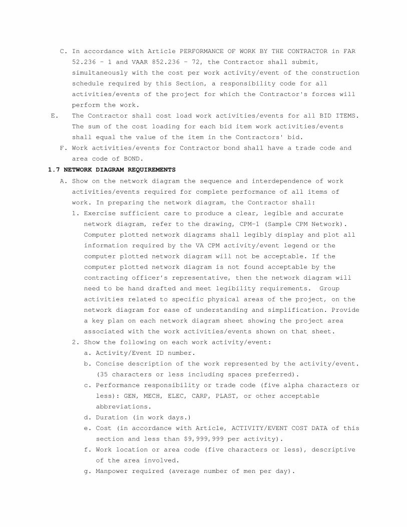
1.7 NETWORK DIAGRAM REQUIREMENTS
A. Show on the network diagram the sequence and interdependence of work
activities/events required for complete performance of all items of
work. In preparing the network diagram, the Contractor shall:
1. Exercise sufficient care to produce a clear, legible and accurate
network diagram, refer to the drawing, CPM-1 (Sample CPM Network).
Computer plotted network diagrams shall legibly display and plot all
information required by the VA CPM activity/event legend or the
computer plotted network diagram will not be acceptable. If the
computer plotted network diagram is not found acceptable by the
contracting officer’s representative, then the network diagram will
need to be hand drafted and meet legibility requirements. Group
activities related to specific physical areas of the project, on the
network diagram for ease of understanding and simplification. Provide
a key plan on each network diagram sheet showing the project area
associated with the work activities/events shown on that sheet.
2. Show the following on each work activity/event:
a. Activity/Event ID number.
b. Concise description of the work represented by the activity/event.
(35 characters or less including spaces preferred).
c. Performance responsibility or trade code (five alpha characters or
less): GEN, MECH, ELEC, CARP, PLAST, or other acceptable
abbreviations.
d. Duration (in work days.)
e. Cost (in accordance with Article, ACTIVITY/EVENT COST DATA of this
section and less than $9,999,999 per activity).
f. Work location or area code (five characters or less), descriptive
of the area involved.
g. Manpower required (average number of men per day).
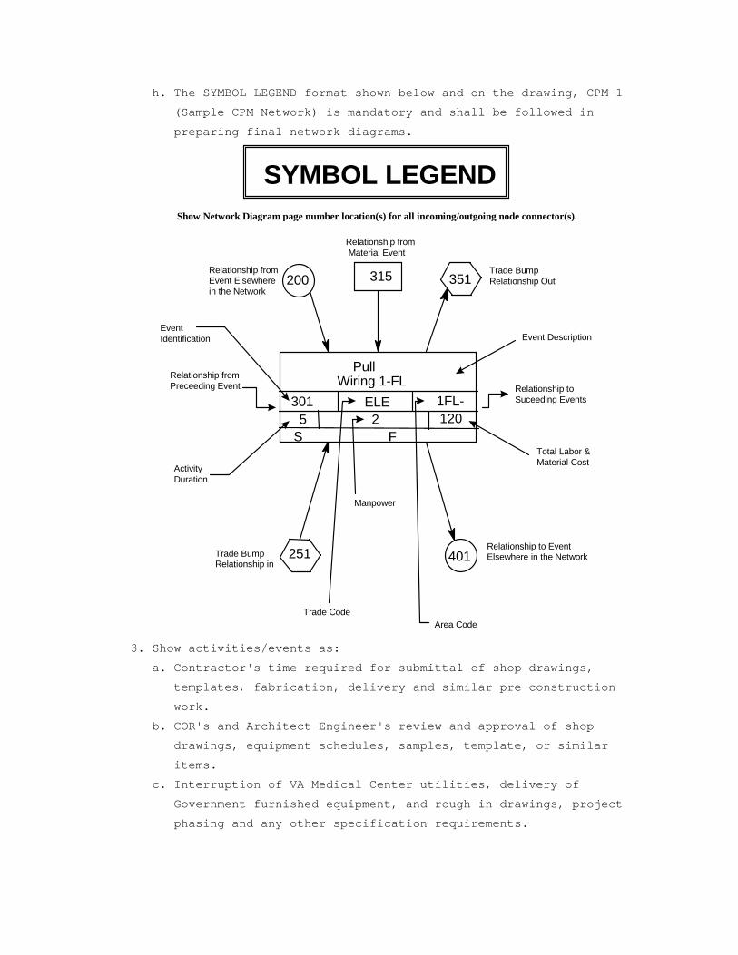
h. The SYMBOL LEGEND format shown below and on the drawing, CPM-1
(Sample CPM Network) is mandatory and shall be followed in
preparing final network diagrams.
Pull Wiring 1-FL
200 351
251 401
315Relationship from Event Elsewhere in the Network
Trade Bump Relationship Out
Relationship from Material Event
Relationship to Event Elsewhere in the Network Trade Bump
Relationship in
301 ELE 1FL-5 2 120
Event Identification
Relationship from Preceeding Event Relationship to
Suceeding Events
S F
Activity Duration
Manpower
Total Labor & Material Cost
Area CodeTrade Code
SYMBOL LEGEND
Event Description
Show Network Diagram page number location(s) for all incoming/outgoing node connector(s).
3. Show activities/events as:
a. Contractor's time required for submittal of shop drawings,
templates, fabrication, delivery and similar pre-construction
work.
b. COR's and Architect-Engineer's review and approval of shop
drawings, equipment schedules, samples, template, or similar
items.
c. Interruption of VA Medical Center utilities, delivery of
Government furnished equipment, and rough-in drawings, project
phasing and any other specification requirements.
d. Test, balance and adjust various systems and pieces of equipment,
maintenance and operation manuals, instructions and preventive
maintenance tasks.
e. Commissioning Activities – Based upon the project specific
Commissioning plan and the specification section 01 91 00, the
contractor shall include in the Day 1 CPM Diagram all the systems
commissioning activities (see systems covered in Division 7, 8,
21, 22, 23, 26, 28, 31 and others as specified) such as start up,
Pre-functional check list, Pre –test, individual component and
system level Functional test, Operator’s training, O.& M. Manuals
etc.(including any deficiency correction and re-testing). The
majority of commissioning activities should be completed as part
of the normal construction schedule and finalized prior to the
construction contract completion date. To this end, it is
imperative that the Commissioning Agent and the Contractor
collaborate to integrate commissioning activities into the
Contractor’s overall construction schedule. All commissioning
activities shall be cost loaded as required in the earlier
paragraphs.
f. The Commissioning Plan will identify critical commissioning
activities and associated construction/start up tasks that must
precede these activities to allow for successful execution of the
commissioning activities. In order to coordinate these activities
with the construction schedule, a Commissioning Duration Schedule
should be provided by the Commissioning Agent to the VA RE and the
Contractor to provide a rational basis for integration of
commissioning into the Day 1 diagram and the construction
schedule. The Commissioning Duration Schedule should include the
following information:
1) Description of Commissioning Activity
2) Prerequisite Construction Tasks Required to Execute the Cx
Activity
3) Elapsed Time Duration of Each Activity
4) Documentation Associated with Each Task/Document Responsibility
g. Once the duration schedule is delivered to the Contractor, the
Commissioning Agent will collaborate with the Contractor to
integrate all commissioning activities into the fixed duration
construction schedule in accordance with VA NAS requirements for
scheduling the project.
h. VA inspection and acceptance activity/event with a minimum
duration of five work days at the end of each phase and
immediately preceding any VA move activity/event required by the
contract phasing for that phase. Schedule these activities/events
so that only one phase is scheduled for completion within the same
30 consecutive calendar day period (except for those phases
immediately preceding the final acceptance). Maintain this
scheduling condition throughout the length of the contract unless
waived by the Contracting Officer’s representative in writing.
i. Work activities/events for the asbestos abatement bid item shall
have a trade code of ASB.
j. Bid items other than the Base Bid (ITEM 1) and Asbestos Abatement
item shall have trade codes corresponding to the appropriate bid
item number (e.g., ITM 3, ITM 4 and other items).
4. Show not only the activities/events for actual construction work for
each trade category of the project, but also trade relationships to
indicate the movement of trades from one area, floor, or building, to
another area, floor, or building, for at least five trades who are
performing major work under this contract.
5. Break up the work into activities/events of a duration no longer than
20 work days each, except as to non-construction activities/events
(i.e., procurement of materials, delivery of equipment, concrete and
asphalt curing) and any other activities/events for which the
Contracting Officer may approve the showing of a longer duration. The
duration for VA approval of any required submittal, shop drawing, or
other submittals shall not be less than 20 work days. Refer to
drawing CPM-1 for VA approval activities/events which will require
minimum duration longer than 20 workdays. The construction time as
determined by the CPM schedule from early start to late finish for
any sub-phase, phase or the entire project shall not exceed the
contract time(s) specified or shown.
6. Describe work activities/events clearly, so the work is readily
identifiable for assessment of completion. Activities/events labeled
"start," "continue," or "completion," are not specific and will not
be allowed. Lead and lag time activities will not be acceptable.

7. Uniquely number each activity/event with numbers ranging from 1 to
99998 only. The network diagram should be generally numbered in such
a way to reflect either discipline, phase or location of the work.
B. Submit the following supporting data in addition to the network diagram,
activity/event ID schedule and electronic file (s). Failure of the
Contractor to include this data will delay the review of the submittal
until the Contracting Officer is in receipt of the missing data:
1. The proposed number of working days per week.
2. The holidays to be observed during the life of the contract (by day,
month, and year).
3. The planned number of shifts per day.
4. The number of hours per shift.
5. List the major construction equipment to be used on the site,
describing how each piece relates to and will be used in support of
the submitted network diagram work activities/events.
6. Provide a typed, doubled spaced, description, at least one page in
length, of the plan and your approach to constructing the project.
C. To the extent that the network diagram or any revised network diagram
shows anything not jointly agreed upon, it shall not be deemed to have
been approved by the Contracting Officer. Failure to include any element
of work required for the performance of this contract shall not excuse
the Contractor from completing all work required within any applicable
completion date of each phase regardless of the Contracting Officer's
approval of the network diagram.
D. Compact Disk Requirements and CPM Activity/Event Record Specifications:
Submit to the VA (C.O.R. and CPM Schedule Analyst) an electronic file(s)
containing one file of the data required to produce a Primavera (P3 or
P6), (PDM) produced schedule, reflecting all the activities/events of
the complete project network diagram being submitted.
1.8 PAYMENT TO THE CONTRACTOR:
A. Monthly, the contractor shall submit the AIA application and certificate
for payment documents G702 & G703 reflecting updated schedule activities
and cost data in accordance with the provisions of the following
Article, PAYMENT AND PROGRESS REPORTING, as the basis upon which
progress payments will be made pursuant to Article FAR 52.232 – 5
(PAYMENTS UNDER FIXED-PRICE CONSTRUCTION), and VAAR 852.236 -
83(PAYMENTS UNDER FIXED-PRICE CONSTRUCTION). The Contractor is entitled
to a monthly progress payment upon approval of estimates as determined
from the currently approved updated computer-produced calendar-dated
schedule unless, in special situations, the Contracting Officer permits
an exception to this requirement. Monthly payment requests shall
include: three copies of up to five different reports (inclusive of all
pages) available within the user defined reports of Primavera (P3 or
P6), (PDM) to the contracting officer’s representative; a listing of all
project schedule changes, and associated data, made at the update; and
an electronic file (s) of the resulting monthly updated schedule in a
compressed Primavera (P3 or P6), (PDM) format. These must be submitted
with and substantively support the contractor’s monthly application and
certificate for payment request documents.
B. When the Contractor fails or refuses to furnish to the Contracting
Officer the information and the associated updated Primavera (P3 or P6),
(PDM) schedule in electronic format, which, in the sole judgment of the
Contracting Officer, is necessary for processing the monthly progress
payment, the Contractor shall not be deemed to have provided an estimate
and supporting schedule data upon which progress payment may be made.
1.9 PAYMENT AND PROGRESS REPORTING
A. Monthly job site progress meetings shall be held on dates mutually
agreed to by the Contracting Officer (or Contracting Officer's
representative) and the Contractor. Contractor and the CPM consultant
will be required to attend all monthly progress meetings. Presence of
Subcontractors during progress meeting is optional unless required by
the Contracting Officer (or Contracting Officer's representative). The
Contractor shall update the project schedule and all other data required
by this section shall be accurately filled in and completed prior to the
monthly progress meeting. The Contractor shall provide this information
to the Contracting Officer or the VA representative in completed form
three work days in advance of the progress meeting. Job progress will be
reviewed to verify:
1. Actual start and/or finish dates for updated/completed
activities/events.
2. Remaining duration, required to complete each activity/event started,
or scheduled to start, but not completed.
3. Logic, time and cost data for change orders, and supplemental
agreements that are to be incorporated into the network diagram and
computer-produced schedules. Changes in activity/event sequence and
duration which have been made pursuant to the provisions of following
Article, ADJUSTMENT OF CONTRACT COMPLETION.
4. Percentage for completed and partially completed activities/events.
5. Logic and duration revisions required by this section of the
specifications.
6. Activity/event duration and percent complete shall be updated
independently.
B. The Contractor shall submit a narrative report as a part of his monthly
review and update, in a form agreed upon by the Contractor and the
Contracting Officer. The narrative report shall include a description of
problem areas; current and anticipated delaying factors and their
estimated impact on performance of other activities/events and
completion dates; and an explanation of corrective action taken or
proposed. This report is in addition to the daily reports pursuant to
the provisions of Article, DAILY REPORT OF WORKERS AND MATERIALS in the
GENERAL CONDITIONS.
C. After completion of the joint review and the Contracting Officer's
approval of all entries, the contractor will generate an updated
computer-produced calendar-dated schedule and supply the Contracting
Officer’s representative with reports in accordance with the Article,
COMPUTER PRODUCED SCHEDULES, specified.
D. After completing the monthly schedule update, the contractor’s
scheduling consultant shall rerun all current period contract change(s)
against the prior approved monthly project schedule. The analysis shall
only include original workday durations and schedule logic agreed upon
by the contractor and C.O.R. for the contract change(s). When there is a
disagreement on logic and/or durations, the consultant shall use the
schedule logic and/or durations provided and approved by the C.O.R. .
After each rerun update, the resulting electronic project schedule data
file shall be appropriately identified and submitted to the VA in
accordance to the requirements listed in articles 1.4 and 1.7. This
electronic submission is separate from the regular monthly project
schedule update requirements and shall be submitted to the C.O.R. within
fourteen (14) calendar days of completing the regular schedule update.
Before inserting the contract changes durations, care must be taken to
ensure that only the original durations will be used for the analysis,
not the reported durations after progress. In addition, once the final
network diagram is approved, the contractor must recreate all manual
progress payment updates on this approved network diagram and associated
reruns for contract changes in each of these update periods as outlined
above for regular update periods. This will require detailed record
keeping for each of the manual progress payment updates.
E. After VA acceptance and approval of the final network diagram, and after
each monthly update, the contractor shall submit to the Contracting
Officer three blue line copies of a revised complete network diagram
showing all completed and partially completed activities/events,
contract changes and logic changes made on the intervening updates or at
the first update on the final diagram. The Contracting Officer may elect
to have the contractor do this on a less frequent basis, but it shall be
done on a quarterly basis as a minimum.
F. Following approval of the CPM schedule, the VA, the General Contractor,
its approved CPM Consultant, RE office representatives, and all
subcontractors needed, as determined by the SRE, shall meet to discuss
the monthly updated schedule. The main emphasis shall be to address work
activities to avoid slippage of project schedule and to identify any
necessary actions required to maintain project schedule during the
reporting period. The Government representatives and the Contractor
should conclude the meeting with a clear understanding of those work and
administrative actions necessary to maintain project schedule status
during the reporting period. This schedule coordination meeting will
occur after each monthly project schedule update meeting utilizing the
resulting schedule reports from that schedule update. If the project is
behind schedule, discussions should include ways to prevent further
slippage as well as ways to improve the project schedule status, when
appropriate.
1.10 RESPONSIBILITY FOR COMPLETION
A. Whenever it becomes apparent from the current monthly progress review
meeting or the monthly computer-produced calendar-dated schedule that
phasing or contract completion dates will not be met, the Contractor
shall execute some or all of the following remedial actions:
1. Increase construction manpower in such quantities and crafts as
necessary to eliminate the backlog of work.
2. Increase the number of working hours per shift, shifts per working
day, working days per week, the amount of construction equipment, or
any combination of the foregoing to eliminate the backlog of work.
3. Reschedule the work in conformance with the specification
requirements.
B. Prior to proceeding with any of the above actions, the Contractor shall
notify and obtain approval from the Contracting Officer for the proposed
schedule changes. If such actions are approved, the CPM revisions shall
be incorporated by the Contractor into the network diagram before the
next update, at no additional cost to the Government.
1.11 CHANGES TO NETWORK DIAGRAM AND SCHEDULE
A. Within 30 calendar days after VA acceptance and approval of any updated
computer-produced schedule, the Contractor will submit a revised network
diagram, the associated compact disk(s), and a list of any
activity/event changes including predecessors and successors for any of
the following reasons:
1. Delay in completion of any activity/event or group of
activities/events, indicate an extension of the project completion by
20 working days or 10 percent of the remaining project duration,
whichever is less. Such delays which may be involved with contract
changes, strikes, unusual weather, and other delays will not relieve
the Contractor from the requirements specified unless the conditions
are shown on the CPM as the direct cause for delaying the project
beyond the acceptable limits.
2. Delays in submittals, or deliveries, or work stoppage are encountered
which make rescheduling of the work necessary.
3. The schedule does not represent the actual prosecution and progress
of the project.
4. When there is, or has been, a substantial revision to the
activity/event costs of the network diagram regardless of the cause
for these revisions.
B. CPM revisions made under this paragraph which affect the previously
approved computer-produced schedules for Government furnished equipment,
vacating of areas by the VA Medical Center, contract phase(s) and sub
phase(s), utilities furnished by the Government to the Contractor, or
any other previously contracted item, must be furnished in writing to
the Contracting Officer for approval.
C. Contracting Officer's approval for the revised network diagram and all
relevant data is contingent upon compliance with all other paragraphs of
this section and any other previous agreements by the Contracting
Officer or the VA representative.
D. The cost of revisions to the network diagram resulting from contract
changes will be included in the proposal for changes in work as
specified in Article, FAR 52.243 -4 (CHANGES), VAAR 852.236 – 88
(CHANGES – SUPPLEMENTS), and will be based on the complexity of the
revision or contract change, man hours expended in analyzing the change,
and the total cost of the change.
E. The cost of revisions to the network diagram not resulting from contract
changes is the responsibility of the Contractor.
1.12 ADJUSTMENT OF CONTRACT COMPLETION
A. The contract completion time will be adjusted only for causes specified
in this contract. Request for an extension of the contract completion
date by the Contractor shall be supported with a justification, CPM data
and supporting evidence as the Contracting Officer may deem necessary
for determination as to whether or not the Contractor is entitled to an
extension of time under the provisions of the contract. Submission of
proof based on revised activity/event logic, durations (in work days)
and costs is obligatory to any approvals. The schedule must clearly
display that the Contractor has used, in full, all the float time
available for the work involved in this request. The Contracting
Officer's determination as to the total number of days of contract
extension will be based upon the current computer-produced
calendar-dated schedule for the time period in question and all other
relevant information.
B. Actual delays in activities/events which, according to the
computer-produced calendar-dated schedule, do not affect the extended
and predicted contract completion dates shown by the critical path in
the network, will not be the basis for a change to the contract
completion date. The Contracting Officer will within a reasonable time
after receipt of such justification and supporting evidence, review the
facts and advise the Contractor in writing of the Contracting Officer's
decision.
C. The Contractor shall submit each request for a change in the contract
completion date to the Contracting Officer in accordance with the
provisions specified under Article, FAR 52.243 -4 (CHANGES), VAAR
852.236 – 88 (CHANGES – SUPPLEMENTS). The Contractor shall include, as a
part of each change order proposal, a sketch showing all CPM logic
revisions, duration (in work days) changes, and cost changes, for work
in question and its relationship to other activities on the approved
network diagram.
D. All delays due to non-work activities/events such as RFI’s, WEATHER,
STRIKES, and similar non-work activities/events shall be analyzed on a
month by month basis.
1.13 CONSTRUCTION SCHEDULE RISK ANALYSIS / MITIGATION PLAN
A. Schedule Risk Analysis – The contractor shall conduct the statistical
schedule risk analysis based on the above detailed construction
activities in the Day 1 approved diagram, identifying major schedule
risk areas and recommended risk mitigation plans as outlined below.
B. The risk analysis shall be conducted by a person or firm skilled in the
statistical method of schedule risk analysis based on the (PDM) network
techniques for major construction projects, preferably in the major
health care related projects. The cost of this service shall be included
in the Contractor's proposal.
C. The Contracting Officer has the right to approve or disapprove the
Person or firm designated to perform the risk analysis.
1.14 RISK ANALYSIS FORMAT / REQUIREMENTS / SUBMITTALS
A. Risk Analysis Software / Format - Within 45 calendar days (60 calendar
days on projects over $50,000,000) after receipt of Notice to Proceed,
the Contractor shall submit for the Contracting Officer's review; a Risk
Analysis software to be utilized, the method of performing the analysis,
the format of presenting the data and the reports for VA approval.
B. Conduct Risk Analysis / Submittals - Based on the approved software /
format, the consultant shall perform statistical risk analysis on the
detailed approved Day 1 diagram. The contractor shall review and utilize
any previous Risk analysis performed by the A/E of record based on the
“semi-detailed” (yet at an overall level) construction logic and
schedule to ensure the continuity of previous schedule risk analysis.
The contractor’s project manager and Superintendent shall identify the
major schedule risk areas and possible risk mitigation strategy/plan and
record it in a narrative format, with electronic file submission to the
VA. The risk analysis exercise shall be performed or updated at least
on a quarterly basis or as directed by the VA Contracting officer.
C. The submittal shall include three copies of a computer-produced risk
analysis results, predicting the various meaningful probability curves
of achieving the contract schedules. It shall also include a detailed
narrative list of all major and minor potential and specific schedule
and cost risk areas, and a contractor’s recommendations of mitigating
the identified risks which must be addressed by the VA Project and
C.O.R. teams to maintain the contract schedule.
- - - E N D - - -
SECTION 01 33 23 SHOP DRAWINGS, PRODUCT DATA, AND SAMPLES
1-1. Refer to Articles titled SPECIFICATIONS AND DRAWINGS FOR CONSTRUCTION
(FAR 52.236-21) and, SPECIAL NOTES (VAAR 852.236-91), in GENERAL
CONDITIONS.
1-2. For the purposes of this contract, samples, test reports, certificates,
and manufacturers' literature and data shall also be subject to the
previously referenced requirements. The following text refers to all
items collectively as SUBMITTALS.
1-3. Submit for approval, all of the items specifically mentioned under the
separate sections of the specification, with information sufficient to
evidence full compliance with contract requirements. Materials,
fabricated articles and the like to be installed in permanent work shall
equal those of approved submittals. After an item has been approved, no
change in brand or make will be permitted unless:
A. Satisfactory written evidence is presented to, and approved by
Contracting Officer, that manufacturer cannot make scheduled delivery of
approved item or;
B. Item delivered has been rejected and substitution of a suitable item is
an urgent necessity or;
C. Other conditions become apparent which indicates approval of such
substitute item to be in best interest of the Government.
1-4. Enter submittals into SUBMITTAL EXCHANGE in sufficient time to permit
proper consideration and approval action by Government. Time submission
to assure adequate lead time for procurement of contract for required
items. Delays attributable to untimely and rejected submittals will not
serve as a basis for extending contract time for completion.
1-5. Submittals will be reviewed for compliance with contract requirements by
Transport Consultant, and action thereon will be taken by C.O.R. on
behalf of the Contracting Officer.
1-6. Upon entering of submittals into SUBMITTAL EXCHANGE, SUBMITTAL EXCHANGE
will assign a file number thereto. Contractor, in any subsequent
correspondence, shall refer to this file and identification number to
expedite replies relative to previously approved or disapproved
submittals.
1-7. The Government reserves the right to require additional submittals,
whether or not particularly mentioned in this contract. If additional
submittals beyond those required by the contract are furnished pursuant
to request therefor by Contracting Officer, adjustment in contract price
and time will be made in accordance with Articles titled CHANGES (FAR
52.243-4) and CHANGES - SUPPLEMENT (VAAR 852.236-88) of the GENERAL
CONDITIONS.
1-8. Schedules called for in specifications and shown on shop drawings shall
be submitted for use and information of Department of Veterans Affairs
and Architect-Engineer. However, the Contractor shall assume
responsibility for coordinating and verifying schedules. The Contracting
Officer and Architect- Engineer assumes no responsibility for checking
schedules or layout drawings for exact sizes, exact numbers and detailed
positioning of items.
1-9. Submittals must be entered into SUBMITTAL EXCHANGE by Contractor and
their Sub-Contractor members. Contracting Officer assumes no
responsibility for checking quantities or exact numbers included in such
submittals.
A. Submit samples required in . in single units unless otherwise specified.
Submit shop drawings, schedules, manufacturers' literature and data, and
certificates in quadruplicate, except where a greater number is
specified.
B. Submittals will receive consideration only when covered by a transmittal
letter signed by Contractor. Letter shall be entered into SUBMITTAL
EXCHANGE and shall contain the list of items, name of Medical Center,
name of Contractor, contract number, applicable specification paragraph
numbers, applicable drawing numbers, and other information required for
exact identification of location for each item, manufacturer and brand,
ASTM or Federal Specification Number (if any) and such additional
information as may be required by specifications for particular item
being furnished. In addition, catalogs shall be marked to indicate
specific items submitted for approval.
1. A copy of letter must be enclosed with items, and any items received
without identification letter will be considered "unclaimed goods"
and held for a limited time only.
2. Each sample, certificate, manufacturers' literature and data shall be
labeled to indicate the name and location of the Medical Center, name
of Contractor, manufacturer, brand, contract number and ASTM or
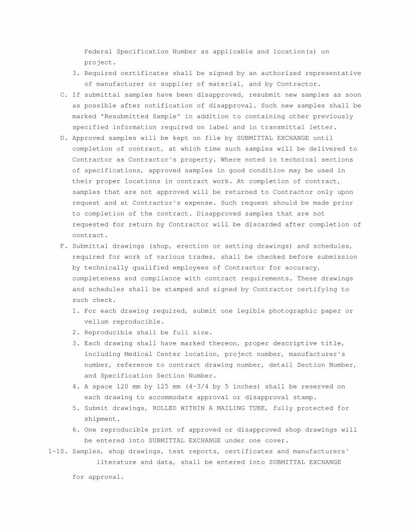
Federal Specification Number as applicable and location(s) on
project.
3. Required certificates shall be signed by an authorized representative
of manufacturer or supplier of material, and by Contractor.
C. If submittal samples have been disapproved, resubmit new samples as soon
as possible after notification of disapproval. Such new samples shall be
marked "Resubmitted Sample" in addition to containing other previously
specified information required on label and in transmittal letter.
D. Approved samples will be kept on file by SUBMITTAL EXCHANGE until
completion of contract, at which time such samples will be delivered to
Contractor as Contractor's property. Where noted in technical sections
of specifications, approved samples in good condition may be used in
their proper locations in contract work. At completion of contract,
samples that are not approved will be returned to Contractor only upon
request and at Contractor's expense. Such request should be made prior
to completion of the contract. Disapproved samples that are not
requested for return by Contractor will be discarded after completion of
contract.
F. Submittal drawings (shop, erection or setting drawings) and schedules,
required for work of various trades, shall be checked before submission
by technically qualified employees of Contractor for accuracy,
completeness and compliance with contract requirements. These drawings
and schedules shall be stamped and signed by Contractor certifying to
such check.
1. For each drawing required, submit one legible photographic paper or
vellum reproducible.
2. Reproducible shall be full size.
3. Each drawing shall have marked thereon, proper descriptive title,
including Medical Center location, project number, manufacturer's
number, reference to contract drawing number, detail Section Number,
and Specification Section Number.
4. A space 120 mm by 125 mm (4-3/4 by 5 inches) shall be reserved on
each drawing to accommodate approval or disapproval stamp.
5. Submit drawings, ROLLED WITHIN A MAILING TUBE, fully protected for
shipment.
6. One reproducible print of approved or disapproved shop drawings will
be entered into SUBMITTAL EXCHANGE under one cover.
1-10. Samples, shop drawings, test reports, certificates and manufacturers'
literature and data, shall be entered into SUBMITTAL EXCHANGE
for approval.

1-11. At the time of entry into SUBMITTAL EXCHANGE, a copy shall be sent for
approval to the Transport Consultant by the C.O.R.
- - - E N D - - -

SECTION 01 42 19 REFERENCE STANDARDS
PART 1 - GENERAL
1.1 DESCRIPTION
This section specifies the availability and source of references and
standards specified in the project manual under paragraphs APPLICABLE
PUBLICATIONS and/or shown on the drawings.
1.2 AVAILABILITY OF SPECIFICATIONS LISTED IN THE GSA INDEX OF FEDERAL SPECIFICATIONS, STANDARDS AND COMMERCIAL ITEM DESCRIPTIONS FPMR PART 101-29 (FAR 52.211-1) (AUG 1998)
A. The GSA Index of Federal Specifications, Standards and Commercial Item
Descriptions, FPMR Part 101-29 and copies of specifications, standards,
and commercial item descriptions cited in the solicitation may be
obtained for a fee by submitting a request to – GSA Federal Supply
Service, Specifications Section, Suite 8100, 470 East L’Enfant Plaza,
SW, Washington, DC 20407, Telephone (202) 619-8925, Facsimile (202) 619-
8978.
B. If the General Services Administration, Department of Agriculture, or
Department of Veterans Affairs issued this solicitation, a single copy
of specifications, standards, and commercial item descriptions cited in
this solicitation may be obtained free of charge by submitting a request
to the addressee in paragraph (a) of this provision. Additional copies
will be issued for a fee.
1.3 AVAILABILITY FOR EXAMINATION OF SPECIFICATIONS NOT LISTED IN THE GSA INDEX OF FEDERAL SPECIFICATIONS, STANDARDS AND COMMERCIAL ITEM DESCRIPTIONS (FAR 52.211-4) (JUN 1988)
The specifications and standards cited in this solicitation can be
examined at the following location:
DEPARMENT OF VETERANS AFFAIRS
Office of Construction & Facilities Management
Facilities Quality Service (00CFM1A)
425 Eye Street N.W, (sixth floor)
Washington, DC 20001
Telephone Numbers: (202) 632-5249 or (202) 632-5178
Between 9:00 AM - 3:00 PM
1.4 AVAILABILITY OF SPECIFICATIONS NOT LISTED IN THE GSA INDEX OF FEDERAL SPECIFICATIONS, STANDARDS AND COMMERCIAL ITEM DESCRIPTIONS (FAR 52.211-3) (JUN 1988)
The specifications cited in this solicitation may be obtained from the
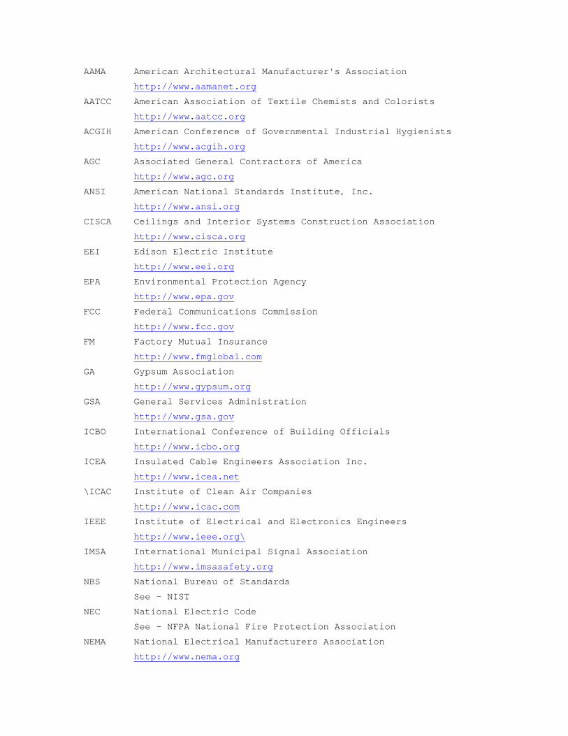
AAMA American Architectural Manufacturer's Association
http://www.aamanet.org
AATCC American Association of Textile Chemists and Colorists
http://www.aatcc.org
ACGIH American Conference of Governmental Industrial Hygienists
http://www.acgih.org
AGC Associated General Contractors of America
http://www.agc.org
ANSI American National Standards Institute, Inc.
http://www.ansi.org
CISCA Ceilings and Interior Systems Construction Association
http://www.cisca.org
EEI Edison Electric Institute
http://www.eei.org
EPA Environmental Protection Agency
http://www.epa.gov
FCC Federal Communications Commission
http://www.fcc.gov
FM Factory Mutual Insurance
http://www.fmglobal.com
GA Gypsum Association
http://www.gypsum.org
GSA General Services Administration
http://www.gsa.gov
ICBO International Conference of Building Officials
http://www.icbo.org
ICEA Insulated Cable Engineers Association Inc.
http://www.icea.net
\ICAC Institute of Clean Air Companies
http://www.icac.com
IEEE Institute of Electrical and Electronics Engineers
http://www.ieee.org\
IMSA International Municipal Signal Association
http://www.imsasafety.org
NBS National Bureau of Standards
See - NIST
NEC National Electric Code
See - NFPA National Fire Protection Association
NEMA National Electrical Manufacturers Association
http://www.nema.org
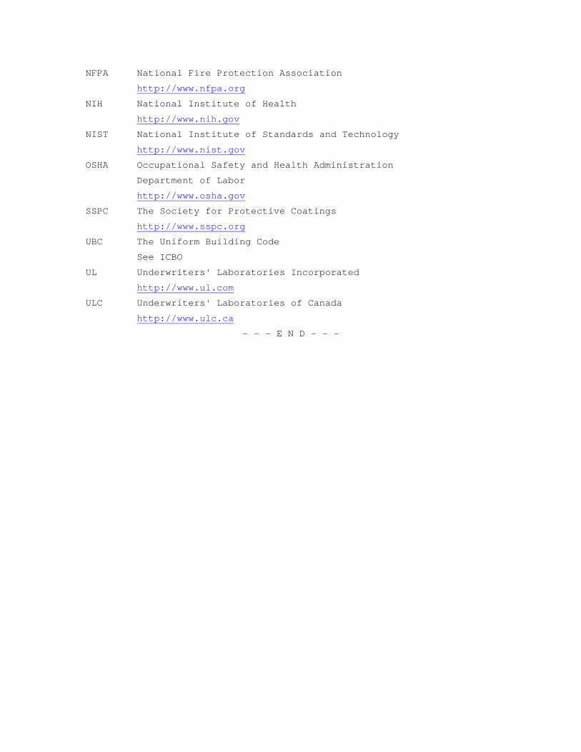
NFPA National Fire Protection Association
http://www.nfpa.org
NIH National Institute of Health
http://www.nih.gov
NIST National Institute of Standards and Technology
http://www.nist.gov
OSHA Occupational Safety and Health Administration
Department of Labor
http://www.osha.gov
SSPC The Society for Protective Coatings
http://www.sspc.org
UBC The Uniform Building Code
See ICBO
UL Underwriters' Laboratories Incorporated
http://www.ul.com
ULC Underwriters' Laboratories of Canada
http://www.ulc.ca
- - - E N D - - -
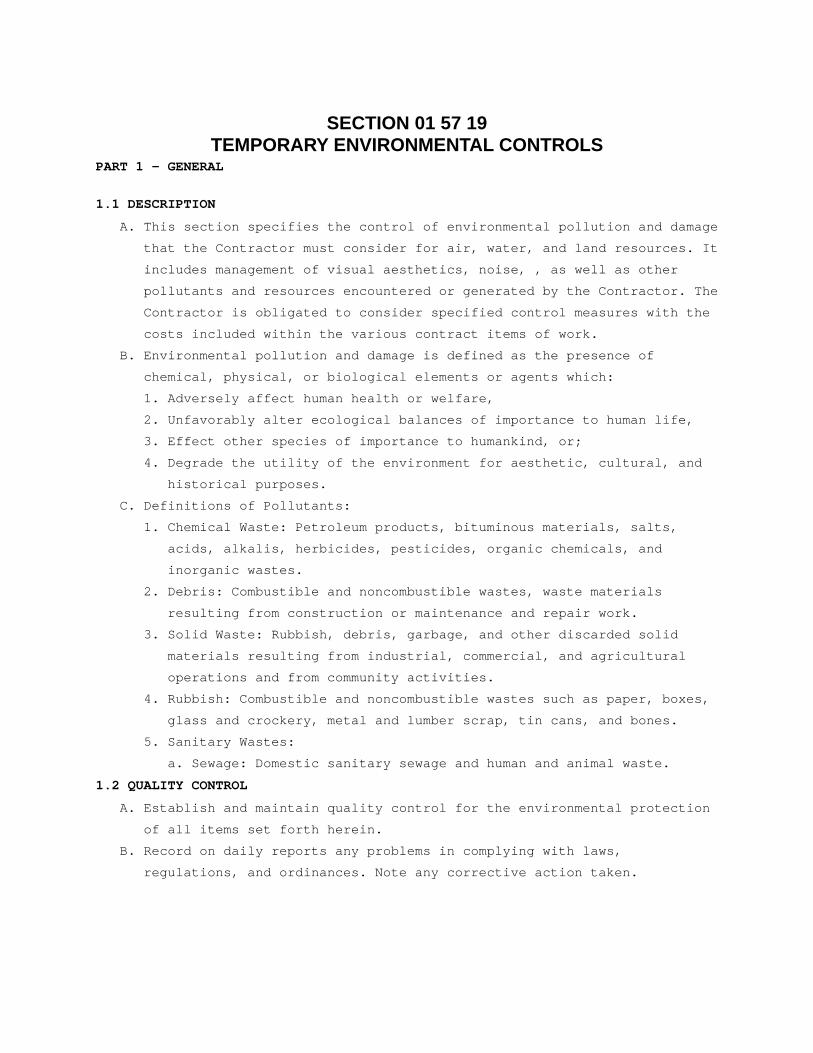
SECTION 01 57 19 TEMPORARY ENVIRONMENTAL CONTROLS
PART 1 - GENERAL
1.1 DESCRIPTION
A. This section specifies the control of environmental pollution and damage
that the Contractor must consider for air, water, and land resources. It
includes management of visual aesthetics, noise, , as well as other
pollutants and resources encountered or generated by the Contractor. The
Contractor is obligated to consider specified control measures with the
costs included within the various contract items of work.
B. Environmental pollution and damage is defined as the presence of
chemical, physical, or biological elements or agents which:
1. Adversely affect human health or welfare,
2. Unfavorably alter ecological balances of importance to human life,
3. Effect other species of importance to humankind, or;
4. Degrade the utility of the environment for aesthetic, cultural, and
historical purposes.
C. Definitions of Pollutants:
1. Chemical Waste: Petroleum products, bituminous materials, salts,
acids, alkalis, herbicides, pesticides, organic chemicals, and
inorganic wastes.
2. Debris: Combustible and noncombustible wastes, waste materials
resulting from construction or maintenance and repair work.
3. Solid Waste: Rubbish, debris, garbage, and other discarded solid
materials resulting from industrial, commercial, and agricultural
operations and from community activities.
4. Rubbish: Combustible and noncombustible wastes such as paper, boxes,
glass and crockery, metal and lumber scrap, tin cans, and bones.
5. Sanitary Wastes:
a. Sewage: Domestic sanitary sewage and human and animal waste.
1.2 QUALITY CONTROL
A. Establish and maintain quality control for the environmental protection
of all items set forth herein.
B. Record on daily reports any problems in complying with laws,
regulations, and ordinances. Note any corrective action taken.
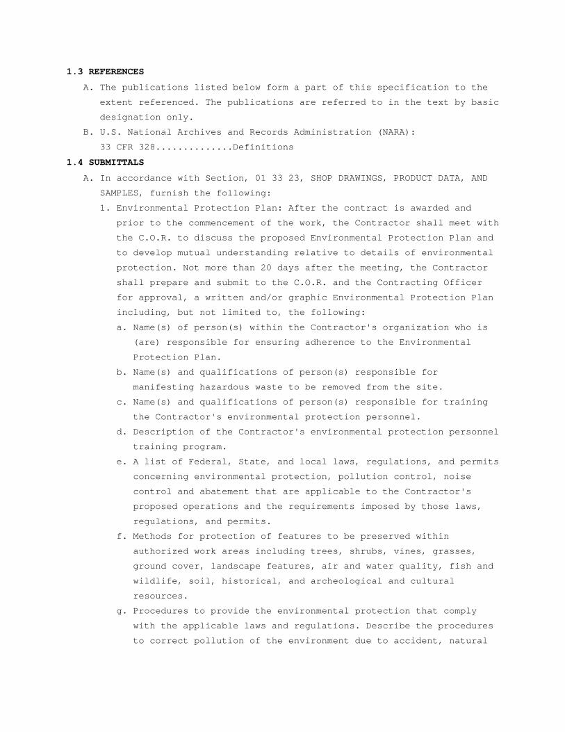
1.3 REFERENCES
A. The publications listed below form a part of this specification to the
extent referenced. The publications are referred to in the text by basic
designation only.
B. U.S. National Archives and Records Administration (NARA):
33 CFR 328..............Definitions
1.4 SUBMITTALS
A. In accordance with Section, 01 33 23, SHOP DRAWINGS, PRODUCT DATA, AND
SAMPLES, furnish the following:
1. Environmental Protection Plan: After the contract is awarded and
prior to the commencement of the work, the Contractor shall meet with
the C.O.R. to discuss the proposed Environmental Protection Plan and
to develop mutual understanding relative to details of environmental
protection. Not more than 20 days after the meeting, the Contractor
shall prepare and submit to the C.O.R. and the Contracting Officer
for approval, a written and/or graphic Environmental Protection Plan
including, but not limited to, the following:
a. Name(s) of person(s) within the Contractor's organization who is
(are) responsible for ensuring adherence to the Environmental
Protection Plan.
b. Name(s) and qualifications of person(s) responsible for
manifesting hazardous waste to be removed from the site.
c. Name(s) and qualifications of person(s) responsible for training
the Contractor's environmental protection personnel.
d. Description of the Contractor's environmental protection personnel
training program.
e. A list of Federal, State, and local laws, regulations, and permits
concerning environmental protection, pollution control, noise
control and abatement that are applicable to the Contractor's
proposed operations and the requirements imposed by those laws,
regulations, and permits.
f. Methods for protection of features to be preserved within
authorized work areas including trees, shrubs, vines, grasses,
ground cover, landscape features, air and water quality, fish and
wildlife, soil, historical, and archeological and cultural
resources.
g. Procedures to provide the environmental protection that comply
with the applicable laws and regulations. Describe the procedures
to correct pollution of the environment due to accident, natural
causes, or failure to follow the procedures as described in the
Environmental Protection Plan.
h. Permits, licenses, and the location of the solid waste disposal
area.
j. Environmental Monitoring Plans for the job site including land,
water, air, and noise.
B. Approval of the Contractor's Environmental Protection Plan will not
relieve the Contractor of responsibility for adequate and continued
control of pollutants and other environmental protection measures.
1.5 PROTECTION OF ENVIRONMENTAL RESOURCES
A. Protect environmental resources within the project boundaries and those
affected outside the limits of permanent work during the entire period
of this contract. Confine activities to areas defined by the
specifications and drawings.
B. Protection of Air Resources: Keep construction activities under
surveillance, management, and control to minimize pollution of air
resources. Burning is not permitted on the job site. Keep activities,
equipment, processes, and work operated or performed, in strict
accordance with the State of Oklahoma State Air Pollution Statue, Rule,
or Regulation and Federal emission and performance laws and standards.
Maintain ambient air quality standards set by the Environmental
Protection Agency, for those construction operations and activities
specified.
1. Particulates: Control dust particles, aerosols, and gaseous by-
products from all construction activities, processing, and
preparation of materials (such as from asphaltic batch plants) at all
times, including weekends, holidays, and hours when work is not in
progress.
2. Particulates Control: Maintain all work areas within or outside the
project boundaries free from particulates which would cause a hazard
or a nuisance.
3. Hydrocarbons and Carbon Monoxide: Control monoxide emissions from
equipment to Federal and State allowable limits.
4. Odors: Control odors of construction activities and prevent obnoxious
odors from occurring.
C. Reduction of Noise: Minimize noise using every action possible. Perform
noise-producing work in less sensitive hours of the day or week as
directed by the C.O.R. Maintain noise-produced work at or below the
decibel levels and within the time periods specified.
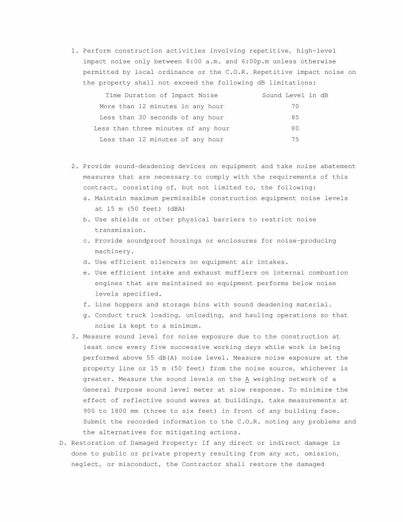
1. Perform construction activities involving repetitive, high-level
impact noise only between 8:00 a.m. and 6:00p.m unless otherwise
permitted by local ordinance or the C.O.R. Repetitive impact noise on
the property shall not exceed the following dB limitations:
Time Duration of Impact Noise Sound Level in dB
More than 12 minutes in any hour 70
Less than 30 seconds of any hour 85
Less than three minutes of any hour 80
Less than 12 minutes of any hour 75
2. Provide sound-deadening devices on equipment and take noise abatement
measures that are necessary to comply with the requirements of this
contract, consisting of, but not limited to, the following:
a. Maintain maximum permissible construction equipment noise levels
at 15 m (50 feet) (dBA)
b. Use shields or other physical barriers to restrict noise
transmission.
c. Provide soundproof housings or enclosures for noise-producing
machinery.
d. Use efficient silencers on equipment air intakes.
e. Use efficient intake and exhaust mufflers on internal combustion
engines that are maintained so equipment performs below noise
levels specified.
f. Line hoppers and storage bins with sound deadening material.
g. Conduct truck loading, unloading, and hauling operations so that
noise is kept to a minimum.
3. Measure sound level for noise exposure due to the construction at
least once every five successive working days while work is being
performed above 55 dB(A) noise level. Measure noise exposure at the
property line or 15 m (50 feet) from the noise source, whichever is
greater. Measure the sound levels on the A weighing network of a
General Purpose sound level meter at slow response. To minimize the
effect of reflective sound waves at buildings, take measurements at
900 to 1800 mm (three to six feet) in front of any building face.
Submit the recorded information to the C.O.R. noting any problems and
the alternatives for mitigating actions.
D. Restoration of Damaged Property: If any direct or indirect damage is
done to public or private property resulting from any act, omission,
neglect, or misconduct, the Contractor shall restore the damaged
property to a condition equal to that existing before the damage at no
additional cost to the Government. Repair, rebuild, or restore property
as directed or make good such damage in an acceptable manner.
E. Final Clean-up: On completion of project and after removal of all
debris, rubbish, and temporary construction, Contractor shall leave the
construction area in a clean condition satisfactory to the C.O.R..
Cleaning shall include off the station disposal of all items and
materials not required to be salvaged, as well as all debris and rubbish
resulting from demolition and new work operations.
- - - E N D - - -
SECTION 01 74 19 CONSTRUCTION WASTE MANAGEMENT
PART 1 – GENERAL
1.1 DESCRIPTION
A. This section specifies the requirements for the management of non-
hazardous building construction and demolition waste.
B. Waste disposal in landfills shall be minimized to the greatest extent
possible. Of the inevitable waste that is generated, as much of the
waste material as economically feasible shall be salvaged, recycled or
reused.
C. Contractor shall use all reasonable means to divert construction and
demolition waste from landfills and incinerators, and facilitate their
salvage and recycle not limited to the following:
1. Waste Management Plan development and implementation.
2. Techniques to minimize waste generation.
3. Sorting and separating of waste materials.
4. Salvage of existing materials and items for reuse or resale.
5. Recycling of materials that cannot be reused or sold.
D. At a minimum the following waste categories shall be diverted from
landfills:
1. Soil.
2. Inerts (eg, concrete, masonry and asphalt).
3. Clean dimensional wood and palette wood.
4. Green waste (biodegradable landscaping materials).
5. Engineered wood products (plywood, particle board and I-joists, etc).
6. Metal products (eg, steel, wire, beverage containers, copper, etc).
7. Cardboard, paper and packaging.
8. Bitumen roofing materials.
9. Plastics (eg, ABS, PVC).
10. Carpet and/or pad.
11. Gypsum board.
12. Insulation.
13. Paint.
14. Fluorescent lamps.
1.2 RELATED WORK
A. Section 02 41 00, DEMOLITION.
B. Section 01 00 00, GENERAL REQUIREMENTS.
1.3 QUALITY ASSURANCE
A. Contractor shall practice efficient waste management when sizing, cutting and installing building products. Processes shall be employed to ensure the generation of as little waste as possible. Construction /Demolition waste includes products of the following:
1. Excess or unusable construction materials.
2. Packaging used for construction products.
3. Poor planning and/or layout.
4. Construction error.
5. Over ordering.
6. Weather damage.
7. Contamination.
8. Mishandling.
9. Breakage.
B. Establish and maintain the management of non-hazardous building construction and demolition waste set forth herein. Conduct a site assessment to estimate the types of materials that will be generated by demolition and construction.
C. Contractor shall develop and implement procedures to recycle construction and demolition waste to a minimum of 50 percent.
D. Contractor shall be responsible for implementation of any special programs involving rebates or similar incentives related to recycling. Any revenues or savings obtained from salvage or recycling shall accrue to the contractor.
E. Contractor shall provide all demolition, removal and legal disposal of materials. Contractor shall ensure that facilities used for recycling, reuse and disposal shall be permitted for the intended use to the extent required by local, state, federal regulations. The Whole Building Design Guide website http://www.cwm.wbdg.org provides a Construction Waste Management Database that contains information on companies that haul, collect, and process recyclable debris from construction projects.
F. Contractor shall assign a specific area to facilitate separation of materials for reuse, salvage, recycling, and return. Such areas are to be kept neat and clean and clearly marked in order to avoid contamination or mixing of materials.
G. Contractor shall provide on-site instructions and supervision of separation, handling, salvaging, recycling, reuse and return methods to be used by all parties during waste generating stages.
H. Record on daily reports any problems in complying with laws, regulations and ordinances with corrective action taken.
1.4 TERMINOLOGY
A. Class III Landfill: A landfill that accepts non-hazardous resources such as household, commercial and industrial waste resulting from construction, remodeling, repair and demolition operations.
B. Clean: Untreated and unpainted; uncontaminated with adhesives, oils, solvents, mastics and like products.
C. Construction and Demolition Waste: Includes all non-hazardous resources resulting from construction, remodeling, alterations, repair and demolition operations.
D. Dismantle: The process of parting out a building in such a way as to preserve the usefulness of its materials and components.
E. Disposal: Acceptance of solid wastes at a legally operating facility for the purpose of land filling (includes Class III landfills and inert fills).
F. Inert Backfill Site: A location, other than inert fill or other disposal facility, to which inert materials are taken for the purpose of filling an excavation, shoring or other soil engineering operation.
G. Inert Fill: A facility that can legally accept inert waste, such as asphalt and concrete exclusively for the purpose of disposal.
H. Inert Solids/Inert Waste: Non-liquid solid resources including, but not limited to, soil and concrete that does not contain hazardous waste or soluble pollutants at concentrations in excess of water-quality objectives established by a regional water board, and does not contain significant quantities of decomposable solid resources.
I. Mixed Debris: Loads that include commingled recyclable and non-recyclable materials generated at the construction site.
J. Mixed Debris Recycling Facility: A solid resource processing facility that accepts loads of mixed construction and demolition debris for the purpose of recovering re-usable and recyclable materials and disposing non-recyclable materials.
K. Permitted Waste Hauler: A company that holds a valid permit to collect and transport solid wastes from individuals or businesses for the purpose of recycling or disposal.
L. Recycling: The process of sorting, cleansing, treating, and reconstituting materials for the purpose of using the altered form in the manufacture of a new product. Recycling does not include burning, incinerating or thermally destroying solid waste.
1. On-site Recycling – Materials that are sorted and processed on site for use in an altered state in the work, i.e. concrete crushed for use as a sub-base in paving.
2. Off-site Recycling – Materials hauled to a location and used in an altered form in the manufacture of new products.
M. Recycling Facility: An operation that can legally accept materials for the purpose of processing the materials into an altered form for the manufacture of new products. Depending on the types of materials accepted and operating procedures, a recycling facility may or may not be required to have a solid waste facilities permit or be regulated by the local enforcement agency.
N. Reuse: Materials that are recovered for use in the same form, on-site or off-site.
O. Return: To give back reusable items or unused products to vendors for credit.
P. Salvage: To remove waste materials from the site for resale or re-use by a third party.
Q. Source-Separated Materials: Materials that are sorted by type at the site for the purpose of reuse and recycling.
R. Solid Waste: Materials that have been designated as non-recyclable and are discarded for the purposes of disposal.
S. Transfer Station: A facility that can legally accept solid waste for the purpose of temporarily storing the materials for re-loading onto other trucks and transporting them to a landfill for disposal, or recovering some materials for re-use or recycling.
1.5 SUBMITTALS
A. In accordance with Section 01 33 23, SHOP DRAWINGS, PRODUCT DATA, and SAMPLES, furnish the following:
B. Prepare and submit to the C.O.R. a written demolition debris management plan. The plan shall include, but not be limited to, the following information:
1. Procedures to be used for debris management.
2. Techniques to be used to minimize waste generation.
3. Analysis of the estimated job site waste to be generated:
a. List of each material and quantity to be salvaged, reused, recycled.
b. List of each material and quantity proposed to be taken to a landfill.
4. Detailed description of the Means/Methods to be used for material handling.
a. On site: Material separation, storage, protection where applicable.
b. Off site: Transportation means and destination. Include list of materials.
1) Description of materials to be site-separated and self-hauled to designated facilities.
2) Description of mixed materials to be collected by designated waste haulers and removed from the site.
c. The names and locations of mixed debris reuse and recycling facilities or sites.
d. The names and locations of trash disposal landfill facilities or sites.
e. Documentation that the facilities or sites are approved to receive the materials.
C. Designated Manager responsible for instructing personnel, supervising, documenting and administer over meetings relevant to the Waste Management Plan.
D. Monthly summary of construction and demolition debris diversion and disposal, quantifying all materials generated at the work site and disposed of or diverted from disposal through recycling.
1.6 APPLICABLE PUBLICATIONS
A Publications listed below form a part of this specification to the extent referenced. Publications are referenced by the basic designation only. In the event that criteria requirements conflict, the most stringent requirements shall be met.
B. U.S. Green Building Council (USGBC):
LEED Green Building Rating System for New Construction
1.7 RECORDS
Maintain records to document the quantity of waste generated; the quantity of waste diverted through sale, reuse, or recycling; and the quantity of waste disposed by landfill or incineration. Records shall be kept in accordance with the LEED Reference Guide and LEED Template.
PART 2 - PRODUCTS
2.1 MATERIALS
A. List of each material and quantity to be salvaged, recycled, reused.
B. List of each material and quantity proposed to be taken to a landfill.
C. Material tracking data: Receiving parties, dates removed, transportation costs, weight tickets, tipping fees, manifests, invoices, net total costs or savings.
PART 3 - EXECUTION
3.1 COLLECTION
A. Provide all necessary containers, bins and storage areas to facilitate effective waste management.
B. Clearly identify containers, bins and storage areas so that recyclable materials are separated from trash and can be transported to respective recycling facility for processing.
C. Hazardous wastes shall be separated, stored, disposed of according to local, state, federal regulations.
3.2 DISPOSAL
A. Contractor shall be responsible for transporting and disposing of materials that cannot be delivered to a source-separated or mixed materials recycling facility to a transfer station or disposal facility that can accept the materials in accordance with state and federal regulations.
B. Construction or demolition materials with no practical reuse or that cannot be salvaged or recycled shall be disposed of at a landfill or incinerator.
3.3 REPORT
A. With each application for progress payment, submit a summary of construction and demolition debris diversion and disposal including beginning and ending dates of period covered.
B. Quantify all materials diverted from landfill disposal through salvage or recycling during the period with the receiving parties, dates removed, transportation costs, weight tickets, manifests, invoices. Include the net total costs or savings for each salvaged or recycled material.
C. Quantify all materials disposed of during the period with the receiving parties, dates removed, transportation costs, weight tickets, tipping fees, manifests, invoices. Include the net total costs for each disposal.
- - - E N D - - -
SECTION 01 91 00 GENERAL COMMISSIONING REQUIREMENTS
PART 1 - GENERAL 1.1 DESCRIPTION
A. This Section 01 91 00 GENERAL COMMISSIONING REQUIREMENTS shall form the
basis of the construction phase commissioning process and procedures.
The Commissioning Agent shall add, modify, and refine the commissioning
procedures, as approved by the Department of Veterans Affairs (VA), to
suit field conditions and actual manufacturer's equipment, incorporate
test data and procedure results, and provide detailed scheduling for all
commissioning tasks.
B. Various sections of the project specifications require equipment
startup, testing, and adjusting services. Requirements for startup,
testing, and adjusting services specified in the Division 7, Division
21, Division 22, Division 23, Division 26, Division 27, Division 28, and
Division 31 series sections of these specifications are intended to be
provided in coordination with the commissioning services and are not
intended to duplicate services. The Contractor shall coordinate the work
required by individual specification sections with the commissioning
services requirements specified herein.
C. Where individual testing, adjusting, or related services are required in
the project specifications and not specifically required by this
commissioning requirements specification, the specified services shall
be provided and copies of documentation, as required by those
specifications shall be submitted to the VA and the Commissioning Agent
to be indexed for future reference.
D. Where training or educational services for VA are required and specified
in other sections of the specifications, including but not limited to
Division 7, Division 8, Division 21, Division 22, Division 23, Division
26, Division 27, Division 28, and Division 31 series sections of the
specification, these services are intended to be provided in addition to
the training and educational services specified herein.
E. Commissioning is a systematic process of verifying that the building
systems perform interactively according to the construction documents
and the VA’s operational needs. The commissioning process shall
encompass and coordinate the system documentation, equipment startup,
control system calibration, testing and balancing, performance testing
and training. Commissioning during the construction, and post-occupancy
phases is intended to achieve the following specific objectives
according to the contract documents:
1. Verify that the applicable equipment and systems are installed in
accordance with the contact documents and according to the
manufacturer's recommendations.
2. Verify and document proper integrated performance of equipment and
systems.
3. Verify that Operations & Maintenance documentation is complete.
4. Verify that all components requiring servicing can be accessed,
serviced and removed without disturbing nearby components including
ducts, piping, cabling or wiring.
5. Verify that the VA’s operating personnel are adequately trained to
enable them to operate, monitor, adjust, maintain, and repair
building systems in an effective and energy-efficient manner.
6. Document the successful achievement of the commissioning objectives
listed above.
F. The commissioning process does not take away from or reduce the
responsibility of the Contractor to provide a finished and fully
functioning product.
G. The Commissioning Agent, both the firm and individual designated as the
Commissioning Agent, shall be certified by at least one of the following
entities: the National Environmental Balancing Bureau (NEBB), the
Associated Air Balance Council Commissioning Group (AABC), and the
Building Commissioning Association (BCA). Certification(s) shall be
valid and active. Proof of certification(s) shall be submitted to the
Contracting Officer and the C.O.R. three (3) calendar days after the
Notice to Proceed.
1.2 CONTRACTUAL RELATIONSHIPS
A. For this construction project, the Department of Veterans Affairs
contracts with a Contractor to provide construction services. The
contracts are administered by the VA Contracting Officer and the C.O.R.
as the designated representative of the Contracting Officer. On this
project, the authority to modify the contract in any way is strictly
limited to the authority of the Contracting Officer and the C.O.R..
B. In this structure, only two contract parties are recognized and
communications on contractual issues are strictly limited to VA C.O.R.
and the Contractor. It is the practice of the VA to require that
communications between other parties to the contracts (Subcontractors
and Vendors) be conducted through the C.O.R. and Contractor. It is also
the practice of the VA that communications between other parties of the
project (Commissioning Agent and Architect/Engineer) be conducted
through the C.O.R..
C. Whole Building Commissioning is a process that relies upon frequent and
direct communications, as well as collaboration between all parties to
the construction process. By its nature, a high level of communication
and cooperation between the Commissioning Agent and all other parties
(Architects, Engineers, Subcontractors, Vendors, third party testing
agencies, etc) is essential to the success of the Commissioning effort.
D. With these fundamental practices in mind, the commissioning process
described herein has been developed to recognize that, in the execution
of the Commissioning Process, the Commissioning Agent must develop
effective methods to communicate with every member of the construction
team involved in delivering commissioned systems while simultaneously
respecting the exclusive contract authority of the Contracting Officer
and C.O.R.. Thus, the procedures outlined in this specification must
be executed within the following limitations:
1. No communications (verbal or written) from the Commissioning Agent
shall be deemed to constitute direction that modifies the terms of
any contract between the Department of Veterans Affairs and the
Contractor.
2. Commissioning Issues identified by the Commissioning Agent will be
delivered to the C.O.R. and copied to the designated Commissioning
Representatives for the Contractor and subcontractors on the
Commissioning Team for information only in order to expedite the
communication process. These issues must be understood as the
professional opinion of the Commissioning Agent and as suggestions
for resolution.
3. In the event that any Commissioning Issues and suggested resolutions
are deemed by the C.O.R. to require either an official interpretation
of the construction documents or require a modification of the
contract documents, the Contracting Officer or C.O.R. will issue an
official directive to this effect.
4. All parties to the Commissioning Process shall be individually
responsible for alerting the C.O.R. of any issues that they deem to
constitute a potential contract change prior to acting on these
issues.
5. Authority for resolution or modification of design and construction
issues rests solely with the Contracting Officer or C.O.R., with
appropriate technical guidance from the Architect/Engineer and/or
Commissioning Agent.
1.3 RELATED WORK
A. Section 01 00 00 GENERAL REQUIREMENTS.
B. Section 28 08 00 COMMISSIONING OF ELECTRONIC SAFETY AND SECURITY
SYSTEMS.
1.4 SUMMARY
A. This Section includes general requirements that apply to implementation
of commissioning without regard to systems, subsystems, and equipment
being commissioned.
B. The commissioning activities have been developed to support the VA
requirements to meet guidelines for Federal Leadership in Environmental,
Energy, and Economic Performance.
C. The commissioning activities have been developed to support the United
States Green Building Council (USGBC) LEED ™ rating program and to
support delivery of project performance in accordance with the VA
requirements developed for the project.
1. Commissioning activities and documentation for the LEED™ section on
“Energy and Atmosphere” and the prerequisite of “Fundamental Building
Systems Commissioning.”
2. Commissioning activities and documentation for the LEED™ section on
“Energy and Atmosphere” requirements for the “Enhanced Building
System Commissioning” credit.
3. Activities and documentation for the LEED™ section on “Measurement
and Verification” requirements for the Measurement and Verification
credit.
D. The commissioning activities have been developed to support the Green
Buildings Initiative Green Globes rating program and to support delivery
of project performance in accordance with the VA requirements developed
for the project.
1.5 DEFINITIONS
A. Architect: Includes Architect identified in the Contract for
Construction between the Department of Veterans Affairs and Contractor,
plus consultant/design professionals responsible for design of fire
suppression, plumbing, HVAC, controls for HVAC systems, electrical,
communications, electronic safety and security, as well as other related
systems.
B. CxA: Commissioning Agent.
C. Commissioning Plan: a document that is an overall plan that outlines the
commissioning process, commissioning team responsibilities, schedule for
commissioning activities, and commissioning documents.

D. Commissioning Issue: a condition in the installation or function of a
component, piece of equipment or system that affects the system
operations, maintenance, and/or repair.
E. Commissioning Observation: a condition in the installation or function
of a component, piece of equipment or system that may not be in
compliance with the Contract Documents, or may not be in compliance with
the manufacturer’s installation instruction, or may not be in compliance
with generally accepted industry standards.
F. Systems Functional Performance Test: a test, or tests, of the dynamic
function and operation of equipment and systems using manual (direct
observation) or monitoring methods. Systems Functional Performance
Testing is the dynamic testing of systems (rather than just components)
under full operation (e.g., the chiller pump is tested interactively
with the chiller functions to see if the pump ramps up and down to
maintain the differential pressure setpoint). Systems are tested under
various modes, such as during low cooling or heating loads, high loads,
component failures, unoccupied, varying outside air temperatures, fire
alarm, power failure, etc. The systems are run through all the control
system’s sequences of operation and components are verified to be
responding as the sequences state. Traditional air or water test and
balancing (TAB) is not Systems Functional Performance Testing, in the
commissioning sense of the word. TAB’s primary work is setting up the
system flows and pressures as specified, while System Functional
Performance Testing is verifying that the system has already been set up
properly and is functioning in accordance with the Construction
Documents. The Commissioning Agent develops the Systems Functional
Performance Test Procedures in a sequential written form, coordinates,
witnesses, and documents the actual testing. Systems Functional
Performance Testing is performed by the Contractor. Systems Functional
Performance Tests are performed after startups, control systems are
complete and operational, TAB functions and Pre-Functional Checklists
are complete.
G. System: A system is defined as the entire set of components, equipment,
and subsystems which must be coordinated to work together during normal
operation to produce results for which the system is designed. For
example, air conditioning supply air is only one component of an entire
system which provides comfort conditions for a building. Other related
components are return air, exhaust air, steam supply, chilled water
supply, refrigerant supply, hot water supply, controls and electrical
service, etc. Another example of a system which involves several

components of different disciplines is a boiler installation. Efficient
and acceptable boiler operation depends upon the coordination and proper
operation of the fuel supply, combustion air, controls, steam, feedwater
supply, condensate return and other related components.
H. Pre-Functional Checklist: a list of items provided by the Commissioning
Agent to the Contractor that require inspection and elementary component
tests conducted to verify proper installation of equipment. Pre-
Functional Checklists are primarily static inspections and procedures to
prepare the equipment or system for initial operation (e.g., belt
tension, oil levels OK, labels affixed, gages in place, sensors
calibrated, etc.). However, some Pre-Functional Checklist items entail
simple testing of the function of a component, a piece of equipment or
system (such as measuring the voltage imbalance on a three-phase pump
motor of a chiller system). The term “Pre-Functional” refers to before
Systems Functional Performance Testing. Pre-Functional Checklists
augment and are combined with the manufacturer’s startup checklist and
the Contractor’s Quality Control checklists.
I. Seasonal Functional Performance Testing: a test or tests that are
deferred until the system will experience conditions closer to their
design conditions.
J. VA: Includes the Contracting Officer, Resident Engineer, or other
authorized representative of the Department of Veterans Affairs.
K. TAB: Testing, Adjusting, and Balancing.
1.6 SYSTEMS TO BE COMMISSIONED
A. Commissioning of a system or systems specified for this project is part
of the construction process. Documentation and testing of these systems,
as well as training of the VA’s Operation and Maintenance personnel, is
required in cooperation with the VA and the Commissioning Agent.
B. The following systems will be commissioned as part of this project:
1. Electronic Safety and Security (Division 28)
a. Fire Detection and Alarm (Master panel and software, addressable
units – i.e. pull stations, flow detectors, hear detectors, etc.,
controls and alarm functions, horns/bells/door releases and other
output devices, and fire command center functions – stairwell
communications, stairwell pressurization fan start, mechanical
systems shutdowns).
1.7 COMMISSIONING TEAM
A. Members Appointed by Contractor:
1. Contractor: The designated person, company, or entity that plans,
schedules and coordinates the commissioning activities for the
construction team.
2. Contractor’s Commissioning Representative(s): Individual(s), each
having authority to act on behalf of the entity he or she represents,
explicitly organized to implement the commissioning process through
coordinated actions. The commissioning team shall consist of, but
not be limited to, representatives of Contractor, including Project
Superintendent and subcontractors, installers, suppliers, and
specialists deemed appropriate by the Department of Veterans Affairs
(VA) and Commissioning Agent.
B. Members Appointed by VA:
1. Commissioning Agent: The designated person, company, or entity that
plans, schedules, and coordinates the commissioning team to implement
the commissioning process. The VA will engage the CxA under a
separate contract.
2. Representatives of the facility user and operation and maintenance
personnel.
3. Architect and engineering design professionals.
1.8 VA'S COMMISSIONING RESPONSIBILITIES
A. Appoint an individual, company or firm to act as the Commissioning
Agent.
B. Assign operation and maintenance personnel and schedule them to
participate in commissioning team activities including, but not limited
to, the following:
1. Coordination meetings.
2. Training in operation and maintenance of systems, subsystems, and
equipment.
3. Testing meetings.
4. Witness and assist in Systems Functional Performance Testing.
5. Demonstration of operation of systems, subsystems, and equipment.
C. Provide the Construction Documents, prepared by Architect and approved
by VA, to the Commissioning Agent and for use in managing the
commissioning process, developing the commissioning plan, systems
manuals, and reviewing the operation and maintenance training plan.
1.9 CONTRACTOR'S COMMISSIONING RESPONSIBILITIES
A. The Contractor shall assign a Commissioning Manager to manage
commissioning activities of the Contractor, and subcontractors.
B. The Contractor shall ensure that the commissioning responsibilities
outlined in these specifications are included in all subcontracts and
that subcontractors comply with the requirements of these
specifications.
C. The Contractor shall ensure that each installing subcontractor shall
assign representatives with expertise and authority to act on behalf of
the subcontractor and schedule them to participate in and perform
commissioning team activities including, but not limited to, the
following:
1. Participate in commissioning coordination meetings.
2. Conduct operation and maintenance training sessions in accordance
with approved training plans.
3. Verify that Work is complete and systems are operational according to
the Contract Documents, including calibration of instrumentation and
controls.
4. Evaluate commissioning issues and commissioning observations
identified in the Commissioning Issues Log, field reports, test
reports or other commissioning documents. In collaboration with
entity responsible for system and equipment installation, recommend
corrective action.
5. Review and comment on commissioning documentation.
6. Participate in meetings to coordinate Systems Functional Performance
Testing.
7. Provide schedule for operation and maintenance data submittals,
equipment startup, and testing to Commissioning Agent for
incorporation into the commissioning plan.
8. Provide information to the Commissioning Agent for developing
commissioning plan.
9. Participate in training sessions for VA's operation and maintenance
personnel.
10. Provide technicians who are familiar with the construction and
operation of installed systems and who shall develop specific test
procedures to conduct Systems Functional Performance Testing of
installed systems.
1.10 COMMISSIONING AGENT’S RESPONSIBILITIES
A. Organize and lead the commissioning team.
B. Prepare the commissioning plan. See Paragraph 1.11-A of this
specification Section for further information.
C. Review and comment on selected submittals from the Contractor for
general conformance with the Construction Documents. Review and comment
on the ability to test and operate the system and/or equipment,
including providing gages, controls and other components required to

operate, maintain, and test the system. Review and comment on
performance expectations of systems and equipment and interfaces between
systems relating to the Construction Documents.
D. At the beginning of the construction phase, conduct an initial
construction phase coordination meeting for the purpose of reviewing the
commissioning activities and establishing tentative schedules for
operation and maintenance submittals; operation and maintenance training
sessions; TAB Work; Pre-Functional Checklists, Systems Functional
Performance Testing; and project completion.
E. Convene commissioning team meetings for the purpose of coordination,
communication, and conflict resolution; discuss status of the
commissioning processes. Responsibilities include arranging for
facilities, preparing agenda and attendance lists, and notifying
participants. The Commissioning Agent shall prepare and distribute
minutes to commissioning team members and attendees within five workdays
of the commissioning meeting.
F. Observe construction and report progress, observations and issues.
Observe systems and equipment installation for adequate accessibility
for maintenance and component replacement or repair, and for general
conformance with the Construction Documents.
G. Prepare Project specific Pre-Functional Checklists and Systems
Functional Performance Test procedures.
H. Coordinate Systems Functional Performance Testing schedule with the
Contractor.
I. Witness selected systems startups.
J. Verify selected Pre-Functional Checklists completed and submitted by the
Contractor.
K. Witness and document Systems Functional Performance Testing.
L. Compile test data, inspection reports, and certificates and include them
in the systems manual and commissioning report.
M. Review and comment on operation and maintenance (O&M) documentation and
systems manual outline for compliance with the Contract Documents.
Operation and maintenance documentation requirements are specified in
Paragraph 1.25, Section 01 00 00 GENERAL REQUIREMENTS.
N. Review operation and maintenance training program developed by the
Contractor. Verify training plans provide qualified instructors to
conduct operation and maintenance training.
O. Prepare commissioning Field Observation Reports.
P. Prepare the Final Commissioning Report.
Q. Return to the site at 10 months into the 12 month warranty period and
review with facility staff the current building operation and the
condition of outstanding issues related to the original and seasonal
Systems Functional Performance Testing. Also interview facility staff
and identify problems or concerns they have operating the building as
originally intended. Make suggestions for improvements and for recording
these changes in the O&M manuals. Identify areas that may come under
warranty or under the original construction contract. Assist facility
staff in developing reports, documents and requests for services to
remedy outstanding problems.
R. Assemble the final commissioning documentation, including the Final
Commissioning Report and Addendum to the Final Commissioning Report.
1.11 COMMISSIONING DOCUMENTATION
A. Commissioning Agent’s Certification(s): Commissioning Agent shall
submit evidence of valid and current certification(s), as required in
Section 1.1(G), to the Contracting Officer.
B. Commissioning Plan: A document, prepared by Commissioning Agent, that
outlines the schedule, allocation of resources, and documentation
requirements of the commissioning process, and shall include, but is not
limited, to the following:
1. Plan for delivery and review of submittals, systems manuals, and
other documents and reports. Identification of the relationship of
these documents to other functions and a detailed description of
submittals that are required to support the commissioning processes.
Submittal dates shall include the latest date approved submittals
must be received without adversely affecting commissioning plan.
2. Description of the organization, layout, and content of commissioning
documentation (including systems manual) and a detailed description
of documents to be provided along with identification of responsible
parties.
3. Identification of systems and equipment to be commissioned.
4. Schedule of Commissioning Coordination meetings.
5. Identification of items that must be completed before the next
operation can proceed.
6. Description of responsibilities of commissioning team members.
7. Description of observations to be made.
8. Description of requirements for operation and maintenance training.
9. Schedule for commissioning activities with dates coordinated with
overall construction schedule.
10. Process and schedule for documenting changes on a continuous basis to
appear in Project Record Documents.
11. Process and schedule for completing prestart and startup checklists
for systems, subsystems, and equipment to be verified and tested.
12. Preliminary Systems Functional Performance Test procedures.
C. Systems Functional Performance Test Procedures: The Commissioning Agent
will develop Systems Functional Performance Test Procedures for each
system to be commissioned, including subsystems, or equipment and
interfaces or interlocks with other systems. Systems Functional
Performance Test Procedures will include a separate entry, with space
for comments, for each item to be tested. Preliminary Systems
Functional Performance Test Procedures will be provided to the VA,
Architect/Engineer, and Contractor for review and comment. The Systems
Performance Test Procedure will include test procedures for each mode of
operation and provide space to indicate whether the mode under test
responded as required. Each System Functional Performance Test
procedure, regardless of system, subsystem, or equipment being tested,
shall include, but not be limited to, the following:
1. Name and identification code of tested system.
2. Test number.
3. Time and date of test.
4. Indication of whether the record is for a first test or retest
following correction of a problem or issue.
5. Dated signatures of the person performing test and of the witness, if
applicable.
6. Individuals present for test.
7. Observations and Issues.
8. Issue number, if any, generated as the result of test.
D. Pre-Functional Checklists: The Commissioning Agent will prepare Pre-
Functional Checklists. Pre-Functional Checklists shall be completed and
signed by the Contractor, verifying that systems, subsystems, equipment,
and associated controls are ready for testing. The Commissioning Agent
will spot check Pre-Functional Checklists to verify accuracy and
readiness for testing. Inaccurate or incomplete Pre-Functional
Checklists shall be returned to the Contractor for correction and
resubmission.
E. Test and Inspection Reports: The Commissioning Agent will record test
data, observations, and measurements on Systems Functional Performance
Test Procedure. The report will also include recommendation for system
acceptance or non-acceptance. Photographs, forms, and other means

appropriate for the application shall be included with data.
Commissioning Agent Will compile test and inspection reports and test
and inspection certificates and include them in systems manual and
commissioning report.
F. Corrective Action Documents: The Commissioning Agent will document
corrective action taken for systems and equipment that fail tests. The
documentation will include any required modifications to systems and
equipment and/or revisions to test procedures, if any. The
Commissioning Agent will witness and document any retesting of systems
and/or equipment requiring corrective action and document retest
results.
G. Commissioning Issues Log: The Commissioning Agent will prepare and
maintain Commissioning Issues Log that describes Commissioning Issues
and Commissioning Observations that are identified during the
Commissioning process. These observations and issues include, but are
not limited to, those that are at variance with the Contract Documents.
The Commissioning Issues Log will identify and track issues as they are
encountered, the party responsible for resolution, progress toward
resolution, and document how the issue was resolved. The Master
Commissioning Issues Log will also track the status of unresolved
issues.
1. Creating an Commissioning Issues Log Entry:
a. Identify the issue with unique numeric or alphanumeric identifier
by which the issue may be tracked.
b. Assign a descriptive title for the issue.
c. Identify date and time of the issue.
d. Identify test number of test being performed at the time of the
observation, if applicable, for cross reference.
e. Identify system, subsystem, and equipment to which the issue
applies.
f. Identify location of system, subsystem, and equipment.
g. Include information that may be helpful in diagnosing or
evaluating the issue.
h. Note recommended corrective action.
i. Identify commissioning team member responsible for corrective
action.
j. Identify expected date of correction.
k. Identify person that identified the issue.
2. Documenting Issue Resolution:
a. Log date correction is completed or the issue is resolved.
b. Describe corrective action or resolution taken. Include
description of diagnostic steps taken to determine root cause of
the issue, if any.
c. Identify changes to the Contract Documents that may require
action.
d. State that correction was completed and system, subsystem, and
equipment are ready for retest, if applicable.
e. Identify person(s) who corrected or resolved the issue.
f. Identify person(s) verifying the issue resolution.
H. Final Commissioning Report: The Commissioning Agent will document
results of the commissioning process, including unresolved issues, and
performance of systems, subsystems, and equipment. The Commissioning
Report will indicate whether systems, subsystems, and equipment have
been properly installed and are performing according to the Contract
Documents. This report will be used by the Department of Veterans
Affairs when determining that systems will be accepted. This report
will be used to evaluate systems, subsystems, and equipment and will
serve as a future reference document during VA occupancy and operation.
It shall describe components and performance that exceed requirements
of the Contract Documents and those that do not meet requirements of the
Contract Documents. The commissioning report will include, but is not
limited to, the following:
1. Lists and explanations of substitutions; compromises; variances with
the Contract Documents; record of conditions; and, if appropriate,
recommendations for resolution. Design Narrative documentation
maintained by the Commissioning Agent.
2. Commissioning plan.
3. Pre-Functional Checklists completed by the Contractor, with
annotation of the Commissioning Agent review and spot check.
4. Systems Functional Performance Test Procedures, with annotation of
test results and test completion.
5. Commissioning Issues Log.
6. Listing of deferred and off season test(s) not performed, including
the schedule for their completion.
I. Addendum to Final Commissioning Report: The Commissioning Agent will
prepare an Addendum to the Final Commissioning Report near the end of
the Warranty Period. The Addendum will indicate whether systems,
subsystems, and equipment are complete and continue to perform according
to the Contract Documents. The Addendum to the Final Commissioning
Report shall include, but is not limited to, the following:
1. Documentation of deferred and off season test(s) results.
2. Completed Systems Functional Performance Test Procedures for off
season test(s).
3. Documentation that unresolved system performance issues have been
resolved.
4. Updated Commissioning Issues Log, including status of unresolved
issues.
5. Identification of potential Warranty Claims to be corrected by the
Contractor.
J. Systems Manual: The Commissioning Agent will gather required
information and compile the Systems Manual. The Systems Manual will
include, but is not limited to, the following:
1. Design Narrative, including system narratives, schematics, single-
line diagrams, flow diagrams, equipment schedules, and changes made
throughout the Project.
2. Reference to Final Commissioning Plan.
3. Reference to Final Commissioning Report.
4. Approved Operation and Maintenance Data as submitted by the
Contractor.
1.12 SUBMITTALS
A. Preliminary Commissioning Plan Submittal: The Commissioning Agent has
prepared a Preliminary Commissioning Plan based on the final
Construction Documents. The Preliminary Commissioning Plan is included
as an Appendix to this specification section. The Preliminary
Commissioning Plan is provided for information only. It contains
preliminary information about the following commissioning activities:
1. The Commissioning Team: A list of commissioning team members by
organization.
2. Systems to be commissioned. A detailed list of systems to be
commissioned for the project. This list also provides preliminary
information on systems/equipment submittals to be reviewed by the
Commissioning Agent; preliminary information on Pre-Functional
Checklists that are to be completed; preliminary information on
Systems Performance Testing, including information on testing sample
size (where authorized by the VA).
3. Commissioning Team Roles and Responsibilities: Preliminary roles and
responsibilities for each Commissioning Team member.
4. Commissioning Documents: A preliminary list of commissioning-related
documents, include identification of the parties responsible for
preparation, review, approval, and action on each document.
5. Commissioning Activities Schedule: Identification of Commissioning
Activities, including Systems Functional Testing, the expected
duration and predecessors for the activity.
6. Pre-Functional Checklists: Preliminary Pre-Functional Checklists for
equipment, components, subsystems, and systems to be commissioned.
These Preliminary Pre-Functional Checklists provide guidance on the
level of detailed information the Contractor shall include on the
final submission.
7. Systems Functional Performance Test Procedures: Preliminary step-by-
step System Functional Performance Test Procedures to be used during
Systems Functional Performance Testing. These Preliminary Systems
Functional Performance procedures provide information on the level of
testing rigor, and the level of Contractor support required during
performance of system’s testing.
B. Final Commissioning Plan Submittal: Based on the Final Construction
Documents and the Contractor’s project team, the Commissioning Agent
will prepare the Final Commissioning Plan as described in this section.
The Commissioning Agent will submit three hard copies and three sets of
electronic files of Final Commissioning Plan. The Contractor shall
review the Commissioning Plan and provide any comments to the VA. The
Commissioning Agent will incorporate review comments into the Final
Commissioning Plan as directed by the VA.
C. Systems Functional Performance Test Procedure: The Commissioning Agent
will submit preliminary Systems Functional Performance Test Procedures
to the Contractor, and the VA for review and comment. The Contractor
shall return review comments to the VA and the Commissioning Agent. The
VA will also return review comments to the Commissioning Agent. The
Commissioning Agent will incorporate review comments into the Final
Systems Functional Test Procedures to be used in Systems Functional
Performance Testing.
D. Pre-Functional Checklists: The Commissioning Agent will submit Pre-
Functional Checklists to be completed by the Contractor.
E. Test and Inspection Reports: The Commissioning Agent will submit test
and inspection reports to the VA with copies to the Contractor and the
Architect/Engineer.
F. Corrective Action Documents: The Commissioning Agent will submit
corrective action documents to the VA Resident Engineer with copies to
the Contractor and Architect.
G. Preliminary Commissioning Report Submittal: The Commissioning Agent
will submit three electronic copies of the preliminary commissioning
report. One electronic copy, with review comments, will be returned to
the Commissioning Agent for preparation of the final submittal.
H. Final Commissioning Report Submittal: The Commissioning Agent will
submit four sets of electronically formatted information of the final
commissioning report to the VA. The final submittal will incorporate
comments as directed by the VA.
I. Data for Commissioning:
1. The Commissioning Agent will request in writing from the Contractor
specific information needed about each piece of commissioned
equipment or system to fulfill requirements of the Commissioning
Plan.
2. The Commissioning Agent may request further documentation as is
necessary for the commissioning process or to support other VA data
collection requirements, including Construction Operations Building
Information Exchange (COBIE), Building Information Modeling (BIM),
etc.
1.13 COMMISSIONING PROCESS
A. The Commissioning Agent will be responsible for the overall management
of the commissioning process as well as coordinating scheduling of
commissioning tasks with the VA and the Contractor. As directed by the
VA, the Contractor shall incorporate Commissioning tasks, including, but
not limited to, Systems Functional Performance Testing (including
predecessors) with the Master Construction Schedule.
B. Within 10 days of contract award, the Contractor shall designate a
specific individual as the Commissioning Manager (CM) to manage and lead
the commissioning effort on behalf of the Contractor. The Commissioning
Manager shall be the single point of contact and communications for all
commissioning related services by the Contractor.
C. Within 10 days of contract award, the Contractor shall ensure that each
subcontractor designates specific individuals as Commissioning
Representatives (CR) to be responsible for commissioning related tasks.
The Contractor shall ensure the designated Commissioning Representatives
participate in the commissioning process as team members providing
commissioning testing services, equipment operation, adjustments, and
corrections if necessary. The Contractor shall ensure that all

Commissioning Representatives shall have sufficient authority to direct
their respective staff to provide the services required, and to speak on
behalf of their organizations in all commissioning related contractual
matters.
1.14 QUALITY ASSURANCE
A. Instructor Qualifications: Factory authorized service representatives
shall be experienced in training, operation, and maintenance procedures
for installed systems, subsystems, and equipment.
B. Test Equipment Calibration: The Contractor shall comply with test
equipment manufacturer's calibration procedures and intervals.
Recalibrate test instruments immediately whenever instruments have been
repaired following damage or dropping. Affix calibration tags to test
instruments. Instruments shall have been calibrated within six months
prior to use.
1.15 COORDINATION
A. Management: The Commissioning Agent will coordinate the commissioning
activities with the VA and Contractor. The Commissioning Agent will
submit commissioning documents and information to the VA. All
commissioning team members shall work together to fulfill their
contracted responsibilities and meet the objectives of the contract
documents.
B. Scheduling: The Contractor will work with the Commissioning Agent and
the VA to incorporate the commissioning activities into the construction
schedule. The Commissioning Agent will provide sufficient information on
commissioning activities to allow the Contractor and the VA to schedule
commissioning activities. All parties shall address scheduling issues
and make necessary notifications in a timely manner in order to expedite
the project and the commissioning process. The Contractor shall update
the Master Construction as directed by the VA.
C. Initial Schedule of Commissioning Events: The Commissioning Agent will
provide the initial schedule of primary commissioning events in the
Commissioning Plan and at the commissioning coordination meetings. The
Commissioning Plan will provide a format for this schedule. As
construction progresses, more detailed schedules will be developed by
the Contractor with information from the Commissioning Agent.
D. Commissioning Coordinating Meetings: The Commissioning Agent will
conduct periodic Commissioning Coordination Meetings of the
commissioning team to review status of commissioning activities, to
discuss scheduling conflicts, and to discuss upcoming commissioning
process activities.

E. Pretesting Meetings: The Commissioning Agent will conduct pretest
meetings of the commissioning team to review startup reports, Pre-
Functional Checklist results, Systems Functional Performance Testing
procedures, testing personnel and instrumentation requirements.
F. Systems Functional Performance Testing Coordination: The Contractor
shall coordinate testing activities to accommodate required quality
assurance and control services with a minimum of delay and to avoid
necessity of removing and replacing construction to accommodate testing
and inspecting. The Contractor shall coordinate the schedule times for
tests, inspections, obtaining samples, and similar activities.
PART 2 - PRODUCTS
2.1 TEST EQUIPMENT
A. The Contractor shall provide all standard and specialized testing
equipment required to perform Systems Functional Performance Testing.
Test equipment required for Systems Functional Performance Testing will
be identified in the detailed System Functional Performance Test
Procedure prepared by the Commissioning Agent.
B. Data logging equipment and software required to test equipment shall be
provided by the Contractor.
C. All testing equipment shall be of sufficient quality and accuracy to
test and/or measure system performance with the tolerances specified in
the Specifications. If not otherwise noted, the following minimum
requirements apply: Temperature sensors and digital thermometers shall
have a certified calibration within the past year to an accuracy of 0.5 oC (1.0 oF) and a resolution of + or - 0.1 oC (0.2 oF). Pressure sensors
shall have an accuracy of + or - 2.0% of the value range being measured
(not full range of meter) and have been calibrated within the last year.
All equipment shall be calibrated according to the manufacturer's
recommended intervals and when dropped or damaged. Calibration tags
shall be affixed or certificates readily available.
PART 3 - EXECUTION
3.1 STARTUP, INITIAL CHECKOUT, AND PRE-FUNCTIONAL CHECKLISTS
A. The following procedures shall apply to all equipment and systems to be
commissioned, according to Part 1, Systems to Be Commissioned.
1. Pre-Functional Checklists are important to ensure that the equipment
and systems are hooked up and operational. These ensure that Systems
Functional Performance Testing may proceed without unnecessary
delays. Each system to be commissioned shall have a full Pre-
Functional Checklist completed by the Contractor prior to Systems
Functional Performance Testing. No sampling strategies are used.
a. The Pre-Functional Checklist will identify the trades responsible
for completing the checklist. The Contractor shall ensure the
appropriate trades complete the checklists.
b. The Commissioning Agent will review completed Pre-Functional
Checklists and field-verify the accuracy of the completed
checklist using sampling techniques.
2. Startup and Initial Checkout Plan: The Contractor shall develop
detailed startup plans for all equipment. The primary role of the
Contractor in this process is to ensure that there is written
documentation that each of the manufacturer recommended procedures
have been completed. Parties responsible for startup shall be
identified in the Startup Plan and in the checklist forms.
a. The Contractor shall develop the full startup plan by combining
(or adding to) the checklists with the manufacturer's detailed
startup and checkout procedures from the O&M manual data and the
field checkout sheets normally used by the Contractor. The plan
shall include checklists and procedures with specific boxes or
lines for recording and documenting the checking and inspections
of each procedure and a summary statement with a signature block
at the end of the plan.
b. The full startup plan shall at a minimum consist of the following
items:
1) The Pre-Functional Checklists.
2) The manufacturer's standard written startup procedures copied
from the installation manuals with check boxes by each
procedure and a signature block added by hand at the end.
3) The manufacturer's normally used field checkout sheets.
a) The Commissioning Agent will submit the full startup plan to
the VA and Contractor for review. Final approval will be by
the VA.
b) The Contractor shall review and evaluate the procedures and
the format for documenting them, noting any procedures that
need to be revised or added.
3. Sensor and Actuator Calibration
a. All field installed temperature, relative humidity, CO2 and
pressure sensors and gages, and all actuators (dampers and valves)
on all equipment shall be calibrated using the methods described
in Division 21, Division 22, Division 23, Division 26, Division
27, and Division 28 specifications.
b. All procedures used shall be fully documented on the Pre-
Functional Checklists or other suitable forms, clearly referencing
the procedures followed and written documentation of initial,
intermediate and final results.
4. Execution of Equipment Startup
a. Four weeks prior to equipment startup, the Contractor shall
schedule startup and checkout with the VA and Commissioning Agent.
The performance of the startup and checkout shall be directed and
executed by the Contractor.
b. The Commissioning Agent will observe the startup procedures for
selected pieces of primary equipment.
c. The Contractor shall execute startup and provide the VA and
Commissioning Agent with a signed and dated copy of the completed
startup checklists, and contractor tests.
d. Only individuals that have direct knowledge and witnessed that a
line item task on the Startup Checklist was actually performed
shall initial or check that item off. It is not acceptable for
witnessing supervisors to fill out these forms.
3.2 DEFICIENCIES, NONCONFORMANCE, AND APPROVAL IN CHECKLISTS AND STARTUP
A. The Contractor shall clearly list any outstanding items of the initial
startup and Pre-Functional Checklist procedures that were not completed
successfully, at the bottom of the procedures form or on an attached
sheet. The procedures form and any outstanding deficiencies shall be
provided to the VA and the Commissioning Agent within two days of
completion.
B. The Commissioning Agent will review the report and submit comments to
the VA. The Commissioning Agent will work with the Contractor to correct
and verify deficiencies or uncompleted items. The Commissioning Agent
will involve the VA and others as necessary. The Contractor shall
correct all areas that are noncompliant or incomplete in the checklists
in a timely manner, and shall notify the VA and Commissioning Agent as
soon as outstanding items have been corrected. The Contractor shall
submit an updated startup report and a Statement of Correction on the
original noncompliance report. When satisfactorily completed, the
Commissioning Agent will recommend approval of the checklists and
startup of each system to the VA.
C. The Contractor shall be responsible for resolution of deficiencies as
directed the VA.
3.3 PHASED COMMISSIONING
A. The project may require startup and initial checkout to be executed in
phases. This phasing shall be planned and scheduled in a coordination
meeting of the VA, Commissioning Agent, and the Contractor. Results will
be added to the master construction schedule and the commissioning
schedule.
3.4 TRENDING AND ALARMS
A. Trending is a method of testing as a standalone method or to augment
manual testing. The Contractor shall trend any and all points of the
system or systems at intervals specified below.
B. Alarms are a means to notify the system operator that abnormal
conditions are present in the system. Alarms shall be structured into
three tiers – Critical, Priority, and Maintenance.
1. Critical alarms are intended to be alarms that require the immediate
attention of and action by the Operator. These alarms shall be
displayed on the Operator Workstation in a popup style window that is
graphically linked to the associated unit's graphical display. The
popup style window shall be displayed on top of any active window
within the screen, including non DDC system software.
2. Priority level alarms are to be printed to a printer which is
connected to the Operator’s Work Station located within the
engineer’s office. Additionally Priority level alarms shall be able
to be monitored and viewed through an active alarm application.
Priority level alarms are alarms which shall require reaction from
the operator or maintenance personnel within a normal work shift, and
not immediate action.
3. Maintenance alarms are intended to be minor issues which would
require examination by maintenance personnel within the following
shift. These alarms shall be generated in a scheduled report
automatically by the DDC system at the start of each shift. The
generated maintenance report will be printed to a printer located
within the engineer’s office.
C. The Contractor shall provide a wireless internet network in the building
for use during controls programming, checkout, and commissioning. This
network will allow project team members to more effectively program,
view, manipulate and test control devices while being in the same room
as the controlled device.
D. The Contractor shall provide graphical trending through the DDC control
system of systems being commissioned. Trending requirements are
indicated below and included with the Systems Functional Performance
Test Procedures. Trending shall occur before, during and after Systems
Functional Performance Testing. The Contractor shall be responsible for
producing graphical representations of the trended DDC points that show
each system operating properly during steady state conditions as well as
during the System Functional Testing. These graphical reports shall be
submitted to the Resident Engineer and Commissioning Agent for review
and analysis before, during dynamic operation, and after Systems
Functional Performance Testing. The Contractor shall provide, but not
limited to, the following trend requirements and trend submissions:
1. Pre-testing, Testing, and Post-testing – Trend reports of trend logs
and graphical trend plots are required as defined by the
Commissioning Agent. The trend log points, sampling rate, graphical
plot configuration, and duration will be dictated by the
Commissioning Agent. At any time during the Commissioning Process the
Commissioning Agent may recommend changes to aspects of trending as
deemed necessary for proper system analysis. The Contractor shall
implement any changes as directed by the Resident Engineer. Any pre-
test trend analysis comments generated by the Commissioning Team
should be addressed and resolved by the Contractor, as directed by
the Resident Engineer, prior to the execution of Systems Functional
Performance Testing.
2. Dynamic plotting – The Contractor shall also provide dynamic plotting
during Systems Functional Performance testing at frequent intervals
for points determined by the Systems Functional Performance Test
Procedure. The graphical plots will be formatted and plotted at
durations listed in the Systems Functional Performance Test
Procedure.
3. Graphical plotting - The graphical plots shall be provided with a
dual y-axis allowing 15 or more trend points (series) plotted
simultaneously on the graph with each series in distinct color. The
plots will further require title, axis naming, legend etc. all
described by the Systems Functional Performance Test Procedure. If
this cannot be sufficiently accomplished directly in the Direct
Digital Control System then it is the responsibility of the
Contractor to plot these trend logs in Microsoft Excel.
4. The following tables indicate the points to be trended and alarmed by
system. The Operational Trend Duration column indicates the trend
duration for normal operations. The Testing Trend Duration column
indicates the trend duration prior to Systems Functional Performance
Testing and again after Systems Functional Performance Testing. The
Type column indicates point type: AI = Analog Input, AO = Analog
Output, DI = Digital Input, DO = Digital Output, Calc = Calculated
Point. In the Trend Interval Column, COV = Change of Value. The
Alarm Type indicates the alarm priority; C = Critical, P = Priority,
and M = Maintenance. The Alarm Range column indicates when the point
is considered in the alarm state. The Alarm Delay column indicates
the length of time the point must remain in an alarm state before the
alarm is recorded in the DDC. The intent is to allow minor, short-
duration events to be corrected by the DDC system prior to recording
an alarm.
3.8 OPERATION AND MAINTENANCE TRAINING REQUIREMENTS
A. Training Preparation Conference: Before operation and maintenance
training, the Commissioning Agent will convene a training preparation
conference to include VA's Resident Engineer, VA’s Operations and
Maintenance personnel, and the Contractor. The purpose of this
conference will be to discuss and plan for Training and Demonstration of
VA Operations and Maintenance personnel.
B. The Contractor shall provide training and demonstration as required by
other Division 21, Division 22, Division 23, Division 26, Division 27,
Division 28, and Division 31 sections. The Training and Demonstration
shall include, but is not limited to, the following:
1. Review the Contract Documents.
2. Review installed systems, subsystems, and equipment.
3. Review instructor qualifications.
4. Review instructional methods and procedures.
5. Review training module outlines and contents.
6. Review course materials (including operation and maintenance
manuals).
7. Review and discuss locations and other facilities required for
instruction.
8. Review and finalize training schedule and verify availability of
educational materials, instructors, audiovisual equipment, and
facilities needed to avoid delays.
9. For instruction that must occur outside, review weather and
forecasted weather conditions and procedures to follow if conditions
are unfavorable.
C. Training Module Submittals: The Contractor shall submit the following
information to the VA and the Commissioning Agent:
1. Instruction Program: Submit two copies of outline of instructional
program for demonstration and training, including a schedule of
proposed dates, times, length of instruction time, and instructors'
names for each training module. Include learning objective and
outline for each training module. At completion of training, submit
two complete training manuals for VA's use.
2. Qualification Data: Submit qualifications for facilitator and/or
instructor.
3. Attendance Record: For each training module, submit list of
participants and length of instruction time.
4. Evaluations: For each participant and for each training module,
submit results and documentation of performance-based test.
5. Demonstration and Training Videotapes: Submit two copies within
seven days of end of each training module.
a. Identification: On each copy, provide an applied label with the
following information:
1) Name of Project.
2) Name and address of photographer
3) Name of Contractor.
4) Date videotape was recorded.
5) Description of vantage point, indicating location, direction
(by compass point), and elevation or story of construction.
6. Transcript: Prepared on 8-1/2-by-11-inch paper, punched and bound in
heavy-duty, 3-ring, vinyl-covered binders. Mark appropriate
identification on front and spine of each binder. Include a cover
sheet with same label information as the corresponding videotape.
Include name of Project and date of videotape on each page.
D. QUALITY ASSURANCE
1. Facilitator Qualifications: A firm or individual experienced in
training or educating maintenance personnel in a training program
similar in content and extent to that indicated for this Project, and
whose work has resulted in training or education with a record of
successful learning performance.
2. Instructor Qualifications: A factory authorized service
representative, complying with requirements in Division 01 Section
"Quality Requirements," experienced in operation and maintenance
procedures and training.
3. Photographer Qualifications: A professional photographer who is
experienced photographing construction projects.
E. COORDINATION
1. Coordinate instruction schedule with VA's operations. Adjust
schedule as required to minimize disrupting VA's operations.
2. Coordinate instructors, including providing notification of dates,
times, length of instruction time, and course content.
3. Coordinate content of training modules with content of approved
emergency, operation, and maintenance manuals. Do not submit
instruction program until operation and maintenance data has been
reviewed and approved by the VA.
F. INSTRUCTION PROGRAM
1. Program Structure: Develop an instruction program that includes
individual training modules for each system and equipment not part of
a system, as required by individual Specification Sections, and as
follows:
a. Fire protection systems, including fire alarm, fire pumps, and
fire suppression systems.
b. Intrusion detection systems.
c. Conveying systems, including elevators, wheelchair lifts,
escalators, and automated materials handling systems.
d. Medical equipment, including medical gas equipment and piping.
e. Laboratory equipment, including laboratory air and vacuum
equipment and piping.
f. Heat generation, including boilers, feed water equipment, pumps,
steam distribution piping, condensate return systems, heating hot
water heat exchangers, and heating hot water distribution piping.
g. Refrigeration systems, including chillers, cooling towers,
condensers, pumps, and distribution piping.
h. HVAC systems, including air handling equipment, air distribution
systems, and terminal equipment and devices.
i. switchgear, transformers, switchboards, panelboards,
uninterruptible power supplies, and motor controls.
j. Packaged engine generators, including synchronizing
switchgear/switchboards, and transfer switches.
k. Lighting equipment and controls.
l. Communication systems, including intercommunication, surveillance,
nurse call systems, public address, mass evacuation, voice and
data, and entertainment television equipment.
m. Site utilities including lift stations, condensate pumping and
return systems, and storm water pumping systems.
G. Training Modules: Develop a learning objective and teaching outline for
each module. Include a description of specific skills and knowledge
that participants are expected to master. For each module, include
instruction for the following:
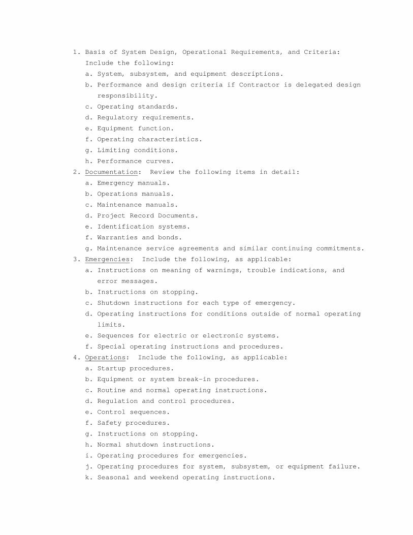
1. Basis of System Design, Operational Requirements, and Criteria:
Include the following:
a. System, subsystem, and equipment descriptions.
b. Performance and design criteria if Contractor is delegated design
responsibility.
c. Operating standards.
d. Regulatory requirements.
e. Equipment function.
f. Operating characteristics.
g. Limiting conditions.
h. Performance curves.
2. Documentation: Review the following items in detail:
a. Emergency manuals.
b. Operations manuals.
c. Maintenance manuals.
d. Project Record Documents.
e. Identification systems.
f. Warranties and bonds.
g. Maintenance service agreements and similar continuing commitments.
3. Emergencies: Include the following, as applicable:
a. Instructions on meaning of warnings, trouble indications, and
error messages.
b. Instructions on stopping.
c. Shutdown instructions for each type of emergency.
d. Operating instructions for conditions outside of normal operating
limits.
e. Sequences for electric or electronic systems.
f. Special operating instructions and procedures.
4. Operations: Include the following, as applicable:
a. Startup procedures.
b. Equipment or system break-in procedures.
c. Routine and normal operating instructions.
d. Regulation and control procedures.
e. Control sequences.
f. Safety procedures.
g. Instructions on stopping.
h. Normal shutdown instructions.
i. Operating procedures for emergencies.
j. Operating procedures for system, subsystem, or equipment failure.
k. Seasonal and weekend operating instructions.
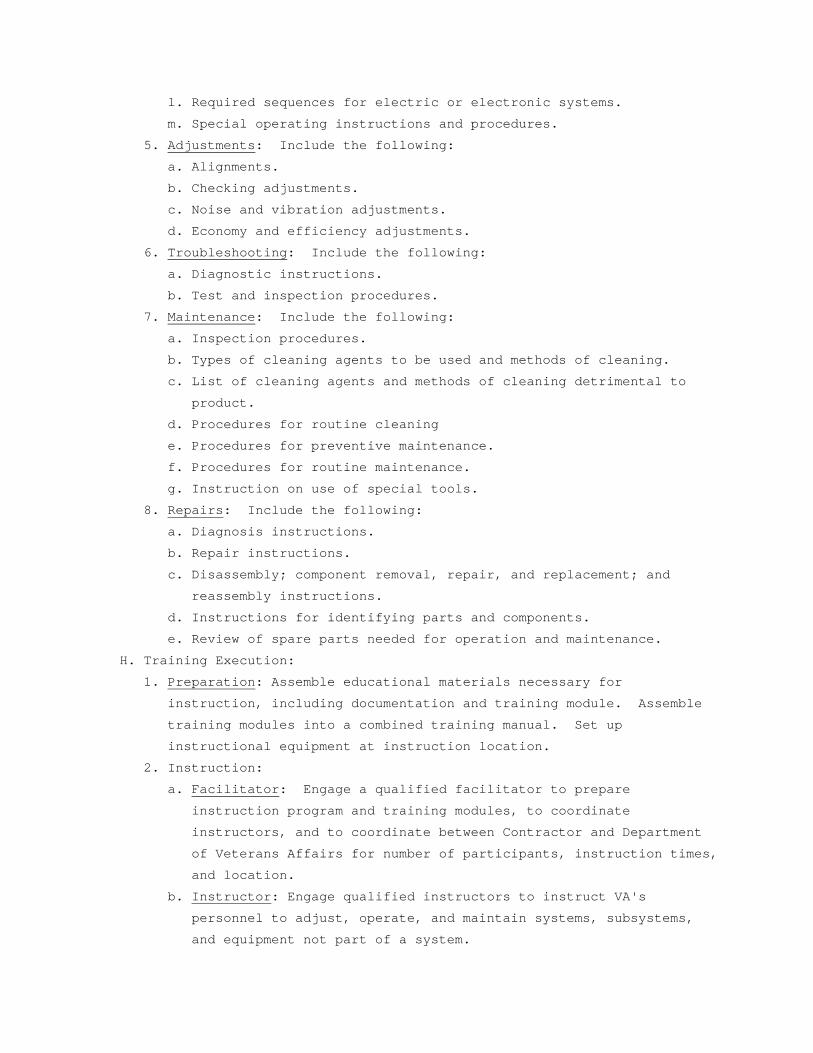
l. Required sequences for electric or electronic systems.
m. Special operating instructions and procedures.
5. Adjustments: Include the following:
a. Alignments.
b. Checking adjustments.
c. Noise and vibration adjustments.
d. Economy and efficiency adjustments.
6. Troubleshooting: Include the following:
a. Diagnostic instructions.
b. Test and inspection procedures.
7. Maintenance: Include the following:
a. Inspection procedures.
b. Types of cleaning agents to be used and methods of cleaning.
c. List of cleaning agents and methods of cleaning detrimental to
product.
d. Procedures for routine cleaning
e. Procedures for preventive maintenance.
f. Procedures for routine maintenance.
g. Instruction on use of special tools.
8. Repairs: Include the following:
a. Diagnosis instructions.
b. Repair instructions.
c. Disassembly; component removal, repair, and replacement; and
reassembly instructions.
d. Instructions for identifying parts and components.
e. Review of spare parts needed for operation and maintenance.
H. Training Execution:
1. Preparation: Assemble educational materials necessary for
instruction, including documentation and training module. Assemble
training modules into a combined training manual. Set up
instructional equipment at instruction location.
2. Instruction:
a. Facilitator: Engage a qualified facilitator to prepare
instruction program and training modules, to coordinate
instructors, and to coordinate between Contractor and Department
of Veterans Affairs for number of participants, instruction times,
and location.
b. Instructor: Engage qualified instructors to instruct VA's
personnel to adjust, operate, and maintain systems, subsystems,
and equipment not part of a system.
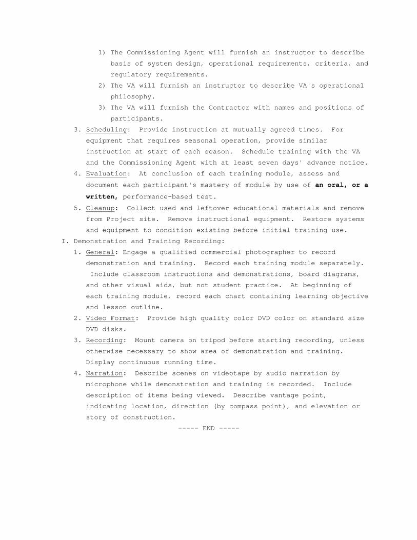
1) The Commissioning Agent will furnish an instructor to describe
basis of system design, operational requirements, criteria, and
regulatory requirements.
2) The VA will furnish an instructor to describe VA's operational
philosophy.
3) The VA will furnish the Contractor with names and positions of
participants.
3. Scheduling: Provide instruction at mutually agreed times. For
equipment that requires seasonal operation, provide similar
instruction at start of each season. Schedule training with the VA
and the Commissioning Agent with at least seven days' advance notice.
4. Evaluation: At conclusion of each training module, assess and
document each participant's mastery of module by use of an oral, or a
written, performance-based test.
5. Cleanup: Collect used and leftover educational materials and remove
from Project site. Remove instructional equipment. Restore systems
and equipment to condition existing before initial training use.
I. Demonstration and Training Recording:
1. General: Engage a qualified commercial photographer to record
demonstration and training. Record each training module separately.
Include classroom instructions and demonstrations, board diagrams,
and other visual aids, but not student practice. At beginning of
each training module, record each chart containing learning objective
and lesson outline.
2. Video Format: Provide high quality color DVD color on standard size
DVD disks.
3. Recording: Mount camera on tripod before starting recording, unless
otherwise necessary to show area of demonstration and training.
Display continuous running time.
4. Narration: Describe scenes on videotape by audio narration by
microphone while demonstration and training is recorded. Include
description of items being viewed. Describe vantage point,
indicating location, direction (by compass point), and elevation or
story of construction.
----- END -----
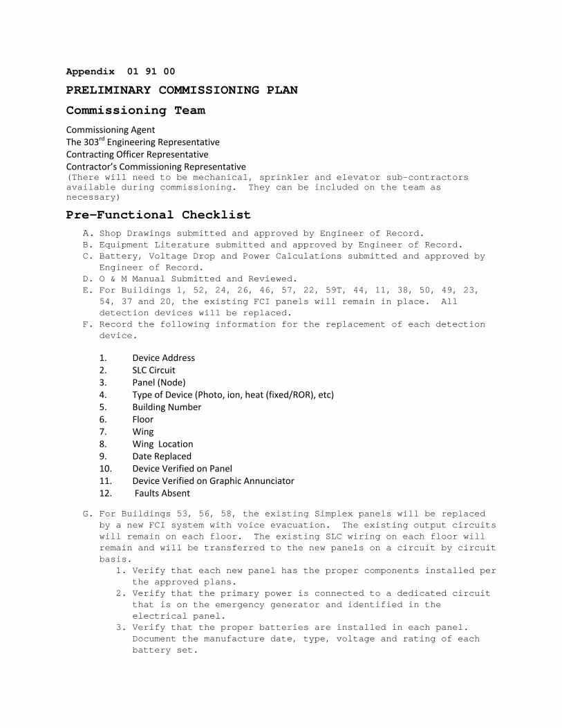
Appendix 01 91 00
PRELIMINARY COMMISSIONING PLAN
Commissioning Team
Commissioning Agent The 303rd Engineering Representative Contracting Officer Representative Contractor’s Commissioning Representative (There will need to be mechanical, sprinkler and elevator sub-contractors available during commissioning. They can be included on the team as necessary)
Pre-Functional Checklist A. Shop Drawings submitted and approved by Engineer of Record. B. Equipment Literature submitted and approved by Engineer of Record. C. Battery, Voltage Drop and Power Calculations submitted and approved by
Engineer of Record. D. O & M Manual Submitted and Reviewed. E. For Buildings 1, 52, 24, 26, 46, 57, 22, 59T, 44, 11, 38, 50, 49, 23,
54, 37 and 20, the existing FCI panels will remain in place. All detection devices will be replaced.
F. Record the following information for the replacement of each detection device.
1. Device Address 2. SLC Circuit 3. Panel (Node) 4. Type of Device (Photo, ion, heat (fixed/ROR), etc) 5. Building Number 6. Floor 7. Wing 8. Wing Location 9. Date Replaced 10. Device Verified on Panel 11. Device Verified on Graphic Annunciator 12. Faults Absent
G. For Buildings 53, 56, 58, the existing Simplex panels will be replaced by a new FCI system with voice evacuation. The existing output circuits will remain on each floor. The existing SLC wiring on each floor will remain and will be transferred to the new panels on a circuit by circuit basis.
1. Verify that each new panel has the proper components installed per the approved plans.
2. Verify that the primary power is connected to a dedicated circuit that is on the emergency generator and identified in the electrical panel.
3. Verify that the proper batteries are installed in each panel. Document the manufacture date, type, voltage and rating of each battery set.
4. Verify that the floor plans loaded into the Graphic Annunciator are current.
5. Verify the new wiring between panels is free of troubles and grounds. Record resistance and impedance of the new wiring.
6. Verify each panel is properly pre-programmed to expedite transition the SLC circuits from the Simplex panels to the new panels.
7. Record the following information for the installation of each addressable device when each SLC circuit is transitioned to the new panel.
1. Device Address 2. SLC Circuit 3. Panel (Node) 4. Type of Device (Photo, ion, heat (fixed/ROR), pull, output module, input module,
etc) 5. Building Number 6. Floor 7. Wing 8. Wing Location 9. Date Installed 10. Device Verified on Panel 11. Device Verified on Graphic Annunciator 12. Faults Absent
8. Test each detector using approved method to verify it functions
properly on the SLC circuit. (does not need to be via test smoke for pre-commissioning phase)
9. Verify that each input device transmits the proper voice message. 10. Verify that each input device causes proper output action. 11. Verify that elevator recall functions operate properly.
H. For Buildings 6, 7, 8, 9, and 10, the existing FCI panels will remain in place. New Detection devices will be installed and a new fiber optic connection will make these panels part of the overall FCI network.
1. Test fiber optic connection for proper data transmission. 2. Record the following information for the replacement of each
detection device.
1. Device Address 2. SLC Circuit 3. Panel (Node) 4. Type of Device (Photo, ion, heat (fixed/ROR), etc) 5. Building Number 6. Floor 7. Location 8. Date Replaced 9. Device Verified on Panel 10. Device Verified on Graphic Annunciator 11. Faults Absent

SECTION 02 41 00 DEMOLITION
PART 1 - GENERAL
1.1 DESCRIPTION:
This section specifies demolition and removal of buildings, portions of
buildings, utilities, other structures and debris from trash dumps
shown.
1.2 RELATED WORK:
A. Safety Requirements: GENERAL CONDITIONS Article, ACCIDENT PREVENTION.
B. Disconnecting utility services prior to demolition: Section 01 00 00,
GENERAL REQUIREMENTS.
C. Reserved items that are to remain the property of the Government:
Section 01 00 00, GENERAL REQUIREMENTS.
D. Environmental Protection: Section 01 57 19, TEMPORARY ENVIRONMENTAL
CONTROLS.
E. Construction Waste Management: Section 01 74 19 CONSTRUCTION WASTE
MANAGEMENT.
F. Infectious Control: Section 01 00 00, GENERAL REQUIREMENTS, Article 1.7,
INFECTION PREVENTION MEASURES.
1.3 PROTECTION:
A. Perform demolition in such manner as to eliminate hazards to persons and
property; to minimize interference with use of adjacent areas, utilities
and structures or interruption of use of such utilities; and to provide
free passage to and from such adjacent areas of structures. Comply with
requirements of GENERAL CONDITIONS Article, ACCIDENT PREVENTION.
B. Provide safeguards, including warning signs, barricades, temporary
fences, warning lights, and other similar items that are required for
protection of all personnel during demolition and removal operations.
Comply with requirements of Section 01 00 00, GENERAL REQUIREMENTS,
Article PROTECTION OF EXISTING VEGETATION, STRUCTURES, EQUIPMENT,
UTILITIES AND IMPROVEMENTS.
C. Maintain fences, barricades, lights, and other similar items around
exposed excavations until such excavations have been completely filled.
D. Provide enclosed dust chutes with control gates from each floor to carry
debris to truck beds and govern flow of material into truck. Provide
overhead bridges of tight board or prefabricated metal construction at
dust chutes to protect persons and property from falling debris.
E. Prevent spread of flying particles and dust. Sprinkle rubbish and debris
with water to keep dust to a minimum. Do not use water if it results in
hazardous or objectionable condition such as, but not limited to; ice,
flooding, or pollution. Vacuum and dust the work area daily.
F. In addition to previously listed fire and safety rules to be observed in
performance of work, include following:
1. No wall or part of wall shall be permitted to fall outwardly from
structures.
2. 3. Wherever a cutting torch or other equipment that might cause a
fire is used, provide and maintain fire extinguishers nearby ready
for immediate use. Instruct all possible users in use of fire
extinguishers.
4. Keep hydrants clear and accessible at all times. Prohibit debris from
accumulating within a radius of 4500 mm (15 feet) of fire hydrants.
G. Before beginning any demolition work, the Contractor shall survey the
site and examine the drawings and specifications to determine the extent
of the work. The contractor shall take necessary precautions to avoid
damages to existing items to remain in place, to be reused, or to remain
the property of the Medical Center ; any damaged items shall be
repaired or replaced as approved by the C.O.R. The Contractor shall
coordinate the work of this section with all other work and shall
construct and maintain shoring, bracing, and supports as required. The
Contractor shall ensure that structural elements are not overloaded and
shall be responsible for increasing structural supports or adding new
supports as may be required as a result of any cutting, removal, or
demolition work performed under this contract. Do not overload
structural elements. Provide new supports and reinforcement for existing
construction weakened by demolition or removal works. Repairs,
reinforcement, or structural replacement must have Resident Engineer’s
approval.
H. The work shall comply with the requirements of Section 01 57 19,
TEMPORARY ENVIRONMENTAL CONTROLS.
I. The work shall comply with the requirements of Section 01 00 00, GENERAL
REQUIREMENTS, Article 1.7 INFECTION PREVENTION MEASURES.
1.4 UTILITY SERVICES:
A. Demolish and remove outside utility service lines shown to be removed.
B. Remove abandoned outside utility lines that would interfere with
installation of new utility lines and new construction.
PART 2 - PRODUCTS (Not Used)
PART 3 – EXECUTION
3.1 DEMOLITION:
A. Completely demolish and remove buildings and structures, including all
appurtenances related or connected thereto, as noted below:
1. As required for installation of new utility service lines.
2. To full depth within an area defined by hypothetical lines located
1500 mm (5 feet) outside building lines of new structures.
B. Debris, including brick, concrete, stone, metals and similar materials
shall become property of Contractor and shall be disposed of by him
daily, off the Medical Center to avoid accumulation at the demolition
site. Materials that cannot be removed daily shall be stored in areas
specified by the Resident Engineer. Break up concrete slabs below grade
that do not require removal from present location into pieces not
exceeding 600 mm (24 inches) square to permit drainage. Contractor shall
dispose debris in compliance with applicable federal, state or local
permits, rules and/or regulations.
C. Remove and legally dispose of all materials, other than earth to remain
as part of project work, from any trash dumps shown. Materials removed
shall become property of contractor and shall be disposed of in
compliance with applicable federal, state or local permits, rules and/or
regulations. All materials in the indicated trash dump areas, including
above surrounding grade and extending to a depth of 1500mm (5feet) below
surrounding grade, shall be included as part of the lump sum
compensation for the work of this section. Materials that are located
beneath the surface of the surrounding ground more than 1500 mm (5
feet), or materials that are discovered to be hazardous, shall be
handled as unforeseen. The removal of hazardous material shall be
referred to Hazardous Materials specifications.
D. Remove existing utilities as indicated or uncovered by work and
terminate in a manner conforming to the nationally recognized code
covering the specific utility and approved by the Resident Engineer.
When Utility lines are encountered that are not indicated on the
drawings, the Resident Engineer shall be notified prior to further work
in that area.
3.2 CLEAN-UP:
On completion of work of this section and after removal of all debris,
leave site in clean condition satisfactory to C.O.R. Clean-up shall
include off the Medical Center disposal of all items and materials not
required to remain property of the Government as well as all debris and
rubbish resulting from demolition operations.
- - - E N D - - -

SECTION 07 92 00 JOINT SEALANTS
PART 1 - GENERAL
1.1 DESCRIPTION:
Section covers all sealant and caulking materials and their application,
wherever required for complete installation of building materials or
systems.
1.2 RELATED WORK:
1.3 QUALITY CONTROL:
A. Installer Qualifications: An experienced installer who has specialized
in installing joint sealants similar in material, design, and extent to
those indicated for this Project and whose work has resulted in joint-
sealant installations with a record of successful in-service
performance.
B. Source Limitations: Obtain each type of joint sealant through one source
from a single manufacturer.
C.VOC: Acrylic latex and Silicon sealants shall have less than 50g/l VOC
content.
1.4 SUBMITTALS:
A. Submit in accordance with Section 01 33 23, SHOP DRAWINGS, PRODUCT DATA,
AND SAMPLES.
B. Manufacturer's installation instructions for each product used.
C. Cured samples of exposed sealants for each color where required to match
adjacent material.
D. Manufacturer's Literature and Data:
1. Caulking compound
2. Primers
3. Sealing compound, each type, including compatibility when different
sealants are in contact with each other.
1.5 PROJECT CONDITIONS:
A. Environmental Limitations:
1. Do not proceed with installation of joint sealants under following
conditions:
a. When ambient and substrate temperature conditions are outside
limits permitted by joint sealant manufacturer or are below 4.4 C
(40 F).
b. When joint substrates are wet.
B. Joint-Width Conditions:
1. Do not proceed with installation of joint sealants where joint widths
are less than those allowed by joint sealant manufacturer for
applications indicated.
C. Joint-Substrate Conditions:
1. Do not proceed with installation of joint sealants until contaminants
capable of interfering with adhesion are removed from joint
substrates.
1.6 DELIVERY, HANDLING, AND STORAGE:
A. Deliver materials in manufacturers' original unopened containers, with
brand names, date of manufacture, shelf life, and material designation
clearly marked thereon.
B. Carefully handle and store to prevent inclusion of foreign materials.
C. Do not subject to sustained temperatures exceeding 32 C (90 F) or less
than 5 C (40 F).
1.7 DEFINITIONS:
A. Definitions of terms in accordance with ASTM C717 and as specified.
B. Back-up Rod: A type of sealant backing.
C. Bond Breakers: A type of sealant backing.
D. Filler: A sealant backing used behind a back-up rod.
1.8 WARRANTY:
A. Warranty exterior sealing against leaks, adhesion, and cohesive failure,
and subject to terms of "Warranty of Construction", FAR clause 52.246-
21, except that warranty period shall be extended to two years.
B. General Warranty: Special warranty specified in this Article shall not
deprive Government of other rights Government may have under other
provisions of Contract Documents and shall be in addition to, and run
concurrent with, other warranties made by Contractor under requirements
of Contract Documents.
1.9 APPLICABLE PUBLICATIONS:
A. Publications listed below form a part of this specification to extent
referenced. Publications are referenced in text by basic designation
only.
B. American Society for Testing and Materials (ASTM):
C509-06.................Elastomeric Cellular Preformed Gasket and
Sealing Material.
C612-10.................Mineral Fiber Block and Board Thermal
Insulation.
C717-10.................Standard Terminology of Building Seals and
Sealants.
C834-10.................Latex Sealants.
C919-08.................Use of Sealants in Acoustical Applications.
C920-10.................Elastomeric Joint Sealants.
C1021-08................Laboratories Engaged in Testing of Building
Sealants.
C1193-09................Standard Guide for Use of Joint Sealants.
C1330-02 (R2007)........Cylindrical Sealant Backing for Use with Cold
Liquid Applied Sealants.
D1056-07................Specification for Flexible Cellular Materials—
Sponge or Expanded Rubber.
E84-09..................Surface Burning Characteristics of Building
Materials.
C. Sealant, Waterproofing and Restoration Institute (SWRI).
The Professionals’ Guide
PART 2 - PRODUCTS
2.1 SEALANTS:
A. FIRESTOPPING SEALANT: shall be JACO Firestop Plus™ firestopping sealant OR APPROVED EQUAL; single component intumescent firestopping sealant , non-slumping, expanding when exposed to fire and seal penetration voids. Pressure tight, water resistant , Classified by Underwriters Laboratories (UL) in accordance with UL 1479 (ASTM-E814) fire resistant and positive pressure water spray test that meets or exceeds the firestopping requirements of BOCA, ICBO, NEC (NFPA-70), NFPA Code #101, and SBCCI. Water Based: Endothermic: Intumescent: Thixotropic: Non-slumping. Fast Drying: Non Shrinking: Paintable: With no asbestos or PCB’s.; Halogen Free.
FLEXIBLE INTUMESCENT FIRESTOPPING SEALANT
UL 1479 / ASTM-E814
STANDARD TEST METHOD FOR THROUGH PENETRATION FIRESTOPS
UL 263 / ASTM-E119
STANDARD TEST METHOD FOR BUILDING CONSTRUCTION AND MATERIALS
UL 723 / ASTM-E84
TESTED APPLICATIONS
Assemblies: Concrete, Concrete Block, CMU, Wood Frame Construction, Metal Pan Deck Floor, Gypsum Wallboard, Ceilings and Wall Joints.
Penetrations: Iron, Steel, Copper, and EMT Pipe (static and thermally expanding), Plastic
Pipe ABS, CPVC, PVC, FRPP (vented and non-vented), Fiberglass, AB/PVC, and Cellular Glass pipe insulation, Romex Cables, Jacketed Cables, and Wire. Communication Wire and Cables, Ductwork and Blank Openings.
JACO MANUFACTURING, INC.
Mountain Empire Industrial Park
P. O. BOX 550 ATKINS, VA 24311
Ph: (877) 660-2688 Ph: (276) 783-2688
Fax: (276) 783-4222
Email: [email protected]
Web: www.jacomanufacturing.com
INSTALLATION
Refer to Manufacturers Installation Manual or the UL/ULC Fire Resistance Directory for specific installation instructions. The Firestop System Instructions detail the required sealant depth, necessary backing and packing material and permitted annular space or joint size.
CLEANING
Clean Tools and equipment , installation smears and errors with water while the sealant is still wet.
WARRANTY
Guarantee to be free of defects and to meet the conditions listed in the UL / ULC Fire Resistance Directory.
2.2 CAULKING COMPOUND:
A. C-1: ASTM C834, acrylic latex.
B. C-2: One component acoustical caulking, non drying, non hardening,
synthetic rubber.
2.3 COLOR:
A. Sealants used with exposed masonry shall match color of mortar joints.
B. Sealants used with unpainted concrete shall match color of adjacent
concrete.
C. Color of sealants for other locations shall be light gray or aluminum,
unless specified otherwise.
D. Caulking shall be light gray or white, unless specified otherwise.
2.4 JOINT SEALANT BACKING:
A. General: Provide sealant backings of material and type that are non-
staining; are compatible with joint substrates, sealants, primers, and
other joint fillers; and are approved for applications indicated by
sealant manufacturer based on field experience and laboratory testing.
B. Cylindrical Sealant Backings: ASTM C1330, of type indicated below and of
size and density to control sealant depth and otherwise contribute to
producing optimum sealant performance:
1. Type C: Closed-cell material with a surface skin.
C. Elastomeric Tubing Sealant Backings: Neoprene, butyl, EPDM, or silicone
tubing complying with ASTM D1056, nonabsorbent to water and gas, and
capable of remaining resilient at temperatures down to minus 32 C
(minus 26 F). Provide products with low compression set and of size and
shape to provide a secondary seal, to control sealant depth, and
otherwise contribute to optimum sealant performance.
D. Bond-Breaker Tape: Polyethylene tape or other plastic tape recommended
by sealant manufacturer for preventing sealant from adhering to rigid,
inflexible joint-filler materials or joint surfaces at back of joint
where such adhesion would result in sealant failure. Provide self-
adhesive tape where applicable.
2.5 FILLER:
A. Mineral fiber board: ASTM C612, Class 1.
B. Thickness same as joint width.
C. Depth to fill void completely behind back-up rod.
2.6 PRIMER:
A. As recommended by manufacturer of caulking or sealant material.
B. Stain free type.
2.7 CLEANERS-NON POUROUS SURFACES:
Chemical cleaners acceptable to manufacturer of sealants and sealant
backing material, free of oily residues and other substances capable of
staining or harming joint substrates and adjacent non-porous surfaces
and formulated to promote adhesion of sealant and substrates.
PART 3 - EXECUTION
3.1 INSPECTION:
A. Inspect substrate surface for bond breaker contamination and unsound
materials at adherent faces of sealant.
B. Coordinate for repair and resolution of unsound substrate materials.
C. INSPECT FOR UNIFORM JOINT WIDTHS AND THAT DIMENSIONS ARE WITHIN TOLERANCE ESTABLISHED BY SEALANT MANUFACTURER.3.2 PREPARATIONS:
A. Prepare joints in accordance with manufacturer's instructions and SWRI.
B. Clean surfaces of joint to receive caulking or sealants leaving joint
dry to the touch, free from frost, moisture, grease, oil, wax, lacquer
paint, or other foreign matter that would tend to destroy or impair
adhesion.
1. Clean porous joint substrate surfaces by brushing, grinding, blast
cleaning, mechanical abrading, or a combination of these methods to
produce a clean, sound substrate capable of developing optimum bond
with joint sealants.
2. Remove loose particles remaining from above cleaning operations by
vacuuming or blowing out joints with oil-free compressed air. Porous
joint surfaces include the following:
a. Concrete.
b. Masonry.
c. Unglazed surfaces of ceramic tile.
3. Remove laitance and form-release agents from concrete.
4. Clean nonporous surfaces with chemical cleaners or other means that
do not stain, harm substrates, or leave residues capable of
interfering with adhesion of joint sealants.
a. Metal.
b. Glass.
c. Porcelain enamel.
d. Glazed surfaces of ceramic tile.
C. Do not cut or damage joint edges.
D. Apply masking tape to face of surfaces adjacent to joints before
applying primers, caulking, or sealing compounds.
1. Do not leave gaps between ends of sealant backings.
2. Do not stretch, twist, puncture, or tear sealant backings.
3. Remove absorbent sealant backings that have become wet before sealant
application and replace them with dry materials.
E. Apply primer to sides of joints wherever required by compound
manufacturer's printed instructions.
1. Apply primer prior to installation of back-up rod or bond breaker
tape.
2. Use brush or other approved means that will reach all parts of
joints.
F. Take all necessary steps to prevent three sided adhesion of sealants.
3.3 BACKING INSTALLATION:
A. Install back-up material, to form joints enclosed on three sides as
required for specified depth of sealant.
B. Where deep joints occur, install filler to fill space behind the back-up
rod and position the rod at proper depth.
C. Cut fillers installed by others to proper depth for installation of
back-up rod and sealants.
D. Install back-up rod, without puncturing the material, to a uniform
depth, within plus or minus 3 mm (1/8 inch) for sealant depths
specified.
E. Where space for back-up rod does not exist, install bond breaker tape
strip at bottom (or back) of joint so sealant bonds only to two opposing
surfaces.
F. Take all necessary steps to prevent three sided adhesion of sealants.
3.4 SEALANT DEPTHS AND GEOMETRY:
A. At widths up to 6 mm (1/4 inch), sealant depth equal to width.
B. At widths over 6 mm (1/4 inch), sealant depth 1/2 of width up to 13 mm
(1/2 inch) maximum depth at center of joint with sealant thickness at
center of joint approximately 1/2 of depth at adhesion surface.
3.5 INSTALLATION:
A. General:
1. Apply sealants and caulking only when ambient temperature is between
5 C and 38 C (40 and 100 F).
2. Do not use polysulfide base sealants where sealant may be exposed to
fumes from bituminous materials, or where water vapor in continuous
contact with cementitious materials may be present.
3. Do not use sealant type listed by manufacture as not suitable for use
in locations specified.
4. Apply caulking and sealing compound in accordance with manufacturer's
printed instructions.
5. Avoid dropping or smearing compound on adjacent surfaces.
6. Fill joints solidly with compound and finish compound smooth.
7. Tool joints to concave surface unless shown or specified otherwise.
8. Finish paving or floor joints flush unless joint is otherwise
detailed.
9. Apply compounds with nozzle size to fit joint width.
10. Test sealants for compatibility with each other and substrate. Use
only compatible sealant.
B. For application of sealants, follow requirements of ASTM C1193 unless
specified otherwise.
C. Where gypsum board partitions are of sound rated, fire rated, or smoke
barrier construction, follow requirements of ASTM C919 only to seal all
cut-outs and intersections with the adjoining construction unless
specified otherwise.
1. Apply a 6 mm (1/4 inch) minimum bead of sealant each side of runners
(tracks), including those used at partition intersections with
dissimilar wall construction.

2. Coordinate with application of gypsum board to install sealant
immediately prior to application of gypsum board.
3. Partition intersections: Seal edges of face layer of gypsum board
abutting intersecting partitions, before taping and finishing or
application of veneer plaster-joint reinforcing.
4. Openings: Apply a 6 mm (1/4 inch) bead of sealant around all cut-outs
to seal openings of electrical boxes, ducts, pipes and similar
penetrations. To seal electrical boxes, seal sides and backs.
5. Control Joints: Before control joints are installed, apply sealant in
back of control joint to reduce flanking path for sound through
control joint.
D. APPLICATION OF FIRESTOPPING SEALANT is required where fire alarm system
installation requires through penetration of existing fire-rated barrier
(i.e.walls, partitions, floors or ceilings.)
3.6 FIELD QUALITY CONTROL:
A. Inspect tested joints and report on following:
1. Whether sealants in joints connected to pulled-out portion failed to
adhere to joint substrates or tore cohesively. Include data on pull
distance used to test each type of product and joint substrate.
2. Compare these results to determine if adhesion passes sealant
manufacturer’s field-adhesion hand-pull test criteria.
3. Whether sealants filled joint cavities and are free from voids.
4. Whether sealant dimensions and configurations comply with specified
requirements.
B. Evaluation of Field-Test Results: Sealants not evidencing adhesive
failure from testing or noncompliance with other indicated requirements,
will be considered satisfactory. Remove sealants that fail to adhere to
joint substrates during testing or to comply with other requirements.
Retest failed applications until test results prove sealants comply with
indicated requirements.
3.7 CLEANING:
A. Fresh compound accidentally smeared on adjoining surfaces: Scrape off
immediately and rub clean with a solvent as recommended by the caulking
or sealant manufacturer.
B. After filling and finishing joints, remove masking tape.
C. Leave adjacent surfaces in a clean and unstained condition.
3.8 LOCATIONS:
A. Horizontal Traffic Joints:
1. Concrete Paving, Unit Pavers: Type S-11 or S-12
2. Garage/Parking Decks: Type S-10
B. High Temperature Joints over 204 degrees C (400 degrees F):
1. Exhaust Pipes, Flues, Breech Stacks: Type S-7 or S-8
C. Interior Caulking:
1. Typical Narrow Joint 6 mm, (1/4 inch) or less at Walls and Adjacent
Components: Types C-1 and C-2.
2. Perimeter of Doors, Windows, Access Panels which Adjoin Concrete or
Masonry Surfaces: Types C-1 and C-2.
3. Joints at Masonry Walls and Columns, Piers, Concrete Walls or
Exterior Walls: Types C-1 and C-2.
4. Perimeter of Lead Faced Control Windows and Plaster or Gypsum
Wallboard Walls: Types C-1 and C-2.
5. Exposed Isolation Joints at Top of Full Height Walls: Types C-1 and
C-2.
6. Exposed Acoustical Joint at Sound Rated Partitions Type C-2.
7. Concealed Acoustic Sealant Types S-4, C-1 and C-2.
- - - E N D - - -
SECTION 09 91 00 PAINTING
PART 1-GENERAL
1.1 DESCRIPTION
A. Section specifies field painting.
B. Section specifies prime coats which may be applied in shop under other
sections.
C. Painting includes shellacs, stains, varnishes, coatings specified, and
striping or markers and identity markings.
1.2 RELATED WORK
1.3 SUBMITTALS
A. Submit in accordance with Section 01 33 23, SHOP DRAWINGS, PRODUCT DATA,
AND SAMPLES.
B. Manufacturer's Literature and Data:
Before work is started, or sample panels are prepared, submit
manufacturer's literature, the current Master Painters Institute (MPI)
"Approved Product List" indicating brand label, product name and product
code as of the date of contract award, will be used to determine
compliance with the submittal requirements of this specification. The
Contractor may choose to use subsequent MPI "Approved Product List",
however, only one list may be used for the entire contract and each
coating system is to be from a single manufacturer. All coats on a
particular substrate must be from a single manufacturer. No variation
from the MPI "Approved Product List" where applicable is acceptable.
C. Sample Panels:
1. After painters' materials have been approved and before work is
started submit sample panels showing each type of finish and color
specified.
2. Panels to show color: Composition board, 100 by 250 by 3 mm (4 inch
by 10 inch by 1/8 inch).
3. Panel to show transparent finishes: Wood of same species and grain
pattern as wood approved for use, 100 by 250 by 3 mm (4 inch by 10
inch face by 1/4 inch) thick minimum, and where both flat and edge
grain will be exposed, 250 mm (10 inches) long by sufficient size, 50
by 50 mm (2 by 2 inch) minimum or actual wood member to show complete
finish.
4. Attach labels to panel stating the following:
a. Federal Specification Number or manufacturers name and product
number of paints used.
b. Product type and color.
c. Name of project.
5. Strips showing not less than 50 mm (2 inch) wide strips of undercoats
and 100 mm (4 inch) wide strip of finish coat.
D. Sample of identity markers if used.
E. Manufacturers' Certificates indicating compliance with specified
requirements:
1. Manufacturer's paint substituted for Federal Specification paints
meets or exceeds performance of paint specified.
2. High temperature aluminum paint.
3. Epoxy coating.
4. Intumescent clear coating or fire retardant paint.
5. Plastic floor coating.
1.4 DELIVERY AND STORAGE
A. Deliver materials to site in manufacturer's sealed container marked to
show following:
1. Name of manufacturer.
2. Product type.
3. Batch number.
4. Instructions for use.
5. Safety precautions.
B. In addition to manufacturer's label, provide a label legibly printed as
following:
1. Federal Specification Number, where applicable, and name of material.
2. Surface upon which material is to be applied.
3. If paint or other coating, state coat types; prime, body or finish.
C. Maintain space for storage, and handling of painting materials and
equipment in a neat and orderly condition to prevent spontaneous
combustion from occurring or igniting adjacent items.
D. Store materials at site at least 24 hours before using, at a temperature
between 18 and 30 degrees C (65 and 85 degrees F).
1.5 MOCK-UP PANEL
A. Before starting application of water paint mixtures, apply paint as
specified to an area, not to exceed 9 m2 (100 ft2), selected by C.O.R.
B. Finish and texture approved by C.O.R. will be used as a standard of
quality for remainder of work.
1.6 APPLICABLE PUBLICATIONS
A. Publications listed below form a part of this specification to the
extent referenced. Publications are referenced in the text by basic
designation only.
B. American Conference of Governmental Industrial Hygienists (ACGIH):
ACGIH TLV-BKLT-2012.....Threshold Limit Values (TLV) for Chemical
Substances and Physical Agents and Biological
Exposure Indices (BEIs)
ACGIH TLV-DOC-2012......Documentation of Threshold Limit Values and
Biological Exposure Indices, (Seventh Edition)
C. American National Standards Institute (ANSI):
A13.1-07................Scheme for the Identification of Piping Systems
D. American Society for Testing and Materials (ASTM):
D260-86..........Boiled Linseed Oil
E. Commercial Item Description (CID):
A-A-1555................Water Paint, Powder (Cementitious, White and
Colors) (WPC) (cancelled)
A-A-3120................Paint, For Swimming Pools (RF) (cancelled)
F. Federal Specifications (Fed Spec):
TT-P-1411A..............Paint, Copolymer-Resin, Cementitious (For
Waterproofing Concrete and Masonry Walls) (CEP)
G. Master Painters Institute (MPI):
No. 1-12................Aluminum Paint (AP)
No. 4-12................Interior/ Exterior Latex Block Filler
No. 5-12................Exterior Alkyd Wood Primer
No. 7-12................Exterior Oil Wood Primer
No. 8-12................Exterior Alkyd, Flat MPI Gloss Level 1 (EO)
No. 9-12................Exterior Alkyd Enamel MPI Gloss Level 6 (EO)
No. 10-12...............Exterior Latex, Flat (AE)
No. 11-12...............Exterior Latex, Semi-Gloss (AE)
No. 18-12...............Organic Zinc Rich Primer
No. 22-12...............Aluminum Paint, High Heat (up to 590% - 1100F)
(HR)
No. 26-12...............Cementitious Galvanized Metal Primer
No. 27-12...............Exterior / Interior Alkyd Floor Enamel, Gloss
(FE)
No. 31-12...............Polyurethane, Moisture Cured, Clear Gloss (PV)
No. 36-12...............Knot Sealer
No. 43-12...............Interior Satin Latex, MPI Gloss Level 4
No. 44-12...............Interior Low Sheen Latex, MPI Gloss Level 2
No. 45-12...............Interior Primer Sealer
No. 46-12...............Interior Enamel Undercoat
No. 47-12...............Interior Alkyd, Semi-Gloss, MPI Gloss Level 5
(AK)
No. 48-12...............Interior Alkyd, Gloss, MPI Gloss Level 6 (AK)
No. 49-12...............Interior Alkyd, Flat, MPI Gloss Level 1 (AK)
No. 50-12...............Interior Latex Primer Sealer
No. 51-12...............Interior Alkyd, Eggshell, MPI Gloss Level 3
No. 52-12...............Interior Latex, MPI Gloss Level 3 (LE)
No. 53-12...............Interior Latex, Flat, MPI Gloss Level 1 (LE)
No. 54-12...............Interior Latex, Semi-Gloss, MPI Gloss Level 5
(LE)
No. 59-12...............Interior/Exterior Alkyd Porch & Floor Enamel,
Low Gloss (FE)
No. 60-12...............Interior/Exterior Latex Porch & Floor Paint, Low
Gloss
No. 66-12...............Interior Alkyd Fire Retardant, Clear Top-Coat
(ULC Approved) (FC)
No. 67-12...............Interior Latex Fire Retardant, Top-Coat (ULC
Approved) (FR)
No. 68-12...............Interior/ Exterior Latex Porch & Floor Paint,
Gloss
No. 71-12...............Polyurethane, Moisture Cured, Clear, Flat (PV)
No. 74-12...............Interior Alkyd Varnish, Semi-Gloss
No. 77-12...............Epoxy Cold Cured, Gloss (EC)
No. 79-12...............Marine Alkyd Metal Primer
No. 90-12...............Interior Wood Stain, Semi-Transparent (WS)
No. 91-12...............Wood Filler Paste
No. 94-12...............Exterior Alkyd, Semi-Gloss (EO)
No. 95-12...............Fast Drying Metal Primer
No. 98-12...............High Build Epoxy Coating
No. 101-12..............Epoxy Anti-Corrosive Metal Primer
No. 108-12..............High Build Epoxy Coating, Low Gloss (EC)
No. 114-12..............Interior Latex, Gloss (LE) and (LG)
No. 119-12..............Exterior Latex, High Gloss (acrylic) (AE)
No. 135-12..............Non-Cementitious Galvanized Primer
No. 138-12..............Interior High Performance Latex, MPI Gloss Level
2 (LF)
No. 139-12..............Interior High Performance Latex, MPI Gloss Level
3 (LL)
No. 140-12..............Interior High Performance Latex, MPI Gloss Level
4
No. 141-12..............Interior High Performance Latex (SG) MPI Gloss
Level 5
H. Steel Structures Painting Council (SSPC):
SSPC SP 1-04 (R2004)....Solvent Cleaning
SSPC SP 2-04 (R2004)....Hand Tool Cleaning
SSPC SP 3-04 (R2004)....Power Tool Cleaning
PART 2 - PRODUCTS
2.1 MATERIALS
A. Interior Satin Latex: MPI 43.
B. Interior Primer Sealer: MPI 45.
C. Interior Latex, Semi-Gloss, MPI Gloss Level 5 (LE): MPI 54.
2.2 PAINT PROPERTIES
A. Use ready-mixed (including colors), except two component epoxies,
polyurethanes, polyesters, paints having metallic powders packaged
separately and paints requiring specified additives.
B. Where no requirements are given in the referenced specifications for
primers, use primers with pigment and vehicle, compatible with substrate
and finish coats specified.
2.3 REGULATORY REQUIREMENTS/QUALITY ASSURANCE
A. Paint materials shall conform to the restrictions of the local
Environmental and Toxic Control jurisdiction.
1. Volatile Organic Compounds (VOC): VOC content of paint materials
shall not exceed 10g/l for interior latex paints/primers and 50g/l
for exterior latex paints and primers.
2. Lead-Base Paint:
a. Comply with Section 410 of the Lead-Based Paint Poisoning
Prevention Act, as amended, and with implementing regulations
promulgated by Secretary of Housing and Urban Development.
b. Regulations concerning prohibition against use of lead-based paint
in federal and federally assisted construction, or rehabilitation
of residential structures are set forth in Subpart F, Title 24,
Code of Federal Regulations, Department of Housing and Urban
Development.
3. Asbestos: Materials shall not contain asbestos.
4. Chromate, Cadmium, Mercury, and Silica: Materials shall not contain
zinc-chromate, strontium-chromate, Cadmium, mercury or mercury
compounds or free crystalline silica.
5. Human Carcinogens: Materials shall not contain any of the ACGIH-BKLT
and ACGHI-DOC confirmed or suspected human carcinogens.
6. Use high performance acrylic paints in place of alkyd paints, where
possible.
7. VOC content for solvent-based paints shall not exceed 250g/l and
shall not be formulated with more than one percent aromatic hydro
carbons by weight.
PART 3 - EXECUTION
3.1 JOB CONDITIONS
A. Safety: Observe required safety regulations and manufacturer's warning
and instructions for storage, handling and application of painting
materials.
1. Take necessary precautions to protect personnel and property from
hazards due to falls, injuries, toxic fumes, fire, explosion, or
other harm.
2. Deposit soiled cleaning rags and waste materials in metal containers
approved for that purpose. Dispose of such items off the site at end
of each day’s work.
B. Atmospheric and Surface Conditions:
1. Do not apply coating when air or substrate conditions are:
a. Less than 3 degrees C (5 degrees F) above dew point.
b. Below 10 degrees C (50 degrees F) or over 35 degrees C (95 degrees
F), unless specifically pre-approved by the Contracting Officer
and the product manufacturer. Under no circumstances shall
application conditions exceed manufacturer recommendations.
2. Maintain interior temperatures until paint dries hard.
3. Do no exterior painting when it is windy and dusty.
4. Do not paint in direct sunlight or on surfaces that the sun will soon
warm.
5. Apply only on clean, dry and frost free surfaces except as follows:
a. Apply water thinned acrylic and cementitious paints to damp (not
wet) surfaces where allowed by manufacturer's printed
instructions.
b. Dampened with a fine mist of water on hot dry days concrete and
masonry surfaces to which water thinned acrylic and cementitious
paints are applied to prevent excessive suction and to cool
surface.
6. Varnishing:
a. Apply in clean areas and in still air.
b. Before varnishing vacuum and dust area.
c. Immediately before varnishing wipe down surfaces with a tack rag.
3.2 SURFACE PREPARATION
A. Method of surface preparation is optional, provided results of finish
painting produce solid even color and texture specified with no
overlays.
B. General:
1. Remove prefinished items not to be painted such as lighting fixtures,
escutcheon plates, hardware, trim, and similar items for
reinstallation after paint is dried.
2. Remove items for reinstallation and complete painting of such items
and adjacent areas when item or adjacent surface is not accessible or
finish is different.
3. See other sections of specifications for specified surface conditions
and prime coat.
4. Clean surfaces for painting with materials and methods compatible
with substrate and specified finish. Remove any residue remaining
from cleaning agents used. Do not use solvents, acid, or steam on
concrete and masonry.
C. Wood:
1. Sand to a smooth even surface and then dust off.
2. Sand surfaces showing raised grain smooth between each coat.
3. Wipe surface with a tack rag prior to applying finish.
4. Surface painted with an opaque finish:
a. Coat knots, sap and pitch streaks with MPI 36 (Knot Sealer) before
applying paint.
b. Apply two coats of MPI 36 (Knot Sealer) over large knots.
5. After application of prime or first coat of stain, fill cracks, nail
and screw holes, depressions and similar defects with wood filler
paste. Sand the surface to make smooth and finish flush with adjacent
surface.
6. Before applying finish coat, reapply wood filler paste if required,
and sand surface to remove surface blemishes. Finish flush with
adjacent surfaces.
7. Fill open grained wood such as oak, walnut, ash and mahogany with MPI
91 (Wood Filler Paste), colored to match wood color.
a. Thin filler in accordance with manufacturer's instructions for
application.
b. Remove excess filler, wipe as clean as possible, dry, and sand as
specified.
D. Ferrous Metals:
1. Remove oil, grease, soil, drawing and cutting compounds, flux and
other detrimental foreign matter in accordance with SSPC-SP 1
(Solvent Cleaning).
2. Remove loose mill scale, rust, and paint, by hand or power tool
cleaning, as defined in SSPC-SP 2 (Hand Tool Cleaning) and SSPC-SP 3
(Power Tool Cleaning). Exception: where high temperature aluminum
paint is used, prepare surface in accordance with paint
manufacturer's instructions.
3. Fill dents, holes and similar voids and depressions in flat exposed
surfaces of hollow steel doors and frames, access panels, roll-up
steel doors and similar items specified to have semi-gloss or gloss
finish with TT-F-322D (Filler, Two-Component Type, For Dents, Small
Holes and Blow-Holes). Finish flush with adjacent surfaces.
a. This includes flat head countersunk screws used for permanent
anchors.
b. Do not fill screws of item intended for removal such as glazing
beads.
4. Spot prime abraded and damaged areas in shop prime coat which expose
bare metal with same type of paint used for prime coat. Feather edge
of spot prime to produce smooth finish coat.
5. Spot prime abraded and damaged areas which expose bare metal of
factory finished items with paint as recommended by manufacturer of
item.
E. Gypsum Plaster and Gypsum Board:
1. Remove efflorescence, loose and chalking plaster or finishing
materials.
2. Remove dust, dirt, and other deterrents to paint adhesion.
3. Fill holes, cracks, and other depressions with CID-A-A-1272A
[Plaster, Gypsum (Spackling Compound) finished flush with adjacent
surface, with texture to match texture of adjacent surface. Patch
holes over 25 mm (1-inch) in diameter as specified in Section for
plaster or gypsum board.
3.3 PAINT PREPARATION
A. Thoroughly mix painting materials to ensure uniformity of color,
complete dispersion of pigment and uniform composition.
B. Do not thin unless necessary for application and when finish paint is
used for body and prime coats. Use materials and quantities for thinning
as specified in manufacturer's printed instructions.
C. Remove paint skins, then strain paint through commercial paint strainer
to remove lumps and other particles.
D. Mix two component and two part paint and those requiring additives in
such a manner as to uniformly blend as specified in manufacturer's
printed instructions unless specified otherwise.
E. For tinting required to produce exact shades specified, use color
pigment recommended by the paint manufacturer.
3.4 APPLICATION
A. Start of surface preparation or painting will be construed as acceptance
of the surface as satisfactory for the application of materials.
B. Unless otherwise specified, apply paint in three coats; prime, body, and
finish. When two coats applied to prime coat are the same, first coat
applied over primer is body coat and second coat is finish coat.
C. Apply each coat evenly and cover substrate completely.
D. Allow not less than 48 hours between application of succeeding coats,
except as allowed by manufacturer's printed instructions, and approved
by Resident Engineer.
E. Finish surfaces to show solid even color, free from runs, lumps,
brushmarks, laps, holidays, or other defects.
F. Apply by brush, roller or spray, except as otherwise specified.
G. Do not spray paint in existing occupied spaces unless approved by
Resident Engineer, except in spaces sealed from existing occupied
spaces.
1. Apply painting materials specifically required by manufacturer to be
applied by spraying.
2. In areas, where paint is applied by spray, mask or enclose with
polyethylene, or similar air tight material with edges and seams
continuously sealed including items specified in WORK NOT PAINTED,
motors, controls, telephone, and electrical equipment, fronts of
sterilizes and other recessed equipment and similar prefinished
items.
I. Do not paint in closed position operable items such as access doors and
panels, window sashes, overhead doors, and similar items except overhead
roll-up doors and shutters.
3.5 PRIME PAINTING
A. After surface preparation prime surfaces before application of body and
finish coats, except as otherwise specified.

B. Spot prime and apply body coat to damaged and abraded painted surfaces
before applying succeeding coats.
C. Additional field applied prime coats over shop or factory applied prime
coats are not required except for exterior exposed steel apply an
additional prime coat.
D. Prime rebates for stop and face glazing of wood, and for face glazing of
steel.
G. Gypsum Board :
1. Surfaces scheduled to have MPI 53 (Interior Latex, Flat), MPI MPI 52
(Interior Latex, MPI Gloss Level 3 (LE)) MPI 54 (Interior Latex,
Semi-Gloss, MPI Gloss Level 5 (LE)) finish: Use MPI 53 (Interior
Latex, MPI Gloss Level 3 (LE)) MPI 52 (Interior Latex, MPI Gloss
Level 3 (LE)) MPI 54 (Interior Latex, Semi-Gloss, MPI Gloss Level 5
(LE)) respectively.
2. Primer: MPI 50(Interior Latex Primer Sealer) except use MPI 45
(Interior Primer Sealer).
3.7 INTERIOR FINISHES
A. Apply following finish coats over prime coats in spaces or on surfaces
specified in Section 09 06 00, SCHEDULE FOR FINISHES.
B. Gypsum Board:
1. One coat of MPI 45 (Interior Primer Sealer) plus one coat of MPI 139
(Interior High Performance Latex, MPI Gloss level 3 (LL)).
3.8 REFINISHING EXISTING PAINTED SURFACES
A. Clean, patch and repair existing surfaces as specified under surface
preparation.
B. Remove and reinstall items as specified under surface preparation.
C. Remove existing finishes or apply separation coats to prevent non
compatible coatings from having contact.
D. Patched or Replaced Areas in Surfaces and Components: Apply spot prime
and body coats as specified for new work to repaired areas or replaced
components.
E. Except where scheduled for complete painting apply finish coat over
plane surface to nearest break in plane, such as corner, reveal, or
frame.
F. Refinish areas as specified for new work to match adjoining work unless
specified or scheduled otherwise.
G. Coat knots and pitch streaks showing through old finish with MPI 36
(Knot Sealer) before refinishing.

I. Sand existing coatings to a feather edge so that transition between new
and existing finish will not show in finished work.
3.9 PAINT COLOR
A. Color and gloss of finish coats is specified in Section 09 06 00,
SCHEDULE FOR FINISHES.
B. For additional requirements regarding color see Articles, REFINISHING
EXISTING PAINTED SURFACE and MECHANICAL AND ELECTRICAL FIELD PAINTING
SCHEDULE.
C. Coat Colors:
1. Color of priming coat: Lighter than body coat.
2. Color of body coat: Lighter than finish coat.
3. Color prime and body coats to not show through the finish coat and to
mask surface imperfections or contrasts.
D. Painting, Caulking, Closures, and Fillers Adjacent to Casework:
1. Paint to match color of casework where casework has a paint finish.
2. Paint to match color of wall where casework is stainless steel,
plastic laminate, or varnished wood.
- - - E N D - - -
APPENDIX
Coordinate the following abbreviations used in Section 09 91 00,
PAINTING. Use the same abbreviation and terms consistently.
Paint or coating Abbreviation
Acrylic Emulsion AE (MPI 10 – flat/MPI 11 – semigloss/MPI 119 - gloss)
Alkyd Flat Ak (MPI 49)
Alkyd Gloss Enamel G (MPI 48)
Alkyd Semigloss Enamel SG (MPI 47)
Aluminum Paint AP (MPI 1)
Cementitious Paint CEP (TT-P-1411)
Exterior Latex EL??(MPI 10 / 11 / 119)??
Exterior Oil EO (MPI 9 – gloss/MPI 8 – flat/MPI 94 – semigloss)
Epoxy Coating EC (MPI 77 – walls, floors/MPI 108 – CMU, concrete)
Fire Retardant Paint FR (MPI 67)
Fire Retardant Coating (Clear) FC (MPI 66, intumescent type)
Floor Enamel FE (MPI 27 – gloss/MPI 59 – eggshell)
Heat Resistant Paint HR (MPI 22)
Latex Emulsion LE (MPI 53, flat/MPI 52, eggshell/MPI 54,
semigloss/MPI 114, gloss Level 6
Latex Flat LF (MPI 138)
Latex Gloss LG (MPI 114)
Latex Semigloss SG (MPI 141)
Latex Low Luster LL (MPI 139)
Plastic Floor Coating PL
Polyurethane Varnish PV (MPI 31 – gloss/MPI 71 - flat)
Rubber Paint RF (CID-A-A-3120 - Paint for Swimming Pools (RF)).
Water Paint, Cement WPC (CID-A-A-1555 - Water Paint, Powder).
Wood Stain WS (MPI 90)
Verify abbreviations used in the following coating sections:
- - - E N D - - -
SECTION 26 05 11 REQUIREMENTS FOR ELECTRICAL INSTALLATIONS
PART 1 - GENERAL
1.1 DESCRIPTION
A. This section applies to all sections of Division 26.
B. Furnish and install electrical wiring, systems, equipment and
accessories in accordance with the specifications and drawings.
Capacities and ratings of cable, and other items and arrangements for
the specified items are shown on drawings.
C. Wiring ampacities specified or shown on the drawings are based on copper
conductors, with the conduit and raceways accordingly sized. Aluminum
conductors are prohibited.
1.2 MINIMUM REQUIREMENTS
A. References to the International Building Code (IBC), National Electrical
Code (NEC), Underwriters Laboratories, Inc. (UL) and National Fire
Protection Association (NFPA) are minimum installation requirement
standards.
B. Drawings and other specification sections shall govern in those
instances where requirements are greater than those specified in the
above standards.
1.3 TEST STANDARDS
A. All materials and equipment shall be listed, labeled or certified by a
nationally recognized testing laboratory to meet Underwriters
Laboratories, Inc., standards where test standards have been
established. Equipment and materials which are not covered by UL
Standards will be accepted provided equipment and material is listed,
labeled, certified or otherwise determined to meet safety requirements
of a nationally recognized testing laboratory. Equipment of a class
which no nationally recognized testing laboratory accepts, certifies,
lists, labels, or determines to be safe, will be considered if inspected
or tested in accordance with national industrial standards, such as
NEMA, or ANSI. Evidence of compliance shall include certified test
reports and definitive shop drawings.
B. Definitions:
1. Listed; Equipment, materials, or services included in a list
published by an organization that is acceptable to the authority
having jurisdiction and concerned with evaluation of products or
services, that maintains periodic inspection of production or listed
equipment or materials or periodic evaluation of services, and whose
listing states that the equipment, material, or services either meets
appropriate designated standards or has been tested and found
suitable for a specified purpose.
2. Labeled; Equipment or materials to which has been attached a label,
symbol, or other identifying mark of an organization that is
acceptable to the authority having jurisdiction and concerned with
product evaluation, that maintains periodic inspection of production
of labeled equipment or materials, and by whose labeling the
manufacturer indicates compliance with appropriate standards or
performance in a specified manner.
3. Certified; equipment or product which:
a. Has been tested and found by a nationally recognized testing
laboratory to meet nationally recognized standards or to be safe
for use in a specified manner.
b. Production of equipment or product is periodically inspected by a
nationally recognized testing laboratory.
c. Bears a label, tag, or other record of certification.
4. Nationally recognized testing laboratory; laboratory which is
approved, in accordance with OSHA regulations, by the Secretary of
Labor.
1.4 QUALIFICATIONS (PRODUCTS AND SERVICES)
A. Manufacturers Qualifications: The manufacturer shall regularly and
presently produce, as one of the manufacturer's principal products, the
equipment and material specified for this project, and shall have
manufactured the item for at least three years.
B. Product Qualification:
1. Manufacturer's product shall have been in satisfactory operation, on
three installations of similar size and type as this project, for
approximately three years.
2. The Government reserves the right to require the Contractor to submit
a list of installations where the products have been in operation
before approval.
C. Service Qualifications: There shall be a permanent service organization
maintained or trained by the manufacturer which will render satisfactory
service to this installation within eight hours of receipt of
notification that service is needed. Submit name and address of service
organizations.
1.5 APPLICABLE PUBLICATIONS
Applicable publications listed in all Sections of Division are the
latest issue, unless otherwise noted.
1.6 MANUFACTURED PRODUCTS
A. Materials and equipment furnished shall be of current production by
manufacturers regularly engaged in the manufacture of such items, for
which replacement parts shall be available.
B. When more than one unit of the same class or type of equipment is
required, such units shall be the product of a single manufacturer.
C. Equipment Assemblies and Components:
1. Components of an assembled unit need not be products of the same
manufacturer.
2. Manufacturers of equipment assemblies, which include components made
by others, shall assume complete responsibility for the final
assembled unit.
3. Components shall be compatible with each other and with the total
assembly for the intended service.
4. Constituent parts which are similar shall be the product of a single
manufacturer.
D. Factory wiring shall be identified on the equipment being furnished and
on all wiring diagrams.
E. When Factory Testing Is Specified:
1. The Government shall have the option of witnessing factory tests. The
contractor shall notify the VA through the C.O.R. a minimum of 15
working days prior to the manufacturers making the factory tests.
2. Four copies of certified test reports containing all test data shall
be furnished to the C.O.R. prior to final inspection and not more
than 90 days after completion of the tests.
3. When equipment fails to meet factory test and re-inspection is
required, the contractor shall be liable for all additional expenses,
including expenses of the Government.
1.7 EQUIPMENT REQUIREMENTS
Where variations from the contract requirements are requested in
accordance with Section 00 72 00, GENERAL CONDITIONS and Section 01 33
23, SHOP DRAWINGS, PRODUCT DATA, AND SAMPLES, the connecting work and
related components shall include, but not be limited to additions or
changes to branch circuits, circuit protective devices, conduits, wire,
feeders, controls, panels and installation methods.
1.8 EQUIPMENT PROTECTION
A. Equipment and materials shall be protected during shipment and storage
against physical damage, vermin, dirt, corrosive substances, fumes,
moisture, cold and rain.
1. Store equipment indoors in clean dry space with uniform temperature
to prevent condensation. Equipment shall include but not be limited
to switchgear, switchboards, panelboards, transformers, motor control
centers, motor controllers, uninterruptible power systems,
enclosures, controllers, circuit protective devices, cables, wire,
light fixtures, electronic equipment, and accessories.
2. During installation, equipment shall be protected against entry of
foreign matter; and be vacuum-cleaned both inside and outside before
testing and operating. Compressed air shall not be used to clean
equipment. Remove loose packing and flammable materials from inside
equipment.
3. Damaged equipment shall be, as determined by the Resident Engineer,
placed in first class operating condition or be returned to the
source of supply for repair or replacement.
4. Painted surfaces shall be protected with factory installed removable
heavy craft paper, sheet vinyl or equal.
5. Damaged paint on equipment and materials shall be refinished with the
same quality of paint and workmanship as used by the manufacturer so
repaired areas are not obvious.
1.9 WORK PERFORMANCE
A. All electrical work must comply with the requirements of NFPA 70 (NEC),
NFPA 70B, NFPA 70E, OSHA Part 1910 subpart J, OSHA Part 1910 subpart S
and OSHA Part 1910 subpart K in addition to other references required by
contract.
B. Job site safety and worker safety is the responsibility of the
contractor.
C. Electrical work shall be accomplished with all affected circuits or
equipment de-energized. When an electrical outage cannot be accomplished
in this manner for the required work, the following requirements are
mandatory:
1. Electricians must use full protective equipment (i.e., certified and
tested insulating material to cover exposed energized electrical
components, certified and tested insulated tools, etc.) while working
on energized systems in accordance with NFPA 70E.
2. Electricians must wear personal protective equipment while working on
energized systems in accordance with NFPA 70E.
3. Before initiating any work, a job specific work plan must be
developed by the contractor with a peer review conducted and
documented by the Resident Engineer and Medical Center staff. The
work plan must include procedures to be used on and near the live
electrical equipment, barriers to be installed, safety equipment to
be used and exit pathways.
4. Work on energized circuits or equipment cannot begin until prior
written approval is obtained from the COR.
D. For work on existing stations, arrange, phase and perform work to assure
electrical service for other buildings at all times. Refer to Article
OPERATIONS AND STORAGE AREAS under Section 01 00 00, GENERAL
REQUIREMENTS.
E. New work shall be installed and connected to existing work neatly,
safely and professionally. Disturbed or damaged work shall be replaced
or repaired to its prior conditions, as required by Section 01 00 00,
GENERAL REQUIREMENTS.
F. Coordinate location of equipment and conduit with other trades to
minimize interferences.
1.10 EQUIPMENT INSTALLATION AND REQUIREMENTS
A. Equipment location shall be as close as practical to locations shown on
the drawings.
B. Working spaces shall not be less than specified in the NEC for all
voltages specified.
C. Inaccessible Equipment:
1. Where the Government determines that the Contractor has installed
equipment not conveniently accessible for operation and maintenance,
the equipment shall be removed and reinstalled as directed at no
additional cost to the Government.
2. "Conveniently accessible" is defined as being capable of being
reached quickly for operation, maintenance, or inspections without
the use of ladders, or without climbing or crawling under or over
obstacles such as, but not limited to, motors, pumps, belt guards,
transformers, piping, ductwork, conduit and raceways.
1.11 EQUIPMENT IDENTIFICATION
A. In addition to the requirements of the NEC, install an identification
sign which clearly indicates information required for use and
maintenance of items such as switchboards and switchgear, panelboards,
cabinets, motor controllers (starters), fused and unfused safety
switches, automatic transfer switches, separately enclosed circuit
breakers, individual breakers and controllers in switchboards,
switchgear and motor control assemblies, control devices and other
significant equipment.
B. Nameplates for Normal Power System equipment shall be laminated black
phenolic resin with a white core with engraved lettering. Nameplates
for Essential Electrical System (EES) equipment, as defined in the NEC,
shall be laminated red phenolic resin with a white core with engraved
lettering. Lettering shall be a minimum of 1/2 inch [12mm] high.
Nameplates shall indicate equipment designation, rated bus amperage,
voltage, number of phases, number of wires, and type of EES power branch
as applicable. Secure nameplates with screws.
1.12 SUBMITTALS
A. Submit in accordance with Section 01 33 23, SHOP DRAWINGS, PRODUCT DATA,
AND SAMPLES.
B. The Government's approval shall be obtained for all equipment and
material before delivery to the job site. Delivery, storage or
installation of equipment or material which has not had prior approval
will not be permitted at the job site.
C. All submittals shall include adequate descriptive literature, catalog
cuts, shop drawings and other data necessary for the Government to
ascertain that the proposed equipment and materials comply with
specification requirements. Catalog cuts submitted for approval shall
be legible and clearly identify equipment being submitted.
D. Submittals for individual systems and equipment assemblies which consist
of more than one item or component shall be made for the system or
assembly as a whole. Partial submittals will not be considered for
approval.
1. Mark the submittals, "SUBMITTED UNDER SECTION__________________".
2. Submittals shall be marked to show specification reference including
the section and paragraph numbers.
3. Submit each section separately.
E. The submittals shall include the following:
1. Information that confirms compliance with contract requirements.
Include the manufacturer's name, model or catalog numbers, catalog
information, technical data sheets, shop drawings, pictures,
nameplate data and test reports as required.
2. Submittals are required for all equipment anchors and supports.
Submittals shall include weights, dimensions, center of gravity,
standard connections, manufacturer's recommendations and behavior
problems (e.g., vibration, thermal expansion,) associated with
equipment or piping so that the proposed installation can be properly
reviewed. Include sufficient fabrication information so that
appropriate mounting and securing provisions may be designed and/or
attached to the equipment.
3. Elementary and interconnection wiring diagrams for communication and
signal systems, control systems and equipment assemblies. All
terminal points and wiring shall be identified on wiring diagrams.
4. Parts list which shall include those replacement parts recommended by
the equipment manufacturer.
F. Manuals: Submit in accordance with Section 01 00 00, GENERAL
REQUIREMENTS.
1. Maintenance and Operation Manuals: Submit as required for systems and
equipment specified in the technical sections. Furnish four copies,
bound in hardback binders, (manufacturer's standard binders) or an
approved equivalent. Furnish one complete manual as specified in the
technical section but in no case later than prior to performance of
systems or equipment test, and furnish the remaining manuals prior to
contract completion.
2. Inscribe the following identification on the cover: the words
"MAINTENANCE AND OPERATION MANUAL," the name and location of the
system, equipment, building, name of Contractor, and contract number.
Include in the manual the names, addresses, and telephone numbers of
each subcontractor installing the system or equipment and the local
representatives for the system or equipment.
3. Provide a "Table of Contents" and assemble the manual to conform to
the table of contents, with tab sheets placed before instructions
covering the subject. The instructions shall be legible and easily
read, with large sheets of drawings folded in.
4. The manuals shall include:
a. Internal and interconnecting wiring and control diagrams with data
to explain detailed operation and control of the equipment.
b. A control sequence describing start-up, operation, and shutdown.
c. Description of the function of each principal item of equipment.
d. Installation instructions.
e. Safety precautions for operation and maintenance.
f. Diagrams and illustrations.
g. Periodic maintenance and testing procedures and frequencies,
including replacement parts numbers and replacement frequencies.
h. Performance data.
i. Pictorial "exploded" parts list with part numbers. Emphasis shall
be placed on the use of special tools and instruments. The list
shall indicate sources of supply, recommended spare parts, and
name of servicing organization.
j. List of factory approved or qualified permanent servicing
organizations for equipment repair and periodic testing and
maintenance, including addresses and factory certification
qualifications.
G. Approvals will be based on complete submission of manuals together with
shop drawings.
H. After approval and prior to installation, furnish the C.O.R. with one
sample of each of the following:
1. A 300 mm (12 inch) length of each type and size of wire and cable
along with the tag from the coils of reels from which the samples
were taken.
2. Each type of conduit coupling, bushing and termination fitting.
3. Conduit hangers, clamps and supports.
4. Duct sealing compound.
5. Each type of receptacle, toggle switch, occupancy sensor, outlet box,
manual motor starter, device wall plate, engraved nameplate, wire and
cable splicing and terminating material, and branch circuit single
pole molded case circuit breaker.
1.13 SINGULAR NUMBER
Where any device or part of equipment is referred to in these
specifications in the singular number (e.g., "the switch"), this
reference shall be deemed to apply to as many such devices as are
required to complete the installation as shown on the drawings.
1.15 ACCEPTANCE CHECKS AND TESTS
The contractor shall furnish the instruments, materials and labor for
field tests.
1.16 TRAINING
A. Training shall be provided in accordance with Article 1.25,
INSTRUCTIONS, of Section 01 00 00, GENERAL REQUIREMENTS.
B. Training shall be provided for the particular equipment or system as
required in each associated specification.
C. A training schedule shall be developed and submitted by the contractor
and approved by the C.O.R. at least 30 days prior to the planned
training.
- - - E N D - - -

SECTION 26 05 21 LOW-VOLTAGE ELECTRICAL POWER CONDUCTORS AND CABLES
(600 VOLTS AND BELOW)
PART 1 - GENERAL
1.1 DESCRIPTION
This section specifies the furnishing, installation, and connection of
the low voltage power and lighting wiring.
1.2 RELATED WORK
A. Section 07 92 00, JOINT SEALANTS: Sealing around penetrations to
maintain the integrity of fire-rated construction.
B. Section 26 05 11, REQUIREMENTS FOR ELECTRICAL INSTALLATIONS: General
electrical requirements that are common to more than one section.
C. Section 26 05 33, RACEWAY AND BOXES FOR ELECTRICAL SYSTEMS: Conduits for
cables and wiring.
1.3 QUALITY ASSURANCE
Refer to Paragraph, QUALIFICATIONS, in Section 26 05 11, REQUIREMENTS
FOR ELECTRICAL INSTALLATIONS.
1.4 FACTORY TESTS
Low voltage cables shall be thoroughly tested at the factory per NEMA
WC-70 to ensure that there are no electrical defects. Factory tests
shall be certified.
1.5 SUBMITTALS
In accordance with Section 26 05 11, REQUIREMENTS FOR ELECTRICAL
INSTALLATIONS, submit the following:
1. Manufacturer's Literature and Data: Showing each cable type and
rating.
2. Certifications: Two weeks prior to the final inspection, submit four
copies of the following certifications to the C.O.R.:
a. Certification by the manufacturer that the materials conform to
the requirements of the drawings and specifications.
b. Certification by the contractor that the materials have been
properly installed, connected, and tested.
1.6 APPLICABLE PUBLICATIONS
A. Publications listed below (including amendments, addenda, revisions,
supplements and errata) form a part of this specification to the extent
referenced. Publications are reference in the text by designation only.
B. American Society of Testing Material (ASTM):
D2301-04................Standard Specification for Vinyl Chloride
Plastic Pressure-Sensitive Electrical Insulating
Tape
C. National Fire Protection Association (NFPA):
70-08...................National Electrical Code (NEC)
D. National Electrical Manufacturers Association (NEMA):
WC 70-09................Power Cables Rated 2000 Volts or Less for the
Distribution of Electrical Energy
E. Underwriters Laboratories, Inc. (UL):
44-05...................Thermoset-Insulated Wires and Cables
83-08...................Thermoplastic-Insulated Wires and Cables
467-071.................Electrical Grounding and Bonding Equipment
486A-486B-03............Wire Connectors
486C-04.................Splicing Wire Connectors
486D-05.................Sealed Wire Connector Systems
486E-94.................Equipment Wiring Terminals for Use with Aluminum
and/or Copper Conductors
493-07..................Thermoplastic-Insulated Underground Feeder and
Branch Circuit Cable
514B-04.................Conduit, Tubing, and Cable Fittings
1479-03.................Fire Tests of Through-Penetration Fire Stops
PART 2 - PRODUCTS
2.1 CONDUCTORS AND CABLES
A. Conductors and cables shall be in accordance with NEMA WC-70 and as
specified herein.
B. Single Conductor:
1. Shall be annealed copper.
2. Shall be stranded for sizes No. 8 AWG and larger, solid for sizes No.
10 AWG and smaller.
3. Shall be minimum size No. 12 AWG, except where smaller sizes are
allowed herein.
C. Insulation:
1. XHHW-2 or THHN-THWN shall be in accordance with NEMA WC-70, UL 44,
and UL 83.
D. Color Code:
1. Secondary service feeder and branch circuit conductors shall be
color-coded as follows:
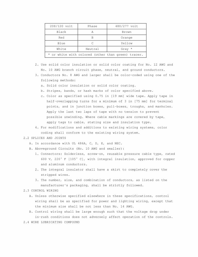
208/120 volt Phase 480/277 volt
Black A Brown
Red B Orange
Blue C Yellow
White Neutral Gray *
* or white with colored (other than green) tracer.
2. Use solid color insulation or solid color coating for No. 12 AWG and
No. 10 AWG branch circuit phase, neutral, and ground conductors.
3. Conductors No. 8 AWG and larger shall be color-coded using one of the
following methods:
a. Solid color insulation or solid color coating.
b. Stripes, bands, or hash marks of color specified above.
c. Color as specified using 0.75 in [19 mm] wide tape. Apply tape in
half-overlapping turns for a minimum of 3 in [75 mm] for terminal
points, and in junction boxes, pull-boxes, troughs, and manholes.
Apply the last two laps of tape with no tension to prevent
possible unwinding. Where cable markings are covered by tape,
apply tags to cable, stating size and insulation type.
4. For modifications and additions to existing wiring systems, color
coding shall conform to the existing wiring system.
2.2 SPLICES AND JOINTS
A. In accordance with UL 486A, C, D, E, and NEC.
B. Aboveground Circuits (No. 10 AWG and smaller):
1. Connectors: Solderless, screw-on, reusable pressure cable type, rated
600 V, 220˚ F [105˚ C], with integral insulation, approved for copper
and aluminum conductors.
2. The integral insulator shall have a skirt to completely cover the
stripped wires.
3. The number, size, and combination of conductors, as listed on the
manufacturer's packaging, shall be strictly followed.
2.3 CONTROL WIRING
A. Unless otherwise specified elsewhere in these specifications, control
wiring shall be as specified for power and lighting wiring, except that
the minimum size shall be not less than No. 14 AWG.
B. Control wiring shall be large enough such that the voltage drop under
in-rush conditions does not adversely affect operation of the controls.
2.4 WIRE LUBRICATING COMPOUND
A. Lubricating compound shall be suitable for the wire insulation and
conduit, and shall not harden or become adhesive.
PART 3 - EXECUTION
3.1 GENERAL
A. Install in accordance with the NEC, and as specified.
B. Install all wiring in raceway systems.
C. Splice cables and wires only in outlet boxes, junction boxes, pull-
boxes, manholes, or handholes.
D. Wires of different systems (e.g., 120 V, 277 V) shall not be installed
in the same conduit or junction box system.
E. Install cable supports for all vertical feeders in accordance with the
NEC. Provide split wedge type which firmly clamps each individual cable
and tightens due to cable weight.
F. For panel boards, cabinets, wire ways, switches, and equipment
assemblies, neatly form, train, and tie the cables in individual
circuits.
G. Seal cable and wire entering a building from underground between the
wire and conduit where the cable exits the conduit, with a non-hardening
approved compound.
H. Wire Pulling:
1. Provide installation equipment that will prevent the cutting or
abrasion of insulation during pulling of cables. Use lubricants
approved for the cable.
2. Use nonmetallic ropes for pulling feeders.
3. Attach pulling lines for feeders by means of either woven basket
grips or pulling eyes attached directly to the conductors, as
approved by the C.O.R.4. All cables in a single conduit shall be
pulled simultaneously.
5. Do not exceed manufacturer’s recommended maximum pulling tensions and
sidewall pressure values.
I. No more than three single-phase branch circuits shall be installed in
any one conduit.
J. Fireproofing:
1. Install fireproofing on low-voltage cables where the low-voltage
cables are installed in the same manholes with medium-voltage cables;
also cover the low-voltage cables with arcproof and fireproof tape.
2. Use tape of the same type used for the medium-voltage cables, and
apply the tape in a single layer, half-lapped, or as recommended by
the manufacturer. Install the tape with the coated side towards the
cable and extend it not less than 1 in [25 mm] into each duct.
3. Secure the tape in place by a random wrap of glass cloth tape.
3.3 SPLICE INSTALLATION
A. Splices and terminations shall be mechanically and electrically secure.
B. Tighten electrical connectors and terminals according to manufacturer's
published torque values.
C. Where the Government determines that unsatisfactory splices or
terminations have been installed, remove the devices and install
approved devices at no additional cost to the Government.
3.5 EXISTING WIRING
Unless specifically indicated on the plans, existing wiring shall not be
reused for a new installation.
3.6 CONTROL AND SIGNAL WIRING INSTALLATION
A. Unless otherwise specified in other sections, install wiring and connect
to equipment/devices to perform the required functions as shown and
specified.
B. Except where otherwise required, install a separate power supply circuit
for each system so that malfunctions in any system will not affect other
systems.
C. Where separate power supply circuits are not shown, connect the systems
to the nearest panel boards of suitable voltages, which are intended to
supply such systems and have suitable spare circuit breakers or space
for installation.
3.7 CONTROL AND SIGNAL SYSTEM wiring IDENTIFICATION
A. Install a permanent wire marker on each wire at each termination.
B. Identifying numbers and letters on the wire markers shall correspond to
those on the wiring diagrams used for installing the systems.
C. Wire markers shall retain their markings after cleaning.
D. In each manhole and hand hole, install embossed brass tags to identify
the system served and function.
3.9 ACCEPTANCE CHECKS AND TESTS
A. Feeders and branch circuits shall have their insulation tested after
installation and before connection to utilization devices, such as
fixtures, motors, or appliances. Test each conductor with respect to
adjacent conductors and to ground. Existing conductors to be reused
shall also be tested.
B. Applied voltage shall be 500VDC for 300-volt rated cable, and 1000VDC
for 600-volt rated cable. Apply test for one minute or until reading is
constant for 15 seconds, whichever is longer. Minimum insulation
resistance values shall not be less than 25 megohms for 300-volt rated
cable and 100 megohms for 600-volt rated cable.
C. Perform phase rotation test on all three-phase circuits.
D. The contractor shall furnish the instruments, materials, and labor for
all tests.
- - - E N D - - -
SECTION 26 05 33 RACEWAY AND BOXES FOR ELECTRICAL SYSTEMS
PART 1 - GENERAL
1.1 DESCRIPTION
A. This section specifies the furnishing, installation, and connection of
conduit, fittings, and boxes, to form complete, coordinated, grounded
raceway systems. Raceways are required for all wiring unless shown or
specified otherwise.
B. Definitions: The term conduit, as used in this specification, shall mean
any or all of the raceway types specified.
1.2 RELATED WORK
A. Section 07 92 00, JOINT SEALANTS: Sealing around conduit penetrations
through the building envelope to prevent moisture migration into the
building and Sealing around penetrations to maintain the integrity of
fire rated construction.
B. Section 09 91 00, PAINTING: Identification and painting of conduit and
other devices.
C. Section 26 05 11, REQUIREMENTS FOR ELECTRICAL INSTALLATIONS: General
electrical requirements and items that are common to more than one
section of Division 26.
D. Section 26 05 26, GROUNDING AND BONDING FOR ELECTRICAL SYSTEMS:
Requirements for personnel safety and to provide a low impedance path
for possible ground fault currents.
1.3 QUALITY ASSURANCE
Refer to Paragraph, QUALIFICATIONS, in Section 26 05 11, REQUIREMENTS
FOR ELECTRICAL INSTALLATIONS.
1.4 SUBMITTALS
In accordance with Section 26 05 11, REQUIREMENTS FOR ELECTRICAL
INSTALLATIONS, submit the following:
A. Manufacturer's Literature and Data: Showing each cable type and rating.
The specific item proposed and its area of application shall be
identified on the catalog cuts.
B. Shop Drawings:
1. Size and location of main feeders.
2. Size and location of panels and pull-boxes.
3. Layout of required conduit penetrations through structural elements.
C. Certifications:
1. Two weeks prior to the final inspection, submit four copies of the
following certifications to the C.O.R.:
a. Certification by the manufacturer that the material conforms to
the requirements of the drawings and specifications.
b. Certification by the contractor that the material has been
properly installed.
1.5 APPLICABLE PUBLICATIONS
A. Publications listed below (including amendments, addenda, revisions,
supplements, and errata) form a part of this specification to the extent
referenced. Publications are referenced in the text by designation only.
B. American National Standards Institute (ANSI):
C80.1-05................Electrical Rigid Steel Conduit
C80.3-05................Steel Electrical Metal Tubing
C80.6-05................Electrical Intermediate Metal Conduit
C. National Fire Protection Association (NFPA):
70-08...................National Electrical Code (NEC)
D. Underwriters Laboratories, Inc. (UL):
1-05....................Flexible Metal Conduit
5-04....................Surface Metal Raceway and Fittings
6-07....................Electrical Rigid Metal Conduit - Steel
50-95...................Enclosures for Electrical Equipment
360-093.................Liquid-Tight Flexible Steel Conduit
467-07..................Grounding and Bonding Equipment
514A-04.................Metallic Outlet Boxes
514B-04.................Conduit, Tubing, and Cable Fittings
514C-96.................Nonmetallic Outlet Boxes, Flush-Device Boxes and
Covers
651-05..................Schedule 40 and 80 Rigid PVC Conduit and
Fittings
651A-00.................Type EB and A Rigid PVC Conduit and HDPE Conduit
797-07..................Electrical Metallic Tubing
1242-06.................Electrical Intermediate Metal Conduit - Steel
E. National Electrical Manufacturers Association (NEMA):
TC-2-03.................Electrical Polyvinyl Chloride (PVC) Tubing and
Conduit
TC-3-04.................PVC Fittings for Use with Rigid PVC Conduit and
Tubing
FB1-07..................Fittings, Cast Metal Boxes and Conduit Bodies
for Conduit, Electrical Metallic Tubing and
Cable
PART 2 - PRODUCTS
2.1 MATERIAL
A. Conduit Size: In accordance with the NEC, but not less than 0.5 in [13
mm] unless otherwise shown. Where permitted by the NEC, 0.5 in [13 mm]
flexible conduit may be used for tap connections to recessed lighting
fixtures.
B. Conduit:
1. Rigid steel: Shall conform to UL 6 and ANSI C80.1.
2. Rigid aluminum: Shall conform to UL 6A and ANSI C80.5.
3. Rigid intermediate steel conduit (IMC): Shall conform to UL 1242 and
ANSI C80.6.
4. Electrical metallic tubing (EMT): Shall conform to UL 797 and ANSI
C80.3. Maximum size not to exceed 4 in [105 mm] and shall be
permitted only with cable rated 600 V or less.
5. Flexible galvanized steel conduit: Shall conform to UL 1.
6. Liquid-tight flexible metal conduit: Shall conform to UL 360.
7. Direct burial plastic conduit: Shall conform to UL 651 and UL 651A,
heavy wall PVC or high density polyethylene (PE).
8. Surface metal raceway: Shall conform to UL 5.
C. Conduit Fittings:
1. Rigid steel and IMC conduit fittings:
a. Fittings shall meet the requirements of UL 514B and NEMA FB1.
b. Standard threaded couplings, locknuts, bushings, conduit bodies,
and elbows: Only steel or malleable iron materials are acceptable.
Integral retractable type IMC couplings are also acceptable.
c. Locknuts: Bonding type with sharp edges for digging into the metal
wall of an enclosure.
d. Bushings: Metallic insulating type, consisting of an insulating
insert, molded or locked into the metallic body of the fitting.
Bushings made entirely of metal or nonmetallic material are not
permitted.
e. Erickson (union-type) and set screw type couplings: Approved for
use in concrete are permitted for use to complete a conduit run
where conduit is installed in concrete. Use set screws of case-
hardened steel with hex head and cup point to firmly seat in

conduit wall for positive ground. Tightening of set screws with
pliers is prohibited.
f. Sealing fittings: Threaded cast iron type. Use continuous drain-
type sealing fittings to prevent passage of water vapor. In
concealed work, install fittings in flush steel boxes with blank
cover plates having the same finishes as that of other electrical
plates in the room.
2. Rigid aluminum conduit fittings:
a. Standard threaded couplings, locknuts, bushings, conduit bodies,
and elbows: Malleable iron, steel or aluminum alloy materials;
Zinc or cadmium plate iron or steel fittings. Aluminum fittings
containing more than 0.4% copper are prohibited.
b. Locknuts and bushings: As specified for rigid steel and IMC
conduit.
c. Set screw fittings: Not permitted for use with aluminum conduit.
3. Electrical metallic tubing fittings:
a. Fittings and conduit bodies shall meet the requirements of UL
514B, ANSI C80.3, and NEMA FB1.
b. Only steel or malleable iron materials are acceptable.
c. Setscrew couplings and connectors: Use setscrews of case-hardened
steel with hex head and cup point, to firmly seat in wall of
conduit for positive grounding.
d. Indent-type connectors or couplings are prohibited.
e. Die-cast or pressure-cast zinc-alloy fittings or fittings made of
"pot metal" are prohibited.
4. Flexible steel conduit fittings:
a. Conform to UL 514B. Only steel or malleable iron materials are
acceptable.
b. Clamp-type, with insulated throat.
5. Liquid-tight flexible metal conduit fittings:
a. Fittings shall meet the requirements of UL 514B and NEMA FB1.
b. Only steel or malleable iron materials are acceptable.
c. Fittings must incorporate a threaded grounding cone, a steel or
plastic compression ring, and a gland for tightening. Connectors
shall have insulated throats.
6. Direct burial plastic conduit fittings:
Fittings shall meet the requirements of UL 514C and NEMA TC3.
7. Surface metal raceway fittings: As recommended by the raceway
manufacturer. Include couplings, offsets, elbows, expansion joints,
adapters, hold-down straps, end caps, conduit entry fittings,
accessories, and other fittings as required for complete system.
8. Expansion and deflection couplings:
a. Conform to UL 467 and UL 514B.
b. Accommodate a 0.75 in [19 mm] deflection, expansion, or
contraction in any direction, and allow 30 degree angular
deflections.
c. Include internal flexible metal braid, sized to guarantee conduit
ground continuity and a low-impedance path for fault currents, in
accordance with UL 467 and the NEC tables for equipment grounding
conductors.
d. Jacket: Flexible, corrosion-resistant, watertight, moisture and
heat-resistant molded rubber material with stainless steel jacket
clamps.
D. Conduit Supports:
1. Parts and hardware: Zinc-coat or provide equivalent corrosion
protection.
2. Individual Conduit Hangers: Designed for the purpose, having a
pre-assembled closure bolt and nut, and provisions for receiving a
hanger rod.
3. Multiple conduit (trapeze) hangers: Not less than 1.5 x 1.5 in [38 mm
x 38 mm], 12-gauge steel, cold-formed, lipped channels; with not less
than 0.375 in [9 mm] diameter steel hanger rods.
4. Solid Masonry and Concrete Anchors: Self-drilling expansion shields,
or machine bolt expansion.
E. Outlet, Junction, and Pull Boxes:
1. UL-50 and UL-514A.
2. Cast metal where required by the NEC or shown, and equipped with
rustproof boxes.
3. Sheet metal boxes: Galvanized steel, except where otherwise shown.
4. Flush-mounted wall or ceiling boxes shall be installed with raised
covers so that the front face of raised cover is flush with the wall.
Surface-mounted wall or ceiling boxes shall be installed with
surface-style flat or raised covers.
F. Wireways: Equip with hinged covers, except where removable covers are
shown. Include couplings, offsets, elbows, expansion joints, adapters,
hold-down straps, end caps, and other fittings to match and mate with
wire ways as required for a complete system.
PART 3 - EXECUTION
3.1 PENETRATIONS
A. Cutting or Holes:
1. Cut holes in advance where they should be placed in the structural
elements, such as ribs or beams. Obtain the approval of the C.O.R.
prior to drilling through structural elements.
2. Cut holes through concrete and masonry in new and existing structures
with a diamond core drill or concrete saw. Pneumatic hammers, impact
electric, hand, or manual hammer-type drills are not allowed, except
where permitted by the C.O.R.as required by limited working space.
B. Firestop: Where conduits, wireways, and other electrical raceways pass
through fire partitions, fire walls, smoke partitions, or floors,
install a fire stop that provides an effective barrier against the
spread of fire, smoke and gases as specified in Section 07 92 00, JOINT
SEALANT.
C. Waterproofing: At floor, exterior wall, and roof conduit penetrations,
completely seal clearances around the conduit and make watertight, as
specified in Section 07 92 00, JOINT SEALANTS.
3.2 INSTALLATION, GENERAL
A. In accordance with UL, NEC, as shown, and as specified herein.
B. Essential (Emergency) raceway systems shall be entirely independent of
other raceway systems, except where shown on drawings.
C. Install conduit as follows:
1. In complete mechanically and electrically continuous runs before
pulling in cables or wires.
2. Unless otherwise indicated on the drawings or specified herein,
installation of all conduits shall be concealed within finished
walls, floors, and ceilings.
3. Flattened, dented, or deformed conduit is not permitted. Remove and
replace the damaged conduits with new undamaged material.
4. Assure conduit installation does not encroach into the ceiling height
head room, walkways, or doorways.
5. Cut square, ream, remove burrs, and draw up tight.
6. Independently support conduit at 8 ft [2.4 M] on centers. Do not use
other supports, i.e., suspended ceilings, suspended ceiling
supporting members, lighting fixtures, conduits, mechanical piping,
or mechanical ducts.
7. Support within 12 in [300 mm] of changes of direction, and within 12
in [300 mm] of each enclosure to which connected.
8. Close ends of empty conduit with plugs or caps at the rough-in stage
until wires are pulled in, to prevent entry of debris.
9. Conduit installations under fume and vent hoods are prohibited.
10. Secure conduits to cabinets, junction boxes, pull-boxes, and outlet
boxes with bonding type locknuts. For rigid and IMC conduit
installations, provide a locknut on the inside of the enclosure, made
up wrench tight. Do not make conduit connections to junction box
covers.
11. Conduit bodies shall only be used for changes in direction, and shall
not contain splices.
12. Do not use aluminum conduits in wet locations.
D. Conduit Bends:
1. Make bends with standard conduit bending machines.
2. Conduit hickey may be used for slight offsets and for straightening
stubbed out conduits.
3. Bending of conduits with a pipe tee or vise is prohibited.
E. Layout and Homeruns:
1. Install conduit with wiring, including homeruns, as shown on
drawings.
2. Deviations: Make only where necessary to avoid interferences and only
after drawings showing the proposed deviations have been submitted
approved by the C.O.R..
3.3 CONCEALED WORK INSTALLATION
A. In Concrete:
1. Conduit: Rigid steel, IMC, or EMT. Do not install EMT in concrete
slabs that are in contact with soil, gravel, or vapor barriers.
2. Align and run conduit in direct lines.
3. Install conduit through concrete beams only:
a. Where shown on the structural drawings.
b. As approved by the C.O.R. prior to construction, and after
submittal of drawing showing location, size, and position of each
penetration.
4. Installation of conduit in concrete that is less than 3 in [75 mm]
thick is prohibited.
a. Conduit outside diameter larger than one-third of the slab
thickness is prohibited.
b. Space between conduits in slabs: Approximately six conduit
diameters apart, and one conduit diameter at conduit crossings.
c. Install conduits approximately in the center of the slab so that
there will be a minimum of 0.75 in [19 mm] of concrete around the
conduits.
5. Make couplings and connections watertight. Use thread compounds that
are UL approved conductive type to ensure low resistance ground
continuity through the conduits. Tightening setscrews with pliers is
prohibited.
B. Above Furred or Suspended Ceilings and in Walls:
1. Conduit for conductors above 600 V: Rigid steel. Mixing different
types of conduits indiscriminately in the same system is prohibited.
2. Conduit for conductors 600 V and below: Rigid steel, IMC, or EMT.
Mixing different types of conduits indiscriminately in the same
system is prohibited.
3. Align and run conduit parallel or perpendicular to the building
lines.
4. Connect recessed lighting fixtures to conduit runs with maximum 6 ft
[1.8 M] of flexible metal conduit extending from a junction box to
the fixture.
5. Tightening setscrews with pliers is prohibited.
3.4 EXPOSED WORK INSTALLATION
A. Unless otherwise indicated on the drawings, exposed conduit is only
permitted in mechanical and electrical rooms.
B. Conduit for Conductors above 600 V: Rigid steel. Mixing different types
of conduits indiscriminately in the system is prohibited.
C. Conduit for Conductors 600 V and Below: Rigid steel, IMC, or EMT. Mixing
different types of conduits indiscriminately in the system is
prohibited.
D. Align and run conduit parallel or perpendicular to the building lines.
E. Install horizontal runs close to the ceiling or beams and secure with
conduit straps.
F. Support horizontal or vertical runs at not over 8 ft [2.4 M] intervals.
G. Surface metal raceways: Use only where shown.
H. Painting:
1. Paint exposed conduit as specified in Section 09 91 00, PAINTING.
2. Paint all conduits containing cables rated over 600 V safety orange.
Refer to Section 09 91 00, PAINTING for preparation, paint type, and
exact color. In addition, paint legends, using 2 in [50 mm] high
black numerals and letters, showing the cable voltage rating. Provide
legends where conduits pass through walls and floors and at maximum
20 ft [6 M] intervals in between.
3.5 HAZARDOUS LOCATIONS
A. Use rigid steel conduit only, notwithstanding requirements otherwise
specified in this or other sections of these specifications.
B. Install UL approved sealing fittings that prevent passage of explosive
vapors in hazardous areas equipped with explosion-proof lighting
fixtures, switches, and receptacles, as required by the NEC.
3.6 WET OR DAMP LOCATIONS
A. Unless otherwise shown, use conduits of rigid steel or IMC.
B. Provide sealing fittings to prevent passage of water vapor where
conduits pass from warm to cold locations, i.e., refrigerated spaces,
constant-temperature rooms, air-conditioned spaces, building exterior
walls, roofs, or similar spaces.
C. Unless otherwise shown, use rigid steel or IMC conduit within 5 ft [1.5
M] of the exterior and below concrete building slabs in contact with
soil, gravel, or vapor barriers. Conduit shall be half-lapped with 10
mil PVC tape before installation. After installation, completely recoat
or retape any damaged areas of coating.
3.7 MOTORS AND VIBRATING EQUIPMENT
A. Use flexible metal conduit for connections to motors and other
electrical equipment subject to movement, vibration, misalignment,
cramped quarters, or noise transmission.
B. Use liquid-tight flexible metal conduit for installation in exterior
locations, moisture or humidity laden atmosphere, corrosive atmosphere,
water or spray wash-down operations, inside airstream of HVAC units, and
locations subject to seepage or dripping of oil, grease, or water.
Provide a green equipment grounding conductor with flexible metal
conduit.
3.8 EXPANSION JOINTS
A. Conduits 3 in [75 mm] and larger that are secured to the building
structure on opposite sides of a building expansion joint require
expansion and deflection couplings. Install the couplings in accordance
with the manufacturer's recommendations.
B. Provide conduits smaller than 3 in [75 mm] with junction boxes on both
sides of the expansion joint. Connect conduits to junction boxes with
sufficient slack of flexible conduit to produce 5 in [125 mm] vertical
drop midway between the ends. Flexible conduit shall have a bonding
jumper installed. In lieu of this flexible conduit, expansion and
deflection couplings as specified above for conduits 15 in [375 mm] and
larger are acceptable.
C. Install expansion and deflection couplings where shown.
3.9 CONDUIT SUPPORTS, INSTALLATION
A. Safe working load shall not exceed one-quarter of proof test load of
fastening devices.
B. Use pipe straps or individual conduit hangers for supporting individual
conduits.
C. Support multiple conduit runs with trapeze hangers. Use trapeze hangers
that are designed to support a load equal to or greater than the sum of
the weights of the conduits, wires, hanger itself, and 200 lbs [90 kg].
Attach each conduit with U-bolts or other approved fasteners.
D. Support conduit independently of junction boxes, pull-boxes, fixtures,
suspended ceiling T-bars, angle supports, and similar items.
E. Fasteners and Supports in Solid Masonry and Concrete:
1. New Construction: Use steel or malleable iron concrete inserts set in
place prior to placing the concrete.
2. Existing Construction:
a. Steel expansion anchors not less than 0.25 in [6 mm] bolt size and
not less than 1.125 in [28 mm] embedment.
b. Power set fasteners not less than 0.25 in [6 mm] diameter with
depth of penetration not less than 3 in [75 mm].
c. Use vibration and shock-resistant anchors and fasteners for
attaching to concrete ceilings.
E. Hollow Masonry: Toggle bolts.
F. Bolts supported only by plaster or gypsum wallboard are not acceptable.
G. Metal Structures: Use machine screw fasteners or other devices
specifically designed and approved for the application.
H. Attachment by wood plugs, rawl plug, plastic, lead or soft metal
anchors, or wood blocking and bolts supported only by plaster is
prohibited.
I. Chain, wire, or perforated strap shall not be used to support or fasten
conduit.
J. Spring steel type supports or fasteners are prohibited for all uses
except horizontal and vertical supports/fasteners within walls.
K. Vertical Supports: Vertical conduit runs shall have riser clamps and
supports in accordance with the NEC and as shown. Provide supports for
cable and wire with fittings that include internal wedges and retaining
collars.
3.10 BOX INSTALLATION
A. Boxes for Concealed Conduits:
1. Flush-mounted.
2. Provide raised covers for boxes to suit the wall or ceiling,
construction, and finish.
B. In addition to boxes shown, install additional boxes where needed to
prevent damage to cables and wires during pulling-in operations.

C. Remove only knockouts as required and plug unused openings. Use threaded
plugs for cast metal boxes and snap-in metal covers for sheet metal
boxes.
D. Outlet boxes mounted back-to-back in the same wall are prohibited. A
minimum 24 in [600 mm] center-to-center lateral spacing shall be
maintained between boxes.
E. Minimum size of outlet boxes for ground fault interrupter (GFI)
receptacles is 4 in [100 mm] square x 2.125 in [55 mm] deep, with device
covers for the wall material and thickness involved.
F. Stencil or install phenolic nameplates on covers of the boxes identified
on riser diagrams; for example "SIG-FA JB No. 1."
G. On all branch circuit junction box covers, identify the circuits with
black marker.
- - - E N D - - -
SECTION 26 08 00 COMMISSIONING OF ELECTRICAL SYSTEMS
PART 1 - GENERAL
1.1 DESCRIPTION
A. The requirements of this Section apply to all sections of Division 26.
B. This project will have selected building systems commissioned. The
complete list of equipment and systems to be commissioned are specified
in Section 01 91 00 GENERAL COMMISSIONING REQUIREMENTS. The
commissioning process, which the Contractor is responsible to execute,
is defined in Section 01 91 00 GENERAL COMMISSIONING REQUIREMENTS. A
Commissioning Agent (CxA) appointed by the Department of Veterans
Affairs will manage the commissioning process.
1.2 RELATED WORK
A. Section 01 00 00 GENERAL REQUIREMENTS.
B. Section 01 91 00 GENERAL COMMISSIONING REQUIREMENTS.
C. Section 01 33 23 SHOP DRAWINGS, PRODUCT DATA, AND SAMPLES.
1.3 SUMMARY
A. This Section includes requirements for commissioning the electrical
systems, subsystems and equipment. This Section supplements the general
requirements specified in Section 01 91 00 GENERAL COMMISSIONING
REQUIREMENTS.
B. The commissioning activities have been developed to support the VA
requirements to meet guidelines for Federal Leadership in Environmental,
Energy, and Economic Performance.
C. The commissioning activities have been developed to support the United
States Green Building Council (USGBC) LEED™ rating program and to
support delivery of project performance in accordance with the Contract
Documents developed with the approval of the VA.
1. Commissioning activities and documentation for the LEED™ section on
“Energy and Atmosphere” prerequisite of “Fundamental Building Systems
Commissioning”.
2. Commissioning activities and documentation for the LEED™ section on
“Energy and Atmosphere” requirements for the “Enhanced Building
System Commissioning” credit.
3. Activities and documentation for the LEED™ section on “Measurement
and Verification” requirements for the Measurement and Verification
credit.
D. Refer to Section 01 91 00 GENERAL COMMISSIONING REQUIREMENTS for more
specifics regarding processes and procedures as well as roles and
responsibilities for all Commissioning Team members.
1.4 DEFINITIONS
A. Refer to Section 01 91 00 GENERAL COMMISSIONING REQUIREMENTS for
definitions.
1.5 COMMISSIONED SYSTEMS
A. Commissioning of a system or systems specified in this Division is part
of the construction process. Documentation and testing of these systems,
as well as training of the VA’s Operation and Maintenance personnel, is
required in cooperation with the VA and the Commissioning Agent.
B. The following Electrical systems will be commissioned:
1. Utility Service Entrance Switchgear (Fuses and circuit breaker
settings, metering, mimic diagram, gages, and controls).
2. Standby Generator Systems (Automatic transfer switches, fuel delivery
pumps and motors, battery charging and instrumentation, muffler and
exhaust system, and vibration isolation).
3. Generator Paralleling Switchboards (Automatic transfer switches,
instrumentation, metering and gages, and controls).
4. Generator Power Distribution Systems (Fuses and circuit breaker
settings, metering, gages, and controls).
5. Utility Power Unit Substations (Transformers and tap settings, fuses
and circuit breaker settings, metering, gages, and controls).
6. Generator Power Unit Substations (Transformers and tap settings,
fuses and circuit breaker settings, metering, gages, and controls).
7. Automatic Transfer Switches (Test with associated generator).
8. Normal Power Distribution Systems (Grounding tests, coordination
study review, major circuit breaker settings, meters and gages, and
controls).
9. Life Safety Power Distribution Systems (Automatic transfer on loss of
normal power, grounding tests, coordination study review, major
circuit breaker settings, meters and gages, and controls).
10. Critical Power Distribution Systems (Automatic transfer on loss of
normal power, grounding tests, coordination study review, major
circuit breaker settings, meters and gages, and controls).
11. Essential Equipment Power Distribution Systems (Automatic transfer on
loss of normal power, grounding tests, coordination study review,
major circuit breaker settings, meters and gages, and controls).
12. Lighting Controls (Control system hardware and software, scene
settings, zone settings, occupancy sensor interface, and unoccupied
cycle control).
13. Uninterruptible Power Supply Systems and UPS Power Distribution
Systems (Battery chargers, static and dynamic power generators – i.e.
inverters, MG sets, metering and controls, system power displays, and
distribution panel circuit breakers).
1.6 SUBMITTALS
A. The commissioning process requires review of selected Submittals. The
Commissioning Agent will provide a list of submittals that will be
reviewed by the Commissioning Agent. This list will be reviewed and
approved by the Resident Engineer prior to forwarding to the Contractor.
Refer to Section 01 33 23 SHOP DRAWINGS, PRODUCT DATA, and SAMPLES for
further details.
B. The commissioning process requires Submittal review simultaneously with
engineering review. Specific submittal requirements related to the
commissioning process are specified in Section 01 91 00 GENERAL
COMMISSIONING REQUIREMENTS.
PART 2 - PRODUCTS (NOT USED)
PART 3 - EXECUTION
3.1 PRE-FUNCTIONAL CHECKLISTS
A. The Contractor shall complete Pre-Functional Checklists to verify
systems, subsystems, and equipment installation is complete and systems
are ready for Systems Functional Performance Testing. The Commissioning
Agent will prepare Pre-Functional Checklists to be used to document
equipment installation. The Contractor shall complete the checklists.
Completed checklists shall be submitted to the VA and to the
Commissioning Agent for review. The Commissioning Agent may spot check
a sample of completed checklists. If the Commissioning Agent determines
that the information provided on the checklist is not accurate, the
Commissioning Agent will return the marked-up checklist to the
Contractor for correction and resubmission. If the Commissioning Agent
determines that a significant number of completed checklists for similar
equipment are not accurate, the Commissioning Agent will select a
broader sample of checklists for review. If the Commissioning Agent
determines that a significant number of the broader sample of checklists
is also inaccurate, all the checklists for the type of equipment will be
returned to the Contractor for correction and resubmission. Refer to
SECTION 01 91 00 GENERAL COMMISSIONING REQUIREMENTS for submittal
requirements for Pre-Functional Checklists, Equipment Startup Reports,
and other commissioning documents.
3.2 CONTRACTORS TESTS
A. Contractor tests as required by other sections of Division 26 shall be
scheduled and documented in accordance with Section 01 00 00 GENERAL
REQUIREMENTS. The Commissioning Agent will witness selected Contractor
tests. Contractor tests shall be completed prior to scheduling Systems
Functional Performance Testing.
3.3 SYSTEMS FUNCTIONAL PERFORMANCE TESTING:
A. The Commissioning Process includes Systems Functional Performance
Testing that is intended to test systems functional performance under
steady state conditions, to test system reaction to changes in operating
conditions, and system performance under emergency conditions. The
Commissioning Agent will prepare detailed Systems Functional Performance
Test procedures for review and approval by the Resident Engineer. The
Contractor shall review and comment on the tests prior to approval. The
Contractor shall provide the required labor, materials, and test
equipment identified in the test procedure to perform the tests. The
Commissioning Agent will witness and document the testing. The
Contractor shall sign the test reports to verify tests were performed.
See Section 01 91 00 GENERAL COMMISSIONING REQUIREMENTS, for additional
details.
3.4 TRAINING OF VA PERSONNEL
A. Training of the VA’s operation and maintenance personnel is required in
cooperation with the Resident Engineer and Commissioning Agent. Provide
competent, factory authorized personnel to provide instruction to
operation and maintenance personnel concerning the location, operation,
and troubleshooting of the installed systems. The instruction shall be
scheduled in coordination with the Resident Engineer after submission
and approval of formal training plans. Refer to Section 01 91 00
GENERAL COMMISSIONING REQUIREMENTS and Division 26 Sections for
additional Contractor training requirements.
----- END -----
SECTION 26 27 26 WIRING DEVICES
PART 1 - GENERAL
1.1 DESCRIPTION
This section specifies the furnishing, installation and connection of
wiring devices.
1.2 RELATED WORK
A. Section 26 05 11, REQUIREMENTS FOR ELECTRICAL INSTALLATIONS: General
electrical requirements that are common to more than one section of
Division 26.
B. Section 26 05 33, RACEWAY AND BOXES FOR ELECTRICAL SYSTEMS: Conduits and
outlets boxes.
C. Section 26 05 21, LOW-VOLTAGE ELECTRICAL POWER CONDUCTORS AND CABLES
(600 VOLTS AND BELOW): Cables and wiring.
D. Section 26 05 26, GROUNDING AND BONDING FOR ELECTRICAL SYSTEMS:
Requirements for personnel safety and to provide a low impedance path to
ground for possible ground fault currents.
1.3 QUALITY ASSURANCE
Refer to Paragraph, QUALIFICATIONS, in Section 26 05 11, REQUIREMENTS
FOR ELECTRICAL INSTALLATIONS.
1.4 SUBMITTALS
A. In accordance with Section 26 05 11, REQUIREMENTS FOR ELECTRICAL
INSTALLATIONS, submit the following:
B. Shop Drawings:
1. Sufficient information, clearly presented, shall be included to
determine compliance with drawings and specifications.
2. Include electrical ratings, dimensions, mounting details,
construction materials, grade and termination information.
C. Manuals: Two weeks prior to final inspection, deliver four copies of the
following to the Resident Engineer: Technical data sheets and
information for ordering replacement units.
D. Certifications: Two weeks prior to final inspection, submit four copies
of the following to the Resident Engineer: Certification by the
Contractor that the devices comply with the drawings and specifications,
and have been properly installed, aligned, and tested.
1.5 APPLICABLE PUBLICATIONS
A. Publications listed below (including amendments, addenda, revisions,
supplements and errata) form a part of this specification to the extent
referenced. Publications are referenced in the text by basic designation
only.
B. National Fire Protection Association (NFPA):
70......................National Electrical Code (NEC)
C. National Electrical Manufacturers Association (NEMA):
WD 1....................General Color Requirements for Wiring Devices
WD 6 ...................Wiring Devices – Dimensional Requirements
D. Underwriter’s Laboratories, Inc. (UL):
5.......................Surface Metal Raceways and Fittings
20......................General-Use Snap Switches
231.....................Power Outlets
467.....................Grounding and Bonding Equipment
498.....................Attachment Plugs and Receptacles
943.....................Ground-Fault Circuit-Interrupters
PART 2 - PRODUCTS
2.1 RECEPTACLES
A. General: All receptacles shall be listed by Underwriters Laboratories,
Inc., and conform to NEMA WD 6.
1. Mounting straps shall be plated steel, with break-off plaster ears
and shall include a self-grounding feature. Terminal screws shall be
brass, brass plated or a copper alloy metal.
2. Receptacles shall have provisions for back wiring with separate metal
clamp type terminals (four min.) and side wiring from four captively
held binding screws.
B. Duplex Receptacles: Hospital-grade, single phase, 20 ampere, 120 volts,
2-pole, 3-wire, and conform to the NEMA 5-20R configuration in NEMA WD
6. The duplex type shall have break-off feature for two-circuit
operation. The ungrounded pole of each receptacle shall be provided with
a separate terminal.
1. Bodies shall be ivory in color.
2. Switched duplex receptacles shall be wired so that only the top
receptacle is switched. The remaining receptacle shall be unswitched.
3. Duplex Receptacles on Emergency Circuit:
a. In rooms without emergency powered general lighting, the emergency
receptacles shall be of the self-illuminated type.
4. Ground Fault Interrupter Duplex Receptacles: Shall be an integral
unit, hospital-grade, suitable for mounting in a standard outlet box.
a. Ground fault interrupter shall be consist of a differential
current transformer, solid state sensing circuitry and a circuit
interrupter switch. Device shall have nominal sensitivity to
ground leakage current of five milliamperes and shall function to
interrupt the current supply for any value of ground leakage
current above five milliamperes (+ or – 1 milliamp) on the load
side of the device. Device shall have a minimum nominal tripping
time of 1/30th of a second.
b. Ground Fault Interrupter Duplex Receptacles (not hospital-grade)
shall be the same as ground fault interrupter hospital-grade
receptacles except for the “hospital-grade” listing.
5. Safety Type Duplex Receptacles:
a. Bodies shall be gray in color.
1) Shall permit current to flow only while a standard plug is in
the proper position in the receptacle.
2) Screws exposed while the wall plates are in place shall be the
tamperproof type.
6. Duplex Receptacles (not hospital grade): Shall be the same as
hospital grade duplex receptacles except for the "hospital grade"
listing and as follows.
a. Bodies shall be brown phenolic compound supported by a plated
steel mounting strap having plaster ears.
C. Receptacles; 20, 30 and 50 ampere, 250 volts: Shall be complete with
appropriate cord grip plug. Devices shall meet UL 231.
D. TVSS Receptacles. Shall comply with NEMA WD 1, NEMA WD 6, UL 498, and
UL 1449, with integral TVSS in line to ground, line to neutral, and
neutral to ground.
1. TVSS Components: Multiple metal-oxide varistors; with a nominal
clamp-level rating of 400 volts and minimum single transient pulse
energy dissipation of 240 J, according to IEEE C62.41.2 and
IEEE C62.45.
2. Active TVSS Indication: Visual and audible, with light visible in
face of device to indicate device is "active" or "no longer in
service."
2.4 WALL PLATES
A. Wall plates for switches and receptacles shall be type smooth nylon.
Oversize plates are not acceptable.
B. Color shall be ivory unless otherwise specified.
C. Standard NEMA design, so that products of different manufacturers will
be interchangeable. Dimensions for openings in wall plates shall be
accordance with NEMA WD 6.
D. For receptacles or switches mounted adjacent to each other, wall plates
shall be common for each group of receptacles or switches.
E. Wall plates for data, telephone or other communication outlets shall be
as specified in the associated specification.
G. Duplex Receptacles on Emergency Circuit:
1. Bodies shall be red in color. Wall plates shall be red with the word
"EMERGENCY" engraved in 6 mm, (1/4 inch) white letters.
PART 3 - EXECUTION
3.1 INSTALLATION
A. Installation shall be in accordance with the NEC and as shown as on the
drawings.
B. Ground terminal of each receptacle shall be bonded to the outlet box
with an approved green bonding jumper, and also connected to the green
equipment grounding conductor.
C. Outlet boxes for light and dimmer switches shall be mounted on the
strike side of doors.
D. Provide barriers in multi-gang outlet boxes to separate systems of
different voltages, Normal Power and Emergency Power systems, and in
compliance with the NEC.
E. Coordinate with other work, including painting, electrical boxes and
wiring installations, as necessary to interface installation of wiring
devices with other work. Coordinate the electrical work with the work
of other trades to ensure that wiring device flush outlets are positioned
with box openings aligned with the face of the surrounding finish
material. Pay special attention to installations in cabinet work, and in
connection with laboratory equipment.
F. Exact field locations of floors, walls, partitions, doors, windows, and
equipment may vary from locations shown on the drawings. Prior to
locating sleeves, boxes and chases for roughing-in of conduit and
equipment, the Contractor shall coordinate exact field location of the
above items with other trades. In addition, check for exact direction of
door swings so that local switches are properly located on the strike
side.
G. Install convenience receptacles 18 inches [450mm] above floor, and 6
inches [152mm] above counter backsplash or workbenches. Install
specific-use receptacles at heights shown on the drawings.
H. Label device plates with a permanent adhesive label listing panel and
circuit feeding the wiring device.
I. Test wiring devices for damaged conductors, high circuit resistance,
poor connections, inadequate fault current path, defective devices, or
similar problems using a portable receptacle tester. Correct circuit
conditions, remove malfunctioning units and replace with new, and retest
as specified above.
J. Test GFCI devices for tripping values specified in UL 1436 and UL 943.
- - - E N D - - -
SECTION 28 05 13 CONDUCTORS AND CABLES FOR ELECTRONIC SAFETY AND
SECURITY PART 1 – GENERAL
1.1 DESCRIPTION
A. This section specifies the finishing, installation, connection, testing
and certification the conductors and cables required for a fully
functional for electronic safety and security (ESS) system.
1.2 RELATED WORK
A. Section 01 00 00 - GENERAL REQUIREMENTS. For General Requirements.
B. Section 28 05 26 - GROUNDING AND BONDING FOR ELECTRONIC SAFETY AND
SECURITY. Requirements for personnel safety and to provide a low
impedance path for possible ground fault currents.
C. Section 28 05 28.33 - CONDUITS AND BOXES FOR ELECTRONIC SECURITY AND
SAFETY. Requirements for infrastructure.
D. Section 28 08 00 - COMMISSIONING OF ELECTRONIC SAFETY AND SECURITY
SYSTEMS. Requirements for commissioning.
1.3 DEFINITIONS
A. BICSI: Building Industry Consulting Service International.
B. COR: Contracting Officer Representative
C. EMI: Electromagnetic interference.
D. IDC: Insulation displacement connector.
E. Ladder Cable Tray: A fabricated structure consisting of two
longitudinal side rails connected by individual transverse members
(rungs).
F. Low Voltage: As defined in NFPA 70 for circuits and equipment operating
at less than 50 V or for remote-control and signaling power-limited
circuits.
G. Open Cabling: Passing telecommunications cabling through open space
(e.g., between the studs of a wall cavity).
H. RCDD: Registered Communications Distribution Designer.
I. Solid-Bottom or Non-ventilated Cable Tray: A fabricated structure
consisting of integral or separate longitudinal side rails, and a bottom
without ventilation openings.
J. Trough or Ventilated Cable Tray: A fabricated structure consisting of
integral or separate longitudinal rails and a bottom having openings
sufficient for the passage of air and using 75 percent or less of the
plan area of the surface to support cables.
K. UTP: Unshielded twisted pair.
1.4 QUALITY ASSURANCE
A. See section 28 31 00, Paragraph 1.6.
1.5 SUBMITTALS
A. In accordance with Section 01 33 23, SHOP DRAWINGS, PRODUCT DATA, AND
SAMPLES, furnish the following:
1. Manufacturer's Literature and Data: Showing each cable type and
rating.
2. Certificates: Two weeks prior to final inspection, deliver to the
C.O.R. four copies of the certification that the material is in
accordance with the drawings and specifications and diagrams for
cable management system.
3. Shop Drawings: Cable tray layout, showing cable tray route to scale,
with relationship between the tray and adjacent structural,
electrical, and mechanical elements. Include the following:
a. Vertical and horizontal offsets and transitions.
b. Clearances for access above and to side of cable trays.
c. Vertical elevation of cable trays above the floor or bottom of
ceiling structure.
d. Load calculations to show dead and live loads as not exceeding
manufacturer's rating for tray and its support elements.
e. System labeling schedules, including electronic copy of labeling
schedules that are part of the cable and asset identification
system of the software specified in Parts 2 and 3.
4. Wiring Diagrams. Show typical wiring schematics including the
following:
a. Workstation outlets, jacks, and jack assemblies.
b. Patch cords.
c. Patch panels.
5. Cable Administration Drawings: As specified in Part 3
"Identification" Article.
6. Project planning documents as specified in Part 3.
7. Maintenance Data: For wire and cable to include in maintenance
manuals.

1.6 APPLICABLE PUBLICATIONS
A. Publications listed below (including amendments, addenda, revisions,
supplements and errata) form a part of this specification to the extent
referenced. Publications are reference in the text by the basic
designation only.
B. American Society of Testing Material (ASTM):
D2301-04................Standard Specification for Vinyl Chloride
Plastic Pressure Sensitive Electrical Insulating
Tape
C. Federal Specifications (Fed. Spec.):
A-A-59544-08............Cable and Wire, Electrical (Power, Fixed
Installation)
D. National Fire Protection Association (NFPA):
70-11...................National Electrical Code (NEC)
E. Underwriters Laboratories, Inc. (UL):
44-05...................Thermoset-Insulated Wires and Cables
83-08...................Thermoplastic-Insulated Wires and Cables
467-07..................Electrical Grounding and Bonding Equipment
486A-03.................Wire Connectors and Soldering Lugs for Use with
Copper Conductors
486C-04.................Splicing Wire Connectors
486D-05.................Insulated Wire Connector Systems for Underground
Use or in Damp or Wet Locations
486E-00.................Equipment Wiring Terminals for Use with Aluminum
and/or Copper Conductors
493-07..................Thermoplastic-Insulated Underground Feeder and
Branch Circuit Cable
514B-04.................Fittings for Cable and Conduit
1479-03.................Fire Tests of Through-Penetration Fire Stops
1.7 DELIVERY, STORAGE, AND HANDLING
A. Test cables upon receipt at Project site.
1. Test optical fiber cable to determine the continuity of the strand
end to end. Use optical-fiber flashlight or optical loss test set.
2. Test optical fiber cable on reels. Use an optical time domain
reflectometer to verify the cable length and locate cable defects,
splices, and connector; include the loss value of each. Retain test
data and include the record in maintenance data.
3. Test each pair of UTP cable for open and short circuits.

1.8 PROJECT CONDITIONS
A. Environmental Limitations: Do not deliver or install UTP, optical
fiber, and coaxial cables and connecting materials until wet work in
spaces is complete and dry, and temporary HVAC system is operating and
maintaining ambient temperature and humidity conditions at occupancy
levels during the remainder of the construction period.
PART 2 - PRODUCTS
2.1 GENERAL
A. General: All cabling locations shall be in conduit systems as outlined
in Division 28 unless a waiver is granted in writing or an exception is
noted on the construction drawings.
2.2 BACKBOARDS
A. Backboards: Plywood, fire-retardant treated, 3/4 by 48 by 96 inches.
2.3 OPTICAL FIBER CABLE
A. Description: Multimode, 62.5/125-micrometer, 8-fiber, nonconductive,
tight buffer, optical fiber cable.
1. Comply with ICEA S-83-596 for mechanical properties.
2. Comply with TIA/EIA-568-B.3 for performance specifications.
3. Comply with TIA/EIA-492AAAA-B for detailed specifications.
4. Listed and labeled by an NRTL acceptable to authorities having
jurisdiction as complying with UL 444, UL 1651, and NFPA 70 for the
following types:
a. General Purpose, Nonconductive: Type OFN or OFNG.
b. Plenum Rated, Nonconductive: Type OFNP, complying with NFPA 262.
c. Riser Rated, Nonconductive: Type OFNR, complying with UL 1666.
d. General Purpose, Conductive: Type OFC or OFCG.
e. Plenum Rated, Conductive: Type OFCP, complying with NFPA 262.
f. Riser Rated, Conductive: Type OFCR, complying with UL 1666.
5. Conductive cable shall be steel armored type.
6. Maximum Attenuation: 3.50 dB/km at 850 nm; 1.5 dB/km at 1300 nm.
7. Minimum Modal Bandwidth: 160 MHz-km at 850 nm; 500 MHz-km at 1300
nm.
8. Approved by the fire alarm system equipment manufacturer.
B. Jacket:
1. Jacket Color: Orange for 62.5/125-micrometer cable.
2. Cable cordage jacket, fiber, unit, and group color shall be according
to TIA/EIA-598-B.
3. Imprinted with fiber count, fiber type, and aggregate length at
regular intervals not to exceed 40 inches (1000 mm).
2.4 OPTICAL FIBER CABLE HARDWARE
A. Cable Connecting Hardware: Meet the Optical Fiber Connector
Intermateability Standards (FOCIS) specifications of TIA/EIA-604-2,
TIA/EIA-604-3-A, and TIA/EIA-604-12. Comply with TIA/EIA-568-B.3.
1. Quick-connect, simplex and duplex, Type ST connectors. Insertion
loss shall be not more than 0.75 dB.
2. Type SFF connectors may be used in termination racks, panels, and
equipment packages.
2.5 RS-485 CABLE
A. Standard Cable: NFPA 70, Type CM or CMG.
1. Paired, 2 pairs, twisted, No. 22 AWG, stranded (7x30) tinned copper
conductors.
2. PVC insulation.
3. Unshielded.
4. PVC jacket.
5. Flame Resistance: Comply with UL 1581.
B. Plenum-Rated Cable: NFPA 70, Type CMP.
1. Paired, 2 pairs, No. 22 AWG, stranded (7x30) tinned copper
conductors.
2. Fluorinated ethylene propylene insulation.
3. Unshielded.
4. Fluorinated ethylene propylene jacket.
5. Flame Resistance: NFPA 262, Flame Test.
2.6 LOW-VOLTAGE CONTROL CABLE
A. Paired Lock Cable: NFPA 70, Type CMG.
1. 1 pair, twisted, No. 16 AWG, stranded (19x29) tinned copper
conductors.
2. PVC insulation.
3. Unshielded.
4. PVC jacket.
5. Flame Resistance: Comply with UL 1581.
B. Paired Lock Cable: NFPA 70, Type CMG.
1. 1 pair, twisted, No. 18 AWG, stranded (19x30) tinned copper
conductors.
2. PVC insulation.
3. Unshielded.
4. PVC jacket.
5. Flame Resistance: Comply with UL 1581.
C. Plenum-Rated, Paired Lock Cable: NFPA 70, Type CMP.
1. 1 pair, twisted, No. 18 AWG, stranded (19x30) tinned copper
conductors.
2. Fluorinated ethylene propylene insulation.
3. Unshielded.
4. Plastic jacket.
5. Flame Resistance: NFPA 262, Flame Test.
2.7 CONTROL-CIRCUIT CONDUCTORS
A. Class 1 Control Circuits: Stranded copper, Type THHN-THWN, in raceway
complying with UL 83.
B. Class 2 Control Circuits: Stranded copper, Type THHN-THWN, in raceway
complying with UL 83.
C. Class 3 Remote-Control and Signal Circuits: Stranded copper, Type TW or
TF, complying with UL 83.
2.8 FIRE ALARM WIRE AND CABLE
A. General Wire and Cable Requirements: NRTL listed and labeled as
complying with NFPA 70, Article 760.
B. Signaling Line Circuits: Twisted, un-shielded pair, not less than No.
18 AWG.
1. Circuit Integrity Cable: Twisted un-shielded pair, NFPA 70, Article
760, Classification CI, for power-limited fire alarm signal service
Type FPL. NRTL listed and labeled as complying with UL 1424 and UL
2196 for a 2-hour rating.
C. Non-Power-Limited Circuits: Solid-copper conductors with 600-V rated,
75 deg C, color-coded insulation.
1. Low-Voltage Circuits: No. 16 AWG, minimum.
2. Line-Voltage Circuits: No. 12 AWG, minimum.
3. Multiconductor Armored Cable: NFPA 70, Type MC, copper conductors,
Type TFN/THHN conductor insulation, copper drain wire, copper armor
with outer jacket with red identifier stripe, NTRL listed for fire
alarm and cable tray installation, plenum rated, and complying with
requirements in UL 2196 for a 2-hour rating.
2.9 IDENTIFICATION PRODUCTS
A. Comply with UL 969 for a system of labeling materials, including label
stocks, laminating adhesives, and inks used by label printers.
2.10 SOURCE QUALITY CONTROL
A. Testing Agency: Engage a qualified testing agency to evaluate cables.
B. Factory test UTP and optical fiber cables on reels according to TIA/EIA-
568-B.1.
C. Factory test UTP cables according to TIA/EIA-568-B.2.
D. Factory test multimode optical fiber cables according to TIA/EIA-526-14-
A and TIA/EIA-568-B.3.
E. Factory sweep test coaxial cables at frequencies from 5 MHz to 1 GHz.
Sweep test shall test the frequency response, or attenuation over
frequency, of a cable by generating a voltage whose frequency is varied
through the specified frequency range and graphing the results.
F. Cable will be considered defective if it does not pass tests and
inspections.
G. Prepare test and inspection reports.
2.11 WIRE LUBRICATING COMPOUND
A. Suitable for the wire insulation and conduit it is used with, and shall
not harden or become adhesive.
B. Shall not be used on wire for isolated type electrical power systems.
2.12 FIREPROOFING TAPE
A. The tape shall consist of a flexible, conformable fabric of organic
composition coated one side with flame-retardant elastomer.
B. The tape shall be self-extinguishing and shall not support combustion.
It shall be arc-proof and fireproof.
C. The tape shall not deteriorate when subjected to water, gases, salt
water, sewage, or fungus and be resistant to sunlight and ultraviolet
light.
D. The finished application shall withstand a 200-ampere arc for not less
than 30 seconds.
E. Securing tape: Glass cloth electrical tape not less than 0.18 mm
(7 mils) thick, and 19 mm (3/4 inch) wide.
PART 3 - EXECUTION
3.1 INSTALLATION of conductors and cables
A. Comply with NECA 1.
B. General Requirements for Cabling:
1. Comply with TIA/EIA-568-B.1.
2. Comply with BICSI ITSIM, Ch. 6, "Cable Termination Practices."
3. Install 110-style IDC termination hardware unless otherwise
indicated.
4. Terminate all conductors; no cable shall contain un-terminated
elements. Make terminations only at indicated outlets, terminals,
and cross-connect and patch panels.
5. Cables may not be spliced. Secure and support cables at intervals
not exceeding 30 inches (760 mm) and not more than 6 inches (150 mm)
from cabinets, boxes, fittings, outlets, racks, frames, and
terminals.
6. Bundle, lace, and train conductors to terminal points without
exceeding manufacturer's limitations on bending radii, but not less

than radii specified in BICSI ITSIM, "Cabling Termination Practices"
Chapter. Install lacing bars and distribution spools.
7. Do not install bruised, kinked, scored, deformed, or abraded cable.
Do not splice cable between termination, tap, or junction points.
Remove and discard cable if damaged during installation and replace
it with new cable.
8. Cold-Weather Installation: Bring cable to room temperature before
dereeling. Heat lamps shall not be used for heating.
9. Pulling Cable:
a. Comply with BICSI ITSIM, Ch. 4, "Pulling Cable." Monitor cable
pull tensions.
b. Provide installation equipment that will prevent the cutting or
abrasion of insulation during pulling of cables.
c. Use ropes made of nonmetallic material for pulling feeders.
d. Attach pulling lines for feeders by means of either woven basket
grips or pulling eyes attached directly to the conductors, as
approved by the C.O.R.
e. Pull in multiple cables together in a single conduit.
C. Splice cables and wires where necessary only in outlet boxes, junction
boxes, or pull boxes.
1. Splices and terminations shall be mechanically and electrically
secure.
2. Where the Government determines that unsatisfactory splices or
terminations have been installed, remove the devices and install
approved devices at no additional cost to the Government.
D. Seal cable and wire entering a building from underground, between the
wire and conduit where the cable exits the conduit, with a non-hardening
approved compound.
E. Unless otherwise specified in other sections install wiring and connect
to equipment/devices to perform the required functions as shown and
specified.
F. Except where otherwise required, install a separate power supply circuit
for each system so that malfunctions in any system will not affect other
systems.
G. Where separate power supply circuits are not shown, connect the systems
to the nearest panel boards of suitable voltages, which are intended to
supply such systems and have suitable spare circuit breakers or space
for installation.
H. Install a red warning indicator on the handle of the branch circuit
breaker for the power supply circuit for each system to prevent
accidental de-energizing of the systems.
I. System voltages shall be 120 volts or lower where shown on the drawings
or as required by the NEC.
J. UTP Cable Installation:
1. Comply with TIA/EIA-568-B.2.
2. Do not untwist UTP cables more than 1/2 inch (12 mm) from the point
of termination to maintain cable geometry.
K. Optical Fiber Cable Installation:
1. Comply with TIA/EIA-568-B.3.
2. Cable shall be terminated on connecting hardware that is rack or
cabinet mounted.
L. Open-Cable Installation:
1. Install cabling with horizontal and vertical cable guides in
telecommunications spaces with terminating hardware and
interconnection equipment.
2. Suspend copper cable not in a wireway or pathway a minimum of 8
inches (200 mm) above ceilings by cable supports not more than 60
inches (1525 mm) apart.
3. Cable shall not be run through structural members or in contact with
pipes, ducts, or other potentially damaging items.
M. Separation from EMI Sources:
1. Comply with BICSI TDMM and TIA/EIA-569-A recommendations for
separating unshielded copper voice and data communication cable from
potential EMI sources, including electrical power lines and
equipment.
2. Separation between open communications cables or cables in
nonmetallic raceways and unshielded power conductors and electrical
equipment shall be as follows:
a. Electrical Equipment Rating Less Than 2 kVA: A minimum of 5
inches (127 mm).
b. Electrical Equipment Rating between 2 and 5 kVA: A minimum of 12
inches (300 mm).
c. Electrical Equipment Rating More Than 5 kVA: A minimum of 24
inches (600 mm).
3. Separation between communications cables in grounded metallic
raceways and unshielded power lines or electrical equipment shall be
as follows:
a. Electrical Equipment Rating Less Than 2 kVA: A minimum of 2-1/2
inches (64 mm).
b. Electrical Equipment Rating between 2 and 5 kVA: A minimum of 6
inches (150 mm).
c. Electrical Equipment Rating More Than 5 kVA: A minimum of 12
inches (300 mm).
4. Separation between communications cables in grounded metallic
raceways and power lines and electrical equipment located in grounded
metallic conduits or enclosures shall be as follows:
a. Electrical Equipment Rating Less Than 2 kVA: No requirement.
b. Electrical Equipment Rating between 2 and 5 kVA: A minimum of 3
inches (75 mm).
c. Electrical Equipment Rating More Than 5 kVA: A minimum of 6
inches (150 mm).
5. Separation between Cables and Electrical Motors and Transformers, 5
kVA or HP and Larger: A minimum of 48 inches (1200 mm).
6. Separation between Cables and Fluorescent Fixtures: A minimum of 5
inches (127 mm).
3.2 FIRE ALARM WIRING INSTALLATION
A. Comply with NECA 1 and NFPA 72.
B. Wiring Method: Install wiring in metal raceway according to Division 28
Section CONDUITS AND BACKBOXES FOR ELECTRICAL SYSTEMS."
1. Install plenum cable in environmental air spaces, including plenum
ceilings.
2. Fire alarm circuits and equipment control wiring associated with the
fire alarm system shall be installed in a dedicated raceway system.
This system shall not be used for any other wire or cable.
C. Wiring Method:
1. Cables and raceways used for fire alarm circuits, and equipment
control wiring associated with the fire alarm system, may not contain
any other wire or cable.
2. Fire-Rated Cables: Use of 2-hour, fire-rated fire alarm cables, NFPA
70, Types MI and CI, is permitted.
3. Signaling Line Circuits: Power-limited fire alarm cables may be
installed in the same cable or raceway as signaling line circuits.
D. Wiring within Enclosures: Separate power-limited and non-power-limited
conductors as recommended by manufacturer. Install conductors parallel
with or at right angles to sides and back of the enclosure. Bundle,
lace, and train conductors to terminal points with no excess. Connect
conductors that are terminated, spliced, or interrupted in any enclosure
associated with the fire alarm system to terminal blocks. Mark each
terminal according to the system's wiring diagrams. Make all
connections with approved crimp-on terminal spade lugs, pressure-type
terminal blocks, or plug connectors.
E. Cable Taps: Use numbered terminal strips in junction, pull, and outlet
boxes, cabinets, or equipment enclosures where circuit connections are
made.
F. Color-Coding: Color-code fire alarm conductors differently from the
normal building power wiring. Use one color-code for alarm circuit
wiring and another for supervisory circuits. Color-code audible alarm-
indicating circuits differently from alarm-initiating circuits. Use
different colors for visible alarm-indicating devices. Paint fire alarm
system junction boxes and covers red.
G. Risers: Install at least two vertical cable risers to serve the fire
alarm system. Separate risers in close proximity to each other with a
minimum one-hour-rated wall, so the loss of one riser does not prevent
the receipt or transmission of signals from other floors or zones.
H. Wiring to Remote Alarm Transmitting Device: 1-inch (25-mm) conduit
between the fire alarm control panel and the transmitter. Install
number of conductors and electrical supervision for connecting wiring as
needed to suit monitoring function.
3.3 CONTROL CIRCUIT CONDUCTORS
A. Minimum Conductor Sizes:
1. Class 1 remote-control and signal circuits, No. 14 AWG.
2. Class 2 low-energy, remote-control and signal circuits, No. 16 AWG.
3. Class 3 low-energy, remote-control, alarm and signal circuits, No. 12
AWG.
3.4 CONNECTIONS
A. Comply with requirements in Division 28 Section "FIRE DETECTION AND
ALARM" for connecting, terminating, and identifying wires and cables.
3.5 GROUNDING
A. For communications wiring, comply with ANSI-J-STD-607-A and with BICSI
TDMM, "Grounding, Bonding, and Electrical Protection" Chapter.
B. For low-voltage wiring and cabling, comply with requirements in Division
28 Section "GROUNDING AND BONDING FOR ELECTRONIC SAFETY AND SECURITY."
3.6 IDENTIFICATION
A. Identify system components, wiring, and cabling complying with TIA/EIA-
606-A.
B. Install a permanent wire marker on each wire at each termination.
C. Identifying numbers and letters on the wire markers shall correspond to
those on the wiring diagrams used for installing the systems.
D. Wire markers shall retain their markings after cleaning.
E. In each handhole, install embossed brass tags to identify the system
served and function.
3.7 FIELD QUALITY CONTROL
A. Testing Agency: Engage a qualified testing agency to perform tests and
inspections.
B. Perform tests and inspections.
C. Tests and Inspections:
1. Visually inspect UTP and optical fiber cable jacket materials for UL
or third-party certification markings. Inspect cabling terminations
to confirm color-coding for pin assignments, and inspect cabling
connections to confirm compliance with TIA/EIA-568-B.1.
2. Visually inspect cable placement, cable termination, grounding and
bonding, equipment and patch cords, and labeling of all components.
3. Test UTP cabling for DC loop resistance, shorts, opens, intermittent
faults, and polarity between conductors. Test operation of shorting
bars in connection blocks. Test cables after termination but not
cross connection.
a. Test instruments shall meet or exceed applicable requirements in
TIA/EIA-568-B.2. Perform tests with a tester that complies with
performance requirements in "Test Instruments (Normative)" Annex,
complying with measurement accuracy specified in "Measurement
Accuracy (Informative)" Annex. Use only test cords and adapters
that are qualified by test equipment manufacturer for channel or
link test configuration.
4. Optical Fiber Cable Tests:
a. Test instruments shall meet or exceed applicable requirements in
TIA/EIA-568-B.1. Use only test cords and adapters that are
qualified by test equipment manufacturer for channel or link test
configuration.
b. Link End-to-End Attenuation Tests:
1) Multimode Link Measurements: Test at 850 or 1300 nm in 1
direction according to TIA/EIA-526-14-A, Method B, One
Reference Jumper.
2) Attenuation test results for links shall be less than 2.0 dB.
Attenuation test results shall be less than that calculated
according to equation in TIA/EIA-568-B.1.
5. Coaxial Cable Tests: Comply with requirements in Division 27 Section
"Master Antenna Television System."
D. Document data for each measurement. Print data for submittals in a
summary report that is formatted using Table 10.1 in BICSI TDMM as a
guide, or transfer the data from the instrument to the computer, save as
text files, print, and submit.
E. End-to-end cabling will be considered defective if it does not pass
tests and inspections.
F. Prepare test and inspection reports.
3.8 EXISTING WIRING
A. Unless specifically indicated on the plans, existing wiring shall be
reused for the new installation. Only wiring that conforms to the
specifications and applicable codes may be reused. If existing wiring
does not meet these requirements, existing wiring may not be reused and
new wires shall be installed.
- - - E N D - - -
SECTION 28 05 28.33 CONDUITS AND BACKBOXES FOR ELECTRONIC SAFETY AND
SECURITY
PART 1 - GENERAL
1.1 DESCRIPTION
A. This section specifies the finishing, installation, connection, testing
certification of the conduit, fittings, and boxes to form a complete,
coordinated, raceway system(s). Conduits and when approved separate UL
Certified and Listed partitioned telecommunications raceways are
required for a fully functional Electronic Safety and Security (ESS)
system. Raceways are required for all electronic safety and security
cabling unless shown or specified otherwise.
B. Definitions: The term conduit, as used in this specification, shall mean
any or all of the raceway types specified.
1.2 related work
A. Section 01 00 00 - GENERAL REQUIREMENTS. For General Requirements.
B. Section 09 91 00 - PAINTING. Requirements for identification and
painting of conduit and other devices.
C. Section 28 05 26 - GROUNDING AND BONDING FOR ELECTRONIC SAFETY AND
SECURITY. Requirements for personnel safety and to provide a low
impedance path for possible ground fault currents.

D. Section 28 08 00 - COMMISIONING OF ELECTRONIC SAFETY AND SECURITY SYSTEMS. Requirements for commissioning - systems readiness checklists, and training.
1.3 DEFINITIONS
A. COR: Contracting Office Representative
B. EMT: Electrical metallic tubing.
C. ENT: Electrical nonmetallic tubing.
D. EPDM: Ethylene-propylene-diene terpolymer rubber.
E. FMC: Flexible metal conduit.
F. IMC: Intermediate metal conduit.
G. LFMC: Liquid tight flexible metal conduit.
H. LFNC: Liquid tight flexible nonmetallic conduit.
I. NBR: Acrylonitrile-butadiene rubber.
J. RNC: Rigid nonmetallic conduit.
1.4 QUALITY ASSURANCE
A. Refer to Paragraph 1.4 Quality Assurance, in Section 28 05 00, COMMON WORK RESULTS FOR ELECTRONIC SAFETY AND SECURITY.
1.5 SUBMITTALS
A. Submit in accordance with Section 28 05 00, COMMON WORK RESULTS FOR
ELECTRONIC SAFETY AND SECURITY and Section 01 33 23, SHOP DRAWINGS,
PRODUCT DATA, AND SAMPLES. Furnish the following:
B. Shop Drawings:
1. Size and location of main feeders;
2. Size and location of panels and pull boxes
3. Layout of required conduit penetrations through structural elements.
4. The specific item proposed and its area of application shall be
identified on the catalog cuts.
C. Certification: Prior to final inspection, deliver to the C.O.R. four
copies of the certification that the material is in accordance with the
drawings and specifications and has been properly installed.
D. Completed System Readiness Checklists provided by the Commissioning
Agent and completed by the contractor, signed by a qualified technician
and dated on the date of completion, in accordance with the requirements
of Section 28 08 00 COMMISSIONING OF ELECTRONIC SAFETY AND SECURITY
SYSTEMS.
E. Product Data: For surface raceways, wire ways and fittings, floor
boxes, hinged-cover enclosures, and cabinets.
F. Shop Drawings: For the following raceway components. Include plans,
elevations, sections, details, and attachments to other work.
G. Source quality-control test reports.
1.6 APPLICABLE PUBLICATIONS
A. Publications listed below (including amendments, addenda, revisions,
supplements and errata) form a part of this specification to the extent
referenced. Publications are referenced in the text by the basic
designation only.
B. National Electrical Manufacturers Association (NEMA):
TC-3-04.................PVC Fittings for Use with Rigid PVC Conduit and
Tubing
FB1-07..................Fittings, Cast Metal Boxes and Conduit Bodies
for Conduit, Electrical Metallic Tubing and
Cable
C. National Fire Protection Association (NFPA):
70-11...................National Electrical Code (NEC)
D. Underwriters Laboratories, Inc. (UL):
1-05....................Flexible Metal Conduits
5-04....................Surface Metal Raceway and Fittings
6-07....................Rigid Metal Conduits
50-07...................Enclosures for Electrical Equipment
360-09..................Liquid-Tight Flexible Steel Conduit
467-07..................Grounding and Bonding Equipment
514A-04.................Metallic Outlet Boxes
514B-04.................Fittings for Cable and Conduit
514C-02.................Nonmetallic Outlet Boxes, Flush-Device Boxes and
Covers
651-05..................Schedule 40 and 80 Rigid PVC Conduit
651A-07.................Type EB and A Rigid PVC Conduit and HDPE Conduit
797-07..................Electrical Metallic Tubing
1242-06.................Intermediate Metal Conduit
PART 2 - PRODUCTS
2.1 General
A. Conduit Size: In accordance with the NEC, but not less than 20 mm (3/4
inch) unless otherwise shown.
2.2. CONDUIT
A. Rigid galvanized steel: Shall Conform to UL 6, ANSI C80.1.
B. Rigid aluminum: Shall Conform to UL 6A, ANSI C80.5.
C. Rigid intermediate steel conduit (IMC): Shall Conform to UL 1242, ANSI
C80.6.
D. Electrical metallic tubing (EMT): Shall Conform to UL 797, ANSI C80.3.
Maximum size not to exceed 105 mm (4 inches) and shall be permitted only
with cable rated 600 volts or less.
E. Flexible galvanized steel conduit: Shall Conform to UL 1.
F. Liquid-tight flexible metal conduit: Shall Conform to UL 360.
G. Direct burial plastic conduit: Shall conform to UL 651 and UL 651A,
heavy wall PVC or high density polyethylene (PE).
2.3. Wireways and Raceways
A. Surface metal raceway: Shall Conform to UL 5.
2.4. Conduit Fittings
A. Rigid steel and IMC conduit fittings:
1. Fittings shall meet the requirements of UL 514B and ANSI/ NEMA FB1.
2. Standard threaded couplings, locknuts, bushings, and elbows: Only
steel or malleable iron materials are acceptable. Integral
retractable type IMC couplings are also acceptable.
3. Locknuts: Bonding type with sharp edges for digging into the metal
wall of an enclosure.
4. Bushings: Metallic insulating type, consisting of an insulating
insert molded or locked into the metallic body of the fitting.
Bushings made entirely of metal or nonmetallic material are not
permitted.
5. Erickson (union-type) and set screw type couplings: Approved for use
in concrete are permitted for use to complete a conduit run where
conduit is installed in concrete. Use set screws of case hardened
steel with hex head and cup point to firmly seat in conduit wall for
positive ground. Tightening of set screws with pliers is prohibited.
6. Sealing fittings: Threaded cast iron type. Use continuous drain type
sealing fittings to prevent passage of water vapor. In concealed
work, install fittings in flush steel boxes with blank cover plates
having the same finishes as that of other electrical plates in the
room.
B. Rigid aluminum conduit fittings:
1. Standard threaded couplings, locknuts, bushings, and elbows:
Malleable iron, steel or aluminum alloy materials; Zinc or cadmium
plate iron or steel fittings. Aluminum fittings containing more than
0.4 percent copper are prohibited.
2. Locknuts and bushings: As specified for rigid steel and IMC conduit.
3. Set screw fittings: Not permitted for use with aluminum conduit.
C. Electrical metallic tubing fittings:
1. Fittings shall meet the requirements of UL 514B and ANSI/ NEMA FB1.
2. Only steel or malleable iron materials are acceptable.
3. Couplings and connectors: Concrete tight and rain tight, with
connectors having insulated throats. Use gland and ring compression

type couplings and connectors for conduit sizes 50 mm (2 inches) and
smaller. Use set screw type couplings with four set screws each for
conduit sizes over 50 mm (2 inches). Use set screws of case-hardened
steel with hex head and cup point to firmly seat in wall of conduit
for positive grounding.
4. Indent type connectors or couplings are prohibited.
5. Die-cast or pressure-cast zinc-alloy fittings or fittings made of
"pot metal" are prohibited.
D. Flexible steel conduit fittings:
1. Conform to UL 514B. Only steel or malleable iron materials are
acceptable.
2. Clamp type, with insulated throat.
1. Fittings shall meet the requirements of UL 514C and NEMA TC3.
2. As recommended by the conduit manufacturer.
E. Expansion and deflection couplings:
1. Conform to UL 467 and UL 514B.
2. Accommodate, 19 mm (0.75 inch) deflection, expansion, or contraction
in any direction, and allow 30 degree angular deflections.
3. Include internal flexible metal braid sized to guarantee conduit
ground continuity and fault currents in accordance with UL 467, and
the NEC code tables for ground conductors.
4. Jacket: Flexible, corrosion-resistant, watertight, moisture and heat
resistant molded rubber material with stainless steel jacket clamps.
2.5 CONDUIT SUPPORTS
A. Parts and hardware: Zinc-coat or provide equivalent corrosion
protection.
B. Individual Conduit Hangers: Designed for the purpose, having a
pre-assembled closure bolt and nut, and provisions for receiving a
hanger rod.
C. Multiple conduit (trapeze) hangers: Not less than 38 mm by 38 mm (1-1/2
by 1-1/2 inch), 12 gage steel, cold formed, lipped channels; with not
less than 9 mm (3/8 inch) diameter steel hanger rods.
D. Solid Masonry and Concrete Anchors: Self-drilling expansion shields, or
machine bolt expansion.
2.6 Outlet, Junction, and Pull Boxes
A. UL-50 and UL-514A.
B. Cast metal where required by the NEC or shown, and equipped with
rustproof boxes.
C. Nonmetallic Outlet and Device Boxes: NEMA OS 2.
D. Metal Floor Boxes: Cast or sheet metal, semi-adjustable, rectangular.
E. Sheet metal boxes: Galvanized steel, except where otherwise shown.
F. Flush mounted wall or ceiling boxes shall be installed with raised
covers so that front face of raised cover is flush with the wall.
Surface mounted wall or ceiling boxes shall be installed with surface
style flat or raised covers.
2.7 CABINETS
A. NEMA 250, Type 1, galvanized-steel box with removable interior panel and
removable front, finished inside and out with manufacturer's standard
enamel.
B. Hinged door in front cover with flush latch and concealed hinge.
C. Key latch to match panel boards.
D. Metal barriers to separate wiring of different systems and voltage.
E. Accessory feet where required for freestanding equipment.
2.8 Wireways
A. Equip with hinged covers, except where removable covers are shown.
2.9 Warning Tape
A. Standard, 4-Mil polyethylene 76 mm (3 inches) wide tape non-detectable
type, red with black letters, and imprinted with “CAUTION BURIED
ELECTRONIC SAFETY AND SECURITY CABLE BELOW”.
PART 3 - EXECUTION
3.1 PENETRATIONS
A. Cutting or Holes:
1. Locate holes in advance where they are proposed in the structural
sections such as ribs or beams. Obtain the approval of the C.O.R.
prior to drilling through structural sections.
2. Cut holes through concrete and masonry in new and existing structures
with a diamond core drill or concrete saw. Pneumatic hammer, impact
electric, hand or manual hammer type drills are not allowed, except
where permitted by the C.O.R. as required by limited working space.
B. Fire Stop: Where conduits, wire ways, and other electronic safety and
security raceways pass through fire partitions, fire walls, smoke
partitions, or floors, install a fire stop that provides an effective
barrier against the spread of fire, smoke and gases with rock wool fiber
or silicone foam sealant only. Completely fill and seal clearances
between raceways and openings with the fire stop material.
3.2 INSTALLATION, GENERAL
A. Install conduit as follows:
1. In complete runs before pulling in cables or wires.
2. Flattened, dented, or deformed conduit is not permitted. Remove and
replace the damaged conduits with new undamaged material.
3. Assure conduit installation does not encroach into the ceiling height
head room, walkways, or doorways.
4. Cut square with a hacksaw, ream, remove burrs, and draw up tight.
5. Mechanically continuous.
6. Independently support conduit at 2.4 m (8 foot) on center. Do not use
other supports i.e., (suspended ceilings, suspended ceiling
supporting members, lighting fixtures, conduits, mechanical piping,
or mechanical ducts).
7. Support within 300 mm (12 inches) of changes of direction, and within
300 mm (12 inches) of each enclosure to which connected.
8. Close ends of empty conduit with plugs or caps at the rough-in stage
to prevent entry of debris, until wires are pulled in.
9. Conduit installations under fume and vent hoods are prohibited.
10. Secure conduits to cabinets, junction boxes, pull boxes and outlet
boxes with bonding type locknuts. For rigid and IMC conduit
installations, provide a locknut on the inside of the enclosure, made
up wrench tight. Do not make conduit connections to junction box
covers.
11. Do not use aluminum conduits in wet locations.
12. Unless otherwise indicated on the drawings or specified herein, all
conduits shall be installed concealed within finished walls, floors
and ceilings.
B. Conduit Bends:
1. Make bends with standard conduit bending machines.
2. Conduit hickey may be used for slight offsets, and for straightening
stubbed out conduits.
3. Bending of conduits with a pipe tee or vise is prohibited.
C. Layout and Homeruns:
1. Install conduit with wiring, including homeruns, as shown.
2. Deviations: Make only where necessary to avoid interferences and only
after drawings showing the proposed deviations have been submitted
approved by the C.O.R.
D. Fire Alarm:
1. Fire alarm conduit shall be painted red (a red “top-coated” conduit
from the conduit manufacturer may be used in lieu of painted conduit)
in accordance with the requirements of Section 28 31 00, “FIRE
DETECTION AND ALARM”.
3.3 CONCEALED WORK INSTALLATION
A. In Concrete:
1. Conduit: Rigid steel, IMC or EMT. Do not install EMT in concrete
slabs that are in contact with soil, gravel or vapor barriers.
2. Align and run conduit in direct lines.
3. Install conduit through concrete beams only when the following
occurs:
a. Where shown on the structural drawings.
b. As approved by the C.O.R. prior to construction, and after
submittal of drawing showing location, size, and position of each
penetration.
4. Installation of conduit in concrete that is less than 3 inch thick is
prohibited.
a. Conduit outside diameter larger than 1/3 of the slab thickness is
prohibited.
b. Space between conduits in slabs: Approximately six conduit
diameters apart, except one conduit diameter at conduit crossings.
c. Install conduits approximately in the center of the slab so that
there will be a minimum of 3/4 inch of concrete around the
conduits.
5. Make couplings and connections watertight. Use thread compounds that
are UL approved conductive type to insure low resistance ground
continuity through the conduits. Tightening set screws with pliers is
prohibited.
B. Furred or Suspended Ceilings and in Walls:
1. Conduit for conductors above 600 volts:
a. Rigid steel or rigid aluminum.
b. Aluminum conduit mixed indiscriminately with other types in the
same system is prohibited.
2. Conduit for conductors 600 volts and below:
a. Rigid steel, IMC, rigid aluminum, or EMT. Different type conduits
mixed indiscriminately in the same system is prohibited.
3. Align and run conduit parallel or perpendicular to the building
lines.
4. Connect recessed lighting fixtures to conduit runs with maximum 6
feet of flexible metal conduit extending from a junction box to the
fixture.
5. Tightening set screws with pliers is prohibited.
3.4 CONDUIT SUPPORTS, INSTALLATION
A. Safe working load shall not exceed 1/4 of proof test load of fastening
devices.
B. Use pipe straps or individual conduit hangers for supporting individual
conduits. Maximum distance between supports is 8 foot on center.
C. Support multiple conduit runs with trapeze hangers. Use trapeze hangers
that are designed to support a load equal to or greater than the sum of
the weights of the conduits, wires, hanger itself, and 200 pounds.
Attach each conduit with U-bolts or other approved fasteners.
D. Support conduit independently of junction boxes, pull boxes, fixtures,
suspended ceiling T-bars, angle supports, and similar items.
E. Fasteners and Supports in Solid Masonry and Concrete:
1. New Construction: Use steel or malleable iron concrete inserts set in
place prior to placing the concrete.
2. Existing Construction:
a. Steel expansion anchors not less than 1/4 inch bolt size and not
less than 1-1/8 inch embedment.
b. Power set fasteners not less than 1/4 inch diameter with depth of
penetration not less than 3 inches.
c. Use vibration and shock resistant anchors and fasteners for
attaching to concrete ceilings.
F. Hollow Masonry: Toggle bolts are permitted.
G. Bolts supported only by plaster or gypsum wallboard are not acceptable.
H. Metal Structures: Use machine screw fasteners or other devices
specifically designed and approved for the application.
I. Attachment by wood plugs, rawl plug, plastic, lead or soft metal
anchors, or wood blocking and bolts supported only by plaster is
prohibited.
J. Chain, wire, or perforated strap shall not be used to support or fasten
conduit.
K. Spring steel type supports or fasteners are prohibited for all uses
except: Horizontal and vertical supports/fasteners within walls.
L. Vertical Supports: Vertical conduit runs shall have riser clamps and
supports in accordance with the NEC and as shown. Provide supports for
cable and wire with fittings that include internal wedges and retaining
collars.
3.5 BOX INSTALLATION
A. Boxes for Concealed Conduits:
1. Flush mounted.
2. Provide raised covers for boxes to suit the wall or ceiling,
construction and finish.
B. In addition to boxes shown, install additional boxes where needed to
prevent damage to cables and wires during pulling in operations.
C. Remove only knockouts as required and plug unused openings. Use
threaded plugs for cast metal boxes and snap-in metal covers for sheet
metal boxes.
D. Outlet boxes in the same wall mounted back-to-back are prohibited. A
minimum 24 inch, center-to-center lateral spacing shall be maintained
between boxes).
E. Minimum size of outlet boxes for ground fault interrupter (GFI)
receptacles is 4 inches square by 2-1/8 inches deep, with device covers
for the wall material and thickness involved.
F. Stencil or install phenolic nameplates on covers of the boxes identified
on riser diagrams; for example "SIG-FA JB No. 1".
G. On all Branch Circuit junction box covers, identify the circuits with
black marker.
3.6 ELECTRONIC SAFETY AND SECURITY CONDUIT
A. Install the electronic safety and security raceway system as shown on
drawings.
B. Minimum conduit size of 3/4 inch, but not less than the size shown on
the drawings.
C. All conduit ends shall be equipped with insulated bushings.
D. All four inch conduits within buildings shall include pull boxes after
every two 90 degree bends. Size boxes per the NEC.
E. Vertical conduits/sleeves through closets floors shall terminate not
less than 3 inches below the floor and not less than 3 inches below the
ceiling of the floor below.
F. Terminate conduit runs to/from a backboard in a closet or interstitial
space at the top or bottom of the backboard. Conduits shall enter
communication closets next to the wall and be flush with the backboard.
G. Where drilling is necessary for vertical conduits, locate holes so as
not to affect structural sections such as ribs or beams.
H. All empty conduits located in communications closets or on backboards
shall be sealed with a standard non-hardening duct seal compound to
prevent the entrance of moisture and gases and to meet fire resistance
requirements.
I. Conduit runs shall contain no more than four quarter turns (90 degree
bends) between pull boxes/backboards. Minimum radius of communication
conduit bends shall be as follows (special long radius):
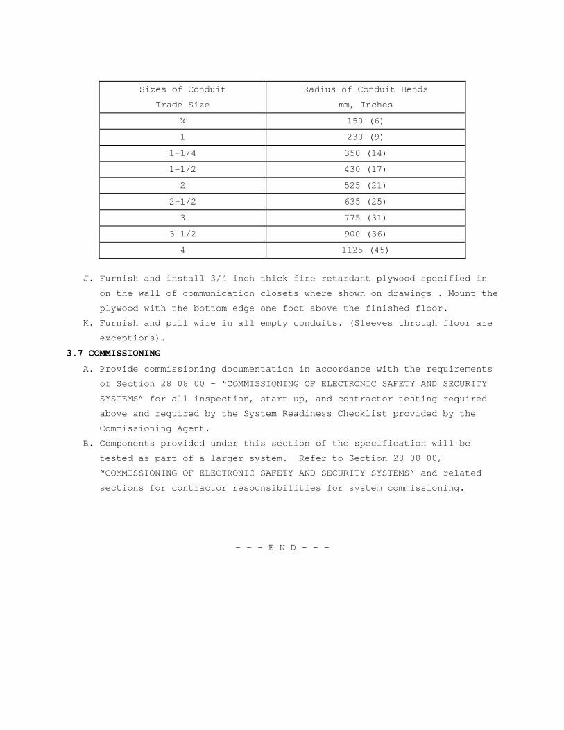
Sizes of Conduit
Trade Size
Radius of Conduit Bends
mm, Inches
¾ 150 (6)
1 230 (9)
1-1/4 350 (14)
1-1/2 430 (17)
2 525 (21)
2-1/2 635 (25)
3 775 (31)
3-1/2 900 (36)
4 1125 (45)
J. Furnish and install 3/4 inch thick fire retardant plywood specified in
on the wall of communication closets where shown on drawings . Mount the
plywood with the bottom edge one foot above the finished floor.
K. Furnish and pull wire in all empty conduits. (Sleeves through floor are
exceptions).
3.7 COMMISSIONING
A. Provide commissioning documentation in accordance with the requirements
of Section 28 08 00 – “COMMISSIONING OF ELECTRONIC SAFETY AND SECURITY
SYSTEMS” for all inspection, start up, and contractor testing required
above and required by the System Readiness Checklist provided by the
Commissioning Agent.
B. Components provided under this section of the specification will be
tested as part of a larger system. Refer to Section 28 08 00,
“COMMISSIONING OF ELECTRONIC SAFETY AND SECURITY SYSTEMS” and related
sections for contractor responsibilities for system commissioning.
- - - E N D - - -

SECTION 28 08 00 COMMISSIONING OF ELECTRONIC SAFETY AND SECURITY
SYSTEMS
PART 1 - GENERAL
1.1 DESCRIPTION
A. The requirements of this Section apply to all sections of Division 28.
B. This project will have selected building systems commissioned. The
complete list of equipment and systems to be commissioned are specified
in Section 01 91 00 GENERAL COMMISSIONING REQUIREMENTS. The
commissioning process, which the Contractor is responsible to execute,
is defined in Section 01 91 00 GENERAL COMMISSIONING REQUIREMENTS. A
Commissioning Agent (CxA) appointed by the VA will manage the
commissioning process.
1.2 RELATED WORK
A. Section 01 00 00 GENERAL REQUIREMENTS.
B. Section 01 91 00 GENERAL COMMISSIONING REQUIREMENTS.
C. Section 01 33 23 SHOP DRAWINGS, PRODUCT DATA, AND SAMPLES.
1.3 SUMMARY
A. This Section includes requirements for commissioning the electronic
safety and security systems, subsystems and equipment. This Section
supplements the general requirements specified in Section 01 91 00
GENERAL COMMISSIONING REQUIREMENTS.
B. The commissioning activities have been developed to support the VA
requirements to meet guidelines for Federal Leadership in Environmental,
Energy, and Economic Performance.
C. Refer to Section 01 91 00 GENERAL COMMISSIONING REQUIREMENTS for more
specifics regarding processes and procedures as well as roles and
responsibilities for all Commissioning Team members.
1.4 DEFINITIONS
A. Refer to Section 01 91 00 GENERAL COMMISSIONING REQUIREMENTS for
definitions.
1.5 COMMISSIONED SYSTEMS
A. Commissioning of a system or systems specified in this Division is part
of the construction process. Documentation and testing of these systems,
as well as training of the VA’s Operation and Maintenance personnel, is
required in cooperation with the VA and the Commissioning Agent.
B. The following Electronic Safety and Security systems will be
commissioned:
1. Fire Detection and Alarm – Building 1 Fire Alarm System (Master panel
and software, addressable units – i.e. pull stations, flow detectors,
heat detectors, etc., controls and alarm functions, horns/bells/door
releases and other output devices, and fire command center functions
– mechanical systems shutdowns, disable switch functions, manual
voice controls).
2. Fire Detection and Alarm – Building 8 Fire Alarm System (Master panel
and software, addressable units – i.e. pull stations, flow detectors,
heat detectors, etc., controls and alarm functions, horns/bells/door
releases and other output devices.
3. Focal Point Graphic Workstations - Building 1 and Building 18 Boiler
Plant (workstation and software, disable switch functions, manual
voice controls, and graphic representations).
4. Fire alarm Graphic Annunciators – Building 11 and Building 53 (Master
panel and software, controls and alarm functions).
1.6 SUBMITTALS
A. The commissioning process requires review of selected Submittals. The
Commissioning Agent will provide a list of submittals that will be
reviewed by the Commissioning Agent. This list will be reviewed and
approved by the C.O.R. prior to forwarding to the Contractor. Refer to
Section 01 33 23 SHOP DRAWINGS, PRODUCT DATA, and SAMPLES for further
details.
B. The commissioning process requires Submittal review simultaneously with
engineering review. Specific submittal requirements related to the
commissioning process are specified in Section 01 91 00 GENERAL
COMMISSIONING REQUIREMENTS.
PART 2 - PRODUCTS (Not Used)
PART 3 - EXECUTION
3.1 PRE-FUNCTIONAL CHECKLISTS
A. The Contractor shall complete Pre-Functional Checklists to verify
systems, subsystems, and equipment installation is complete and systems
are ready for Systems Functional Performance Testing. The Commissioning
Agent will prepare Pre-Functional Checklists to be used to document
equipment installation. The Contractor shall complete the checklists.
Completed checklists shall be submitted to the VA and to the
Commissioning Agent for review. The Commissioning Agent may spot check
a sample of completed checklists. If the Commissioning Agent determines
that the information provided on the checklist is not accurate, the
Commissioning Agent will return the marked-up checklist to the
Contractor for correction and resubmission. If the Commissioning Agent
determines that a significant number of completed checklists for similar
equipment are not accurate, the Commissioning Agent will select a
broader sample of checklists for review. If the Commissioning Agent
determines that a significant number of the broader sample of checklists
is also inaccurate, all the checklists for the type of equipment will be
returned to the Contractor for correction and resubmission. Refer to
SECTION 01 91 00 GENERAL COMMISSIONING REQUIREMENTS for submittal
requirements for Pre-Functional Checklists, Equipment Startup Reports,
and other commissioning documents.
3.2 CONTRACTORS TESTS
A. Contractor tests as required by other sections of Division 28 shall be
scheduled and documented in accordance with Section 01 00 00 GENERAL
REQUIREMENTS. The Commissioning Agent will witness selected Contractor
tests. Contractor tests shall be completed prior to scheduling Systems
Functional Performance Testing.
3.3 SYSTEMS FUNCTIONAL PERFORMANCE TESTING:
A. The Commissioning Process includes Systems Functional Performance
Testing that is intended to test systems functional performance under
steady state conditions, to test system reaction to changes in operating
conditions, and system performance under emergency conditions. The
Commissioning Agent will prepare detailed Systems Functional Performance
Test procedures for review and approval by the C.O.R. The Contractor
shall review and comment on the tests prior to approval. The Contractor
shall provide the required labor, materials, and test equipment
identified in the test procedure to perform the tests. The
Commissioning Agent will witness and document the testing. The
Contractor shall sign the test reports to verify tests were performed.
See Section 01 91 00 GENERAL COMMISSIONING REQUIREMENTS, for additional
details.
3.4 TRAINING OF VA PERSONNEL
A. Training of the VA’s operation and maintenance personnel is required in
cooperation with the C.O.R. and Commissioning Agent. Provide competent,
factory authorized personnel to provide instruction to operation and
maintenance personnel concerning the location, operation, and
troubleshooting of the installed systems. The instruction shall be
scheduled in coordination with the C.O.R. after submission and approval
of formal training plans. Refer to Section 01 91 00 GENERAL
COMMISSIONING REQUIREMENTS and Division 28 Sections for additional
Contractor training requirements.

----- END -----

SECTION 28 31 00 FIRE DETECTION AND ALARM
PART 1 - GENERAL
1.1 DESCRIPTION
A. This section of the specifications includes the furnishing,
installation, and connection of the fire alarm equipment to form a
complete coordinated system ready for operation. It shall include, but
not be limited to, alarm initiating devices, alarm notification
appliances, control units, fire safety control devices, annunciators,
power supplies, and wiring as shown on the drawings and specified. The
fire alarm system shall not be combined with other systems such as
building automation, energy management, security, etc.
B. Fire alarm systems shall comply with requirements of the most recent VA
FIRE PROTECTION DESIGN MANUAL and NFPA 72 unless variations to NFPA 72
are specifically identified within these contract documents by the
following notation: "variation". The design, system layout, document
submittal preparation, and supervision of installation and testing shall
be provided by a technician that is certified NICET level III or a
registered fire protection engineer. The NICET certified technician
shall be on site for the supervision and testing of the system. Factory
engineers from the equipment manufacturer, thoroughly familiar and
knowledgeable with all equipment utilized, shall provide additional
technical support at the site as required by the Contracting Officer
Representative (C.O.R.). Installers shall have a minimum of 2 years
experience installing fire alarm systems.
C. Fire alarm signals:
1. Building(s) 1, 22, 24, 26, 52, 53, 56, and 58 shall have an automatic
digitized voice fire alarm signal with emergency manual voice
override to notify occupants to evacuate. The digitized voice message
shall identify the area of the building (smoke zone) from which the
alarm was initiated, as currently configured.
2. Building(s) 6, 7, 8, 9, 10, 11, and 18 shall have a general
evacuation fire alarm signal in accordance with ASA S3.41 to notify
all occupants in the respective building to evacuate.
D. Alarm signals (by device), supervisory signals (by device) and system
trouble signals (by device not reporting) for Buildings 6, 7, 8, 9, and
10 shall be distinctly transmitted to the main fire alarm system control
unit located in Building 8 Corridor 100-8. Alarm signals (by device),
supervisory signals (by device) and system trouble signals (by device
not reporting) for all other buildings shall be distinctly transmitted
to the main fire alarm system control unit located in Building 1 Fire
Control Room 1C-144. All signals shall be distinctly transmitted over
the fire alarm network to the Fire Alarm Graphic Annunciator (FAGA)
located in Building 53 Corridor C1 11, to the Focal Point Graphic
Workstation (FPGW) located in Building 53 Police Operations Center
Office 1D-137, to the FPGW located in Building 53 Records File Room B-
119, to the FocalPoint Mobile Graphic Workstation (FPMW) located in
Building 11 Office 105-11, to the FAGW located in Building 18 Boiler
Plant Control Room SB01A-18, and to the FPGW located in Building 1 Fire
Control Room 1C-144. All fire alarm network system events and operator
responses shall be recorded on the Fire Alarm Event Printer (PTR)
located in the Building 1 Fire Control Room 1C-144.
E. The main fire alarm control unit located in Building 1 Fire Control Room
1C-144 shall automatically transmit alarm signals to a listed central
station using the existing digital alarm communicator transmitter in
accordance with NFPA 72.
1.2 SCOPE
A. Contractor shall, before beginning any work on the project, review the
project areas of work with the COR to discuss any areas of work where
hazardous materials may be present. Contractor shall not work in the
affected area(s) except by written agreement of the SRE. In the event
that the contractor encounters material believed to be asbestos,
asbestos containing, lead-based paint, or any other hazardous material
which has not been rendered harmless, the contractor shall immediately
stop work in the area affected and notify the SRE. The work in the
affected area shall not thereafter be resumed except by written
agreement of the SRE.
B. Contractor shall, before beginning any work on the project, review the
project areas of work with the COR to discuss any areas of work where
Infectious Control measures may be required. Contractor shall provide
all necessary equipment and procedures to meet all applicable VA
Infectious Control requirements.
C. A fully addressable fire alarm system shall be designed and installed in
accordance with the specifications and drawings. Device location and
wiring runs shown on the drawings are for reference only unless
specifically dimensioned. Actual locations shall be in accordance with
NFPA 72 and this specification.
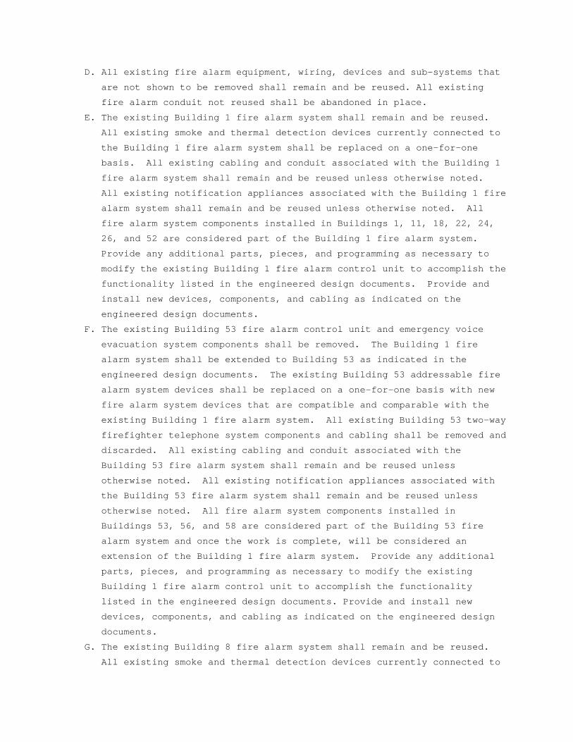
D. All existing fire alarm equipment, wiring, devices and sub-systems that
are not shown to be removed shall remain and be reused. All existing
fire alarm conduit not reused shall be abandoned in place.
E. The existing Building 1 fire alarm system shall remain and be reused.
All existing smoke and thermal detection devices currently connected to
the Building 1 fire alarm system shall be replaced on a one-for-one
basis. All existing cabling and conduit associated with the Building 1
fire alarm system shall remain and be reused unless otherwise noted.
All existing notification appliances associated with the Building 1 fire
alarm system shall remain and be reused unless otherwise noted. All
fire alarm system components installed in Buildings 1, 11, 18, 22, 24,
26, and 52 are considered part of the Building 1 fire alarm system.
Provide any additional parts, pieces, and programming as necessary to
modify the existing Building 1 fire alarm control unit to accomplish the
functionality listed in the engineered design documents. Provide and
install new devices, components, and cabling as indicated on the
engineered design documents.
F. The existing Building 53 fire alarm control unit and emergency voice
evacuation system components shall be removed. The Building 1 fire
alarm system shall be extended to Building 53 as indicated in the
engineered design documents. The existing Building 53 addressable fire
alarm system devices shall be replaced on a one-for-one basis with new
fire alarm system devices that are compatible and comparable with the
existing Building 1 fire alarm system. All existing Building 53 two-way
firefighter telephone system components and cabling shall be removed and
discarded. All existing cabling and conduit associated with the
Building 53 fire alarm system shall remain and be reused unless
otherwise noted. All existing notification appliances associated with
the Building 53 fire alarm system shall remain and be reused unless
otherwise noted. All fire alarm system components installed in
Buildings 53, 56, and 58 are considered part of the Building 53 fire
alarm system and once the work is complete, will be considered an
extension of the Building 1 fire alarm system. Provide any additional
parts, pieces, and programming as necessary to modify the existing
Building 1 fire alarm control unit to accomplish the functionality
listed in the engineered design documents. Provide and install new
devices, components, and cabling as indicated on the engineered design
documents.
G. The existing Building 8 fire alarm system shall remain and be reused.
All existing smoke and thermal detection devices currently connected to
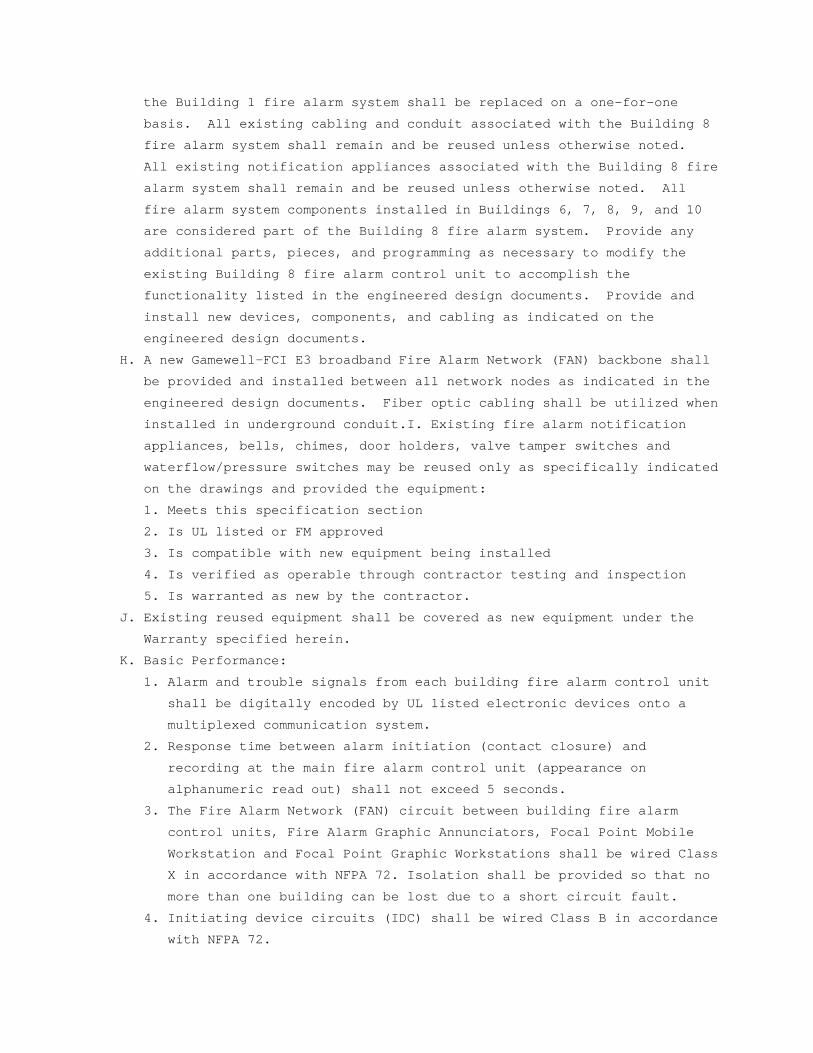
the Building 1 fire alarm system shall be replaced on a one-for-one
basis. All existing cabling and conduit associated with the Building 8
fire alarm system shall remain and be reused unless otherwise noted.
All existing notification appliances associated with the Building 8 fire
alarm system shall remain and be reused unless otherwise noted. All
fire alarm system components installed in Buildings 6, 7, 8, 9, and 10
are considered part of the Building 8 fire alarm system. Provide any
additional parts, pieces, and programming as necessary to modify the
existing Building 8 fire alarm control unit to accomplish the
functionality listed in the engineered design documents. Provide and
install new devices, components, and cabling as indicated on the
engineered design documents.
H. A new Gamewell-FCI E3 broadband Fire Alarm Network (FAN) backbone shall
be provided and installed between all network nodes as indicated in the
engineered design documents. Fiber optic cabling shall be utilized when
installed in underground conduit.I. Existing fire alarm notification
appliances, bells, chimes, door holders, valve tamper switches and
waterflow/pressure switches may be reused only as specifically indicated
on the drawings and provided the equipment:
1. Meets this specification section
2. Is UL listed or FM approved
3. Is compatible with new equipment being installed
4. Is verified as operable through contractor testing and inspection
5. Is warranted as new by the contractor.
J. Existing reused equipment shall be covered as new equipment under the
Warranty specified herein.
K. Basic Performance:
1. Alarm and trouble signals from each building fire alarm control unit
shall be digitally encoded by UL listed electronic devices onto a
multiplexed communication system.
2. Response time between alarm initiation (contact closure) and
recording at the main fire alarm control unit (appearance on
alphanumeric read out) shall not exceed 5 seconds.
3. The Fire Alarm Network (FAN) circuit between building fire alarm
control units, Fire Alarm Graphic Annunciators, Focal Point Mobile
Workstation and Focal Point Graphic Workstations shall be wired Class
X in accordance with NFPA 72. Isolation shall be provided so that no
more than one building can be lost due to a short circuit fault.
4. Initiating device circuits (IDC) shall be wired Class B in accordance
with NFPA 72.
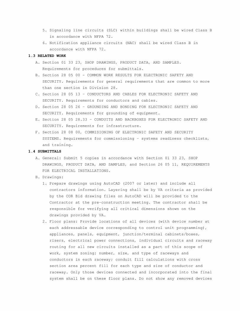
5. Signaling line circuits (SLC) within buildings shall be wired Class B
in accordance with NFPA 72.
6. Notification appliance circuits (NAC) shall be wired Class B in
accordance with NFPA 72.
1.3 RELATED WORK
A. Section 01 33 23, SHOP DRAWINGS, PRODUCT DATA, AND SAMPLES.
Requirements for procedures for submittals.
B. Section 28 05 00 – COMMON WORK RESULTS FOR ELECTRONIC SAFETY AND
SECURITY. Requirements for general requirements that are common to more
than one section in Division 28.
C. Section 28 05 13 - CONDUCTORS AND CABLES FOR ELECTRONIC SAFETY AND
SECURITY. Requirements for conductors and cables.
D. Section 28 05 26 - GROUNDING AND BONDING FOR ELECTRONIC SAFETY AND
SECURITY. Requirements for grounding of equipment.
E. Section 28 05 28.33 - CONDUITS AND BACKBOXES FOR ELECTRONIC SAFETY AND
SECURITY. Requirements for infrastructure.
F. Section 28 08 00, COMMISIONING OF ELECTRONIC SAFETY AND SECURITY
SYSTEMS. Requirements for commissioning - systems readiness checklists,
and training.
1.4 SUBMITTALS
A. General: Submit 5 copies in accordance with Section 01 33 23, SHOP
DRAWINGS, PRODUCT DATA, AND SAMPLES, and Section 26 05 11, REQUIREMENTS
FOR ELECTRICAL INSTALLATIONS.
B. Drawings:
1. Prepare drawings using AutoCAD (2007 or later) and include all
contractors information. Layering shall be by VA criteria as provided
by the COR Bid drawing files on AutoCAD will be provided to the
Contractor at the pre-construction meeting. The contractor shall be
responsible for verifying all critical dimensions shown on the
drawings provided by VA.
2. Floor plans: Provide locations of all devices (with device number at
each addressable device corresponding to control unit programming),
appliances, panels, equipment, junction/terminal cabinets/boxes,
risers, electrical power connections, individual circuits and raceway
routing for all new circuits installed as a part of this scope of
work, system zoning; number, size, and type of raceways and
conductors in each raceway; conduit fill calculations with cross
section area percent fill for each type and size of conductor and
raceway. Only those devices connected and incorporated into the final
system shall be on these floor plans. Do not show any removed devices
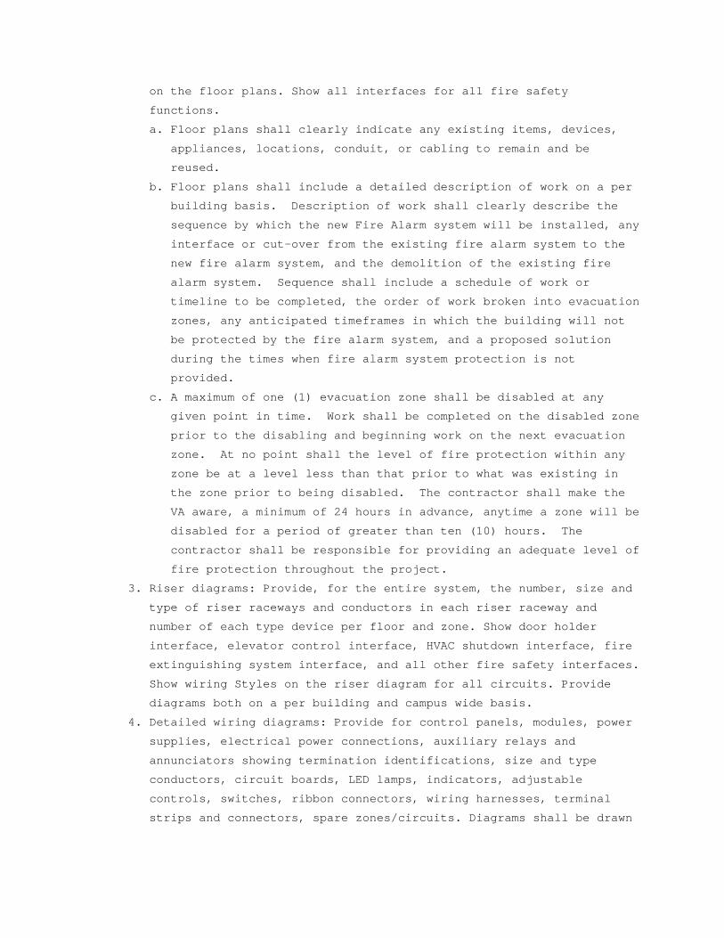
on the floor plans. Show all interfaces for all fire safety
functions.
a. Floor plans shall clearly indicate any existing items, devices,
appliances, locations, conduit, or cabling to remain and be
reused.
b. Floor plans shall include a detailed description of work on a per
building basis. Description of work shall clearly describe the
sequence by which the new Fire Alarm system will be installed, any
interface or cut-over from the existing fire alarm system to the
new fire alarm system, and the demolition of the existing fire
alarm system. Sequence shall include a schedule of work or
timeline to be completed, the order of work broken into evacuation
zones, any anticipated timeframes in which the building will not
be protected by the fire alarm system, and a proposed solution
during the times when fire alarm system protection is not
provided.
c. A maximum of one (1) evacuation zone shall be disabled at any
given point in time. Work shall be completed on the disabled zone
prior to the disabling and beginning work on the next evacuation
zone. At no point shall the level of fire protection within any
zone be at a level less than that prior to what was existing in
the zone prior to being disabled. The contractor shall make the
VA aware, a minimum of 24 hours in advance, anytime a zone will be
disabled for a period of greater than ten (10) hours. The
contractor shall be responsible for providing an adequate level of
fire protection throughout the project.
3. Riser diagrams: Provide, for the entire system, the number, size and
type of riser raceways and conductors in each riser raceway and
number of each type device per floor and zone. Show door holder
interface, elevator control interface, HVAC shutdown interface, fire
extinguishing system interface, and all other fire safety interfaces.
Show wiring Styles on the riser diagram for all circuits. Provide
diagrams both on a per building and campus wide basis.
4. Detailed wiring diagrams: Provide for control panels, modules, power
supplies, electrical power connections, auxiliary relays and
annunciators showing termination identifications, size and type
conductors, circuit boards, LED lamps, indicators, adjustable
controls, switches, ribbon connectors, wiring harnesses, terminal
strips and connectors, spare zones/circuits. Diagrams shall be drawn
to a scale sufficient to show spatial relationships between
components, enclosures and equipment configuration.
5. Two weeks prior to final inspection, the Contractor shall deliver to
the COTR 3 sets of as-built drawings and one set of the as-built
drawing computer files using AutoCAD 2007 or later. As-built drawings
(floor plans) shall show all new and/or existing conduit used for the
fire alarm system.
C. Manuals:
1. Submit simultaneously with the shop drawings, companion copies of
complete maintenance and operating manuals including technical data
sheets for all items used in the system, power requirements, device
wiring diagrams, dimensions, and information for ordering replacement
parts.
a. Wiring diagrams shall have their terminals identified to
facilitate installation, operation, expansion and maintenance.
b. Wiring diagrams shall indicate internal wiring for each item of
equipment and the interconnections between the items of equipment.
c. Include complete listing of all software used and installation and
operation instructions including the input/output matrix chart.
d. Provide a clear and concise description of operation that gives,
in detail, the information required to properly operate, inspect,
test and maintain the equipment and system. Provide all
manufacturer's installation limitations including but not limited
to circuit length limitations.
e. Complete listing of all digitized voice messages.
f. Provide standby battery calculations under normal operating and
alarm modes. Battery calculations shall include the magnets for
holding the doors open for one minute.
g. Include information indicating who will provide emergency service
and perform post contract maintenance.
h. Provide a replacement parts list with current prices. Include a
list of recommended spare parts, tools, and instruments for
testing and maintenance purposes.
i. A computerized preventive maintenance schedule for all equipment.
The schedule shall be provided on disk in a computer format
acceptable to the VAMC and shall describe the protocol for
preventive maintenance of all equipment. The schedule shall
include the required times for systematic examination, adjustment
and cleaning of all equipment. A print out of the schedule shall
also be provided in the manual. Provide the disk in a pocket
within the manual.
j. Furnish manuals in 3 ring loose-leaf binder or manufacturer's
standard binder.
k. A print out for all devices proposed on each signaling line
circuit with spare capacity indicated.
2. Two weeks prior to final inspection, deliver 4 copies of the final
updated maintenance and operating manual to the COTR.
a. The manual shall be updated to include any information
necessitated by the maintenance and operating manual approval.
b. Complete "As installed" wiring and schematic diagrams shall be
included that shows all items of equipment and their
interconnecting wiring. Show all final terminal identifications.
c. Complete listing of all programming information, including all
control events per device including an updated input/output
matrix.
d. Certificate of Installation as required by NFPA 72 for each
building. The certificate shall identify any variations from the
National Fire Alarm Code.
e. Certificate from equipment manufacturer assuring compliance with
all manufacturers installation requirements and satisfactory
system operation.
D. Certifications:
1. Together with the shop drawing submittal, submit the technician's
NICET level III fire alarm certification as well as certification
from the control unit manufacturer that the proposed performer of
contract maintenance is an authorized representative of the major
equipment manufacturer. Include in the certification the names and
addresses of the proposed supervisor of installation and the proposed
performer of contract maintenance. Also include the name and title of
the manufacturer’s representative who makes the certification.
2. Together with the shop drawing submittal, submit a certification from
either the control unit manufacturer or the manufacturer of each
component (e.g., smoke detector) that the components being furnished
are compatible with the control unit.
3. Together with the shop drawing submittal, submit a certification from
the major equipment manufacturer that the wiring and connection
diagrams meet this specification, UL and NFPA 72 requirements.
1.5 WARRANTY
A. All work performed and all material and equipment furnished under this
contract shall be free from defects and shall remain so for a period of
one year from the date of acceptance of the entire installation by the
COR.
1.6 GUARANTY PERIOD SERVICES
A. Complete inspection, testing, maintenance and repair service for the
fire alarm system shall be provided by a factory trained authorized
representative of the manufacturer of the major equipment for a period
of 5 years from the date of acceptance of the entire installation by the
COR.
B. Contractor shall provide all necessary test equipment, parts and labor
to perform required inspection, testing, maintenance and repair.
C. All inspection, testing, maintenance and permanent records required by
NFPA 72, and recommended by the equipment manufacturer shall be provided
by the contractor. Work shall include operation of sprinkler system
alarm and supervisory devices as well as all reused existing equipment
connected to the fire alarm system. It shall include all interfaced
equipment including but not limited to elevators, HVAC shutdown, and
extinguishing systems.
D. Maintenance and testing shall be performed in accordance with NFPA 72. A
computerized preventive maintenance schedule shall be provided and shall
describe the protocol for preventive maintenance of equipment. The
schedule shall include a systematic examination, adjustment and cleaning
of all equipment.
E. Non-included Work: Repair service shall not include the performance of
any work due to improper use, accidents, or negligence for which the
contractor is not responsible.
F. Service and emergency personnel shall report to the Engineering Office
or their authorized representative upon arrival at the hospital and
again upon the completion of the required work. A copy of the work
ticket containing a complete description of the work performed and parts
replaced shall be provided to the VA C.O.R.
G. Emergency Service:
1. Warranty Period Service: Service other than the preventative
maintenance, inspection, and testing required by NFPA 72 shall be
considered emergency call-back service and covered under the warranty
of the installation during the first year of the warranty period,
unless the required service is a result of abuse or misuse by the
Government. Written notification shall not be required for emergency
warranty period service and the contractor shall respond as outlined
in the following sections on Normal and Overtime Emergency Call-Back
Service. Warranty period service can be required during normal or
overtime emergency call-back service time periods at the discretion
of the C.O.R.
2. Normal and overtime emergency call-back service shall consist of an
on-site response within 2 hours of notification of a system trouble.
3. Normal emergency call-back service times are between the hours of
7:30 a.m. and 4:00 p.m., Monday through Friday, exclusive of federal
holidays. Service performed during all other times shall be
considered to be overtime emergency call-back service. The cost of
all normal emergency call-back service for years 2 through 5 shall be
included in the cost of this contract.
4. Overtime emergency call-back service shall be provided for the system
when requested by the Government. The cost of the first 40 manhours
per year of overtime call-back service during years 2 through 5 of
this contract shall be provided under this contract. Payment for
overtime emergency call-back service in excess of the 40 man hours
per year requirement will be handled through separate purchase
orders. The method of calculating overtime emergency call-back hours
is based on actual time spent on site and does not include travel
time.
H. The contractor shall maintain a log at each fire alarm control unit. The
log shall list the date and time of all examinations and trouble calls,
condition of the system, and name of the technician. Each trouble call
shall be fully described, including the nature of the trouble, necessary
correction performed, and parts replaced.
I. In the event that VA modifies the fire alarm system post-Acceptance but
during the 5 year Guaranty Period Service period, Contractor shall be
required to verify that the system, as newly modified or added, is
consistent with the manufacturer's requirements; any verification
performed will be equitably adjusted under the Changes clause. The post-
Acceptance modification or addition to the fire alarm system shall not
void the continuing requirements under this contract set forth in the
Guarantee Period Service provision for the fire alarm system as modified
or added. The contract will be equitably adjusted under the Changes
clause for such additional performance.
1.7 APPLICABLE PUBLICATIONS
A. The publications listed below (including amendments, addenda, revisions,
supplements and errata) form a part of this specification to the extent
referenced. The publications are referenced in text by the basic
designation only and the latest editions of these publications shall be
applicable.
B. National Fire Protection Association (NFPA):
NFPA 13 ................Standard for the Installation of Sprinkler
Systems, 2010 edition
NFPA 14 ................ Standard for the Installation of Standpipes and
Hose Systems, 2010 edition
NFPA 20 ................ Standard for the Installation of Stationary
Pumps for Fire Protection, 2010 edition
NFPA 70.................National Electrical Code (NEC), 2010 edition
NFPA 72.................National Fire Alarm Code, 2010 edition
NFPA 90A................Standard for the Installation of Air
Conditioning and Ventilating Systems, 2009
edition
NFPA 101................Life Safety Code, 2009 edition
C. Underwriters Laboratories, Inc. (UL): Fire Protection Equipment
Directory
D. Factory Mutual Research Corp (FM): Approval Guide, 2007-2011
E. American National Standards Institute (ANSI):
S3.41...................Audible Emergency Evacuation Signal, 1990
edition, reaffirmed 2008
F. International Code Council, International Building Code (IBC), 2009
edition
PART 2 - PRODUCTS
2.1 EQUIPMENT AND MATERIALS, GENERAL
A. All equipment and components shall be new and the manufacturer's current
model. All equipment shall be tested and listed by Underwriters
Laboratories, Inc. or Factory Mutual Research Corporation for use as
part of a fire alarm system. The authorized representative of the
manufacturer of the major equipment shall certify that the installation
complies with all manufacturers’ requirements and that satisfactory
total system operation has been achieved.
2.2 CONDUIT, BOXES, AND WIRE
A. Conduit shall be in accordance with Section 28 05 28.33 CONDUIT AND
BACKBOXES FOR ELECTRONIC SAFETY AND SECURITY and as follows:
1. All new conduits shall be installed in accordance with NFPA 70.
2. Conduit fill shall not exceed 40 percent of interior cross sectional
area.
3. All new conduits shall be 3/4 inch minimum.

B. Wire:
1. Wiring shall be in accordance with NEC article 760, Section 28 05 13,
CONDUCTORS AND CABLES FOR ELECTRONIC SAFETY AND SECURITY, and as
recommended by the manufacturer of the fire alarm system. All wires
shall be color coded. Number and size of conductors shall be as
recommended by the fire alarm system manufacturer, but not less than
18 AWG for initiating device circuits and 14 AWG for notification
device circuits.
2. Any fire alarm system wiring that extends outside of a building shall
have additional power surge protection to protect equipment from
physical damage and false signals due to lightning, voltage and
current induced transients. Protection devices shall be shown on the
submittal drawings and shall be UL listed or in accordance with
written manufacturer's requirements.
3. All wire or cable used in underground conduits including those in
concrete shall be listed for wet locations.
C. Terminal Boxes, Junction Boxes, and Cabinets:
1. Shall be galvanized steel in accordance with UL requirements.
2. All boxes shall be sized and installed in accordance with NFPA 70.
3. covers shall be repainted red in accordance with Section 09 91 00,
PAINTING and shall be identified with white markings as "FA" for
junction boxes and as "FIRE ALARM SYSTEM" for cabinets and terminal
boxes. Lettering shall be a minimum of 3/4 inch high.
4. Terminal boxes and cabinets shall have a volume 50 percent greater
than required by the NFPA 70. Minimum sized wire shall be considered
as 14 AWG for calculation purposes.
5. Terminal boxes and cabinets shall have identified pressure type
terminal strips and shall be located at the base of each riser.
Terminal strips shall be labeled as specified or as approved by the
COTR.
2.3 FIRE ALARM CONTROL UNIT
A. General:
1. The existing building 1 and 8 Gamewell-FCI E3 fire alarm control
units shall remain and be reused. The building 53 FACU shall be
removed.
2. Each power source shall be supervised from the other source for loss
of power.
3. All circuits shall be monitored for integrity.
4. Visually and audibly annunciate any trouble condition including, but
not limited to main power failure, grounds and system wiring
derangement.
5. Transmit all digital alarm, trouble, and supervisory information,
including operator responses, across the campus fire alarm network to
each fire alarm control unit, Fire Alarm Graphic Annunciator (FAGA),
Focal Point Graphic Workstation (FPGW), and the existing digital
alarm communicator transmitter (DACT) connected to the Building 1
FACU.
B. Enclosure:
1. The control unit shall be housed in a cabinet suitable for both
recessed and surface mounting. Cabinet and front shall be corrosion
protected, given a rust-resistant prime coat, and manufacturer's
standard finish.
2. Cabinet shall contain all necessary relays, terminals, lamps, and
legend plates to provide control for the system.
C. Operator terminal at main control unit:
1. Existing operator terminal shall remain and be reused.
D. Power Supply:
1. The control unit shall derive its normal power from a 120 volt, 60 Hz
dedicated supply connected to the emergency power system. Standby
power shall be provided by a 24 volt DC battery as hereinafter
specified. The normal power shall be transformed, rectified,
coordinated, and interfaced with the standby battery and charger.
2. Power supply for smoke detectors shall be taken from the fire alarm
control unit.
3. Provide protectors to protect the fire alarm equipment from damage
due to lightning or voltage and current transients.
4. Provide new separate and direct ground lines to the outside to
protect the equipment from unwanted grounds.
E. Circuit Supervision: Each alarm initiating device circuit, signaling
line circuit, and notification appliance circuit, shall be supervised
against the occurrence of a break or ground fault condition in the field
wiring. These conditions shall cause a trouble signal to sound in the
control unit until manually silenced by an off switch.
F. Supervisory Devices: All sprinkler system valves, standpipe control
valves, post indicator valves (PIV), and main gate valves shall be
supervised for off-normal position. Closing a valve shall sound a
supervisory signal at the control unit until silenced by an off switch.
The specific location of all closed valves shall be identified at the
control unit. Valve operation shall not cause an alarm signal. Low air
pressure switches and duct detectors shall be monitored as supervisory
signals. The power supply to the elevator shunt trip breaker shall be
monitored by the fire alarm system as a supervisory signal.
G. Trouble signals:
1. Arrange the trouble signals for automatic reset (non-latching).
2. System trouble switch off and on lamps shall be visible through the
control unit door.
H. Function Switches: Provide the following switches in addition to any
other switches required for the system:
1. All existing Building 1 and Building 8 fire alarm system function
switches shall remain and be reused. All function switches currently
configured on the Building 53 FACU to be removed shall be replicated
on the Building 1 FACU.
I. Remote Transmissions:
1. Provide capability and equipment for transmission of all alarm,
supervisory and trouble signals as well as operator responses across
the campus FAN to each FACU, FAGA, and FPGW.
2. Transmitters shall be compatible with the systems and equipment they
are connected to such as timing, operation and other required
features.
J. Remote Control Capability: Each building fire alarm control unit shall
be installed and programmed so that each must be reset locally after an
alarm, before the main fire alarm control unit can be reset. After the
local building fire alarm control unit has been reset, then the all
system acknowledge, reset, silence or disabling functions can be
operated by the main fire alarm control unit
K. System Expansion: Design the control units and enclosures so that the
system can be expanded in the future (to include the addition of 20
percent more alarm initiating, alarm notification and door holder
circuits) without disruption or replacement of the existing control unit
and secondary power supply. Fire Alarm Transponder Panels (FTR) will be
acceptable in lieu of additional control panels if the main control unit
and transponder panels are capable of performing all of the functions in
this specification. FTR shall be provided with the maximum amount of
voice evacuation system capacity, including one (1) backup amplifier per
FTR enclosure. FTR shall be provided with additional SLC loop expander
modules for additional node and loop circuits as indicated on the
engineered design documents. The FTR shall be a node on the FCI E3 fire
alarm network.
2.4 STANDBY POWER SUPPLY
A. Uninterrupted Power Supply (UPS):
1. The UPS system shall be comprised of a static inverter, a precision
battery float charger, and sealed maintenance free batteries.
2. Under normal operating conditions, the load shall be filtered through
a ferroresonant transformer.
3. When normal AC power fails, the inverter shall supply AC power to the
transformer from the battery source. There shall be no break in
output of the system during transfer of the system from normal to
battery supply or back to normal.
4. Batteries shall be sealed, gel cell type.
5. UPS system shall be sized to operate the central processor, CRT,
printer, and all other directly connected equipment for 5 minutes
upon a normal AC power failure.
B. Batteries:
1. Battery shall be of the sealed, maintenance free type, 24-volt
nominal.
2. Battery shall have sufficient capacity to power the fire alarm system
for not less than 24 hours plus 5 minutes of alarm to an end voltage
of 1.14 volts per cell, upon a normal AC power failure.
3. Battery racks shall be steel with an alkali-resistant finish.
Batteries shall be secured in seismic areas 2B, 3, or 4 as defined by
the Uniform Building Code.
C. Battery Charger:
1. Shall be completely automatic, with constant potential charger
maintaining the battery fully charged under all service conditions.
Charger shall operate from a 120-volt, 60 hertz emergency power
source.
2. Shall be rated for fully charging a completely discharged battery
within 48 hours while simultaneously supplying any loads connected to
the battery.
3. Shall have protection to prevent discharge through the charger.
4. Shall have protection for overloads and short circuits on both AC and
DC sides.
5. A trouble condition shall actuate the fire alarm trouble signal.
6. Charger shall have automatic AC line voltage regulation, automatic
current-limiting features, and adjustable voltage controls.
2.5 DOOR HOLDER POWER SUPPLIES
A. Provide each door holder power supply (DHPS) unit in an individual,
single, self-contained, lockable cabinet. Input shall be 120 volt AC

nominal with an output of regulated 24 volt DC. Each DHPS shall be
capable of actuation from either a host panel notification circuit, or
programmed dry contacts. Each DHPS shall provide trouble indication to
host panel upon loss of AC power or abnormal conditions on individual
output circuits. Each DHPS shall have a minimum of four (4) supervised
output notification circuits rated individually at a minimum of two
(2.0) amperes available per circuit, with a total output of eight (8.0)
amps. The Contractor shall be responsible for all redesign, circuiting,
and additional equipment costs to provide the necessary output amperage.
Each DHPS shall have a minimum of twenty (20) percent spare capacity on
each circuit.
2.6 ANNUNCIATION
A. Focal Point Graphic Workstation (FPGW):
1. Provide an approved PC based graphical campus monitoring and control
system with text and color graphics display capabilities of all
network events and points. The PC based graphical campus monitoring
and control system shall include, but not be limited to, one or more
PC based graphical workstations, fiber optic FAN communications
media, campus voice control equipment, power supplies, and auxiliary
control devices.
2. The system software shall have the capacity of at least 1,000
screens/floor plans.
3. Provide all necessary equipment, installation, and programming to
include all information for each building connected to the campus
wide FAN.
4. Provide a minimum 19” touchscreen flat screen LCD monitor, full 104
key QWERTY keypad, and mouse type pointing device.
5. The FPGW shall operate from a dedicated 120 volt AC source with a
listed secondary power source conforming to the same alarm and
standby time requirements as the FACU.
7. The FPGW shall be provided such that any condition on the FAN or any
FACU connected to the FAN shall be displayed.
8. The FPGW shall be provided with a serial RS-232 or printer specific
connection such that all events and operator responses of all FAN
connected FACUs will be transmitted to the event printer.
9. A push-to-talk microphone shall be provided at FPGW panel for manual
voice messages. The FPGW shall be provided with the ability to
provide manual "all call" of live or pre-recorded messages to each
individual building or all buildings connected to the FAN
simultaneously on a building wide basis.
10. A single switch shall be provided for each building connected to the
FAN such that live voice paging or a pre-recorded message can be
communicated to each individual building on a whole, general building
basis.
11. A single “all call” switch shall be provided to activate all speaker
circuit groups simultaneously throughout the entire campus.
12. The PC based graphical workstation and all associated equipment that
comprises the FANC shall be UL listed for its intended application.
13. The Focal Point shall be manufactured by Gamewell-FCI.
B. Fire Alarm Graphic Annunciator (FAGA):
1. The FAGA shall be a Gamewell-FCI NGA LCD Graphic Annunciator.
2. Provide all cabling and conduit necessary to extend the E3 FAN to
each FAGA.
3. Provide all enclosures, power supplies, network interface
components, and batteries as necessary.
4. Provide all programming as necessary.
C. Focal Point Mobile Workstation (FPMW):
1. The FPMW shall be a Gamewell-FCI Focal Point Mobile Workstation; a
tablet PC-based graphic user interface.
2. Provide all cabling and conduit necessary to extend the E3 FAN to
each FPMW.
3. Provide all enclosures, power supplies, network interface
components, and batteries as necessary.
4. Provide all programming as necessary.
5. Provide all parts and pieces necessary to wall mount the FPMW as
indicated on the engineered design documents. Wall mount shall
include charging / docking station hardwired to the FCI-E3 fire alarm
network.
D. Fire Alarm Event Printers (PTR):
1. System printers shall be high reliability digital input devices, UL
approved, for fire alarm applications. The printers shall operate at
a minimum speed of 30 characters per second. The printer shall be
continually supervised.
2. Printers shall be programmable to either alarm only or event logging
output.
a. Alarm printers shall provide a permanent (printed) record of all
alarm information that occurs within the fire alarm system. Alarm
information shall include the date, time, building number, floor,
zone, device type, device address, and condition.
b. Event logging printers shall provide a permanent (printed) record
of every change of status that occurs within the fire alarm
system. Status information shall include date, time, building
number, floor, zone, device type, device address and change of
status (alarm, trouble, supervisory, reset/return to normal).
3. System printers shall provide tractor drive feed pins for
conventional fan fold 8-1/2" x 11" paper.
4. The printers shall provide a printing and non-printing self test
feature.
5. Power supply for printers shall be taken from and coordinated with
the building emergency service.
6. Each printer shall be provided with a stand for the printer and
paper.
7. Spare paper and ribbons for printers shall be stocked and maintained
as part of the one year guarantee period services in addition to the
one installed after the approval of the final acceptance test.
2.7 VOICE COMMUNICATION SYSTEM (VCS)
A. General:
1. The existing emergency voice communication system installed
throughout Buildings 1, 11, 18, 22, 24, 26, and 52 shall remain and
be reused The existing emergency voice communication system
installed throughout Building 53, 56, and 58 shall be removed from
the existing Building 53 FACU and added to the Building 1 system.
The existing Building 1 emergency voice communication system shall be
modified as necessary to include the Building 53 emergency voice
evacuation system. The existing Building 53 emergency voice
evacuation system and system functionality shall be replicated on the
Building 1 FACU.
2. Upon receipt of an alarm signal from the building fire alarm system,
the VCS shall automatically transmit a pre-recorded fire alarm
message throughout the evacuation zone in alarm, the adjacent
evacuation zone(s), Building 11, and Building 18 (including the
Boiler Plant), as indicated in the engineered design documents.
3. A digitized voice module shall be used to store each prerecorded
message. The existing Building 1 voice modules shall remain and be
reused. Provide any additional voice modules in the Building 1 FACU
to replicate the current Building 53 messages.
4. The VCS shall be arranged as a single channel system.
5. The VCS shall supervise all speaker circuits, control equipment,
remote audio control equipment, and amplifiers.
B. Speaker Circuit Control Unit:
1. The existing Building 1 speaker circuit control unit shall remain and
be reused. Provide additional speaker circuit control units in the
Building 1 FACU to duplicate those currently installed on the
Building 53 FACU.
2. Speaker circuit control switches shall provide on, off, and automatic
positions and indications.
3. The speaker circuit control unit shall include visual indication of
active or trouble status for each group of speaker circuits in the
system.
4. A trouble indication shall be provided if a speaker circuit group is
disabled.
5. A lamp test switch shall be provided to test all indicator lamps.
6. A single "all call" switch shall be provided to activate all speaker
circuit groups simultaneously.
7. A push-to-talk microphone shall be provided for manual voice
messages.
8. Remote microphones shall be provided at each FPGW for manual "all
call" messages to each individual building and throughout all
buildings 1, 11, 18, 22, 24, 26, 52, 53, 56, and 58.
9. A voice message disconnect switch shall be provided to disconnect
automatic digitized voice messages from the system. The system shall
be arranged to allow manual voice messages and indicate a system
trouble condition when activated.
C. Speaker Circuit Arrangement:
1. Existing speaker circuits shall remain and be reused.
2. Audio amplifiers and control equipment shall be electrically
supervised for normal and abnormal conditions.
3. Speaker circuits shall be 25 VRMS .
4. Speaker circuits and control equipment shall be arranged such that
loss of any one speaker circuit will not cause the loss of any other
speaker circuit in the system.
D. Digitized Voice Module (DVM):
1. The Digitized Voice Module shall provide prerecorded digitized
evacuation and instructional messages. The messages shall be
professionally recorded and approved by the COTR prior to
programming.
2. The DVM shall be configured to automatically output to the desired
circuits following a 10-second slow whoop alert tone.
3. Prerecorded magnetic taped messages and tape players are not
permitted.
4. The digitized message capacity shall be no less than 15 second in
length.
5. The digitized message shall be transmitted 3 times.
6. The DVM shall be supervised for operational status.
7. Failure of the DVM shall result in the transmission of a constant
alarm tone.
8. The DVM memory shall have a minimum 50 percent spare capacity after
those messages identified in this section are recorded. Multiple
DVM's may be used to obtain the required capacity.
9. The existing Building 1 DVMs shall remain and be reused. Provide any
additional DVMs as necessary to duplicate the Building 53 emergency
voice messages and include them on the Building 1 FACU.
E. Audio Amplifiers:
1. Audio Amplifiers shall be Gamewell-FCI AM-50 series amplifiers and
shall provide a minimum of 50 Watts at 25 VRMS output voltage levels.
2. Amplifiers shall be continuously supervised for operational status.
3. Amplifiers shall be configured for either single or dual channel
application.
4. Existing audio output circuit connections shall remain and be reused
as configured. The existing Building 53 audio output circuits shall
be connected to a new Gamewell-FCI Fire Alarm Transponder Panel (FTR)
to be installed in the Building 53 electrical closets as indicated on
the engineered design documents.
5. A minimum of 50 percent spare output capacity shall be available for
each amplifier.
6. Fire Alarm Transponder panels shall be Gamewell-FCI INX Intelligent
Network Transponder panels with a minimum four (4) AM-50 amplifiers
including backup.
7. One (1) backup amplifier shall be provided and installed within each
FTR.
F. Tone Generator(s):
1. Tone Generator(s) shall be capable of providing a distinctive 3-pulse
temporal pattern fire alarm signal as well as a slow whoop.
2. Tone Generator(s) shall be continuously supervised for operational
status.
2.8 ALARM NOTIFICATION APPLIANCES
A. Bells:
1. All bells are existing and shall remain and be reused as currently
configured, unless otherwise noted on the engineered design
documents.
B. Speakers:
1. All speakers are existing and shall remain and be reused as currently
configured, unless otherwise noted on the engineered design
documents.
C. Strobes:
1. All strobes are existing and shall remain and be reused as currently
configured, unless otherwise noted on the engineered design
documents.
D. Fire Alarm Horns:
1. All fire alarm horns are existing and shall remain and be reused as
currently configured, unless otherwise noted on the engineered design
documents.
2.9 ALARM INITIATING DEVICES
A. Manual Fire Alarm Stations:
1. All manual pull stations currently connected to the Building 1 or
Building 8 fire alarm systems shall remain and be reused as currently
configured.
2. All existing manual pull stations currently connected to the Building
53 fire alarm system shall be replaced on a one-for-one basis with a
Gamewell-FCI MS-7 manual station.
B. Smoke Detectors:
1. All spot type and duct type detectors installed shall be a Gamewell-
FCI ASD-PL2F and ASD-PL2FR analog, addressable photoelectric smoke
sensor, respectively.
C. Heat Detectors:
1. All Heat detectors installed shall be a Gamewell-FCI ATD-L2F, ATD-
RL2F, or ATD-HL2 addressable thermal sensor as necessary.
D. Water Flow and Pressure Switches:
1. All wet pipe water flow switches and dry pipe alarm pressure switches
for sprinkler systems are existing and shall be connected to the fire
alarm system by way of an address reporting interface device.
E. Extinguishing System Connections:
1. Kitchen Range Hood and Duct Suppression Systems:
a. Each suppression system shall be equipped with a micro-switch
connected to the building fire alarm control unit. Discharge of a
suppression system shall automatically send a alarm signal to the
building fire detection and alarm system for annunciation.
b. Operation of this suppression system shall also automatically shut
off all sources of fuel and heat to all equipment requiring
protection under the same hood.
2. Each gaseous suppression system shall be monitored for system alarm
and system trouble conditions via addressable interface devices.
2.10 SUPERVISORY DEVICES
A. Duct Smoke Detectors:
1. Duct smoke detectors shall be provided and connected by way of an
address reporting interface device. Detectors shall be provided with
an approved duct housing mounted exterior to the duct, and shall have
perforated sampling tubes extending across the full width of the duct
(wall to wall). Detector placement shall be such that there is
uniform airflow in the cross section of the duct.
2. Interlocking with fans shall be provided in accordance with NFPA 90A
and as specified hereinafter under Part 3.2, "TYPICAL OPERATION".
3. Provide remote indicator lamps, key test stations and identification
nameplates (e.g. "DUCT SMOKE DETECTOR AHU-X") for all duct detectors.
Locate key test stations in plain view on walls or ceilings so that
they can be observed and operated from a normal standing position.
B. Sprinkler and Standpipe System Supervisory Switches:
1. Existing valve supervisory switches shall be connected to the fire
alarm system by way of address reporting interface device. Existing
Building 1 and Building 8 fire alarm system valve supervisory
switches and address reporting monitor modules shall remain and be
reused. Replace all existing Building 53 fire alarm system
addressable monitor modules on a one-for-for one basis with a new
Gamewell-FCI AMM-4F addressable monitor module. 2.10 ADDRESS
REPORTING INTERFACE DEVICE
C. Existing Building 1 and Building 8 fire alarm system address reporting
monitor modules shall remain and be reused. Replace all existing
Building 53 fire alarm system addressable monitor modules on a one-for-
for one basis with a new Gamewell-FCI AMM-4F addressable monitor module.
2.11 SMOKE BARRIER DOOR CONTROL
A. Electromagnetic Door Holders:
1. All door holders are existing and shall remain and be reused. The
Building 1 door hold open power supply cabinet and contents shall be
replaced with an adequate number of self-contained door hold open
power supplies as indicated on the engineered design documents.
2.12 UTILITY LOCKS AND KEYS:
A. All key operated test switches, control units, annunciator panels and
lockable cabinets shall be provided with a single standardized utility
lock and key.
B. Key-operated manual fire alarm stations shall have a single standardized
lock and key separate from the control equipment.
C. All keys shall be delivered to the COTR.
2.13 SPARE AND REPLACEMENT PARTS
A. Provide spare and replacement parts as follows:
1. Manual pull stations - 5
2. Heat detectors - 2 of each type
3. Smoke detectors - 20
4. Duct smoke detectors with all appurtenances - 1
5. Control equipment keys - 25
6. 2.5 oz containers aerosol smoke - 12
7. Printer paper - 3 boxes
8. Printer replacement ribbons - 3
9. Monitor modules - 3
10. Control modules - 3
11. Fire alarm SLC cable (same as installed) – 500 feet
B. Spare and replacement parts shall be in original packaging and submitted
to the COR.
C. Provide to the VA, all hardware, software, programming tools, license
and documentation necessary to permanently modify the fire alarm system
on site. The minimum level of modification includes addition and
deletion of devices, circuits, zones and changes to system description,
system operation, and digitized evacuation and instructional messages.
2.14 INSTRUCTION CHART:
A. Provide typewritten instruction card mounted behind a Lexan plastic or
glass cover in a stainless steel or aluminum frame with a backplate.
Install the frame in a conspicuous location observable from each control
unit where operations are performed. The card shall show those steps to
be taken by an operator when a signal is received under all conditions,
normal, alarm, supervisory, and trouble. Provide an additional copy with
the binder for the input output matrix for the sequence of operation.
The instructions shall be approved by the COTR before being posted.
PART 3 - EXECUTION
3.1 INSTALLATION:
A. Installation shall be in accordance with NFPA 70, 72, 90A, and 101 as
shown on the drawings, and as recommended by the major equipment
manufacturer. Fire alarm wiring shall be installed in conduit. All
conduit and wire shall be installed in accordance with, Section 28 05 13
CONDUCTORS AND CABLES FOR ELECTRONIC SAFETY AND SECURITY, Section 28 05
26 GROUNDING AND BONDING FOR ELECTRONIC SAFETY AND SECURITY, and Section
28 05 28.33 CONDUIT AND BACKBOXES FOR ELECTRONIC SAFETY AND SECURITY.
B. All conduits, junction boxes, conduit supports and hangers shall be
concealed in finished areas and may be exposed in unfinished areas.
C. All new and reused exposed conduits shall be painted in accordance with
Section 09 91 00, PAINTING to match surrounding finished areas and red
in unfinished areas.
D. All existing fire alarm conduit not reused shall be abandoned in-place
if approved by SRE and COTR.
E. Existing devices that are reused shall be properly mounted and
installed. Where devices are installed on existing shallow backboxes,
extension rings of the same material, color and texture of the new fire
alarm devices shall be used. Mounting surfaces shall be cut and patched
in accordance with Section 01 00 00, GENERAL REQUIREMENTS, Restoration,
and be re-painted in accordance with Section 09 91 00, PAINTING as
necessary to match existing.
F. All new fire detection and alarm system devices, control units and
remote annunciators shall be flush mounted when located in finished
areas and may be surface mounted when located in unfinished areas. Exact
locations are to be approved by the COTR.
G. Manual pull stations shall be installed as part of the Building 53 one-
for-one replacement shall utilize the existing pull station location.
3.2 TYPICAL OPERATION
A. Activation of any manual pull station, water flow or pressure switch,
heat detector, kitchen hood suppression system, gaseous suppression
system, or smoke detector shall cause the following operations to occur:
1. Operate the emergency voice communication system in the zone of alarm
origin and adjacent zone as well as Buildings 11, 18, and Boiler
Plant. For sprinkler protected buildings, flash strobes continuously
only in the zone of alarm. For buildings without sprinkler protection
throughout, flash strobes continuously only on the floor of alarm.
2. Continuously sound a temporal pattern general alarm and flash all
strobes in the building in alarm until reset at the local fire alarm
control unit in Buildings 6, 7, 8, 9, and 10.
3. Release only the magnetic door holders in the evacuation zone of
alarm origin and adjacent evacuation zone after the alert signal.
4. Transmit a separate alarm signal, via the main fire alarm control
unit to the fire department.
5. Unlock the electrically locked exit doors within the evacuation zone
of alarm.
B. Heat detectors in elevator machine rooms shall, in addition to the above
functions, disconnect all power to all elevators served by that machine
room after a time delay. The time delay shall be programmed within the
fire alarm system programming and be equal to the time it takes for the
car to travel from the highest to the lowest level, plus 10 seconds.
C. Smoke detectors in the primary elevator lobbies of Buildings 1, 22, 24,
and 53 shall, in addition to the above functions, return all elevators
in the bank to the secondary floor.
D. Smoke detectors in the remaining elevator lobbies, elevator machine
room, or top of hoistway shall, in addition to the above functions,
return all elevators in the bank to the primary floor.
E. Operation of a smoke detector at a corridor door used for automatic
closing shall also release only the magnetic door holders in that
evacuation zone and adjacent zone. Operation of a smoke detector at a
shutter used for automatic closing shall also release only the shutters
in that smoke zone.
F. Operation of duct smoke detectors shall cause a system supervisory
condition and shut down the ventilation system and close the associated
smoke dampers as appropriate.
G. Operation of any sprinkler or standpipe system valve supervisory switch,
high/low air pressure switch, or fire pump alarm switch shall cause a
system supervisory condition.
H. Alarm verification shall not be used for smoke detectors installed for
the purpose of early warning.
3.3 TESTS
A. Provide the service of a NICET level III, competent, factory-trained
engineer or technician authorized by the manufacturer of the fire alarm
equipment to technically supervise and participate during all of the
adjustments and tests for the system. Make all adjustments and tests in
the presence of the COR.
B. When the systems have been completed and prior to the scheduling of the
final inspection, furnish testing equipment and perform the following
tests in the presence of the COR. When any defects are detected, make
repairs or install replacement components, and repeat the tests until
such time that the complete fire alarm systems meets all contract
requirements. After the system has passed the initial test and been
approved by the COTR, the contractor may request a final inspection.
1. Before energizing the cables and wires, check for correct connections
and test for short circuits, ground faults, continuity, and
insulation.
2. Test the insulation on all installed cable and wiring by standard
methods as recommended by the equipment manufacturer.
3. Run water through all flow switches. Check time delay on water flow
switches. Submit a report listing all water flow switch operations
and their retard time in seconds.
4. Open each alarm initiating and notification circuit to see if trouble
signal actuates.
5. Ground each alarm initiation and notification circuit and verify
response of trouble signals.
3.4 FINAL INSPECTION AND ACCEPTANCE
A. Prior to final acceptance a minimum 30 day "burn-in" period shall be
provided. The purpose shall be to allow equipment to stabilize and
potential installation and software problems and equipment malfunctions
to be identified and corrected. During this diagnostic period, all
system operations and malfunctions shall be recorded. Final acceptance
will be made upon successful completion of the "burn-in" period and
where the last 14 days is without a system or equipment malfunction.
B. At the final inspection a factory trained representative of the
manufacturer of the major equipment shall repeat the tests in Article
3.3 TESTS and those required by NFPA 72. In addition the representative
shall demonstrate that the systems function properly in every respect.
The demonstration shall be made in the presence of a VA representative.
3.5 INSTRUCTION
A. The manufacturer's authorized representative shall provide instruction
and training to the VA as follows:
1. Six 1-hour sessions to engineering staff, security police and central
attendant personnel for simple operation of the system. Two sessions
at the start of installation, 2 sessions at the completion of
installation and 2 sessions 3 months after the completion of
installation.
2. Four 2-hour sessions to engineering staff for detailed operation of
the system. Two sessions at the completion of installation and 2
sessions 3 months after the completion of installation.
3. Three 8-hour sessions to electrical technicians for maintaining,
programming, modifying, and repairing the system at the completion of
installation and one 8-hour refresher session 3 months after the
completion of installation.
B. The Contractor and/or the Systems Manufacturer's representative shall
provide a typewritten "Sequence of Operation" including a trouble
shooting guide of the entire system for submittal to the VA. The
sequence of operation will be shown for each input in the system in a
matrix format and provided in a loose leaf binder. When reading the
sequence of operation, the reader will be able to quickly and easily
determine what output will occur upon activation of any input in the
system. The INPUT/OUTPUT matrix format shall be as shown in Appendix A
to NFPA 72.
C. Furnish the services of a competent instructor for instructing personnel
in the programming requirements necessary for system expansion. Such
programming shall include addition or deletion of devices, zones,
indicating circuits and printer/display text.
PART 4 - SCHEDULES
4.1 SMOKE ZONE DESCRIPTIONS:
1. ZONE 01:01-A BUILDING 1, FIRST FLOOR, A WING.
2. ZONE 01:01-B BUILDING 1, FIRST FLOOR, B WING.
3. ZONE 01:01-C BUILDING 1, FIRST FLOOR, C WING.
4. ZONE 01:01-E BUILDING 1, FIRST FLOOR, E WING.
5. ZONE 01:02-A BUILDING 1, SECOND FLOOR, A WING.
6. ZONE 01:02-B BUILDING 1, SECOND FLOOR, B WING.
7. ZONE 01:02-C BUILDING 1, SECOND FLOOR, C WING.
8. ZONE 01:03-A BUILDING 1, THIRD FLOOR, A WING.
9. ZONE 01:03-B BUILDING 1, THIRD FLOOR, B WING.
10. ZONE 01:03-C BUILDING 1, THIRD FLOOR, C WING.
11. ZONE 01:04-A BUILDING 1, FOURTH FLOOR, A WING.
12. ZONE 01:04-B BUILDING 1, FOURTH FLOOR, B WING.
13. ZONE 01:04-C BUILDING 1, FOURTH FLOOR, C WING.
14. ZONE 01:05-A BUILDING 1, FIFTH FLOOR, A WING.
15. ZONE 01:05-B BUILDING 1, FIFTH FLOOR, B WING.
16. ZONE 01:06-A BUILDING 1, SIXTH FLOOR, A WING.
17. ZONE 11:01-A BUILDING 11, FIRST FLOOR.
18. ZONE 18:B-A BUILDING 18, BOILER PLANT.
19. ZONE 18:01-A BUILDING 18, FIRST FLOOR.
20. ZONE 22:B-A BUILDING 22, BASEMENT.
21. ZONE 22:01-A BUILDING 22, FIRST FLOOR.
22. ZONE 22:02-A BUILDING 22, SECOND FLOOR.
23. ZONE 24:B-A BUILDING 24, BASEMENT.
24. ZONE 24:01-A BUILDING 24, FIRST FLOOR.
25. ZONE 24:02-A BUILDING 24, SECOND FLOOR.
26. ZONE 52:01-A BUILDING 52, FIRST FLOOR.
27. ZONE 53:B-A BUILDING 53, BASEMENT.
28. ZONE 53:SL-A BUILDING 53, SERVICE LEVEL.
29. ZONE 53:01-A BUILDING 53, FIRST FLOOR.
30. ZONE 53:02-A BUILDING 53, SECOND FLOOR.
31. ZONE 53:03-A BUILDING 53, THIRD FLOOR.
32. ZONE 53:3N-A BUILDING 53, THIRD FLOOR - INTERSTITIAL.
33. ZONE 53:04-A BUILDING 53, FOURTH FLOOR.
34. ZONE 53:4N-A BUILDING 53, FOURTH FLOOR - INTERSTITIAL.
35. ZONE 53:05-A BUILDING 53, FIFTH FLOOR.
36. ZONE 53:5N-A BUILDING 53, FIFTH FLOOR - INTERSTITIAL.
37. ZONE 53:06-A BUILDING 53, SIXTH FLOOR.
4.2 DIGITIZED VOICE MESSAGES:
A. Digitized voice messages shall be provided for each smoke zone of
Buildings 1, 11, 18, 22, 24, 26, 52, 53, 56, and 58. The messages shall
be arranged with a 3 second alert tone, a "Code Red" message and a
description of the fire alarm area (building number, floor, level and
smoke zone). A sample of such a message is as follows:
Alert Tone
Code Red
Building One, Second Floor, ’A’ Wing
Code Red
Building One, Second Floor, ’A’ Wing
Code Red
Building One, Second Floor, ’A’ Wing
4.3 LOCATION OF VOICE MESSAGES:
A. Upon receipt of an alarm signal from the building fire alarm system, the
voice communication system shall automatically transmit a 3 second tone
alert and a pre-recorded fire alarm message throughout evacuation zone
of alarm origin, the adjacent evacuation zone, Building 11, Building 18,
and the Boiler Plant as indicated in the engineered design documents.
- - END - -