DESIGN BASIS DOCUMENT - Vendor Registry
626
TABLE OF CONTENTS b2E #18608 ARLINGTON COUNTY DETENTION FACILITY KITCHEN AIR HANDLER Air Handler (AHU-2) and Air Distribution FOR BID Arlington County Detention Facility Kitchen Air Handler Table of Contents Air Handler (AHU-2) and Air Distribution Page - 1 b2E Consulting Engineers, P.C. B2E TABLE OF CONTENTS FOR PROJECT MANUAL This Table of Contents is for convenience only. Its accuracy and completeness is not guaranteed and it is not to be considered part of the Specifications. In case of a discrepancy between the Table of Contents and the Specifications, the Specifications shall govern. SECT.NO. SECTION TITLE SPECIAL CONDITIONS DIVISION 01 GENERAL REQUIREMENTS 01 00 00 GENERAL REQUIREMENTS 01 10 00 SUMMARY 01 25 00 SUBSTITUTION PROCEDURES 01 26 00 CONTRACT MODIFICATIONS PROCEDURES 01 29 00 PAYMENT PROCEDURES 01 31 00 PROJECT MANAGEMENT AND COORDINATION 01 32 00 CONSTRUCTION PROGRESS DOCUMENTATION 01 32 33 PHOTOGRAPHIC DOCUMENTATION 01 33 00 SUBMITTAL PROCEDURES 01 35 16 ALTERATION PROJECT PROCEDURES 01 40 00 QUALITY REQUIREMENTS 01 42 00 REFERENCES 01 50 00 TEMPORARY FACILITIES AND CONTROLS 01 56 39 TEMPORARY TREE AND PLANT PROTECTION 01 60 00 PRODUCT REQUIREMENTS 01 73 00 EXECUTION 01 74 19 CONSTRUCTION WASTE MANAGEMENT AND DISPOSAL 01 77 00 CLOSEOUT PROCEDURES 01 78 23 OPERATION AND MAINTENANCE DATA 01 78 39 PROJECT RECORD DOCUMENTS 01 79 00 DEMONSTRATION AND TRAINING 01 91 13 GENERAL COMMISSIONING REQUIREMENTS 01 95 00 PROPOSED PHASING PLAN DIVISION 02 EXISTING CONDITIONS 02 41 19 SELECTIVE DEMOLITION DIVISION 03 CONCRETE 03 30 00 CAST-IN-PLACE CONCRETE 03 35 00 CONCRETE FINISHING DIVISION 05 METALS 05 50 00 METAL FABRICATIONS DIVISION 07 THERMAL AND MOISTURE PROTECTION 07 84 10 THROUGH-PENETRATION FIRESTOP SYSTEMS 07 92 00 JOINT SEALANTS DIVISION 09 FINISHES 09 91 00 PAINTING 09 96 00 HIGH PERFORMANCE EPOXY COATINGS DIVISION 21 FIRE SUPPRESSION 21 01 00 GENERAL REQUIREMENTS FOR FIRE SUPPRESSION SPRINKLER SYSTEM ATTACHMENT B – ACDF KITCHEN HVAC SPECIFICATIONS
-
Upload
khangminh22 -
Category
Documents
-
view
4 -
download
0
Transcript of DESIGN BASIS DOCUMENT - Vendor Registry

TABLE OF CONTENTS b2E #18608
ARLINGTON COUNTY DETENTION FACILITY KITCHEN AIR HANDLER Air Handler (AHU-2) and Air Distribution
FOR BID
Arlington County Detention Facility Kitchen Air Handler Table of Contents Air Handler (AHU-2) and Air Distribution Page - 1 b2E Consulting Engineers, P.C.
B2E TABLE OF CONTENTS FOR PROJECT MANUAL
This Table of Contents is for convenience only. Its accuracy and completeness is not guaranteed and it is not to be considered part of the Specifications. In case of a discrepancy between the Table of Contents and the Specifications, the Specifications shall govern.
SECT.NO. SECTION TITLE
SPECIAL CONDITIONS
DIVISION 01 GENERAL REQUIREMENTS 01 00 00 GENERAL REQUIREMENTS 01 10 00 SUMMARY 01 25 00 SUBSTITUTION PROCEDURES 01 26 00 CONTRACT MODIFICATIONS PROCEDURES 01 29 00 PAYMENT PROCEDURES 01 31 00 PROJECT MANAGEMENT AND COORDINATION 01 32 00 CONSTRUCTION PROGRESS DOCUMENTATION 01 32 33 PHOTOGRAPHIC DOCUMENTATION 01 33 00 SUBMITTAL PROCEDURES 01 35 16 ALTERATION PROJECT PROCEDURES 01 40 00 QUALITY REQUIREMENTS 01 42 00 REFERENCES 01 50 00 TEMPORARY FACILITIES AND CONTROLS 01 56 39 TEMPORARY TREE AND PLANT PROTECTION 01 60 00 PRODUCT REQUIREMENTS 01 73 00 EXECUTION 01 74 19 CONSTRUCTION WASTE MANAGEMENT AND DISPOSAL 01 77 00 CLOSEOUT PROCEDURES 01 78 23 OPERATION AND MAINTENANCE DATA 01 78 39 PROJECT RECORD DOCUMENTS 01 79 00 DEMONSTRATION AND TRAINING 01 91 13 GENERAL COMMISSIONING REQUIREMENTS 01 95 00 PROPOSED PHASING PLAN
DIVISION 02 EXISTING CONDITIONS 02 41 19 SELECTIVE DEMOLITION
DIVISION 03 CONCRETE 03 30 00 CAST-IN-PLACE CONCRETE 03 35 00 CONCRETE FINISHING
DIVISION 05 METALS 05 50 00 METAL FABRICATIONS
DIVISION 07 THERMAL AND MOISTURE PROTECTION 07 84 10 THROUGH-PENETRATION FIRESTOP SYSTEMS 07 92 00 JOINT SEALANTS
DIVISION 09 FINISHES 09 91 00 PAINTING 09 96 00 HIGH PERFORMANCE EPOXY COATINGS
DIVISION 21 FIRE SUPPRESSION 21 01 00 GENERAL REQUIREMENTS FOR FIRE SUPPRESSION SPRINKLER SYSTEM
ATTACHMENT B – ACDF KITCHEN HVAC SPECIFICATIONS
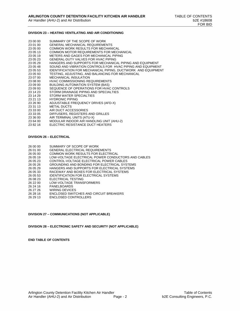
TABLE OF CONTENTS b2E #18608
ARLINGTON COUNTY DETENTION FACILITY KITCHEN AIR HANDLER Air Handler (AHU-2) and Air Distribution
FOR BID
Arlington County Detention Facility Kitchen Air Handler Table of Contents Air Handler (AHU-2) and Air Distribution Page - 2 b2E Consulting Engineers, P.C.
DIVISION 23 – HEATING VENTILATING AND AIR CONDITIONING
23 00 00 SUMMARY OF THE SCOPE OF WORK 23 01 00 GENERAL MECHANICAL REQUIREMENTS 23 05 00 COMMON WORK RESULTS FOR MECHANICAL 23 05 13 COMMON MOTOR REQUIREMENTS FOR MECHANICAL 23 05 19 METERS AND GAGES FOR MECHANICAL PIPING 23 05 23 GENERAL-DUTY VALVES FOR HVAC PIPING 23 05 29 HANGERS AND SUPPORTS FOR MECHANICAL PIPING AND EQUIPMENT 23 05 48 SOUND AND VIBRATION CONTROLS FOR HVAC PIPING AND EQUIPMENT 23 05 53 IDENTIFICATION FOR MECHANICAL PIPING, DUCTWORK AND EQUIPMENT 23 05 93 TESTING, ADJUSTING, AND BALANCING FOR MECHANICAL 23 07 00 MECHANICAL INSULATION 23 08 00 HVAC COMMISSIONING REQUIREMENTS 23 09 00 BUILDING AUTOMATION SYSTEM (BAS) 23 09 93 SEQUENCE OF OPERATIONS FOR HVAC CONTROLS 23 14 23 STORM DRAINAGE PIPING AND SPECIALTIES 23 14 29 STORM WATER SPECIALTIES 23 21 13 HYDRONIC PIPING 23 26 90 ADJUSTABLE FREQUENCY DRIVES (AFD-X) 23 31 13 METAL DUCTS 23 33 00 AIR DUCT ACCESSORIES 23 33 05 DIFFUSERS, REGISTERS AND GRILLES 23 36 00 AIR TERMINAL UNITS (ATU-X) 23 64 00 MODULAR INDOOR AIR HANDLING UNIT (AHU-2) 23 82 16 ELECTRIC RESISTANCE DUCT HEATERS
DIVISION 26 – ELECTRICAL
26 00 00 SUMMARY OF SCOPE OF WORK 26 01 00 GENERAL ELECTRICAL REQUIREMENTS 26 05 00 COMMON WORK RESULTS FOR ELECTRICAL 26 05 19 LOW-VOLTAGE ELECTRICAL POWER CONDUCTORS AND CABLES 26 05 23 CONTROL-VOLTAGE ELECTRICAL POWER CABLES 26 05 26 GROUNDING AND BONDING FOR ELECTRICAL SYSTEMS 26 05 29 HANGERS AND SUPPORTS FOR ELECTRICAL SYSTEMS 26 05 33 RACEWAY AND BOXES FOR ELECTRICAL SYSTEMS 26 05 53 IDENTIFICATION FOR ELECTRICAL SYSTEMS 26 08 23 ELECTRICAL TESTING 26 22 00 LOW-VOLTAGE TRANSFORMERS 26 24 16 PANELBOARDS 26 27 26 WIRING DEVICES 26 28 16 ENCLOSED SWITCHES AND CIRCUIT BREAKERS 26 29 13 ENCLOSED CONTROLLERS
DIVISION 27 – COMMUNICATIONS (NOT APPLICABLE)
DIVISION 28 – ELECTRONIC SAFETY AND SECURITY (NOT APPLICABLE)
END TABLE OF CONTENTS
Arlington County Detention Facility Kitchen Air Handler General Requirements Air Handler (AHU-2) and Air Distribution 01 00 00-1 b2E Consulting Engineers, P.C.
For Bid
SECTION 01 00 00
GENERAL REQUIREMENTS
This Section is reserved for additional information and/or conditions the County deems necessary to add for the project.
PART 1 - GENERAL (Not Used)
PART 2 - PRODUCTS (Not Used)
PART 3 - EXECUTION (Not Used)
END OF SECTION 01 00 00
Arlington County Detention Facility Kitchen Air Handler Summary Air Handler (AHU-2) and Air Distribution 01 10 00-1 b2E Consulting Engineers, P.C.
For Bid
SECTION 01 10 00
SUMMARY
PART 1 - GENERAL
1.1 RELATED DOCUMENTS
A. Drawings and general provisions of the Contract, including General and SupplementaryConditions and other Division 01 Specification Sections, apply to this Section.
1.2 SUMMARY
A. Section Includes:
Project information. Work covered by Contract Documents.
Phased construction. Work by Owner. Work under separate contracts. Access to site.
Coordination with occupants. Work restrictions.
Specification and Drawing conventions. Miscellaneous provisions.
B. Related Requirements:
Section 015000 "Temporary Facilities and Controls" for limitations and procedures governing temporary use of Owner's facilities.
C. Common Definitions Used in the Specification:
Owner – Arlington County and its various sub entities.
Architect – Designer of Record hired by the County as a consultant, (Architect shall mean Engineer when the Engineer is the Lead Designer).
Engineer – Designer of Record hired by the county or by a consultant or contractor under contract with the County
Project Manager – Arlington Count Project Officer.
Construction Manager – Consultant hired by the County to assist the Project Officer.
Contractor – General Contractor hired by the County to construct the project or subcontractor under contract to the General Contractor.
Arlington County Detention Facility Kitchen Air Handler Summary Air Handler (AHU-2) and Air Distribution 01 10 00-2 b2E Consulting Engineers, P.C. For Bid
1.3 PROJECT INFORMATION
A. Project Identification: Detention Facility Kitchen Air Handler Replacement Project.
Project Location: Arlington County Detention Facility (1435 N. Courthouse Road Arlington, VA 22201).
B. Owner: Arlington County Government 2100 Clarendon Blvd. Arlington, VA 22201
C. Owner's Representative: Alberto Abosaid, PE Facilities Management Bureau [email protected] (703) 228-7516
D. Design Team: Bruce Beddow, PE b2E Consulting Engineers, PC [email protected] O: (703) 737-0400; Ext 19
E. Web-Based Project Software: Project software administered by Owner will be used for purposes of managing communication and documents during the construction stage. At the Owner’s discretion and by direction and approval of the Project Officer the Architect or the Contractor but, not both, may make Project Management Software available for use by the team at no extra cost to the Owner or other Team members.
See Section 013100 "Project Management and Coordination." for requirements for establishing administering and using web-based Project software.
1.4 WORK COVERED BY CONTRACT DOCUMENTS
A. The Work of Project is defined by the Contract Documents and consists of the following:
1. The summary of the scope of work is described on the title sheet of the drawings for this project and in Section 23 00 00 and Section 26 00 00.
2. The existing heating only air handler (AHU-2) serving the kitchen and the laundry shall be replaced with a new air handler with heating and cooling.
3. The replacement of the air handler shall occur in the heating season and AHU-1 shall be used to condition the existing kitchen air distribution system while AHU-2 is replaced.
4. The existing air handler (AHU-3) return ductwork shall be temporarily modified to feed the existing laundry ductwork originally fed by AHU-2.
5. The air handler (AHU-2) and associated chilled water and hot water piping work in the Detention Facility upper mechanical room on the ground floor level shall be completed in
Arlington County Detention Facility Kitchen Air Handler Summary Air Handler (AHU-2) and Air Distribution 01 10 00-3 b2E Consulting Engineers, P.C. For Bid
Phase 1. The new return ductwork including security bar penetrations serving the kitchen shall be installed in Phase 1.
6. The hot water heating type air terminal units and associated controls in the Detention Facility Kitchen on the ground floor level shall be replaced and the controls completed in Phase 2.
7. The return ductwork requires brinell bars and fire dampers at the walls for security as indicated on the construction documents.
8. Refer to the proposed phasing plan in Section 01 95 00 for other applicable requirements.
B. Type of Contract:
Project will be constructed under a single prime contract.
C. Work Schedule Summary
1. Detention Facility a. Phase 1 - Demolition and new work may proceed before or by Mach 1st, 2021. b. Phase 2 - Kitchen air terminal unit replacement demolition may proceed after Phase 1
new work is completed. c. Phase 2 - Kitchen AHU and associated kitchen ductwork shall be fully operational with
the chilled water piping connected, the air terminal units connected and the system working on or before June 1st, 2021.
d. Final air handling system with the hot water piping and freeze protected pump shall be fully operational by July 1st, 2021 in accordance with the approved construction schedule.
e. Project closeout and commissioning by July 15th, 2021.
1.5 CONSTRUCTION PERMITS
A. The County will obtain and pay fees for the Building Construction Permit and Certificate of Occupancy. The Contractor shall be solely responsible for thoroughly understanding, obtaining, and paying for all other permits requirement as it pertains to work under this Contract. All Permits obtained by The County are the responsibility of the Contractor to track and monitor for renewal. The Contractor will notify the County at least 30 days prior to the permit expiration date.
B. Permits required for the project may include some or all of the following, but are not limited to:
a. County Land Disturbing Activities (LDA) permit b. County Public Right-Of-Way (PROW) permit c. County Transportation Right-Of-Way(TROW) permit d. VDOT Land Use Permit e. VDOT Open Cut Permit f. Crane Permits g. Burn Permits
C. All fees for County DES permits will be waived by Arlington County, and fees for non-County permits will be paid by Arlington County.
D. The County LDA permit, VDOT Land Use and Open Cut permits will be obtained by the County prior to the start of Work. These permits shall be transferred to the Contractor as the named
Arlington County Detention Facility Kitchen Air Handler Summary Air Handler (AHU-2) and Air Distribution 01 10 00-4 b2E Consulting Engineers, P.C. For Bid
permittee and/or responsible party prior to the start of Work. The Contractor shall complete and sign both the VDOT LUP-E&S and LUP-WZTC forms and submit to the County Project Officer for submission to VDOT prior to the start of Work.
E. The Contractor is responsible for obtaining an Arlington County PROW and TROW permits for any work within the Arlington County Right-Of-Way. The Contractor is responsible for obtaining all other required permits not obtained by the County. The Contractor is responsible for investigating and satisfying all County and VDOT Permit requirements.
F. The Contractor shall provide a Responsible Land Disturber (RLD) that meets all the required qualifications of the permits. The Contractor shall complete and sign the RLD certificate and submit to the County Project Officer prior to the start of Work
G. Any activities requiring welding or soldering shall require a Permit from Arlington County. The permit shall include time frame for welding or soldering, certification of welder and method of odor and/or smoke mitigation. The permit shall be submitted for work no greater than 5 days in duration and shall be submitted a 3 day in advance of the associated work. The contractor shall receive written authorization for the permit from Arlington County prior to initiating work requiring the permit.
H. The Contractor shall be responsible for scheduling and coordinating inspections and receipts of local or state permits/approvals/certifications for any tanks, piping and associated appurtenances, which are constructed, installed tested or removed as part of this contract.
1.6 INSPECTIONS
A. It is the contractor’s responsibility to schedule all required inspections with either of the appropriate parties (ISD, DES, Inspection Agency, VDOT, etc.).
B. The contractor is required to fully understand the County inspection process and is responsible for researching and obtaining all required permits and or non-permit reviews as identified by Arlington County Government. See www.arlingtonva.us for applicable requirements.
1.7 PHASED CONSTRUCTION
A. The phasing of the project will be the responsibility of the General Contractor, with the means and methods of construction determined by the General Contractor, while ensuring that the warranties for the systems are not affected by the contractor selected means and methods.
B. Before commencing Work of each phase, submit an updated copy of Contractor's construction schedule showing the sequence, commencement and completion dates, and move-out and -in dates of Owner's personnel for all phases of the Work.
1.8 WORK BY OWNER
A. General: Cooperate fully with Owner so work may be carried out smoothly, without interfering with or delaying work under this Contract or work by Owner. Coordinate the Work of this Contract with work performed by Owner.
B. Preceding Work: Owner will perform the following construction operations at Project site. Those operations are scheduled to be substantially complete before work under this Contract begins.
Arlington County Detention Facility Kitchen Air Handler Summary Air Handler (AHU-2) and Air Distribution 01 10 00-5 b2E Consulting Engineers, P.C. For Bid
N/A
C. Concurrent Work: Owner will perform the following construction operations at Project site. Those operations will be conducted simultaneously with Work under this Contract.
N/A
D. Subsequent Work: Owner will perform the following additional work at site after Substantial Completion. Completion of that work will depend on successful completion of preparatory Work under this Contract.
N/A
1.9 OWNER-FURNISHED PRODUCTS
A. Owner-Furnished Products:
The Owner shall provide mandatory contractor training for working in the Justice Center buildings. The superintendant and limited other key positions shall be provided with badges and card readers for access into the facilities which will be necessary to perform the work.
1.10 ACCESS TO SITE
A. The Contractor’s use of the premises is limited by the Owner's right to perform construction operations with its own forces or to employ separate contractors on portions of the project.
B. The Contractor’s use of the premises for construction activities with respect to the production of noise or odors which impact the occupied areas of the building (the laboratory) during occupied building hours shall be limited. Activities which include, but are not limited to welding, soldering, demolition, saw cutting and rigging shall, in the sole opinion of Arlington County, not adversely impact or affect the building operations. Remedial measures to eliminate the source of the impacts shall be undertaken by the Contractor at the Contractors expense. If impacts are not addressed to the satisfaction of Arlington County, the Contractor shall modify the work schedule and perform the activities which impact the occupied areas of the building during non-occupied building timeframes.
C. Staging: The staging area will be confined to the staging area defined and established with the County. No material will be staged on the sidewalks, other areas around the other buildings. The contractor must visit the site prior to bid to familiarize himself with the existing conditions and staging area. The contractor is responsible for coordinating, furnishing and implementing any Maintenance of Traffic (MOT) required for staging operations.
D. Photography: Contractor shall maintain a photographic record of the project both with monthly overall progress photos and repair specific photos. This is to include photos taken pre-construction, pre-repair (post cleaning and prep), and post repair. Submit repair photos with monthly progress photos along with monthly request for payment.
E. The contractor shall be aware that limited ceiling heights exist throughout the building.
F. The Contractor shall assume full responsibility for materials and equipment stored on-site.
Arlington County Detention Facility Kitchen Air Handler Summary Air Handler (AHU-2) and Air Distribution 01 10 00-6 b2E Consulting Engineers, P.C. For Bid
G. The Contractor shall limit the use of the premises to the work indicated, so as to allow for the County occupancy and operation at all times.
Confine equipment, the storage of materials and equipment, and operations of workmen to within the defined project site or as identified on the drawings.
Storage of equipment (either demolished or new units to be installed) shall not occur within occupied building space and shall be constrained to areas designated by the owner.
Keep the existing driveways, loading docks and entrances serving the premises clear and available to the County and his/her employees at all times. Do not use these areas for parking or storage of materials.
Do not unreasonably encumber the site with materials or equipment. Confine stockpiling of materials and locations of storage sheds to the areas designated by the County. If additional storage is necessary, obtain and pay for such storage off site.
No use of county trash dumpsters shall be permitted.
Weatherproofing of the exterior building shell shall be maintained by the Contractor during all construction activities.
H. Access to the facility and emergency egress doors shall be accessible to the building occupants at all times.
I. Limited construction/demolition debris shall be permitted for transportation through occupied spaces within the building.
1.11 COORDINATION WITH OCCUPANTS
A. Full Owner Occupancy: Owner will occupy site and adjacent building(s) during entire construction period. Cooperate with Owner during construction operations to minimize conflicts and facilitate Owner usage. Perform the Work so as not to interfere with Owner's day-to-day operations. Maintain existing exits unless otherwise indicated.
Maintain access to existing walkways, corridors, and other adjacent occupied or used facilities. Do not close or obstruct walkways, corridors, or other occupied or used facilities without written permission from Owner and approval of authorities having jurisdiction.
Notify Owner not less than 72 hours in advance of activities that will affect Owner's operations.
B. Owner Limited Occupancy of Completed Areas of Construction: Owner reserves the right to occupy and to place and install equipment in completed portions of the Work, prior to Substantial Completion of the Work, provided such occupancy does not interfere with completion of the Work. Such placement of equipment and limited occupancy shall not constitute acceptance of the total Work.
Architect will prepare a Certificate of Substantial Completion for each specific portion of the Work to be occupied prior to Owner acceptance of the completed Work.
Obtain a Certificate of Occupancy from authorities having jurisdiction before limited Owner occupancy.
Before limited Owner occupancy, mechanical and electrical systems shall be fully operational, and required tests and inspections shall be successfully completed. On

Arlington County Detention Facility Kitchen Air Handler Summary Air Handler (AHU-2) and Air Distribution 01 10 00-7 b2E Consulting Engineers, P.C. For Bid
occupancy, Owner will operate and maintain mechanical and electrical systems serving occupied portions of Work.
On occupancy, Owner will assume responsibility for maintenance and custodial service for occupied portions of Work.
1.12 WORK RESTRICTIONS
A. Work Restrictions, General: Comply with restrictions on construction operations.
Comply with limitations on use of public streets and with other requirements of authorities having jurisdiction.
B. On-Site Work Hours: Standard working hours are 7:00 a.m. to 5:00 p.m., Monday through Friday, unless otherwise indicated. However, the nature of the building occupancy and will require much of the work to be performed outside of standard working hours and to be closely coordinated with the building occupants.
Weekend Hours: Permitted between 10:00 am and 5:00 pm on weekends and County holidays, when approved in writing 24 hours prior to any activity start by the County Project Officer.
Early Morning Hours: Permitted with approval of the County Project Officer. Hours for Utility Shutdowns: After normal business hours unless approved otherwise. Hours for Core Drilling After normal business hours unless approved otherwise. All shutdowns or work outside of the boiler/mechanical rooms shall be coordinated well in
advance and may require work to be performed during non-standard hours.
C. Existing Utility Interruptions: Do not interrupt utilities serving facilities occupied by Owner or others unless permitted under the following conditions and then only after providing temporary utility services according to requirements indicated:
Notify County Project Officer not less than two days in advance of proposed utility interruptions.
Obtain County Project Officer’s written permission before proceeding with utility interruptions.
D. Noise, Vibration, and Odors: Coordinate operations that may result in high levels of noise and vibration, odors, or other disruption to Owner occupancy with Owner.
Notify Owner not less than two days in advance of proposed disruptive operations. Obtain Owner's written permission before proceeding with disruptive operations.
E. Restricted Substances: Use of tobacco products and other controlled substances on Project site is not permitted.
F. Employee Identification: Provide identification tags for Contractor personnel working on Project site. Require personnel to use identification tags at all times.
G. Employee Screening: Comply with Owner's requirements for drug and background screening of Contractor personnel working on Project site.
Maintain list of approved screened personnel with Owner's representative.
H. Construction/ Contractor/ Subcontractor Parking There will be designated on-site parking spaces allowed for vehicles belonging to the
Contractor and their sub-Contractors.

Arlington County Detention Facility Kitchen Air Handler Summary Air Handler (AHU-2) and Air Distribution 01 10 00-8 b2E Consulting Engineers, P.C. For Bid
No on-site parking will be allowed. All parking for construction will be provided by the contractor at its expense offsite.
I. Delivery of Building Material and Removal of Trash
The Trash Contractor shall not obstruct the main entry to the site and roadways and/or roadways inside the site at any time for the delivery of building materials and the removal of all refuse, rubbish, scrap materials and debris. The Contractor shall use designated areas for loading, delivery and removal of debris/trash. Coordinate any materials or containers leaving the site with security
J. BACNET
All equipment shall be compatible and able to communicate with Arlington Counties BAS (BACnet). Any questions regarding BACnet should be asked during the pre-bid RFI period.
K. Security All employees will be required to pass a background check and gain a County security
clearance and to do so they must attend an eight (8) hour training class.
1.13 SPECIFICATION AND DRAWING CONVENTIONS
A. It is the contractor’s responsibility to review and understand drawings and specifications. Any discrepancies or issues shall be addressed via an RFI prior to bid day. Any discrepancies brought up after bid day are subject to non-payment by the County and the greater condition shall be assumed as included in the contract sum.
B. Specification Content: The Specifications use certain conventions for the style of language and the intended meaning of certain terms, words, and phrases when used in particular situations. These conventions are as follows:
Imperative mood and streamlined language are generally used in the Specifications. The words "shall," "shall be," or "shall comply with," depending on the context, are implied where a colon (:) is used within a sentence or phrase.
Specification requirements are to be performed by Contractor unless specifically stated otherwise.
C. Division 01 General Requirements: Requirements of Sections in Division 01 apply to the Work of all Sections in the Specifications.
D. Drawing Coordination: Requirements for materials and products identified on Drawings are described in detail in the Specifications. One or more of the following are used on Drawings to identify materials and products:
Terminology: Materials and products are identified by the typical generic terms used in the individual Specifications Sections.
Abbreviations: Materials and products are identified by abbreviations published as part of the U.S. National CAD Standard and scheduled on Drawings.
Keynoting: Materials and products are identified by reference keynotes referencing Specification Section numbers found in this Project Manual.
Arlington County Detention Facility Kitchen Air Handler Summary Air Handler (AHU-2) and Air Distribution 01 10 00-9 b2E Consulting Engineers, P.C. For Bid
1.14 CONSTRUCTON STANDARDS
A. All work shall conform to project plans, specifications and supplementary specifications along with the current edition of following County and State Construction Standards, as applicable:
The Arlington County Department of Environmental Services (DES) Construction Standards and Specifications, a copy of which may be downloaded at no charge from the internet at: http://arlingtonva.s3.amazonaws.com/wp-content/uploads/sites/21/2013/12/Construction-Specifications-9-30-13.pdf
The Arlington County Department of Environmental Services (DES) Traffic Signal & Streetlight Specifications, a copy of which may be downloaded at no charge from the internet at: http://arlingtonva.s3.amazonaws.com/wp-content/uploads/sites/21/2013/12/Traffic-Signal-and-Street-Light-Specifications.pdf
The Arlington County Department of Environmental Services (DES) Streetlight Specifications, a copy of which may be downloaded at no charge from the internet at: https://transportation.arlingtonva.us/streets/street-lights/lighting-standards-specifications-updates/
The Arlington County Department of Environmental Services (DES) Pavement Marking Specifications, a copy of which may be downloaded at no charge from the internet at: http://transportation.arlingtonva.us/streets/traffic-signals/
The Arlington County Department of Parks and Recreation (DPR) Specifications, a copy of which may be downloaded at no charge from the internet at: http://parks.arlingtonva.us/design-standards/
The Arlington County Department of Environmental Services (DES) Dichlorination and Disposal Procedures, a copy of which may be downloaded at no charge from the internet at: http://topics.arlingtonva.us/building/discharging-chlorinated-water/
The Virginia Department of Transportation (VDOT) Road and Bridge Standards and Specifications, a copy of which may be downloaded at no charge from the internet at: http://www.virginiadot.org/business/locdes/Standards_TOC.asp and http://www.virginiadot.org/business/const/spec-default.asp
The Virginia Department of Transportation (VDOT) The Virginia Work Area Protection Manual (WAPM) found on the internet at: http://www.virginiadot.org/business/trafficeng-WZS.asp
Manual on Uniform Traffic Control Devices(MUTCD) a copy of which may be downloaded at no charge from the internet at: http://mutcd.fhwa.dot.gov/pdfs/2009r1r2/pdf_index.htm
The Virginia Department of Transportation (VDOT) Supplement to the MUTCD found on the internet at: http://www.virginiadot.org/business/virginia_mutcd_supplement.asp
Arlington County Detention Facility Kitchen Air Handler Summary Air Handler (AHU-2) and Air Distribution 01 10 00-10 b2E Consulting Engineers, P.C. For Bid
PART 2 - PRODUCTS (Not Used)
PART 3 - EXECUTION (Not Used)
END OF SECTION 01 10 00

Arlington County Detention Facility Kitchen Air Handler Substitution Procedures Air Handler (AHU-2) and Air Distribution 01 25 00-1 b2E Consulting Engineers, P.C. For Bid
SECTION 01 25 00
SUBSTITUTION PROCEDURES
PART 1 - GENERAL
1.1 RELATED DOCUMENTS
A. Drawings and general provisions of the Contract, including General and Supplementary Conditions and other Division 01 Specification Sections, apply to this Section.
1.2 SUMMARY
A. Section includes administrative and procedural requirements for substitutions.
B. Related Requirements:
1. Section 016000 "Product Requirements" for requirements for submitting comparable product submittals for products by listed manufacturers.
1.3 DEFINITIONS
A. Substitutions: Changes in products, materials, equipment, and methods of construction from those required by the Contract Documents and proposed by Contractor.
1. Substitutions for Cause: Changes proposed by Contractor that are required due to changed Project conditions, such as unavailability of product, regulatory changes, or unavailability of required warranty terms.
2. Substitutions for Convenience: Changes proposed by Contractor or Owner that are not required in order to meet other Project requirements but may offer advantage to Contractor or Owner.
1.4 ACTION SUBMITTALS
A. Substitution Requests: Submit three copies of each request for consideration. Identify product or fabrication or installation method to be replaced. Include Specification Section number and title and Drawing numbers and titles. 1. Submit 3 copies of each request for substitution for consideration. Submit requests in the
form and in accordance with procedures required for Change Order proposals 2. Documentation: Show compliance with requirements for substitutions and the following,
as applicable:
a. Statement indicating why specified product or fabrication or installation method cannot be provided, if applicable.
b. Coordination of information, including a list of changes or revisions needed to other parts of the Work and to construction performed by Owner and separate contractors that will be necessary to accommodate proposed substitution.

Arlington County Detention Facility Kitchen Air Handler Substitution Procedures Air Handler (AHU-2) and Air Distribution 01 25 00-2 b2E Consulting Engineers, P.C. For Bid
c. Detailed comparison of significant qualities of proposed substitutions with those of the Work specified. Include annotated copy of applicable Specification Section. Significant qualities may include attributes, such as performance, weight, size, durability, visual effect, sustainable design characteristics, warranties, and specific features and requirements indicated. Indicate deviations, if any, from the Work specified.
d. Product Data, including drawings and descriptions of products and fabrication and installation procedures.
e. Samples, where applicable or requested. f. Certificates and qualification data, where applicable or requested. g. List of similar installations for completed projects, with project names and
addresses as well as names and addresses of architects and owners. h. Material test reports from a qualified testing agency, indicating and interpreting test
results for compliance with requirements indicated. i. Research reports evidencing compliance with building code in effect for Project,
from ICC-ES. j. Detailed comparison of Contractor's construction schedule using proposed
substitutions with products specified for the Work, including effect on the overall Contract Time. If specified product or method of construction cannot be provided within the Contract Time, include letter from manufacturer, on manufacturer's letterhead, stating date of receipt of purchase order, lack of availability, or delays in delivery.
k. Cost information, including a proposal of change, if any, in the Contract Sum. l. Contractor's certification that proposed substitution complies with requirements in
the Contract Documents, except as indicated in substitution request, is compatible with related materials and is appropriate for applications indicated.
m. Contractor's waiver of rights to additional payment or time that may subsequently become necessary because of failure of proposed substitution to produce indicated results.
3. Architect's Action: If necessary, Architect will request additional information or documentation for evaluation within seven days of receipt of a request for substitution. Architect will notify Contractor of acceptance or rejection of proposed substitution within 15 days of receipt of request, or seven days of receipt of additional information or documentation, whichever is later.
a. Forms of Acceptance: Change Order, Construction Change Directive, or Architect's Supplemental Instructions for minor changes in the Work.
b. Use product specified if Architect does not issue a decision on use of a proposed substitution within time allocated.
1.5 QUALITY ASSURANCE
A. Compatibility of Substitutions: Investigate and document compatibility of proposed substitution with related products and materials. Engage a qualified testing agency to perform compatibility tests recommended by manufacturers.
1.6 PROCEDURES
A. Coordination: Revise or adjust affected work as necessary to integrate work of the approved substitutions.
Arlington County Detention Facility Kitchen Air Handler Substitution Procedures Air Handler (AHU-2) and Air Distribution 01 25 00-3 b2E Consulting Engineers, P.C. For Bid
1.7 SUBSTITUTIONS
A. Substitutions for Cause: Submit requests for substitution immediately on discovery of need for change, but not later than 15 days prior to time required for preparation and review of related submittals.
1. Conditions: Architect will consider Contractor's request for substitution when the following conditions are satisfied. If the following conditions are not satisfied, Architect will return requests without action, except to record noncompliance with these requirements:
a. Requested substitution is consistent with the Contract Documents and will produce indicated results and revisions to Contract Documents are not required.
b. Requested substitution provides sustainable design characteristics that specified product provided for compliance with LEED requirements. The stated County Goal is LEED Silver for all projects over $1,000,000.00.
c. Substitution request is fully documented and properly submitted. d. Requested substitution will not adversely affect Contractor's construction schedule. e. Requested substitution has received necessary approvals of authorities having
jurisdiction. f. Requested substitution is compatible with other portions of the Work. g. Requested substitution has been coordinated with other portions of the Work. h. Requested substitution provides specified warranty. i. If requested substitution involves more than one contractor, requested substitution
has been coordinated with other portions of the Work, is uniform and consistent, is compatible with other products, and is acceptable to all contractors involved.
j. The request is timely, fully documented and properly submitted. The specified product or method of construction can be provided within the Contract Time. The request will not be considered if the product or method cannot be provided as a result of failure to pursue the Work promptly or coordinate activities properly.
k. A substantial advantage is offered the Owner, in terms of cost, time, energy conservation or other considerations of merit, after deducting offsetting responsibilities the Owner may be required to bear. Additional responsibilities for the Owner may include additional compensation to the A/E for redesign and evaluation services, increased cost of other construction by the Owner or separate Contractors, and similar considerations.
l. Requested substitution will fit in the space without modifying or relocating other existing equipment or systems in the building.
B. Substitutions for Convenience: Not allowed.
PART 2 - PRODUCTS (Not Used)
PART 3 - EXECUTION (Not Used)
END OF SECTION 01 25 00
Arlington County Detention Facility Kitchen Air Handler Contract Modification Air Handler (AHU-2) and Air Distribution 01 26 00-1 b2E Consulting Engineers, P.C. For Bid
SECTION 01 26 00
CONTRACT MODIFICATION PROCEDURES
PART 1 - GENERAL
1.1 RELATED DOCUMENTS
A. Drawings and general provisions of the Contract, including General and Supplementary Conditions and other Division 01 Specification Sections, apply to this Section.
1.2 SUMMARY
A. Section includes administrative and procedural requirements for handling and processing Contract modifications.
B. Related Requirements:
1. Section 012500 "Substitution Procedures" for administrative procedures for handling requests for substitutions made after the Contract award.
1.3 MINOR CHANGES IN THE WORK
A. Architect will issue through the Owner supplemental instructions authorizing minor changes in the Work, not involving adjustment to the Contract Sum or the Contract Time, on AIA Document G710.
1.4 PROPOSAL REQUESTS
A. Owner-Initiated Proposal Requests: The Owner will issue a detailed description of proposed changes in the Work that may require adjustment to the Contract Sum or the Contract Time. If necessary, the description will include supplemental or revised Drawings and Specifications.
1. Work Change Proposal Requests issued by the Owner are not instructions either to stop work in progress or to execute the proposed change.
2. Within time specified in Proposal Request or 14 days, when not otherwise specified, after receipt of Proposal Request, submit a quotation estimating cost adjustments to the Contract Sum and the Contract Time necessary to execute the change.
a. Include a list of quantities of products required or eliminated and unit costs, with total amount of purchases and credits to be made. If requested, furnish survey data to substantiate quantities.
b. Indicate applicable taxes, delivery charges, equipment rental, and amounts of trade discounts.
c. Include costs of labor and supervision directly attributable to the change. d. Include an updated Contractor's construction schedule that indicates the effect of
the change, including, but not limited to, changes in activity duration, start and
Arlington County Detention Facility Kitchen Air Handler Contract Modification Air Handler (AHU-2) and Air Distribution 01 26 00-2 b2E Consulting Engineers, P.C. For Bid
finish times, and activity relationship. Use available total float before requesting an extension of the Contract Time.
e. Quotation Form: Use forms acceptable to Architect.
B. Contractor-Initiated Proposals: If latent or changed conditions require modifications to the Contract, Contractor may initiate a claim by submitting a request for a change to the Owner.
1. Include a statement outlining reasons for the change and the effect of the change on the Work. Provide a complete description of the proposed change. Indicate the effect of the proposed change on the Contract Sum and the Contract Time.
2. Include a list of quantities of products required or eliminated and unit costs, with total amount of purchases and credits to be made. If requested, furnish survey data to substantiate quantities.
3. Indicate applicable taxes, delivery charges, equipment rental, and amounts of trade discounts.
4. Include costs of labor and supervision directly attributable to the change. 5. Include an updated Contractor's construction schedule that indicates the effect of the
change, including, but not limited to, changes in activity duration, start and finish times, and activity relationship. Use available total float before requesting an extension of the Contract Time.
6. Comply with requirements in Section 012500 "Substitution Procedures" if the proposed change requires substitution of one product or system for product or system specified.
7. Proposal Request Form: Use form acceptable to Architect.
1.5 CHANGE ORDER PROCEDURES
A. On Owner's approval of a Work Change Proposal Request, Owner will issue a Change Order for signatures of Owner and Contractor on AIA Document G701.
1.6 CONSTRUCTION CHANGE DIRECTIVE
A. Construction Change Directive: Architect may issue a Construction Change Directive on AIA Document G714. Construction Change Directive instructs Contractor to proceed with a change in the Work, for subsequent inclusion in a Change Order.
1. Construction Change Directive contains a complete description of change in the Work. It also designates method to be followed to determine change in the Contract Sum or the Contract Time.
B. Documentation: Maintain detailed records on a time and material basis of work required by the Construction Change Directive.
1. After completion of change, submit an itemized account and supporting data necessary to substantiate cost and time adjustments to the Contract.
Arlington County Detention Facility Kitchen Air Handler Contract Modification Air Handler (AHU-2) and Air Distribution 01 26 00-3 b2E Consulting Engineers, P.C. For Bid
PART 2 - PRODUCTS (Not Used)
PART 3 - EXECUTION (Not Used)
END OF SECTION 01 26 00
Arlington County Detention Facility Kitchen Air Handler Payment Procedures Air Handler (AHU-2) and Air Distribution 01 29 00-1 b2E Consulting Engineers, P.C. For Bid
SECTION 01 29 00
PAYMENT PROCEDURES
PART 1 - GENERAL
1.1 RELATED DOCUMENTS
A. Drawings and general provisions of the Contract, including General and Supplementary Conditions and other Division 01 Specification Sections, apply to this Section.
1.2 SUMMARY
A. Section includes administrative and procedural requirements necessary to prepare and process Applications for Payment.
B. Related Requirements: 1. Section 012600 "Contract Modification Procedures" for administrative procedures for
handling changes to the Contract. 2. Section 013200 "Construction Progress Documentation" for administrative requirements
governing the preparation and submittal of the Contractor's construction schedule.
1.3 DEFINITIONS
A. Schedule of Values: A statement furnished by Contractor allocating portions of the Contract Sum to various portions of the Work and used as the basis for reviewing Contractor's Applications for Payment.
1.4 SCHEDULE OF VALUES
A. Coordination: Coordinate preparation of the schedule of values with preparation of Contractor's construction schedule. Cost-loaded Critical Path Method Schedule may serve to satisfy requirements for the schedule of values.
1. Coordinate line items in the schedule of values with items required to be indicated as separate activities in Contractor's construction schedule.
2. Submit the schedule of values to the Project Officer or his representative at earliest possible date, but no later than seven days before the date scheduled for submittal of initial Applications for Payment.
3. Subschedules for Phased Work: Where the Work is separated into phases requiring separately phased payments, provide subschedules showing values coordinated with each phase of payment.
4. Subschedules for Separate Elements of Work: Where the Contractor's construction schedule defines separate elements of the Work, provide subschedules showing values coordinated with each element.
5. Subschedules for Separate Design Contracts: Where the Owner has retained design professionals under separate contracts who will each provide certification of payment
Arlington County Detention Facility Kitchen Air Handler Payment Procedures Air Handler (AHU-2) and Air Distribution 01 29 00-2 b2E Consulting Engineers, P.C. For Bid
requests, provide subschedules showing values coordinated with the scope of each design services contract, as described in Section 011000 "Summary."
B. Format and Content: Use Project Manual table of contents as a guide to establish line items for the schedule of values. Provide at least one-line item for each Specification Section.
1. Identification: Include the following Project identification on the schedule of values:
a. Project name and location. b. Name of Architect. c. Architect's Project number. d. Contractor's name and address. e. Date of submittal.
2. Arrange schedule of values consistent with format of AIA Document G703. 3. Arrange the schedule of values in tabular form, with separate columns to indicate the
following for each item listed:
a. Related Specification Section or Division. b. Description of the Work. c. Name of subcontractor. d. Name of manufacturer or fabricator. e. Name of supplier. f. Change Orders (numbers) that affect value. g. Dollar value of the following, as a percentage of the Contract Sum to nearest one-
hundredth percent, adjusted to total 100 percent. Round dollar amounts to whole dollars, with total equal to Contract Sum.
1) Labor. 2) Materials. 3) Equipment.
4. Provide a breakdown of the Contract Sum in enough detail to facilitate continued evaluation of Applications for Payment and progress reports. Provide multiple line items for principal subcontract amounts in excess of five percent of the Contract Sum.
5. Provide a separate line item in the schedule of values for each part of the Work where Applications for Payment may include materials or equipment purchased or fabricated and stored, but not yet installed.
a. Differentiate between items stored on-site and items stored off-site. 6. Purchase Contracts: Provide a separate line item in the schedule of values for each
purchase contract. Show line-item value of purchase contract. Indicate Owner payments or deposits, if any, and balance to be paid by Contractor.
7. Overhead Costs: Include total cost and proportionate share of general overhead and profit for each line item.
8. Closeout Costs. Include separate line items under Contractor and principal subcontracts for Project closeout requirements in an amount totaling five percent of the Contract Sum and subcontract amount.
9. Schedule of Values Revisions: Revise the schedule of values when Change Orders or Construction Change Directives result in a change in the Contract Sum. Include at least one separate line item for each Change Order and Construction Change Directive.
1.5 APPLICATIONS FOR PAYMENT
Arlington County Detention Facility Kitchen Air Handler Payment Procedures Air Handler (AHU-2) and Air Distribution 01 29 00-3 b2E Consulting Engineers, P.C. For Bid
A. Each Application for Payment following the initial Application for Payment shall be consistent with previous applications and payments as certified by the Project Officer or designated representative and paid for by Owner.
B. Payment Application Times: The date for each progress payment is indicated in the Agreement between Owner and Contractor. The period of construction work covered by each Application for Payment is the period indicated in the Agreement.
C. Application for Payment Forms: Use AIA Document G702 and AIA Document G703 as form for Applications for Payment.
D. Application Preparation: Complete every entry on form. Notarize and execute by a person authorized to sign legal documents on behalf of Contractor. The Project Officer or designated representative will return incomplete applications without action.
1. Entries shall match data on the schedule of values and Contractor's construction schedule. Use updated schedules if revisions were made.
2. Include amounts for work completed following previous Application for Payment, whether or not payment has been received. Include only amounts for work completed at time of Application for Payment.
3. Include amounts of Change Orders and Construction Change Directives issued before last day of construction period covered by application.
4. Indicate separate amounts for work being carried out under Owner-requested project acceleration.
E. Stored Materials: Include in Application for Payment amounts applied for materials or equipment purchased or fabricated and stored, but not yet installed. Differentiate between items stored on-site and items stored off-site.
1. Provide certificate of insurance, evidence of transfer of title to Owner, and consent of surety to payment for stored materials.
2. Provide supporting documentation that verifies amount requested, such as paid invoices. Match amount requested with amounts indicated on documentation; do not include overhead and profit on stored materials.
3. Provide summary documentation for stored materials indicating the following:
a. Value of materials previously stored and remaining stored as of date of previous Applications for Payment.
b. Value of previously stored materials put in place after date of previous Application for Payment and on or before date of current Application for Payment.
c. Value of materials stored since date of previous Application for Payment and remaining stored as of date of current Application for Payment.
F. Transmittal: Submit three signed and notarized original copies of each Application for Payment to Architect by a method ensuring receipt within 24 hours. One copy shall include waivers of lien and similar attachments if required.
1. Transmit each copy with a transmittal form listing attachments and recording appropriate information about application.
G. Waivers of Mechanic's Lien: With each Application for Payment, submit waivers of mechanic's lien from subcontractors, sub-subcontractors, and suppliers for construction period covered by the previous application.
Arlington County Detention Facility Kitchen Air Handler Payment Procedures Air Handler (AHU-2) and Air Distribution 01 29 00-4 b2E Consulting Engineers, P.C. For Bid
1. Submit partial waivers on each item for amount requested in previous application, after deduction for retainage, on each item.
2. When an application shows completion of an item, submit conditional final or full waivers. 3. Owner reserves the right to designate which entities involved in the Work must submit
waivers. 4. Submit final Application for Payment with or preceded by conditional final waivers from
every entity involved with performance of the Work covered by the application who is lawfully entitled to a lien.
5. Waiver Forms: Submit executed waivers of lien on forms acceptable to Owner.
H. Initial Application for Payment: Administrative actions and submittals that must precede or coincide with submittal of first Application for Payment include the following:
1. List of subcontractors. 2. Schedule of values. 3. Contractor's construction schedule (preliminary if not final). 4. Products list (preliminary if not final). 5. Sustainable design action plans, including preliminary project materials cost data. 6. Schedule of unit prices. 7. Submittal schedule (preliminary if not final). 8. List of Contractor's staff assignments. 9. List of Contractor's principal consultants. 10. Copies of building permits. 11. Copies of authorizations and licenses from authorities having jurisdiction for performance
of the Work. 12. Initial progress report. 13. Report of preconstruction conference.
I. Application for Payment at Substantial Completion: After Architect issues the Certificate of Substantial Completion, submit an Application for Payment showing 100 percent completion for portion of the Work claimed as substantially complete.
1. Include documentation supporting claim that the Work is substantially complete and a statement showing an accounting of changes to the Contract Sum.
2. This application shall reflect Certificate(s) of Substantial Completion issued previously for Owner occupancy of designated portions of the Work.
J. Final Payment Application: After completing Project closeout requirements, submit final Application for Payment with releases and supporting documentation not previously submitted and accepted, including, but not limited, to the following:
1. Evidence of completion of Project closeout requirements. 2. Insurance certificates for products and completed operations where required and proof
that taxes, fees, and similar obligations were paid. 3. Updated final statement, accounting for final changes to the Contract Sum. 4. AIA Document G706. 5. AIA Document G706A. 6. Evidence that claims have been settled. 7. Final meter readings for utilities, a measured record of stored fuel, and similar data as of
date of Substantial Completion or when Owner took possession of and assumed responsibility for corresponding elements of the Work.
8. Final liquidated damages settlement statement.
PART 2 - PRODUCTS (Not Used)
Arlington County Detention Facility Kitchen Air Handler Payment Procedures Air Handler (AHU-2) and Air Distribution 01 29 00-5 b2E Consulting Engineers, P.C. For Bid
PART 3 - EXECUTION (Not Used)
END OF SECTION 01 29 00
Arlington County Detention Facility Kitchen Air Handler Project Management and Coordination Air Handler (AHU-2) and Air Distribution 01 31 00-1 b2E Consulting Engineers, P.C. For Bid
SECTION 01 31 00
PROJECT MANAGEMENT AND COORDINATION
PART 1 - GENERAL
1.1 RELATED DOCUMENTS
A. Drawings and general provisions of the Contract, including General and Supplementary Conditions and other Division 01 Specification Sections, apply to this Section.
1.2 SUMMARY
A. Section includes administrative provisions for coordinating construction operations on Project including, but not limited to, the following:
1. General coordination procedures. 2. Coordination drawings. 3. RFIs. 4. Digital project management procedures. 5. Project meetings.
B. Provide management and coordination for activities involving the relocation of existing sprinkler piping, sprinkler heads, fire alarm devices, security devices, miscellaneous lighting, electrical conduit, hot water piping, domestic water and domestic hot water piping and other impediments to the installation of the AHU-2 return air ductwork.
1. These tasks shall be identified on the Contractors Construction Schedule.
C. Related Requirements:
1. Section 013200 "Construction Progress Documentation" for preparing and submitting Contractor's construction schedule.
2. Section 017300 "Execution" for procedures for coordinating general installation and field-engineering services, including establishment of benchmarks and control points.
3. Section 017700 "Closeout Procedures" for coordinating closeout of the Contract. 4. Section 019113 "General Commissioning Requirements" for coordinating the Work with
Owner's Commissioning Authority.
1.3 DEFINITIONS
A. BIM: Building Information Modeling.
B. RFI: Request for Information. Request from Owner, Construction Manager, Architect, or Contractor seeking information required by or clarifications of the Contract Documents.
Arlington County Detention Facility Kitchen Air Handler Project Management and Coordination Air Handler (AHU-2) and Air Distribution 01 31 00-2 b2E Consulting Engineers, P.C. For Bid
1.4 INFORMATIONAL SUBMITTALS
A. Subcontract List: Prepare a written summary identifying individuals or firms proposed for each portion of the Work, including those who are to furnish products or equipment fabricated to a special design. Include the following information in tabular form:
1. Name, address, telephone number, and email address of entity performing subcontract or supplying products.
2. Number and title of related Specification Section(s) covered by subcontract. 3. Drawing number and detail references, as appropriate, covered by subcontract.
B. Key Personnel Names: Within 15 days of starting construction operations, submit a list of key personnel assignments, including superintendent and other personnel in attendance at Project site. Identify individuals and their duties and responsibilities; list addresses and cellular telephone numbers and e-mail addresses. Provide names, addresses, and telephone numbers of individuals assigned as alternates in the absence of individuals assigned to Project.
1. Post copies of list in project meeting room, in temporary field office, in web-based Project software directory, and in prominent location in each built facility. Keep list current at all times.
1.5 GENERAL COORDINATION PROCEDURES
A. Coordination: Coordinate construction operations included in different Sections of the Specifications to ensure efficient and orderly installation of each part of the Work. Coordinate construction operations included in different Sections that depend on each other for proper installation, connection, and operation.
1. Schedule construction operations in sequence required to obtain the best results where installation of one part of the Work depends on installation of other components, before or after its own installation.
2. Coordinate installation of different components to ensure maximum performance and accessibility for required maintenance, service, and repair.
3. Make adequate provisions to accommodate items scheduled for later installation. 4. The General Contractor shall cooperate with and coordinate work required to be
performed by the Owner’s independent subcontractors.
B. Administrative Procedures: Coordinate scheduling and timing of required administrative procedures with other construction activities to avoid conflicts and to ensure orderly progress of the Work. Such administrative activities include, but are not limited to, the following:
1. Preparation of Contractor's construction schedule. 2. Preparation of the schedule of values. 3. Installation and removal of temporary facilities and controls. 4. Delivery and processing of submittals. 5. Progress meetings. 6. Preinstallation conferences. 7. Project closeout activities. 8. Startup and adjustment of systems.

Arlington County Detention Facility Kitchen Air Handler Project Management and Coordination Air Handler (AHU-2) and Air Distribution 01 31 00-3 b2E Consulting Engineers, P.C. For Bid
1.6 COORDINATION DRAWINGS
A. Coordination Drawings, General: Prepare coordination drawings according to requirements in individual Sections, and additionally where installation is not completely indicated on Shop Drawings, where limited space availability necessitates coordination, or if coordination is required to facilitate integration of products and materials fabricated or installed by more than one entity.
1. Content: Project-specific information, drawn accurately to a scale large enough to indicate and resolve conflicts. Do not base coordination drawings on standard printed data. Include the following information, as applicable:
a. Use applicable Drawings as a basis for preparation of coordination drawings. Prepare sections, elevations, and details as needed to describe relationship of various systems and components.
b. Coordinate the addition of trade-specific information to coordination drawings by multiple contractors in a sequence that best provides for coordination of the information and resolution of conflicts between installed components before submitting for review.
c. Indicate functional and spatial relationships of components of architectural, structural, civil, mechanical, and electrical systems.
d. Indicate space requirements for routine maintenance and for anticipated replacement of components during the life of the installation.
e. Show location and size of access doors required for access to concealed dampers, valves, and other controls.
f. Indicate required installation sequences. g. Indicate dimensions shown on Drawings. Specifically note dimensions that appear
to be in conflict with submitted equipment and minimum clearance requirements. Provide alternative sketches indicating proposed resolution of such conflicts. Minor dimension changes and difficult installations will not be considered changes to the Contract.
B. Coordination Drawing Organization: Organize coordination drawings as follows:
1. Floor Plans and Reflected Ceiling Plans: Show architectural and structural elements, and mechanical, plumbing, fire-protection, fire-alarm, and electrical Work. Show locations of visible ceiling-mounted devices relative to acoustical ceiling grid. Supplement plan drawings with section drawings where required to adequately represent the Work.
2. Plenum Space: Indicate subframing for support of ceiling, raised access floor, and wall systems, mechanical and electrical equipment, and related Work. Locate components within plenums to accommodate layout of light fixtures and other components indicated on Drawings. Indicate areas of conflict between light fixtures and other components.
3. Mechanical Rooms: Provide coordination drawings for mechanical rooms showing plans and elevations of mechanical, plumbing, fire-protection, fire-alarm, and electrical equipment.
4. Structural Penetrations: Indicate penetrations and openings required for all disciplines. 5. Slab Edge and Embedded Items: Indicate slab edge locations and sizes and locations of
embedded items for metal fabrications, sleeves, anchor bolts, bearing plates, angles, door floor closers, slab depressions for floor finishes, curbs and housekeeping pads, and similar items.
6. Mechanical and Plumbing Work: Show the following:
a. Sizes and bottom elevations of ductwork, piping, and conduit runs, including insulation, bracing, flanges, and support systems.
Arlington County Detention Facility Kitchen Air Handler Project Management and Coordination Air Handler (AHU-2) and Air Distribution 01 31 00-4 b2E Consulting Engineers, P.C. For Bid
b. Dimensions of major components, such as dampers, valves, diffusers, access doors, cleanouts and electrical distribution equipment.
c. Fire-rated enclosures around ductwork.
7. Electrical Work: Show the following:
a. Runs of vertical and horizontal conduit 1-1/4 inches (32 mm) in diameter and larger.
b. Light fixture, exit light, emergency battery pack, smoke detector, and other fire-alarm locations.
c. Panel board, switch board, switchgear, transformer, busway, generator, and motor-control center locations.
d. Location of pull boxes and junction boxes, dimensioned from column center lines.
8. Fire-Protection System: Show the following:
a. Locations of standpipes, mains piping, branch lines, pipe drops, and sprinkler heads.
9. Review: Will review coordination drawings to confirm that in general the Work is being coordinated, but not for the details of the coordination, which are Contractor's responsibility. If Architect determines that coordination drawings are not being prepared in sufficient scope or detail, or are otherwise deficient, Architect will so inform Contractor, who shall make suitable modifications and resubmit.
10. Coordination Drawing Prints: Prepare coordination drawing prints according to requirements in Section 013300 "Submittal Procedures."
C. Coordination Digital Data Files: Prepare coordination digital data files according to the following requirements:
1. File Preparation Format: Same digital data software program, version, and operating system as original Drawings.
2. File Submittal Format: Submit or post coordination drawing files using PDF format. 3. BIM File Incorporation: Develop and incorporate coordination drawing files into BIM
established for Project.
a. Perform three-dimensional component conflict analysis as part of preparation of coordination drawings. Resolve component conflicts prior to submittal. Indicate where conflict resolution requires modification of design requirements by Architect.
4. Architect may furnish Contractor one limited set of digital data files of Drawings for use in preparing coordination digital data files at the direction of the Owner.
a. Architect makes no representations as to the accuracy or completeness of digital data files as they relate to Drawings.
b. Digital Data Software Program: Drawings are available in Autocad 2017. c. Contractor shall execute a data licensing agreement in the form of Agreement form
acceptable to Owner and Architect.
Arlington County Detention Facility Kitchen Air Handler Project Management and Coordination Air Handler (AHU-2) and Air Distribution 01 31 00-5 b2E Consulting Engineers, P.C. For Bid
1.7 REQUEST FOR INFORMATION (RFI)
A. General: Immediately on discovery of the need for additional information, clarification, or interpretation of the Contract Documents, Contractor shall prepare and submit an RFI in the form specified.
1. The Project Officer will return without response those RFIs submitted to Architect by other entities controlled by Contractor.
2. Coordinate and submit RFIs in a prompt manner so as to avoid delays in Contractor's work or work of subcontractors.
B. Content of the RFI: Include a detailed, legible description of item needing information or interpretation and the following:
1. Project name. 2. Project number. 3. Date. 4. Name of Contractor. 5. Name of Architect. 6. RFI number, numbered sequentially. 7. RFI subject. 8. Specification Section number and title and related paragraphs, as appropriate. 9. Drawing number and detail references, as appropriate. 10. Field dimensions and conditions, as appropriate. 11. Contractor's suggested resolution. If Contractor's suggested resolution impacts the
Contract Time or the Contract Sum, Contractor shall state impact in the RFI. 12. Contractor's signature. 13. Attachments: Include sketches, descriptions, measurements, photos, Product Data, Shop
Drawings, coordination drawings, and other information necessary to fully describe items needing interpretation.
a. Include dimensions, thicknesses, structural grid references, and details of affected materials, assemblies, and attachments on attached sketches.
C. RFI Forms: AIA Document G716 or Software-generated form with substantially the same content as indicated above, acceptable to Architect.
1. Attachments shall be electronic files in PDF format.
D. Architect's Action: Architect will review each RFI, determine action required, and respond. Allow seven working days for Architect's response for each RFI. RFIs received by Architect after 1:00 p.m. will be considered as received the following working day.
1. The following Contractor-generated RFIs will be returned without action:
a. Requests for approval of submittals. b. Requests for approval of substitutions. c. Requests for approval of Contractor's means and methods. d. Requests for coordination information already indicated in the Contract
Documents. e. Requests for adjustments in the Contract Time or the Contract Sum. f. Requests for interpretation of Architect's actions on submittals. g. Incomplete RFIs or inaccurately prepared RFIs.
Arlington County Detention Facility Kitchen Air Handler Project Management and Coordination Air Handler (AHU-2) and Air Distribution 01 31 00-6 b2E Consulting Engineers, P.C. For Bid
2. Architect's action may include a request for additional information, in which case Architect's time for response will date from time of receipt by Architect of additional information.
3. Architect's action on RFIs that may result in a change to the Contract Time or the Contract Sum may be eligible for Contractor to submit Change Proposal according to Section 012600 "Contract Modification Procedures."
a. If Contractor believes the RFI response warrants change in the Contract Time or the Contract Sum, notify Architect in writing within 10 days of receipt of the RFI response.
E. RFI Log: Prepare, maintain, and submit a tabular log of RFIs organized by the RFI number. Submit log submitted at each coordination bi-weekly coordination meeting. Use software log that is part of web-based Project software log with not less than the following:
1. Project name. 2. Name and address of Contractor. 3. Name and address of Architect. 4. RFI number including RFIs that were returned without action or withdrawn. 5. RFI description. 6. Date the RFI was submitted. 7. Date Architect's response was received. 8. Identification of related Minor Change in the Work, Construction Change Directive, and
Proposal Request, as appropriate.
F. On receipt of Architect's action, update the RFI log and immediately distribute the RFI response to affected parties. Review response and notify Architect within seven days if Contractor disagrees with response.
1.8 DIGITAL PROJECT MANAGEMENT PROCEDURES
A. Use of Architect's Digital Data Files: Digital data files of Architect's limited CAD drawings will be provided by Architect for Contractor's use during construction.
1. Digital data files may be used by Contractor in preparing coordination drawings, Shop Drawings, and Project record Drawings.
2. Architect makes no representations as to the accuracy or completeness of digital data files as they relate to Contract Drawings.
3. Digital Drawing Software Program: Contract Drawings are available in Autocad 2017. 4. Contractor shall execute a data licensing agreement in the form of AIA Document C106
Digital Data Licensing Agreement.
a. Subcontractors, and other parties granted access by Contractor to Architect's digital data files shall execute a data licensing agreement in the form of AIA Document C106.
5. The following digital data files will be furnished for each appropriate discipline:
a. Floor plans. b. Reflected ceiling plans.
B. Web-Based Project Software: The Project and all participants will use the Contractor’s web-based Project software site for purposes of hosting and managing Project communication and documentation until Final Completion.
Arlington County Detention Facility Kitchen Air Handler Project Management and Coordination Air Handler (AHU-2) and Air Distribution 01 31 00-7 b2E Consulting Engineers, P.C. For Bid
C. Web-Based Project Software: The Project and all participants will use the Architect’s web-based Project software site for purposes of hosting and managing Project communication and documentation until Final Completion.
D. Web-Based Project Software: The Project and all participants will use the Contractor’s web-based Project software site for purposes of hosting and managing Project communication and documentation until Final Completion.
1. Web-based Project software site includes, at a minimum, the following features:
a. Compilation of Project data, including Contractor, subcontractors, Architect, architect's consultants, Owner, and other entities involved in Project. Include names of individuals and contact information.
b. Access control for each entity for each workflow process, to determine entity's digital rights to create, modify, view, and print documents.
c. Document workflow planning, allowing customization of workflow between project entities.
d. Creation, logging, tracking, and notification for Project communications required in other Specification Sections, including, but not limited to, RFIs, submittals, Minor Changes in the Work, Construction Change Directives, and Change Orders.
e. Track status of each Project communication in real time, and log time and date when responses are provided.
f. Procedures for handling PDFs or similar file formats, allowing markups by each entity. Provide security features to lock markups against changes once submitted.
g. Processing and tracking of payment applications. h. Processing and tracking of contract modifications. i. Creating and distributing meeting minutes. j. Document management for Drawings, Specifications, and coordination drawings,
including revision control. k. Management of construction progress photographs. l. Mobile device compatibility, including smartphones and tablets.
2. Provide up to 14 web-based Project software user licenses for use of Owner, Owner's Commissioning Authority, Construction Manager, Architect, and Architect's consultants. Provide eight hours of software training at Architect's office for web-based Project software users.
3. At completion of Project, provide digital archive in format that is readable by common desktop software applications in format acceptable to Architect. Provide data in locked format to prevent further changes.
4. Provide one of the following web-based Project software packages under their current published licensing agreements:
a. Corecon Technologies, Inc. b. Meridian Systems; Prolog. c. Newforma, Inc. d. Procore Technologies, Inc. e. Viewpoint, Inc.; Viewpoint for Project Collaboration.
E. PDF Document Preparation: Where PDFs are required to be submitted to Architect, prepare as follows:
1. Assemble complete submittal package into a single indexed file incorporating submittal requirements of a single Specification Section and transmittal form with links enabling navigation to each item.
2. Name file with submittal number or other unique identifier, including revision identifier.
Arlington County Detention Facility Kitchen Air Handler Project Management and Coordination Air Handler (AHU-2) and Air Distribution 01 31 00-8 b2E Consulting Engineers, P.C. For Bid
3. Certifications: Where digitally submitted certificates and certifications are required, provide a digital signature with digital certificate on where indicated.
1.9 PROJECT MEETINGS
A. General: Schedule and conduct meetings and conferences at Project site unless otherwise indicated.
1. Attendees: Inform participants and others involved, and individuals whose presence is required, of date and time of each meeting. Notify Owner and Architect of scheduled meeting dates and times a minimum of 10 working days prior to meeting.
2. Agenda: Prepare the meeting agenda. Distribute the agenda to all invited attendees. 3. Minutes: Entity responsible for conducting meeting will record significant discussions and
agreements achieved. Distribute the meeting minutes to everyone concerned, including Owner and Architect, within three days of the meeting.
B. Preconstruction Conference: Schedule and conduct a preconstruction conference before starting construction, at a time convenient to Owner, but no later than15 days after execution of the Agreement.
1. Attendees: Authorized representatives of Owner, Owner's Commissioning Authority, Architect, and their consultants; Contractor and its superintendent; major subcontractors; suppliers; and other concerned parties shall attend the conference. Participants at the conference shall be familiar with Project and authorized to conclude matters relating to the Work.
2. Agenda: Discuss items of significance that could affect progress, including the following:
a. Responsibilities and personnel assignments. b. Tentative construction schedule. c. Phasing. d. Critical work sequencing and long lead items. e. Designation of key personnel and their duties. f. Lines of communications. g. Use of web-based Project software. h. Procedures for processing field decisions and Change Orders. i. Procedures for RFIs. j. Procedures for testing and inspecting. k. Procedures for processing Applications for Payment. l. Distribution of the Contract Documents. m. Submittal procedures. n. Preparation of Record Documents. o. Use of the premises and existing building. p. Work restrictions. q. Working hours. r. Owner's occupancy requirements. s. Responsibility for temporary facilities and controls. t. Procedures for moisture and mold control. u. Procedures for disruptions and shutdowns. v. Construction waste management and recycling. w. Parking availability. x. Office, work, and storage areas. y. Equipment deliveries and priorities. z. First aid. aa. Security.
Arlington County Detention Facility Kitchen Air Handler Project Management and Coordination Air Handler (AHU-2) and Air Distribution 01 31 00-9 b2E Consulting Engineers, P.C. For Bid
bb. Progress cleaning.
3. Minutes: Entity responsible for conducting meeting will record and distribute meeting minutes.
4. Attendees: Authorized representatives of Owner, Owner's Commissioning Authority, Architect, and their consultants; Contractor and its superintendent and sustainable design coordinator; major subcontractors; suppliers; and other concerned parties shall attend the conference. Participants at the conference shall be familiar with Project and authorized to conclude matters relating to the Work.
5. Agenda: Discuss items of significance that could affect meeting sustainable design requirements, including the following:
a. Sustainable design Project checklist. b. General requirements for sustainable design-related procurement and
documentation. c. Project closeout requirements and sustainable design certification procedures. d. Role of sustainable design coordinator. e. Construction waste management. f. Construction operations and sustainable design requirements and restrictions.
6. Minutes: Entity responsible for conducting meeting will record and distribute meeting minutes.
C. Preinstallation Conferences: Conduct a preinstallation conference at Project site before each construction activity when required by other sections and when required for coordination with other construction.
1. Attendees: Installer and representatives of manufacturers and fabricators involved in or affected by the installation and its coordination or integration with other materials and installations that have preceded or will follow, shall attend the meeting. Advise Architect, and Owner's Commissioning Authority of scheduled meeting dates.
2. Agenda: Review progress of other construction activities and preparations for the particular activity under consideration, including requirements for the following:
a. Contract Documents. b. Options. c. Related RFIs. d. Related Change Orders. e. Purchases. f. Deliveries. g. Submittals. h. Review of mockups. i. Possible conflicts. j. Compatibility requirements. k. Time schedules. l. Weather limitations. m. Manufacturer's written instructions. n. Warranty requirements. o. Compatibility of materials. p. Acceptability of substrates. q. Temporary facilities and controls. r. Space and access limitations. s. Regulations of authorities having jurisdiction. t. Testing and inspecting requirements.
Arlington County Detention Facility Kitchen Air Handler Project Management and Coordination Air Handler (AHU-2) and Air Distribution 01 31 00-10 b2E Consulting Engineers, P.C. For Bid
u. Installation procedures. v. Coordination with other work. w. Required performance results. x. Protection of adjacent work. y. Protection of construction and personnel.
3. Record significant conference discussions, agreements, and disagreements, including required corrective measures and actions.
4. Reporting: Distribute minutes of the meeting to each party present and to other parties requiring information.
5. Do not proceed with installation if the conference cannot be successfully concluded. Initiate whatever actions are necessary to resolve impediments to performance of the Work and reconvene the conference at earliest feasible date.
D. Project Closeout Conference: Schedule and conduct a project closeout conference, at a time convenient to Owner and Architect, but no later than 90 days prior to the scheduled date of Substantial Completion.
1. Conduct the conference to review requirements and responsibilities related to Project closeout.
2. Attendees: Authorized representatives of Owner, Owner's Commissioning Authority, Architect, and their consultants; Contractor and its superintendent; major subcontractors; suppliers; and other concerned parties shall attend the meeting. Participants at the meeting shall be familiar with Project and authorized to conclude matters relating to the Work.
3. Agenda: Discuss items of significance that could affect or delay Project closeout, including the following:
a. Preparation of Record Documents. b. Procedures required prior to inspection for Substantial Completion and for final
inspection for acceptance. c. Procedures for completing and archiving web-based Project software site data
files. d. Submittal of written warranties. e. Requirements for completing sustainable design documentation. f. Requirements for preparing operations and maintenance data. g. Requirements for delivery of material samples, attic stock, and spare parts. h. Requirements for demonstration and training. i. Preparation of Contractor's punch list. j. Procedures for processing Applications for Payment at Substantial Completion and
for final payment. k. Submittal procedures. l. Owner's partial occupancy requirements. m. Installation of Owner's furniture, fixtures, and equipment. n. Responsibility for removing temporary facilities and controls.
4. Minutes: Entity conducting meeting will record and distribute meeting minutes.
E. Progress Meetings: Conduct progress meetings at biweekly intervals. Progress meeting frequency can be adjusted with the Project Officers approval.
1. Coordinate dates of meetings with preparation of payment requests. 2. Attendees: In addition to representatives of Owner, Owner's Commissioning Authority
and Architect, each contractor, subcontractor, supplier, and other entity concerned with current progress or involved in planning, coordination, or performance of future activities
Arlington County Detention Facility Kitchen Air Handler Project Management and Coordination Air Handler (AHU-2) and Air Distribution 01 31 00-11 b2E Consulting Engineers, P.C. For Bid
shall be represented at these meetings. All participants at the meeting shall be familiar with Project and authorized to conclude matters relating to the Work.
3. Agenda: Review and correct or approve minutes of previous progress meeting. Review other items of significance that could affect progress. Include topics for discussion as appropriate to status of Project.
a. Contractor's Construction Schedule: Review progress since the last meeting. Determine whether each activity is on time, ahead of schedule, or behind schedule, in relation to Contractor's construction schedule. Determine how construction behind schedule will be expedited; secure commitments from parties involved to do so. Discuss whether schedule revisions are required to ensure that current and subsequent activities will be completed within the Contract Time.
1) Review schedule for next period.
b. Review present and future needs of each entity present, including the following:
1) Interface requirements. 2) Sequence of operations. 3) Resolution of BIM component conflicts. 4) Status of submittals. 5) Deliveries. 6) Off-site fabrication. 7) Access. 8) Site use. 9) Temporary facilities and controls. 10) Progress cleaning. 11) Quality and work standards. 12) Status of correction of deficient items. 13) Field observations. 14) Status of RFIs. 15) Status of Proposal Requests. 16) Pending changes. 17) Status of Change Orders. 18) Pending claims and disputes. 19) Documentation of information for payment requests.
4. Minutes: The General Contractor shall be responsible for conducting the meeting, recording and distributing the meeting minutes to each party present and to parties requiring information.
a. Schedule Updating: Revise Contractor's construction schedule after each progress meeting where revisions to the schedule have been made or recognized. Issue revised schedule concurrently with the report of each meeting.
PART 2 - PRODUCTS (Not Used)
PART 3 - EXECUTION (Not Used)
END OF SECTION 01 31 00

Arlington County Detention Facility Kitchen Air Handler Construction Progress Documentation Air Handler (AHU-2) and Air Distribution 01 32 00-1 b2E Consulting Engineers, P.C. For Bid
SECTION 01 32 00
CONSTRUCTION PROGRESS DOCUMENTATION
PART 1 - GENERAL
1.1 RELATED DOCUMENTS
A. Drawings and general provisions of the Contract, including General and Supplementary Conditions and other Division 01 Specification Sections, apply to this Section.
1.2 SUMMARY
A. Section includes administrative and procedural requirements for documenting the progress of construction during performance of the Work, including the following:
1. Startup construction schedule. 2. Contractor's Construction Schedule. 3. Construction schedule updating reports. 4. Daily construction reports. 5. Material location reports. 6. Site condition reports. 7. Unusual event reports.
B. Provide management and coordination for activities involving the relocation of existing sprinkler piping, sprinkler heads, fire alarm devices, security devices, miscellaneous lighting, electrical conduit, hot water piping, domestic water and domestic hot water piping and other impediments to the installation of the AHU-2 return air ductwork.
1. These tasks shall be identified on the Contractors Construction Schedule.
1.3 DEFINITIONS
A. Activity: A discrete part of a project that can be identified for planning, scheduling, monitoring, and controlling the construction Project. Activities included in a construction schedule consume time and resources.
1. Critical Activity: An activity on the critical path that must start and finish on the planned early start and finish times.
2. Predecessor Activity: An activity that precedes another activity in the network. 3. Successor Activity: An activity that follows another activity in the network.
B. Cost Loading: The allocation of the schedule of values for completing an activity as scheduled. The sum of costs for all activities must equal the total Contract Sum.
C. CPM: Critical path method, which is a method of planning and scheduling a construction project where activities are arranged based on activity relationships. Network calculations determine when activities can be performed and the critical path of Project.
Arlington County Detention Facility Kitchen Air Handler Construction Progress Documentation Air Handler (AHU-2) and Air Distribution 01 32 00-2 b2E Consulting Engineers, P.C. For Bid
D. Critical Path: The longest connected chain of interdependent activities through the network schedule that establishes the minimum overall Project duration and contains no float.
E. Event: The starting or ending point of an activity.
F. Float: The measure of leeway in starting and completing an activity.
1. Float time belongs to Owner. 2. Free float is the amount of time an activity can be delayed without adversely affecting the
early start of the successor activity. 3. Total float is the measure of leeway in starting or completing an activity without adversely
affecting the planned Project completion date.
G. Resource Loading: The allocation of manpower and equipment necessary for completing an activity as scheduled.
1.4 INFORMATIONAL SUBMITTALS
A. Format for Submittals: Submit required submittals in the following format:
1. Working electronic copy of schedule file, where indicated. 2. PDF file.
B. Startup construction schedule.
1. Submittal of cost-loaded, startup construction schedule will not constitute approval of schedule of values for cost-loaded activities.
C. Startup Network Diagram: Of size required to display entire network for entire construction period. Show logic ties for activities.
D. Contractor's Construction Schedule: Initial schedule, of size required to display entire schedule for entire construction period.
1. Submit a working digital copy of schedule, using software indicated, and labeled to comply with requirements for submittals.
E. CPM Reports: Concurrent with CPM schedule, submit each of the following reports. Format for each activity in reports shall contain activity number, activity description, cost and resource loading, original duration, remaining duration, early start date, early finish date, late start date, late finish date, and total float in calendar days.
1. Activity Report: List of activities sorted by activity number and then early start date, or actual start date if known.
2. Logic Report: List of preceding and succeeding activities for each activity, sorted in ascending order by activity number and then by early start date, or actual start date if known.
3. Total Float Report: List of activities sorted in ascending order of total float. 4. Earnings Report: Compilation of Contractor's total earnings from commencement of the
Work until most recent Application for Payment.
F. Construction Schedule Updating Reports: Submit with Applications for Payment.
Arlington County Detention Facility Kitchen Air Handler Construction Progress Documentation Air Handler (AHU-2) and Air Distribution 01 32 00-3 b2E Consulting Engineers, P.C. For Bid
G. Daily Construction Reports: Submit at monthly intervals.
H. Material Location Reports: Submit at monthly intervals.
I. Site Condition Reports: Submit at time of discovery of differing conditions.
J. Unusual Event Reports: Submit at time of unusual event.
K. Qualification Data: For scheduling consultant.
1.5 QUALITY ASSURANCE
A. Scheduling Consultant Qualifications: An experienced specialist in CPM scheduling and reporting, with capability of producing CPM reports and diagrams within 24 hours of Architect's request.
B. Prescheduling Conference: Conduct conference at Project site to comply with requirements in Section 013100 "Project Management and Coordination." Review methods and procedures related to the preliminary construction schedule and Contractor's Construction Schedule, including, but not limited to, the following:
1. Review software limitations and content and format for reports. 2. Verify availability of qualified personnel needed to develop and update schedule. 3. Discuss constraints, including phasing work stages area separations interim milestones
and partial Owner occupancy. 4. Review delivery dates for Owner-furnished products. 5. Review schedule for work of Owner's separate contracts. 6. Review submittal requirements and procedures. 7. Review time required for review of submittals and resubmittals. 8. Review requirements for tests and inspections by independent testing and inspecting
agencies. 9. Review time required for Project closeout and Owner startup procedures, including
commissioning activities. 10. Review and finalize list of construction activities to be included in schedule. 11. Review procedures for updating schedule.
1.6 COORDINATION
A. Coordinate Contractor's Construction Schedule with the schedule of values, list of subcontracts, submittal schedule, progress reports, payment requests, and other required schedules and reports.
1. Secure time commitments for performing critical elements of the Work from entities involved.
2. Coordinate each construction activity in the network with other activities and schedule them in proper sequence.
Arlington County Detention Facility Kitchen Air Handler Construction Progress Documentation Air Handler (AHU-2) and Air Distribution 01 32 00-4 b2E Consulting Engineers, P.C. For Bid
1.7 CONTRACTOR'S CONSTRUCTION SCHEDULE, GENERAL
A. Computer Scheduling Software: Prepare schedules using current version of a program that has been developed specifically to manage construction schedules.
1. Use Software package acceptable to the Owner and Architect for current Windows operating system.
B. Scheduling Consultant: Engage a consultant to provide planning, evaluation, and reporting using CPM scheduling.
1. In-House Option: Owner may waive requirement to retain a consultant if Contractor employs skilled personnel with experience in CPM scheduling and reporting techniques. Submit qualifications.
2. Meetings: Scheduling consultant shall attend all meetings related to Project progress, alleged delays, and time impact.
C. Time Frame: Extend schedule from date established for the Notice of Award to date of final completion.
1. Contract completion date shall not be changed by submission of a schedule that shows an early completion date, unless specifically authorized by Change Order.
D. Activities: Treat each floor or separate area as a separate numbered activity for each main element of the Work. Comply with the following:
1. Activity Duration: Define activities so no activity is longer than 20 days, unless specifically allowed by Architect.
2. Procurement Activities: Include procurement process activities for the following long lead items and major items, requiring a cycle of more than 60 days, as separate activities in schedule. Procurement cycle activities include, but are not limited to, submittals, approvals, purchasing, fabrication, and delivery. a. Air Handler (AHU-2). b. Hot Water Circulation Pump (HWCP-1). c. Building Automation Controls (BAS). d. Automatic Control valves (TCV-X). e. High Performance butterfly valves. f. Air Terminal Units ATU-X (VAV-X). g. Ducted Air Dampers (D-X). h. Adjustable Frequency Drives (AFD-X). i. Motor Controllers (MC-X).
3. Submittal Review Time: Include review and resubmittal times indicated in Section 013300 "Submittal Procedures" in schedule. Coordinate submittal review times in Contractor's Construction Schedule with submittal schedule.
4. Startup and Testing Time: Include no fewer than 15 days for startup and testing. 5. Commissioning Time: Include no fewer than 15 days for commissioning. 6. Substantial Completion: Indicate completion in advance of date established for
Substantial Completion and allow time for Architect's administrative procedures necessary for certification of Substantial Completion.
7. Punch List and Final Completion: Include not more than 30 days for completion of punch list items and final completion.
Arlington County Detention Facility Kitchen Air Handler Construction Progress Documentation Air Handler (AHU-2) and Air Distribution 01 32 00-5 b2E Consulting Engineers, P.C. For Bid
E. Constraints: Include constraints and work restrictions indicated in the Contract Documents and as follows in schedule and show how the sequence of the Work is affected.
1. Phasing: Arrange list of activities on schedule by phase. 2. Work by Owner: Include a separate activity for each portion of the Work performed by
Owner. 3. Products Ordered in Advance: Include a separate activity for each product. Include
delivery date indicated in Section 011000 "Summary." Delivery dates indicated stipulate the earliest possible delivery date.
4. Owner-Furnished Products: Include a separate activity for each product. Include delivery date indicated in Section 011000 "Summary." Delivery dates indicated stipulate the earliest possible delivery date.
5. Work Restrictions: Show the effect of the following items on the schedule:
a. Coordination with existing construction. b. Limitations of continued occupancies. c. Uninterruptible services. d. Partial occupancy before Substantial Completion. e. Use-of-premises restrictions. f. Provisions for future construction. g. Seasonal variations. h. Environmental control.
6. Work Stages: Indicate important stages of construction for each major portion of the Work, including, but not limited to, the following:
a. Subcontract awards. b. Submittals. c. Purchases. d. Mockups. e. Fabrication. f. Sample testing. g. Deliveries. h. Installation. i. Tests and inspections. j. Adjusting. k. Curing. l. Building flush-out. m. Startup and placement into final use and operation. n. Commissioning.
7. Construction Areas: Identify each major area of construction for each major portion of the Work. Indicate where each construction activity within a major area must be sequenced or integrated with other construction activities to provide for the following:
a. Structural completion. b. Temporary enclosure and space conditioning. c. Permanent space enclosure. d. Completion of mechanical installation. e. Completion of electrical installation. f. Substantial Completion.
Arlington County Detention Facility Kitchen Air Handler Construction Progress Documentation Air Handler (AHU-2) and Air Distribution 01 32 00-6 b2E Consulting Engineers, P.C. For Bid
F. Milestones: Include milestones indicated in the Contract Documents in schedule, including, but not limited to, the Notice to Proceed, Substantial Completion, and final completion, and the following interim milestones:
1. Temporary enclosure and space conditioning.
G. Cost Correlation: Superimpose a cost correlation timeline, indicating planned and actual costs. On the line, show planned and actual dollar volume of the Work performed as of planned and actual dates used for preparation of payment requests.
1. See Section 012900 "Payment Procedures" for cost reporting and payment procedures.
H. Upcoming Work Summary: Prepare summary report indicating activities scheduled to occur or commence prior to submittal of next schedule update. Summarize the following issues:
1. Unresolved issues. 2. Unanswered Requests for Information. 3. Rejected or unreturned submittals. 4. Notations on returned submittals. 5. Pending modifications affecting the Work and the Contract Time.
I. Contractor's Construction Schedule Updating: At monthly intervals, update schedule to reflect actual construction progress and activities. Issue schedule one week before each regularly scheduled progress meeting.
1. Revise schedule immediately after each meeting or other activity where revisions have been recognized or made. Issue updated schedule concurrently with the report of each such meeting.
2. Include a report with updated schedule that indicates every change, including, but not limited to, changes in logic, durations, actual starts and finishes, and activity durations.
3. As the Work progresses, indicate final completion percentage for each activity.
J. Recovery Schedule: When periodic update indicates the Work is 14 or more calendar days behind the current approved schedule, submit a separate recovery schedule indicating means by which Contractor intends to regain compliance with the schedule. Indicate changes to working hours, working days, crew sizes, equipment required to achieve compliance, and date by which recovery will be accomplished.
K. Distribution: Distribute copies of approved schedule to Architect Owner, separate contractors, testing and inspecting agencies, and other parties identified by Contractor with a need-to-know schedule responsibility.
1. Post copies in Project meeting rooms and temporary field offices. 2. When revisions are made, distribute updated schedules to the same parties and post in
the same locations. Delete parties from distribution when they have completed their assigned portion of the Work and are no longer involved in performance of construction activities.
1.8 STARTUP CONSTRUCTION SCHEDULE
A. Gantt-Chart Schedule: Submit startup, horizontal, Gantt-chart-type construction schedule within seven days of date established for the Notice of Award.
Arlington County Detention Facility Kitchen Air Handler Construction Progress Documentation Air Handler (AHU-2) and Air Distribution 01 32 00-7 b2E Consulting Engineers, P.C. For Bid
B. Preparation: Indicate each significant construction activity separately. Identify first workday of each week with a continuous vertical line. Outline significant construction activities for first 90 days of construction. Include skeleton diagram for the remainder of the Work and a cash requirement prediction based on indicated activities.
1.9 GANTT-CHART SCHEDULE REQUIREMENTS
A. Gantt-Chart Schedule: Submit a comprehensive, fully developed, horizontal, Gantt-chart-type, Contractor's Construction Schedule within 30 days of date established for the Notice of Award.
1. Base schedule on the startup construction schedule and additional information received since the start of Project.
B. Preparation: Indicate each significant construction activity separately. Identify first workday of each week with a continuous vertical line.
1. For construction activities that require three months or longer to complete, indicate an estimated completion percentage in 10 percent increments within time bar.
1.10 CPM SCHEDULE REQUIREMENTS
A. General: Prepare network diagrams using AON (activity-on-node) format.
B. Startup Network Diagram: Submit diagram within 14 days of date established for the Notice of Award. Outline significant construction activities for the first 90 days of construction. Include skeleton diagram for the remainder of the Work and a cash requirement prediction based on indicated activities.
C. CPM Schedule: Prepare Contractor's Construction Schedule using a cost- and resource-loaded, time-scaled CPM network analysis diagram for the Work.
1. Develop network diagram in sufficient time to submit CPM schedule so it can be accepted for use no later than 60 days after date established for commencement of the Work from the Notice to Proceed.
a. Failure to include any work item required for performance of this Contract shall not excuse Contractor from completing all work within applicable completion dates.
2. Conduct educational workshops to train and inform key Project personnel, including subcontractors' personnel, in proper methods of providing data and using CPM schedule information.
3. Establish procedures for monitoring and updating CPM schedule and for reporting progress. Coordinate procedures with progress meeting and payment request dates.
4. Use "one workday" as the unit of time for individual activities. Indicate nonworking days and holidays incorporated into the schedule to coordinate with the Contract Time.
D. CPM Schedule Preparation: Prepare a list of all activities required to complete the Work. Using the startup network diagram, prepare a skeleton network to identify probable critical paths.

Arlington County Detention Facility Kitchen Air Handler Construction Progress Documentation Air Handler (AHU-2) and Air Distribution 01 32 00-8 b2E Consulting Engineers, P.C. For Bid
1. Activities: Indicate the estimated time duration, sequence requirements, and relationship of each activity in relation to other activities. Include estimated time frames for the following activities:
a. Preparation and processing of submittals. b. Mobilization and demobilization. c. Purchase of materials. d. Delivery. e. Fabrication. f. Utility interruptions. g. Installation. h. Work by Owner that may affect or be affected by Contractor's activities. i. Testing and inspection. j. Commissioning. k. Punch list and final completion. l. Activities occurring following final completion.
2. Critical Path Activities: Identify critical path activities, including those for interim completion dates. Scheduled start and completion dates shall be consistent with Contract milestone dates.
3. Processing: Process data to produce output data on a computer-drawn, time-scaled network. Revise data, reorganize activity sequences, and reproduce as often as necessary to produce the CPM schedule within the limitations of the Contract Time.
4. Format: Mark the critical path. Locate the critical path near center of network; locate paths with most float near the edges.
a. Subnetworks on separate sheets are permissible for activities clearly off the critical path.
5. Cost- and Resource-Loading of CPM Schedule: Assign cost to construction activities on the CPM schedule. Do not assign costs to submittal activities. Obtain Architect's approval prior to assigning costs to fabrication and delivery activities. Assign costs under main subcontracts for testing and commissioning activities, operation and maintenance manuals, punch list activities, Project record documents, and demonstration and training (if applicable), in the amount of percent of the Contract Sum.
a. Each activity cost shall reflect an appropriate value subject to approval by Architect.
b. Total cost assigned to activities shall equal the total Contract Sum.
E. Contract Modifications: For each proposed contract modification and concurrent with its submission, prepare a time-impact analysis using a network fragment to demonstrate the effect of the proposed change on the overall Project schedule.
F. Initial Issue of Schedule: Prepare initial network diagram from a sorted activity list indicating straight "early start-total float." Identify critical activities. Prepare tabulated reports showing the following:
1. Contractor or subcontractor and the Work or activity. 2. Description of activity. 3. Main events of activity. 4. Immediate preceding and succeeding activities. 5. Early and late start dates. 6. Early and late finish dates.
Arlington County Detention Facility Kitchen Air Handler Construction Progress Documentation Air Handler (AHU-2) and Air Distribution 01 32 00-9 b2E Consulting Engineers, P.C. For Bid
7. Activity duration in workdays. 8. Total float or slack time. 9. Average size of workforce. 10. Dollar value of activity (coordinated with the schedule of values).
G. Schedule Updating: Concurrent with making revisions to schedule, prepare tabulated reports showing the following:
1. Identification of activities that have changed. 2. Changes in early and late start dates. 3. Changes in early and late finish dates. 4. Changes in activity durations in workdays. 5. Changes in the critical path. 6. Changes in total float or slack time. 7. Changes in the Contract Time.
H. Value Summaries: Prepare two cumulative value lists, sorted by finish dates.
1. In first list, tabulate activity number, early finish date, dollar value, and cumulative dollar value.
2. In second list, tabulate activity number, late finish date, dollar value, and cumulative dollar value.
3. In subsequent issues of both lists, substitute actual finish dates for activities completed as of list date.
4. Prepare list for ease of comparison with payment requests; coordinate timing with progress meetings.
a. In both value summary lists, tabulate "actual percent complete" and "cumulative value completed" with total at bottom.
b. Submit value summary printouts one week before each regularly scheduled progress meeting.
1.11 REPORTS
A. Daily Construction Reports: Prepare a daily construction report recording the following information concerning events at Project site:
1. List of subcontractors at Project site. 2. List of separate contractors at Project site. 3. Approximate count of personnel at Project site. 4. Equipment at Project site. 5. Material deliveries. 6. High and low temperatures and general weather conditions, including presence of rain or
snow. 7. Testing and inspection. 8. Accidents. 9. Meetings and significant decisions. 10. Unusual events. 11. Stoppages, delays, shortages, and losses. 12. Meter readings and similar recordings. 13. Emergency procedures. 14. Orders and requests of authorities having jurisdiction.
Arlington County Detention Facility Kitchen Air Handler Construction Progress Documentation Air Handler (AHU-2) and Air Distribution 01 32 00-10 b2E Consulting Engineers, P.C. For Bid
15. Change Orders received and implemented. 16. Construction Change Directives received and implemented. 17. Services connected and disconnected. 18. Equipment or system tests and startups. 19. Partial completions and occupancies. 20. Substantial Completions authorized.
B. Site Condition Reports: Immediately on discovery of a difference between site conditions and the Contract Documents, prepare and submit a detailed report. Submit with a Request for Information. Include a detailed description of the differing conditions, together with recommendations for changing the Contract Documents.
C. Unusual Event Reports: When an event of an unusual and significant nature occurs at Project site, whether or not related directly to the Work, prepare and submit a special report. List chain of events, persons participating, responses by Contractor's personnel, evaluation of results or effects, and similar pertinent information. Advise Owner in advance when these events are known or predictable.
1. Submit unusual event reports directly to Owner within one day(s) of an occurrence. Distribute copies of report to parties affected by the occurrence.
PART 2 - PRODUCTS (Not Used)
PART 3 - EXECUTION (Not Used)
END OF SECTION 01 32 00

Arlington County Detention Facility Kitchen Air Handler Photographic Documentation Air Handler (AHU-2) and Air Distribution 01 32 33-1 b2E Consulting Engineers, P.C. For Bid
SECTION 01 32 33
PHOTOGRAPHIC DOCUMENTATION
PART 1 - GENERAL
1.1 RELATED DOCUMENTS
A. Drawings and general provisions of the Contract, including General and Supplementary Conditions and other Division 01 Specification Sections, apply to this Section.
1.2 SUMMARY
A. Section includes administrative and procedural requirements for the following:
1. Preconstruction photographs. 2. Periodic construction photographs. 3. Final completion construction photographs. 4. Construction webcam.
B. Related Requirements:
1. Section 017700 "Closeout Procedures" for submitting photographic documentation as Project Record Documents at Project closeout.
2. Section 017900 "Demonstration and Training" for submitting video recordings of demonstration of equipment and training of Owner's personnel.
3. Section 024119 "Selective Demolition" for photographic documentation before selective demolition operations commence.
1.3 INFORMATIONAL SUBMITTALS
A. Key Plan: Submit key plan of Project site and building with notation of vantage points marked for location and direction of each photograph. Indicate elevation or story of construction. Include same information as corresponding photographic documentation.
B. Digital Photographs: Submit image files within three days of taking photographs.
1. Submit photos on thumb-drive or by uploading to web-based project software site. Include copy of key plan indicating each photograph's location and direction.
2. Identification: Provide the following information with each image description in file metadata tag:
a. Name of Project. b. Name and contact information for photographer. c. Name of Architect. d. Name of Contractor. e. Date photograph was taken. f. Description of location, vantage point, and direction. g. Unique sequential identifier keyed to accompanying key plan.
Arlington County Detention Facility Kitchen Air Handler Photographic Documentation Air Handler (AHU-2) and Air Distribution 01 32 33-2 b2E Consulting Engineers, P.C. For Bid
1.4 QUALITY ASSURANCE
1.5 FORMATS AND MEDIA
A. Digital Photographs: Provide color images in JPG format, produced by a digital camera with minimum sensor size of 12 megapixels, and at an image resolution of not less than 3200 by 2400 pixels, and with vibration-reduction technology. Use flash in low light levels or backlit conditions.
B. Digital Images: Submit digital media as originally recorded in the digital camera, without alteration, manipulation, editing, or modifications using image-editing software.
C. Metadata: Record accurate date and time and GPS location data from camera.
D. File Names: Name media files with date and sequential numbering suffix.
1.6 CONSTRUCTION PHOTOGRAPHS
A. General: Take photographs with maximum depth of field and in focus.
1. Maintain key plan with each set of construction photographs that identifies each photographic location.
B. Preconstruction Photographs: Before starting construction, take photographs of Project site and surrounding properties, including existing items to remain during construction, from different vantage points, as directed by the Owner.
1. Flag construction limits before taking construction photographs. 2. Take 20 photographs to show existing conditions adjacent to property before starting the
Work. 3. Take 20 photographs of existing buildings either on or adjoining property to accurately
record physical conditions at start of construction. 4. Take additional photographs as required to record settlement or cracking of adjacent
structures, pavements, and improvements.
C. Periodic Construction Photographs: Take 10 photographs monthly coinciding with the cutoff date associated with each Application for Payment. Select vantage points to show status of construction and progress since last photographs were taken.
D. Final Completion Construction Photographs: Take 20 photographs after date of Substantial Completion for submission as Project Record Documents. Owner will inform photographer of desired vantage points.
E. Additional Photographs: Owner may request photographs in addition to periodic photographs specified. Additional photographs will be paid for by Change Order and are not included in the Contract Sum.
1. Three days' notice will be given, where feasible. 2. In emergency situations, take additional photographs within 24 hours of request. 3. Circumstances that could require additional photographs include, but are not limited to,
the following:
Arlington County Detention Facility Kitchen Air Handler Photographic Documentation Air Handler (AHU-2) and Air Distribution 01 32 33-3 b2E Consulting Engineers, P.C. For Bid
a. Special events planned at Project site. b. Immediate follow-up when on-site events result in construction damage or losses. c. Photographs to be taken at fabrication locations away from Project site. These
photographs are not subject to unit prices or unit-cost allowances. d. Substantial Completion of a major phase or component of the Work. e. Extra record photographs at time of final acceptance. f. Owner's request for special publicity photographs.
4. Remotely controllable view with mouse-click user navigation for horizontal pan, vertical tile, and optical zoom of 500 percent minimum.
5. Capable of producing minimum 12 megapixel images. 6. Provide power supply, active high-speed data connection to service provider's network,
and static public IP address for each camera.
F. Live Streaming Images: Provide web-accessible image of current site image, updated at five-minute intervals.
G. Web-Based Interface: Provide online interface to allow viewing of each high-definition digital still image captured and stored during construction, from the Internet.
1. Access Control: Provide password-protected access for Project team administered by Contractor, providing current image access and archival image access by date and time, with images downloadable to viewer's device.
2. Storage: Maintain images on the website for reference during entire construction period, and for not less than 30 days after final completion. Provide sufficient memory on remote server to store all Project images.
3. Online Interface: Provide website interface with Project and client information and logos; calendar-based navigation interface for selecting images; pan and zoom capability within high-definition images.
4. Forward and Reverse: Provide capability to browse through images, moving forward and backward in time by individual image and by day.
5. Slideshow: Provide capability to automatically display current images from sites when there are three or more cameras used.
6. Time-Lapse: Provide capability for online display of project time-lapse. 7. Dashboard: Provide capability to view thumbnails of all cameras on one screen. 8. Weather: Provide corresponding weather data for each image captured.
H. Maintain cameras and web-based access in good working order according to web-based construction photographic documentation service provider's written instructions until final completion. Provide for service of cameras and related networking devices and software.
PART 2 - PRODUCTS (Not Used)
PART 3 - EXECUTION (Not Used)
END OF SECTION 01 32 33
Arlington County Detention Facility Kitchen Air Handler Submittal Procedures Air Handler (AHU-2) and Air Distribution 01 33 00-1 b2E Consulting Engineers, P.C. For Bid
SECTION 01 33 00
SUBMITTAL PROCEDURES
PART 1 - GENERAL
1.1 RELATED DOCUMENTS
A. Drawings and general provisions of the Contract, including General and Supplementary Conditions and other Division 01 Specification Sections, apply to this Section.
1.2 SUMMARY
A. Section Includes:
1. Submittal schedule requirements. 2. Administrative and procedural requirements for submittals.
B. Related Requirements:
1. Section 012900 "Payment Procedures" for submitting Applications for Payment and the schedule of values.
2. Section 013100 "Project Management and Coordination" for submitting coordination drawings and subcontract list and for requirements for web-based Project software.
3. Section 013200 "Construction Progress Documentation" for submitting schedules and reports, including Contractor's construction schedule.
4. Section 013233 "Photographic Documentation" for submitting preconstruction photographs, periodic construction photographs, and final completion construction photographs.
5. Section 014000 "Quality Requirements" for submitting test and inspection reports, and schedule of tests and inspections.
6. Section 017700 "Closeout Procedures" for submitting closeout submittals and maintenance material submittals.
7. Section 017823 "Operation and Maintenance Data" for submitting operation and maintenance manuals.
8. Section 017839 "Project Record Documents" for submitting record Drawings, record Specifications, and record Product Data.
9. Section 017900 "Demonstration and Training" for submitting video recordings of demonstration of equipment and training of Owner's personnel.
1.3 DEFINITIONS
A. Action Submittals: Written and graphic information and physical samples that require Architect's responsive action. Action submittals are those submittals indicated in individual Specification Sections as "action submittals."
B. Informational Submittals: Written and graphic information and physical samples that do not require Architect's responsive action. Submittals may be rejected for not complying with
Arlington County Detention Facility Kitchen Air Handler Submittal Procedures Air Handler (AHU-2) and Air Distribution 01 33 00-2 b2E Consulting Engineers, P.C. For Bid
requirements. Informational submittals are those submittals indicated in individual Specification Sections as "informational submittals."
1.4 SUBMITTAL SCHEDULE
A. Submittal Schedule: Submit, as an action submittal, a list of submittals, arranged in chronological order by dates required by construction schedule. Include time required for review, ordering, manufacturing, fabrication, and delivery when establishing dates. Include additional time required for making corrections or revisions to submittals noted by Architect and additional time for handling and reviewing submittals required by those corrections.
1. Coordinate submittal schedule with list of subcontracts, the schedule of values, and Contractor's construction schedule.
2. Initial Submittal: Submit concurrently with startup construction schedule. Include submittals required during the first 60 days of construction. List those submittals required to maintain orderly progress of the Work and those required early because of long lead time for manufacture or fabrication.
3. Final Submittal: Submit concurrently with the first complete submittal of Contractor's construction schedule.
a. Submit revised submittal schedule to reflect changes in current status and timing for submittals.
4. Format: Arrange the following information in a tabular format:
a. Scheduled date for first submittal. b. Specification Section number and title. c. Submittal Category: Action; informational. d. Name of subcontractor. e. Description of the Work covered. f. Scheduled date for Project Officer’s final release or approval. g. Scheduled dates for purchasing. h. Scheduled date of fabrication. i. Scheduled dates for installation. j. Activity or event number.
1.5 SUBMITTAL FORMATS
A. Submittal Information: Include the following information in each submittal:
1. Project name. 2. Date. 3. Name of Architect. 4. Name of Construction Manager. 5. Name of Contractor. 6. Name of firm or entity that prepared submittal. 7. Names of subcontractor, manufacturer, and supplier. 8. Unique submittal number, including revision identifier. Include Specification Section
number with sequential alphanumeric identifier; and alphanumeric suffix for resubmittals. 9. Category and type of submittal. 10. Submittal purpose and description. 11. Number and title of Specification Section, with paragraph number and generic name for
each of multiple items.

Arlington County Detention Facility Kitchen Air Handler Submittal Procedures Air Handler (AHU-2) and Air Distribution 01 33 00-3 b2E Consulting Engineers, P.C. For Bid
12. Drawing number and detail references, as appropriate. 13. Indication of full or partial submittal. 14. Location(s) where product is to be installed, as appropriate. 15. Other necessary identification. 16. Remarks. 17. Signature of transmitter.
B. Options: Identify options requiring selection by Architect.
C. Deviations and Additional Information: On each submittal, clearly indicate deviations from requirements in the Contract Documents, including minor variations and limitations; include relevant additional information and revisions, other than those requested by Architect on previous submittals. Indicate by highlighting on each submittal or noting on attached separate sheet.
D. Paper Submittals:
1. Place a permanent label or title block on each submittal item for identification; include name of firm or entity that prepared submittal.
2. Provide a space approximately 6 by 8 inches on label or beside title block to record Contractor's review and approval markings and action taken by Architect.
3. Action Submittals: Submit three paper copies of each submittal unless otherwise indicated. Architect will return two copies.
4. Informational Submittals: Submit two paper copies of each submittal unless otherwise indicated. Architect will not return copies.
5. Additional Copies: Unless additional copies are required for final submittal, and unless Architect observes noncompliance with provisions in the Contract Documents, initial submittal may serve as final submittal.
6. Transmittal for Submittals: Assemble each submittal individually and appropriately for transmittal and handling. Transmit each submittal using AIA Document G810 transmittal form.
E. PDF Submittals: Prepare submittals as PDF package, incorporating complete information into each PDF file. Name PDF file with submittal number.
F. Submittals for Web-Based Project Software: Prepare submittals as PDF files, or other format indicated by Project software website.
1.6 SUBMITTAL PROCEDURES
A. Prepare and submit submittals required by individual Specification Sections. Types of submittals are indicated in individual Specification Sections.
1. Email: Prepare submittals as PDF package, and transmit to Architect by sending via email. Include PDF transmittal form. Include information in email subject line as requested by Architect.
a. Architect will return annotated file. Annotate and retain one copy of file as a digital Project Record Document file.
2. Web-Based Project Software: Prepare submittals in PDF form, and upload to web-based Project software website. Enter required data in web-based software site to fully identify submittal.
3. Paper: Prepare submittals in paper form, and deliver to Architect.
Arlington County Detention Facility Kitchen Air Handler Submittal Procedures Air Handler (AHU-2) and Air Distribution 01 33 00-4 b2E Consulting Engineers, P.C. For Bid
B. Coordination: Coordinate preparation and processing of submittals with performance of construction activities.
1. Coordinate each submittal with fabrication, purchasing, testing, delivery, other submittals, and related activities that require sequential activity.
2. Submit all submittal items required for each Specification Section concurrently unless partial submittals for portions of the Work are indicated on approved submittal schedule.
3. Submit action submittals and informational submittals required by the same Specification Section as separate packages under separate transmittals.
4. Coordinate transmittal of submittals for related parts of the Work specified in different Sections so processing will not be delayed because of need to review submittals concurrently for coordination.
a. Architect reserves the right to withhold action on a submittal requiring coordination with other submittals until related submittals are received.
C. Processing Time: Allow time for submittal review, including time for resubmittals, as follows. Time for review shall commence on Architect's receipt of submittal. No extension of the Contract Time will be authorized because of failure to transmit submittals enough in advance of the Work to permit processing, including resubmittals.
1. Initial Review: Allow 14 days for initial review of each submittal. Allow additional time if coordination with subsequent submittals is required. Architect will advise Contractor when a submittal being processed must be delayed for coordination.
2. Intermediate Review: If intermediate submittal is necessary, process it in same manner as initial submittal.
3. Resubmittal Review: Allow 14 days for review of each resubmittal. 4. Sequential Review: Where sequential review of submittals by Architect's consultants,
Owner, or other parties is indicated, allow 21 days for initial review of each submittal.
D. Resubmittals: Make resubmittals in same form and number of copies as initial submittal.
1. Note date and content of previous submittal. 2. Note date and content of revision in label or title block and clearly indicate extent of
revision. 3. Resubmit submittals until they are marked with approval notation from Architect's action
stamp.
E. Distribution: Furnish copies of final submittals to manufacturers, subcontractors, suppliers, fabricators, installers, authorities having jurisdiction, and others as necessary for performance of construction activities. Show distribution on transmittal forms.
F. Use for Construction: Retain complete copies of submittals on Project site. Use only final action submittals that are marked with approval notation from Architect's action stamp.
1.7 SUBMITTAL REQUIREMENTS
A. Product Data: Collect information into a single submittal for each element of construction and type of product or equipment.
1. If information must be specially prepared for submittal because standard published data are unsuitable for use, submit as Shop Drawings, not as Product Data.
2. Mark each copy of each submittal to show which products and options are applicable. 3. Include the following information, as applicable:
Arlington County Detention Facility Kitchen Air Handler Submittal Procedures Air Handler (AHU-2) and Air Distribution 01 33 00-5 b2E Consulting Engineers, P.C. For Bid
a. Manufacturer's catalog cuts. b. Manufacturer's product specifications. c. Standard color charts. d. Statement of compliance with specified referenced standards. e. Testing by recognized testing agency. f. Application of testing agency labels and seals. g. Notation of coordination requirements. h. Availability and delivery time information.
4. For equipment, include the following in addition to the above, as applicable:
a. Wiring diagrams that show factory-installed wiring. b. Printed performance curves. c. Operational range diagrams. d. Clearances required to other construction, if not indicated on accompanying Shop
Drawings.
5. Submit Product Data before Shop Drawings, and before or concurrent with Samples.
B. Shop Drawings: Prepare Project-specific information, drawn accurately to scale. Do not base Shop Drawings on reproductions of the Contract Documents or standard printed data unless submittal based on Architect's digital data drawing files is otherwise permitted.
1. Preparation: Fully illustrate requirements in the Contract Documents. Include the following information, as applicable:
a. Identification of products. b. Schedules. c. Compliance with specified standards. d. Notation of coordination requirements. e. Notation of dimensions established by field measurement. f. Relationship and attachment to adjoining construction clearly indicated. g. Seal and signature of professional engineer if specified.
2. Paper Sheet Size: Except for templates, patterns, and similar full-size Drawings, submit Shop Drawings on sheets at least 8-1/2 by 11 inches, but no larger than 24 by 3 inches.
3. BIM Incorporation: Develop and incorporate Shop Drawing files into BIM established for Project.
C. Samples: Submit Samples for review of kind, color, pattern, and texture for a check of these characteristics with other materials.
1. Transmit Samples that contain multiple, related components such as accessories together in one submittal package.
2. Identification: Permanently attach label on unexposed side of Samples that includes the following:
a. Project name and submittal number. b. Generic description of Sample. c. Product name and name of manufacturer. d. Sample source. e. Number and title of applicable Specification Section. f. Specification paragraph number and generic name of each item.
Arlington County Detention Facility Kitchen Air Handler Submittal Procedures Air Handler (AHU-2) and Air Distribution 01 33 00-6 b2E Consulting Engineers, P.C. For Bid
3. Email Transmittal: Provide PDF transmittal. Include digital image file illustrating Sample characteristics, and identification information for record.
4. Web-Based Project Software: Prepare submittals in PDF form, and upload to web-based Project software website. Enter required data in web-based software site to fully identify submittal.
5. Paper Transmittal: Include paper transmittal including complete submittal information indicated.
6. Disposition: Maintain sets of approved Samples at Project site, available for quality-control comparisons throughout the course of construction activity. Sample sets may be used to determine final acceptance of construction associated with each set.
a. Samples not incorporated into the Work, or otherwise designated as Owner's property, are the property of Contractor.
7. Samples for Verification: Submit full-size units or Samples of size indicated, prepared from same material to be used for the Work, cured and finished in manner specified, and physically identical with material or product proposed for use, and that show full range of color and texture variations expected. Samples include, but are not limited to, the following: partial sections of manufactured or fabricated components; small cuts or containers of materials; complete units of repetitively used materials; swatches showing color, texture, and pattern; color range sets; and components used for independent testing and inspection.
a. Number of Samples: Submit three sets of Samples. Architect through Project Officer will retain two Sample sets; remainder will be returned. Mark up and retain one returned Sample set as a project record Sample.
1) Submit a single Sample where assembly details, workmanship, fabrication techniques, connections, operation, and other similar characteristics are to be demonstrated.
2) If variation in color, pattern, texture, or other characteristic is inherent in material or product represented by a Sample, submit at least three sets of paired units that show approximate limits of variations.
D. Product Schedule: As required in individual Specification Sections, prepare a written summary indicating types of products required for the Work and their intended location. Include the following information in tabular form:
1. Type of product. Include unique identifier for each product indicated in the Contract Documents or assigned by Contractor if none is indicated.
2. Manufacturer and product name, and model number if applicable. 3. Number and name of room or space. 4. Location within room or space.
E. Qualification Data: Prepare written information that demonstrates capabilities and experience of firm or person. Include lists of completed projects with project names and addresses, contact information of architects and owners, and other information specified.
F. Design Data: Prepare and submit written and graphic information indicating compliance with indicated performance and design criteria in individual Specification Sections. Include list of assumptions and summary of loads. Include load diagrams if applicable. Provide name and version of software, if any, used for calculations. Number each page of submittal.
G. Certificates:

Arlington County Detention Facility Kitchen Air Handler Submittal Procedures Air Handler (AHU-2) and Air Distribution 01 33 00-7 b2E Consulting Engineers, P.C. For Bid
1. Certificates and Certifications Submittals: Submit a statement that includes signature of entity responsible for preparing certification. Certificates and certifications shall be signed by an officer or other individual authorized to sign documents on behalf of that entity. Provide a notarized signature where indicated.
2. Installer Certificates: Submit written statements on manufacturer's letterhead certifying that Installer complies with requirements in the Contract Documents and, where required, is authorized by manufacturer for this specific Project.
3. Manufacturer Certificates: Submit written statements on manufacturer's letterhead certifying that manufacturer complies with requirements in the Contract Documents. Include evidence of manufacturing experience where required.
4. Material Certificates: Submit written statements on manufacturer's letterhead certifying that material complies with requirements in the Contract Documents.
5. Product Certificates: Submit written statements on manufacturer's letterhead certifying that product complies with requirements in the Contract Documents.
6. Welding Certificates: Prepare written certification that welding procedures and personnel comply with requirements in the Contract Documents. Submit record of Welding Procedure Specification and Procedure Qualification Record on AWS forms. Include names of firms and personnel certified.
H. Test and Research Reports:
1. Compatibility Test Reports: Submit reports written by a qualified testing agency, on testing agency's standard form, indicating and interpreting results of compatibility tests performed before installation of product. Include written recommendations for primers and substrate preparation needed for adhesion.
2. Field Test Reports: Submit written reports indicating and interpreting results of field tests performed either during installation of product or after product is installed in its final location, for compliance with requirements in the Contract Documents.
3. Material Test Reports: Submit reports written by a qualified testing agency, on testing agency's standard form, indicating and interpreting test results of material for compliance with requirements in the Contract Documents.
4. Preconstruction Test Reports: Submit reports written by a qualified testing agency, on testing agency's standard form, indicating and interpreting results of tests performed before installation of product, for compliance with performance requirements in the Contract Documents.
5. Product Test Reports: Submit written reports indicating that current product produced by manufacturer complies with requirements in the Contract Documents. Base reports on evaluation of tests performed by manufacturer and witnessed by a qualified testing agency, or on comprehensive tests performed by a qualified testing agency.
6. Research Reports: Submit written evidence, from a model code organization acceptable to authorities having jurisdiction, that product complies with building code in effect for Project. Include the following information:
a. Name of evaluation organization. b. Date of evaluation. c. Time period when report is in effect. d. Product and manufacturers' names. e. Description of product. f. Test procedures and results.
g. Limitations of use.
1.8 CONTRACTOR'S CONSTRUCTION SCHEDULE AND PHASING PLAN A. Bar-Chart Schedule: Prepare a fully developed, horizontal bar-chart-type, contractor's
construction schedule.

Arlington County Detention Facility Kitchen Air Handler Submittal Procedures Air Handler (AHU-2) and Air Distribution 01 33 00-8 b2E Consulting Engineers, P.C. For Bid
1. Provide a separate time bar for each significant construction activity. Provide a
continuous vertical line to identify the first working day of each week. Use the same breakdown of units of the Work as indicated in the "Schedule of Values."
2. Within each time bar, indicate estimated completion percentage in 10 percent increments. As Work progresses, place a contrasting mark in each bar to indicate Actual Completion.
3. Prepare the schedule on a sheet, or series of sheets, of stable transparency, or other reproducible media, of sufficient width to show data for the entire construction period.
4. Secure time commitments for performing critical elements of the Work from parties involved. Coordinate each element on the schedule with other construction activities; include minor elements involved in the sequence of the Work. Show each activity in proper sequence. Indicate graphically the sequences necessary for completion of related portions of the Work.
5. Coordinate the Contractor's Construction Schedule with the Schedule of Values, list of subcontracts, Submittal Schedule, progress reports, payment requests, and other schedules.
6. Indicate completion in advance of the date established for Substantial Completion. Indicate Substantial Completion on the schedule to allow time for the Engineer's procedures necessary for certification of Substantial Completion.
7. Contractor’s Phasing Plan: Identify the project phases, long lead equipment delivery, crane lifts, outages, equipment start-up, controls completion, commissioning, substantial completion and project close-out. i. The Contractor’s phasing schedule shall be updated prior to each progress
meeting.
C. Work Stages: Indicate important stages of construction for each major portion of the Work, including submittal review, testing, and installation.
D. Area Separations: Provide a separate time bar to identify each major construction area for
each major portion of the Work. Indicate where each element in an area must be sequenced or integrated with other activities.
E. Cost Correlation: At the head of the schedule, provide a cost correlation line, indicating planned and actual costs. On the line, show dollar volume of Work performed as of the dates used for preparation of payment requests.
F. Distribution: Following response to the initial submittal, print and distribute copies to the
Engineer, Owner, subcontractors, and other parties required to comply with scheduled dates. Post copies in the Project meeting room and temporary field office. 1. When revisions are made, distribute to the same parties and post in the same locations.
Delete parties from distribution when they have completed their assigned portion of the Work and are no longer involved in construction activities.
G. Schedule Updating: Revise the schedule and the phasing plan after each meeting, event, or activity where revisions have been recognized or made. Issue the updated schedule concurrently with the report of each meeting.
1.9 DELEGATED-DESIGN SERVICES
A. Performance and Design Criteria: Where professional design services or certifications by a design professional are specifically required of Contractor by the Contract Documents, provide products and systems complying with specific performance and design criteria indicated.
Arlington County Detention Facility Kitchen Air Handler Submittal Procedures Air Handler (AHU-2) and Air Distribution 01 33 00-9 b2E Consulting Engineers, P.C. For Bid
1. If criteria indicated are insufficient to perform services or certification required, submit a written request for additional information to Architect.
B. Delegated-Design Services Certification: In addition to Shop Drawings, Product Data, and other required submittals, submit digitally signed PDF file and three paper copies of certificate, signed and sealed by the responsible design professional, for each product and system specifically assigned to Contractor to be designed or certified by a design professional.
1. Indicate that products and systems comply with performance and design criteria in the Contract Documents. Include list of codes, loads, and other factors used in performing these services.
C. BIM Incorporation: Incorporate delegated-design drawing and data files into BIM established for Project.
1. Prepare delegated-design drawings in the following format: Same digital data software program, version, and operating system as original Drawings.
1.10 CONTRACTOR'S REVIEW
A. Action Submittals and Informational Submittals: Review each submittal and check for coordination with other Work of the Contract and for compliance with the Contract Documents. Note corrections and field dimensions. Mark with approval stamp before submitting to Architect.
B. Contractor's Approval: Indicate Contractor's approval for each submittal with a uniform approval stamp or by indication in web-based Project software. Include name of reviewer, date of Contractor's approval, and statement certifying that submittal has been reviewed, checked, and approved for compliance with the Contract Documents.
1. Architect will not review submittals received from Contractor that do not have Contractor's review and approval.
1.11 ENGINEERS REVIEW
A. Action Submittals: Architect will review each submittal, indicate corrections or revisions required, and return it.
1. PDF Submittals: Engineer will indicate, via markup on each submittal, the appropriate action. 2. Submittals by Web-Based Project Software: Engineer will indicate, on Project software
website, the appropriate action.
B. Informational Submittals: Engineer will review each submittal and will not return it, or will return it if it does not comply with requirements. Engineer will forward each submittal to appropriate party.
C. Partial submittals prepared for a portion of the Work will be reviewed when use of partial submittals has received prior approval from Engineer.
D. Incomplete submittals are unacceptable, will be considered nonresponsive, and will be returned for resubmittal without review.
E. Engineer will return without review submittals received from sources other than Contractor.
Arlington County Detention Facility Kitchen Air Handler Submittal Procedures Air Handler (AHU-2) and Air Distribution 01 33 00-10 b2E Consulting Engineers, P.C. For Bid
F. Submittals not required by the Contract Documents will be returned by Engineer without action.
1.12 ENGINEER'S ACTION
A. Except for submittals for the record or information, where action and return is required, the Engineer will review each submittal, mark to indicate action taken, and return promptly.
1. Compliance with the characteristics specified in the Contract Documents is the Contractor's responsibility.
B. Action Stamp: The Engineer will stamp each submittal with a uniform, action stamp. The Engineer will mark the stamp appropriately to indicate the action taken, as follows: 1. Final Unrestricted Release: When the Engineer marks a submittal "No Exception Taken,"
the Work covered by the submittal may proceed provided it complies with requirements of the Contract Documents. Final payment depends on that compliance.
2. Final-But-Restricted Release: When the Engineer marks a submittal "Make Corrections Noted," the Work covered by the submittal may proceed provided it complies with notations or corrections on the submittal and requirements of the Contract Documents. Final payment depends on that compliance.
3. Returned for Resubmittal: When the Engineer marks a submittal "Revise and Resubmit or Rejected," do not proceed with Work covered by the submittal, including purchasing, fabrication, delivery, or other activity. Revise or prepare a new submittal according to the notations; resubmit without delay. Repeat if necessary to obtain different action mark. “Rejected” does not meet the requirements of the Contract Documents. Resubmit another product or material that is in compliance with the Contract Documents. a. Do not use, or allow others to use, submittals marked "Revise and Resubmit or
Rejected" at the Project Site or elsewhere where Work is in progress. 4. Other Action: Where a submittal is for information or record purposes or special
processing or other activity, the Engineer will return the submittal marked "Action Not Required."
C. Unsolicited Submittals: The Engineer will return unsolicited submittals to the sender without action.
PART 2 - PRODUCTS (Not Used)
PART 3 - EXECUTION (Not Used)
END OF SECTION 01 33 00
Arlington County Detention Facility Kitchen Air Handler Alteration Project Procedures Air Handler (AHU-2) and Air Distribution 01 35 16-1 b2E Consulting Engineers, P.C. For Bid
SECTION 01 35 16
ALTERATION PROJECT PROCEDURES
PART 1 - GENERAL
1.1 RELATED DOCUMENTS
A. Drawings and general provisions of the Contract, including General and Supplementary Conditions and Division 01 Specification Sections, apply to this Section.
1.2 SUMMARY
A. Section includes special procedures for alteration work.
1.3 DEFINITIONS
A. Alteration Work: This term includes remodeling, renovation, repair, and maintenance work performed within existing spaces or on existing surfaces as part of the Project.
B. Consolidate: To strengthen loose or deteriorated materials in place.
C. Design Reference Sample: A sample that represents the Architect's prebid selection of work to be matched; it may be existing work or work specially produced for the Project.
D. Dismantle: To remove by disassembling or detaching an item from a surface, using gentle methods and equipment to prevent damage to the item and surfaces; disposing of items unless indicated to be salvaged or reinstalled.
E. Match: To blend with adjacent construction and manifest no apparent difference in material type, species, cut, form, detail, color, grain, texture, or finish; as approved by Architect.
F. Refinish: To remove existing finishes to base material and apply new finish to match original, or as otherwise indicated.
G. Repair: To correct damage and defects, retaining existing materials, features, and finishes. This includes patching, piecing-in, splicing, consolidating, or otherwise reinforcing or upgrading materials.
H. Replace: To remove, duplicate, and reinstall entire item with new material. The original item is the pattern for creating duplicates unless otherwise indicated.
I. Replicate: To reproduce in exact detail, materials, and finish unless otherwise indicated.
J. Reproduce: To fabricate a new item, accurate in detail to the original, and from either the same or a similar material as the original, unless otherwise indicated.
K. Retain: To keep existing items that are not to be removed or dismantled.
Arlington County Detention Facility Kitchen Air Handler Alteration Project Procedures Air Handler (AHU-2) and Air Distribution 01 35 16-2 b2E Consulting Engineers, P.C. For Bid
L. Strip: To remove existing finish down to base material unless otherwise indicated.
1.4 COORDINATION
A. Alteration Work Subschedule: A construction schedule coordinating the sequencing and scheduling of alteration work for entire Project, including each activity to be performed, and based on Contractor's Construction Schedule. Secure time commitments for performing critical construction activities from separate entities responsible for alteration work.
1. Schedule construction operations in sequence required to obtain best Work results. 2. Coordinate sequence of alteration work activities to accommodate the following:
a. Owner's continuing occupancy of portions of existing building. b. Owner's partial occupancy of completed Work. c. Other known work in progress. d. Tests and inspections.
3. Detail sequence of alteration work, with start and end dates. 4. Utility Services: Indicate how long utility services will be interrupted. Coordinate shutoff,
capping, and continuation of utility services. 5. Use of elevator and stairs. 6. Equipment Data: List gross loaded weight, axle-load distribution, and wheel-base
dimension data for mobile and heavy equipment proposed for use in existing structure. Do not use such equipment without certification from Contractor's professional engineer that the structure can support the imposed loadings without damage.
B. Pedestrian and Vehicular Circulation: Coordinate alteration work with circulation patterns within Project building(s) and site. Some work is near circulation patterns and adjacent to restricted areas such as the Sally Port elevator lobbies, and inmate detention areas. Circulation patterns cannot be closed off entirely and in places can be only temporarily redirected around small areas of work. Access to restricted areas may not be obstructed. Plan and execute the Work accordingly.
1.5 PROJECT MEETINGS FOR ALTERATION WORK
A. Preliminary Conference for Alteration Work: Before starting alteration work, the Project Officer will conduct a conference at a location to be determined.
1. Attendees: In addition to representatives of Owner, Construction Manager (if applicable), Architect, and Contractor, testing service representative, specialists, and chemical-cleaner manufacturer(s) shall be represented at the meeting.
2. Agenda: Discuss items of significance that could affect progress of alteration work, including review of the following:
a. Alteration Work Subschedule: Discuss and finalize; verify availability of materials, specialists' personnel, equipment, and facilities needed to make progress and avoid delays.
b. Fire-prevention plan. c. Governing regulations. d. Areas where existing construction is to remain and the required protection. e. Hauling routes.
Arlington County Detention Facility Kitchen Air Handler Alteration Project Procedures Air Handler (AHU-2) and Air Distribution 01 35 16-3 b2E Consulting Engineers, P.C. For Bid
f. Sequence of alteration work operations. g. Storage, protection, and accounting for salvaged and specially fabricated items. h. Existing conditions, staging, and structural loading limitations of areas where
materials are stored. i. Qualifications of personnel assigned to alteration work and assigned duties. j. Requirements for extent and quality of work, tolerances, and required clearances. k. Embedded work such as flashings and lintels, special details, collection of waste,
protection of occupants and the public, and condition of other construction that affects the Work or will affect the work.
3. Reporting: The Project Officer will record the conference results and distribute copies to everyone in attendance and to others affected by decisions or actions resulting from conference.
B. Coordination Meetings: Conduct coordination meetings specifically for alteration work at biweekly intervals. Coordination meetings are in addition to specific meetings held for other purposes, such as progress meetings and preinstallation conferences. 1. Attendees: In addition to representatives of Owner, Construction Manager (if applicable,),
Architect, and Contractor, each specialist, supplier, installer, and other entity concerned with progress or involved in planning, coordination, or performance of alteration work activities shall be represented at these meetings. All participants at conference shall be familiar with Project and authorized to conclude matters relating to alteration work.
2. Agenda: Review and correct or approve minutes of previous coordination meeting. Review other items of significance that could affect progress of alteration work. Include topics for discussion as appropriate to status of Project.
a. Alteration Work Subschedule: Review progress since last coordination meeting. Determine whether each schedule item is on time, ahead of schedule, or behind schedule. Determine how construction behind schedule will be expedited with retention of quality; secure commitments from parties involved to do so. Discuss whether schedule revisions are required to ensure that current and subsequent activities are completed within the Contract Time.
b. Schedule Updating: Revise Contractor's Alteration Work Subschedule after each coordination meeting where revisions to schedule have been made or recognized. Issue revised schedule concurrently with report of each meeting.
c. Review present and future needs of each entity present, including review items listed in the "Preliminary Conference for Alteration Work" Paragraph in this article and the following:
1) Interface requirements of alteration work with other Project Work. 2) Status of submittals for alteration work. 3) Access to alteration work locations. 4) Effectiveness of fire-prevention plan. 5) Quality and work standards of alteration work. 6) Change Orders for alteration work.
3. Reporting: Record meeting results and distribute copies to everyone in attendance and to others affected by decisions or actions resulting from each meeting.
1.6 MATERIALS OWNERSHIP
A. Historic items, relics, and similar objects including, but not limited to, cornerstones and their contents, commemorative plaques and tablets, antiques, and other items of interest or value to
Arlington County Detention Facility Kitchen Air Handler Alteration Project Procedures Air Handler (AHU-2) and Air Distribution 01 35 16-4 b2E Consulting Engineers, P.C. For Bid
Owner that may be encountered or uncovered during the Work, regardless of whether they were previously documented, remain Owner's property.
1. Carefully dismantle and salvage each item or object in a manner to prevent damage and protect it from damage, then promptly deliver it to Owner where directed.
1.7 INFORMATIONAL SUBMITTALS
A. Alteration Work Subschedule:
1. Submit alteration work subschedule within seven days of date established for commencement of alteration work.
B. Preconstruction Documentation: Show preexisting conditions of adjoining construction and site improvements that are to remain, including finish surfaces, that might be misconstrued as damage caused by Contractor's alteration work operations.
C. Alteration Work Program: Submit 30 days before work begins.
D. Fire-Prevention Plan: Submit 30 days before work begins.
1.8 QUALITY ASSURANCE
A. Specialist Qualifications: An experienced firm regularly engaged in specialty work similar in nature, materials, design, and extent to alteration work as specified in each Section and that has completed a minimum of five recent projects with a record of successful in-service performance that demonstrates the firm's qualifications to perform this work.
1. Field Supervisor Qualifications: Full-time supervisors experienced in specialty work similar in nature, material, design, and extent to that indicated for this Project. Supervisors shall be on-site when specialty work begins and during its progress. Supervisors shall not be changed during Project except for causes beyond the control of the specialist firm.
B. Title X Requirement: Each firm conducting activities that disturb painted surfaces shall be a "Lead-Safe Certified Firm" according to 40 CFR 745, Subpart E, and use only workers that are trained in lead-safe work practices.
C. Alteration Work Program: Prepare a written plan for alteration work for whole Project, including each phase or process and protection of surrounding materials during operations. Show compliance with indicated methods and procedures specified in this and other Sections. Coordinate this Project alteration work program with specific requirements of programs required in other alteration work Sections.
1. Dust and Noise Control: Include locations of proposed temporary dust- and noise-control partitions and means of egress from occupied areas coordinated with continuing on-site operations and other known work in progress.
2. Debris Hauling: Include plans clearly marked to show debris hauling routes, turning radii, and locations and details of temporary protective barriers.
Arlington County Detention Facility Kitchen Air Handler Alteration Project Procedures Air Handler (AHU-2) and Air Distribution 01 35 16-5 b2E Consulting Engineers, P.C. For Bid
D. Fire-Prevention Plan: Prepare a written plan for preventing fires during the Work, including placement of fire extinguishers, fire blankets, rag buckets, and other fire-control devices during each phase or process. Coordinate plan with Owner's fire-protection equipment and requirements. Include fire-watch personnel's training, duties, and authority to enforce fire safety.
E. Safety and Health Standard: Comply with ANSI/ASSE A10.6.
1.9 STORAGE AND HANDLING OF SALVAGED MATERIALS
A. Salvaged Materials:
1. Clean loose dirt and debris from salvaged items unless more extensive cleaning is indicated.
2. Pack or crate items after cleaning; cushion against damage during handling. Label contents of containers.
3. Store items in a secure area until delivery to Owner. 4. Transport items to Owner's storage area designated by Owner. 5. Protect items from damage during transport and storage.
B. Salvaged Materials for Reinstallation:
1. Repair and clean items for reuse as indicated. 2. Pack or crate items after cleaning and repairing; cushion against damage during
handling. Label contents of containers. 3. Protect items from damage during transport and storage. 4. Reinstall items in locations indicated. Comply with installation requirements for new
materials and equipment unless otherwise indicated. Provide connections, supports, and miscellaneous materials to make items functional for use indicated.
C. Existing Materials to Remain: Protect construction indicated to remain against damage and soiling from construction work. Where permitted by Architect, items may be dismantled and taken to a suitable, protected storage location during construction work and reinstalled in their original locations after alteration and other construction work in the vicinity is complete.
D. Storage: Catalog and store items within a weathertight enclosure where they are protected from moisture, weather, condensation, and freezing temperatures.
1. Identify each item for reinstallation with a nonpermanent mark to document its original location. Indicate original locations on plans, elevations, sections, or photographs by annotating the identifying marks.
2. Secure stored materials to protect from theft. 3. Control humidity so that it does not exceed 85 percent. Maintain temperatures 5 deg F (3
deg C) or more above the dew point.
E. Storage Space:
1. Arrange for off-site locations for storage and protection of salvaged material that cannot be stored and protected on-site.
Arlington County Detention Facility Kitchen Air Handler Alteration Project Procedures Air Handler (AHU-2) and Air Distribution 01 35 16-6 b2E Consulting Engineers, P.C. For Bid
1.10 FIELD CONDITIONS
A. Survey of Existing Conditions: Record existing conditions that affect the Work by use of measured drawings preconstruction photographs and preconstruction videotapes.
1. Comply with requirements specified in Section 013233 "Photographic Documentation."
B. Discrepancies: Notify Architect of discrepancies between existing conditions and Drawings before proceeding with removal and dismantling work.
C. Owner's Removals: Before beginning alteration work, verify in correspondence with Owner that the following items have been removed:
1. Owner will shut-off the steam to hot water converter located in the Courts Police penthouse. All other demolition and new make shall be coordinated and provided by the Contractor.
D. Size Limitations in Existing Spaces: Materials, products, and equipment used for performing the Work and for transporting debris, materials, and products shall be of sizes that clear surfaces within existing spaces, areas, rooms, and openings, including temporary protection, by 12 inches (300 mm) or more.
E. Return duct wall penetrations shall be GBR tested for rebar locations prior to cutting openings. Work on openings shall proceed after approval from AC (DES/and the AC Sherriff’s Department).
PART 2 - PRODUCTS - (Not Used)
PART 3 - EXECUTION
3.1 PROTECTION
A. Protect persons, motor vehicles, surrounding surfaces of building, building site, plants, and surrounding buildings from harm resulting from alteration work.
1. Use only proven protection methods, appropriate to each area and surface being protected.
2. Provide temporary barricades, barriers, and directional signage to exclude the public from areas where alteration work is being performed.
3. Erect temporary barriers to form and maintain fire-egress routes. 4. Erect temporary protective covers over walkways and at points of pedestrian and
vehicular entrance and exit that must remain in service during alteration work. 5. Contain dust and debris generated by alteration work, and prevent it from reaching the
public or adjacent surfaces. 6. Provide shoring, bracing, and supports as necessary. Do not overload structural
elements. 7. Protect floors and other surfaces along hauling routes from damage, wear, and staining. 8. Provide supplemental sound-control treatment to isolate demolition work from other areas
of the building.
Arlington County Detention Facility Kitchen Air Handler Alteration Project Procedures Air Handler (AHU-2) and Air Distribution 01 35 16-7 b2E Consulting Engineers, P.C. For Bid
B. Temporary Protection of Materials to Remain:
1. Protect existing materials with temporary protections and construction. Do not remove existing materials unless otherwise indicated.
2. Do not attach temporary protection to existing surfaces except as indicated as part of the alteration work program.
C. Comply with each product manufacturer's written instructions for protections and precautions. Protect against adverse effects of products and procedures on people and adjacent materials, components, and vegetation.
D. Utility and Communications Services:
1. Notify Owner, Architect, authorities having jurisdiction, and entities owning or controlling wires, conduits, pipes, and other services affected by alteration work before commencing operations.
2. Disconnect and cap pipes and services as required by authorities having jurisdiction, as required for alteration work.
3. Maintain existing services unless otherwise indicated; keep in service, and protect against damage during operations. Provide temporary services during interruptions to existing utilities.
E. Existing Drains: Prior to the start of work in an area, test drainage system to ensure that it is functioning properly. Notify Architect immediately of inadequate drainage or blockage. Do not begin work in an area until the drainage system is functioning properly.
1. Prevent solids such as adhesive or mortar residue or other debris from entering the drainage system. Clean out drains and drain lines that become sluggish or blocked by sand or other materials resulting from alteration work.
2. Protect drains from pollutants. Block drains or filter out sediments, allowing only clean water to pass.
F. Existing Roofing: Prior to the start of work in an area, install roofing protection.
3.2 PROTECTION FROM FIRE
A. General: Follow fire-prevention plan and the following:
1. Comply with NFPA 241 requirements unless otherwise indicated. 2. Remove and keep area free of combustibles, including rubbish, paper, waste, and
chemicals, unless necessary for the immediate work.
a. If combustible material cannot be removed, provide fire blankets to cover such materials.
B. Heat-Generating Equipment and Combustible Materials: Comply with the following procedures while performing work with heat-generating equipment or combustible materials, including welding, torch-cutting, soldering, brazing, removing paint with heat, or other operations where open flames or implements using high heat or combustible solvents and chemicals are anticipated:

Arlington County Detention Facility Kitchen Air Handler Alteration Project Procedures Air Handler (AHU-2) and Air Distribution 01 35 16-8 b2E Consulting Engineers, P.C. For Bid
1. Obtain Owner's approval for operations involving use of open-flame or welding or other high-heat equipment. Notify Owner at least 72 hours before each occurrence, indicating location of such work.
2. As far as practicable, restrict heat-generating equipment to shop areas or outside the building.
3. Do not perform work with heat-generating equipment in or near rooms or in areas where flammable liquids or explosive vapors are present or thought to be present. Use a combustible gas indicator test to ensure that the area is safe.
4. Use fireproof baffles to prevent flames, sparks, hot gases, or other high-temperature material from reaching surrounding combustible material.
5. Prevent the spread of sparks and particles of hot metal through open windows, doors, holes, and cracks in floors, walls, ceilings, roofs, and other openings.
6. Fire Watch: Before working with heat-generating equipment or combustible materials, station personnel to serve as a fire watch at each location where such work is performed. Fire-watch personnel shall have the authority to enforce fire safety. Station fire watch according to NFPA 51B, NFPA 241, and as follows:
a. Train each fire watch in the proper operation of fire-control equipment and alarms. b. Prohibit fire-watch personnel from other work that would be a distraction from fire-
watch duties. c. Cease work with heat-generating equipment whenever fire-watch personnel are
not present. d. Have fire-watch personnel perform final fire-safety inspection each day beginning
no sooner than 30 minutes after conclusion of work in each area to detect hidden or smoldering fires and to ensure that proper fire prevention is maintained.
e. Maintain fire-watch personnel at each area of Project site until 60 minutes after conclusion of daily work.
C. Fire-Control Devices: Provide and maintain fire extinguishers, fire blankets, and rag buckets for disposal of rags with combustible liquids. Maintain each as suitable for the type of fire risk in each work area. Ensure that nearby personnel and the fire-watch personnel are trained in fire-extinguisher and blanket use.
D. Sprinklers: Where sprinkler protection exists and is functional, maintain it without interruption while operations are being performed. If operations are performed close to sprinklers, shield them temporarily with guards.
1. Remove temporary guards at the end of work shifts, whenever operations are paused, and when nearby work is complete.
3.3 PROTECTION DURING APPLICATION OF CHEMICALS
A. Protect motor vehicles, surrounding surfaces of building, building site, plants, and surrounding buildings from harm or spillage resulting from applications of chemicals and adhesives.
B. Cover adjacent surfaces with protective materials that are proven to resist chemicals selected for Project unless chemicals being used will not damage adjacent surfaces as indicated in alteration work program. Use covering materials and masking agents that are waterproof and UV resistant and that will not stain or leave residue on surfaces to which they are applied. Apply protective materials according to manufacturer's written instructions. Do not apply liquid masking agents or adhesives to painted or porous surfaces. When no longer needed, promptly remove protective materials.
Arlington County Detention Facility Kitchen Air Handler Alteration Project Procedures Air Handler (AHU-2) and Air Distribution 01 35 16-9 b2E Consulting Engineers, P.C. For Bid
C. Do not apply chemicals during winds of sufficient force to spread them to unprotected surfaces.
D. Neutralize alkaline and acid wastes and legally dispose of off Owner's property.
E. Collect and dispose of runoff from chemical operations by legal means and in a manner that prevents soil contamination, soil erosion, undermining of paving and foundations, damage to landscaping, or water penetration into building interior.
3.4 GENERAL ALTERATION WORK
A. Have specialty work performed only by qualified specialists.
B. Ensure that supervisory personnel are present when work begins and during its progress.
C. Record existing work before each procedure (preconstruction), and record progress during the work. Use digital preconstruction documentation photographs or video recordings. Comply with requirements in Section 013233 "Photographic Documentation."
D. Perform surveys of Project site as the Work progresses to detect hazards resulting from alterations.
E. Notify Architect of visible changes in the integrity of material or components whether from environmental causes including biological attack, UV degradation, freezing, or thawing or from structural defects including cracks, movement, or distortion.
1. Do not proceed with the work in question until directed by Architect.
3.5 SECURITY FOR RETURN AIR OPENINGS IN WALLS
A. Return Air Openings in Existing Walls: Provide constant supervision of work when providing openings in existing walls. Work shall not proceed unless approved by AC (DES) and AC Sherriff’s Department.
B. Wall sleeve and security bar system shall be prefabricated and on site prior to cutting any walls. The sleeve system shall be installed, bolted and welded in place immediately upon preparing the opening.
C. This work shall be performed after hours at a time and date determined by Arlington County.
END OF SECTION 01 35 16
Arlington County Detention Facility Kitchen Air Handler Quality Requirements Air Handler (AHU-2) and Air Distribution 01 40 00-1 b2E Consulting Engineers, P.C. For Bid
SECTION 01 40 00
QUALITY REQUIREMENTS
PART 1 - GENERAL
1.1 RELATED DOCUMENTS
A. Drawings and general provisions of the Contract, including General and Supplementary Conditions and other Division 01 Specification Sections, apply to this Section.
1.2 SUMMARY
A. Section includes administrative and procedural requirements for quality assurance and quality control.
B. Testing and inspection services are required to verify compliance with requirements specified or indicated. These services do not relieve Contractor of responsibility for compliance with the Contract Document requirements.
1. Specific quality-assurance and quality-control requirements for individual work results are specified in their respective Specification Sections. Requirements in individual Sections may also cover production of standard products.
2. Specified tests, inspections, and related actions do not limit Contractor's other quality-assurance and quality-control procedures that facilitate compliance with the Contract Document requirements.
3. Requirements for Contractor to provide quality-assurance and quality-control services required by Architect, Owner, Commissioning Authority, or authorities having jurisdiction are not limited by provisions of this Section.
4. Specific test and inspection requirements are not specified in this Section.
1.3 DEFINITIONS
A. Experienced: When used with an entity or individual, "experienced" unless otherwise further described means having successfully completed a minimum of five previous projects similar in nature, size, and extent to this Project; being familiar with special requirements indicated; and having complied with requirements of authorities having jurisdiction.
B. Field Quality-Control Tests: Tests and inspections that are performed on-site for installation of the Work and for completed Work.
C. Installer/Applicator/Erector: Contractor or another entity engaged by Contractor as an employee, Subcontractor, or Sub-subcontractor, to perform a particular construction operation, including installation, erection, application, assembly, and similar operations.
1. Use of trade-specific terminology in referring to a trade or entity does not require that certain construction activities be performed by accredited or unionized individuals, or that requirements specified apply exclusively to specific trade(s).
Arlington County Detention Facility Kitchen Air Handler Quality Requirements Air Handler (AHU-2) and Air Distribution 01 40 00-2 b2E Consulting Engineers, P.C. For Bid
D. Preconstruction Testing: Tests and inspections performed specifically for Project before products and materials are incorporated into the Work, to verify performance or compliance with specified criteria.
E. Product Tests: Tests and inspections that are performed by a nationally recognized testing laboratory (NRTL) according to 29 CFR 1910.7, by a testing agency accredited according to NIST's National Voluntary Laboratory Accreditation Program (NVLAP), or by a testing agency qualified to conduct product testing and acceptable to authorities having jurisdiction, to establish product performance and compliance with specified requirements.
F. Source Quality-Control Tests: Tests and inspections that are performed at the source; for example, plant, mill, factory, or shop.
G. Testing Agency: An entity engaged to perform specific tests, inspections, or both. Testing laboratory shall mean the same as testing agency.
H. Quality-Assurance Services: Activities, actions, and procedures performed before and during execution of the Work to guard against defects and deficiencies and substantiate that proposed construction will comply with requirements.
I. Quality-Control Services: Tests, inspections, procedures, and related actions during and after execution of the Work to evaluate that actual products incorporated into the Work and completed construction comply with requirements. Contractor's quality-control services do not include contract administration activities performed by Architect.
J. Commissioning Process: The commissioning process is a quality process which is intended to monitor the construction process, including but not limited to, submittal conformance with the contract documents, construction installation and associated testing and system startup, prove-out and seasonal performance monitoring.
1.4 DELEGATED-DESIGN SERVICES
A. Performance and Design Criteria: Where professional design services or certifications by a design professional are specifically required of Contractor by the Contract Documents, provide products and systems complying with specific performance and design criteria indicated.
1. If criteria indicated are not sufficient to perform services or certification required, submit a written request for additional information to Architect.
1.5 CONFLICTING REQUIREMENTS
A. Conflicting Standards and Other Requirements: If compliance with two or more standards or requirements are specified and the standards or requirements establish different or conflicting requirements for minimum quantities or quality levels, comply with the most stringent requirement. Refer conflicting requirements that are different, but apparently equal, to Architect for direction before proceeding.
B. Minimum Quantity or Quality Levels: The quantity or quality level shown or specified shall be the minimum provided or performed. The actual installation may comply exactly with the minimum quantity or quality specified, or it may exceed the minimum within reasonable limits. To comply with these requirements, indicated numeric values are minimum or maximum, as appropriate,

Arlington County Detention Facility Kitchen Air Handler Quality Requirements Air Handler (AHU-2) and Air Distribution 01 40 00-3 b2E Consulting Engineers, P.C. For Bid
for the context of requirements. Refer uncertainties to Architect for a decision before proceeding.
1.6 ACTION SUBMITTALS
A. Delegated-Design Services Submittal: In addition to Shop Drawings, Product Data, and other required submittals, submit a statement signed and sealed by the responsible design professional, for each product and system specifically assigned to Contractor to be designed or certified by a design professional, indicating that the products and systems are in compliance with performance and design criteria indicated. Include list of codes, loads, and other factors used in performing these services.
1.7 INFORMATIONAL SUBMITTALS
A. Contractor's Quality-Control Plan: For quality-assurance and quality-control activities and responsibilities.
B. Qualification Data: For Contractor's quality-control personnel.
C. Contractor's Statement of Responsibility: When required by authorities having jurisdiction, submit copy of written statement of responsibility submitted to authorities having jurisdiction before starting work on the following systems:
1. Seismic-force-resisting system, designated seismic system, or component listed in the Statement of Special Inspections.
2. Main wind-force-resisting system or a wind-resisting component listed in the Statement of Special Inspections.
D. Testing Agency Qualifications: For testing agencies specified in "Quality Assurance" Article to demonstrate their capabilities and experience. Include proof of qualifications in the form of a recent report on the inspection of the testing agency by a recognized authority.
E. Schedule of Tests and Inspections: Prepare in tabular form and include the following:
1. Specification Section number and title. 2. Entity responsible for performing tests and inspections. 3. Description of test and inspection. 4. Identification of applicable standards. 5. Identification of test and inspection methods. 6. Number of tests and inspections required. 7. Time schedule or time span for tests and inspections. 8. Requirements for obtaining samples. 9. Unique characteristics of each quality-control service.
F. Reports: Prepare and submit certified written reports and documents as specified.
G. Permits, Licenses, and Certificates: For Owner's record, submit copies of permits, licenses, certifications, inspection reports, releases, jurisdictional settlements, notices, receipts for fee payments, judgments, correspondence, records, and similar documents established for compliance with standards and regulations bearing on performance of the Work.
Arlington County Detention Facility Kitchen Air Handler Quality Requirements Air Handler (AHU-2) and Air Distribution 01 40 00-4 b2E Consulting Engineers, P.C. For Bid
1.8 CONTRACTOR'S QUALITY-CONTROL PLAN
A. Quality-Control Plan, General: Submit quality-control plan within 10 days of Notice of Award, and not less than five days prior to preconstruction conference. Submit in format acceptable to Architect. Identify personnel, procedures, controls, instructions, tests, records, and forms to be used to carry out Contractor's quality-assurance and quality-control responsibilities. Coordinate with Contractor's Construction Schedule.
B. Quality-Control Personnel Qualifications: Engage qualified personnel trained and experienced in managing and executing quality-assurance and quality-control procedures similar in nature and extent to those required for Project.
1. Project quality-control manager shall not have other Project responsibilities.
C. Submittal Procedure: Describe procedures for ensuring compliance with requirements through review and management of submittal process. Indicate qualifications of personnel responsible for submittal review.
D. Testing and Inspection: In quality-control plan, include a comprehensive schedule of Work requiring testing or inspection, including the following:
1. Contractor-performed tests and inspections including Subcontractor-performed tests and inspections. Include required tests and inspections and Contractor-elected tests and inspections. Distinguish source quality-control tests and inspections from field quality-control tests and inspections.
2. Special inspections required by authorities having jurisdiction and indicated on the Statement of Special Inspections.
3. Owner-performed tests and inspections indicated in the Contract Documents, including tests and inspections indicated to be performed by Commissioning Authority.
E. Continuous Inspection of Workmanship: Describe process for continuous inspection during construction to identify and correct deficiencies in workmanship in addition to testing and inspection specified. Indicate types of corrective actions to be required to bring work into compliance with standards of workmanship established by Contract requirements and approved mockups.
F. Monitoring and Documentation: Maintain testing and inspection reports including log of approved and rejected results. Include work Architect has indicated as nonconforming or defective. Indicate corrective actions taken to bring nonconforming work into compliance with requirements. Comply with requirements of authorities having jurisdiction.
1.9 REPORTS AND DOCUMENTS
A. Test and Inspection Reports: Prepare and submit certified written reports specified in other Sections. Include the following:
1. Date of issue. 2. Project title and number. 3. Name, address, telephone number, and email address of testing agency. 4. Dates and locations of samples and tests or inspections. 5. Names of individuals making tests and inspections. 6. Description of the Work and test and inspection method.
Arlington County Detention Facility Kitchen Air Handler Quality Requirements Air Handler (AHU-2) and Air Distribution 01 40 00-5 b2E Consulting Engineers, P.C. For Bid
7. Identification of product and Specification Section. 8. Complete test or inspection data. 9. Test and inspection results and an interpretation of test results. 10. Record of temperature and weather conditions at time of sample taking and testing and
inspection. 11. Comments or professional opinion on whether tested or inspected Work complies with
the Contract Document requirements. 12. Name and signature of laboratory inspector. 13. Recommendations on retesting and reinspecting.
B. Manufacturer's Technical Representative's Field Reports: Prepare written information documenting manufacturer's technical representative's tests and inspections specified in other Sections. Include the following:
1. Name, address, telephone number, and email address of technical representative making report.
2. Statement on condition of substrates and their acceptability for installation of product. 3. Statement that products at Project site comply with requirements. 4. Summary of installation procedures being followed, whether they comply with
requirements and, if not, what corrective action was taken. 5. Results of operational and other tests and a statement of whether observed performance
complies with requirements. 6. Statement whether conditions, products, and installation will affect warranty. 7. Other required items indicated in individual Specification Sections.
C. Factory-Authorized Service Representative's Reports: Prepare written information documenting manufacturer's factory-authorized service representative's tests and inspections specified in other Sections. Include the following:
1. Name, address, telephone number, and email address of factory-authorized service representative making report.
2. Statement that equipment complies with requirements. 3. Results of operational and other tests and a statement of whether observed performance
complies with requirements. 4. Statement whether conditions, products, and installation will affect warranty. 5. Other required items indicated in individual Specification Sections.
1.10 QUALITY ASSURANCE
A. General: Qualifications paragraphs in this article establish the minimum qualification levels required; individual Specification Sections specify additional requirements.
B. Manufacturer Qualifications: A firm experienced in manufacturing products or systems similar to those indicated for this Project and with a record of successful in-service performance, as well as sufficient production capacity to produce required units. As applicable, procure products from manufacturers able to meet qualification requirements, warranty requirements, and technical or factory-authorized service representative requirements.
C. Fabricator Qualifications: A firm experienced in producing products similar to those indicated for this Project and with a record of successful in-service performance, as well as sufficient production capacity to produce required units.
Arlington County Detention Facility Kitchen Air Handler Quality Requirements Air Handler (AHU-2) and Air Distribution 01 40 00-6 b2E Consulting Engineers, P.C. For Bid
D. Installer Qualifications: A firm or individual experienced in installing, erecting, applying, or assembling work similar in material, design, and extent to that indicated for this Project, whose work has resulted in construction with a record of successful in-service performance.
E. Professional Engineer Qualifications: A professional engineer who is legally qualified to practice in jurisdiction where Project is located and who is experienced in providing engineering services of the kind indicated. Engineering services are defined as those performed for installations of the system, assembly, or product that are similar in material, design, and extent to those indicated for this Project.
F. Specialists: Certain Specification Sections require that specific construction activities shall be performed by entities who are recognized experts in those operations. Specialists shall satisfy qualification requirements indicated and shall be engaged for the activities indicated.
1. Requirements of authorities having jurisdiction shall supersede requirements for specialists.
G. Testing Agency Qualifications: An NRTL, an NVLAP, or an independent agency with the experience and capability to conduct testing and inspection indicated, as documented according to ASTM E 329; and with additional qualifications specified in individual Sections; and, where required by authorities having jurisdiction, that is acceptable to authorities.
H. Manufacturer's Technical Representative Qualifications: An authorized representative of manufacturer who is trained and approved by manufacturer to observe and inspect installation of manufacturer's products that are similar in material, design, and extent to those indicated for this Project.
I. Factory-Authorized Service Representative Qualifications: An authorized representative of manufacturer who is trained and approved by manufacturer to inspect installation of manufacturer's products that are similar in material, design, and extent to those indicated for this Project.
J. Preconstruction Testing: Where testing agency is indicated to perform preconstruction testing for compliance with specified requirements for performance and test methods, comply with the following:
1. Contractor responsibilities include the following:
a. Provide test specimens representative of proposed products and construction. b. Submit specimens in a timely manner with sufficient time for testing and analyzing
results to prevent delaying the Work. c. Provide sizes and configurations of test assemblies, mockups, and laboratory
mockups to adequately demonstrate capability of products to comply with performance requirements.
d. Build site-assembled test assemblies and mockups using installers who will perform same tasks for Project.
e. Build laboratory mockups at testing facility using personnel, products, and methods of construction indicated for the completed Work.
f. When testing is complete, remove test specimens and test assemblies, and mockups; do not reuse products on Project.
2. Testing Agency Responsibilities: Submit a certified written report of each test, inspection, and similar quality-assurance service to Architect and Commissioning Authority, with

Arlington County Detention Facility Kitchen Air Handler Quality Requirements Air Handler (AHU-2) and Air Distribution 01 40 00-7 b2E Consulting Engineers, P.C. For Bid
copy to Contractor. Interpret tests and inspections and state in each report whether tested and inspected work complies with or deviates from the Contract Documents.
K. Mockups: Before installing portions of the Work requiring mockups, build mockups for each form of construction and finish required to comply with the following requirements, using materials indicated for the completed Work:
1. Build mockups of size indicated. 2. Build mockups in location indicated or, if not indicated, as directed by Architect. 3. Notify Architect seven days in advance of dates and times when mockups will be
constructed. 4. Employ supervisory personnel who will oversee mockup construction. Employ workers
that will be employed to perform same tasks during the construction at Project. 5. Demonstrate the proposed range of aesthetic effects and workmanship. 6. Obtain Architect's approval of mockups before starting corresponding work, fabrication, or
construction.
a. Allow seven days for initial review and each re-review of each mockup.
7. Maintain mockups during construction in an undisturbed condition as a standard for judging the completed Work.
8. Demolish and remove mockups when directed unless otherwise indicated.
L. additional lighting where required to enable Architect to evaluate quality of the Work. Comply with requirements in "Mockups" Paragraph.
1.11 QUALITY CONTROL
A. Contractor Responsibilities: Tests and inspections not explicitly assigned to Owner are Contractor's responsibility. Perform additional quality-control activities, whether specified or not, to verify and document that the Work complies with requirements.
1. Unless otherwise indicated, provide quality-control services specified and those required by authorities having jurisdiction. Perform quality-control services required of Contractor by authorities having jurisdiction, whether specified or not.
2. Engage a qualified testing agency to perform quality-control services.
a. Contractor shall not employ same entity engaged by Owner, unless agreed to in writing by Owner.
3. Notify testing agencies at least 24 hours in advance of time when Work that requires testing or inspection will be performed.
4. Where quality-control services are indicated as Contractor's responsibility, submit a certified written report, in duplicate, of each quality-control service.
5. Testing and inspection requested by Contractor and not required by the Contract Documents are Contractor's responsibility.
6. Submit additional copies of each written report directly to authorities having jurisdiction, when they so direct.
B. Retesting/Reinspecting: Regardless of whether original tests or inspections were Contractor's responsibility, provide quality-control services, including retesting and reinspecting, for construction that replaced Work that failed to comply with the Contract Documents.

Arlington County Detention Facility Kitchen Air Handler Quality Requirements Air Handler (AHU-2) and Air Distribution 01 40 00-8 b2E Consulting Engineers, P.C. For Bid
C. Testing Agency Responsibilities: Cooperate with Architect, Commissioning Authority and Contractor in performance of duties. Provide qualified personnel to perform required tests and inspections.
1. Notify Architect, Commissioning Authority, and Contractor promptly of irregularities or deficiencies observed in the Work during performance of its services.
2. Determine the locations from which test samples will be taken and in which in-situ tests are conducted.
3. Conduct and interpret tests and inspections and state in each report whether tested and inspected work complies with or deviates from requirements.
4. Submit a certified written report, in duplicate, of each test, inspection, and similar quality-control service through Contractor.
5. Do not release, revoke, alter, or increase the Contract Document requirements or approve or accept any portion of the Work.
6. Do not perform duties of Contractor.
D. Manufacturer's Field Services: Where indicated, engage a factory-authorized service representative to inspect field-assembled components and equipment installation, including service connections. Report results in writing as specified in Section 013300 "Submittal Procedures."
E. Manufacturer's Technical Services: Where indicated, engage a manufacturer's technical representative to observe and inspect the Work. Manufacturer's technical representative's services include participation in preinstallation conferences, examination of substrates and conditions, verification of materials, observation of Installer activities, inspection of completed portions of the Work, and submittal of written reports.
F. Associated Contractor Services: Cooperate with agencies and representatives performing required tests, inspections, and similar quality-control services, and provide reasonable auxiliary services as requested. Notify agency sufficiently in advance of operations to permit assignment of personnel. Provide the following:
1. Access to the Work. 2. Incidental labor and facilities necessary to facilitate tests and inspections. 3. Adequate quantities of representative samples of materials that require testing and
inspection. Assist agency in obtaining samples. 4. Facilities for storage and field curing of test samples. 5. Delivery of samples to testing agencies. 6. Preliminary design mix proposed for use for material mixes that require control by testing
agency. 7. Security and protection for samples and for testing and inspection equipment at Project
site.
G. Coordination: Coordinate sequence of activities to accommodate required quality-assurance and quality-control services with a minimum of delay and to avoid necessity of removing and replacing construction to accommodate testing and inspection.
1. Schedule times for tests, inspections, obtaining samples, and similar activities.
H. Schedule of Tests and Inspections: Prepare a schedule of tests, inspections, and similar quality-control services required by the Contract Documents as a component of Contractor's quality-control plan. Coordinate and submit concurrently with Contractor's Construction Schedule. Update as the Work progresses.
Arlington County Detention Facility Kitchen Air Handler Quality Requirements Air Handler (AHU-2) and Air Distribution 01 40 00-9 b2E Consulting Engineers, P.C. For Bid
1. Distribution: Distribute schedule to Owner, Architect, Commissioning Authority, testing agencies, and each party involved in performance of portions of the Work where tests and inspections are required.
1.12 SPECIAL TESTS AND INSPECTIONS
A. Special Tests and Inspections: Engage a qualified testing agency to conduct special tests and inspections required by authorities having jurisdiction as the responsibility of Owner, as indicated in the Statement of Special Inspections attached to this Section, and as follows:
1. Verifying that manufacturer maintains detailed fabrication and quality-control procedures and reviewing the completeness and adequacy of those procedures to perform the Work.
2. Notifying Architect, Commissioning Authority, and Contractor promptly of irregularities and deficiencies observed in the Work during performance of its services.
3. Submitting a certified written report of each test, inspection, and similar quality-control service to Architect and Commissioning Authority with copy to Contractor and to authorities having jurisdiction.
4. Submitting a final report of special tests and inspections at Substantial Completion, which includes a list of unresolved deficiencies.
5. Interpreting tests and inspections and stating in each report whether tested and inspected work complies with or deviates from the Contract Documents.
6. Retesting and reinspecting corrected work.
PART 2 - PRODUCTS (Not Used)
PART 3 - EXECUTION
3.1 TEST AND INSPECTION LOG
A. Test and Inspection Log: Prepare a record of tests and inspections. Include the following:
1. Date test or inspection was conducted. 2. Description of the Work tested or inspected. 3. Date test or inspection results were transmitted to Architect. 4. Identification of testing agency or special inspector conducting test or inspection.
B. Maintain log at Project site. Post changes and revisions as they occur. Provide access to test and inspection log for Architect's, Commissioning Authority's, reference during normal working hours.
1. Submit log at Project closeout as part of Project Record Documents.
3.2 REPAIR AND PROTECTION
A. General: On completion of testing, inspection, sample taking, and similar services, repair damaged construction and restore substrates and finishes.
Arlington County Detention Facility Kitchen Air Handler Quality Requirements Air Handler (AHU-2) and Air Distribution 01 40 00-10 b2E Consulting Engineers, P.C. For Bid
1. Provide materials and comply with installation requirements specified in other Specification Sections or matching existing substrates and finishes. Restore patched areas and extend restoration into adjoining areas with durable seams that are as invisible as possible. Comply with the Contract Document requirements for cutting and patching in Section 017300 "Execution."
B. Protect construction exposed by or for quality-control service activities.
C. Repair and protection are Contractor's responsibility, regardless of the assignment of responsibility for quality-control services.
END OF SECTION 014000
Arlington County Detention Facility Kitchen Air Handler References Air Handler (AHU-2) and Air Distribution 01 42 00-1 b2E Consulting Engineers, P.C. For Bid
SECTION 01 42 00
REFERENCES
PART 1 - GENERAL
1.1 RELATED DOCUMENTS
A. Drawings and general provisions of the Contract, including General and Supplementary Conditions and other Division 01 Specification Sections, apply to this Section.
1.2 DEFINITIONS
A. General: Basic Contract definitions are included in the Conditions of the Contract.
B. "Approved": When used to convey Architect's action on Contractor's submittals, applications, and requests, "approved" is limited to Architect's duties and responsibilities as stated in the Conditions of the Contract.
C. "Directed": A command or instruction by Architect. Other terms including "requested," "authorized," "selected," "required," and "permitted" have the same meaning as "directed."
D. "Indicated": Requirements expressed by graphic representations or in written form on Drawings, in Specifications, and in other Contract Documents. Other terms including "shown," "noted," "scheduled," and "specified" have the same meaning as "indicated."
E. Reviewed: The term "reviewed" where used in conjunction with the Engineer's action on the Contractor's submittals, applications, and requests, is limited to the Engineer's duties and responsibilities as stated in the Conditions of the Contract.
F. "Regulations": Laws, ordinances, statutes, and lawful orders issued by authorities having jurisdiction, and rules, conventions, and agreements within the construction industry that control performance of the Work.
G. Recycled Content Materials: Building materials that contain in aggregate, a minimum weighted average of post-consumer or post industrial recycled content material.
H. Post Industrial Recycled Content: Building material generated by collection of waste material or by products of the manufacturing process.
I. "Furnish": Supply and deliver to Project site, ready for unloading, unpacking, assembly, installation, and similar operations.
J. "Install": Unload, temporarily store, unpack, assemble, erect, place, anchor, apply, work to dimension, finish, cure, protect, clean, and similar operations at Project site.
K. Installer: An "Installer" is the Contractor or an entity engaged by the Contractor, either as an employee, subcontractor, or contractor of lower tier for performance of a particular construction activity, including installation, erection, application, and similar operations. Installers are required to be experienced in the operations they are engaged to perform.

Arlington County Detention Facility Kitchen Air Handler References Air Handler (AHU-2) and Air Distribution 01 42 00-2 b2E Consulting Engineers, P.C. For Bid
1. The term "experienced," when used with the term "Installer," means a person regularly engaged in this type of work, being familiar with the special requirements indicated, and having complied with requirements of the authority having jurisdiction.
2. Trades: Use of titles such as "carpentry" is not intended to imply that certain construction activities must be performed by accredited or unionized individuals of a corresponding generic name, such as "carpenter." It also does not imply that requirements specified apply exclusively to tradespersons of the corresponding generic name.
3. Assignment of Specialists: Certain Sections of the Specifications require that specific construction activities shall be performed by specialists who are recognized experts in the operations to be performed. The specialists must be engaged for those activities, and assignments are requirements over which the Contractor has no choice or option. Nevertheless, the ultimate responsibility for fulfilling Contract requirements remains with the Contractor. a. This requirement shall not be interpreted to conflict with enforcement of building
codes and similar regulations governing the Work. It is also not intended to interfere with local trade union jurisdictional settlements and similar conventions.
L. "Provide": Furnish and install, complete and ready for the intended use.
M. "Project Site": Space available for performing construction activities. The extent of Project site is shown on Drawings and may or may not be identical with the description of the land on which Project is to be built.
N. Testing Laboratories: A "testing laboratory" is an independent entity engaged to perform specific inspections or tests, either at the Project Site or elsewhere, and to report on and, if required, to interpret results of those inspections or tests.
1.3 SPECIFICATION FORMAT AND CONTENT EXPLANATION
A. Specification Format: These Specifications are organized into Divisions and Sections based on the Construction Specifications Institute's 50 Division format and MASTERFORMAT numbering system.
B. Specification Content: This Specification uses certain conventions in the use of language and the intended meaning of certain terms, words, and phrases when used in particular situations or circumstances. These conventions are explained as follows:
1. Abbreviated Language: Language used in Specifications and other Contract Documents
is the abbreviated type. Words and meanings shall be interpreted as appropriate. Words that are implied, but not stated shall be interpolated as the sense required. Singular words will be interpreted as plural and plural words interpreted as singular where applicable and the context of the Contract Documents so indicates.
2. Imperative and streamlined language is used generally in the Specifications. Requirements expressed in the imperative mood are to be performed by the Contractor. At certain locations in the text, for clarity, subjective language is used to describe responsibilities that must be fulfilled indirectly by the Contractor, or by others when so noted. a. The words "shall be" shall be included by inference wherever a colon (:) is used
within a sentence or phrase.

Arlington County Detention Facility Kitchen Air Handler References Air Handler (AHU-2) and Air Distribution 01 42 00-3 b2E Consulting Engineers, P.C. For Bid
1.4 INDUSTRY STANDARDS
A. Applicability of Standards: Unless the Contract Documents include more stringent requirements, applicable construction industry standards have the same force and effect as if bound or copied directly into the Contract Documents to the extent referenced. Such standards are made a part of the Contract Documents by reference.
B. Publication Dates: Comply with standards in effect as of date of the Contract Documents unless otherwise indicated.
C. Conflicting Requirements: Where compliance with two or more standards is specified, and the standards may establish different or conflicting requirements for minimum quantities or quality levels. Refer requirements that are different, but apparently equal, and uncertainties to the Engineer for a decision before proceeding.
1. Minimum Quantity or Quality Levels: The quantity or quality level shown or specified shall be the minimum provided or performed. The actual installation may comply exactly with the minimum quantity or quality specified, or it may exceed the minimum within reasonable limits. In complying with these requirements, indicated numeric values are minimum or maximum, as appropriate for the context of the requirements. Refer uncertainties to the Engineer for a decision before proceeding.
D. Copies of Standards: Each entity engaged in construction on Project should be familiar with industry standards applicable to its construction activity. Copies of applicable standards are not bound with the Contract Documents.
1. Where copies of standards are needed to perform a required construction activity, obtain copies directly from publication source.
1.5 ABBREVIATIONS AND ACRONYMS
A. Industry Organizations: Where abbreviations and acronyms are used in Specifications or other Contract Documents, they shall mean the recognized name of the entities indicated in Gale's "Encyclopedia of Associations: National Organizations of the U.S." or in Columbia Books' "National Trade & Professional Associations of the United States."
B. Code Agencies: Where abbreviations and acronyms are used in Specifications or other Contract Documents, they shall mean the recognized name of the entities in the following list. This information is believed to be accurate as of the date of the Contract Documents.
1. ICC - International Code Council; www.iccsafe.org.
C. Federal Government Agencies: Where abbreviations and acronyms are used in Specifications or other Contract Documents, they shall mean the recognized name of the entities in the following list. Information is subject to change and is up to date as of the date of the Contract Documents.
. 1. DOC - Department of Commerce; National Institute of Standards and Technology;
www.nist.gov. 2. DOE - Department of Energy; www.energy.gov. 3. EPA - Environmental Protection Agency; www.epa.gov. 4. OSHA - Occupational Safety & Health Administration; www.osha.gov.
Arlington County Detention Facility Kitchen Air Handler References Air Handler (AHU-2) and Air Distribution 01 42 00-4 b2E Consulting Engineers, P.C. For Bid
5. SD - Department of State; www.state.gov. 6. USDOJ - Department of Justice; Office of Justice Programs; National Institute of Justice;
www.ojp.usdoj.gov.
1.6 GOVERNING REGULATIONS/AUTHORITIES
A. The Engineer has contacted authorities having jurisdiction where necessary to obtain information necessary for preparation of Contract Documents. Contact authorities having jurisdiction directly for information and decisions having a bearing on the Work.
B. Copies of Regulations: Obtain copies of the following regulations and retain at the Project Site, available for reference by parties who have a reasonable need for such reference.
C. International Building Code - 2012.
1. Current list of codes in use by Arlington County:
a. ICC International Building Code/2015. b. ICC International Residential Code/2015. c. NFPA National Electrical Code/2015. d. ICC International Mechanical Code/2015. e. ICC International Fuel Gas Code/2015. f. ICC International Plumbing Code/2015. g. NFPA-72/10. h. NFPA-13/10. i. ICC/ANSI A117.1/2009. j. ICC International Energy Conservation Code/2015. k. ICC International Property Maintenance Code/2015.
2. Verify current codes and standards in use by Arlington County at the following site: https://building.arlingtonva.us/resource/building-codes-standards/.
D. VA Uniform Statewide Building Code – VUSBC 2012
1. Verify current codes in use by Arlington County at the following site: http://www.dhcd.virginia.gov/index.php/va-building-codes/building-and-fire-codes/regulations/uniform-statewide-building-code-usbc.html.
E. Precast/Prestressed Concrete Institute. Parking Structures practice for design and construction.
1. Available from the institute - https://www.pci.org/.
F. Americans with Disabilities Act Accessibility Guidelines (ADAAG)
1. Available from the Organization - https://www.access-board.gov/guidelines-and-standards/buildings-and-sites/about-the-ada-standards/background/adaag.
Arlington County Detention Facility Kitchen Air Handler References Air Handler (AHU-2) and Air Distribution 01 42 00-5 b2E Consulting Engineers, P.C. For Bid
1.7 SUBMITTALS
A. Permits, Licenses, and Certificates: For the Owner's records, submit copies of permits, licenses, certifications, inspection reports, releases, jurisdictional settlements, notices, receipts for fee payments, judgments, and similar documents, correspondence, and records established in conjunction with compliance with standards and regulations bearing upon performance of the Work.
PART 2 - PRODUCTS (Not Used)
PART 3 - EXECUTION (Not Used)
END OF SECTION 014200
Arlington County Detention Facility Kitchen Air Handler Temporary Facilities and Controls Air Handler (AHU-2) and Air Distribution 01 50 00-1 b2E Consulting Engineers, P.C. For Bid
SECTION 01 50 00
TEMPORARY FACILITIES AND CONTROLS
PART 1 - GENERAL
1.1 RELATED DOCUMENTS
A. Drawings and general provisions of the Contract, including General and Supplementary Conditions and other Division 01 Specification Sections, apply to this Section.
1.2 SUMMARY
A. Section includes requirements for temporary utilities, support facilities, and security and protection facilities. In addition to the specifications contained herein, Work shall be performed in accordance with the Arlington County Department of Parks & Recreation Design Standards for Tree Protection and Trimming as shown on plans and available online at:
http://parks.arlingtonva.us/design-standards/
B. Related Requirements:
1. Section 011000 "Summary" for work restrictions and limitations on utility interruptions. 2. Section 311000 “Site Clearing” for temporary water dispersal procedures. 3. Section 312000 "Earth Moving" for disposal of ground water at Project site.
C. Applicable Regulations
1. Erosion and Sediment Control (Chapter 57 of the Arlington County Code) 2. Utilities (Chapter 26 of the Arlington County Code) 3. Stormwater Management (Chapter 60 of the Arlington County Code) 4. Chesapeake Bay Preservation Ordinance (Chapter 61 of the Arlington County Code) 5. Trees and Shrubs (Chapter 67 of the Arlington County Code) 6. Virginia State Water Control Board Regulations
D. Applicable References
1. Virginia Erosion and Sediment Control Handbook 2. Arlington County Stormwater Management Ordinance Guidance Manual 3. Arlington County Planning Guide to Erosion and Sediment Control 4. Arlington County Pre-Storm Erosion and Sediment Control Checklist 5. Arlington County Planning & Field Guide for Pollution Prevention (P2) 6. Arlington County Tree Protection and Planting Standards
1.3 USE CHARGES
A. General: Installation and removal of and use charges for temporary facilities shall be included in the Contract Sum unless otherwise indicated. Allow other entities engaged in the Project to use
Arlington County Detention Facility Kitchen Air Handler Temporary Facilities and Controls Air Handler (AHU-2) and Air Distribution 01 50 00-2 b2E Consulting Engineers, P.C. For Bid
temporary services and facilities without cost, including, but not limited to, Project Engineer, testing agencies, and authorities having jurisdiction.
B. Sewer Service: Owner will pay sewer-service use charges for sewer usage by all entities for construction operations with the exception of exterior restroom facilities for the Contractor’s team.
C. Water Service: Owner will pay water-service use charges for water used by all entities for construction operations with the exception of exterior restroom facilities for the Contractor’s team.
D. Electric Power Service: Owner will pay electric-power-service use charges for electricity used by all entities for construction operations.
E. Water and Sewer Service from Existing System: Water from Owner's existing water system is available for use without metering and without payment of use charges. Provide connections and extensions of services as required for construction operations.
F. Electric Power Service from Existing System: Electric power from Owner's existing system is available for use without metering and without payment of use charges. Provide connections and extensions of services as required for construction operations.
1. Provide electric power service and distribution system of sufficient size, capacity, and power characteristics required for construction operations.
2. Connect temporary service to the existing power source, as directed by the CM.
1.4 INFORMATIONAL SUBMITTALS
A. Site Utilization Plan: Show temporary facilities, temporary utility lines and connections, staging areas, construction site entrances, vehicle circulation, and parking areas for construction personnel.
B. Implementation and Termination Schedule: Within 15 days of date established for commencement of the Work, submit schedule indicating implementation and termination dates of each temporary utility.
C. Stormwater Pollution Prevention Plan (SWPPP): Required for any activity that disturbs greater than or equal to 2500 square feet per the requirements of Arlington County Code Chapter 60. This plan contains the following elements:
1. Erosion and Sediment (E&S) Control Plan 2. Pollution Prevention Plan (P2 Plan) 3. Stormwater Management Plan (SWMP) 4. Virginia Stormwater Management Program (VSMP) Requirements where applicable
D. Where work is governed by an approved SWPPP, the Contractor shall be responsible for all SWPPP self-inspection and documentation requirements. Where work is governed by an approved SWPPP, the Contractor shall be responsible for all SWPPP self-inspection and documentation requirements which includes but is not limited to the following:
1. A SWPPP box is installed and maintained at project site. 2. Permit(s) and applicable documentation are posted near the SWPPP box.
Arlington County Detention Facility Kitchen Air Handler Temporary Facilities and Controls Air Handler (AHU-2) and Air Distribution 01 50 00-3 b2E Consulting Engineers, P.C. For Bid
3. All sections of the SWPPP are kept complete and up to date throughout the duration of the project. (For example, notation of when erosion and sediment controls (ESC) are installed and information about the types of pollution prevention measures used.)
4. Any modifications to controls are documented in the SWPPP, which includes the ESC plan.
5. Self-inspections are conducted every four business days or as required. 6. Completed and signed inspection reports are kept at the project site. 7. Items identified during inspections requiring correction action are properly documented
and addressed. 8. The ESC Pre-storm checklist provided in the plan / SWPPP is used and followed
accordingly.
E. Permits: The Contractor is responsible for complying with all applicable State, Federal, and Local permits which are required for construction, including, but not limited to:
1. Virginia Water Protection Permits issued by the Virginia DEQ 2. General Nationwide Permits issued by the US Army Corps of Engineers 3. Land Disturbing Activity (LDA) permits (Virginia Stormwater Management Program
(VSMP) authority permits) issued by Arlington County 4. General Virginia Pollutant Discharge Elimination System (VPDES) Permit for
Discharges of Stormwater from Construction Activity issued by Virginia DEQ. 5. A separate VPDES permit, issued by DEQ may be required for certain non-stormwater
discharges such as contaminated groundwater.
F. Project Identification and Temporary Signs: Show fabrication and installation details, including plans, elevations, details, layouts, typestyles, graphic elements, and message content.
G. Erosion and Sedimentation-Control Plan: Show compliance with requirements of EPA Construction General Permit or authorities having jurisdiction, whichever is more stringent.
H. Fire-Safety Program: Show compliance with requirements of NFPA 241 and authorities having jurisdiction. Indicate Contractor personnel responsible for management of fire-prevention program.
1. 1. Fire Extinguishers: Portable, UL rated; with class and extinguishing agent as required by locations and classes of fire exposures
I. Moisture- and Mold-Protection Plan: Describe procedures and controls for protecting materials and construction from water absorption and damage and mold.
J. Dust- and HVAC-Control Plan: Submit coordination drawing and narrative that indicates the dust- and HVAC-control measures proposed for use, proposed locations, and proposed time frame for their operation. Include the following:
1. Locations of dust-control partitions at each phase of work. 2. HVAC system isolation schematic drawing. 3. Location of proposed air-filtration system discharge. 4. Waste-handling procedures. 5. Other dust-control measures.
K. Equipment 1. Heating and Cooling: Provide temporary heating and cooling required by construction
activities for curing or drying of completed installations or for protecting installed construction from adverse effects of low temperatures or high humidity. Select
Arlington County Detention Facility Kitchen Air Handler Temporary Facilities and Controls Air Handler (AHU-2) and Air Distribution 01 50 00-4 b2E Consulting Engineers, P.C. For Bid
equipment that will not have a harmful effect on completed installations or elements being installed.
2. Ventilation and Humidity Control: Provide temporary ventilation required by construction activities for curing or drying of completed installations or for protecting installed construction from adverse effects of high humidity. Select equipment that will not have a harmful effect on completed installations or elements being installed. Coordinate ventilation requirements to produce ambient condition required and minimize energy consumption.
a. Provide dehumidification systems when required to reduce substrate moisture levels to level required to allow installation or application of finishes.
3. Lighting: Provide temporary lighting with local switching that provides adequate illumination for construction operations (per OSHA Standards), observations, inspections, and traffic conditions.
a. Install and operate temporary lighting that fulfills security and protection requirements without operating entire system.
4. Waste Disposal Facilities: Comply with requirements specified in Division 1 Section "Construction Waste Management."
5. Waste Disposal Facilities: Provide waste-collection containers in sizes adequate to handle waste from construction operations. Comply with requirements of authorities having jurisdiction. Comply with Division 1 Section "Execution Requirements" for progress cleaning requirements.
1.5 QUALITY ASSURANCE
A. Electric Service: Comply with NECA, NEMA, and UL standards and regulations for temporary electric service. Install service to comply with NFPA 70.
B. Tests and Inspections: Arrange for authorities having jurisdiction to test and inspect each temporary utility before use. Obtain required certifications and permits.
C. Accessible Temporary Egress: Comply with applicable provisions in the United States Access Board's ADA-ABA Accessibility Guidelines and ICC/ANSI A117.1.
1.6 PROJECT CONDITIONS
A. Temporary Use of Permanent Facilities: Engage Installer of each permanent service to assume responsibility for operation, maintenance, and protection of each permanent service during its use as a construction facility before Owner's acceptance, regardless of previously assigned responsibilities.
PART 2 - PRODUCTS
2.1 MATERIALS
A. Portable Chain-Link Fencing: Minimum 2-inch, 0.148-inch-thick, galvanized-steel, chain-link fabric fencing; minimum 6 feet high with galvanized-steel pipe posts; minimum 2-3/8-inch-OD line posts and 2-7/8-inch-OD corner and pull posts, with 1-5/8-inch-OD top and bottom rails. Provide concrete bases for supporting posts.
Arlington County Detention Facility Kitchen Air Handler Temporary Facilities and Controls Air Handler (AHU-2) and Air Distribution 01 50 00-5 b2E Consulting Engineers, P.C. For Bid
B. Fencing Windscreen Privacy Screen: Polyester fabric scrim with grommets for attachment to chain link fence, sized to height of fence, in color selected by Architect from manufacturer's standard colors.
C. Polyethylene Sheet: Reinforced, fire-resistive sheet, 10-mil minimum thickness, with flame-spread rating of 15 or less per ASTM E 84 and passing NFPA 701 Test Method 2.
D. Dust-Control Adhesive-Surface Walk-Off Mats: Provide mats minimum 36 by 60 inches.
E. Insulation: Unfaced mineral-fiber blanket, manufactured from glass, slag wool, or rock wool; with maximum flame-spread and smoke-developed indexes of 25 and 50, respectively.
F. Gypsum Board: Minimum 1/2 inch (12.7 mm) thick by 48 inches (1219 mm) wide by maximum available lengths; regular-type panels with tapered edges. Comply with ASTM C 36/C 36M.
2.2 TEMPORARY FACILITIES
A. Field Offices, General: Prefabricated or mobile units with serviceable finishes, temperature controls, and above ground foundations adequate for normal loading. The field office shall be set up in an acceptable location, and in proximity to sewer/water lines when practicable. It is the Contractor’s responsibility to secure the location of the field office. The field office shall be equipped and completely operational for use three days prior to start of any work, and shall remain at the site until field records pertinent to the project have been completed, not to exceed 30 calendar days after acceptable completion of all Contract work
B. Common-Use Field Office: Of sufficient size (minimum of 240 square feet of floor space) to accommodate needs of Owner, Architect, and construction personnel office activities and to accommodate Project meetings specified in other Division 01 Sections. Keep office clean and orderly. Furnish and equip offices as follows:
1. Furniture required for Project-site documents including file cabinets, plan tables, plan racks, and bookcases.
2. Conference room of sufficient size to accommodate meetings of 10 individuals. Provide electrical power service and 120-V ac duplex receptacles, with no fewer than one receptacle on each wall. Furnish room with conference table, chairs, and 4-foot-square tack and marker boards.
3. Drinking water and private toilet. 4. Heating and cooling equipment necessary to maintain a uniform indoor temperature of
68 to 72 deg F. 5. Lighting fixtures capable of maintaining average illumination of 20 fc at desk height. 6. Utility service (electricity, DSL or broadband internet connection, water and sewer). 7. Adequate windows 8. Six square feet of shelving 9. Plan table: 3 feet 6 inches deep by 6 feet wide by 3 feet 3 inches high 10. Fire Extinguisher 11. Water cooler 12. Drafting stool 13. Conference table: 4 foot by 8 foot 14. Four chairs 15. Cylinder door lock and six keys 16. Sanitary facilities (unless existing facilities are available) 17. Adequate janitorial service (removal of waste, etc.)
Arlington County Detention Facility Kitchen Air Handler Temporary Facilities and Controls Air Handler (AHU-2) and Air Distribution 01 50 00-6 b2E Consulting Engineers, P.C. For Bid
C. Storage and Fabrication Sheds: Provide sheds sized, furnished, and equipped to accommodate materials and equipment for construction operations. The contractor shall work within the staging areas as noted on the contract drawings.
1. Store combustible materials apart from building.
2.3 EQUIPMENT
A. Fire Extinguishers: Portable, UL rated; with class and extinguishing agent as required by locations and classes of fire exposures.
B. HVAC Equipment: Provide vented, self-contained, liquid-propane-gas or fuel-oil heaters with individual space thermostatic control.
1. Use of gasoline-burning space heaters, open-flame heaters, or salamander-type heating units is prohibited.
2. Heating Units: Listed and labeled for type of fuel being consumed, by a qualified testing agency acceptable to authorities having jurisdiction, and marked for intended location and application.
C. Air-Filtration Units: Primary and secondary HEPA-filter-equipped portable units with four-stage filtration. Provide single switch for emergency shutoff. Configure to run continuously.
2.4 LOSS OF HEATING FOR DHW AND/OR HVAC HW
A. The Justice Center is a 24/7 per week 365 day per year operation. This is a critical facility for Arlington County and the HVAC heating and domestic hot water heating systems shall not be interrupted throughout the duration of construction for this contract.
B. Domestic Hot Water Heating System: The domestic hot water heating system shall not be interrupted, with the exception of a short duration less than 8 hour planned outages throughout the duration of construction for this contract.
C. HVAC Hot Water Heating System: The HVAC hot water heating system shall not be interrupted between October 15
th until April 15
th throughout the heating season throughout the duration of
construction for this contract.
D. Temporary Heating Systems: Provide temporary heating system(s) of sufficient capacity to support the Courts Police and the Detention Facility Buildings if the conditions indicated in paragraph B and C above cannot be met.
PART 3 - EXECUTION
3.1 TEMPORARY FACILITIES, GENERAL
A. Conservation: Coordinate construction and use of temporary facilities with consideration given to conservation of energy, water, and materials. Coordinate use of temporary utilities to minimize waste.
Arlington County Detention Facility Kitchen Air Handler Temporary Facilities and Controls Air Handler (AHU-2) and Air Distribution 01 50 00-7 b2E Consulting Engineers, P.C. For Bid
1. Salvage materials and equipment involved in performance of, but not actually incorporated into, the Work. See other Sections for disposition of salvaged materials that are designated as Owner's property.
3.2 INSTALLATION, GENERAL
A. Locate facilities where they will serve Project adequately and result in minimum interference with performance of the Work. Relocate and modify facilities as required by progress of the Work.
1. Locate facilities to limit site disturbance as specified in Section 011000 "Summary."
B. Provide each facility ready for use when needed to avoid delay. Do not remove until facilities are no longer needed or are replaced by authorized use of completed permanent facilities.
3.3 TEMPORARY UTILITY INSTALLATION
A. General: Install temporary service or connect to existing service.
1. Arrange with utility company, Owner, and existing users for time when service can be interrupted, if necessary, to make connections for temporary services.
B. Sewers and Drainage: Provide temporary utilities to remove effluent lawfully.
1. Connect temporary sewers to municipal system as directed by authorities having jurisdiction.
C. Water Service: Connect to Owner's existing water service facilities. Clean and maintain water service facilities in a condition acceptable to Owner. At Substantial Completion, restore these facilities to condition existing before initial use. Install water service and distribution piping in sizes and pressures adequate for construction.
D. Sanitary Facilities: Provide temporary toilets, wash facilities, and drinking water for use of construction personnel. Comply with requirements of authorities having jurisdiction for type, number, location, operation, and maintenance of fixtures and facilities.
E. Temporary Heating and Cooling: Provide temporary heating and cooling required by construction activities for curing or drying of completed installations or for protecting installed construction from adverse effects of low temperatures or high humidity. Select equipment that will not have a harmful effect on completed installations or elements being installed.
1. Provide temporary dehumidification systems when required to reduce ambient and substrate moisture levels to level required to allow installation or application of finishes and their proper curing or drying.
F. Isolation of Work Areas in Occupied Facilities: Prevent dust, fumes, and odors from entering occupied areas.
1. Prior to commencing work, isolate the HVAC system in area where work is to be performed according to coordination drawings.
Arlington County Detention Facility Kitchen Air Handler Temporary Facilities and Controls Air Handler (AHU-2) and Air Distribution 01 50 00-8 b2E Consulting Engineers, P.C. For Bid
a. Disconnect supply and return ductwork in work area from HVAC systems servicing occupied areas.
b. Maintain negative air pressure within work area using HEPA-equipped air-filtration units, starting with commencement of temporary partition construction, and continuing until removal of temporary partitions is complete.
2. Maintain dust partitions during the Work. Use vacuum collection attachments on dust-producing equipment. Isolate limited work within occupied areas using portable dust-containment devices.
3. Perform daily construction cleanup and final cleanup using approved, HEPA-filter-equipped vacuum equipment.
G. Electric Power Service: Provide electric power service and distribution system of sufficient size, capacity, and power characteristics required for construction operations.
1. Install electric power service overhead unless otherwise indicated. 2. Connect temporary service to Owner's existing power source, as directed by Owner.
H. Lighting: Provide temporary lighting with local switching that provides adequate illumination for construction operations, observations, inspections, and traffic conditions.
1. Install and operate temporary lighting that fulfills security and protection requirements without operating entire system.
I. Telephone Service: Provide temporary telephone service in common-use facilities for use by all construction personnel. Install WiFi cell phone access equipment and one land-based telephone line(s) for each field office.
1. Provide additional telephone lines for the following:
2. At each telephone, post a list of important telephone numbers.
a. Police and fire departments. b. Ambulance service. c. Contractor's home office. d. Contractor's emergency after-hours telephone number. e. Architect's office. f. Engineers' offices. g. Owner's office. h. Principal subcontractors' field and home offices.
3.4 SUPPORT FACILITIES INSTALLATION
A. General: Comply with the following:
1. Provide construction for temporary offices, shops, and sheds located within construction area or within 30 feet of building lines that is noncombustible according to ASTM E 136. Comply with NFPA 241.
2. Maintain support facilities until Architect Schedules Substantial Completion inspection. Remove before Substantial Completion. Personnel remaining after Substantial Completion will be permitted to use permanent facilities, under conditions acceptable to Owner.
Arlington County Detention Facility Kitchen Air Handler Temporary Facilities and Controls Air Handler (AHU-2) and Air Distribution 01 50 00-9 b2E Consulting Engineers, P.C. For Bid
B. Temporary Roads and Paved Areas: Construct and maintain temporary roads and paved areas adequate for construction operations. Locate temporary roads and paved areas as indicated on Drawings.
1. Provide dust-control treatment that is nonpolluting and nontracking. Reapply treatment as required to minimize dust.
C. Traffic Controls: Comply with requirements of authorities having jurisdiction.
1. Protect existing site improvements to remain including curbs, pavement, and utilities. 2. Maintain access for fire-fighting equipment and access to fire hydrants. 3. The Contractor shall provide a traffic control plan and devices including qualified
flagman during delivery of material and equipment or during performance of site work. Contractor shall work in tandem with building security to assure all vehicles entering and leaving the building have full access and priority at all times.
D. Parking: Provide temporary parking areas for construction personnel.
E. Dewatering Facilities and Drains: Comply with requirements of authorities having jurisdiction. Maintain Project site, excavations, and construction free of water.
1. Dispose of rainwater in a lawful manner that will not result in flooding Project or adjoining properties or endanger permanent Work or temporary facilities.
2. Remove snow and ice as required to minimize accumulations.
F. Project Signs: Provide Project signs as indicated. Unauthorized signs are not permitted.
1. Identification Signs: Provide, permit, and install project identification signs as indicated on Drawings and in the specifications.
2. Temporary Signs: Provide other signs as indicated and as required to inform public and individuals seeking entrance to Project.
a. Provide temporary, directional signs for construction personnel and visitors.
3. Maintain and touch up signs so they are legible at all times.
G. Waste Disposal Facilities: Comply with requirements specified in Section 017419 "Construction Waste Management and Disposal."
H. Waste Disposal Facilities: Provide waste-collection containers in sizes adequate to handle waste from construction operations. Comply with requirements of authorities having jurisdiction. Comply with progress cleaning requirements in Section 017300 "Execution."
I. Lifts and Hoists: Provide facilities necessary for hoisting materials and personnel.
1. Truck cranes and similar devices used for hoisting materials are considered "tools and equipment" and not temporary facilities.
J. Existing Elevator Use: Use of Owner's existing elevators will be permitted, provided elevators are cleaned and maintained in a condition acceptable to Owner. At Substantial Completion, restore elevators to condition existing before initial use, including replacing worn cables, guide shoes, and similar items of limited life.
1. Do not load elevators beyond their rated weight capacity.

Arlington County Detention Facility Kitchen Air Handler Temporary Facilities and Controls Air Handler (AHU-2) and Air Distribution 01 50 00-10 b2E Consulting Engineers, P.C. For Bid
2. Provide protective coverings, barriers, devices, signs, or other procedures to protect elevator car and entrance doors and frame. If, despite such protection, elevators become damaged, engage elevator Installer to restore damaged work so no evidence remains of correction work. Return items that cannot be refinished in field to the shop, make required repairs and refinish entire unit, or provide new units as required.
K. Temporary Stairs: Until permanent stairs are available, provide temporary stairs where ladders are not adequate.
L. Existing Stair Usage: Use of Owner's existing stairs will be permitted, provided stairs are cleaned and maintained in a condition acceptable to Owner. At Substantial Completion, restore stairs to condition existing before initial use.
1. Provide protective coverings, barriers, devices, signs, or other procedures to protect stairs and to maintain means of egress. If stairs become damaged, restore damaged areas so no evidence remains of correction work.
M. Temporary Use of Permanent Stairs: Use of new stairs for construction traffic will be permitted, provided stairs are protected and finishes restored to new condition at time of Substantial Completion.
3.5 SECURITY AND PROTECTION FACILITIES INSTALLATION
A. Protection of Existing Facilities: Protect existing vegetation, equipment, structures, utilities, and other improvements at Project site and on adjacent properties, except those indicated to be removed or altered. Repair damage to existing facilities.
1. Where access to adjacent properties is required in order to affect protection of existing facilities, obtain written permission from adjacent property owner to access property for that purpose.
B. Environmental Protection: Provide protection, operate temporary facilities, and conduct construction as required to comply with environmental regulations and that minimize possible air, waterway, and subsoil contamination or pollution or other undesirable effects.
1. Comply with work restrictions specified in Section 011000 "Summary."
C. Stormwater Control: Comply with requirements of authorities having jurisdiction. Provide barriers in and around excavations and subgrade construction to prevent flooding by runoff of stormwater from heavy rains.
D. Stormwater Control: Where work is governed by an approved SWPPP, the contractor shall follow the plan, which includes but is not limited to the conditions below. Where the work is not governed by an approved SWPPP, the contractor shall meet the conditions below.
1. The Contractor shall employ good housekeeping at work sites at all times. The Contractor shall collect, remove and legally dispose of all refuse, trash, litter, waste materials, and/or debris generated at the work site as frequently as necessary to prevent pollution releases from the site. Liquid waste must be properly contained prior to being placed into a waste receptacle to prevent leaking. The County, in its sole discretion, may require the Contractor to provide disposal tickets or other information sufficiently demonstrating legal disposal.

Arlington County Detention Facility Kitchen Air Handler Temporary Facilities and Controls Air Handler (AHU-2) and Air Distribution 01 50 00-11 b2E Consulting Engineers, P.C. For Bid
2. The Contractor shall contain, capture, collect and legally dispose of any unauthorized non-stormwater discharge(s), including but not limited to, saw cut slurry from saw cutting operations, concrete / asphalt wash water, waste water, and / or wash water from equipment, material, and/or vehicle washing.
3. A vacuum system shall be used to collect liquid waste / slurry generated from saw cutting operations to prevent a discharge to a storm drain or surface water. Collected slurry must be disposed of at an approved waste receiving facility (e.g. landfill, soil safe, waste water treatment plant, commercial dump pad).
4. Methods used for capturing / collecting unauthorized non-stormwater discharges must be on site and operational prior to starting any work that will generate a non-stormwater discharge.
5. The Contractor shall have designated wash out areas or containers for materials, including but not limited to concrete, asphalt, paint, grout, mortar, stucco, form release oil, curing compounds, and /or sealers.
6. Construction materials shall be properly stored and secured to ensure no pollutants are released into the environment.
7. The Contractor shall ensure waste receptacles and portable lavatories are not damaged and/or leaking.
8. The Contractor shall ensure spill clean-up materials (including but not limited to absorbent materials, spill pads, rags, booms, bags for waste disposal) and tools (including but not limited to shovels, brooms, containers, vacuums) are kept on the work site and accessible at all times. Spills and leaks shall be cleaned up as soon as discovered and wastes properly disposed of at an approved waste receiving facility. Spills shall not be washed into a street, storm drain, or surface waters.
9. The Contractor shall ensure that the County’s procedures for disposing of chlorinated water are followed (DES Construction Standards and Specifications, Section 02550 4.12 Discharge of Chlorinated Water).
10. The Contractor shall not dump or dispose of anything in a storm drain, street, or stream that is not authorized under the County’s VSMP MS4 permit or violates County Code Chapter 26-5 B and/or C.
E. Covered Walkway: Erect protective, covered walkway for passage of individuals through or adjacent to Project site. Coordinate with entrance gates, other facilities, and obstructions. Comply with regulations of authorities having jurisdiction and requirements indicated on Drawings.
1. Provide overhead decking, protective enclosure walls, handrails, barricades, warning signs, exit signs, lights, safe and well-drained walkways, and similar provisions for protection and safe passage.
2. Paint and maintain appearance of walkway for duration of the Work.
F. Temporary Enclosures: Provide temporary enclosures for protection of construction, in progress and completed, from exposure, foul weather, other construction operations, and similar activities. Provide temporary weathertight enclosure for building exterior.
1. Where heating or cooling is needed, and permanent enclosure is incomplete, insulate temporary enclosures.
G. Temporary Partitions: Provide floor-to-ceiling dustproof partitions to limit dust and dirt migration and to separate areas occupied by Owner from fumes and noise.
1. Construct dustproof partitions with gypsum wallboard with joints taped on occupied side, and fire-retardant-treated plywood on construction operations side.
2. Construct dustproof partitions with two layers of 6-mil polyethylene sheet on each side. Cover floor with two layers of 6-mil polyethylene sheet, extending sheets 18 inches up

Arlington County Detention Facility Kitchen Air Handler Temporary Facilities and Controls Air Handler (AHU-2) and Air Distribution 01 50 00-12 b2E Consulting Engineers, P.C. For Bid
the sidewalls. Overlap and tape full length of joints. Cover floor with fire-retardant-treated plywood.
a. Construct vestibule and airlock at each entrance through temporary partition with not less than 48 inches between doors. Maintain water-dampened foot mats in vestibule.
3. Where fire-resistance-rated temporary partitions are indicated or are required by authorities having jurisdiction, construct partitions according to the rated assemblies.
4. Insulate partitions to control noise transmission to occupied areas. 5. Seal joints and perimeter. Equip partitions with gasketed dustproof doors and security
locks where openings are required. 6. Protect air-handling equipment. 7. Provide walk-off mats at each entrance through temporary partition.
H. Temporary Fire Protection: Install and maintain temporary fire-protection facilities of types needed to protect against reasonably predictable and controllable fire losses. Comply with NFPA 241; manage fire-prevention program.
1. Prohibit smoking in construction areas. Comply with additional limits on smoking specified in other Sections.
2. Supervise welding operations, combustion-type temporary heating units, and similar sources of fire ignition according to requirements of authorities having jurisdiction.
3. Develop and supervise an overall fire-prevention and -protection program for personnel at Project site. Review needs with local fire department and establish procedures to be followed. Instruct personnel in methods and procedures. Post warnings and information.
4. Provide temporary standpipes and hoses for fire protection. Hang hoses with a warning sign stating that hoses are for fire-protection purposes only and are not to be removed. Match hose size with outlet size and equip with suitable nozzles.
3.6 MOISTURE AND MOLD CONTROL
A. Contractor's Moisture-Protection Plan: Describe delivery, handling, storage, installation, and protection provisions for materials subject to water absorption or water damage.
1. Indicate procedures for discarding water-damaged materials, protocols for mitigating water intrusion into completed Work, and replacing water-damaged Work.
2. Indicate sequencing of work that requires water, such as sprayed fire-resistive materials, plastering, and terrazzo grinding, and describe plans for dealing with water from these operations. Show procedures for verifying that wet construction has dried sufficiently to permit installation of finish materials.
3. Indicate methods to be used to avoid trapping water in finished work.
B. Exposed Construction Period: Before installation of weather barriers, when materials are subject to wetting and exposure and to airborne mold spores, protect as follows:
1. Protect porous materials from water damage. 2. Protect stored and installed material from flowing or standing water. 3. Keep porous and organic materials from coming into prolonged contact with concrete. 4. Remove standing water from decks. 5. Keep deck openings covered or dammed.
Arlington County Detention Facility Kitchen Air Handler Temporary Facilities and Controls Air Handler (AHU-2) and Air Distribution 01 50 00-13 b2E Consulting Engineers, P.C. For Bid
C. Partially Enclosed Construction Period: After installation of weather barriers but before full enclosure and conditioning of building, when installed materials are still subject to infiltration of moisture and ambient mold spores, protect as follows:
1. Do not load or install drywall or other porous materials or components, or items with high organic content, into partially enclosed building.
2. Keep interior spaces reasonably clean and protected from water damage. 3. Periodically collect and remove waste containing cellulose or other organic matter. 4. Discard or replace water-damaged material. 5. Do not install material that is wet. 6. Discard and replace stored or installed material that begins to grow mold. 7. Perform work in a sequence that allows wet materials adequate time to dry before
enclosing the material in gypsum board or other interior finishes.
D. Controlled Construction Period: After completing and sealing of the building enclosure but prior to the full operation of permanent HVAC systems, maintain as follows:
1. Control moisture and humidity inside building by maintaining effective dry-in conditions. 2. Use temporary or permanent HVAC system to control humidity within ranges specified
for installed and stored materials. 3. Comply with manufacturer's written instructions for temperature, relative humidity, and
exposure to water limits.
a. Hygroscopic materials that may support mold growth, including wood and gypsum-based products, that become wet during the course of construction and remain wet for 48 hours are considered defective and require replacing.
b. Measure moisture content of materials that have been exposed to moisture during construction operations or after installation. Record readings beginning at time of exposure and continuing daily for 48 hours. Identify materials containing moisture levels higher than allowed. Report findings in writing to Architect.
c. Remove and replace materials that cannot be completely restored to their manufactured moisture level within 48 hours.
3.7 OPERATION, TERMINATION, AND REMOVAL
A. Supervision: Enforce strict discipline in use of temporary facilities. To minimize waste and abuse, limit availability of temporary facilities to essential and intended uses.
B. Maintenance: Maintain facilities in good operating condition until removal.
1. Maintain operation of temporary enclosures, heating, cooling, humidity control, ventilation, and similar facilities on a 24-hour basis where required to achieve indicated results and to avoid possibility of damage.
C. Temporary Facility Changeover: Do not change over from using temporary security and protection facilities to permanent facilities until Substantial Completion.
D. Termination and Removal: Remove each temporary facility when need for its service has ended, when it has been replaced by authorized use of a permanent facility, or no later than Substantial Completion. Complete or, if necessary, restore permanent construction that may have been delayed because of interference with temporary facility. Repair damaged Work, clean exposed surfaces, and replace construction that cannot be satisfactorily repaired.
Arlington County Detention Facility Kitchen Air Handler Temporary Facilities and Controls Air Handler (AHU-2) and Air Distribution 01 50 00-14 b2E Consulting Engineers, P.C. For Bid
1. Materials and facilities that constitute temporary facilities are property of Contractor. Owner reserves right to take possession of Project identification signs.
2. Remove temporary roads and paved areas not intended for or acceptable for integration into permanent construction. Where area is intended for landscape development, remove soil and aggregate fill that do not comply with requirements for fill or subsoil. Remove materials contaminated with road oil, asphalt and other petrochemical compounds, and other substances that might impair growth of plant materials or lawns. Repair or replace street paving, curbs, and sidewalks at temporary entrances, as required by authorities having jurisdiction. Finish grounds occupied by temporary facilities as scheduled and indicated on the drawings.
3. At Substantial Completion, repair, renovate, and clean permanent facilities used during construction period. Comply with final cleaning requirements specified in Section 017700 "Closeout Procedures."
END OF SECTION 015000
Arlington County Detention Facility Kitchen Air Handler Temporary Tree and Plant Protection Air Handler (AHU-2) and Air Distribution 01 56 39-1 b2E Consulting Engineers, P.C. For Bid
SECTION 015639
TEMPORARY TREE AND PLANT PROTECTION
PART 1 - GENERAL
1.1 RELATED DOCUMENTS
A. Drawings and general provisions of the Contract, including General and Supplementary Conditions and Division 01 Specification Sections, apply to this Section.
1.2 SUMMARY
A. Section includes general protection and pruning of existing trees and plants that are affected by execution of the Work, whether temporary or permanent construction.
B. Related Requirements:
1. Section 015000 "Temporary Facilities and Controls" for temporary site fencing. 2. Section 311000 "Site Clearing" for removing existing trees and shrubs.
1.3 DEFINITIONS
A. Caliper: Diameter of a trunk measured by the average of the smallest and largest diameters at a height 6 inches (150 mm) above the ground for trees up to and including 4-inch (100-mm) size at this height and as measured at a height of 12 inches (300 mm) above the ground for trees larger than 4-inch (100-mm) size.
B. Plant-Protection Zone: Area surrounding individual trees, groups of trees, shrubs, or other vegetation to be protected during construction and indicated on Drawings.
C. Tree-Protection Zone: Area surrounding individual trees or groups of trees to be protected during construction and defined by a circle concentric with each tree with a radius 1.5 times the diameter of the drip line unless otherwise indicated.
D. Vegetation: Trees, shrubs, groundcovers, grass, and other plants.
1.4 PREINSTALLATION MEETINGS
A. Preinstallation Conference: Conduct conference at Project site.
1. Review methods and procedures related to temporary tree and plant protection including, but not limited to, the following:
a. Tree-service firm's personnel, and equipment needed to make progress and avoid delays.
Arlington County Detention Facility Kitchen Air Handler Temporary Tree and Plant Protection Air Handler (AHU-2) and Air Distribution 01 56 39-2 b2E Consulting Engineers, P.C. For Bid
b. Arborist's responsibilities. c. Quality-control program. d. Coordination of Work and equipment movement with the locations of protection
zones. e. Trenching by hand or with air spade within protection zones. f. Field quality control.
1.5 ACTION SUBMITTALS
A. Product Data: For each type of product.
B. Shop Drawings:
1. Include plans, elevations, sections, and locations of protection-zone fencing and signage, showing relation of equipment-movement routes and material storage locations with protection zones.
2. Detail fabrication and assembly of protection-zone fencing and signage. 3. Indicate extent of trenching by hand or with air spade within protection zones.
C. Samples: For each type of the following:
1. Organic Mulch: 1-pint (0.5-L) volume of organic mulch; in sealed plastic bags labeled with composition of materials by percentage of weight and source of mulch.
2. Protection-Zone Fencing: Assembled Samples of manufacturer's standard size made from full-size components.
3. Protection-Zone Signage: Full-size Samples of each size and text, ready for installation.
1.6 INFORMATIONAL SUBMITTALS
A. Qualification Data: For arborist and tree service firm.
B. Certification: From arborist, certifying that trees indicated to remain have been protected during construction according to recognized standards and that trees were promptly and properly treated and repaired when damaged.
C. Maintenance Recommendations: From arborist, for care and protection of trees affected by construction during and after completing the Work.
D. Existing Conditions: Documentation of existing trees and plantings indicated to remain, which establishes preconstruction conditions that might be misconstrued as damage caused by construction activities.
1. Use sufficiently detailed photographs or video recordings. 2. Include plans and notations to indicate specific wounds and damage conditions of each
tree or other plants designated to remain.
E. Quality-control program.
Arlington County Detention Facility Kitchen Air Handler Temporary Tree and Plant Protection Air Handler (AHU-2) and Air Distribution 01 56 39-3 b2E Consulting Engineers, P.C. For Bid
1.7 QUALITY ASSURANCE
A. Arborist Qualifications: Licensed arborist in jurisdiction where Project is located.
B. Tree Service Firm Qualifications: An experienced tree service firm that has successfully completed temporary tree and plant protection work similar to that required for this Project and that will assign an experienced, qualified arborist to Project site during execution of the Work.
C. Quality-Control Program: Prepare a written program to systematically demonstrate the ability of personnel to properly follow procedures and handle materials and equipment during the Work without damaging trees and plantings. Include dimensioned diagrams for placement of protection zone fencing and signage, the arborist's and tree-service firm's responsibilities, instructions given to workers on the use and care of protection zones, and enforcement of requirements for protection zones.
1.8 FIELD CONDITIONS
A. The following practices are prohibited within protection zones:
Revise subparagraphs below to suit Project.
1. Storage of construction materials, debris, or excavated material. 2. Moving or parking vehicles or equipment. 3. Foot traffic. 4. Erection of sheds or structures. 5. Impoundment of water. 6. Excavation or other digging unless otherwise indicated. 7. Attachment of signs to or wrapping materials around trees or plants unless otherwise
indicated.
B. Do not direct vehicle or equipment exhaust toward protection zones.
C. Prohibit heat sources, flames, ignition sources, and smoking within or near protection zones and organic mulch.
PART 2 - PRODUCTS
2.1 MATERIALS
A. Backfill Soil: Stockpiled soil mixed with planting soil of suitable moisture content and granular texture for placing around tree; free of stones, roots, plants, sod, clods, clay lumps, pockets of coarse sand, concrete slurry, concrete layers or chunks, cement, plaster, building debris, and other extraneous materials harmful to plant growth.
1. Mixture: Well-blended mix of two parts stockpiled soil to one part planting soil.
B. Organic Mulch: Free from deleterious materials and suitable as a top dressing for trees and shrubs, consisting of one of the following:
Arlington County Detention Facility Kitchen Air Handler Temporary Tree and Plant Protection Air Handler (AHU-2) and Air Distribution 01 56 39-4 b2E Consulting Engineers, P.C. For Bid
1. Type: Shredded hardwood. 2. Size Range: 3 inches (76 mm) maximum, 1/2 inch (13 mm) minimum. 3. Color: Natural.
C. Protection-Zone Fencing: Fencing fixed in position and meeting one of the following requirements:
1. Chain-Link Protection-Zone Fencing: Galvanized-steel fencing fabricated from minimum 2-inch (50-mm) opening, 0.148-inch- (3.76-mm-) diameter wire chain-link fabric; with pipe posts, minimum 2-3/8-inch- (60-mm-) OD line posts, and 2-7/8-inch- (73-mm-) OD corner and pull posts; with 1-5/8-inch- (42-mm-) OD top rails and 0.177-inch- (4.5-mm-) diameter bottom tension wire; with tie wires, hog ring ties, and other accessories for a complete fence system.
a. Height: 72 inches (1800 mm).
2. Gates: Single- swing access gates matching material and appearance of fencing, to allow for maintenance activities within protection zones; leaf width 36 inches (914 mm).
PART 3 - EXECUTION
3.1 EXAMINATION
A. Erosion and Sedimentation Control: Examine the site to verify that temporary erosion- and sedimentation-control measures are in place. Verify that flows of water redirected from construction areas or generated by construction activity do not enter or cross protection zones.
B. Prepare written report, endorsed by arborist, listing conditions detrimental to tree and plant protection.
3.2 PREPARATION
A. Locate and clearly identify trees, shrubs, and other vegetation to remain. Tie a 1-inch (25-mm) blue vinyl tape around each tree trunk at 54 inches (1372 mm) above the ground.
B. Protect tree root systems from damage caused by runoff or spillage of noxious materials while mixing, placing, or storing construction materials. Protect root systems from ponding, eroding, or excessive wetting caused by dewatering operations.
C. Tree-Protection Zones: Mulch areas inside tree-protection zones and other areas indicated. Do not exceed indicated thickness of mulch.
1. Apply 4-inch (100-mm) uniform thickness of organic mulch unless otherwise indicated. Do not place mulch within 6 inches (150 mm) of tree trunks.
Arlington County Detention Facility Kitchen Air Handler Temporary Tree and Plant Protection Air Handler (AHU-2) and Air Distribution 01 56 39-5 b2E Consulting Engineers, P.C. For Bid
3.3 PROTECTION ZONES
A. Protection-Zone Fencing: Install protection-zone fencing along edges of protection zones before materials or equipment are brought on the site and construction operations begin in a manner that will prevent people and animals from easily entering protected areas except by entrance gates. Construct fencing so as not to obstruct safe passage or visibility at vehicle intersections where fencing is located adjacent to pedestrian walkways or in close proximity to street intersections, drives, or other vehicular circulation.
1. Chain-Link Fencing: Install to comply with ASTM F 567 and with manufacturer's written instructions.
2. Posts: Set or drive posts into ground one-third the total height of the fence without concrete footings. Where a post is located on existing paving or concrete to remain, provide appropriate means of post support acceptable to Architect.
3. Access Gates: Install where indicated; adjust to operate smoothly, easily, and quietly; free of binding, warp, excessive deflection, distortion, nonalignment, misplacement, disruption, or malfunction throughout entire operational range. Confirm that latches and locks engage accurately and securely without forcing or binding.
B. Maintain protection zones free of weeds and trash.
C. Maintain protection-zone fencing in good condition as acceptable to Architect and remove when construction operations are complete and equipment has been removed from the site.
1. Do not remove protection-zone fencing, even temporarily, to allow deliveries or equipment access through the protection zone.
2. Temporary access is permitted subject to preapproval in writing by arborist if a root buffer effective against soil compaction is constructed as directed by arborist. Maintain root buffer so long as access is permitted.
3.4 EXCAVATION
A. General: Excavate at edge of protection zones and for trenches indicated within protection zones according to requirements in Section 312000 "Earth Moving" unless otherwise indicated.
B. Trenching within Protection Zones: Where utility trenches are required within protection zones, excavate under or around tree roots by hand or with air spade, or tunnel under the roots by drilling, auger boring, or pipe jacking. Do not cut main lateral tree roots or taproots; cut only smaller roots that interfere with installation of utilities. Cut roots as required for root pruning. If excavating by hand, use narrow-tine spading forks to comb soil and expose roots.
C. Redirect roots in backfill areas where possible. If encountering large, main lateral roots, expose roots beyond excavation limits as required to bend and redirect them without breaking. If encountered immediately adjacent to location of new construction and redirection is not practical, cut roots approximately 3 inches (75 mm) back from new construction and as required for root pruning.
D. Do not allow exposed roots to dry out before placing permanent backfill. Provide temporary earth cover or pack with peat moss and wrap with burlap. Water and maintain in a moist condition. Temporarily support and protect roots from damage until they are permanently relocated and covered with soil.
Arlington County Detention Facility Kitchen Air Handler Temporary Tree and Plant Protection Air Handler (AHU-2) and Air Distribution 01 56 39-6 b2E Consulting Engineers, P.C. For Bid
3.5 REGRADING
A. Lowering Grade: Where new finish grade is indicated below existing grade around trees, slope grade beyond the protection zone. Maintain existing grades within the protection zone.
B. Lowering Grade within Protection Zone: Where new finish grade is indicated below existing grade around trees, slope grade away from trees as recommended by arborist unless otherwise indicated.
1. Root Pruning: Prune tree roots exposed by lowering the grade. Do not cut main lateral roots or taproots; cut only smaller roots. Cut roots as required for root pruning.
C. Raising Grade: Where new finish grade is indicated above existing grade around trees, slope grade beyond the protection zone. Maintain existing grades within the protection zone.
D. Minor Fill within Protection Zone: Where existing grade is 2 inches (50 mm) or less below elevation of finish grade, fill with backfill soil. Place backfill soil in a single uncompacted layer and hand grade to required finish elevations.
3.6 FIELD QUALITY CONTROL
A. Inspections: Engage a qualified arborist to direct plant-protection measures in the vicinity of trees, shrubs, and other vegetation indicated to remain and to prepare inspection reports.
3.7 REPAIR AND REPLACEMENT
A. General: Repair or replace trees, shrubs, and other vegetation indicated to remain or to be relocated that are damaged by construction operations, in a manner approved by Architect.
1. Submit details of proposed pruning and repairs. 2. Perform repairs of damaged trunks, branches, and roots within 24 hours according to
arborist's written instructions. 3. Replace trees and other plants that cannot be repaired and restored to full-growth status,
as determined by Architect.
B. Trees: Remove and replace trees indicated to remain that are more than 25 percent dead or in an unhealthy conditionbefore the end of the corrections period or are damaged during construction operations that Architect determines are incapable of restoring to normal growth pattern.
1. Small Trees: Provide new trees of same size and species as those being replaced for each tree that measures 4 inches (100 mm) or smaller in caliper size.
2. Large Trees: Provide one new tree(s) of 6-inch (150-mm) caliper size for each tree being replaced that measures more than 6 inches (150 mm) in caliper size.
a. Species: As selected by Architect.
3. Plant and maintain new trees as specified in Section 329300 "Plants."
Arlington County Detention Facility Kitchen Air Handler Temporary Tree and Plant Protection Air Handler (AHU-2) and Air Distribution 01 56 39-7 b2E Consulting Engineers, P.C. For Bid
C. Excess Mulch: Rake mulched area within protection zones, being careful not to injure roots. Rake to loosen and remove mulch that exceeds a 4-inch (100-mm) uniform thickness to remain.
D. Soil Aeration: Where directed by Architect, aerate surface soil compacted during construction. Aerate 10 feet (3 m) beyond drip line and no closer than 36 inches (900 mm) to tree trunk. Drill 2-inch- (50-mm-) diameter holes a minimum of 12 inches (300 mm) deep at 24 inches (600 mm) o.c. Backfill holes with an equal mix of augered soil and sand.
3.8 DISPOSAL OF SURPLUS AND WASTE MATERIALS
A. Disposal: Remove excess excavated material, displaced trees, trash, and debris and legally dispose of them off Owner's property.
END OF SECTION 015639
Arlington County Detention Facility Kitchen Air Handler Product Requirements Air Handler (AHU-2) and Air Distribution 01 60 00-1 b2E Consulting Engineers, P.C. For Bid
SECTION 01 60 00
PRODUCT REQUIREMENTS
PART 1 - GENERAL
1.1 RELATED DOCUMENTS
A. Drawings and general provisions of the Contract, including General and Supplementary Conditions and other Division 01 Specification Sections, apply to this Section.
1.2 SUMMARY
A. Section includes administrative and procedural requirements for selection of products for use in Project; product delivery, storage, and handling; manufacturers' standard warranties on products; special warranties; and comparable products.
B. Related Requirements: 1. Section 014200 "References" for applicable industry standards for products specified.
1.3 DEFINITIONS
A. Products: Items obtained for incorporating into the Work, whether purchased for Project or taken from previously purchased stock. The term "product" includes the terms "material," "equipment," "system," and terms of similar intent.
1. Named Products: Items identified by manufacturer's product name, including make or model number or other designation shown or listed in manufacturer's published product literature that is current as of date of the Contract Documents.
2. New Products: Items that have not previously been incorporated into another project or facility. Products salvaged or recycled from other projects are not considered new products.
3. Comparable Product: Product that is demonstrated and approved by Architect through submittal process to have the indicated qualities related to type, function, dimension, in-service performance, physical properties, appearance, and other characteristics that equal or exceed those of specified product.
B. Basis-of-Design Product Specification: A specification in which a single manufacturer's product is named and accompanied by the words "basis-of-design product," including make or model number or other designation. In addition to the basis-of-design product description, product attributes and characteristics may be listed to establish the significant qualities related to type, function, in-service performance and physical properties, weight, dimension, durability, visual characteristics, and other special features and requirements for purposes of evaluating comparable products of additional manufacturers named in the specification.
C. Subject to Compliance with Requirements: Where the phrase "Subject to compliance with requirements" introduces a product selection procedure in an individual Specification Section, provide products qualified under the specified product procedure. In the event that a named

Arlington County Detention Facility Kitchen Air Handler Product Requirements Air Handler (AHU-2) and Air Distribution 01 60 00-2 b2E Consulting Engineers, P.C. For Bid
product or product by a named manufacturer does not meet the other requirements of the specifications, select another named product or product from another named manufacturer that does meet the requirements of the specifications. Submit a comparable product request, if applicable.
D. Substitutions: Requests for changes in products, materials, equipment, and methods of construction required by Contract Documents proposed by the Contractor after award of the Contract are considered requests for "substitutions." The following are not considered substitutions:
1. Substitutions requested by Bidders during the bidding period, and accepted prior to award of Contract, are considered as included in the Contract Documents and are not subject to requirements specified in this Section for substitutions.
2. Revisions to Contract Documents requested by the Owner or A/E. 3. Specified options of products and construction methods included in Contract Documents. 4. The Contractor's determination of and compliance with governing regulations and orders issued by governing authorities.
1.4 ACTION SUBMITTALS
A. Comparable Product Request Submittal: Submit request for consideration of each comparable product. Identify basis-of-design product or fabrication or installation method to be replaced. Include Specification Section number and title and Drawing numbers and titles.
1. Include data to indicate compliance with the requirements specified in "Comparable Products" Article.
2. Architect's Action: If necessary, Architect will request additional information or documentation for evaluation within seven days of receipt of a comparable product request. Architect will notify Contractor of approval or rejection of proposed comparable product request within 15 days of receipt of request, or seven days of receipt of additional information or documentation, whichever is later.
a. Form of Architect's Approval of Submittal: As specified in Section 013300 "Submittal Procedures."
b. Use product specified if Architect does not issue a decision on use of a comparable product request within time allocated.
B. Basis-of-Design Product Specification Submittal: Comply with requirements in Section 013300 "Submittal Procedures." Show compliance with requirements.
1.5 QUALITY ASSURANCE
A. Compatibility of Options: If Contractor is given option of selecting between two or more products for use on Project, select product compatible with products previously selected, even if previously selected products were also options.
B. Identification of Products: Except for required labels and operating data, do not attach or imprint manufacturer or product names or trademarks on exposed surfaces of products or equipment that will be exposed to view in occupied spaces or on the exterior.
Arlington County Detention Facility Kitchen Air Handler Product Requirements Air Handler (AHU-2) and Air Distribution 01 60 00-3 b2E Consulting Engineers, P.C. For Bid
1. Labels: Locate required product labels and stamps on a concealed surface, or, where required for observation following installation, on a visually accessible surface that is not conspicuous.
2. Equipment Nameplates: Provide a permanent nameplate on each item of service-connected or power-operated equipment. Locate on a visually accessible but inconspicuous surface. Include information essential for operation, including the following:
a. Name of product and manufacturer. b. Model and serial number. c. Capacity. d. Speed. e. Ratings.
3. See individual identification sections in Divisions 21, 22, 23, and 26 for additional identification requirements.
1.6 PRODUCT DELIVERY, STORAGE, AND HANDLING
A. Deliver, store, and handle products using means and methods that will prevent damage, deterioration, and loss, including theft and vandalism. Comply with manufacturer's written instructions.
B. Delivery and Handling:
1. Schedule delivery to minimize long-term storage at Project site and to prevent overcrowding of construction spaces.
2. Coordinate delivery with installation time to ensure minimum holding time for items that are flammable, hazardous, easily damaged, or sensitive to deterioration, theft, and other losses.
3. Deliver products to Project site in an undamaged condition in manufacturer's original sealed container or other packaging system, complete with labels and instructions for handling, storing, unpacking, protecting, and installing.
4. Inspect products on delivery to determine compliance with the Contract Documents and to determine that products are undamaged and properly protected.
C. Storage:
1. Store products to allow for inspection and measurement of quantity or counting of units. 2. Store materials in a manner that will not endanger Project structure. 3. Store products that are subject to damage by the elements, under cover in a weathertight
enclosure above ground, with ventilation adequate to prevent condensation. 4. Protect foam plastic from exposure to sunlight, except to extent necessary for period of
installation and concealment. 5. Comply with product manufacturer's written instructions for temperature, humidity,
ventilation, and weather-protection requirements for storage. 6. Protect stored products from damage and liquids from freezing.

Arlington County Detention Facility Kitchen Air Handler Product Requirements Air Handler (AHU-2) and Air Distribution 01 60 00-4 b2E Consulting Engineers, P.C. For Bid
1.7 PRODUCT WARRANTIES
A. Warranties specified in other Sections shall be in addition to, and run concurrent with, other warranties required by the Contract Documents. Manufacturer's disclaimers and limitations on product warranties do not relieve Contractor of obligations under requirements of the Contract Documents.
1. Manufacturer's Warranty: Written warranty furnished by individual manufacturer for a particular product and specifically endorsed by manufacturer to Owner.
2. Special Warranty: Written warranty required by the Contract Documents to provide specific rights for Owner.
B. Special Warranties: Prepare a written document that contains appropriate terms and identification, ready for execution.
1. Manufacturer's Standard Form: Modified to include Project-specific information and properly executed.
2. Specified Form: When specified forms are included with the Specifications, prepare a written document using indicated form properly executed.
3. See other Sections for specific content requirements and particular requirements for submitting special warranties.
C. Submittal Time: Comply with requirements in Section 017700 "Closeout Procedures."
PART 2 - PRODUCTS
2.1 PRODUCT SELECTION PROCEDURES
A. General Product Requirements: Provide products that comply with the Contract Documents, are undamaged and, unless otherwise indicated, are new at time of installation.
1. Provide products complete with accessories, trim, finish, fasteners, and other items needed for a complete installation and indicated use and effect.
2. Standard Products: If available, and unless custom products or nonstandard options are specified, provide standard products of types that have been produced and used successfully in similar situations on other projects.
3. Owner reserves the right to limit selection to products with warranties meeting requirements of the Contract Documents.
4. Where products are accompanied by the term "as selected," Architect will make selection.
5. Descriptive, performance, and reference standard requirements in the Specifications establish salient characteristics of products.
6. Or Equal: For products specified by name and accompanied by the term "or equal," or "or approved equal," or "or approved," comply with requirements in "Comparable Products" Article to obtain approval for use of an unnamed product.
a. Submit additional documentation required by Architect in order to establish equivalency of proposed products. Evaluation of "or equal" product status is by the Architect; whose determination is final.
B. Product Selection Procedures:
Arlington County Detention Facility Kitchen Air Handler Product Requirements Air Handler (AHU-2) and Air Distribution 01 60 00-5 b2E Consulting Engineers, P.C. For Bid
1. Sole Product: Where Specifications name a single manufacturer and product, provide the named product that complies with requirements. Comparable products or substitutions for Contractor's convenience will not be considered.
a. Sole product may be indicated by the phrase: "Subject to compliance with requirements, provide the following: …"
2. Sole Manufacturer/Source: Where Specifications name a single manufacturer or source, provide a product by the named manufacturer or source that complies with requirements. Comparable products or substitutions for Contractor's convenience will not be considered.
a. Sole manufacturer/source may be indicated by the phrase: "Subject to compliance with requirements, provide products by the following: …"
3. Limited List of Products: Where Specifications include a list of names of both manufacturers and products, provide one of the products listed that complies with requirements. Comparable products or substitutions for Contractor's convenience will not be considered.
a. Limited list of products may be indicated by the phrase: "Subject to compliance with requirements, provide one of the following: …"
4. Non-Limited List of Products: Where Specifications include a list of names of both available manufacturers and products, provide one of the products listed, or an unnamed product, which complies with requirements.
a. Non-limited list of products is indicated by the phrase: "Subject to compliance with requirements, available products that may be incorporated in the Work include, but are not limited to, the following: …"
5. Limited List of Manufacturers: Where Specifications include a list of manufacturers' names, provide a product by one of the manufacturers listed that complies with requirements. Comparable products or substitutions for Contractor's convenience will not be considered.
a. Limited list of manufacturers is indicated by the phrase: "Subject to compliance with requirements, provide products by one of the following: …"
6. Non-Limited List of Manufacturers: Where Specifications include a list of available manufacturers, provide a product by one of the manufacturers listed, or a product by an unnamed manufacturer, which complies with requirements.
a. Non-limited list of manufacturers is indicated by the phrase: "Subject to compliance with requirements, available manufacturers whose products may be incorporated in the Work include, but are not limited to, the following: …"
7. Basis-of-Design Product: Where Specifications name a product, or refer to a product indicated on Drawings, and include a list of manufacturers, provide the specified or indicated product or a comparable product by one of the other named manufacturers. Drawings and Specifications indicate sizes, profiles, dimensions, and other characteristics that are based on the product named. Comply with requirements in
Arlington County Detention Facility Kitchen Air Handler Product Requirements Air Handler (AHU-2) and Air Distribution 01 60 00-6 b2E Consulting Engineers, P.C. For Bid
"Comparable Products" Article for consideration of an unnamed product by one of the other named manufacturers.
a. For approval of products by unnamed manufacturers, comply with requirements in Section 012500 "Substitution Procedures" for substitutions for convenience.
C. Visual Matching Specification: Where Specifications require "match Architect's sample," provide a product that complies with requirements and matches Architect's sample. Architect's decision will be final on whether a proposed product matches.
1. If no product available within specified category matches and complies with other specified requirements, comply with requirements in Section 012500 "Substitution Procedures" for proposal of product.
D. Visual Selection Specification: Where Specifications include the phrase "as selected by Architect from manufacturer's full range" or similar phrase, select a product that complies with requirements. Architect will select color, gloss, pattern, density, or texture from manufacturer's product line that includes both standard and premium items.
2.2 COMPARABLE PRODUCTS
A. Conditions for Consideration of Comparable Products: Architect will consider Contractor's request for comparable product when the following conditions are satisfied. If the following conditions are not satisfied, Architect may return requests without action, except to record noncompliance with these requirements:
1. Evidence that proposed product does not require revisions to the Contract Documents, is consistent with the Contract Documents, will produce the indicated results, and is compatible with other portions of the Work. Detailed comparison of significant qualities of proposed product with those named in the Specifications. Significant product qualities include attributes such as type, function, in-service performance and physical properties, weight, dimension, durability, visual characteristics, and other specific features and requirements.
2. Evidence that proposed product provides specified warranty. 3. List of similar installations for completed projects with project names and addresses and
names and addresses of architects and owners, if requested. 4. Samples, if requested.
B. Submittal Requirements: Approval by the Architect of Contractor's request for use of comparable product is not intended to satisfy other submittal requirements. Comply with specified submittal requirements.
PART 3 - EXECUTION (Not Used)
END OF SECTION 01 60 00
Arlington County Detention Facility Kitchen Air Handler Execution Air Handler (AHU-2) and Air Distribution 01 73 00-1 b2E Consulting Engineers, P.C. For Bid
SECTION 01 73 00
EXECUTION
PART 1 - GENERAL
1.1 RELATED DOCUMENTS
A. Drawings and general provisions of the Contract, including General and Supplementary Conditions and other Division 01 Specification Sections, apply to this Section.
1.2 SUMMARY
A. Section includes general administrative and procedural requirements governing execution of the Work including, but not limited to, the following:
1. Construction layout. 2. Field engineering and surveying. 3. Installation of the Work. 4. Cutting and patching. 5. Coordination of Owner-installed products. 6. Progress cleaning. 7. Starting and adjusting. 8. Protection of installed construction.
B. Related Requirements:
1. Section 011000 "Summary" for limits on use of Project site. 2. Section 013300 "Submittal Procedures" for submitting surveys. 3. Section 017700 "Closeout Procedures" for submitting final property survey with Project
Record Documents, recording of Owner-accepted deviations from indicated lines and levels, replacing defective work, and final cleaning.
4. Section 024119 "Selective Demolition" for demolition and removal of selected portions of the building.
5. Section 078413 "Penetration Firestopping" for patching penetrations in fire-rated construction.
1.3 DEFINITIONS
A. Cutting: Removal of in-place construction necessary to permit installation or performance of subsequent work.
B. Patching: Fitting and repair work required to restore construction to original conditions after installation of subsequent work.
1.4 PREINSTALLATION MEETINGS
A. Cutting and Patching Conference: Conduct conference at Project site.
Arlington County Detention Facility Kitchen Air Handler Execution Air Handler (AHU-2) and Air Distribution 01 73 00-2 b2E Consulting Engineers, P.C. For Bid
1. Prior to commencing work requiring cutting and patching, review extent of cutting and patching anticipated and examine procedures for ensuring satisfactory result from cutting and patching work. Require representatives of each entity directly concerned with cutting and patching to attend, including the following:
a. Contractor's superintendent. b. Trade supervisor responsible for cutting operations. c. Trade supervisor(s) responsible for patching of each type of substrate. d. Mechanical, electrical, and utilities subcontractors' supervisors, to the extent each
trade is affecting by cutting and patching operations.
2. Review areas of potential interference and conflict. Coordinate procedures and resolve potential conflicts before proceeding.
1.5 INFORMATIONAL SUBMITTALS
A. Cutting and Patching Plan: Submit plan describing procedures at least 10 days prior to the time cutting and patching will be performed. Include the following information:
1. Extent: Describe reason for and extent of each occurrence of cutting and patching. 2. Changes to In-Place Construction: Describe anticipated results. Include changes to
structural elements and operating components as well as changes in building appearance and other significant visual elements.
3. Products: List products to be used for patching and firms or entities that will perform patching work.
4. Dates: Indicate when cutting and patching will be performed. 5. Utilities and Mechanical and Electrical Systems: List services and systems that cutting
and patching procedures will disturb or affect. List services and systems that will be relocated and those that will be temporarily out of service. Indicate length of time permanent services and systems will be disrupted.
a. Include description of provisions for temporary services and systems during interruption of permanent services and systems.
1.6 QUALITY ASSURANCE
A. Land Surveyor Qualifications: A professional land surveyor who is legally qualified to practice in jurisdiction where Project is located and who is experienced in providing land-surveying services of the kind indicated.
B. Cutting and Patching: Comply with requirements for and limitations on cutting and patching of construction elements.
1. Structural Elements: When cutting and patching structural elements, notify Architect of locations and details of cutting and await directions from Architect before proceeding. Shore, brace, and support structural elements during cutting and patching. Do not cut and patch structural elements in a manner that could change their load-carrying capacity or increase deflection.
2. Operational Elements: Do not cut and patch operating elements and related components in a manner that results in reducing their capacity to perform as intended or that results in increased maintenance or decreased operational life or safety. Operational elements include the following:
Arlington County Detention Facility Kitchen Air Handler Execution Air Handler (AHU-2) and Air Distribution 01 73 00-3 b2E Consulting Engineers, P.C. For Bid
a. Primary operational systems and equipment. b. Fire separation assemblies. c. Air or smoke barriers. d. Fire-suppression systems. e. Plumbing piping systems. f. Mechanical systems piping and ducts. g. Control systems. h. Communication systems. i. Fire-detection and -alarm systems. j. Conveying systems. k. Electrical wiring systems. l. Operating systems of special construction.
3. Other Construction Elements: Do not cut and patch other construction elements or components in a manner that could change their load-carrying capacity, that results in reducing their capacity to perform as intended, or that results in increased maintenance or decreased operational life or safety. Other construction elements include but are not limited to the following:
a. Water, moisture, or vapor barriers. b. Membranes and flashings. c. Exterior curtain-wall construction. d. Sprayed fire-resistive material. e. Equipment supports. f. Piping, ductwork, vessels, and equipment. g. Noise- and vibration-control elements and systems.
4. Visual Elements: Do not cut and patch construction in a manner that results in visual evidence of cutting and patching. Do not cut and patch exposed construction in a manner that would, in Architect's opinion, reduce the building's aesthetic qualities. Remove and replace construction that has been cut and patched in a visually unsatisfactory manner.
C. Manufacturer's Installation Instructions: Obtain and maintain on-site manufacturer's written recommendations and instructions for installation of products and equipment.
PART 2 - PRODUCTS
2.1 MATERIALS
A. General: Comply with requirements specified in other Sections.
1. For projects requiring compliance with sustainable design and construction practices and procedures, use products for patching that comply with sustainable design requirements.
B. In-Place Materials: Use materials for patching identical to in-place materials. For exposed surfaces, use materials that visually match in-place adjacent surfaces to the fullest extent possible.
1. If identical materials are unavailable or cannot be used, use materials that, when installed, will provide a match acceptable to Architect for the visual and functional performance of in-place materials.
Arlington County Detention Facility Kitchen Air Handler Execution Air Handler (AHU-2) and Air Distribution 01 73 00-4 b2E Consulting Engineers, P.C. For Bid
PART 3 - EXECUTION
3.1 EXAMINATION
A. Existing Conditions: The existence and location of underground and other utilities and construction indicated as existing are not guaranteed. Before beginning sitework, investigate and verify the existence and location of underground utilities, mechanical and electrical systems, and other construction affecting the Work.
1. Before construction, verify the location and invert elevation at points of connection of sanitary sewer, storm sewer, and water-service piping; underground electrical services; and other utilities.
2. Furnish location data for work related to Project that must be performed by public utilities serving Project site.
B. Examination and Acceptance of Conditions: Before proceeding with each component of the Work, examine substrates, areas, and conditions, with Installer or Applicator present where indicated, for compliance with requirements for installation tolerances and other conditions affecting performance. Record observations.
1. Examine roughing-in for mechanical and electrical systems to verify actual locations of connections before equipment and fixture installation.
2. Examine walls, floors, and roofs for suitable conditions where products and systems are to be installed.
3. Verify compatibility with and suitability of substrates, including compatibility with existing finishes or primers.
C. Written Report: Where a written report listing conditions detrimental to performance of the Work is required by other Sections, include the following:
1. Description of the Work. 2. List of detrimental conditions, including substrates. 3. List of unacceptable installation tolerances. 4. Recommended corrections.
D. Proceed with installation only after unsatisfactory conditions have been corrected. Proceeding with the Work indicates acceptance of surfaces and conditions.
3.2 PROTECTION OF EXISTING EQUIPMENT
A. The Contractor shall be responsible for protection of the existing equipment at all times until the completion of the construction. The Contractor shall be responsible for replacing any damages by the Contractor or his sub-contractors. See also Section 015000 Temporary Facilities and Controls
3.3 PREPARATION
A. Existing Utility Information: Furnish information to Owner that is necessary to adjust, move, or relocate existing utility structures, utility poles, lines, services, or other utility appurtenances located in or affected by construction. Coordinate with authorities having jurisdiction.
Arlington County Detention Facility Kitchen Air Handler Execution Air Handler (AHU-2) and Air Distribution 01 73 00-5 b2E Consulting Engineers, P.C. For Bid
B. Field Measurements: Take field measurements as required to fit the Work properly. Recheck measurements before installing each product. Where portions of the Work are indicated to fit to other construction, verify dimensions of other construction by field measurements before fabrication. Coordinate fabrication schedule with construction progress to avoid delaying the Work.
C. Space Requirements: Verify space requirements and dimensions of items shown diagrammatically on Drawings.
D. Review of Contract Documents and Field Conditions: Immediately on discovery of the need for clarification of the Contract Documents caused by differing field conditions outside the control of Contractor, submit a request for information to Architect according to requirements in Section 013100 "Project Management and Coordination."
3.4 CONSTRUCTION LAYOUT
A. Verification: Before proceeding to lay out the Work, verify layout information shown on Drawings, in relation to the property survey and existing benchmarks. If discrepancies are discovered, notify Architect promptly.
B. General: Engage a land surveyor to lay out the Work using accepted surveying practices.
1. Establish benchmarks and control points to set lines and levels at each story of construction and elsewhere as needed to locate each element of Project.
2. Establish limits on use of Project site. 3. Establish dimensions within tolerances indicated. Do not scale Drawings to obtain
required dimensions. 4. Inform installers of lines and levels to which they must comply. 5. Check the location, level and plumb, of every major element as the Work progresses. 6. Notify Architect when deviations from required lines and levels exceed allowable
tolerances. 7. Close site surveys with an error of closure equal to or less than the standard established
by authorities having jurisdiction.
C. Site Improvements: Locate and lay out site improvements, including pavements, grading, fill and topsoil placement, utility slopes, and rim and invert elevations.
D. Building Lines and Levels: Locate and lay out control lines and levels for structures, building foundations, column grids, and floor levels, including those required for mechanical and electrical work. Transfer survey markings and elevations for use with control lines and levels. Level foundations and piers from two or more locations.
E. Record Log: Maintain a log of layout control work. Record deviations from required lines and levels. Include beginning and ending dates and times of surveys, weather conditions, name and duty of each survey party member, and types of instruments and tapes used. Make the log available for reference by Architect.
3.5 FIELD ENGINEERING
A. Identification: Owner will identify existing benchmarks, control points, and property corners.
Arlington County Detention Facility Kitchen Air Handler Execution Air Handler (AHU-2) and Air Distribution 01 73 00-6 b2E Consulting Engineers, P.C. For Bid
B. Reference Points: Locate existing permanent benchmarks, control points, and similar reference points before beginning the Work. Preserve and protect permanent benchmarks and control points during construction operations.
1. Do not change or relocate existing benchmarks or control points without prior written approval of Architect. Report lost or destroyed permanent benchmarks or control points promptly. Report the need to relocate permanent benchmarks or control points to Architect before proceeding.
2. Replace lost or destroyed permanent benchmarks and control points promptly. Base replacements on the original survey control points.
C. Benchmarks: Establish and maintain a minimum of two permanent benchmarks on Project site, referenced to data established by survey control points. Comply with authorities having jurisdiction for type and size of benchmark.
1. Record benchmark locations, with horizontal and vertical data, on Project Record Documents.
2. Where the actual location or elevation of layout points cannot be marked, provide temporary reference points sufficient to locate the Work.
3. Remove temporary reference points when no longer needed. Restore marked construction to its original condition.
D. Certified Survey: On completion of foundation walls, major site improvements, and other work requiring field-engineering services, prepare a certified survey showing dimensions, locations, angles, and elevations of construction and sitework.
E. Final Property Survey: Engage a land surveyor to prepare a final property survey showing significant features (real property) for Project. Include on the survey a certification, signed by professional engineer, that principal metes, bounds, lines, and levels of Project are accurately positioned as shown on the survey.
1. Show boundary lines, monuments, streets, site improvements and utilities, existing improvements and significant vegetation, adjoining properties, acreage, grade contours, and the distance and bearing from a site corner to a legal point.
2. Recording: At Substantial Completion, have the final property survey recorded by or with authorities having jurisdiction as the official "property survey."
3.6 INSTALLATION
A. General: Locate the Work and components of the Work accurately, in correct alignment and elevation, as indicated.
1. Make vertical work plumb and make horizontal work level. 2. Where space is limited, install components to maximize space available for maintenance
and ease of removal for replacement. 3. Conceal pipes, ducts, and wiring in finished areas unless otherwise indicated. 4. Maintain minimum headroom clearance of 96 inches in occupied spaces and in
unoccupied spaces.
B. Comply with manufacturer's written instructions and recommendations for installing products in applications indicated.
Arlington County Detention Facility Kitchen Air Handler Execution Air Handler (AHU-2) and Air Distribution 01 73 00-7 b2E Consulting Engineers, P.C. For Bid
C. Install products at the time and under conditions that will ensure the best possible results. Maintain conditions required for product performance until Substantial Completion.
D. Conduct construction operations so no part of the Work is subjected to damaging operations or loading in excess of that expected during normal conditions of occupancy.
E. Sequence the Work and allow adequate clearances to accommodate movement of construction items on site and placement in permanent locations.
F. Tools and Equipment: Where possible, select tools or equipment that minimize production of excessive noise levels.
G. Templates: Obtain and distribute to the parties involved templates for work specified to be factory prepared and field installed. Check Shop Drawings of other portions of the Work to confirm that adequate provisions are made for locating and installing products to comply with indicated requirements.
H. Attachment: Provide blocking and attachment plates and anchors and fasteners of adequate size and number to securely anchor each component in place, accurately located and aligned with other portions of the Work. Where size and type of attachments are not indicated, verify size and type required for load conditions.
1. Mounting Heights: Where mounting heights are not indicated, mount components at heights directed by Architect.
2. Allow for building movement, including thermal expansion and contraction. 3. Coordinate installation of anchorages. Furnish setting drawings, templates, and directions
for installing anchorages, including sleeves, concrete inserts, anchor bolts, and items with integral anchors, that are to be embedded in concrete or masonry. Deliver such items to Project site in time for installation.
I. Joints: Make joints of uniform width. Where joint locations in exposed work are not indicated, arrange joints for the best visual effect. Fit exposed connections together to form hairline joints.
J. Repair or remove and replace damaged, defective, or nonconforming Work.
1. Comply with Section 017700 "Closeout Procedures" for repairing or removing and replacing defective Work.
3.7 POWER/WATER/HVAC OUTAGES
A. Although not anticipated, the Contractor shall provide a plan and schedule for interruption of utilities including short power interruptions. Connections and transfer of power shall have performed only when arrangements are made and approved at specific times approved by the County. The contractor must take all necessary steps to minimize interruption of utilities and services that will affect occupied adjacent buildings. Power (with advanced written request and County written approval) service interruptions and/or switchover must only be performed when adjacent affected buildings will be minimally occupied.
3.8 CUTTING AND PATCHING
A. Cutting and Patching, General: Employ skilled workers to perform cutting and patching. Proceed with cutting and patching at the earliest feasible time, and complete without delay.

Arlington County Detention Facility Kitchen Air Handler Execution Air Handler (AHU-2) and Air Distribution 01 73 00-8 b2E Consulting Engineers, P.C. For Bid
1. Cut in-place construction to provide for installation of other components or performance of other construction, and subsequently patch as required to restore surfaces to their original condition.
B. Existing Warranties: Remove, replace, patch, and repair materials and surfaces cut or damaged during installation or cutting and patching operations, by methods and with materials so as not to void existing warranties.
C. Temporary Support: Provide temporary support of work to be cut.
D. Protection: Protect in-place construction during cutting and patching to prevent damage. Provide protection from adverse weather conditions for portions of Project that might be exposed during cutting and patching operations.
E. Adjacent Occupied Areas: Where interference with use of adjoining areas or interruption of free passage to adjoining areas is unavoidable, coordinate cutting and patching according to requirements in Section 011000 "Summary."
F. Existing Utility Services and Mechanical/Electrical Systems: Where existing services/systems are required to be removed, relocated, or abandoned, bypass such services/systems before cutting to prevent interruption to occupied areas.
G. Cutting: Cut in-place construction by sawing, drilling, breaking, chipping, grinding, and similar operations, including excavation, using methods least likely to damage elements retained or adjoining construction. If possible, review proposed procedures with original Installer; comply with original Installer's written recommendations.
1. In general, use hand or small power tools designed for sawing and grinding, not hammering and chopping. Cut holes and slots neatly to minimum size required, and with minimum disturbance of adjacent surfaces. Temporarily cover openings when not in use.
2. Finished Surfaces: Cut or drill from the exposed or finished side into concealed surfaces. 3. Concrete: Cut using a cutting machine, such as an abrasive saw or a diamond-core drill. 4. Excavating and Backfilling: Comply with requirements in applicable Sections where
required by cutting and patching operations. 5. Mechanical and Electrical Services: Cut off pipe or conduit in walls or partitions to be
removed. Cap, valve, or plug and seal remaining portion of pipe or conduit to prevent entrance of moisture or other foreign matter after cutting.
6. Proceed with patching after construction operations requiring cutting are complete.
H. Patching: Patch construction by filling, repairing, refinishing, closing up, and similar operations following performance of other work. Patch with durable seams that are as invisible as practicable. Provide materials and comply with installation requirements specified in other Sections, where applicable.
1. Inspection: Where feasible, test and inspect patched areas after completion to demonstrate physical integrity of installation.
2. Exposed Finishes: Restore exposed finishes of patched areas and extend finish restoration into retained adjoining construction in a manner that will minimize evidence of patching and refinishing.
a. Clean piping, conduit, and similar features before applying paint or other finishing materials.
b. Restore damaged pipe covering to its original condition.

Arlington County Detention Facility Kitchen Air Handler Execution Air Handler (AHU-2) and Air Distribution 01 73 00-9 b2E Consulting Engineers, P.C. For Bid
3. Floors and Walls: Where walls or partitions that are removed extend one finished area into another, patch and repair floor and wall surfaces in the new space. Provide an even surface of uniform finish, color, texture, and appearance. Remove in-place floor and wall coverings and replace with new materials, if necessary, to achieve uniform color and appearance.
a. Where patching occurs in a painted surface, prepare substrate and apply primer and intermediate paint coats appropriate for substrate over the patch, and apply final paint coat over entire unbroken surface containing the patch. Provide additional coats until patch blends with adjacent surfaces.
4. Ceilings: Patch, repair, or rehang in-place ceilings as necessary to provide an even-plane surface of uniform appearance.
5. Exterior Building Enclosure: Patch components in a manner that restores enclosure to a weathertight condition and ensures thermal and moisture integrity of building enclosure.
I. Cleaning: Clean areas and spaces where cutting and patching are performed. Remove paint, mortar, oils, putty, and similar materials from adjacent finished surfaces.
3.9 OWNER-INSTALLED PRODUCTS
A. Site Access: Provide access to Project site for Owner's construction personnel.
B. Coordination: Coordinate construction and operations of the Work with work performed by Owner's construction personnel.
1. Construction Schedule: Inform Owner of Contractor's preferred construction schedule for Owner's portion of the Work. Adjust construction schedule based on a mutually agreeable timetable. Notify Owner if changes to schedule are required due to differences in actual construction progress.
2. Preinstallation Conferences: Include Owner's construction personnel at preinstallation conferences covering portions of the Work that are to receive Owner's work. Attend preinstallation conferences conducted by Owner's construction personnel if portions of the Work depend on Owner's construction.
3.10 PROGRESS CLEANING
A. General: Clean Project site and work areas daily, including common areas. Enforce requirements strictly. Dispose of materials lawfully.
1. Comply with requirements in NFPA 241 for removal of combustible waste materials and debris.
2. Do not hold waste materials more than seven days during normal weather or three days if the temperature is expected to rise above 80 deg F.
3. Containerize hazardous and unsanitary waste materials separately from other waste. Mark containers appropriately and dispose of legally, according to regulations.
a. Use containers intended for holding waste materials of type to be stored.
4. Coordinate progress cleaning for joint-use areas where Contractor and other contractors are working concurrently.
Arlington County Detention Facility Kitchen Air Handler Execution Air Handler (AHU-2) and Air Distribution 01 73 00-10 b2E Consulting Engineers, P.C. For Bid
5. The Contractor shall provide continuous cleaning of the job site and any roadways, alleys, sidewalks and parking spaces used as part of their work to remove debris, other construction residue and to minimize dust and debris in the area near or adjacent to the other buildings and parking spaces in the site.
6. The Contractor shall maintain the roadways, sidewalk and parking lots they use to access the construction area at all times. Roads must also be kept clean and safe for local vehicular and pedestrian traffic at all times. Emergency vehicles must have access at all time. All damage to existing roadways, sidewalks and surface parking caused by the Contractor and their subcontractors shall be repaired by the Contractor at their expenses.
B. Site: Maintain Project site free of waste materials and debris.
C. Work Areas: Clean areas where work is in progress to the level of cleanliness necessary for proper execution of the Work.
1. Remove liquid spills promptly. 2. Where dust would impair proper execution of the Work, broom-clean or vacuum the
entire work area, as appropriate.
D. Installed Work: Keep installed work clean. Clean installed surfaces according to written instructions of manufacturer or fabricator of product installed, using only cleaning materials specifically recommended. If specific cleaning materials are not recommended, use cleaning materials that are not hazardous to health or property and that will not damage exposed surfaces.
E. Concealed Spaces: Remove debris from concealed spaces before enclosing the space.
F. Exposed Surfaces in Finished Areas: Clean exposed surfaces and protect as necessary to ensure freedom from damage and deterioration at time of Substantial Completion.
G. Waste Disposal: Do not bury or burn waste materials on-site. Do not wash waste materials down sewers or into waterways. Comply with waste disposal requirements in Section 017419 "Construction Waste Management and Disposal."
H. During handling and installation, clean and protect construction in progress and adjoining materials already in place. Apply protective covering where required to ensure protection from damage or deterioration at Substantial Completion.
I. Clean and provide maintenance on completed construction as frequently as necessary through the remainder of the construction period. Adjust and lubricate operable components to ensure operability without damaging effects.
J. Limiting Exposures: Supervise construction operations to ensure that no part of the construction, completed or in progress, is subject to harmful, dangerous, damaging, or otherwise deleterious exposure during the construction period.
3.11 STARTING AND ADJUSTING
A. Coordinate startup and adjusting of equipment and operating components with requirements in Section 019113 "General Commissioning Requirements."
B. Start equipment and operating components to confirm proper operation. Remove malfunctioning units, replace with new units, and retest.
Arlington County Detention Facility Kitchen Air Handler Execution Air Handler (AHU-2) and Air Distribution 01 73 00-11 b2E Consulting Engineers, P.C. For Bid
C. Adjust equipment for proper operation. Adjust operating components for proper operation without binding.
D. Test each piece of equipment to verify proper operation. Test and adjust controls and safeties. Replace damaged and malfunctioning controls and equipment.
E. Manufacturer's Field Service: Comply with qualification requirements in Section 014000 "Quality Requirements."
3.12 PROTECTION OF INSTALLED CONSTRUCTION
A. Provide final protection and maintain conditions that ensure installed Work is without damage or deterioration at time of Substantial Completion.
B. Protection of Existing Items: Provide protection and ensure that existing items to remain undisturbed by construction are maintained in condition that existed at commencement of the Work.
C. Comply with manufacturer's written instructions for temperature and relative humidity.
END OF SECTION 017300
Arlington County Detention Facility Kitchen Air Handler Construction Waste Management and Disposal Air Handler (AHU-2) and Air Distribution 01 74 19-1 b2E Consulting Engineers, P.C. For Bid
SECTION 01 74 19
CONSTRUCTION WASTE MANAGEMENT AND DISPOSAL
PART 1 - GENERAL
1.1 RELATED DOCUMENTS
A. Drawings and general provisions of the Contract, including General and Supplementary Conditions and other Division 01 Specification Sections, apply to this Section.
1.2 SUMMARY
A. Section includes administrative and procedural requirements for the following:
1. Salvaging nonhazardous demolition and construction waste. 2. Recycling nonhazardous demolition and construction waste. 3. Disposing of nonhazardous demolition and construction waste.
B. Related Requirements: 1. Section 042000 "Unit Masonry" for disposal requirements for masonry waste.
1.3 DEFINITIONS
A. Construction Waste: Building, structure, and site improvement materials and other solid waste resulting from construction, remodeling, renovation, or repair operations. Construction waste includes packaging.
B. Demolition Waste: Building, structure, and site improvement materials resulting from demolition operations.
C. Disposal: Removal of demolition or construction waste and subsequent salvage, sale, recycling, or deposit in landfill, incinerator acceptable to authorities having jurisdiction, or designated spoil areas on Owner’s property.
D. Recycle: Recovery of demolition or construction waste for subsequent processing in preparation for reuse.
E. Salvage: Recovery of demolition or construction waste and subsequent sale or reuse in another facility.
F. Salvage and Reuse: Recovery of demolition or construction waste and subsequent incorporation into the Work.
1.4 MATERIALS OWNERSHIP
A. Unless otherwise indicated, demolition and construction waste becomes property of Contractor.
Arlington County Detention Facility Kitchen Air Handler Construction Waste Management and Disposal Air Handler (AHU-2) and Air Distribution 01 74 19-2 b2E Consulting Engineers, P.C. For Bid
B. Historic items, relics, antiques, and similar objects including, but not limited to, cornerstones and their contents, commemorative plaques and tablets, and other items of interest or value to Owner that may be uncovered during demolition remain the property of Owner.
1. Carefully salvage in a manner to prevent damage and promptly return to Owner.
1.5 ACTION SUBMITTALS
A. Waste Management Plan: Submit plan within 30 days of date established for the Notice to Proceed.
1.6 INFORMATIONAL SUBMITTALS
A. Waste Reduction Progress Reports: Concurrent with each Application for Payment, submit report. Use Form CWM-7 for construction waste and Form CWM-8 for demolition waste. Include the following information:
1. Material category. 2. Generation point of waste. 3. Total quantity of waste in tons. 4. Quantity of waste salvaged, both estimated and actual in tons. 5. Quantity of waste recycled, both estimated and actual in tons. 6. Total quantity of waste recovered (salvaged plus recycled) in tons. 7. Total quantity of waste recovered (salvaged plus recycled) as a percentage of total
waste.
B. Waste Reduction Calculations: Before request for Substantial Completion, submit calculated end-of-Project rates for salvage, recycling, and disposal as a percentage of total waste generated by the Work.
C. Records of Donations: Indicate receipt and acceptance of salvageable waste donated to individuals and organizations. Indicate whether organization is tax exempt.
D. Records of Sales: Indicate receipt and acceptance of salvageable waste sold to individuals and organizations. Indicate whether organization is tax exempt.
E. Recycling and Processing Facility Records: Indicate receipt and acceptance of recyclable waste by recycling and processing facilities licensed to accept them. Include manifests, weight tickets, receipts, and invoices.
F. Landfill and Incinerator Disposal Records: Indicate receipt and acceptance of waste by landfills and incinerator facilities licensed to accept them. Include manifests, weight tickets, receipts, and invoices.
G. Qualification Data: For waste management coordinator and refrigerant recovery technician.
H. Statement of Refrigerant Recovery: Signed by refrigerant recovery technician responsible for recovering refrigerant, stating that all refrigerant that was present was recovered and that recovery was performed according to EPA regulations. Include name and address of technician and date refrigerant was recovered.

Arlington County Detention Facility Kitchen Air Handler Construction Waste Management and Disposal Air Handler (AHU-2) and Air Distribution 01 74 19-3 b2E Consulting Engineers, P.C. For Bid
I. Refrigerant Recovery: Comply with requirements in Section 024119 "Selective Demolition" for refrigerant recovery submittals.
1.7 QUALITY ASSURANCE
A. Waste Management Coordinator Qualifications: Experienced firm, or individual employed and assigned by General Contractor, with a record of successful waste management coordination of projects with similar requirements. Superintendent may serve as Waste Management Coordinator.
B. Refrigerant Recovery Technician Qualifications: Comply with requirements in Section 024119 "Selective Demolition."
C. Regulatory Requirements: Comply with transportation and disposal regulations of authorities having jurisdiction.
D. Waste Management Conference(s): Conduct conference(s) at Project site to comply with requirements in Section 013100 "Project Management and Coordination." Review methods and procedures related to waste management including, but not limited to, the following:
1. Review and discuss waste management plan including responsibilities of each contractor and waste management coordinator.
2. Review requirements for documenting quantities of each type of waste and its disposition.
3. Review and finalize procedures for materials separation and verify availability of containers and bins needed to avoid delays.
4. Review procedures for periodic waste collection and transportation to recycling and disposal facilities.
5. Review waste management requirements for each trade.
1.8 WASTE MANAGEMENT PLAN
A. General: Develop a waste management plan according to requirements in this Section. Plan shall consist of waste identification, waste reduction work plan, and cost/revenue analysis. Distinguish between demolition and construction waste. Indicate quantities by weight or volume, but use same units of measure throughout waste management plan.
B. Waste Identification: Indicate anticipated types and quantities of demolition and construction waste generated by the Work. Use Form CWM-1 for construction waste and Form CWM-2 for demolition waste. Include estimated quantities and assumptions for estimates.
C. Waste Reduction Work Plan: List each type of waste and whether it will be salvaged, recycled, or disposed of in landfill or incinerator. Use Form CWM-3 for construction waste and Form CWM-4 for demolition waste. Include points of waste generation, total quantity of each type of waste, quantity for each means of recovery, and handling and transportation procedures.
1. Salvaged Materials for Reuse: For materials that will be salvaged and reused in this Project, describe methods for preparing salvaged materials before incorporation into the Work in compliance with Section 024119 "Selective Demolition."
2. Salvaged Materials for Sale: For materials that will be sold to individuals and organizations, include list of their names, addresses, and telephone numbers.
Arlington County Detention Facility Kitchen Air Handler Construction Waste Management and Disposal Air Handler (AHU-2) and Air Distribution 01 74 19-4 b2E Consulting Engineers, P.C. For Bid
3. Recycled Materials: Include list of local receivers and processors and type of recycled materials each will accept. Include names, addresses, and telephone numbers.
4. Disposed Materials: Indicate how and where materials will be disposed of. Include name, address, and telephone number of each landfill and incinerator facility.
5. Handling and Transportation Procedures: Include method that will be used for separating recyclable waste including sizes of containers, container labeling, and designated location where materials separation will be performed.
D. Cost/Revenue Analysis: Indicate total cost of waste disposal as if there were no waste management plan and net additional cost or net savings resulting from implementing waste management plan. Use Form CWM-5 for construction waste and Form CWM-6 for demolition waste. Include the following:
1. Total quantity of waste. 2. Estimated cost of disposal (cost per unit). Include transportation and tipping fees and cost
of collection containers and handling for each type of waste. 3. Total cost of disposal (with no waste management). 4. Revenue from salvaged materials. 5. Revenue from recycled materials. 6. Savings in transportation and tipping fees by donating materials. 7. Savings in transportation and tipping fees that are avoided. 8. Handling and transportation costs. Include cost of collection containers for each type of
waste. 9. Net additional cost or net savings from waste management plan.
PART 2 - PRODUCTS
2.1 PERFORMANCE REQUIREMENTS
A. General: Achieve end-of-Project rates for salvage/recycling of 50 percent by weight of total nonhazardous solid waste generated by the Work. Practice efficient waste management in the use of materials in the course of the Work. Use all reasonable means to divert construction and demolition waste from landfills and incinerators. Facilitate recycling and salvage of materials, including the following:
1. Demolition Waste:
a. Asphalt paving. b. Concrete. c. Concrete reinforcing steel. d. Brick. e. Concrete masonry units. f. Wood studs. g. Wood joists. h. Plywood and oriented strand board. i. Wood paneling. j. Wood trim. k. Structural and miscellaneous steel. l. Rough hardware. m. Roofing. n. Insulation. o. Doors and frames.
Arlington County Detention Facility Kitchen Air Handler Construction Waste Management and Disposal Air Handler (AHU-2) and Air Distribution 01 74 19-5 b2E Consulting Engineers, P.C. For Bid
p. Door hardware. q. Windows. r. Glazing. s. Metal studs. t. Gypsum board. u. Acoustical tile and panels. v. Carpet. w. Carpet pad. x. Demountable partitions. y. Equipment. z. Cabinets. aa. Plumbing fixtures. bb. Piping. cc. Supports and hangers. dd. Valves. ee. Sprinklers. ff. Mechanical equipment. gg. Refrigerants. hh. Electrical conduit. ii. Copper wiring. jj. Lighting fixtures. kk. Lamps. ll. Ballasts. mm. Electrical devices. nn. Switchgear and panelboards. oo. Transformers.
2. Construction Waste:
a. Masonry and CMU. b. Lumber. c. Wood sheet materials. d. Wood trim. e. Metals. f. Roofing. g. Insulation. h. Carpet and pad. i. Gypsum board. j. Piping. k. Electrical conduit. l. Packaging: Regardless of salvage/recycle goal indicated in "General" Paragraph
above, salvage or recycle 100 percent of the following uncontaminated packaging materials:
1) Paper. 2) Cardboard. 3) Boxes. 4) Plastic sheet and film. 5) Polystyrene packaging. 6) Wood crates. 7) Wood pallets. 8) Plastic pails.
Arlington County Detention Facility Kitchen Air Handler Construction Waste Management and Disposal Air Handler (AHU-2) and Air Distribution 01 74 19-6 b2E Consulting Engineers, P.C. For Bid
m. Construction Office Waste: Regardless of salvage/recycle goal indicated in "General" Paragraph above, salvage or recycle 100 percent of the following construction office waste materials:
1) Paper. 2) Aluminum cans. 3) Glass containers.
PART 3 - EXECUTION
3.1 PLAN IMPLEMENTATION
A. General: Implement approved waste management plan. Provide handling, containers, storage, signage, transportation, and other items as required to implement waste management plan during the entire duration of the Contract.
1. Comply with operation, termination, and removal requirements in Section 015000 "Temporary Facilities and Controls."
B. Training: Train workers, subcontractors, and suppliers on proper waste management procedures, as appropriate for the Work.
1. Distribute waste management plan to everyone concerned within seven days of submittal return.
2. Distribute waste management plan to entities when they first begin work on-site. Review plan procedures and locations established for salvage, recycling, and disposal.
C. Site Access and Temporary Controls: Conduct waste management operations to ensure minimum interference with roads, streets, walks, walkways, and other adjacent occupied and used facilities.
1. Designate and label specific areas on Project site necessary for separating materials that are to be salvaged and recycled.
2. Comply with Section 015000 "Temporary Facilities and Controls" for controlling dust and dirt, environmental protection, and noise control.
3.2 SALVAGING DEMOLITION WASTE
A. Comply with requirements in Section 024119 "Selective Demolition" for salvaging demolition waste.
3.3 RECYCLING DEMOLITION AND CONSTRUCTION WASTE, GENERAL
A. General: Recycle paper and beverage containers used by on-site workers.
B. Recycling Incentives: Revenues, savings, rebates, tax credits, and other incentives received for recycling waste materials shall accrue to Owner.
Arlington County Detention Facility Kitchen Air Handler Construction Waste Management and Disposal Air Handler (AHU-2) and Air Distribution 01 74 19-7 b2E Consulting Engineers, P.C. For Bid
C. Preparation of Waste: Prepare and maintain recyclable waste materials according to recycling or reuse facility requirements. Maintain materials free of dirt, adhesives, solvents, petroleum contamination, and other substances deleterious to the recycling process.
D. Procedures: Separate recyclable waste from other waste materials, trash, and debris. Separate recyclable waste by type at Project site to the maximum extent practical according to approved construction waste management plan.
1. Provide appropriately marked containers or bins for controlling recyclable waste until removed from Project site. Include list of acceptable and unacceptable materials at each container and bin.
a. Inspect containers and bins for contamination and remove contaminated materials if found.
2. Stockpile processed materials on-site without intermixing with other materials. Place, grade, and shape stockpiles to drain surface water. Cover to prevent windblown dust.
3. Stockpile materials away from construction area. Do not store within drip line of remaining trees.
4. Store components off the ground and protect from the weather. 5. Remove recyclable waste from Owner's property and transport to recycling receiver or
processor as often as required to prevent overfilling bins.
3.4 RECYCLING DEMOLITION WASTE
A. Asphalt Paving: Break up and transport paving to asphalt-recycling facility.
B. Concrete: Remove reinforcement and other metals from concrete and sort with other metals.
1. Pulverize concrete to maximum 1-1/2-inch size.
C. Masonry: Remove metal reinforcement, anchors, and ties from masonry and sort with other metals.
1. Pulverize masonry to maximum 1-1/2-inch size.
2. Clean and stack undamaged, whole masonry units on wood pallets.
D. Wood Materials: Sort and stack members according to size, type, and length. Separate lumber, engineered wood products, panel products, and treated wood materials.
E. Metals: Separate metals by type.
1. Structural Steel: Stack members according to size, type of member, and length. 2. Remove and dispose of bolts, nuts, washers, and other rough hardware.
F. Asphalt Shingle Roofing: Separate organic and glass-fiber asphalt shingles and felts. Remove and dispose of nails, staples, and accessories.
G. Gypsum Board: Stack large clean pieces on wood pallets or in container and store in a dry location. Remove edge trim and sort with other metals. Remove and dispose of fasteners.
Arlington County Detention Facility Kitchen Air Handler Construction Waste Management and Disposal Air Handler (AHU-2) and Air Distribution 01 74 19-8 b2E Consulting Engineers, P.C. For Bid
H. Acoustical Ceiling Panels and Tile: Stack large clean pieces on wood pallets and store in a dry location.
I. Metal Suspension System: Separate metal members, including trim and other metals from acoustical panels and tile, and sort with other metals.
J. Carpet and Pad: Roll large pieces tightly after removing debris, trash, adhesive, and tack strips.
1. Store clean, dry carpet and pad in a closed container or trailer provided by carpet reclamation agency or carpet recycler.
K. Carpet Tile: Remove debris, trash, and adhesive.
1. Stack tile on pallet and store clean, dry carpet in a closed container or trailer provided by carpet reclamation agency or carpet recycler.
L. Piping: Reduce piping to straight lengths and store by material and size. Separate supports, hangers, valves, sprinklers, and other components by material and size.
M. Conduit: Reduce conduit to straight lengths and store by material and size.
N. Lamps: Separate lamps by type and store according to requirements in 40 CFR 273.
3.5 RECYCLING CONSTRUCTION WASTE
A. Packaging:
1. Cardboard and Boxes: Break down packaging into flat sheets. Bundle and store in a dry location.
2. Polystyrene Packaging: Separate and bag materials. 3. Pallets: As much as possible, require deliveries using pallets to remove pallets from
Project site. For pallets that remain on-site, break down pallets into component wood pieces and comply with requirements for recycling wood.
4. Crates: Break down crates into component wood pieces and comply with requirements for recycling wood.
B. Wood Materials:
1. Clean Cut-Offs of Lumber: Grind or chip into small pieces. 2. Clean Sawdust: Bag sawdust that does not contain painted or treated wood.
C. Gypsum Board: Stack large clean pieces on wood pallets or in container and store in a dry location.
D. Paint: Seal containers and store by type.
3.6 DISPOSAL OF WASTE
A. General: Except for items or materials to be salvaged or recycled, remove waste materials from Project site and legally dispose of them in a landfill or incinerator acceptable to authorities having jurisdiction.
Arlington County Detention Facility Kitchen Air Handler Construction Waste Management and Disposal Air Handler (AHU-2) and Air Distribution 01 74 19-9 b2E Consulting Engineers, P.C. For Bid
1. Except as otherwise specified, do not allow waste materials that are to be disposed of accumulate on-site.
2. Remove and transport debris in a manner that will prevent spillage on adjacent surfaces and areas.
B. General: Except for items or materials to be salvaged or recycled, remove waste materials and legally dispose of at designated spoil areas on Owner’s property.
C. Burning: Do not burn waste materials.
END OF SECTION 01 74 19
Arlington County Detention Facility Kitchen Air Handler Closeout Procedures Air Handler (AHU-2) and Air Distribution 01 77 00-1 b2E Consulting Engineers, P.C. For Bid
SECTION 01 77 00
CLOSEOUT PROCEDURES
PART 1 - GENERAL
1.1 RELATED DOCUMENTS
A. Drawings and general provisions of the Contract, including General and Supplementary Conditions and other Division 01 Specification Sections, apply to this Section.
1.2 SUMMARY
A. Section includes administrative and procedural requirements for contract closeout, including, but not limited to, the following:
1. Substantial Completion procedures. 2. Final completion procedures. 3. Warranties. 4. Final cleaning. 5. Repair of the Work.
B. Related Requirements:
1. Section 013233 "Photographic Documentation" for submitting final completion construction photographic documentation.
2. Section 017823 "Operation and Maintenance Data" for additional operation and maintenance manual requirements.
3. Section 017839 "Project Record Documents" for submitting Record Drawings, Record Specifications, and Record Product Data.
4. Section 017900 "Demonstration and Training" for requirements to train the Owner's maintenance personnel to adjust, operate, and maintain products, equipment, and systems.
1.3 ACTION SUBMITTALS
A. Product Data: For each type of cleaning agent.
B. Contractor's List of Incomplete Items: Initial submittal at Substantial Completion.
C. Certified List of Incomplete Items: Final submittal at final completion.
1.4 CLOSEOUT SUBMITTALS
A. Certificates of Release: From authorities having jurisdiction.
B. Certificate of Insurance: For continuing coverage.
Arlington County Detention Facility Kitchen Air Handler Closeout Procedures Air Handler (AHU-2) and Air Distribution 01 77 00-2 b2E Consulting Engineers, P.C. For Bid
C. Field Report: For pest control inspection.
1.5 MAINTENANCE MATERIAL SUBMITTALS
A. Schedule of Maintenance Material Items: For maintenance material submittal items specified in other Sections.
1.6 SUBSTANTIAL COMPLETION PROCEDURES
A. Contractor's List of Incomplete Items: Prepare and submit a list of items to be completed and corrected (Contractor's punch list), indicating the value of each item on the list and reasons why the Work is incomplete.
B. Submittals Prior to Substantial Completion: Complete the following a minimum of 10 days prior to requesting inspection for determining date of Substantial Completion. List items below that are incomplete at time of request.
1. Certificates of Release: Obtain and submit releases from authorities having jurisdiction permitting Owner unrestricted use of the Work and access to services and utilities. Include occupancy permits, operating certificates, and similar releases.
2. Submit closeout submittals specified in other Division 01 Sections, including project record documents, operation and maintenance manuals, damage or settlement surveys, property surveys, and similar final record information.
3. Submit closeout submittals specified in individual Sections, including specific warranties, workmanship bonds, maintenance service agreements, final certifications, and similar documents.
4. Submit maintenance material submittals specified in individual Sections, including tools, spare parts, extra materials, and similar items, and deliver to location designated by Architect. Label with manufacturer's name and model number.
a. Schedule of Maintenance Material Items: Prepare and submit schedule of maintenance material submittal items, including name and quantity of each item and name and number of related Specification Section. Obtain Owner's signature for receipt of submittals.
5. Submit testing, adjusting, and balancing records. 6. Submit sustainable design submittals if required for LEED Certification not previously
submitted. 7. Submit changeover information related to Owner's occupancy, use, operation, and
maintenance.
C. Before requesting inspection for certification of Substantial Completion, complete the following: 1. Submit six copies of applied repair product information, care, and warranties
workmanship bonds, maintenance service agreements, final certifications, and similar documents for approval by the A/E of Record.
2. Complete startup testing of systems and initial system commissioning (seasonal systems commissioning will occur in accordance with Specification Section 01815 “HVAC Commissioning”).
3. Three sets of black/blue line prints of the "as-built" site plan and building drawings or Digital copy as approved by the Project Officer and receive written approval from the A/E of Record that the drawings are complete.
Arlington County Detention Facility Kitchen Air Handler Closeout Procedures Air Handler (AHU-2) and Air Distribution 01 77 00-3 b2E Consulting Engineers, P.C. For Bid
4. Acceptance of HVAC system performance including Building Automation Controls by Arlington County Commissioning Authority.
5. Instruct Owner's personnel in operation, adjustment, and maintenance of products, equipment, and systems as required by the Specifications.
6. Submit operations and maintenance manuals and receive written approval from the A/E of Record that the manuals are complete.
7. Submission of certificate of final inspection from city, county and/or state agencies in accord with applicable codes, laws and ordinances.
8. The Contractor is responsible for securing any (partial or full) occupancy permits required by local authorities. The contractor shall obtain and submit releases permitting Owner unrestricted use of the Work and access to services and utilities.
9. Perform the first final cleaning as described herein. 10. Obtain inspection of fire protection system (sprinkler system) by the Fire Marshal's office
and Owner's Insurance Rating Bureau plus correction of any deficiencies identified by Arlington County.
11. Provide electrical systems fully operating, inspection and acceptance by appropriate authorities.
12. All labeling shall be complete as required in the Specifications. 13. All safety devices shall be fully operational. 14. All pressure vessels must be inspected and approved by appropriate state and local
authorities.
D. Procedures Prior to Substantial Completion: Complete the following a minimum of 10 days prior to requesting inspection for determining date of Substantial Completion. List items below that are incomplete at time of request.
1. Advise Owner of pending insurance changeover requirements. 2. Make final changeover of permanent locks and deliver keys to Owner. Advise Owner's
personnel of changeover in security provisions. 3. Complete startup and testing of systems and equipment. 4. Perform preventive maintenance on equipment used prior to Substantial Completion. 5. Instruct Owner's personnel in operation, adjustment, and maintenance of products,
equipment, and systems. Submit demonstration and training video recordings specified in Section 017900 "Demonstration and Training."
6. Advise Owner of changeover in utility services. 7. Participate with Owner in conducting inspection and walkthrough with local emergency
responders. 8. Terminate and remove temporary facilities from Project site, along with mockups,
construction tools, and similar elements. 9. Complete final cleaning requirements. 10. Touch up paint and otherwise repair and restore marred exposed finishes to eliminate
visual defects.
E. Validation: Submit a written request for validation of Substantial Completion. On receipt of request, Arlington County will either proceed with validation or notify Contractor of unfulfilled requirements. A/E will prepare the Certificate of Substantial Completion after substantial completion validation or will notify Contractor of items, either on Contractor's list or additional items identified by A/E, which must be completed or corrected before certificate will be issued.
F. Upon issuance of a Certificate of Substantial Completion, the seasonal commissioning and warranty period shall begin. As a component of the warranty period, the contractor shall participate in the seasonal commissioning activities as required by Commissioning Specification Section. Seasonal commissioning shall occur regardless of the time of year in which Substantial Completion occurs.
Arlington County Detention Facility Kitchen Air Handler Closeout Procedures Air Handler (AHU-2) and Air Distribution 01 77 00-4 b2E Consulting Engineers, P.C. For Bid
G. At Substantial Completion of the Contract (this does not include individual phase), the retainage, or escrow, may be reduced at the Project Officers approval (no less than 1% remaining).
H. Inspection: Submit a written request for inspection to determine Substantial Completion a minimum of 10 days prior to date the Work will be completed and ready for final inspection and tests. On receipt of request, Architect will either proceed with inspection or notify Contractor of unfulfilled requirements. Architect will prepare the Certificate of Substantial Completion after inspection or will notify Contractor of items, either on Contractor's list or additional items identified by Architect, that must be completed or corrected before certificate will be issued.
1. Request reinspection when the Work identified in previous inspections as incomplete is completed or corrected.
2. Results of completed inspection will form the basis of requirements for final completion.
1.7 FINAL COMPLETION PROCEDURES
A. Submittals Prior to Final Completion: Before requesting final inspection for determining final completion, complete the following:
1. Submit a final Application for Payment according to Section 012900 "Payment Procedures."
2. Certified List of Incomplete Items: Submit certified copy of Architect's Substantial Completion inspection list of items to be completed or corrected (punch list), endorsed and dated by Architect. Certified copy of the list shall state that each item has been completed or otherwise resolved for acceptance.
3. Certificate of Insurance: Submit evidence of final, continuing insurance coverage complying with insurance requirements.
4. Submit pest-control final inspection report. 5. Submit final completion photographic documentation.
B. Inspection: Submit a written request for final inspection to determine acceptance a minimum of 10 days prior to date the work will be completed and ready for final inspection and tests. On receipt of request, Architect will either proceed with inspection or notify Contractor of unfulfilled requirements. Architect will prepare a final Certificate for Payment after inspection or will notify Contractor of construction that must be completed or corrected before certificate will be issued.
1. Request reinspection when the Work identified in previous inspections as incomplete is completed or corrected.
1.8 LIST OF INCOMPLETE ITEMS (PUNCH LIST)
A. Organization of List: Include name and identification of each space and area affected by construction operations for incomplete items and items needing correction including, if necessary, areas disturbed by Contractor that are outside the limits of construction.
1. Organize list of spaces in sequential order, starting with exterior areas first and proceeding from lowest floor to highest floor.
2. Organize items applying to each space by major element, including categories for ceiling, individual walls, floors, equipment, and building systems.
3. Include the following information at the top of each page:
Arlington County Detention Facility Kitchen Air Handler Closeout Procedures Air Handler (AHU-2) and Air Distribution 01 77 00-5 b2E Consulting Engineers, P.C. For Bid
a. Project name. b. Date. c. Name of Architect. d. Name of Contractor. e. Page number.
1.9 SUBMITTAL OF PROJECT WARRANTIES
A. Time of Submittal: Submit written warranties on request of Architect for designated portions of the Work where warranties are indicated to commence on dates other than date of Substantial Completion, or when delay in submittal of warranties might limit Owner's rights under warranty.
B. Partial Occupancy: Submit properly executed warranties within 15 days of completion of designated portions of the Work that are completed and occupied or used by Owner during construction period by separate agreement with Contractor.
C. Organize warranty documents into an orderly sequence based on the table of contents of Project Manual.
D. Warranty Electronic File: Provide warranties and bonds in PDF format. Assemble complete warranty and bond submittal package into a single electronic PDF file with bookmarks enabling navigation to each item. Provide bookmarked table of contents at beginning of document.
1. Submit on digital media acceptable to Architect.
E. Warranties in Paper Form:
1. Bind warranties and bonds in heavy-duty, three-ring, vinyl-covered, loose-leaf binders, thickness as necessary to accommodate contents, and sized to receive 8-1/2-by-11-inch (215-by-280-mm) paper.
2. Provide heavy paper dividers with plastic-covered tabs for each separate warranty. Mark tab to identify the product or installation. Provide a typed description of the product or installation, including the name of the product and the name, address, and telephone number of Installer.
3. Identify each binder on the front and spine with the typed or printed title "WARRANTIES," Project name, and name of Contractor.
F. Provide additional copies of each warranty to include in operation and maintenance manuals.
PART 2 - PRODUCTS
2.1 MATERIALS
A. Cleaning Agents: Use cleaning materials and agents recommended by manufacturer or fabricator of the surface to be cleaned. Do not use cleaning agents that are potentially hazardous to health or property or that might damage finished surfaces.
Arlington County Detention Facility Kitchen Air Handler Closeout Procedures Air Handler (AHU-2) and Air Distribution 01 77 00-6 b2E Consulting Engineers, P.C. For Bid
PART 3 - EXECUTION
3.1 FINAL CLEANING
A. General: Perform final cleaning. Conduct cleaning and waste-removal operations to comply with local laws and ordinances and Federal and local environmental and antipollution regulations.
B. Cleaning: Employ experienced workers or professional cleaners for final cleaning. Clean each surface or unit to condition expected in an average commercial building cleaning and maintenance program. Comply with manufacturer's written instructions.
1. Complete the following cleaning operations before requesting inspection for certification of Substantial Completion for entire Project or for a designated portion of Project:
a. Clean Project site, yard, and grounds, in areas disturbed by construction activities, including landscape development areas, of rubbish, waste material, litter, and other foreign substances.
b. Sweep paved areas broom clean. Remove petrochemical spills, stains, and other foreign deposits.
c. Rake grounds that are not planted, mulched, or paved to a smooth, even-textured surface.
d. Remove tools, construction equipment, machinery, and surplus material from Project site.
e. Remove snow and ice to provide safe access to building. f. Clean exposed exterior and interior hard-surfaced finishes to a dirt-free condition,
free of stains, films, and similar foreign substances. Avoid disturbing natural weathering of exterior surfaces. Restore reflective surfaces to their original condition.
g. Remove debris and surface dust from limited access spaces, including roofs, plenums, shafts, trenches, equipment vaults, manholes, attics, and similar spaces.
h. Sweep concrete floors broom clean in unoccupied spaces. i. Vacuum carpet and similar soft surfaces, removing debris and excess nap; clean
according to manufacturer's recommendations if visible soil or stains remain. j. Clean transparent materials, including mirrors and glass in doors and windows.
Remove glazing compounds and other noticeable, vision-obscuring materials. Polish mirrors and glass, taking care not to scratch surfaces.
k. Remove labels that are not permanent. l. Wipe surfaces of mechanical and electrical equipment and similar equipment.
Remove excess lubrication, paint and mortar droppings, and other foreign substances.
m. Clean plumbing fixtures to a sanitary condition, free of stains, including stains resulting from water exposure.
n. Replace disposable air filters and clean permanent air filters. Clean exposed surfaces of diffusers, registers, and grills.
o. Clean luminaires, lamps, globes, and reflectors to function with full efficiency. p. Leave Project clean and ready for occupancy.
C. Pest Control: Comply with pest control requirements in Section 015000 "Temporary Facilities and Controls." Prepare written report.
D. Construction Waste Disposal: Comply with waste disposal requirements in Section 017419 "Construction Waste Management and Disposal."
Arlington County Detention Facility Kitchen Air Handler Closeout Procedures Air Handler (AHU-2) and Air Distribution 01 77 00-7 b2E Consulting Engineers, P.C. For Bid
3.2 REPAIR OF THE WORK
A. Complete repair and restoration operations before requesting inspection for determination of Substantial Completion.
B. Repair, or remove and replace, defective construction. Repairing includes replacing defective parts, refinishing damaged surfaces, touching up with matching materials, and properly adjusting operating equipment. Where damaged or worn items cannot be repaired or restored, provide replacements. Remove and replace operating components that cannot be repaired. Restore damaged construction and permanent facilities used during construction to specified condition.
1. Remove and replace chipped, scratched, and broken glass, reflective surfaces, and other damaged transparent materials.
2. Touch up and otherwise repair and restore marred or exposed finishes and surfaces. Replace finishes and surfaces that that already show evidence of repair or restoration.
a. Do not paint over "UL" and other required labels and identification, including mechanical and electrical nameplates. Remove paint applied to required labels and identification.
3. Replace parts subject to operating conditions during construction that may impede operation or reduce longevity.
4. Replace burned-out bulbs, bulbs noticeably dimmed by hours of use, and defective and noisy starters in fluorescent and mercury vapor fixtures to comply with requirements for new fixtures.
END OF SECTION 017700
Arlington County Detention Facility Kitchen Air Handler Operation and Maintenance Data Air Handler (AHU-2) and Air Distribution 01 78 23-1 b2E Consulting Engineers, P.C. For Bid
SECTION 01 78 23
OPERATION AND MAINTENANCE DATA
PART 1 - GENERAL
1.1 RELATED DOCUMENTS
A. Drawings and general provisions of the Contract, including General and Supplementary Conditions and other Division 01 Specification Sections, apply to this Section.
1.2 SUMMARY
A. Section includes administrative and procedural requirements for preparing operation and maintenance manuals, including the following:
1. Operation and maintenance documentation directory manuals. 2. Emergency manuals. 3. Systems and equipment operation manuals. 4. Systems and equipment maintenance manuals. 5. Product maintenance manuals.
B. Related Requirements:
1. Section 013300 "Submittal Procedures" for submitting copies of submittals for operation and maintenance manuals.
2. Section 019113 "General Commissioning Requirements" for verification and compilation of data into operation and maintenance manuals.
3. Comply with Section 017700 "Closeout Procedures" for schedule for submitting operation and maintenance documentation.
1.3 DEFINITIONS
A. System: An organized collection of parts, equipment, or subsystems united by regular interaction.
B. Subsystem: A portion of a system with characteristics similar to a system.
1.4 CLOSEOUT SUBMITTALS
A. Submit operation and maintenance manuals indicated. Provide content for each manual as specified in individual Specification Sections, and as reviewed and approved at the time of Section submittals. Submit reviewed manual content formatted and organized as required by this Section.
1. Architect and Commissioning Authority will comment on whether content of operation and maintenance submittals is acceptable.
Arlington County Detention Facility Kitchen Air Handler Operation and Maintenance Data Air Handler (AHU-2) and Air Distribution 01 78 23-2 b2E Consulting Engineers, P.C. For Bid
2. Where applicable, clarify and update reviewed manual content to correspond to revisions and field conditions.
B. Format: Submit operation and maintenance manuals in the following format:
1. Submit on digital media acceptable to Architect by uploading to web-based project software site or by email to Architect. Enable reviewer comments on draft submittals.
2. Submit three paper copies. Architect, through Construction Manager, will return two copies.
C. Initial Manual Submittal: Submit draft copy of each manual at least 30 days before commencing demonstration and training. Architect and Commissioning Authority will comment on whether general scope and content of manual are acceptable.
D. Final Manual Submittal: Submit each manual in final form prior to requesting inspection for Substantial Completion and at least 15 days before commencing demonstration and training. Architect and Commissioning Authority will return copy with comments.
1. Correct or revise each manual to comply with Architect's and Commissioning Authority's comments. Submit copies of each corrected manual within 15 days of receipt of Architect's and Commissioning Authority's comments and prior to commencing demonstration and training.
E. Comply with Section 017700 "Closeout Procedures" for schedule for submitting operation and maintenance documentation.
1.5 FORMAT OF OPERATION AND MAINTENANCE MANUALS
A. Manuals, Electronic Files: Submit manuals in the form of a multiple file composite electronic PDF file for each manual type required.
1. Electronic Files: Use electronic files prepared by manufacturer where available. Where scanning of paper documents is required, configure scanned file for minimum readable file size.
2. File Names and Bookmarks: Bookmark individual documents based on file names. Name document files to correspond to system, subsystem, and equipment names used in manual directory and table of contents. Group documents for each system and subsystem into individual composite bookmarked files, then create composite manual, so that resulting bookmarks reflect the system, subsystem, and equipment names in a readily navigated file tree. Configure electronic manual to display bookmark panel on opening file.
B. Manuals, Paper Copy: Submit manuals in the form of hard-copy, bound and labeled volumes.
1. Binders: Heavy-duty, three-ring, vinyl-covered, loose-leaf binders, in thickness necessary to accommodate contents, sized to hold 8-1/2-by-11-inch (215-by-280-mm) paper; with clear plastic sleeve on spine to hold label describing contents and with pockets inside covers to hold folded oversize sheets.
a. If two or more binders are necessary to accommodate data of a system, organize data in each binder into groupings by subsystem and related components. Cross-reference other binders if necessary to provide essential information for proper operation or maintenance of equipment or system.
Arlington County Detention Facility Kitchen Air Handler Operation and Maintenance Data Air Handler (AHU-2) and Air Distribution 01 78 23-3 b2E Consulting Engineers, P.C. For Bid
b. Identify each binder on front and spine, with printed title "OPERATION AND MAINTENANCE MANUAL," Project title or name, and subject matter of contents, and indicate Specification Section number on bottom of spine. Indicate volume number for multiple-volume sets.
2. Dividers: Heavy-paper dividers with plastic-covered tabs for each section of the manual. Mark each tab to indicate contents. Include typed list of products and major components of equipment included in the section on each divider, cross-referenced to Specification Section number and title of Project Manual.
3. Protective Plastic Sleeves: Transparent plastic sleeves designed to enclose diagnostic software storage media for computerized electronic equipment. Enclose title pages and directories in clear plastic sleeves.
4. Supplementary Text: Prepared on 8-1/2-by-11-inch (215-by-280-mm) white bond paper. 5. Drawings: Attach reinforced, punched binder tabs on drawings and bind with text.
a. If oversize drawings are necessary, fold drawings to same size as text pages and use as foldouts.
b. If drawings are too large to be used as foldouts, fold and place drawings in labeled envelopes and bind envelopes in rear of manual. At appropriate locations in manual, insert typewritten pages indicating drawing titles, descriptions of contents, and drawing locations.
1.6 REQUIREMENTS FOR EMERGENCY, OPERATION, AND MAINTENANCE MANUALS
A. Directory: Prepare a single, comprehensive directory of emergency, operation, and maintenance data and materials, listing items and their location to facilitate ready access to desired information.
B. Organization of Manuals: Unless otherwise indicated, organize each manual into a separate section for each system and subsystem, and a separate section for each piece of equipment not part of a system. Each manual shall contain the following materials, in the order listed:
1. Title page. 2. Table of contents. 3. Manual contents.
C. Title Page: Include the following information:
1. Subject matter included in manual. 2. Name and address of Project. 3. Name and address of Owner. 4. Date of submittal. 5. Name and contact information for Contractor. 6. Name and contact information for Construction Manager. 7. Name and contact information for Architect. 8. Name and contact information for Commissioning Authority. 9. Names and contact information for major consultants to the Architect that designed the
systems contained in the manuals. 10. Cross-reference to related systems in other operation and maintenance manuals.
D. Table of Contents: List each product included in manual, identified by product name, indexed to the content of the volume, and cross-referenced to Specification Section number in Project Manual.
Arlington County Detention Facility Kitchen Air Handler Operation and Maintenance Data Air Handler (AHU-2) and Air Distribution 01 78 23-4 b2E Consulting Engineers, P.C. For Bid
1. If operation or maintenance documentation requires more than one volume to accommodate data, include comprehensive table of contents for all volumes in each volume of the set.
E. Manual Contents: Organize into sets of manageable size. Arrange contents alphabetically by system, subsystem, and equipment. If possible, assemble instructions for subsystems, equipment, and components of one system into a single binder.
F. Identification: In the documentation directory and in each operation and maintenance manual, identify each system, subsystem, and piece of equipment with same designation used in the Contract Documents. If no designation exists, assign a designation according to ASHRAE Guideline 4, "Preparation of Operating and Maintenance Documentation for Building Systems."
1.7 OPERATION AND MAINTENANCE DOCUMENTATION DIRECTORY MANUAL
A. Operation and Maintenance Documentation Directory: Prepare a separate manual that provides an organized reference to emergency, operation, and maintenance manuals. List items and their location to facilitate ready access to desired information. Include the following:
1. List of Systems and Subsystems: List systems alphabetically. Include references to operation and maintenance manuals that contain information about each system.
2. List of Equipment: List equipment for each system, organized alphabetically by system. For pieces of equipment not part of system, list alphabetically in separate list.
3. Tables of Contents: Include a table of contents for each emergency, operation, and maintenance manual.
1.8 EMERGENCY MANUALS
A. Emergency Manual: Assemble a complete set of emergency information indicating procedures for use by emergency personnel and by Owner's operating personnel for types of emergencies indicated.
B. Content: Organize manual into a separate section for each of the following:
1. Type of emergency. 2. Emergency instructions. 3. Emergency procedures.
C. Type of Emergency: Where applicable for each type of emergency indicated below, include instructions and procedures for each system, subsystem, piece of equipment, and component:
1. Fire. 2. Flood. 3. Gas leak. 4. Water leak. 5. Power failure. 6. Water outage. 7. System, subsystem, or equipment failure. 8. Chemical release or spill.
Arlington County Detention Facility Kitchen Air Handler Operation and Maintenance Data Air Handler (AHU-2) and Air Distribution 01 78 23-5 b2E Consulting Engineers, P.C. For Bid
D. Emergency Instructions: Describe and explain warnings, trouble indications, error messages, and similar codes and signals. Include responsibilities of Owner's operating personnel for notification of Installer, supplier, and manufacturer to maintain warranties.
E. Emergency Procedures: Include the following, as applicable:
1. Instructions on stopping. 2. Shutdown instructions for each type of emergency. 3. Operating instructions for conditions outside normal operating limits. 4. Required sequences for electric or electronic systems. 5. Special operating instructions and procedures.
1.9 SYSTEMS AND EQUIPMENT OPERATION MANUALS
A. Systems and Equipment Operation Manual: Assemble a complete set of data indicating operation of each system, subsystem, and piece of equipment not part of a system. Include information required for daily operation and management, operating standards, and routine and special operating procedures.
1. Engage a factory-authorized service representative to assemble and prepare information for each system, subsystem, and piece of equipment not part of a system.
2. Prepare a separate manual for each system and subsystem, in the form of an instructional manual for use by Owner's operating personnel.
B. Content: In addition to requirements in this Section, include operation data required in individual Specification Sections and the following information:
1. System, subsystem, and equipment descriptions. Use designations for systems and equipment indicated on Contract Documents.
2. Performance and design criteria if Contractor has delegated design responsibility. 3. Operating standards. 4. Operating procedures. 5. Operating logs. 6. Wiring diagrams. 7. Control diagrams. 8. Piped system diagrams. 9. Precautions against improper use. 10. License requirements including inspection and renewal dates.
C. Descriptions: Include the following:
1. Product name and model number. Use designations for products indicated on Contract Documents.
2. Manufacturer's name. 3. Equipment identification with serial number of each component. 4. Equipment function. 5. Operating characteristics. 6. Limiting conditions. 7. Performance curves. 8. Engineering data and tests. 9. Complete nomenclature and number of replacement parts.
D. Operating Procedures: Include the following, as applicable:
Arlington County Detention Facility Kitchen Air Handler Operation and Maintenance Data Air Handler (AHU-2) and Air Distribution 01 78 23-6 b2E Consulting Engineers, P.C. For Bid
1. Startup procedures. 2. Equipment or system break-in procedures. 3. Routine and normal operating instructions. 4. Regulation and control procedures. 5. Instructions on stopping. 6. Normal shutdown instructions. 7. Seasonal and weekend operating instructions. 8. Required sequences for electric or electronic systems. 9. Special operating instructions and procedures.
E. Systems and Equipment Controls: Describe the sequence of operation, and diagram controls as installed.
F. Piped Systems: Diagram piping as installed, and identify color coding where required for identification.
1.10 SYSTEMS AND EQUIPMENT MAINTENANCE MANUALS
A. Systems and Equipment Maintenance Manuals: Assemble a complete set of data indicating maintenance of each system, subsystem, and piece of equipment not part of a system. Include manufacturers' maintenance documentation, preventive maintenance procedures and frequency, repair procedures, wiring and systems diagrams, lists of spare parts, and warranty information.
1. Engage a factory-authorized service representative to assemble and prepare information for each system, subsystem, and piece of equipment not part of a system.
2. Prepare a separate manual for each system and subsystem, in the form of an instructional manual for use by Owner's operating personnel.
B. Content: For each system, subsystem, and piece of equipment not part of a system, include source information, manufacturers' maintenance documentation, maintenance procedures, maintenance and service schedules, spare parts list and source information, maintenance service contracts, and warranties and bonds as described below.
C. Source Information: List each system, subsystem, and piece of equipment included in manual, identified by product name and arranged to match manual's table of contents. For each product, list name, address, and telephone number of Installer or supplier and maintenance service agent, and cross-reference Specification Section number and title in Project Manual and drawing or schedule designation or identifier where applicable.
D. Manufacturers' Maintenance Documentation: Include the following information for each component part or piece of equipment:
1. Standard maintenance instructions and bulletins; include only sheets pertinent to product or component installed. Mark each sheet to identify each product or component incorporated into the Work. If data include more than one item in a tabular format, identify each item using appropriate references from the Contract Documents. Identify data applicable to the Work and delete references to information not applicable.
a. Prepare supplementary text if manufacturers' standard printed data are not available and where the information is necessary for proper operation and maintenance of equipment or systems.
Arlington County Detention Facility Kitchen Air Handler Operation and Maintenance Data Air Handler (AHU-2) and Air Distribution 01 78 23-7 b2E Consulting Engineers, P.C. For Bid
2. Drawings, diagrams, and instructions required for maintenance, including disassembly and component removal, replacement, and assembly.
3. Identification and nomenclature of parts and components. 4. List of items recommended to be stocked as spare parts.
E. Maintenance Procedures: Include the following information and items that detail essential maintenance procedures:
1. Test and inspection instructions. 2. Troubleshooting guide. 3. Precautions against improper maintenance. 4. Disassembly; component removal, repair, and replacement; and reassembly instructions. 5. Aligning, adjusting, and checking instructions. 6. Demonstration and training video recording, if available.
F. Maintenance and Service Schedules: Include service and lubrication requirements, list of required lubricants for equipment, and separate schedules for preventive and routine maintenance and service with standard time allotment.
1. Scheduled Maintenance and Service: Tabulate actions for daily, weekly, monthly, quarterly, semiannual, and annual frequencies.
2. Maintenance and Service Record: Include manufacturers' forms for recording maintenance.
G. Spare Parts List and Source Information: Include lists of replacement and repair parts, with parts identified and cross-referenced to manufacturers' maintenance documentation and local sources of maintenance materials and related services.
1. Include procedures to follow and required notifications for warranty claims.
H. Drawings: Prepare drawings supplementing manufacturers' printed data to illustrate the relationship of component parts of equipment and systems and to illustrate control sequence and flow diagrams. Coordinate these drawings with information contained in record Drawings to ensure correct illustration of completed installation.
1. Do not use original project record documents as part of maintenance manuals.
1.11 PRODUCT MAINTENANCE MANUALS
A. Product Maintenance Manual: Assemble a complete set of maintenance data indicating care and maintenance of each product, material, and finish incorporated into the Work.
B. Content: Organize manual into a separate section for each product, material, and finish. Include source information, product information, maintenance procedures, repair materials and sources, and warranties and bonds, as described below.
C. Source Information: List each product included in manual, identified by product name and arranged to match manual's table of contents. For each product, list name, address, and telephone number of Installer or supplier and maintenance service agent, and cross-reference Specification Section number and title in Project Manual and drawing or schedule designation or identifier where applicable.
D. Product Information: Include the following, as applicable:
Arlington County Detention Facility Kitchen Air Handler Operation and Maintenance Data Air Handler (AHU-2) and Air Distribution 01 78 23-8 b2E Consulting Engineers, P.C. For Bid
1. Product name and model number. 2. Manufacturer's name. 3. Color, pattern, and texture. 4. Material and chemical composition. 5. Reordering information for specially manufactured products.
E. Maintenance Procedures: Include manufacturer's written recommendations and the following:
1. Inspection procedures. 2. Types of cleaning agents to be used and methods of cleaning. 3. List of cleaning agents and methods of cleaning detrimental to product. 4. Schedule for routine cleaning and maintenance. 5. Repair instructions.
F. Repair Materials and Sources: Include lists of materials and local sources of materials and related services.
G. Warranties and Bonds: Include copies of warranties and bonds and lists of circumstances and conditions that would affect validity of warranties or bonds.
1. Include procedures to follow and required notifications for warranty claims.
PART 2 - PRODUCTS (Not Used)
PART 3 - EXECUTION (Not Used)
END OF SECTION 017823
Arlington County Detention Facility Kitchen Air Handler Project Record Documents Air Handler (AHU-2) and Air Distribution 01 78 39-1 b2E Consulting Engineers, P.C. For Bid
SECTION 01 78 39
PROJECT RECORD DOCUMENTS
PART 1 - GENERAL
1.1 RELATED DOCUMENTS
A. Drawings and general provisions of the Contract, including General and Supplementary Conditions and other Division 01 Specification Sections, apply to this Section.
1.2 SUMMARY
A. Section includes administrative and procedural requirements for project record documents, including the following:
1. Record Drawings. 2. Record Specifications. 3. Record Product Data. 4. Miscellaneous record submittals.
B. Related Requirements: 1. Section 017300 "Execution" for final property survey. 2. Section 017700 "Closeout Procedures" for general closeout procedures. 3. Section 017823 "Operation and Maintenance Data" for operation and maintenance
manual requirements.
1.3 CLOSEOUT SUBMITTALS
A. Record Drawings: Comply with the following:
1. Number of Copies: Submit copies of record Drawings as follows:
a. Initial Submittal:
1) Submit record digital data files and one set(s) of plots. 2) Architect will indicate whether general scope of changes, additional
information recorded, and quality of drafting are acceptable.
b. Final Submittal:
1) Submit one paper-copy set(s) of marked-up record prints. 2) Submit record digital data files and three set(s) of record digital data file
plots. 3) Plot each drawing file, whether or not changes and additional information
were recorded.
B. Record Specifications: Submit one paper copy and one annotated PDF electronic files of Project's Specifications, including addenda and contract modifications.
Arlington County Detention Facility Kitchen Air Handler Project Record Documents Air Handler (AHU-2) and Air Distribution 01 78 39-2 b2E Consulting Engineers, P.C. For Bid
C. Record Product Data: Submit one paper copy and one annotated PDF electronic files and directories of each submittal.
1. Where record Product Data are required as part of operation and maintenance manuals, submit duplicate marked-up Product Data as a component of manual.
D. Miscellaneous Record Submittals: See other Specification Sections for miscellaneous record-keeping requirements and submittals in connection with various construction activities. Submit one paper copy and one annotated PDF electronic files and directories of each submittal.
E. Reports: Submit written report weekly indicating items incorporated into project record documents concurrent with progress of the Work, including revisions, concealed conditions, field changes, product selections, and other notations incorporated.
1.4 RECORD DRAWINGS
A. Record Prints: Maintain one set of marked-up paper copies of the Contract Drawings and Shop Drawings, incorporating new and revised drawings as modifications are issued.
1. Preparation: Mark record prints to show the actual installation where installation varies from that shown originally. Require individual or entity who obtained record data, whether individual or entity is Installer, subcontractor, or similar entity, to provide information for preparation of corresponding marked-up record prints.
a. Give particular attention to information on concealed elements that would be difficult to identify or measure and record later.
b. Accurately record information in an acceptable drawing technique. c. Record data as soon as possible after obtaining it. d. Record and check the markup before enclosing concealed installations. e. Cross-reference record prints to corresponding photographic documentation.
2. Content: Types of items requiring marking include, but are not limited to, the following:
a. RFI’s b. Clarifications made in approved submittals c. Dimensional changes to Drawings. d. Revisions to details shown on Drawings. e. Depths of foundations. f. Locations and depths of underground utilities. g. Revisions to routing of piping and conduits. h. Revisions to electrical circuitry. i. Actual equipment locations. j. Duct size and routing. k. Locations of concealed internal and underground utilities. l. Changes made following Architect's written orders. m. Details not on the original Contract Drawings. n. Field records for variable and concealed conditions. o. Record information on the Work that is shown only schematically. p. Modifications to equipment schedules, with specific attention to deviations from
named “Basis of Design” vendors and equipment capacities. q. Modifications to Building Automation Controls systems operating logic. r. Any changes in grade and location of duct banks and appurtenances.

Arlington County Detention Facility Kitchen Air Handler Project Record Documents Air Handler (AHU-2) and Air Distribution 01 78 39-3 b2E Consulting Engineers, P.C. For Bid
3. Mark the Contract Drawings and Shop Drawings completely and accurately. Use personnel proficient at recording graphic information in production of marked-up record prints.
4. Mark record sets with erasable, red-colored pencil. Use other colors to distinguish between changes for different categories of the Work at same location.
5. Mark important additional information that was either shown schematically or omitted from original Drawings.
6. Note Construction Change Directive numbers, alternate numbers, Change Order numbers, and similar identification, where applicable.
B. Record Digital Data Files: Immediately before inspection for Certificate of Substantial Completion, review marked-up record prints with Architect. When authorized, prepare a full set of corrected digital data files of the Contract Drawings, as follows:
1. Format: Annotated PDF electronic file. 2. Incorporate changes and additional information previously marked on record prints.
Delete, redraw, and add details and notations where applicable. 3. Refer instances of uncertainty to Architect for resolution. 4. Architect will furnish Contractor with one set of digital data files of the Contract Drawings
for use in recording information.
a. See Section 013100 "Project Management and Coordination" for requirements related to use of Architect's digital data files.
b. Architect will provide data file layer information. Record markups in separate layers.
C. Format: Identify and date each record Drawing; include the designation "PROJECT RECORD DRAWING" in a prominent location.
1. Record Prints: Organize record prints into manageable sets. Bind each set with durable paper cover sheets. Include identification on cover sheets.
2. Format: Annotated PDF electronic file with comment function enabled. 3. Record Digital Data Files: Organize digital data information into separate electronic files
that correspond to each sheet of the Contract Drawings. Name each file with the sheet identification. Include identification in each digital data file.
4. Identification: As follows:
a. Project name. b. Date. c. Designation "PROJECT RECORD DRAWINGS." d. Name of Architect. e. Name of Contractor.
1.5 RECORD SPECIFICATIONS
A. Preparation: Mark Specifications to indicate the actual product installation where installation varies from that indicated in Specifications, addenda, and contract modifications.
1. Give particular attention to information on concealed products and installations that cannot be readily identified and recorded later.
2. Mark copy with the proprietary name and model number of products, materials, and equipment furnished, including substitutions and product options selected.

Arlington County Detention Facility Kitchen Air Handler Project Record Documents Air Handler (AHU-2) and Air Distribution 01 78 39-4 b2E Consulting Engineers, P.C. For Bid
3. Record the name of manufacturer, supplier, Installer, and other information necessary to provide a record of selections made.
4. Note related Change Orders, record Product Data, and record Drawings where applicable.
B. Format: Submit record Specifications as annotated PDF electronic file and one paper copy.
1.6 RECORD PRODUCT DATA
A. Recording: Maintain one copy of each submittal during the construction period for project record document purposes. Post changes and revisions to project record documents as they occur; do not wait until end of Project.
B. Preparation: Mark Product Data to indicate the actual product installation where installation varies substantially from that indicated in Product Data submittal.
1. Give particular attention to information on concealed products and installations that cannot be readily identified and recorded later.
2. Include significant changes in the product delivered to Project site and changes in manufacturer's written instructions for installation.
3. Note related Change Orders, record Specifications, and record Drawings where applicable.
C. Format: Submit record Product Data as annotated PDF electronic file.
1. Include record Product Data directory organized by Specification Section number and title, electronically linked to each item of record Product Data.
1.7 MISCELLANEOUS RECORD SUBMITTALS
A. Assemble miscellaneous records required by other Specification Sections for miscellaneous record keeping and submittal in connection with actual performance of the Work. Bind or file miscellaneous records and identify each, ready for continued use and reference.
B. Format: Submit miscellaneous record submittals as PDF electronic file.
1. Include miscellaneous record submittals directory organized by Specification Section number and title, electronically linked to each item of miscellaneous record submittals.
1.8 MAINTENANCE OF RECORD DOCUMENTS
A. Maintenance of Record Documents: Store record documents in the field office apart from the Contract Documents used for construction. Do not use project record documents for construction purposes. Maintain record documents in good order and in a clean, dry, legible condition, protected from deterioration and loss. Provide access to project record documents for Architect's reference during normal working hours.

Arlington County Detention Facility Kitchen Air Handler Project Record Documents Air Handler (AHU-2) and Air Distribution 01 78 39-5 b2E Consulting Engineers, P.C. For Bid
PART 2 - PRODUCTS
PART 3 - EXECUTION
END OF SECTION 017839
Arlington County Detention Facility Kitchen Air Handler Demonstration and Training Air Handler (AHU-2) and Air Distribution 01 79 00-1 b2E Consulting Engineers, P.C. For Bid
SECTION 01 79 00
DEMONSTRATION AND TRAINING
PART 1 - GENERAL
1.1 RELATED DOCUMENTS
A. Drawings and general provisions of the Contract, including General and Supplementary Conditions and other Division 01 Specification Sections, apply to this Section.
1.2 SUMMARY
A. Section includes administrative and procedural requirements for instructing Owner's personnel, including the following:
1. Instruction in operation and maintenance of systems, subsystems, and equipment. 2. Demonstration and training video recordings.
1.3 INFORMATIONAL SUBMITTALS
A. Instruction Program: Submit outline of instructional program for demonstration and training, including a list of training modules and a schedule of proposed dates, times, length of instruction time, and instructors' names for each training module. Include learning objective and outline for each training module.
1. Indicate proposed training modules using manufacturer-produced demonstration and training video recordings for systems, equipment, and products in lieu of video recording of live instructional module.
B. Qualification Data: For firms and persons specified in "Quality Assurance" Article to demonstrate their capabilities and experience. Include lists of completed projects with project names and addresses, names and addresses of architects and owners, and other information specified. And for instructor.
C. Attendance Record: For each training module, submit list of participants and length of instruction time.
D. Evaluations: For each participant and for each training module, submit results and documentation of performance-based test.
1.4 CLOSEOUT SUBMITTALS
A. Demonstration and Training Video Recordings: Submit two copies within seven days of end of each training module.
1. Identification: On each copy, provide an applied label with the following information:

Arlington County Detention Facility Kitchen Air Handler Demonstration and Training Air Handler (AHU-2) and Air Distribution 01 79 00-2 b2E Consulting Engineers, P.C. For Bid
a. Name of Project. b. Name and address of videographer. c. Name of Architect. d. Name of Construction Manager. e. Name of Contractor. f. Date of video recording.
2. Transcript: Prepared in PDF electronic format. Include a cover sheet with same label information as the corresponding video recording and a table of contents with links to corresponding training components. Include name of Project and date of video recording on each page.
3. At completion of training, submit complete training manual(s) for Owner's use prepared in same PDF file format required for operation and maintenance manuals specified in Section 017823 "Operation and Maintenance Data."
1.5 QUALITY ASSURANCE
A. Facilitator Qualifications: A firm or individual experienced in training or educating maintenance personnel in a training program similar in content and extent to that indicated for this Project, and whose work has resulted in training or education with a record of successful learning performance.
B. Instructor Qualifications: A factory-authorized service representative, complying with requirements in Section 014000 "Quality Requirements," experienced in operation and maintenance procedures and training.
C. Videographer Qualifications: A professional videographer who is experienced photographing demonstration and training events similar to those required.
D. Pre-instruction Conference: Conduct conference at Project site to comply with requirements in Section 013100 "Project Management and Coordination." Review methods and procedures related to demonstration and training including, but not limited to, the following:
1. Inspect and discuss locations and other facilities required for instruction. 2. Review and finalize instruction schedule and verify availability of educational materials,
instructors' personnel, audiovisual equipment, and facilities needed to avoid delays. 3. Review required content of instruction. 4. For instruction that must occur outside, review weather and forecasted weather
conditions and procedures to follow if conditions are unfavorable.
1.6 COORDINATION
A. Coordinate instruction schedule with Owner's operations. Adjust schedule as required to minimize disrupting Owner's operations and to ensure availability of Owner's personnel.
B. Coordinate instructors, including providing notification of dates, times, length of instruction time, and course content.
C. Coordinate content of training modules with content of approved emergency, operation, and maintenance manuals. Do not submit instruction program until operation and maintenance data have been reviewed and approved by Architect.
Arlington County Detention Facility Kitchen Air Handler Demonstration and Training Air Handler (AHU-2) and Air Distribution 01 79 00-3 b2E Consulting Engineers, P.C. For Bid
1.7 INSTRUCTION PROGRAM
A. Program Structure: Develop an instruction program that includes individual training modules for each system and for equipment not part of a system, as required by individual Specification Sections.
B. Training Modules: Develop a learning objective and teaching outline for each module. Include a description of specific skills and knowledge that participant is expected to master. For each module, include instruction for the following as applicable to the system, equipment, or component:
1. Basis of System Design, Operational Requirements, and Criteria: Include the following:
a. System, subsystem, and equipment descriptions. b. Performance and design criteria if Contractor is delegated design responsibility. c. Operating standards. d. Regulatory requirements. e. Equipment function. f. Operating characteristics. g. Limiting conditions. h. Performance curves.
2. Documentation: Review the following items in detail:
a. Emergency manuals. b. Systems and equipment operation manuals. c. Systems and equipment maintenance manuals. d. Product maintenance manuals. e. Project Record Documents. f. Identification systems. g. Warranties and bonds. h. Maintenance service agreements and similar continuing commitments.
3. Emergencies: Include the following, as applicable:
a. Instructions on meaning of warnings, trouble indications, and error messages. b. Instructions on stopping. c. Shutdown instructions for each type of emergency. d. Operating instructions for conditions outside of normal operating limits. e. Sequences for electric or electronic systems. f. Special operating instructions and procedures.
4. Operations: Include the following, as applicable:
a. Startup procedures. b. Equipment or system break-in procedures. c. Routine and normal operating instructions. d. Regulation and control procedures. e. Control sequences. f. Safety procedures. g. Instructions on stopping. h. Normal shutdown instructions. i. Operating procedures for emergencies. j. Operating procedures for system, subsystem, or equipment failure.
Arlington County Detention Facility Kitchen Air Handler Demonstration and Training Air Handler (AHU-2) and Air Distribution 01 79 00-4 b2E Consulting Engineers, P.C. For Bid
k. Seasonal and weekend operating instructions. l. Required sequences for electric or electronic systems. m. Special operating instructions and procedures.
5. Adjustments: Include the following:
a. Alignments. b. Checking adjustments. c. Noise and vibration adjustments. d. Economy and efficiency adjustments.
6. Troubleshooting: Include the following:
a. Diagnostic instructions. b. Test and inspection procedures.
7. Maintenance: Include the following:
a. Inspection procedures. b. Types of cleaning agents to be used and methods of cleaning. c. List of cleaning agents and methods of cleaning detrimental to product. d. Procedures for routine cleaning. e. Procedures for preventive maintenance. f. Procedures for routine maintenance. g. Instruction on use of special tools.
8. Repairs: Include the following:
a. Diagnosis instructions. b. Repair instructions. c. Disassembly; component removal, repair, and replacement; and reassembly
instructions. d. Instructions for identifying parts and components. e. Review of spare parts needed for operation and maintenance.
1.8 PREPARATION
A. Assemble educational materials necessary for instruction, including documentation and training module. Assemble training modules into a training manual organized in coordination with requirements in Section 017823 "Operation and Maintenance Data."
B. Set up instructional equipment at instruction location.
1.9 INSTRUCTION
A. Facilitator: Engage a qualified facilitator to prepare instruction program and training modules, to coordinate instructors, and to coordinate between Contractor and Owner for number of participants, instruction times, and location.
B. Engage qualified instructors to instruct Owner's personnel to adjust, operate, and maintain systems, subsystems, and equipment not part of a system.
Arlington County Detention Facility Kitchen Air Handler Demonstration and Training Air Handler (AHU-2) and Air Distribution 01 79 00-5 b2E Consulting Engineers, P.C. For Bid
1. Owner will furnish an instructor to describe Owner's operational philosophy. 2. Owner will furnish Contractor with names and positions of participants.
C. Scheduling: Provide instruction at mutually agreed-on times. For equipment that requires seasonal operation, provide similar instruction at start of each season.
1. Schedule training with Owner with at least seven days' advance notice.
D. Training Location and Reference Material: Conduct training on-site in the completed and fully operational facility using the actual equipment in-place. Conduct training using final operation and maintenance data submittals.
E. Evaluation: At conclusion of each training module, assess and document each participant's mastery of module by use of a written performance-based test.
F. Cleanup: Collect used and leftover educational materials and give to Owner. Remove instructional equipment. Restore systems and equipment to condition existing before initial training use.
1.10 DEMONSTRATION AND TRAINING VIDEO RECORDINGS
A. General: Engage a qualified commercial videographer to record demonstration and training video recordings. Record each training module separately. Include classroom instructions and demonstrations, board diagrams, and other visual aids, but not student practice.
1. At beginning of each training module, record each chart containing learning objective and lesson outline.
B. Digital Video Recordings: Provide high-resolution, digital video in MPEG format, produced by a digital camera with minimum sensor resolution of 12 megapixels and capable of recording in full HD mode with vibration reduction technology.
1. Submit video recordings thumb drive or by uploading to web-based Project software site. 2. File Hierarchy: Organize folder structure and file locations according to Project Manual
table of contents. Provide complete screen-based menu. 3. File Names: Utilize file names based on name of equipment generally described in video
segment, as identified in Project specifications. 4. Contractor and Installer Contact File: Using appropriate software, create a file for
inclusion on the equipment demonstration and training recording that describes the following for each Contractor involved on the Project, arranged according to Project Manual table of contents:
a. Name of Contractor/Installer. b. Business address. c. Business phone number. d. Point of contact. e. Email address.
C. Recording: Mount camera on tripod before starting recording, unless otherwise necessary to adequately cover area of demonstration and training. Display continuous running time.
1. Film training session(s) in segments not to exceed 15 minutes.
Arlington County Detention Facility Kitchen Air Handler Demonstration and Training Air Handler (AHU-2) and Air Distribution 01 79 00-6 b2E Consulting Engineers, P.C. For Bid
a. Produce segments to present a single significant piece of equipment per segment. b. Organize segments with multiple pieces of equipment to follow order of Project
Manual table of contents. c. Where a training session on a particular piece of equipment exceeds 15 minutes,
stop filming and pause training session. Begin training session again upon commencement of new filming segment.
D. Light Levels: Verify light levels are adequate to properly light equipment. Verify equipment markings are clearly visible prior to recording.
1. Furnish additional portable lighting as required.
E. Narration: Describe scenes on video recording by audio narration by microphone while video recording is recorded. Include description of items being viewed.
F. Transcript: Provide a transcript of the narration. Display images and running time captured from videotape opposite the corresponding narration segment.
G. Preproduced Video Recordings: Provide video recordings used as a component of training modules in same format as recordings of live training.
PART 2 - PRODUCTS
PART 3 - EXECUTION
END OF SECTION 017900
Arlington County Detention Facility Kitchen Air Handler General Commissioning Requirements Air Handler (AHU-2) and Air Distribution 01 91 13-1 b2E Consulting Engineers, P.C. For Bid
SECTION 01 91 13
GENERAL COMMISSIONING REQUIREMENTS
PART 1 - GENERAL
1.1 RELATED DOCUMENTS
A. Drawings and general provisions of the Contract, including General and Supplementary Conditions and other Division 01 Specification Sections, apply to this Section.
B. Commissioning shall be completed in two (2) phases as indicated in Section 019500, 230000 and 260000.
1.2 SUMMARY
A. Section Includes:
1. General requirements for coordinating and scheduling commissioning activities. 2. Commissioning meetings. 3. Commissioning reports. 4. Use of commissioning process test equipment, instrumentation, and tools. 5. Construction checklists, including, but not limited to, installation checks, startup,
performance tests, and performance test demonstration. 6. Commissioning tests and commissioning test demonstration. 7. Adjusting, verifying, and documenting identified systems and assemblies.
B. Related Requirements:
1. Section 013300 "Submittal Procedures" for submittal procedure requirements for commissioning process.
2. Section 017700 "Closeout Procedures" for Certificate of Construction-Phase Commissioning Process Completion submittal requirements.
3. Section 017823 "Operation and Maintenance Data" for preliminary operation and maintenance data submittal requirements.
4. Section 230800 "Commissioning of HVAC" for technical commissioning requirements for HVAC.
1.3 DEFINITIONS
A. Acceptance Criteria: Threshold of acceptable work quality or performance specified for a commissioning activity, including, but not limited to, construction checklists, performance tests, performance test demonstrations, commissioning tests, and commissioning test demonstrations.
B. Basis-of-Design Document: A document prepared by Architect that records concepts, calculations, decisions, and product selections used to comply with Owner's Project Requirements and to suit applicable regulatory requirements, standards, and guidelines.
Arlington County Detention Facility Kitchen Air Handler General Commissioning Requirements Air Handler (AHU-2) and Air Distribution 01 91 13-2 b2E Consulting Engineers, P.C. For Bid
C. Commissioning Authority: An entity engaged by Owner, and identified in Section 011000 "Summary," to evaluate Commissioning-Process Work.
D. Commissioning Plan: A document, prepared by Commissioning Authority, that outlines the organization, schedule, allocation of resources, and documentation of commissioning requirements.
E. Commissioning: A quality-focused process for verifying and documenting that the facility and all of its systems and assemblies are planned, designed, installed, and tested to comply with Owner's Project Requirements. The requirements specified here are limited to the construction phase commissioning activities. The scope of the commissioning process is defined in Section 011000 "Summary and Section 230800 “HVAC Commissioning Requirements."
F. Construction-Phase Commissioning-Process Completion: The stage of completion and acceptance of commissioning process when resolution of deficient conditions and issues discovered during commissioning process and retesting until acceptable results are obtained has been accomplished. Owner will establish in writing the date construction-phase commissioning-process completion is achieved. See Section 017700 "Closeout Procedures" for Certificate of Construction-Phase Commissioning Process Completion submittal requirements.
1. Commissioning process is complete when the Work specified of this Section and related Sections has been completed and accepted, including, but not limited to, the following:
a. Completion of tests and acceptance of test results. b. Resolution of issues, as verified by retests performed and documented with
acceptance of retest results. c. Comply with requirements in Section 017900 "Demonstration and Training." d. Completion and acceptance of submittals and reports.
G. Owner's Project Requirements: A document that details the functional requirements of a project and the expectations of how it will be used and operated, including Project goals, measurable performance criteria, cost considerations, benchmarks, success criteria, and supporting information. This document is prepared either by the Owner or for the Owner by the Architect or Commissioning Authority.
H. Owner's Witness: Commissioning Authority, Owner's Project Manager, or Architect-designated witness authorized to authenticate test demonstration data and to sign completed test data forms.
I. "Systems," "Assemblies," "Subsystems," "Equipment," and "Components": Where these terms are used together or separately, they shall mean "as-built" systems, assemblies, subsystems, equipment, and components.
J. Test: Performance tests, performance test demonstrations, commissioning tests, and commissioning test demonstrations.
K. Sampling Procedures and Tables for Inspection by Attributes: As defined in ASQ Z1.4.
L. Timely Notice: Seven calendar days’ notice.
M. Pre-functional checklists (PFC): a document that includes procedures that must be completed prior to functional performance testing can take place. PFCs are provided by the Commissioning Authority and are completed by the Contractor. PFCs are distinct from manufacturer’s start-up checklists.
Arlington County Detention Facility Kitchen Air Handler General Commissioning Requirements Air Handler (AHU-2) and Air Distribution 01 91 13-3 b2E Consulting Engineers, P.C. For Bid
N. Cx Online: An online software and equipment database used by the Commissioning Team to document the commissioning process. Checklists, tests, issues logs, site reporting, equipment database information, project files, and other information is stored and used from this site. Access to and permissions for use of the database and software is controlled by the CxA.
1.4 COMPENSATION
A. If Architect, Commissioning Authority, other Owner's witness, or Owner's staff perform additional services or incur additional expenses due to actions of Contractor listed below, compensate Owner for such additional services and expenses.
1. Failure to provide timely notice of commissioning activities schedule changes. 2. Failure to meet acceptance criteria for test demonstrations.
B. Contractor shall compensate Owner for such additional services and expenses at the standard rate (current at the time of billing) of the firm performing the services, plus per diem allowances for meals and lodging according to current U.S. General Services Administration (GSA) Per Diem Rates.
1.5 COMMISSIONING TEAM
A. Members Appointed by Contractor(s):
1. Commissioning Coordinator: A person or entity employed by Contractor to manage, schedule, and coordinate commissioning process.
2. Project superintendent and other employees that Contractor may deem appropriate for a particular portion of the commissioning process.
3. Subcontractors, installers, suppliers, and specialists that Contractor may deem appropriate for a particular portion of the commissioning process.
4. Appointed team members shall have the authority to act on behalf of the entity they represent.
B. Members Appointed by Owner:
1. Commissioning Authority, plus consultants that Commissioning Authority may deem appropriate for a particular portion of the commissioning process.
2. Owner representative(s), facility operations and maintenance personnel, plus other employees, separate contractors, and consultants that Owner may deem appropriate for a particular portion of the commissioning process.
3. Architect, plus employees and consultants that Architect may deem appropriate for a particular portion of the commissioning process.
1.6 INFORMATIONAL SUBMITTALS
A. Comply with requirements in Section 013300 "Submittal Procedures" for submittal procedure general requirements for commissioning process.
B. Commissioning Plan Information:
Arlington County Detention Facility Kitchen Air Handler General Commissioning Requirements Air Handler (AHU-2) and Air Distribution 01 91 13-4 b2E Consulting Engineers, P.C. For Bid
1. List of Contractor-appointed commissioning team members to include specific personnel and subcontractors performing the various commissioning requirements.
2. Schedule of commissioning activities, integrated with the Construction Schedule. Comply with requirements in Section 013200 "Construction Progress Documentation" for the Construction Schedule general requirements for commissioning process.
3. Contractor personnel and subcontractors participating in each test. 4. List of instrumentation required for each test to include identification of parties that will
provide instrumentation for each test.
C. Commissioning schedule.
D. Two-week look-ahead schedules.
E. Commissioning Coordinator Letter of Authority:
1. Within 10 days after approval of Commissioning Coordinator qualifications, submit a letter of authority for Commissioning Coordinator, signed by a principal of Contractor's firm. Letter shall authorize Commissioning Coordinator to do the following:
a. Make inspections required for commissioning process. b. Coordinate, schedule, and manage commissioning process of Contractor,
subcontractors, and suppliers. c. Obtain documentation required for commissioning process from Contractor,
subcontractors, and suppliers. d. Report issues, delayed resolution of issues, schedule conflicts, and lack of
cooperation or expertise on the part of members of the commissioning team.
F. Commissioning Coordinator Qualification Data: For entity coordinating Contractor's commissioning activities to demonstrate their capabilities and experience.
1. Experienced: When used with an entity or individual, "experienced" means having successfully completed a minimum of five previous projects similar in nature, size, and extent to this Project; being familiar with special requirements indicated; and having complied with requirements of authorities having jurisdiction.
G. List test instrumentation, equipment, and monitoring devices. Include the following information:
1. Make, model, serial number, and application for each instrument, equipment, and monitoring device.
2. Brief description of intended use. 3. Calibration record showing the following:
a. Calibration agency, including name and contact information. b. Last date of calibration. c. Range of values for which calibration is valid. d. Certification of accuracy. e. Certification for calibration equipment traceable to NIST. f. Due date of the next calibration.
H. Test Reports:
1. Pre-Startup Report: Prior to startup of equipment or a system, submit signed, completed construction checklists.
Arlington County Detention Facility Kitchen Air Handler General Commissioning Requirements Air Handler (AHU-2) and Air Distribution 01 91 13-5 b2E Consulting Engineers, P.C. For Bid
2. Test Data Reports: At the end of each day in which tests are conducted, submit test data for tests performed.
3. Commissioning Issue Reports: Daily, at the end of each day in which tests are conducted, submit commissioning issue reports for tests for which acceptable results were not achieved.
4. Weekly Progress Report: Weekly, at the end of each week in which tests are conducted, submit a progress report.
5. Data Trend Logs: Submit data trend logs at the end of the trend log period. 6. System Alarm Logs: Daily, at the start of days following a day in which tests were
performed, submit printout of log of alarms that occurred since the last log was printed.
I. Construction Checklists:
1. Material checks. 2. Installation checks. 3. Startup procedures, where required.
1.7 CLOSEOUT SUBMITTALS
A. Commissioning Report:
1. At Construction-Phase Commissioning Completion, include the following:
a. Pre-startup reports. b. Approved test procedures. c. Test data forms, completed and signed. d. Progress reports. e. Commissioning issue report log. f. Commissioning issue reports showing resolution of issues. g. Correspondence or other documents related to resolution of issues. h. Other reports required by commissioning process. i. List unresolved issues and reasons they remain unresolved and should be
exempted from the requirements for Construction-Phase Commissioning Completion.
j. Report shall include commissioning work of Contractor.
B. Request for Certificate of Construction-Phase Commissioning Process Completion.
C. Operation and Maintenance Data: For proprietary test equipment, instrumentation, and tools to include in operation and maintenance manuals.
1.8 QUALITY ASSURANCE
A. Commissioning Coordinator Qualifications:
1. Documented experience commissioning systems of similar complexity to those contained in these documents on at least three projects of similar scope and complexity.
2. Certification of commissioning-process expertise. The following certifications are acceptable. Owner reserves the right to accept or reject certifications as evidence of qualification.
a. Certified Commissioning Authority, by AABC Commissioning Group (ACG).
Arlington County Detention Facility Kitchen Air Handler General Commissioning Requirements Air Handler (AHU-2) and Air Distribution 01 91 13-6 b2E Consulting Engineers, P.C. For Bid
b. Commissioning-Process Management Professional, by American Society of Heating, Refrigerating and Air-Conditioning Engineers.
c. Certified Commissioning Professional, by Building Commissioning Association. d. Accredited Commissioning-Process Authority Professional, by University of
Wisconsin. e. Accredited Commissioning-Process Manager, by University of Wisconsin. f. Accredited Green Commissioning-Process Provider, by University of Wisconsin.
B. Calibration Agency Qualifications: Certified by The American Association for Laboratory Accreditation that the calibration agency complies with minimum requirements of ISO/IEC 17025.
PART 2 - PRODUCTS
2.1 TEST EQUIPMENT, INSTRUMENTATION, AND TOOLS
A. Test equipment and instrumentation required to perform the commissioning process shall remain the property of Contractor unless otherwise indicated.
B. Test equipment and instrumentation required to perform commissioning process shall comply with the following criteria:
1. Be manufactured for the purpose of testing and measuring tests for which they are being used and have an accuracy to test and measure system performance within the tolerances required to determine acceptable performance.
2. Calibrated and certified.
a. Calibration performed and documented by a qualified calibration agency according to national standards applicable to the tools and instrumentation being calibrated. Calibration shall be current according to national standards or within test equipment and instrumentation manufacturer's recommended intervals, whichever is more frequent, but not less than within six months of initial use on Project. Calibration tags shall be permanently affixed.
b. Repair and recalibrate test equipment and instrumentation if dismantled, dropped, or damaged since last calibrated.
3. Maintain test equipment and instrumentation. 4. Use test equipment and instrumentation only for testing or monitoring Work for which
they are designed.
2.2 PROPRIETARY TEST EQUIPMENT, INSTRUMENTATION, AND TOOLS
A. Proprietary test equipment, instrumentation, and tools are those manufactured or prescribed by tested equipment manufacturer and required for work on its equipment as a condition of equipment warranty, or as otherwise required to service, repair, adjust, calibrate, or perform work on its equipment.
1. Identify proprietary test equipment, instrumentation, and tools required in the test equipment identification list submittal.
2. Proprietary test equipment, instrumentation, and tools shall become the property of Owner at Substantial Completion.
Arlington County Detention Facility Kitchen Air Handler General Commissioning Requirements Air Handler (AHU-2) and Air Distribution 01 91 13-7 b2E Consulting Engineers, P.C. For Bid
2.3 REPORT FORMAT AND ORGANIZATION
A. General Format and Organization:
1. Bind report in three-ring binders. 2. Label the front cover and spine of each binder with the report title, volume number,
project name, Contractor's name, and date of report. 3. Record report on compact disk. 4. Electronic Data: Portable document format (PDF); a single file with outline-organized
bookmarks for major and minor tabs and tab contents itemized for specific reports.
B. Commissioning Report:
1. Include a table of contents and an index to each test. 2. Include major tabs for each Specification Section. 3. Include minor tabs for each test. 4. Within each minor tab, include the following:
a. Test specification. b. Pre-startup reports. c. Approved test procedures. d. Test data forms, completed and signed. e. Commissioning issue reports, showing resolution of issues, and documentation
related to resolution of issues pertaining to a single test. Group data forms, commissioning issue reports showing resolution of issues, and documentation related to resolution of issues for each test repetition together within the minor tab, in reverse chronological order (most recent on top).
PART 3 - EXECUTION
3.1 PREPARATION
A. Review preliminary construction checklists and preliminary test procedures and data forms.
3.2 CONSTRUCTION CHECKLISTS
A. Construction checklists cannot modify or conflict with the Contract Documents.
B. Create construction checklists based on actual systems and equipment to be included in Project.
C. Material Checks: Compare specified characteristics and approved submittals with materials as received. Include factory tests and other evaluations, adjustments, and tests performed prior to shipment if applicable.
1. Service connection requirements, including configuration, size, location, and other pertinent characteristics.
2. Included optional features. 3. Delivery Receipt Check: Inspect and record physical condition of materials and
equipment on delivery to Project site, including agreement with approved submittals, cleanliness, and lack of damage.
Arlington County Detention Facility Kitchen Air Handler General Commissioning Requirements Air Handler (AHU-2) and Air Distribution 01 91 13-8 b2E Consulting Engineers, P.C. For Bid
4. Installation Checks:
a. Location according to Drawings and approved Shop Drawings. b. Configuration. c. Compliance with manufacturers' written installation instructions. d. Attachment to structure. e. Access clearance to allow for maintenance, service, repair, removal, and
replacement without the need to disassemble or remove other equipment or building elements. Access coordinated with other building elements and equipment, including, but not limited to, ceiling and wall access panels, in a manner consistent with OSHA fall-protection regulations and safe work practices.
f. Utility connections are of the correct characteristics, as applicable. g. Correct labeling and identification. h. Startup Checks: Verify readiness of equipment to be energized. Include
manufacturer's standard startup procedures and forms.
D. Startup: Perform and document initial operation of equipment to prove that it is installed properly and operates as intended according to manufacturer's standard startup procedures, at minimum.
E. Performance Tests:
1. Static Tests: As specified elsewhere, including, but not limited to, duct and pipe leakage tests, insulation-resistance tests, and water-penetration tests.
2. Component Performance Tests: Tests evaluate the performance of an input or output of components under a full range of operating conditions.
3. Equipment and Assembly Performance Tests: Test and evaluate performance of equipment and assemblies under a full range of operating conditions and loads.
4. System Performance Tests: Test and evaluate performance of systems under a full range of operating conditions and loads.
5. Intersystem Performance Tests: Test and evaluate the interface of different systems under a full range of operating conditions and loads.
F. Deferred Construction Checklists: Obtain Owner approval of proposed deferral of construction checklists, including proposed schedule of completion of each deferred construction checklist, before submitting request for Certificate of Construction-Phase Commissioning Process Completion. When approved, deferred construction checklists may be completed after date of Construction-Phase Commissioning Completion. Include the following in a request for Certificate of Construction-Phase Commissioning Process Completion:
1. Identify deferred construction checklists by number and title. 2. Provide a target schedule for completion of deferred construction checklists. 3. Written approval of proposed deferred construction checklists, including approved
schedule of completion of each deferred construction checklist.
G. Delayed Construction Checklists: Obtain Owner approval of proposed delayed construction checklists, including proposed schedule of completion of each delayed construction checklist, before submitting request for Certificate of Construction-Phase Commissioning Process Completion. When approved, delayed construction checklists may be completed after date of Construction-Phase Commissioning Completion. Include the following in a request for Certificate of Construction-Phase Commissioning Process Completion:
1. Identify delayed construction checklist by construction checklist number and title. 2. Provide a target schedule for completion of delayed construction checklists.
Arlington County Detention Facility Kitchen Air Handler General Commissioning Requirements Air Handler (AHU-2) and Air Distribution 01 91 13-9 b2E Consulting Engineers, P.C. For Bid
3. Written approval of proposed delayed construction checklists, including approved schedule of completion of each delayed construction checklist.
3.3 GENERAL EXECUTION REQUIREMENTS
A. Schedule and coordinate commissioning process with the Construction Schedule.
B. Perform activities identified in construction checklists, including tests, and document results of actions as construction proceeds.
C. Perform test demonstrations for Owner's witness. Unless otherwise indicated, demonstrate tests for 100 percent of work to which the test applies. In some instances, demonstration of a random sample of other than 100 percent of the results of a test is specified.
1. Where sampling is specified, the sampling plan and procedure for the test demonstration shall be determined using ASQ Z1.4.
2. The "lot size" in ASQ Z1.4 is the sum of the number of items to which the test demonstration applies, as described in the scope subparagraph of each test.
3. On determination of the sample size, the samples shall be selected randomly by Owner's witness at the time of the test demonstration.
4. Include in the Commissioning Plan a detailed list of the test demonstrations with lot and sample quantities for each test.
D. Report test data and commissioning issue resolutions.
E. Schedule personnel to participate in and perform Commissioning-Process Work.
F. Installing contractors' commissioning responsibilities include, but are not limited to, the following:
1. Operating the equipment and systems they install during tests. 2. In addition, installing contractors may be required to assist in tests of equipment and
systems with which their work interfaces.
G. Respond to commissioning issues within 2 days using the Cx online software and database and provide narrative explanation describing plans for commissioning issue resolutions
3.4 COMMISSIONING COORDINATOR RESPONSIBILITIES
A. Management and Coordination: Manage, schedule, and coordinate commissioning process, including, but not limited to, the following:
1. Coordinate with subcontractors on their commissioning responsibilities and activities. 2. Obtain, assemble, and submit commissioning documentation. 3. Conduct periodic on-site commissioning meetings. Comply with requirements in
Section 013100 "Project Management and Coordination." 4. Develop and maintain the commissioning schedule. Integrate commissioning schedule
into the Construction Schedule. Update Construction Schedule at specified intervals. 5. Review and comment on preliminary test procedures and data forms. 6. Report inconsistencies and issues in system operations. 7. Verify that tests have been completed and results comply with acceptance criteria, and
that equipment and systems are ready before scheduling test demonstrations.

Arlington County Detention Facility Kitchen Air Handler General Commissioning Requirements Air Handler (AHU-2) and Air Distribution 01 91 13-10 b2E Consulting Engineers, P.C. For Bid
8. Direct and coordinate test demonstrations. 9. Coordinate witnessing of test demonstrations by Owner's witness. 10. Coordinate and manage training. Be present during training sessions to direct video
recording, present training, and direct the training presentations of others. Comply with requirements in Section 017900 "Demonstration and Training."
11. Prepare and submit specified commissioning reports. 12. Track commissioning issues until resolution and retesting is successfully completed. 13. Retain original records of Commissioning-Process Work, organized as required for the
commissioning report. Provide Owner's representative access to these records on request.
14. Assemble and submit commissioning report.
3.5 COMMISSIONING TESTING
A. Quality Control: Construction checklists, including tests, are quality-control tools designed to improve the functional quality of Project. Test demonstrations evaluate the effectiveness of Contractor's quality-control process.
B. Owner's witness will be present to witness commissioning work requiring the signature of an owner's witness, including, but not limited to, test demonstrations. Owner's project manager will coordinate attendance by Owner's witness with Contractor's published Commissioning Schedule. Owner's witness will provide no labor or materials in the commissioning work. The only function of Owner's witness will be to observe and comment on the progress and results of commissioning process.
C. Construction Checklists:
1. Complete construction checklists as Work is completed. 2. Coordinate with Commissioning Authority on distribution of construction checklists via Cx
Online to installing contractors before they start work. 3. Distribute construction checklists to installing contractors before they start work. 4. Installers:
a. Verify installation using approved construction checklists as Work proceeds using the Cx Online software.
b. Complete and sign construction checklists weekly for work performed during the preceding week.
5. Provide Commissioning Authority access to construction checklists.
D. Installation Compliance Issues: Record as an installation compliance issue Work found to be incomplete, inaccessible, at variance with the Contract Documents, nonfunctional, or that does not comply with construction checklists. Record installation compliance issues on the construction checklist at the time they are identified. Record corrective action and how future Work should be modified before signing off the construction checklist.
E. Pre-Startup Audit: Prior to executing startup procedures, review completed installation checks to determine readiness for startup and operation. Report conditions, which, if left uncorrected, adversely impact the ability of systems or equipment to operate satisfactorily or to comply with acceptance criteria. Prepare pre-startup report for each system.
F. Test Procedures and Test Data Forms:
Arlington County Detention Facility Kitchen Air Handler General Commissioning Requirements Air Handler (AHU-2) and Air Distribution 01 91 13-11 b2E Consulting Engineers, P.C. For Bid
1. Test procedures shall define the step-by-step procedures to be used to execute tests and test demonstrations.
2. Test procedures shall be specific to the make, model, and application of the equipment and systems being tested.
3. Completed test data forms are the official records of the test results. 4. Commissioning Authority will provide to Contractor preliminary test procedures and test
data forms for performance tests and commissioning tests after approval of Product Data, Shop Drawings, and preliminary operation and maintenance manual.
5. Review preliminary test procedures and test data forms, and provide comments within 14 days of receipt from Commissioning Authority. Review shall address the following:
a. Equipment protection and warranty issues, including, but not limited to, manufacturers' installation and startup recommendations, and operation and maintenance instructions.
b. Applicability of the procedure to the specific software, equipment, and systems approved for installation.
6. After Contractor has reviewed and commented on the preliminary test procedures and test data forms, Commissioning Authority will revise and reissue the approved revised test procedures and test data forms marked "Approved for Testing."
7. Use only approved test procedures and test data forms marked "Approved for Testing" to perform and document tests and test demonstrations.
G. Performance of Tests:
1. The sampling rate for tests is 100 percent. The sampling rate for test demonstrations is 100 percent unless otherwise indicated.
2. Perform and complete each step of the approved test procedures in the order listed. 3. Record data observed during performance of tests on approved data forms at the time of
test performance and when the results are observed. 4. Record test results that are not within the range of acceptable results on commissioning
issue report forms in addition to recording the results on approved test procedures and data forms according to the "Commissioning Compliance Issues" Paragraph in this Article.
5. On completion of a test, sign the completed test procedure and data form. Tests for which test procedures and data forms are incomplete, not signed, or which indicate performance that does not comply with acceptance criteria will be rejected. Tests for which test procedures and data forms are rejected shall be repeated and results resubmitted.
H. Performance of Test Demonstration:
1. Perform test demonstrations on a sample of tests after test data submittals are approved. The sampling rate for test demonstrations shall be 100 percent unless otherwise indicated in the individual test specification.
2. Notify Owner's witness at least three days in advance of each test demonstration. 3. Perform and complete each step of the approved test procedures in the order listed. 4. Record data observed during performance of test demonstrations on approved data
forms at the time of demonstration and when the results are observed. 5. Provide full access to Owner's witness to directly observe the performance of all aspects
of system response during the test demonstration. On completion of a test demonstration, sign the completed data form and obtain signature of Owner's witness at the time of the test to authenticate the reported results.
Arlington County Detention Facility Kitchen Air Handler General Commissioning Requirements Air Handler (AHU-2) and Air Distribution 01 91 13-12 b2E Consulting Engineers, P.C. For Bid
6. Test demonstration data forms not signed by Contractor and Owner's witness at the time of the completion of the procedure will be rejected. Test demonstrations for which data forms are rejected shall be repeated and results shall be resubmitted.
a. Exception for Failure of Owner's Witness to Attend: Failure of Owner's witness to be present for agreed-on schedule of test demonstration shall not delay Contractor. If Owner's witness fails to attend a scheduled test, Contractor shall proceed with the scheduled test. On completion, Contractor shall sign the data form for Contractor and for Owner's witness, and shall note the absence of Owner's witness at the scheduled time and place.
7. False load test requirements are specified in related sections.
a. Where false load testing is specified, provide temporary equipment, power, controls, wiring, piping, valves, and other necessary equipment and connections required to apply the specified load to the system. False load system shall be capable of steady-state operation and modulation at the level of load specified. Equipment and systems permanently installed in this work shall not be used to create the false load without Architect's written approval.
I. Deferred Tests:
1. Deferred Test List: Identify, in the request for Certificate of Construction-Phase Commissioning Process Completion, proposed deferred tests or other tests approved for deferral until specified seasonal or other conditions are available. When approved, deferred tests may be completed after the date of Construction-Phase Commissioning Completion. Identify proposed deferred tests in the request for Certificate of Construction-Phase Commissioning Process Completion as follows:
a. Identify deferred tests by number and title. b. Provide a target schedule for completion of deferred tests.
2. Schedule and coordinate deferred tests. Schedule deferred tests when specified conditions are available. Notify Architect and Commissioning Authority at least three working days (minimum) in advance of tests.
3. Where deferred tests are specified, coordinate participation of necessary personnel and of Architect, Commissioning Authority, and Owner's witness. Schedule deferred tests to minimize occupant and facility impact. Obtain Architect's approval of the proposed schedule.
J. Delayed Tests:
1. Delayed Test List: Identify, in the request for Certificate of Construction-Phase Commissioning Process Completion, proposed delayed tests. Obtain Owner approval of proposed delayed tests, including proposed schedule of completion of each delayed test, before submitting request for Certificate of Construction-Phase Commissioning Process Completion. Include the following in the request for Certificate of Construction-Phase Commissioning Process Completion:
a. Identify delayed tests by test number and title. b. Written approval of proposed delayed tests, including approved schedule of
completion of delayed tests.
Arlington County Detention Facility Kitchen Air Handler General Commissioning Requirements Air Handler (AHU-2) and Air Distribution 01 91 13-13 b2E Consulting Engineers, P.C. For Bid
2. Schedule and coordinate delayed tests. Schedule delayed tests when conditions that caused the delay have been rectified. Notify Architect and Commissioning Authority at least three working days (minimum) in advance of tests.
3. Where delayed tests are approved, coordinate participation of necessary personnel and of Architect, Commissioning Authority, and Owner's witness. Schedule delayed tests to minimize occupant and facility impact. Obtain Architect's approval of the proposed schedule.
K. Commissioning Compliance Issues:
1. Test results that are not within the range of acceptable results are commissioning compliance issues.
2. Track and report commissioning compliance issues until resolution and retesting are successfully completed using the Cx Online software.
3. If a test demonstration fails, determine the cause of failure. Direct timely resolution of issue and then repeat the demonstration. If a test demonstration must be repeated due to failure caused by Contractor work or materials, reimburse Owner for billed costs for the participation in the repeated demonstration.
4. Test Results: If a test demonstration fails to meet the acceptance criteria, perform the following:
a. Complete a commissioning compliance issue report form promptly on discovery of test results that do not comply with acceptance criteria.
b. Submit commissioning compliance issue report form within 24 hours of the test. c. Determine the cause of the failure. d. Establish responsibility for corrective action if the failure is due to conditions found
to be Contractor's responsibility.
5. Commissioning Compliance Issue Report: Provide a commissioning compliance issue report for each issue. Do not report multiple issues on the same commissioning compliance issue report.
a. Exception: If an entire class of devices is determined to exhibit the identical issue, they may be reported on a single commissioning compliance issue report. (For example, if all return-air damper actuators that are specified to fail to the open position are found to fail to the closed position, they may be reported on a single commissioning issue report. If a single commissioning issue report is used for multiple commissioning compliance issues, each device shall be identified in the report, and the total number of devices at issue shall be identified.
b. Complete and submit Part 1 of the commissioning compliance issue report immediately when the condition is observed.
c. Record the commissioning compliance issue report number and describe the deficient condition on the data form.
d. Resolve commissioning compliance issues promptly. Complete and submit Part 2 of the commissioning compliance issue report when issues are resolved.
6. Diagnose and correct failed test demonstrations as follows:
a. Perform diagnostic tests and activities required to determine the fundamental cause of issues observed.
b. Record each step of the diagnostic procedure prior to performing the procedure. Update written procedure as changes become necessary.
c. Record the results of each step of the diagnostic procedure. d. Record the conclusion of the diagnostic procedure on the fundamental cause of
the issue.

Arlington County Detention Facility Kitchen Air Handler General Commissioning Requirements Air Handler (AHU-2) and Air Distribution 01 91 13-14 b2E Consulting Engineers, P.C. For Bid
e. Determine and record corrective measures. f. Include diagnosis of fundamental cause of issues in commissioning compliance
issue report using the Cx Online software.
7. Retest:
a. Schedule and repeat the complete test procedure for each test demonstration for which acceptable results are not achieved. Obtain signature of Owner's witness on retest data forms. Repeat test demonstration until acceptable results are achieved. Except for issues that are determined to result from design errors or omissions, or other conditions beyond Contractor's responsibility, compensate Owner for direct costs incurred as the result of repeated test demonstrations to achieve acceptable results.
b. For each repeated test demonstration, submit a new test data form, marked "Retest."
8. Do not correct commissioning compliance issues during test demonstrations.
a. Exceptions will be allowed if the cause of the issue is obvious and resolution can be completed in less than five minutes. If corrections are made under this exception, note the deficient conditions on the test data form and issue a commissioning compliance issue report. A new test data form, marked "Retest," shall be initiated after the resolution has been completed.
3.6 COMMISSIONING MEETINGS
A. Commissioning Authority will schedule and conduct commissioning meetings. Comply with requirements in Section 013100 "Project Management and Coordination."
3.7 SEQUENCING
A. Sequencing of Commissioning Verification Activities: For a particular material, item of equipment, assembly, or system, perform the following in the order listed unless otherwise indicated:
1. Construction Checklists:
a. Material checks. b. Installation checks. c. Startup, as appropriate. Some startup may depend on component performance.
Such startup may follow component performance tests on which the startup depends.
d. Performance Tests:
1) Static tests, as appropriate. 2) Component performance tests. Some component performance tests may
depend on completion of startup. Such component performance tests may follow startup.
3) Equipment and assembly performance tests. 4) System performance tests. 5) Intersystem performance tests.
Arlington County Detention Facility Kitchen Air Handler General Commissioning Requirements Air Handler (AHU-2) and Air Distribution 01 91 13-15 b2E Consulting Engineers, P.C. For Bid
2. Commissioning tests.
B. Before performing commissioning tests, verify that materials, equipment, assemblies, and systems are delivered, installed, started, and adjusted to perform according to construction checklists.
C. Verify readiness of materials, equipment, assemblies, and systems by performing tests prior to performing test demonstrations. Notify Architect if acceptable results cannot be achieved due to conditions beyond Contractor's control or responsibility.
D. Commence tests as soon as installation checks for materials, equipment, assemblies, or systems are satisfactorily completed. Tests of a particular system may proceed prior to completion of other systems, provided the incomplete work does not interfere with successful execution of test.
3.8 SCHEDULING
A. Commence commissioning process as early in the construction period as possible.
B. Commissioning Schedule: Integrate commissioning activities into Construction Schedule. See Section 013200 "Construction Progress Documentation."
1. Include detailed commissioning activities in monthly updated Construction Schedule and short-interval schedule submittals.
2. Schedule the start date and duration for the following commissioning activities:
a. Submittals. b. Preliminary operation and maintenance manual submittals. c. Installation checks. d. Startup, where required. e. Performance tests. f. Performance test demonstrations. g. Commissioning tests. h. Commissioning test demonstrations.
3. Schedule shall include a line item for each installation check, startup, and test activity specific to the equipment or systems involved.
4. Determine milestones and prerequisites for commissioning process. Show commissioning milestones, prerequisites, and dependencies in monthly updated critical-path-method construction schedule and short-interval schedule submittals.
C. Two-Week Look-Ahead Commissioning Schedule:
1. Two weeks prior to the beginning of tests, submit a detailed two-week look-ahead schedule. Thereafter, submit updated two-week look-ahead schedules weekly for the duration of commissioning process.
2. Two-week look-ahead schedules shall identify the date, time, beginning location, Contractor personnel required, and anticipated duration for each startup or test activity.
3. Use two-week look-ahead schedules to notify and coordinate participation of Owner's witnesses.
D. Owner's Witness Coordination:

Arlington County Detention Facility Kitchen Air Handler General Commissioning Requirements Air Handler (AHU-2) and Air Distribution 01 91 13-16 b2E Consulting Engineers, P.C. For Bid
1. Coordinate Owner's witness participation via Architect. 2. Notify Architect of commissioning schedule changes at least two work days in advance
for activities requiring the participation of Owner's witness.
3.9 COMMISSIONING REPORTS
A. Test Reports:
1. Pre-startup reports include observations of the conditions of installation, organized into the following sections:
a. Equipment Model Verification: Compare contract requirements, approved submittals, and provided equipment. Note inconsistencies.
b. Preinstallation Physical Condition Checks: Observe physical condition of equipment prior to installation. Note conditions including, but not limited to, physical damage, corrosion, water damage, or other contamination or dirt.
c. Preinstallation Component Verification Checks: Verify components supplied with the equipment, preinstalled or field installed, are correctly installed and functional. Verify external components required for proper operation of equipment correctly installed and functional. Note missing, improperly configured, improperly installed, or nonfunctional components.
d. Summary of Installation Compliance Issues and Corrective Actions: Identify installation compliance issues and the corrective actions for each. Verify that issues noted have been corrected.
e. Evaluation of System Readiness for Startup: For each item of equipment for each system for which startup is anticipated, document in summary form acceptable to Owner completion of equipment model verification, preinstallation physical condition checks, preinstallation component verification checks, and completion of corrective actions for installation compliance issues.
2. Test data reports include the following:
a. "As-tested" system configuration. Complete record of conditions under which the test was performed, including, but not limited to, the status of equipment, systems, and assemblies; temporary adjustments and settings; and ambient conditions.
b. Data and observations, including, but not limited to, data trend logs, recorded during the tests.
c. Signatures of individuals performing and witnessing tests. d. Data trend logs accumulated overnight from the previous day of testing.
3. Commissioning Compliance Issue Reports: Report as commissioning compliance issues results of tests and test demonstrations that do not comply with acceptance criteria. Report only one issue per commissioning compliance issue report using the Cx Online software. Distribute commissioning compliance issue reports to parties responsible for taking corrective action. Identify the following:
a. Commissioning compliance issue report number. Assign unique, sequential numbers to individual commissioning compliance issue reports when they are created, to be used for tracking.
b. Action distribution list. c. Report date. d. Test number and description. e. Equipment identification and location.
Arlington County Detention Facility Kitchen Air Handler General Commissioning Requirements Air Handler (AHU-2) and Air Distribution 01 91 13-17 b2E Consulting Engineers, P.C. For Bid
f. Briefly describe observations about the performance associated with failure to achieve acceptable results. Identify the cause of failure if apparent.
g. Diagnostic procedure or plan to determine the cause (include in initial submittal) h. Diagnosis of fundamental cause of issues as specified below (include in
resubmittal). i. Fundamental cause of unacceptable performance as determined by diagnostic
tests and activities. j. When issues have been resolved, update and resubmit the commissioning issue
report forms by completing Part 2. Identify resolution taken and the dates and initials of the persons making the entries.
k. Schedule for retesting.
4. Weekly progress reports include information for tests conducted since the preceding report and the following:
a. Completed data forms. b. Equipment or system tested, including test number, system or equipment tag
number and location, and notation about the apparent acceptability of results. c. Activities scheduled but not conducted per schedule. d. Commissioning compliance issue report log. e. Schedule changes for remaining Commissioning-Process Work, if any.
5. Data trend logs shall be initiated and running prior to the time scheduled for the test demonstration.
a. Trend log data format shall be multiple data series graphs. Where multiple data series are trend logged concurrently, present the data on a common horizontal time axis. Individual data series may be presented on a segmented vertical axis to avoid interference of one data series with another, and to accommodate different axis scale values. Graphs shall be sufficiently clear to interpret data within the accuracy required by the acceptance criteria.
b. Attach to the data form printed trend log data collected during the test or test demonstration.
c. Record, print out, and attach to the data form operator activity during the time the trend log is running. During the time the trend log is running, operator intervention not directed by the test procedure invalidates the test results.
6. System Alarm Logs: Record and print out a log of alarms that occurred since the last log was printed. Evaluate alarms to determine if the previous day's work resulted in any conditions that are not considered "normal operation."
a. Conditions that are not considered "normal operation" shall be reported on a commissioning issue report attached to the alarm log. Resolve as necessary. The intent of this requirement is to discover control system points or sequences left in manual or disabled conditions, equipment left disconnected, set points left with abnormal values, or similar conditions that may have resulted from failure to fully restore systems to normal, automatic control after test completion.
3.10 CERTIFICATE OF CONSTRUCTION-PHASE COMMISSIONING PROCESS COMPLETION
A. When Contractor considers that construction-phase commissioning process, or a portion thereof which Owner agrees to accept separately, is complete, Contractor shall prepare and submit to Owner and Commissioning Authority through Architect a comprehensive list of items to be
Arlington County Detention Facility Kitchen Air Handler General Commissioning Requirements Air Handler (AHU-2) and Air Distribution 01 91 13-18 b2E Consulting Engineers, P.C. For Bid
completed or corrected. Failure to include an item on such list does not alter Contractor's responsibility to compete commissioning process.
B. On receipt of Contractor's list, Commissioning Authority will make an inspection to determine whether the construction-phase commissioning process or designated portion thereof is complete. If Commissioning Authority's inspection discloses items, whether included on Contractor's list, which is not sufficiently complete as defined in "Construction-Phase Commissioning Process Completion" Paragraph in the "Definitions" Article, Contractor shall, before issuance of the Certificate of Construction-Phase Commissioning Process Completion, complete or correct such items on notification by Commissioning Authority. In such case, Contractor shall then submit a request for another inspection by Commissioning Authority to determine construction-phase commissioning process completion.
C. Contractor shall promptly correct deficient conditions and issues discovered during commissioning process. Costs of correcting such deficient conditions and issues, including additional testing and inspections, the cost of uncovering and replacement, and compensation for Architect's and Commissioning Authority's services and expenses made necessary thereby, shall be at Contractor's expense.
D. When construction-phase commissioning process or designated portion is complete, Commissioning Authority will prepare a Certificate of Construction-Phase Commissioning Process Completion that shall establish the date of completion of construction-phase commissioning process. Certificate of Construction-Phase Commissioning Process Completion shall be submitted prior to requesting inspection for determining date of Substantial Completion.
END OF SECTION 019113
Arlington County Detention Facility Kitchen Air Handler Proposed Phasing Plan Air Handler (AHU-2) and Air Distribution 01 95 00-1 b2E Consulting Engineers, P.C.
For Bid
SECTION 01 95 00
PROPOSED PHASING PLAN
PART 1 – GENERAL
1.1 RELATED DOCUMENTS:
A. Drawings and General Provisions of Contract, including General and Supplementary Conditions, Division 1 Specification sections, and all other sections of the specifications shall also apply to the extent required for proper performance of the Work of the section.
1.2 SUMMARY
A. This proposed phasing plan is provided as an overview of the scope of work to maintain the
existing kitchen and laundry ventilation systems operational throughout the duration of
construction. This proposed phasing plan shall not be considered the approved contractor
phasing plan, which is the responsibility of the Contractor.
B. Provide a schedule which identifies the project phases, long lead equipment delivery,
disassembly and reassembly of the air handler in the mechanical room, outages, equipment start-
up, controls completion, commissioning, substantial completion and project close out.
C. The phasing plan shall allow the existing heating only air handler (AHU-2) to be taken out of
service during the heating season. The new heating and cooling air handler (AHU-2) and
associated air distribution system shall be operational prior to April 15th the start of the cooling
season. If the contractor does not meet this schedule they shall provide temporary cooling for the
kitchen and their expense with no additional cost to the Owner.
D. Plan the work accordingly and/or AHU-2 (RAF-1) to keep air handler (AHU-1) operational serving
ventilation air to the kitchen and AHU-3 (RAF-3) serves temporarily ventilation to the laundry to
ensure ventilation is maintained throughout the duration of construction until AHU-2 is fully
operational. Plan and schedule all work activities to meet the milestone dates required to
complete the work in phases and substantial completion deadlines.
E. Submit Contractors Phasing Plan for review and approval by the Owner/Engineer. Refer to
Section 01 33 00, “Submittal Procedure”.
1.3 CONTRACTOR'S CONSTRUCTION SCHEDULE AND PHASING PLAN A. Bar-Chart Schedule: Prepare a fully developed, horizontal bar-chart-type, contractor's
construction schedule. 1. Provide a separate time bar for each significant construction activity. Provide a
continuous vertical line to identify the first working day of each week. Use the same breakdown of units of the Work as indicated in the "Schedule of Values."
Arlington County Detention Facility Kitchen Air Handler Proposed Phasing Plan Air Handler (AHU-2) and Air Distribution 01 95 00-2 b2E Consulting Engineers, P.C.
For Bid
2. Within each time bar, indicate estimated completion percentage in 10 percent increments. As Work progresses, place a contrasting mark in each bar to indicate Actual Completion.
3. Prepare the schedule on a sheet, or series of sheets, of stable transparency, or other reproducible media, of sufficient width to show data for the entire construction period.
4. Secure time commitments for performing critical elements of the Work from parties involved. Coordinate each element on the schedule with other construction activities; include minor elements involved in the sequence of the Work. Show each activity in proper sequence. Indicate graphically the sequences necessary for completion of related portions of the Work.
5. Coordinate the Contractor's Construction Schedule with the Schedule of Values, list of subcontracts, Submittal Schedule, progress reports, payment requests, and other schedules.
6. Indicate completion in advance of the date established for Substantial Completion. Indicate Substantial Completion on the schedule to allow time for the Engineer's procedures necessary for certification of Substantial Completion.
7. Contractor’s Phasing Plan: Identify the project phases, long lead equipment delivery, crane lifts, outages, equipment start-up, controls completion, commissioning, substantial completion and project close-out. i. The Contractor’s phasing schedule shall be updated prior to each progress
meeting. C. Work Stages: Indicate important stages of construction for each major portion of the Work,
including submittal review, testing, and installation. D. Area Separations: Provide a separate time bar to identify each major construction area for each
major portion of the Work. Indicate where each element in an area must be sequenced or integrated with other activities.
E. Cost Correlation: At the head of the schedule, provide a cost correlation line, indicating planned
and actual costs. On the line, show dollar volume of Work performed as of the dates used for preparation of payment requests.
F. Distribution: Following response to the initial submittal, print and distribute copies to the
Engineer, Owner, subcontractors, and other parties required to comply with scheduled dates. Post copies in the Project meeting room and temporary field office. 1. When revisions are made, distribute to the same parties and post in the same locations.
Delete parties from distribution when they have completed their assigned portion of the Work and are no longer involved in construction activities.
G. Schedule Updating: Revise the schedule and the phasing plan after each meeting, event, or
activity where revisions have been recognized or made. Issue the updated schedule concurrently with the report of each meeting.
1. MECHANICAL – DENTENTION FACILITY BUILDING
A. Phase 1 – Refer to the proposed phasing plan in this Section 01 95 00 and on
sheet M003. 1. Provide an initial air balance of AHU-1 air terminal units (VAV boxes) serving the
kitchen and the corridor next to the kitchen (Typ. of 6 ATU’s) and the kitchen
Arlington County Detention Facility Kitchen Air Handler Proposed Phasing Plan Air Handler (AHU-2) and Air Distribution 01 95 00-3 b2E Consulting Engineers, P.C.
For Bid
hood exhaust fan and the laundry exhaust fan on the roof and submit the airflow test report for review.
2. Make a temporary duct connection from the return duct downstream of air handler (AHU-3 and/or AHU-1) return air fan (RAF-3 and/or RAF-1) into the laundry supply duct previously served from air handler (AHU-2).
3. Position the relief damper for air handler (AHU-3 and/or AHU-1) closed to divert the relief air (5,000 CFM) to the existing clothes dryer plenum in the laundry.
3. Once the dryer duct plenum is supplied with air from air handler (AHU-3 and/or AHU-1) the air handler (AHU-2) can be shut-down and demolished.
4. The existing air handler (AHU-1) serves the existing kitchen air distribution system and shall remain operational throughout the duration of construction.
5. The existing 2 ½” heating hot water piping serving the AHU-2 shall be reworked to serve the new AHU-2 preheat coil. Do not drain or connect the HW piping until the end of the heating season to prevent heating system outage.
6. The new air handler (AHU-2) 4-inch cooling coil piping shall be run from the existing 5-inch branch main before it reduces to 4-inch in the mechanical room. The piping shall be roughed-in and connected to AHU-2 with all hydronic specialties prior to the cooling season.
7. The secondary chilled water pumps variable speed drives shall be tested, adjusted and balanced to provide additional flow to AHU-2.
8. The existing ductwork serving the kitchen shall be disconnected from AHU-1 and shall be connected to the new AHU-2 along with the existing ductwork serving the make-up air to the kitchen exhaust hood. An automatic damper shall be installed in the existing make-up air duct serving the kitchen hoods in the corridor between the loading dock and the kitchen.
9. The new air handler (AHU-2) shall be started-up and shall be tested adjusted and balanced to the design airflow rate.
10. The new air handler (AHU-2) controls shall be completed to affect the sequence of operation specified.
11. The temporary duct connection from AHU-3 and/or AHU-1 (RAF-3 and/or RAF-1) to the laundry whall be removed and shall be permanently connected to AHU-1 (RAF-1) to serve the laundry clothes dryer plenum.
12. The air handlers (AHU-1 and AHU-2) shall be commissioned prior to completing Phase 1 and once the system is functioning correctly the contractor shall proceed to Phase 2.
B. Phase 2 – Refer to the proposed phasing plan in this Section 01 95 00 and on
sheet M003. 1. Remove the metal pan ceiling tiles in the kitchen to allow the existing air terminal
units (variable air volume boxes) to be removed one at a time as indicated. 2. The open ceilings shall be closed at the end of each work day to maintain health
department standards. 3. The existing hot water piping serving the variable air volume (VAV) boxes shall
be disconnected from the existing new hydronic specialties shall be installed and connected to the new air terminal units. The existing piping is in a reverse return arrangement.
4. When the VAV boxes are removed the flex duct serving the VAV box shall be turned down to blow air into the kitchen and the low pressure ductwork shall be modified to fit the new ATU (VAV Box) into the existing ducted air distribution system.
5. The VAV boxes shall be replaced one at a time in smaller areas of the kitchen to allow the ceiling tile removal to be limited to the areas of work. Once the VAV
Arlington County Detention Facility Kitchen Air Handler Proposed Phasing Plan Air Handler (AHU-2) and Air Distribution 01 95 00-4 b2E Consulting Engineers, P.C.
For Bid
box is removed the new air terminal unit (VAV box) shall be installed including the associated BAS controls and hot water piing specialties.
6. Upon completing air terminal unit (VAV Box) the ceiling tiles shall be reinstalled and the next VAV box shall be replaced and so on until all the air terminal units (VAV Boxes) in the kitchen are replaced.
7. The new AHU-2 shall be re-tested, re-adjusted and rebalanced (TAB) after the air terminal units (VAV Boxes) are replaced and the BAS controls are functioning. Each existing duct air outlet (diffuser) shall be balanced to the airflow indicated for air handler (AHU-2) at the design airflow.
8. The existing air handler (AHU-1) shall be rebalanced to the airflow (15,000 CFM) specified and the duct static pressure setpoint shall be adjusted accordingly.
9. The air handler (AHU-2) shall be recommissioned prior to substantial completion in accordance with the commissioning plan to affect the sequence of operation specified.
10. Provide close-out documentation such as operation and maintenance manuals, warranties, as-builts documents, and training. Refer to Division 1 for other applicable requirements.
C. ARCHITECTURAL/STRUCTURAL The architectural/structural work required for the HVAC replacement consists of the following:
1. Provide GBR testing for wall openings and core drilling or saw cutting
penetrations in the ground level boiler room walls and the corridor walls and the kitchen walls where penetrations are indicated on the construction documents.
2. Provide openings in secure areas under Arlington County (DES) and Sherriff’s Department supervision. Openings shall be temporarily secured with metal plates bolted through the wall until the ductwork security bars are permanently installed. Temporary dust controls and exhaust fans shall be used to remove dust and debris. The area shall be cleaned each day to maintain acceptable indoor air quality conditions.
3. Coordinate requirements and schedule removal and reinstallation of the existing low voltage devices, light fixtures, and sprinkler heads prior to penetrating existing walls for AHU-2 return ductwork installation. The work will be performed by the Arlington County Subcontractor for relocation of existing lighting, miscellaneous conduit, sprinkler piping, fire alarm and security devices for installation of the AHU-2 return ductwork.
4. Provide Pipe supports for hanging or supporting pipe from existing concrete structures. Supports shall be ASTM A123 ot dipped galvanized beam brackets.
5. Provide extended housekeeping pad and provide epoxy coating for entire pad for supporting air handler (AHU-2).
6. Remove and replace ceilings as necessary to complete work. All low voltage devices, lighting, sprinkler heads, etc., that are temporarily removed shall be replaced back in the original location prior to starting the work.
7. Coordinate requirements and schedule removal and reinstallation of the low voltage devices, lighting, sprinkler heads, etc., that are in the way of installing the AHU-2 return air ductwork in the corridors, the trash room and the loading dock to miss the new sheet metal return air ductwork.
8. Provide high performance epoxy floor coating in the Detention Facility housekeeping pad for AHU-2.
9. Patch, paint, repair and finish any walls, floors or ceiling damage throughout the duration of construction.
Arlington County Detention Facility Kitchen Air Handler Proposed Phasing Plan Air Handler (AHU-2) and Air Distribution 01 95 00-5 b2E Consulting Engineers, P.C.
For Bid
D. WALL OPENINGS
1. When installing the return duct with penetrations through the existing secure walls the openings shall be guarded by the Arlington County Sherriffs Department. The drilling and all wiring activity work shall occur during regular hours from 6:00 am until 8:00 pm. Each opening shall be sealed with either the final security bar bolted and welded assembly or a temperoary bolted barrier. However, a temporary bolted barrier cannot be left for more than 24 hours before the final bolted and welded assembly is installed. The fire damper shall be installed on the less secure side of the wall and shall be provided with an access door for damper and security bar inspection.
E. KITCHEN METAL PAN CEILING
1. Provide removal and replacement of the metal pan ceiling panels in the kitchen daily for
access to the existing air terminal unt (VAV boxes) for removal and replacement with new hot water VAV boxes with new piping specialties and electronic direct digital controls.
F. FIRE ALARM
1. Existing Fire Alarm devices that need to be relocated to install the ductwork shall be relocated by a separate contractor provided by Arlington County.
2. The contractor responsible for installing the new air handler and ductwork shall coordinate with Arlington County (DES) Project Manger and with the fire alarm trade to minimize outages.
G. SPRINKLER
1. Existing sprinkler devices that need to be relocated to install the ductwork shall be relocated by a separate contractor provided by Arlington County.
2. The contractor responsible for installing the new air handler and ductwork shall coordinate with Arlington County (DES) Project Manger and with the sprinkler trade to minimize outages.
H. SECURITY
1. Existing security devices that need to be relocated to install the ductwork shall be relocated by a separate contractor provided by Arlington County.
2. The contractor responsible for installing the new air handler and ductwork shall coordinate with Arlington County (DES) Project Manger and with the security trade to minimize outages.
I. MISCELLANEOUS ELECTRIC CONDUIT
1. The existing miscellaneous electric circuit that needs to be relocated to install the ductwork shall be relocated by a separate contractor provided by Arlington County.
2. The contractor responsible for installing the new air handler and ductwork shall coordinate with Arlington County (DES) Project Manager and with the electrical trade to minimize outages.
Arlington County Detention Facility Kitchen Air Handler Proposed Phasing Plan Air Handler (AHU-2) and Air Distribution 01 95 00-6 b2E Consulting Engineers, P.C.
For Bid
J. MISCELLANEOUS LIGHTING
1. The existing miscellaneous lighting that needs to be relocated to install the ductwork shall be relocated by a separate contractor provided by Arlington County.
2. The contractor responsible for installing the new air handlers and ductwork shall coordinate with Arlington County (DES) Project Manger and with the electrical trade to minimize outages.
PART 2 - PRODUCTS
2.1 SUMMARY
A. Provide all labor and materials as necessary to plan the phasing activities, prepare a detailed phasing schedule to keep the chilled water system operational and manage and complete the work in accordance with the contract requirements.
B. Provide management and coordination with Arlington County (DES) Project Manger and the Arlington County Sherriffs Department for all work related to relocation of existing sprinkler piping and heads, lighting, miscellaneous conduit, fire alarm and security devices by the Arlington County subcontractors in the sprinkler, fire alarm and security trades. Incorporate this work in the Project Schedule.
PART 3 - EXECUTION
3.1 SUMMARY
A. Coordinate and provide all activities to perform the work as required to keep the hot water heating system and the domestic hot water heating operational throughout the duration of this contract. Perform the work in accordance with the Contractors Phasing Plan and other construction document requirements.
END OF SECTION 01 95 00
Arlington County Detention Facility Kitchen Air Handler Selective Demolition Air Handler (AHU-2) and Air Distribution 02 41 19 - 1 b2E Consulting Engineers, P.C.
For Bid
SECTION 02 41 19
SELECTIVE DEMOLITION
PART 1 - GENERAL
1.1 RELATED DOCUMENTS
A. Drawings and General Provisions of Contract, including General and Supplementary Conditions, Division I Specification sections, and all other sections of the specifications below shall also apply to the extent required for proper performance of the Work of the section.
1.2 SUMMARY
A. This Section includes the following:
1. Phased occupied demolition and removal of existing kitchen and laundry air handler (AHU-2) and associated piping, ductwork and equipment over the winter months while air handler (AHU-1) provides ventilation and cooling to the kitchen and AHU-3 and/or AHU-1 (RAF-3 and/or RAF-1) temporarily provides ventilation to the laundry.
2. Phased occupied demolition of air handler (AHU-2) over the winter with existing air handler (AHU-1) operational to provide ventilation and cooling to the Detention Facility Kitchen and the return fan serving air handler (AHU-3 and/or AHU-1) is temporarily modified to serve the laundry dryers.
3. Cutting and Patching to accommodate the phasing schedule and keep the building fully operational. a. Prior to cutting any walls, floors or roofs X-ray or GBR testing shall be provided
and all steel reinforcement clearly identified prior to core drilling or cutting. 4. Floor drain removal and relocation of the existing floor drain and removal of the humidifier
drain piping and floor leveling and epoxy coat finishing.
B. FIRE ALARM 1. Existing Fire Alarm devices that need to be relocated to install the ductwork shall be
relocated by a separate contractor provided by Arlington County. 2. The contractor responsible for installing the new air handler and ductwork shall
coordinate with Arlington County (DES) Project Manger and with the fire alarm trade to minimize outages.
C. SPRINKLER 1. Existing Sprinkler piping and heads that need to be relocated to install the ductwork shall
be relocated by a separate contractor provided by Arlington County. 2. The contractor responsible for installing the new air handler and ductwork shall
coordinate with Arlington County (DES) Project Manger and with the sprinkler trade to minimize outages.
Arlington County Detention Facility Kitchen Air Handler Selective Demolition Air Handler (AHU-2) and Air Distribution 02 41 19 - 2 b2E Consulting Engineers, P.C.
For Bid
D. SECURITY 1. Existing security devices that need to be relocated to install the ductwork shall be
relocated by a separate contractor provided by Arlington County. 2. The contractor responsible for installing the new air handler and ductwork shall
coordinate with Arlington County (DES) Project Manger and with the security trade to minimize outages.
E. MISCELLANEOUS ELECTRIC CONDUIT
1. The existing miscellaneous electric circuit that needs to be relocated to install the ductwork shall be relocated by a separate contractor provided by Arlington County.
2. The contractor responsible for installing the new air handler and ductwork shall coordinate with Arlington County (DES) Project Manager and with the electrical trade to minimize outages.
F. MISCELLANEOUS LIGHTING
1. The existing miscellaneous lighting that needs to be relocated to install the ductwork shall be relocated by a separate contractor provided by Arlington County.
2. The contractor responsible for installing the new air handlers and ductwork shall coordinate with Arlington County (DES) Project Manger and with the electrical trade to minimize outages.
1.3 DEFINITIONS
A. Phasing Plan: Develop a detailed phasing plan to replace and upgrade the existing air handler (AHU-2) for the kitchen HVAC systems while keeping the existing air handlers (AHU-1 and AHU-3) operational. In addition, the air handler (AHU-2) system for the kitchen HVAC for cooling shall be fully operational on or before March 15
th, 2021.
1. Refer to Section 01 95 00 for other applicable requirements.
B. Remove: Detach items from existing construction and legally dispose of them off-site unless indicated to be removed and salvaged or recycle.
C. Remove and Salvage: Items indicated to be removed and salvaged remain the Owner's property. Remove, clean, and pack or crate items to protect against damage. Identify contents of containers and deliver to Owner's designated storage area.
D. Remove and Reinstall: Remove items indicated; clean, service, and otherwise prepare them for reuse; store and protect against damage. Reinstall items in the same locations or in locations indicated.
E. Existing to Remain: Protect construction indicated to remain against damage and soiling during selective demolition. When permitted by the Engineer, items may be removed to a suitable, protected storage location during selective demolition and then cleaned and reinstalled in their original locations.
F. Salvage: Existing equipment or components which are indicated to be salvaged shall be turned over to the Owner in good operating condition.
1.4 MATERIALS OWNERSHIP
Arlington County Detention Facility Kitchen Air Handler Selective Demolition Air Handler (AHU-2) and Air Distribution 02 41 19 - 3 b2E Consulting Engineers, P.C.
For Bid
A. Except for items or materials indicated to be reused, salvaged, reinstalled, or otherwise indicated to remain the Owner's property, demolished materials shall become the Contractor's property and shall be removed from the site with further disposition at the Contractor's option.
1.5 SUBMITTALS
A. General: Submit each item in this Article according to the Conditions of the Contract and Division 1 Specification Sections, for information only, unless otherwise indicated.
B. Detailed Phasing Plan: Narrative and accompanying schedule shall include but not be limited to, the project phases, long lead equipment delivery, crane lifts, outages, equipment startup, controls completion, commissioning, substantial completion and project close-out.
C. Proposed dust-control measures.
D. Proposed noise-control measures.
E. Schedule of selective demolition activities indicating the following:
1. Detailed sequence of selective demolition and removal work, with starting and ending dates for each activity.
2. Interruption of utility services. 3. Coordination for shutoff, capping, and continuation of existing systems and utility
services. 4. Detailed sequence of selective demolition and removal work to ensure uninterrupted
progress of Owner's on-site operations. 5. Coordination for the Owner's continuing full occupancy of the existing building for its
intended use. 6. Locations of temporary partitions and means of egress. 7. Coordination for dates, times and duration where cranes or other lifting devices will be
used to remove equipment from the building.
F. Inventory: After each phase of building demolition is complete, submit a list of items that have been removed and salvaged.
G. Upper Level Mechanical Room (Detention Facility): Survey existing conditions for removal of existing air handler (AHU-2) and reworking existing ductwork serving the existing laundry dryers and associated piping and controls in accordance with the contractors phasing plan.
H. Ductwork (Detention Facility Kitchen): Survey the existing kitchen ductwork and new return duct pathway Detention Facility for removal of existing air terminal units (VAV Boxes) above the slip-in metal ceiling including the pathway for the new return duct and associated wall penetration locations. Some wall penetrations require fire dampers and/or maximum security bars as indicated on the construction documents.
1. Any wall penetrations thru secure walls shall be coordinated with Arlington County (DES) and the Sherriff’s Department to ensure security requirements for penetrations are provided by the contractor in accordance with Arlington County for consultant supervision of any openings and immediate installation of operating sleeves and security boxes for all ductwork penetrations.
1.6 QUALITY ASSURANCE

Arlington County Detention Facility Kitchen Air Handler Selective Demolition Air Handler (AHU-2) and Air Distribution 02 41 19 - 4 b2E Consulting Engineers, P.C.
For Bid
A. Demolition Firm Qualifications: Engage an experienced firm that has successfully completed selective demolition Work similar to that indicated for this Project.
B. Regulatory Requirements: Comply with governing EPA notification regulations before starting selective demolition. Comply with hauling and disposal regulations of authorities having jurisdiction.
C. Predemolition Phasing Plan Conference: Conduct conference at Project site to comply with pre-installation conference requirements of Division 1 Section "Arlington County - Project Meetings."
1.7 PROJECT CONDITIONS
A. Owner will occupy portions of the building immediately adjacent to selective demolition area. Conduct selective demolition so that Owner's operations will not be affected by dust, noise or vibration or otherwise not be disrupted. Provide not less than 72 hours' notice to Owner of activities that will affect Owner's operations. 1. Conditions existing at time of inspection for bidding purposes will be maintained by
Owner as far as practical. 2. Asbestos: Asbestos abatement may be occurring in conjunction with the construction.
The contractor shall coordinate the work under this contract with the work of the Owner’s asbestos abatement contractor.
B. Storage or sale of removed items or materials on-site will not be permitted.
1.8 SCHEDULING
A. Arrange selective demolition phasing plan schedule so as not to interfere with Owner's on-site operations.
1.9 WARRANTY
A. Existing Special Warranty: Remove, replace, patch, and repair materials and surfaces cut or damaged during selective demolition, by methods and with materials so as not to void existing warranties.
PART 2 - PRODUCTS
2.1 REPAIR MATERIALS
A. Use repair materials identical to existing materials.
1. Where identical materials are unavailable or cannot be used for exposed surfaces, use materials that visually match existing adjacent surfaces to the fullest extent possible.
2. Use materials whose installed performance equals or surpasses and exceeds that of existing materials.
PART 3 - EXECUTION
Arlington County Detention Facility Kitchen Air Handler Selective Demolition Air Handler (AHU-2) and Air Distribution 02 41 19 - 5 b2E Consulting Engineers, P.C.
For Bid
3.1 EXAMINATION
A. Verify that utilities have been disconnected and capped.
B. Survey existing conditions and correlate with requirements indicated to determine ex-tent of selective demolition required.
C. Inventory and record the condition of items to be removed and reinstalled and items to be removed and salvaged.
D. When unanticipated mechanical, electrical, or structural elements that conflict with the intended function or design are encountered, investigate and measure the nature and extent of the conflict. Promptly submit a written report to the Architect.
E. Survey the condition of the building to determine whether removing any element might result in structural deficiency or unplanned collapse of any portion of the structure or adjacent structures during selective demolition.
F. Perform surveys as the Work progresses to detect hazards resulting from selective demolition activities.
3.2 UTILITY SERVICES
A. Maintain existing utilities indicated to remain in service and protect them against damage during selective demolition operations.
1. Do not interrupt existing utilities serving occupied or operating facilities, except when authorized in writing by Owner and authorities having jurisdiction. Provide temporary services during interruptions to existing utilities, as acceptable to Owner and to governing authorities. a. Provide not less than 72 hours' notice to Owner if shutdown of service is required
during changeover.
3.3 PREPARATION
A. Refrigerant: Remove and store refrigerant according to 40 CFR 82 and regulations of authorities having jurisdiction.
B. Existing Utilities: Locate, identify, disconnect, and seal or cap off indicated utilities serving buildings systems and structures to be demolished.
1. Owner will arrange to shut off indicated utilities when requested by Contractor. 2. Arrange to shut off indicated utilities with utility companies.
C. Conduct lifting and demolition operations remove debris to ensure minimum interference with roads, streets, walks, garages and other adjacent occupied businesses and facilities.
1. Do not close or obstruct streets, walks, or other adjacent occupied businesses, garages and facilities without permission from Owner and authorities having jurisdiction. Provide alternate routes around closed or obstructed traffic ways if required by governing regulations.
Arlington County Detention Facility Kitchen Air Handler Selective Demolition Air Handler (AHU-2) and Air Distribution 02 41 19 - 6 b2E Consulting Engineers, P.C.
For Bid
D. Conduct demolition operations to prevent injury to people and damage to adjacent buildings businesses and facilities to remain. Ensure safe passage of people around lifting and selective demolition areas.
1. Erect temporary protection, such as walks, fences, railings, canopies, and covered passageways, where required by authorities having jurisdiction.
2. Protect existing site improvements, appurtenances, and landscaping to remain. 3. Erect a plainly visible fence around drip line of individual trees or around perimeter drip
line of groups of trees to remain. 4. Provide temporary weather protection, during interval between demolition and removal of
existing construction, on exterior surfaces and new construction to ensure that no water leakage or damage occurs to structure or interior areas.
5. Protect walls, ceilings, floors, roofs and waterproofing systems and, and other existing finish work that are to remain and are exposed during selective demolition operations.
6. Cover and protect floors, furnishings, and equipment that have not been removed. 7. Lay down min. ½” thick steel plates on top of 100 psi/sf protection board on top of pavers
to prevent damage prior to lifting off or in the heavy chilled water system equipment.
E. Erect and maintain dustproof partitions and temporary enclosures to limit dust and dirt migration and to separate areas from fumes and noise.
1. Construct dustproof partitions of not less than nominal 4-inch studs, 5/8-inch gypsum wallboard with joints taped on occupied side, and 1/2-inch fire-retardant plywood on the demolition side.
2. Seal joints and perimeter. Equip partitions with dustproof doors and security locks. 3. Protect other equipment on the building which may be affected by the phased demolition
activities.
3.4 SELECTIVE DEMOLITION
A. Demolish and remove existing phased construction only to the extent required by new construction and as indicated. Use methods required to complete Work within limitations of governing regulations and as follows:
1. Neatly cut openings and holes plumb, square, and true to dimensions required. Use cutting methods least likely to damage construction to remain or adjoining construction. To minimize disturbance of adjacent surfaces, use hand or small power tools designed for sawing or grinding, not hammering and chopping. Temporarily cover openings to remain.
2. Cut or drill from the exposed or finished side into concealed surfaces to avoid marring existing finished surfaces.
3. Do not use cutting torches until burn permit is obtained and work area is cleared of flammable materials. At concealed spaces, such as duct and pipe interiors, verify condition and contents of hidden space before starting flame-cutting operations.
4. Maintain portable fire-suppression devices during flame-cutting operations. 5. Maintain adequate ventilation when using cutting torches. 6. Return elements of construction and surfaces to remain to condition existing be-fore start
of selective demolition operations. 7. Use burn blankets to protect existing equipment to remain. 8. Clean area of work each day. If Owner requires cleaners to maintain existing plant in
good clean operational condition, the cost shall be charged to the contractor.
3.5 PATCHING AND REPAIRS
Arlington County Detention Facility Kitchen Air Handler Selective Demolition Air Handler (AHU-2) and Air Distribution 02 41 19 - 7 b2E Consulting Engineers, P.C.
For Bid
A. Promptly patch and repair holes and damaged surfaces caused to adjacent construction by selective demolition operations.
B. Where repairs to existing surfaces are required, patch to produce surfaces suitable for new materials. 1. Completely fill holes and depressions in existing exterior and interior walls to remain with
an approved masonry patching material, applied according to manufacturer's printed recommendations.
C. Restore exposed finishes of patched areas and extend finish restoration into adjoining construction to remain in a manner that eliminates evidence of patching and refinishing.
D. Patch and repair any floor and wall surfaces damaged by construction activities. Where housekeeping pads are removed provide a flush and even surface of uniform color and appearance to match existing.
1. Closely match texture and finish of existing adjacent surface. 2. Where patching smooth painted surfaces, extend final paint coat over entire un-broken
surface containing the patch after the surface has received primer and second coat. 3. Remove existing floor and wall coverings and replace with new materials, if necessary, to
achieve uniform color and appearance. 4. Inspect and test patched areas to demonstrate integrity of the installation, where feasible.
E. Patch, repair, or re-spray existing spray-on fireproofing as necessary to maintain existing fire rating of roof structure in penthouse if building attachments are connected to the existing roof structure.
3.6 DISPOSAL OF DEMOLISHED MATERIALS
A. General: Promptly dispose of demolished materials. Do not allow demolished materials to accumulate on-site.
B. Disposal: Transport demolished materials off Owner's property and legally dispose of them.
3.7 CLEANING
A. Sweep the building broom clean on completion of selective demolition operation.
B. Change filters on air-handling equipment on completion of selective demolition operations.
C. Heavy equipment such as chillers and cooling towers shall be removed before the replacement for the equipment can be set on the building structure.
END OF SECTION 02 41 19
Arlington County Detention Facility Kitchen Air Handler Cast in Place Concrete Air Handler (AHU-2) and Air Distribution 03 30 00-1 b2E Consulting Engineers, P.C.
For Bid
SECTION 03 30 00
CAST-IN-PLACE CONCRETE
PART 1 - GENERAL
1.1 SUMMARY
A. Section includes cast-in-place concrete, including formwork, reinforcement, concrete materials, mixture design, placement procedures, and finishes.
B. Extend existing housekeeping pad for AHU-2 in the upper mechanical room on the ground floor level.
C. Fill any concrete block construction with concrete for maximum security as required for this building by Arlington County.
D. Seal the floor opening where the existing floor drain is relocated.
1.2 ACTION SUBMITTALS
A. Product Data: For each type of product indicated.
B. Design Mixtures: For each concrete mixture.
C. Steel Reinforcement Shop Drawings: Placing drawings that detail fabrication, bending, and placement.
1.3 INFORMATIONAL SUBMITTALS
A. Material certificates.
B. Material test reports.
1.4 QUALITY ASSURANCE
A. Manufacturer Qualifications: A firm experienced in manufacturing ready-mixed concrete products and that complies with ASTM C 94/C 94M requirements for production facilities and equipment.
1. Manufacturer certified according to NRMCA's "Certification of Ready Mixed Concrete Production Facilities."
B. Testing Agency Qualifications: An independent agency, acceptable to authorities having jurisdiction, qualified according to ASTM C 1077 and ASTM E 329 for testing indicated.
C. Welding Qualifications: Qualify procedures and personnel according to AWS D1.4/D 1.4M, "Structural Welding Code - Reinforcing Steel."

Arlington County Detention Facility Kitchen Air Handler Cast in Place Concrete Air Handler (AHU-2) and Air Distribution 03 30 00-2 b2E Consulting Engineers, P.C.
For Bid
D. ACI Publications: Comply with the following unless modified by requirements in the Contract Documents: 1. ACI 117, "Specifications for Tolerances for Concrete Construction and Materials."
E. Concrete Testing Service: Engage a qualified independent testing agency to perform material evaluation tests and to design concrete mixtures.
F. Preinstallation Conference: Conduct conference at Project Site.
PART 2 - PRODUCTS
2.1 FORM-FACING MATERIALS
A. Smooth-Formed Finished Concrete: Form-facing panels that will provide continuous, true, and smooth concrete surfaces. Furnish in largest practicable sizes to minimize number of joints.
B. Rough-Formed Finished Concrete: Plywood, lumber, metal, or another approved material. Provide lumber dressed on at least two edges and one side for tight fit.
2.2 STEEL REINFORCEMENT
A. Reinforcing Bars: ASTM A 615/A 615M, Grade 60 (Grade 420), deformed.
B. Plain-Steel Welded Wire Reinforcement: ASTM A 185/A 185M, plain, fabricated from as-drawn steel wire into flat sheets.
C. Bar Supports: Bolsters, chairs, spacers, and other devices for spacing, supporting, and fastening reinforcing bars and welded wire reinforcement in place. Manufacture bar supports from steel wire, plastic, or precast concrete according to CRSI's "Manual of Standard Practice.
2.3 CONCRETE MATERIALS
A. Cementitious Material: Use the following cementitious materials, of the same type, brand, and source, throughout Project:
1. Portland Cement: ASTM C 150, Type I. Supplement with the following:
a. Fly Ash: ASTM C 618, Class F or C. b. Ground Granulated Blast-Furnace Slag: ASTM C 989, Grade 100 or 120.
B. Normal-Weight Aggregates: ASTM C 33, graded.
1. Maximum Coarse-Aggregate Size: 3/4 inch (19 mm) nominal. 2. Fine Aggregate: Free of materials with deleterious reactivity to alkali in cement.
C. Water: ASTM C 94/C 94M and potable.

Arlington County Detention Facility Kitchen Air Handler Cast in Place Concrete Air Handler (AHU-2) and Air Distribution 03 30 00-3 b2E Consulting Engineers, P.C.
For Bid
2.4 ADMIXTURES
A. Chemical Admixtures: Provide admixtures certified by manufacturer to be compatible with other admixtures and that will not contribute water-soluble chloride ions exceeding those permitted in hardened concrete. Do not use calcium chloride or admixtures containing calcium chloride.
1. Water-Reducing Admixture: ASTM C 494/C 494M, Type A. 2. Retarding Admixture: ASTM C 494/C 494M, Type B. 3. Water-Reducing and Retarding Admixture: ASTM C 494/C 494M, Type D. 4. High-Range, Water-Reducing Admixture: ASTM C 494/C 494M, Type F. 5. High-Range, Water-Reducing and Retarding Admixture: ASTM C 494/C 494M, Type G. 6. Plasticizing and Retarding Admixture: ASTM C 1017/C 1017M, Type II.
2.5 CURING MATERIALS
A. Evaporation Retarder: Waterborne, monomolecular film forming, manufactured for application to fresh concrete.
B. Absorptive Cover: AASHTO M 182, Class 2, burlap cloth made from jute or kenaf, weighing approximately 9 oz./sq. yd. (305 g/sq. m) when dry.
C. Moisture-Retaining Cover: ASTM C 171, polyethylene film or white burlap-polyethylene sheet.
D. Water: Potable.
E. Clear, Waterborne, Membrane-Forming Curing Compound: ASTM C 309, Type 1, Class B, nondissipating, certified by curing compound manufacturer to not interfere with bonding of floor covering.
2.6 CONCRETE MIXTURES
A. Prepare design mixtures for each type and strength of concrete, proportioned on the basis of laboratory trial mixture or field test data, or both, according to ACI 301.
B. Cementitious Materials: Use fly ash, pozzolan, ground granulated blast-furnace slag, and silica fume as needed to reduce the total amount of portland cement, which would otherwise be used, by not less than 40 percent.
C. Admixtures: Use admixtures according to manufacturer's written instructions.
1. Use water-reducing high-range water-reducing or plasticizing admixture in concrete, as required, for placement and workability.
2. Use water-reducing and retarding admixture when required by high temperatures, low humidity, or other adverse placement conditions.
3. Use water-reducing admixture in pumped concrete, concrete for heavy-use industrial slabs and parking structure slabs, concrete required to be watertight, and concrete with a water-cementitious materials ratio below 0.50.
D. Proportion normal-weight concrete mixture as follows:
1. Minimum Compressive Strength: 3500 psi (24.1 MPa) at 28 days. 2. Maximum Water-Cementitious Materials Ratio: 0.55. 3. Slump Limit: 4 inches (100 mm), plus or minus 1 inch (25 mm).
Arlington County Detention Facility Kitchen Air Handler Cast in Place Concrete Air Handler (AHU-2) and Air Distribution 03 30 00-4 b2E Consulting Engineers, P.C.
For Bid
4. Air Content: 6 percent, plus or minus 2 percent at point of delivery for nominal maximum aggregate size 3/4 inch (19 mm) or less.
5. Air Content: Do not allow air content of trowel-finished floors to exceed 3 percent.
2.7 FABRICATING REINFORCEMENT
A. Fabricate steel reinforcement according to CRSI's "Manual of Standard Practice."
2.8 CONCRETE MIXING
A. Ready-Mixed Concrete: Measure, batch, mix, and deliver concrete according to ASTM C 94/C 94M and ASTM C 1116/C 1116M, and furnish batch ticket information.
1. When air temperature is between 85 and 90 deg F (30 and 32 deg C), reduce mixing and delivery time from 1-1/2 hours to 75 minutes; when air temperature is above 90 deg F (32 deg C), reduce mixing and delivery time to 60 minutes.
B. Project-Site Mixing: Measure, batch, and mix concrete materials and concrete according to ASTM C 94/C 94M. Mix concrete materials in appropriate drum-type batch machine mixer.
1. For mixer capacity of 1 cu. yd. (0.76 cu. m) or smaller, continue mixing at least 1-1/2 minutes, but not more than 5 minutes after ingredients are in mixer, before any part of batch is released.
2. For mixer capacity larger than 1 cu. yd. (0.76 cu. m), increase mixing time by 15 seconds for each additional 1 cu. yd. (0.76 cu. m).
3. Provide batch ticket for each batch discharged and used in the Work, indicating Project identification name and number, date, mixture type, mixture time, quantity, and amount of water added. Record approximate location of final deposit in structure.
PART 3 - EXECUTION
3.1 FORMWORK
A. Design, erect, shore, brace, and maintain formwork, according to ACI 301, to support vertical, lateral, static, and dynamic loads, and construction loads that might be applied, until structure can support such loads.
B. Construct formwork so concrete members and structures are of size, shape, alignment, elevation, and position indicated, within tolerance limits of ACI 117.
C. Chamfer exterior corners and edges of permanently exposed concrete.
3.2 EMBEDDED ITEMS
A. Place and secure anchorage devices and other embedded items required for adjoining work that is attached to or supported by cast-in-place concrete. Use setting drawings, templates, diagrams, instructions, and directions furnished with items to be embedded.
Arlington County Detention Facility Kitchen Air Handler Cast in Place Concrete Air Handler (AHU-2) and Air Distribution 03 30 00-5 b2E Consulting Engineers, P.C.
For Bid
3.3 STEEL REINFORCEMENT
A. General: Comply with CRSI's "Manual of Standard Practice" for placing reinforcement.
1. Do not cut or puncture vapor retarder. Repair damage and reseal vapor retarder before placing concrete.
3.4 JOINTS
A. General: Construct joints true to line with faces perpendicular to surface plane of concrete.
B. Construction Joints: Install so strength and appearance of concrete are not impaired, at locations indicated or as approved by Architect.
3.5 CONCRETE PLACEMENT
A. Before placing concrete, verify that installation of formwork, reinforcement, and embedded items is complete and that required inspections have been performed.
B. Deposit concrete continuously in one layer or in horizontal layers of such thickness that no new concrete will be placed on concrete that has hardened enough to cause seams or planes of weakness. If a section cannot be placed continuously, provide construction joints as indicated. Deposit concrete to avoid segregation.
1. Consolidate placed concrete with mechanical vibrating equipment according to ACI 301.
C. Cold-Weather Placement: Comply with ACI 306.1.
D. Hot-Weather Placement: Comply with ACI 301.
3.6 FINISHING FORMED SURFACES
A. Rough-Formed Finish: As-cast concrete texture imparted by form-facing material with tie holes and defects repaired and patched. Remove fins and other projections that exceed specified limits on formed-surface irregularities.
1. Apply to concrete surfaces not exposed to owner’s view.
B. Smooth-Formed Finish: As-cast concrete texture imparted by form-facing material, arranged in an orderly and symmetrical manner with a minimum of seams. Repair and patch tie holes and defects. Remove fins and other projections that exceed specified limits on formed-surface irregularities.
1. Apply to concrete surfaces exposed to owner’s view, to be covered with a coating or covering material applied directly to concrete.
C. Related Unformed Surfaces: At tops of walls, horizontal offsets, and similar unformed surfaces adjacent to formed surfaces, strike off smooth and finish with a texture matching adjacent formed surfaces. Continue final surface treatment of formed surfaces uniformly across adjacent unformed surfaces unless otherwise indicated.
Arlington County Detention Facility Kitchen Air Handler Cast in Place Concrete Air Handler (AHU-2) and Air Distribution 03 30 00-6 b2E Consulting Engineers, P.C.
For Bid
3.7 FINISHING ROOFS, FLOORS AND HOUSEKEEPING PADS
A. General: Comply with ACI 302.1R recommendations for screeding, restraightening, and finishing operations for concrete surfaces. Do not wet concrete surfaces.
B. Float Finish: Consolidate surface with power-driven floats or by hand floating if area is small or inaccessible to power driven floats. Restraighten, cut down high spots, and fill low spots. Repeat float passes and restraightening until surface is left with a uniform, smooth, granular texture.
1. Apply float finish to surfaces to receive trowel finish and to be covered with fluid-applied or sheet waterproofing, built-up or membrane roofing.
C. Trowel Finish: After applying float finish, apply first troweling and consolidate concrete by hand or power-driven trowel. Continue troweling passes and restraighten until surface is free of trowel marks and uniform in texture and appearance. Grind smooth any surface defects that would telegraph through applied coatings or floor coverings.
1. Apply a trowel finish to surfaces exposed to view or to be covered with resilient flooring, paint, or another thin-film-finish coating system.
2. Finish and measure surface so gap at any point between concrete surface and an unleveled, freestanding, 10-ft.- (3.05-m-) long straightedge resting on two high spots and placed anywhere on the surface does not exceed 1/4 inch (6 mm).
CONCRETE PROTECTING AND CURING
D. General: Protect freshly placed concrete from premature drying and excessive cold or hot temperatures. Comply with ACI 306.1 for cold-weather protection and ACI 301 for hot-weather protection during curing.
E. Evaporation Retarder: Apply evaporation retarder to unformed concrete surfaces if hot, dry, or windy conditions cause moisture loss approaching 0.2 lb/sq. ft. x h (1 kg/sq. m x h) before and during finishing operations. Apply according to manufacturer's written instructions after placing, screeding, and bull floating or darbying concrete, but before float finishing.
F. Cure concrete according to ACI 308.1, by one or a combination of the following methods:
1. Moisture Curing: Keep surfaces continuously moist for not less than seven days. 2. Moisture-Retaining-Cover Curing: Cover concrete surfaces with moisture-retaining cover
for curing concrete, placed in widest practicable width, with sides and ends lapped at least 12 inches (300 mm), and sealed by waterproof tape or adhesive. Cure for not less than seven days. Immediately repair any holes or tears during curing period using cover material and waterproof tape.
3. Curing Compound: Apply uniformly in continuous operation by power spray or roller according to manufacturer's written instructions. Recoat areas subjected to heavy rainfall within three hours after initial application. Maintain continuity of coating and repair damage during curing period.
a. Removal: After curing period has elapsed, remove curing compound without damaging concrete surfaces by method recommended by curing compound manufacturer[ unless manufacturer certifies curing compound will not interfere with bonding of floor covering used on Project].
Arlington County Detention Facility Kitchen Air Handler Cast in Place Concrete Air Handler (AHU-2) and Air Distribution 03 30 00-7 b2E Consulting Engineers, P.C.
For Bid
4. Curing and Sealing Compound: Apply uniformly to floors and slabs indicated in a continuous operation by power spray or roller according to manufacturer's written instructions. Recoat areas subjected to heavy rainfall within three hours after initial application. Repeat process 24 hours later and apply a second coat. Maintain continuity of coating and repair damage during curing period.
3.8 CONCRETE SURFACE REPAIRS
A. Defective Concrete: Repair and patch defective areas when approved by Architect. Remove and replace concrete that cannot be repaired and patched to Architect's approval.
3.9 FIELD QUALITY CONTROL
A. Testing and Inspecting: Engage a qualified, independent, testing and inspecting agency to perform field tests and inspections and prepare test reports.
END OF SECTION 03 30 00
Arlington County Detention Facility Kitchen Air Handler Concrete Finishing Air Handler (AHU-2) and Air Distribution 03 35 00-1 b2E Consulting Engineers, P.C.
For Bid
SECTION 03 35 00
CONCRETE FINISHING
PART 1 - GENERAL
1.1 RELATED DOCUMENTS
A. Drawings and General Provisions of Contract, including General and Supplementary Conditions, Division I Specification sections, and all other sections of the specifications below shall also apply to the extent required for proper performance of the Work of the section.
B. Finish concrete smooth to match adjacent construction and allow to dry prior to applying epoxy coating.
1.2 SUMMARY
A. Section includes finishing of exposed formed surfaces, horizontal surfaces and surface treatment.
B. Section includes finishing of existing floor in the Detention Facility Upper Mechanical room housekeeping pad for AHU-2 to make ready for epoxy coating.
C. Provide exhaust fans and temporary dust partitions to protect existing equipment and systems to ensure acceptable indoor air quality conditions are maintained throughout the duration of construction.
1.3 REFERENCES
A. American Concrete Institute (ACI):
1. ACI 301 - Specifications for Structural Concrete 2. ACI 302.1 - Guide for Concrete Floor and Slab Construction.
B. ASTM International:
1. ASTM C309 - Liquid Membrane-Forming Compounds for Curing Concrete. 2. ASTM E1155 - Standard Test Method for Determining Floor Flatness and Levelness Using
the F-Number System.
1.4 SUBMITTALS
A. Section 01 30 00 - Submittals: Submittal procedures.
B. Product Data: Submit data on concrete hardener, sealer and slip resistant treatment, compatibilities, and limitations.
Arlington County Detention Facility Kitchen Air Handler Concrete Finishing Air Handler (AHU-2) and Air Distribution 03 35 00-2 b2E Consulting Engineers, P.C.
For Bid
C. Closeout Submittals:
1. Operation and Maintenance Data: Submit data on maintenance renewal of applied coatings.
1.5 QUALITY ASSURANCE
A. Perform Work in accordance with ACI 301 and ACI 302.1.
B. Floor finishers shall have a minimum five years of experience finishing concrete floors and housekeeping pads
C. Pre-installation Conference: Hold a conference for application of overlay coatings.
1. Convene minimum one week prior to commencing Work of this Section.
1.6 DELIVERY, STORAGE, AND HANDLING
A. Deliver materials in manufacturer's packaging including application instructions.
1.7 PROJECT CONDITIONS
A. Environmental Requirements:
1. Temporary Lighting: Provide minimum 200 watt light clean source, placed 8 feet above housekeeping pads surface, for each 425 square feet of flat concrete work being finished.
2. Temporary Heat: Provide ambient temperature of 50 degrees F minimum. 3. Ventilation: Sufficient to prevent injurious gases from temporary heat or other sources
affecting concrete.
B. Coordinate the Work with concrete placement and concrete curing.
PART 2 - PRODUCTS
2.1 HARDENERS AND SEALERS
A. Chemical Hardener/Sealer:
1. Provide for interior housekeeping pads not receiving a subsequent finish (remaining exposed concrete); regardless of the Finish Schedule indicating concrete hardener or not.
2. Surfaces shall receive curing and sealing compound. 3. Product Selection: VOC-compliant reactive siliconate solution; provide one of the following
products, or equal as approved by the Architect.
a. Ashford Formula, Curecrete Chemical Company, Inc. b. Seal Hard, L & M Construction Chemicals, Inc. c. Substitutions: Section 01631 - Substitutions.
B. Overlay:

Arlington County Detention Facility Kitchen Air Handler Concrete Finishing Air Handler (AHU-2) and Air Distribution 03 35 00-3 b2E Consulting Engineers, P.C.
For Bid
1. Provide pigmented overlay that is complete with the existing overlay system. Building Owner to provide existing overlay information.
PART 3 - EXECUTION
3.1 EXAMINATION
A. Verify housekeeping pad and formed surfaces are acceptable to receive the Work of this Section.
3.2 FINISHING
A. Finish concrete surfaces in accordance with ACI 301 and ACI 302.1.
B. A separate topping coat of concrete will not be allowed.
C. Screeded Finish:
1. Place screed blocks at frequent intervals to establish final elevations, then after placement of concrete, strike off the surface to elevation desired.
2. Use for all concrete slabs. 3. Provide in floor depressions receiving a full mortar bed setting system.
D. Floated Finish:
1. Rub the screeded slab finish with a float until a uniform textured surface, without laitance, is obtained.
E. Broom Finish:
1. Provide light broom, trowel joint edges over previously floated finish. 2. Location: Exterior pads, steps, ramps and similar locations not scheduled to receive slip
retardant treatment.
F. Steel-Troweled Finish: 1. Screed surfaces, then float finish concrete, making surfaces true, even and free from
depressions. 2. All concrete pads shall be steel trowel finished unless noted otherwise. 3. Buffing: After concrete floors have been properly cured, buff thoroughly to remove soluble
salt incrustation or other foreign substances.
3.3 SURFACE TREATMENT
A. Chemical Hardener Application: Hardener shall be applied in two-coat application, in strict accordance with manufacturer’s instructions.
B. Nonmetallic Aggregate Hardener: 1. Coverage: 0.75 - 1.00 pounds per square foot applied in two shakes. 2. Remove excess surface water from concrete which has been placed, screed and floated,
using burlap or a rubber hose.
Arlington County Detention Facility Kitchen Air Handler Concrete Finishing Air Handler (AHU-2) and Air Distribution 03 35 00-4 b2E Consulting Engineers, P.C.
For Bid
3. First Shake:
a. Immediately after the stiff surface has been opened by float and excess water removed, apply approximately two-thirds of the total material.
b. Allow first shake to remain unworked on surface until it has absorbed moisture and is uniform in color.
c. Float surface.
4. Second Shake:
a. Apply immediately after floating first shake. b. Apply at right angles to first shake application, making application to edges first. c. Float after second shake has absorbed moisture, working the edges, then cross
floating for a level surface.
5. First Steel Troweling: Perform after aggregate surface becomes dull. 6. Final Steel Troweling: When no additional water or fines are brought to the surface,
commence troweling by slightly raising the trowel to give a hard and smooth finish.
3.4 PREPARING EXISTING FLOOR FOR EPOXY COATING
A. Cover operating equipment to protect from dust and debris. B. Provide temporary ventilation to remove dust and debris build-up on surfaces. C. Diamond grind the existing floor and existing housekeeping pads prior to setting new equipment. All
previous coatings shall be removed back to the original concrete substrate to ensure epoxy will adhere to the existing concrete.
D. Existing Houskeeping Pads: Provide epoxy coating prior to setting new equipment on ground existing
pad. Some pads are new or require extensions and shall be poured prior to epoxy coating is applied.
3.5 TOLERANCES
A. Finish and measure surface so gap at any point between concrete surface and an unleveled freestanding 10-foot long straightedge, resting on two high spots and placed anywhere on the surface, does not exceed these specified tolerances.
B. Maximum Variation of Surface Flatness for Exposed Concrete Housekeeping Pads: 1/4 inch in 10 feet.
3.6 GRINDING
A. Correct unsuitable rough finish, surfaces not flat or level, or to provide acceptable surface conditions for finish flooring after the concrete slabs have been cured.
B. Grind concrete with a multiple stone carborundum motor-driven rotary type grinder to remove any roughness, unevenness, soluble salt incrustation or other substance.
C. Grind entire floor in Detention Facility lower boiler room and areas where housekeeping pads are removed in upper boiler room.
Arlington County Detention Facility Kitchen Air Handler Concrete Finishing Air Handler (AHU-2) and Air Distribution 03 35 00-5 b2E Consulting Engineers, P.C.
For Bid
D. Remove dust and residue using a commercial type vacuum cleaner.
E. Provide temporary dust partitions and fan powered exhaust systems to maintain acceptable indoor air quality conditions throughout the duration of construction.
F. Sweep clean and wipe down all surfaces of existing building surfaces and equipment daily. Do not let dust accumulate in the immediate or adjacent areas of construction.
END OF SECTION 03 35 00
Arlington County Detention Facility Kitchen Air Handler Metal Fabrications Air Handler (AHU-2) and Air Distribution 05 55 00-1 b2E Consulting Engineers, P.C. For Bid
SECTION 05 50 00
METAL FABRICATIONS
PART 1 - GENERAL
1.1 RELATED DOCUMENTS
A. Drawings and general provisions of the Contract, including General and Supplementary Conditions and Division 1 Specification Sections, apply to this Section.
B. Provide steel piping supports for CHW and HW piping and piping assemblies. All metal fabrication shall be ASTM A125 hot dipped galvanized or high performance TNEMEC coated.
C. Provide steel angles for side beam brackets with cross member to hang piping between concrete joists. 1. Hot Water Piping less than 4-inches shall be hung using one side beam bracket at the
spacing specified in Section 23 21 13. 2. Chilled Water Piping 4-inch and greater shall be hung using two side beam brackets and
a cross member at the spacing specified in Section 23 21 13.
1.2 SUMMARY
A. This Section includes the following:
1. Steel strengthening for slab openings. 2. Steel framing for slab mounted pipe supports.
B. Products furnished, but not installed, under this Section include the following: 1. Post-install adhesive anchors, expansion bolt anchors and wedge-type inserts indicated
to be embedded into concrete.
C. Related Sections include the following:
1. Division 3 Section "Cast-in-Place Concrete" for installing anchor bolts, steel pipe sleeves, wedge-type inserts and other items indicated to be cast into concrete.
1.3 PERFORMANCE REQUIREMENTS
1.4 SUBMITTALS
A. Product Data: For the following:
1. Sprayed-on Fire Protection. 2. Paint products. 3. Grout.
B. Shop Drawings: Show fabrication and installation details for metal fabrications.
Arlington County Detention Facility Kitchen Air Handler Metal Fabrications Air Handler (AHU-2) and Air Distribution 05 55 00-2 b2E Consulting Engineers, P.C. For Bid
1. Include plans, elevations, sections, and details of metal fabrications and their connections. Show anchorage and accessory items.
2. Provide templates for anchors and bolts specified for installation under other Sections. 3. For installed products indicated to comply with design loads, include structural analysis
data signed and sealed by the qualified professional engineer responsible for their preparation.
C. Mill Certificates: Signed by manufacturers of stainless-steel sheet certifying that products furnished comply with requirements.
D. Welding certificates.
E. Qualification Data: For professional engineer.
1.5 QUALITY ASSURANCE
A. Welding: Qualify procedures and personnel according to the following:
1. AWS D1.1, "Structural Welding Code--Steel." 2. AWS D1.3, "Structural Welding Code--Sheet Steel."
1.6 PROJECT CONDITIONS
A. Field Measurements: Verify actual locations of walls and other construction contiguous with metal fabrications by field measurements before fabrication and indicate measurements on Shop Drawings.
1. Established Dimensions: Where field measurements cannot be made without delaying the Work, establish dimensions and proceed with fabricating metal fabrications without field measurements. Coordinate wall and other contiguous construction to ensure that actual dimensions correspond to established dimensions.
2. Provide allowance for trimming and fitting at site.
1.7 COORDINATION
A. Coordinate installation of anchorages for metal fabrications. Furnish setting drawings, templates, and directions for installing anchorages, including sleeves, concrete inserts, anchor bolts, and items with integral anchors, that are to be embedded in concrete or masonry. Deliver such items to Project site in time for installation.
B. Coordinate installation of steel weld plates and angles for casting into concrete that are specified in this Section but required for work of another Section. Deliver such items to Project site in time for installation.
Arlington County Detention Facility Kitchen Air Handler Metal Fabrications Air Handler (AHU-2) and Air Distribution 05 55 00-3 b2E Consulting Engineers, P.C. For Bid
PART 2 - PRODUCTS
2.1 METALS, GENERAL
A. Metal Surfaces, General: Provide materials with smooth, flat surfaces, unless otherwise indicated. For metal fabrications exposed to view in the completed Work, provide materials without seam marks, roller marks, rolled trade names, or blemishes.
2.2 FERROUS METALS
A. Steel Plates, Shapes, and Bars: ASTM A 36/A 36M.
B. Steel Tubing: ASTM A 500, cold-formed steel tubing.
C. Steel Pipe: ASTM A 53/A 53M, standard weight (Schedule 40), unless another weight is indicated or required by structural loads.
D. Testing Agency Qualifications: An independent agency, acceptable to authorities having jurisdiction.
2.3 FASTENERS
A. Steel Bolts and Nuts: Regular hexagon-head bolts, ASTM A 307, Grade A (ASTM F 568M, Property Class 4.6); with hex nuts, ASTM A 563 (ASTM A 563M); and, where indicated, flat washers.
B. Anchor Bolts: ASTM F 1554, Grade 36.
1. Provide hot-dip or mechanically deposited, zinc-coated anchor bolts where item being fastened is indicated to be galvanized.
C. Machine Screws: ASME B18.6.3 (ASME B18.6.7M).
D. Plain Washers: Round, ASME B18.22.1 (ASME B18.22M).
E. Lock Washers: Helical, spring type, ASME B18.21.1 (ASME B18.21.2M).
F. Cast-in-Place Anchors in Concrete: Anchors capable of sustaining, without failure, a load equal to four times the load imposed, as determined by testing according to ASTM E 488, conducted by a qualified independent testing agency.
1. Threaded or wedge type; galvanized ferrous castings, either ASTM A 47/A 47M malleable iron or ASTM A 27/A 27M cast steel. Provide bolts, washers, and shims as needed, hot-dip galvanized per ASTM A 153/A 153M.
G. Expansion Anchors: Anchor bolt and sleeve assembly with capability to sustain, without failure, a load equal to six times the load imposed when installed in unit masonry and four times the load imposed when installed in concrete, as determined by testing according to ASTM E 488, conducted by a qualified independent testing agency.
Arlington County Detention Facility Kitchen Air Handler Metal Fabrications Air Handler (AHU-2) and Air Distribution 05 55 00-4 b2E Consulting Engineers, P.C. For Bid
1. Material for Anchors in Interior Locations: Carbon-steel components zinc-plated to comply with ASTM B 633, Class Fe/Zn 5.
2.4 MISCELLANEOUS MATERIALS
A. Welding Rods and Bare Electrodes: Select according to AWS specifications for metal alloy welded.
B. Zinc-Rich Primer: Complying with SSPC-Paint 20 or SSPC-Paint 29 and compatible with topcoat.
C. Nonshrink, Nonmetallic Grout: Factory-packaged, nonstaining, noncorrosive, nongaseous grout complying with ASTM C 1107. Provide grout specifically recommended by manufacturer for interior and exterior applications.
D. Concrete Materials and Properties: Comply with requirements in Division 3 Section "Cast-in-Place Concrete" for normal-weight, air-entrained, ready-mix concrete with a minimum 28-day compressive strength of 3500 psi, unless otherwise indicated.
2.5 FABRICATION, GENERAL
A. Shop Assembly: Preassemble items in the shop to greatest extent possible. Disassemble units only as necessary for shipping and handling limitations. Use connections that maintain structural value of joined pieces. Clearly mark units for reassembly and coordinated installation.
B. Cut, drill, and punch metals cleanly and accurately. Remove burrs and ease edges to a radius of approximately 1/32 inch (1 mm), unless otherwise indicated. Remove sharp or rough areas on exposed surfaces.
C. Form bent-metal corners to smallest radius possible without causing grain separation or otherwise impairing work.
D. Form exposed work true to line and level with accurate angles and surfaces and straight edges.
E. Weld corners and seams continuously to comply with the following:
1. Use materials and methods that minimize distortion and develop strength and corrosion resistance of base metals.
2. Obtain fusion without undercut or overlap. 3. Remove welding flux immediately. 4. At exposed connections, finish exposed welds and surfaces smooth and blended so no
roughness shows after finishing and contour of welded surface matches that of adjacent surface.
F. Form exposed connections with hairline joints, flush and smooth, using concealed fasteners where possible. Where exposed fasteners are required, use Phillips flat-head (countersunk) screws or bolts, unless otherwise indicated. Locate joints where least conspicuous.
G. Fabricate seams and other connections that will be exposed to weather in a manner to exclude water. Provide weep holes where water may accumulate.

Arlington County Detention Facility Kitchen Air Handler Metal Fabrications Air Handler (AHU-2) and Air Distribution 05 55 00-5 b2E Consulting Engineers, P.C. For Bid
H. Cut, reinforce, drill, and tap metal fabrications as indicated to receive finish hardware, screws, and similar items.
2.6 MISCELLANEOUS FRAMING AND SUPPORTS
A. General: Provide steel framing and supports not specified in other Sections as needed to complete the Work.
B. Prime miscellaneous framing and supports with zinc-rich primer where indicated.
2.7 LOOSE STEEL LINTELS
A. Fabricate loose steel lintels from steel angles and shapes of size indicated for openings and recesses in masonry walls and partitions at locations indicated. Weld adjoining members together to form a single unit where indicated.
B. Size loose lintels to provide bearing length at each side of openings equal to 1/12 of clear span but not less than 8 inches (200 mm), unless otherwise indicated.
C. Galvanize loose steel lintels located in exterior walls.
2.8 LOOSE BEARING AND LEVELING PLATES
A. Provide loose bearing and leveling plates for steel items bearing on masonry or concrete construction. Drill plates to receive anchor bolts and for grouting.
B. Prime plates with zinc-rich primer.
2.9 FINISHES, GENERAL
A. Comply with NAAMM's "Metal Finishes Manual for Architectural and Metal Products" for recommendations for applying and designating finishes.
B. Finish metal fabrications after assembly.
2.10 STEEL AND IRON FINISHES
A. Preparation for Shop Priming: Prepare uncoated ferrous-metal surfaces to comply with minimum requirements indicated below for SSPC surface preparation specifications and environmental exposure conditions of installed metal fabrications: 1. Interiors (SSPC Zone 1A): SSPC-SP 3, "Power Tool Cleaning."
B. Shop Priming: Apply shop primer to uncoated surfaces of metal fabrications, except those with galvanized finishes and those to be embedded in concrete, sprayed-on fireproofing, or masonry, unless otherwise indicated. Comply with SSPC-PA 1, "Paint Application Specification No. 1: Shop, Field, and Maintenance Painting of Steel," for shop painting.
1. Stripe paint corners, crevices, bolts, welds, and sharp edges.
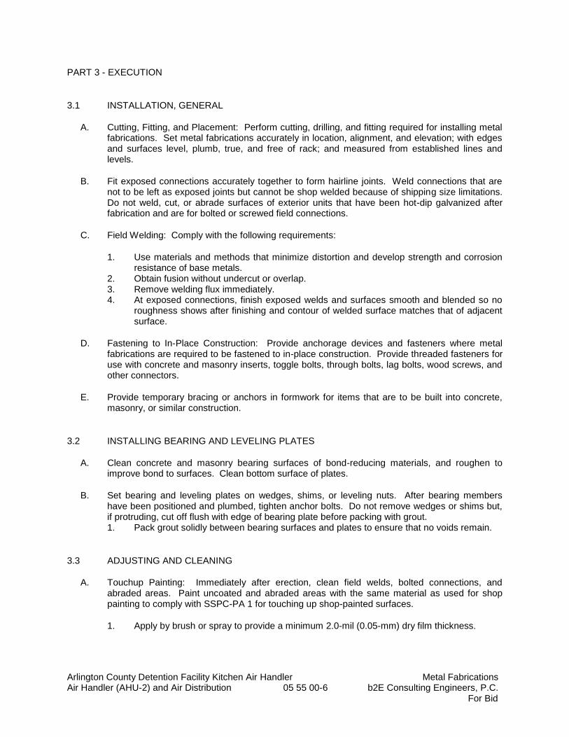
Arlington County Detention Facility Kitchen Air Handler Metal Fabrications Air Handler (AHU-2) and Air Distribution 05 55 00-6 b2E Consulting Engineers, P.C. For Bid
PART 3 - EXECUTION
3.1 INSTALLATION, GENERAL
A. Cutting, Fitting, and Placement: Perform cutting, drilling, and fitting required for installing metal fabrications. Set metal fabrications accurately in location, alignment, and elevation; with edges and surfaces level, plumb, true, and free of rack; and measured from established lines and levels.
B. Fit exposed connections accurately together to form hairline joints. Weld connections that are not to be left as exposed joints but cannot be shop welded because of shipping size limitations. Do not weld, cut, or abrade surfaces of exterior units that have been hot-dip galvanized after fabrication and are for bolted or screwed field connections.
C. Field Welding: Comply with the following requirements:
1. Use materials and methods that minimize distortion and develop strength and corrosion resistance of base metals.
2. Obtain fusion without undercut or overlap. 3. Remove welding flux immediately. 4. At exposed connections, finish exposed welds and surfaces smooth and blended so no
roughness shows after finishing and contour of welded surface matches that of adjacent surface.
D. Fastening to In-Place Construction: Provide anchorage devices and fasteners where metal fabrications are required to be fastened to in-place construction. Provide threaded fasteners for use with concrete and masonry inserts, toggle bolts, through bolts, lag bolts, wood screws, and other connectors.
E. Provide temporary bracing or anchors in formwork for items that are to be built into concrete, masonry, or similar construction.
3.2 INSTALLING BEARING AND LEVELING PLATES
A. Clean concrete and masonry bearing surfaces of bond-reducing materials, and roughen to improve bond to surfaces. Clean bottom surface of plates.
B. Set bearing and leveling plates on wedges, shims, or leveling nuts. After bearing members have been positioned and plumbed, tighten anchor bolts. Do not remove wedges or shims but, if protruding, cut off flush with edge of bearing plate before packing with grout. 1. Pack grout solidly between bearing surfaces and plates to ensure that no voids remain.
3.3 ADJUSTING AND CLEANING
A. Touchup Painting: Immediately after erection, clean field welds, bolted connections, and abraded areas. Paint uncoated and abraded areas with the same material as used for shop painting to comply with SSPC-PA 1 for touching up shop-painted surfaces.
1. Apply by brush or spray to provide a minimum 2.0-mil (0.05-mm) dry film thickness.

Arlington County Detention Facility Kitchen Air Handler Metal Fabrications Air Handler (AHU-2) and Air Distribution 05 55 00-7 b2E Consulting Engineers, P.C. For Bid
3.4 FIELD QUALITY CONTROL
A. Testing and Inspecting: Engage a qualified, independent, testing and inspecting agency to perform field tests and inspections and prepare test reports.
END OF SECTION 05 50 00
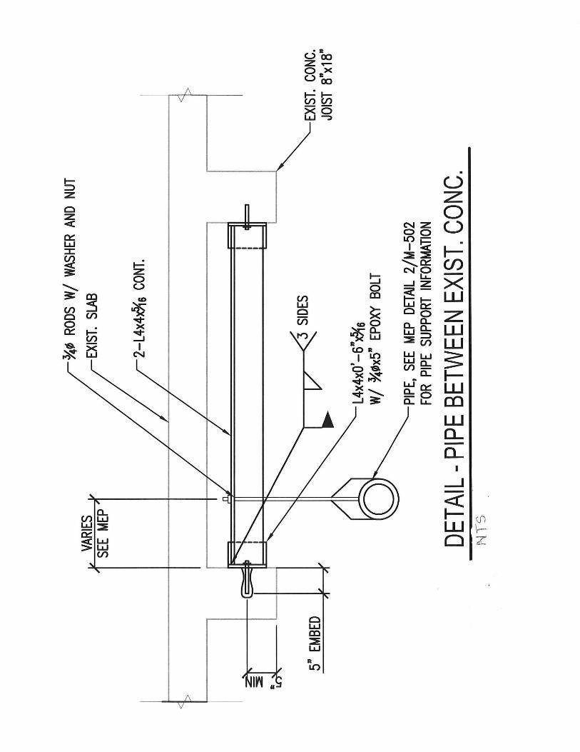
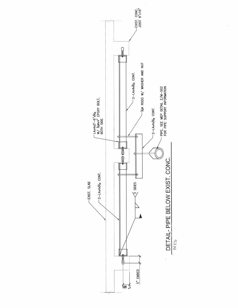
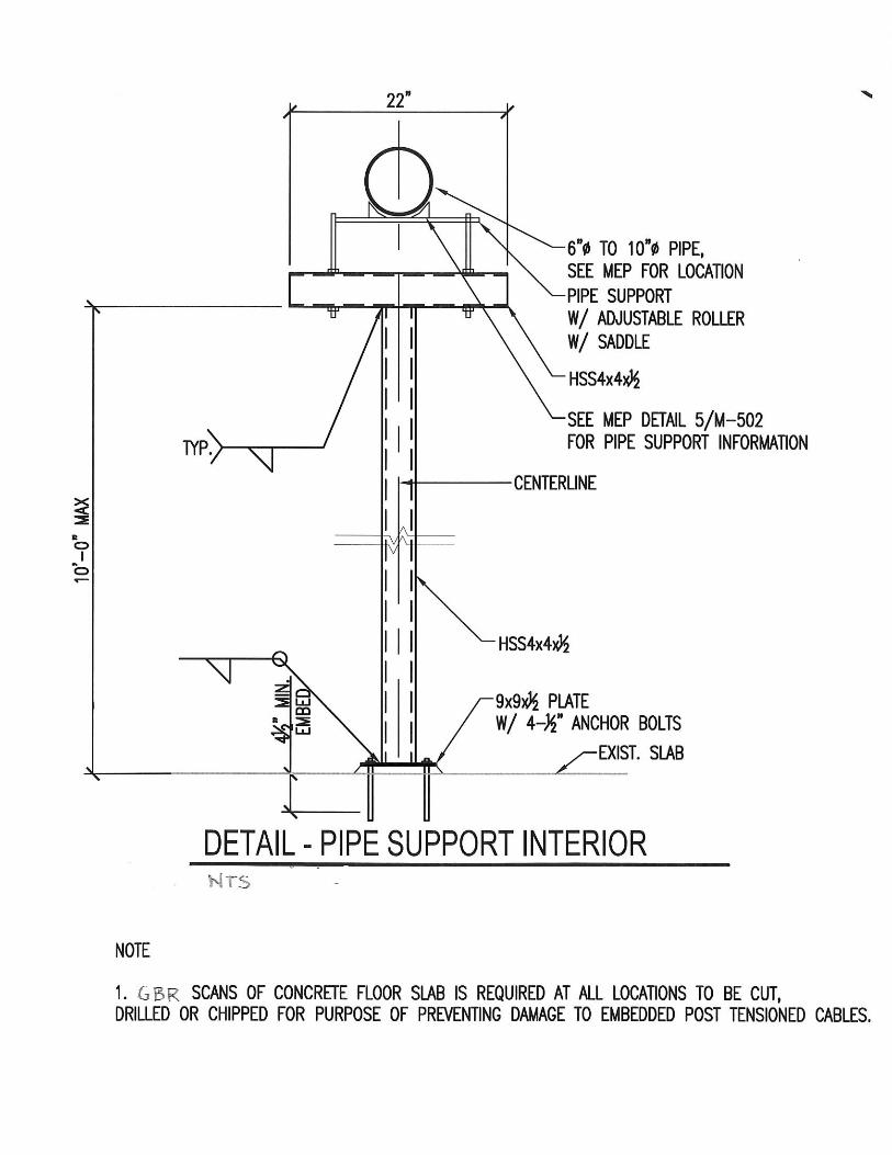
Arlington County Detention Facility Kitchen Air Handler Through-Penetration Firestop Systems Air Handler (AHU-2) and Air Distribution 07 84 10-1 b2E Consulting Engineers, P.C.
For Bid
SECTION 07 84 10
THROUGH-PENETRATION FIRESTOP SYSTEMS
PART 1 - GENERAL
1.1 RELATED DOCUMENTS
A. Drawings and General Provisions of Contract, including General and Supplementary Conditions, Division I Specification sections, and all other sections of the specifications below shall also apply to the extent required for proper performance of the Work of the section.
1.2 SUMMARY
A. Section Includes penetrations vertical and horizontal through existing assemblies. All corridor and loading dock walls are fire rated.
B. See Mechanical drawings for additional details and requirements.
1.3 SUBMITTALS
A. Product Data: For each type of product indicated.
PART 2 - PRODUCTS
2.1 MANUFACTURERS
A. Manufacturers: Subject to compliance with requirements, available manufacturers offering products that may be incorporated into the Work include, but are not limited to, the following:
1. Hilti, Inc.
2. Nelson Firestop Products.
3. 3M Fire Protection Products.
2.2 PENETRATION FIRESTOPPING
A. Provide penetration firestopping that is produced and installed to resist spread of fire according to requirements indicated, resist passage of smoke and other gases, and maintain original fire-resistance rating of construction penetrated. Penetration firestopping systems shall be compatible with one another, with the substrates forming openings, and with penetrating items if any.
B. Accessories: Provide components for each penetration firestopping system that are needed to install fill materials and to maintain ratings required. Use only those components specified by penetration firestopping manufacturer and approved by qualified testing and inspecting agency for firestopping indicated.
PART 3 - EXECUTION
3.1 INSTALLATION
A. Examine substrates and conditions, with Installer present, for compliance with requirements for opening configurations, penetrating items, substrates, and other conditions affecting performance of the Work.
B. Install penetration firestopping to comply with manufacturer's written installation instructions and published drawings for products and applications indicated. 1. All penetrations in this project shall be considered 2 Hr fire rated and require UL listed
firestopping.
Arlington County Detention Facility Kitchen Air Handler Through-Penetration Firestop Systems Air Handler (AHU-2) and Air Distribution 07 84 10-2 b2E Consulting Engineers, P.C.
For Bid
C. Install forming materials and other accessories of types required to support fill materials during their application and in the position needed to produce cross-sectional shapes and depths required to achieve fire ratings indicated.
3.2 IDENTIFICATION
A. Identify penetration firestopping with preprinted metal or plastic labels.
END OF SECTION 07 84 10
Arlington County Detention Facility Kitchen Air Handler Joint Sealants Air Handler (AHU-2) and Air Distribution 07 92 00-1 b2E Consulting Engineers, P.C.
For Bid
SECTION 07 92 00
JOINT SEALANTS
PART 1 - GENERAL
1.1 RELATED DOCUMENTS
A. Drawings and General Provisions of Contract, including General and Supplementary Conditions, Division I Specification sections, and all other sections of the specifications below shall also apply to the extent required for proper performance of the Work of the section.
1.2 SUMMARY
A. Section includes for exterior and interior building applications.
1.3 SUBMITTALS
A. Product Data: For each joint-sealant product indicated.
PART 2 - PRODUCTS
2.1 MATERIALS, GENERAL
A. VOC Content of Interior Sealants: Provide sealants and sealant primers for use inside the weatherproofing system.
B. Liquid-Applied Joint Sealants: Comply with ASTM C 920 and other requirements indicated for each liquid-applied joint sealant specified, including those referencing ASTM C 920 classifications for type, grade, class, and uses related to exposure and joint substrates.
2.2 SEALANT TYPES
A. Sealants for Exterior applications: One part non-sag, polyurethane.
B. Sealants for Interior applications: One part, non-sag, silicone acrylic latex, paintable.
C. Sealants for toilet rooms and similar areas: one part silicone sanitary sealant, moisture and mildew resistant.
2.3 JOINT SEALANT BACKING
A. Cylindrical Sealant Backings: ASTM C 1330 and of size and density to control sealant depth and otherwise contribute to producing optimum sealant performance.
B. Bond-Breaker Tape: Polyethylene tape or other plastic tape recommended by sealant manufacturer.
PART 3 - EXECUTION
3.1 INSTALLATION
A. Install sealant backings of kind indicated to support sealants during application and at position required to produce cross-sectional shapes and depths of installed sealants relative to joint widths that allow optimum sealant movement capability.
Arlington County Detention Facility Kitchen Air Handler Joint Sealants Air Handler (AHU-2) and Air Distribution 07 92 00-2 b2E Consulting Engineers, P.C.
For Bid
B. Install bond-breaker tape behind sealants where sealant backings are not used between sealants and backs of joints.
C. Tooling of Sealants: Immediately after sealant application and before skinning or curing begins, tool sealants to form smooth, uniform beads; to eliminate air pockets; and to ensure contact and adhesion of sealant with sides of joint.
D. Clean off excess sealant or sealant smears adjacent to joints as the Work progresses by methods and with cleaning materials approved in writing by manufacturers of joint sealants and of products in which joints occur.
END OF SECTION 07 92 00
Arlington County Detention Facility Kitchen Air Handler Painting Air Handler (AHU-2) and Air Distribution 09 91 00-1 b2E Consulting Engineers, P.C.
For Bid
SECTION 09 91 00
PAINTING
PART 1 - GENERAL
1.1 RELATED DOCUMENTS
A. Drawings and General Provisions of Contract, including General and Supplementary Conditions, Division I Specification sections, and all other sections of the specifications below shall also apply to the extent required for proper performance of the Work of the section.
1.2 SUMMARY
A. This Section includes surface preparation and the application of paint systems on the following interior and exterior substrates:
1. Concrete. 2. Steel. 3. Gypsum board.
B. Painting under this project is generally to be limited to patched walls and/or ceiling areas where the wall and/or ceiling has been removed to install HVAC equipment, piping, ductwork, etc. where disturbance to existing walls and ceilings occur.
C. Any un-insulated ferrous steel HVAC piping or piping supports shall be painted.
1.3 SUBMITTALS
A. Product Data: For each type of product indicated.
B. Samples: For each finish and for each color and texture required.
1.4 EXTRA MATERIALS
A. Furnish extra materials described below that are from same production run (batch mix) as materials applied and that are packaged for storage and identified with labels describing contents.
1. Quantity: Furnish an additional 5 percent, but not less than 1 gal. of each material and color applied.
PART 2 - PRODUCTS
2.1 PAINT, GENERAL
A. Material Compatibility:
1. Provide materials for use within each paint system that are compatible with one another and substrates indicated, under conditions of service and application as demonstrated by manufacturer, based on testing and field experience.
2. For each coat in a paint system, provide products recommended in writing by manufacturers of topcoat for use in paint system and on substrate indicated.
B. Colors: To match existing adjacent painted finishes to remain.
Arlington County Detention Facility Kitchen Air Handler Painting Air Handler (AHU-2) and Air Distribution 09 91 00-2 b2E Consulting Engineers, P.C.
For Bid
PART 3 - EXECUTION
3.1 EXAMINATION
A. Examine substrates and conditions, with Applicator present, for compliance with requirements for maximum moisture content and other conditions affecting performance of work.
B. Maximum Moisture Content of Substrates: When measured with an electronic moisture meter as follows:
1. Concrete: 12 percent. 2. Masonry (Clay and CMU): 12 percent. 3. Gypsum Board: 12 percent.
C. Verify suitability of substrates, including surface conditions and compatib ility with existing finishes and primers.
D. Begin coating application only after unsatisfactory conditions have been corrected and surfaces are dry.
3.2 PREPARATION AND APPLICATION
A. Comply with manufacturer's written instructions applicable to substrates indicated.
B. Clean substrates of substances that could impair bond of paints, including dirt, oil, grease, and incompatible paints and encapsulants.
C. Apply paints to produce surface films without cloudiness, spotting, holidays, laps, brush marks, roller tracking, runs, sags, ropiness, or other surface imperfections. Cut in sharp lines and color breaks.
D. Painting Mechanical and Electrical Work: Paint items exposed in equipment rooms and occupied spaces. Do NOT paint equipment nameplates or specification tags.
E. Protect work of other trades against damage from paint application. Correct damage to work of other trades by cleaning, repairing, replacing, and refinishing, and leave in an undamaged condition.
F. At completion of construction activities, touch up and restore damaged or defaced painted surfaces.
3.3 INTERIOR PAINTING SCHEDULE
A. Concrete Substrates, Nontraffic Surfaces:
1. Latex System: Where existing floors scratched. a. Prime Coat: Interior latex matching topcoat. b. Intermediate Coat: Interior latex matching topcoat. c. Topcoat: Interior latex satin.
2. Epoxy System: Detention Facility Boiler Room Floors a. Prime Coat: Epoxy Coating. b. Final Coat: Epoxy Coating. c. Refer to Section 09 9600 for applicable requirements.
B. Steel Substrates:
1. Quick-Drying Enamel System: a. Prime Coat: Quick-drying alkyd metal primer. b. Intermediate Coat: Quick-drying enamel matching topcoat. c. Topcoat: Quick-drying enamel, semi-gloss.
C. Gypsum Board Substrates:
Arlington County Detention Facility Kitchen Air Handler Painting Air Handler (AHU-2) and Air Distribution 09 91 00-3 b2E Consulting Engineers, P.C.
For Bid
1. Latex System: a. Prime Coat: Interior latex primer/sealer. b. Intermediate Coat: Interior latex matching topcoat. c. Topcoat: Interior latex satin.
3.4 Exterior Painting Schedule
A. Steel Substrates:
1. Water-Based Light Industrial Coating System: a. Prime Coat: Primer, alkyd, anti-corrosive for metal. b. Intermediate Coat: Light industrial coating, exterior, water based, matching
topcoat. c. Topcoat: Light industrial coating, exterior, water based, semi-gloss.
END OF SECTION 09 91 00
Arlington County Detention Facility Kitchen Air Handler High Performance Epoxy Coatings Air Handler (AHU-2) and Air Distribution 09 96 00-1 b2E Consulting Engineers, P.C.
For Bid
SECTION 09 96 00
HIGH-PERFORMANCE EPOXY COATINGS
PART 1 - GENERAL
1.1 RELATED DOCUMENTS
A. Drawings and general provisions of the Contract, including General and Supplementary Conditions and Division 01 Specification Sections, apply to this Section.
1.2 SUMMARY
A. Section includes surface preparation and the application of high-performance coating systems on the following substrates.
1. Interior Substrates:
a. Concrete horizontal and vertical housekeeping pad surfaces. b. Provide color to match adjacent finishes.
B. The epoxy coatings will be installed near a boiler room which has a source of ignition. No unsuitable VOC or flammable epoxy or urethane based products shall be used on this project.
C. Diamond grind existing housekeeping pad finish to bare concrete. Allow housekeeping concrete pad extension to dry before applying epoxy coating over entire housekeeping pad.
1.3 DEFINITIONS
A. MPI Gloss Level 5: 35 to 70 units at 60 degrees, according to ASTM D523.
1.4 ACTION SUBMITTALS
A. Product Data: For each type of product. Include preparation requirements and application instructions.
1. Include printout of current "MPI Approved Products List" for each product category specified, with the proposed product highlighted.
2. Indicate zero VOC content.
B. Samples for Initial Selection: For each type of topcoat product indicated.
C. Samples for Verification: For each type of coating system and each color and gloss of topcoat indicated.
1. Submit Samples on rigid backing, 8 inches (200 mm) square. 2. Apply coats on Samples in steps to show each coat required for system. 3. Label each coat of each Sample. 4. Label each Sample for location and application area.
Arlington County Detention Facility Kitchen Air Handler High Performance Epoxy Coatings Air Handler (AHU-2) and Air Distribution 09 96 00-2 b2E Consulting Engineers, P.C.
For Bid
D. Product List: Cross-reference to coating system and locations of application areas. Use same designations indicated on Drawings and in schedules. Include color designations.
1.5 MAINTENANCE MATERIAL SUBMITTALS
A. Furnish extra materials, from the same product run, that match products installed and that are packaged with protective covering for storage and identified with labels describing contents.
1. Coatings: 5 percent, but not less than 2 gal. of each material and color applied.
1.6 QUALITY ASSURANCE
A. Mockups: Apply mockups of each coating system indicated to verify preliminary selections made under Sample submittals and to demonstrate aesthetic effects and set quality standards for materials and execution.
1. Architect will select one surface to represent surfaces and conditions for application of each coating system.
2. Final approval of color selections will be based on mockups.
a. If preliminary color selections are not approved, apply additional mockups of additional colors selected by Architect at no added cost to Owner.
3. Approval of mockups does not constitute approval of deviations from the Contract Documents contained in mockups unless Architect specifically approves such deviations in writing.
4. Subject to compliance with requirements, approved mockups may become part of the completed Work if undisturbed at time of Substantial Completion.
1.7 DELIVERY, STORAGE, AND HANDLING
A. Store materials not in use in tightly covered containers in well-ventilated areas with ambient temperatures continuously maintained at not less than 45 deg F (7 deg C).
1. Maintain containers in clean condition, free of foreign materials and residue. 2. Remove rags and waste from storage areas daily.
1.8 FIELD CONDITIONS
A. Apply coatings only when temperature of surfaces to be coated and ambient air temperatures are between 50 and 95 deg F.
B. Do not apply coatings when relative humidity exceeds 85 percent; at temperatures less than 5 deg F above the dew point; or to damp or wet surfaces.
Arlington County Detention Facility Kitchen Air Handler High Performance Epoxy Coatings Air Handler (AHU-2) and Air Distribution 09 96 00-3 b2E Consulting Engineers, P.C.
For Bid
PART 2 - PRODUCTS
2.1 MANUFACTURERS
A. Products: Subject to compliance with requirements, provide one of the products listed in the Interior High-Performance Coating Schedule for the coating category indicated.
1. Epoxy Coat (800) 841-5580. 2. Other approved equal product.
2.2 HIGH-PERFORMANCE COATINGS, GENERAL
A. MPI Standards: Products shall comply with MPI standards indicated and shall be listed in its "MPI Approved Products Lists."
B. Material Compatibility:
1. Materials for use within each paint system shall be compatible with one another and substrates indicated, under conditions of service and application as demonstrated by manufacturer, based on testing and field experience.
2. For each coat in a paint system, products shall be recommended in writing by topcoat manufacturers for use in paint system and on substrate indicated.
3. Products shall be of same manufacturer for each coat in a coating system.
C. Colors: Shall be selected by Owner from the manufacturer’s selection of available colors.
2.3 SOURCE QUALITY CONTROL
A. Testing of Coating Materials: Owner reserves the right to invoke the following procedure:
1. Owner will engage the services of a qualified testing agency to sample coating materials. Contractor will be notified in advance and may be present when samples are taken. If coating materials have already been delivered to Project site, samples may be taken at Project site. Samples will be identified, sealed, and certified by testing agency.
2. Testing agency will perform tests for compliance with product requirements. 3. Owner may direct Contractor to stop applying coatings if test results show materials
being used do not comply with product requirements. Contractor shall remove non-complying coating materials from Project site, pay for testing, and recoat surfaces coated with rejected materials. Contractor will be required to remove rejected materials from previously coated surfaces if, on recoating with complying materials, the two coatings are incompatible.
PART 3 - EXECUTION
3.1 EXAMINATION
A. Examine substrates and conditions, with Applicator present, for compliance with requirements for maximum moisture content and other conditions affecting performance of the Work.
B. Maximum Moisture Content of Substrates: When measured with an electronic moisture meter as follows:
Arlington County Detention Facility Kitchen Air Handler High Performance Epoxy Coatings Air Handler (AHU-2) and Air Distribution 09 96 00-4 b2E Consulting Engineers, P.C.
For Bid
1. Concrete: 12 percent.
C. Verify suitability of substrates, including surface conditions and compatibility, with existing finishes and primers.
D. Proceed with coating application only after unsatisfactory conditions have been corrected.
1. Application of coating indicates acceptance of surfaces and conditions.
3.2 PREPARATION
A. Comply with manufacturer's written instructions and recommendations in "MPI Architectural Painting Specification Manual" applicable to substrates and coating systems indicated.
B. Remove hardware, covers, plates, and similar items already in place that are removable and are not to be painted. If removal is impractical or impossible because of size or weight of item, provide surface-applied protection before surface preparation and painting.
1. After completing painting operations, use workers skilled in the trades involved to reinstall items that were removed. Remove surface-applied protection if any.
C. Clean substrates of substances that could impair bond of coatings, including dust, dirt, oil, grease, and incompatible paints and encapsulants.
1. Remove incompatible primers and reprime substrate with compatible primers or apply tie coat as required to produce coating systems indicated.
D. Concrete Substrates: Remove release agents, curing compounds, efflorescence, and chalk. Do not coat surfaces if moisture content or alkalinity of surfaces to be coated exceeds that permitted in manufacturer's written instructions.
1. Clean surfaces with diamond grinder and pressurized water. Use pressure range of 1500 to 4000 psi or as recommended by the manufactutrer at 6 to 12 inches.
2. Abrasive blast clean surfaces to comply with SSPC-SP 7/NACE No. 4.
3.3 APPLICATION
A. Apply high-performance coatings according to manufacturer's written instructions and recommendations in "MPI Architectural Painting Specification Manual."
1. Use applicators and techniques suited for coating and substrate indicated. 2. Coat surfaces behind movable equipment and furniture same as similar exposed
surfaces. Before final installation, coat surfaces behind permanently fixed equipment or furniture with prime coat only.
3. Coat backsides of access panels, removable or hinged covers, and similar hinged items to match exposed surfaces.
4. Do not apply coatings over labels of independent testing agencies or equipment name, identification, performance rating, or nomenclature plates.
B. Tint each undercoat a lighter shade to facilitate identification of each coat if multiple coats of the same material are to be applied. Tint undercoats to match color of finish coat, but provide sufficient difference in shade of undercoats to distinguish each separate coat.
C. If undercoats or other conditions show through final coat, apply additional coats until cured film has a uniform coating finish, color, and appearance.
Arlington County Detention Facility Kitchen Air Handler High Performance Epoxy Coatings Air Handler (AHU-2) and Air Distribution 09 96 00-5 b2E Consulting Engineers, P.C.
For Bid
D. Apply coatings to produce surface films without cloudiness, spotting, holidays, laps, brush marks, runs, sags, ropiness, or other surface imperfections. Produce sharp glass lines and color breaks.
3.4 FIELD QUALITY CONTROL
A. Dry Film Thickness Testing: Owner may engage the services of a qualified testing and inspecting agency to inspect and test coatings for dry film thickness.
1. Contractor shall touch up and restore coated surfaces damaged by testing. 2. If test results show that dry film thickness of applied coating does not comply with coating
manufacturer's written recommendations, Contractor shall pay for testing and apply additional coats as needed to provide dry film thickness that complies with coating manufacturer's written recommendations.
3.5 CLEANING AND PROTECTION
A. At end of each workday, remove rubbish, empty cans, rags, and other discarded materials from Project site.
B. After completing coating application, clean spattered surfaces. Remove spattered coatings by washing, scraping, or other methods. Do not scratch or damage adjacent finished surfaces.
C. Protect work of other trades against damage from coating operation. Correct damage to work of other trades by cleaning, repairing, replacing, and recoating, as approved by Architect, and leave in an undamaged condition.
D. At completion of construction activities of other trades, touch up and restore damaged or defaced coated surfaces.
3.6 INTERIOR HIGH-PERFORMANCE COATING SCHEDULE
A. Concrete Substrates, Horizontal Surfaces.
1. Epoxy System MPI INT 3.2C: Full solid (no water based, low VOC, no flammable, no urethane products shall be used)
a. Prime Coat: Epoxy, matching topcoat. b. Intermediate Coat: Epoxy, matching topcoat. c. Topcoat: Epoxy, gloss, MPI #77.
1) Epoxy Coat (800) 841-5580.
END OF SECTION 09 96 00

Arlington County Detention Facility Kitchen Air Handler General Requirements for Fire Suppression Air Handler (AHU-2) and Air Distribution 21 0100-1 Sprinkler System
b2e Consulting Engineers, P.C. For Bid
SECTION 21 0100
GENERAL REQUIREMENTS FOR FIRE SUPPRESSION SPRINKLER SYSTEM
(THIS SECTION IS FOR THE OWNER’S SPRINKLER TRADE CONTRACTOR)
PART 1 - GENERAL
1.1 SUMMARY
A. Sprinkler bulk main and sprinkler branch mains shall be relocated and/or provided new to allow installation of ductwork. The work shall be installed tight to the under side of the concrete floor above. The contractor shall perform a detailed survey of the existing systems. Field measurements take precedence over plan scales.
B. The sprinkler system shall remain operational at all times. If a section of pipe is temporarily removed or modified the area where the sprinkler coverage is temporarily out of service shall be provided with a Fire Watch until the coverage is restored.
C. Provide all piping fittings, sprinkler heads, valves, etc., as required for a complete NFPA 13 code compliant system. Materials shall match the existing system construction.
D. All work shall be performed under the supervision of a licensed NICET Certified Technician (Level III or IV) or a registered Fire Protection Engineer.
E. Warranty: Provide one (1) year parts and labor warranty for the work performed.
1.2 DRAWINGS:
A. The Drawings are diagrammatic in nature and show the general arrangement of all ductwork, piping, equipment and appurtenances and shall be followed as closely as actual building construction and the work of other trades will permit. Because of the small scale of the Drawings, it is not feasible to indicate all offsets, fittings and accessories that may be required. The Contractor shall investigate the construction conditions affecting the work and provide fittings and accessories as required to meet actual conditions.
B. Where discrepancies in scope of work as to which Trade provides specific items, such as starters, disconnects, flow switches, electrical control components, etc. exist, such conflicts shall be reported to the Engineer. If such action is not taken, the Contractor, as applicable, shall furnish such items as part of his work, for complete and operable systems and equipment, as determined by the Engineer.
C. Layout combination standpipe and sprinkler system complete and size all fire protection piping in accordance with requirements of the National Fire Protection Association and the Local Fire Marshall. System shall be designed for occupancy as required by applicable codes. Conceal fire protection piping in finished spaces unless indicated otherwise. System drains and inspector’s test shall not be located in finished spaces.
Arlington County Detention Facility Kitchen Air Handler General Requirements for Fire Suppression Air Handler (AHU-2) and Air Distribution 21 0100-2 Sprinkler System
b2e Consulting Engineers, P.C. For Bid
D. Sprinkler equipment and work shall conform to requirements of National Fire Protection Association (NFPA) Standard No. 13. In addition, all work shall conform to the latest requirements of all codes and regulations of authorities having jurisdiction over this work, including, but not limited to, Local Fire Marshall, Life Safety Codes.
E. Preliminary Shop Drawing: Prior to preparing detailed working drawings for submission to the authority having jurisdiction, submit preliminary sprinkler system layout to the Engineer for review and approval. Show all finished ceilings, light fixtures, air diffusers and other ceiling mounted devices. Coordinate sprinkler head types and locations with existing ceiling types.
F. The Fire Protection Contractor shall prepare dimensioned and detailed working drawings, specifications, and hydraulic calculations and submit same to the authority having jurisdiction for review and approval. One set of these approved documents shall be provided to the Engineer for record purposes. All costs related to changes required to obtain the Fire Marshall’s approval shall be the responsibility of the Contractor.
G. Drawings and submittals shall be approved by authority having jurisdiction prior to submitting to the Engineer.
H. Installer Requirements: Design shall be signed, sealed and submitted for permit by a NICET Certified (Level III or IV) Technician or a Registered Fire Protection Engineer. Installation shall be performed by a certified sprinkler contractor or a specialist who is experienced in the design and installation of automatic sprinkler systems (minimum 5 years), licensed or certified by authority having jurisdiction.
1. The Contractor shall submit the following for verification of qualifications: Prior to installation, submit documentation, to the A/E, showing that the Contractor has successfully installed automatic fire suppression sprinkler systems of comparable size, type and design as specified herein or that the Contractor has a firm contractual agreement with a Subcontractor having such experience. The data shall include the names and locations of at least two installations where the Contractor, or Subcontractor, installed such systems. The Contractor, or Subcontractor, shall certify that each system has performed satisfactory for a period of not less than one year.
2. Submit sprinkler drawings and hydraulic calculations utilizing hydraulic test data not older than 18 months to the local authority having jurisdiction for review. Make any changes to the design as requested by the local authority having jurisdiction at no additional cost to the Owner.
3. Obtain permit approval from the local authority having jurisdiction.
1.3 REGULATIONS AND STANDARDS:
A. The completed installation and all materials and equipment shall conform to local ordinances and codes, other regulations and standards listed herein or in related sections. These are intended as a minimum and shall be exceeded if required by the specifications or the Drawings. In the event of conflict between the codes, standards, or regulations, and information contained in the Contract Documents, the applicable code, standards, or regulation shall take precedence.
1.4 INSPECTION CERTIFICATES:
A. The Contractor shall furnish three copies of certificates of final acceptance to the Engineer from all inspection authorities having jurisdiction.
Arlington County Detention Facility Kitchen Air Handler General Requirements for Fire Suppression Air Handler (AHU-2) and Air Distribution 21 0100-3 Sprinkler System
b2e Consulting Engineers, P.C. For Bid
1.5 SUBSTANTIAL COMPLETION:
A. The Engineer will visit the site for the purpose of conducting a substantial completion inspection once the following items have been met by the Contractor.
1. All fire protection systems shall be complete, operational and under automatic control. 2. Fire suppression systems cleaning and testing shall be complete and the final report shall
be approved by the Engineer.
B. All discrepancies noted in the substantial completion report shall be corrected prior to the final inspection. The Contractor shall provide a detailed item-by-item description of all corrections made for each item on the substantial completion discrepancy list prior to scheduling final inspection by the Engineer. Additional visits required after the final inspection, for the reason that previously documented discrepancies had not been corrected at the time of the final inspection, will be made at the Contractor’s expense.
1.6 MATERIALS AND WORKMANSHIP:
A. Equipment and material used in the project shall be new and undamaged. The mechanical installation shall fit into the space allotted and shall allow adequate and acceptable clearances for entry, servicing and maintenance. Similar types of equipment shall be the products of the same manufacturer unless specified otherwise. Work shall be performed by mechanics or tradesmen skilled in the trade involved.
B. All piping, sprinkler heads, valves, switches, conduit and other devices shall be installed in a neat and organized manner, parallel to other work and the nearest building elements, unless specifically shown otherwise on the Drawings.
C. Guarantee: The Contractor shall guarantee labor, materials, and equipment provided under this contract against defects for a period of one year after the date of final acceptance of this work by the Owner. Final Acceptance includes, but is not limited to, the receipt of as-built drawings and operation and maintenance manuals. Contractor is responsible for all work required obtaining approval from the Local Fire Marshall, the Owner and the Engineer.
1.7 SUBMITTALS:
A. Submit shop drawings, product data and samples in accordance with Division 1 for all items as specified in this and other sections of these specifications. The submittal documents will be marked with the Owner, Engineer each retaining one (1) print each for their records. All submittal data shall be correctly identified to show project name, and the exact model, style, or size of item being submitted. Improperly identified submittals will not be reviewed by the Engineer. Each item submitted for review shall bear the Subcontractor’s stamp which states that they have reviewed the submission, that it is complete, and that in their opinion it meets the contract requirements. Contractor’s stamp shall identify the specification section, paragraph and page number for which the submittal is being made. Shop drawings will be reviewed only for general compliance with the Contract Documents. Review will not include correctness of details, proper configuration, utility connections, dimensions, sizes, quantities, and the like. Any submission which has not been reviewed and stamped by the Subcontractor will not be reviewed by the Engineer. No reviews prior to award of Contract will be considered or accepted. Re-submissions of shop drawings, product data and samples shall include the entire original submittal. Partial submittals will not be reviewed by the Engineer.
Arlington County Detention Facility Kitchen Air Handler General Requirements for Fire Suppression Air Handler (AHU-2) and Air Distribution 21 0100-4 Sprinkler System
b2e Consulting Engineers, P.C. For Bid
B. Equivalents: Acceptable Manufacturers, trade names, and model numbers indicated herein and on Drawings shall be interpreted as establishing a standard of quality and shall not be construed as limiting competition. Manufacturers listed first in these specifications and on Drawings were used as a basis of design. It will be the responsibility of the Contractor to verify all connections, physical sizes, capacities, etc. of all other manufacturer’s items, both named or proposed. If the equipment necessitates changes in, piping, devices, wiring or other building systems from that indicated on the Drawings, the Contractor shall be responsible for all additional costs included and notify other trades. Where such changes are required, detail drawings indicating all required changes shall be submitted for review at the same time the manufacturers drawings are submitted for approval.
C. Shop drawings, diagrams, catalog data and such other data necessary to fully describe and substantiate compliance with these specifications shall be submitted for all equipment and materials.
D. Operation and Maintenance manual(s) shall be submitted in accordance with Division 1 and shall include a complete product index in each volume, installation and maintenance data, sequence of controls, parts lists, a copy of all approved shop drawings and the name, address and telephone number of supplier or nearest representative. All mechanical devices, equipment and systems shall be included and all other such mechanical items that will require servicing before the duration of its useful life has been reached. Manual(s) shall be presented to the Engineer for review and transmittal to the Owner before final payment is recommended.
1.8 VERIFYING MEASUREMENTS AND CONDITIONS:
A. The exactness of elevations, dimensions, or locations given on the Drawings, is not guaranteed by the Engineer. The Contractor shall, therefore, satisfy himself as to the accuracy of all grades, elevations, dimensions and locations. In all cases of interconnection of his work and existing or other work, he shall verify at the site all dimensions, relating to such existing or other work. Any errors due to the Contractor’s failure to so verify all such grades, elevations, locations, or dimensions shall be promptly rectified by him without cost to Owner.
1.9 COORDINATION OF WORK:
A. General: The Contract Documents indicate the extent and general arrangement of the fire suppression systems. The Contractor shall be responsible for the coordination and proper relation of the fire suppression work to the building structure and to the work of other trades. No additional compensation nor extension of completion of time will be granted for extra work caused by the lack of coordination.
B. Cooperation: The Contractor shall provide dimensions and locations of all openings, shafts and similar items to the proper trades and install work as required so as not to interfere with, or delay, the building construction.
C. Locations of lines and equipment shall be determined from actual field measurements. The outlines of the building shown on the Drawings are intended only as a guide to indicate relative locations of the work. Refer to architectural and structural Drawings for building construction details. The Contractor shall determine the exact routing and location of his systems prior to fabrication or installation of any system component. Accurate measurements and coordination shall be completed to verify dimensions and characteristics for the installation of each system.
Arlington County Detention Facility Kitchen Air Handler General Requirements for Fire Suppression Air Handler (AHU-2) and Air Distribution 21 0100-5 Sprinkler System
b2e Consulting Engineers, P.C. For Bid
D. Unless necessitated by equipment access or otherwise indicated in the Contract Documents, all piping, ductwork, and conduit concealed above ceilings and in finished or utility spaces shall be routed as high as possible.
E. Offsets, transitions and changes of direction in all systems shall be made as required to maintain proper headroom and pitch of sloping lines whether or not indicated on the drawings. The Contractor shall provide manual drains as required for his work to affect these offsets, transitions and changes in direction, as applicable.
F. Cutting and Patching: Refer to Division 1.
G. Roughing-In: Verify the locations of other trades work before roughing-in.
H. Fire protection piping shall be concealed except in rooms or spaces without ceilings, and the equipment rooms and as indicated otherwise. Sprinkler heads in ceilings shall be located centered in ceiling tiles and other ceilings. This Contractor shall give due consideration to minimize conflicts, and coordinate, with other trades as to location of ceiling heights, piping, conduits, ductwork, electrical fixtures, etc.
1. The sprinkler contractor shall coordinate with other trades work. Sprinkler shall be shown on the coordination drawings.
2. Where the elevation and/or locations of sprinkler piping create a conflict for other trades work (including service access clearance) the sprinkler contractor shall relocate his piping at his own expense.
I. Damage to Other Work: Each Contractor s responsible for damage to other work caused by his work or workmen. Repairing of damaged work shall be done by the Contractor who installed the work, and as directed by the Engineer; the cost of which shall be paid for by the Contractor responsible for the damage.
1.10 EQUIPMENT INSTALLATION:
A. General: Equipment shall be installed in accordance with manufacturer’s instructions to conform with the details and application indicated.
B. Supports: Provide necessary supports for all equipment and appurtenances as required; this includes but is not limited to frames or supports for items such as tanks, compressors, pumps, valves, and other similar items requiring supports. Floor mounted equipment in Equipment Rooms shall be set on 6-inch high concrete foundation pads unless shown otherwise. All pads shall be poured such that the top of the pad is level. Foundation drawings, bolt setting information and foundation bolts shall be furnished by the subcontractors furnishing the equipment for all equipment required to have concrete foundations. Concrete for foundations shall be provided by Contractor unless indicated otherwise. Except where indicated, all equipment shall be anchored to concrete pads.
C. Service Area: All equipment and appurtenances shall be located to permit adequate service clearance in accordance with the manufacturer’s recommendations and as otherwise required. Service clearance shall include but not be limited to service and removal of motors, controls and removal of equipment sections. All piping, ductwork, and other equipment shall be located outside of the service area or shall be flanged for easy removal to facilitate equipment service. All equipment shall be located with sufficient distance from building features, structural components, and the equipment of other trades. Service clearance in front of electrical panels shall be minimum as required by National Electric Code (NEC) where applicable.
Arlington County Detention Facility Kitchen Air Handler General Requirements for Fire Suppression Air Handler (AHU-2) and Air Distribution 21 0100-6 Sprinkler System
b2e Consulting Engineers, P.C. For Bid
D. Temporary Requirements: Openings in equipment shall be kept plugged at all times until connection is made to the system. The ends of all pipes and equipment openings shall be kept plugged or capped properly with approved devices. Approved devices are items such as specially molded plastic caps, pipe plugs, test plugs and sheet metal caps.
1.11 PAINTING
A. Sprinkler piping shall be painted red to match existing sprinkler piping.
1.12 TEMPORARY FIRE PROTECTION
A. Provide all piping and accessories including temporary piping equipment to provide and maintain system operation during construction as required by the applicable building codes.
B. Where any sprinkler coverage is temporarily taken out of service, provide a Fire Watch in the area where the service is out of service until coverage is restored.
1.13 TESTING OF WORK:
A. Partial Testing: As much as practical, systems shall be tested as complete systems. Tests on portions of a system will be permitted to facilitate proper progress scheduling. When systems are tested in segments, a system diagram indicating portion tested and a separate and complete report including the date of test is required for each segment.
B. Concealed Work:
1. All concealed work shall be tested and approved by the Engineer prior to the application of insulation or construction of chase walls.
2. Covering shall not be applied to any piping nor shall any piping be concealed or covered until pipes have been tested, all leaks stopped, retested and approved.
C. Fire Suppression System Testing:
1. Perform and pay for all tests as may be required in the applicable NFPA Standards and as specified herein and as may be required by Authorities having jurisdiction. Any defects shall be corrected to the satisfaction of the Authorities having jurisdiction and the Engineer.
2. The entire sprinkler system shall be tested at 200 psi for a period of two (2) hours with no leaks or loss of pressure.
3. After the Contractor has satisfied himself that the Sprinkler System is complete and properly serviceable in all respects, he shall arrange with the Authorities having jurisdiction and the Engineer for a final test and inspection as applicable.
4. The final tests and inspections shall be made by a representative of the Authorities having jurisdiction, who must be satisfied with the entire installation before final acceptance by the Engineer.
5. For the Sprinkler System, the Contractor shall furnish the Architect/Engineer with two (2) copies of complete NFPA 13 (latest edition) Form “Sprinkler Contractor’s Certificate Covering Materials and Tests”.
Arlington County Detention Facility Kitchen Air Handler General Requirements for Fire Suppression Air Handler (AHU-2) and Air Distribution 21 0100-7 Sprinkler System
b2e Consulting Engineers, P.C. For Bid
PART 2 - PRODUCTS
2.1 PAINTING:
A. Acceptable Manufacturers: Except as otherwise specified, materials shall be the products of the following manufacturers:
1. Sherwin-Williams 2. Pratt and Lambert 3. Pittsburgh Paints (PPG) 4. Benjamin Moore 5. Porter Paints 6. Seton Identification Products
B. Materials:
1. Deliver all paints and materials to the project site in their unopened original containers with all labels intact and legible at the time of use.
2. Sherwin-Williams Industrial Maintenance Coatings System 4000 products are listed below to establish color and a standard of quality.
a. All Hangers and Supports: One coat Series 54 Gloss Black Alkyd Enamel. b. Piping: Exposed in equipment rooms and where connections are made to
equipment located in storage rooms and other utility type areas.
1) Priming
a) Bare Iron or Steel or Copper: One coat No. B50Y1 Zinc Chromate Primer.
b) Galvanized Steel: Pipes and ductwork shall be chemically prepared and primed with one coat of Galvite B50W3 Primer.
2) Finish: All pipe lines and the supports or hangers therefore, shall be finished with Series 54 Alkyd Gloss Enamel, gray No. SW4028 Gypsum applied in sufficient number of coats to effectively cover the prime coat. Painting of pipe hangers is specified hereinbefore.
3) Materials shall be as recommended by the manufacturer for the surface to be finished.
4) Unless otherwise specified, primer shall be by the same manufacturer as the finish coat.
5) Materials shall not be thinned or cut except as recommended by the coating manufacturer. Thinners shall be by the same manufacturer as the primer and finish coat.
6) Sprinkler heads and all associated fire protection sensors and controllers shall not be painted.
7) Fire Protection System piping shall not be painted until fire protection system testing is complete and accepted by the authorities having jurisdiction.

Arlington County Detention Facility Kitchen Air Handler General Requirements for Fire Suppression Air Handler (AHU-2) and Air Distribution 21 0100-8 Sprinkler System
b2e Consulting Engineers, P.C. For Bid
PART 3 - EXECUTION
3.1 PAINTING:
A. Workmanship: The work shall be accomplished by qualified mechanics skilled in the painting trade. Painting of equipment, piping, ductwork and other materials shall not commence until all testing is complete and systems are ready for operation. Materials shall be applied according to manufacturer’s directions. All containers shall be securely closed when not in use. Flammable materials shall not be stored on premises. Flammable waste shall be disposed of daily in devices approved for such purposes. Materials shall be evenly spread, and smoothly flowed on without runs or sags. Each coat shall be thoroughly dry before application of succeeding coats.
B. Protection of Work: The painters shall protect all adjacent surfaces with drop covers during the process of painting. Upon completion, paint spots, if any, shall be removed from all surfaces.
C. Preparation of Surface: Surfaces to be painted shall be completely dry before applying paint. Metal surfaces shall be cleaned with mineral spirits before applying materials. Rust and scale shall be removed by wire brushing or sanding. Galvanized surfaces shall be chemically pretreated with crystalline (zinc phosphate) phosphate in strict accordance with the manufacturer’s recommendations. Surfaces shall not be painted when the temperature is, or is likely to be, near the freezing point, nor when they are exposed to hot sun.
END OF SECTION 21 01 00
Arlington County Detention Facility Kitchen Air Handler Summary of Scope of Work Air Handler (AHU-2) and Air Distribution 23 00 00-1 b2E Consulting Engineers, P.C.
For Bid
SECTION 23 00 00
SUMMARY OF THE SCOPE OF WORK
PART 1 - GENERAL
1.1 SUMMARY
A. The following preliminary scope of work for this project is for information only and shall not be considered an all inclusive list of the entire scope of work for this project.
B. The contractor shall provide all materials and labor a necessary for the complete replacement of existing air handler (AHU-2) which serves the existing laundry and the existing kitchen hood. The new air handler (AHU-2) shall be reconfigured to serve heating, cooling and ventilation to the kitchen and the kitchen hood. The kitchen loads shall be removed from existing air handler (AHU-1) and the AHU-1 return fan (RAF-1) damper system shall be permanently modified to serve air to the laundry dryer combustion air plenum.
C. The contractor shall install all materials, components and equipment in accordance with the manufacturers written instructions and recommendations.
D. The contractor shall install all materials, components and equipment with adequate service access as required by the manufacturer and in accordance with local code requirements.
E. FIRE ALARM 1. Existing Fire Alarm devices that need to be relocated to install the ductwork shall be
relocated by a separate contractor provided by Arlington County. 2. The contractor responsible for installing the new air handler shall coordinate with
Arlington County (DES) Project Manger and with the fire alarm trade to minimize outages.
F. SPRINKLER 1. Existing sprinkler piping and heads that need to be relocated to install the ductwork
shall be relocated by a separate contractor provided by Arlington County. 2. The contractor responsible for installing the new air handler and ductwork shall
coordinate with Arlington County (DES) Project Manger and with the sprinkler trade to minimize outages.
G. SECURITY 1. Existing security devices that need to be relocated to install the ductwork shall be
relocated by a separate contractor provided by Arlington County. 2. The contractor responsible for installing the new air handler and ductwork shall
coordinate with Arlington County (DES) Project Manger and with the security trade to minimize outages.
H. MISCELLANEOUS ELECTRIC CONDUIT
1. The existing miscellaneous electric circuit that needs to be relocated to install the ductwork shall be relocated by a separate contractor provided by Arlington County.
2. The contractor responsible for installing the new air handler and ductwork shall coordinate with Arlington County (DES) Project Manager and with the electrical trade to minimize outages.
Arlington County Detention Facility Kitchen Air Handler Summary of Scope of Work Air Handler (AHU-2) and Air Distribution 23 00 00-2 b2E Consulting Engineers, P.C.
For Bid
I. MISCELLANEOUS LIGHTING 1. The existing miscellaneous lighting that needs to be relocated to install the ductwork shall
be relocated by a separate contractor provided by Arlington County. 2. The contractor responsible for installing the new air handlers and ductwork shall
coordinate with Arlington County (DES) Project Manger and with the electrical trade to minimize outages.
1.2 SUMMARY OF THE SCOPE OF WORK
A. General:
1. The contractor shall obtain and pay for all permits required to complete the contract scope of work.
2. The contractor shall plan and schedule all activities as necessary to meet the project substantial completion deadline.
3. The contractor shall provide all overtime, weekend, and holiday and night work labor as needed to minimize heating hot water, chilled water and air handler outages and meet the project substantial completion deadline in their bid price.
B. Architectural:
1. Epoxy paint the housekeeping pad for AHU-2 in the detention facility to match existing floor color.
2. Provide openings in the existing block walls to install the return air ductwork. The openings shall be maintained secure at all times with temporary steel plates on both sides of the wall bolted thru the wall. These temporary securements shall remain until the security bars are permanently installed in the thru wall duct openings.
3. Repair the openings and seal the holes with a steel frame to match the thickness of the existing wall. This work shall be scheduled and performed under the supervision of the Arlington County (DES) and the Sherriff’s Department.
4. Install security bars in the existing wall at the duct penetrations indicated to be provid-ed with the security bars on the construction documents. Provide fire dampers on the non-secure side of the walls where fire dampers are indicated on the construction doc-uments.
5. Patch, repair and paint walls to match adjacent construction.
C. Structural:
1. Provide steel lintel over duct penetrations (openings in walls) to support remaining block above. Provide W8 x 40 wide flange beam with TNEMEC or ASTM A123 galva-nized coating. Lintel shall extend 16-inches beyond opening on each side and shall be the same thickness as the penetration thru the existing wall.
2. Extend existing concrete housekeeping pad for AHU-2 to match height of existing pad as indicated on mechanical plans. Provide chamfered edge to match existing.
3. Patch hole in floor when floor drain is removed and core drill new hole for new open site floor drain in new location. Humidifier drain shall also be removed and the floor shall be patched and finished to match adjacent construction.
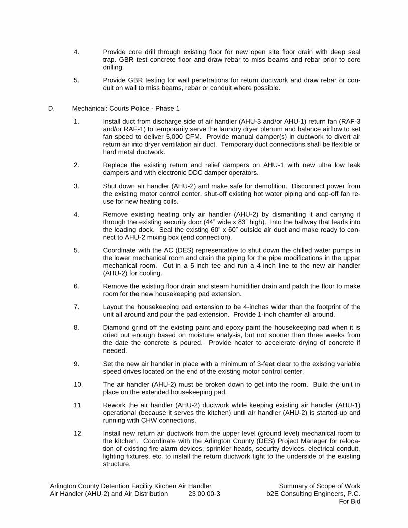
Arlington County Detention Facility Kitchen Air Handler Summary of Scope of Work Air Handler (AHU-2) and Air Distribution 23 00 00-3 b2E Consulting Engineers, P.C.
For Bid
4. Provide core drill through existing floor for new open site floor drain with deep seal trap. GBR test concrete floor and draw rebar to miss beams and rebar prior to core drilling.
5. Provide GBR testing for wall penetrations for return ductwork and draw rebar or con-duit on wall to miss beams, rebar or conduit where possible.
D. Mechanical: Courts Police - Phase 1
1. Install duct from discharge side of air handler (AHU-3 and/or AHU-1) return fan (RAF-3 and/or RAF-1) to temporarily serve the laundry dryer plenum and balance airflow to set fan speed to deliver 5,000 CFM. Provide manual damper(s) in ductwork to divert air return air into dryer ventilation air duct. Temporary duct connections shall be flexible or hard metal ductwork.
2. Replace the existing return and relief dampers on AHU-1 with new ultra low leak dampers and with electronic DDC damper operators.
3. Shut down air handler (AHU-2) and make safe for demolition. Disconnect power from the existing motor control center, shut-off existing hot water piping and cap-off fan re-use for new heating coils.
4. Remove existing heating only air handler (AHU-2) by dismantling it and carrying it through the existing security door (44” wide x 83” high). Into the hallway that leads into the loading dock. Seal the existing 60” x 60” outside air duct and make ready to con-nect to AHU-2 mixing box (end connection).
5. Coordinate with the AC (DES) representative to shut down the chilled water pumps in the lower mechanical room and drain the piping for the pipe modifications in the upper mechanical room. Cut-in a 5-inch tee and run a 4-inch line to the new air handler (AHU-2) for cooling.
6. Remove the existing floor drain and steam humidifier drain and patch the floor to make room for the new housekeeping pad extension.
7. Layout the housekeeping pad extension to be 4-inches wider than the footprint of the unit all around and pour the pad extension. Provide 1-inch chamfer all around.
8. Diamond grind off the existing paint and epoxy paint the housekeeping pad when it is dried out enough based on moisture analysis, but not sooner than three weeks from the date the concrete is poured. Provide heater to accelerate drying of concrete if needed.
9. Set the new air handler in place with a minimum of 3-feet clear to the existing variable speed drives located on the end of the existing motor control center.
10. The air handler (AHU-2) must be broken down to get into the room. Build the unit in place on the extended housekeeping pad.
11. Rework the air handler (AHU-2) ductwork while keeping existing air handler (AHU-1) operational (because it serves the kitchen) until air handler (AHU-2) is started-up and running with CHW connections.
12. Install new return air ductwork from the upper level (ground level) mechanical room to the kitchen. Coordinate with the Arlington County (DES) Project Manager for reloca-tion of existing fire alarm devices, sprinkler heads, security devices, electrical conduit, lighting fixtures, etc. to install the return ductwork tight to the underside of the existing structure.
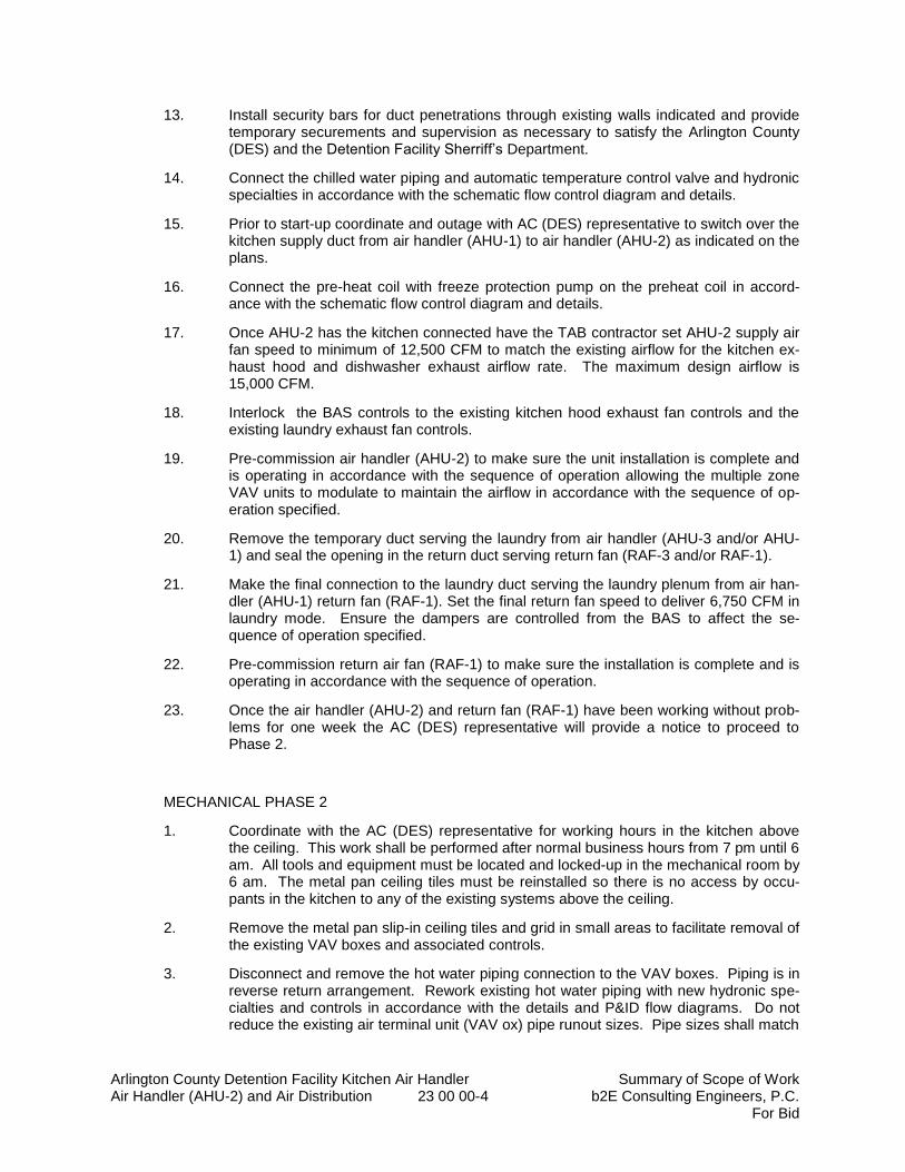
Arlington County Detention Facility Kitchen Air Handler Summary of Scope of Work Air Handler (AHU-2) and Air Distribution 23 00 00-4 b2E Consulting Engineers, P.C.
For Bid
13. Install security bars for duct penetrations through existing walls indicated and provide temporary securements and supervision as necessary to satisfy the Arlington County (DES) and the Detention Facility Sherriff’s Department.
14. Connect the chilled water piping and automatic temperature control valve and hydronic specialties in accordance with the schematic flow control diagram and details.
15. Prior to start-up coordinate and outage with AC (DES) representative to switch over the kitchen supply duct from air handler (AHU-1) to air handler (AHU-2) as indicated on the plans.
16. Connect the pre-heat coil with freeze protection pump on the preheat coil in accord-ance with the schematic flow control diagram and details.
17. Once AHU-2 has the kitchen connected have the TAB contractor set AHU-2 supply air fan speed to minimum of 12,500 CFM to match the existing airflow for the kitchen ex-haust hood and dishwasher exhaust airflow rate. The maximum design airflow is 15,000 CFM.
18. Interlock the BAS controls to the existing kitchen hood exhaust fan controls and the existing laundry exhaust fan controls.
19. Pre-commission air handler (AHU-2) to make sure the unit installation is complete and is operating in accordance with the sequence of operation allowing the multiple zone VAV units to modulate to maintain the airflow in accordance with the sequence of op-eration specified.
20. Remove the temporary duct serving the laundry from air handler (AHU-3 and/or AHU-1) and seal the opening in the return duct serving return fan (RAF-3 and/or RAF-1).
21. Make the final connection to the laundry duct serving the laundry plenum from air han-dler (AHU-1) return fan (RAF-1). Set the final return fan speed to deliver 6,750 CFM in laundry mode. Ensure the dampers are controlled from the BAS to affect the se-quence of operation specified.
22. Pre-commission return air fan (RAF-1) to make sure the installation is complete and is operating in accordance with the sequence of operation.
23. Once the air handler (AHU-2) and return fan (RAF-1) have been working without prob-lems for one week the AC (DES) representative will provide a notice to proceed to Phase 2.
MECHANICAL PHASE 2
1. Coordinate with the AC (DES) representative for working hours in the kitchen above the ceiling. This work shall be performed after normal business hours from 7 pm until 6 am. All tools and equipment must be located and locked-up in the mechanical room by 6 am. The metal pan ceiling tiles must be reinstalled so there is no access by occu-pants in the kitchen to any of the existing systems above the ceiling.
2. Remove the metal pan slip-in ceiling tiles and grid in small areas to facilitate removal of the existing VAV boxes and associated controls.
3. Disconnect and remove the hot water piping connection to the VAV boxes. Piping is in reverse return arrangement. Rework existing hot water piping with new hydronic spe-cialties and controls in accordance with the details and P&ID flow diagrams. Do not reduce the existing air terminal unit (VAV ox) pipe runout sizes. Pipe sizes shall match
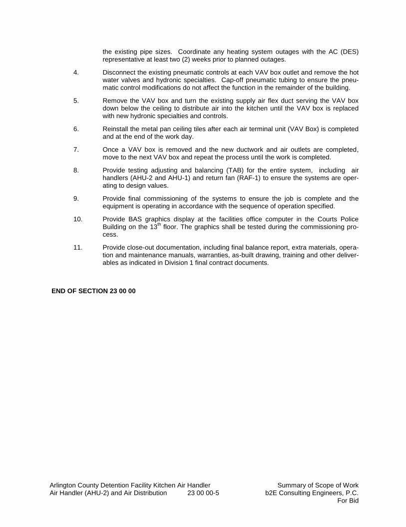
Arlington County Detention Facility Kitchen Air Handler Summary of Scope of Work Air Handler (AHU-2) and Air Distribution 23 00 00-5 b2E Consulting Engineers, P.C.
For Bid
the existing pipe sizes. Coordinate any heating system outages with the AC (DES) representative at least two (2) weeks prior to planned outages.
4. Disconnect the existing pneumatic controls at each VAV box outlet and remove the hot water valves and hydronic specialties. Cap-off pneumatic tubing to ensure the pneu-matic control modifications do not affect the function in the remainder of the building.
5. Remove the VAV box and turn the existing supply air flex duct serving the VAV box down below the ceiling to distribute air into the kitchen until the VAV box is replaced with new hydronic specialties and controls.
6. Reinstall the metal pan ceiling tiles after each air terminal unit (VAV Box) is completed and at the end of the work day.
7. Once a VAV box is removed and the new ductwork and air outlets are completed, move to the next VAV box and repeat the process until the work is completed.
8. Provide testing adjusting and balancing (TAB) for the entire system, including air handlers (AHU-2 and AHU-1) and return fan (RAF-1) to ensure the systems are oper-ating to design values.
9. Provide final commissioning of the systems to ensure the job is complete and the equipment is operating in accordance with the sequence of operation specified.
10. Provide BAS graphics display at the facilities office computer in the Courts Police Building on the 13
th floor. The graphics shall be tested during the commissioning pro-
cess.
11. Provide close-out documentation, including final balance report, extra materials, opera-tion and maintenance manuals, warranties, as-built drawing, training and other deliver-ables as indicated in Division 1 final contract documents.
END OF SECTION 23 00 00
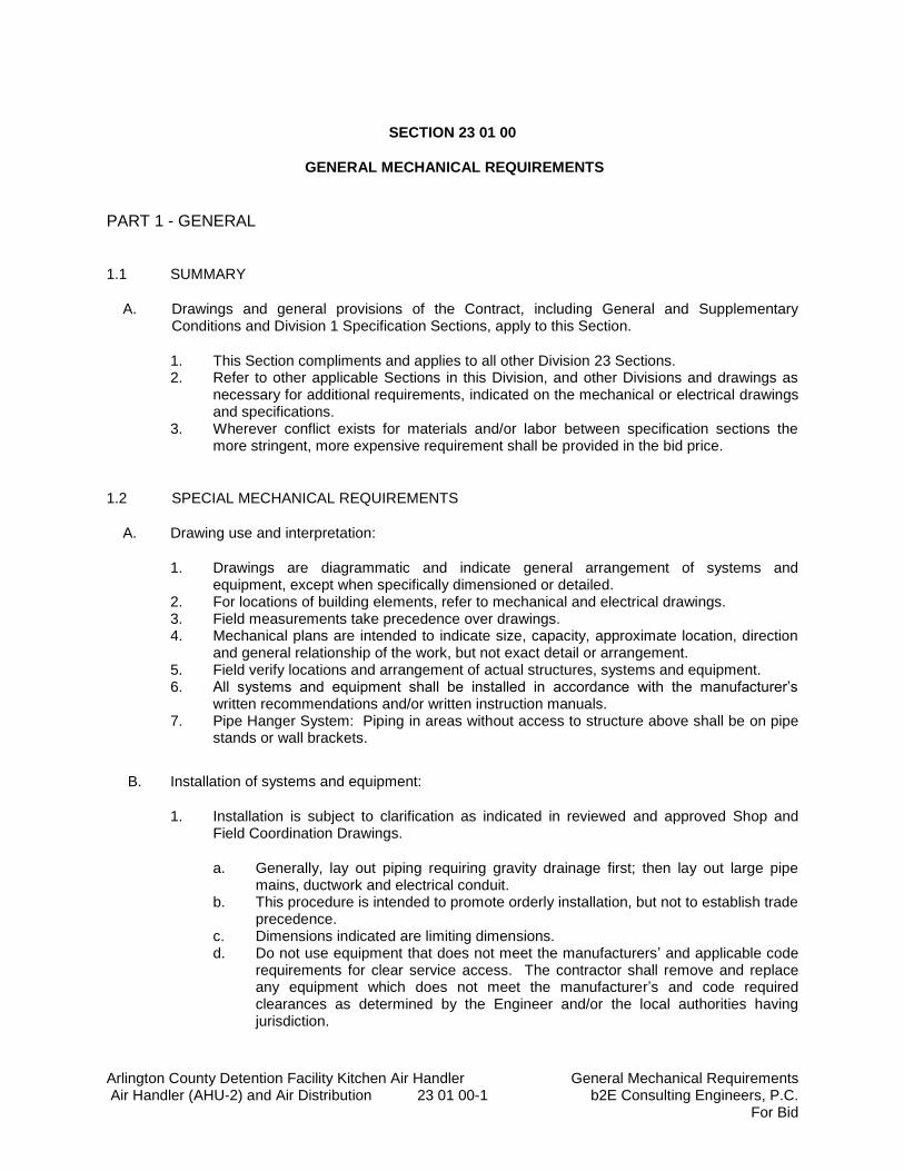
Arlington County Detention Facility Kitchen Air Handler General Mechanical Requirements Air Handler (AHU-2) and Air Distribution 23 01 00-1 b2E Consulting Engineers, P.C.
For Bid
SECTION 23 01 00
GENERAL MECHANICAL REQUIREMENTS
PART 1 - GENERAL
1.1 SUMMARY
A. Drawings and general provisions of the Contract, including General and Supplementary Conditions and Division 1 Specification Sections, apply to this Section.
1. This Section compliments and applies to all other Division 23 Sections. 2. Refer to other applicable Sections in this Division, and other Divisions and drawings as
necessary for additional requirements, indicated on the mechanical or electrical drawings and specifications.
3. Wherever conflict exists for materials and/or labor between specification sections the more stringent, more expensive requirement shall be provided in the bid price.
1.2 SPECIAL MECHANICAL REQUIREMENTS
A. Drawing use and interpretation:
1. Drawings are diagrammatic and indicate general arrangement of systems and equipment, except when specifically dimensioned or detailed.
2. For locations of building elements, refer to mechanical and electrical drawings. 3. Field measurements take precedence over drawings. 4. Mechanical plans are intended to indicate size, capacity, approximate location, direction
and general relationship of the work, but not exact detail or arrangement. 5. Field verify locations and arrangement of actual structures, systems and equipment. 6. All systems and equipment shall be installed in accordance with the manufacturer’s
written recommendations and/or written instruction manuals. 7. Pipe Hanger System: Piping in areas without access to structure above shall be on pipe
stands or wall brackets.
B. Installation of systems and equipment:
1. Installation is subject to clarification as indicated in reviewed and approved Shop and Field Coordination Drawings.
a. Generally, lay out piping requiring gravity drainage first; then lay out large pipe mains, ductwork and electrical conduit.
b. This procedure is intended to promote orderly installation, but not to establish trade precedence.
c. Dimensions indicated are limiting dimensions. d. Do not use equipment that does not meet the manufacturers’ and applicable code
requirements for clear service access. The contractor shall remove and replace any equipment which does not meet the manufacturer’s and code required clearances as determined by the Engineer and/or the local authorities having jurisdiction.
Arlington County Detention Facility Kitchen Air Handler General Mechanical Requirements Air Handler (AHU-2) and Air Distribution 23 01 00-2 b2E Consulting Engineers, P.C.
For Bid
e. Coordinate ductwork and piping penetrations through walls, floors and roof with actual field conditions and dimensions. Contractors shall thoroughly familiarize themselves with the project requirements and the construction documents prior to submitting bid price, and shall have measured and coordinated the installations between trades using manufacturer’s actual equipment dimension drawings prior to submitting coordinated shop drawings.
f. Under no circumstances shall any mechanical equipment be hung, supported or suspended from the building ceilings. Ductwork, piping, etc. shall only be hung or supported directly from the building structure (i.e. steel beam, or concrete floor system). Refer to structural requirements for building attachments.
C. Utility coordination with the Owner: There shall be no unauthorized utility interruptions
throughout the duration of the project.
1. The Contractor shall notify Engineer/Owner and obtain approval for any utility interruptions at least seventy two (72) hours in advance of such interruption and obtain approval from the Owner before proceeding.
2. Identify extent and duration of utility interruptions. 3. Any damage to the Owner materials and equipment due to the Contractor’s work or utility
interruptions shall be entirely the Contractor’s responsibility. D. Description of systems: Furnish and install materials resulting, upon completion, in functioning
systems in compliance with performance requirements specified, and including all modifications resulting from reviewed and approved Shop and Field Coordination Drawings.
1. Provide materials and equipment as indicated on the construction documents. Where items installed are determined by the Owner and the Engineer not in general conformance with the intent of the construction documents replace materials and equipment at no additional cost to the Owner.
E. Start-up and Commissioning the System:
1. The contractor is responsible to provide pre-functional testing, equipment start up, system demonstrations and detailed documentation for each of these items.
2. Refer to the Commissioning Plan in Section 23 08 00.
F. Energy Management System Coordination and Related Work: This project includes installation of a Web based electronic control system to monitor and control equipment provided under this contract.
1. The air handler (AHU-2) shall be provided with field installed controls, except those control devices that are provided from the factory for the AHU shall be interlocked to the BAS for a complete operating system.
2. The Building Automation System (BAS) vendor for the Owner is Siemens Infrastructure & Cities. Siemens shall provide BACnet integraton for monitoring control and setpoint adjustment via graphical interface.
3. All equipment provided under this contract for mechanical systems shall be provided
with hard wired controls to BAS controllers and shall be indicated on Building Automation System (BAS) graphics via the Siemens server in the AC data room.
Arlington County Detention Facility Kitchen Air Handler General Mechanical Requirements Air Handler (AHU-2) and Air Distribution 23 01 00-3 b2E Consulting Engineers, P.C.
For Bid
G. Phasing: The proposed phasing plan is indicated in Division 1 and on the drawings. The contractor shall provide a detailed phasing plan to ensure domestic hot water heating is maintained throughout the duration of construction.
1. Refer to Section 01 95 00 “Proposed Phasing Plan” for other applicable requirements.
H. HVAC Pipe Flushing: Provide plant isolation valves with a bypass for flushing the air handler piping. These valves shall allow flushing debris out of the piping system prior to running water through the air handler.
1. Contractor shall be responsible for the initial flushing of the air handler branch piping system and supply all cleaning chemicals. The Owner’s mechanical inspector shall verify that this has been done. The contractor shall obtain written approval from the Owner that the flushing and cleaning of the plant piping system is complete prior to system startup of the system by the Contractor.
I. Warranty: Provide a full five (5) year warranty on all HVAC labor and materials with guaranteed 24 hr. service.
1. Extended Warranty: Provide a manufacturer’s five (5) year labor and materials warranty for the air handler as indicated in Section 23 64 00.
J. Miscellaneous Emergency Electric Power: Provide emergency power to all air handlers, pumps, fans and BAS panels serving equipment in the boiler mechanical room, to maintain communication from remote site.
K. Rigging: All equipment and piping shall be rigged in through the loading dock and brought through the existing security doors which are 44” wide x 83” high.
L. Demonstration and Training: Provide demonstration and training for Arlington County Facilities Maintenance personnel. Refer to Division 1 for other applicable requirements.
1.3 DEFINITIONS
A. Finished Spaces: Spaces other than mechanical and electrical equipment rooms, concealed furred spaces, pipe and duct shafts, unheated spaces immediately below roof, spaces above ceilings, unexcavated spaces, crawlspaces, and tunnels.
B. Exposed, Interior Installations: Exposed to view indoors. Examples include finished occupied spaces and mechanical equipment rooms.
C. Exposed, Exterior Installations: Exposed to view outdoors or on grade subject to outdoor ambient temperatures and weather conditions. Examples include rooftop locations.
D. Concealed, Interior Installations: Concealed from view and protected from physical contact by building occupants. Examples include above ceilings and in duct shafts.
E. Concealed, Exterior Installations: Concealed from view and protected from weather conditions and physical contact by building occupants but subject to outdoor ambient temperatures. Examples include installations within unheated shelters.
F. Basis of Design: Equipment specifically designated with the term “Basis of Design” as indicated in the specifications or as scheduled on drawings.
Arlington County Detention Facility Kitchen Air Handler General Mechanical Requirements Air Handler (AHU-2) and Air Distribution 23 01 00-4 b2E Consulting Engineers, P.C.
For Bid
1. The Contractor shall provide the “Basis of Design” or one of the “Acceptable Manufacturers” listed in the specification. Where “Acceptable Manufacturer’s” equipment other than the “Basis of Design” is provided, the contractor is responsible to fully coordinate and provide design changes to structural steel, electrical power to match nameplate data, controls, ductwork connections, piping connections, unit efficiency, compatibility with controls, for a complete operating system in accordance with the plans and specifications.
G. Substantial Completion: Refer to the Supplemental Conditions and Division 1 and Section 017700 “Closeout Procedures” sections of the specifications for the Substantial Completion requirements.
H. Acceptance: Shall occur after Substantial Completion and at which time all contract requirements and Quality Control for the HVAC system (including equipment start-up, pre-functional checklists, and functional performance testing) have been completed and all Cx Issues Log items have been resolved by the Contractor to the satisfaction of the Owner and the Engineer.
1. With respect to initiation of warranty, the date when the Engineer signs the certificate for Substantial Completion for the work.
2. With respect to payment of retainage, the date when the Engineer accepts the Commissioning of the Mechanical System (including systems demonstrations in summer (>90°F) for the entire building, Functional checklists are complete, start-up commissioning is complete, and performance verification and issues logs are completed with the systems fully operational in accordance with the Contract Documents.
I. The Owner:
J. TAB: Testing, Adjusting and Balancing. Refer to Section 23 05 93 for specific requirements.
K. BAS: Building Automation System (Division 23).
L. Acceptable Manufacturer: Equipment that meets the criteria specified and which is fabricated and assembled by one of the manufacturers listed in the “manufacturer’s” paragraph of the Specification Section.
M. After-hours: Unoccupied hours of operation for the facility as determined by the Owner.
N. Occupied Area: Any area on the property during occupied hours as determined by the Owner.
O. Scheduled: As scheduled on drawing equipment schedules or as called-out by manufacturer/model number/designation in the specification.
P. Cutting: Removal of existing construction necessary to permit installation or performance of other Work.
Q. Patching: Fitting and repair work required to restore surfaces to specified “new” or better conditions after installation or removal of other Work.
R. AFD: Adjustable Frequency Drive.
S. AHU-X: Air Handler; X = numbering sequence (See schedule on plans).
Arlington County Detention Facility Kitchen Air Handler General Mechanical Requirements Air Handler (AHU-2) and Air Distribution 23 01 00-5 b2E Consulting Engineers, P.C.
For Bid
T. HWCP-X: Hot Water Circulating Heating Pump (Freeze Protection); X = numbering sequence (See schedule on plans).
U. RAF: Return Air Fan.
V. SAF: Supply Air Fan.
W. VFD: Variable Frequency Drive (Same as AFD).
X. DHWP-X: Domestic Hot Water Circulating Pumps: X = numbering sequence (See schedule on plans).
Y. PHX-X: Plate Frame Heat Exchanger; X = numbering sequence (See schedule on plans).
Z. DHWST-X: Domestic Hot Water Storage Tank; X = numbering sequence (See schedule on plans).
AA. (E): Existing to remain (in the current phase of work).
BB. (R): Existing to be removed (in the current phase of work).
CC. (RL): Existing to be relocated (in the current phase of work).
2.14 SUBMITTALS
A. Product Data: For the following:
1. Shop Drawings. 2. Coordination Drawings. 3. Penetration and Building Attachment Coordination Plans. 4. Auto CAD 2017 (MEP 3-D) or Revit 2017 Generated Coordination and Installation
Drawings (1/4 scale). 5. Identifying Devices and Labels. 6. Housekeeping Pads. 7. Rated Penetrations. 8. Structural Steel for Supports. 9. Motor Protectors. 10. Commercial Power Relay. 11. List of Mock-Ups.
B. Shop Drawings: Detail fabrication and installation for structural steel strengthening, metal supports and anchorage for mechanical materials and equipment. Provide structural and mechanical submittals at same time to allow engineering review of complete proposed systems located on the roof, or inside the building.
C. Contractor’s Phasing Plan: Provide a detailed phasing plan clearly identifying each phase of construction. The phasing plan shall have a narrative explaining the selective demolition, the sequences of the work, the submittal schedule, the equipment lead times, the quantity and duration of any outages, the number days of work in the mechanical room and in the kitchen separately for each activity, details on wall penetrations and temporary security for return air duct openings and security bar installation and other pertinent information which affects the schedule.
Arlington County Detention Facility Kitchen Air Handler General Mechanical Requirements Air Handler (AHU-2) and Air Distribution 23 01 00-6 b2E Consulting Engineers, P.C.
For Bid
1. Refer to Section 01 95 00 “Proposed Phasing Plan”.
D. Project Schedule: Provide a detailed project schedule using MS Project which is coordinated with the contractor’s phasing plan.
E. Coordination Drawings: Detail major elements, components, and systems of mechanical equipment and materials in relationship with other systems, installations, and building components. Show space requirements for installation and access. Indicate if sequence and coordination of installations are important to efficient flow of the Work. Include the following:
1. Clearances for servicing and maintaining equipment, accessories, and specialties, including space for disassembly required for periodic maintenance, minimum or greater code required clearance to electric panels, fan and shaft pull and coil removal and motor service access shall be indicated.
2. Equipment and accessory service connections and support details. 3. Wall penetrations and securements to maintain the secure integrity of the wall openings
throughout the duration of construction. 4. Fire-rated wall penetrations. 5. Scheduling, sequencing, movement, and positioning of large equipment into/onto building
during construction. 6. Floor plans, elevations, and details to indicate penetrations in walls and roofs and their
relationship to other penetrations and installations. 7. Floor plans indicating the existing devices and equipment to be removed and relocated to
make room for the new return ductwork from the upper level mechanical room (ground floor) to the kitchen.
8. Access panel and door locations. 9. Operation and Maintenance Data: In accordance with Division 1 and provide multiple
review submissions to modify or reorganize format and content as requested by the Engineer at no additional cost to the Owner.
a. Submit O&M manuals for initial review and comment no later than 90 days after
equipment submittals have been completed.
F. Building Attachment Coordination Plans: Submit scaled coordination plans indicating all attachments, sleeves, etc. Plan shall be min. ¼” scale and shall indicate penetrations required for all trades work, including mechanical, and, electrical. Include the following information:
1. Extent: Indicate all building attachments. 2. Products: List products to be used and firms or entities that will perform the Work. 3. Structural Elements: Where building attachments involve adding reinforcement to
structural elements, submit details and engineering calculations showing integration of reinforcement with structure for review and approval by the Engineer.
4. Powder-Driven Fasteners Prohibited: Do not use powder driven fasteners in concrete construction in this building without prior written approval from the Structural Engineer. Building damage due to the Contractor’s use of powder-driven fasteners in the building shall be entirely the responsibility of the Contractor.
5. Steel Stanchions and Channels: The Contractor shall provide steel stanchions and channels to support from the floor all multiple mechanical, piping and, electrical conduit and for equipment. The steel stanchions and channels position (spacing interval) and quantities and lengths shall be coordinated and provided by the Contractor for the actual quantity and weight of pipes. Individual pipes which are not hung from the concrete roof area shall be supported using floor stanchions. Refer to structural for other applicable requirements.
Arlington County Detention Facility Kitchen Air Handler General Mechanical Requirements Air Handler (AHU-2) and Air Distribution 23 01 00-7 b2E Consulting Engineers, P.C.
For Bid
G. CAD Generated 3-D Coordination and Installation Drawings (1/4 scale): Provide for the following systems; including the air handling unit (AHU-2) air distribution systems. The drawings shall show the building structure and other trades work (including but not limited to, electrical, lighting, mechanical) and shall indicate all air handlers, ductwork, pumps, fans, etc.
H. Samples: Of color, lettering style, and other graphic representation required for each identification material and device.
1.5 QUALITY ASSURANCE
A. Comply with ASME A13.1 for lettering size, length of color field, colors, and viewing angles of identification devices.
B. Equipment Selection: Provide “Basis of Design” where listed in the drawings and specifications. “Acceptable Manufacturers” equipment of higher electrical characteristics, physical dimensions, weight, capacities, and ratings other than indicated as “Basis of Design”, may be furnished if connecting mechanical and electrical services, circuit breakers, conduit, motors, bases, structural steel, hangers and supports, and equipment spaces are increased. Additional costs to the Owner shall not be considered for such modifications, and shall remain the responsibility of the contractor. Equipment must meet design capacities, minimum energy ratings or efficiencies, not to exceed physical dimensions, controls and all commissioning requirements.
C. Investigation: Coordinate and provide thorough investigation of concrete slabs and CMU walls which have penetrations drilled or cut into the slab or wall before proceeding with such work. Immediately repair and or replace conduit, piping or structural members in or under the concrete slabs or walls which are damaged during the course of the work at no additional cost to the Owner.
a. Investigate structures and locate any cables, electric conduit, piping, etc. prior to cutting or drilling.
D. Structural Elements: Do not cut and patch structural elements in a manner that could change their load-carrying capacity or load-deflection ratio.
a. Repair or replace the damaged structure immediately as determined by the Engineer.
E. Operational Elements: Do not cut and patch the following operating elements and related components in a manner that results in reducing their capacity to perform as intended or that results in increased maintenance or decreased operational life or safety.
1. Primary operational systems and equipment. 2. Fire-protection systems. 3. Control systems. 4. Communication systems. 5. Conveying systems. 6. Electrical wiring systems. 7. Building structure.
F. Miscellaneous Elements: Do not cut and patch the following elements or related components in a manner that could change their load-carrying capacity that results in reducing their capacity to perform as intended or that results in increased maintenance or decreased operational life or safety.
1. Water, moisture, or vapor barriers. 2. Membranes and flashings.
Arlington County Detention Facility Kitchen Air Handler General Mechanical Requirements Air Handler (AHU-2) and Air Distribution 23 01 00-8 b2E Consulting Engineers, P.C.
For Bid
3. Exterior curtain-wall construction. 4. Equipment supports. 5. Piping, ductwork, vessels, and equipment. 6. Noise- and vibration-control elements and systems. 7. Building structure.
G. Visual Requirements: Do not cut and patch construction in a manner that results in visual evidence of cutting and patching. Do not cut and patch construction exposed on the exterior or in occupied spaces in a manner that would, in Engineer’s opinion, reduce the building's aesthetic qualities. Remove and replace construction that has been cut and patched in a visually unsatisfactory manner.
H. Perform work in accordance with following codes:
1. International Building Code (IBC 2015). 2. International Mechanical Code (IMC 2015). 3. International Plumbing Code (IPC 2015). 4. International Fuel Gas Code (IFGC 2015). 5. International Fire Protection Code (IFPC 2015). 6. International Energy Efficiency Code (IEEC 2015) 7. National Fire Protection Association Applicable Codes listed below others applicable
latest editions unless otherwise specified.
a. National Sprinkler Code (NFPA 13). b. Standpipes (NFPA 14). c. Fire pumps (NFPA 20). d. National Electric Code (NFPA 70). e. Air Distribution (NFPA 90 A).
8. ASHRAE, Standard 15, 2016 - Mechanical Refrigeration Safety Code, (Latest Edition). 9. ASHRAE/IES 90.1, 2010 - Energy Code for Commercial and High-Rise Residential
Buildings. 10. SMACNA Fire and Smoke Damper Installation. 11. Underwriters Laboratories (UL) Firestopping Systems Guide. (Latest Edition). 12. ASHRAE Guideline 1-2010: The HVAC Commissioning Process. 13. Virginia Uniform Statewide Building Code (latest amendments). 14. In accordance with local codes, ordinances, amendments, etc. and as required by the
authorities having jurisdiction.
1.6 DELIVERY, STORAGE, AND HANDLING
A. Deliver pipes and tubes with factory-applied end caps. Maintain end caps through shipping, storage, and handling to prevent pipe end damage and prevent entrance of dirt, debris, and moisture.
B. Protect stored pipes and tubes from moisture and dirt. Elevate above grade. Do not exceed structural capacity of floor or roof, when rigging materials or equipment.
C. Protect flanges, fittings, and piping specialties from moisture and dirt.
D. Provide covering and shielding for equipment to protect from damage.
E. Protect existing building and building components.

Arlington County Detention Facility Kitchen Air Handler General Mechanical Requirements Air Handler (AHU-2) and Air Distribution 23 01 00-9 b2E Consulting Engineers, P.C.
For Bid
F. Repair, restore, and replace damaged building components and equipment.
G. Protect nameplates on motors, pumps and other equipment.
1.7 COORDINATION, SEQUENCING AND SCHEDULING
A. Coordinate mechanical equipment installation with other building components.
B. The walls may require electric conduit and piping walls to rough-in equipment. Coordinate and provide electric conduit and piping as necessary to maintain weatherproof integrity of exterior walls to rough-in for actual equipment connections.
1. Immediately repair any equipment damaged due to cutting the exterior or interior walls.
C. Arrange for pipe penetrations in building walls during progress of construction to allow for mechanical installations.
1. Set sleeves in wall penetrations as they are constructed.
D. Coordinate installation of required supporting devices with actual field conditions to ensure that maximum support intervals do not exceed code requirements.
E. Sequence, coordinate, and integrate installations of mechanical materials and equipment for efficient flow of the Work.
F. Coordinate lifting and rigging, and connection of mechanical systems with exterior underground and overhead utilities and services. Comply with requirements of governing regulations, franchised service companies, and controlling agencies for setting or moving large equipment. Perform work in accordance with all applicable codes and local authorities having jurisdiction and obtain and pay for all permits and other costs.
1. Do not lift or crane any equipment above occupied areas of the site or the building.
G. Coordinate requirements for access panels and doors if mechanical items requiring access are concealed behind finished surfaces.
H. Coordinate installation of identifying devices after completing covering and painting, if devices are applied to surfaces. Install identifying devices before installing acoustical ceilings and similar concealment.
I. Coordinate lifting and rigging and connection of mechanical systems with interior space limitations and finishes. Remove and replace as necessary existing architectural, mechanical, electrical, plumbing, etc., building components as required to install large and/or heavy equipment.
J. Coordinate and provide installation of all work to meet the contract milestone deadlines, substantial completion, and construction completion dates. Refer to the “Contract Requirements” and Division 1 and Section 01 77 00 “Closeout Procedures” sections of the specifications for other applicable requirements.
1.8 JOB CONDITIONS

Arlington County Detention Facility Kitchen Air Handler General Mechanical Requirements Air Handler (AHU-2) and Air Distribution 23 01 00-10 b2E Consulting Engineers, P.C.
For Bid
A. Once utilities and services are functional cause as little interference or interruption of utilities and services as possible.
1. The Contractor shall notify Owner/Engineer and obtain approval for any utility interruptions at least seventy two (72) hours in advance of such interruption and obtain approval from Engineer before proceeding.
B. Keep roads and parking areas clear of materials and debris.
C. Examine Contract Documents to determine how other work will affect execution of mechanical work.
D. Examine site and become familiar with actual conditions affecting work.
E. Make arrangements and pay for necessary permits, licenses, and inspections as required in the Supplemental Conditions and Division 1 sections of the specifications.
F. Record drawings: Shall be provided as required in the supplemental Conditions and Division 1 sections of the specifications.
1. Keep a complete set of mechanical drawings in job site office for indicating actual installation of mechanical systems and equipment.
2. Use this set of drawings for no other purpose. 3. Where material, equipment, or systems components are installed differently from that
indicated, show such differences clearly and neatly. 4. At project completion, submit record set of as-built drawings in accordance with Division
1.
1.9 SUBSTANTIAL COMPLETION AND ACCEPTANCE
A. The Contractor shall refer to Division 1, and other applicable Project Manual Sections for Substantial Completion requirements prior to submitting bid price.
B. Acceptance: The mechanical and plumbing systems shall not be accepted by the Engineer until all systems are installed, fully operational, all commissioning of HVAC systems (including all functional performance testing and resolution of all Cx Issue Log items), and documentation are completed to the satisfaction of the Owner and the Engineer.
1. The Engineer will not Accept and will not release payment for retainage until all Contract
Requirements, including Division 23 contract requirements are completed, and the systems are Accepted by the Owner and Engineer.
2. Refer to paragraph 3.7 of this Section for other applicable requirements.
PART 2 - PRODUCTS
2.1 MANUFACTURERS
A. Acceptable Manufacturers: Subject to compliance with requirements, provide products by one of the manufacturers specified.
1. Refer to Section 01 60 00 “Product Requirements” for other applicable requirements.
Arlington County Detention Facility Kitchen Air Handler General Mechanical Requirements Air Handler (AHU-2) and Air Distribution 23 01 00-11 b2E Consulting Engineers, P.C.
For Bid
2.2 IDENTIFYING DEVICES AND LABELS
A. General: Manufacturer's standard products of categories and types required for each application as referenced in Division 23 Section 23 05 53 “Identification for HVAC Piping and Equipment.” If more than one type is specified for application, selection is Installer's option, but provides one selection for each product category.
2.3 RATED PENETRATIONS
A. The contractor is responsible for reviewing the full set of drawings prior to submitting their bid price. The contractor shall include in their bid price all required UL listed firestopping penetration system whether or not indicated on the mechanical drawings.
2.4 STRUCTURAL STEEL FOR SUPPORTS
A. Mechanical Equipment: Maximum allowable operating weights are identified on the mechanical equipment schedules. The contractor shall ensure that the operating weight of the actual equipment installed does not exceed the scheduled value.
2.5 THREE-PHASE MOTOR PROTECTORS
A. Provide all labor and materials for provision, installation, setup and testing motor protectors which will shut-down and protect all three-phase motors (1 HP and greater) upon detecting overvoltage, under-voltage, loss of phase, phase reversal, phase imbalance, etc.
B. Provide motor protectors for each 3-phase motor whether provided as a factory mounted or field installed motor. Provide for built-up and for factory fabricated equipment. Provide whether or not equipment is provided with internal motor protection (i.e. AFD) or not. Provide all motor protectors with auto reset.
C. Basis of Design: ICM 450 or approved equal.
PART 3 - EXECUTION
3.1 GENERAL
A. When changes in location of work are required, for coordination with the building structural or between trades work, obtain approval of Engineer before making change.
1. Make changes at no additional cost to the Owner.
B. Provide all necessary offsets and crossovers in piping and ductwork, whether indicated or not, as required to allow code required maintenance (service) access.
C. Do not change indicated piping sizes without approval of Engineer.
D. Electrical equipment:
1. Install no piping in or above electrical equipment rooms and closets, unless above and protected by a rated ceiling
Arlington County Detention Facility Kitchen Air Handler General Mechanical Requirements Air Handler (AHU-2) and Air Distribution 23 01 00-12 b2E Consulting Engineers, P.C.
For Bid
2. Install no piping above panelboards, switchboards, motor control centers, or motor control panels, unless above and protected by a rated ceiling.
3. Adjustable Frequency Drives (AFD’s) shall be installed indoors as close as possible to the motor served. The AFD’s shall be remote mounted in the mechanical rooms where the drive is located.
a. All AFD’s shall be by the same manufacturer. b. AFD’s serving equipment outdoors shall be factory installed in the equipment
housings by the manufacturer. c. AFD’s serving the pump motors shall be located wall mounted in the main
equipment room.
4. Motor Controllers: All disconnect/starters shall be provided with panel mounted hand-off-auto (H.O.A.) switches. The H.O.A. switches shall be provided with indicator lights, and control power transformers.
5. Motor Protectors: Provide motor protectors for all three-phase motors.
a. Provide ICM-450 motor protectors. b. Mount in NEMA 1 enclosure adjacent motor controller, or inside control panel of
equipment served.
3.2 LOCATING SERVICEABLE DEVICES
A. Install devices that may require adjustment, service, or maintenance in normally accessible locations, or provide flush-mounted access doors.
1. Such devices include but are not limited to equipment, valves, motors, drives, compressors, unions, traps, strainers, thermometers, gauges, meters, switches, measurement devices, tubes, detectors, dampers, sensors, monitors, backflow prevention devices, test stations, signal devices, air vents, expansion joints, system drains, fire dampers, manual balancing dampers, etc.
2. Arrange piping and conduit, and related work to facilitate maintenance. 3. Relocate items, which interfere with access, to satisfaction of Engineer. 4. All equipment in mechanical spaces requiring adjustment, service or maintenance shall
be installed no higher than 8’-0” above finished floor or roof level. Where indicated on drawings, locate at elevation no higher than scaled in sections, elevations or as noted.
5. Final location of equipment requiring adjustment, service or maintenance shall be identified on the coordination drawings. The Owner and the Engineer will make the final determination whether equipment is accessible. The contractor shall relocate at their own expense any equipment, which is determined inaccessible due to apparent lack of coordination.
6. Provide adequate means for maintenance and inspection and removal of equipment for repairs, such as compressor motors, cooling tower motors and pump motors. This includes, but is not limited to, removable railings, removable structural, supports, etc. Demonstrate the method for maintenance and inspection and removal of the equipment with one (1) person to the Owner/Engineer. If the Engineer determines that the equipment is not serviceable by one (1) person the Contractor shall revise the installations until the installation is serviceable as determined by the Engineer.
3.3 CUTTING AND PATCHING
A. General: Employ skilled workers to perform cutting and patching.
Arlington County Detention Facility Kitchen Air Handler General Mechanical Requirements Air Handler (AHU-2) and Air Distribution 23 01 00-13 b2E Consulting Engineers, P.C.
For Bid
1. Do not cut construction without prior written approval from the Structural Engineer and the Contractor.
2. Do not damage the building finishes or structural systems. The contractor shall fix any building damage immediately.
3.4 EQUIPMENT INSTALLATION - COMMON REQUIREMENTS
A. Install equipment in accordance with manufacturer’s recommendations, and as specified. B. Install equipment to provide maximum possible headroom if mounting heights are not indicated.
C. Install equipment according to approved submittal data. Portions of the Work are shown only in diagrammatic form. Refer conflicts to Engineer.
D. Install equipment level and plumb, parallel and perpendicular to other building systems and components in exposed interior spaces, unless otherwise indicated.
E. Install mechanical equipment to facilitate service, maintenance, and repair or replacement of components. Connect equipment for ease of disconnecting, with minimum interference to other installations. Extend grease fittings to accessible locations.
F. Provide necessary anchoring devices and supports.
1. Use structural supports suitable for equipment. 2. Check loadings and dimensions of equipment with shop drawings. 3. Do not cut or weld to building structural members. 4. Provide equipment supports, for all equipment whether or not, indicated or detailed on
construction documents. 5. Where installed equipment exceeds the maximum weight indicated by the “Basis of
Design” manufacturer, it shall be the contractor’s responsibility to design, provide and install additional structural work required to support the acceptable manufacturer’s equipment at no additional cost to the Owner.
G. Verify that equipment will fit exactly in the support layouts indicated.
1. Where substitute equipment is used, revise supports to fit. 2. See Structural.
H. Arrange for necessary openings in building or clear passage thru building corridors and to allow entry of equipment.
I. Install rain hoods and metal counter flashings and make penetrations of mechanical piping ductwork, conduit, and other work through walls both water and weathertight.
J. Install equipment to allow right of way for piping installed at required slope.
3.5 FIELD QUALITY CONTROL
A. Perform indicated tests to demonstrate workmanship, operation, and performance.
1. Conduct tests in presence of Engineer and the Owner and, if required, inspectors of agencies having jurisdiction.

Arlington County Detention Facility Kitchen Air Handler General Mechanical Requirements Air Handler (AHU-2) and Air Distribution 23 01 00-14 b2E Consulting Engineers, P.C.
For Bid
2. Arrange date of tests in advance with Engineer and the Owner, manufacturer and installer.
3. Give inspectors minimum of 24 hours notice, or as required by local inspection department.
4. Furnish or arrange for use of electrical energy, water or gas required for tests. 5. Furnish materials required for test.
B. Repair or replace equipment and systems found inoperative or defective and retest.
1. If equipment or system fails retest, replace it with products conforming to Contract Document.
2. Continue remedial measures and retest until satisfactory results are obtained. 3. Provide demonstrations of system functionality and assist in system testing as required
by the Owner’s Commissioning Agent (CxA). The pre-functional checklists, point to point verification forms, and start-up forms shall be developed by the contractor and reviewed by the Owner’s CxA as outlined in the Cx Plan. The start-ups and pre-functional testing shall be performed by the contractor. Refer to the Cx Plan for required attendees for these demonstrations and testing.
4. Commissioning shall be executed in accordance with the Cx Plan. The commissioning shall be performed by the Contractor necessary for a complete operating system. The Contractor shall execute the commissioning plan until a result satisfactory to the Owner is achieved.
C. Test all equipment and systems.
1. Tests specified in Section 23 05 93, “Testing, Adjusting, and Balancing” need not be duplicated under other sections.
2. Assist in system testing as required by the Owner’s Commissioning Agent (CxA). The functional performance test (FPT) procedures shall be developed by the Owner’s Commissioning Agent (CxA) for each commissioned system as outlined in the Cx Plan. The FPTs shall be performed by the contractor in the presence of the CxA, A/E, and the Owner. Testing shall be repeated by the Contractor(s) until all systems are accepted to the Satisfaction of the Engineer.
3. The Commissioning requirements shall be planned by the CxA. The Contractor is required to assist the Owner’s CxA as necessary to ensure that the owner is delivered a complete operating system in accordance with applicable Contract Documents. Contractor shall execute Cx testing in accordance with the Cx Plan until results satisfactory to the Owner are achieved. Costs incurred due to faulty equipment and/or contractor errors shall be the responsibility of the Contractor.
3.6 ADJUST AND CLEAN
A. Inspect equipment and put in satisfactory working order. Refer to Section 23 21 13 for other applicable requirements.
1. Flush plant piping system prior to system start-up and/or balancing.
B. Clean exposed and concealed items:
1. Clean all surfaces of air handlers, pumps, fans and piping. 2. Clean existing floor drains, cleanouts.
a. Rod-out all existing plumbing drains and test to ensure all floor drains are clear and draining prior to performing any work.

Arlington County Detention Facility Kitchen Air Handler General Mechanical Requirements Air Handler (AHU-2) and Air Distribution 23 01 00-15 b2E Consulting Engineers, P.C.
For Bid
b. Existing floor drains shall be clear and draining prior to turning building over to the Owner.
3. Clean piping of tags, debris and other construction materials before insulating or painting.
4. Clean dust and debris out of new air handlers as well as existing ductwork and exhaust fans.
5. Clean debris out of piping, flush clean using flushing valves before opening valves to equipment coils. a. Provide detergent cleaning agent and cleaning pump connected to hose
connections in piping system. b. Refer to Section 23 25 00 for other applicable requirements.
C. Clean the floor of the mechanical room, the kitchen below the ceiling, the kitchen above the ceiling (in the area of work), and other areas of work.
1. Clean off the top of all equipment. 2. Wipe down the entire piping system and equipment all around to remove dust and
debris. 3. Clean the building floors as necessary after the equipment is wiped off and cleaned. 4. Clean all metal pan ceiling-tiles that one temporarily removed with soap and water prior
to replacing the tiles back into the ceiling.
3.7 PUTTING SYSTEMS IN OPERATION-START-UP
A. Prior to substantial completion, at time agreed to by Engineer, put systems into satisfactory operation.
1. At first cooling season following Substantial Completion, put systems not yet operated under their seasonal loads into satisfactory operation.
2. Back-check systems until all commissioning issues log and punch list items are completed to the satisfaction of the Owner and the Engineer.
B. Perform initial equipment start-ups and functional performance testing in accordance with Contract Documents including the Cx Plan. The Contractor is responsible for all adjustments required to provide a functioning system in accordance with contract documents. The first Systems Demonstration shall be completed by the Contractor and results approved by the Owner/Engineer prior to the Engineer accepting the work.
1. Start-ups shall be completed by the contractor and results approved by the A/E prior to the Engineer accepting the work.
2. Equipment start-ups and TAB must be completed and documentation submitted and approved prior to Substantial Completion.
END OF SECTION 23 01 00
Arlington County Detention Facility Kitchen Air Handler Common work results for Mechanical Air Handler (AHU-2) and Air Distribution 23 05 00-1 b2E Consulting Engineers, P.C.
For Bid
SECTION 23 05 00
COMMON WORK RESULTS FOR MECHANICAL
PART 1 - GENERAL
1.1 SUMMARY
A. This Section includes the following:
1. Piping materials and installation instructions common to most piping systems. 2. Transition fittings. 3. Dielectric fittings. 4. Mechanical sleeve seals for above ground pipe and conduit penetrations. 5. Exterior wall weatherproof pipe and conduit penetrations. 6. Sleeves. 7. Escutcheons. 8. Grout. 9. Adjust and clean. 10. Painting and finishing. 11. Concrete bases.
1.2 SUBMITTALS
A. Product Data: For the following:
1. Transition fittings. 2. Dielectric fittings. 3. Mechanical sleeve seals. 4. Escutcheons. 5. Flexible connections.
B. Welding certificates.
1.3 QUALITY ASSURANCE
A. Steel Support Welding: Qualify processes and operators according to AWS D1.1, "Structural Welding Code Steel."
B. Steel Pipe Welding: Qualify processes and operators according to ASME Boiler and Pressure Vessel Code: Section IX, "Welding and Brazing Qualifications."
1. Comply with provisions in ASME B31 Series, "Code for Pressure Piping." 2. Certify that each welder has passed AWS qualification tests for welding processes
involved and that certification is current.
Arlington County Detention Facility Kitchen Air Handler Common work results for Mechanical Air Handler (AHU-2) and Air Distribution 23 05 00-2 b2E Consulting Engineers, P.C.
For Bid
1.4 DELIVERY, STORAGE, AND HANDLING
A. Deliver pipes and tubes with factory-applied end caps. Maintain end caps through shipping, storage, and handling to prevent pipe end damage and to prevent entrance of dirt, debris, and moisture.
1.5 COORDINATION
A. Arrange for pipe spaces, chases, slots, and openings in building walls during progress of construction, to allow for pipe and conduit installations.
B. Coordinate installation of required supporting devices and fasten to existing concrete and other structural components as they are constructed.
1. Coordinate with structural engineer and obtain permission in writing for all penetrations and anchors in floors.
1.6 GRAPHICS DATABASE
A. This project’s Computer Aided Design & Drafting (CADD) drawing files may be purchased directly from the Engineer for $200 for use in preparing computer graphics specific to this project. These drawings are not allowed to be transferred electronically over the internet per Arlington County Security Standards.
PART 2 - PRODUCTS
2.1 MANUFACTURERS
A. Acceptable Manufacturers: Subject to compliance with requirements, provide products by the manufacturers specified. 1. Refer to Section 01 60 00 “Project Requirements” for other applicable requirements.
B. FLEXIBLE CONNECTORS
C. General: Fabricated from materials suitable for system fluid and that will provide flexible pipe connections. Include 125-psig minimum working-pressure rating, unless higher working pressure is indicated, and ends according to the following:
1. 2-Inch NPS and Smaller: Threaded. 2. 2-1/2-Inch NPS and Larger: Flanged.
D. Stainless-Steel-Hose/Steel Pipe, Flexible Connectors: Corrugated, stainless-steel, inner tubing covered with stainless-steel wire braid. Include steel nipples or flanges, welded to hose.
1. Provide stainless steel hose type connectors for boiler connections.
2. Refer to Hydronic Piping (Section 23 21 13) for spherical rubber flexible connectors. Provide spherical rubber flexible for all centrifugal base-mounted pumps.
Arlington County Detention Facility Kitchen Air Handler Common work results for Mechanical Air Handler (AHU-2) and Air Distribution 23 05 00-3 b2E Consulting Engineers, P.C.
For Bid
2.2 PIPE, TUBE, AND FITTINGS
A. Refer to individual Division 23 piping Sections for pipe, tube, and fitting materials and joining methods.
B. Pipe Threads: ASME B1.20.1 for factory-threaded pipe and pipe fittings.
2.3 JOINING MATERIALS
A. Refer to individual Division 23 piping Sections for special joining materials not listed below.
B. Pipe-Flange Gasket Materials: Suitable for chemical and thermal conditions of piping system contents.
1. ASME B16.21, nonmetallic, flat, asbestos-free, 1/8-inch maximum thickness unless thickness or specific material is indicated.
a. Full-Face Type: For flat-face, Class 125, cast-iron and cast-bronze flanges. b. Narrow-Face Type: For raised-face, Class 250, cast-iron and steel flanges.
2. AWWA C110, rubber, flat face, 1/8 inch thick, unless otherwise indicated; and full-face or ring type, unless otherwise indicated.
C. Flange Bolts and Nuts: ASME B18.2.1, carbon steel, unless otherwise indicated.
D. Solder Filler Metals: ASTM B 32, lead-free alloys. Include water-flushable flux according to ASTM B 813.
E. Brazing Filler Metals: AWS A5.8, BCuP Series, copper-phosphorus alloys for general-duty brazing, unless otherwise indicated; and AWS A5.8, BAg1, silver alloy for refrigerant piping, unless otherwise indicated.
F. Welding Filler Metals: Comply with AWS D10.12 for welding materials appropriate for wall thickness and chemical analysis of steel pipe being welded.
2.4 DIELECTRIC FITTINGS
A. Description: Combination fitting of copper alloy and ferrous materials with threaded, solder-joint, plain, or weld-neck end connections that match piping system materials.
B. Insulating Material: Suitable for system fluid, pressure, and temperature.
C. Dielectric Unions: Not allowed.
D. Dielectric Flanges: Factory-fabricated, companion-flange assembly, for 150- or 300-psig minimum working pressure as required to suit system pressures.
1. Acceptable Manufacturers:
a. Capitol Manufacturing Co. b. Central Plastics Company. c. Epco Sales, Inc. d. Watts Industries, Inc.; Water Products Div.
Arlington County Detention Facility Kitchen Air Handler Common work results for Mechanical Air Handler (AHU-2) and Air Distribution 23 05 00-4 b2E Consulting Engineers, P.C.
For Bid
E. Dielectric-Flange Kits: Companion-flange assembly for field assembly. Include flanges, full-face or ring-type neoprene or phenolic gasket, phenolic or polyethylene bolt sleeves, phenolic washers, and steel backing washers.
1. Acceptable Manufacturers:
a. Advance Products & Systems, Inc. b. Calpico, Inc. c. Central Plastics Company. d. Pipeline Seal and Insulator, Inc.
2. Separate companion flanges and steel bolts and nuts shall have 150- or 300-psig minimum working pressure where required to suit system pressures.
F. Dielectric Couplings: Galvanized-steel coupling with inert and noncorrosive, thermoplastic lining; threaded ends; and 300-psig minimum working pressure at 225 deg F.
1. Acceptable Manufacturers:
a. Calpico, Inc. b. Lochinvar Corp.
G. Dielectric Nipples: Electroplated steel nipple with inert and noncorrosive, thermoplastic lining; plain, threaded, or grooved ends; and 300-psig minimum working pressure at 225 deg F.
1. Acceptable Manufacturers:
a. Perfection Corp. b. Precision Plumbing Products, Inc. c. Sioux Chief Manufacturing Co., Inc. d. Victaulic Co. of America.
2.5 MECHANICAL SLEEVE SEALS (for above ground pipe and conduit penetrations)
A. Description: Modular sealing element unit, designed for field assembly, to fill annular space between pipe and sleeve.
1. Acceptable Manufacturers:
a. Advance Products & Systems, Inc. b. Calpico, Inc. c. Metraflex Co. d. Pipeline Seal and Insulator, Inc.
2. Sealing Elements: EPDM or NBR interlocking links shaped to fit surface of pipe. Include type and number required for pipe material and size of pipe.
3. Pressure Plates: Carbon steel or Stainless steel. Include two for each sealing element. 4. Connecting Bolts and Nuts: Carbon steel with corrosion-resistant coating or Stainless
steel of length required to secure pressure plates to sealing elements. Include one for each sealing element.
Arlington County Detention Facility Kitchen Air Handler Common work results for Mechanical Air Handler (AHU-2) and Air Distribution 23 05 00-5 b2E Consulting Engineers, P.C.
For Bid
2.6 SLEEVES
A. Galvanized-Steel Sheet: 0.0239-inch minimum thickness; round tube closed with welded longitudinal joint.
B. Steel Pipe: ASTM A 53, Type E, Grade B, Schedule 40, galvanized, plain ends.
C. Cast Iron: Cast or fabricated "wall pipe" equivalent to ductile-iron pressure pipe, with plain ends and integral waterstop, unless otherwise indicated.
D. Stack Sleeve Fittings: Manufactured, cast-iron sleeve with integral clamping flange. Include clamping ring and bolts and nuts for membrane flashing.
1. Underdeck Clamp: Clamping ring with set screws.
2.7 ESCUTCHEONS
A. Description: Manufactured wall and ceiling escutcheons and floor plates, with an ID to closely fit around pipe, tube, and insulation of insulated piping and an OD that completely covers opening.
B. One-Piece, Deep-Pattern Type: Deep-drawn, box-shaped brass with polished chrome-plated finish.
C. One-Piece, Cast-Brass Type: With set screw.
1. Finish: Polished chrome-plated or Polished chrome-plated and rough brass to match adjacent construction.
2.8 GROUT
A. Description: ASTM C 1107, Grade B, non-shrink and nonmetallic, dry hydraulic-cement grout.
1. Characteristics: Post-hardening, volume-adjusting, non-staining, noncorrosive, nongaseous, and recommended for interior and exterior applications.
2. Design Mix: 5000-psi, 28-day compressive strength. 3. Packaging: Premixed and factory packaged.
2.9 PAINTING AND FINISHING
A. Ferrous Metal: Provide the following finish systems over bare ferrous metal or un-insulated piping.
1. Semigloss, Alkyd-Enamel Finish. One finish coat over an enamel undercoater and a primer.
a. Primer: Quick-drying, rust inhibitive, alkyd-based or epoxy-metal primer, as recommended by the manufacturer for this substrate, applied at spreading rate recommended by the manufacturer to achieve a total dry film thickness of not less than 1.5 mils.
1. Devoe 13101 Mirrolac Rust Penetrating Metal Primer.
Arlington County Detention Facility Kitchen Air Handler Common work results for Mechanical Air Handler (AHU-2) and Air Distribution 23 05 00-6 b2E Consulting Engineers, P.C.
For Bid
2. Fuller: 621-04 Blox-Rust Alkyd Metal Primer. 3. Glidden: 520 Ghd-Guard Tank & Structural Primer, White. 4. Moore: IronClad Retardo Rust-Inhibitive Pain #163. 5. PPG: 6-208 Speedhide Interior/Exterior Rust Inhibitive Steel Primer. 6. S-W: Kem Kromik Metal Primer B50N2/B50WI.
b. Undercoat Alkyd, interior enamel undercoat or semigloss, interior, alkyd-enamel finish coat, as recommended by the manufacturer for this substrate, applied at spreading rate recommended by the manufacturer to achieve a total dry film thickness of not less than 1.2 mils.
1. Devoe 26XX Velour Interior Alkyd Semi-Gloss Enamel. 2. Fuller: 222-07 Interior Alkyd Enamel Undercoat. 3. Glidden: UH 8400 Ultra Traditional Alkyd Semi-Gloss Enamel. 4. Moore: Moore’s Alkyd Enamel Underbody #217. 5. PPG: 6-6 Speedhide Interior Quick-Drying Enamel Undercoat. 6. P & L: S/D 1011 Suprime “11” Interior Alkyd Wood Primer. 7. S-W: ProMar 200 Interior Alkyd Semi-Glass Enamel B34W200.
c. Finish Coat: Odorless, semigloss, alkyd, interior enamel applied at spreading rate recommended by the manufacturer to achieve a total dry film thickness of not less than 1.4 mils.
1. Devoe 26XX Velour Interior Alkyd Semi-Gloss Enamel. 2. Fuller: 110-XX Fullerglo Alkyd Semi-Gloss Enamel. 3. Glidden: UH 8400 Ultra Traditional Alkyd Semi-Gloss Enamel. 4. Moore: Satin Impervo #235. 5. PPG: 27 Line Wallhide Low Odor Interior Enamel Wall and Trim Semi-Gloss Oil. 6. P & L: S/D 5700 Cellu-Tone Alkyd Satin Enamel. 7. S-W: Classic 99 Interior/Exterior Semi-Gloss Alkyd Enamel A-40 Series.
PART 3 - EXECUTION
3.1 PIPING SYSTEMS - COMMON REQUIREMENTS
A. Install piping according to the following requirements and Division 23 Sections specifying piping systems.
B. Drawing plans, schematics, and diagrams indicate general location and arrangement of piping systems. Indicated locations and arrangements were used to size pipe and calculate friction loss, expansion, pump sizing, and other design considerations. Install piping as indicated unless deviations to layout are approved on Coordination Drawings.
C. Install piping in concealed locations, unless otherwise indicated and except in equipment rooms and service areas.
D. Install piping indicated to be exposed and piping in equipment rooms and service areas at right angles or parallel to building walls. Diagonal runs are prohibited unless specifically indicated otherwise.
E. Install piping above accessible ceilings to allow sufficient space for ceiling panel removal.
Arlington County Detention Facility Kitchen Air Handler Common work results for Mechanical Air Handler (AHU-2) and Air Distribution 23 05 00-7 b2E Consulting Engineers, P.C.
For Bid
F. Install piping to permit valve servicing.
G. Install piping at required slopes for a complete operating system.
H. Install piping free of sags and bends.
I. Install fittings for changes in direction and branch connections.
J. Install piping to allow application of insulation.
K. Select system components with pressure rating equal to or greater than system operating pressure.
L. Install escutcheons for penetrations of walls, ceilings, and floors according to the following:
1. New Piping:
a. Piping with Fitting or Sleeve Protruding from Wall: One-piece, deep-pattern type. b. Chrome-Plated Piping: One-piece, cast-brass type with polished chrome-plated
finish. c. Insulated Piping: One-piece, stamped-steel type with spring clips. d. Bare Piping at Wall and Floor Penetrations in Finished Spaces: One-piece, cast-
brass type with polished chrome-plated finish. e. Bare Piping in Unfinished Service Spaces: One-piece, cast-brass type with rough-
brass finish. f. Bare Piping at Floor Penetrations in Equipment Rooms: One-piece, floor-plate
type.
M. Install sleeves for pipes passing through concrete and masonry walls, gypsum-board partitions, and concrete floor and roof slabs.
1. Cut sleeves to length for mounting flush with both surfaces.
a. Exception: Extend sleeves installed in floors of mechanical equipment areas or other wet areas 2 inches above finished floor level. Extend cast-iron sleeve fittings below floor slab as required to secure clamping ring if ring is specified.
2. Install sleeves in existing walls and slabs as new walls and slabs are constructed. 3. Install sleeves that are large enough to provide 1-inch annular clear space between
sleeve and pipe or pipe insulation. Use the following sleeve materials:
a. Steel Pipe Sleeves: For pipes smaller than NPS 6. b. Steel Sheet Sleeves: For pipes NPS 6 and larger, penetrating gypsum-board
partitions. c. Stack Sleeve Fittings: For pipes penetrating floors with membrane waterproofing.
Secure flashing between clamping flanges. Install section of cast-iron soil pipe to extend sleeve to 2 inches above finished floor level. Refer to Division 07 Section 07 62 00 "Sheet Metal Flashing and Trim" for flashing.
1) Seal space outside of sleeve fittings with grout.
4. Except for underground wall penetrations, seal annular space between sleeve and pipe or pipe insulation, using joint sealants appropriate for size, depth, and location of joint. Refer to Division 07 Section 07 92 00 "Joint Sealants" for materials and installation.
Arlington County Detention Facility Kitchen Air Handler Common work results for Mechanical Air Handler (AHU-2) and Air Distribution 23 05 00-8 b2E Consulting Engineers, P.C.
For Bid
N. Aboveground, Exterior-Wall Pipe Penetrations: Seal penetrations using sleeves and mechanical sleeve seals. Select sleeve size to allow for 1-inch annular clear space between pipe and sleeve for installing mechanical sleeve seals.
1. Install steel pipe for sleeves smaller than 6 inches in diameter. 2. Install cast-iron "wall pipes" for sleeves 6 inches and larger in diameter. 3. Mechanical Sleeve Seal Installation: Select type and number of sealing elements
required for pipe material and size. Position pipe in center of sleeve. Assemble mechanical sleeve seals and install in annular space between pipe and sleeve. Tighten bolts against pressure plates that cause sealing elements to expand and make watertight seal.
O. Fire-Barrier Penetrations: Maintain indicated fire rating of walls, partitions, ceilings, and floors at pipe penetrations. Seal pipe penetrations with firestop materials. Refer to Division 07 Section "Penetration Firestopping" for materials.
P. Verify final equipment locations for roughing-in.
Q. Refer to equipment specifications in other Sections of these Specifications for roughing-in requirements.
3.2 PIPING JOINT CONSTRUCTION
A. Join pipe and fittings according to the following requirements and Division 23 Sections specifying piping systems.
B. Ream ends of pipes and tubes and remove burrs. Bevel plain ends of steel pipe.
C. Remove scale, slag, dirt, and debris from inside and outside of pipe and fittings before assembly.
D. Soldered Joints: Apply ASTM B 813, water-flushable flux, unless otherwise indicated, to tube end. Construct joints according to ASTM B 828 or CDA's "Copper Tube Handbook," using lead-free solder alloy complying with ASTM B 32.
E. Brazed Joints: Construct joints according to AWS's "Brazing Handbook," "Pipe and Tube" Chapter, using copper-phosphorus brazing filler metal complying with AWS A5.8.
F. Threaded Joints: Thread pipe with tapered pipe threads according to ASME B1.20.1. Cut threads full and clean using sharp dies. Ream threaded pipe ends to remove burrs and restore full ID. Join pipe fittings and valves as follows:
1. Apply appropriate tape or thread compound to external pipe threads unless dry seal threading is specified.
2. Damaged Threads: Do not use pipe or pipe fittings with threads that are corroded or damaged. Do not use pipe sections that have cracked or open welds.
G. Welded Joints: Construct joints according to AWS D10.12, using qualified processes and welding operators according to Part 1 "Quality Assurance" Article.
H. Flanged Joints: Select appropriate gasket material, size, type, and thickness for service application. Install gasket concentrically positioned. Use suitable lubricants on bolt threads.
Arlington County Detention Facility Kitchen Air Handler Common work results for Mechanical Air Handler (AHU-2) and Air Distribution 23 05 00-9 b2E Consulting Engineers, P.C.
For Bid
3.3 PIPING CONNECTIONS
A. Make connections according to the following, unless otherwise indicated:
1. Install unions, in piping NPS 2 and smaller, adjacent to each valve and at final connection to each piece of equipment.
2. Install flanges, in piping NPS 2-1/2 and larger, adjacent to flanged valves and at final connection to each piece of equipment.
3. Dry Piping Systems: Install dielectric flanges to connect piping materials of dissimilar metals.
4. Wet Piping Systems: Install dielectric coupling and nipple fittings to connect piping materials of dissimilar metals.
3.4 EQUIPMENT INSTALLATION - COMMON REQUIREMENTS
A. Install equipment to allow maximum possible headroom unless specific mounting heights are not indicated.
B. Install equipment level and plumb, parallel and perpendicular to other building systems and components in exposed interior spaces, unless otherwise indicated.
C. Install HVAC equipment to facilitate service, maintenance, and repair or replacement of components. Connect equipment for ease of disconnecting, with minimum interference to other installations. Extend grease fittings to accessible locations.
D. Install equipment to allow right of way for piping installed at required slope.
E. Install piping on floor mounted pipe supports. Refer to schedule for other applicable requirements.
F. Pipe penetrations shall be provided with sleeves, sleeve seals and rubber boot for waterproofing.
3.5 PAINTING AND FINISHING
A. Apply paint to exposed piping according to the following, unless otherwise indicated:
1. Interior, Ferrous Water Piping: Use semigloss, acrylic-enamel finish. Include finish coat over enamel undercoat and primer.
2. Interior, Ferrous Supports (misc.): Use semigloss, acrylic-enamel finish. Include finish coat over enamel undercoat and primer.
B. Do not paint piping specialties with factory-applied finish.
C. Damage and Touchup: Repair marred and damaged factory-painted finishes with materials and procedures to match original factory finish.
1. Touchup of welded galvanized metal with zinc-rich coating and other high performance coatings.
Arlington County Detention Facility Kitchen Air Handler Common work results for Mechanical Air Handler (AHU-2) and Air Distribution 23 05 00-10 b2E Consulting Engineers, P.C.
For Bid
3.6 CONCRETE BASES
A. Concrete Bases: Anchor equipment to concrete base according to equipment manufacturer's written instructions.
1. Construct concrete bases of dimensions indicated, but not less than 6 inches larger in both directions than supported unit.
2. Install dowel rods to connect concrete base to concrete floor. Unless otherwise indicated, install dowel rods on 18-inch centers around the full perimeter of the base.
3. Install epoxy-coated anchor bolts for supported equipment that extend through concrete base, and anchor into structural concrete floor.
4. Place and secure anchorage devices. Use supported equipment manufacturer's setting drawings, templates, diagrams, instructions, and directions furnished with items to be embedded.
5. Install anchor bolts to elevations required for proper attachment to supported equipment. 6. Install anchor bolts according to anchor-bolt manufacturer's written instructions. 7. Use 3500-psi, 28-day compressive-strength concrete and reinforcement as specified in
Division 03 Section 03 30 00 "Cast-in-Place Concrete."
3.7 ERECTION OF METAL SUPPORTS AND ANCHORAGES
A. Refer to Division 05 Section "Metal Fabrications" for structural steel.
B. Cut, fit, and place miscellaneous metal supports accurately in location, alignment, and elevation to support and anchor HVAC materials and equipment.
C. Field Welding: Comply with AWS D1.1.
3.8 GROUTING
A. Mix and install grout for HVAC equipment base bearing surfaces, pump and other equipment base plates, and anchors.
B. Clean surfaces that will come into contact with grout.
C. Provide forms as required for placement of grout.
D. Avoid air entrapment during placement of grout.
E. Place grout, completely filling equipment bases.
F. Place grout on concrete bases and provide smooth bearing surface for equipment.
G. Place grout around anchors.
H. Cure placed grout.
3.9 ADJUST AND CLEAN
A. Inspect equipment and put in satisfactory working order. Refer to Section 23 21 13 for other applicable requirements.
Arlington County Detention Facility Kitchen Air Handler Common work results for Mechanical Air Handler (AHU-2) and Air Distribution 23 05 00-11 b2E Consulting Engineers, P.C.
For Bid
1. Flush plant piping system prior to system start-up and/or balancing.
B. Clean exposed and concealed items:
1. Clean all surfaces of air handlers, pumps, fans and piping. 2. Clean existing floor drains, cleanouts.
a. Rod-out all existing plumbing drains and test to ensure all floor drains are clear and draining prior to performing any work.
b. Existing floor drains shall be clear and draining prior to turning building over to the Owner.
3. Clean piping of tags, debris and other construction materials before insulating or painting. 4. Clean dust and debris out of new air handlers as well as existing ductwork and exhaust
fans. 5. Clean debris out of piping, flush clean using flushing valves before opening valves to
equipment coils. a. Provide detergent cleaning agent and cleaning pump connected to hose
connections in piping system. b. Refer to Section 23 25 00 for other applicable requirements.
C. Clean the floor of the mechanical room, the kitchen below the ceiling, the kitchen above the ceiling (in the area of work) and other areas of work.
1. Clean off the top of all equipment. 2. Wipe down the entire piping system and equipment all around to remove dust and debris. 3. Clean the building floors as necessary after the equipment is wiped off and cleaned. 4. Clean all metal pan kitchen ceiling tiles that are temporarily removed with soap and water
prior to replacing the tiles back into the ceiling.
END OF SECTION 23 05 00
Arlington County Detention Facility Kitchen Air Handler Common Motor Requirements for HVAC Equip Air Handler (AHU-2) and Air Distribution 23 05 13-1 b2E Consulting Engineers, P.C.
For Bid
SECTION 23 05 13
COMMON MOTOR REQUIREMENTS FOR HVAC EQUIPMENT
PART 1 - GENERAL
1.1 SUMMARY
A. Section includes general requirements for single-phase and polyphase, general-purpose, horizontal, small and medium, squirrel-cage induction motors for use on ac power systems up to 600 V and installed at equipment manufacturer's factory or shipped separately by equipment manufacturer for field installation.
1.2 SUBMITTALS
A. Submit shop drawings for all motors, including manufacturer, motor rpm, full load efficiency, full load power factor, service factor, and frame type.
1.3 COORDINATION
A. Coordinate features of motors, installed units, and accessory devices to be compatible with the following:
1. Motor controllers. 2. Torque, speed, and horsepower requirements of the load. 3. Ratings and characteristics of supply circuit and required control sequence. 4. Ambient and environmental conditions of installation location.
B. Provide all motors, power transformers, control power transformers, and all electrically powered or electrically controlled equipment.
C. All starters, disconnects, VFDs, relays, pushbuttons, pilot lights, and other devices required for the control of motors or electrical equipment shall be furnished by Division 26, except as specifically noted elsewhere in the specifications. Coordinate minimum AIC ratings with Division 26 drawings for Division 22 supplied starters and variable frequency drives.
D. Drawings and/or specifications show number and horsepower ratings of all motors, together with the actuating devices. Should any change in size, horsepower rating or means of control be made to any motor or other electrical equipment after the contracts are awarded, Division 22 Contractor to immediately notify General Contractor of change. Any additional costs due to these changes shall be the responsibility of the Division 22 Contractor.
E. Division 26 Contractor will provide power wiring to starter, disconnect, and motor and connect all equipment complete and ready to operate. Division 22 Contractor shall provide all control wiring line and low voltage, including associated conduit for all control wiring.
F. Wire all equipment associated with this contract, including interlock wiring, except wiring which is scheduled to be done by others.
Arlington County Detention Facility Kitchen Air Handler Common Motor Requirements for HVAC Equip Air Handler (AHU-2) and Air Distribution 23 05 13-2 b2E Consulting Engineers, P.C.
For Bid
G. Provide wiring diagrams to Division 26 Contractor for all apparatus indicating external connection and internal controls.
PART 2 - PRODUCTS
2.1 GENERAL MOTOR REQUIREMENTS
A. Comply with requirements in this Section except when stricter requirements are specified in HVAC equipment schedules or Sections.
B. Comply with NEMA MG 1 unless otherwise indicated.
C. Comply with IEEE 841 for severe-duty motors.
D. Select motors for conditions in which the will be required to perform; i.e., general purpose, splash proof, explosion proof, standard duty, high torque, or any other special type as required by the manufacturer’s recommendations. 1. Furnish ODP Motors for indoor non-hazardous environments. 2. Furnish Inverter Duty motors for all application connected to variable frequency drives as
specified in this section. 3. Furnish motors with splash proof or weather proof housing where required or
recommended by the manufacturer. 4. Furnish TEFC or TENF motors for outdoor installation. 5. Furnish Severe Duty motors complying with IEEE-841 standards or severe duty and
hazardous locations.
E. Motor enclosures shall be of the type recommended by the equipment manufacturer for the specified application.
F. All motors shall be furnished for starting in accordance with utility requirements, and shall be compatible with starters, as specified hereinafter, or under Division 26 of the specifications.
2.2 MOTOR CHARACTERISTICS
A. Refer to the equipment schedules and specification sections for specific voltages required.
B. All motors shall be 1750 RPM, unless otherwise noted.
C. Motors 1-1/2 horsepower and larger shall be premium efficiency, unless otherwise noted.
D. Duty: Continuous duty at ambient temperature of 40 degrees Celsius and at altitude of 3300 feet above sea level.
E. Voltage Rating: NEMA standard voltage selected to operate on nominal circuit voltage to which motor is connected.
F. Duty: Continuous duty at ambient temperature of 40 deg C and at altitude of 3300 feet above sea level.
Arlington County Detention Facility Kitchen Air Handler Common Motor Requirements for HVAC Equip Air Handler (AHU-2) and Air Distribution 23 05 13-3 b2E Consulting Engineers, P.C.
For Bid
G. Capacity and Torque Characteristics: Sufficient to start, accelerate, and operate connected loads at designated speeds, at installed altitude and environment, with indicated operating sequence, and without exceeding nameplate ratings or considering service factor.
H. Enclosure: Open dripproof (ODP) for motors located in airstreams. Totally enclosed fan-cooled (TEFC) for motors used in unconditioned spaces (i.e. mechanical rooms) with adjustable frequency drives (AFD’s).
2.3 PREMIUM EFFICIENCY POLYPHASE MOTORS
A. Basis-of-Design Product: Subject to compliance with requirements, provide comparable product by one of the following: 1. Baldor Super E 2. Marathon Blue Chip XRI 3. Reliance XEX 4. Siemens GP100A 5. Toshiba EQPIII
B. Description: NEMA MG 1, Design B, medium induction motor.
C. Efficiency: Meet or exceed the stringent of the applicable Energy Code, NEMA Premium efficiency standards, as defined in NEMA MG 1 or the efficiencies listed below when tested in accordance with IEEE Standard 112, Method B procedures as stated in NEMA MG 1-12.53a.
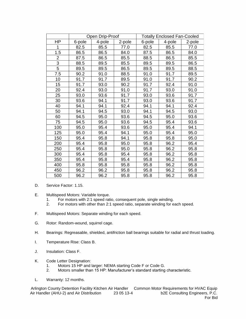
Arlington County Detention Facility Kitchen Air Handler Common Motor Requirements for HVAC Equip Air Handler (AHU-2) and Air Distribution 23 05 13-4 b2E Consulting Engineers, P.C.
For Bid
HP 6-pole 4-pole 2-pole 6-pole 4-pole 2-pole
1 82.5 85.5 77.0 82.5 85.5 77.0
1.5 86.5 86.5 84.0 87.5 86.5 84.0
2 87.5 86.5 85.5 88.5 86.5 85.5
3 88.5 89.5 85.5 89.5 89.5 86.5
5 89.5 89.5 86.5 89.5 89.5 88.5
7.5 90.2 91.0 88.5 91.0 91.7 89.5
10 91.7 91.7 89.5 91.0 91.7 90.2
15 91.7 93.0 90.2 91.7 92.4 91.0
20 92.4 93.0 91.0 91.7 93.0 91.0
25 93.0 93.6 91.7 93.0 93.6 91.7
30 93.6 94.1 91.7 93.0 93.6 91.7
40 94.1 94.1 92.4 94.1 94.1 92.4
50 94.1 94.5 93.0 94.1 94.5 93.0
60 94.5 95.0 93.6 94.5 95.0 93.6
75 94.5 95.0 93.6 94.5 95.4 93.6
100 95.0 95.4 93.6 95.0 95.4 94.1
125 95.0 95.4 94.1 95.0 95.4 95.0
150 95.4 95.8 94.1 95.8 95.8 95.0
200 95.4 95.8 95.0 95.8 96.2 95.4
250 95.4 95.8 95.0 95.8 96.2 95.8
300 95.4 95.8 95.4 95.8 96.2 95.8
350 95.4 95.8 95.4 95.8 96.2 95.8
400 95.8 95.8 95.8 95.8 96.2 95.8
450 96.2 96.2 95.8 95.8 96.2 95.8
500 96.2 96.2 95.8 95.8 96.2 95.8
Open Drip-Proof Totally Enclosed Fan-Cooled
D. Service Factor: 1.15.
E. Multispeed Motors: Variable torque. 1. For motors with 2:1 speed ratio, consequent pole, single winding. 2. For motors with other than 2:1 speed ratio, separate winding for each speed.
F. Multispeed Motors: Separate winding for each speed.
G. Rotor: Random-wound, squirrel cage.
H. Bearings: Regreasable, shielded, antifriction ball bearings suitable for radial and thrust loading.
I. Temperature Rise: Class B.
J. Insulation: Class F.
K. Code Letter Designation: 1. Motors 15 HP and larger: NEMA starting Code F or Code G. 2. Motors smaller than 15 HP: Manufacturer’s standard starting characteristic.
L. Warranty: 12 months.
Arlington County Detention Facility Kitchen Air Handler Common Motor Requirements for HVAC Equip Air Handler (AHU-2) and Air Distribution 23 05 13-5 b2E Consulting Engineers, P.C.
For Bid
M. Enclosure Material: Cast iron for motor frame sizes 324T and larger; rolled steel for motor frame sizes smaller than 324T.
N. All motors 40 HP and greater shall be provided with motor mounted power factor correction capacitors to improve power factor to 0.90 minimum. Motors less than 40 HP shall be provided with 0.85 power factor. Where motors less than 40 HP are not available with minimum 0.85 power factor, provide motor mounted power factor correction capacitor to improve power factor to at least 0.90 under rated load condition.
2.4 POLYPHASE MOTORS WITH ADDITIONAL REQUIREMENTS
A. Motors Used with Reduced-Voltage and Multispeed Controllers: Match wiring connection requirements for controller with required motor leads. Provide terminals in motor terminal box, suited to control method.
B. Motors Used with Variable Frequency Controllers: Ratings, characteristics, and features coordinated with and approved by controller manufacturer.
1. Windings: Copper magnet wire with moisture-resistant insulation varnish, designed and tested to resist transient spikes, high frequencies, and short time rise pulses produced by pulse-width modulated inverters.
2. Energy- and Premium-Efficient Motors: Class B temperature rise; Class F insulation. 3. Inverter-Duty Motors: Class F temperature rise; Class H insulation. 4. Thermal Protection: Comply with NEMA MG 1 requirements for thermally protected
motors. 5. Motors connected to variable frequency controllers shall have shaft grounding devices
meeting the following requirements. a. Shaft grounding shall be a bearing isolator, or labyrinth seal, that includes a built-in
grounding ring and brush. The brush shall contain conductive microfibers that completely surround the shaft the discharge any current flowing through it.
b. Motors less than 100 HP size shall be provided with a single shaft grounding ring provided on the drive end of the motor.
c. Motors 100 HP in size and larger shall be provided with a shaft grounding ring on both ends of the motor shaft or shall have an insulated ceramic bearing installed on the non-drive end of the motor and a shaft grounding ring installed on the drive end of the motor.
d. Apply a fast drying silver paint on the shaft surface to prevent corrosion. e. Shaft grounding ring wear shall be less than 0.001” in 10,000 hours with a fiber
wear length designed for expected life 200,000+ hours based on testing. Shaft grounding rings shall be compatible with operating environments ranging from 40 degrees Fahrenheit to 300 degrees Fahrenheit.
f. AEGIS SGR Bearing Protection Rings manufactured by Electro Static Technology (EST).
C. Severe-Duty Motors: Comply with IEEE 841, with 1.15 minimum service factor.
2.5 SINGLE-PHASE MOTORS
A. Motors larger than 1/20 hp shall be one of the following, to suit starting torque and requirements of specific motor application:

Arlington County Detention Facility Kitchen Air Handler Common Motor Requirements for HVAC Equip Air Handler (AHU-2) and Air Distribution 23 05 13-6 b2E Consulting Engineers, P.C.
For Bid
1. Permanent-split capacitor. 2. Split phase. 3. Capacitor start, inductor run. 4. Capacitor start, capacitor run.
B. Multispeed Motors: Variable-torque, permanent-split-capacitor type.
C. Bearings: Pre-lubricated, antifriction ball bearings or sleeve bearings suitable for radial and thrust loading.
D. Motors 1/20 HP and Smaller: Shaded-pole type.
E. Thermal Protection: Internal protection to automatically open power supply circuit to motor when winding temperature exceeds a safe value calibrated to temperature rating of motor insulation. Thermal-protection device shall automatically reset when motor temperature returns to normal range.
2.6 STARTERS AND DISCONNECTS
A. Furnish starters in accordance with Division 26 Specifications.
B. Furnish adjustable frequency drives in accordance with of Division 26 Specifications.
C. Furnish disconnect switches in accordance with Division 26 Specifications.
D. Starters for NEMA rated 200 or 230 volt motors, 30 HP and above, shall be reduced voltage starting type.
E. Starters for NEMA rated 460 volt motors, 60 HP and above shall be reduced voltage starting type.
F. Unless otherwise indicated, reduced voltage starters to be autotransformer type.
G. Equipment control power transformers shall have the required primary and secondary voltage and be of adequate size for equipment served.
H. AIC Ratings:
1. All starters and adjustable frequency drives (AFD/VFD) furnished by Division 23 shall comply with minimum amps interrupting current (AIC) rating as identified on Division 26 drawings and specifications. Where furnished equipment does not meet these minimum ratings requirements by itself, then a U.L. series rating can be used by providing U.L. recognized fuse of circuit breaker located upstream of starter of VFD in accordance with U.L. distance limitations. Division 22 Contractor is responsible for providing any additional fusing or circuit breakers to meet the minimum AIC requirements.
Arlington County Detention Facility Kitchen Air Handler Common Motor Requirements for HVAC Equip Air Handler (AHU-2) and Air Distribution 23 05 13-7 b2E Consulting Engineers, P.C.
For Bid
PART 3 - EXECUTION
3.1 EXAMINATION
A. Examine areas to receive field-installed motors for compliance with requirements, installation tolerances, and other conditions affecting performance.
B. Examine roughing-in of conduit systems to verify actual locations of conduit connections before motor installation.
C. Proceed with installation only after unsatisfactory conditions have been corrected.
3.2 MOTOR INSTALLATION
A. Install materials in accordance with details, approved shop drawings, and manufacturer’s instructions.
B. Anchor each motor assembly to base, adjustable rails, or other support, arranged and sized according to manufacturer's written instructions. Attach by bolting. Level and align with load transfer link.
C. Install motors on equipment bases for pumps, and on other equipment in accordance with manufacturer’s written instructions.
D. Comply with mounting and anchoring requirements specified.
3.3 FIELD QUALITY CONTROL
A. Prepare for acceptance tests as follows:
1. Align motors, bases, shafts, pulleys, and belts. Tension belts according to manufacture’s written instructions.
2. Verify bearing lubrication. 3. Run each motor with its controller. Demonstrate correct rotation, alignment, and speed at
motor design load. 4. Test interlocks and control and safety features for proper operation. 5. Verify that current and voltage for each phase comply with nameplate rating and NEMA
MG 1 tolerances.
B. Testing: Engage a qualified testing agency to perform the following field quality-control testing:
1. Perform each electrical test and visual and mechanical inspection stated in NETA ATS, Section 7.15.1.
2. Certify compliance with test parameters. 3. Correct malfunctioning units on-site, where possible, and retest to demonstrate
compliance; otherwise, replace with new units and retest.
C. Manufacturer's Field Service: Engage a factory-authorized service representative to perform the following:
Arlington County Detention Facility Kitchen Air Handler Common Motor Requirements for HVAC Equip Air Handler (AHU-2) and Air Distribution 23 05 13-8 b2E Consulting Engineers, P.C.
For Bid
1. Inspect components, equipment installation, and piping and electrical connections for compliance with requirements.
2. Test and adjust controls and safeties. Replace damaged and malfunctioning controls and equipment.
3. Verify bearing lubrication. 4. Verify proper motor rotation. 5. Test Reports: Prepare a written report to record the following:
a. Test procedures used. b. Test results that comply with requirements. c. Test results that do not comply with requirements and corrective action taken to
achieve compliance.
3.4 ADJUSTING
A. Align motors, bases, shafts, pulleys and belts. Tension belts according to manufacturer's written instructions.
3.5 CLEANING
A. After completing equipment installation, inspect unit components. Remove paint splatters and other spots, dirt, and debris. Repair damaged finish to match original finish.
B. Clean motors, on completion of installation, according to manufacturer's written instructions.
3.6 FIELD-INTALLED MOTOR DEMONSTATION
A. Engage a factory-authorized service representative to train Owner’s maintenance personnel to adjust, operate, and maintain field-installed motors.
END OF SECTION
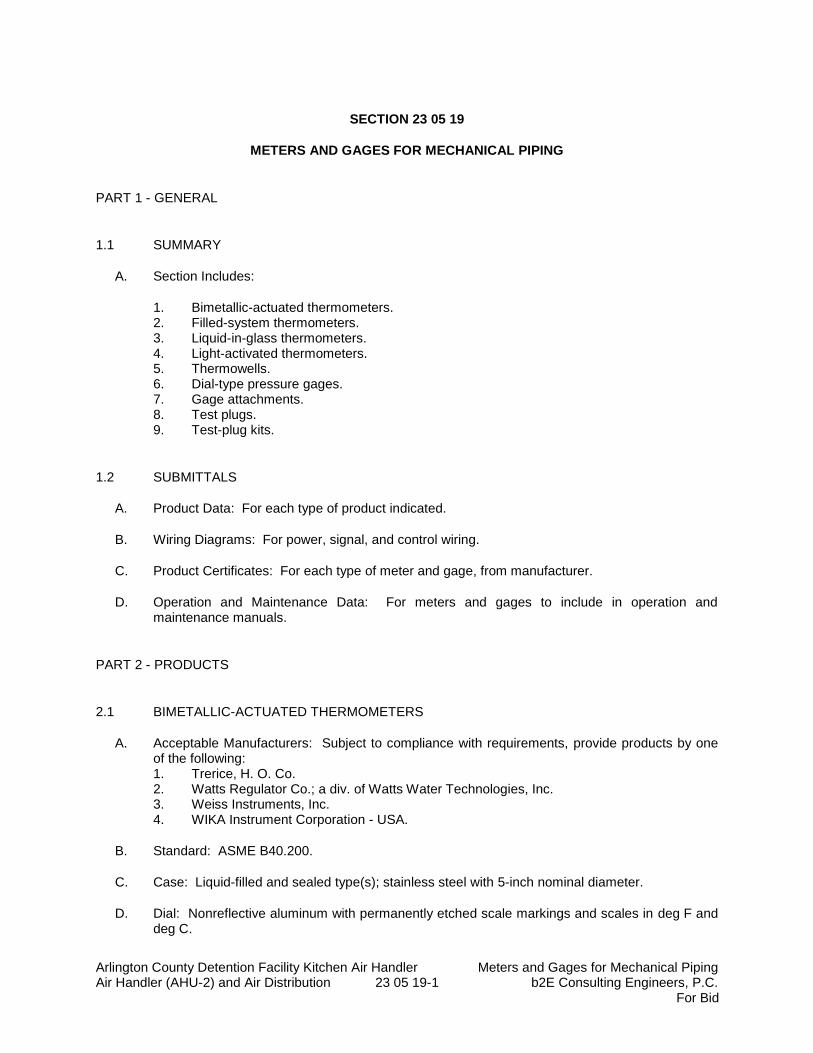
Arlington County Detention Facility Kitchen Air Handler Meters and Gages for Mechanical Piping Air Handler (AHU-2) and Air Distribution 23 05 19-1 b2E Consulting Engineers, P.C.
For Bid
SECTION 23 05 19
METERS AND GAGES FOR MECHANICAL PIPING
PART 1 - GENERAL
1.1 SUMMARY
A. Section Includes:
1. Bimetallic-actuated thermometers. 2. Filled-system thermometers. 3. Liquid-in-glass thermometers. 4. Light-activated thermometers. 5. Thermowells. 6. Dial-type pressure gages. 7. Gage attachments. 8. Test plugs. 9. Test-plug kits.
1.2 SUBMITTALS
A. Product Data: For each type of product indicated.
B. Wiring Diagrams: For power, signal, and control wiring.
C. Product Certificates: For each type of meter and gage, from manufacturer.
D. Operation and Maintenance Data: For meters and gages to include in operation and maintenance manuals.
PART 2 - PRODUCTS
2.1 BIMETALLIC-ACTUATED THERMOMETERS
A. Acceptable Manufacturers: Subject to compliance with requirements, provide products by one of the following: 1. Trerice, H. O. Co. 2. Watts Regulator Co.; a div. of Watts Water Technologies, Inc. 3. Weiss Instruments, Inc. 4. WIKA Instrument Corporation - USA.
B. Standard: ASME B40.200.
C. Case: Liquid-filled and sealed type(s); stainless steel with 5-inch nominal diameter.
D. Dial: Nonreflective aluminum with permanently etched scale markings and scales in deg F and deg C.
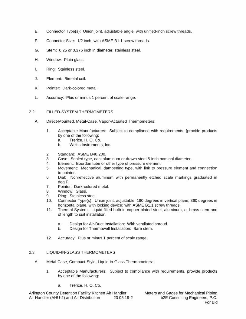
Arlington County Detention Facility Kitchen Air Handler Meters and Gages for Mechanical Piping Air Handler (AHU-2) and Air Distribution 23 05 19-2 b2E Consulting Engineers, P.C.
For Bid
E. Connector Type(s): Union joint, adjustable angle, with unified-inch screw threads.
F. Connector Size: 1/2 inch, with ASME B1.1 screw threads.
G. Stem: 0.25 or 0.375 inch in diameter; stainless steel.
H. Window: Plain glass.
I. Ring: Stainless steel.
J. Element: Bimetal coil.
K. Pointer: Dark-colored metal.
L. Accuracy: Plus or minus 1 percent of scale range.
2.2 FILLED-SYSTEM THERMOMETERS
A. Direct-Mounted, Metal-Case, Vapor-Actuated Thermometers:
1. Acceptable Manufacturers: Subject to compliance with requirements, [provide products by one of the following: a. Trerice, H. O. Co. b. Weiss Instruments, Inc.
2. Standard: ASME B40.200. 3. Case: Sealed type, cast aluminum or drawn steel 5-inch nominal diameter. 4. Element: Bourdon tube or other type of pressure element. 5. Movement: Mechanical, dampening type, with link to pressure element and connection
to pointer. 6. Dial: Nonreflective aluminum with permanently etched scale markings graduated in
deg F. 7. Pointer: Dark-colored metal. 8. Window: Glass. 9. Ring: Stainless steel. 10. Connector Type(s): Union joint, adjustable, 180 degrees in vertical plane, 360 degrees in
horizontal plane, with locking device; with ASME B1.1 screw threads. 11. Thermal System: Liquid-filled bulb in copper-plated steel, aluminum, or brass stem and
of length to suit installation.
a. Design for Air-Duct Installation: With ventilated shroud. b. Design for Thermowell Installation: Bare stem.
12. Accuracy: Plus or minus 1 percent of scale range.
2.3 LIQUID-IN-GLASS THERMOMETERS
A. Metal-Case, Compact-Style, Liquid-in-Glass Thermometers:
1. Acceptable Manufacturers: Subject to compliance with requirements, provide products by one of the following:
a. Trerice, H. O. Co.

Arlington County Detention Facility Kitchen Air Handler Meters and Gages for Mechanical Piping Air Handler (AHU-2) and Air Distribution 23 05 19-3 b2E Consulting Engineers, P.C.
For Bid
2. Standard: ASME B40.200. 3. Case: Cast aluminum; 6-inch nominal size. 4. Case Form: Back angle or Straight unless otherwise indicated. 5. Tube: Glass with magnifying lens and blue or red organic liquid. 6. Tube Background: Nonreflective aluminum with permanently etched scale markings
graduated in deg F. 7. Window: Glass or plastic. 8. Stem: Aluminum or brass and of length to suit installation.
a. Design for Air-Duct Installation: With ventilated shroud. b. Design for Thermowell Installation: Bare stem.
9. Connector: 3/4 inch, with ASME B1.1 screw threads. 10. Accuracy: Plus or minus 1 percent of scale range or one scale division, to a maximum of
1.5 percent of scale range.
2.4 LIGHT-ACTIVATED THERMOMETERS
A. Direct-Mounted, Light-Activated Thermometers:
1. Acceptable Manufacturers: Subject to compliance with requirements, provide products by one of the following: a. Trerice, H. O. Co. b. Weiss Instruments, Inc. c. WIKA Instrument Corporation - USA.
2. Case: Metal 7-inch or 9-inch nominal size unless otherwise indicated. 3. Scale(s): Deg F. 4. Case Form: Adjustable angle. 5. Connector: 1-1/4 inches, with ASME B1.1 screw threads. 6. Stem: Aluminum and of length to suit installation.
a. Design for Air-Duct Installation: With ventilated shroud. b. Design for Thermowell Installation: Bare stem.
7. Display: Digital. 8. Accuracy: Plus or minus 2 deg F.
2.5 DUCT-THERMOMETER MOUNTING BRACKETS
A. Description: Flanged bracket with screw holes, for attachment to air duct and made to hold thermometer stem.
2.6 THERMOWELLS
A. Thermowells:
1. Standard: ASME B40.200. 2. Description: Pressure-tight, socket-type fitting made for insertion into piping tee fitting. 3. Material for Use with Copper Tubing: CNR or CUNI. 4. Material for Use with Steel Piping: CRES or CSA. 5. Type: Stepped shank unless straight or tapered shank is indicated.
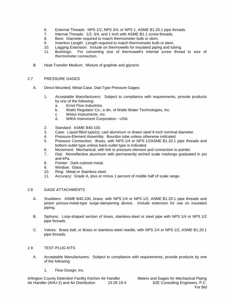
Arlington County Detention Facility Kitchen Air Handler Meters and Gages for Mechanical Piping Air Handler (AHU-2) and Air Distribution 23 05 19-4 b2E Consulting Engineers, P.C.
For Bid
6. External Threads: NPS 1/2, NPS 3/4, or NPS 1, ASME B1.20.1 pipe threads. 7. Internal Threads: 1/2, 3/4, and 1 inch with ASME B1.1 screw threads. 8. Bore: Diameter required to match thermometer bulb or stem. 9. Insertion Length: Length required to match thermometer bulb or stem. 10. Lagging Extension: Include on thermowells for insulated piping and tubing. 11. Bushings: For converting size of thermowell's internal screw thread to size of
thermometer connection.
B. Heat-Transfer Medium: Mixture of graphite and glycerin.
2.7 PRESSURE GAGES
A. Direct-Mounted, Metal-Case, Dial-Type Pressure Gages:
1. Acceptable Manufacturers: Subject to compliance with requirements, provide products by one of the following: a. Ernst Flow Industries. b. Watts Regulator Co.; a div. of Watts Water Technologies, Inc. c. Weiss Instruments, Inc. d. WIKA Instrument Corporation - USA.
2. Standard: ASME B40.100. 3. Case: Liquid-filled type(s); cast aluminum or drawn steel 6-inch nominal diameter. 4. Pressure-Element Assembly: Bourdon tube unless otherwise indicated. 5. Pressure Connection: Brass, with NPS 1/4 or NPS 1/2ASME B1.20.1 pipe threads and
bottom-outlet type unless back-outlet type is indicated. 6. Movement: Mechanical, with link to pressure element and connection to pointer. 7. Dial: Nonreflective aluminum with permanently etched scale markings graduated in psi
and kPa. 8. Pointer: Dark-colored metal. 9. Window: Glass. 10. Ring: Metal or Stainless steel. 11. Accuracy: Grade A, plus or minus 1 percent of middle half of scale range.
2.8 GAGE ATTACHMENTS
A. Snubbers: ASME B40.100, brass; with NPS 1/4 or NPS 1/2, ASME B1.20.1 pipe threads and piston porous-metal-type surge-dampening device. Include extension for use on insulated piping.
B. Siphons: Loop-shaped section of brass, stainless-steel or steel pipe with NPS 1/4 or NPS 1/2 pipe threads.
C. Valves: Brass ball; or Brass or stainless-steel needle, with NPS 1/4 or NPS 1/2, ASME B1.20.1 pipe threads.
2.9 TEST-PLUG KITS
A. Acceptable Manufacturers: Subject to compliance with requirements, provide products by one of the following:
1. Flow Design, Inc.
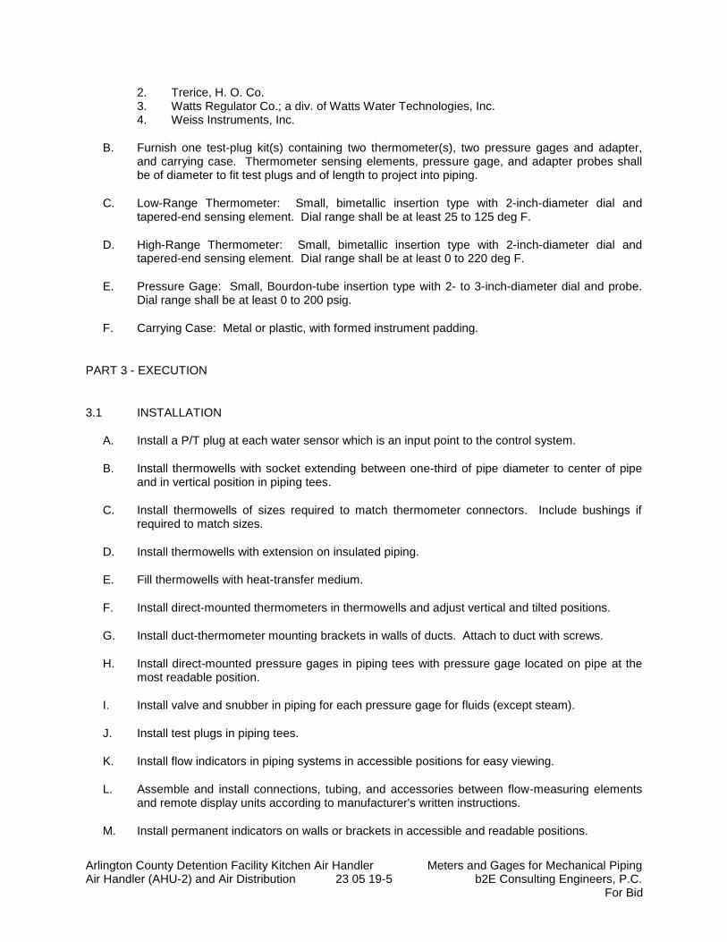
Arlington County Detention Facility Kitchen Air Handler Meters and Gages for Mechanical Piping Air Handler (AHU-2) and Air Distribution 23 05 19-5 b2E Consulting Engineers, P.C.
For Bid
2. Trerice, H. O. Co. 3. Watts Regulator Co.; a div. of Watts Water Technologies, Inc. 4. Weiss Instruments, Inc.
B. Furnish one test-plug kit(s) containing two thermometer(s), two pressure gages and adapter, and carrying case. Thermometer sensing elements, pressure gage, and adapter probes shall be of diameter to fit test plugs and of length to project into piping.
C. Low-Range Thermometer: Small, bimetallic insertion type with 2-inch-diameter dial and tapered-end sensing element. Dial range shall be at least 25 to 125 deg F.
D. High-Range Thermometer: Small, bimetallic insertion type with 2-inch-diameter dial and tapered-end sensing element. Dial range shall be at least 0 to 220 deg F.
E. Pressure Gage: Small, Bourdon-tube insertion type with 2- to 3-inch-diameter dial and probe. Dial range shall be at least 0 to 200 psig.
F. Carrying Case: Metal or plastic, with formed instrument padding.
PART 3 - EXECUTION
3.1 INSTALLATION
A. Install a P/T plug at each water sensor which is an input point to the control system.
B. Install thermowells with socket extending between one-third of pipe diameter to center of pipe and in vertical position in piping tees.
C. Install thermowells of sizes required to match thermometer connectors. Include bushings if required to match sizes.
D. Install thermowells with extension on insulated piping.
E. Fill thermowells with heat-transfer medium.
F. Install direct-mounted thermometers in thermowells and adjust vertical and tilted positions.
G. Install duct-thermometer mounting brackets in walls of ducts. Attach to duct with screws.
H. Install direct-mounted pressure gages in piping tees with pressure gage located on pipe at the most readable position.
I. Install valve and snubber in piping for each pressure gage for fluids (except steam).
J. Install test plugs in piping tees.
K. Install flow indicators in piping systems in accessible positions for easy viewing.
L. Assemble and install connections, tubing, and accessories between flow-measuring elements and remote display units according to manufacturer's written instructions.
M. Install permanent indicators on walls or brackets in accessible and readable positions.
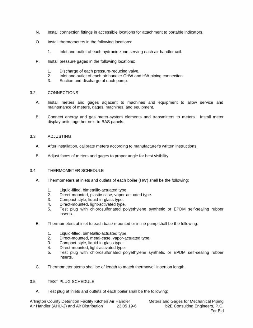
Arlington County Detention Facility Kitchen Air Handler Meters and Gages for Mechanical Piping Air Handler (AHU-2) and Air Distribution 23 05 19-6 b2E Consulting Engineers, P.C.
For Bid
N. Install connection fittings in accessible locations for attachment to portable indicators.
O. Install thermometers in the following locations:
1. Inlet and outlet of each hydronic zone serving each air handler coil.
P. Install pressure gages in the following locations:
1. Discharge of each pressure-reducing valve. 2. Inlet and outlet of each air handler CHW and HW piping connection. 3. Suction and discharge of each pump.
3.2 CONNECTIONS
A. Install meters and gages adjacent to machines and equipment to allow service and maintenance of meters, gages, machines, and equipment.
B. Connect energy and gas meter-system elements and transmitters to meters. Install meter display units together next to BAS panels.
3.3 ADJUSTING
A. After installation, calibrate meters according to manufacturer's written instructions.
B. Adjust faces of meters and gages to proper angle for best visibility.
3.4 THERMOMETER SCHEDULE
A. Thermometers at inlets and outlets of each boiler (HW) shall be the following:
1. Liquid-filled, bimetallic-actuated type. 2. Direct-mounted, plastic-case, vapor-actuated type. 3. Compact-style, liquid-in-glass type. 4. Direct-mounted, light-activated type. 5. Test plug with chlorosulfonated polyethylene synthetic or EPDM self-sealing rubber
inserts.
B. Thermometers at inlet to each base-mounted or inline pump shall be the following:
1. Liquid-filled, bimetallic-actuated type. 2. Direct-mounted, metal-case, vapor-actuated type. 3. Compact-style, liquid-in-glass type. 4. Direct-mounted, light-activated type. 5. Test plug with chlorosulfonated polyethylene synthetic or EPDM self-sealing rubber
inserts.
C. Thermometer stems shall be of length to match thermowell insertion length.
3.5 TEST PLUG SCHEDULE
A. Test plug at inlets and outlets of each boiler shall be the following:
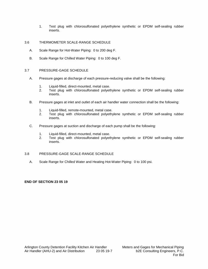
Arlington County Detention Facility Kitchen Air Handler Meters and Gages for Mechanical Piping Air Handler (AHU-2) and Air Distribution 23 05 19-7 b2E Consulting Engineers, P.C.
For Bid
1. Test plug with chlorosulfonated polyethylene synthetic or EPDM self-sealing rubber inserts.
3.6 THERMOMETER SCALE-RANGE SCHEDULE
A. Scale Range for Hot-Water Piping: 0 to 200 deg F.
B. Scale Range for Chilled Water Piping: 0 to 100 deg F.
3.7 PRESSURE-GAGE SCHEDULE
A. Pressure gages at discharge of each pressure-reducing valve shall be the following:
1. Liquid-filled, direct-mounted, metal case. 2. Test plug with chlorosulfonated polyethylene synthetic or EPDM self-sealing rubber
inserts.
B. Pressure gages at inlet and outlet of each air handler water connection shall be the following:
1. Liquid-filled, remote-mounted, metal case. 2. Test plug with chlorosulfonated polyethylene synthetic or EPDM self-sealing rubber
inserts.
C. Pressure gages at suction and discharge of each pump shall be the following:
1. Liquid-filled, direct-mounted, metal case. 2. Test plug with chlorosulfonated polyethylene synthetic or EPDM self-sealing rubber
inserts.
3.8 PRESSURE-GAGE SCALE-RANGE SCHEDULE
A. Scale Range for Chilled Water and Heating Hot-Water Piping: 0 to 100 psi.
END OF SECTION 23 05 19
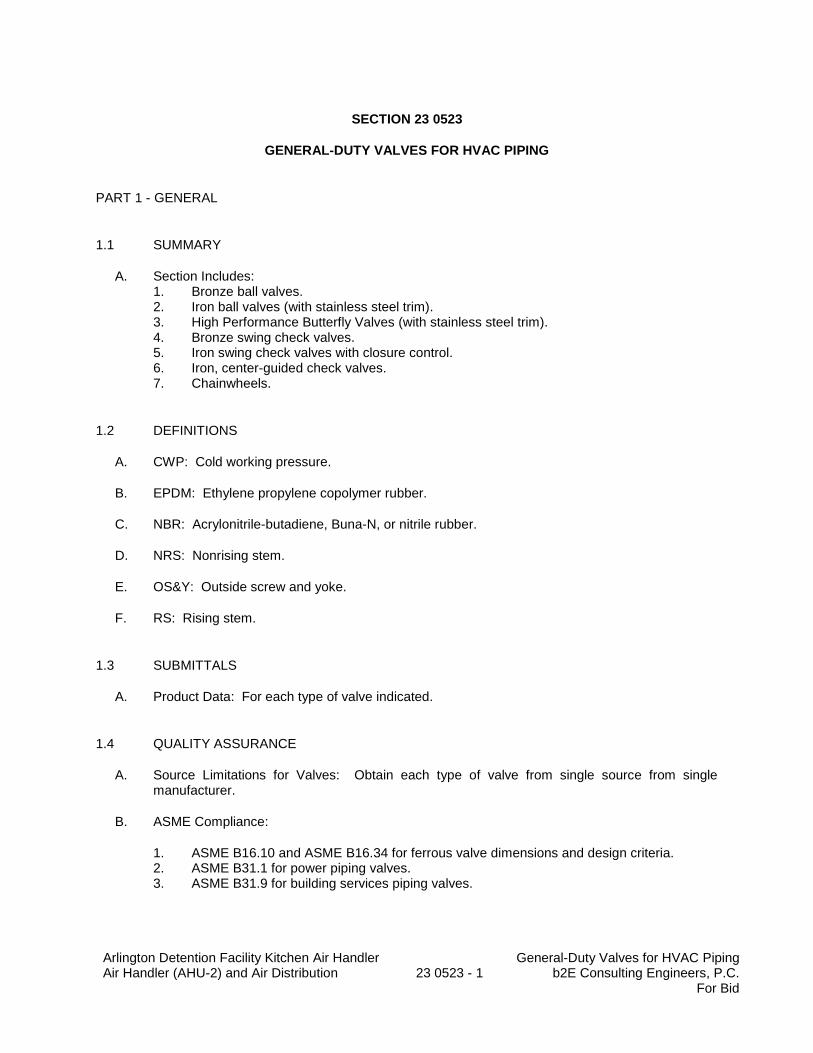
Arlington Detention Facility Kitchen Air Handler Air Handler (AHU-2) and Air Distribution
23 0523 - 1
General-Duty Valves for HVAC Piping b2E Consulting Engineers, P.C.
For Bid
SECTION 23 0523
GENERAL-DUTY VALVES FOR HVAC PIPING
PART 1 - GENERAL
1.1 SUMMARY
A. Section Includes: 1. Bronze ball valves. 2. Iron ball valves (with stainless steel trim). 3. High Performance Butterfly Valves (with stainless steel trim). 4. Bronze swing check valves. 5. Iron swing check valves with closure control. 6. Iron, center-guided check valves. 7. Chainwheels.
1.2 DEFINITIONS
A. CWP: Cold working pressure.
B. EPDM: Ethylene propylene copolymer rubber.
C. NBR: Acrylonitrile-butadiene, Buna-N, or nitrile rubber.
D. NRS: Nonrising stem.
E. OS&Y: Outside screw and yoke.
F. RS: Rising stem.
1.3 SUBMITTALS
A. Product Data: For each type of valve indicated.
1.4 QUALITY ASSURANCE
A. Source Limitations for Valves: Obtain each type of valve from single source from single manufacturer.
B. ASME Compliance:
1. ASME B16.10 and ASME B16.34 for ferrous valve dimensions and design criteria. 2. ASME B31.1 for power piping valves. 3. ASME B31.9 for building services piping valves.
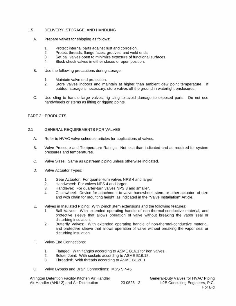
Arlington Detention Facility Kitchen Air Handler Air Handler (AHU-2) and Air Distribution
23 0523 - 2
General-Duty Valves for HVAC Piping b2E Consulting Engineers, P.C.
For Bid
1.5 DELIVERY, STORAGE, AND HANDLING
A. Prepare valves for shipping as follows:
1. Protect internal parts against rust and corrosion. 2. Protect threads, flange faces, grooves, and weld ends. 3. Set ball valves open to minimize exposure of functional surfaces. 4. Block check valves in either closed or open position.
B. Use the following precautions during storage:
1. Maintain valve end protection. 2. Store valves indoors and maintain at higher than ambient dew point temperature. If
outdoor storage is necessary, store valves off the ground in watertight enclosures.
C. Use sling to handle large valves; rig sling to avoid damage to exposed parts. Do not use handwheels or stems as lifting or rigging points.
PART 2 - PRODUCTS
2.1 GENERAL REQUIREMENTS FOR VALVES
A. Refer to HVAC valve schedule articles for applications of valves.
B. Valve Pressure and Temperature Ratings: Not less than indicated and as required for system pressures and temperatures.
C. Valve Sizes: Same as upstream piping unless otherwise indicated.
D. Valve Actuator Types:
1. Gear Actuator: For quarter-turn valves NPS 4 and larger. 2. Handwheel: For valves NPS 4 and larger. 3. Handlever: For quarter-turn valves NPS 3 and smaller. 4. Chainwheel: Device for attachment to valve handwheel, stem, or other actuator; of size
and with chain for mounting height, as indicated in the "Valve Installation" Article.
E. Valves in Insulated Piping: With 2-inch stem extensions and the following features: 1. Ball Valves: With extended operating handle of non-thermal-conductive material, and
protective sleeve that allows operation of valve without breaking the vapor seal or disturbing insulation.
2. Butterfly Valves: With extended operating handle of non-thermal-conductive material, and protective sleeve that allows operation of valve without breaking the vapor seal or disturbing insulation
F. Valve-End Connections:
1. Flanged: With flanges according to ASME B16.1 for iron valves. 2. Solder Joint: With sockets according to ASME B16.18. 3. Threaded: With threads according to ASME B1.20.1.
G. Valve Bypass and Drain Connections: MSS SP-45.
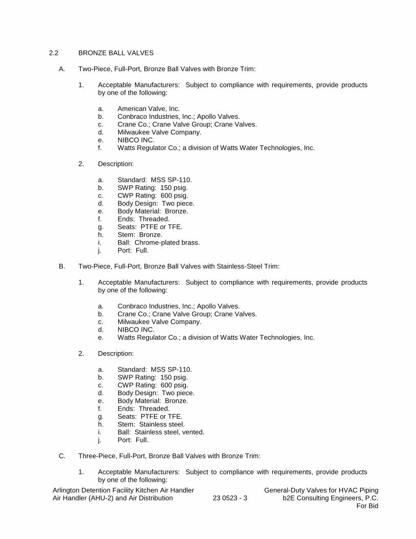
Arlington Detention Facility Kitchen Air Handler Air Handler (AHU-2) and Air Distribution
23 0523 - 3
General-Duty Valves for HVAC Piping b2E Consulting Engineers, P.C.
For Bid
2.2 BRONZE BALL VALVES
A. Two-Piece, Full-Port, Bronze Ball Valves with Bronze Trim:
1. Acceptable Manufacturers: Subject to compliance with requirements, provide products by one of the following:
a. American Valve, Inc. b. Conbraco Industries, Inc.; Apollo Valves. c. Crane Co.; Crane Valve Group; Crane Valves. d. Milwaukee Valve Company. e. NIBCO INC. f. Watts Regulator Co.; a division of Watts Water Technologies, Inc.
2. Description:
a. Standard: MSS SP-110. b. SWP Rating: 150 psig. c. CWP Rating: 600 psig. d. Body Design: Two piece. e. Body Material: Bronze. f. Ends: Threaded. g. Seats: PTFE or TFE. h. Stem: Bronze. i. Ball: Chrome-plated brass. j. Port: Full.
B. Two-Piece, Full-Port, Bronze Ball Valves with Stainless-Steel Trim:
1. Acceptable Manufacturers: Subject to compliance with requirements, provide products by one of the following:
a. Conbraco Industries, Inc.; Apollo Valves. b. Crane Co.; Crane Valve Group; Crane Valves. c. Milwaukee Valve Company. d. NIBCO INC. e. Watts Regulator Co.; a division of Watts Water Technologies, Inc.
2. Description:
a. Standard: MSS SP-110. b. SWP Rating: 150 psig. c. CWP Rating: 600 psig. d. Body Design: Two piece. e. Body Material: Bronze. f. Ends: Threaded. g. Seats: PTFE or TFE. h. Stem: Stainless steel. i. Ball: Stainless steel, vented. j. Port: Full.
C. Three-Piece, Full-Port, Bronze Ball Valves with Bronze Trim:
1. Acceptable Manufacturers: Subject to compliance with requirements, provide products by one of the following:
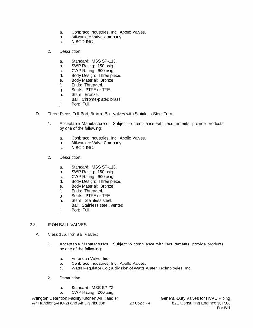
Arlington Detention Facility Kitchen Air Handler Air Handler (AHU-2) and Air Distribution
23 0523 - 4
General-Duty Valves for HVAC Piping b2E Consulting Engineers, P.C.
For Bid
a. Conbraco Industries, Inc.; Apollo Valves. b. Milwaukee Valve Company. c. NIBCO INC.
2. Description:
a. Standard: MSS SP-110. b. SWP Rating: 150 psig. c. CWP Rating: 600 psig. d. Body Design: Three piece. e. Body Material: Bronze. f. Ends: Threaded. g. Seats: PTFE or TFE. h. Stem: Bronze. i. Ball: Chrome-plated brass. j. Port: Full.
D. Three-Piece, Full-Port, Bronze Ball Valves with Stainless-Steel Trim:
1. Acceptable Manufacturers: Subject to compliance with requirements, provide products by one of the following:
a. Conbraco Industries, Inc.; Apollo Valves. b. Milwaukee Valve Company. c. NIBCO INC.
2. Description:
a. Standard: MSS SP-110. b. SWP Rating: 150 psig. c. CWP Rating: 600 psig. d. Body Design: Three piece. e. Body Material: Bronze. f. Ends: Threaded. g. Seats: PTFE or TFE. h. Stem: Stainless steel. i. Ball: Stainless steel, vented. j. Port: Full.
2.3 IRON BALL VALVES
A. Class 125, Iron Ball Valves:
1. Acceptable Manufacturers: Subject to compliance with requirements, provide products by one of the following:
a. American Valve, Inc. b. Conbraco Industries, Inc.; Apollo Valves. c. Watts Regulator Co.; a division of Watts Water Technologies, Inc.
2. Description:
a. Standard: MSS SP-72. b. CWP Rating: 200 psig.
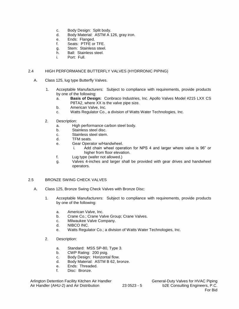
Arlington Detention Facility Kitchen Air Handler Air Handler (AHU-2) and Air Distribution
23 0523 - 5
General-Duty Valves for HVAC Piping b2E Consulting Engineers, P.C.
For Bid
c. Body Design: Split body. d. Body Material: ASTM A 126, gray iron. e. Ends: Flanged. f. Seats: PTFE or TFE. g. Stem: Stainless steel. h. Ball: Stainless steel. i. Port: Full.
2.4 HIGH PERFORMANCE BUTTERFLY VALVES (HYDRRONIC PIPING)
A. Class 125, lug type Butterfly Valves.
1. Acceptable Manufacturers: Subject to compliance with requirements, provide products by one of the following: a. Basis of Design: Conbraco Industries, Inc. Apollo Valves Model #215 LXX CS
P8TA2, where XX is the valve pipe size. b. American Valve, Inc. c. Watts Regulator Co., a division of Watts Water Technologies, Inc.
2. Description: a. High performance carbon steel body. b. Stainless steel disc. c. Stainless steel stem. d. TFM seats. e. Gear Operator w/Handwheel.
i. Add chain wheel operation for NPS 4 and larger where valve is 96” or higher from floor elevation.
f. Lug type (wafer not allowed.) g. Valves 4-inches and larger shall be provided with gear drives and handwheel
operators.
2.5 BRONZE SWING CHECK VALVES
A. Class 125, Bronze Swing Check Valves with Bronze Disc:
1. Acceptable Manufacturers: Subject to compliance with requirements, provide products by one of the following:
a. American Valve, Inc. b. Crane Co.; Crane Valve Group; Crane Valves. c. Milwaukee Valve Company. d. NIBCO INC. e. Watts Regulator Co.; a division of Watts Water Technologies, Inc.
2. Description:
a. Standard: MSS SP-80, Type 3. b. CWP Rating: 200 psig. c. Body Design: Horizontal flow. d. Body Material: ASTM B 62, bronze. e. Ends: Threaded. f. Disc: Bronze.
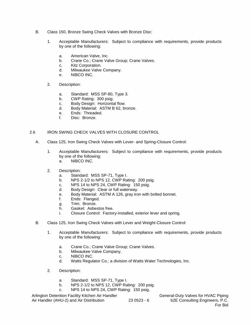
Arlington Detention Facility Kitchen Air Handler Air Handler (AHU-2) and Air Distribution
23 0523 - 6
General-Duty Valves for HVAC Piping b2E Consulting Engineers, P.C.
For Bid
B. Class 150, Bronze Swing Check Valves with Bronze Disc:
1. Acceptable Manufacturers: Subject to compliance with requirements, provide products by one of the following:
a. American Valve, Inc. b. Crane Co.; Crane Valve Group; Crane Valves. c. Kitz Corporation. d. Milwaukee Valve Company. e. NIBCO INC.
2. Description:
a. Standard: MSS SP-80, Type 3. b. CWP Rating: 300 psig. c. Body Design: Horizontal flow. d. Body Material: ASTM B 62, bronze. e. Ends: Threaded. f. Disc: Bronze.
2.6 IRON SWING CHECK VALVES WITH CLOSURE CONTROL
A. Class 125, Iron Swing Check Valves with Lever- and Spring-Closure Control:
1. Acceptable Manufacturers: Subject to compliance with requirements, provide products by one of the following: a. NIBCO INC.
2. Description: a. Standard: MSS SP-71, Type I. b. NPS 2-1/2 to NPS 12, CWP Rating: 200 psig. c. NPS 14 to NPS 24, CWP Rating: 150 psig. d. Body Design: Clear or full waterway. e. Body Material: ASTM A 126, gray iron with bolted bonnet. f. Ends: Flanged. g. Trim: Bronze. h. Gasket: Asbestos free. i. Closure Control: Factory-installed, exterior lever and spring.
B. Class 125, Iron Swing Check Valves with Lever and Weight-Closure Control:
1. Acceptable Manufacturers: Subject to compliance with requirements, provide products by one of the following:
a. Crane Co.; Crane Valve Group; Crane Valves. b. Milwaukee Valve Company. c. NIBCO INC. d. Watts Regulator Co.; a division of Watts Water Technologies, Inc.
2. Description:
a. Standard: MSS SP-71, Type I. b. NPS 2-1/2 to NPS 12, CWP Rating: 200 psig. c. NPS 14 to NPS 24, CWP Rating: 150 psig.
Arlington Detention Facility Kitchen Air Handler Air Handler (AHU-2) and Air Distribution
23 0523 - 7
General-Duty Valves for HVAC Piping b2E Consulting Engineers, P.C.
For Bid
d. Body Design: Clear or full waterway. e. Body Material: ASTM A 126, gray iron with bolted bonnet. f. Ends: Flanged. g. Trim: Bronze. h. Gasket: Asbestos free. i. Closure Control: Factory-installed, exterior lever and weight.
2.7 IRON, CENTER-GUIDED CHECK VALVES
A. Class 125, Iron, Compact-Wafer, Center-Guided Check Valves with Resilient Seat:
1. Acceptable Manufacturers: Subject to compliance with requirements, provide products by one of the following: a. Flo Fab Inc. b. Milwaukee Valve Company. c. NIBCO INC.
2. Description:
a. Standard: MSS SP-125. b. NPS 2-1/2 to NPS 12, CWP Rating: 200 psig. c. NPS 14 to NPS 24, CWP Rating: 150 psig. d. Body Material: ASTM A 126, gray iron. e. Style: Compact wafer. f. Seat: EPDM or NBR.
2.8 CHAINWHEELS
A. Acceptable Manufacturers: Subject to compliance with requirements, provide products by one of the following:
1. Babbitt Steam Specialty Co. 2. Roto Hammer Industries. 3. Trumbull Industries.
B. Description: Valve actuation assembly with sprocket rim, brackets, and chain.
1. Brackets: Type, number, size, and fasteners required to mount actuator on valve. 2. Attachment: For connection to ball and butterfly valve stems. 3. Sprocket Rim with Chain Guides: Ductile or cast iron, of type and size required for valve. 4. Chain: Hot-dip, galvanized steel, of size required to fit sprocket rim.
PART 3 - EXECUTION
3.1 EXAMINATION
A. Examine valve interior for cleanliness, freedom from foreign matter, and corrosion. Remove special packing materials, such as blocks, used to prevent disc movement during shipping and handling.
Arlington Detention Facility Kitchen Air Handler Air Handler (AHU-2) and Air Distribution
23 0523 - 8
General-Duty Valves for HVAC Piping b2E Consulting Engineers, P.C.
For Bid
B. Operate valves in positions from fully open to fully closed. Examine guides and seats made accessible by such operations.
C. Examine threads on valve and mating pipe for form and cleanliness.
D. Examine mating flange faces for conditions that might cause leakage. Check bolting for proper size, length, and material. Verify that gasket is of proper size, that its material composition is suitable for service, and that it is free from defects and damage.
E. Do not attempt to repair defective valves; replace with new valves.
3.2 VALVE INSTALLATION
A. Install valves with unions or flanges at each piece of equipment arranged to allow service, maintenance, and equipment removal without system shutdown.
B. Locate valves for easy access and provide separate support where necessary.
C. Install valves in horizontal piping with stem at or above center of pipe.
D. Install valves in position to allow full stem movement.
E. Install chainwheels on operators for ball or high performance butterfly valves NPS 4 and larger and more than 96 inches above floor. Extend chains to 60 inches above finished floor.
F. Install check valves for proper direction of flow and as follows:
1. Swing Check Valves: In horizontal position with hinge pin level. 2. Center-Guided Check Valves: In horizontal or vertical position, between flanges. 3. Lift Check Valves: With stem upright and plumb.
G. Install high performance butterfly valves in strict conformance with manufacturer’s installation instructions. 1. Valve disc shall be in the full open position prior to fitting the valve to the flange lugs to
ensure the valve is properly aligned. 2. If not installed properly the valve seat can be damaged and then the valve will not hold
under pressure when closed. 3. Where valve(s) are found leaking through when closed during the warranty period they
shall be replaced at no additional cost to the Owner.
3.3 ADJUSTING
A. Adjust or replace valve packing after piping systems have been tested and put into service but before final adjusting and balancing. Replace valves if persistent leaking occurs.
3.4 GENERAL REQUIREMENTS FOR VALVE APPLICATIONS
A. If valve applications are not indicated, use the following:
1. Shutoff Service: Ball valves or High Performance Butterfly Valves. a. NPS 2 and smaller: Bronze ball valves.
Arlington Detention Facility Kitchen Air Handler Air Handler (AHU-2) and Air Distribution
23 0523 - 9
General-Duty Valves for HVAC Piping b2E Consulting Engineers, P.C.
For Bid
b. NPS 2½ and larger. Iron body Ball Valves or High Performance Butterfly Valves. 2. Throttling Service: Ball valves or high performance butterfly valves. 3. Pump-Discharge Check Valves:
a. NPS 2 and Smaller: Bronze swing check valves with bronze disc. b. NPS 2-1/2 and Larger: Iron swing check valves with lever and weight or with
spring or iron, center-guided, resilient-seat check valves.
B. If valves with specified SWP classes or CWP ratings are not available, the same types of valves with higher SWP classes or CWP ratings may be substituted.
C. Select valves, except wafer types, with the following end connections:
1. For Copper Tubing, NPS 2 and Smaller: Threaded ends except where solder-joint valve-end option is indicated in valve schedules below.
2. For Copper Tubing, NPS 2-1/2 to NPS 4: Flanged ends except where threaded valve-end option is indicated in valve schedules below.
3. For Copper Tubing, NPS 5 and Larger: Flanged ends. 4. For Steel Piping, NPS 2 and Smaller: Threaded ends. 5. For Steel Piping, NPS 2-1/2 to NPS 4: Flanged ends. 6. For Steel Piping, NPS 5 and Larger: Flanged ends.
3.5 HEATING HOT WATER AND COOLING CHILLED WATER VALVE SCHEDULE
A. Pipe NPS 2 and Smaller:
1. Bronze Valves: May be provided with solder-joints ends instead of threaded ends. 2. Ball Valves: Two or Three piece, full port, bronze with bronze for hot and chilled water. 3. Bronze Swing Check Valves: Class 125 or Class 150, bronze disc.
B. Pipe NPS 2-1/2 and Larger:
1. Iron Valves, NPS 2-1/2 to NPS 10: Shall be provided with flanged ends or lug type for flanged connection.
2. Iron Ball Valves or High Performance Butterfly Valves, NPS 2-1/2 to NPS 10: Class 125. 3. Iron Swing Check Valves with Closure Control, NPS 2-1/2 to NPS 10: Class 125, lever
and spring or weight. 4. Iron, Center-Guided Check Valves: Class 125, compact-wafer, resilient seat.
END OF SECTION 23 05 23
Arlington County Detention Facility Kitchen Air Handler Hangers & Supports for Mechanical Piping & Equipment Air Handler (AHU-2) and Air Distribution 23 05 29-1 b2e Consulting Engineers, P.C.
For Bid
SECTION 23 05 29
HANGERS AND SUPPORTS FOR MECHANICAL PIPING AND EQUIPMENT
PART 1 - GENERAL
1.1 SUMMARY
A. This Section includes the following hangers and supports for HVAC system piping and equipment:
1. Steel pipe hangers and supports. 2. Trapeze pipe hangers. 3. Metal framing systems. 4. Thermal-saddles and blocking inserts. 5. Fastener systems. 6. Pipe stands. 7. Equipment supports. 8. Burn Permit.
B. The piping shall be supported using a galvanized steel side beam bracket building attachment pipe support system. 1. 3-inch and smaller piping: Hang from one (1) side beam bracket. 2. 4-inch and longer piping: Hang from steel angle bolted between two concrete joists. a. Refer to Section 05 50 00 for other applicable requirements.
1.2 DEFINITIONS
A. MSS: Manufacturers Standardization Society for The Valve and Fittings Industry Inc.
B. Terminology: As defined in MSS SP-90, "Guidelines on Terminology for Pipe Hangers and Supports."
1.3 PERFORMANCE REQUIREMENTS
A. Design supports for multiple pipes, including pipe stands, capable of supporting combined weight of supported systems, system contents, and test water.
B. Design equipment supports capable of supporting combined operating weight of supported equipment and connected systems and components.
1.4 SUBMITTALS
A. Product Data: For the following:
1. Steel pipe hangers and supports. 2. Thermal-hanger shield inserts. 3. Powder-actuated fastener systems.
Arlington County Detention Facility Kitchen Air Handler Hangers & Supports for Mechanical Piping & Equipment Air Handler (AHU-2) and Air Distribution 23 05 29-2 b2e Consulting Engineers, P.C.
For Bid
a. Do not install powder-actuated fasteners without written approval from the Structural Engineer for type, size, length, material and acceptable locations.
4. Mechanical-expansion anchor systems.
a. Do not install mechanical-expansion anchors without written approval from the Structural Engineer for type, size, length, material and acceptable locations.
B. Shop Drawings: Show fabrication and installation details and include calculations for the following:
1. Trapeze pipe hangers. Include Product Data for components. 2. Metal framing systems. Include Product Data for components. 3. Pipe stands. Include Product Data for components. 4. Equipment supports. 5. Design Calculations (Delegated Design): Signed and sealed by a qualified professional
engineer for designing the underslab pipe hanger system to support the operating weight of the piping system.
C. Welding certificates.
1.5 QUALITY ASSURANCE
A. Welding: Qualify procedures and personnel according to AWS D1.1, "Structural Welding Code-Steel”. AWS D1.3, "Structural Welding Code--Sheet Steel."; AWS D1.4, "Structural Welding Code--Reinforcing Steel."; ASME Boiler and Pressure Vessel Code: Section IX.
B. Welding: Qualify procedures and personnel according to the following:
1. AWS D1.1, "Structural Welding Code-Steel." 2. AWS D1.2, "Structural Welding Code-Aluminum." 3. AWS D1.3, "Structural Welding Code-Sheet Steel." 4. AWS D1.4, "Structural Welding Code-Reinforcing Steel." 5. ASME Boiler and Pressure Vessel Code: Section IX.
C. PVC piping is not allowed.
PART 2 - PRODUCTS
2.1 MANUFACTURERS
A. Acceptable Manufacturers: Subject to compliance with requirements, provide products by one of the manufacturers specified.
2.2 STEEL PIPE HANGERS AND SUPPORTS
A. Description: MSS SP-58, Types 1 through 58, factory-fabricated components. Refer to Part 3 "Hanger and Support Applications" Article for where to use specific hanger and support types.
B. Acceptable Manufacturers:
Arlington County Detention Facility Kitchen Air Handler Hangers & Supports for Mechanical Piping & Equipment Air Handler (AHU-2) and Air Distribution 23 05 29-3 b2e Consulting Engineers, P.C.
For Bid
1. B-Line Systems, Inc.; a division of Cooper Industries. 2. ERICO/Michigan Hanger Co. 3. Grinnell Corp. 4. GS Metals Corp. 5. National Pipe Hanger Corporation.
C. Galvanized, Metallic Coatings: Pregalvanized or hot dipped.
D. Nonmetallic Coatings: Plastic coating, jacket, or liner.
E. Uninsulated Copper Piping: Provide similar copper metal hangers where copper piping is in direct contact with hangers.
2.3 TRAPEZE PIPE HANGERS
A. Description: MSS SP-69, Type 59, shop- or field-fabricated pipe-support assembly made from structural-steel shapes with MSS SP-58 hanger rods, nuts, saddles, and U-bolts.
2.4 METAL FRAMING SYSTEMS
A. MFMA Manufacturer Metal Framing Systems: For concrete roof areas only.
1. Manufacturers: Subject to compliance with requirements, provide products by one of the following:
a. Allied Tube & Conduit. b. Cooper B-Line, Inc. c. Flex-Strut Inc. d. GS Metals Corp. e. Thomas & Betts Corporation. f. Unistrut Corporation; Tyco International, Ltd. g. Wesanco, Inc.
2. Description: Shop- or field-fabricated pipe-support assembly for supporting multiple parallel pipes.
3. Standard: MFMA-4. 4. Channels: Continuous slotted steel channel with inturned lips. 5. Channel Nuts: Formed or stamped steel nuts or other devices designed to fit into
channel slot and, when tightened, prevent slipping along channel. 6. Hanger Rods: Continuous-thread rod, nuts, and washer made of ASTM A123 hot dipped
galvanized carbon steel. 7. Metallic Coating: Hot-dipped galvanized or High Performance Paint.
a. Basis of Design: Galvanized or TNEMEC.
B. Non-MFMA Manufacturer Metal Framing Systems: For concrete roof areas only.
1. Manufacturers: Subject to compliance with requirements, provide products by one of the following:
a. Anvil International; a subsidiary of Mueller Water Products Inc. b. Empire Industries, Inc.
Arlington County Detention Facility Kitchen Air Handler Hangers & Supports for Mechanical Piping & Equipment Air Handler (AHU-2) and Air Distribution 23 05 29-4 b2e Consulting Engineers, P.C.
For Bid
c. ERICO International Corporation. d. Haydon Corporation; H-Strut Division. e. NIBCO INC. f. PHD Manufacturing, Inc. g. PHS Industries, Inc.
2. Description: Shop- or field-fabricated pipe-support assembly made of steel channels, accessories, fittings, and other components for supporting multiple parallel pipes.
3. Standard: Comply with MFMA-4. 4. Channels: Continuous slotted steel channel with inturned lips. 5. Channel Nuts: Formed or stamped steel nuts or other devices designed to fit into
channel slot and, when tightened, prevent slipping along channel. 6. Hanger Rods: Continuous-thread rod, nuts, and washer made of ASTM A123 hot dipped
galvanized carbon steel. 7. Coating: Hot dipped galvanized or High Performance Paint.
a. Basis of Design: Galvanized or TNEMEC.
2.5 THERMAL-SADDLES AND BLOCKING INSERTS
A. Manufacturers: Subject to compliance with requirements, provide products by one of the following:
1. Buckaroos (no substitution). 2. Material for Cold Piping: Fiberglass blocking which meets ASTM E-84 for 25 flame
spread index and 50 smoke development index. 3. Material for Hot Piping: Wood blocking which meets ASTM E-84 for 25 flame spread
index and 50 smoke development index. 4. UL listed for use in return air ceiling plenums. 5. For Trapeze or Clamped System: Insert and shield cover entire circumference of pipe in
accordance with manufacturer’s recommendations. 6. For Clevis, Band or Roller Hanger: Insert and shield cover lower 180 degrees of pipe. 7. Insert length shall be in accordance with manufacturer’s recommendations for each pipe
diameter size. 8. Saddle length and sheet steel gauge thickness shall be in accordance with the
manufacturer’s recommendations.
a. Provide flared and rounded saddle with hanger ridges. 9. For 8-inch and 10-inch pipe size (only) roller hangers may be replaced with sliding
saddled system using dual upper/lower saddles with Teflon (PTFE) inner layer. The sliding saddle system can be used with clevis hangers (instead of pipe rollers).
10. Basis of Design: Buckaroos, Inc. or approved equal.
a. Single Pipe Saddle with Fiberglass Inserts: Model Flared Roundup Saddles. b. Sliding Saddle System with Fiberglass Inserts: Model Tru-Balance 2550FS. c. Contact: Buckaroos.com
B. For Trapeze or Clamped Systems: Insert and shield shall cover entire circumference of pipe.
C. For Clevis or Band Hangers: Insert and shield shall cover lower 180 degrees of pipe.
D. Insert Length: Extend 2 inches (50 mm) beyond sheet metal shield for piping operating below ambient air temperature.
Arlington County Detention Facility Kitchen Air Handler Hangers & Supports for Mechanical Piping & Equipment Air Handler (AHU-2) and Air Distribution 23 05 29-5 b2e Consulting Engineers, P.C.
For Bid
2.6 FASTENER SYSTEMS
A. Powder-Actuated Fasteners: Threaded-steel stud, for use in hardened portland cement concrete with pull-out, tension, and shear capacities appropriate for supported loads and building materials where used.
1. Acceptable Manufacturers:
a. Hilti, Inc. b. ITW Ramset/Red Head. c. Masterset Fastening Systems, Inc. d. MKT Fastening, LLC. e. Powers Fasteners.
2. Building Attachments: Do not install powder-actuated fasteners without written approval from the Structural Engineer for type, size, length, material and acceptable locations.
B. Mechanical-Expansion Anchors: Insert-wedge-type stainless steel, for use in hardened portland cement concrete with pull-out, tension, and shear capacities appropriate for supported loads and building materials where used.
1. Acceptable Manufacturers:
a. B-Line Systems, Inc.; a division of Cooper Industries. b. Hilti, Inc. c. ITW Ramset/Red Head. d. MKT Fastening, LLC. e. Powers Fasteners.
2. Building Attachments: Do not install mechanical-expansion anchors without written approval from the Structural Engineer for type, size, length, material and acceptable locations.
2.7 PIPE STAND FABRICATION
A. Pipe Stands, General: Shop or field-fabricated assemblies made of manufactured corrosion-resistant components to support roof-mounted piping.
B. Compact Pipe Stand: One-piece plastic unit with integral-rod-roller, pipe clamps, or V-shaped cradle to support pipe, for roof installation without membrane penetration.
1. Acceptable Manufacturers:
a. ERICO/Michigan Hanger Co. b. MIRO Industries.
C. Low-Type, Single-Pipe Stand: One-piece stainless-steel base unit with plastic roller, for roof installation without membrane penetration.
1. Acceptable Manufacturers:
a. MIRO Industries.
Arlington County Detention Facility Kitchen Air Handler Hangers & Supports for Mechanical Piping & Equipment Air Handler (AHU-2) and Air Distribution 23 05 29-6 b2e Consulting Engineers, P.C.
For Bid
D. High-Type, Single-Pipe Stand: Assembly of base, vertical and horizontal members, and pipe support, for roof installation without membrane penetration.
1. Acceptable Manufacturers:
a. ERICO/Michigan Hanger Co. b. MIRO Industries. c. Portable Pipe Hangers.
2. Base: Stainless steel. 3. Vertical Members: Two or more cadmium-plated-steel or stainless-steel, continuous-
thread rods. 4. Horizontal Member: Cadmium-plated-steel or stainless-steel rod with plastic or stainless-
steel, roller-type pipe support.
E. High-Type, Multiple-Pipe Stand: Assembly of bases, vertical and horizontal members, and pipe supports, for roof installation without membrane penetration.
1. Acceptable Manufacturers:
a. Portable Pipe Hangers.
2. Bases: One or more plastic. 3. Vertical Members: Two or more protective-coated-steel channels. 4. Horizontal Member: Protective-coated-steel channel. 5. Pipe Supports: Galvanized-steel, clevis-type pipe hangers.
F. Curb-Mounting-Type Pipe Stands: Shop- or field-fabricated pipe support made from structural-carbon steel shape, continuous-thread rods, and rollers for mounting on permanent stationary roof curb.
2.8 EQUIPMENT SUPPORTS
A. Description: Welded, shop- or field-fabricated equipment support made from structural-carbon steel shapes.
B. Burn Permit: Obtain a Burn Permit form the local authorities having jurisdiction prior to performing work.
2.9 MISCELLANEOUS MATERIALS
A. Powder-Actuated Drive-Pin Fasteners: Powder-actuated-type, drive-pin attachments with pull-out and shear capacities appropriate for supported loads and building materials where used.
1. Do not use powder-activated drive pipe fasteners without prior written approval by Structural Engineer. Any building damage due to the use of powder-activated drive pin fasteners shall be entirely the responsibility of the contractor.
B. Mechanical-Anchor Fasteners: Insert-type attachments with pull-out and shear capacities appropriate for supported loads and building materials where used.
Arlington County Detention Facility Kitchen Air Handler Hangers & Supports for Mechanical Piping & Equipment Air Handler (AHU-2) and Air Distribution 23 05 29-7 b2e Consulting Engineers, P.C.
For Bid
1. Do not use mechanical-anchor fasteners without prior written approval by Structural Engineer. Any building damage due to the use of powder-activated drive pin fasteners shall be entirely the responsibility of the contractor.
C. Structural Steel: ASTM A36/A 36M, steel plates, shapes, and bars; black and galvanized.
D. Grout: ASTM C 1107, factory-mixed and packaged, dry, hydraulic-cement, nonshrink and nonmetallic grout; suitable for interior and exterior applications.
1. Properties: Nonstaining, noncorrosive, and nongaseous.
PART 3 - EXECUTION
3.1 HANGER AND SUPPORT APPLICATIONS
A. Specific hanger and support requirements are specified in Sections specifying piping systems and equipment.
B. Comply with MSS SP-69 for pipe hanger selections and applications that are not specified in piping system Sections.
C. Use nonmetallic coatings on attachments for electrolytic protection where attachments are in direct contact with copper tubing.
D. Horizontal-Piping Hangers and Supports: Unless otherwise indicated and except as specified in piping system Sections, install the following types:
1. Adjustable, Steel Clevis Hangers (MSS Type 1): For suspension of noninsulated or insulated stationary pipes, NPS 1/2 to NPS 30.
2. U-Bolts (MSS Type 24): For support of heavy pipes, NPS 1/2 to NPS 30. 3. Pipe Saddle Supports (MSS Type 36): For support of pipes, NPS 4 to NPS 36, with steel
pipe base stanchion support and cast-iron floor flange. 4. Pipe Stanchion Saddles (MSS Type 37): For support of pipes, NPS 4 to NPS 36, with
steel pipe base stanchion support and cast-iron floor flange and with U-bolt to retain pipe. 5. Adjustable, Pipe Saddle Supports (MSS Type 38): For stanchion-type support for pipes,
NPS 2-1/2 to NPS 36, if vertical adjustment is required, with steel pipe base stanchion support and cast-iron floor flange.
6. Single Pipe Rolls (MSS Type 41): For suspension of pipes, NPS 1 to NPS 30, from 2 rods if longitudinal movement caused by expansion and contraction might occur.
7. Adjustable Roller Hangers (MSS Type 43): For suspension of pipes, NPS 2-1/2 to NPS 20, from single rod if horizontal movement caused by expansion and contraction might occur.
8. Complete Pipe Rolls (MSS Type 44): For support of pipes, NPS 2 to NPS 42, if longitudinal movement caused by expansion and contraction might occur but vertical adjustment is not necessary.
9. Pipe Roll and Plate Units (MSS Type 45): For support of pipes, NPS 2 to NPS 24, if small horizontal movement caused by expansion and contraction might occur and vertical adjustment is not necessary.
10. Adjustable Pipe Roll and Base Units (MSS Type 46): For support of pipes, NPS 2 to NPS 30, if vertical and lateral adjustment during installation might be required in addition to expansion and contraction.

Arlington County Detention Facility Kitchen Air Handler Hangers & Supports for Mechanical Piping & Equipment Air Handler (AHU-2) and Air Distribution 23 05 29-8 b2e Consulting Engineers, P.C.
For Bid
E. Vertical-Piping Clamps: Unless otherwise indicated and except as specified in piping system Sections, install the following types:
1. Extension Pipe or Riser Clamps (MSS Type 8): For support of pipe risers, NPS 3/4 to NPS 20.
2. Carbon- or Alloy-Steel Riser Clamps (MSS Type 42): For support of pipe risers, NPS 3/4 to NPS 20, if longer ends are required for riser clamps.
F. Hanger-Rod Attachments: Unless otherwise indicated and except as specified in piping system Sections, install the following types:
1. Steel Turnbuckles (MSS Type 13): For adjustment up to 6 inches for heavy loads. 2. Steel Clevises (MSS Type 14): For 120 to 450 deg F piping installations. 3. Swivel Turnbuckles (MSS Type 15): For use with MSS Type 11, split pipe rings. 4. Malleable-Iron Sockets (MSS Type 16): For attaching hanger rods to various types of
building attachments. 5. Steel Weldless Eye Nuts (MSS Type 17): For 120 to 450 deg F piping installations.
G. Building Attachments: Unless otherwise indicated and except as specified in piping system Sections, install the following type as approved by the project structural engineer:
1. Steel or Malleable Concrete Inserts (MSS Type 18): For upper attachment to suspend pipe hangers from concrete ceiling.
2. Top-Beam C-Clamps (MSS Type 19): For use under roof installations with bar-joist construction to attach to top flange of structural shape.
3. Side-Beam or Channel Clamps (MSS Type 20): For attaching to bottom flange of beams, channels, or angles.
4. Center-Beam Clamps (MSS Type 21): For attaching to center of bottom flange of beams. 5. Welded Beam Attachments (MSS Type 22): For attaching to bottom of beams if loads
are considerable and rod sizes are large. 6. C-Clamps (MSS Type 23): For structural shapes. 7. Top-Beam Clamps (MSS Type 25): For top of beams if hanger rod is required tangent to
flange edge. 8. Side-Beam Clamps (MSS Type 27): For bottom of steel I-beams. 9. Steel-Beam Clamps with Eye Nuts (MSS Type 28): For attaching to bottom of steel I-
beams for heavy loads. 10. Linked-Steel Clamps with Eye Nuts (MSS Type 29): For attaching to bottom of steel I-
beams for heavy loads, with link extensions. 11. Malleable Beam Clamps with Extension Pieces (MSS Type 30): For attaching to
structural steel. 12. Welded-Steel Brackets: For support of pipes from below, or for suspending from above
by using clip and rod. Use one of the following for indicated loads:
a. Light (MSS Type 31): 750 lb. b. Medium (MSS Type 32): 1500 lb. c. Heavy (MSS Type 33): 3000 lb.
13. Side-Beam Brackets (MSS Type 34): For sides of steel beams. 14. Plate Lugs (MSS Type 57): For attaching to steel beams if flexibility at beam is required. 15. Horizontal Travelers (MSS Type 58): For supporting piping systems subject to linear
horizontal movement where headroom is limited.
H. Thermal Insulation Support System (Saddles and Inserts): Fiberglass insert (blocking) for CHW piping and wood insert (blocking) for HW and SHW piping sized to match insulation thickness. Insert quantity shall be based on pipe size as indicated in the manufacturer’s literature.
Arlington County Detention Facility Kitchen Air Handler Hangers & Supports for Mechanical Piping & Equipment Air Handler (AHU-2) and Air Distribution 23 05 29-9 b2e Consulting Engineers, P.C.
For Bid
1. Material for Cold Piping: Fiberglass blocking which meets ASTM E-84 for 25 flame spread index and 50 smoke development index.
2. Material for Hot Piping: Pressure treated fire retardant wood blocking which meets ASTM E84 for 25 flame spread index and 50 smoke development index.
3. UL listed for use in return air ceiling plenums. 4. For Trapeze or Clamped System: Insert and shield cover entire circumference of pipe in
accordance with manufacturer’s recommendations. 5. For Clevis, Band or Roller Hanger: Insert and shield cover lower 180 degrees of pipe. 6. Insert length shall be in accordance with manufacturer’s recommendations for each pipe
diameter size. 7. Saddle length and sheet steel gauge thickness shall be in accordance with the
manufacturer’s recommendations. a. Provide flared and rounded saddle with hanger ridges.
8. For 8-inch and 10-inch pipe size (only) roller hangers may be replaced with sliding saddled system using dual upper/lower saddles with Teflon (PTFE) inner layer. The sliding saddle system can be used with clevis hangers (instead of pipe rollers).
9. Basis of Design: Buckaroos, Inc. or approved equal. a. Single Pipe Saddle with Fiberglass Inserts: Model Flared Roundup Saddles. b. Sliding Saddle System with Fiberglass Inserts: Model Tru-Balance 2550FS. c. Contact: Buckaroos.com
I. Spring Hangers and Supports: Unless otherwise indicated and except as specified in piping system Sections, install the following types:
1. Restraint-Control Devices (MSS Type 47): Where indicated to control piping movement. 2. Spring Cushions (MSS Type 48): For light loads if vertical movement does not exceed 1-
1/4 inches. 3. Spring-Cushion Roll Hangers (MSS Type 49): For equipping Type 41 roll hanger with
springs.
J. Comply with MSS SP-69 for trapeze pipe hanger selections and applications that are not specified in piping system Sections.
K. Comply with MFMA-102 for metal framing system selections and applications that are not specified in piping system Sections.
L. Where approved in writing by the project Structural Engineer, use powder-actuated fasteners or mechanical-expansion anchors for building attachments where allowed in concrete construction, if approved in writing by the Structural Engineer.
M. Provide hanger rod spacing in accordance with Section 23 21 13. 1. Where approved in writing by the project Structural Engineer as allowed provide hanger
rods of different hanger spacing than indicated in Section 23 21 13. 2. All point loads shall be calculated, checked and verified not to exceed design limits by the
project Structural Engineer as approved by the Contractor.
3.2 HANGER AND SUPPORT INSTALLATION
A. Steel Pipe Hanger Installation: Comply with MSS SP-69 and MSS SP-89. Install hangers, supports, clamps, and attachments as required to properly support piping from building structure.
Arlington County Detention Facility Kitchen Air Handler Hangers & Supports for Mechanical Piping & Equipment Air Handler (AHU-2) and Air Distribution 23 05 29-10 b2e Consulting Engineers, P.C.
For Bid
B. Channel Support System Installation: Arrange for grouping of parallel runs of piping and support together on field-assembled channel systems. 1. Field assemble and install according to manufacturer’s written instructions.
C. Heavy-Duty Trapeze Pipe Hanger Installation: Comply with MSS SP-69 and MSS SP-89. Arrange for grouping of parallel runs of horizontal piping and support together on field-fabricated trapeze pipe hangers.
1. Pipes of Various Sizes: Support together and space trapezes for smallest pipe size or install intermediate supports for smaller diameter pipes as specified above for individual pipe hangers.
2. Field fabricate from ASTM A 36/A 36M, steel shapes selected for loads being supported. Weld steel according to AWS D1.1.
D. Install building attachments within concrete slabs or attach to structural steel. Space attachments within maximum piping span length indicated in MSS SP-69. Install additional attachments at concentrated loads, including valves, flanges, guides, strainers, and expansion joints, and at changes in direction of piping.
1. The contractor is responsible to provide complete coordinate shop drawings indicating each building attachment location, type, load, etc. The contractor’s structural engineer shall submit sealed shop drawings and calculations for each pipe support, duct support, duct support, conduit support, HVAC unit support, etc.
2. Building damage due to the contractor’s work shall be entirely the responsibility of the contractor.
E. Install powder-actuated drive-pin fasteners in concrete after concrete is placed and completely cured. Use operators that are licensed by powder-actuated tool manufacturer. Install fasteners according to powder-actuated tool manufacturer's operating manual. 1. Do not use powder-activated drive pipe fasteners without prior written approval by
Structural Engineer. Any building damage due to the use of powder-activated drive pin fasteners shall be entirely the responsibility of the contractor.
F. Install mechanical-anchor fasteners in concrete after concrete is placed and completely cured. Install fasteners according to manufacturer’s written instructions. 1. Do not use mechanical-anchor fasteners without prior written approval by Structural
Engineer. Any building damage due to the use of powder-activated drive pin fasteners shall be entirely the responsibility of the Contractor.
G. Metal Framing System Installation: Arrange for grouping of parallel runs of piping and support together on field-assembled metal framing systems.
H. Thermal-Saddles and Blocking Insert Installation: Install in pipe hanger with saddle and inserts for insulated piping.
1. Hot water piping shall be supported at each hanger or support using fire retardant wood inserts for blocking.
2. Chilled water piping shall be supported at each hanger or support using fire retardant fiberglass insert for blocking.
3. Insert shield length and gauge and number of inserts as in accordance with manufacturer’s recommendations for each pipe size.
I. Pipe Stand Installation:
Arlington County Detention Facility Kitchen Air Handler Hangers & Supports for Mechanical Piping & Equipment Air Handler (AHU-2) and Air Distribution 23 05 29-11 b2e Consulting Engineers, P.C.
For Bid
1. Pipe Stand Types except Curb-Mounting Type: Assemble components and mount on smooth roof surface. Do not penetrate roof membrane.
2. Curb-Mounting-Type Pipe Stands: Assemble components or fabricate pipe stand and mount on permanent, stationary roof curb. Refer to Division 07 Section "Roof Accessories" for curbs.
J. Install hangers and supports complete with necessary inserts, bolts, rods, nuts, washers, and other accessories.
K. Equipment Support Installation: Fabricate from welded-structural-steel shapes.
L. Install hangers and supports to allow controlled thermal movement of piping systems, to permit freedom of movement between pipe anchors, and to facilitate action of expansion joints, expansion loops, expansion bends, and similar units.
M. Load Distribution: Install hangers and supports so piping live and dead loads and stresses from movement will not be transmitted to connected equipment.
N. Pipe Slopes: Install hangers and supports to provide indicated pipe slopes and so maximum pipe deflections allowed by ASME B31.1 (for power piping) and ASME B31.9 (for building services piping) are not exceeded.
O. Insulated Piping: Comply with the following:
1. Attach clamps and spacers to piping.
a. Piping Operating above Ambient Air Temperature: Use thermal-hanger shield insert with clamp sized to match OD of insert.
b. Piping Operating below Ambient Air Temperature: Use fiberglass insert for blocking to prevent insulation from sweating.
c. Do not exceed pipe stress limits according to ASME B31.1 for power piping and ASME B31.9 for building services piping.
2. Install MSS SP-58, Type 39 protection saddles.
a. Basis of Design: Buckaroos, Inc. or approved equal. Refer to Paragraph 2.7. and 3.1.H this section.
3. Install MSS SP-58, Type 40 protective shields on cold piping with vapor barrier.
a. Basis of Design: Buckaroos, Inc. or approved equal. Refer to Paragraph 2.5 and 3.1.H this section.
4. Saddle Dimensions for Insulated Pipe (outside diameter of insulation): Not less than the following:
a. NPS 2 to NPS 5 ½ (O.D.): 12 inches (305 mm) long and 22-gauge galvanized steel thick.
b. NPS 6 to NPS 11 (O.D.): 12 inches (305 mm) long and 20-gauge galvanized steel thick.
c. NPS 11 ½ and NPS 14 (O.D.): 15 inches (381 mm) long and 20-gauge galvanized steel thick.
d. NPS 15 and NPS 16 (O.D): 18-inches (457 mm) long and 18-gauge galvanized steel thick.

Arlington County Detention Facility Kitchen Air Handler Hangers & Supports for Mechanical Piping & Equipment Air Handler (AHU-2) and Air Distribution 23 05 29-12 b2e Consulting Engineers, P.C.
For Bid
5. Pipes NPS 2 (DN50) and Larger: Include fiberglass inserts for CHW piping and wood inserts for HW and SHW piping. Quantity shall be determined by pipe diameter based on manufacturer’s recommendations.
6. Insert Material: Length of insert shall be determined by pipe diameter based on manufacturer’s recommendations.
7. Thermal-Hanger and Support Saddles and Blocking Inserts: Metal Thermal Hanger Shields not allowed.
3.3 EQUIPMENT SUPPORTS
A. Fabricate structural-steel stands to suspend equipment from structure overhead or to support equipment above floor.
B. Grouting: Place grout under supports for equipment and make smooth bearing surface.
3.4 METAL FABRICATIONS
A. Cut, drill, and fit miscellaneous metal fabrications for trapeze pipe hangers and equipment supports.
B. Fit exposed connections together to form hairline joints. Field weld connections that cannot be shop welded because of shipping size limitations.
C. Field Welding: Comply with AWS D1.1 procedures for shielded metal arc welding, appearance and quality of welds, and methods used in correcting welding work, and with the following: 1. Burn Permit: Obtain Burn Permit from the local authorities having jurisdiction prior to
performing work. 2. Use materials and methods that minimize distortion and develop strength and corrosion
resistance of base metals. 3. Obtain fusion without undercut or overlap. 4. Remove welding flux immediately. 5. Finish welds at exposed connections so no roughness shows after finishing and contours
of welded surfaces match adjacent contours.
3.5 ADJUSTING
A. Hanger Adjustments: Adjust hangers to distribute loads equally on attachments and to achieve indicated slope of pipe.
B. Trim excess length of continuous-thread hanger and support rods to 1-1/2 inches.
3.6 PAINTING
A. Touch Up: Clean field welds and abraded areas of shop paint. Paint exposed areas immediately after erecting hangers and supports. Use same materials as used for shop painting. Comply with SSPC-PA 1 requirements for touching up field-painted surfaces.
1. Apply paint by brush or spray to provide minimum dry film thickness of 2.0 mils.
Arlington County Detention Facility Kitchen Air Handler Hangers & Supports for Mechanical Piping & Equipment Air Handler (AHU-2) and Air Distribution 23 05 29-13 b2e Consulting Engineers, P.C.
For Bid
B. Galvanized Surfaces: Clean welds, bolted connections, and abraded areas and apply galvanizing-repair paint to comply with ASTM A 780.
END OF SECTION 23 05 29
Arlington County Detention Facility Kitchen Air Handler Sound and Vibration Controls for HVAC Piping and Air Handler (AHU-2) and Air Distribution Equipment 23 05 48-1 b2E Consulting Engineers, P.C.
For Bid
SECTION 23 05 48
SOUND AND VIBRATION CONTROLS FOR HVAC PIPING AND EQUIPMENT
PART 1 - GENERAL
1.1 SUMMARY
A. This Section includes the following:
1. Isolation pads. 2. Isolation mounts. 3. Restrained elastomeric isolation mounts. 4. Freestanding and restrained spring isolators. 5. Housed spring mounts. 6. Elastomeric hangers. 7. Spring hangers. 8. Spring hangers with vertical-limit stops. 9. Concrete Inertia Pads.
1.2 DEFINITIONS
A. IBC: International Building Code.
B. ICC-ES: ICC-Evaluation Service.
1.3 SUBMITTALS
A. Product Data: For the following:
1. Include rated load, rated deflection, and overload capacity for each vibration isolation device.
B. Submittal: For vibration isolation and restraint details indicated to comply with performance requirements and design criteria, including analysis data.
1. Riser Supports: Include riser diagrams and calculations showing anticipated expansion and contraction at each support point, initial and final loads on building structure and spring deflection changes. Include certification that riser system has been examined for excessive stress and that none will exist.
2. Vibration Isolation Base Details: Detail overall dimensions, including anchorages and attachments to structure and to supported equipment. Include auxiliary motor slides and rails, base weights, equipment static loads, power transmission, component misalignment, and cantilever loads.
C. Coordination Drawings: Show coordination of seismic bracing for HVAC piping and equipment with other systems and equipment in the vicinity, including other supports.
Arlington County Detention Facility Kitchen Air Handler Sound and Vibration Controls for HVAC Piping and Air Handler (AHU-2) and Air Distribution Equipment 23 05 48-2 b2E Consulting Engineers, P.C.
For Bid
D. Welding certificates.
E. Qualification Data: For testing agency.
F. Field quality-control test reports.
G. Operation and Maintenance Data: For air-mounting systems to include in operation and maintenance manuals.
1.4 QUALITY ASSURANCE
A. Testing Agency Qualifications: An independent agency, with the experience and capability to conduct the testing indicated, that is a nationally recognized testing laboratory (NRTL) as defined by OSHA in 29 CFR 1910.7, and that is acceptable to authorities having jurisdiction.
B. Comply with seismic-restraint requirements in the IBC unless requirements in this Section are more stringent.
C. Welding: Qualify procedures and personnel according to AWS D1.1/D1.1M, "Structural Welding Code - Steel."
PART 2 - PRODUCTS
2.1 VIBRATION ISOLATORS
A. Acceptable Manufacturers: Subject to compliance with requirements, provide products by one of the following: 1. Amber/Booth Company, Inc. 2. Kinetics Noise Control. 3. Mason Industries. 4. Vibration Eliminator Co., Inc. 5. Vibration Mountings & Controls, Inc.
B. Elastometric Isolator Pads (ASHRAE Type 1): Arranged in single or multiple layers of sufficient stiffness for uniform loading over pad area, molded with a nonslip pattern and galvanized-steel baseplates, and factory cut to sizes that match requirements of supported equipment.
1. Resilient Material: Oil- and water-resistant neoprene or rubber.
C. Elastometric Isolator Mounts (ASHRAE Type 2): Double-deflection type, with molded, oil-resistant rubber, hermetically sealed compressed fiberglass, or neoprene isolator elements with factory-drilled, encapsulated top plate for bolting to equipment and with baseplate for bolting to structure. Color-code or otherwise identify to indicate capacity range.
1. Materials: Cast-ductile-iron or welded steel housing containing two separate and opposing, oil-resistant rubber or neoprene elements that prevent central threaded element and attachment hardware from contacting the housing during normal operation.
2. Neoprene: Shock-absorbing materials compounded according to the standard for bridge-bearing neoprene as defined by AASHTO.
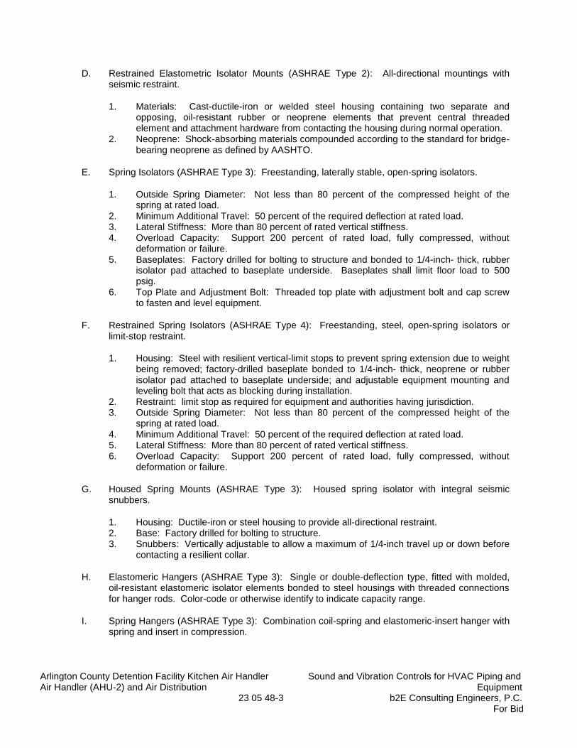
Arlington County Detention Facility Kitchen Air Handler Sound and Vibration Controls for HVAC Piping and Air Handler (AHU-2) and Air Distribution Equipment 23 05 48-3 b2E Consulting Engineers, P.C.
For Bid
D. Restrained Elastometric Isolator Mounts (ASHRAE Type 2): All-directional mountings with seismic restraint.
1. Materials: Cast-ductile-iron or welded steel housing containing two separate and opposing, oil-resistant rubber or neoprene elements that prevent central threaded element and attachment hardware from contacting the housing during normal operation.
2. Neoprene: Shock-absorbing materials compounded according to the standard for bridge-bearing neoprene as defined by AASHTO.
E. Spring Isolators (ASHRAE Type 3): Freestanding, laterally stable, open-spring isolators.
1. Outside Spring Diameter: Not less than 80 percent of the compressed height of the spring at rated load.
2. Minimum Additional Travel: 50 percent of the required deflection at rated load. 3. Lateral Stiffness: More than 80 percent of rated vertical stiffness. 4. Overload Capacity: Support 200 percent of rated load, fully compressed, without
deformation or failure. 5. Baseplates: Factory drilled for bolting to structure and bonded to 1/4-inch- thick, rubber
isolator pad attached to baseplate underside. Baseplates shall limit floor load to 500 psig.
6. Top Plate and Adjustment Bolt: Threaded top plate with adjustment bolt and cap screw to fasten and level equipment.
F. Restrained Spring Isolators (ASHRAE Type 4): Freestanding, steel, open-spring isolators or limit-stop restraint.
1. Housing: Steel with resilient vertical-limit stops to prevent spring extension due to weight being removed; factory-drilled baseplate bonded to 1/4-inch- thick, neoprene or rubber isolator pad attached to baseplate underside; and adjustable equipment mounting and leveling bolt that acts as blocking during installation.
2. Restraint: limit stop as required for equipment and authorities having jurisdiction. 3. Outside Spring Diameter: Not less than 80 percent of the compressed height of the
spring at rated load. 4. Minimum Additional Travel: 50 percent of the required deflection at rated load. 5. Lateral Stiffness: More than 80 percent of rated vertical stiffness. 6. Overload Capacity: Support 200 percent of rated load, fully compressed, without
deformation or failure.
G. Housed Spring Mounts (ASHRAE Type 3): Housed spring isolator with integral seismic snubbers.
1. Housing: Ductile-iron or steel housing to provide all-directional restraint. 2. Base: Factory drilled for bolting to structure. 3. Snubbers: Vertically adjustable to allow a maximum of 1/4-inch travel up or down before
contacting a resilient collar.
H. Elastomeric Hangers (ASHRAE Type 3): Single or double-deflection type, fitted with molded, oil-resistant elastomeric isolator elements bonded to steel housings with threaded connections for hanger rods. Color-code or otherwise identify to indicate capacity range.
I. Spring Hangers (ASHRAE Type 3): Combination coil-spring and elastomeric-insert hanger with spring and insert in compression.

Arlington County Detention Facility Kitchen Air Handler Sound and Vibration Controls for HVAC Piping and Air Handler (AHU-2) and Air Distribution Equipment 23 05 48-4 b2E Consulting Engineers, P.C.
For Bid
1. Frame: Steel, fabricated for connection to threaded hanger rods and to allow for a maximum of 30 degrees of angular hanger-rod misalignment without binding or reducing isolation efficiency.
2. Outside Spring Diameter: Not less than 80 percent of the compressed height of the spring at rated load.
3. Minimum Additional Travel: 50 percent of the required deflection at rated load. 4. Lateral Stiffness: More than 80 percent of rated vertical stiffness. 5. Overload Capacity: Support 200 percent of rated load, fully compressed, without
deformation or failure. 6. Elastomeric Element: Molded, oil-resistant rubber or neoprene. Steel-washer-reinforced
cup to support spring and bushing projecting through bottom of frame. 7. Self-centering hanger rod cap to ensure concentricity between hanger rod and support
spring coil.
J. Spring Hangers with Vertical-Limit Stop (ASHRAE Type 4): Combination coil-spring and elastomeric-insert hanger with spring and insert in compression and with a vertical-limit stop.
1. Frame: Steel, fabricated for connection to threaded hanger rods and to allow for a maximum of 30 degrees of angular hanger-rod misalignment without binding or reducing isolation efficiency.
2. Outside Spring Diameter: Not less than 80 percent of the compressed height of the spring at rated load.
3. Minimum Additional Travel: 50 percent of the required deflection at rated load. 4. Lateral Stiffness: More than 80 percent of rated vertical stiffness. 5. Overload Capacity: Support 200 percent of rated load, fully compressed, without
deformation or failure. 6. Elastomeric Element: Molded, oil-resistant rubber or neoprene. 7. Adjustable Vertical Stop: Steel washer with neoprene washer "up-stop" on lower
threaded rod. 8. Self-centering hanger rod cap to ensure concentricity between hanger rod and support
spring coil.
2.2 FACTORY FINISHES
A. Finish: Manufacturer's standard paint applied to factory-assembled and -tested equipment before shipping.
1. Powder coating on springs and housings. 2. All hardware shall be galvanized. Hot-dip galvanize metal components for exterior use. 3. Baked enamel or powder coat for metal components on isolators for interior use. 4. Color-code or otherwise mark vibration isolation and control devices to indicate capacity
range.
PART 3 - EXECUTION
3.1 EXAMINATION
A. Examine areas and equipment to receive vibration isolation and control devices for compliance with requirements for installation tolerances and other conditions affecting performance.
Arlington County Detention Facility Kitchen Air Handler Sound and Vibration Controls for HVAC Piping and Air Handler (AHU-2) and Air Distribution Equipment 23 05 48-5 b2E Consulting Engineers, P.C.
For Bid
B. Examine roughing-in of reinforcement and cast-in-place anchors to verify actual locations before installation.
C. Proceed with installation only after unsatisfactory conditions have been corrected.
3.2 APPLICATIONS
A. Multiple Pipe Supports: Secure pipes to trapeze member with clamps approved for application by the Structural Engineer.
B. Strength of Support and Assemblies: Where not indicated, select sizes of components so strength will be adequate to carry present and future static loads within specified loading limits.
3.3 VIBRATION-CONTROL DEVICE INSTALLATION
A. Comply with requirements in Division 07 Section "Roof Accessories" for installation of roof curbs, equipment supports, and roof penetrations.
B. Equipment Restraints:
1. Install snubbers on HVAC equipment mounted on vibration isolators. Locate snubbers as close as possible to vibration isolators and bolt to equipment base and supporting structure.
2. Install resilient bolt isolation washers on equipment anchor bolts where clearance between anchor and adjacent surface exceeds 0.125 inch.
C. Install cables so they do not bend across edges of adjacent equipment or building structure.
D. Install bushing assemblies for anchor bolts for floor-mounted equipment, arranged to provide resilient media between anchor bolt and mounting hole in concrete base.
E. Install bushing assemblies for mounting bolts for wall-mounted equipment, arranged to provide resilient media where equipment or equipment-mounting channels are attached to wall.
F. Attachment to Structure: If specific attachment is not indicated, anchor bracing to structure at flanges of beams, at upper truss chords of bar joists, or at concrete members.
G. Drilled-in Anchors (where prior approved in writing by the project Structural Engineer):
1. Identify position of reinforcing steel and other embedded items prior to drilling holes for anchors. Do not damage existing reinforcing or embedded items during coring or drilling. Notify the structural engineer if reinforcing steel or other embedded items are encountered during drilling. Locate and avoid prestressed tendons, electrical and telecommunications conduit, and gas lines.
2. Do not drill holes in concrete or masonry until concrete, mortar, or grout has achieved full design strength.
3. Wedge Anchors: Protect threads from damage during anchor installation. Heavy-duty sleeve anchors shall be installed with sleeve fully engaged in the structural element to which anchor is to be fastened.
4. Adhesive Anchors: Clean holes to remove loose material and drilling dust prior to installation of adhesive. Place adhesive in holes proceeding from the bottom of the hole
Arlington County Detention Facility Kitchen Air Handler Sound and Vibration Controls for HVAC Piping and Air Handler (AHU-2) and Air Distribution Equipment 23 05 48-6 b2E Consulting Engineers, P.C.
For Bid
and progressing toward the surface in such a manner as to avoid introduction of air pockets in the adhesive.
5. Set anchors to manufacturer's recommended torque, using a torque wrench. 6. Install zinc-coated steel anchors for interior and stainless-steel anchors for exterior
applications.
3.4 FIELD QUALITY CONTROL
A. Testing Agency: Engage a qualified testing agency to perform tests and inspections.
B. Perform tests and inspections.
C. Tests and Inspections:
1. Provide evidence of recent calibration of test equipment by a testing agency acceptable to authorities having jurisdiction.
2. Schedule test with Owner, through Architect, before connecting anchorage device to restrained component (unless postconnection testing has been approved), and with at least seven days' advance notice.
3. Obtain Architect's approval before transmitting test loads to structure. Provide temporary load-spreading members.
4. Test at least four of each type and size of installed anchors and fasteners selected by Architect.
5. Test to 90 percent of rated proof load of device. 6. Measure isolator restraint clearance. 7. Measure isolator deflection. 8. Verify snubber minimum clearances. 9. If a device fails test, modify all installations of same type and retest until satisfactory
results are achieved.
D. Remove and replace malfunctioning units and retest as specified above.
E. Prepare test and inspection reports.
3.5 ADJUSTING
A. Adjust isolators after piping systems have been filled and equipment is at operating weight.
B. Adjust limit stops on restrained spring isolators to mount equipment at normal operating height. After equipment installation is complete, adjust limit stops so they are out of contact during normal operation.
C. Adjust active height of spring isolators.
D. Adjust restraints to permit free movement of equipment within normal mode of operation.
E. Adjust snubbers according to manufacturer’s written recommendations.

Arlington County Detention Facility Kitchen Air Handler Sound and Vibration Controls for HVAC Piping and Air Handler (AHU-2) and Air Distribution Equipment 23 05 48-7 b2E Consulting Engineers, P.C.
For Bid
3.6 DEMONSTRATION
A. Engage a factory-authorized service representative to train Owner's maintenance personnel to adjust, operate, and maintain air-mounting systems. Refer to Division 01 Section "Project Closeout."
3.7 VIBRATION ISOLATOR SCHEDULE
A. Air Handling Unit (AHU-2):
1. Isolator Type: By manufacturer. 2. Isolator Material: By manufacturer. 3. Deflection: By manufacturer. 4. Internally Isolated Equipment: Yes, by manufacturer. 5. Location: Detention Facility Upper Mechanical room. 6. Area Served: Kitchen. 7. Housekeeping Pad Required: Yes, extend existing pad to match adjacent construction.
B. Piping Connected to Vibrating Equipment (Pumps):
1. Isolator Type: Spring hangers with vertical stop (ASHRAE Type 3). 2. Isolator Material: Steel springs. 3. Deflection: 1/2 inch. 4. Internally Isolated Equipment: No. 5. Location: Main level. Install within first 20-feet (in plan view) of connection to rotating
equipment.
END OF SECTION 23 05 48
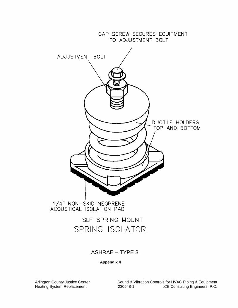
Arlington County Justice Center Sound & Vibration Controls for HVAC Piping & Equipment Heating System Replacement 230548-1 b2E Consulting Engineers, P.C.
ASHRAE – TYPE 3
Appendix 4

Arlington County Justice Center Sound & Vibration Controls for HVAC Piping & Equipment Heating System Replacement 230548-1 b2E Consulting Engineers, P.C.
ASHRAE – TYPE 3
Appendix 8
Arlington County Detention Facility Kitchen Air Handler Identification for Mechanical Piping, Ductwork Air Handler (AHU-2) and Air Distribution and Equipment 23 05 53-1 b2E Consulting Engineers, P.C.
For Bid
SECTION 23 05 53
IDENTIFICATION FOR MECHANICAL PIPING, DUCTWORK AND EQUIPMENT
PART 1 - GENERAL
1.1 SUMMARY
A. This Section includes the following mechanical identification materials and their installation:
1. Equipment nameplates. 2. Equipment markers. 3. Equipment signs. 4. Access panel and door markers. 5. Pipe markers. 6. Duct markers. 7. Stencils. 8. Valve tags. 9. Valve schedules. 10. Warning tags.
B. Ceiling Identification: Provide a tag on the ceiling for each adjustable and/or serviceable device concealed above the ceiling. Provide engraved tag with min. ¼-inch high lettering and dual color scheme. Color coordinate identification with engraved plates permanently fastened with stainless steel screws or rivets (no double stick tape) to the wall and/or ceiling for clear view.
1. Submit visual signage and tags to Owner for review.
C. Valve Numbering and As-Built Drawings: Provide as-built floor plans indicating locations of all valves and associated valve numbers.
1. Provide numbered valve tag for each valve. 2. Show valve schedule on as-built drawings indicating valve number, type, size, duty and
equipment served.
1.2 SUBMITTALS
A. Product Data: For each type of product indicated.
B. Samples: For color, letter style, and graphic representation required for each identification material and device.
C. Valve numbering scheme.
D. Valve Schedules: For each piping system. Furnish extra copies (in addition to mounted copies) to include in maintenance manuals.

Arlington County Detention Facility Kitchen Air Handler Identification for Mechanical Piping, Ductwork Air Handler (AHU-2) and Air Distribution and Equipment 23 05 53-2 b2E Consulting Engineers, P.C.
For Bid
1.3 QUALITY ASSURANCE
A. ASME Compliance: Comply with ASME A13.1, "Scheme for the Identification of Piping Systems," for letter size, length of color field, colors, and viewing angles of identification devices for piping.
1.4 COORDINATION
A. Coordinate installation of identifying devices with completion of covering and painting of surfaces where devices are to be applied.
B. Coordinate installation of identifying devices with location of access panels and doors.
C. Install identifying devices before installing acoustical ceilings and similar concealment.
PART 2 - PRODUCTS
2.1 EQUIPMENT IDENTIFICATION DEVICES
A. Equipment Nameplates: Metal, with data engraved or stamped, for permanent attachment on equipment.
1. Data:
a. Manufacturer, product name, model number, and serial number. b. Capacity, operating and power characteristics, and essential data. c. Labels of tested compliances.
2. Location: Accessible and visible. 3. Fasteners: As required to mount on equipment.
B. Equipment Markers: Engraved, color-coded laminated plastic. Include contact-type, permanent adhesive.
1. Terminology: Match schedules as closely as possible. 2. Data:
a. Name and plan number. b. Equipment service. c. Design capacity. d. Other design parameters such as pressure drop, entering and leaving conditions,
and speed.
3. Size: 2-1/2 by 4 inches for control devices, dampers, and valves; 4-1/2 by 6 inches for equipment.
4. Color Coding: Refer to paragraph 3.2.D.
Arlington County Detention Facility Kitchen Air Handler Identification for Mechanical Piping, Ductwork Air Handler (AHU-2) and Air Distribution and Equipment 23 05 53-3 b2E Consulting Engineers, P.C.
For Bid
C. Equipment Signs: ASTM D 709, Type I, cellulose, paper-base, phenolic-resin-laminate engraving stock; Grade ES-2, black surface, black phenolic core, with white melamine subcore, unless otherwise indicated. Fabricate in sizes required for message. Provide holes for mechanical fastening.
1. Data: Instructions for operation of equipment and for safety procedures. 2. Engraving: Manufacturer's standard letter style, of sizes and with terms to match
equipment identification. 3. Thickness: 1/16 inch for units up to 20 sq. in. or 8 inches in length, and 1/8 inch for larger
units. 4. Fasteners: Self-tapping, stainless-steel screws or contact-type, permanent adhesive.
D. Access Panel and Door Markers: 1/16-inch- thick, engraved laminated plastic, with abbreviated terms and numbers corresponding to identification. Provide 1/8-inch center hole for attachment.
1. Fasteners: Self-tapping, stainless-steel screws or contact-type, permanent adhesive.
2.2 PIPING IDENTIFICATION DEVICES
A. Manufactured Pipe Markers, General: Preprinted, color-coded, with lettering indicating service, and showing direction of flow.
1. Colors: Comply with ASME A13.1, unless otherwise indicated. 2. Lettering: Use piping system terms indicated and abbreviate only as necessary for each
application length. 3. Pipes with OD, Including Insulation, Less Than 6 Inches: Full-band pipe markers
extending 360 degrees around pipe at each location. 4. Pipes with OD, Including Insulation, 6 Inches and Larger: Either full-band or strip-type
pipe markers at least three times letter height and of length required for label. 5. Arrows: Integral with piping system service lettering to accommodate both directions; or
as separate unit on each pipe marker to indicate direction of flow.
B. Plastic Tape: Continuously printed, vinyl tape at least 3 mils thick with pressure-sensitive, permanent-type, self-adhesive back.
1. Width for Markers on Pipes with OD, Including Insulation, Less Than 6 Inches: 3/4 inch minimum.
2. Width for Markers on Pipes with OD, Including Insulation, 6 Inches or Larger: 1-1/2 inches minimum.
C. Pipe Painting for Pipe with Board Insulation and Glass Cloth Jacket: Prepare surface for painting and paint entire surface of glass cloth jacket pipework (all sides) with color indicated in paragraph 3.3.B. Provide stencil marking after painting to indicate pipe type, pressure, and water-flow direction.
D. “Venture Clad” Jacket Color for Exposed Insulated Pipework: Provide the colors indicated in paragraph 3.3.B. Provide stencil marking to indicate pipe type and air-flow direction.
E. Pipe Painting for Uninsulated Pipe: Prepare surface for painting and paint entire surface of pipe (all sides) with color indicated in paragraph 3.3.B. Provide stencil marking after painting to indicate pipe type, pressure, and water-flow direction.
Arlington County Detention Facility Kitchen Air Handler Identification for Mechanical Piping, Ductwork Air Handler (AHU-2) and Air Distribution and Equipment 23 05 53-4 b2E Consulting Engineers, P.C.
For Bid
2.4 STENCILS
A. Stencils: Prepared with letter sizes according to ASME A13.1 for piping; minimum letter height of 1-1/4 inches for ducts; and minimum letter height of 3/4 inch for access panel and door markers, equipment markers, equipment signs, and similar operational instructions.
1. Stencil Material: Galvanized. 2. Stencil Paint: Exterior, gloss, alkyd enamel or acrylic enamel black, unless otherwise
indicated. Paint may be in pressurized spray-can form. 3. Identification Paint: Exterior, alkyd enamel or acrylic enamel in colors according to
ASME A13.1, unless otherwise indicated.
2.5 VALVE TAGS
A. Valve Tags: Stamped or engraved with 1/4-inch letters for piping system abbreviation and 1/2-inch numbers, with numbering scheme approved by Architect/Engineer. Provide 5/32-inch hole for fastener.
1. Material: 0.032-inch thick brass in equipment areas. 2. Valve-Tag Fasteners: Brass wire-link; or S-hook.
2.6 VALVE SCHEDULES
A. Valve Schedules: For each piping system, on standard-size bond paper. Tabulate valve number, piping system, system abbreviation (as shown on valve tag), location of valve (room or space), normal-operating position (open, closed, or modulating), and variations for identification. Mark valves for emergency shutoff and similar special uses.
1. Valve-Schedule Frames: Glazed display frame for removable mounting on masonry walls for each page of valve schedule. Include mounting screws.
2. Frame: Extruded Galvanized. 3. Glazing: ASTM C 1036, Type I, Class 1, Glazing Quality B, 2.5-mm, single-thickness
glass.
2.7 WARNING TAGS
A. Warning Tags: Preprinted or partially preprinted, accident-prevention tags; of plasticized card stock with matte finish suitable for writing.
1. Size: Approximately 4 by 7 inches 2. Fasteners: Brass grommet and wire. 3. Nomenclature: Large-size primary caption such as DANGER, CAUTION, or DO NOT
OPERATE. 4. Color: Yellow background with black lettering.
PART 3 - EXECUTION
3.1 APPLICATIONS, GENERAL
Arlington County Detention Facility Kitchen Air Handler Identification for Mechanical Piping, Ductwork Air Handler (AHU-2) and Air Distribution and Equipment 23 05 53-5 b2E Consulting Engineers, P.C.
For Bid
A. Products specified are for applications referenced in other Division 23 Sections. If more than single-type material, device, or label is specified for listed applications, selection is Installer's option.
3.2 EQUIPMENT IDENTIFICATION
A. Install color coded “Venture Clad” jackets or painted glass cloth jackets for all equipment and permanently fasten equipment nameplates on each major item of mechanical equipment. Locate nameplates where accessible and visible. Include nameplates for the following general categories of equipment: 1. Pumps, chillers, cooling towers and similar motor-driven units. 2. Adjustable frequency drives and motor controllers. 3. Flow meter and water meters. 4. Tanks and pressure vessels, including air separator, expansion tank and bypass feeder. 5. Strainers, filters, water-treatment systems, and similar equipment. 6. BAS Control Panels, actuators, operators, valves, dampers, switches, temperature
sensors, etc. 7. Any electrical breakers, disconnects, AFD’s, etc. serving mechanical equipment.
B. Install equipment markers on ceiling grid and walls to identify the location of concealed equipment with minimum two (2) permanent self-tapping screws on or near each major item of mechanical equipment.
1. Letter Size: Minimum 1/4 inch for name of units if viewing distance is less than 24 inches, 1/2 inch for viewing distances up to 72 inches, and proportionately larger lettering for greater viewing distances. Include secondary lettering two-thirds to three-fourths the size of principal lettering.
2. Data: Identify equipment tag with marker. 3. Locate markers where accessible and visible. Include markers for the following general
categories of equipment:
a. Main control and operating valves, including safety devices and hazardous units such as gas outlets.
b. Meters, gages, thermometers, and similar units. c. Fans, and other similar motor-driven units. d. BAS Control Panels, actuators, operators, valves, dampers, switches, etc. e. Any electrical disconnects, motor controllers, etc. serving mechanical equipment.
C. Stenciled Equipment Marker: Stenciled markers shall be provided instead of laminated-plastic equipment markers, if lettering larger than 1 inch high is needed for proper identification because of distance from normal location of required identification.
D. Install equipment signs with minimum two (2) self-tapping screws on or near each major item of mechanical equipment. Locate signs where accessible and visible.
1. Identify mechanical equipment with color coded PVC jackets or painted glass cloth jackets with equipment markers in the following color codes:
a. Blue: For cooling equipment and components. b. Red: For heating equipment and components. c. Red/Blue: For combination cooling and heating equipment and components. d. Green: For energy-reclamation equipment and components.

Arlington County Detention Facility Kitchen Air Handler Identification for Mechanical Piping, Ductwork Air Handler (AHU-2) and Air Distribution and Equipment 23 05 53-6 b2E Consulting Engineers, P.C.
For Bid
2. Letter Size: Minimum 1/4 inch for name of units if viewing distance is less than 24 inches, 1/2 inch for viewing distances up to 72 inches, and proportionately larger lettering for greater viewing distances. Include secondary lettering two-thirds to three-fourths the size of principal lettering.
3. Data: Distinguish among multiple units, indicate operational requirements, indicate safety and emergency precautions, warn of hazards and improper operations, and identify units.
4. Include signs for the following general categories of equipment: a. Main control and operating valves, including safety devices and hazardous units
such as gas outlets. b. Sprinkler service and stack flow preventers assembly and valves. c. Meters, gages, thermometers, and similar units. d. Adjustable frequency drives and motor controllers. e. Pumps, boilers, domestic water tanks, domestic water piping, hot water piping. f. Flow meters, water meters, and gas meters. g. Tanks and pressure vessels, including air separator, expansion tank and bypass
feeder. h. Strainers, filters, water-treatment systems, and similar equipment. i. EMS Control Panels, actuators, operators, valves, dampers, switches, etc. j. Any electrical breakers, disconnects, AFD’s, MCC’s, etc. serving mechanical
equipment.
E. Stenciled Equipment Sign Option: Stenciled signs may be provided instead of laminated-plastic equipment signs, at Installer's option, if lettering larger than 1 inch high is needed for proper identification because of distance from normal location of required identification.
F. Install access panel markers with screws on equipment access panels.
3.3 PIPING IDENTIFICATION
A. Install “Venture Clad” jacket for all insulated exposed piping and concealed fittings and equipment inside the building. Install aluminum jackets for all piping outside the building. Install manufactured pipe markers indicating service on each piping system. Install with flow indication arrows showing direction of flow.
B. Install piping in the following color codes; concealed piping shall be provided with piping markers with permanent adhesive; exposed piping shall be color coded jacket, prepared and clearly painted with stencils and identification. Provide minimum 2 coats of paint on all bare plumbing and HVAC piping. Provide pipe colors and marker designation symbols in all mechanical rooms and exposed areas per the following.
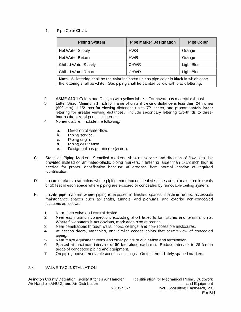
Arlington County Detention Facility Kitchen Air Handler Identification for Mechanical Piping, Ductwork Air Handler (AHU-2) and Air Distribution and Equipment 23 05 53-7 b2E Consulting Engineers, P.C.
For Bid
1. Pipe Color Chart:
Piping System Pipe Marker Designation Pipe Color
Hot Water Supply HWS Orange
Hot Water Return HWR Orange
Chilled Water Supply CHWS Light Blue
Chilled Water Return CHWR Light Blue
Note: All lettering shall be the color indicated unless pipe color is black in which case the lettering shall be white. Gas piping shall be painted yellow with black lettering.
2. ASME A13.1 Colors and Designs with yellow labels: For hazardous material exhaust. 3. Letter Size: Minimum 1 inch for name of units if viewing distance is less than 24 inches
(600 mm), 1-1/2 inch for viewing distances up to 72 inches, and proportionately larger lettering for greater viewing distances. Include secondary lettering two-thirds to three-fourths the size of principal lettering.
4. Nomenclature: Include the following:
a. Direction of water-flow. b. Piping service. c. Piping origin. d. Piping destination. e. Design gallons per minute (water).
C. Stenciled Piping Marker: Stenciled markers, showing service and direction of flow, shall be provided instead of laminated-plastic piping markers, if lettering larger than 1-1/2 inch high is needed for proper identification because of distance from normal location of required identification.
D. Locate markers near points where piping enter into concealed spaces and at maximum intervals of 50 feet in each space where piping are exposed or concealed by removable ceiling system.
E. Locate pipe markers where piping is exposed in finished spaces; machine rooms; accessible maintenance spaces such as shafts, tunnels, and plenums; and exterior non-concealed locations as follows:
1. Near each valve and control device. 2. Near each branch connection, excluding short takeoffs for fixtures and terminal units.
Where flow pattern is not obvious, mark each pipe at branch. 3. Near penetrations through walls, floors, ceilings, and non-accessible enclosures. 4. At access doors, manholes, and similar access points that permit view of concealed
piping. 5. Near major equipment items and other points of origination and termination. 6. Spaced at maximum intervals of 50 feet along each run. Reduce intervals to 25 feet in
areas of congested piping and equipment. 7. On piping above removable acoustical ceilings. Omit intermediately spaced markers.
3.4 VALVE-TAG INSTALLATION
Arlington County Detention Facility Kitchen Air Handler Identification for Mechanical Piping, Ductwork Air Handler (AHU-2) and Air Distribution and Equipment 23 05 53-8 b2E Consulting Engineers, P.C.
For Bid
A. Install tags on all valves and control devices in piping systems, except check valves; plumbing fixture supply stops; shutoff valves; faucets; convenience and lawn-watering hose connections; and similar roughing-in connections of end-use fixtures and units. List tagged valves in a valve schedule.
1. Contractor shall number valves to match control valves schedule for all HVAC equipment control valves.
2. Contractor shall number isolation valves in each HVAC system circuit as follows; where “X” denotes a numbering sequence for the actual numbering of valves installed.
a. Equipment Isolation Valves: EI - Equip # - X b. Plant Isolation Valves: PI-Room # - X c. Bypass Valves: BP - Device - X d. Drain Valves: D -Equip # - X e. Manual Air Vent Valves: MV – Equip # - X f. Calibrated Balancing Valves: BV – Equip # - X g. Temperature Control Valves: TC-Equip# - X.
B. Valve-Tag Application Schedule: Tag valves according to size, shape, and color scheme and with captions similar to those indicated in the following:
1. Valve-Tag Size and Shape:
a. Hot Water: 2-inches, round. b. Fire Protection: 2-inches, round. c. Non-Potable: 2-inches, round.
2. Valve-Tag Color:
a. Cold Water: Natural. b. Hot Water: Natural. c. Fire Protection: Red. d. Fuel: Yellow.
3. Letter Color:
a. Cold Water: Black. b. Hot Water: Black. c. Fire Protection: Black. d. Gas: Black.
3.5 VALVE-SCHEDULE INSTALLATION
A. Mount valve schedule on wall in accessible location in each equipment room.
3.6 WARNING-TAG INSTALLATION
A. Write required message on, and attach warning tags to, equipment and other items where required.
1. Provide warning tag for all automatically controlled equipment. 2. Provide warning tags wherever required in other sections.
Arlington County Detention Facility Kitchen Air Handler Identification for Mechanical Piping, Ductwork Air Handler (AHU-2) and Air Distribution and Equipment 23 05 53-9 b2E Consulting Engineers, P.C.
For Bid
3.7 ADJUSTING
A. Relocate mechanical identification materials and devices that have become visually blocked by other work.
3.8 CLEANING
A. Clean faces of mechanical identification devices and glass frames of valve schedules.
END OF SECTION 23 05 53
Arlington County Detention Facility Kitchen Air Handler Testing, Adjusting, and Balancing for Mechanical Air Handler (AHU-2) and Air Distribution 23 05 93-1 b2E Consulting Engineers, P.C.
For Bid
SECTION 23 05 93
TESTING, ADJUSTING, AND BALANCING FOR MECHANICAL
PART 1 - GENERAL
1.1 SUMMARY
A. Section Includes:
1. Air Systems: a. Variable air volume systems.
2. Balancing Hydronic Piping Systems: a. Constant-flow hydronic systems. b. Variable-flow hydronic systems.
3. Equipment quantitative-performance settings. 4. Vibration measuring. 5. Sound level measuring. 6. Verifying that automatic control devices are functioning 7. Reporting results of activities and procedures specified in this Section.
B. Pre-Tab Documentation: The TAB contractor shall measure the flow in all existing Air Handlers (AHU-1, AHU-2 and AHU-3) pumps in the Detention Facility buildings and record the waterflow rate and pressure loss and flow rate for each coil, and the airflow rate (OA, SA and RA) for each air handler.
1. Provide this information to the design engineer of record prior to ordering pumps and other equipment.
1.2 DEFINITIONS
A. AABC: Associated Air Balance Council.
B. NEBB: National Environmental Balancing Bureau.
C. TAB: Testing, adjusting, and balancing.
D. TABB: Testing, Adjusting, and Balancing Bureau.
E. TAB Specialist: An entity engaged to perform TAB Work.
1.3 SUBMITTALS
A. Qualification Data: Within 45 days of Contractor's Notice to Proceed, submit documentation that the TAB contractor and this Project's TAB team members meet the qualifications specified in "Quality Assurance" Article.
Arlington County Detention Facility Kitchen Air Handler Testing, Adjusting, and Balancing for Mechanical Air Handler (AHU-2) and Air Distribution 23 05 93-2 b2E Consulting Engineers, P.C.
For Bid
B. Contract Documents Examination Report: Within 90 days of Contractor's Notice to Proceed, submit the Contract Documents review report as specified in Part 3.
C. Strategies and Procedures Plan: Within 90 days of Contractor's Notice to Proceed, submit TAB strategies and step-by-step procedures as specified in "Preparation" Article.
D. Certified TAB reports.
E. Sample report forms.
F. Instrument calibration reports, to include the following:
1. Instrument type and make. 2. Serial number. 3. Application. 4. Dates of use. 5. Dates of calibration.
1.4 QUALITY ASSURANCE
A. TAB Contractor Qualifications: Engage a TAB entity certified by AABC, NEBB or TABB.
1. TAB Field Supervisor: Employee of the TAB contractor and certified by AABC, NEBB, or TABB.
2. TAB Technician: Employee of the TAB contractor and who is certified by AABC, NEBB, or TABB as a TAB technician.
B. TAB Conference: Meet with Engineer, Owner, and Commissioning Agent on approval of the TAB strategies and procedures plan to develop a mutual understanding of the details. Require the participation of the TAB field supervisor and technicians. Provide 14 days' advance notice of scheduled meeting time and location.
1. Agenda Items:
a. The Contract Documents examination report. b. The TAB plan. c. Coordination and cooperation of trades and subcontractors. d. Coordination of documentation and communication flow. e. Hours of work in Detention Facility Kitchen.
C. Certify TAB field data reports and perform the following:
1. Review field data reports to validate accuracy of data and to prepare certified TAB reports.
2. Certify that the TAB team complied with the approved TAB plan and the procedures specified and referenced in this Specification.
D. TAB Report Forms: Use standard TAB contractor's forms reviewed by Commissioning Agent.
E. Instrumentation Type, Quantity, Accuracy, and Calibration: As described in ASHRAE 111, Section 5, "Instrumentation."
Arlington County Detention Facility Kitchen Air Handler Testing, Adjusting, and Balancing for Mechanical Air Handler (AHU-2) and Air Distribution 23 05 93-3 b2E Consulting Engineers, P.C.
For Bid
1.5 PROJECT CONDITIONS
A. Full Owner Occupancy: Owner occupied all areas at the building up to and beyond Substantial Completion. Cooperate with Arlington County (DES) and the Sherriff’s Department during TAB operations to minimize conflicts with Detention Facility operations.
1.6 COORDINATION
A. Notice: Provide fourteen (14) days' advance notice for each test. Include scheduled test dates and times.
B. Perform TAB after leakage and pressure tests on air and water distribution systems have been satisfactorily completed.
1.7 WARRANTY
A. National Project Performance Guarantee: Provide a guarantee on AABC's "National Standards for Testing and Balancing Heating, Ventilating, and Air Conditioning Systems" forms stating that AABC will assist in completing requirements of the Contract Documents if TAB firm fails to comply with the Contract Documents. Guarantee includes the following provisions:
B. Special Guarantee: Provide a guarantee on NEBB forms stating that NEBB will assist in completing requirements of the Contract Documents if TAB firm fails to comply with the Contract Documents. Guarantee shall include the following provisions:
1. The certified TAB firm has tested and balanced systems according to the Contract Documents.
2. Systems are balanced to optimum performance capabilities within design and installation limits.
PART 2 - PRODUCTS (Not Applicable)
PART 3 - EXECUTION
3.1 TAB SPECIALISTS
A. Subject to compliance with requirements, engage one of the following:
1. Annandale Air Balancing Co. 2. Other qualified TAB contractor with large chiller plant experience.
a. TAB contractor shall have made TAB pressure measurements for hot water, chilled water and air handler control systems for at least five (5) facilities of similar size and scope within the past five (5) years.

Arlington County Detention Facility Kitchen Air Handler Testing, Adjusting, and Balancing for Mechanical Air Handler (AHU-2) and Air Distribution 23 05 93-4 b2E Consulting Engineers, P.C.
For Bid
3.2 EXAMINATION
A. Examine the Contract Documents to become familiar with Project requirements and to discover conditions in systems' designs that may preclude proper TAB of systems and equipment.
B. Examine systems for installed balancing devices, such as test ports, gage cocks, thermometer wells, flow-control devices, balancing valves and fittings, and manual volume dampers. Verify that locations of these balancing devices are accessible.
C. Examine the approved submittals for HVAC systems and equipment.
D. Examine design data including chilled water system descriptions, statements of design assumptions for environmental conditions and systems' output, and statements of philosophies and assumptions about chilled water system and equipment controls.
E. Examine ceiling plenums and under-floor air plenums used for supply, return, or relief air to verify that they meet the leakage class of connected ducts as specified in Division 23 Section "Metal Ducts" and are properly separated from adjacent areas. Verify that penetrations in plenum walls are sealed and fire-stopped if required.
F. Examine equipment performance data including pump curves.
1. Relate performance data to Project conditions and requirements, including system effects that can create undesired or unpredicted conditions that cause reduced capacities in all or part of a system.
G. Examine system and equipment installations and verify that field quality-control testing,
cleaning, and adjusting specified in individual Sections have been performed.
H. Examine test reports specified in individual system and equipment Sections.
I. Examine HVAC equipment and filters and verify that bearings are greased, belts are aligned and tight, and equipment with functioning controls is ready for operation.
J. Examine strainers. Verify that startup screens are replaced by permanent screens with indicated perforations.
K. Examine three-way valves for proper installation for their intended function of diverting or mixing fluid flows.
L. Examine system pumps to ensure absence of entrained air in the suction piping.
M. Examine operating safety interlocks and controls on HVAC equipment.
N. Report deficiencies discovered before and during performance of TAB procedures. Observe and record system reactions to changes in conditions. Record default set points if different from indicated values.
3.3 PREPARATION
A. Prepare a TAB plan that includes strategies and step-by-step procedures.
B. Complete system-readiness checks and prepare reports. Verify the following:
Arlington County Detention Facility Kitchen Air Handler Testing, Adjusting, and Balancing for Mechanical Air Handler (AHU-2) and Air Distribution 23 05 93-5 b2E Consulting Engineers, P.C.
For Bid
1. Permanent electrical-power wiring is complete. 2. Hydronic systems are filled, clean, and free of air. 3. Automatic temperature-control systems are operational. 4. Equipment and duct access doors are securely closed. 5. Balance, smoke, and fire dampers are open. 6. Isolating and balancing valves are open and control valves are operational. 7. Ceilings are installed in critical areas where air-pattern adjustments are required and
access to balancing devices is provided. 8. Windows and doors can be closed so indicated conditions for system operations can be
met.
C. Provide Pre-Balance for existing condenser water and chilled water pumps to determine the existing system flow rate, pressure loss and bhp consumption. Provide this report prior to submitting for the CW and CHW pumps on this project.
D. Cut insulation, ducts, pipes, and equipment cabinets for installation of test probes to the minimum extent necessary to allow adequate performance of procedures. After testing and balancing, close probe holes and patch insulation with new materials identical to those removed. Items that are beyond the TAB contractor’s ability to repair appropriately must be submitted in writing to the general contractor for coordination with appropriate parties. Restore vapor barrier and finish according to insulation Specifications for this Project.
E. Mark equipment and balancing device settings with paint or other suitable, permanent identification material, including damper-control positions, valve position indicators, fan speed control levers, and similar controls and devices, to show final settings.
F. All valves and dampers are to be placed in normal operating conditions whenever possible. At no time should the TAB contractor close or manually regulate valves and dampers to offer temporary resolution of balance, mechanical, or temperature control problems, unless it is necessary to prevent damage to property. Such deficiencies must be recorded in the Daily Deficiency Report, and the General Contractor is to be informed immediately.
3.4 GENERAL PROCEDURES FOR BALANCING AIR SYSTEMS
A. Prepare test reports for both fans and outlets. Obtain manufacturer's outlet factors and recommended testing procedures. Crosscheck the summation of required outlet volumes with required fan volumes.
B. Prepare schematic diagrams of systems' "as-built" duct layouts.
C. For variable-air-volume systems, develop a plan to simulate diversity.
D. Determine the best locations in main and branch ducts for accurate duct-airflow measurements.
E. Check airflow patterns from the outdoor-air louvers and dampers and the return- and exhaust-air dampers through the supply-fan discharge and mixing dampers.
F. Locate start-stop and disconnect switches, electrical interlocks, and motor starters.
G. Verify that motor starters are equipped with properly sized thermal protection.
H. Check dampers for proper position to achieve desired airflow path.
Arlington County Detention Facility Kitchen Air Handler Testing, Adjusting, and Balancing for Mechanical Air Handler (AHU-2) and Air Distribution 23 05 93-6 b2E Consulting Engineers, P.C.
For Bid
I. Check for airflow blockages.
J. Check condensate drains for proper connections and functioning.
K. Check for proper sealing of air-handling-unit components.
L. Verify that air duct system is sealed as specified in Division 23 Section "Metal Ducts."
3.5 PROCEDURES FOR CONSTANT-VOLUME AIR SYSTEMS
A. Adjust fans to deliver total indicated airflows within the maximum allowable fan speed listed by fan manufacturer.
1. Measure total airflow.
a. Where sufficient space in ducts is unavailable for Pitot-tube traverse measurements, measure airflow at terminal outlets and inlets and calculate the total airflow.
2. Measure fan static pressures as follows to determine actual static pressure:
a. Measure outlet static pressure as far downstream from the fan as practical and upstream from restrictions in ducts such as elbows and transitions.
b. Measure static pressure directly at the fan outlet or through the flexible connection. c. Measure inlet static pressure of single-inlet fans in the inlet duct as near the fan as
possible, upstream from the flexible connection, and downstream from duct restrictions.
d. Measure inlet static pressure of double-inlet fans through the wall of the plenum that houses the fan.
3. Measure static pressure across each component that makes up an air-handling unit, rooftop unit, and other air-handling and -treating equipment.
a. Report the cleanliness status of filters and the time static pressures are measured.
4. Measure static pressures entering and leaving other devices, such as sound traps, heat-recovery equipment, and air washers, under final balanced conditions.
5. Review Record Documents to determine variations in design static pressures versus actual static pressures. Calculate actual system-effect factors. Recommend adjustments to accommodate actual conditions.
6. Obtain approval from Architect for adjustment of fan speed higher or lower than indicated speed. Comply with requirements in Division 23 Sections for air-handling units for adjustment of fans, belts, and pulley sizes to achieve indicated air-handling-unit performance.
7. Do not make fan-speed adjustments that result in motor overload. Consult equipment manufacturers about fan-speed safety factors. Modulate dampers and measure fan-motor amperage to ensure that no overload will occur. Measure amperage in full-cooling, full-heating, economizer, and any other operating mode to determine the maximum required brake horsepower.
B. Adjust volume dampers for main duct, submain ducts, and major branch ducts to indicated airflows within specified tolerances.
Arlington County Detention Facility Kitchen Air Handler Testing, Adjusting, and Balancing for Mechanical Air Handler (AHU-2) and Air Distribution 23 05 93-7 b2E Consulting Engineers, P.C.
For Bid
1. Measure airflow of submain and branch ducts.
a. Where sufficient space in submain and branch ducts is unavailable for Pitot-tube traverse measurements, measure airflow at terminal outlets and inlets and calculate the total airflow for that zone.
2. Measure static pressure at a point downstream from the balancing damper, and adjust volume dampers until the proper static pressure is achieved.
3. Re-measure each submain and branch duct after all have been adjusted. Continue to adjust submain and branch ducts to indicated airflows within specified tolerances.
C. Measure air outlets and inlets without making adjustments.
1. Measure terminal outlets using a direct-reading hood or outlet manufacturer's written instructions and calculating factors.
D. Adjust air outlets and inlets for each space to indicated airflows within specified tolerances of indicated values. Make adjustments using branch volume dampers rather than extractors and the dampers at air terminals.
1. Adjust each outlet in same room or space to within specified tolerances of indicated quantities without generating noise levels above the limitations prescribed by the Contract Documents.
2. Adjust patterns of adjustable outlets for proper distribution without drafts.
3.6 PROCEDURES FOR VARIABLE-AIR-VOLUME SYSTEMS
A. Compensating for Diversity: When the total airflow of all terminal units is more than the indicated airflow of the fan, place a selected number of terminal units at a minimum set-point airflow with the remainder at maximum-airflow condition until the total airflow of the terminal units equals the indicated airflow of the fan. Select the reduced-airflow terminal units so they are distributed evenly among the branch ducts.
B. Pressure-Independent, Variable-Air-Volume Systems: After the fan systems have been adjusted, adjust the variable-air-volume systems as follows:
1. Set outdoor-air dampers at minimum, and set return- and exhaust-air dampers at a position that simulates full-cooling load.
2. Select the terminal unit that is most critical to the supply-fan airflow and static pressure. Measure static pressure. Adjust system static pressure so the entering static pressure for the critical terminal unit is not less than the sum of the terminal-unit manufacturer's recommended minimum inlet static pressure plus the static pressure needed to overcome terminal-unit discharge system losses.
3. Measure total system airflow. Adjust to within indicated airflow. 4. Set terminal units at maximum airflow and adjust controller or regulator to deliver the
designed maximum airflow. Use terminal-unit manufacturer's written instructions to make this adjustment. When total airflow is correct, balance the air outlets downstream from terminal units the same as described for constant-volume air systems.
5. Set terminal units at minimum airflow and adjust controller or regulator to deliver the designed minimum airflow. Check air outlets for a proportional reduction in airflow the same as described for constant-volume air systems.

Arlington County Detention Facility Kitchen Air Handler Testing, Adjusting, and Balancing for Mechanical Air Handler (AHU-2) and Air Distribution 23 05 93-8 b2E Consulting Engineers, P.C.
For Bid
a. If air outlets are out of balance at minimum airflow, report the condition but leave outlets balanced for maximum airflow.
6. Remeasure the return airflow to the fan while operating at maximum return airflow and minimum outdoor airflow.
a. Adjust the fan and balance the return-air ducts and inlets the same as described for constant-volume air systems.
7. Measure static pressure at the most critical terminal unit and adjust the static-pressure controller at the main supply-air sensing station to ensure that adequate static pressure is maintained at the most critical unit.
8. Record final fan-performance data.
3.7 GENERAL PROCEDURES FOR TESTING AND BALANCING
A. Perform testing and balancing procedures on each system according to the procedures contained in AABC's "National Standards for Total System Balance;" ASHRAE 111; NEBB's "Procedural Standards for Testing, Adjusting, and Balancing of Environmental Systems;" or SMACNA's "HVAC Systems - Testing, Adjusting, and Balancing" and in this Section.
1. Comply with requirements in ASHRAE 62.1-2013, Section 7.2.2, "Air Balancing." 2. Install and join new insulation that matches removed materials. Restore insulation,
coverings, vapor barrier, and finish according to Division 23 Section "HVAC Insulation."
3.8 GENERAL PROCEDURES FOR HYDRONIC SYSTEMS
A. Prepare test reports with pertinent design data, and number in sequence starting at pump to end of system. Check the sum of branch-circuit flows against the approved pump flow rate. Correct variations that exceed plus or minus 5 percent.
B. Prepare schematic diagrams of systems' "as-built" piping layouts.
C. Prepare hydronic systems for testing and balancing according to the following, in addition to the general preparation procedures specified above:
1. Open all manual valves for maximum flow. 2. Check liquid level in expansion tank. 3. Check makeup water-station pressure gage for adequate pressure for highest vent. 4. Check flow-control valves for specified sequence of operation, and set at indicated flow. 5. Set differential-pressure control valves at the specified differential pressure. Do not set at
fully closed position when pump is positive-displacement type unless several terminal valves are kept open.
6. Set system controls so automatic valves are wide open to heat exchangers. 7. Check pump-motor load. If motor is overloaded, throttle main flow-balancing device so
motor nameplate rating is not exceeded. 8. Check air vents for a forceful liquid flow exiting from vents when manually operated.
Arlington County Detention Facility Kitchen Air Handler Testing, Adjusting, and Balancing for Mechanical Air Handler (AHU-2) and Air Distribution 23 05 93-9 b2E Consulting Engineers, P.C.
For Bid
3.9 PROCEDURES FOR CONSTANT-FLOW HYDRONIC SYSTEMS
A. Measure water flow at pumps. Use the following procedures except for positive-displacement pumps:
1. Verify impeller size by operating the pump with the discharge valve closed. Read pressure differential across the pump. Convert pressure to head and correct for differences in gage heights. Note the point on manufacturer's pump curve at zero flow and verify that the pump has the intended impeller size.
a. If impeller sizes must be adjusted to achieve pump performance, obtain approval from Architect and comply with requirements in Division 23 Section "Hydronic Pumps."
2. Check system resistance. With all valves open, read pressure differential across the pump and mark pump manufacturer's head-capacity curve. Adjust pump discharge valve until indicated water flow is achieved.
a. Monitor motor performance during procedures and do not operate motors in overload conditions.
3. Verify pump-motor brake horsepower. Calculate the intended brake horsepower for the system based on pump manufacturer's performance data. Compare calculated brake horsepower with nameplate data on the pump motor. Report conditions where actual amperage exceeds motor nameplate amperage.
4. Report flow rates that are not within plus or minus 10 percent of design.
B. Measure flow at all stations and adjust, where necessary, to obtain first balance.
1. System components that have Cv rating or an accurately cataloged flow-pressure-drop relationship may be used as a flow-indicating device.
C. Measure flow at main balancing station and set main balancing device to achieve flow that is 5 percent greater than indicated flow.
D. Adjust balancing stations to within specified tolerances of indicated flow rate as follows:
1. Determine the balancing station with the highest percentage over indicated flow. 2. Adjust each station in turn, beginning with the station with the highest percentage over
indicated flow and proceeding to the station with the lowest percentage over indicated flow.
3. Record settings.
E. Open all automatic modulating flow control valves to 100% open position. Measure flow at all calibrated balancing valves from longest run back towards pumps to verify that valves are set to design flow rates. 1. Isolate areas of the building with similar dynamic head loss and balance to design water
flow rates. 2. Open all areas of building for water flow through piping systems. 3. Re-measure water flow through calibrated balancing valves with automatic control valves
in full open position.
Arlington County Detention Facility Kitchen Air Handler Testing, Adjusting, and Balancing for Mechanical Air Handler (AHU-2) and Air Distribution 23 05 93-10 b2E Consulting Engineers, P.C.
For Bid
4. All flows should read as a percentage of block load (design) max. flow over the connected load. All valves shall read as a percentage within 5% plus or minus of the calculated design percentage.
5. Record settings and mark balancing devices.
F. Measure pump flow rate and make final measurements of pump amperage, voltage, rpm, pump heads, and systems' pressures and temperatures including outdoor-air temperature.
G. Measure the differential-pressure-control-valve settings existing at the conclusion of balancing. 1. Calculate to differential pressure setpoint at EMS to provide adequate flow to longest
runs in system.
H. Release the automatic modulating flow control valves to automatic. 1. Adjust EMS pressure differential setpoints and verify adequate flow at farthest run in
system.
I. Check settings and operation of each safety valve. Record settings.
3.10 PROCEDURES FOR VARIABLE-FLOW HYDRONIC SYSTEMS
A. Balance systems with automatic two- and three-way control valves by setting systems at maximum flow through heat-exchange terminals and proceed as specified above for hydronic systems.
B. Variable Primary Chilled Water System: Balance system for max. flow for block load with pony chiller off. Once system is adjusted for large chiller turn small chiller pump on. Reread the water balance valves with max flow thru both chillers. Once system flows are adjusted to design with both chillers running, check for min. flow in main system required to keep small chiller on-line. Reduce flow in main slowly to 40% of design flow in main chiller. 1. Run Chiller System: Ensure the flow rate is constant thru the pony (smaller) chiller as the
main flow is reduced. Ensure there are no swings in temperature or water flow to the pony chiller. Adjust the rate of AFD speed to ensure the system remains stable and under control when the main chiller flow modulated from 40% to 100% and back again while both chillers are running and loaded.
3.11 PROCEDURES FOR MOTORS
A. Motors, 1/2 HP and Larger: Test at final balanced conditions and record the following data:
1. Manufacturer's name, model number, and serial number. 2. Motor horsepower rating. 3. Motor rpm. 4. Efficiency rating. 5. Nameplate and measured voltage, each phase. 6. Nameplate and measured amperage, each phase. 7. Starter thermal-protection-element rating.
B. Motors Driven by Variable-Frequency Controllers: Test for proper operation at speeds varying from minimum to maximum. Test the manual bypass of the controller to prove proper operation. Record observations including name of controller manufacturer, model number, serial number, and nameplate data.
Arlington County Detention Facility Kitchen Air Handler Testing, Adjusting, and Balancing for Mechanical Air Handler (AHU-2) and Air Distribution 23 05 93-11 b2E Consulting Engineers, P.C.
For Bid
3.12 PROCEDURES FOR RETURN FANS
A. Measure, adjust, and record the airflow of each exhaust fan. Measure airflow by duct Pitot-tube traverse. If a duct Pitot-tube traverse is not possible, explain why, in the Final Report and explain the test method used.
B. Take measurements on remaining fans with all related HVAC or process equipment under full control. This includes makeup dampers, heating and cooling supply air and boilers.
C. Verify Motor horsepower rating.
3.13 TEMPERATURE-CONTROL VERIFICATION
A. Verify that controllers are calibrated and commissioned.
B. Check transmitter and controller locations and note conditions that would adversely affect control functions.
C. Record controller settings and note variances between set points and actual measurements.
D. Check the operation of limiting controllers (i.e., high- and low-temperature controllers).
E. Check the sequence of operation of control devices. Note air pressures and device positions and correlate with airflow and water flow measurements. Note the speed of response to input changes.
F. Check the interaction of electrically operated switch transducers.
G. Check the interaction of interlock and lockout systems.
H. Check main control supply-air pressure and observe compressor and dryer operations.
I. Record voltages of power supply and controller output. Determine whether the system operates on a grounded or nongrounded power supply.
J. Note operation of electric actuators using spring return for proper fail-safe operations.
3.14 TOLERANCES
A. Set HVAC system's air flow rates and water flow rates within the following tolerances: 1. Hot-Water Flow Rate: Plus or minus 5 percent. 2. Chilled Water Flow Rate: Plus or minus 5 percent. 3. AHU SAF: Design plus 10 percent, minus 5 percent. 4. RAF: Design plus 10 percent, minus 10 percent.
3.15 REPORTING
A. Initial Construction-Phase Report: Based on examination of the Contract Documents as specified in "Examination" Article, prepare a report on the adequacy of design for systems' balancing devices. Recommend changes and additions to systems' balancing devices to
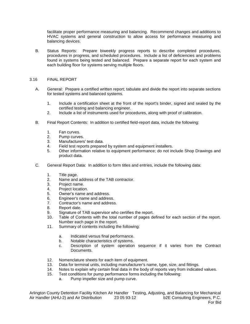
Arlington County Detention Facility Kitchen Air Handler Testing, Adjusting, and Balancing for Mechanical Air Handler (AHU-2) and Air Distribution 23 05 93-12 b2E Consulting Engineers, P.C.
For Bid
facilitate proper performance measuring and balancing. Recommend changes and additions to HVAC systems and general construction to allow access for performance measuring and balancing devices.
B. Status Reports: Prepare biweekly progress reports to describe completed procedures, procedures in progress, and scheduled procedures. Include a list of deficiencies and problems found in systems being tested and balanced. Prepare a separate report for each system and each building floor for systems serving multiple floors.
3.16 FINAL REPORT
A. General: Prepare a certified written report; tabulate and divide the report into separate sections for tested systems and balanced systems.
1. Include a certification sheet at the front of the report's binder, signed and sealed by the certified testing and balancing engineer.
2. Include a list of instruments used for procedures, along with proof of calibration.
B. Final Report Contents: In addition to certified field-report data, include the following:
1. Fan curves. 2. Pump curves. 3. Manufacturers' test data. 4. Field test reports prepared by system and equipment installers. 5. Other information relative to equipment performance; do not include Shop Drawings and
product data.
C. General Report Data: In addition to form titles and entries, include the following data:
1. Title page. 2. Name and address of the TAB contractor. 3. Project name. 4. Project location. 5. Owner’s name and address. 6. Engineer's name and address. 7. Contractor's name and address. 8. Report date. 9. Signature of TAB supervisor who certifies the report. 10. Table of Contents with the total number of pages defined for each section of the report.
Number each page in the report. 11. Summary of contents including the following:
a. Indicated versus final performance. b. Notable characteristics of systems. c. Description of system operation sequence if it varies from the Contract
Documents.
12. Nomenclature sheets for each item of equipment. 13. Data for terminal units, including manufacturer's name, type, size, and fittings. 14. Notes to explain why certain final data in the body of reports vary from indicated values. 15. Test conditions for pump performance forms including the following:
a. Pump impeller size and pump curve.
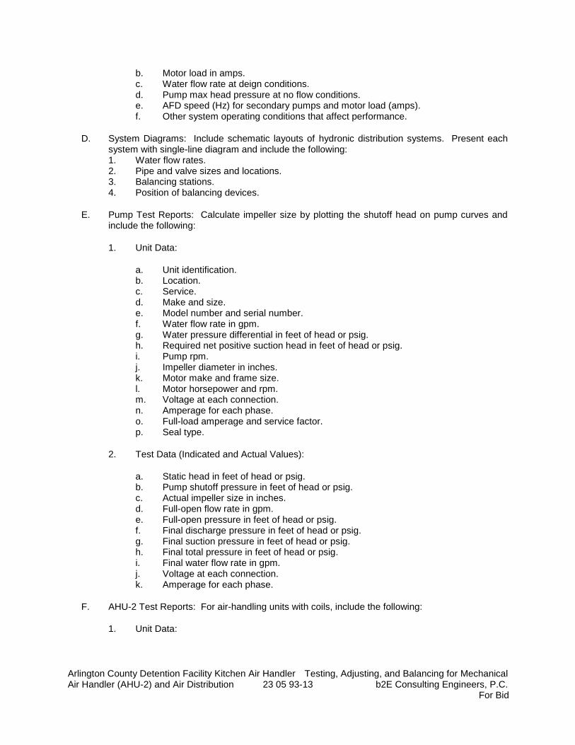
Arlington County Detention Facility Kitchen Air Handler Testing, Adjusting, and Balancing for Mechanical Air Handler (AHU-2) and Air Distribution 23 05 93-13 b2E Consulting Engineers, P.C.
For Bid
b. Motor load in amps. c. Water flow rate at deign conditions. d. Pump max head pressure at no flow conditions. e. AFD speed (Hz) for secondary pumps and motor load (amps). f. Other system operating conditions that affect performance.
D. System Diagrams: Include schematic layouts of hydronic distribution systems. Present each system with single-line diagram and include the following: 1. Water flow rates. 2. Pipe and valve sizes and locations. 3. Balancing stations. 4. Position of balancing devices.
E. Pump Test Reports: Calculate impeller size by plotting the shutoff head on pump curves and include the following:
1. Unit Data:
a. Unit identification. b. Location. c. Service. d. Make and size. e. Model number and serial number. f. Water flow rate in gpm. g. Water pressure differential in feet of head or psig. h. Required net positive suction head in feet of head or psig. i. Pump rpm. j. Impeller diameter in inches. k. Motor make and frame size. l. Motor horsepower and rpm. m. Voltage at each connection. n. Amperage for each phase. o. Full-load amperage and service factor. p. Seal type.
2. Test Data (Indicated and Actual Values):
a. Static head in feet of head or psig. b. Pump shutoff pressure in feet of head or psig. c. Actual impeller size in inches. d. Full-open flow rate in gpm. e. Full-open pressure in feet of head or psig. f. Final discharge pressure in feet of head or psig. g. Final suction pressure in feet of head or psig. h. Final total pressure in feet of head or psig. i. Final water flow rate in gpm. j. Voltage at each connection. k. Amperage for each phase.
F. AHU-2 Test Reports: For air-handling units with coils, include the following:
1. Unit Data:
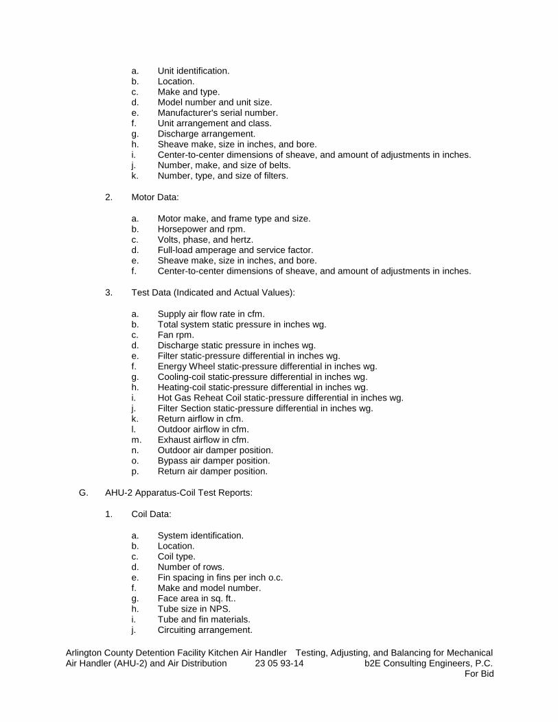
Arlington County Detention Facility Kitchen Air Handler Testing, Adjusting, and Balancing for Mechanical Air Handler (AHU-2) and Air Distribution 23 05 93-14 b2E Consulting Engineers, P.C.
For Bid
a. Unit identification. b. Location. c. Make and type. d. Model number and unit size. e. Manufacturer's serial number. f. Unit arrangement and class. g. Discharge arrangement. h. Sheave make, size in inches, and bore. i. Center-to-center dimensions of sheave, and amount of adjustments in inches. j. Number, make, and size of belts. k. Number, type, and size of filters.
2. Motor Data:
a. Motor make, and frame type and size. b. Horsepower and rpm. c. Volts, phase, and hertz. d. Full-load amperage and service factor. e. Sheave make, size in inches, and bore. f. Center-to-center dimensions of sheave, and amount of adjustments in inches.
3. Test Data (Indicated and Actual Values):
a. Supply air flow rate in cfm. b. Total system static pressure in inches wg. c. Fan rpm. d. Discharge static pressure in inches wg. e. Filter static-pressure differential in inches wg. f. Energy Wheel static-pressure differential in inches wg. g. Cooling-coil static-pressure differential in inches wg. h. Heating-coil static-pressure differential in inches wg. i. Hot Gas Reheat Coil static-pressure differential in inches wg. j. Filter Section static-pressure differential in inches wg. k. Return airflow in cfm. l. Outdoor airflow in cfm. m. Exhaust airflow in cfm. n. Outdoor air damper position. o. Bypass air damper position. p. Return air damper position.
G. AHU-2 Apparatus-Coil Test Reports:
1. Coil Data:
a. System identification. b. Location. c. Coil type. d. Number of rows. e. Fin spacing in fins per inch o.c. f. Make and model number. g. Face area in sq. ft.. h. Tube size in NPS. i. Tube and fin materials. j. Circuiting arrangement.
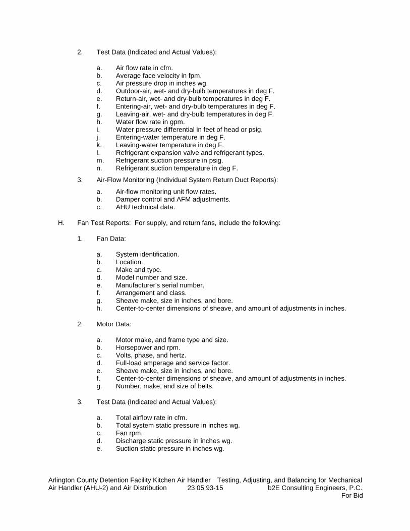
Arlington County Detention Facility Kitchen Air Handler Testing, Adjusting, and Balancing for Mechanical Air Handler (AHU-2) and Air Distribution 23 05 93-15 b2E Consulting Engineers, P.C.
For Bid
2. Test Data (Indicated and Actual Values):
a. Air flow rate in cfm. b. Average face velocity in fpm. c. Air pressure drop in inches wg. d. Outdoor-air, wet- and dry-bulb temperatures in deg F. e. Return-air, wet- and dry-bulb temperatures in deg F. f. Entering-air, wet- and dry-bulb temperatures in deg F. g. Leaving-air, wet- and dry-bulb temperatures in deg F. h. Water flow rate in gpm. i. Water pressure differential in feet of head or psig. j. Entering-water temperature in deg F. k. Leaving-water temperature in deg F. l. Refrigerant expansion valve and refrigerant types. m. Refrigerant suction pressure in psig. n. Refrigerant suction temperature in deg F.
3. Air-Flow Monitoring (Individual System Return Duct Reports):
a. Air-flow monitoring unit flow rates. b. Damper control and AFM adjustments. c. AHU technical data.
H. Fan Test Reports: For supply, and return fans, include the following:
1. Fan Data:
a. System identification. b. Location. c. Make and type. d. Model number and size. e. Manufacturer's serial number. f. Arrangement and class. g. Sheave make, size in inches, and bore. h. Center-to-center dimensions of sheave, and amount of adjustments in inches.
2. Motor Data:
a. Motor make, and frame type and size. b. Horsepower and rpm. c. Volts, phase, and hertz. d. Full-load amperage and service factor. e. Sheave make, size in inches, and bore. f. Center-to-center dimensions of sheave, and amount of adjustments in inches. g. Number, make, and size of belts.
3. Test Data (Indicated and Actual Values):
a. Total airflow rate in cfm. b. Total system static pressure in inches wg. c. Fan rpm. d. Discharge static pressure in inches wg. e. Suction static pressure in inches wg.
Arlington County Detention Facility Kitchen Air Handler Testing, Adjusting, and Balancing for Mechanical Air Handler (AHU-2) and Air Distribution 23 05 93-16 b2E Consulting Engineers, P.C.
For Bid
I. Round and Rectangular Duct Traverse Reports: Include a diagram with a grid representing the duct cross-section and record the following:
1. Report Data:
a. System and air-handling-unit number. b. Location and zone. c. Traverse air temperature in deg F. d. Duct static pressure in inches wg. e. Duct size in inches. f. Duct area in sq. ft.. g. Indicated air flow rate in cfm. h. Indicated velocity in fpm. i. Actual air flow rate in cfm. j. Actual average velocity in fpm. k. Barometric pressure in psig.
J. Air-Terminal-Device Reports (Provide one report for each VAV box):
1. Unit Data:
a. System and air-handling unit identification. b. Location and zone. c. Test apparatus used. d. Area served. e. Air-terminal-device make. f. Air-terminal-device number from system diagram. g. Air-terminal-device type and model number. h. Air-terminal-device size. i. Air-terminal-device effective area in sq. ft..
2. Air-Side Test Data (Indicated and Actual Values):
a. Airflow rate in cfm. b. Air velocity in fpm. c. Preliminary airflow rate as needed in cfm. d. Preliminary velocity as needed in fpm. e. Final airflow rate in cfm at minimum and maximum damper position. f. Final velocity in fpm. g. Space temperature in deg F. h. Discharge Air Temperature in deg F. i. Hot Water flow rate in gpm. j. Hot Water pressure loss in ft wc.
K. Pump Test Reports: Calculate impeller size by plotting the shutoff head on pump curves and include the following:
1. Unit Data:
a. Unit identification. b. Location. c. Service. d. Make and size.
Arlington County Detention Facility Kitchen Air Handler Testing, Adjusting, and Balancing for Mechanical Air Handler (AHU-2) and Air Distribution 23 05 93-17 b2E Consulting Engineers, P.C.
For Bid
e. Model and serial numbers. f. Water flow rate in gpm (L/s). g. Water pressure differential in feet of head or psig (kPa). h. Required net positive suction head in feet of head or psig (kPa). i. Pump rpm. j. Impeller diameter in inches (mm). k. Motor make and frame size. l. Motor horsepower and rpm. m. Voltage at each connection. n. Amperage for each phase. o. Full-load amperage and service factor. p. Seal type.
2. Test Data (Indicated and Actual Values):
a. Static head in feet of head or psig (kPa). b. Pump shutoff pressure in feet of head or psig (kPa). c. Actual impeller size in inches (mm). d. Full-open flow rate in gpm (L/s). e. Full-open pressure in feet of head or psig (kPa). f. Final discharge pressure in feet of head or psig (kPa). g. Final suction pressure in feet of head or psig (kPa). h. Final total pressure in feet of head or psig (kPa). i. Final water flow rate in gpm (L/s). j. Voltage at each connection. k. Amperage for each phase.
L. Return Fan Test Reports:
1. Unit Data:
a. System and air-handling unit identification. b. Location and zone. c. Apparatus used for test. d. Area served. e. Make. f. Number from system diagram. g. Type and model number. h. Size. i. Effective area in sq. ft.
2. Test Data (Indicated and Actual Values):
a. Air flow rate in cfm. b. Air velocity in fpm. c. Preliminary air flow rate as needed in cfm. d. Preliminary velocity as needed in fpm. e. Preliminary static pressure in inches water column (in-wg.). f. Final air flow rate in cfm. g. Final velocity in fpm. h. Final static pressure in inches water column (in-wg.). i. Space temperature in deg F.
Arlington County Detention Facility Kitchen Air Handler Testing, Adjusting, and Balancing for Mechanical Air Handler (AHU-2) and Air Distribution 23 05 93-18 b2E Consulting Engineers, P.C.
For Bid
M. Instrument Calibration Reports:
1. Report Data:
a. Instrument type and make. b. Serial number. c. Application. d. Dates of use. e. Dates of calibration.
3.17 INSPECTIONS
A. Initial Inspection:
1. After testing and balancing are complete, operate each system and randomly check measurements to verify that the system is operating according to the final test and balance readings documented in the final report.
2. Check the following for each system: a. Measure water temperature at each temperature sensor. Compare the reading to
the set point. b. Verify that balancing devices are marked with final balance position. c. Note deviations from the Contract Documents in the final report.
B. Final Inspection:
1. After initial inspection is complete and documentation by random checks verifies that testing and balancing are complete and accurately documented in the final report, request that a final inspection be made by Commissioning Agent.
2. The TAB contractor's test and balance engineer shall conduct the inspection in the presence of Commissioning Agent.
3. Commissioning Agent shall randomly select measurements, documented in the final report, to be rechecked. Rechecking shall be 100 percent of the total measurements recorded.
4. If rechecks yield measurements that differ from the measurements documented in the final report by more than the tolerances allowed, the measurements shall be noted as "FAILED."
5. If the number of "FAILED" measurements is greater than 20 percent of the total measurements checked during the final inspection, the testing and balancing shall be considered incomplete and shall be rejected.
C. TAB Work will be considered defective if it does not pass final inspections. If TAB Work fails, proceed as follows:
1. Recheck all measurements and make adjustments. Revise the final report and balancing device settings to include all changes; resubmit the final report and request a second final inspection.
2. If the second final inspection also fails, Owner may contract the services of another TAB contractor to complete TAB Work according to the Contract Documents and deduct the cost of the services from the original TAB contractor's final payment.
D. Prepare test and inspection reports.
Arlington County Detention Facility Kitchen Air Handler Testing, Adjusting, and Balancing for Mechanical Air Handler (AHU-2) and Air Distribution 23 05 93-19 b2E Consulting Engineers, P.C.
For Bid
3.18 ADDITIONAL TESTS
A. Within 90 days of completing TAB, perform additional TAB to verify that balanced conditions are being maintained throughout and to correct unusual conditions.
B. Seasonal Periods: If initial TAB procedures were not performed during near-peak summer and winter conditions, perform additional TAB during near-peak summer and winter conditions.
C. Warranty Period: TAB services may be required during the Warranty Period to facilitate resolution of deficiencies or malfunctions that occur during the Warranty Period. Perform TAB services during the Warranty Period as deemed necessary by the Architect or Engineer. If the TAB report is found to have errors during the Warranty Period, the TAB firms hall repeat the requirements of the Initial Inspection as needed to the satisfaction of the Owner and generate a new Final Report.
3.19 COMMISSIONING
A. Provide documentation support for commissioning activities, and support for functional performance testing as outlined in specification section 23 08 00 “Commissioning Plan”.
END OF SECTION 23 05 93

Arlington County Detention Facility Kitchen Air Handler Mechanical Insulation Air Handler (AHU-2) and Air Distribution 23 07 00-1 b2E Consulting Engineers, P.C.
For Bid
SECTION 23 07 00
MECHANICAL INSULATION
PART 1 - GENERAL
1.1 SUMMARY
A. Section Includes:
1. Insulation Materials: a. Mineral fiber.
2. Fire-rated insulation systems. 3. Insulating cements. 4. Adhesives. 5. Mastics. 6. Lagging adhesives. 7. Sealants. 8. Factory-applied jackets. 9. Field-applied fabric-reinforcing mesh. 10. Field-applied cloths. 11. Field-applied jackets. 12. Tapes. 13. Securements. 14. Corner angles. 15. Thermal shield inserts and fire retardant blocking.
1.2 SUBMITTALS
A. Product Data: For each type of product indicated. Include thermal conductivity, thickness, and jackets (both factory and field applied, if any).
B. Shop Drawings:
1. Detail application of protective shields, saddles, and inserts at hangers for each type of insulation and hanger.
2. Detail attachment and covering of heat tracing inside insulation. 3. Detail insulation application at pipe expansion joints for each type of insulation. 4. Detail insulation application at elbows, fittings, flanges, valves, and specialties for each
type of insulation. 5. Detail removable insulation at piping specialties, equipment connections, and access
panels. 6. Detail application of field-applied jackets. 7. Detail application at linkages of control devices. 8. Detail field application for each equipment type.
C. Samples: For each type of insulation and jacket indicated. Identify each Sample, describing product and intended use.
1. Sample Sizes:
Arlington County Detention Facility Kitchen Air Handler Mechanical Insulation Air Handler (AHU-2) and Air Distribution 23 07 00-2 b2E Consulting Engineers, P.C.
For Bid
a. Preformed Pipe Insulation Materials: 12 inches long by NPS 2 (DN 50). b. Sheet Form Insulation Materials: 12 inches square. c. Jacket Materials for Pipe: 12 inches long by NPS 2 (DN 50). d. Sheet Jacket Materials: 12 inches square. e. Manufacturer's Color Charts: For products where color is specified, show the full
range of colors available for each type of finish material.
D. Qualification Data: For qualified Installer.
E. Material Test Reports: From a qualified testing agency acceptable to authorities having jurisdiction indicating, interpreting, and certifying test results for compliance of insulation materials, sealers, attachments, cements, and jackets, with requirements indicated. Include dates of tests and test methods employed.
F. Field quality-control reports.
1.3 QUALITY ASSURANCE
A. Installer Qualifications: Skilled mechanics who have successfully completed an apprenticeship program or another craft training program certified by the Department of Labor, Bureau of Apprenticeship and Training.
B. Fire-Test-Response Characteristics: Insulation and related materials shall have fire-test-response characteristics indicated, as determined by testing identical products per ASTM E 84, by a testing and inspecting agency acceptable to authorities having jurisdiction. Factory label insulation and jacket materials and adhesive, mastic, tapes, and cement material containers, with appropriate markings of applicable testing and inspecting agency.
1. Insulation Installed Indoors: Flame-spread index of 25 or less, and smoke-developed index of 50 or less.
2. Insulation Installed Outdoors: Flame-spread index of 75 or less, and smoke-developed index of 150 or less.
1.4 DELIVERY, STORAGE, AND HANDLING
A. Packaging: Insulation material containers shall be marked by manufacturer with appropriate ASTM standard designation, type and grade, and maximum use temperature.
1.5 COORDINATION
A. Coordinate size and location of supports, hangers, and insulation shields specified in Division 23 Section "Hangers and Supports for HVAC Piping and Equipment."
B. Coordinate clearance requirements with piping Installer for piping insulation application, duct Installer for duct insulation application, and equipment Installer for equipment insulation application. Before preparing piping and ductwork Shop Drawings, establish and maintain clearance requirements for installation of insulation and field-applied jackets and finishes and for space required for maintenance.
C. Coordinate installation and testing of heat tracing.
Arlington County Detention Facility Kitchen Air Handler Mechanical Insulation Air Handler (AHU-2) and Air Distribution 23 07 00-3 b2E Consulting Engineers, P.C.
For Bid
1.6 SCHEDULING
A. Schedule insulation application after pressure testing systems and, where required, after installing and testing heat tracing. Insulation application may begin on segments that have satisfactory test results.
B. Complete installation and concealment of plastic materials as rapidly as possible in each area of construction.
PART 2 - PRODUCTS
2.1 INSULATION MATERIALS
A. Comply with requirements in Part 3 schedule articles for where insulating materials shall be applied.
B. Products shall not contain asbestos, lead, mercury, or mercury compounds.
C. Products that come in contact with stainless steel shall have a leachable chloride content of less than 50 ppm when tested according to ASTM C 871.
D. Insulation materials for use on austenitic stainless steel shall be qualified as acceptable according to ASTM C 795.
E. Foam insulation materials shall not use CFC or HCFC blowing agents in the manufacturing process.
F. Mineral-Fiber Blanket Insulation: Mineral or glass fibers bonded with a thermosetting resin. Comply with ASTM C 553, Type II and ASTM C 1290, Type I or III with factory-applied FSK jacket. Factory-applied jacket requirements are specified in "Factory-Applied Jackets" Article.
1. Products: Subject to compliance with requirements, provide one of the following:
a. CertainTeed Corp.; Duct Wrap. b. Johns Manville; Microlite. c. Knauf Insulation; Duct Wrap. d. Manson Insulation Inc.; Alley Wrap. e. Owens Corning; All-Service Duct Wrap.
G. Mineral-Fiber Board Insulation: Mineral or glass fibers bonded with a thermosetting resin. Comply with ASTM C 612, Type IA or Type IB. For duct and plenum applications, provide insulation with factory-applied FSK jacket. For equipment applications, provide insulation with factory-applied FSK jacket. Factory-applied jacket requirements are specified in "Factory-Applied Jackets" Article.
1. Acceptable Products: Subject to compliance with requirements, provide one of the following:
a. CertainTeed Corp.; Commercial Board. b. Fibrex Insulations Inc.; FBX. c. Johns Manville; 800 Series Spin-Glas. d. Knauf Insulation; Insulation Board. e. Manson Insulation Inc.; AK Board.
Arlington County Detention Facility Kitchen Air Handler Mechanical Insulation Air Handler (AHU-2) and Air Distribution 23 07 00-4 b2E Consulting Engineers, P.C.
For Bid
f. Owens Corning; Fiberglas 700 Series.
H. Mineral-Fiber, Preformed Pipe Insulation:
1. Acceptable Products: Subject to compliance with requirements, provide one of the following:
a. Owens Corning, Evolution. b. Johns Manville; Paper free with polymer face Micro-Lok. c. Knauf Insulation; Paper free with polymer face 1000 Pipe Insulation.
2. Type I, 850 deg F Materials: Mineral or glass fibers bonded with a thermosetting resin. Comply with ASTM C 547, Type I, Grade A, with factory-applied paper free ASJ and polymer facing. Factory-applied jacket requirements are specified in "Factory-Applied Jackets" Article.
3. Type II, 1200 deg F Materials: Mineral or glass fibers bonded with a thermosetting resin. Comply with ASTM C 547, Type II, Grade A, with factory-applied paper free ASJ and polymer facing. Factory-applied jacket requirements are specified in "Factory-Applied Jackets" Article.
I. Mineral-Fiber, Pipe and Tank Insulation: Mineral or glass fibers bonded with a thermosetting resin. Semirigid board material with factory-applied FSK jacket complying with ASTM C 1393, Type II or Type IIIA Category 2, or with properties similar to ASTM C 612, Type IB. Nominal density is 2.5 lb/cu. ft. or more. Thermal conductivity (k-value) at 100 deg F is 0.29 Btu x in./h x sq. ft. x deg F or less. Factory-applied jacket requirements are specified in "Factory-Applied Jackets" Article.
1. Products: Subject to compliance with requirements, provide one of the following:
a. CertainTeed Corp.; CrimpWrap. b. Johns Manville; MicroFlex. c. Knauf Insulation; Pipe and Tank Insulation. d. Manson Insulation Inc.; AK Flex. e. Owens Corning; Fiberglas Pipe and Tank Insulation.
2.2 INSULATING CEMENTS
A. Mineral-Fiber Insulating Cement: Comply with ASTM C 195.
1. Acceptable Products: Subject to compliance with requirements, provide one of the following:
a. Insulco, Division of MFS, Inc.; Triple I. b. P. K. Insulation Mfg. Co., Inc.; Super-Stik.
B. Expanded or Exfoliated Vermiculite Insulating Cement: Comply with ASTM C 196.
1. Acceptable Products: Subject to compliance with requirements, provide one of the following:
a. P. K. Insulation Mfg. Co., Inc.; Thermal-V-Kote.
C. Mineral-Fiber, Hydraulic-Setting Insulating and Finishing Cement: Comply with ASTM C 449/C 449M.
Arlington County Detention Facility Kitchen Air Handler Mechanical Insulation Air Handler (AHU-2) and Air Distribution 23 07 00-5 b2E Consulting Engineers, P.C.
For Bid
1. Acceptable Products: Subject to compliance with requirements, provide one of the following:
a. Insulco, Division of MFS, Inc.; SmoothKote. b. P. K. Insulation Mfg. Co., Inc.; PK No. 127, and Quik-Cote. c. Rock Wool Manufacturing Company; Delta One Shot.
2.3 ADHESIVES
A. Materials shall be compatible with insulation materials, jackets, and substrates and for bonding insulation to itself and to surfaces to be insulated, unless otherwise indicated.
B. Cellular-Glass, Phenolic, Polyisocyanurate, and Polystyrene Adhesive: Solvent-based resin adhesive, with a service temperature range of minus 75 to plus 300 deg F.
1. Acceptable Products: Subject to compliance with requirements, provide one of the following:
a. Childers Products, Division of ITW; CP-96. b. Foster Products Corporation, H. B. Fuller Company; 81-33.
2. For indoor applications, use adhesive that has a VOC content of 50 g/L or less when calculated according to 40 CFR 59, Subpart D (EPA Method 24).
C. Mineral-Fiber Adhesive: Comply with MIL-A-3316C, Class 2, Grade A.
1. Acceptable Products: Subject to compliance with requirements, provide one of the following:
a. Childers Products, Division of ITW; CP-82. b. Foster Products Corporation, H. B. Fuller Company; 85-20. c. ITW TACC, Division of Illinois Tool Works; S-90/80. d. Marathon Industries, Inc.; 225. e. Mon-Eco Industries, Inc.; 22-25.
2. For indoor applications, use adhesive that has a VOC content of 80 g/L or less when calculated according to 40 CFR 59, Subpart D (EPA Method 24).
D. ASJ Adhesive, and FSK Jacket Adhesive: Comply with MIL-A-3316C, Class 2, Grade A for bonding insulation jacket lap seams and joints.
1. Acceptable Products: Subject to compliance with requirements, provide one of the following:
a. Childers Products, Division of ITW; CP-82. b. Foster Products Corporation, H. B. Fuller Company; 85-20. c. ITW TACC, Division of Illinois Tool Works; S-90/80. d. Marathon Industries, Inc.; 225. e. Mon-Eco Industries, Inc.; 22-25.
2. For indoor applications, use adhesive that has a VOC content of 50 g/L or less when calculated according to 40 CFR 59, Subpart D (EPA Method 24).
E. “Venture Clad” Jacket Adhesive: Compatible with “Venture Clad” jacket.
Arlington County Detention Facility Kitchen Air Handler Mechanical Insulation Air Handler (AHU-2) and Air Distribution 23 07 00-6 b2E Consulting Engineers, P.C.
For Bid
1. Acceptable Products: Subject to compliance with requirements, provide one of the following:
a. Dow Chemical Company (The); 739, Dow Silicone. b. Johns-Manville; Zeston Perma-Weld, CEEL-TITE Solvent Welding Adhesive. c. P.I.C. Plastics, Inc.; Welding Adhesive. d. Speedline Corporation; Speedline Vinyl Adhesive. e. “Venture Clad” recommended adhesive.
2. For indoor applications, use adhesive that has a VOC content of 50 g/L or less when calculated according to 40 CFR 59, Subpart D (EPA Method 24).
2.4 MASTICS
A. Materials shall be compatible with insulation materials, jackets, and substrates; comply with MIL-C-19565C, Type II.
1. For indoor applications, use mastics that have a VOC content of 80 g/L or less when calculated according to 40 CFR 59, Subpart D (EPA Method 24).
B. Vapor-Barrier Mastic: Water based; suitable for indoor and outdoor use on below ambient services.
1. Acceptable Products: Subject to compliance with requirements, provide one of the following:
a. Childers Products, Division of ITW; CP-35. b. Foster Products Corporation, H. B. Fuller Company; 30-90. c. ITW TACC, Division of Illinois Tool Works; CB-50. d. Marathon Industries, Inc.; 590. e. Mon-Eco Industries, Inc.; 55-40. f. Vimasco Corporation; 749.
2. Water-Vapor Permeance: ASTM E 96, Procedure B, 0.013 perm at 43-mil dry film thickness.
3. Service Temperature Range: Minus 20 to plus 180 deg F. 4. Solids Content: ASTM D 1644, 59 percent by volume and 71 percent by weight. 5. Color: White.
C. Vapor-Barrier Mastic: Solvent based; suitable for indoor use on below ambient services.
1. Acceptable Products: Subject to compliance with requirements, provide one of the following:
a. Childers Products, Division of ITW; CP-30. b. Foster Products Corporation, H. B. Fuller Company; 30-35. c. ITW TACC, Division of Illinois Tool Works; CB-25. d. Marathon Industries, Inc.; 501. e. Mon-Eco Industries, Inc.; 55-10.
2. Water-Vapor Permeance: ASTM F 1249, 0.05 perm at 35-mil dry film thickness. 3. Service Temperature Range: 0 to 180 deg F. 4. Solids Content: ASTM D 1644, 44 percent by volume and 62 percent by weight.
Arlington County Detention Facility Kitchen Air Handler Mechanical Insulation Air Handler (AHU-2) and Air Distribution 23 07 00-7 b2E Consulting Engineers, P.C.
For Bid
5. Color: White.
D. Vapor-Barrier Mastic: Solvent based; suitable for outdoor use on below ambient services.
1. Acceptable Products: Subject to compliance with requirements provide one of the following:
a. Childers Products, Division of ITW; Encacel. b. Foster Products Corporation, H. B. Fuller Company; 60-95/60-96. c. Marathon Industries, Inc.; 570. d. Mon-Eco Industries, Inc.; 55-70.
2. Water-Vapor Permeance: ASTM F 1249, 0.05 perm at 30-mil dry film thickness. 3. Service Temperature Range: Minus 50 to plus 220 deg F. 4. Solids Content: ASTM D 1644, 33 percent by volume and 46 percent by weight. 5. Color: White.
E. Breather Mastic: Water based; suitable for indoor and outdoor use on above ambient services.
1. Acceptable Products: Subject to compliance with requirements, provide one of the following:
a. Childers Products, Division of ITW; CP-10. b. Foster Products Corporation, H. B. Fuller Company; 35-00. c. ITW TACC, Division of Illinois Tool Works; CB-05/15. d. Marathon Industries, Inc.; 550. e. Mon-Eco Industries, Inc.; 55-50. f. Vimasco Corporation; WC-1/WC-5.
2. Water-Vapor Permeance: ASTM F 1249, 3 perms at 0.0625-inch dry film thickness. 3. Service Temperature Range: Minus 20 to plus 200 deg F. 4. Solids Content: 63 percent by volume and 73 percent by weight. 5. Color: White.
2.5 LAGGING ADHESIVES
A. Description: Comply with MIL-A-3316C Class I, Grade A and shall be compatible with insulation materials, jackets, and substrates.
1. For indoor applications, use lagging adhesives that have a VOC content of 80 g/L or less when calculated according to 40 CFR 59, Subpart D (EPA Method 24).
2. Acceptable Products: Subject to compliance with requirements, provide one of the following:
a. Childers Products, Division of ITW; CP-52. b. Foster Products Corporation, H. B. Fuller Company; 81-42. c. Marathon Industries, Inc.; 130. d. Mon-Eco Industries, Inc.; 11-30. e. Vimasco Corporation; 136.
3. Fire-resistant, water-based lagging adhesive and coating for use indoors to adhere fire-resistant lagging cloths over duct, equipment, and pipe insulation.
4. Service Temperature Range: Minus 50 to plus 180 deg F. 5. Color: White.
Arlington County Detention Facility Kitchen Air Handler Mechanical Insulation Air Handler (AHU-2) and Air Distribution 23 07 00-8 b2E Consulting Engineers, P.C.
For Bid
2.6 SEALANTS
A. Joint Sealants:
1. Joint Sealants for Cellular-Glass, Phenolic, and Polyisocyanurate Products: Subject to compliance with requirements, provide one of the following:
a. Childers Products, Division of ITW; CP-76. b. Foster Products Corporation, H. B. Fuller Company; 30-45. c. Marathon Industries, Inc.; 405. d. Mon-Eco Industries, Inc.; 44-05. e. Pittsburgh Corning Corporation; Pittseal 444. f. Vimasco Corporation; 750.
B. FSK and Metal Jacket Flashing Sealants:
1. Products: Subject to compliance with requirements, provide one of the following:
a. Childers Products, Division of ITW; CP-76-8. b. Foster Products Corporation, H. B. Fuller Company; 95-44. c. Marathon Industries, Inc.; 405. d. Mon-Eco Industries, Inc.; 44-05. e. Vimasco Corporation; 750.
2. Materials shall be compatible with insulation materials, jackets, and substrates. 3. Fire- and water-resistant, flexible, elastomeric sealant. 4. Service Temperature Range: Minus 40 to plus 250 deg F. 5. Color: Aluminum. 6. For indoor applications, use sealants that have a VOC content of 250 g/L or less when
calculated according to 40 CFR 59, Subpart D (EPA Method 24).
C. ASJ Flashing Sealants, and ”Venture Clad” Jacket Flashing Sealants:
1. Products: Subject to compliance with requirements, provide one of the following:
a. Childers Products, Division of ITW; CP-76. b. “Venture Clad” recommended sealants.
2. Materials shall be compatible with insulation materials, jackets, and substrates. 3. Fire- and water-resistant, flexible, elastomeric sealant. 4. Service Temperature Range: Minus 40 to plus 250 deg F. 5. Color: White. 6. For indoor applications, use sealants that have a VOC content of 250 g/L or less when
calculated according to 40 CFR 59, Subpart D (EPA Method 24).
2.7 FACTORY-APPLIED JACKETS
A. Insulation system schedules indicate factory-applied jackets on various applications. When factory-applied jackets are indicated, comply with the following: 1. ASJ-paper free polymer facing: ASJ with self-sealing, pressure-sensitive, acrylic-based
adhesive covered by a removable protective strip; complying with ASTM C 1136, Type I and ASTM C 1338 to prevent mold growth, and microbial resistant when treated by the “Greenguard Environmental Institute”.
Arlington County Detention Facility Kitchen Air Handler Mechanical Insulation Air Handler (AHU-2) and Air Distribution 23 07 00-9 b2E Consulting Engineers, P.C.
For Bid
2. FSK Jacket: Aluminum-foil, fiberglass-reinforced scrim with kraft-paper backing; complying with ASTM C 1136, Type II.
2.8 FIELD-APPLIED FABRIC-REINFORCING MESH
A. Woven Glass-Fiber Fabric for Pipe Insulation: Approximately 2 oz./sq. yd. with a thread count of 10 strands by 10 strands/sq. inch for covering pipe and pipe fittings.
1. Acceptable Products: Subject to compliance with requirements, provide one of the following:
a. Vimasco Corporation; Elastafab 894.
B. Woven Glass-Fiber Fabric for Duct and Equipment Insulation: Approximately 6 oz./sq. yd. with a thread count of 5 strands by 5 strands/sq. inch for covering equipment.
1. Acceptable Products: Subject to compliance with requirements, provide one of the following:
a. Childers Products, Division of ITW; Chil-Glas No. 5.
C. Woven Polyester Fabric: Approximately 1 oz./sq. yd. with a thread count of 10 strands by 10 strands/sq. inch, in a Leno weave, for duct, equipment, and pipe.
1. Acceptable Products: Subject to compliance with requirements, provide one of the following:
a. Foster Products Corporation, H. B. Fuller Company; Mast-A-Fab. b. Vimasco Corporation; Elastafab 894.
2.9 FIELD-APPLIED CLOTHS
A. Woven Glass-Fiber Fabric: Comply with MIL-C-20079H, Type I, plain weave, and presized a minimum of 8 oz./sq. yd.
1. Acceptable Products: Subject to compliance with requirements, provide one of the following:
a. Alpha Associates, Inc.; Alpha-Maritex 84215 and 84217/9485RW, Luben 59.
2.10 FIELD-APPLIED JACKETS
A. Field-applied jackets shall comply with ASTM C 921, Type I, unless otherwise indicated.
B. Metal Jacket:
1. Products: Subject to compliance with requirements, provide one of the following:
a. Childers Products, Division of ITW; Metal Jacketing Systems. b. PABCO Metals Corporation; Surefit. c. RPR Products, Inc.; Insul-Mate.
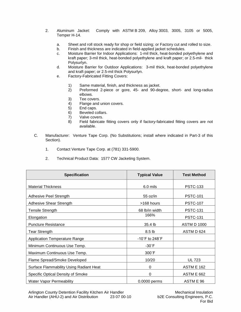
Arlington County Detention Facility Kitchen Air Handler Mechanical Insulation Air Handler (AHU-2) and Air Distribution 23 07 00-10 b2E Consulting Engineers, P.C.
For Bid
2. Aluminum Jacket: Comply with ASTM B 209, Alloy 3003, 3005, 3105 or 5005, Temper H-14.
a. Sheet and roll stock ready for shop or field sizing; or Factory cut and rolled to size. b. Finish and thickness are indicated in field-applied jacket schedules. c. Moisture Barrier for Indoor Applications: 1-mil thick, heat-bonded polyethylene and
kraft paper; 3-mil thick, heat-bonded polyethylene and kraft paper; or 2.5-mil- thick Polysurlyn.
d. Moisture Barrier for Outdoor Applications: 3-mil thick, heat-bonded polyethylene and kraft paper; or 2.5-mil thick Polysurlyn.
e. Factory-Fabricated Fitting Covers:
1) Same material, finish, and thickness as jacket. 2) Preformed 2-piece or gore, 45- and 90-degree, short- and long-radius
elbows. 3) Tee covers. 4) Flange and union covers. 5) End caps. 6) Beveled collars. 7) Valve covers. 8) Field fabricate fitting covers only if factory-fabricated fitting covers are not
available.
C. Manufacturer: Venture Tape Corp. (No Substitutions; install where indicated in Part-3 of this Section).
1. Contact Venture Tape Corp. at (781) 331-5900.
2. Technical Product Data: 1577 CW Jacketing System.
Specification Typical Value Test Method
Material Thickness 6.0 mils PSTC-133
Adhesive Peel Strength 55 oz/in PSTC-101
Adhesive Shear Strength >168 hours PSTC-107
Tensile Strength 68 lb/in width PSTC-131
Elongation 166%
PSTC-131
Puncture Resistance 35.4 lb ASTM D 1000
Tear Strength 8.5 lb ASTM D 624
Application Temperature Range -10˚F to 248˚F
Minimum Continuous Use Temp. -30˚F
Maximum Continuous Use Temp. 300˚F
Flame Spread/Smoke Developed 10/20 UL 723
Surface Flammability Using Radiant Heat 0 ASTM E 162
Specific Optical Density of Smoke 0 ASTM E 662
Water Vapor Permeability 0.0000 perms ASTM E 96

Arlington County Detention Facility Kitchen Air Handler Mechanical Insulation Air Handler (AHU-2) and Air Distribution 23 07 00-11 b2E Consulting Engineers, P.C.
For Bid
2.11 TAPES
A. ASJ Tape: White vapor-retarder tape matching factory-applied jacket with acrylic adhesive, complying with ASTM C 1136.
1. Products: Subject to compliance with requirements, provide one of the following:
a. Avery Dennison Corporation, Specialty Tapes Division; Fasson 0835. b. Compac Corp.; 104 and 105. c. Ideal Tape Co., Inc., an American Biltrite Company; 428 AWF ASJ. d. Venture Tape; 1540 CW Plus, 1542 CW Plus, and 1542 CW Plus/SQ.
2. Width: 3 inches. 3. Thickness: 11.5 mils. 4. Adhesion: 90 ounces force/inch in width. 5. Elongation: 2 percent. 6. Tensile Strength: 40 lbf/inch in width. 7. ASJ Tape Disks and Squares: Precut disks or squares of ASJ tape.
B. FSK Tape: Foil-face, vapor-retarder tape matching factory-applied jacket with acrylic adhesive; complying with ASTM C 1136.
1. Products: Subject to compliance with requirements, provide one of the following:
a. Avery Dennison Corporation, Specialty Tapes Division; Fasson 0827. b. Compac Corp.; 110 and 111. c. Ideal Tape Co., Inc., an American Biltrite Company; 491 AWF FSK. d. Venture Tape; 1525 CW, 1528 CW, and 1528 CW/SQ.
2. Width: 3 inches. 3. Thickness: 6.5 mils. 4. Adhesion: 90 ounces force/inch in width. 5. Elongation: 2 percent. 6. Tensile Strength: 40 lbf/inch in width. 7. FSK Tape Disks and Squares: Precut disks or squares of FSK tape.
C. Aluminum-Foil Tape: Vapor-retarder tape with acrylic adhesive.
1. Products: Subject to compliance with requirements, provide one of the following:
a. Avery Dennison Corporation, Specialty Tapes Division; Fasson 0800. b. Compac Corp.; 120. c. Ideal Tape Co., Inc., an American Biltrite Company; 488 AWF. d. Venture Tape; 3520 CW.
2. Width: 2 inches. 3. Thickness: 3.7 mils. 4. Adhesion: 100 ounces force/inch in width. 5. Elongation: 5 percent. 6. Tensile Strength: 34 lbf/inch in width.
2.12 SECUREMENTS
A. Bands:
Arlington County Detention Facility Kitchen Air Handler Mechanical Insulation Air Handler (AHU-2) and Air Distribution 23 07 00-12 b2E Consulting Engineers, P.C.
For Bid
1. Products: Subject to compliance with requirements, provide one of the following: a. Childers Products; Bands. b. PABCO Metals Corporation; Bands. c. RPR Products, Inc.; Bands.
2. Stainless Steel: ASTM A 167 or ASTM A 240/A 240M, Type 304 or Type 316; 0.015 inch thick, 1/2 inch or 3/4 inch wide with wing or closed seal.
3. Aluminum: ASTM B 209 (ASTM B 209M), Alloy 3003, 3005, 3105, or 5005; Temper H-14, 0.020 inch thick, 1/2 inch or 3/4 inch wide with wing or closed seal.
4. Springs: Twin spring set constructed of stainless steel with ends flat and slotted to accept metal bands. Spring size determined by manufacturer for application.
2.13 THERMAL SADDLES AND FIRE RETARDANT WOOD/FIBERGLASS BLOCKING FOR PIPING
A. Domestic Cold Water (Condensing): Provide insulation protection saddles and fiberglass or foam glass inserts matching insulation thickness at each hanger or support location.
B. Fire-Rated Fiberglass or Foam Glass Blocking: Provide strips of under pipe matching length of saddle (or min. 12 inches long). Insulation must be cut exactly to match dimension of blocking. Blocking shall be factory fabricated to exact thickness of insulation and installed in preformed pipe insulation. Provide quantity of blocks at each hanger or support location in accordance with the factory manufacturer’s recommendations for each pipe size.
C. Refer to Section 23 05 29 for “Hangers and Supports” where saddles and inserts are specified.
2.14 Hot Water and Chilled Water: Provide insulation protection saddles and thermal hanger shield, wood block or fiberglass block inserts matching insulation thickness at each hanger or support location.
1. Hot Water Piping: Provide thermal hanger shield inserts for steel piping and wood blocking for copper tubing.
2. Chilled Water Piping: Provide fiberglass blocking for steel piping and for copper tubing.
PART 3 - EXECUTION
3.1 EXAMINATION
A. Examine substrates and conditions for compliance with requirements for installation and other conditions affecting performance of insulation application.
1. Verify that systems and equipment to be insulated have been tested and are free of defects.
2. Verify that surfaces to be insulated are clean and dry. 3. Proceed with installation only after unsatisfactory conditions have been corrected.
3.2 PREPARATION
A. Surface Preparation: Clean and dry surfaces to receive insulation. Remove materials that will adversely affect insulation application.
Arlington County Detention Facility Kitchen Air Handler Mechanical Insulation Air Handler (AHU-2) and Air Distribution 23 07 00-13 b2E Consulting Engineers, P.C.
For Bid
B. Surface Preparation: Clean and prepare surfaces to be insulated. Before insulating, apply a corrosion coating to insulated surfaces as follows:
1. Stainless Steel: Coat 300 series stainless steel with an epoxy primer 5 mils thick and an epoxy finish 5 mils thick if operating in a temperature range between 140 and 300 deg F. Consult coating manufacturer for appropriate coating materials and application methods for operating temperature range.
2. Carbon Steel: Coat carbon steel operating at a service temperature between 32 and 300 deg Fwith an epoxy coating. Consult coating manufacturer for appropriate coating materials and application methods for operating temperature range.
C. Coordinate insulation installation with the trade installing heat tracing. Comply with requirements for heat tracing that apply to insulation.
D. Mix insulating cements with clean potable water; if insulating cements are to be in contact with stainless-steel surfaces, use de-mineralized water.
3.3 GENERAL INSTALLATION REQUIREMENTS
A. Install insulation materials, accessories, and finishes with smooth, straight, and even surfaces; free of voids throughout the length of equipment, and piping including fittings, valves, and specialties.
B. Install insulation materials, forms, vapor barriers or retarders, jackets, and thicknesses required for each item of equipment, and pipe system as specified in insulation system schedules.
C. Install accessories compatible with insulation materials and suitable for the service. Install accessories that do not corrode, soften, or otherwise attack insulation or jacket in either wet or dry state.
D. Install insulation with longitudinal seams at top and bottom of horizontal runs.
E. Install multiple layers of insulation with longitudinal and end seams staggered.
F. Do not weld brackets, clips, or other attachment devices to piping, fittings, and specialties.
G. Keep insulation materials dry during application and finishing.
H. Install insulation with tight longitudinal seams and end joints. Bond seams and joints with adhesive recommended by insulation material manufacturer.
I. Install insulation with least number of joints practical.
J. Where vapor barrier is indicated, seal joints, seams, and penetrations in insulation at hangers, supports, anchors, and other projections with vapor-barrier mastic.
1. Install insulation continuously through hangers and around anchor attachments. 2. For insulation application where vapor barriers are indicated, extend insulation on anchor
legs from point of attachment to supported item to point of attachment to structure. Taper and seal ends at attachment to structure with vapor-barrier mastic.
3. Install insert materials and install insulation to tightly join the insert. Seal insulation to insulation inserts with adhesive or sealing compound recommended by insulation material manufacturer.
Arlington County Detention Facility Kitchen Air Handler Mechanical Insulation Air Handler (AHU-2) and Air Distribution 23 07 00-14 b2E Consulting Engineers, P.C.
For Bid
4. Cover inserts with jacket material matching adjacent pipe insulation. Install shields over jacket, arranged to protect jacket from tear or puncture by hanger, support, and shield.
K. Apply adhesives, mastics, and sealants at manufacturer's recommended coverage rate and wet and dry film thicknesses.
L. Install insulation with factory-applied jackets as follows:
1. Draw jacket tight and smooth. 2. Cover circumferential joints with 3-inch- wide strips, of same material as insulation jacket.
Secure strips with adhesive and outward clinching staples along both edges of strip, spaced 4 inches o.c.
3. Overlap jacket longitudinal seams at least 1-1/2 inches. Install insulation with longitudinal seams at bottom of pipe. Clean and dry surface to receive self-sealing lap. Staple laps with outward clinching staples along edge at 2 inches or 4 inches o.c.
a. For below ambient services, apply vapor-barrier mastic over staples.
4. Cover joints and seams with tape as recommended by insulation material manufacturer to maintain vapor seal.
5. Where vapor barriers are indicated, apply vapor-barrier mastic on seams and joints and at ends adjacent to duct and pipe flanges and fittings.
M. Cut insulation in a manner to avoid compressing insulation more than 75 percent of its nominal thickness.
N. Finish installation with systems at operating conditions. Repair joint separations and cracking due to thermal movement.
O. Repair damaged insulation facings by applying same facing material over damaged areas. Extend patches at least 4 inches beyond damaged areas. Adhere, staple, and seal patches similar to butt joints.
P. For above ambient services, do not install insulation to the following:
1. Vibration-control devices. 2. Testing agency labels and stamps. 3. Nameplates and data plates. 4. Manholes. 5. Handholes. 6. Cleanouts.
3.4 PENETRATIONS
A. Insulation Installation at Roof Penetrations: Install insulation continuously through roof penetrations.
1. Seal penetrations with flashing sealant. 2. For applications requiring only indoor insulation, terminate insulation above roof surface
and seal with joint sealant. For applications requiring indoor and outdoor insulation, install insulation for outdoor applications tightly joined to indoor insulation ends. Seal joint with joint sealant.
3. Extend jacket of outdoor insulation outside roof flashing at least 2 inches below top of roof flashing.
4. Seal jacket to roof flashing with flashing sealant.
Arlington County Detention Facility Kitchen Air Handler Mechanical Insulation Air Handler (AHU-2) and Air Distribution 23 07 00-15 b2E Consulting Engineers, P.C.
For Bid
B. Insulation Installation at Aboveground Exterior Wall Penetrations: Install insulation continuously through wall penetrations.
1. Seal penetrations with flashing sealant. 2. For applications requiring only indoor insulation, terminate insulation inside wall surface
and seal with joint sealant. For applications requiring indoor and outdoor insulation, install insulation for outdoor applications tightly joined to indoor insulation ends. Seal joint with joint sealant.
3. Extend jacket of outdoor insulation outside wall flashing and overlap wall flashing at least 2 inches.
4. Seal jacket to wall flashing with flashing sealant.
C. Insulation Installation at Interior Wall and Partition Penetrations (That Are Not Fire Rated): Install insulation continuously through walls and partitions.
D. Insulation Installation at Fire-Rated Wall and Partition Penetrations: Install insulation continuously up to penetrations of fire-rated walls and partitions. Terminate insulation at fire damper sleeves for fire-rated wall and partition penetrations. Externally insulate damper sleeves to match adjacent insulation and overlap duct insulation at least 2 inches.
1. Comply with requirements in Division 07 Section "Penetration Firestopping" and fire-resistive joint sealers.
E. Insulation Installation at Floor Penetrations:
1. Duct: Install insulation continuously through floor penetrations that are not fire rated. For penetrations through fire-rated assemblies, terminate insulation at fire damper sleeves and externally insulate damper sleeve beyond floor to match adjacent duct insulation. Overlap damper sleeve and duct insulation at least 2 inches.
2. Pipe: Install insulation continuously through floor penetrations. 3. Seal penetrations through fire-rated assemblies. Comply with requirements in
Division 07 Section "Penetration Firestopping."
F. Insulation Installation at Floor Penetrations:
1. Pipe: Install insulation continuously through floor penetrations. 2. Seal penetrations through fire-rated assemblies. Comply with requirements in
Division 07 Section "Penetration Firestopping."
3.5 MINERAL-FIBER INSULATION INSTALLATION
A. Blanket Insulation Installation on Ducts and Plenums: Secure with adhesive and insulation pins.
1. Apply adhesives according to manufacturer's recommended coverage rates per unit area, for 100 percent coverage of duct and plenum surfaces.
2. Apply adhesive to entire circumference of ducts and to all surfaces of fittings and transitions.
3. Install either capacitor-discharge-weld pins and speed washers or cupped-head, capacitor-discharge-weld pins on sides and bottom of horizontal ducts and sides of vertical ducts as follows:
a. On duct sides with dimensions 18 inches and smaller, place pins along longitudinal centerline of duct. Space 3 inches maximum from insulation end joints, and 16 inches o.c.
Arlington County Detention Facility Kitchen Air Handler Mechanical Insulation Air Handler (AHU-2) and Air Distribution 23 07 00-16 b2E Consulting Engineers, P.C.
For Bid
b. On duct sides with dimensions larger than 18 inches, place pins 16 inches o.c. each way, and 3 inches maximum from insulation joints. Install additional pins to hold insulation tightly against surface at cross bracing.
c. Pins may be omitted from top surface of horizontal, rectangular ducts and plenums.
d. Do not overcompress insulation during installation. e. Impale insulation over pins and attach speed washers. f. Cut excess portion of pins extending beyond speed washers or bend parallel with
insulation surface. Cover exposed pins and washers with tape matching insulation facing.
4. For ducts and plenums with surface temperatures below ambient, install a continuous unbroken vapor barrier. Create a facing lap for longitudinal seams and end joints with insulation by removing 2 inches from 1 edge and 1 end of insulation segment. Secure laps to adjacent insulation section with 1/2-inch outward-clinching staples, 1 inch o.c. Install vapor barrier consisting of factory- or field-applied jacket, adhesive, vapor-barrier mastic, and sealant at joints, seams, and protrusions. a. Repair punctures, tears, and penetrations with tape or mastic to maintain vapor-
barrier seal. b. Install vapor stops for ductwork and plenums operating below 50 deg F at 18-foot
intervals. Vapor stops shall consist of vapor-barrier mastic applied in a Z-shaped pattern over insulation face, along butt end of insulation, and over the surface. Cover insulation face and surface to be insulated a width equal to 2 times the insulation thickness but not less than 3 inches.
5. Overlap unfaced blankets a minimum of 2 inches on longitudinal seams and end joints. At end joints, secure with steel bands spaced a maximum of 18 inches o.c.
6. Install insulation on rectangular duct elbows and transitions with a full insulation section for each surface. Install insulation on round and flat-oval duct elbows with individually mitered gores cut to fit the elbow.
7. Insulate duct stiffeners, hangers, and flanges that protrude beyond insulation surface with 6-inch- wide strips of same material used to insulate duct. Secure on alternating sides of stiffener, hanger, and flange with pins spaced 6 inches o.c.
B. Board Insulation Installation on Ducts and Plenums: Secure with adhesive and insulation pins.
1. Apply adhesives according to manufacturer's recommended coverage rates per unit area, for 100 percent coverage of duct and plenum surfaces.
2. Apply adhesive to entire circumference of ducts and to all surfaces of fittings and transitions.
3. Install either capacitor-discharge-weld pins and speed washers or cupped-head, capacitor-discharge-weld pins on sides and bottom of horizontal ducts and sides of vertical ducts as follows:
a. On duct sides with dimensions 18 inches and smaller, place pins along longitudinal centerline of duct. Space 3 inches maximum from insulation end joints, and 16 inches o.c.
b. On duct sides with dimensions larger than 18 inches, space pins 16 inches o.c. each way, and 3 inches maximum from insulation joints. Install additional pins to hold insulation tightly against surface at cross bracing.
c. Pins may be omitted from top surface of horizontal, rectangular ducts and plenums.
d. Do not overcompress insulation during installation. e. Cut excess portion of pins extending beyond speed washers or bend parallel with
insulation surface. Cover exposed pins and washers with tape matching insulation facing.
Arlington County Detention Facility Kitchen Air Handler Mechanical Insulation Air Handler (AHU-2) and Air Distribution 23 07 00-17 b2E Consulting Engineers, P.C.
For Bid
4. For ducts and plenums with surface temperatures below ambient, install a continuous unbroken vapor barrier. Create a facing lap for longitudinal seams and end joints with insulation by removing 2 inches from 1 edge and 1 end of insulation segment. Secure laps to adjacent insulation section with 1/2-inch outward-clinching staples, 1 inch o.c. Install vapor barrier consisting of factory- or field-applied jacket, adhesive, vapor-barrier mastic, and sealant at joints, seams, and protrusions. a. Repair punctures, tears, and penetrations with tape or mastic to maintain vapor-
barrier seal. b. Install vapor stops for ductwork and plenums operating below 50 deg F at 18-foot
intervals. Vapor stops shall consist of vapor-barrier mastic applied in a Z-shaped pattern over insulation face, along butt end of insulation, and over the surface. Cover insulation face and surface to be insulated a width equal to 2 times the insulation thickness but not less than 3 inches.
5. Install insulation on rectangular duct elbows and transitions with a full insulation section for each surface. Groove and score insulation to fit as closely as possible to outside and inside radius of elbows. Install insulation on round and flat-oval duct elbows with individually mitered gores cut to fit the elbow.
6. Insulate duct stiffeners, hangers, and flanges that protrude beyond insulation surface with 6-inch- wide strips of same material used to insulate duct. Secure on alternating sides of stiffener, hanger, and flange with pins spaced 6 inches o.c.
C. Insulation Installation on Straight Pipes and Tubes: 1. Secure each layer of preformed pipe insulation to pipe with wire or bands and tighten
bands without deforming insulation materials. 2. Where vapor barriers are indicated, seal longitudinal seams, end joints, and protrusions
with vapor-barrier mastic and joint sealant. 3. For insulation with factory-applied jackets on above ambient surfaces, secure laps with
outward clinched staples at 6 inches o.c. 4. For insulation with factory-applied jackets on below ambient surfaces, do not staple
longitudinal tabs but secure tabs with additional adhesive as recommended by insulation material manufacturer and seal with vapor-barrier mastic and flashing sealant.
5. Provide insulation shields to prevent insulation from crushing at hanger locations. a. Piping (non-condensing): Install thermal insulation shield inserts at each hanger
location. Weld steel inserts to bottom of steel pipe. b. Piping (condensing): Install thermal insulation with fire retardant treated wood
block strips at each hanger location. Carefully cut away the insulation at support point over entire length of saddle (or min. 12 inches long).
D. Insulation Installation on Pipe Flanges: 1. Install preformed pipe insulation to outer diameter of pipe flange. 2. Make width of insulation section same as overall width of flange and bolts, plus twice the
thickness of pipe insulation. 3. Fill voids between inner circumference of flange insulation and outer circumference of
adjacent straight pipe segments with mineral-fiber blanket insulation. 4. Install jacket material with manufacturer's recommended adhesive, overlap seams at
least 1 inch, and seal joints with flashing sealant.
E. Insulation Installation on Pipe Fittings and Elbows: 1. Install preformed sections of same material as straight segments of pipe insulation when
available. 2. When preformed insulation elbows and fittings are not available, install mitered sections
of pipe insulation, to a thickness equal to adjoining pipe insulation. Secure insulation materials with wire or bands.
F. Insulation Installation on Valves and Pipe Specialties:
Arlington County Detention Facility Kitchen Air Handler Mechanical Insulation Air Handler (AHU-2) and Air Distribution 23 07 00-18 b2E Consulting Engineers, P.C.
For Bid
1. Install preformed sections of same material as straight segments of pipe insulation when available.
2. When preformed sections are not available, install mitered sections of pipe insulation to valve body.
3. Arrange insulation to permit access to packing and to allow valve operation without disturbing insulation.
4. Install insulation to flanges as specified for flange insulation application.
3.6 FINISHES
A. Duct, Equipment, and Pipe Insulation with ASJ, Glass-Cloth, or Other Paintable Jacket Material: Paint jacket with paint system identified below and as specified in Division 09 painting Sections.
1. Flat Acrylic Finish: Two finish coats over a primer that is compatible with jacket material and finish coat paint. Add fungicidal agent to render fabric mildew proof.
a. Finish Coat Material: Interior, flat, latex-emulsion size.
B. Color: Final color as selected by Engineer. Vary first and second coats to allow visual inspection of the completed Work.
C. Do not field paint aluminum or stainless-steel jackets.
3.7 FIELD QUALITY CONTROL
A. Testing Agency: Engage a qualified testing agency to perform tests and inspections.
B. Perform tests and inspections.
C. Tests and Inspections:
1. Inspect ductwork, randomly selected by Engineer, by removing field-applied jacket and insulation in layers in reverse order of their installation. Extent of inspection shall be limited to one location(s) for each duct system defined in the "Duct Insulation Schedule, General" Article.
2. Inspect field-insulated equipment, randomly selected by Engineer, by removing field-applied jacket and insulation in layers in reverse order of their installation. Extent of inspection shall be limited to one location(s) for each type of equipment defined in the "Equipment Insulation Schedule" Article. For large equipment, remove only a portion adequate to determine compliance.
3. Inspect pipe, fittings, strainers, and valves, randomly selected by Engineer, by removing field-applied jacket and insulation in layers in reverse order of their installation. Extent of inspection shall be limited to three locations of straight pipe, three locations of threaded fittings, three locations of welded fittings, two locations of threaded strainers, two locations of welded strainers, three locations of threaded valves, and three locations of flanged valves for each pipe service defined in the "Piping Insulation Schedule, General" Article.
D. All insulation applications will be considered defective Work if sample inspection reveals noncompliance with requirements.
Arlington County Detention Facility Kitchen Air Handler Mechanical Insulation Air Handler (AHU-2) and Air Distribution 23 07 00-19 b2E Consulting Engineers, P.C.
For Bid
3.8 DUCT INSULATION SCHEDULE, GENERAL
A. Plenums and Ducts Requiring Insulation:
1. Indoor, concealed supply, return, and outdoor air. 2. Indoor, exposed supply, return and outdoor air. 3. Existing Indoor, supply, return and outside air ductwork that is modified under this
contract.
B. Items Not Insulated: 1. Metal ducts with duct liner of sufficient thickness to comply with energy code and
ASHRAE/IESNA 90.1. 2. Factory-insulated flexible ducts. 3. Factory-insulated plenums and casings. 4. Flexible connectors. 5. Vibration-control devices. 6. Factory-insulated access panels and doors.
3.9 INDOOR DUCT AND PLENUM INSULATION SCHEDULE
A. Concealed, round, supply-air duct insulation shall be the following:
1. Mineral-Fiber Blanket: 2 inches thick and 0.75-lb/cu. ft. nominal density.
B. Concealed, rectangular, supply-air duct insulation shall be the following:
1. Mineral-Fiber Blanket: 2 inches thick and 0.75-lb/cu. ft. nominal density.
C. Concealed, rectangular, return-air duct insulation shall be the following:
1. Mineral-Fiber Blanket: 2 inches thick and 0.75-lb/cu. ft. nominal density.
D. Concealed, supply-air plenum insulation shall be the following:
1. Mineral-Fiber Blanket: 2 inches thick and 0.75-lb/cu. ft. nominal density.
E. Concealed, return-air plenum insulation shall be the following:
1. Mineral-Fiber Blanket: 2 inches thick and 0.75-lb/cu. ft. nominal density.
F. Exposed, round, supply-air duct insulation shall be the following:
1. Mineral-Fiber Board: 2 inches thick and 2-lb/cu. ft. nominal density. G. Exposed, rectangular, supply-air duct insulation shall be the following:
1. Mineral-Fiber Board: 2 inches thick and 2-lb/cu. ft. nominal density.
H. Exposed, rectangular, return-air duct shall be the following:
1. Mineral-Fiber Board: 2 inches thick and 2-lb/cu. ft. nominal density.
I. Exposed, rectangular, outside-air duct insulation shall be the following:
Arlington County Detention Facility Kitchen Air Handler Mechanical Insulation Air Handler (AHU-2) and Air Distribution 23 07 00-20 b2E Consulting Engineers, P.C.
For Bid
1. Mineral-Fiber Board: 2-inches thick and 2-lb/cu. ft. nominal velocity.
J. Exposed, supply-air plenum insulation shall be the following:
1. Mineral-Fiber Board: 2 inches thick and 2-lb/cu. ft. nominal density.
K. Exposed, return-air plenum insulation shall be the following:
1. Mineral-Fiber Board: 2 inches thick and 2-lb/cu. ft. nominal density.
L. Exposed, outdoor-air plenum insulation shall be the following:
1. Mineral-Fiber Board: 2 inches thick and 2-lb/cu. ft. nominal density.
M. Exposed, exhaust-air plenum insulation shall be the following:
1. Mineral-Fiber Board: 2 inches thick and 2-lb/cu. ft. nominal density.
3.10 PIPING INSULATION SCHEDULE, GENERAL
A. Acceptable preformed pipe and tubular insulation materials and thicknesses are identified for each piping system and pipe size range. If more than one material is listed for a piping system, selection from materials listed is Contractor's option.
B. Items Not Insulated: Unless otherwise indicated, do not install insulation on the following: 1. Hot Water Circulation Pump.
3.11 INDOOR PIPING INSULATION SCHEDULE
A. Hot Water, 160 Deg F and below (inside building):
1. NPS 1 ½ and Smaller: Insulation shall be one of the following: a. Mineral Fiber, Preformed Pipe, Type I: 2 inches thick.
2. NPS 2 to NPS 12: Insulation shall be one of the following: a. Mineral Fiber, Preformed Pipe, Type I: 2 inches thick.
B. Chilled Water Piping, 40°F to 60°F (inside building): 1. NPS 1 ½” and smaller: Insulation shall be one of the following.
a. Mineral Fiber, Preformed Pipe, Insulation with repair barrier Type I: 1-inch thick.
2. NPS 2 to NPS 12: Insulation shall be the following: a. Miner Fiber, Preformed Pipe Insulation with vapor barrier, Type I: 1½ - inch thick.
3.12 INDOOR, FIELD-APPLIED JACKET SCHEDULE
A. Install jacket over insulation material. For insulation with factory-applied jacket, install the field-applied jacket over the factory-applied jacket.
B. If more than one material is listed, selection from materials listed is Contractor's option.
Arlington County Detention Facility Kitchen Air Handler Mechanical Insulation Air Handler (AHU-2) and Air Distribution 23 07 00-21 b2E Consulting Engineers, P.C.
For Bid
C. Hydronic Specialties, including shut-off valves, strainers, balancing valves, control valves, check valves, drains and other piping specialties. 1. “Venture Clad”, Color-Coded by System: 20 mils thick. 2. Aluminum: Smooth, 0.040 inch thick.
D. Piping, Exposed (in mechanical rooms): 1. “Venture Clad”, Color-Coded by System: 20 mils thick. 2. Aluminum Jackets: 0.04” thick. 3. PVC Jacket: Color coded.
END OF SECTION 23 07 00
Arlington County Detention Facility Kitchen Air Handler HVAC Commissioning Requirements Air Handler (AHU-2) and Air Distribution 23 08 00-1 b2E Consulting Engineers, P.C.
For Bid
SECTION 23 08 00
HVAC COMMISSIONING REQUIREMENTS
PART 1 - GENERAL
1.1 RELATED DOCUMENTS:
A. Drawings and General Provisions of Contract, including General and Supplementary Conditions,
Division I Specification sections, and all other sections of the specifications shall also apply to the extent required for proper performance of the Work of the section.
1.2 DESCRIPTION
A. Commissioning is a quality-oriented process for achieving, verifying, and documenting that the performance of facilities, systems, and assemblies meet defined objectives and criteria. The commissioning process includes specific tasks to be conducted during construction to verify that construction is performed in accordance with contract requirements, equipment installations provide adequate service access, systems perform in accordance with design intent, and training meets the owner's requirements.
B. The commissioning process does not take away from or reduce the responsibility of the system designers or installing contractors to provide a finished and fully functioning product.
1.3 COMMISSIONING TEAM
A. Commissioning Team: The members of the commissioning team consist of:
1. The owner’s representative (OR) 2. The commissioning authority (CA) – Third party or the Engineer of Record. 3. The design engineers of record (AE) 4. The general contractor (GC) 5. The mechanical contractor (MC) 6. The electrical contractor (EC) 7. The testing and balancing contractor (TAB) 8. The controls contractor (CC) 9. The facility operating and maintenance staff
10. Other installing subcontractors 11. Equipment suppliers and manufacturers representatives
B. The CA directs and coordinates the project commissioning activities and reports to the owner. All team members work together to fulfill their contracted responsibilities and meet the objectives of the contract documents.
1.4 SCOPE
A. This section provides the general requirements that apply to the implementation of the commissioning process. Specific components, assemblies, and systems commissioning requirements are per Division 23.
B. In general, the following components, assemblies, and systems will be commissioned:
Arlington County Detention Facility Kitchen Air Handler HVAC Commissioning Requirements Air Handler (AHU-2) and Air Distribution 23 08 00-2 b2E Consulting Engineers, P.C.
For Bid
1. Detention Center: Air Handler (AHU-2) for Kitchen.
2. Detention Center: Return Fans (RF-1) for Laundry Dryers.
1.5 COORDINATION
A. Project Commissioning Team: The members of the project commissioning team will consist of the commissioning authority and any support personnel, the construction manager, the owner’s facility staff or designee, the general contractor, subcontractors and/or vendors as required, and the architect/ engineer.
B. Management: The CA coordinates the commissioning activities through the construction manager. All members shall work together to fulfill their contracted responsibilities and meet the objectives of the contract documents.
C. Scheduling: The CA will provide sufficient information to the contractor for required commissioning activities. The contractor will integrate all commissioning activities into the overall project schedule. All parties will address scheduling problems and make necessary notifications in a timely manner in order to expedite the commissioning process.
1.6 PROCESS
A. The following is a brief overview of the typical commissioning tasks during and after construction and the general order in which they occur.
1. Commissioning during construction begins with an initial commissioning meeting conducted by the CA where the commissioning process is reviewed with the project commissioning team members.
2. Additional meetings will be required throughout construction, scheduled by the CA, through the owner or CM, with necessary parties attending to plan, scope, coordinate, schedule future activities and resolve problems.
3. Equipment documentation is submitted to the CA, through the owner or CM, during normal submittals, including detailed startup procedures.
4. The pre-functional checklists are to be completed by the contractors throughout the construction installation and during the startup process.
5. Pre-functional checklists and equipment startup must be completed before systems performance verification. Additionally, testing and balancing and automation system trending must be completed before HVAC systems performance verification can occur.
6. The contractor ensures that the subcontractors’ construction checklists are executed and documented and that startup and initial checkout are performed. The CA verifies that the TAB, construction checklists and startup were completed according to contract requirements.
7. The CA develops and implements equipment and system performance verification procedures. The performance verification tests are executed by the contractor under the direction of the CA with participation of the facility staff.
8. Deficiencies discerned during construction, start-up, or performance verification will be documented by the CA. Rectification of deficiencies resides with the contractor or AE.
9. The CA reviews the O&M documentation for completeness and pertinence; and participates in contractor’s instructions and training of Owner’s operating and maintenance personnel.
B. All equipment/systems:
1. This includes functional checklists completion, trends analysis and seasonal performance verification testing.
1.7 RESPONSIBILITIES
Arlington County Detention Facility Kitchen Air Handler HVAC Commissioning Requirements Air Handler (AHU-2) and Air Distribution 23 08 00-3 b2E Consulting Engineers, P.C.
For Bid
A. The general responsibilities of various parties in the commissioning process are provided herein; amplification of specific responsibilities are in Division 23.
B. All Parties
1. Follow the commissioning plan. 2. Attend initial commissioning meeting and additional meetings as necessary.
C. Owner’s Representative (OR)
1. Facilitate the coordination of the commissioning work by the CA, and, with the GC and CA, insure that commissioning activities are being scheduled into the master schedule.
2. Review and approve the final Commissioning Plan. 3. Attend a commissioning scoping meeting and other commissioning team meetings. 4. Furnish a copy of all construction documents, addenda, change orders and approved
submittals and shop drawings related to commissioned equipment to the CA, OR may delegate this duty to the AE.
5. Review and approve the performance test procedures submitted by the CA. 6. Observe and witness startup and performance testing of selected equipment. 7. Review commissioning progress and deficiency reports. Coordinate and enforce the
resolution of cited non-compliance issues and deficiencies. 8. Sign-off (final approval) on individual commissioning tests as completed and passing. 9. Assign operation and maintenance personnel and schedule them to participate in
commissioning team activities and contractor’s instructions and training. 10. Assist the CA as necessary in the seasonal or deferred performance verification and
deficiency corrections required by the specifications. 11. Acknowledge completion of commissioning process and accept substantial completion.
D. Engineer of Record (AE)
1. Engineer: In addition to performing the normal construction contract administration functions, architect shall:
a. Attend initial commissioning meeting and selected commissioning team meetings. b. Provide any design narrative documentation requested by the CA. c. Coordinate with OR to assure that the CA is:
1) Provided copies of approved shop drawings as they are returned to the Contractor 2) Notified of time, date, and place of all regularly scheduled progress meetings, and of
any special meetings that may be called regarding commissioned systems. 3) Copied on all correspondence pertinent to the commissioned systems including but
not limited to minutes of progress meetings, responses to contractor requests for information, change order documentation.
d. Coordinate resolution of cited deficiencies.
2. Engineers: In addition to performing the normal construction contract administration functions of submittals review, site visits, O&M manuals and As-Built documents review, engineers shall: a. Attend initial commissioning meeting and other selected commissioning team meetings. b. Provide any design narrative and sequences documentation requested by the CA. Assist
in clarifying the operation and control of commissioned equipment in areas where the specifications, control drawings, or equipment documentation is not sufficient for writing performance verification procedures.
c. Participate in the resolution of cited deficiencies. d. Participate in training of owner’s operating and maintenance personnel, including
providing systems design intent. e. Witness performance verification of selected equipment and systems.
E. Contractors: General contractor, subcontractors, and vendors shall assign representatives with
Arlington County Detention Facility Kitchen Air Handler HVAC Commissioning Requirements Air Handler (AHU-2) and Air Distribution 23 08 00-4 b2E Consulting Engineers, P.C.
For Bid
expertise and authority to act on their behalf and schedule them to participate in and perform commissioning activities including, but not limited to, the following: 1. Facilitate the coordination of commissioning and incorporate commissioning activities into the
project schedule. 2. Provide detailed startup procedures for all commissioned equipment/systems. 3. Include the cost of commissioning in the total contract price. 4. Attend initial commissioning meeting and other selected commissioning team meetings. 5. GC shall execute the commissioning responsibilities according to the contract documents and
ensure that all subcontractors and vendors do likewise. Among the requirements: a. The CA is to be notified to witness construction milestones. b. Pre-functional checklists are completed by contractors as work progresses. c. Written responses are to be provided to deficiencies/issues resolution logs issued by the
CA; responses are to be returned to the CA within 2-weeks of date of issue. d. O&M manuals are to be submitted for review no later than 60 days after the last shop
drawing/submittal has been approved.
6. Provide the training of owner personnel. Training plan shall be submitted for approval at least four weeks prior to first training session. Approved O&M manuals shall be employed in training.
7. Provide equipment/systems performance verification under CA direction, including for seasonal or deferred verification. The contractors shall provide all tools or the use of tools to start, check-out and test equipment and systems. Evaluate performance deficiencies and, in collaboration with entity responsible for system and equipment installation, recommend corrective action.
F. Commissioning Authority (CA)
1. Coordinates and directs the commissioning activities in a logical, sequential and efficient manner using consistent protocols and forms, centralized documentation, clear and regular communications and consultations with all necessary parties, frequently updated timelines and schedules and technical expertise.
2. Coordinate the commissioning work and, with the GC and owner/CM, help integrate commissioning activities into the master schedule.
3. Revise the Construction Phase Commissioning Plan as necessary. 4. Plan and conduct an initial commissioning meeting and other commissioning meetings as
required. 5. Request and review additional information required to perform commissioning tasks, including
O&M materials, contractor startup and checkout procedures. 6. Review AE approved contractor submittals applicable to systems being commissioned for
compliance with commissioning needs. 7. Write and distribute construction pre-functional checklists. Monitor execution of checklists
during construction and provide approval when warranted. 8. Perform site visits, as necessary, to observe component and system installations. Attend
selected planning and job-site meetings to obtain information on construction progress. Review construction meeting minutes for revisions/substitutions relating to the commissioning process. Assist in resolving discrepancies.
9. Witness and document milestone events as identified in Division 23. 10. Recommend approval of systems startup by reviewing startup reports and by selected site
observation. 11. With necessary assistance and review from A/E, installing contractors, and vendors; write the
performance verification procedures for equipment and systems. Analyze any performance trend logs and monitoring data to verify performance. Direct, coordinate, and/or witness equipment/systems performance verification and recommend approval. Coordinate retesting as necessary until satisfactory performance is achieved
12. Maintain a master Issues Log. Provide the owner with written progress reports and test results with recommended actions.
13. Witness performance testing of select systems over which the CA may not have direct control
Arlington County Detention Facility Kitchen Air Handler HVAC Commissioning Requirements Air Handler (AHU-2) and Air Distribution 23 08 00-5 b2E Consulting Engineers, P.C.
For Bid
such as refrigerant safety monitoring systems tested by Fire Marshall, tests by manufacturer’s personnel, and other owner contracted tests. Assure that tests documentation is in O&M manuals.
14. Review equipment warranties to ensure that the owner’s responsibilities are clearly defined. 15. Witness and participate in the contractor’s training of the owner’s operating personnel. 16. Review the O&M manuals. 17. Provide a final commissioning report (as described in this section).
PART 2 – PRODUCTS (Not Used)
PART 3 - EXECUTION
3.1 SEQUENCING AND SCHEDULING: Systems commissioning may be construed to be in three parts: installation verification, training and demonstrations, and performance verification.
A. Installation verification utilizes Pre-Functional Check Lists, documenting that equipment/systems are installed with contract documents, are serviceable, and started in accordance contract requirements and/or manufacturers’ recommendations.
B. Contractor’s training of and demonstrations for Owner’s operating and maintenance personnel occurs after Pre-Functional Checks are complete and all test and inspection reports and operation and maintenance manuals have been submitted and approved. Training and demonstrations usually precede Performance Verification; some training, such as use and operations of the automation system, occurs during and after performance verifications.
C. Performance verification employs Functional Performance Verification forms and occurs only after all work required in related Sections has been successfully completed. HVAC systems require functional performance verification in distinct heating and cooling seasons; i.e. a minimum of two sessions of performance verification.
3.2 MEETINGS:
A. Initial Meeting. Within 60 days of the Notice to Proceed, CA shall schedule an initial commissioning meeting. All commissioning parties are required to attend. CA will issue an agenda and chair the meeting. General content of the meeting will be for the CA to provide an overview of the commissioning process for the project, to establish lines of communications.
B. Post-Submittal Meeting: Within 30 days of the final submittal approval by trade (mechanical, electrical, security, etc.), the CA will schedule a coordination meeting for the concerned parties. CA will issue an agenda and chair the meeting. General content of the meeting will be for the CA to provide and discuss pre-functional checklists and performance verification forms.
C. Miscellaneous Meetings. Other meetings may be planned and conducted by the CA as construction progresses to address coordination, deficiency resolution, and planning issues.
3.3 SUBMITTALS
A. The CA will review the approved submittals related to the commissioned equipment for conformance to the contract documents as it relates to the commissioning process, to the performance of the equipment and adequacy for developing test procedures. This review is intended primarily to aid in the development of performance verification procedures and only secondarily to verify compliance with equipment specifications. The CA will notify the owner, PM
Arlington County Detention Facility Kitchen Air Handler HVAC Commissioning Requirements Air Handler (AHU-2) and Air Distribution 23 08 00-6 b2E Consulting Engineers, P.C.
For Bid
and/or A/E as requested, of items missing or areas that are not in conformance with contract documents.
B. The CA may request additional submittal documentation to facilitate the commissioning work. These requests may entail manufacturer’s printed installation and detailed startup procedures, full sequences of operation, O&M data, performance test procedures, control drawings and details of owner contracted tests. All documentation requested by the CA shall be included by the subcontractors in the O&M manuals.
3.4 CONSTRUCTION CHECKLISTS AND START-UP
A. Pre-Functional checklists are employed to verify that the equipment and systems are fully connected and operational. Installation elements of the checklists for a given system must be successfully completed and approved prior to startup. Contractors assert completion of installations, CA verifies contractors’ assertions.
B. Equipment startups are performed by responsible contractors and/or factory authorized technicians as required by pertinent specification sections. The primary role of the CA in the start-up process is to ensure that there is written documentation that each of the specified start-up requirements or the manufacturer-recommended procedures has been completed. Successful start-ups shall be documented on the Pre-Functional Checklists.
C. Execution of Pre-Functional Checklists and Startup
1. The pre-functional checklists will be provided by the CA at the Post Submittal Commissioning Meeting. Sample checklists are provided by the EMS/ATC Contractor and shall be indicative of required procedures to be executed as part of startup and initial checkout of the systems and the parties responsible for their execution. The sample pre-functional checklists will be honed responsive to approved submittals.
2. The execution and approval of the pre-functional checklist and startup shall be directed and performed by the contractor, subcontractor or vendor. Signatures are required of the applicable subcontractors for verification of completion of their work.
3. The contractor/subcontractor responsible for the purchase of the equipment shall develop the full startup plan by combining the manufacturer’s detailed startup and checkout procedures and the construction checklists and document the successful start-up. CA shall witness startups and verify successful startup documentation.
4. The contractor shall coordinate startup and checkout with the owner, A/E, and CA. Startups requiring witnessing by the CA and the ERU system, and the hot water boilers. In general, startup of all major pieces of equipment shall be witnessed; a sampling strategy will be used for witnessing startup of multiple similar pieces of equipment.
D. Deficiencies, Non-Conformance, and Approval in Checklists and Startup (Issues Log).
1. During the commissioning process, the Commissioning Agent may identify issues that require corrective action. The Commissioning Agent has no authority to dictate ways and means of issues resolution other than enforcing the dictates of Contract Drawings and Specifications. Resolution of issues that require interpretations or modifications to the contract documents shall be the responsibility of the Architect and Engineers. Project completion date shall not be delayed due to lack of timely issues resolution unless authorized contract extensions have been executed.
2. Written responses shall be made to issues reported by the Commissioning Agent. The Commissioning Agent shall provide status reports and issues logs as deemed appropriate during the commissioning process with original provided to Owner and copies to the General Contractor, and Architect. The General Contractor and/or Architect shall provide the Owner with a written response to each issue cited by the Commissioning Agent as to corrective actions implemented. The written response shall be provided to the Owner within two (2)
Arlington County Detention Facility Kitchen Air Handler HVAC Commissioning Requirements Air Handler (AHU-2) and Air Distribution 23 08 00-7 b2E Consulting Engineers, P.C.
For Bid
weeks of the date of the Commissioning Agent's issues citing correspondence; copies shall be provided to the Commissioning Agent, General Contractor, and Architect. Issues that have not been fully resolved within the two week period shall be noted as such with explanation of intended resolution; and subsequent status reports of the continued issue resolution shall be made in writing at two week intervals until such time as the issue has been fully rectified. The Owner reserves the right to withhold partial payment for construction contract or professional services until satisfactory resolution of mechanical issues have been documented and verified.
3.5 OPERATIONS AND MAINTENANCE MANUALS
A. The commissioning process requires detailed O&M documentation as identified in this section, Division 1, and technical specifications.
B. Operating and Maintenance Manuals shall be provided to the Architect/Engineer for review no later than sixty (60) days after the last submittal/shop drawing has been approved. A/E shall provide the Operating and Maintenance Manuals to the Commissioning Agent after the A/E’s review. The Manuals with A/E and Commissioning Agent’s review comments will be returned to the Contractor for preparation for use in training of Owner’s operating and maintenance personnel. Return of the reviewed Manuals shall be approximately six weeks after Contractor submission.
C. Manuals format and content shall be as specified in Division 1.
3.6 DEMONSTRATIONS AND TRAINING
A. The contractor shall provide demonstrations and training in accordance with Division 1, technical specification sections.
B. Demonstration and training plan shall be submitted to the Commissioning Agent at the time of submission of the Operation and Maintenance Manuals. Plan shall fully detail all demonstrations and training that are to be provided by the Contractor to the Owner’s operating and maintenance personnel and include a time allocation schedule. Actual dates and times, if used, shall be understood as tentative and subject to change based upon actual construction progress. However, at a minimum, the Demonstration and Training schedule shall include time allocations (i.e. hours) for each piece of equipment or system for which demonstration and training are specified. Commissioning agent review comments will be provided to when Operating and Maintenance Manuals are returned to the Contractor. The plan shall cover the following elements:
1. Equipment/system 2. Intended audience 3. Location of training 4. Subjects covered (description, duration of discussion, special methods, etc.) 5. Methods (classroom lecture, manufacturer’s quality video, site walk-through, actual
operational demonstrations, written handouts, etc.).
C. The O&M manuals shall be incorporated into all training sessions.
1. Use the printed installation, operation and maintenance instruction material included in the O&M manuals.
2. Review the written O&M instructions emphasizing safe and proper operating requirements, preventative maintenance, special tools needed and spare parts inventory suggestions. The training shall include startup, operation in all modes possible, shutdown, seasonal changeover and any emergency procedures.
3. Discussion of relevant health and safety issues and concerns. 4. Discussion of warranties and guarantees. 5. Common troubleshooting problems and solutions.
Arlington County Detention Facility Kitchen Air Handler HVAC Commissioning Requirements Air Handler (AHU-2) and Air Distribution 23 08 00-8 b2E Consulting Engineers, P.C.
For Bid
6. Discussion of any peculiarities of equipment installation or operation.
D. The majority of training and demonstrations shall precede Performance Verification; some training, such as use and operations of the automation system, occurs during and after performance verifications.
E. The CA participation in demonstration and training is largely observation, verifying that training has given to the satisfaction of Owner’s operating and maintenance personnel. The CA may amplify the training sessions by explaining design concepts and systems interactions.
3.7 PERFORMANCE VERIFICATION
A. Requirements: Performance verification shall demonstrate that each system is operating according to the design intent and contract documents. Performance verification facilitates bringing the systems from a state of individual substantial completion to full dynamic operation. All major systems, such as large air handling units, shall have performances verified by the CA. Systems involving multiple, repeated equipment, such as VAV terminals, shall be verified by sampling.
B. Coordination and Scheduling: The contractor shall provide sufficient notice, regarding their completion schedule for the pre-functional checklists and startup of all equipment and systems to allow the performance verification to be scheduled. The commissioning team shall oversee, witness, and document the performance all equipment and systems. The CA in association with the contractor/subcontractors and facility staff shall execute the verifications.
1. Performance verification shall be conducted after the pre-functional checklists and startup has been satisfactorily completed.
2. For HVAC and DHW systems, air balancing and water balancing shall be completed and all systems shall be operating under automation system control programming (automatic control) prior to performance verification.
3. Performance verification proceeds from components to sub-systems to systems. When the proper performance of all interacting individual systems has been achieved, the interface or coordinated responses between systems shall be verified.
C. Procedures. CA will provide detailed performance verification procedures and forms after all submittals, including controls, have been approved. Equipment performance shall be tested or verified per the parameters and requirements of the pertinent technical specifications and/or manufacturers’ recommendations. Systems performances shall be verified per procedures of pertinent technical specifications, including Testing and Balancing of Division 23, and as further amplified by the CA.
1. Performance testing and verification may be achieved by manual testing or by monitoring the performance and analyzing the results using the control system’s trend log capabilities or by stand-alone data loggers. The CA may substitute specified methods or require an additional method to be executed other than what was specified, with the approval of the A/E and owner. The CA will determine which method is most appropriate for tests that do not have a specified method.
2. Performance verification and testing shall be performed under design conditions as closely as is practically possible. Simulation of design conditions may be employed to verify performance. When simulation is used, the actual results may also require re-verification under design load conditions.
3. The Installing Contractor shall operate all equipment and systems in support of the commissioning work effort and shall provide all labor, equipment, and materials necessary to allow operational and performance verification of all commissioned equipment and systems.
Arlington County Detention Facility Kitchen Air Handler HVAC Commissioning Requirements Air Handler (AHU-2) and Air Distribution 23 08 00-9 b2E Consulting Engineers, P.C.
For Bid
D. Non-Conformance.
1. Corrections of minor deficiencies identified may be made during performance verification at the discretion of the CA. In such cases the deficiency and resolution will be documented on the procedure form or on an attached sheet.
2. As tests progress and a deficiency is identified that cannot be immediately rectified, the CA shall discuss the issue with the commissioning team:
a. When there is no dispute on the deficiency and the contractor accepts responsibility to correct it, the CA will document the deficiency in the Issues Log. After the contractor acknowledges correction of the deficiency in writing in the Issues Log, the contractor shall reschedule the test; and the test shall be repeated.
b. If there is a dispute about a deficiency, regarding whether it is a contractor issue or a design issue:
1) The apparent deficiency shall be documented in the Issues Log. 2) The deciding responsible party shall indicate the resolution on the Issues Log and the
performance verification shall be repeated responsive to the resolution.
3. The contractor shall acknowledge in writing the status of each outstanding discrepancy identified in the Issues Log. A two week time interval shall be allowed between the date of issuance of the Issues Log and the contractor’s response. Where deficiencies have not been rectified within the allotted two weeks, contractor’s response shall provide explanations.
4. Failure Due to Manufacturer Defect: If 10% (or three, whichever is greater) of identical pieces of equipment fail to perform to the contract documents (mechanically or substantively) due to a manufacturing defect, not allowing it to meet its submitted performance specification, all identical units may be considered unacceptable by the A/E or CA. In such case, the contractor shall provide the owner with the following:
a. The contractor or manufacturer’s representative shall examine all other identical units making a record of the findings. The findings shall signed and dated, written explanation of the problem, cause of failures, etc., and all proposed solutions.
b. The A/E will determine whether a replacement of all identical units or a repair is acceptable.
c. Performance verification shall be repeated after all repairs/replacements have been completed.
E. Deferred Performance Verification
1. Unforeseen Deferred Tests. If any check or test cannot be completed due to the project completion level or required occupancy condition, execution of checklists and performance verification may be delayed upon approval of the CA and Owner. These tests will be conducted in the same manner as originally required as soon as possible.
2. Seasonal Testing: During the warranty period, seasonal testing (tests delayed until weather conditions are closer to the system’s design) shall be completed as part of this contract. The CA shall coordinate this activity through the owner. Tests will be executed, documented by the CA and deficiencies should be corrected by the appropriate contractor/ subcontractors with the CA witnessing. Any final adjustments to the O&M manuals and as-builts due to the testing shall be made by the contractor.
F. Costs for Re-Testing: Contractor is responsible for costs of performance verification. The cost of the work of the CA is covered by the Owner. However, where re-testing of a system is required due to a deficiency having been cited and the re-test again fails due to un-rectified deficiencies, the costs of the CA associated with all subsequent re-testing may be withheld from Owner’s payment to the contractor. Retesting shall not be considered a justified reason for a claim of delay or for a time extension by the contractor.

Arlington County Detention Facility Kitchen Air Handler HVAC Commissioning Requirements Air Handler (AHU-2) and Air Distribution 23 08 00-10 b2E Consulting Engineers, P.C.
For Bid
3.8 RECOMMENDED ACCEPTANCE: The CA notes each satisfactorily demonstrated function on the performance verification forms. CA provides all forms in he final commissioning manual delivered to the Owner with an executive summary recommending acceptance of the installation as complete and operating in accordance with contract requirements. Recommendation of acceptance may be conditional where:
A. The vast majority of the work was found to be installed and operating per contract requirements, but some minor deficiencies remain. Final acceptance would be predicated upon the condition that all know deficiencies have been corrected and accepted by the Owner.
B. The HVAC system may be conditionally accepted in the initial season of operation, with the condition that the operations in the opposite season must meet performance verification. Final acceptance of the HVAC system requires two season (i.e. heating season and cooling season) performance verification.
HVAC PRE-FUNCTIONAL CHECKLISTS
SPEC. SECTION
SYSTEM DESCRIPTION
230513 Common Motor Requirements for HVAC
230519 Meters and Gages for Mechanical Piping
230523 General Duty Valves for Mechanical Piping
230529 Hangers and Supports
230553 Mechanical Identification
230593 Testing, Adjusting and Balancing
230700 Mechanical Insulation
232113 Hydronic Piping
232690 Adjustable Frequency Drives (AFD-X)
233113 Metal Ducts
233305 Duct Accessories Diffuses Registers and Grilles
236400 Modular Indoor Air Handlers (AHU-2)
HVAC FUNCTIONAL PERFORMANCE VERIFICATION (TYP. FOR EACH BUILDING)
SPEC. SECTION
SYSTEM DESCRIPTION
230900 & 230993 Detention Facility Air Handler System Controls
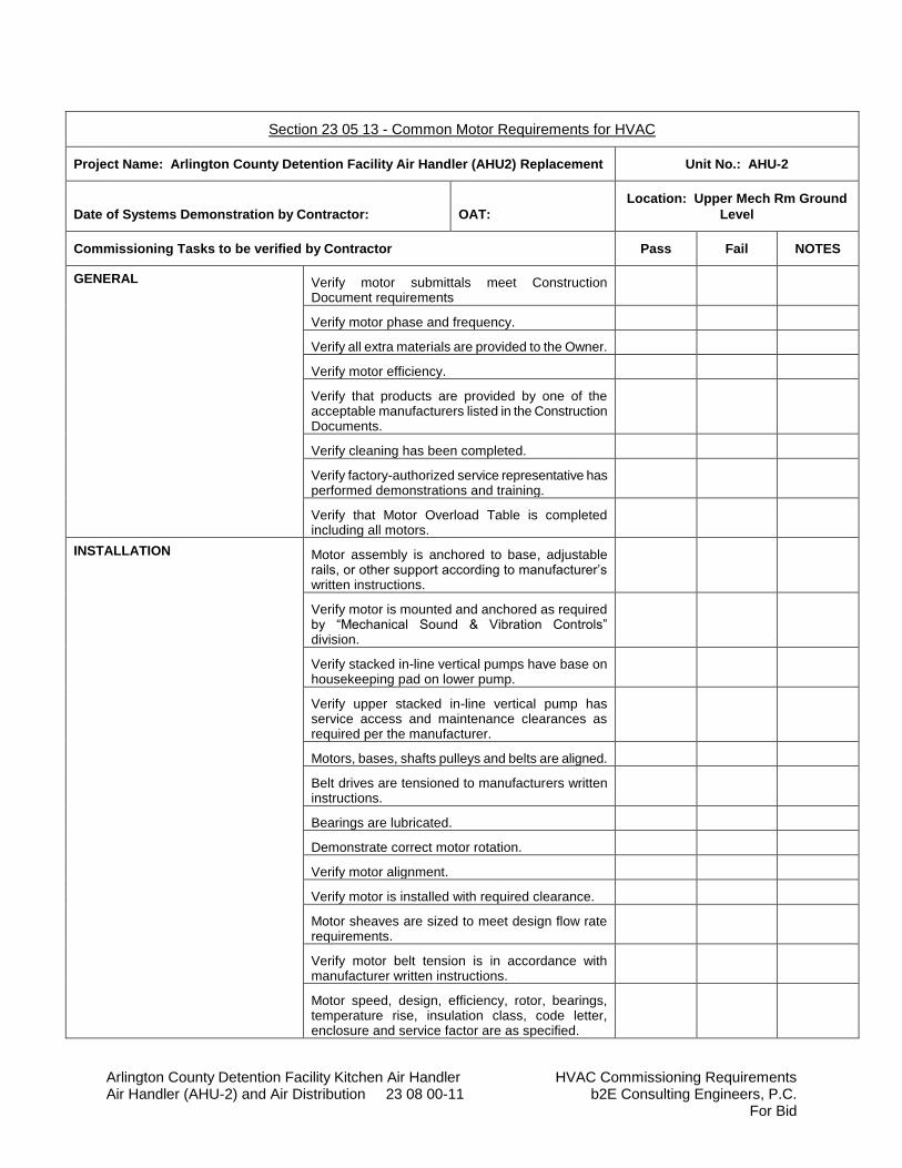
Arlington County Detention Facility Kitchen Air Handler HVAC Commissioning Requirements Air Handler (AHU-2) and Air Distribution 23 08 00-11 b2E Consulting Engineers, P.C.
For Bid
Section 23 05 13 - Common Motor Requirements for HVAC
Project Name: Arlington County Detention Facility Air Handler (AHU2) Replacement Unit No.: AHU-2
Date of Systems Demonstration by Contractor: OAT:
Location: Upper Mech Rm Ground
Level
Commissioning Tasks to be verified by Contractor Pass Fail NOTES
GENERAL Verify motor submittals meet Construction Document requirements
Verify motor phase and frequency.
Verify all extra materials are provided to the Owner.
Verify motor efficiency.
Verify that products are provided by one of the acceptable manufacturers listed in the Construction Documents.
Verify cleaning has been completed.
Verify factory-authorized service representative has performed demonstrations and training.
Verify that Motor Overload Table is completed including all motors.
INSTALLATION Motor assembly is anchored to base, adjustable rails, or other support according to manufacturer’s written instructions.
Verify motor is mounted and anchored as required by “Mechanical Sound & Vibration Controls” division.
Verify stacked in-line vertical pumps have base on housekeeping pad on lower pump.
Verify upper stacked in-line vertical pump has service access and maintenance clearances as required per the manufacturer.
Motors, bases, shafts pulleys and belts are aligned.
Belt drives are tensioned to manufacturers written instructions.
Bearings are lubricated.
Demonstrate correct motor rotation.
Verify motor alignment.
Verify motor is installed with required clearance.
Motor sheaves are sized to meet design flow rate requirements.
Verify motor belt tension is in accordance with manufacturer written instructions.
Motor speed, design, efficiency, rotor, bearings, temperature rise, insulation class, code letter, enclosure and service factor are as specified.
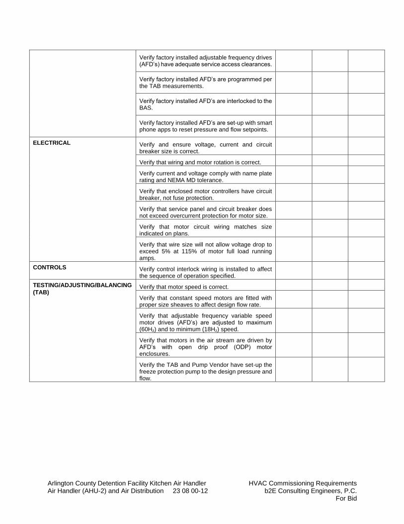
Arlington County Detention Facility Kitchen Air Handler HVAC Commissioning Requirements Air Handler (AHU-2) and Air Distribution 23 08 00-12 b2E Consulting Engineers, P.C.
For Bid
Verify factory installed adjustable frequency drives (AFD’s) have adequate service access clearances.
Verify factory installed AFD’s are programmed per the TAB measurements.
Verify factory installed AFD’s are interlocked to the BAS.
Verify factory installed AFD’s are set-up with smart phone apps to reset pressure and flow setpoints.
ELECTRICAL Verify and ensure voltage, current and circuit breaker size is correct.
Verify that wiring and motor rotation is correct.
Verify current and voltage comply with name plate rating and NEMA MD tolerance.
Verify that enclosed motor controllers have circuit breaker, not fuse protection.
Verify that service panel and circuit breaker does not exceed overcurrent protection for motor size.
Verify that motor circuit wiring matches size indicated on plans.
Verify that wire size will not allow voltage drop to exceed 5% at 115% of motor full load running amps.
CONTROLS Verify control interlock wiring is installed to affect the sequence of operation specified.
TESTING/ADJUSTING/BALANCING
(TAB) Verify that motor speed is correct.
Verify that constant speed motors are fitted with proper size sheaves to affect design flow rate.
Verify that adjustable frequency variable speed motor drives (AFD’s) are adjusted to maximum (60Hz) and to minimum (18Hz) speed.
Verify that motors in the air stream are driven by AFD’s with open drip proof (ODP) motor enclosures.
Verify the TAB and Pump Vendor have set-up the freeze protection pump to the design pressure and flow.
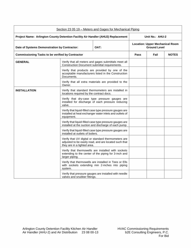
Arlington County Detention Facility Kitchen Air Handler HVAC Commissioning Requirements Air Handler (AHU-2) and Air Distribution 23 08 00-13 b2E Consulting Engineers, P.C.
For Bid
Section 23 05 19 – Meters and Gages for Mechanical Piping
Project Name: Arlington County Detention Facility Air Handler (AHU2) Replacement Unit No.: AHU-2
Date of Systems Demonstration by Contractor: OAT:
Location: Upper Mechanical Room
Ground Level
Commissioning Tasks to be verified by Contractor Pass Fail NOTES
GENERAL Verify that all meters and gages submittals meet all Construction Document submittal requirements.
Verify that products are provided by one of the acceptable manufacturers listed in the Construction Documents.
Verify that all extra materials are provided to the Owner.
INSTALLATION Verify that standard thermometers are installed in locations required by the contract docs.
Verify that dry-case type pressure gauges are installed for discharge of each pressure reducing valve.
Verify that liquid-filled case type pressure gauges are installed at heat exchanger water inlets and outlets of equipment.
Verify that liquid-filled case type pressure gauges are installed at the suction and discharge of each pump.
Verify that liquid-filled case type pressure gauges are installed at outlets of boilers.
Verify that UV digital or standard thermometers are adjusted to be easily read, and are located such that they are in a lighted area.
Verify that thermowells are installed with sockets extending to the center of the piping for 3-inch and larger piping.
Verify that thermowells are installed in Tees or Ells with sockets extending min 2-inches into piping system.
Verify that pressure gauges are installed with needle valves and snubber fittings.
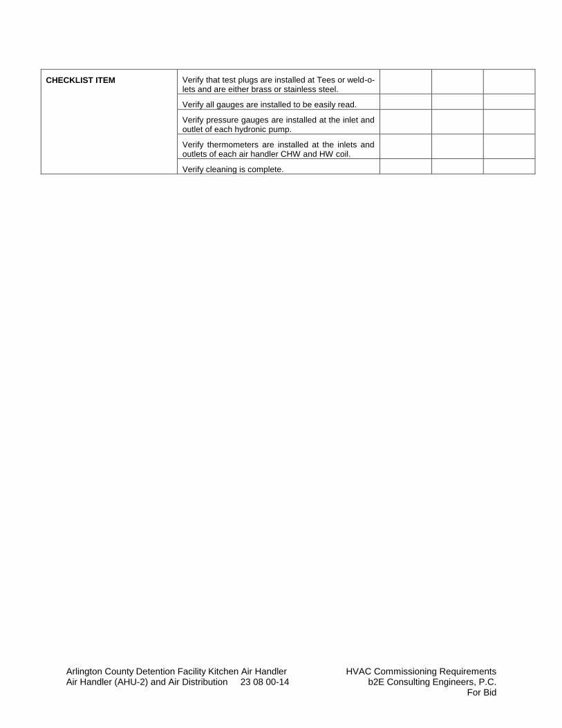
Arlington County Detention Facility Kitchen Air Handler HVAC Commissioning Requirements Air Handler (AHU-2) and Air Distribution 23 08 00-14 b2E Consulting Engineers, P.C.
For Bid
CHECKLIST ITEM Verify that test plugs are installed at Tees or weld-o-lets and are either brass or stainless steel.
Verify all gauges are installed to be easily read.
Verify pressure gauges are installed at the inlet and outlet of each hydronic pump.
Verify thermometers are installed at the inlets and outlets of each air handler CHW and HW coil.
Verify cleaning is complete.

Arlington County Detention Facility Kitchen Air Handler HVAC Commissioning Requirements Air Handler (AHU-2) and Air Distribution 23 08 00-15 b2E Consulting Engineers, P.C.
For Bid
Section 23 05 23 – General Duty Valves for Mechanical Piping
Project Name: Arlington County Detention Facility Air Handler (AHU2) Replacement Unit No.: AHU-2
Date of Systems Demonstration by Contractor: OAT:
Location: Upper Mechanical Room
Ground Level
Commissioning Tasks to be verified by Contractor Pass Fail NOTES
GENERAL Verify that all valve submittals meet all Construction Document submittal requirements.
Verify that products are provided by one of the acceptable manufacturer’s listed in the Construction Documents.
INSTALLATION Verify only ball valves or high performance butterfly valves are used for shut-off service; verify no gate valves are installed in hydronic piping.
Verify only ball or high performance butterfly valves are used for throttling service; 2 ½-inch and larger. Verify ball valves used in all Hydronic water copper piping 2-inch or less unless otherwise specified.
Verify calibrated balancing valves used for in-line pumping applications.
Verify non-slam check valves are used on the discharge of each in-line pump.
Verify valves are installed with unions or flanges at each piece of equipment.
Verify that valves have valve handle extensions in all insulated piping.
Verify that chainwheel operator chains are provided for valves higher than 96 inches AFF and are extended to min. 60-inches above finished floor.
Verify that all ball and high performance butterfly valves NPS 4 and larger have hand wheel operators and are gear operated.
Verify all valves in insulated piping are provided with valve handle extensions for levers or gear operated hand wheel operators.
Verify that cleaning is complete.
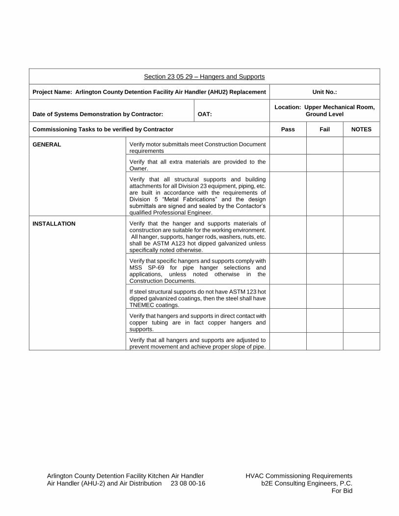
Arlington County Detention Facility Kitchen Air Handler HVAC Commissioning Requirements Air Handler (AHU-2) and Air Distribution 23 08 00-16 b2E Consulting Engineers, P.C.
For Bid
Section 23 05 29 – Hangers and Supports
Project Name: Arlington County Detention Facility Air Handler (AHU2) Replacement Unit No.:
Date of Systems Demonstration by Contractor: OAT:
Location: Upper Mechanical Room,
Ground Level
Commissioning Tasks to be verified by Contractor Pass Fail NOTES
GENERAL Verify motor submittals meet Construction Document requirements
Verify that all extra materials are provided to the Owner.
Verify that all structural supports and building attachments for all Division 23 equipment, piping, etc. are built in accordance with the requirements of Division 5 “Metal Fabrications” and the design submittals are signed and sealed by the Contactor’s qualified Professional Engineer.
INSTALLATION Verify that the hanger and supports materials of construction are suitable for the working environment. All hanger, supports, hanger rods, washers, nuts, etc. shall be ASTM A123 hot dipped galvanized unless specifically noted otherwise.
Verify that specific hangers and supports comply with MSS SP-69 for pipe hanger selections and applications, unless noted otherwise in the Construction Documents.
If steel structural supports do not have ASTM 123 hot dipped galvanized coatings, then the steel shall have TNEMEC coatings.
Verify that hangers and supports in direct contact with copper tubing are in fact copper hangers and supports.
Verify that all hangers and supports are adjusted to prevent movement and achieve proper slope of pipe.
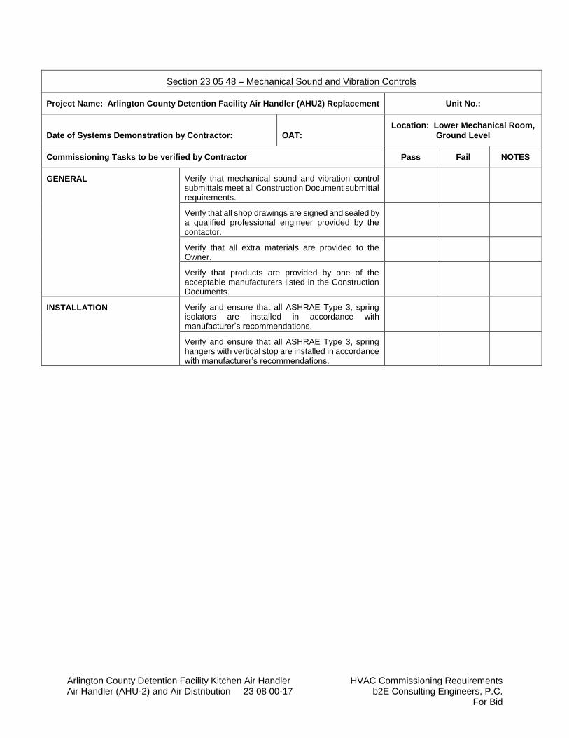
Arlington County Detention Facility Kitchen Air Handler HVAC Commissioning Requirements Air Handler (AHU-2) and Air Distribution 23 08 00-17 b2E Consulting Engineers, P.C.
For Bid
Section 23 05 48 – Mechanical Sound and Vibration Controls
Project Name: Arlington County Detention Facility Air Handler (AHU2) Replacement Unit No.:
Date of Systems Demonstration by Contractor: OAT:
Location: Lower Mechanical Room,
Ground Level
Commissioning Tasks to be verified by Contractor Pass Fail NOTES
GENERAL Verify that mechanical sound and vibration control submittals meet all Construction Document submittal requirements.
Verify that all shop drawings are signed and sealed by a qualified professional engineer provided by the contactor.
Verify that all extra materials are provided to the Owner.
Verify that products are provided by one of the acceptable manufacturers listed in the Construction Documents.
INSTALLATION
Verify and ensure that all ASHRAE Type 3, spring isolators are installed in accordance with manufacturer’s recommendations.
Verify and ensure that all ASHRAE Type 3, spring hangers with vertical stop are installed in accordance with manufacturer’s recommendations.
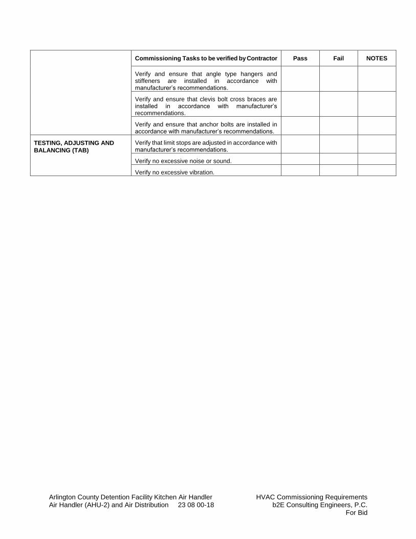
Arlington County Detention Facility Kitchen Air Handler HVAC Commissioning Requirements Air Handler (AHU-2) and Air Distribution 23 08 00-18 b2E Consulting Engineers, P.C.
For Bid
Commissioning Tasks to be verified by Contractor Pass Fail NOTES
Verify and ensure that angle type hangers and stiffeners are installed in accordance with manufacturer’s recommendations.
Verify and ensure that clevis bolt cross braces are installed in accordance with manufacturer’s recommendations.
Verify and ensure that anchor bolts are installed in accordance with manufacturer’s recommendations.
TESTING, ADJUSTING AND
BALANCING (TAB)
Verify that limit stops are adjusted in accordance with manufacturer’s recommendations.
Verify no excessive noise or sound.
Verify no excessive vibration.
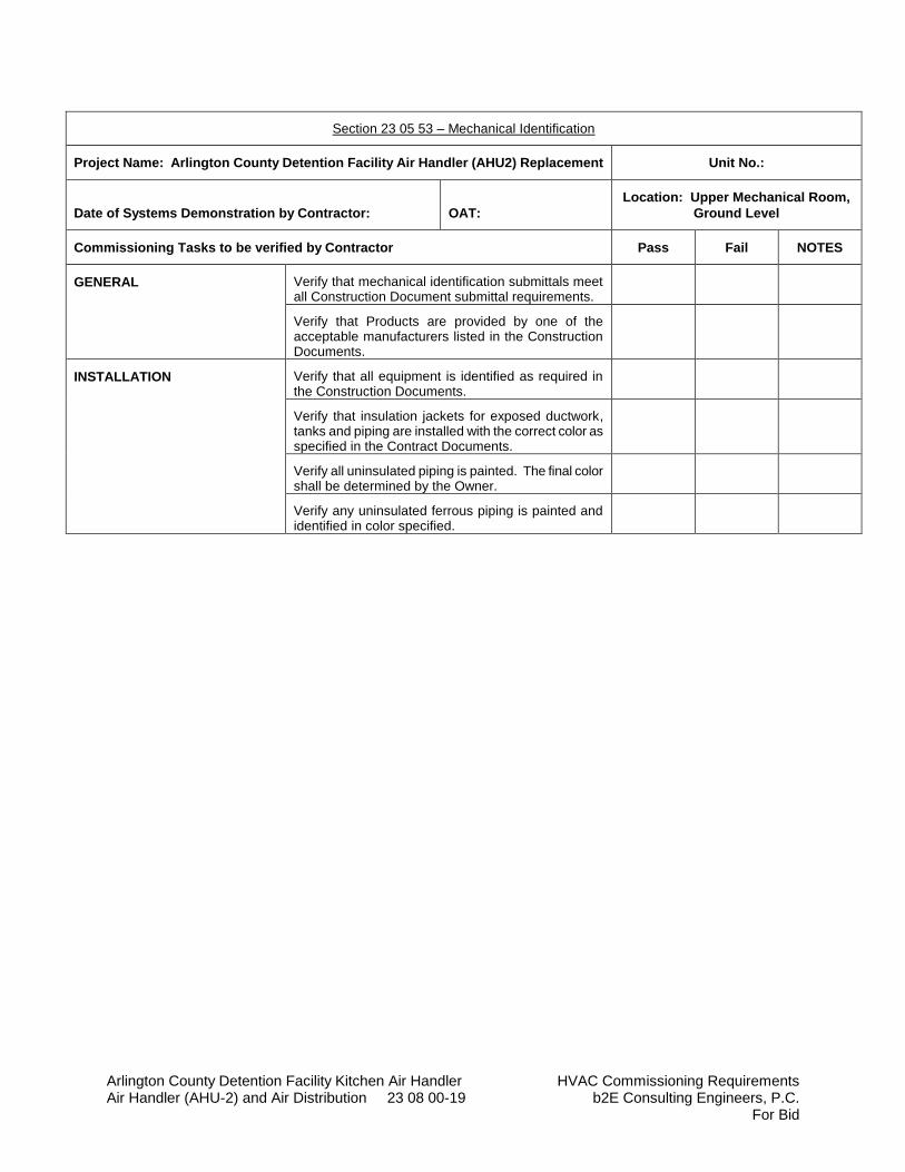
Arlington County Detention Facility Kitchen Air Handler HVAC Commissioning Requirements Air Handler (AHU-2) and Air Distribution 23 08 00-19 b2E Consulting Engineers, P.C.
For Bid
Section 23 05 53 – Mechanical Identification
Project Name: Arlington County Detention Facility Air Handler (AHU2) Replacement Unit No.:
Date of Systems Demonstration by Contractor: OAT:
Location: Upper Mechanical Room,
Ground Level
Commissioning Tasks to be verified by Contractor Pass Fail NOTES
GENERAL Verify that mechanical identification submittals meet all Construction Document submittal requirements.
Verify that Products are provided by one of the acceptable manufacturers listed in the Construction Documents.
INSTALLATION Verify that all equipment is identified as required in the Construction Documents.
Verify that insulation jackets for exposed ductwork, tanks and piping are installed with the correct color as specified in the Contract Documents.
Verify all uninsulated piping is painted. The final color shall be determined by the Owner.
Verify any uninsulated ferrous piping is painted and identified in color specified.
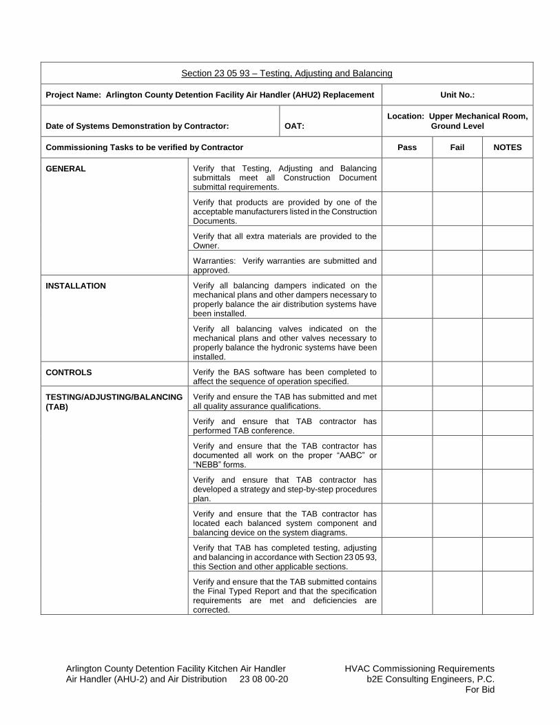
Arlington County Detention Facility Kitchen Air Handler HVAC Commissioning Requirements Air Handler (AHU-2) and Air Distribution 23 08 00-20 b2E Consulting Engineers, P.C.
For Bid
Section 23 05 93 – Testing, Adjusting and Balancing
Project Name: Arlington County Detention Facility Air Handler (AHU2) Replacement Unit No.:
Date of Systems Demonstration by Contractor: OAT:
Location: Upper Mechanical Room,
Ground Level
Commissioning Tasks to be verified by Contractor Pass Fail NOTES
GENERAL Verify that Testing, Adjusting and Balancing submittals meet all Construction Document submittal requirements.
Verify that products are provided by one of the acceptable manufacturers listed in the Construction Documents.
Verify that all extra materials are provided to the Owner.
Warranties: Verify warranties are submitted and approved.
INSTALLATION Verify all balancing dampers indicated on the mechanical plans and other dampers necessary to properly balance the air distribution systems have been installed.
Verify all balancing valves indicated on the mechanical plans and other valves necessary to properly balance the hydronic systems have been installed.
CONTROLS Verify the BAS software has been completed to affect the sequence of operation specified.
TESTING/ADJUSTING/BALANCING
(TAB)
Verify and ensure the TAB has submitted and met all quality assurance qualifications.
Verify and ensure that TAB contractor has performed TAB conference.
Verify and ensure that the TAB contractor has documented all work on the proper “AABC” or “NEBB” forms.
Verify and ensure that TAB contractor has developed a strategy and step-by-step procedures plan.
Verify and ensure that the TAB contractor has located each balanced system component and balancing device on the system diagrams.
Verify that TAB has completed testing, adjusting and balancing in accordance with Section 23 05 93, this Section and other applicable sections.
Verify and ensure that the TAB submitted contains the Final Typed Report and that the specification requirements are met and deficiencies are corrected.
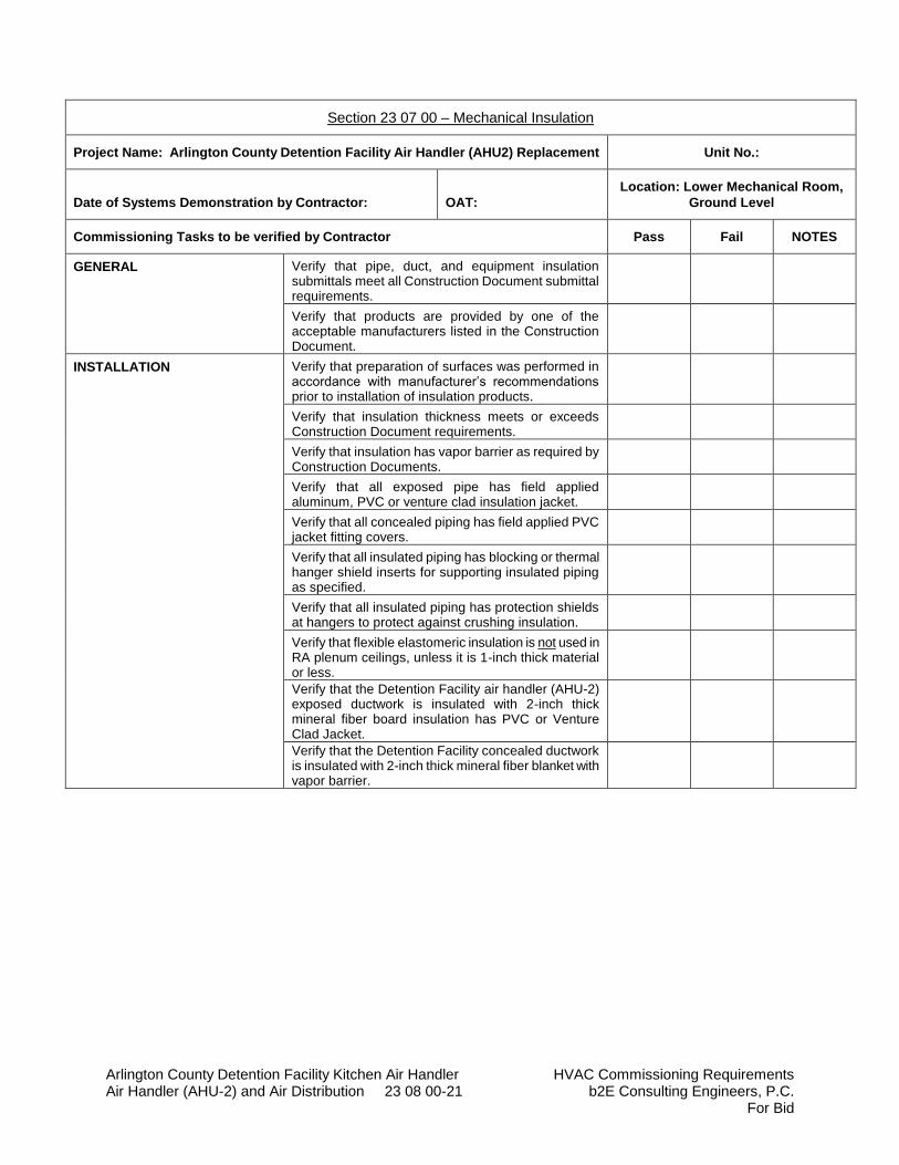
Arlington County Detention Facility Kitchen Air Handler HVAC Commissioning Requirements Air Handler (AHU-2) and Air Distribution 23 08 00-21 b2E Consulting Engineers, P.C.
For Bid
Section 23 07 00 – Mechanical Insulation
Project Name: Arlington County Detention Facility Air Handler (AHU2) Replacement Unit No.:
Date of Systems Demonstration by Contractor: OAT:
Location: Lower Mechanical Room,
Ground Level
Commissioning Tasks to be verified by Contractor Pass Fail NOTES
GENERAL Verify that pipe, duct, and equipment insulation submittals meet all Construction Document submittal requirements.
Verify that products are provided by one of the acceptable manufacturers listed in the Construction Document.
INSTALLATION
Verify that preparation of surfaces was performed in accordance with manufacturer’s recommendations prior to installation of insulation products.
Verify that insulation thickness meets or exceeds Construction Document requirements.
Verify that insulation has vapor barrier as required by Construction Documents.
Verify that all exposed pipe has field applied aluminum, PVC or venture clad insulation jacket.
Verify that all concealed piping has field applied PVC jacket fitting covers.
Verify that all insulated piping has blocking or thermal hanger shield inserts for supporting insulated piping as specified.
Verify that all insulated piping has protection shields at hangers to protect against crushing insulation.
Verify that flexible elastomeric insulation is not used in RA plenum ceilings, unless it is 1-inch thick material or less.
Verify that the Detention Facility air handler (AHU-2) exposed ductwork is insulated with 2-inch thick mineral fiber board insulation has PVC or Venture Clad Jacket.
Verify that the Detention Facility concealed ductwork is insulated with 2-inch thick mineral fiber blanket with vapor barrier.
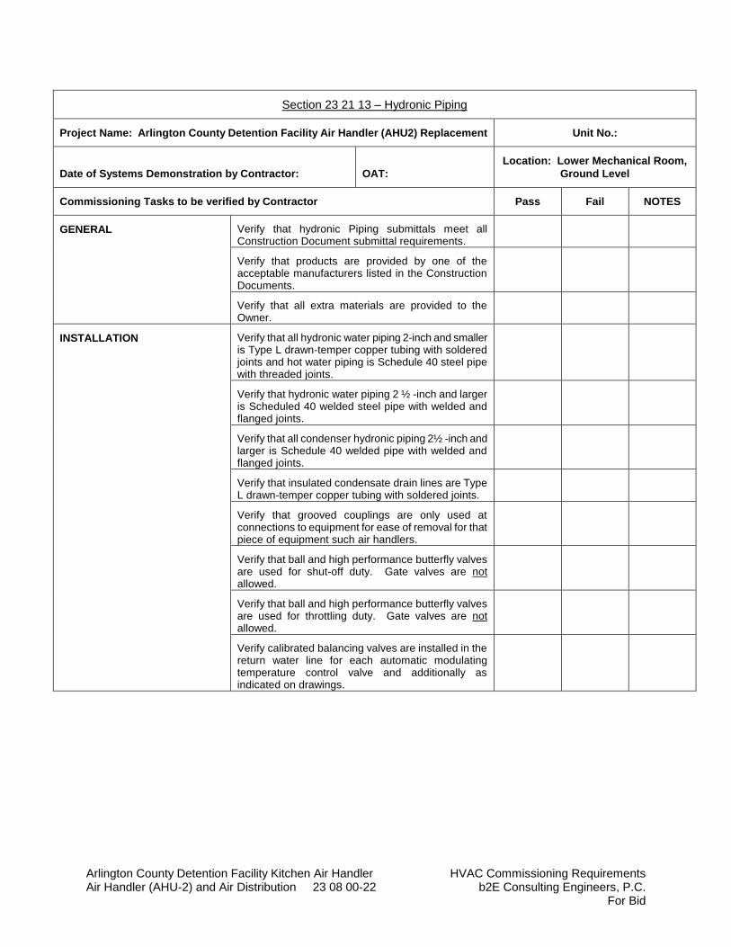
Arlington County Detention Facility Kitchen Air Handler HVAC Commissioning Requirements Air Handler (AHU-2) and Air Distribution 23 08 00-22 b2E Consulting Engineers, P.C.
For Bid
Section 23 21 13 – Hydronic Piping
Project Name: Arlington County Detention Facility Air Handler (AHU2) Replacement Unit No.:
Date of Systems Demonstration by Contractor: OAT:
Location: Lower Mechanical Room,
Ground Level
Commissioning Tasks to be verified by Contractor Pass Fail NOTES
GENERAL Verify that hydronic Piping submittals meet all Construction Document submittal requirements.
Verify that products are provided by one of the acceptable manufacturers listed in the Construction Documents.
Verify that all extra materials are provided to the Owner.
INSTALLATION Verify that all hydronic water piping 2-inch and smaller is Type L drawn-temper copper tubing with soldered joints and hot water piping is Schedule 40 steel pipe with threaded joints.
Verify that hydronic water piping 2 ½ -inch and larger is Scheduled 40 welded steel pipe with welded and flanged joints.
Verify that all condenser hydronic piping 2½ -inch and larger is Schedule 40 welded pipe with welded and flanged joints.
Verify that insulated condensate drain lines are Type L drawn-temper copper tubing with soldered joints.
Verify that grooved couplings are only used at connections to equipment for ease of removal for that piece of equipment such air handlers.
Verify that ball and high performance butterfly valves are used for shut-off duty. Gate valves are not allowed.
Verify that ball and high performance butterfly valves are used for throttling duty. Gate valves are not allowed.
Verify calibrated balancing valves are installed in the return water line for each automatic modulating temperature control valve and additionally as indicated on drawings.
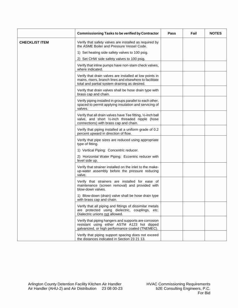
Arlington County Detention Facility Kitchen Air Handler HVAC Commissioning Requirements Air Handler (AHU-2) and Air Distribution 23 08 00-23 b2E Consulting Engineers, P.C.
For Bid
Commissioning Tasks to be verified by Contractor Pass Fail NOTES
CHECKLIST ITEM Verify that safety valves are installed as required by the ASME Boiler and Pressure Vessel Code.
1) Set heating side safety valves to 100 psig.
2) Set CHW side safety valves to 100 psig.
Verify that inline pumps have non-slam check valves, where indicated.
Verify that drain valves are installed at low points in mains, risers, branch lines and elsewhere to facilitate total and partial system draining as desired.
Verify that drain valves shall be hose drain type with brass cap and chain.
Verify piping installed in groups parallel to each other, spaced to permit applying insulation and servicing of valves.
Verify that all drain valves have Tee fitting, ½-inch ball valve, and short ½-inch threaded nipple (hose connections) with brass cap and chain.
Verify that piping installed at a uniform grade of 0.2 percent upward in direction of flow.
Verify that pipe sizes are reduced using appropriate type of fitting.
1) Vertical Piping: Concentric reducer.
2) Horizontal Water Piping: Eccentric reducer with level side up.
Verify that strainer installed on the inlet to the make-up-water assembly before the pressure reducing valve.
Verify that strainers are installed for ease of maintenance (screen removal) and provided with blow-down valves.
1) Blow-down (drain) valve shall be hose drain type with brass cap and chain.
Verify that all piping and fittings of dissimilar metals are protected using dielectric, couplings, etc. Dialectric unions not allowed.
Verify that piping hangers and supports are corrosion resistant using either ASTM A123 hot dipped galvanized, or high performance coated (TNEMEC).
Verify that piping support spacing does not exceed the distances indicated in Section 23 21 13.
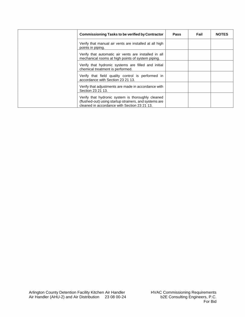
Arlington County Detention Facility Kitchen Air Handler HVAC Commissioning Requirements Air Handler (AHU-2) and Air Distribution 23 08 00-24 b2E Consulting Engineers, P.C.
For Bid
Commissioning Tasks to be verified by Contractor Pass Fail NOTES
Verify that manual air vents are installed at all high points in piping.
Verify that automatic air vents are installed in all mechanical rooms at high points of system piping.
Verify that hydronic systems are filled and initial chemical treatment is performed.
Verify that field quality control is performed in accordance with Section 23 21 13.
Verify that adjustments are made in accordance with Section 23 21 13.
Verify that hydronic system is thoroughly cleaned (flushed-out) using startup strainers, and systems are cleaned in accordance with Section 23 21 13.
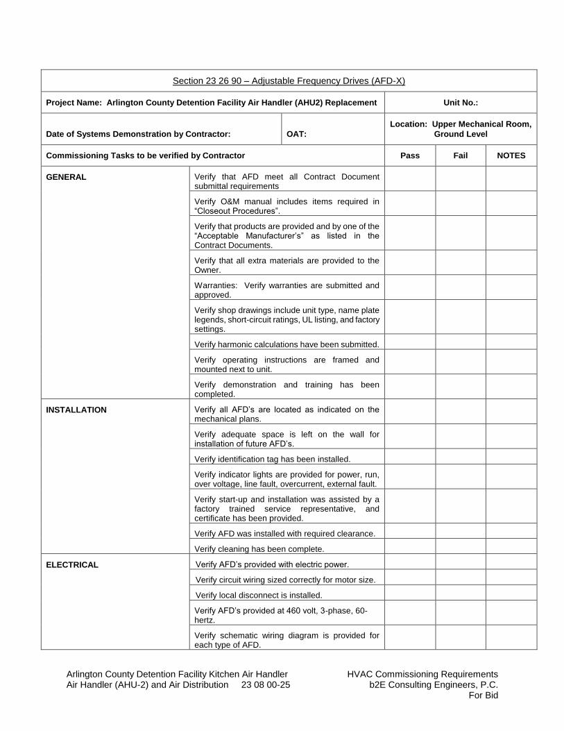
Arlington County Detention Facility Kitchen Air Handler HVAC Commissioning Requirements Air Handler (AHU-2) and Air Distribution 23 08 00-25 b2E Consulting Engineers, P.C.
For Bid
Section 23 26 90 – Adjustable Frequency Drives (AFD-X)
Project Name: Arlington County Detention Facility Air Handler (AHU2) Replacement Unit No.:
Date of Systems Demonstration by Contractor: OAT:
Location: Upper Mechanical Room,
Ground Level
Commissioning Tasks to be verified by Contractor Pass Fail NOTES
GENERAL Verify that AFD meet all Contract Document submittal requirements
Verify O&M manual includes items required in “Closeout Procedures”.
Verify that products are provided and by one of the “Acceptable Manufacturer’s” as listed in the Contract Documents.
Verify that all extra materials are provided to the Owner.
Warranties: Verify warranties are submitted and approved.
Verify shop drawings include unit type, name plate legends, short-circuit ratings, UL listing, and factory settings.
Verify harmonic calculations have been submitted.
Verify operating instructions are framed and mounted next to unit.
Verify demonstration and training has been completed.
INSTALLATION Verify all AFD’s are located as indicated on the mechanical plans.
Verify adequate space is left on the wall for installation of future AFD’s.
Verify identification tag has been installed.
Verify indicator lights are provided for power, run, over voltage, line fault, overcurrent, external fault.
Verify start-up and installation was assisted by a factory trained service representative, and certificate has been provided.
Verify AFD was installed with required clearance.
Verify cleaning has been complete.
ELECTRICAL Verify AFD’s provided with electric power.
Verify circuit wiring sized correctly for motor size.
Verify local disconnect is installed.
Verify AFD’s provided at 460 volt, 3-phase, 60-hertz.
Verify schematic wiring diagram is provided for each type of AFD.

Arlington County Detention Facility Kitchen Air Handler HVAC Commissioning Requirements Air Handler (AHU-2) and Air Distribution 23 08 00-26 b2E Consulting Engineers, P.C.
For Bid
Verify loss of phase, reverse phase, and short-circuit protection.
Commissioning Tasks to be verified by Contractor Pass Fail NOTES
TESTING/ADJUSTING/BALANCING
(TAB)
Verify that AFD’s are indexed to correct frequency for the associated pump waterflow rate required.
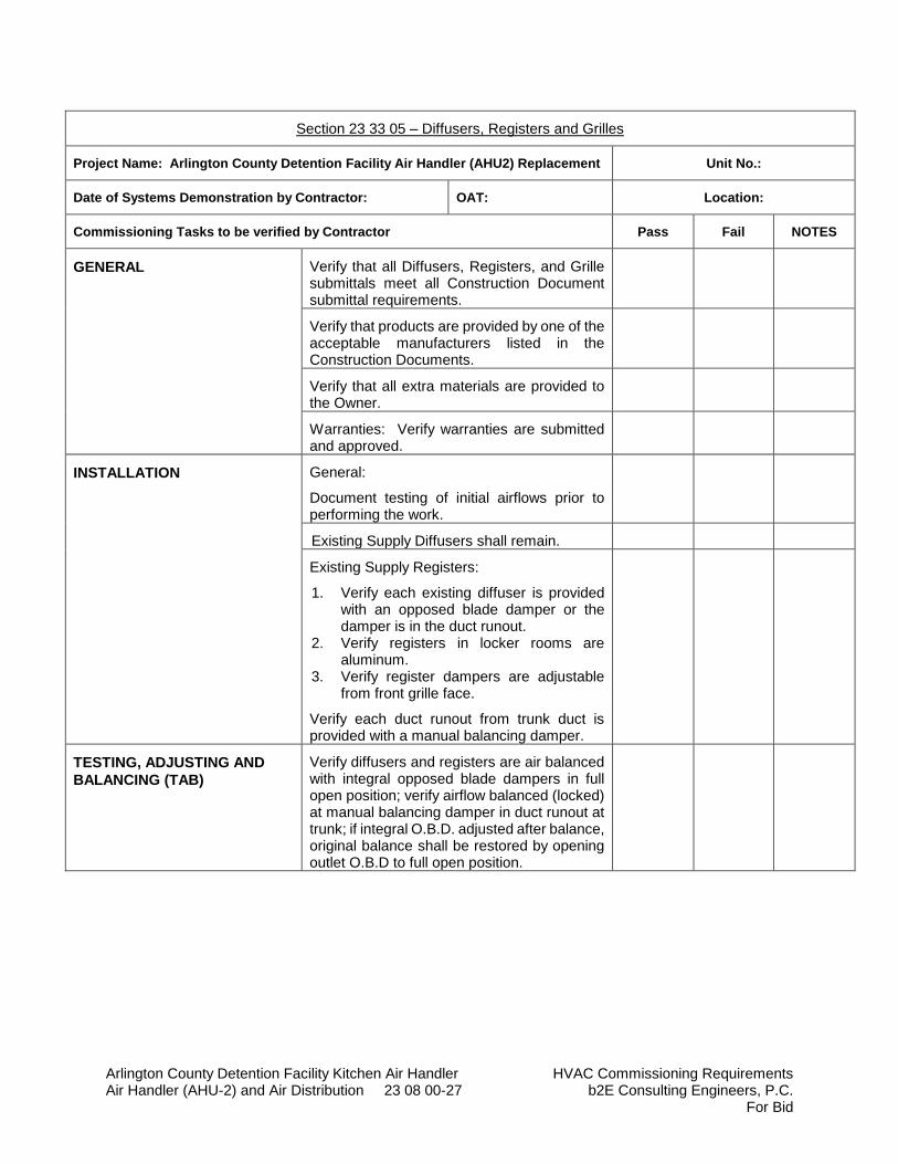
Arlington County Detention Facility Kitchen Air Handler HVAC Commissioning Requirements Air Handler (AHU-2) and Air Distribution 23 08 00-27 b2E Consulting Engineers, P.C.
For Bid
Section 23 33 05 – Diffusers, Registers and Grilles
Project Name: Arlington County Detention Facility Air Handler (AHU2) Replacement Unit No.:
Date of Systems Demonstration by Contractor: OAT: Location:
Commissioning Tasks to be verified by Contractor Pass Fail NOTES
GENERAL Verify that all Diffusers, Registers, and Grille submittals meet all Construction Document submittal requirements.
Verify that products are provided by one of the acceptable manufacturers listed in the Construction Documents.
Verify that all extra materials are provided to the Owner.
Warranties: Verify warranties are submitted and approved.
INSTALLATION General:
Document testing of initial airflows prior to performing the work.
Existing Supply Diffusers shall remain.
Existing Supply Registers:
1. Verify each existing diffuser is provided with an opposed blade damper or the damper is in the duct runout.
2. Verify registers in locker rooms are aluminum.
3. Verify register dampers are adjustable from front grille face.
Verify each duct runout from trunk duct is provided with a manual balancing damper.
TESTING, ADJUSTING AND
BALANCING (TAB)
Verify diffusers and registers are air balanced with integral opposed blade dampers in full open position; verify airflow balanced (locked) at manual balancing damper in duct runout at trunk; if integral O.B.D. adjusted after balance, original balance shall be restored by opening outlet O.B.D to full open position.
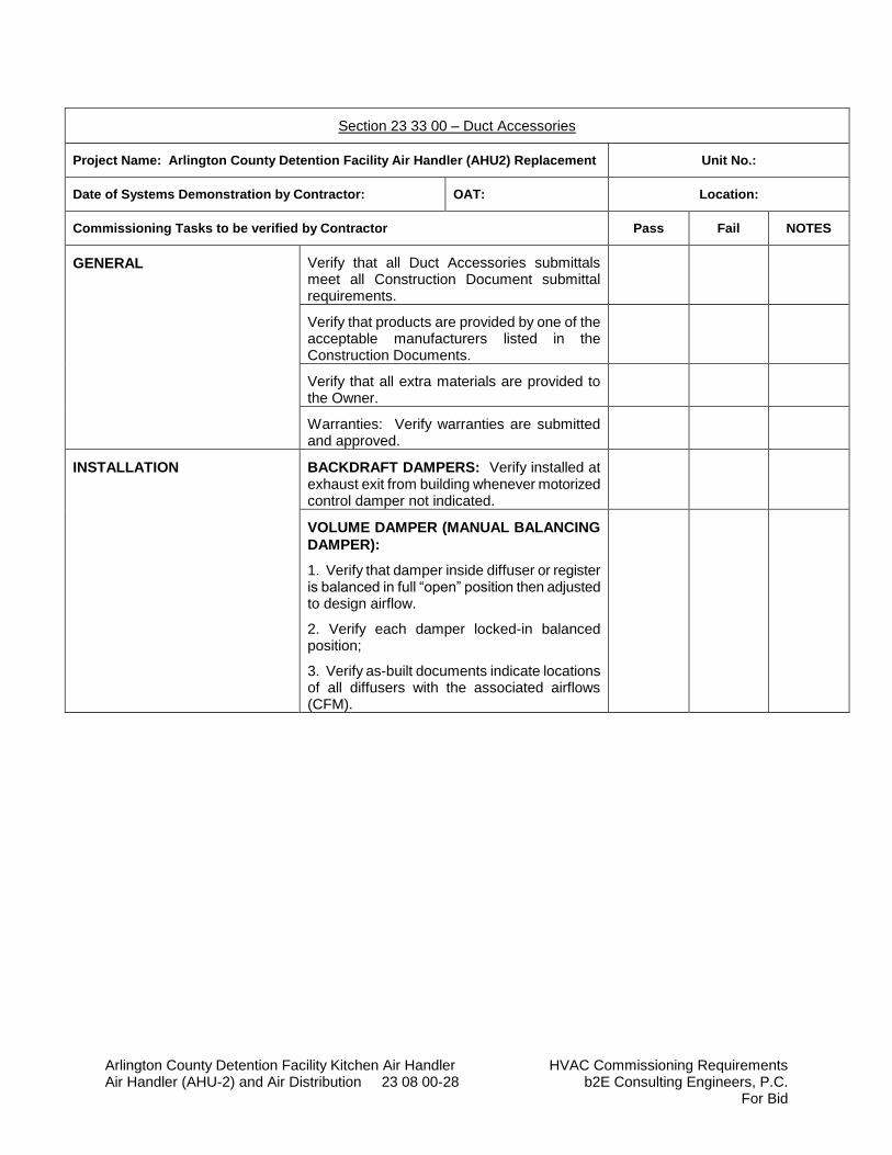
Arlington County Detention Facility Kitchen Air Handler HVAC Commissioning Requirements Air Handler (AHU-2) and Air Distribution 23 08 00-28 b2E Consulting Engineers, P.C.
For Bid
Section 23 33 00 – Duct Accessories
Project Name: Arlington County Detention Facility Air Handler (AHU2) Replacement Unit No.:
Date of Systems Demonstration by Contractor: OAT: Location:
Commissioning Tasks to be verified by Contractor Pass Fail NOTES
GENERAL Verify that all Duct Accessories submittals meet all Construction Document submittal requirements.
Verify that products are provided by one of the acceptable manufacturers listed in the Construction Documents.
Verify that all extra materials are provided to the Owner.
Warranties: Verify warranties are submitted and approved.
INSTALLATION BACKDRAFT DAMPERS: Verify installed at exhaust exit from building whenever motorized control damper not indicated.
VOLUME DAMPER (MANUAL BALANCING
DAMPER):
1. Verify that damper inside diffuser or register is balanced in full “open” position then adjusted to design airflow.
2. Verify each damper locked-in balanced position;
3. Verify as-built documents indicate locations of all diffusers with the associated airflows (CFM).
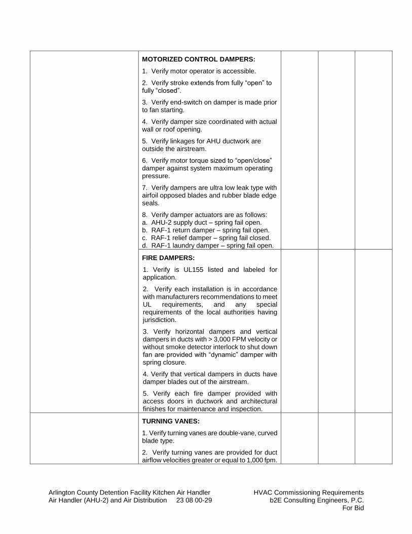
Arlington County Detention Facility Kitchen Air Handler HVAC Commissioning Requirements Air Handler (AHU-2) and Air Distribution 23 08 00-29 b2E Consulting Engineers, P.C.
For Bid
MOTORIZED CONTROL DAMPERS:
1. Verify motor operator is accessible.
2. Verify stroke extends from fully “open” to fully “closed”.
3. Verify end-switch on damper is made prior to fan starting.
4. Verify damper size coordinated with actual wall or roof opening.
5. Verify linkages for AHU ductwork are outside the airstream.
6. Verify motor torque sized to “open/close” damper against system maximum operating pressure.
7. Verify dampers are ultra low leak type with airfoil opposed blades and rubber blade edge seals.
8. Verify damper actuators are as follows: a. AHU-2 supply duct – spring fail open. b. RAF-1 return damper – spring fail open. c. RAF-1 relief damper – spring fail closed. d. RAF-1 laundry damper – spring fail open.
FIRE DAMPERS:
1. Verify is UL155 listed and labeled for application.
2. Verify each installation is in accordance with manufacturers recommendations to meet UL requirements, and any special requirements of the local authorities having jurisdiction.
3. Verify horizontal dampers and vertical dampers in ducts with > 3,000 FPM velocity or without smoke detector interlock to shut down fan are provided with “dynamic” damper with spring closure.
4. Verify that vertical dampers in ducts have damper blades out of the airstream.
5. Verify each fire damper provided with access doors in ductwork and architectural finishes for maintenance and inspection.
TURNING VANES:
1. Verify turning vanes are double-vane, curved blade type.
2. Verify turning vanes are provided for duct airflow velocities greater or equal to 1,000 fpm.
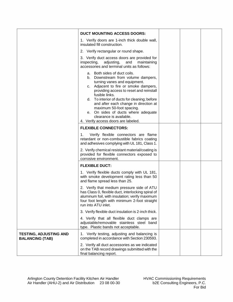
Arlington County Detention Facility Kitchen Air Handler HVAC Commissioning Requirements Air Handler (AHU-2) and Air Distribution 23 08 00-30 b2E Consulting Engineers, P.C.
For Bid
DUCT MOUNTING ACCESS DOORS:
1. Verify doors are 1-inch thick double wall, insulated fill construction.
2. Verify rectangular or round shape.
3. Verify duct access doors are provided for inspecting, adjusting, and maintaining accessories and terminal units as follows:
a. Both sides of duct coils. b. Downstream from volume dampers,
turning vanes and equipment. c. Adjacent to fire or smoke dampers,
providing access to reset and reinstall fusible links.
d. To interior of ducts for cleaning; before and after each change in direction at maximum 50-foot spacing.
e. On sides of ducts where adequate clearance is available.
4. Verify access doors are labeled.
FLEXIBLE CONNECTORS:
1. Verify flexible connectors are flame retardant or non-combustible fabrics coating and adhesives complying with UL 181, Class 1.
2. Verify chemical resistant material/coating is provided for flexible connectors exposed to corrosive environment.
FLEXIBLE DUCT:
1. Verify flexible ducts comply with UL 181, with smoke development rating less than 50 and flame spread less than 25.
2. Verify that medium pressure side of ATU has Class 0, flexible duct, interlocking spiral of aluminum foil, with insulation; verify maximum four foot length with minimum 2-foot straight run into ATU inlet.
3. Verify flexible duct insulation is 2-inch thick.
4. Verify that all flexible duct clamps are adjustable/removable stainless steel band type. Plastic bands not acceptable.
TESTING, ADJUSTING AND
BALANCING (TAB)
1. Verify testing, adjusting and balancing is completed in accordance with Section 230593.
2. Verify all duct accessories as we indicated on the TAB record drawings submitted with the final balancing report.
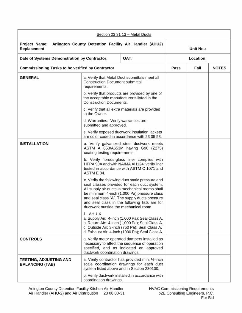
Arlington County Detention Facility Kitchen Air Handler HVAC Commissioning Requirements Air Handler (AHU-2) and Air Distribution 23 08 00-31 b2E Consulting Engineers, P.C.
For Bid
Section 23 31 13 – Metal Ducts
Project Name: Arlington County Detention Facility Air Handler (AHU2)
Replacement Unit No.:
Date of Systems Demonstration by Contractor: OAT: Location:
Commissioning Tasks to be verified by Contractor Pass Fail NOTES
GENERAL a. Verify that Metal Duct submittals meet all Construction Document submittal requirements.
b. Verify that products are provided by one of the acceptable manufacturer’s listed in the Construction Documents.
c. Verify that all extra materials are provided to the Owner.
d. Warranties: Verify warranties are submitted and approved.
e. Verify exposed ductwork insulation jackets are color coded in accordance with 23 05 53.
INSTALLATION a. Verify galvanized steel ductwork meets ASTM A 653/A653M having G90 (Z275) coating testing requirements.
b. Verify fibrous-glass liner complies with HFPA 90A and with NAIMA AH124; verify liner tested in accordance with ASTM C 1071 and ASTM E 84.
c. Verify the following duct static pressure and seal classes provided for each duct system. All supply air ducts in mechanical rooms shall be minimum 4-inch (1,000 Pa) pressure class and seal class “A”. The supply ducts pressure and seal class in the following lists are for ductwork outside the mechanical room.
1. 1. AHU-X a. a. Supply Air: 4-inch (1,000 Pa); Seal Class A. b. b. Return Air: 4-inch (1,000 Pa); Seal Class A. c. c. Outside Air: 3-inch (750 Pa); Seal Class A. d. d. Exhaust Air: 4-inch (1000 Pa); Seal Class A.
CONTROLS a. Verify motor operated dampers installed as necessary to affect the sequence of operation specified, and as indicated on approved ductwork coordination drawings.
TESTING, ADJUSTING AND
BALANCING (TAB)
a. Verify contractor has provided min. ¼-inch scale coordination drawings for each duct system listed above and in Section 230100.
b. Verify ductwork installed in accordance with coordination drawings.
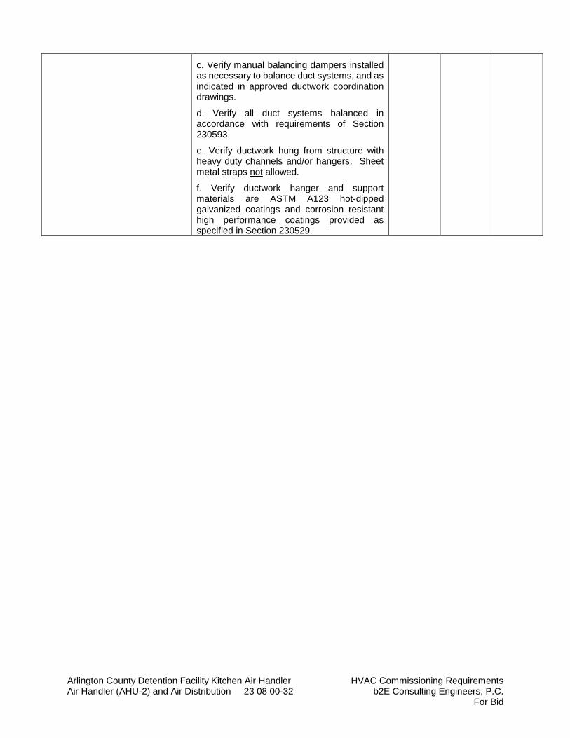
Arlington County Detention Facility Kitchen Air Handler HVAC Commissioning Requirements Air Handler (AHU-2) and Air Distribution 23 08 00-32 b2E Consulting Engineers, P.C.
For Bid
c. Verify manual balancing dampers installed as necessary to balance duct systems, and as indicated in approved ductwork coordination drawings.
d. Verify all duct systems balanced in accordance with requirements of Section 230593.
e. Verify ductwork hung from structure with heavy duty channels and/or hangers. Sheet metal straps not allowed.
f. Verify ductwork hanger and support materials are ASTM A123 hot-dipped galvanized coatings and corrosion resistant high performance coatings provided as specified in Section 230529.
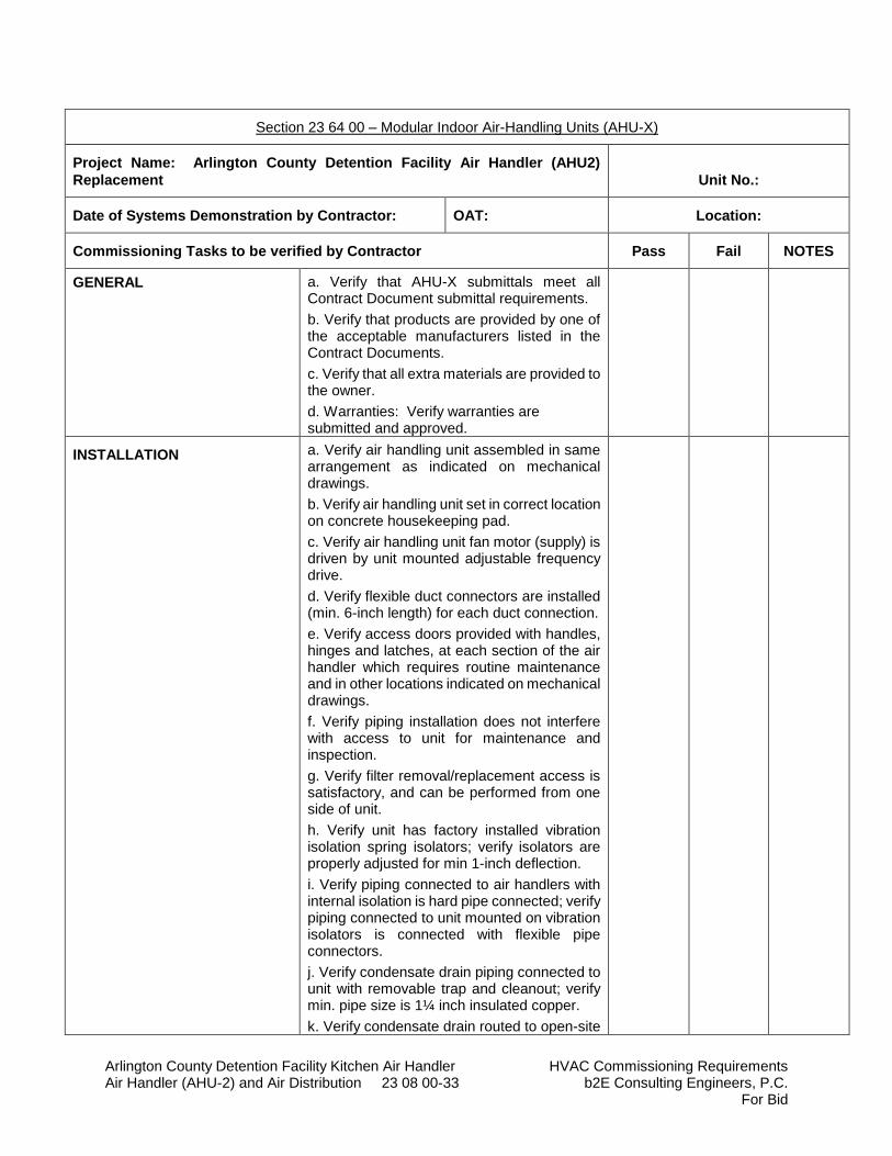
Arlington County Detention Facility Kitchen Air Handler HVAC Commissioning Requirements Air Handler (AHU-2) and Air Distribution 23 08 00-33 b2E Consulting Engineers, P.C.
For Bid
Section 23 64 00 – Modular Indoor Air-Handling Units (AHU-X)
Project Name: Arlington County Detention Facility Air Handler (AHU2)
Replacement Unit No.:
Date of Systems Demonstration by Contractor: OAT: Location:
Commissioning Tasks to be verified by Contractor Pass Fail NOTES
GENERAL a. Verify that AHU-X submittals meet all Contract Document submittal requirements.
b. Verify that products are provided by one of the acceptable manufacturers listed in the Contract Documents.
c. Verify that all extra materials are provided to the owner.
d. Warranties: Verify warranties are submitted and approved.
INSTALLATION a. Verify air handling unit assembled in same arrangement as indicated on mechanical drawings.
b. Verify air handling unit set in correct location on concrete housekeeping pad.
c. Verify air handling unit fan motor (supply) is driven by unit mounted adjustable frequency drive.
d. Verify flexible duct connectors are installed (min. 6-inch length) for each duct connection.
e. Verify access doors provided with handles, hinges and latches, at each section of the air handler which requires routine maintenance and in other locations indicated on mechanical drawings.
f. Verify piping installation does not interfere with access to unit for maintenance and inspection.
g. Verify filter removal/replacement access is satisfactory, and can be performed from one side of unit.
h. Verify unit has factory installed vibration isolation spring isolators; verify isolators are properly adjusted for min 1-inch deflection.
i. Verify piping connected to air handlers with internal isolation is hard pipe connected; verify piping connected to unit mounted on vibration isolators is connected with flexible pipe connectors.
j. Verify condensate drain piping connected to unit with removable trap and cleanout; verify min. pipe size is 1¼ inch insulated copper.
k. Verify condensate drain routed to open-site
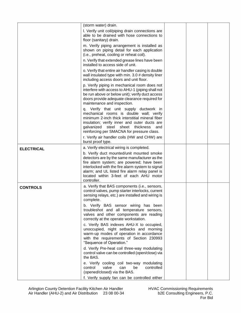
Arlington County Detention Facility Kitchen Air Handler HVAC Commissioning Requirements Air Handler (AHU-2) and Air Distribution 23 08 00-34 b2E Consulting Engineers, P.C.
For Bid
(storm water) drain.
l. Verify unit coil/piping drain connections are able to be drained with hose connections to floor (sanitary) drain.
m. Verify piping arrangement is installed as shown on piping detail for each application (i.e., preheat, cooling or reheat coil).
n. Verify that extended grease lines have been installed to access side of unit.
o. Verify that entire air handler casing is double wall insulated type with min. 3.0 # density liner including access doors and unit floor.
p. Verify piping in mechanical room does not interfere with access to AHU-1 (piping shall not be run above or below unit); verify duct access doors provide adequate clearance required for maintenance and inspection.
q. Verify that unit supply ductwork in mechanical rooms is double wall; verify minimum 2-inch thick interstitial mineral fiber insulation; verify inner and outer ducts are galvanized steel sheet thickness and reinforcing per SMACNA for pressure class.
r. Verify air handler coils (HW and CHW) are burst proof type.
ELECTRICAL a. Verify electrical wiring is completed.
b. Verify duct mounted/unit mounted smoke detectors are by the same manufacturer as the fire alarm system; are powered; have been interlocked with the fire alarm system to signal alarm; and UL listed fire alarm relay panel is located within 3-feet of each AHU motor controller.
CONTROLS a. Verify that BAS components (i.e., sensors, control valves, pump starter interlocks, current sensing relays, etc.) are installed and wiring is complete.
b. Verify BAS sensor wiring has been troubleshot and all temperature sensors, valves and other components are reading correctly at the operate workstation.
c. Verify BAS indexes AHU-X to occupied, unoccupied, night setbacks and morning warm-up modes of operation in accordance with the requirements of Section 230993 “Sequence of Operation.”
d. Verify Pre-heat coil three-way modulating control valve can be controlled (open/close) via the BAS.
e. Verify cooling coil two-way modulating control valve can be controlled (opened/closed) via the BAS.
f. Verify supply fan can be controlled either
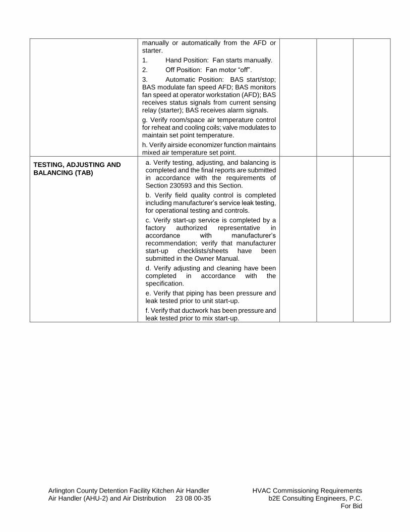
Arlington County Detention Facility Kitchen Air Handler HVAC Commissioning Requirements Air Handler (AHU-2) and Air Distribution 23 08 00-35 b2E Consulting Engineers, P.C.
For Bid
manually or automatically from the AFD or starter.
1. Hand Position: Fan starts manually.
2. Off Position: Fan motor “off”.
3. Automatic Position: BAS start/stop; BAS modulate fan speed AFD; BAS monitors fan speed at operator workstation (AFD); BAS receives status signals from current sensing relay (starter); BAS receives alarm signals.
g. Verify room/space air temperature control for reheat and cooling coils; valve modulates to maintain set point temperature.
h. Verify airside economizer function maintains mixed air temperature set point.
TESTING, ADJUSTING AND
BALANCING (TAB)
a. Verify testing, adjusting, and balancing is completed and the final reports are submitted in accordance with the requirements of Section 230593 and this Section.
b. Verify field quality control is completed including manufacturer’s service leak testing, for operational testing and controls.
c. Verify start-up service is completed by a factory authorized representative in accordance with manufacturer’s recommendation; verify that manufacturer start-up checklists/sheets have been submitted in the Owner Manual.
d. Verify adjusting and cleaning have been completed in accordance with the specification.
e. Verify that piping has been pressure and leak tested prior to unit start-up.
f. Verify that ductwork has been pressure and leak tested prior to mix start-up.
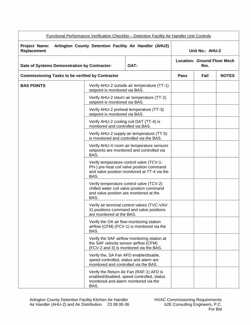
Arlington County Detention Facility Kitchen Air Handler HVAC Commissioning Requirements Air Handler (AHU-2) and Air Distribution 23 08 00-36 b2E Consulting Engineers, P.C.
For Bid
Functional Performance Verification Checklist – Detention Facility Air Handler Unit Controls
Project Name: Arlington County Detention Facility Air Handler (AHU2)
Replacement Unit No.: AHU-2
Date of Systems Demonstration by Contractor: OAT:
Location: Ground Floor Mech
Rm.
Commissioning Tasks to be verified by Contractor Pass Fail NOTES
BAS POINTS Verify AHU-2 outside air temperature (TT-1) setpoint is monitored via BAS.
Verify AHU-2 return air temperature (TT-2) setpoint is monitored via BAS.
Verify AHU-2 preheat temperature (TT-3) setpoint is monitored via BAS.
Verify AHU-2 cooling coil DAT (TT-4) is monitored and controlled via BAS.
Verify AHU-2 supply air temperature (TT-5) is monitored and controlled via the BAS.
Verify AHU-X room air temperature sensors setpoints are monitored and controlled via BAS.
Verify temperature control valve (TCV-1-PH-) pre-heat coil valve position command and valve position monitored at TT-4 via the BAS.
Verify temperature control valve (TCV-2) chilled water coil valve position command and valve position are monitored at the BAS.
Verify air terminal control valves (TVC-VAV-X) positions command and valve positions are monitored at the BAS.
Verify the OA air flow monitoring station airflow (CFM) (FCV-1) is monitored via the BAS.
Verify the SAF airflow monitoring station at the SAF velocity sensor airflow (CFM) (FCV-2 and 3) is monitored via the BAS.
Verify the, SA Fan AFD enable/disable, speed controlled, status and alarm are monitored and controlled via the BAS.
Verify the Return Air Fan (RAF-1) AFD is enabled/disabled, speed controlled, status monitored and alarm monitored via the BAS.

Arlington County Detention Facility Kitchen Air Handler HVAC Commissioning Requirements Air Handler (AHU-2) and Air Distribution 23 08 00-37 b2E Consulting Engineers, P.C.
For Bid
Verify the outside air damper position command and position (D-1) are monitored via the EMS.
Verify the modulating return air damper (D-2) position command and status are monitored and controlled via the BAS.
Verify the RAF-1 modulating return air damper (D-3) position command and status are monitored and controlled via the BAS.
Verify the RAF-1 damper (D-4) position command and status are monitored and controlled via the BAS.
Verify humidity sensor (MT-1) in the return air stream and is monitored via the BAS.
Verify the five (5) temperature sensors (TT-R 1 thru TT-R5) in the kitchen and one in the corridor are monitored via the BAS (Typ. of 6).
Verify freeze protection pump HWCP-1 is commanded “on” when the OAT < 45° F at
the OAT sensor in the OAT ductwork and status is monitored in the BAS.
Verify cooling coil control valve (TCV-2) modulates open to the coil to maintain cooling LAT setpoint 55°F (adj.) and
modulating SAT speed to maintain room temperature setpoint. Upon a drop in room temperature below setpoint the air terminal unit reheat coil valves (TCV-VAV-X) shall open to the coil to maintain kitchen room air temperature setpoint.
Verify the AHU-2 is enabled 30 minutes (adj.) prior to when the kitchen hood exhaust fan is started.
Verify AHU-2 SAF is started in morning warm up mode at 4:00 am (adj.) with outside air damper (FCV-1) closed and return air damper (D-1) open. Open all kitchen air terminal units (VAV Boxes) to maximum position. Verify the AHU-2 SAF modulates SAF speed to maintain 6,000 CFM.
Morning Warm Up: Verify the AHU-2 pre-heat coil valve (TCV-PH1) modulates open to the hot water preheat coil to maintain 70°F (adj.) when return air temperature (TT-
2) is less than setpoint.
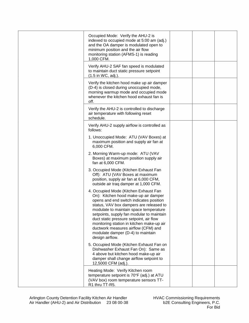
Arlington County Detention Facility Kitchen Air Handler HVAC Commissioning Requirements Air Handler (AHU-2) and Air Distribution 23 08 00-38 b2E Consulting Engineers, P.C.
For Bid
Occupied Mode: Verify the AHU-2 is indexed to occupied mode at 5:00 am (adj.) and the OA damper is modulated open to minimum position and the air flow monitoring station (AFMS-1) is reading 1,000 CFM.
Verify AHU-2 SAF fan speed is modulated to maintain duct static pressure setpoint (1.5 in WC, adj.).
Verify the kitchen hood make up air damper (D-4) is closed during unoccupied mode, morning warmup mode and occupied mode whenever the kitchen hood exhaust fan is off.
Verify the AHU-2 is controlled to discharge air temperature with following reset schedule.
Verify AHU-2 supply airflow is controlled as follows:
1. Unoccupied Mode: ATU (VAV Boxes) at maximum position and supply air fan at 6,000 CFM.
2. Morning Warm-up mode: ATU (VAV Boxes) at maximum position supply air fan at 6,000 CFM.
3. Occupied Mode (Kitchen Exhaust Fan Off): ATU (VAV Boxes at maximum position, supply air fan at 6,000 CFM, outside air traq damper at 1,000 CFM.
4. Occupied Mode (Kitchen Exhaust Fan On): Kitchen hood make-up air damper opens and end switch indicates position status, VAV box dampers are released to modulate to maintain space temperature setpoints, supply fan modular to maintain duct static pressure setpoint, air flow monitoring station in kitchen make-up air ductwork measures airflow (CFM) and modulate damper (D-4) to maintain design airflow.
5. Occupied Mode (Kitchen Exhaust Fan on Dishwasher Exhaust Fan On): Same as 4 above but kitchen hood make-up air damper shall change airflow setpoint to 12,5000 CFM (adj.).
Heating Mode: Verify Kitchen room temperature setpoint is 70°F (adj.) at ATU
(VAV box) room temperature sensors TT-R1 thru TT-R5.
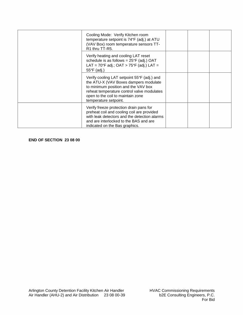
Arlington County Detention Facility Kitchen Air Handler HVAC Commissioning Requirements Air Handler (AHU-2) and Air Distribution 23 08 00-39 b2E Consulting Engineers, P.C.
For Bid
Cooling Mode: Verify Kitchen room temperature setpoint is 74°F (adj.) at ATU
(VAV Box) room temperature sensors TT-R1 thru TT-R5.
Verify heating and cooling LAT reset schedule is as follows = 25°F (adj.) OAT
LAT = 70°F adj.; OAT > 75°F (adj.) LAT =
55°F (adj.)
Verify cooling LAT setpoint 55°F (adj.) and
the ATU-X (VAV Boxes dampers modulate to minimum position and the VAV box reheat temperature control valve modulates open to the coil to maintain zone temperature setpoint.
Verify freeze protection drain pans for preheat coil and cooling coil are provided with leak detectors and the detection alarms and are interlocked to the BAS and are indicated on the Bas graphics.
END OF SECTION 23 08 00
Arlington County Detention Facility Kitchen Air Handler Building Automation System (BAS) Air Handler (AHU-2) and Air Distribution 23 09 00-1 b2E Consulting Engineers, P.C.
For Bid
SECTION 23 09 00
BUILDING AUTOMATION SYSTEM (BAS)
PART 1 - GENERAL
1.1 SCOPE
A. The intent of this Specification Section is to provide the Owner a complete web-based temperature control system consisting of, but not limited to electric and electronic controls and an automated Building Automation and digital control system. The temperature control system shall meet all of the performance requirements as shown on drawings and as outlined in this and related Sections of the Specifications.
B. The controls system shall consist of a BACnet DDC automation system primarily used for the Building Automation (BAS). Automatic temperature controls (ATC) are primarily local, electric or electronic. HVAC equipment shall be provided with either DDC and/or electric controls as specified and shall be connected to the automation system as specified herein after.
C. All control BAS and ATC work shall be installed by the BAS contractor for a complete fully operational control system. All labor, materials, equipment, software, and services necessary for the installation of a complete integrated system of BAS, ATC, and manufacturers' controls shall be furnished as specified herein, on drawings, and in related Sections of the Specifications.
D. Equipment and labor not specifically referred to herein or on the plans that are required to meet the functional intent shall be provided without additional cost to the Owner.
E. Commissioning Cooperation:
1. Manufacturer’s will be required to provide support required to: a. Clarify factory-programmed equipment sequences to allow an
independent party to write and execute testing of the design sequence of operations, including overriding programmed points.
b. Provide submittal documentation supporting compliance with EORs design specification (this includes identification and explanation of any areas of non-compliance with design).
c. Support start-up and verification of operation, as noted in EORs design specifications.
d. Provide personnel support during testing to confirm programmed points, equipment operation, troubleshooting operations and updating sequence to meet design intent on day of functional third party testing.
e. Timely support of equipment resolutions to close testing (and any retesting) within a 2 week period.
f. Manufacturer’s information should clearly identify equipment model, capacity, capabilities, options included, applicable O&M documentation, specific identification of recommended schedule for recalibration, maintenance activities, preventative maintenance plan/documentation and schedule, ongoing system optimization strategies, etc.
g. Provide operator and occupant training agenda and documentation.
Arlington County Detention Facility Kitchen Air Handler Building Automation System (BAS) Air Handler (AHU-2) and Air Distribution 23 09 00-2 b2E Consulting Engineers, P.C.
For Bid
1.2 PRE-CONSTRUCTION SUBMITTALS
A. Only equipment and/or devices that were approved for installation in this specification shall be used for installation under this contract.
B. Submit copies of appropriate shop drawings and control drawings for the building. The quantities of shop drawings submitted shall be in response to the requirements of the General Contractor; at a minimum, a copy shall be provided for each of the following:
1. General Contractor 2. Electrical Subcontractor 3. Mechanical Consulting Engineer 4. DES Construction Division 5. Mechanical Subcontractor 6. Engineer
C. Required shop drawings shall include but not be limited to the following items:
a. Controllers b. Transmitters c. Valves d. Software Manuals e. Microprocessors f. Dampers g. Sensors h. Enclosures i. Actuators j. Relays k. Switches l. Thermostats m. Panel enclosures
2. Control drawings shall be submitted. Integrate with flow diagrams, show outlines of HVAC equipment with control devices, schematic one line control piping and wiring, and written sequence of operation and operating instructions. Equipment numbers shall correspond to those shown on the construction documents. Submit points list showing each control input and output, the device being controlled, the location of the device, and the symbol or label of the control point in the software. Indicate the point of connection and function where connections are made to equipment with manufacturers' controls.
Refer to the following Building Automation System (BAS) drawings for other applicable requirements:
a. M801 – Air Handling Unit (AHU-2) Schematic Flow Control Diagram.
1.3 TEST AND GUARANTEE
A. The entire control system for the building shall be guaranteed free from all mechanical, electrical, and software defects for a period of five (5) years. During this five (5) year period, the Contractor shall be responsible for the proper adjustments of all system, equipment, and apparatus installed by him and do all work necessary to insure efficient and proper functioning
Arlington County Detention Facility Kitchen Air Handler Building Automation System (BAS) Air Handler (AHU-2) and Air Distribution 23 09 00-3 b2E Consulting Engineers, P.C.
For Bid
of the system hardware and software. The Contractor shall arrange to meet with the Engineers, the Architect, and the Owner within thirty (30) days prior to the specified end of the guarantee period for the purpose of compiling a list of items that require correction under specified guarantees. Should the Contractor fail to schedule the final meeting, then the Guarantee shall be automatically extended until such time as the meeting takes place; and the Contractor shall be fully responsible for correcting such deficiencies as if they occurred under the original guarantee period.
B. Controls Contractor shall have qualified service personnel on staff to respond in person at the project site within twenty-four (24) hours of receiving of service call from the Owner to the Contractors' office throughout the guarantee period. A no-heat or emergency condition shall require an immediate response.
C. Placing in service: Upon completion of the installation, calibrate equipment and verify transmission media operation before system is placed on line. All testing, adjusting, and calibrating shall be completed and system shall be properly operating prior to acceptance by Owner. Cross check each control point by comparing the control command and the field controlled device, equipment.
D. Prior to final acceptance and authorization for final payment by the Owner, Automatic Control System "punch list" inspections shall be made by the BAS Engineer and representatives of the Owner's construction, maintenance, and Building Automation departments. This is not to preclude that punch lists shall be made by the Contractor to check the completion of his work prior to final "punch lists" inspection. The punch lists inspections shall be in three parts. An inspection shall be performed and punch list (Installation Punch List) prepared regarding the physical installation of the BAS equipment, wiring, etc., and a separate punch list shall be prepared regarding the software programming at the site (Site Programming Punch List), and a third punch list shall be prepared regarding the software programming at the head-end (Head-End Programming Punch List).
1. At a minimum, prior to requesting a Head-End Programming Punch List inspection, all required "head end" software and graphics at the host computers shall be installed.
2. Prior to requesting a Site Programming Punch List inspection, all specified software and control strategies shall have been loaded into the computers at the facility to be inspected. It is recognized that not all software programming may be fully "debugged" at the time of Punch List inspections; however, the BAS Contractor shall be able to demonstrate that all required software strategies are installed and that equipment is being controlled by those strategies. To facilitate punch outs of installations, the Contractor shall have their software completely loaded and functional and a complete set of histories shall have been submitted to the BAS Engineer for his review. BAS Engineer shall not review histories until Head-End software and graphics have been approved by the DES Building Automation personnel.
3. A minimum of two (2) complete sets of trends shall be submitted for review. Trends must be delivered to the Engineer at least two (2) weeks prior to a scheduled on-site walk-thru of the facility. Trends shall be submitted illustrating system operations when the central plant is operating in the cooling mode (summer) and the heating mode (winter). The intent of this is to determine whether installed software is functioning as intended.
a. Central plant and global control points must be included in all runs of trends. b. Histories shall be presented at hourly intervals for a 24 hour period, unless
directed otherwise. System being monitored shall be operated with an occupancy schedule; i.e. indications that a system was scheduled off for the 24 hours of the history and remained off are of no value. Occupancy schedule and all system setpoints (both calculated and manual inputs) shall be provided with the histories.
Arlington County Detention Facility Kitchen Air Handler Building Automation System (BAS) Air Handler (AHU-2) and Air Distribution 23 09 00-4 b2E Consulting Engineers, P.C.
For Bid
c. Prior to submitting a history to the Owner, the Contractor shall perform a self review to identify and correct problem. Where trends indicate problem, discrepancies, and/or deficiencies and the Contractor has performed corrections, partial trends may be submitted as addenda or inserts with the original set of complete building trends indicating that the problem has been corrected.
d. To assure that trends suitably demonstrate appropriate operations, heating trends shall be run when outdoor air drops to an occurrence of at least 35°F during the trend period, cooling season trends can be run whenever outdoor air rises to an occurrence of at least 85°F during the trend period.
e. Predicated upon the discrepancies discerned by the engineer’s review of trends, subsequent complete or partial trends may be required.
4. A minimum of two (2) on-site inspections for punch-out of software shall be performed, one each for the heating and cooling modes. If scheduled delivery of the project falls during a period in which the central plant is not operating, BAS punch out will be delayed until such time as the central plant has been operating under BAS control for the afore specified one week. Initial acceptance of the BAS to start the warranty shall be conditional. Final acceptance shall be predicated on acceptance of the BAS in the subsequent seasonal operations. It is anticipated that two (2) on-site inspections and three (3) series of trends review will be sufficient to substantiate control system performance; however, the Owner reserves the right to convene a third on-site demonstration to witness all modes of operation should, in their opinion, trends warrant such. The following constitutes those items that, at a minimum, shall be included in a trend submittal:
a. Outdoor air: Dry bulb temperature and humidity b. Overrides: Run status c. Heating Water Plant (Boilers, pumps, loop temperatures) d. Chilled Water Plant (Chillers, pumps, loop temperatures). e. Air Handler (AHU-2) (all BAS points). f. Existing Air Handler (AHU-1 and RAF-1) (all available BAS points).
E. Over the five (5) year guarantee period, a complete BAS history shall be submitted by the
1. Contractor four times a year to the Owner for their review. The submission of histories may be increased or decreased pursuant to their evaluation; i.e., decreased if all is well, increased if problems exist. Prior to submitting a history to the Owner, the Contractor shall perform a self review to identify and correct problem. The intent of history reviews during the guarantee period by the Owner is fine tuning of the BAS, not debugging. The histories shall contain all of the points cited hereinbefore for Punch-Out histories.
F. Over the two year guarantee period, the Contractor shall provide and install all software upgrades released by the manufacturer as applicable to the system installed at the facility and at the central head-end computers at the Owner’s Construction Department and the Department of Environmental Services (DES).
1. Provide backup copies of software in the O&M Manual.
1.4 PERMITS AND INSPECTIONS
A. Contractor shall be responsible for obtaining and paying for electrical permits for any power wiring performed in the execution of the controls work. Certificate of final inspection shall be delivered to the Owner upon completion of the work.
Arlington County Detention Facility Kitchen Air Handler Building Automation System (BAS) Air Handler (AHU-2) and Air Distribution 23 09 00-5 b2E Consulting Engineers, P.C.
For Bid
1.5 PROJECT SEQUENCE
A. The control system work for this project shall proceed in the following order:
1. Submit and receive approval on the Shop Drawings, Product Data, and Certificates specified under the paragraph entitled "SUBMITTALS."
2. Perform the control system installation work, including all field check-outs and tuning. 3. Provide support to TAB personnel as specified under the paragraph "TEST AND
BALANCE SUPPORT." 4. Submit and receive approval of the Controls System Operators Manual specified under
the paragraph "CONTROLS SYSTEM OPERATORS MANUALS." 5. Submit and receive approval of the Performance Verification Testing Plan and the Pre-
PVT Checklist specified under the paragraph "PERFORMANCE VERIFICATION TESTING."
6. Perform the Performance Verification Testing. 7. Submit and receive approval on the PVT Report. 8. Submit and receive approval on the Training Documentation specified under the
paragraph "INSTRUCTION TO GOVERNMENT PERSONNEL" and "AFD Service Support". Submit at least 30 days before training.
9. Deliver the final Controls System Operators Manuals and AFD Service Manuals. 10. Conduct the Phase I Training and pump AFD on-site/hands-on training. 11. Conduct the Phase II Training. 12. Submit and receive approval of Closeout Submittals.
PART 2 – PRODUCTS
2.1 MANUFACTURERS
A. Acceptable Manufacturers: 1. Siemens – (Existing BAS) Contact Brad Turgeon 301-837-2600, (No substitutions).
2.2 BACnet DIRECT DIGITAL CONTROL SYSTEM FOR HVAC
A. Provide new BACnet DDC system including associated equipment and accessories. All new
devices are accessible using a Web browser interface and communicate using ASHRAE 135 BACnet communications without the use of gateways, unless gateways are shown on the design drawings and specifically requested by the Government. Where gateways are allowed, they must support ASHRAE 135, including all object properties and read-write services shown on Government approved interoperability schedules. Manufacturer's products, including design, materials, fabrication, assembly, inspection, and testing shall be in accordance with ASHRAE 135, ASME B31.1, and NFPA 70, except where indicated otherwise.
B. The building control network shall be an Open implementation of BACnet technology using ASHRAE 135 as the only communications protocol and use only standard BACnet services, for communication between DDC Hardware devices to allow multi-vendor interoperability.
C. The building automation system shall be open in that it is designed and installed such that the Government or its agents are able to perform repair, replacement, upgrades, and expansions of
Arlington County Detention Facility Kitchen Air Handler Building Automation System (BAS) Air Handler (AHU-2) and Air Distribution 23 09 00-6 b2E Consulting Engineers, P.C.
For Bid
the system without further dependence on the original Contractor. This includes, but is not limited to the following:
D. Install hardware such that individual control equipment can be replaced by similar control equipment from other equipment manufacturers with no loss of system functionality.
E. Necessary documentation (including rights to documentation and data), configuration information, configuration tools, programs, drivers, and other software shall be licensed to and otherwise remain with the Government.
F. Performance Standards: System shall conform to the following minimum standards over network connections. System shall be tested using manufacturer’s recommended hardware and software for operator workstation (server and browser for web-based system).
1. Graphics Display: A graphic with 20 dynamic points shall display with current data within 10 seconds.
2. Graphic Refresh: A graphic with 20 dynamic points shall display with current data within 8 seconds and shall automatically refresh every 15 seconds.
3. Configuration and Tuning Screens: Screens used for configuring, calibrating or tuning points, PID loops and similar control logic shall automatically refresh within 6 seconds.
4. Object Command: Devices shall react to command of a binary object within 2 seconds. Devices shall begin reacting to command of an analog object within 2 seconds.
5. Alarm Response Time: An object that goes into alarm shall be annunciated at the workstation within 15 seconds.
6. Program Execution Frequency: Custom and standard applications shall be capable of running as often as once every 5 seconds. Select execution times consistent with the mechanical process under control.
7. Performance: Programmable controllers shall be able to completely execute DDC PID control loops at a frequency adjustable down to once per second. Select execution times consistent with the mechanical process under control.
8. Multiple Alarm Annunciation: Each workstation on the network shall receive alarms within 5 seconds of other workstations.
9. Reporting Accuracy: System shall report values with minimum end-to-end accuracy listed in Table 1.
10. Control Stability and Accuracy: Control loops shall maintain measured variable at setpoint within tolerances listed in Table 2.
Table 1 – Reporting Accuracy
Measured Variable Reported Accuracy
Space Temperature ±0.5°C (±1°F)
Ducted Air ±0.5°C (±1°F)
Outside Air ±1.0°C (±2°F)
Dew Point ±1.5°C (±3°F)
Water Temperature ±0.5°C (±1°F)
Delta-T ±0.15°C (±0.25°F)
Relative Humidity ±5% RH
Water Flow ±2% of full scale

Arlington County Detention Facility Kitchen Air Handler Building Automation System (BAS) Air Handler (AHU-2) and Air Distribution 23 09 00-7 b2E Consulting Engineers, P.C.
For Bid
Airflow (terminal) ±10/% of full scale (see Note 1)
Airflow (measuring stations) ±5% of full scale
Airflow )pressurized spaces) ±3% of full scale
Air Pressure (ducts) ±25 Pa (±0.1 in. w.g.)
Air Pressure (space) ±3 Pa (±0.01 in. w.g.)
Water Pressure ±2% of full scale (see Note 2)
Electrical (A, V. W, Power Factor) ±1% of reading (see Note 3)
Carbon Monoxide (CO) ±5% of reading
Carbon Dioxide (CO2) ±50 ppm
Note 1: Accuracy applies to 10%-100% of scale Note 2: For both absolute and differential pressure Note 3: Not including utility-supplied meters
Table 2 – Control Stability and Accuracy
Controlled Variable Controlled Accuracy Range of Medium
Air Pressure ±50 Pa (±0.2 in. w.g.)
±3 Pa (±0.01 in. w.g.)
0-1.5 kPa (0-6 in. w.g.)
-25 to 25 Pa (-0.1 to 0.1 in. w.g.)
Airflow ±10% of full scale
Space Temperature ±1.0°C (±2.0°F)
Duct Temperature ±1.5°C (±3.0°F)
Humidity ±5% RH
Fluid Pressure ±10 kPa (±1.5 psi)
±250 Pa (±1.0 in. w.g.)
MPa (1-150 psi)
0-12.5 kPa (0-50 in. w.g.) differential
2.3 DDC SYSTEM
A. Open system design – The system shall be an open BACnet system, that will allow the owner flexibility for expansion/additions, and maintenance/service of the system. None of the hardware or software provided shall be proprietary or sole/single source. All hardware or software shall be available from two or more competing sources within a 100 mile radius of the building. All communications will be either BACnet/IP/Ethernet or BACnet MSTP (except for Boilers, Boiler Vent Controls and Pump AFD controls systems, which require a BACnet gateway).
B. Open systems design – The system shall be an open BACnet system, that will allow the owner flexibility for expansion/additions, and maintenance/service of the system. None of the hardware or software provided shall be proprietary or sole/single source. All hardware or software shall be available from two or more competing sources within a 100 mile radius of the building. All communications will be either BACnet/IP/Ethernet or BACnet MSTP (except
Arlington County Detention Facility Kitchen Air Handler Building Automation System (BAS) Air Handler (AHU-2) and Air Distribution 23 09 00-8 b2E Consulting Engineers, P.C.
For Bid
for Boilers, Boiler Vent Controls and Pump AFD controls system, which require a BACnet gateway).
C. Provide a networked DDC system for stand-alone control in compliance with the latest revision of the ASHRAE 135 BACnet standard. Include all programming, objects, and services required to meet the sequence of control. Provide BACnet communications between the DDC system and native BACnet devices furnished with HVAC equipment and plant equipment including boilers, chillers, and variable frequency drives. Devices provided shall be certified in the BACnet Testing Laboratories (BTL) Product Listing. Provide PICS (protocol implementation conformance statement) for each component.
D. Provide an operator workstation and new server with complete interface software capable of programming, configuring, and monitoring the digital controllers. Interface the new DDC system with the site's existing server and operator workstation and software including graphic creation, scheduling, alarming, and trending. The server and workstation are located at the site AC Justice Center Facilities Office on the 13
th floor of the Courts Police
Building 1425 N Courthouse Road, Arlington VA.
2.4 MATERIALS
A. Use new products the manufacturer is currently manufacturing and selling for use in new installations. Do not use this installation as a product test site unless explicitly approved in writing by Owner. Spare parts shall be available for at least five years after completion of this contract.
2.5 COMMUNICATION
A. Control products, communication media connectors, repeaters, hubs, and routers shall comprise a BACnet internetwork. Controller and operator interface communication shall conform to ANSI/ASHRAE Standard 135, BACnet.
B. Install new wiring and network devices as required to provide a complete and workable control network. Use existing Ethernet backbone for network segments marked “existing” on project drawings.
C. Each controller shall have a communication port for temporary connection to a laptop computer or other operator interface. Connection shall support memory downloads and other commissioning and troubleshooting operations.
D. Internetwork operator interface and value passing shall be transparent to internetwork architecture. 1. An operator interface connected to a controller shall allow the operator to interface
with each internetwork controller as if directly connected. Controller information such as data, status, and control algorithms shall be viewable and editable from each internetwork controller.
2. Inputs, outputs, and control variables used to integrate control strategies across multiple controllers shall be readable by each controller on the internetwork. Program and test all cross-controller links required to execute control strategies specified in Section 23 09 93. An authorized operator shall be able to edit cross-controller links by typing a standard object address or by using a point-and-click interface.
Arlington County Detention Facility Kitchen Air Handler Building Automation System (BAS) Air Handler (AHU-2) and Air Distribution 23 09 00-9 b2E Consulting Engineers, P.C.
For Bid
E. Controllers with real-time clocks shall use the BACnet Time Synchronization service. System shall automatically synchronize system clocks daily from an operator-designated controller via the internetwork. If applicable, system shall automatically adjust for daylight saving and standard time.
F. System shall be expandable to at least twice the required input and output objects with additional controllers, associated devices, and wiring.
2.6 OPERATOR INTERFACE
A. Operator Interface: Web server shall reside on high-speed network with building controllers. Each standard browser connected to server shall be able to access all system information.
B. Communication: Web server or workstation and controllers shall communicate using BACnet Controllers for BACnet protocol. Web server or workstation and control network backbone shall communicate using ISO 8802-3 (Ethernet) Data Link/Physical layer protocol and BACnet/IP addressing as specified in ANSI/ASHRAE 135. BACnet Annex J.
C. Hardware: Each workstation or web server shall consist of the following: 1. Hardware Base: Industry-standard hardware shall meet or exceed DDC system
manufacturer’s recommended specifications. Hard disk shall have sufficient memory to store system software, one year of data for trended points specified. Configure computers and network connections if multiple computers are required to meet specified memory and performance. Web server or workstations shall be IBM-compatible PCs with a minimum of:
a. Intel Core i7 24 GHz CPU, or better. b. 16 GB DDR4 Ram, or better. c. 500 GB solid state drive, or better. d. Minimum of 1 Ethernet ports. e. Minimum 1 USB 3.0 ports. f. Minimum 2 USB 2.0 ports. g. Minimum 1 HDMI, DVI, or Display Port Connections.
D. Operator Functions: Operator interface shall allow each authorized operator to execute the following functions as a minimum:
1. Log in and Log out: System shall require user name and password to log in to operator interface.
2. Point-and-click Navigation: Operator interface shall be graphically based and shall allow operators to access graphics for equipment and geographic areas using pint-and-click navigation.
3. View and Adjust Equipment Properties: Operators shall be able to view controlled equipment status and to adjust operating parameters such as setpoints, PID gains, on and off controls, and sensor calibration.
4. View and Adjust Operating Schedules: Operators shall be able to view scheduled operating hours of each schedulable piece of equipment on a weekly or monthly calendar-based graphical schedule display, to select and adjust each schedule and time period, and to simultaneously schedule related equipment. System shall clearly show exception schedules and holidays on the schedule display.
5. View and Respond to Alarms: Operators shall be able to view a list of currently active system alarms, to acknowledge each alarm, and to clear (delete) unneeded alarms.
Arlington County Detention Facility Kitchen Air Handler Building Automation System (BAS) Air Handler (AHU-2) and Air Distribution 23 09 00-10 b2E Consulting Engineers, P.C.
For Bid
6. View and Configure Trends: Operators shall be able to view a trend graph of each trended point and to edit graph configuration to display a specific time period or data range. Operator shall be able to create custom trend graphs to display on the same page data from multiple trended points.
7. View and Configure Reports: Operators shall be able to run preconfigured reports, to view report results, and to customize report configuration to show data of interest.
8. Manage Control System Hardware: Operators shall be able to view controller status, to restart (reboot) each controller, and to download new control software to each controller.
9. Manage Operator Access: Typically, only a few operators are authorized to manage operator access. Authorized operators shall be able to view a list of operators with system access and of functions they can perform while logged in. Operators shall be able to add operators, to delete operators, and to edit operator function authorization. Operator shall be able to authorize each operator function separately.
E. System Software 1. Operating System: Web server shall have an industry-standard professional-
grade operating system. Acceptable systems include Microsoft Windows 7, Vista, Windows XP Pro, Red Hat Linux, or Sun Solaris.
2. System Graphics: Operator interface shall be graphically based and shall include at least one graphic per piece of equipment or occupied zone, graphics for each chilled water and hot water system, and graphics that summarize conditions on each floor of each building included in this contract. Indicate thermal comfort on floor plan summary graphics using dynamic colors to represent zone temperature relative to zone setpoint. a. Functionality: Graphics shall allow operator to monitor system status, to
view a summary of the most important data for each controlled zone or piece of equipment, to use point-and-click navigation between zones or equipment, and to edit setpoints and other specified parameters.
b. Animation: Graphics shall be able to animate by displaying different image files for changed object status.
c. Alarm Indication: Indicate areas or equipment in an alarm condition using color or other visual indicator.
d. Format: Graphics shall be saved in an industry-standard format such as BMP, JPEG, PNG, or GIF. Web-based system graphics shall be viewable on browsers compatible with World Wide Web Consortium browser standards. Web graphic format shall require o plug-in (such as HTML and JavaScript) or shall only require widely available no-cost plug-ins (such as Active-X and Adobe Flash).
F. System Tools: System shall provide the following functionality to authorized operators as an integral part of the operator interface or as stand-alone software programs. If furnished as part of the interface, the tool shall be available from each workstation or web browser interface. If furnished as a stand-alone program, software shall be installable o standard IBM-compatible PCs with no limit on the number of copies that can be installed under the system license. 1. Automatic System Database Configuration: Each workstation or web server shall
store on its hard disk a copy of the current system database, including controller firmware and software. Stored database shall be automatically updated with each system configuration or controller firmware or software change.
2. Controller Memory Download: Operators shall be able to download memory from the system database to each controller.
3. System Configuration: Operators shall be able to configure the system.
Arlington County Detention Facility Kitchen Air Handler Building Automation System (BAS) Air Handler (AHU-2) and Air Distribution 23 09 00-11 b2E Consulting Engineers, P.C.
For Bid
4. Online Help: Context-sensitive online help for each tool shall assist operators in operating and editing the system.
5. Security: System shall require a user name and password to view, edit, add, or delete data. a. Operator Access: Each user name and password combination shall
define accessible viewing, editing, adding, and deleting functions in each system application, editor, and object.
b. Automatic Log Out: Automatically log out each operator if no keyboard or mouse activity if detected. Operators shall be able to adjust automatic log out delay.
c. Encrypted Security Data: Store system security data including operator passwords in an encrypted format. System shall not display operator passwords.
6. System Diagnostics: System shall automatically monitor controller and I/O point operation. System shall annunciate controller failure and I/O point locking (manual overriding to a fixed value).
7. Alarm Processing: System input and status objects shall be configurable to alarm on departing from and on returning to normal state. Operator shall be able to enable or disable each alarm and to configure alarm limits, alarm limit differentials, alarm states, and alarm reactions for each system object. Configure and enable alarm points as specified in Section 23 09 93 “Sequence of Operations for HVAC Controls”. Alarms shall be BACnet alarm objects and shall use BACnet alarm services.
8. Alarm Messages: Alarm messages shall use an English language descriptor without acronyms or mnemonics to describe alarm source, location, and nature.
9. Alarm Reactions: Operator shall be able to configure (by object) actions workstation or web server shall initiate on receipt of each alarm. As a minimum, workstation or web server shall be able to log, print, start programs, display messages, send e-mail, send page, and audibly annunciate.
10. Alarm Maintenance: Operators shall be able to view system alarms and changes of state chronologically, to acknowledge and delete alarms, and to archive closed alarms to the workstation or web server hard disk from each workstation or web browser interface.
11. Trend Configuration: Operator shall be able to configure trend sample or change of value (COV) interval, start-time, and stop time for each system data object and shall be able to retrieve data for use in spreadsheets and standard database programs. Controller shall sample and store trend data and shall be able to archive data to the hard disk. Configure trends as specified in Section 23 09 93 “Sequence of Operations for HVAC Controls”. Trends shall be BACnet trend objects.
12. Object and Property Status and Control: Operator shall be able to view, and to edit if applicable, the status of each system object and property by menu, on graphics, or through custom programs.
13. Reports and Logs: Operator shall be able to select, to modify, to create, and to print reports and logs. Operator shall be able to store report data in a format accessible by standard spreadsheet and word processing programs.
14. Standard Reports: Furnish the following standard system reports: a. Objects: System objects and current values filtered by object type, by
status (in alarm, locked, normal) by equipment, by geographic location, or by combination of filter criteria.
b. Alarm Summary: Current alarms and closed alarms. System shall retain closed alarms for an adjustable period.
c. Logs: System shall log the following to a database or text file and shall retain data for an adjustable period:
Arlington County Detention Facility Kitchen Air Handler Building Automation System (BAS) Air Handler (AHU-2) and Air Distribution 23 09 00-12 b2E Consulting Engineers, P.C.
For Bid
i. Alarm History ii. Trend Data: Operator shall be able to select trends to be
logged. iii. Operator Activity: At a minimum, system shall log operator log
in and log out, control parameter changes, schedule changes, and alarm acknowledge and deletion. System shall date and time stamp logged activity.
15. Energy Reports: System shall include an easily configured energy reporting tool that provides the capabilities described in this section. a. The energy reporting tool shall be accessible through the same user
interface (Web browser or operator workstation software) as is used to manage the BAS.
b. The energy reporting tool shall be preconfigured by the Contractor to gather and store energy demand and consumption data from each energy source that provides metered data to the BAS. Meter data shall be stored at 5 minute intervals unless otherwise specified in the Sequence of Operation provided in Section 23 09 93. This data shall be maintained in an industry standard SQL database for a period of not less than five years. Typed by CB.
c. The energy reporting tool shall allow the operator to select an energy source and a time period of interest (day, week, month, year, or date range) and shall provide options to view the data in a table, line graph, bar graph, or pie chart. The tool shall also allow the operator to select two or more data sources and display a comparison of the energy used over this period in any of the listed graph formats, or to total the energy used by the selected sources and display that data in the supported formats.
d. The energy reporting tool shall allow the operator to select an energy source and two time periods of interest (day, week, month, year, or date range) and display a graph that compares the energy use over the two time periods in any of the graph formats listed in the previous paragraph. The tool shall also allow the operator to select multiple energy sources and display a graph that compares the total energy used by these sources over the two time periods.
e. The energy reporting tool shall allow the operator to easily generate the previously described graphs "on the fly," and shall provide an option to store the report format so the operator can select that format to regenerate the graph at a future date. The tool shall also allow the user to schedule these reports to run on a recurring basis using relative time periods, such as automatically generating a consumption report on the first Monday of each month showing consumption over the previous month. Automatically generated reports shall be archived on the server in a common industry format such as Adobe PDF or Microsoft Excel with copies e-mailed to a user editable list of recipients.
f. The energy reporting tool shall be capable of collecting and displaying data from the following types of meters:
i. Electricity ii. Gas iii. Potable Water iv. Heating and cooling degree days. (May be calculated from
sensor data rather than metered.)
g. The user shall have the option of using kW (Kwh) or BTU/hr (BTU) as the units for demand and consumption reports. Multiples of these units (MWH,
Arlington County Detention Facility Kitchen Air Handler Building Automation System (BAS) Air Handler (AHU-2) and Air Distribution 23 09 00-13 b2E Consulting Engineers, P.C.
For Bid
kBtu, etc.) shall be used as appropriate. All selected sources shall be automatically converted to the selected units. The user shall similarly have the option of entering facility area and occupancy hours and creating reports that are normalized on an area basis, an annual use basis, or an occupied hour basis.
h. The user shall have the option of entering benchmark data for an individual facility or a group of facilities.
i. The user shall have the option of displaying any or all of the following data on any chart, line, or bar graph generated by the energy reporting tool:
i. Low/High/Average value of the metered value being displayed. ii. Heating and/or Cooling Degree Days for the time period(s) being
displayed. iii. The Environmental Index for the facilities and time periods being
displayed.
16. Environmental Index. System shall monitor all occupied zones and compile an index that provides a numerical indication of the environmental comfort within the zone. As a minimum, this indication shall be based upon the deviation of the zone temperature from the heating or cooling setpoint. If humidity is being measured within the zone then the environmental index shall be adjusted to reflect a lower comfort level for high or low humidity levels. Similarly, if carbon dioxide levels are being measured as an indication of ventilation effectiveness then the environmental index shall be adjusted to indicate degraded comfort at high carbon dioxide levels. Other adjustments may be made to the environmental index based upon additional measurements. The system shall maintain a trend of the environmental index for each zone in the trend log. The system shall also compute an average comfort index for every building included in this contract and maintain trend logs of these building environmental indices. Similarly, the system shall compute the percentage of occupied time that comfortable conditions were maintained within the zones. Through the UI the user shall be able to add a weighting factor to adjust the contribution of each zone to the average index based upon the floor area of the zone, importance of the zone, or other static criteria.
17. Custom Reports. Operator shall be able to create custom reports that retrieve data, including archived trend data, from the system, that analyze data using common algebraic calculations, and that present results in tabular or graphical format. Reports shall be launched from the operator interface.
18. Graphics Generation. Graphically based tools and documentation shall allow Operator to edit system graphics, to create graphics, and to integrate graphics into the system. Operator shall be able to add analog and binary values, dynamic text, static text, and animation files to a background graphic using a mouse.
19. Graphics Library. Complete library of standard HVAC equipment graphics shall include equipment such as chillers, boilers, air handlers, terminals, fan coils, and unit ventilators. Library shall include standard symbols for other equipment including fans, pumps, coils, valves, piping, dampers, and ductwork. Library graphic file format shall be compatible with graphics generation tools.
20. Custom Application Programming. Operator shall be able to create, edit, debug, and download custom programs. System shall be fully operable
Arlington County Detention Facility Kitchen Air Handler Building Automation System (BAS) Air Handler (AHU-2) and Air Distribution 23 09 00-14 b2E Consulting Engineers, P.C.
For Bid
while custom programs are edited, compiled, and downloaded. Programming language shall have the following features:
a. Language. Language shall be graphically based and shall use function blocks arranged in a logic diagram that clearly shows control logic flow. Function blocks shall directly provide functions listed below, and operators shall be able to create custom or compound function blocks.
b. Programming Environment. Tool shall provide a full-screen, cursor-and-mouse-driven programming environment that incorporates word processing features such as cut and paste. Operators shall be able to insert, add, modify, and delete custom programming code, and to copy blocks of code to a file library for reuse in other control programs.
c. Independent Program Modules. Operator shall be able to develop independently executing program modules that can disable, enable and exchange data with other program modules.
d. Debugging and Simulation. Operator shall be able to step through the program observing intermediate values and results. Operator shall be able to adjust input variables to simulate actual operating conditions. Operator shall be able to adjust each step's time increment to observe operation of delays, integrators, and other time-sensitive control logic. Debugger shall provide error messages for syntax and for execution errors.
e. Conditional Statements. Operator shall be able to program conditional logic using compound Boolean (AND, OR, and NOT) and relational (EQUAL, LESS THAN, GREATER THAN, NOT EQUAL) comparisons.
f. Mathematical Functions. Language shall support floating-point addition, subtraction, multiplication, division, and square root operations, as well as absolute value calculation and programmatic selection of minimum and maximum values from a list of values.
g. Variables: Operator shall be able to use variable values in program conditional statements and mathematical functions.
i. Time Variables. Operator shall be able to use predefined variables to represent time of day, day of the week, month of the year, and date. Other predefined variables or simple control logic shall provide elapsed time in seconds, minutes, hours, and days. Operator shall be able to start, stop, and reset elapsed time variables using the program language.
ii. System Variables. Operator shall be able to use predefined variables to represent status and results of Controller Software and shall be able to enable, disable, and change setpoints of Controller Software as described in Controller Software section.
G. Portable Operator's Terminal Laptop. Provide all necessary software to configure an IBM-compatible Tablet computer for use as a Portable Operator's Terminal. Operator shall be able to connect configured Terminal to the system network or directly to each controller for programming, setting up, and troubleshooting.
H. Operator Workstation: Web server and workstation shall conform to BACnet Operator Workstation (B-OWS) device profile or BACnet Advanced Workstation (B-AWS) as specified
Arlington County Detention Facility Kitchen Air Handler Building Automation System (BAS) Air Handler (AHU-2) and Air Distribution 23 09 00-15 b2E Consulting Engineers, P.C.
For Bid
in ANSI/ASHRAE 135, BACnet Annex L and shall be listed as a certified B-OWS or B-AWS in the BACnet Testing Laboratories (BTL) Product Listing.
2.6 CONTROLLER SOFTWARE
A. Building and Building Automationapplication software shall reside and operate in system controllers. Applications shall be editable through operator workstation, web browser interface, or engineering workstation.
B. Scheduling. System shall provide the following schedule options as a minimum:
1. Weekly. Provide separate schedules for each day of the week. Each schedule shall be able to include up to 5 occupied periods (5 start-stop pairs or 10 events).
2. Exception. Operator shall be able to designate an exception schedule for each of the next 365 days. After an exception schedule has executed, system shall discard and replace exception schedule with standard schedule for that day of the week.
3. Holiday. Operator shall be able to define 24 special or holiday schedules of varying length on a scheduling calendar that repeats each year.
C. System Coordination. Operator shall be able to group related equipment based on function and location and to use these groups for scheduling and other applications.
D. Remote Communication. System shall automatically contact operator workstation or server on receipt of critical alarms. If no network connection is available, system shall use a modem connection.
E. Demand Limiting.
1. System shall monitor building power consumption from building power meter pulse generator signals or from building feeder line watt transducer or current transformer.
2. When power consumption exceeds adjustable levels, system shall automatically adjust setpoints, de-energize low-priority equipment, and take other programmatic actions to reduce demand as specified in Section 23 09 93 – Sequence of Operations for HVAC Controls. When demand drops below adjustable levels, system shall restore loads as specified.
F. Maintenance Management. System shall generate maintenance alarms when equipment exceeds adjustable runtime, equipment starts, or performance limits. Configure and enable maintenance alarms as specified in Section 23 09 93 – Sequence of Operations for HVAC Controls.
G. Sequencing. Application software shall sequence chillers, boilers, and pumps as specified in Section 23 09 93 – Sequence of Operations for HVAC Controls.
H. PID Control. System shall provide direct- and reverse-acting PID (proportional-integral-derivative) algorithms. Each algorithm shall have anti-windup and selectable controlled variable, setpoint, and PID gains. Each algorithm shall calculate a time-varying analog value that can be used to position an output or to stage a series of outputs.
I. Staggered Start. System shall stagger controlled equipment restart after power outage. Operator shall be able to adjust equipment restart order and time delay between equipment restarts.
J. Energy Calculations. 1. System shall accumulate and convert instantaneous power (kW) or flow rates gpm)
to energy usage data.
Arlington County Detention Facility Kitchen Air Handler Building Automation System (BAS) Air Handler (AHU-2) and Air Distribution 23 09 00-16 b2E Consulting Engineers, P.C.
For Bid
2. System shall calculate a sliding-window average (rolling average). Operator shall be able to adjust window interval to 15 minutes, 30 minutes, or 60 minutes.
K. Anti-Short Cycling. Binary output objects shall be protected from short cycling by means of adjustable minimum on-time and off-time settings.
L. On and Off Control with Differential. System shall provide direct- and reverse-acting on and off algorithms with adjustable differential to cycle a binary output based on a controlled variable and setpoint.
M. Runtime Totalization. System shall provide an algorithm that can totalize runtime for each binary input and output. Operator shall be able to enable runtime alarm based on exceeded adjustable runtime limit. Configure and enable runtime totalization and alarms as specified in Section 23 09 93 – Sequence of Operations for HVAC Controls.
2.7 CONTROLLERS
A. General. Provide Building Controllers (BC), Advanced Application Controllers (AAC), Application Specific Controllers (ASC), Smart Actuators (SA), and Smart Sensors (SS) as required to achieve performance specified in Section 23 09 23. Every device in the system which executes control logic and directly controls HVAC equipment must conform to a standard BACnet Device profile as specified in ANSI/ASHRAE 135, BACnet Annex L. Unless otherwise specified, hardwired actuators and sensors may be used in lieu of BACnet Smart Actuators and Smart Sensors.
B. BACnet.
1. Building Controllers (BCs). Each BC shall conform to BACnet Building Controller (B-BC) device profile as specified in ANSI/ASHRAE 135, BACnet Annex L and shall be listed as a certified B-BC in the BACnet Testing Laboratories (BTL) Product Listing.
2. Advanced Application Controllers (AACs). Each AAC shall conform to BACnet Advanced Application Controller (B-AAC) device profile as specified in ANSI/ASHRAE 135, BACnet Annex L and shall be listed as a certified B-AAC in the BACnet Testing Laboratories (BTL) Product Listing.
3. Application Specific Controllers (ASCs). Each ASC shall conform to BACnet Application Specific Controller (B-ASC) device profile as specified in ANSI/ASHRAE 135, BACnet Annex L and shall be listed as a certified B-ASC in the BACnet Testing Laboratories (BTL) Product Listing.
4. Smart Actuators (SAs). Each SA shall conform to BACnet Smart Actuator (B-SA) device profile as specified in ANSI/ASHRAE 135, BACnet Annex L and shall be listed as a certified B-SA in the BACnet Testing Laboratories (BTL) Product Listing.
5. Smart Sensors (SSs). Each SS shall conform to BACnet Smart Sensor (B-SS) device profile as specified in ANSI/ASHRAE 135, BACnet Annex L and shall be listed as a certified B-SS in the BACnet Testing Laboratories (BTL) Product Listing.
6. BACnet Communication.
a. Each BC shall reside on or be connected to a BACnet network using ISO 8802-3 (Ethernet) Data Link/Physical layer protocol and BACnet/IP addressing.
b. BACnet routing shall be performed by BCs or other BACnet device routers as necessary to connect BCs to networks of AACs and ASCs.
c. Each AAC shall reside on a BACnet network using ISO 8802-3 (Ethernet) Data Link/Physical layer protocol with BACnet/IP addressing, or it shall reside on a BACnet network using the ARCNET or MS/TP Data Link/Physical layer protocol.
Arlington County Detention Facility Kitchen Air Handler Building Automation System (BAS) Air Handler (AHU-2) and Air Distribution 23 09 00-17 b2E Consulting Engineers, P.C.
For Bid
d. Each ASC shall reside on a BACnet network using the ARCNET or MS/TP Data Link/Physical layer protocol.
e. Each SA shall reside on a BACnet network using the ARCNET or MS/TP Data Link/Physical layer protocol.
C. Each SS shall reside on a BACnet network using ISO 8802-3 (Ethernet) Data Link/Physical layer protocol with BACnet/IP addressing, or it shall reside on a BACnet network using ARCNET or MS/TP Data Link/Physical layer protocol.
D. Communication 1. Service Port. Each controller shall provide a service communication port for connection to
a Portable Operator's Terminal. Connection shall be extended to space temperature sensor ports where shown on drawings.
2. Signal Management. BC and ASC operating systems shall manage input and output communication signals to allow distributed controllers to share real and virtual object information and to allow for central monitoring and alarms.
3. Data Sharing. Each BC and AAC shall share data as required with each networked BC and AAC.
4. Stand-Alone Operation. Each piece of equipment specified in Section 23 09 93 shall be controlled by a single controller to provide stand-alone control in the event of communication failure. All I/O points specified for a piece of equipment shall be integral to its controller. Provide stable and reliable stand-alone control using default values or other method for values normally read over the network.
E. Environment - Controller hardware shall be suitable for anticipated ambient conditions. 1. Controllers used outdoors or in wet ambient conditions shall be mounted in waterproof
enclosures and shall be rated for operation at -29°C to 60°C (-20°F to 140°F). 2. Controllers used in conditioned space shall be mounted in dust-protective enclosures and
shall be rated for operation at 0°C to 50°C (32°F to 120°F).
F. Keypad. Provide a local keypad and display for each BC and AAC. Operator shall be able to use keypad to view and edit data. Keypad and display shall require password to prevent unauthorized use. If the manufacturer does not normally provide a keypad and display for each BC and AAC, provide the software and any interface cabling needed to use a laptop computer as a Portable Operator's Terminal for the system.
G. Real-Time Clock. Controllers that perform scheduling shall have a real-time clock.
H. Serviceability. 1. Controllers shall have diagnostic LEDs for power, communication, and processor. 2. Wires shall be connected to a field-removable modular terminal strip or to a termination
card connected by a ribbon cable. 3. Each BC and AAC shall continually check its processor and memory circuit status and
shall generate an alarm on abnormal operation. System shall continuously check controller network and generate alarm for each controller that fails to respond.
I. Memory. 1. Controller memory shall support operating system, database, and programming
requirements. 2. Each BC and AAC shall retain BIOS and application programming for at least 72 hours in
the event of power loss. 3. Each ASC and SA shall use nonvolatile memory and shall retain BIOS and application
programming in the event of power loss. System shall automatically download dynamic control parameters following power loss.
Arlington County Detention Facility Kitchen Air Handler Building Automation System (BAS) Air Handler (AHU-2) and Air Distribution 23 09 00-18 b2E Consulting Engineers, P.C.
For Bid
J. Immunity to Power and Noise. Controllers shall be able to operate at 90% to 110% of nominal voltage rating and shall perform an orderly shutdown below 80% nominal voltage. Operation shall be protected against electrical noise of 5 to 120 Hz and from keyed radios up to 5 W at 1 m (3 ft).
K. Transformer. ASC power supply shall be fused or current limiting and shall be rated at a minimum of 125% of ASC power consumption.
2.8 INPUT AND OUTPUT INTERFACE
A. General. Hard-wire input and output points to BCs, AACs, ASCs, or SAs.
B. Protection. Shorting an input or output point to itself, to another point, or to ground shall cause no controller damage. Input or output point contact with up to 24 V for any duration shall cause no controller damage.
C. Binary Inputs. Binary inputs shall monitor the on and off signal from a remote device. Binary inputs shall provide a wetting current of at least 12 mA and shall be protected against contact bounce and noise. Binary inputs shall sense dry contact closure without application of power external to the controller.
D. Pulse Accumulation Inputs. Pulse accumulation inputs shall conform to binary input requirements and shall accumulate up to 10 pulses per second.
E. Analog Inputs. Analog inputs shall monitor low-voltage (0-10 Vdc), current (4-20 mA), or resistance (thermistor or RTD) signals. Analog inputs shall be compatible with and field configurable to commonly available sensing devices.
F. Binary Outputs. Binary outputs shall send an on-or-off signal for on and off control. Building Controller binary outputs shall have three-position (on-off-auto) override switches and status lights. Outputs shall be selectable for normally open or normally closed operation.
G. Analog Outputs. Analog outputs shall send a modulating 0-10 Vdc or 4-20 mA signal as required to properly control output devices. Each Building Controller analog output shall have a two-position (auto-manual) switch, a manually adjustable potentiometer, and status lights. Analog outputs shall not drift more than 0.4% of range annually.
H. Tri-State Outputs. Control three-point floating electronic actuators without feedback with tri-state outputs (two coordinated binary outputs). Tri-State outputs may be used to provide analog output control in zone control and terminal unit control applications such as VAV terminal units, duct-mounted heating coils, and zone dampers.
I. Universal Inputs and Outputs. Inputs and outputs that can be designated as either binary or analog in software shall conform to the provisions of this section that are appropriate for their designated use.
J. Provide a BACnet internetwork with control products, communication media, connectors, repeaters, hubs, and routers. Provide intermediate gateways, only when requested by the Government and shown on the contract drawings, to connect existing non-BACnet devices to the BACnet internetwork. Controller and operator interface communication shall conform to ASHRAE 135, BACnet. [Use the building's existing Ethernet backbone for network segments marked "existing" on project drawings. Coordinate connections to existing Ethernet backbones with the BAS Owner and LAN administrator.] If a controller becomes non-responsive, the remaining controllers shall continue operating and not be affected by the failed controller.
Arlington County Detention Facility Kitchen Air Handler Building Automation System (BAS) Air Handler (AHU-2) and Air Distribution 23 09 00-19 b2E Consulting Engineers, P.C.
For Bid
K. Provide BACnet communication ports, whenever available as a plant equipment OEM standard option, for DDC integration via a single communication cable. Typical BACnet controlled plant equipment includes, but is not limited to, boilers, chillers, and variable frequency motor drives. Provide gateways to connect BACnet to legacy system, existing non-BACnet devices, and existing non-BACnet DDC controlled plant equipment, only when specifically requested and approved by the Government, and shown on the Government approved BACnet Communication Architecture Schematic. Provide with each gateway an interoperability schedule [Use gateway interoperability schedules shown on design drawings or other project documents], showing each point or event on the legacy side that the BACnet "client" will read, and each parameter that the BACnet network will write to. Describe this interoperability in terms of BACnet services, or Interoperability Building Blocks (BIBBS), defined in ASHRAE 135 Annex K. Provide two-year minimum warranty for each gateway, including parts and labor. The following minimum capabilities are required a. Gateways shall be able to read and view all readable object properties listed in the
interoperability schedule on the non-BACnet network to the BACnet network and vice versa where applicable.
b. Gateways shall include all hardware, software, software licenses, and configuration tools for operator-to-gateway communications. Provide backup programming and parameters on CD media and the ability to modify, download, backup, and restore gateway configuration.
L. Native trending capabilities are provided for in paragraph a. below, but may or may not be used at the discretion of the user. Primary trending of all points identified in the Trend Schedule shall be performed by a dedicated device as described in paragraph b. These trends shall be automatically collected by the operator workstation and may also be collected by an authorized third party. a. Provide BACnet trend services capable of trending all object present values set points,
and other parameters indicated for trending on project schedules. Trends may be associated into groups, and a trend report may be set up for each group. Trends are stored within a device on the BACnet network, with operator selectable trend intervals from 10 seconds up to 60 minutes. The minimum number of consecutive trend values stored at one time shall be 300 per variable. When trend memory is full, the most recent data shall overwrite the oldest data. Trending objects:
1) Create BACnet TL’s (Trend Log) objects for every physical input, output, and every set-point in the system. The TL’s can exist in field controller or global controllers.
2) BACnet TL’s (Trend Log) objects for every physical input, output, and every set-point in the system. The TL’s can exist in field controller or global controllers
3) All analog inputs, outputs, and automatically resetting set-points shall be interval trended.
a) Intervals i. Space temperatures – 30 minutes. ii. Analog inputs and outputs associated with PID loops – 5
minutes. iii. All other inputs, outputs, and automatically resetting set-points –
15 minutes. 4) Local storage – all trended data shall be stored in the system for a minimum of 4
days. a) 193 instances for 30 minute trends. b) 384 instances for 15 minute trends. c) 1152 instances for 5 minute trends.
b. The operator workstation shall upload trends automatically upon reaching 3/4 of the device buffer limit (via Notification_Threshold property), by operator request, or by time
Arlington County Detention Facility Kitchen Air Handler Building Automation System (BAS) Air Handler (AHU-2) and Air Distribution 23 09 00-20 b2E Consulting Engineers, P.C.
For Bid
schedule for archiving. Archived and real-time trend data shall be available for viewing numerically and graphically for at the workstation and connected notebook computers.
c. The operator workstation shall upload trends automatically upon reaching 3/4 of the device buffer limit (via Notification_Threshold property), by operator request, or by time schedule for archiving. Archived and real-time trend data shall be available for viewing numerically and graphically for at the workstation and connected notebook computers.
1) Ability to trend all of the points as specified in the Trend Schedule and store all trend data for a minimum of 7 days.
2) to trend all of the points as specified in the Trend Schedule and store all trend data for a minimum of 7 days.
2.9 POWER SUPPLIES AND LINE FILTERING
A. Power Supplies. Control transformers shall be UL listed. Furnish Class 2 current-limiting type or furnish over-current protection in primary and secondary circuits for Class 2 service in accordance with NEC requirements. Limit connected loads to 80% of rated capacity. a. DC power supply output shall match output current and voltage requirements. Unit shall
be full-wave rectifier type with output ripple of 5.0 mV maximum peak-to-peak. Regulation shall be 1.0% line and load combined, with 100-microsecond response time for 50% load changes. Unit shall have built-in over-voltage and over-current protection and shall be able to withstand 150% current overload for at least three seconds without trip-out or failure.
b. Unit shall operate between 0°C and 50°C (32°F and 120°F). EM/RF shall meet FCC Class B and VDE 0871 for Class B and MILSTD 810C for shock and vibration.
c. Line voltage units shall be UL recognized and CSA listed.
B. Power Line Filtering. a. Provide internal or external transient voltage and surge suppression for workstations and
controllers. Surge protection shall have: b. Dielectric strength of 1000 V minimum c. Response time of 10 nanoseconds or less d. Transverse mode noise attenuation of 65 dB or greater e. Common mode noise attenuation of 150 dB or greater at 40-100 Hz
2.10 CONTROL DEVICES
A. All automation system products shall be as currently in use by DES for Justice Center installations.
B. Temperature Sensors: Electronic, RTD copper wound or Balco wire wound types, 1000 ohm at 70° F, or thermistor resistance sensor, maximum 10,000 ohms at 70° F. All sensors shall be accurate to ±0.5°F over their maximum operating temperature limits. Sensing elements shall be of a configuration such as to accurately sense temperature of the medium (water) over the full range of the piping, duct, casing, or equipment; i.e. eliminate errors due to stratification by applying averaging sensors of five to twenty four feet, six to twelve inch probes, etc.
1. Temperature immersion wells shall be selected to so the temperature sensing element is in the middle of the pipe diameter.
2. Immersion well temperature sensors shall be suitably insulated so that the sense true water temperature.
3. Sensors shall be permanently labeled to identify the equipment that they control.
Arlington County Detention Facility Kitchen Air Handler Building Automation System (BAS) Air Handler (AHU-2) and Air Distribution 23 09 00-21 b2E Consulting Engineers, P.C.
For Bid
C. Control Valves: Control valves shall be two-way or three-way pattern as shown, constructed for tight shutoff and shall operate satisfactorily against system pressures and differentials. Valves with size up to and including 2" shall be "screwed" type with 250 psi static pressure body rating; 2-1/2" and larger valves shall be 'flanged' configuration. Proportional control valves shall be sized for a maximum pressure drop of 5 psig at rated flow (except as noted).
1. Globe control valves shall be selected with a CV for 5 psig pressure loss with the valve in
the full open position. 2. Hot Water Control Valve (3-way) Basis of Design: Belimo G340 with AF24-MFT-X). 3. Chilled Water Control Valve (2-way) Basis of Design: Belimo G680 with 2-GMX24 –
MFT-X1.
D. Valve Actuators: All actuators shall be electric/electronic:
1. Valve actuators shall be equal to NEMA 4x Belimo Series – MFT with 120 or higher psi close-off pressure complete with manual override (no substitutions).
2. Valve shall shut-off control power upon inserting hand crank into the override socket to eliminate the need to disconnect power to the valve prior to manual override.
E. Control Dampers: Ultra low leak extruded aluminum damper with rubber blade seals designed with airfoil blades for higher velocity and pressure HVAC systems.
1. Leakage: Less than 3 CFM / sq. ft. at 1” of static pressure and IECC compliant. 2. AMCA licensed as Class 1A Damper. 3. Basis of Design: Ruskin CD50 or Arrow AFD-20.
F. Damper Acuators: Actuators shall be electric/electronic type.
1. Damper actuators shall be equal to NEMA 4x Belimo spring return normally open with end switches.
2. AHU-2 Supply Damper (Serving Hood): Normally open. 3. RAF-1 Return Damper: Normally open. 4. RAF-1 Relief Damper: Normally closed. 5. RAF-1 Laundry Damper: Normally open.
G. Relays
1. Control Relays. Control relays shall be plug-in type, UL listed, and shall have dust cover and LED "energized" indicator. Contact rating, configuration, and coil voltage shall be suitable for application.
2. Time Delay Relays. Time delay relays shall be solid-state plug-in type, UL listed, and shall have adjustable time delay. Delay shall be adjustable ±100% from setpoint shown. Contact rating, configuration, and coil voltage shall be suitable for application. Provide NEMA 1 enclosure for relays not installed in local control panel.
H. Override Timers.
1. Unless implemented in control software, override timers shall be spring-wound line voltage, UL Listed, with contact rating and configuration required by application. Provide 0-6 hour calibrated dial unless otherwise specified. Flush mount timer on local control panel face or where shown.
Arlington County Detention Facility Kitchen Air Handler Building Automation System (BAS) Air Handler (AHU-2) and Air Distribution 23 09 00-22 b2E Consulting Engineers, P.C.
For Bid
I. Current Transmitters.
1. AC current transmitters shall be self-powered, combination split-core current transformer type with built-in rectifier and high-gain servo amplifier with 4-20 mA two-wire output. Full-scale unit ranges shall be 10 A, 20 A, 50 A, 100 A, 150 A, and 200 A, with internal zero and span adjustment. Unit accuracy shall be ±1% full-scale at 500 ohm maximum burden.
2. Transmitter shall meet or exceed ANSI/ISA S50.1 requirements and shall be UL/CSA recognized.
3. Unit shall be split-core type for clamp-on installation on existing wiring.
J. Current Transformers.
1. AC current transformers shall be UL/CSA recognized and shall be completely encased (except for terminals) in approved plastic material.
2. Transformers shall be available in various current ratios and shall be selected for ±1% accuracy at 5 A full-scale output.
3. Use fixed-core transformers for new wiring installation and split-core transformers for existing wiring installation.
K. Voltage Transmitters.
1. AC voltage transmitters shall be self-powered single-loop (two-wire) type, 4-20 mA output with zero and span adjustment.
2. Adjustable full-scale unit ranges shall be 100-130 Vac, 200-250 Vac, 250-330 Vac, and 400-600 Vac. Unit accuracy shall be ±1% full-scale at 500 ohm maximum burden.
3. Transmitters shall meet or exceed ANSI/ISA S50.1 requirements and shall be UL/CSA recognized at 600 Vac rating.
L. Voltage Transformers.
1. AC voltage transformers shall be UL/CSA recognized, 600 Vac rated, and shall have built-in fuse protection.
2. Transformers shall be suitable for ambient temperatures of 4°C-55°C (40°F-130°F) and shall provide ±0.5% accuracy at 24 Vac and 5 VA load.
3. Windings (except for terminals) shall be completely enclosed with metal or plastic.
M. Power Monitors.
1. Power monitors shall be three-phase type and shall have three-phase disconnect and shorting switch assembly, UL listed voltage transformers, and UL listed split-core current transformers.
2. Power monitors shall provide selectable output: rate pulse for kWh reading or 4-20 mA for kW reading. Power monitors shall operate with 5 A current inputs and maximum error of ±2% at 1.0 power factor or ±2.5% at 0.5 power factor.
N. Current Switches.
1. Current-operated switches shall be self-powered, solid-state with adjustable trip current. Select switches to match application current and DDC system output requirements.

Arlington County Detention Facility Kitchen Air Handler Building Automation System (BAS) Air Handler (AHU-2) and Air Distribution 23 09 00-23 b2E Consulting Engineers, P.C.
For Bid
O. Pressure Transducers.
1. Transducers shall have linear output signal and field-adjustable zero and span. 2. Continuous operating conditions of positive or negative pressure 50% greater than
calibrated span shall not damage transducer sensing elements. 3. Water pressure transducer diaphragm shall be stainless steel with minimum proof pressure
of 1000 kPa (150 psi). Transducer shall have 4-20 mA output, suitable mounting provisions, and block and bleed valves.
P. Differential Pressure Switches. Differential pressure switches (air service) shall be UL listed, SPDT snap-acting, pilot duty rated (125 VA minimum) and shall have scale range and differential suitable for intended application and NEMA 1 enclosure unless otherwise specified.
Q. Local Control Panels.
1. Indoor control panels shall be fully enclosed NEMA 1 construction with hinged door key-lock latch and removable sub-panels. A common key shall open each control panel and sub-panel.
2. Pre-wire internal and face-mounted device connections with color-coded stranded conductors tie-wrapped or neatly installed in plastic troughs. Field connection terminals shall be UL listed for 600 V service, individually identified per control and interlock drawings, with adequate clearance for field wiring.
3. Each local panel shall have a control power source power switch (on-off) with overcurrent protection.
2.11 WIRING AND RACEWAYS
A. General. Provide copper wiring, plenum rated cable, and raceways as specified in applicable sections of Division 26.
B. Insulated wire shall use copper conductors and shall be UL listed for 90°C (200°F) minimum service.
2.12 FIBER OPTIC CABLE SYSTEM (WHERE DISTANCE REQUIRES)
A. Optical Cable. Optical cables shall be duplex 900 mm tight-buffer construction designed for intra-building environments. Sheath shall be UL listed OFNP in accordance with NEC Article 770. Optical fiber shall meet the requirements of FDDI, ANSI X3T9.5 PMD for 62.5/125mm.
B. Connectors. Field terminate optical fibers with ST type connectors. Connectors shall have ceramic ferrules and metal bayonet latching bodies.
2.13 GRAPHICS
A. Color schemes and text: 1. Normal text shall be black on a neutral colored box background. Normal conditions
shall be displayed in normal text. Examples of normal conditions are temperature, pressure, humidity, etc. that are within setpoints; commands that are pre programming and not overridden; status that gels with command (e.g. “Off” status is normal when the command is “Off”), etc.
Arlington County Detention Facility Kitchen Air Handler Building Automation System (BAS) Air Handler (AHU-2) and Air Distribution 23 09 00-24 b2E Consulting Engineers, P.C.
For Bid
2. Alarm conditions shall be displayed in red text on a neutral background box or black text with red background; i.e. red color shall only be used for alarm conditions. Examples of alarm conditions are temperature, pressure, humidity, etc. that are outside of setpoints; commands that are not per programming and not overridden; status that does not gel with command (e.g. “Off” status when the command is “On”); etc. For space temperatures, alarm conditions shall be when actual temperature is more than 2°F below the heating setpoint and when actual temperature is more than 2°F above cooling setpoint.
3. Point data, attributes, and commands shall be displayed in and labeled with descriptive text; i.e. temperature in °F, C02 in ppm, humidity in %, etc.; modulating dampers and valves in % open, AFD speeds in %. Two-position on/off operations shall be displayed as on/off; open/closed shall be displayed as open/closed; alarm conditions shall be alarm/normal.
B. Links: Provide a display linking function so that clicking an object associated with the link changes the display to a new display. Data and attributes for points selected with the mouse shall be accessed; security settings shall limit the dynamic information displayed or capability of making changes. For example:
C. Transfers: All screens shall have “transfer buttons” or icons to expedite graphic interrogations and for quick navigation to other functions.
1. Back button shall revert to the previous page. 2. Each screen shall have a Home button. The Home button will revert to the specific
building Home Page. 3. The name of the building shall appear on every specific screen.
D. At a minimum, the graphics provided shall include:
1. Building Floor Plans: The link from the Justice Center home page to building floor plans shall provide color coded floor plans of the facility; each floor plan shall be fitted on a screen. Displayed on the floor plan:
a. Zone identified by number as follows:
1) Detention Facility – Ground Floor Kitchen. 2) Detention Facility – Ground Floor Upper Boiler Room.
b. “ON/OFF” zone status. c. Worst case space temperature within the Zone. d. Text identification of Central Boiler and Chiller Plants, correlating numbers to
specified zone names: e.g. Detention Facility (Kitchen, Laundry) etc. e. Active Displays and Links:
1) Outdoor air temperature shall be displayed. Temperature display shall be a dynamic point that when clicked, shall allow the operator (with highest password) to override OAT value.
2) Central plant status (Heating On, Cooling On, etc.) shall be displayed. Dynamic button(s) shall transfer to the pertinent central plant when clicked.
3) Buttons shall link to: a) Other floor plans and roof plan b) Zone Schedules c) Exhaust Fan Screen d) Home and Back as previously specified.
Arlington County Detention Facility Kitchen Air Handler Building Automation System (BAS) Air Handler (AHU-2) and Air Distribution 23 09 00-25 b2E Consulting Engineers, P.C.
For Bid
f. Clicking on a Zone on the graphic floor plan shall transfer to a screen pertinent to that zone.
2. Air Handler System Equipment Screen: a. A text screen shall be provided listing all end devices under BAS control (Fans,
temperature control valves, airflow, measuring velocity sensors, damper operations, freeze protection pump, temperature sensors, humidity sensors, pressure switches, and other devices monitored and controlled by the BAS. The following information shall be provided:
(1) Interlock to the existing hood exhaust fan controller for hood operational status.
(2) Interlock to the existing laundry dryer exhaust fan for laundry operational status.
(3) Active System schedule (Occupied or Unoccupied). (4) Equipment’s command and status. (5) All points indicated on the points list and flow control diagram on
Sheet M-801. b. Clicking on the Equipment’s name shall transfer to the graphic screen for that
unit. c. Clicking on the AHU listing shall transfer to the AHU floor plan. d. Home and Back as previously specified.
3. Air Terminal Units (VAV Boxes):
a. A text screen shall be provided listing all end devices under BAS control (air flow damper, velocity sensor (CFM), room temperature sensor, discharge air temperature sensor, reheat valve position and other devices mounted and controlled by the BAS. The following information shall be provided. (1) Unoccupied temperature setpoint for heating and cooling. (2) Morning Warm Up temperature setpoint for heating and cooling. (3) Occupied temperature setpoint for heating and cooling. (4) Occupied and unoccupied schedule. (5) All points indicated on the points list and on the flow control diagrams on
sheet M-801. b. Clicking on the Equipment’s name shall transfer to the graphic screen for that
unit. c. Clicking on the AHU listing shall transfer to the AHU floor plan. d. Home and Back as previously specified.
Graphics: Provide graphics for all systems and equipment controlled by the BAS.
1. Provide separate graphics screens to match DES existing building graphics for the existing Detention Facility chilled water hot water and air handler systems. Improve graphics for AHU-2 and Kitchen air terminal units (VAV boxes) to include all points and updated floor plans.
2. Provide button on graphics screen which brings up the as-built of the control drawings and control component submittal cut sheets from the home screen for each system.
PART 3 -EXECUTION
Arlington County Detention Facility Kitchen Air Handler Building Automation System (BAS) Air Handler (AHU-2) and Air Distribution 23 09 00-26 b2E Consulting Engineers, P.C.
For Bid
3.1 HARDWARE INSTALLATION
A. General: Install systems and materials in accordance with manufacturer's instructions and
roughing-in drawings and details on drawings. Install electrical components and use electrical products complying with requirements of applicable Division-26 sections of these specifications. Mount controllers at convenient locations and heights.
1. Division 23 shall provide all equipment manufacturers and the BAS wall-mounted water sensors with exact location, height and size.
B. Temperature Sensors and Thermostats:
1. Install electronic temperature sensors at all locations where plant temperature monitoring and/or control is placed on the BAS. Sensors and thermostats shall be located as indicated on drawings. Where a temperature sensor, gas flow energy meter has been inadvertently left off of the drawings, the Contractor shall obtain direction from the Engineer as to location. No change in contract price shall be made for providing thermostats or sensors not indicated on drawings.
D. Control Wiring: The term "control wiring" is defined to include providing of wire, conduit and miscellaneous materials as required for mounting and connecting electric control devices.
1. Wiring System: Install complete control wiring system for electric control system. All wiring to be installed in partial conduit system and in accordance with the electrical specifications.
2. Number-code or color-code conductors, excluding those used for local individual room controls, appropriately for future identification and servicing of control system.
3. Contractor shall provide all control wiring for complete control system including temperature control, interlocks, and communications. Power or interlock wiring shall be run in conduits separate from sensor wiring. Except for short apparatus connections, run conduit parallel to or at right angles to the building structure. Conceal conduit in finished spaces.
4. Do not run conduit concealed under insulation or inside ducts. Mount control devices, conduit located on ducts or apparatus with external insulation on stand-off support to avoid interference with insulation.
5. Run wire connecting devices on or in control cabinets parallel with the sides of the cabinet neatly racked to permit tracing. Rack connections bridging a cabinet door along the hinge side and protect from damage. Provide grommets, sleeves or vinyl tape to protect wires from sharp edges of panels, conduit, and other items.
6. Where any control, signal, power, or communication wiring penetrates a rated fire or smoke barrier, the wiring shall be run in conduit and the area around the conduit penetration of the barrier shall be thoroughly sealed with fire stopping material.
7. Plenum rated control cable installation is permitted in concealed accessible areas not subjected to mechanical damage or excessive temperature or humidity conditions.
8. Control wiring shall be run concealed above ceilings and concealed in all finished spaces. The use of exposed wiremold or wiring trough is prohibited except in Mechanical Equipment Rooms or Electrical Closets.
9. Plenum rated cable and wiring shall be used in all ceiling cavities.
F. Contactors and Relays: Installation of control contactors, relays, etc. shall be such as to not interfere with the required access for servicing of equipment and/or factory installed control devices.
Arlington County Detention Facility Kitchen Air Handler Building Automation System (BAS) Air Handler (AHU-2) and Air Distribution 23 09 00-27 b2E Consulting Engineers, P.C.
For Bid
G. H-O-A Switches (Provided by Div. 26): H-O-A switches and indicator lights shall be provided on motor starters for all 3-phase motors. Provide warning labels and affix to all automatic equipment (i.e., starters, disconnects, etc.) which are under BAS control.
H. Spare Points: Provide new control panels of sufficient capacity to accommodate the new work of the Auditorium and as may be required for the renovation areas. Provide a total of 10% spare points among the new controllers.
I. BAS panels shall be wired to dedicated electrical power circuits. Power wiring shall be installed by the General Contractor and/or his Electrical Subcontractor; BAS Contractor shall inform the Electrical Subcontractor, via the General Contractor, of the locations and electrical requirements of the BAS control panels within 30 days of notice to proceed from DES to the BAS Contractor. BAS Contractor shall provide switches at each control panel to serve as panel disconnects. Each panel shall be fuse protected.
J. Field/Manufacturer Controls Installation Coordination:
1. Boiler Sequencing Control Panels (BSCP) shall be supplied by the manufacturer and installed by the control contractor. Interlock BSCP to each boiler control panel (BCP) in each boiler in the system.
2. Controls contractor is responsible to coordinate the installation by Division 26 for all plant equipment power wiring and conduit required for system operation.
3. Control contractor shall furnish and install all interlocks to shut down controls for the boilers for emergency boiler shut-down switches and for interlock to the existing chiller plant refrigerant monitoring controls as required by code.
4. Provide all other controls either factory or field installed for complete operating code compliant systems.
N. Panels Locations/Architecture:
1. Locate new BAS control panels in plant mechanical rooms. 2. Point and software configurations within controllers shall be such that all points and
control strategies required for proper control of a particular mechanical system shall be resident within the one controller; i.e. stand-alone architecture. The only acceptable exceptions to this architecture are:
a. The cases where the mechanical system control points requirements exceed the point capacity of a single control panel, and
b. Control points for exhaust fans need not be located in same panels of the system with which they are interlocked.
3. Point expander modules may be utilized, but no more than two expander modules per main controller.
3.2 SOFTWARE: Software shall be as per the DES standards. This project shall be added to graphics at the Justice Center in the DES facilities office.
1. Detention Facility: Existing Building Automation System is Siemens.
3.3 SEQUENCES OF OPERATION/CONTROL STRATEGIES:
A. General:
Arlington County Detention Facility Kitchen Air Handler Building Automation System (BAS) Air Handler (AHU-2) and Air Distribution 23 09 00-28 b2E Consulting Engineers, P.C.
For Bid
1. Satisfying this and all other sections of the specifications shall enable the Contractor to implement the following control sequences through the combination of electric and electronic hardware, software, and programming.
2. Contractor shall perform all system adjusting, tuning, programming, etc., to provide the Owner with an operating control system that will function as hereinafter described.
3. Control sequences hereinafter defined shall not be construed as absolute final sequences, i.e. Owner shall be able to reconstruct sequencing through program modifications at his discretion. Therefore, sequencing defined hereinafter shall constitute the initial control strategies to be installed by Contractor.
4. All equipment and/or system safeties and/or overrides such as freeze, fire, and smoke detection shall override BAS as necessary to execute their functions without relying on BAS software programming. High limit/low limit control shall be by BAS for equipment under BAS occupied cycle temperature control and by electric devices in all other cases. All safety controls shall be wired independent of the motor starters HOA switches.
Refer to detailed sequence of operation in section 23 09 93.
B. Control Strategies:
1. Scheduled Start/Stop Program: Provide start/stop based on the zones indicated below.
a. Detention Facility HW and CHW HVAC heating and cooling. b. AHU-2: Kitchen Heating and Cooling.
3.4 COORDINATION WITH TAB
A. The Controls Contractor shall allocate 6 man-hours to the testing and balancing procedures; providing a competent technician to assist the TAB Contractor. This time shall be in addition to that required for start-up and testing of the controls, and for the time required to respond to any punch list generated by the TAB Contractor or to the Commissioning process.
3.5 DOCUMENTATION, DEMONSTRATIONS, AND ACCEPTANCE
A. Installation Documentation:
1. Provide software documentation so all software programs may be easily referenced from summary sheets which compare control programs with hardware controlled and wiring. Documentation shall include complete point identification including terminal number, symbol, engineering units, and control program reference number; field information including location, device type and function, electrical parameters and installation drawing number, location of BAS control hardware.
2. At the completion and final acceptance of the project, the Contractor shall furnish to the Owner six (6) sets of prints as As-Built control drawings and installation floor plans, as well as the AutoCAD electronic files.
3. Operation Manual: This shall describe in concise English terms all the functional and operational requirements for the systems and their functions that have been provided under this contract.
a. For the BAS system the manual shall not require knowledge of digital processor programming techniques or control system theory. The operation manual shall provide instructions for operation of the system including:
1) System start-up procedures. 2) Use of system and applications software. 3) Alarm presentation (where applicable).
Arlington County Detention Facility Kitchen Air Handler Building Automation System (BAS) Air Handler (AHU-2) and Air Distribution 23 09 00-29 b2E Consulting Engineers, P.C.
For Bid
4) Failure and recovery procedures. 5) Preventative maintenance schedule. 6) Parameter schedules and sequence definition. 7) System access requirements. 8) Floor plans showing coverage of each controlled HVAC grouping, and BAS
control panel location. 5. Maintenance Manual: The maintenance manual shall provide descriptions of
maintenance for all equipment including inspection, periodic preventive maintenance, fault diagnosis, and repair or replacement of defective components.
B. Demonstration:
1. Instruct the Owner's representative in all the necessary procedures for satisfactory operation, maintenance, and programming of the controls systems. Instruction shall be by competent personnel totally familiar with the systems installed.
2. Provide complete maintenance and program manuals, one (1) set pdf’s and four (4) sets. Maintenance manuals shall include complete wiring diagrams, parts lists, etc., so as to enable the Owner to perform any and all service, maintenance, troubleshooting, inspection, testing, etc. as may be necessary and/or required. Program manuals shall provide complete description of programming language including commands, editing and writing control programs, algorithms, printouts and logs, mathematical calculations, passwords, instructions on modifying any control algorithm or parameter, verifying errors or status, changing passwords, and initiating or disabling programs.
3. Green Touch Screen: Demonstrate the function of all hardware and software for the system. Train DES onsite educational staff and other designated DES personnel to operate and maintain the green screen system. Training shall include 16 hours of classroom training at the site.
4. Training on the functional operation of the system shall include: a. Explanation of drawings, operations and maintenance manuals. b. Walk-through of the job to locate control components. c. Operator workstation and peripherals. d. DDC and ASC Controller operation/function. e. Operator control functions including graphic generation and field panel
programming. f. Operation of portable operator’s terminal. g. Programming. h. Diagnostics. i. Failure and recovery procedures. j. Alarm formats (where applicable). k. Maintenance and calibration of components. l. Development of maintenance and trend logs. m. Trouble shooting, diagnostics, and repair instructions. n. Saving and Reloading Software.
C. Acceptance (As-Built Control Documents): At the completion and final acceptance of the project, the Contractor shall provide the Owner with a complete, accurate points list as actually installed showing each input and output, the device being controlled, the location of the device, the symbol or label of the control point in the software and detailed sequence of operation describing method of control and/or alarm function. Provide CD-ROM with as-built pdf files with O&M Manual.
Arlington County Detention Facility Kitchen Air Handler Building Automation System (BAS) Air Handler (AHU-2) and Air Distribution 23 09 00-30 b2E Consulting Engineers, P.C.
For Bid
PART 4 - BUILDING AUTOMATION SYSTEM POINTS LIST
4.1 GENERAL
A. The Input/Output Summary Table included on the drawings represents the minimum requirements control points listing, alarm, and software functions to be included in the project.
B. Contractor shall prepare and submit a Contractor prepared original points list tailored to the system he proposes to install to meet the functional requirements of this entire specification.
C. Section 23 09 93, SEQUENCES OF OPERATION and the Points List on the drawings are complementary. All control strategies specified in Section 23 09 93 shall be satisfied even if some of the required control points or alarm or software have been inadvertently left off of the Points List. Similarly, control points and alarm and software strategies indicated on the Points List shall be provided even if a written sequence has been inadvertently omitted from Section 23 09 93.
END OF SECTION 23 09 00
Arlington County Detention Facility Kitchen Air Handler Sequence of Operations for HVAC Controls Air Handler (AHU-2) and Air Distribution 23 09 93-1 b2E Consulting Engineers, P.C.
For Bid
SECTION 23 09 93
SEQUENCE OF OPERATIONS FOR HVAC CONTROLS
PART 1 - GENERAL
1.1 SUMMARY
A. This Section includes control sequences for HVAC systems subsystems, and equipment.
1.2 DEFINITIONS
AC (DES): Arlington County (Department of Environmental Services)
ACPR: Arlington County Parks and Recreation (Personnel)
AFD: Adjustable Frequency Drive
AFD-X: Adjustable Frequency Drive Tag
AHU: Air Handling Unit
AHU-X: Air Handling Unit Tag
AI: Analog Input to the BAS
AO: Analog Output from the BAS
ASC: Application Specific Controllers
ATC: Automatic Temperature Controls
ATU-X: Air Terminal Unit Tag
BAS: Building Automation Systems
BI: Digital or Binary Input to the BAS
BO: Digital or Binary Output from the BAS
CCP: Chiller Control Panel
CEF: Cabinet Exhaust Fan
CF: Cubic Feet
CO2-X: Carbon Dioxide Sensor (Tag)
CV: Constant Volume
Arlington County Detention Facility Kitchen Air Handler Sequence of Operations for HVAC Controls Air Handler (AHU-2) and Air Distribution 23 09 93-2 b2E Consulting Engineers, P.C.
For Bid
DDC: Direct-digital Controls.
D-X: Damper Tag
E/D: Enable/Disable
EF: Exhaust Fan
EF-X: Exhaust Fan Tag
EMS: Energy Management System (see BAS)
EPO: Emergency Power-off Switch
H: Humidity Sensor
HOA: Hand-Off-Auto Switch
HW: Hot Water (HVAC Heating)
HWB: Hot Water Boiler
HWCP-X: Hot Water Circulating Pump
HZ: Frequency
I/O: Input/Output
IEF: In Line Exhaust Fan
LAN: Local Area Network.
MAT: Mixed Air Temperature
MOD: Motor Operated Damper
MS/TP: Master-slave/token-passing
MT-X: Moisture (Humidity) Indicator (Tag)
OAH: Outside Air Humidity
OAT: Outside Air Temperature
PB: Pushbutton Override
PI: Proportional Integral
PICS: Protocol Implementation Conformance Statement.
PID: Proportional Integral Derivative
PT: Pressure Transducer
Arlington County Detention Facility Kitchen Air Handler Sequence of Operations for HVAC Controls Air Handler (AHU-2) and Air Distribution 23 09 93-3 b2E Consulting Engineers, P.C.
For Bid
RAT: Room Air Temperature
SNVT: Standard Network Variable Types
S/S: Start/Stop
T: Temperature Sensor
TCV: Temperature Control Valve
TOD: Time of day.
TT-X: Temperature Transmitter (Tag)
UH-X: Unit Heater Tag
V: Valve
VX: Valve Tag
VD: Volume Damper (Manual)
V-X: Valve Tag
WAN: Wide Area Network
1.3 GENERAL
A. The BAS shall give central control and maximum flexibility of the environmental control systems, and miscellaneous systems to the Owner.
B. The successful BAS contractor shall be required to coordinate all programming with the Engineer. The BAS contractor shall request in writing from the Owner all final control parameters (times, temperatures) prior to commencing with his programming.
C. Provide all the necessary initial programming and any revisions to the software to accomplish the desired sequence of operation, comfort levels and energy consumption as required by the Engineer. This shall include incorporation of all software revisions during any of the warranty periods that are required by the contract documents.
D. All graphical displays and report formats shall be developed specifically for this project. A sample shall be printed and submitted to the Engineer/Owner for review and approval prior to developing final graphic screens. The graphics standards for the Arlington County Department of Environmental Services shall be used as the minimum basis for this system. Refer to Paragraph 1.7 this section for other applicable requirements.
1.4 AIR HANDLING UNIT (AHU-2)
A. Unoccupied Mode: The air terminal units shall modulate to minimum position, AHU-2 supply fan shall modulate speed to maintain supply duct static pressure 1.75” WC with the outside air damper closed and the return damper open. The hood damper AHU-2 (SA) shall be closed.
Arlington County Detention Facility Kitchen Air Handler Sequence of Operations for HVAC Controls Air Handler (AHU-2) and Air Distribution 23 09 93-4 b2E Consulting Engineers, P.C.
For Bid
1. Cooling: Setpoint temperature 74°F (adj.). 2. Heating: Setpoint temperature 70°F (adj.).
B. Morning warm up mode: 60 min (adj.) prior to startup at the existing kitchen hood exhaust fan, the air terminal units shall open to maximum position and the AHU-2 supply fan shall modulate speed to maintain supply duct static pressure setpoint 1.75” WC, with the outside air damper closed and the return damper open. 1. When the space temperature is below occupied setpoint the reheat coil heating valve
shall modulate open to the coil to maintain 70°F (adj.) in the return air ductwork space temperature sensors.
2. Upon reaching 70°F (adj.) at the RAT Sensor (TT-2) the unit shall be ready to be indexed to occupied mode.
C. Occupied Mode: Upon a signal from the BAS that the kitchen exhaust hood exhaust fan is running AHU-2 outside air damper shall modulate open and return air dampers shall modulate closed. The AHU-2 (SA) damper shall open. The supply air fan speed shall modulate to maintain 12,500 CFM of outside air and 12,500 CFM of supply air to the kitchen. 1. Heating and Cooling Reset: The discharge air temperature shall be reset based on
outdoor air temperature OAT <30 (adj.) DAT = 65 (adj.) and OAT > 70 (adj.); DAT = 55°F (adj.).
2. Fan Speed: The supply air fan speed shall modulate to maintain duct discharge air pressure setpoint 1.75 inches water column (adj.). Upon an increase in static pressure the fan speed shall be reduced to maintain setpoint. Upon a drop in static pressure the fan speed shall be increased to maintain setpoint.
3. Cooling: Upon a rise in discharge air temperature above discharge air temperature setpoint the two-way cooling temperature control valve (TCV-2) shall modulate open to the cooling coil to maintain discharge air temperature setpoint. Upon a drop in discharge air temperature below discharge air temperature the two-way cooling temperature control valve (TCV-2) shall modulate closed to the cooling coil to maintain discharge air temperature setpoints.
4. Heating: Upon a drop in discharge air temperature below discharge air temperature setpoint the three0way preheat temperature control valve (TCV-1) shall modulate open to the preheat coil to maintain discharge air temperature setpoint the three-way preheat temperature control valve (TCV-1) shall modulate closed to the preheat coil to maintain discharge air temperature setpoint.
5. Freeze Protection Pump (HRCP-1): Whenever the mixed air temperature falls below 45°F (adj.) the hot water recirculation pump shall run to keep hot water flowing through the preheat coil.
6. Low Temperature Sensor: The low temperature sensor shall be provided on the downstream side of the preheat coil. In the event this averaging type sensor detects temperature below 40°F (adj.) a trouble alarm shall be signaled to the BAS. In the event the temperature falls below 36°F (adj.). The unit supply fan shall be stopped and the outside air damper shall be closed and a low temperature supply fan failure alarm shall be signaled to the BAS.
7. Kitchen Hood Interlock: Whenever the kitchen grease hood exhaust fan is running the AHU-2 supply damper shall open and the air terminal units shall open to 100% damper position and the air handler shall provide 12,500 CFM of outdoor and supply air. In this mode the air handler will be operating at 100% outside air. Whenever the kitchen grease hood exhaust fan is off the AHU-2 supply damper shall close and the air handler shall modulate the outside air damper to 1,000 CFM and the supply fan shall modulate to maintain supply air dust static pressure setprint 1.75 inches heater column.
8. Laundry Dryer Exhaust Fan Interlock: Whenever the laundry dryer exhaust fan is running the airhandlers AHU-1 shall start running and the return air fan RAF-1 shall start running.
Arlington County Detention Facility Kitchen Air Handler Sequence of Operations for HVAC Controls Air Handler (AHU-2) and Air Distribution 23 09 93-5 b2E Consulting Engineers, P.C.
For Bid
The RAF-1 Laundry damper shall open and the RAF-1 relief fan shall close. The RAF-1 return damper shall modulate to 50% open (adjustable).
9. AHU-2 Damper Position: The return air damper shall be open whenever the air handler is running. The outside air traq damper shall continuously modulate the airflow rate (CFM) and the supply airflow rate (CFM) and display the information on the BAS graphics. a. The outside air damper shall be closed in unoccupied mode and in morning
warm-up mode. b. The outside air damper shall be open and maintain 12,500 CFM when the
kitchen grease hood exhaust fan is “on” in occupied mode. c. The outside air damper shall be open and maintain 1,000 CFM when the kitchen
grease hood exhaust fan is “off” in occupied mode.
D. Air Terminal Units: The air terminal units shall modulate to maintain room (space) temperature setpoint but not less than 50% minimum damper position. 1. Damper Position: The damper shall modulate to maintain space temperature setpoint. 2. Flow Sensor: The airflow shall be monitored at the BAS (CFM). 3. Wall Mounted Temperature Sensor: The temperature sensor shall be monitored at the
BAS. 4. Discharge air temperature sensor shall be monitored at the BAS.
1.5 ALARMS
A. Alarms shall be as noted within the specifications, the input/output summary sheets and as established with the Architect.
B. Alarm shall be controlled as follows: 1. Flexible time delays shall be used before generating an alarm to insure it is a true
alarm. 2. All alarms shall be stored in memory for printing at the time inquiry is made. 3. All alarm messages shall have a time and date. 4. Alarm messages shall be capable of being sent to remote locations via the BAS
modem.
C. Central Plant Alarm: Provide the following alarms: 1. AHU Low Temperature Alarm [Preheat Coil LAT <45°F (adj.) with OAT <40°F
(adj.) ]. 2. HWCP-1 status off when OAT < 45°F (adj.). 3. Hot Water Heating System Low Temperature Alarm (HWR common <100°F with
OAT<50°F). 4. Low temperature sensor (freeze stat) trip alarm. 5. Other individual equipment and/or system alarms as specified. 6. Freeze Protection Drain Pan Leak Detection Alarm: The freeze protection drain
pans for the preheat coil and the cooling coil shall each be provided with leak detectors. a. If the OAT < 40°F (adj.) and the drain pan leak detector detects water the
BAS shall initiate an alarm at the BAS graphics. b. The BAS shall identify the freeze coil blow-off in the preheat coil, cooling
coil or both as appropriate.
1.6 REPORTS
Arlington County Detention Facility Kitchen Air Handler Sequence of Operations for HVAC Controls Air Handler (AHU-2) and Air Distribution 23 09 93-6 b2E Consulting Engineers, P.C.
For Bid
A. In addition to the Graphical displays required on the BAS, the BAS shall program reporting functions into the respective controllers for the mechanical equipment. These reports shall be accessible from any terminal mode connection point into the system. These reports shall conform to the following criteria.
B. All reports shall include the following:
1. Custom user design. 2. User defined units and labels. 3. Being generated on a periodic basis which shall be user defined or on a
requested basis. 4. Being generated and printed on a local or remote terminal.
C. Status Reports: Status reports shall contain current status of all controlled equipment and current value of all sensors in user units required.
D. Runtime Reports: Runtime reports shall contain the runtime of equipment controlled.
E. Summary Reports: Summary reports shall contain a minimum of the following information: 1. High, low and mean temperatures per day. 2. Heating and cooling degree days.
F. Collection and Analysis of Historical Data
1. Provide additional functionality that allows the user to view trended data on trend displays. Displays shall be similar in format approved by the Engineer. A minimum of 8 points may be viewed simultaneously on a single display.
2. Static trend logs (Histories) shall represent actual point data that has been trended and stored. Provide capability to print any trend log on the system printer for use as a building management and diagnostics tool.
3. Provide trends that allow the user to easily monitor and preserve records of system activity over an extended period of time. Any system point may be trended automatically at time-based intervals or changes of value, both of which shall be user-definable. Trend data may be down loaded to hard disk for future diagnostics and reporting.
4. Trends shall record data in increments of 1-1440 min. Trended data may be user selected between averaging and “snap shot”. Trends shall contain a minimum of 48 increments.
5. BAS contractor shall set up a minimum of 30 such trend logs easily called up for review by menu selection. Exact points/data on each trend to be determined prior to expiration of the warranty period.
G. Other Reports to be able to track history of any other controlled points as to their previous and current status. BAS contractor shall program the system for a minimum of 10 reports of each system status. Reports to be developed per the requirements of the Engineer.
H. Below are several specific examples of reports and displays. The information contained on the reports is required. The BAS contractor shall produce the graphical displays in the BAS system to duplicate this function.
1.7 GRAPHICS
Arlington County Detention Facility Kitchen Air Handler Sequence of Operations for HVAC Controls Air Handler (AHU-2) and Air Distribution 23 09 93-7 b2E Consulting Engineers, P.C.
For Bid
A. All graphics are to be available on the operator workstation and laptop via modem. All setpoints, programming and anything that could alter the operation of the system is to be password protected. The operators at the site AC (DES) shall have access to the entire system. The local building engineer in the facility shall have access to setpoints and the graphical buttons defined under each piece of equipment “Monitoring and Alarming” paragraphs above. All other terminals gaining access over the modem connection are to have only monitoring privileges; they will not be permitted to change anything.
B. As this project is built it shall be understood that the building name and all room numbers are subject to change. It is the intent and expectation that all drawings, programming and system documentation, including the BAS graphics, provided by the BAS contractor is to be developed in a manner that accommodates these inevitable changes. All point names, room numbers, building name, as-built drawings, system graphics and any reference to a physical location are to be reviewed at the end of the project and will be modified to coordinate in a meaningful way with the finished project.
C. Simple word commands presently used by the Owner such as “SNOW DAY” or “CODE RED” shall be incorporated into the graphical human interface.
D. Provide unique, customized, three dimensional color graphic system schematics for each piece of mechanical equipment, including: Justice Center Courts Police and Detention Facility, hot water boiler systems, domestic hot water heating systems, pumping systems, heat exchangers, exhaust fans, etc. The BAS contractor shall provide these graphics in a format approved by the Architect and the engineer. All graphics are to be submitted to the Engineers in a form of color printout.
E. All points listed in the point I/O summary of this specification shall be displayed on an appropriate graphic to help optimize system performance analysis and speed alarm recognition. All physical points in facility shall incorporate into dynamic graphics.
F. All manual software switches, setpoint adjustments and alarming as defined in the individual equipment sequence of operation specifications and specifically under “Monitoring and Alarming” shall be incorporated into the graphics package.
G. Provide unique, customized color graphic floor plans, overviews, and miscellaneous screens allowing a custom sequencing of graphic screens to access all system information.
H. All screens shall include static and dynamic values of all inputs, outputs and setpoints for the area or equipment being displayed.
I. All graphic screens of floor plan for the kitchen shall have a data block containing the following information:
1. The value of the exterior temperature and humidity sensors. 2. The AHU-2 Status: SA (CFM), OA (CFM), SAT, PHC LAT, CC DAT, SA Fan
Speed, RA damper position, OA damper position. PHC valve command and position, CC valve command and position.
3. The air terminal unit status: Airflow command, airflow status (CFM), damper command, damper position, reheat coil command, reheat coil position, discharge air temperature status, room temperature command, room temperature status.
4. Add and “Active Alarm” button. This button should access a report that displays all current active alarm messages.
Arlington County Detention Facility Kitchen Air Handler Sequence of Operations for HVAC Controls Air Handler (AHU-2) and Air Distribution 23 09 93-8 b2E Consulting Engineers, P.C.
For Bid
J. The BAS contractor shall furnish a minimum of the following graphics:
1. Overview of the Kitchen. 2. Detailed schematic flow graphics of:
a. Kitchen Air Handler (AHU-2). b. Air Terminal Units (in Kitchen for AHU-2). c. Kitchen Make-p Air damper (D-4) command and position and Airflow
Monitoring System airflow (CFM). d. Kitchen Hood Exhaust Fan Status. e. Kitchen Dishwasher Exhaust Fan Status. f. AHU-2: OA traq damper command, position and airflow (CFM) and RA
damper command and position. g. AHU-1: RAF-1 command and status. h. AHU-1: Relief damper command and status. i. AHU-1: Laundry damper command and status.
K. The operator interface shall allow users to access the various system schematics and floor plans via a graphical penetration scheme, menu selection or text-based commands.
L. Setpoints (heating, cooling, humidity, CO2, CFM etc.), shall be shown in a data block and shall be password protected for operator modification.
M. Dynamic temperature values, humidity values, air or water flow values and status indication shall be shown in their actual respective locations and shall automatically update to represent current conditions without operator intervention.
N. For consistency between the various AC (DES) facilities and programming contractors the following progression of graphic penetration should be utilized. The indentation used below is intended to indicate penetration levels.
1. When calling a facility the first screen should be the overall floor plan showing color-coded override zones, all room walls, all exterior sensors (temperature, humidity) and an alarm status display. Provide the data block with the central plant statuses and temperatures as specified above.
2. Provide a “Hot Button” on the first screen labeled “Code Red”. When this button is clicked the facility and all mechanical equipment shall immediately be placed into the unoccupied mode whereby all unit fans shut-down and all motor operated dampers closed for the remainder of the day. Display a prominent object on the screen indicating a “Code Red” condition for this facility has been enabled.
3. The Alarm Display should be red when an alarm exists and a neutral color when no alarm exists. Clicking on the alarm display button will directly access the alarm report.
a. Once into the alarm report the operator should be able to print any group of alarms.
b. From the alarm report the operator should be able to return to the main floor plan and the Main Menu screen.
PRODUCTS (Not Applicable)
PART 2 - EXECUTION (Not Applicable)
END OF SECTION 23 09 93
Arlington Detention Facility Kitchen Air Handler Air Handler (AHU-2) and Air Distribution
23 14 23 - 1
Storm Drainage Piping and Specialties
b2E Consulting Engineers, P.C. For Bid
SECTION 23 14 23
STORM DRAINAGE PIPING AND SPECIALTIES
PART 1 - GENERAL
1.1 SUMMARY
A. Section Includes: 1. Open Site Drain. 2. Hubless Cast-Iron Storm Pipe and Fittings.
1.2 SUBMITTALS
A. Product Data: For each type of product indicated.
1.3 QUALITY ASSURANCE
A. Drainage piping specialties shall bear label, stamp, or other markings of specified testing agency.
PART 2 - PRODUCTS
2.1 MISCELLANEOUS SANITARY DRAINAGE PIPING SPECIALTIES
A. Open Site Drain: 1. Acceptable Manufacturers: Subject to compliance with requirements, provide products
by one of the following: a. Jay R. Smith; JOSAM; WADE.
B. Basis of Design: Jay R. Smith Model 2110 Y, Duco Cast-Iron Body and flashing collar less iron bar grate. Include P-trap, hub-and-spigot riser section; and where required, increaser fitting joined with ASTM C 564, rubber gaskets, and trap-seal primer valve connection. Size: Same as connected waste piping with increaser fitting of size indicated.
2.2 HUBLESS CAST-IRON STORM PIPE AND FITTINGS
A. Pipe and Fittings: ASTM A 888 or CISPI 301.
B. Shielded Couplings: ASTM C 1277 assembly of metal shield or housing, corrosion-resistant fasteners, and rubber sleeve with integral, center pipe stop.
C. Heavy-Duty, Shielded, Stainless-Steel Couplings: With stainless steel shield, stainless steel bands and tightening devices, and ASTM C 564, rubber sleeve. 1. Acceptable Manufacturers:
a. ANACO. b. Clamp-All Corp.
Arlington Detention Facility Kitchen Air Handler Air Handler (AHU-2) and Air Distribution
23 14 23 - 2
Storm Drainage Piping and Specialties
b2E Consulting Engineers, P.C. For Bid
c. Ideal Divl; Stant Corp. d. Mission Rubber Co. e. Tyler Pipe; Soil Pipe Div.
END OF SECTION 23 14 23

Arlington County Detention Facility Kitchen Air Handler Storm Water Piping Specialties Air Handler (AHU-2) and Air Distribution 23 14 29-1 b2E Consulting Engineers, P.C.
For Bid
SECTION 23 14 29
STORM WATER PIPING SPECIALTIES
PART 1 - GENERAL
1.1 SUMMARY
A. This Section includes the following sanitary drainage piping specialties:
1. Open site drain.
1.2 SUBMITTALS
A. Product Data: For each type of product indicated. Include rated capacities, operating characteristics, and accessories for the following: 1. Open site drain and associated cast iron piping with heavy duty no-hub fittings with
stainless steel bands.
1.3 QUALITY ASSURANCE
A. Drainage piping specialties shall bear label, stamp, or other markings of specified testing agency.
B. Comply with NSF 14, "Plastics Piping Components and Related Materials," for plastic sanitary piping specialty components.
1.4 COORDINATION
A. Coordinate size and location of concrete bases. Cast anchor-bolt inserts into bases. Concrete, reinforcement, and formwork requirements are specified in Division 03.
B. Coordinate drain locations with floor structure to miss concrete beams and other equipment in the garage under the floor.
PART 2 - PRODUCTS
2.1 OPEN SITE DRAIN
A. Cast-Iron Floor Drains: Basis of Design: Jay R. Smith Figure Number 2005Y (A) Round Top with flashing collar and adjustable strainer head. 1. Acceptable Manufacturers: Subject to compliance with requirements, provide products
by one of the following:
a. Josam Company; Josam Div. b. MIFAB, Inc. c. Smith, Jay R. Mfg. Co.; Division of Smith Industries, Inc.
Arlington County Detention Facility Kitchen Air Handler Storm Water Piping Specialties Air Handler (AHU-2) and Air Distribution 23 14 29-2 b2E Consulting Engineers, P.C.
For Bid
d. Tyler Pipe; Wade Div. e. Watts Drainage Products Inc. f. Zurn Plumbing Products Group; Specification Drainage Operation.
2. Standard: ASME A112.6.3. 3. Pattern: Floor drain. 4. Body Material: Gray iron. 5. Seepage Flange: Required. 6. Anchor Flange: Required. 7. Clamping Device: Required. 8. Outlet: Bottom. 9. Backwater Valve: Note required. 10. Coating on Interior and Exposed Exterior Surfaces: Not required. 11. Sediment Bucket: Not required. 12. Top or Strainer Material: Nickel bronze, funnel with raised lip. 13. Top of Body and Strainer Finish: Nickel bronze. 14. Top Shape: Round. 15. Dimensions of Top or Strainer: 7 inch (178 mm). 16. Top Loading Classification: Light Duty. 17. Funnel: Required. 18. Trap Material: Cast iron. 19. Trap Pattern: Deep seal P-trap.
2.2 MISCELLANEOUS STORM DRAINAGE PIPING SPECIALTIES
A. Open Drains :
1. Description: Shop or field fabricate from ASTM A 74, Service class, hub-and-spigot, cast-iron, soil-pipe fittings. Include P-trap, hub-and-spigot riser section; and where required, increaser fitting joined with ASTM C 564, rubber gaskets, and trap-seal primer valve connection.
2. Size: Same as connected waste piping with increaser fitting of size indicated.
B. Deep-Seal Traps :
1. Description: Cast-iron or bronze casting, with inlet and outlet matching connected piping and cleanout trap-seal primer valve connection.
2. Size: Same as connected waste piping.
a. NPS 2 (DN 50): 4-inch- (100-mm-) minimum water seal. b. NPS 2-1/2 (DN 65) and Larger: 5-inch- (125-mm-) minimum water seal.
PART 3 - EXECUTION
3.1 INSTALLATION
A. Refer to Division 23 Section "Common Work Results for HVAC " for piping joining materials, joint construction, and basic installation requirements.
B. Install floor drains at low points of surface areas to be drained. Set funnel above finished floor.

Arlington County Detention Facility Kitchen Air Handler Storm Water Piping Specialties Air Handler (AHU-2) and Air Distribution 23 14 29-3 b2E Consulting Engineers, P.C.
For Bid
1. Position open site drains for easy access and maintenance.
2. Install open site-drain flashing collar or flange so no leakage occurs between drain and adjoining flooring. Maintain integrity of waterproof membranes where penetrated.
3. Install individual traps for open site drains connected to storm building drain.
C. Assemble open site drain fittings and install with top of hub 1 inch (25 mm) above floor.
D. Install deep-seal traps on open site drains.
3.2 CONNECTIONS
A. Piping installation requirements are specified in other Division 23 Sections. Drawings indicate general arrangement of piping, fittings, and specialties.
3.3 FIELD QUALITY CONTROL
A. Tests and Inspections:
1. Leak Test: After installation, charge system and test for leaks. Repair leaks and retest until no leaks exist.
3.4 PROTECTION
A. Protect drains during remainder of construction period to avoid clogging with dirt or debris and to prevent damage from traffic or construction work.
B. Place plugs in ends of uncompleted piping at end of each day or when work stops.
END OF SECTION 23 14 23
Arlington County Detention Facility Kitchen Air Handler Hydronic Piping Air Handler (AHU-2) and Air Distribution 23 21 13-1 b2E Consulting Engineers, P.C.
For Bid
SECTION 23 21 13
HYDRONIC PIPING
PART 1 - GENERAL
1.1 SUMMARY
A. This Section includes pipe and fitting materials, joining methods, special-duty valves, and specialties for the following: 1. Hot Water Piping. 2. Chilled Water Piping. 3. Condensate Drain Piping.
1.2 SYSTEM DEMONSTRATION
A. The project includes, but is not limited to, installation of heating hot water and chilled water cooling piping to Service Air Handler Unit (AHU-2). The existing HW heating piping system shall be modified to serve AHU-2 preheat coil, and the existing CHW piping system shall be modified to serve AHU-2 cooling coil as indicated on drawings. The existing air terminal units (VAV Boxes) shall be replaced including the hot water heating coil and associated hydronic piping, specialties and controls.
1.3 PERFORMANCE REQUIREMENTS
A. Hydronic piping components and installation shall be capable of withstanding the following minimum working pressure and temperature:
1. Chilled Water Piping: 125 psig at 100 °F.
2. Hot Water Piping: 125 psig at 200 deg F. 3. Air-Vent Piping: 125 psi at 100 deg F. 4. Safety-Valve-Inlet and Outlet Piping: Equal to the pressure of the piping system to which
it is attached, but not less than 125 psi at 100 deg F.
1.4 SUBMITTALS
A. Product Data: For each type of the following:
1. Pressure-seal fittings. 2. Valves. Include flow and pressure drop curves based on manufacturer's testing for
calibrated-orifice balancing valves and automatic flow-control valves. 3. Air control devices. 4. Chemical treatment. 5. Hydronic specialties.
C. Shop Drawings: Detail, at 1/4 (1:50) scale, the piping layout, fabrication of pipe anchors, hangers, supports for multiple pipes, alignment guides, expansion joints and loops, and attachments of the same to the building structure. Detail location of anchors, alignment guides, and expansion joints and loops.
D. Welding certificates.
E. Qualification Data: For Installer.

Arlington County Detention Facility Kitchen Air Handler Hydronic Piping Air Handler (AHU-2) and Air Distribution 23 21 13-2 b2E Consulting Engineers, P.C.
For Bid
F. Field quality-control test reports.
G. Operation and Maintenance Data: For air control devices, hydronic specialties, and special-duty valves to include in emergency, operation, and maintenance manuals.
H. Water Analysis: Submit a copy of the water analysis to illustrate water quality available at Project site.
1.5 QUALITY ASSURANCE
A. Steel Support Welding: Qualify processes and operators according to AWS D1.1/D1.1M, "Structural Welding Code - Steel."
B. Welding: Qualify processes and operators according to ASME Boiler and Pressure Vessel Code: Section IX.
1. Comply with provisions in ASME B31 Series, "Code for Pressure Piping." 2. Certify that each welder has passed AWS qualification tests for welding processes
involved and that certification is current.
C. ASME Compliance: Comply with ASME B31.9, "Building Services Piping," for materials, products, and installation. Safety valves and pressure vessels shall bear the appropriate ASME label. Fabricate and stamp air separators and expansion tanks to comply with ASME Boiler and Pressure Vessel Code: Section VIII, Division 01.
1.6 EXTRA MATERIALS
A. Water-Treatment Chemicals: Furnish enough chemicals for initial system startup and for preventive maintenance for one year from date of Substantial Completion.
B. Differential Pressure Meter: For each type of balancing valve and automatic flow control valve, include flowmeter, probes, hoses, flow charts, and carrying case.
C. Manual Air Vents: Provide 2 extra.
D. Automatic Air Vents: Provide 2 extra.
E. Strainer Screens, Stainless Steel: Provide one (1) extra for each strainer.
F. Pressure Relief Valves: Provide two (2) extra (100psi).
PART 2 - PRODUCTS
2.1 MANUFACTURERS
A. Acceptable Manufacturers: Subject to compliance with requirements, provide products by one of the following:
1. Calibrated Balancing Valves:
a. Armstrong Pumps, Inc. b. Flow Design, Inc. c. Gerand Engineering Company. d. Griswold Controls.
Arlington County Detention Facility Kitchen Air Handler Hydronic Piping Air Handler (AHU-2) and Air Distribution 23 21 13-3 b2E Consulting Engineers, P.C.
For Bid
e. ITT Bell & Gossett; ITT Fluid Technology Corp. f. Taco, Inc. g. Vitaulic.
2. Pressure-Reducing Valves:
a. Amtrol, Inc. b. Armstrong Pumps, Inc. c. Conbraco Industries, Inc. d. ITT Bell & Gossett; ITT Fluid Technology Corp. e. Spence Engineering Company, Inc. f. Watts Industries, Inc.; Watts Regulators.
3. Safety Valves:
a. Amtrol, Inc. b. Armstrong Pumps, Inc. c. Conbraco Industries, Inc. d. ITT McDonnell & Miller Div.; ITT Fluid Technology Corp. e. Kunkle Valve Division. f. Spence Engineering Company, Inc.
4. Expansion Tanks:
a. Amtrol, Inc. b. Armstrong Pumps, Inc. c. ITT Bell & Gossett; ITT Fluid Technology Corp. d. Taco, Inc.
5. Air Separators and Air Purgers:
a. Amtrol, Inc. b. Armstrong Pumps, Inc. c. ITT Bell & Gossett; ITT Fluid Technology Corp. d. Taco, Inc.
2.2 COPPER TUBE AND FITTINGS
A. Drawn-Temper Copper Tubing: ASTM B 88, Type L (ASTM B 88M, Type B); or ASTM B 88, Type M (ASTM B 88M, Type C).
B. Annealed-Temper Copper Tubing: ASTM B 88, Type K (ASTM B 88M, Type A).
C. DWV Copper Tubing: ASTM B 306, Type DWV.
D. Wrought-Copper Fittings: ASME B16.22.
E. Wrought-Copper Unions: ASME B16.22.
2.3 STEEL PIPE AND FITTINGS
A. Steel Pipe: ASTM A 53/A 53M, black steel with plain ends; type, grade A or B, and wall thickness as indicated in Part 3 "Piping Applications" Article.
Arlington County Detention Facility Kitchen Air Handler Hydronic Piping Air Handler (AHU-2) and Air Distribution 23 21 13-4 b2E Consulting Engineers, P.C.
For Bid
B. Malleable-Iron Threaded Fittings: ASME B16.3, Classes 150 and 300 as indicated in Part 3 "Piping Applications" Article.
C. Malleable-Iron Unions: ASME B16.39; Classes 150, 250, and 300 as indicated in Part 3 "Piping Applications" Article.
D. Cast-Iron Pipe Flanges and Flanged Fittings: ASME B16.1, Classes 25, 125, and 250; raised ground face, and bolt holes spot faced as indicated in Part 3 "Piping Applications" Article.
E. Wrought-Steel Fittings: ASTM A 234/A 234M, wall thickness to match adjoining pipe.
F. Wrought Cast- and Forged-Steel Flanges and Flanged Fittings: ASME B16.5, including bolts, nuts, and gaskets of the following material group, end connections, and facings:
1. Material Group: 1.1. 2. End Connections: Butt welding. 3. Facings: Raised face.
G. Steel Pipe Nipples: ASTM A 733, made of same materials and wall thicknesses as pipe in which they are installed.
2.4 JOINING MATERIALS
A. Pipe-Flange Gasket Materials: Suitable for chemical and thermal conditions of piping system contents.
1. ASME B16.21, nonmetallic, flat, asbestos free, 1/8-inch maximum thickness unless thickness or specific material is indicated.
a. Full-Face Type: For flat-face, Class 125, cast-iron and cast-bronze flanges. b. Narrow-Face Type: For raised-face, Class 250, cast-iron and steel flanges.
B. Flange Bolts and Nuts: ASME B18.2.1, carbon steel, unless otherwise indicated.
C. Solder Filler Metals: ASTM B 32, lead-free alloys. Include water-flushable flux according to ASTM B 813.
D. Brazing Filler Metals: AWS A5.8, BCuP Series, copper-phosphorus alloys for joining copper with copper; or BAg-1, silver alloy for joining copper with bronze or steel.
E. Welding Filler Metals: Comply with AWS D10.12/D10.12M for welding materials appropriate for wall thickness and chemical analysis of steel pipe being welded.
F. Gasket Materials Thickness, material, and type suitable for fluid to be handled and working temperatures and pressures.
2.5 DIELECTRIC FITTINGS
A. Description: Combination fitting of copper-alloy and ferrous materials with threaded, solder-joint, plain, or weld-neck end connections that match piping system materials.
B. Insulating Material: Suitable for system fluid, pressure, and temperature.
C. Dielectric Unions:
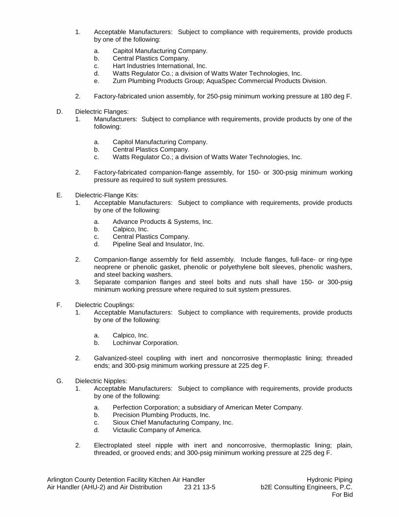
Arlington County Detention Facility Kitchen Air Handler Hydronic Piping Air Handler (AHU-2) and Air Distribution 23 21 13-5 b2E Consulting Engineers, P.C.
For Bid
1. Acceptable Manufacturers: Subject to compliance with requirements, provide products by one of the following:
a. Capitol Manufacturing Company. b. Central Plastics Company. c. Hart Industries International, Inc. d. Watts Regulator Co.; a division of Watts Water Technologies, Inc. e. Zurn Plumbing Products Group; AquaSpec Commercial Products Division.
2. Factory-fabricated union assembly, for 250-psig minimum working pressure at 180 deg F.
D. Dielectric Flanges: 1. Manufacturers: Subject to compliance with requirements, provide products by one of the
following:
a. Capitol Manufacturing Company. b. Central Plastics Company. c. Watts Regulator Co.; a division of Watts Water Technologies, Inc.
2. Factory-fabricated companion-flange assembly, for 150- or 300-psig minimum working pressure as required to suit system pressures.
E. Dielectric-Flange Kits: 1. Acceptable Manufacturers: Subject to compliance with requirements, provide products
by one of the following:
a. Advance Products & Systems, Inc. b. Calpico, Inc. c. Central Plastics Company. d. Pipeline Seal and Insulator, Inc.
2. Companion-flange assembly for field assembly. Include flanges, full-face- or ring-type neoprene or phenolic gasket, phenolic or polyethylene bolt sleeves, phenolic washers, and steel backing washers.
3. Separate companion flanges and steel bolts and nuts shall have 150- or 300-psig minimum working pressure where required to suit system pressures.
F. Dielectric Couplings: 1. Acceptable Manufacturers: Subject to compliance with requirements, provide products
by one of the following:
a. Calpico, Inc. b. Lochinvar Corporation.
2. Galvanized-steel coupling with inert and noncorrosive thermoplastic lining; threaded ends; and 300-psig minimum working pressure at 225 deg F.
G. Dielectric Nipples: 1. Acceptable Manufacturers: Subject to compliance with requirements, provide products
by one of the following:
a. Perfection Corporation; a subsidiary of American Meter Company. b. Precision Plumbing Products, Inc. c. Sioux Chief Manufacturing Company, Inc. d. Victaulic Company of America.
2. Electroplated steel nipple with inert and noncorrosive, thermoplastic lining; plain, threaded, or grooved ends; and 300-psig minimum working pressure at 225 deg F.
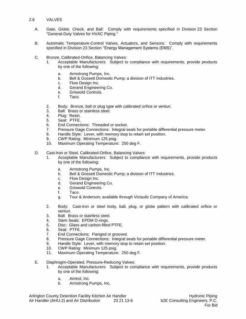
Arlington County Detention Facility Kitchen Air Handler Hydronic Piping Air Handler (AHU-2) and Air Distribution 23 21 13-6 b2E Consulting Engineers, P.C.
For Bid
2.6 VALVES
A. Gate, Globe, Check, and Ball: Comply with requirements specified in Division 23 Section "General-Duty Valves for HVAC Piping."
B. Automatic Temperature-Control Valves, Actuators, and Sensors: Comply with requirements specified in Division 23 Section "Energy Management Systems (EMS)”.
C. Bronze, Calibrated-Orifice, Balancing Valves: 1. Acceptable Manufacturers: Subject to compliance with requirements, provide products
by one of the following:
a. Armstrong Pumps, Inc. b. Bell & Gossett Domestic Pump; a division of ITT Industries. c. Flow Design Inc. d. Gerand Engineering Co. e. Griswold Controls. f. Taco.
2. Body: Bronze, ball or plug type with calibrated orifice or venturi. 3. Ball: Brass or stainless steel. 4. Plug: Resin. 5. Seat: PTFE. 6. End Connections: Threaded or socket. 7. Pressure Gage Connections: Integral seals for portable differential pressure meter. 8. Handle Style: Lever, with memory stop to retain set position. 9. CWP Rating: Minimum 125 psig. 10. Maximum Operating Temperature: 250 deg F.
D. Cast-Iron or Steel, Calibrated-Orifice, Balancing Valves: 1. Acceptable Manufacturers: Subject to compliance with requirements, provide products
by one of the following:
a. Armstrong Pumps, Inc. b. Bell & Gossett Domestic Pump; a division of ITT Industries. c. Flow Design Inc. d. Gerand Engineering Co. e. Griswold Controls. f. Taco. g. Tour & Anderson; available through Victaulic Company of America.
2. Body: Cast-iron or steel body, ball, plug, or globe pattern with calibrated orifice or venturi.
3. Ball: Brass or stainless steel. 4. Stem Seals: EPDM O-rings. 5. Disc: Glass and carbon-filled PTFE. 6. Seat: PTFE. 7. End Connections: Flanged or grooved. 8. Pressure Gage Connections: Integral seals for portable differential pressure meter. 9. Handle Style: Lever, with memory stop to retain set position. 10. CWP Rating: Minimum 125 psig. 11. Maximum Operating Temperature: 250 deg F.
E. Diaphragm-Operated, Pressure-Reducing Valves: 1. Acceptable Manufacturers: Subject to compliance with requirements, provide products
by one of the following:
a. Amtrol, Inc. b. Armstrong Pumps, Inc.
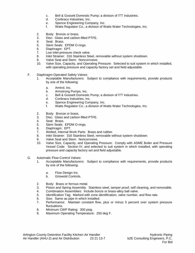
Arlington County Detention Facility Kitchen Air Handler Hydronic Piping Air Handler (AHU-2) and Air Distribution 23 21 13-7 b2E Consulting Engineers, P.C.
For Bid
c. Bell & Gossett Domestic Pump; a division of ITT Industries. d. Conbraco Industries, Inc. e. Spence Engineering Company, Inc. f. Watts Regulator Co.; a division of Watts Water Technologies, Inc.
2. Body: Bronze or brass. 3. Disc: Glass and carbon-filled PTFE. 4. Seat: Brass. 5. Stem Seals: EPDM O-rings. 6. Diaphragm: EPT. 7. Low inlet-pressure check valve. 8. Inlet Strainer: 316 Stainless Steel, removable without system shutdown. 9. Valve Seat and Stem: Noncorrosive. 10. Valve Size, Capacity, and Operating Pressure: Selected to suit system in which installed,
with operating pressure and capacity factory set and field adjustable.
F. Diaphragm-Operated Safety Valves: 1. Acceptable Manufacturers: Subject to compliance with requirements, provide products
by one of the following:
a. Amtrol, Inc. b. Armstrong Pumps, Inc. c. Bell & Gossett Domestic Pump; a division of ITT Industries. d. Conbraco Industries, Inc. e. Spence Engineering Company, Inc. f. Watts Regulator Co.; a division of Watts Water Technologies, Inc.
2. Body: Bronze or brass. 3. Disc: Glass and carbon-filled PTFE. 4. Seat: Brass. 5. Stem Seals: EPDM O-rings. 6. Diaphragm: EPT. 7. Wetted, Internal Work Parts: Brass and rubber. 8. Inlet Strainer: 316 Stainless Steel, removable without system shutdown. 9. Valve Seat and Stem: Noncorrosive. 10. Valve Size, Capacity, and Operating Pressure: Comply with ASME Boiler and Pressure
Vessel Code: Section IV, and selected to suit system in which installed, with operating pressure and capacity factory set and field adjustable.
G. Automatic Flow-Control Valves: 1. Acceptable Manufacturers: Subject to compliance with requirements, provide products
by one of the following:
a. Flow Design Inc. b. Griswold Controls.
2. Body: Brass or ferrous metal. 3. Piston and Spring Assembly: Stainless steel, tamper proof, self cleaning, and removable. 4. Combination Assemblies: Include bonze or brass-alloy ball valve. 5. Identification Tag: Marked with zone identification, valve number, and flow rate. 6. Size: Same as pipe in which installed. 7. Performance: Maintain constant flow, plus or minus 5 percent over system pressure
fluctuations. 8. Minimum CWP Rating: 300 psig. 9. Maximum Operating Temperature: 250 deg F.
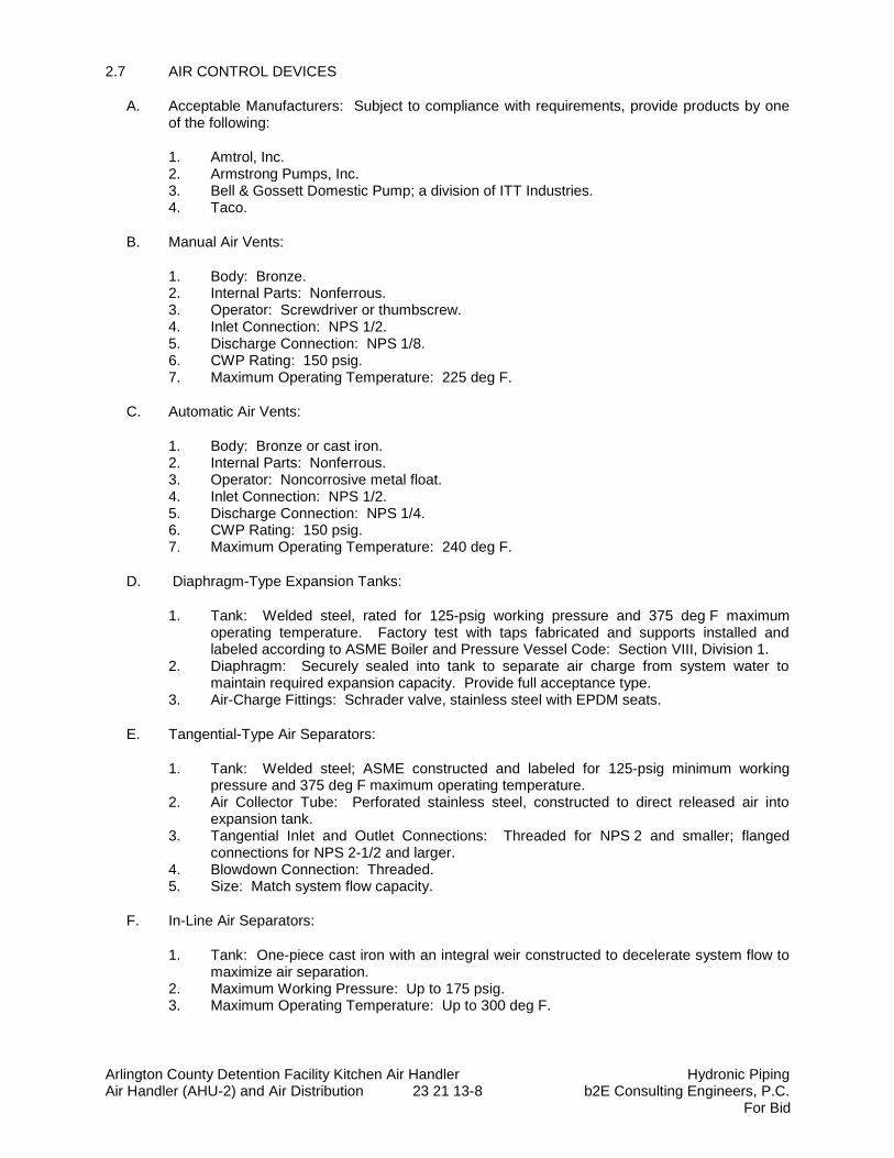
Arlington County Detention Facility Kitchen Air Handler Hydronic Piping Air Handler (AHU-2) and Air Distribution 23 21 13-8 b2E Consulting Engineers, P.C.
For Bid
2.7 AIR CONTROL DEVICES
A. Acceptable Manufacturers: Subject to compliance with requirements, provide products by one of the following:
1. Amtrol, Inc. 2. Armstrong Pumps, Inc. 3. Bell & Gossett Domestic Pump; a division of ITT Industries. 4. Taco.
B. Manual Air Vents:
1. Body: Bronze. 2. Internal Parts: Nonferrous. 3. Operator: Screwdriver or thumbscrew. 4. Inlet Connection: NPS 1/2. 5. Discharge Connection: NPS 1/8. 6. CWP Rating: 150 psig. 7. Maximum Operating Temperature: 225 deg F.
C. Automatic Air Vents:
1. Body: Bronze or cast iron. 2. Internal Parts: Nonferrous. 3. Operator: Noncorrosive metal float. 4. Inlet Connection: NPS 1/2. 5. Discharge Connection: NPS 1/4. 6. CWP Rating: 150 psig. 7. Maximum Operating Temperature: 240 deg F.
D. Diaphragm-Type Expansion Tanks:
1. Tank: Welded steel, rated for 125-psig working pressure and 375 deg F maximum operating temperature. Factory test with taps fabricated and supports installed and labeled according to ASME Boiler and Pressure Vessel Code: Section VIII, Division 1.
2. Diaphragm: Securely sealed into tank to separate air charge from system water to maintain required expansion capacity. Provide full acceptance type.
3. Air-Charge Fittings: Schrader valve, stainless steel with EPDM seats.
E. Tangential-Type Air Separators:
1. Tank: Welded steel; ASME constructed and labeled for 125-psig minimum working pressure and 375 deg F maximum operating temperature.
2. Air Collector Tube: Perforated stainless steel, constructed to direct released air into expansion tank.
3. Tangential Inlet and Outlet Connections: Threaded for NPS 2 and smaller; flanged connections for NPS 2-1/2 and larger.
4. Blowdown Connection: Threaded. 5. Size: Match system flow capacity.
F. In-Line Air Separators:
1. Tank: One-piece cast iron with an integral weir constructed to decelerate system flow to maximize air separation.
2. Maximum Working Pressure: Up to 175 psig. 3. Maximum Operating Temperature: Up to 300 deg F.
Arlington County Detention Facility Kitchen Air Handler Hydronic Piping Air Handler (AHU-2) and Air Distribution 23 21 13-9 b2E Consulting Engineers, P.C.
For Bid
G. Air Purgers:
1. Body: Cast iron with internal baffles that slow the water velocity to separate the air from solution and divert it to the vent for quick removal.
2. Maximum Working Pressure: 150 psig. 3. Maximum Operating Temperature: 250 deg F.
2.8 CHEMICAL TREATMENT
A. Bypass Chemical Feeder (Closed Loop HW): Welded steel construction; 125-psig working pressure; 5-gal., capacity; with fill funnel and inlet, outlet, and drain valves.
1. Chemicals: Specially formulated, based on analysis of makeup water, to prevent accumulation of scale and corrosion in piping and connected equipment.
2.9 HYDRONIC PIPING SPECIALTIES
A. Y-Pattern Strainers:
1. Body: ASTM A 126, Class B, cast iron with bolted cover and bottom drain connection. 2. End Connections: Threaded ends for NPS 2 and smaller; flanged ends for NPS 2-1/2
and larger. 3. Strainer Screen: 60-mesh startup strainer, and perforated stainless-steel basket with 50
percent free area. 4. CWP Rating: 125 psig.
B. Basket Strainers:
1. Body: ASTM A 126, Class B, high-tensile cast iron with bolted cover and bottom drain connection.
2. End Connections: Threaded ends for NPS 2 and smaller; flanged ends for NPS 2-1/2 and larger.
3. Strainer Screen: 60-mesh startup strainer, and perforated stainless-steel basket with 50 percent free area.
4. CWP Rating: 125 psig.
C. T-Pattern Strainers:
1. Body: Ductile or malleable iron with removable access coupling and end cap for strainer maintenance.
2. End Connections: Grooved ends. 3. Strainer Screen: 60-mesh startup strainer, and perforated stainless-steel basket with 57
percent free area. 4. CWP Rating: 750 psig.
D. Stainless-Steel Bellow, Flexible Connectors:
1. Body: Stainless-steel bellows with woven, flexible, bronze, wire-reinforcing protective jacket.
2. End Connections: Threaded or flanged to match equipment connected. 3. Performance: Capable of 3/4-inch misalignment. 4. CWP Rating: 150 psig. 5. Maximum Operating Temperature: 250 deg F.
E. Spherical, Rubber, Flexible Connectors:
Arlington County Detention Facility Kitchen Air Handler Hydronic Piping Air Handler (AHU-2) and Air Distribution 23 21 13-10 b2E Consulting Engineers, P.C.
For Bid
1. Body: Fiber-reinforced rubber body. 2. End Connections: Steel flanges drilled to align with Classes 150 and 300 steel flanges. 3. Performance: Capable of misalignment. 4. CWP Rating: 150 psig. 5. Maximum Operating Temperature: 250 deg F.
F. Expansion fittings are specified in Division 23 Section "Expansion Fittings and Loops for HVAC Piping."
PART 3 - EXECUTION
3.1 PIPING APPLICATIONS
A. Heating Hot-water piping, aboveground, NPS 2-1/2 and larger, shall be the following: 1. Schedule 40 steel pipe, wrought-steel fittings and wrought-cast or forged-steel flanges
and flange fittings, and welded and flanged joints.
B. Chilled Water Piping, above ground, NPS 2 ½” and larger, shall be the following:
1. ASTM A53, Grade A Schedule 40 Steel pipe, wrought steel fittings and wrought-cast or forged-steel flanges and flange fittings, and welded and flanged joints.
C. Blowdown-Drain Piping: Same materials and joining methods as for piping specified for the service in which blowdown drain is installed.
E. Blowdown-Drain Piping: Same materials and joining methods as for piping specified for the service in which blowdown drain is installed.
F. Air-Vent Piping: 1. Inlet: Same materials and joining methods as service piping materials where installed. 2. Outlet: Type K (A), annealed-temper copper tubing with soldered or flared joints.
G. Safety-Valve-Inlet and -Outlet Piping for Closed-Loop Piping (CHW): Same materials and joining methods as for piping specified for the service in which safety valve is installed.
3.2 VALVE APPLICATIONS
A. General-Duty Valve Applications: Use the following valve types:
1. Shutoff Duty: Ball valves or high performance butterfly valves. 2. Throttling Duty: Ball valves or high performance butterfly valves.
B. Install shutoff duty valves at each branch connection to supply mains, at supply connection to each piece of equipment, unless only one piece of equipment is connected in the branch line. Install throttling duty valves at each branch connection to return mains, at return connections to each piece of equipment, and elsewhere as indicated.
C. Install calibrated balancing valves in the return water line of each air handler and elsewhere as required to facilitate system balancing.
D. Install safety valves as required by the ASME Boiler and Pressure Vessel Code. Install safety-valve discharge piping, with union at valve connection and without valves, to floor. Comply with the ASME Boiler and Pressure Vessel Code, Section VIII, Division 1, for installation requirements.
Arlington County Detention Facility Kitchen Air Handler Hydronic Piping Air Handler (AHU-2) and Air Distribution 23 21 13-11 b2E Consulting Engineers, P.C.
For Bid
1. All safety valves shall be provided with piped drain to closest floor drain. Provide union adjacent safety valve to allow easy removal of drain piping.
E. Install pressure-reducing valves as required to regulate system pressure.
F. Provide check valve at preheat coil inlet piping before freeze protection pump connection for AHU-2.
G. Install drain valves at low points in mains, risers, branch lines, and elsewhere as required for system drainage.
H. Install air vents where indicated on piping plans.
1. Install ½” weld-0-let with steel nipple to dielectric union to ½” copper drain line with ½” ball valve with ¾” hose thread and brass cap on chain.
2. Install ½-inch ball valve with hose connection. Valve shall be installed at 3’-6” above finished floor.
I. Install the automatic 2-way and 3-way temperature control mixing valves with electronic Belimo
Valve operators per the schedule on the drawings. 1. 3-way automatic modulating temperature control valve shall be installed at the preheat
heat coil. 2. 2-way automatic modulating temperature control valves shall be installed at the cooling
coil and at the reheat coil.
3.3 PIPING INSTALLATIONS
A. Drawing plans, schematics, and diagrams indicate general location and arrangement of piping systems. Indicate piping locations and arrangements if such were used to size pipe and calculate friction loss, expansion, pump sizing, and other design considerations. Install piping as indicated unless deviations to layout are approved on Coordination Drawings.
B. Install piping in concealed locations, unless otherwise indicated and except in equipment rooms and service areas.
C. Install piping indicated to be exposed and piping in equipment rooms and service areas at right angles or parallel to building walls. Diagonal runs are prohibited unless specifically indicated otherwise.
D. Install piping above accessible ceilings to allow sufficient space for ceiling panel removal.
E. Install piping to permit valve servicing.
F. Install piping at indicated slopes.
G. Install piping free of sags and bends.
H. Install fittings for changes in direction and branch connections.
I. Install piping to allow application of insulation.
J. Select system components with pressure rating equal to or greater than system operating pressure.
K. Install groups of pipes parallel to each other, spaced to permit applying insulation and servicing of valves.
Arlington County Detention Facility Kitchen Air Handler Hydronic Piping Air Handler (AHU-2) and Air Distribution 23 21 13-12 b2E Consulting Engineers, P.C.
For Bid
L. Install drains, consisting of a tee fitting, NPS 3/4 ball valve, and short NPS 3/4 threaded nipple with cap, at low points in piping system mains and elsewhere as required for system drainage.
M. Install piping at a uniform grade of 0.2 percent upward in direction of flow.
N. Reduce pipe sizes using eccentric reducer fitting installed with level side up.
O. Install branch connections to mains using tee fittings in main pipe, with the branch connected to the bottom of the main pipe. For up-feed risers, connect the branch to the top of the main pipe.
P. Install valves according to Division 23 Section "General-Duty Valves for HVAC Piping."
Q. Install unions in piping, NPS 2 and smaller, adjacent to valves, at final connections of equipment, and elsewhere as indicated.
R. Install flanges in piping, NPS 2-1/2 and larger, at final connections of equipment and elsewhere as indicated.
S. Install strainers on inlet side of each control valve, pressure-reducing valve, solenoid valve, in-line pump, and elsewhere as indicated. Install NPS 3/4 nipple and ball valve in blowdown connection of strainers NPS 2 and larger. Match size of strainer blowoff connection for strainers smaller than NPS 2.
T. Identify piping as specified in Division 23 Section "Identification for HVAC Piping and Equipment."
U. Refer to Division 23 Section "Basic Mechanical Materials and Methods" for basic piping installation requirements.
V. Install groups of pipes parallel to each other, spaced to permit applying insulation and servicing of valves.
W. Install drains, consisting of a tee fitting, NPS 3/4 ball valve, and short NPS 3/4 threaded nipple with cap, at low points in piping system mains and elsewhere as required for system drainage.
X. Install piping at a uniform grade of 0.2 percent upward in direction of flow.
Y. Reduce pipe sizes using correct reducer fitting installed with level side up.
1. Vertical Piping: Concentric reducer. 2. Horizontal Water Piping: Eccentric reducer with level side up.
Z. Unless otherwise indicated, install branch connections to mains using tee fittings in main pipe, with the takeoff coming out the bottom of the main pipe. For up-feed risers, install the takeoff coming out the side of the main pipe.
AA. Install strainers on supply side of each, HW coil and CHW coil or other element with a control valve. In addition, install strainers on the inlet side of each pressure-reducing valve, solenoid valve, in-line pump, and elsewhere as indicated. Install NPS 3/4 nipple and ball valve in blowdown connection of strainers NPS 2 and larger. Match size of strainer blowoff connection for strainers smaller than NPS 2.
3.4 HANGERS AND SUPPORTS
A. Hanger, support, and anchor devices are specified in Division 23 Section "Hangers and Supports for HVAC Piping and Equipment." Comply with the following requirements for maximum spacing of supports.

Arlington County Detention Facility Kitchen Air Handler Hydronic Piping Air Handler (AHU-2) and Air Distribution 23 21 13-13 b2E Consulting Engineers, P.C.
For Bid
B. Vibration isolation is specified in Division 23 Section "Sound and Vibration Controls for HVAC Piping and Equipment."
C. Install the following pipe attachments:
1. Adjustable steel clevis hangers for individual horizontal piping less than 20 feet long, and entire run for pipe 5-inch and smaller.
2. Adjustable roller hangers or sliding saddles (Buckaroos) and spring hangers for individual horizontal piping 20 feet or longer, for pipe 6-inch and larger.
3. Pipe Roller: MSS SP-58, Type 44 for multiple horizontal piping 20 feet or longer, supported on a trapeze, for pipe 6-inch and larger.
4. Spring hangers to support runs, within 20 feet of a connection to vibrating equipment. 5. Provide copper-clad hangers and supports for hangers and supports in direct contact with
copper pipe.
D. Install the following hangers and supports:
1. Adjustable ASTM A123 hot-dipped galvanized steel clevis hangers. 2. Adjustable ASTM A 123 hot-dipped galvanized roller hangers or sliding saddles
(Buckaroos) and spring hangers. 3. Vertical pipe risers shall be supported with all directional anchor (ADA) pipe riser resilient
support at bottom of riser. All upper level riser resilient supports shall be vertical sliding guides (VSG).
E. All hangers and supports shall be protected against galvanized corrosion. There shall be no non-insulated piping on this project. All hangers and supports shall be ASTM A123 hot dipped galvanized steel.
F. Piping support Spacing Schedule: Install piping with the following minimum rod sizes and maximum spacing:
Steel Pipe Maximum Hanger
Spacing
Copper Tube Maximum
Hanger Spacing
Rod Hanger Diameter
Pipe Size Water Service Gas or Air Service
1/2 to 3/4 inch 7 Ft. 8 Ft. 5 Ft. 3/8 inches
1 to 1-1/4 inches 7 Ft. 8 Ft. 6 Ft. 3/8 inches
1 – 1/2 inches 7 Ft. 9 Ft. 7 Ft. 3/8 inches
2 inches 9Ft. 9 Ft. 7 Ft. 3/8 inches
2-1/2 inches 10 Ft. 10 Ft. 8 Ft. 1/2 inches
3 inches 10 Ft. 10 Ft. 9 Ft. 1/2 inches
4 inches 10 Ft. 10 Ft. 8 Ft. 5/8 inches
5 inches 10 Ft. 10 Ft.--- 8 Ft. 5/8 inches
6 inches 15 Ft. 10 Ft.--- 8 Ft. 3/4 inches
8 inches 15 Ft. --- 3/4 inches
10 inches 20 Ft. --- -- 7/8 inches
G. Support vertical runs the floor.
Arlington County Detention Facility Kitchen Air Handler Hydronic Piping Air Handler (AHU-2) and Air Distribution 23 21 13-14 b2E Consulting Engineers, P.C.
For Bid
1. Refer to Section 23 05 29, “Hangers and Supports”, and coordinate. Most stringent requirement applies.
a. Do not exceed hanger rod loading indicated in MSS SP-58, Table 3 or as required by the Structural Engineer, whichever is less.
b. See Structural for other applicable requirements.
3.5 PIPE JOINT CONSTRUCTION
A. Join pipe and fittings according to the following requirements and Division 23 Sections specifying piping systems.
B. Ream ends of pipes and tubes and remove burrs. Bevel plain ends of steel pipe.
C. Remove scale, slag, dirt, and debris from inside and outside of pipe and fittings before assembly.
D. Soldered Joints: Apply ASTM B 813, water-flushable flux, unless otherwise indicated, to tube end. Construct joints according to ASTM B 828 or CDA's "Copper Tube Handbook," using lead-free solder alloy complying with ASTM B 32.
E. Brazed Joints: Construct joints according to AWS's "Brazing Handbook," "Pipe and Tube" Chapter, using copper-phosphorus brazing filler metal complying with AWS A5.8.
F. Threaded Joints: Thread pipe with tapered pipe threads according to ASME B1.20.1. Cut threads full and clean using sharp dies. Ream threaded pipe ends to remove burrs and restore full ID. Join pipe fittings and valves as follows:
1. Apply appropriate tape or thread compound to external pipe threads unless dry seal threading is specified.
2. Damaged Threads: Do not use pipe or pipe fittings with threads that are corroded or damaged. Do not use pipe sections that have cracked or open welds.
G. Welded Joints: Construct joints according to AWS D10.12/D10.12M, using qualified processes and welding operators according to Part 1 "Quality Assurance" Article.
H. Install calibrated balancing valves for each piece of mechanical equipment with hot water and chilled water, connections.
1. Install one (1) balancing valve for each piece of equipment without control valves. 2. Provide one (1) balancing valve for equipment with two-way control valves. 3. Provide two (2) balancing valves for equipment with three-way control valves.
I. Flanged Joints: Select appropriate gasket material, size, type, and thickness for service application. Install gasket concentrically positioned. Use suitable lubricants on bolt threads.
3.6 HYDRONIC SPECIALTIES INSTALLATION
A. Install manual air vents at high points in piping, at heat-transfer coils, and elsewhere as required for system air venting.
B. Install automatic air vents at high points of system piping in mechanical equipment rooms only. Manual vents at heat-transfer coils and elsewhere as required for air venting.

Arlington County Detention Facility Kitchen Air Handler Hydronic Piping Air Handler (AHU-2) and Air Distribution 23 21 13-15 b2E Consulting Engineers, P.C.
For Bid
3.7 TERMINAL EQUIPMENT CONNECTIONS
A. Sizes for supply and return piping connections shall be the same as or larger than equipment connections.
B. Install control valves in accessible locations close to connected equipment.
C. Install ports for pressure gages and thermometers at coil inlet and outlet connections according to Division 23 Section "Meters and Gages for HVAC Piping."
3.8 CHEMICAL TREATMENT (ENGAGE ARLINGTON COUNTY CURRENT WATER TREATMENT VENDOR)
A. Perform an analysis of makeup water to determine type and quantities of chemical treatment needed to keep system free of scale, corrosion, and fouling, and to sustain the following water characteristics:
1. pH: 9.0 to 10.5. 2. "P" Alkalinity: 100 to 500 ppm. 3. Boron: 100 to 200 ppm. 4. Chemical Oxygen Demand: Maximum 100 ppm. Modify this value if closed system
contains glycol. 5. Corrosion Inhibitor:
a. Sodium Nitrate: 1000 to 1500 ppm. b. Molybdate: 200 to 300 ppm. c. Chromate: 200 to 300 ppm. d. Sodium Nitrate Plus Molybdate: 100 to 200 ppm each. e. Chromate Plus Molybdate: 50 to 100 ppm each.
6. Soluble Copper: Maximum 0.20 ppm. 7. Tolyiriazole Copper and Yellow Metal Corrosion Inhibitor: Minimum 10 ppm. 8. Total Suspended Solids: Maximum 10 ppm. 9. Ammonia: Maximum 20 ppm. 10. Free Caustic Alkalinity: Maximum 20 ppm. 11. Microbiological Limits:
a. Total Aerobic Plate Count: Maximum 1000 organisms/ml. b. Total Anaerobic Plate Count: Maximum 100 organisms/ml. c. Nitrate Reducers: 100 organisms/ml. d. Sulfate Reducers: Maximum 0 organisms/ml. e. Iron Bacteria: Maximum 0 organisms/ml.
B. Fill system with fresh water and add liquid alkaline compound with emulsifying agents and detergents to remove grease and petroleum products from piping. Circulate solution for a minimum of 24 hours, drain, clean strainer screens, and refill with fresh water.
1. Repeat at least three (3) times to ensure entire piping system is clean prior to start-up of pumps.
C. Add initial chemical treatment and maintain water quality in ranges noted above for the first two (2) years of operation.
3.9 FIELD QUALITY CONTROL
A. Prepare hydronic piping according to ASME B31.9 and as follows:
Arlington County Detention Facility Kitchen Air Handler Hydronic Piping Air Handler (AHU-2) and Air Distribution 23 21 13-16 b2E Consulting Engineers, P.C.
For Bid
1. Leave joints, including welds, uninsulated and exposed for examination during test. 2. Provide temporary restraints for expansion joints that cannot sustain reactions due to test
pressure. If temporary restraints are impractical, isolate expansion joints from testing. 3. Flush hydronic piping systems with clean water; then remove and clean or replace
strainer screens. 4. Isolate equipment from piping. If a valve is used to isolate equipment, its closure shall be
capable of sealing against test pressure without damage to valve. Install blinds in flanged joints to isolate equipment.
5. Install safety valve, set at a pressure no more than one-third higher than test pressure, to protect against damage by expanding liquid or other source of overpressure during test.
B. Perform the following tests on hydronic piping:
1. Use ambient temperature water as a testing medium unless there is risk of damage due to freezing. Another liquid that is safe for workers and compatible with piping may be used.
2. While filling system, use vents installed at high points of system to release air. Use drains installed at low points for complete draining of test liquid.
3. Isolate expansion tanks and determine that hydronic system is full of water. 4. Subject piping system to hydrostatic test pressure that is not less than 1.5 times the
system's working pressure (200 psig). Test pressure shall not exceed maximum pressure for any vessel, pump, valve, or other component in system under test. Verify that stress due to pressure at bottom of vertical runs does not exceed 90 percent of specified minimum yield strength or 1.7 times "SE" value in Appendix A in ASME B31.9, "Building Services Piping."
5. After hydrostatic test pressure has been applied for at least 10 minutes, examine piping, joints, and connections for leakage. Eliminate leaks by tightening, repairing, or replacing components and repeat hydrostatic test until there are no leaks. Leave under pressure for 24 hours and check to ensure no leaks have occurred.
6. Prepare written report of testing.
C. Perform the following before operating the system: 1. Open manual valves fully. 2. Inspect pumps for proper rotation. 3. Set makeup pressure-reducing valves for required system pressure. 4. Inspect air vents at high points of system and determine if all are installed and operating
freely (automatic type), or bleed air completely (manual type). 5. Set temperature controls so all coils are calling for full flow. 6. Inspect and set operating temperatures of hydronic equipment, such as boilers, chillers,
cooling towers, to specified values. 7. Verify lubrication of motors and bearings.
3.10 ADJUSTING
A. Mark calibrated nameplates of pump discharge valves after hydronic system balancing has been completed, to permanently indicate final balanced position.
B. Perform these adjustments before operating the system: 1. Open valves to fully open position. Close coil bypass valves. 2. Check pump for proper direction of rotation. 3. Set existing automatic fill valves for required system pressure. 4. Check existing and new air vents at high points of system and determine if all are
installed and operating freely (automatic type), or bleed air completely (manual type). 5. Set temperature controls so AHU-2 coils are calling for full flow. 6. Check operation of existing or new automatic bypass valves. 7. Check and set operating temperatures of existing chillers and boilers and boilers to
design requirements.
Arlington County Detention Facility Kitchen Air Handler Hydronic Piping Air Handler (AHU-2) and Air Distribution 23 21 13-17 b2E Consulting Engineers, P.C.
For Bid
8. Lubricate motors and bearings.
3.11 CLEANING
A. Flush hydronic piping systems with clean water. Remove and clean or replace strainer screens. After cleaning and flushing hydronic piping systems, but before balancing, remove disposable fine-mesh strainers in pump suction diffusers. 1. Piping systems shall be flushed continuously twice per week until project acceptable weld
slag, dirt, rust, etc. is removed and the water is clearance. The contractor is responsible for any and all damage to the equipment. The contractor shall thoroughly chemically clean all heat-transfer coils and surface prior to project substantial completion.
2. Contractor shall supply all HVAC water treatment chemicals, and shall measure, test and adjust the chemical water treatment to protect all piping systems in accordance with Section 23 25 00.
END OF SECTION 23 21 13

Arlington County Detention Facility Kitchen Air Handler Adjustable Frequency Drives (AFD-X) Air Handler (AHU-2) and Air Distribution 23 26 90-1 b2E Consulting Engineers, P.C.
For Bid
SECTION 23 26 90
ADJUSTABLE FREQUENCY DRIVES (AFD’s)
PART 1 - GENERAL
1.1 SUMMARY
A. This Section includes solid-state, PWM, AFD’s for speed control of three-phase, squirrel-cage induction motors, for HVAC components indicated on the plans to be AFD protected. The AFD’s shall be provided by the pump manufacturer.
B. The contractor shall provide full coordination between the AFD manufacturer and the boiler plant control system contractor, and shall coordinate, furnish and adjust all contactors, controllers, auxiliary contacts, digital and analog inputs and outputs, and devices required to provide the sequence of operation specified under Section 23 09 93.
C. The contractor shall provide full coordination between the equipment manufacturers to ensure that the AFD is fully compatible with the pump/motor, and fan/motor drives. The contractor shall provide start-up, testing, adjusting and systems demonstration in accordance with this Section and Related Sections.
D. The air handler (AHU-2) shall be provided with an Adjustable Frequency Drain ultimate complies with the requirements of this specification.
E. The existing return air fan (RAF-3) adjustable frequency drive shall be relocated, if necessary. This drive shall be reinstalled and shall be provided with a new 1 year warranty for parts and labor to ensure it is reinstated correctly.
1.2 DEFINITIONS
A. AFD: Adjustable Frequency Drive.
B. BAS: Building Automation System.
C. IGBT: Integrated gate bipolar transistor.
D. LAN: Local area network.
E. PID: Control action, proportional plus integral plus derivative.
F. PWM: Pulse-width modulated.
1.3 SUBMITTALS
A. Product Data: For each AFD, provide dimensions; mounting arrangements; location for conduit entries; shipping and operating weights; and manufacturer's technical data on features, performance, electrical ratings, characteristics, and finishes.

Arlington County Detention Facility Kitchen Air Handler Adjustable Frequency Drives (AFD-X) Air Handler (AHU-2) and Air Distribution 23 26 90-2 b2E Consulting Engineers, P.C.
For Bid
1. All AFD’s in this building shall be the same manufacturer and provided by the same local manufacturer’s representative.
B. Shop Drawings: For each AFD.
1. Include dimensioned plans, elevations, sections, and details, including required clearances and service space around equipment. Show tabulations of installed devices, equipment features, and ratings. Include the following:
a. Each installed unit's type and details. b. Nameplate legends. c. Short-circuit current ratings of integrated unit. d. UL listing for series rating of overcurrent protective devices in combination
controllers. e. Features, characteristics, ratings, and factory settings of each motor-control center
unit.
2. Wiring Diagrams: Power, signal, and control wiring for AFD. Provide schematic wiring diagram for each type of AFD.
C. Coordination Drawings: Floor plans showing dimensioned layout, required working clearances, and required area above and around AFD’s where pipe and ducts are prohibited. Show AFD layout and relationships between electrical components and adjacent structural and mechanical elements. Show support locations, type of support, and weight on each support. Indicate field measurements.
D. Qualification Data: For testing agency and manufacturer.
E. Field Test Reports: Written reports specified in Part 3.
F. Manufacturer's field service report.
G. Operation and Maintenance Data: For AFD’s, all installed devices, and components to include in emergency, operation, and maintenance manuals. In addition to items specified in Division 1 Section "Closeout Procedures," include the following:
1. Routine maintenance requirements for AFD’s and all installed components. 2. Manufacturer's written instructions for testing and adjusting overcurrent protective
devices. 3. Final as-built drawings and information for items provided. 4. Wiring diagrams. 5. Certified production test reports. 6. Installation information.
H. Load-Current and Overload-Relay Heater List: Compile after motors have been installed and arrange to demonstrate that selection of heaters suits actual motor nameplate full-load currents.
I. Load-Current and List of Settings of Adjustable Overload Relays: Compile after motors have been installed and arrange to demonstrate that dip switch settings for motor running overload protection suit actual motor to be protected.
J. Harmonic Calculations: Contractor shall provide calculations performed by the equipment manufacturer. The calculations shall indicate harmonic distortion reflected on to the installed power distribution system. The calculations shall reference voltage and distortion levels as
Arlington County Detention Facility Kitchen Air Handler Adjustable Frequency Drives (AFD-X) Air Handler (AHU-2) and Air Distribution 23 26 90-3 b2E Consulting Engineers, P.C.
For Bid
defined by IEEE 519 for general system applications. The calculations shall indicate reduction in harmonic distortion using the drive-line reactance or multi-counter phase shifting arrangement actually provided for each AFD. The manufacturer shall perform calculations and submit same attached to equipment shop drawing submittals.
1.4 QUALITY ASSURANCE
A. Manufacturer Qualifications: Maintain, within 100 miles of Project site, a service center capable of providing training, parts, and emergency maintenance and repairs.
B. Testing Agency Qualifications: An independent testing agency, acceptable to authorities having jurisdiction, with the experience and capability to conduct the testing indicated, as documented according to ASTM E 548.
C. Source Limitations: Obtain AFD’s of a single type through one source from a single manufacturer.
D. Electrical Components, Devices, and Accessories: Listed and labeled as defined in NFPA 70, Article 100, by a testing agency acceptable to authorities having jurisdiction, and marked for intended use.
E. Product Selection for Restricted Space: Drawings indicate maximum dimensions for AFD’s, minimum clearances between AFD’s, and adjacent surfaces and other items. Comply with indicated dimensions and clearances.
F. Comply with NFPA 70.
G. The manufacturer of the assembly shall be the manufacturer of the major components within the assembly.
H. For the equipment specified herein, the manufacturer shall be ISO 9000, 9001 or 9002 certified.
I. The manufacturer of this equipment shall have produced similar electrical equipment for a minimum period of five (5) years in manufacture and operation of pulse width modulated drive(s) in sizes indicated for this project. When requested by the Engineer, an acceptable list of installations with similar equipment shall be provided demonstrating compliance with this requirement.
J. UL listed and labeled, Canadian Standards Association listed and labeled, and/or Electrical Testing Laboratories listed and labeled.
K. Tested to ANSI/UL-508.
L. Meet requirements of IEEE Standard 519, latest edition, “Guide for Harmonic Control and Reactive Compensation of Static Power Converters”.
M. Local service representative’s qualifications:
1. Provide and maintain field service personnel authorized and factory trained to perform service both in and out of warranty.
2. Maintain full stock of service parts for all units furnished. 3. Provide in-depth training in operation of all units.
Arlington County Detention Facility Kitchen Air Handler Adjustable Frequency Drives (AFD-X) Air Handler (AHU-2) and Air Distribution 23 26 90-4 b2E Consulting Engineers, P.C.
For Bid
1.5 DELIVERY, STORAGE, AND HANDLING
A. Deliver AFD’s in shipping splits of lengths that can be moved past obstructions in delivery path as indicated.
B. Store AFD’s indoors in clean, dry space with uniform temperature to prevent condensation. Protect AFD’s from exposure to dirt, fumes, water, corrosive substances, and physical damage.
C. If stored in areas subject to weather, cover AFD’s to protect them from weather, dirt, dust, corrosive substances, and physical damage. Remove loose packing and flammable materials from inside controllers; install electric heating of sufficient wattage to prevent condensation.
1.6 COORDINATION
A. Coordinate layout and installation of AFD’s with other construction including conduit, piping, equipment, and adjacent surfaces. Maintain required workspace clearances and required clearances for equipment access doors and panels.
B. Coordinate size and location of concrete bases. Cast anchor-bolt inserts into bases. Concrete, reinforcement, and formwork requirements are specified in Division 3.
C. Coordinate features of AFD’s, installed units, and accessory devices with pilot devices and control circuits to which they connect.
D. Coordinate features, accessories, and functions of each AFD and each installed unit with ratings and characteristics of supply circuit, motor, required control sequence, and duty cycle of motor and load.
1.8 REGULATORY REQUIREMENTS
A. The entire AFD system shall be factory assembled and system tested by the AFD manufacturer to assure a properly coordinated system.
B. Codes: Provide equipment in full accordance with the latest applicable rules, regulations, and
standards of: 1. National Electric Code (NEC). 2. Underwriters Laboratories (UL). 3. American National Standards Institute (ANSI). 4. National Electrical Manufacturers Association (NEMA). 5. Institute of Electrical and Electronics Engineers (IEEE).
C. The complete drive system shall be UL listed.

Arlington County Detention Facility Kitchen Air Handler Adjustable Frequency Drives (AFD-X) Air Handler (AHU-2) and Air Distribution 23 26 90-5 b2E Consulting Engineers, P.C.
For Bid
1.9 WARRANTY
A. All equipment furnished under this section shall be warranted for parts and labor by the contractor and the equipment manufacturers for a period of two (2) years after Substantial Completion. As part of this warranty, the manufacturer shall be engaged to provide all start up and commissioning for frequency drive equipment. The contractors bid includes all start up procedures recommended by the manufacturer.
B. The vendor shall respond on site within 24 hours for any service call during the warranty period.
PART 2 - PRODUCTS
2.1 MANUFACTURERS
A. Acceptable Manufacturers: Subject to compliance with requirements, provide products by one of the following:
1. Basis of Design: Trane. 2. ABB. 3. Cutler Hammer.
2.2 ADJUSTABLE FREQUENCY DRIVES (AFD’S)
A. Description: NEMA ICS 2, IGBT, PWM, AFD; listed and labeled as a complete unit and arranged to provide variable speed of a NEMA MG 1, Design B, 3-phase, premium-efficiency induction motor by adjusting output voltage and frequency.
B. Design and Rating: Match load type such as fans, blowers, and pumps; and type of connection used between motor and load such as direct or through a power-transmission connection.
1. The AFD shall be rated for continuous duty at 460V. The AFD shall provide a microprocessor-based adjustment of three-phase motors. The variable frequency and voltage output shall provide constant volts per hertz excitation for the motor up to 60 hertz. The controllers shall be rated as shown in the drawings. As a minimum the full load output current of the drive shall be equal to the equivalent motor horsepower as listed by National Electric Code Table 430-150.
2. The AFDs shall be of the Pulse Width Modulated (PWM) design converting the utility input voltage and frequency to a variable voltage and frequency output via a two-step operation. Variable Current Source AFD’s are not acceptable. Insulated Gate Bipolar Transistor shall be used in the inverter section. Bipolar Transistor, GTOs and SCRs are not acceptable.
3. The AFD’s shall have an efficiency that exceeds 96% at 100% speed and load. The efficiency shall exceed 80% at 50% speed and load.
4. The AFD’s shall maintain the line side displacement power factor no less than 0.95 regardless of speed and load.
5. The AFD’s shall have a one (1) minute overload current rating of 110% for variable torque loads and 150% for constant torque loads.
6. The AFD’s shall be capable of operating any NEMA B squirrel cage induction motor, regardless of manufacturer, with a load rating within the capacity of the AFD’s.
7. The AFD’s shall limit harmonic distortion reflected onto the installed distribution system to a voltage and current distortion level as defined by IEEE 519 for general system applications. Harmonic attenuation shall be provided by the addition of drive line
Arlington County Detention Facility Kitchen Air Handler Adjustable Frequency Drives (AFD-X) Air Handler (AHU-2) and Air Distribution 23 26 90-6 b2E Consulting Engineers, P.C.
For Bid
reactance or multi-converter phase shifting arrangement. Tuned harmonic filters are not acceptable.
8. The AFD’s shall be able to start into a spinning motor. The AFD’s shall be able to determine the motor speed in any direction and resume operation without tripping. If the motor is spinning in the reverse direction, the AFD’s shall start into the motor in the reverse direction, bring the motor to a controlled stop, and then accelerate the motor in the preset method of starting.
9. Standard operating conditions shall be:
a. Incoming Power: Three -phase, 460V/60 hertz (+/-2 hertz) power to a fixed potential DC bus level.
b. Frequency stability of +/- 0.5% for 24 hours with voltage regulation of +/- 2% of maximum rated output voltage.
c. Motor slip dependent speed regulation of 3%. d. Five cycle carry-over during utility loss. e. Insensitive to input line rotation. f. Humidity: 0 to 95% (noncondensing and noncorrosive). g. Altitude: 0 to 3,300 feet above sea level. h. Ambient Temperature: 0 to 40 degrees C.
10. THD (Total Harmonic Distortion) at the AFD supply bus shall not exceed 10% (current measure) or 5% (voltage measure). THD performance shall be consistent from half-load through full load of equipment.
C. Output Rating: 3-phase; 6 to 60 Hz, with voltage proportional to frequency throughout voltage range.
D. Unit Operating Requirements:
1. Input ac voltage tolerance of 380 to 500 V, plus or minus 10 percent. 2. Input frequency tolerance of 50/60 Hz, plus or minus 6 percent. 3. Capable of driving full load, under the following conditions, without derating:
a. Ambient Temperature: 32 to 104 deg C. b. Humidity: Up to 90 percent (non-condensing). c. Altitude: 0 feet (0 m).
4. Minimum Efficiency: 96 percent at 60 Hz, full load. 5. Minimum Displacement Primary-Side Power Factor: 96 percent. 6. Overload Capability: 1.1 times the base load current for 60 seconds; 2.0 times the base
load current for 3 seconds. 7. Starting Torque: 100 percent of rated torque or as indicated. 8. Speed Regulation: Plus or minus 1 percent. 9. Isolated control interface to allow controller to follow control signal over an 11:1 speed
range. 10. Unit shall not cause > 5 dba noise increase (5 feet from motor) throughout complete
frequency operating range. 11. Pool Filter Pumps: AFDs shall have capability of 30 seconds ramp up to full speed from
zero, and 5 second ramp down from full speed to zero.
E. Internal Adjustability Capabilities:
1. Minimum Speed: 5 to 25 percent of maximum rpm. 2. Maximum Speed: 80 to 100 percent of maximum rpm. 3. Acceleration: 2 to a minimum of 22 seconds.
Arlington County Detention Facility Kitchen Air Handler Adjustable Frequency Drives (AFD-X) Air Handler (AHU-2) and Air Distribution 23 26 90-7 b2E Consulting Engineers, P.C.
For Bid
4. Deceleration: 2 to a minimum of 22 seconds. 5. Current Limit: 50 to a minimum of 110 percent of maximum rating.
F. Self-Protection and Reliability Features:
1. AC input current limiting fuses rated 65,000 AIC for fault current protection of AC to DC converter section for all units.
2. Input transient protection by means of surge suppressors. 3. Snubber networks to protect against malfunction due to system voltage transients. 4. Under- and overvoltage trips; inverter over temperature, overload (over frequency), and
overcurrent trips (protection). 5. Motor Overload Relay: Adjustable and capable of NEMA 250, Class 30 performance. 6. Notch filter to prevent operation of the controller-motor-load combination at a natural
frequency of the combination. 7. Instantaneous line-to-line and line-to-ground overcurrent trips (short circuit protection). 8. Loss-of-phase protection. 9. Reverse-phase protection. 10. Short-circuit protection. 11. Motor over temperature fault. 12. Input line reactors, drive line reactance or multi-counter phase shifting arrangement only. 13. Ground fault protection. 14. Variable current limit. 15. Variable torque overload capability shall be 110% of the motor FLA based on the NEC
ratings for 60 seconds.
G. Control Functions:
1. All AFD programmable parameters shall be variable from a digital operator keypad located on the front door of the AFD. Parameters shall include:
a. Programmable frequency command (setpoint adjustment) (keypad, remote). b. Programmable start command (keypad, remote). c. Programmable maximum and minimum frequency limits. d. Programmable acceleration and deacceleration times. e. Programmable carrier frequencies, V/Hz, and critical frequency avoidance lockout
zones. f. Programmable electronic overload and torque limits. g. Programmable multiple attempt restart. h. Programmable jog and preset speeds. i. Programmable dwell time at start to maximize motor starting torque. j. Programmable "Catch a Spinning Motor" function.
H. System Interfaces:
1. Inputs: Provide full coordination with Equipment and BAS contractors.
a. Process control speed reference interface to receive either a 0-10 Vdc, 4-20 mAdc or speed potentiometer signal.
b. Remote mode start contact. c. Remote preset speed contacts. d. Remote external trip contact. e. Remote reset contact. f. Remote jog contact.
Arlington County Detention Facility Kitchen Air Handler Adjustable Frequency Drives (AFD-X) Air Handler (AHU-2) and Air Distribution 23 26 90-8 b2E Consulting Engineers, P.C.
For Bid
2. Outputs: Provide full coordination with the equipment and BAS contractors and provide the AFD with the required number of outputs and type for connection to external relays and equipment as required.
a. Run relay with an isolated set of Form C contacts. b. Dry contact output to indicate protective function trip. c. Analog output signal proportional to output frequency.
I. Additional Features:
1. Input breaker to provide a disconnect means. Breaker operating handle shall protrude through the AFD door and the breaker shall not be mounted on the door. Extended breaker operator handles shall not be permitted. The handle position shall indicate ON, OFF or TRIPPED condition of the circuit breaker. The handle shall have provisions for padlocking in the OFF position with at least three (3) padlocks. Interlocks shall prevent unauthorized opening or closing of the AFD door with disconnect handle in the ON position.
2. Contactor bypass which includes an output contactor electrically and mechanically interlocked with a bypass contactor; and a run relay. This circuit shall include control logic, status lights and a motor overcurrent relay. The complete bypass system and Inverter-Off-Bypass selector switch shall be packaged in the AFD’s enclosure. The unit may be set up for:
1. Manual bypass operation. 2. Bypass position indication relay.
3. AC output contactor to provide a means for positive disconnection of the drive output from the motor terminals.
4. Line reactors for units less than 25 HP, supplied inside the AFD enclosure. 5. Enclosure floor stand for units that are normally wall-mounted, allowing the units to be
freestanding. Provide where necessary. 6. Fused space heaters with thermostat to minimize condensation potential upon drive
shutdown. 7. Laminated plastic nameplate engraved with customer’s identifying name or number for
the drive. 8. Electronic potentiometer to allow the drive to follow a discrete increase or decrease
contact closure causing the AFD to increase or decrease the motor speed. 9. Isolated input process follower for use when more than one drive is being controlled via
one process signal or when the input process signal is greater than 35 Vdc in reference to ground.
10. 120 Vac 3-wire control to allow AFD to interface with remote dry contacts at a distance up to 500 feet.
11. Auxiliary drive status relay with two Form C relay pairs, rated 2 amps resistive at 120-volt AC for indication of running condition.
12. Motor overcurrent relay to provide motor overcurrent sensing of a given level of load current.
13. Operator’s station to remote mounting of pilot devices with enclosure to match specified requirements.
J. Automatic Reset and Restart: To attempt three restarts after controller fault or on return of power after an interruption and before shutting down for manual reset or fault correction. Bidirectional auto speed search shall be capable of starting into rotating loads spinning in either direction and returning motor to set speed in proper direction, without damage to controller, motor, or load.
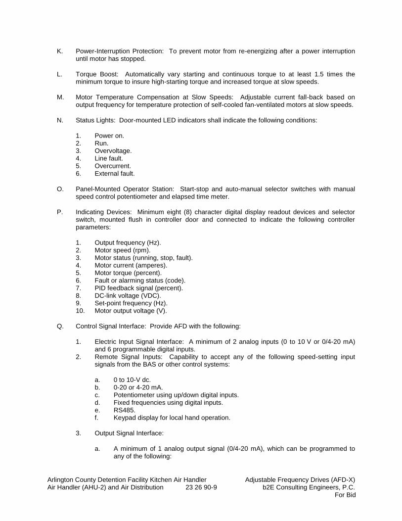
Arlington County Detention Facility Kitchen Air Handler Adjustable Frequency Drives (AFD-X) Air Handler (AHU-2) and Air Distribution 23 26 90-9 b2E Consulting Engineers, P.C.
For Bid
K. Power-Interruption Protection: To prevent motor from re-energizing after a power interruption until motor has stopped.
L. Torque Boost: Automatically vary starting and continuous torque to at least 1.5 times the minimum torque to insure high-starting torque and increased torque at slow speeds.
M. Motor Temperature Compensation at Slow Speeds: Adjustable current fall-back based on output frequency for temperature protection of self-cooled fan-ventilated motors at slow speeds.
N. Status Lights: Door-mounted LED indicators shall indicate the following conditions:
1. Power on. 2. Run. 3. Overvoltage. 4. Line fault. 5. Overcurrent. 6. External fault.
O. Panel-Mounted Operator Station: Start-stop and auto-manual selector switches with manual speed control potentiometer and elapsed time meter.
P. Indicating Devices: Minimum eight (8) character digital display readout devices and selector switch, mounted flush in controller door and connected to indicate the following controller parameters:
1. Output frequency (Hz). 2. Motor speed (rpm). 3. Motor status (running, stop, fault). 4. Motor current (amperes). 5. Motor torque (percent). 6. Fault or alarming status (code). 7. PID feedback signal (percent). 8. DC-link voltage (VDC). 9. Set-point frequency (Hz). 10. Motor output voltage (V).
Q. Control Signal Interface: Provide AFD with the following:
1. Electric Input Signal Interface: A minimum of 2 analog inputs (0 to 10 V or 0/4-20 mA) and 6 programmable digital inputs.
2. Remote Signal Inputs: Capability to accept any of the following speed-setting input signals from the BAS or other control systems:
a. 0 to 10-V dc. b. 0-20 or 4-20 mA. c. Potentiometer using up/down digital inputs. d. Fixed frequencies using digital inputs. e. RS485. f. Keypad display for local hand operation.
3. Output Signal Interface:
a. A minimum of 1 analog output signal (0/4-20 mA), which can be programmed to any of the following:
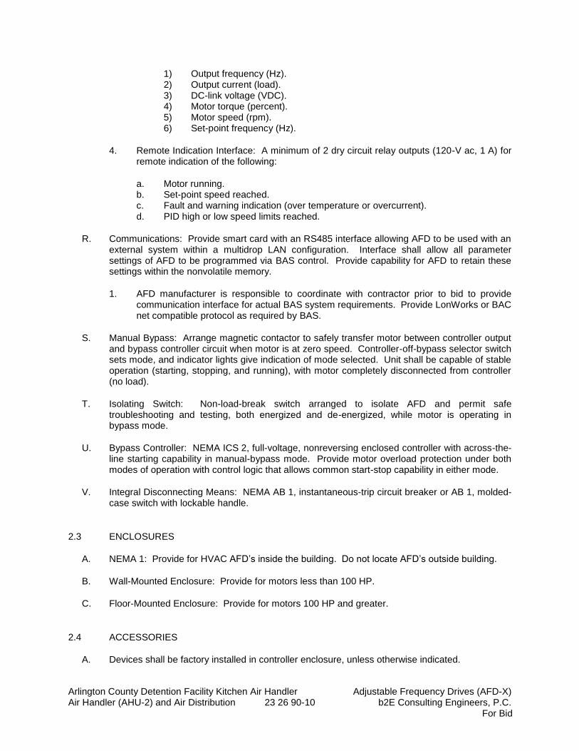
Arlington County Detention Facility Kitchen Air Handler Adjustable Frequency Drives (AFD-X) Air Handler (AHU-2) and Air Distribution 23 26 90-10 b2E Consulting Engineers, P.C.
For Bid
1) Output frequency (Hz). 2) Output current (load). 3) DC-link voltage (VDC). 4) Motor torque (percent). 5) Motor speed (rpm). 6) Set-point frequency (Hz).
4. Remote Indication Interface: A minimum of 2 dry circuit relay outputs (120-V ac, 1 A) for remote indication of the following:
a. Motor running. b. Set-point speed reached. c. Fault and warning indication (over temperature or overcurrent). d. PID high or low speed limits reached.
R. Communications: Provide smart card with an RS485 interface allowing AFD to be used with an external system within a multidrop LAN configuration. Interface shall allow all parameter settings of AFD to be programmed via BAS control. Provide capability for AFD to retain these settings within the nonvolatile memory.
1. AFD manufacturer is responsible to coordinate with contractor prior to bid to provide communication interface for actual BAS system requirements. Provide LonWorks or BAC net compatible protocol as required by BAS.
S. Manual Bypass: Arrange magnetic contactor to safely transfer motor between controller output and bypass controller circuit when motor is at zero speed. Controller-off-bypass selector switch sets mode, and indicator lights give indication of mode selected. Unit shall be capable of stable operation (starting, stopping, and running), with motor completely disconnected from controller (no load).
T. Isolating Switch: Non-load-break switch arranged to isolate AFD and permit safe troubleshooting and testing, both energized and de-energized, while motor is operating in bypass mode.
U. Bypass Controller: NEMA ICS 2, full-voltage, nonreversing enclosed controller with across-the-line starting capability in manual-bypass mode. Provide motor overload protection under both modes of operation with control logic that allows common start-stop capability in either mode.
V. Integral Disconnecting Means: NEMA AB 1, instantaneous-trip circuit breaker or AB 1, molded-case switch with lockable handle.
2.3 ENCLOSURES
A. NEMA 1: Provide for HVAC AFD’s inside the building. Do not locate AFD’s outside building.
B. Wall-Mounted Enclosure: Provide for motors less than 100 HP.
C. Floor-Mounted Enclosure: Provide for motors 100 HP and greater.
2.4 ACCESSORIES
A. Devices shall be factory installed in controller enclosure, unless otherwise indicated.
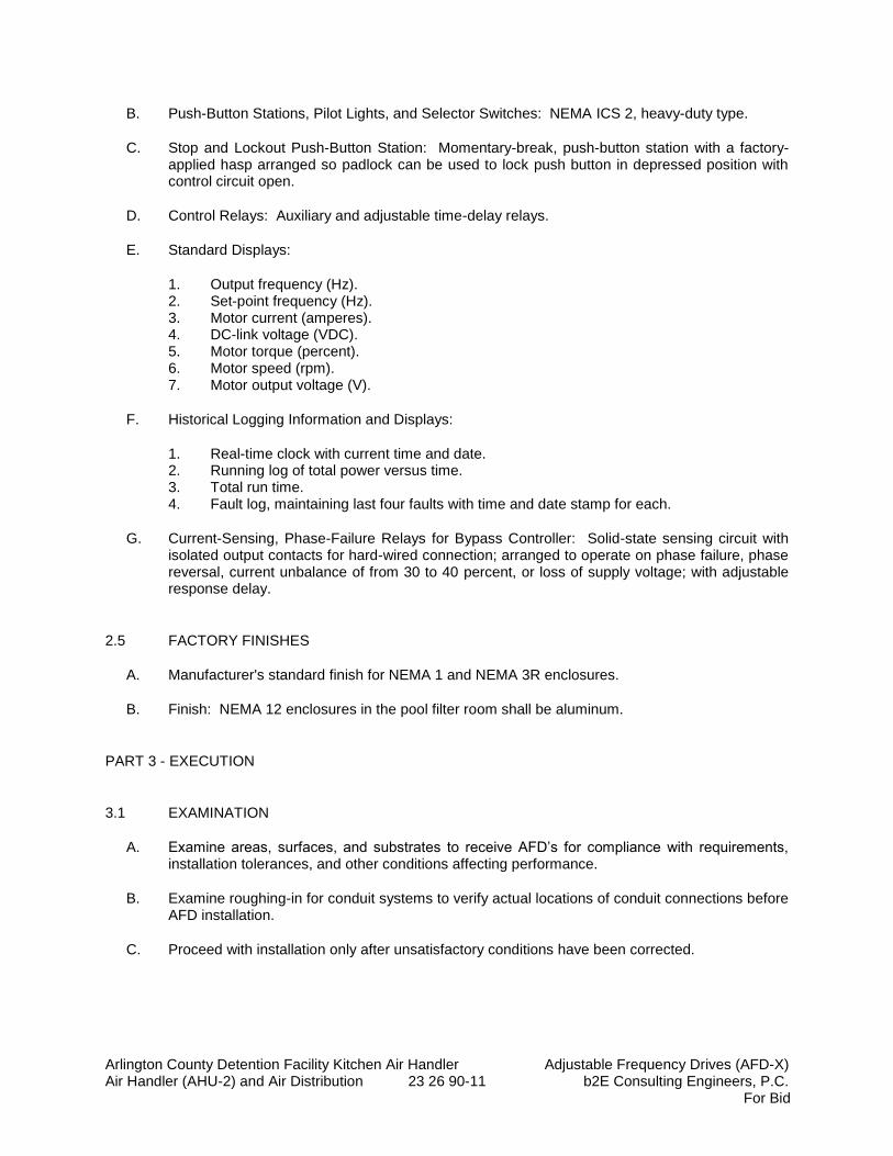
Arlington County Detention Facility Kitchen Air Handler Adjustable Frequency Drives (AFD-X) Air Handler (AHU-2) and Air Distribution 23 26 90-11 b2E Consulting Engineers, P.C.
For Bid
B. Push-Button Stations, Pilot Lights, and Selector Switches: NEMA ICS 2, heavy-duty type.
C. Stop and Lockout Push-Button Station: Momentary-break, push-button station with a factory-applied hasp arranged so padlock can be used to lock push button in depressed position with control circuit open.
D. Control Relays: Auxiliary and adjustable time-delay relays.
E. Standard Displays:
1. Output frequency (Hz). 2. Set-point frequency (Hz). 3. Motor current (amperes). 4. DC-link voltage (VDC). 5. Motor torque (percent). 6. Motor speed (rpm). 7. Motor output voltage (V).
F. Historical Logging Information and Displays:
1. Real-time clock with current time and date. 2. Running log of total power versus time. 3. Total run time. 4. Fault log, maintaining last four faults with time and date stamp for each.
G. Current-Sensing, Phase-Failure Relays for Bypass Controller: Solid-state sensing circuit with isolated output contacts for hard-wired connection; arranged to operate on phase failure, phase reversal, current unbalance of from 30 to 40 percent, or loss of supply voltage; with adjustable response delay.
2.5 FACTORY FINISHES
A. Manufacturer's standard finish for NEMA 1 and NEMA 3R enclosures.
B. Finish: NEMA 12 enclosures in the pool filter room shall be aluminum.
PART 3 - EXECUTION
3.1 EXAMINATION
A. Examine areas, surfaces, and substrates to receive AFD’s for compliance with requirements, installation tolerances, and other conditions affecting performance.
B. Examine roughing-in for conduit systems to verify actual locations of conduit connections before AFD installation.
C. Proceed with installation only after unsatisfactory conditions have been corrected.
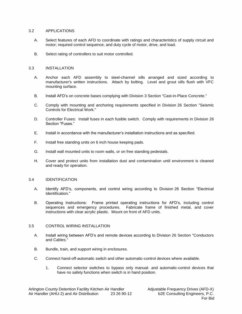
Arlington County Detention Facility Kitchen Air Handler Adjustable Frequency Drives (AFD-X) Air Handler (AHU-2) and Air Distribution 23 26 90-12 b2E Consulting Engineers, P.C.
For Bid
3.2 APPLICATIONS
A. Select features of each AFD to coordinate with ratings and characteristics of supply circuit and motor; required control sequence; and duty cycle of motor, drive, and load.
B. Select rating of controllers to suit motor controlled.
3.3 INSTALLATION
A. Anchor each AFD assembly to steel-channel sills arranged and sized according to manufacturer's written instructions. Attach by bolting. Level and grout sills flush with VFC mounting surface.
B. Install AFD’s on concrete bases complying with Division 3 Section "Cast-in-Place Concrete."
C. Comply with mounting and anchoring requirements specified in Division 26 Section "Seismic Controls for Electrical Work."
D. Controller Fuses: Install fuses in each fusible switch. Comply with requirements in Division 26 Section "Fuses.”
E. Install in accordance with the manufacturer’s installation instructions and as specified.
F. Install free standing units on 6 inch house keeping pads.
G. Install wall mounted units to room walls, or on free standing pedestals.
H. Cover and protect units from installation dust and contamination until environment is cleaned and ready for operation.
3.4 IDENTIFICATION
A. Identify AFD’s, components, and control wiring according to Division 26 Section “Electrical Identification."
B. Operating Instructions: Frame printed operating instructions for AFD’s, including control sequences and emergency procedures. Fabricate frame of finished metal, and cover instructions with clear acrylic plastic. Mount on front of AFD units.
3.5 CONTROL WIRING INSTALLATION
A. Install wiring between AFD’s and remote devices according to Division 26 Section "Conductors and Cables."
B. Bundle, train, and support wiring in enclosures.
C. Connect hand-off-automatic switch and other automatic-control devices where available.
1. Connect selector switches to bypass only manual- and automatic-control devices that have no safety functions when switch is in hand position.
Arlington County Detention Facility Kitchen Air Handler Adjustable Frequency Drives (AFD-X) Air Handler (AHU-2) and Air Distribution 23 26 90-13 b2E Consulting Engineers, P.C.
For Bid
3.6 CONNECTIONS
A. Conduit installation requirements are specified in other Division 26 Sections. Drawings indicate general arrangement of conduit, fittings, and specialties.
B. Ground equipment.
C. Tighten electrical connectors and terminals according to manufacturer's published torque-tightening values. If manufacturer's torque values are not indicated, use those specified in UL 486A and UL 486B.
D. The following standard factory tests shall be performed on the equipment provided under this section. All tests shall be in accordance with the latest version of UL, ANSI and NEMA standards.
1. All printed circuit boards shall be tested under a temperature cycling load test and then functionally tested via fault finder bench equipment prior to unit installation.
2. All final assemblies shall be tested at full load with application of line-to-line and line-to-ground bolted faults. The Adjustable Frequency Drive shall trip electronically without device failure.
3. After all tests have been performed; each AFD shall undergo a 12-hour burn-in test. The drive shall be burned in at 100% inductive or motor load for 12 hours without an unscheduled shutdown.
4. After the burn-in cycle is complete, each AFD shall be put through a 30-minute cycling motor load test before inspection and shipping.
E. The manufacturer shall provide certified copies of factory test reports, to confirm that AFD has been tested as specified.
1. Tests shall verify not only performance of unit and integrated assembly, but also suitability of enclosure venting and rigging.
2. In addition, unit shall be tested in accordance with ANSI Standards.
3.7 FIELD QUALITY CONTROL
A. Provide the services of a qualified, factory-trained manufacturer's representative to assist the Contractor in installation and start-up of the equipment specified under this section. The manufacturer's representative shall provide technical direction and assistance to the Contractor in general assembly of the equipment, connections and adjustments, and testing of the assembly and components contained herein. The contractor shall include any and all applicable commissioning procedures recommended by the manufacturer for the specific unit.
B. The following minimum work shall be performed by the Contractor under the technical direction of the manufacturer's service representative.
1. Inspection and final adjustment. 2. Operational and function checks of AFD’s and spare parts. 3. Coordination and field service as required or requested by the HVAC Balancing
contractor. 4. Coordination and field service as required or requested by the BAS contractor.
C. The Contractor shall provide Submittals of the manufacturer's field start-up report before final payment is made.
Arlington County Detention Facility Kitchen Air Handler Adjustable Frequency Drives (AFD-X) Air Handler (AHU-2) and Air Distribution 23 26 90-14 b2E Consulting Engineers, P.C.
For Bid
D. Prepare for acceptance tests as follows:
1. Test insulation resistance for each AFD element, bus, component, connecting supply, feeder, and control circuit.
2. Test continuity of each circuit.
E. Testing: Engage a qualified testing agency to perform the following field quality-control testing:
1. Perform each electrical test and visual and mechanical inspection stated in NETA ATS, Sections 7.5, 7.6, and 7.16. Certify compliance with test parameters.
2. Correct malfunctioning units on-site, where possible, and retest to demonstrate compliance; otherwise, replace with new units and retest.
F. Manufacturer's Field Service: Engage a factory-authorized service representative to inspect field-assembled components and equipment installation, including pretesting and adjusting AFD’s.
G. Test Reports: Prepare a written report to record the following:
1. Test procedures used. 2. Test results that comply with requirements. 3. Test results that do not comply with requirements and corrective action taken to achieve
compliance with requirements.
3.8 MANUFACTURER'S CERTIFICATION
A. A qualified factory-trained manufacturer's representative shall certify in writing that the equipment has been installed, adjusted, and tested in accordance with the manufacturer's recommendations.
B. The Contractor shall provide three (3) copies of the manufacturer's representative's certification before final payment is made.
3.9 TRAINING
A. The Contractor shall provide a factory training session for up to 4 owner’s representative for 2 normal workdays at a jobsite location. In addition, one day of factory training shall be provided at the vendors training center.
B. The training session shall be conducted by a manufacturer’s qualified representative.
C. The training program for the Owner’s maintenance staff shall consist of the following:
1. Instructions on the proper maintenance and operation of the equipment. 2. Instructional hours shall be in addition to testing and start-up hours. 3. Schedule training after equipment and associated systems are completely installed and
tested and can operate under normal loads. 4. Provide instruction on each type of system.
D. The training program for the EMS contractor shall consist of the following:
Arlington County Detention Facility Kitchen Air Handler Adjustable Frequency Drives (AFD-X) Air Handler (AHU-2) and Air Distribution 23 26 90-15 b2E Consulting Engineers, P.C.
For Bid
1. Train the BAS contractor to use the AFD and provide wiring diagrams, and direction specific to this project to ensure that the BAS contractor is able to operate the AFD’s, and that all input and output interlocks are fully coordinated with the BAS.
2. Provide additional training for BAS contractor field technicians until all monitoring and control points are operating as specified under Section 23 09 93, and as required by the Arlington County Commissioning Agent.
3. Provide the BAS contractor with a complete set of installation and start-up, and operating manuals. These documents shall be in addition to those provided to the owner. Provide the BAS contractor documents no later than 60 days prior to the contract completion date.
3.10 STARTUP SERVICE
A. Engage a factory-authorized service representative to perform startup service.
B. Verify that electrical wiring installation complies with manufacturer's submittal and installation requirements in Division 26 Sections.
C. Complete installation and startup checks according to manufacturer's written instructions.
3.11 ADJUSTING
A. Set field-adjustable switches and circuit-breaker trip ranges.
3.12 CLEANING
A. Clean AFD’s internally, on completion of installation, according to manufacturer's written instructions. Vacuum dirt and debris; do not use compressed air to assist in cleaning.
3.13 DEMONSTRATION
A. Engage a factory-authorized service representative to train Owner's maintenance personnel to adjust, operate, and maintain AFD’s. Refer to Division 1 Section 01 70 00 "Closeout Procedures."
3.14 COMMISSIONING
A. The Adjustable Frequency Drives (AFDs) shall be commissioned in accordance with the Commissioning (Cx) Plan.
B. The mechanical, controls, and start-up contractors are responsible for supporting all Cx activities and testing as outlined in the Cx Plan. These activities include but are not limited to the following:
1. Respond to all comments provided on the AFD submittals by the Commissioning Agent (CxA).
2. Attend Cx related meetings as outlined in the Cx Plan.
Arlington County Detention Facility Kitchen Air Handler Adjustable Frequency Drives (AFD-X) Air Handler (AHU-2) and Air Distribution 23 26 90-16 b2E Consulting Engineers, P.C.
For Bid
3. Ensure all VFDs are operational in accordance with the contract drawings prior to the start of functional performance testing (FPT).
4. Provide copies of the completed start-up reports and pre-functional checklists to the CxA prior to the start of FPT.
5. Technicians from the start-up, controls, and mechanical contractors are required during all AFD FPT. The start-up technician shall be familiar with the operation of the units and be capable of demonstrating and troubleshooting all required functions.
6. Promptly rectify all AFD related issues that are recorded in the Cx Issues Log. Submit written notification to the Owner, CxA, and Engineer that this has been done. (Note: The CxA does not provide any directives so any deviation from the original scope must be approved be approved by the Owner or Engineer prior to performing work).
3.15 SCHEDULE OF AFD’S (PROVIDED BY PUMP MANUFACTURER)
A. Total of 1 AFD: Coordinate and provide with capacity to match final approved equipment motor horsepower.
JUSTICE CENTER PUMP AFD SCHEDULE
Equipment Served AFD Tag Location Motor Size Bypass Controller
AHU-2 AFD-1 Upper Level Mech Rm 30 HP NO AFD Notes:
1. Unit enclosure shall be NEMA 1. 2. Provide manual speed adjustment via keypad mounted on the enclosure’s exterior. 3. Provide AFD with the number of outputs for connection to exterior relays and equipment as
required. 4. AFDs shall be suitable for an operating environment from 32 degrees to 104 degrees F and
humidity up to 90% non-condensing. 5. AFD shall be capable of 30 second ramp up to full speed and 5 seconds ramp down from full
speed to zero. 6. AHU vendor shall perform start-up and field adjustments for factory trained. An AFD and
associated systems and coordinate with other trade’s work for full adjusted and complete operating system.
END OF SECTION 23 60 90

Arlington County Detention Facility Kitchen Air Handler Metal Ducts Air Handler (AHU-2) and Air Distribution 23 31 13-1 b2E Consulting Engineers, P.C.
For Bid
SECTION 23 31 13
METAL DUCTS
PART 1 - GENERAL
1.1 SUMMARY
A. Section Includes: 1. Single-wall rectangular ducts and fittings. 2. Sheet metal materials. 3. Duct liner. 4. Sealants and gaskets. 5. Hangers and supports.
1.2 PERFORMANCE REQUIREMENTS
A. Delegated Duct Design: Duct construction, including sheet metal thicknesses, seam and joint construction, reinforcements, and hangers and supports, shall comply with SMACNA's "HVAC Duct Construction Standards - Metal and Flexible" and performance requirements and design criteria indicated in "Duct Schedule" Article.
B. Structural Performance: Duct hangers and supports shall withstand the effects of gravity loads and stresses within limits and under conditions described in SMACNA's "HVAC Duct Construction Standards - Metal and Flexible"
C. Airstream Surfaces: Surfaces in contact with the airstream shall comply with requirements in ASHRAE 62.1-2007 and NFPA 90A
D. Low Pressure Ductwork: Whenever a duct size is not indicated in the contract documents the contractor shall use a duct size (inside clear) with a resultant airflow velocity equal to or less than the velocity indicated below (FPM) for the design airflow (CFM) connected to that portion of ductwork.
1. 0-120 CFM = 500 FPM 7. 1501-2000 CFM = 1100 FPM 2. 101-220 CFM = 600 FPM 8. 2001-3000 CFM = 1200 FPM 3. 221-350 CFM = 700 FPM 9. 3001-4000 CFM = 1300 FPM 4. 351-500 CFM = 800 FPM 10. 4001-5500 CFM = 1400 FPM 5. 501-1000 CFM = 900 FPM 11. 5501-6000 CFM = 1500 FPM 6. 1001-1500 CFM = 1000 FPM 12. > 6000 CFM = 1600 FPM
E. Medium Pressure Ductwork: Whenever a duct size is not indicated in the contract documents the contractor shall use a duct size (inside clear) with a resultant airflow velocity equal to or less than the velocity indicated below (FPM) for the design airflow (CFM) connected to that portion of ductwork.
1. 0-120 CFM = 700 FPM 7. 1501-2000 CFM = 1400 FPM 2. 101-220 CFM = 800 FPM 8. 2001-3000 CFM = 1500 FPM 3. 221-350 CFM = 900 FPM 9. 3001-4000 CFM = 1700 FPM 4. 351-500 CFM = 1000 FPM 10. 4001-5500 CFM = 1800 FPM 5. 501-1000 CFM = 1200 FPM 11. 5501-6000 CFM = 1900 FPM 6. 1001-1500 CFM = 1300 FPM 12. > 6000 CFM = 2000 FPM
Arlington County Detention Facility Kitchen Air Handler Metal Ducts Air Handler (AHU-2) and Air Distribution 23 31 13-2 b2E Consulting Engineers, P.C.
For Bid
F. Product Data: For each type of the following products:
1. Liners and adhesives. 2. Sealants and gaskets.
G. Shop Drawings:
1. Fabrication, assembly, and installation, including plans, elevations, sections, components, and attachments to other work.
2. Factory- and shop-fabricated ducts and fittings. 3. Duct layout indicating sizes, configuration, liner material, and static-pressure classes. 4. Elevation of top of ducts. 5. Dimensions of main duct runs from building grid lines. 6. Fittings. 7. Reinforcement and spacing. 8. Seam and joint construction. 9. Penetrations through fire-rated and other partitions. 10. Equipment installation based on equipment being used on Project. 11. Locations for duct accessories, including dampers, turning vanes, and access doors and
panels. 12. Hangers and supports, including methods for duct and building attachment and vibration
isolation. 13. Show locations for all lined transfer ducts between rooms.
H. Delegated-Design Submittal:
1. Sheet metal thicknesses. 2. Joint and seam construction and sealing. 3. Reinforcement details and spacing. 4. Materials, fabrication, assembly, and spacing of hangers and supports. 5. Design Calculations: Calculations or tables, for selecting hangers and supports.
I. Coordination Drawings: CAD generated plans, drawn to 1/4-inch equals 1-foot scale (show fabrication and installation details for all metal ducts), on which the following items are shown and coordinated with each other, using input from installers of the items involved:
1. CAD generated drawings (1/4 scale) shall be provided for the following systems; including the entire air distribution system for supply, return, outside and exhaust air ductwork, diffusers, registers, grilles, duct accessories, etc.
2. Fabrication, assembly, and installation, including plans, elevations, sections, components, and attachments to other work.
3. Duct layout indicating sizes and pressure classes. 4. Elevations of top and bottom of ducts. 5. Dimensions of main duct runs from building grid lines. 6. Fittings. 7. Reinforcement and spacing. 8. Seam and joint construction. 9. Penetrations through fire-rated and other partitions. 10. Equipment installation based on equipment being used on Project. 11. Duct accessories, including access doors and panels. 12. Hangers and supports, including methods of duct and building attachment, vibration
isolation.
Arlington County Detention Facility Kitchen Air Handler Metal Ducts Air Handler (AHU-2) and Air Distribution 23 31 13-3 b2E Consulting Engineers, P.C.
For Bid
J. Welding certificates.
K. Field quality-control reports.
1.3 QUALITY ASSURANCE
A. Welding Qualifications: Qualify procedures and personnel according to AWS D1.1/D1.1M, "Structural Welding Code - Steel," for hangers and supports; AWS D1.2/D1.2M, "Structural Welding Code - Aluminum," for aluminum supports; and AWS D9.1M/D9.1, "Sheet Metal Welding Code," for duct joint and seam welding.
B. Welding Qualifications: Qualify procedures and personnel according to the following:
1. AWS D1.1/D1.1M, "Structural Welding Code - Steel," for hangers and supports. 2. AWS D1.2/D1.2M, "Structural Welding Code - Aluminum," for aluminum supports. 3. AWS D9.1M/D9.1, "Sheet Metal Welding Code," for duct joint and seam welding.
C. ASHRAE Compliance: Applicable requirements in ASHRAE 62.1-2004, Section 5 - "Systems and Equipment" and Section 7 - "Construction and System Start-Up."
D. ASHRAE/IESNA Compliance: Applicable requirements in ASHRAE/IESNA 90.1-2010, Section 6.4.4 - "HVAC System Construction and Insulation" and International Energy Conservation Code – 2012 (IECC) Section 603.9.
PART 2 - PRODUCTS
2.1 SINGLE-WALL RECTANGULAR DUCTS AND FITTINGS
A. General Fabrication Requirements: Comply with SMACNA's "HVAC Duct Construction Standards - Metal and Flexible" based on indicated static-pressure class unless otherwise indicated.
B. Transverse Joints: Select joint types and fabricate according to SMACNA's "HVAC Duct Construction Standards - Metal and Flexible," Figure 1-4, "Transverse (Girth) Joints," for static-pressure class, applicable sealing requirements, materials involved, duct-support intervals, and other provisions in SMACNA's "HVAC Duct Construction Standards - Metal and Flexible."
C. Longitudinal Seams: Select seam types and fabricate according to SMACNA's "HVAC Duct Construction Standards - Metal and Flexible," Figure 1-5, "Longitudinal Seams - Rectangular Ducts," for static-pressure class, applicable sealing requirements, materials involved, duct-support intervals, and other provisions in SMACNA's "HVAC Duct Construction Standards - Metal and Flexible."
D. Elbows, Transitions, Offsets, Branch Connections, and Other Duct Construction: Select types
and fabricate according to SMACNA's "HVAC Duct Construction Standards - Metal and Flexible," Chapter 2, "Fittings and Other Construction," for static-pressure class, applicable sealing requirements, materials involved, duct-support intervals, and other provisions in SMACNA's "HVAC Duct Construction Standards - Metal and Flexible."
Arlington County Detention Facility Kitchen Air Handler Metal Ducts Air Handler (AHU-2) and Air Distribution 23 31 13-4 b2E Consulting Engineers, P.C.
For Bid
E. Supply, Return Ductwork: Provide concealed ductwork with a 2-inch external mineral fiber insulation with vapor barrier jacket.
2.2 SHEET METAL MATERIALS
A. General Material Requirements: Comply with SMACNA's "HVAC Duct Construction Standards - Metal and Flexible" for acceptable materials, material thicknesses, and duct construction methods unless otherwise indicated. Sheet metal materials shall be free of pitting, seam marks, roller marks, stains, discolorations, and other imperfections.
B. Galvanized Sheet Steel: Comply with ASTM A 653.
1. Galvanized Coating Designation: G90. 2. Finishes for Surfaces Exposed to View: Mill phosphatized.
C. Carbon-Steel Sheets: Comply with ASTM A 1008 with oiled, matte finish for exposed ducts.
1. Welded carbon steel sheets for kitchen grease ductwork. Wrap with UL Listed 2-hour rated grease duct wrap from connection to hood to underside of fan curb.
D. Stainless-Steel Sheets: Comply with ASTM A 480, Type 304 or 316, as indicated in the "Duct Schedule" Article; cold rolled, annealed, sheet. Exposed surface finish shall be No. 2B, No. 2D, No. 3, or No. 4 as indicated in the "Duct Schedule" Article.
E. Aluminum Sheets: Comply with ASTM B 209 Alloy 3003, H14 temper; with mill finish for concealed ducts, and standard, one-side bright finish for duct surfaces exposed to view.
F. Reinforcement Shapes and Plates: ASTM A 36, steel plates, shapes, and bars; black and galvanized.
1. Where black- and galvanized-steel shapes and plates are used to reinforce aluminum ducts, isolate the different metals with butyl rubber, neoprene, or EPDM gasket materials.
G. Tie Rods: Galvanized steel, 1/4-inch (6-mm) minimum diameter for lengths 36 inches or less; 3/8-inch minimum diameter for lengths longer than 36 inches.
2.3 SEALANT AND GASKETS
A. General Sealant and Gasket Requirements: Surface-burning characteristics for sealants and gaskets shall be a maximum flame-spread index of 25 and a maximum smoke-developed index of 50 when tested according to UL 723; certified by an NRTL.
B. Two-Part Tape Sealing System:
1. Tape: Woven cotton fiber impregnated with mineral gypsum and modified acrylic/silicone activator to react exothermically with tape to form hard, durable, airtight seal.
2. Tape Width: 3 inches, 4 inches, or 6 inches. 3. Sealant: Modified styrene acrylic. 4. Water resistant. 5. Mold and mildew resistant. 6. Maximum Static-Pressure Class: 10-inch wg, positive and negative. 7. Service: Indoor and outdoor.
Arlington County Detention Facility Kitchen Air Handler Metal Ducts Air Handler (AHU-2) and Air Distribution 23 31 13-5 b2E Consulting Engineers, P.C.
For Bid
8. Service Temperature: Minus 40 to plus 200 deg F. 9. Substrate: Compatible with galvanized sheet steel (both PVC coated and bare), stainless
steel, or aluminum. 10. For indoor applications, use sealant that has a VOC content of 250 g/L or less when
calculated according to 40 CFR 59, Subpart D (EPA Method 24).
C. Water-Based Joint and Seam Sealant:
1. Application Method: Brush on. 2. Solids Content: Minimum 65 percent. 3. Shore A Hardness: Minimum 20. 4. Water resistant. 5. Mold and mildew resistant. 6. VOC: Maximum 75 g/L (less water). 7. Maximum Static-Pressure Class: 10-inch wg, positive and negative. 8. Service: Indoor or outdoor. 9. Substrate: Compatible with galvanized sheet steel (both PVC coated and bare), stainless
steel, or aluminum sheets.
D. Solvent-Based Joint and Seam Sealant:
1. Application Method: Brush on. 2. Base: Synthetic rubber resin. 3. Solvent: Toluene and heptane. 4. Solids Content: Minimum 60 percent. 5. Shore A Hardness: Minimum 60. 6. Water resistant. 7. Mold and mildew resistant. 8. For indoor applications, use sealant that has a VOC content of 250 g/L or less when
calculated according to 40 CFR 59, Subpart D (EPA Method 24). 9. VOC: Maximum 395 g/L. 10. Maximum Static-Pressure Class: 10-inch wg, positive or negative. 11. Service: Indoor or outdoor. 12. Substrate: Compatible with galvanized sheet steel (both PVC coated and bare), stainless
steel, or aluminum sheets.
E. Flanged Joint Sealant: Comply with ASTM C 920.
1. General: Single-component, acid-curing, silicone, elastomeric. 2. Type: S. 3. Grade: NS. 4. Class: 25. 5. Use: O. 6. For indoor applications, use sealant that has a VOC content of 250 g/L or less when
calculated according to 40 CFR 59, Subpart D (EPA Method 24).
F. Flange Gaskets: Butyl rubber, neoprene, or EPDM polymer with polyisobutylene plasticizer.
G. Round Duct Joint O-Ring Seals:
1. Seal shall provide maximum leakage class of 3 cfm/100 sq. ft. at 1-inch wg and shall be rated for 10-inch wg static-pressure class, positive or negative.
2. EPDM O-ring to seal in concave bead in coupling or fitting spigot.
Arlington County Detention Facility Kitchen Air Handler Metal Ducts Air Handler (AHU-2) and Air Distribution 23 31 13-6 b2E Consulting Engineers, P.C.
For Bid
3. Double-lipped, EPDM O-ring seal, mechanically fastened to factory-fabricated couplings and fitting spigots.
2.4 HANGERS AND SUPPORTS
A. Hanger Rods for Noncorrosive Environments: Cadmium-plated steel rods and nuts.
B. Hanger Rods for Corrosive Environments: Electrogalvanized, all-thread rods or galvanized rods with threads painted with zinc-chromate primer after installation.
C. Strap and Rod Sizes: Comply with SMACNA's "HVAC Duct Construction Standards - Metal and Flexible," Table 4-1 (Table 4-1M), "Rectangular Duct Hangers Minimum Size," and Table 4-2, "Minimum Hanger Sizes for Round Duct."
D. Steel Cables for Galvanized-Steel Ducts: Galvanized steel complying with ASTM A 603.
E. Steel Cables for Stainless-Steel Ducts: Stainless steel complying with ASTM A 492.
F. Steel Cable End Connections: Cadmium-plated steel assemblies with brackets, swivel, and bolts designed for duct hanger service; with an automatic-locking and clamping device.
G. Duct Attachments: Sheet metal screws, blind rivets, or self-tapping metal screws; compatible with duct materials.
H. Trapeze and Riser Supports:
1. Supports for Galvanized-Steel Ducts: Galvanized-steel shapes and plates. 2. Supports for Stainless-Steel Ducts: Stainless-steel shapes and plates. 3. Supports for Aluminum Ducts: Aluminum or galvanized steel coated with zinc chromate.
PART 3 - EXECUTION
3.1 DUCT INSTALLATION
A. Drawing plans, schematics, and diagrams indicate general location and arrangement of duct system. Indicated duct locations, configurations, and arrangements were used to size ducts and calculate friction loss for air-handling equipment sizing and for other design considerations. Install duct systems as indicated unless deviations to layout are approved on Shop Drawings and Coordination Drawings.
B. Install ducts according to SMACNA's "HVAC Duct Construction Standards - Metal and Flexible" unless otherwise indicated.
C. Install round ducts in maximum practical lengths.
D. Install ducts with fewest possible joints.
E. Install factory- or shop-fabricated fittings for changes in direction, size, and shape and for branch connections.
Arlington County Detention Facility Kitchen Air Handler Metal Ducts Air Handler (AHU-2) and Air Distribution 23 31 13-7 b2E Consulting Engineers, P.C.
For Bid
F. Unless otherwise indicated, install ducts vertically and horizontally, and parallel and perpendicular to building lines.
G. Install ducts close to walls, overhead construction, columns, and other structural and permanent enclosure elements of building.
H. Install ducts with a clearance of 1 inch, plus allowance for insulation thickness.
I. Route ducts to avoid passing through transformer vaults and electrical equipment rooms and enclosures.
J. Where ducts pass through non-fire-rated interior partitions and exterior walls and are exposed to view, cover the opening between the partition and duct or duct insulation with sheet metal flanges of same metal thickness as the duct. Overlap openings on four sides by at least 1-1/2 inches.
K. Where ducts pass through fire-rated interior partitions and exterior walls, install fire dampers. Comply with requirements in Division 23 Section "Air Duct Accessories" for fire and smoke dampers.
L. Protect duct interiors from moisture, construction debris and dust, and other foreign materials. Comply with SMACNA's "Duct Cleanliness for New Construction Guidelines."
3.2 INSTALLATION OF EXPOSED DUCTWORK
A. Protect ducts exposed in finished spaces from being dented, scratched, or damaged.
B. Trim duct sealants flush with metal. Create a smooth and uniform exposed bead. Do not use two-part tape sealing system.
C. Grind welds to provide smooth surface free of burrs, sharp edges, and weld splatter. When welding stainless steel with a No. 3 or 4 finish, grind the welds flush, polish the exposed welds, and treat the welds to remove discoloration caused by welding.
D. Maintain consistency, symmetry, and uniformity in the arrangement and fabrication of fittings, hangers and supports, duct accessories, and air outlets.
E. Repair or replace damaged sections and finished work that does not comply with these requirements.
F. Paint exposed ductwork with metal primer and with 2-finish coats in color as directed by the Architect.
3.3 DUCT SEALING
A. Seal ducts for duct static-pressure, seal classes, and leakage classes specified in "Duct Schedule" Article according to SMACNA's "HVAC Duct Construction Standards - Metal and Flexible."
B. Seal ducts to the following seal classes according to SMACNA's "HVAC Duct Construction Standards - Metal and Flexible":
Arlington County Detention Facility Kitchen Air Handler Metal Ducts Air Handler (AHU-2) and Air Distribution 23 31 13-8 b2E Consulting Engineers, P.C.
For Bid
1. Comply with SMACNA's "HVAC Duct Construction Standards - Metal and Flexible." 2. Outdoor, Supply-Air Ducts: Seal Class A. 3. Outdoor, Exhaust Ducts: Seal Class A. 4. Outdoor, Return-Air Ducts: Seal Class A. 5. Unconditioned Space, Supply-Air Ducts in Pressure Classes 2-Inch wg and Lower: Seal
Class A. 6. Unconditioned Space, Supply-Air Ducts in Pressure Classes Higher than 2-Inch wg: Seal
Class A. 7. Unconditioned Space, Exhaust Ducts: Seal Class A. 8. Unconditioned Space, Return-Air Ducts: Seal Class A. 9. Conditioned Space, Supply-Air Ducts in Pressure Classes 2-Inch wg and Lower: Seal
Class A. 10. Conditioned Space, Supply-Air Ducts in Pressure Classes Higher Than 2-Inch wg: Seal
Class A. 11. Conditioned Space, Exhaust Ducts: Seal Class A. 12. Conditioned Space, Return-Air Ducts: Seal Class A.
3.4 HANGER AND SUPPORT INSTALLATION
A. Comply with SMACNA's "HVAC Duct Construction Standards - Metal and Flexible," Chapter 4, "Hangers and Supports."
B. Building Attachments: Concrete inserts, powder-actuated fasteners, or structural-steel fasteners appropriate for construction materials to which hangers are being attached.
1. Where practical, install concrete inserts before placing concrete. 2. Install powder-actuated concrete fasteners after concrete is placed and completely cured. 3. Use powder-actuated concrete fasteners for standard-weight aggregate concretes or for
slabs more than 4 inches thick. 4. Do not use powder-actuated concrete fasteners for lightweight-aggregate concretes or for
slabs less than 4 inches thick. 5. Do not use powder-actuated concrete fasteners for seismic restraints.
C. Hanger Spacing: Comply with SMACNA's "HVAC Duct Construction Standards - Metal and Flexible," Table 4-1 (Table 4-1M), "Rectangular Duct Hangers Minimum Size," and Table 4-2, "Minimum Hanger Sizes for Round Duct," for maximum hanger spacing; install hangers and supports within 24 inches of each elbow and within 48 inches of each branch intersection.
D. Hangers Exposed to View: Threaded rod and angle or channel supports.
E. Support vertical ducts with steel angles or channel secured to the sides of the duct with welds, bolts, sheet metal screws, or blind rivets; support at each floor and at a maximum intervals of 16 feet.
F. Install upper attachments to structures. Select and size upper attachments with pull-out, tension, and shear capacities appropriate for supported loads and building materials where used.
Arlington County Detention Facility Kitchen Air Handler Metal Ducts Air Handler (AHU-2) and Air Distribution 23 31 13-9 b2E Consulting Engineers, P.C.
For Bid
3.5 CONNECTIONS
A. Make connections to equipment with flexible connectors complying with Division 23 Section "Air Duct Accessories."
B. Comply with SMACNA's "HVAC Duct Construction Standards - Metal and Flexible" for branch, outlet and inlet, and terminal unit connections.
C. Dissimilar Metals: Make connections of ductwork to units of dissimilar metals using flexible duct connectors suitable for type of use.
1. Fasteners in aluminum ductwork shall be 316 stainless steel material.
3.6 PAINTING
A. Paint interior of metal ducts that are visible through registers and grilles and that do not have duct liner. Apply one coat of flat, black, latex paint over a compatible galvanized-steel primer.
3.7 FIELD QUALITY CONTROL
A. Perform tests and inspections.
B. Duct system will be considered defective if it does not pass tests and inspections.
C. Prepare test and inspection reports.
3.8 DUCT CLEANING
A. Clean new duct system(s) before testing, adjusting, and balancing.
B. Use service openings for entry and inspection.
1. Create new openings and install access panels appropriate for duct static-pressure class if required for cleaning access. Provide insulated panels for insulated or lined duct. Patch insulation and liner as recommended by duct liner manufacturer. Comply with Division 23 Section "Air Duct Accessories" for access panels and doors.
2. Disconnect and reconnect flexible ducts as needed for cleaning and inspection. 3. Remove and reinstall ceiling to gain access during the cleaning process.
C. Particulate Collection and Odor Control:
1. When venting vacuuming system inside the building, use HEPA filtration with 99.97 percent collection efficiency for 0.3-micron-size (or larger) particles.
2. When venting vacuuming system to outdoors, use filter to collect debris removed from HVAC system, and locate exhaust downwind and away from air intakes and other points of entry into building.
D. Clean the following components by removing surface contaminants and deposits:
1. Air outlets and inlets (registers, grilles, and diffusers).
Arlington County Detention Facility Kitchen Air Handler Metal Ducts Air Handler (AHU-2) and Air Distribution 23 31 13-10 b2E Consulting Engineers, P.C.
For Bid
2. Supply, return, and exhaust fans including fan housings, plenums (except ceiling supply and return plenums), scrolls, blades or vanes, shafts, baffles, dampers, and drive assemblies.
3. Air-handling unit internal surfaces and components including mixing box, coil section, air wash systems, spray eliminators, condensate drain pans, humidifiers and dehumidifiers, filters and filter sections, and condensate collectors and drains.
4. Coils and related components. 5. Return-air ducts, dampers, actuators, and turning vanes except in ceiling plenums and
mechanical equipment rooms. 6. Supply-air ducts, dampers, actuators, and turning vanes. 7. Dedicated exhaust and ventilation components and makeup air systems.
E. Mechanical Cleaning Methodology:
1. Clean metal duct systems using mechanical cleaning methods that extract contaminants from within duct systems and remove contaminants from building.
2. Use vacuum-collection devices that are operated continuously during cleaning. Connect vacuum device to downstream end of duct sections so areas being cleaned are under negative pressure.
3. Use mechanical agitation to dislodge debris adhered to interior duct surfaces without damaging integrity of metal ducts, duct liner, or duct accessories.
4. Clean fibrous-glass duct liner with HEPA vacuuming equipment; do not permit duct liner to get wet. Replace fibrous-glass duct liner that is damaged, deteriorated, or delaminated or that has friable material, mold, or fungus growth.
5. Clean coils and coil drain pans according to NADCA 1992. Keep drain pan operational. Rinse coils with clean water to remove latent residues and cleaning materials; comb and straighten fins.
6. Provide drainage and cleanup for wash-down procedures. 7. Antimicrobial Agents and Coatings: Apply EPA-registered antimicrobial agents if fungus
is present. Apply antimicrobial agents according to manufacturer's written instructions after removal of surface deposits and debris.
8. Source-Removal Cleaning Methods: The HVAC system shall be cleaned using source-removal mechanical cleaning methods designed to extract contaminants from within the HVAC system and to safely remove these contaminants from the facility. No cleaning method, or combination of methods, shall be used that could potentially damage components of the HVAC system or negatively alter the integrity of the system.
a. Use continuously operating vacuum-collection devices to keep each section being cleaned under negative pressure.
b. Cleaning methods that require mechanical agitation devices to dislodge debris that is adhered to interior surfaces of HVAC system components shall be equipped to safely remove these devices. Cleaning methods shall not damage the integrity of HVAC system components or damage porous surface materials such as duct and plenum liners.
9. Cleaning Mineral-Fiber Insulation Components:
a. Fibrous-glass thermal or acoustical insulation elements present in equipment or ductwork shall be thoroughly cleaned with HEPA vacuuming equipment while the HVAC system is under constant negative pressure and shall not be permitted to get wet according to NADCA ACR 2006.
b. Cleaning methods used shall not cause damage to fibrous-glass components and will render the system capable of passing the HVAC System Cleanliness Tests (see NADCA ACR 2006).
Arlington County Detention Facility Kitchen Air Handler Metal Ducts Air Handler (AHU-2) and Air Distribution 23 31 13-11 b2E Consulting Engineers, P.C.
For Bid
c. Fibrous materials that become wet shall be discarded and replaced.
3.9 START UP
A. Air Balance: Comply with requirements in Division 23 Section "Testing, Adjusting, and Balancing for HVAC."
3.10 DUCT SCHEDULE
A. Fabricate ducts with galvanized sheet steel except as otherwise indicated and as follows:
1. Supply Air Ducts Galvanized (G90)
a. Pressure Class = Positive 4-inch wg. b. Minimum SMACNA Seal Class = A. c. SMACNA Leakage Class for Rectangular = 12. d. SMACNA Leakage Class for Round = 12.
2. Return Air Ducts: Galvanized (G90) a. Pressure Class = Negative 4-inch wg. b. Minimum SMACNA Seal Class = A. c. SMACNA leakage Class Rectangular = 12.
3. Outside Air Ducts: Galvanized (G90). a. Pressure Class: Negative 4-inch wg. b. Minimum SMACNA Seal Class = A. c. SMACNA leakage Class Rectangular = 12.
4. Exhaust Ducts: Ducts Connected to Return Air Fans (RAF-X): a. Pressure Class: Negative 4-inch wg. b. Minimum SMACNA Seal Class: A. c. SMACNA Leakage Class for Rectangular: 12.
B. Intermediate Reinforcement:
1. Galvanized-Steel Ducts: Galvanized steel or carbon steel coated with zinc-chromate primer.
C. Elbow Configuration:
1. Rectangular Duct: Comply with SMACNA's "HVAC Duct Construction Standards - Metal and Flexible," Figure 2-2, "Rectangular Elbows."
a. Velocity 1000 fpm or Lower:
1) Radius Type RE 1 with minimum 0.5 radius-to-diameter ratio. 2) Mitered Type RE 4 without vanes.
b. Velocity 1000 to 1500 fpm:
Arlington County Detention Facility Kitchen Air Handler Metal Ducts Air Handler (AHU-2) and Air Distribution 23 31 13-12 b2E Consulting Engineers, P.C.
For Bid
1) Radius Type RE 1 with minimum 1.0 radius-to-diameter ratio. 2) Radius Type RE 3 with minimum 0.5 radius-to-diameter ratio and two vanes. 3) Mitered Type RE 2 with vanes complying with SMACNA's "HVAC Duct
Construction Standards - Metal and Flexible," Figure 2-3, "Vanes and Vane Runners," and Figure 2-4, "Vane Support in Elbows."
c. Velocity 1500 fpm or Higher:
1) Radius Type RE 1 with minimum 1.5 radius-to-diameter ratio. 2) Radius Type RE 3 with minimum 1.0 radius-to-diameter ratio and two vanes. 3) Mitered Type RE 2 with vanes complying with SMACNA's "HVAC Duct
Construction Standards - Metal and Flexible," Figure 2-3, "Vanes and Vane Runners," and Figure 2-4, "Vane Support in Elbows."
D. Branch Configuration:
1. Rectangular Duct: Comply with SMACNA's "HVAC Duct Construction Standards - Metal and Flexible," Figure 2-6, "Branch Connections."
a. Rectangular Main to Rectangular Branch: 45-degree entry. b. Rectangular Main to Round Branch: Spin in.
END OF SECTION 23 31 13
Arlington County Detention Facility Kitchen Air Handler Air Handler (AHU-2) and Air Distribution 23 33 00 - 1
Air Duct Accessories b2E Consulting Engineers, P.C.
For Bid
SECTION 23 33 00
AIR DUCT ACCESSORIES
PART 1 - GENERAL
1.1 SUMMARY
A. Section Includes:
1. Manual volume dampers. 2. Control dampers. 3. Fire dampers. 4. Flange connectors. 5. Duct silencers. 6. Turning vanes. 7. Security Barrier Grilles with Sleeve. 8. Duct-mounted access doors. 9. Flexible connectors. 10. Flexible ducts. 11. Duct accessory hardware.
B. Manual Balancing Dampers (VD) provide a manual balancing damper with standoff graduated
quadrant, and locking wing nut for each duct runout to all air inlets and outlets (typical for all).
1. Provide TAB for each VD indicated or implied. Where volume dampers are not indicated on plans it shall be provided. The volume dampers are required for balancing.
2. Provide VD for each major branch duct running out from a main duct.
3. Provide VD for each branch duct from a major branch duct to all smaller duct runouts.
C. Security Barrier Grilles with Sleeve: Provide security barrier grilles to separate secure and non-secure areas at duct penetration through walls where indicated on floor plans.
1. The openings through concrete fitted block walls shall be temporarily secured and shall be closely monitored to prevent intrusion in accordance with Arlington County (DES) and the Sherriff’s Department requirements throughout the duration of construction.
D. Motor Operated Dampers: Equipment with motor operated dampers less than 10-LF from the edge of the roof shall have the damper installed (duct or unit mounted) inside the building with the damper actuator accessible from inside the building.
E. UL Listed Fire Stopping Systems: Provide UL listed fire stopping systems for floors and walls as indicated.
1. Floors: Provide UL listed firestopping system for all ductwork penetrations thru mezzanine mechanical room walls.
Arlington County Detention Facility Kitchen Air Handler Air Handler (AHU-2) and Air Distribution 23 33 00 - 2
Air Duct Accessories b2E Consulting Engineers, P.C.
For Bid
1.2 SUBMITTALS
A. Product Data: For each type of product indicated.
1. For duct silencers, include pressure drop and dynamic insertion loss data. Include breakout noise calculations for high transmission loss casings.
B. Shop Drawings: For duct accessories. Include plans, elevations, sections, details and attachments to other work.
1. Detail duct accessories fabrication and installation in ducts and other construction. Include dimensions, weights, loads, and required clearances; and method of field assembly into duct systems and other construction. Include the following:
a. Special fittings. b. Manual volume damper installations. c. Control damper installations. d. Detailed drawings for fire-damper, smoke-damper, combination fire-and smoke-
damper, ceiling, and corridor damper installations, including sleeves; and duct-mounted access doors and remote damper operators. Provide for each (non-typical) condition.
e. Duct security bars. f. Wiring Diagrams: For power, signal, and control wiring. g. Fire Rated Blankets
C. Coordination Drawings: Reflected ceiling plans, drawn to scale, on which ceiling-mounted access panels and access doors required for access to duct accessories are shown and coordinated with each other, using input from Installers of the items involved.
D. Source quality-control reports.
E. Operation and Maintenance Data: For air duct accessories to include in operation and maintenance manuals.
F. Sustainable Design Submittals:
1. Product Data for Prerequisite EQ 1: Documentation indicating that units comply with ASHRAE 62.1, Section 5 – “Systems and Equipment”.
2. Product Data for Prerequisite EA 2: Documentation indicating that duct insulation R-values comply with tables in ASHRAE/IESNA 90.1, Section 6 – “Heating, Ventilating, and Air Conditioning”.
1.3 QUALITY ASSURANCE
A. Comply with NFPA 90A, "Installation of Air Conditioning and Ventilating Systems," and with NFPA 90B, "Installation of Warm Air Heating and Air Conditioning Systems."
B. Comply with AMCA 500-D testing for damper rating.
1.4 EXTRA MATERIALS
A. Furnish extra materials that match products installed and that are packaged with protective covering for storage and identified with labels describing contents.
Arlington County Detention Facility Kitchen Air Handler Air Handler (AHU-2) and Air Distribution 23 33 00 - 3
Air Duct Accessories b2E Consulting Engineers, P.C.
For Bid
1. Fusible Links: Furnish quantity equal to 10 percent of amount installed.
PART 2 - PRODUCTS
2.1 MATERIALS
A. Comply with SMACNA's "HVAC Duct Construction Standards - Metal and Flexible" for acceptable materials, material thicknesses, and duct construction methods unless otherwise indicated. Sheet metal materials shall be free of pitting, seam marks, roller marks, stains, discolorations, and other imperfections.
B. Galvanized Sheet Steel: Comply with ASTM A 653/A 653M.
1. Galvanized Coating Designation: G90. 2. Exposed-Surface Finish: Mill phosphatized.
C. Stainless-Steel Sheets: Comply with ASTM A 480/A 480M, Type 304, and having a No. 2 finish for concealed ducts and No. 4 finish for exposed ducts.
D. Aluminum Sheets: Comply with ASTM B 209, Alloy 3003, Temper H14; with mill finish for concealed ducts and standard, 1-side bright finish for exposed ducts.
E. Extruded Aluminum: Comply with ASTM B 221, Alloy 6063, Temper T6.
F. Reinforcement Shapes and Plates: Galvanized-steel reinforcement where installed on galvanized sheet metal ducts; compatible materials for aluminum and stainless-steel ducts.
G. Tie Rods: Galvanized steel, 1/4-inch minimum diameter for lengths 36 inches or less; 3/8-inch minimum diameter for lengths longer than 36 inches.
2.2 MANUAL VOLUME DAMPERS
A. Low-Leakage, Steel, Manual Volume Dampers:
1. Acceptable Manufacturers: Subject to compliance with requirements, provide products by one of the following:
a. Air Balance Inc.; a division of Mestek, Inc. b. McGill AirFlow LLC. c. METALAIRE, Inc. d. Nailor Industries Inc. e. Pottorff; a division of PCI Industries, Inc. f. Ruskin Company.
2. Low-leakage rating, with linkage outside airstream, and bearing AMCA's Certified Ratings Seal for both air performance and air leakage.
3. Suitable for horizontal or vertical applications. 4. Frames:
a. Hat, U, or Angle shaped. b. Galvanized or Stainless-steel channels, 0.064 inch thick. c. Mitered and welded corners.
Arlington County Detention Facility Kitchen Air Handler Air Handler (AHU-2) and Air Distribution 23 33 00 - 4
Air Duct Accessories b2E Consulting Engineers, P.C.
For Bid
d. Flanges for attaching to walls and flangeless frames for installing in ducts.
5. Blades:
a. Multiple for ducts 24-inches wide by 12-inches high or larger. Otherwise use single blade.
b. Parallel- for shut-off duty and opposed-blade design for air flow control or balancing.
c. Stiffen damper blades for stability. d. Galvanized or Stainless, roll-formed steel, 0.064 inch thick.
6. Blade Axles: Galvanized steel or Stainless steel. 7. Bearings:
a. Oil-impregnated bronze or Stainless-steel sleeve. b. Dampers in ducts with pressure classes of 3-inch wg or less shall have axles full
length of damper blades and bearings at both ends of operating shaft.
8. Blade Seals: Vinyl or Neoprene. 9. Jamb Seals: Cambered stainless steel or aluminum. 10. Tie Bars and Brackets: Galvanized steel or Aluminum. 11. Accessories:
a. Include locking device to hold single-blade dampers in a fixed position without vibration.
B. Low-Leakage, Aluminum, Manual Volume Dampers:
1. Acceptable Manufacturers: Subject to compliance with requirements, provide products by one of the following:
a. Air Balance Inc.; a division of Mestek, Inc. b. McGill AirFlow LLC. c. METALAIRE, Inc. d. Nailor Industries Inc. e. Pottorff; a division of PCI Industries, Inc. f. Ruskin Company.
2. Low-leakage rating, with linkage outside airstream, and bearing AMCA's Certified Ratings Seal for both air performance and air leakage.
3. Suitable for horizontal or vertical applications. 4. Frames: Hat, U, or Angle-shaped, 0.10-inch-thick, aluminum sheet channels; frames with
flanges for attaching to walls and flangeless frames for installing in ducts. 5. Blades:
a. Multiple for ducts 24-inches wide by 12-inches high and larger. Otherwise use single blade.
b. Parallel- For shut-off duty and opposed-blade design for airflow control or balancing.
c. Roll-Formed Aluminum Blades: 0.10-inch-thick aluminum sheet. d. Extruded-Aluminum Blades: 0.050-inch-thick extruded aluminum.
6. Blade Axles: Galvanized steel or Stainless steel. 7. Bearings:
Arlington County Detention Facility Kitchen Air Handler Air Handler (AHU-2) and Air Distribution 23 33 00 - 5
Air Duct Accessories b2E Consulting Engineers, P.C.
For Bid
a. Oil-impregnated bronze and Stainless-steel sleeve. b. Dampers in ducts with pressure classes of 3-inch wg or less shall have axles full
length of damper blades and bearings at both ends of operating shaft.
8. Blade Seals: Vinyl or Neoprene. 9. Jamb Seals: Cambered stainless steel or aluminum. 10. Tie Bars and Brackets: Galvanized steel or Aluminum. 11. Accessories:
a. Include locking device to hold single-blade dampers in a fixed position without vibration.
C. Jackshaft:
1. Size: 1-inch diameter. 2. Material: Galvanized-steel pipe rotating within pipe-bearing assembly mounted on
supports at each mullion and at each end of multiple-damper assemblies. 3. Length and Number of Mountings: As required to connect linkage of each damper in
multiple-damper assembly.
D. Damper Hardware:
1. Zinc-plated, die-cast core with dial and handle made of 3/32-inch-thick zinc-plated steel, and a 3/4-inch hexagon locking nut.
2. Include center hole to suit damper operating-rod size. 3. Include elevated platform for insulated duct mounting.
2.3 CONTROL DAMPERS
A. Acceptable Manufacturers: Subject to compliance with requirements, provide products by one of the following:
1. Arrow United Industries; a division of Mestek, Inc. 2. McGill AirFlow LLC. 3. METALAIRE, Inc. 4. Nailor Industries Inc. 5. Ruskin Company. 6. Young Regulator Company.
B. Low-leakage rating of 4 CFM/SF area at 1.0 in wg, with linkage outside airstream, and bearing AMCA's Certified Ratings Seal for both air performance and air leakage.
C. Frames:
1. Hat, U, or Angle shaped. 2. Galvanized or Stainless-steel channels, 0.064 inch thick. 3. Mitered and welded corners.
D. Blades:
1. Multiple blade with maximum blade width of 8 inches. 2. Parallel- and opposed-blade design. 3. Galvanized or Stainless steel. 4. 0.064 inch thick.
Arlington County Detention Facility Kitchen Air Handler Air Handler (AHU-2) and Air Distribution 23 33 00 - 6
Air Duct Accessories b2E Consulting Engineers, P.C.
For Bid
5. Blade Edging: Closed-cell neoprene edging. 6. Blade Edging: Inflatable seal blade edging, or replaceable rubber seals.
E. Blade Axles: 1/2-inch-diameter; galvanized steel or stainless steel; blade-linkage hardware of zinc-plated steel and brass; ends sealed against blade bearings.
1. Operating Temperature Range: From minus 40 to plus 200 deg F.
F. Bearings:
1. Oil-impregnated bronze or Stainless-steel sleeve. 2. Dampers in ducts with pressure classes of 3-inch wg or less shall have axles full length of
damper blades and bearings at both ends of operating shaft. 3. Thrust bearings at each end of every blade.
2.4 FIRE DAMPERS
A. Acceptable Manufacturers: Subject to compliance with requirements, provide products by one of the following: 1. McGill AirFlow LLC. 2. METALAIRE, Inc. 3. Nailor Industries Inc. 4. Pottorff; a division of PCI Industries, Inc. 5. Prefco; Perfect Air Control, Inc. 6. Ruskin Company.
B. Type: Static and dynamic; rated and labeled according to UL 555 by an NRTL.
C. Closing rating in ducts up to 4-inch wg static pressure class and minimum 4000-fpm velocity.
D. Fire Rating: 1-1/2 and 3 hours.
E. Frame: Curtain type with blades inside airstream for 3-inch or less duct pressure class; Curtain type with blades outside airstream for 4-inch or higher duct pressure class, fabricated with roll-formed, 0.034-inch-thick galvanized steel; with mitered and interlocking corners.
F. Mounting Sleeve: Factory- or field-installed, galvanized sheet steel.
1. Minimum Thickness: 0.052 or 0.138 inch thick, as indicated, and of length to suit application.
2. Exception: Omit sleeve where damper-frame width permits direct attachment of perimeter mounting angles on each side of wall or floor; thickness of damper frame must comply with sleeve requirements.
G. Mounting Orientation: Vertical or horizontal as indicated.
H. Blades: Roll-formed, interlocking, 0.034-inch-thick, galvanized sheet steel. In place of interlocking blades, use full-length, 0.034-inch-thick, galvanized-steel blade connectors.
I. Horizontal Dampers: Include blade lock and stainless-steel closure spring.
J. Heat-Responsive Device: Replaceable, 165 deg F rated, fusible links.
Arlington County Detention Facility Kitchen Air Handler Air Handler (AHU-2) and Air Distribution 23 33 00 - 7
Air Duct Accessories b2E Consulting Engineers, P.C.
For Bid
2.5 FLANGE CONNECTORS
A. Acceptable Manufacturers: Subject to compliance with requirements, provide products by one of the following:
1. Ductmate Industries, Inc. 2. Nexus PDQ; Division of Shilco Holdings Inc. 3. Ward Industries, Inc.; a division of Hart & Cooley, Inc.
B. Description: Add-on or roll-formed, factory-fabricated, slide-on transverse flange connectors, gaskets, and components.
C. Material: Galvanized steel.
D. Gage and Shape: Match connecting ductwork.
2.6 TURNING VANES
A. Acceptable Manufacturers: Subject to compliance with requirements, provide products by one of the following:
1. Ductmate Industries, Inc. 2. Duro Dyne Inc. 3. METALAIRE, Inc. 4. SEMCO Incorporated. 5. Ward Industries, Inc.; a division of Hart & Cooley, Inc.
B. Manufactured Turning Vanes for Metal Ducts: Curved blades of galvanized sheet steel; support with bars perpendicular to blades set; set into vane runners suitable for duct mounting.
1. Acoustic Turning Vanes: Fabricate airfoil-shaped aluminum extrusions with perforated faces and fibrous-glass fill.
C. Manufactured Turning Vanes for Nonmetal Ducts: Fabricate curved blades of resin-bonded fiberglass with acrylic polymer coating; support with bars perpendicular to blades set; set into vane runners suitable for duct mounting.
D. General Requirements: Comply with SMACNA's "HVAC Duct Construction Standards - Metal and Flexible"; Figures 2-3, "Vanes and Vane Runners," and 2-4, "Vane Support in Elbows."
E. Vane Construction: Single wall for ducts up to 24 inches wide and double wall for larger dimensions.
2.7 SECURITY BARRIER GRILLES WITH SLEEVE
A. Acceptable Manufacturers: Subject to compliance with requirements, provide products by one of the following:
1. Basis of Design: Titus Model SG-BG-SLV. 2. Other approved equal products.
B. Description: Grilles shall be constructed with ¾ - inch diameter vertical steel bars with maximum spacing of 6-inches. All barrier grilles shall be surrounded by a 3/16-inch thick steel sleeve.
Arlington County Detention Facility Kitchen Air Handler Air Handler (AHU-2) and Air Distribution 23 33 00 - 8
Air Duct Accessories b2E Consulting Engineers, P.C.
For Bid
The sleeve shall be stitch welded along the entire length. Two 1½ x 1½ x 3/16 inch steel angle frames shall be shipped loose for field welding in place.
C. Finish: The barrier grille shall be #26 white. The finish shall be an anodic acrylic paint, baked
at 315°F for 30 minutes.
D. Performance: The pencil harness of the finish shall be HB to H. The paint must pass a 100-hr ASTM B117 Corrosive Environments Salt Spray Test without creep age, blistering or deterioration of filters. The paint must pass a 250-hour ASTM B870 water luminaries test. The paint must also pass the ASTM D2794 Reverse Impact Cracking Test with a 50-inch pound force applied.
E. Accessories: Provide the following accessories as required to complete the installation in the existing concrete filled block wall construction.
1. Angle Modulating Frame. 2. Sleeve Barrier Grille. 3. Anchor Bars.
2.8 DUCT-MOUNTED ACCESS DOORS
A. Acceptable Manufacturers: Subject to compliance with requirements, provide products by one of the following: 1. Cesco Products; a division of Mestek, Inc. 2. Ductmate Industries, Inc. 3. McGill AirFlow LLC. 4. Nailor Industries Inc. 5. Pottorff; a division of PCI Industries, Inc.
B. Duct-Mounted Access Doors: Fabricate access panels according to SMACNA's "HVAC Duct Construction Standards - Metal and Flexible"; Figures 2-10, "Duct Access Doors and Panels," and 2-11, "Access Panels - Round Duct."
1. Door:
a. Double wall, rectangular. b. Galvanized sheet metal with insulation fill and thickness as indicated for duct
pressure class. c. Vision panel. d. Hinges and Latches: 1-by-1-inch butt or piano hinge and cam latches. e. Fabricate doors airtight and suitable for duct pressure class.
2. Frame: Galvanized sheet steel, with bend-over tabs and foam gaskets. 3. Number of Hinges and Locks:
a. Access Doors Less Than 12 Inches Square: No hinges and two sash locks. b. Access Doors up to 18 Inches Square: Two hinges and two sash locks. c. Access Doors up to 24 by 48 Inches: Three hinges and two compression
latches with outside and inside handles. d. Access Doors Larger Than 24 by 48 Inches: Four hinges and two compression
latches with outside and inside handles.
C. Pressure Relief Access Door:
1. Door and Frame Material: Galvanized sheet steel.
Arlington County Detention Facility Kitchen Air Handler Air Handler (AHU-2) and Air Distribution 23 33 00 - 9
Air Duct Accessories b2E Consulting Engineers, P.C.
For Bid
2. Door: Double wall with insulation fill with metal thickness applicable for duct pressure class.
3. Operation: Open outward for positive-pressure ducts and inward for negative-pressure ducts.
4. Factory set at 10-inch wg. 5. Doors close when pressures are within set-point range. 6. Hinge: Continuous piano. 7. Latches: Cam. 8. Seal: Neoprene or foam rubber. 9. Insulation Fill: 1-inch-thick, fibrous-glass or polystyrene-foam board.
2.9 DUCT ACCESS PANEL ASSEMBLIES
A. Acceptable Manufacturers: Subject to compliance with requirements, provide products by one of the following:
1. Ductmate Industries, Inc. 2. Flame Gard, Inc. 3. 3M.
B. Labeled according to UL 1978 by an NRTL.
C. Panel and Frame: Minimum thickness 0.0528-inch carbon or 0.0428-inch stainless steel.
D. Fasteners: Carbon or Stainless steel. Panel fasteners shall not penetrate duct wall.
E. Gasket: Comply with NFPA 96; grease-tight, high-temperature ceramic fiber, rated for minimum 2000 deg F.
F. Minimum Pressure Rating: 10-inch wg, positive or negative.
2.10 FLEXIBLE CONNECTORS
A. Acceptable Manufacturers: Subject to compliance with requirements, provide products by one of the following:
1. Ductmate Industries, Inc. 2. Duro Dyne Inc. 3. Ventfabrics, Inc. 4. Ward Industries, Inc.; a division of Hart & Cooley, Inc.
B. Materials: Flame-retardant or noncombustible fabrics.
C. Coatings and Adhesives: Comply with UL 181, Class 1.
D. Metal-Edged Connectors: Factory fabricated with a fabric strip 5-3/4 inches wide attached to 2 strips of 2-3/4-inch-wide, 0.028-inch-thick, galvanized sheet steel or 0.032-inch-thick aluminum sheets. Provide metal compatible with connected ducts.
E. Indoor System, Flexible Connector Fabric: Glass fabric double coated with neoprene.
1. Minimum Weight: 26 oz./sq. yd. 2. Tensile Strength: 480 lbf/inch in the warp and 360 lbf/inch in the filling.
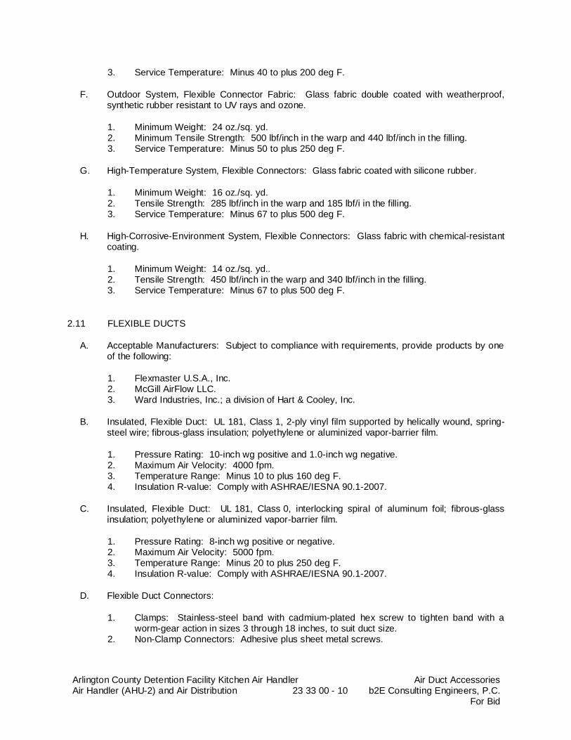
Arlington County Detention Facility Kitchen Air Handler Air Handler (AHU-2) and Air Distribution 23 33 00 - 10
Air Duct Accessories b2E Consulting Engineers, P.C.
For Bid
3. Service Temperature: Minus 40 to plus 200 deg F.
F. Outdoor System, Flexible Connector Fabric: Glass fabric double coated with weatherproof, synthetic rubber resistant to UV rays and ozone.
1. Minimum Weight: 24 oz./sq. yd. 2. Minimum Tensile Strength: 500 lbf/inch in the warp and 440 lbf/inch in the filling. 3. Service Temperature: Minus 50 to plus 250 deg F.
G. High-Temperature System, Flexible Connectors: Glass fabric coated with silicone rubber.
1. Minimum Weight: 16 oz./sq. yd. 2. Tensile Strength: 285 lbf/inch in the warp and 185 lbf/i in the filling. 3. Service Temperature: Minus 67 to plus 500 deg F.
H. High-Corrosive-Environment System, Flexible Connectors: Glass fabric with chemical-resistant coating.
1. Minimum Weight: 14 oz./sq. yd.. 2. Tensile Strength: 450 lbf/inch in the warp and 340 lbf/inch in the filling. 3. Service Temperature: Minus 67 to plus 500 deg F.
2.11 FLEXIBLE DUCTS
A. Acceptable Manufacturers: Subject to compliance with requirements, provide products by one of the following:
1. Flexmaster U.S.A., Inc. 2. McGill AirFlow LLC. 3. Ward Industries, Inc.; a division of Hart & Cooley, Inc.
B. Insulated, Flexible Duct: UL 181, Class 1, 2-ply vinyl film supported by helically wound, spring-steel wire; fibrous-glass insulation; polyethylene or aluminized vapor-barrier film.
1. Pressure Rating: 10-inch wg positive and 1.0-inch wg negative. 2. Maximum Air Velocity: 4000 fpm. 3. Temperature Range: Minus 10 to plus 160 deg F. 4. Insulation R-value: Comply with ASHRAE/IESNA 90.1-2007.
C. Insulated, Flexible Duct: UL 181, Class 0, interlocking spiral of aluminum foil; fibrous-glass insulation; polyethylene or aluminized vapor-barrier film.
1. Pressure Rating: 8-inch wg positive or negative. 2. Maximum Air Velocity: 5000 fpm. 3. Temperature Range: Minus 20 to plus 250 deg F. 4. Insulation R-value: Comply with ASHRAE/IESNA 90.1-2007.
D. Flexible Duct Connectors:
1. Clamps: Stainless-steel band with cadmium-plated hex screw to tighten band with a worm-gear action in sizes 3 through 18 inches, to suit duct size.
2. Non-Clamp Connectors: Adhesive plus sheet metal screws.

Arlington County Detention Facility Kitchen Air Handler Air Handler (AHU-2) and Air Distribution 23 33 00 - 11
Air Duct Accessories b2E Consulting Engineers, P.C.
For Bid
2.12 DUCT ACCESSORY HARDWARE
A. Instrument Test Holes: Cast iron or cast aluminum to suit duct material, including screw cap and gasket. Size to allow insertion of pitot tube and other testing instruments and of length to suit duct-insulation thickness.
B. Adhesives: High strength, quick setting, neoprene based, waterproof, and resistant to gasoline and grease.
PART 3 - EXECUTION
3.1 INSTALLATION
A. Install duct accessories according to applicable details in SMACNA's "HVAC Duct Construction Standards - Metal and Flexible" for metal ducts and in NAIMA AH116, "Fibrous Glass Duct Construction Standards," for fibrous-glass ducts.
B. Install duct accessories of materials suited to duct materials; use galvanized-steel accessories in galvanized-steel and fibrous-glass ducts, stainless-steel accessories in stainless-steel ducts, and aluminum accessories in aluminum ducts.
C. Install control dampers at inlet of exhaust fans or exhaust ducts as close as possible to exhaust fan unless otherwise indicated.
D. Install volume dampers at points on supply, return, and exhaust systems where branches extend from larger ducts. Where dampers are installed in ducts having duct liner, install dampers with hat channels of same depth as liner, and terminate liner with nosing at hat channel.
1. Install steel volume dampers in steel ducts. 2. Install aluminum volume dampers in aluminum ducts. 3. Do not run ductwork in such a way to require manual balancing dampers above
inaccessible ceiling areas. Layout ductwork with manual balancing dampers above accessible ceilings only.
E. Set dampers to fully open position before testing, adjusting, and balancing.
F. Install test holes at fan inlets and outlets and elsewhere as indicated.
G. Install fire dampers according to UL listing at electric room transfer ducts. 1. Fire Dampers: Refer to details on drawings. Provide detailed drawing for submittal
review for each penetration type for review by the Architect/Engineer. Provide mock-up for each penetration conditions and obtain approval from Architect/Engineer prior to starting the fire damper installation.
H. Connect ducts to duct silencers rigidly.
1. Adjust exact location and elevation of duct mains to fit sound attenuators in space available.
I. Install duct access doors on sides of ducts to allow for inspecting, adjusting, and maintaining accessories and equipment at the following locations:
1. On both sides of duct coils.
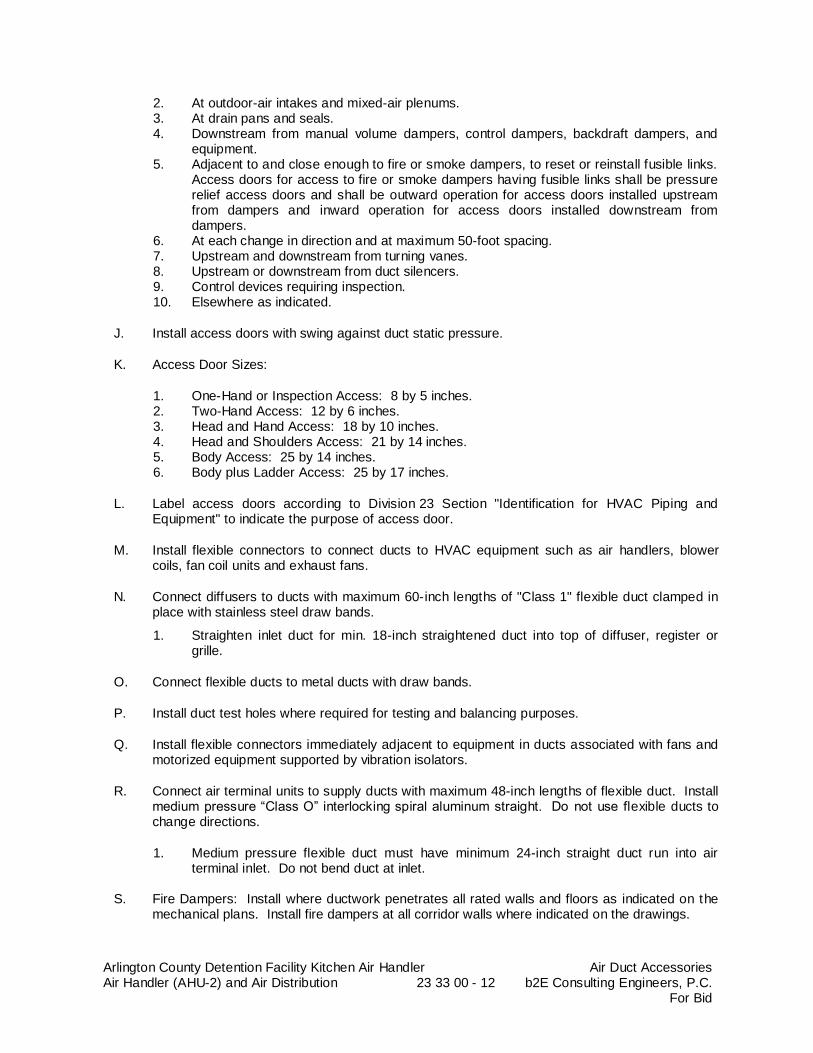
Arlington County Detention Facility Kitchen Air Handler Air Handler (AHU-2) and Air Distribution 23 33 00 - 12
Air Duct Accessories b2E Consulting Engineers, P.C.
For Bid
2. At outdoor-air intakes and mixed-air plenums. 3. At drain pans and seals. 4. Downstream from manual volume dampers, control dampers, backdraft dampers, and
equipment. 5. Adjacent to and close enough to fire or smoke dampers, to reset or reinstall fusible links.
Access doors for access to fire or smoke dampers having fusible links shall be pressure relief access doors and shall be outward operation for access doors installed upstream from dampers and inward operation for access doors installed downstream from dampers.
6. At each change in direction and at maximum 50-foot spacing. 7. Upstream and downstream from turning vanes. 8. Upstream or downstream from duct silencers. 9. Control devices requiring inspection. 10. Elsewhere as indicated.
J. Install access doors with swing against duct static pressure.
K. Access Door Sizes:
1. One-Hand or Inspection Access: 8 by 5 inches. 2. Two-Hand Access: 12 by 6 inches. 3. Head and Hand Access: 18 by 10 inches. 4. Head and Shoulders Access: 21 by 14 inches. 5. Body Access: 25 by 14 inches. 6. Body plus Ladder Access: 25 by 17 inches.
L. Label access doors according to Division 23 Section "Identification for HVAC Piping and Equipment" to indicate the purpose of access door.
M. Install flexible connectors to connect ducts to HVAC equipment such as air handlers, blower coils, fan coil units and exhaust fans.
N. Connect diffusers to ducts with maximum 60-inch lengths of "Class 1" flexible duct clamped in place with stainless steel draw bands.
1. Straighten inlet duct for min. 18-inch straightened duct into top of diffuser, register or grille.
O. Connect flexible ducts to metal ducts with draw bands.
P. Install duct test holes where required for testing and balancing purposes.
Q. Install flexible connectors immediately adjacent to equipment in ducts associated with fans and motorized equipment supported by vibration isolators.
R. Connect air terminal units to supply ducts with maximum 48-inch lengths of flexible duct. Install medium pressure “Class O” interlocking spiral aluminum straight. Do not use flexible ducts to change directions.
1. Medium pressure flexible duct must have minimum 24-inch straight duct run into air terminal inlet. Do not bend duct at inlet.
S. Fire Dampers: Install where ductwork penetrates all rated walls and floors as indicated on the
mechanical plans. Install fire dampers at all corridor walls where indicated on the drawings.
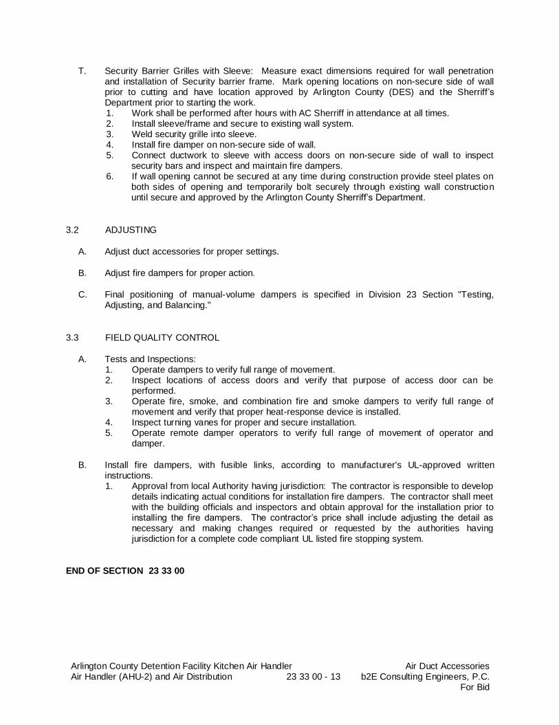
Arlington County Detention Facility Kitchen Air Handler Air Handler (AHU-2) and Air Distribution 23 33 00 - 13
Air Duct Accessories b2E Consulting Engineers, P.C.
For Bid
T. Security Barrier Grilles with Sleeve: Measure exact dimensions required for wall penetration and installation of Security barrier frame. Mark opening locations on non-secure side of wall prior to cutting and have location approved by Arlington County (DES) and the Sherriff’s Department prior to starting the work. 1. Work shall be performed after hours with AC Sherriff in attendance at all times. 2. Install sleeve/frame and secure to existing wall system. 3. Weld security grille into sleeve. 4. Install fire damper on non-secure side of wall. 5. Connect ductwork to sleeve with access doors on non-secure side of wall to inspect
security bars and inspect and maintain fire dampers. 6. If wall opening cannot be secured at any time during construction provide steel plates on
both sides of opening and temporarily bolt securely through existing wall construction until secure and approved by the Arlington County Sherriff’s Department.
3.2 ADJUSTING
A. Adjust duct accessories for proper settings.
B. Adjust fire dampers for proper action.
C. Final positioning of manual-volume dampers is specified in Division 23 Section "Testing, Adjusting, and Balancing."
3.3 FIELD QUALITY CONTROL
A. Tests and Inspections: 1. Operate dampers to verify full range of movement. 2. Inspect locations of access doors and verify that purpose of access door can be
performed. 3. Operate fire, smoke, and combination fire and smoke dampers to verify full range of
movement and verify that proper heat-response device is installed. 4. Inspect turning vanes for proper and secure installation. 5. Operate remote damper operators to verify full range of movement of operator and
damper.
B. Install fire dampers, with fusible links, according to manufacturer's UL-approved written instructions. 1. Approval from local Authority having jurisdiction: The contractor is responsible to develop
details indicating actual conditions for installation fire dampers. The contractor shall meet with the building officials and inspectors and obtain approval for the installation prior to installing the fire dampers. The contractor’s price shall include adjusting the detail as necessary and making changes required or requested by the authorities having jurisdiction for a complete code compliant UL listed fire stopping system.
END OF SECTION 23 33 00
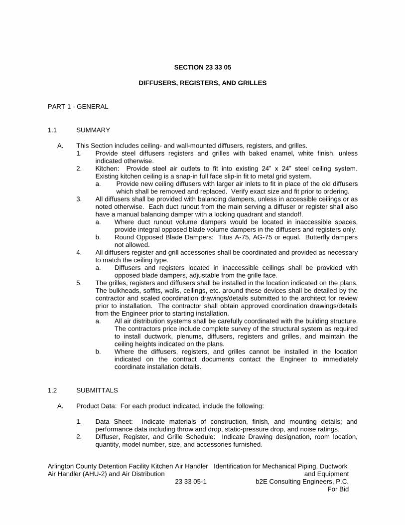
Arlington County Detention Facility Kitchen Air Handler Identification for Mechanical Piping, Ductwork Air Handler (AHU-2) and Air Distribution and Equipment 23 33 05-1 b2E Consulting Engineers, P.C.
For Bid
SECTION 23 33 05
DIFFUSERS, REGISTERS, AND GRILLES
PART 1 - GENERAL
1.1 SUMMARY
A. This Section includes ceiling- and wall-mounted diffusers, registers, and grilles. 1. Provide steel diffusers registers and grilles with baked enamel, white finish, unless
indicated otherwise. 2. Kitchen: Provide steel air outlets to fit into existing 24” x 24” steel ceiling system.
Existing kitchen ceiling is a snap-in full face slip-in fit to metal grid system. a. Provide new ceiling diffusers with larger air inlets to fit in place of the old diffusers
which shall be removed and replaced. Verify exact size and fit prior to ordering. 3. All diffusers shall be provided with balancing dampers, unless in accessible ceilings or as
noted otherwise. Each duct runout from the main serving a diffuser or register shall also have a manual balancing damper with a locking quadrant and standoff. a. Where duct runout volume dampers would be located in inaccessible spaces,
provide integral opposed blade volume dampers in the diffusers and registers only. b. Round Opposed Blade Dampers: Titus A-75, AG-75 or equal. Butterfly dampers
not allowed. 4. All diffusers register and grill accessories shall be coordinated and provided as necessary
to match the ceiling type. a. Diffusers and registers located in inaccessible ceilings shall be provided with
opposed blade dampers, adjustable from the grille face. 5. The grilles, registers and diffusers shall be installed in the location indicated on the plans.
The bulkheads, soffits, walls, ceilings, etc. around these devices shall be detailed by the contractor and scaled coordination drawings/details submitted to the architect for review prior to installation. The contractor shall obtain approved coordination drawings/details from the Engineer prior to starting installation. a. All air distribution systems shall be carefully coordinated with the building structure.
The contractors price include complete survey of the structural system as required to install ductwork, plenums, diffusers, registers and grilles, and maintain the ceiling heights indicated on the plans.
b. Where the diffusers, registers, and grilles cannot be installed in the location indicated on the contract documents contact the Engineer to immediately coordinate installation details.
1.2 SUBMITTALS
A. Product Data: For each product indicated, include the following:
1. Data Sheet: Indicate materials of construction, finish, and mounting details; and performance data including throw and drop, static-pressure drop, and noise ratings.
2. Diffuser, Register, and Grille Schedule: Indicate Drawing designation, room location, quantity, model number, size, and accessories furnished.
Arlington County Detention Facility Kitchen Air Handler Identification for Mechanical Piping, Ductwork Air Handler (AHU-2) and Air Distribution and Equipment 23 33 05-2 b2E Consulting Engineers, P.C.
For Bid
a. Shall also indicate ceiling/wall type and margin type to be provided. Contractor is responsible to match.
b. Contractor is responsible to coordinate all quantities and sizes indicated on plans.
B. Coordination Drawings: Reflected ceiling plans, drawn to scale, on which the following items are shown and coordinated with each other, based on input from installers of the items involved:
1. Ceiling suspension assembly members (i.e. Grid, drywall, etc.). 2. Method of attaching hangers to building structure. 3. Size and location of initial access modules for acoustical tile. 4. Ceiling-mounted items including lighting fixtures, diffusers, grilles, speakers, sprinklers,
access panels, and special moldings. 5. Duct access panels. 6. Provide margin type schedule to match existing ceiling/wall type for all diffusers, registers
and grilles. 7. Detailed, scaled coordination drawings/details for each diffusers, registers and grilles
installation condition. Indicated existing structure, architectural, mechanical, electrical, plumbing and fire protection work as applicable.
C. Samples for Initial Selection: For diffusers, registers, and grilles with factory-applied color finishes.
D. Samples for Verification: For diffusers, registers, and grilles, in manufacturer's standard sizes to verify color selected.
PART 2 - PRODUCTS
2.1 MANUFACTURERS
A. In other Part 2 articles where titles below introduce lists, the following requirements apply to product selection:
1. Acceptable Manufacturers: Subject to compliance with requirements, provide products by one of the manufacturers specified.
2.2 GRILLES AND REGISTERS
A. Adjustable Bar Grilles and Registers: Refer to Schedule on Drawings for Basis of Design.
1. Acceptable Manufacturers:
a. Basis of Design: Titus. b. Carnes. c. Krueger. d. Lindab. e. METALAIRE, Inc.; Metal Industries Inc. f. Nailor Industries of Texas Inc. g. Price.
B. Perforated Return Grilles: Refer to Schedule on Drawings for Basis of Design.
Arlington County Detention Facility Kitchen Air Handler Identification for Mechanical Piping, Ductwork Air Handler (AHU-2) and Air Distribution and Equipment 23 33 05-3 b2E Consulting Engineers, P.C.
For Bid
a. Basis of Design: Titus. b. Carnes. c. Krueger. d. METALAIRE, Inc.; Metal Industries Inc. e. Nailor Industries of Texas Inc. f. Price.
C. Square Ceiling High Performance Round Neck Diffusers: Refer to Schedule on Drawings for Basis of Design to fit into existing slip-in friction-fit metal frame.
a. Basis of Design: Titus. b. METALAIRE, Inc.; Metal Industries Inc. c. Tuttle and Bailey. d. Hart and Cooley. e. Price.
2.3 CEILING DIFFUSER OUTLETS
A. Architectural Diffuser: Refer to Schedule on Drawings for Basis of Design.
1. Acceptable Manufacturers:
a. Basis of Design: Titus, “TDC.” b. Krueger, “SH”.
B. Extruded Aluminum Linear Diffusers: Refer to Schedule on Drawings for Basis of Design.
a. Basis of Design: Titus. b. METALAIRE, Inc.; Metal Industries Inc. c. Tuttle and Bailey. d. Hart and Cooley. e. Price.
2.4 SOURCE QUALITY CONTROL
A. Verification of Performance: Rate diffusers, registers, and grilles according to ASHRAE 70, “Method of Testing for Rating the Performance of Air Outlets and Inlets”.
B. All devices shall be tested per Air Diffusion Council and labeled as such.
C. Conform to ARI 890-94 Rating of Air Diffusers and Air Assemblies.
PART 3 - EXECUTION
3.1 EXAMINATION
A. Examine areas where diffusers, registers, and grilles are to be installed for compliance with requirements for installation tolerances and other conditions affecting performance of equipment.

Arlington County Detention Facility Kitchen Air Handler Identification for Mechanical Piping, Ductwork Air Handler (AHU-2) and Air Distribution and Equipment 23 33 05-4 b2E Consulting Engineers, P.C.
For Bid
1. Verify that accessory items such as plaster frames are installed for areas with drywall ceilings. Coordinate exact location with architectural for symmetrical and even installation.
2. The contractor’s price shall include survey, coordination between trades, detailing, adjusting ductwork to fit in space, and coordination with architect as required to fit the systems in the available space to maintain architectural ceiling heights, wall thicknesses, bulkhead/soffit dimensions, etc.
B. Proceed with installation only after unsatisfactory conditions have been corrected.
3.2 INSTALLATION
A. Install diffusers, registers, and grilles level, plumbing and evenly spaced.
B. Ceiling-Mounted Outlets and Inlets: Drawings indicate general arrangement of ducts, fittings, and accessories. Air outlet and inlet locations have been indicated to achieve design requirements for air volume, noise criteria, airflow pattern, throw, and pressure drop. Make final locations where indicated, as much as practicable. For units installed in lay-in ceiling panels, locate units in the center of panel. Where architectural features or other items conflict with installation, notify Architect/Engineer for a determination of final location.
C. Install diffusers, registers, and grilles with airtight connections to ducts and to allow service and maintenance of dampers, air extractors, and fire dampers.
D. Inaccessible Ceilings: Do not provide manual balancing dampers in ductwork above inaccessible ceilings. Do not add access panels in drywall ceilings to access manual balancing dampers in duct runouts. Rework ductwork to ensure no dampers are located above inaccessible ceilings. Provide opposed blade damper in diffuser or register throat in inaccessible ceilings.
3.3 ADJUSTING
A. After installation, adjust diffusers, registers, and grilles to air patterns indicated, or as directed, before starting air balancing.
B. Diffusers and Registers: Shall typically not be provided with integral manual volume damper. Manual volume dampers shall be provided at each duct runout from the main serving a diffuser or register.
1. Provide integral opposed blade volume dampers for all diffusers, registers and grilles in inaccessible ceilings only.
2. Round opposed Blade Dampers: Titus A-75, AG-75 or equal. Butterfly dampers not allowed.
C. Air Balance: Refer to Section 23 05 93 for other applicable requirements.
1. Accessible Ceilings: TAB shall be achieved using the manual volume damper at the duct runout. The manual volume damper in the duct runout shall be provided with a stand-off locking quadrant. The quadrant shall be marked once the entire system air balance has been achieved. Provide a stand-off locking quadrant with exposed, graduated scale clearly identifiable so the quadrant and locking mechanism are easily located and
Arlington County Detention Facility Kitchen Air Handler Identification for Mechanical Piping, Ductwork Air Handler (AHU-2) and Air Distribution and Equipment 23 33 05-5 b2E Consulting Engineers, P.C.
For Bid
adjusted. Indicate the actual location for each diffuser and manual volume damper on the as-built drawings and in the sketches included with the balancing report.
2. Inaccessible Ceilings: TAB shall be achieved using the opposed blade damper at the diffuser or register throat. The air outlet shall be provided with a means of adjustment through the front face of the air outlet. Indicate the actual location for each air outlet on the as-built drawings and in the sketches included with the balancing report.
END OF SECTION 23 33 05
Arlington County Detention Facility Kitchen Air Handler Air Terminal Units (ATU-X) Air Handler (AHU-2) and Air Distribution 23 36 00 - 1 b2E Consulting Engineers, P.C.
For Bid
AIR TERMINAL UNITS (ATU-X)
SECTION 23 36 00
AIR TERMINAL UNITS (ATU-X)
PART 1 - GENERAL
1.1 SUMMARY
A. Section Includes:
1. Bypass, single-duct air terminal units. 2. Fan-powered air terminal units. 3. Shutoff, single-duct air terminal units.
1.2 PERFORMANCE REQUIREMENTS
A. Structural Performance: Hangers and supports shall withstand the effects of gravity loads and stresses within limits and under conditions described in SMACNA's "HVAC Duct Construction Standards - Metal and Flexible"
1.3 SUBMITTALS
A. Product Data: For each type of the following products, including rated capacities, furnished specialties, sound-power ratings, and accessories.
1. Air terminal units. 2. Liners and adhesives. 3. Sealants and gaskets.
B. Shop Drawings: For air terminal units. Include plans, elevations, sections, details, and attachments to other work.
1. Detail equipment assemblies and indicate dimensions, weights, loads, required clearances, method of field assembly, components, and location and size of each field connection.
2. Wiring Diagrams: For power, signal, and control wiring. 3. Hangers and supports, including methods for duct and building attachment and vibration
isolation.
C. Delegated-Design Submittal:
1. Materials, fabrication, assembly, and spacing of hangers and supports. 2. Design Calculations: Calculations for selecting hangers and supports.
D. Coordination Drawings: Reflected ceiling plans, drawn to scale, on which the following items are shown and coordinated with each other, using input from Installers of the items involved:
1. Ceiling suspension assembly members.

Arlington County Detention Facility Kitchen Air Handler Air Terminal Units (ATU-X) Air Handler (AHU-2) and Air Distribution 23 36 00 - 2 b2E Consulting Engineers, P.C.
For Bid
AIR TERMINAL UNITS (ATU-X)
2. Size and location of initial access modules for acoustic tile. 3. Ceiling-mounted items including lighting fixtures, diffusers, grilles, speakers, sprinklers,
access panels, and special moldings.
E. Field quality-control reports.
F. Operation and Maintenance Data: For air terminal units to include in emergency, operation, and maintenance manuals. In addition to items specified in Division 01 Section "Operation and Maintenance Data," include the following:
1. Instructions for resetting minimum and maximum air volumes. 2. Instructions for adjusting software set points.
G. Sustainable Design Submittals:
1. Product Data for Prerequisite EQ 1: Documentation indicating that units comply with ASHRAE 62.1, Section 5 – “Systems and Equipment”.
1.4 QUALITY ASSURANCE
A. Electrical Components, Devices, and Accessories: Listed and labeled as defined in NFPA 70, by a qualified testing agency, and marked for intended location and application.
B. ASHRAE Compliance: Applicable requirements in ASHRAE 62.1-2007, Section 5 - "Systems and Equipment" and Section 7 - "Construction and System Start-Up."
PART 2 - PRODUCTS
2.1 SHUTOFF, SINGLE-DUCT AIR TERMINAL UNITS
A. Acceptable Manufacturers: Subject to compliance with requirements, provide products by one of the following: 1. Basis of Design: Trane; a business of American Standard Companies. 2. Nailor Industries Inc. 3. Titus. 4. York.
B. Configuration: Volume-damper assembly inside unit casing with control components inside a protective metal shroud.
C. Casing: 0.034-inch steel, single wall.
Arlington County Detention Facility Kitchen Air Handler Air Terminal Units (ATU-X) Air Handler (AHU-2) and Air Distribution 23 36 00 - 3 b2E Consulting Engineers, P.C.
For Bid
AIR TERMINAL UNITS (ATU-X)
1. Casing Lining: Adhesive attached, 1-inch thick, coated, fibrous-glass duct liner complying with ASTM C 1071, and having a maximum flame-spread index of 25 and a maximum smoke-developed index of 50, for both insulation and adhesive, when tested according to ASTM E 84.
a. Cover liner with nonporous foil.
2. Casing Lining: Adhesive attached, 1-inch- thick, polyurethane foam insulation complying with UL 181 erosion requirements, and having a maximum flame-spread index of 25 and a maximum smoke-developed index of 50, for both insulation and adhesive, when tested according to ASTM E 84.
3. Air Inlet: Round stub connection or S-slip and drive connections for duct attachment. 4. Air Outlet: S-slip and drive connections, size matching inlet size. 5. Access: Removable panels for access to parts requiring service, adjustment, or
maintenance; with airtight gasket. 6. Airstream Surfaces: Surfaces in contact with the airstream shall comply with
requirements in ASHRAE 62.1-2007.
D. Velocity Sensors: Multipoint array with velocity sensors in air inlets. 1. Velocity Sensor Accuracy: +/- 5%.
E. Volume Damper: Galvanized steel with peripheral gasket and self-lubricating bearings.
1. Maximum Damper Leakage: ARI 880 rated, 2 percent of nominal airflow at 6-inch wg inlet static pressure.
2. Damper Position: Normally open.
F. Attenuator Section: 0.034-inch steel sheet.
1. Lining: Adhesive attached, 1-inch- thick, coated, fibrous-glass duct liner complying with ASTM C 1071, and having a maximum flame-spread index of 25 and a maximum smoke-developed index of 50, for both insulation and adhesive, when tested according to ASTM E 84.
a. Cover liner with nonporous foil.
2. Airstream Surfaces: Surfaces in contact with the airstream shall comply with requirements in ASHRAE 62.1-2007.
G. Acoustical Performance:
1. Total discharge sound power level for shut-off with VAV box operating at scheduled maximum capacity and 1.5 inch W.G. inlet static pressure shall not exceed the following values: Octave Band
2 3 4 5 6 7 8
SPL, dB 72 65 59 58 55 53 50
2. Sound power level tests shall be conducted and data reported in accordance with procedures specified ARI Standard 880. Submit certified test data to verify compliance with acoustical requirements.
Arlington County Detention Facility Kitchen Air Handler Air Terminal Units (ATU-X) Air Handler (AHU-2) and Air Distribution 23 36 00 - 4 b2E Consulting Engineers, P.C.
For Bid
AIR TERMINAL UNITS (ATU-X)
H. Hydronic Coils: Copper tube, with mechanically bonded aluminum fins spaced no closer than 0.1 inch, and rated for a minimum working pressure of 200 psig and a maximum entering-water temperature of 220 deg F. Include manual air vent and drain valve.
I. Electronic Controls: Bidirectional damper operators and microprocessor-based controller and room sensor. Control devices shall be compatible with temperature controls specified in Division 23 Section "Energy Management System (EMS)" and shall have the following features:
1. Damper Actuator: 24 V, powered closed, powered open. 2. Terminal Unit Controller: Pressure-independent, variable-air-volume controller with
electronic airflow transducer with multipoint velocity sensor at air inlet, factory calibrated to minimum and maximum air volumes, and having the following features:
a. Occupied and unoccupied operating mode. b. Remote reset of airflow or temperature set points. c. Adjusting and monitoring with portable terminal. d. Communication with temperature-control system specified in Division 23 Section
"Energy Management System (EMS)."
3. Room Sensor: Wall mounted with temperature set-point adjustment and access for connection of portable operator terminal.
J. Control Sequence:
1. Suitable for operation with duct pressures between 0.25- and 3.0-inch wg inlet static pressure.
2. Refer to Section 23 09 93 “Sequence of Operation”.
2.2 HANGERS AND SUPPORTS
A. Hanger Rods for Noncorrosive Environments: Cadmium-plated steel rods and nuts.
B. Hanger Rods for Corrosive Environments: Electrogalvanized, all-thread rods or galvanized rods with threads painted with zinc-chromate primer after installation.
C. Steel Cables: Galvanized steel complying with ASTM A 603 or Stainless steel complying with ASTM A 492.
D. Steel Cable End Connections: Cadmium-plated steel assemblies with brackets, swivel, and bolts designed for duct hanger service; with an automatic-locking and clamping device.
E. Air Terminal Unit Attachments: Sheet metal screws, blind rivets, or self-tapping metal screws; compatible with duct materials.
F. Trapeze and Riser Supports: Steel shapes and plates for units with steel casings; aluminum for units with aluminum casings.
2.3 SOURCE QUALITY CONTROL
A. Factory Tests: Test assembled air terminal units according to ARI 880.
Arlington County Detention Facility Kitchen Air Handler Air Terminal Units (ATU-X) Air Handler (AHU-2) and Air Distribution 23 36 00 - 5 b2E Consulting Engineers, P.C.
For Bid
AIR TERMINAL UNITS (ATU-X)
1. Label each air terminal unit with plan number, nominal airflow, maximum and minimum factory-set airflows, coil type, and ARI certification seal.
PART 3 - EXECUTION
3.1 INSTALLATION
A. Install air terminal units according to NFPA 90A, "Standard for the Installation of Air Conditioning and Ventilating Systems."
B. Install air terminal units level and plumb. Maintain sufficient clearance for normal service and maintenance.
C. Install wall-mounted thermostats.
D. Install bypass single duct ATV (RTU-10) across the supply air and return air duct system prior to any duct take offs from the main.
3.2 HANGER AND SUPPORT INSTALLATION
A. Comply with SMACNA's "HVAC Duct Construction Standards - Metal and Flexible," Chapter 4, "Hangers and Supports."
B. Building Attachments: Concrete inserts, powder-actuated fasteners, or structural-steel fasteners appropriate for construction materials to which hangers are being attached.
1. Where practical, install concrete inserts before placing concrete. 2. Install powder-actuated concrete fasteners after concrete is placed and completely cured. 3. Use powder-actuated concrete fasteners for standard-weight aggregate concretes and
for slabs more than 4 inches thick. 4. Do not use powder-actuated concrete fasteners for lightweight-aggregate concretes and
for slabs less than 4 inches thick. 5. Do not use powder-actuated concrete fasteners for seismic restraints.
C. Hangers Exposed to View: Threaded rod and angle or channel supports.
D. Install upper attachments to structures. Select and size upper attachments with pull-out, tension, and shear capacities appropriate for supported loads and building materials where used.
3.3 CONNECTIONS
A. Install piping adjacent to air terminal unit to allow service and maintenance.
B. Hot-Water Piping: In addition to requirements in Division 23 Section "Hydronic Piping," connect heating coils to supply with shutoff valve, strainer, control valve, and union or flange; and to return with balancing valve and union or flange.
C. Connect ducts to air terminal units according to Division 23 Section "Metal Ducts."
Arlington County Detention Facility Kitchen Air Handler Air Terminal Units (ATU-X) Air Handler (AHU-2) and Air Distribution 23 36 00 - 6 b2E Consulting Engineers, P.C.
For Bid
AIR TERMINAL UNITS (ATU-X)
D. Make connections to air terminal units with flexible connectors complying with requirements in Division 23 Section "Air Duct Accessories."
3.4 IDENTIFICATION
A. Label each air terminal unit with plan number, nominal airflow, and maximum and minimum factory-set airflows. Comply with requirements in Division 23 Section "Identification for HVAC Piping and Equipment" for equipment labels and warning signs and labels.
3.5 FIELD QUALITY CONTROL
A. Testing Agency: Engage a qualified testing agency to perform tests and inspections.
B. Manufacturer's Field Service: Engage a factory-authorized service representative to inspect, test, and adjust components, assemblies, and equipment installations, including connections.
C. Perform tests and inspections.
1. Manufacturer's Field Service: Engage a factory-authorized service representative to inspect components, assemblies, and equipment installations, including connections, and to assist in testing.
D. Tests and Inspections:
1. After installing air terminal units and after electrical circuitry has been energized, test for compliance with requirements.
2. Leak Test: After installation, fill water coils and test for leaks. Repair leaks and retest until no leaks exist.
3. Operational Test: After electrical circuitry has been energized, start units to confirm proper motor rotation and unit operation.
4. Test and adjust controls and safeties. Replace damaged and malfunctioning controls and equipment.
E. Air terminal unit will be considered defective if it does not pass tests and inspections.
F. Prepare test and inspection reports.
3.6 STARTUP SERVICE
A. Engage a factory-authorized service representative to perform startup service.
1. Complete installation and startup checks according to manufacturer's written instructions. 2. Verify that inlet duct connections are as recommended by air terminal unit manufacturer
to achieve proper performance. 3. Verify that controls and control enclosure are accessible. 4. Verify that control connections are complete. 5. Verify that nameplate and identification tag are visible. 6. Verify that controls respond to inputs as specified.
Arlington County Detention Facility Kitchen Air Handler Air Terminal Units (ATU-X) Air Handler (AHU-2) and Air Distribution 23 36 00 - 7 b2E Consulting Engineers, P.C.
For Bid
AIR TERMINAL UNITS (ATU-X)
3.7 DEMONSTRATION
A. Engage a factory-authorized service representative to train Owner’s maintenance personnel to adjust, operate, and maintain hydronic pumps as specified below:
1. Train Owner’s maintenance personnel on procedures and schedules for starting and stopping, troubleshooting, servicing, and maintaining pumps.
2. Review data in maintenance manuals. Refer to Division 1 Section "Contract Closeout." 3. Review data in maintenance manuals. Refer to Division 1 Section "Operation and
Maintenance Data." 4. Schedule training with Owner, through Architect, with at least seven days' advance
notice. 5. Refer to Division 01 Section "Demonstration and Training."
END OF SECTION 23 36 00
Arlington County Detention Facility Kitchen Air Handler Modular Indoor Air Handling Unit Air Handler (AHU-2) and Air Distribution 23 64 00-1 b2E Consulting Engineers, P.C.
For Bid
SECTION 23 64 00
MODULAR INDOOR AIR-HANDLING UNITS (AHU-2)
PART 1 - GENERAL
1.1 SUMMARY
A. This Section includes multiple zone variable-volume, modular air-handling unit (AHU-2) with air economizer and freeze proof coils for indoor installations.
B. The air-handling unit (AHU-2) shall be controlled as a multiple zone variable air volume (MZ VAV) with air terminal units (VAV Boxes) serving the kitchen and adjacent corridor. 1. The unit supply air fan motor shall be provided with an adjustable frequency drive (AFD).
The AFD shall be provided in accordance with Section 232690 “Adjustable Frequency Drives”.
2. The AHU shall be provided with a unit mounted outside airflow monitoring station which will allow the outside (ventilation) air to be increased or reduced to an operator preset value based on the actual operational mode of the space.
3. The air handler supply fan shall be a dual plenum type fan with an airflow monitoring station for each fan which will allow the total supply air flow to be monitored via the EMS.
4. The air-handler shall have chilled water and preheat hot water heating coils with freeze protection coils controlled by temperature and pressure and shall be interlocked to the BAS for status and alarms.
5. The unit casing shall be galvanized, double-wall construction with min. 2-inch thick internal rigid vapor barrier foam injected.
6. The unit preheat and cooling coils shall have drain pans to accept coil blow-off from the mechanical freeze protection blow off valve. The electronic freeze protection monitoring control panel shall provie a status and alarm signal on the BAS.
7. The unit condensate drain shall be double wall ASTM A666 Type 304 stainless steel sloped in both directions to drain. Provide an externally piped blow-ff drain for the preheat coil and a condensate/blow-off drain for the chilled water coil. Both the drain shall be piped connection line size with a p-trap with cleanout to the new open site floor drain.
C. BAS Coordination: Refer to Section 230900 and schematic flow control diagram drawings for other applicable field controls installation requirements. 1. Controls shall be Siemens (No Substitutions).
D. Weights: Air Handling Units shall not exceed the weight listed on the air handling unit schedule.
1.2 SUBMITTALS
A. Product Data: For each type of modular indoor air-handling unit indicated. Include the following: 1. Certified fan-performance curves with system operating conditions indicated. 2. Certified fan-sound power ratings, in accordance with ARI 260. 3. Certified coil-performance ratings with system operating conditions indicated. 4. Motor ratings, electrical characteristics, and motor and fan accessories.
Arlington County Detention Facility Kitchen Air Handler Modular Indoor Air Handling Unit Air Handler (AHU-2) and Air Distribution 23 64 00-2 b2E Consulting Engineers, P.C.
For Bid
5. Material gages and finishes. 6. Filters with performance characteristics. 7. Dampers, including housings, linkages, and operators. 8. Complete air side static pressure loss calculations.
B. Shop Drawings: 1. Vibration Isolators: Select vibration isolators to ensure isolators meet or provide greater
than 95% vibration isolation efficiency. 2. Detailed Dimensional Drawing: Scaled (min. ¼” scale) drawings with all details and
dimensions. 3. Wiring Diagrams: Power, signal, and control wiring.
C. Coordination Drawings: Submit with Shop Drawings. Show mechanical unit layout in service corridor and relationships between components and adjacent structural and mechanical elements. Show support locations, type of support, and weight on each support. Indicate and certify field measurements.
D. Field Quality-Control Test Reports: From manufacturer.
1.3 QUALITY ASSURANCE
A. Source Limitations: Obtain modular indoor air-handling units through one source from a single manufacturer.
B. Product Options: Drawings indicate size, profiles, and dimensional requirements of modular indoor air-handling units and are based on the specific system indicated. Refer to Division 1 Section "Product Requirements."
C. Electrical Components, Devices, and Accessories: Listed and labeled as defined in NFPA 70, Article 100, by a testing agency acceptable to authorities having jurisdiction, and marked for intended use.
D. NFPA Compliance: Modular indoor air-handling units and components shall be designed, fabricated, and installed in compliance with NFPA 90A, "Installation of Air Conditioning and Ventilating Systems."
E. ARI Certification: Modular indoor air-handling units and their components shall be factory tested according to ARI 430-1999, "Central-Station Air-Handling Units," and ARI 260 – 2001 “Sound Rating of Ducted Air Moving and Conditioning” and shall be listed and labeled by ARI.
1.4 COORDINATION
A. Indoor Modular Air-Handler: (AHU-2) shall have a mixing box with outside air end connection traq damper, a top connection return damper, a filter section (pre-filter and final filter) a freeze protection preheat coil with a drain pan, an access section, a cooling coil with condensate / freeze protection drain pan, an access section before the fan section and a fan section with top discharge. The contractor shall coordinate the locations and dimensions for each duct connection to the unit with the actual conditions (including but not limited to the building structure, existing equipment, existing piping, existing conduit. The exact locations of the exising duct, piping and conduit and other existing limitations) shall be surveyed by the contractor. Field measurements take precedence over plan dimensions.
Arlington County Detention Facility Kitchen Air Handler Modular Indoor Air Handling Unit Air Handler (AHU-2) and Air Distribution 23 64 00-3 b2E Consulting Engineers, P.C.
For Bid
B. Coordinate the exact layout for ductwork, piping and all unit dimensions in the room to ensure the following:
1. Provide flexible duct connections to the supply air opening in the top of the air handler. The ductwork shall be provided with air foil blade type turning vanes.
2. Provide flexible duct connections to return plenum. The contractor shall provide a double wall sound attenuated return air plenum mounted to the return mixing box. The plenum shall be sized to match the unit connection unless indicated to be larger. The return air duct connection(s) to the return plenum shall be sized for maximum air velocity at the ductwork correction not to exceed 1000 FPM.
3. Outside Air Connection: The unit shall be provided with a double-wall connection in the end of the unit with a built-in traq damper assembly. The outside air duct connection to the existing outside air plenum casing shall be sized for maximum air velocity at the ductwork connection not to exceed 1000 FPM. Provide flexible duct connections.
C. Coordinate installation of unit mounted adjustable frequency drives (AFD’s) with Division 23 and 26. The AFD’s shall be interlocked to the Building Automation System (BAS) and the Fire Alarm System.
1. Each AFD shall be matched to the actual AHU SA motor size provided. 2. Each AFD shall be provided with a smart card installed at the factory compatible with the
actual control system provided. The smart card shall allow the information in the AFD to be translated to the BAS DDC system for graphical monitoring and control of the AFD at the operator workstation. Refer to Sections 232690 and 230900 for other applicable requirements.
3. Each AFD shall be interlocked to the fire alarm system by Division 26. Provide a zone addressable, UL listed fire alarm relay within 3-feet of each AFD. The relay must be located within 3-feet as required by NFPA 72 to allow visual inspection of the interlock between the relay and the AFD since the AFD is not a zone addressable fire alarm device. The fire alarm system shall shut-down each AFD serving the air-handler upon detecting products of combustion in the supply or return ductwork to that air-handler.
D. Duct Smoke Detectors: Coordinate and provide the installation of the duct mounted smoke detectors between Division 23 and 26. Installation of the duct smoke detectors (two per AHU) shall be: 1. Provided by Div. 26. 2. Installed in ductwork by Div. 23. 3. Powered by Div. 26. 4. Interlocked to fire alarm system by Div. 26. 5. Hard wire interlocked between fire alarm relay and AFD or starter by Div. 23. 6. Fire alarm system programming by Div. 26. 7. Fire Alarm Inspections with local inspector with Div. 23 and 26 present.
E. Coordinate the installation of the handler to ensure that access is maintained to open the AHU service doors and replace non-scheduled (ie. fan motor, etc) as well as scheduled (i.e. filters, etc.) replacement parts. In addition, the layout shall allow access to filters, dampers, hydronic coils, freeze protection valves and assemblies and controller, and access doors for routine maintenance as well as accurate measurement and operation.
F. Coordinate the installation of the ductwork with the air handler, to miss existing trades work, such as lighting, power, fire alarm, sprinkler, security, and other trades work to allow maintenance and service access as required per the manufacturers recommendations and the local code.
Arlington County Detention Facility Kitchen Air Handler Modular Indoor Air Handling Unit Air Handler (AHU-2) and Air Distribution 23 64 00-4 b2E Consulting Engineers, P.C.
For Bid
G. Coordinate the actual sizes of the air handler and expand the existing concrete housekeeping pad dimensions. Provide detailed ¼-scale drawing indicating the superstructure with building attachments and equipment hangers to the Engineer for review and approval prior to starting any work.
H. Unit Disassembly: Provide unit sections which can be disassembled and reassembled in place. Disassemble air handler sections into their component parts to fit through the existing security doors. Reassemble HVAC unit in place as required to for a complete operating system. The contractor is responsible to coordinate with the existing conditions prior to submitting their bid price. Coordinate rigging with existing conditions so that no wall openings are required to install the AHU. Components shall be brought in at the loading dock and through the exiting security doors. Any damage shall be entirely the responsibility of the contractor.
1.5 WARRANTY
A. General Warranty: Special warranty specified in this Article shall not deprive Engineer/Owner of other rights Engineer/Owner may have under other provisions of the Contract Documents and shall be in addition to, and run concurrent with, other warranties made by Contractor under requirements of the Contract Documents.
B. Special Warranty: Written warranty, executed by manufacturer agreeing to repair or replace components of air-handling units that fail in materials or workmanship within specified warranty period.
C. Warranty Period: Five (5) years parts and labor from date of substantial completion.
1.6 EXTRA MATERIALS
A. Furnish extra materials described below that match products installed and that are packaged with protective covering for storage and identified with labels describing contents. 1. Gaskets: Two (2) sets for each size access door. 2. Filters: Three (3) sets of prefilters and final filters for each modular indoor air-handling
unit. Do not run without filters installed.
a. Install one (1) set during construction.
b. Install one (1) set at Substantial Completion.
c. Install one (1) set at six months after Substantial Completion.
PART 2 - PRODUCTS
2.1 MANUFACTURERS
A. Acceptable Manufacturers: Subject to compliance with requirements, provide products by one of the following; “No Substitutions Allowed.”
1. Basis of Design: Trane Company (The); Worldwide Applied Systems Group, Model “CSAA040”.
2. Innovent. 3. Buffalo.
Arlington County Detention Facility Kitchen Air Handler Modular Indoor Air Handling Unit Air Handler (AHU-2) and Air Distribution 23 64 00-5 b2E Consulting Engineers, P.C.
For Bid
B. The air handler cannot fit in the space if it is larger than the Basis of Design. If a listed manufacturer other than the Basis of Design air handling unit is submitted, and is larger than the Basis of Design Manufacturer’s unit, than that larger unit will not be approved and the contractor shall provide the Basis of Design at no additional cost to the Owner.
2.2 MANUFACTURED UNITS
A. Modular indoor air-handling units shall be factory assembled and consist of fans, motor and drive assemblies (fan wall), adjustable frequency drives (AFD) coils, damper, plenums, filters, condensate pans, mixing dampers, air flow monitoring stations in fans and outddor air damper (Traq Damper), control devices, and accessories. 1. AFD: The supply fan motor AFD’s shall be provided by the air-handling unit vendor and
shall meet the requirements of Section 232690. 2. The factory assembled units shall be disassembled and reassembled in the upper
mechanical room as required for a complete operating system with a full 5 year warranty.
2.3 CABINET
A. Materials: Formed and reinforced double-wall insulated panels, fabricated to allow removal for access to internal parts and components, with joints between sections sealed. 1. Double wall Outside Casing: Galvanized steel, 0.0635 inch (1.61 mm) thick. 2. Inside Casing: Galvanized steel, 0.0276 inch (0.7 mm) perforated. 3. Floor Plate: Galvanized steel, 0.1382 inch (3.5 mm) thick. The floor shall also be
insulated over the entire area of the unit. 4. Provide min. 6-inch high feet to raise unit for condensate and freeze protection drainage.
B. Cabinet Insulation: Comply with NFPA 90A or NFPA 90B. 1. Materials: ASTM C 1071 with coated surface exposed to airstream to prevent erosion of
glass fibers. 2. Thickness: 2 inches (50 mm). 3. Thermal Conductivity (k-Value): 0.26 at 75 deg F (0.037 at 24 deg C) mean temperature.
Provide min. 3.0 # density liner material. 4. Fire-Hazard Classification: Maximum flame-spread index of 25 and smoke-developed
index of 50, when tested according to ASTM C 411. 5. Liner Adhesive: Comply with NFPA 90A or NFPA 90B and ASTM C 926. 6. Mechanical Fasteners: Galvanized steel, suitable for adhesive attachment, mechanical
attachment, or welding attachment to duct without damaging liner when applied as recommended by manufacturer and without causing leakage in cabinet.
7. Location and Application: Encased between outside and inside casing.
C. Access Panels and Doors: Same materials and finishes as cabinet complete with hinges, latches, handles, and gaskets. Inspection and access panels and doors shall be sized and located to allow periodic maintenance and inspections. Provide access doors and inspection windows in the following locations:
1. Fan Section: Access and general service LED light and switch on both sides of unit. 2. Access Sections (between filter and heating and cooling coils and between cooling coil
and fan section): Doors with locking levers on both sides of unit. 3. Coil Section: Doors with locking levers on both sides of unit. 4. Filter Section: Access Doors with Locking leavers to allow periodic removal and
installation of pre-filters and final filters from both sides of unit.
Arlington County Detention Facility Kitchen Air Handler Modular Indoor Air Handling Unit Air Handler (AHU-2) and Air Distribution 23 64 00-6 b2E Consulting Engineers, P.C.
For Bid
D. Condensate and Freeze Protection Drain Pans for preheat and cooling coils: Formed sections of stainless-steel sheet complying with requirements in ASHRAE 62. Fabricate pans with slopes in two planes to collect condensate and coil water in freeze protection mode from preheat and cooling coils. 1. Double-Wall Construction: Fill space between walls with foam insulation and seal
moisture tight. 2. Drain Connections: Both ends of pan, but internally piped to the side of unit that has the
open site floor drain.
2.4 FAN SECTION
A. Fan-Section Construction: Direct Drive centrifugal fans consisting of housing, wheel, fan shaft, bearings, motor, non-fused and disconnect switch, AFD drive assembly, support structure and equipped with formed-steel channel base for integral mounting of fan, motor, and casing panels. Mount fan assembly with spring vibration isolation (min. 1-inch deflection).
B. Centrifugal Fan Housings: Formed- and reinforced-steel panels to make curved scroll housings with shaped cutoff, spun-metal inlet bell, and access doors or panels to allow entry to internal parts and components. 1. Panel Bracing: Steel angle- or channel-iron member supports for mounting and
supporting fan scroll, wheel, motor, and accessories. 2. Horizontal Flanged Split Housing: Bolted construction.
C. Fan Assemblies: Statically and dynamically balanced and designed for continuous operation at maximum rated fan speed and motor horsepower. 1. Performance Class: AMCA 99-2408, Class II or greater depending on total static
pressure (in wc) and angular velocity (RPM). 2. Plug Fans: Welded steel construction. Fabricate without fan scroll and volute housing.
D. Supply Fan, Backward-Inclined (Plug) Fan Wheels: Steel construction with curved inlet flange, backplate, and backward-inclined blades welded to flange and backplate or cast-iron or cast-steel hub riveted to backplate and fastened to shaft with set screws. 1. Fans and motors shall be selected using minimum 0.5-inch wc static pressure loss for
each pre-filter and 1.0-inch for each final filter. Add a 20% safety factor for internal losses and submit calculations. Provide increased fan motor size, including AFD, as necessary at no additional cost to owner.
2. Provide sure-air velocity sensor and transducer for airflow monitoring (CFM) with each fan for interface to BAS. Where multiple fans are used totalize airflow at BAS graphics to read supply airflow (CFM).
E. Coatings: Galvanized.
F. Shafts: Statically and dynamically balanced and designed for continuous operation at maximum rated fan speed and motor horsepower, with final alignment and belt adjustment made after installation. 1. Turned, ground, and polished hot-rolled steel with keyway. Ship with a protective coating
of lubricating oil. 2. Designed to operate at no more than 70 percent of first critical speed at top of fan's
speed range.
G. Grease-Lubricated Shaft Bearings: Self-aligning, pillow-block-type, ball or roller bearings with adapter mount and two-piece, cast-iron housing.
Arlington County Detention Facility Kitchen Air Handler Modular Indoor Air Handling Unit Air Handler (AHU-2) and Air Distribution 23 64 00-7 b2E Consulting Engineers, P.C.
For Bid
1. Ball-Bearing Rating Life: ABMA 9, L10 of 120,000 hours. 2. Roller-Bearing Rating Life: ABMA 11, L10 of 120,000 hours. 3. Provide extended grease lines to access side of unit.
H. Direct Drives: Factory mounted, statically and dynamically balanced and with 1.5 service factor based on fan motor, size and type.
I. Adjustable Frequency Drive (AFD): Mount on channels on the unit. 1. Do not locate where AFD will cause interference or obstruction to operation or
maintenance. 2. Install in location which provides min. clearance requirements in accordance with NFPA
70 (NEC). 3. Refer to Section 23 26 90 “Adjustable Frequency Drives” for other applicable
requirements.
J. Vibration Control: Install fans on open-spring vibration isolators having a minimum of 1-inch (25-mm) static deflection and side snubbers. 1. Vibration isolation shall be designed for min. 95% vibration isolation efficiency.
K. Fan-Section Source Quality Control: 1. Sound Power Level Ratings: Comply with ARI 260-(Latest Version), “Sound Rating of
Ducted Air Moving and Conditioning”. Test fans according to AMCA 300, "Reverberant Room Method for Sound Testing of Fans." Fans shall bear ARI Certified sound ratings seal.
2. Factory test fan performance for flow rate, pressure, power, air density, rotation speed, and efficiency. Establish ratings according to AMCA 210, "Laboratory Methods of Testing Fans for Rating."
2.5 MOTORS
A. General: Refer to Division 23 Section "Motors" for general requirements.
B. Torque Characteristics: Sufficient to accelerate driven loads satisfactorily.
C. Motor Sizes: Minimum size as indicated. If not indicated, large enough so driven load will not require motor to operate in service factor range.
D. Temperature Rating: 50 deg C maximum temperature rise at 40 deg C ambient for continuous duty at full load (Class A Insulation).
E. Service Factor: 1.15 for polyphase motors and 1.35 for single-phase motors.
F. Motor Construction: NEMA MG 1, premium efficiency, continuous inverter duty, Design B.
G. Bearings: The following features are required: 1. Ball or roller bearings with inner and outer shaft seals grease fittings at bearing assembly. 2. Designed to resist thrust loading where belt or other grease lubricated with drives
produce lateral or axial thrust in motor.
H. Enclosure Type: The following features are required: 1. Supply Fan Motor: Open drip – proof (ODP).
Arlington County Detention Facility Kitchen Air Handler Modular Indoor Air Handling Unit Air Handler (AHU-2) and Air Distribution 23 64 00-8 b2E Consulting Engineers, P.C.
For Bid
I. Overload Protection: Built-in, automatically resetting, thermal-overload protection.
J. Noise Rating: Extra Quite.
K. Efficiency: Premium-efficient, inverter duty rated motors shall have a minimum efficiency as scheduled according to IEEE 112, Test Method B and as specified in Section 230513.
L. Nameplate: Indicate ratings, characteristics, construction, special features, and full identification of manufacturer.
M. Starters, Electrical Devices, and Wiring: Are specified in Division 26.
N. Adjustable Frequency Drives: Are specified in Division 23 Section 232690.
2.6 COILS WITH FREEZE BLOCK TECHNOLOGY
A. Coil Sections: Common or individual, insulated, galvanized-steel casings for heating and cooling coils. Design and construct to facilitate removal and replacement of coil for maintenance and to ensure full airflow through coils.
B. Hot water coil: Provide ARI Standard 410 rated coil constructed with minimum 0.060 inch thick wall headers and 0.0075-inch thick aluminum fins, 5/8-inch outside diameter (OD), 0.049 inch wall seamless copper tubes, and galvanized casing, tested and guaranteed for 200 psi working pressure. Stub coil connections through unit casing with cleanable coil header inside unit casing with removable coil access panel for ease of maintenance.
1. Basis of Design: Cooney Engineered Solutions
C. Chilled water Coil: Provide ARI Standard 410 rated coil constructed with minimum 0.060-inch thick wall headers and 5/8-inch outside diameter OD, 0.049 inch thick seamless copper tubes and 0.0075-inch thick aluminum fins, pressure tested and guaranteed for 200 psi working pressure. Provide stainless steel IAQ drain pan under the coil extending past the coil to ensure condensate retention. Stub coil connections through unit coating with cleanable coil header inside 14 gauge unit casing with removable coil access panel for ease of maintenance. Maximum face velocity is 500 FPM.
1. Basis of Design: Cooney Engineered Solutions. 2. Freeze Protection Coils shall be installed in Factory by AHU manufacturer. 3. Leak detection alarm shall be provided by the BAS contractor.
D. Heating and Cooling-Coil Freeze Protection and Condensate Drain Pans: 1. Fabricated from stainless-steel sheet and sloped in multiple planes to collect and drain
freeze protection run off and condensate from the preheat and cooling coils, coil piping connections, coil headers, and return bends.
2. Complying with requirements in ASHRAE 62.1-2007. 3. Drain Connections: At low point of pan with minimum 1 ½ inch threaded nipple. 4. Units with stacked coils shall have an intermediate drain pans to collect and drain freeze
protection run off and condensate from the top coil.
E. Freeze Block Technology
1. Provide a fluid coil with Cooney Freeze Block Technology. Coil shall be manufactured with an expansion relief header that is brazed into each and every return bend.
Arlington County Detention Facility Kitchen Air Handler Modular Indoor Air Handling Unit Air Handler (AHU-2) and Air Distribution 23 64 00-9 b2E Consulting Engineers, P.C.
For Bid
2. A combination relief valve that operates by pressure and temperature, (designed to re-seat after activation) shall be affixed to the expansion relief header to protect the coil during freezing conditions. a. The pressure relief set point to be 200 psi. b. The temperature relief set point to be 35 degrees. c. Valve shall be situated above a drain pan.
3. This technology shall be wind tunnel, climate room and field tested with a 100% success rate over a minimum of three, (3) years.
4. Provide a thirty-six, (36) month warranty against any freeze related damages to the coil. Warranty shall cover repair of existing or supply of a replacement coil. a. All Coil Components, including but not limited to return bends shall be covered
under this warranty. b. Warranty shall be activated once product is shipped. No additional activation nor
registration shall be required.
2.7 DAMPERS
A. General: Leakage rate, according to AMCA 500, "Laboratory Methods for Testing Dampers for Rating," shall not exceed 2 percent of air quantity at 2000-fpm (10-m/s) face velocity through damper and 4-inch wg (1000-Pa) pressure differential. 1. Acceptance Manufacturers: Ruskin CD60; Air Balance: AC-126; Awow-Foil: ODB AF-
207.
B. Damper Operators: Electric specified in Division 23 Section "Building Automation System (BAS)."
C. Mixing Boxes: Parallel-blade galvanized-steel return dampers mechanically fastened to steel operating rod in reinforced, galvanized-steel cabinet. Connect operating rods with separate linkage so dampers operate independently. 1. Airflow Monitoring Traq Damper: Round damper assemblies with velocity rings and
pressure transducers for airflow measurement. Damper control shall be accurate from 15,000 CFM to 1,000 CFM. Provide multiple transducers as necessary.
2. Interlock to the BAS to monitor OA flow rate (CFM) and show the BAS graphics at the 13
th floor Facilities office in the Courts Police Building.
2.8 FILTER SECTION
A. Filters: Comply with NFPA 90A.
B. Filter Box: Cabinet support members shall hold 2-inch (50-mm-) thick, pleated, flat MERV 8 throwaway filters and 6-inch thick, pleated, flat MERV 11 filter. Provide hinged access panels or doors to allow removal of filters from both sides of unit.
C. Filter Section: Provide filter holding frames arranged for prefilter and final filter orientation. Filters shall be removable from both sides of the air handler. Refer to Section 238000 for filter specification.
2.9 CONTROLS
A. Controls shall be field installed by Siemans.
Arlington County Detention Facility Kitchen Air Handler Modular Indoor Air Handling Unit Air Handler (AHU-2) and Air Distribution 23 64 00-10 b2E Consulting Engineers, P.C.
For Bid
B. Refer to Sheet M801 and Section 23 09 93 for other applicable requirements.
C. Freeze Protection Leak Detection: Provide leak detectors to initiate alarm if outside air temperature (OAT) drops below 40°F (adj.) and the leak detector detects water in freeze
protection drain pan. Alarm shall be initiate to the Siemans BAS and graphics screen.
D. The controls shall be commissioned in phases. Phase 1 for the air handler (AHU-2) and associated return fan (RAF-1) and automatic modulating dampers as indicated on the plans and in the specifications.
PART 3 - EXECUTION
3.1 EXAMINATION
A. Examine areas and conditions for compliance with requirements for installation tolerances and other conditions affecting performance.
B. Examine roughing-in of condensate and freeze protection overflow drainage piping systems and electrical services to verify actual locations of connections before installation. 1. Provide drains with P-traps with cleanouts for the preheat coil and the cooling coil and
run to the new open site drain provided under this scope of work.
C. Proceed with installation only after unsatisfactory conditions have been corrected.
3.2 INSTALLATION
A. Supported Units: Set units on min. 4-inch high feet on top of concrete housekeeping pad. Contractor shall coordinate exact location, height, etc, of pad with actual AHU dimensions and mechanical room layout. 1. Floor System: 4-inch high housekeeping pad or match adjacent construction.
B. Arrange installation of units to provide access space around modular indoor air-handling units for service and maintenance. 1. Fan Section Service Secure AHU (shut-down): Unbolt steel duct flanges; slide out of way
for maintenance.
C. Fan Section with marine LED lights and two (2) exterior (3-way) 30 min timer switches mounted on either side of unit casing.
3.3 CONNECTIONS
A. Piping installation requirements are specified in other Division 23 Sections. Drawings indicate general arrangement of piping, fittings, and specialties.
B. Install piping adjacent to machine to allow service and maintenance.
C. Connect condensate and freeze protection overflow drain pans using NPS 1-1/4 (or NPS 1½ to match unit connection) insulated, Type M copper tubing. Extend to nearest equipment
Arlington County Detention Facility Kitchen Air Handler Modular Indoor Air Handling Unit Air Handler (AHU-2) and Air Distribution 23 64 00-11 b2E Consulting Engineers, P.C.
For Bid
condensate (clear water). Construct deep trap at connection to drain pan and install cleanouts at P-trap.
D. Duct installation and connection requirements are specified in other Division 23 Sections. Drawings indicate general arrangement of ducts and duct accessories. Make final duct connections with flexible connections.
E. Electrical: Comply with applicable requirements in Division 26 Sections for power wiring, switches, and motor controls.
F. Ground equipment according to Division 26 Section "Grounding and Bonding."
G. Tighten electrical connectors and terminals according to manufacturer's published torque-tightening values. If manufacturer's torque values are not indicated, use those specified in UL 486A and UL 486B.
3.4 FIELD QUALITY CONTROL
A. The Div. 23 contractor shall disassemble the air handling unit modular sections to fit through the existing security doors. The air handler sections shall be reassembled in the upper mechanical room and shall be inspected by the manufacturers factory trained service technician prior to start-up.
B. Manufacturer's Field Service: Engage a factory-authorized service representative to inspect field-assembled air handler, components and equipment installation, including piping and electrical connections. Report results in writing. 1. Leak Test: After installation, fill water coils with water and test coils and connections for
leaks. Repair leaks and retest until no leaks exist. 2. Fan Operational Test: After electrical circuitry has been energized, start units to confirm
proper motor rotation and unit operation. Remove malfunctioning units, replace with new units, and retest.
3. Test and adjust controls and safeties. Replace damaged and malfunctioning controls and equipment.
3.5 STARTUP SERVICE
A. Engage a factory-authorized service representative to perform startup service.
B. Final Checks before Startup: Perform the following: 1. Prior to start-up verify the reassembly of the air handler is complete in accordance with
the manufacturer’s requirements for all modular sections, components, and electrical wiring.
2. Verify that shipping, blocking, and bracing are removed. 3. Verify that unit is secure on mountings and supporting devices and that connections to
piping, ducts, and electrical systems are complete. Verify that proper thermal-overload protection is installed in motors, starters, and disconnect switches.
4. Perform cleaning and adjusting specified in this Section. 5. Disconnect fan drive from motor, verify proper motor rotation direction, and verify free fan
wheel rotation and smooth bearing operations. Reconnect fan drive system, align belts, and install belt guards.
Arlington County Detention Facility Kitchen Air Handler Modular Indoor Air Handling Unit Air Handler (AHU-2) and Air Distribution 23 64 00-12 b2E Consulting Engineers, P.C.
For Bid
6. Lubricate bearings, pulleys, belts, and other moving parts with factory-recommended lubricants.
7. Set outside- and return-air mixing dampers to minimum outside-air setting; verify that OA dampers are functioning properly as supply fan speed is changed.
8. Comb coil fins for parallel orientation. 9. Install clean filters. 10. Verify that manual and automatic volume control and smoke dampers in connected duct
systems are in fully open position.
C. Starting procedures for modular indoor air-handling units include the following: 1. Energize motor; verify proper operation of motor, drive system, and fan wheel. Adjust fan
to indicated rpm. Coordinate with Balancing Contractor and replace fan and motor pulleys as required to achieve design airflow conditions.
2. Measure and record motor electrical values for voltage and amperage. 3. Manually operate dampers from fully closed to fully open position and record fan
performance.
D. Refer to Division 23 Section "Testing, Adjusting, and Balancing" for modular indoor air-handling system testing, adjusting, and balancing.
E. Only the factory AHU manufacturer’s service technician is authorized to start up and provide warranty services for AHU-2.
3.6 ADJUSTING
A. Adjust damper linkages for proper damper operation.
3.7 CLEANING
A. Clean modular indoor air-handling units internally, on completion of installation, according to manufacturer's written instructions. Clean fan interiors to remove foreign material and construction dirt and dust. Vacuum clean fan wheels, cabinets, and coils entering air face.
B. After completing system installation and testing, adjusting, and balancing modular indoor air-handling and air-distribution systems, clean filter housings and install new filters.
3.8 DEMONSTRATION
A. Engage a factory service representative to train Architect's maintenance personnel to adjust, operate, and maintain modular indoor air-handling units. Refer to Division 1 Sections "Closeout Procedures and Demonstration and Training."
END OF SECTION 23 64 00
Arlington County Detention Facility Kitchen Air Handler Electric Resistance Duct Heaters Air Handler (AHU-2) and Air Distribution 23 82 16 - 1 b2E Consulting Engineers, P.C.
For Bid
SECTION 23 82 16
ELECTRIC RESISTANCE DUCT HEATERS
PART 1 - GENERAL
1.1 SUMMARY
A. This Section includes the following:
1. Electric duct heating coils for kitchen office.
1.2 SUBMITTALS
A. Product Data: Include rated capacities of selected models; pressure drop; shipping, installed, and operating weights; installation instructions; and startup instructions for each type of product indicated.
B. Shop Drawings: Detail equipment assemblies and indicate dimensions, weights, loads, required clearances, method of field assembly, components, and location and size of each field connection.
1. Wiring Diagrams: Detail wiring for power, signal, and control systems and differentiate between manufacturer-installed and field-installed wiring.
C. Coordination Drawings: Reflected ceiling plans drawn to scale and coordinating coil location and ceiling-mounted access panels.
D. Maintenance Data: For air coils to include in maintenance manuals.
1.3 QUALITY ASSURANCE
A. Electrical Components, Devices, and Accessories: Listed and labeled as defined in NFPA 70, Article 100, by a testing agency acceptable to authorities having jurisdiction, and marked for intended use.
PART 2 - PRODUCTS
2.1 MANUFACTURERS
A. Manufacturers: Subject to compliance with requirements, provide products by one of the following:
1. SCR Controlled Electric Coils:
a. Basis of Design: Indeeco (Industrial Engineering and Equipment Co.) b. Brash Manufacturing Co., Inc. c. Chromalox Wiegand Industrial Division; Emerson Electric Company. d. Neptronic.
Arlington County Detention Facility Kitchen Air Handler Electric Resistance Duct Heaters Air Handler (AHU-2) and Air Distribution 23 82 16 - 2 b2E Consulting Engineers, P.C.
For Bid
2.2 ELECTRIC COILS (SCR Modulating Type)
A. Electrical Heating Coils, Controls, and Accessories: Listed and labeled as defined in NFPA 70, Article 100, by a testing agency acceptable to authorities having jurisdiction, and marked for intended use.
B. Coil Assembly: Comply with UL 1096.
C. Casing Assembly: Slip-in or flanged type with galvanized-steel frame.
1. Duct mounted coils shall be slip-in type and plenum coils shall be flanged type using open wire construction and comply with requirements of UL for zero clearance between heater and combustible surfaces, and the National Electric Code (NFPA 70).
D. Heating Elements: Open-coil resistance wire of 80 percent nickel and 20 percent chromium, supported and insulated by floating ceramic bushings recessed into casing openings, fastened to supporting brackets, and mounted in galvanized-steel frame.
1. Select element in the black heat range, maximum 25 watts/square inch. 2. Select wire so surface temperature will not exceed 1200ºF at full load.
E. Overtemperature Protection: Disk-type, automatically reset, thermal-cutout, safety device; serviceable through terminal box without removing heater from duct or unit.
1. Secondary Protection: Load-carrying, manually reset or manually replaceable, thermal cutouts; factory wired in series with each heater stage.
2. Safety devices shall be serviceable through terminal box without removing heating coil from duct.
3. Cut-outs shall meet UL requirements for 100,000 cycle duty.
F. Control Panel: U.L. Listed, unit mounted with disconnecting means and overcurrent protection. Include the following controls:
1. Disconnecting magnetic contactors with 120 volt holding coils. 2. 3-stage with SCR solid state sequencing controller with safety contactor. 3. Time-delay relay. 4. Pressure type airflow proving switch. 5. Provide auxiliary contacts to enable duct heater when associated rooftop unit (RTU), is
energized, and disable duct heater when RTU is de-energized. 6. Automatic reset thermal cutout for primary over temperature protection. 7. Manual reset thermal cutout for secondary over temperature protection. 8. Primary power fuses for each phase. 9. Stainless steel power terminals. 10. Secondary power fuses for each stage of heating capacity. 11. Control power transformer with fuse protection. 12. Insulated cabinet. 13. Interlocking disconnect switch. 14. Matching wiring diagram shall be permanently affixed to inside of control panel cover. 15. Coordinate control panel cover swing, with available service access space available
above ceiling. Panel height shall not exceed duct height. 16. Pilot lights to indicate each step of capacity. 17. Single terminal block to accept number, type and size of conductors required to match
nameplate overcurrent protection requirements.
Arlington County Detention Facility Kitchen Air Handler Electric Resistance Duct Heaters Air Handler (AHU-2) and Air Distribution 23 82 16 - 3 b2E Consulting Engineers, P.C.
For Bid
G. Temperature Sensor by BAS Contractor: Discharge air duct mounted sensor with output signal to match SCR controller, with temperature range from 0 to 100 deg F, and 2.5 deg F throttling range. Install in accordance with manufacturers recommendations.
1. BAS Contractor shall coordinate with the electric duct heater manufacturer as necessary to obtain wiring diagrams and other pertinent information required to interface with the heater control panel.
2. BAS Contractor shall provide the control points indicated on the drawing points list. 3. Electric Duct Heater shall be enabled when the associated blower coil supplying air to the
unit is running.
PART 3 - EXECUTION
3.1 EXAMINATION
A. Examine ducts, plenums, and units to receive air coils for compliance with requirements for installation tolerances and other conditions affecting coil performance.
B. Examine roughing-in for piping systems to verify actual locations of piping connections before coil installation.
C. Install electric duct heating coils with min 42 inches clearance from the control panel door to any obstructions as required per code.
D. Proceed with installation only after unsatisfactory conditions have been corrected.
3.2 INSTALLATION
A. Install coils level and plumb.
B. Install coils in metal ducts and casings constructed according to SMACNA’s “HVAC Duct Construction Standards, Metal and Flexible.”
3.3 CONNECTIONS
A. Ground equipment.
1. Tighten electrical connectors and terminals according to manufacturer’s published torque-tightening values. If manufacturer’s torque values are not indicated, use those specified in UL 486A and UL 486B.
3.4 ADJUSTING
A. Adjust initial temperature set points.
B. Set field-adjustable switches and circuit-breaker trip ranges as indicated.
3.5 CLEANING

Arlington County Detention Facility Kitchen Air Handler Electric Resistance Duct Heaters Air Handler (AHU-2) and Air Distribution 23 82 16 - 4 b2E Consulting Engineers, P.C.
For Bid
A. After completing system installation, including outlet fitting and devices, inspect exposed finish. Remove burrs, dirt, and construction debris and repair damaged finishes.
B. Clean coils using materials and methods recommended in writing by manufacturers, and clean inside of casings and enclosures to remove dust and debris.
3.6 DEMONSTRATION
A. Start-up Services: Engage a factory-authorized service representative to train Owner’s maintenance personnel as specified below.
1. Train Owner’s maintenance personnel on procedures and schedules related to startup and shutdown, troubleshooting, servicing, and preventative maintenance.
2. Review data in the maintenance manuals. 3. Review data in the maintenance manuals. 4. Schedule training with Owner, through Architect/Engineer, with at least 7 days’ advance
notice.
END OF SECTION 23 82 16
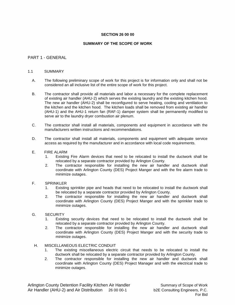
Arlington County Detention Facility Kitchen Air Handler Summary of Scope of Work
Air Handler (AHU-2) and Air Distribution 26 00 00-1 b2E Consulting Engineers, P.C. For Bid
SECTION 26 00 00
SUMMARY OF THE SCOPE OF WORK
PART 1 - GENERAL
1.1 SUMMARY
A. The following preliminary scope of work for this project is for information only and shall not be considered an all inclusive list of the entire scope of work for this project.
B. The contractor shall provide all materials and labor a necessary for the complete replacement of existing air handler (AHU-2) which serves the existing laundry and the existing kitchen hood. The new air handler (AHU-2) shall be reconfigured to serve heating, cooling and ventilation to the kitchen and the kitchen hood. The kitchen loads shall be removed from existing air handler (AHU-1) and the AHU-1 return fan (RAF-1) damper system shall be permanently modified to serve air to the laundry dryer combustion air plenum.
C. The contractor shall install all materials, components and equipment in accordance with the manufacturers written instructions and recommendations.
D. The contractor shall install all materials, components and equipment with adequate service access as required by the manufacturer and in accordance with local code requirements.
E. FIRE ALARM 1. Existing Fire Alarm devices that need to be relocated to install the ductwork shall be
relocated by a separate contractor provided by Arlington County. 2. The contractor responsible for installing the new air handler and ductwork shall
coordinate with Arlington County (DES) Project Manger and with the fire alarm trade to minimize outages.
F. SPRINKLER 1. Existing sprinkler pipe and heads that need to be relocated to install the ductwork shall
be relocated by a separate contractor provided by Arlington County. 2. The contractor responsible for installing the new air handler and ductwork shall
coordinate with Arlington County (DES) Project Manger and with the sprinkler trade to minimize outages.
G. SECURITY 1. Existing security devices that need to be relocated to install the ductwork shall be
relocated by a separate contractor provided by Arlington County. 2. The contractor responsible for installing the new air handler and ductwork shall
coordinate with Arlington County (DES) Project Manger and with the security trade to minimize outages.
H. MISCELLANEOUS ELECTRIC CONDUIT
1. The existing miscellaneous electric circuit that needs to be relocated to install the ductwork shall be relocated by a separate contractor provided by Arlington County.
2. The contractor responsible for installing the new air handler and ductwork shall coordinate with Arlington County (DES) Project Manager and with the electrical trade to minimize outages.
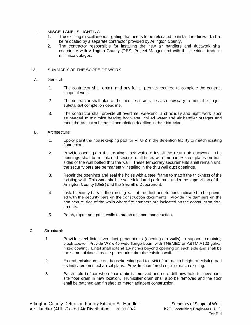
Arlington County Detention Facility Kitchen Air Handler Summary of Scope of Work
Air Handler (AHU-2) and Air Distribution 26 00 00-2 b2E Consulting Engineers, P.C. For Bid
I. MISCELLANEUS LIGHTING 1. The existing miscellaneous lighting that needs to be relocated to install the ductwork shall
be relocated by a separate contractor provided by Arlington County. 2. The contractor responsible for installing the new air handlers and ductwork shall
coordinate with Arlington County (DES) Project Manger and with the electrical trade to minimize outages.
1.2 SUMMARY OF THE SCOPE OF WORK
A. General:
1. The contractor shall obtain and pay for all permits required to complete the contract scope of work.
2. The contractor shall plan and schedule all activities as necessary to meet the project substantial completion deadline.
3. The contractor shall provide all overtime, weekend, and holiday and night work labor as needed to minimize heating hot water, chilled water and air handler outages and meet the project substantial completion deadline in their bid price.
B. Architectural:
1. Epoxy paint the housekeeping pad for AHU-2 in the detention facility to match existing floor color.
2. Provide openings in the existing block walls to install the return air ductwork. The openings shall be maintained secure at all times with temporary steel plates on both sides of the wall bolted thru the wall. These temporary securements shall remain until the security bars are permanently installed in the thru wall duct openings.
3. Repair the openings and seal the holes with a steel frame to match the thickness of the existing wall. This work shall be scheduled and performed under the supervision of the Arlington County (DES) and the Sherriff’s Department.
4. Install security bars in the existing wall at the duct penetrations indicated to be provid-ed with the security bars on the construction documents. Provide fire dampers on the non-secure side of the walls where fire dampers are indicated on the construction doc-uments.
5. Patch, repair and paint walls to match adjacent construction.
C. Structural:
1. Provide steel lintel over duct penetrations (openings in walls) to support remaining block above. Provide W8 x 40 wide flange beam with TNEMEC or ASTM A123 galva-nized coating. Lintel shall extend 16-inches beyond opening on each side and shall be the same thickness as the penetration thru the existing wall.
2. Extend existing concrete housekeeping pad for AHU-2 to match height of existing pad as indicated on mechanical plans. Provide chamfered edge to match existing.
3. Patch hole in floor when floor drain is removed and core drill new hole for new open site floor drain in new location. Humidifier drain shall also be removed and the floor shall be patched and finished to match adjacent construction.
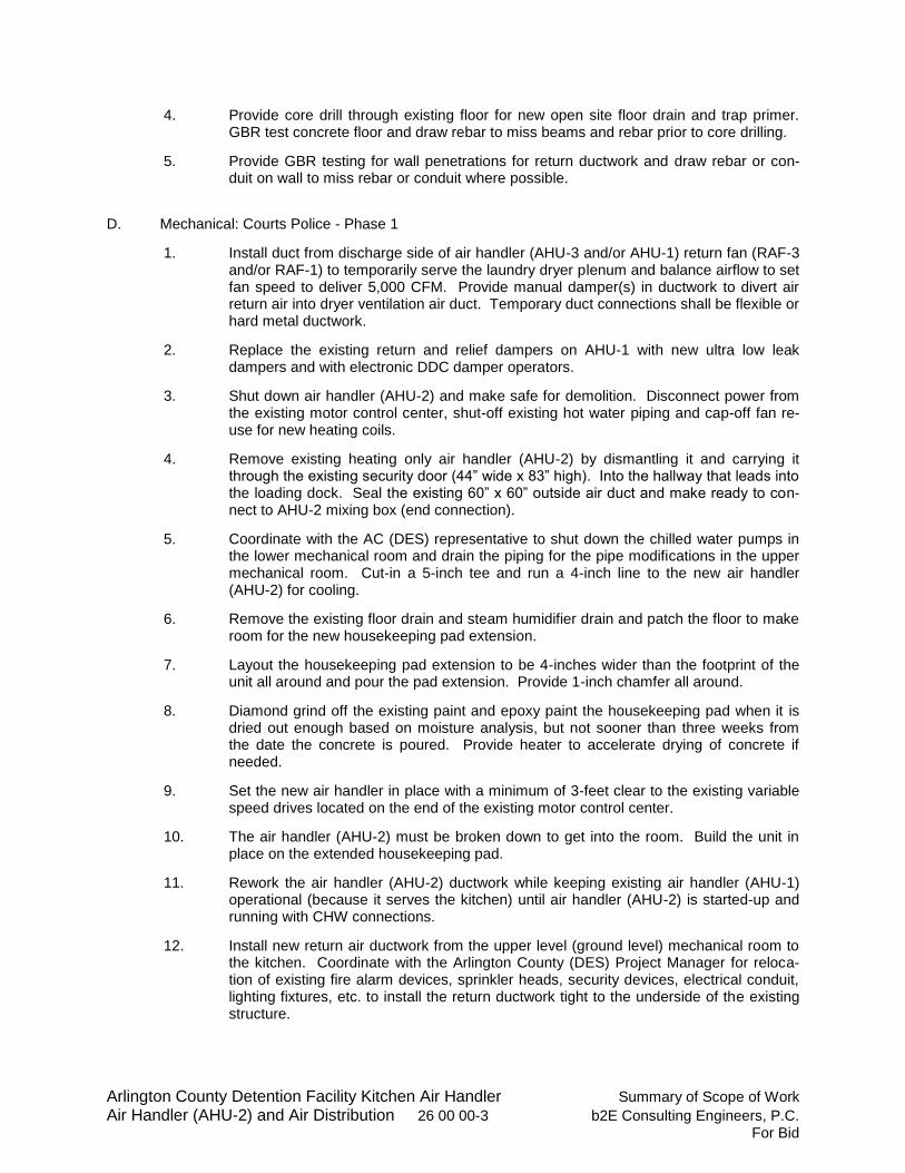
Arlington County Detention Facility Kitchen Air Handler Summary of Scope of Work
Air Handler (AHU-2) and Air Distribution 26 00 00-3 b2E Consulting Engineers, P.C. For Bid
4. Provide core drill through existing floor for new open site floor drain and trap primer. GBR test concrete floor and draw rebar to miss beams and rebar prior to core drilling.
5. Provide GBR testing for wall penetrations for return ductwork and draw rebar or con-duit on wall to miss rebar or conduit where possible.
D. Mechanical: Courts Police - Phase 1
1. Install duct from discharge side of air handler (AHU-3 and/or AHU-1) return fan (RAF-3 and/or RAF-1) to temporarily serve the laundry dryer plenum and balance airflow to set fan speed to deliver 5,000 CFM. Provide manual damper(s) in ductwork to divert air return air into dryer ventilation air duct. Temporary duct connections shall be flexible or hard metal ductwork.
2. Replace the existing return and relief dampers on AHU-1 with new ultra low leak dampers and with electronic DDC damper operators.
3. Shut down air handler (AHU-2) and make safe for demolition. Disconnect power from the existing motor control center, shut-off existing hot water piping and cap-off fan re-use for new heating coils.
4. Remove existing heating only air handler (AHU-2) by dismantling it and carrying it through the existing security door (44” wide x 83” high). Into the hallway that leads into the loading dock. Seal the existing 60” x 60” outside air duct and make ready to con-nect to AHU-2 mixing box (end connection).
5. Coordinate with the AC (DES) representative to shut down the chilled water pumps in the lower mechanical room and drain the piping for the pipe modifications in the upper mechanical room. Cut-in a 5-inch tee and run a 4-inch line to the new air handler (AHU-2) for cooling.
6. Remove the existing floor drain and steam humidifier drain and patch the floor to make room for the new housekeeping pad extension.
7. Layout the housekeeping pad extension to be 4-inches wider than the footprint of the unit all around and pour the pad extension. Provide 1-inch chamfer all around.
8. Diamond grind off the existing paint and epoxy paint the housekeeping pad when it is dried out enough based on moisture analysis, but not sooner than three weeks from the date the concrete is poured. Provide heater to accelerate drying of concrete if needed.
9. Set the new air handler in place with a minimum of 3-feet clear to the existing variable speed drives located on the end of the existing motor control center.
10. The air handler (AHU-2) must be broken down to get into the room. Build the unit in place on the extended housekeeping pad.
11. Rework the air handler (AHU-2) ductwork while keeping existing air handler (AHU-1) operational (because it serves the kitchen) until air handler (AHU-2) is started-up and running with CHW connections.
12. Install new return air ductwork from the upper level (ground level) mechanical room to the kitchen. Coordinate with the Arlington County (DES) Project Manager for reloca-tion of existing fire alarm devices, sprinkler heads, security devices, electrical conduit, lighting fixtures, etc. to install the return ductwork tight to the underside of the existing structure.
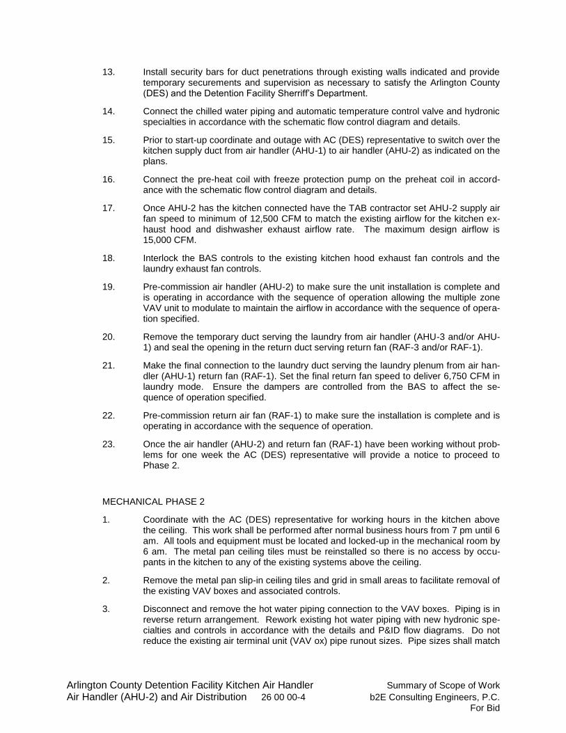
Arlington County Detention Facility Kitchen Air Handler Summary of Scope of Work
Air Handler (AHU-2) and Air Distribution 26 00 00-4 b2E Consulting Engineers, P.C. For Bid
13. Install security bars for duct penetrations through existing walls indicated and provide temporary securements and supervision as necessary to satisfy the Arlington County (DES) and the Detention Facility Sherriff’s Department.
14. Connect the chilled water piping and automatic temperature control valve and hydronic specialties in accordance with the schematic flow control diagram and details.
15. Prior to start-up coordinate and outage with AC (DES) representative to switch over the kitchen supply duct from air handler (AHU-1) to air handler (AHU-2) as indicated on the plans.
16. Connect the pre-heat coil with freeze protection pump on the preheat coil in accord-ance with the schematic flow control diagram and details.
17. Once AHU-2 has the kitchen connected have the TAB contractor set AHU-2 supply air fan speed to minimum of 12,500 CFM to match the existing airflow for the kitchen ex-haust hood and dishwasher exhaust airflow rate. The maximum design airflow is 15,000 CFM.
18. Interlock the BAS controls to the existing kitchen hood exhaust fan controls and the laundry exhaust fan controls.
19. Pre-commission air handler (AHU-2) to make sure the unit installation is complete and is operating in accordance with the sequence of operation allowing the multiple zone VAV unit to modulate to maintain the airflow in accordance with the sequence of opera-tion specified.
20. Remove the temporary duct serving the laundry from air handler (AHU-3 and/or AHU-1) and seal the opening in the return duct serving return fan (RAF-3 and/or RAF-1).
21. Make the final connection to the laundry duct serving the laundry plenum from air han-dler (AHU-1) return fan (RAF-1). Set the final return fan speed to deliver 6,750 CFM in laundry mode. Ensure the dampers are controlled from the BAS to affect the se-quence of operation specified.
22. Pre-commission return air fan (RAF-1) to make sure the installation is complete and is operating in accordance with the sequence of operation.
23. Once the air handler (AHU-2) and return fan (RAF-1) have been working without prob-lems for one week the AC (DES) representative will provide a notice to proceed to Phase 2.
MECHANICAL PHASE 2
1. Coordinate with the AC (DES) representative for working hours in the kitchen above the ceiling. This work shall be performed after normal business hours from 7 pm until 6 am. All tools and equipment must be located and locked-up in the mechanical room by 6 am. The metal pan ceiling tiles must be reinstalled so there is no access by occu-pants in the kitchen to any of the existing systems above the ceiling.
2. Remove the metal pan slip-in ceiling tiles and grid in small areas to facilitate removal of the existing VAV boxes and associated controls.
3. Disconnect and remove the hot water piping connection to the VAV boxes. Piping is in reverse return arrangement. Rework existing hot water piping with new hydronic spe-cialties and controls in accordance with the details and P&ID flow diagrams. Do not reduce the existing air terminal unit (VAV ox) pipe runout sizes. Pipe sizes shall match
Arlington County Detention Facility Kitchen Air Handler Summary of Scope of Work
Air Handler (AHU-2) and Air Distribution 26 00 00-5 b2E Consulting Engineers, P.C. For Bid
the existing pipe sizes. Coordinate any heating system outages with the AC (DES) representative at least two (2) weeks prior to planned outages.
4. Disconnect the existing pneumatic controls at each VAV box outlet and remove the hot water valves and hydronic specialties. Cap-off pneumatic tubing to ensure the pneu-matic control modifications do not affect the function in the remainder of the building.
5. Remove the VAV box and turn the existing supply air flex duct serving the VAV box down below the ceiling to distribute air into the kitchen until the VAV box is replaced with new hydronic specialties and controls.
6. Reinstall the metal pan ceiling tiles after each air terminal unit (VAV Box) is completed and at the end of the work day.
30. Once a VAV box is removed and the new ductwork and air outlets are completed, move to the next VAV box and repeat the process until the work is completed.
7. Provide testing adjusting and balancing (TAB) for the entire system, including air handlers (AHU-2 and AHU-1) and return fan (RAF-1) to ensure the systems are oper-ating to design values.
8. Provide final commissioning of the systems to ensure the job is complete and the equipment is operating in accordance with the sequence of operation specified.
9. Provide BAS graphics display at the facilities office computer in the Courts Police Building on the 13
th floor. The graphics shall be tested during the commissioning pro-
cess.
10. Provide close-out documentation, including final balance report, extra materials, opera-tion and maintenance manuals, warranties, as-built drawing, training and other deliver-ables as indicated in Division 1 final contract documents.
END OF SECTION 26 00 00

Arlington County Detention Facility Kitchen Air Handler General Electrical Requirements Air Handler (AHU-2) and Air Distribution 26 01 00-1 b2E Consulting Engineers, P.C.
For Bid
SECTION 26 01 00
GENERAL ELECTRICAL REQUIREMENTS
PART 1 - GENERAL
1.1 SPECIAL ELECTRICAL REQUIREMENTS
A. Drawing use and interpretation:
1. Design drawings are diagrammatic and do not show all offsets, bends, elbows, or other specific elements that may be required for proper installation of the work. Such work shall be verified at the site. Additional bends and offsets, and conduit as required by vertical and horizontal equipment locations or other job conditions, shall be provided to complete the work at no additional cost to the Owner.
2. For locations of building elements, refer to architectural, structural, mechanical and electrical drawings. Except where shown in dimensional detail, the locations of switches, receptacles, lights, motors, outlets, and other equipment shown on plans are approximate. Such items shall be placed to eliminate interference with ducts, piping and equipment. Outlets shall not be installed behind ducts, grilles, built-in casework, or in other inaccessible places. Exact locations shall be determined in the field. Door swings shall be verified to ensure that light switches are properly located.
3. Field measurements take precedence over drawings. 4. Electrical plans are intended to indicate size, capacity, approximate location, direction
and general relationship of the work, but not exact detail or arrangement. The contractor is responsible for indicating detailed arrangements for procured equipment and layouts on all shop drawings required in all specification sections. Equipment sizes indicated are minimum. Before installing any wire or conduit, the Contractor shall obtain the exact equipment requirements and shall install wire, conduit, disconnect switches, motor starters, heaters, circuit breakers, and other items for the correct size for the equipment actually installed. Wire and conduit sizes shown on the drawings shall be taken as a minimum and shall not be reduced without written approval.
5. Where job conditions require reasonable deviation from contract documents, make such deviations without additional cost to Owner after obtaining approval of the Engineer.
B. Installation of systems and equipment:
1. Installation is subject to clarification as indicated in reviewed Shop and Field Coordination Drawings.
a. Generally, lay out piping requiring gravity drainage first; then lay out large pipe mains, ductwork and electrical conduit.
b. This procedure is intended to promote orderly installation, but not to establish trade precedence.
c. Dimensions indicated are limiting dimensions. d. Do not use equipment exceeding dimensions required by manufacturer for service
access, and applicable codes reduce required clearances. e. In electrical equipment room corridors and aisle ways, maintain clear head room
between floor and underside of conduit, switches, controllers, panelboards, transformers and equipment to allow for future replacing of equipment and major components.
Arlington County Detention Facility Kitchen Air Handler General Electrical Requirements Air Handler (AHU-2) and Air Distribution 26 01 00-2 b2E Consulting Engineers, P.C.
For Bid
f. Coordinate connections to all equipment, and penetrations of conduit through floors, walls and roof with actual field conditions and dimensions. Contractors shall thoroughly familiarize themselves with the project requirements prior to submitting bid price.
g. Measure and coordinate the connections and the installations between trades prior to submitting shop drawings.
h. Under no circumstances shall any electrical equipment be hung, supported or suspended from the building suspended ceilings.
C. Utility coordination with Owner
1. Notify Owner’s representative of any utility interruptions at least seventy two (72) hours in advance and obtain approval from property manager before proceeding.
2. Identify extent and duration of utility interruptions.
D. Installation of chilled water system equipment and distribution equipment.
1. Installation requirements are subject to vary with each manufacturer’s equipment. The contractor is responsible for reviewing the manufacturer’s shop and installation drawings.
a. The contractor shall install the electrical distribution equipment per manufacturer’s installation drawings.
b. Prior to the preparation of submittals, the contractor shall contact the manufacturer and coordinate the exact locations, sizes, weights, connections, and assembly requirements for each piece of equipment.
c. The contractor is responsible for installation of a complete operating system in accordance with the manufacturer installation drawings and in accordance with the specification requirements.
2. As part of the submittal process, the contractor shall provide a detailed installation drawing for all electrical distribution equipment specifically for the chilled water system to fit within the allocated space. Distribution equipment submittals which are presented without complete room layout drawings will not be considered or reviewed. The manufacturer and contractor shall coordinate with actual field conditions and perform surveys as necessary to develop a complete equipment installation drawing which meets all applicable codes, code amendments, Arlington County Standards, ordinances, laws, etc., including but not limited to:
a. Manufacturer service access clearances; top, front, back and sides. b. National Electric Code (NEC) service access clearances; top, front, back and
sides. c. Any other requirements of the local authorities having jurisdiction. d. All conduit routings and terminations. e. Full field erection drawing with detail on distribution wireway. f. Detail of conduit penetrations through exterior walls far waterproof installation. h. Drawings for pull box. These drawings shall be submitted coincident with
distribution gear shop drawings.
3. The contractor and manufacturer shall fully coordinate the complete installation of all materials and labor described in the following sections. a. Section 26 24 16 – Panelboards. b. Section 26 28 16 – Enclosed Switches and Circuit Breakers.
E. Electrical coordination study:
Arlington County Detention Facility Kitchen Air Handler General Electrical Requirements Air Handler (AHU-2) and Air Distribution 26 01 00-3 b2E Consulting Engineers, P.C.
For Bid
1. The contractor shall provide short circuit study and overcurrent protective device coordination and arc flash study for the chilled water system distribution equipment. Study shall include all unique feeder circuits, equipment, and individual nodes of distribution from utility company service termination at switchboard through each branch circuit panelboard serving the chilled water system distribution.
2. Coordination study shall be plotted on standard log-log graph paper and shall show the following:
a. Fuse melting curves with reaction time. b. Circuit breaker trip curve with reaction time. c. Ground fault relay settings. d. Transformer magnetic inrush and ANSI point. e. Arc Flash Study.
3. Results of coordination study shall outline in tabular form all required trip settings for adjustable trip type circuit breakers in order to maximize the electrical distribution.
4. Short circuit and protective device studies shall be performed by the distribution equipment manufacturer. The studies shall be submitted complete and as an integral part of the distribution equipment shop drawings.
5. The contractor shall provide all distribution board equipment, feeders, switches, branch circuit overload devices, panelboards, frequency drive units, breakers and fuses with fault current/short circuiting ratings to meet or exceed values indicated in final submittal approved study.
6. The contractor shall base bid in panelboards and equipment with the A.I.C. Ratings as follows, and as indicated in Section 26 24 13 and 26 24 16.
a. Distribution Panel (460V/3-phase): 65,000 AIC. b. Panelboards (460V/3-phase): 35,000 AIC. c. Panelboards (208V/3-phase): 22,000 AIC.
7. The contractor shall submit the required short circuit study along with switchboard and panelboard submittals. Switchboard and panelboard submittals received prior to a completed short circuit analysis will not be reviewed.
8. The above indicated A.I.C. ratings include all bus, lug, terminal, and circuit breaker ratings. Circuit breakers in a specific panel must have equal A.I.C. rating to panel in which the breaker is mounted.
9. Submit copy of studies and curves in O&M manual.
F. Fully coordinate the size and location of concrete housekeeping pads for floor mounted equipment with the dimensions of the actual equipment purchased per Division 03.
G. Description of systems: Furnish and install materials resulting, upon completion, in functioning systems in compliance with performance requirements specified, and modifications resulting from reviewed Shop and Field Coordination Drawings.
1.2 SUMMARY
A. This Section includes the following: 1. Raceways. 2. Building wire and connectors. 3. Supporting devices for electrical components. 4. Electrical identification. 5. Concrete equipment bases. 6. Electrical equipment coordination and installation. 7. Cutting and patching for electrical construction. 8. Touchup painting.
Arlington County Detention Facility Kitchen Air Handler General Electrical Requirements Air Handler (AHU-2) and Air Distribution 26 01 00-4 b2E Consulting Engineers, P.C.
For Bid
1.3 DEFINITIONS
A. RMC: Rigid metal conduit.
B. EMT: Electrical metallic tubing.
C. FMC: Flexible metal conduit.
D. IMC: Intermediate metal conduit.
E. LFMC: Liquid tight flexible metal conduit.
F. Scheduled: As scheduled on drawing equipment schedules or as called out by model number/designation in the specification.
G. Acceptance: With respect to initiation of warranty, the date when the Engineer signs the Contractor’s Application for Final Payment for release of retainage.
H. EMS: Energy Management System.
J. Notice-to-Proceed: The date, which the building owner or authorized agent authorizes Notice–to-Proceed by Letter.
K. Scheduled: As scheduled on drawing equipment schedules or as called-out by manufacturer/model number/designation in the specification.
1.4 SUBMITTALS
A. Shop Drawings: Dimensioned plans and sections or elevation layouts of electricity-metering equipment.
B. Field Test Reports: Indicate and interpret test results for compliance with performance requirements.
1.5 QUALITY ASSURANCE
A. Electrical Components, Devices, and Accessories: Listed and labeled as defined in NFPA 70, Article 100, by a testing agency acceptable to authorities having jurisdiction, and marked for intended use.
B. Equipment Selection: Mechanical equipment by “Acceptable Manufacturer” of higher electrical characteristics other than as indicated as “Basis of Design” on drawings may be furnished provided electrical services, circuit breakers, conduit, starters, adjustable frequency drives, panelboards, motor control cabinets are increased. The contractor is responsible to coordinate between trades prior to submitting bid price. Additional costs to the Owner shall not be considered for such modifications, and shall remain the responsibility of the contractor.
C. Perform work in accordance with the following codes: 1. State and local building electrical and fire alarm codes. 2. National Electric Code (NFPA 70). 3. National Fire Alarm Code (NFAP 72). 4. National Fire Protection Association (Applicable Codes).
Arlington County Detention Facility Kitchen Air Handler General Electrical Requirements Air Handler (AHU-2) and Air Distribution 26 01 00-5 b2E Consulting Engineers, P.C.
For Bid
5. Underwriter Laboratories (Comply with or exceed all provisions of specific equipment listings or classifications).
6. National Electrical Manufacturers Association (NEMA). 7. Virginia Uniform Statewide Building Code (latest amendments). 8. Fire alarm testing criteria as may published by the Chief Fire Code Inspector for Arlington
County, Virginia. 9. ASHRAE Energy Code – 90.1 - 2010.
D. Conductors: All wire, bus, lugs terminations, connectors, etc. shall be copper. Use of any aluminum in the conductor path is not allowed. This includes but is not limited to all panels, disconnects, enclosed breakers, lugs, splices, terminals, etc.
1.6 DELIVERY, STORAGE AND HANDLING
A. Deliver conduit with factory-applied end caps. Maintain end caps through shipping, storage, and handling to prevent conduit end damage and prevent entrance of dirt, debris, and moisture.
B. Protect stored conduit from moisture and dirt. Elevate above grade. Do not exceed structural capacity of floor or roof, if stored inside or on the roof.
1. Do not store heavy equipment or materials inside or on the roof.
C. Protect couplings, fittings and specialties from moisture and dirt.
D. Provide covering and shielding for equipment to protect from damage.
E. Protect existing building and building components.
F. Repair, restore, and replace damaged existing and new building components and equipment.
G. Protect nameplates on electrical panelboards, motor controllers, control centers, transformers, circuit breakers and other equipment.
1.7 SEQUENCING AND SCHEDULING
A. Coordinate electrical equipment installation with other building components. B. Arrange for conduit spaces, chases, slots, and openings in existing building structure and shaft
during progress of construction to allow for electrical installations.
C. Coordinate installation of required supporting devices and set sleeves in poured-in-place concrete and other structural components, as they are constructed.
D. Sequence, coordinate, and integrate installations of electrical materials and equipment for efficient flow of the Work. Coordinate installation of large equipment requiring positioning, re-assembly before closing in chiller room, electric room, shaft, etc.
E. Coordinate lifting and rigging and connection of electrical systems with exterior underground and overhead utilities and services. Comply with requirements of governing regulations, franchised service companies, and controlling agencies for setting or moving large equipment. Perform work in accordance with all applicable codes and local authorities having jurisdiction and obtain and pay for all permits and other costs.
Arlington County Detention Facility Kitchen Air Handler General Electrical Requirements Air Handler (AHU-2) and Air Distribution 26 01 00-6 b2E Consulting Engineers, P.C.
For Bid
F. Coordinate requirements for access panels and doors if electrical items requiring access are concealed behind finished surfaces.
G. Coordinate installation of identifying devices and panel schedules after completing covering and painting, if devices are applied to surfaces. Install identifying devices before installing acoustical ceilings and similar concealment.
H. Coordinate lifting and rigging and connection of electrical systems with interior space limitations and finishes. Remove and replace as necessary existing architectural, mechanical, electrical, plumbing, etc., building components as required to install large and/or heavy equipment.
I. Survey the existing electric gear to ensure all existing conditions are known prior to ordering equipment or starting work.
J. All work shall be coordinated with the Sherriff’s Department and AC DES representative prior to performing any work.
K. Power outages shall be approved in writing by the AC DES representative two weeks prior to the outage date. Outages shall be planned to minimize any impact to the Courts Police or Detention Facility.
1.8 JOB CONDITIONS
A. Cause as little interference or interruption of existing utilities and services as possible.
1. Schedule work which will cause interference or interruption in advance with Owner Authorities having jurisdiction, and affected contractors.
B. Keep roads clear of materials and debris.
C. Examine Contract Documents to determine how other work will affect execution of electrical work.
D. Examine site and become familiar with existing local conditions affecting work.
E. Determine and verify locations of conduit and equipment in building where work is being performed.
F. Make arrangements and pay for necessary permits, licenses, and inspections.
G. Record drawings:
1. Keep one (1) complete set of electrical drawings in job site office for indicating actual installation of electrical systems and equipment.
2. Use this set of drawings for no other purpose. 3. Where material, equipment, or systems components are installed differently from that
indicated, show such differences clearly and neatly. 4. At project completion, provide record set of drawings in accordance with Division 1.
Record drawing shall show all important information which is changed from contract drawings. Dimensionally locate all underground or in-slab conduit on record drawings.
1.9 HAZARDOUS MATERIALS
Arlington County Detention Facility Kitchen Air Handler General Electrical Requirements Air Handler (AHU-2) and Air Distribution 26 01 00-7 b2E Consulting Engineers, P.C.
For Bid
A. The Contractor shall refer to the “Contract Requirements” Sections, Division 1 and other applicable Divisions and Sections for hazardous materials abatement coordination and other requirements prior to submitting bid price.
1.10 SUBSTANTIAL COMPLETION AND ACCEPTANCE
A. The Contractor shall refer to Section 017700, “Closeout Procedures”, Division 1, and other applicable Project Manual Sections for Substantial Completion requirements prior to submitting bid price.
B. Acceptance: The electrical and fire alarm systems shall not be accepted by the Owner and Engineer until all systems are installed, fully operational, and commissioning for HVAC systems and low voltage electrical systems are completed, pre-commissioning is completed, and commissioning is completed to the satisfaction of the Owner.
1. The Owner will not accept and will not release payment for retainage identified in the
paragraph below until all Division 26, 27 and 28 contract requirements are completed and the systems are accepted by the Owner and Architect.
PART 2 - PRODUCTS
2.1 SUPPORTING DEVICES
A. Material: Cold-formed steel, with corrosion-resistant coating acceptable to authorities having jurisdiction.
B. Metal Items for Use Outdoors or in Damp Locations: Hot-dip galvanized steel.
C. Slotted-Steel Channel Supports: Flange edges turned toward web, and 9/16-inch- diameter slotted holes at a maximum of 2 inches o.c., in webs.
D. Slotted-Steel Channel Supports: Comply with Division 5 Section "Metal Fabrications" for slotted channel framing.
1. Channel Thickness: Selected to suit structural loading. 2. Fittings and Accessories: Products of the same manufacturer as channel supports.
E. Raceway and Cable Supports: Manufactured clevis hangers, “J” hooks, riser clamps, straps, threaded C-clamps with retainers, ceiling trapeze hangers, wall brackets, and spring-steel clamps or click-type hangers.
F. Pipe Sleeves: ASTM A 53, Type E, Grade A, Schedule 40, galvanized steel, plain ends.
G. Cable Supports for Vertical Conduit: Factory-fabricated assembly consisting of threaded body and insulating wedging plug for non-armored electrical cables in riser conduits. Plugs have number and size of conductor gripping holes as required to suit individual risers. Body constructed of malleable-iron casting with hot-dip galvanized finish.
H. Expansion Anchors: Carbon-steel wedge or sleeve type.
I. Toggle Bolts: All-steel springhead type.
J. Powder-Driven Threaded Studs: Heat-treated steel (obtain approval from Structural Engineer).
Arlington County Detention Facility Kitchen Air Handler General Electrical Requirements Air Handler (AHU-2) and Air Distribution 26 01 00-8 b2E Consulting Engineers, P.C.
For Bid
2.2 WARRANTIES
A. The Contractor shall warrant for period of two (2) years all work provided under the contract to include, but not necessarily limited to, all systems, equipment, materials, and workmanship. This shall not be construed to limit any extended warranty periods of longer than one year for specific items or systems specified elsewhere in the Contract Documents.
B. The warranty period shall commence on the date of acceptance by the Owner and shall cover all parts and labor as required to fulfill the warranty at no cost to the Owner. Refer to Division 1 for additional warranty requirements.
C. Information on all warranties shall be included in the O&M Manuals specified herein to be provided by the Owner.
D. Provide a separate warranty binder for all warranties that are included in the O&M manuals.
2.5 ASBESTOS
A. Asbestos Free Materials: The intention of these drawings and specifications is that there be no asbestos containing materials installed on this project. The best of Architect’s and Engineer’s knowledge, none of the material or equipment specified herein or shown on the drawings contains asbestos. The Contractor shall make every effort to prevent any asbestos materials from being installed in or used on construction of the project. At the completion of the project, the Contractor shall certify by letter that to the best of his knowledge, no asbestos containing materials were used for or in the construction of this project.
2.6 TOUCHUP PAINT
A. For Equipment: Equipment manufacturer's paint selected to match installed equipment finish.
B. Galvanized Surfaces: Zinc-rich paint recommended by item manufacturer.
2.7 PENETRATIONS
A. Maintain fire ratings and provide U.L. Listed firestopping system where electrical items penetrate fire rated building elements (See Architectural). Include in written warranty of work, a guarantee of the weatherproof integrity of penetrations where such penetrations occur at exterior envelope.
B. See Roof Curbs, Division 23, Section “HVAC General Mechanical Requirements” for piping penetrations through special roof curbs. Do not penetrate roof with wiring, conduit, etc, unless through a roof curb.
PART 3 - EXECUTION
A. Survey the existing electric gear to ensure all existing conditions are known prior to ordering equipment or starting work.
B. All work shall be coordinated with the Sherriff’s Department and AC DES representative prior to performing any work.
Arlington County Detention Facility Kitchen Air Handler General Electrical Requirements Air Handler (AHU-2) and Air Distribution 26 01 00-9 b2E Consulting Engineers, P.C.
For Bid
C. Power outages shall be approved in writing by the AC DES representative two weeks prior to the outage date. Outages shall be planned to minimize any impact to the Courts Police or Detention Facility.
D. Survey the existing electric gear to ensure all existing conditions are known prior to ordering equipment or starting work.
E. All work shall be coordinated with the Sherriff’s Department and AC DES representative prior to performing any work.
F. Power outages shall be approved in writing by the AC DES representative two weeks prior to the outage date. Outages shall be planned to minimize any impact to the Courts Police or Detention Facility.
3.2 ELECTRICAL EQUIPMENT INSTALLATION
A. Headroom Maintenance: If mounting heights or other location criteria are not indicated, arrange and install components and equipment to provide the maximum possible headroom.
B. Materials and Components: Install level, plumb, and parallel and perpendicular to other building systems and components, unless otherwise indicated. Where headroom or space conditions appear inadequate, contractor shall notify Architect before proceeding.
C. Equipment: Install to facilitate service, maintenance, and repair or replacement of components. Connect for ease of disconnecting, with minimum interference with other installations.
D. Conduit Raceway Right of Way: Give to raceways and piping systems installed at a required slope.
E. The contractor shall not install any raceway in a manner that creates moisture traps.
3.3 RACEWAY APPLICATION
A. Use the following raceways for outdoor installations:
1. Exposed: RMC (galvanized) or IMC. 2. Concealed: Aboveground RMC (galvanized) or IMC. 3. Underground: RNC, Type EPC-40-PVC, direct buried or concrete encased. 4. Connection to Vibrating Equipment: LFMC. 5. Boxes and Enclosures: NEMA 250, Type 3R or Type 4.
B. Use the following raceways for indoor installations:
1. Exposed: Not subject to damage; EMT, Subject to damage; RMC (galvanized) or IMC. 2. Concealed: EMT. 3. Connection to Vibrating Equipment: FMC; except in wet or damp locations, use LFMC. 4. Damp or Wet Locations: RMC (galvanized). 5. Boxes and Enclosures: NEMA 250, Type 1, unless otherwise indicated.
3.4 RACEWAY AND CABLE INSTALLATION
Arlington County Detention Facility Kitchen Air Handler General Electrical Requirements Air Handler (AHU-2) and Air Distribution 26 01 00-10 b2E Consulting Engineers, P.C.
For Bid
A. Conceal raceways and cables, unless otherwise indicated, within finished walls, ceilings, and floors.
B. Install raceways and cables at least 6 inches away from parallel runs of flues and steam or hot-water pipes. Locate horizontal raceway runs above water and steam piping.
C. Use temporary raceway caps to prevent foreign matter from entering.
D. Make conduit bends and offsets so ID is not reduced. Keep legs of bends in the same plane and straight legs of offsets parallel, unless otherwise indicated.
E. Use raceway and cable fittings compatible with raceways and cables and suitable for use and location.
F. Install raceways embedded in slabs in middle third of slab thickness where practical, and leave at least 1-inch concrete cover. 1. Secure raceways to reinforcing rods to prevent sagging or shifting during concrete
placement. 2. Space raceways laterally to prevent voids in concrete. 3. Install conduit larger than 1-inch trade size parallel to or at right angles to main
reinforcement. Where conduit is at right angles to reinforcement, place conduit close to slab support.
4. Transition from nonmetallic tubing to Schedule 80 nonmetallic conduit, rigid steel conduit (RMC), or IMC before rising above floor.
5. Make bends in exposed parallel or banked runs from same centerline to make bends parallel. Use factory elbows only where elbows can be installed parallel; otherwise, provide field bends for exposed parallel raceways.
G. Without exception, install pull wires in empty raceways. Use No. 14 AWG zinc-coated steel or monofilament plastic line with not less than 200-lb tensile strength. Leave at least 12 inches of slack at each end of the pull wire.
H. Install telephone and signal system raceways, 2-inch trade size and smaller, in maximum lengths of 150 feet and with a maximum of two 90-degree bends or equivalent. Separate lengths with pull or junction boxes where necessary to comply with these requirements, in addition to requirements above.
I. Connect motors and equipment subject to vibration, noise transmission, or movement with a maximum of 72-inch flexible conduit. Install LFMC in wet or damp locations. Install separate ground conductor across flexible connections.
3.5 WIRING METHODS FOR POWER, LIGHTING, AND CONTROL CIRCUITS
A. Feeders: Type THHN/THWN insulated conductors in raceway.
B. Branch Circuits: Type THHN/THWN insulated conductors in raceway, #12 AWG and larger. MC-flexible raceway not allowed.
1. Do not use less than ¾-inch diameter conduit for any branch circuit. 2. Do not install more than three (3) current carrying conductors in any conduit. 3. Do not install smaller than #12 awg. wire size for any power distribution circuits.
C. Remote-Control Signaling and Power-Limited Circuits: Type THHN/THWN insulated conductors in raceway for Classes 1, 2, and 3, unless otherwise indicated.
Arlington County Detention Facility Kitchen Air Handler General Electrical Requirements Air Handler (AHU-2) and Air Distribution 26 01 00-11 b2E Consulting Engineers, P.C.
For Bid
3.6 WIRING INSTALLATION
A. Install splices and taps that are compatible with conductor material and that possess equivalent or better mechanical strength and insulation ratings than un-spliced conductors.
B. Install wiring at outlets with at least 6 inches of slack conductor at each outlet.
C. Connect outlet and component connections to wiring systems and to ground. Tighten electrical connectors and terminals, according to manufacturer's published torque-tightening values. If manufacturer's torque values are not indicated, use those specified in UL 486A.
3.7 ELECTRICAL SUPPORTING DEVICE APPLICATION
A. Damp Locations and Outdoors: Hot-dip galvanized materials or nonmetallic, U-channel system components.
B. Natatorium: Aluminum, powder coated.
C. Dry Locations: Steel materials.
D. Selection of Supports: Comply with manufacturer's written instructions, (See Structural).
E. Strength of Supports: Adequate to carry present and future loads, times a safety factor of at least four; minimum of 200-lb design load.
3.8 SUPPORT INSTALLATION
A. Install support devices to securely and permanently fasten and support electrical components.
B. Install individual and multiple raceway hangers and riser clamps to support raceways. Provide U-bolts, clamps, attachments, and other hardware necessary for hanger assemblies and for securing hanger rods and conduits.
C. Support parallel runs of horizontal raceways together on trapeze- or bracket-type hangers.
D. Size supports for multiple raceway installations so capacity can be increased by a 25 percent minimum in the future.
E. Support individual horizontal raceways with separate, malleable-iron pipe hangers or clamps.
F. Install 1/4-inch- diameter or larger threaded steel hanger rods, unless otherwise indicated.
G. Spring-steel fasteners specifically designed for supporting single conduits or tubing may be used instead of malleable-iron hangers for 1-1/2-inch and smaller raceways serving lighting and receptacle branch circuits above suspended ceilings and for fastening raceways to slotted channel and angle supports.
H. Arrange supports in vertical runs so the weight of raceways and enclosed conductors is carried entirely by raceway supports, with no weight load on raceway terminals.
I. Simultaneously install vertical conductor supports with conductors.
Arlington County Detention Facility Kitchen Air Handler General Electrical Requirements Air Handler (AHU-2) and Air Distribution 26 01 00-12 b2E Consulting Engineers, P.C.
For Bid
J. Install metal channel racks for mounting cabinets, panelboards, disconnect switches, control enclosures, pull and junction boxes, transformers, and other devices unless components are mounted directly to structural elements of adequate strength.
K. Install sleeves for cable and raceway penetrations of concrete slabs and walls unless core-drilled holes are used. Install sleeves for cable and raceway penetrations of masonry and fire-rated gypsum walls and of all other fire-rated floor and wall assemblies. Install sleeves during erection of concrete and masonry walls.
L. Securely fasten electrical items and their supports to the building structure, unless otherwise indicated. Perform fastening according to the following unless other fastening methods are indicated: 1. Masonry: Toggle bolts on hollow masonry units and expansion bolts on solid masonry
units. 2. New Concrete: Concrete inserts with machine screws and bolts. 3. Existing Concrete: Expansion bolts.
a. Instead of expansion bolts, threaded studs driven by a powder charge and provided with lock washers may be used in existing concrete.
4. Steel: Welded threaded studs or spring-tension clamps on steel.
a. Field Welding: Comply with AWS D1.1.
5. Welding to steel structure may be used only for threaded studs, not for conduits, pipe straps, or other items.
6. Light Steel: Sheet-metal screws. 7. Fasteners: Select so the load applied to each fastener does not exceed 25 percent of its
proof-test load.
3.9 FIRESTOPPING
A. Apply firestopping to cable and raceway penetrations of fire-rated floor and wall assemblies to achieve fire-resistance rating of the assembly. Firestopping materials and installation requirements are specified in Division 7 Section "Firestopping."
3.10 CONCRETE BASES AND CONSTRUCTION
A. Construct concrete bases of dimensions required by all floor mounted electrical equipment including transformers, switchboards, motor control centers, distribution panels, generators, etc., but not less than 6-inches larger, in both directions, than supported unit. Follow supported equipment manufacturer's anchorage recommendations and setting templates for anchor-bolt and tie locations, unless otherwise indicated. Use compressive-strength concrete and reinforcement as specified in Division 3 Section "Cast-in-Place Concrete", 3500-psi, 28-day compressive-strength concrete. Provide test samples.
3.11 CUTTING AND PATCHING
A. The installed floors, walls and roofs contain electric conduit and piping either under or in the floor/roof and walls. The contractor is responsible for locating previously installed equipment under or in the floor/roof or walls. The contractor is responsible for repairing previously installed equipment damaged due to cutting the floors, walls and roof.
B. Perform or pay for cutting, fitting, repairing, patching and finishing of work of other sections where it is necessary to disturb such work to permit installation of mechanical work.

Arlington County Detention Facility Kitchen Air Handler General Electrical Requirements Air Handler (AHU-2) and Air Distribution 26 01 00-13 b2E Consulting Engineers, P.C.
For Bid
C. Avoid cutting, where possible, by setting sleeves or frames, and by requesting openings in advance. Coordinate locations with work of other sections.
D. Before cutting of structural elements, obtain written approval of Structural Engineer. Use only approved methods. Neatly cut holes as small as possible to admit work. Do not weaken walls or floors; locate holes in concrete to miss structural.
E. Locate openings and sleeves to permit neat installation of piping, ductwork and equipment.
F. Do not remove or damage fireproofing materials. Install hangers, inserts, supports, and anchors prior to installation of fireproofing. Repair or replace fireproofing removed or damaged, at no extra cost.
G. Cut channel, chase and drill floors, walls, partitions, ceilings and other surfaces necessary for mechanical installations. Perform cutting by skilled mechanics of trades involved.
H. Repair cut surfaces to match adjacent surfaces.
I. Cut, channel, chase, and drill floors, walls, partitions, ceilings, and other surfaces required to permit electrical installations. Perform cutting by skilled mechanics of trades involved.
J. Repair and refinish disturbed finish materials and other surfaces to match adjacent undisturbed surfaces. Install new fireproofing where existing firestopping has been disturbed. Repair and refinish materials and other surfaces by skilled mechanics of trades involved.
3.12 FIELD QUALITY CONTROL
A. Inspect installed components for damage and faulty work, including the following:
1. Raceways. 2. Building wire and connectors. 3. Supporting devices for electrical components. 4. Electrical identification. 5. Concrete bases. 6. Electrical demolition. 7. Cutting and patching for electrical construction. 8. Touchup painting.
3.13 REFINISHING AND TOUCHUP PAINTING
A. Refinish and touch up paint. Paint materials and application requirements are specified in Division 9 Section "Painting."
1. Clean damaged and disturbed areas and apply primer, intermediate, and finish coats to suit the degree of damage at each location.
2. Follow paint manufacturer's written instructions for surface preparation and for timing and application of successive coats.
3. Repair damage to galvanized finishes with zinc-rich paint recommended by manufacturer.
4. Repair damage to PVC or paint finishes with matching touchup coating recommended by manufacturer.
Arlington County Detention Facility Kitchen Air Handler General Electrical Requirements Air Handler (AHU-2) and Air Distribution 26 01 00-14 b2E Consulting Engineers, P.C.
For Bid
3.14 CLEANING AND PROTECTION
A. Protect work area against damage for all causes. Provide and maintain protective coverings to exclude dirt, dust, water, paint, etc. from equipment. Close all ducts, conduits, box and equipment openings to prevent entrance of dirt or construction material.
B. On completion of installation, including outlets, fittings, and devices, inspect exposed finish. Remove burrs, dirt, paint spots, and construction debris.
C. Protect equipment and installations and maintain conditions to ensure that coatings, finishes, and cabinets are without damage or deterioration during construction and restore finishes to original condition at time of Substantial Completion.
1. Thoroughly clean work area no less than weekly.
3.15 DIV. 26 CONTRACTOR SUPPORT FOR SYSTEMS IN OPERATION-START-UP
The Div. 26 contractor shall provide all labor and materials to fully support Div. 23 HVAC systems start up field quality control, pre-commissioning and commissioning. The Div. 26 contractor shall perform all required electrical portions of the Div. 23 commissioning. As part of this requirement, indicate by signature when check list items are complete where so indicated in the Div. 23 checklists. Assist in performing the following:
A. Prior to substantial completion, at time agreed to by Owner, put systems into satisfactory operation. 1. At first cooling or heating season following Substantial Completion, put systems not yet
operated under their seasonal loads into satisfactory operation. 2. At second cooling or heating season following Substantial Completion put systems not
yet operated under their first seasonal loads into satisfactory operation.
B. Perform first quality control for the HVAC system (i.e. Systems Demonstration) specified in Commissioning Section and make all adjustments required. The first Systems Demonstration shall be completed by the Contractor and results approved by the Owner and Engineer prior to the Owner accepting the work. 1. Perform first Systems Demonstration in accordance with Commissioning Sections for all
of the work prior to Substantial Completion and after the Contractor has obtained a certificate of occupancy, and the TAB balancing report is submitted and approved.
C. Provide a second Systems Demonstration, not sooner than twelve (12) months after substantial completion and make all adjustments/corrections required by the Owner and Engineer prior to expiration of three (3) year EMS warranty period. 1. Retainage will be withheld from the payment to the Contractor until all the Systems
Demonstrations, Precommissioning Checklists and contract requirements in the contract documents are completed by the contractor to the satisfaction of the Owner and Engineer, and the Commissioning is completed to the satisfaction of the Owner and the Owner’s Commissioning Agent. The contractor can apply for payment of this amount after all systems are Commissioned and Accepted by the Owner and Engineer.
D. Coordinate all provisions and installations of Div. 26 and 28 with the hardware schedule indicated on the Architectural drawings.
END OF SECTION 26 01 00
Arlington County Detention Facility Kitchen Air Handler Common Work Results for Electrical Air Handler (AHU-2) and Air Distribution 26 05 00-1 b2E Consulting Engineers, P.C.
For Bid
SECTION 26 05 00
COMMON WORK RESULTS FOR ELECTRICAL
PART 1 - GENERAL
1.1 SUMMARY
A. Section Includes:
1. Electrical equipment coordination and installation. 2. Sleeves for raceways and cables. 3. Sleeve seals. 4. Grout. 5. Common electrical installation requirements. 6. Power Distribution for Air Handlers (AHU-2). 7. Connections For:
a. Air Handler (AHU-2). b. Freeze Protection Pump (HRCP-1). c. Building Automation System (BAS) Control Panels. d. Modify the existing motor control center. e. Junction Boxes and Serviceable Devices. f. All electrical work for receptacles or connections to the above equipment shall be
provided by the Electrical Trade. The complete scope is not indicated on the drawings and where unclear shall be provided by the contractor based on these specifications. Run power back to the closest non-overloaded panelboard in accordance with requirements where unclear on the plans. 1) Do not rough-in or install other electrical work in these areas until submittals
are reviewed for the actual systems provided and roughing-in drawings reviewed by the Engineer are received. The presumed location of all presently envisioned equipment having electrical connections is shown on the drawings and specified herein, but this is for estimating purposes only and the Contractor shall prepare his bid to allow for any possible rearrangement of the equipment listed, or as indicated. Provide permanent liquid-tight flexible metal conduit connections to the equipment from the outlet boxes or conduit stubbed up above the floor or conduit stubbed down from the ceiling for all equipment indicated, except where receptacles are indicated. These connections shall include but not be limited to: disconnect switches, service switches, combination motor starters, motor protective switches and other wiring devices, conduit, cable, wire, boxes, etc. as required per the manufacturer’s drawings, the NEC and the Contract Documents.
2) Obtain the detailed vendor’s recommended installation instructions and drawings and install as necessary for a complete code compliant installation.
1.2 DEFINITIONS
A. EPDM: Ethylene-propylene-diene terpolymer rubber.
Arlington County Detention Facility Kitchen Air Handler Common Work Results for Electrical Air Handler (AHU-2) and Air Distribution 26 05 00-2 b2E Consulting Engineers, P.C.
For Bid
B. NBR: Acrylonitrile-butadiene rubber.
1.3 ELECTRICAL SUBMITTALS
A. Refer to the Conditions of the Contract (General and Supplementary) and Division 1 for submittal definitions, requirements and procedures. Examples for samples, provision of submittals by the Contractor in electronic format is required unless otherwise authorized by the Architect.
B. Submittal of shop drawings, product data and samples will be accepted only when submitted by the General Contractor. Data submitted from subcontractors and material suppliers directly to the Architect will not be processed.
C. Submittals that are not acceptable in their entirety must be resubmitted until returned as approved by the engineer. If the third submittal is not approved, the contractor will be responsible for paying additional fees for subsequent reviews of submittals at a rate of $150 per hour. Submittals will not be returned until payment is received.
D. Shop drawings, samples, diagrams, catalog data and such other data necessary to fully describe and substantiate compliance with these contract documents shall be submitted as follows:
1. All the equipment and materials where submissions are specifically required by other Divisions of the Contract Documents.
2. All the equipment and materials that are acceptable equal substitution. 3. Samples, in good working order, shall be submitted in accordance with Division 1,
complete with all installation and service drawings and instructions. All samples will be returned at the submitter’s expense unless otherwise indicated. Samples may be subject to destructive testing by Engineer.
E. OPERATING AND MAINTENANCE DATA
1. Refer to sections of Division 1 for procedures and requirements for preparation and submittal of maintenance manuals.
2. In addition to the information required by Division 1 for Maintenance Data, include the following information: a. Description of function, normal operating characteristics and limitations,
performance curves, engineering data and tests, and complete nomenclature and commercial numbers of all replaceable parts.
b. Manufacturer’s printed operating procedures to include start-up, break-in, routine and normal operating instructions; regulation, control, stopping, shut-down, and emergency instructions; and summer and winter operating instructions.
c. Maintenance procedures for routine preventative maintenance and troubleshooting; disassembly, repair and reassembly, aligning and adjusting instructions.
d. Servicing instructions and lubrication charts and schedules. Provide two (2) copies to Owner and one (1) copy electronic media (CD).
F. Equivalents: Manufacturers, trade names and model numbers indicated herein and on drawings shall be interpreted as establishing a standard of quality and shall not be construed as limiting competition. Where three or more manufacturers are named in the specifications or on the drawings for any item, the Contractor shall use one of the manufacturers. No others shall be reviewed or accepted. Manufacturers listed first in these specifications and on drawings were used as a basis of design. It will be the responsibility of the Contractor to verify all
Arlington County Detention Facility Kitchen Air Handler Common Work Results for Electrical Air Handler (AHU-2) and Air Distribution 26 05 00-3 b2E Consulting Engineers, P.C.
For Bid
connections, physical sizes and capacities of all other manufacturer’s items, both items named herein, or items proposed. If the equipment necessitates changes in power distribution, conduit, wiring, lighting, ductwork, piping, or any other building systems from that indicated on the drawings, the Contractor shall be responsible for all additional costs included and notify other trades of the changes. Where such changes are required, detail drawings indicating all required changed shall be submitted for review at the same time the manufacturer’s drawings are submitted for approval. See Division 1 for substitutions.
G. Guarantee: Electrical equipment, materials and labor required by these specifications and accompanying drawings shall be guaranteed to be free from defective materials or workmanship for a period of two (2) years after final acceptance of the project except extended warranties as specified elsewhere in these documents on specific items of equipment will be furnished by the Trade providing the equipment. Defects in material or workmanship occurring during this period shall be corrected with new material and equipment or additional labor at no cost to the Owner. Manufacturer’s certificates of warranty shall be transmitted to the Owner before final payment is recommended.
1.4 QUALITY ASSURANCE
A. Equipment and materials used in the project shall be new and undamaged. The electrical installation shall fit into the space allotted and shall allow adequate, acceptable, clearances for entry, servicing, safety, and maintenance. The Contractor shall coordinate the work to ensure that the equipment may be moved into place without altering building components or other installations. All electrical work shall be performed by a Commonwealth of Virginia Class-A licensed Electrical Contractor whose technicians, mechanics, or tradesmen shall be skilled in the trade involved. All electrical work shall be performed under the direct supervision of an electrician with locally recognized and accepted master license.
1.5 REFERENCES
A. The complete installation and all materials and equipment under Division 26 shall conform to the Virginia Uniform Statewide Building Code, current issue, including all applicable portions of the National Fire Protection Association Codes and all other governing codes and regulations.
B. All equipment used shall bear the Underwriters Laboratory (U.L.) label for the intended application, or other organizations label if acceptable to the Authority having jurisdiction and concern with product evaluation.
1.6 PERMITS, LICENSES, TAXES AND INSPECTION CERTIFICATES
A. All permits, bonds, licenses, electrical connection fees, inspection fees and taxes required for the execution of the work shall be obtained and paid for by the Contractor. Under each phase of the electrical work the Contractor shall furnish three copies of certificates of final acceptance to the Engineer from any inspection authority having jurisdiction.
B. At the completion of the job, provide the Engineer with three (3) copies of an electrical inspection certificate from the local Electrical Inspector, if such inspection is provided and/or required by the locality prior to Owner acceptance.
Arlington County Detention Facility Kitchen Air Handler Common Work Results for Electrical Air Handler (AHU-2) and Air Distribution 26 05 00-4 b2E Consulting Engineers, P.C.
For Bid
1.7 GRAPHICS DATABASE
A. This project’s Computer Aided Design & Drafting (CADD) drawing files may be purchased directly from the Engineer for $200 for use in preparing computer graphics specific to this project. These drawings are not allowed to be transferred electronically over the internet per Arlington County Security Standards.
1.8 COORDINATION
A. Coordinate arrangement, mounting, and support of electrical equipment:
1. To allow maximum possible headroom unless specific mounting heights that reduce headroom are indicated. Where headroom or space conditions appear inadequate, contractor shall notify Architect before proceeding.
2. To provide for ease of disconnecting the equipment with minimum interference to other installations.
3. To allow right of way for piping and conduit installed at required slope. 4. So connecting raceways, cables, wireways, cable trays, and busways will be clear of
obstructions and of the working and access space of other equipment.
B. Coordinate installation of required supporting devices and set sleeves in cast-in-place concrete, masonry walls, and other structural components as they are constructed.
C. Coordinate location of access panels and doors for electrical items that are behind finished surfaces or otherwise concealed. Access doors and panels are specified in Division 08 Section "Access Doors and Frames."
D. Coordinate sleeve selection and application with selection and application of firestopping specified in Division 07 Section "Penetration Firestopping."."
E. The contract documents indicate the extent and general arrangement of the electrical systems. The Contractor shall be responsible for the coordination and proper relation of the electrical work to the building structure and to the work of other trades. No additional compensation or extension of completion time will be granted for extra work caused by the lack of coordination.
F. Cooperation: The Contractor shall provide dimensions and locations of all openings, shafts and similar items to the proper trades and install work as required so as not to interfere with, or delay, the building construction.
G. Location of lines and equipment shall be determined from actual field measurements. The outlines of the building shown on the electrical drawings are intended only as a guide to indicate relative locations of the electrical work. Refer to architectural and structural drawings for building construction details. If conflicts prevent installation of electrical work at the locations indicated, minor deviations shall be made subject to acceptance by the Engineer, and without additional compensation.
H. Roughing-In: Receptacles, switches, and other similar items shall align vertically or horizontally with each other, hose bibs, thermostats, the building structure and features thereof when it appears obvious and logical that they should.
I. Damage to Other Work: The Electrical Trade is responsible for damage to other work caused by his work or workmen. Repairing of damage work shall be done by the Trade who installed
Arlington County Detention Facility Kitchen Air Handler Common Work Results for Electrical Air Handler (AHU-2) and Air Distribution 26 05 00-5 b2E Consulting Engineers, P.C.
For Bid
the work, and as directed by the Architect-Engineer; the cost of which shall be paid for by the Electrical Trade.
J. Where conduit, equipment, devices and other electrical appurtenances are shown on the drawings, the general arrangement of such items on the electrical drawings shall be followed as closely as actual building construction and the work of other trades will permit. Because of the small scale of the electrical drawings, it is not feasible to indicate all offsets, fittings and accessories which may be required. The Contractor shall investigate the construction conditions affecting the work and provide fittings and accessories as required to meet actual conditions.
1.9 WARRANTIES
A. The Contractor shall warrant for a period of two (2) year all work provided under the Contract including, but not necessarily limited to, all systems, equipment, materials, and workmanship. This shall not be construed to limit any extended warranty periods of longer than two (2) year for specific items or systems specified elsewhere in the Contract Documents.
B. The warranty period shall commence on the date of acceptance by the Owner and shall cover all parts and labor as required to fulfill the warranty at no cost to the Owner. Refer to Division 1 for additional warranty requirements.
C. Information on all warranties shall be included in the O&M Manuals specified herein to be provided to the Owner.
D. Provide a separate Warranty Binder for all warranties that are included in the O&M Manuals.
PART 2 - PRODUCTS
2.1 SLEEVES FOR RACEWAYS AND CABLES
A. Steel Pipe Sleeves: ASTM A 53/A 53M, Type E, Grade B, Schedule 40, galvanized steel, plain ends.
B. Cast-Iron Pipe Sleeves: Cast or fabricated "wall pipe," equivalent to ductile-iron pressure pipe, with plain ends and integral waterstop, unless otherwise indicated.
C. Sleeves for Rectangular Openings: Galvanized sheet steel.
1. Minimum Metal Thickness:
a. For sleeve cross-section rectangle perimeter less than 50 inches and no side more than 16 inches, thickness shall be 0.052 inch.
b. For sleeve cross-section rectangle perimeter equal to, or more than, 50 inches and 1 or more sides equal to, or more than, 16 inches, thickness shall be 0.138 inch.
Arlington County Detention Facility Kitchen Air Handler Common Work Results for Electrical Air Handler (AHU-2) and Air Distribution 26 05 00-6 b2E Consulting Engineers, P.C.
For Bid
2.2 SLEEVE SEALS
A. Description: Modular sealing device, designed for field assembly, to fill annular space between sleeve and raceway or cable. 1. Manufacturers: Subject to compliance with requirements, available manufacturers
offering products that may be incorporated into the Work include, but are not limited to the following: O-Z, Spring City Electrical.
2. Fire Wall and Smoke Partition Seals: O-Z type CFS fire seals or T & B “Flame Safe” Fire Stop System or 3M Brand Fire Barrier Penetration Sealing System #7904, 3M Brand Fire Barrier Caulk CP-25 and Putty 303, Nelson “Flameseal” fire stop putty, or accepted equal for each conduit or cable as required.
3. Manufacturers: Subject to compliance with requirements, available manufacturers offering products that may be incorporated into the Work include, but are not limited to, the following:
a. Advance Products & Systems, Inc. b. Calpico, Inc. c. Metraflex Co. d. Pipeline Seal and Insulator, Inc.
4. Sealing Elements: EPDM interlocking links shaped to fit surface of cable or conduit. Include type and number required for material and size of raceway or cable.
5. Pressure Plates: Stainless steel. Include two for each sealing element. 6. Connecting Bolts and Nuts: Stainless steel of length required to secure pressure plates
to sealing elements. Include one for each sealing element.
2.3 GROUT
A. Nonmetallic, Shrinkage-Resistant Grout: ASTM C 1107, factory-packaged, nonmetallic aggregate grout, noncorrosive, nonstaining, mixed with water to consistency suitable for application and a 30-minute working time.
2.4 MISCLEANEOUS DEVICES
A. Contactors and Relays: 1. Shall be provided as required for proper circuit control. Each contactor shall have a
hand-off automatic switch and LED indicator.
B. Emergency Boiler Switch: Asco #124 breakglass station with proper logo.
PART 3 - EXECUTION
3.1 COMMON REQUIREMENTS FOR ELECTRICAL INSTALLATION
A. Comply with NECA 1.
B. Measure indicated mounting heights to bottom of unit for suspended items and to center of unit for wall-mounting items.

Arlington County Detention Facility Kitchen Air Handler Common Work Results for Electrical Air Handler (AHU-2) and Air Distribution 26 05 00-7 b2E Consulting Engineers, P.C.
For Bid
C. Headroom Maintenance: If mounting heights or other location criteria are not indicated, arrange and install components and equipment to provide maximum possible headroom consistent with these requirements.
D. Equipment: Install to facilitate service, maintenance, and repair or replacement of components of both electrical equipment and other nearby installations. Connect in such a way as to facilitate future disconnecting with minimum interference with other items in the vicinity.
E. Right of Way: Give to piping systems installed at a required slope.
3.2 SLEEVE INSTALLATION FOR ELECTRICAL PENETRATIONS
A. Electrical penetrations occur when raceways, cables, wireways, cable trays, or busways penetrate concrete slabs, concrete or masonry walls, or fire-rated floor and wall assemblies.
B. Provide sleeves for all conduits passing through concrete or masonry walls, partitions, concrete slabs or beams installed during construction of the wall, partition, slab or beam. Sleeves placed horizontally in walls or in any position in beams shall be standard weight ASTM A53 steel pipe of length equal to thickness of wall or beam. Those placed vertically in non-waterproof floors shall be 20 gauge galvanized sheet steel of length equal to thickness of slab, flared and nailed to the form, or fastened to reinforcing fabric and filled with sand during pouring to prevent deformation. Sleeves occurring in walls of rooms, shall be standard weight steel pipe projecting 2” on both sides of the finished wall. All sleeves shall be of sufficient diameter to allow installation of conduit except sleeves on lines subject to movement, which shall clear the conduit at least one inch all around. Conduits through exterior walls, shall have seals specified herein between the conduit and wall sleeve. Sleeve shall have anchor and water stop plate. The entire assembly shall be tightened and adjusted to make watertight.
C. Fire-Rated Assemblies: Install sleeves for penetrations of fire-rated floor and wall assemblies unless openings compatible with firestop system used are fabricated during construction of floor or wall. Sleeves for insulated wiring and conduit, penetrating fire (and smoke) rated partitions, walls and floors shall have seals as specified herein and shall be sealed in accordance with the terms of U.L. Listed Through-Penetration Firestop Systems (XHEZ) as published in the U.L. Fire Resistance Directory. Penetrations shall exactly conform to details of the Firestop System indicated for the type of partition, wall construction encountered. Do not penetrate floors. All firestopping of sleeves for electrical work shall be provided under Division 26.
D. Cut sleeves to length for mounting flush with both surfaces of walls.
E. Extend sleeves installed in floors 2 inches above finished floor level.
F. Size pipe sleeves to provide 1/4-inch annular clear space between sleeve and raceway or cable, unless indicated otherwise.
G. Seal space outside of sleeves with grout for penetrations of concrete and masonry
1. Promptly pack grout solidly between sleeve and wall so no voids remain. Tool exposed surfaces smooth; protect grout while curing.
H. Interior Penetrations of Non-Fire-Rated Walls and Floors: Seal annular space between sleeve and raceway or cable, using joint sealant appropriate for size, depth, and location of joint. Comply with requirements in Division 07 Section "Joint Sealants.".
Arlington County Detention Facility Kitchen Air Handler Common Work Results for Electrical Air Handler (AHU-2) and Air Distribution 26 05 00-8 b2E Consulting Engineers, P.C.
For Bid
I. Fire-Rated-Assembly Penetrations: Maintain indicated fire rating of walls, partitions, ceilings, and floors at raceway and cable penetrations. Install sleeves and seal raceway and cable penetration sleeves with firestop materials. Comply with requirements in Division 07 Section "Penetration Firestopping."
J. Aboveground, Exterior-Wall Penetrations: Seal penetrations using steel pipe sleeves and mechanical sleeve seals. Select sleeve size to allow for 1-inch annular clear space between pipe and sleeve for installing mechanical sleeve seals.
3.3 SLEEVE-SEAL INSTALLATION
A. Install to seal exterior wall penetrations.
B. Use type and number of sealing elements recommended by manufacturer for raceway or cable material and size. Position raceway or cable in center of sleeve. Assemble mechanical sleeve seals and install in annular space between raceway or cable and sleeve. Tighten bolts against pressure plates that cause sealing elements to expand and make watertight seal.
3.4 FIRESTOPPING
A. Apply firestopping to penetrations of fire-rated floor and wall assemblies for electrical installations to restore original fire-resistance rating of assembly. Firestopping materials and installation requirements are specified in Division 07 Section “Penetration Firestopping”.
3.5 FIELD QUALITY CONTROL
A. System Readings: Certain system voltage and current readings shall be taken, the values recorded and submitted in triplicate to the Engineer. Two complete sets of readings are required, one under no load and one under maximum available load. The current and voltage shall be recorded on each phase (plus voltage between all phases) at main panelboard and at each branch circuit panelboard. Additional spot readings shall be made if required. Resistance of grounding system shall be tested and recorded. Forms for submitting this report may be obtained from the Engineer’s office. A sample form is bound herewith.
B. Equipment Readings: Voltage and amperage readings on each phase of each motor circuit an each resistance heater circuit installed under this contract shall be measured, the values recorded, and submitted in triplicate to the Engineer. Also record motor nameplate data, actual motor heater protective ratings and all other data necessary for selection of heater device.
C. Verification: Upon completion of the project, the Contractor shall submit a separate letter of certification (or compliance) to the Owner/Engineer that each of the following systems or equipment functions properly, conforms to all requirements of these specifications and all requirements of the manufacturer of the systems:
1. Section 26 09 23 – Lighting Control Devices.
3.6 INSTRUCTION OF OWNER’S REPRESENTATIVE
A. The Electrical Trade shall instruct the representative of the Owner in the proper operation and maintenance of all elements of the electrical systems. Competent representatives of the
Arlington County Detention Facility Kitchen Air Handler Common Work Results for Electrical Air Handler (AHU-2) and Air Distribution 26 05 00-9 b2E Consulting Engineers, P.C.
For Bid
Contractor shall spend such time as necessary to fully prepare the Owner to operate and maintain the electrical systems.
3.7 MANUFACTURER’S ASSISTANCE
A. Qualified technical representatives of manufacturers shall be available to visit the project and provide required assistance for any problems or trouble areas of any systems, material or equipment used in the project. Manufacturer’s engineering assistance shall also be available for above problems or trouble areas. The Contractor shall purchase all materials, equipment or systems with these services included in the purchase price or otherwise be prepared to have the above service provided when needed or requested by the Engineer without additional compensation. Where on manufacturer’s equipment constitutes the majority of the components or devices to make a system, the manufacturer’s equipment constitutes the majority of components or devices to make a system, the manufacturer’s technically qualified representative shall inspect and accept the completed installation whether or not especially requested by the Engineer.
3.8 INSTALLATION
A. General: Division 26 shall coordinate the installation methods and provide the power and control connections specified hereinafter for the following equipment: a. Air Handler (AHU-2). b. Freeze Protection Pump (HRCP-1). c. Building Automation System (BAS) Control Panels. d. Junction Boxes and Serviceable Devices. e. All electrical work for receptacles or connections to the above equipment shall be
provided by the Electrical Trade. The complete scope is not indicated on the drawings and where unclear shall be provided by the contractor based on these specifications. Run power back to the closest non-overloaded panelboard in accordance with requirements where unclear on the plans.
1) Do not rough-in or install other electrical work in these areas until submittals are reviewed for the actual systems provided and roughing-in drawings reviewed by the Engineer are received. The presumed location of all presently envisioned equipment having electrical connections is shown on the drawings and specified herein, but this is for estimating purposes only and the Contractor shall prepare his bid to allow for any possible rearrangement of the equipment listed, or as indicated. Provide permanent liquid-tight flexible metal conduit connections to the equipment from the outlet boxes or conduit stubbed up above the floor or conduit stubbed down from the ceiling for all equipment indicated, except where receptacles are indicated. These connections shall include but not be limited to: disconnect switches, service switches, combination motor starters, motor protective switches and other wiring devices, conduit, cable, wire, boxes, etc. as required per the manufacturer’s drawings, the NEC and the Contract Documents.
2) Obtain the detailed vendor’s recommended installation instructions and drawings and install as necessary for a complete code compliant installation.
B. Equipment Wiring: Shall be in accordance with equipment manufacturer’s drawings and instructions, and the equipment installing Trades’ written instructions.
C. Contactors and Relays: Install all contactors and relays in accordance with NEC as required.
Arlington County Detention Facility Kitchen Air Handler Common Work Results for Electrical Air Handler (AHU-2) and Air Distribution 26 05 00-10 b2E Consulting Engineers, P.C.
For Bid
D. Building Automation Control Panels: Coordinate with Div 23 and provide dedicated 120 volt, 1-phase circuits to BAS panels. Provide head-end BAS panels in building service managers office on emergency power circuit.
E. Junction Boxes, Access Panels and Serviceable Devices: Do not install junction boxes, access panels or serviceable devices above drywall (inaccessible) ceilings. Locate junction boxes above accessible ceilings and run conduit above in accessible ceiling to device served.
F. Modify the existing motor control center: Remove the existing 20 HP starter for AHU-2 supply fan and replace with a 80 amp circuit breaker for the new 30 HP adjustable frequency drive for AHU-2 supply fans.
3.9 COMMISSIONING OF ELECTRICAL SYSTEMS
A. Refer to Section 01 91 13 and 26 08 23, Electrical Testing, for systems to be commissioned and responsibilities for commissioning.
B. All manufacturers recommend check list and testing shall be completed prior to performing all functional testing and startups for each component of a system shall be successfully completed by the Subcontractor responsible for the purchase of the equipment or system and shall be conducted prior to formal NETA testing of equipment or subsystems of the given system.
C. The Contractor and each Subcontractor shall provide skilled tradesmen/technicians, with specific knowledge of the equipment and systems installed on this project, to provide and support the functional performance testing of individual systems as outlined in Section 26 08 00.
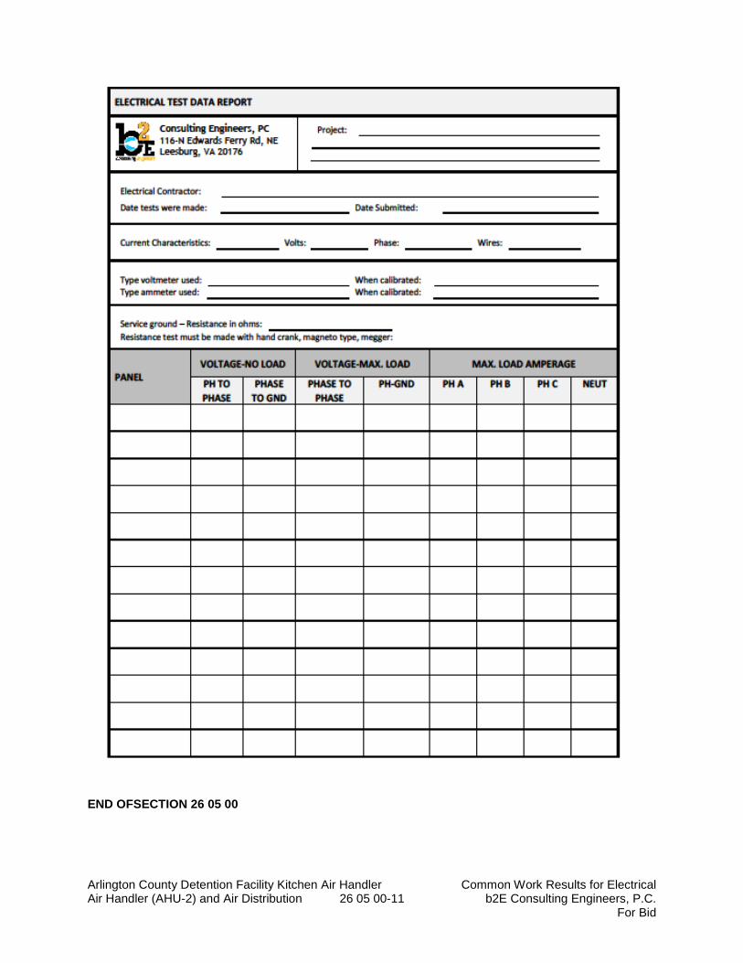
Arlington County Detention Facility Kitchen Air Handler Common Work Results for Electrical Air Handler (AHU-2) and Air Distribution 26 05 00-11 b2E Consulting Engineers, P.C.
For Bid
END OFSECTION 26 05 00
Arlington County Detention Facility Kitchen Air Handler Low-Voltage Electrical Power Air Handler (AHU-2) and Air Distribution Conductors and Cables 26 05 19-1 b2E Consulting Engineers, P.C
For Bid
SECTION 26 05 19
LOW-VOLTAGE ELECTRICAL POWER CONDUCTORS AND CABLES
PART 1 - GENERAL
1.1 SUMMARY
A. Section Includes:
1. Building wires and cables rated 600 V and less. 2. Connectors, splices, and terminations rated 600 V and less. 3. Sleeves and sleeve seals for cables.
1.2 DEFINITIONS
A. VFC: Variable frequency controller.
B. EPDM: Ethylene-propylene-diene terpolymer rubber.
C. NBR: Acrylonitrile-butadiene rubber.
D. RACEWAY: An enclosed channel of metal or nonmetallic materials designed expressly for holding wires or cables. Raceways include, but are not limited to, rigid metal conduit, intermediate metal conduit, liquidtight flexible conduit, and electrical metallic conduit.
1.3 SUBMITTALS
A. Product data: For each type of product indicated.
B. Qualification Data: For testing agency.
C. Field quality-control reports: From Contractor.
1.4 QUALITY ASSURANCE
A. Testing Agency Qualifications: An independent agency, with the experience and capability to conduct the testing indicated, that is a member company of the International Electrical Testing Association or is a nationally recognized testing laboratory (NRTL) as defined by OSHA in 29 CFR 1910.7, and that is acceptable to authorities having jurisdiction.
1. Testing Agency's Field Supervisor: Person currently certified by the International Electrical Testing Association or the National Institute for Certification in Engineering Technologies to supervise on-site testing specified in Part 3.
Arlington County Detention Facility Kitchen Air Handler Low-Voltage Electrical Power Air Handler (AHU-2) and Air Distribution Conductors and Cables 26 05 19-2 b2E Consulting Engineers, P.C
For Bid
B. Electrical Components, Devices, and Accessories: Listed and labeled as defined in NFPA 70, Article 100, by a testing agency acceptable to authorities having jurisdiction, and marked for intended use.
C. Comply with NFPA 70.
1.5 COORDINATION
A. Set sleeves in cast-in-place concrete, masonry walls, and other structural components as they are constructed.
B. Do not install more than three (3) current carrying conductors in any conduit.
C. Label each branch circuit conduit with panel board and circuit breaker number.
PART 2 - Comply with NFPA 70 PRODUCTS
2.1 CONDUCTORS AND CABLES
A. Acceptable Manufacturers: Subject to compliance with requirements, manufacturers offering products that may be incorporated into the Work include, but are not limited to the comparable product by one of the following:
1. Alcan Products Corporation; Alcan Cable Division. 2. Alpha Wire. 3. Belden Inc. 4. General Cable Technologies Corporation. 5. Senator Wire & Cable Company 6. Southwire Incorporated.
B. Copper Conductors: Comply with NEMA WC 70
C. Conductor Insulation: Comply with NEMA WC 70 for Type THHN, Type THWN, Type XHHW & Type SO. Insulation shall be color-coded entire length of conductor as indicated in section 26 05 53 “Identification for Electrical Systems.”
2.2 CONNECTORS AND SPLICES
A. Acceptable Manufacturers: Subject to compliance with requirements, manufacturers offering products that may be incorporated into the Work include, but are not limited, to the following: 1. AFC Cable Systems, Inc. 2. Hubbell Power Systems, Inc. 3. Ideal Industries, Inc. 4. O-Z/Gedney; a brand of the EGS Electrical Group. 5. 3-M; Electrical Markets Division. 6. Tyco Electronics.
B. Description: Factory-fabricated connectors and splices of size, capacity rating, material, type, and class for application and service indicated.

Arlington County Detention Facility Kitchen Air Handler Low-Voltage Electrical Power Air Handler (AHU-2) and Air Distribution Conductors and Cables 26 05 19-3 b2E Consulting Engineers, P.C
For Bid
2.3 SLEEVES FOR CABLES
A. Description: Modular sealing device, designed for field assembly, to fill annular space between sleeve and raceway or cable.
B. Acceptable Manufacturers: Subject to compliance with requirements, manufacturers offering products that may be incorporated into the Work include, but are not limited, to the following: 1. O-Z, Gedney: a brand of the EGS Electrical Group. 2. Spring City Electrical.
C. Steel Pipe Sleeves: ASTM A 53/A 53M, Type E, Grade B Schedule 40, galvanized steel, plain ends.
D. Sleeves for Rectangular Openings: Galvanized sheet metal with minimum 0.052- or 0.138-inch thickness as indicated and of length to suit application.
1. Sealing Elements: EPDM interlocking links shaped to fit surface of cable or conduit. Include type and number required for material and size of raceway or cable.
2. Pressure Plates: Stainless steel. Include two (2) for each sealing element. 3. Connecting Bolts and Nuts: Stainless steel of length required to secure pressure plates to
sealing elements. Include one for each sealing element.
E. Coordinated sleeve selection and application with selection and application of fire stopping specified
2.4 RATED WALL SEALS
A. Acceptable Manufacturers: Subject to compliance with requirements, manufacturers offering products that may be incorporated into the Work include, but are not limited, to the following:
1. Thomas & Betts “Flame Safe” Fire Stop System. 2. 3M Brand Fire Barrier Penetration Sealing System #7904. 3. 3M Brand Fire Barrier Caulk CP-25 and Putty-303.
2.5 SLEEVE SEALS
A. Acceptable Manufacturers: Subject to compliance with requirements, manufacturers offering products that may be incorporated into the Work include, but are not limited to, the following: 1. Advance Products & Systems, Inc. 2. Calpico, Inc. 3. Metraflex Co. 4. Pipeline Seal and Insulator, Inc.
B. Description: Modular sealing device, designed for field assembly, to fill annular space between sleeve and cable. 1. Sealing Elements: EPDM interlocking links shaped to fit surface of cable or conduit. Include
type and number required for material and size of raceway or cable. 2. Pressure Plates: Stainless steel. Include two (2) for each sealing element. 3. Connecting Bolts and Nuts: Stainless steel of length required to secure pressure plates to
sealing elements. Include one (1) for each sealing element.
Arlington County Detention Facility Kitchen Air Handler Low-Voltage Electrical Power Air Handler (AHU-2) and Air Distribution Conductors and Cables 26 05 19-4 b2E Consulting Engineers, P.C
For Bid
PART 3 - EXECUTION
3.1 CONDUCTOR MATERIAL APPLICATIONS
A. Feeders: All wire sizes indicated on the drawings are based upon the use of copper conductors rated at 75 degree C rated insulation. Terminals for all equipment shall be listed and labeled either 60/75C or 75C. Feeder schedule on drawings is based on copper conductors. Solid for No. 10 AWG and smaller; stranded for No. 8 AWG and larger.
B. Branch Circuits: Copper. Solid for No. 10 AWG and smaller; stranded for No. 8 AWG and larger.
C. Minimum size of Branch Circuit Wire shall be No. 12 AWG.
D. Maximum length for 12 AWG copper conductors for the following voltage.
1. 120V/1-phase: 50-feet, use 10 AWG for 51 to 75 feet. Use larger wire as required beyond 75-feet.
2. 208V, 3-phase, 3-wire: 110-feet maximum, use 10 AWG from 111-feet to 175 feet. Use larger wire size as required beyond 175-feet.
3. 120/208V, 3-phase, 4-wire: 110-feet maximum, use 10 AWG from 111 to 175 feet. Use larger wire size, as required beyond 175 feet.
4. 277V/1-phase: 125-feet, use to 10 AWG from 126 to 200 feet. Use larger wire size, as required beyond 200-feet.
5. 460V/3-phase, 3-wire 250-feet, use 10 AWG for 251 to 400 feet. Use larger wire size, as required beyond 400-feet.
6. 277V/460-volt, 3-phase, 4-wire: 250 feet, use 10 AWG for 251 to 400 feet. Use larger wire size, as required beyond 400-feet.
3.2 CONDUCTOR INSULATION APPLICATIONS AND WIRING METHODS
A. Exposed Feeders: Type THHN-THWN, single conductors in raceway.
B. Exposed Branch Circuits: Type THHN-THWN, single conductors in raceway.
C. Branch Circuits Concealed in Walls, and Partitions: Type THHN-THWN, single conductors in raceway.
D. Class 1 Control Circuits: Type THHN-THWN, in raceway.
E. Class 2 Control Circuits: Type THHN-THWN, in raceway; Power-limited tray cable in J-hook systems.
F. Multi-Conductor Cable: Not allowed.
3.3 INSTALLATION OF CONDUCTORS AND CABLES
A. Conceal cables in finished walls, unless otherwise indicated.
B. Complete raceway installation between conductor and cable termination points according to Section 26 05 33 “’Raceways and Boxes for Electrical Systems” prior to pulling conductors and cables.
Arlington County Detention Facility Kitchen Air Handler Low-Voltage Electrical Power Air Handler (AHU-2) and Air Distribution Conductors and Cables 26 05 19-5 b2E Consulting Engineers, P.C
For Bid
C. Use manufacturer-approved pulling compound or lubricant where necessary; compound used must not deteriorate conductor or insulation. Do not exceed manufacturer's recommended maximum pulling tensions and sidewall pressure values.
D. Use pulling means, including fish tape, cable, rope, and basket-weave wire/cable grips, that will not damage cables or raceway.
E. Install exposed cables parallel and perpendicular to surfaces of exposed structural members, and follow surface contours where possible.
F. Support cables according to Section 26 05 29 "Hangers and Supports for Electrical Systems."
G. Identify and color-code conductors and cables according to Division 26 Section 26 05 53 "Identification for Electrical Systems."
H. Do not install more than three (3) current carrying conductors in any one conduit.
I. Seal around cables penetrating fire-rated elements according to Division 7 Section “Firestopping”.
J. Identify and color-code conductors and cables according to Division 26 Section “Identification for Electrical Systems”.
K. All line to neutral branch circuits shall include a grounding conductor and a dedicated neutral.
L. Unless otherwise indicated, minimum conductor size shall be 12 AWG.
3.4 CONNECTIONS
A. Tighten electrical connectors and terminals according to manufacturer's published torque-tightening values. If manufacturer's torque values are not indicated, use those specified in UL 486A and UL 486B.
B. Make splices and taps that are compatible with conductor material and that possess equivalent or better mechanical strength and insulation ratings than un-spliced conductors.
C. Wiring at Outlets: Install conductor at each outlet, with at least 6-inches of slack.
3.5 SLEEVE INSTALLATION FOR ELECTRICAL PENETRATIONS
A. Coordinate sleeve selection and application with selection and application of firestopping specified in Division 07 Section "Penetration Firestopping."
B. Use pipe sleeves unless penetration arrangement requires rectangular sleeved opening.
C. Rectangular Sleeve Minimum Metal Thickness:
1. For sleeve rectangle perimeter less than 50 inches and no side greater than 16 inches, thickness shall be 0.052 inch.
2. For sleeve rectangle perimeter equal to, or greater than, 50 inches and 1 or more sides equal to, or greater than, 16 inches, thickness shall be 0.138 inch.
Arlington County Detention Facility Kitchen Air Handler Low-Voltage Electrical Power Air Handler (AHU-2) and Air Distribution Conductors and Cables 26 05 19-6 b2E Consulting Engineers, P.C
For Bid
D. Fire-Rated Assemblies: Install sleeves for penetrations of fire-rated floor and wall assemblies unless openings compatible with firestop system used are fabricated during construction of floor or wall.
E. Cut sleeves to length for mounting flush with both wall surfaces.
F. Size pipe sleeves to provide 1/4-inch annular clear space between sleeve and cable unless sleeve seal is to be installed.
G. Seal space outside of sleeves with grout for penetrations of concrete and masonry and with approved joint compound for gypsum board assemblies.
H. Interior Penetrations of Non-Fire-Rated Walls and Floors: Seal annular space between sleeve and cable, using joint sealant appropriate for size, depth, and location of joint according to Division 07 Section "Joint Sealants."
I. Fire-Rated-Assembly Penetrations: Maintain indicated fire rating of walls, partitions, ceilings, and floors at cable penetrations. Install sleeves and seal with firestop materials according to Division 07 Section "Penetration Firestopping."
J. Aboveground Exterior-Wall Penetrations: Seal penetrations using sleeves and mechanical sleeve seals. Size sleeves to allow for 1-inch annular clear space between pipe and sleeve for installing mechanical sleeve seals.
3.6 SLEEVE-SEAL INSTALLATION
A. Use type and number of sealing elements recommended by manufacturer for cable material and size. Position cable in center of sleeve. Assemble mechanical sleeve seals and install in annular space between cable and sleeve. Tighten bolts against pressure plates that cause sealing elements to expand and make watertight seal.
3.7 FIRESTOPPING
A. Apply firestopping to electrical penetrations of fire-rated floor and wall assemblies to restore original fire-resistance rating of assembly according to Division 07 Section "Penetration Firestopping."
3.8 FIELD QUALITY CONTROL
A. Testing Agency: Engage a qualified testing agency to perform tests and inspections and prepare test reports.
B. Perform tests and inspections and prepare test reports. Provide written test results to Engineer within 30-days of test completion.
C. Tests and Inspections:
1. After installing conductors and cables and before electrical circuitry has been energized, test service entrance and feeder conductors for compliance with requirements.
2. Perform each visual and mechanical inspection and electrical test stated in NETA Acceptance Testing Specification. Certify compliance with test parameters.
Arlington County Detention Facility Kitchen Air Handler Low-Voltage Electrical Power Air Handler (AHU-2) and Air Distribution Conductors and Cables 26 05 19-7 b2E Consulting Engineers, P.C
For Bid
3. Infrared Scanning: After Substantial Completion, but not more than 60 days after Final Acceptance, perform an infrared scan of each splice in cables and conductors No. 3 AWG and larger. Remove box and equipment covers so splices are accessible to portable scanner. Provide written test results to Engineer within 30-days of test completion.
a. Follow-up Infrared Scanning: Perform an additional follow-up infrared scan of each splice 11 months after date of Substantial Completion.
b. Instrument: Use an infrared scanning device designed to measure temperature or to detect significant deviations from normal values. Provide calibration record for device.
c. Record of Infrared Scanning: Prepare a certified report that identifies splices checked and that describes scanning results. Include notation of deficiencies detected, remedial action taken and observations after remedial action.
D. Test Reports: Prepare a written report to the Engineer to record the following:
1. Test procedures used. 2. Test results that comply with requirements. 3. Test results that do not comply with requirements and corrective action taken to achieve
compliance with requirements.
E. Cables will be considered defective if they do not pass tests and inspections.
F. Remove and replace malfunctioning units and retest as specified above.
END OF SECTION 26 05 19
Arlington County Detention Facility Kitchen Air Handler Control-Voltage Electrical Power Cables Air Handler (AHU-2) and Air Distribution 26 05 23-1 b2E Consulting Engineers, P.C.
For Bid
SECTION 26 05 23
CONTROL-VOLTAGE ELECTRICAL POWER CABLES
PART 1 - GENERAL
1.1 SUMMARY
A. Section Includes: 1. Low-voltage control cabling. 2. Control-circuit conductors. 3. Identification products.
B. Fire Alarm Wiring: Provide all fire alarm wiring in continuous EMT raceway system. 1. Partial conduit fire alarm systems not allowed.
1.2 DEFINITIONS
A. EMI: Electromagnetic interference.
B. IDC: Insulation displacement connector.
C. Low Voltage: As defined in NFPA 70 for circuits and equipment operating at less than 50 V or for remote-control and signaling power-limited circuits.
D. RCDD: Registered Communications Distribution Designer.
E. Raceway: An enclosed channel of metal or non-metallic materials designed expressly for holding wires or cables. Raceways include, but are not limited to, rigid metal conduit, rigid non-metallic conduit, intermediate metal conduit, liquid tight flexible conduit, electrical metallic conduit. 1. Cables such as MC, AC, or Greenfield are not raceways.
F. UTP: Unshielded Twisted Pair.
1.3 SUBMITTALS
A. Product Data: For each type of product indicated.
B. Shop Drawings: For cable tray layout, showing cable tray route to scale, with relationship between the tray and adjacent structural, electrical, and mechanical elements. Include the following:
1. Vertical and horizontal offsets and transitions. 2. Clearances for access above and to side of cable trays. 3. Vertical elevation of cable trays above the floor or bottom of ceiling structure. 4. Load calculations to show dead and live loads as not exceeding manufacturer's rating for
tray and its support elements.
C. Qualification Data: For qualified layout technician, installation supervisor, and field inspector.
Arlington County Detention Facility Kitchen Air Handler Control-Voltage Electrical Power Cables Air Handler (AHU-2) and Air Distribution 26 05 23-2 b2E Consulting Engineers, P.C.
For Bid
D. Source quality-control reports.
E. Field quality-control reports by contractor.
F. Maintenance Data: For wire and cable to include in maintenance manuals.
1.4 QUALITY ASSURANCE
A. Testing Agency Qualifications: Member company of an NRTL.
1. Testing Agency's Field Supervisor: Currently certified by BICSI as an RCDD to supervise on-site testing. Provide copy of certification with submittals.
B. Surface-Burning Characteristics: As determined by testing identical products according to ASTM E 84 by a qualified testing agency. Identify products with appropriate markings of applicable testing agency.
1. Flame-Spread Index: 25 or less. 2. Smoke-Developed Index: 50 or less.
C. Electrical Components, Devices, and Accessories: Listed and labeled as defined in NFPA 70, by a qualified testing agency, and marked for intended location and application.
1.5 DELIVERY, STORAGE, AND HANDLING
A. Test cables upon receipt at Project site.
1.6 PROJECT CONDITIONS
A. Environmental Limitations: Do not deliver or install low voltage control cables and connecting materials until wet work in spaces is complete and dry, and temporary HVAC system is operating and maintaining ambient temperature and humidity conditions at occupancy levels during the remainder of the construction period.
1.7 EXTRA MATERIALS
A. Furnish extra materials that match products installed that are packaged with protection covering for storage and identified with labels describing contents. 1. Connecting Blocks: Equal to 25% installed, but not fewer than five (5).
PART 2 - PRODUCTS
2.1 PATHWAYS
A. Conduit and Boxes: Comply with requirements in Division 26 Section "Raceway and Boxes for Electrical Systems."
1. Outlet boxes shall be no smaller than 2 inches wide, 3 inches high and 2-1/2 inches deep.
Arlington County Detention Facility Kitchen Air Handler Control-Voltage Electrical Power Cables Air Handler (AHU-2) and Air Distribution 26 05 23-3 b2E Consulting Engineers, P.C.
For Bid
2.2 LOW-VOLTAGE CONTROL CABLE
A. Plenum-Rated, Paired Cable: NFPA 70, Type CMP.
1. Two pair, twisted, No. 16 AWG, stranded (19x29) tinned-copper conductors. 2. PVC insulation. 3. Unshielded. 4. PVC jacket. 5. Flame Resistance: Comply with NFPA 262.
B. Plenum-Rated, Paired Cable: NFPA 70, Type CMP.
1. Two pair, twisted, No. 18 AWG, stranded (19x30) tinned-copper conductors. 2. Fluorinated ethylene propylene insulation. 3. Unshielded. 4. Plastic jacket. 5. Flame Resistance: NFPA 262, Flame Test.
2.3 CONTROL-CIRCUIT CONDUCTORS
A. Acceptable Manufacturers: Subject to compliance with requirements, manufacturers offering products that may be incorporated into the work include one of the following: 1. Encore Wire Corporation. 2. General Cable Technologies Corporation. 3. Southwire Company.
B. Class 2 Control Circuits: Stranded copper, Type THHN-THWN, in raceway, complying with UL 83.
C. Class 3 Remote-Control and Signal Circuits: Stranded copper, Type TW or Type TF, complying with UL 83.
2.4 IDENTIFICATION PRODUCTS
A. Manufacturers: Subject to compliance with requirements. Provide products by one of the following:
1. Brady Corporation. 2. HellermannTyton. 3. Kroy LLC. 4. Panduit Corp.
B. Comply with UL 969 for a system of labeling materials, including label stocks, laminating adhesives, and inks used by label printers.
C. Comply with requirements in Division 26 Section "Identification for Electrical Systems."
2.5 SOURCE QUALITY CONTROL
A. Testing Agency: Engage a qualified testing agency to evaluate cables.
B. Cable will be considered defective if it does not pass tests and inspections.

Arlington County Detention Facility Kitchen Air Handler Control-Voltage Electrical Power Cables Air Handler (AHU-2) and Air Distribution 26 05 23-4 b2E Consulting Engineers, P.C.
For Bid
C. Prepare test and inspection reports. Provide to engineer for review.
PART 3 - EXECUTION
3.1 INSTALLATION OF PATHWAYS
A. Comply with requirements in Division 26 Section 26 05 33 “Raceways and Boxes for Electrical Systems” for raceway selection and installation requirements for boxes, conduits, and wireways as supplemented or modified in this section.
1. Flexible metal conduit shall not be used.
B. Comply with requirements in Division 26 Section 26 05 33 "Raceway and Boxes for Electrical Systems" for installation of conduits and wireways.
3.2 INSTALLATION OF CONDUCTORS AND CABLES
A. Comply with NECA 1 and NFPA 70.
B. General Requirements for Cabling: 1. Terminate all conductors; no cable shall contain un-terminated elements. Make
terminations only at indicated outlets, terminals, and cross-connect and patch panels. 2. Cables may not be spliced. 3. Secure and support cables at intervals not exceeding 30 inches and not more than 6
inches from cabinets, boxes, fittings, outlets, racks, frames, and terminals. 4. Do not install bruised, kinked, scored, deformed, or abraded cable. Do not splice cable
between termination, tap, or junction points. Remove and discard cable if damaged during installation and replace it with new cable.
5. Cold-Weather Installation: Bring cable to room temperature before de-reeling. Do not use heat lamps for heating.
C. Installation of Control-Circuit Conductors:
1. Install wiring in raceways. Comply with requirements specified in Division 26 Section 26 05 33, "Raceway and Boxes for Electrical Systems."
D. Separation from EMI Sources:
1. Comply with BICSI TDMM and TIA/EIA-569-A recommendations for separating unshielded copper voice and data communication cable from potential EMI sources, including electrical power lines and equipment.
2. Separation between open communications cables or cables in nonmetallic raceways and unshielded power conductors and electrical equipment shall be as follows: a. Electrical Equipment Rating Less Than 2 kVA: A minimum of 5 inches. b. Electrical Equipment Rating between 2 and 5 kVA: A minimum of 12 inches. c. Electrical Equipment Rating More Than 5 kVA: A minimum of 24 inches.
3. Separation between communications cables in grounded metallic raceways and unshielded power lines or electrical equipment shall be as follows: a. Electrical Equipment Rating Less Than 2 kVA: A minimum of 2-1/2 inches. b. Electrical Equipment Rating between 2 and 5 kVA: A minimum of 6 inches. c. Electrical Equipment Rating More Than 5 kVA: A minimum of 12 inches.

Arlington County Detention Facility Kitchen Air Handler Control-Voltage Electrical Power Cables Air Handler (AHU-2) and Air Distribution 26 05 23-5 b2E Consulting Engineers, P.C.
For Bid
4. Separation between communications cables in grounded metallic raceways and power lines and electrical equipment located in grounded metallic conduits or enclosures shall be as follows: a. Electrical Equipment Rating Less Than 2 kVA: No requirement. b. Electrical Equipment Rating between 2 and 5 kVA: A minimum of 3 inches. c. Electrical Equipment Rating More Than 5 kVA: A minimum of 6 inches.
5. Separation between Cables and Electrical Motors and Transformers, 5 kVA or HP and Larger: A minimum of 48 inches.
6. Separation between Cables and Fluorescent Fixtures: A minimum of 5 inches.
E. Fire Alarm Wiring: Provide all fire alarm wiring in red EMT raceway for concealed and exposed conduit.
3.3 CONTROL-CIRCUIT CONDUCTORS
A. Minimum Conductor Sizes: 1. Class 1 remote-control and signal circuits, No. 14 AWG. 2. Class 2 low-energy, remote-control, and signal circuits, No. 16 AWG. 3. Class 3 low-energy, remote-control, alarm, and signal circuits, No. 12 AWG.
3.4 FIRESTOPPING
A. Apply firestopping to electrical penetrations of fire-rated floor and wall assemblies to restore original fire-resistance rating of assembly. Comply with requirements in Division 07 Section "Penetration Firestopping."
3.5 GROUNDING
A. For low-voltage wiring and cabling, comply with requirements in Division 26 Section 26 05 26, "Grounding and Bonding for Electrical Systems."
3.6 IDENTIFICATION
A. Comply with requirements for identification specified in Division 26 Section 26 05 53, "Identification for Electrical Systems."
3.7 FIELD QUALITY CONTROL
A. Testing Agency: Engage a qualified testing agency to perform tests and inspections.
B. End-to-end cabling will be considered defective if it does not pass tests and inspections.
C. Remove and replace malfunctioning units and retest if it does not pass tests and inspections.
D. Prepare test and inspection reports for review by the Engineer.
END OF SECTION 26 05 23
Arlington County Detention Facility Kitchen Air Handler Grounding and Bonding for Electrical Systems Air Handler (AHU-2) and Air Distribution 26 05 26-1 b2E Consulting Engineers, P.C.
For Bid
SECTION 26 05 26
GROUNDING AND BONDING FOR ELECTRICAL SYSTEMS
PART 1 - GENERAL
1.1 SUMMARY
A. This Section includes methods and materials for grounding systems and equipment, plus the following special application:
1.2 SUBMITTALS
A. Product Data: For each type of product indicated.
B. Other Informational Submittals: Plans showing dimensioned as-built locations of grounding features specified in Part 3 "Field Quality Control" Article, including the following: 1. Grounding arrangements and connections for separately derived systems. 2. Grounding for sensitive electronic equipment.
C. Qualification Data: For testing agency and testing agencies field supervisor.
D. Field quality-control test reports. Submit written test reports for review by the Engineer. 1. Test procedures used. 2. Test results that comply with requirements. 3. Results of failed tests and corrective action taken to achieve test results that comply with
requirements.
E. Operation and Maintenance Data: For grounding to include the following in emergency, operation, and maintenance manuals:
1. In addition to items specified in Section 01 70 00, “Project Closeout”.
2. Instructions for periodic testing and inspection of grounding features at test wells, ground rings, grounding connections for separately derived systems based on NFPA 70B.
a. Tests shall be to determine if ground resistance or impedance values remain within specified maximums, and instructions shall recommend corrective action if they do not.
b. Include recommended testing intervals.
1.3 QUALITY ASSURANCE
A. Testing Agency Qualifications: An independent agency, with the experience and capability to conduct the testing indicated, that is a member company of the International Electrical Testing Association or is a nationally recognized testing laboratory (NRTL) as defined by OSHA in 29 CFR 1910.7, and that is acceptable to authorities having jurisdiction.
1. Testing Agency's Field Supervisor: Person currently certified by the InterNational Electrical Testing Association to supervise on-site testing specified in Part 3.
Arlington County Detention Facility Kitchen Air Handler Grounding and Bonding for Electrical Systems Air Handler (AHU-2) and Air Distribution 26 05 26-2 b2E Consulting Engineers, P.C.
For Bid
B. Electrical Components, Devices, and Accessories: Listed and labeled as defined in NFPA 70, Article 100, by a testing agency acceptable to authorities having jurisdiction, and marked for intended use.
C. Comply with UL 467 for grounding and bonding materials and equipment.
PART 2 - PRODUCTS
2.1 Manufacturers: Subject to compliance with requirements, manufacturers offering products that may be incorporated into the Work include:
A. Burndy; Part of Hubbell Electrical Systems.
B. ERICO International Corporation.
C. O-Z/Gedney, A brand of the EGS Electrical Group.
2.2 SYSTEM DESCRIPTION
A. Electrical Components, Devices, and Accessories: Listed and labeled as defined in NFPA 70, by a qualified testing agency, and marked for intended location and application.
B. Comply with UL 467 for grounding and bonding materials and equipment.
2.3 CONDUCTORS
A. For Insulated Conductors: Copper wire or cable insulated for 600 V unless otherwise required by applicable Code or authorities having jurisdiction.
B. Bare Copper Conductors:
1. Solid Conductors: ASTM B 3. 2. Stranded Conductors: ASTM B 8. 3. Bonding Cable: 28 kcmil, 14 strands of No. 17 AWG conductor, 1/4 inch in diameter. 4. Bonding Conductor: No. 4 or No. 6 AWG, stranded conductor. 5. Bonding Jumper: Copper tape, braided conductors, terminated with copper ferrules; 1-
5/8 inches wide and 1/16 inch thick.
C. Grounding Bus: Predrilled Rectangular bars of annealed copper, 1/4 by 4 inches in cross section, with 9/32-inch holes spaced 1 1/8-inches apart. Stand-off isolators for mounting shall comply with UL 891 for use in switchboards, 600 V. Lexan or PVC, impulse tested at 5000 V.
D. Equipment Grounding Conductors: Insulated with green-colored insulation sized in accordance with 20014 NEC Table 250.122.
E. Isolated Ground Conductors: Insulated with green-colored insulation with yellow stripe. On feeders with isolated ground, use colored tape, alternating bands of green and yellow tape. Provide a minimum of three (3) bands of green and two (2) bands of yellow.
Arlington County Detention Facility Kitchen Air Handler Grounding and Bonding for Electrical Systems Air Handler (AHU-2) and Air Distribution 26 05 26-3 b2E Consulting Engineers, P.C.
For Bid
2.4 CONNECTORS
A. Listed and labeled by a nationally recognized testing laboratory (NRTL) acceptable to authorities having jurisdiction for applications in which used, and for specific types, sizes, and combinations of conductors and other items connected.
B. Bolted Connectors for Conductors and Pipes: Copper or copper alloy, bolted pressure-type, with at least two bolts.
1. Pipe Connectors: Clamp type, sized for pipe.
C. Welded Connectors: Exothermic-welding kits of types recommended by kit manufacturer for materials being joined and installation conditions.
D. Bus-bar Connectors: Mechanical type, cast silicone bronze, solderless compression type wire terminals, and long-barrel, two-bolt connection to ground bus.
PART 3 - EXECUTION
3.1 APPLICATIONS
A. Conductors: Install solid conductor for No. 8 AWG and smaller, and stranded conductors for No. 6 AWG and larger, unless otherwise indicated.
B. Conductor Terminations and Connections:
1. Pipe and Equipment Grounding Conductor Terminations: Bolted connectors. 2. Underground Connections: Welded connectors, except at test wells and as otherwise
indicated. 3. Connections to Structural Steel: Welded connectors.
3.2 EQUIPMENT GROUNDING
A. Install insulated equipment grounding conductors with all feeders and branch circuits.
B. Install insulated equipment grounding conductors with the following items, in addition to those required by NFPA 70:
1. Feeders and branch circuits. 2. Receptacle circuits. 3. Three-phase motor and appliance branch circuits. 4. Computer Electronic Equipment Circuits: Install insulated equipment grounding
conductor in branch-circuit runs from equipment-area power panels and power-distribution units.
5. Transformer primary and secondary feeders.
C. Heat-Tracing: Install a separate insulated equipment grounding conductor to each heat-tracing cable from the Heat Trace control panel. Bond conductor to heat trace panels, piping, connected equipment, and components.
Arlington County Detention Facility Kitchen Air Handler Grounding and Bonding for Electrical Systems Air Handler (AHU-2) and Air Distribution 26 05 26-4 b2E Consulting Engineers, P.C.
For Bid
D. Solids Separator: Install a separate insulated equipment ground conductor to the solid separator from the solids separator control panel. Bond conductor to the control panel, piping, connected equipment and components.
E. Signal and Communication Equipment: In addition to grounding and bonding required by NFPA 70, provide a separate grounding system complying with requirements in TIA/ATIS, J-STD-670-A.
1. For control data network, and other communication equipment, provide No. 2 AWG minimum insulated grounding conductor in raceway from grounding electrode system to each service location, terminal cabinet, wiring closet, and central equipment location.
2. ¼Terminal Cabinets: Terminate grounding conductor on cabinet grounding terminal.
F. Isolated Grounding Receptacle: Install an insulated equipment grounding connected to the receptacle grounding terminal. Isolate conductor from raceway and from panelboard grounding terminals. Terminate at equipment grounding terminal of the applicable derived system or service, unless otherwise indicated.
G. Power Transformers: Provide system ground to building steel and bonding conductor to nearest water line serving the area per NEC, or as scheduled, whichever is the larger conductor.
3.3 INSTALLATION
A. Grounding Conductors: Route along shortest and straightest paths possible, unless otherwise indicated or required by Code. Avoid obstructing access or placing conductors where they may be subjected to strain, impact, or damage.
B. Bonding Straps and Jumpers: Install in locations accessible for inspection and maintenance, except where routed through short lengths of conduit.
1. Bonding to Structure: Bond straps directly to basic structure, taking care not to penetrate any adjacent parts.
2. Bonding to Equipment Mounted on Vibration Isolation Hangers and Supports: Install so vibration is not transmitted to rigidly mounted equipment.
3. Use exothermic-welded connectors for outdoor locations, but if a disconnect-type connection is required, use a bolted clamp.
C. Grounding and Bonding for Piping:
1. Metal Water Service Pipe: Install insulated copper grounding conductors, in conduit, from building’s main service equipment, or grounding bus, to main metal water service entrances to building. Connect grounding conductors to main metal water service pipes, using a bolted clamp connector or by bolting a lug-type connector to a pipe flange, using one of the lug bolts of the flange. Where a dielectric main water fitting is installed, connect grounding conductor on street side of fitting. Bond metal grounding conductor conduit or sleeve to conductor at each end.
2. Water Meter Piping: Use braided-type bonding jumpers to electrically bypass water meters. Connect to pipe with a bolted connector.
D. Grounding for Steel Building Structure: Install a driven ground rod at base of each corner column and at intermediate exterior columns at distances not more than 60 feet apart.
E. Moisture Protection: If insulated conductors are connected to ground rods or grounding buses, insulate entire area of connection and seal against moisture penetration of insulation and cable.
Arlington County Detention Facility Kitchen Air Handler Grounding and Bonding for Electrical Systems Air Handler (AHU-2) and Air Distribution 26 05 26-5 b2E Consulting Engineers, P.C.
For Bid
3.4 CONNECTIONS
A. General: Make connections so galvanic action or electrolysis possibility is minimized. Select connectors, connection hardware, conductors, and connection methods so metals in direct contact will be galvanically compatible. 1. Use electroplated or hot-tin coated materials to ensure high conductivity and to make
contact points closer to order of galvanic series. 2. Make connections with clean, bare metal at points of contact. 3. Make aluminum-to-steel connections with stainless-steel separators and mechanical
clamps. 4. Make aluminum-to-galvanized steel connections with tin-plated copper jumpers and
mechanical clamps. 5. Coat and seal connections having dissimilar metals with inert material to prevent future
penetration of moisture to contact surfaces.
B. Exothermic-Welded Connections: Comply with manufacturer’s written instructions. Welds that are puffed up or that show convex surfaces indicating improper cleaning are not acceptable.
C. Equipment Grounding Conductor Terminations: For No. 8 AWG and larger, use pressure-type grounding lugs. No. 10 AWG and smaller grounding conductors may be terminated with winged pressure-type connectors.
D. Noncontact Metal Raceway Terminations: Ensure continuity of metallic raceway systems, boxes, and equipment. 1. Circuits Greater than 250V to Ground: If metallic raceways terminate at metal housings
without mechanical and electrical connection to housing, or where raceways connect to equipment or boxes with eccentric or concentric knockouts, terminate each conduit with a grounding bushing. Connect grounding bushings with a bare grounding conductor to grounding bus or terminal in housing. Bond electrically non-continuous conduits at entrances and exits with grounding bushings and bare grounding conductors, unless otherwise indicated.
E. Tighten screws and bolts for grounding and bonding connectors and terminals according to manufacturer’s published torque-tightening values. If manufacturer’s torque values are not indicated, use those specified in UL 486A.
F. Compression-Type Connections: Use hydraulic compression tools to provide correct circumferential pressure for compression connectors. Use tools and dies recommended by a connector manufacturer. Provide embossing die code or other standard method to make a visible indication that a connector has been adequately compressed on grounding conductor.
3.5 LABELING
A. Comply with requirements in Division 26, Section 26 05 53 “Identification for Electrical Systems” for instructional signs.
B. Install labels at telecommunications bonding conductor and grounding equalizer. 1. Label Text: “If this connector or cable is loose or must be removed for any reason, notify
the facility manager”.

Arlington County Detention Facility Kitchen Air Handler Grounding and Bonding for Electrical Systems Air Handler (AHU-2) and Air Distribution 26 05 26-6 b2E Consulting Engineers, P.C.
For Bid
3.6 FIELD QUALITY CONTROL
A. Testing Agency: Engage a qualified testing and inspecting agency to perform the following field tests and inspections and prepare test reports:
B. Manufacturers Field Services: Engage a factory-authorized service representative to inspect, test and adjust components, assemblies, and equipment installations, including connections.
C. Perform the following tests and inspections and prepare test reports:
1. After installing grounding system but before permanent electrical circuits have been energized, test for compliance with requirements.
2. Inspect and physical and mechanical conditions. Verify tightness of accessible, bolted, electrical connections with a calibrated torque wrench according to manufacturers written instructions.
3. Test completed grounding system at each location where a maximum ground-resistance level is specified, at service disconnect enclosure grounding terminal.
a. Measure ground resistance not less than two full days after last trace of precipitation and without soil being moistened by any means other than natural drainage or seepage and without chemical treatment or other artificial means of reducing natural ground resistance.
b. Perform tests by fall-of-potential method according to IEEE 81.
D. Grounding system shall be considered defective if it does not pass tests and inspections.
E. Report measured ground resistances that exceed the following values:
1. Power Equipment or System with Capacity 500 kVA and Less: 10 ohms. 2. Power Equipment or System with Capacity 500 to 1000 kVA: 5 ohms. 3. Power Equipment or System with Capacity More Than 1000 kVA: 3 ohms. 4. Power Distribution Units or Panelboards Serving Electronic Equipment: 1 ohm(s).
F. Excessive Ground Resistance: If resistance to ground exceeds specified values, notify Engineer promptly and include recommendations to reduce ground resistance.
END OF SECTION 26 05 26
Arlington County Justice Center Hangers and Supports for Electrical Systems Heating System Replacement 26 05 29-1 b2E Consulting Engineers, P.C.
For Bid
SECTION 26 05 29
HANGERS AND SUPPORTS FOR ELECTRICAL SYSTEMS
PART 1 - GENERAL
1.1 SUMMARY
A. This Section includes the following:
1. Hangers and supports for electrical equipment and systems. 2. Construction requirements for concrete bases.
1.2 DEFINITIONS
A. EMT: Electrical metallic tubing.
B. IMC: Intermediate metal conduit.
C. RMC: Rigid metal conduit.
1.3 PERFORMANCE REQUIREMENTS
A. Delegated Design: Design supports for multiple raceways, including comprehensive engineering analysis by a qualified professional engineer, using performance requirements and design criteria indicated.
B. Design supports for multiple raceways capable of supporting combined weight of supported systems and its contents.
C. Design equipment supports capable of supporting combined operating weight of supported equipment and connected systems and components.
D. Rated Strength: Adequate in tension, shear, and pullout force to resist maximum loads calculated or imposed for this Project, with a minimum structural safety factor of five times the applied force.
1.4 SUBMITTALS
A. Product Data: For the following:
1. Steel slotted support systems. 2. Nonmetallic slotted support systems.
B. Shop Drawings: Signed and sealed by a qualified professional engineer. Show fabrication and installation details and include calculations for the following:
1. Trapeze hangers. Include Product Data for components.
Arlington County Justice Center Hangers and Supports for Electrical Systems Heating System Replacement 26 05 29-2 b2E Consulting Engineers, P.C.
For Bid
2. Steel slotted channel systems. Include Product Data for components. 3. Nonmetallic slotted channel systems. Include Product Data for components. 4. Equipment supports.
C. Welding certificates.
1.5 QUALITY ASSURANCE
A. Welding: Qualify procedures and personnel according to AWS D1.1/D1.1M, "Structural Welding Code - Steel."
B. Comply with NFPA 70.
1.6 COORDINATION
A. Coordinate size and location of concrete bases. Cast anchor-bolt inserts into bases. Concrete, reinforcement, and formwork requirements are specified in Division 03.
B. Coordinate installation of roof curbs, equipment supports, and roof penetrations. These items are specified in Division 07 Section "Roof Accessories."
PART 2 - PRODUCTS
2.1 SUPPORT, ANCHORAGE, AND ATTACHMENT COMPONENTS
A. Steel Slotted Support Systems: Comply with MFMA-4, factory-fabricated components for field assembly.
1. Acceptable Manufacturers: Subject to compliance with requirements, manufacturers offering products that may be incorporated into the Work include, but are not limited to, the following:
a. Allied Tube & Conduit. b. Cooper B-Line, Inc.; a division of Cooper Industries. c. ERICO International Corporation. d. GS Metals Corp. e. Thomas & Betts Corporation. f. Unistrut; Tyco International, Ltd. g. Wesanco, Inc.
2. Metallic Coatings: Hot-dip galvanized after fabrication and applied according to MFMA-4. 3. Nonmetallic Coatings: Manufacturer's standard PVC, polyurethane, or polyester coating
applied according to MFMA-4. 4. Painted Coatings: Manufacturer's standard painted coating applied according to MFMA-
4. 5. Channel Dimensions: Selected for applicable load criteria.
B. Raceway Supports: As described in NECA 1 and NECA 101.
Arlington County Justice Center Hangers and Supports for Electrical Systems Heating System Replacement 26 05 29-3 b2E Consulting Engineers, P.C.
For Bid
C. Conduit Support Devices: Steel hangers, clamps, and associated fittings, designed for types and sizes of raceway or cable to be supported.
D. Support for Conductors in Vertical Conduit: Factory-fabricated assembly consisting of threaded body and insulating wedging plug or plugs for non-armored electrical conductors or cables in riser conduits. Plugs shall have number, size, and shape of conductor gripping pieces as required to suit individual conductors or cables supported. Body shall be malleable iron.
E. Structural Steel for Fabricated Supports and Restraints: ASTM A 36/A 36M, steel plates, shapes, and bars; black and galvanized.
F. Mounting, Anchoring, and Attachment Components: Items for fastening electrical items or their supports to building surfaces include the following:
1. Powder-Actuated Fasteners: Threaded-steel stud, for use in hardened portland cement concrete, steel, or wood, with tension, shear, and pullout capacities appropriate for supported loads and building materials where used. a. Acceptable Manufacturers: Subject to compliance with requirements, provide
products by one of the following:
1) Hilti Inc. 2) ITW Ramset/Red Head; a division of Illinois Tool Works, Inc. 3) MKT Fastening, LLC. 4) Simpson Strong-Tie Co., Inc.; Masterset Fastening Systems Unit.
2. Mechanical-Expansion Anchors: Insert-wedge-type, stainless steel, for use in hardened portland cement concrete with tension, shear, and pullout capacities appropriate for supported loads and building materials in which used.
a. Acceptable Manufacturers: Subject to compliance with requirements, provide products by one of the following:
1) Cooper B-Line, Inc.; a division of Cooper Industries. 2) Empire Tool and Manufacturing Co., Inc. 3) Hilti Inc. 4) ITW Ramset/Red Head; a division of Illinois Tool Works, Inc. 5) MKT Fastening, LLC.
3. Concrete Inserts: Steel or malleable-iron, slotted support system units similar to MSS Type 18; complying with MFMA-4 or MSS SP-58.
4. Clamps for Attachment to Steel Structural Elements: MSS SP-58, type suitable for attached structural element.
5. Through Bolts: Structural type, hex head, and high strength. Comply with ASTM A 325. 6. Toggle Bolts: All-steel springhead type. 7. Hanger Rods: Threaded steel.
2.2 FABRICATED METAL EQUIPMENT SUPPORT ASSEMBLIES
A. Description: Welded or bolted, structural-steel shapes, shop or field fabricated to fit dimensions of supported equipment.
B. Materials: Comply with requirements in Division 05 Section "Metal Fabrications" for steel shapes and plates.
Arlington County Justice Center Hangers and Supports for Electrical Systems Heating System Replacement 26 05 29-4 b2E Consulting Engineers, P.C.
For Bid
PART 3 - EXECUTION
3.1 APPLICATION
A. Comply with NECA 1 and NECA 101 for application of hangers and supports for electrical equipment and systems except if requirements in this Section are stricter.
B. Maximum Support Spacing and Minimum Hanger Rod Size for Raceway: Space supports for EMT, IMC, and RMC as required by NFPA 70. Minimum rod size shall be 1/4 inch in diameter.
C. Multiple Raceways or Cables: Install trapeze-type supports fabricated with steel slotted support system, sized so capacity can be increased by at least 25 percent in future without exceeding specified design load limits.
1. Secure raceways and cables to these supports with two-bolt conduit clamps.
D. Spring-steel clamps designed for supporting single conduits without bolts may be used for 1-1/2-inch and smaller raceways serving branch circuits and communication systems above suspended ceilings and for fastening raceways to trapeze supports.
3.2 SUPPORT INSTALLATION
A. Comply with NECA 1 and NECA 101 for installation requirements except as specified in this Article.
B. Raceway Support Methods: In addition to methods described in NECA 1, EMT, IMC, and RMC may be supported by openings through structure members, as permitted in NFPA 70.
C. Strength of Support Assemblies: Where not indicated, select sizes of components so strength will be adequate to carry present and future static loads within specified loading limits. Minimum static design load used for strength determination shall be weight of supported components plus 200 lb.
D. Mounting and Anchorage of Surface-Mounted Equipment and Components: Anchor and fasten electrical items and their supports to building structural elements by the following methods unless otherwise indicated by code: 1. To Masonry: Approved toggle-type bolts on hollow masonry units and expansion anchor
fasteners on solid masonry units. 2. To Concrete: Expansion anchor fasteners. 3. Instead of expansion anchors, powder-actuated driven threaded studs provided with lock
washers and nuts may be used in existing standard-weight concrete 4 inches thick or greater. Do not use for anchorage to lightweight-aggregate concrete or for slabs less than 4 inches thick.
4. To Steel: Beam clamps (MSS Type 19, 21, 23, 25, or 27) complying with MSS SP-69. 5. To Light Steel: Sheet metal screws. 6. Items Mounted on Hollow Walls and Nonstructural Building Surfaces: Mount cabinets,
panelboards, disconnect switches, control enclosures, pull and junction boxes, transformers, and other devices on slotted-channel racks attached to substrate by means that meet seismic-restraint strength and anchorage requirements.
E. Drill holes for expansion anchors in concrete at locations and to depths that avoid reinforcing bars.
Arlington County Justice Center Hangers and Supports for Electrical Systems Heating System Replacement 26 05 29-5 b2E Consulting Engineers, P.C.
For Bid
3.3 INSTALLATION OF FABRICATED METAL SUPPORTS
A. Comply with installation requirements in Division 05 Section "Metal Fabrications" for site-fabricated metal supports.
B. Cut, fit, and place miscellaneous metal supports accurately in location, alignment, and elevation to support and anchor electrical materials and equipment.
C. Field Welding: Comply with AWS D1.1/D1.1M.
3.4 CONCRETE BASES
A. Construct concrete bases of dimensions indicated but not less than 4 inches larger in both directions than supported unit, and so anchors will be a minimum of 10 bolt diameters from edge of the base.
B. Use 3500-psi, 28-day compressive-strength concrete. Provide samples for testing. Concrete materials, reinforcement, and placement requirements are specified in Division 03 Section "Cast-in-Place Concrete.”
C. Anchor equipment to concrete base.
1. Place and secure anchorage devices. Use supported equipment manufacturer's setting drawings, templates, diagrams, instructions, and directions furnished with items to be embedded.
2. Install anchor bolts to elevations required for proper attachment to supported equipment. 3. Install anchor bolts according to anchor-bolt manufacturer's written instructions.
3.5 PAINTING
A. Touchup: Clean field welds and abraded areas of shop paint. Paint exposed areas immediately after erecting hangers and supports. Use same materials as used for shop painting. Comply with SSPC-PA 1 requirements for touching up field-painted surfaces.
1. Apply paint by brush or spray to provide minimum dry film thickness of 2.0 mils.
B. Touchup: Comply with requirements in Division 09 painting Sections for cleaning and touchup painting of field welds, bolted connections, and abraded areas of shop paint on miscellaneous metal.
C. Galvanized Surfaces: Clean welds, bolted connections, and abraded areas and apply galvanizing-repair paint to comply with ASTM A 780.
END OF SECTION 26 05 29
Arlington County Detention Facility Kitchen Air Handler Raceway and Boxes for Electrical Systems Air Handler (AHU-2) and Air Distribution 26 05 33-1 b2E Consulting Engineers, P.C.
For Bid
SECTION 26 05 33
RACEWAY AND BOXES FOR ELECTRICAL SYSTEMS
PART 1 - GENERAL
1.1 SUMMARY
A. Section Includes: 1. Metal conduits, tubing and fittings. 2. Metal wireways and auxiliary gutters. 3. Boxes, enclosures, and cabinets.
1.2 DEFINITIONS
A. EMT: Electrical metallic tubing.
B. IMC: Intermediate metal conduit.
C. LFMC: Liquidtight flexible metal conduit.
D. RACEWAY: An enclosed channel of metal or non-metallic materials designed expressly for holding wires or cables. Raceways include, but are not limited to, rigid metal conduit, rigid non-metallic conduit, intermediate metal conduit, liquid tight flexible conduit and electrical metallic tubing. 1. Cables such as AC or Greenfield are not raceways.
E. RMC: Rigid metal conduit (Galvanized).
1.3 SUBMITTALS
A. Product Data: For surface raceways, wireways and fittings, floor boxes, hinged-cover enclosures, and cabinets.
B. Shop Drawings: For the following raceway components. Include plans, elevations, sections, details, and attachments to other work.
1. Custom enclosures and cabinets. 2. For handholes and boxes for underground wiring, including the following:
a. Frame and cover design. b. Grounding details. c. Joint details.
C. Coordination Drawings: Conduit routing plans, drawn to scale, on which the following items are shown and coordinated with each other, based on input from installers of the items involved:
1. Structural members in the paths of conduit groups with common supports. 2. HVAC and plumbing items and architectural features in the paths of conduit groups with
common supports.
Arlington County Detention Facility Kitchen Air Handler Raceway and Boxes for Electrical Systems Air Handler (AHU-2) and Air Distribution 26 05 33-2 b2E Consulting Engineers, P.C.
For Bid
D. Qualification Data: For professional engineer and testing agency.
E. Source quality-control test reports.
F. Samples for Initial Selection: For wireways and surface raceways with factory-applied textures and color finishes. Size 9-inches length of each material proposed.
1.4 QUALITY ASSURANCE
A. Electrical Components, Devices, and Accessories: Listed and labeled as defined in NFPA 70, Article 100, by a testing agency acceptable to authorities having jurisdiction, and marked for intended use.
B. Comply with NFPA 70.
PART 2 - PRODUCTS
2.1 METAL CONDUIT AND TUBING
A. Acceptable Manufacturers: Subject to compliance with requirements, provide products by one of the following:
1. AFC Cable Systems, Inc. 2. Allied Tube & Conduit; a Tyco International Ltd. Co. 3. O-Z Gedney; a unit of General Signal. 4. Wheatland Tube Company.
B. RMC Galvanized (Rigid Metal Conduit): ANSI C80.1.
C. IMC: ANSI C80.6.
D. EMT: ANSI C80.3.
E. LFMC: Flexible steel conduit with PVC jacket and complying with UL 360.
F. Fittings for Conduit (Including all Types and Flexible and Liquidtight), EMT: NEMA FB 1; listed for type and size raceway with which used, and for application and environment in which installed.
1. Fittings for EMT: Steel compression type. 2. Expansion Fittings: Steel to match conduit type complying with UL 651, rated for
environmental conditions where conduit installed and including flexible external bonding jumper.
G. Joint Compound for Rigid Metal Conduit or IMC: Listed, approved as defined in NFPA 70, by authorities having jurisdiction, for use in conduit assemblies and compounded for use to lubricate and protect threaded raceway joints from corrosion and enhance their conductivity.
Arlington County Detention Facility Kitchen Air Handler Raceway and Boxes for Electrical Systems Air Handler (AHU-2) and Air Distribution 26 05 33-3 b2E Consulting Engineers, P.C.
For Bid
2.2 METAL WIREWAYS
A. Acceptable Manufacturers: Subject to compliance with requirements, manufacturers offering products that may be incorporated into the Work include, but are not limited to, the following:
1. Cooper B-Line, Inc. 2. Hoffman. 3. Square D; Schneider Electric.
B. Description: Sheet metal sized and shaped as indicated, NEMA 250, Type 1R unless otherwise indicated.
1. Metal wireways installed outdoors shall be listed and labeled as defined in NFPA 70 by a qualified testing agency and marked for intended location and application.
C. Fittings and Accessories: Include couplings, offsets, elbows, expansion joints, adapters, hold-down straps, end caps, and other fittings to match and mate with wireways as required for complete system.
D. Wireway Covers: Hinged type unless otherwise indicated.
E. Finish: Manufacturer's standard enamel finish.
2.3 BOXES, ENCLOSURES, AND CABINETS
A. Acceptable Manufacturers: Subject to compliance with requirements, provide products by one of the following:
1. Cooper Crouse-Hinds; Div. of Cooper Industries, Inc. 2. Hoffman. 3. Killark Electric Manufacturing Co. Division. 4. RACO, Hubbell Inc. 5. Thomas & Betts Corporation. 6. Walker Systems, Inc.; Wiremold Company (The). 7. Woodhead, Daniel Company; Woodhead Industries, Inc. Subsidiary. 8. Wiremold©/Legrand
B. Sheet Metal Outlet and Device Boxes: Comply with NEMA OS 1 and UL 514A.
C. Cast-Metal Outlet and Device Boxes: Comply with NEMA FB 1, ferrous alloy, Type FD, with gasketed cover.
D. Small Sheet Metal Pull and Junction Boxes: NEMA OS 1.
E. Cast-Metal Access, Pull, and Junction Boxes: NEMA FB 1, galvanized, cast iron with gasketed cover.
F. Hinged-Cover Enclosures: NEMA 250, Type 1, with continuous-hinge cover with flush latch, unless otherwise indicated.
1. Metal Enclosures: Steel, finished inside and out with manufacturer's standard enamel.
G. Cabinets:
Arlington County Detention Facility Kitchen Air Handler Raceway and Boxes for Electrical Systems Air Handler (AHU-2) and Air Distribution 26 05 33-4 b2E Consulting Engineers, P.C.
For Bid
1. NEMA 250, Type 1, galvanized-steel box with removable interior panel and removable front, finished inside and out with manufacturer's standard enamel.
2. Hinged door in front cover with flush latch and concealed hinge. 3. Key latch to match panelboards. Provide twelve (12) sets of keys to Owner. 4. Metal barriers to separate wiring of different systems and voltage. 5. Accessory feet where required for freestanding equipment.
H. Small Sheet Metal Pull and Junction Boxes: NEMA OS 1.
2.4 SLEEVES FOR RACEWAYS
A. Steel Pipe Sleeves: ASTM A 53/A 53M, Type E, Grade B, Schedule 40, galvanized steel, plain ends.
B. Cast-Iron Pipe Sleeves: Cast or fabricated "wall pipe," equivalent to ductile-iron pressure pipe, with plain ends and integral waterstop, unless otherwise indicated.
C. Sleeves for Rectangular Openings: Galvanized sheet steel with minimum 0.052- or 0.138-inch thickness as indicated and of length to suit application.
D. Coordinate sleeve selection and application with selection and application of firestopping specified in Division 07 Section "Penetration Firestopping."
2.5 SLEEVE SEALS
A. Acceptable Manufacturers: Subject to compliance with requirements, provide products by one of the following:
1. Advance Products & Systems, Inc. 2. Calpico, Inc. 3. Metraflex Co. 4. Pipeline Seal and Insulator, Inc.
B. Description: Modular sealing device, designed for field assembly, to fill annular space between sleeve and cable.
1. Sealing Elements: EPDM interlocking links shaped to fit surface of cable or conduit. Include type and number required for material and size of raceway or cable.
2. Pressure Plates: Stainless steel. Include two for each sealing element. 3. Connecting Bolts and Nuts: Stainless steel of length required to secure pressure plates
to sealing elements. Include one for each sealing element.
PART 3 - EXECUTION
3.1 RACEWAY APPLICATION
A. Outdoors: Apply raceway products as specified below, unless otherwise indicated:
1. Exposed Conduit: Rigid Metal Conduit (RMC) or IMC. Provide galvanized conduit in outdoor or wet locations.
2. Concealed Conduit, Aboveground: RMC (Rigid Metal Conduit) or IMC.
Arlington County Detention Facility Kitchen Air Handler Raceway and Boxes for Electrical Systems Air Handler (AHU-2) and Air Distribution 26 05 33-5 b2E Consulting Engineers, P.C.
For Bid
3. Connection to Vibrating Equipment (Including Transformers and Hydraulic, Pneumatic, Electric Solenoid, or Motor-Driven Equipment): LFMC.
4. Boxes and Enclosures, Aboveground: NEMA 250, Type 3R.
B. Comply with the following indoor applications, unless otherwise indicated:
1. Exposed, Not Subject to Physical Damage: EMT. 2. Exposed, Not Subject to Severe Physical Damage: EMT. 3. Exposed and Subject to Severe Physical Damage: Rigid steel conduit (RMC) and IMC.
Includes raceways in the following locations: a. Penthouse Mechanical rooms. b. Corridors used for traffic of equipment. c. Outdoor Cooling Tower Enclosure. d. 90 degree elbows and vertical risers.
4. Concealed in Interior Walls and Partitions: EMT. 5. Connection to Vibrating Equipment (Including Transformers and Hydraulic, Pneumatic,
Electric Solenoid, or Motor-Driven Equipment): FMC, except use LFMC in damp or wet locations.
6. Damp or Wet Locations: IMC. 7. Boxes and Enclosures: NEMA 250, Type 1, except use NEMA 250, Type 4, stainless
steel , where UL listed for slab-on-grade use in damp or wet locations.
C. Minimum Raceway Size: 3/4-inch trade size.
D. Raceway Fittings: Compatible with raceways and suitable for use and location.
1. Rigid Metal Conduit (RMC) and Intermediate Metal Conduit (IMC): Use threaded rigid steel conduit fittings, unless otherwise indicated. Comply with NEMA FB 2.10.
2. Electrical Metallic Conduit (EMT): Compression type fittings with insulated throats.
Comply with NEMA FB 2.10.
3. Flexible Conduit: Use only fittings listed for use with flexible conduit. Comply with NEMA FB 2.10.
3.2 INSTALLATION
A. Comply with NECA 1 and NECA 101 for installation requirements applicable to products specified in Part 2 except where requirements on Drawings or in this Article are stricter. Comply with NFPA 70 limitations for types of raceways allowed in specific occupancies and number of floors.
B. Keep raceways at least 6 inches away from parallel runs of flues and steam or hot-water pipes. Install horizontal raceway runs above water and steam piping.
C. Complete raceway installation before starting conductor installation.
D. Support raceways as specified in Division 26 Section 26 05 29, “Hangers and Supports for Electrical Systems.”
E. Install no more than the equivalent of three 90-degree bends in any conduit run except for communications conduits, for which fewer bends are allowed. Provide pull or junction boxes where more than three (3) bends are needed.
Arlington County Detention Facility Kitchen Air Handler Raceway and Boxes for Electrical Systems Air Handler (AHU-2) and Air Distribution 26 05 33-6 b2E Consulting Engineers, P.C.
For Bid
F. Support conduit within 12-inches of enclosures to which attached.
G. Conceal conduit and EMT within finished walls.
H. Raceways Below Floor Slabs: 1. Arrange raceways to cross building expansion joints at right angles with expansion
fittings.
I. Threaded Conduit Joints, Exposed to Wet, Damp, Corrosive, or Outdoor Conditions: Apply listed compound to threads of raceway and fittings before making up joints. Follow compound manufacturer’s written instructions.
J. Raceway Terminations at Locations Subject to Moisture or Vibration: Use insulating bushings to protect conductors, including conductors smaller than No. 4 AWG.
K. Install pull wires in empty raceways. Use polypropylene or monofilament plastic line with not less than 200-lb tensile strength. Leave at least 12 inches of slack at each end of pull wire.
L. Install raceway sealing fittings at suitable, approved, and accessible locations and fill them with listed sealing compound. For concealed raceways, install each fitting in a flush steel box with a blank cover plate having a finish similar to that of adjacent plates or surfaces. Install raceway sealing fittings at the following points:
1. Where conduits pass from warm to cold locations, such as boundaries of refrigerated spaces.
2. Where otherwise required by NFPA 70.
M. Flexible Conduit Connections: Use maximum of 72 inches of flexible conduit for recessed and semi recessed lighting fixtures, equipment subject to vibration, noise transmission, or movement; and for transformers and motors.
1. Use LFMC in damp or wet locations.
N. Outlet Boxes for devices shown on drawings to be installed on opposite sides of same wall shall be separated horizontally by not less than 6-inches and if connected with each other, the ends of the raceway shall be filled with sound insulating material after wiring has been installed to fill the voids around the wire. For fire-rated walls, provide a minimum of 24-inches separation or use fire-rated assembly.
3.3 SLEEVE INSTALLATION FOR ELECTRICAL PENETRATIONS
A. Coordinate sleeve selection and application with selection and application of firestopping specified in Division 07 Section “Penetration Firestopping.”
B. Use pipe sleeves unless penetration arrangement requires rectangular sleeved opening.
C. Fire-Rated Assemblies: Install sleeves for penetrations of fire-rated floor and wall assemblies unless openings compatible with firestop system used are fabricated during construction of floor or wall.
D. Cut sleeves to length for mounting flush with both surfaces of walls.
E. Size pipe sleeves to provide 1/4-inch annular clear space between sleeve and raceway unless sleeve seal is to be installed or unless seismic criteria require different clearance.
Arlington County Detention Facility Kitchen Air Handler Raceway and Boxes for Electrical Systems Air Handler (AHU-2) and Air Distribution 26 05 33-7 b2E Consulting Engineers, P.C.
For Bid
F. Seal space outside of sleeves with grout for penetrations of concrete and masonry and with approved joint compound for gypsum board assemblies.
G. Interior Penetrations of Non-Fire-Rated Walls and Floors: Seal annular space between sleeve and raceway, using joint sealant appropriate for size, depth, and location of joint. Refer to Division 07 Section “Joint Sealants” for materials and installation.
H. Fire-Rated-Assembly Penetrations: Maintain indicated fire rating of walls, partitions, ceilings, and floors at raceway penetrations. Install sleeves and seal with firestop materials. Comply with Division 07 Section “Penetration Firestopping.”
I. Aboveground, Exterior-Wall Penetrations: Seal penetrations using sleeves and mechanical sleeve seals. Select sleeve size to allow for 1-inch annular clear space between pipe and sleeve for installing mechanical sleeve seals.
3.4 SLEEVE-SEAL INSTALLATION
A. Use type and number of sealing elements recommended by manufacturer for raceway material and size. Position raceway in center of sleeve. Assemble mechanical sleeve seals and install in annular space between raceway and sleeve. Tighten bolts against pressure plates that cause sealing elements to expand and make watertight seal.
3.5 FIRESTOPPING
A. Apply firestopping to electrical penetrations of fire-rated floor and wall assemblies to restore original fire-resistance rating of assembly. Firestopping materials and installation requirements are specified in Division 07 Section “Penetration Firestopping.”
3.6 PROTECTION
A. Provide final protection and maintain conditions that ensure coatings, finishes, and cabinets are without damage or deterioration at time of Substantial Completion.
1. Repair damage to galvanized finishes with zinc-rich paint recommended by manufacturer.
2. Repair damage to PVC or paint finishes with matching touchup coating recommended by manufacturer.
END OF SECTION 26 05 33
Arlington County Detention Facility Kitchen Air Handler Identification for Electrical Systems Air Handler (AHU-2) and Air Distribution 26 05 53-1 b2E Consulting Engineers, P.C.
For Bid
SECTION 26 05 53
IDENTIFICATION FOR ELECTRICAL SYSTEMS
PART 1 - GENERAL
1.1 SUMMARY
A. Section Includes:
1. Identification for raceways. 2. Identification of power and control cables. 3. Identification for conductors. 4. Warning labels and signs. 5. Instruction signs. 6. Equipment identification labels. 7. Miscellaneous identification products.
1.2 SUBMITTALS
A. Product Data: For each electrical identification product indicated.
B. Samples: For each type of label and sign to illustrate size, colors, lettering style, mounting provisions, and graphic features of identification products.
C. Identification Schedule: An index of nomenclature of electrical equipment and system components used in identification signs and labels.
1.3 QUALITY ASSURANCE
A. Comply with ANSI A13.1 and IEEE C2.
B. Comply with NFPA 70.
C. Comply with 29 CFR 1910.144 and 29 CFR 1910.145.
D. Comply with ANSI Z535.4 for safety signs and labels.
E. Adhesive-attached labeling materials, including label stocks, laminating adhesives, and inks used by label printers, shall comply with UL 969.
1.4 COORDINATION
A. Coordinate identification names, abbreviations, colors, and other features with requirements in other Sections requiring identification applications, Drawings, Shop Drawings, manufacturer's wiring diagrams, and the Operation and Maintenance Manual; and with those required by codes, standards, and 29 CFR 1910.145. Use consistent designations throughout Project.
Arlington County Detention Facility Kitchen Air Handler Identification for Electrical Systems Air Handler (AHU-2) and Air Distribution 26 05 53-2 b2E Consulting Engineers, P.C.
For Bid
B. Coordinate installation of identifying devices with completion of covering and painting of surfaces where devices are to be applied.
C. Coordinate installation of identifying devices with location of access panels and doors.
D. Install identifying devices before installing acoustical ceilings and similar concealment.
PART 2 - PRODUCTS
2.1 POWER RACEWAY IDENTIFICATION MATERIALS
A. Comply with ANSI A13.1 for minimum size of letters for legend and for minimum length of color field for each raceway size.
B. Colors for Raceways Carrying Circuits at 600 V or Less:
1. Black letters on an orange field. 2. Legend: Indicate voltage and system or service type.
C. Self-Adhesive Vinyl Labels for Raceways Carrying Circuits at 600 V or Less: Preprinted, flexible label laminated with a clear, weather- and chemical-resistant coating and matching wraparound adhesive tape for securing ends of legend label.
D. Snap-Around Labels for Raceways Carrying Circuits at 600 V or Less: Slit, pretensioned, flexible, preprinted, color-coded acrylic sleeve, with diameter sized to suit diameter of raceway or cable it identifies and to stay in place by gripping action.
E. Snap-Around, Color-Coding Bands for Raceways Carrying Circuits at 600 V or Less: Slit, pretensioned, flexible, solid-colored acrylic sleeve, 2 inches long, with diameter sized to suit diameter of raceway or cable it identifies and to stay in place by gripping action.
F. Metal Tags: Brass or aluminum, 2 by 2 by 0.05 inch, with stamped legend, punched for use with self-locking cable tie fastener.
G. Write-On Tags: Polyester tag, 0.015 inch thick, with corrosion-resistant grommet and cable tie for attachment to conductor or cable.
1. Marker for Tags: Machine-printed, permanent, waterproof, black ink marker recommended by printer manufacturer.
2.2 POWER AND CONTROL CABLE IDENTIFICATION MATERIALS
A. Comply with ANSI A13.1 for minimum size of letters for legend and for minimum length of color field for each raceway and cable size.
B. Self-Adhesive Vinyl Labels: Preprinted, flexible label laminated with a clear, weather- and chemical-resistant coating and matching wraparound adhesive tape for securing ends of legend label.
C. Metal Tags: Brass or aluminum, 2 by 2 by 0.05 inch, with stamped legend, punched for use with self-locking cable tie fastener.
Arlington County Detention Facility Kitchen Air Handler Identification for Electrical Systems Air Handler (AHU-2) and Air Distribution 26 05 53-3 b2E Consulting Engineers, P.C.
For Bid
D. Write-On Tags: Polyester tag, 0.010 inch or 0.015 inch thick, with corrosion-resistant grommet and cable tie for attachment to conductor or cable.
1. Marker for Tags: Machine-printed, permanent, waterproof, black ink marker
recommended by printer manufacturer.
E. Snap-Around Labels: Slit, pretensioned, flexible, preprinted, color-coded acrylic sleeve, with diameter sized to suit diameter of raceway or cable it identifies and to stay in place by gripping action.
F. Snap-Around, Color-Coding Bands: Slit, pretensioned, flexible, solid-colored acrylic sleeve, 2 inches long, with diameter sized to suit diameter of raceway or cable it identifies and to stay in place by gripping action.
2.3 CONDUCTOR IDENTIFICATION MATERIALS
A. Color-Coding Conductor Tape: Colored, self-adhesive vinyl tape not less than 3 mils thick by 1 to 2 inches wide.
B. Self-Adhesive Vinyl Labels: Preprinted, flexible label laminated with a clear, weather- and chemical-resistant coating and matching wraparound adhesive tape for securing ends of legend label.
C. Snap-Around Labels: Slit, pretensioned, flexible, preprinted, color-coded acrylic sleeve, with diameter sized to suit diameter of raceway or cable it identifies and to stay in place by gripping action.
D. Snap-Around, Color-Coding Bands: Slit, pretensioned, flexible, solid-colored acrylic sleeve, 2 inches long, with diameter sized to suit diameter of raceway or cable it identifies and to stay in place by gripping action.
E. Marker Tapes: Vinyl or vinyl-cloth, self-adhesive wraparound type, with circuit identification legend machine printed by thermal transfer or equivalent process.
F. Write-On Tags: Polyester tag, 0.010 inch or 0.015 inch thick, with corrosion-resistant grommet and cable tie for attachment to conductor or cable. 1. Marker for Tags: Machine-printed, permanent, waterproof, black ink marker
recommended by printer manufacturer.
2.4 FLOOR MARKING TAPE
A. 2-inch- wide, 5-mil pressure-sensitive vinyl tape, with black and white stripes and clear vinyl overlay.
2.5 WARNING LABELS AND SIGNS
A. Comply with NFPA 70 and 29 CFR 1910.145.
B. Baked-Enamel Warning Signs:
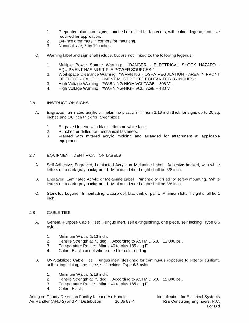
Arlington County Detention Facility Kitchen Air Handler Identification for Electrical Systems Air Handler (AHU-2) and Air Distribution 26 05 53-4 b2E Consulting Engineers, P.C.
For Bid
1. Preprinted aluminum signs, punched or drilled for fasteners, with colors, legend, and size required for application.
2. 1/4-inch grommets in corners for mounting. 3. Nominal size, 7 by 10 inches.
C. Warning label and sign shall include, but are not limited to, the following legends:
1. Multiple Power Source Warning: "DANGER - ELECTRICAL SHOCK HAZARD - EQUIPMENT HAS MULTIPLE POWER SOURCES."
2. Workspace Clearance Warning: "WARNING - OSHA REGULATION - AREA IN FRONT OF ELECTRICAL EQUIPMENT MUST BE KEPT CLEAR FOR 36 INCHES."
3. High Voltage Warning: “WARNING-HIGH VOLTAGE – 208 V”. 4. High Voltage Warning: “WARNING-HIGH VOLTAGE – 480 V”.
2.6 INSTRUCTION SIGNS
A. Engraved, laminated acrylic or melamine plastic, minimum 1/16 inch thick for signs up to 20 sq. inches and 1/8 inch thick for larger sizes.
1. Engraved legend with black letters on white face. 2. Punched or drilled for mechanical fasteners. 3. Framed with mitered acrylic molding and arranged for attachment at applicable
equipment.
2.7 EQUIPMENT IDENTIFICATION LABELS
A. Self-Adhesive, Engraved, Laminated Acrylic or Melamine Label: Adhesive backed, with white letters on a dark-gray background. Minimum letter height shall be 3/8 inch.
B. Engraved, Laminated Acrylic or Melamine Label: Punched or drilled for screw mounting. White letters on a dark-gray background. Minimum letter height shall be 3/8 inch.
C. Stenciled Legend: In nonfading, waterproof, black ink or paint. Minimum letter height shall be 1 inch.
2.8 CABLE TIES
A. General-Purpose Cable Ties: Fungus inert, self extinguishing, one piece, self locking, Type 6/6 nylon.
1. Minimum Width: 3/16 inch. 2. Tensile Strength at 73 deg F, According to ASTM D 638: 12,000 psi. 3. Temperature Range: Minus 40 to plus 185 deg F. 4. Color: Black except where used for color-coding.
B. UV-Stabilized Cable Ties: Fungus inert, designed for continuous exposure to exterior sunlight, self extinguishing, one piece, self locking, Type 6/6 nylon.
1. Minimum Width: 3/16 inch. 2. Tensile Strength at 73 deg F, According to ASTM D 638: 12,000 psi. 3. Temperature Range: Minus 40 to plus 185 deg F. 4. Color: Black.
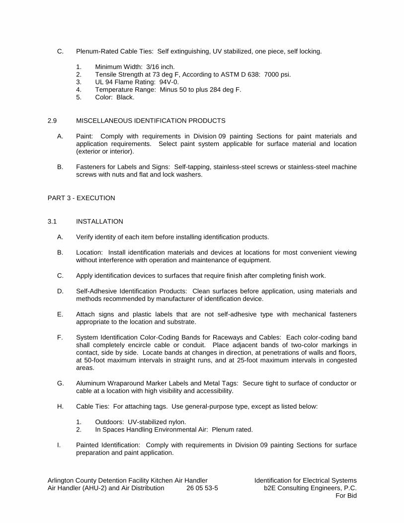
Arlington County Detention Facility Kitchen Air Handler Identification for Electrical Systems Air Handler (AHU-2) and Air Distribution 26 05 53-5 b2E Consulting Engineers, P.C.
For Bid
C. Plenum-Rated Cable Ties: Self extinguishing, UV stabilized, one piece, self locking.
1. Minimum Width: 3/16 inch. 2. Tensile Strength at 73 deg F, According to ASTM D 638: 7000 psi. 3. UL 94 Flame Rating: 94V-0. 4. Temperature Range: Minus 50 to plus 284 deg F. 5. Color: Black.
2.9 MISCELLANEOUS IDENTIFICATION PRODUCTS
A. Paint: Comply with requirements in Division 09 painting Sections for paint materials and application requirements. Select paint system applicable for surface material and location (exterior or interior).
B. Fasteners for Labels and Signs: Self-tapping, stainless-steel screws or stainless-steel machine screws with nuts and flat and lock washers.
PART 3 - EXECUTION
3.1 INSTALLATION
A. Verify identity of each item before installing identification products.
B. Location: Install identification materials and devices at locations for most convenient viewing without interference with operation and maintenance of equipment.
C. Apply identification devices to surfaces that require finish after completing finish work.
D. Self-Adhesive Identification Products: Clean surfaces before application, using materials and methods recommended by manufacturer of identification device.
E. Attach signs and plastic labels that are not self-adhesive type with mechanical fasteners appropriate to the location and substrate.
F. System Identification Color-Coding Bands for Raceways and Cables: Each color-coding band shall completely encircle cable or conduit. Place adjacent bands of two-color markings in contact, side by side. Locate bands at changes in direction, at penetrations of walls and floors, at 50-foot maximum intervals in straight runs, and at 25-foot maximum intervals in congested areas.
G. Aluminum Wraparound Marker Labels and Metal Tags: Secure tight to surface of conductor or cable at a location with high visibility and accessibility.
H. Cable Ties: For attaching tags. Use general-purpose type, except as listed below:
1. Outdoors: UV-stabilized nylon. 2. In Spaces Handling Environmental Air: Plenum rated.
I. Painted Identification: Comply with requirements in Division 09 painting Sections for surface preparation and paint application.
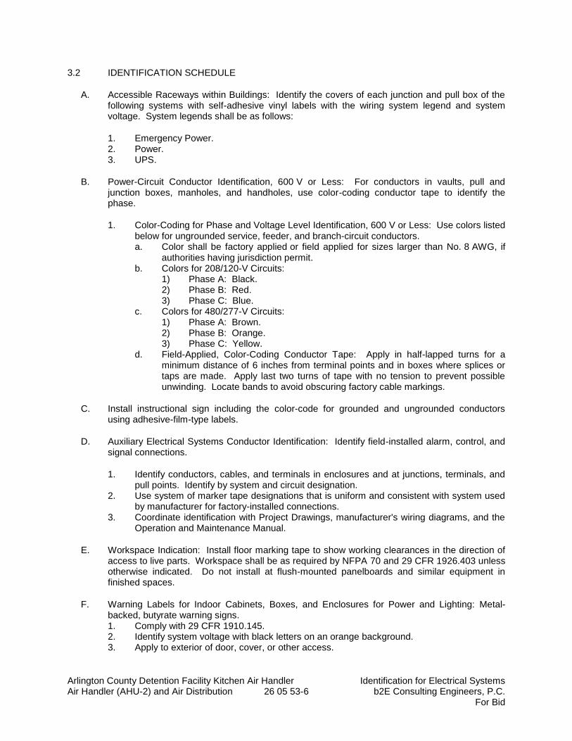
Arlington County Detention Facility Kitchen Air Handler Identification for Electrical Systems Air Handler (AHU-2) and Air Distribution 26 05 53-6 b2E Consulting Engineers, P.C.
For Bid
3.2 IDENTIFICATION SCHEDULE
A. Accessible Raceways within Buildings: Identify the covers of each junction and pull box of the following systems with self-adhesive vinyl labels with the wiring system legend and system voltage. System legends shall be as follows:
1. Emergency Power. 2. Power. 3. UPS.
B. Power-Circuit Conductor Identification, 600 V or Less: For conductors in vaults, pull and junction boxes, manholes, and handholes, use color-coding conductor tape to identify the phase.
1. Color-Coding for Phase and Voltage Level Identification, 600 V or Less: Use colors listed below for ungrounded service, feeder, and branch-circuit conductors. a. Color shall be factory applied or field applied for sizes larger than No. 8 AWG, if
authorities having jurisdiction permit. b. Colors for 208/120-V Circuits:
1) Phase A: Black. 2) Phase B: Red. 3) Phase C: Blue.
c. Colors for 480/277-V Circuits: 1) Phase A: Brown. 2) Phase B: Orange. 3) Phase C: Yellow.
d. Field-Applied, Color-Coding Conductor Tape: Apply in half-lapped turns for a minimum distance of 6 inches from terminal points and in boxes where splices or taps are made. Apply last two turns of tape with no tension to prevent possible unwinding. Locate bands to avoid obscuring factory cable markings.
C. Install instructional sign including the color-code for grounded and ungrounded conductors using adhesive-film-type labels.
D. Auxiliary Electrical Systems Conductor Identification: Identify field-installed alarm, control, and signal connections.
1. Identify conductors, cables, and terminals in enclosures and at junctions, terminals, and pull points. Identify by system and circuit designation.
2. Use system of marker tape designations that is uniform and consistent with system used by manufacturer for factory-installed connections.
3. Coordinate identification with Project Drawings, manufacturer's wiring diagrams, and the Operation and Maintenance Manual.
E. Workspace Indication: Install floor marking tape to show working clearances in the direction of access to live parts. Workspace shall be as required by NFPA 70 and 29 CFR 1926.403 unless otherwise indicated. Do not install at flush-mounted panelboards and similar equipment in finished spaces.
F. Warning Labels for Indoor Cabinets, Boxes, and Enclosures for Power and Lighting: Metal-backed, butyrate warning signs. 1. Comply with 29 CFR 1910.145. 2. Identify system voltage with black letters on an orange background. 3. Apply to exterior of door, cover, or other access.

Arlington County Detention Facility Kitchen Air Handler Identification for Electrical Systems Air Handler (AHU-2) and Air Distribution 26 05 53-7 b2E Consulting Engineers, P.C.
For Bid
4. For equipment with multiple power or control sources, apply to door or cover of equipment including, but not limited to, the following: a. Power transfer switches. b. Controls with external control power connections.
G. Operating Instruction Signs: Install instruction signs to facilitate proper operation and maintenance of electrical systems and items to which they connect. Install instruction signs with approved legend where instructions are needed for system or equipment operation.
H. Emergency Operating Instruction Signs: Install instruction signs with white legend on a red background with minimum 3/8-inch- high letters for emergency instructions at equipment used for power transfer, load shedding.
I. Equipment Identification Labels: On each unit of equipment, install unique designation label that is consistent with wiring diagrams, schedules, and the Operation and Maintenance Manual. Apply labels to disconnect switches and protection equipment, central or master units, control panels, control stations, terminal cabinets, and racks of each system. Systems include power, lighting, control, communication, signal, monitoring, and alarm systems unless equipment is provided with its own identification.
1. Labeling Instructions: a. Indoor Equipment: Engraved, laminated acrylic or melamine label. Unless
otherwise indicated, provide a single line of text with 1/2-inch- high letters on 1-1/2-inch- high label; where two lines of text are required, use labels 2 inches high.
b. Outdoor Equipment: Engraved, laminated acrylic or melamine label. c. Elevated Components: Increase sizes of labels and letters to those appropriate for
viewing from the floor. d. Unless provided with self-adhesive means of attachment, fasten labels with
appropriate mechanical fasteners that do not change the NEMA or NRTL rating of the enclosure.
2. Equipment to Be Labeled: a. Panelboards: Typewritten directory of circuits in the location provided by
panelboard manufacturer. Panelboard identification shall be engraved, laminated acrylic or melamine label.
b. Enclosures and electrical cabinets. c. Access doors and panels for concealed electrical items. d. New circuit breakers in existing gear. e. Transformers: Label that includes tag designation shown on Drawings for the
transformer, feeder, and panelboards or equipment supplied by the secondary. f. Emergency system boxes and enclosures. g. Enclosed switches. h. Enclosed circuit breakers. i. Enclosed controllers. j. Variable-speed controllers. k. Push-button stations. l. Contactors. m. Remote-controlled switches, dimmer modules, and control devices. n. Monitoring and control equipment. o. UPS equipment.
END OF SECTION 26 05 53
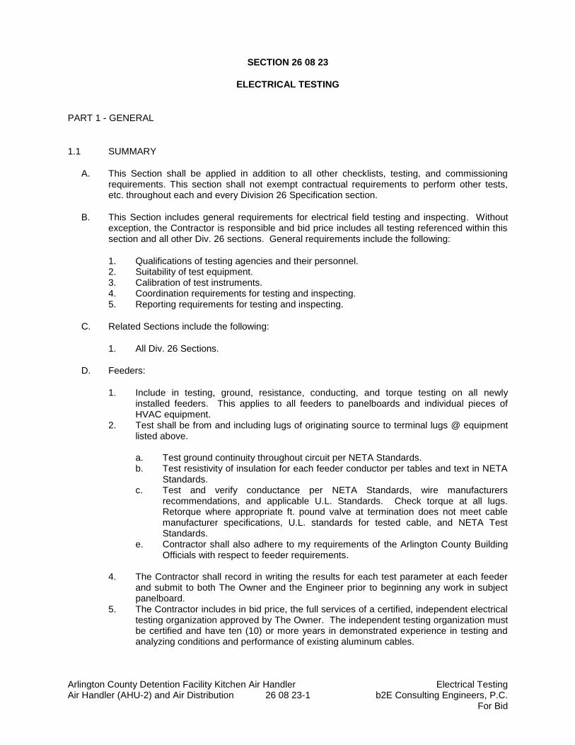
Arlington County Detention Facility Kitchen Air Handler Electrical Testing Air Handler (AHU-2) and Air Distribution 26 08 23-1 b2E Consulting Engineers, P.C.
For Bid
SECTION 26 08 23
ELECTRICAL TESTING
PART 1 - GENERAL
1.1 SUMMARY
A. This Section shall be applied in addition to all other checklists, testing, and commissioning requirements. This section shall not exempt contractual requirements to perform other tests, etc. throughout each and every Division 26 Specification section.
B. This Section includes general requirements for electrical field testing and inspecting. Without exception, the Contractor is responsible and bid price includes all testing referenced within this section and all other Div. 26 sections. General requirements include the following:
1. Qualifications of testing agencies and their personnel. 2. Suitability of test equipment. 3. Calibration of test instruments. 4. Coordination requirements for testing and inspecting. 5. Reporting requirements for testing and inspecting.
C. Related Sections include the following:
1. All Div. 26 Sections.
D. Feeders:
1. Include in testing, ground, resistance, conducting, and torque testing on all newly installed feeders. This applies to all feeders to panelboards and individual pieces of HVAC equipment.
2. Test shall be from and including lugs of originating source to terminal lugs @ equipment listed above.
a. Test ground continuity throughout circuit per NETA Standards. b. Test resistivity of insulation for each feeder conductor per tables and text in NETA
Standards. c. Test and verify conductance per NETA Standards, wire manufacturers
recommendations, and applicable U.L. Standards. Check torque at all lugs. Retorque where appropriate ft. pound valve at termination does not meet cable manufacturer specifications, U.L. standards for tested cable, and NETA Test Standards.
e. Contractor shall also adhere to my requirements of the Arlington County Building Officials with respect to feeder requirements.
4. The Contractor shall record in writing the results for each test parameter at each feeder
and submit to both The Owner and the Engineer prior to beginning any work in subject panelboard.
5. The Contractor includes in bid price, the full services of a certified, independent electrical testing organization approved by The Owner. The independent testing organization must be certified and have ten (10) or more years in demonstrated experience in testing and analyzing conditions and performance of existing aluminum cables.
Arlington County Detention Facility Kitchen Air Handler Electrical Testing Air Handler (AHU-2) and Air Distribution 26 08 23-2 b2E Consulting Engineers, P.C.
For Bid
6. Voltage Drop: Calculate, then measure the voltage drop at all feeders from the switchboard through the system to each panelboard.
a. Where large equipment is connected, measure the voltage drop to the equipment at full load.
1.2 QUALITY ASSURANCE
A. Testing Agency Qualifications: As specified in each Section containing electrical testing requirements and in subparagraph and associated subparagraph below.
1. Independent Testing Agencies: Independent of manufacturers, suppliers, and installers of components to be tested or inspected.
a. Testing Agency's Field Supervisor for Power Component Testing: Person currently certified by the InterNational Electrical Testing Association or the National Institute for Certification in Engineering Technologies to supervise on-site testing specified in Division 26 power component Sections.
B. Test Equipment Suitability: Comply with NETA ATS, Section 5.2.
C. Test Equipment Calibration: Comply with NETA ATS, Section 5.3.
PART 2 - NOT USED
PART 3 - EXECUTION
3.1 GENERAL TESTS AND INSPECTIONS
A. If a group of tests are specified to be performed by an independent testing agency, prepare systems, equipment, and components for tests and inspections, and perform preliminary tests to ensure that systems, equipment, and components are ready for independent agency testing. Include the following minimum preparations as appropriate:
1. Perform insulation-resistance tests. 2. Perform continuity tests. 3. Perform rotation test (for motors to be tested). 4. Provide a stable source of single-phase, 208/120-V electrical power for test
instrumentation at each test location.
B. Test and Inspection Reports: In addition to requirements specified elsewhere, report the following:
1. Manufacturer's written testing and inspecting instructions. 2. Calibration and adjustment settings of adjustable and interchangeable devices involved in
tests. 3. Tabulation of expected measurement results made before measurements. 4. Tabulation of "as-found" and "as-left" measurement and observation results. 5. Tabulate the calculated and measured voltage drop to each panelboard and large
equipment.
END OF SECTION 26 08 23
Arlington County Detention Facility Kitchen Air Handler Low-Voltage Transformers b2E Consulting Engineers, P.C.
26 22 00 - 1 For Bid
SECTION 26 2200
LOW-VOLTAGE TRANSFORMERS
PART 1 - GENERAL
1.1 SUMMARY
A. This Section includes the following types of dry-type transformers rated 600 V and less, with capacities up to 1000 kVA:
1. Distribution transformers.
1.2 SUBMITTALS
A. Product Data: Include rated nameplate data, capacities, weights, dimensions, minimum clearances, installed devices and features, and performance for each type and size of transformer indicated.
B. Shop Drawings: Detail equipment assemblies and indicate dimensions, weights, loads, required clearances, method of field assembly, components, and location and size of each field connection.
1. Wiring Diagrams: Power, signal, and control wiring.
C. Qualification Data: For testing agency.
D. Source quality-control test reports.
E. Field quality-control test reports.
F. Operation and Maintenance Data: For transformers to include in emergency, operation, and maintenance manuals.
1.3 QUALITY ASSURANCE
A. Testing Agency Qualifications: An independent agency, with the experience and capability to conduct the testing indicated, that is a nationally recognized testing laboratory (NRTL) as defined by OSHA in 29 CFR 1910.7, and that is acceptable to the authorities having jurisdiction.
1. Testing Agency’s Field Supervisor: Person currently certified by the InterNational Electrical Testing Association or the National Institute for Certification in Engineering Technologies to supervise on-site testing specified in Part 3.
B. Source Limitations: Obtain each transformer type through one source from a single manufacturer.
C. Electrical Components, Devices, and Accessories: Listed and labeled as defined in NFPA 70, Article 100, by a testing agency acceptable to authorities having jurisdiction, and marked for intended use.
Arlington County Detention Facility Kitchen Air Handler Low-Voltage Transformers b2E Consulting Engineers, P.C.
26 22 00 - 2 For Bid
D. Comply with IEEE C57.12.91, "Test Code for Dry-Type Distribution and Power Transformers."
1.4 DELIVERY, STORAGE, AND HANDLING
A. Temporary Heating: Apply temporary heat according to manufacturer's written instructions within the enclosure of each ventilated-type unit, throughout periods during which equipment is not energized and when transformer is not in a space that is continuously under normal control of temperature and humidity.
1.5 COORDINATION
A. Coordinate size and location of concrete bases with actual transformer provided. Cast anchor-bolt inserts into bases. Concrete, reinforcement, and formwork requirements are specified in Division 03.
B. Coordinate installation of wall-mounting and structure-hanging supports with actual transformer provided.
1.6 Warranty
A. The transformer shall carry a 2 year warranty.
PART 2 - PRODUCTS
2.1 MANUFACTURERS
A. Acceptable Manufacturers: Subject to compliance with requirements. Provide products by one of the manufacturer’s listed.
1. Eaton Electrical Inc.; Cutler-Hammer Products. 2. General Electric Company. 3. Siemens Energy & Automation, Inc. 4. Square D; a brand of Schneider Electric.
2.2 GENERAL TRANSFORMER REQUIREMENTS
A. Description: Factory-assembled and -tested, air-cooled units for 60-Hz service.
B. Cores: Grain-oriented, non-aging silicon steel.
C. Coils: Continuous windings without splices except for taps.
1. Internal Coil Connections: Brazed or pressure type. 2. Coil Material: Copper.
2.3 DISTRIBUTION TRANSFORMERS
A. Comply with NEMA ST 20, and list and label as complying with UL 1561.
Arlington County Detention Facility Kitchen Air Handler Low-Voltage Transformers b2E Consulting Engineers, P.C.
26 22 00 - 3 For Bid
B. Cores: One leg per phase.
C. Enclosure: Ventilated, NEMA 250, Type 2.
1. Core and coil shall be encapsulated within resin compound, sealing out moisture and air.
D. Transformer Enclosure Finish: Comply with NEMA 250.
1. Finish Color: ANSI 49 Gray; over corrosion resistant pretreatment and primer.
E. Taps for Transformers Smaller Than 3 kVA: One 5 percent tap above and one 5 percent below normal full capacity.
F. Taps for Transformers 7.5 to 24 kVA: One 5 percent tap above and one 5 percent tap below normal full capacity.
G. Taps for Transformers 25 kVA and Larger: Two 2.5 percent taps above and two 2.5 percent taps below normal full capacity.
H. Insulation Class: 220 deg C, UL-component-recognized insulation system with a maximum of 80 deg C rise above 40 deg C ambient temperature.
I. Energy Efficiency for Transformers Rated 15 kVA and Larger:
1. Complying with NEMA TP 1, Class 1 efficiency levels. 2. Tested according to NEMA TP 2.
J. Electrostatic Shielding: Each winding shall have an independent, single, full-width copper electrostatic shield arranged to minimize interwinding capacitance.
1. Arrange coil leads and terminal strips to minimize capacitive coupling between input and output terminals.
2. Include special terminal for grounding the shield. 3. Shield Effectiveness:
a. Capacitance between Primary and Secondary Windings: Not to exceed 33 picofarads over a frequency range of 20 Hz to 1 MHz.
b. Common-Mode Noise Attenuation: Minimum of minus 120 dBA at 0.5 to 1.5 kHz; minimum of minus 65 dBA at 1.5 to 100 kHz.
c. Normal-Mode Noise Attenuation: Minimum of minus 52 dBA at 1.5 to 10 kHz.
K. Wall Brackets: Manufacturer's standard brackets.
L. Fungus Proofing; Permanent fungicidal treatment for coil and core.
M. Low-Sound-Level Requirements: Minimum of 3 dBA less than NEMA ST 20 standard sound levels when factory tested according to IEEE C57.12.91.
N. Low-Sound-Level Requirements: Maximum sound levels, when factory tested according to IEEE C57.12.91, as follows:
1. 9kVA and Less: 34 dBa 2. 30 to 50 kVA: 39 dBa 3. 51 to 150 kVA: 44 dBa 4. 151 to 300 kVA: 49 dBa 5. 301 to 500 kVA: 54dBa
Arlington County Detention Facility Kitchen Air Handler Low-Voltage Transformers b2E Consulting Engineers, P.C.
26 22 00 - 4 For Bid
2.4 IDENTIFICATION DEVICES
A. Nameplates: Engraved, laminated-plastic or metal nameplate for each distribution transformer, mounted with corrosion-resistant screws. Nameplates and label products are specified in Section 260553 "Identification for Electrical Systems."
B. Identify transformers and install warning signs according to Section 26 05 53 “Identification for Electrical Systems.”
2.5 SOURCE QUALITY CONTROL
A. Test and inspect transformers according to IEEE C57.12.91.
B. Factory Sound-Level Tests: Conduct sound-level tests on equipment for this Project.
PART 3 - EXECUTION
3.1 EXAMINATION
A. Examine conditions for compliance with enclosure- and ambient-temperature requirements for each transformer.
B. Verify that field measurements are as needed to maintain working clearances required by NFPA 70 and manufacturer's written instructions.
C. Examine walls, floors, roofs, and concrete bases for suitable mounting conditions where transformers will be installed.
D. Verify that ground connections are in place and requirements in Section 26 05 26 "Grounding and Bonding for Electrical Systems" have been met. Maximum ground resistance shall be 5 ohms at location of transformer.
E. Proceed with installation only after unsatisfactory conditions have been corrected.
3.2 INSTALLATION
A. Install wall-mounting transformers level and plumb with wall brackets fabricated by transformer manufacturer.
B. Arrange equipment to provide adequate spacing for access and for air circulation for cooling.
C. Check for damage and loose connections.
D. Construct concrete bases and anchor floor-mounting transformers according to manufacturer's written instructions and requirements in Section 260529 “Hangers and Supports for Electrical Systems.”
E. Prior to energizing transformer, verify secondary voltages and if necessary adjust primary taps.
Arlington County Detention Facility Kitchen Air Handler Low-Voltage Transformers b2E Consulting Engineers, P.C.
26 22 00 - 5 For Bid
3.3 CONNECTIONS
A. Ground equipment according to Section 26 05 26 "Grounding and Bonding for Electrical Systems."
B. Connect wiring according to Section 26 05 19 "Low-Voltage Electrical Power Conductors and Cables."
C. Install wiring connections to transformer in flexible conduit.
D. Tighten electrical connections and terminals to manufacturer’s published torque tightening values. Where manufacturer’s values are not furnished use those specified in UL 486A and UL 486B.
3.4 FIELD QUALITY CONTROL
A. Testing Agency: Engage a qualified testing agency to perform tests and inspections and prepare test reports.
B. Manufacturer's Field Service: Engage a factory-authorized service representative to inspect, test, and adjust components, assemblies, and equipment installations, including connections. Report results in writing to Engineer.
C. Perform tests and inspections and prepare test reports.
1. Manufacturer's Field Service: Engage a factory-authorized service representative to inspect components, assemblies, and equipment installations, including connections, and to assist in testing.
D. Tests and Inspections:
1. Perform each visual and mechanical inspection and electrical test stated in NETA Acceptance Testing Specification. Certify compliance with test parameters.
E. Remove and replace units that do not pass tests or inspections and retest as specified above.
F. Infrared Scanning: Two months after Substantial Completion, perform an infrared scan of transformer connections.
1. Use an infrared-scanning device designed to measure temperature or detect significant deviations from normal values. Provide documentation of device calibration.
2. Prepare a certified report identifying each transformer checked and describing results of scanning, including color scan images with temperature scale of each unit. For units found not operating within manufacturer’s guidelines, include notation of deficiencies detected, remedial action taken, and scanning observations after remedial action demonstrating nominal operation.
3. Perform two follow-up infrared scans of transformers, one at 4 months and the other at 11 months after Substantial Completion. Take remedial actions to leave each unit operating with manufacture recommendation parameters. Provide a report per item D-2 above..
G. Test Labeling: On completion of satisfactory testing of each unit, attach a dated and signed "Satisfactory Test" label to tested component.
Arlington County Detention Facility Kitchen Air Handler Low-Voltage Transformers b2E Consulting Engineers, P.C.
26 22 00 - 6 For Bid
3.5 ADJUSTING
A. Record transformer secondary voltage at each unit for at least 48 hours of typical occupancy period. Adjust transformer taps to provide optimum voltage conditions at secondary terminals. Optimum is defined as not exceeding nameplate voltage plus 10 percent and not being lower than nameplate voltage minus 3 percent at maximum load conditions. Submit recording and tap settings as test results.
B. Connect buck-boost transformers to provide nameplate voltage of equipment being served, plus or minus 5 percent, at secondary terminals.
C. Output Settings Report: Prepare a written report recording output voltages and tap settings.
3.6 CLEANING
A. On completion of installation, inspect components. Remove paint splatters and other spots, dirt and debris. Repair scratches and mars on finish to match original finish. Clean components internally using methods and materials recommended by manufacturer.
B. Vacuum dirt and debris; do not use compressed air to assist in cleaning..
END OF SECTION 26 22 00

Arlington County Detention Facility Kitchen Air Handler Panelboards Air Handler (AHU-2) and Air Distribution 26 24 16-1 b2E Consulting Engineers, P.C.
For Bid
SECTION 26 24 16
PANELBOARDS
PART 1 - GENERAL
1.1 SUMMARY
A. Section Includes:
1. Distribution panelboards.
1.2 DEFINITIONS
A. SVR: Suppressed voltage rating.
1.3 SUBMITTALS
A. Product Data: For each type of panelboard, switching and overcurrent protective device, transient voltage suppression device, accessory, and component indicated. Include dimensions and manufacturers' technical data on features, performance, electrical characteristics, ratings, and finishes.
B. Shop Drawings: For each panelboard and related equipment.
1. Include dimensioned plans, elevations, sections, and details. Show tabulations of installed devices, equipment features, and ratings.
2. Detail enclosure types and details for types other than NEMA 250, Type 1. 3. Detail bus configuration, current, and voltage ratings. 4. Short-circuit current rating of panelboards and overcurrent protective devices. 5. Include evidence of NRTL listing for series rating of installed devices. 6. Detail features, characteristics, ratings, and factory settings of individual overcurrent
protective devices and auxiliary components. 7. Include wiring diagrams for power, signal, and control wiring.
C. Qualification Data: For qualified testing agency.
D. Field Quality-Control Reports:
1. Test procedures used. 2. Test results that comply with requirements. 3. Results of failed tests and corrective action taken to achieve test results that comply with
requirements.
E. Panelboard Schedules: For installation in panelboards. Submit final versions after load balancing.
F. Operation and Maintenance Data: For panelboards and components to include in emergency, operation, and maintenance manuals. In addition to items specified in Division 01 Section "Operation and Maintenance Data," include the following:
Arlington County Detention Facility Kitchen Air Handler Panelboards Air Handler (AHU-2) and Air Distribution 26 24 16-2 b2E Consulting Engineers, P.C.
For Bid
1. Manufacturer's written instructions for testing and adjusting overcurrent protective devices.
2. Time-current curves, including selectable ranges for each type of overcurrent protective device that allows adjustments.
1.4 QUALITY ASSURANCE
A. Testing Agency Qualifications: Member Company of NETA or an NRTL.
1. Testing Agency's Field Supervisor: Currently certified by NETA to supervise on-site testing.
B. Source Limitations: Obtain panelboards, overcurrent protective devices, components, and accessories from single source from single manufacturer.
C. Product Selection for Restricted Space: Drawings indicate maximum dimensions for panelboards including clearances between panelboards and adjacent surfaces and other items. Comply with indicated maximum dimensions.
D. Electrical Components, Devices, and Accessories: Listed and labeled as defined in NFPA 70, by a qualified testing agency, and marked for intended location and application.
E. Comply with NEMA PB 1.
F. Comply with NFPA 70.
1.5 DELIVERY, STORAGE, AND HANDLING
A. Remove loose packing and flammable materials from inside panelboards; install temporary electric heating (250 W per panelboard) to prevent condensation.
B. Handle and prepare panelboards for installation according to NECA 407.
1.6 PROJECT CONDITIONS
A. Environmental Limitations:
1. Do not deliver or install panelboards until spaces are enclosed and weathertight, wet work in spaces is complete and dry, work above panelboards is complete, and temporary HVAC system is operating and maintaining ambient temperature and humidity conditions at occupancy levels during the remainder of the construction period.
2. Rate equipment for continuous operation under the following conditions unless otherwise indicated:
a. Ambient Temperature: Not exceeding minus 22 deg F to plus 104 deg F. b. Altitude: Not exceeding 6600 feet.
1.7 COORDINATION
A. Coordinate layout and installation of panelboards and components with other construction that penetrates walls or is supported by them, including electrical and other types of equipment,
Arlington County Detention Facility Kitchen Air Handler Panelboards Air Handler (AHU-2) and Air Distribution 26 24 16-3 b2E Consulting Engineers, P.C.
For Bid
raceways, piping, encumbrances to workspace clearance requirements, and adjacent surfaces. Maintain required workspace clearances and required clearances for equipment access doors and panels.
B. Coordinate sizes and locations of concrete bases with actual equipment provided. Cast anchor-bolt inserts into bases. Concrete, reinforcement, and formwork requirements are specified in Division 03.
1.8 WARRANTY
A. Special Warranty: Manufacturer's standard form in which manufacturer agrees to repair or replace transient voltage suppression devices that fail in materials or workmanship within specified warranty period.
1. Warranty Period: Five years from date of Substantial Completion.
1.9 EXTRA MATERIALS
A. Furnish extra materials that match products installed and that are packaged with protective covering for storage and identified with labels describing contents.
1. Keys: Two spares for each type of panelboard cabinet lock. 2. Circuit Breakers Including GFCI and Ground Fault Equipment Protection (GFEP) Types:
Two spares for each panelboard.
PART 2 - PRODUCTS
2.1 GENERAL REQUIREMENTS FOR PANELBOARDS
A. Enclosures: Flush- and surface-mounted cabinets.
1. Rated for environmental conditions at installed location.
a. Indoor Dry and Clean Locations: NEMA 250, Type 1. b. Other Wet or Damp Indoor Locations: NEMA 250, Type 4.
2. Hinged Front Cover: Entire front trim hinged to box and with standard door within hinged trim cover.
3. Finishes:
a. Panels and Trim: Steel, factory finished immediately after cleaning and pretreating with manufacturer's standard two-coat, baked-on finish consisting of prime coat and thermosetting topcoat.
b. Back Boxes: Galvanized steel.
4. Directory Card: Inside panelboard door, mounted in transparent card holder.
B. Incoming Mains Location: Top and bottom.
C. Phase, Neutral, and Ground Buses:
Arlington County Detention Facility Kitchen Air Handler Panelboards Air Handler (AHU-2) and Air Distribution 26 24 16-4 b2E Consulting Engineers, P.C.
For Bid
1. Material: Hard-drawn copper, 98 percent conductivity. 2. Equipment Ground Bus: Adequate for feeder and branch-circuit equipment grounding
conductors; bonded to box.
D. Conductor Connectors: Suitable for use with conductor material and sizes.
1. Material: Hard-drawn copper, 98 percent conductivity. 2. Main and Neutral Lugs: Mechanical type. 3. Ground Lugs and Bus-Configured Terminators: Mechanical type. 4. Feed-Through Lugs: Compression type, suitable for use with conductor material. Locate
at opposite end of bus from incoming lugs or main device. 5. Subfeed (Double) Lugs: Mechanical type suitable for use with conductor material. Locate
at same end of bus as incoming lugs or main device.
E. Future Devices: Mounting brackets, bus connections, filler plates, and necessary appurtenances required for future installation of devices.
F. Panelboard Short Circuit Current Rating: Fully rated to 65,000 AIC interrupt symmetrical short-
circuit current as indicated below or greater as is available at terminals.
1. Full-rated for connected system with integral or remote upstream overcurrent protective devices and labeled by an NRTL. Include size and type of allowable upstream and branch devices, listed and labeled for series-connected short-circuit rating by an NRTL. a. Provide minimum KAIC fault current interrupt based on the study for all panels,
panelboards and other applicable gear provided for this project. b. Bidding: The Contractor shall bid the following: KAIC fault current interrupt
ratings. Provide credit to Owner where rating is reduced. 1) 480/277V Distribution Boards: 65,000 KAIC. 2) 480/277V Panelboards: 35,000 KAIC. 3) 208/120V Panelboards: 22,000 KAIC.
2.2 DISTRIBUTION PANELBOARDS
A. Acceptable Manufacturers: Subject to compliance with requirements, provide products by one of the following:
1. Basis of Design: Siemens Energy & Automation, Inc. 2. General Electric Company; GE Consumer & Industrial - Electrical Distribution. 3. Eaton Electrical Inc., Cutler Hammer Business Unit.
B. Panelboards: NEMA PB 1, power and feeder distribution type.
C. Doors: Secured with vault-type latch with tumbler lock; keyed alike.
1. For doors more than 36 inches high, provide two latches, keyed alike.
D. Mains: Circuit breaker or Lugs as indicated on the drawings.
E. Branch Overcurrent Protective Devices for Circuit-Breaker Frame Sizes 125 A and Smaller: Bolt-on circuit breakers.
F. Branch Overcurrent Protective Devices for Circuit-Breaker Frame Sizes Larger than 125 A: Bolt-on circuit breakers; plug-in circuit breakers where individual positive locking device requires mechanical release for removal.
Arlington County Detention Facility Kitchen Air Handler Panelboards Air Handler (AHU-2) and Air Distribution 26 24 16-5 b2E Consulting Engineers, P.C.
For Bid
2.3 APPLIANCE BRANCH-CIRCUIT PANELBOARDS
A. Acceptable Manufacturers: Subject to compliance with requirements, provide products by one of the following:
1. General Electric Company; GE Consumer & Industrial - Electrical Distribution. 2. Siemens Energy & Automation, Inc. 3. Eaton Electrical Inc., Cutler Hammer Business Unit.
B. Panelboards: NEMA PB 1, lighting and appliance branch-circuit type.
C. Mains: Circuit breaker or lugs only.
D. Branch Overcurrent Protective Devices: Bolt-on circuit breakers, replaceable without disturbing adjacent units.
E. Doors: Concealed hinges; secured with flush latch with tumbler lock; keyed alike.
2.4 DISCONNECTING AND OVERCURRENT PROTECTIVE DEVICES
A. Acceptable Manufacturers: Subject to compliance with requirements, provide products by one of the following:
1. General Electric Company; GE Consumer & Industrial - Electrical Distribution. 2. Siemens Energy & Automation, Inc. 3. Eaton Electric Inc., Cutler Hammer Business Unit.
B. Molded-Case Circuit Breaker (MCCB): Comply with UL 489, with interrupting capacity to meet available fault currents.
1. Thermal-Magnetic Circuit Breakers: Inverse time-current element for low-level overloads, and instantaneous magnetic trip element for short circuits. Adjustable magnetic trip setting for circuit-breaker frame sizes 250 A and larger.
2. Adjustable Instantaneous-Trip Circuit Breakers: Magnetic trip element with front-mounted, field-adjustable trip setting.
3. Electronic trip circuit breakers with rms sensing; field-replaceable rating plug or field-replicable electronic trip; and the following field-adjustable settings:
a. Instantaneous trip. b. Long- and short-time pickup levels. c. Long- and short-time time adjustments. d. Ground-fault pickup level, time delay, and I
2t response.
4. Current-Limiting Circuit Breakers: Frame sizes 400 A and smaller; let-through ratings less than NEMA FU 1, RK-5.
5. GFCI Circuit Breakers: Single- and two-pole configurations with Class A ground-fault protection (6-mA trip).
6. Ground-Fault Equipment Protection (GFEP) Circuit Breakers: Class B ground-fault protection (30-mA trip).
7. Molded-Case Circuit-Breaker (MCCB) Features and Accessories:
a. Standard frame sizes, trip ratings, and number of poles. b. Lugs: Mechanical style, suitable for number, size, trip ratings, and conductor
materials.
Arlington County Detention Facility Kitchen Air Handler Panelboards Air Handler (AHU-2) and Air Distribution 26 24 16-6 b2E Consulting Engineers, P.C.
For Bid
c. Application Listing: Appropriate for application; Type SWD for switching fluorescent lighting loads; Type HID for feeding fluorescent and high-intensity discharge (HID) lighting circuits.
d. Ground-Fault Protection: Integrally mounted relay and trip unit with adjustable pickup and time-delay settings, push-to-test feature, and ground-fault indicator.
e. Shunt Trip: 120-V trip coil energized from separate circuit, set to trip at 55 percent of rated voltage.
f. Handle Padlocking Device: Fixed attachment, for locking circuit-breaker handle in on or off position.
g. Handle Clamp: Loose attachment, for holding circuit-breaker handle in on position.
2.5 ACCESSORY COMPONENTS AND FEATURES
A. Accessory Set: Include tools and miscellaneous items required for overcurrent protective device test, inspection, maintenance, and operation.
B. Portable Test Set: For testing functions of solid-state trip devices without removing from panelboard. Include relay and meter test plugs suitable for testing panelboard meters and switchboard class relays.
PART 3 - EXECUTION
3.1 EXAMINATION
A. Receive, inspect, handle, and store panelboards according to NECA 407.
B. Examine panelboards before installation. Reject panelboards that are damaged or rusted or have been subjected to water saturation.
C. Examine elements and surfaces to receive panelboards for compliance with installation tolerances and other conditions affecting performance of the Work.
D. Proceed with installation only after unsatisfactory conditions have been corrected.
3.2 INSTALLATION
A. Install panelboards and accessories according to NECA 407.
B. Equipment Mounting: Install panelboards on concrete bases, 4-inch nominal thickness. Comply with requirements for concrete base specified in Division 03 Section "Cast-in-Place Concrete."
1. Install dowel rods to connect concrete base to concrete floor. Unless otherwise indicated, install dowel rods on 18-inch centers around full perimeter of base.
2. For panelboards, install epoxy-coated anchor bolts that extend through concrete base and anchor into structural concrete floor.
3. Place and secure anchorage devices. Use setting drawings, templates, diagrams, instructions, and directions furnished with items to be embedded.
4. Install anchor bolts to elevations required for proper attachment to panelboards. 5. Attach panelboard to the vertical finished or structural surface behind the panelboard.

Arlington County Detention Facility Kitchen Air Handler Panelboards Air Handler (AHU-2) and Air Distribution 26 24 16-7 b2E Consulting Engineers, P.C.
For Bid
C. Temporary Lifting Provisions: Remove temporary lifting eyes, channels, and brackets and temporary blocking of moving parts from panelboards.
D. Mount top of trim 90 inches above finished floor unless otherwise indicated.
E. Mount panelboard cabinet plumb and rigid without distortion of box. Mount recessed panelboards with fronts uniformly flush with wall finish and mating with back box.
F. Install overcurrent protective devices and controllers not already factory installed.
1. Set field-adjustable, circuit-breaker trip ranges.
G. Install filler plates in unused spaces.
H. Stub four 1-inch empty conduits from panelboard into accessible ceiling space or space designated to be ceiling space in the future. Stub four 1-inch empty conduits into raised floor space or below slab not on grade.
I. Arrange conductors in gutters into groups and bundle and wrap with wire ties after completing load balancing.
J. Comply with NECA 1.
3.3 IDENTIFICATION
A. Identify field-installed conductors, interconnecting wiring, and components; provide warning signs complying with Division 26 Section "Identification for Electrical Systems."
B. Create a directory to indicate installed circuit loads after balancing panelboard loads; incorporate Owner's final room designations. Obtain approval before installing. Use a computer or typewriter to create directory; handwritten directories are not acceptable.
C. Panelboard Nameplates: Label each panelboard with a nameplate complying with requirements for identification specified in Division 26 Section "Identification for Electrical Systems."
D. Device Nameplates: Label each branch circuit device in distribution panelboards with a nameplate complying with requirements for identification specified in Division 26 Section "Identification for Electrical Systems."
3.4 FIELD QUALITY CONTROL
A. Testing Agency: Engage a qualified testing agency to perform tests and inspections.
B. Manufacturer's Field Service: Engage a factory-authorized service representative to inspect, test, and adjust components, assemblies, and equipment installations, including connections.
C. Perform tests and inspections.
1. Manufacturer's Field Service: Engage a factory-authorized service representative to inspect components, assemblies, and equipment installations, including connections, and to assist in testing.
Arlington County Detention Facility Kitchen Air Handler Panelboards Air Handler (AHU-2) and Air Distribution 26 24 16-8 b2E Consulting Engineers, P.C.
For Bid
D. Acceptance Testing Preparation:
1. Test insulation resistance for each panelboard bus, component, connecting supply, feeder, and control circuit.
2. Test continuity of each circuit.
E. Tests and Inspections:
1. Perform each visual and mechanical inspection and electrical test stated in NETA Acceptance Testing Specification. Certify compliance with test parameters.
2. Correct malfunctioning units on-site, where possible, and retest to demonstrate compliance; otherwise, replace with new units and retest.
3. Perform the following infrared scan tests and inspections and prepare reports:
a. Initial Infrared Scanning: After Substantial Completion, but not more than 60 days after Final Acceptance, perform an infrared scan of each panelboard. Remove front panels so joints and connections are accessible to portable scanner.
b. Follow-up Infrared Scanning: Perform an additional follow-up infrared scan of each panelboard 11 months after date of Substantial Completion.
c. Instruments and Equipment:
1) Use an infrared scanning device designed to measure temperature or to detect significant deviations from normal values. Provide calibration record for device.
F. Panelboards will be considered defective if they do not pass tests and inspections.
G. Prepare test and inspection reports, including a certified report that identifies panelboards included and that describes scanning results. Include notation of deficiencies detected, remedial action taken, and observations after remedial action.
3.5 ADJUSTING
A. Adjust moving parts and operable component to function smoothly, and lubricate as recommended by manufacturer.
B. Set field-adjustable circuit-breaker trip ranges as specified in Division 26 Section "Overcurrent Protective Device Coordination Study."
C. Load Balancing: After Substantial Completion, but not more than 60 days after Final Acceptance, measure load balancing and make circuit changes.
1. Measure as directed during period of normal system loading. 2. Perform load-balancing circuit changes outside normal occupancy/working schedule of
the facility and at time directed. Avoid disrupting critical 24-hour services such as fax machines and on-line data processing, computing, transmitting, and receiving equipment.
3. After circuit changes, recheck loads during normal load period. Record all load readings before and after changes and submit test records.
4. Tolerance: Difference exceeding 20 percent between phase loads, within a panelboard, is not acceptable. Rebalance and recheck as necessary to meet this minimum requirement.
Arlington County Detention Facility Kitchen Air Handler Panelboards Air Handler (AHU-2) and Air Distribution 26 24 16-9 b2E Consulting Engineers, P.C.
For Bid
3.6 PROTECTION
A. Temporary Heating: Apply temporary heat to maintain temperature according to manufacturer's written instructions.
END OF SECTION 26 24 16
Arlington County Detention Facility Kitchen Air Handler Wiring Devices Air Handler (AHU-2) and Air Distribution 26 27 26-1 b2E Consulting Engineers, P.C.
For Bid
SECTION 26 27 26
WIRING DEVICES
PART 1 - GENERAL
1.1 SUMMARY
A. This Section includes the following:
1. Receptacles, receptacles with integral GFCI, and associated device plates. 2. Wall-switch and exterior occupancy sensors. 3. Communications outlets. 4. Cord and plug sets.
1.2 SUBMITTALS
A. Product Data: For each type of product indicated.
B. Shop Drawings: List of legends and description of materials and process used for premarking wall plates.
C. Samples: One for each type of device and wall plate specified, in each color specified.
D. Field quality-control test reports.
E. Operation and Maintenance Data: For wiring devices to include in all manufacturers' packing label warnings and instruction manuals that include labeling conditions.
1.3 QUALITY ASSURANCE
A. Source Limitations: Obtain each type of wiring device and associated wall plate through one source from a single manufacturer. Insofar as they are available, obtain all wiring devices and associated wall plates from a single manufacturer and one source.
B. Electrical Components, Devices, and Accessories: Listed and labeled as defined in NFPA 70, Article 100, by a testing agency acceptable to authorities having jurisdiction, and marked for intended use.
C. Comply with NFPA 70.
1.4 COORDINATION
A. Receptacles for Owner-Furnished Equipment: Match plug configurations.
1. Cord and Plug Sets: Match equipment requirements.
Arlington County Detention Facility Kitchen Air Handler Wiring Devices Air Handler (AHU-2) and Air Distribution 26 27 26-2 b2E Consulting Engineers, P.C.
For Bid
PART 2 - PRODUCTS
2.1 MANUFACTURERS
A. Acceptable Manufacturers' Names: Shortened versions (shown in parentheses) of the following manufacturers' names are used in other Part 2 articles:
1. Cooper Wiring Devices; a division of Cooper Industries, Inc. (Cooper). 2. Hubbell Incorporated; Wiring Device-Kellems (Hubbell). 3. Leviton Mfg. Company Inc. (Leviton). 4. Pass & Seymour/Legrand; Wiring Devices & Accessories (Pass & Seymour).
2.2 STRAIGHT BLADE RECEPTACLES
A. Convenience Receptacles, 125 V, 20 A: Comply with NEMA WD 1, NEMA WD 6 configuration 5-20R, and UL 498.
1. Acceptable Products: Subject to compliance with requirements, provide one of the following:
a. Cooper; 5351 (single), 5352 (duplex). b. Hubbell; HBL5351 (single), CR5352 (duplex). c. Leviton; 5891 (single), 5352 (duplex). d. Pass & Seymour; 5381 (single), 5352 (duplex).
2.3 GFCI RECEPTACLES
A. General Description: Straight blade, non-feed-through type. Comply with NEMA WD 1, NEMA WD 6, UL 498, and UL 943, Class A, and include indicator light that is lighted when device is tripped.
B. Duplex GFCI Convenience Receptacles, 125 V, 20 A:
1. Acceptable Products: Subject to compliance with requirements, provide products by one of the manufacturers listed:
a. Cooper; GF20. b. Pass & Seymour; 2084.
2.4 CORD AND PLUG SETS
A. Description: Match voltage and current ratings and number of conductors to requirements of equipment being connected.
1. Cord: Rubber-insulated, stranded-copper conductors, with Type SOW-A jacket; with green-insulated grounding conductor and equipment-rating ampacity plus a minimum of 30 percent.
2. Plug: Nylon body and integral cable-clamping jaws. Match cord and receptacle type for connection.
Arlington County Detention Facility Kitchen Air Handler Wiring Devices Air Handler (AHU-2) and Air Distribution 26 27 26-3 b2E Consulting Engineers, P.C.
For Bid
2.5 COMMUNICATIONS OUTLETS
A. Communications Outlets:
1. Outlets to be specified on other divisions of this specification. Refer to Division 27 for requirements and descriptions of data telephone, intercom, CATV, and other communication type outlets.
2.6 WALL PLATES
A. Single and combination types to match corresponding wiring devices.
1. Plate-Securing Screws: Metal with head color to match plate finish. 2. Material for Finished Spaces: 0.04-inch- thick steel with chrome-plated finish. 3. Material for Unfinished Spaces: Galvanized steel. 4. Material for Damp Locations: Cast aluminum with spring-loaded lift cover, and listed and
labeled for use in "wet locations."
B. Wet-Location, Weatherproof Cover Plates: NEMA 250, complying with type 3R weather-resistant, die-cast aluminum with lockable cover.
2.7 MULTIOUTLET ASSEMBLIES
A. Acceptable Manufacturers: Subject to compliance with requirements, manufacturers offering products that may be incorporated into the Work include, but are not limited to, the following:
1. Hubbell Incorporated; Wiring Device-Kellems. 2. Wiremold Company (The).
B. Components of Assemblies: Products from a single manufacturer designed for use as a complete, matching assembly of raceways and receptacles.
C. Raceway Material: Metal, with manufacturer's standard finish.
D. Wire: No. 12 AWG.
2.8 FINISHES
A. Color: Wiring device catalog numbers in Section Text do not designate device color.
1. Wiring Devices Connected to Normal Power System: As selected by Architect, unless otherwise indicated or required by NFPA 70 or device listing.
2. Wiring Devices Connected to Emergency Power System: Red. 3. TVSS Devices: Blue.
Arlington County Detention Facility Kitchen Air Handler Wiring Devices Air Handler (AHU-2) and Air Distribution 26 27 26-4 b2E Consulting Engineers, P.C.
For Bid
PART 3 - EXECUTION
3.1 INSTALLATION
A. Comply with NECA 1, including the mounting heights listed in that standard, unless otherwise noted.
B. Coordination with Other Trades:
1. Take steps to insure that devices and their boxes are protected. Do not place wall finish materials over device boxes and do not cut holes for boxes with routers that are guided by riding against outside of the boxes.
2. Keep outlet boxes free of plaster, drywall joint compound, mortar, cement, concrete, dust, paint, and other material that may contaminate the raceway system, conductors, and cables.
3. Install device boxes in brick or block walls so that the cover plate does not cross a joint unless the joint is troweled flush with the face of the wall.
4. Install wiring devices after all wall preparation, including painting, is complete.
C. Conductors:
1. Do not strip insulation from conductors until just before they are spliced or terminated on devices.
2. Strip insulation evenly around the conductor using tools designed for the purpose. Avoid scoring or nicking of solid wire or cutting strands from stranded wire.
3. The length of free conductors at outlets for devices shall meet provisions of NFPA 70, Article 300, without pigtails.
D. Device Installation:
1. Replace all devices that have been in temporary use during construction or that show signs that they were installed before building finishing operations were complete.
2. Keep each wiring device in its package or otherwise protected until it is time to connect conductors.
3. Do not remove surface protection, such as plastic film and smudge covers, until the last possible moment.
4. Connect devices to branch circuits using pigtails that are not less than 6 inches in length. 5. When there is a choice, use side wiring with binding-head screw terminals. Wrap solid
conductor tightly clockwise, 2/3 to 3/4 of the way around terminal screw. 6. Use a torque screwdriver when a torque is recommended or required by the
manufacturer. 7. When conductors larger than No. 12 AWG are installed on 15- or 20-A circuits, splice
No. 12 AWG pigtails for device connections. 8. Tighten unused terminal screws on the device. 9. When mounting into metal boxes, remove the fiber or plastic washers used to hold device
mounting screws in yokes, allowing metal-to-metal contact.
E. Receptacle Orientation:
1. Install ground pin of vertically mounted receptacles up, and on horizontally mounted receptacles to the right.
F. Device Plates: Do not use oversized or extra-deep plates. Repair wall finishes and remount outlet boxes when standard device plates do not fit flush or do not cover rough wall opening.
Arlington County Detention Facility Kitchen Air Handler Wiring Devices Air Handler (AHU-2) and Air Distribution 26 27 26-5 b2E Consulting Engineers, P.C.
For Bid
G. Arrangement of Devices: Unless otherwise indicated, mount flush, with long dimension vertical and with grounding terminal of receptacles on top. Group adjacent switches under single, multigang wall plates. All outlets shall align horizontally and vertically and be installed parallel to other building structure elements.
3.2 IDENTIFICATION
A. Comply with Division 26 Section "Identification for Electrical Systems."
1. Receptacles: Identify panelboard and circuit number from which served. Use hot, stamped or engraved machine printing with black-filled lettering on face of plate, and durable wire markers or tags inside outlet boxes.
3.3 FIELD QUALITY CONTROL
A. Perform tests and inspections and prepare test reports.
1. Test Instruments: Use instruments that comply with UL 1436. 2. Test Instrument for Convenience Receptacles: Digital wiring analyzer with digital readout
or illuminated LED indicators of measurement.
B. Tests for Convenience Receptacles:
1. Line Voltage: Acceptable range is 105 to 132 V. 2. Percent Voltage Drop under 15-A Load: A value of 6 percent or higher is not acceptable. 3. Ground Impedance: Values of up to 2 ohms are acceptable. 4. GFCI Trip: Test for tripping values specified in UL 1436 and UL 943. 5. Using the test plug, verify that the device and its outlet box are securely mounted. 6. The tests shall be diagnostic, indicating damaged conductors, high resistance at the
circuit breaker, poor connections, inadequate fault current path, defective devices, or similar problems. Correct circuit conditions, remove malfunctioning units and replace with new ones, and retest as specified above.
END OF SECTION 26 27 26
Arlington County Detention Facility Kitchen Air Handler Enclosed Switches and Circuit Breakers Air Handler (AHU-2) and Air Distribution 26 28 16-1 b2E Consulting Engineers, P.C.
For Bid
SECTION 26 28 16
ENCLOSED SWITCHES AND CIRCUIT BREAKERS
PART 1 - GENERAL
1.1 SUMMARY
A. Section Includes:
1. Fusible switches. 2. Nonfusible switches. 3. Molded-case circuit breakers (MCCBs). 4. Enclosures.
1.2 DEFINITIONS
A. NC: Normally closed.
B. NO: Normally open.
C. SPDT: Single pole, double throw.
1.3 SUBMITTALS
A. Product Data: For each type of enclosed switch, circuit breaker, accessory, and component indicated. Include dimensioned elevations, sections, weights, and manufacturers' technical data on features, performance, electrical characteristics, ratings, accessories, and finishes.
1. Enclosure types and details for types other than NEMA 250, Type 1. 2. Current and voltage ratings. 3. Short-circuit current ratings (interrupting and withstand, as appropriate). 4. Include evidence of NRTL listing for series rating of installed devices. 5. Detail features, characteristics, ratings, and factory settings of individual overcurrent
protective devices, accessories, and auxiliary components. 6. Include time-current coordination curves (average melt) for each type and rating of
overcurrent protective device; include selectable ranges for each type of overcurrent protective device.
B. Shop Drawings: For enclosed switches and circuit breakers. Include plans, elevations, sections, details, and attachments to other work.
1. Wiring Diagrams: For power, signal, and control wiring.
C. Qualification Data: For qualified testing agency.
D. Field quality-control reports.
1. Test procedures used.
Arlington County Detention Facility Kitchen Air Handler Enclosed Switches and Circuit Breakers Air Handler (AHU-2) and Air Distribution 26 28 16-2 b2E Consulting Engineers, P.C.
For Bid
2. Test results that comply with requirements. 3. Results of failed tests and corrective action taken to achieve test results that comply with
requirements.
E. Manufacturer's field service report.
F. Operation and Maintenance Data: For enclosed switches and circuit breakers to include in emergency, operation, and maintenance manuals. In addition to items specified in Division 01 Section "Operation and Maintenance Data," include the following:
1. Manufacturer's written instructions for testing and adjusting enclosed switches and circuit breakers.
2. Time-current coordination curves (average melt) for each type and rating of overcurrent protective device; include selectable ranges for each type of overcurrent protective device.
1.4 QUALITY ASSURANCE
A. Testing Agency Qualifications: Member company of NETA or an NRTL.
1. Testing Agency's Field Supervisor: Currently certified by NETA to supervise on-site testing.
B. Source Limitations: Obtain enclosed switches and circuit breakers, overcurrent protective devices, components, and accessories, within same product category, from single source from single manufacturer.
C. Product Selection for Restricted Space: Drawings indicate maximum dimensions for enclosed switches and circuit breakers, including clearances between enclosures, and adjacent surfaces and other items. Comply with indicated maximum dimensions.
D. Electrical Components, Devices, and Accessories: Listed and labeled as defined in NFPA 70, by a qualified testing agency, and marked for intended location and application.
E. Comply with NFPA 70.
1.5 PROJECT CONDITIONS
A. Environmental Limitations: Rate equipment for continuous operation under the following conditions unless otherwise indicated:
1. Ambient Temperature: Not less than minus 22 deg F and not exceeding 104 deg F. 2. Altitude: Not exceeding 6600 feet.
1.6 COORDINATION
A. Coordinate layout and installation of switches, circuit breakers, and components with equipment served and adjacent surfaces. Maintain required workspace clearances and required clearances for equipment access doors and panels.

Arlington County Detention Facility Kitchen Air Handler Enclosed Switches and Circuit Breakers Air Handler (AHU-2) and Air Distribution 26 28 16-3 b2E Consulting Engineers, P.C.
For Bid
1.7 EXTRA MATERIALS
A. Furnish extra materials that match products installed and that are packaged with protective covering for storage and identified with labels describing contents.
1. Fuses: Equal to 10 percent of quantity installed for each size and type, but no fewer than three of each size and type.
2. Fuse Pullers: Two for each size and type.
PART 2 - PRODUCTS
2.1 FUSIBLE SWITCHES
A. Manufacturers: Subject to compliance with requirements, provide products by one of the following:
1. Eaton Electric Inc., Cutler-Hammer Business Unit. 2. General Electric Company; GE Consumer & Industrial – Electrical Distribution. 3. Siemens Energy & Automation, Inc. 4. Square D; a brand of Schneider Electric.
B. Type HD, Heavy Duty, Single Throw, 600-V ac, 1200 A and Smaller: UL 98 and NEMA KS 1, horsepower rated, with clips or bolt pads to accommodate specified fuses, lockable handle with capability to accept three padlocks, and interlocked with cover in closed position.
C. Accessories (provide for all): 1. Equipment Ground Kit: Internally mounted and labeled for copper and aluminum ground
conductors. 2. Neutral Kit: Internally mounted; insulated, capable of being grounded and bonded;
labeled for copper and aluminum neutral conductors. 3. Isolated Ground Kit: Internally mounted; insulated, capable of being grounded and
bonded, labeled for copper and aluminum neutral conductors. 4. Class R Fuse Kit: Provides rejection of other fuse types when Class R fuses are
specified. 5. Auxiliary Contact Kit: Two NO/NC (Form "C") auxiliary contact(s), arranged to activate
before switch blades open. 6. Hookstick Handle: Allows use of a hookstick to operate the handle. 7. Lugs: Mechanical type, suitable for number, size, and conductor material. 8. Service-Rated Switches: Labeled for use as service equipment. 9. Accessory Control Power Voltage: Remote mounted and powered; 120-V ac.
2.2 NONFUSIBLE SWITCHES
A. Manufacturers: Subject to compliance with requirements, provide products by one of the following: 1. Eaton Electric Inc., Cutler-Hammer Business Unit. 2. General Electric Company; GE Consumer & Industrial - Electrical Distribution. 3. Siemens Energy & Automation, Inc. 4. Square D; a brand of Schneider Electric.

Arlington County Detention Facility Kitchen Air Handler Enclosed Switches and Circuit Breakers Air Handler (AHU-2) and Air Distribution 26 28 16-4 b2E Consulting Engineers, P.C.
For Bid
B. Type HD, Heavy Duty, Single Throw, 600-V ac, 1200 A and Smaller: UL 98 and NEMA KS 1, horsepower rated, lockable handle with capability to accept three padlocks, and interlocked with cover in closed position.
C. Accessories (provide for all): 1. Equipment Ground Kit: Internally mounted and labeled for copper and aluminum ground
conductors. 2. Neutral Kit: Internally mounted; insulated, capable of being grounded and bonded;
labeled for copper and aluminum neutral conductors. 3. Isolated Ground Kit: Internally mounted; insulated, capable of being grounded and
bonded; labeled for copper and aluminum neutral conductors. 4. Auxiliary Contact Kit: Two NO/NC (Form "C") auxiliary contact(s), arranged to activate
before switch blades open. 5. Hookstick Handle: Allows use of a hookstick to operate the handle. 6. Lugs: Mechanical type, suitable for number, size, and conductor material. 7. Accessory Control Power Voltage: Remote mounted and powered; 120-V ac.
2.3 MOLDED-CASE CIRCUIT BREAKERS
A. Acceptable Manufacturers: Subject to compliance with requirements, provide products by one of the following: 1. Eaton Electric, Inc.; Cutler-Hammer Business Unit. 2. General Electric Company; GE Consumer & Industrial – Electrical Distribution. 3. Siemens Energy & Automation, Inc. 4. Square D; a brand of Schneider Electric
B. General Requirements: Comply with UL 489, NEMA AB 1, and NEMA AB 3, with interrupting capacity to comply with available fault currents.
C. Thermal-Magnetic Circuit Breakers: Inverse time-current element for low-level overloads and instantaneous magnetic trip element for short circuits. Adjustable magnetic trip setting for circuit-breaker frame sizes 250 A and larger.
D. Adjustable, Instantaneous-Trip Circuit Breakers: Magnetic trip element with front-mounted, field-adjustable trip setting.
E. Electronic Trip Circuit Breakers: Field-replaceable rating plug, RMS sensing, with the following field-adjustable settings: 1. Instantaneous trip. 2. Long- and short-time pickup levels. 3. Long- and short-time time adjustments. 4. Ground-fault pickup level, time delay, and I
2t response.
F. Ground-Fault, Circuit-Interrupter (GFCI) Circuit Breakers: Single- and two-pole configurations with Class A ground-fault protection (6-mA trip).
G. Ground-Fault, Equipment-Protection (GFEP) Circuit Breakers: With Class B ground-fault protection (30-mA trip).
H. Features and Accessories:
1. Standard frame sizes, trip ratings, and number of poles. 2. Lugs: Mechanical type, suitable for number, size, trip ratings, and conductor material.

Arlington County Detention Facility Kitchen Air Handler Enclosed Switches and Circuit Breakers Air Handler (AHU-2) and Air Distribution 26 28 16-5 b2E Consulting Engineers, P.C.
For Bid
3. Ground-Fault Protection: Comply with UL 1053; integrally mounted, self-powered type with mechanical ground-fault indicator; relay with adjustable pickup and time-delay settings, push-to-test feature, internal memory, and shunt trip unit; and three-phase, zero-sequence current transformer/sensor.
4. Communication Capability: Integral communication module with functions and features compatible with power monitoring and control system, specified in Section 260913 "Electrical Power Monitoring."
5. Shunt Trip: Trip coil energized from separate circuit, with coil-clearing contact. 6. Undervoltage Trip: Set to operate at 35 to 75 percent of rated voltage without intentional
time delay. 7. Auxiliary Contacts: Two SPDT switches with "a" and "b" contacts; "a" contacts mimic
circuit-breaker contacts, "b" contacts operate in reverse of circuit-breaker contacts. 8. Alarm Switch: One NO contact that operates only when circuit breaker has tripped.
2.4 ENCLOSURES
A. Enclosed Switches and Circuit Breakers: NEMA AB 1, NEMA KS 1, NEMA 250, and UL 50, to comply with environmental conditions at installed location. 1. Indoor, Dry and Clean Locations: NEMA 250, Type 1. 2. Outdoor Locations: NEMA 250, Type 3R. 3. Other Wet or Damp, Indoor Locations: NEMA 250, Type 4.
PART 3 - EXECUTION
3.1 EXAMINATION
A. Examine elements and surfaces to receive enclosed switches and circuit breakers for compliance with installation tolerances and other conditions affecting performance of the Work.
B. Proceed with installation only after unsatisfactory conditions have been corrected.
C. Survey the existing electric gear to ensure all existing conditions are known prior to ordering equipment or starting work.
D. All work shall be coordinated with the Sherriff’s Department and AC DES representative prior to performing any work.
E. Power outages shall be approved in writing by the AC DES representative two weeks prior to the outage date. Outages shall be planned to minimize any impact to the Courts Police or Detention Facility.
3.2 INSTALLATION
A. Install individual wall-mounted switches and circuit breakers with tops at uniform height unless otherwise indicated.
B. Temporary Lifting Provisions: Remove temporary lifting eyes, channels, and brackets and temporary blocking of moving parts from enclosures and components.
C. Install fuses in fusible devices.
Arlington County Detention Facility Kitchen Air Handler Enclosed Switches and Circuit Breakers Air Handler (AHU-2) and Air Distribution 26 28 16-6 b2E Consulting Engineers, P.C.
For Bid
D. Comply with NECA 1.
3.3 IDENTIFICATION
A. Comply with requirements in Section 260553 "Identification for Electrical Systems." 1. Identify field-installed conductors, interconnecting wiring, and components; provide
warning signs. 2. Label each enclosure with engraved metal or laminated-plastic nameplate.
3.4 FIELD QUALITY CONTROL
A. Testing Agency: Engage a qualified testing agency to perform tests and inspections.
B. Manufacturer's Field Service: Engage a factory-authorized service representative to inspect, test, and adjust components, assemblies, and equipment installations, including connections.
C. Perform tests and inspections. 1. Manufacturer's Field Service: Engage a factory-authorized service representative to
inspect components, assemblies, and equipment installations, including connections, and to assist in testing.
D. Acceptance Testing Preparation: 1. Test insulation resistance for each enclosed switch and circuit breaker, component,
connecting supply, feeder, and control circuit. 2. Test continuity of each circuit.
E. Tests and Inspections:
1. Perform each visual and mechanical inspection and electrical test stated in NETA Acceptance Testing Specification. Certify compliance with test parameters.
2. Correct malfunctioning units on-site, where possible, and retest to demonstrate compliance; otherwise, replace with new units and retest.
3. Perform the following infrared scan tests and inspections and prepare reports: a. Initial Infrared Scanning: After Substantial Completion, but not more than 60 days
after Final Acceptance, perform an infrared scan of each enclosed switch and circuit breaker. Remove front panels so joints and connections are accessible to portable scanner.
b. Follow-up Infrared Scanning: Perform an additional follow-up infrared scan of each enclosed switch and circuit breaker four months and 11 months after date of Substantial Completion.
c. Instruments and Equipment: Use an infrared scanning device designed to measure temperature or to detect significant deviations from normal values. Provide calibration record for device.
4. Test and adjust controls, remote monitoring, and safeties. Replace damaged and malfunctioning controls and equipment.
F. Enclosed switches and circuit breakers will be considered defective if they do not pass tests and inspections.
Arlington County Detention Facility Kitchen Air Handler Enclosed Switches and Circuit Breakers Air Handler (AHU-2) and Air Distribution 26 28 16-7 b2E Consulting Engineers, P.C.
For Bid
G. Prepare test and inspection reports, including a certified report that identifies enclosed switches and circuit breakers and that describes scanning results. Include notation of deficiencies detected, remedial action taken, and observations after remedial action.
3.5 ADJUSTING
A. Adjust moving parts and operable components to function smoothly, and lubricate as recommended by manufacturer.
END OF SECTION 26 28 16
Arlington County Detention Facility Kitchen Air Handler Enclosed Controllers Air Handler (AHU-2) and Air Distribution 26 29 13-1 b2E Consulting Engineers, P.C.
For Bid
SECTION 26 29 13
ENCLOSED CONTROLLERS
PART 1 - GENERAL
1.1 SUMMARY
A. Section includes the following enclosed controllers rated 600 V and less:
B. Provide motor controller for HRCP-1 for the AHU-2 freeze protection pump. The motor controller shall have a NEMA 1 enclsoure with a hand-off-auto switch and indicator “on” and “off” lights.
1.2 DEFINITIONS
A. CPT: Control power transformer.
B. MCCB: Molded-case circuit breaker.
C. MCP: Motor circuit protector.
D. N.C.: Normally closed.
E. N.O.: Normally open.
F. OCPD: Overcurrent protective device.
G. SCR: Silicon-controlled rectifier.
1.3 SUBMITTALS
A. Product Data: For each type of enclosed controller. Include manufacturer's technical data on features, performance, electrical characteristics, ratings, and enclosure types and finishes.
B. Shop Drawings: For each enclosed controller. Include dimensioned plans, elevations, sections, details, and required clearances and service spaces around controller enclosures.
1. Show tabulations of the following:
a. Each installed unit's type and details.
b. Factory-installed devices.
c. Nameplate legends.
d. Short-circuit current rating of integrated unit.
e. Listed and labeled for integrated short-circuit current (withstand) rating of OCPDs in combination controllers by an NRTL acceptable to authorities having jurisdiction.
f. Features, characteristics, ratings, and factory settings of individual OCPDs in combination controllers.
2. Wiring Diagrams: For power, signal, and control wiring.
Arlington County Detention Facility Kitchen Air Handler Enclosed Controllers Air Handler (AHU-2) and Air Distribution 26 29 13-2 b2E Consulting Engineers, P.C.
For Bid
C. Qualification Data: For qualified testing agency.
D. Field quality-control reports.
1.4 CLOSEOUT SUBMITTALS
A. Operation and Maintenance Data: For enclosed controllers to include in emergency, operation, and maintenance manuals. In addition to items specified in Division 01 Section "Operation and Maintenance Data," include the following:
1. Routine maintenance requirements for enclosed controllers and installed components. 2. Manufacturer's written instructions for testing and adjusting circuit breaker and MCP trip
settings. 3. Manufacturer's written instructions for setting field-adjustable overload relays. 4. Manufacturer's written instructions for testing, adjusting, and reprogramming reduced-
voltage solid-state controllers.
B. Load-Current and Overload-Relay Heater List:
1. Compile after motors have been installed, and arrange to demonstrate that selection of heaters suits actual motor nameplate full-load currents.
2. Provide list to Engineer for review.
C. Load-Current and List of Settings of Adjustable Overload Relays:
1. Compile after motors have been installed, and arrange to demonstrate that switch settings for motor running overload protection suit actual motors to be protected.
2. Provide list to Engineer for review.
1.5 QUALITY ASSURANCE
A. Testing Agency Qualifications: Member company of NETA or an NRTL.
1. Testing Agency's Field Supervisor: Currently certified by NETA to supervise on-site testing.
B. Electrical Components, Devices, and Accessories: Listed and labeled as defined in NFPA 70, by a qualified testing agency, and marked for intended location and application.
C. Comply with NFPA 70.
1.6 DELIVERY, STORAGE, AND HANDLING
A. Store enclosed controllers indoors in clean, dry space with uniform temperature to prevent condensation. Protect enclosed controllers from exposure to dirt, fumes, water, corrosive substances, and physical damage.
B. Do not store materials exposed to weather.
Arlington County Detention Facility Kitchen Air Handler Enclosed Controllers Air Handler (AHU-2) and Air Distribution 26 29 13-3 b2E Consulting Engineers, P.C.
For Bid
1.7 PROJECT CONDITIONS
A. Environmental Limitations: Rate equipment for continuous operation under the following conditions unless otherwise indicated:
1. Ambient Temperature: Not less than minus 22 deg. F and not exceeding 104 deg. F. 2. Altitude: Not exceeding 6600 feet.
1.8 COORDINATION
A. Coordinate layout and installation of enclosed controllers with other construction including conduit, piping, equipment, and adjacent surfaces. Maintain required workspace clearances and required clearances for equipment access doors and panels.
B. Coordinate sizes and locations of concrete bases with actual equipment provided. Cast anchor-bolt inserts into bases. Concrete, reinforcement, and formwork requirements are specified with concrete.
C. Coordinate installation of roof curbs, equipment supports, and roof penetrations.
1.9 EXTRA MATERIALS
A. Furnish extra materials that match products installed and that are packaged with protective covering for storage and identified with labels describing contents.
1. Fuses for Fused Switches: 2 of each size and type, but no fewer than three of each size and type.
2. Control Power Fuses: 2 of each size and type. 3. Indicating Lights: Two (2) of each type and color installed. 4. Auxiliary Contacts: Furnish one (1) spare for each size and type of magnetic controller
installed. 5. Power Contacts: Furnish one (1) spares for each size and type of magnetic contactor
installed.
PART 2 - PRODUCTS
2.1 MULTISPEED MAGNETIC CONTROLLERS
A. General Requirements for Multispeed Magnetic Controllers: Comply with NEMA ICS 2, general purpose, Class A.
B. Multispeed Magnetic Controllers: Two speed, full voltage, across the line, electrically held.
1. Manufacturers: Subject to compliance with requirements, provide products by one of the following:
a. Basis of Design: Siemens Energy & Automation, Inc.
b. Eaton Electrical Inc.; Cutler-Hammer Business Unit.
c. Square D, a brand of Schneider Electric.
2. Configuration: Non-reversing, two winding. 3. Contactor Coils: Pressure-encapsulated type with coil transient suppressors.

Arlington County Detention Facility Kitchen Air Handler Enclosed Controllers Air Handler (AHU-2) and Air Distribution 26 29 13-4 b2E Consulting Engineers, P.C.
For Bid
a. Operating Voltage: Depending on contactor NEMA size and line-voltage rating, manufacturer's standard matching control power or line voltage.
4. Power Contacts: Totally enclosed, double break, silver-cadmium oxide; assembled to allow inspection and replacement without disturbing line or load wiring.
5. Control Circuits: 24 or 120-V ac; obtained from integral CPT, with primary and secondary fuses of sufficient capacity to operate integral devices and remotely located pilot, indicating, and control devices.
a. CPT Spare Capacity: Calculated by Div. 26 Contractor to power all control loads. 6. Compelling relays shall ensure that motor will start only at low speed. 7. Accelerating timer relays shall ensure properly timed acceleration through speeds lower
than that selected. 8. Decelerating timer relays shall ensure automatically timed deceleration through each
speed. 9. Antiplugging timer relays shall ensure a time delay when transferring from FORWARD to
REVERSE and back. 10. Solid-State Overload Relay:
a. Switch or dial selectable for motor running overload protection.
b. Sensors in each phase.
c. Class 10/20 tripping characteristic selected to protect motor against voltage and current unbalance and single phasing.
d. Class II ground-fault protection, with start and run delays to prevent nuisance trip on starting.
e. Analog communication module. 11. N.C. or N.O., isolated overload alarm contact. 12. External overload reset push button.
C. Combination Multispeed Magnetic Controller: Factory-assembled combination of reduced-voltage magnetic controller, OCPD, and disconnecting means.
1. Manufacturers: Subject to compliance with requirements, provide products by one of the following:
a. Basis of Design: Siemens Energy & Automation, Inc.
b. Eaton Electrical Inc.; Cutler-Hammer Business Unit.
c. Square D; a brand of Schneider Electric.
2. Fusible Disconnecting Means:
a. NEMA KS 1, heavy-duty, horsepower-rated, fusible switch with clips or bolt pads to accommodate Class J or Class R fuses.
b. Lockable Handle: Accepts three padlocks and interlocks with cover in closed position.
c. Auxiliary Contacts: N.O./N.C., arranged to activate before switch blades open.
3. Nonfusible Disconnecting Means:
a. NEMA KS 1, heavy-duty, horsepower-rated, nonfusible switch.
b. Lockable Handle: Accepts three padlocks and interlocks with cover in closed position.
c. Auxiliary Contacts: N.O./N.C., arranged to activate before switch blades open.
Arlington County Detention Facility Kitchen Air Handler Enclosed Controllers Air Handler (AHU-2) and Air Distribution 26 29 13-5 b2E Consulting Engineers, P.C.
For Bid
2.2 ENCLOSURES
A. Enclosed Controllers: NEMA ICS 6, to comply with environmental conditions at installed location. 1. Dry and Clean Indoor Locations: Type 1. 2. Outdoor Locations: Type 3R; Cooling Tower Enclosure: Type 4X. 3. Kitchen and Wash-Down Areas: Type 4X stainless steel. 4. Other Wet or Damp Indoor Locations: Type 4. 5. Indoor Locations Subject to Dust, Falling Dirt, and Dripping Noncorrosive Liquids: Type
12.
2.3 ACCESSORIES
A. General Requirements for Control Circuit and Pilot Devices: NEMA ICS 5; factory installed in controller enclosure cover unless otherwise indicated.
1. Push Buttons, Pilot Lights, and Selector Switches: Heavy-duty type.
a. Push Buttons: Recessed or Shrouded types; maintained or momentary, as indicated.
b. Pilot Lights: Incandescent types; colors as indicated; push to test.
c. Selector Switches: Rotary type.
2. Elapsed Time Meters: Heavy duty with digital readout in hours; nonresettable. 3. Meters: Panel type, 2-1/2-inch minimum size with 90- or 120-degree scale and plus or
minus two percent accuracy. Where indicated, provide selector switches with an off position.
B. N.C. or N.O. auxiliary contact(s).
C. Control Relays: Auxiliary and adjustable solid-state time-delay relays.
D. Phase-Failure, Phase-Reversal, and Undervoltage and Overvoltage Relays: Solid-state sensing circuit with isolated output contacts for hard-wired connections. Provide adjustable under voltage, overvoltage, and time-delay settings.
E. Breather and drain assemblies, to maintain interior pressure and release condensation in Type 4, Type 4X, or Type 7 enclosures installed outdoors or in unconditioned interior spaces subject to humidity and temperature swings.
F. Space heaters, with N.C. auxiliary contacts, to mitigate condensation in Type 3R, Type 4X, or Type 12 enclosures installed outdoors or in unconditioned interior spaces subject to humidity and temperature swings.
G. Sun shields installed on fronts, sides, and tops of enclosures installed outdoors and subject to direct and extended sun exposure.
H. Cover gaskets for Type 1 enclosures.
I. Terminals for connecting power factor correction capacitors to the line and load side of overload relays.
J. Spare control wiring terminal blocks, quantity as indicated; unwired.
Arlington County Detention Facility Kitchen Air Handler Enclosed Controllers Air Handler (AHU-2) and Air Distribution 26 29 13-6 b2E Consulting Engineers, P.C.
For Bid
PART 3 - EXECUTION
3.1 EXAMINATION
A. Examine areas and surfaces to receive enclosed controllers, with Installer present, for compliance with requirements and other conditions affecting performance of the Work.
B. Examine enclosed controllers before installation. Reject enclosed controllers that are wet, moisture damaged, or mold damaged.
C. Proceed with installation only after unsatisfactory conditions have been corrected.
3.2 INSTALLATION
A. Wall-Mounted Controllers: Install enclosed controllers on walls with tops at uniform height unless otherwise indicated, and by bolting units to wall or mounting on lightweight structural-steel channels bolted to wall. For controllers not at walls, provide freestanding racks complying with Section 26 05 29 "Hangers and Supports for Mechanical Piping and Equipment."
B. Temporary Lifting Provisions: Remove temporary lifting eyes, channels, and brackets and temporary blocking of moving parts from enclosures and components.
C. Install fuses in each fusible-switch enclosed controller.
D. Install fuses in control circuits if not factory installed.
E. Install heaters in thermal overload relays. Select heaters based on actual nameplate full-load amperes after motors have been installed.
F. Install, connect, and fuse thermal-protector monitoring relays furnished with motor-driven equipment.
G. Install power factor correction capacitors. Connect to the line and load side of overload relays. If connected to the load side of overload relays, adjust overload heater sizes to accommodate the reduced motor full-load currents.
H. Comply with NECA 1.
3.3 IDENTIFICATION
A. Identify enclosed controllers, components, and control wiring. Comply with requirements for identification specified in Section 26 05 53 "Identification for Mechanical Piping, Ductwork and Equipment."
1. Identify field-installed conductors, interconnecting wiring, and components; provide warning signs.
2. Label each enclosure with engraved nameplate. 3. Label each enclosure-mounted control and pilot device.
Arlington County Detention Facility Kitchen Air Handler Enclosed Controllers Air Handler (AHU-2) and Air Distribution 26 29 13-7 b2E Consulting Engineers, P.C.
For Bid
3.4 CONTROL WIRING INSTALLATION
A. Install wiring between enclosed controllers and remote devices. Comply with requirements in Section 26 05 23 "Control-Voltage Electrical Power Cables."
B. Bundle, train, and support wiring in enclosures.
C. Connect selector switches and other automatic-control selection devices where applicable.
1. Connect selector switches to bypass only those manual- and automatic-control devices that have no safety functions when switch is in manual-control position.
2. Connect selector switches with enclosed-controller circuit in both manual and automatic positions for safety-type control devices such as low- and high-pressure cutouts, high-temperature cutouts, and motor overload protectors.
3.5 FIELD QUALITY CONTROL
A. Testing Agency: Engage a qualified testing agency to perform tests and inspections.
B. Manufacturer's Field Service: Engage a factory-authorized service representative to inspect, test, and adjust components, assemblies, and equipment installations, including connections.
C. Perform tests and inspections.
1. Manufacturer's Field Service: Engage a factory-authorized service representative to inspect components, assemblies, and equipment installations, including connections, and to assist in testing.
D. Acceptance Testing Preparation:
1. Test insulation resistance for each enclosed controller, component, connecting supply, feeder, and control circuit.
2. Test continuity of each circuit.
E. Tests and Inspections:
1. Inspect controllers, wiring, components, connections, and equipment installation.
a. Test and adjust controllers, components, and equipment.
2. Test insulation resistance for each enclosed-controller element, component, connecting motor supply, feeder, and control circuits.
3. Test continuity of each circuit. 4. Verify that voltages at controller locations are within plus or minus 10 percent of motor
nameplate rated voltages. If outside this range for any motor, notify Architect and Owner before starting the motor(s).
5. Test each motor for proper phase rotation. 6. Perform each electrical test and visual and mechanical inspection stated in
NETA Acceptance Testing Specification. Certify compliance with test parameters. 7. Correct malfunctioning units on-site, where possible, and retest to demonstrate
compliance; otherwise, replace with new units and retest. 8. Perform the following infrared (thermographic) scan tests and inspections and prepare
reports for review by the Engineer:
Arlington County Detention Facility Kitchen Air Handler Enclosed Controllers Air Handler (AHU-2) and Air Distribution 26 29 13-8 b2E Consulting Engineers, P.C.
For Bid
a. Initial Infrared Scanning: After Substantial Completion, but not more than 60 days after Final Acceptance, perform an infrared scan of each multi-pole enclosed controller. Remove front panels so joints and connections are accessible to portable scanner.
b. Follow-up Infrared Scanning: Perform an additional follow-up infrared scan of each multi-pole enclosed controller 11 months after date of Substantial Completion.
c. Instruments and Equipment: Use an infrared scanning device designed to measure temperature or to detect significant deviations from normal values. Provide calibration record for device.
9. Test and adjust controls, remote monitoring, and safeties. Replace damaged and malfunctioning controls and equipment.
F. Enclosed controllers will be considered defective if they do not pass tests and inspections.
G. Prepare test and inspection reports including a certified report that identifies enclosed controllers and that describes scanning results. Include notation of deficiencies detected, remedial action taken, and observations after remedial action.
3.6 ADJUSTING
A. Set field-adjustable switches, auxiliary relays, time-delay relays, timers, and overload-relay pickup and trip ranges.
B. Adjust overload-relay heaters or settings if power factor correction capacitors are connected to the load side of the overload relays.
C. Set field-adjustable circuit-breaker trip ranges.
3.7 PROTECTION
A. Temporary Heating: Apply temporary heat to maintain temperature according to manufacturer’s written instructions until enclosed controllers are ready to be energized and placed into service.
B. Replace controllers whose interiors have been exposed to water or other liquids prior to Substantial Completion.
3.8 DEMONSTRATION
A. Engage a factory-authorized service representative to train Owner's maintenance personnel to adjust, operate, and maintain enclosed controllers.
END OF SECTION 26 29 13