ludlum model 177 alarm ratemeter
488
LUDLUM MODEL 177 ALARM RATEMETER November 2005 Serial Number 121166 and Succeeding Serial Numbers LUDLUM MEASUREMENTS, INC. 501 OAK STREET, P.O. BOX 810 SWEETWATER, TEXAS 79556 325-235-5494, FAX: 325-235-4672
-
Upload
khangminh22 -
Category
Documents
-
view
9 -
download
0
Transcript of ludlum model 177 alarm ratemeter

LUDLUM MODEL 177ALARM RATEMETER
November 2005
Serial Number 121166 and Succeeding
Serial Numbers
LUDLUM MEASUREMENTS, INC.501 OAK STREET, P.O. BOX 810SWEETWATER, TEXAS 79556325-235-5494, FAX: 325-235-4672

LU DhliA LMEASUREMENTS, INC.LULILUISWEETWATER, TEXAS
0
0 0 0ALARM
0
R
VOLUME ALARM
FASTHVH ALARM @ MODEL 177
SLOW //SET
:ESPONSE BAT RESET-TEST",
CMP'T 2-7-05 I* IDATE•
DWG NUM, 4347-186 jSCALD Ifdm
LUI-N -- Im 47'7

I I I I i •l I I .0.-
L.
0 DISCR('® Xl000
0 0 X100oo xioo0 X 0
O HV ADJ$ ORCDR ]D
00000r~ WARNING: FOR CONTINUEDPROTECTION AGAINST RISK OFFIRE, REPLACE ONLY WITH FUSE OFTHE SPECIFIED TYPE AND CURRENTRATING.
DATA
REMOVE THE COVER FORINTERNAL BATTERY ACCESS.REPLACE INTERNAL GEL-CELLBATTERY EVERY 4 YEARS.
-INPUT: 120 VAC50/60 Hz 250W
LINE FUSE: I EACHLITTELFUSE F1A, L250V
CcI I
I I I

T able of Contents
Introduction I
Getting Started 2Preparing the Instrument for Use 2-1
Operating the Instrument 2-1
Specifications 3
Description of Controls and Functions 4Front Panel 4-1
Back Panel 4-2
CAL Control 4-3
Internal Controls (Overhaul Only) 4-4
Safety Considerations 5Environmental Conditions for Normal Use 5-1
Cleaning Instructions and Precautions 5-1
Warning Markings and Symbols 5-2
Replacement of Main Fuse 5-3
Calibration and Maintenance 6Calibration 6-1
Establishing an Operating Point 6-2
Maintenance 6-3
Troubleshooting 7Troubleshooting Electronics that utilize a G-M, or Scintillation Detector 7-1
Troubleshooting G-M Detectors 7-2
Troubleshooting Scintillators 7-3
Technical Theory of Operation 8Amplifier 8-1
Discriminator 8-1
Digital Analog Conversion 8-1
Time Constant 8-2
Ludlum Measurements, Inc. November 2005

Model 177 Technical Manual
Alarm 8-2
Reset 8-2
Audio 8-2
High Voltage (HV) 8-3
Low Voltage 8-3
Battery Charge 8-3
High Voltage Test 8-3
Alarm Set Voltage 8-3
Battery Test Voltage 8-4
Recycling 9
Parts List 10Model 177 Alarm Ratemeter 10-1
Main Board, Drawing 347 x 227 10-1
Calibration Board, Drawing 347 x 132 10-4
Wiring Diagram, Drawing 347 x 230 10-5
Drawings and Diagrams 11
Ludlum Measurements, Inc. November 2005
Ludlum Measurements, Inc. November 2005
Moded 177 Technk;al Manual SecionlModel 177 Ted ink~al Manual Sec~on1
Introducflon
The Ludlum Model 177 Alarm Ratemeter may be used with G-M(Geiger-Mueller) or scintillation detectors for contaminationmonitoring, surveying and area monitoring. The unit provides fourranges (in decades) of the analog meter, enabling measurement from 0
to 500,000 counts per minute (CPM) on the standard meter dial; others areavailable. Detector high voltage is adjustable from 200 to 1500 volts.
The unit incorporates an adjustable alarm set point. The alarm setting may bechecked by depressing the front panel TEST switch. Audible and visualenunciators are triggered when the meter reading rises above the alarm setpoint. Accessory outputs include: Unbuffered Output, Supply Voltage,Negative Pulse Output, Recorder and Alarm Sink for Remote Relay. The unitmay be operated from an internal rechargeable battery or by line AC power.
Ludium Measurements, Inc. Page 1-1 November 2005

Model 177 Technical Manual Secion 2
~~PJ
G n Starte
The Ludlum Model 177 Alarm Ratemeter is designed for use withG-M (Geiger Mueller) or scintillation detectors which operate from200 to 1500 volts. Typical applications include contaminationmonitoring, surveying and area monitoring.
Preparing the Instrument for UseTurn the power switch to the ON position. Depress the BAT TEST button.Check that the meter reads above the BAT TEST indication. If the batterydoes not check, the instrument will operate on AC line power only. Thebattery may be trickle-charged from line power or fast-charged from anexternal source. Connect the instrument to line power if necessary.
Select the operating voltage. This voltage is set by the manufacturer for thedetector shipped with the instrument and recorded on the Certificate ofCalibration. For other detector/instrument setups, consult the detectormanual or manufacturer. Then adjust the Hv potentiometer accordingly.
Not6:
Most G-M detectors will operate at 900 volts. However, somesmaller G-M tubes operate at lower voltages.
Operating the InstrumentConnect a detector to the instrument. Obtain a meter reading from a checksource or calibrated source, if available. Remove the source.
Set the instrument to the appropriate range with the RANGE selector switch.
If the alarm point is not already set, press the ALARM TEST switch and adjustALARM SET for the desired alarm point.
Ludlum Measurements, Inc.Page 2-1 November 2005Ludlum Measurements, Inc. Page 2-1 November 2005

Model 177 Technkial Manual Section 2
Note:The meter displays the alarm set point when the ALARM TEST
switch is depressed. Recheck the set point after locking theALARM SET control.
Increase the meter count to exceed the alarm threshold. Both the alarm lampand audible alarm signal should activate.
Depress the RESET button. The meter needle should drive to zero and thealarm circuit should de-energize, shutting off both the visual and audiblealarms.
Depress the HV TEST button and ensure that the high voltage is properly set.
Proceed with use.
Ludlum Measurements, Inc. Page 2-2 November 2005Ludlum Measurements, Inc. Page 2-2 November 2005

Model 177 Technical Manual Secion 3
SpecificationsPower: 120 VAC 50/60 Hz 250W line power and 6 volt Gell-Cell(sealed lead-acid) battery. Typical battery life of approximately 50 hoursin a non-alam-ing condition with fully charged battery.
Fuse: 1 amp, IITLEFUSE FIA L250V.
Response Time: Two positions: fast 2.2 seconds; slow 22 seconds for90% of full scale reading.
Linearity- Within plus or minus 5% of full scale. Typically plus or minus2% of full scale reading when measured with an electronic pulsegenerator.
Battery Dependence: Meter readings vary less than 3% within batterycheck limits.
High Voltage: Variable from 200 to 1500 volts.
Input Sensitivity: Adjustable from 10 through 100 millivolts.
Connector: Series "C".
Audio: Unimorph speaker with volume control located on the frontpanel.
Meter: 1 mA, size: 2.5" X 2.5," DC movement.
Meter Scale: 0-500 CPM; 0-1.5 kV; BAT TEST.
Ranges: Four ranges of X1 through X1K.
Recorder Output: Adjustable from 0 to 1.25 volts at I mA.
Alarm Output: Current sink to 200 mA DC. Open circuit voltage not toexceed 50 Vdc.
Unbuffered Output: May be used to externally add to or subtract fromthe meter reading.
Ludlum Measurements, Inc. Page 3-1 November 2005Ludium Measurements, Inc. Page 3-1 November 2005

Model 177 TednicalManual Seclion 3Model 177 T~hnk~aI Manual Section 3
Alarm Range: Adjustable from 0 through 150% of full scale.
Alarm Output: Visual indicator (lamp), audible tone and remote currentsink.
Alarm Control: Factory set to latching. Non-latching alarm availablethrough the removal of main board resistor RI 16.
Finish: Computer-beige, polyurethane enamel.
Size: 6" (15.24 cm) Depth X 8" (20.32 cm) W X 5"(12.7 cm) H,excluding handle.
Weight: 4.2 lbs. (1.9 kg) with battery.
Ludlurn Measurements, Inc. Page 3-2 November 2005Ludlum Measurements, Inc. Page 3-2 November 2005

Model 177 Technial Manual Section 4
Deciinof Controlsan
~Functions
Front Panel
Power ON-OFF Switch: Provides line power of 120 VAC 50/60 Hz to
the instrument and trickle-charges the standby battery. In case of linepower failure, the battery automatically comes on-line to power theinstrument. The battery will provide up to 50 hours of operation.
To recharge the battery, the ON-OFF switch must be in the ONposition.
Power-on Lamp: A red lamp that comes on when power is supplied tothe instrument.
VOLUME Control: Varies the volume of the audio output through theunimorph speaker. This control has minimal effect on the audio whenthe alarm is activated.
Audio Speaker:. A unimorph speaker, located behind the front panel.
ALARM Lamp: A red lamp that comes on when the alarm threshold hasbeen exceeded. The lamp will remain on (unless the alarm is configuredto "non-latching') until the reset button is depressed, driving the meterneedle below the alarm threshold.
RANGE Selector Switch: A four-position switch providing rangemultipliers of X1K-, X100, X10, and X1. With a scale (meter face) of0-500 CPM, the full. range of the instrument is 0 to 500,000 CPM.
Ratemeten. A four-decade linear meter with ranges of 0-500, 0-5000,0-50,000, 0-500,000 CPM. Other meter faces are available depending onthe application. Readout is on a 2.5-inch scale panel meter. A separatescale is provided for battery check and high voltage readout.
Ludlum Measurements, Inc. Page 4-1 November 2005Ludlum Measurements, Inc. Page 4-1 November 2005

Model 177 Technkial Manual Secion 4
Connector. Series "C" connector. (Series BNC and MHV connectors arealso available). The connector is provided on the front of the instrumentfor connection to a detector.
RESET Button: This button, when depressed, provides a rapid means ofdriving the meter needle to zero.
FAST-SLOW RESPONSE Toggle Switch: When in the FAST position, thisswitch provides 90% of full-scale meter deflection in 2.2 seconds. Withthis switch in the SLOW position, 90% of fuRl-scale meter deflection takes22 seconds. If quick needle response and maximum deviation are desired,the FAST position should be used. For slow response and damped metermovement, the SLOW position should be used.
BAT TEST Button: When this button is depressed, the meter displays thebattery status. A sufficiently charged battery is indicated when the meterneedle is on or within the BAT TEST range.
HV TEST Button: When this button is depressed, the meter displays thedetector high voltage.
ALARM TEST Button: When this button is depressed, the meter displaysthe alarm calibration set point.
ALARM SET: Used to adjust the alarm calibration set point. Note thelocking knob below the control.
Back Panel120V AC plug: Provides power to the instrument from a 120 volts AC,50/60 Hz, 250W line.
LINE FUSE: Provides line protection with a 1 amp fuse- LiTILEFUSEF1A L250V.
Data: A 9-pin type "D" data plug with connections as follows:
PIN 1: Battery terminal. This is a direct connection and doesnot go through the front panel ON-OFF switch. Use to parallelbattery or use external charger.
PIN 2: Unregulated supply from approximately 6 volts, batteryonly to 9.5 volts with AC power on. Limit current drain to 50milliamperes.
Ludlum Measurements, Inc. Page 4-2 November 2005

Model 177 Technkial Manual Secion 4
PIN 3: Instrument common (Ground).
PIN 4: Alarm sink. The open collector of a 2N7002L. Limitssink current to 200 milliamperes with open circuit voltagelimited to a range of 0 to +50 volts. Unit conducts when inalarm.
PIN 5: Pulse Out. A negative pulse connected to thediscriminator output through a 0.001 uF capacitor.Typically -4.0 volts.
PIN 6: Unbuffered output ties directly to the meter drivecircuit. (R124/C122). Approximately 1.3 volts at full scale.Using an external constant current sink will allowbackground subtract. At full-scale, draws out approximately3.3 microamperes to zero the meter.
PIN 7: Recorder output, adjustable from 0 to 1.0 volts at1 milliamperes.
PIN 8 and PIN 9: Spares
CAL Control
Remove the calibration (cal) cover plate to access the following calibrationpotentiometers:
DiSCR: Discrimination Control. For pancake-type G-M detectors (ie.Model 44-9), adjust DISCR for 80 ± 10 millivolts. All other G-Mdetectors and scintillators should be set to 35 ± 10 millivolts. If a loweroperating voltage for a scintillator is desired, adjust the discriminator to10 ± 2 millivolts. This control has an adjustable range of 10 to 100millivolts. A Ludlum Model 500 Pulser may be used to determine thediscrimination level.
Calibration Controls: XIK through X1 calibration controls used tocalibrate ranges.
HV ADJ: Used to set detector operating voltage.
RCDR: Used to calibrate the recorder output
Ludlum Measurements, Inc. Page 4-3 November 2005Ludium Measurements, Inc. Page 4-3 November 2005

Model 177 Technkial Manual Secion 4
Internal Controls (Overhaul Only)The following controls are located internally, on the main circuit board:
BAT CQ Used to adjust charge voltage to 6.825 volts.
BAT T: Used to adjust meter test voltage reading to 5.97 volts at the BAT
OK line.
HV T: Used to adjust the high voltage test reading to correspond withthe actual high voltage output.
Ludlum Measurements, Inc. Page 4-4 November 2005Ludium Measurements, Inc. Page 4-4 November 2005

Model 177 Technkial Manual Section 5
Safety Considerations
Environmental Conditions for Normal UseIndoor use only
No maximum altitude
Temperature range of-20'C to 50 0C (-40 F to 1220 F)
Maximum relative humidity of less then 95% (non-condensing)
Mains supply voltage range of 95-135 VAC (178-240 VAC available),50/60Hz single phase (less than 100mA)
Maximum transient voltage of 1500 VAC
Installation Category II (Overvoltage Category as defined by IEC 1010-1)
Pollution Degree 1 (as defined by IEC 664).
Cleaning Instructions and PrecautionsThe Model 177 Alarm Ratemeter may be cleaned externally with a dampcloth, using only water as the wetting agent. Do not immerse the instrumentin any liquid. Observe the following precautions when cleaning.
1. Turn the instrument OFF and disconnect the instrument powercord.
2. Allow the instrument to sit for 1 minute before cleaning.
Ludlum Measurements, Inc. Page 5-1 November 2005Ludlum Measurements, Inc. Page 5-1 November 2005

Model 177 Technical Manual Section 5
Warning Markings and Symbols
Caution!
The operator or responsible body is cautioned that theprotection provided by the equipment may be impaired if theequipment is used in a manner not specified by LudlumMeasurements, Inc.
The Model 177 Alarm Ratemeter is marked withthe following symbols:
SALTERNATING CURRENT (AC) (IEC 417, No. 5032) - designates aninput receptade that accommodates a power cord intended for connectionto AC voltages. This symbol appears on the back panel.
O PROTECTIVE CONDUCTOR TERMINAL (per IEC 417, No. 5019)- designates the central grounding point for the safety ground. This symbolis visible inside the chassis.
A• CAUTION (per ISO 3864, No. B.3.1) - designates hazardous live voltageand risk of electric shock. During normal use, internal components arehazardous live. This instrument must be isolated or disconnected from thehazardous live voltage before accessing the internal components. Thissymbol appears on the front panel. Note the following precautions:
Warnin!The operator is strongly cautioned to take the followingprecautions to avoid contact with internal hazardous live partsthat are accessible using a tool:
1. Turn the instrument power OFF and disconnect the powercord.
2. Allow the instrument to sit for 1 minute before accessinginternal components.
Ludlum Measurements, Inc. Page 5-2 November 2005Ludium Measurements, Inc. Page 5-2 November 2005

Model 177 Technicl Manual Section 5
//>• CAUTION, RISK OF ELECTRIC SHOCK (per ISO 3864, No. B.3.6)- designates a terminal (connector) that allows connection to a voltageexceeding 1 kV. Contact with the subject connector while the instrument ison or shortly after turning off may result in electric shock. This symbolappears on the front panel.
\ The "crossed-out wheelie bin" symbol notifies the consumer that theproduct is not to be mixed with unsorted municipal waste when discarding;each material must be separated. The symbol is placed near the ACreceptacle. See section 9, "Recycling" for further information.
Replacement of Main Fuse (Back Panel)
Wa-.ing!-.For continued protection against risk of fire, replace only withfuse of the specified type and current rating!
Ludlum Measurements, Inc. Page 5-3 November 2005Ludlum Measurements, Inc. Page 5-3 November 2005

Model 177 Tednkial Manual Secion 6
Sechon
CaibatonanidMaintenance
Calibration
Local procedures may supersede the following.
Connect the instrument to a Ludlum Model 500 Pulser (Pulse Generator) orequivalent.
The ratemeter may be calibrated by adjusting the calibration controls labeled1, 10, 100 and IK Starting with the 1000 range, apply 400,000 CPM fromPulser. Adjust the 1K calibration control for a meter reading of 400. Dropthe Pulser pulse rate to 100,000 CPM and ensure a meter reading of 100 -k10.
Repeat this procedure for the lower scales with scaled pulse rates.
For pancake-type G-M detectors (ie. Model 44-9), adjust DISCR for 80 _ 10millivolts. All other G-M detectors and scintillators should be set to 35 ± 10millivolts. To lower the scintillation detector operating voltage, decrease theinput sensitivity to 10 ± 2 millivolts. Adjustment is made by setting the pulsegenerator amplitude to the desired pulse height. Adjust DISCR until the meterreaches 75% of the generated incoming count rate.
Connect the Model 177 to an external voltmeter. Adjust the rear panel HVcontrol for a reading of 1000 Vdc on the voltmeter. Depress HV TEST. Onthe main board, adjust HV for a meter reading of 1.0 kV. Using the rearpanel HV control, vary the high voltage output from 500 to 1500 Vdc andensure that the high voltage meter reads within 10% of the Model 177 meterreading.
Adjust RCDR (recorder output) for 1 volt output (equivalent to full scale).
Adjust ALARM SET to the desired set point.
Ludlum Measurements, Inc. Page 6-1 November 2005

Model 177 Technical Manual Section 6
Establishing an Operating PointThe operating point for the instrument and detectors is established bysetting the detector voltage and instrument sensitivity (HV and DIS). Theproper selection of this point is the key to instrument performance.
Efficiency, background sensitivity and noise are fixed by the physicalmakeup of the given detector and rarely vary from unit to unit. However,the selection of the operating point makes a significant difference in thecontribution of these three sources of count.
The purpose of setting the operating point is to establish the system gain sothat the desirable signal pulses (including background) are above thediscrimination level, and the unwanted pulses from noise are below thediscrimination level. The pulses above the discrimination level are countedby the instrument, while those below are not.
The total system gain is controlled by adjusting the instrument gain or thehigh voltage. Voltage affects the output of the detector. Amplifier gain iscontrolled by the DIS (discriminator) control.
In special cases of G-M detectors, a minimum voltage must be applied toestablish the Geiger-Mueller characteristic. Further changes in gain will notaffect this type of detector.
The operating point for each detector is set at a compromise point betweensensitivity, stability and background contribution. These operating points arebest for general monitoring. In application, these arbitrarily selected pointsmay not be a better operating point. The following guidelines are presented:
G-M Detectors: The output pulse height of the G-M detector is notproportional to the energy of the detected radiation. Adjusting DIS willhave minimal effect on the observed count rate unless the setting is solow that the instrument double pulses.
For most G-M detectors, set DIS for 30-40 millivolts and adjust HV tothe G-M tube recommended high voltage. Most G-M detectors operateat 900 volts, however, some miniature detectors operate at 400-600volts. If a recommended setting is unavailable, run a plateau of HVsetting vs. count rate. Then set the high voltage on the low side of"ccenter."
Ludlum Measurements, Inc. Page 6-2 November 2005

Model 177 Technkcl Manual Section 6
Scintillators: Set DIS for 10 millivolts. Carefully increase HV until theinstrument plateaus on the background count. This provides the moststable operating point for the detector.
MaintenanceInstrument maintenance consists of keeping the instrument clean andperiodically checking the battery and calibration.
An instrument operational check should be performed prior to each use byexposing the detector to a known source and confirning the proper readingon each scale.
Recalibration should be accomplished after any maintenance or adjustmenthas been performed on the instrument. Ludlum Measurements recommendsrecalibration at intervals no greater than one year. Local regulations mayhave precedence over this recommendation.
To maintain the life of the battery, it is recommended that the instrument beconstantly connected to line power with the power switch in the ONposition, even when the instrument is not in use. This will keep the internalbattery fully charged.
When the instrument is used without line power, adequate charge time mustbe allowed for the internal battery to recharge. If possible, leave theinstrument on with line power applied overnight and weekends. At aminimum, allow one hour of charge time for each hour of use. If the batteryis inadvertently allowed to fully discharge, and is left in that state, constantcharging for 500 hours (3 weeks) may be required for battery recovery.
The ON-OFF switch must be in the ON position to charge thebatteries. If the unit is out of service for extended periods oftime, charge the battery every 6 months.
It is recommended that the internal GEL-CELL battery be replaced every 4years.
Ludlum Measurements, Inc. Page 6-3 November 2005Ludlum Measurements, Inc. Page 6-3 November 2005

Model 177 Technkal Manual Secion 7
Troubleshooting
ccasionally, you may encounter problems with your LMIA
instrument or detector that may be repaired or resolved in thefield, saving turnaround time and expense in returning theinstrument to us for repair. Toward that end, LMI electronics
technicians offer the following tips for troubleshooting the most commonproblems. Where several steps are given, perform them in order until theproblem is corrected. Keep in mind that with this instrument, the mostcommon problems encountered are: 1. detector cables; 2: sticky meters.
Note that the first troubleshooting tip is for determining whether theproblem is with the electronics or with the detector. A Ludlum Model 500Pulser is invaluable at this point, because of its ability to simultaneouslycheck high voltage, input sensitivity or threshold, and the electronics forproper counting.
We hope these tips will prove to be helpful. As always, please call if youencounter difficulty in resolving a problem or if you have any questions.
Troubleshooting Electronics that utilize a
G-M, or Scintillation Detector
SYMPTOM POSSIBLE SOLUTION
1. Check battery and charge if necessary.No power (or meterdoes not reach BAT 2. Check for loose or broken wires,TEST or BAT OK especially between the main boardmark) and the calibration board.
Ludium Measurements, Inc. Page 7-1 November 2005Ludium Measurements, Inc. Page 7-1 November 2005

Model 177 Technical Manual Secion 7
SYMPTOM POSSIBLE SOLUTION
Nonlinear Readings 1. Check the high voltage (HV) bypressing the HV TEST button. If aMultimeter is used to check the HV,ensure that one with high impedanceis used; as a standard Multimetercould be damaged in this process.
2. Check for noise in the detector cableby disconnecting the detector andplacing the instrument on the lowestrange setting. Wiggle the cable andobserve the reading for significantchanges.
3. Check for "sticky" meter movement.Does the reading change when youtap the meter? Does the meter needle"stick" at any spot?
4. Check the "meter zero." Turn thepower OFF. The meter should cometo rest on "0".
1. Replace the detector cable to see if ithas failed, causing excess noise.
Meter goes full-scaleor "Pegs Out"
2. Check the FLV and, if possible, theinput threshold for proper setting.
3. Check for loose wires, especiallybetween the main board and thecalibration board.
Troubleshooting G-M Detectors
1. If the tube has a thin mica window, check for window breakage.If damage is evident, the tube must be replaced.
Ludium Measumments, Inc. Page 7-2 November 2005Ludium Measurements, Inc. Page 7-2 November 2005

Model 177 Technical Manual Secion 7
2. Check the RV. For most G-M tubes, the voltage is normally900 Vdc, or 460-550 Vdc for "peanut" tubes (Ludlum Model133 series).
3. If the input sensitivity is too low, the user could see somedouble-pulsing. See Page 4-3, "DISCR" for further informationon sensitivity/discrimination control
4. Wires to the tube may be broken or the crimped connectorcould have a loose wire.
Troubleshooting Scintillators1. Alpha or Alpha/Beta scintillators are prone to light leaks. They
can be tested for this problem in a dark room or with a brightlight. If a light leak is determined, changing the Mylar windowassembly will usually fix the problem.
When replacing the window, make sure to use a window madewith the same thickness Mylar and the same number of layersas the original window.
2. Veif* that the HV and input sensitivity are correct. Alpha andgamma scintillators typically operate from 10-35 mV. Highvoltage varies with photomultiplier tubes (PMT), from as lowas 600 Vdc, to as high as 1400 Vdc.
3. On a gamma scintillator, visually inspect the crystal forbreakage or humidity leakage. Water inside the crystal will turnit yellow and gradually degrade performance.
4. Check the PMT to see if the photocathode still exists. If theend of the PMT is clear (not brownish), this indicates a loss ofvacuum which will render the PMT useless.
Ludlum Measurements, Inc. Page 7-3 November 2005Ludlum Measurements, Inc. Page 7-3 November 2005

Model 177 TechnknaI Manual Section 8
Technical Theory of Operation
AmplifierNegative detector pulses are coupled through C124 to emitter follower PinU121. R127 protects the input from inadvertent H.V. shorts. R129 couplesthe detector to the high voltage supply.
Negative pulses from emitter, Pin 2 of U121, are coupled through C121 toamplifier Pin 5 through Pin 7 of U121. This amplifier is self-biased andprovides gain in proportion to R029 divided by R0210. Transistor (pins 4-5-6, U121) provides amplification. Pins 12 and 15 of U121 are coupled as acurrent mirror to provide a load for Pin 6 of U121. The output self-bias to 2Vbe (approximately 1.4 volts) at Pin 7 of U121. This provides just enoughbias current through Pin 6 of U121 to conduct all of the current from thecurrent mirror.
Positive pulses from Pin 7 of U121 are coupled to the discriminator.
DiscriminatorComparator U021 provides discrimination. The discriminator is set by theDIS (Discriminator) control located on the rear panel, coupled to Pin 5 ofU021. Negative pulses (approx. 5 volts) at Pin 7 of U021 are coupled to Pin5 of U01 1 for meter drive and Pin 11 of U01 1 for audio.
Digital Analog ConversionPin 7 of U021 is connected to the dual univibrator, U01 1. For each lowpulse for Pin 7 of U021, Pin 6 of U011 goes high. The pulse of Pin 6 ofU01 1 is typically 5.0 volts for 6 milliseconds on Xl to 6 microseconds onXlk. This pulse is connected to the constant current drive U012. The pulsewidth control (R3-C2 on calibration board) is utilized for calibrationadjustment. Controls R4 through R6 allow calibration on other scales.
For each positive pulse connected to Pin 8 of U012, a constant current pulseis sourced at Pin 15 of U012. This current pulse charges C122, which is
Ludlum Measurements, Inc. Page 8-1 November 2005Ludium Measurements, Inc. Page 8-1 November 2005

Model 177 Technkial Manual Section 8
discharged by R124. The average voltage on C122 is coupled through HV,BAT, and ALARM TEST switch to voltage-follower Pin 5 of U31 1. Pin 7 ofU311 drives the meter and recorder output.
Time ConstantThe meter time constant is determined by R124 and C122. For a slower timeconstant, C122 is paralleled by C101. When C101 is not used, it is connectedto Pin 7 of U311 (voltage follower), maintaining the same voltage level asC122. This allows C101 to be switched in or out of the circuit withouttransients.
Alarm
An alarm is provided by U021, Pins 1, 2, and 3. The alarm set control biasesthe op-amp U021 for a low output. When the meter signal at Pin 3 exceedsthe bias of Pin 2, the output at Pin 1 goes high. Q102 and Q103 saturate,allowing supply voltage to be coupled to:
Lamp voltage through R004.
Audio Oscillator U16 through CR112.
Rl 16 couples back to Base of Q1 02, locking up the Alarm On.
Through CR113 to Audio Transformer T21 1, allowing full voltage forfull volume.
Through R1 11 to saturating current sink Q101 for external use.
ResetReset is provided by coupling a voltage to the base of transistors U012 pins1, 2, 3, and 4, 5, 6. Both transistors saturate. One discharges C122 causingthe meter to zero. Pin 3 U012 turns Q102 off, allowing the alarm to reset.
AudioA high on Pin 4 U111 turns the oscillator on saturating Q111 with eachpositive swing of the oscillator. T211 couples the pulses to the unimorph.Audio volume is controlled by voltage, applied to Pin 2 of T211. This iseither 4.3 volts from the alarm circuit or 0 to 4.3 volts from external volumecontrol through emitter follower Q104.
Ludlum Measurements, Inc. Page 8-2 November 2005

Model 177 Technical Manual Secton 8
For counting, audio pulse width is set by R113/C11 of UOlI with onepulse per count. For an alarm condition, Pin 4 Ul 11 is held high throughCR112 until alarm is reset. Alarm audio tone is controlled by RI17 andC112.
High Voltage (HV)The high voltage power supply is a blocking oscillator utilizing Q401-T411and quadrupler CR123, CR421, CR422 and through CR423. The HV outputis controlled by conduction to ground through Q302. With Q302 saturated,the HV output is maximum.
The op amp, U311 Pins 1, 2, 3, is used as a comparator to compare thevoltage reference at Pin 3 to the feedback voltage at Pin 2 through R322 forvoltage control and regulation. High voltage is adjusted by HV control R311changing bias on Pin 2 U31 1. With the HV control wiper at ground, H.Voutput is maximum.
Low VoltageLow voltage is supplied by internal battery B1 (wiring diagram, 347 X 126)or line power T1. Unregulated power at C125 is coupled to voltage regulatorVR211 and battery charger U201 -Q301.
Regulated low voltage is supplied to the balance of the circuit throughVR131 at 5.0 volts and U301 at 1.2 volts.
Battery ChargeBattery charge is provided by voltage regulator U201 and power transistorQ301. R402 limits charge current for discharged battery. A negative voltagecoefficient of 0-0063 volts per degree F is provided by ratio of R013/R201.R013 set output voltage to 6.825 volts.
High Voltage TestHigh voltage test is supplied by R001 through HV TEST switch, BAT TEST
switch, ALARM TEST, Pin 5 of U31 1, then the meter. The HV readout iscalibrated by ROOI.
Alarm Set VoltageAlarm set voltage is coupled from ALARM SET control through the ALARM
TEST switch, voltage follower Pin 5 of U31 1, and to the meter.
Ludlum Measurements, Inc. Page 8-3 November 2005Ludium Measurements, Inc. Page 8-3 November 2005

Model 177 Technical Manual Secfion 8
Baftery Test VoltageBattery test voltage is controlled by R002 through BAT TEST switch, ALARMTEST switch, voltage follower Pin 5 of U311 to the meter.
Ludlum Measurements, Inc. Page 8-4 November 2005

Model 177 Technical Manual Section 9
Repydir g
L udlum Measurements, Inc. supports the recycling of the electronicsproducts it produces for the purpose of protecting the environmentand to comply with all regional, national and international agenciesthat promote economically and environmentally sustainable
recycling systems. To this end, Ludlum Measurements, Inc. strives to supplythe consumer of its goods with information regarding reuse and recycling ofthe many different types of materials used in its products. With manydifferent agencies, public and private, involved in this pursuit it becomesevident that a myriad of methods can be used in the process of recycling.Therefore, Ludlum Measurements, Inc. does not suggest one particularmethod over another, but simply desires to inform its consumers of therange of recyclable materials present in its products, so that the user willhave flexibility in following all local and federal laws.
The following types of recyclable materials are present in LudlumMeasurements, Inc. electronics products, and should be recycled separately.The list is not all-inclusive, nor does it suggest that all materials are present ineach piece of equipment:
Batteries Glass Aluminum and Stainless Steel
Circuit Boards Plastics Liquid Crystal Display (LCD)
Ludlum Measurements, Inc. products which have been placed on themarket after August 13, 2005 have been labeled with a symbol recognizedinternationally as the "crossed-out wheelie bin" which notifies the consumerthat the product is not to be mixed with unsorted municipal waste whendiscarding, each material must be separated. The symbol will be placed nearthe AC receptacle, except for portable equipment where it will be placed onthe battery lid.
The symbol appears as such:
Ludlum Measurements, Inc. Page 9-1 November 2005Ludlum Measurements, Inc. Page9-1 November 2005

Model 177 Technical Manual Secion 10
Part __List
Reference Description Part Number
Model 177 AlarmRatemeter UNIT Completely Assembled
Model 177 Alarm Ratemeter 48-1632
Main Board, Drawing347 x 227 BOARD Completely Assembled
Circuit Board 5347-293
CAPACITORS Cool 1OUF, 20V, 04-5655
Col1 47PF, 100V 04-5660C012 68UF, 6.3V 04-5654C021 0.1UF, 50V 04-5663C022 0.001UF, 100V 04-5659C023-C024 0.1UF, 50V 04-5663C025 1OPF, 100V 04-5673C101 22UF, 1OV 04-5672CiII 0.022UF, 50V 04-5667Cl12 470PF, 100V 04-5668C121 0.001UF, 100V 04-5659C122 2.2UF, 20V 04-5671C123 lUF, 35V 04-5656C124 100PF, 3KV 04-5532C125 3300UF, 35V 04-5675C211 47UF, 10V 04-5666C221 0.0056UF, 3KV 04-5522C301-C302 47UF, 10V 04-5666C311-C312 0.01UF, 50V 04-5664C321 10OPF, 3KV 04-5532C322 0.0056UF, 3KV 04-5522C323 0.0047UF, 3KV 04-5547
Ludlum Measurements, Inc. Page 10-1 November 2005

Model 177 Technkal Manual Secfion 10
Reference
C401-C402C403C411C421-C423
Description Part Number
TRANSISTORS
VOLTAGEREGULATOR
INTEGRATEDCIRCUITS
Q101Q102Q103Q104QillQ301Q302Q401
VR211
U01 1U012U021UllU121U201U301U311
1UF, 35V0.1UF, 50V47UF, 10V0.0047UF, 3KV
2N7002LMMBT3904TMJD210MMBT3904TMMBT3904TMJD200MMBT3904TMJD210
LM2931AT 5.0
CD74HC4538MCA3096MTLC3721DICM7555CBACA3096MICL7663SCBALM285M-1.2TLC27M71D
MMBD914LCXSH-41N4007MMBD914L1N4007
250
1M, HV TEST50K, BAT T50K, BAT C
04-565604-566304-566604-5547
05-584005-584105-584305-584105-584105-584405-584105-5843
05-5813
06-629706-628806-629006-630006-628806-630205-584506-6292
07-635307-635807-627407-635307-6274
07-6366
09-690609-692009-6920
DIODES
CR111-CRl14CR201-CR202CR321CR401CR421-CR423
R314
THERMIHSTOR
POTENTIOMETERSTRIMMERS
R001R002R013
Ludlum Measurements, Inc. Page 10-2 November 2005

Model 177 Techniaal Manual Section 10
RESISTORS
Reference
R003R004R01 1R012R014-RO15R016R021-R022R023R024R025R026-R027R028R029R0210R101R102R103R111RI 12RI 13R1 14
Ri 15Ri 16Ri17RI 18R121R122R123R124R125R126R127R128R129R201R202R203R221R301
Description Part Number
475K, 1%, 125mW10.0, 1%, 125mW4.75K, 1%, 125mW82.5K, 1%, 125mW100K, 1%, 125mW100, 1%, 125mW10.0K, 1%, 125mW100K, 1%, 125mW1.00K, 1%, 125mW10.0K, 1%, 125mW100K, 1%, 125mW10.0K, 1%, 125mW221K, 1%, 125mW5.62K, 1%, 125mW1.00K, 1%, 125mW10.0K, 1%, 125mW100, 1%, 125mW1.00K, 1%, 125mW100K, 1%, 125mW1.OOM, 1%, 125mWSAT, TYPICALLY 35.7K,1%, 125mW100 OHM, 1%56.2K, 1%, 125mW1.OOM, 1%, 125mW3.32K, 1%, 125mW3.92K, 1%, 125mW10.0K, 1%, 125mW100, 1%, 125mW392K, 1%, 125mW47.51K, 1%, 125mW100K, 1%, 125mW10.0K, 1%, 125mW221K, 1%, 125mWIM165K, 1%, 125mW1.00K, 1%, 125mW2.2, 5%, 125mWIM10.0K, 1%, 125mW
12-785912783612-785812-784912 783412-784012-783912-783412-783212-783912-783412-783912-784512-787112-783212-783912-784012-783212-783412-7844
12-791112-784012-787312-784412-787012-787512-783912-784012-784112-787212-783412-783912-784510-702812-787712-783212-793210-702812-7839
Ludlum Measurements, Inc. Page 10-3 November 2005

Model 177 Technical Manual Section 10
TRANSFORMERS
MISCELLANEOUS
Calibration Board,Drawing 347 x 132
Reference
R302R303R311R312R313R315R316R321 -R322R323R401R402
T211T411
P1
P2
P3
10 EA.
BOARD
Description
1.00K, 1%, 125mW2.21K, 1%, 125mW750K, 1%, 125mW301, 1%, 125mW475 ohm, 1%, 125mW22.1K, 1%, 125mW1 .00M, 1%, 125mW1GiM200, 1%, 125mW15, 1W
4275-08340-0902, 9=GND, 10=GND
CONN-640445-3MTA156CONN-1-640456-2MTA100CONN-1-640456-0MTA100CLOVERLEAF RECEPT.011-6809-000-599
Completely AssembledCalibration Board
Part Number
12-783212-783512-788212-786312-785112-784312-784412-768610-702812-784612-7738
4275-08340-0902
13-8125
13-8061
13-8066
18-8771
5347-189
CAPACITORS
POTENTIOMETERS
C1C2
R1R2R3R4R5R6R7
0.0047UF, 100V0.047UF, 100V
10K, RECORDER100K, HViM, XlIM, XIO2M, Xl00250K, Xl00010K, DISCRIMIINATOR
04-557004-5565
09-678709-681309-681409-681409-683409-681909-6787
Ludlum Measurements, Inc. Page 10-4 November 2005

Model 177 Technical Manual Section 10
Reference
R9
RESISTOR
RESISTORNETWORK
Description
680, 1/3W
Part Number
12-7885
12-7720RN1 10K
MISCELLANEOUS
P6
Wiring Diagram,Drawing 347 x 230
SWITCHES
POTENTIOMETERS
CONNECTORS
S1S2S3S4S5S6S7
R1R2
Ji
J2
J3
J4
J5
J6
J7
CONN 1-640457-1 MTA100
46206-LR SLIDEPA-10027101-SYZ-QEHV (#923 SWITCHCRAFI)BAT (#923 SWITCHCRAFI)ALARM (#923 SWITCHCRAFI)RESET (30 1 PB GRAYHILL)
10K, VOLUME100K, ALARM SET
13 8397
08-652308-654308-651108-651808-651808-651808-6517
09-675309-6795
MAIN BOARD 5347-293,3 PIN SIP(CONN 640428-3 MTA 156)MAIN BOARD 5347-293,12 PIN SIP (CONN 1-640441-2)MAIN BOARD 5347-293,10 PIN SIP(CONN 1-640441-OMTA 100)ACRECEP(RECPT-AC W/FUSE)"D" CONN, 9 PIN(RECPT-RD9F000V3 9P)CALIBRATION BOARD5347-189, 11 PIN SIP(CONN 1-640441-1 MTA 100)FLYING LEAD TO MAINBOARD 5347-293(RECPT-UG706)
13-8124
13-8431
13-8197
13-8427
13-8003
13-8161
13-7751
Ludlum Measurements, Inc. Page 10-5 November 2005Ludlum Measurements, Inc. Page 10-5 November 2005

Model 177 Technical Manual Section 10
Reference Description Part Number
AUDIO
DS2 UNIMORPH (TEC3526PU) 21-9251
BATTERY
B1 6V (PS610 GELL CELL) 21-9385
TRANSFORMER
T1 P6465 22-9908
MISCELLANEOUS
F1 1 AMP (FUSE #312001 AGC-1) 21-9277DS1 PILOT ([AMP-RED) 21-9296DS3 ALARM (BULB #338) 21-9307* LAMP HOLDER
101-8430-09-201 21-9410M1 M177 METER 4173-166* KNOB PKG-50B 08-6601* KNOB-407D2KI 08-6604* KNOB-LOCK KL 701 08-6607* KNOB-70-1-2G 08-6637
Ludlum Measurements, Inc. Page 10-6 November 2005Ludium Measurements, Inc. Page 10-6 November 2005
Model 177 TechnkafManual Secfion 11Model 177 Techn~al Manual Sec~on11
Drawings
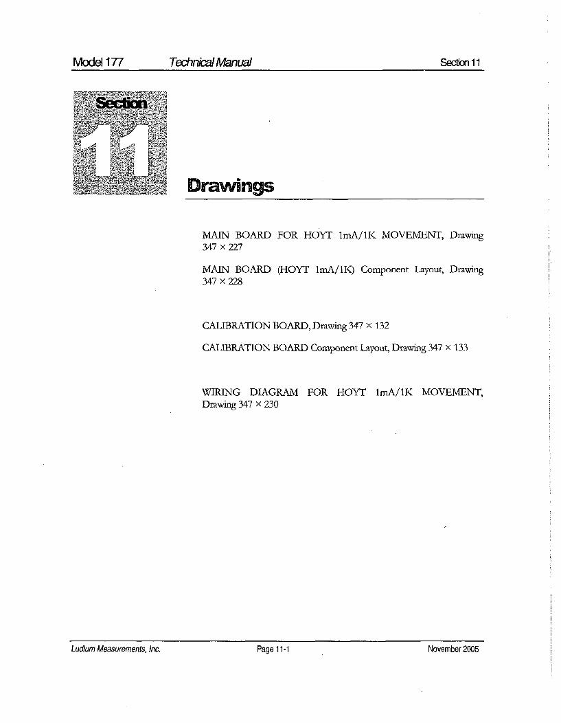
MAIN BOARD FOR HOYT lmA/1K MOVEMENT, Drawing347 x 227
MAIN BOARD (HOYT lmA/1K) Component Layout, Drawing347 x 228
CALIBRATION BOARD, Drawing 347 x 132
CALIBRATION BOARD Component Layout, Drawing 347 x 133
WIRING DIAGRAM FOR HOYT lmA/1K MOVEMENT,Drawing 347 x 230
Ludlum Measurements, Inc. Page 11 -1 November 2005

0127 2107 I rrr I *IIW~ITv I7flkrI~?DI
721 47.S11It .126,14
R123I0 +SV I rcc I AUTHOR! v Z- R el -fAft . h
L & I g iAE YU
-- A ý-ý AA
SICNALFLYINCLEAD
17 I ' IIto I/S 1U121C124 190K[ CA40E117 2122PF I> RIB T 12 IG=6,2
1212to1 14 I/S U121711111~ ~~ ~~~ /S6, UX161 / 11 212 A' 6
2/1 21 0.0 3 9 IA 0ItI9 B1 U 121 R12 I , .
2212 K 2 CI2I RIIfi 3 A221/ 21 1.
1 26 2...... RF 211 TLC:72ID xWay I f~ 12, t 6i I/ 1 1 ,,7 -2mT R1299 1 2S,11/ U12 R12S,
R1122 CR70912 11224 102 1S.211 I .223 2.121 C7 22
10,8K 2 s1- 0. V2 6181UFI25 I1 V09 I 2.48+V4CD t
12S~~~ 2 2 IK111ý 7IX 25,1 C024 1122sC02' SW' I
IPF112 112 21 I'12m
22NT 122II /2S 1
DISCRIMINATOR 12 129,1W
LROIG +SV 0 0•too10 11,' I/S U8122 rIl, 1CA3/9611
Coil 2lmW 12 16-I=GND 1341PF 14 I/S U012I1V CEA309SM
R2114 Is I6'C9D
TIPCALLY 711 .71 2.21 79211SA2 121V
5 126 9 l/2S25 2
1/2 22Il X 126MW , IG6CN0CD74HC4S382 82 .21
l9.,4.911 2.905 R 221
T211Rile T' AUOIO 12 -13.32KIf 12sw 1 3 M11111713901 001'
2 Cal I".F . 7=P NO,
toy T= 0104 1 1 1 1 to 1 0 2SmW
MMBT3904T P2 -8
CRI14 aIBD911L
CRIIJ 3 R004
Pi -9
Pi -9• R221 R323I
7411i~4-90 -SY J ~oC222C229 22DO=N 04. 1
R121 . 2. . GU/F . F .4V ....l2C1 JD12 04IG I "3K / -6 K •
711 CR721 2.224711 100T
P3 -12 4 C1 RC el .. N407 V1," TEST HY TEST .... PFD ,4L IUF
.I .2 0,2247UF 124227 1 2227 12 12Stow iUO
72R3 I -2C4RI01
P2 -12 1. :
2271 12-2 w I.2 720
015392 07 2 0,072 F I407 1 1C76 2C6A 1 .21
7721 V 41 7
P1-2it I N•>0,.• -.- 4 R223R2 1 C2479 261
P2 7 22 S 29.1 2 211
1/2 U311 ATTEIi
2.2 621111 22,1 . 1 'CNR30I 26, 41262t 26
2CIII 21
I5 14 CRII1
75 12 20 9
A o S )9CI ~ m
/2 1 9NC N
C).D74HC45i32/
I RH+B6
S 121L IM-2DS14L2IAMP
R12Ioo ] / +BY / S 0103oo REMOTE ALARM P3 -2.
111126.14 Roll M JE2!0 Rill • "
Cv l 0If 125422 21214 12ICLC2SSCPA 12S9W I RtI Riot2
24 39r I=PC96 8.5.00K1 22
. ....OUT • 120 u021 R 1=4 it If<> 1•C - -Iv I I TLC3O721 I a9• 2< m 12 5,14 I~m
Ioll NI t i /s.w 1 3 0102
3A I I 1CROI.1 SUB•TR ACTPO NSE I
A ITH I2 . .. .o t > P2s -9 1
1.0011 1 I/. U01
IFIV
l11CK T 21
-T-'20V
RESET ' 21 -411227125m
i1 125mW*11V0--A yIV.--, 1P2 -to
ALARM SET1162 P -6
CR21so.IF -.21 F RECOR DER P2 - 3
.U114L7 7 6 R313 7321
O.OIUF ~ ~ 7 ohL., . 301RZI
7 B1 ER P2 -4
=71
1 6E :CKB 12- 77-.9 LF0LULU2l EAsLImRE1NTV S INC.
ITT EI A-IN B ARDFOR 1102 .1,11/111.TVB11T
A PP U A: 5 C S l CZE I MO SL J ER S S E TNEXT HIGHER 0SSY. I E I 0L0 SERIES SI ET
17 4, 2
12-A.Q-91 S9347291 I SHEET I I

CR2 CXH- 2 3ý'
SLUDLUMI MEASUREM1ENTS INC. SWEETWATER, TX.
/13/SS~J!IrTITLE MAIN BOARD INOYT 1I¶A/IK)
Ds n DL a17/ 10/921MODEL 117 I LIS R 47S HEET228
UfSN COI¶P OUTLINE
S-DRPAS OR MASKOJCOMP 5 . I - I

cwt R3 d PG ct
IC
-1 ... 79 . ... "9
PG -s 4
J IO 0
P6 -3
PG -2
PG -to
PG -71121 30131
HV9 DISCRI31INAO RECORDER
PG -11
PG -6

DISCRIMINATOR
X1000
X100
X 10
xi
Nv
RECORDER
(D R7
10K CD P
R 4in I
IM LUDLUMi MEASUREM1ENTS INC. SW4EETW4ATER, TX.
IDR CKE loe20/2I TITLE T CAlIBRATION BOARDCHK IB34 83DSN // OAROR E347"189 8S347185
MODEL I-SERIES SHEET
IAPPJLJ6JI 17 (o Pfl47 133114'I1:.1 T 0-Uy-93 SCOTIP SIDED SLTR SIDEID UTLrNEMI
ICOIIP PASTEDCCOnTI MASKD SLOP PASTED ISLOR MASERD

Fl PSN SIFI Sl P Ti
61 65
N PLO
J7/-x:- , FLYING LEAS T0
T SI 7 056 11 1
-loot

LUDLUM MODEL 19MICRO R METER
November 2005
Serial Number 207422 and Succeeding
Serial Numbers
LUDLUM MEASUREMENTS, INC.501 OAK STREET, P.O. BOX 810SWEETWATER, TEXAS 79556325-235-5494, FAX: 325-235-4672

JIEV#I ALTERATIONS I DATE IBY1 VALID 13-16
OWN JDATEH AT PP DT
DD v-16-04 r i-04- U. 3V-16-0+DWG NUM: 4367-169.IAM I SCALE: o9TILE: M 9 FRONT PANELU LUDLUM m.Asum...... I SERIES ISHEETwI O 1367 1169
T able of Cones
Introduction 1
Getting Started 2Unpacking and Repacking 2-1
Battery Installation 2-1
Operational Check 2-2
Maintenance 2-3
Recalibration 2-3
Batteries 2-3
Specifications 3
Identification of Controls and Functions 4
Safety Considerations 5Environmental Conditions for Normal Use 5-1
Warning Markings and Symbols 5-1
Cleaning and Maintenance Precautions 5-2
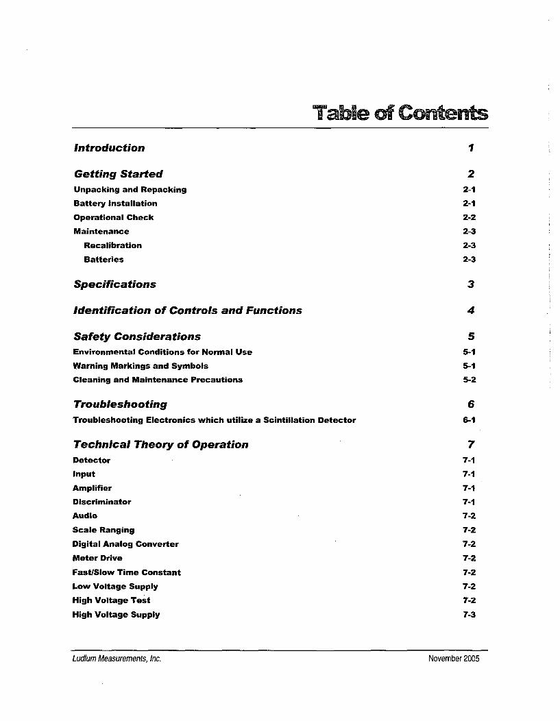
Troubleshooting 6Troubleshooting Electronics which utilize a Scintillation Detector 6-1
Technical Theory of Operation 7Detector 7-1
Input 7-1
Amplifier 7-1
Discriminator 7-1
Audio 7-2
Scale Ranging 7-2
Digital Analog Converter 7-2
Meter Drive 7-2
Fast/Slow Time Constant 7-2
Low Voltage Supply 7-2
High Voltage Test 7-2
High Voltage Supply 7-3
Ludlum Measurements, Inc. November 2005

Model 19 MICRO R METER Technkial Manual
Recycling 8
Parts List 9Model 19 Micro R Meter 9-1
Main Board, Drawing 367 x 166 9-1
Wiring Diagram, Drawing 367 x 174 9-4
Drawings and Diagrams 10
Ludlum Measurements, Inc. November 2005
Ludlum Measurements, inc. November 2005
Model 19 MICRO R METER Technical Manual Secfion 1
Introduction
The Ludlum Model 19 Micro R Meter utilizes an internally-mounted1" x 1" NaI(TI) scintillator for optimum performance in locatingand measuring low-level (near "background') gamma radiation.
The unit features a pushbutton lighted meter and was designed to bemoisture and dust resistant. The meter is housed in a rugged aluminum bezelwith waterproof seals. All controls, including a calibration potentiometer foreach range, are located on the front panel. Front panel switches are rubber-booted to seal out moisture and dust. A high voltage (Hy) test control isprovided to allow rapid plateau testing of the detector.
Five range divisions are provided in the 0-5000 micro R/hr spectrum. Themeter face is made up of two scales, 0-50 and 0-25, plus battery test. The 0-50 scale corresponds to the 50, 500 and 5000 positions on the range selectorswitch. The 0-25 scale corresponds to the 25 and 250 positions on the rangeselector switch.
The instrument is capable of using either standard "D" cell flashlightbatteries or nickel-cadmium rechargeable batteries. However, the Model 19does not include circuitry for recharging the batteries. The two "D" cellbatteries are located in an isolated compartment, easily accessible from thefront panel.
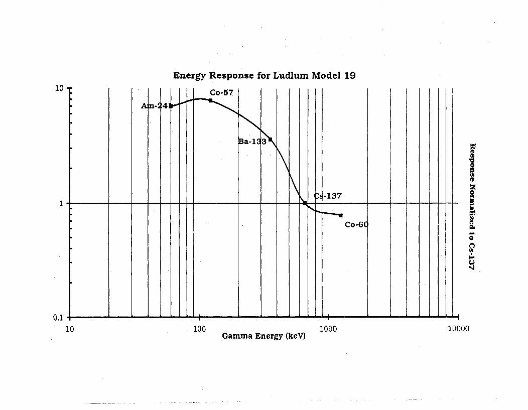
The Model 19 Nal scintillator is energy sensitive. An energy response curveis included in section 10 of this manual for further reference.
Ludlum Measurements, Inc.Page 1-1 November 2005Ludlum Measurements, Inc. Page 1-1 November 2005

Model 19 MICRO R METER TechnicalManual Seclion 2
Unpacking and Repacking
Remove the calibration certificate and place it in a secure location. Removethe instrument and accessories (batteries, cable, etc.) and ensure that all ofthe items listed on the packing list are in the carton. Check individual itemserial numbers and ensure calibration certificates match. The Model 19 serialnumber is located on the front panel below the battery compartment. MostLudlum Measurements, Inc. detectors have a label on the base or body ofthe detector for model and serial number identification.
If multiple shipments are received, ensure that the detectorsand instruments are not interchanged. Each instrument iscalibrated to specific detectors, and therefore notinterchangeable.
To return an instrument for repair or calibration, provide sufficient packingmaterial to prevent damage during shipment. Also provide appropriatewarning labels to ensure careful handling. Include detector(s) and relatedcable(s) for calibration. Include brief information as to the reason for return,as well as return shipping instructions:
- Return shipping address- Customer name or contact- Telephone number
Description of service requested and all other necessaryinformation
Baftery InstallationEnsure the Model 19 power switch is in the "OFF" position. Open thebattery lid by pushing down and turning the quarter-turn thumbscrewcounterclockwise ¼/4 turn. Install two "D" size batteries in the compartment.
Ludlum Measurements, Inc. Page 2-1 November 2005Ludlum Measurements, Inc. Page 2-1 November 2005

Model 19 MICRO R METER Technical Manual Secion 2
Note the (+) and (-) marks inside the battery door. Match the battery polarity tothese marks. Close the battery box lid, push down and turn the quarter-turnthumb screw clockwise ¼/4 turn.
Note:
Center post of a flashlight battery is positive. The batteries areplaced in the battery compartment in opposite directions.
Operational CheckTurn the Range Selector switch to the "25" position. Depress the "BAT"pushbutton switch and ensure that the meter needle falls within the "BAT OK"marks. Check for a proper background reading. A typical reading would be: 5-15 uR/hr
Turn the Range Selector switch to the "5000" position. Expose the instrumentto a "check source" and verify that the instrument indicates within 20%/0 of thecheck source reading obtained during the last calibration.
Switch the "AUD ON/OFF" switch to the "ON" position and confirm that theexternal unimorph speaker produces an audible click for each event detected.The "AUD ON/OFF" switch will silence the audible clicks if in the "OFF"position. It is recommended that the "AUD ON/OFF" switch be kept in the"OFF" position when not needed in order to preserve battery life.
Turn the Range Selector switch to the "250" position and increase the sourceactivity for a meter reading of 10-100 uR/hr. While observing the meterfluctuations, select between the fast and slow response time ("F/S") positionsto observe variations in the display. The "S" position should respondapproximately 5 times slower than the "F" position.
The slow response position is normally used when the instrumentis displaying low numbers which require a more stable metermovement. The fast response position is used at high rate levels.
Check the meter reset function by depressing the "reset" pushbutton switchand ensuring the meter needle drops to "0".
Ludlum Measurements, Inc. Page 2-2 November 2005Ludlum Measurements, Inc. Page 2-2 November 2005

Model 19 MICRO R METER Technikal Manual Secon 2
Depress the "LAMP" pushbutton switch. Ensure that the meter face illuminateswhen the switch is depressed. Proceed to use the instrument.
MaintenanceInstrument maintenance consists of keeping the instrument clean andperiodically checking the batteries and the calibration. The Model 19instrument may be cleaned with a damp cloth (using only water as the wettingagent). Do not immerse instrument in any liquid. Observe the followingprecautions when cleaning.
1. Turn the instrument off and remove the batteries.
2. Allow the instrument to sit for 1 minute before accessing internalcomponents.
RecalibrationRecalibration should be accomplished after any maintenance or adjustment ofany kind has been performed on the instrument. Battery replacements are notconsidered maintenance and do not normally require instrument recalibrated.
Note:,,-
Ludlum Measurements, Inc. recommends recalibration atintervals no greater than one year. Check the appropriateregulations to determine required recalibration intervals.
Ludlum Measurements offers a full service repair and calibration department.We not only repair and calibrate our own instruments but most othermanufacturer's instruments. Calibration procedures are available upon requestfor customers who choose to calibrate their own instruments.
BatteriesThe batteries should be removed any time the instrument is placed into storage.Battery leakage may cause corrosion on the battery contacts, which must bescraped off and/or washed using a paste solution made from baking soda andwater. Use a spanner wrench to unscrew the battery contact insulators,
Ludlum Measurements, Inc. Page 2-3 November 2005Ludlum Measurements, Inc. Page 2-3 November 2005

Model 19 MICRO R METER TechnAialManual Section 2
exposing the internal contacts and battery springs. Removal of the handle willfacilitate access to these contacts.
Note:- -
Never store the instrument over 30 days without removing thebatteries. Although this instrument will operate at very highambient temperatures, battery seal failure may occur attemperatures as low as 1 00F.
Ludlum Measurements, Inc. Page 2-4 November 2005Ludium Measurements, Inc. Page 2-4 November 2005

Model 19 MICRO R METER Technkal Manual Section 3
SpecificationsLinearity- Reading within ± 10% of true value.
High Voltage: Variable from 400 to 1500 Vdc; electronically regulatedto within ± 1%.
Battery Dependence: Instrument calibration change less than 3%within the meter battery check limits.
Power. Two standard alkaline "D" cell batteries, secured in an isolatedcompartment
Battery Life: Expected lifetime of approximately 2000 hours with the"AUD ON/OFF" switch in the off position.
Audio Output: Built-in unimorph speaker and "ON/OFF" switchprovided on the front panel
Counting Ranges: Two-scale meter face presenting 0-50 micro R/hrwith full scale range positions of 5000, 500 and 50; and 0-25 micro R/hrwith fuill scale range positions of 250 and 25.
Meter. 1 mA, 2 1/2 -inch scale, pivot-and-jewel suspension.
Detector:. Photomultiplier coupled to a 1" X 1" NaI0fl) crystal,mounted inside the instrument housing.
Construction: Cast and drawn aluminum with computer-beigepowdercoating finish and printed membrane front panel.
Size: 15.75 cm (6.2'" H X 8.9 cm (3.5") W X 21.6 cm (8.5") L, notincluding instrument handle.
Weight: 1.36 kg (3 lbs.), less detector and batteries.
Ludiwn Measurements, Inc. Page 3-1 November 2005Ludlum Measurements, Inc. Page 3-1 November 2005

Model 19 MICRO R METER TechnialManual Section 4
Identificationl of Controls andFunctions
Range Selector Switch: A six-position switch marked OFF, 5000, 500,250, 50 and 25. Moving the range selector switch to one of the rangepositions (5000, 500, 250, 50, 25) provides the operator with an overallrange of 0-5000 micro R/hr. Note that the range positions 5000, 500and 50 are screened in black and correspond to the meter scale screenedin black. The range positions 250 and 25 are screened in red andcorrespond to the meter scale screened in red.
AUD ON-OFF Toggle Switch: In the ON position, operates theunimorph speaker, located on the left side of the instrument. Thefrequency of the clicks is relative to the rate of the incoming pulses. Thehigher the rate is, the higher the audio frequency. The audio should beturned OFF when not required, to reduce battery drain.
F-S Toggle Switch: Provides meter response. Selecting the fast, "F",position of the toggle switch provides 90% of full scale meter deflectionin four seconds. In the slow, "s", position, 90% of full scale meterdeflection takes 22 seconds. In "F" position, there is fast response andlarge meter deviation. The "s" position should be used for slow responseand damped, meter deviation.
BAT Pushbutton Switch: When depressed, this switch indicates thebattery charge status on the meter. The range selector switch must beout of the OFF position.
RES Pushbutton Switch: When depressed, this switch provides a rapidmeans to drive the meter to zero.
LAMP Pushbutton Switch: When depressed, this switch lights the meterface.
HV Pushbutton Switch: When depressed, the meter reads the detectorhigh voltage. Each meter division is equivalent to 100 volts.
Ludlum Measurements, Inc. Page 4-1 November 2005

Model 19 MICRO R METER TechnkicaManual Section4
HV Adjustment: Provides a means to vary the high voltage from 400 to1500 volts.
Range Calibration Adjustments: Recessed potentiometers locatedunder the calibration cover, on the right side of the front panel. Theseadjustment controls allow individual calibration for each rangemultiplier.
Ludlum Measurements, Inc. Page 4-2 November 2005Ludlurn Measurements, Inc. Page 4-2 November 2005

Model 19 MICRO R METER Technical Manual Seclion 5
_Safety Considera~ons
Environmental Conditions for Normal UseIndoor or outdoor use
No maximum altitude
Temperature range of-20TC to 50TC (-4°F to 122°F)
Maximum relative humidity of less then 95% (non-condensing)
Pollution Degree 1 (as defined by IEC 664).
Warning Markings and Symbols
Caution!
The operator or responsible body is cautioned that theprotection provided by the equipment may be impaired if theequipment is used in a manner not specified by LudlumMeasurements, Inc.
The Model 19 Micro R Meter is marked with thefollowing symbols:
ACAUTION (per ISO 3864, No. B.3.1) - designates hazardous live voltageand risk of electric shock During normal use, internal components arehazardous live. This instrument must be isolated or disconnected from thehazardous live voltage before accessing the internal components. Thissymbol appears on the front panel. Note the following precautions:
Ludlum Measurements, Inc. Page 5-1 November 2005Ludlum Measurements, Inc. Page 5-1 November 2005

Modd 19 MICRO R METER Technical Manual Section 5
Wa.n !
The operator is strongly cautioned to take the followingprecautions to avoid contact with internal hazardous live partsthat are accessible using a tool:
1. Turn the instrument power OFF and remove the batteries.2. Allow the instrument to sit for 1 minute before accessing
internal components.
i The "crossed-out wheelie bin" symbol notifies the consumer that theproduct is not to be mixed with unsorted municipal waste when discarding;each material must be separated. The symbol is placed on the batterycompartment lid. See section 8, "Recycling" for further information.
Cleaning and Maintenance PrecautionsThe Model 19 may be cleaned externally with a damp cloth, using only wateras the wetting agent. Do not immerse the instrument in any liquid. Observethe following precautions when cleaning or performing maintenance on theinstrument:
1. Turn the instrument OFF and remove the batteries.
2. Allow the instrument to sit for 1 minute before cleaning theexterior or accessing any internal components for maintenance.
Ludlum Measurements, Inc. Page 5-2 November 2005Ludlum Measurements, Inc. Page 5-2 November 2005

Model 19 MICRO R METER Tehnical Manual Section 6
Troubleshooting
ccasionally, you may encounter problems with your LMI
instrument or detector that may be repaired or resolved in thefield, saving turnaround time and expense in returning theinstrument to us for repair. Toward that end, LMI electronics
technicians offer the following tips for troubleshooting the most commonproblems. Where several steps are given, perform them in order until theproblem is corrected. Keep in mind that with this instrument, the mostcommon problems encountered are: (1) sticky meters (2) battery contacts.
Note that the first troubleshooting tip is for determining whether theproblem is with the electronics or with the detector. A Ludlum Model 500Pulser is invaluable at this point, because of its ability to simultaneouslycheck high voltage, input sensitivity or threshold, and the electronics forproper counting.
We hope these tips will prove to be helpful. As always, please call if youencounter difficulty in resolving a problem or if you have any questions.
Troubleshooting Electronics which utilize a
Scintillation Detector
SYMPTOM POSSIBLE SOLUTION
1. Check batteries and replace if weak.No power (or meterdoes not reach BAT 2. Check polarity (See marks insideTEST or BAT OK batter lid). Are the batteries installedmark) backwards?
Ludlum Measurements, Inc. Page 6-1 November 2005Ludium Measurements, Inc. Page 6-1 November 2005

Model 19 MICRO R METER Technical Manual Section 6
SYMPTOM POSSIBLE SOLUTION
No power (or meterdoes not reach BAT
TEST or BAT OK
mark) (continued)
Nonlinear Readings
3. Check battery contacts. Clean themwith rough sandpaper or use anengraver to clean the tips.
4. Check for loose or broken wires,especially between the main boardand the calibration board.
1. Check the high voltage (HV) bypressing the HV TEST button. If aMultimeter is used to check the HV,ensure that one with high impedanceis used, as a standard Multimetercould be damaged in this process.
2. Check for "sticky" meter movement.Does the reading change when youtap the meter? Does the meter needle"stick" at any spot?
3. Check the "meter zero." Turn thepower OFF. The meter should cometo rest on "0".
1. Check the HV and, if possible, theinput threshold for proper setting.
2. Check for loose wires, especiallybetween the main board and thecalibration board.
Meter goes full-scaleor "Pegs Out"
Ludlum Measurements, Inc. Page 6-2 November 2005Ludlum Measurements, Inc. Page 6-2 November 2005

Model 19 MICRO R METER TechnicaI Manual Section 7
~Technical Theory of Operation
DetectorThe detector consists of a crystal of sodium iodide with Thallium activation(Nal TI) that gives off light pulses when penetrated by radiation photons.
The light pulses are converted to electrical pulses by the photo cathode ofthe photomultiplier tube. The photomultiplier includes a 9 stage electronamplifier. This amplifier utilizes an electrostatic field for each stage, addingup to a required 500 to 1500 volt supply.
Input
Detector pulses are coupled from the detector through C6 to the amplifier.CR1 protects the amplifier from input shorts. R37 couples the detector tothe high voltage supply.
AmplifierA self-biased amplifier provides gain in proportion to R1 5 and C4 divided byR14. Transistor (pin 3 of U4) provides amplification. U6 is configured as acurrent mirror to provide a load for pin 3 of U4. The output self-biases to 2Vbe (approximately 1.4 volts) at emitter of Q1. This provides just enoughbias current through pin 3 of U4 to conduct all of the current from thecurrent mirror.
Positive pulses at R16 are coupled to the discriminator through C5.
DiscriminatorComparator U8 provides discrimination. The discriminator is set by thevoltage divider, R21 and R23, coupled to pin 3 of U8. U8 output pulses arecoupled to pin 5 of U9A for meter drive and pin 12 of U9B for audio.
Ludlum Measurements, Inc. Page 7-1 November 2005Ludlum Measurements, Inc. Page 7-1 November 2005

Model 19 MICRO R METER TechnkialManual Section 7
AudioDiscriminator pulses are coupled to univibrator pin 12 of U9B. Front panelaudio ON-OFF selector controls the reset at pin 13 of U9B. When ON, pulsesfrom pin 10 of U9B turn on oscillator U12, which drives the can-mountedunimorph. Speaker tone is set by R31, Cl 4; duration by R22, C7.
Scale RangingDetector pulses from the discriminator are coupled to univibrator pin 5 ofU9A. For each scale, the pulse width of pin 6 of U9A is controlled by thefront panel calibration controls and their related capacitors. Thisarrangement allows the same current to be delivered to C9 in proportion tothe meter reading.
Digital Analog ConverterU5 is configured as a current mirror. For each pulse of current through R24,an equal current is delivered to C9. This charge is drained off by R25. Thevoltage across C9 is proportional to the incoming count rate.
Meter DriveThe meter is driven by the collector of Q2 coupled as a voltage follower inconjunction with pin 1 of U10.
For Battery Test, the voltage follower is bypassed and the meter movementis directly coupled to the battery through R8.
Fast/Slow Time ConstantFor slow time constant, C17 is switched from the output of the meter driveto parallel C9.
Low Voltage SupplyBattery voltage is coupled to U11 and associated components (a switchingregulator) to provide 5 volts at pin 8 to power all circuits.
High Voltage TestA constant current is developed by collector of Q3 in proportion to HVsignal at pin 1 of U17. U16 provides a current mirror to drive the meter
Ludlum Measurements, Inc. Page 7-2 November 2005
Model 19 MICRO R METER Technkml Manual Secfon 7Model 19 MICRO R METER Technk:'al Manual Section 7
through analog switch logic circuit U15, U14, and U3.
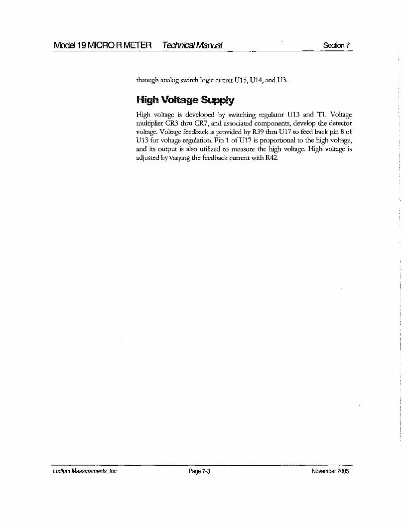
High Voltage SupplyHigh voltage is developed by switching regulator U13 and TI. Voltagemultiplier CR3 thru CR7, and associated components, develop the detectorvoltage. Voltage feedback is provided by R39 thru U17 to feed back pin 8 ofU13 for voltage regulation. Pin 1 of U17 is proportional to the high voltage,and its output is also utilized to measure the high voltage. High voltage isadjusted by varying the feedback current with R42.
Ludlum Measurements, Inc. Page 7-3 November 2005Ludlum Measurements, Inc. Page 7-3 November 2005

Model 19 MICRO R METER TechnicalManual Sec&,n 8
L udlum Measurements, Inc. supports the recycling of the electronicsproducts it produces for the purpose of protecting the environmentand to comply with all regional, national and international agenciesthat promote economically and environmentally sustainable
recycling systems. To this end, Ludlum Measurements, Inc. strives to supplythe consumer of its goods with information regarding reuse and recycling ofthe many different types of materials used in its products. With manydifferent agencies, public and private, involved in this pursuit it becomesevident that a myriad of methods can be used in the process of recycling.Therefore, Ludlum Measurements, Inc. does not suggest one particularmethod over another, but simply desires to inform its consumers of therange of recyclable materials present in its products, so that the user willhave flexibility in following all local and federal laws.
The following types of recyclable materials are present in LudlumMeasurements, Inc. electronics products, and should be recycled separately.The list is not all-inclusive, nor does it suggest that all materials are present ineach piece of equipment.
Batteries Glass Aluminum and Stainless Steel
Circuit Boards Plastics Liquid Crystal Display (LCD)
Ludlum Measurements, Inc. products which have been placed on themarket after August 13, 2005 have been labeled with a symbol recognizedinternationally as the "crossed-out wheelie bin" which notifies the consumerthat the product is not to be mixed with unsorted municipal waste whendiscarding, each material must be separated. The symbol will be placed nearthe AC receptacle, except for portable equipment where it will be placed onthe battery lid.
The symbol appears as such:
Ludlum Measurements, Inc. Page 8-1 November 2005Ludium Measurements, Inc. Page 8-1 November 2005

Model 19 MICRO R METER Technial Manual Section 9
Parts List
Model 19Micro R Meter
Main Board,Drawing 367 x 166
CAPACITORS
Reference
UNIT
BOARD
C1C2C3C4C5C6C7C8C9c10CllC12C14C17C1 8-C27C28C29C30-C31C32C33
Description Part Number
Completely AssembledModel 19 Micro R Meter
Completely AssembledCircuit Board
47pF, 100V0.00229F, 50V0.001LtF, 1OOV10pF, 100V0.019iF, 50V100pF, 3KV0.022jiF, 50VltF, 16V10OgF, 25V100pF, 100V68jiF, 10V101gF, 25V470pF, 100V47.F, 10V0.01 [tF, 500V0.0019F, 2KV68gtF, 10V1 RF, 16V270pF, 100V0.01gF, 50V
48-1615
5367-166
04-566004-567604-565904-567304-566404-573504-566704-570104-565504-566104-565404-572804-566804-566604-569604-570304-565404-570104-567904-5664
Lud/um Measurements, Inc. Page 9-1 November 2005Ludium Measurements, Inc. Page 9-1 November 2005

Model 19 MICRO R METER Technical Manual Section 9
TRANSISTORS
VOLTAGEREGULATOR
INTEGRATEDCIRCUITS
Reference
QiQ2Q3
VR1
U1-U3U4-U5U6U7U8U9U10UllU12U13U14-U15U16U17-C18
CR1CR2CR3-CR7CR9
Description Part Number
MMBT3904LT1MMBT4403LT1MMBT3904LT1
LT1460KCS3-2.5TR
MAX4542ESACMXT3904CMXT3906MAX4541ESAMAX985EUK-TCD74HC4538MLMC711 1 BIM5XLT1304CS8-5MiC1557BM5LT1304CS8MAX4542ESACMXT3906LMC7111BIM5X
05-584105-584205-5841
05-5867
06-645305-588805-589006-645206-645906-629706-641006-643406-645706-639406-645305-589006-6410
07-646807-641107-646807-6411
08-676108-677008-678108-678108-677008-677008-6770
09-681409-681409-681409-681409-6813
DIODES
SWITCHES
SW1SW2SW3SW4SW5SW6SW7
R33R34R35R36R41
CMPD2005SCMSHl-40MCMPD2005SCMSHl-40M
RANGE SELECTORH.V. PUSHBUTTONF-S TOGGLEAUD ON-OFF TOGGLERES PUSHBUTTONLAMP PUSHBUITONBAT PUSHBUTTON
POTENTIOMETERS /TRIMMERS
1M, 64W105 NAME1M, 64W105 X101M, 64W105 Xl1M, 64W105 X0.1100K, 64W104 X100
Ludlum Measurements, Inc. Page 9-2 November 2005Ludlum Measurements, Inc. Page 9-2 November 2005

Model 19 MICRO R METER Technikal Manual Secon 9
Reference Description Part Number
R42 100K, 64W104 HV ADJ 09-6813R52 10K, 3266X1-103 NAME 09-6822
RESISTORS
R1-R5 200K, 1/8W, 1% 12-7992R6 8.25K, 1/8W, 1% 12-7838R7 10K, 1/8W, 1% 12-7839R8 2.37K, 1/8W, 1% 12-7861R9-Rl1 10K, 1/8W, 1% 12-7839R12 200 Ohm, 1/8W, 1% 12-7846R13 10K, 1/8W, 1% 12-7839R14 4.75K, 1/8W, 1% 12-7858R15 200K, 1 /8W, 1% 12-7992R16 10K, 1/8W, 1% 12-7839R17 1K, 1/8W, 1% 12-7832R18 4.75K, 1/8W, 1% 12-7858R19 2K, 1/8W, 1% 12-7926R20-R21 100K, 1/4W, 1% 12-7834R22 IM, 1/8W, 1% 12-7844R23 2.49K, 1/8W, 1% 12-7999R24 14.7K, 1/8W, 1% 12-7068R25 200K, 1/4W, 1% 12-7992R26 1001, 1/4W, 1% 12-7834R27 68.1K, 1/8W, 1% 12-7881R28 100K, 1/8W, 1% 12-7834R29 IK, 1/8W, 1% 12-7832R30 100K, 1/8W, 1% 12-7834R31 475K, 1/8W, 1% 12-7859R32 100K, 1/8W, 1% 12-7834R37 100K, 1/8W, 1% 12-7834R38 4.75M, 1/8W, 1% 12-7995R39 500M, 3KV, 2% 12-7031R40 1M, 1/4W, 1% 12-7844R44 1K, 1/4W, 1% 12-7832R45 8.25K, 1/8W, 1% 12-7838R46-R48 2001, 1/4W, 1% 12-7992R49 825K, 1/8W, 1% 12-7005R50 953K, 1/8W, 1% 12-7950R53 1K, 1/4W, 1% 12-7832
CONNECTORS
P1 CONN-640456-4MTA100x4 NAME 13-8088
Ludlum Measurements, Inc. Page 9-3 November 2005

Model 19 MICRO R METER TechnicalManual Section 9
Reference
P2
P3
P4
Description
CONN-640456-3MTA100x3 NAMECONN-640456-2MTA100x2 NAMECONTACT #1434 NAME
Part Number
13-8081
13-807318-9124
INDUCTOR
LI
T1
2211H, CD43-220
TRANSFORMER
31032R
Wiring Diagram,Drawing 367 x 174
AUDIO
CONNECTOR
BATTERY
DS1DS2
P1
P2
P3
B1-B2
MISCELLANEOUS
Ml
*g
*g
M19 LAMP BOARD 5367-113UNIMORPH TEC-3526-PU
MTA100x4 MAIN BOARD5367-166MTA 100x3 MAIN BOARD5367-166MTA 100x2 MAIN BOARD5367-166
DURACELL "D"
M19 INTERNAL DETECTORTUBE/XTAL ASSYMODEL 19 METERASSY 987010-001 imAM19 METERFACE(202-016)METER BEZEL W/ GLASSW/ SCREWSMETER MOVEMENT (imA)M19 BATTERY BOXLID W/CNTCTDEEP PORTABLECAN ASSYM19 CASTINGM19 MAIN HARNESS
47-34262004-061
4367-024
7367-023
4363-352-0015-8030
2363-191
4363-6157367-1718367-170
21-9808
21-9925
5367-11321-9251
13-8170
13-8135
13-8178
21-9313
Ludlum Measurements, Inc. Page 9-4 November 2005Ludlum Measurements, Inc. Page 9-4 November 2005

Model 19 MICRO R METER Technical Manual Section 9
Reference Description Part Number
* PORTABLE KNOB 08-6613* SWITCH SEAL (P/B) 08-6611* UNIMORPH W/WIRES,
O'RING 40-0034* CAL COVER W/SCREWS 4363-200* HANDLE- PORTABLE (GRIP) 7363-139
Ludlum Measurements, Inc. Page 9-5 November 2005Ludium Measuremenfs, Inc. Page 9-5 November 2005

Model 19 MICRO R MEFER TechnicalManual Secfion 10Model 19 MICRO R METER Te~hn kaI Manual Section 10
Drawings
Model Board Circuit, Drawing 367 x 166 (4 sheets)
Model Board Component Layouts, Drawings 367 x 167 (2 sheets)
Wiring Diagram, Drawing 367 x 174
Energy Response for Ludlum Model 19
Ludlum Measurements, Inc. Page 10-1 November 2005Ludium Measurements, Inc. Page 10-1 November 2005

¶ 2 3 4 . 5 6 7
1313.
F F
l67XI66b367X 66b-sh
HV A12
All
31670 ISA,367X W6-,
AllAIM A12
367X166d
A1O
HV
D
-W L U D L U S S0 1 O a k S t r e e ttwllatllr, T-0 795:WSMEASUREMENTS, INC. U.S.A. 1.800-622.0828
Drawn: JK 04-MAR-04 Title: MAIN BOARDDol nI: DL 04-MAR-04 Modal: M19Check: Board#: 5367.166 A
t•prove • " I Shoot: 1 01 4 Series Shoot11:08:49 31 -Ma,-200 , A 4.0 ,.o 3 6 7 1 6 6
0. -
1 i 4 5 1 7

,BAT .5V
OWlCENTRAL-2PGP A1 82 R3 R4 8R5........... 20K 200K 200K 2001K 200K
I 1180 11e 18W 118W 118W 1O7P 14ý MEER 1% 1% 1% 1% 1%
OFF 14 METE
5K 1
500 12
250
50 10
RAINSAT_
640450.4MTAIOOx4 +5VA
NAME T R1
PPCI
PORTA DLCSTING
,5V U14A +SV
2 1 R47 I R41 8.26K
10IK 1/8W64W104 1%
V V. 40X100MAX4542ESA
ULA
7I
IV, V.4
MAX4542ESA
+5V
R33 825K1M 1/8W
64W105 I %NAME
1
a~ 4
3V I ý
MAX V4
52S
0 +5V
C32 034 10K
9 270PF iM 1/8W
100V 64W105 1%
010
U4 U6
2 25 5
3 4 f 3 4
RIO lCMXT3904 10K< 1OK CMXT35061/8W• I •/SW1%, 1%/
1 j1O CMX-390
260,0"0118W1%
C301UP
•;l6V
c I I
LFVC
+5VO-3 F Vcc j10,5V
5 g
4 A 6
GND Z5 2.
CD74HC4530M/ý-Uall -
USA
8
4
V.
V.2t +5VýC3 IM3 101K'p, .0u1U 1M 1/8W,G0V 60Vh4W5 1%
XI
-7L7 /37
01 ..5VAMMBT3904LTI us qI
MAX985UK- 22
U2B
3 I
IAX4542ESA
-. ISV
ow 13
<C2 R36 10K
X 00uF IM 1/8W50V2U 64W105 1 %
00.1IC4I,
l0pE
18W
14 I %
4.75<1 la
R1/8 I/ W 5
10OK CS %~0
1124
14.7K1/8W
I %+5V
255
200K<I /4W
:;M P 02 0 0 5 S 1 8_50 V FR 2 2 /S W _-_ _16 6
10O0P F R20 ,
=73KV, . 118W' 1/8• 5 14 1% W 2
13 1q •I - "V CX30
OS'lI1 5 W51 iR - lE U/S
• .BAT11 1%cBA
12 A a 10P2
22uHCD43-220 +5V 2• • 640456-3
+HV W RE TPI1LTCOE NAMEIRE LAMP
R27 Ul +5V U12'68 1K -S4P3i/SW 3 4 LT1304CSS- +5V
C 011 1% INSW4 ON68F 1 LEI FB/I0ENOE B12 GNOOP 1004
C320SIOICCOE 1/8W 8 5
150 ILIM Leo2
ICUF I%,laW _ 25V NOT USED ,2L-75K
% S N . c31 G GD8w-- VB V. MIC1557BM5 1%
.BAT
25V
f ~010
l00V
/77 sW5
---
TP11LTCOE
RESBETR19
2K118W
1% +V
SLOW 47uF•10sV
SW30Z44 FAST 7lOlSDCQE
UIO 1/4W+SV LM071tIBIM5X 1%
2 1 R26 UA
1 264 o MMBT4403LT1 2
5 1/ 4W
I5V 8
V. v4
MSPARE /47

SW2
TPI LTCOrBAT TEST

3G
E
c
aa
501 Oak atretLU DL UM ~iDSS,I~jMEASUREMENTS, INC. U.S.A. 1.800-622-U528
Drawn; JK 04.-MARl04 Titl.: MAIN BOARDDel n: . 04-MAR04 IModot: MISCShrk.I Boord 4: 53e7-16S
pprom W 1-3felOV Shoot: 40.1 4 ISar.in giool11:0851 1 31.Mar.20001 A-on 4. On- '2 tQ1L2
AA
1 3-7 100d.-ch 1I OllUU2 3 4 I 7
I/

Drawn: JK 04-MAR-04 Title: MAIN BOARD
Design: DL 04-MAR-04
Check- D(• 0k(- -oj- Model: M19
Approve: Board#: 5367-166Laye. Rev. 4.0 Series Sheet
14:46:39 6-Apr-2004 SCALE: 1.75 367 1 67

Drawn: JK 04-MAR-04 Title: MAIN BOARD
Design: DL 04-MAR-04
Check -E tc,-tP---L - Model: M19
Approve: Board#: 5367-166
Layer Rev- 4.0 Series Sheet14:46:40 6-Apr-2004 SCALES 1.75 367 1 67

MAIN BOARD5367-166
ImA
M 19 LAMP BOARD5367.113
I
MTAlCD53 I B 1738MAIN BOARD I5367-166
DS2
P3
MAIN BOARD UNIMORPH5367-166 TEC-3525-PU
Energy Response for Ludlum Model 1910 Co-57
A n.d 141t POO
IiI
Ba-13 3•
Co-60I II.
0.1,
10 100 1000 10000-- v -- v w
Gamma Energy (keV)

LUDLUM MODEL 2221PORTABLE SCALER RATEMETER
Revised January 2002
Serial Number 161568 andSucceeding Serial Numbers
LUDLUM MEASUREMENTS, INC.501 OAK ST., P.O. BOX 810SWEETWATER, TX 79556915/235-5494 FAX: 915/235-4672

r f
S(~~)WNJOUT
lillfAMEASUREMENTS INC.L UULUSWEETWATER TEXAS
MODEL 2221SCALER RATEMETER
0.1 0.20.5
ICOUNT
CONT 10MINUTES HOLD
S E DIG.SCALE~ RATE
-DIGITAL CONTROLJ
z ccX-4 -
0 0 0 0 xxxxx
M2221 Portable Scaler RatemeterJanuary 2002
TABLE OF CONTENTS
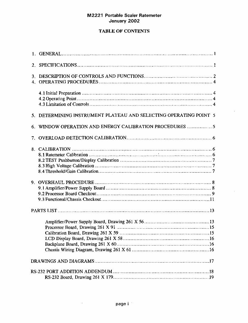
1. GENERAL .............................................................................................. 1
2. SPECIFICATIONS ..................................................................................... 1
3. DESCRIPTION OF CONTROLS AND FUNCTIONS ......................................... 24. OPERATING PROCEDURES ....................................................................... 4
4.1 Initial Preparation .................................................................................... 44.2 Operating Point ....................................................................................... 44.3 Limitation of Controls ............................................................................... 4
5. DETERMINING INSTRUMENT PLATEAU AND SELECTING OPERATING POINT 5
6. WINDOW OPERATION AND ENERGY CALIBRATION PROCEDURES ................ 5
7. OVERLOAD DETECTION CALIBRATION .................................................... 6
8. CALIBRATION ....................................................................................... 68.1 Ratemeter Calibration ............................................ .............................. 68.2 TEST Pushbutton/Display Calibration ......................................................... 78.3 High Voltage Calibration ......................................................................... 78.4 Threshold/Gain Calibration ...................................................................... 7
9. OVERHAUL PROCEDURE ......................................................................... 89.1 Amplifier/Power Supply Board .................................................................. 89.2 Processor Board Checkout ........................................................................ 99.3 Functional/Chassis Checkout ...................................................................... 11
PARTS LIST .............................................................................................. 13
Amplifier/Power Supply Board, Drawing 261 X 56 ....................................... 13Processor Board, Drawing 261 X 91 ......................................................... 15Calibration Board, Drawing 261 X 59 ................................. 15LCD Display Board, Drawing 261 X 58 .................................................... 16Backplane Board, Drawing 261 X 60 ............................................................ 16Chassis Wiring Diagram, Drawing 261 X 61 .............................................. 16
DRAWINGS AND DIAGRAMS* ......................................................................... 17
RS-232 PORT ADDITION ADDENDUM ........................................................... 18RS-232 Board, Drawing 261 X 179 .............................................................. 19
page i

M2221 Portable Scaler RatemeterJanuary 2002
1. GENERAL
The Ludlum Model 2221 Portable ScalerRatemeter is a self-contained countinginstrument designed for operation withscintillation, proportional or G-M detectors.Power is derived from four flashlight batteries.
The unit is complete with a voltage-sensitive preamplifier, linear amplifier,electronic timer, detector high-voltage powersupply and detector overload detectioncircuitry.
A single channel analyzer is also featuredin this unit for use in gamma spectrumanalysis. The analyzer may be switched on oroff, allowing gross or window counting.
The unit has a combination four-decadelinear and log ratemeter and a six-digit LCDreadout for the scaler and digital ratemeter.Potentiometers are supplied for threshold,window and high-voltage controls.
2. SPECIFICATIONS,
0 HIGH VOLTAGE: 200 to 2400 voltswith digital readout
* BATTERY COMPLEMENT: foureach "D" cell flashlight batteries
* BATTERY LIFE: approximately 250hours with size D, alkaline batteries
* CALIBRATION STABILITY: lessthan 3 % variance to battery endpoint
* SENSITIVITY: voltage-sensitive andadjustable from 1.5 mV to 100 mV; typicallyfactory-calibrated to 10 mV = 100 on theTHR display
* INPUT IMPEDANCE: 22k
* READOUT: 6 digit liquid crystaldisplay, 0.5" (1.3cm) characters with backlightselection
* METER: 2 1/2-inch scale, 1 mA,pivot and jewel suspension
* SCALES/RANGE: four decade logratemeter ranging from 50 to 500k CPM; fourdecade linear ratemeter - 0-500 CPM meterdial with range multipliers of X1K, X100,
X1O, X1 producing an overall range of 0-500k CPM
* OPERATING TEMPERATURE: 5-1220F (-15 to 50'C)
0 LINEARITY: ± 10 % of the true valuefor the analog and digital ratemeter; ±2% ofthe true value for the digital Scaler, HV, THR,and WIN digital voltmeter readings; ±4% ofthe true value for the BAT voltmeter reading
* RESPONSE: 2 positions - Fastresponse = 4 ±1 second, Slow response = 22± 2 second; all response times are measuredfrom 10-90% of final reading
* CALIBRATION CONTROLS:recessed screwdriver adjustments withcalibration cover
* AUDIO: built-in unimorph speakerwith click-per-event and switch selectabledivide by 1, 10, and 100.
* CONNECTOR: Series "C"
" SIZE: 4.25" (10.8 cm)W X 10"(25.4cm) L X 9" (22.9cm) H including handle
page 1

M2221 Portable Scaler RatemeterJanuary 2002
3. DESCRIPTION OF CONTROLS AND FUNCTIONS
0 POWER: Two-position switch to turnpower to instrument on or off
* DETECTOR: series "C" connector fordetector
Input Impedance: 22k
Ballast Resistor: IM
* RATEMETER:
e F-S RESP Switch: Two-positionswitch for selecting ratemeter response: Fposition 4 ±1 second; S position 22 ±2seconds.
* ZERO: when pressed, resets theratemeter
0 RANGE SELECTOR: Five-position switch labeled LOG, XIK, X100,X10, X1 used to select the analogratemeter range. The LOG position selectsthe upper meter scale to provide a fourdecade logarithmic reading from 50-500kCPM. The X1, X10, X100, and XlKrange multipliers used with the lower 0-500 CPM meter scale providing andoverall measuring range from 0-500kCPM. Multiply the meter reading by therespective range position.
* DIGITAL CONTROL:
* COUNT Pushbutton: Whenpressed, resets and starts the counter.While the counter is counting, two colonson the display are turned on.
* HOLD Pushbutton: Whenpressed, stops the counter and leaves thecount in the display.
* SCALER/DIG RATE ToggleSwitch: Two-position toggle switch forselecting scaler or digital ratemeter
SCALER Position: The display showsthe counter contents.
DIG. RATE Position: The displayshows the ratemeter count rate.
./ Note: The scaler and digitalratemeter are active even when notselected. This allows the user to start atimed count, switch to the DigitalRatemeter and then switch back to Scalerwithout having to restart the counter.
* MINVITES Selector Switch: Eight-position switch used for selecting the counttimes for the Scaler:
POSITION COUNT TIMEIN MINUTES
0.1 0.10.2 0.20.5 0.5
1 12 25 5
10 10CONT
COUNTER COUNTS UNTIL HOLDIS PRESSED
• CALIBRATION CONTROLS:
t WIN: 20-turn potentiometer usedto adjust window width when the windowtoggle switch, WIN, is in the "IN" position
0 THR: 20-turn potentiometer usedto adjust the Threshold
page 2

M2221 Portable Scaler RatemeterJanuary 2002
& HV: 20-turn potentiometer used toadjust detector voltage
0 O.L.: 20-turn potentiometer usedto adjust detector overload current
* TEST:
* BAT Pushbutton Switch: Whenpressed, displays the battery voltage in thedigital display.
* HV Pushbutton Switch: Whenpressed, displays the detector high voltagein the digital display.
* THR Pushbutton Switch: Whenpressed, displays the Threshold setting inthe digital display.
* WIN Pushbutton Switch: Whenpressed, displays the window setting in thedigital display.
* LAMP Toggle Switch: Two-position switch to turn on the display lights.
" WIN Toggle Switch: Two- positionswitch for switching the window IN or OUT
IN position: The SCA is set up as awindow counter.
OUT position: The SCA is set up as agross counter.
* AUDIO:
• VOL Control: One-turnpotentiometer used to adjust the volume of thespeaker or headset.
* AUDIO DIVIDE:
"1" Position: provides 1 click perevent
"10" Position: provides 1 click per 10events
"100" Position: provides 1 click per100 events
0 1/8" PHONE JACK: Used forheadset. When headset is plugged in, theunimorph on the can is disabled.
* LIQUID CRYSTAL DISPLAY:Six-1/2" high digits, displaying countercontents or digital count rate
* STATUS INDICATORS:
Counter Overflow: When in SCALERmode, the left digit alternates between thecorrect digit and an "H".
Detector Overload: The display flashesall dashes.
Battery: When the battery voltage is4.4 volts or less, all decimal points areturned on.
Scaler Counting: The two colons areturned on when MINUTES selector switchis in CONT position.
page 3

M2221 Portable Scaler RatemeterJanuary 2002
4. OPERATING PROCEDURES
4.1 Initial Preparation
o Unscrew battery door latch.
o Install for "D" size batteries in the
battery holder. The correct position of thebatteries is indicated on the bottom of thebattery door.
o Switch the POWER ON/OFFswitch to the ON position. A randomnumber will first be observed in thedisplay, then 8.8:8.8:8.8. The thirddisplayed number will be the programversion. (At the time of this printing,program version is #261010.)
o Press COUNT pushbutton. Thedisplay should zero. Two colons shouldappear on the display.
o Press HOLD pushbutton. Thecolons should disappear.
o Switch LAMP toggle switch to theON position. LCD display backlightingand two lamps at the bottom of the analogmeter should be illuminated.
/ NOTE: If the Lamp switch is left in theON position for extended periods of time,battery life will decrease rapidly.
o Check TEST pushbutton functionsfor proper operation.
4.2 Operating Point
Instrument and detector operating point isestablished by setting the probe voltage (HV)and instrument sensitivity (THR). For a givendetector system, efficiency, background andnoise are fixed by the physical makeup of thedetector and rarely vary from unit to unit.
However, the selection of the operating pointmakes a marked difference in the apparentcontribution of these three sources of count.
In the singular case of the G-M detector, aminimum operating voltage is required toestablish the G-M operating region. (At lowervoltages, the detector operates as a veryinsensitive proportional counter.) Thisdetector is not capable of energydiscrimination (pulse-height discrimination).The Threshold (THR) is typically adjusted to550, with a THR reading of 100 = 10 mVinput pulse, for G-M detectors.
For gain sensitive detectors (proportionalor scintillation), the most straightforwardmethod of selecting the operating point is todevelop a graph, relating count rate to systemgain. This relationship is commonly referredto as a plateau or instrument plateau curve.System gain may be changed by adjustingdetector high voltage or THR control. Thethreshold is typically adjusted for 100 = 10mV for scintillation detectors and 50 (5mVequivalent) on the THR readout forproportional detectors.
4.3 Limitation of Controls
HV Control provides a linear adjustment ofthe detector voltage supply. The range isapproximately 0 to 2400 volts. Changing thedetector voltage will cause the detector gain tochange. It should be remembered that a linearchange in voltage will cause an exponentialchange in detector gain. THR Control sets thebasic pulse discrimination point of the scaler.
WIN Control is calibrated with the THRcontrol so that the reading of the WIN controlis equivalent to the reading of the THRcontrol. As an example, 100 on the THR isequal to 100 on the WIN.
page 4

M2221 Portable Scaler RatemeterJanuary 2002
5. DETERMINING INSTRUMENT PLATEAU AND SELECTING OPERATING POINT
El Set WIN ON/OFF to OFF.
El Set MINUTES switch to 0.1 minutes.
El Set THR control at 100.
El With detector shielded from source,turn up high voltage control and take a plot ofHV versus background count rate until thedetector maximum voltage rating is reached.(Maximum voltage on most scintillationdetectors is 1500-1600 Vdc; maximum voltageon proportional detectors is reached at thecontinuous discharge point. Return HVcontrol to minimum.
6. WINDOW OPERATION AND ENERGY
El Expose the detector to a source andagain make a plot of voltage versus count.
El Plot both sets of data and select theoperating point to correspond with maximumsource count and minimum background count.Avoid areas of very fast count rate changeswith small changes in detector voltage. Theoptimum operating point for low backgrounddetectors is just above the inflection point (orbreak-over point) of the plateau curve. Ifbackground count is irrelevant, shift operatingpoint to the plateau center for greater stability.
CALIBRATION PROCEDURES
E The following procedure calibratesthreshold directly in keV.
El Place RATEMETER multiplier switchto LOG position.
"l Unscrew and remove CAL cover.
El Press HV pushbutton. The HV shouldread out on the display directly in volts.While depressing the HV pushbutton, turn HVpotentiometer maximum counterclockwise.The HV should be less than 50 volts.
El Depress the THR pushbutton. Turn theTHR potentiometer clockwise until 652displays.
El With WIN IN/OUT switch IN, depressthe WIN pushbutton. Turn the WINpotentiometer until 20 appears on the display.
El Switch WIN IN/OUT to OUT.
El Connect the probe and expose to Cs137source.
El Increase HV (if HV potentiometer is atminimum, it will take approximately 3 turnsbefore any change is indicated). Whileincreasing the HV, observe the log scale of theratemeter. Increase HV until ratemeterindication occurs.
El Switch WIN IN/OUT switch to IN.
El Turn the HV control until maximumreading occurs on the log scale. Increase HVuntil reading starts to drop off, then decreasethe HV for maximum reading.
El Turn RATEMETER selector switch tothe X1K position.
El Press ZERO pushbutton and release. Ifmeter does not read, switch to a lower rangeuntil a reading occurs.
page 5

M2221 Portable Scaler RatemeterJanuary 2002
EO Carefully adjust HV potentiometer untilmaximum reading is achieved on the rangescale. The instrument is now peaked forCs 137 on both the LOG and Linear scales.
/NOTE: When the THR control isadjusted, the effective window width remainsconstant. As an example, if the THR is set at612, the WIN at 100, a 662 keV peak 612 +
(100 divided by 2) will be centered in thewindow. Then the threshold point isequivalent to 612 keV with a 100 keV windowand calibrated for 100 keV per turn. Now ifthe threshold is reduced to 250, the thresholdis equivalent to 250 keV, but the window (100)is still equal to 100 keV. Proportionally, thisrepresents a broader window.
7. OVERLOAD DETECTION CALIBRATION
N Detector Count Saturation is detectedin this instrument and is indicated by the LCDdisplay flashing all dashes and the analogratemeter deflecting full scale. The countsaturation or "overload" point is calibrated bythe O.L. front panel control.
0 Adjust the O.L. control to fullyclockwise position.
ol Connect detector and set HV forcorrect detector operating voltage.
O Expose detector to radiation field andwhile observing ratemeter, increase fieldintensity until a decrease in count rate isnoticed. For alpha scintillators, the detectorphotomultiplier tube (PMT) should be exposedto a small light leak through the probe face toestablish the detector saturation point.
o] With thesaturation field,counterclockwisepoint is reacheddisplay).
detector in the countadjust the O.L. controluntil the overload alarm(flashing dashes in LCD
0] Position detector in a lower fieldintensity just below the saturation point andconfirm overload is defeated.
Example: Ludlum Model 44-9 GMpancake detector saturates at approximately500 mR/hr (5mS/h).
0l Full scale instrument analog meterreading=200 mR/hr (2 mS/h). Set the Model2221 to overload at 500 mR/hr (5 mS/h) field,then position detector in a 300 mR/hr (3 mS/h)field and confirm that overload alarm isdefeated. The O.L. control will have to be"fine adjusted" to perform the aboveprocedure.
8. CALIBRATION
E Refer to schematic and componentlayout for the following calibration.
8.1 Ratemeter Calibration
01 Connect Frequency counter to pin 18 ofU22 (80C51FA) on Processor board,
#5261-073. Confirm crystal frequency is 6MHz ±_0.1% (6,006 khz-5,994 kHz).
0l Set THR control to 100 and WindowIN/OUT switch to the OUT position.
page 6
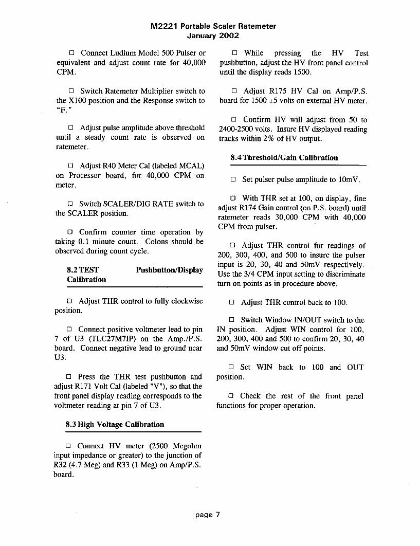
M2221 Portable Scaler RatemeterJanuary 2002
El Connect Ludlum Model 500 Pulser orequivalent and adjust count rate for 40,000CPM.
El Switch Ratemeter Multiplier switch tothe X100 position and the Response switch to"1F.
13 Adjust pulse amplitude above thresholduntil a steady count rate is observed onratemeter.
El Adjust R40 Meter Cal (labeled MCAL)on Processor board, for 40,000 CPM onmeter.
El Switch SCALER/DIG RATE switch tothe SCALER position.
El Confirm counter time operation bytaking 0.1 minute count. Colons should beobserved during count cycle.
El While pressing the HV Testpushbutton, adjust the HV front panel controluntil the display reads 1500.
El Adjust R175 HV Cal on Amp/P.S.board for 1500 ±5 volts on external HV meter.
El Confirm HV will adjust from 50 to2400-2500 volts. Insure HV displayed readingtracks within 2% of HV output.
8.4 Threshold/Gain Calibration
El Set pulser pulse amplitude to lOmV.
El With THR set at 100, on display, fineadjust R174 Gain control (on P.S. board) untilratemeter reads 30,000 CPM with 40,000CPM from pulser.
El Adjust THR control for readings of200, 300, 400, and 500 to insure the pulserinput is 20, 30, 40 and 50mV respectively.Use the 3/4 CPM input setting to discriminateturn on points as in procedure above.
0 Adjust THR control back to 100.
El Switch Window IN/OUT switch to theIN position. Adjust WIN control for 100,200, 300, 400 and 500 to confirm 20, 30, 40and 50mV window cut off points.
El Set WIN back to 100 and OUTposition.
El Check the rest of the front panelfunctions for proper operation.
8.2 TESTCalibration
Pushbutton/Display
El Adjust THR control to fully clockwiseposition.
El Connect positive voltmeter lead to pin7 of U3 (TLC27M7IP) on the Amp./P.S.board. Connect negative lead to ground nearU3.
El Press the THR test pushbutton andadjust R171 Volt Cal (labeled "V"), so that thefront panel display reading corresponds to thevoltmeter reading at pin 7 of U3.
8.3 High Voltage Calibration
El Connect HV meter (2500 Megohminput impedance or greater) to the junction ofR32 (4.7 Meg) and R33 (1 Meg) on Amp/P.S.board.
page 7

M2221 Portable Scaler RatemeterJanuary 2002
9. OVERHAUL PROCEDURE
0 The checkout below can be performedwith boards in instrument. An extender board(part no. 5261-098) is available if better accessto board components is necessary.
9.1 Amplifier/Power Supply Board
O Connect L.V. power supply to Model2221 and plug in Amp/P.S. board.(component side to back of instrument).
CO Adjust the WIN, THR and O.L. frontpanel controls to maximum clockwise position.Turn HV control to maximumcounterclockwise position. Switch the lampswitch to the OFF position. Window IN/ OUTswitch to the OUT position.
El Adjust input voltage for approximately+4 Vdc and turn instrument to the ONposition. Battery current should beapproximately 30 mA or less.
El Confirm pin 8 of U7 (CA3290A) isequal to or greater than +6.4 Vdc.
El Increase supply voltage toapproximately + 5 Vdc and pin 8 of U7 shouldincrease to +9 ± 1 Vdc.
El Check for +5 ±0.15 Vdc at pin 8 ofany of the TLC27M7IP's.
El Check for -6.5 ±0.5 Vdc at pin 4 ofany of the same TLC27M7IP's.
El Connect subminax wire from detectorinput to Amp/P.S. board.
El Connect HV meter to detector inputand adjust front panel HV control to fullyclockwise position.
El Adjust the HV front panel control tothe fully clockwise position. Then adjust R175
HV CAL for approximately 2400-2450 Vdc.Decrease front panel HV control to the fullycounterclockwise position and confirm that HVoutput is 50 volts or less. Then set HV forapproximately 1000 Vdc.
0l Connect voltmeter to pin 1 of U3(TLC27M7IP).
El With HV output set at approximately1000 volts adjust R176 Current Cal (labeled"0") for approximately 0.1 Vdc at pin 1 ofU3.
0l Connect Overrange Simulator (needs tohave a 1000 meg resistor) to detector input andconfirm pin 1 of U3 increases toapproximately 0.15 ±0.01 Vdc.
El Connect voltmeter to pin 1 of U2(LM358) and with Overrange Simulatorconnected, adjust O.L. control on the frontpanel counterclockwise until the voltmeterreads approx +0.5 Vdc. DisconnectSimulator and confirm pin 1 of U2 goes above+3 volts.
El Turn O.L. control to its maximumclockwise position.
E: Connect positive voltmeter lead to pin7 of U3 (TLC27M7IP) and connect negativelead to ground close to U3.
El Press the WIN test pushbutton andconfirm pin 7 of U3 is approximately 2.7 to3.8 volts.
El Press THR test and confirm pin 7 is1.23 ±0.02 Vdc.
El Press BAT test pushbutton and confirmpin 7 is approximately 0.5 with supply voltageat +5 Vdc.
page 8
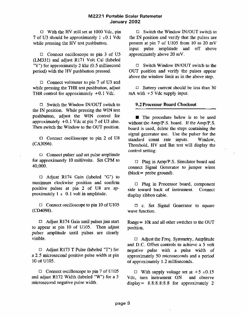
M2221 Portable Scaler RatemeterJanuary 2002
o With the HV still set at 1000 Vdc, pin7 of U3 should be approximately 1 ±0.1 Vdcwhile pressing the HV test pushbutton.
0 Connect oscilloscope to pin 3 of U5(LM331) and adjust R171 Volt Cal (labeled"V") for approximately 2 khz (0.5 millisecondperiod) with the HV pushbutton pressed.
0l Connect voltmeter to pin 7 of U3 andwhile pressing the THR test pushbutton, adjustTHR control for approximately +0.1 Vdc.
o Switch the Window IN/OUT switch tothe IN position. While pressing the WIN testpushbutton, adjust the WIN control forapproximately + 0.1 Vdc at pin 7 of U3 also.Then switch the Window to the OUT position.
O] Connect oscilloscope to pin 2 of U8(CA3096).
O Connect pulser and set pulse amplitudefor approximately 10 millivolts. Set CPM to40,000.
ol Adjust R174 Gain (labeled "G") tomaximum clockwise position and confirmpositive pulses at pin 2 of U8 are ap-proximately 1 ± 0.1 volt in amplitude.
11 Connect oscilloscope to pin 10 of U105(CD4098).
El Adjust R174 Gain until pulses just startto appear at pin 10 of U105. Then adjustpulser amplitude until pulses are clearlyvisible.
El Adjust R173 T Pulse (labeled "T") fora 2.5 microsecond positive pulse width at pin10 of U105.
El Connect oscilloscope to pin 7 of U105and adjust R172 Width (labeled "W") for a 3microsecond negative pulse width.
o Switch the Window IN/OUT switch tothe IN position and verify that the pulses arepresent at pin 7 of U105 from 10 to 20 mVinput pulse amplitude and off aboveapproximately above 20 mV.
0l Switch Window IN/OUT switch to theOUT position and verify the pulses appearabove the window limit as in the above step.
El Battery current should be less than 30mA with +5 Vdc supply input.
9.2 Processor Board Checkout
0 The procedure below is to be usedwithout the Amp/P.S. board. If the Amp/P.S.board is used, delete the steps containing thesignal generator use. Use the pulser for thestandard count rate inputs. Window,Threshold, HV and Bat test will display thecontrol setting.
0l Plug in Amp/P.S. Simulator board andconnect Signal Generator to jumper wires(black = probe ground).
El Plug in Processor board, componentside toward back of instrument. Connectdisplay ribbon cable.
El c. Set Signal Generator to squarewave function.
Range= 10k and all other switches to the OUTposition.
El Adjust the Freq. Symmetry, Amplitudeand D.C. Offset controls to achieve a 5 voltnegative pulse with a pulse width ofapproximately 50 microseconds and a periodof approximately 1.2 milliseconds.
El With supply voltage set at +5 ±0.15Vdc, turn instrument ON and observedisplay= 8.8:8.8:8.8 for approximately 2
page 9

M2221 Portable Scaler RatemeterJanuary 2002
seconds, then 261010 indicating the programnumber.
ol Connect Frequency Counter to pin 18of U22 (80C51FA) and confirm crystalfrequency is 6 Mhz ±_0.1% (6,006 khz-5,994khz).
El Switch the Scaler/Dig. Rate Switch tothe Dig Rate position.
O1 Counts should start accumulating every2 seconds until approximately 50,000 CPM isobserved. (The symmetry control can be fineadjusted until 50,000 CPM is achieved). Atthis displayed count rate, the low BAT Testindication should be observed, indicated by 5decimal points across the bottom of the-display.
11 Press BAT Test and display should be4.1 ±0.2.
EO Press HV and WINDOW= 410 ±_20.Threshold pushbutton has no effect withoutAmp/P.S. plugged in.
El Switch Ratemeter Response time to F.
o1 Switch Ratemeter multiply to X100.
o Adjust R40 Meter Cal, (labeledMCAL), until Ratemeter matches displayedaccumulated count (approximately 50,000CPM).
El Decade the Multiplier range on theSignal Generator to correspond to each decadeon Rate Multiplier to confirm range switchoperation.
El Connect Voltmeter to recorder outputand confirm R41 RCDR CAL, (labeledRCAL), will adjust from 0 to approximately3.7 Vdc, with full scale CPM on display andratemeter. Then set for 1 Vdc to equal fullscale meter deflection.
0l Connect Oscilloscope to pin 9 of U10(ICM7556) and decade Sweep Generator downto the lk range.
0l Switch the Audio Divide switchbetween the 1, 10, and 100 positions toconfirm Audio frequency divides or multipliesby 10, between each position.
0l Connect Headset or unimorph andconfirm volume control operation.
0l With full scale meter deflection (500),check F/S response time (90% full scale) for4.5 ±0.5 seconds and 22 ±2 secondsrespectively.
0 Check Count, Hold, and Zeropushbutton functions.
0l Switch Scaler/Dig. Rate switch to theScaler position and check the 0.1, 0.2 and 2minute time multipliers for correct timeoperation.
0l With +5 volts supply input, batterycurrent should be less than approximately 15mA, with full scale meter deflection.
9.3 Functional/Chassis Checkout
0l This procedure requires a checked-outAmp/P.S. board and Processor board.
El Connect one lead of an ohmmeter tochassis ground.
page 10

M2221 Portable Scaler RatemeterJanuary 2002
o1 Connect other lead of ohmmeter to theProcessor board cinch connector pins below tocheck count time switch operation. Boards arenot plugged in yet.1= open0 = shorted
COUNT TIMEPOSITION
PROCESSOR BOARDCINCH CONNECTOR
PIN 8 30 31
0.10.20.5
12510
CONT
0 0 00 0 11 0 01 0 10 1 00 1 11 1 01 1 1
Connect external power supply and setinput voltage for approximately + 5 Vdc.
o1 Turn Lamp switch to the OFF position.THR and O.L. controls to maximum clockwiseposition and HV to maximumcounterclockwise position.
o Plug in Processor and Amp/P.S. boardsand related cable connections.
O1 Turn instrument ON. Current drawshould be less than 45 mA.
o1 Confirm display reads 8.8:8.8:8.8 forapproximately 2 seconds, then 261010indicating the program version.
o Connect positive voltmeter lead to pin7 of U3 (TLC27M7IP) on the Amp./P.S.board. Connect negative lead to ground nearU3.
ol With the THR control full clockwise,press the THR test pushbutton and adjust R171Volt Cal (labeled "V"), so that the front paneldisplay reading corresponds to the voltmeterreading at pin 7 of U3.
o1 Connect HV meter (2500 Megohminput impedance or greater) to the junction ofR32 (4.7 Meg) and R33 (1 Meg) on P.S.board.
o While pressing the HV Testpushbutton, adjust HV control until the displayreads 1500. R176 Current Cal may have to beadjusted counterclockwise to defeat theOverrange function.
0l Adjust R175 HV Cal on Amp/P.S.board for 1500 ±5 on external HV meter.
o Confirm HV will adjust from 50 to2400-2500 volts. Insure HV displayed readingtracks within 2% of HV output.
o Adjust HV for approximately 1000volts.
El Adjust R176 Current Cal (labeled "0")for approximately 0.1 volt at pin 1 of U3(TLC27M7IP) on Amp/P.S. board.
0l Connect Overrange Simulator (1000megohm) to the detector input.
0l Adjust the O.L. controlcounterclockwise until hyphens start flashingacross display every other count interval.Disconnect Overrange Simulator and confirmoverrange function is defeated. Then adjust tofully clockwise position.
0l Set THR control to 100 and WindowIN/OUT switch to the OUT position.
0l Connect pulser and adjust count ratefor 40,000 CPM.
0l Switch Ratemeter Multiplier switch tothe X100 position and the Response switch to
0 Adjust pulse amplitude above thresholduntil a steady count rate is observed onratemeter.
page 11

M2221 Portable Scaler RatemeterJanuary 2002
El Adjust R40 Meter Cal (labeled MCAL)on Processor board, for 400 CPM on meter.
El Adjust pulser for 10,000 CPM andcheck meter for ±10% linearity of reading.Adjust pulser and rate Multiplier switch toconfirm linear readings on all ranges.
El Switch SCALER/DIG. RATE switchto the SCALER position.
El Confirm count time switch operationby taking a 0.1 minute and 0.5 minute count.Colons should be observed during count cycle.
El Check HOLD and ZERO pushbuttonfunctions.
El Switch SCALER/DIG. RATE switchto the DIG. RATE position and confirm updatecount display operation approximately every 2seconds.
o Connect unimorph and headset to theaudio outputs and confirm audio divide andvolume control functions. NOTE: Unimorphshould shut off when headset is connected.
0l With the THR control adjusted for 100,adjust R174 Gain (labeled G) for 1.5 millivoltinput sensitivity. Insure instrument functionsat low input sensitivity without "noise".
El Instrument may have to be placed incan to permit "noise free" operation.
El Set pulser pulse amplitude to lOmV.
El With THR still set at 100, fine adjustR174 Gain control until ratemeter reads30,000 CPM with 40,000 CPM from pulser.
El Adjust THR control for readings of200, 300, 400, and 500 to insure the pulserinput is 20, 30, 40 and 50mV respectively.Use the 3/4 CPM input setting to discriminateturn on points as in procedure above.
El Adjust THR control back to 100.
El Switch Window IN/OUT switch to theIN position. Adjust WIN control for 100,200, 300, 400 and 500 to confirm 20, 30, 40and 50mV window cut off points.
E: Set WIN back to 100 and OUT positionfor instrument shipment.
El Input a full-scale ratemeter count rate(500 CPM) and connect voltmeter to therecorder output. Adjust R41 (labeled RCAL)on Processor board for 1 volt.
El Check F/S ratemeter response time for4.5 ±0.5 and 22 ±2 seconds at 90% of fullscale.
El Decrease input supply voltage untilperiods are observed at bottom of display.Press BAT Test pushbutton and confirm lowBAT Test is 4.4 ± 0.1 Vdc. Adjust supplyvoltage back to 5 volts and confirm BAT testand actual supply input is 5 ±0.05 Vdc.
El Switch SCALER/DIG. RATE switch tothe SCALER position. Count Time Multiplierto CONT. Press count pushbutton and startwith low enough count rate to observe eachdigit number count sequence from Leastsignificant digit to MSD. Decade pulser countrate to speed up digit segment display check.
El Increase count rate enough to overflowcounter. An "H" should be observed in theMSD flashing every count interval.
El Turn Lamp switch to the ON positionand confirm 2 lamps in the display and 2 lampsbelow the meter are illuminated.
El Current draw with lamps on should be210 ±20 mA.
El Turn lamp OFF and current should beapproximately 40 ± 5 mA.
page 12

M2221 Portable Scaler RatemeterJanuary 2002
PARTS LIST
Ref. No. Description Part No. Ref. No. Description
Model 2221 Portable Scaler Ratemeter
UNIT Completely Assembled Model 2221Portable Scaler Ratemeter 48-2065
Amplifier/Power Supply Board,Drawing 261 X 56
C154C 164C165
0.0015ItF, 3kV, C0.1F, 100V, C0.1ItF, 100V, C
Part No.
04-551804-552104-5521
0 TRANSISTORS
Q142Q143
2N3904MPSU51
05-575505-5765
BOARD Assembled Board 5261-0720 INTEGRATED CIRCUITS
* CAPACITORS
C 107C108C109CIIoClllCl12Cl14C1 15Cl16Cl 17C118C120C121C122C 123C 124C125C126C 127C128C129C130
C131C132C133
C 135C136C 137C138C 139C140C141C 145
C 146C 147C 148
IiF, 35V, DT2.2iF, 25V, DT
4.7p.F, 10V, DT4.7pF, IOV, DT
100lF, 10V, DT4.7jF, 10V, DTlOpF, 100V, C0.1gF, 100V, C0.1ltF, 100V, C
0.14F, 100V, C0.1jIF, 100V, C
0.0022gF, 100V, P
0.001lF, 100V, C0.1gF, 100V, C100pF, 100V, C0.1AF, 100V, C0.01tF, 100V, C47pF, 100V, C0.lgF, 100V, C47pF, 100V, C100pF, 100V, C10pF, 100V, C0. lgF, 100V, ClOpF, 10OV, C0.00154iF, 3kV, C0.0015gF, 3kV, C
0.0015gF, 3kV, C100pF, 3kV, C100pF, 3kV, C0.00564F, 3kV, C0.0056giF, 3kV, C0.00564tF, 3kV, C
lgF, 35V, DT
IOOjtF, IoV, DT100ljF, 10V, DT
10AF, 20V, DT
04-557504-555904-557804-557804-557604-557804-557304-5521
04-552104-552104-5521
04-558004-551904-552104-552704-552104-552304-553304-552104-553304-552704-557304-552104-557304-5518
04-551804-551804-553204-553204-552204-552204-552204-5575
04-557604-557604-5592
U1U2U3U4U5U6U7U8U9UI05U106U144
TLC27M7LM358TLC27M7TLC27M7LM331LM2578CA3290AECA3096CA3096CD4098CA3096CD4052
06-624806-602406-624806-624806-615606-622306-614006-602306-602306-606606-602306-6141
0 DIODES
CRIOCR12CR13CR14CR15CR16CR17CR18CR19CR20CR21CR22CR24CR25CR151CR177
IN5819MR-250-2MR-250-2MR-250-2MR-250-21N41481N41481N41481N41481N41481N41481N41481N58191N5819MR-250-21N5252
07-630607-626607-626607-626607-626607-627207-627207-627207-627207-627207-627207-627207-630607-630607-626607-6265
. RESISTORS
R32R33R34R35R36R37
4.7MiMIMIGIG0.1 OHM, 1%
10-703010-702810-702812-768612-768612-7647
page 13

M2221 Portable Scaler RatemeterJanuary 2002
Ref. No. Description Part No. Ref. No. Description Part No.
R38 10k 12-7748 R96 IM, 1% 12-7763R39 iM, 1% 12-7763 R97 10M 12-7749
R40 10k 12-7748 R98 IM 12-7751R41 10k 12-7748 R99 470k 12-7757
R42 10k 12-7748 R100 470k 12-7757
R43 10k 12-7748 RIO0 100k 12-7747
R44 47k 12-7758 R102 IM, 1% 12-7763R45 4.7k 12-7755 R171 10k TRIMMER 09-6822R46 10k 12-7748 R172 100k TRIMMER 09-6823R47 10k 12-7748 R173 100k TRIMMER 09-6823R48 10k 12-7748 R174 10k TRIMMER 09-6822R49 1k 12-7750 R175 IM TRIMMER 09-6828R50 220 OHM 12-7753 R176 IM TRIMMER 09-6828R51 220 OHM 12-7753R52 470k 12-7757 * TRANSFORMERSR53 47k 12-7758R54 1k 12-7750 T103 M2300 HVPS 4275-037
R55 10k 12-7748 T104 M2221 LVPS 4275-094R56 4.7k 12-7755R57 10k 12-7748 * MISCELLANEOUSR58 10k 12-7748R59 10k 12-7748 9 EA. CLOVERLEAF RECEPTACLESR60 1k 12-7750 011-6809-00 18-8771R61 178k, 1% 12-7769 3 EA. SPACERS 18-8933R62 4.7k 12-7755 * TRANSISTOR SPACER 18-8992R63 100k 12-7747 * AMPLIFIER SHIELD 7261-100R64 10k 12-7748R65 10k, 1% 12-7764 Processor Board, Drawing 261 X 91R66 220 OHM 12-7753R68 10k 12-7748 BOARD Assembled Board 5261-136R69 1.5k 12-7773R70 100k, 1% 12-7765R71 200k 12-7752R72 200k 12-7752R73 100k 12-7747 C2 0.047gF, 100V, C 04-5565R74 100k 12-7747 C2 0.047MF, 100V, C 04-5519R78 22k 12-7754 C3 0.O7lpF, 100V, C 04-5519R79 10k 12-7748 C4 27pF, 100V, C 04-5614R80 10k 12-7748 CS 27pF, 15oV, C 04-5614R81 100k 12-7557 C6 22jF, 15V, DT 04-5579R82 200k 12-7752 C7 lOgF, 20V, DT 04-5592
R83 22k 12-7754 C8 100ltF, 10V, DT 04-5576
R84 10k 12-7748 C9 1004F, 10V, DT 04-5576R85 IM 12-7763R86 4.42k 12-7760 0 TRANSISTORR87 47 OHM 12-7756R88 100k, 1% 12-7765 Q36 2N3904 05-5755
R89 17.8k 12-7759R90 10k, 1 % 12-7764 0 INTEGRATED CIRCUITSR91 1M, 1% 12-7763R92 iM, 1% 12-7763 U10 ICM7556 06-6244
R93 40.2k, 1% 12-7761 Ull CD74HCO8 06-6222R94 100 OHM 12-7746 U13 CD4054 06-6245R95 10k 12-7748 U14 CD4056 06-6095
U15 CD4056 06-6095U16 CD4056 06-6095
page 14
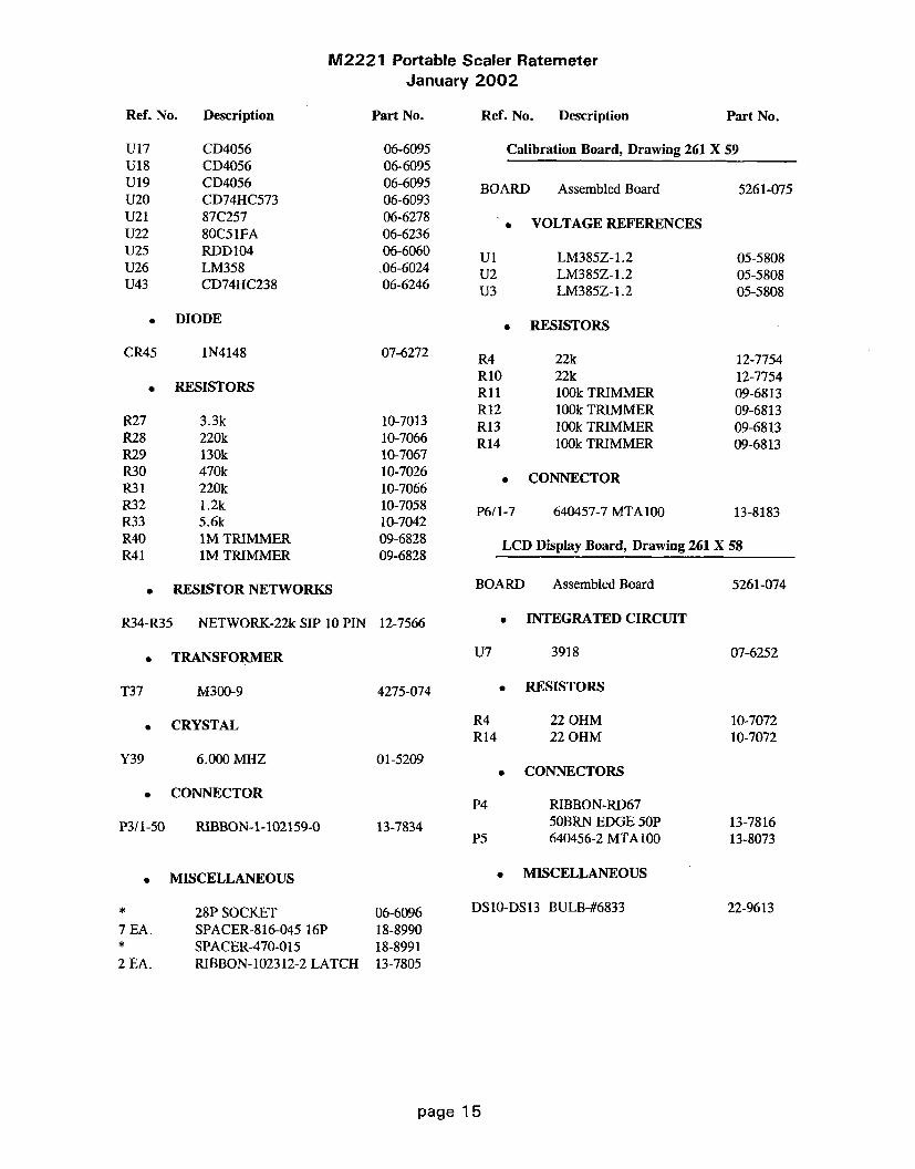
M2221 Portable Scaler RatemeterJanuary 2002
Ref. No. Description
U17 CD4056U18 CD4056U19 CD4056U20 CD74HC573U21 87C257U22 80C51FAU25 RDD104U26 LM358U43 CD74HC238
Part No.
06-609506-609506-609506-609306-627806-623606-6060
,06-602406-6246
Ref. No. Description Pa
Calibration Board, Drawing 261 X 59
BOARD Assembled Board 5
rt No.
5261-075
0 VOLTAGE REFERENCES
U1U2U3
LM385Z-1.2LM385Z-1.2LM385Z-1.2
05-580805-580805-5808
• DIODE 0 RESISTORS
CR45 1N4148 07-6272
0 RESISTORS
R4RIORi1R12R13R14
22k22k100k TRIMMER100k TRIMMER100k TRIMMER100k TRIMMER
12-775412-775409-681309-681309-681309-6813
R27R28R29R30R31R32R33R40R41
3.3k220k130k470k220k1.2k5.6kIM TRIMMER1M TRIMMER
10-701310-706610-706710-702610-706610-705810-704209-682809-6828
* CONNECTOR
P6/1-7 640457-7 MTA100 13-8183
LCD Display Board, Drawing 261 X 58
* RESISTOR NETWORKS
R34-R35 NETWORK-22k SIP 10 PIN 12-7566
BOARD Assembled Board
INTEGRATED CIRCUIT
U7 3918
5261-074
0 TRANSFORMER 07-6252
T37 M300-9 4275-074
0 CRYSTAL
* RESISTORS
R4 22 OHMR14 22 OHM
* CONNECTORS
10-707210-7072
Y39 6.000 MHZ 01-5209
6 CONNECTOR
P3/1-50 RIBBON-1-102159-0
* MISCELLANEOUS
* 28P SOCKET
7 EA. SPACER-816-045 16P* SPACER-470-015
2 EA. RIBBON-102312-2 LATCH
P4
P5
RIBBON-RD6750BRN EDGE 50P640456-2 MTAIOO
13-7834 13-781613-8073
* MISCELLANEOUS
DSIO-DS13 BULB-#683306-609618-899018-899113-7805
22-9613
page 15

M2221 Portable Scaler RatemeterJanuary 2002
Ref. No. Description Part No. Ref. No. Description Part No.
Chassis Wiring Diagram, Drawing 261 X 61Backplane Board, Drawing 261 X 60
BOARD Assembled Backplane Board 5261-076
0 DIODE
0 AUDIODS1 UNIMORPH 60690 21-9251
CONNECTORSCR6 1N5819 07-6306
0 CONNECTORS
J1-J2P7P8P9P1OPl1
EZA22DRSN640456-7 MTA 1001-640456-4 MTA100640456-5 MTA100640456-2 MTA1001-640456-4 MTAIOO
13-818113-811513-814113-805713-807313-8141
JiJ2J5J6-J7J8J9J10Jill
CONN-640456-2 MTA100UG706/U SERIES CPHONE JACK TINI #42A(ON CAL HARNESS)(ON MAIN HARNESS)(ON BATTERY HARNESS)NOT USED(ON MAIN HARNESS)
13-807313-775121-93338261-0888261-0878261-089
8261-087
SWITCHES
S1-S7 30-1-PB GRAYHILL 08-6517S8-S12 7101-SYZ-QE TOGGLE 08-6511SWI 513381 08-6656SW2 513381 08-6656SW3 MTA-206PA 08-6657
* BATTERY
B1-B4 1.5 VOLT "D" DURACELL 21-9313
* RESISTORS
RI 10k NON-LOCKING 09-6753
* MISCELLANEOUS
M1 M2221 METER ASSY. 4261-091
page 16
M2221 Portable Scaler RatemeterJanuary 2002
DRAWINGS AND DIAGRAMS
Amplifier/Power Supply Board Schematic, Drawing 261 x 56Amplifier/Power Supply Board Component Layout, Drawing BS261072
Processor Board Schematic, Drawing 261 x 91Processor Board Component Layout, Drawing 261 x 103
Calibration Board Schematic, Drawing 261 x 59Calibration Board Component Layout, Drawing BS261075
LED Display Board Schematic, Drawing 261 x 58LED Display Board Component Layout, Drawing BS261074
Backplane Board Schematic, Drawing 261 x 60Backplane Board Component Layout, Drawing BS261076
RS-232 Board Schematic, Drawing 261 x 179RS-232 Board Component Layout, Drawing 261 x 180
Wiring Diagram, Drawing 261 x 61
page 1 7

M2221 Portable Scaler RatemeterJanuary 2002
Model 2221 RS-232 Port Addition (LMI Part Number 4261-148)
The Model 2221 RS-232 port addition allows the M2221 data to be read as output to a computeror serial printer, by dumping either the ratemeter or scaler reading, as desired. The desiredreading is selected with a toggle switch located in the digital control section of the front panel,labeled with two positions: "SCALER" and "DIG. RATE." The port addition kit (LMI PartNumber 4261-148) includes the internal board, a cable that will connect directly to a 9-pin PC portand software routines to log the readings.
The scaler reading dumps when the scaler has completed a count. The ratemeter is dumped every2 seconds in one of three formats, depending on the firmware installed. The three availableformats are (1) counts per 2 seconds, (2) counts per 60 seconds (cpm), or (3) counts per second(cps). Data output is always in a 6-digit format with a letter prefix, corresponding to thefollowing:
Ratemeter: "R"
Scaler: According to the table below
Letter Prefix Time of Count (min) Time of Count (sec)Format 1 or 2 Format 3 (cps version)
A 0.1 1B 0.2 2C 0.5 5D 1.0 10E 2.0 30F 5.0 60G 10.0 120
A carriage return and then a linefeed character follow the 6' digit.
The communication protocol is 9600 baud, no parity, 1 stop bit, and 8 data bits. The RS-232 portis an output only with no handshaking available. The M2221 will dump the data, no matter what,even if the attached computer or printer is not ready. The cable provided is a coaxial cable,providing TXD and GND to a 9-pin D-connector, ready to plug into a standard PC serial port.
The Model 2221 Processor Board (Part Number 5261-136) utilizes an 87C257 EPROM with oneof the following firmware numbers, depending on the desired rate:
Rate Dump as counts per 2 seconds -- #261-06-N03.Rate Dump as counts per 60 seconds -- #261-07-N02.Rate Dump as counts per second with meterface 202-930 -- #261-02-N02
page 18
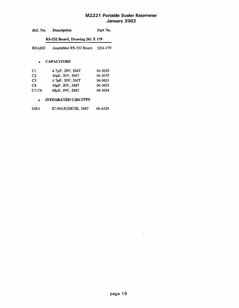
M2221 Portable Scaler RatemeterJanuary 2002
Ref. No. Description Part No.
RS-232 Board, Drawing 261 X 179
BOARD Assembled RS-232 Board 5261-179
* CAPACITORS
C1 4.7gF, 20V, SMT 04-5653C2 lOtF, 20V, SMT 04-5655C3 4.7gF, 20V, SMT 04-5653C4 lOpF, 20V, SMT 04-5655C5-C6 68gF, 10V, SMT 04-5654
a INTEGRATED CIRCUITS
U001 IC-MAX220CSE, SMT 06-6329
page 19
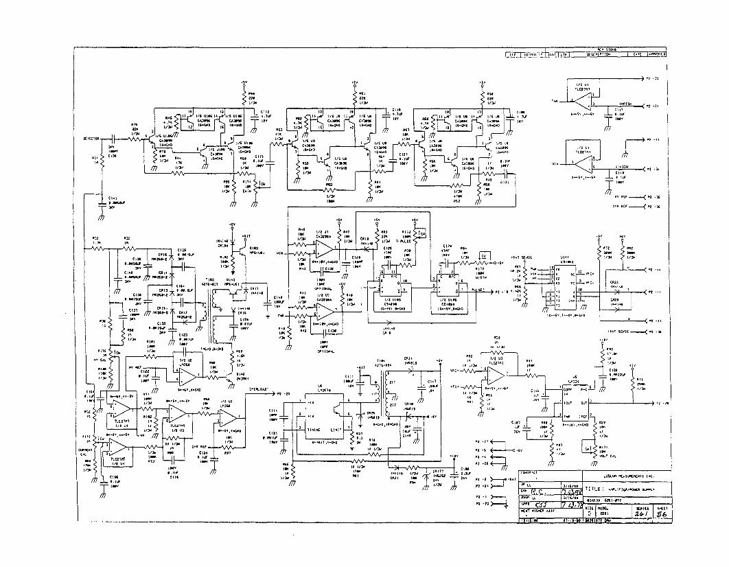
lin I.-Ca7 C1.1 el-22K1 3 1.0" 12l/31o I-
1/2w 2/1IgU .16W vs113a
1 s" 4 I SL
~C.2.2.
I 2. CR 11 1
2. IIRC2.L.
CIIIS~VI *.-'.1 I. IS
I1CR~1
I /
2 111101 .2.2.1
l~I *U.~...........< .2 31
.A46
Ulu I
1113"is1 -S' 114240
COSO 22tIv-Q ýI
CIS. 127"31 nn-USIC*X1 .312.e5 16 C111 .I* a1264-a 211/3V Al
CV31 ISU- IM11211
e~,i CR11 2CR14
344 0 2 126
CALII I /2 U
WWI 711. , LI..
CR11 3/w
ISI ;s 11 c112221C1
02.1S7
I,
~~.s.I~1 1.. .2CI
.1w~~I - 2,I ,
TLC zim12 1, 2 16I.
- svIII 2IT213 al
I
.6y
A72 "IW.
"""'-10 W-CE Vill I/N LIN
all,
"I "C '/N LIN
X3 YC ý,C- -2
17
Y;
-. 1 Iýs( n _)S
* 1R 111 ~21 CR
IIIN
,IN
22.12P I K - - - 1 - - 11 21- . .
3~,0204. 1 1s. su" 241 ,
Ir~n 11MiU1l' IA

BOARD# 5261-072TITLE AMPLIFIER/POWER SUPPLýMODEL 2221COMPONENT OUTLINESDR RDS 4/7/89CHK R/. 1 /13/99DSGN LL 3/1S/89APPD 5 2 /3/%/B :BS26 1072 DRW
07-19-89 15:32:24

.656
? ;PP
INV
7417" '37 A
@use
BU26
_-A6
17PF L-CS
42.P2.P2.P2.P2.P2.P2.P2.
p2 3 .7> - BAT..2 TEST'
PI -44 >- H TEST'
,1 -21 > _W..~2 TEST'
P2 -22 > - O.. VERLOAD'
PI 7 0 2
P2 -26 > - MB
P2 -is26 (XE
PI -20 > - V....OL S
BAT TEST'
24TEST.!-.
4IE2B-ŽI
SCALER, lc ATE 670
SPARE 6
U22.K2IrA
pg. P1 .2-8 14'
P6.2 1GUS1
P6.4 -LS4L2 PINS Buss
SE I
P 2 AS
P' P2 24 Al4 P,. L4 A4 P2 . 615 P2.6 7A 241 PP 2 , 2 6 A 6 I
7.2 . 6.6 ALI • ALE.4 3
.?
21.4IF 7214
2J6' E Y
*6V sv 26 1
?1 -7, >.......20126DIG RATE'
Pi -42 >..3.2P6E'
P2 -72 RESPONSE
p.'I
PI -1 >
P: -24 e6
P2 -2
P2 -27
2622.
P2 -4
PvL.SE' 1-ii P3
222.2
5 ~ ~ 6 8 61
2203
42 02217 gus2
B S USS132164
66 SYUT6 27 oussCN
U212
6-a~l-eto
B$e. - /1 10167025
U.JS2I 2 /02BUS,7 A2 1/D3
622 67 ;/043US4 6' 4 2/0"6ouJ"/• AS 1 /0661152 42 A 2/07
AB0--1 " A&.:a2 67 /00
24
AL4 Alt Z
6214 21 A 46
26'66V,l40222
Pi -toI23 F7AUTO ~~ 0 I TY 2062M7 L I R1
P3 -12
CD4054 P3 -'21 11111, OUT P3 -14 a1"
Bus2 2 1W T2 P3 "4? I- B2
S222 3 22. n27 PO -22 52.626120 274 22.7 0.2 P7 -752
27(
if4 U][ OCD)74HC68 e
144 14
CD74MCgO4
SOHZ - P3 • p
U4.62V I2-I0D 6200 C746063
1/4 L I II
140S6 17=GND
Bust122
LIL 61.22IL
REIvSIONS
024C D4" 4.,
us 0PI -41
us 0 I ? I -
v t , Z2-P3
US a4 2 d 3-s
U19
S4 21 5 P7-41
56 2.22 1•5 3 37.43
57G Z P7 -76USP7 2-76
1 7 P2 -7SP, -37
CD485
tol• p3 I..
6 *22 P -77
U 5'2 6-_21 2.7-22
US 124 ..- 2202663
OHZ -I-D FRED -'27
I'll t b 3 -2S
m 1223 -27•72
U57 6 d P3 27
SIB 1 13-:2'
2S 6 -22 ,6*3-227.02
BN Q 4 P3 -is
16.-S ,19- 7"-NO
P2 -36
616132
B,
-2
UIS004656
a62.22a _±- 26
-7- 2221 b22
P2 ~ 2 d2 16,5 4V22746
121222
-;
P . '3S TO r P3 -I•
P2-27 D226 26 E 9
P1-2 BUSS 22
P26
P,- e , l -11
P7 23 2• P3 -6
I ,, P3 -4
SIB" 1• 3 P3-t91G 2 6 P3-
. ~LUBLUMl t*ASUREMENTS |NK0R22K2 03/ ]6/9 L
DSC LL O3114/89 O2AR06 6271-12 2
022 SITZE 624L2121222 R 16242WýIHI KRAs 7 -22042 52________________D 222 M:./
21
B-.6SV,3-CD
6:27.67 I7266 A:242216.24 I2(6 I

MWLUDLUMi MEASUREMEN~TS INC. SWEETWATER, Tx.
DR ORB- BFlO'/SL9 ITITLE : PROCESSOR BOARDICHK SDRD DOr.I~ ISB I~BIDSCN LL 103/14/91 MODEL 2~221 SERIES 26 1 SHE-ET lIOD[APRP $ 12-1 - DPATOK0SDS ARTWORKRED109:19:04 29rl,-S CEI JULN LR OUTLINE CICOrIP PASTECIICOtP MASKRO ISODB PASTE 0 JSODR 'ASK

1ý1 ..tr~ I~ I 1. 1LI R I *ctp c DECITO I PAT( I.
PS -Z
PS -1
PS -3
7¶PcI [WC L--LP KEsM&Iý LL1/66
EW. .C S49TITLE : C L19-1 .90f
RMoDO 6291-676
SIZE JIODCL ~ ~ C fD 2Z7I 26 ?
I ii 5~ ~4 9-S~ 3 SS~S IIfl ~

WIN
R14 0THR 0
R11 0 0
HVR12 0 -
OVRLD 0R13 0 10
I
BOARID# 5261-075TITLE CAL. BOARD[ODEL 2221COHPONENT OUTLINESDR RDS 3/28/89CHK P,C, I /Ks /gyDSON LL 3/16/89APPP -• 5 7/3 /D "BS2610751 DIR
05-20-89 07:38:12

PT 3F 330 oro3 701 ILI I3 KCA I 23PH DITC lk33(
LCI DISPLAY
p -2 3S 1 26 I4 fl3 -23, P3 .60
24 -" 33 2 " "9P423• 2-3 23 *3
P4 -4 4 , .I36
- is , ZI P: -.3P4 -1$ C C2 p 44
2 9G 32 , .....ES -E2 I-
21 2 $1 -'S 32 a 32
74.3 P ,,4 32 "4 -3.P4
A•
CS 491 P4-29P - I 3+6 ¢2 23 -
23 -25 O3 -34
12 - 36 < P, - 3G
D2352.33 L.3'
23~ ~ -I 3
I.I L3"1L33M. .3.
054W LL 3 ; D 26 304 .
['k" • 7 D,, ju, I 3J|K ijI a ~I
I J97314M WK1-imi.lucahby4 I City I Fl

FOI I-
U700
0 0 0 0 0 a 0 0 0 0 0 0 0 0 0 0 0 0 0 0 0. -0 0 0 0
0 0a0 a a a 0 0 0 0 0 0 0 0 0 a0 0 0 0 0 0 0 0 0 0
I
BOARD# E281-074TITLE DISPLAY BOARDMODEL 222 1COMPONENT OUTLINESDR - 3/27/89CHK P.C. /1_ _ /u_DSGN LL 3/16/89APP.D 73 7 /•BS26 1074 ,DRN
05-24-89 15 :44 :20

PS -2
PS -3 >ps -4 4 SPKR-
ps -s -BAT
1-58)3C4G
Pg -zReo-2 > - SF4(
Ps -3 >.. HV TEST,
ps -4 .- ¢ouNl.
Pe -5 >....--WIN TEST'
Pe -o •=.s•THR TEST,
Pe -5 -PLE
Pe -i1i> ,,.-AVII IN
PO "12 =,•-- DIV 5{;L
Pe - 13 >_ ZERO,"
P8 -14 >- S..- L6•li .,ATE'
P111l-I•. = RC.SPONSE
P11-2 >...=.- CTI
P31.3 > - CT2
J2AMPLIFIER 'POWER SUPPLY
326 '-072 PROCESSOR$263-013
VOUE 3 AUDIO
6NG 120 METER
ZRO,3. 9 CIL
DI 1 - 4 36 RCOD
AUDIO I" IS 131 ,
1 T 33 S..CALR/3
PLE- sI I3 AS -I
WC SL.. FR j- 20 [4.2 00
WI20 N TEST- 21 CONT
OVERLOAO.Hý 221 I -H I
I1 3I iT
"3JSEA- "1e "PA S[ IQ -T• "I 5 3I..TMR TEST
WIN TEST' 2
OVERLOAD' 221 I K TEST
'D3G RATE'
I,"
PEý IS IR
co .. ' UDLUM~ MAUREMENTS INC.
4m 7T1TLE PA S.2LANE
20124 LL 3/16/82 620ARD8 626t.076
NEXT KI312( 4ZSS 5j 1 2 Z / I MDE17!4614 96-24-89 $26 tf7G.DAW 6362 I
P11.6 >_ N-4GI
Pi3-36 4=.-.,-4AT TEST'
PI3-9 >_... R..1423
PI3 3.8 4...-M22ETEA
P33-33 4.....U2230 PT -3P1-1 4-- eAUDT P•-TECTED,7 -1 <_7
P11.-14 >_ý P7- I
P7 -6
P lS36-3 P7 -7 OV4

0l0
iOo
lol
ED
w
00 0
0)111 a
a
00
J13
OC
13 a
FT0iiJd 13a0- 0 00 -
0 J2 i0
AMP/OWER PROESSO
BOARDf# 5261-076TITLE BACKPLANEMODEL 2221COMPONENT OUTLINESDR RDS 3/28/89CHK Rx.c. q /13 /16DSCN LL 3/16/89APPD 153 • 7 // /Yr-BS26 1076, DRN
05-24-89 15:15:37

I UL1430
12"
W5
#22 BLACK UL1430
12"

I
o 1 022 YflMW LJLI4•0
920 w AY UL1429
#2. BLACK ULPL430
i2 BLAC L L1429
0 0
Drawn: CKB 21-MAR-01 Titlem
Design: RDS 11-NOV-99 RS-232 BOARDCheck t,*. I~ea,~oo Modet 2221
Approve: ,- , - Board#: 5261-179Lo - Top O verlay Rev -1.0 Series Sheet
Mec, I IIeC4 14:02-28 4--Feb--2002 SCALE 1.00

J2D~EECTOA
I I,~ I
RE2SOErF I AUIIIORI TY UtK T OSRI PTIO ýOT AD M
CAL. CCN7FL CAL SOAM7 PIN SIP 7 PIN SIP
wc4
rn65 a
LAW~ DISCONNECT2 PIN SIP
LLISLLIM MEAkW*BDIETS INC
M~wLL 3/3" TTL' ~ RSI~
1.7 4/N o"1 c r
PATI
RE~wm'
Z PIN SIP
RECO~RDR-

LUDLUM MODEL 2224
SCALER/RATEMETER
March 2002Serial No. 183080 and Succeeding
Serial Numbers
Measuring Range: 0-500,000 counts per minutePower Requirement: two standard "D" cell batteries
LUDLUM MEASUREMENTS, INC.501 OAK ST., P.O. BOX 810SWEETWATER, TX 79556915/235-5494 FAX: 915/235-4672

rr(D-
0
VOLO
a
HVC
RES 0
0 0D
0
" OHv
MODEL 2224SCALER/RATEMETER
~ LUDLUM MEASUREMENTS. INC.SWEETWATER. TEXAS
I II

M2224 Scaler/RatemeterMarch 2002
TABLE OF CONTENTS
1. G E N E R A L ...................................................................................................................... 1
2. SPECIFICATIONS .............................................................. 1
3. PRINCIPLE OF OPERATION ........................................................................................... 2
4. PRELIMINARY INSTRUCTIONS ...................................................................................... 24.1 Unpacking and Repacking ............................................................................................ 2
5. OPERATING INSTRUCTIONS ......................................................................................... 25.1 Safety Measures ......................................................................................................... 25.2 Descriptions of Controls and Functions ............................................................................. 2
5.2.1 Operator Controls .............................................................................................. 25.2.2 Internal C ontrols .................................................................................................. 3
5.3 Operating Procedures .................................................................................................. 45.4 C alibration .............................................................................................................. 5
5.4.1 Meter Calibration .............................................................................................. 55.4.2 Detector Overload Calibration .............................................................................. 5
6. THEORY OF OPERATION ............................................................. ...................... 66.1 Amplifier/Power Supply board # 5390-066 ........................................................................... 6
6.1.1 Detector Input/Amplifier ................. : ................................................................... 66.1.2 Alpha/Beta Discriminator ....................................... ............. 66.1.3 Alpha/Beta Disc. Logic Circuit ............................................................................... 66.1.4 Low Voltage Supply ........................................................................................... 66.1.5 High Voltage Supply ...................................................... 66.1.6 Detector Overload ............................................................................................... 66.1.7 M eter D rive ........................................................................................................ 6
6.2 Processor Bd.# 5390-095 ................................................................................................ 76.2.1 Power supply .................................................................................................... 76.2.2 Microproccessor .................................................................................................. 76.2.3 L C D D rive ......................................................................................................... 76.2.4 A udio ........................................................................................................... . . 7
7. MAINTENANCE ............................................................................................................. 8
PARTS LIST ...................................................................................................................... 9Model 2224 Scaler/Ratemeter ............................................................................................ 9
Amp/Power Supply, Drawing 390 X 63 ........................................................................... 9Processor Board, Drawing 390 x 97 ............................................................................... 10Calibration Board, Drawing 390 x 100 ............................................................................ 10Display Board, Drawing 390 x 127 .................................................................................. 11Interconnect Board, Drawing 390 x 124 ............................................................................ 11Chassis Wiring Diagram, Drawing 390 X 103 ..................................................................... 11
DRAWINGS AND DIAGRAMS ............................................................................................. 12
page

M2224 Scaler/RatemeterMarch 2002
1. GENERAL
The Model 2224 is a portable microprocessor basedradiation survey instrument used to measure anddiscriminate low level alpha/beta radiation when usedwith an alpha/beta scintillation or proportional detector.
The data is displayed by an analog ratemeter and asix-digit liquid crystal display (LCD) counter. Theratemeter dial indicates 0-500 CPM with four linearrange multipliers of XI-X1000 producing an overallrange of 0-500 k CPM. The LCD is used to display thecounts accumulated during the preset count time. Thereare four count times available via internal switches.These count times are 6 seconds, 30 seconds, 60seconds, and 120 seconds. The counter is reset andstarted by pressing the Count button located in the endof the carrying handle.
The ratemeter and LCD can display alpha only, betaonly, or alpha and beta by selecting the correspondingtoggle switch selection. Audible click per event tonescan also be selected to discriminate beta (low pitch tone)
from alpha (high pitch tone) via the side mountedspeaker. Beta threshold, window, and alpha thresholdare adjustable to optimize alpha/beta efficiency andcount separation.
A regulated high voltage power supply adjustablefrom 200 to 2000 volts with detector overload detectionis utilized to operate a wide range of scintillationdetectors. Other operating features of the instrumentinclude programmable audio divide by (beta channelonly), a two-position switch (internal) for selecting theaudio discrimination mode, an adjustable volume,pushbutton battery test switch, pushbutton high voltagetest switch and meter reset.
The unit body is made of cast aluminum with adrawn aluminum can. The unit is operated with two "D"cell flashlight batteries for operation from -100C toapproximately 50'C. For temperature operation to-10C, either very fresh alkaline or rechargeable NiCdbatteries may be used.
2. SPECIFICATIONS
" ýPOWER: two standard "D" size batteries.
* RANGES: four linear range multiples of Xl,X10, X100, and X1000; used in combination with the 0-500 CPM meter dial, 0-500k CPM is achieved with therange multiplier
0 SENSITIVITY: beta Threshold (BT) isadjustable from 2 - 15 millivolts (mV), beta Window(BW) is adjustable from the beta Threshold up to thealpha Threshold setting; alpha Threshold (AT) isadjustable from 40 - 700 mV
* AUDIO: Dual or single tone click per eventthrough a built-in speaker with an adjustable volumecontrol and internally switchable divide by of 1, 10, 100,and 1000 counts per click (beta only).
* HIGH VOLTAGE: externally adjustable from200 - 2000 volts
0 LINEARITY: within ± 5% of full scale forthe analog ratemeter; ± 2% for the LCD
* RESPONSE TIME: Xl range multplier = 10seconds, X10 = 7 sec., X100 = 2 sec., X1000 = 1.5sec.; all response times measured from 10-90% of fullscale
* BATTERY DEPENDENCE: Instrumentcalibration change less than 3% to battery endpoint
, METER: 1 mA, 250 degree, 8.3 cm scale,with pivot-and-jewel suspension
• LCD: 6 digit Liquid Crystal Display with6.4 mm characters and a counter overflow arrow, colonsindicate count in process
" CONNECTOR: Series "C"
" SIZE: 10.67 cm (4.2") H x 8.9 cm (3.5") Wx 21.6 cm (8.5") L, exclusive of handle
* WEIGHT: 1.36kg (3 lbs.) less detector andbatteries
0 FINISH: drawn-and-cast aluminum, withcomputer-beige polyurethane enamel and silk-screenednomenclature
* BATTERY LIFE: Exceeds 350 hours with afresh set of alkaline "D" cell batteries
a TEMPERATURE RANGE: -100C to 500C(-14 0F to 1220F)
0 CROSSTALK: No more than 10% of grossalpha counts in beta channel and no more than 1 % ofgross beta counts in alpha channel.
page 1

M2224 Scaler/RatemeterMarch 2002
3. PRINCIPLE OF OPERATION
The Model 2224 is to be used in combination withalpha/beta scintillation or proportional detectors. TheM2224 uses pulse heights discrimination to distinguishbetween alpha and beta pulses from the radiationdetector.
The detected alpha count is displayed by selectingthe a position on the three position a, a + 13, and 13toggle switch. The sum of the alpha and beta counts aredisplayed in the a + 13 position and beta counts aredisplayed in the 13 position. Multiply the cpm reading onthe analog ratemeter by the range multiplier position.When using the LCD and preset count time interval, thecounts are accumulated in each of the three channelsduring the count cycle. The alpha, alpha + beta, and
beta counts can be displayed by selecting the appropriatea, a + 13, 13 channel. The count cycle is started bydepressing the pushbutton switch located in the end ofthe carrying handle.
The RESET pushbutton switch resets the meterpointer to zero. The detector operating voltage isdisplayed on the meter dial, 0-2 kV (kilovolts), bydepressing the HV switch. The OL (overload) lamp,located it the lower right-hand corner of the meter dial,is to indicate that the detector is saturated either by apuncture in the detector face on a scintillation detectoror an exposure to a radiation field above the countingcapability of the M2224. The analog meter will deflectfull scale when the OL lamp is illuminated.
4. PRELIMINARY INSTRUCTIONS
4.1 Unpacking and Repacking* To return instrument for repair or calibration
* Remove calibration certificate and place in provide sufficient packing material to prevent damagesecure location. Remove instrument and accessories during shipment. Provide appropriate warning labels to(batteries, cable, etc.) and ensure that all of the items ensure careful handling. Include detector(s) and relatedlisted on the packing list are in the carton. If more than cable(s) for calibration. Include brief information as toone instrument (M2224 and detector) is in carton refer the reason for return and return shipping instructionsto the calibration certificate for serial number match. (address, P.O.#, etc.).
5. OPERATING INSTRUCTIONS
5.1 Safety Measures
CAUTION
The high voltage (HV) constant current output is limitedby the internal circuitry to approximately. 50 microamps,but a mild electric shock may occur if you make contactwith the input connector. Switch the M2224 to the OFFposition before connecting or disconnecting the cable ordetector.
5.2 Descriptions of Controls and Functions
5.2.1 Operator Controls
OFFIBAT/X1000/XI00/XIO/X1 Switch: A sixposition rotary switch to select the analog meter rangemultipliers and check the battery status. When switchedto the BAT position the meter pointer should deflectabove the left vertical mark on the BAT OK line.Moving the range selector switch to one of the rangemultiplier positions (XI, X10, X100, X1000) providesthe operator with and overall range of 0-500 k cpm.
Multiply the scale reading by the multplier fordetermining the actual reading.
During the initial turn ON, the meter will bedriven full scale for about 2 seconds and then returnto zero. The LCD will show "888888", display theprocessor program version, and then 0.
0 Liquid Crystal Display (LCD): 6 digitdisplay that displays the scaler count for the selectedchannel. The display also indicates when a count isin progress by turning on two colons. The colons areturned off when the count is completed. If thecounter exceeds 999999, an arrow in the upper leftcorner of the display turns on to indicate theoverflow and the counter rolls over to zero andcontinues counting.
• VOL: The volume control for the speaker.Turning this control clockwise will increase thespeaker volume and counterclockwise will decreasethe volume.
/NOTE: The volume should be turned down whennot required to reduce battery drain.
page 2
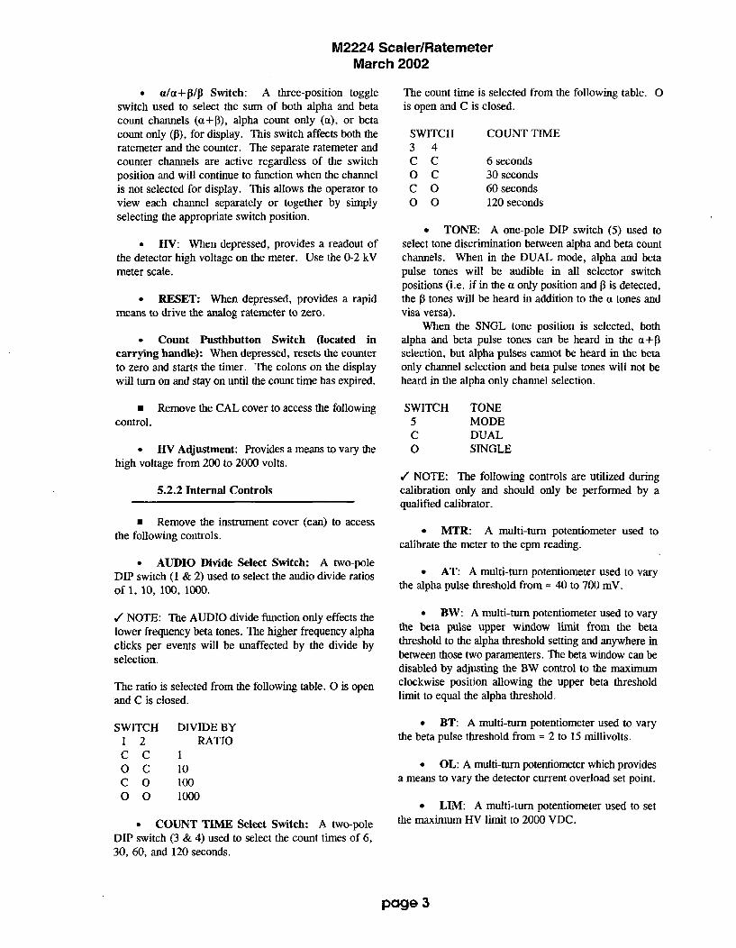
M2224 Scaler/RatemeterMarch 2002
a/a+AIA Switch: A three-position toggleswitch used to select the sum of both alpha and betacount channels (a+13), alpha count only (a), or betacount only (13), for display. This switch affects both theratemeter and the counter. The separate ratemeter andcounter channels are active regardless of the switchposition and will continue to function when the channelis not selected for display. This allows the operator toview each channel separately or together by simplyselecting the appropriate switch position.
H -V: When depressed, provides a readout ofthe detector high voltage on the meter. Use the 0-2 kVmeter scale.
* RESET: When depressed, provides a rapidmeans to drive the analog ratemeter to zero.
* Count Pusthbutton Switch (located incarrying handle): When depressed, resets the counterto zero and starts the timer. The colons on the displaywill turn on and stay on until the count time has expired.
0 Remove the CAL cover to access the followingcontrol.
- HV Adjustment: Provides a means to vary thehigh voltage from 200 to 2000 volts.
5.2.2 Internal Controls
* Remove the instrument cover (can) to accessthe following controls.
" AUDIO Divide Select Switch: A two-poleDIP switch (1 & 2) used to select the audio divide ratiosof 1, 10, 100, 1000.
./ NOTE: The AUDIO divide function only effects thelower frequency beta tones. The higher frequency alphaclicks per events will be unaffected by the divide byselection.
The ratio is selected from the following table. 0 is openand C is closed.
The count time is selected from the following table. 0is open and C is closed.
SWITCH3 4C CO CC O0 0
COUNT TIME
6 seconds30 seconds60 seconds120 seconds
0 TONE: A one-pole DIP switch (5) used toselect tone discrimination between alpha and beta countchannels. When in the DUAL mode, alpha and betapulse tones will be audible in all selector switchpositions (i.e. if in the a only position and jI is detected,the 03 tones will be heard in addition to the a tones andvisa versa).
When the SNGL tone position is selected, bothalpha and beta pulse tones can be heard in the a+13selection, but alpha pulses cannot be heard in the betaonly channel selection and beta pulse tones will not beheard in the alpha only channel selection.
SWITCH TONE5 MODEC DUAL0 SINGLE
/ NOTE: The following controls are utilized duringcalibration only and should only be performed by aqualified calibrator.
* MTR: A multi-turn potentiometer used tocalibrate the meter to the cpm reading.
* AT: A multi-turn potentiometer used to varythe alpha pulse threshold from - 40 to 700 mV.
* BW: A multi-turn potentiometer used to varythe beta pulse upper window limit from the betathreshold to the alpha threshold setting and anywhere inbetween those two paramenters. The beta window can bedisabled by adjusting the BW control to the maximumclockwise position allowing the upper beta thresholdlimit to equal the alpha threshold.
* BT: A multi-turn potentiometer used to varythe beta pulse threshold from = 2 to 15 millivolts.
* OL: A multi-turn potentiometer which providesa means to vary the detector current overload set point.
* LIM: A multi-turn potentiometer used to setthe maximum HV limit to 2000 VDC.
SWITCH1 2C CO CC O0 0
DIVIDE BYRATIO
1101001000
* COUNT TFVIE Select Switch: A two-poleDIP switch (3 & 4) used to select the count times of 6,30, 60, and 120 seconds.
page 3

M2224 Scaler/RatemeterMarch 2002
* HV: A multi-turn potentiometer used to adjustthe high voltage test reading to correspond with theactual high voltage output. The HV switch must bedepressed during adjustment.
* LB: A multi-turn potentiometer used to adjustthe minimum battery voltage level corresponding to thelow battery indication on the meter dial. The BATswitch must be depressed during adjustment.
5.3 Operating Procedures
o Release the can latches and remove the canfrom the 2224 taking care not to damage the speakerwires. Using a ball point pen, set the switches forthe AUDIO divide by, TONE, and COUNT TIMEto the desired selection. Then replace the can andfasten the latches.
V NOTE: To open the Battery Lid, twist the lidbutton counterclockwise 1/4 turn. To close, twistclockwise 1/4 turn.
o Open the Battery Lid and install two "D"size batteries. Note (+) (-) marks on the inside ofthe lid. Match the battery polarity to these marks.
/ NOTE: Center post of flashlight battery ispositive. Close the battery box lid.
o Connect a detector to the M2224.
o Switch the OFF/BAT/X1000-X1 switch tothe BAT position. The meter pointer should deflectabove the left vertical mark on the BAT OK line. Ifthe meter does not respond correctly, recheck thatthe batteries have proper polarity and are good.The LCD should show all eights, display theprogram version number, and then display 0.
0 The detector operating parameters areestablished by adjusting the detector operating voltage(HV), alpha threshold, and beta window to find anoptimum efficiency for the alpha/beta scintillator orproportional detector.
The threshold and window parameters can beadjusted to optimize alpha/beta count discrimination,count efficiency, and minimize "cross talk" betweenchannels. Refer to the specific detector OperationManual or calibration certificate for the suggestedthreshold and window settings. Once the thresholds andwindow settings are established, an operating voltageversus count rate plot should be performed for both
alpha and beta count channels with alpha and betaparticle emission sources.
The following procedure is example of determining theoperating voltage for an alpha/beta scintillation orproportional detector:
o Connect a Ludlum Model 500 Pulser orequivalent to the Model 2224.
o Switch the 2224 to the 03 position. Adjustthe beta threshold (BT) for 3.5 mV and the window(BW) for 30 mV. The pulser counts should bedetected on the 2224 ratemeter above 3.5 +1 mVand should shut off above 30mV.
o Switch the channel selector switch to the aposition. Adjust the pulser for a 120mV pulseoutput and vary the AT control until counts aredetected on the ratemeter.
o Depress the HV switch and adjust the HVpotentiometer for 0.4 to 0.5 kV on the 0-2.0 kVscale. Connect the scintillator and switch to the P)only position. Place an alpha source on the detectorface.
o Slowly increase the HV potentiometer toobserve an increase, then decrease, and increaseagain in count as the HV is increased. Decrease theHV until the ratemeter is in the "dip" of theobserved count rate versus HV plot just performed.Depress the HV switch and note the HV setting.
o Plot a HV versus count rate plateau in 25volt increments, 50 volts each side of the HVreading found in the above step (ie, HV setting forcount "dip" in the above step = 675 volts, start theplot at 625 volts and increase in 25 volts steps until725 volts is reached). Plot alpha source, betasource, and background counts for both the a and 03channel positions.
o Find the optimum operating voltage fromthe plot which gives the greatest alpha and betasource efficiency while maintaining no greater thanthe maximum acceptable level of "cross talk"between channels.
o Select the desired count channel display,and proceed to use instrument.
page 4

M2224 Scaler/RatemeterMarch 2002
5.4 Calibration
5.4.1 Meter Calibration
A Ludlum Model 500 Pulser or equivalent isrequired. If the Pulser does not have a high voltagereadout, use a high impedance voltmeter with at least1000 Megohm input resistance to measure the detectorvoltage.
o Ensure that the meter movement hasproper mechanical zero. The adjustment is on thefront of the meter bezel. It must be adjusted to"zero" with the ON/OFF selector switch in the OFFposition.
o Connect the Model 500 Pulser to theModel 2224 with the appropriate cable. Rotate theM2224 range multplier switch to the X100 position.Select the a+ P3 channel position.
o Adjust the Pulser for 40,000 cpm andadjust the pulse amplitude to twice the betathreshold level (ie; beta threshold = 3.5mV, adjustpulser to 7-10mV).
o Remove the instrument cover and adjustthe MTR potentiometer until the meter reads 400cpm. Adjust the Pulser to 10,000 cpm and ensureratemeter reads 100 :E 10%. Decade the Pulser andM2224 range multiplier switch to check meterlinearity on the X1000, X10, X1 positions.Linearity should be within ± 10% of each reading.
o Set the LCD count time for 60 seconds.Adjust Pulser count rate to 40k cpm. Depress thecount button and when count cycle is completeconfirm that LCD reads within ± 2% of theincoming count rate.
o Adjust the BT, BW, and AT controls forthe appropriate set points as described in section5.3.
o Connect high impedance high voltagemeter (may use the Model 500 Pulser if equippedwith a HV meter) and adjust the HV control for areading of 1000 VDC on the voltmeter.
o Depress the HV pushbutton switch andadjust the HV potentiometer located on the circuitboard for a reading of 1.0 kV on the meter dial.Adjust the HV output from 500 to 1500 Vdc andconfirm that the 2224 HV meter corresponds to theexternal voltmeter within ± 10% of each reading.
o Remove batteries from the batterycompartment and connect a DC power supply to thetwo screw terminals located at the rear of thebattery compartment. The positive power supplylead should connect to the terminal with the redwire and the negative lead to the terminal with theblack wire.
o Adjust the power supply for 2.2 Vdc andswitch the M2224 to the a + P position. Depress theBAT pushbutton switch and adjust the LBpotentiometer to align the meter needle with the lowbattery mark on the meter dial (vertical line to theleft of BAT OK).
o Replace M2224 cover and proceed withuse.
5.4.2 Detector Overload Calibration
./ NOTE: The detector operating voltage (HV)must be determined and set before the OL(overload) adjustment is performed. If the detectoroperating voltage is re-adjusted, the overloadadjustment must be re-adjusted.
o Adjust the OL control to the maximumcounterclockwise position.
/ NOTE: Detector saturation is when the meterresponse no longer increases with increasingradiation field intensity.
o For alpha/beta scintillators, expose thedetector photomultiplier tube (PMT) to a small lightleak by loosening the detector window. Somescintillation detectors incorporate a screw in thedetector body which when removed will simulate adetector face puncture or light leak. The metershould start to decrease toward zero as lightsaturates the scintillation material.
o Expose just enough light to where the
meter starts to decrease. Adjust the OL controluntil the overload LED just begins to flicker on themeter dial. The ratemeter should deflect above fullmeter scale at this point.
o Re-seal the detector window and exposethe detector to a radiation source that will drive themeter near full scale. Confirm that the LED doesnot turn on and the meter remains on scale.
page 5

M2224 Scaler/RatemeterMarch 2002
6. THEORY OF OPERATION
6.1 Amplifier/Power Supply board # 5390-066
Refer to schematic 390 x 63 for the following:
6.1.1 Detector Input/Amplifier
Negative going detector pulses are coupled from thedetector through C021 to Amplifier U021. R023 andCR021 protects the input of U021 from inadvertentshorts. Self-biased amplifier U021 provides gain inproportion to R021 divided by R022. Transistor pins 4,5, and 6 of U021, provides amplification. Pins 12 and15 of U021 are coupled as a constant current source topin 6 of U021- The output self-bias to 2V be(approximately 1.4 volts) at pin 7 of U021. Thisprovides just enough bias current through pin 6 of U021to conduct all of the current for the constant currentsource. Positive pulses from pin 7 of U021 are coupledto the discriminators through ROll and C01 1.
6.1.2 Alpha/Beta Discriminator
Positive pulses from amplifier U021 are coupled tocomparator U012, pin 6, for alpha discrimination andpins 6 and 2 of U011 for beta discrimination. R103,Alpha Threshold, provides the reference voltage foralpha comparator U012. R106, Beta Threshold (definedas the lower threshold limit of the beta countingwindow) provides the reference voltage for betathreshold comparator pins 1, 2, and 3 of U011. R102,Beta Window (defined as the upper threshold limit of thebeta counting window) provides the reference voltagefor the beta window comparator pins 5, 6, and 7 ofU01 1.
6.1.3 Alpha/Beta Disc. Logic Circuit
the [tP clock cycle to complete before the next beta pulsecan be recognized by the riP.
6.1.4 Low Voltage Supply
Battery Voltage is coupled to switching regulatorU201 and associated components to provide +5V topower op-amps and logic circuitry. The charge pump(cp) output, C202, CR211, CR212, and C201 form avoltage doubler circuit to provide +9V for U201amplifier supply. UOOI and related components provide+2.5V reference HV SET and Alpha/Beta discriminatorcontrols. R201, LO BAT, is adjusted so that the meterpointer is aligned with the left vertical mark on the BATOK line with 2.2 volt battery input.
6.1.5 High Voltage Supply
High Voltage is developed blocking oscillator Q421,T321, C412, and rectified by voltage multiplier CR221-CR224, C221-C223, C211, and C114. High voltageincreases as current through Q421 increases, withmaximum output voltage with Q421 saturated.
High voltage is coupled back through R123 to op-amp pin 2 of U311. Resistor network R211-214completes the HV division circuit to ground. R214provides HV limit at 2.0 kV when the HV SET controlon the calibration board is at maximum. The regulatedHV output is controlled by HV potentiometer locatedunder the CAL cover on the front panel. This controlprovides the reference for comparator pin 3, U311.During stable operation, the voltage at pin 2 of U311will equal the voltage at pin 3 of U311. Pin 1 of U311will cause conduction of Q312 to increase or decreaseuntil the HV finds a level of stability. Rl15, HV TEST,calibrates the analog meter to the HV output when theHV test pushbutton switch is depressed.
6.1.6 Detector OverloadAlpha pulses from U012 are coupled to univibratorUl 11. Pulses at pin 6 of Ul IIare inverted by Q I 1 forconnection to reset (R) pins 3 and 13 of U101. Pin 9 ofU111 provides the pulses to be counted themicroprocessor (jiP). Pulses from pin 9 of U 111 areconnected to pin 3 of Ull to provide a time delay for the1iP clock cycle to complete before the next alpha pulsecan be recognized by the piP.
Beta pulses from pin I of U01 1 are coupled tounivibrator U101. Pulses are coupled to the gP from pin7 of U101 as long as pins 3 and 13 of U011 remain high(+5V). When an alpha and/or a beta window pulse ispresent, the reset (pins 3 and 13 of U101) function isenabled and 7 of U101 remains high. Pin 7 of Up isconnected to pin 13 of U101 to provide a time delay for
A voltage drop is developed across R121 and sensedby comparator U012 as detector current increases. Whenthe voltage at pin 3 of U012 goes below pin 2, pin 1 goeslow illuminating the OL LED and driving the meter tofull scale. R21 1, Overload, provides adjustment for theoverload set point.
6.1.7 Meter Drive
Pulses are coupled from the gP board (refer to liPtheory of operation) to the gate of Q302. Q302 invertsthe pulses, R403 and C401 provides inergration.Integrated meter drive voltage is coupled from P1-13 via
page 6

M2224 Scaler/RatemeterMarch 2002
the battery (BAT) and HV test switch to pin 5 of U311.The meter is driven by the emitter of Q11, coupled asa voltage follower in conjunction with pin 6 and 7 ofU311. R104, Meter Cal, is adjusted to calibrate theratemeter reading corresponding to the incoming countrate. R405 and R406 provide temperature compensationfor changes in the meter resistance due to temperaturevariations.
6.2 Processor Bd.# 5390-095
Refer to schematic 390 x 97 for the following:
loop the liP looks at all of the input switches forinitiation or status changes and responds accordingly.
The RtP uses Pulse-width Modulation to control theanalog ratemeter. The analog output, RATE (P3-4), isdivided into 255 increments in a 166 ps period. At fullmeter deflection the low pulse period, leading edge toleading edge, will be 166 jts, 500 cpm = 130 ps, 400cpm = 104 pjs, 200 cpm = 52 Its, 100 cpm = 26 ps,and 0 = no pulse or +5V. The pulses are inverted byQ302 on the Amplifier/Power Supply board and thenintegrated by R403, C401.
6.2.3 LCD Drive
U211 and U212 make up the liquid crystal displaydrive circuitry. The display information is sent from theliP to U211 and 212 via BUSO-3 and ADDO-1 data lines.When the SELECT' line is brought low by the 11P, thedata is transferred and latched into the drivers until theSELECT' line is brought low again. The correspondingdigits and segments are illuminated corresponding to thestored count information from the [tP.
6.2.4 Audio
6.2.1 Power supply
Battery voltage is coupled to switching regulatorU201 and associated components to provide +5V topower the 11P and display drivers U211, 212. R101,C101, Q101, and Q201 form a delay switch which allowthe U321 to stabilize before the load current is connectedto the +5V supply.
6.2.2 Microproccessor (pP)
U311, Intel N87C51FA, controls all of the data,control inputs, and display information. The 'clockfrequency is crystal controlled by Y211 and relatedcomponents at 6.144 MHz. The pP incorporatesinternal memory (ROM) storing the programinformation. C311 resets the IP at power-up to initiatethe start of the program routine. During the program
Alpha and/or beta audio pulse frequency isgenerated by the jiP and coupled to Q204. Q204 theninverts the pulses and drives the negative side of thespeaker. Bias voltage is provided by the volume controlvia Q202 and 203 and related circuitry.
page 7

M2224 Scaler/RatemeterMarch 2002
7. MAINTENANCE
Instrument maintenance consists of keeping theinstrument clean and periodically checking the batteriesand the calibration.
An instrument operational check should beperformed prior to each use by exposing the detector toa known source and confirming the proper reading oneach scale.
Re-calibration should be accomplished after anymaintenance or adjustment of any kind has beenperformed on the instrument. Battery replacements arenot considered to be maintenance and do not normallyrequire the instrument to be recalibrated.
Ludlum Measurements recommends recalibration atintervals no greater than one year. Check theappropriate regulatory agencies regulations to determinerequired recalibration intervals.
The batteries should be removed and the batterycontacts cleaned of any corrosion at least every threemonths. If the instrument has been exposed to a verydusty or corrosive atmosphere, more frequent batteryservicing should be used.
Use a spanner wrench to unscrew the batterycontact insulators, exposing the internal contacts andbattery springs. Removing the handle will facilitateaccess to these contacts.
NOTE
NEVER STORE THE INSTRUMENT OVER 30 DAYS WITHOUT REMOVING BATTERIES.ALTHOUGH THIS INSTRUMENT WILL OPERATE AT VERY HIGH AMBIENT TEMPERATURES,BATTERY SEAL FAILURE CAN OCCUR AT TEMPERATURES AS LOW AS 1000 FAHRENHEIT.
page 8

M2224 Scaler/RatemeterMarch 2002
PARTS LIST
Ref. No. Description Part No.Ref. No.
Model 2224 Scaler/Ratemeter
UNIT Completely Assembled Model2224 Scaler/Ratemeter 48-2494
Amp/Power Supply, Drawing 390 X 63
U021U101
UlllU201U311
Description
CA3096MCD74HC4538MCD74HC4538MMAX631AESATLC27M7ID
Part No.
06-628806-629706-629706-628506-6292
0 DIODESBOARD Completely Assembled
Amp/PS Board 5390-066
0 CAPACITORS
CR021CR111-112CR21 1-CR212CR221-CR225CR411
MMBD7000LT 1MMBD914LBAT54G1250-2MMBD914L
07-635507-635307-635407-626607-6353cool
C002COl IC012-C014C015C016
C017C021C022C101-C102Cl11-Cl13C114C121-C122C201-C202C203C211C212C213C214C221-C223C301C311C401C411C412C421
100pF, 100V47pF, 100V0. ltF, 50V0.001liF, 100V0.lpF, 50V0.01gtF, 50V101.F, 20V100pF, 3Kv10pF, 100V47pF, 100V47pF, IOOV0.0047jtF, 3kV0.0047jtF, 3kV10aF, 20V330pF, 100V0.00471iF, 3kV68jtF, 6.3ViliF, 35V0.01gjF, 50V0.0047jiF, 3kV68pF, 6.3V0. 1 pF, 50V0. 1tgF, 50V0.1 piF, 50Vl.tF, 35V68VF, 6.3V
04-566104-556004-566304-565904-566304-566404-565504-553204-567304-556004-556004-554704-554704-565504-565704-554704-565404-565604-566404-554704-565404-566404-566304-566304-565604-5654
0 RESISTORS
R001R002R003R004ROl1R013R014R015R016R017R021R022-R023R024R025R026RI01R102-R103R104R105R106RillR1 12Rl13-Ri14RI 15RI 16R121R122R123R201R211R212-R213R214R215R301R302R311
22. 1k, 1%249k, 1%22. lk, 1%1.5k, 1%100 OHM, 1%22.1k, 1%33.2k, 1%10k, 1%22. lk, 1%10k, 1%392k, 1%10k, 1%33.2k, 1%22.1k, 1%I MEG100k, 1%1 MEG TRIMMER22.1k, 1%100k, 1%10k TRIMMER100 OHM 1%IG100k, 1%1 MEG TRIMMER249k, 1%4.7 MEG1 MEGIG200k TRIMMER1 MEG TRIMMER1 MEG, 1%1 MEG TRIMMERI MEG, 1%2.21k, 1%200 OHM, 1%10k, 1%
12-784312-786212-784312-787812-784012-784312-784212-783912-784312-783912-784112-783912-784212-784310-702812-783409-690612-784312-783409-692112-784012-768612-783409-690612-786210-703010-702812-768609-690809-690612-784409-690612-784412-783512-784612-7839
TRANSISTORS
Q111Q301Q302Q311-C312Q421
2N7002LMMBT4403LT2N7002LMMBT3904TMJD210
05-584005-584205-584005-584105-5843
* INTEGRATED CIRCUITS
U001 LM285M-2.5U011-U012 TLC372ID
06-629106-6290
page 9

M2224 Scaler/RatemeterMarch 2002
R312R313R314R401R402R403R404R406R407R411R412
22. lk, 1%2.21k, 1%10k, 1%221k, 1%7.5k, 1%1M, 1%5k TRIMMER301 OHM, 1%1k, 1%200 OHM, 1%10k, 1%
ERMISTORS
03006-165.9-55G100
12-784312-783512-783912-784512-784712-784409-690712-786312-783212-784612-7839
07-6366
s INTEGRATED CIRCUITS
U21 1-U212U311U321
ICM7211AMIQHN87C51FAMAX631AESA
06-629406-628606-6285
RESISTORS
RI01R 102R211R221R222R301-R306
IM, 1%10k, 1%2.21k, 1%150k, 1%100k, 1%22.1k, 1%
12-784412-783912-783512-783312-783412-7843
THi
R405* RESISTOR NETWORK
INDUCTORSRN401 220k 12-7831
L301 220tH 21-9678CRYSTALS
* TRANSFORMERSY211 6.144 MHZ 01-5262
T321 L8050 40-09020 SWITCHES
MISCELLANEOUSS301 90HBW06S 08-6710
P1
P2
CONN-1-640456-5MTA100CONN-640456-3MTA 100M2222 BD. SHIELDRECEPTACLE (8 ca)Cloverleaf 011-6809
13-8355
13-80817390-044
18-8771
* INDUCTOR
L311 150fH 21-9677
0 MISCELLANEOUS
Processor Board, Drawing 390 x 97P3
P4
CONN-1-640456-6MTA100CONN-640456-2MTA100SOCKET-44P
13-8134
13-807306-6293
BOARD Assembled Processor 5390-095*
* CAPACITORSCalibration Board, Drawing 390 x 100
CIloCl10C211-C212C221C311-312C321C322
0.l5jiF, 50V47jiF, 10V27pF, 100V68[tF, 6.3V10tF, 20V330pF, 100V68jiF, 6.3V
ISTORS
2N7002LMMBT4403L2N7002LMMBT4403L
04-566504-566604-565804-565404-565504-565704-5654
05-584005-584205-584005-5842
BOARD Completely AssembledCalibration Board 5390-096
LEDS
DS1 HLMP4700LED-SPACER 456-500
07-635607-6349
* TRANS* RESISTORS
Q101Q201Q204Q311
R3 250k TRIMMER 09-6819
a MISCELLANEOUS
P7 CONN-640456-5MTA100 13-8057
page 10
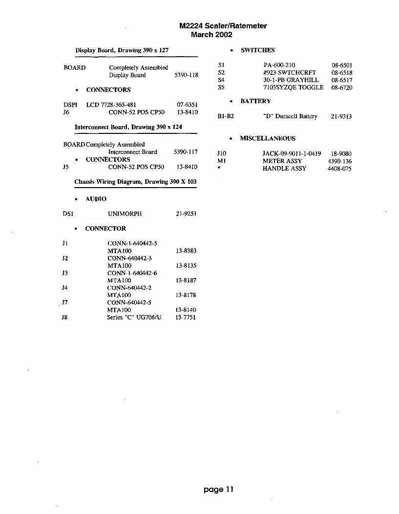
M2224 Scaler/RatemeterMarch 2002
Display Board, Drawing 390 x 127 SWITCHES
BOARD Completely AssembledDisplay Board 5390-118
S1S2S4S5
PA-600-210#923 SWTCHCRFT30-1-PB GRAYHILL7103SYZQE TOGGLE
BATTERY
08-650108-651808-651708-6720* CONNECTORS
DSPI LCD 7728-365-481J6 CONN-52 POS CP50
07-635113-8410
Bl-B2 "D" Duracell Battery 21-9313
Interconnect Board, Drawing 390 x 124
0 MISCELLANEOUSBOARD Completely Assembled
Interconnect BoardCONNECTORS
J5 CONN-52 POS CP50
5390-117
13-8410
J10M1*€
JACK-09-9011-1-0419METER ASSYHANDLE ASSY
18-90804390-1364408-075
Chassis Wiring Diagram, Drawing 390 X 103
0 AUDIO
DS1 UNIMORPH 21-9251
0 CONNECTOR
J1
J2
J3
J4
J7
38
CONN- 1-640442-5MTA100CONN-640442-3MTA 100CONN- 1-640442-6MTA100CONN-640442-2MTA100CONN-640442-5MTA 100Series "C" UG706/U
13-8383
13-8135
13-8187
13-8178
13-814013-7751
page 11
M2224 Scaler/RatemeterMarch 2002
DRAWINGS AND DIAGRAMS
Amp/Power Board, Drawing 390 x 63Amp/Power Supply Board Component Layout, Drawing 390 x 64
Processor Board, Drawing 390 x 97Processor Board Component Layout, Drawing 390 x 98
Calibration Board, Drawing 390 x 100Calibration Board Component Layout, Drawing 390 x 101
Display Board, Drawing 390 x 127Display Board Component Layout, 2 sheets, Drawing 390 x 128
Interconnect Board, Drawing 390 x 124Interconnect Board Component Layout, Drawing 390 x 125
Wiring Diagram, Drawing 390 x 103
page 12

RIH
I3 I s 12S.II
UrI 1 U21vg
2 CAM
Iv is .6CI-D
*2 .2I~
5102 5123
WIN 155ES4
U02.0090 A 16 uBi
A to
ItRIG I25 M
I'S llSCI
2 IN I I2P2 I6ý 510210 8.O
3G 0
AIR ~ ~ ~ C .IKt 6ON e
61265-21 2S..
A 121 A122
RIIZ V KV 21260.
1551214
Ic Ol 221 3XV ,T2 22-BA
?S6 _26 0 .2.7UF
PI -2 3 'LIM)5GOL
'HY~~S I I VC
1Cwa
.GV-SV SV
1:17Ua 12 A
ILC7721D ji.OK C,1,13 AlIt' C112 0113At 1 4 2 *It,,1K 11PF4C4 1 1K "IF I COXIOOV
1. 41I 2stAl I ev ,,V II Rý
1 2ItWSW 3 -C R/c _c A/C
7p:'
to
Al cc
a PULSE' pi
Wit v 114CD74HC4630M 7..C111.1
ON. II.CNb
A eat .5v
22. IK
I ,*,, 'IVTLC3,721D IRS- CRIII
MMODII.l. ý2sý7 3 1
.$V,4.gND toC :11, Sv
1 2 Cleo RIOS
..OoILF 4C'IP'F' 1 7 0; I es, if .P.1v 71TV la.
U01i Reis 1 2TLC3721C ý6.01( -C Rc 3 C R/C
I! 12G.W A 0 To 5 A 0 6
3 i a 9 4 i u I
cl A A Pi
C013 B..SVI-GND A 7p Ulal
O'colul' I. CD74HC4530M
loov MMS19 IL 11 16 .,SvG.CND
C,1ý12 5 -
-I
.- i
PI o9

2 fml) ""'L;CR02t 2
Roll min ...U... C41
CR1 U02C3
Cols 1, RS, U2C 2 t12
r C21[4 R412.LII2RSP1-2.S ~~ - ~ cze~ MAXS4IEA~.M1T4~
1
0 THEHLRHESOD 2.
MA LE ASPLT44ERL
POR S2PPLI

::::: REV IS IONS IDAE I- OEIF UP WO I0091 ZN0I6 1 DESCRIPTION4PPO160
19V C2 1l
28 2TP
0221 12 99
290
RESET is
60 PULS.E' 2P3 -1 > -....COUNIT' 'RZERO' 4
P3 -2 C .....so601-
P3 -4 >- SCALCR/A4tE' CL~lR0~
P3 -5 )P .. ZERO' :A'4'E0
,3 .7 R- RANCEI
P3 -4 > - OVE.. RLPOAD' OORED.is
32 .7 > -. A.. PULS40EI'
P2 - to ..-. SC PULSE56
32 -11> - AU
U31tNO CSIFA20RoRS-NR0
XTA P .P9.P6.:
0712 P9,0STt?, PR .5
P9 ,7
iH~t
4446
I 1
40 L -I J t iBl"
I- I•E2 A A D 1I
•?• AUD DIv9.
A , I C.
24 SELECT@'-5 SE ECT I7 ADDS
ios ous$
31 Ps
,SV
RUS2 -2
SELECTO =39900
02 12100 72111,110
019 RI
aii CIlAAZE;
421
02
CU42
ce
D2
(2
04C3A464
CA,11
C4t
OP
0. .S0 20.CND
, I
743
BATTERY
OvERFLOW -25
P's .26
7 AS PS -500 06 P
I@ DG P .-;2
PIt E6 IS :23
11 MFS 2.
G.
R 01 '1: :41117 Cto D,Is
E521 15 P,zo CS PS AS
22 AA P,Z. 8 P, :,",
2 CA 11 ;:2, D PS
29 PSF
20 CA PS A
6 PS -2
i2 1
R IS 2 1 2 11C
4us000e I DI
:U: ','- D I ¢11
401 Es :42SELECTI. R R
CO? C:
F2
A ICO3
C4
6702l
0'262
it "I s -i,
I Al2 PS -16- • Ps - 111
rnPs "141
SPs -13
is 12 IS -31
Ps .
Ps .31
I s -as
11 -1z• r12e~ :sP5-3
A6SETPI .0P1,9
P1.2.
PI,2p1.4
pi.6
P3 ,
P3,4P3.6
P3.7
P2.0
20.P2.4
P2,P27M
ILE
C3212
177
,3 -1,4 >...--" .8 R0
P3 -13 > -VX
P3 - 12
P 1 2694 CC1r2Cl.IE $4Itc1
400 0104' - I 140010 0 1i 6 V O FF1
1 12604AiUS mOilU('DVI( •'m400 2101' 2 2 140010 610106 I CIII
P242 2 140UlO DIVIDE I o062
22. 16U ... 4
It 12094
TIMES. 4 1T106 I 0*1
22. o•U4
11 14594
6226
II102S.4
S P ASPRE 0* OiPR POE02
WIG1"CR -
00.177 P,16
120 ~P 2 0 P-2
1 74042N4D 1
CL 0044 02610 YI / / 1 E 0E2175 INC.PROCESSO .OR I/ ..
104 I.JAS,.11.I'" 0 o.4 o •,-
S,$10 o 000... SE IE ....i,0Ex1 9104CR 0SSY. OD 2R24 004 07
K.IS:2 K 7-70-. 155 222,0* K06 E I
r7.7s;7-, -ý2-Oct-qs I S8350 ass I SHEET I OF I_
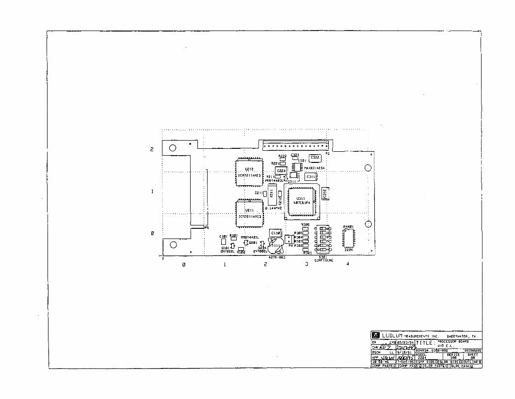
............... ........
0
0 1 2 3 4
LUDLUrI MEASUR~EMENTS INC. SWEE TWA TER, TX(
DR K 03/23/94T T TlE PROCESSOJR BOARD~ W/O E.L.
A ODEL SERIES I SHEET
W0S13 46 2-7Oct-90 COMP SIEEDISLDR SIDEfl OUTLINED-COTIPPASTED COMP I1ASKOI01SLR PASTED ISLOR IIASKO
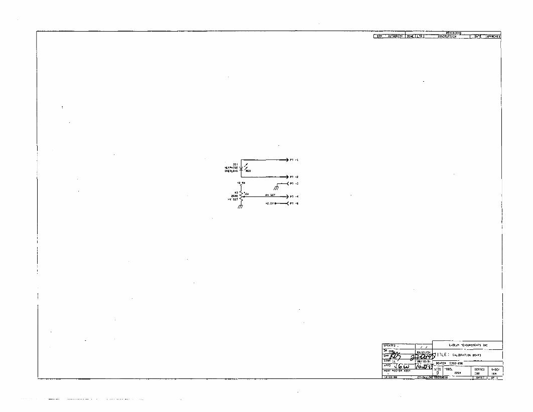
'REYVISIONSI EFF E-AUTHORITY FZNE J1R DESCRIPTION DATE APPROVE
P7 -1
OVERLOAD E
P7 -e
-2 sU
P7 .
SEST ~ -
AUST
UPDATED - LUDLUM MEASUREMENTS INC.
OR CU§, IS'wS L
1~E CALIBRAION 9OARD
/ý ScODEI 3g-•
NE XT H IGHER ASS . OB RIID EVA4 DSB xeR.I lUsslo Z7-Dct-RUSq fOR E AET I' OF

DSI
P7
R3 HV SET
DESC: CALIBRATION BOARDMODEL: 2224PART #: 5390-096DWN: CKB DATE: 04/01/94DSGN: DATE:
M-.d 1 4 --
OU. 4 mloo someML ý am

DSPI7128-3GS-4S I
S2 POS CPSO CD EPCE COWA DtSPLAY
JS _i B a JG -2CS -31 D4 1 -49AS -36 E4 El -49
is529 C4 C5'A32is- 4 S A2 31 s-20
21 .3 coso42 36 -47DP2 -32 ES 2 A1 -44
JsTDA 368 8 -16-:It CS QA0-4-ze 9 D3 s 24

6spI
10 LUDILUMI MEASUREMENTS INC, SWEETWATER, TX,ACF 02-.A -V91 T IITE IISILAY 9OARDý.OAV .-j BORD S _~11B
nsrN,jjrwl i7-jui -ad moEL : 2224Ap o F16E~Ee~~2
cNEXT- I OLDER
ourLINEI 1UN .0 3901 128

I-
, LUDLUM MEASUREMENTS INC. SWEETWATER, TX.
DR ACF 02-JUN-SS TITLE: DISPLAY BOARD
CNN.t)ý -2-Y ' BOARD# S390-1I
DSCN ,JGA 17-JUL-9S [MODEL 2224 ISERIES 350 SHEET 128APP,,!F5 4'-e-%7 COMP ARTWORK 0 SLDR ARTWORK 0
COMP OUTLINE 0 1 SLDR OUTLINE ZCOMRP PASTEO COMP MASKO ISLDR PASTED |SLDR MASKO
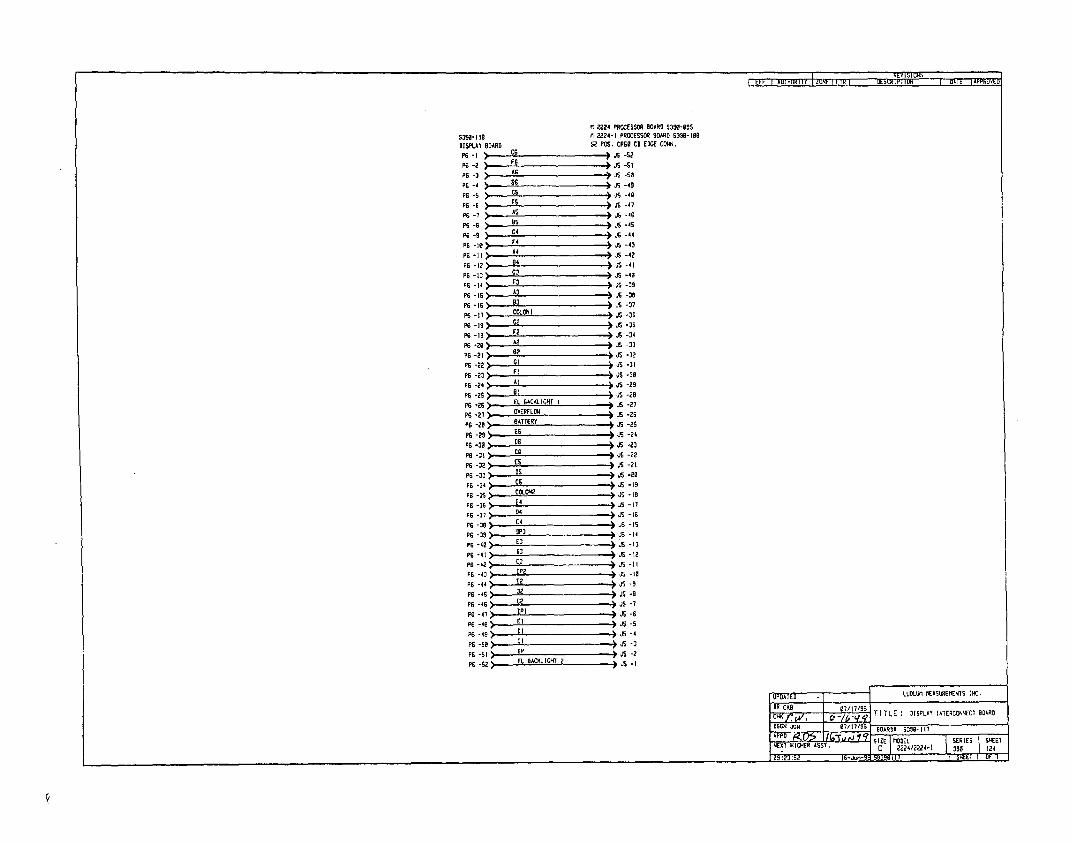
tPý I AU;HiUR.I I Y U) I L I RI UE
M 2224 PROCESSOR BOARD 533-OSS53SII- 11 2224-1 PROCESSOR BOARD S390-l0BDISPLAY BOARD 52 POS. CPSI CO EDGE CONN,
P"1 CS• ) JE -52P6 -2 G )JS -S2
PS-3 AG is -soPG-- > ItsJS-49PG -S• CS JS -40
P6S -6 S -47e6s-i AS is15-46
PG-9 C4 J.S-44
PS -0 F4 J5 -43P A - 45 JS -42P6 -12 94 i Js -4lPG -to C3 J .S -40PG -14) F3 . .i -39
PS -15 ;::__L is -3ePG -16 A83 9S -37
PS IS> is J -37PS -I8 COLONI is -35PS -Is> )- 0 > J 35sPG 2 _1 F -34
P6 -2O A2 is -33
P6 -21 62 J O-32PS -22 GI JO -31PS -2> Fl is J-39PS -24) At J -29P6 -2S I JS -2B
PS -06 EL BACKLIGHT I )JS -27PS -27 OVERFLOWI * JO -20P6 -28•-- BATTERYP6 -29;J J -2S
PG .32> ESzjJ -03P6 -32> ES JS -23
P6 -31- CG5 is -19P 6 -32 Is is -I2
PG -35>-- 046PS -36 'P. JO -17
p -i3s . JO -1IP6 -364 4 8-
P6 -41 03 i -IIPS -42> ,- - Js -11PG6-43) OP2 isJ -tBP6 -44) E2 is -9P6o-4s> D, is -P6 -46 c2 is -7
DG -4T , PI is -6P6 - > -6 .E is -5
P6 -49 DI s -4P6-so 11 is ; ,
Ps-si) ~ J-2P6-62) EL BACLIGHT• is -0
UPDATED LU0LL1 MTEASUREMENTS INC.DR CK10/1/S
cm5w. /l i/S TI TLE DISPLAY INTERCONNECT BOARD05CR 6c 7/li13S BOARDI 5358-Ill
p1.. zI SERIES SEETNEXT 61RA55. 02224/22/024-I 399 124
109 :23:52 16-J-- SBJ99i I I I SKEET I OF I
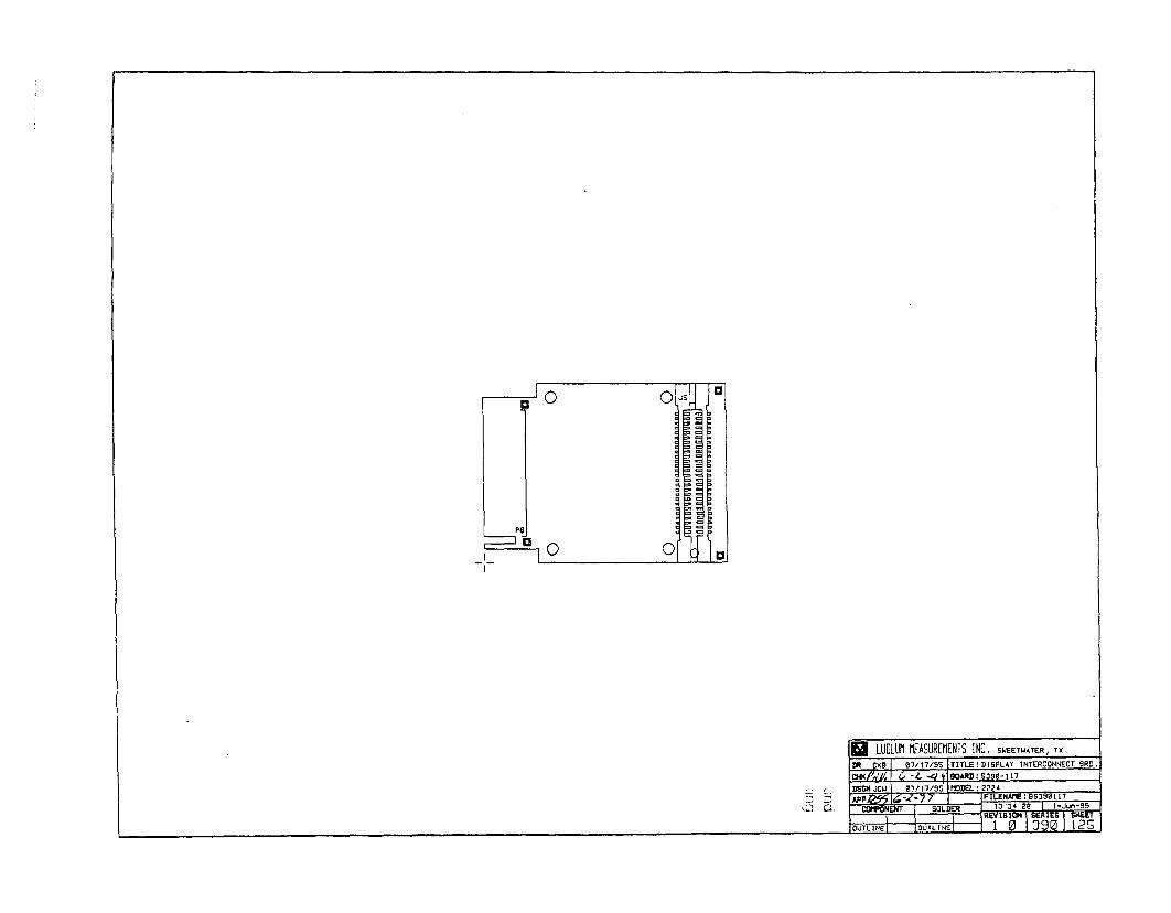
PGJ
01
R LUDlLUM MEASUREM1ENTS INC. SWEETWATER, TX,-D TWA 0flhl7ISS ITITL.E!D[SPLAY INTERCONNECT 9RD.
I
cw se , BOAAD 5390-117DS~4CI j w VII/I7sS MODEL 12224
CWNi XT SO5LDER 428 1J-3
RE-1 SERIES ISNBkETýCUTLINEI - OUiLINd IR"1 01) 3 I 2iJ I a J . . . .
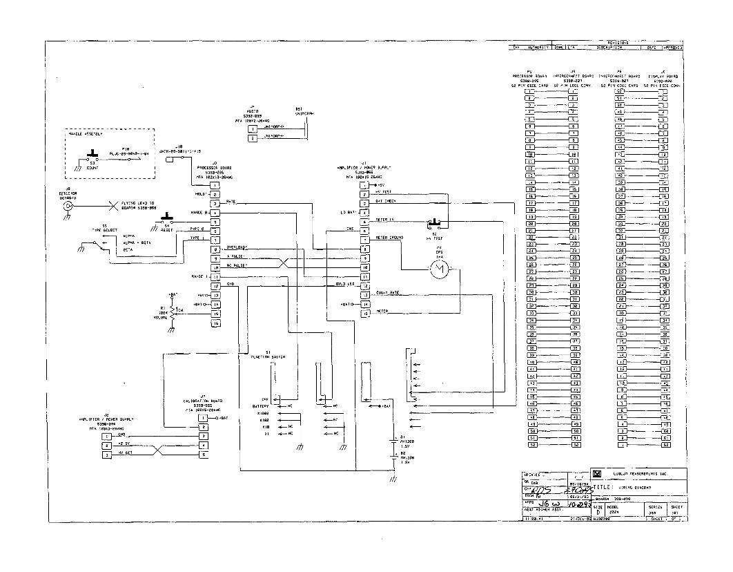
526-A D'AIY 1ý ýORP
UUIMORPH*
UN U9IlDPH-
HANDLE ASNDM9LY
PS JS29C0CS509 90AR0 INTERCONNECr 00A90
S2 PIN £ODE CA*D SD 0610 LaCE C0NS.
2AD • 29S
E322223 22E
E• (2925 226 2272
29 2293 E926 2
26 2223 022
290 29
025 29290 2729• 29329 2999 '
92 92
95S , 5S
95 460
99 993
52•,. 52
96e-• jS9-0
52 PIN 22CC CARD 52 PIol [0CC CONNS
S2E~
56 E
99-
AN E
AS }-- ' -- -]
92 E
920]
96
29,
E29
(322
J2O
-9LI06109 / P26ER SUPPLY Ic 99S2SA.A66LI6I69*99
2 HOES

LUDLUM MODEL 2350-1DATA LOGGER
Calibration Routines,Parts List, and Schematics
August 1999
j LUDLUM MEASUREMENTS, INC.
501 OAK ST., P.O. BOX 810SWEETWATER, TX 79556915/235-5494; FAX: 915/235-4672

TABLE OF CONTENTS
1, INITIAL INSTRUMENT CALIBRATION ....................................................................... 41.1 Equipment Required ....................................................................................... 41.2 Instrument Preparation .................................................................................. 41.3 Threshold and Window Calibration ................................................................ 41.4 High Voltage Calibration .................................................................................. 51.5 Overload Calibration ....................................................................................... 51.6 A larm S etpoints ............................................................................................ .. 6
2. CALIBRATION ROUTINES ......................................................................................... 7Source Parameters and Typical Values for Dead Time and Calibration Constants. 72.1 High Voltage Ramp Routine ............................................................................ 82.2 Calibration Constant and Dead Time Calibration with background subtract ..... 102.3 Calibration Constant Using a Single Point with Background Subtract ........... 122.4 Dead Time Calibration Using 2 Source Method with Background Subtract ...... 14
3. THEORY OF OPERATION ......................................................................................... 163.1 Amplifier/Power Supply Board ....................................................................... 163.2 Central Processor Board ............................................................................. .183.3 I/O Interface Board ....................................................................................... 193.4 64k Memory Expander Board ....................................................................... 20
4. PARTS LIST, COMPONENT LAYOUT, AND SCHEMATICS ..................................... 214.1 Amplifier/ Power Supply Board Component Layout ...................................... 234.2 Amplifier / Power Supply Board Schematic ................................................... 234.3 Central Processor Board Component Layout ............................................... 254.4 Central Processor Board Schematic ............................................................ 254.5 64k Memory Expander Board Component Layout ........................................ 264.6 64k Memory Expander Board Schematic ..................................................... 264.7 I/O Interface Board Component Layout ........................................................ 274.8 I/O Interface Board Schematic ..................................................................... 274.9 Backplane Board Component Layout ............................................................ 274.10 Backplane Board Schematic ....................................................................... 284.11 Chassis Wireing Diagram ............................................................................ 28

MODEL 2350-1 Data Logger
1. INITIAL INSTRUMENT CALIBRATION
1.1 Equipment Required
All instruments used in calibrating the Model 2350-1 must be calibrated by standards traceable to theNational Institute of Standards and Technology and must have a current calibration label attached.
1. Ludlum Model 500 Pulser.2. High Impedance voltmeter with at least 1000 megohms meter resistance and an accuracy of 0.5%.3. Overload simulator (1000 megohm resistor).
1.2 Instrument Calibration
The following procedures will calibrate the electronics only. To program the instrument please refer tosection 6. OPERATING INSTRUCTIONS of the Model 2350-1 Data Logger Manual.
WARNING:The following procedures require that the instrument be re-initialized. This will clear alllogged data and return all programmable settings to their default values. DETECTORSETUPS AND LOGGED DATA WILL BE PERMANENTLY LOST.
1. Turn the Model 2350-1 ON. The display will temporarily go black and then the following two displayswill appear for a few seconds each. Then the display that was active when the instrument wasturned off will appear.
MEMORY TEST OK BATTERY VOLTAGECPU TEST.OK
BAT = 6.3
2. Re-initialize the instrument by entering the cold initialize command (SSR).3. Check the battery voltage on the parameters display (SVDI). If it reads below 5.5 volts replace the
batteries with fresh alkaline batteries and proceed.
Threshold and Window Calibration
4. Change the display time base to minutes (SB1) display units to counts (SU7), and the threshold to100 (T100).
5. Turn the Model 500 Pulser polarity switch to the negative position.6. Set the pulse amplitude range selector to the 50 mV position, and the LO-HI control to the maximum
clockwise position.7. Set the pulse frequency multiplier to the lk position and adjust the pulse frequency so that the
output is 400k cpm.8. Connect the Model 2350-1 to the Pulser and verify that the ratemeter reads between 392-408kC/m.9. Adjust the pulser amplitude control until the meter reads approximately 10 mV. The ratemeter
display should read approximately 75% of the count input (300 kC/m).
4

MODEL 2350-1 Data Logger
1. INITIAL INSTRUMENT CALIBRATION
10. If the instrument does not read approximately 300 kC/m adjust the gain pot (R1 0) on the mainboard until it reads properly.
NOTE: The instrument threshold is now set at 100 = 10 mV
11. Turn the window ON (WON), and set it to 100 (W100).12. Adjust the pulse amplitude control until it reads approximately 20 -mV. The ratemeter reading
should again indicate approximately 75% of the counts (300 kC/m).13. Adjust the threshold setting to 200 (T200), 300 (T300), and 400 (T400) repeating the above procedure
each time to verify that the threshold and window settings are linear.14.Turn the window off (WOFF) and reset the threshold to 100.(T100).
High Voltage Calibration
15. Disconnect the instrument from the pulser and connect it to a high impedance voltmeter.16. Set the high voltage to 1500 volts (H1I500).17. If the voltmeter does not read from 1498 - 1502 volts adjust the HV pot (R52) on the main board
until it reads within tolerance.18. Adjust the high voltage to 500 volts (H500). The voltmeter should read between 490 - 510 volts.19. Adjust the high voltage to 2000 volts (H2000). The voltmeter should read between 1940 - 2060
volts.
Overload Calibration
21. Disconnect the instrument from the voltmeter, and connect it to the overload simulator resistorbox.
22. Change to the Alarm Display (SVD3).23. Turn the overload on (OON), and set it to 15.0 pA (0150).24. Change to the Parameter Display (SVD1).25. Set the high voltage to 1500 volts (H1I500).26. Change to the Main Display (SVDO). The ratemeter display at the top of the screen should be
alternating between the ratemeter display and the word OVERLOAD at approximately 1 secondintervals.
27. If this is not occuring adjust the OVERLOAD pot (R7) on the main board until the display alternatesproperly.
28. Adjust the high voltage to 1000 volts (HI 000). The overload indicator should stop appearing.29. Adjust the overlaod to 10.0 pA (0100). The OVERLAOD indicator should again begin to alternate
with the ratemeter indicator.30. Repeat steps 28 and 29 again with a voltage setting of 500 (H500) volts and an overload setting of
5 pA (050).31. When properly completed turn the overload alarm off (0OFF).
5

MODEL 2350-1 Data Logger
1. INITIAL INSTRUMENT CALIBRATION
1.2 Instrument Calibration (cont.)
Alarm Checkout
1. Connect the Model 2350-1 to the pulser.2. Set the pulse frequency to 600k cpm.3. Select the Alarm Display (SVD3).4. Set the integrated dose alarm to 100k cpm (PIE5).
NOTE: If an alarm is indicated press the ACK/SCRL button to silence the audio.
5. Select the Main Display (SVDO) and zero the integrated dose (SIZ). The Integrated dose countershould start counting immediately and an alarm should be indicated when it reaches 100k cpm.After the alarm press the ACK/SCRL button to silence the audio.
6. Select the Alarm Display(SVD3) and set the scaler alarm to 60,000 counts (K60000).7. Return to the Main Display (SVDO), set the scaler count time to 6 seconds (F6), and take a scaler
count (C). When the scaler reaches 60,000 counts an alarm should again be indicated. Pressthe ACK/SCRL button again to silence the audio.
8. Adjust the pulse frequency of the pulser to less than 600k cpm.9. Select the Alarm Display (SVD3) and set the ratemeter alarm to 600k cpm (J6E5).10. Select the Main Display (SVDO) and readjust the pulse frequency to a setting of 600k cpm. The
ratemeter alarm should be triggered. Press the ACK/SCRL button to silence the audio.11. Verify that the ratemeter (RAT), scaler (SCL), and integrated dose (DOS) indicators are all
alternating with the alarm (ALM) indicators at 1 second intervals.12. Select the alarm display (SVD3)13. Set all of the alarms to their default high settings (ratemeter, JI E9; scaler, KI 000000;
integrated dose, PIE9)14. Select the Main Display (SVDO) and reset all of the alarm indicators (X).15. Disconnect the instrument from the pulser and place it into the instrument can.
The electronics have now been calibrated and functionally checked. All remaining calibrationprocedures involve setting the programmable parameters of the instrument and are covered in theModel 2350-1 Data Logger Instruction Manual.
6
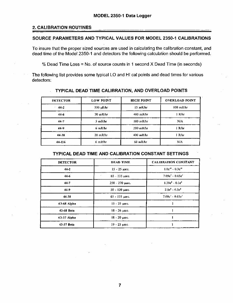
MODEL 2350-1 Data Logger
2. CALIBRATION ROUTINES
SOURCE PARAMETERS AND TYPICAL VALUES FOR MODEL 2350-1 CALIBRATIONS
To insure that the proper sized sources are used in calculating the calibration constant, anddead time of the Model 2350-1 and detectors the following calculation should be performed.
% Dead Time Loss = No. of source counts in 1 second X Dead Time (in seconds)
The following list provides some typical LO and HI cal points and dead times for various
detectors:
TYPICAL DEAD TIME CALIBRATION, AND OVERLOAD POINTS
DETECTOR LOW POINT HIGH POINT OVERLOAD POINT
44-2 500 1jR/hr 15 mR/hr 100 mR/hr
44-6 20 mR/hr 400 mR/hr I R/hr
44-7 5 mR/hr 100 mR/hr N/A
44-9 6 mR/hr 200 mR/hr I R/hr
44-38 20 mR/hr 400 mR/hr I R/hr
44-116 6 mR/hr 60 mR/hr N/A
TYPICAL DEAD TIME AND CALIBRATION CONSTANT SETTINGS
DETECTOR DEAD TIME CALIBRATION CONSTANT
44-2 15 - 25 psec. 1.0e'0 - 0.3e"0
44-6 65 - 135 psec. 7.09e7 - 0.65e7
44-7 250 - 270 "sec. 1.39e' - 0.1e'
44-9 50 - 120 psec. 2.0e' - 0.3e'
44-38 65 - 135 psec. 7.09e 7 - 0.65e 7
43-68 Alpha 15 - 25 psec. 1
43-68 Beta 18 - 26 pWcc. 1
43-37 Alpha 18 - 20 psec. I
43-37 Beta 19 - 25 Wsec. I
7

MODEL 2350-1 Data Logger
2. CALIBRATION ROUTINES
2.1 High Voltage Ramp RoutineThe high voltage ramp routine is useful when a user needs to plateau a detector to
determine the proper operating voltage of the detector. The following display will appear whenperforming the routine.
AB
C
D
CPROCEED W/ HV?
0 SCL-"10 SEC SCL
CURRENT HV = 800STR END - INC0 0 0
OPR CNT 0
E
KH
HIGH VOLTAGE RAMP ROUTINE DISPLAY
A. INFORMATION PROMPT: Prompts the user for the parameters required for the rampingroutine. When the routine is first started the prompt will ask if the user wants to proceedwith the current parameters. If answered YES the instrument will then prompt the user tobegin the routine by executing the scaler count command. If answered NO then the followinginformation prompts will appear immediately after the one before is answered.
Starting HV ?Ending HV?HV Increment?
The message DUMPING HEADER will then appear momentarily followed by the command"Ent C to start".
B. RATEMETER BARGRAPH DISPLAY: A logarithmic display of the ratemeter reading incps.
C. HV IDENTIFIER: Identifies the current HV setting.
D. STR: Identifies the starting voltage of the HV ramping routine.
E. SCALER COUNT: Shows the scaler reading in progress.
F. SCALERTIMER: Shows the count time for the scaler. When a count is in progress the timerwill show the time remaining in the count.
G. END: Identifies the ending HV setting for the ramping routine.
H. INC: Identifies the increment the voltage will be increased by in each step of the routine.
I. OPR CNT: Identifies the count at the beginning knee of the plateau or the recommendedoperating voltage.
8

MODEL 2350-1 Data Logger
2. CALIBRATION ROUTINES
The following example demonstrates how to run a plateau on a Model 44-2 GammaScintillator.
KEYSTROKES RESPONSE
Note: Before performing the SHR(x) command, certain parameters must be set. The parametersthat need to be set include the threshold, window position, and count time.
SHR(x) ENTERWhere (x) = the number 0 or 1.0 = Disables data dump to the serial port.1 = Enables data dump to the serial port.
The Model 2350 display will show the detectordisplay with the current set of detector parameters.There will be no prompt but you will need to selecta set of parameters to use in the routine. If thecurrent parameters are correct press "Y ENTER",otherwise select the set of detector parametersthat you want to use and then press "Y ENTER".The instrument will proceed with the routine bydisplaying the screen shown on the opposite page.
This answers the prompt"PROCEED W/ HV" allowing the user to changethe parameters of the routine.
N ENTER
500 ENTER
1000 ENTER
25 ENTER
volts.
volts.
This set the beginning high voltage at 500
This sets the ending high voltage at 1000
This sets the HV increment to 25 volts.(This increment is the amount that the high voltagesetting will change between each step of theramping routine.)
This activates the routine by starting thescaler counting.C ENTER
"SHRO" will run the plateau routine, determine the operating votage, but will not dumpdata to the RS-232 port. "SHR1" will run the plateau routine, determine the operating voltage,and will dump the voltage setting and scaler count at each increment of the plateau routine.
When the routine is complete the following prompt will appear:"SAVE? HV = XXX"
"Y ENTER" will save the voltage as the operating voltage of the detector and theinstrument will return to the screen that was active prior to the exucution of the routine. "NENTER" will return to the screen that was active prior to the exucution of the routine withoutsaving the voltage.
9

MODEL 2350-1 Data Logger
2. CALIBRATION ROUTINES
2.2 Calibration Constant and Dead Time Calibration with Background SubtractThis routine will use a two point (low-hi) method to calculate the calibration constant
and dead time of the detector. The following display will appear when performing the routine.
AB LOW CAL POINT?
"1 I ,,,I lull a,,, m,,
L CAL 0.000e+00D H CAL 0.000e+00
LO SMPL 0E HI SMPL 0F
CALIBRATION CONSTANT/DEAD TIME ROUTINE DISPLAY
A. INFORMATION PROMPT: Prompts the user for the parameters required for the routine.When the routine is first started the prompt will prompt the user low calibration point. Onceentered it will prompt for the following parameters in order.
HI CAL POINTTAKE BACKGROUNDTAKE LOW SAMPLETAKE HI SAMPLESAVE NUMBERS?
B. RATEMETER BARGRAPH DISPLAY: A logarithmic display of the ratemeter reading incps.
C. L CAL: Identifies the low calibration point that will be used in the routine.
D. H CAL: Identifies the high calibration point that will be used in-the routine.
E. LO SMPL: Shows the reading obtained from the low sample source.
F. HI SMPL: Shows the reading obtained from the high sample source.
NOTE: Line 1 will indicate the ratemeter reading when a sample is being taken,and lines 3 and 4 will show the scaler taking a count. When the routine iscomplete Line 3 will display the calculated calibration constant, and line4 will show the calculated dead time constant. These numbers will besaved into the active detector setup if the user answers yes to the promptto save the numbers.
10

MODEL 2350-1 Data Logger
2. CALIBRATION ROUTINES
The following example willGamma Scintillator in R/hr.
KEYSTROKES
calculate the cal constant and dead time of a Model 44-2
RESPONSE
SKB ENTER
5e-4 ENTER
15e-3 ENTER
The Model 2350-1 will show the calibrationconstant/dead time routine with backgroundsubtract control display with a prompt to set thelow cal point.
This will set the lower calibration point at500 jiR/hr, then a prompt will appear for the hi calpoint.
This will set the high calibration point at 15mR/hr, then a prompt will appear to take abackground sample.
This will initiate the scaler to take abackground reading, then a prompt will appear totake the low sample count. Place a 1 jCi 137Cscheck source on the end of the detector.
This will initiate the scaler to take a countwith the low sample source, then a prompt willappear for the hi sample count. Place a 5 iCi 137Cscheck source on the end of the detector.
This will initiate the scaler to take the hisample reading.
C ENTER
C ENTER
C ENTER
NOTE: The SSK command initiates the same routine as stated above exceptthat the background count is not taken or considered when determiningthe calibration constant and dead time of the system.
ADDITIONAL PARAMETERS1. The background count should be less than 2% of the low sample count.2. The low sample count should have at least 15,000 counts.3. The high sample should be at least 100 times the low sample and produce
between 30 - 60% dead time loss.
11

MODEL 2350-1 Data Logger
2. CALIBRATION ROUTINES
2.3 Single Point Calibration Constant Routine with Background SubtractThis routine will use a single point method to calculate the calibration constant of the
detector. The following display will appear when performing the routine.
AB
D
E
SINGLE CAL PT?I Iil III I tii l l III
BACKGRND= 0-AMPLE= 0
-CALPT = 0.000e+00
CALIBRATION CONSTANT/DEAD TIME ROUTINE DISPLAY
A. INFORMATION PROMPT: Prompts the user for the parameters required for the routine.When the routine is first started the prompt will prompt the user single calibration point.Once entered it will prompt for the following parameters in order.
TAKE BACKGROUNDTAKE SAMPLESAVE CAL CNST?
B. RATEMETER BARGRAPH DISPLAY: A logarithmic display of the ratemeter reading incps.
C. BACKGRND: Identifies the background reading obtained during the routine.
D. SAMPLE: Identifies the sample count taken during the routine.
E. CALPT: Identifies the reference calibration point set for the routine.
NOTE: Line 1 will indicate the ratemeter reading when a sample is being taken,and lines 3 and 4 will show the scaler taking a count. When the routine iscomplete Line 8 will display the calculated calibration constant. Thisnumber will be saved into the active detector setup if the user answersYES to the prompt to save the number.
12

MODEL 2350-1 Data Logger
2. CALIBRATION ROUTINES
The following example will calculate the cal constant of a Model 44-2 Gamma Scintillatorin R/hr.
KEYSTROKES RESPONSE
SSB ENTER
5e-4 ENTER
The Model 2350-1 will show the single pointcalibration constant routine with backgroundsubtract control display with a prompt to set thesingle cal point.
This will set the single calibration point at500 ptR/hr, then a prompt.will appear to take abackground reading.
This will -initiate the scaler to take abackground count, then a prompt will appear forthe sample count. Place the detector in a500 ptR/hr field.
: This will initiate the scaler to take the singlesample reading.
C ENTER
C ENTER
NOTE: The SSS command -initiates the same routine as stated above exceptthat the background count is not taken or considered when determiningthe calibration constant.
13

MODEL 2350-1 Data Logger
2. CALIBRATION ROUTINES
2.4 Two Source Dead Time Calibration Routine with Background SubtractThis routine will use a single point method to calculate the calibration constant of the
detector. The following display will appear when performing the routine.
AB
D
EF
BACKGROUND
BACKGRND 0SAMPLE 1 0SAMPLE 1+2 0SAMPLE 2 0
CALIBRATION CONSTANT/DEAD TIME ROUTINE DISPLAY
A. INFORMATION PROMPT: Prompts the user for the parameters required for the routine.When the routine is first started the prompt will appear for the background count. Onceentered it will prompt for the following parameters in order.
SAMPLE 1SAMPLE 1+2SAMPLE 2SAVE DEAD TIME?
B. RATEMETER BARGRAPH DISPLAY: A logarithmic display of the ratemeter reading incps.
C. BACKGRND: Identifies the background count taken during the routine.
D. SAMPLE 1: Identifies the sample count taken with source 1 during the routine.
E. SAMPLE 1 +2: Identifies the sample count taken with sources 1 & 2 during the routine.
F. SAMPLE 2: Identifies the sample count taken with source 2 during the routine.
NOTE: Lines 3 will show a timer and line 4 will show the word COUNTING whena count is in progress. When the routine is complete Line 3 will displaythe calculated dead time for the detector. This number will be saved intothe active detector setup if the user answers YES to the prompt to savethe number.
14

MODEL 2350-1 Data Logger
2. CALIBRATION ROUTINES
The following example will calculate the dead time of a Model 44-2 Gamma Scintillatorin R/hr.
KEYSTROKES RESPONSE
SSD ENTER
C ENTER
The Model 2350-1 will show the dead timecalibration routine with background subtract controldisplay with a prompt to take a backgroundreading.
This will initiate a count to get a backgrou-sample, then a prompt will appear to take a readtfrom sample 1.
This will initiate count for sample 1, then aprompt will appear for a count with samples 1 & 2.
This will initiate a count of samples 1 & 2together, then a prompt will appear for a countwith sample 2 only.
This will initiate a count of sample 2 only.
C ENTER
C ENTER
C ENTER
ADDITIONAL PARAMETERS1. The sources used for this test should be approximately the same size and
each should provide a minimum of 25,000 cpm.2. When combined the sources must provide a between 25 - 60% dead time
loss.
15

MODEL 2350-1 Data Logger
3. THEORY OF OPERATION
3.1 AMPLIFIER/POWER SUPPLY BOARD #5371-002
3.1.1 INPUT
Negative going pulses are coupled fromthe detector through C9 to emitter follower Q1.CR6is a voltage reference which provides a biasvoltage of approximately +3.3 Vdc to Q1 via R45.R9 protects Q1 from input inadvertent shorts/transients. :R40 couples the detector to the highvoltage supply (HV).
3.1.2 AMPLIFIER
U3 is a self-biased amplifier whichprovides gain in proportion to R12 divided by theseries combination of R11 and R10. R10 isadjusted to provide a pulse height in proportion toa given threshold setting at comparator U4(typically adjusted to trigger with a detector inputpulse of 10 millivolts at a threshold setting of 100).Transistor (pins 4, 5, and 6 of U3) provideamplification and pulse polarity inversion.Transistor pins 10 through 15 are coupled as aconstant current source to pin 6 of U3. The outputself-biases to 2 Vbe - approximately 1.4 Vdc atpin 7 of U3. This provides just enough bias currentthrough pin 6 to conduct all of the current from theconstant current source. Positive pulses from pin7 are coupled to the Window and Thresholdcomparators, U4.
3.1.3 WINDOW/THRESHOLD
Threshold (THR) comparator, pins 5, 6,and 7 of U4,: provides the lower pulse heightdiscrimination. Pulses are AC coupled fromamplifier U3 via C23 to pin 6 of U4. THR referencevoltage data from the microprocessor board (pP)is processed by digital to analog convertor (DAC)U6 and coupled to pin 5 of U4 via opamp U5. R54and C13 provide additional filtering of thereference voltage. THR reference Vdc is approx.+122 millivolts (mV) with the THR set at 100 ondisplay - 1.222 Vdc at a THR setting of 1000. Asthe pulse height at pin 6 of U4 increases above thereference
voltage at pin 5, pin 7-normally high (approx. +5Vdc) goes low for the pulse duration.
Window (WIN) comparator, pins 1, 2, and3 of U4 provide the upper pulse heightdiscrimination. Pulses are coupled from amplifierU3 to pin 2 of U4. WIN reference voltage data fromthe pP is processed by DAC U6 and coupled to pin3 of U4. Q2 applies approx. +5 Vdc to the WINreference to disable the WIN comparator whenthe WIN OFF signal is applied to the base of Q2.The WIN reference voltage rides on top of theTHR reference- i.e., with a THR and WIN settingof 100, the WIN reference at pin 3 of U4 will equalapprox. +122 mV referenced above the THR atpin 5 or approx. +244. mV referenced to chassisground. If the THR is increased to 200 and theWIN still remains at 100 the WIN reference will stillequal approx. +122 mV referenced to thethreshold but will increase to approx. +366 mVwhen referenced to ground (THR = 244 mV + 122mV WIN = 366 mV). As the pulse amplitudeincreases above the WIN reference voltage, pin 1of U4 goes low for the pulse duration.
3.1.4 WINDOW/THRESHOLD LOGICCIRCUIT
Negative pulses from the THR comparatorare coupled to univibrator U9. Negative, pulses(approx. 5 volt) are present at univibrator outputpin 7 of U9 (PULSE'):as long as pins 13 and 3remain high. When a WIN pulse is present at pins13 and 3 the Reset function is enabled whichdisables the PULSE'. output locking pin 7 high.Pulses are connected from pin 7 to the pP on theCentral Processor Board for count processing.Pin 7 is tied back to pin 13 via CR1 to provide atime delay (approx. 8 to 10 ps) for the pP clockcycle to complete before the next pulse can berecognized by the micro-processor.
16

MODEL 2350-1 Data Logger
3. THEORY OF OPERATION
3.1.5 DIGITAL TO ANALOG CONVERTORS
U6 and U7 are digital to analog convertors(DAC) which convert the digital data from the pP toanalog signals to control the THR, WIN, HighVoltage Reference (HV REF), and OverloadReference (OVR REF) variables. Data via BUSO-BUS3 and AO-A2 is loaded into the DAC latchesfor U6 and U7 by strobing CE3' and CE4' (ChipSelect). CE5' (Up Date) is then strobed to transferthe data stored in the latches to the DAC outputs.
3.1.6 HIGH VOLTAGE SUPPLY ANDDETECTOR OVERLOAD
Detector High Voltage (HV) is developedby blocking oscillator Q3, T1, C29 and rectified byvoltage multiplier CR3-CR5, CR14, CR15, C5,C32, C37, and C38. Q4, CR13, and R41 providea regulated voltage of approx. 4.4 Vdc (batteryvoltage must be +4.4 Vdc) to the emitter of Q3.HV increases as current through Q5 increaseswith maximum output voltage with Q5 saturated.
HV is coupled back through R5, throughvoltage follower U1, to pin 6 of U2 to complete theregulation loop. Resistors R52 and R6 completethe HV divider network to ground. HV regulation isproduced by opamp comparator pins 5,6, and 7 ofU2. During stable operation the voltage at pin 6 will.equal pin 5. If HV REF is increased, pin 7 of U2will increase increasing conduction of Q5 until thevoltage at pin 6 equals pin 5 of U2 via HV dividernetwork, R5, R52, and R6. R52 is adjusted tocalibrate the HV output to the HV REF signalsupplied to pin 5 of U5 by the DAC - HV REF isset at approx. 1500 mV by entering the "H1500"command into the Model 2350-1, the HV CAL isadjusted for 1500 Vdc at the detector connector.C1-C3, C8-C7, C19, and C27 provide additionalfiltering of the HV output.
Detector Overload is achieved bymeasuring the voltage differential across R4. Ascurrent is increased into the detector, a voltagedrop is produced across R4. The HV on either sideof R4 is converted to a low voltage by resistordivider networks R5, R52, R6, and R44, R7, and
R43. The voltage differential is coupled todifferential opamp, pins 12-14 of U1, via opampbuffers. The differential output is coupled toopamp comparator, pins 8- 10 of U 1. OVR REF isprovided by the pP via the DAC - OVERLOAD' iscoupled back to the pP. R7, CURRENT CAL,calibrates the detector current drain to the OVRREF input - i.e., a 1 OpA load is connected to thedetector output; the overload is set to "100" byentering the "O100" command (approx. 61OmV atOVR REF), R7, CURRENT CAL, is then adjusteduntil pin 8 or Ul just starts to trigger low.
3.1.7 LOW VOLTAGE SUPPLY
Supply voltages of +5 and -10 Vdc aresupplied by U8, T2, and supporting components.US is a switching regulator with an on-boardcomparator providing regulation. An internalvoltage reference of 1.0 Vdc maintains theinverting and non-inverting comparators at 1.OVvia the feedback loop. Oscillator frequency, set byC36, is approx. 100 kHz at pin 5 of U5. CR11 andC26 provide rectification and filtering for the +5Voutput. CR12 and C25 provide rectification andfiltering for the -1OV output.
U 11 is a -2.5 Vdc voltage reference for theDAC's -- U6 and U7. C8 located on the Backplaneboard maintains the battery voltage charge duringinadvertent battery disconnection (mechanicalshock).
3.1.8 LCD VIEWING ANGLE SUPPLY
U2 is configured as a differential opampwhich controls the backplane voltage to adjust theviewing angle for the LCD graphics display.Output voltage, pin 1 of U2 is adjustable from 0 to-10 Vdc by varying R50 (VIEWING ANGLE). LCDbackplane variance due to temperature iscompensated by CR10.
17

MODEL 2350-1 Data Logger
3. THEORY OF OPERATION
3.2 CENTRAL PROCESSOR BOARD #5371-068
3.2.1 MICROPROCESSOR (pP)
U124, Intel 80C51FA, is the Model 2350-1central processor. The pP clock frequency iscrystal controlled by Y1 59 and related componentsat 6.144 MHZ. C172 resets the pP at power-up toinitiate the start of the program routine. The mainprogram routine is stored in EPROM, U122. Userparameters and logged data is stored in the 8k X8 RAM, Ul 23. (replaced with 64k X 8 RAM locatedon the Memory Expander board)
Address and data information aremultiplexed by latch U121 from the pP to the twomemory chips. The low address bits A0-A7 aremultiplexed with the data bus, BUSO-BUS7, out ofthe pP. U121 latches the address data AO-A7 onlines BUSO-BUS7 during the first part of theexternal memory cycle when the ALE input isstrobed.
The HD175 ACCESS shunt configures thepP parameter access mode and password. Whenpins 1 and 2 are shunted (default) the accessparameters is determined by the settings preset inthe EPROM and the password entered in RAM. Ifshunt is placed between pins 2 and 3 thepassword is set to "0" and the access level is setto "3".
The ACKNOWLEDGE' input is pulled lowwhen the front panel ACKNLDGE pushbuttonswitch is depressed silencing the audiblealarm(s). The OVERLOAD' signal from the AMP/PS board instructs the pP to initiate anOVERLOAD condition. WIN OFF' is an outputsignal from the pP to the AMP/PS board whichdisables the Window feature.
The TONE' input comes from the I/Oprocessor which toggles the TONE'/ALARM linelow when the external bar code wand registers barcode information. The TONE' and ALARM' (pPoutput signal from pin 5 of U 124) signals initiate anindependent audible tone by changing the CV(control voltage) input on the ICM7556 timer,U118.
The READY, CLEAR SEND, RECEIVE,and XMIT data lines communicate the RS-232and bar code reader wand information from/to theI/O processor to/from the central processor. TheRESET output at pin 13 of U 124 is coupled to the
I/O board to reset the I/O processor. Q1 74 invertsthe RESET signal (RESET') providing a reset linefor the LCD graphics display. The PULSE' inputsupplies the pulses from the AMP/PS board to becounted and converted into data by the pP.
3.2.2 BATTERY VOLTAGE VFC
Un-switched (connected directly tobatteries) battery voltage - +BATUNS - isdivided by resistor divider network R1 48 and R149and connected to voltage to frequency convertor(VFC), U 125. VFC OUT is connected to a counterinside the pP which counts the frequency for apreset time converting to a number displayed onthe LCD representing the battery voltage. R130,BAT CAL, adjusts the VFC frequency output tocalibrate the LCD BAT reading to the actualbattery voltage.
NOTE: Disregard sections 3.2.3 and 3.2.4 for theModel 2350-1
3.2.3 RECORDER DRIVE CIRCUIT
The RCDR output from the pP is coupledto MOSFET transistor Q126. The pP uses pulse-width modulation for the recorder signal. Thepulse-modulated signal is integrated by R144 andC100. Pins 5, 6, and 7 of U126 "buffers" theintegrated voltage from R131. R131 providescalibration of the recorder output voltage. Pins 1,2, and 3 of U126 are configured as an opampvoltage follower providing recorder drive.
3.2.4 ADDRESS DECODERIVOLTAGEBACKUP
U120 is address decoderwhich generatesthe chip enable signals - CEO-CE7 - bymonitoring address lines A13-A15. U120 alsoprovides battery backup, +5VBACK, to the Clockchip U119 and the RAM U123. This enables theuser to change the instrument batteries withoutlosing RAM memory. +BATUNSR suppliesbattery voltage to CR112 voltage reference to limitthe voltage at 5.1 Vdc. The 5.1 Vdc is coupled to a0.1
18

MODEL 2350-1 Data Logger
3. THEORY OF OPERATION
3.3 I/O INTERFACE BOARD #5371-063
farad capacitor through CR113. CR113 preventsC129 from discharging through the +BATUNSRline when the batteries are removed.
3.2.5 CLOCK CHIP
Ul19 provides the time and dateinformation used in conjunction with the loggeddata. U119 is crystal controlled by Y158 andsupporting components C102 and C103 at32.786 kHz. The 10 Hz output at pin 13 of U 119,provides the timing frequency to the pP.
3.2.6 AUDIO CIRCUIT
Pulses are coupled from the AMP/PSboard to U128 - RDD 104 decade divider chip.AUDIO DIVIDE (front panel) by "1" switch positionjumpers the PULSE' input directly to the CLICK'input to the timers. Divide by "10" and "100" switchpositions connect the DIV OUT of U128 to theCLICK' input using U128 for pulse division. U118,a dual package 7555 timer, provides audiooscillation. Pulses (CLICK') are coupled to the firsttimer, pins 1-6 of Ul18, via C97. This timer isconfigured as a monostable multivibrator (one-shot) producing a fixed pulse-width for each inputpulse at pin 6 of Ul 18. Pulse-width is set by R161and C95. CR11.4 limits pulse input to pin 6 of U 118to 5.6 volts; R134 is a pull-up resistor for the ACcoupled pulse. The second half of Ul18 isconfigured as a astable (free-running) multivibratorwhich produces the audible tone - frequency isset by R133 and C96.
, T157 provides amplification of the audiosignal driving the unimorph speaker. Audiovolume is varied by adjusting the voltage on top ofthe primary winding of T157 via the front panelvolume control. When an ALARM' is initiatedmaximum voltage applied by saturating Q154.
3.3.1 MICROPROCESSOR (pP)
U15, Intel 80C51FA, communicates andprocesses information bi-directionally from/to theRS-232 interface (U13) to/from the centralprocessor via the serial interface lines XMIT,READY, RECEIVE, and CLEAR SEND. Ul5 alsodecodes information from the bar code reader(WAND) and sends. information to centralprocessor. The pP clock frequency is crystalcontrolled by Y159 and related components at6.144 MHZ.
U14, EPROM, stores the program for theI/O pP. U14 incorporates on-board latches toseparate the multiplexed address and data busslines.
CR26-CR28 provide "clipping" of transientswhich may be produced at the SERIAL I/O port.
3.3.2 RS-232 INTERFACE
U13, MAX232, is a +5 Vdc powered RS-232 driver/ receiver used to interface the Model2350-1 to a computer or keypad terminal. U13incorporates on-board voltage multipliers whichgenerate the +10 and -10 volts required for RS-232 communication.
3.3.3 BACKLIGHT DRIVE
The LCD backlight is illuminated byappling power to +EL POWER when front panelBACKLIGHT switch is ON. With battery voltageapplied to +EL POWER, blocking oscillator -
Q23, T1 and supporting components beginoscillating. The signal is amplified by T1 to providea 70VAC signal to drive the LCD backlight. R30,a 10 ohm resistor, limits the power-up surge to theoscillator circuit.
19

MODEL 2350-1 Data Logger
3. THEORY OF OPERATION
3.4 64k MEMORY EXPANDER BOARD #5371-054
NOTE: When the MEMORY EXPANSION boardis added, U120 (DS1211) and U123 (CDM6264)on the CENTRAL PROCESSOR board must beremoved. The red entries in the CENTRALPROCESSOR theory of operation should beremoved/or inserted for the M2350-1.
U 119 isa 128k RAM (only64k is used) usedtostore user parameters and logged data. U1 19 isselected by the central pP by applying a logic"high" to the RAM input, Pin 30 of U119. TheRecorder circuit is disabled on the CentralProcessor board and the RCDR output on thecentral pP is used to enable the MemoryExpansion board RAM.
Ul 17 is address decoder which generates thechip enable signals - CE1-CE7, El - for theDAC's on the AMP/PS board and the Clock chipon the Central pP board by monitoring addresslines A12-A14 from the central pP.
U1 15 provides battery backup, +5VBACK, tothe Clock chip (U 119) on the Central pP board andthe RAM. This enables the user to change theinstrument batteries without losing the RAMmemory. Ul15 also provides a RESET signalwhich goes low when the +5V supply to pin 2 ofUl15 drops below a preset threshold (4.5-4.75volts). This opens Ul 16 analog switchesdisabling the RAM and CLOCK' signals from thedata bus to save the parameter and loggingmemory.
20
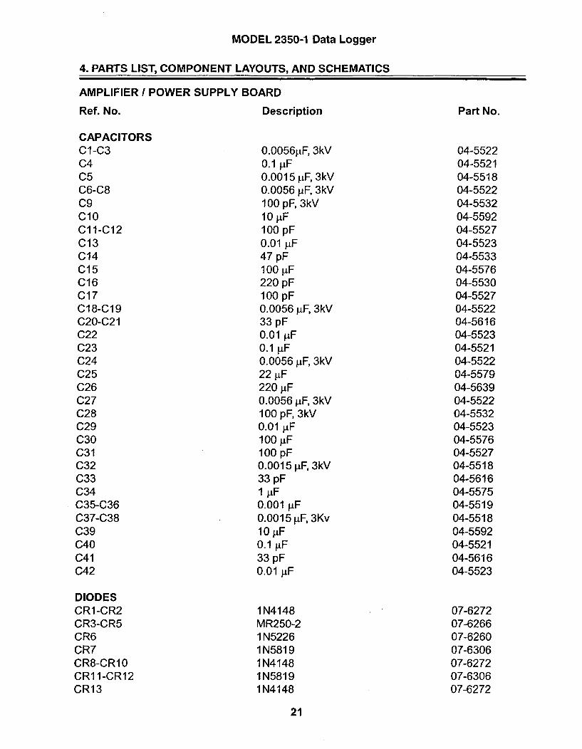
MODEL 2350-1 Data Logger
4. PARTS LIST, COMPONENT LAYOUTS, AND SCHEMATICS
AMPLIFIER I POWER SUPPLY BOARD
Ref. No. Description
CAPACITORSC1-C3C4C5C6-C8C9C10C11-C12C13C14C15C16C17C18-C19C20-C21C22C23C24C25C26C27C28C29C30C31C32C33C34C35-C36C37-C38C39C40C41C42
0.00561[F, 3kV0.1 pF0.0015 tF, 3kV0.0056 pF, 3kV100 pF, 3kV10 j.F100 pF0.01 jiF47 pF100 jiF220 pF100 pF0.0056 pF, 3kV33 pF0.01 piF0.1 V.F0.0056 ýtF, 3kV22 jiF220 piF0.0056 jiF, 3kV100 pF, 3kV0.01 1iF100 jiF100 pF0.0015 jiF, 3kV33 pFI jiF0.001 jiF0.0015 jiF, 3Kv10 iF0.1 1iF33 pF0.01 1iF
Part No.
04-552204-552104-551804-552204-553204-559204-552704-552304-553304-557604-553004-552704-552204-561604-552304-552104-552204-557904-563904-552204-553204-552304-557604-552704-551804-561604-557504-551904-551804-559204-552104-561604-5523
07-627207-626607-626007-630607-627207-630607-6272
DIODESCR1-CR2CR3-CR5CR6CR7CR8-CRI0CR11-CR12CR13
1N4148MR250-21 N52261N58191 N41481N58191N4148
21
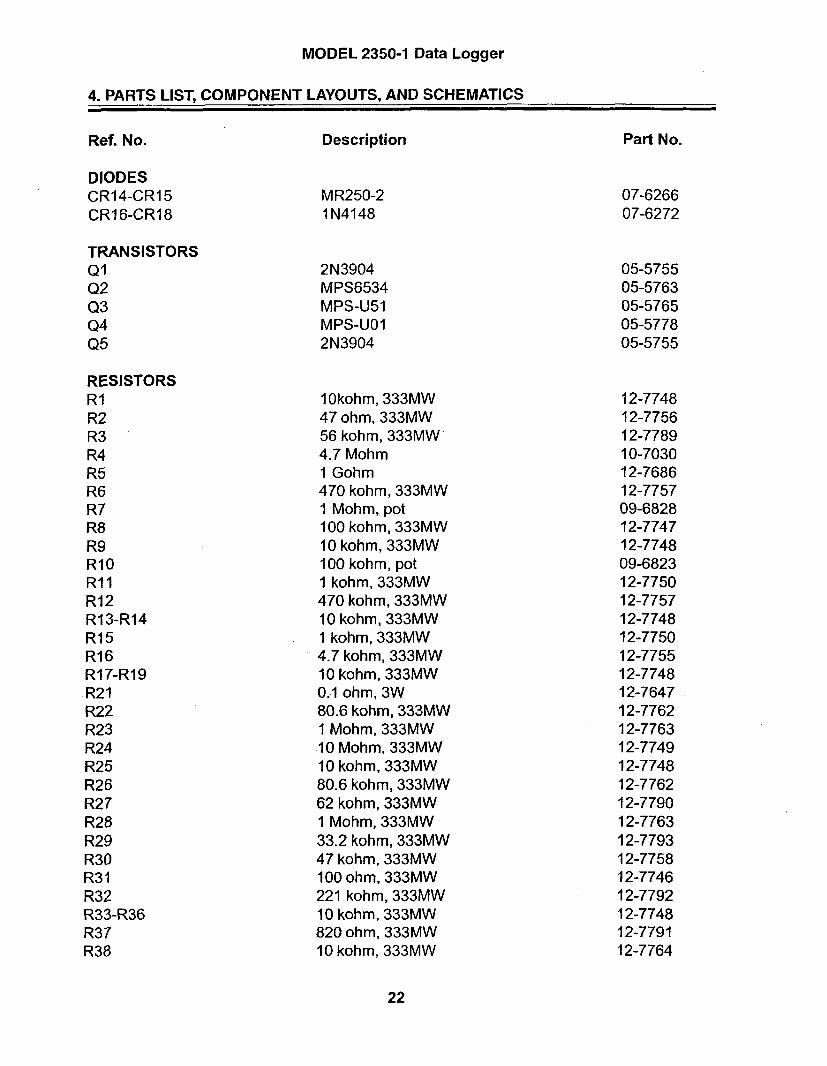
MODEL 2350-1 Data Logger
4. PARTS LIST, COMPONENT LAYOUTS, AND SCHEMATICS
Ref. No. Description
DIODESCR14-CR15CR16-CR18
MR250-21N4148
TRANSISTORSQ1Q203Q4Q5
RESISTORSRIR2R3R4R5R6R7R8R9R10R11R12R13-R14R15R16R17-R19R21R22R23R24R25R26R27R28R29R30R31R32R33-R36R37R38
2N3904MPS6534MPS-U51MPS-UO12N3904
1Okohm, 333MW47 ohm, 333MW56 kohm, 333MW4.7 Mohm1 Gohm470 kohm, 333MW1 Mohm, pot100 kohm, 333MW10 kohm, 333MW100 kohm, pot1 kohm, 333MW470 kohm, 333MW10 kohm, 333MW1 kohm, 333MW4.7 kohm, 333MW10 kohm, 333MW0.1 ohm, 3W80.6 kohm, 333MW1 Mohm, 333MW10 Mohm, 333MW10 kohm, 333MW80.6 kohm, 333MW62 kohm, 333MW1 Mohm, 333MW33.2 kohm, 333MW47 kohm, 333MW100 ohm, 333MW221 kohm, 333MW10 kohm, 333MW820 ohm, 333MW10 kohm, 333MW
Part No.
07-626607-6272
05-575505-576305-576505-577805-5755
12-774812-775612-778910-703012-768612-775709-682812-774712-774809-682312-775012-775712-774812-775012-775512-774812-764712-776212-776312-774912-774812-776212-779012-776312-779312-775812-774612-779212-774812-779112-7764
22

MODEL 2350-1 Data Logger
4. PARTS LIST, COMPONENT LAYOUTS, AND SCHEMATICS
Ref. No. Description
RESISTORSR39-R40R41R42R43R44R45R46R47R48R49R50R51R52R53R54R55R56R57R58R59
1 Mohm100 kohm, 333MW3 kohm, 333MW470 kohm, 333MW1 Gohm100 kohm, 333MW10 kohm, 333MW33.2 kohm, 333MW1 Mohm, 333MW12 kohm, 333MW1 kohm, pot330 ohm, 333MW1 Mohm, pot22 kohm, 333MW10 kohm, 333MW1 kohm, 333MW1 Mohm, 333MW80.6 kohm, 333MW1 Mohm, 333MW10 kohm, 333MW
Part No.
10-702812-774712-776812-775712-768612-774712-774812-779312-776312-778709-683112-778809-682812-775412-774812-775012-776312-776212-775112-7748
12-769612-7578
4275-0374275-089
06-625206-625106-602306-626506-625106-625306-622306-606606-625105-5791
RESISTOR NETWORKRN1RN20
5.6 kohm220 kohm
TRANSFORMERSTiT2
M2350-1 HVPSM2350-1 LVPS
INTEGRATED CIRCUITSulU2U3U4U5U6-U7U8U9U10ull
LT1 079LT1 078CA3096TLC372LT1 078AD7549LM2578CD4098LT1 078LM385Z
23
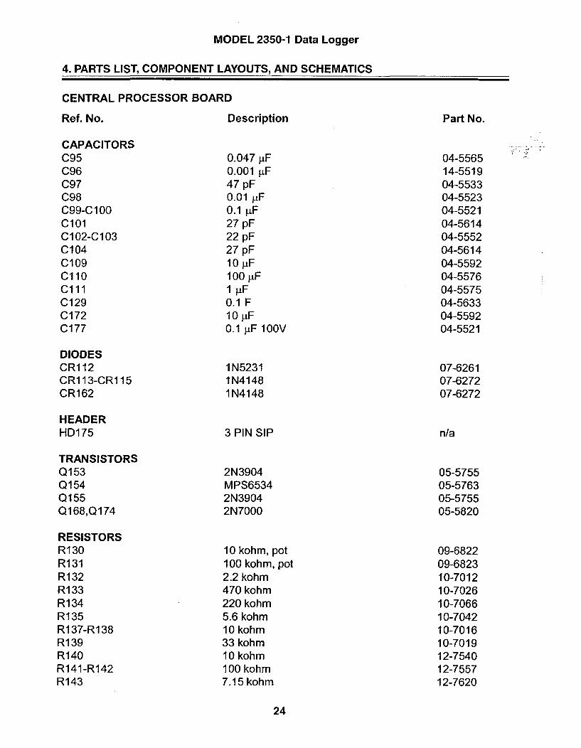
MODEL 2350-1 Data Logger
4. PARTS LIST, COMPONENT LAYOUTS, AND SCHEMATICS
CENTRAL PROCESSOR BOARD
Ref. No.
CAPACITORSC95C96C97C98C99-C 100C101C102-C103C104C109Cl10C1l1C129C172C177
DIODESCR112CR113-CR1 15CR1 62
HEADERHD175
TRANSISTORSQ153Q154Q155Q168,Q174
RESISTORSR130R131R132RI 33Ri 34R135R137-R138R139R140R141-R142R143
Description
0.047 pF0.001 pF47 pF0.01 1LF0.1 jiF27 pF22 pF27 pF10 ýtF100 [F1 iF0.1 F10 [iF0.1 ýtF 100V
1N52311N41481N4148
3 PIN SIP
2N3904MPS65342N39042N7000
10 kohm, pot100 kohm, pot2.2 kohm470 kohm220 kohm5.6 kohm10 kohm33 kohm10 kohm100 kohm7.15 kohm
Part No.
04-556514-551904-553304-552304-552104-561404-555204-561404-559204-557604-557504-563304-559204-5521
07-626107-627207-6272
n/a
05-575505-576305-575505-5820
09-682209-682310-701210-702610-706610-704210-701610-701912-754012-755712-7620
24

MODEL 2350-1 Data Logger
4. PARTS LIST, COMPONENT LAYOUTS, AND SCHEMATICS
Ref. No.
RESISTORSR144R148R149R160R161R164R166-R167RI 70R176
Description
I Mohm35.7 kohm8.66 kohm220 kohm150 kohmI Mohm10 kohm1 Mohm220 kohm
RESISTOR NETWORKSRN151
TRANSFORMERSTI 57
INTEGRATED CIRCUITSUl18Ul19U120U121U122U123U124U125U126U128
CRYSTALSY158Y159
22 kohm
Part No.
10-702812-764012-762310-706610-702410-702812-754010-702810-7066
12-7566
4275-074
06-624406-625406-644106-609306-626406-643906-623606-615606-624806-6060
01-521901-5212
M2221, 300-9
ICM7556MM58274CPL-200-T2-TCD74HC57327C512CPL-140-T2-T80C51 FALM331TLC27M71PRDD104
32 kHzXTAL6.144 MHz XTAL
25

MODEL 2350-1 Data Logger
4. PARTS LIST, COMPONENT LAYOUTS, AND SCHEMATICS
64k MEMORY EXPANDER BOARD
Ref. No.
RESISTORSR001Rl14
Description
22.1 kohm221 kohm
Part No.
12-784312-7845
06-638106-632306-633906-6385
INTEGRATED CIRCUITSUl15Ul16Ul 17Ul19
MAX703ESACD74HC4066MCD74HC138MCXK581 0OOM
26

MODEL 2350-1 Data Logger
4. PARTS LIST, COMPONENT LAYOUTS, AND SCHEMATICS
110 INTERFACE BOARD
Ref. No.
CAPACITORSC3-C4C5C6C8-Cl 1C12C37-C39
RESISTORSR16R19R20-R21R30R40
Description
27 pF0.047 [tF100 RF10 [tF4.7 jtF220 ýtF
RESISTOR NETWORKSRN33
DIODESCR26-CR28
TRANSISTORSQ23
TRANSFORMERSTI
INTEGRATED CIRCUITSU13U36
CRYSTALSY25
33 ohm8.2 kohm3.3 kohm10 ohm4.7 ohm
10 kohm
1N5231
2N3904
Part No.
04-561404-556504-557604-559204-557804-5639
10-700110-701510-701310-704610-7095
12-7777
07-6261
05-5755
4275-090
06-618806-6405
01-5212
M2350-1 EL
MAX23287C51 FA
6.144 MHz MICRO XTAL
27

MODEL 2350-1 Data Logger
4. PARTS LIST, COMPONENT LAYOUTS, AND SCHEMATICS
BACKPLANE BOARD
Ref. No.
RESISTORSR6
DIODESCR5CR7
CONNECTORSJ1-J2
Description
1 kohm
1N41481 N5819
125X44-CBNEARSEZA22DRSN
Part No.
10-7009
07-627207-6306
13-8181
28
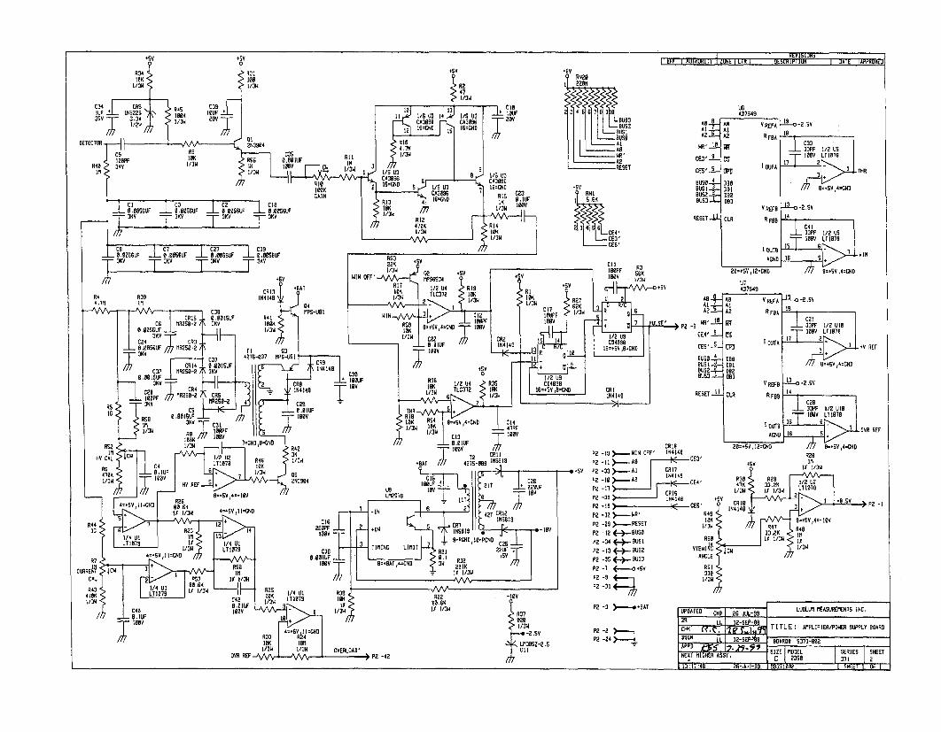
R347
646 IRA A66 C ID60
2C2GNS226 OOK lU31/50L. flowO 14L 1C7 COCU313 66s CSS3UF CA3096U 20YSU 37MY~ flo TIS 63
I LFt I AU1HUKI 1Y I ZONE I LIK I ULSLRIMUN I DATE APPMVEIT+sY
RN2'
225
BUSIBUSS
WR'A2REME
A2_
63R' 10
CE3' I-9
CES'1-i
BUS72
RESETL
URAD7S49
As V RErAAlA2 R FOA
A OUTA
DBO
Do
39-10-2.5v16
_.L F IOOF 1/2
17 2 THR
8,.SA 4.CNA+5V
RN I
CII -E4'CEO"CES'
_ .0s5GUF I .6- 0SUF _ 6- 66SSUF I 51.1•.•5611T - oAV T Av AoV T •K A v
R4 R39 1413464.7M 36 a4,76 1I S 0
CR1S . 6.6o00 6SI R41CG lIR2S-2/ \ KV 766 666( ) o,++SGU•_6 _ "'3"",'3 •
C2I I CR76.1056LUF ; 625C-2 TI 8AV-'C07 4275-037 MP5-553
C32 R34 6.663500I O+OOiSUF _ + I tt I !2 iKO
"V 2 CR6CR4 16414
trr S- 1CR5
R5 lAS MR256-2 4C29IC CS .•61, S A ,o Rv2 ,- )
IR
1216
RS2 R~4
HY CA c 2 2 4 I /o vvv--"•
4/70 1/76
OAR REFS,4-B 2O0
LI6/O G 36/3WRG0 i2
D82D83VREF8 --30-2.SV
CLR R F09 14
C 4 113 333PF 112 USIOBV LT1078
I CUTS Is 6 1 -WINACHD Is S
20=-SVI2xGND 9m+Sv.,4=cND
RS3 "SV22K R CGil oW I F " I/ OW 0 2 - - -
I O O P F R
WIN OFF'--/4 MPS434 +sv 145v GGX6 RI0 M6U 64 Cig SIV 13W CSV)s~~u,, Hi. TL3 i 1 , 0K )), • R
flow 2 3 l./.. 027 ..1 CR372 -- 2, I......+ . R lI
6 16561 • I P2K 36 (.R 5 C 6
0310 LIIT = 6'PCNDV34=CND CO C2-7 SS
T2 C•II ~ ~~~~P2 -9S•,,,,,WHOF 4
+t+ II .•I -roT (•. ~plsP2 -73 4--RSE
WP 622--+IN 3 +1123 l 0 -
1/ II 3/ ,1/ . 6 l F? -7 )<-..---o+ATNCO P2 -2 -- B
'=+01 • -.sU4.s -flo I I Lu8E- S-
P2SRA -4CND
Al--A2I=
P2 -8 WR't10
CE,4' I.
BUSSBUSI 2
BUS3=.•
U0AD7S49
AS vREFAAlIA2 R FDA
BRBDalB0ea
1 -2.5V
0233FPF 1/2 Ul21666 LT0170
17 2,- 1 rHV REF
B=.SV,4=CND
RESETOi,•
V R9EF -9 -- 0-2.SV
CLR R6 FOS 1
C2037PF 1/2 U163I6V LT1S78
Dul A5 6 OA•• OVR REF+ =N0 16 5, 4
20=*SV,12'ORD 6'.56,4-CMDR
a CE3' R28.SV IIIit E/311
8 CE4' R30 R 112 LIE47K47K 33 . KI/ 3w It 1 3 2 L71078
+SV Roo R'UKII P2CES 14' IN41 a 3 +
12K L"w 2 Bm+SV,4=- IýBV
B '/2 'USflow R47 R48L
ow
33.2K IHRSO 11 1/3w 11VIEW A jcw I/ON
ANGLE
RS1330
"" 'K
UPDATED CKO 1 2G- fill LUDLUM MEASUREMENTS INC,
LI. 12-DEP-891LLK 12SEP-88 ,. TITLE : AMPLIFIER/PDAER SUPPLY BOAR6
DSGN LL I2-SEPAS B20ARD6 5371-602APPD 7K51 •ER - • SIZE OEL SERIES SHEETNEXT HIGHER ASEY. C I M2DSB "71
[- I . . 1 .11, 1 - -

0
C.,
21 R54a U10K 106K -- OS33F , -:ý; C271 RIB R 14 R13~f ~i~ 035 RSS'5R___ 3_ IOF D BNs4d U
L 227 ORIK 0 U
,5 47 'E
3N3PF I0P7C1217P C7 .OESFR
33PF US
0R34
LM C5-2S 117 IN34 RN CR15 .S~R4100F 024 SU 18OOSUF I C
CR1111 R303 2'S R9 MR5
CD3:8 4 RSu'Ir~U62y,~s wfR17 I XLU 7 04
FM8Z2iiS rrI~ 7- ReC)',FS L112E7CI0IOK C3L M 3
R00
IN LUDLUI MEASUREMENTS INC. SWEETWATER, TX.
,TITLE AMPLIFIER/POWER'CH 2j'? SUPPLY BOARD12E - 0RDO S371-002 as1 1002
U1:Il:4e '26-Ju I-OS CouSIDE S'LOR MIE0O OUTfLI EgICOMP PASTE01COMP -- wi.- PASTEC31SLDR MASKC3
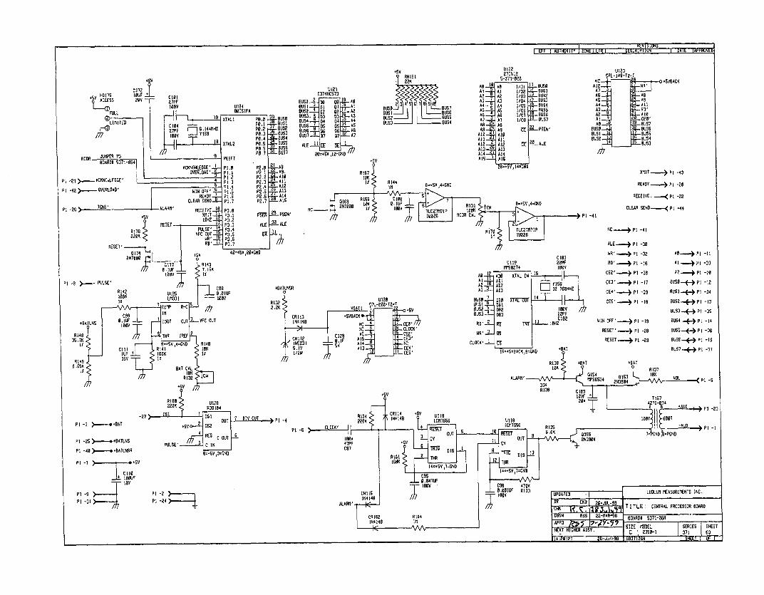
U12CD74HCSE3
BUSE AI • a5 A-t- k
ALE D 9 A
22K
BUSS B USTBust BUSSBUS2 BUSS
U1222"/C5 125-3"/$-926
AD 1 AS 1l0) I BUSSA I A 1 I/02 BUSlA2 m A2 1/03 1 JBUS2A3 AJ I/04 BUS3
AS AS I/US BUSSAS AS 1/07 QBSSAT- AT 1/08 D°-- UST•AR ARAS A9 2-- PSEN'AIR AIOAll "A'A12 A- 2 S 20 ALEASS Al3AlA A014AtS- AM
AIS 0 Y15 =N
U123PPL-140-T2-7
NO +SYRACKA12 AR'07
A f3As AS04 -All.A S
A I 'A3 RNS
AR ICEORUS
AB - SU57BUSS- BUSSsusl.j~ I BUSSBUS2 _ - BUS4
_ US3'
PI
P1
XMIT--•--• P1 -43
READY----> PI -2R
RECEIVE- PI -22
CLEAR SEND-... PI -44
PI -2G
-41
NC ) p1 -41
ALE.. P 1 -30
WR' -... ,.. pI -32
RD' ..- P1 -16
CE2' -) P 1 -3B
CE3'-.-- PPI -S7
CE4' _ P P -33CES" -4 Pt -IS
Pt -8
2.0 AS M -M T2-
SR
CCPL-URSZ!,L!
IN414B AC 4 CEO'AC CLOCK'
CCl C12S AC CEZ'CR112 S IF 015 CE]1IRSOS1 A14 AC N 4S,1 I01A3 CE'1/2W 7I CE'
A -I P1 -3S
Bus -..-..-.),pi -IS
RUSo.P.(--) P1 -12
BUS3P-.(.- PI -3S
BUS4-., P -I4
BUSS_" , PI -is
BUSS7 P1 -35
WIN OFF'-.-->) Pt -is
RESET' Pt p -O8
RESET p l -29
UIIR1017555U187[C175SSGPS -6
PI -7 > -- RIgV
PI -9
PI -31PI -2P 1 -24;), , ,_
ALARn'

L UDLUM MEASUREMENTS [NC. SWEETWATER, TX.
DR CKB 09/17/-99 1ITLE : CENTRAL PROCESSOR SCARD[OH C. 19OARD: S371-068
6 TTIIA -- I~. rl EV'9 Z sI 1 1 ý
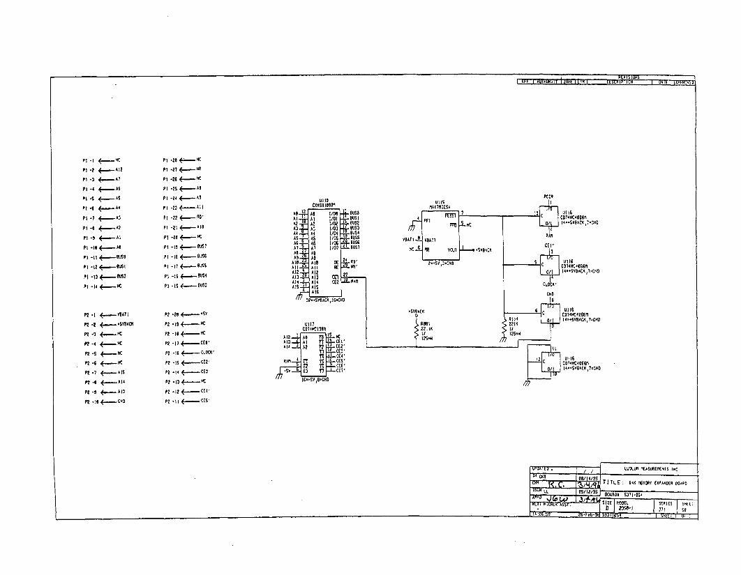
PI -I m
Pt -2 4-.-..AI2
Pt -4 AS
P I -S ,•-, AS
P• -t S 4.....-.....A
P 1-6 ~A4
PI -7Z A.-- - 3
PI - . A2
Pi -t2 <,- e-s-
P 1 .13 +~-M2
p 1 -14 +-
P1 -20 M-
P2 -26 K.----
PI -2S ASA
P1 -24 . A
Pt -e . - DP 1 -22 RD
P2 -21 A1•.....A
P1 -20 +--
PI -Is <..--..- BUS
P2I -20 BUSS
PI -I? - uss
P1 -1 , 8US4
PI -IS -BUS3
UI ISCXAS8100"
At At 1/ I BUSlA2 A2 I/Uz BUS?A3 - 3 2/03 9U53A4 A4 1/Oa - US4AS AS I/0S BussAG0 U I/OS -USGAT.. A l I/O0" BUI--us
All ASA 9 A 9 24 aA6. Allt BE SI
Al12 A1? 22A13 A13 mfA14 Al4 CE? PAMlAIS AIS
AIS
32?- S ASACA lB 'C A
MAX52OESA
VAUTI V BATS
RC OR
2 C C221AC65' • tCD 4HC40G•
0/ I4:.SUSAUCK,l-CN
R ,
CE'
C 4LOCK AC4BS
P2 -2 <- SYACKP2- ? ..... ,.-.-UBAOA
P2 -2 <-..-
P2-4 -
P2 -S K
P2 -6 K....AP2.- <,--- IS
P2.2 4 A...--AS
P2 . ,--.,---AD
P2 -26 4 -~SU
P2 -19S<..--
P2 -Il - -
P2 -I•7 CO
P2 -Is .- CLOCK'
P2 -is ..,..--CE2V
P2 -14 •.,, CE2'
P2 -I:-•
P2 -I1 - -CE4'
P2 -11 ES
Ull?CD74K1,3|8MA 1 4 A2 2 t
A 4 Ti- CE?
ISTT~ CE2RM11 T514CES4
E2 T; CEG'SA V2 T7 CEV
B7 IA B CA.GD
* SUBAC U
I2SMA
CND
CB14MC40S~rn522 4 / 14-.SVOACx,l-CAD
It
CD14KC40BBIM
I4-VA''UOC4I l'CA0
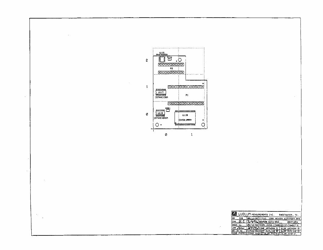
2
0
0 1
Q LUDLUM MEASUREMENTS INC. SWEETWATER, Tx.
fL1R CK8 18/14/SS TITLE: 12eK MEMORf EXPANDER BRDj1C."A C.OARDN S371-eS4 BS371OSS7
I D S CN L L. OS / 1 2f S S M¶ O DE L 2 3 50 -I I S E R I E S 3 7 11S KE T ,EOS:8:4--2-Fe-6COMP AUTINER a) SLDR AUTLORK CJ~COM AST C) I OMP MSX 001W SULINE P4T Sl DR MULN A KMC-'.O~1P FASTEC COn? rIASKO ISLOR PASTE C ISLOR I1AAKti

PB -12
CIDBGUAA
Cli
20V
,P8 -II
C427FION
U3s87CSIFA
, PA -2
P8 -4
'Pe -3
pe -s
P9 -I 4-o SA
P5 -2> WAND
P7 -6 > -.... RESET
P7 -*7 ).-...T.OW'
P? -s xrnrPI .-4 READ'
I' -3 ECE
P7 -2> CLEA
.S2R40
PA -I1A
PB -1
,sV
ZERO Z ER UTO Pe -13CR28
1145231A V IIi iA
PL8 PROCRAMAILE LOCCINC BUTTON ) P8 -GCR27
1N523 I5.IV51/2W NR30lB
P7 -I -EL PO RCC,
*IBBtF
P7 -6 - TA
BAUD BAUD RA E SELECT ) PA -ISCR26.
INS2315.1V 11/2w/
P7 -1B0SC39 C30 C37
*1 1 .IF 221" 1. 22V1R
P7 -T >'s
I


----- a:ATUNS*BATTUN
CR7INS0910
P.4 -S>
P4 -2
P4 -3
P4 -4 SPEAKER.
P4 -I P
SRS
PS -R
PS -2
PS -3
PS -4
PS -5PS -6
P5 -7
PS -8
PS -9
PS -to
J2 JIA1PLIFIER/POWER SUPPLY PROCESSOR
5371 _-82 I3I1 -u1
-R-,.-H 1 I 5 1023. Uo I 1 23 [AUDIO.
3I 12S I.BATUNS .BAo-j 31 1o s H-o.- USsDIV OU 4 ZS [TONE' DI U 26 [TONE,
VO L S 27 [S I VOL- S 27 DOSCLCI'. I I2CK "ESE7' 0I Lo•' IO -RESET'
,sV.-d ? I 29 FRESET .svo- 7 1029 FRESE'
PULSE'. B 30 [ALE PULSDEl a I 1 30[FRLE
A2 - o 2 WR' A2. 10 32 WR'0 !- HOI I •F o , I•,
2u$,- 121 3, [ei-. ,2 It , 3I-4BUSA 2 34F BU I- s• , 12 , 24 F BUS ,IOUS2. 17 I OS3 BU2s. 13•s , I U• 3 SoV
OU54. 14j IS 1BUSS 2US4- '14 36[FOUSS
BUSS • S 37 OusT BuSS- IS 137[ usT NR
RD' o 16 N[FCE2' RD'. 161 32 CEO'1E I CE21D
CE3'4 17 1 F ICEd' CE7J' 17 39 .CE4 ' I4
CES'O to 10 O -BATUNSR CES'. 18 142O - +BATUNSR
WIN OFF' I3 1 41 FRECOROER WIN OFF- 'S 19 41 RECORDER
READY..!20 42 HOYELOA"' READY 21 4,2 F OVERLOAD'ALARM RESET' , 2I 14 FX",1 AL.ARM RESET'.] 21 4 lo F T
RECEIVE 22 1 44 [CLEAR SEND RECEI IVE 22 44 I CLEAR SEND
P 1-I
P 10 -2
P10-3
P 10-4
plo-S
PIe-S
PIO-8
DlV OUT
>._ TONE'
>.- -CLICX'
<- RESE I
P3 -2
.SVO-----..-4 P3 -3
-. ,vo---.----* P3 -4
AR' ---- , p3 -S
RD' pi p -6
COOS' P3 .7AO--. P3 .0
RESET' P p3 -10
BUS--., P7 -P I I
BUS I P3 -12
BUS -.-.- p3 -13
0US34--,, P3 -14
BUSS . .P3 -IS
BUSS..-.4, P3 -17
BUSE 7 P3 -I8
PlI'l <__,, ÷BAIswr__ --
PIt1-2 <(--,.R-ADY
P1-3 >_.ALARM RESET'
P11-4 <_ X..Sl l
PiI-$ >m---RECEIVE
PII-6 >--.. CLEAR SEND
PG -I +. RECORDER
PS -2

00
0 - 0RG
8•tt NI
.J tI/I4 11P O lESO
DR LL 12/17/90 TITLE: BACKPLANE
iHE BOARD* S371-000 OS371003DON LIL. 10/2z/e MODEL 23S0ISERIES371ISHEET 29APP J ./ CO ARTlRK 0 SLR ARTWRK 008:ES:02 2IFbS CoTPOULINE M SLDR OUTLINE Q-
.-.. P-,. , *'~LaUflASTE ' JSiLtJN flAXf
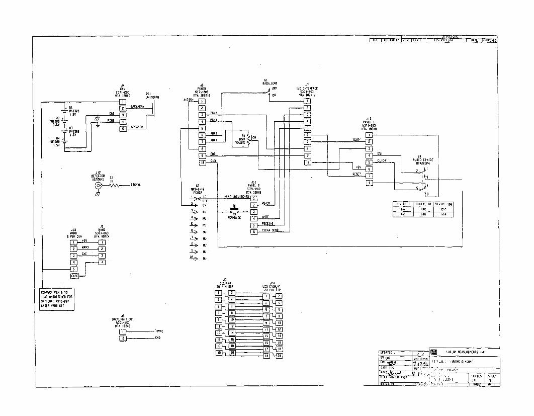
CANS371-033MTA IOSHADS
ISV ONT
AD
JSPEANEIS-
dI2 POND 4
I IE SVI-A
CODETECTT PI42T
LASE WANDNDl
WAND 5371 -063
C-ASE
SI8ACKLICET
-'31ISPLAY J14
20 PIN DIP LCD DISPLAY2] 20 PIN DIP
4 E]_L ' 2
S-L ,E
C3IA
LUDLUM MODEL 3SURVEY METER
June 2007
Serial Number 239543 and Succeeding
Serial Numbers

LUDLUM MODEL 3SURVEY METER
June 2007
Serial Number 239543 and Succeeding
Serial Numbers
LUDLUM MEASUREMENTS, INC.501 OAK STREET, P.O. BOX 810SWEETWATER, TEXAS 79556325-235-5494, FAX: 325-235-4672

I REV II ALTERATIONS I DATE I BY
SIVALID 12/21/05DOW
2 1 REDESIGNED BATTERY LID ARTWORK 8/11/06 lCmC
(,
e9f
l@ AxOFF S BAT [ @
OFF- I IxlO0
0RESET
xl0 00
-•xl 0ioo
x01o~l 0100.1
\ j
IL1I MODEL 3 I~SURVEY METER
LUDLUM MEASUREMENTS INC.SWEETWATER, TEXAS
AC Ei _ I
. o
I P I 51n11E AN L iDWG N 446-041 SCALE, M '
TITLE N 3 FRONT PANEL
INM1 81t- - 1 464 I 41A

Irable of Cnet
Introduction 1
Getting Started 2Unpacking and Repacking 2-1
Battery Installation 2-1
Connecting a Detector to the Instrument 2-2
Battery Test 2-2
Instrument Test 2-2
Reading the Meter Face Dial 2-3
Operational Check 2-6
Specifications 3
Identification of Controls and Functions 4
Safety Considerations 5Environmental Conditions for Normal Use 5-1
Warning Markings and Symbols 5-1
Cleaning and Maintenance Precautions 5-2
Calibration and Maintenance 6
Calibration 6-1
Exposure Rate Calibration 6-1
CPM Calibration 6-2
Establishing an Operating Point 6-3
Maintenance 6-4
Recalibration 6-4
Batteries 6-5
Troubleshooting 7Troubleshooting Electronics which utilize a
G-M Detector or Scintillator 7-1
Troubleshooting G-M Detectors 7-3
Troubleshooting Scintillators 7-4
Ludlum Measurements, Inc. June 2007

Model 3 Technkial Manual
Technical Theory of Operation 8Low Voltage Supply 8-1
High Voltage Supply 8-1
Detector Input 8-1
Amplifier 8-1
Discriminator 8-2
Audio 8-2
Scale Ranging 8-2
Meter Drive 8-2
Meter Reset 8-2
Fast/Slow Time Constant 8-2
Recycling 9
Parts List 10Model 3 Survey Meter 10-1
Main Board, Drawing 464 x 204 10-1
Wiring Diagram, Drawing 464 x 212 10-3
Drawings and Diagrams 11
Ludlum Measurements, Inc. June 2007

Model 3 Technical Manual Secfion 1
Introducgon
The Model 3 is a portable radiation survey instrument with four linearranges used with exposure rate or cpm (counts per minute) meterdials or a combination of both, exposure rate and count rate(referred to as "combo") meter face dials. The instrument features a
regulated high-voltage power supply, unimorph speaker with audio ON-OFFcapability, fast-slow meter response, meter reset button and a six-positionswitch for selecting battery check or scale multiples of X0.1, X1, X10 andX 100. Each range multiplier has its own calibration potentiometer. The unitbody and meter housing are made of cast aluminum and the can is 0.090"thick aluminum.
The audio provides a brief "click" for every radiation event detected. It alsoprovides a steady tone to warn the user of a low battery condition. This lowbattery warning overrides the position of the AUD ON-OFF switch.
Any Geiger-Mueller (G-M) detector offered by Ludlum Measurements willoperate with this unit as well as any scintillation type detector. Theinstrument is typically set at 900 volts for G-M tube operation. For specialrequirements of G-M or scintillation detectors, the instrument high voltagemay be adjusted from 200 to 1500 volts.
The unit is operated with two "D" cell batteries for operation from -4°F(-200C) to 1220 F (500 C). For instrument operation below 32TF (0°C) eithervery fresh alkaline or rechargeable NiCd batteries should be used.
Ludlum Measurements, Inc.Page 1-1 June 2007Ludlum Measurements, Inc. Page 1-1 June 2007

Model 3 Technkal Manual Section 2
KGettng Started
Unpacking and RepackingRemove the calibration certificate and place it in a secure location. Removethe instrument and accessories (batteries, cable, etc.) and ensure that all ofthe items listed on the packing list are in the carton. Check individual itemserial numbers and ensure calibration certificates match. The Model 3 serialnumber is located on the front panel below the battery compartment MostLudlum Measurements, Inc. detectors have a label on the base or body ofthe detector for model and serial number identification.
"Iprtarat!
If multiple shipments are received, ensure that the detectorsand instruments are not interchanged. Each instrument iscalibrated to specific detector(s), and therefore notinterchangeable.
To return an instrument for repair or calibration, provide sufficient packingmaterial to prevent damage during shipment. Also provide appropriatewarning labels to ensure careful handling. Include detector(s) and relatedcable(s) for calibration. Include brief information as to the reason for return,as well as return shipping instructions:
- Return shipping address- Customer name or contact- Telephone number- Description of service requested and all other necessary
information
Battery InstallationEnsure the Model 3 range selector switch is in the OFF position. Open thebattery lid by pushing down and turning the quarter-turn thumbscrew
Ludlum Measurements, Inc. Page 2-1 June2007Ludlum Measurements, Inc. Page 2-1 June 2007

Model 3 TechnicaI Manual Secion 2
counterclockwise 1¼/ rn. Install two "D_ size batteries in the compartment.
Note the (+) and (-) marks inside the battery door. Match the batterypolarity to these marks. Close the battery box lid, push down and turn thequarter-turn thumb screw clockwise ¼4 turn.
B E
The center post of a "D" size battery is positive.
Connecting a Detector to the Instrument
Caution!The detector operating voltage (HV) is supplied to the detectorvia the detector input connector. A mild electric shock mayoccur if you make contact with the center pin of the inputconnector. Switch the Model 3 range selector switch to theOFF position before connecting or disconnecting the cable ordetector.
Connect one end of a detector cable to the detector by firmly pushing theV/ • connectors together while twisting clockwise ¼A turn. Repeat the process in
the same manner with the other end of the cable and the instrument.% Battery Test
Check the batteries daily or prior to use, whichever is less frequent, to assureproper operation of the instrument. Move the range multiplier switch to theBAT position. Ensure that the meter needle deflects to the battery checkportion on the meter scale. If the meter does not respond, check to see if thebatteries have been correctly installed. Replace the batteries if necessary.
Instrument TestAfter checking the batteries, turn the instrument range switch to the X100position. Place the AUD ON-OFF switch in the ON position. Expose thedetector to a check source. The instrument speaker should emit "clicks"relative to the rate of counts detected. The "AUD ON/OFF" switch will silencethe audible clicks if in the OFF position. It is recommended that the
Ludlum Measurements, Inc. Page 2-2 June2007Ludium Measurements, Inc. Page 2-2 June 2007
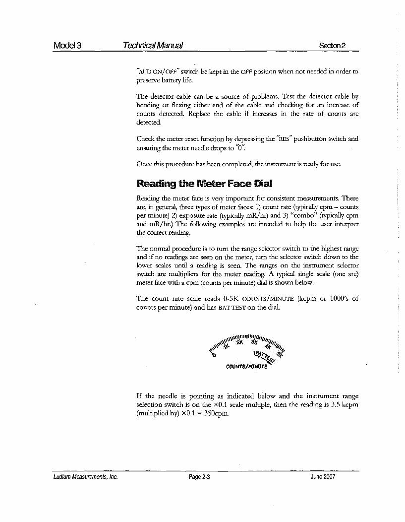
Model 3 Technical Manual Section 2
AUD ON/OFF" switch be kept in the OFF position when not needed in order topreserve battery life.
The detector cable can be a source of problems. Test the detector cable bybending or flexing either end of the cable and checking for an increase ofcounts detected. Replace the cable if increases in the rate of counts aredetected.
Check the meter reset function by depressing the "RES" pushbutton switch andensuring the meter needle drops to "0'.
Once this procedure has been completed, the instrument is ready for use.
Reading the Meter Face DialReading the meter face is very important for consistent measurements. Thereare, in general, three types of meter faces: 1) count rate (typically cpm - countsper minute) 2) exposure rate (typically mR/hr) and 3) "combo" (typically cpmand mR/hr.) The following examples are intended to help the user interpretthe correct reading.
The normal procedure is to turn the range selector switch to the highest rangeand if no readings are seen on the meter, turn the selector switch down to thelower scales until a reading is seen. The ranges on the instrument selectorswitch are multipliers for the meter reading. A typical single scale (one arc)meter face with a cpm (counts per minute) dial is shown below.
The count rate scale reads 0-5K COUNTS/MINUTE (kcpm or 1000's ofcounts per minute) and has BAT TEST on the dial.
COUN~TS/MINUTE
If the needle is pointing as indicated below and the instrument rangeselection switch is on the x0.1 scale multiple, then the reading is 3.5 kcpm(multiplied by) XO.1 = 350cpm.
Ludlum Measurements, Inc. Page 2-3 June 2007Ludium Measurements, Inc. Page 2-3 June 2007

Model 3 Technicai Manual Secfion 2
9K 3
The same needle indications on successive ranges would be:
×1 = 3.5 kcpm (or 3,500 cpm)
X10 = 35 kcpm (or 35,000 cpm)
X100 = 350 kcpm (or 350,000 cpm)
A typical dual scale (two arcs) meter face is shown below. The top scalereads 0-2 mR/hr. The bottom scale also reads 0-2 mR/hr and is for X100only scale. The x 100 ONLY scale will work correctly when the multiplierswitch is in the x100 range. The meter face also has a BAT TEST positionon the dial.
410
If the needle is pointing as indicated below and the range selection switchis on the X0.1 scale, then the reading is 0.1 mR/hr.
t 0
The same needle indications on successive ranges would be:
X 1 = 1.0 mR/hr (or 1,000 ýtR/hr)
XI0 = 10 mR/hr (or 10,000 p.R/hr)
X100 = 70 mR/hr (or 70,000 pR/hr)
Ludlum Measurements, Inc. Page 2-4 June 2007Ludlum Measurements, Inc. Page 2-4 June 2007
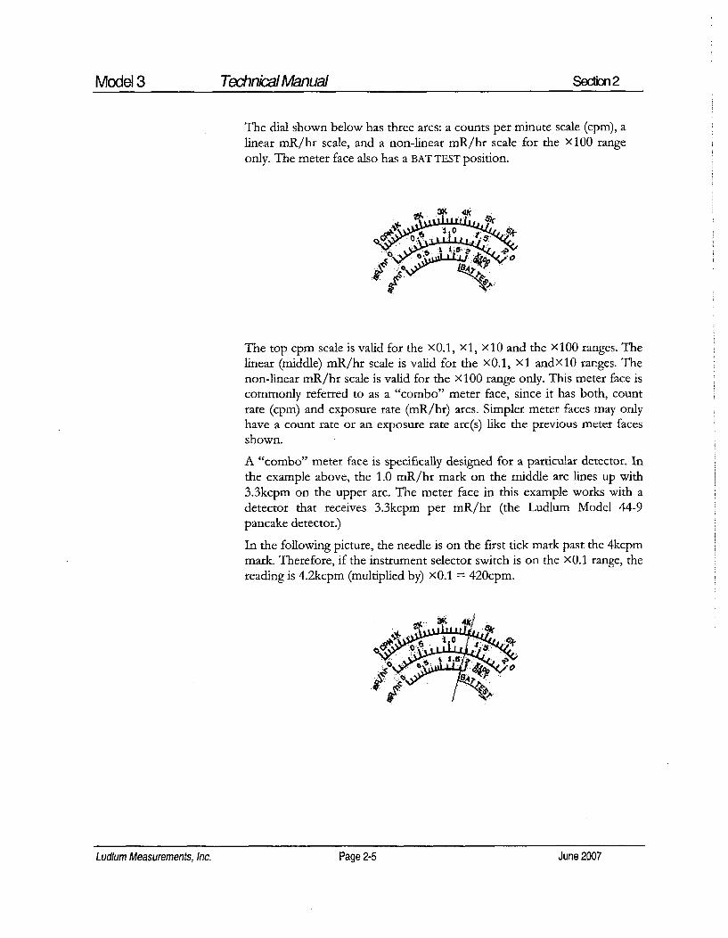
Model 3 Technical Manual Secfion 2
The dial shown below has three arcs: a counts per minute scale (cpm), alinear mR/hr scale, and a non-linear mR/hr scale for the X100 rangeonly. The meter face also has a BAT TEST position.
1.3K
The top cpm scale is valid for the XO.1, Xl, X10 and the X100 ranges. Thelinear (middle) mR/hr scale is valid for the X0.1, Xl andXlO ranges. Thenon-linear mR/hr scale is valid for the X 100 range only. This meter face iscommonly referred to as a "combo" meter face, since it has both, countrate (cpm) and exposure rate (mR/hr) arcs. Simpler meter faces may onlyhave a count rate or an exposure rate arc(s) like the previous meter facesshown.
A "combo" meter face is specifically designed for a particular detector. Inthe example above, the 1.0 mR/hr mark on the middle arc lines up with3.3kcpm on the upper arc. The meter face in this example works with adetector that receives 3.3kcpm per mR/hr (the Ludlum Model 44-9pancake detector.)
In the following picture, the needle is on the first tick mark past the 4kcpmmark. Therefore, if the instrument selector switch is on the XO.1 range, thereading is 4.2kcpm (multiplied by) xO.1 = 420cpm.
Ludlum Measurements, Inc. Page 2-5 June 2007

Model 3 Technial Manual Section 2
The same needle indications on successive ranges would be:
x 1 = 4.2kcpm (or 4,200 cpm)
x 10 - 42kcpmn (or 42,000 cpm)
x 100 = 420kcpm (or 420,000 cpm)
If you use the mR/hr scales, then the readings would be:
X0.1 = 0.13 mR/hr
Xl = 1.3 mR/hr
x10 = 13 mR/hr
x100 180 mR/hr*
Note:~*This reading is using the bottom (non-linear) scale.
Many different dials are available, but each can be used as described above.
Operational CheckTo assure proper operation of the instrument and detectors(s) betweencalibrations, an instrument operational check including battery test andinstrument test (as described on pages 2-2 and 2-3) should be performed atleast daily or prior to use, whichever is less frequent. A reference reading(or readings) with a check source should be obtained with the detector(s)in a constant and reproducible manner at the time of calibration or at thetime the instrument is received in the field.
If at any time the instrument fails to read within 20% of the referencereading when using the same check source, it should be sent to acalibration facility for recalibration and/or repair. If desired, multiplereadings may be taken at different distances and/or with different sourcesso that other ranges or scales are checked.
Ludlum Measurements, Inc. Page 2-6 June 2007

Model 3 Tedhnkial Manual Section 3
Speciffica fonsPower two D cell batteries housed in a sealed externally accessible
compartment.
Battery Life: typically greater than 2000 hours with alkaline batteries andwith the AUD ON-OFF switch in the OFF position.
End-of-Battery Life Warning: At 2.1 Vdc the meter needle will drop to the
edge of the BAT TEST or BAT OK area when the meter selector switch ismoved to the BAT position. At 2.0 Vdc a steady audible tone will be emitted
to warn the user of the low battery condition.
High Voltage: adjustable from 400 to 1500 volts.
Threshold: fixed at 40 mV ± 10 mV.
Meter 2.5" (6.4 cm) arc, 1 mA analog type.
Meter Dial: 0-2 mR/hr, or 0-5k cpm, BAT TEST (others available).
Multipliers: X0.1, X1, X10, X100.
Range: typically 0-200 mR/br, or 0-500,000 counts/minute (cpm).
Linearity: reading within 10% of true value with detector connected.
Battery Dependence: less than 3% change in readings to battery failure
indication.
Calibration Controls: individual potentiometers for each range; accessible
from front of instrument (protective cover provided).
Audio: built-in unimorph speaker with ON-OFF switch (greater than 60 dB at2 feet).
Response: toggle switch for fast (4 seconds) or slow (22 seconds) from 10%to 90% of final reading.
Ludlum Measurements, Inc. Page 3-1 June 2007
Model 3 Technkial Manual Section 3
Reset: pushbutton to zero the meter.
Connector series C" (other available).
Size: 6.5" (16.5 cm) H x 3.5" (8.9 cm) W x 8.5" (21.6 cm) L
Weight: 3.5 lbs. (1.6 kg) including batteries.
Construction: cast and drawn aluminum with beige powder-coat
Cable: 39-inch with "C" connector (others available).
Ludium Measurements, Inc. Ludlum Measurements, Inc. Page 3-2 June 2007Page 3-2 June 2007

Model 3 Technical Manual Sectio 4
Idenifcation of Controls and~Functions
See the Model 3 FRONT PANEL drawing at the
beginning of this manual to reference the
following controls:
Meter. 2.5" (6.4cm) arc, 1 mA analog type with pivot-and-jewel suspension.Typical meter dials are 0-2 mR/hr, 0-20 ptSv/h, 0-5k cpm or combination ofexposure rates (0-2 mR/hr or 0-20 pSv/h) and cpm. and BAT TEST.
Connector. Used to connect the detector to the instrument. Typically series-C- but can be "B3NC-, "MHV", "UHF-, or others.
Range Selector Switch: A six-position switch marked OFF, BAT, X100,X10, X1, X0.1. Turning the range selector switch from OFF to BAT providesthe operator with a battery check of the instrument. A BAT check scale onthe meter provides a visual means of checking the battery-charge status.Moving the range selector switch to one of the range multiplier positions(X100, X10, X1, X0.1) provides the operator with an overall range of 0 to500,000 cpm. Multiply the scale reading by the multiplier to determine theactual scale reading.
Calibration Controls: Recessed potentiometers which are used to calibratethe individual range selections and allow for high voltage adjustment from400 to 1500 volts. A protective cover is provided to prevent tampering.
Battery Compartment: Sealed compartment to house two "D_ cell batteries.
RESET Button: When depressed, this switch provides a rapid means to drivethe meter to zero.
AUD) ON-OFF Switch: In the ON position, operates the unimorph speaker,located on the left side of the instrument. The frequency of the clicks isrelative to the rate of the incoming pulses. The higher the rate,
Ludlum Measurements, Inc. Page 4-1 June 2007Ludium Measurements, Inc. Page 4-1 June 2007

Model 3 Technical Manual Section 4
the higher the audio frequency. The audio should be turned OFF when notrequired to reduce battery drain.
Note:
A low battery condition results in a steady audio toneregardless of the position of the AUD ON-OFF switch.
F-S Toggle Switch: Provides meter response. Selecting the fast, "F" positionof the toggle switch provides 90% of full scale meter deflection in fourseconds. In the slow, "s" position, 90% of full scale meter deflection takes 22seconds. In "F" position there is fast response and large meter deviation. The"s" position should be used for slow response and damped, meter deviation.
Note:
The slow response position is normally used when theinstrument is displaying low numbers that require a morestable meter movement. The fast response position is used athigh rate levels.
Ludlum Measurements, Inc. Page 4-2 June 2007

Model 3 Technkial Manual Section 5
Sadety Considera ons
Environmental Conditions for Normal UseIndoor or outdoor use
No maximum altitude
Temperature range of -20'C to 50*C (-4'F to 122oF). May be certified foroperation from -40°C to 65°C (-40'F to 150T).
Maximum relative humidity of less then 95% (non-condensing)
Pollution Degree 1 (as defined by IEC 664).
Warning Markings and Symbols
The operator or responsible body is cautioned that theprotection provided by the equipment may be impaired if theequipment is used in a manner not specified by LudlumMeasurements, Inc.
The Model 3 Survey Meter is marked with thefollowing symbols:
/• CAUTION, RISK OF ELECTRIC SHOCK (per ISO 3864, No. B.3.6)- designates a terminal (connector) that allows connection to a voltageexceeding 1 kV. Contact with the subject connector while the instrument ison or shortly after turning off may result in electric shock. This symbolappears on the front panel.
Ludlum Measurements, Inc. Page 5-1 June2007Ludlum Measurements, Inc. Page 5-1 June 2007

Model 3 Technical Manual Section 5
A CAUTION (per ISO 3864, No. B.3.1) - designates hazardous live voltageand risk of electric shock. During normal use, internal components arehazardous live. This instrument must be isolated or disconnected from thehazardous live voltage before accessing the internal components. Thissymbol appears on the front panel. Note the following precautions:
~Waminkg!
The operator is strongly cautioned to take the followingprecautions to avoid contact with internal hazardous live partsthat are accessible using a tool:
1. Turn the instrument power OFF and remove the batteries.2. Allow the instrument to sit for 1 minute before accessing
internal components.
~ The "crossed-out wheelie bin" symbol notifies the consumer that theproduct is not to be mixed with unsorted municipal waste when discarding;each material must be separated. The symbol is placed on the batterycompartment lid. See section 9, "Recycling" for further information.
Cleaning and Maintenance PrecautionsThe Model 3 may be cleaned externally with a damp cloth, using only wateras the wetting agent. Do not immerse the instrument in any liquid. Observethe following precautions when cleaning or performing maintenance on theinstrument:
1. Turn the instrument OFF and remove the batteries.
2. Allow the instrument to sit for 1 minute before cleaning theexterior or accessing any internal components for maintenance.
Ludlum Measurements, Inc. Page 5-2 June 2007Ludlum Measurements, Inc. Page 5-2 June 2007

Model 3 Technkial Manual Section 6
_Calibraion and Mainenance
CalibrationCalibration controls are located on the front of the instrument under thecalibration cover. The controls may be adjusted with a 1/8-inch bladescrewdriver.
Note:, :•
Local procedures may supersede the following
The instrument may be calibrated using Exposure Rate Calibration orCPM Calibration. Both methods are described below. Unless otherwisespecified, the instrument is calibrated to Exposure Rate at the factory.
Measure High Voltage with a Model 500 Pulser or a HighImpedance voltmeter with a high meg probe. If one ofthese instruments is not available use a voltmeter with aminimum of 1000 megohm input resistance.
Exposure Rate Calibration
Connect the input of the instrument to a negative pulse generator, suchas a Ludlum Model 500 Pulser.
'~Caution!'
The instrument input operates at a high potential.Connect the pulse generator through a 0.014F, 3,000-voltcapacitor, unless the pulse generator is already protected.
Ludlum Measurements, Inc. Page 6-1 June2007Ludlum Measurements, Inc. Page 6-1 June 2007
Model 3 Technical Manual Section 6
Adjust the H-V control for the proper operation voltage of the detector to beused. Disconnect the Pulser and connect the detector to the instrument.
Turn the range selector switch to the X100 position. Expose the detector toa calibrated gamma field which corresponds to approximately 80% of full-scale meter deflection. Adjust the xl00 calibration control for the properreading.
Reposition the detector so the field corresponds to approximately 20% offull-scale meter deflection. Confirm that the meter reading is within ± 10%of the field.
Repeat this process for the X10, Xl and x 0.1 ranges.
If your gamma exposure range cannot calibrate two positions on each scale,the Pulser may be used to "electronically calibrate" the remaining points.Reconnect the Pulser to the instrument and determine the count rateconversion at a previous range calibration point. Then use that conversionrate to calibrate other points or scales.
If for example, you can exposure rate calibrate the 400 p[R/hr point, first usethe Pulser to get the count rate equivalent to the calibrated 400 pR/hr point.Then switch the Pulser "multiplier" switch to the next lower setting, andadjust the appropriate calibration control on the Model 3 for the meter toread 40 pR/hr.
CPM Calibration
Connect the input of the instrument to a negative pulse generator, such as aLudlum Model 500 Pulser.
The instrument input operates at a high potential. Connect thepulse generator through a 0.01LF, 3,000-volt capacitor, unlessthe pulse generator is already protected
Adjust the HV control for the proper operating voltage of the detector to beused. Adjust the Pulser negative pulse frequency to provide a meter
Ludium Measurements, Inc. Page 6-2 June 2007

Model 3 Technical Manual Section 6
deflection of approximately 80% of full-scale on the X100 range. Adjust thex 100 calibration controlfor the proper reading.
Check the 20% scale indication of the Model 3 by reducing the Pulser countrate by a factor of 4. The Model 3 should read within 10% of the actualpulse rate. Decrease the pulse rate of the Model 500 by one decade and turnthe Model 3 range selector to the next lower range. Repeat the aboveprocedure for the remaining lower ranges.
In the event that any reading is not within 10% of the truevalue on any scale after any of the above calibration methodsis performed, a reading within 20% of true value shall beacceptable- if a calibration graph or chart is provided with theinstrument. Instruments that cannot meet these criteria aredefective and require repair
Establishing an Operating Point
The operating point for the instrument and detector is established by settingthe instrument high voltage (HV). The proper selection of this point is thekey to instrument performance. Efficiency, background sensitivity and noiseare fixed by the physical makeup of the given detector and rarely vary fromunit to unit. However, the selection of the operating point makes a markeddifference in the apparent contribution of these three sources of count.
In setting the operating point, the final result of the adjustment is toestablish the system gain so that the desirable signal pulses (includingbackground) are above the discrimination level and the unwanted pulsesfrom noise are below the discrimination level and are therefore not counted.The system gain is controlled by adjusting the high voltage.
Note: -
Measure the high voltage with a Ludlum Model 500 Pulser. Ifthe Pulser does not have a high voltage readout, use a highimpedance voltmeter with at least 1000 megohm inputresistance to measure the high voltage.
Ludlum Measurements, Inc. Page 6-3 June 2007

Model 3 Technical Manual Section 6
G-M Detectors: In the special case of G-M detectors, a minimum voltagemust be applied to establish the Geiger-Mueller characteristic. The outputpulse height of the G-M Detector is not proportional to the energy of thedetected radiation. Most G-M detectors operate at 900 volts, although someminiature detectors operate at 400-500 volts. Refer to the detector operatingmanual for specific recommendations. If a recommended setting isunavailable, plot a HV versus count rate curve to produce a plateau graphsimilar to the one displayed below. Adjust the HV for 25-50 volts above theknee or start of the plateau. For mixed detector use, the high voltage may betailed for both, as long as the G-M detector is operated within therecommended voltage range.
Scintillators: Scintillation type detectors have a wide gain spectrum, typically1000:1 at a single operating point. An operating voltage versus count ratecurve (plateau) must be established to determine the proper operatingvoltage. The operating voltage is typically set above the knee of the plateau.Plot the HV versus background and source count to produce a plateau graphsimilar to the one in the figure below. Adjust the HV to 25-50 volts abovethe knee or start of the plateau. This provides the most stable operatingpoint for the detector.
SorcC0UN 1lackgroundT
Knee Knee + 50 VoltsVOLTS
If more than one detector is to be used with the instrument andthe operating voltages are different, the HV will have to bereadjusted for each detector substitution.
MaintenanceInstrument maintenance consists of keeping the instrument clean andperiodically checking the batteries and the calibration. The Model 3instrument may be cleaned with a damp cloth (using only water as the
Ludlum Measurements, Inc. Page 6-4 June 2007Ludlum Measurements, Inc. Page 6-4 June 2007
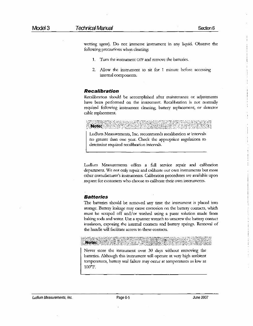
Model 3 Technical Manual Section 6
wetting agent). Do not immerse instrument in any liquid. Observe thefollowing precautions when cleaning.
1. Turn the instrument OFF and remove the batteries.
2. Allow the instrument to sit for 1 minute before accessinginternal components.
RecalibrationRecalibration should be accomplished after maintenance or adjustmentshave been performed on the instrument. Recalibration is not normallyrequired following instrument cleaning, battery replacement, or detector
cable replacement.
Note.
Ludlum Measurements, Inc. recommends recalibration at intervalsno greater than one year. Check the appropriate regulations todetermine required recalibration intervals.
Ludlum Measurements offers a full service repair and calibrationdepartment. We not only repair and calibrate our own instruments but mostother manufacturer's instruments. Calibration procedures are available uponrequest for customers who choose to calibrate their own instruments.
BatteriesThe batteries should be removed any time the instrument is placed intostorage. Battery leakage may cause corrosion on the battery contacts, whichmust be scraped off and/or washed using a paste solution made frombaking soda and water. Use a spanner wrench to unscrew the battery contactinsulators, exposing the internal contacts and battery springs. Removal ofthe handle will facilitate access to these contacts.
Never store the instrument over 30 days without removing thebatteries. Although this instrument will operate at very high ambienttemperatures, battery seal failure may occur at temperatures as low as
1000F.
Ludlum Measurements, Inc. Page 6-5 June 2007

Model 3 Technical Manual Section 7
Troubleshooting
ccasionally, you may encounter problems with your LAI
instrument or detector that may be repaired or resolved in thefield, saving turnaround time and expense in returning theinstrument to us for repair. Toward that end, LMI electronics
technicians offer the following tips for troubleshooting the most commonproblems. Where several steps are given, perform them in order until theproblem is corrected. Keep in mind that with this instrument, the mostcommon problems encountered are: (1) detector cables, (2) sticky meters,(3) battery contacts.
Note that the first troubleshooting tip is for determining whether theproblem is with the electronics or with the detector. A Ludlum Model 500Pulser is invaluable at this point, because of its ability to simultaneouslycheck high voltage, input sensitivity or threshold, and the electronics forproper counting.
We hope these tips will prove to be helpful. As always, please call if youencounter difficulty in resolving a problem or if you have any questions.
Troubleshooting Electronics which utilize aG-M Detector or Scintillator
SYMPTOM POSSIBLE SOLUTION
no power (or meter 1. Check batteries and replace if weak.does not reach BATTEST or BAT OK 2. Check polarity (See marks insidemark) batter lid). Are the batteries installed
backwards?
Ludlum Measurements, Inc. Page 7-1 June 2007

Model 3 Technical Manual Sedion 7
SYMPTOM POSSIBLE SOLUTION
no power (or meterdoes not reach BATTEST or BAT OKmark) (continued)
nonlinear Readings
3. Check battery contacts. Clean themwith rough sandpaper or use anengraver to clean the tips.
4. Remove the can and check for looseor broken wires.
1. Check the high voltage (Hy) using aLudlum Model 500 Pulser (orequivalent). If a Multimeter is used tocheck the HV, ensure that one withhigh impedance is used, as a standardMultimeter could be damaged in thisprocess.
2. Check for noise in the detector cableby disconnecting the detector,placing the instrument on the lowestrange setting, and wiggling the cablewhile observing the meter face forsignificant changes in readings.
3. Check for "sticky" meter movement.Does the reading change when youtap the meter? Does the meter needle"stick" at any spot?
4. Check the "meter zero." Turn thepower OFF. The meter should cometo rest on "0".
1. Replace the detector cable todetermine whether or not the cablehas failed- causing excessive noise.
2. Check the HV and, if possible, theinput threshold for proper setting.
meter goes full-scaleor "pegs out"
Ludlum Measurements, Inc. Page 7-2 June 2007Ludium Measurements, Inc. Page 7-2 June 2007
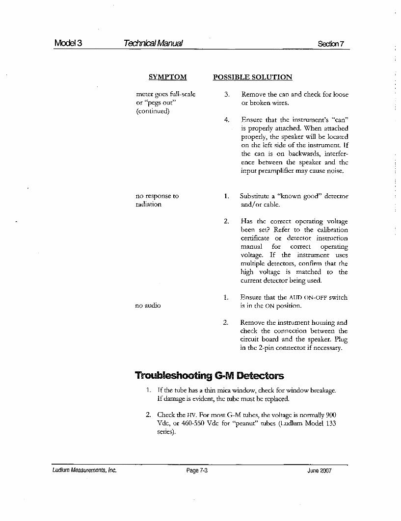
Model 3 Technkcal Manual Secon 7
SYMPTOM POSSIBLE SOLUTION
meter goes full-scale 3. Remove the can and check for looseor "pegs out" or broken wires.(continued)
4. Ensure that the instrument's "can"is properly attached. When attachedproperly, the speaker will be locatedon the left side of the instrument. Ifthe can is on backwards, interfer-ence between the speaker and theinput preamplifier may cause noise.
no response to 1. Substitute a "known good" detectorradiation and/or cable.
2. Has the correct operating voltagebeen set? Refer to the calibrationcertificate or detector instructionmanual for correct operatingvoltage. If the instrument usesmultiple detectors, confirm that thehigh voltage is matched to thecurrent detector being used.
1. Ensure that the AUD ON-OFF switchno audio is in the ON position.
2. Remove the instrument housing andcheck the connection between thecircuit board and the speaker. Plugin the 2-pin connector if necessary.
Troubleshooting G-M ors1. If the tube has a thin mica window, check for window breakage.
If damage is evident, the tube must be replaced.
2. Check the HV. For most G-M tubes, the voltage is normally 900Vdc, or 460-550 Vdc for "peanut' tubes (Ludlum Model 133series).
Lud/um Measurements, Inc. Page 7-3 June 2007Ludlum Measurements, Inc. Page7-3 June2007

Model 3 Technkial Manual Section 7
3. If the input sensitivity is too low, the user could see somedouble-pulsing.
4. Wires to the tube may be broken or the crimped connectorcould have a loose wire.
Troubleshooting Scintillators1. Alpha or alpha/beta scintillators are prone to light leaks. They
can be tested for this problem in a dark room or with a brightlight. If a light leak is determined, changing the Mylar windowassembly will usually fix the problem.
Note:
When replacing the window, make sure to use a window madewith the same thickness Mylar and the same number of layersas the original window.
2. Verify that the HV and input sensitivity are correct. Alpha andgamma scintillators typically operate from 10-35 mV. Highvoltage varies with the photomultiplier tubes (PMT) from aslow as 600 Vdc, to as high as 1400 Vdc.
3. On a gamma scintillator, visually inspect the crystal forbreakage or humidity leakage. Water inside the crystal will turnit yellow and gradually degrade performance.
4. Check the PMT to see if the photocathode still exists. If theend of the PMT is clear (not brownish), this indicates a loss ofvacuum which will render the PMT useless.
Ludlum Measurements, Inc. Page 7-4 June 2007

Model 3 Technkial Manual Section 8
Technical Theory of Operation
Low Voltage Supply
Battery voltage is coupled to U1l and associated components (a switchingregulator) to provide 5 volts at pin 8 to power all logic circuits. A voltagedivider (R27 and R32) located at pin 1 of U11 sets the end-of-battery-lifesqueal at 2.0 Vdc. Components R12 and C30 provide filtering to create+5 VA used by the amplifier and discriminator circuits.
High Voltage SupplyHigh voltage is developed by pulses from the switching regulator U13 totransformer T1. High voltage is multiplied by the ladder network of diodesCR3 through CR7 and capacitors C18 through C27. High voltage is coupledback through R39 to pin 8 of U13. High voltage output is set by front panelpotentiometer R42, which sets the voltage feedback of 1.31 Vdc to pin 8 ofU13. R38 and C28 provide filtering.
Detector InputDetector pulses are coupled from the detector through C6 to amplifier inputpin 2 of U4. CR1 protects U4 from input shorts. R37 couples the detector tothe high voltage supply.
AmplifierA self-biased amplifier provides gain in proportion to R15 divided by R14,with some gain loss due to feedback capacitor C4. A transistor (pin 3 of U4)provides amplification. U6 is configures as a constant current source to pin 3of U4. The output self-biases to 2 Vbe (approximately 1.4 volts) at theemitter of Q1. This provides just enough bias current through pin 3 of U4 toconduct all of the current from the current source. Positive pulses from theemitter of Q1 are coupled to the discriminator.
Ludlum Measurements, Inc. Page 8-1 June 2007Ludlum Measurements, Inc. Page 8-1 June 2007

Model 3 Technical Manual Section 8
DiscriminatorComparator U8 provides discrimination. The discriminator is set by avoltage divider (R21 and R23), coupled to pin 3 of U8. As the amplifiedpulses at pin 4 of U8 increase above the discriminator voltage, 5 voltnegative pulses are produced at pin 1 of US. These pulses are coupled to pin5 of U9 for meter drive and pin 12 of U9 for audio.
AudioDiscriminator pulses are coupled to univibrator pin 12 of U9. The frontpanel audio ON-OFF selector controls the reset at pin 13 of U9. When ON,pulses from pin 10 of U9 turn on oscillator U12, which drives the housing-mounted unimorph speaker. Speaker tone is set by R31 and C14. Toneduration is controlled by R22 and C7.
Scale RangingDetector pulses from the discriminator are coupled to univibrator pin 5 ofU9. For each scale, the pulse width of pin 6 of U9 is changed by a factor of10 with the actual pulse width being controlled by the front panel switch, theanalog switches U1 and U2, and the related potentiometers. Thisarrangement allows the same current to be delivered to C9 by 1 count on thex0.1 range as 1000 counts on the ×100 range.
Meter DrivePulses from pin 6 of U9 charge capacitor C9. A constant current driver(opamp U10 and transistor Q2) delivers proportional current to the meter.For battery test (BAT TEST), the meter is directly coupled by the analogswitch U3 to the batteries through resistor RS.
Meter ResetRatemeter reset is initiated by changing the voltage differential at C9 to zerowhen the RESET button is depressed.
Fast/Slow Time ConstantFor the slow time constant, C17 is switched from the output of the meterdrive to parallel C9.
Ludlum Measurements, Inc. Page 8-2 June2007Ludlum Measurements, Inc. Page 8-2 June 2007

Model 3 Technical Manual Secion 9
~Recyding
L udlum Measurements, Inc. supports the recycling of the electronicsproducts it produces for the purpose of protecting the environmentand to comply with all regional, national and international agenciesthat promote economically and environmentally sustainable
recycling systems. To this end, Ludlum Measurements, Inc. strives to supplythe consumer of its goods with information regarding reuse and recycling ofthe many different types of materials used in its products. With manydifferent agencies, public and private, involved in this pursuit it becomesevident that a myriad of methods can be used in the process of recycling.Therefore, Ludlum Measurements, Inc. does not suggest one particularmethod over another, but simply desires to inform its consumers of therange of recyclable materials present in its products, so that the user willhave flexibility in following all local and federal laws.
The following types of recyclable materials are present in LudlumMeasurements, Inc. electronics products, and should be recycled separately.The list is not all-indusive, nor does it suggest that all materials are present ineach piece of equipment:
Batteries Glass Aluminum and Stainless Steel
Circuit Boards Plastics Liquid Crystal Display (LCD)
Ludlum Measurements, Inc. products which have been placed on themarket after August 13, 2005 have been labeled with a symbol recognizedinternationally as the "crossed-out wheelie bin" which notifies the consumerthat the product is not to be mixed with unsorted municipal waste whendiscarding-, each material must be separated. The symbol will be placed nearthe AC receptacle, except for portable equipment where it will be placed onthe battery lid.
The symbol appears as such:
Lucllum Measurements, Inc. Page 9-1 June 2007Ludium Measurements, Inc. Page 9-1 June 2007

Model 3 Technkial Manual Section 10
Reference Description Part Number
Model 3Survey Meter UNIT Completely Assembled
Model 3 Survey Meter 48-1605
Main Board,Drawing 464 x 204 BOARD Completely Assembled
Main Circuit Board 5464-204
CAPACITORS C1 47pF, 100V 04-5660
C2 0.19xF, 35V 04-5755C3 0.00479F, 100V 04-5669C4 10pF, 100V 04-5673C5 0.01 gF, 50V 04-5664C6 100pF, 3KV 04-5735C7 0.022giF, 50V 04-5667C8 lptF, 16V 04-5701C9 1011F, 25V 04-5655C10 100pF, 100V 04-5661Cli 68jtF, 10V 04-5654C12 10gF, 25V 04-5728C14 470pF, 100V 04-5668C15 220pF, 100V 04-5674C16 689F, 10V 04-5654C17 47gF, 10V 04-5666C18-C27 0.01gtF, 500V 04-5696C28 0.001 tF, 2KV 04-5703
or 100pF, 3KV 04-5735C29 109tF, 25V 04-5655C30-C31 lgtF, 16V 04-5701C32 470pF, 100V 04-5668
Ludlum Measurements, Inc. Page 10-1 June 2007

Model 3 Technical Manual Section 10
TRANSISTORS
INTEGRATEDCIRCUITS
DIODES
SWITCHES
POTENTIOMETERS /TRIMMERS
Reference
Q1Q2
UI-U3U4-U5U6U7U8U9U10UllU12U13
CR1CR2CR3-CR7CR9
SWISW2SW3-SW4
R33R34R35R36R42
Description Part Number
MMBT3904LT1MMBT4403LT1
MAX4542ESACMXT3904CMXT3906NVLAX4541ESAMAX985EUK-TCD74HC4538MLMC7111BIM5XLT1304CS8-5MIC1557BM5LT1304CS8
CMPD2005SRECTIFIER CMSH1-40MCMPD2005SRECTIFIER CMSH1-40M
D5G0206S-9802TPllLTCQE7101SDCQE
250K, 64W254, X100250K, 64W254, X10500K, 64W504, x 1250K, 64W254, X0.11.2M, 3296W, HV
05-584105-5842
06-645305-588805-589006-645206-645906-629706-641006-643406-645706-6394
07-646807-641107-646807-6411
08-676108-677008-6781
09-681909-681909-685009-681909-6814
12-799212-783812-783912-786112-783912-784612-783912-7858
RESISTORS
R1-R5R6R7R8R9-R11R12R13R14
200K, 1/8W, 1%8.25K, 1/8W, 1%10K, 1/8W, 1%2.37K, 1/8W, 1%10K, 1/8W, 1%200 Ohm, 1/8W, 1%10K, 1/8W, 1%4.75K, 1/8W, 1%
Ludlum Measurements, Inc. Page 10-2 June 2007

Model3 Technkial Manual Secton 10
Reference
R15R16R17R18R19R20-R21R22R23R24R25R26R27R28R29R30R31R32R37R38R39R40R44
Description
200K, 1/8W, 1 %10K, 1/8W, 1%1K, 1/8W, 1%4.75K, 1/8W, 1%
2K, 1/8W, 1%1001(, 1/8W, 1%1M, 1/8W, 1%2.49K, 1/8W, 1%14.7K, 1/8W, 1%200K, 1/4W, 1%100K, 1/4W, 1%68.1K, 1/8W, 1%1001K, 1/8W, 1%1K, 1/8W, 1%1001, 1/8W, 1%475K, 1/8W, 1%100K, 1/8W, 1%100Y, 1/8W, 1%2.2M, 1/8W, 1%500M, 3KV, 2%402K, 1/8W, 1%14K, 1/4W, 1%
640456-5 - MTA100640456-6 - MTA100
(installed as required)640456-2 - MTA100
22 /H
31032R
Part Number
12-799212-783912-783212-785812-792612-783412-784412-799912-706812-799212-783412-788112-783412-783212-783412-785912-783412-783412-798612-703112-788812-7832
CONNECTORS
P1P2
P3
LI
T1
13-8057
13-809513-8073
21-9808
21-9925
INDUCTOR
TRANSFORMER
Wiring Diagram,Drawing 464 x 212
CONNECTORS j1
J2
J3
MTA10 x5, MAINBOARD 5464-204OPTIONAL (M3 overload)MTA100x6, 5464-204MTA10Ox2, MAINBOARD 5464-204
13-8140
13-8171
13-8178
Ludlum Measurements, Inc. Page 10-3 June 2007

Model 3 Technical Manual Section 10
Reference Description Part Number
AUDIO
DS1
BATrERIES
B1-B2
MISCELLANEOUS
*
*
*
*
*
Ml
*
*
*
*
*
*
*
*
*
*
*
*
*
UNIMORPH TEC3526-PU
'D" DURACELL BATTERY
PORTABLE BATTERYCONTACT ASSEMBLYMODEL 3 CASTINGMODEL 3 MAIN HOUSINGPORTABLE CANASSEMBLY (QvTA)PORTABLE KNOBMETER ASSEMBLY METERBEZEL W/GLASSW/O SCREWSMETER MOVEMENT (1 mA)PORTABLE METER FACEHARNESS-PORT CAN WIRESBATTERY LID W/O LATCHKIT MODEL 3PORTABLE LATCH KIT W/OBATTERY LIDPORTABLE HANDLE(GRIP)W/SCREWSPORTHANDLE FOR CLIPW/SCREWSREPLACEMENT CABLE(STD 39")CLIP (44-3 TYPE) W/SCREWSCLIP (44-6 TYPE) W/SCREWSLABEL-M3 CALIBRATIONLABEL-M3 BATTERY LIDLABEL-M3 FACEPLATE
21-9251
21-9313
2001-0427464-2198464-035
4363-44108-6613
4364-18815-80307363-1368363-462
2363-191
4363-349
4363-139
4363-203
40-10044002-026-014010-007-01231060223106012310603
Ludlum Measurements, Inc. Page 10-4 June 2007

Model 3 Technkial Manual Secon 11
Dravvings and Diagrams
MAIN CIRCUIT BOARD, Drawing 464 x 204 (3 sheets)
MAIN CIRCUIT BOARD LAYOUT, Drawing 464 X 205 (2 sheets)
CHASSIS WIRING DIAGRAM, Drawing 464 x 212
Ludlum Measurements, Inc. Page 11 -1 'June 2007

464X204b464X204b.h
HV
46M4Xý4A6AX2O4k~h
IiDýV

.BAT
SWICENTRAL-2P6P
X00 11
x120di
PI
23 METER-
4 ,ClC~
.5V
RI ~ jRs200 K2 K20K 0.5
PPOIFv
¶1/8W ¶1%8W 1/8w
I I |
7
404NITA
1 O5 /77 R12
20W ohm
U4 S1
ILP
2 4 3f 4
0M0350 1K ICK CM/1T39S0I/SW I/swI1% I1%
C4 R77 0s
ilaw U ABLIF CASTING
%
L+13AT
R82.37KIlaw U AI %
ý4v a V+ V_ 4
MAX4642ESAa
ci
U7A 1 2C SIC
2 1 vcc -1-6--o +5v
7 1>ý 5
+SVO_ 8 V+ V_ 4 4 A I
+5VA IV KXýIFSA ONO 62.
us /7 7 UDA
3 + 2
ýMAXDMEUKJ
CD74HC4&38M
I.5v
477 250K 1/SWao~ 94W254 I%
+5V
0LC2 P38 10K
IF 250K I/SW
61 3V. 4W264 I %
MAX45445V ..2 0W
0 W SR
// /
TPIILTCOO
SW3 , C&K7jOlSOCQS 0+t17
SLO 08K 47uP2 byv
II[I OpFI oov R15
200K1/aW
R14 1%4.75K
I/8W *SV1%
RAMPD2005S
C6
f3KV
RI 3K o'6i 110K % ov1%8
4.76K
.SVAAOl
lOOK 07114W 4V ~ .S.+0v %R22 (1/SW
v J -IM iI820 l/aw
S 4 ; 1%
1/ iV
J1R24814.7K
ItSw1%
+5V
200K + 05 2K1/4W - So• lu,,
T1%
R441K1/4W1%
u/sI
- i
I %01 0 MV1 C a +BAT .V P
13V 0 112 2s X+R2V
_1 2
A 010- v% -AOK
OD320+v1%8CD74HC4.538M
I +V 1 47ACCESSRY
MHP-4SM ESE 13012 7101 SDQE2
_ _0K _I _ L O 5 r NO TU S E D C015 K.
68.1/ K U11 S2 Ma441 I/a4C46-
+BAT 3 T---"- Q 51 ý-10
/-/7 VN W S4 ý11 ~ C 3
CIO
100VU1
lOK MMST4-403LTI

Gig C22A37 R38
C23 024 C25 2
COML OCluF O.O1LP O.OIUFsCCV 600V SOWV soCV
027
1% 1 TI

Drawn: SA 02/08/07. Title- MAIN BOARDIDesign: DIL 02/08/07
Check- Modet M3Approve: * , •'bO Board#: 5464-204Layer Rev. 2 Series Sheet
14:47:02 8-Feb--2007 SCALE 1.21 464 205

AS REOWJRED
Drawn: SA 02/08/'7 Tife: MAIN BOARDDesign: DIL 02/08/07'MIBOR
Check_ Modet M3
Approve: W 0F, ??6 Board#: 5464-204Laye Rev 2 Series Sheet
14,:47.V 8--2007 SCALE: 1.21 464 1205

~i i ~ "O' CELL BATTERY
MEr_•'"ERCELL BATTERY
J2
I +6V
MTA I000OPTIONAL5484.20
osi
1 X21
MAIN BOARD5484-204 TEC-3220-PL

LUDLUM MODEL 177ALARM RATEMETER
November 2005
Serial Number 121166 and Succeeding
Serial Numbers
LUDLUM MEASUREMENTS, INC.501 OAK STREET, P.O. BOX 810SWEETWATER, TEXAS 79556325-235-5494, FAX: 325-235-4672

RE~V #i ALTERATIONS IDATE I DYVALID 8/8/91 JJ.
ADDED SYMBOLS 12/7/05 QMQ
CM4012-7-o5 aDWG NUN, 4347-186 ISCALEnu
TITLE M 177 ALARM RATEMETERg ln au- .. . .. . I .... I
I-r -alK-? 347 "26

EV ALTERATIONS IDATE BYVALID 8/8/91 IgK
ADDED SYMBOLS 12/7/05 _ MC
............. ........ ............
vvý L
0 DISCR(D® Xl000o xio o ° °I
o O X0 oi [5o jl
o HV ADJ DATAQD o RCDRjf
SREMOVE THE COVER FORINTERNAL BATTERY ACCESS. TJREPLACE INTERNAL GEL-CELLBATTERY EVERY 4 YEARS.
WARNING: FOR CONTINUEDPROTECTION AGAINST RISK OFFIRE, REPLACE ONLY WITH FUSE OFTHE SPECIFIED TYPE AND CURRENTRATING.
®"N-.INPUT: 120 VAC =
50/60 Hz 250WLINE FUSE: 1 EACH
LITTELFUSE. F1A, L250V
Cc[ ITZ::1
W"CMdIE2/7/05 IA Ae.MeSDVG NUM, 4347-186 SCALD F'u
TITLE M 177 ALA~RM RATEMETER
I LULI annom at I s= I a= ow rnm347 26AftalwylL "m mm J

Table of Contents
Introduction I
Getting Started 2Preparing the Instrument for Use 2-1
Operating the Instrument 2-1
Specifications 3
Description of Controls and Functions 4
Front Panel 4-1
Back Panel 4-2
CAL Control 4-3
Internal Controls (Overhaul Only) 4-4
Safety Considerations 5Environmental Conditions for Normal Use 5-1
Cleaning Instructions and Precautions 5-1
Warning Markings and Symbols 5-2
Replacement of Main Fuse 5-3
Calibration and Maintenance 6
Calibration 6-1
Establishing an Operating Point 6-2
Maintenance 6-3
Troubleshooting 7Troubleshooting Electronics that utilize a G-M, or Scintillation Detector 7-1
Troubleshooting G-M Detectors 7-2
Troubleshooting Scintillators 7-3
Technical Theory of Operation 8Amplifier 8-1
Discriminator 8-1
Digital Analog Conversion 8-1
Time Constant 8-2
Ludium Measurements, Inc. November 2005

Model 177 Tehnical Manual
Alarm 8-2
Reset 8-2
Audio 8-2
High Voltage (HV) 8-3
Low Voltage 8-3
Battery Charge 8-3
High Voltage Test 8-3
Alarm Set Voltage 8-3
Battery Test Voltage 84
Recycling 9
Parts List 10Model 177 Alarm Ratemeter 10-1
Main Board, Drawing 347 x 227 10-1
Calibration Board, Drawing 347 x 132 10-4
Wiring Diagram, Drawing 347 x 230 10-5
Drawings and Diagrams 11
Ludlum Measurements, Inc. November 2005
Ludlum Measurements, Inc. November 2005

Model 177 Technikal Manual Secfion 1
|ntroducgon
The Ludlum Model 177 Alarm Ratemeter may be used with G-M(Geiger-Mueller) or scintillation detectors for contaminationmonitoring, surveying and area monitoring. The unit provides fourranges (in decades) of the analog meter, enabling measurement from 0
to 500,000 counts per minute (CPM) on the standard meter dial; others areavailable. Detector high voltage is adjustable from 200 to 1500 volts.
The unit incorporates an adjustable alarm set point. The alarm setting may bechecked by depressing the front panel TEST switch. Audible and visualenunciators are triggered when the meter reading rises above the alarm setpoint. Accessory outputs include: Unbuffered Output, Supply Voltage,Negative Pulse Output, Recorder and Alarm Sink for Remote Relay. The unitmay be operated from an internal rechargeable battery or by line AC power.
Ludlum Measurements, Inc.Page 1-1 November 2005Ludlum Measurements, Inc. Page 1-1 November 2005
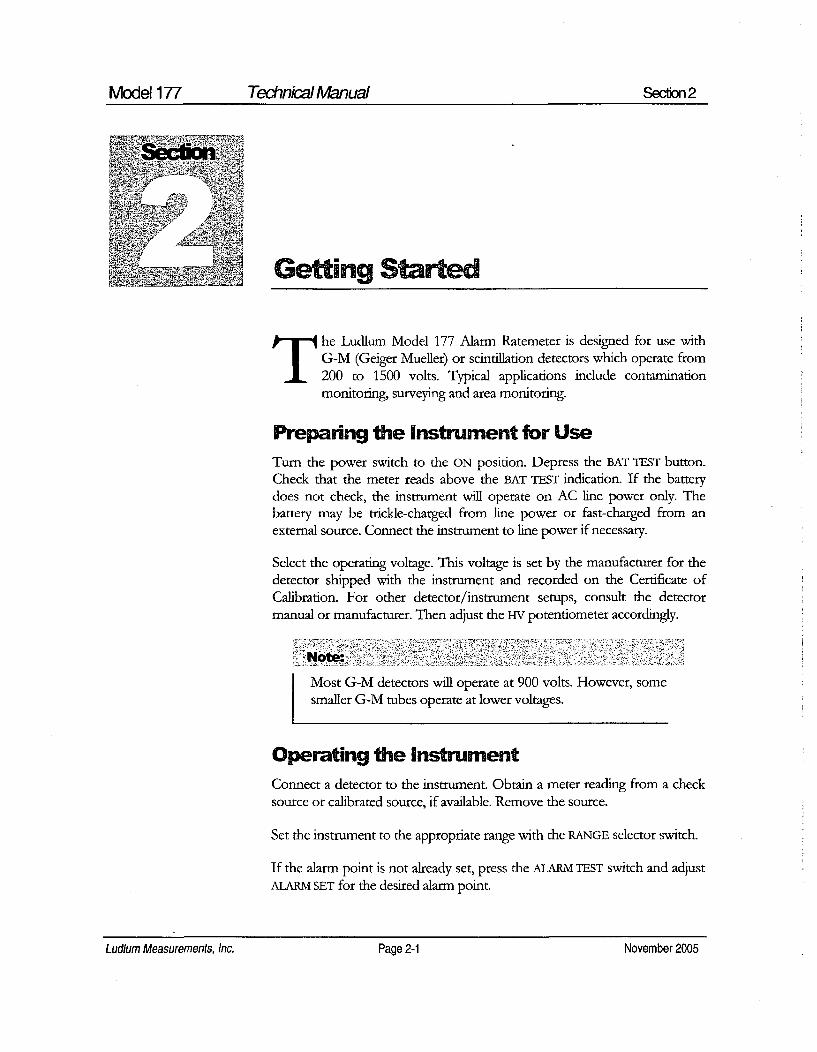
Model 177 Technkial Manual Secion 2
~Seclin
• ,•
The Ludlum Model 177 Alarm Ratemeter is designed for use withG-M (Geiger Mueller) or scintillation detectors which operate from200 to 1500 volts. Typical applications include contaminationmonitoring, surveying and area monitoring.
Preparing the Instrument for UseTurn the power switch to the ON position. Depress the BAT TEST button.Check that the meter reads above the BAT TEST indication. If the batterydoes not check, the instrument will operate on AC line power only. Thebattery may be trickle-charged from line power or fast-charged from anexternal source. Connect the instrument to line power if necessary.
Select the operating voltage. This voltage is set by the manufacturer for thedetector shipped with the instrument and recorded on the Certificate ofCalibration. For other detector/instrument setups, consult the detectormanual or manufacturer. Then adjust the HV potentiometer accordingly.
Note::
Most G-M detectors will operate at 900 volts. However, somesmaller G-M tubes operate at lower voltages.
Operating the InstrumentConnect a detector to the instrument. Obtain a meter reading from a checksource or calibrated source, if available. Remove the source.
Set the instrument to the appropriate range with the RANGE selector switch.
If the alarm point is not already. set, press the ALARM TEST switch and adjustALARM SET for the desired alarm point.
Ludlum Measurements, Inc. Page 2-1 November 2005Ludlum Measurements, Inc. Page 2-1 November 2005

Model 177 Technkial Manual Secon 2
Note..
The meter displays the alarm set point when the ALARM TESTswitch is depressed. Recheck the set point after locking theALARM SET control.
Increase the meter count to exceed the alarm threshold. Both the alarm lampand audible alarm signal should activate.
Depress the RESET button. The meter needle should drive to zero and thealarm circuit should de-energize, shutting off both the visual and audiblealarms.
Depress the HV TEST button and ensure that the high voltage is properly set.
Proceed with use.
Ludlum Measurements, Inc. Page 2-2 November 2005Ludium Measurements, Inc. Page 2-2 November 2005

Model 177 Technkical Manual Section 3
SpecificationsPower. 120 VAC 50/60 Hz 250W line power and 6 volt Gell-Cell(sealed lead-acid) battery. Typical battery life of approximately 50 hoursin a non-alarming condition with fully charged battery.
Fuse: 1 amp, LFITLEFUSE FIA L250V.
Response Time: Two positions: fast 2.2 seconds; slow 22 seconds for900/0 of full scale reading.
Linearity: Within plus or minus 5% of full scale. Typically plus or minus2% of full scale reading when measured with an electronic pulsegenerator.
Battery Dependence: Meter readings vary less than 3% within batterycheck limits.
High Voltage: Variable from 200 to 1500 volts.
Input Sensitivity: Adjustable from 10 through 100 millivolts.
Connecton Series "C".
Audio: Unimorph speaker with volume control located on the frontpanel.
Meten 1 mA, size: 2.5" X 2.5," DC movement.
Meter Scale: 0-500 CPM; 0-1.5 kV; BAT TEST.
Ranges: Four ranges of X1 through X1K.
Recorder Output: Adjustable from 0 to 1.25 volts at 1 mA.
Alarm Output: Current sink to 200 mA DC. Open circuit voltage not toexceed 50 Vdc.
Unbuffered Output: May be used to externally add to or subtract fromthe meter reading.
Ludlum Measurements, Inc. Page 3-1 November 2005Ludium Measurements, Inc. Page 3-1 November 2005

Model 177 Technical Manual Secion 3
Alarm Range: Adjustable from 0 through 150% of full scale.
Alarm Output: Visual indicator (lamp), audible tone and remote currentsink.
Alarm Control: Factory set to latching. Non-latching alarm available
through the removal of main board resistor RI 16.
Finish: Computer-beige, polyurethane enamel.
Size: 6" (15.24 cm) Depth x 8" (20.32 cm) W X 5"(12.7 cm) H,excluding handle.
Weight: 4.2 lbs. (1.9 kg) with battery.
Ludlum Measurements, Inc. Page 3-2 November 2005Ludlum Measurements, Inc. Page 3-2 November 2005
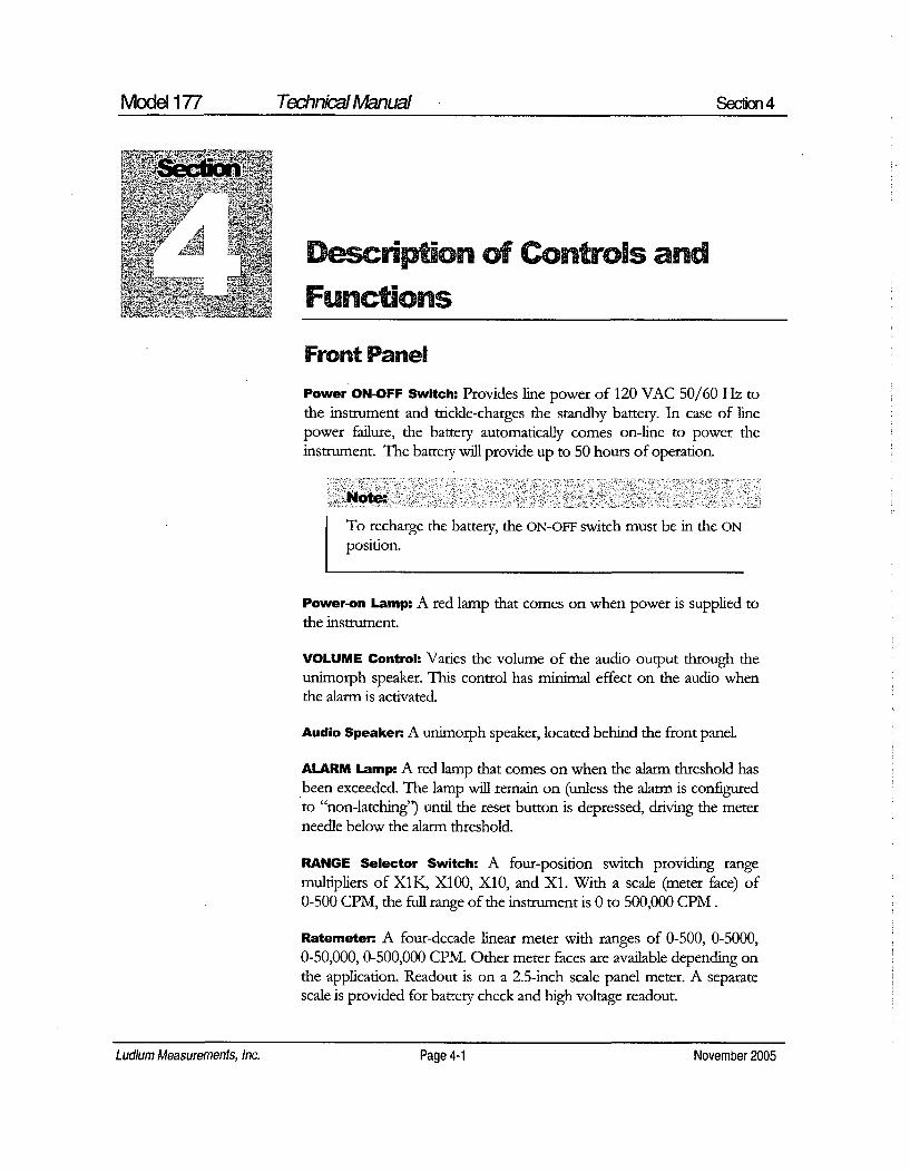
Model 177 Technical Manual Secfion 4
' ADesc on of Controls and
Functions
Front Panel
Power ON-OFF Switch: Provides line power of 120 VAC 50/60 Hz tothe instrument and trickle-charges the standby battery. In case of linepower failure, the battery automatically comes on-line to power theinstrument. The battery will provide up to 50 hours of operation.
Note:
To recharge the battery, the ON-OFF switch must be in the ON
position.
Power-on Lamp: A red lamp that comes on when power is supplied tothe instrument.
VOLUME Control: Varies the volume of the audio output through theunimorph speaker. This control has minimal effect on the audio whenthe alarm is activated.
Audio Speaker. A unimorph speaker, located behind the front panel
ALARM Lamp: A red lamp that comes on when the alarm threshold hasbeen exceeded. The lamp will remain on (unless the alarm is configuredto "non-latching") until the reset button is depressed, driving the meterneedle below the alarm threshold.
RANGE Selector Switch: A four-position switch providing rangemultipliers of X1K, X100, X10, and X1. With a scale (meter face) of0-500 CPM, the full range of the instrument is 0 to 500,000 CPM.
Ratemeten A four-decade linear meter with ranges of 0-500, 0-5000,0-50,000, 0-500,000 CPM. Other meter faces are available depending onthe application. Readout is on a 2.5-inch scale panel meter. A separatescale is provided for battery check and high voltage readout.
Ludlum Measurements, Inc. Page 4-1 November 2005

Mode 177 Technkial Manual Sec4ion4
Connector. Series "C" connector. (Series BNC and MIHV connectors arealso available). The connector is provided on the front of the instrumentfor connection to a detector.
RESET Button: This button, when depressed, provides a rapid means ofdriving the meter needle to zero.
FAST-SLOW RESPONSE Toggle Switch: When in the FAST position, thisswitch provides 90% of full-scale meter deflection in 2.2 seconds. Withthis switch in the SLOW position, 90% of full-scale meter deflection takes22 seconds. If quick needle response and maximum deviation are desired,the FAST position should be used. For slow response and damped metermovement, the SLOW position should be used.
BAT TEST Button: When this button is depressed, the meter displays thebattery status. A sufficiently charged battery is indicated when the meterneedle is on or within the BAT TEST range.
HV TEST Button: When this button is depressed, the meter displays thedetector high voltage.
ALARM TEST Button: When this button is depressed, the meter displaysthe alarm calibration set point.
ALARM SET: Used to adjust the alarm calibration set point. Note thelocking knob below the control.
Back Panel120V AC plug: Provides power to the instrument from a 120 volts AC,50/60 Hz, 250W line.
LINE FUSE: Provides line protection with a 1 amp fuse- LITILEFUSEF1A L250V.
Data: A 9-pin type "D" data plug with connections as follows:
PIN 1: Battery terminal. This is a direct connection and doesnot go through the front panel ON-OFF switch. Use to parallelbattery or use external charger.
PIN 2: Unregulated supply from approximately 6 volts, batteryonly to 9.5 volts with AC power on. Limit current drain to 50milliamperes.
Ludlum Measurements, Inc. Page 4-2 November 2005

Mode 177 Technical Manual Section 4
PIN 3: Instrument common (Ground).
PIN 4: Alarm sink. The open collector of a 2N7002L. Limitssink current to 200 milliamperes with open circuit voltagelimited to a range of 0 to +50 volts. Unit conducts when inalanr.
PIN 5: Pulse Out A negative pulse connected to thediscriminator output through a 0.001 uF capacitor.Typically. -4.0 volts.
PIN 6: Unbuffered output ties directly to the meter drivecircuit. (R124/C122). Approximately 1.3 volts at flil scale.Using an external constant current sink will allowbackground subtract. At full-scale, draws out approximately3.3 microamperes to zero the meter.
PIN 7: Recorder output, adjustable from 0 to 1.0 volts at1 milliamperes.
PIN 8 and PIN 9: Spares
CAL ControlRemove the calibration (cal) cover plate to access the following calibrationpotentiometers:
DISCR: .Discrimnination Control. For pancake-type G-M detectors (ie.Model 44-9), adjust DISCR for 80 ± 10 millivolts. All other G-Mdetectors and scintillators should be set to 35 + 10 millivolts. If a loweroperating voltage for a scintillator is desired, adjust the discriminator to10 + 2 millivolts. This control has an adjustable range of 10 to 100millivolts. A Ludlum Model 500 Pulser may be used to determine thediscrimination level.
Calibration Controls: X1K through X1 calibration controls used tocalibrate ranges.
HV ADJ: Used to set detector operating voltage.
RCDR: Used to calibrate the recorder output
Ludlum Measurements, Inc. Page 4-3 November 2005
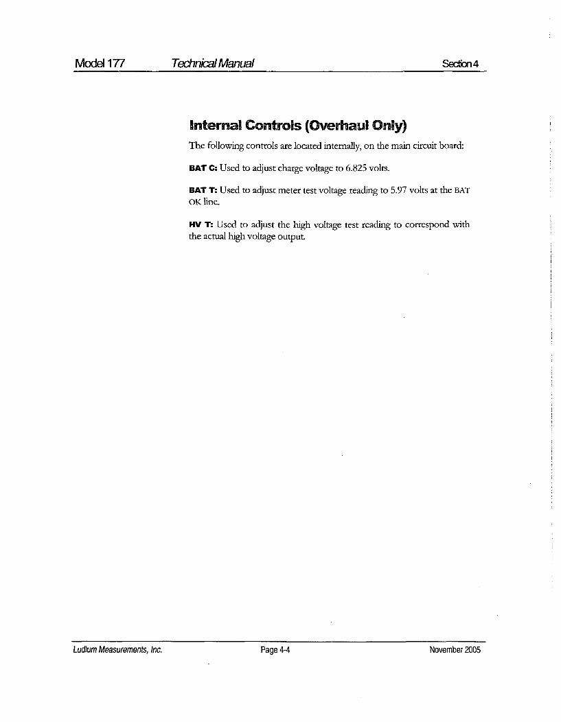
Model 177 Technical Manual Secbon4
Internal Controls (Overhaul Only)The following controls are located internally, on the main circuit board:
BAT CQ Used to adjust charge voltage to 6.825 volts.
BAT T. Used to adjust meter test voltage reading to 5.97 volts at the BAT
OK line.
HV T. Used to adjust the high voltage test reading to correspond withthe actual high voltage output.
Ludlum Measurements, Inc. Page 4-4 November 2005Ludium Measurements, Inc. Page 4-4 November 2005

Model 177 Technical Manual Section 5
-Safety Considerations
Environmental Conditions for Normal UseIndoor use only
No maximum altitude
Temperature range of-20'C to 50'C (-4'F to 122°F)
Maximum relative humidity of less then 95% (non-condensing)
Mains supply voltage range of 95-135 VAC (178-240 VAC available),50/60Hz single phase (less than 100lrA)
Maximum transient voltage of 1500 VAC
Installation Category II (Overvoltage Category as defined by IEC 1010-1)
Pollution Degree I (as defined by IEC 664).
Cleaning Instructions and PrecautionsThe Model 177 Alarm Ratemeter may be cleaned externally with a dampcloth, using only water as the wetting agent. Do not immerse the instrumentin any liquid. Observe the following precautions when deaning.
1. Turn the instrument OFF and disconnect the instrument powercord.
2. Allow the instrument to sit for 1 minute before cleaning.
Ludlum Measurements, Inc. Page 5-1 November 2005

Model 177 Technical Manual Secton 5
Warning Markings and Symbols
Caution!
The operator or responsible body is cautioned that theprotection provided by the equipment may be impaired if theequipment is used in a manner not specified by LudlurnMeasurements, Inc.
The Model 177 Alarm Ratemeter is marked withthe following symbols:
N. ALTERNATING CURRENT (AC) (JEC 417, No. 5032) - designates aninput receptacle that accommodates a power cord intended for connectionto AC voltages. This symbol appears on the back panel.QPROTECTIVE CONDUCTOR TERMINAL (per IEC 417, No. 5019)- designates the central grounding point for the safety ground. This symbolis visible inside the chassis.
A CAUTION (per ISO 3864, No. B.3.1) - designates hazardous live voltageand risk of electric shock During normal use, internal components arehazardous live. This instrument must be isolated or disconnected from thehazardous live voltage before accessing the internal components. Thissymbol appears on the front panel. Note the following precautions:
Warning!* - - - .
The operator is strongly cautioned to take the followingprecautions to avoid contact with internal hazardous live partsthat are accessible using a tool:
1. Turn the instrument power OFF and disconnect the powercord.
2. Allow the instrument to sit for 1 minute before accessinginternal components.
Ludlum Measurements, Inc. Page 5-2 November 2005Ludlum Measurements, Inc. Page 5-2 November 2005

Model 177 Technkial Manual Section 5
CAUTION, RISK OF ELECTRIC SHOCK (per ISO 3864, No. B.3.6)- designates a terminal (connector) that allows connection to a voltageexceeding 1 kV. Contact with the subject connector while the instrument ison or shortly after turning off may result in electric shock. This symbolappears on the front panel.
\ The "crossed-out wheelie bin" symbol notifies the consumer that theproduct is not to be mixed with unsorted municipal waste when discarding;each material must be separated. The symbol is placed near the ACreceptacle. See section 9, "Recycling" for further information.
Replacement of Main Fuse (Back Panel)
Warning!
For continued protection against risk of fire, replace only withfuse of the specified type and current rating!
Ludlum Measurements, Inc. Page 5-3 November 2005Ludium Measurements, Inc. Page 5-3 November 2005

Model 177 Technial Manual Section 6
Calibration Maintenance
CalibrationNote:Local procedures may supersede the following.
Connect the instrument to a Ludlum Model 500 Pulser (Pulse Generator) orequivalent.
The ratemeter may be calibrated by adjusting the calibration controls labeled1, 10, 100 and 1K. Starting with the 1000 range, apply 400,000 CPM fromPulser. Adjust the 1K calibration control for a meter reading of 400. Dropthe Pulser pulse rate to 100,000 CPM and ensure a meter reading of 100 -10.
Repeat this procedure for the lower scales with scaled pulse rates.
For pancake-type G-M detectors (ie. Model 44-9), adjust DISCR for 80 ± 10millivolts. All other G-M detectors and scintillators should be set to 35 _ 10millivolts. To lower the scintillation detector operating voltage, decrease theinput sensitivity to 10 :# 2 millivolts. Adjustment is made by setting the pulsegenerator amplitude to the desired pulse height. Adjust D1SCR until the meterreaches 75% of the generated incoming count rate.
Connect the Model 177 to an external voltmeter. Adjust the rear panel -t-vcontrol for a reading of 1000 Vdc on the voltmeter. Depress HV TEST. Onthe main board, adjust HV for a meter reading of 1.0 kV. Using the rearpanel HV control, vary the high voltage output from 500 to 1500 Vdc andensure that the high voltage meter reads within 10% of the Model 177 meterreading.
Adjust RCDR (recorder output) for 1 volt output (equivalent to full scale).
Adjust ALAEivM SET to the desired set point.
Ludlum Measurements, Inc. Page 6-1 November 2005Ludlum Measurements, Inc. Page 6-1 November 2005

Model 177 Technical Manual Section 6
Establishing an Operating PointThe operating point for the instrument and detectors is established bysetting the detector voltage and instrument sensitivity (-V and DIS). Theproper selection of this point is the key to instrument performance.
Efficiency, background sensitivity and noise are fixed by the physicalmakeup of the given detector and rarely vary from unit to unit. However,the selection of the operating point makes a significant difference in thecontribution of these three sources of count.
The purpose of setting the operating point is to establish the system gain sothat the desirable signal pulses (including background) are above thediscrimination level, and the unwanted pulses from noise are below thediscrimination level. The pulses above the discrimination level are countedby the instrument, while those below are not.
The total system gain is controlled by adjusting the instrument gain or thehigh voltage. Voltage affects the output of the detector. Amplifier gain iscontrolled by the DIS (discriminator) control.
In special cases of G-M detectors, a minimum voltage must be applied toestablish the Geiger-Mueller characteristic. Further changes in gain will notaffect this type of detector.
The operating point for each detector is set at a compromise point betweensensitivity, stability and background contribution. These operating points arebest for general monitoring. In application, these arbitrarily selected pointsmay not be a better operating point. The following guidelines are presented:
G-M Detectors: The output pulse height of the G-M detector is notproportional to the energy of the detected radiation. Adjusting DIS willhave minimal effect on the observed count rate unless the setting is solow that the instrument double pulses.
For most G-M detectors, set DIS for 30-40 millivolts and adjust HV tothe G-M tube recommended high voltage. Most G-M detectors operateat 900 volts, however, some miniature detectors operate at 400-600volts. If a recommended setting is unavailable, run a plateau of HV
setting vs. count rate. Then set the high voltage on the low side of"ccenter,"
Ludlum Measurements, Inc. Page 6-2 November 2005Ludlum Measurements, Inc. Page 6-2 November 2005

Model 177 Technkial Manual Section 6
Scintillators: Set DIS for 10 millivolts. Carefully increase -V until theinstrument plateaus on the background count. This provides the moststable operating point for the detector.
MaintenanceInstrument maintenance consists of keeping the instrument clean andperiodically checking the battery and calibration.
An instrument operational check should be performed prior to each use byexposing the detector to a known source and confirming the proper readingon each scale.
Recalibration should be accomplished after any maintenance or adjustmenthas been performed on the instrument. Ludlum Measurements recommendsrecalibration at intervals no greater than one year. Local regulations mayhave precedence over this recommendation.
To maintain the life of the battery, it is recommended that the instrument beconstantly connected to line power with the power switch in the ON
position, even when the instrument is not in use. This will keep the internalbattery fully charged.
When the instrument is used without line power, adequate charge time mustbe allowed for the internal battery to recharge. If possible, leave theinstrument on with line power applied overnight and weekends. At aminimum, allow one hour of charge time for each hour of use. If the batteryis inadvertently allowed to fully discharge, and is left in that state, constantcharging for 500 hours (3 weeks) may be required for battery recovery.
Note:
The ON-OFF switch must be in the ON position to charge thebatteries. If the unit is out of service for extended periods oftime, charge the battery every 6 months.
It is recommended that the internal GEL-CELL battery be replaced every 4years.
Ludlum Measurements, Inc. Page 6-3 November 2005

Model 177 Technical Manual Seion 7
Sehli
Troubleshooting
ccasionally, you may encounter problems with your LMIinstrument or detector that may be repaired or resolved in thefield, saving turnaround time and expense in returning theinstrument to us for repair. Toward that end, LMI electronics
technicians offer the following tips for troubleshooting the most commonproblems. Where several steps are given, perform them in order until theproblem is corrected. Keep in mind that with this instrument, the mostcommon problems encountered are: 1. detector cables; 2: sticky meters.
Note that the first troubleshooting tip is for determining whether theproblem is with the electronics or with the detector. A Ludlum Model 500Pulser is invaluable at this point, because of its ability to simultaneouslycheck high voltage, input sensitivity or threshold, and the electronics forproper counting.
We hope these tips will prove to be helpful. As always, please call if youencounter difficulty in resolving a problem or if you have any questions.
Troubleshooting Electronics that utilize a
G-M, or Scintillation Detector
SYMPTOM POSSIBLE SOLUTION
No power (or meterdoes not reach BAT
TEST or BAT OK
mark)
1. Check battery and charge if necessary.
2. Check for loose or broken wires,especially between the main boardand the calibration board.
Ludlum Measurements, Inc. Page 7-1 November 2005Ludlum Measurements, Inc. Page 7-1 November 2005

Model 177 Technical Manual SeCio 7
SYMPTOM POSSIBLE SOLUTION
Nonlinear Readings 1. Check the high voltage (IV) bypressing the HV TEST button. If aMultimeter is used to check the HV,ensure that one with high impedanceis used; as a standard Multimetercould be damaged in this process.
2. Check for noise in the detector cableby disconnecting the detector andplacing the instrument on the lowestrange setting. Wiggle the cable andobserve the reading for significantchanges.
3. Check for "sticky" meter movement.Does the reading change when youtap the meter? Does the meter needle"stick" at any spot?
4. Check the "meter zero." Turn thepower OFF. The meter should cometo rest on "0".
1. Replace the detector cable to see if ithas failed, causing excess noise.
Meter goes full-scaleor "Pegs Out"
2. Check the HV and, if possible, theinput threshold for proper setting.
3. Check for loose wires, especiallybetween the main board and thecalibration board.
Troubleshooting G-M Detectors
1. If the tube has a thin mica window, check for window breakage.If damage is evident, the tube must be replaced.
Ludlum Measurements, Inc. Page 7-2 November 2005Ludlum Measurements, Inc. Page 7-2 November 2005

Model 177 Technical Manual Section 7
2. Check the HV. For most G-M tubes, the voltage is normally900 Vdc, or 460-550 Vdc for "peanut" tubes (Ludlum Model133 series).
3. If the input sensitivity is too low, the user could see somedouble-pulsing. See Page 4-3, "DISCR" for further informationon sensitivity/discrimination control
4. Wires to the tube may be broken or the crimped connectorcould have a loose wire.
Troubleshooting Scintillators1. Alpha or Alpha/Beta scintillators are prone to light leaks. They
can be tested for this problem in a dark room or with a brightlight. If a light leak is determined, changing the Mylar windowassembly will usually fix the problem.
: `.Note:M.:
When replacing the window, make sure to use a window madewith the same thickness Mylar and the same number of layersas the original window.
2. Verify that the HV and input sensitivity are correct. Alpha andgamma scintillators typically operate from 10-35 mV. Highvoltage varies with photomultiplier tubes (PMT), from as lowas 600 Vdc, to as high as 1400 Vdc.
3. On a gamma scintillator, visually inspect the crystal forbreakage or humidity leakage. Water inside the crystal will turnit yellow and gradually degrade performance.
4. Check the PMT to see if the photocathode still exists. If theend of the PMT is clear (not brownish), this indicates a loss ofvacuum which will render the PMT useless.
Ludlum Measurements, Inc. Page 7-3 November 2005
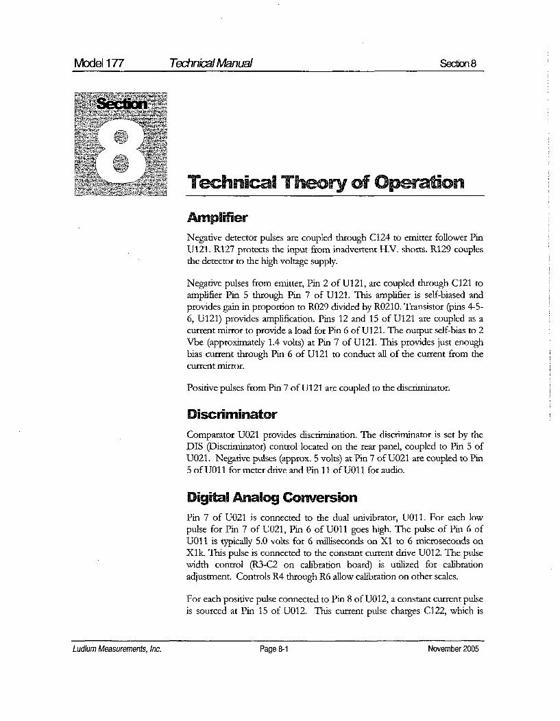
Model 177 Technical Manual Section 8
n
~Technical Theory of Operation
AmplifierNegative detector pulses are coupled through C124 to emitter follower PinU121. R127 protects the input from inadvertent H.V. shorts. R129 couplesthe detector to the high voltage supply.
Negative pulses from emitter, Pin 2 of U121, are coupled through C121 toamplifier Pin 5 through Pin 7 of U121. This amplifier is self-biased andprovides gain in proportion to R029 divided by R0210. Transistor (pins 4-5-6, U121) provides amplification. Pins 12 and 15 of U121 are coupled as acurrent mirror to provide a load for Pin 6 of U121. The output self-bias to 2Vbe (approximately 1.4 volts) at Pin 7 of U121. This provides just enoughbias current through Pin 6 of U121 to conduct all of the current from thecurrent mirror.
Positive pulses from Pin 7 of U121 are coupled to the discriminator.
Discriminator
Comparator U021 provides discrimination. The discriminator is set by theDIS (Discriminator) control located on the rear panel, coupled to Pin 5 ofU021. Negative pulses (approx. 5 volts) at Pin 7 of U021 are coupled to Pin5 of U011 for meter drive and Pin 11 of U011 for audio.
Digital Analog ConversionPin 7 of U021 is connected to the dual univibrator, U01 1. For each lowpulse for Pin 7 of U021, Pin 6 of U011 goes high. The pulse of Pin 6 ofU011 is typically 5.0 volts for 6 milliseconds on X1 to 6 microseconds onXlk. This pulse is connected to the constant current drive U012. The pulsewidth control (R3-C2 on calibration board) is utilized for calibrationadjustment. Controls R4 through R6 allow calibration on other scales.
For each positive pulse connected to Pin 8 of U012, a constant current pulseis sourced at Pin 15 of U012. This current pulse charges C122, which is
Ludlum Measurements, Inc. Page 8-1 November 2005Ludlum Measurements, Inc. Page 8-1 November 2005

Model 177 Technical Manual Section 8
discharged by R124. The average voltage on C122 is coupled through HV,BAT, and ALARM TEST switch to voltage-follower Pin 5 of U311. Pin 7 ofU311 drives the meter and recorder output.
Time ConstantThe meter time constant is determined by R124 and C122. For a slower timeconstant, C122 is paralleled by C101. When C101 is not used, it is connectedto Pin 7 of U311 (voltage follower), maintaining the same voltage level asC122. This allows C101 to be switched in or out of the circuit withouttransients.
AlarmAn alarm is provided by U021, Pins 1, 2, and 3. The alarm set control biasesthe op-amp U021 for a low output. When the meter signal at Pin 3 exceedsthe bias of Pin 2, the output at Pin 1 goes high. Q102 and Q103 saturate,allowing supply voltage to be coupled to:
Lamp voltage through R004.
Audio Oscillator U16 through CR112.
R1 16 couples back to Base of Q102, locking up the Alarm On.
Through CR113 to Audio Transformer T21 1, allowing full voltage forfull volume.
Through RI 11 to saturating current sink Q101 for external use.
ResetReset is provided by coupling a voltage to the base of transistors U012 pins1, 2, 3, and 4, 5, 6. Both transistors saturate. One discharges C122 causingthe meter to zero. Pin 3 U012 turns Q102 off, allowing the alarm to reset.
AudioA high on Pin 4 U111 turns the oscillator on saturating Q111 with eachpositive swing of the oscillator. T211 couples the pulses to the unimorph.Audio volume is controlled by voltage, applied to Pin 2 of T21 1. This iseither 4.3 volts from the alarm circuit or 0 to 4.3 volts from external volumecontrol through emitter follower Q104.
Ludlum Measurements, Inc. Page 8-2 November 2005Ludium Measurements, Inc. Page 8-2 November 2005
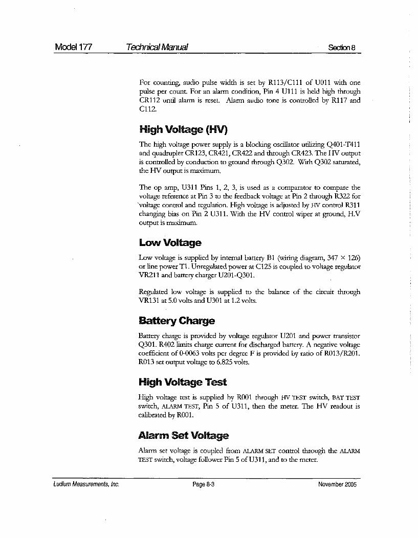
Model 177 Technical Manual Section 8
For counting, audio pulse width is set by R113/C11l of U011 with onepulse per count. For an alarm condition, Pin 4 U111 is held high throughCR112 until alarm is reset. Alarm audio tone is controlled by RI17 andCl 12.
High Voltage (HV)The high voltage power supply is a blocking oscillator utilizing Q401-T411and quadrupler CR123, CR421, CR422 and through CR423. The HV outputis controlled by conduction to ground through Q302. With Q302 saturated,the HV output is maximum.
The op amp, U311 Pins 1, 2, 3, is used as a comparator to compare thevoltage reference at Pin 3 to the feedback voltage at Pin 2 through R322 for'voltage control and regulation. High voltage is adjusted by HV control R311changing bias on Pin 2 U311. With the HV control wiper at ground, H.Voutput is maximum.
Low VoltageLow voltage is supplied by internal battery B1 (wiring diagram, 347 X 126)or line power T1. Unregulated power at C125 is coupled to voltage regulatorVR211 and battery charger U201 -Q301.
Regulated low voltage is supplied to the balance of the circuit throughVR131 at 5.0 volts and U301 at 1.2 volts.
Battery ChargeBattery charge is provided by voltage regulator U201 and power transistorQ301. R402 limits charge current for discharged battery. A negative voltagecoefficient of 0-0063 volts per degree F is provided by ratio of R013/R201.R013 set output voltage to 6.825 volts.
High Voltage TestHigh voltage test is supplied by R001 through HV TEST switch, BAT TESTswitch, ALARM TEST, Pin 5 of U311, then the meter. The HV readout iscalibrated by ROO.
Alarm Set VoltageAlarm set voltage is coupled from ALARM SET control through the ALARMTEST switch, voltage follower Pin 5 of U31 1, and to the meter.
Ludlum Measurements, Inc. Page 8-3 November 2005Ludium Measurements, Inc. Page 8-3 November 2005

Model 177 Technkial Manual Section 8
lafery Test VoltageBattery test voltage is controlled by R002 through BAT TEST switch, ALARM
TEST switch, voltage follower Pin 5 of U311 to the meter.
Ludlum Measurements, Inc. Page 8-4 November 2005

Model 177 Technkial Manual Section 9
RecylbnI A I
L udlurn Measurements, Inc. supports the recycling of the electronics
products it produces for the purpose of protecting the environmentand to comply with all regional, national and international agenciesthat promote economically and environmentally" sustainable
recycling systems. To this end, Ludlumn Measurements, Inc. strives to supplythe consumer of its goods with information regarding reuse and recycling ofthe many different types of materials used in its products. With manydifferent agencies, public and private, involved in this pursuit it becomesevident that a myriad of methods can be used in the process of recycling.Therefore, Ludium Measurements, Inc. does not suggest one particularmethod over another, but simply desires to inform its consumers of therange of recyclable materials present in its products, so that the user willhave flexibility in following all local and federal laws.
The following types of recyclable materials are present in LudlumnMeasurements, Inc. electronics products, and should be recycled separately.The list is not all-inclusive, nor does it suggest that all materials are present ineach piece of equipment:
Batteries Glass Aluminum and Stainless Steel
Circuit Boards Plastics Liquid Crystal Display (LCD)
Ludlum Measurements, Inc. products which have been placed on themarket after August 13, 2005 have been labeled with a symbol recognizedinternationally as the "crossed-out wheelie bin" which notifies the consumerthat the product is not to be mixed with unsorted municipal waste whendiscarding, each material must be separated. The symbol will be placed nearthe AC receptacle, except for portable equipment where it will be placed on
the battery lid.
The symbol appears as such: x
Ludlum Measurements, Inc. Page 9-1 November 2005Ludlum Measurements, Inc. Page 9-1 November 2005

Model 177 Technical Manual Section 10
Parts List
ReferenceModel 177 AlarmRatemeter
Main Board, Drawing347 x 227
UNIT
Description
Completely AssembledModel 177 Alarm Ratemeter
Completely AssembledCircuit Board
Part Number
48-1632
BOARD
CAPACITORS CoolCoil1C012
C021C022C023-C024C025Cl01ClllC112C121C122C123C124C125C211C221C301-C302C31 1-C312C321C322C323
1OUF, 20V,47PF, 100V68UF, 6.3V0.1UF, 50V0.001UF, 100V0.1UF, 50V10PF, 100V22UF, 10V0.022UF, 50V470PF, 100V0.001UF, 100V2.2UF, 20VlUF, 35V10OPF, 3KV3300UF, 35V47UF, 10V0.0056UF, 3KV47UF, 10V0.01UF, 50V100PF, 3KV0.0056UF, 3KV0.0047UF, 3KV
5347-293
04-565504-566004-565404-566304-565904-566304-567304-567204-566704-566804-565904-567104-565604-553204-567504-566604-552204-566604-566404-553204-552204-5547
Ludlum Measurements, Inc. Page 10-1 November 2005

Model 177 Technical Manual Section 10
Reference
C401-C402C403C411C421-C423
TRANSISTORS
VOLTAGEREGULATOR
INTEGRATEDCIRCUITS
Q1OlQ102Q103Q104Q1I1Q301Q302Q401
VR211
U011U012
U021UlllU121U201U301U311
Description
1UF, 35V0.1UF, 50V47UF, 10V0.0047UF, 3KV
2N7002LMMBT3904TMJD210MMBT3904TMMBT3904TMJD200MMBT3904TMJD210
LM2931AT 5.0
CD74HC4538MCA3096MTLC3721DICM7555CBACA3096MICL7663SCBALM285M-1.2TLC27M71D
MMBD914LCXSH-41N4007MMBD914L1N4007
Part Number
04-565604-566304-566604-5547
05-584005-584105-584305-584105-584105-584405-584105-5843
05-5813
06-629706-628806-629006-630006-628806-630205-584506-6292
07-635307-635807-627407-635307-6274
07-6366
09-690609-692009-6920
DIODES
CR111-CR114CR201-CR202CR321CR401CR421-CR423
THERMIISTOR
POTENTIOMETERS /TRIMMERS
R314
R001R002R013
250
1M, HV TEST50K, BAT T50K, BAT C
Ludlum Measurements, Inc. Page 10-2 November 2005Ludlum Measurements, Inc. Page 10-2 November 2005
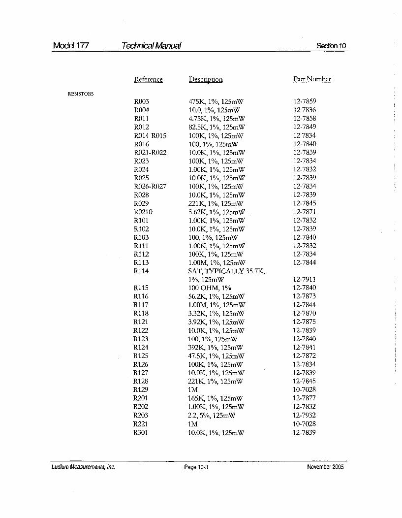
Model 177 Technkial Manual Sec-ion 10
RESISTORS
Reference
R003R004R01 1R012R014-R015R016R021-R022R023R024R025R026-R027R028R029R0210R101R102R103R111RI12R113R114
Ri15Ri16Ri17R118R121R122R123R124R125R126R127R128R129R201R202R203R221R301
Description Part Number
475K, 1%, 125mW10.0, 1%, 125mW4.75K, 1%, 125mW82.5K, 1%, 125mW100K, 1%, 125mW100, 1%, 125mW10.0K, 1%, 125mW100K, 1%, 125mW1.00K, 1%, 125mW10.0K, 1%, 125mW100K, 1%, 125mW10.0K, 1%, 125mW221K, 1%, 125mW5.62K, 1%, 125mW1.00K, 1%, 125mW10.0K, 1%, 125mW100, 1%, 125mW1.00K, 1%, 125mW100K, 1%, 125mW1.00M, 1%, 125mWSAT, TYPICALLY 35.7K,1%, 125mW100 OHM, 1%56.2K, 1%, 125mW1.OOM, 1%, 125mW3.32K, 1%, 125mW3.92K, 1%, 125mW10.0K, 1%, 125mW100, 1%, 125mW392K, 1%, 125mW47.5K, 1%, 125mW100K, 1%, 125mW10.0K, 1%, 125mW221K, 1%, 125mWIM165K, 1%, 125mW1.00K, 1%, 125mW2.2, 5%, 125mWiM10.0K, 1%, 125mW
12-785912783612-785812-784912783412-784012-783912-783412-783212-783912-783412-783912-784512-787112-783212-783912-784012-783212-783412-7844
12-791112-784012-787312-784412-787012-787512-783912-784012-784112-787212-783412-783912-784510-702812-787712-783212-793210-702812-7839
Ludlum Measurements, Inc. Page 10-3 November 2005Ludlum Measurements, Inc. Page 10-3 November 2005

Model 177 Technkial Manual Section 10
TRANSFORMERS
MISCELLANEOUS
Calibration Board,Drawing 347 x 132
Reference
R302R303R311R312R313R315R316R321-R322R323R401R402
T211T411
P1
P2
P3
10 EA.
BOARD
Description
1.00K, 1%, 125mW2.21K, 1%, 125mW750K, 1%, 125mW301, 1%, 125mW475 ohm, 1%, 125mW22.1K, 1%, 125mW1.00M, 1%, 125mW1GIM200, 1%, 125mW15, 1W
4275-08340-0902, 9=GND, 10=GND
CONN-6404-45-3MTA156CONN-1-640456-2MTA100CONN-1-640456-0MTA100CLOVERLEAF RECEPT.011-6809-000-599
Completely AssembledCalibration Board
Part Number
12-783212-783512-788212-786312-785112-784312-784412-768610-702812-784612-7738
4275-08340-0902
13-8125
13-8061
13-8066
18-8771
5347-189
04-557004-5565
09-678709-681309-681409-681409-683409-681909-6787
CAPACITORS
POTENTIOMETERS
C1C2
R1R2R3R4R5R6R7
0.0047UF, 100V0.047UF, 100V
1 OK, RECORDER100K, HVIM, X1IM, X102M, X100250K, Xl00010K, DISCRIMIINATOR
Ludlum Measurements, Inc. Page 10-4 November 2005

Model 177 Technical Manual Secon 10
Reference Description Part Number
RESISTOR
R9 680, 1/3W 12-7885
RESISTORNETWORK
RN1 10K 12-7720
MISCELLANEOUS
P6 CONN 1-640457-1 MTA100 13 8397
Wiring Diagram,Drawing 347 x 230 S1 46206-LR SLIDE 08-6523
SWITCHES S2 PA-1002 08-6543S3 7101-SYZ-QE 08-6511S4 HV (#923 SWITCHCRAFT) 08-6518S5 BAT (#923 SWITCHCRAFI) 08-6518S6 ALARM (#923 SWITCHCRAFT) 08-6518S7 RESET (30 1 PB GRAYHILL) 08-6517
POTENTIOMETERS
R1 10K, VOLUME 09-6753R2 100K, ALARM SET 09-6795
CONNECTORS
Ji MAIN BOARD 5347-293,3 PIN SIP(CONN 64042873 MTA 156) 13-8124
J2 MAIN BOARD 5347-293,12 PIN SIP (CONN 1-640441-2) 13-8431
J3 MAIN BOARD 5347-293,10 PIN SIP(CONN 1-640441-0MTA 100) 13-8197
-J4 ACRECEP(RECPT-AC W/FUSE) 13-8427
J5 "D" CONN, 9 PIN(RECPT-RD9FOOOV3 9P) 13-8003
J6 CALIBRATION BOARD5347-189, 11 PIN SIP(CONN 1-640441-1 MTA 100) 13-8161
J7 FLYING LEAD TO MAINBOARD 5347-293(RECPT-UG706) 13-7751
Ludlum Measurements, Inc. Page 10-5 November 2005

Model 177 Technkial Manual Section 10
Reference Description Part Number
AUDIO
DS2 UNIMORPH (TEC3526PU) 21-9251
BATTERY
B1 6V (PS610 GELL CELL) 21-9385
TRANSFORMER
T1 P6465 22-9908
MISCELLANEOUS
Fl 1 AMP (FUSE #312001 AGC-1) 21-9277DS1 PILOT (LAMP-RED) 21-9296DS3 ALARM (BULB #338) 21-9307* LAMP HOLDER
101-8430-09-201 21-9410M1 M177 METER 4173-166* KNOB PKG-50B 08-6601* KNOB-407D2KI 08-6604* KNOB-LOCK KL 701 08-6607* KNOB-70-1-2G 08-6637
Ludlum Measurements, Inc. Page 10-6 November 2005

Model 177 Technical Manual Secion 11
Drawings
MAIN BOARD FOR HOYT lmA/1K MOVEMENT, Drawing347 x 227
MAIN BOARD (HOYT lmA/1K') Component Layout, Drawing347 x 228
CALIBRATION BOARD, Drawing 347 x 132
CALIBRATION BOARD Component Layout, Drawing 347 x 133
WIRING DIAGRAM FOR HOYT lmA/1K MOVEMENT,Drawing 347 x 230
Ludlum Measurements, Inc. Page 11-1 November 2005Ludlum Measurements, Inc. Page 11-1 November 2005

C 123 R 12S R1231112 4756V9
912 47.S 1/011C124~~ 1901 11156
R11 ..2 2 ..CA II26mW 19.C. 14 / J2
2L1IN R,2 CASS, 1.2K I 4 ls IS' 21 S 42?S 2111K IBMS f 92
1S129~RI CAOSII2L1711 I
"I5 212 12 11 E1D 4F122 CA111,111, 3.929is
R12w IK IBM I2m
LE2 D92 9992 1zc
912 999KL29.92 1 1 9.9947112 S5 1 /2W1 1491 01
P1 -19m 411IU c021 T21211 I
C112 9,9942 2 1497 16= 29 IS 5m 112Sm
P2 12R2-A09M
R2 lF +C2
1P2129 I -l.I 8CL7661SC9 29
II -2I R0222C
P1P -1v ;125"15m 5
EFF I AUTHORI TY I ZONE I LTR I DESCRIPT I DATE I APPROVED
RO9i6 1] T211•> I,1I II II• U01I2 RIIS AUDIO., P -'
19 CADBSSM 31325 11 P -1CIll 125mW IG=GND 13 I4T7PF 12 14 I/S Us 12 1S. 1 GI 3 4 9 999TleBV CA389sm M
SATTYPICALLY 3S,1K C2.12 R12K U . =
2 2It1 IS 392KW1R125miW 20V itT5 10
7 9 0/10942A NC a I/~~S 01 2 M T3641P1-112 1.9I11 19 125.14 1 G-
CD74HC4S39M 82,55M DSI
CRI12CR 33 R 4I53MIlL M2 D19 4L .110
R I.93"5'."... 2 • 1230 ? ALARM LAM1 P P3-3
is 14 CR11oIIRII
1/2 Uo11ICD74HC4538M
lG--4.91V =ASND
11UF V +4V
BB+C.U`T .3
R' I 12 -12 U@s ]
8=•2Vs =CN R111 I 88eX J3 1
1C765P ,,0EI R 1CII4 -- 7K 6=N
I .. . ~~~ ~~ ~ ~~... .8CCON)SBRC )"
I .
1 5 I/,S U919
CA4 639I1G=CND T2UFT20V
RESET . P3 -4R027
,~192KIf125r.W
P311 -4
II11 12s,1ýsoA% --- PS -10
ALR E 1_ýp -6
. n •*}
C 2IBe. lIPSOY91
C.91I1I RECORDER 2-
... .... 1 411 R1251
7 If6 j15W11SWEE 2-5 R314O~mEY 4=02
TI 3E41 9029S@IEVES 91 -Au5 -9 1B47 1 14 227TI F
0 95: 2:sr - --- - ~- V-TQS;5175 5EISAE I OF I
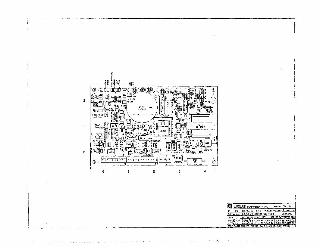
2
RE ~ I Z ic: It 7i " 0-09021fl0 a.~ 0r':-up LV I
S0K w vNJ~J ,,
aLmUU U rT@ CR202 LJJm-0 ~ ~ [~j* ~ 'uCXSH -4 UM95i- . R~jge C
PD fJ014 R402
0 12 3
03LUDLUM IIEASURErENTS INC, SWEETWATERI TX.1
DR C8 10D/13/SSIT ITLE: MAIN BOARD IHOYT ImA/IK)CHK Pi* . Ij,/ •7 8OARDO S347-293 0$347293
1SND . , 1071/921 MODEL. 177 ISERIES 3471SHEET 229(
t7f~9CoM~OT INEWSLD OULIN F 0[
-P DR P- SI iComp . I . I I 1--l- l"Ll-

cwt R3 C14t R 4 a R5 cwtI m 22G
2. .4 7U5 J P B.W.5452
ps -3
PS -5
P6 -7
1553IIK 1"K elSCI1 ~ W~ DISCX1PINATDR PECODXXC
PS -
PG -11<-

DISCR IMINATOR
X1000
X 100
S 10
xi
ROK (1 P6~RG
R4
680 O0K()R I
Q 1I K (D oRECORDER
I LUDLUM1 MEASUREMIENTS INC. SWEETWATER, TX.
SR EIR 10e20192 TITLE IP CALIBRRATYION BOARD
CHKBORD S47-189 -- BSf47189DSG 8OADfI SEýRI1ES ISASElE
APP (0 7-1__ I7f 1
t4:19:19 10-J.-93 CCMP SIDEOISLDR SIDEC)JOUTLINEZJ
- P T S R rl KO
.... ....... ....... ............. .. .......... .... .

EFF AU7RITY ZONE ILDR I DOscRIFTIODA I DADE JAPPROHED
MAIN g RORRS347-5333 PEN S(P
CAIBRATION BOARD
H IAm
MEIIER
M ~RESPONSLJNTRORPH
cR1 RI
VOSRM NYCA CDOH
lSO
A2RAI'M tcRI
A47AMD
ALAR 4ATCAG
PUEEDU
______________________________________________________ ____________ RCHOOUNSSURCAC
DEARS SUBTRACT GA________S_________I
HP ROSEST4-0- S NC w
1I.ADOR
UPDADED -LUDL.UR MEASURDEMENTS INC.
._\/LING LE'R 53D-0R) -~iP~7 7T I TLE HIRING OIHORRI
NEXT HIGHER HODDI, 1RD i )
II) S:RN J3-Mol-O4 W3172-5. I SHOOT I OF A

LUDLUM MODEL 19MICRO R METER
November 2005
Serial Number 207422 and Succeeding
Serial Numbers
LUDLUM MEASUREMENTS, INC.501 OAK STREET, P.O. BOX 810SWEETWATER, TEXAS 79556325-235-5494, FAX: 325-235-4672

ýEV#I ALTERATIONS I DATE I BY1 VALID 13-16-04 DD\
rflV .(' ,, 20
MIC0
MIC R(
(D / 5ý'
30
R/hr
ONF/ON F*gl
AUD
OFF S Af-
@ A
H.V.0
BATO
RESI
r I MICRO R METER
LUDLUM MEASUREMENTS INC.SWEETWATER, TEXAS,. ~CE,
I I
OWN ATE ATE DAE00 -16-04 -1-04- l. l-1TE
IDWG NUM: 4367-169.IAM ISCALE:"TI M 19 FO SEL EU LUDLUM mEAuREmET.N I SERIES ~SHEETI ~ xs~o 1367 1169

T able of Content
Introduction I
Getting Started 2Unpacking and Repacking 2-1
Battery Installation 2-1
Operational Check 2-2
Maintenance 2-3
Recalibration 2-3
Batteries 2-3
Specifications 3
Identification of Controls and Functions 4
Safety Considerations 5Environmental Conditions for Normal Use 5-1
Warning Markings and Symbols 5-1
Cleaning and Maintenance Precautions 5-2
Troubleshooting 6Troubleshooting Electronics which utilize a Scintillation Detector 6-1
Technical Theory of Operation 7Detector 7-1
Input 7-1
Amplifier 7-1
Discriminator 7-1
Audio 7-2
Scale Ranging 7-2
Digital Analog Converter 7-2
Meter Drive 7-2
Fast/Slow Time Constant 7-2
Low Voltage Supply 7-2
High Voltage Test 7-2
High Voltage Supply 7-3
Ludlum Measurements, Inc. November 2005
Model 19 MICRO R METER Technical Manual
Recycling 8
Parts List 9Model 19 Micro R Meter 9-1
Main Board, Drawing 367 x 166 9-1
Wiring Diagram, Drawing 367 x 174 9-4
Drawings and Diagrams 10
Ludlum Measurements, Inc. November 2005

Model 19 MICRO R METER Technkial Manual Section 1
• -on -z:
The Ludlum Model 19 Micro R Meter utilizes an internally-mounted1" x 1" NaI(Tl) scintillator for optimum performance in locatingand measuring low-level (near "background") gamma radiation.
The unit features a pushbutton lighted meter and was designed to bemoisture and dust resistant. The meter is housed in a rugged aluminum bezelwith waterproof seals. All controls, including a calibration potentiometer foreach range, are located on the front panel. Front panel switches are rubber-booted to seal out moisture and dust. A high voltage (HV) test control isprovided to allow rapid plateau testing of the detector.
Five range divisions are provided in the 0-5000 micro R/hr spectrum. Themeter face is made up of two scales, 0-50 and 0-25, plus battery test. The 0-50 scale corresponds to the 50, 500 and 5000 positions on the range selectorswitch. The 0-25 scale corresponds to the 25 and 250 positions on the rangeselector switch.
The instrument is capable of using either standard "D" cell flashlightbatteries or nickel-cadmium rechargeable batteries. However, the Model 19does not include circuitry for recharging the batteries. The two "D" cellbatteries are located in an isolated compartment, easily accessible from thefront panel.
The Model 19 NaI scintillator is energy sensitive. An energy response curveis induded in section 10 of this manual for further reference.
Ludlum Measurements, Inc.Page 1-1 November 2005Ludlum Measurements, Inc. Page 1-1 November 2005

Model 19 MICRO R METER Technical Manual Sectw 2
' Ge ,,, Started
Unpacking and RepackingRemove the calibration certificate and place it in a secure location. Removethe instrument and accessories (batteries, cable, etc.) and ensure that all ofthe items listed on the packing list are in the carton. Check individual itemserial numbers and ensure calibration certificates match. The Model 19 serialnumber is located on the front panel below the battery compartment. MostLudlum Measurements, Inc. detectors have a label on the base or body ofthe detector for model and serial number identification.
If multiple shipments are received, ensure that the detectorsand instruments are not interchanged. Each instrument iscalibrated to specific detectors, and therefore notinterchangeable.
To return an instrument for repair or calibration, provide sufficient packingmaterial to prevent damage during shipment. Also provide appropriatewarning labels to ensure careful handling. Include detector(s) and relatedcable(s) for calibration. Include brief information as to the reason for return,as well as return shipping instructions:
- Return shipping address- Customer name or contact- Telephone number- Description of service requested and all other necessary
information
Battery InstallationEnsure the Model 19 power switch is in the "OFF" position. Open thebattery lid by pushing down and turning the quarter-turn thumbscrewcounterclockwise ¼4 turn. Install two "D" size batteries in the compartment.
Ludlum Measurements, Inc. Page 2-1 November 2005Ludlum Measurements, Inc. Page 2-1 November 2005

Model 19 MICRO R METER TechnkcalManual Section 2
Note the (+) and (-) marks inside the battery door. Match the battery polarity tothese marks. Close the battery box lid, push down and turn the quarter-turnthumb screw clockwise ¼4 turn.
Center post of a flashlight battery is positive. The batteries areplaced in the battery compartment in opposite directions.
Operational CheckTurn the Range Selector switch to the "25" position. Depress the "BAT"pushbutton switch and ensure that the meter needle falls within the "BAT OK"marks. Check for a proper background reading. A typical reading would be: 5-15 uR/hr
Turn the Range Selector switch to the "5000" position. Expose the instrumentto a "check source" and verify that the instrument indicates within 20% of thecheck source reading obtained during the last calibration.
Switch the "AUD ON/OFF" switch to the "ON" position and confirm that theexternal unimorph speaker produces an audible click for each event detected.The "AUD ON/OFF" switch will silence the audible clicks if in the "OFF"
position. It is recommended that the "AUD ON/OFF" switch be kept in the"OFF" position when not needed in order to preserve battery life.
Turn the Range Selector switch to the "250" position and increase the sourceactivity for a meter reading of 10-100 uR/hr. While observing the meterfluctuations, select between the fast and slow response time ("F/S') positionsto observe variations in the display. The "s" position should respondapproximately 5 times slower than the "F" position.
Note: -
The slow response position is normally used when the instrumentis displaying low numbers which require a more stable metermovement. The fast response position is used at high rate levels.
Check the meter reset function by depressing the "reset" pushbutton switchand ensuring the meter needle drops to "0".
Ludlum Measurements, inc. Page 2-2 November 2005

Model 19 MICRO R METER TechnicalManual Sedion 2
Depress the "LAMP" pushbutton switch. Ensure that the meter face illuminateswhen the switch is depressed. Proceed to use the instrument.
MaintenanceInstrument maintenance consists of keeping the instrument clean andperiodically checking the batteries and the calibration. The Model 19instrument may be cleaned with a damp cloth (using only water as the wettingagent). Do not immerse instrument in any liquid. Observe the following
precautions when cleaning.
1. Turn the instrument off and remove the batteries.
2. Allow the instrument to sit for 1 minute before accessing internal
components.
RecalibrationRecalibration should be accomplished after any maintenance or adjustment ofany kind has been performed on the instrument. Battery replacements are notconsidered maintenance and do not normally require instrument recalibrated.
Note:
Ludlum Measurements, Inc. recommends recalibration atintervals no greater than one year. Check the appropriateregulations to determine required recalibration intervals.
Ludlum Measurements offers a full service repair and calibration departmentWe not only repair and calibrate our own instruments but most othermanufacturer's instruments. Calibration procedures are available upon requestfor customers who choose to calibrate their own instruments.
BatteriesThe batteries should be removed any time the instrument is placed into storage.Battery leakage may cause corrosion on the battery contacts, which must bescraped off and/or washed using a paste solution made from baking soda andwater. Use a spanner wrench to unscrew the battery contact insulators,
Ludlum Measurements, Inc. Page 2-3 November 2005

Model 19 MICRO R METER TehnkicalManual Section 2Section 2
exposing the internal contacts and battery springs. Removal of the handle willfacilitate access to these contacts.
Note:
Never store the instrument over 30 days without removing thebatteries. Although this instrument will operate at very highambient temperatures, battery seal failure may occur attemperatures as low as 100TF.
Ludlum Measurements, Inc. Page 2-4 November2005Ludium Measurements, Inc. Page 2-4 November 2005
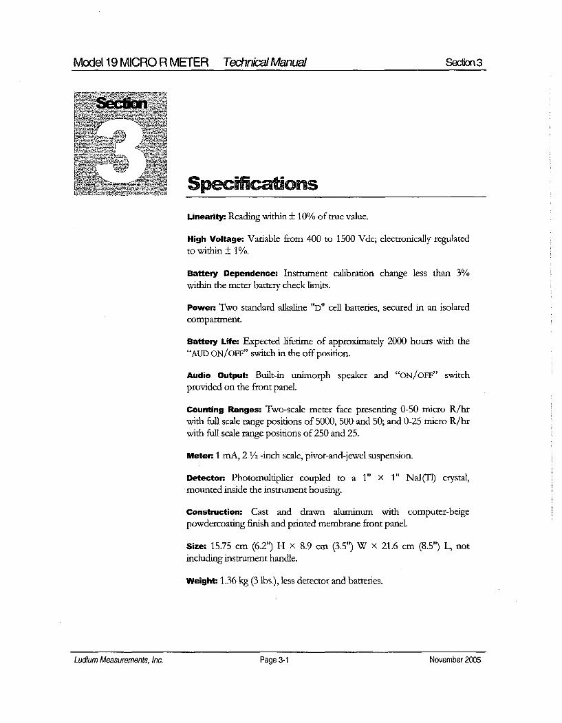
Model 19 MICRO R METER TechnialManual Section3
Specifications
Linearity: Reading within ± 10% of true value.
High Voltage: Variable from 400 to 1500 Vdc; electronically regulatedto within ± 1%.
Battery Dependence: Instrument calibration change less than 3%within the meter battery check limits.
Power. Two standard alkaline "D" cell batteries, secured in an isolatedcompartment
Battery Life: Expected lifetime of approximately 2000 hours with the"AUD ON/OFF" switch in the off position.
Audio Output: Built-in unimorph speaker and "ON/OFF" switchprovided on the front panel.
Counting Ranges: Two-scale meter face presenting 0-50 micro R/hrwith full scale range positions of 5000, 500 and 50; and 0-25 micro R/hrwith full scale range positions of 250 and 25.
Meter. 1 mA, 2 1/2 -inch scale, pivot-and-jewel suspension.
Detector. Photomultiplier coupled to a 1" X 1" NaI(T1) crystal,-mounted inside the instrument housing.
Construction: Cast and drawn aluminum with computer-beigepowdercoating finish and printed membrane front panel.
Size: 15.75 cm (6.2') H x 8.9 cm (3.5') W X 21.6 cm (8.5") L, notincluding instrument handle.
Weight: 1.36 kg (3 lbs.), less detector and batteries.
Ludlum Measurements, Inc. Page 3-1 November 2005
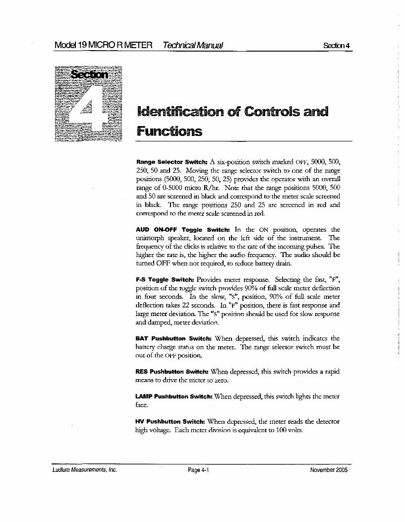
Model 19 MICRO R METER Technkal Manual Section 4
Identifcation of Controls andFunctions
Range Selector Switch: A six-position switch marked OFF, 5000, 500,250, 50 and 25. Moving the range selector switch to one of the rangepositions (5000, 500, 250, 50, 25) provides the operator with an overallrange of 0-5000 micro R/hr. Note that the range positions 5000, 500and 50 are screened in black and correspond to the meter scale screenedin black. The range positions 250 and 25 are screened in red andcorrespond to the meter scale screened in red.
AUD ON-OFF Toggle Switch: In the ON position, operates theunimorph speaker, located on the left side of the instrument. Thefrequency of the clicks is relative to the rate of the incoming pulses. Thehigher the rate is, the higher the audio frequency. The audio should beturned OFF when not required, to reduce battery drain.
F-S Toggle Switch: Provides meter response. Selecting the fast, "F",position of the toggle switch provides 90% of full scale meter deflectionin four seconds. In the slow, "s", position, 90% of fuill scale meterdeflection takes 22 seconds. In "F" position, there is fast response andlarge meter deviation. The "s" position should be used for slow responseand damped, meter deviation.
BAT Pushbutton Switch: When depressed, this switch indicates thebattery charge status on the meter. The range selector switch must beout of the OFF position.
RES Pushbutton Switch: When depressed, this switch provides a rapidmeans to drive the meter to zero.
LAMP Pushbutton Switch: When depressed, this switch lights the meterface.
HV Pushbutton Switch: When depressed, the meter reads the detectorhigh voltage. Each meter division is equivalent to 100 volts.
Ludlum Measurements, Inc. Page 4-1 November 2005Ludium Measurements, Inc. Page 4-1 November 2005
Modd 19MICROR METER TechnkýýManual Secfion4Model 19 MICRO R METER Technk~a) Manual Section 4
HV Adjustment: Provides a means to vary the high voltage from 400 to1500 volts.
Range Calibration Adjustments: Recessed potentiometers locatedunder the calibration cover, on the right side of the front panel. Theseadjustment controls allow individual calibration for each rangemultiplier.
Ludlum Measurements, Inc. Page 4-2 November 2005Ludlum Measurements, Inc. Page 4-2 November 2005

Model 19 MICRO R METER Technical Manual Secon 5
Seclim~
Safet Cnsidera tions.Environmental Conditions for Normal UseIndoor or outdoor use
No maximum altitude
Temperature range of-20TC to 50'C (-4°F to 122'F)
Maximum relative humidity of less then 95% (non-condensing)
Pollution Degree 1 (as defined by JEC 664).
Warning- Markings and Symbols
Caution!
The operator or responsible body is cautioned that theprotection provided by the equipment may be impaired if theequipment is used in a manner not specified by LudlumMeasurements, Inc.
The Model 19 Micro R Meter is marked with thefollowing symbols:
CAUTION (per ISO 3864, No. B.3.1) - designates hazardous live voltageA and risk of electric shock. During normal use, internal components arehazardous live. This instrument must be isolated or disconnected from thehazardous live voltage before accessing the internal components. Thissymbol appears on the front panel. Note the following precautions:
Ludlum Measurements, Inc. Page 5-1 November 2005Ludlum Measurements, Inc. Page 5-1 November 2005

Model 19 MICRO R METER Technal AI Manual Secfion 5
YWarning
The operator is strongly cautioned to take the followingprecautions to avoid contact with internal hazardous live partsthat are accessible using a tool:
1. Turn the instrument power OFF and remove the batteries.2. Allow the instrument to sit for 1 minute before accessing
internal components.
\ The "crossed-out wheelie bin" symbol notifies the consumer that theproduct is not to be mixed with unsorted municipal waste when discarding,each material must be separated. The symbol is placed on the batterycompartment lid. See section 8, "Recycling" for further information.
Cleaning and Maintenance PrecautionsThe Model 19 may be deaned externally with a damp cloth, using only wateras the wetting agent. Do not immerse the instrument in any liquid. Observethe following precautions when cleaning or performing maintenance on theinstrument:
1. Turn the instrument OFF and remove the batteries.
2. Allow the instrument to sit for 1 minute before cleaning theexterior or accessing any internal components for maintenance.
Ludlum Measurements, Inc. Page 5-2 November 2005
Model 19 MICRO R METER Technk:,--VA4anua1 Sefin6Model 19 MICRO R METER Technibal Manual Section 6
Troubleshooting
ccasionally, you may encounter problems with your LMI
instrument or detector that may be repaired or resolved in thefield, saving turnaround time and expense in returning theinstrument to us for repair. Toward that end, LMI electronics
technicians offer the following tips for troubleshooting the most commonproblems. Where several steps are given, perform them in order until theproblem is corrected. Keep in mind that with this instrument, the mostcommon problems encountered are: (1) sticky meters (2) battery contacts.
Note that the first troubleshooting tip is for determining whether theproblem is with the electronics or with the detector. A Ludlum Model 500Pulser is invaluable at this point, because of its ability to simultaneouslycheck high voltage, input sensitivity or threshold, and the electronics forproper counting.
We hope these tips will prove to be helpful. As always, please call if youencounter difficulty in resolving a problem or if you have any questions.
Troubleshooting Electronics which utilize a
Scintillation Detector
SYMPTOM POSSIBLE SOLUTION
1. Check batteries and replace if weak.No power (or meterdoes not reach BAT 2. Check polarity (See marks insideTEST or BAT OK batter lid). Are the batteries installedmark) backwards?
Ludlum Measurements, Inc. Page 6-1 November 2005Ludium Measurements, Inc. Page 6-1 November 2005

Model 19 MICRO R METER Technical Manual Section 6
SYMPTOM POSSIBLE SOLUTION
No power (or meterdoes not reach BAT
TEST or BAT OK
mark) (continued)
Nonlinear Readings
3. Check battery contacts. Clean themwith rough sandpaper or use anengraver to clean the tips.
4. Check for loose or broken wires,especially between the main boardand the calibration board.
1. Check the high voltage (HV) bypressing the HV TEST button. If aMultimeter is used to check the HV,ensure that one with high impedanceis used, as a standard Multimetercould be damaged in this process.
2. Check for "sticky" meter movement.Does the reading change when youtap the meter? Does the meter needle"stick" at any spot?
3. Check the "meter zero." Turn thepower OFF. The meter should cometo rest on "0".
1. Check the HV and, if possible, theinput threshold for proper setting.
2. Check for loose wires, especiallybetween the main board and thecalibration board.
Meter goes full-scaleor "Pegs Out"
Ludlum Measurements, Inc. Page 6-2 November 2005

Model 19 MICRO R METER Technkial Manual Secfion 7
Technica Theory of Operation
DetectorThe detector consists of a crystal of sodium iodide with Thallium activation(NaI TI) that gives off light pulses when penetrated by radiation photons.
The light pulses are converted to electrical pulses by the photo cathode ofthe photomultiplier tube. The photomultiplier includes a 9 stage electronamplifier. This amplifier utilizes an electrostatic field for each stage, addingup to a required 500 to 1500 volt supply.
Input
Detector pulses are coupled from the detector through C6 to the amplifier.CR1 protects the amplifier from input shorts. R37 couples the detector tothe high voltage supply.
AmplifierA self-biased amplifier provides gain in proportion to R15 and C4 divided byR14. Transistor (pin 3 of U4) provides amplification. U6 is configured as acurrent mirror to provide a load for pin 3 of U4. The output self-biases to 2Vbe (approximately 1.4 volts) at emitter of Q1. This provides just enoughbias current through pin 3 of U4 to conduct all of the current from thecurrent mirror.
Positive pulses at R16 are coupled to the discriminator through C5.
DiscriminatorComparator U8 provides discrimination. The discriminator is set by thevoltage divider, R21 and R23, coupled to pin 3 of U8. U8 output pulses arecoupled to pin 5 of U9A for meter drive and pin 12 of U9B for audio.
Ludlum Measurements, Inc. Page 7-1 November 2005

Model 19 MICRO R METER Technical Manual Secfion7
AudioDiscriminator pulses are coupled to univibrator pin 12 of U9B. Front panelaudio ON-OFF selector controls the reset at pin 13 of U9B. When ON, pulsesfrom pin 10 of U9B turn on oscillator U12, which drives the can-mountedunimorph. Speaker tone is set by R31, C14; duration by R22, C7.
Scale RangingDetector pulses from the discriminator are coupled to univibrator pin 5 ofU9A. For each scale, the pulse width of pin 6 of U9A is controlled by thefront panel calibration controls and their related capacitors. Thisarrangement allows the same current to be delivered to C9 in proportion tothe meter reading.
Digital Analog ConverterU5 is configured as a current mirror. For each pulse of current through R24,an equal current is delivered to C9. This charge is drained off by R25. Thevoltage across C9 is proportional to the incoming count rate.
Meter DriveThe meter is driven by the collector of Q2 coupled as a voltage follower inconjunction with pin I of U10.
For Battery Test, the voltage follower is bypassed and the meter movementis directly coupled to the battery through R8.
Fast/Slow Time ConstantFor slow time constant, C17 is switched from the output of the meter driveto parallel C9.
Low Voltage SupplyBattery voltage is coupled to Ul1 and associated components (a switchingregulator) to provide 5 volts at pin 8 to power all circuits.
High Voltage TestA constant current is developed by collector of Q3 in proportion to HVsignal at pin 1 of U17. U16 provides a current mirror to drive the meter
Ludlum Measurements, Inc. Page 7-2 November 2005Ludium Measurements, Inc. Page 7-2 November 2005

Model 19 MICRO R METER TechnicaIManual Section 7
through analog switch logic circuit U15, U14, and U3.
High Voltage SupplyHigh voltage is developed by switching regulator U13 and T1. Voltagemultiplier CR3 thru CR7, and associated components, develop the detectorvoltage. Voltage feedback is provided by R39 thru U17 to feed back pin 8 ofU13 for voltage regulation. Pin 1 of U17 is proportional to the high voltage,and its output is also utilized to measure the high voltage. High voltage isadjusted by varying the feedback current with R42.
Ludlum Measurements, Inc. Page 7-3 November 2005Ludium Measurements, Inc. Page 7-3 November 2005

Model 19 MICRO R METER TechnicalManual Section 8
L udlum Measurements, Inc. supports the recycling of the electronicsproducts it produces for the purpose of protecting the environmentand to comply with all regional, national and international agenciesthat promote economically and environmentally sustainable
recycling systems. To this end, Ludlum Measurements, Inc. strives to supplythe consumer of its goods with information regarding reuse and recycling ofthe many different types of materials used in its products. With manydifferent agencies, public and private, involved in this pursuit it becomesevident that a myriad of methods can be used in the process of recycling.Therefore, Ludlum Measurements, Inc. does not suggest one particularmethod over another, but simply desires to inform its consumers of therange of recyclable materials present in its products, so that the user willhave flexibility in following all local and federal laws.
The following types of recydable materials are present in LudlumMeasurements, Inc. electronics products, and should be recycled separately.The list is not all-inclusive, nor does it suggest that all materials are present ineach piece of equipment:
Batteries Glass Aluminum and Stainless Steel
Circuit Boards Plastics Liquid Crystal Display (LCD)
Ludlum Measurements, Inc. products which have been placed on themarket after August 13, 2005 have been labeled with a symbol recognizedinternationally as the "crossed-out wheelie bin" which notifies the consumerthat the product is not to be mixed with unsorted municipal waste whendiscarding, each material must be separated. The symbol will be placed nearthe AC receptacle, except for portable equipment where it will be placed onthe battery lid.
The symbol appears as such:
Ludlum Measurements, Inc. Page 8-1 November 2005Ludlum Measurements, Inc. Page 8-1 November 2005

Model 19 MICRO R METER TechnkialiManual Section 9
Parts List
Model 19Micro R Meter
Main Board,Drawing 367 x 166
CAPACITORS
Reference
UNIT
BOARD
C1C2C3C4C5C6C7C8C9C10Cl'C12C14C17C1 8-C27C28C29C30-C31C32C33
Description Part Number
Completely AssembledModel 19 Micro R Meter
Completely AssembledCircuit Board
47pF, 100V0.0022gF, 50V0.001gF, 100V10pF, 100V0.011F, 50V1OOpF, 3KV0.022gF, 50VIgjF, 16V1OjiF, 25V100pF, 100V68jF, 10V10tF, 25V470pF, 100V47tF, 10V0.01RF, 500V0.001gF, 2KV68gF, 10V19F, 16V270pF, 100V0.01 tF, 50V
48-1615
5367-166
04-566004-567604-565904-567304-566404-573504-566704-570104-565504-566104-565404-572804-566804-566604-569604-570304-565404-570104-567904-5664
Ludlum Measurements, Inc. Page 9-1 November 2005

Model 19 MICRO R METER Technical Manual Section 9
Reference Description Part Number
TRANSISTORS Q1 MMBT3904LT1 05-5841
Q2 MMBT4403LT1 05-5842Q3 MMBT3904LT1 05-5841
VOLTAGEREGULATOR VR1 LT1460KCS3-2.5TR 05-5867
INTEGRATED
CIRCUITS U1-U3 MAX4542ESA 06-6453
U4-U5 CMXT3904 05-5888U6 CMXT3906 05-5890U7 MAX4541ESA 06-6452U8 MAX985EUK-T 06-6459U9 CD74HC4538M 06-6297U10 LMC7111BIMSX 06-6410Ull LT1304CS8-5 06-6434U12 vIC1557BM5 06-6457U13 LT1304CS8 06-6394U14-U15 MAX4542ESA 06-6453U16 CMXT3906 05-5890U17-C18 LMC7111BIM5X 06-6410
DIODES
CR1 CMPD2005S 07-6468CR2 CMSHl-40M 07-6411CR3-CR7 CMPD2005S 07-6468CR9 CMSHl-40M 07-6411
SWITCHES
SWI RANGE SELECTOR 08-6761SW2 H.V. PUSHBUTTON 08-6770SW3 F-S TOGGLE 08-6781SW4 AUD ON-OFF TOGGLE 08-6781SW5 RES PUSHBUTTON 08-6770SW6 LAMP PUSHBUTTON 08-6770SW7 BAT PUSHBUTTON 08-6770
POTENTIOMETERS /TRIMMERS R33 1M, 64W105 NAME 09-6814
R34 1M, 64W105 X10 09-6814R35 1M, 64W105 Xl 09-6814R36 1M, 64W105 X0.1 09-6814R41 100K, 64W104 X100 09-6813
Ludlum Measurements, Inc. Page 9-2 November 2005

Model 19 MICRO R METER TechnicalManual Section 9
Reference Description Part Number
R42 100K,64W104IHVADJ 09-6813R52 10K, 3266X1-103 NAME 09-6822
RESISTORS
R1-R5 200K, 1/8W, 1% 12-7992R6 8.25K, 1/8W, 1% 12-7838R7 10K, 1/8W, 1% 12-7839R8 2.37K, 1/8W, 1% 12-7861R9-R11 10K, 1/8W, 1% 12-7839R12 200 Ohm, 1/8W, 1% 12-7846R13 10K, 1/8W, 1% 12-7839R14 4.75K, 1/8W, 1% 12-7858R15 200K, 1/8W, 1% 12-7992R16 10K, 1/8W, 1% 12-7839R17 1K, 1/8W, 1% 12-7832R18 4.75K, 1/8W, 1% 12-7858R19 2K, 1/8W, 1% 12-7926R20-R21 100K, 1/4W, 1% 12-7834R22 1M, 1/8W, 1% 12-7844R23 2.49K, 1/8W, 1% 12-7999R24 14.7K, 1/8W, 1% 12-7068R25 200K, 1/4W, 1% 12-7992R26 100K, 1/4W, 1% 12-7834R27 68.1K, 1/8W, 1% 12-7881R28 100K, 1/8W, 1% 12-7834R29 1K, 1/8W, 1% 12-7832R30 100K, 1/8W, 1% 12-7834R31 475K, 1/8W, 1% 12-7859R32 100K, 1/8W, 1% 12-7834R37 100K, 1/8W, 1% 12-7834R38 4.75M, 1/8W, 1% 12-7995R39 500M, 3KV, 2% 12-7031R40 1M, 1/4W, 1% 12-7844R44 1K, 1/4W, 1% 12-7832R45 8.25K, 1/8W, 1% 12-7838R46-R48 200K, 1/4W, 1% 12-7992R49 825K, 1/8W, 1% 12-7005R50 953K, 1/8W, 1% 12-7950R53 1K, 1/4W, 1% 12-7832
CONNECTORS
P1 CONN-640456-4MTA100x4 NAME 13-8088
Ludium Measurements, Inc. Page 9-3 November 2005

Model 19 MICRO R METER TechnicalManual Section 9
Reference
P2
P3
P4
Description
CONN-640456-3MTA100x3 NAMECONN-640456-2MTA10Ox2 NAMECONTACT #1434 NAME
22gH, CD43-220
Part Number
INDUCTOR
TRANSFORMER
Li
T1 31032R
Wiring Diagram,Drawing 367 x 174
AUDIO
13-8081
13-807318-9124
21-9808
21-9925
5367-11321-9251
13-8170
13-8135
13-8178
21-9313
DS1DS2
CONNECTOR
P1
P2
P3
M19 LAMP BOARD 5367-113UNIMORPH TEC-3526-PU
MTA100x4 MAIN BOARD5367-166MTA 100x3 MAIN BOARD5367-166MTA 100x2 MAIN BOARD5367-166
BATTERY
B1-B2 DURACELL "D"
MISCELLANEOUS
M1
*
*
*
*
*
*
*
M19 INTERNAL DETECTORTUBE/XTAL ASSYMODEL 19 METERASSY 987010-001 lmAM19 METERFACE(202-016)METER BEZEL W/ GLASSW/ SCREWSMETER MOVEMENT (lmA)M19 BATTERY BOXLID W/CNTCTDEEP PORTABLECAN ASSYM19 CASTINGM19 MAIN HARNESS
47-34262004-061
4367-024
7367-023
4363-352-0015-8030
2363-191
4363-6157367-1718367-170
Ludlum Measurements, Inc. Page 9-4 November 2005

Model 19 MICRO R METER Technkial Manual Section 9
Reference Description Part Number
* PORTABLE KNOB 08-6613* SWITCH SEAL (P/B) 08-6611* UNIMORPH W/WIRES,
OMRING 40-0034* CAL COVER W/SCREWS 4363-200* HANDLE- PORTABLE (GRIP) 7363-139
Ludlum Measurements, Inc. Page 9-5 November 2005

Model 19 MICRO R METER Technical Manual Secfion 10
Drawings
Model Board Circuit, Drawing 367 x 166 (4 sheets)
Model Board Component Layouts, Drawings 367 x 167 (2 sheets)
Wiring Diagram, Drawing 367 x 174
Energy Response for Ludlum Model 19
Ludlum Measurements, Inc. Page 10-1 November 2005Ludlum Measurements, Inc. Page 10-1 November 2005

MI7Xl6b.~.6
HVA12
All
3657X:66&367X I6ft-I
Aill
AiO A12
6;7XId
AiO

S2 4 5 7
GSWI
CENTRAL 2P6P
OFF 7 t ETE9
5K 16- 1-3
500 -- , 12
250 <-- < i
50 *_10
25 8
PlRIAWEAT
2 METER.3METER.
64045 .4MTA 100'4
NAME
+5v
RI R2 R3 84 R51200K 200K . 200K 200K 200Kf118W t18W 1/sW 1/8W 1/6W
%1-t %ý %ý1I I I I
7
POPITA [I'ISTING
Cl
47PF
C c RC,S vcC IS5
.5V UI4A "5V72 , 02 R45
I 00K_ 1_M
64W104 1%
MAX4542ESA
U IA 46.0V
2t I FI0 B 9
S9R33 8.25K- M 1/8W
64W 105 1%NAME
MAX4542ESA
a3
F
Uls
. I
F17 ?
(All )
+5VA
T
U4 U6
3 4
21 5 l3 4 R 10 U1 3 14
' I0• ' .1XTý3.4 739'06=,,
C301 uF9 1EGV
3 3C42 10 K-270pF 1M 1/8W
1I0V 645W105 1%
-:a X10MAX4542ESA
U2A+5
7 -L 2 R
8 ]001uF 1M 1/8W10 WV/105 1%
MAX4542ESAU2B +5"
5 04 93
E
GNO " [al . 5VA N
MMBT3904LT1 us 1 UA
C 5 MAX98 .EUK. 2 0074HC4530M
917 CO4
6 1/W o 918 8
0V Rs10K 1 % 50 4.75K(- -24 . 1l'W R24
2 14 7K8 la +1/8W
14 % 17 % R25
/4W 0V " .' 23/
0.022uF all 2.K 4 u U5 1%
.MPD2005S % 50V R22 1 6
+5V 1%, 'IC 5 I5= 10OF R20 118W 5"
1O0K 1%1/ BW3 15 14 W 2 R 4
%C13 C ,5V W 1 CM-- 'T37O4Pt2u
CR2 +5V
1 +BAT
LI 12 1 10P2
22UH a G50a
C043-220 CR2 ___W___
LAMP
F 27 ull+5 t68.16 K P340E, /8W
+3 L
law1K LT13D4CS 8-5 . . . . R3g 4 OU1 T 5
oil 7% VIN SW SW4 2
5BF LBI FB/EENS' ONOO2 100168lOv•U 1LB FBS NE 8 GND.OFF 1COK 1 % 640458 -2
R32 C12 7t0ISDCQE 7/8W 6 5 O C
L004 E L2V LEO10 0) X 6 IL IM L BO 2 I O U F C 1 3/ o U S E -U 1 % _ '" IT 1I . . . / • / N A M E
1 7SHON 101,o,0,
7 5 , , , ,V v. 4 M 1C1557 BM S 1%
'BAT /. MAV54IESA V17 16G.•
8 4
MAX4542ESAI-;
I1C2 6390 0022uF AW9 0V 6450100'/7O0.7
D
1OK
1 */
•7
+5V
~1/8WCs 2K<
25V 1%
II
8W5
--- o0 -TPl1LTCOEREEE
10V
944 o rw3
CIO100pF1500V
UlO 754W+LMC7111BIM5X 1%
3 2 267A
4 - 7001 MMBT4403LT1 2
A 1 2 N 'IA X 45 E SSPARE
.65
41-r
HLUDLUMMEASUREMENTS. INC.
PO BOX 81050, (3.k S•tSw owltw er, T ox . 79556U.SA. 148004"22.821
FI5738 S7L7'5 6
02 3 4 5 e
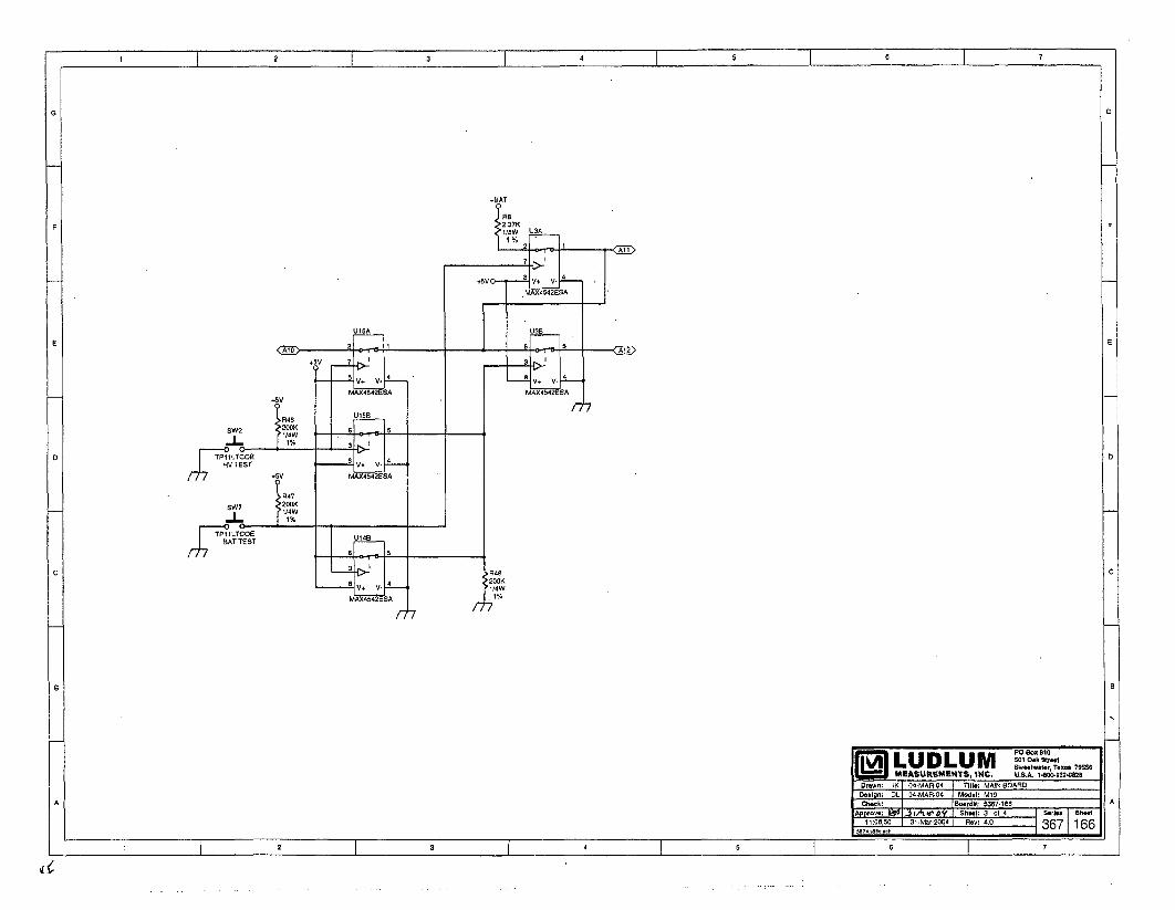

C27
500V
PRl SEC
3102
1-172F
03MMBT3904LT1

Drawn: JK 04-MAR-04 Title: MAIN BOARD
Design: DL 04-MAR-04
Check- bL O-(z,- o Model: M19
Approve: Board#: 5367-166
Laye. Rev- 4.0 Series Sheet
14:46:39 6-Apr-2004 SCALE: 1.75 367 1 67

Drawn: JK 04-MAR-04 Title: MAIN BOARD
Design: DL 04-MAR-04
Check. •L o•-f•R--c Model: M19
Approve: Board#: 5367-166
LWye Rev- 4.0 Series Sheet
14:46:40 6-Apr-2004 SCALE: 1.75 367 1 671.

II 2 3 4 5 6 7
0G
FF
PP
" -" Z7 - OURACELL'O"
MTAI00X4 Ml1 2M IMAIN BOARD + UAEL D
5367-16le6jDUAELO
987010-001 AImA
M19 LAMP BOARD5357.113
P2
MTA100w3 I B 1738MAIN BOARD I5367.166
DS2
P3
MTAIO0lMAIN BOARD UNIMORPH5367-166 TEC.3526.PU
~501 Oak Btr@tSLUDLUM Swoetwle., Teoae 70056MEASUREMENTS, INC. U.S.A. 1-40-42--MB
Der.wI:MEB 02-APR-04 "Ithi: WIRING DIAGRAMA D.Ilun: DL 0y2-APRC4 !MoI.h lg5717I•oerdI. 3B7-174 -A
P 18:2:34 " 73pr-2:004r RoWI r. tW.174 367 74
2 3 4 47

Energy Response for Ludlum Model 1910 Co-57
\C
1a 133
.... • •'." 137"
Co-60
I .,
0.1 -- - - - -- S - - - * - -I--
10 100 1000 10000Gamma Energy (keV)
LUDLUM MODEL 2221PORTABLE SCALER RATEMETER
Revised January 2002
Serial Number 161568 andSucceeding Serial Numbers
LUDLUM MEASUREMENTS, INC.501 OAK ST., P.O. BOX 810SWEETWATER, TX 79556915/235-5494 FAX: 915/235-4672

wlI
L
ZERO@WIN
OUT
MEASUR~EMENTS INC.LUDLUMSWEETWATER. TEXAS
MODEL 2221SCALER RATEMETER
z= CC- .r:X@@>F- r
m 0
0.1 0.20.5
ICOUNT
CONT 10MINUTES HOLD
SL; DIG.SCALE RATE
-DIGITAL CONTROL
0 0 0 0xxxxx

M2221 Portable Scaler RatemeterJanuary 2002
TABLE OF CONTENTS
1. GENERAL .............................................................................................. 1
2. SPECIFICATIONS ..................................................................................... 1
3. DESCRIPTION OF CONTROLS AND FUNCTIONS ......................................... 24. OPERATING PROCEDURES ....................................................................... 4
4.1 Initial Preparation .................................................................................... 44.2 Operating Point ....................................................................................... 44.3 Limitation of Controls ............................................................................... 4
5. DETERMINING INSTRUMENT PLATEAU AND SELECTING OPERATING POINT 5
6. WINDOW OPERATION AND ENERGY CALIBRATION PROCEDURES ................ 5
7. OVERLOAD DETECTION CALIBRATION .................................................... 6
8. CALIBRATION ....................................................................................... 68.1 Ratemeter Calibration ............................................................................ 68.2 TEST Pushbutton/Display Calibration ......................................................... 78.3 High Voltage Calibration ......................................................................... 78.4 Threshold/Gain Calibration ...................................................................... 7
9. OVERHAUL PROCEDURE ......................................................................... 89.1 Amplifier/Power Supply Board .................................................................. 89.2 Processor Board Checkout ........................................................................ 99.3 Functional/Chassis Checkout .................................................................. 11
PA R T S L IST .................................................................................................. 13
Amplifier/Power Supply Board, Drawing 261 X 56 ....................................... 13Processor Board, Drawing 261 X 91 ......................................................... 15Calibration Board, Drawing 261 X 59 ....................................................... 15LCD Display Board, Drawing 261 X 58 .................................................... 16Backplane Board, Drawing 261 X 60 ............................................................ 16Chassis Wiring Diagram, Drawing 261 X 61 .............................................. 16
DRAWINGS AND DIAGRAMS ....................................................................... 17
RS-232 PORT ADDITION ADDENDUM ........................................................... 18RS-232 Board, Drawing 261 X 179 .............................................................. 19
page i

M2221 Portable Scaler RatemeterJanuary 2002
1. GENERAL
The Ludlum Model 2221 Portable ScalerRatemeter is a self-contained countinginstrument designed for operation withscintillation, proportional or G-M detectors.Power is derived from four flashlight batteries.
The unit is complete with a voltage-sensitive preamplifier, linear amplifier,electronic timer, detector high-voltage powersupply and detector overload detectioncircuitry.
A single channel analyzer is also featuredin this unit for use in gamma spectrumanalysis. The analyzer may be switched on oroff, allowing gross or window counting.
The unit has a combination four-decadelinear and log ratemeter and a six-digit LCDreadout for the scaler and digital ratemeter.Potentiometers are supplied for threshold,window and high-voltage controls.
2. SPECIFICATIONS
0 HIGH VOLTAGE: 200 to 2400 voltswith digital readout
* BATTERY COMPLEMENT: foureach "D" cell flashlight batteries
* BATTERY LIFE: approximately 250hours with size D, alkaline batteries
* CALIBRATION STABILITY: lessthan 3 % variance to battery endpoint
* SENSITIVITY: voltage-sensitive andadjustable from 1.5 mV to 100 mV; typicallyfactory-calibrated to 10 mV = 100 on theTHR display
" INPUT IMPEDANCE: 22k
* READOUT: 6 digit liquid crystaldisplay, 0.5" (1.3cm) characters with backlightselection
0 METER: 2 1/2-inch scale, 1 mA,pivot and jewel suspension
a SCALES/RANGE: four decade logratemeter ranging from 50 to 500k CPM; fourdecade linear ratemeter - 0-500 CPM meterdial with range multipliers of X1K, X100,
X10, XI producing an overall range of 0-500k CPM
0 OPERATING TEMPERATURE: 5-122°F (-15 to 50'C)
0 LINEARITY: ±10% of the true valuefor the analog and digital ratemeter; ±2% ofthe true value for the digital Scaler, HV, THR,and WIN digital voltmeter readings; ±4% ofthe true value for the BAT voltmeter reading
* RESPONSE: 2 positions - Fastresponse = 4 ±1 second, Slow response = 22± 2 second; all response times are measuredfrom 10-90% of final reading
• CALIBRATIONrecessed screwdrivercalibration cover
CONTROLS:adjustments with
* AUDIO: built-in unimorph speakerwith click-per-event and switch selectabledivide by 1, 10, and 100.
" CONNECTOR: Series "C"
" SIZE: 4.25" (10.8 cm)W X 10"(25.4cm) L X 9" (22.9cm) H including handle
page 1

M2221 Portable Scaler RatemeterJanuary 2002
3. DESCRIPTION OF CONTROLS AND FUNCTIONS
0 POWER: Two-position switch to turnpower to instrument on or off
0 DETECTOR: series "C" connector fordetector
Input Impedance: 22k
Ballast Resistor: IM
* RATEMETER:
& F-S RESP Switch: Two-positionswitch for selecting ratemeter response: Fposition 4 ±1 second; S position 22 ±2seconds.
* ZERO: when pressed, resets theratemeter
0 RANGE SELECTOR: Five-position switch labeled LOG, XlK, X100,X10, X1 used to select the analogratemeter range. The LOG position selectsthe upper meter scale to provide a fourdecade logarithmic reading from 50-500kCPM. The X1, X16, X100, and X1Krange multipliers used with the lower 0-500 CPM meter scale providing andoverall measuring range from 0-500kCPM. Multiply the meter reading by therespective range position.
* DIGITAL CONTROL:
* COUNT Pushbutton: Whenpressed, resets and starts the counter.While the counter is counting, two colonson the display are turned on.
* HOLD Pushbutton: Whenpressed, stops the counter and leaves thecount in the display.
* SCALER/DIG RATE ToggleSwitch: Two-position toggle switch forselecting scaler or digital ratemeter
SCALER Position: The display showsthe counter contents.
DIG. RATE Position: The displayshows the ratemeter count rate.
./ Note: The scaler and digitalratemeter are active even when notselected. This allows the user to start atimed count, switch to the DigitalRatemeter and then switch back to Scalerwithout having to restart the counter.
* MINUTES Selector Switch: Eight-position switch used for selecting the counttimes for the Scaler:
POSITION
0.10.20.5
COUNT TIMEIN MINUTES
0.10.20.5
1 12 25 5
10 10CONT
COUNTER COUNTS UNTIL HOLDIS PRESSED
• CALIBRATION CONTROLS:
* WIN: 20-turn potentiometer usedto adjust window width when the windowtoggle switch, WIN, is in the "IN" position
* THR: 20-turn potentiometer usedto adjust the Threshold
page 2

M2221 Portable Scaler RatemeterJanuary 2002
* I-V: 20-turn potentiometer used toadjust detector voltage
* O.L.: 20-turn potentiometer usedto adjust detector overload current
* TEST:
* BAT Pushbutton Switch: Whenpressed, displays the battery voltage in thedigital display.
" HV Pushbutton Switch: Whenpressed, displays the detector high voltagein the digital display.
0 THR Pushbutton Switch: Whenpressed, displays the Threshold setting inthe digital display.
a WIN Pushbutton Switch: Whenpressed, displays the window setting in thedigital display.
* LAMP Toggle Switch: Two-position switch to turn on the display lights.
" WIN Toggle Switch: Two- positionswitch for switching the window IN or OUT
IN position: The SCA is set up as awindow counter.
OUT position: The SCA is set up as agross counter.
* AUDIO:
* VOL Control: One-turnpotentiometer used to adjust the volume of thespeaker or headset.
* AUDIO DIVIDE:
"1" Position: provides 1 click perevent
"10" Position: provides 1 click per 10events
"100" Position: provides 1 click per100 events
* 1/8" PHONE JACK: Used forheadset. When headset is plugged in, theunimorph on the can is disabled.
* LIQUID CRYSTAL DISPLAY:Six-1/2" high digits, displaying countercontents or digital count rate
* STATUS INDICATORS:
Counter Overflow: When in SCALERmode, the left digit alternates between thecorrect digit and an "H".
Detector Overload: The display flashesall dashes.
Battery: When the battery voltage is4.4 volts or less, all decimal points areturned on.
Scaler Counting: The two colons areturned on when MINUTES selector switchis in CONT position.
page 3

M2221 Portable Scaler RatemeterJanuary 2002
4. OPERATING PROCEDURES
4.1 Initial Preparation
o Unscrew battery door latch.
o Install for "D" size batteries in thebattery holder. The correct position of thebatteries is indicated on the bottom of thebattery door.
o Switch the POWER ON/OFFswitch to the ON position. A randomnumber will first be observed in thedisplay, then 8.8:8.8:8.8. The thirddisplayed number will be the programversion. (At the time of this printing,program version is #261010.)
o Press COUNT pushbutton. Thedisplay should zero. Two colons shouldappear on the display.
o Press HOLD pushbutton. Thecolons should disappear.
o Switch LAMP toggle switch to theON position. LCD display backlightingand two lamps at the bottom of the analogmeter should be illuminated.
./ NOTE: If the Lamp switch is left in theON position for extended periods of time,battery life will decrease rapidly.
o Check TEST pushbutton functionsfor proper operation.
4.2 Operating Point
Instrument and detector operating point isestablished by setting the probe voltage (HV)and instrument sensitivity (THR). For a givendetector system, efficiency, background andnoise are fixed by the physical makeup of thedetector and rarely vary from unit to unit.
However, the selection of the operating pointmakes a marked difference in the apparentcontribution of these three sources of count.
In the singular case of the G-M detector, aminimum operating voltage is required toestablish the G-M operating region. (At lowervoltages, the detector operates as a veryinsensitive proportional counter.) Thisdetector is not capable of energydiscrimination (pulse-height discrimination).The Threshold (THR) is typically adjusted to550, with a THR reading of 100 = 10 mVinput pulse, for G-M detectors.
For gain sensitive detectors (proportionalor scintillation), the most straightforwardmethod of selecting the operating point is todevelop a graph, relating count rate to systemgain. This relationship is commonly referredto as a plateau or instrument plateau curve.System gain may be changed by adjustingdetector high voltage or THR control. Thethreshold is typically adjusted for 100 = 10mV for scintillation detectors and 50 (5mVequivalent) on the THR readout forproportional detectors.
4.3 Limitation of Controls
HV Control provides a linear adjustment ofthe detector voltage supply. The range isapproximately 0 to 2400 volts. Changing thedetector voltage will cause the detector gain tochange. It should be remembered that a linearchange in voltage will cause an exponentialchange in detector gain. THR Control sets thebasic pulse discrimination point of the scaler.
WIN Control is calibrated with the THRcontrol so that the reading of the WIN controlis equivalent to the reading of the THRcontrol. As an example, 100 on the THR isequal to 100 on the WIN.
page 4

M2221 Portable Scaler RatemeterJanuary 2002
5. DETERMINING INSTRUMENT PLATEAU AND SELECTING OPERATING POINT
El Set WIN ON/OFF to OFF.
o Set MINUTES switch to 0.1 minutes.
o: Set THR control at 100.
E] With detector shielded from source,turn up high voltage control and take a plot ofHV versus background count rate until thedetector maximum voltage rating is reached.(Maximum voltage on most scintillationdetectors is 1500-1600 Vdc; maximum voltageon proportional detectors is reached at thecontinuous discharge point. Return HVcontrol to minimum.
6. WINDOW OPERATION AND ENERGY
o Expose the detector to a source andagain make a plot of voltage versus count.
El Plot both sets of data and select theoperating point to correspond with maximumsource count and minimum background count.Avoid areas of very fast count rate changeswith small changes in detector voltage. Theoptimum operating point for low backgrounddetectors is just above the inflection point (orbreak-over point) of the plateau curve. Ifbackground count is irrelevant, shift operatingpoint to the plateau center for greater stability.
CALIBRATION PROCEDURES
E The following procedure calibratesthreshold directly in keV.
0l Place RATEMETER multiplier switchto LOG position.
El Unscrew and remove CAL cover.
0 Press HV pushbutton. The HV shouldread out on the display directly in volts.While depressing the HV pushbutton, turn HVpotentiometer maximum counterclockwise.The HV should be less than 50 volts.
0l Depress the THR pushbutton. Turn theTHR potentiometer clockwise until 652displays.
El With WIN IN/OUT switch IN, depressthe WIN pushbutton. Turn the WINpotentiometer until 20 appears on the display.
El Switch WIN IN/OUT to OUT.
El Connect the probe and expose to Cs137source.
El Increase HV (if HV potentiometer is atminimum, it will take approximately 3 turnsbefore any change is indicated). Whileincreasing the HV, observe the log scale of theratemeter. Increase HV until ratemeterindication occurs.
El Switch WIN IN/OUT switch to IN.
"l Turn the HV control until maximumreading occurs on the log scale. Increase HVuntil reading starts to drop off, then decreasethe HV for maximum reading.
El Turn RATEMETER selector switch tothe X1K position.
El Press ZERO pushbutton and release. Ifmeter does not read, switch to a lower rangeuntil a reading occurs.
page 5

M2221 Portable Scaler RatemeterJanuary 2002
CO Carefully adjust HV potentiometer untilmaximum reading is achieved on the rangescale. The instrument is now peaked forCs137 on both the LOG and Linear scales.
%/ NOTE: When the THR control isadjusted, the effective window width remainsconstant. As an example, if the THR is set at612, the WIN at 100, a 662 keV peak 612 +
(100 divided by 2) will be centered in thewindow. Then the threshold point isequivalent to 612 keV with a 100 keV windowand calibrated for 100 keV per turn. Now ifthe threshold is reduced to 250, the thresholdis equivalent to 250 keV, but the window (100)is still equal to 100 keV. Proportionally, thisrepresents a broader window.
7. OVERLOAD DETECTION CALIBRATION
N Detector Count Saturation is detectedin this instrument and is indicated by the LCDdisplay flashing all dashes and the analogratemeter deflecting full scale. The countsaturation or "overload" point is calibrated bythe O.L. front panel control.
El Adjust the O.L. control to fullyclockwise position.
E: Connect detector and set HV forcorrect detector operating voltage.
E: Expose detector to radiation field andwhile observing ratemeter, increase fieldintensity until a decrease in count rate isnoticed. For alpha scintillators, the detectorphotomultiplier tube (PMT) should be exposedto a small light leak through the probe face toestablish the detector saturation point.
0 With thesaturation field,counterclockwisepoint is reacheddisplay).
detector in the countadjust the O.L. controluntil the overload alarm(flashing dashes in LCD
El Position detector in a lower fieldintensity just below the saturation point andconfirm overload is defeated.
Example: Ludlum Model 44-9 GMpancake detector saturates at approximately500 mR/hr (5mS/h).
El Full scale instrument analog meterreading=200 mR/hr (2 mS/h). Set the Model2221 to overload at 500 mR/hr (5 mS/h) field,then position detector in a 300 mR/hr (3 mS/h)field and confirm that overload alarm isdefeated. The O.L. control will have to be"fine adjusted" to perform the aboveprocedure.
8. CALIBRATION
* Refer to schematic and componentlayout for the following calibration.
8.1 Ratemeter Calibration
#5261-073. Confirm crystal frequency is 6MHz ±_0.1% (6,006 khz-5,994 kHz).
El Set THR control to 100 and WindowIN/OUT switch to the OUT position.
El Connect Frequency counter to pin 18 ofU22 (80C51FA) on Processor board,
page 6

M2221 Portable Scaler RatemeterJanuary 2002
El Connect Ludlum Model 500 Pulser orequivalent and adjust count rate for 40,000CPM.
11 Switch Ratemeter Multiplier switch tothe X100 position and the Response switch to"F."
El Adjust pulse amplitude above thresholduntil a steady count rate is observed onratemeter.
El Adjust R40 Meter Cal (labeled MCAL)on Processor board, for 40,000 CPM onmeter.
[] Switch SCALER/DIG RATE switch tothe SCALER position.
0l Confirm counter time operation bytaking 0.1 minute count. Colons should beobserved during count cycle.
0l While pressing the HV Testpushbutton, adjust the HV front panel controluntil the display reads 1500.
El Adjust R175 HV Cal on Amp/P.S.board for 1500 ±5 volts on external HV meter.
El Confirm HV will adjust from 50 to2400-2500 volts. Insure HV displayed readingtracks within 2 % of HV output.
8.4 Threshold/Gain Calibration
0 Set pulser pulse amplitude to lOmV.
El With THR set at 100, on display, fineadjust R174 Gain control (on P.S. board) untilratemeter reads 30,000 CPM with 40,000CPM from pulser.
El Adjust THR control for readings of200, 300, 400, and 500 to insure the pulserinput is 20, 30, 40 and 50mV respectively.Use the 3/4 CPM input setting to discriminateturn on points as in procedure above.
El Adjust THR control back to 100.
El Switch Window IN/OUT switch to theIN position. Adjust WIN control for 100,200, 300, 400 and 500 to confirm 20, 30, 40and 50mV window cut off points.
El Set WIN back to 100 and OUTposition.
El Check the rest of the front panelfunctions for proper operation.
8.2 TESTCalibration
Pushbutton/Display
El Adjust THR control to fully clockwiseposition.
El Connect positive voltmeter lead to pin7 of U3 (TLC27M7IP) on the Amp./P.S.board. Connect negative lead to ground nearU3.
El Press the THR test pushbutton andadjust R171 Volt Cal (labeled "V"), so that thefront panel display reading corresponds to thevoltmeter reading at pin 7 of U3.
8.3 High Voltage Calibration
El Connect HV meter (2500 Megohminput impedance or greater) to the junction ofR32 (4.7 Meg) and R33 (1 Meg) on Amp/P.S.board.
page 7
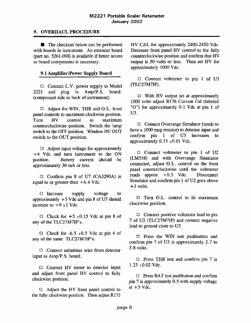
M2221 Portable Scaler RatemeterJanuary 2002
9. OVERHAUL PROCEDURE
N The checkout below can be performedwith boards in instrument. An extender board(part no. 5261-098) is available if better accessto board components is necessary.
9.1 Amplifier/Power Supply Board
El Connect L.V. power supply to Model2221 and plug in Amp/P.S. board.(component side to back of instrument).
El Adjust the WIN, THR and O.L. frontpanel controls to maximum clockwise position.Turn HV control to maximumcounterclockwise position. Switch the lampswitch to the OFF position. Window IN/ OUTswitch to the OUT position.
o Adjust input voltage for approximately+4 Vdc and turn instrument to the ONposition. Battery current should beapproximately 30 mA or less.
El Confirm pin 8 of U7 (CA3290A) isequal to or greater than +6.4 Vdc.
El Increase supply voltage toapproximately +5 Vdc and pin 8 of U7 shouldincrease to +9 ±1 Vdc.
El Check for +5 ±0.15 Vdc at pin 8 ofany of the TLC27M7IP's.
o1 Check for -6.5 ±0.5 Vdc at pin 4 ofany of the same TLC27M7IP's.
El Connect subminax wire from detectorinput to Amp/P.S. board.
11 Connect HV meter to detector inputand adjust front panel HV control to fullyclockwise position.
El Adjust the HV front panel control tothe fully clockwise position. Then adjust R175
HV CAL for approximately 2400-2450 Vdc.Decrease front panel HV control to the fullycounterclockwise position and confirm that HVoutput is 50 volts or less. Then set HV forapproximately 1000 Vdc.
El Connect voltmeter to pin 1 of U3(TLC27M7IP).
El With HV output set at approximately1000 volts adjust R176 Current Cal (labeled"0") for approximately 0.1 Vdc at pin 1 ofU3.
0l Connect Overrange Simulator (needs tohave a 1000 meg resistor) to detector input andconfirm pin 1 of U3 increases toapproximately 0.15 ±_0.01 Vdc.
E: Connect voltmeter to pin 1 of U2(LM358) and with Overrange Simulatorconnected, adjust O.L. control on the frontpanel counterclockwise until the voltmeterreads approx +0.5 Vdc. DisconnectSimulator and confirm pin 1 of U2 goes above+3 volts.
El Turn O.L. control to its maximumclockwise position.
El Connect positive voltmeter lead to pin7 of U3 (TLC27M7IP) and connect negativelead to ground close to U3.
El Press the WIN test pushbutton andconfirm pin 7 of U3 is approximately 2.7 to3.8 volts.
El Press THR test and confirm pin 7 is1.23 ±0.02 Vdc.
El Press BAT test pushbutton and confirmpin 7 is approximately 0.5 with supply voltageat +5 Vdc.
page 8

M2221 Portable Scaler RatemeterJanuary 2002
El With the HV still set at 1000 Vdc, pin7 of U3 should be approximately 1 ± 0.1 Vdcwhile pressing the HV test pushbutton.
O: Connect oscilloscope to pin 3 of U5(LM331) and adjust R171 Volt Cal (labeled"V") for approximately 2 khz (0.5 millisecondperiod) with the HV pushbutton pressed.
El Connect voltmeter to pin 7 of U3 andwhile pressing the THR test pushbutton, adjustTHR control for approximately +0.1 Vdc.
11 Switch the Window IN/OUT switch tothe IN position. While pressing the WIN testpushbutton, adjust the WIN control forapproximately +0.1 Vdc at pin 7 of U3 also.Then switch the Window to the OUT position.
0l Connect oscilloscope to pin 2 of U8(CA3096).
El Connect pulser and set pulse amplitudefor approximately 10 millivolts. Set CPM to40,000.
11 Adjust R174 Gain (labeled "G") tomaximum clockwise position and confirmpositive pulses at pin 2 of U8 are ap-proximately 1 ± 0.1 volt in amplitude.
11 Connect oscilloscope to pin 10 of U105(CD4098).
El Adjust R174 Gain until pulses just startto appear at pin 10 of U105. Then adjustpulser amplitude until pulses are clearlyvisible.
El Adjust R173 T Pulse (labeled "T") fora 2.5 microsecond positive pulse width at pin10 of U105.
El Connect oscilloscope to pin 7 of U105and adjust R172 Width (labeled "W") for a 3microsecond negative pulse width.
o Switch the Window IN/OUT switch tothe IN position and verify that the pulses arepresent at pin 7 of U105 from 10 to 20 mVinput pulse amplitude and off aboveapproximately above 20 mV.
El Switch Window IN/OUT switch to theOUT position and verify the pulses appearabove the window limit as in the above step.
o Battery current should be less than 30mA with +5 Vdc supply input.
9.2 Processor Board Checkout
N The procedure below is to be usedwithout the Amp/P.S. board. If the Amp/P.S.board is used, delete the steps containing thesignal generator use. Use the pulser for thestandard count rate inputs. Window,Threshold, HV and Bat test will display thecontrol setting.
0J Plug in Amp/P.S. Simulator board andconnect Signal Generator to jumper wires(black = probe ground).
51 Plug in Processor board, componentside toward back of instrument. Connectdisplay ribbon cable.
11 c. Set Signal Generator to squarewave function.
Range= 10k and all other switches to the OUTposition.
El Adjust the Freq. Symmetry, Amplitudeand D.C. Offset controls to achieve a 5 voltnegative pulse with a pulse width ofapproximately 50 microseconds and a periodof approximately 1.2 milliseconds.
El With supply voltage set at +5 ±0.15Vdc, turn instrument ON and observedisplay= 8.8:8.8:8.8 for approximately 2
page 9

M2221 Portable Scaler RatemeterJanuary 2002
seconds, then 261010 indicating the programnumber.
o] Connect Frequency Counter to pin 18of U22 (80C51FA) and confirm crystalfrequency is 6 Mhz ±_0.1% (6,006 khz-5,994khz).
3 Switch the Scaler/Dig. Rate Switch tothe Dig Rate position.
13 Counts should start accumulating every2 seconds until approximately 50,000 CPM isobserved. (The symmetry control can be fineadjusted until 50,000 CPM is achieved). Atthis displayed count rate, the low BAT Testindication should be observed, indicated by 5decimal points across the bottom of thedisplay.
El Press BAT Test and display should be4.1 ±0.2.
El Press HV and WINDOW= 410 ±_20.Threshold pushbutton has no effect withoutAmp/P.S. plugged in.
El Switch Ratemeter Response time to F.
El Switch Ratemeter multiply to X100.
El Adjust R40 Meter Cal, (labeledMCAL), until Ratemeter matches displayedaccumulated count (approximately 50,000CPM).
El Decade the Multiplier range on theSignal Generator to correspond to each decadeon Rate Multiplier to confirm range switchoperation.
El Connect Voltmeter to recorder outputand confirm R41 RCDR CAL, (labeledRCAL), will adjust from 0 to approximately3.7 Vdc, with full scale CPM on display andratemeter. Then set for 1 Vdc to equal fullscale meter deflection.
0l Connect Oscilloscope to pin 9 of U10(ICM7556) and decade Sweep Generator downto the lk range.
El Switch the Audio Divide switchbetween the 1, 10, and 100 positions toconfirm Audio frequency divides or multipliesby 10, between each position.
El Connect Headset or unimorph andconfirm volume control operation.
El With full scale meter deflection (500),check F/S response time (90% full scale) for4.5 ±0.5 seconds and 22 +2 secondsrespectively.
El Check Count,pushbutton functions.
Hold, and Zero
E: Switch Scaler/Dig. Rate switch to theScaler position and check the 0.1, 0.2 and 2minute time multipliers for correct timeoperation.
El With +5 volts supply input, batterycurrent should be less than approximately 15mA, with full scale meter deflection.
9.3 Functional/Chassis Checkout
El This procedure requires a checked-outAmp/P.S. board and Processor board.
El Connect one lead of an ohmmeter tochassis ground.
page 10

M2221 Portable Scaler RatemeterJanuary 2002
11 Connect other lead of ohmmeter to theProcessor board cinch connector pins below tocheck count time switch operation. Boards arenot plugged in yet.1 = open0= shorted
COUNT TIME PROCESSOR BOARDPOSITION CINCH CONNECTOR
PIN 8 30 31
0.1 0 0 00.2 0 0 10.5 1 0 0
1 1 0 12 0 1 05 0 1 1
10 1 1 0CONT 1 1 1
Connect external power supply and setinput voltage for approximately +5 Vdc.
El Turn Lamp switch to the OFF position.THR and O.L. controls to maximum clockwiseposition and HV to maximumcounterclockwise position.
El Plug in Processor and Amp/P.S. boardsand related cable connections.
El Turn instrument ON. Current drawshould be less than 45 mA.
El Confirm display reads 8.8:8.8:8.8 forapproximately 2 seconds, then 261010indicating the program version.
El Connect positive voltmeter lead to pin7 of U3 (TLC27M7IP) on the Amp./P.S.board. Connect negative lead to ground nearU3.
El With the THR control full clockwise,press the THR test pushbutton and adjust R171Volt Cal (labeled "V"), so that the front paneldisplay reading corresponds to the voltmeterreading at pin 7 of U3.
El Connect HV meter (2500 Megohminput impedance or greater) to the junction ofR32 (4.7 Meg) and R33 (1 Meg) on P.S.board.
ol While pressing the HV Testpushbutton, adjust HV control until the displayreads 1500. R176 Current Cal may have to beadjusted counterclockwise to defeat theOverrange function.
El Adjust R175 HV Cal on Amp/P.S.board for 1500 ±5 on external HV meter.
El Confirm HV will adjust from 50 to2400-2500 volts. Insure HV displayed readingtracks within 2 % of HV output.
o1 Adjust HV for approximately 1000volts.
11 Adjust R176 Current Cal (labeled "0")for approximately 0.1 volt at pin 1 of U3(TLC27M7IP) on Amp/P.S. board.
El Connect Overrange Simulator (1000megohm) to the detector input.
El Adjust the O.L. controlcounterclockwise until hyphens start flashingacross display every other count interval.Disconnect Overrange Simulator and confirmoverrange function is defeated. Then adjust tofully clockwise position.
El Set THR control to 100 and WindowIN/OUT switch to the OUT position.
El Connect pulser and adjust count ratefor 40,000 CPM.
El Switch Ratemeter Multiplier switch tothe X100 position and the Response switch to"F."
o Adjust pulse amplitude above thresholduntil a steady count rate is observed onratemeter.
page 11

M2221 Portable Scaler RatemeterJanuary 2002
El Adjust R40 Meter Cal (labeled MCAL)on Processor board, for 400 CPM on meter.
El Adjust pulser for 10,000 CPM andcheck meter for ± 10% linearity of reading.Adjust pulser and rate Multiplier switch toconfirm linear readings on all ranges.
El Switch SCALER/DIG. RATE switchto the SCALER position.
El Confirm count time switch operationby taking a 0.1 minute and 0.5 minute count.Colons should be observed during count cycle.
El Check HOLD and ZERO pushbuttonfunctions.
El Switch SCALER/DIG. RATE switchto the DIG. RATE position and confirm updatecount display operation approximately every 2seconds.
El Connect unimorph and headset to theaudio outputs and confirm audio divide andvolume control functions. NOTE: Unimorphshould shut off when headset is connected.
El With the THR control adjusted for 100,adjust R174 Gain (labeled G) for 1.5 millivoltinput sensitivity. Insure instrument functionsat low input sensitivity without "noise".
El Instrument may have to be placed incan to permit "noise free" operation.
El Set pulser pulse amplitude to lOmV.
11 With THR still set at 100, fine adjustR174 Gain control until ratemeter reads30,000 CPM with 40,000 CPM from pulser.
01 Adjust THR control for readings of200, 300, 400, and 500 to insure the pulserinput is 20, 30, 40 and 50mV respectively.Use the 3/4 CPM input setting to discriminateturn on points as in procedure above.
El Adjust THR control back to 100.
El Switch Window IN/OUT switch to theIN position. Adjust WIN control for 100,200, 300, 400 and 500 to confirm 20, 30, 40and 50mV window cut off points.
El Set WIN back to 100 and OUT positionfor instrument shipment.
0. Input a full-scale ratemeter count rate(500 CPM) and connect voltmeter to therecorder output. Adjust R41 (labeled RCAL)on Processor board for 1 volt.
0l Check F/S ratemeter response time for4.5 ±0.5 and 22 ±2 seconds at 90% of fullscale.
0l Decrease input supply voltage untilperiods are observed at bottom of display.Press BAT Test pushbutton and confirm lowBAT Test is 4.4 ± 0.1 Vdc. Adjust supplyvoltage back to 5 volts and confirm BAT testand actual supply input is 5 ±0.05 Vdc.
13 Switch SCALER/DIG. RATE switch tothe SCALER position. Count Time Multiplierto CONT. Press count pushbutton and startwith low enough count rate to observe eachdigit number count sequence from Leastsignificant digit to MSD. Decade pulser countrate to speed up digit segment display check.
El Increase count rate enough to overflowcounter. An "H" should be observed in theMSD flashing every count interval.
El Turn Lamp switch to the ON positionand confirm 2 lamps in the display and 2 lampsbelow the meter are illuminated.
El Current draw with lamps on should be210 ±20 mA.
El Turn lamp OFF and current should beapproximately 40 ±5 mA.
page 12
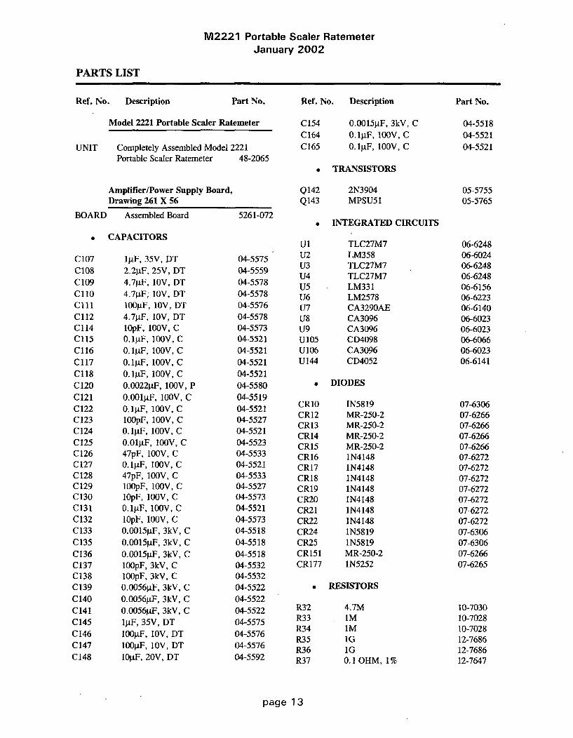
M2221 Portable Scaler RatemeterJanuary 2002
PARTS LIST
Ref. No. Description Part No. Ref. No. Description
Model 2221 Portable Scaler Ratemeter
UNIT Completely Assembled Model 2221Portable Scaler Ratemeter 48-2065
Amplifier/Power Supply Board,Drawing 261 X 56
C154C164C165
0.0015gF, 3kV, C0. lgF, 1O0V, C0. lIF, 100V, C
Part No.
04-551804-552104-5521
. TRANSISTORS
Q142Q143
2N3904MPSU51
05-575505-5765
BOARD Assembled Board 5261-072INTEGRATED CIRCUITS
0 CAPACITORS
C107C108C 109CIIoClllCl12C114Cl15Cl16Cl17Cl18C120
C121C122C123C124C125C126C127C128C129C 130C131C132C133
C135
C136C137C138C139
C140C 141C145C146C147C148
IAF, 35V, DT2.2tF, 25V, DT4.7piF, 10V, DT4.7pF, 10V, DT100liF, 10V, DT4.7TF, 10V, DT10pF, 100V, C0.1F, 100V, C0.1F, 10OV, C
0.1jF, 100V, C0.1IF, 100V, C0.0022gF, 100V, P0.001&F, 100V, C
0.1gF, 100V, C100pF, 100V, C0.lAF, 100V, C0.01gF, 100V, C47pF, 100V, C0.1jF, 100V, C47pF, 100V, C100pF, 100V, C1OpF, 100V, C0.1AF, 100V, ClOpF, 10OV, C0.0015F, 3kV, C0.0015tF, 3kV, C
0.0015AF, 3kV, C100pF, 3kV, C100pF, 3kV, C0.00564F, 3kV, C0.0056AF, 3kV, C0.0056pF, 3kV, Clj.tF, 35V, DT1OOA.F, 10V, DT100pF, 10V, DTlO.F, 20V, DT
04-557504-555904-557804-557804-557604-557804-557304-552104-5521
04-552104-552104-5580
04-551904-552104-552704-552104-552304-553304-552104-553304-552704-557304-552104-557304-5518
04-5518
04-551804-553204-553204-552204-552204-552204-5575
04-557604-557604-5592
U1U2U3U4U5U6U7U8U9U105U106U144
TLC27M7LM358TLC27M7TLC27M7LM331LM2578CA3290AECA3096CA3096CD4098CA3096CD4052
06-624806-602406-624806-624806-615606-622306-614006-602306-602306-606606-602306-6141
. DIODES
CR10CR12CR13CR14CR15CR16CR17CR18CR19CR20CR21CR22CR24CR25CR151CR177
IN5819MR-250-2MR-250-2MR-250-2MR-250-21N41481N41481N41481N4148IN41481N41481N41481N58191N5819MR-250-21N5252
07-630607-626607-626607-626607-626607-627207-627207-627207-627207-627207-627207-627207-630607-630607-626607-6265
. RESISTORS
R32R33R34R35R36R37
4.7MIMIM1GIG0.1 OHM, 1%
10-703010-702810-702812-768612-768612-7647
page 13

M2221 Portable Scaler RatemeterJanuary 2002
Ref. No. Description Part No. Ref. No. Description Part No.
R38 10k 12-7748 R96 iM, 1% 12-7763R39 iM, 1% 12-7763 R97 10M 12-7749R40 10k 12-7748 R98 iM 12-7751R41 10k 12-7748 R99 470k 12-7757R42 10k 12-7748 R100 470k 12-7757R43 10k 12-7748 R101 100k 12-7747R44 47k 12-7758 R102 IM, 1% 12-7763R45 4.7k 12-7755 R171 10k TRIMMER 09-6822R46 10k 12-7748 R172 100k TRIMMER 09-6823R47 10k 12-7748 R173 100k TRIMMER 09-6823R48 10k 12-7748 R174 10k TRIMMER 09-6822R49 1k 12-7750 R175 IM TRIMMER 09-6828R50 220 OHM 12-7753 R176 IM TRIMMER 09-6828R51 220 OHM 12-7753R52 470k 12-7757 * TRANSFORMERSR53 47k 12-7758R54 1k 12-7750 T103 M2300 HVPS 4275-037R55 10k 12-7748 T104 M2221 LVPS 4275-094R56 4.7k 12-7755R57 10k 12-7748 * MISCELLANEOUSR58 10k 12-7748R59 10k 12-7748 9 EA. CLOVERLEAF RECEPTACLESR60 1k 12-7750 011-6809-00 18-8771R61 178k, 1% 12-7769 3 EA. SPACERS 18-8933R62 4.7k 12-7755 TRANSISTOR SPACER 18-8992R63 100k 12-7747 * AMPLIFIER SHIELD 7261-100R64. 10k 12-7748R65 10k, 1% 12-7764 Processor Board, Drawing 261 X 91R66 220 OHM 12-7753R68 10k 12-7748 BOARD Assembled Board 5261-136R69 1.5k 12-7773
R70 100k, 1% 12-7765 0 CAPACITORSR71 200k 12-7752R72 200k 12-7752 C1 47pF, 100V, C 04-5533R73 100k 12-7747
C2 0.047gtF, 100V, C 04-5565R74 100k 12-7747 C3 0.O0lgF, 100V, C 04-5519R78 22k 12-7754 C4 001F, 100V, C 04-5614R79 10k 12-7748 C4 27pF, 100V, C 04-5614R80 10k 12-7748 Cs 27pF, 100V, C 04-5614R81 100k 12-7557 C6 22tF, 15V, DT 04-5579
R82 200k 12-7752 C7 10j.F, 20V, DT 04-5592
R83 22k 12-7754 C8 100gtF, 10V, DT 04-5576
R84 10k 12-7748 C9 100oF, 10V, DT 04-5576R85 iM 12-7763R86 4.42k 12-7760 0 TRANSISTORR87 47 OHM 12-7756R88 100k, 1% 12-7765 Q36 2N3904 05-5755R89 17.8k 12-7759R90 10k, 1% 12-7764 a INTEGRATED CIRCUITSR91 1M, 1% 12-7763R92 IM, 1% 12-7763 U10 ICM7556 06-6244R93 40.2k, 1% 12-7761 Ull CD74HCO8 06-6222R94 100 OHM 12-7746 U13 CD4054 06-6245R95 10k 12-7748 U14 CD4056 06-6095
U15 CD4056 06-6095U16 CD4056 06-6095
page 14

M2221 Portable Scaler RatemeterJanuary 2002
Ref. No. Description
U17U18U19U20U21U22U25U26U43
CD4056CD4056CD4056CD74HC57387C25780C51FARDD104LM358CD74HC238
Part No.
06-609506-609506-609506-609306-627806-623606-606006-602406-6246
07-6272
Ref. No. Description Part No.
Calibration Board, Drawing 261 X 59
BOARD Assembled Board
0 VOLTAGE REFERENCES
5261-075
UlU2U3
LM385Z-1.2LM385Z-1.2LM385Z-1.2
05-580805-580805-5808
* DIODE 0 RESISTORS
CR45 1N4148
• RESISTORS
R4RIORi1R12R13R14
22k22k100k TRIMMER100k TRIMMER100k TRIMMER100k TRIMMER
12-775412-775409-681309-681309-681309-6813
R27R28R29R30R31R32R33R40R41
3.3k220k130k470k220k1.2k5.6kIM TRIMMERIM TRIMMER
10-701310-706610-706710-702610-706610-705810-704209-682809-6828
a CONNECTOR
P6/1-7 640457-7 MTA100 13
LCD Display Board, Drawing 261 X 58
-8183
* RESISTOR NETWORKS
R34-R35 NETWORK-22k SIP 10 PIN 12-7566
* TRANSFORMER
BOARD Assembled Board
* INTEGRATED CIRCUIT
U7 3918
5261-074
07-6252
T37 M300-9 4275-074
0 CRYSTAL
* RESISTORS
R4 22 OHMR14 22 OHM
" CONNECTORS
10-707210-7072
Y39 6.000 MHZ 01-5209
a CONNECTORP4
P5
RIBBON-RD6750BRN EDGE 50P640456-2 MTA100
P3/1-50 RIBBON-l-102159-0
* MISCELLANEOUS
* 28P SOCKET7 EA. SPACER-816-045 16P* SPACER-470-015
2 EA. RIBBON-102312-2 LATCH
13-783413-781613-8073
* MISCELLANEOUS
DS1O-DS13 BULB-#6833 22-961306-609618-899018-899113-7805
page 15
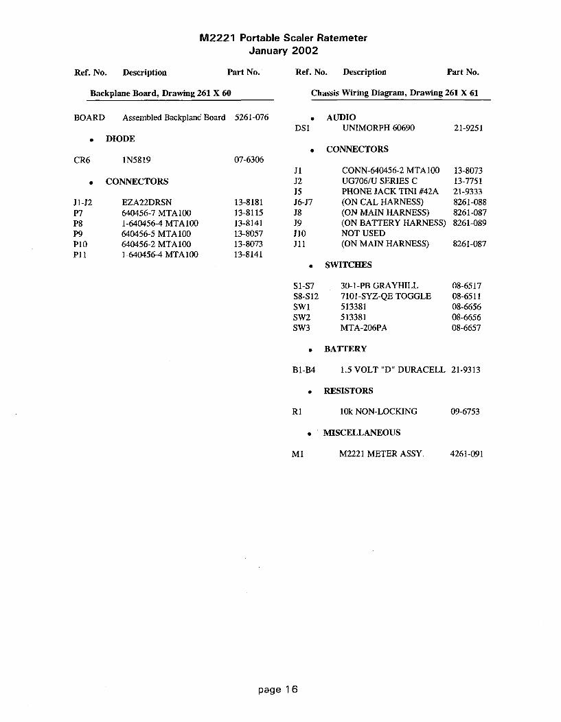
M2221 Portable Scaler RatemeterJanuary 2002
Ref. No. Description Part No. Ref. No. Description Part No.
Chassis Wiring Diagram, Drawing 261 X 61Backplane Board, Drawing 261 X 60
BOARD Assembled Backplane Board 5261-076 0 AUDIODS1 UNIMORPH 60690 21-9251
0 DIODECONNECTORS
CR6 1N5819 07-6306
0 CONNECTORS
J1-J2P7P8P9P1OPl1
EZA22DRSN640456-7 MTA 1001-640456-4 MTA100640456-5 MTA100640456-2 MTA1001-640456-4 MTA100
13-818113-811513-814113-805713-807313-8141
JiJ2J5J6-J7J8J9J10ill
CONN-640456-2 MTA100UG706/U SERIES CPHONE JACK TINI #42A(ON CAL HARNESS)(ON MAIN HARNESS)(ON BATTERY HARNESS)NOT USED(ON MAIN HARNESS)
13-807313-775121-93338261-0888261-0878261-089
8261-087
SWITCHES
S1-S7S8-S12SWiSW2SW3
30-1-PB GRAYHILL7101-SYZ-QE TOGGLE513381513381MTA-206PA
08-651708-651108-665608-665608-6657
a BATTERY
B1-B4 1.5 VOLT "D" DURACELL 21-9313
* RESISTORS
RI 10k NON-LOCKING 09-6753
* MISCELLANEOUS
M1 M2221 METER ASSY. 4261-091
page 16

M2221 Portable Scaler RatemeterJanuary 2002
DRAWINGS AND DIAGRAMS
Amplifier/Power Supply Board Schematic, Drawing 261 x 56Amplifier/Power Supply Board Component Layout, Drawing BS261072
Processor Board Schematic, Drawing 261 x 91Processor Board Component Layout, Drawing 261 x 103
Calibration Board Schematic, Drawing 261 x 59Calibration Board Component Layout, Drawing BS261075
LED Display Board Schematic, Drawing 261 x 58LED Display Board Component Layout, Drawing BS261074
Backplane Board Schematic, Drawing 261 x 60Backplane Board Component Layout, Drawing BS261076
RS-232 Board Schematic, Drawing 261 x 179RS-232 Board Component Layout, Drawing 261 x 180
Wiring Diagram, Drawing 261 x 61
page 17

M2221 Portable Scaler RatemeterJanuary 2002
Model 2221 RS-232 Port Addition (LMI Part Number 4261-148)
The Model 2221 RS-232 port addition allows the M2221 data to be read as output to a computeror serial printer, by dumping either the ratemeter or scaler reading, as desired. The desiredreading is selected with a toggle switch located in the digital control section of the front panel,labeled with two positions: "SCALER" and "DIG. RATE." The port addition kit (LMI PartNumber 4261-148) includes the internal board, a cable that will connect directly to a 9-pin PC portand software routines to log the readings.
The scaler reading dumps when the scaler has completed a count. The ratemeter is dumped every2 seconds in one of three formats, depending on the firmware installed. The three availableformats are (1) counts per 2 seconds, (2) counts per 60 seconds (cpm), or (3) counts per second(cps). Data output is always in a 6-digit format with a letter prefix, corresponding to thefollowing:
Ratemeter: "R"
Scaler: According to the table below
Letter Prefix Time of Count (min) Time of Count (sec)Format 1 or 2 Format 3 (cps version)
A 0.1 1B 0.2 2C 0.5 5D 1.0 10E 2.0 30F 5.0 60G 10.0 120
A carriage return and then a linefeed character follow the 6' digit.
The communication protocol is 9600 baud, no parity, 1 stop bit, and 8 data bits. The RS-232 portis an output only with no handshaking available. The M2221 will dump the data, no matter what,even if the attached computer or printer is not ready. The cable provided is a coaxial cable,providing TXD and GND to a 9-pin D-connector, ready to plug into a standard PC serial port.
The Model 2221 Processor Board (Part Number 5261-136) utilizes an 87C257 EPROM with oneof the following firmware numbers, depending on the desired rate:
Rate Dump as counts per 2 seconds -- #261-06-N03.Rate Dump as counts per 60 seconds -- #261-07-N02.Rate Dump as counts per second with meterface 202-930 -- #261-02-N02
page 1 8

M2221 Portable Scaler RatemeterJanuary 2002
Ref. No. Description Part No.
RS-232 Board, Drawing 261 X 179
BOARD Assembled RS-232 Board 5261-179
* CAPACITORS
C1 4.7p.F, 20V, SMT 04-5653C2 10.tF, 20V, SMT 04-5655C3 4.7gF, 20V, SMT 04-5653C4 10tF, 20V, SMT 04-5655C5-C6 68J.F, 10V, SMT 04-5654
* INTEGRATED CIRCUITS
U001 IC-MAX220CSE, SMT 06-6329
page 19

FmQT
I/NN
x t 199 - I tc -I
I/N 2433 I /UsN
CI"I IV
99/34 1 ,. I
J~~4 il!v 111
IIt3,FTý h ~ L 331 4 1433
-5ý -p n,
Sns- In 9134
.mec /c DT
c 3127 437 V$'1Al
M31
; 6
t33 T138.,-IN /7. 1
1393 T c//3wIn
9.3 to- 1, 11-4
322 t,' c2 In4
IV 7 235 ~lI, ICMdI
L,2 '"T' ~ 49
J C'' ."--- '2 -)G
.92 lE 434
12'C
VIC-
.9 2
.4 .
9 H2 *
3491 349
tow.1
Cli) 499 9*Ill 384 91943.4.ea? I
3443 32 3
'Mrt CAL.
I L-- -631--1 AC.A444I4 t
I it 31:94 9I~3i-a it . . -- ' I2R1I

0ue-
ECg 61-EEco 0 0 0 0
F22 C129-0
m 9 ý R1 2 0 C,..
fW- EE3 -gas
1Yý AH N l:
ila _ff=RIBIO -'
Mn -- PM M13
\U|4
m R'V
I-I
BOARD# 5261-072TITLE AMPLIFIER/POWER SUPPLYMODEL 2221COMPONENT OUTLINESDR RDS 4/7/89CHK Rf.Q,. " /13/9?DSGN LL 3/15/89APP D 5 2 //3/'B:BS261072,DRW
07-19-89 iS :32:24
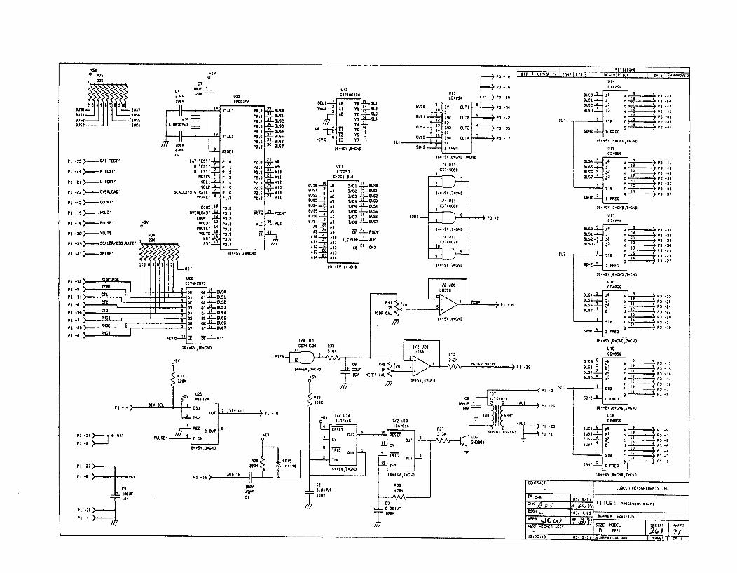
R3S22K
M~ 91
BUS4 I9u,4422 au'
C74
2755 2
P1 -33= >.'-'BsAT TEST'
P1 -44 ,, H TEST'
Pi -zi > - W TEST'
P1 -22 > - VROD
PI -43 ,. .OLNT'
PI -19 >---- D,
PI -10 > -...PULSE'
PI -26 - OT
27PF 2" 4T
//7 724' 1.
g47 TEST' P2.0
TEST "'-•L P4,2
SEL34-7 PI.4SELO 6X-P.SCALERq/Of MIGTE":-? P,
SPARE"ilP3'
OVERLOAD2 ' 21.
2494T' 42 P7,2
PIULSE'- 3,4
R34 V.TSI P3.5R 6 -!-, ".6IlII~i• "' 99..._.
RD' P3.7
39764473
D2 02 -~ 9U26
N2 4 -1 US
IT Q7 9097
.26 62'
3.429 4G9. 262N
J2OCG 4A
FZ .0P2 I52,4
P2 .7P? .4
P2 ,
P9,9
P92
54 .7
P9 .4P9.5P59.iP'6.?
TS -E
ALE2
U
UL I
A-Ouse 5k
24 :us•R
A]93 I I
A714
- 6S US3 -L
BUS4
-Bull
L.ALE
31AS -_4
A -92
-449L ~A:1 L44Ala--
At 39.-I2A t459-E
U22972247
C_261-010
As 1/04A)4 4/D2A2. 1 /03A3 1/04A4 1/09
A? /
-A:', I(.E11PPI
44 4/9
62 /4
64 .Y 4/67GN
443
20174W22790sT L-: P3 -t4
Col.4 Pi -2•
a0u2 ,,N or I P3 -34426t- 61 pe (j2 pi-42
OL2- S2 €3 PO -)S
SL44
I/4 U1lCD7T4HCO$
34 4
14-.229.44,7- .24
1/4 U24
CD74HCOG4 9
14,111,
•D74HC99
14--1 P,72D
BLUS3216 U4~-Ueuss
92 06sA2- DUST
Li.. 412
ALE.26P4 -70 >.....CALERID42 .9.474'
P 1 -41 > - SPARE*526 4
CUeE 24 -4 'A ,:923 '• 6 77 -29
4344
S 1 I S .... P73 -42
OU34 P3 -41
9USG 2 2 -'*9L17 4 2 d -73
Satz ; I <;D ?.,,Q : 9
16-16Y 4Q.C64,7.242
SV442i2G3
PI'4 -72 27Pl -31 CTI
P1 -1
224946
44444 2U P7 -3S91442 -2 2 P3 -326Bus Z3 P3 -37sL2P -tS41 D 57 -329
226
2.4946
P9 -22
U"374 3 4 P2 -24gUS 3 d3 13
I ~ 77-2.BL,'S7 67P .-9
4644 D 9 E 590 7P3 -19
46.422,4C..247.264
U4SC24942
-47
-16
-14
-91
P4 144
P4 -24 ý'4 -2
Pi -27
PI -4 6
f OINL

LUDLUM1 MEASUREME~NTS INC. SWE~TEZIRTX.J
DR CKS eo IS/Sl TITLE: PROCESSOR BOARD
CHK RBLiE EOARDB 6261-136 B 261136~DSCN LL 03,/14/91 MODEL 2221 ISERIES 2EIIDNEET 103A~PP 27Tq COMTP ARTWORK (3 SLDR ARTWORK C09:19:04 29-Mr~-94 COMP OUTLINE W SLDR OUTLINE 0COMP PASTE0CONC~P MASKO ISLOR PASTEO0ISLDR MASRC

Pq~vl !II"
P.52
PC -2
:42K
-2.48Y
IIII
L'U¶,6z-I1.2 INKp -G 1c " tcw P
A7
I IF &UrWAIt IV ZOK I O I 6~ KRPS IN IS DAC JAPP6OVE1
-7
.vatrVtA.Pptvs
:isWa.
-4
PC -3
LL VISea1TITLE CALioa.111Q. O0.4
00450I6 2NI-075
17- t-9 1OI 6265.WAIS D-- WE
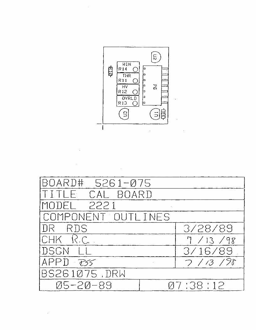
WINR14 Q
THRRIu 0
HVR12 O
OVRLDRI3 0Go
D0
aC3
o - --0 -
0
I
BOARD# 52681-075TITLE CAL. BOARDMODEL 2221COMPONENT OUTLINESDR RDS 3/28/89CHK V.C, i /rs /u•DSON LL 3/16/89APP]D •-5 ? / 1 /1JDS28107l5 PDRP
05-20-89 07 :38 :12

IATI ,UAHO4tY 7 t7 1 DA LIR I 722CR PTil221 I DATE 1APP4VAS I
v?
LCID ISPL.AY
[3 25P4 •2 2 A1 P4 -0
D: 12 2Z) P 5P,4-it+ £4 CI P944-i
PA -2223to DI P. -(44C
P3 -18 1 . P4 -*P4 " , 4 AZ 2-., P
PAi -I$ c., 2I *, -*
P4 -: Pc -41
P AD D1*2 3 1 1* 4PA 1 -IS 15 X2 2Z p, S.PA G1 3 2 P4 -37P. -Ii 42 P. -36
p4 -14 0l
-,
P. -41 25 P. 44 .
P4 .3 £2 P.32 ,
P4 -i 13 W3 P4 -A2P4i-7 ,93 PA-4
P4 -1 -$ 1 iiP r- " CA £Ai33
442, P4314 -i26 f~r. * 23+ PA -2
P4TL-26 IT 27•.,
P4 22 ~ 2A A3
CaS
D31136.09
22 P.P 92
2" LL 251--9l
l'•''''° ''T I TE I-,, l llS . 1•.Y
I7P9 17914owba
D all tli Cs
1Eilil•
1 bgry 1 & I
I
I Is 11 In

1~> C-)
U7
6100 000 DO D 0 o 0 000 00000 0 0 o..o00
0 00 a a a 0 a 0 a 0 0 0 0 00 0 0 0 0 0 0 0 0 00
BOARD# S28 i-074TITLE DISPLAY BOARDMODEL 2221COMPONENT OUTLINESDR - 1 3/27/89CHK .c. v /1s /qRDSCN LL 3/1E6/89APP.D -eK5 7 3BS28 1074 ,DRVJ
05-24-893 15 :44 :20

Fi, I A- tORr I ZONE IR , 01-ESCRIPTlI1 I DATE IIP64OU~2I
PS
-
PS -3
P3 - SKR
PS -S .640GATG
IRORISca6
PS -
pe -z >_ .. SwIR.
Po -3 >. -HV TEST'
P$ -4 >- COUNT"
Pe -s >......41 1661'
PS -6 ---- SPARE'
P8-.7 >),,-HOL.D'
Pe -e ).9..T - SE'
PA -.1 >_.-DIV OUT
P6 -II ) ,,- .. AU IN
Pe -12 >-.- -.DiV SU.
Ps - 13 >- ZERO'
Pe -14 )Pm.=.- $SCAL A. /DC .RAT(
Pli-I >... RESPONSE6
P11-2 -CI
PII-3 >- CT2
P11-4 >- CT3
P11.6 >- R62P11.6 ) - 1BAT TEST'PI L-I )P-"- R-G3
Pli-e ) ,.,...-R . P2
PIi-8 .q ,i. > - PIETERd
PlL-12 9 .9AT PROTECTE~p? -s-/[/
SJ2 J IAMlPLI P .R/POWER SUPPLY PROCESSOR
'261-972 526, Tl-
---- ' -H2 '1 [..--t ...j231
+$TPRDTECTEDO-] 2 -H 14_________________ 2 l--I24
'= I =• • ! A26 I'
S 27f 1 ~ 27P
-1 °.1 .. 7 I ER
I," '"" " I 131 Z H I R3-1 II ~ ~ ~ 7 1S 3 11 1 T32HsZERO' 9 CT I
1 2 1 1 3 1 1 3 I, " ,I141 136 DIV SEL 14 ' RC D
IS 131 4UD2IO 4.~ I S_ 16 II 11 31 -. ~rDIV OUT-f 161 I
I I 1 1 171 3 SCALERPUL.SEA q 41 PULSEA 16j 11
I1Sf 41 [...r TEST' HLCD-.. tof 41 j..SPARE'
414 FRED. 2 11 IF RFfse S-j 21
OVERLOAD' -~ I 22 " ý TEST' OVERI040'-j 221 H"Vv YES
6$,
ER
IT'/DIG .•TE'
Gr"
7Sy
P I1- 14 >-P7 -3
P7 -4
P7 -6
46..26
> WINDOW10 i-
t ld INDOW
P 16-I
P16-2 4-.. ROcOROERP7 -6) "V
P71. - t OVERLOAD
I ¢IGnTRIT I LUDLIAM M-SUR•E•O.TS INC.
PSI I L 46)/B 4 6-4N 26IlS.2 I 9N6( I-7
1 17 :46 114 96-24-69 1 $926 If7f DRIJ I sKET I .. I

III a
Oldl
0 o0J200APPWEoPOCSO
BOARD# 5261-076TITLE BACKPLANEMODEL 2221COMPONENT OUTLINESDR RDS 3/38/89CHK R.c. h / 13 /j?DSGN LL 3/16/89APPE ?5S. _ /D3 /Yr6S2861078,DRR
05-24-89 15 :15:37

#22 YELLOW UL1430DATA OUT12"
W5
#22 BLAC. UL1430

I
o 26 RAY UL1429$22 'lflfW LIL1430
7 26 GAYl L1429
0 0
Drawn: 0KB 21-MAR-01 Title-Design: RDS 11-NOV-99 RS-232 BOARD
Check E. p g ,oo2 Model: 2221Approve: + Boord#: 5261-179LoY-,I Top Ov-y Rev- 1.0 Series SheetMeoMl
1:M02 4 SCALE 1.0o 251 1180Me4 14-.02-28 4--Feb--200226 18
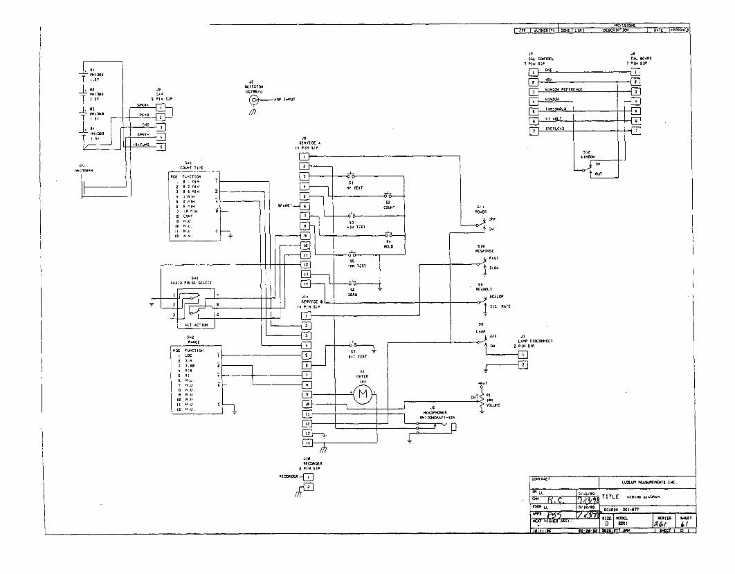
....... . :...I - !Z~ A AMVEFF 'U koRI DWt I LIN I E
CAJ. ROLI PIN SIP
CAL O•ARD7 PIN SIP
'2DEECTOR
VWX" I.u
ja&(Q IC A
. PIN SIP
LAMP :Isco-ECT2 PIN SIP
jig
RE DERu2 PIN 61
RECRDECol,",I LIDLLmNI MEASJ.NIENTS INC.
/1/9TITLE : WING~ MIC~A-
LO~ SCl-I16:4 :9
I
-

LUDLUM MODEL 2224
SCALER/RATEMETER
March 2002Serial No. 183080 and Succeeding
Serial Numbers
Measuring Range: 0-500,000 counts per minutePower Requirement: two standard "D" cell batteries
LUDLUM MEASUREMENTS, INC.501 OAK ST., P.O. BOX 810SWEETWATER, TX 79556915/235-5494 FAX: 915/235-4672
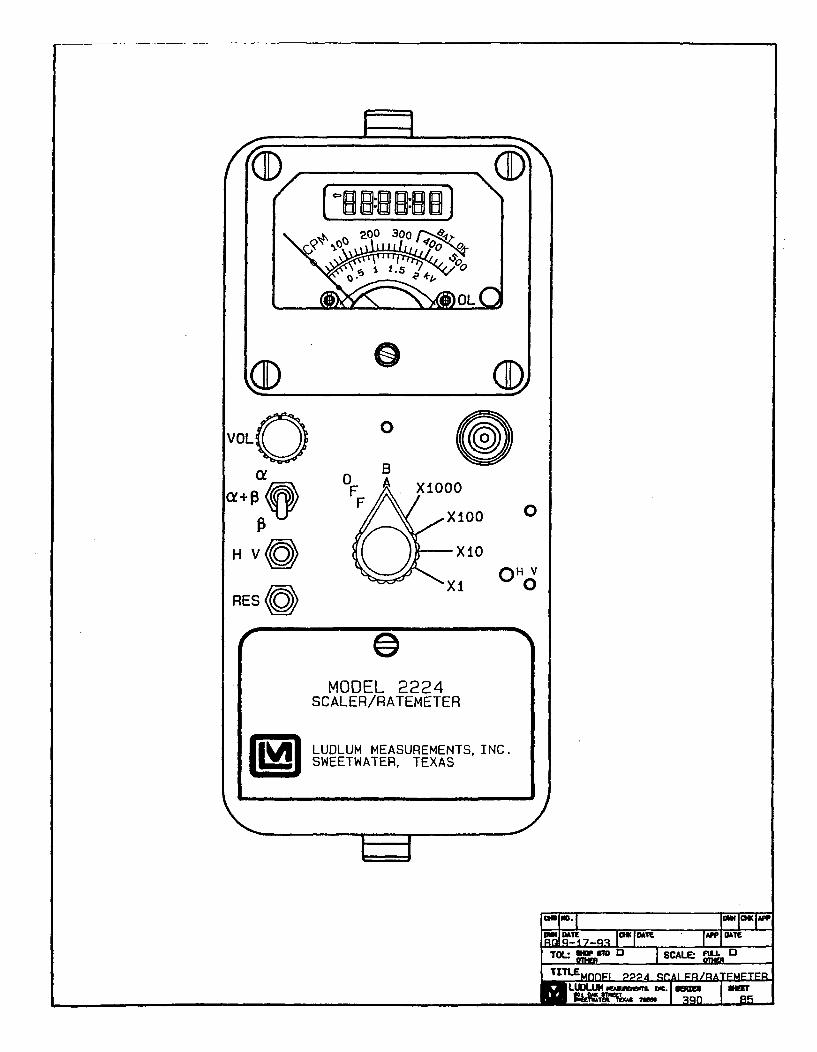
r(4O- 0'
0
VOLQ
a+
HVC
0 0B
0
OH v
RES
MODEL 2224SCALER/RATEMETER
I LUDLUM MEASUREMENTS. INC.SWEETWATER, TEXAS
JEl
M2224 Scaler/RatemeterMarch 2002
TABLE OF CONTENTS
1. G E N E R A L ................................................................................................................ . ... 1
2. SPECIFICATIONS ......................................................................................................... 1
3. PRINCIPLE OF OPERATION ........................................................................................... 2
4. PRELIMINARY INSTRUCTIONS ...................................................................................... 24.1 Unpacking and Repacking ............................................................................................ 2
5. OPERATING INSTRUCTIONS ......................................................................................... 25.1 Safety M easures ......................................................................................................... 25.2 Descriptions of Controls and Functions ................................................................................ 2
5.2.1 O perator C ontrols ................................................................................................. 25.2.2 Internal C ontrols ................................................................................................ 3
5.3 Operating Procedures .................................................................................................. 45.4 C alibration .............................................................................................................. 5
5.4.1 Meter Calibration .............................................................................................. 55.4.2 Detector Overload Calibration .............................................................................. 5
6. THEORY OF OPERATION ................................................................................................. 66.1 Amplifier/Power Supply board # 5390-066 ........................................................................ 6
6.1.1 Detector Input/Amplifier ..................................................................................... 66.1.2 Alpha/Beta Discriminator ....................................................................................... 66.1.3 Alpha/Beta Disc. Logic Circuit ............................................................................... 66.1.4 Low Voltage Supply ........................................................................................... 66.1.5 High Voltage Supply ........................................................................................... 66.1.6 Detector Overload ............................................................................................... 66.1.7 M eter D rive .................................................. .............................. 6
6.2 Processor Bd.# 5390-095 ................................................................................................ 76.2.1 Pow er supply .................................................................................................... 76.2.2 Microproccessor ................................................................................................ 76.2.3 L C D D rive ......................................................................................................... 76.2.4 A udio ........................................................................................................... . . 7
7. M A IN T EN A N C E ............................................................................................................. 8
PARTS LIST ................................................................................................................... 9Model 2224 Scaler/Ratemeter ................................................................................................ 9
Amp/Power Supply, Drawing 390 X 63 ............................................................................ 9Processor Board, Drawing 390 x 97 ............................................................................... 10Calibration Board, Drawing 390 x 100 ............................................................................ 10Display Board, Drawing 390 x 127 .................................................................................. 11Interconnect Board, Drawing 390 x 124 ............................................................................ 11Chassis Wiring Diagram, Drawing 390 X 103 ..................................................................... 11
DRAWINGS AND DIAGRAMS ............................................................................................. 12
pagei

M2224 Scaler/RatemeterMarch 2002
1. GENERAL
The Model 2224 is a portable microprocessor basedradiation survey instrument used to measure anddiscriminate low level alpha/beta radiation when usedwith an alpha/beta scintillation or proportional detector.
The data is displayed by an analog ratemeter and asix-digit liquid crystal display (LCD) counter. Theratemeter dial indicates 0-500 CPM with four linearrange multipliers of X1-X1000 producing an overallrange of 0-500 k CPM. The LCD is used to display thecounts accumulated during the preset count time. Thereare four count times available via internal switches.These count times are 6 seconds, 30 seconds, 60seconds, and 120 seconds. The counter is reset andstarted by pressing the Count button located in the endof the carrying handle.
The ratemeter and LCD can display alpha only, betaonly, or alpha and beta by selecting the correspondingtoggle switch selection. Audible click per event tonescan also be selected to discriminate beta (low pitch tone)
from alpha (high pitch tone) via the side mountedspeaker. Beta threshold, window, and alpha thresholdare adjustable to optimize alpha/beta efficiency andcount separation.
A regulated high voltage power supply adjustablefrom 200 to 2000 volts with detector overload detectionis utilized to operate a wide range of scintillationdetectors. Other operating features of the instrumentinclude programmable audio divide by (beta channelonly), a two-position switch (internal) for selecting theaudio discrimination mode, an adjustable volume,pushbutton battery test switch, pushbutton high voltagetest switch and meter reset.
The unit body is made of cast aluminum with adrawn aluminum can. The unit is operated with two "D"cell flashlight batteries for operation from -10°C toapproximately 50°C. For temperature operation to-100C, either very fresh alkaline or rechargeable NiCdbatteries may be used.
2. SPECIFICATIONS
* POWER: two standard "D" size batteries.
* RANGES: four linear range multiples of X1,X10, X100, and X1000; used in combination with.the 0-500 CPM meter dial, 0-500k CPM is achieved with therange multiplier
* SENSITIVITY: beta Threshold (BT) isadjustable from 2 - 15 millivolts (mV), beta Window(BW) is adjustable from the beta Threshold up to thealpha Threshold setting; alpha Threshold (AT) isadjustable from 40 - 700 mV
a AUDIO: Dual or single tone click per eventthrough a built-in speaker with an adjustable volumecontrol and internally switchable divide by of 1, 10, 100,and 1000 counts per click (beta only).
* HIGH VOLTAGE: externally adjustable from200 - 2000 volts
a LINEARITY: within ± 5% of full scale forthe analog ratemeter; ± 2% for the LCD
* RESPONSE TIME: XI range multplier = 10seconds, X10 = 7 sec., X100 = 2 sec., X1000 = 1.5sec.; all response times measured from 10-90% of fullscale
* BATTERY DEPENDENCE: Instrumentcalibration change less than 3 % to battery endpoint
a METER: 1 mA, 250 degree, 8.3 cm scale,with pivot-and-jewel suspension
* LCD: 6 digit Liquid Crystal Display with6.4 mm characters and a counter overflow arrow, colonsindicate count in process
" CONNECTOR: Series "C"
" SIZE: 10.67 cm (4.2") H x 8.9 cm (3.5") Wx 21.6 cm (8.5") L, exclusive of handle
a WEIGHT: 1.36kg (3 lbs.) less detector andbatteries
0 FINISH: drawn-and-cast aluminum, withcomputer-beige polyurethane enamel and silk-screenednomenclature
* BATTERY LIFE: Exceeds 350 hours with afresh set of alkaline "D" cell batteries
0 TEMPERATURE RANGE: -10°C to 500C(-14°F to 122°F)
0 CROSSTALK: No more than 10% of grossalpha counts in beta channel and no more than 1% ofgross beta counts in alpha channel.
page 1

M2224 Scaler/RatemeterMarch 2002
3. PRINCIPLE OF OPERATION
The Model 2224 is to be used in combination withalpha/beta scintillation or proportional detectors. TheM2224 uses pulse heights discrimination to distinguishbetween alpha and beta pulses from the radiationdetector.
The detected alpha count is displayed by selectingthe a position on the three position a, a + 13, and 03toggle switch. The sum of the alpha and beta counts aredisplayed in the a + 13 position and beta counts aredisplayed in the 13 position. Multiply the cpm reading onthe analog ratemeter by the range multiplier position.When using the LCD and preset count time interval, thecounts are accumulated in each of the three channelsduring the count cycle. The alpha, alpha + beta, and
beta counts can be displayed by selecting the appropriatea, a + 13, 13 channel. The count cycle is started bydepressing the pushbutton switch located in the end ofthe carrying handle.
The RESET pushbutton switch resets the meterpointer to zero. The detector operating voltage isdisplayed on the meter dial, 0-2 kV (kilovolts), bydepressing the HV switch. The OL (overload) lamp,located it the lower right-hand corner of the meter dial,is to indicate that the detector is saturated either by apuncture in the detector face on a scintillation detectoror an exposure to a radiation field above the countingcapability of the M2224. The analog meter will deflectfull scale when the OL lamp is illuminated.
4. PRELIMINARY INSTRUCTIONS
4.1 Unpacking and Repacking* To return instrument for repair or calibration
* Remove calibration certificate and place in provide sufficient packing material to prevent damage
secure location. Remove instrument and accessories during shipment. Provide appropriate warning labels to
(batteries, cable, etc.) and ensure that all of the items ensure careful handling. Include detector(s) and related
listed on the packing list are in the carton. If more than cable(s) for calibration. Include brief information as to
one instrument (M2224 and detector) is in carton refer the reason for return and return shipping instructions
to the calibration certificate for serial number match. (address, P.O.#, etc.).
5. OPERATING INSTRUCTIONS
5.1 Safety Measures
CAUTION
The high voltage (HV) constant current output is limitedby the internal circuitry to approximately. 50 microamps,but a mild electric shock may occur if you make contactwith the input connector. Switch the M2224 to the OFFposition before connecting or disconnecting the cable ordetector.
5.2 Descriptions of Controls and Functions
Multiply the scale reading by the multplier fordetermining the actual reading.
During the initial turn ON, the meter will bedriven full scale for about 2 seconds and then returnto zero. The LCD will show "888888", display theprocessor program version, and then 0.
0 Liquid Crystal Display (LCD): 6 digitdisplay that displays the scaler count for the selectedchannel. The display also indicates when a count isin progress by turning on two colons. The colons areturned off when the count is completed. If thecounter exceeds 999999, an arrow in the upper leftcorner of the display turns on to indicate theoverflow and the counter rolls over to zero andcontinues counting.
* VOL: The volume control for the speaker.Turning this control clockwise will increase thespeaker volume and counterclockwise will decreasethe volume.
./NOTE: The volume should be turned down whennot required to reduce battery drain.
5.2.1 Operator Controls
0 OFF/BAT/X1000/X100/Xl0/X1 Switch: A sixposition rotary switch to select the analog meter rangemultipliers and check the battery status. When switchedto the BAT position the meter pointer should deflectabove the left vertical mark on the BAT OK line.Moving the range selector switch to one of the rangemultiplier positions (Xl, X10, Xl00, XI000) providesthe operator with and overall range of 0-500 k cpm.
page 2

M2224 Scaler/RatemeterMarch 2002
Scia++pi/p Switch: A three-position toggleswitch used to select the sum of both alpha and betacount channels (a+ f), alpha count only (a), or betacount only (13), for display. This switch affects both theratemeter and the counter. The separate ratemeter andcounter channels are active regardless of the switchposition and will continue to function when the channelis not selected for display. This allows the operator toview each channel separately or together by simplyselecting the appropriate switch position.
t HV: When depressed, provides a readout ofthe detector high voltage on the meter. Use the 0-2 kVmeter scale.
* RESET: When depressed, provides a rapidmeans to drive the analog ratemeter to zero.
* Count Pusthbutton Switch (located incarrying handle): When depressed, resets the counterto zero and starts the timer. The colons on the displaywill turn on and stay on until the count time has expired.
M Remove the CAL cover to access the followingcontrol.
0 HIV Adjustment: Provides a means to vary thehigh voltage from 200 to 2000 volts.
5.2.2 Internal Controls
* Remove the instrument cover (can) to accessthe following controls.
* AUDIO Divide Select Switch: A two-poleDIP switch (1 & 2) used to select the audio divide ratiosof 1, 10, 100, 1000.
V NOTE: The AUDIO divide function only effects thelower frequency beta tones. The higher frequency alphaclicks per events will be unaffected by the divide byselection.
The ratio is selected from the following table. 0 is openand C is closed.
The count time is selected from the following table. 0is open and C is closed.
SWITCH3 4C CO CC O0 0
COUNT TIME
6 seconds30 seconds60 seconds120 seconds
0 TONE: A one-pole DIP switch (5) used toselect tone discrimination between alpha and beta countchannels. When in the DUAL mode, alpha and betapulse tones will be audible in all selector switchpositions (i.e. if in the a only position and 13 is detected,the (3 tones will be heard in addition to the a tones andvisa versa).
When the SNGL tone position is selected, bothalpha and beta pulse tones can be heard in the a+p3selection, but alpha pulses cannot be heard in the betaonly channel selection and beta pulse tones will not beheard in the alpha only channel selection.
SWITCH TONE5 MODEC DUAL0 SINGLE
/ NOTE: The following controls are utilized duringcalibration only and should only be performed by aqualified calibrator.
0 MTR: A multi-turn potentiometer used tocalibrate the meter to the cpm reading.
* AT: A multi-turn potentiometer used to varythe alpha pulse threshold from = 40 to 700 mV.
. BW: A multi-turn potentiometer used to varythe beta pulse upper window limit from the betathreshold to the alpha threshold setting and anywhere inbetween those two paramenters. The beta window can bedisabled by adjusting the BW control to the maximumclockwise position allowing the upper beta thresholdlimit to equal the alpha threshold.
* BT: A multi-turn potentiometer used to varythe beta pulse threshold from = 2 to 15 millivolts.
* OL: A multi-turn potentiometer which providesa means to vary the detector current overload set point.
* LIM: A multi-tum potentiometer used to setthe maximum HV limit to 2000 VDC.
SWITCH1 2C CO CC O0 0
DIVIDE BYRATIO
I101001000
* COUNT TIME Select Switch: A two-poleDIP switch (3 & 4) used to select the count times of 6,30, 60, and 120 seconds.
page 3

M2224 Scaler/RatemeterMarch 2002
0HV: A multi-turn potentiometer used to adjustthe high voltage test reading to correspond with theactual high voltage output. The HV switch must bedepressed during adjustment.
* LB: A multi-turn potentiometer used to adjustthe minimum battery voltage level corresponding to thelow battery indication on the meter dial. The BATswitch must be depressed during adjustment.
5.3 Operating Procedures
0 Release the can latches and remove the canfrom the 2224 taking care not to damage the speakerwires. Using a ball point pen, set the switches forthe AUDIO divide by, TONE, and COUNT TIMEto the desired selection. Then replace the can andfasten the latches.
V NOTE: To open the Battery Lid, twist the lidbutton counterclockwise 1/4 turn. To close, twistclockwise 1/4 turn.
o Open the Battery Lid and install two "D"size batteries. Note (+) (-) marks on the inside ofthe lid. Match the battery polarity to these marks.
./ NOTE: Center post of flashlight battery ispositive. Close the battery box lid.
o Connect a detector to the M2224.
o Switch the OFF/BAT/X1000-X1 switch tothe BAT position. The meter pointer should deflectabove the left vertical mark on the BAT OK line. Ifthe meter does not respond correctly, recheck thatthe batteries have proper polarity and are good.The LCD should show all eights, display theprogram version number, and then display 0.
• The detector operating parameters areestablished by adjusting the detector operating voltage(HV), alpha threshold, and beta window to find anoptimum efficiency for the alpha/beta scintillator orproportional detector.
The threshold and window parameters can beadjusted to optimize alpha/beta count discrimination,count efficiency, and minimize "cross talk" betweenchannels. Refer to the specific detector OperationManual or calibration certificate for the suggestedthreshold and window settings. Once the thresholds andwindow settings are established, an operating voltageversus count rate plot should be performed for both
alpha and beta count channels with alpha and betaparticle emission sources.
The following procedure is example of determining theoperating voltage for an alpha/beta scintillation orproportional detector:
o Connect a Ludlum Model 500 Pulser orequivalent to the Model 2224.
o Switch the 2224 to the 03 position. Adjustthe beta threshold (BT) for 3.5 mV and the window(BW) for 30 mV. The pulser counts should bedetected on the 2224 ratemeter above 3.5 ± 1 mVand should shut off above 30mV.
o Switch the channel selector switch to the aposition. Adjust the pulser for a 120mV pulseoutput and vary the AT control until counts aredetected on the ratemeter.
o Depress the HV switch and adjust the HVpotentiometer for 0.4 to 0.5 kV on the 0-2.0 kVscale. Connect the scintillator and switch to the P•only position. Place an alpha source on the detectorface.
o Slowly increase the HV potentiometer toobserve an increase, then decrease, and increaseagain in count as the HV is increased. Decrease theHV until the ratemeter is in the "dip" of theobserved count rate versus HV plot just performed.Depress the HV switch and note the HV setting.
o Plot a HV versus count rate plateau in 25volt increments, 50 volts each side of the HVreading found in the above step (ie, HV setting forcount "dip" in the above step = 675 volts, start theplot at 625 volts and increase in 25 volts steps until725 volts is reached). Plot alpha source, betasource, and background counts for both the a and 03channel positions.
o Find the optimum operating voltage fromthe plot which gives the greatest alpha and betasource efficiency while maintaining no greater thanthe maximum acceptable level of "cross talk"between channels.
o Select the desired count channel display,and proceed to use instrument.
page 4

M2224 Scaler/RatemeterMarch 2002
5.4 Calibration
5.4.1 Meter Calibration
* A Ludlum Model 500 Pulser or equivalent isrequired. If the Pulser does not have a high voltagereadout, use a high impedance voltmeter with at least1000 Megohm input resistance to measure the detectorvoltage.
o Ensure that the meter movement hasproper mechanical zero. The adjustment is on thefront of the meter bezel. It must be adjusted to"zero" with the ON/OFF selector switch in the OFFposition.
o Connect the Model 500 Pulser to theModel 2224 with the appropriate cable. Rotate theM2224 range multplier switch to the X100 position.Select the a+ 03 channel position.
o Adjust the Pulser for 40,000 cpm andadjust the pulse amplitude to twice the betathreshold level (ie; beta threshold = 3.5mV, adjustpulser to 7-1OmV).
o Remove the instrument cover and adjustthe MTR potentiometer until the meter reads 400cpm. Adjust the Pulser to 10,000 cpm and ensureratemeter reads 100 ± 10%. Decade the Pulser andM2224 range multiplier switch to check meterlinearity on the X1000, X10, X1 positions.Linearity should be within ± 10% of each reading.
o Set the LCD count time for 60 seconds.Adjust Pulser count rate to 40k cpm. Depress thecount button and when count cycle is completeconfirm that LCD reads within ± 2% of theincoming count rate.
o Adjust the BT, BW, and AT controls forthe appropriate set points as described in section5.3.
o Connect high impedance high voltagemeter (may use the Model 500 Pulser if equippedwith a HV meter) and adjust the HV control for areading of 1000 VDC on the voltmeter.
o Depress the HV pushbutton switch andadjust the HV potentiometer located on the circuitboard for a reading of 1.0 kV on the meter dial.Adjust the HV output from 500 to 1500 Vdc andconfirm that the 2224 HV meter corresponds to theexternal voltmeter within ± 10% of each reading.
o Remove batteries from the batterycompartment and connect a DC power supply to thetwo screw terminals located at the rear of thebattery compartment. The positive power supplylead should connect to the terminal with the redwire and the negative lead to the terminal with theblack wire.
o Adjust the power supply for 2.2 Vdc andswitch the M2224 to the a + PI position. Depress theBAT pushbutton switch and adjust the LBpotentiometer to align the meter needle with the lowbattery mark on the meter dial (vertical line to theleft of BAT OK).
o Replace M2224 cover and proceed withuse.
5.4.2 Detector Overload Calibration
/ NOTE: The detector operating voltage (HV)must be determined and set before the OL(overload) adjustment is performed. If the detectoroperating voltage is re-adjusted, the overloadadjustment must be re-adjusted.
o Adjust the OL control to the maximumcounterclockwise position.
, NOTE: Detector saturation is when the meterresponse no longer increases with increasingradiation field intensity.
o For alpha/beta scintillators, expose thedetector photomultiplier tube (PMT) to a small lightleak by loosening the detector window. Somescintillation detectors incorporate a screw in thedetector body which when removed will simulate adetector face puncture or light leak. The metershould start to decrease toward zero as lightsaturates the scintillation material.
o Expose just enough light to where themeter starts to decrease. Adjust the OL controluntil the overload LED just begins to flicker on themeter dial. The ratemeter should deflect above fullmeter scale at this point.
o Re-seal the detector window and exposethe detector to a radiation source that will drive themeter near full scale. Confirm that the LED doesnot turn on and the meter remains on scale.
page 5

M2224 Scaler/RatemeterMarch 2002
6. THEORY OF OPERATION
6.1 Amplifier/Power Supply board # 5390-066
Refer to schematic 390 x 63 for the following:
6.1.1 Detector Input/Amplifier
Negative going detector pulses are coupled from thedetector through C021 to Amplifier U021. R023 andCR021 protects the input of U021 from inadvertentshorts. Self-biased amplifier U021 provides gain inproportion to R021 divided by R022. Transistor pins 4,5, and 6 of U021, provides amplification. Pins 12 and15 of U021 are coupled as a constant current source topin 6 of U02 1. The output self-bias to 2V be(approximately 1.4 volts) at pin 7 of U021. Thisprovides just enough bias current through pin 6 of U021to conduct all of the current for the constant currentsource. Positive pulses from pin 7 of U021 are coupledto the discriminators through RO0 I and C011.
6.1.2 Alpha/Beta Discriminator
Positive pulses from amplifier U021 are coupled tocomparator U012, pin 6, for alpha discrimination andpins 6 and 2 of UOII for beta discrimination. R103,Alpha Threshold, provides the reference voltage foralpha comparator U012. R106, Beta Threshold (definedas the lower threshold limit of the beta countingwindow) provides the reference voltage for betathreshold comparator pins 1, 2, and 3 of U011. R102,Beta Window (defined as the upper threshold limit of thebeta counting window) provides the reference voltagefor the beta window comparator pins 5, 6, and 7 ofU01 1.
6.1.3 Alpha/Beta Disc. Logic Circuit
the IiP clock cycle to complete before the next beta pulsecan be recognized by the IiP.
6.1.4 Low Voltage Supply
Battery Voltage is coupled to switching regulatorU201 and associated components to provide +5V topower op-amps and logic circuitry. The charge pump(cp) output, C202, CR211, CR212, and C201 form avoltage doubler circuit to provide +9V for U201amplifier supply. UOOI and related components provide+2.5V reference HV SET and Alpha/Beta discriminatorcontrols. R201, LO BAT, is adjusted so that the meterpointer is aligned with the left vertical mark on the BATOK line with 2.2 volt battery input.
6.1.5 High Voltage Supply
High Voltage is developed blocking oscillator Q421,T321, C412, and rectified by voltage multiplier CR221-CR224, C221-C223, C211, and C114. High voltageincreases as current through Q421 increases, withmaximum output voltage with Q421 saturated.
High voltage is coupled back through R123 to op-amp pin 2 of U311. Resistor network R211-214completes the HV division circuit to ground. R214provides HV limit at 2.0 kV when the HV SET controlon the calibration board is at maximum. The regulatedHV output is controlled by HV potentiometer locatedunder the CAL cover on the front panel. This controlprovides the reference for comparator pin 3, U311.During stable operation, the voltage at pin 2 of U311will equal the voltage at pin 3 of U311. Pin 1 of U311will cause conduction of Q312 to increase or decreaseuntil the HV finds a level of stability. R115, HV TEST,calibrates the analog meter to the HV output when theHV test pushbutton switch is depressed.
6.1.6 Detector Overload
A voltage drop is developed across R121 and sensedby comparator U012 as detector current increases. Whenthe voltage at pin 3 of U012 goes below pin 2, pin 1 goeslow illuminating the OL LED and driving the meter tofull scale. R2 11, Overload, provides adjustment for theoverload set point.
6.1.7 Meter Drive
Pulses are coupled from the ltP board (refer to liPtheory of operation) to the gate of Q302. Q302 invertsthe pulses, R403 and C401 provides inergration.Integrated meter drive voltage is coupled from P1-13 via
Alpha pulses from U012 are coupled to univibratorU11l. Pulses atpin 6 of Ul1l are inverted by QIll forconnection to reset (R) pins 3 and 13 of U101. Pin 9 ofUl11 provides the pulses to be counted themicroprocessor (jaP). Pulses from pin 9 of U111 areconnected to pin 3 of UIII to provide a time delay for thejiP clock cycle to complete before the next alpha pulsecan be recognized by the jiP.
Beta pulses from pin 1 of UO1 1 are coupled tounivibrator U101. Pulses are coupled to the jtP from pin7 of U101 as long as pins 3 and 13 of U011 remain high(+5V). When an alpha and/or a beta window pulse ispresent, the reset (pins 3 and 13 of U101) function isenabled and 7 of U101 remains high. Pin 7 of Up isconnected to pin 13 of U101 to provide a time delay for
page 6

M2224 Scaler/RatemeterMarch 2002
the battery (BAT) and HV test switch to pin5 of U311.The meter is driven by the emitter of Q111, coupled asa voltage follower in conjunction with pin 6 and 7 ofU311. R104, Meter Cal, is adjusted to calibrate theratemeter reading corresponding to the incoming countrate. R405 and R406 provide temperature compensationfor changes in the meter resistance due to temperaturevariations.
6.2 Processor Bd.# 5390-095
Refer to schematic 390 x 97 for the following:
6.2.1 Power supply
Battery voltage is coupled to switching regulatorU201 and associated components to provide +5V topower the jiP and display drivers U211, 212. R101,C101, Q101, and Q201 form a delay switch which allowthe U321 to stabilize before the load current is connectedto the +5V supply.
6.2.2 Microproccessor (pP)
U311, Intel N87C51FA, controls all of the data,control inputs, and display information. The clockfrequency is crystal controlled by Y211 and relatedcomponents at 6.144 MHz. The [tP incorporatesinternal memory (ROM) storing the programinformation. C31 1 resets the pP at power-up to initiatethe start of the program routine, During the program
loop the pP looks at all of the input switches forinitiation or status changes and responds accordingly.
The gP uses Pulse-width Modulation to control theanalog ratemeter. The analog output, RATE (P3-4), isdivided into 255 increments in a 166 ps period, At fullmeter deflection the low pulse period, leading edge toleading edge, will be 166 [is, 500 cpm = 130 ps, 400cpm = 104 ps, 200 cpm = 52 as, 100 cpm = 26 ps,and 0 = no pulse or +5V. The pulses are inverted byQ302 on the Amplifier/Power Supply board and thenintegrated by R403, C401.
6.2.3 LCD Drive
U211 and U212 make up the liquid crystal displaydrive circuitry. The display information is sent from thetP to U211 and 212 via BUSO-3 and ADDO-1 data lines.
When the SELECT' line is brought low by the aP, thedata is transferred and latched into the drivers until theSELECT' line is brought low again. The correspondingdigits and segments are illuminated corresponding to thestored count information from the WP.
6.2.4 Audio
Alpha and/or beta audio pulse frequency isgenerated by the [tp and coupled to Q204. Q204 theninverts the pulses and drives the negative side of thespeaker. Bias voltage is provided by the volume controlvia Q202 and 203 and related circuitry.
page 7

M2224 Scaler/RatemeterMarch 2002
7. MAINTENANCE
Instrument maintenance consists of keeping theinstrument clean and periodically checking the batteriesand the calibration.
An instrument operational check should beperformed prior to each use by exposing the detector toa known source and confirming the proper reading oneach scale.
Re-calibration should be accomplished after anymaintenance or adjustment of any kind has beenperformed on the instrument. Battery replacements arenot considered to be maintenance and do not normallyrequire the instrument to be recalibrated.
Ludlum Measurements recommends recalibration atintervals no greater than one year. Check theappropriate regulatory agencies regulations to determinerequired recalibration intervals.
The batteries should be removed and the batterycontacts cleaned of any corrosion at least every threemonths. If the instrument has been exposed to a verydusty or corrosive atmosphere, more frequent batteryservicing should be used.
Use a spanner wrench to unscrew the batterycontact insulators, exposing the internal contacts andbattery springs. Removing the handle will facilitateaccess to these contacts.
NOTE
NEVER STORE THE INSTRUMENT OVER 30 DAYS WITHOUT REMOVING BATTERIES.ALTHOUGH THIS INSTRUMENT WILL OPERATE AT VERY HIGH AMBIENT TEMPERATURES,BATTERY SEAL FAILURE CAN OCCUR AT TEMPERATURES AS LOW AS 1000 FAHRENHEIT.
page 8
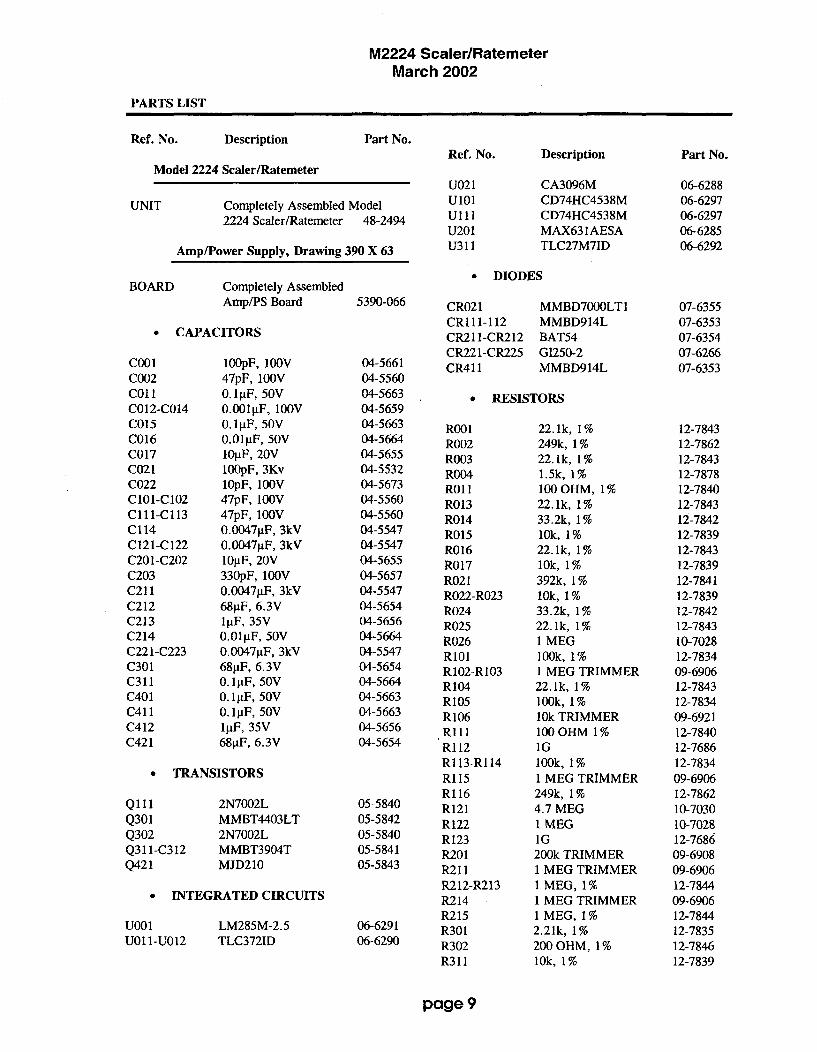
M2224 Scaler/RatemeterMarch 2002
PARTS LIST
Ref. No. Description Part No.
Model 2224 Scaler/Ratemeter
UNIT Completely Assembled Model2224 Scaler/Ratemeter 48-2494
Amp/Power Supply, Drawing 390 X 63
Ref. No.
U021U101U"llU201U311
Description
CA3096MCD74HC4538MCD74HC4538MMAX631AESATLC27M7ID
Part No.
06-628806-629706-629706-628506-6292
DIODESBOARD Completely Assembled
Amp/PS Board 5390-066
0 CAPACITORS
CR021CRl11-112CR21 1-CR212CR221-CR225CR411
MMBD7000LTIMMBD914LBAT54G1250-2MMBD914L
07-635507-635307-635407-626607-6353cool
C002COO2
C012-C014C015C016
C017C021C022C101-C102Cl11-Cl13C114C121-C122C201-C202C203C211C212C213C214C221-C223C301C311C401C411C412C421
IOOpF, 100V47pF, 100V0. l tF, 50V0.001liF, 100V0.l[tF, 50V0.011tF, 50V10tF, 20V100pF, 3Kv10pF, 100V47pF, 1OOV47pF, IOOV0.0047g.F, 3kV0.00471tF, 3kV10tF, 20V330pF, 100V0.00471tF, 3kV68pF, 6.3VljIF, 35V0.01F, 50V0.00471 tF, 3kV68pF, 6.3V0. lpF, 50V0. ltF, 50V0. 1 F, 50VlpF, 35V68VF, 6.3V
04-566104-556004-566304-565904-566304-566404-565504-553204-567304-556004-556004-554704-554704-565504-565704-554704-565404-565604-566404-554704-565404-566404-566304-566304-565604-5654
RESISTORS
R001R002R003R004RO1lR013R014R015R016R017R021R022-R023R024R025R026R101R102-R103R104R105R106RiIlR1 12RI 13-RI 14RI 15Rl 16R121R122R123R201R211R212-R213R214R215R301R302R311
22.1k, 1%249k, 1%22.1k, 1%1.5k, 1%100 OHM, 1%22. lk, 1%33.2k, 1%10k, 1%22.1k, 1%10k, 1%392k, 1%10k, 1%33.2k, 1%22.1k, 1%1 MEG100k, 1%I MEG TRIMMER22. lk, 1%100k, 1%10k TRIMMER100 OHM 1%IG100k, 1%1 MEG TRIMMER249k, 1%4.7 MEG1 MEGIG200k TRIMMER1 MEG TRIMMER1 MEG, 1%1 MEG TRIMMER1 MEG, 1%2.21k, 1%200 OHM, 1%10k, 1%
12-784312-786212-784312-787812-784012-784312-784212-783912-784312-783912-784112-783912-784212-784310-702812-783409-690612-784312-783409-692112-784012-768612-783409-690612-786210-703010-702812-768609-690809-690612-784409-690612-784412-783512-784612-7839
e TRANSISTORS
Qi1lQ301Q302Q311-C312Q421
2N7002LMMBT4403LT2N7002LMMBT3904TMJD210
05-584005-584205-584005-584105-5843
* INTEGRATED CIRCUITS
U001 LM285M-2.5U01 l-U012 TLC372ID
06-629106-6290
page 9

M2224 Scaler/RatemeterMarch 2002
R312R313R314R401R402R403R404R406R407R411R412
22.1k, 1%2.21k, 1%10k, 1%221k, 1%7.5k, 1%IM, 1%5k TRIMMER301 OHM, 1%1k, 1%200 OHM, 1%10k, 1%
ERMISTORS
03006-165.9-55G100
12-784312-783512-783912-784512-784712-784409-690712-786312-783212-784612-7839
07-6366
21-9678
INTEGRATED CIRCUITS
U21 1-U212U311U321
ICM7211AMIQHN87C51FAMAX631AESA
06-629406-628606-6285
. RESISTORS
R101R102R211R221R222R301-R306
IM, 1%10k, 1%2.21k, 1%150k, 1%100k, 1%22. 1k, 1%
12-784412-783912-783512-783312-783412-7843
THI
R405RESISTOR NETWORK
INDUCTORSRN401 220k 12-7831
L301 220ptH* CRYSTALS
* TRANSFORMERSY211 6.144 MHZ 01-5262
T321 L8050 40-0902a SWITCHES
MISCELLANEOUSS301 90HBW06S 08-6710
P1
P2
CONN-1-640456-5MTA100CONN-640456-3MTA100M2222 BD. SHIELDRECEPTACLE (8 ea)Cloverleaf 011-6809
13-8355
13-80817390-044
18-8771
0 INDUCTOR
L311 150%H 21-9677
. MISCELLANEOUS
Processor Board, Drawing 390 x 97P3
P4
CONN- 1-640456-6MTA100CONN-640456-2MTA100SOCKET-44P
13-8134
13-807306-6293
BOARD Assembled Processor 5390-095*€
* CAPACITORSCalibration Board, Drawing 390 x 100
Clol.Cli0C211-C212C221C311-312C321C322
0.l5jiF, 50V47jtF, 1OV27pF, 100V68 1 F, 6.3V10•tF, 20V330pF, 100V68pF, 6.3V
04-566504-566604-565804-565404-565504-565704-5654
BOARD Completely AssembledCalibration Board 5390-096
LEDS
DS1 HLMP4700LED-SPACER 456-500
07-635607-6349
a TRANSISTORS0 RESISTORS
Q101Q201Q204Q311
2N7002LMMBT4403L2N7002LMMBT4403L
05-584005-584205-584005-5842
R3 250k TRIMMER 09-6819
0 MISCELLANEOUS
P7 CONN-640456-5MTA 100 13-8057
page 10

M2224 Scaler/RatemeterMarch 2002
Display Board, Drawing 390 x 127 SWITCHES
BOARD Completely AssembledDisplay Board 5390-118
S1S2S4S5
PA-600-210#923 SWTCHCRFT30-1-PB GRAYHILL7103SYZQE TOGGLE
BATTERY
08-650108-651808-651708-6720* CONNECTORS
DSPI LCD 7728-365-481J6 CONN-52 POS CP50
07-635113-8410
B1-B2 "D" Duracell Battery 21-9313
Interconnect Board, Drawing 390 x 124
BOARD Completely AssembledInterconnect Board 5390-117
0 CONNECTORSJ5 CONN-52 POS CP50 13-8410
Chassis Wiring Diagram, Drawing 390 X 103
MISCELLANEOUS
J10Ml
JACK-09-9011-1-0419METER ASSYHANDLE ASSY
18-90804390-1364408-075
0 AUDIO
DS1 UNIMORPH 21-9251
0 CONNECTOR
J1
J2
J3
J4
P7
J8
CONN- 1-640442-5MTA100CONN-640442-3MTA100CONN- 1-640442-6MTA100CONN-640442-2MTA 100CONN-640442-5MTA100Series "C" UG706/U
13-8383
13-8135
13-8187
13-8178
13-814013-7751
page 11

M2224 Scaler/RatemeterMarch 2002
DRAWINGS AND DIAGRAMS
Amp/Power Board, Drawing 390 x 63Amp/Power Supply Board Component Layout, Drawing 390 x 64
Processor Board, Drawing 390 x 97Processor Board Component Layout, Drawing 390 x 98
Calibration Board, Drawing 390 x 100Calibration Board Component Layout, Drawing 390 x 101
Display Board, Drawing 390 x 127Display Board Component Layout, 2 sheets, Drawing 390 x 128
Interconnect Board, Drawing 390 x 124Interconnect Board Component Layout, Drawing 390 x 125
Wiring Diagram, Drawing 390 x 103
page 12

14~. U02 .9
R2P 122
I 221K 1 :CT 2.1 A
T, RLOA 2 166O CII 8 uez N',II.PC6D
11 I M U6 1 A !56DEI c~olim 7 162.N
nNBD7BOL. a 16CND us,
Is ~ ~ P 1-.1322
066202 RI.82
.9V.Sv SV
U!,, 2 ý61 C7112 4113T .OK CIP13 R114
, 1 143, A PF I 09K
125.61 1. EMY I,
c4 I " 1, .6V
-SVI-CND ... 1 2 1 1
T C.14 D R-C R/C -C /C
@.to ILIF IIR E to
5
I A 1 9 A PLTELSE' ps .10
I I UEEI
'ev A C*vu ' Wom CD 7.4clsim
Is.. O-GND r,..Gv WIND
Re 13 GV
ROO I .5vIM.W 22. IK 0..
LO I
Let I I I
R 1041. ZN`113021.ý
TLCO721D 22
B In1,EE!ý-
C. I o T MV RE I clez A EBB
coo I0-1sy'..CNU IMPF .54 .6y
O.O.EV I I,ILF C4'11 47Pr OK: 0; OOK
; "Ov
GV I ýw
UAD I I Rols I I 1 2TLC3721 E I is :C Ac C /C
Is1 1M.w lir
C1.1 I A 9 Be PULSE PI -9
C013 B..SV,4-GND 11PF Ljol
6.001ur I. CD74Hc4s3en
100V MODO14L 16--%VB-CND.. SV'4.''N.
24 CRI12 5 ,
Pl -4
RE -II
PR -.

2
cot L..J 1- j*=*J TLC2711711)ý2;! '394CO 14 TLC312ZIDW, Lill 1 -]Cll3 A; A 3II1coi 13 M3 I RIIBT3SB4T:
rD M BATS4 C214J 11B3S4:RI
MEMO: C•I 1. • 0uo 'l' !fl : . u I , :C401
0MI,8M: ,AX631AESA :r-1MBr4403L .
- -2 oR o0000000000020 o0 'R4BS ,o000 M-" 1;4 BET LB
BETA WINO CN ALPHA
0 THRESHOLD I THRESHOLD 2 3 4
U LUDLUM IIEASUREMENTS INC. SWEETWATER, TX.
DR C 4/299 TITLE * AMPLIFIER /
DSN LJ0 BOA5illRDO 6390-066 IBS330062GDSC L /2/7 MODEL SES SHEET
APP I C4_T4 . 2223 9 6414!33:•4 21-Au,-9 COPIP SIDEi SLDR BIDED OUTLINEWCOMP PASTED 0COMP tIASK 0ISLR PASTED SLUR tASKD

avvi IoNsIrr I A•THORIT I TON0 ITDA I OASCAIPI D PTE APPRoEDI
161. C211927P;
C3I1 1 690v
2"E 121 2
2 7 , ,I D_
RESET 1S
0- COUNT' ZERO'
02 -j ~SCALER/RATE'AP, 03 )---00 RATE
COORIT
>2-R >....SCALER/RDTE C!1.1.
2 *S > -ZEO RATJCEO'±RASC
P2 .1 > )....RDR.OSa NODELOO
92 -7 >....RANCEI, A PULSE-.-
P3 -0 > - O.~VERLOAD' AUX' to
P2 .9 > -A...R PULSE'
P3 -11> AX
0 11WAST 1PTO
905-06-NXX
XTA1.2
RESET
Pý.POI,
PI,P3.0P3 .1
Pi.2
01.3
P3 ,AP1.0
P3,4P,3SP3 , IP3.1P2,202,2
pDeP5.0PVT.P6.0
P9.2
P9.2
P5.5P9.6
P2.2P2.2
PA .6P0.0
LSEArAL
0N651
I IA
43 P CAL tRT.0 !ME I"
A 2
:•S [ [ I TIrES,•B " _ ! UD Dtrt'
0 17•AUD 01ve'as I WITCH'
24• SELECtR'S SLECT"
6 AA D 01
00 ADDIZ7 , ODOR•e euso
05 6002
20US2
2u2 Ous
SVY
Bus I -U32
SU'T-
8001
SELECTS'
05
ICM72 I JAMIS
AUI
012 DI212 El
FlDAl G!
02
S 90CO CO
COE CO
D2
02
0203
83
D,E203
CO
AA
00C.
CA
OP
4 1 COL•ON •• 3
3"•" BATTERY P •
A OVERFLOW 1%11H, PS. -00a Ps5-S C' Ps -20
oI -01C..~t3 C6PS -0.
Is 45Ps -2s
22 AC s A 1-224 8, Pý -41
6) PS, + 4
0 Il
UOIII6009 20 00
US I21 DI-I CI000 2 D2 v DS2 223012 El
22 -- A2
CAD CcDA
022
A2
0e 2
02
7 -osc E O2
F2
AlC3o 3
r 2CA
DOEA
CA
ORS,3-•
T_
5 13 *PS -toI A3D PS -36
e 93 P 39 C3 • PS"27
Ps -:1
11 -1'
Is 42s 0
Is DR PS -3,311 Cl pp eS -17:7 Da P S -
19 E• 2 s -9
•g c• •s-38
21 -- a - - s 11ees C , :S -326 01 • S-
•sr• PS :30
O ACKPLANE
0, S.,39,ON2
P3 -14 > +•
P3 -1"•>----O.SVEXT
P3 -(0
SUlIcED
e~ 150 CCT# NICLPROEI WCK
R30 :I 01 0100 5 n
0292 I
AuD DIVI,,•L' ý:(uCio DIVIDE I ON1m03 ,I A o DIVI01 Io0,11$ 12500
2U IL--- 0 (6001O 010100! I 05t
000e.
02 IA 2 (6u010 DIVIDE I 0001
It I 2oAles• 3#t•• N
22.1A ' ' A . ....
22 I Dto 101I0 I 00NIIS lO~mO
829
20 IT .• 5 ,1ei.0• TONE 090
IA 120,0
SPARE FF
C3(1
177
I'll.... •it•J~l T LIt 'III
,ueIl S.
(SD 2'EsOA.CT PA -2
CLIC 02K UPDAT0 D . 0LUDLUM MEASUREMENTS INC.
DR tK& 1 3/23/94_2 a T I T[LE : PRCESSDR BOARD W/O E0.1.
NEXT l/I15i0 I ....NE~tNI~eR ,SS' s~z: MDEL. SE~[S $E01
im.e ..........................1 le:Se:?2 _ 21-11- S933009S 1 WE, I a, I

................ ...... ...... ...
:7 7 ýcM 1: M1I GOIAESA 0L i T403 G LI I
lCM.72 I AMIQr(
Clo1 m I1IT4403L
0. 0 O14 11 Ve4 P4 RO 2[=CZMý
427S-083S301CONI~FGURE
0 12 3 4
LUDLUJM MEASUREMENTS INC. SWEETWATER, TX,
DR A0~/~/S4T ITLE PROCESSOR BOARD
cAR -gE0/D9 L W/O E.L.DRN L 81/1 OARDV6: S US-095 SSOSSC LItIODEL SERIES ISHEET
APP q&LA) T 2224 1380 98I0S4SS-KA-SRCMP SIDED SLSR SIDED31OUTLINES'
I I- -- 'SEIcump HAS OSLD PASTE 0I1SLDR MASK 0

I EFF I AUTHORITY I ZONE ILTR I DESCRIPTION DATE APPROVED
P7 - I
OVERLOAD RED
A2.SV P-1
NV w SET I
2.DSV T.... P7 -6
UPDATED - LUDLUM MEASURMENTS INC.
DA CMAlq, I4/BI/94cmL CALIBRATION BARUD
NEAT HIGHER USSR.LD 2224 S .
I SHUT 1 0

DSI
P7 :6::
R3 "- E HV SET
0
DESC: CALIBRATION BOARDMODEL: 2224PART #: 5390-096DWN: CKB DATE: 04/01/94DSGN: DATE:

S2 PDS CPSO CD EDCEiA -1I
A -79A _37
is -96As -7
As -6As -11As -33As -32
As -2
A-4
As -29
is -27ý=
AG -47 >A -42 )
AG -27 )
A -Z4J6 -49A -46
J6 23
31 is-20jo -21is6 -46As -4SA -44
A J -19
A J -16
6 AJ6 -IS
A :46 -42
*J6 -14is6-13
* 16 -3'sA2 -29
is 16SI

DSPI
EI-~BOBBB8HoI
a [UDLUM MEASUREMIENTS INC - $WEETWATER, TX.I~ ACFI 02-JUN-S~TITLE~ DSF'LAY BOARD
nq ACF I 02-JUN-94TITLE: DISPLAY BOARDCWXINJI /- ISOARD! S3,90-118
rtmj~ l 7-JJL-Sd MODEL: 2224
APP F !~AiE esy0i IsCCN~ SOLER 1:21 96 -Jugn-S5
7E~~ 75 iE 61 S1EEOnriA rwrl UTL 1.1 1 .0 3

(U LUDLUMi hEASUREMiENTS INC. SWEETWATER, TX.DR ACF 02-JUN-~3 TITLE: DISPLAY BOARD
CAR4,t)ý -.2-1'( BOARD$ C390-I18iDSCN JGW 17-JUL-95 MrODEL .224 [SERIES 3S0 ISHEET 128A PP ý"w COMP ARTWORK D SLOR, ADRTAOR,( IF
COMP OUTLINE I SLOR OUTLINEICOMP PASTE C ICOMP MASK DISLDR PASTED ISLOR MASKO

O5~5 TVI SSCRIIIOA IDOTROPPO1tI LFP I AUIHORIHY !ZON'E[LIN I [SLCR]i[wN I DATE: 11PPRUMVED
M 0224 PROCESSOR BOARD 539•-635S39o-tli 2224-I PROCESSOR BOARD S39S-leGDISPLAY ROARD S2 POS. CPS9 CD EDGE CONM.
s-i >• CR >s -sl
P6 -3) FR -5
PR -> JS -549PR-A 09 CS5S-49PS -6 FS is -41
PG -1 3 AS is -4G
PS -B es JS -4PG -9 C4 JS -44PG -t) F4 4 JS -43
PG -1 > A4 JS -42pG -;2 > 8 JS -41PR -13 03 JSl-.--------- 5 40PB -14> 3 i s -JRPR-IS> A3 is -39
P6 -21) 2 IS -37
PG -17) CI i J-3sP6 -2i) DI+ s
PG -23 Fl is -39PR -24) 8 Al 5-32
PR -RE> EL BACGIICATI is -21PR -23 OVERiLOs - 5 -20P6 -2R BATTERY > S -29
P6 -2S - a i5 -28
,B -_. 5•O llILIH JS -27P6 -327) ODRW 5 -2s
P6 -28 BATTERYJS -25PS -39 Es i -214
PR -30 f> - is -03Pe -31 CS is -i2PI -32 01...2 JS -I1
PG -JR 64 i -I0PR -34) 04 i 5 -19PS6-36) Cd11 J 5-17
PS -31• D4 is d-4
PR -is> DP3 is -IAPR -493 E3 is 5-3
Ps -4l D3 is -1P6 -4D 3 451; -1PG -43'- SPO is -19P6-44) ED i ,PG-A S D2 is -)-PS -46 C2353 IPG -43 •DPI i /-6FR -46> RI -5oP6 -49;i 5-A
PR -sI is> -D
PG602> EL BAOII.ICN 2is1
UPDATED JJDLLU MENSUREMENTS INC.DR C0 0/11TTLCAR r TITLE DISPLAY INTERCONNECT BOARDDOOM c GlA' 63/13 0 OADI 13-B9-113
ARBI AIQ4R ASY.,0tl S IDE I MOEL1 SERIES SHESTNETHGE C 2224/D2224-I 399 ID124,- O
I SHI't f I Uý I BS
:•3:D• L6-• -9 ... .F I

PS
0
W LUDlLUM MEASUREMENTS INC. WEARTDR -r.XB 1 07/1-1/95 ITITLE:DISPLAY INTERCONNECT 8RDr~KAiVi 6 -1 -,O0AOARn:Gn9O-lI7
Jp i#,1-4 7 ------lNC I'
c~CO NW.T j SOLDER 1 1 :34 :28 I-Jum-~9
flhJ~ IW OUT TNT REV159ON SERIES ISHEET

JA DSL
UDIO UIIM
MTA UNQ26flRPc
ý UNIMORPH":AHANDLE ASDI-OLD
I,/77 COUNTCPR(
L - - - - - - - - - A -fI'
RB JRPROCESSOR BOARR INTERCONNECr BOARD
SO PIN EDOE CARD SO BIN ERCE DONN,
02-J ...
Ž6 7
Ž7 Ž7
ZR++' ZR
OR OR
72'T 7'Ž
77 77
7A 70•
7; , 5•
76 O
77] 7-
OR -- ---- R-
IN/AIORNCDREC BOARD DISIBAY BOARD6790-BOA SORB-BOB
52 PiN EDD CARD 0Ž PIH 600 CONN.
'2 •
76 I
75 1
77 20
29 22
7B 27
IŽ 3
OR OS
Ž7 39
20 27
CALIBRATION BOARO5S33-B65
177 IRARS-RBDWA
APýLIFIER / POWER SUPPLY -BAT535'-0"s[
MTW IEOXI-6ADWC
W .ND

LUDLUM MODEL 2350-1DATA LOGGER
Calibration Routines,Parts List, and Schematics
August 1999
ij LUDLUM MEASUREMENTS, INC.501 OAK ST., P.O. BOX 810SWEETWATER, TX 79556915/235-5494; FAX: 915/235-4672

TABLE OF CONTENTS
1. INITIAL INSTRUMENT CALIBRATION ....................................................................... 41.1 Equipment Required ....................................................................................... 41.2 Instrument Preparation .................................................................................. 41.3 Threshold and Window Calibration ................................................................ 41.4 High Voltage Calibration ................................................................................... 51.5 Overload Calibration ....................................................................................... 51.6 Alarm Setpoints .............................................................................................. 6
2. CALIBRATION ROUTINES .......................................................................................... 7Source Parameters and Typical Values for Dead Time and Calibration Constants. 72.1 High Voltage Ramp Routine ............................................................................ 82.2 Calibration Constant and Dead Time Calibration with background subtract ..... 102:3 Calibration Constant Using a Single Point with Background Subtract ........... 122.4 Dead Time Calibration Using 2 Source Method with Background Subtract ...... 14
3. THEORY OF OPERATION ......................................................................................... 163.1 Amplifier/Power Supply Board ....................................................................... 163.2 Central Processor Board ............................................................................. .183.3 I/O Interface Board ....................................................................................... 193.4 64k Memory Expander Board ....................................................................... 20
4. PARTS LIST, COMPONENT LAYOUT, AND SCHEMATICS ....................................... 214.1 Amplifier / Power Supply Board Component Layout ..................................... 234.2 Amplifier / Power Supply Board Schematic ................................................... 234.3 Central Processor Board Component Layout ................................................ 254.4 Central Processor Board Schematic ............................................................ 254.5 64k Memory Expander Board Component Layout ........................................ 264.6 64k Memory Expander Board Schematic ..................................................... 264.7 I/O Interface Board Component Layout ........................................................ 274.8 I/O Interface Board Schematic ..................................................................... 274.9 Backplane Board Component Layout ............................................................. 274.10 Backplane Board Schematic ....................................................................... 284.11 Chassis W ireing Diagram ............................................................................ 28

MODEL 2350-1 Data Logger
1. INITIAL INSTRUMENT CALIBRATION
1.1 Equipment RequiredAll instruments used in calibrating the Model 2350-1 must be calibrated by standards traceable to theNational Institute of Standards and Technology and must have a current calibration label attached.
1. Ludlum Model 500 Pulser.2. High Impedance voltmeter with at least 1000 megohms meter resistance and an accuracy of 0.5%.3. Overload simulator (1000 megohm resistor).
1.2 Instrument Calibration
The following procedures will calibrate the electronics only. To program the instrument please refer tosection 6. OPERATING INSTRUCTIONS of the Model 2350-1 Data Logger Manual.
WARNING:The following procedures require that the instrument be re-initialized. This will clear alllogged data and return all programmable settings to their default values. DETECTORSETUPS AND LOGGED DATA WILL BE PERMANENTLY LOST.
1. Turn the Model 2350-1 ON. The display will temporarily go black and then the following two displayswill appear for a few seconds each. Then the display that was active when the instrument wasturned off will appear.
MEMORY TEST OK BATTERY VOLTAGECPU TEST OK
BAT = 6.3
2. Re-initialize the instrument by entering the cold initialize command (SSR).3. Check the battery voltage on the parameters display (SVDI). If it reads below 5.5 volts replace the
batteries with fresh alkaline batteries and proceed.
Threshold and Window Calibration
4. Change the display time base to minutes (SB1) display units to counts (SU7), and the threshold to100 (T100).
5. Turn the Model 500 Pulser polarity switch to the negative position.6. Set the pulse amplitude range selector to the 50 mV position, and the LO-HI control to the maximum
clockwise position.7. Set the pulse frequency multiplier to the lk position and adjust the pulse frequency so that the
output is 400k cpm.8. Connect the Model 2350-1 to the Pulser and verify that the ratemeter reads between 392-408kC/m.9. Adjust the pulser amplitude control until the meter reads approximately 10 mV. The ratemeter
display should read approximately 75% of the count input (300 kC/m).
4

MODEL 2350-1 Data Logger
1. INITIAL INSTRUMENT CALIBRATION
10. If the instrument does not read approximately 300 kC/m adjust the gain pot (R10) on the mainboard until it reads properly.
NOTE: The instrument threshold is now set at 100 = 10 mV
11. Turn the window ON (WON), and set it to 100 (W100).12. Adjust the pulse amplitude control until it reads approximately 20 mV. The ratemeter reading
should again indicate approximately 75% of the counts (300 kClm).13. Adjust the threshold setting to 200 (T200), 300 (T300), and 400 (T400) repeating the above procedure
each time to verify that the threshold and window settings are linear.14.Turn the window off (WOFF) and reset the threshold to 100 (T100).
High Voltage Calibration
15. Disconnect the instrument from the pulser and connect it to a high impedance voltmeter.16. Set the high voltage to 1500 volts (H1500).17. If the voltmeter does not read from 1498 - 1502 volts adjust the HV pot (R52) on the main board
until it reads within tolerance.18. Adjust the high voltage to 500 volts (H500). The voltmeter should read between 490 - 510 volts.19. Adjust the high voltage to 2000 volts (H2000). The voltmeter should read between 1940 - 2060
volts.
Overload Calibration
21. Disconnect the instrument from the voltmeter, and connect it to the overload simulator resistorbox.
22. Change to the Alarm Display (SVD3).23. Turn the overload on (OON), and set it to 15.0 pA (0150).24. Change to the Parameter Display (SVD1).25. Set the high voltage to 1500 volts (H1500).26. Change to the Main Display (SVDO). The ratemeter display at the top of the screen should be
alternating between the ratemeter display and the word OVERLOAD at approximately 1 secondintervals.
27. If this is not occuring adjust the OVERLOAD pot (R7) on the main board until the display alternatesproperly.
28. Adjust the high voltage to 1000 volts (H1 000). The overload indicator should stop appearing.29. Adjust the overlaod to 10.0 ýA (0100). The OVERLAOD indicator should again begin to alternate
with the ratemeter indicator.30. Repeat steps 28 and 29 again with a voltage setting of 500 (H500) volts and an overload setting of
5 pA (050).31. When properly completed turn the overload alarm off (OOFF).
5
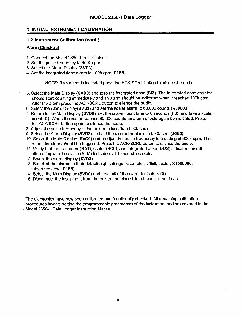
MODEL 2350-1 Data Logger
1. INITIAL INSTRUMENT CALIBRATION
1.2 Instrument Calibration (cont.)
Alarm Checkout
1. Connect the Model 2350-1 to the pulser.2. Set the pulse frequency to 600k cpm.3. Select the Alarm Display (SVD3).4. Set the integrated dose alarm to 100k cpm (PIE5).
NOTE: If an alarm is indicated press the ACK/SCRL button to silence the audio.
5. Select the Main Display (SVDO) and zero the integrated dose (SIZ). The Integrated dose countershould start counting immediately and an alarm should be indicated when it reaches 100k cpm.After the alarm press the ACK/SCRL button to silence the audio.
6. Select the Alarm Display(SVD3) and set the scaler alarm to 60,000 counts (K60000).7. Return to the Main Display (SVDO), set the scaler count time to 6 seconds (F6), and take a scaler
count (C). When the scaler reaches 60,000 counts an alarm should again be indicated. Pressthe ACK/SCRL button again to silence the audio.
8. Adjust the pulse frequency of the pulser to less than 600k cpm.9. Select the Alarm Display (SVD3) and set the ratemeter alarm to 600k cpm (J6E5).10. Select the Main Display (SVDO) and readjust the pulse frequency to a setting of 600k cpm. The
ratemeter alarm should be triggered. Press the ACK/SCRL button to silence the audio.11. Verify that the ratemeter (RAT), scaler (SCL), and integrated dose (DOS) indicators are all
alternating with the alarm (ALM) indicators at I second intervals.12. Select the alarm display (SVD3)13. Set all of the alarms to their default high settings (ratemeter, JI E9; scaler, K1 000000;
integrated dose, PIE9)14. Select the Main Display (SVDO) and reset all of the alarm indicators (X).15. Disconnect the instrument from the pulser and place it into the instrument can.
The electronics have now been calibrated and functionally checked. All remaining calibrationprocedures involve setting the programmable parameters of the instrument and are covered in theModel 2350-1 Data Logger Instruction Manual.
6

MODEL 2350-1 Data Logger
2. CALIBRATION ROUTINES
SOURCE PARAMETERS AND TYPICAL VALUES FOR MODEL 2350-1 CALIBRATIONS
To insure that the proper sized sources are used in calculating the calibration constant, anddead time of the Model 2350-1 and detectors the following calculation should be performed.
% Dead Time Loss = No. of source counts in 1 second X Dead Time (in seconds)
The following list provides some typical LO and HI cal points and dead times for variousdetectors:
TYPICAL DEAD TIME CALIBRATION, AND OVERLOAD POINTS
DETECTOR LOW POINT HIGH POINT OVERLOAD POINT
44-2 500 piRJhr 15 mR/hr 100 mR/hr
44-6 20 mR/hr 400 mR/hr I R/hr
44-7 5 mR/hr 100 mR/hr N/A
44-9 6 mR/hr 200 mR/hr I R/hr
44-38 20 mR/hr 400 mR/hr I R/hr
44-116 6 mR/hr 60 mR/hr N/A
TYPICAL DEAD TIME AND CALIBRATION CONSTANT SETTINGS
DETECTOR DEAD TIME CALIBRATION CONSTANT
44-2 15 - 25 psec. 1.0e"' - 0.3e'°
44-6 65 - 135 jisec. 7.09e 7 - 0.65e'
44-7 250 - 270 psec. 1.39e' - 0.1e'
44-9 50 - 120 psec. 2.0e' - 0.3e'
44-38 65 - 135 psec. 7.09e' - 0.65e7
43-68 Alpha 15 - 25 psec. 1
43-68 Beta 18 - 26 wsec. I
43-37 Alpha 18 - 20 psec. 1
43-37 Beta 19 - 25 psec.
7

MODEL 2350-1 Data Logger
2. CALIBRATION ROUTINES
2.1 High Voltage Ramp RoutineThe high voltage ramp routine is useful when a user needs to plateau a detector to
determine the proper operating voltage of the detector. The following display will appear whenperforming the routine.
B PROCEED W/ HV?0 SCL-J F
10 SEC SCL- GCURRENT H 0
0_ 0 0 -H
HIGH VOLTAGE RAMP ROUTINE DISPLAY
A. INFORMATION PROMPT: Prompts the user for the parameters required for the rampingroutine. When the routine is first started the prompt will ask if the user wants to proceedwith the current parameters. If answered YES the instrument will then prompt the user tobegin the routine by executing the scaler count command. If answered NO then the followinginformation prompts will appear immediately after the one before is answered.
Starting HV ?Ending HV?HV Increment?
The message DUMPING HEADER will then appear momentarily followed by the command"Ent C to start".
B. RATEMETER BARGRAPH DISPLAY: A logarithmic display of the ratemeter reading in
cps.
C. HV IDENTIFIER: Identifies the current HV setting.
D. STR: Identifies the starting voltage of the HV ramping routine.
E. SCALER COUNT: Shows the scaler reading in progress.
F. SCALERTIMER: Shows the count time for the scaler. When a count is in progress the timerwill show the time remaining in the count.
G. END: Identifies the ending HV setting for the ramping routine.
H. INC: Identifies the increment the voltage will be increased by in each step of the routine.
I. OPR CNT: Identifies the count at the beginning knee of the plateau or the recommendedoperating voltage.
8

MODEL 2350-1 Data Logger
2. CALIBRATION ROUTINES
The following example demonstrates how to run a plateau on a Model 44-2 GammaScintillator.KEYSTROKES RESPONSE
Note: Before performing the SHR(x) command, certain parameters must be set. The parametersthat need to be set include the threshold, window position, and count time.
SHR(x) ENTERWhere (x) = the number 0 or 1.0 = Disables data dump to the serial port.1 = Enables data dump to the serial port.
The Model 2350 display will show the detectordisplay with the current set of detector parameters.There will be no prompt but you will need to selecta set of parameters to use in the routine. If thecurrent parameters are correct press "Y ENTER",otherwise select the set of detector parametersthat you want to use and then press "Y ENTER".The instrument will proceed with the routine bydisplaying the screen shown on the opposite page.
This answers the prompt"PROCEED W/ HV" allowing the user to changethe parameters of the routine.
N ENTER
500 ENTER
1000 ENTER
25 ENTER
volts.
volts.
This set the beginning high voltage at 500
This sets the ending high voltage at 1000
This sets the HV increment to 25 volts.(This increment is the amount that the high voltagesetting will change between each step of theramping routine.)
This activates the routine by starting thescaler counting.C ENTER
"SHRO" will run the plateau routine, determine the operating votage, but will not dumpdata to the RS-232 port. "SHRI" will run the plateau routine, determine the operating voltage,and will dump the voltage setting and scaler count at each increment of the plateau routine.
When the routine is complete the following prompt will appear:"SAVE? HV = XXX"
"Y ENTER" will save the voltage as the operating voltage of the detector and theinstrument will return to the screen that was active prior to the exucution of the routine. "NENTER" will return to the screen that was active prior to the exucution of the routine withoutsaving the voltage.
9

MODEL 2350-1 Data Logger
2. CALIBRATION ROUTINES
2.2 Calibration Constant and Dead Time Calibration with Background SubtractThis routine will use a two point (low-hi) method to calculate the calibration constant
and dead time of the detector. The following display will appear when performing the routine.
AB LOW CAL POINT?
"1~ II t,1 I, oi1 pit
CC
L CAL O.O00e+O0D H CAL 0.000e+00
-LO SMPL 0E HI SMPL 0F
CALIBRATION CONSTANT/DEAD TIME ROUTINE DISPLAY
A. INFORMATION PROMPT: Prompts the user for the parameters required for the routine.When the routine is first started the prompt will prompt the user low calibration point. Onceentered it will prompt for the following parameters in order.
Hi CAL POINTTAKE BACKGROUNDTAKE LOW SAMPLETAKE HI SAMPLESAVE NUMBERS?
B. RATEMETER BARGRAPH DISPLAY: A logarithmic display of the ratemeter reading incps.
C. L CAL: Identifies the low calibration point that will be used in the routine.
D. H CAL: Identifies the high calibration point that will be used in~the routine.
E. LO SMPL: Shows the reading obtained from the low sample source.
F. HI SMPL: Shows the reading obtained from the high sample source.
NOTE: Line 1 will indicate the ratemeter reading when a sample is being taken,and lines 3 and 4 will show the scaler taking a count. When the routine iscomplete Line 3 will display the calculated calibration constant, and line4 will show the calculated dead time constant. These numbers will besaved into the active detector setup if the user answers yes to the promptto save the numbers.
10

MODEL 2350-1 Data Logger
2. CALIBRATION ROUTINES
The following example will calculate the cal constant and dead time of a Model 44-2Gamma Scintillator in R/hr.
KEYSTROKES RESPONSE
SKB ENTER
5e-4 ENTER
15e-3 ENTER
The Model 2350-1 will show the calibrationconstant/dead time routine with backgroundsubtract control display with a prompt to set thelow cal point.
This will set the lower calibration point at500 gR/hr, then a prompt will appear for the hi calpoint.
This will set the high calibration point at 15mR/hr, then a prompt will appear to take abackground sample.
This will initiate the scaler to take abackground reading, then a prompt will appear totake the low sample count. Place a I ý.Ci
137Cscheck source on the end of the detector.
This will initiate the scaler to take a countwith the low sample source, then a prompt willappear for the hi sample count. Place a 5 pCi 137Cscheck source on the end of the detector.
This will initiate the scaler to take the hisample reading.
C ENTER
C ENTER
C ENTER
NOTE: The SSK command initiates the same routine as stated above exceptthat the background count is not taken or considered when determiningthe calibration constant and dead time of the system.
ADDITIONAL PARAMETERS1. The background count should be less than 2% of the low sample count.2. The low sample count should have at least 15,000 counts.3. The high sample should be at least 100 times the low sample and produce
between 30 - 60% dead time loss.
11

MODEL 2350-1 Data Logger
2. CALIBRATION ROUTINES
2.3 Single Point Calibration Constant Routine with Background Subtract
This routine will use a single point method to calculate the calibration constant of thedetector. The following display will appear when performing the routine.
CALIBRATION CONSTANT/DEAD TIME ROUTINE DISPLAY
A. INFORMATION PROMPT: Prompts the user for the parameters required for the routine.When the routine is first started the prompt will prompt the user single calibration point.Once entered it will prompt for the following parameters in order.
TAKE BACKGROUNDTAKE SAMPLESAVE CAL CNST?
B. RATEMETER BARGRAPH DISPLAY: A logarithmic display of the ratemeter reading incps.
C. BACKGRND: Identifies the background reading obtained during the routine.
D. SAMPLE: Identifies the sample count taken during the routine.
E. CALPT: Identifies the reference calibration point set for the routine.
NOTE: Line 1 will indicate the ratemeter reading when a sample is being taken,and lines 3 and 4 will show the scaler taking a count. When the routine iscomplete Line 8 will display the calculated calibration constant. Thisnumber will be saved into the active detector setup if the user answersYES to the prompt to save the number.
12

MODEL 2350-1 Data Logger
2. CALIBRATION ROUTINES
The following example will calculate the cal constant of a Model 44-2 Gamma Scintillatorin R/hr.
KEYSTROKES
SSB ENTER
RESPONSE
5e-4 ENTER
The Model 2350-1 will show the single pointcalibration constant routine with backgroundsubtract control display with a prompt to set thesingle cal point.
This will set the single calibration point at500 liR/hr, then a prompt will appear to take abackground reading.
This will -initiate the scaler to take abackground count, then a prompt will appear forthe sample count. Place the detector in a500 pPRhr field.
: This will initiate the scaler to take the singlesample reading.
C ENTER
C ENTER
NOTE: The SSS command ,initiates the same routine as stated above exceptthat the background count is not taken or considered when determiningthe calibration constant.
13

MODEL 2350-1 Data Logger
2. CALIBRATION ROUTINES
2,4 Two Source Dead Time Calibration Routine with Background SubtractThis routine will use a single point method to calculate the calibration constant of the
detector. The following display will appear when performing the routine.
AB
D
EF
C- BACKGROUND6mm1 =I I , ,, I ,, I , I , ,
BACKGRND 0-SAMPLE 1 0SAMPLE 1+2 0
*SAMPLE 2 0
CALIBRATION CONSTANT/DEAD TIME ROUTINE DISPLAY
A. INFORMATION PROMPT: Prompts the user for the parameters required for the routine.When the routine is first started the prompt will appear for the background count. Onceentered it will prompt for the following parameters in order.
SAMPLE 1SAMPLE 1+2SAMPLE 2SAVE DEAD TIME?
B. RATEMETER BARGRAPH DISPLAY: A logarithmic display of the ratemeter reading in
cps.
C. BACKGRND::Identifies the background count taken during the routine.
D. SAMPLE 1: Identifies the sample count taken with source 1 during the routine.
E. SAMPLE 1 +2: Identifies the sample count taken with sources 1 & 2 during the routine.
F. SAMPLE 2: Identifies the sample count taken with source 2 during the routine.
NOTE: Lines 3 will show a timer and line 4 will show the word COUNTING whena count is in progress. When the routine is complete Line 3 will displaythe calculated dead time for the detector. This number will be saved intothe active detector setup if the user answers YES to the prompt to savethe number.
14

MODEL 2350-1 Data Logger
2. CALIBRATION ROUTINES
The following example will calculate the dead time of a Model 44-2 Gamma Scintillatorin R/hr.
KEYSTROKES RESPONSE
SSD ENTER
C ENTER
The Model 2350-1 will show the dead timecalibration routine with background subtract controldisplay with a prompt to take a backgroundreading.
This will initiate a count to get a backgroundsample, then a prompt will appear to take a readingfrom sample 1.
This will initiate count for sample 1, then aprompt will appear for a count with samples 1 & 2.C ENTER
C ENT
C ENT
ER This will initiate a count of samples 1 & 2together, then a prompt will appear for a countwith sample 2 only.
IER This will initiate a count of sample 2 only.
ADDITIONAL PARAMETERS1. The sources used for this test should be approximately the same size and
each should provide a minimum of 25,000 cpm.2. When combined the sources must provide a between 25 - 60% dead time
loss.
15

MODEL 2350-1 Data Logger
3. THEORY OF OPERATION
3.1 AMPLIFIER/POWER SUPPLY BOARD #5371-002
3.1.1 INPUT
Negative going pulses are coupled fromthe detector through C9 to emitter follower QI.CR6 is a voltage reference which provides a biasvoltage of approximately +3.3 Vdc to Q1 via R45.R9 protects Q1 from input inadvertent shorts/transients. R40 couples the detector to the highvoltage supply (HV).
3.1.2 AMPLIFIER
U3 ýis a self-biased amplifier whichprovides gain in proportion to R12 divided by theseries combination of Ri1 and R10. R10 isadjusted to provide a pulse height in proportion toa given threshold setting at comparator U4(typically adjusted to trigger with a detector inputpulse of 10 millivolts at a threshold setting of 100).Transistor (pins 4, 5, and 6 of U3) provideamplification and pulse polarity inversion.Transistor pins 10 through 15 are coupled as aconstant current source to pin 6 of U3. The outputself-biases to 2 Vbe - approximately 1.4 Vdc atpin 7 of U3. This provides just enough bias currentthrough pin 6 to conduct all of the current from theconstant current source. Positive pulses from pin7 are coupled to the Window and Thresholdcomparators, U4.
3.1.3 WINDOW/THRESHOLD
Threshold (THR) comparator, pins 5, 6,.. and 7 of U4,: provides the lower pulse height
discrimination. Pulses are AC coupled fromamplifier U3 via C23 to pin 6 of U4. THR referencevoltage data from the microprocessor board (pP)is processed by digital to analog convertor (DAC)U6 and coupled to pin 5 of U4 via opamp U5. R54and C13 provide additional filtering of thereference voltage. THR reference Vdc is approx.+122 millivolts (mV) with the THR set at 100 ondisplay - 1.222 Vdc at a THR setting of 1000. Asthe pulse height at pin 6 of U4 increases above thereference
voltage at pin 5, pin 7-normally high (approx. +5Vdc) goes low for the pulse duration.
Window (WIN) comparator, pins 1, 2, and3 of U4 provide the upper pulse heightdiscrimination. Pulses are coupled from amplifierU3 to pin 2 of U4. WIN reference voltage data fromthe pP is processed by DAC U6 and coupled to pin3 of U4. Q2 applies approx. ý+5. Vdc to the WINreference to disable the WIN comparator whenthe WIN OFF signal is applied to the base of Q2.The WIN reference voltage rides on top of theTHR reference - i.e., with a THR and WIN settingof 100, the WIN reference at pin 3 of U4 will equalapprox. +122 mV referenced above the THR atpin 5 or approx. +244 mV referenced to chassisground. If the THR is increased to 200 and theWIN still remains at 100 the WIN reference will stillequal approx. +122 mV referenced to thethreshold but will increase to approx. +366 mVwhen referenced to ground (THR = 244 mV + 122mV WIN = 366 mV). As the pulse amplitudeincreases above the WIN reference voltage, pin 1of U4 goes low for the pulse duration.
3.1.4 WINDOW/THRESHOLD LOGICCIRCUIT
Negative pulses from the THR comparatorare coupled to univibrator U9. Negative, pulses(approx. 5 volt) are present at univibrator outputpin 7 of U9 (PULSE'):as long as pins 13 and 3remain high. When a WIN pulse is present at pins13 and 3 the Reset function is enabled whichdisables the PULSE' output locking pin 7 high.Pulses are connected from pin 7 to the pP on theCentral Processor Board for count processing.Pin 7 is tied back to pin 13 via CR1 to provide atime delay (approx. 8 to 10 ps) for the pP clockcycle to complete before the next pulse can berecognized by the micro-processor.
16

MODEL 2350-1 Data Logger
3. THEORY OF OPERATION
3.1.5 DIGITAL TO ANALOG CONVERTORS
U6 and U7 are digital to analog convertors(DAC) which convert the digital data from the pP toanalog signals to control the THR, WIN, HighVoltage Reference (HV REF), and OverloadReference (OVR REF) variables. Data via BUSO-BUS3 and A0-A2 is loaded into the DAC latchesfor U6 and U7 by strobing CE3' and CE4' (ChipSelect). CE5' (Up Date) is then strobed to transferthe data stored in the latches to the DAC outputs.
3.1.6 HIGH VOLTAGE SUPPLY ANDDETECTOR OVERLOAD
Detector High Voltage (HV) is developedby blocking oscillator Q3, T1, C29 and rectified byvoltage multiplier CR3-CR5, CR14, CR15, C5,C32, C37, and C38. Q4, CR13, and R41 providea regulated voltage of approx. 4.4 Vdc (batteryvoltage must be +4.4 Vdc) to the emitter of Q3.HV increases as current through Q5 increaseswith maximum output voltage with Q5 saturated.
HV is coupled back through R5, through-voltage follower U1, to pin 6 of U2 to complete theregulation loop. Resistors R52 and R6 completethe HV divider network to ground. HV regulation isproduced by opamp comparator pins 5,6, and 7 ofU2. During stable operation the voltage at pin 6 willequal pin 5. If HV REF is increased, pin 7 of U2.will increase increasing conduction of Q5 until thevoltage at pin 6 equals pin 5 of U2 via HV dividernetwork, R5, R52, and R6. R52 is adjusted tocalibrate the HV output to the HV REF signalsupplied to pin 5 of U5 by the DAC - HV REF isset at approx. 1500 mV byentering the "H1500"command into the Model 2350-1, the HV CAL isadjusted for 1500 Vdc at the detector connector.Cl-C3, C8-C7, C19, and C27 provide additionalfiltering of the HV output.
Detector Overload is achieved bymeasuring the voltage differential across R4. Ascurrent is increased into the detector, a voltagedrop is produced across R4. The HV on either sideof R4 is converted to a low voltage by resistordivider networks R5, R52, R6, and R44, R7, and
R43. The voltage differential is coupled todifferential opamp, pins 12-14 of U1, via opampbuffers. The differential output is coupled toopamp comparator, pins 8- 10 of U1. OVR REF isprovided by the pP via the DAC - OVERLOAD' iscoupled back to the pP. R7, CURRENT CAL,calibrates the detector current drain to the OVRREF input - i.e., a 1 OpA load is connected to thedetector output; the overload is set to "100" byentering the "0100" command (approx. 61OmV atOVR REF), R7, CURRENT CAL, is then adjusteduntil pin 8 or Ul just starts to trigger low.
3.1.7 LOW VOLTAGE SUPPLY
Supply voltages of +5 and -10 Vdc aresupplied by U8, T2, and supporting components.U8 is a switching regulator with an on-boardcomparator providing regulation. An internalvoltage reference of 1.0 Vdc maintains theinverting and non-inverting comparators at 1.OVvia the feedback loop. Oscillator frequency, set byC36, is approx. 100 kHz at pin 5 of U5. CR11 andC26 provide rectification and filtering for the +5Voutput. CR12 and C25 provide rectification andfiltering for the -1 OV output.
U 11 is a -2.5 Vdc voltage reference for theDAC's -- U6 and U7. C8 located on the Backplaneboard maintains the battery voltage charge duringinadvertent battery disconnection (mechanicalshock).
3.1.8 LCD VIEWING ANGLE SUPPLY
U2 is configured as a differential opampwhich controls the backplane voltage to adjust theviewing angle for the LCD graphics display.Output voltage, pin 1 of U2 is adjustable from 0 to-10 Vdc by varying R50 (VIEWING ANGLE). LCDbackplane variance due to temperature iscompensated by CR10.
17

MODEL 2350-1 Data Logger
3. THEORY OF OPERATION
3.2 CENTRAL PROCESSOR BOARD #5371-068
3.2.1 MICROPROCESSOR (pP)
U124, Intel 80C51 FA, is the Model 2350-1central processor. The pP clock frequency iscrystal controlled by Y1 59 and related componentsat 6.144 MHZ. C172 resets the pP at power-up toinitiate the start of the program routine. The mainprogram routine is stored in EPROM, U122. Userparameters and logged data is stored in the 8k X8 RAM, U1 23. (replaced with 64k X 8 RAM locatedon the Memory Expander board)
Address and data information aremultiplexed by latch U121 from the pP to the twomemory chips. The low address bits A0-A7 aremultiplexed with the data bus, BUSO-BUS7, out ofthe pP. U121 latches the address data AO-A7 onlines BUSO-BUS7 during the first part of theexternal memory cycle when the ALE input isstrobed.
The HD175 ACCESS shunt configures thepP parameter access mode and password. Whenpins 1 and 2 are shunted (default) the accessparameters is determined by the settings preset inthe EPROM and the password entered in RAM. Ifshunt is placed between pins 2 and 3 thepassword is set to "0" and the access level is setto "3".
.The ACKNOWLEDGE' input is pulled lowwhen the front panel ACKNLDGE pushbutton.switch -is depressed silencing the audiblealarm(s). The OVERLOAD' signal from the AMP/PS board instructs the pP to initiate anOVERLOAD condition. WIN OFF' is an outputsignal from the pP to the AMP/PS board whichdisables the Window feature.
The TONE' input comes from the I/Oprocessor which toggles the TONE'/ALARM linelow when the external bar code wand registers barcode information. The TONE' and ALARM' (pPoutput signal from pin 5 of U 124) signals initiate anindependent audible tone by changing the CV(control voltage) input on the ICM7556 timer,U118.
The READY, CLEAR SEND, RECEIVE,and XMIT data lines communicate the RS-232and bar code reader wand information from/to theI/O processor to/from the central processor. TheRESET output at pin 13 of U124 is coupled to the
I/O board to reset the I/O processor. Q174 invertsthe RESET signal (RESET') providing a reset linefor the LCD graphics display. The PULSE' inputsupplies the pulses from the AMP/PS board to becounted and converted into data by the pP.
3.2.2 BATTERY VOLTAGE VFC
Un-switched (connected directly tobatteries) battery voltage - +BATUNS - isdivided by resistor divider network R148 and R149and connected to voltage to frequency convertor(VFC), U 125. VFC OUT is connected to a counterinside the pP which counts the frequency for apreset time converting to a number displayed onthe LCD representing the battery voltage. R1 30,BAT CAL, adjusts the VFC frequency output tocalibrate the LCD BAT reading to the actualbattery voltage.
NOTE: Disregard sections 3.2.3 and 3.2.4 for the
Model 2350-1
3.2.3 RECORDER DRIVE CIRCUIT
The RCDR output from the pP is coupledto MOSFET transistor Q126. The pP uses pulse-width modulation for the recorder signal. Thepulse-modulated signal is integrated by R144 andC100. Pins 5, 6, and 7 of U126 "buffers" theintegrated voltage from R131. R131 providescalibration of the recorder output voltage. Pins 1,2, and 3 of.U126 are configured as an opampvoltage follower providing recorder drive.
3.2.4 ADDRESS DECODERIVOLTAGEBACKUP
Ul 20 is address decoder which generatesthe chip enable signals - CEO-CE7 - bymonitoring address lines A13-A15. U120 alsoprovides battery backup, +5VBACK, to the Clockchip U119 and the RAM U123. This enables theuser to change the instrument batteries withoutlosing RAM memory. +BATUNSR suppliesbattery voltage to CR1 12 voltage reference to limitthe voltage at 5.1 Vdc. The 5.1 Vdc is coupled to a0.1
18

MODEL 2350-1 Data Logger
3. THEORY OF OPERATION
3.3 1/0 INTERFACE BOARD #5371-063
farad capacitor through CR113. CR113 preventsC129 from discharging through the +BATUNSRline when the batteries are removed.
3.2.5 CLOCK CHIP
Ul19 provides the time and dateinformation used in conjunction with the loggeddata. U119 is crystal controlled by Y158 andsupporting components C102 and C103 at32.786 kHz. The 10 Hz output at pin 13 of U 119,provides the timing frequency to the pP.
3.2.6 AUDIO CIRCUIT
Pulses are coupled from the AMP/PSboard to U128 - RDD 104 decade divider chip.AUDIO DIVIDE (front panel) by"1" switch positionjumpers the PULSE' input directly to the CLICK'input to the timers. Divide by "10" and "100" switchpositions connect the DIV OUT of U128 to theCLICK' input using U 128 for pulse division. U 118,a dual package 7555 timer, provides audiooscillation. Pulses (CLICK') are coupled to the firsttimer, pins 1-6 of U118, via C97. This timer isconfigured as a monostable multivibrator (one-
--shot) producing a fixed pulse-width for each inputpulse at pin 6 of U 118. Pulse-width is set by R1 61and C95. CR114 limits pulse input to pin 6 of Ul 18to 5.6 volts; R134 is a pull-up resistor for the ACcoupled pulse. The second half of Ul18 isconfigured as a astable (free-running) multivibratorwhich produces the audible tone - frequency isset by R133 and C96.I T157 provides amplification of the audio
signal driving the unimorph speaker. Audiovolume is varied by adjusting the voltage on top ofthe primary winding of T157 via the front panelvolume control. When an ALARM' is initiatedmaximum voltage applied by saturating Q154.
3.3.1 MICROPROCESSOR (pP)
U15, Intel 80C51FA, communicates andprocesses information bi-directionally from/to theRS-232 interface (U13) to/from the centralprocessor via the serial interface lines XMIT,READY, RECEIVE, and CLEAR SEND. U15 alsodecodes information from the bar code reader(WAND) and sends information to centralprocessor. The pP clock frequency is crystalcontrolled by Y159 and related components at6.144 MHZ.
U14, EPROM, stores the program for theI/O pP. U14 incorporates on-board latches toseparate the multiplexed address and data busslines.
CR26-CR28 provide "clipping" of transientswhich may be produced at the SERIAL I/O port.
3.3.2 RS-232 INTERFACE
U13, MAX232, is a +5 Vdc powered RS-232 driver/. receiver used to interface the Model2350-1 to a computer. or keypad terminal. U13incorporates on-board voltage multipliers whichgenerate the +10 and -10 volts required for RS-232 communication.
3.3.3 BACKLIGHT DRIVE
The LCD backlight is illuminated byappling power to +EL POWER when front panelBACKLIGHT switch is ON. With battery voltageapplied to +EL POWER, blocking oscillator -
Q23, T1 and supporting components beginoscillating. The signal is amplified by T1 to providea 70VAC signal to drive the LCD backlight. R30,a 10 ohm resistor, limits the power-up surge to theoscillator circuit.
19

MODEL 2350-1 Data Logger
3. THEORY OF OPERATION
3.4 64k MEMORY EXPANDER BOARD #5371-054
NOTE: When the MEMORY EXPANSION boardis added, U120 (DS 1211) and U123 (CDM6264)on the CENTRAL PROCESSOR board must beremoved. The red entries in the CENTRALPROCESSOR theory of operation should beremoved/or inserted for the M2350-1.
U 19 isa 128k RAM (only64kisused) usedtostore user parameters and logged data. U1 19 isselected by the central pP by applying a logic"high" to the RAM input, Pin 30 of U119. TheRecorder circuit is disabled on the CentralProcessor board and the RCDR output on thecentral pP is used to enable the MemoryExpansion board RAM.
U1 17 is address decoder which generates thechip enable signals - CE1-CE7, El - for theDAC's on the AMP/PS board and the Clock chipon the Central pP board by monitoring addresslines A12-A14 from the central pP.
U1 15 provides battery backup, +5VBACK, tothe Clock chip (U 119) on the Central pP board andthe RAM. This enables the user to change theinstrument batteries without losing the RAMmemory. Ul15 also provides a RESET signalwhich goes low when the +5V supply to pin 2 ofUl 15 drops below a preset threshold (4.5-4.75volts). This opens Ul 16 analog switchesdisabling the RAM and CLOCK' signals from thedata bus to save the parameter and loggingmemory.
20

MODEL 2350-1 Data Logger
4. PARTS LIST, COMPONENT LAYOUTS, AND SCHEMATICS
AMPLIFIER I POWER SUPPLY BOARD
Ref. No. Description
CAPACITORSCl-C3C4C5C6-C8C9C10C11-C12C13C14C15C16C17C18-C19C20-C21C22C23C24C25C26C27C28C29C30C31C32C33C34C35-C36C37-C38C39C40C41C42
DIODESCR1-CR2CR3-CR5CR6CR7CR8-CR10CR1 1-CR12CR13
0.0056ttF, 3kV0.1 jiF0.0015 [iF, 3kV0.0056 piF, 3kV100 pF, 3kV10 g±F100 pF0.01 pF47 pF100 •tF220 pF100 pF0.0056 pF, 3kV33 pF0.01 pF0.1 [iF0.0056 ýiF, 3kV22 .LF220 pF0.OO56 jiF, 3kV100 pF, 3kV0.01 [tF100 pF100 pF0.0015 pF, 3kV33 pFI pF0.001 ,iF0.0015 #F, 3Kv10 liF0.1 4F33 pF0.01 g.F
1N4148MR250-21 N52261N58191 N41481 N58191N4148
Part No.
04-552204-552104-551804-552204-553204-559204-552704-552304-553304-557604-553004-552704-552204-561604-552304-552104-552204-557904-563904-552204-553204-552304-557604-552704-551804-561604-557504-551904-551804-559204-552104-561604-5523
07-627207-626607-626007-630607-627207-630607-6272
21

MODEL 2350-1 Data Logger
4. PARTS LIST, COMPONENT LAYOUTS, AND SCHEMATICS
Ref. No. Description
DIODESCR14-CR15CR16-CR18
MR250-21N4148
TRANSISTORSQ1Q2Q3Q4Q5
RESISTORSRIR2R3R4R5R6R7R8R9RIOR11R12R13-R14R15R16R17-R19R21R22R23R24R25R26R27R28R29R30R31R32R33-R36R37R38
2N3904MPS6534MPS-U51MPS-UO12N3904
l0kohm, 333MW47 ohm, 333MW56 kohm, 333MW4.7 MohmI Gohm470 kohm, 333MW1 Mohm, pot100 kohm, 333MW10 kohm, 333MW100 kohm, pot1 kohm, 333MW470 kohm, 333MW10 kohm, 333MW1 kohm, 333MW4.7 kohm, 333MW10 kohm, 333MW0.1 ohm, 3W80.6 kohm, 333MWI Mohm, 333MW10 Mohm, 333MW10 kohm, 333MW80.6 kohm, 333MW62 kohm, 333MW1 Mohm, 333MW33.2 kohm, 333MW47 kohm, 333MW100 ohm, 333MW221 kohm, 333MW10 kohm, 333MW820 ohm, 333MW10 kohm, 333MW
Part No.
07-626607-6272
05-575505-576305-576505-577805-5755
12-774812-775612-778910-703012-768612-775709-682812-774712-774809-682312-775012-775712-774812-775012-775512-774812-764712-776212-776312-774912-774812-776212-779012-776312-779312-775812-774612-779212-774812-779112-7764
22

MODEL 2350-1 Data Logger
4. PARTS LIST, COMPONENT LAYOUTS, AND SCHEMATICS
Ref. No. Description
RESISTORSR39-R40R41R42R43R44R45R46R47R48R49R50R51R52R53R54R55R56R57R58R59
RESISTOR NETWORKRNIRN20
TRANSFORMERSTiT2
INTEGRATED CIRCUITSulU2U3U4U5U6-U7U8U9U10ull
1 Mohm100 kohm, 333MW3 kohm, 333MW470 kohm, 333MW1 Gohm100 kohm, 333MW10 kohm, 333MW33.2 kohm, 333MW1 Mohm, 333MW12 kohm, 333MW1 kohm, pot330 ohm, 333MWI Mohm, pot22 kohm, 333MW10 kohm, 333MW1 kohm, 333MW1 Mohm, 333MW80.6 kohm, 333MW1 Mohm, 333MW10 kohm, 333MW
5.6 kohm220 kohm
Part No.
10-702812-774712-776812-775712-768612-774712-774812-779312-776312-778709-683112-778809-682812-775412-774812-775012-776312-776212-775112-7748
12-769612-7578
4275-0374275-089
06-625206-625106-602306-626506-625106-625306-622306-606606-625105-5791
M2350-1M2350-1
LT1 079LT1 078CA3096TLC372LT1 078AD7549LM2578CD4098LT1 078LM385Z
HVPSLVPS
23

MODEL 2350-1 Data Logger
4. PARTS LIST, COMPONENT LAYOUTS, AND SCHEMATICS
CENTRAL PROCESSOR BOARD
Ref. No.
CAPACITORSC95C96C97C98C99-C 100C101C102-C103C104C109Cl10C1l1C129C172C177
DIODESCR112CR1 13-CR1 15CR162
HEADERHD175
TRANSISTORSQ153Q154Q155Q168,Q174
RESISTORSR130RI 31R132R1 33Ri 34R135R1 37-Rl 38R1 39R140R141-R142R143
Description
0.047 ptF0.001 pF47 pF0.01 pF0.1 gF27 pF22 pF27 pF10 pF100 1pF1 pF0.1 F10 piF0.1 •F 100V
1N52311N41481N4148
3 PIN SIP
2N3904MPS65342N39042N7000
10 kohm, pot100 kohm, pot2.2 kohm470 kohm220 kohm5.6 kohm10 kohm33 kohm10 kohm100 kohm7.15 kohm
Part No.
04-556514-551904-553304-552304-552104-561404-555204-561404-559204-557604-557504-563304-559204-5521
07-626107-627207-6272
n/a
05-575505-576305-575505-5820
09-682209-682310-701210-702610-706610-704210-701610-701912-754012-755712-7620
24

MODEL 2350-1 Data Logger
4. PARTS LIST, COMPONENT LAYOUTS, AND SCHEMATICS
Ref. No.
RESISTORSR144R148R149RI 60R161R164R166-R167Rl 70RR176
Description
1 Mohm35.7 kohm8.66 kohm220 kohm150 kohm1 Mohm10 kohm1 Mohm220 kohm
RESISTOR NETWORKSRN151
TRANSFORMERSTI 57
INTEGRATED CIRCUITSUl18U119U120U121U122U123U124U125U126U128
CRYSTALSY1 58Y1 59
22 kohm
Part No.
10-702812-764012-762310-706610-702410-702812-754010-702810-7066
12-7566
4275-074
06-624406-625406-644106-609306-626406-643906-623606-615606-624806-6060
01-521901-5212
M2221, 300-9
ICM7556MM58274CPL-200-T2-TCD74HC57327C512CPL-140-T2-T80C51 FALM331TLC27M71PRDD104
32 kHz XTAL6.144 MHz XTAL
25

MODEL 2350-1 Data Logger
4. PARTS LIST, COMPONENT LAYOUTS, AND SCHEMATICS
64k MEMORY EXPANDER BOARD
Ref. No.
RESISTORSR001Rl14
Description
22.1 kohm221 kohm
Part No.
12-784312-7845
06-638106-632306-633906-6385
INTEGRATED CIRCUITSUl15Ul16U117Ul19
MAX703ESACD74HC4066MCD74HC138MCXK581 OOM
26
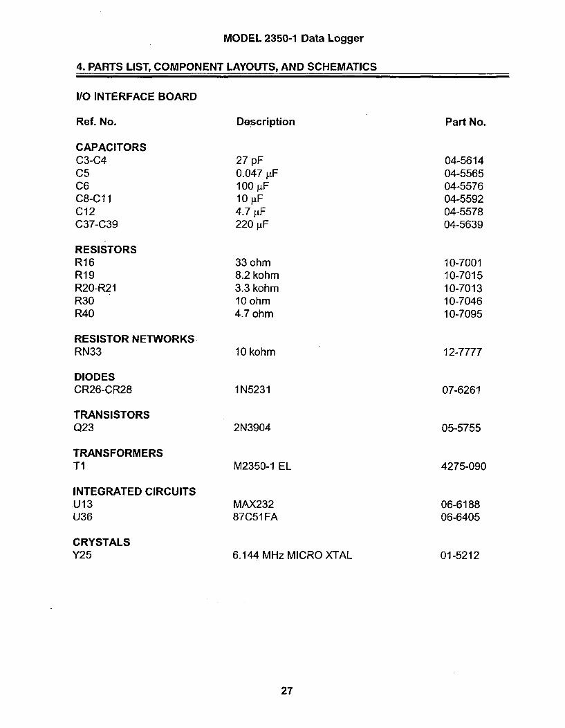
MODEL 2350-1 Data Logger
4. PARTS LIST, COMPONENT LAYOUTS, AND SCHEMATICS
I/O INTERFACE BOARD
Ref. No.
CAPACITORSC3-C4C5C6C8-C11C12C37-C39
RESISTORSR16R19R20-R21R30R40
RESISTOR NETWORKSRN33
DIODESCR26-CR28
TRANSISTORSQ23
TRANSFORMERSTI
INTEGRATED CIRCUITSU13U36
CRYSTALSY25
Description
27 pF0.047 LtF100 jiF10 jiF4.7 jiF220 jiF
33 ohm8.2 kohm3.3 kohm10 ohm4.7 ohm
10 kohm
1N5231
2N3904
Part No.
04-561404-556504-557604-559204-557804-5639
10-700110-701510-7013.10-704610-7095
12-7777
07-6261
05-5755
4275-090
06-618806-6405
01-5212
M2350-1 EL
MAX23287C51 FA
6.144 MHz MICRO XTAL
27

MODEL 2350-1 Data Logger
4. PARTS LIST, COMPONENT LAYOUTS, AND SCHEMATICS
BACKPLANE BOARD
Ref. No.
RESISTORSR6
DIODESCR5CR7
CONNECTORSJ 1 -J2
Description
1 kohm
1N41481N5819
125X44-CBNEARSEZA22DRSN
Part No.
10-7009
07-627207-6306
13-8181
28

134 131 Sv
47
C 34 CR6 R46 C39 6 II'l INS226 16611 1/6sF O
I/16 165 12 s6CN i/ s 53 1CW
e~~e2s9a4 ReRuFICI 6W1
10P FO R5 RISIU i40 3 311 lay 47og1 61
IAIN R11411 W______ Cie__O_
I,,S0.05UFI OBUFI ZZFý 0.05YF1174
RSVi566R75
-SVRN2622D0
RUSERUS2
RustRUSS
WR,
RESET
AZ
CR5
euseRus Ieuss-lBUS3--
RESET -I-
usAD7549
6RFFA
AW VA2S 6
FDA
66 UT
REFS6L R Fee
.5V
hRNI
S I CL-CE4'CE3'
!- - CES'c R I c l I C S? / C ARI .0LID Re.e-5SUF 1.166SUF . , 6,IRSUFT 7 T 3f 3KV T 3XV S2
.| I, /I/,
S 1V WIN OFF'
CR13 .DBATR4 R63 1641484.76 ITT 94
C3D - as-uel WINCRIS ,6661SUF R41I ~ C M • }iR250-2• uV TOOK>
{ I .6SGUF 1. - 13
- 3KV 65S I 30I OSU ;- e M~t,'i iR2SO-/l 2 Tl 03] C 3 2 C R 14 .J 3. 42 7 S-6 37 t •R ,S I C R SI C35 6 6'R266-S2 03K6IV / I 6 ' N4... .. I6O4 4
3KV S1 j CR6 166sCCR4 16474
I ePF ; 6R2S6-2 CTS 1l4.46
•.. •"-" .60 IIU )=G4 B=i( l_.-
1/3W R42- ] OVRO• ) ; 4
IC J
4670 666 U 13
4--S711565 6'6
_LTI 13W T107 C36TIRINGR7100V
8-84.R
11 "1U166/w 2470 Ti 1/34 111LRS
a6 REF to -4
1/314
11 -2.5V
16
C3333FF I/2 US
SI88V LT1078ITI
WRIN
//8 9SV4•CND
IL-2.5V
141
33PF 1/2 USC66 1717
" T-OBY LT1078
is 6~
IS 5, 7 WIN
is S
C26
33FF I1S 5161865 LT1078
17 2 ~ WAE
3 1 -HV REF
/1/ =÷V¥4=CND
$3 eSV
1 667 CRo,, PSGS3 4 -RSY io o+D
2 52lt VS-I .... 6NRFF 644----4'....,FS -3"3>1,.. :-,AI'CR I7
I/3W -i-2 CR4
617 1 F2 -36= +ig 4=14
/4 6LC37 I1K RI
1/ 14 LI B 2
6 P2K I // CR2/ CR7 3 1 P1 -1S3W R G-]R OF 1
lpAT / S *••• -,IA VS -is 4--.-Du ---s--6
3 + 63 2 IS ..V 4, C
S)" IT 2_ 1;IIOPF T leo- -- ;l
.-+" IS 113 -T P-O25 V
P 2 -S
62/ -2I4
15 1/3 6R37 PS -3 -. ,,- AT CND
K-.,112Z-,s P2 C24 -- .SN
77IS "l = D C,
SNX S
A?-
CES-
SUED 4.
BTJ63r
ONTSACND
26:+5VIZ1=CN1
U7AD7549
AR V REFAATA2 R FDA
aIl562S63
V REFS -- 0-2 .!SV
ESET-1 CLR RFee 14C2033PF I/S2 UI
I OUT6 S0 TAR REF
A:Ot 6I 5/
56"5al2'SND R"8R,4'CND
646615 .SV/,' III
' 47K 33.2
1/41 I II + "
ANCLE " l
1/314
-.-
i ....... , i
E L I pS fl , LUDLUM MEASUSEEMENTS INC.
SLI 12SE TITLE: AMPLIFIER/PDSRER SUPPLY BOARD
LLI 12-SEp4 -I A06R66 537 1-002
o 22i!.'T4 HSlz iRODEL SERE I SHEETIISKEI 61T C 236 1

22 054RS4 10 OIUF OOU
cIO RS3U FC2-- LOK Ri 14 -ii CS oLI -,- R53 "N94 "Lý II O OKEp22P K 05 104 470.. C 4 4 R0 c
C~~~1N30 1o1I.9 OIFR
fN] ci ) 0 " 0BOSU
Ci-4- 0.00S6U CR2 4OSU .7CKC
L.33P I~ N4 348 RI CeSU N14 0BSUcl 0 C OBSSUF CIS 0 .OOSSUF 0 '22122K
F- 0 ýC17 C2OU R.:S C RS..56 100N4 Clp l .05-- 320IN4148 -C.F 10
FORU 221-00 603IM0DSUOS MOEL SRIS SHE
ULuCOOP 62KEICM R27OILE LATDSE T XASK'IT
ICOMP PASTEr'OICOMlP MASKO ISLLDR PASTEO ISLDR MASKt"I

U121CD74KC5"3
8551 D--4I 0I144 AlBUS? ..1 D2 ftNC A2BUS) D3~- 0)S)43 A3BUS4 D14 5545- A4BUSs D ASBUSSG BF as &BUST D7 Q? AT
ALE 11tEr SE2B-.SV,I0=CND
'SO9 RNIS I
Buse 2 BUSTBUSS BJ~ USSB5S3f BUSA
U122
5-37 I-B2B
AS~~~ ISA I BUSOAl Al I/02 T7- SUSIA2 A2 1/03 55s--5su2h3 A3 1/04 i- BUSSA -- A4 I/OS B9usAS-T AS 1/0O W-mBuSs
AS AS I/SI BUSS
AS A-- AS 1/ BAS3-- AS
2 2
ASS AS CR -15N
All,, AllA 2I8AI ALEAIAS
A .4SI AIS
2B'SY_4ýCS
UI21PL-lIB-T2-T
NC a +SVBACK
A7AS ASAS ASA4 AllA2 ASM
Al CEO'Ig BUS7
"5 1 BUSSBUS2 BUSS
BUS)
P1 -21
P1 -42
XMIT-.--.-. Pi -43
READy •-- P -28
RECEIVE---< P1 -22
CLEAR SEND.-.--- P1 -44
PI -2G
, Fl -4 1
NC-•, Pi -41
ALE.. P 1 -3)
NR'.. P1 -32
CE2'-.P 1 -38
CE"--P-, -17
CE4' P•tP -39
CES'.- P1 -IA
PI
ABATO•
U120RI), CPL-.S-.T2-72.2K SATI I BCRIll -S+BACKN14 lNBAC 4 CEO'
NC CLOCA'CI2 C129 AC5 CE3'CKll1 S IF A14 NCE)
1555) AlA BCE
A O -•,-- P 1 -33Al +PI -33
A2 P-i..•1P -IS
BUSO -- > PI -IS
BUSI • 1P -34
BUS••--. el -13
BUS3-P-. 1El -3S
BUS4A--.( P1 -I4
BUSS P1 -3)
BUss-.4 PI -IS
BUS7-.+4 P1 -37
BIN OFF'. ..- PI -is
RESET'---.+ P1 -28
RESET-.--+ P1 -29
P1 -3 --- +BAT
PI -25 >- +BATUNS
P1 -4A >-•• -BATUNSR
PI -1 7 + - 1 BI4S V
PI -9 B
PI -31
1155[C?1?556PI -6
PI > -:P 1-24
CRl14IN4148

-I
9 LUDLUM MEASUREMENTS INC. SWEETWATER, TX.INR CK1B 09/17/96 TITLE: CENTRAL PROCESSOR BOARDCHK fC. Jý.27 BOARD: 5371-068VSGN RSS 09,117/96 I I'ED : 23501-1
App FILENAM:BS371068C rPOEN I 0OLE 16:31:18 128-.Ju-9S
SERIES I 4~ffI
1 .0 371 64
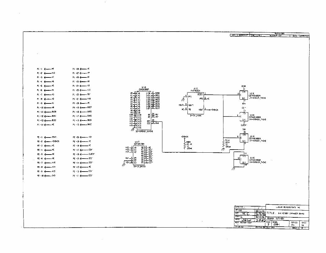
A1 -..... 12
P 1 -2 4...At
P1 -4 AsP 1s .- -mAS
P -1 -6 -A4
PI -7 .- A3
P - --- A2
Pi -9 - AI
P -I . . A,
Pl .-12 9slS6
P1 -12 •<----S
Pt -14 +- Ac
P1 -28 4--H
P1 -21 .--.-
P 1 -26 K~~A
p 1 -25 4..As
P1 .24 4..----..AS
P1 -2 R....-A'IP 1 -21 -A0
P1 -26 -
PI *I9 e----v
Pi -IS <- BUSS
p 1 -I6 4 B~US6PI -is - US1P1 -I6 4--.-US4
P1 -IS 4 .. =-...,BUlS4
ULIGC D74AC4066M1I I Ui
CnS14 , 'SVDACK t7-CHD
CD74HC4996RI 4US AC 4966I4..SA8 ACK, 7=CAD
P2-I <-- .A AT I
FP2 -2 <........YBACl1
F? .3 <.-- NP2 -4 4(- NC
P? -S <-~- KA
P2 -i NIC
P2.- -. AISF? .1 --. mA 14
P2- .9 A1
P2 -1 <.- .. CAND
P2 -25 -------SyP2 -19 -- CP2 - is -- -- C
P2 -Il CEO'
P2 -IS <~CLOCK'
P2 -is C.--.---
P2 .14 ----- CEV'
P2 -12 - CE4
P2 -1 I S
ICD74AC46662J14.-SVBACK,l.CNDUl 1l
CD74HC1381
A12 As? IS -NA13-..-~ YTT-r-CEI'A17-4 AA 21 T44- CE'
I T3 .CEV'Al CE4Z
12 T9 CE ,-52y (3 T7 CUI. I6..IV 9.51D
CD14, KC4iCAOM

UlIs
P2
CD74MC138Mr
0 m
SLUDLUMI !1ASUREI1ENTS INC. SWEETWATER, ~08C~ R/14/35 TITLE: 12 K IErORI EXPANDER 9
CAR C. eARDN S371-OS4 BSn~lAS4DSCH LL M51/5~OVEL23SO-1 SERIES' 371 SHEET S I
APP R.JCOMP ARTWORK D SUOR ARTWORK 009:30:4e 21F-SCOPOTNE SROULECCrMP PAEDCRIASOLD ATD5.9t9K

-12
CIOiEV
Cil
20V
-i1
Ps- WAND
P7 *S >- RSET
P7 -7 > -... T.OWE'
P7 -4 READ
P7 -3 A ECE
P7 -2 CIEX
Ps -2
PS -4
Pe -3
P8 -s
,SvR40
P8 -IA
ZERO ZERO. BUTTON Pe -i3
Si I'l
PLB PROCRAMA LE LOCCiNC BUTTON ) PA -GCR27
S.1v T11/2/7R30
iaLP7 -i *EL POWERC,
P7 -8 >
TO AND12ISTE.L. BACKLICHTIRC
BAUD B!AUD RAIE SELECT......... Pa -15CR26 -IMS231
S.iV1/2A
P7 -ia Sv7C39 Ca C37211UF C126 2ft
P7 -9 V
I o

mm LUDLUM meommws iNc. SWEETWATER, TX.DR tX9 11/20/95 TITLE: 1/0 INTERFACE GOARDTW= 144 GOARDN 5371-or.3 BS371063
M DSCH AS I SS MODEL22SO-1 SERIES071
SMEETS9App 4rp COMP ARTWORK 0 SUR ART ORK 09-Feb SG TO-MPOUTLINE 11
PASTE 0 1 COMP MASK 0 1 SUR PASTE 11 &-l"I", %UQLAN" 11 11

F_ REV - ____ 100I EFF I AUIRURIlY I LIR i - KRUM ppH_
P4 -S
P4 -2
P4 -3
P4 -4
P4 .1
PS -1 <-.~.AUDIO-
P5 -2 > -
P'S -3
Ps-
PS -s +BA
PS -6 0 +B3'AT
PS -7 4-o BAT
PS -6 >
PS -9
PS -10
pi9-1 <_ .. DIV OAT
Pie0-a >- VO
Pi604 >***ITS Ipie-S >_ ~CIlCKi'
PiG-8 < 4....PULSSE'
j2 i IA5rLIFIEe/POWER SUPPLY PROCESSOR6371-8112 5371-068
-e.-S.-- 1 23 AUDIO- A I 1 1 22)AUDIO.
__2 2-" 4 1' a _ ---- I 2"4
.6650--) 1 125K 9AtuS .-EAT0 3 1 12S)-6o-eAIsDIVTS . 4 212 TOE' DIV OT. 4 2 TOEs '
VOL.) 5I IS27 DS I oL-V S 21DSTSCLICAK'" 16 20F RESEl' CLICK'-A 6 1 12-8FRESET'
4sv.-A 7 I 12 RESET +SVo.-.,A 7 I29 RESET
PIASE'] a1 163-/ILE PULSE, '-! a I0ALE
A2 e J0 2 ) WR' A2,,, 1 • 12• 1 "R'"ABA it1 13 3 -AT A, - ItI 1 3a 1-AI
Buse A 12 1 13 U I Bus A-1 6006 1 2) gu 2 1-5uiS2"I iA1 las l-Ous3 BUS-I A 1 la s 1 -is .,
US4-A 14 I 1 3 F" Bss US4. 14 ) 136 Buss REBUSS. is IS o 1 1 7BSeUSS.A is) I a I ITSUSRD'-A is) I)sI-CE' C,- RDI' ) as CE2' CE2
CEa'.. A) 11 1 3 FcE' C02. 1) l39 )CE4 ' 4T4146CR
CES' Aj 1) 1 1 0 o .5RTIIRSR CES' -161 1 46 IBATUNSWIN OFF' is) 1 41 -RECORDER AI " OFF - sA 1941 1 uRECORDER
READY. 26@ 142 ý.OAERLOAD' READY)20 142 F OVERLOAD'ALARM RESET' 21 I" ", 515AL1 RESET'.] 21 4I T1-,oT
RECEIVEA 221 1 44CLEAR SEAS RECEIc.•E 22) 44 1-CLEAR SEND
IF ?P3 -2
.5Ao-'' P3 -3
R 4pa -4
A ED'- P3-6
RE-.1) .+P3 -s
RESE I'-.-P3 -10
Bu06se - P3 - 11
BUSE- ~.Pi -12BU52--.Pa -1a
5054 -. 4-'P3 -IS
BSiSR.*..P3 -Is
BST o....P3 -is
PI111
P 11-2
P1]-3
P I1-4
P11-4
P 11-s
4+..REXD0
>-......ALARM RESET'
-,-RECE IVE
> _aw SEN4
pS -1 +....-RECORDER
PS -2 -7
IJPDAILO / / , , M LU.LUM •EASUREMENTS INC.
AFFI jai - -- i-,-A4521P I SER11IESF
I ou:bbýlu 503 okli I5HE•T L OF II

00
0
a.
0

J4CAN
6371-003mTA laoXs
SiBACKLICHT
O N
Ji2DETECTORUGl70/U
JRJ13 WANDWAND S371-063
5 PIN DIN MISA 10OX4
d~fc~4 PGND 4 ANl.M--ý - - --- Gl " PANESPEAKER- S T 7T1-WS•A• MTA IBOXR
Nh,
S CLICK' AUDIO DIVIDE
R :RESiET I 72
SICNAL S2 PANEL 2 S 4TRSA-I-I- 5371-G37
POWER MTA ISOAXI IC +BAT UNSWITCHD = "•
2 ON 2 ROAST1! 1 DIIE V DOOIAIDOE lo_L> H --
CL> NJ
20 PIN 6IP LCO DISEAY
3 47 DR PIN OIP
OAWOACMIA IOOXZIO;VACEl m[] o~~ND • N

LUDLUM MODEL 3SURVEY METER
June 2007
Serial Number 239543 and Succeeding
Serial Numbers

LUDLUM MODEL 3SURVEY METER
June 2007
Serial Number 239543 and Succeeding
Serial Numbers
LUDLUM MEASUREMENTS, INC.501 OAK STREET, P.O. BOX 810SWEETWATER, TEXAS 79556325-235-5494, FAX: 325-235-4672
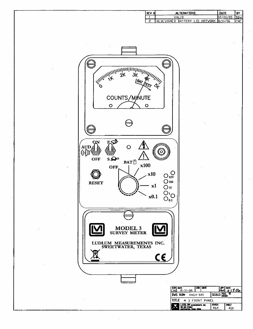
-IREV ii ALTERATIONS IDATE IBY1I VALID 112/21/05 IDDW2 IREDESIGNED BATTERY LID ARTWORK 18/11/06 ICMC
CI U1 tl I 1 Id l _8-11-06 II,
DWG NUN' 4464-041 aTITLE M 3 FRONT PANEL
LUDULU nM,,. I 4 I412menam s=464 41A

Table of Cnet
Introduction 1
Getting Started 2Unpacking and Repacking 2-1
Battery Installation 2-1
Connecting a Detector to the Instrument 2-2
Battery Test 2-2
Instrument Test 2-2
Reading the Meter Face Dial 2-3
Operational Check 2-6
Specifications 3
Identification of Controls and Functions 4
Safety Considerations 5Environmental Conditions for Normal Use 5-1
Warning Markings and Symbols 5-1
Cleaning and Maintenance Precautions 5-2
Calibration and Maintenance 6Calibration 6-1
Exposure Rate Calibration 6-1
CPM Calibration 6-2
Establishing an Operating Point 6-3
Maintenance 6-4
Recalibration 6-4
Batteries 6-5
Troubleshooting 7Troubleshooting Electronics which utilize a
G-M Detector or Scintillator 7-1
Troubleshooting G-M Detectors 7-3
Troubleshooting Scintillators 7-4
Ludlum Measurements, Inc. June 2007
Ludium Measurements, Inc. June 2007

Model 3 Technkial Manual
Technical Theory of Operation 8
Low Voltage Supply 8-1
High Voltage Supply 8-1
Detector Input 8-1
Amplifier 8-1
Discriminator 8-2
Audio 8-2
Scale Ranging 8-2
Meter Drive 8-2
Meter Reset 8-2
Fast/Slow Time Constant 8-2
Recycling 9
Parts List 10Model 3 Survey Meter 10-1
Main Board, Drawing 464 x 204 10-1
Wiring Diagram, Drawing 464 x 212 10-3
Drawings and Diagrams 11
Ludium Measurements, Inc. June 2007

Model 3 Technical Manual Secfion 1
Lo ntroucton
The Model 3 is a portable radiation survey instrument with four linearranges used with exposure rate or cpm (counts per minute) meterdials or a combination of both, exposure rate and count rate(referred to as "combo") meter face dials. The instrument features a
regulated high-voltage power supply, unimorph speaker with audio ON-OFFcapability, fast-slow meter response, meter reset button and a six-positionswitch for selecting battery check or scale multiples of X0.1, X1, XIO andx 100. Each range multiplier has its own calibration potentiometer. The unitbody and meter housing are made of cast aluminum and the can is 0.090"thick aluminum.
The audio provides a brief "click" for every radiation event detected. It alsoprovides a steady tone to warn the user of a low battery condition. This lowbattery warning overrides the position of the AUD ON-OFF switch.
Any Geiger-Mueller (G-AM) detector offered by Ludlum Measurements willoperate with this unit as well as any scintillation type detector. Theinstrument is typically set at 900 volts for G-M tube operation. For specialrequirements of G-M or scintillation detectors, the instrument high voltagemay be adjusted from 200 to 1500 volts.
The unit is operated with two "D" cell batteries for operation from -4°F(-20'C) to 122TF (50T). For instrument operation below 32TF (00 C) eithervery fresh alkaline or rechargeable NiCd batteries should be used.
Ludlum Measurements, Inc. Page 1-1 June 2007

Model 3 Technical Manual Secion 2
S e___ -m
Gettng Started
Unpacking and RepackingRemove the calibration certificate and place it in a secure location. Removethe instrument and accessories (batteries, cable, etc.) and ensure that all ofthe items listed on the packing list are in the carton. Check individual itemserial numbers and ensure calibration certificates match. The Model 3 serialnumber is located on the front panel below the battery compartment MostLudlum Measurements, Inc. detectors have a label on the base or body ofthe detector for model and serial number identification.
Imnportant.!
If multiple shipments are received, ensure that the detectorsand instruments are not interchanged. Each instrument iscalibrated to specific detector(s), and therefore notinterchangeable.
To return an instrument for repair or calibration, provide sufficient packingmaterial to prevent damage during shipment. Also provide appropriatewarning labels to ensure careful handling. Include detector(s) and relatedcable(s) for calibration. Include brief information as to the reason for return,as well as return shipping instructions:
- Return shipping address- Customer name or contact- Telephone number- Description of service requested and all other necessary
information
Baftery InstallationEnsure the Model 3 range selector switch is in the OFF position. Open thebattery lid by pushing down and turning the quarter-turn thumbscrew
Ludlum Measurements, Inc. Page 2-1 June 2007
Model 3 Technkial Manual Section 2
counterclockwise ¼ turn. Install two "D- size batteries in the compartment.
Note the (+) and (-) marks inside the battery door. Match the batterypolarity to these marks. Close the battery box lid, push down and turn thequarter-turn thumb screw clockwise ¼4 turn.
B E0) -r -77
The center post of a "D" size battery is positive.
Connecting a Detector to the Instrument
Caution!
The detector operating voltage (Hv) is supplied to the detectorvia the detector input connector. A mild electric shock mayoccur if you make contact with the center pin of the inputconnector. Switch the Model 3 range selector switch to theOFF position before connecting or disconnecting the cable ordetector.
Connect one end of a detector cable to the detector by firmly pushing theconnectors together while twisting clockwise ¼A turn. Repeat the process inthe same manner with the other end of the cable and the instrument.
Battery TestCheck the battenies daily or prior to use, whichever is less frequent, to assureproper operation of the instrument. Move the range multiplier switch to theBAT position. Ensure that the meter needle deflects to the battery checkportion on the meter scale. If the meter does not respond, check to see if thebatteries have been correctly installed. Replace the batteries if necessary.
Instrument TestAfter checking the batteries, turn the instrument range switch to the X100position. Place the AUD ON-OFF switch in the ON position. Expose thedetector to a check source. The instrument speaker should emit "clicks"relative to the rate of counts detected. The "AUD ON/OFF- switch will silencethe audible clicks if in the OFF position. It is recommended that the
Ludium Measurements, Inc. Page 2-2 June 2007

Model 3 Technical Manual Section 2
AUD ON/OFF" switch be kept in the OFF position when not needed in order to
preserve battery life.
The detector cable can be a source of problems. Test the detector cable bybending or flexing either end of the cable and checking for an increase ofcounts detected. Replace the cable if increases in the rate of counts aredetected.
Check the meter reset function by depressing the "RES" pushbutton switch andensuring the meter needle drops to "0'.
Once this procedure has been completed, the instrument is ready for use.
Reading the Meter Face DialReading the meter face is very important for consistent measurements. Thereare, in general, three types of meter faces: 1) count rate (typically cpm - countsper minute) 2) exposure rate (typically mR/hr) and 3) "combo" (typically cpmand mR/hr.) The following examples are intended to help the user interpretthe correct reading.
The normal procedure is to turn the range selector switch to the highest rangeand if no readings are seen on the meter, turn the selector switch down to thelower scales until a reading is seen. The ranges on the instrument selectorswitch are multipliers for the meter reading. A typical single scale (one arc)meter face with a cpm (counts per minute) dial is shown below.
The count rate scale reads 0-5K COUNTS/MINUTE (kcpm or 1000's ofcounts per minute) and has BAT TEST on the dial.
COUNTS/HINUTE
If the needle is pointing as indicated below and the instrument rangeselection switch is on the X0.1 scale multiple, then the reading is 3.5 kcpm(multiplied by) X0.1 = 350cpm.
Ludlum Measurements, Inc. Page 2-3 June 2007Ludium Measurements, Inc. Page 2-3 June 2007

Model 3 Technkial Manual Section 2
The same needle indications on successive ranges would be:
xl = 3.5 kcpm (or 3,500 cpm)
×10 = 35 kcpm (or 35,000 cpm)
X100 = 350 kcpm (or 350,000 cpm)
A typical dual scale (two arcs) meter face is shown below. The top scalereads 0-2 mR/hr. The bottom scale also reads 0-2 mR/hr and is for Xl00only scale. The X100 ONLY scale will work correctly when the multiplierswitch is in the x100 range. The meter face also has a BAT TEST positionon the dial.
10
If the needle is pointing as indicated below and the range selection switchis on the X0.1 scale, then the reading is 0.1 mR/hr.
sM 4hr.
The same needle indications on successive ranges would be:
Xl = 1.0 mR/hr (or 1,000 fiR/hr)
xl0 = 10 mR/hr (or 10,000 ptR/hr)
X100 = 70 mR/hr (or 70,000 ptR/hr)
Ludlum Measurements, Inc. Page 2-4 June2007Ludium Measurements, Inc. Page 2-4 June 2007

Model 3 Technkial Manual Secon 2
The dial shown below has three arcs: a counts per minute scale (cpm), alinear mR/hr scale, and a non-linear mR/hr scale for the x100 rangeonly. The meter face also has a BAT TEST position.
The top cpm scale is valid for the X0.1, Xl, XIO and the X100 ranges. Thelinear (middle) mR/hr scale is valid for the XO.1, Xl andXlO ranges. Thenon-linear mR/hr scale is valid for the Xl00 range only. This meter face iscommonly referred to as a "combo" meter face, since it has both, countrate (cpm) and exposure rate (mR/hr) arcs. Simpler meter faces may onlyhave a count rate or an exposure rate arc(s) like the previous meter facesshown.
A "combo" meter face is specifically designed for a particular detector. Inthe example above, the 1.0 mR/hr mark on the middle arc lines up with3.3kcpm on the upper arc. The meter face in this example works with adetector that receives 3.3kcpm per mR/hr (the Ludlum Model 44-9pancake detector.)
In the following picture, the needle is on the first tick mark past the 4kcpmmark. Therefore, if the instrument selector switch is on the XO.1 range, thereading is 4.2kcpm (multiplied by) XO.1 = 420cpm.
Ludluni Measurements, Inc. Page 2-5 June 2007Ludium Measurements, Inc. Page 2-5 June 2007

Model 3 Technical Manual Section 2
The same needle indications on successive ranges would be:
X 1 = 4.2kcpm (or 4,200 cpm)
x 10 = 42kcpm (or 42,000 cpm)
×100 = 420kcpm (or 420,000 cpm)
If you use the mR/hr scales, then the readings would be:
X0.1 = 0.13 mR/hr
xl = 1.3 mR/hr
X10 = 13 mR/hr
x100 180 mR/hr*
*This reading is using the bottom (non-linear) scale.
Many different dials are available, but each can be used as described above.
Operational CheckTo assure proper operation of the instrument and detectors(s) betweencalibrations, an instrument operational check including battery test andinstrument test (as described on pages 2-2 and 2-3) should be performed atleast daily or prior to use, whichever is less frequent. A reference reading(or readings) with a check source should be obtained with the detector(s)in a constant and reproducible manner at the time of calibration or at thetime the instrument is received in the field.
If at any time the instrument fails to read within 20% of the referencereading when using the same check source, it should be sent to acalibration facility for recalibration and/or repair. If desired, multiplereadings may be taken at different distances and/or with different sourcesso that other ranges or scales are checked.
Ludlum Measurements, Inc. Page 2-6 June 2007Ludium Measurements, Inc. Page 2-6 June 2007
Model 3 Technkial Manual Section 3
Specifca onsPower two D cell batteries housed in a sealed externally accessible
compartment.
Battery Life: typically greater than 2000 hours with alkaline batteries andwith the AUD ON-OFF switch in the OFF position.
End-of-Battery Life Warning: At 2.1 Vdc the meter needle will drop to theedge of the BAT TEST or BAT OK area when the meter selector switch ismoved to the BAT position. At 2.0 Vdc a steady audible tone will be emittedto warn the user of the low battery condition.
High Voltage: adjustable from 400 to 1500 volts.
Threshold: fixed at 40 mV ± 10 mV.
Meter. 2.5" (6.4 cm) arc, 1 mA analog type.
Meter Dial: 0-2 mR/hr, or 0-5k cpm, BAT TEST (others available).
Multipliers: X0.1, X1, Xl0, X1O0.
Range: typically 0-200 mR/hr, or 0-500,000 counts/minute (cpm).
Linearity: reading within 10% of true value with detector connected.
Battery Dependence: less than 3% change in readings to battery failureindication.
Calibration Controls: individual potentiometers for each range; accessiblefrom front of instrument (protective cover provided).
Audio: built-in unimorph speaker with ON-OFF switch (greater than 60 dB at2 feet).
Response: toggle switch for fast (4 seconds) or slow (22 seconds) from 10%to 90% of final reading.
Ludlum Measurements, Inc. Page 3-1 June 2007Ludium Measurements, Inc. Page 3-1 June 2007

Model 3 Technical Manual Secton 3
Reset: pushbutton to zero the meter.
Connector series "C- (other available).
Size: 6.5" (16.5 cm) H x 3.5" (8.9 cm) W x 8.5" (21.6 cm) L.
Weight: 3.5 lbs. (1.6 kg) including batteries.
Construction: cast and drawn aluminum with beige powder-coat
Cable: 39-inch with "C" connector (others available).
Ludlum Measurements, Inc. Page 3-2 June 2007

Model 3 Technical Manual Secfion 4
Identifcation of Controls andFunctions
See the Model 3 FRONT PANEL drawing at thebeginning of this manual to reference thefollowing controls:
Meter 2.5" (6.4cm) arc, 1 mA analog type with pivot-and-jewel suspension.Typical meter dials are 0-2 mR/hr, 0-20 pSv/h, 0-5k cpm or combination ofexposure rates (0-2 mR/hr or 0-20 6Sv/h) and cpm and BAT TEST.
Connector Used to connect the detector to the instrument. Typically series"C" but can be '"BNC", "MHV', "UHF', or others.
Range Selector Switch: A six-position switch marked OFF, BAT, X100,X10, X1, X0.1. Turning the range selector switch from OFF to BAT providesthe operator with a battery check of the instrument A BAT check scale onthe meter provides a visual means of checking the battery-charge status.Moving the range selector switch to one of the range multiplier positions(X100, X10, Xl, X0.1) provides the operator with an overall range of 0 to500,000 cpm. Multiply the scale reading by the multiplier to determine theactual scale reading.
Calibration Controls: Recessed potentiometers which are used to calibratethe individual range selections and allow for high voltage adjustment from400 to 1500 volts. A protective cover is provided to prevent tampering.
Battery Compartment: Sealed compartment to house two 3"- cell batteries.
RESET Button: When depressed, this switch provides a rapid means to drivethe meter to zero.
AUD ON-OFF Switch: In the ON position, operates the unimorph speaker,located on the left side of the instrument. The frequency of the clicks isrelative to the rate of the incoming pulses. The higher the rate,
Ludlum Measurements, Inc. Page 4-1 June 2007

Model 3 Technical Manual Secon 4
the higher the audio frequency. The audio should be turned OFF when notrequired to reduce battery drain.
Note:-,.
A low battery condition results in a steady audio toneregardless of the position of the AUD ON-OFF switch.
F-S Toggle Switch: Provides meter response. Selecting the fast, "F" positionof the toggle switch provides 90% of full scale meter deflection in fourseconds. In the slow, "s" position, 90% of full scale meter deflection takes 22seconds. In "F_ position there is fast response and large meter deviation. The"s" position should be used for slow response and damped, meter deviation.
Note:, ,
The slow response position is normally used when theinstrument is displaying low numbers that require a morestable meter movement. The fast response position is used athigh rate levels.
Ludlum Measurements, Inc. Page 4-2 June 2007Ludium Measurements, Inc. Page 4-2 June 2007

Model 3 Technical Manual Secfion 5
Safety Consideratons
Environmental Conditions for Normal UseIndoor or outdoor use
No maximum altitude
Temperature range of -20'C to 50'C (-4°F to 122DF). May be certified foroperation from -40°C to 65'C (-40°F to 150 0F).
Maximum relative humidity of less then 95% (non-condensing)
Pollution Degree 1 (as defined by MEC 664).
Warning Markings and Symbols
C Pton.
The operator or responsible body is cautioned that theprotection provided by the equipment may be impaired if theequipment is used in a manner not specified by LudlumMeasurements, Inc.
The Model 3 Survey Meter is marked with thefollowing symbols:
Aj CAUTION, RISK OF ELECTRIC SHOCK (per ISO 3864, No. B.3.6)- designates a terminal (connector) that allows connection to a voltageexceeding 1 kV. Contact with the subject connector while the instrument ison or shortly after turning off may result in electric shock. This symbolappears on the front panel.
Ludlum Measurements, Inc. Page 5-1 June 2007

Model 3 Technical Manual Secon 5
A CAUTION (per ISO 3864, No. B.3.1) - designates hazardous live voltageand risk of electric shock. During normal use, internal components arehazardous live. This instrument must be isolated or disconnected from thehazardous live voltage before accessing the internal components. Thissymbol appears on the front panel Note the following precautions:
W~arinq!
The operator is strongly cautioned to take the followingprecautions to avoid contact with internal hazardous live partsthat are accessible using a tool:
1. Turn the instrument power OFF and remove the batteries.2. Allow the instrument to sit for 1 minute before accessing
internal components.
\ The "crossed-out wheelie bin" symbol notifies the consumer that theproduct is not to be mixed with unsorted municipal waste when discarding-,each material must be separated. The symbol is placed on the batterycompartment lid. See section 9, "Recycling" for further information.
Cleaning and Maintenance PrecautionsThe Model 3 may be cleaned externally with a damp cloth, using only wateras the wetting agent. Do not immerse the instrument in any liquid. Observethe following precautions when deaning or performing maintenance on theinstrument:
1. Turn the instrument oFF and remove the batteries.
2. Allow the instrument to sit for 1 minute before cleaning theexterior or accessing any internal components for maintenance.
Ludlum Measurements, Inc. Page 5-2 June2007Ludium Measurements, Inc. Page 5-2 June 2007

Model 3 Technkial Manual Section 6
Calibration and Maintenance
CalibrationCalibration controls are located on the front of the instrument under thecalibration cover. The controls may be adjusted with a 1/8-inch bladescrewdriver.
Note:, ,-
Local procedures may supersede the following
The instrument may be calibrated using Exposure Rate Calibration orCPM Calibration. Both methods are described below. Unless otherwisespecified, the instrument is calibrated to Exposure Rate at the factory.
Note:.
Measure High Voltage with a Model 500 Pulser or a HighImpedance voltmeter with a high meg probe. If one ofthese instruments is not available use a voltmeter with aminimum of 1000 megohm input resistance.
Exposure Rate Calibration
Connect the input of the instrument to a negative pulse generator, suchas a Ludlum Model 500 Pulser.
The instrument input operates at a high potential.Connect the pulse generator through a 0.014F, 3,000-voltcapacitor, unless the pulse generator is already protected.
Ludlum Measurements, Inc. Page 6-1 June 2007
Ludlum Measurements, Inc. Page 6-1 June 2007

Model 3 Technical Manual Secon 6
Adjust the HV control for the proper operation voltage of the detector to beused. Disconnect the Pulser and connect the detector to the instrument.
Turn the range selector switch to the X100 position. Expose the detector toa calibrated gamma field which corresponds to approximately 80% of full-scale meter deflection. Adjust the xl00 calibration control for the properreading.
Reposition the detector so the field corresponds to approximately 20% offull-scale meter deflection. Confirm that the meter reading is within :t 10%of the field.
Repeat this process for the X10, Xl and X0.1 ranges.
If your gamma exposure range cannot calibrate two positions on each scale,the Pulser may be used to "electronically calibrate" the remaining points.Reconnect the Pulser to the instrument and determine the count rateconversion at a previous range calibration point. Then use that conversionrate to calibrate other points or scales.
If for example, you can exposure rate calibrate the 400 piR/hr point, first usethe Pulser to get the count rate equivalent to the calibrated 400 pR/hr pointThen switch the Pulser "multiplier" switch to the next lower setting, andadjust the appropriate calibration control on the Model 3 for the meter toread 40 pR/hr.
CPM Calibration
Connect the input of the instrument to a negative pulse generator, such as aLudlum Model 500 Pulser.
Caution!
The instrument input operates at a high potential. Connect thepulse generator through a 0.01•F, 3,000-volt capacitor, unlessthe pulse generator is already protected
Adjust the HV control for the proper operating voltage of the detector to beused. Adjust the Pulser negative pulse frequency to provide a meter
Ludlurn Measurements, Inc. Page 6-2 June 2007
Model 3 Technial Manual Secfion 6
deflection of approximately 80% of full-scale on the X100 range. Adjust theX 100 calibration control for the proper reading.
Check the 20% scale indication of the Model 3 by reducing the Pulser countrate by a factor of 4. The Model 3 should read within 10% of the actualpulse rate. Decrease the pulse rate of the Model 500 by one decade and turnthe Model 3 range selector to the next lower range. Repeat the aboveprocedure for the remaining lower ranges.
In the event that any reading is not within 10% of the truevalue on any scale after any of the above calibration methodsis performed, a reading within 20% of true value shall beacceptable- if a calibration graph or chart is provided with theinstrument. Instruments that cannot meet these criteria aredefective and require repair.
Establishing an Operating Point
The operating point for the instrument and detector is established by settingthe instrument high voltage (HV). The proper selection of this point is thekey to instrument performance. Efficiency, background sensitivity and noiseare fixed by the physical makeup of the given detector and rarely vary fromunit to unit. However, the selection of the operating point makes a markeddifference in the apparent contribution of these three sources of count.
In setting the operating point, the final result of the adjustment is toestablish the system gain so that the desirable signal pulses (includingbackground) are above the discrimination level and the unwanted pulsesfrom noise are below the discrimination level and are therefore not counted.The system gain is controlled by adjusting the high voltage.
Note: "- i-
Measure the high voltage with a Ludlum Model 500 Pulser. Ifthe Pulser does not have a high voltage readout, use a highimpedance voltmeter with at least 1000 megohmi inputresistance to measure the high voltage.
Ludlum Measurements, Inc. Page 6-3 June2007Ludlum Measurements, Inc. Page 6-3 June 2007

Model 3 Technical Manual Section 6
G-M Detectors: In the special case of G-M detectors, a minimum voltagemust be applied to establish the Geiger-Mueller characteristic. The outputpulse height of the G-M Detector is not proportional to the energy of the
detected radiation. Most G-M detectors operate at 900 volts, although someminiature detectors operate at 400-500 volts. Refer to the detector operatingmanual for specific recommendations. If a recommended setting isunavailable, plot a HV versus count rate curve to produce a plateau graphsimilar to the one displayed below. Adjust the HV for 25-50 volts above theknee or start of the plateau. For mixed detector use, the high voltage may betailed for both, as long as the G-M detector is operated within therecommended voltage range.
Scintillators: Scintillation type detectors have a wide gain spectrum, typically1000:1 at a single operating point. An operating voltage versus count ratecurve (plateau) must be established to determine the proper operatingvoltage. The operating voltage is typically set above the knee of the plateau.Plot the Hv versus background and source count to produce a plateau graphsimilar to the one in the figure below. Adjust the HV to 25-50 volts abovethe knee or start of the plateau. This provides the most stable operatingpoint for the detector.
SorcC0U
T BacRground
Knee Knee + 50 VoltsVOLTS
Note:
If more than one detector is to be used with the instrument andthe operating voltages are different, the Hv will have to bereadjusted for each detector substitution.
MaintenanceInstrument maintenance consists of keeping the instrument clean andperiodically checking the batteries and the calibration. The Model 3instrument may be cleaned with a damp cloth (using only water as the
Lud/um Measurements, Inc. Page 6-4 June 2007

Mode 3 Technial Manual Secfion 6
wetting agent). Do not immerse instrument in any liquid. Observe thefollowing precautions when cleaning.
1. Turn the instrument OFF and remove the batteries.
2. Allow the instrument to sit for 1 minute before accessinginternal components.
RecalibrationRecalibration should be accomplished after maintenance or adjustmentshave been performed on the instrument. Recalibration is not normallyrequired following instrument cleaning, battery replacement, or detectorcable replacement.
Ludlum Measurements, Inc. recommends recalibration at intervalsno greater than one year. Check the appropriate regulations todetermine required recalibration intervals.
Ludlum Measurements offers a full service repair and calibrationdepartment. We not only repair and calibrate our own instruments but mostother manufacturer's instruments. Calibration procedures are available uponrequest for customers who choose to calibrate their own instruments.
BatteriesThe batteries should be removed any time the instrument is placed intostorage. Battery leakage may cause corrosion on the battery contacts, whichmust be scraped off and/or washed using a paste solution made frombaking soda and water. Use a spanner wrench to unscrew the battery contactinsulators, exposing the internal contacts and battery springs. Removal ofthe handle will facilitate access to these contacts.
Never store the instrument over 30 days without removing thebatteries. Although this instrument will operate at very high ambienttemperatures, battery seal failure may occur at temperatures as low as
1000 F.
Ludlum Measurements, Inc. Page 6-5 June 2007Ludium Measurements, Inc. Page 6-5 June 2007

Modd 3 Technical Manual Section 7
Troubleshooting
ccasionally, you may encounter problems with your LMI
instrument or detector that may be repaired or resolved in thefield, saving turnaround time and expense in returning theinstrument to us for repair. Toward that end, LMI electronics
technicians offer the following tips for troubleshooting the most commonproblems. Where several steps are given, perform them in order until theproblem is corrected. Keep in mind that with this instrument, the mostcommon problems encountered are: (1) detector cables, (2) sticky meters,(3) battery contacts.
Note that the first troubleshooting tip is for determining whether theproblem is with the electronics or with the detector. A Ludlum Model 500Pulser is invaluable at this point, because of its ability to simultaneouslycheck high voltage, input sensitivity or threshold, and the electronics forproper counting.
We hope these tips will prove to be helpful. As always, please call if youencounter difficulty in resolving a problem or if you have any questions.
Troubleshooting Electronics which utilize a
G-MV Detector or Scintillator
SYMPTOM POSSIBLE SOLUTION
no power (or meterdoes not reach BAT
TEST or BAT OK
mark)
1. Check batteries and replace if weak.
2. Check polarity (See marks insidebatter lid). Are the batteries installedbackwards?
Ludlum Measurements, Inc. Page 7-1 June 2007Ludium Measurements, Inc. Page 7-1 June 2007

Mode 3 Technical Manual Section 7
SYMPTOM POSSIBLE SOLUTION
no power (or meterdoes not reach BATTEST or BAT OK
mark) (continued)
nonlinear Readings
3. Check battery contacts. Clean themwith rough sandpaper or use anengraver to clean the tips.
4. Remove the can and check for looseor broken wires.
1. Check the high voltage (HV) using aLudlum Model 500 Pulser (orequivalent). If a Multimeter is used tocheck the HV, ensure that one withhigh impedance is used, as a standardMultimeter could be damaged in thisprocess.
2. Check for noise in the detector cableby disconnecting the detector,placing the instrument on the lowestrange setting, and wiggling the cablewhile observing the meter face forsignificant changes in readings.
3. Check for "sticky" meter movement.Does the reading change when youtap the meter? Does the meter needle"stick" at any spot?
4. Check the "meter zero." Turn thepower OFF. The meter should cometo rest on "0".
1. Replace the detector cable todetermine whether or not the cablehas failed- causing excessive noise.
2. Check the HV and, if possible, theinput threshold for proper setting.
meter goes full-scaleor "pegs out"
Ludlum Measurements, Inc. Page 7-2 June 2007

Model 3 Technical Manual Section 7
SYMPTOM POSSIBLE SOLUTION
meter goes full-scale 3. Remove the can and check for looseor "pegs out" or broken wires.(continued)
4. Ensure that the instrument's "can"is properly attached. When attachedproperly, the speaker will be locatedon the left side of the instrument. Ifthe can is on backwards, interfer-ence between the speaker and theinput preamplifier may cause noise.
no response to 1. Substitute a "known good" detectorradiation and/or cable.
2. Has the correct operating voltagebeen set? Refer to the calibrationcertificate or detector instructionmanual for correct operatingvoltage. If the instrument usesmultiple detectors, confirm that thehigh voltage is matched to thecurrent detector being used.
1. Ensure that the AUD ON-OFF switchno audio is in the ON position.
2. Remove the instrument housing andcheck the connection between thecircuit board and the speaker. Plugin the 2-pin connector if necessary.
Troubleshooting G-M Detectors1. If the tube has a thin mica window, check for window breakage.
If damage is evident, the tube must be replaced.
2. Check the HV. For most G-M tubes, the voltage is normally 900Vdc, or 460-550 Vdc for "peanut" tubes (Ludlum Model 133series).
Ludlum Measurements, Inc. Page 7-3 June 2007Ludium Measurements, Inc. Page 7-3 June 2007

Model 3 Technical Manual Secon 7
3. If the input sensitivity is too low, the user could see somedouble-pulsing.
4. Wires to the tube may be broken or the crimped connectorcould have a loose wire.
Troubleshooting Scintillators1. Alpha or alpha/beta scintillators are prone to light leaks. They
can be tested for this problem in a dark room or with a brightlight. If a light leak is determined, changing the Mylar windowassembly will usually fix the problem.
Note:
When replacing the window, make sure to use a window madewith the same thickness Mylar and the same number of layersas the original window.
2. Verify that the HV and input sensitivity are correct. Alpha andgamma scintillators typically operate from 10-35 mV. Highvoltage varies with the photomultiplier tubes (PMIrn from aslow as 600 Vdc, to as high as 1400 Vdc.
3. On a gamma scintillator, visually inspect the crystal forbreakage or humidity leakage. Water inside the crystal will turnit yellow and gradually degrade performance.
4. Check the PMT1' to see if the photocathode still exists. If theend of the PMT is clear (not brownish), this indicates a loss ofvacuum which will render the PMT useless.
Ludlum Measurements, Inc. Page 7-4 June 2007

Model 3 Technkial Manual Secton 8
Technical Theory of Operation
Low Voltage Supply
Battery voltage is coupled to U1 1 and associated components (a switchingregulator) to provide 5 volts at pin 8 to power all logic circuits. A voltagedivider (R27 and R32) located at pin 1 of U11 sets the end-of-battery-lifesqueal at 2.0 Vdc. Components R12 and C30 provide filtering to create+5 VA used by the amplifier and discriminator circuits.
High Voltage SupplyHigh voltage is developed by pulses from the switching regulator U13 totransformer T1. High voltage is multiplied by the ladder network of diodesCR3 through CR7 and capacitors C18 through C27. High voltage is coupledback through R39 to pin 8 of U13. High voltage output is set by front panelpotentiometer R42, which sets the voltage feedback of 1.31 Vdc to pin 8 ofU13. R38 and C28 provide filtering.
Detector InputDetector pulses are coupled from the detector through C6 to amplifier inputpin 2 of U4. CR1 protects U4 from input shorts. R37 couples the detector tothe high voltage supply.
AmplifierA self-biased amplifier provides gain in proportion to R15 divided by R14,with some gain loss due to feedback capacitor C4. A transistor (pin 3 of U4)provides amplification. U6 is configures as a constant current source to pin 3of U4. The output self-biases to 2 Vbe (approximately 1.4 volts) at theemitter of Q1. This provides just enough bias current through pin 3 of U4 toconduct all of the current from the current source. Positive pulses from theemitter of Q1 are coupled to the discriminator.
Ludlum Measurements, Inc. Page 8-1 June 2007
Model 3 TechnkiaJ Manual Section 8
DiscriminatorComparator U8 provides discrimination. The discriminator is set by avoltage divider (R21 and R23), coupled to pin 3 of U8. As the amplifiedpulses at pin 4 of US increase above the discriminator voltage, 5 voltnegative pulses are produced at pin 1 of US. These pulses are coupled to pin5 of U9 for meter drive and pin 12 of U9 for audio.
AudioDiscriminator pulses are coupled to univibrator pin 12 of U9. The frontpanel audio ON-OFF selector controls the reset at pin 13 of U9. When ON,pulses from pin 10 of U9 turn on oscillator U12, which drives the housing-mounted unimorph speaker. Speaker tone is set by R31 and C14. Toneduration is controlled by R22 and C7.
Scale RangingDetector pulses from the discriminator are coupled to univibrator pin 5 ofU9. For each scale, the pulse width of pin 6 of U9 is changed by a factor of10 with the actual pulse width being controlled by the front panel switch, theanalog switches UI and U2, and the related potentiometers. Thisarrangement allows the same current to be delivered to C9 by 1 count on theX0.1 range as 1000 counts on the X100 range.
Meter DrivePulses from pin 6 of U9 charge capacitor C9. A constant current driver(opamp U10 and transistor Q2) delivers proportional current to the meter.For battery test (BAT TEST), the meter is directly coupled by the analogswitch U3 to the batteries through resistor R8.
Meter ResetRatemeter reset is initiated by changing the voltage differential at C9 to zerowhen the RESET button is depressed.
Fast/Slow Time ConstantFor the slow time constant, C17 is switched from the output of the meterdrive to parallel C9.
Ludlum Measurements, Inc. Page 8-2 June2007Ludlum Measurements, Inc. Page 8-2 June 2007

Model 3 Technkal Manual Section 9
~Recycling
L udlum Measurements, Inc. supports the recycling of the electronicsproducts it produces for the purpose of protecting the environmentand to comply with all regional, national and international agenciesthat promote economically and environmentally sustainable
recycling systems. To this end, Ludlum Measurements, Inc. strives to supplythe consumer of its goods with information regarding reuse and recycling ofthe many different types of materials used in its products. With manydifferent agencies, public and private, involved in this pursuit it becomesevident that a myriad of methods can be used in the process of recycling.Therefore, Ludlurn Measurements, Inc. does not suggest one particularmethod over another, but simply desires to inform its consumers of therange of recyclable materials present in its products, so that the user willhave flexibility in following all local and federal laws.
The following types of recyclable materials are present in LudlumMeasurements, Inc. electronics products, and should be recycled separately.The list is not all-inclusive, nor does it suggest that all materials are present ineach piece of equipment:
Batteries Glass Aluminum and Stainless Steel
Circuit Boards Plastics Liquid Crystal Display (LCD)
Ludlum Measurements, Inc. products which have been placed on themarket after August 13, 2005 have been labeled with a symbol recognizedinternationally as the "crossed-out wheelic bin" which notifies the consumerthat the product is not to be mixed with unsorted municipal waste whendiscarding, each material must be separated. The symbol will be placed nearthe AC receptacle, except for portable equipment where it will be placed onthe battery lid.
The symbol appears as such:
Ludlum Measurements, Inc. Page 9-1 June 2007

Model 3 TechnkiaJ Manual Secfion 10
Reference Description Part Number
Model 3Survey Meter UNIT Completely Assembled
Model 3 Survey Meter 48-1605
Main Board,Drawing 464 x 204 BOARD Completely Assembled
Main Circuit Board 5464-204
CAPACITORS C1 47pF, 100V 04-5660
C2 0.19iF, 35V 04-5755C3 0.00479F, 100V 04-5669C4 10pF, 1OOV 04-5673C5 0.01giF, 50V 04-5664C6 1OOpF, 3KV 04-5735C7 0.022gF, 50V 04-5667C8 ljiF, 16V 04-5701C9 1OjIF, 25V 04-5655C10 100pF, 1OOV 04-5661C11 68jiF, 10V 04-5654C12 10F, 25V 04-5728C14 470pF,100V 04-5668C15 220pF, 100V 04-5674C16 68gF, 10V 04-5654C17 47 iF, 1OV 04-5666C18-C27 0.01gtF, 500V 04-5696C28 0.001gtF, 2KV 04-5703
or 100pF, 3KV 04-5735C29 10tF, 25V 04-5655C30-C31 ljF, 16V 04-5701C32 470pF, 100V 04-5668
Ludlum Measurements, Inc. Page 10-1 June 2007Ludlum Measurements, Inc. Page 10-1 June 2007

Model 3 Technica Manual Secfion 10
Reference Description Part Number
TRANSISTORS Q1 MMBT3904LT1 05-5841
Q2 MMBT4403LT1 05-5842
INTEGRATEDCIRCUITS U1-U3 MAX4542ESA 06-6453
U4-U5 CMXT3904 05-5888U6 CMXT3906 05-5890U7 MAX4541ESA 06-6452U8 MAX985EUK-T 06-6459U9 CD74HC4538M 06-6297U10 LMC7111BIM5X 06-6410U11 LT1304CS8-5 06-6434U12 MIC1557BM5 06-6457U13 LT1304CS8 06-6394
DIODES
CR1 CMPD2005S 07-6468CR2 RECTIFIER CMSHl-40M 07-6411CR3-CR7 CMPD2005S 07-6468CR9 RECTIFIER CMSH1-40M 07-6411
SWITCHES
SWi D5G0206S-9802 08-6761SW2 TP11LTCQE 08-6770SW3-SW4 7101SDCQE 08-6781
POTENTIOMETERS /TRIMMERS R33 2501K, 64W254, xl00 09-6819
R34 250K, 64W254, x10 09-6819R35 500K, 64W504, x1 09-6850R36 250K, 64W254, xO.1 09-6819R42 1.2M, 3296W, HV 09-6814
RESISTORS
RI-R5 200K, 1/8W, 1% 12-7992R6 8.25K, 1/8W, 1% 12-7838R7 10K, 1/8W, 1% 12-7839R8 2.37K, 1/8W, 1% 12-7861R9-R11 10I<K, 1/8W, 1% 12-7839R12 200 Ohm, 1/8W, 1% 12-7846R13 10K, 1/8W, 1% 12-7839R14 4.75K, 1/8W, 1% 12-7858
Ludium Measurements, Inc. Page 10-2 June 2007

Model 3 Technical Manual Section 10
Reference
R15R16R17R18R19R20-R21R22R23R24R25R26R27R28R29R30R31R32R37R38R39R40R44
Description
200K, 1/8W, 1%10K, 1/8W, 1%1K, 1/8W, 1%4.75K, 1/8W, 1%2K, 1/8W, 1%100K, 1/8W, 1%1M, 1/8W, 1%2.49K, 1/8W, 1%14.7K,, 1/8W, 1%200K, 1/4W, 1%100K, 1/4W, 1%68.1K,, 1/8W, 1%100K, 1/8W, 1%1K, 1/8W, 1%100K, 1/8W, 1%475K, 1/8W, 1%100K, 1/8W, 1%100K, 1/8W, 1%2.2M, 1/8W, 1%500M, 3KV, 2%402K, 1/8W, 1%1K, 1/4W, 1%
Part Number
12-799212-783912-783212-785812-792612-783412-784412-799912-706812-799212-783412-788112-783412-783212-783412-785912-783412-783412-798612-703112-788812-7832
CONNECTORS
P1P2
P3
LI
T1
INDUCTOR
TRANSFORMER
Waring Diagram,Drawing 464 x 212
CONNECTORS
640456-5 - AMTA100640456-6 - MTA100(installed as required)640456-2 - MTA100
22 AH
31032R
MTA100x5, MAINBOARD 5464-204OPTIONAL (M3 overload)MTA100x6, 5464-204MTA10Ox2, MAINBOARD 5464-204
13-8057
13-809513-8073
21-9808
21-9925
jI
J2
J3
13-8140
13-8171
13-8178
Ludlum Measurements, Inc. Page 10-3 June 2007

Model 3 TechnicaI Manual Section 10
Reference Description Part Number
AUDIO
DS1
BA="ERIES
B1-B2
MISCELLANEOUS
*
*
*
*
*
Ml
*
*
*
*
*
*
*
*
*
*
*
*
*
UNIMORPH TEC3526-PU
"'D" DURACELL BATTERY
PORTABLE BATTERYCONTACT ASSEMBLYMODEL 3 CASTINGMODEL 3 MAIN HOUSINGPORTABLE CANASSEMBLY (MIA)PORTABLE KNOBMETER ASSEMBLY METERBEZEL W/GLASSW/O SCREWSMETER MOVEMENT (1 mA)PORTABLE METER FACEHARNESS-PORT CAN WIRESBATTERY LID W/O LATCHKIT MODEL 3PORTABLE LATCH KIT W/OBATTERY LIDPORTABLE HANDLE(GRIP)W/SCREWSPORTHANDLE FOR CLIPW/SCREWSREPLACEMENT CABLE(STD 39")CLIP (44-3 TYPE) W/SCREWSCLIP (44-6 TYPE) W/SCREWSLABEL-M3 CALIBRATIONLABEL-M3 BATTERY LIDLABEL-M3 FACEPLATE
21-9251
21-9313
2001-0427464-2198464-035
4363-44108-6613
4364-18815-80307363-1368363-462
2363-191
4363-349
4363-139
4363-203
40-10044002-026-014010-007-01231060223106012310603
Ludlum Measurements, Inc. Page 10-4 June 2007

Model 3 Technkial Manual Secfion 11
Dravvings and Diagrams
MAIN CIRCUIT BOARD, Drawing 464 X 204 (3 sheets)
MAIN CIRCUIT BOARD LAYOUT, Drawing 464 x 205 (2 sheets)
CHASSIS WIRING DIAGRAM, Drawing 464 x 212
Ludlum Measurements, Inc. Page 11-1 June 2007

1 2 3
G 0
EEt
464X204Lb
46AX2L14c464X204-h
--- 1MV
0
-n
cC
98
(jLUDLUM b..ai.T.-r TOM0MESREMENTS, INC. U.S.A. 1.6-60.04228
0týw, SA 0210&/07 Till.: MAIN BOARIDDc.Ig DL. 02108/07 ModoI¶ M3C,.ok; 1or8 58404204
NEp -.k1IE D7IS.t:1C .S~144:9 B-F.b.2007 IR.r-. 2 464 204
A
2 I 5
7
I 2 3 1 57

4 5 7
a SWiCENTRAL-2P6P
OFF 7
BAT 0
x100xio 4
P1
RAMET2 -F J4 ME5TER
OSV
Al R2 R3200K ý20K( 220K1/SW 1/SW I/aWI% 11% I1%
1 I I
PPC?
I I E I
84041MTAI
5 ,, AR12
118W
U4 us 1%
2 2. BsIU
3 4 3 4s
I AlUl
CMT50 0K1K PCMXT39.06
CM)C3%1 1 %K
QIBT3S04LTI
C4 All Cs711 1
_K 200K" /W W lowTALE CASTING1% 1%
+BAT '
I_812.1KrW U3A_
,•V ' • MAX4542ESA C1
77p+5V~~~ O- B 44 V
US7AV 1' 2
_ SO 4V _4.A81OND
.0VUIA
I A3 8.26K250K 1Vow
8v+ 64W250 4 I %
MAX4S2ESýA
a
U15
8V. V
A~X4542ESA
r IL
SV+ V.
MAXý4542SA
BUr 7
,5V
S32 A34 1oK--4705 F 250K 1laW100V 54W254 1%
X10
ASV
03 R35 I0KJ/. :47,F 5001 1/8W9;~450,00K IS
I oV W4w504 1%Xl
F
3 I>
-SVV _.4
07454S2E SA
+L2 R389 UF250K80- 4W254x0. 1
1OK1/8W1%
'7+SV SW2
CW &K
7101SDCQE ttLpl7SLO C&K 47uF
S-d 2 ý 10V
FA-T D1
200KI/8W
R14 1%4.75K1VW SV1%
R1MPD2005S
CS
1Ks10K 1%1/SW
oI•1/SW
I -9+SVAV
I 0 %A22 116WT 716ViSVI
iM 1-9-
us
R24S14.7K1%
+5V
200K L 09 2K1/4W OuF 1/sW1% - 25V 1%
ii
1K1/4W1 %
G
+Ey
llB7 / SW 5 4 K+BAT +6V
CD43-220~ CR F VC 405-
13 rMSi 4A MXT3904 BT
1A 0 10 -A%= 3
527 GND 7 1/8W 5
CD4-22 1%2 +51S1 U12CMSHI-40M_______________.5_______12__ ACCESSORY
.BATT
7 27 INN T10Vl U713 /1 70S8w 168AK 12 I% 4O0-
1/4 7 '.'.'S- 2 NOT USE
11% VIN54 R31 A
7o6u B aSNS N , 45
I10 UOPO
+6V LMC7111BIMSX
a-+ 2 A2 - 024 100 --. OK MIMST4-4O3LTI
1/4WI1%
a
C
Pt) U0x 510
MEASURMETS INC.
5ml Oft St1.0SwIr, T..j 7555U.S.A. 1-800 2- 8.1
4 2ARD
044
7
A
1-I . I -
3 64I 2

027O,01LFsoov

Drawn: SA 02/08/07 TMte: MAIN BOARDDesign: DL 02/08/07
Check: ModeL M3Approve: r0 o-iO,- Board#: 5464-204Ly. Rev-- 2 Series Sheet
14-:47:2 ' -Feb--2007 SCALE 1.21 464 205

AS REGU•ED
Drawn: SA 02/08/07 Tfet MAIN BOARD
Design: DL 02/08/07Check_ Modek M3
Approve: "Fb$• 6 • ý2 Board#: 5464-204
Rev. 2 Series Sheet
14:4701 8-Feb-2007 SCALE 1.21 464 205

2 2 4 B 7
2 3 4 6 7
Ga
F
al'0' CELL BATTERY
B20 CELL BATTERY
DD
DSI
MTA2]00Xý2MANt BOARD
484-4204 TEC-3526-PLI
Po BoxBlE10
HjLUDLUM 71Oem5e
glgm: K 0l--JUN-094 I TRIG WIRIN30LAGRAM,Dd,:SS 01-JUN-04 iModel: .4...j
Bo.ftt 0442 q AA
08:3:52 l~i~,-204 Rv I464 1212 II 4
2 3 4 6 7

Escort Elf® Pump
instruction manual
THIS MANUAL MUST BE CAREFULLY READ BY ALL INDMDUALSWHO HAVE OR WILL HAVE THE RESPONSIBILITY FOR USING ORSERVICING THE PRODUCT. Like any piece of complex equipment,this product will perform as designed only if it is used andserviced In accordance with the manufacturer's instructions.OTHERWISE, IT COULD FAIL TO PERFORM AS DESIGNED ANDPERSONS WHO RELY ON THIS PRODUCT FOR THEIR SAFETY COULDSUSTAIN SEVERE PERSONAL INJURY OR DEATH.
The warranties made by Mine Safety Appliances Company withrespect to the product are voided it the product Is not usedand serviced in accordance with the instructions in this manual.Please protect yourself and others by following them. Weencourage our customers to write or call regarding thisequipment prior to use or for any additional information relativeto use or repairs.
In the U.S., to contact your nearest stocking location, dial toll-free1-800-MSA-2222.To contact MSA International, dial 1-800-672-7777.
@ Mine Safety Appliances Company 1997 - All Righls Reserved
Manufactured byMINE SAFETY APPLIANCES COMPANYP.O. Box 427, Pittsburgh, Pennsylvania 15230
(L) Rev 4 813549

Do not charge the battery pack in areas that maycontain a flammable mixture of combustible gases,vapors, or dust and air; otherwise, an explosionmay occur because a source of ignition existsduring charging.
2. Do not operate the pump in oxygen-enrichedatmospheres (more than 21% oxygen) containingcombustible gases, vapors, or other materials.Fire or explosion can result from operating inthese atmospheres.
3. Operate the pump with MSA p/n 497702 battery packonly. Do not use other batteries or power sources.
4. When using the pump in a hazardous area (with respectto fire or explosion) as specified in the NationalElectric Code (NEC) Article 500 - Hazardous(Classified) Locations, the pump must be labeledstating that it meets the design criteria of the specificClass, Division and Group. Users must operate thepump in accordance with the instructions for thatClass; Division, and Group. A copy of the NEC Codecan be obtained from the National Fire ProtectionAssociation, Batterymarch Park, Quincy, MA 02269.
5. Use only genuine MSA replacement parts whenperforming maintenance procedures described inthis manual; failure to do so may seriously impairthe ESCORT ELF Pump performance. Repair oralteration beyond the scope of these maintenanceinstructions or by anyone other than authorizedMSA service personnel could cause the product tofail to perform as designed, and persons who relyon this product for their safety could sustainsevere personal injury or death.
FAILURE TO COMPLY WITH THE ABOVE WARNINGS CAN RESULT INSERIOUS PERSONAL INJURY OR DEATH

1. Do not use the pump with organic fluids in animpinger without an absorber trap; otherwise, thepump will be damaged.
2. Use only an MSA Omega (Q) Charger to chargethe pump.
3. If, after thoroughly reading this manual, you areuncertain of the installation, operation, ormaintenance procedures, call 1-800-MSA-2222for assistance.

Table of Contents
Section 1General Inform ation ............................ 1-1
Introductio n . .......... .... .......... .... ...... ...... .. 1-1Operating Specifications ............................. 1-2
Section 2Theory of Operation ............................ 2-1
Introductio n ... ........ .... .......... .... .. .......... .. 2-1Functional Description of Operation .................... 2-1Figure 2-1. Flow-Feedback Control System .............. 2-2
LED Indicator Operation ............................. 2-3
Section 3Operation ................................... 3-1
Charging the Battery Pack ............................... 3-1A W ARN ING ..................................... 3-1A CAUTIO N ...................................... 3-1
O perating Tim e ........................................ 3-1Personal/Area Sam pling ................................. 3-2
Figure 3-1. Typical Operating Time Graph ............... 3-2O perating the Pum p .................................... 3-3
Section 4Routine Maintenance ........................... 4-1
Periodic M aintenance ................................... 4-1Checking the Inlet Filter ............................. 4-1Figure 4-1. Checking the Inlet Filter ................... 4-1Filter Replacem ent .................................. 4-2Frit Replacem ent ................................... 4-2
Battery Pack Replacement ............................... 4-2Figure 4-2. Replacing the Battery Pack ................ 4-3
TOC- 1

Section 5ELF Sensor Calibration .......................... 5-1
Section 6ELF Sensor Calibrationfor Pumps used in the U.S. Government Mine Safety andHealth Administration (MSHA) Coal Mine Dust SamplingProgram .................................... 6-1
Section 7Repairs and Replacement Parts ................... 7-1
Troubleshooting ........................................ 7-1A W ARN ING ..................................... 7-1
Corrective M aintenance .................................. 7-1Table 7-1. Troubleshooting Guidelines ....... .......... 7-2Unplugging the Electrical Connectors .................. 7-3Reattaching the Electrical Connectors .................. 7-3Pump & Drive Assembly, Outlet Dampener, orPressure Sensor Replacement ........................ 7-4Printed Circuit Control Board Replacement ............. 7-4
Obtaining Replacement Parts ............................. 7-5Figure 7-1. Replacement Parts ........................ 7-6Table 7-2. Replacement Parts List ..................... 7-7Figure 7-2. Replacement Parts (cont.) .................. 7-8
TOC-2

Section 1, General Information
Section 1General Information
I ntroducti onThe ESCORT ELF Pump introduces a totally new, patentedconcept of flow control and flow readout (U.S. Patent 5,295,790).The heart of this new system is the electronic laminar flowsensor. The ELF sensor combines a laminar flow element and adifferential pressure sensor to measure sample volume flow rate.This measure of flow rate is not affected by changes in sampleloading or the other factors that affect rotameter-type indicatorsused in other pumps. The ELF sensor provides an electronicsignal which is linearly related to flow rate. This signal is usedin the pump control circuit to maintain the chosen flow rateconstant to within +2.5% and is used in the readout circuit toallow the digital display of the actual flow rate to within +0.1liters per minute (LPM).
The ESCORT ELF sensor and control circuitry are very stableboth in storage and use. Together they form a secondarystandard to maintain the calibration accuracy for at least 200hours of pump usage. A built-in operating time totalizer helpsremind the user of the total operating hours since the lastcalibration check was performed against a primary flowstandard. This totalizer automatically resets to 0 when acalibration is performed. If the pump is used in the coal minedust sampling program, these calibration checks should bedone after each 200 hours of use. If the pump is used forOSHA compliance sampling, the recalibration should beperformed monthly.
ESCORT ELF Pump Instruction Manual 1-1

Section 1, General Information
Operating Specifications
ELECTRICAL CHARACTERISTICS
POWER SUPPLY 4.8-volt battery pack of four nickel-cadmium cells
BATTERY PACKCAPACITY 1.8 ampere hour
BATTERY PACKRECHARGE TIME 14-16 hours (overnight) with recommended chargersCHARGING
TEMPERATURE 100 to 300C (500 to 860F)
TYPICAL BATTERY 300 or more charging cyclesPACK LIFE
OPERATING AND PHYSICAL CHARACTERISTICS
Volumetric flow rate is controlled at the set-point withFLOW CONTROL automatic compensation for battery voltage, altitude,
temperature, and sample load changes
0.5 TO 3.0 LPM
OPERATING RANGE 5 to 30 inches water load up to 1.0 LPM;up to 30 inches ot water load up to 2.0 LPM;up to 20 inches of water load up to 2.5 LPM; andup to 10 inches of water load up to 3.0 LPM
When flow is blocked the FLOW FAULT LED indicator lights
FLOW BLOCKAGE and stays lighted until the cause of flow blockage isremoved. If blocked for longer than 1.5 minutes, the pumpDETECTION shuts down. Pumps that are ordered for coal mine dustsampling are factory-programmed to not shut down
Liquid crystal digital display with 0.01 LPM resolution from0.5 to 3.0 LPM
FLOW READOUTAccuracy ±2.5% from 1.0 to 3.0 LPM, 0' to 45'C+5% from 1.0 to 3.0 LPM, -200 to 00C and 450 to 650C1+5% from 0.5 to 0.9 LPM, 00 to 450C
1-2 ESCORT ELF Pump Instruction Manual

Section 1, General Information
Operating Specifications
Quartz controlled timer reads out to 999 minutes in1-minute steps. Holds last reading after either flow fault or
ELAPSED TIME low battery shut-down, and when pump is OFF or inREADOUT HOLD mode; resets to zero automatically when pump is
turned ON. Timer does not count time when FLOW FAULTLED is lighted.
SCHEDULED The pump has an operating hours totalizer to help remindCALIBRATION user of the need for periodic calibration checks.
Varies with flow rate, sampling device loading andOPERATING TIME temperature. Minimum eight-hour operation at 2.5 LPM with
20-inch water load. (See FIGURE 3-1.)
LOW BATTERY The pump shuts down and lights the LOW BATT LED whenFUNCTION battery voltage drops below 4.1 volts
TEMPERATURE 00 to 450C (320 to 113 0F) ±2.5% accuracy-200 to 00C and 450 to 650CCOMPENSATION (-40 to +149 0F and 1120 to 148 0F) ±5.0% accuracy
ALTITUDECOMPENSATION Below sea-level to at least 10,000 ft.
2 inches deep x 4 inches high x 3-7/8 inches wideDIMENSIONS (5.1 centimeters deep x 10.3 centimeters high x 9.8
centimeters wide)
WEIGHT 19 oz. (550 grams)
Case plastic is electrically conductive to reduce radio frequencyCASE interference; an optional leather case is available tor pumpprotection during rough usage such as underground mining or
construction and demolition work areas
SERIAL NUMBER Located on the side of the case under the battery packIDENTIFICATION (include number in correspondence with MSA)
ESCORT ELF Pump Instruction Manual 1-3

Section 2, Theory of Operation
Section 2Theory of Operation
I ntroducti onThis section describes the operation of the sample flow controland readout circuitry of the ESCORT ELF Pump.
Functional Description of Operation
The ESCORT ELF Pump contains a rechargeable battery pack, amotor-driven pump, the ELF sensor, and the electronic circuit tocontrol and display the flow rate.
The battery pack consists of four nickel-cadmium cells. The cellsare connected in series with a current limiting resistor to allowuse in hazardous atmospheres (see "Warnings"). The pack alsohas a PTC resistor which functions as a self-resetting circuitbreaker to prevent damage to the pack if the output terminalsare accidentally shorted.
The motor-driven pump consists of an inlet pulsation dampener,a diaphragm pump, and silicone rubber inlet and exhaustvalves. The diaphragm is driven by the motor to make onepump stroke with each revolution. The pulsation dampener actsas an elastic storage chamber to smooth the individual pumppulses to minimize their effect on the sampling devicesconnected to the pump inlet.
The ELF sensor consists of a laminar flow element and apressure sensor. All of the air flow through the pump passesfrom the exhaust port of the pump and through the laminarflow element. The element is a hollow cylinder of porousstainless steel. The air flowing through the narrow passages inthe cylinder produces an air pressure difference between theouter and inner walls of the cylinder. This difference is
ESCORT ELF Pump Instruction Manual 2-1

Section 2, Theory of Operation
INLET
FI E _LAMINAR FLOW SENSOR EXHAUST
PUMP LAMINAR FLOW
L _j
Figure 2-1. Flow-Feedback Control System
monitored by connections to the high and low pressure taps of asensitive differential pressure sensor. The electrical signal fromthe sensor is a linear voltage, which is directly related to the airflow through the laminar element. This signal is compared tothe flow set point in the electronic circuit and is used to controlthe flow at the set point. Any deviation in flow rate is sensed
2-2 ESCORT ELF Pump Instruction Manual
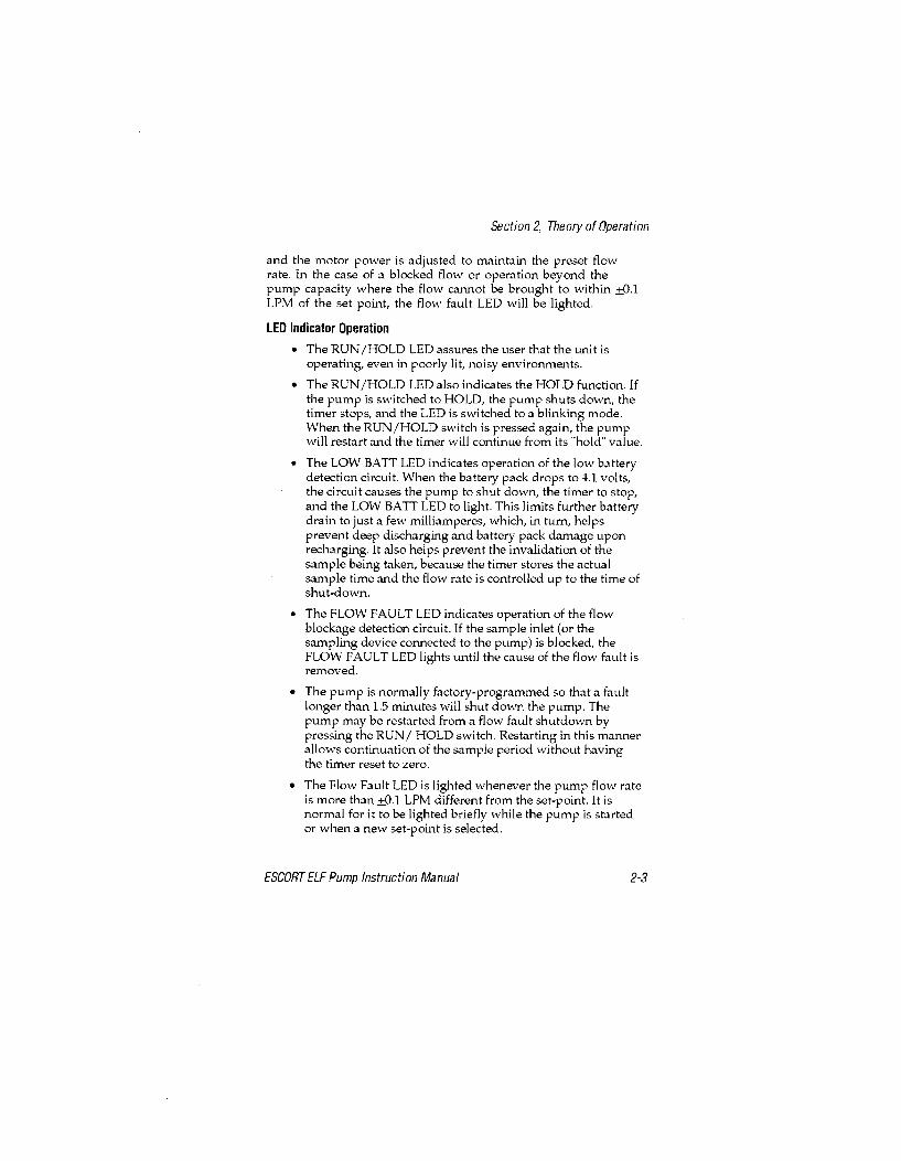
Section 2, Theory of Operation
and the motor power is adjusted to maintain the preset flowrate. In the case of a blocked flow or operation beyond thepump capacity where the flow cannot be brought to within +0.1LPM of the set point, the flow fault LED will be lighted.
LED Indicator Operation
" The RUN/HOLD LED assures the user that the unit isoperating, even in poorly lit, noisy environments.
" The RUN/HOLD LED also indicates the HOLD function. Ifthe pump is switched to HOLD, the pump shuts down, thetimer stops, and the LED is switched to a blinking mode.When the RUN/HOLD switch is pressed again, the pumpwill restart and the timer will continue from its "hold" value.
" The LOW BATT LED indicates operation of the low batterydetection circuit. When the battery pack drops to 4.1. volts,the circuit causes the pump to shut down, the timer to stop,and the LOW BATT LED to light. This limits further batterydrain to just a few milliamperes, which, in turn, helpsprevent deep discharging and battery pack damage uponrecharging. It also helps prevent the invalidation of thesample being taken, because the timer stores the actualsample time and the flow rate is controlled up to the time ofshut-down.
" The FLOW FAULT LED indicates operation of the flowblockage detection circuit. If the sample inlet (or thesampling device connected to the pump) is blocked, theFLOW FAULT LED lights until the cause of the flow fault isremoved.
" The pump is normally factory-programmed so that a faultlonger than 1.5 minutes will shut down the pump. Thepump may be restarted from a flow fault shutdown bypressing the RUN/ HOLD switch. Restarting in this mannerallows continuation of the sample period without havingthe timer reset to zero.
" The Flow Fault LED is lighted whenever the pump flow rateis more than +0.1 LPM different from the set-point. It isnormal for it to be lighted briefly while the pump is startedor when a new set-point is selected.
ESCORT ELF Pump Instruction Manual 2-3
Section 3, Operation
Section 3Operation
C har gi ng t he B att ery P ackUse any Omega TM charger (for example: P/N 494716, 495965,800525 or 801759) for charging the battery pack. Remove theprotective rubber plug and charge the battery pack for 14 to 16hours. (Note that charging for longer periods will not reducebattery life, provided the charging is performed at roomtemperature.) The battery pack can be charged with the packremoved from the pump. Always replace the rubber plug aftercharging and before using the pump to prevent water entryinto the jack.
Do not charge the battery pack in areas that may contain a flammablemixture of combustible gases, vapors, or dust and air; otherwise, anexplosion may occur because a source of ignition exists during charging.
Use only an MSA Omega (ýý) charger from MSA to charge the pump.
Operating T i meThe maximum expected operating time for a pump with a fullycharged battery pack depends on:
1. The selected flow rate.
2. The vacuum load imposed by the sampling device.
3. The temperature.
4. The age of the battery pack.
ESCORT ELF Pump Instruction Manual 3-1

Section 3, Operation
3.0
a<20
N~ IS
I-.
G 9 10 /1 12
OPERATING HOURS
Figure 3-1. Typical Operating Time Graph
See FIGURE 3-1 for approximate operating times. The shadedarea shows operating loads and flow rates within the pumpspecifications. The example shown with dashed lines is for apump set for 2.0 LPM with a sampling load of 15"; the expectedmaximum operating time would be 11.5 hours. This figure isbased on room temperature operation with a new pack. At 0degrees Centigrade, the operating time will be reduced by 10%,20% at -20oC. After several hundred charge/discharge cycles,the pack capacity may be reduced by 20%.
Personal/Area SamplingThe ESCORT ELF Pump is designed for either personal or areasampling of ambient air. It automatically provides a constantvolumetric flow rate of the sample air through the samplingdevice (filter disc, impinger, or absorbent tube) to measure theconcentration of airborne mists, dusts, particulates, gases, andvapors in the workplace.
3-2 ESCORT ELF Pump Instruction Manual

Section 3, Operation
Operating the P ump1. Charge the battery pack for 16 hours using the MSA Omega
(Q) Charger.
* Read the WARNING on the battery pack.
2. Connect the desired sampling device to the inlet fitting.
3. Press ON/OFF button until the RUN/HOLD LED lights.
" The Flow Fault and Low Bat LEDs will then light.During the time these LEDs are being lighted, anumber from 0 to 999 will be displayed. This is thetotal of the pump's operating hours since itslast calibration.
" When all three LEDs are lighted, the display changesto 8.88 LPM/MINS, to show all segments are functional.
" The pump will then begin operation. The LOW BATLED will be dark if the battery voltage is above 4.1volts. The Flow Fault LED will be dark when the flowrate is within 0.1 LPM of the setpoint.
4. Use the T and ,I, switch buttons to adjust the flow setpoint ifa new flow rate is desired. When either button is pressed:
* RUN/HOLD LED will be dark
o Display will show the flow setpoint being stepped upor stepped down to the new setpoint.
5. The RUN/HOLD button may be pressed to interruptsampling without causing the timer to reset to zero.
6. Press the ON/OFF button at the end of sampling.
* Total sample minutes will be on the display and willremain until the pump is turned ON again.
7. Check calibration monthly (every 200 hours of use for coalmine dust sampling).
8. Operate the pump with a sampling device connected to theinlet. Operation without a sampler attached will reducethe life of the pump inlet filter. Operation at very low flowrates may be unstable without an attached samplingdevice, such as a charcoal tube.
ESCORT ELF Pump Instruction Manual 3-3
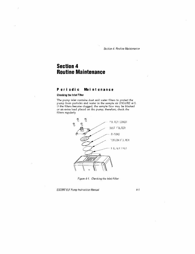
Section 4, Routine Maintenance
Section 4Routine Maintenance
P eri odi c MaintenanceChecking the Inlet Filter
The pump inlet contains dust and water filters to protect thepump from particles and water in the sample air (FIGURE 4-1).If the filters become clogged, the sample flow may be blockedor an extra load placed on the pump; therefore, check thefilters regularly.
FILTER COVER
DUST FILTER
O-RING
TEFLON FILTER
FILTER FRIT
Figure 4-1. Checking the Inlet Filter
ESCORT ELF Pump Instruction Manual 4-1

Section 4, Routine Maintenance
The frequency of the checks should depend on the amount ofpump usage and the concentration of particles allowed to enterthe pump. Usually, only the dust filter needs to be replaced. TheTeflon water filter should rarely need to be replaced. The waterfilter is very fragile and must be handled with care. Even a tinypin hole will destroy its function. The filter frit should neverneed to be replaced if the other filters are maintained.
Filter Replacement
1. Remove the four screws holding the filter cover and 0-ring.
2. Replace the filter with a new one.
3. Re-assemble the 0-ring and cover.
Frit Replacement
1. Stab the frit center with a small screwdriver, and lift it out.
2. Press in a new frit.
3. Re-assemble the Teflon and dust filters, 0-ring, and cover.
Battery Pack Replacement
(FIGURE 4-2 illustrates the battery pack.)
1. Remove the two screws securing the battery pack to the case.
2. Separate the pack from the case.
3. Make sure that the 0-ring is in place on the replacementpack. Then, slide the pack into the pump case whilepressing the case front and back to make sure the caseedges go inside the edges of the pack.
4. Insert the two screws and tighten.
* Tefloni is a trademark of the du Pont Company
4-2 ESCORT ELF Pump Instruction Manual

Section 4, Routine Maintenance
O-RING
-PRESS
SLIDE
CHARGE-JACKPLUG
Figure 4-2. Replacing the Battery Pack
ESCORT ELF Pump Instruction Manual 4-3

Section 5, ELF Sensor Calibration
Section 5ELF Sensor Calibration
1. Check pump inlet filter for dust; replace if heavily loaded.
2. Turn ON the pump and allow it to reach its flow rate setting.
3. If the pump is not set for 2.50 LPM, set it to 2.50.
4. Allow the pump to operate for 10 to 15 minutes at 2.50 LPM.To check for leaks, temporarily block the pump inlet; 0.02LPM or less should be displayed. If not, check the inletfilter cover and o-ring for correct assembly.
5. Leave the pump set for 2.50 LPM and turn OFF the pump.
6. Connect a primary calibration standard to the pump.
7. Turn ON the pump; as the pump goes through its self-checksequence, press and hold the ON/OFF and RUN/HOLDswitches simultaneously until the display reads CAL.Immediately release both buttons.
NOTE: Failure to release both buttons will turn OFF the pump.
* The display will show CAL and a countdownsequence of numbers from 9 through 0; thereafter, itwill alternately display CAL and 2.50 LPM.
8. Operate the calibration standard and obtain at least sixreadings which are very close to one another.
9. Use the T" and I switch buttons to step the pump display up ordown until it agrees exactly with the average of the six readings.
10. Turn OFF the pump; the ELF sensor is now calibrated.Repeat monthly or every 200 hours of use.
11. When you next turn ON the pump, the operating hours willbe reset to 0 and be displayed during the lighting of theFLOW FAULT and LOW BAT LEDs.
ESCORT ELF Pump Instruction Manual 5-1
Section 5, ELF Sensor Calibration
The BIOS DryCal should be used to calibrate or check theflow rate of an MSA Escort ELF pump only if an isolatingflow restrictor (e.g., a filter or an orifice such as P/N 632646)providing at least 10" WC is placed in line between the pumpand the calibrator. Failure to use such an isolation techniquecan cause a calibration inaccuracy on the order of 2% and isnot recommended.
5-2 ESCORT ELF Pump Instruction Manual

Section 6, ELF Sensor Calibration for Pumps used inMSHA Coal Mine Dust Sampling Program
Section 6ELF Sensor Calibrationfor Pumps used in the U.S.Government Mine Safety and HealthAdministration (MSHA) Coal MineDust Sampling Program
1. Check pump inlet filter for dust; replace if heavily loaded.
2. Turn ON the pump and allow it to reach its flow rate setting.
3. If the pump is not set for 2.00 LPM, set it to 2.00.
4. Allow the pump to operate for 10 to 15 minutes at 2.00 LPM.To check for leaks, temporarily block the pump inlet; 0.02LPM or less should be displayed. If not, check the inletfilter cover and o-ring for correct assembly.
5. Leave the pump set for 2.00 LPM and turn OFF the pump.
6. Connect a primary calibration standard to the pump.
7. Turn ON the pump; as the pump goes through its self-checksequence, press and hold the ON/OFF and RUN/HOLDswitches simultaneously until the display reads CAL.Immediately release both buttons.
NOTE: Failure to release both buttons will turn OFF the pump.
* The display will show CAL and a countdownsequence of numbers from 9 through 0; thereafter, itwill alternately display CAL and 2.00 LPM.
8. Operate the calibration standard and obtain at least sixreadings which are very close to one another.
ESCORT ELF Pump Instruction Manual 6-1

Section 6, ELF Sensor Calibration for Pumps used inMSHA Coal Mine Dust Sampling Program
9. Use the 'and ,I, switch buttons to step the pump displayup or down until it agrees exactly with the average of thesix readings.
10. Turn OFF the pump; the ELF sensor is now calibrated.Repeat every 200 hours of use.
11. When you next turn ON the pump, the operating hours willbe reset to 0 and will be displayed during the lighting ofthe FLOW FAULT and LOW BAT LEDs.
6-2 ESCORT ELF Pump Instruction Manual

Section 7, Repairs and Replacement Part
Section 7Repairs and Replacement Parts
T r oubIl eshoot i ng
TABLE 7-1, "Troubleshooting Guidelines," lists the symptoms ofthe most common problems; it also lists their probable cause(s)and the action required to correct each problem. Use theguidelines if you cannot calibrate the ESCORT ELF Pump or ifthe pump does not operate properly. If you cannot resolve aproblem by using the guidelines, call 1-800-MSA-2222 to locate alocal MSA Repair Center.
Use only genuine MSA replacement parts when performing themaintenance procedures described in this manual. Failure to do somay seriously impair instrument performance. Repair or alterationbeyond the scope of these maintenance instructions or by anyoneother than an MSA-trained service person could cause the productto fail to perform as designed, and persons who rely on this productfor their safety could sustain severe personal injury or death.
C orrecti ve MaintenanceWhen an inoperative part is located by using TABLE 7-1,Troubleshooting Guidelines, replace it according to one of thereplacement procedures later in this section. Also refer to"Obtaining Replacement Parts" later in this section forinformation on how to order the necessary part from MSA.
ESCORT ELF Pump Instruction Manual Page 7-1

Section 7, Repairs and Replacement Part
Table 7-1. Troubleshooting Guidelines
SYMPTOM PROBABLE CAUSE CORRECTIVE ACTION
1. Inlet filler clogged or 1. Replace filter according toON-IOLD LED blocked with water "Checking the Inlet Filter"indicator turns OFF 2. Install new pack on pumpprematurely; FLOW 2. Battery pack is by performing procedureFAULT LED Indicator degraded described under "Batterymay be ON or OFF Pack Replacement"and LOW BATT LEDis turned ON 3. Operation beyond 3. Reduce flow or replace
flow and load limits sampler with lowerload device
1. Pump motor connector Iimproperly plugged into 1. Check connectorPC board
ON/HOLD LED andFLOW FAULT LED 2. Pressure sensor 2. Check connector. Verify fiveindicators turned connector fault pins are plugged inON, and pump will 3. Replace pump and motornot run or, if it does drive assembly according torun, no flow is 3. Pump motor dre asse rdisplayed on readout inoperative procedure under
"Replacing the Pump andDrive Assembly"
4. Pressure sensor orPC board inoperative 4. Replace sensor or PC board
When inlet is 1. Check for leaking tubeblocked, the flow 1. Sample flow leaks connection or O-ring seal atindication is not tin or 0rgea0.02 1pm or less the inlet tilter cover
LED indicator on 1. Power source 1. Check and correctcharger does not turn inactive cause of power lossON when plug on-linecord is inserted in 2. Charger failure 2. Replace charger115 VAC outlet and 3. Replace battery packplug on charging cord by performing procedureis inserted in jack on 3. Battery pack failure under "Replacing thebattery pack Battery Pack"
Desired flow rate 1. Inlet filler partially 1. Replace filler according tocannot be obtained clogged instructions underunder heavy "Checking the Inlet Filter"sampling device 2. Check tor leaking tubeloads within regime 2. Leak exists in connect or 0-ring tuteof FIGURE 3-1 sample flow system connection or O-ring at theinlet filter cover
Page 7-2 ESCORT ELF Pump Instruction Manual

Section 7, Repairs and Replacement Part
Unplugging the Electrical Connectors
Service procedures which require opening the ELF pump caserequire the unplugging of two electrical connectors:
1. Pull on the motor electrical connector to remove the motorwires from the printed circuit board.
2. Pull on the 5-pin ribbon cable to remove the connector fromthe ELF sensor.
Reattaching the Electrical Connectors
1. When reattaching the motor connector, make sure theangular ramp at the end faces towards the latch projectingfrom the printed circuit board socket.
NOTE: The pump will operate with the connector installedthe other way, but the above method isencouraged because the ramp and latch helpkeep the connector attached as the pump isknocked around during use.
2. When reattaching the connector to the ELF sensor, makesure pins #1 through #5 are straight and in line.
N OTE: If these pins are bent, use needle-nose pliers tostraighten and align them. Pin #6 is intentionallycut off because it is not used in the ELF pump.
3. Pull the cable so that the end of the connector is about 7/8"above the printed circuit board.
4. Hold the pump face in the right hand and position yourthumb and forefinger around the top left hand corner ofthe pump face.
5. Hold the connector with these two fingers and hold thepump case with the left hand.
6. Position the connector so that an end pin is just inside thefunnel opening of the corresponding pin socket.
7. Gradually tilt the connector to get the next pin just inside itssocket, and repeat this process until all five pins are justinside their corresponding sockets.
8. Slowly press the connector onto the pins until they"bottom out."
ESCORT ELF Pump Instruction Manual Page 7-3

Section 7, Repairs and Replacement Part
9. Inspect the connector at the top and bottom to make sure allpins are correctly inserted.
Pump & Drive Assembly,
Outlet Dampener, or Pressure Sensor Replacement
1. Remove two screws securing the battery pack to the case.
2. Remove the battery pack.
3. Remove the two screws securing the pump case.
4. Pull the 5-pin ribbon connector from the pressure sensor.
5. Pull the motor electrical connector from the PC board.
6. Remove the two screws securing the pump mounting collarto the back of the case.
7. Lift out the pump and drive while removing the inletdampener connection from the fitting.
NOTE: A drop of soap solution (SNOOP) "worked in" atthe end of the rubber tube makes removal easierand will prevent tearing the rubber tube.
8. Remove the two screws securing the pressure sensor.
9. Remove the pressure sensor and be careful not to drop it,even to the table top.
10. Remove the outlet dampener if it is to be replaced.
11. Install the replacement pump and drive, outlet dampener orpressure sensor by reversing this procedure.
NOTE: Wetting the end of the outlet dampener will makesliding it over the sensor body easier. Make sureboth cuffs are completely in the grooves.
NOTE: Tighten the upper motor collar screw beforetightening the lower screw when installing thenew pump and drive.
Printed Circuit Control Board Replacement
1. Remove the two screws securing the battery pack.
2. Remove the battery pack.
*SNOOP is a trademark of Nupro Company
Page 7-4 ESCORT ELF Pump Instruction Manual

Section 7, Repairs and Replacement Part
3. Remove the two screws securing the pump case.
4. Pull the connector from the pressure sensor.
5. Pull the motor electrical connector from the printed circuit board.
7. Remove and save the three screws, two washers and spacersecuring the PC board to the pump face.
8. Install the replacement printed circuit board by reversingthis procedure.
NOTE: Be sure the battery connector is mounted with theblack wire towards the top of the case.
Obtai ni ng R epl acement P ar tsThe ESCORT ELF Pump parts and part numbers are listed inTABLE 7-2. To obtain parts, service, or information in the U.S.,call 1-800-MSA-2222 to find the nearest customer service center.To reach MSA International, call 1412-967-3000.
ESCORT ELF Pump Instruction Manual Page 7-5

Section 7, Repairs and Replacement Part
OTY. 4 5
- SNUG THISSCREW FIRS T
NO TICE; MA KE SUREBATTERY CONNECTORBLACK W[RE 7S TOWARD TOP]
Figure 7-1. Replacement Parts
Page 7-6 ESCORT ELF Pump Instruction Manual

Section 7, Repairs and Replacement Part
Table 7-2. Replacement Parts List
FIGURE 7-1 ITEM NO. PART/COMPONENT PART NO.1 Pump and Flow Assembly, complete 8046612 Collar 8000253 Printed Circuit-Board Assembly 8135514 Pump Face Assembly 8132975 Screw 6364936 0-ring 6366027 Screw 6364148 Belt Clip 6362939 Screw 63641610 Screw 63641511 Spacer 62885212 Lockwasher 6409513 Switch Cover 802381
FIGURE 7-2 ITEM NO. PART/COMPONENT PART NO.14 Pump and Drive less Pressure Sensor 80528515 Flow Sensor Only 80528616 Replacement Sensor Only 80528417 Motor and Conneclor Assembly 80529618 Eccentric and Bearing Assembly 80504619 Pump Block and Valves Assembly 80536020 Inlet Dampener 80381621 Screws 63714022 Outlet Dampener 804663
Screw 636418Filter Cover 497393
FIGURE 4-1 0-ring 637009Inlet dust filter (pack of 5) 808935Filter, Teflon 802897Filter Frit 800303Battery Pack (includes 0-ring & Plug) 497702
FIGURE 4-2 0-ring for Battery Pack 636603Charge Jack Plug 804158Instruction Manual 813549Screwdriver 636913
not shown Leather Case (optional) 811741Upgrade Kit (includes printed circuit 814029board and pump face assemblies) 81_029
ESCORT ELF Pump Instruction Manual Page 7-7
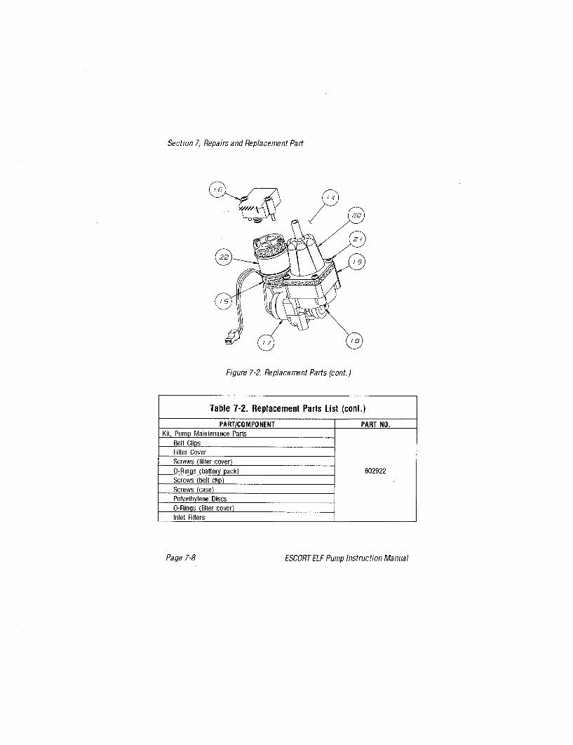
Section 7, Repairs and Replacement Part
16-
Figure 7-2. Replacement Parts (cont.)
Table 7-2. Replacement Parts List (cont.)
PART/COMPONENT PART NO.Kit, Pump Maintenance Parts
Belt ClipsFilter CoverScrews (filler cover)O-Rings (battery pack) 802922Screws (belt clip)Screws (case)Polyethylene DiscsO-Rinms (filler cover)Inlet Filters
Page 7-8 ESCORT ELF Pump Instruction Manual
IS £TI
Escort Elf® Pump
instruction manual
0ýI = k
THIS MANUAL MUST BE CAREFULLY READ BY ALL INDIVIDUALSWHO HAVE OR WILL HAVE THE RESPONSIBIUTY FOR USING ORSERVICING THE PRODUCT. Uke any piece of complex equipment,this product will perform as designed only if It Is used andserviced in accordance with the manufacturer's instructions.OTHERWISE, IT COULD FAIL TO PERFORM AS DESIGNED ANDPERSONS WHO RELY ON THIS PRODUCT FOR THEIR SAFETY COULDSUSTAIN SEVERE PERSONAL INJURY OR DEATH.
The warranties made by Mine Safety Appliances Company withrespect to the product are voided if the product is not usedand serviced in accordancewith the Instructions in this manual.Please protect yourself and others by following them. Weencourage our customers to write or call regarding thisequipment prior to use or for any additional information relativeto use or repairs.
In the U.S., to contact your nearest stocking location, dial toll-free1-800-MSA-2222.To contact MSA International, dial 1-800-672-7777.
© Mine Safety Appliances Company 1997 - All Rights Reserved
Manufactured byMINE SAFETY APPLIANCES COMPANYP.O. Box 427, Pittsburgh, Pennoylvania 15230
(L) Rev 4 813549

1. Do not charge the battery pack in areas that maycontain a flammable mixture of combustible gases,vapors, or dust and air; otherwise, an explosionmay occur because a source of ignition existsduring charging.
2. Do not operate the pump in oxygen-enrichedatmospheres (more than 21% oxygen) containingcombustible gases, vapors, or other materials.Fire or explosion can result from operating inthese atmospheres.
3. Operate the pUMp with MSA p/n 497702 battery packonly. Do not use other batteries or power sources.
4. When using the pump in a hazardous area (with respectto fire or explosion) as specified in the NationalElectric Code (NEC) Article 500 - Hazardous(Classified) Locations, the pump must be labeledstating that it meets the design criteria of the specificClass, Division and Group. Users must operate thepump in accordance with the instructions for thatClass, Division, and Group. A copy of the NEC Codecan be obtained from the National Fire ProtectionAssociation, Batterymarch Park, Quincy, MA 02269.
5. Use only genuine MSA replacement parts whenperforming maintenance procedures described inthis manual; failure to do so may seriously impairthe ESCORT ELF Pump performance. Repair oralteration beyond the scope of these maintenanceinstructions or by anyone other than authorizedMSA service personnel could cause the product tofail to perform as designed, and persons who relyon this product for their safety could sustainsevere personal injury or death.
FAILURE TO COMPLY WITH THE ABOVE WARNINGS CAN RESULT INSERIOUS PERSONAL INJURY OR DEATH

;I [1. Do not use the pump with organic fluids in an
impinger without an absorber trap; otherwise, thepump will be damaged.
2. Use only an MSA Omega (Q) Charger to chargethe pump.
3. If, after thoroughly reading this manual, you aretmcertain of the installation, operation, ormaintenance procedures, call 1-800-MSA-2222for assistance.

Table of Contents
Section 1General Inform ation ............................ 1-1
Introd uction ........................................... 1-1Operating Specifications ............................. 1-2
Section 2Theory of Operation ............................ 2-1
Introd uctio n ......... ...... .......... .. .. .............. 2-1Functional Description of Operation .................... 2-1Figure 2-1. Flow-Feedback Control System .............. 2-2LED Indicator Operation ............................. 2-3
Section 3Operation ................................... 3-1
Charging the Battery Pack ............................... 3-1A W ARN ING ..................................... 3-1A CAUTIO N ...................................... 3-1
O perating Tim e ........................................ 3-1Personal/Area Sam pling ................................. 3-2
Figure 3-1. Typical Operating Time Graph ............... 3-2Operating the Pum p ..................... .............. 3-3
Section 4Routine Maintenance ........................... 4-1
Periodic M aintenance ................................... 4-1Checking the Inlet Filter ............................. 4-1Figure 4-1. Checking the Inlet Filter ................... 4-1Filter Replacem ent .................................. 4-2Frit Replacem ent ................................... 4-2
Battery Pack Replacement .......................... 4-2Figure 4-2. Replacing the Battery Pack ................ 4-3
TOC-1

Section 5ELF Sensor Calibration .......................... 5-1
Section 6ELF Sensor Calibrationfor Pumps used in the U.S. Government Mine Safety andHealth Administration (MSHA) Coal Mine Dust SamplingProgram .................................... 6-1
Section 7Repairs and Replacement Parts ................... 7-1
T roubleshooting ........................................ 7-1A W ARNING ..................................... 7-1
Corrective M aintenance .................................. 7-1Table 7-1. Troubleshooting Guidelines .................. 7-2Unplugging the Electrical Connectors .................. 7-3Reattaching the Electrical Connectors .................. 7-3Pump & Drive Assembly, Outlet Dampener, orPressure Sensor Replacement ........................ 7-4Printed Circuit Control Board Replacement ............. 7-4
Obtaining Replacem ent Parts ............................. 7-5Figure 7-1. Replacement Parts ........................ 7-6Table 7-2. Replacement Parts List ..................... 7-7Figure 7-2. Replacement Parts (cont.) .................. 7-8
TOC-2

Section 1, General Information
Section 1General Information
I ntroducti onThe ESCORT ELF Pump introduces a totally new, patentedconcept of flow control and flow readout (U.S. Patent 5,295,790).The heart of this new system is the electronic laminar flowsensor. The ELF sensor combines a laminar flow element and adifferential pressure sensor to measure sample volume flow rate.This measure of flow rate is not affected by changes in sampleloading or the other factors that affect rotameter-type indicatorsused in other pumps. The ELF sensor provides an electronicsignal which is linearly related to flow rate. This signal is usedin the pump control circuit to maintain the chosen flow rateconstant to within +2.5% and is used in the readout circuit toallow the digital display of the actual flow rate to within +0.1liters per minute (LPM).
The ESCORT ELF sensor and control circuitry are very stableboth in storage and use. Together they form a secondarystandard to maintain the calibration accuracy for at least 200hours of pump usage. A built-in operating time totalizer helpsremind the user of the total operating hours since the lastcalibration check was performed against a primary flowstandard. This totalizer automatically resets to 0 when acalibration is performed. If the pump is used in the coal minedust sampling program, these calibration checks should bedone after each 200 hours of use. If the pump is used forOSHA compliance sampling, the recalibration should beperformed monthly.
ESCORT ELF Pump Instruction Manual 1-1

Section 1, General Information
Operating Specifications
ELECTRICAL CHARACTERISTICS
POWER SUPPLY 4.8-volt battery pack of four nickel-cadmium cells
BATTERY PACK 1.8 ampere hourCAPACITY
BATTERY PACKRECHARGE TIME 14-16 hours (overnight) with recommended chargers
RCHARGE INGCHARGING 100 to 300C (500 to 860F)TEMPERATURE
TYPICAL BATTERY 300 or more charging cycles
PACK LIFE
OPERATING AND PHYSICAL CHARACTERISTICS
Volumetric flow rate is controlled at the set-point withFLOW CONTROL automatic compensation for battery voltage, altitude,
temperature, and sample load changes
0.5 TO 3.0 LPM
OPERATING RANGE 5 to 30 inches water load up to 1.0 LPM;up to 30 inches of water load up to 2.0 LPM;up to 20 inches of water load up to 2.5 LPM; andup to 10 inches of water load up to 3.0 LPM
When flow is blocked the FLOW FAULT LED indicator lightsFLOW BLOCKAGE and stays lighted until the cause of flow blockage isDETECTION removed. It blocked for longer than 1.5 minutes, the pumpshuts down. Pumps that are ordered for coal mine dust
sampling are factory-programmed to not shut down
Liquid crystal digital display with 0.01 LPM resolution from0.5 to 3.0 LPM
FLOW READOUTAccuracy ±2.5% from 1.0 to 3.0 LPM, 00 to 450C+5% from 1.0 to 3.0 LPM, -200 to A0C and 450 to 650CT5% from 0.5 to 0.9 LPM, 00 to 450C.
1-2 ESCORT ELF Pump Instruction Manual

Section 1, General Information
Operating Specifications
Quartz controlled timer reads out to 999 minutes in1-minute steps. Holds last reading after either flow fault or
ELAPSED TIME low battery shut-down, and when pump is OFF or inREADOUT HOLD mode; resets to zero automatically when pump is
turned ON. Timer does not count time when FLOW FAULTLED is lighted.
SCHEDULED The pump has an operating hours totalizer to help remindCALIBRATION user of the need for periodic calibration checks.
Varies with flow rate, sampling device loading andOPERATING TIME temperature. Minimum eight-hour operation at 2.5 LPM with
20-inch water load. (See FIGURE 3-1.)
LOW BATTERY The pump shuts down and lights the LOW BATT LED whenFUNCTION battery voltage drops below 4.1 volts
TEMPERATURE 00 to 450C (320 to 113 0F) ±2.5% accuracy-20o to 000 and 450 to 650CCOMPENSATION (-40 to +149°F and 1120 to 148 0F) ±5.0% accuracy
ALTITUDECOMPENSATION Below sea-level to at least 10,000 ft.
2 inches deep x 4 inches high x 3-7/8 inches wideDIMENSIONS (5.1 centimeters deep x 10.3 centimeters high x 9.8
centimeters wide)
WEIGHT 19 oz. (550 grams)
Case plastic is electrically conductive to reduce radio frequencyCASE interference; an optional leather case is available for pump
protection during rough usage such as underground mining orconstruction and demolition work areas
SERIAL NUMBER Located on the side of the case under the battery packIDENTIFICATION (include number in correspondence with MSA)
ESCORT ELF Pump Instruction Manual 1-3
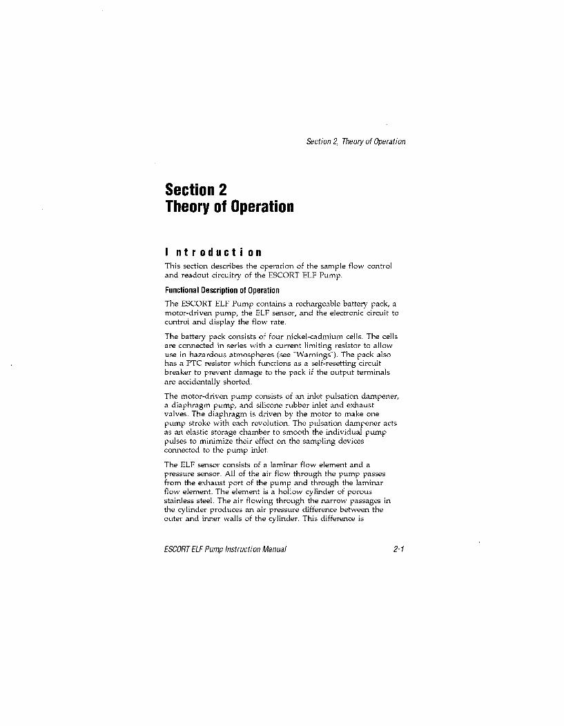
Section 2, Theory of Operation
Section 2Theory of Operation
I ntr oducti onThis section describes the operation of the sample flow controland readout circuitry of the ESCORT ELF Pump.
Functional Description of Operation
The ESCORT ELF Pump contains a rechargeable battery pack, amotor-driven pump, the ELF sensor, and the electronic circuit tocontrol and display the flow rate.
The battery pack consists of four nickel-cadmium cells. The cellsare connected in series with a current limiting resistor to allowuse in hazardous atmospheres (see "Warnings"). The pack alsohas a PTC resistor which functions as a self-resetting circuitbreaker to prevent damage to the pack if the output terminalsare accidentally shorted.
The motor-driven pump consists of an inlet pulsation dampener,a diaphragm pump, and silicone rubber inlet and exhaustvalves. The diaphragm is driven by the motor to make onepump stroke with each revolution. The pulsation dampener actsas an elastic storage chamber to smooth the individual pumppulses to minimize their effect on the sampling devicesconnected to the pump inlet.
The ELF sensor consists of a laminar flow element and apressure sensor. All of the air flow through the pump passesfrom the exhaust port of the pump and through the laminarflow element. The element is a hollow cylinder of porousstainless steel. The air flowing through the narrow passages inthe cylinder produces an air pressure difference between theouter and inner walls of the cylinder. This difference is
ESCORT ELF Pump Instruction Manual 2-1

Section 2, Theory of Operation
INLET
l PUMP OUTLINE
TER--I-LAMINAR FLOW SENSOR EXHAUST
PUMP LAMINAR FLOW• ~~ELEMdEN7
•Figure 2-1. Flow-Feedback Control System
monitored by connections to the high and low pressure taps of asensitive differential pressure sensor. The electrical signal fromthe sensor is a linear voltage, which is directly related to the airflow through the laminar element. This signal is compared tothe flow set point in the electronic circuit and is used to controlthe flow at the set point. Any deviation in flow rate is sensed
2-2 ESCORT ELF Pump Instruction Manual

Section 2, Theory of Operation
and the motor power is adjusted to maintain the preset flowrate. In the case of a blocked flow or operation beyond thepump capacity where the flow cannot be brought to within +0.1LPM of the set point, the flow fault LED will be lighted.
LED Indicator Operation
" The RUN/HOLD LED assures the user that the unit isoperating, even in poorly lit, noisy environments.
" The RUN/HOLD LED also indicates the HOLD function. Ifthe pump is switched to HOLD, the pump shuts down, thetimer stops, and the LED is switched to a blinking mode.When the RUN/HOLD switch is pressed again, the pumpwill restart and the timer will continue from its "hold" value.
" The LOW BATT LED indicates operation of the low batterydetection circuit. When the battery pack drops to 4.1 volts,the circuit causes the pump to shut down, the timer to stop,and the LOW BATT LED to light. This limits further batterydrain to just a few milliamperes, which, in turn, helpsprevent deep discharging and battery pack damage uponrecharging. It also helps prevent the invalidation of thesample being taken, because the timer stores the actualsample time and the flow rate is controlled up to the time ofshut-down.
" The FLOW FAULT LED indicates operation of the flowblockage detection circuit. If the sample inlet (or thesampling device connected to the pump) is blocked, theFLOW FAULT LED lights until the cause of the flow fault isremoved.
* The pump is normally factory-programmed so that a faultlonger than 1.5 minutes will shut down the pump. Thepump may be restarted from a flow fault shutdown bypressing the RUN/ HOLD switch. Restarting in this mannerallows continuation of the sample period without havingthe timer reset to zero.
" The Flow Fault LED is lighted whenever the pump flow rateis more than +0.1 LPM different from the set-point. It isnormal for it to be lighted briefly while the pump is startedor when a new set-point is selected.
ESCORT ELF Pump Instruction Manual 2-3

Section 3, Operation
Section 3Operation
C har gi ng t he B att ery P ackUse any OmegaTM charger (for example: P/N 494716, 495965,800525 or 801759) for charging the battery pack. Remove theprotective rubber plug and charge the battery pack for 14 to 16hours. (Note that charging for longer periods will not reducebattery life, provided the charging is performed at roomtemperature.) The battery pack can be charged with the packremoved from the pump. Always replace the rubber plug aftercharging and before using the pump to prevent water entryinto the jack.
Do not charge the battery pack in areas that may contain a flammablemixture of combustible gases, vapors, or dust and air; otherwise, anexplosion may occur because a source of ignition exists during charging.
Use only an MSA Omega (Q2) charger from MSA to charge the pump.
Operating T i meThe maximum expected operating time for a pump with a fullycharged battery pack depends on:
1. The selected flow rate.
2. The vacuum load imposed by the sampling device.
3. The temperature.
4. The age of the battery pack.
ESCORT ELF Pump Instruction Manual 3-1

Section 3, Operation
/ " // / / / i / /
/ / / / / / /
/z / / / // z /z
'0 II /2 /. .
OPERA TING HOURS
Figure 3-1. Typical Operating Time Graph
See FIGURE 3-1 for approximate operating times. The shadedarea shows operating loads and flow rates within the pumpspecifications. The example shown with dashed lines is for apump set for 2.0 LPM with a sampling load of 15"; the expectedmaximum operating time would be 11.5 hours. This figure isbased on room temperature operation with a new pack. At 0degrees Centigrade, the operating time will be reduced by 10%,20% at -2OoC. After several hundred charge/discharge cycles,the pack capacity may be reduced by 20%.
Personal/Area Sampl i ngThe ESCORT ELF Pump is designed for either personal or areasampling of ambient air. It automatically provides a constantvolumetric flow rate of the sample air through the samplingdevice (filter disc, impinger, or absorbent tube) to measure theconcentration of airborne mists, dusts, particulates, gases, andvapors in the workplace.
3-2 ESCORT ELF Pump Instruction Manual

Section 3, Operation
Operating the Pump1. Charge the battery pack for 16 hours using the MSA Omega
(0) Charger.
* Read the W ARNING on the battery pack.
2. Connect the desired sampling device to the inlet fitting.
3. Press ON/OFF button until the RUN/HOLD LED lights.
" The Flow Fault and Low Bat LEDs will then light.During the time these LEDs are being lighted, anumber from 0 to 999 will be displayed. This is thetotal of the pump's operating hours since itslast calibration.
" When all three LEDs are lighted, the display changesto 8.88 LPM/MINS, to show all segments are functional.
" The pump will then begin operation. The LOW BATLED will be dark if the battery voltage is above 4.1volts. The Flow Fault LED will be dark when the flowrate is within 0.1 LPM of the setpoint.
4. Use the T and Ib switch buttons to adjust the flow setpoint ifa new flow rate is desired. When either button is pressed:
" RUN/HOLD LED will be dark
" Display will show the flow setpoint being stepped upor stepped down to the new setpoint.
5. The RUN/HOLD button may be pressed to interruptsampling without causing the timer to reset to zero.
6. Press the ON/OFF button at the end of sampling.
* Total sample minutes will be on the display and willremain until the pump is turned ON again.
7. Check calibration monthly (every 200 hours of use for coalmine dust sampling).
8. Operate the pump with a sampling device connected to theinlet. Operation without a sampler attached will reducethe life of the pump inlet filter. Operation at very low flowrates may be unstable without an attached samplingdevice, such as a charcoal tube.
ESCORT ELF Pump Instruction Manual 3-3

Section 4, Routine Maintenance
Section 4Routine Maintenance
P eri odi c Mai ntenanceChecking the Inlet Filter
The pump inlet contains dust and water filters to protect thepump from particles and water in the sample air (FIGURE 4-1).If the filters become clogged, the sample flow may be blockedor an extra load placed on the pump; therefore, check thefilters regularly.
FILTER COVER
DUST FILTER
0-RING
TEFLON FILTER
~-FILTER FRIT
Figure 4-1. Checking the Inlet Filter
ESCORT ELF Pump Instruction Manual 4-1
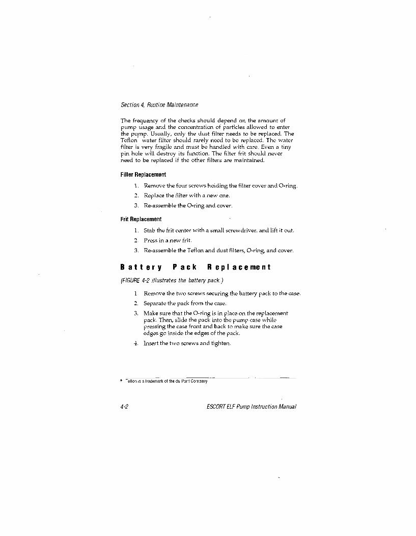
Section 4, Routine Maintenance
The frequency of the checks should depend on the amount ofpump usage and the concentration of particles allowed to enterthe pump. Usually, only the dust filter needs to be replaced. TheTeflon water filter should rarely need to be replaced. The waterfilter is very fragile and must be handled with care. Even a tinypin hole will destroy its function. The filter frit should neverneed to be replaced if the other filters are maintained.
Filter Replacement
1. Remove the four screws holding the filter cover and 0-ring.
2-. Replace the filter with a new one.
3. Re-assemble the 0-ring and cover.
Frit Replacement
1. Stab the frit center with a small screwdriver, and lift it out.
2. Press in a new frit.
3. Re-assemble the Teflon and dust filters, 0-ring, and cover.
Battery Pack Replacement
(FIGURE 4-2 illustrates the battery pack.)
1. Remove the two screws securing the battery pack to the case.
2. Separate the pack from the case.
3. Make sure that the 0-ring is in place on the replacementpack. Then, slide the pack into the pump case whilepressing the case front and back to make sure the caseedges go inside the edges of the pack.
4. Insert the two screws and tighten.
* Teflon is a trademark of the du Poet Company
4-2 ESCORT ELF Pump Instruction Manual

Section 4, Routine Maintenance
PRESSý
SLIDE
CHARGEJACKPLUG
Figure 4-2. Replacing the Battery Pack
ESCORT ELF Pump Instruction Manual 4-3

Section 5, ELF Sensor Calibration
Section 5ELF Sensor Calibration
1. Check pump inlet filter for dust; replace if heavily loaded.
2. Turn ON the pump and allow it to reach its flow rate setting.
3. If the pump is not set for 2.50 LPM, set it to 2.50.
4. Allow the pump to operate for 10 to 15 minutes at 2.50 LPM.To check for leaks, temporarily block the pump inlet; 0.02LPM or less should be displayed. If not, check the inletfilter cover and o-ring for correct assembly.
5. Leave the pump set for 2.50 LPM and turn OFF the pump.
6. Connect a primary calibration standard to the pump.
7. Turn ON the pump; as the pump goes through its self-checksequence, press and hold the ON/OFF and RUN/HOLDswitches simultaneously until the display reads CAL.Immediately release both buttons.
NOTE: Failure to release both buttons will turn OFF the pump.
The display will show CAL and a countdownsequence of numbers from 9 through 0; thereafter, itwill alternately display CAL and 2.50 LPM.
8. Operate the calibration standard and obtain at least sixreadings which are very close to one another.
9. Use the 1T and I switch buttons to step the pump display up ordown until it agrees exactly with the average of the six readings.
10. Turn OFF the pump; the ELF sensor is now calibrated.Repeat monthly or every 200 hours of use.
11. When you next turn ON the pump, the operating hours willbe reset to 0 and be displayed during the lighting of theFLOW FAULT and LOW BAT LEDs.
ESCORT ELF Pump Instruction Manual 5-1

Section 5, ELF Sensor Calibration
The BIOS DryCal should be used to calibrate or check theflow rate of an MSA Escort ELF pump only if an isolatingflow restrictor (e.g., a filter or an orifice such as P/N 632646)providing at least 10" WC is placed in line between the pumpand the calibrator. Failure to use such an isolation techniquecan cause a calibration inaccuracy on the order of 2 % and isnot recommended.
5-2 ESCORT ELF Pump Instruction Manual
Section 6, ELF Sensor Calibration for Pumps used inMSHA Coal Mine Dust Sampling Program
Section 6ELF Sensor Calibrationfor Pumps used in the U.S.Government Mine Safety and HealthAdministration (MSHA) Coal MineDust Sampling Program
1. Check pump inlet filter for dust; replace if heavily loaded.
2. Turn ON the pump and allow it to reach its flow rate setting.
3. If the pump is not set for 2.00 LPM, set it to 2.00.
4. Allow the pump to operate for 10 to 15 minutes at 2.00 LPM.To check for leaks, temporarily block the pump inlet; 0.02LPM or less should be displayed. If not, check the inletfilter cover and o-ring for correct assembly.
5. Leave the pump set for 2.00 LPM and turn OFF the pump.
6. Connect a primary calibration standard to the pump.
7. Turn ON the pump; as the pump goes through its self-checksequence, press and hold the ON/OFF and RUN/HOLDswitches simultaneously until the display reads CAL.Immediately release both buttons.
NOTE: Failure to release both buttons will turn OFF the pump.
* The display will show CAL and a countdownsequence of numbers from 9 through 0; thereafter, itwill alternately display CAL and 2.00 LPM.
8. Operate the calibration standard and obtain at least sixreadings which are very close to one another.
ESCORT ELF Pump Instruction Manual 6-1

Section 6, ELF Sensor Calibration for Pumps used inMSHA Coal Mine Dust Sampling Program
9. Use the T and Ib switch buttons to step the pump displayup or down until it agrees exactly with the average of thesix readings.
10. Turn OFF the pump; the ELF sensor is now calibrated.Repeat every 200 hours of use.
11. When you next turn ON the pump, the operating hours willbe reset to 0 and will be displayed during the lighting ofthe FLOW FAULT and LOW BAT LEDs.
6-2 ESCORT ELF Pump Instruction Manual

Section 7, Repairs and Replacement Part
Section 7Repairs and Replacement Parts
T r oubI eshoot i ng
TABLE 7-1, "Troubleshooting Guidelines," lists the symptoms ofthe most common problems; it also lists their probable cause(s)and the action required to correct each problem. Use theguidelines if you cannot calibrate the ESCORT ELF Pump or ifthe pump does not operate properly. If you cannot resolve aproblem by using the guidelines, call 1-800-MSA-2222 to locate alocal MSA Repair Center.
Use only genuine MSA replacement parts when performing themaintenance procedures described in this manual. Failure to do somay seriously impair instrument performance. Repair or alterationbeyond the scope of these maintenance instructions or by anyoneother than an MSA-trained service person could cause the productto fail to perform as designed, and persons who rely on this productfor their safety could sustain severe personal injury or death.
C orrecti ve Maintenance
When an inoperative part is located by using TABLE 7-1.,Troubleshooting Guidelines, replace it according to one of thereplacement procedures later in this section. Also refer to"Obtaining Replacement Parts" later in this section forinformation on how to order the necessary part from MSA.
ESCORT ELF Pump Instruction Manual Page 7-1

Section 7, Repairs and Replacement Part
Table 7-1. Troubleshooting Guidelines
SYMPTOM PROBABLE CAUSE CORRECTIVE ACTION1. Inlet filter clogged or 1. Replace filter according to
ONA-OLD LED blocked with water "Checking the Inlet Filter"indicator turns OFF 2. Install new pack on pumpprematurely; FLOW 2. Battery pack is by performing procedureFAULT LED Indicator degraded described under "Batterymay be ON or OFFPakRpce ntand LOW BATT LEDPakRpce ntis turned ON 3. Operation beyond 3. Reduce flow or replace
flow and load limits sampler with lowerload device
1. Pump motor connectorimproperly plugged into 1. Check connectorPC board
ON/HOLD LED andFLOW FAULT LED 2. Pressure sensor 2. Check connector. Verity tiveindicators turned connector tault pins are plugged inON, and pump will 3. Replace pump and motornot run or, if if doesdrvasebycodigtrun, no flow is 3. Pump motordrvasebycodigtdisplayed on readout inoperative procedure under
"Replacing the Pump andDrive Assembly"
4. Pressure sensor or 4.RpaesnoorPbadPC board inoperative 4.RpaesnoorP bad
When inlet isblocked, the flow 1 . Check for leaking tubeindication is not 1 . Sample flow leaks connection or 0-ring seal at0.02 1pm or less the inlet filter cover
LED indicator on 1 . Power source 1 . Check and correctcharger does not turn inactive cause of power lossON when plug on-linecord is inserted in 2. Charger failure 2. Replace charger115 VAC outlet and 3. Replace battery packplug on charging cord by performing procedureis inserted in jack on 3. Battery pack failure under "Replacing thebattery pack Battery Pack"
Desired flow rate 1. Inlet filter partially 1. Replace filter according tocannot be obtained clogged instructions underunder heavy 'Checking the Inlet Filler"sampling device2.Cekfrlaigtbloads within regime 2. Leak exists in connhectio for 0-rking atu theof FIGURE 3-1 sample flow system ionlectfite covrO-igath
Page 7-2 Page 7-2ESCORT ELF Pump Instruction Manual

Section 7, Repairs and Replacement Part
Unplugging the Electrical Connectors
Service procedures which require opening the ELF pump caserequire the unplugging of two electrical connectors:
1. Pull on the motor electrical connector to remove the motorwires from the printed circuit board.
2. Pull on the 5-pin ribbon cable to remove the connector fromthe ELF sensor.
Reattaching the Electrical Connectors
1. When reattaching the motor connector, make sure theangular ramp at the end faces towards the latch projectingfrom the printed circuit board socket.
NOTE: The pump will operate with the connector installedthe other way, but the above method isencouraged because the ramp and latch helpkeep the connector attached as the pump isknocked around during use.
2. When reattaching the connector to the ELF sensor, makesure pins #1 through #5 are straight and in line.
NOTE: If these pins are bent, use needle-nose pliers tostraighten and align them. Pin #6 is intentionallycut off because it is not used in the ELF pump.
3. Pull the cable so that the end of the connector is about 7/8"above the printed circuit board.
4. Hold the pump face in the right hand and position yourthumb and forefinger around the top left hand corner ofthe pump face.
5. Hold the connector with these two fingers and hold thepump case with the left hand.
6. Position the connector so that an end pin is just inside thefunnel opening of the corresponding pin socket.
7. Gradually tilt the connector to get the next pin just inside itssocket, and repeat this process until all five pins are justinside their corresponding sockets.
8. Slowly press the connector onto the pins until they"bottom out."
ESCORT ELF Pump Instruction Manual Page 7-3

Section 7, Repairs and Replacement Part
9. Inspect the connector at the top and bottom to make sure allpins are correctly inserted.
Pump & Drive Assembly,Outlet Dampener, or Pressure Sensor Replacement
1. Remove two screws securing the battery pack to the case.
2. Remove the battery pack.
3. Remove the two screws securing the pump case.
4. Pull the 5-pin ribbon connector from the pressure sensor.
5. Pull the motor electrical connector from the PC board.
6. Remove the two screws securing the pump mounting collarto the back of the case.
7. Lift out the pump and drive while removing the inletdampener connection from the fitting.
NOTE: A drop of soap solution (SNOOP) "worked in" atthe end of the rubber tube makes removal easierand will prevent tearing the rubber tube.
8. Remove the two screws securing the pressure sensor.
9. Remove the pressure sensor and be careful not to drop it,even to the table top.
10. Remove the outlet dampener if it is to be replaced.
11. Install the replacement pump and drive, outlet dampener orpressure sensor by reversing this procedure.
NOTE: Wetting the end of the outlet dampener will makesliding it over the sensor body easier. Make sureboth cuffs are completely in the grooves.
NOTE: Tighten the upper motor collar screw beforetightening the lower screw when installing thenew pump and drive.
Printed Circuit Control Board Replacement
1. Remove the two screws securing the battery pack.
2. Remove the battery pack.
*SNOOP is a trademark of Nupro Company
Page 7-4 ESCORT ELF Pump Instruction Manual

Section 7, Repairs and Replacement Part
3. Remove the two screws securing the pump case.
4. Pull the connector from the pressure sensor.
5. Pull the motor electrical connector from the printed circuit board.
7. Remove and save the three screws, two washers and spacersecuring the PC board to the pump face.
8. Install the replacement printed circuit board by reversingthis procedure.
NOTE: Be sure the battery connector is moumted with theblack wire towards the top of the case.
0 bt ai ni ng R epl acement P ar tsThe ESCORT ELF Pump parts and part numbers are listed inTABLE 7-2. To obtain parts, service, or information in the U.S.,call 1-800-MSA-2222 to find the nearest customer service center.To reach MSA International, call 1412-967-3000.
ESCORT ELF Pump Instruction Manual Page 7-5

Section 7, Repairs and Replacement Part
OTY. 4 5
SNUG THISSCREW FIRS T
•===• k) NOTICE. MAKE SUREBATTERY CONNECTORBLACK WIRE IS TOWARD TOP.
Figure 7-1. Replacement Parts
Page 7-6 ESCORT ELF Pump Instruction Manual

Section 7, Repairs and Replacement Part
Table 7-2. Replacement Parts List
FIGURE 7-1 ITEM NO. PART/COMPONENT PART NO.1 Pump and Flow Assembly, complete 8046612 Collar 8000253 Printed Circuit-Board Assembly 8135514 Pump Face Assembly 8132975 Screw 6364936 O-ring 6366027 Screw 6364148 Belt Clip 6362939 Screw 63641610 Screw 63641511 Spacer 62885212 Lockwasher 6409513 Switch Cover 802381
FIGURE 7-2 ITEM NO. PART/COMPONENT PART NO.14 Pump and Drive less Pressure Sensor 80528515 Flow Sensor Only 80528616 Replacement Sensor Only 80528417 Motor and Connector Assembly 80529618 Eccentric and Bearing Assembly 80504619 Pump Block and Valves Assembly 80536020 Inlet Dampener 80381621 Screws 63714022 Outlet Dampener 804663
Screw 636418Filter Cover 497393
FIGURE 4-1 0-ring 637009Inlet dust filter (pack of 5) 808935Filter, Teflon 802897Filter Frit 800303Battery Pack (includes 0-ring & Plug) 497702
FIGURE 4-2 0-ring for Battery Pack 636603Charge Jack Plug 804158Instruction Manual 813549Screwdriver 636913
not shown Leather Case (optional) 811741Upgrade Kit (includes printed circuit 814029board and pump face assemblies)
ESCORT ELF Pump Instruction Manual Page 7-7

Section 7, Repairs and Replacement Part
Figure 7-2. Replacement Parts (cont.)
Table 7-2. Replacement Parts List (cont.)
PART/COMPONENT PART NO.Kit, Pump Maintenance Parts
Belt ClipsFilter CoverScrews (filter cover)O-Rings (batlery pack) 802922Screws (bell clip)Screws (case)Polyethylene DiscsO-Rings (filter cover)Inlet Filters
Page 7-8 ESCORT ELF Pump Instruction Manual