fire prevention education for boys and girls who misuse fire: a ...
Upload
khangminh22Category
view
0download
0
Freestanding Gas Fire
PLEASE KEEP THESE INSTRUCTIONSFOR FUTURE REFERENCE
Owners &Installation
Man
ual
LISTINGS AND CODE APPROVALS
These gas appliances have beentested in accordance with AG 103,NZS 5262 and have been certified bythe Australian Gas Association forinstallation and operation asdescribed in these Installation andOperating Instructions.
Your unit should be servicedannually by an authorised serviceperson.
Models: F37-NGF37-LPG
01/20/04
FOR YOUR SAFETYWhat to do if you smell gas:
Do not try to light any appli-anceDo not touch any electricalswitch: do not use anyphone in your building.Immediately call your gassupplier from a neighbour'sphone. Follow the gas sup-plier's instructions.If you cannot reach yourgas supplier, call the firedepartment.
WARNING:Improper installation, adjustment, altera-tion, service or maintenance can causeinjury or property damage. Refer to thismanual. For assistance or additional infor-mation consult an authorized installer, serv-ice agency or the gas supplier.
FOR YOUR SAFETYDo not store or use gasoline or other flamma-ble vapours and liquids in the vicinity of thisor any other appliance.
Installation and service must be performedby an authorized installer, service agency orthe gas supplier.
918-080b
AustraliaP.O. Box 533Braeside, Victoria 3195
New Zealand1-37 Mt Wellington Hwy.Panmure,P.O. Box 14349Auckland 6.
Geneva

2 F37 Masport Rear Flued Room Sealed Freestanding Gas Heater
To the New Owner:
Congratulations! You are the owner of a state-of-the-art Masport Rear Flued Room Sealed Freestanding Gas Fire. The
Masport Gas Series of hand crafted appliances has been designed to provide you with all the warmth and charm of a
woodfire, at the flick of a switch. The models F37-NG, and F37-LPG of this series has been approved by AGA for both
safety and efficiency. As it also bears our own mark, it promises to provide you with economy, comfort and security for many
trouble free years to follow. Please take a moment now to acquaint yourself with these instructions and the many features
of your Masport Rear Flued Room Sealed Freestanding Gas Fire.

F37 Masport Rear Flued Room Sealed Freestanding Gas Heater 3
TABLE OF CONTENTS
Page Page
Operating Instructions
Operating Instructions ............................................... 16Lighting Procedure .................................................... 16Shutdown Procedure ................................................. 16First Fire ................................................................... 16Convection Fan Operation ......................................... 16Normal Operating Sounds of Gas Appliances ............ 16Copy of Lighting Plate Instructions ............................ 17
Maintenance
Maintenance Instructions .......................................... 18General Flue Maintenance ........................................ 18Log Replacement ...................................................... 18Gold Plated Doors ..................................................... 18Door Gasket .............................................................. 18Latch Adjustment ...................................................... 19Glass Replacement ................................................... 19Fan Maintenance ...................................................... 20Removing Valve ......................................................... 20Firebox Paint ............................................................. 21Replacement Parts List ............................................. 22
Warranty
Warranty ................................................................... 27
Specifications diagram ................................................ 2Data Plate ................................................................... 4
Installation
Specifications ............................................................. 5Before You Start ......................................................... 5General Safety Information .......................................... 5Installation Checklist ................................................... 6Locating Your MASPORT Gas Fire ............................. 6Clearances to Combustibles ....................................... 6Combustion and Ventilation Air ................................... 6Exterior Flue Terminal Locations ................................. 7Flueing ...................................................................... 8Flueing Installation Precautions ................................... 8Safety Precautions for the Installer .............................. 8Planning Your Fluing Installation ................................. 8Fluing Arrangements - Vertical Terminations
for both Residential & ManufacturedHomes/Mobile Homes .......................................... 9
Flue Restrictor Position ............................................... 9Horizontal Installations .............................................. 10Gas Connection ........................................................ 10System Data Chart ................................................... 10Conversion from NG to LPG ...................................... 11Aeration Adjustment .................................................. 12Log Installation .......................................................... 12Door Installation ........................................................ 13Pressure Testing ....................................................... 14Valve Description ...................................................... 14Louvre Installation...................................................... 14Optional Wall Thermostat .......................................... 14Optional Remote Control ........................................... 15Final Check ............................................................... 15Wiring Diagram ......................................................... 15

4 F37 Masport Rear Flued Room Sealed Freestanding Gas Heater
This is a copy of the label that accompanieseach MASPORT Rear Flued Room Sealed Free-standing Gas Fire. We have printed a copy of
DATA PLATE
the contents here for your review. The dataplate is located on the inside of the drop downpedestal door.
NOTE: Masport units are constantly being im-proved. Check the label on the unit and if thereis a difference, the label on the unit is the correctone.
(Australia Only)

F37 Masport Rear Flued Room Sealed Freestanding Gas Heater 5
INSTALLATION AND REPAIRSSHOULD BE DONE BY AN AUTHOR-IZED SERVICE PERSON. THIS AP-PLIANCE SHOULD BE INSTALLED,REPAIRED, INSPECTED BEFOREUSE AND AT LEAST ANNUALLYBY AN AUTHORIZED SERVICE PER-SON. MORE FREQUENT CLEAN-ING MAY BE REQUIRED DUE TOEXCESSIVE LINT FROM CARPET-ING, ETC. IT IS IMPERATIVE THATTHE CONTROL COMPARTMENT,BURNERS AND CIRCULATING AIRPASSAGEWAYS OF THE APPLI-ANCE BE KEPT CLEAN.
IMPORTANT:SAVE THESE
INSTRUCTIONS
The MASPORT Rear Flued Room Sealed Free-standing Gas Fire must be installed in accord-ance AG601 and NZS 5261 and with theseinstructions. Carefully read all the instructionsin this manual first. Consult the building authorityhaving jurisdiction to determine the need for apermit prior to starting the installation.
Note: Failure to follow the instructionscould cause a malfunction of theheater which could result in death,serious bodily injury, and/or prop-erty damage. Failure to follow theseinstructions may also void yourfire insurance and/or warranty.
SPECIFICATIONS
Fuels: F37-NG is approved for use with NG.F37-LPG is approved for use withliquefied petroleum gases (LPG).
Electrical: 240 V A.C. system.
Circulation Fan: Two Speed
Log Sets: Ceramic fibre, 7 per set.
Flue System:Axial (6-5/8" outer / 4" inner liner)rigid flue and Riser Vent Terminal.
BEFORE YOU START
Safe installation and operation of this appliancerequires common sense, however, please beaware of the following:
INSTALLATION
4) We recommend that you plan your installa-tion on paper using exact measurementsfor clearances and floor protection beforeactually installing this appliance. Have anauthorized building inspector review yourplans before installation.
GENERAL SAFETYINFORMATION
1) The appliance shall be installed in accord-ance with the manufacturer's installationinstructions, local gas fitting regulations,municipal building codes, water supply reg-ulations, electrical wiring regulations, withAG 601 (AGA gas installation code) NZS5261 (New Zealand)
2) Installation and repair should be doneONLY by an authorised person.
3) DO NOT CONNECT TO MASONARY FLUE.
4) This appliance must be connected tothe specified flue and termination capto the outside of the building enve-lope. Never flue to another room orinside a building. Make sure that theflue is fitted as per Flueing instruc-tions.
5) Inspect the flueing system annually forblockage and any signs of deterioration.
6) Flueing terminals shall not be recessed intoa wall or siding.
7) Any safety glass removed for servicingmust be replaced prior to operating theappliance.
8) To prevent injury, do not allow anyone whois unfamiliar with the operation to use thefireplace.
9) Wear gloves and safety glasses for pro-tection while doing required maintenance.
10) Be aware of electrical wiring locations inwalls and ceilings when cutting holes fortermination.
11) Under no circumstances should this appli-ance be modified. Parts that have to beremoved for servicing should be replacedprior to operating this appliance.
12) Installation and any repairs to this applianceshould be done by an authorised serviceperson. An authorised service personshould be called to inspect this applianceannually. Make it a practice to have all ofyour gas appliances checked annually.
13) Do not slam shut or strike the glass door.
DUE TO HIGH TEMPERATURES,THE APPLIANCE SHOULD BE LO-CATED OUT OF TRAFFIC ANDAWAY FROM FURNITURE ANDDRAPERIES.
WARNING: FAILURE TO INSTALLTHIS APPLIANCE CORRECTLYWILL VOID YOUR WARRANTY ANDMAY CAUSE A SERIOUS HOUSEFIRE.
CHILDREN AND ADULTS SHOULDBE ALERTED TO THE HAZARDS OFHIGH SURFACE TEMPERATURES,ESPECIALLY THE FIREPLACEGLASS, AND SHOULD STAY AWAYTO AVOID BURNS OR CLOTHINGIGNITION.
YOUNG CHILDREN SHOULD BECAREFULLY SUPERVISED WHENTHEY ARE IN THE SAME ROOM ASTHE APPLIANCE.
CLOTHING OR OTHER FLAMMA-BLE MATERIAL SHOULD NOT BEPLACED ON OR NEAR THE APPLI-ANCE.
1) Provide adequate clearances for servic-ing, proper operation and around the airopenings into the combustion chamber.
2) The appliance must be installed on a flat,solid, continuous surface (e.g. wood, met-al, concrete). This may be the floor, or it canbe raised up on a platform to enhance itsvisual impact. The appliance may be in-stalled on carpeting, tile, wood flooring orother combustible material, because theappliance's metal pedestal base extendsthe full width and depth of the appliance.The MASPORT Rear Flued Room SealedFreestanding Gas Fire can be installed in awide variety of ways and will fit nearly anyroom layout. It may be installed in a re-cessed position, framed out into the room,or across a corner.
3) The MASPORT Rear Flued Room SealedFreestanding Gas Fire is approved for man-ufactured home installations, see pages 6to 9 for the required flue arrangements. Ifinstalled into a manufactured home the unitmust be bolted down to the floor.

6 F37 Masport Rear Flued Room Sealed Freestanding Gas Heater
14) Under no circumstances should any solidfuels (wood, paper, cardboard, coal, etc.)be used in this appliance.
15) The appliance area must be kept clear andfree of combustible materials, (gases andother flammable vapours and liquids).
INSTALLATIONCHECKLIST
1) Check Clearances to Combustibles (page6), location of unit (page 6) and fluingrequirements (pages 6-9).
2) Install fluing: Check all fluing requirements,pages 8-10.
3) Make gas connections, page 10. Test thepilot. Must be as per diagram, page 12.
4) If necessary, convert from NG to LPG (page11).
5) Install log set, page 12.
6) Install Front Door Front, page 13.
7) Test Gas Pressure, page 14.
8) Install Louvres, page 14.
9) Install optional Remote Control, or Wall Ther-mostat, pages 14 and 15.
10) Final check, page 15.
Before leaving this unit with the customer, theinstaller must ensure that the appliance is firingcorrectly and operation fully explained tocustomer.
This includes:1) Clocking the appliance to ensure the cor-
rect firing rate (rate noted on label) afterburning appliance for 15 minutes.
2) If required, adjusting the primary air toensure that the flame does not carbon. Firstallow the unit to burn for 15-20 min. tostabilize.
CAUTION: Any alteration to the productthat causes sooting or carboning thatresults in damage is not the responsibil-ity of the manufacturer.
LOCATING YOURMASPORT GAS FIRE
When selecting a location for your stove, en-sure that the clearances listed above are met aswell as ensuring that there is adequate acces-sibility for servicing and proper operation.
For Flue Termination requirements, see page 7.
This appliance is Listed for bedroom installa-tions when used with a Listed Millivolt Thermo-stat. Some areas may have further require-ments, check local codes before installation.
This appliance is Listed for Alcove installations,maintain minimum Alcove clearances as fol-lows, minimum ceiling height of 1.7m, minimumwidth of 1.0m and a maximum depth of 0.9m.
INSTALLATION
Use the minimum clearances shown in thediagrams below:
F37-NG & F37-LPG Clearances
A Side Wall to Unit 190 mm
B Back Wall to Unit 76 mm
E Side Wall to Unit 114 mm
F37-NG & F37-LPGReference Dimensions
C Floor to Flue Centerline 635 mm
D Side Wall to Flue Centerline 521 mm
A) Cross CornerB) Flush with Wall/AlcoveC) Flat on Wall CornerD) Flat on Wall
CLEARANCES TOCOMBUSTIBLES
The clearances listed are MINIMUM distances.Measure the clearance to both the applianceand the chimney connector. The farthestdistance is correct if the two clearancesdo not coincide. For example, if the appli-ance is set as indicated in one of the diagramsbut the connector is too close, move the stoveuntil the correct clearance to the connector isobtained.
This appliance may be installed only with theclearances as shown in the situations pic-tured. Do not combine clearances fromone type of installation with another inorder to achieve closer clearances.
This unit can be installed on a solid combustiblesurface like a wood floor. This unit can also beinstalled directly on carpeting or vinyl whenthe bottom pedestal cover plate (provided withunit) is installed.
COMBUSTION ANDVENTILATION AIR
The combustion air from this appliance is drawnfrom outside the building through the outer flue.Extra provision for combustion air insidethe room is not required.
Minimum ceiling heightis 914 mm from top ofunit.

F37 Masport Rear Flued Room Sealed Freestanding Gas Heater 7
INSTALLATION
EXTERIOR FLUE TERMINATION LOCATIONS
Minimum clearances required for balanced flue terminals orthe flue terminals of outdoor appliances according
to AG 601 (AGA gas installation code) or NZS 5261 (New Zealand).For vertical termination heights refer to AG 601 or NZS 5261.
Minimum Clearance (mm)
a Below eaves, balconies or other projections:- Appliances up to 50 MJ/h input 300- Appliances over 50 MJ/h input 500
b From the ground or above a balcony 300c From a return wall or external corner 500d From a gas meter (M) 1000e From an electricity meter or fuse box (P) 500f From a drain or soil pipe 150g Horizontal from any building structure (unless appliance is approved
for closer installation) or obstruction facing a terminal 500h From any other flue terminal, cowl or combustion air intake 500j Horizontally from an openable window, door, or non-mechanical air inlet, or
any other opening into a building, with the exception of sub-floor ventilation(see also Note (I)):- Appliances up to 150 MJ/h input 500- Appliances over 150 MJ/h input 1500
k Vertically below an openable window, door, or non-mechanical air inlet,or any other opening into a building, with the exception of sub-floor ventilation(see also Note (I)): see table below
Clearance 'k' in mm
Space Heaters All Other AppliancesUp to 50 MJ/h Up to 50 MJ/h input Over 50 MJ/h input Over 150 MJ/h input input to 150 MJ/h input
150 500 1000 1500
NOTES:(I) For mechanical air inlets, including spa blowers, the clearance 'j' and 'k' shall be 1500 mm in all cases.(II) All distances shall be measured vertically or horizontally along the wall to a point in line with the nearest
par to of the terminal.(III) Prohibited area below electricity meter or fuse box extends to ground level.(IV)A flue terminal of this type shall not be located under a roofed area unless the roofed area is fully open on
at least two sides and a free flow of air at the appliance is achieved.

8 F37 Masport Rear Flued Room Sealed Freestanding Gas Heater
PLANNING YOUR FLUEING INSTALLATION
INSTALLATION
FLUEING
The Horizontal Termination Kit includes every-thing required for a straight through the wallinstallation, or add a 45o elbow for a cornerinstallation.
IMPORTANT
Read all instructions carefully before startingthe installation. Failure to follow these instruc-tions may create a fire or other safety hazard,and will void the warranty. Be sure to check thefluing and clearance to combustible require-ments on pages 6 to 9. Consult your localbuilding codes before beginning installation.
The location of the termination cap must con-form to the requirements in the Exterior FlueTerminal Locations diagram on page 7.
Refer to the Masport Flue Kit in-structions supplied with each kit.
FLUEINGINSTALLATIONPRECAUTIONS
The Masport Room Sealed System are engi-neered products that have been designed andtested for use with the F37-NG, and F37-LPG.The Masport warranty will be voided and seri-ous fire, health or other safety hazards mayresult from any of the following actions:
1) Installation of any damaged Room Sealedcomponent
2) Unauthorized modification of the RoomSealed System
3) Installation of any component part not man-ufactured or approved by Masport.
4) Installation other than as instructed byMasport.
Warning: Always maintain requiredclearances (air spaces) to nearbycombustibles to prevent a fire haz-ard. Do not fill air spaces with insu-lation.
The minimum clearance requirements betweenthe outer wall of the flue pipe and nearbycombustible surfaces is 40mm. Be sure tocheck the flue termination clearance require-ments from decks, windows, soffits, gas reg-ulators, air supply inlets and public walkwaysas specified on page 7 and in your local buildingcodes.
The gas appliance and flue systemmust be flued directly to the outsideof the building, and never be at-tached to a chimney serving a sep-arate solid fuel or gas-burning ap-pliance.
Each Room Sealed gas appliance must use itsown separate flue system. Common flue sys-tems are prohibited.
SAFETYPRECAUTIONS FOR
THE INSTALLER
1) Wear gloves and safety glasses for pro-tection.
2) Exercise extreme caution when using lad-ders or on roof tops.
3) Be aware of electrical wiring locations inwalls and ceilings.
See page 7 for Exterior Flue Terminationrequirements.
When planning your installation, it will be nec-essary to select the proper length of flue pipefor your particular requirements. Determine theminimum clearance to combustibles from therear of the unit to the wall. It is also important tonote the wall thickness. Before cutting the fluehole through the wall ensure that ALL flue andtermination clearances (see page 7) will be met.
*If this is an outside corner, the minimum distance between the flue and the outside corneris 500mm. See "C" in the diagram on page 7.
NOTE: Ensure compliance with the outside flueterminal location before cutting hole as bothdimensions must be met.
For corner installation, Restrictor mustbe set at 1-1/4" (32mm) open.
For straight rear installation, Restrictormust be set at 1-1/8" (28.5mm) open.

F37 Masport Rear Flued Room Sealed Freestanding Gas Heater 9
INSTALLATION
FLUEING ARRANGEMENTS - VERTICAL TERMINATIONSFOR BOTH RESIDENTIAL & MANUFACTURED HOMES/MOBILE HOMES
Offset to Vertical TerminationsVertical Terminations
The shaded areas in the two diagrams below show all allowablecombinations of straight vertical and offset to vertical runs withvertical terminations. Maximum one 90o elbow. All vertical andoffset to vertical flue installations require Flue Restrictor to be set to 32mmopen. If the flue is ENCLOSED in a chase (min. size 255mm x 255mm)maintain a 40mm clearance to combustibles.
Flue Restrictor Position
Vent RestrictorVent
RestrictorPlate
Vent Restrictor(fully open)Vent
RestrictorPlate
44.5mm 44.5mm 32mm 32mmTo set the Flue restriction as indicated in thediagram, simply loosen the screws and pushthe flue restrictor plate to the correct position.Tighten the screws.

10 F37 Masport Rear Flued Room Sealed Freestanding Gas Heater
System Data - F37
Burner Inlet Orifice Sizes: NG LPGBurner #37 #52
Max. Input Rating 31.7 mj
Min. Input Rating 16 mj
Supply PressureNG min. 1.13kPaLPG min. 2.75kPa
Manifold PressureNG .89 kPaLPG 2.55 kPa
GAS CONNECTION
The gas connection is a 1/2" NPT Male Thread.Copper can be used or other connectionsapproved by AG 604.
When using copper or flex connectors useonly approved fittings. Always provide a unionso that gas lines can be easily disconnected forburner and/or valve servicing. Flare nuts forcopper lines are usually considered to meetthis requirement.
Important: Always check for gas leakswith a soap and water solution or gasleak detector. Do not use open flame forleak testing.
Note: Prior to any pressure testing ofthe gas supply piping system thatexceeds test pressures of 3.45kPa, this appliance must be dis-connected from the piping sys-tem. If test pressures equal to orless than 3.45 kPa are used thenthis appliance must be isolatedfrom the piping system by clos-ing its individual manual shut-offvalve during the testing.
INSTALLATION
c) Riser Terminations:For installations requiring a vertical riseon the exterior of the building, RiserVent Terminations as shown in Dia-gram 2 is available. Follow the sameinstallation procedures as used forstandard Horizontal Termination.
NEVER install the Riser vent upsidedown.
NOTE: For Riser terminations in ABOVEgrade installations, follow nation-al or local code requirements.
Diagram 2
HORIZONTAL INSTALLATIONS
Diagram 1
*Diagram 2: Local codes or regulations mayrequire different clearances.
Refer to instructions with Masport DVRear Exit Flue Kit.
1) Set the unit in its desired location. Check todetermine if wall studs are in the way whenthe fluing system is attached. If this is thecase, you may want to adjust the locationof the unit.
2) Assemble the desired combination of pipeand elbow to the appliance adapter withpipe seams oriented down. Offset the pipeseams as double seams in one place willcause the outer pipe to take an oval shape.Kit comes complete with 18" (457mm) ofstraight flue - 6-5/8" (168mm) dia. blackouter pipe and 4" (102mm) dia. inner flue.
3) With the pipe attached to the stove, slide thestove into its correct location, and mark thewall for a 9-1/2" (241mm) (inside dimen-sions) round hole. The center of the roundhole should line up with the centerline of thehorizontal pipe, as shown in diagram 1. Cutand frame the 9-1/2 (241mm) round hole inthe exterior wall where the flue will beterminated. If the wall being penetrated isconstructed of non-combustible material,i.e. masonry block or concrete, a 7" (178mm)diameter hole is acceptable.
Note:a) The horizontal run of flue should have
a 1/4 inch (6mm) rise for every 1 foot(305mm) of run towards the termina-tion. Never allow the flue to run down-ward. This could cause high tempera-tures and may present the possibility ofa fire.
b) The location of the horizontal flue termi-nation on an exterior wall must meet alllocal and national building codes, andmust not be blocked or obstructed. ForExternal Flue Terminal Locations, seediagram on page 7.
NOTE:All joints shall be sealed with Mill-Pac.
Below Grade Riser InstallationIf the Riser Termination must be installedbelow grade, i.e. basement application,proper drainage must be provided toprevent water from entering the RiserTermination. Do not attempt to enclosethe Riser within the wall, or any othertype of enclosure.

F37 Masport Rear Flued Room Sealed Freestanding Gas Heater 11
INSTALLATION
Installer Notice:These instructions must be leftwith the appliance.
Burner Orifice
Conversion Kit from NG to LPG
THIS CONVERSION MUST BE DONE BY AN AUTHORIZED GAS FITTERIF IN DOUBT DO NOT DO THIS CONVERSION !!
Conversion Kit # 680-969 Contains:
Qty. Part # Description1 910-018 SIT Conversion Kit-
50% Turndown LPG1 910-037 LPG Injector (Pilot Orifice)1 904-390 Burner Orifice #521 908-528 Red "LPG" label1 908-255 Label "Converted to LPG"1 918-031 Instruction Sheet
1) Shut off the gas supply.
2) Open the front door and carefully removethe logs and lava rock.
3) Remove burner. See diagram below.
Pilot assembly is now accessible for steps4) to 9).
Note: Use a magnetic type screwdriver ifpossible.
4) Remove and discard the 3 pressure regu-lator mounting screws (A), pressure reg-ulator tower (B) and diaphragm (C).
5) Insure that the rubber gasket (D) is prop-erly positioned and install the new HI/LOpressure regulator assembly to the valveusing the new screws (E) supplied withthe kit. Tighten screws securely.
6) Pull off the pilot cap to expose the pilotorifice.
7) Unscrew the pilot orifice with the allen keyand replace with the LPG pilot orifice in thekit.
8) Remove burner orifice with a 1/2" spannerand discard. Use a spanner to hold on to theelbow behind the orifice.
9) Reinstall new burner orifice LPG stamped#52 and tighten.
10) Reverse steps 3) to 2).
11) Attach the Conversion label "This unit hasbeen converted to LPG" on top of the Serial# decal.
12) Replace yellow "NG" label with red "LPG"label
13) Check for gas leaks.
14) Check inlet and outlet pressures.
15) Check operation of flame control.
16) Check for proper flame appearance andglow on logs.

12 F37 Masport Rear Flued Room Sealed Freestanding Gas Heater
INSTALLATION
C)02-44
AERATIONADJUSTMENT
The burner aeration is factory set but may needadjusting due to either the local gas supply, airsupply or altitude.
NG: 10mm openLPG: 10mm open
The aeration adjustment gears are located onthe right side of the burner box and can beaccessed from the side or from the front whenthe louvres are removed.
To adjust the aeration: use the allen key to turnthe turning gear which will adjust the air shut-ter. Open the air shutter for a blue flame or closeit for a yellower flame. This adjustment isperformed by an authorized installer. The fac-tory setting should be sufficient for most instal-lations.
Clockwise to open,counter-clockwise to close.
Caution: Carbon will be produced if the airshutter is closed too much.
Note: Any damage due to carboning re-sulting from improperly settingthe aeration controls is NOT cov-ered under warranty.
LOG SETINSTALLATION
Read the instructions below carefullyand refer to the diagrams. If logs arebroken do not use the unit until they arereplaced. Broken logs can interfere withthe pilot operation.
The gas log kit contains the following:
a) 02-65 Rear Log 902-267b) 02-56 Middle Left Log 902-230c) 02-44 Front Left Log 902-228d) 02-46 Left Top Log 902-231e ) 02-45 Front Right Log 902-229f) 02-47 Center Log 902-232g) 02-48 Middle Right Log 902-226h) Embers 902-151i) Lava 902-154
Note: Install Optional Brick Panels priorto installing logs.
Embers Embers
The "02" refer numbers (i.e. 02-65) aremolded into the rear of each log.
1) Carefully remove the logs from the box andunwrap them. The logs are fragile, handlewith care - do not force into position.
2) Sprinkle the embers on the left and rightsides of the firebox base.
Pins on Rear Log Support
A)02-65
B)02-56
3) Place Rear Log A)02-65 on the two pins onthe rear log support.
4) Place the Middle Left Log B)02-56 on thetwo pins as shown.
5) Sprinkle some lava rock just in front of B)02-56 on the burner holes.
lava rock
B)02-56
6) Place Front Left Log C)02-44 onto the 2front pins as shown.

F37 Masport Rear Flued Room Sealed Freestanding Gas Heater 13
Diagram 2
Diagram 3
4) The latches should already be at theproper setting. If they are too hard or tooeasy to close, you may want to adjustthem by loosening the locking nut andturning the latch catch. See diagram 3.
5) Remove the blue plastic protective coat-ing from the glass.
6) Test the seal around the door by placinga piece of paper between the unit and thedoor, close the door and try to pull thepaper out. If it slips out easily, then thedoor is not properly sealed. Tighten orloosen the latch by turning the latch catchinward or outward. See diagram 3.
Note: The door latch may require ad-justment as the door gasket ma-terial compresses after a fewfires and after glass replace-ment. Turn the latch catch in-ward or outward.
Diagram 1
DOOR INSTALLATION(Packaged Separately)
1) Open the two side panels.
2) Slide the dooronto the twohinge pins mak-ing sure thetwo pieces areflush together.See diagram
CutoutPin Notch
D)02-46
B)02-56
A)02-65
E)02-45
Bracket
A)02-65
The bottom right edge of Log G)02-48 mustsit snugly against the bracket
Side View
G)02-48
E)02-45
F)0
2-47
1.
3) Close the door. Thelatch plate must becentered around thealignment pin. See dia-gram 2. If the latch plateinterferes with the cor-ner of the stove you maywant to angle the plateslightly so the door clos-es easier.
7) Place the Left Top Log D)02-46 on the pinon Log B)02-56 and on top of the cutout onLog A)02-65.
E)02-45
C)02-44
8) Place Front Right Log E)02-45 on the twopins as shown.
9) Place the lava rock in the area between theleft and right logs, leaving a space in themiddle for log (F) 02-47.
CutoutNotch
F)02-47
E)02-45
10) Place the notch in Center Log F)02-47 overLog E)02-45 and across the cutout on LogA)02-65.
11) Position notch in Front Right Log G)02-48 onLog F)02-47 and push the bottom right edgeagainst the bracket on the burner tray.
G)02-48
12) Test fire to ensure proper light off (make sureflame flows smoothly from one end of burnerto the other. If there is any flame hesitation,check that area for any blockage of the burnerport.
F)02
-47
E)02-45
A)02-65G)02-48
D)02-
46
B)02-56C)02-44
INSTALLATION

14 F37 Masport Rear Flued Room Sealed Freestanding Gas Heater
INSTALLATION
OPTIONAL WALLTHERMOSTAT
A wall thermostat may be installed if desired.Connect the wires as per the wiring diagrams.Note that the wires are connected to the "TH"on the gas valve. Use table below to determinethe maximum wire length:
CAUTIONDo not connect the millivolt
wall thermostat wiresto the 240V wires.
LOUVREINSTALLATION
Attach the top & bottom louvres to the side stovepanel using 2 screws per side.
PRESSURE TESTING
The manifold pressure is controlled by a regu-lator built into the gas control, and should bechecked at the pressure test point.
Note: To properly check gas pressure,both inlet and manifold pressuresshould be checked using the valvepressure ports on the valve.
1) Make sure the valve is in the "OFF" position.
2) Loosen the "IN" and/or "OUT" pressuretap(s), turning counterclockwise with a 1/8" wide flat screwdriver.
3) Attach manometer to "IN" and/or "OUT"pressure tap(s) using a 5/16" ID hose.
4) Light the pilot and turn the valve to "ON"position. Read manometer.
5) The pressure check should be carried outwith the unit burning and the setting shouldbe within the limits specified on the safetylabel.
6) When finished reading manometer, turn offthe gas valve, disconnect the hose andtighten the screw (clockwise) with a 1/8"flat screwdriver. Note: Screw should besnug, but do not over tighten
Valve Description
1) Gas cock knob
2) Manual high/low adjustment
3) Pilot Adjustment
4) Thermocouple Connection
5) Main Operator
6) Outlet Pressure Tap (Manifold Pressure)
7) Inlet Pressure Tap (Supply Pressure)
8) Pilot Outlet
9) Main Gas Outlet
10) Flange Securing Screw Holes
11) Alternative TC Connection Point
12) Thermoelectric Unit
13) Additional Valve Mounting Hole

F37 Masport Rear Flued Room Sealed Freestanding Gas Heater 15
WARNING: Electrical Grounding InstructionsThis appliance is equipped with a three pronged (grounding) plug for your protection against shock hazard and should beplugged directly into a properly grounded three-prong receptacle. Do not cut or remove the grounding prong from this plug.
FINAL CHECK
Before leaving this unit with the customer, theinstaller must ensure that the appliance is firingcorrectly. This includes:
1) Clocking the appliance to ensure the cor-rect firing rate (rate noted on label) at 15minutes.
2) If required, adjusting the primary air toensure that the flame does not carbon. Firstallow the unit to burn for 15 min. to stabilize.
CAUTIONAny alteration to the product that causessooting or carboning that results in dam-age to the exterior facia is not the respon-sibility of the manufacturer.
OPTIONAL REMOTECONTROL
Use the Masport Remote Control Kit approvedfor this unit. Use of other systems may voidyour warranty.
The remote control kit comes with a hand heldtransmitter, a receiver and a wall mountingplate.
3) Install 3 AAA alkaline batteries in transmitterand 4 AA alkaline batteries in the receiver.Install the receiver and its cover in the wall.Switch the remote receiver to "remote"mode. The remote control is now ready foroperation.
1) Choose a convenient location on the wall toinstall the receiver and the receptacle box(protection from extreme heat is very im-portant). Run wires from the fireplace tothat location, use Thermostat Wire Table.
2) Connect the wires as per the wiring dia-gram above.
CAUTIONDo not connect the millivolt remote
control wires to the 240V wires.
INSTALLATION
14 GA.16 GA.18 GA.20 GA.22 GA.
15.24 m9.75 m6.10 m3.66 m2.71 m
Recommended Maximum Lead Length(Two-Wire) When Using WallThermostat (CP-2 System)
Wire Size Max. Length
Thermostat Wire Table
WIRINGCAUTION: Label all wires prior todisconnection when servicing con-trols. Wiring errors can cause im-proper and dangerous operation.
This heater does not require a 240V A.C. supplyfor the gas control to operate. A 240V A.C.power supply is needed for the fan/bloweroperation.
Caution: Ensure that the wires donot touch any hot surfaces and areaway from sharp edges.
Refer to specific detailed instructionssupplied with each Masport kit.
NOTE: Switch must bein "OFF" position tooperate remote.

16 F37 Masport Rear Flued Room Sealed Freestanding Gas Heater
OPERATING INSTRUCTIONS
OPERATINGINSTRUCTIONS
1) Read and understand these instructionsbefore operating this appliance.
2) Check to see that all wiring is correct andenclosed to prevent possible shock.
3) Check to ensure there are no gas leaks.
4) Make sure the glass in the door frame isproperly positioned. Never operate theappliance with the glass removed.
5) Verify that the fluing and cap are unob-structed.
6) Verify log placement. If the pilot cannot beseen when lighting the unit - the logs havebeen incorrectly positioned.
7) The unit should never be turned off, and onagain without a minimum of a 60 secondwait.
FIRST FIRE
The first fire in your stove is part of the paintcuring process. To ensure that the paint isproperly cured, it is recommended that you burnyour fireplace for at least four (4) hours the firsttime you use it with the fan on. When firstoperated, the unit will release an odour causedby the curing of the paint, the burning off of anyoils remaining from manufacturing. Smoke de-tectors in the house may go off at this time. Opena few windows to ventilate the room for acouple of hours.
The glass panel may require cleaningafter the unit has cooled down. DO NOTATTEMPT TO CLEAN THE GLASSWHILE IT IS HOT.
Note: When the glass is cold and theappliance is lit, it may cause con-densation and fog the glass. Thiscondensation is normal and willdisappear in a few minutes as theglass heats up.
DO NOT BURN THE APPLIANCEWITHOUT THE GLASS FRONT INPLACE.
During the first few fires, a white filmmay develop on the glass front as partof the curing process. The glass shouldbe cleaned or the film will bake on andbecome very difficult to remove. Use anon-abrasive cleaner and NEVER cleanthe glass while it is hot.
NORMAL OPERATINGSOUNDS OF GAS
APPLIANCES
It is possible that you will hear some soundsfrom your gas appliance. This is perfectlynormal due to the fact that there are variousgauges and types of steel used within yourappliance. Listed below are some examples. Allare normal operating sounds and shouldnot be considered as defects in your appliance.
Blower:Masport gas appliances use high tech blowersto push heated air farther into the room. It is notunusual for the fan to make a "whirring" soundwhen ON. This sound will increase or decreasein volume depending on the speed setting ofyour fan speed control.
Burner Tray:The burner tray is positioned directly under theburner tube(s) and logs and is made of adifferent gauge material from the rest of thefirebox and body. Therefore, the varying thick-nesses of steel will expand and contract atslightly different rates which can cause "tick-ing" and "cracking" sounds. You should also beaware that as there are temperature changeswithin the unit these sounds will likely re-occur.Again, this is normal for steel fireboxes.
Blower Thermodisc:When this thermally activated switch turns ONit will create a small "clicking" sound. This is theswitch contacts closing and is normal.
Pilot Flame:While the pilot flame is on it can make a veryslight "whisper" sound.
Gas Control Valve:As the gas control valve turns ON and OFF, adull clicking sound may be audible, this is normaloperation of a gas regulator or valve.
Unit Body/Firebox:Different types and thicknesses of steel willexpand and contract at different rates resultingin some "cracking" and "ticking" sounds will beheard throughout the cycling process.
CONVECTION FANOPERATION
Set the fan speed on control panel at the top rearof the unit to adjust to the desired speed. Thefan will turn on as the stove comes up tooperating temperature. After the unit has beenturned off and the unit cooled to below a usefulheat output range the fan will shut off automat-ically.
LIGHTINGINSTRUCTIONS
1) Push in gas control knob slightly and turn to“PILOT” position.
2) Push in control knob all the way and hold inuntil the pilot lights up. Continue to hold thecontrol knob in for about 20 seconds after thepilot is lit. Release knob.
3) Push in gas control knob slightly andturn to "ON" position.
4) Turn ON the flame switch.
SHUTDOWNINSTRUCTIONS
1) Turn OFF the flame switch.
2) Push in gas control knob slightly and turn to "OFF"position.

F37 Masport Rear Flued Room Sealed Freestanding Gas Heater 17
COPY OF THE LIGHTING PLATE INSTRUCTIONS
OPERATING INSTRUCTIONS
FOR YOUR SAFETY READ BEFORE LIGHTING
A) This appliance has a pilot which must be lightedby hand, following the instructions belowexactly.
B) BEFORE LIGHTING smell all around the appliancearea for gas. Be sure to smell next to the floorbecause some gas is heavier than air and willsettle on the floor.
WHAT TO DO IF YOU SMELL GAS- Do not try to light any appliance- Do not touch any electric switch, do not use anyphone in your building- Immediately call your gas supplier from aneighbors phone. Follow the gas supplier’s in-structions.- If you cannot reach your gas supplier, call thefire department.
C) Use only your hand to push in or turn the gascontrol knob. Never use tools. If the knob will notpush in or turn by hand, don’t try to repair it, call
918-254
WARNING: If you do not follow these instructions exactly, a fire or explosion may resultcausing property damage, personal injury or loss of life. Improper installation, adjustment,alteration, service or maintenance can cause injury or property damage. Refer to theowner’s information manual provided with this appliance. For assistance or additionalinformation consult a qualified installer, service agency or gas supplier.
a qualified service technician. Force or attemptedrepair may result in a fire or explosion.
D) Do not use this appliance if any part has been underwater. Immediately call a qualified service techni-cian to inspect the appliance and to replace any partof the control system and any gas control which hasbeen under water.
This appliance needs fresh air for safe operation andmust be installed so there are provisions for adequatecombustion and ventilation air.
LIGHTING INSTRUCTIONS
TO TURN OFF GAS APPLIANCE
This appliance must be installed in accordance with local codes, if any; if not,follow the current CAN1-B149/ANSI Z 223.1 (Australia: AG601, New Zealand: NZS 5261)
DO NOT REMOVE THIS INSTRUCTION PLATE
CAUTION: Hot while in operation. Do not touch.Severe Burns may result. Due to high surfacetemperatures keep children, clothing andfurniture, gasoline and other liquids havingfammable vapors away. Keep burner and controlcompartment clean. See installation andoperating instructions accompanying appliance.
STOP! Read the safety information above on this label.
1) Push in gas control knob slightly and turn to “PILOT” position.
2) Push in control knob all the way and hold in until the pilot lights up. Continue to hold the control knobin for about 20 seconds after the pilot is lit. Release knob.
3) Push in gas control knob slightly andturn to "ON" position.
4) Turn ON the flame switch.
1) Turn OFF the flame switch.
2) Push in gas control knob slightly and turn to "OFF" position.
You may shut off the pilot during prolonged non use periods to conserve fuel.

18 F37 Masport Rear Flued Room Sealed Freestanding Gas Heater
MAINTENANCE
TROL SYSTEM AND ANY GAS CON-TROL WHICH HAS BEEN UNDERWATER.
CAUTION: ANY SAFETY SCREENOR GUARD REMOVED FOR SERV-ICING AN APPLIANCE MUST BEREPLACED PRIOR TO OPERATINGTHE APPLIANCE.
CLOTHING OR OTHER FLAMMA-BLE MATERIAL SHOULD NOT BEPLACED ON OR NEAR THE APPLI-ANCE.
MAINTENANCEINSTRUCTIONS
1) Always turn off the valve before cleaning.For relighting, refer to lighting instructions.Keep the burner and control compartmentclean by brushing and vacuuming at leastonce a year. When cleaning the logs, usea soft clean paint brush as the logs arefragile and easily damaged.
2) Clean glass (never when unit is hot), appli-ance, louvres, and door with a damp cloth.Never use an abrasive cleaner. The goldlouvres (and optional gold door) may bescratched if abrasives are used to cleanthem.
The heater is finished in a heat resistantpaint and should only be refinished withheat resistant paint (not with wall paint).Masport uses StoveBright Paint - MetallicBlack.
3) Make a periodic check of burner for properposition and condition. Visually check theflame of the burner periodically, makingsure the flames are steady; not lifting orfloating. If there is a problem, call an author-ized service person.
4) The appliance and fluing system must beinspected before use, and at least annually,by an authorized field service person, toensure that the flow of combustion andventilation air is not obstructed.
During the annual service call, the burnersshould be removed from the burner tray andcleaned. Replace the embers but do notblock the pilot.
5) Keep the area near the appliance clear andfree from combustible materials, gasoline,and other flammable vapours and liquids.
Top View of pilot flame
GENERALFLUE MAINTENANCE
Conduct an inspection of the fluing systemsemi-annually. Recommended areas to inspectas follows:
1) Check the Fluing System for corrosion inareas that are exposed to the elements.These will appear as rust spots or streaks,and in extreme cases, holes. These compo-nents should be replaced immediately.
2) Check for evidences of excessive conden-sation, such as water droplets forming inthe inner liner, and subsequently drippingout the joints, Continuous condensationcan cause corrosion of caps, pipe, andfittings. It may be caused by having exteriorportions of the system being exposed tocold weather.
3) Inspect joints, to verify that no pipe sectionsor fittings have been disturbed, and conse-quently loosened.
LOG REPLACEMENT
The unit should never be used with broken logs.Turn off the gas valve and allow the unit to coolbefore opening door to carefully remove thelogs. The pilot light generates enough heat toburn someone. If for any reason a log shouldneed replacement, you must use the properreplacement log. The position of these logsmust be as shown in the diagram under LogInstallation.
Note: Improper positioning of logs maycreate carbon build-up and will al-ter the unit’s performance whichis not covered under warranty.
GOLD-PLATED DOORS
The 24 carat gold plated finish on the doorrequires little maintenance, and need only becleaned with a damp cloth. DO NOT useabrasive materials or chemical cleaners, asthey may harm the finish and void the warranty.Clean any fingerprints off before turning theunit on. If the door starts to discolour,check the gasket seal and replace if nec-essary.
DOOR GASKET
If the door gasket requires replacement use7/8" diameter oval door gasket (Part # 650-920).
Top View of pilot flame
Incorrect flame pattern will have small, probablyyellow flames, not coming into proper contactwith the rear of the burner or thermopile.
WARNING: CHILDREN ANDADULTS SHOULD BE ALERTED TOTHE HAZARDS OF HIGH SURFACETEMPERATURE AND SHOULDSTAY AWAY TO AVOID BURNS ORCLOTHING IGNITION. YOUNGCHILDREN SHOULD BE CAREFUL-LY SUPERVISED WHEN THEY AREIN THE SAME ROOM AS THE AP-PLIANCE.
DO NOT USE THIS APPLIANCE IFANY PART HAS BEEN UNDER WA-TER. IMMEDIATELY CALL AN AU-THORIZED SERVICE TECHNICIANTO INSPECT THE APPLIANCE ANDTO REPLACE ANY PART OF CON-
6) Each time the appliance is lit, it may causecondensation and fog the glass. Thiscondensation and fog is normal and willdisappear in a few minutes as the glassheats up.
Never operate the appliance withoutthe glass properly secured in placeor with the door open.
7) Periodically check the pilot flames. Correctflame pattern has three strong blue flames:1 flowing around the thermopile and 1around the thermocouple, and 1 flowingacross the rear of the burner (it does nothave to be touching the burner).
Note: If you have an incorrect flamepattern, contact your Masportdealer for further instructions.

F37 Masport Rear Flued Room Sealed Freestanding Gas Heater 19
LATCH ADJUSTMENT
The door latch may require adjustment as thedoor gasket material compresses after a fewfires and after glass replacement. Turn thehandle on the adjustable catch to tighten orloosen the latch.
GLASS REPLACEMENT
Your Masport stove is supplied with high tem-perature, 5 mm Neoceram ceramic glass thatwill withstand the highest heat that your unit willproduce. In the event that you break your glass,purchase your replacement from an authorizedMasport dealer only, and follow the step-by-step instructions for replacement.
Never operate your unit with bro-ken glass.
WARNING: Do not operate appli-ance with the glass front removed,cracked or broken. Replacement ofthe glass should be done by a li-censed or qualified service person.
MITRED DOOR
Removing Glass:
Note: Wearing gloves will protect yourhands while handling glass.
1) Remove the door from the unit and place ona soft surface to prevent scratching.
2) Pull out the door gasket.
3) Remove the 24 nuts holding the glass retain-ers in place. Do not remove the nuts under-neath the retainers.
4) Remove the door catch plate.
5) Remove glass retainers on sides first (3each side) then remove two center retain-ers.
Note: Center glass retainers are gluedto center glass.
6) Remove glass from extrusions. When re-moving center glass, leave white insulationin place.
Installing Glass:
1) Install both center and side glass ontoextrusions as per diagram.
2) Place glass assembly into door frame.
3) Install retainers by placing 1 drop of gluewhere previously glued and put in place.
4) Install side retainers.
5) Install door catch plate.
6) Install the 24 nuts loosely, do not tightenyet.
7) Tighten side panels nuts using the follow-ing procedure:
a. tighten top & bottom outside cornernuts (2)
b. tighten inside nuts (3)c. tighten top & bottom inside corners (2)
PANEL DOOR
1) Remove the door from the unit and place ona soft surface to prevent scratching.
2) Pull out the door gasket.
3) Remove the nuts holding the glass retain-ers in place.
4) Remove the glass retainers (sides, top andbottom) and the door catch plate.
5) Replace the glass. The glass must havegasketing around it.
6) Reverse the previous steps, replace theretainers and fasten with the nuts but donot overtighten, as this can break theglass. Note: the door catch plate fits on topof the left side retainer.
7) Put gasket glue on the retainers, but do notput glue on the screws. Replace the doorgasket, the two ends butt tight together onthe bottom edge of the door.
8) Replace door on the stove and check theseal.
8) Tighten the 10 nuts on center glass retain-er.
9) Repeat step 7 for other side panel.
10) Replace new gasket by gluing it in place.
11) Install door onto stove and check the seal.
MAINTENANCE

20 F37 Masport Rear Flued Room Sealed Freestanding Gas Heater
MAINTENANCE
REMOVING VALVE
If your valve requires maintenance or replace-ment, use the following instructions:
Note: Always close off the gas supplybefore removing the valve.
1) Open front pedestal door. You may wantto put a soft cloth on the base of the unit sothat when the pedestal door is open itdoesn't scratch the paint. See diagrambelow.
FAN MAINTENANCE
If your fan requires maintenance or replace-ment it must be performed by an authorisedperson. Access to the fan is through the plateon the rear wall of the firebox. NOTE: the unitMUST NOT be operated without the fanaccess panel securely in place and cor-rectly sealed.
IMPORTANT: These fans collect alot of dust from within your home.Ensure you maintain these fan mo-tors on a regular basis by vacuum-ing out the fan squirrel cages, aroundthe motor, and around the grills onthe back of the stove.
To remove fan:
1) Unplug or discon-nect powersource to stove.
2) Remove the rearaccess panel onthe back of thestove. The fan canonly be accessedfrom the back ofthe stove.
IMPORTANTDisconnect power supply
before servicing
WARNING:Electrical Grounding InstructionsThis appliance is equipped witha three pronged (grounding) plugfor your protection against shockhazard and should be pluggeddirectly into a properly groundedthree-prong receptacle. Do notcut or remove the groundingprong from this plug.
3) Unclip the black and white wires from thefan motor.
4) Lift fan off of the 2 pins, tip back and pullthrough the opening. Disconnect the greenground wire from the right side of the fanas soon as you can reach it.
Replacing Fan:
Reverse the above steps (1 - 4). Make sure thefan wires and the ground wire are reattached.
Hint for pushing fan down onto pins - rub a bitof dish soap on the grommet so it will slide moreeasily onto the pin. Check to make sure the fanis seated properly on the pins - try to move thefan back and forth, there should be no noise, ifthere is check that the grommets haven't comeloose.
2) Undo the six screws holding the controlpanel in place.
3) Disconnect all wires from the back of thecontrol panel and then remove panel. Youshould lay the panel on a soft cloth so itdoesn't get marked up. See diagram above.

F37 Masport Rear Flued Room Sealed Freestanding Gas Heater 21
4) Remove the two outside frame pieces byremoving two screws per side. See dia-gram below.
5) At this point you should disconnect the gasat the valve. You can access it through thefront now that the control panel is off, or youcan access it through the rear pedestalcover plate.
6) Carefully remove the logs and embers.
7) Remove burner. See diagram below.
Note: Use a magnetic type screwdriver ifpossible.
8) Remove all 18 screws holding the burnertray assembly in place.
9) Carefully lift the burner tray assembly out.Be careful not to tear gaskets when liftingout the valve tray; these gaskets seal thevalve from the exterior of the firebox.
10) To replace the burner tray assembly, sim-ply reverse these instructions.
MAINTENANCE
FIREBOX PAINT
The interior of the firebox is subject to extremelyhigh flame temperatures. While the paintedsurface is designed for high durability, thecombustion conditions can cause deteriorationof the paint finish. This is not unique to MasportGas Fires.
If the surface discolors or blisters simply scuffany loose paint from the firebox and lightlyrespray with Masport high temperature paint.
22 F37 Masport Rear Flued Room Sealed Freestanding Gas Heater
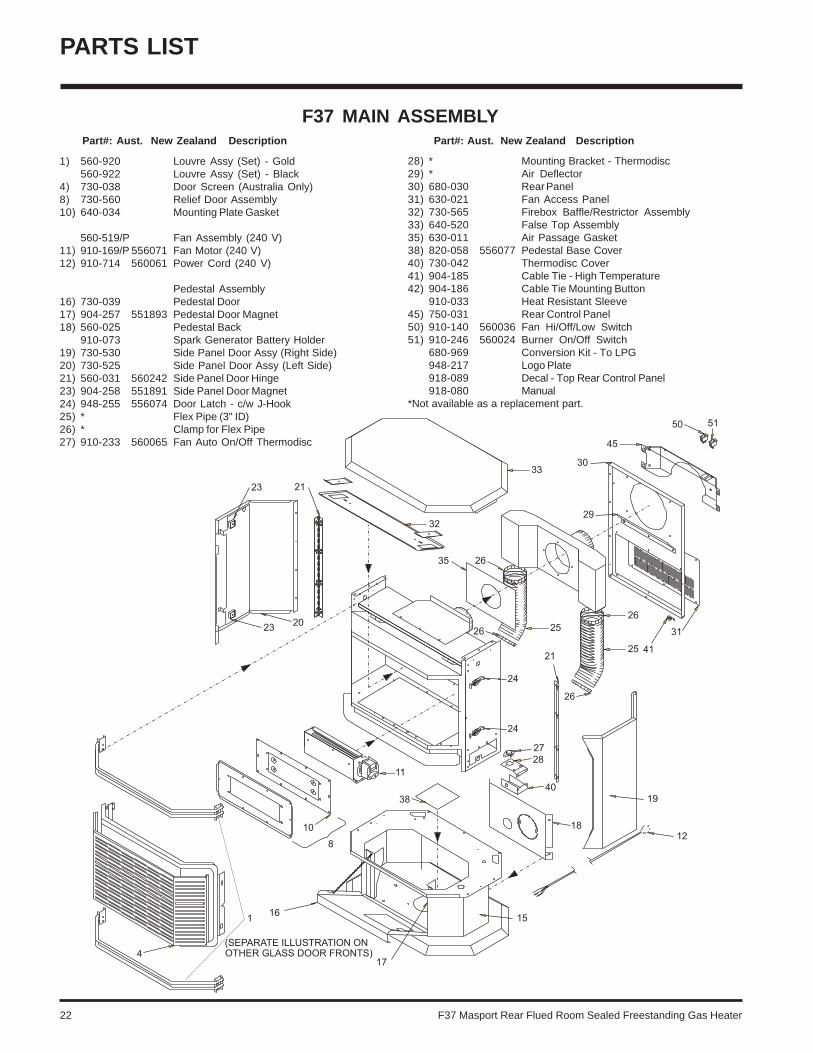
PARTS LIST
1) 560-920 Louvre Assy (Set) - Gold560-922 Louvre Assy (Set) - Black
4) 730-038 Door Screen (Australia Only)8) 730-560 Relief Door Assembly10) 640-034 Mounting Plate Gasket
560-519/P Fan Assembly (240 V)11) 910-169/P 556071 Fan Motor (240 V)12) 910-714 560061 Power Cord (240 V)
Pedestal Assembly16) 730-039 Pedestal Door17) 904-257 551893 Pedestal Door Magnet18) 560-025 Pedestal Back
910-073 Spark Generator Battery Holder19) 730-530 Side Panel Door Assy (Right Side)20) 730-525 Side Panel Door Assy (Left Side)21) 560-031 560242 Side Panel Door Hinge23) 904-258 551891 Side Panel Door Magnet24) 948-255 556074 Door Latch - c/w J-Hook25) * Flex Pipe (3" ID)26) * Clamp for Flex Pipe27) 910-233 560065 Fan Auto On/Off Thermodisc
F37 MAIN ASSEMBLY Part#: Aust. New Zealand Description Part#: Aust. New Zealand Description
28) * Mounting Bracket - Thermodisc29) * Air Deflector30) 680-030 Rear Panel31) 630-021 Fan Access Panel32) 730-565 Firebox Baffle/Restrictor Assembly33) 640-520 False Top Assembly35) 630-011 Air Passage Gasket38) 820-058 556077 Pedestal Base Cover40) 730-042 Thermodisc Cover41) 904-185 Cable Tie - High Temperature42) 904-186 Cable Tie Mounting Button
910-033 Heat Resistant Sleeve45) 750-031 Rear Control Panel50) 910-140 560036 Fan Hi/Off/Low Switch51) 910-246 560024 Burner On/Off Switch
680-969 Conversion Kit - To LPG948-217 Logo Plate918-089 Decal - Top Rear Control Panel918-080 Manual
*Not available as a replacement part.

F37 Masport Rear Flued Room Sealed Freestanding Gas Heater 23
F37 BURNER & LOG ASSEMBLY
54) 910-373 588412 Knob - Pilot Valve Extension55) 910-372 588413 Flame Adjusting Knob56) 918-088 Decal - Control Panel57) * Switch Plate
680-574/P Valve Assembly - NG680-576/P Valve Assembly - LPG
60) 910-378 588394 Valve - S.I.T. - NG904-240 560259 #37 Orifice - NG936-170 556174 Orifice Gasket910-074 Spark Generator Switch c/w Wire
66) 910-038 Pilot Assy - S.I.T. - 3 Flame NG910-039 Pilot Assy - S.I.T. - 3 Flame LPG
67) * Pilot Holder68) W840470 Pilot Assembly Gasket71) 730-528 Log Stand
904-390 551859 Pilot Orifice #52 - NG
75) 730-935 Log Set78) 730-550 Burner Assy - NG/LPG
Part#: Aust. New Zealand Description Part#: Aust. New Zealand Description
PARTS LIST
82) 630-009 Gasket - Burner Tray / Air Passage83) 630-008 Gasket - Burner Tray / Firebox
90) 910-386 Thermocouple91) 910-341 Thermopile
92) 902-267 Rear Log93) 902-231 Left Top Log94) 902-232 Center Log95) 902-226 Middle Right Log96) 902-230 Middle Left Log97) 902-229 Front Right Log98) 902-228 Front Left Log
*Not available as a replacement part.

24 F37 Masport Rear Flued Room Sealed Freestanding Gas Heater
F37 DOOR ASSEMBLIES
PARTS LIST
Part#: Aust. New Zealand Description
730-924 Gold Mitred Door - Complete730-926 Black Mitred Door - Complete730-932 Gold Wrap Door - Complete730-928 Gold Panel Door - Complete
101) 650-920 560018 Door Gasket Kit105) * Ceramic Paper106) 940-323/P Side Glass107) 936-243 560087 Glass Gasket108) 940-322/P Centre Glass111) * Door Frame Fibre Paper112) 750-015 Door Glass Extrusion208) 940-325/P Wrap Glass
*Not available as a replacement part.

F37 Masport Rear Flued Room Sealed Freestanding Gas Heater 25
_____________________________________________________________________________________
____________________________________________________________
__________________________________________________________
____________________________________________________________
_______________________________________________________
_____________________________________________________
__________________________________________________________
_________________________________________________________
_________________________________________________________
______________________________________________________
______________________________________________________
_______________________________________________________________
___________________________________________________________
__________________________________________________________
____________________________________________________________
____________________________________________________________
____________________________________________________________
_____________________________________________________________
__________________________________________________________
__________________________________________________________
_____________________________________________________
________________________________________________________
_________________________________________________________
_________________________________________________________
NOTES

26 F37 Masport Rear Flued Room Sealed Freestanding Gas Heater
_____________________________________________________________________________________
____________________________________________________________
__________________________________________________________
____________________________________________________________
_______________________________________________________
_____________________________________________________
__________________________________________________________
_________________________________________________________
_________________________________________________________
______________________________________________________
______________________________________________________
_______________________________________________________________
___________________________________________________________
__________________________________________________________
____________________________________________________________
____________________________________________________________
____________________________________________________________
_____________________________________________________________
__________________________________________________________
__________________________________________________________
_____________________________________________________
________________________________________________________
_________________________________________________________
_________________________________________________________
NOTES

F37 Masport Rear Flued Room Sealed Freestanding Gas Heater 27
WARRANTY
THE MASPORT EXPRESS WARRANTY
All new Masport Gas appliances are warranted, subject to thefollowing conditions, to be free from defects in material orworkmanship under normal use. The Express Warranty on allparts, including firebox components is two years from date oforiginal purchase as well as labour costs involved in therepair or replacement. The Express Warranty on accessoriesis for a period of twelve months from date of original purchaseand includes labour costs involved in the repair or replace-ment.
This Express Warranty applies only with respect to defects inmaterial and workmanship under normal and proper use ofthe NEW UNIT in its unmodified condition. Masport's obliga-tion under this Express Warranty is limited to the repair orreplacement, at its option, by an approved Masport GasService Agent (Retailer) of any part found to be defective inmaterial or workmanship.
Labour costs involved in the repair or replacement are alsocovered under this Express Warranty as per the time conditionoutlined.
If an approved Masport Gas Service Agent is requested toattend on a service call that is not covered under this ExpressWarranty, a call out charge may be applicable, regardless ofwhether a repair is carried out or not.
Masport can accept no obligation whatsoever for any inciden-tal, consequential or special damages or expenses resultingfrom any product defect. This Express Warranty applies fromthe date of original purchase, applies to the original purchas-er, and is not transferable. The decision to repair or replacedefective components will be made by Masport or its agentand actioned by an approved Masport Service Agent.
This Express Warranty Does Not Cover:1. Defects, malfunctions or failures caused by incorrect
installation, normal wear and tear, misuse, neglect, acci-dental damage or failure to follow the fuel selection,product operating and maintenance instructions, or re-sulting from installations, repairs or modifications to theequipment carried out by unauthorised persons.
2. Defects, malfunctions or failures caused by an act oromission of other persons after the product has leftMasport's control.
3. The costs of collection and delivery of the equipment.
4. The cost of labour or materials as a consequence of faultyinstallation of gas supply line, flue, burner or log settings,or non-compliance with local codes.
The Express Warranty is not intended to exclude any rightsthe purchaser may have under the laws of the place, state,or country of purchase. Nothing in this Express Warrantylimits or restricts any other statutory right or remedyavailable to the purchaser.
How You Obtain Warranty Service:Provide proof of the date of purchase. Should the need for awarranty claim arise reasonable proof of the purchase dateis required therefore you should retain your sales receipt.Where flueless appliances are not permanently installed,they should be returned to a Service Agent for evaluation.
Make the faulty part(s) available for inspection by Masport and/or its agents so that the validity of the claim can be establishedby them.
Australia Distributor:
Masport Pty LimitedP.O. Box 533Braeside Victoria 3195
For your own records, please complete the following:
Model: ________________________________________ Serial Number: ____________________________
New Zealand:
Masport LimitedP.O. Box 14-349PanmureAuckland 6
Retailer: ________________________________________________________________________________
______________________________________________________________________________________
Purchase Date: _______________________________

Printed in Canada© Copyright 2004, FPI Fireplace Products International Ltd. All rights reserved.
Copyright © 2022 FDOKUMEN