GreenStart Igniter 2 for Freestanding Stoves Installation ...
27
GreenStart Igniter 2 for Freestanding Stoves Installation Instructions (SKU 94400953, 94400951A) Page 1 of 27 17601769— 12/10/15 © Travis Industries, Inc. Compatibility Answer (Serial Number 1102-074894 or greater) Endeavor (Serial Number 1103-55526 or greater) Liberty (Serial Number 1105-38119 or greater) Olympic (Serial Number 1303-32053 or greater) (not available in Australia) Rainier (Serial Number 1302-36811 or greater) (not available in Australia) Cape Cod Stove Evergreen Stove (availability in Australia to be Determined) Rockport Stove (availability in Australia to be Determined) RAINIER STOVE REQUIRES ADDITIONAL FIREBRICK The Rainier uses a shorter firebrick. Make sure to order sku 94400019 before installation. On the Answer, Liberty, Olympic, and Rainier, the compressor assembly protrudes 7-1/2” behind the stove. Make sure to accommodate this space when installing. Table of Contents Compatibility ............................................................................................................................................... 1 Table of Contents ........................................................................................................................................ 1 Electrical Requirements ............................................................................................................................. 1 Packing List ................................................................................................................................................. 2 Installation Tips ........................................................................................................................................... 2 All Stove Models – Igniter Hose Clamp .................................................................................................... 3 Using a Room Blower Outlet with the GreenStart 2 Igniter .................................................................... 3 Installation – Answer, Liberty, Olympic, Rainier ..................................................................................... 4 Attaching the Compressor Assembly to the Stove ................................................................................... 6 Answer, Olympic, Rainier Only ............................................................................................................................ 6 Liberty Only ......................................................................................................................................................... 7 Installation Cape Cod, Evergreen, and Rockport ............................................................................... 12 Installation – Endeavor ............................................................................................................................. 18 Igniter Operation ....................................................................................................................................... 25 Warnings ................................................................................................................................................ 25 Operating Tips ........................................................................................................................................ 25 Igniter Instructions .................................................................................................................................. 26 Electrical Requirements USA or CANADA: This kit requires 8 amps, 120 Volt AC. AUSTRALIA: This kit requires 4 amps, 240 Volt AC.
-
Upload
khangminh22 -
Category
Documents
-
view
0 -
download
0
Transcript of GreenStart Igniter 2 for Freestanding Stoves Installation ...
GreenStart Igniter 2 for Freestanding Stoves Installation Instructions (SKU 94400953, 94400951A)
Page 1 of 27 17601769— 12/10/15 © Travis Industries, Inc.
Compatibility
Answer (Serial Number 1102-074894 or greater) Endeavor (Serial Number 1103-55526 or greater) Liberty (Serial Number 1105-38119 or greater) Olympic (Serial Number 1303-32053 or greater) (not available in Australia) Rainier (Serial Number 1302-36811 or greater) (not available in Australia) Cape Cod Stove Evergreen Stove (availability in Australia to be Determined) Rockport Stove (availability in Australia to be Determined)
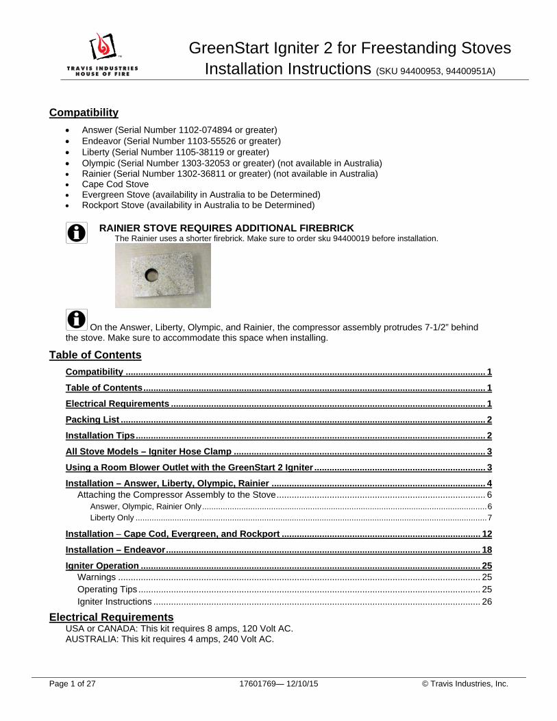
RAINIER STOVE REQUIRES ADDITIONAL FIREBRICK The Rainier uses a shorter firebrick. Make sure to order sku 94400019 before installation.
On the Answer, Liberty, Olympic, and Rainier, the compressor assembly protrudes 7-1/2” behind the stove. Make sure to accommodate this space when installing.
Table of Contents
Compatibility ............................................................................................................................................... 1
Table of Contents ........................................................................................................................................ 1
Electrical Requirements ............................................................................................................................. 1
Packing List ................................................................................................................................................. 2
Installation Tips ........................................................................................................................................... 2
All Stove Models – Igniter Hose Clamp .................................................................................................... 3
Using a Room Blower Outlet with the GreenStart 2 Igniter .................................................................... 3
Installation – Answer, Liberty, Olympic, Rainier ..................................................................................... 4 Attaching the Compressor Assembly to the Stove ................................................................................... 6
Answer, Olympic, Rainier Only ............................................................................................................................ 6 Liberty Only ......................................................................................................................................................... 7
Installation Cape Cod, Evergreen, and Rockport ............................................................................... 12
Installation – Endeavor ............................................................................................................................. 18
Igniter Operation ....................................................................................................................................... 25 Warnings ................................................................................................................................................ 25 Operating Tips ........................................................................................................................................ 25 Igniter Instructions .................................................................................................................................. 26
Electrical Requirements USA or CANADA: This kit requires 8 amps, 120 Volt AC. AUSTRALIA: This kit requires 4 amps, 240 Volt AC.

GreenStart Igniter 2 for Freestanding Stoves Installation Instructions (SKU 94400953, 94400951A)
Page 2 of 27 17601769.docx— 9/16/16 © Travis Industries, Inc.
Packing List
Igniter Firebrick
½” Silicon gasket (Liberty only)
Compressor Assembly Cover Box Igniter (the igniter and cover box together are referred to as
“igniter assembly”)
(2) Cable Holders Gasket Lock-tie Cord Restraint Igniter Spacer (Answer, Rainier, Olympic,
Liberty) (4) 1/2” washers (Olympic only) (6) 10-24 x ½” screws
(4) 3/8-16 x ¾” bolts (Endeavor only) (4) ¼-20 x 2-¾” bolts (Rainier/US Version only) (4) ¼ - 20 x 1-¾” bolts (Answer, Liberty, Olympic)
Endeavor Answer, Liberty, Olympic Rainier
Large grommets Small grommets (4) Washers (Liberty only) (Cape Cod only) (Olympic/US only)
(2) Magnets (Used for Cape Cod/Rockport/Evergreen without blower only)
Installation Tips
Remove the shipping screw from the pump box before proceeding with installation.
The igniter assembly must be installed before placing the stove.
If using a blower, install it first.
It is not necessary to install the blower first on the Endeavor, if applicable.
Wood placement is the key. Experiment with different sizes of wood and wood placement until you find a method that works best for your wood quality and kindling.
The compressor assembly must be placed as shown in the instructions. Placing it on its side, near hot components, or in a location where temperatures go below 40 F will void the warranty and may lead to premature failure.

GreenStart Igniter 2 for Freestanding Stoves Installation Instructions (SKU 94400953, 94400951A)
Page 3 of 27 17601769— 12/10/15 © Travis Industries, Inc.
All Stove Models – Igniter Hose Clamp
A hose clamp is attached to each igniter hose. You will need to set the clamp while attaching the hose to the igniter. See the photos below.
Using a Room Blower Outlet with the GreenStart 2 Igniter (US/Canada Only)
An extra outlet (sku 94400953) for the room blower is included with the GreenStart Igniter 2 for Freestanding Stoves. To access this outlet remove the top of the pump box using a 5/16” nutdriver.
There are two ways to route the cord into the pump box:
a. Route the cord and cord restraint through the right side of the pump box using the “U” shaped cutout above the igniter hose.
b. Route the cord through the bottom of the pump box and secure in place with the included cord restraint as shown below.
Replace the pump box top after plugging in the cord.

GreenStart Igniter 2 for Freestanding Stoves Installation Instructions (SKU 94400953, 94400951A)
Page 4 of 27 17601769— 12/10/15 © Travis Industries, Inc.
Installation – Answer, Liberty, Olympic, Rainier
1. Remove the firebrick covering the igniter housing from the firebox. Install the igniter firebrick as shown below. The igniter firebrick has a special hole drilled in it that the igniter will penetrate. Replace the 2 removed floor firebricks. NOTE: The firebrick for the Answer is the first brick on the right side of the rear of the firebox.
2. Remove the cover plate from the rear of the stove as shown below. Retain the screws.
3. Remove the convection chamber cover plate and gasket, as shown below. Retain the screws and gasket.

GreenStart Igniter 2 for Freestanding Stoves Installation Instructions (SKU 94400953, 94400951A)
Page 5 of 27 17601769— 12/10/15 © Travis Industries, Inc.
Answer, Liberty, Olympic, Rainier Installation, continued
4. Install the igniter spacer using the screws and gasket removed in step 3. Make sure to use the screws that were removed with the gasket.
5. Attach the igniter with gasket to the igniter sleeve using the screws and gasket included in this kit. Note that the igniter gasket is placed between the sleeve and igniter assembly.
NOTE: These instructions show the compressor assembly attached to the back of the stove. Alternatively, you may place it on the floor near the stove. See the Cape Cod model installation instructions on page 12 for details.

GreenStart Igniter 2 for Freestanding Stoves Installation Instructions (SKU 94400953, 94400951A)
Page 6 of 27 17601769— 12/10/15 © Travis Industries, Inc.
Attaching the Compressor Assembly to the Stove
Answer, Olympic, Rainier Only
NOTE: See the Addendum for Liberty igniter attachment.
1. Install the bolts into the rear heat shield on the stove: Answer: Use four (4) ¼-20x1-3/4” bolts. Olympic: Use four (4) ¼-20x1-3/4” bolts with ½” washers. Rainier: Use four (4) ¼-20x2-3/4” bolts into the rear heat shield on the stove.
NOTE: A few bolt threads should protrude from the stove.
NOTE: The washers are used as spacers, and are inserted between the stove and the compressor assembly.
2. Hang the compressor assembly on the rear of the stove, as shown below. The 4 slots fit over the 4 bolts.
3. Tighten the bolts to secure the compressor assembly to the stove. A ratchet with an extension may help with this task.
NOTE: Do not over-tighten these bolts.
NOTE: An extra outlet may be used with the Answer, Olympic and Rainier stoves; see page 3.
This completes attaching the compressor assembly to the Answer, Olympic, and Rainier.

GreenStart Igniter 2 for Freestanding Stoves Installation Instructions (SKU 94400953, 94400951A)
Page 7 of 27 17601769— 12/10/15 © Travis Industries, Inc.
Liberty Only
1. Install the bolts into the rear heat shield on the stove using four (4) ¼-20x1-3/4” bolts with the four (4) large grommets. Note how the grommet is placed so that the notch is at the outer edge of the bolt.
2. Tighten the bolts until the grommets contact the heat shield.
NOTE: Do not over-tighten these bolts.
3. Hang the compressor assembly on the rear of the stove, as shown below. The 4 slots fit over the 4 bolts in the grommet notch (see below).
NOTE: An extra outlet may be used with the Liberty stove; see page 3.
Grommet Notch

GreenStart Igniter 2 for Freestanding Stoves Installation Instructions (SKU 94400953, 94400951A)
Page 8 of 27 17601769— 12/10/15 © Travis Industries, Inc.
Liberty only, continued
The Liberty Stove requires a ½” silicone gasket to be placed between the heat shield and the heat shield support to prevent vibrations from the compressor assembly.
4. Remove the backing from the silicone gasket.
5. While pushing the heat shield back, insert the gasket between the heat shield and heat shield support. Affix the gasket to the heat shield. The photo at right below shows the gasket properly placed.

GreenStart Igniter 2 for Freestanding Stoves Installation Instructions (SKU 94400953, 94400951A)
Page 9 of 27 17601769— 12/10/15 © Travis Industries, Inc.
Attaching the Compressor Assembly to the Stove, continued
6. Cut about 8” off the compressor hose and attach to the brass nipple on the igniter.
7. Connect the compressor assembly wires; orientation does not matter. Wrap the wires around the compressor hose as shown below.
8. Attach the cover box to the heat shield as shown below, using the screws removed in step 2. If your unit does not include these holes, drill the holes with the included bit.

GreenStart Igniter 2 for Freestanding Stoves Installation Instructions (SKU 94400953, 94400951A)
Page 10 of 27 17601769— 12/10/15 © Travis Industries, Inc.
Attaching the Compressor Assembly to the Stove, continued
9. Attach the igniter switch to the bottom of the stove using the 10-24 x ½” screws provided, as shown below.
Olympic and Rainier models using the Ashpan Pedestal: The start button is installed onto the left front corner.
10. Insert the 2 cable holders in the 2 holes on the underside of the stove. Route the start switch wire under the stove, through the cable holders.
11. Push any excess start switch wiring into the compressor assembly. NOTE: A lock-tie is included to secure excess wiring.

GreenStart Igniter 2 for Freestanding Stoves Installation Instructions (SKU 94400953, 94400951A)
Page 11 of 27 17601769— 12/10/15 © Travis Industries, Inc.
Attaching the Compressor Assembly to the Stove, continued
The final installation is shown below.
12. Plug in the compressor, then press the GreenStart start button.
NOTE: The compressor assembly will turn on for 30 seconds when first plugged in.
This completes the compressor assembly attachment.

GreenStart Igniter 2 for Freestanding Stoves Installation Instructions (SKU 94400951)
Page 12 of 27 17601769 — 12/10/15 © Travis Industries, Inc.
Installation Cape Cod, Evergreen, and Rockport
1. Prepare the compressor assembly:
NOTE: The foot plates with grommets serve as feet for the compressor assembly. The mounting brackets are shipped pre-installed on the compressor assembly. They need to be relocated for the Cape Cod installation. c. Remove the two mounting brackets with a 5/16” nut-driver.
d. Install 2 grommets (both sides) into the foot plates.

GreenStart Igniter 2 for Freestanding Stoves Installation Instructions (SKU 94400951)
Page 13 of 27 17601769 — 12/10/15 © Travis Industries, Inc.
2. Attach the foot plates to the bottom of the compressor assembly (both sides).
3. Modify the firebrick inside the firebox as shown below.
Cape Cod
Evergreen Rockport
F
F
FF
F
F
F
F
FF
F
F
1
1
1
12
4"x9"
Remove this cover plate (5/32” Hex Wrench) and replace the firebrick.
Remove this brick and replace it with the igniter firebrick. The Evergreen uses the brick included with the igniter, the Rockport uses the brick included with the stove.

GreenStart Igniter 2 for Freestanding Stoves Installation Instructions (SKU 94400951)
Page 14 of 27 17601769 — 12/10/15 © Travis Industries, Inc.
4. Remove the igniter knock-out on the rear of the stove. This is best done by snipping one of the tabs holding the knock-out in place then bending the knock-out repeatedly until it comes loose.
Cape Cod
Evergreen & Rockport
5. The knock-out may be discarded.
6. Remove the igniter cover plate and gasket. Retain the gasket and screws.

GreenStart Igniter 2 for Freestanding Stoves Installation Instructions (SKU 94400951)
Page 15 of 27 17601769 — 12/10/15 © Travis Industries, Inc.
7. Install the igniter spacer using the screws and gasket removed in step 6. Make sure to use the screws that were removed with the gasket.
8. Attach the igniter with gasket to the igniter sleeve using the screws and gasket included in this kit. Note that the igniter gasket is placed between the sleeve and igniter assembly.
NOTE: The brass nipple faces down.
9. Place the compressor assembly on the floor next to the stove.

GreenStart Igniter 2 for Freestanding Stoves Installation Instructions (SKU 94400951)
Page 16 of 27 17601769 — 12/10/15 © Travis Industries, Inc.
10. Attach the igniter wires to the compressor assembly wires.
11. Attach the ¼” tube to the nipple on the igniter.
12. Attach the cover plate and igniter cover box over the igniter (cover plates are included with the stove). Cape Cod Evergreen Rockport

GreenStart Igniter 2 for Freestanding Stoves Installation Instructions (SKU 94400951)
Page 17 of 27 17601769.docx — 9/16/16 © Travis Industries, Inc.
13. Place the compressor assembly on the floor behind the stove.
NOTE: An extra outlet may be used with the Cape Cod stove; see page 3.
14. Route t attach the igniter switch from the compressor assembly to underneath the stove.
Stoves with Blower
Attach the igniter switch bracket to the bottom of the rheostat bracket with two screws.
Stoves without Blower
Attach the igniter switch to the bottom of the stove using the two included magnets.

GreenStart Igniter 2 for Freestanding Stoves Installation Instructions (SKU 94400951)
Page 18 of 27 17601769 — 12/10/15 © Travis Industries, Inc.
Installation – Endeavor
1. Remove the left rear fire brick and install the igniter fire brick as shown below.
2. Remove the cover plate and 2 screws from the heat shield (located on the back of the stove). Retain the screws.
3. Remove the convection chamber cover plate.

GreenStart Igniter 2 for Freestanding Stoves Installation Instructions (SKU 94400951)
Page 19 of 27 17601769 — 12/10/15 © Travis Industries, Inc.
Endeavor Installation, continued
4. Remove the igniter cover plate and gasket from the stove. Retain the gasket and screws for later use.
ENDEAVOR COMPATIBILITY NOTE:
Endeavors with a serial number of 1103-55526 to 1103-55922 have a built-in spacer; installers of these models should continue to step 5. For Endeavors with a serial number of 1103-55923 or greater, install the spacer as shown below: Attach the igniter spacer, with gasket, to the stove, using the screws removed in step 2. Note how the spacer is installed with the notched plate facing outward.

GreenStart Igniter 2 for Freestanding Stoves Installation Instructions (SKU 94400951)
Page 20 of 27 17601769.docx — 10/13/16 © Travis Industries, Inc.
Endeavor Installation, continued
5. Attach the igniter with gasket to the igniter sleeve using the screws and gasket included in this kit. Note that the igniter gasket is placed between the sleeve and igniter assembly.
NOTE: These instructions show the compressor assembly attached to the bottom of the stove. Alternatively, you may place it on the floor near the stove. See the Cape Cod model installation instructions for details.
6. Remove and discard the cover plate from the compressor assembly.
7. Remove the mounting brackets from the compressor assembly. Re-attach them to the top of the compressor assembly.
NOTE: Each bracket is side-specific. Make sure to keep the brackets on the same side.

GreenStart Igniter 2 for Freestanding Stoves Installation Instructions (SKU 94400951)
Page 21 of 27 17601769 — 12/10/15 © Travis Industries, Inc.
Endeavor Installation, continued
8. Attach the four (4) 3/8”-16x3/4” bolts to the underside of the stove as shown below.
NOTE: If using a pedestal, place the compressor assembly under the pedestal before installing the bolts.
9. Place the compressor assembly under the stove with the power cord to the left (as viewed from the front of the stove).
10. Hang the compressor assembly under the stove on the bolts. Tighten the bolts to secure.

GreenStart Igniter 2 for Freestanding Stoves Installation Instructions (SKU 94400951)
Page 22 of 27 17601769 — 12/10/15 © Travis Industries, Inc.
Endeavor Installation, continued
11. Attach the air hose to the igniter.
12. Wrap the igniter wires around the air hose and connect them to the igniter; orientation does not matter.
13. Attach the igniter switch to the bottom of the stove using the 10-24 x ½” screws provided, as shown below.

GreenStart Igniter 2 for Freestanding Stoves Installation Instructions (SKU 94400951)
Page 23 of 27 17601769 — 12/10/15 © Travis Industries, Inc.
Endeavor Installation, continued
14. Attach the igniter cover box to the rear of the stove using the screws removed in step 2.
NOTE: For early Endeavor models, drilling an additional hole is required.
NOTE: The right side flange is tucked underneath the heat shield.
15. Insert the 2 cable holders into the 2 holes on the bottom of the stove. Route the start switch wire under the stove, through the cable holders.
16. Push any excess start switch wiring into the compressor assembly.
NOTE: A lock-tie is included to secure excess wiring.

GreenStart Igniter 2 for Freestanding Stoves Installation Instructions (SKU 94400951)
Page 24 of 27 17601769 — 12/10/15 © Travis Industries, Inc.
Endeavor Installation, continued
17. Plug in the igniter, then press the GreenStart start button.
NOTE: The compressor assembly will turn on for 30 seconds when it is first plugged in.
This completes the Endeavor installation.

GreenStart Igniter for Freestanding Stoves Installation Instructions (SKU 94400951)
Page 25 of 27 17601674 — 12/10/15 © Travis Industries, Inc.
Igniter Operation
Warnings
MAKE SURE THE AIR CONTROL AND BYPASS (IF APPLICABLE) ARE OPEN. FAILURE TO OPEN THESE CONTROLS MAY LEAD TO SMOKE ENTERING THE HOME.
DO NOT OPEN THE DOOR DURING IGNITION. THIS MAY LEAD TO SMOKE ENTERING THE HOME.
DO NOT PLACE YOUR HAND NEAR THE IGNITER OPENING. THIS AREA BECOMES EXTREMELY HOT AND MAY CAUSE SEVERE BURNS.
Operating Tips
The compressor assembly will turn on for 30 seconds when it is first plugged in. This is normal.
The igniter must be operated only with someone present. Improper operation may lead to smoke entering the home.
Hardwood or un-seasoned wood may take longer to ignite. For this kind of wood you may need to cut the kindling into smaller pieces.
Wood placement is the key. Experiment with different sizes of wood and wood placement until you find a method that works best for your wood quality and kindling.
Make sure to place wood within 1” of the igniter opening.

GreenStart Igniter for Freestanding Stoves Installation Instructions (SKU 94400951)
Page 26 of 27 17601674 — 12/10/15 © Travis Industries, Inc.
Igniter Instructions
1. Gather a handful of kindling, approximately 1-1/2” in diameter. Place two sticks under the igniter in the path of the air stream, as shown below. Stack the remaing kindling near the air opening, leaving a minimum 1” gap to the igniter opening and plenty of space for air to pass through. The more surface area the air flow contacts, the quicker the fire will start.
2. Make sure the air control and bypass are in the open position.
3. Close the stove door when all kindling is in place.
�

GreenStart Igniter for Freestanding Stoves Installation Instructions (SKU 94400951)
Page 27 of 27 17601674 — 12/10/15 © Travis Industries, Inc.
4. Press the igniter button to start the ignition process. The green indicator light on the button will turn on.
The igniter and compressor assembly will run for 15 minutes before shutting off automatically. NOTE: If you need to turn off the igniter after starting the ignition process, press the GreenStart button a second time. The system will turn off power to the igniter and the GreenStart button will flash. The pump will continue to run for about seven minutes and then shut off.
BELLOWS FEATURE If a bellows effect is desired (adding oxygen to the fire without cycling the igniter) simply push the GreenStart button twice, which will start the pump-only mode. The bellows effect will stay on for 7 minutes, before the unit shuts down.