Freestanding-WS-Jib-Manual-103-0012.pdf - Spanco
16
Installation and Maintenance Manual for SPANCO ® Freestanding Workstation Jib Cranes Manual No. 103-0012 REV. 08/14 ISO 9001 REGISTERED © SPANCO, Inc.
-
Upload
khangminh22 -
Category
Documents
-
view
1 -
download
0
Transcript of Freestanding-WS-Jib-Manual-103-0012.pdf - Spanco

Installation and Maintenance Manual forSPANCO® Freestanding Workstation Jib Cranes
Manual No. 103-0012REV. 08/14
ISO 9001 REGISTERED© SPANCO, Inc.

2
Forward...................................................................................................................... 3
Mast Installation...................................................................................................... 3-5
Manual Rotation Stop Installation.................................................................................6
Boom Installation.....................................................................................................6-7
Hoist Trolley and End Stop Installation..........................................................................8
Festoon Options....................................................................................................... 8-9
Hoist Installation.......................................................................................................10
Warning, Safety, or Capacity Labels.............................................................................10
Acceptance Test........................................................................................................11
Spare Parts...............................................................................................................11
Bill of Materials........................................................................................................ 11
Maintenance.............................................................................................................12
Dimensions..........................................................................................................13-14
Warranty and Service Policy........................................................................................16
TABLE OF CONTENTS

3
This manual contains important information to help you install, operate, maintain, and service yournew workstation jib crane. We recommend that you study its contents thoroughly before putting thejib into use. We also recommend that you obtain the latest issue of ANSI B30.11 Safety Standardfor Monorails and Underhung Cranes and study its contents thoroughly. By practicing therecommended maintenance suggestions, with proper installation, and application of correctoperating procedures, you will be assured maximum service from your jib crane.
The jibs described in this manual are intended for indoor service. Jib cranes used for outdoor servicerequire special consideration.
Information in this manual is subject to change without notice.
Note: There are several types of base plate leveling methods to be used.
1. No shims or grout on a level and true smooth concrete surface.
2. Using shims (by others) and grout, as required, to plumb the mast on an irregular concrete surface. (Be aware that the slighest deviation from level will be magnified by the height of the mast and will result in difficulty leveling the boom.)
3. A preset leveling plate (by others) and grout.
4. Using leveling nuts (by others) and grout, as requried.
For purposes of this manual, we will describe method four, leveling nuts and grout. Other methodsare similiar and may require special attention to anchor bolt projection lengths, grout thickness, andother onsight variables. In all cases, the finished installation requirees full contact of the base plateon the foundation. All anchor bolts shall have plate washers (with standard holes) of adequatethickness for oversized base plate holes, per AISC requirements. Along with plate washers, astandard washer shall be used on each anchor bolt.
FORWARD
MAST INSTALLATION(Refer to Figure 1)
THIS EQUIPMENT IS NOT, IN ANY WAY, DESIGNED FORLIFTING, SUPPORTING, OR TRANSPORTING HUMANS.

4
IT IS SOLELY THE CUSTOMER’S RESPONSIBILITY TO PROVIDE THE PROPER FOUNDATION FOR THE JIBCRANE SO THERE SHOULD BE NO DEVIATION FROM THE RECOMMENDED FOUNDATION SIZE ORINSTALLATION RECOMMENDATIONS WITHIOUT FIRST CONSULTING A QUALIFIED PROFESSIONAL.
1. After installing the recommended concrete (3,000 PSI) foundation, reinforcement, and anchor bolts (minumum 1 inch diameter), refer to the dimension sheet of your specific model jib crane (Pages 11-12 and Figures 1A or 1B and 2).
2. Install one set of leveling nuts on the anchor bolts with the top surface approximately one inch above the foundation. Next, place the mast assembly over the anchor bolts resting on leveling nuts. Install the second set of nuts with plate washers and flat washers. Clamp the plumb fixture (a straight and rigid bar, level, or other custom made bracket) to mast cap plate and/or pivot pin. Note: Fixture must be perpendicular to the mast.
3. Select a position on the fixture arm, 2 inches from the edge of the mast, to hang a plumb line. Measure 60 inches down from the top of the mast and use this point to check the 2 inch dimension for mast plumb.
4. Position fixture arm directly over one anchor bolt and measure from the plumb line to the edge of the mast. If this measurement is not 2 inches, adjust the leveling nut directly below. Turn leveling nut up if greater than 2 inches, down if less than 2 inches.
5. Rotate the fixture arm 180 degrees and recheck mast for plumb. Adjust the leveling nuts until you have the same distance on each side of the mast. Repeat this operation at each anchor bolt or at 60 degree increments.
6. When mast is plumb tighten the locking nuts.
Note: Do not grout until installation of boom is complete.
7. When installation of crane is complete and the operation is double checked, float grouting compound under base plate and recheck tightness of locking nuts.
THE BOLT PADS ARE TAC WELDED TO BASE PLATE FOR EASY REMOVAL IN CASE OF SLIGHTMISALIGNMENT OF ANCHOR BOLT. GRIND TAC AREA TO REMOVE BOLT PAD OR PADS. RESETTHE MAST UNIT OVER THE ANCHOR BOLTS AND LEVELING NUTS. BE SURE TO PUT THEBOLT PAD OR PADS BACK INTO PLACE BEFORE INSTALLING THE 2ND SET OF NUTS. THESEBOLT PADS DO NOT REQUIRE WELDING ONCE THEY ARE REMOVED AND REPLACED.
MAST INSTALLATION continued...

5
(Foundation and Anchor Bolts by Others)
NOTE:
MAST INSTALLATION continued...
Figure 1
Figure 1A Figure 1B

6
Note: Do not install the boom until the mast is installed properly and plumbed.
1. Place the bearing cone over the mast pivot pin.
2. Assemble the trunnion roller assembly as shown in Figure 2A andattach to mast assembly.
3. Carefully lower the boom assembly over the mast pivot pin andonto the bearing.
4. Place the washer over the mast pivot pin and insert the cotter pin.
5. Check boom for level and adjust trunnion roller assembly to insurethat boom is level inall positions. Roller must be adjusted to apply pressure to the
mast.
NOTE: If boom and/or mast is not level, the trolley or boom will not stay inposition when not in use.
Re-adjust mast or boom for plumb and level is required.
6. To compsensate for antipicated deflection it may be necessary toadjust boom with thetip raised a distance equal to half the expected deflection. Each
jib is designed for a maximum:
Boom Length (inches) ÷ 150 = Deflection (inches)
ROTATION STOP INSTALLATION INSTRUCTION
BOOM INSTALLATION

7
BOOM INSTALLATION continued...

End Stop Bolt W/ Lock Nut and Rubber Sleeve For500, 600, & 700 Series Track
End Stop W/ LockNut & Rubber Bumper
FestoonTrolleys
Flat Cable
BoomTrack
End ClampAssembly
8
Note: This procedure may differ depending upon the festoon option you choose (See Figures 5A, 5B, and 5C). Festoon cables and trolleys are optional.
1. Place end clamp, festoon trolleys, then hoist trolley on the boom track. (See Figure 3)
2. Secure the end stop bolts and rubber bumper.
3. Install the festoon cable on the festoon trolleys at equal spacing as required.
1. No festooning (Standard Cranes) 4. Air festoon (Figure 5C)
2. Flat cable festoon (Figure 5A) 5. 360 degree collector (Figure 6)
3. Box track festoon (Figure 5B) 6. 360 degree air swivel (Figure 7)
HOIST TROLLEY AND END-STOP INSTALLATION(Refer to Figure 3)
FESTOON OPTIONS
Figure 3BOOM FESTOON DETAIL

9
FESTOON OPTIONS continued...
H I G H V O L T A G E
D A N G E R
Collector (Optional)
Festoon
Figure 5AFestoon Option
H I G H V O L T A G E
D A N G E R
Collector (Optional) Box-Track
Box-Track
Figure 5BBox-Track Option
Figure 5CAir Festoon Option
Air Swivel(Optional) Box-Track
Box-Track
H I G H V O L T A G E
D A N G E R
Figure 6Collector Detail
Figure 7Air Swivel Detail
10
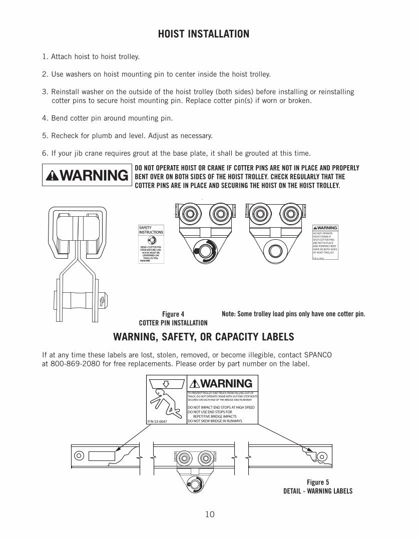
1. Attach hoist to hoist trolley.
2. Use washers on hoist mounting pin to center inside the hoist trolley.
3. Reinstall washer on the outside of the hoist trolley (both sides) before installing or reinstalling cotter pins to secure hoist mounting pin. Replace cotter pin(s) if worn or broken.
4. Bend cotter pin around mounting pin.
5. Recheck for plumb and level. Adjust as necessary.
6. If your jib crane requires grout at the base plate, it shall be grouted at this time.
Figure 4COTTER PIN INSTALLATION
If at any time these labels are lost, stolen, removed, or become illegible, contact SPANCO at 800-869-2080 for free replacements. Please order by part number on the label.
Note: Some trolley load pins only have one cotter pin.
HOIST INSTALLATION
DO NOT OPERATE HOIST OR CRANE IF COTTER PINS ARE NOT IN PLACE AND PROPERLYBENT OVER ON BOTH SIDES OF THE HOIST TROLLEY. CHECK REGULARLY THAT THECOTTER PINS ARE IN PLACE AND SECURING THE HOIST ON THE HOIST TROLLEY.
WARNING, SAFETY, OR CAPACITY LABELS
Figure 5DETAIL - WARNING LABELS

11
After the jib crane has been installed, OSHA requires an acceptance test before operating and alsoafter any modifications. This acceptance test should be performed by an authorized dealer orinstaller.
The following standard bill of materials shall be used as a guide when receiving your workstation jibcrane and when ordering spare parts. Items listed with an asterisk (*) are specific to your particularmodel number. Specify work order number, model number, and part number when ordering spare parts.
ACCEPTANCE TEST
SPARE PARTS
BILL OF MATERIALS

12
Once installation is complete the jib crane system should be checked thoroughly for tightness ofnuts and bolts. In order to maintain efficient operating conditions, SPANCO recommendsestablishing a regular inspecrtion and lubrication schedule. Inspection of all parts should be made.Loose parts should be adjusted and worn parts should be replaced immediately.
If a specific usage pattern cannot be determined, the crane operator or maintenance engineershould estimate when the crane should be lubricated. Generally, a jib crane operating 24 hours perday, seven days per week requires lubrication once a week. A jib crane operating eight hours perday, five days per week requires lubrication once every two to three weeks. A jib crane operatingonce or twice a month requires lubrication at least once every six months.
NOTE: The points requiring lubrication are the main pivot bearing.
RECOMMENDED LUBRICANTS:NLGI No. 1 or No. 2 greases.
MAINTENANCE

13
DIMENSIONS100-150 LB CAPACITY
360° ROTATION
Depth of Foundation
48”
B
MaximumHeight
Span
A
C
10”
Anchor Bolts Are 1” Diameter.Anchor Bolts And Template SuppliedUpon Request. Call Factory For Price
Mast Diameter
TrackDepth
Height Under Boom

14
DIMENSIONS continued...250, 500, AND 1,000 LB CAPACITIES
360° ROTATION

15

16
Spanco, Inc.604 Hemlock RoadMorgantown, PA, 19543
Toll Free: 800-869-2080Local: 610-286-7200Fax: 610-286-0085
Spanco.com
TEN-YEAR SPANCO WARRANTY
Products covered under the Ten-Year Warranty:
• Manual Steel Freestanding, Ceiling Mounted Workstation Bridge Cranes, and Monorails• Manual Aluminum (Alu-Track®) Workstation Bridge Cranes and Monorails• Manual Jib Cranes (I-Beam, Articulating, and Workstation Jib Cranes)• Manual Gantry Cranes and Tripods
What the Ten-Year Warranty covers:
• Defects in Equipment material and workmanship• Wearable parts (end truck and hoist trolley wheels only)
Spanco, Inc. warrants its manual workstation bridge crane products, jib crane products, and gantry crane productsto be free from defects in material and workmanship for a period of ten (10) years or 20,000 hours, commencingon the date of shipment to the first retail purchaser. This warranty extends to non-wearable parts only, with the exception of the wheels supplied on manually operated workstation end trucks and hoist trolleys. This warrantydoes not cover defective equipment or system failure caused by misuse, negligence, improper installation or maintenance, or equipment that has been used in excess of its rated capacity or beyond its service factors. Itdoes not apply to equipment that has been altered without Spanco’s written authorization.
Written notice of any claimed system defect must be given to Spanco within thirty days of discovery. Spanco's obligation under this warranty is limited to the replacement or repair of Spanco’s products at the factory or separate location approved by Spanco. The purchaser is responsible for all freight and transportation costs relatingto equipment repair or replacement. Other than the abovementioned warranty, Spanco will not honor any other warranties—whether express, implied, or statutory—and disclaims any warranties of merchantability or fitness for a particular purpose. Spanco is not liable—under any circumstances—for any indirect, incidental, or consequential damages including but not limited to lost profits, increased operating costs, or loss of production.
This warranty does not extend to components or accessories not manufactured by Spanco. The purchaser’s remedyfor such components and accessories will be determined by the terms and conditions of any the warranty providedby the manufacturer of such components and accessories.
NOTE: All motorized Spanco products come with a One-Year Warranty on drive components.