Nonlinear vibration of cracked plate
19
Vibration analysis of a rectangular thin isotropic plate with a part-through surface crack of arbitrary orientation and position Tanmoy Bose, A.R. Mohanty n Department of Mechanical Engineering, Indian Institute of Technology Kharagpur, Kharagpur 721302, India article info Article history: Received 4 February 2013 Received in revised form 4 July 2013 Accepted 13 August 2013 Handling Editor: M.P. Cartmell Available online 21 September 2013 abstract In this paper, vibration analysis of a rectangular thin isotropic plate with a part-through surface crack of arbitrary orientation and position is performed by using the Kirchhoff plate theory. Simply supported (SSSS), clamped (CCCC) and simply supported–clamped (SCSC) boundary conditions are considered for the analysis. First, the governing differ- ential equation of a cracked plate is formulated. A modified line spring model is then used to formulate the crack terms in the governing equation. Next, by the application of Burger's formulation, the differential equation is transformed into the well-known Duffing equation with cubic and quadratic nonlinearities. The Duffing equation is then solved by the method of multiple scales (MMS) to extract the frequency response curve. Natural frequencies are evaluated for different values of length, angle and position of a part-through surface crack. Some results are compared with the published literature. Amplitude variation with different values of length, angle and position of a part-through surface crack are presented, for all three types of the plate boundary conditions. & 2013 Elsevier Ltd. All rights reserved. 1. Introduction Plates are widely used as structural components. They are mostly used in aviation, automotive and ship building industries. The presence of crack affects the performance and longevity of the structures, especially when subjected to cyclic loads. Therefore, a detailed study of the dynamic characteristics of cracked plates is of the utmost importance. The dynamic characteristics of an intact plate has been rigorously studied and well established. A monograph on the vibration of plates was published by Leissa [1] in 1993; in which he reviewed the contemporary literature on plate vibrations. The static solutions of the surface cracked plates have also been well developed. Most of the solutions are done by different numerical techniques. Approximate analytical solution is only possible by means of the Line Spring Model (LSM). This concept was first proposed by Rice and Levy [2] to represent a part-through surface crack as continuous line springs. The compliance coefficients of the springs were chosen to match those of an edge-cracked strip in plane strain. It reduced the complexity of the problem and became computationally inexpensive. Moreover, they pointed out that the line spring approximation appears to be the most appropriate when the crack length is large compared to the plate thickness. Delalae and Erdogan [3] improved the line spring model by considering the transverse shear deformation of the plate. Reissner plate theory was used to formulate the problem and then solved by the boundary integral method. Later, this model was extended to antisymmetric conditions [4]. King [5] Contents lists available at ScienceDirect journal homepage: www.elsevier.com/locate/jsvi Journal of Sound and Vibration 0022-460X/$ - see front matter & 2013 Elsevier Ltd. All rights reserved. http://dx.doi.org/10.1016/j.jsv.2013.08.017 n Corresponding author. Tel.: þ91 3222 282944; fax: þ91 3222 255303. E-mail address: [email protected] (A.R. Mohanty). Journal of Sound and Vibration 332 (2013) 7123–7141
Transcript of Nonlinear vibration of cracked plate

Contents lists available at ScienceDirect
Journal of Sound and Vibration
Journal of Sound and Vibration 332 (2013) 7123–7141
0022-46http://d
n CorrE-m
journal homepage: www.elsevier.com/locate/jsvi
Vibration analysis of a rectangular thin isotropic platewith a part-through surface crack of arbitraryorientation and position
Tanmoy Bose, A.R. Mohanty n
Department of Mechanical Engineering, Indian Institute of Technology Kharagpur, Kharagpur 721302, India
a r t i c l e i n f o
Article history:Received 4 February 2013Received in revised form4 July 2013Accepted 13 August 2013
Handling Editor: M.P. Cartmellential equation of a cracked plate is formulated. A modified line spring model is then
Available online 21 September 2013
0X/$ - see front matter & 2013 Elsevier Ltd.x.doi.org/10.1016/j.jsv.2013.08.017
esponding author. Tel.: þ91 3222 282944; fail address: [email protected]
a b s t r a c t
In this paper, vibration analysis of a rectangular thin isotropic plate with a part-throughsurface crack of arbitrary orientation and position is performed by using the Kirchhoffplate theory. Simply supported (SSSS), clamped (CCCC) and simply supported–clamped(SCSC) boundary conditions are considered for the analysis. First, the governing differ-
used to formulate the crack terms in the governing equation. Next, by the application ofBurger's formulation, the differential equation is transformed into the well-known Duffingequation with cubic and quadratic nonlinearities. The Duffing equation is then solved bythe method of multiple scales (MMS) to extract the frequency response curve. Naturalfrequencies are evaluated for different values of length, angle and position of a part-throughsurface crack. Some results are compared with the published literature. Amplitude variationwith different values of length, angle and position of a part-through surface crack arepresented, for all three types of the plate boundary conditions.
& 2013 Elsevier Ltd. All rights reserved.
1. Introduction
Plates are widely used as structural components. They are mostly used in aviation, automotive and ship buildingindustries. The presence of crack affects the performance and longevity of the structures, especially when subjected to cyclicloads. Therefore, a detailed study of the dynamic characteristics of cracked plates is of the utmost importance.
The dynamic characteristics of an intact plate has been rigorously studied and well established. A monograph on the vibrationof plates was published by Leissa [1] in 1993; in which he reviewed the contemporary literature on plate vibrations. The staticsolutions of the surface cracked plates have also been well developed. Most of the solutions are done by different numericaltechniques. Approximate analytical solution is only possible by means of the Line Spring Model (LSM). This concept was firstproposed by Rice and Levy [2] to represent a part-through surface crack as continuous line springs. The compliance coefficientsof the springs were chosen to match those of an edge-cracked strip in plane strain. It reduced the complexity of the problem andbecame computationally inexpensive. Moreover, they pointed out that the line spring approximation appears to be the mostappropriate when the crack length is large compared to the plate thickness. Delalae and Erdogan [3] improved the line springmodel by considering the transverse shear deformation of the plate. Reissner plate theory was used to formulate the problemand then solved by the boundary integral method. Later, this model was extended to antisymmetric conditions [4]. King [5]
All rights reserved.
ax: þ91 3222 255303.(A.R. Mohanty).

T. Bose, A.R. Mohanty / Journal of Sound and Vibration 332 (2013) 7123–71417124
carried out an elastic–plastic analysis for the surface flaws in a plate by the simplified line-spring model. By this simplification thecrack front was replaced with a crack of constant depth, which reduced the coupled integral equations in Ref. [2] to a pair oflinear algebraic equations and became more convenient to implement computationally. Later, this model was used by Zheng andDai [6] to compute the stress intensity factors of an angled part-through surface crack subjected to biaxial stresses. Wen andZhixe [7] investigated the relationship between the stress intensity factors derived from LSM using the Reissner plate theoryand the Kirchhoff plate theory. They also suggested a modified line spring model by taking into account the nonlocal effect ofdeformation.
Although the static solutions of cracked plates have been rigorously studied, very few attempts have been made toinvestigate its dynamic solutions. Some researchers have numerically investigated the natural frequency of a cracked plate.Among them, Stahl and Keer [8] first presented the natural frequencies of a plate with a side crack or a centrally locatedinternal crack using homogeneous Fredholm integral equations of the second kind. Stress singularity was considered at thecrack tips. The results were very accurate but the procedure of the model involved huge computations. Solecki [9] used thecombination of finite Fourier transformation of discontinuous functions and the generalized Green–Gauss theorem to studythe natural flexural vibration of simply supported plate with an arbitrarily located crack parallel to one of the plate edges.Liew et al. [10] employed the domain decomposition technique along with the Ritz method to determine the upper bound ofnatural frequencies for cracked plates. However, the displacement and slope continuities were not satisfied at every pointalong the interconnecting boundaries. So, the crack tip stress singularity was not properly generated. Khadem and Rezaee[11] introduced a new technique for crack detection in a simply supported plate by using modified comparison functions.However, the author neglected nonlinearity in the model and only the effect of bending compliance was considered. Theresults suffered from unacceptable errors at some frequencies. Berger [12] derived the differential equations of rectangularand circular plates subjected to large deflection by neglecting the strain energy due to the second invariant of the middlesurface strains. Using this result and the line spring model of Rice and Levy [2], Israr et al. [13] presented an approximateanalytical solution of the thin rectangular plates with a centrally located part-through surface crack subjected to forcedvibration. The authors related the far-field tensile and bending stress with crack tip tensile and bending stress respectivelybut avoided the coupling between them. This coupling is evident due to the eccentricity of the ligament with respect to thecentreline of the plate thickness [2,5]. Ismail et al. [14] extended the previous model [13] to a plate with an angled crack. Theauthors found that the natural frequency of the cracked plate increases with increasing crack angle. They also identifiedthe natural frequency of a plate with a vertical crack is the same as that of an intact plate. Huang et al. [15] studied the freevibration of thin square plates with arbitrary located side cracks. Stress singularities were introduced by a set of cornerfunctions. The Ritz method was used to extract the natural frequencies. However, the new set of functions are typicallyapplicable for large cracks. Later, the authors extended the previous method to thick rectangular plates with arbitraryoriented cracks [16]. A decrease in the natural frequency with an increase in the crack angle was reported for the simplysupported and cantilever plates with internal through cracks. Until now, only two papers [14,16] have presented thevariation of natural frequency with the crack angle, but both of them contradict each other. Moreover, they generallyconcentrate either on a part-through surface crack at the centre or a side crack. However, no authentic literature is availablewhich discusses about the nonlinear vibration analysis of a rectangular plate with a part-through surface crack of arbitraryorientation and position.
The present research thus aims to perform a detailed investigation on vibration analysis of a rectangular thin isotropicplate with a part-through surface crack of arbitrary orientation and location. In this research, the problem of Ref. [14] isreconsidered and rigorously modified. First, the governing equation of the cracked plate is modified. The effect of far-fieldtensile stress on the crack tip bending stress is then considered. Thus apart from the cubic nonlinearity, a quadraticnonlinearity also appears in the Duffing equation. Moreover, the line spring model is modified by including a twodimensional stress system, which is more realistic and compatible with the Kirchhoff plate theory. Furthermore, the conceptof the modified line spring model is included to shift the crack from the centre. The remainder of the paper is organised asfollows. In the next section, governing equation of the cracked plate is presented. Membrane forces in the governingequation are then formulated using Berger's formulation, followed by the solution of the governing equation by the Galerkinmethod and the method of multiple scales. Finally, all the results are presented along with some validation from wellpublished literature.
2. Development of the governing equation for a rectangular thin plate with a part-through surface crack of arbitraryorientation and position
2.1. Governing equation of a thin plate with a centrally located part-through surface crack of arbitrary orientation
In this section, the governing equation of a cracked plate is derived from the Kirchhoff plate theory. An arbitrary orientedsurface crack penetrating part-through the thickness is considered at the centre of the plate. Material properties areassumed to be isotropic. The membrane forces due to the large deflection are considered. Extra forces and moments areincluded in the model due to the inclusion of the crack, which will be formulated later. Thus, by the application of force andmoment equilibrium equations and the addition of membrane forces, the governing differential equation of the cracked

Fig. 1. An isotropic plate with an arbitrarily oriented part-through surface crack at the centre loaded by an arbitrarily located concentrated force.
T. Bose, A.R. Mohanty / Journal of Sound and Vibration 332 (2013) 7123–7141 7125
plate (Appendix A) can be stated as follows:
D∂4w∂x4
þ2∂4w
∂x2∂y2þ∂4w
∂y4
� �¼�ρh
∂2w∂t2
þ∂2Mx
∂x2þðNxþNxÞ∂
2w∂x2
þ∂2My
∂y2þðNyþNyÞ∂
2w∂y2
þ2∂2Mxy
∂x∂yþ2ðNxyþNxyÞ∂
2w∂x∂y
þPz (1)
where D is the flexural rigidity and is expressed as D¼Eh3/12(1�ν2). E is the modulus of elasticity, h is the thickness of the plateand ν is Poisson's ratio. Pz is the transverse load. Nx, Ny, Nxy¼Nyx are the in-plane forces of an intact plate and Nx, Ny, Nxy ¼Nyx
are the negative forces generated due to the presence of the crack. Therefore, ðNxþNxÞ denotes the net force along the x-direction.Mx,My,Mxy ¼Myx are the bending moments per unit length due to the same crack. In this research,Mx, Nx, Ny and Nxy
are considered which was previously neglected in Ref. [14]. An angled part-through surface crack changes the membrane forcesand bending moments along the x and y-directions. Therefore, Mx and Nx must be included into the governing equation. Nxy isconsidered because ðNxyþNxyÞ represents the net force due to the inclusion of the crack. Ny is included in the analysis due to thesame reason. Non-dimensional co-ordinates ξ¼ x=l1, η¼ y=l2 are introduced and the plate aspect ratio is defined as ϕ¼ l2=l1;where l1 and l2 are the dimensions of the rectangular plate (Fig. 1). So, the above equation becomes
∂4w∂η4
þ2ϕ2 ∂4w∂ξ2∂η2
þϕ4∂4w∂ξ4
þρhD∂2w∂t2
ϕ4l41 ¼�1
l21
∂2ðMxÞ∂ξ2
þϕ4ðNxþNxÞl21D
∂2w∂ξ2
þ l22D∂2ðMyÞ∂η2
þϕ2ðNyþNyÞl21D
∂2w∂η2
þ2l22ϕD
∂2ðMxyÞ∂ξ∂η
þ2l21ϕ3
DðNxyþNxyÞ
∂2w∂ξ∂η
þϕ4l41D
Pz (2)
2.2. Formulation of the relationship between the crack tip stresses and the far-field stresses
The approximate relationship between the crack tip stresses and the far-field stresses was first given by Rice and levy [2].They introduced the line-spring model which reduced the purely three dimensional problem to a two dimensional problem.Israr et al. [13] have used this formulation for vibration analysis of a rectangular plate with a centrally located part-throughsurface crack parallel to one of the plate edges. King [5] proposed a simplified line spring model considering the part-through surface crack as a combination of an edge crack and a through crack. Later Zheng and Dai [6] used that concept foran angled part-through surface crack under biaxial stresses. Ismail et al. [14] have extended the model of Ref. [13] byincorporating the above formulation for uniaxial case and for this reason the natural frequency of a vertical cracked plate isobserved to be same as that of an intact plate.
In this research, biaxial stress state [6] is considered with the addition of far-field bending and shear stresses. It isassumed that the crack is in the centre of an infinite plate subjected to far-field tensile, bending and in-plane shear stresses,as shown in Fig. 2. A plane transformation of the stresses to the “p–q” plane is expressed as
sp ¼ sxx þsyy2 þsxx�syy
2 cos 2θþτxy sin 2θ
sq ¼ sxx þsyy2 �sxx�syy
2 cos 2θ�τxy sin 2θτpq ¼�sxx�syy
2 sin 2θþτxy cos 2θ
9>>>=>>>;
(3)
mp ¼ mxx þmyy
2 �mxx�myy
2 cos 2θ�mxy sin 2θ
mq ¼ mxx þmyy
2 þmxx�myy
2 cos 2θþmxy sin 2θ
mpq ¼�mxx�myy
2 sin 2θþmxy cos 2θ
9>>>=>>>;
(4)
Thus the inclined part-through surface crack problem is divided into two parts: first, a horizontally oriented part-throughsurface crack subjected to tensile and bending stresses (Fig. 3a) and secondly, a horizontally oriented part-through surfacecrack subjected to shearing and twisting stresses (Fig. 3b). The part-through surface crack, shown in Fig. 3a and b, is treated

Fig. 2. Line spring model with an angled surface crack penetrating part-through the thickness.
T. Bose, A.R. Mohanty / Journal of Sound and Vibration 332 (2013) 7123–71417126
as an equivalent through-crack of the same length. The effect of the uncracked ligament is represented by springs whichapply forces and moments on the faces of the equivalent through-crack.
For a part-through surface crack in an infinite plate loaded with far-field tensile stresses sp, sq (Fig. 3a) and normaltensile force Nn, the displacement in the normal direction can be expressed as
δn ¼4aEðsq�stÞ (5)
where st ¼ ðNn=hÞ, h is the thickness of the plate and a is the half-crack length. Similarly, when the part-through surfacecrack is subjected to remote bending stresses mp, mq (Fig. 3a) and normal bending moment Mn, the rotation in the normaldirection is
θn ¼8ð1þνÞað3þνÞEhðmp�sbÞ (6)
where sb ¼ ð6Mn=h2Þ. If the part-through surface crack is loaded with a remote tangential stress τpq (Fig. 3b) and tangential
force Nt, the displacement in the tangential direction is
δt ¼4aEðτpq�τtÞ (7)
where τt ¼ ðNt=hÞ. Again, if the part-through surface crack is subjected to bending stress mpq (Fig. 3b) and twisting momentMt, the rotation in the tangential direction is expressed as
θt ¼8aEh
ðmpq�τbÞ (8)
where τb ¼ ð6Mt=h2Þ. Now by using the non-dimensional terms ðh=l1Þ ¼ γ, ða=l1Þ ¼ Γ and then solving according to Ref. [6],
the relationship between crack tip stresses and far-field stresses are
Rst ¼ 1þ3ð3þνÞð1�νÞ2
γ
Γαbb
� �sq�
1�ν2
2γ
Γαtbmp (9)
Rsb ¼�3ð3þνÞð1�νÞ2
γ
Γαbtsqþ 1þ1�ν2
2γ
Γαtt
� �mp (10)
Tτt ¼ 1þ3ð1þνÞ2
γ
ΓCbb
� �τpq�
1þν
2γ
ΓCtbmpq (11)
Tτb ¼�3ð1þνÞ2
γ
ΓCbtτpqþ 1þ1þν
2γ
ΓCtt
� �mpq (12)

Fig. 3. Horizontal part-through surface crack subjected to (a) tensile and bending stresses and (b) shear and twisting stresses.
T. Bose, A.R. Mohanty / Journal of Sound and Vibration 332 (2013) 7123–7141 7127
where
R¼ 1þ1�ν2
2γ
Γαtt
� �1þ3ð3þνÞð1�νÞ
2γ
Γαbb
� ��3ð1�νÞð3þνÞð1�ν2Þ
4γ
Γ
� �2αbt
2
and
T ¼ 1þ3ð1þνÞ2
γ
ΓCbb
� �1þ1þν
2γ
ΓCtt
� ��3ð1þνÞ2
4γ
Γ
� �2Ctb
2
the compliance coefficients αbb, αtt , αbt ¼ αtb are used to match the stretching and bending resistance for symmetric ormode I loading [2] and the other compliance coefficients Cbb, Ctt , Cbt ¼ Ctb are chosen to take care of the anti-symmetric ormixed mode (i.e., mode II and mode III) loading [4]. For a crack depth ratio (ζ) of 0.7, the values of compliance coefficients areαtt¼9.8181, αbb¼2.4367, αbt¼αtb¼4.8758, Ctt¼0.503067, Cbb¼�0.00395861 and Cbt¼Ctb¼�0.045906.

T. Bose, A.R. Mohanty / Journal of Sound and Vibration 332 (2013) 7123–71417128
2.3. Governing equation of the rectangular plate with a part-through surface crack of arbitrary orientation and location
In the line spring model, the crack is assumed to be in an infinite plate. This assumption is valid only when the crack is atthe centre of a finite plate. So, this concept is not applicable when the crack is away from the centre. Therefore, thecompliance coefficients are modified by using a Modified Line Spring Model (MLSM) like in Ref. [7]. This model is validfor ðγ=2ΓÞo1, which is the same as for the LSM. In this method, each compliance coefficient is multiplied byð2=
ffiffiffiffiffiffiffiffiffiffiffiffiffiffiπðγ=ΓÞ
pÞexpð�ðððΓ�ξcÞ2l21Þ=ðγ=ΓÞÞÞ (Appendix B); where ξc ¼ ðd=l1Þ is the eccentricity ratio, d is the distance between
the crack centre and the plate centre along the x-direction. The nominal tensile and bending stresses are represented asin Ref. [2]
srs ¼Nrs
h¼Z þh=2
�h=2τrsdz (13)
mrs ¼6Mrs
h2¼ 6
h2
Z þh=2
�h=2zτrsdz (14)
where r, s¼x, y. The relationship between the crack tip closure forces and moments with the forces and moments in the farfield can be expressed from Eqs. (9)–(12) as
Nn ¼ Zn1fNx sin2θþNy cos 2θ�Nxy sin 2θg�Zn2fMx sin
2θþMy cos 2θg (15)
Mn ¼�Zn3fNx sin2θþNy cos 2θ�Nxy sin 2θgþZn4fMx sin
2θþMy cos 2θg (16)
Nt ¼ Zn5 �Nx�Ny
2sin 2θþNxy cos 2θ
�Zn6
Mx�My
2sin 2θ
(17)
Mt ¼�Zn7 �Nx�Ny
2sin 2θþNxy cos 2θ
þZn8
Mx�My
2sin 2θ
(18)
where all the coefficients are listed in Appendix C. Along with this,Mx,My,Mxy can be written in dimensionless co-ordinates as
Mx ¼�Dl21
∂2w∂ξ2
þ νϕ2
∂2w∂η2
� �My ¼�D
l22
∂2w∂η2 þνϕ2∂2w
∂ξ2
� �Mxy ¼Myx ¼�Dð1�νÞϕ
l21
∂2w∂x∂y
9>>>>>>=>>>>>>;
(19)
the crack forces and moments appearing in Eq. (2) again can be related to the far-field forces and moments as
Nx ¼�ðNn sin2θ�Nt sin 2θÞ
Ny ¼�ðNn cos 2θþNt sin 2θÞNxy ¼� �Nn
sin 2θ2 þNt cos 2θ
� �9>>=>>; (20)
Mx ¼�ðMn sin2θ�Mt sin 2θÞ
My ¼�ðMn cos 2θþMt sin 2θÞMxy ¼� �Mn
sin 2θ2 þMt cos 2θ
� �9>>=>>; (21)
the negative sign appears in the above equations because the crack causes a reduction in the forces and moments. Bysubstituting Eqs. (15)–(19) into Eqs. (20) and (21) and then using the resulting equations in Eq. (2), one obtains the followingequation:
∂4w∂η4
ð1�J11Þþϕ2ð2�J12Þ∂4w
∂ξ2∂η2þϕ4ð1�J10Þ
∂4w∂ξ4
þρhD
∂2w∂t2
ϕ4l41 ¼ϕ4l41D
Pz
þNxϕ2l21D
J1∂2w∂ξ2
þ J2∂2w∂η2
þ2J3∂2w∂ξ∂η
� �þϕ3J22
∂4w∂ξ3∂η
þϕJ23∂4w∂η3∂ξ
þNyϕ2l21D
J4∂2w∂η2
þ J5∂2w∂ξ2
þ2J6∂2w∂ξ∂η
� �þNxy
ϕ2l21D
2J7∂2w∂ξ∂η
þ J8∂2w∂ξ2
þ J9∂2w∂η2
� �
� J19∂2w∂ξ2
þ J20∂2w∂η2
þ2J21∂2w∂ξ∂η
� �ϕð1�νÞ∂
2w∂ξ∂η
� ϕ2∂2w∂ξ2
þν∂2w∂η2
� �J13
∂2w∂ξ2
þ J14∂2w∂η2
þ2J15∂2w∂ξ∂η
� �

T. Bose, A.R. Mohanty / Journal of Sound and Vibration 332 (2013) 7123–7141 7129
� ∂2w∂η2
þνϕ2∂2w∂ξ2
� �J16
∂2w∂ξ2
þ J17∂2w∂η2
þ2J18∂2w∂ξ∂η
� �(22)
where the coefficients Jn for n¼1,…,23 are listed in Appendix C. Eq. (22) is the final governing equation for forced vibration in arectangular thin plate with a part-through surface crack of arbitrary orientation and position.
3. Solution procedure
3.1. Application of Berger's formulation
Berger [12] developed the formulation for large deflection of plates i.e. where the deflection is of the order of thethickness of the plate. The formulation simplifies the analysis by neglecting the strain energy due to the second invariant ofthe middle surface strains and works well for the combination of simply supported and clamped boundary conditions. Inthis study, Nxy is also included apart from Nx and Ny [13,14]. The in-plane forces can be written as in Refs. [14,19]
Nx ¼ 6Dh2 l1 l2
R l10
R l20
∂w∂x
� �2þν ∂w∂y
� �2� �dxdy
Ny ¼ 6Dh2 l1 l2
R l10
R l20
∂w∂y
� �2þν ∂w
∂x
� �2� �dxdy
Nxy ¼ 12Dð1�νÞh2 l1 l2
R l10
R l20
∂w∂x
∂w∂y
h idxdy
9>>>>>>>>=>>>>>>>>;
(23)
3.2. Use of the Galerkin method
The Galerkin method is used to find an approximate solution of a problem when the exact trial functions are unknown.First, trial functions are chosen to satisfy the boundary conditions and then the orthogonality condition is satisfied byminimisation of the functional. The transverse displacement of the plate is expressed as [13,14]
wðξ; η; tÞ ¼ ∑1
m ¼ 1∑1
n ¼ 1AmnXmðξÞYnðηÞφmnðtÞ (24)
where XmðξÞand YnðηÞ are the modal functions of the cracked rectangular plate (Fig. 4) along the ξ and η directions. Amn is theunknown amplitude and φmnðtÞ is the time dependent term. In this paper, three types of boundary conditions are used forthe analysis. They are:
Boundary Condition 1. All sides are simply supported – SSSS
Xm ¼ ∑1
m ¼ 1sin ðmπξÞ (25)
Yn ¼ ∑1
n ¼ 1sin ðnπηÞ (26)
Boundary Condition 2. Two opposite edges are simply supported while the other two edges are clamped – SCSC
Xm ¼ ∑1
m ¼ 1sin ðmπξÞ (27)
Yn ¼ ∑1
n ¼ 1coshðϵnηÞ� cos ðϵnηÞ�αnðsinhðϵnηÞ� sin ðϵnηÞÞ (28)
Fig. 4. Representation of the part-through surface cracked plate in dimensionless co-ordinates.

T. Bose, A.R. Mohanty / Journal of Sound and Vibration 332 (2013) 7123–71417130
Boundary Condition 3. All edges are clamped – CCCC
Xm ¼ ∑1
m ¼ 1coshðϵmξÞ� cos ðϵmξÞ�αmðsinhðϵmξÞ� sin ðϵmξÞÞ (29)
Yn ¼ ∑1
n ¼ 1coshðϵnηÞ� cos ðϵnηÞ�αnðsinhðϵnηÞ� sin ðϵnηÞÞ (30)
in Eqs. (28)–(30), ϵm, ϵn, αm and αn can be obtained from Ref. [1].The point load Pz at position ðξ0; η0Þ (Fig. 4) can be readily expressed as below
Pz ¼ P0ðtÞδðξ�ξ0Þδðη�η0Þ (31)
the non-dimensional form of the in-plane forces is directly written from Eq. (23) as
Nx ¼DF1mnA2mnφ
2ðtÞNy ¼DF2mnA
2mnφ
2ðtÞNxy ¼DF3mnA
2mnφ
2 tð Þ
9>>=>>; (32)
where
F1mn ¼6
γ2l41
Z 1
0
Z 1
0
∂Xm
∂ξ
� �2
Y2nþ
ν
ϕ2
∂Yn
∂η
� �2
X2m
" #dξdη
F2mn ¼6
γ2l41
Z 1
0
Z 1
0
1ϕ2
∂Yn
∂η
� �2
X2mþν
∂Xm
∂ξ
� �2
Y2n
" #dξdη
F3mn ¼12ð1�νÞγ2l41ϕ
Z 1
0
Z 1
0
∂Xm
∂ξ∂Yn
∂η
� �dξdη
now by substituting Eqs. (32), (31) and (24) into Eq. (22), multiplying by XmYn and then integrating over the plate area yieldsthe well-known Duffing equation
Mmn €φðtÞþKmnφðtÞþHmnφ2ðtÞþGmnφ
3ðtÞ ¼ Pmn (33)
where
Mmn ¼ρhDϕ4l41 ∑
1
m ¼ 1∑1
n ¼ 1Amn
Z 1
0
Z 1
0X2mY
2ndξdη (34)
Kmn ¼ ∑1
m ¼ 1∑1
n ¼ 1Amn
Z 1
0
Z 1
0ðϕ4Xiv
mYnð1�J10Þþϕ2X″mY
″nð2�J12ÞþYiv
n Xmð1�J11Þ
�ϕ3X‴Y0J22�ϕY‴X‴J23ÞXmYndξdη (35)
Hmn ¼ ∑1
m ¼ 1∑1
n ¼ 1A2mn
Z 1
0
Z 1
0ð ðϕ2X″YþνXY″ÞðJ13X″Yþ J14Y″Xþ2J15X′Y ′Þ
þðY″Xþνϕ2X″YÞðJ16X″Yþ J17Y″Xþ2J18X′Y′Þþϕð1�νÞX′Y ′ðJ19X″Yþ J20Y″Xþ2J21X′Y′ÞÞXmYndξdη (36)
Gmn ¼�ϕ2l21 ∑1
m ¼ 1∑1
n ¼ 1A3mn
Z 1
0
Z 1
0ð F1mnðJ1ϕ2X″Yþ J2Y″Xþ2J3ϕX′Y ′Þ
þF2mnðJ4Y″Xþ J5ϕ2X″Yþ2J6ϕX′Y′Þ
þF3mnð2J7ϕX′Y ′þ J8ϕ2X″Yþ J9Y″XÞÞXmYndξdη (37)
and
Pmn ¼ P0ðtÞD
Xmðξ0ÞYnðη0Þ (38)
where Z 1
�1XmðξÞδðξ�ξ0Þdξ¼ Xmðξ0Þ (39)
dividing Eq. (33) by Mmn and introducing classical linear viscous damping we get
€φðtÞþ2μ _φðtÞþω2mnφðtÞþBmnφ
2ðtÞþSmnφ3ðtÞ ¼ λmnl
41
DP0ðtÞ (40)

T. Bose, A.R. Mohanty / Journal of Sound and Vibration 332 (2013) 7123–7141 7131
where ω2mn ¼ ðKmn=MmnÞ; Bmn ¼ ðHmn=MmnÞ; Smn ¼ ðGmn=MmnÞ; λmn ¼ ððXmðξ0ÞYnðη0Þϕ4Þ=MmnÞωmn is the natural frequency
and μ is the damping coefficient. Smn and Bmn are the cubic and quadratic nonlinearity of the cracked plate, respectively. Inthis study, the force is taken as harmonic P0ðtÞ ¼ P cos Ωmnt. Ωmn is the excitation frequency. The non-dimensional naturalfrequency can be expressed as χ ¼ωmnl
21
ffiffiffiffiffiffiffiffiffiffiffiρh=D
p.
3.3. Solution by the method of multiple scales (MMS)
This is one of the most reliable techniques used to determine frequency response curve from the Duffing equation.Authors in Ref. [13,14] have used this to find approximate analytical solution of the Duffing equation with cubic nonlinearity.In this paper, a different multiple scales solution procedure is used according to Ref. [17] to take care of both the quadraticand cubic nonlinearities. The detuning parameter s is introduced in Eq. (41) to describe quantitatively the closeness ofexcitation frequency Ωmn with the natural frequency ωmn. According to Nayfeh and Mook [17]
Ωmn ¼ωmnþε2s (41)
where ε is an arbitrarily small perturbation parameter. The time dependent term in Eq. (24) i.e. φðtÞ can be expressed as inNayfeh and Mook [17]
φðtÞ ¼ b cos ðΩmnt�βÞþ12εBmn
ω2mn
b2 �1þ13cos ð2Ωmnt�2βÞ
� �þOðε2Þ (42)
the unknown terms b and β can be determined from the following equations [17]:
μ2b2þ bs�9Smnω2mn�10B2
mn
24ω3mn
b3 !2
¼ λ2mnP2l81
4D2ω2mn
(43)
tan β¼ μ
ðð9Smnω2mn�10B2
mnÞ=24ω3mnÞðb2�sÞ
(44)
the parameter α is defined as α¼ ð9Smnω2mn�10B2
mnÞ=24ω3mn [17]. When α40, the nonlinearity has a hardening effect and for
αo0, the nonlinearity has a softening effect. The nonlinearity vanishes for α¼0.
4. Results and discussions
Results are divided into two sections. Firstly, non-dimensional natural frequencies of a cracked square plate with threetypes of boundary conditions are presented and compared with existing results. Secondly, amplitude curves determinedfrom the method of multiple scales (MMS) are presented. In this paper, an aluminium plate is considered for the analysis.The material properties are ρ¼2660 kg/m3, ν¼0.33, E¼7.03�1010 N/m2 and damping factor m¼0.08. The geometry of thecracked plate is defined as l1¼1 m, ϕ¼1 and γ¼0.02. Load (P) of 10 N is applied at ξ0 ¼ 0:375, η0 ¼ 0:375.
4.1. Investigation of the natural frequencies for square plates with part-through surface cracks
Non-dimensional natural frequencies of plate with three different boundary conditions i.e., all edges simply supported (SSSS),all edges clamped (CCCC), two edges simply supported and two edges clamped (SCSC), are presented in Tables 2–4. Results for alledges simply supported (SSSS) plates are compared with the very accurate Fredlom integral solution of Stahl and Keer [8] and thedomain decomposition technique of Liew et al. [10], presented in Table 1. In this study, the crack is considered to be in the centreof the plate and parallel to one of the edges. It is obvious from the results that the natural frequency decreases with crack length.The results are very close to that of Stahl and Keer for crack length ratio (Γ) of 0.2 to 0.5. Therefore, approximate solution ofthe line spring model is usually appropriate for small γ=2Γ ratio [2]. The present solution departs from the results of Stahl and
Table 1Comparison of non-dimensional natural frequencies (χ) for simply supported (SSSS) square (ϕ¼1) plateswith centrally located (ξc¼0) part-through surface cracks of various lengths (Г).
Crack length ratio (Г) First mode
Present method Stahl and Keer [8] Liew et al. [10]
0 19.74 19.74 19.740.1 18.31 19.31 19.380.2 18.18 18.27 18.440.3 17.53 17.19 17.330.4 16.28 16.40 16.470.5 16.13 16.13 16.13
T. Bose, A.R. Mohanty / Journal of Sound and Vibration 332 (2013) 7123–71417132
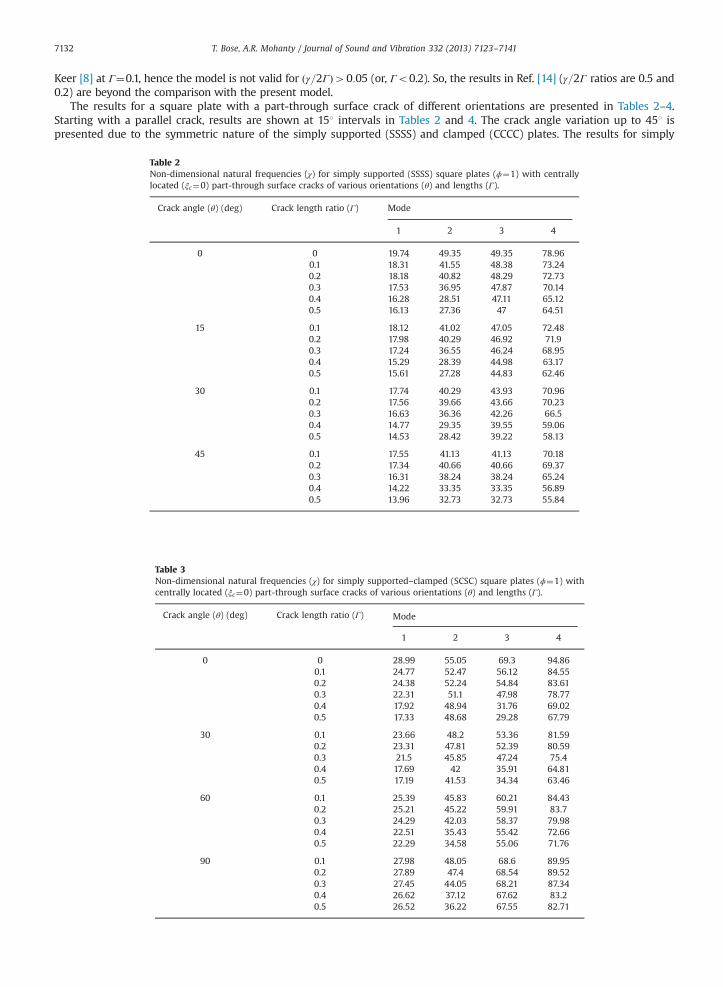
Keer [8] at Γ¼0.1, hence the model is not valid for ðγ=2ΓÞ40:05 (or, Γo0.2). So, the results in Ref. [14] (γ=2Γ ratios are 0.5 and0.2) are beyond the comparison with the present model.
The results for a square plate with a part-through surface crack of different orientations are presented in Tables 2–4.Starting with a parallel crack, results are shown at 151 intervals in Tables 2 and 4. The crack angle variation up to 451 ispresented due to the symmetric nature of the simply supported (SSSS) and clamped (CCCC) plates. The results for simply
Table 2Non-dimensional natural frequencies (χ) for simply supported (SSSS) square plates (ϕ¼1) with centrallylocated (ξc¼0) part-through surface cracks of various orientations (θ) and lengths (Г).
Crack angle (θ) (deg) Crack length ratio (Г) Mode
1 2 3 4
0 0 19.74 49.35 49.35 78.960.1 18.31 41.55 48.38 73.240.2 18.18 40.82 48.29 72.730.3 17.53 36.95 47.87 70.140.4 16.28 28.51 47.11 65.120.5 16.13 27.36 47 64.51
15 0.1 18.12 41.02 47.05 72.480.2 17.98 40.29 46.92 71.90.3 17.24 36.55 46.24 68.950.4 15.29 28.39 44.98 63.170.5 15.61 27.28 44.83 62.46
30 0.1 17.74 40.29 43.93 70.960.2 17.56 39.66 43.66 70.230.3 16.63 36.36 42.26 66.50.4 14.77 29.35 39.55 59.060.5 14.53 28.42 39.22 58.13
45 0.1 17.55 41.13 41.13 70.180.2 17.34 40.66 40.66 69.370.3 16.31 38.24 38.24 65.240.4 14.22 33.35 33.35 56.890.5 13.96 32.73 32.73 55.84
Table 3Non-dimensional natural frequencies (χ) for simply supported–clamped (SCSC) square plates (ϕ¼1) withcentrally located (ξc¼0) part-through surface cracks of various orientations (θ) and lengths (Г).
Crack angle (θ) (deg) Crack length ratio (Г) Mode
1 2 3 4
0 0 28.99 55.05 69.3 94.860.1 24.77 52.47 56.12 84.550.2 24.38 52.24 54.84 83.610.3 22.31 51.1 47.98 78.770.4 17.92 48.94 31.76 69.020.5 17.33 48.68 29.28 67.79
30 0.1 23.66 48.2 53.36 81.590.2 23.31 47.81 52.39 80.590.3 21.5 45.85 47.24 75.40.4 17.69 42 35.91 64.810.5 17.19 41.53 34.34 63.46
60 0.1 25.39 45.83 60.21 84.430.2 25.21 45.22 59.91 83.70.3 24.29 42.03 58.37 79.980.4 22.51 35.43 55.42 72.660.5 22.29 34.58 55.06 71.76
90 0.1 27.98 48.05 68.6 89.950.2 27.89 47.4 68.54 89.520.3 27.45 44.05 68.21 87.340.4 26.62 37.12 67.62 83.20.5 26.52 36.22 67.55 82.71

Table 4Non-dimensional natural frequencies (χ) for clamped (CCCC) square plates (ϕ¼1) with centrally located(ξc¼0) part-through surface cracks of various orientations (θ) and lengths (Г).
Crack angle (θ) (deg) Crack length Ratio (Г) Mode
1 2 3 4
0 0 36.11 73.44 73.74 108.850.1 32.75 61.33 71.75 99.790.2 32.45 60.15 71.58 98.970.3 30.8 53.91 70.72 94.820.4 27.83 40 69.11 86.710.5 27.45 38.05 68.92 85.71
15 0.1 31.87 60.03 69.32 97.90.2 31.56 58.91 69.1 97.030.3 29.98 52.96 67.96 92.590.4 26.83 39.8 65.83 83.850.5 26.44 37.96 65.58 82.77
30 0.1 30.03 57.94 63.65 94.020.2 29.71 57 63.26 93.030.3 28.05 52.01 61.26 87.970.4 24.7 41.31 57.4 77.810.5 24.28 39.88 56.93 76.54
45 0.1 29.06 58.77 58.77 92.020.2 28.74 58.11 58.11 90.970.3 27.03 54.65 54.65 85.560.4 23.57 47.66 47.66 74.610.5 23.13 46.78 46.78 73.22
Table 5Non-dimensional natural frequencies (χ) for all three types of square plate (ϕ¼1) with part-through surface cracks of constant length (Γ¼0.2) and various locations (ξc).
ξc Boundary conditions
SSSS CCCC SCSC
0 18.18 32.45 24.380.1 18.24 32.58 24.560.2 18.28 32.69 24.69
T. Bose, A.R. Mohanty / Journal of Sound and Vibration 332 (2013) 7123–7141 7133
supported–clamped (SCSC) plate are presented at 301 intervals and up to 901. The natural frequency decreases with anincrease in the crack angle for the first, third and fourth modes of a simply supported (SSSS) plate, which was also observed byHuang et al. [16] for thick plates. Similar variation is also found in case of clamped plates (Table 4). The natural frequency of allmodes, for a simply supported–clamped (SCSC) plate, decreases up to the crack angle of 301 and then increases (Table 3).
The natural frequencies for all three types of square plate with part-through surface cracks of constant length (Γ¼0.2)and various locations ðξcÞ are shown in Table 5. In all cases, crack is parallel to ξ-direction (Fig. 4). It is observed that thenatural frequency increases with an increase in eccentricity ðξcÞ i.e. the distance between the crack centre and the platecentre. The variation is the same for all types of plates. It is to be noted that this type of variation was also observed byKhadem et al. [11].
4.2. Determination of the amplitude curves
The amplitude curves for plates with all the boundary conditions are determined by the use of Eq. (43). First, theamplitude curve variation with half-crack length is shown for all types of plates. Amplitude variations with crack angle andposition are subsequently presented. In Fig. 5a–c the amplitude curves for three types of plates i.e., all edges simply supported(SSSS), all edges clamped (CCCC) and two opposite edges simply supported and other two edges clamped (SCSC), are reported fora half-crack length (a) of 0 to 0.2 m at a 0.1 m interval.
It is observed in Fig. 5a (simply supported plate) that the amplitude curve bends towards the right with an increase in thehalf-crack length (a). This phenomenon is known as hardening of soft spring i.e. an increase of α occurs though it remainsnegative. The opposite phenomenon occurs in the case of a clamped (CCCC) plate (Fig. 5b). The amplitude curve bends

Fig. 5. Amplitude variation with crack length for (a) simply supported (SSSS) plate, (b) clamped (CCCC) plate and (c) simply supported–clamped (SCSC) plate.
T. Bose, A.R. Mohanty / Journal of Sound and Vibration 332 (2013) 7123–71417134
towards the left with an increase in the crack length, though the variation is not so prominent after a¼0.1 m. Thus, softeningof a hard spring occurs i.e. α decreases continuously with an increase in the crack length but it remains positive. A similarvariation is observed for the simply supported–clamped (SCSC) plate (Fig. 5c) too.
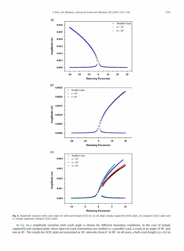
Fig. 6. Amplitude variation with crack angle for half-crack length of 0.2 m: (a) all edges simply supported (SSSS) plate, (b) clamped (CCCC) plate and(c) simply supported–clamped (SCSC) plate.
T. Bose, A.R. Mohanty / Journal of Sound and Vibration 332 (2013) 7123–7141 7135
In Fig. 6a–c amplitude variation with crack angle is shown for different boundary conditions. In the case of simplysupported and clamped plate, three types of crack orientations are studied i.e. a parallel crack, a crack at an angle of 301 andone at 451. The results for SCSC plate are presented at 301 intervals, from 01 to 901. In all cases, a half-crack length (a)¼0.2 m

Fig. 7. Amplitude variation with increasing eccentricity of a parallel crack for (a) simply supported (SSSS) plate, (b) clamped (CCCC) plate and (c) simplysupported–clamped (SCSC) plate.
T. Bose, A.R. Mohanty / Journal of Sound and Vibration 332 (2013) 7123–71417136
is considered. It is observed that no change in amplitude curve occurs with an increase in the crack angle, for the simplysupported plate (Fig. 6a) and the clamped (Fig. 6b) plate. However, in the case of the SCSC plate (Fig. 6c) the amplitude curvebends towards the left with an increase in the crack angle. Thus the nonlinearity decreases with an increase in the crackangle for SCSC plate, although α remains positive.

Fig. 8. The ratio between quadratic and cubic nonlinearity with increasing crack length.
T. Bose, A.R. Mohanty / Journal of Sound and Vibration 332 (2013) 7123–7141 7137
In Fig. 7a–c, amplitude variation with crack position is presented for different plate boundary conditions. A centrallylocated crack of half-crack length (a)¼0.2 m is considered parallel to x-direction and then its position (d) is shifted up to0.2 m along the x-direction at an interval of 0.1 m. It is observed for the simply supported plate that the nonlinearityincreases with increasing eccentricity i.e. the amplitude curves bend towards left. No such variation is observed for thesimply supported–clamped and clamped plates.
In Fig. 8, the ratio of quadratic and cubic nonlinearity of a simply supported square plate is presented with increasingcrack length. It is obvious that the cubic nonlinearity term is dominant over the quadratic term in the range of crack lengthinvestigated here. Now, it can be noticed that the cubic nonlinearity term (Eq. (37)) has originated due to the large deflectionof cracked plate but the quadratic nonlinearity term (Eq. (36)) has generated due to the presence of crack (i.e., due to thecoupling effect mentioned earlier). So, the quadratic nonlinearity term is present when the large deflection is not consideredand still results in a nonlinear equation. Therefore, the quadratic nonlinearity appears to be more fundamental than thecubic nonlinearity for a rectangular plate with a part-through crack. Though its effect is negligible in the determination ofnatural frequency and amplitude (from Eq. (43)), when the large deflection is considered.
5. Conclusions
This paper presents a vibration analysis for rectangular thin isotropic plates with a part-through surface crack of variableangular orientation and position. The line spring model is used with proper modifications. The results are in goodagreement with the published literature for long crack. It is concluded that the natural frequency decreases with an increasein the crack length for all three plate boundary conditions which are simply supported (SSSS), clamped (CCCC) and simplysupported–clamped (SCSC). The natural frequency of the simply supported and clamped plates is found to decrease with anincrease in the crack angle up to 451. This pattern is prominent for the first, third and fourth modes. Furthermore, thenatural frequency of all types of plates is observed to increase with increasing eccentricity of the crack.
Clamped and simply supported–clamped plates are identified as being of hard spring type, whereas simply supportedplate behaves like a soft spring. It is observed that the nonlinearity decreases with an increase in the half-crack length for alltypes of plates. Moreover, the nonlinearity also decreases with a change in the crack angle (0–901) for the SCSC plate.Amplitude variations with position are only observed for simply supported plates. So it is evident from the above discussionthat the crack orientation and position affects the natural frequency and amplitude of the plate. This fact is also useful forvibration based heath monitoring of plate structures.
Appendix A
Similar procedures as in Ref. [18] are used to derive Eq. (1). So this derivation is an extension for rectangular plate with anangled part-through surface crack. Using equilibrium principle for the moments along the x and y-directions and the forcesalong the z-direction (Fig. A1) we get
∂2Mx
∂x2þ∂2Mx
∂x2þ2
∂2Mxy
∂x∂yþ2
∂2Mxy
∂x∂yþ∂2My
∂y2þ∂2My
∂y2¼ ρh
∂2w∂t2
�Pz (A1)

Fig. A1. A differential plate element with an angled part-through surface crack at the centre.
Fig. A2. Membrane forces acting on the plate element with an angled part-through surface crack at the centre.
T. Bose, A.R. Mohanty / Journal of Sound and Vibration 332 (2013) 7123–71417138
where Mx, My, Mxy are the bending moments per unit length along the x and y-directions and is related with the transversedisplacement as
Mx ¼�D∂2w∂x2
þν∂2w∂y2
� �(A2)
My ¼�D∂2w∂y2
þν∂2w∂x2
� �(A3)
Mxy ¼Myx ¼�Dð1�νÞ∂2w
∂x∂y(A4)
where D is the flexural rigidity and can be stated as D¼Eh3/12(1�ν2). E is the modulus of elasticity and ν is Poisson's ratio.Substituting Eqs. (A2)–(A4) into Eq. (A1) leads to the following equation:
D∂4w∂x4
þ2∂4w
∂x2∂y2þ∂4w
∂y4
� �¼�ρh
∂2w∂t2
þ∂2Mx
∂x2þ∂2My
∂y2þ2
∂2Mxy
∂x∂yþPz (A5)
In-plane or membrane forces are accounted for the large deflection of plate. Equilibrium of the differential element isconsidered (Fig. A2). Since there are no body forces, the projection of the membrane forces on the x and y-axes lead to the
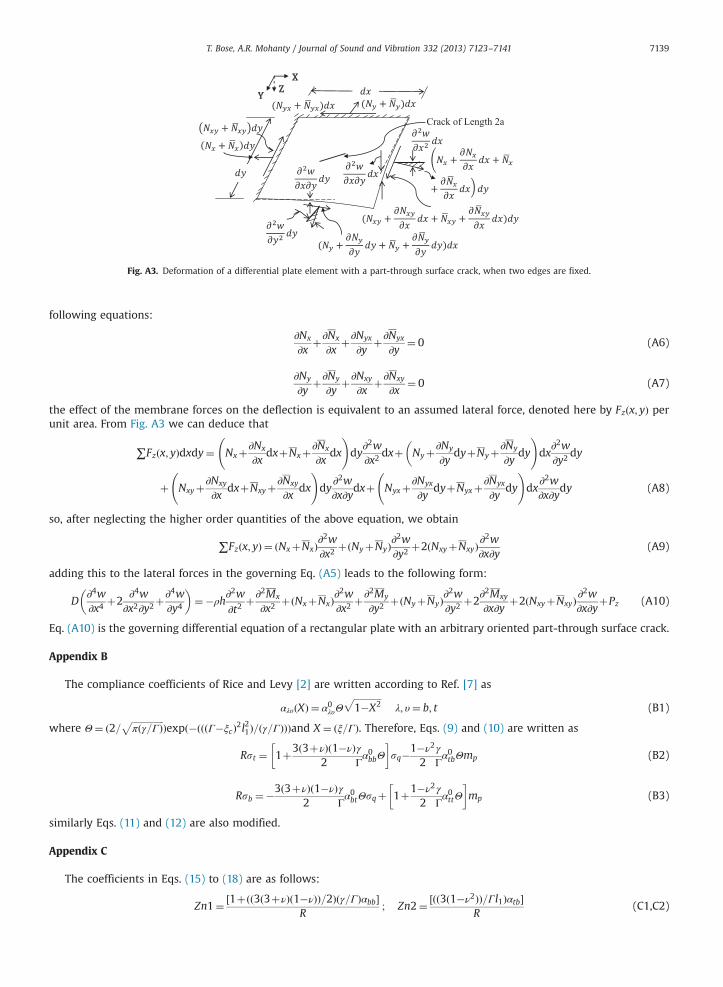
Fig. A3. Deformation of a differential plate element with a part-through surface crack, when two edges are fixed.
T. Bose, A.R. Mohanty / Journal of Sound and Vibration 332 (2013) 7123–7141 7139
following equations:
∂Nx
∂xþ∂Nx
∂xþ∂Nyx
∂yþ∂Nyx
∂y¼ 0 (A6)
∂Ny
∂yþ∂Ny
∂yþ∂Nxy
∂xþ∂Nxy
∂x¼ 0 (A7)
the effect of the membrane forces on the deflection is equivalent to an assumed lateral force, denoted here by Fzðx; yÞ perunit area. From Fig. A3 we can deduce that
∑Fzðx; yÞdxdy¼ Nxþ∂Nx
∂xdxþNxþ∂Nx
∂xdx
!dy
∂2w∂x2
dxþ Nyþ∂Ny
∂ydyþNy
�þ∂Ny
∂ydy
!dx
∂2w∂y2
dy
þ Nxyþ∂Nxy
∂xdxþNxyþ
∂Nxy
∂xdx
!dy
∂2w∂x∂y
dxþ Nyxþ∂Nyx
∂ydyþNyxþ
∂Nyx
∂ydy
!dx
∂2w∂x∂y
dy (A8)
so, after neglecting the higher order quantities of the above equation, we obtain
∑Fzðx; yÞ ¼ ðNxþNxÞ∂2w∂x2
þðNyþNyÞ∂2w∂y2
þ2ðNxyþNxyÞ∂2w
∂x∂y(A9)
adding this to the lateral forces in the governing Eq. (A5) leads to the following form:
D∂4w∂x4
þ2∂4w
∂x2∂y2þ∂4w
∂y4
� �¼�ρh
∂2w∂t2
þ∂2Mx
∂x2þðNxþNxÞ∂
2w∂x2
þ∂2My
∂y2þðNyþNyÞ∂
2w∂y2
þ2∂2Mxy
∂x∂yþ2ðNxyþNxyÞ∂
2w∂x∂y
þPz (A10)
Eq. (A10) is the governing differential equation of a rectangular plate with an arbitrary oriented part-through surface crack.
Appendix B
The compliance coefficients of Rice and Levy [2] are written according to Ref. [7] as
αλυðXÞ ¼ α0λυΘffiffiffiffiffiffiffiffiffiffiffiffi1�X2
pλ; υ¼ b; t (B1)
where Θ¼ ð2=ffiffiffiffiffiffiffiffiffiffiffiffiffiffiπðγ=ΓÞ
pÞexpð�ðððΓ�ξcÞ2l21Þ=ðγ=ΓÞÞÞand X ¼ ðξ=ΓÞ. Therefore, Eqs. (9) and (10) are written as
Rst ¼ 1þ3ð3þνÞð1�νÞ2
γ
Γα0bbΘ
� �sq�1�ν2
2γ
Γα0tbΘmp (B2)
Rsb ¼�3ð3þνÞð1�νÞ2
γ
Γα0btΘsqþ 1þ1�ν2
2γ
Γα0ttΘ
� �mp (B3)
similarly Eqs. (11) and (12) are also modified.
Appendix C
The coefficients in Eqs. (15) to (18) are as follows:
Zn1¼ ½1þðð3ð3þνÞð1�νÞÞ=2Þðγ=ΓÞαbb�R
; Zn2¼ ½ðð3ð1�ν2ÞÞ=Γl1Þαtb�R
(C1,C2)

T. Bose, A.R. Mohanty / Journal of Sound and Vibration 332 (2013) 7123–71417140
Zn3¼ ½ððð1�νÞð3þνÞÞ=4Þððγ2l1Þ=ΓÞαbt �R
; Zn4¼ ½1þðð1�ν2Þ=2Þðγ=ΓÞαtt �R
(C3,C4)
Zn5¼ ½1þð3ð1þνÞ=2Þðγ=ΓÞCbb�T
; Zn6¼ ½ð3ð1þνÞ=2Þðγ=ΓÞCtb�T
(C5,C6)
Zn7¼ ½ðð1þ νÞ=4Þððγ2 l1Þ=ΓÞCbt �T ; Zn8¼ ½1þðð1þ νÞ=2Þðγ=ΓÞCtt �
T (C7,C8)
the coefficients in Eq. (22) are as following:
J1 ¼ 1�Zn1 sin 4θ�Zn5sin 22θ
2; J2 ¼�Zn1 sin 2θ cos 2θþZn5
sin 22θ2
(C9,C10)
J3 ¼ Zn1 sin 2θsin 2θ
2þZn5
sin 4θ4
� �ϕ; J4 ¼ 1�Zn4 cos 4θ�Zn5
sin 22θ2
(C11,C12)
J5 ¼ J2; J6 ¼ Zn1 cos 2θsin 22θ
2�Zn5
sin 4θ4
!ϕ (C13,C14)
J7 ¼ 1�Zn1sin 22θ
2�Zn5 cos 22θ
!ϕ; J8 ¼ Zn1 sin 2θ sin 2θþZn5
sin 4θ2
� �(C15,C16)
J9 ¼ Zn1 sin 2θ cos 2θ�Zn5sin 4θ
2
� �(C17)
J10 ¼ Zn4ð sin 2θþν cos 2θÞ sin 2θþZn8ð1�νÞ sin22θ2
!(C18)
J11 ¼ Zn4ðν sin 2θþ cos 2θÞ cos 2θþZn8ð1�νÞ sin22θ2
!(C19)
J12 ¼ Zn4 νð sin 4θþ cos 4θÞþ sin 22θ2
!þðZn4�Zn8Þð1�νÞ sin 22θ
!(C20)
J13 ¼ Zn2 sin 4θþZn6sin 22θ
2
!ϕ2; J14 ¼ Zn2 sin 2θ cos 2θ�Zn6
sin 22θ2
!(C21,C22)
J15 ¼� Zn2 sin 2θsin 2θ
2þZn6
sin 4θ4
� �ϕ; J16 ¼ J14ϕ
2 (C23,C24)
J17 ¼ Zn2 cos 4θþZn6sin 22θ
2; J18 ¼� Zn2 cos 2θ�Zn6
sin 4θ4
� �ϕ (C25,C26)
J19 ¼ 2J15ϕ; J20 ¼�Zn2 sin 2θ cos 2θþZn6sin 4θ
2(C27,C28)
J21 ¼ Zn2sin 22θ
2þZn6 cos 22θ
!ϕ (C29)
J22 ¼ ½�ð1�νÞ sin 2θfZn4 sin 2θ�Zn8ð cos 2θþ sin 2θÞg�2Zn4ð sin 2θþν cos 2θÞ� (C30)
J23 ¼ Zn8ð1�νÞ sin 2θð cos 2θþ sin 2θÞ�Zn4fð3�νÞ cos 2θþ2ν sin 2θg (C31)
References
[1] A.W. Leissa, Vibration of Plates, National Acoustical and Space Administration, Washington DC, 1993 (NASA SP-160).[2] J.R. Rice, N. Levy, The Part Through Surface Crack in an Elastic Plate, Journal of Applied Mechanics 3 (1972) 185–194.[3] F. Delale, F. Erdogan, Line spring model for surface cracks in a Reissner plate, International Journal of Engineering and Science 19 (1981) 1331–1340.[4] P.F. Joseph, F. Erdogan, Surface crack in a plate under antisymmetric loading conditions, International Journal of Solids and Structures 27 (6) (1991)
725–750.

T. Bose, A.R. Mohanty / Journal of Sound and Vibration 332 (2013) 7123–7141 7141
[5] R.B. King, Elastic–plastic analysis of surface flaws using a simplified line-spring model, Engineering Fracture Mechanics 18 (1983) 217–231.[6] Z.J. Zeng, S.H. Dai, Stress intensity factors for an inclined surface crack under biaxial stress state, Engineering Fracture Mechanics 47 (2) (1994) 281–289.[7] Y.S. Wen, J. Zhixe, On the equivalent relation of the line spring model: a suggested modification, Engineering Fracture Mechanics 26 (1) (1987) 75–82.[8] B. Stahl, L.M. Keer, Vibration and stability of cracked rectangular plates, International Journal of Solids and Structures 8 (1972) 69–91.[9] R. Solecki, Bending vibration of a simply supported rectangular plate with a crack parallel to one edge, Engineering Fracture Mechanics 18 (1983)
1111–1118.[10] K.M. Liew, K.C. Hung, M.K. Lim, A solution method for analysis of cracked plates under vibration, Engineering Fracture Mechanics 48 (3) (1994) 393–404.[11] S.E. Khadem, M. Rezaee, Introduction of modified comparison functions for vibration analysis of a rectangular cracked plate, Journal of Sound and
Vibration 236 (2) (2000) 245–258.[12] H.M. Berger, A new approach to the analysis of large deflections of plates, Journal of Applied Mechanics 22 (1955) 465–472.[13] A. Israr, M.P. Cartmell, E. Manoach, I. Trendafilova, W.M. Ostachowicz, M. Krawczuk, A. Zak, Analytical modelling and vibration analysis of partially
cracked rectangular plates with different boundary conditions and loading, Journal of Applied Mechanics 76 (2009) 1–9.[14] R. Ismail, M.P. Cartmell, An investigation into the vibration analysis of a plate with a surface crack of variable angular orientation, Journal of Sound and
Vibration 331 (2012) 2929–2948.[15] C.S. Huang, A.W. Leissa, Vibration analysis of rectangular plates with side cracks via the Ritz method, Journal of Sound and Vibration 323 (2009)
974–988.[16] C.S. Huang, A.W. Leissa, R.S. Li, Accurate vibration analysis of thick, cracked rectangular plates, Journal of Sound and Vibration 330 (2011) 2079–2093.[17] A.H. Nayfeh, D.T. Mook, Nonlinear Oscillations, Wiley, New York, 1979.[18] A. Israr, Vibration analysis of cracked aluminium plates, University of Glasgow, 2008 (Ph.D. thesis).[19] E. Ventsel, T. Krauthammer, Thin Plates and Shells, Marcel Dekker, New York, 2001.