A mode I fracture analysis of a center-cracked infinite shape memory alloy plate under plane stress
18
1 23
Transcript of A mode I fracture analysis of a center-cracked infinite shape memory alloy plate under plane stress
1 23
��������� ����� ������������������� ����������������������������� ����������
��������� ����� � ��������� �������� �������������� �������� ������� �������� �������
������� ������� ���������� �����

1 23
Your article is protected by copyright andall rights are held exclusively by SpringerScience+Business Media B.V.. This e-offprintis for personal use only and shall not be self-archived in electronic repositories. If youwish to self-archive your work, please use theaccepted author’s version for posting to yourown website or your institution’s repository.You may further deposit the accepted author’sversion on a funder’s repository at a funder’srequest, provided it is not made publiclyavailable until 12 months after publication.
Int J FractDOI 10.1007/s10704-012-9709-z
ORIGINAL PAPER
A mode I fracture analysis of a center-cracked infinite shapememory alloy plate under plane stress
Theocharis Baxevanis · Dimitris Lagoudas
Received: 2 September 2011 / Accepted: 30 March 2012© Springer Science+Business Media B.V. 2012
Abstract The problem of a center plane crack inan infinite, thin, pseudoelastic Shape Memory Alloy(SMA) plate subjected to an in-plane uniform ten-sile stress at infinity is analyzed. The analysis followsclosely the Dugdale–Barenblatt model developed forconventional metals. It is found for low remote stressvalues—less than a critical value—that the SMA is notfully transformed in the vicinity of a crack tip. Closedform expressions for the size of the partial transforma-tion zone, crack opening displacement and J -integralare given for this case. For remote stress levels abovethe critical value, the fully-transformed material near acrack tip is assumed to yield plastically. The sizes ofthe transformed (both partially and fully) and plasticregions are numerically evaluated by solving a systemof integral equations and their sensitivity to the trans-formation characteristics (i.e., maximum transforma-tion strain and temperature) is determined. Moreover,a relationship between the J -integral and the crack-tipopening displacement is derived. The results obtainedare important in understanding the effect of stress-induced phase transformation in the fracture behaviorof SMAs in the presence of static cracks, and subse-quently in formulating conditions for initiation of crackpropagation.
T. Baxevanis (B) · D. LagoudasDepartment of Aeorospace Engineering, MS 3409,Texas A&M University, College Station, TX 77843, USAe-mail: [email protected]
D. Lagoudase-mail: [email protected]
Keywords Shape memory alloys · Superelasticity ·Transformation · Fracture
1 Introduction
Understanding of the fracture properties of SMAs iscrucial for improving their overall multifunctional per-formance. SMAs are desirable in a wide range of actu-ator, energy absorption, and vibration damping appli-cations (Perkins 1975; Funakubo 1987; Duerig et al.1990; Otsuka and Wayman 1999; Lagoudas 2008)due to their unique thermo-mechanical behavior whichresults from a crystallographic phase transformationfrom austenite to martensite and vice-versa. The par-ent austenite phase transforms to the martensite phaseupon cooling under zero load, through the marensitic-start (Ms)—martensitic-finish (M f ) temperature inter-val, which is dependent on composition and materialprocessing. Since the austenite phase has a higher sym-metry than the martensite phase, formation of mul-tiple martensite crystals with different orientations(called variants) occurs through self-accommodation,forming a twinned structure. Similarly, during heat-ing, the reverse transformation initiates at the austen-itic-start temperature (As) and the transformation iscompleted at the austenitic-finish temperature (A f ).If a mechanical load is applied to the material in thetwinned martensite phase, detwinning of martensiteis possible by reorientation of a certain number of
123
Author's personal copy
T. Baxevanis, D. Lagoudas
variants allowing a macroscopic shape change. If theaustenite is stressed above Ms , transformation fromaustenite to martensite can be driven by stress alone(pseudoelasticity). For temperatures above A f , theresulting inelastic strains are recoverable upon unload-ing due to the reverse phase transformation (super-elasticity). There is a vast literature that addressesphenomenological and micromechanical approaches inmodeling of SMAs constitutive behavior (see reviewarticles Patoor et al. 2006; Lagoudas et al. 2006).
There are few experimental research studies devotedto the fracture behavior of SMAs (mainly of NiTialloys). McKelvey and Ritchie (2001) investigatedfatigue crack propagation in stable austenitic, super-elastic and martensitic equiatomic NiTi (Ti-50 at. pct)SMAs. In these experiments, superelasticity did notappear to enhance the austenite crack-growth resis-tance as expected. To explain the latter observation, itwas argued that martensite formation in front of fatiguecracks growing into superelastic NiTi was suppresseddue to the high hydrostatic tensile stress levels in frontof the cracks that characterize the plane strain condi-tions of their experiments. They supported their argu-ment by both transmission electron microscopy andX-ray diffraction studies performed on the fatigue frac-ture surfaces. Robertson et al. (2007) reported mar-tensitic transformation in superelastic NiTi (Ti-50.8at. pct) subjected to fatigue under (most probably)plane stress conditions using ultrahigh spatial reso-lution (!1µm2) X-ray microdiffraction to measurethe crystallographic alignment ahead of the growingfatigue crack. They reported two rather unexpectedobservations: (i) transition from austenite to pure mar-tensite was very abrupt (no partially-transformed aus-tenite), and (ii) compressive strains were measuredahead of the crack-tip. In contrast to the conclusionsof McKelvey and Ritchie (2001), in the compact ten-sion experiments on superelastic NiTi (Ti-50.7 at. pctNi) conducted by Gollerthan et al. (2009a,b), phasetransformation around the crack tip was observed evenunder plane strain conditions. In situ synchrotron X-raydiffraction measurements were also used by Daymondet al. (2007) to create two dimensional maps of elas-tic strain and texture near the crack tip of a compacttension martensitic NiTi (Ti-50.6 at. pct) alloy speci-men. Detwinning was observed in the vicinity of thecrack tip. High tensile strains were measured withinand beyond the detwinning zone, with this strain fieldbecoming compressive upon unloading.
There are several theoretical investigations on thetoughening effect of stress-induced phase transforma-tion associated with cracks advancing in SMAs. Yi andGao (2000) and Yi et al. (2001), based on the micro-mechanical constitutive equations of Sun and Hwang(1993a,b), studied the fracture toughness of martens-itic SMAs in mode I and mixed mode conditions.The transformation volume strain was assumed neg-ligible compared to the transformation shear strain,and was thus ignored. Their analyses followed closelythat of McMeeking and Evans (1982) and Budnian-sky et al. (1983) using linear elastic fracture mechan-ics (LEFM) theory together with the Eshelby equiv-alent inclusion method to obtain resistance R-curves.Transformation toughening was found to be associatedwith crack advance, due to the irreversible transformedregion left behind by a quasi-statically advancing cracktip. Stam and van de Giessen (1985) adopted an ear-lier model of Sun et al. (1991) in a finite elementanalysis of crack propagation under small scale trans-formation conditions to examine the effect of reversephase transformation on the crack growth resistancein the superelastic regime. They found that the reversetransformation can significantly reduce the resistanceincrease. Freed and Banks-Sills (2007) arrived at sim-ilar conclusions in their study of the growth resistancein an SMA under plane strain and mode I conditions bymeans of a cohesive zone model. Yan et al. (2002) stud-ied the effect of transformation volume contraction onthe crack growth resistance of superelastic alloys andconcluded that a 0.39 % volume contraction results inan increase of the crack tip stress intensity factor ofabout 12 %, and that reverse transformation has negli-gible effect on the induced stress intensity factor. Theseresults are in contrast to the aforementioned works thatfind fracture toughness enhancement due to transfor-mation. The reason is that Yan et al. (2002) exam-ined the effect of only the transformation volume strainon the fracture toughness while in the aforementionedworks the transformation volume strain was consid-ered negligible; the stress distribution around a crack tipfavors a stress-biased macroscopic shear strain which ismuch larger than the volumetric strain. The combinedeffect of both contributions was studied in Yan and Mai(2006), and overall enhancement of the fracture tough-ness was found.
Finite element analysis on the stress-induced mar-tensitic transformation near the stationary crack tip ornotch of compact tension SMA specimens has also
123123
Author's personal copy
A mode I fracture analysis
been performed in the literature. In Wang et al. (2005)Auricchio’s model (Auricchio et al. 1997) that neglectsplasticity was implemented into a finite element code. Itwas found that the extent of the transformation zone isload path dependent due to the hysteretic stress–strainbehavior of SMAs and that the formation of martens-ite results in a redistribution process where the stressesnear the crack tip relax. In Wang (2007a,b) an elasto-plastic material model based on the von Mises yieldcriterion was calibrated by an experimental monotonictensile stress-strain relation to account for both trans-formation and plasticity. It was found that there existsa critical applied load below which transformation isnot completed in front of the notch tip. For appliedload levels above the critical load, martensite transfor-mation was shown to increase the required load to pro-duce plastic transformation and decrease the maximumnormal stress near the notch tip.
The analytical models for mode I loading of staticcracks in SMAs are limited (Birman 1998; Xiong andLiu 2007; Maletta and Furgiuele 2010, 2011). Xiongand Liu (2007) and Maletta and Furgiuele (2010, 2011)adopted an analytical approach, in the realm of Irwin’scorrection of LEFM, that accounts for the stress redis-tribution due to transformation around the crack tipon the basis that the stress resultant along the planeof the crack should be equal to the stress resultant oflinear elasticity. The stress resultant along the planeof the crack is related to the equilibrium condition.In the model of Maletta and Furgiuele (2010, 2011) abilinear constitutive law that excludes the possibility ofplastic yielding was used, while Xiong and Liu (2007)assumed a priori that the stress distribution in the regionof elastically-deformed, fully-transformed material islinear. In Birman (1998) the size of the transforma-tion zone was evaluated without taking into account thestress redistribution caused by transformation. Hence,none of the above investigations fully characterize thebehavior of SMAs in the presence of static cracks.
Herein, the mode I plane stress fracture problemof an infinite pseudoelastic SMA plate containing acentral static crack is studied. A model is introducedthat incorporates transformation and plasticity into themodel formulation proposed by Dugdale (1960) forconventional elastic-plastic materials. The model isbased on two assumptions: (i) both transformation andyielding are assumed to be confined in a strip extend-ing along the line of the crack in front of the cracktip of height approximately equal to the plate thick-
ness, and (ii) the crack is assumed to have an effectivelength that exceeds that of the physical crack by thelength of the transformation zone. The extended cracksurfaces are stressed by a cohesive stress distributionwhich represents the stress distribution in the strip-likemartensite zones in front of the physical crack. All theunknowns of the problem are determined from (i) thecondition of a non-singular stress distribution, and (ii) arelation between the crack opening displacement of theextended crack and the transformation strain. Utilizingthis model the sizes of the various zones formed in frontof the crack tip are evaluated. Closed form expressionsof the J integral as a function of the crack-tip open-ing displacement and the thermomechanical parame-ters are obtained depending on the value of the remotestress levels and parametric studies are conducted.
The paper is organized as follows: Sect. 2 reviewsbriefly the phenomenology of the behavior of SMAsunder isothermal monotonic loading and describesthe assumed constitutive mechanical response. Thedescription and analysis of the proposed model isundertaken in Sect. 3 (further details on some deriva-tions are given in the “Appendix”). Section 4 presentsand discusses the obtained results. Finally, Sect. 5 pro-vides a brief summary of findings and concludes thework.
2 Phenomenology of thermomechanical responsein shape memory alloys
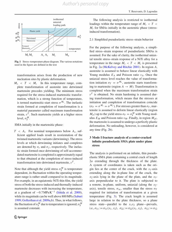
The phenomenology of the material response of SMAssubjected to uniaxial loading can be described using thestress-temperature phase diagram (Fig. 1). The phasediagram is a schematic representation of the equilib-rium conditions between the austenitic and martens-itic phases; the lines emanating from M f , Ms, As A fdenote the respective transformation temperatures ver-sus the applied uniaxial load. The material responsecan be distinguished as:
SMA initially in the austenitic phase:
T > Md For nominal temperatures above Md theaustenitic phase is stable and the resulting stress–strain curve is similar to that of a conventional metal,with plastic deformation (via slip) occurring whenthe stress reaches the yield stress of austenite ! A
Y .Mc < T < Md At temperatures above Mc,
there are values of stress that induce simultaneoustransformation and yield. Additional contribution to
123
Author's personal copy
T. Baxevanis, D. Lagoudas
MdMcMs As
Austenite Twinned Martensite
Plastic yield
temperature
AfMf
stre
ss
Y
DetwinnedMartensiteM
M Y
isothermal uniaxial loading path
M A
f
s
Fig. 1 Stress–temperature phase diagram. The various notationsused in the figure are defined in the text
transformation arises from the production of newnucleation sites by plastic deformation.
Ms < T < Mc In this temperature range, com-plete transformation of austenite into detwinnedmartensite precedes yielding. The minimum stressrequired for the stress-induced martensitic transfor-mation, which is a strong function of temperature,is termed martensitic-start stress ! Ms . The inelasticstrain formed at completion of transformation is amaterial parameter called maximum transformationstrain, "T . Such martensite yields at a higher stresslevel, ! M
Y .
SMA initially in the martensitic phase:
T < As For nominal temperatures below As , suf-ficient applied loads result in reorientation of thetwinned martensitic variants (detwinning). The stresslevels at which detwinning initiates and completesare denoted by !s and ! f , respectively. The inelas-tic strain formed once detwinning of self-accommo-dated martensite is completed is approximately equalto that obtained at the completion of stress-inducedtransformation into detwinned martensite, "T .
Note that although the yield stress ! MY is temperature
dependent, its fluctuation within the operating temper-ature range is rather small compared to its magnitude.For example, in an equiatomic NiTi thin film, the yieldstress of both the stress-induced and thermally-inducedmartensite decreases with increasing the temperature,at a gradient of "0.7 MPa K"1 (Ishida et al. 2000),while its magnitude can be well above 800 MPa (Saburi1999; Gollerthan et al. 2009a,b). Thus, in what follows,the fluctuation of ! M
Y due to temperature is ignored; ! MY
is assumed constant.
The following analysis is restricted to isothermalloadings within the temperature range of Ms < T <
Mc for SMAs initially in the austenitic phase (stress-induced transformation).
2.1 Simplified pseudoelastic stress–strain behavior
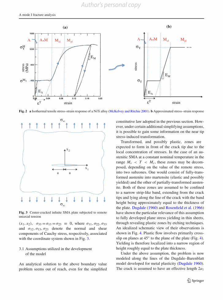
For the purpose of the following analysis, a simpli-fied stress–strain response of pseudoelastic SMAs isassumed. For the sake of clarity, the isothermal uniax-ial tensile stress–strain response of a NiTi alloy for atemperature in the range Ms < T < Mc is presentedin Fig. 2a (McKelvey and Ritchie 2001). In region A,austenite is assumed to behave linear elastically withYoung modulus E A and Poisson ratio #A. Once theuniaxial stress level reaches the value of transforma-tion initiation !T = ! Ms , austenite starts transform-ing to martensite (region A # M). Transformation iscompleted when the maximum transformation strain"T is obtained. No strain hardening is assumed dur-ing transformation, which means that the stresses atinitiation and completion of transformation coincide(!T = ! Ms = ! M f ). For stresses greater than !T , mar-tensite is assumed to deform linear elastically (regionMel ) up to the yield stress !Y = ! M
Y with Young mod-ulus EM and Poisson ratio #M . Finally, in region Mpl ,the martensite is assumed to undergo a perfectly plasticdeformation. No unloading, however, is considered atany time (Fig. 2b).
3 Mode I fracture analysis of a center-crackedinfinite pseudoelastic SMA plate under planestress
The analysis is performed on an infinite, thin pseudo-elastic SMA plate containing a central crack of length2a extending through the thickness of the plate.A system of coordinates is taken such as the ori-gin lies at the center of the crack, with the x1-axisextending along the in-plane line of the crack, thex2-axis lying in the plane of the plate, and the x3-axis perpendicular to it. The plate is subjected toa remote, in-plane, uniform, uniaxial (along the x2-axis), tensile stress, !$, smaller than the stress !Trequired for initiation of transformation at a giventemperature (Fig. 3). The crack length is assumedlarge in relation to the plate thickness, so a planestress state—parallel to the x1x2 plane—prevails,i.e.,!11 := !11(x1, x2), !22 := !22(x1, x2), !12 := !12
123123
Author's personal copy
A mode I fracture analysis
A
T
Y
T
strain
stre
ss
EA
EM
A M Mel Mpl
stre
ss
(MPa
)
strain
Y
M
EM
EA
T
A A M Mel Mpl
s
M
(a) (b)
Fig. 2 a Isothermal tensile stress–strain response of a NiTi alloy (McKelvey and Ritchie 2001). b Approximated stress–strain response
x2
x1 a a
Fig. 3 Center-cracked infinite SMA plate subjected to remoteuniaxial tension
(x1, x2), !33 = !13 = !23 % 0, where !11, !22, !33and !12, !13, !23 denote the normal and shearcomponents of Cauchy stress, respectively, associatedwith the coordinate system shown in Fig. 3.
3.1 Assumptions utilized in the developmentof the model
An analytical solution to the above boundary valueproblem seems out of reach, even for the simplified
constitutive law adopted in the previous section. How-ever, under certain additional simplifying assumptions,it is possible to gain some information on the near tipstress-induced transformation.
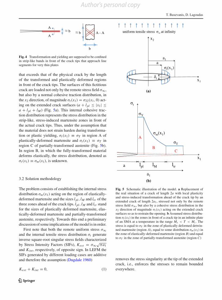
Transformed, and possibly plastic, zones areexpected to form in front of the crack tip due to thelocal concentration of stresses. In the case of an au-stenitic SMA at a constant nominal temperature in therange Ms < T < Mc, these zones may be decom-posed, depending on the value of the remote stress,into two subzones. One would consist of fully-trans-formed austenite into martensite (elastic and possiblyyielded) and the other of partially-transformed austen-ite. Both of these zones are assumed to be confinedto a narrow strip-like band, extending from the cracktips and lying along the line of the crack with the bandheight being approximately equal to the thickness ofthe plate. Dugdale (1960) and Rosenfield et al. (1966)have shown the particular relevance of this assumptionto fully developed plane stress yielding in thin sheets,through revealing plastic zones by etching techniques.An idealized schematic view of their observations isshown in Fig. 4. Plastic flow involves primarily cross-slip on planes at 45& to the plane of the plate (Fig. 4).Yielding is therefore localized into a narrow region ofheight roughly equal to the plate thickness.
Under the above assumption, the problem is nowmodeled along the lines of the Dugdale–Barenblattmodel developed for metal plasticity (Dugdale 1960).The crack is assumed to have an effective length 2a1
123
Author's personal copy
T. Baxevanis, D. Lagoudas
A
A A - A b
b
b
Fig. 4 Transformation and yielding are supposed to be confinedin strip-like bands in front of the crack tips that approach linesegments for very thin plates
that exceeds that of the physical crack by the lengthof the transformed and plastically deformed regionsin front of the crack tips. The surfaces of this fictitiouscrack are loaded not only by the remote stress field !$,but also by a normal cohesive traction distribution, inthe x2 direction, of magnitude !t (x1) = !22(x1, 0) act-ing on the extended crack surfaces (a + l pl ' |x1| 'a + l pl + lM ) (Fig. 5a). This internal cohesive trac-tion distribution represents the stress distribution in thestrip-like, stress-induced martensite zones in front ofthe actual crack tips. Thus, under the assumption thatthe material does not strain harden during transforma-tion or plastic yielding, !t (x1) % !Y in region A ofplastically-deformed martensite and !t (x1) % !T inregion C of partially-transformed austenite (Fig. 5b).In region B, in which the fully-transformed materialdeforms elastically, the stress distribution, denoted as!t (x1) % !m(x1), is unknown.
3.2 Solution methodology
The problem consists of establishing the internal stressdistribution !m(x1) acting on the region of elastically-deformed martensite and the sizes l pl , lM and ltr of thethree zones ahead of the crack tips. l pl , lM and ltr standfor the sizes of plastically deformed martensite, elas-tically-deformed martensite and partially-transformedaustenite, respectively. Towards this end a preliminarydiscussion of some implications of the model is in order.
First note that both the remote uniform stress !$and the internal tensile stress distribution !t generateinverse square-root singular stress fields characterizedby Stress Intensity Factors (SIFs), Kext = !$
($a1
and Kint , respectively, of opposite sign. In LEFM theSIFs generated by different loading cases are additiveand therefore the assumption (Dugdale 1960)
Kext + Kint = 0, (1)
t
a1a
x1
x2
t(x1)
uniform tensile stress at infinity
lpl lM ltr
C B
A
Y
T
m(x1)
x1
t
a
a1
(a)
(b)
Fig. 5 Schematic illustration of the model. a Replacement ofthe real situation of a crack of length 2a with local plasticityand stress-induced transformation ahead of the crack tip by anextended crack of length 2a1, stressed not only by the remotestress field !$, but also by a cohesive stress distribution in thex2 direction of magnitude !t (x1) acting on the extended cracksurfaces so as to restrain the opening. b Assumed stress distribu-tion !t (x1) in the zones in front of a crack tip in an infinite plateof an SMA at a temperature in the range Ms < T < Mc. Thestress is equal to !Y in the zone of plastically deformed detwin-ned martensite (region A), equal to some distribution !m(x1) inthe zone of elastically-deformed martensite (region B) and equalto !T in the zone of partially-transformed austenite (region C)
removes the stress singularity at the tip of the extendedcrack, i.e., enforces the stresses to remain boundedeverywhere.
123123
Author's personal copy
A mode I fracture analysis
lpl lM ltr
x1
a
0.5 t
0.5b T
a1
A B C
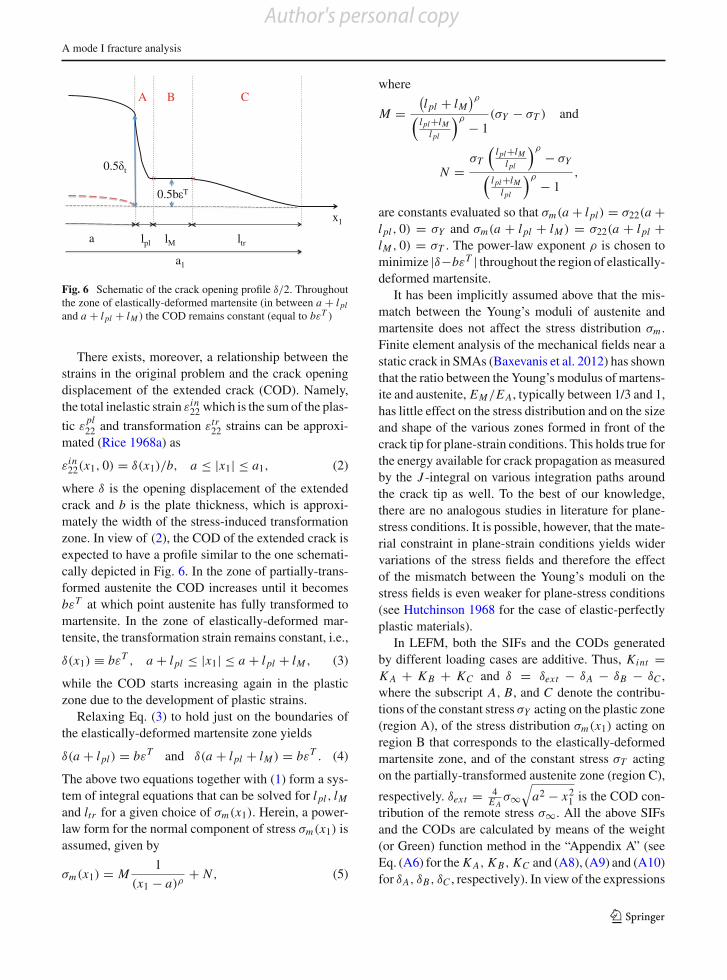
Fig. 6 Schematic of the crack opening profile %/2. Throughoutthe zone of elastically-deformed martensite (in between a + l pland a + l pl + lM ) the COD remains constant (equal to b"T )
There exists, moreover, a relationship between thestrains in the original problem and the crack openingdisplacement of the extended crack (COD). Namely,the total inelastic strain "in
22 which is the sum of the plas-tic "
pl22 and transformation "tr
22 strains can be approxi-mated (Rice 1968a) as
"in22(x1, 0) = %(x1)/b, a ' |x1| ' a1, (2)
where % is the opening displacement of the extendedcrack and b is the plate thickness, which is approxi-mately the width of the stress-induced transformationzone. In view of (2), the COD of the extended crack isexpected to have a profile similar to the one schemati-cally depicted in Fig. 6. In the zone of partially-trans-formed austenite the COD increases until it becomesb"T at which point austenite has fully transformed tomartensite. In the zone of elastically-deformed mar-tensite, the transformation strain remains constant, i.e.,
%(x1) % b"T , a + l pl ' |x1| ' a + l pl + lM , (3)
while the COD starts increasing again in the plasticzone due to the development of plastic strains.
Relaxing Eq. (3) to hold just on the boundaries ofthe elastically-deformed martensite zone yields
%(a + l pl) = b"T and %(a + l pl + lM ) = b"T . (4)
The above two equations together with (1) form a sys-tem of integral equations that can be solved for l pl , lMand ltr for a given choice of !m(x1). Herein, a power-law form for the normal component of stress !m(x1) isassumed, given by
!m(x1) = M1
(x1 " a)&+ N , (5)
where
M =!l pl + lM
"&
#l pl+lM
l pl
$&" 1
(!Y " !T ) and
N =!T
#l pl+lM
l pl
$&" !Y
#l pl+lM
l pl
$&" 1
,
are constants evaluated so that !m(a + l pl) = !22(a +l pl , 0) = !Y and !m(a + l pl + lM ) = !22(a + l pl +lM , 0) = !T . The power-law exponent & is chosen tominimize |%"b"T | throughout the region of elastically-deformed martensite.
It has been implicitly assumed above that the mis-match between the Young’s moduli of austenite andmartensite does not affect the stress distribution !m .Finite element analysis of the mechanical fields near astatic crack in SMAs (Baxevanis et al. 2012) has shownthat the ratio between the Young’s modulus of martens-ite and austenite, EM/E A, typically between 1/3 and 1,has little effect on the stress distribution and on the sizeand shape of the various zones formed in front of thecrack tip for plane-strain conditions. This holds true forthe energy available for crack propagation as measuredby the J -integral on various integration paths aroundthe crack tip as well. To the best of our knowledge,there are no analogous studies in literature for plane-stress conditions. It is possible, however, that the mate-rial constraint in plane-strain conditions yields widervariations of the stress fields and therefore the effectof the mismatch between the Young’s moduli on thestress fields is even weaker for plane-stress conditions(see Hutchinson 1968 for the case of elastic-perfectlyplastic materials).
In LEFM, both the SIFs and the CODs generatedby different loading cases are additive. Thus, Kint =K A + K B + KC and % = %ext " %A " %B " %C ,where the subscript A, B, and C denote the contribu-tions of the constant stress !Y acting on the plastic zone(region A), of the stress distribution !m(x1) acting onregion B that corresponds to the elastically-deformedmartensite zone, and of the constant stress !T actingon the partially-transformed austenite zone (region C),
respectively. %ext = 4E A
!$%
a2 " x21 is the COD con-
tribution of the remote stress !$. All the above SIFsand the CODs are calculated by means of the weight(or Green) function method in the “Appendix A” (seeEq. (A6) for the K A, K B, KC and (A8), (A9) and (A10)for %A, %B, %C , respectively). In view of the expressions
123
Author's personal copy
T. Baxevanis, D. Lagoudas
(A8), (A9), (A10) and (A6) and by introducing the non-dimensional parameter "T = $ E Ab
8a!Y"T , and the non-
dimensional variables ! = !!Y
, l = la , where ! stands
for all stress values and l stands for x1, a, l pl , lM , andltr , the system of (1) and (4) takes the form of Eq. (6).
&'''''''''''''''''''(
''''''''''''''''''')
"T = 12 $!$
%a2
1 " (1 + l pl )2 "* 1+l pl
1
+ln
,%a2
1 " x12 +
%a2
1 " (1 + l pl )2-
" ln,%
(1 + l pl )2 " x12-.
dx1
",* 1+l pl+lM
1+l pl!m(x1) + !T
* a11+l pl+lM
- +ln
,%a2
1 " x12 +
%a2
1 " (1 + l pl )2-
" ln,%
x12 " (1 + l pl )2
-.dx1,
"T = 12 $!$
%a2
1 " (a1 " ltr )2
",* 1+l pl
1 +* 1+l pl+lM
1+l pl!m(x1)
-+ln
,%a2
1 " x12 +
%a2
1 " (a1 " ltr )2-
" ln,%
(a1 " ltr )2 " x12- .
dx1
"!T* a1
1+l pl+lM
+ln
,%a2
1 " x12 +
%a2
1 " (a1 " ltr )2-
" ln,%
x12 " (a1 " ltr )2
-.dx1,
12 $!$ =
,* 1+l pl1 +
* 1+l pl+lM
1+l pl!m(x1) + !T
* a11+l pl+lM
-1%
a21"x1
2dx1.
(6)
In (6) there are integrands that are unbounded at an end-point of integration. By integration by parts, however,one may show that the respective integrals are conver-gent, for the values of the exponent & used in Sect. 4below.
The proposed model also enables the evaluation ofthe J -integral. It is well-known that, for elastic materi-als, the J -integral is equivalent to the energy releaserate (Eshelby 1956, 1970; Rice 1968b). By conve-niently shrinking the curve on which the J -integral isevaluated down to the upper and lower surfaces of theextended crack in the initial configuration, one mayshow (Rice 1968a) that
J =%t/
0
!t (%)d%, (7)
where %t = %|x1=' is the COD at the actual crack-tip,termed as crack-tip opening displacement (CTOD).
In view of (2), (7) yields
J = b
%t /b/
0
!t
#"in
$d"in
= b
0
12"T/
0
!T d"in +%t /b/
"T
!Y d"in
3
45
= !Y %t " (!Y " !T )b"T . (8)
4 Results
In this section the sensitivity of the sizes of the variouszones formed in front of the crack tip, the CTOD and theJ -integral value to the variation of the transformation
characteristics is examined. The results presented aredistinguished into two cases depending on the remotestress value.
4.1 Partial phase transformation ahead of the crack tip
The analysis presented in the previous section assumesthe existence of fully-transformed austenite into mar-tensite in regions in front of the crack tip where thestresses are high. However, for sufficiently low remotestresses, !$, less than a critical value, !cr , such regionsof fully-transformed material are not formed.
In order to determine !cr , let suppose that the mate-rial is not fully-transformed near the crack tip. Then,according to the analysis of the previous section seeEq. 2), the COD of the fictitious crack is less than b"T
everywhere in front of the actual crack tip. In this case,the assumption of a non-singular stress field (A6) canbe written as
12$!$ = !T
a+ltr/
a
1%
a21 " x2
1
dx1, (9)
or equivalently
ltr = a sec,
$
2!$!T
-" a. (10)
Moreover
%t = %ext (a) " %C (a) = 4!$E
6(a + ltr )2 " a2
123123
Author's personal copy
A mode I fracture analysis
" 8!T
$ E A
a+ltr/
a
+ln
,%(a + ltr )2 " x2
1
+6
(a + ltr )2 " a2$
" ln,%
x21 " a2
- .dx1,
(11)
which, in view of (10), reduces to the expression (Dug-dale 1960)
%t = 8!T a$ E A
ln+
sec,
$
2!$!T
-.. (12)
From the above expression, it is deduced that for
!$ ' !cr = 2!T
$cos"1
+exp
,"$ E Ab
8!T a"T
-., (13)
%t is less than b"T , which effectively means that for!$ ' !cr there are no fully-transformed materialzones, since it can be proved that the crack openingdisplacement of the fictitious crack is less than %t every-where in front of the actual crack tip (the proof isomitted here). Equation (13) is a sufficient conditionto ensure that plastic yielding does not occur.
Note that increasing !T , "T , b/a and/or E Aincreases the critical stress level !cr . By assuming therelatively high values !T = !Y = 1/30E A, "T = 0.08and b/a = 1, the critical stress value !cr becomes0.75!Y . For !T = 0.4!Y = 0.01E, "T = 0.04 andb/a = 0.01, the critical stress value !cr is 0.045!Y .
Following the derivation of (8) in the previous sec-tion, one may show that for !$ ' !cr
J = !T %t , (14)
where %t is given in (12). The closed form expres-sions for the J -integral (Eq. 14), crack-tip opening dis-placement (Eq. 12) and size of transformation zone(Eq. 10) coincide with the corresponding Dugdale–Barenblatt expressions for conventional elastic-per-fectly plastic materials by substituting the yield stress!Y with the critical stress !T for initiation of trans-formation. According to these expressions, increasingtransformation stress !T for a given material results todecreasing !tr , %t and J .
4.2 Full phase transformation and plastic yieldingahead of the crack tip
For remote applied stress levels above the critical value!cr , may only elastically-deformed non-yielding mar-tensite be formed in front of a crack tip. However, since
LEFM predicts high stress gradients near the crack tip,it is assumed herein that the elastically-deformed mar-tensite yields in the vicinity of the crack tips. Thus,!$ ' !cr is henceforth considered not only a suffi-cient, but also a necessary condition, to prevent plasticyielding of the material.
System (6) is now solved for the parameter valuesgiven in Table 1 and remote stress levels in excess of!cr . The material parameter values in Table 1 are typi-cal for NiTi-based SMAs. There are additionally a non-dimensional geometrical parameter, b/a = 0.005, anda non-dimensional loading path dependent one, !T /!Y ,which may be interpreted as denoting the temperature.The values assumed for the latter parameter are givenin the captions of the figures.
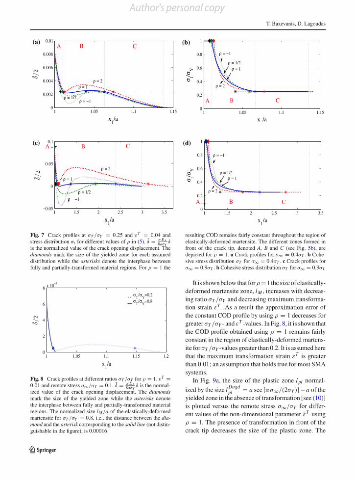
In Fig. 7a, crack opening profiles are plotted fordifferent assumptions of the !t stress distribution(Fig. 7b), i.e., different values of & in (5), for a remoteapplied stress level equal to !$ = 0.4!T at !T /!Y =0.25. Namely, & is set to 2, 1, 1/2 and "1. Note thatthe value & = 1/2 corresponds to the asymptotic stressdistribution predicted by LEFM and the value & = "1corresponds to a linear distribution. For & = 1, theresulting COD remains fairly constant throughout theregion of elastically-deformed martensite bounded bythe diamond on the left hand side and the asterisk on theright hand side of the corresponding curve. In Fig. 7c,d, the same values of & have been used to produce theCOD profile and stress distribution !t , respectively,for a remote applied stress !$ = 0.9!T at the sameratio !T /!Y = 0.25. It is again obvious that the CODprofile obtained by setting & = 1 is the best approx-imation, among those presented in the figure, of theconstant COD profile required in the region of elasti-cally-deformed martensite. For & = 1/2 and & = "1,an overlap of the crack faces can be observed in Fig. 7c.An overlap of the crack faces has also been observed inthe Dugdale–Barenblatt model for conventional strainhardening elastic-plastic materials for certain stress dis-tributions assumed in the plastic region (Hoffmann andSeeger 1985).
Table 1 Parameter values used for the numerical results
Material parameters Values
!Y = ! MY (MPa) 800
E A (GPa) 60
"T 0.04
123
Author's personal copy
T. Baxevanis, D. Lagoudas
(a) (b)
(c) (d)
Fig. 7 Crack profiles at !T /!Y = 0.25 and "T = 0.04 andstress distribution !t for different values of & in (5). % = $ E A
8a!Y%
is the normalized value of the crack opening displacement. Thediamonds mark the size of the yielded zone for each assumeddistribution while the asterisks denote the interphase betweenfully and partially-transformed material regions. For & = 1 the
resulting COD remains fairly constant throughout the region ofelastically-deformed martensite. The different zones formed infront of the crack tip, denoted A, B and C (see Fig. 5b), aredepicted for & = 1. a Crack profiles for !$ = 0.4!T . b Cohe-sive stress distribution !T for !$ = 0.4!T . c Crack profiles for!$ = 0.9!T . b Cohesive stress distribution !T for !$ = 0.9!T
Fig. 8 Crack profiles at different ratios !T /!Y for & = 1, "T =0.01 and remote stress !$/!Y = 0.1. % = $ E A
8a!Y% is the normal-
ized value of the crack opening displacement. The diamondsmark the size of the yielded zone while the asterisks denotethe interphase between fully and partially-transformed materialregions. The normalized size lM/a of the elastically-deformedmartensite for !T /!Y = 0.8, i.e., the distance between the dia-mond and the asterisk corresponding to the solid line (not distin-guishable in the figure), is 0.00016
It is shown below that for& =1 the size of elastically-deformed martensite zone, lM , increases with decreas-ing ratio !T /!Y and decreasing maximum transforma-tion strain "T . As a result the approximation error ofthe constant COD profile by using & = 1 decreases forgreater !T /!Y - and "T -values. In Fig. 8, it is shown thatthe COD profile obtained using & = 1 remains fairlyconstant in the region of elastically-deformed martens-ite for !T /!Y -values greater than 0.2. It is assumed herethat the maximum transformation strain "T is greaterthan 0.01; an assumption that holds true for most SMAsystems.
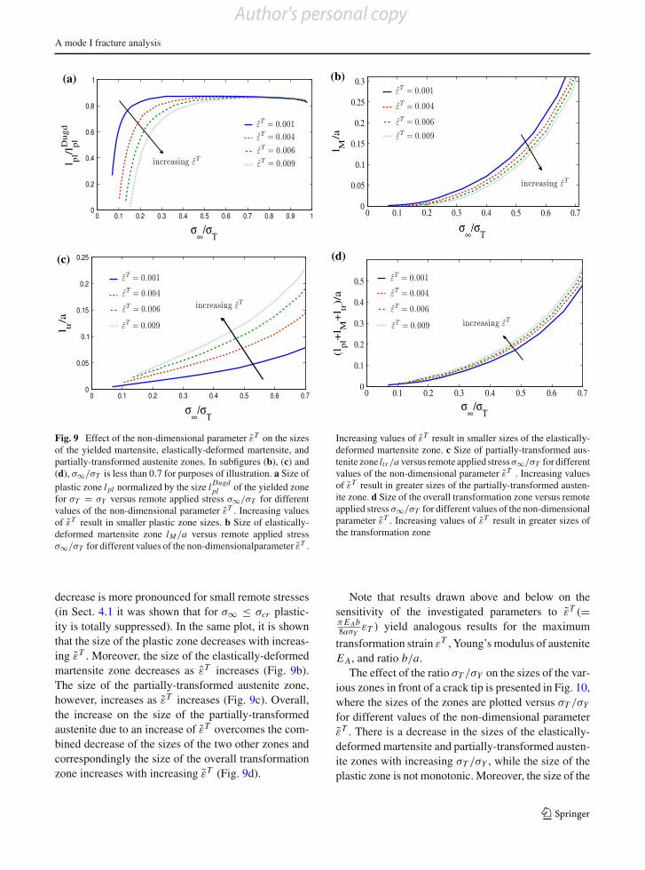
In Fig. 9a, the size of the plastic zone l pl normal-ized by the size l Dugd
pl = a sec [$!$/(2!Y )]"a of theyielded zone in the absence of transformation [see (10)]is plotted versus the remote stress !$/!T for differ-ent values of the non-dimensional parameter "T using& = 1. The presence of transformation in front of thecrack tip decreases the size of the plastic zone. The
123123
Author's personal copy
A mode I fracture analysis
(a) (b)
(c) (d)
Fig. 9 Effect of the non-dimensional parameter "T on the sizesof the yielded martensite, elastically-deformed martensite, andpartially-transformed austenite zones. In subfigures (b), (c) and(d), !$/!T is less than 0.7 for purposes of illustration. a Size ofplastic zone l pl normalized by the size l Dugd
pl of the yielded zonefor !T = !Y versus remote applied stress !$/!T for differentvalues of the non-dimensional parameter "T . Increasing valuesof "T result in smaller plastic zone sizes. b Size of elastically-deformed martensite zone lM/a versus remote applied stress!$/!T for different values of the non-dimensionalparameter "T .
Increasing values of "T result in smaller sizes of the elastically-deformed martensite zone. c Size of partially-transformed aus-tenite zone ltr /a versus remote applied stress!$/!T for differentvalues of the non-dimensional parameter "T . Increasing valuesof "T result in greater sizes of the partially-transformed austen-ite zone. d Size of the overall transformation zone versus remoteapplied stress !$/!T for different values of the non-dimensionalparameter "T . Increasing values of "T result in greater sizes ofthe transformation zone
decrease is more pronounced for small remote stresses(in Sect. 4.1 it was shown that for !$ ' !cr plastic-ity is totally suppressed). In the same plot, it is shownthat the size of the plastic zone decreases with increas-ing "T . Moreover, the size of the elastically-deformedmartensite zone decreases as "T increases (Fig. 9b).The size of the partially-transformed austenite zone,however, increases as "T increases (Fig. 9c). Overall,the increase on the size of the partially-transformedaustenite due to an increase of "T overcomes the com-bined decrease of the sizes of the two other zones andcorrespondingly the size of the overall transformationzone increases with increasing "T (Fig. 9d).
Note that results drawn above and below on thesensitivity of the investigated parameters to "T (=$ E Ab8a!Y
"T ) yield analogous results for the maximumtransformation strain "T , Young’s modulus of austeniteE A, and ratio b/a.
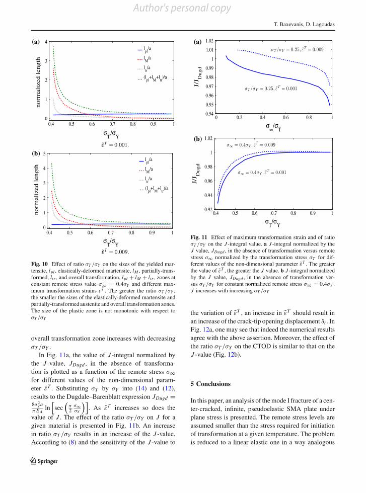
The effect of the ratio !T /!Y on the sizes of the var-ious zones in front of a crack tip is presented in Fig. 10,where the sizes of the zones are plotted versus !T /!Yfor different values of the non-dimensional parameter"T . There is a decrease in the sizes of the elastically-deformed martensite and partially-transformed austen-ite zones with increasing !T /!Y , while the size of theplastic zone is not monotonic. Moreover, the size of the
123
Author's personal copy
T. Baxevanis, D. Lagoudas
(a)
(b)
Fig. 10 Effect of ratio !T /!Y on the sizes of the yielded mar-tensite, l pl , elastically-deformed martensite, lM , partially-trans-formed, ltr , and overall transformation, l pl + lM + ltr , zones atconstant remote stress value !$ = 0.4!Y and different max-imum transformation strains "T . The greater the ratio !T /!Y ,the smaller the sizes of the elastically-deformed martensite andpartially-transformed austenite and overall transformation zones.The size of the plastic zone is not monotonic with respect to!T /!Y
overall transformation zone increases with decreasing!T /!Y .
In Fig. 11a, the value of J -integral normalized bythe J -value, JDugd , in the absence of transforma-tion is plotted as a function of the remote stress !$for different values of the non-dimensional param-eter "T . Substituting !T by !Y into (14) and (12),results to the Dugdale–Barenblatt expression JDugd =8! 2
Y a$ E A
ln7sec
#$2
!$!Y
$8. As "T increases so does the
value of J . The effect of the ratio !T /!Y on J for agiven material is presented in Fig. 11b. An increasein ratio !T /!Y results in an increase of the J -value.According to (8) and the sensitivity of the J -value to
(a)
(b)
Fig. 11 Effect of maximum transformation strain and of ratio!T /!Y on the J -integral value. a J -integral normalized by theJ value, JDugd , in the absence of transformation versus remotestress !$ normalized by the transformation stress !T for dif-ferent values of the non-dimensional parameter "T . The greaterthe value of "T , the greater the J value. b J -integral normalizedby the J value, JDugd , in the absence of transformation ver-sus !T /!Y for constant normalized remote stress !$ = 0.4!Y .J increases with increasing !T /!Y
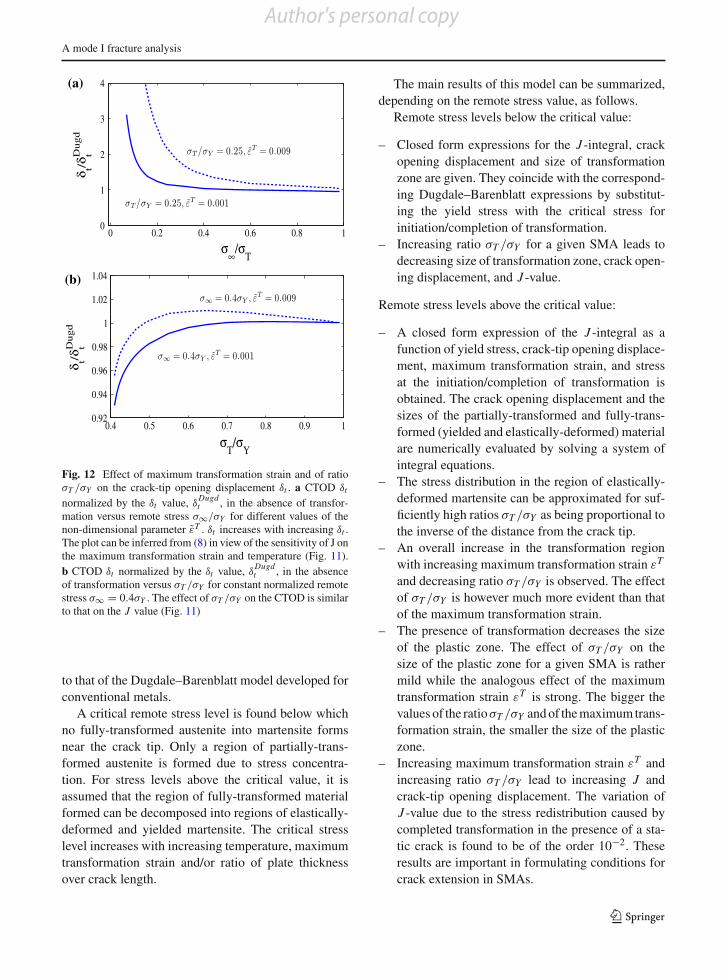
the variation of "T , an increase in "T should result inan increase of the crack-tip opening displacement %t . InFig. 12a, one may see that indeed the numerical resultsagree with the above assertion. Moreover, the effect ofthe ratio !T /!Y on the CTOD is similar to that on theJ -value (Fig. 12b).
5 Conclusions
In this paper, an analysis of the mode I fracture of a cen-ter-cracked, infinite, pseudoelastic SMA plate underplane stress is presented. The remote stress levels areassumed smaller than the stress required for initiationof transformation at a given temperature. The problemis reduced to a linear elastic one in a way analogous
123123
Author's personal copy
A mode I fracture analysis
(a)
(b)
Fig. 12 Effect of maximum transformation strain and of ratio!T /!Y on the crack-tip opening displacement %t . a CTOD %t
normalized by the %t value, %Dugdt , in the absence of transfor-
mation versus remote stress !$/!Y for different values of thenon-dimensional parameter "T . %t increases with increasing %t .The plot can be inferred from (8) in view of the sensitivity of J onthe maximum transformation strain and temperature (Fig. 11).b CTOD %t normalized by the %t value, %
Dugdt , in the absence
of transformation versus !T /!Y for constant normalized remotestress !$ = 0.4!Y . The effect of !T /!Y on the CTOD is similarto that on the J value (Fig. 11)
to that of the Dugdale–Barenblatt model developed forconventional metals.
A critical remote stress level is found below whichno fully-transformed austenite into martensite formsnear the crack tip. Only a region of partially-trans-formed austenite is formed due to stress concentra-tion. For stress levels above the critical value, it isassumed that the region of fully-transformed materialformed can be decomposed into regions of elastically-deformed and yielded martensite. The critical stresslevel increases with increasing temperature, maximumtransformation strain and/or ratio of plate thicknessover crack length.
The main results of this model can be summarized,depending on the remote stress value, as follows.
Remote stress levels below the critical value:
– Closed form expressions for the J -integral, crackopening displacement and size of transformationzone are given. They coincide with the correspond-ing Dugdale–Barenblatt expressions by substitut-ing the yield stress with the critical stress forinitiation/completion of transformation.
– Increasing ratio !T /!Y for a given SMA leads todecreasing size of transformation zone, crack open-ing displacement, and J -value.
Remote stress levels above the critical value:
– A closed form expression of the J -integral as afunction of yield stress, crack-tip opening displace-ment, maximum transformation strain, and stressat the initiation/completion of transformation isobtained. The crack opening displacement and thesizes of the partially-transformed and fully-trans-formed (yielded and elastically-deformed) materialare numerically evaluated by solving a system ofintegral equations.
– The stress distribution in the region of elastically-deformed martensite can be approximated for suf-ficiently high ratios !T /!Y as being proportional tothe inverse of the distance from the crack tip.
– An overall increase in the transformation regionwith increasing maximum transformation strain "T
and decreasing ratio !T /!Y is observed. The effectof !T /!Y is however much more evident than thatof the maximum transformation strain.
– The presence of transformation decreases the sizeof the plastic zone. The effect of !T /!Y on thesize of the plastic zone for a given SMA is rathermild while the analogous effect of the maximumtransformation strain "T is strong. The bigger thevalues of the ratio!T /!Y and of the maximum trans-formation strain, the smaller the size of the plasticzone.
– Increasing maximum transformation strain "T andincreasing ratio !T /!Y lead to increasing J andcrack-tip opening displacement. The variation ofJ -value due to the stress redistribution caused bycompleted transformation in the presence of a sta-tic crack is found to be of the order 10"2. Theseresults are important in formulating conditions forcrack extension in SMAs.
123
Author's personal copy
T. Baxevanis, D. Lagoudas
The analysis presented can be also applied for mar-tensitic SMAs, in which case detwinning of martensitetakes place near the crack tip instead of stress-inducedtransformation. The only difference is that !T shouldbe understood as the stress required for detwinning at agiven temperature. Thus, all the above results hold formartensitic SMAs as well.
Acknowledgments The support of the NSF InternationalInstitute of Materials for Energy Conversion (IIMEC), award#0844082, is acknowledged.
Appendix A
In this Appendix the SIFs and CODs generated by theconstraining stresses are calculated using the weightfunction method. The weight function method was firstproposed by Buecker (1970) and later by Rice (1972).The weight function is the expression for the SIF engen-dered by a unit point load-pair applied at any locationon the crack line. Finding the weight function for aparticular case is a difficult problem of elasticity the-ory (for a systematic approach, see Wu and Carlsson1991).
If the SIF K0 and the crack face displacementu0(a, x1) for a reference loading system is known, thenfor any other loading system ! (x1) acting on the samebody (both loading systems are of traction prescribedtype and are symmetric with respect to the crack linex2 = 0), the SIF K is given by
K =a/
0
! (x1)m(a, x1)dx1, (A1)
where m(a, x1) is the weight function, defined as
m(a, x1) = E )
K0u0,a, (A2)
and E ) is the effective elastic modulus, defined as E ) =E for plane stress or E ) = E/(1 " #2) for plane strain,where # is Poisson ratio. m is a universal function for agiven geometry and material, independent on the par-ticular loading system represented by the subscript 0.
For the infinite center-cracked plate loaded symmet-rically by a remote uniform applied tensile stress !$,the crack face displacement and the stress intensity fac-tor are given by
u0 = 2E ) !$
%a2 " x2
1 , K0 = !$(
$a, (A3)
and thus the weight function for this specific geometryreads, by virtue of (A2), as
m(a, x1) = 29
a$
1%
a2 " x21
. (A4)
Calculation of the stress intensity factor
Consider now an infinite center-cracked plate underplane stress loaded symmetrically by an arbitrary stressdistribution ! (x1) over the region ["(2,"(1] * [(1,
(2] on the crack faces. In view of (A4), (A1) yields
K = 29
a$
(2/
(1
! (x1)1
%a2 " x2
1
dx1. (A5)
Using (A5), one may easily calculate
K A = 29
a1
$!Y
a+l pl/
a
1%
a21 " x2
1
dx1, (A6a)
K B = 29
a1
$
a+l pl+lM/
a+l pl
!m(x1)1
%a2
1 " x21
dx1, (A6b)
KC = 29
a1
$!T
a1/
a+l pl+lM
1%
a21 " x2
1
dx1. (A6c)
A.2 Calculation of the crack opening displacement
In view of (A4), the crack opening profile of an infinitecenter-cracked plate under plane stress loaded symmet-rically by an arbitrary stress distribution ! (x1) over theregion ["(2, "(1] * [(1, (2] on the crack faces canbe obtained, by integration of (A2), as
%(x1) = 2u(x1) =&'''''''''''''''(
''''''''''''''')
8$ E )
* (2(1
! (x )1)
:* a
x1a)
%a)2"x )2
1
%a)2"x2
1
da);
dx )1,
8$ E )
7 * x1(1
! (x )1)
:* a
x1a)
%a)2"x )2
1
%a)2"x2
1
da);
dx )1
+* (2
x1! (x )
1)
:* a
x )1a)
%a)2"x )2
1
%a)2"x2
1
da);
dx )1
8,
8$ E )
* (2(1
! (x )1)
:* a
x )1a)
%a)2"x )2
1
%a)2"x2
1
da);
dx )1,
(A7)
where the first branch holds for (2 ' |x1| ' a, thesecond for (1 ' |x1| ' (2, and the third for |x1| ' (1.
123123
Author's personal copy
A mode I fracture analysis
Using (A7) and taking into account that
/a)
%a)2 " x )2
1
%a)2 " x2
1
da)
= ln,%
a)2 " x )21 +
%a)2 " x2
1
-,
one can readily show that
%A(x1) =&'''''''''''''''''''''''(
''''''''''''''''''''''')
8!Y$ E )
* a+l pla
+ln
,%a2
1 " x )21 +
%a2
1 " x21
-
" ln,%
x21 " x )2
1
- .dx )
1,
8!Y$ E )
+ * a+l pla ln
,%a2
1 " x )21 +
%a2
1 " x21
-dx )
1
"* x1
a ln,%
x21 " x )2
1
-dx )
1
"* a+l pl
x1ln
,%x )2
1 " x21
-dx )
1
.,
8!Y$ E )
* a+l pla
+ln
,%a2
1 " x )21 +
%a2
1 " x21
-
" ln,%
x )21 " x2
1
- .dx )
1,
(A8)
where the first branch holds for a + l pl ' |x1| ' a1,the second for a ' |x1| ' a + l pl and the third holdsfor |x1| ' a,
%B(x1) =&'''''''''''''''''''''''(
''''''''''''''''''''''')
8$ E )
* a+l pl +lMa+l1 !m(x )
1)
+ln
,%a2
1 " x )21 +
%a2
1 " x21
-
" ln,%
x21 " x )2
1
-.dx )
1,
8$ E )
+ * a+l pl+lMa+l pl
!m(x )1) ln
,%a2
1 "x )21+
%a2
1 "x21
-dx )
1
"* x1
a+l pl!m(x )
1) ln,%
x21 " x )2
1
-dx )
1
"* a+l pl +lM
x1!m(x )
1) ln,%
x )21 " x2
1
-dx )
1
8,
8$ E )
* a+l pl +lMa+l pl
!m(x )1)
+ln
,%a2
1 " x )21 +
%a2
1 " x21
-
" ln,%
x )21 " x2
1
-.dx )
1,
(A9)
where the first branch holds for a + l pl + lM ' |x1| 'a1, the second for a + l pl ' |x1| ' a + l pl + lM andthe third holds for |x1| ' a + l pl ,
%C (x1)
=
&'''''''''''''''(
''''''''''''''')
8!T$ E )
+ * a1a+l pl+lM
ln,%
a21 "x )2
1+%
a21 "x2
1
-dx )
1
"* x1
a+l pl+lMln
,%x2
1 " x )21
-dx )
1
"* a1
x1ln
,%x )2
1 " x21
-dx )
1
.,
8!T$ E )
* a1a+l pl+lM
+ln
,%a2
1 " x )21 +
%a2
1 " x21
-
" ln,%
x )21 " x2
1
- .dx )
1,
(A10)
where the first branch holds for a + l pl + lM ' |x1| 'a1, and the second holds for |x1| ' a + l pl + lM .
References
Auricchio F, Taylor R, Lubliner J (1997) Shape-memory alloys:macro-modeling and numerical simulations of the super-elastic behavior. Comput Methods Appl Mech 146:241–312
Baxevanis T, Chemisky Y, Lagoudas D (2012) Finite elementanalysis of the plane-strain crack-tip mechanical fields inpseudoelastic shape memory alloys. (submitted)
Birman V (1998) On mode I fracture of shape memory alloyplates. Smart Mater Struct 7:433–437
Budniansky B, Hutchinson J, Lambropoulos J (1983) Contin-uum theory of dilatant transformation toughening in ceram-ics. Int J Solids Struct 19:337–355
Buecker H (1970) A novel principle for the computation of stressintensity factors. Z angew Math Mech 50:529–546
Daymond M, Young M, Almer J, Dunand D (2007) Strain andtexture evolution during mechanical loading of a crack tipin martensitic shape-memory Ni Ti. Acta Mater 55:3929–3942
Duerig T, Melton K, Stockel D, Wayman C (eds) (1990) Engi-neering aspects of shape memory alloys. Butterworth-Heinemann, London
Dugdale D (1960) Yielding of steel sheets containing slits.J Mech Phys Solids 8:100
Eshelby J (1956) The continuum theory of lattice defects. In:Solid state physics. Academic, New York.
Eshelby J (1970) Energy relations and the energy momentumtensor in continuum mechanics. In: Inelastic behavior ofsolids. McGraw-Hill, New York.
Freed Y, Banks-Sills L (2007) Crack growth resistance of shapememory alloys by means of a cohesive zone model. J MechPhys Solids 55:2157–2180
Funakubo H (ed) (1987) Shape Memory Alloys. Gordon andBreach Science, New York
Gollerthan S, Young M, Baruj A, Frenzel J, Schmahl W, EggelerG (2009a) Fracture mechanics and microstructure in NiTishape memory alloys. Acta Mater 57:1015–1025
123
Author's personal copy
T. Baxevanis, D. Lagoudas
Gollerthan S, Young M, Baruj A, Frenzel J, Schmahl W, EggelerG (2009b) Fracture mechanics and microstructure in NiTishape memory alloys. Acta Mater 57:1015–1025
Hoffmann M, Seeger T (1985) Dugdale solutions for strain hard-ening materials. In: Schwalbe K (ed) The crack tip openingdisplacement in elastic-plastic fracture mechanics Proceed-ings of the Workshop on the CTOD Methodology. Springer,Geesthacht pp 57–77
Hutchinson J (1968) Singular behavior at the end of a tensilecrack in a hardening material. J Mech Phys Solids 16:13–31
Ishida A, Sato M, Kimura T, Miyazaki S (2000) Stress-straincurves of sputter-deposited Ti-Ni thin films. Philos Mag A80:967–980
Lagoudas D (ed) (2008) Shape memory alloys: modelling andengineering applications. Springer, New-York
Lagoudas D, Entchev P, Popov P, Patoor E, Brinson L, Gao X(2006) Shape memory alloys. Part II: modeling of polycrys-tals. Mech Mater 38:430–462
Maletta C, Furgiuele F (2010) Analytical modeling of stress-induced martensitic transformation in the crack tip regionof nickel-titanium alloys. Acta Mater 58:92–101
Maletta C, Furgiuele F (2011) Fracture control parameters forniti based shape memory alloys. Int J Solids Struct 48:1658–1664
McKelvey A, Ritchie R (2001) Fatigue-crack growth behaviorin the superelastic and shape-memory alloy Nitinol. MetallMater Trans A 32:731–743
McMeeking R, Evans A (1982) Mechanics of transformation-toughening in brittle materials. J Am Ceram Soc 65:242–246
Otsuka K, Wayman C (eds) (1999) Shape memory materials.Cambridge University Press, Cambridge
Patoor E, Lagoudas D, Entchev P, Brinson L, Gao X (2006)Shape memory alloys. Part I: General properties and mod-eling of single crystals. Mech Mater 38:391–429
Perkins J (ed) (1975) Shape memory effects in alloys. PlenumPress, New York
Rice J (1968a) Mathematical analysis in the mechanics of frac-ture, vol 2. In: Liebowitz H, (ed), Mathematical fundamen-tals. Academic Press, New York, Chapter 3 of Fracture: anadvanced treatise, pp 191–311
Rice J (1968b) A path independent integral and approximateanalysis of strain concentration by notches and cracks.ASME J Appl Mech 35:379–386
Rice J (1972) Some remarks on elastic crack-tip stress fields. IntJ Solids Struct 8:751–758
Robertson S, Metha A, Pelton A, Ritchie R (2007) Evolutionof crack-tip transformation zones in superelastic Nitinolsubjected to in situ fatigue: A fracture mechanics and syn-chrotron X-ray micro-diffraction analysis. Acta Mater 55:6198–6207
Rosenfield A, Dai P, Hahn G (1966) In: Yokobori T, Kawasaki T,Swedlow J (eds), Proccedings of the 1st International Con-ference on Fracture, Sendai, 1965. vol I. Japanese Societyfor Strength and Fracture, Tokyo, pp 223–257
Saburi T (1999) Shape memory materials. In: Ti-Ni shape mem-ory alloys. Cambridge University Press, Cambridge, pp 49–93
Stam G, van de Giessen E (1985) Effect of reversible phasetransformations on crack growth. Mech Mater 21:51–71
Sun Q, Hwang K (1993a) Micromechanics modelling for theconstitutive behavior of polycrystalline shape memoryalloysI. derivation of general relations. J Mech Phys Sol-ids 41:1–17
Sun Q, Hwang K (1993b) Micromechanics modelling for theconstitutive behavior of polycrystalline shape memoryalloysII. study of the individual phenomena. J Mech PhysSolids 41:19–33
Sun Q, Hwang K, Yu S (1991) A micromechanics constitutivemodel of transformation plasticity with shear and dilatationeffect. J Mech Phys Solids 39:507–524
Wang G (2007a) Effect of martensite transformation on fracturebehavior of shape memory alloy NiTi in a notched speci-men. Int J Fract 146:93–104
Wang G (2007b) A finite element analysis of evolution of stress-strain and martensite transformation in front of a notch inshape memory alloy NiTi. Mater Sci Eng A 460–461:460–461
Wang X, Wang Y, Baruj A, Eggeler G, Yue Z (2005) On theformation of martensite in front of cracks in pseudoelasticshape memory alloys. Mater Sci Eng A 394:393–398
Wu X-R, Carlsson A (1991) Weight functions and stress inten-sity factor solutions. Pergamon Press, Oxford
Xiong F, Liu Y (2007) Effect of stress-induced martensitic trans-formation on the crack tip stress-intensity factor in Ni-Mn-Ga shape memory alloy. Acta Mater 55:5621–5629
Yan W, Mai Y (2006) Theoretical consideration on the fractureof shape memory alloys, vol 127. Springer, Netherlands217–226
Yan W, Wang C, Zhang X, Mai Y (2002) Effect of transforma-tion volume contraction on the toughness of superelasticshape memory alloys. Smart Mater Struct 11:947–955
Yi S, Gao S (2000) Fracture toughening mechanism of shapememory alloys due to martensite transformation. Int J Sol-ids Struct 37:5315–5327
Yi S, Gao S, Shen S (2001) Fracture toughening mechanism ofshape memory alloys under mixed-mode loading due tomartensite transformation. Int J Solids Struct 38:4463–4476
123123
Author's personal copy