Review on dynamics of cracked gear systems
22
Review Review on dynamics of cracked gear systems Hui Ma ⇑ , Jin Zeng, Ranjiao Feng, Xu Pang, Qibin Wang, Bangchun Wen School of Mechanical Engineering and Automation, Northeastern University, Shenyang, Liaoning 110819, PR China article info Article history: Received 5 December 2014 Received in revised form 2 June 2015 Accepted 12 June 2015 Available online 16 June 2015 Keywords: Crack propagation path Time-varying mesh stiffness (TVMS) Cracked gear systems Analytical method Finite element method abstract Dynamic characteristics of cracked gear systems, also known as cracked-gear rotor sys- tems, have received increasing interests among industry and academy in the past two dec- ades. This paper reviews published papers on the dynamics of cracked gear systems. These studies mainly focused on three topics: crack propagation prediction, time-varying mesh stiffness (TVMS) calculation and vibration response calculation; Study objects involve the spur gear, helical gear and planetary gear; Different modeling methods including ana- lytical method, finite element (FE) method, combined analytical-FE approach were adopted. More specifically, this review is composed of three related parts according to the above three topics. The first part involves the prediction of the crack propagation path based on two-dimensional (2D) or three-dimensional (3D) gear models, which provides a basis for the hypothesis of crack path in the process of TVMS calculation of cracked gear pairs. The second part summarizes the TVMS calculation methods including analytical methods, FE methods, combined analytical-FE approaches and experimental methods. The final part reviews the dynamic models for vibration analysis of cracked gear systems including lumped mass models and FE models, where the crack effects are characterized by introducing TVMS of cracked gear pairs into the system dynamic models. The well known open problems about cracked gear dynamics are finally stated, and some new research interests are also pointed out. The review will provide valuable references for future studies on dynamics of cracked gears. Ó 2015 Elsevier Ltd. All rights reserved. 1. Introduction Gear tooth fatigue cracks can be caused by many reasons, such as inappropriate operating conditions, material defects, manufacturing errors [1]. The crack often propagates either along the tooth root or along the rim, which depends on the gear geometry and the applied torque on the gear [2–24]. Its propagation direction may vary and it is usually determined by crack tip stress intensity factors (SIFs). The tooth crack can change mesh stiffness and therefore produce abnormal vibration responses, such as impact and high frequency noise. First of all, it is important to predict the fatigue crack propagation path with the aim of estimating the gear remaining life. Finite element (FE) method using the principles of linear elastic fracture mechanics (LEFM) are widely used to simulate the propagation path. Once the propagation path is determined, the corre- sponding time-varying mesh stiffness (TVMS) can be calculated using theoretical or experimental methods [25–64]. The changed TVMS can result in different dynamic responses, compared to the healthy gear systems. The dynamic responses of the cracked gear systems can be estimated using lumped mass models or FE models. http://dx.doi.org/10.1016/j.engfailanal.2015.06.004 1350-6307/Ó 2015 Elsevier Ltd. All rights reserved. ⇑ Corresponding author. Tel./fax: +86 24 83684491. E-mail address: [email protected] (H. Ma). Engineering Failure Analysis 55 (2015) 224–245 Contents lists available at ScienceDirect Engineering Failure Analysis journal homepage: www.elsevier.com/locate/engfailanal
Transcript of Review on dynamics of cracked gear systems

Engineering Failure Analysis 55 (2015) 224–245
Contents lists available at ScienceDirect
Engineering Failure Analysis
journal homepage: www.elsevier .com/locate /engfai lanal
Review
Review on dynamics of cracked gear systems
http://dx.doi.org/10.1016/j.engfailanal.2015.06.0041350-6307/� 2015 Elsevier Ltd. All rights reserved.
⇑ Corresponding author. Tel./fax: +86 24 83684491.E-mail address: [email protected] (H. Ma).
Hui Ma ⇑, Jin Zeng, Ranjiao Feng, Xu Pang, Qibin Wang, Bangchun WenSchool of Mechanical Engineering and Automation, Northeastern University, Shenyang, Liaoning 110819, PR China
a r t i c l e i n f o a b s t r a c t
Article history:Received 5 December 2014Received in revised form 2 June 2015Accepted 12 June 2015Available online 16 June 2015
Keywords:Crack propagation pathTime-varying mesh stiffness (TVMS)Cracked gear systemsAnalytical methodFinite element method
Dynamic characteristics of cracked gear systems, also known as cracked-gear rotor sys-tems, have received increasing interests among industry and academy in the past two dec-ades. This paper reviews published papers on the dynamics of cracked gear systems. Thesestudies mainly focused on three topics: crack propagation prediction, time-varying meshstiffness (TVMS) calculation and vibration response calculation; Study objects involvethe spur gear, helical gear and planetary gear; Different modeling methods including ana-lytical method, finite element (FE) method, combined analytical-FE approach wereadopted. More specifically, this review is composed of three related parts according tothe above three topics. The first part involves the prediction of the crack propagation pathbased on two-dimensional (2D) or three-dimensional (3D) gear models, which provides abasis for the hypothesis of crack path in the process of TVMS calculation of cracked gearpairs. The second part summarizes the TVMS calculation methods including analyticalmethods, FE methods, combined analytical-FE approaches and experimental methods.The final part reviews the dynamic models for vibration analysis of cracked gear systemsincluding lumped mass models and FE models, where the crack effects are characterizedby introducing TVMS of cracked gear pairs into the system dynamic models. The wellknown open problems about cracked gear dynamics are finally stated, and some newresearch interests are also pointed out. The review will provide valuable references forfuture studies on dynamics of cracked gears.
� 2015 Elsevier Ltd. All rights reserved.
1. Introduction
Gear tooth fatigue cracks can be caused by many reasons, such as inappropriate operating conditions, material defects,manufacturing errors [1]. The crack often propagates either along the tooth root or along the rim, which depends on the geargeometry and the applied torque on the gear [2–24]. Its propagation direction may vary and it is usually determined by cracktip stress intensity factors (SIFs). The tooth crack can change mesh stiffness and therefore produce abnormal vibrationresponses, such as impact and high frequency noise. First of all, it is important to predict the fatigue crack propagation pathwith the aim of estimating the gear remaining life. Finite element (FE) method using the principles of linear elastic fracturemechanics (LEFM) are widely used to simulate the propagation path. Once the propagation path is determined, the corre-sponding time-varying mesh stiffness (TVMS) can be calculated using theoretical or experimental methods [25–64]. Thechanged TVMS can result in different dynamic responses, compared to the healthy gear systems. The dynamic responsesof the cracked gear systems can be estimated using lumped mass models or FE models.

H. Ma et al. / Engineering Failure Analysis 55 (2015) 224–245 225
This paper mainly reviews the recent progresses on the propagation path prediction, TVMS calculation and dynamic mod-els for the cracked gear systems. The whole structure of this paper is shown as follows: In Section 2, the main crack prop-agation path prediction techniques based on two-dimensional (2D) and three-dimensional (3D) gear models are introduced.In Section 3, four types of methods to compute the TVMS, namely analytical methods, FE methods, combined analytical-FEapproaches and experimental method are reviewed. Section 4 mainly introduces two typical dynamic models, namelylumped mass model (LMM) and FE model, followed by some discussions and future prospects given in Section 5. To makepaper contents clear, Fig. 1 summarizes all the involved methods in the literatures.
2. Prediction methods on the crack propagation paths
The studies of the crack propagation paths mostly aim at the spur gear. For the spur gear, many researchers adopt the 2Dgear model based on plane stress or strain assumption, which has a high computational efficiency. In order to simulate thecrack propagating along both the gear width and gear thickness, a 3D gear model should be used. The researches on the crackpropagation paths are classified according to the gear modes in Sections 2.1 and 2.2. A brief summary is performed accordingto the research objectives (spur gear, spiral bevel gear and helical gear) in Section 2.3.
2.1. 2D gear models
Lewicki and Ballarini [2] used a 2D FE program, named FRANC, to simulate gear tooth crack propagation. This work isbased on LEFM without consideration of plastic deformation. Moreover, they also analyzed the effects of rim thicknessand backup ratios on the crack propagation paths where crack tip SIFs were used to determine the crack propagation direc-tion. The effectiveness of the above methods were verified by bending fatigue tests where two different crack propagationpaths along tooth root and rim are considered, as shown in Fig. 2. Based on two FE programs: FRANC for 2D model andFRANC3D for 3D model [3], Lewicki et al. [4] studied the impact of the different loads on the crack propagation paths forboth spur and spiral bevel gears. For the spur gear, the predicted crack propagation path agrees with the measured results.By using FRANC, Glodez et al. [5] simulated the crack propagation using Paris equation, and Pandya and Parey [6–8] simu-lated the propagation paths of the crack along the tooth root using the displacement correlation method, and Krambergeret al. [9] developed a calculation model for the evaluation of the service life of gears with a crack along the gear tooth root.
Specially for a spur gear, Li and Lee [10] developed an embedded model for calculating crack size, a FE program for deter-mining SIFs and a fast algorithm for simulating crack growth based on a Paris model. They also predicted the residual life of agear with a tooth crack, and verified the presented method by experiments. Based on Ref. [10], Choi and Li [11] evaluatedcrack size based on the measured gear vibration data using an artificial neural network and then predicted the remaininglife of a spur gear with tooth crack.
Considering the crack propagation along tooth root as a function of SIFs, Zouari et al. [12] combined the LEFM with FEmethod to study the tooth foot crack propagation of a spur gear. Based on a modified Paris equation, Yin et al. [13] utilized
Fig. 1. Classification of the research contents in this paper.

Fig. 2. (a) gear with fabricated notch, (b) and (c) crack propagation along tooth root and rim in Ref. [2].
226 H. Ma et al. / Engineering Failure Analysis 55 (2015) 224–245
a non-linear dynamic model to predict the crack growth along the gear tooth root, and showed the impact of variable loadson crack growth. By combining rotational motions with varying contact conditions, Sfakiotakis and Anifantis [14] developeda new numerical program to investigate stress singularities during the fracture process of the gear tooth. In order to simulatecrack closure effects based on the Paris-Erdogan equation, Guilbault et al. [15] developed a procedure for detecting the crackpropagation path under the scope of LEFM, and verified the method by comparing the published numerical and experimentalresults [16].
2.2. 3D gear models
Based on the boundary element (BE) method and LEFM, Spievak et al. [17] predicted the 3D crack propagation path of aspiral bevel pinion by applying a moving load along tooth, and simulated the crack front propagation under non-proportionalload condition where fatigue crack closure effects were considered. By combining LEFM with FE method, Ural et al. [18] pre-dicted crack shape and residual life of a spiral bevel gear considering the effects of crack-induced plasticity deformation andmoving loads. Their results show that FE method can simulate the growth of arbitrarily shaped crack more accurately andefficiently than BE method does.
Shao et al. [19] predicted the 3D crack propagation paths of a spur gear using the FRANC3D, and calculated the SIFs ofsemi-circular crack, and validated the simulated results by experiments. Aiming at a helical gear, Rad et al. [20] simulatedthe fatigue crack growth at tooth root under the assumption of LEFM, which is based on the extended finite element method(XFEM) and Paris equation. Ghaffari et al. [22] established a 3D FE model of a gear tooth using the ANSYS software, developeda program for predicting crack growth directions, and analyzed the influences of friction on the initiation life of the fatiguecrack.
2.3. Summary
In Sections 2.1 and 2.2, we have summarized published researches on crack propagation simulation according to the clas-sification of 2D and 3D gear models, respectively. When considering different objects, such as the spur gear, spiral bevel gearand helical gear, their corresponding methods for crack propagating paths are listed in Table 1. These research results can besummarized as follows:
(1) The earlier works mainly involve using simple 2D models for the spur gear. The 2D models are not be suitable for mod-eling complex gears. However, with the development of computer software and hardware, 3D gear models are morepreferable to simulate complex gears like spiral bevel gear and helical gear under complicated load operational con-ditions, which is becoming a hot topic.
(2) Most of current studies are based on LEFM and only a few works are carried out based on the elastic–plastic fracturemechanics. Moreover, most existing studies use the simple quasi-state conditions. However, the study on effects ofdynamic load conditions on crack propagation and fatigue life is still desirable.
3. Mesh models for gear pairs with tooth crack
Assuming different crack propagation paths, TVMS of the cracked gear pair can be calculated using different methods,such as analytical methods, FE methods, combined analytical-FE approaches and experimental methods. Analytical methodhas a higher computational efficiency, FE method has a good calculation accuracy, combined analytical-FE approach has theadvantages of both analytical method and FE method, and experimental method is closer to the actual operation under cer-tain measurement conditions. In this section, the studies on the TVMS calculation models are reviewed according to the fourmethods, respectively.

Table 1Summary of the simulation methods for crack propagating paths.
Objects References Modelingmethod of gear
Method for calculatingSIFs
Crack propagationsimulation
Applied meshing force Experimentverification
Spur gear Lewicki and Ballarini[2]
FE (2D) Displacementcorrelation method
FRANC Varying loads along the tooth profileapplied at the highest point of the single-tooth contact
Yes
Lewicki et al. [4] FE (2D) J-integral technique FRANC Loads as a function of gear rotation YesPandya and Parey [6–8] FE (2D) Displacement
correlation methodFRANC Varying loads along the tooth profile
applied at the highest point of the single-tooth contact
No
Glodez et al. [5] andKramberger et al. [9]
FE (2D) Paris equation FRANC Normal pulsating force applied at theouter point of the single-tooth contact
No
Li and Lee [10] andChoi and Li [11]
FE (2D) Paris equation A fast algorithmbased on a Pariscrack growthmodel
Varying loads along the tooth profileapplied at the highest point of the single-tooth contact
Yes
Zouari et al. [12] FE (2D) Displacementcorrelation method
Paris-Erdoganlaws
Constant load applied at the outer point ofthe single-tooth contact
Experimentalresults in Ref. [2]
Yin et al. [13] AM A modified Parisequation
A nonlinear crackgrowth model
Variable-amplitude loading Yes
Sfakiotakis andAnifantis [14]
FE (2D) Displacementcorrelation method
No Slideline facility for simulating the toothcontact
No
Guilbault et al. [15] BEM Displacementextrapolation methodintegrated into theFinite SeparationMethod
Paris-Erdoganlaws
Load acting along the profile at successivepositions
Experimentalresults in Ref. [16]
Shao et al. [19] BEM Displacementcorrelation method
FRANC3D Load applied on the top of the gear tooth Yes
Ghaffari et al. [22] FE (3D) Energy release rates Paris law Moving Hertzian contact load along thepartial or whole tooth width
Experimentalresults in Refs.[23,24]
Spiral bevel gear Lewicki and Ballarini[2] and Spievak et al.[17]
BEM Displacementcorrelation method
FRANC3D Moving loads applied on a gear tooth as afunction of position, time and magnitude
Yes
Ural et al. [18] FE (3D) J-integral technique FRANC3D Moving Hertz contact loads Yes
Helical gear Rad et al. [20] XFEM Paris equation ABAQUS Loads applied at the first point of the toothcontact zone
Experimentalresults in Ref. [21]
Note: XFEM denotes extended finite element method, BEM boundary element method, AM analytical method, SIFs stress intensity factors.
H.M
aet
al./EngineeringFailure
Analysis
55(2015)
224–245
227
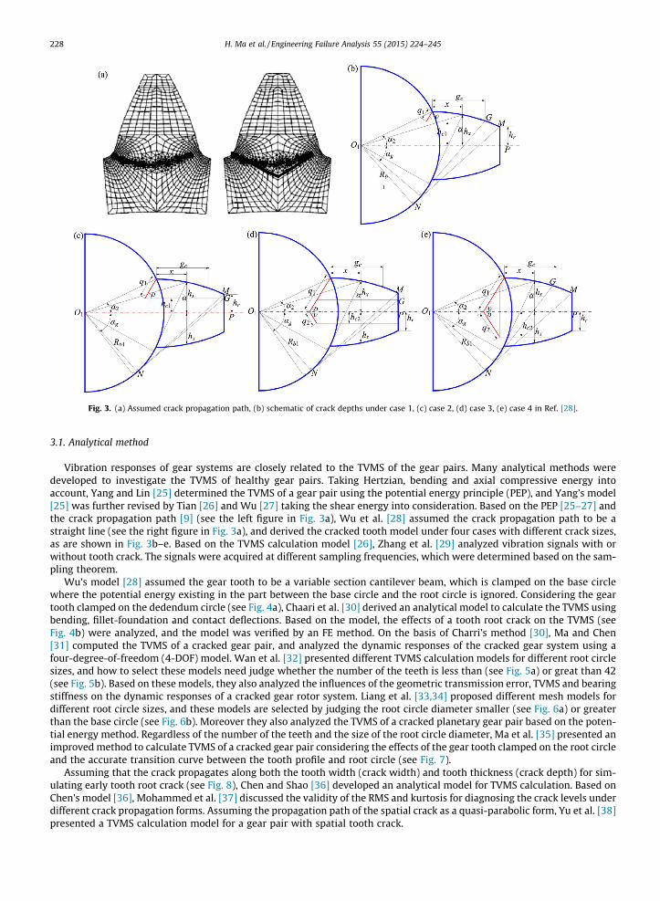
Fig. 3. (a) Assumed crack propagation path, (b) schematic of crack depths under case 1, (c) case 2, (d) case 3, (e) case 4 in Ref. [28].
228 H. Ma et al. / Engineering Failure Analysis 55 (2015) 224–245
3.1. Analytical method
Vibration responses of gear systems are closely related to the TVMS of the gear pairs. Many analytical methods weredeveloped to investigate the TVMS of healthy gear pairs. Taking Hertzian, bending and axial compressive energy intoaccount, Yang and Lin [25] determined the TVMS of a gear pair using the potential energy principle (PEP), and Yang’s model[25] was further revised by Tian [26] and Wu [27] taking the shear energy into consideration. Based on the PEP [25–27] andthe crack propagation path [9] (see the left figure in Fig. 3a), Wu et al. [28] assumed the crack propagation path to be astraight line (see the right figure in Fig. 3a), and derived the cracked tooth model under four cases with different crack sizes,as are shown in Fig. 3b–e. Based on the TVMS calculation model [26], Zhang et al. [29] analyzed vibration signals with orwithout tooth crack. The signals were acquired at different sampling frequencies, which were determined based on the sam-pling theorem.
Wu’s model [28] assumed the gear tooth to be a variable section cantilever beam, which is clamped on the base circlewhere the potential energy existing in the part between the base circle and the root circle is ignored. Considering the geartooth clamped on the dedendum circle (see Fig. 4a), Chaari et al. [30] derived an analytical model to calculate the TVMS usingbending, fillet-foundation and contact deflections. Based on the model, the effects of a tooth root crack on the TVMS (seeFig. 4b) were analyzed, and the model was verified by an FE method. On the basis of Charri’s method [30], Ma and Chen[31] computed the TVMS of a cracked gear pair, and analyzed the dynamic responses of the cracked gear system using afour-degree-of-freedom (4-DOF) model. Wan et al. [32] presented different TVMS calculation models for different root circlesizes, and how to select these models need judge whether the number of the teeth is less than (see Fig. 5a) or great than 42(see Fig. 5b). Based on these models, they also analyzed the influences of the geometric transmission error, TVMS and bearingstiffness on the dynamic responses of a cracked gear rotor system. Liang et al. [33,34] proposed different mesh models fordifferent root circle sizes, and these models are selected by judging the root circle diameter smaller (see Fig. 6a) or greaterthan the base circle (see Fig. 6b). Moreover they also analyzed the TVMS of a cracked planetary gear pair based on the poten-tial energy method. Regardless of the number of the teeth and the size of the root circle diameter, Ma et al. [35] presented animproved method to calculate TVMS of a cracked gear pair considering the effects of the gear tooth clamped on the root circleand the accurate transition curve between the tooth profile and root circle (see Fig. 7).
Assuming that the crack propagates along both the tooth width (crack width) and tooth thickness (crack depth) for sim-ulating early tooth root crack (see Fig. 8), Chen and Shao [36] developed an analytical model for TVMS calculation. Based onChen’s model [36], Mohammed et al. [37] discussed the validity of the RMS and kurtosis for diagnosing the crack levels underdifferent crack propagation forms. Assuming the propagation path of the spatial crack as a quasi-parabolic form, Yu et al. [38]presented a TVMS calculation model for a gear pair with spatial tooth crack.

Fig. 4. Model of the cracked gear tooth [30]: (a) schematic of spur gear tooth, (b) schematic of a crack.
Fig. 5. Schematic of spur gear [32]: (a) z < 42, (b) z > 42.
H. Ma et al. / Engineering Failure Analysis 55 (2015) 224–245 229
The TVMS calculation models for the cracked spur gear pair have also been applied to the cracked planetary gear pair afterthe appropriate correction [39–41]. Based on Chen’s model [36], Chen and Shao [39] developed a coupled planetary geardynamic model with the tooth crack in which tooth cracks with different sizes and inclination angles were assumed inone tooth of the sun gear and planet gear, respectively. Chen and Shao [40] derived the TVMS of the internal gear pair onthe basis of the PEP, and evaluated the ring gear crack on the reduction of the mesh stiffness. Considering the effects ofthe flexible ring gear rim and the tooth root crack on the mesh stiffness, Chen et al. [41] developed an improved TVMS cal-culation model for a planetary gear pair.
By revising limiting lines related to the tooth thickness (see Fig. 9), Mohammed et al. [42] presented an improved methodto calculate the TVMS of the gear with tooth root crack, and compared the effects of different crack sizes on the vibrationresponses of a cracked gear system. Their results show that the improved method calculates the TVMS more accurately thanthe traditional method does. On the foundation of Ref. [35], Ma et al. [43] proposed an improved mesh stiffness model for thecracked spur gear pair where two parabolic curves are used to simulate the crack propagation path and limiting line, respec-tively [42] (see Fig. 10).

Fig. 6. Beam model of an external gear tooth [33]: (a) Rr < Rb, (b) Rr > Rb.
Fig. 7. Schematic of a spur gear tooth [35].
Fig. 8. Crack model at gear tooth root [36].
230 H. Ma et al. / Engineering Failure Analysis 55 (2015) 224–245
Based on the crack propagation paths determined by FRANC, Pandya and Parey [7] presented an improved TVMS calcu-lation method, which adopts straight lines with different slopes rather than only one straight to simulate the predicted crackpath (see Fig. 11), and compared the difference of the TVMS under two crack propagation paths: a straight line and multiplestraight lines. Based on the a curved crack propagation path obtained using FRANC (see Fig. 12), Zhao et al. [44] proposed apotential energy method to calculate the TVMS of a cracked gear pair.

Fig. 9. Limiting lines related to the tooth thickness [42]: (a) parabolic curve under small crack sizes, (b) straight line, (c) parabolic curve under large cracksizes.
Fig. 10. Crack propagation schematic: (a) measured crack propagation path [2], (b) simulated crack propagation path [43].
Fig. 11. Proposed crack propagation path approximation [7].
H. Ma et al. / Engineering Failure Analysis 55 (2015) 224–245 231

Fig. 12. Cracked tooth model [44].
232 H. Ma et al. / Engineering Failure Analysis 55 (2015) 224–245
Considering the combined effects of tooth crack and the plastic inclination, Shao and Chen [45] developed a tooth plasticinclination model for a spur gear pair by considering the cracked tooth as a variable cross-section cantilever beam (seeFig. 13). Considering the effects of the gear tooth root crack which propagates into the gear-body, Zhou et al. [46] presenteda revised mathematical model based on the assumption of a linear propagation path (see Fig. 14). For a spur gear pair, Saxenaet al. [47] established an analytical model by taking the influences of the shaft misalignment and the friction of tooth surfaceinto account.
Omar et al. [48] presented a TVMS expression for a gear pair with tooth root crack, which can be written as follows:
km ¼XN�1
i¼1
kim þ kcracked
m ; ð1Þ
where
kim ¼
f k xt � 2p i�1N þ n� �� �
2px
i�1N þ n� �
6 t 6 2px
i�1N þ n� �
þ hf
x
0 elsewhere
(; ð2Þ
kcrackedm is evaluated using Eq. (1) considering the corresponding crack size function fk in Ref. [49].
Fig. 13. Schematic for plastic inclination of gear tooth due to tooth root crack [45].

Fig. 14. The crack growth model in the pinion [46].
H. Ma et al. / Engineering Failure Analysis 55 (2015) 224–245 233
3.2. FE method
3.2.1. FE models with contact elementsConsidering the effect of the whole meshing spur gear pair (see Fig. 15a), Howard et al. [50] presented a FE model with
tooth crack (see Fig. 15b) where the gear and the contact effect are modeled using 2D plane strain elements and line-to-linecontact elements, respectively. Moreover, in their model, the singular elements around the crack tip are utilized to simulatethe influence of the crack tip. In order to compare the difference of the vibration responses under the localized tooth spallingand crack conditions, Jia and Howard [51] developed the FE models (see Fig. 16) for calculating the TVMS and load sharingratio of the meshing gears. In Refs. [50,51], the LEFM assumption was used. However, it is difficult to describe the fracturebehavior using LEFM [52]. To solve this problem, Wang [53] presented a FE model of a cracked gear pair based on the elastic–plastic fracture mechanics. Considering the influences of the extended tooth contact and root crack of the gear tooth, Maet al. [54] established a FE model of a gear pair using ANSYS software (see Fig. 17) to calculate TVMS of the gear pair withdifferent crack depths, and analyzed the weakening effects of tooth root crack on the gear-body stiffness. Based on ANSYSsoftware, Ma et al. [55] established a FE model of a perforated gear pair with a crack propagating through the rim, and com-pared the TVMS differences of the rim crack and tooth root crack.
3.2.2. FE model by applying contact loadWithout using the contact element between the meshing teeth, Mohammed et al. [42] established a FE model of a cracked
tooth in NX8 software, and calculated the mesh stiffness of the single tooth by applying a single force on the theoretical con-tact point (see Fig. 18), then obtained the TVMS of the gear pair by considering the effects of alternating single-tooth anddouble-tooth contact. Chaari et al. [30] established a 3D FE model of a spur gear with one tooth to improve the computationalefficiency, and evaluated the TVMS of a cracked gear pair by applying the concentrated force. Based on a 3D quasi-static FE
Fig. 15. FE mesh [50]: (a) the meshing spur gears without tooth damage, (b) a cracked tooth.

Fig. 16. FE model of 5 mm crack in Ref. [51].
Fig. 17. (a) meshing model of gear pair, (b) enlarged view, (c) teeth with different crack depths in Ref. [54].
234 H. Ma et al. / Engineering Failure Analysis 55 (2015) 224–245
model (see Fig. 19), Zouari et al. [56] calculated the TVMS of a spur gear pair with a tooth root crack by applying a constantload along the tooth width, and analyzed the influence of the crack sizes and crack propagation directions along the toothroot on the TVMS. Based on the static analysis of MSC.MARC software and Loaded Tooth Contact Analysis (LTCA) [57], Endoet al. [58–60] established the FE models of gears with spalling and tooth crack in which the elastic deformations of theengaging teeth and the gear body as well as the Hertzian deformation are considered.
3.3. Combined analytical-FE approach
Combining the global deformation caused by the tooth bending with the local contact deformation, Del Rincon et al.[61,62] presented a model to calculate meshing forces (see Fig. 20), and deduced some quantities such as the mesh stiffness,

Fig. 18. FE model [42]: (a) FE model of the gear with one tooth, (b) crack model, (c) displacement decomposition schematic.
Fig. 19. FE model of crack gear [56]: (a) meshing gear, (b) constraint and loading of the gear model.
Fig. 20. (a) Crack schematic, (b) FE model of cracked tooth in Ref. [62].
H. Ma et al. / Engineering Failure Analysis 55 (2015) 224–245 235
loaded transmission error and load sharing ratio. Their method, which avoids establishing a FE model with contact elements,is more computationally efficient. Moreover, their method can obtain more accurate meshing forces and has a higher calcu-lation accuracy.

Fig. 21. (a) Fringe order (N) = 9 at crack tip, (b) Fringe order (N) = 13 at crack tip in Ref. [63].
236 H. Ma et al. / Engineering Failure Analysis 55 (2015) 224–245
3.4. Experimental method
Based on the conventional photoelasticity technique (see Fig. 21), Pandya and Parey [63] measured the mesh stiffness of agear pair, and calculated the mesh stiffness changes of a pinion under different crack depths.
3.5. Summary
In Sections 3.1–3.4, we summarized the studies on TVMS calculation methods under gear crack conditions, respectively. Aconcise summary of these methods are listed in Table 2, which shows the following development of the studies on TVMSmodels.
(1) The research objects are largely limited to the spur gear and planetary gear. To our knowledge, there are no publishedresults on TVMS calculation of the other types of gears with tooth crack, for example, helical gears and bevel gears.
(2) Assuming the gear as a variable cross-section cantilever beam, different analytical methods under different gear crackconditions have been developed based on the deformation method and potential energy principle. With the develop-ment of the research, although some important improvements for TVMS models have been put forward, such as accu-rate crack propagation paths, the crack propagating along the gear width or gear body, and spatial crack, there are stillsome questions which are needed to be studied further, such as the extended tooth contact under large crack sizes andcrack propagating along the gear-body.
(3) For the FE method, the studies mostly focused on 2D analysis, and 3D analysis is relatively insufficient. Moreover, thecrack propagation path is mainly assumed to be along the whole tooth width with a uniform crack depth. For the spa-tial crack along the tooth width and tooth thickness with non-uniform crack depth, the related research is not founduntil now. The main challenges are that the finite element mesh generation is difficult for dealing with spatial crack,and the computational convergence is difficult to reach. In addition, the computational efficiency of FE model withcontact elements is also very low, especially when a great quantity of meshes are involved.
(4) The combined analytical-FE approach is a new research method for concern, and one of the main challenges for thismethod is how to accurately determine the meshing force. The researches on the experimental method are rare due tothe difficulty in measuring the tooth deformation. Some new measurement techniques, such as the digital photoelas-ticity and image processing [63], need to be utilized in the future.
4. Dynamic models of gear systems with tooth crack
For the present studies, most dynamic models of cracked gear systems are established by introducing the TVMS ofcracked gear pair into the dynamic models of the healthy gear systems. The existing models for the cracked gear systemsmainly include the lumped mass model and finite element model, which are reviewed in Sections 4.1 and 4.2, respectively.
4.1. Lumped mass model (LMM)
Litak and Friswell [65] established a single degree-of-freedom (DOF) mathematic model of a gear pair (see Fig. 22a), andanalyzed the dynamic characteristics of the gear pair with tooth profile defects. Li and Lee [10] described a gear system con-sisting of driving gear, driven gear, shafts, motor and load as a 4 DOF LMM (see Fig. 22b) in which the mesh stiffness is deter-mined using the properties of geometry and material. Ignoring effects of friction forces at the meshing position, andsimplifying bearings and shafts as the stiffness and damping, Ma and Chen [31] investigated the geared rotor-bearing modelwith local crack (4 DOF model) (see Fig. 22c).
Considering the influences of TVMS, support and meshing damping, tooth backlash, excitation caused by gear defects andprofile modifications, Parey et al. [66] proposed a 6 DOF dynamic model of a gear system including local tooth imperfection

Table 2Summary of the TVMS models.
References Methods Descriptions
Wu et al. [28] and Zhang et al. [29] AM Assuming the tooth is clamped on the base circle, and the crack propagation path is astraight line, TVMS model under different crack depths are derived based on the potentialenergy principle (PEP)
Chaari et al. [30] AM Considering the tooth clamped on the root circle, an analytical formulation of the gearmesh stiffness is derived under gear tooth root crack condition based on the deformationmethod
Wan et al. [32], Liang et al. [33,34]and Ma et al. [35]
AM Considering the tooth clamped on the root circle, different analytical methods arederived to calculate the mesh stiffness of cracked spur gear pair based on the PEP
Chen and Shao [36] AM Tooth root crack propagating along the directions of tooth width and tooth thickness areconsidered to simulate tooth crack, which can be used to simulate the early crack
Yu et al. [38] AM A TVMS model considering the spatial crack is developed by assuming a quasi-paraboliccrack propagation path
Chen et al. [41] AM Considering the effects of the flexible ring gear rim and the tooth root crack, a TVMSmodel of the planetary gear pair is developed
Mohammed et al. [42] AM Limiting line related to the tooth thickness is revised as parabolic curve, which canimprove the calculation accuracy under larger crack sizes
Ma et al. [43] AM Two parabolic curves are used to simulate crack propagation path and limiting line,respectively
Pandya and Parey [7] AM Multiple straight lines with different slopes are used to simulate the crack propagationpaths by combining a 2D FEM with FRANC
Zhao et al. [44] AM Crack propagation path determined by FRANC is used for TVMS calculationShao and Chen [45] AM A tooth plastic inclination model for spur gear with tooth root crack is proposedZhou et al. [46] AM Effect of the gear-body deformation is considered for calculating the TVMS of the
meshing gear pair with tooth crackSaxena et al. [47] AM Influences of the shaft misalignment and the friction of tooth on TVMS are considered
Howard et al. [50] and Jia andHoward [51]
FEM with contactelements
The gears and contact effect are modeled by 2D plane strain elements and 2D line-to-linecontact elements, respectively
Wang [53] FEM with contactelements
A FE model of the cracked gear pair based on the elastic–plastic fracture mechanics isdeveloped
Ma et al. [54] FEM with contactelements
Influences of extended tooth contact and the gear-body weakening caused by tooth rootcrack are considered
Ma et al. [55] FEM with contactelements
Effects of the rim crack and tooth root crack on TVMS are evaluated
Mohammed et al. [42], Ma et al.[35] and Endo et al. [58–60]
FEM by applyingcontact force
Adopting 2D FE model
Chaari et al. [30], Zhou et al. [46]and Zouari et al. [56]
FEM by applyingcontact force
Adopting 3D FE model
Del Rincon et al. [61,62] Combinedanalytical-FEapproach
Their approach considers a combination of the structure deformation using FEM and thelocal contact deformations using AM
Pandya and Parey [63] Experimentalmethod
Conventional photoelasticity technique is adopted to experimentally measure the changeof TVMS of a cracked gear pair
Note: AM denotes the analytical method, FEM the finite element method and PEP the potential energy principle. For all analytical methods, the gear tooth isassumed as a variable cross-section cantilever beam.
Fig. 22. (a) Single DOF model [65], (b) 4 DOF model [10], (c) 4 DOF model [31].
H. Ma et al. / Engineering Failure Analysis 55 (2015) 224–245 237

238 H. Ma et al. / Engineering Failure Analysis 55 (2015) 224–245
(see Fig. 23a). Taking the effects of torsional and lateral stiffness and damping of the shafts into account, Omar et al. [48]established a 9 DOF model for a gear pair (see Fig. 23b).
On the basis of the TVMS model of a cracked gear pair, Chen and Shao [36] established a 6 DOF LMM of a spur gear systemwhere the y axis is parallel to the action line of the gear pair (see Fig. 24a). Based on a similar model presented in Ref. [36](see Fig. 24b), Mohammed et al. [37] investigated the influence of tooth root crack propagation on dynamic response of agear system. Ma et al. [55] established a 6 DOF model of a perforated gear system, which is similar to the model in Ref.[36] except for ignoring the effect of tooth friction.
Considering the torsional and lateral vibrations, Wu et al. [28] adopted a 6 DOF model of a gear system to analyze theeffects of crack on the system vibration response [67] (see Fig. 25a). To study the influence of tooth friction, Bartelmus[67] presented an 8 DOF model (see Fig. 25b) where two lateral degrees of freedom (DOFs) are added into the 6 DOF model.The same models can also be found in Refs. [68,69].
Considering the effects of local tooth damage, changing load and speed, Chaari et al. [70] presented a two stage gearboxmodel with 12 DOFs (see Fig. 26a). Mohammed et al. [71] developed a 12 DOF gear dynamic model including the gyroscopicand friction effects (see Fig. 26b).
In order to investigate dynamic characteristics of the system when the crack in the pinion grows, Zhou et al. [46] adopteda 16 DOF mathematic model, which is developed by Howard et al. [50] for a one-stage gear system. In the model, the gearengagement is described by a TVMS function k(t) and a viscous damping c(t) (see Fig. 27a). Using a lumped parameter tech-nique, Endo et al. [59] established a 16 DOF LMM (Fig. 27b) of a gear test rig to reproduce fault signals.
Jia and Howard [51] presented a 26 DOF mathematic model including two pairs of meshing gears (see Fig. 28a) in whichthe vertical direction (xi) is parallel to the line of action in order to facilitate modeling. Liang et al. [34], Chen and Shao[39,40], Chen et al. [41] as well as Shao and Chen [45] presented a mathematic model of a one stage planetary-gear set with21 DOFs (see Fig. 28b) to study the influences of the tooth root crack on the system vibration.
Fig. 23. (a) 6 DOF model [66], (b) 9 DOF model [48].
Fig. 24. (a) 6 DOF model in Ref. [36], (b) 6 DOF model in Ref. [37].

Fig. 25. (a) 6 DOF model (b) 8 DOF model in Ref. [67].
Fig. 26. (a) 12 DOF model [70], (b) 12 DOF model [71].
Fig. 27. (a) 16 DOF model [46,50], (b) 16 DOF model [59].
H. Ma et al. / Engineering Failure Analysis 55 (2015) 224–245 239

Fig. 28. (a) 26 DOF model [51], (b) 21 DOF model of planetary gear set [45].
Fig. 29. (a) FE model of a cracked gear rotor system, (b) LMM of a spur gear pair in Ref. [32].
240 H. Ma et al. / Engineering Failure Analysis 55 (2015) 224–245
4.2. FE model
Wan et al. [32] developed a FE model considering the effect of the lateral and torsional vibrations to calculate the vibra-tion responses of a cracked gear rotor system (see Fig. 29). Aiming at the gear tooth crack fault in a one-stage reduction gear-box, Ma et al. [35,54] proposed a FE model of this system considering the TVMS of the cracked gear pair (see Fig. 30). Usingthe model, they investigated the effects of tooth crack parameters including crack depth, width, initial position as well ascrack propagation direction on TVMS of the cracked gear pair and crack-induced vibration features.
4.3. Summary
Dynamic models for gear systems or gear rotor systems with tooth crack are summarized in Table 3, including theresearch objects (spur gear and planetary gear), modeling approaches (analytical method and FE method), the DOF numberof the model (single, 4, 6, 8, 9, 12, 16, 21, 26, 126 and 140 DOFs) and how these DOFs are defined. Researches on dynamicmodels of gear systems or gear rotor systems can be summarized as follows:
(1) The research objects mainly involve the spur gear and planetary gear pair where the dynamic models mostly focus onlumped mass models and finite element models. For the reduction gearbox, the lumped mass model is widely adoptedbecause the support including the shafts and bearings is rigid. However, under the flexible shafts, a FE model is moresuitable than a lumped mass model because of the fact that the modeling based on FE is more convenient by assem-bling element matrices, and a FE model can describe the bending-torsional coupling vibration more accurately.

Fig. 30. (a) FE model of a gear rotor system with tooth crack, (b) LMM of a spur gear pair in Ref. [54].
Table 3Summary of the TVMS of gear with tooth crack.
Objects References Methodologies DOFs Descriptions on DOFs
Spur gear Litak and Friswell [65] LMM Single Relative displacement along the line of action for a gear pairLi and lee [10] LMM 4 Torsional displacements of the motor, driving and driven
gears and loadMa and Chen [31] LMM 4 Two lateral DOFs and two torsional DOFs for a gear pair
considering the support stiffnessParey et al. [66], Wu et al. [28], Bartelmus [67],Parey and Tandon [68], Khabou et al. [69] andMohammed et al. [71]
LMM 6 Two lateral DOFs for a gear pair considering the supportstiffness, and four torsional DOFs of the motor, driving anddriven gears and load
Chen and Shao [36], Mohammed et al. [37]and Mohammed et al. [71]
LMM 6 Four lateral DOFs and two torsional DOFs for a gear pairconsidering the support stiffness and tooth surface friction
Bartelmus [67] and Mohammed et al. [71] LMM 8 Four lateral DOFs for a gear pair considering the supportstiffness and tooth surface friction, and torsionaldisplacements of the motor, driving and driven gears andload
Omar et al. [48] LMM 9 Four torsional DOFs of driver, load and a gear pair, and fivelateral DOFs of the plate where the accelerometer ismounted, foundation, bearing and a gear pair
Mohammed et al. [71] LMM 12 Three rotational and two translational DOFs for each gear(10 DOFs for a gear pair) and one torsional DOF for the motorand load
Chaari et al. [70] LMM 12 Six lateral DOFs for a pinion and two disks considering thesupport stiffness and six torsional DOFs for the motor, load,two pinions and two disks
Zhou et al. [46] and Howard et al. [50] LMM 16 Twelve lateral DOFs for pinion, gear and four bearings, andfour torsional DOFs for motor, pinion, gear and load
Endo et al. [59] LMM 16 Six lateral DOFs for four bearings and a gear pair, and tentorsional DOFs
Jia and Howard [51] LMM 26 Twenty lateral DOFs for six bearings and two gear pairs andsix torsional DOFs for motor, load and two gear pairs
Wan et al. [32] FEM 126 21 nodes and each node having six DOFs (two lateral, oneaxial and three rotational DOFs)
Ma et al. [35,54] FEM 140 28 nodes and each node having five DOFs (two lateral andthree rotational DOFs)
Planetarygear
Liang et al. [34], Chen and Shao [39,40], Chenet al. [41] and Shao and Chen [45]
LMM 21 One-stage planetary gear train including seven parts, such asa sun gear, a carrier, a ring gear and four planet gears, andeach part including 3 DOFs, a rotational DOF and two lateralDOFs
Note: LMM denote lumped mass model and FEM finite element model. The support stiffness include the stiffness of the shafts and bearings.
H. Ma et al. / Engineering Failure Analysis 55 (2015) 224–245 241
242 H. Ma et al. / Engineering Failure Analysis 55 (2015) 224–245
(2) For some special machines such as aero engine, some gears with the small widths are manufactured to satisfy thedemand of energy-saving by reducing the weights of gears. The local vibration of these gears can be excited by highfrequency excitation. Under this condition, the rigid gear assumption which is widely adopted by many researcherswill be lead to a big calculation error. More attention will need to be paid on the modeling of the flexible gear withcrack in further researches.
5. Discussions and future prospects
In the previous sections, we have reviewed the published work on dynamics of cracked gear systems. Because of numer-ous references in this field, a complete summary on all the literatures is very difficult and some references are unavoidablyomitted in our review. It is inevitable that the studies on dynamics of crack gears have also been published in non-Englishlanguages. Regrettably, these non-English literatures are not included in the review. The review is composed of three mainparts: prediction on crack propagation path, mesh model of gear pairs with tooth crack and dynamic models of gear systemswith the tooth crack. Summary for the each part has been provided in the end of the associated section. Some further dis-cussions and future prospects are given as follows:
(1) For the studies on the crack propagation, the research objects are mostly focused on spur gears, which are widelyapplied in the reduction gearbox. Although the spiral bevel gears and helical gears have also be investigated, therelated papers are fairly limited. Actually, only a study involved helical gear, to the best of our knowledge, is found.The researches on the tooth crack propagation are mainly focused on simulating the crack growth paths, and evalu-ating the remaining life of gears on the basis of the LEFM assumption. The models on the basis of the elastic–plasticfracture mechanics are still limited. Moreover, the studies are mostly carried out under quasi-state conditions.However, for some flexible gears in aeroengines, the prediction of the propagation of tooth crack and fatigue life underthe dynamic load excitation is also desirable [72].Two potential future research directions are given as follows: Based on elastic–plastic fracture mechanics, the predic-tions of how crack propagates along both the tooth thickness and width or in rim, such as the helical gear and spiralbevel gear. Moreover, for the flexible gear in aeroengines, the prediction of the crack propagation paths under vibra-tion conditions should also be performed.
(2) For the researches on the TVMS calculation, crack propagation path for the spur gear pair is mostly simplified as astraight line. This may result in a big calculation error when the assumed line path is significantly different fromthe true propagation path. Therefore, the predicted crack propagation paths need to be introduced into TVMS calcu-lation in future studies.In the actual engineering, the gear body (wheel) is generally designed as a hollow structure [73] in order to meet thedemand of weight optimization, which may greatly increases the possibility of crack propagation along the gear body(rim). In addition, the predictions and tests in Ref. [2] also showed that the simulated and measured fatigue cracksboth propagate along the rim under some conditions. However, TVMS calculations are mostly carried out under thetooth root crack condition, while the studies on TVMS with the crack along the gear-body propagation (see Fig. 2c)is also fairly limited [46,55]. When the flexibility of the gear body is large, the TVMS calculation of the gear pair haveto consider the effects of the gear body [74–76], especially under the gear body crack condition. Under this condition,the development on TVMS calculation models related to gear body crack is also a new topic.For the analytical method for calculating TVMS, the stiffness of a gear foundation is mostly determined by a bidimen-sional analytical formula [77]. How to revise this formula to include the effects of the crack propagating into thegear-body can also be a research focus. In addition, the effects of the extended tooth contact will have a great influenceon the TVMS calculation when the torque and crack size are large. A new TVMS calculation model including the effectof extended tooth contact (i.e., the tooth is flexible) needs to be developed by calculating the deformations of the teeth[78].For the gear mesh model, only spur gears and planetary gears are included, and no study on the helical gear undertooth crack has been found. There are some difficulties in dealing with 3D nature of helical gear tooth crack due touneven distribution of loads and tooth complicated geometry, where numerous computational resources are needed.The efforts to the further explore of new methods for calculating TVMS of helical gear pair with tooth crack areexpected. Some ideas that can be helpful for the calculation of TVMS of helical gear pair with tooth crack include:(1) approximating the helical gears by many sliced spur models in parallel [79] (see Fig. 31), the TVMS for each slicedspur with tooth crack can then be calculated using the method presented in Ref. [36]; (2) combined analytical-FEapproach proposed in Refs. [61,62] can be further improved to fit for the helical gear pair with tooth crack.
(4) Many researchers discussed the effects of the model of spur gear systems on the system vibration responses [68,71]. Itis important to select an appropriate dynamic model for numerical simulation because a model with a large number ofDOFs, such as FE model, will consume huge computer resources and a small DOF model may lead to a large discrep-ancy between the model and the real gear system. Generally, for the rigid simple gear rotor system, such as one-stagegear reducer, a lumped mass model with small DOFs will satisfy the precision requirement, while for the flexible gearrotor system, such as gear coupled compress rotor systems [80], multi-shaft and multi-gear mesh gear train [51,81], aFE model or a lumped mass model with many DOF may be more suitable.

Fig. 31. Sliced teeth model [79].
H. Ma et al. / Engineering Failure Analysis 55 (2015) 224–245 243
Most researches assume the gear pair as rigid body, however, for some flexible gears in aeroengines [73], this assumptionwill lead to a big calculation error under high frequency excitation. In further studies, more attention will need to be paid onthe modeling of the flexible gear with crack.
Acknowledgment
This project is financially supported by Program for New Century Excellent Talents in University (Grant No.NCET-11-0078), the Fundamental Research Funds for the Central Universities (Grant Nos. N130403006 and N140301001)and the Joint Funds of the National Natural Science Foundation and the Civil Aviation Administration of China (Grant No.U1433109). We also thank the anonymous reviewers for their valuable comments and Dr. Yuzhu Guo and Dr. Long Zhangfrom the University of Sheffield for the proof reading of the final version of the paper and offering suggestions on theimprovement of presentation.
Appendix A
Acronyms
AM Analytical model BE Boundary element DOF Degree-of-freedom DOFs Degrees of freedom FE Finite element FEM Finite element method FRANC, FRANC3D 2D and 3D finite element programs for simulating gear tooth crack propagation LEFM Linear elastic fracture mechanics LMM Lumped mass model PEP Potential energy principle SIFs Stress intensity factors TVMS Time-varying mesh stiffness XFEM Extended finite element method 2D, 3D Two-dimensional, three-dimensionalReferences
[1] Mark WD, Reagor CP, McPherson DR. Assessing the role of plastic deformation in gear-health monitoring by precision measurement of failed gears.Mech Syst Signal Process 2007;21:177–92.
[2] Lewicki DG, Ballarini R. Effect of rim thickness on gear crack propagation path. J Mech Des 1997;119:88–95.[3] Wawrzynek PA. Discrete modeling of crack propagation: theoretical aspects and implementation issues in two and three dimensions. Ph.D.
Dissertation. Cornell University; 1991.[4] Lewicki DG, Handschuh RF, Spievak LE, et al. Consideration of moving tooth load in gear crack propagation predictions. J Mech Des 2001;123:118–24.[5] Glodez S, Sraml M, Kramberger J. A computational model for determination of service life of gears. Int J Fatigue 2002;24:1013–20.[6] Pandya Y, Parey A. Simulation of crack propagation in spur gear tooth for different gear parameter and its influence on mesh stiffness. Eng Fail Anal
2013;30:124–37.

244 H. Ma et al. / Engineering Failure Analysis 55 (2015) 224–245
[7] Pandya Y, Parey A. Failure path based modified gear mesh stiffness for spur gear pair with tooth root crack. Eng Fail Anal 2013;27:286–96.[8] Pandya Y, Parey A. Crack behavior in a high contact ratio spur gear tooth and its effect on mesh stiffness. Eng Fail Anal 2013;34:69–78.[9] Kramberger J, Sraml M, Glodez S, et al. Computational model for the analysis of bending fatigue in gears. Comput Struct 2004;82:2261–9.
[10] Li CJ, Lee H. Gear fatigue crack prognosis using embedded model, gear dynamic model and fracture mechanics. Mech Syst Signal Process2005;19:836–46.
[11] Choi S, Li CJ. Practical gear crack prognosis via gear condition index fusion, gear dynamic simulator, and fast crack growth model. Proc Inst Mech Eng,Part I: J Syst Control Eng 2007;221:465–73.
[12] Zouari S, Maatar M, Fakhfakh T, et al. Following spur gear crack propagation in the tooth foot by finite element method. J Fail Anal Prev 2010;10:531–9.[13] Yin J, Wang W, Man Z. Modeling and analysis of gear tooth crack growth under variable-amplitude loading. Mech Syst Signal Process 2013;40:105–13.[14] Sfakiotakis V, Anifantis N. Finite element modeling of spur gearing fractures. Finite Elem Anal Des 2002;39:79–92.[15] Guilbault R, Lalonde S, Thomas M. Modeling and monitoring of tooth fillet crack growth in dynamic simulation of spur gear set. J Sound Vib
2015;343:144–65.[16] Spitas V, Papadopoulos G, Costopoulos T, et al. Experimental evaluation of stress intensity factors in spur gear teeth. In: Fracture of nano and
engineering materials and structures – proceedings of the 16th European Conference of Fracture (ECF16), Alexandroupolis, Greece, 3–7 July 2006,Kluwer Academic Publishers. p. 1239–40.
[17] Spievak LE, Wawrzynek PA, Ingraffea A, et al. Simulating fatigue crack growth in spiral bevel gears. Eng Fract Mech 2001;68:53–76.[18] Ural A, Heber G, Wawrzynek PA, et al. Three-dimensional, parallel, finite element simulation of fatigue crack growth in a spiral bevel pinion gear. Eng
Fract Mech 2005;72:1148–70.[19] Shao RP, Jia PR, Dong FF. Dynamic characteristics of cracked gear and three-dimensional crack propagation analysis. Proc Inst Mech Eng C: J Mech Eng
Sci 2013;227:1341–61.[20] Rad AA, Forouzan MR, Dolatabad AS. Three-dimensional fatigue crack growth modelling in a helical gear using extended finite element method.
Fatigue Fract Eng Mater Struct 2014;37:581–91.[21] Netpu S, Srichandr P. Failure analysis of a helical gear. In: The first TSME international conference on mechanical engineering, UbonRatchathani; 2010.
p. 20–2.[22] Ghaffari MA, Pahl E, Xiao SP. Three dimensional fatigue crack initiation and propagation analysis of a gear tooth under various load conditions and
fatigue life extension with boron/epoxy patches. Eng Fract Mech 2015;135:126–46.[23] Hosseini-Toudeshky H, Ghaffari MA, Mohammadi B. Finite element fatigue propagation of induced cracks by stiffeners in repaired panels with
composite patches. Compos Struct 2012;94:1771–80.[24] Hosseini-Toudeshky H, Mohammadi B, Bakhshandeh S. Crack trajectory analysis of single-side repaired thin panels in mixed-mode conditions using
glass/epoxy patches. Compos Struct 2008;86:997–1005.[25] Yang DCH, Lin JY. Hertzian damping, tooth friction and bending elasticity in gear impact dynamics. J Mech Trans Automat Des 1987;109:189–96.[26] Tian XH. Dynamic simulation for system response of gearbox including localized gear faults. M.S. thesis. Edmonton: University of Alberta; 2004.[27] Wu S. Gearbox dynamic simulation and estimation of fault growth. M.S. thesis. Edmonton: University of Alberta; 2007.[28] Wu SY, Zuo MJ, Parey A. Simulation of spur gear dynamics and estimation of fault growth. J Sound Vib 2008;317:608–24.[29] Zhang FB, Cai LG, Wang F, et al. Study on calculation methods for sampling frequency of acceleration signals in gear system, Volume 2013, 2013, Article
ID 462401. p. 13.[30] Chaari F, Fakhfakh T, Haddar M. Analytical modelling of spur gear tooth crack and influence on gearmesh stiffness. Eur J Mech – A/Solids
2009;28:461–8.[31] Ma R, Chen YS. Research on the dynamic mechanism of the gear system with local crack and spalling failure. Eng Fail Anal 2012;26:12–20.[32] Wan ZG, Cao HR, Zi YY, et al. An improved time-varying mesh stiffness algorithm and dynamic modeling of gear-rotor system with tooth root crack.
Eng Fail Anal 2014;42:157–77.[33] Liang XH, Zuo MJ, Pandey M. Analytically evaluating the influence of crack on the mesh stiffness of a planetary gear set. Mech Mach Theory
2014;76:20–38.[34] Liang XH, Zuo MJ, Hoseini MR. Vibration signal modeling of a planetary gear set for tooth crack detection. Eng Fail Anal 2015;48:185–200.[35] Ma H, Song RZ, Pang X, et al. Fault feature analysis of a cracked gear coupled rotor system. Math Prob Eng, volume 2014, Article ID 832192, p. 22.[36] Chen ZG, Shao YM. Dynamic simulation of spur gear with tooth root crack propagating along tooth width and crack depth. Eng Fail Anal
2011;18:2149–64.[37] Mohammed OD, Rantatalo M, Aidanpaa J, et al. Vibration signal analysis for gear fault diagnosis with various crack progression scenarios. Mech Syst
Signal Process 2013;41:176–95.[38] Yu WN, Shao YM, Mechefske CK. The effects of spur gear tooth spatial crack propagation on gear mesh stiffness. Eng Fail Anal 2015;54:103–19.[39] Chen ZG, Shao YM. Dynamic features of a planetary gear system with tooth crack under different sizes and inclination angles. Trans ASME – J Vib
Acoust 2013;135:031004-1–031004-12.[40] Chen ZG, Shao YM. Dynamic simulation of planetary gear with tooth root crack in ring gear. Eng Fail Anal 2013;31:8–18.[41] Chen ZG, Zhu ZF, Shao YM. Fault feature analysis of planetary gear system with tooth root crack and flexible ring gear rim. Eng Fail Anal
2015;49:92–103.[42] Mohammed OD, Rantatalo M, Aidanpaa J. Improving mesh stiffness calculation of cracked gears for the purpose of vibration-based fault analysis. Eng
Fail Anal 2013;34:235–51.[43] Ma H, Song RZ, Pang X, et al. Time-varying mesh stiffness calculation of cracked spur gears. Eng Fail Anal 2014;44:179–94.[44] Zhao FQ, Tian ZG, Zeng Y. Uncertainty quantification in gear remaining useful life prediction through an integrated prognostics method. IEEE Trans
Reliab 2013;62:146–59.[45] Shao YM, Chen ZG. Dynamic features of planetary gear set with tooth plastic inclination deformation due to tooth root crack. Nonlinear Dyn
2013;74:1253–66.[46] Zhou XJ, Shao YM, Lei YG, et al. Time-varying meshing stiffness calculation and vibration analysis for a 16DOF dynamic model with linear crack growth
in a pinion. J Vib Acoust 2012;134:011011.1–011011.11.[47] Saxena A, Parey A, Chouksey M. Effect of shaft misalignment and friction force on time-varying mesh stiffness of spur gear pair. Eng Fail Anal
2015;49:79–91.[48] Omar FK, Moustafa KAF, Emam S. Mathematical modeling of gearbox including defects with experimental verification. J Vib Control 2012;18:1310–21.[49] Omar F. Modelling of gear dynamics and diagnostics of tooth cracks. M.Sc. thesis. Canada: University of Waterloo; 1994.[50] Howard I, Jia SX, Wang JD. The dynamic modeling of a spur gear in mesh including friction and a crack. Mech Syst Signal Process 2001;15:831–53.[51] Jia S, Howard I. Comparison of localised spalling and crack damage from dynamic modelling of spur gear vibrations. Mech Syst Signal Process
2006;20:332–49.[52] Anderson TL. Fracture mechanics: fundamentals and applications. Boca Raton: CRC Press; 2005.[53] Wang JD. Numerical and experimental analysis of spur gears in mesh. Ph.D. Thesis. Australia: Curtin University of Technology; 2003.[54] Ma H, Pang X, Feng RJ, et al. Fault features analysis of cracked gear considering the effects of the extended tooth contact. Eng Fail Anal 2015;48:105–20.[55] Ma H, Pang X, Zeng J, et al. Effects of gear crack propagation paths on vibration responses of the perforated gear system. Mech Syst Signal Process
2015;62–63:113–28.[56] Zouari S, Maatar M, Fakhfakh T, et al. Three-dimensional analyses by finite element method of a spur gear: effect of cracks in the teeth foot on the mesh
stiffness. J Fail Anal Prev 2007;7:475–81.[57] HyGEARS V2.0 Hypoid Gear Design. Engineering and Analysis Software. Quebec, Canada: Involute Simulation Softwares Inc.; 2003.

H. Ma et al. / Engineering Failure Analysis 55 (2015) 224–245 245
[58] Endo H, Gosselin C, Randall RB. The effects of localized gear tooth damage on the gear dynamics—a comparison of the effect of a gear tooth root crackand a spall on the gear transmission error. In: Eighth international conference on vibrations in rotating machinery, University of Wales, Swansea,Wales, Institution of Mechanical Engineers, September 7–9, 2004.
[59] Endo H, Randall RB, Gosselin C. Differential diagnosis of spall vs. cracks in the gear tooth fillet region. J Fail Anal Prev 2004;4:63–71.[60] Endo H, Randall RB, Gosselin C. Differential diagnosis of spall vs. cracks in the gear tooth fillet region: experimental validation. Mech Syst Signal
Process 2009;23:636–51.[61] Del Rincon AF, Iglesias M, De-Juan A, et al. Defect simulation in a spur gear transmission model. New Trends Mech Sci 2010;191–198. Springer.[62] Del Rincon AF, Viadero F, Iglesias M, et al. Effect of cracks and pitting defects on gear meshing. Proce Inst Mech Eng C: J Mech Eng Sci
2012;226:2805–15.[63] Pandya Y, Parey A. Experimental investigation of spur gear tooth mesh stiffness in the presence of crack using photoelasticity technique. Eng Fail Anal
2013;34:488–500.[64] Cooley CG, Parker RG. A review of planetary and epicyclic gear dynamics and vibrations research. Appl Mech Rev 2014;66:040804.1–040804.15.[65] Litak G, Friswell MI. Dynamics of a gear system with faults in meshing stiffness. Nonlinear Dyn 2005;41:415–21.[66] Parey A, Badaoui ME, Guillet F, et al. Dynamic modelling of spur gear pair and application of empirical mode decomposition-based statistical analysis
for early detection of localized tooth defect. J Sound Vib 2006;294:547–61.[67] Bartelmus W. Mathematical modelling and computer simulations as an aid to gearbox diagnostics. Mech Syst Signal Process 2001;15(5):855–71.[68] Parey A, Tandon N. Spur gear dynamic models including defects: a review. Shock Vib Dig 2003;35:465–78.[69] Khabou MT, Bouchaala N, Chaari F, et al. Study of a spur gear dynamic behavior in transient regime. Mech Syst Signal Process 2011;25:3089–101.[70] Chaari F, Zimroz R, Bartelmus W, et al. Modeling of local damages in spur gears and effects on dynamics response in presence of varying load
conditions. In: Proceedings of Surveillance 6, UTC Complegne, 2011. p. 1–19.[71] Mohammed OD, Rantataloet M, Aidanpaa JO. Dynamic modeling of a one-stage spur gear system and vibration-based tooth crack detection analysis.
Mech Syst Signal Process 2015;54–55:293–305.[72] Osman T, Velex P. A model for the simulation of the interactions between dynamic tooth loads and contact fatigue in spur gears. Tribol Int
2012;46:84–96.[73] Abbes MS, Trigui M, Chaari F, et al. Dynamic behaviour modelling of a flexible gear system by the elastic foundation theory in presence of defects. Eur J
Mech A/Solid 2010;29:887–96.[74] Li ST. Gear contact model and loaded tooth contact analysis of a three-dimensional, thin-rimmed gear. J Mech Des 2002;124:511–7.[75] Ajmi M, Velex P. A model for simulating the quasi-static and dynamic behaviour of solid wide-faced spur and helical gears. Mech Mach Theory
2005;40:173–90.[76] Bettaieb MN, Velex P, Ajmi M. A static and dynamic model of geared transmissions by combining substructures and elastic foundations � applications
to thin-rimmed gears. J Mech Des 2007;129:184–94.[77] Sainsot P, Velex P, Duverger O. Contribution of gear body to tooth deflections – a new bidimensional analytical formula. J Mech Des 2004;126:748–52.[78] Tse DK, Lin HH. Separation distance and static transmission error of involute spur gears. In: 28th Joint propulsion conference and exhibit, Nashville,
America; 1992.[79] Wang QB, Zhang YM. A model for analyzing stiffness and stress in a helical gear pair with tooth profile errors. J Vib Control 2015. http://dx.doi.org/
10.1177/1077546315576828.[80] Lee AS, Ha JW. Prediction of maximum unbalance responses of a gear-coupled two-shaft rotor-bearing system. J Sound Vib 2005;283:507–23.[81] Kuber M, Kahraman A, Zini DM, et al. Dynamic analysis of a multi-shaft helical gear transmission by finite elements: model and experiment. J Vib
Acoust 2004;126:398–406.