Gear Technology Magazine August 2015
84
THE JOURNAL OF GEAR MANUFACTURING 20 AUG 15 www.geartechnology.com Gearing Up! Get prepped with pre-show coverage of Gear Expo 2015 and the ASM Heat Treating Society Conference & Exhibition
-
Upload
khangminh22 -
Category
Documents
-
view
4 -
download
0
Transcript of Gear Technology Magazine August 2015

THE JOURNAL OF GEAR MANUFACTURING
20AUG
15
www.geartechnology.com
Gearing Up!Get prepped with pre-show coverage of Gear Expo 2015 and the ASM Heat Treating Society Conference & Exhibition

Phone: 847-649-1450 • [email protected] Prairie Stone Pkwy. • Ste. 100 • Hoffman Estates • IL 60192
The Samputensili G 250 gear grinding machine has been especially developed for very low cycle times and for top-quality and effi cient mass production of gears with outside diameters up to 250 mm and shafts with lengths up to 550 mm.
The machine is based on the dual work spindle concept, which eliminates non-productive times almost completely. By means of this feature, the loading/unloading process of a workpiece is carried out in masked time, while simultaneously the manufacturing process proceeds on another workpiece. Simple design concepts in terms of tooling and dressing technology, fast automation and amazing user friendliness are the strengths behind this innovative machine.
Samputensili G 250generating and profi le grinding machine
2015-08_Star-SU_Samputensili_Adv_2pages_us.indd 1 23.07.15 19:36

www.star-su.com/G250geargrinding
The G 250 / G 450 can be easily equipped with various automation solutions
Visit Star SU (booth 2109) at Gear Expo www.star-su.com
V i s i t u s a t b o o t h # 2 1 0 9
2015-08_Star-SU_Samputensili_Adv_2pages_us.indd 2 23.07.15 19:36

Vol. 32, No. 6 GEAR TECHNOLOGY, The Journal of Gear Manufacturing (ISSN 0743-6858) is published monthly, except in February, April, October and December by Randall Publications LLC, 1840 Jarvis Avenue, Elk Grove Village, IL 60007, (847) 437-6604. Cover price $7.00 U.S. Periodical postage paid at Arlington Heights, IL, and at additional mailing office (USPS No. 749-290). Randall Publications makes every effort to ensure that the processes described in GEAR TECHNOLOGY conform to sound engineering practice. Neither the authors nor the publisher can be held responsible for injuries sustained while following the procedures described. Postmaster: Send address changes to GEAR TECHNOLOGY, The Journal of Gear Manufacturing, 1840 Jarvis Avenue, Elk Grove Village, IL, 60007. Contents copyrighted ©2015 by RANDALL PUBLICATIONS LLC. No part of this publication may be reproduced or transmitted in any form or by any means, electronic or mechanical, including photocopying, recording, or by any information storage and retrieval system, without permission in writing from the publisher. Contents of ads are subject to Publisher’s approval. Canadian Agreement No. 40038760.
featurestechnical
2 GEAR TECHNOLOGY | August 2015[www.geartechnology.com]2
contents
30 The Gear Industry’s Family ReunionGear Expo 2015 to feature familiar faces, new exhibits.
34 Gear Expo 2015A four-day learning experience.
42 An Arena of Color, Light and ConceptsGet poetic and pragmatic at Gear Expo’s sister show, Heat Treat 2015.
46 ShowstoppersOur special advertising section featuring VIP Exhibitors
AUG
2015
50 Gear Mathematics for Bevel & Hypoid GearsChapter 2 from Gleason Bevel Gear Technology.
58 Tooth Flank Fracture — Principles, Calculation Model for Sub-Surface-Initiated Fatigue Failure of Case-Hardened Gears
Sub-surface fatigue failure mode and its decisive influence factors are explained; new calculation model presented.
66 Gear Noise Prediction in Automotive Transmissions
Methodology enabling a gear engineer to optimize microgeometry with respect to robust manufacturing.
30

www.kapp-niles.com [email protected]
KAPP Technologies2870 Wilderness Place Boulder, CO 80301Phone: (303) 447-1130 Fax: (303) 447-1131
KAPP NILES Booth #2222
See the PM 750 video on YouTube!
NEW! software for hob sharpening & worm grinding
Compact Flexible ProductiveZE 800
25 module (1 DP) external
prepared for internal
CBN or dressable
g gg
See you at
PM 750/1250Portable Customizable
CMM
dual functionality
docking station option for four-axis generative inspection
g gg
R&P Metrology’s

departments
THE JOURNAL OF GEAR MANUFACTURING
20AUG
15
www.geartechnology.com
Gearing Up!Get prepped with pre-show coverage of Gear Expo 2015 and the ASM Heat Treating Society Conference & Exhibition
FAST AND RELIABLE GEAR TESTINGFOR TODAY’S MODERN ENVIRONMENT
VISIT US AT BOOTH 1242 AT GEAR EXPO 2015
Utilizing eddy current technology, FOERSTER manufactures cutting edge Non-Destructive Testing (NDT) equipment designed to be incorporated into your current production line. Our systems can verify material properties and heat-treat conditions; detect cracks or cracked or missing teeth in the most intricate of gears. Contact a FOERSTER representative today to design your specific customized component testing system.
www.foerstergroup.com 1-800-635-0613
© Copyright 2015 FOERSTER INSTRUMENTS Inc. USA
4 GEAR TECHNOLOGY | August 2015[www.geartechnology.com]4
contents
06 GT ExtrasGo to geartechnology.com for more industry insights and information.
09 Publisher’s PageExperts Work Here.
10 VoicesTotal cost of ownership drives reshoring decisions.
16 Product NewsIndex bevel gear hobbing package.Bonfiglioli harsh environment planetary gearboxes.Schunk Tendo platinum tool-holder.
72 Industry NewsWhat’s worth knowing, and why.
76 Calendar of EventsSeptember 21–23: Gear Failure AnalysisSeptember 29–October 1: Gear Manufacturing SeminarOctober 4–7: Euro PM2015 Congress & Exhibition
78 Advertiser IndexHow and where to reach every advertiser in this issue.
79 ClassifiedsOur products and services marketplace.
80 AddendumA Gear is a Gear is a Gear — Except when it Isn’t.
Cover photo courtesy of the COBO Center
Vol. 32, No. 6
GEAR CUTT ING SOLUT IONS
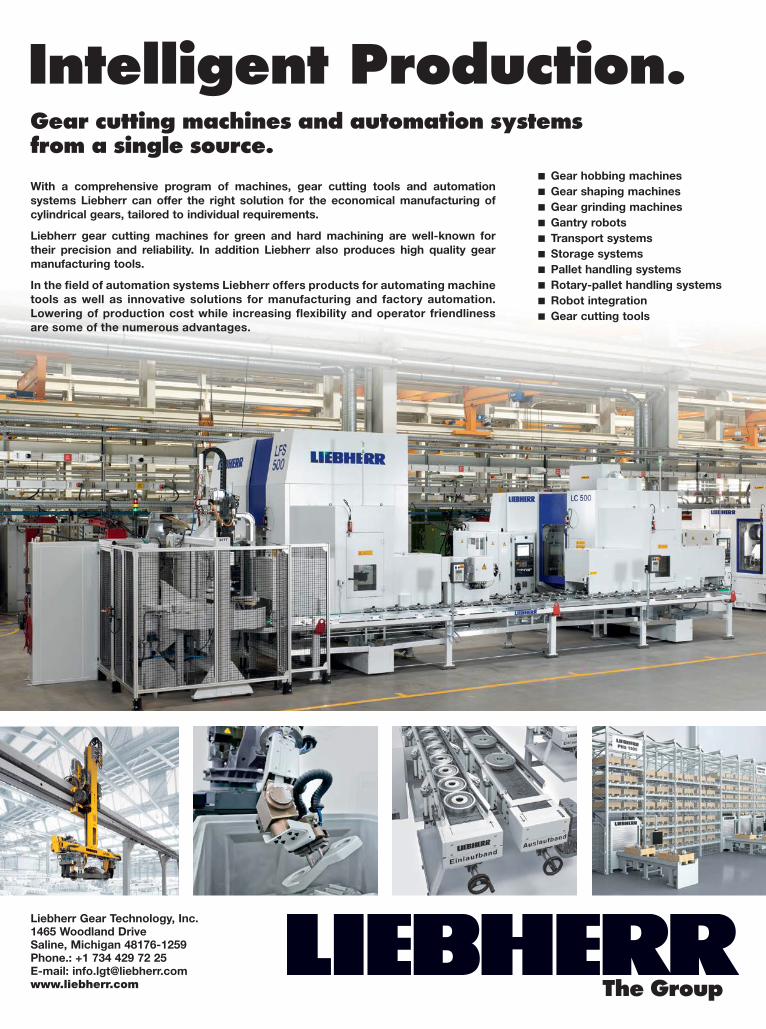
Intelligent Production.
With a comprehensive program of machines, gear cutting tools and automation systems Liebherr can offer the right solution for the economical manufacturing of cylindrical gears, tailored to individual requirements.
Liebherr gear cutting machines for green and hard machining are well-known for their precision and reliability. In addition Liebherr also produces high quality gear manufacturing tools.
In the field of automation systems Liebherr offers products for automating machine tools as well as innovative solutions for manufacturing and factory automation. Lowering of production cost while increasing flexibility and operator friendliness are some of the numerous advantages.
Gear hobbing machines Gear shaping machines Gear grinding machines Gantry robots Transport systems Storage systems Pallet handling systems Rotary-pallet handling systems Robot integration Gear cutting tools
Gear cutting machines and automation systems from a single source.
Liebherr Gear Technology, Inc.1465 Woodland DriveSaline, Michigan 48176-1259Phone.: +1 734 429 72 25E-mail: [email protected] The Group
2014-004_14 AZ Aufbau Image-MFT_Gear-Technology 4_GB_216x279-2.indd 1 05.05.14 14:14

EDITORIALPublisher & Editor-in-ChiefMichael [email protected] Publisher & Managing EditorRandy [email protected] EditorJack [email protected] EditorErik [email protected] EditorAlex Cannella
Editorial ConsultantPaul R. Goldstein
Technical EditorsWilliam (Bill) Bradley, Robert Errichello, Octave Labath, P.E., John Lange, Joseph Mihelick, Charles D. Schultz, P.E., Robert E. Smith, Mike Tennutti, Frank Uherek
DESIGNArt DirectorDavid [email protected]
ADVERTISINGAssociate Publisher & Advertising Sales ManagerDave [email protected] CoordinatorDorothy [email protected] Sales AgentEric Wu, Eastco Industry Co., Ltd.Tel: (86)(21) 52305107Fax: (86)(21) 52305106Cell: (86) [email protected]
ON-LINEDigital Content ManagerKirk [email protected]
CIRCULATIONCirculation ManagerCarol [email protected] CoordinatorBarbara [email protected]
RANDALL STAFFPresidentMichael GoldsteinAccountingLuann Harrold
RANDALL PUBLICATIONS LLC1840 JARVIS AVENUEELK GROVE VILLAGE, IL 60007(847) 437-6604FAX: (847) 437-6618
THE GEAR INDUSTRY’S INFORMATION SOURCEwww.geartechnology.com
Stay Connected
Follow us on Twittertwitter.com/#!/Gear_Technology
Connect with us on LinkedInwww.linkedin.com/groups/Gear-Technology-Magazine-3893880
Subscribe Onlinewww.geartechnology.com/subscribe.htm
Buyers Guide: Recently Added
The Gear Technology Buyers Guide is your fastest way to find information on gear industry product and services vendors. Check back often, because we’re always improving the site and adding new companies to the listings:
Upcoming Webinar
Register today for 3M’s upcoming webinar on advanced grinding tech-nologies. This webi-nar, presented by Gear Technology, will also feature a presentation by Dr. Andreas Mehr of Liebherr Verzahntechnik. The webinar takes place Tuesday, September 22 at 11:00 a.m., but if you sign up now, you’ll get an automatic reminder e-mail prior to the event.
www.geartechnology.com/3MWebinar
This Month’s Highlighed Topics:
Every month we feature two topics from our extensive archive of 31 years of back issues. On the home page you can find a sampling of these key topics, along with links to the archive. Stop by geartechnology.com to see this month’s featured topics:
• Gear Noise• Lubrication
6 GEAR TECHNOLOGY | August 2015[www.geartechnology.com]
GT extras

11715 Main Street, Roscoe, IL 61073815-623-2168
www.forestcitygear.com
Your trusted source for
Smart Move!
For the Last 60 Years,We’ve Never Stopped LearningSearching for a higher gear-producing IQ? Make the smart choice today.
Booth #1826

Our Technologies, Your Tommorow
©2014 Mitsubishi Heavy Industries America
Increased Capacity is AVAILABLE NOW for Immediate Delivery...
HOBBIN G / S HAPING / S HAVING / GRIND ING
...FROM THE WORLD’S LARGEST INVENTORY OF CNC GEAR CUTTING MACHINES.No need to scour the globe searching for a machine in order to quickly fi ll increased production needs. With our vast inventory of new machines right here in the U.S.A., Mitsubishi Heavy Industries America can deliver the machine you need—in perfect condition, optimized for maximum output and all at a moments notice.
Learn more about the world-class Mitsubishi gear machines available from stock at www.mitsubishigearcenter.com or contact sales at 248-669-6136.
MHIA_Stock Ad FINAL.indd 1 7/15/14 3:11 PM
BOOTH #1004

publisher's page
Publisher & Editor-in-ChiefMichael Goldstein
Experts Work Here
9August 2015 | GEAR TECHNOLOGY
Our goal at Gear Technology for the past 31 years has been to bring you the best possible technical information about gear manufacturing. We serve as the industry’s educational resource, explaining the technology not only so that you can under-stand it, but also so that you can make use of it in your gear-related business.
We’re serious about making sure that information is reli-able, accurate and up-to-date. That’s why we have our techni-cal articles reviewed by experts before we publish them. We rely heavily on our roster of technical editors, all of whom have decades of experience solving gear related problems, teaching gear-related classes and seminars, and working with the AGMA to write the standards we all rely upon. Our authors and con-tributors are without a doubt among the most knowledgeable people in the gear industry. In short, when you’re reading Gear Technology, you can be sure that you’re reading the work of experts.
Nowhere is that more true than in our “Ask the Experts” col-umn. Last issue we announced that we’ll be hosting a live, in-person version of that column in our booth (#2030) at Gear Expo in October. We’ve lined up a panel of experts who should be able to answer almost any question you might have related to gears. So far, those experts include:• Dr.-Ing. Nicklas Bylund, Sandvik Coromant, Manager
Engineering Competence Center• Dr.-Ing. Andreas Mehr, Liebherr Verzahntechnik,
Technology Development, Grinding and Shaping• Dr. Hartmuth Müller, Klingelnberg, Chief Technical Officer• John O’Neil, Star SU, Engineering Manager-Gear Tools• Chuck Schultz, Gear Technology technical editor and
Principal, Beyta Gear Service• Dr. Hermann J. Stadtfeld, Gleason Corporation, VP Bevel
Gear Technology/R&D• Prof. Dr.-Ing. Karsten Stahl, Technical University of
Munich, Head of the Gear Research Center (FZG)
• Frank Uherek, Rexnord, Principal Engineer, Gear Engineering Software Development
I’m sure you’ll recognize many of these names as regular con-tributors both to Gear Technology and the industry. We’re in the process of finalizing the roster and expect another expert or two to round out the panel before the show.
We’ve tried to organize topics that will be of greatest interest to the largest number of visitors. There will be four sessions at our booth, with appropriate experts sitting on the panel in each session:• GEAR GRINDING — Tuesday, October 20, 10:30 a.m.• CUTTING TOOLS — Tuesday, October 20, 2:00 p.m.• GEAR DESIGN — Wednesday, October 21, 10:30 a.m.• ASK ANYTHING — Wednesday, October 21, 2:00 p.m.
I encourage all of you to take advantage of this tremendous opportunity. Go to Gear Expo, visit Booth #2030, and make use of the expertise we’ve assembled. Nowhere else can you get your gear-related questions answered in person by the foremost experts in the industry.
We will be video recording the sessions and making them available online after the show, so even if you aren’t able to attend Gear Expo, you can still participate. In fact, we invite all of our readers to submit their challenging gear manufacturing problems to us now, for our expert panel. We’ll get your ques-tions answered either as part of the live event or as part of our ongoing column in the magazine. Either way, everybody bene-fits. Please send your questions to Jack McGuinn, Senior Editor ([email protected]) or use the “Ask the Expert” link on our home page to submit your question online.
We’re looking forward to seeing the experts answer your questions at the show.
P.S. When you go to www.geartechnology.com, type “basics” in the search box to see a wide variety of articles from our archive that demonstrate the educational focus that’s been our hallmark for more than 31 years.
Gear TechnologyExperts
THIS EXIT
BOOTH 2030
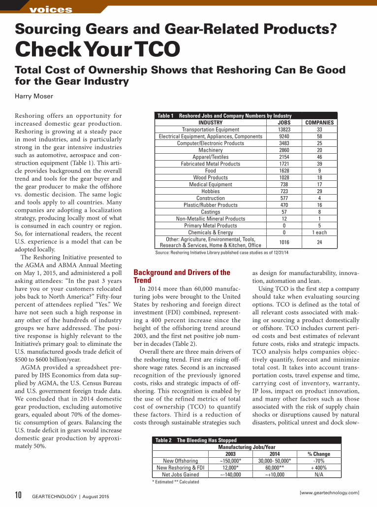
Reshoring offers an opportunity for increased domestic gear production. Reshoring is growing at a steady pace in most industries, and is particularly strong in the gear intensive industries such as automotive, aerospace and con-struction equipment (Table 1). This arti-cle provides background on the overall trend and tools for the gear buyer and the gear producer to make the offshore vs. domestic decision. The same logic and tools apply to all countries. Many companies are adopting a localization strategy, producing locally most of what is consumed in each country or region. So, for international readers, the recent U.S. experience is a model that can be adopted locally.
The Reshoring Initiative presented to the AGMA and ABMA Annual Meeting on May 1, 2015, and administered a poll asking attendees: “In the past 3 years have you or your customers relocated jobs back to North America?” Fifty-four percent of attendees replied “Yes.” We have not seen such a high response in any other of the hundreds of industry groups we have addressed. The posi-tive response is highly relevant to the Initiative’s primary goal: to eliminate the U.S. manufactured goods trade deficit of $500 to $600 billion/year.
AGMA provided a spreadsheet pre-pared by IHS Economics from data sup-plied by AGMA, the U.S. Census Bureau and U.S. government foreign trade data. We concluded that in 2014 domestic gear production, excluding automotive gears, equaled about 70% of the domes-tic consumption of gears. Balancing the U.S. trade deficit in gears would increase domestic gear production by approxi-mately 50%.
Background and Drivers of the Trend
In 2014 more than 60,000 manufac-turing jobs were brought to the United States by reshoring and foreign direct investment (FDI) combined, represent-ing a 400 percent increase since the height of the offshoring trend around 2003, and the first net positive job num-ber in decades (Table 2).
Overall there are three main drivers of the reshoring trend. First are rising off-shore wage rates. Second is an increased recognition of the previously ignored costs, risks and strategic impacts of off-shoring. This recognition is enabled by the use of the refined metrics of total cost of ownership (TCO) to quantify these factors. Third is a reduction of costs through sustainable strategies such
as design for manufacturability, innova-tion, automation and lean.
Using TCO is the first step a company should take when evaluating sourcing options. TCO is defined as the total of all relevant costs associated with mak-ing or sourcing a product domestically or offshore. TCO includes current peri-od costs and best estimates of relevant future costs, risks and strategic impacts. TCO analysis helps companies objec-tively quantify, forecast and minimize total cost. It takes into account trans-portation costs, travel expense and time, carrying cost of inventory, warranty, IP loss, impact on product innovation, and many other factors such as those associated with the risk of supply chain shocks or disruptions caused by natural disasters, political unrest and dock slow-
Sourcing Gears and Gear-Related Products?
Check Your TCOTotal Cost of Ownership Shows that Reshoring Can Be Good for the Gear IndustryHarry Moser
Table 1 Reshored Jobs and Company Numbers by IndustryINDUSTRY JOBS COMPANIES
Transportation Equipment 13823 33Electrical Equipment, Appliances, Components 9240 58
Computer/Electronic Products 3483 25Machinery 2860 20
Apparel/Textiles 2154 46Fabricated Metal Products 1721 39
Food 1628 9Wood Products 1028 18
Medical Equipment 738 17Hobbies 723 29
Construction 577 4Plastic/Rubber Products 470 16
Castings 57 8Non-Metallic Mineral Products 12 1
Primary Metal Products 0 5Chemicals & Energy 0 1 each
Other: Agriculture, Environmental, Tools, Research & Services, Home & Kitchen, Office 1016 24
Source: Reshoring Initiative Library published case studies as of 12/31/14
Table 2 The Bleeding Has StoppedManufacturing Jobs/Year
2003 2014 % ChangeNew Offshoring ~150,000* 30,000- 50,000* -70%
New Reshoring & FDI 12,000* 60,000** + 400%Net Jobs Gained ~-140,000 ~+10,000 N/A
* Estimated ** Calculated
10 GEAR TECHNOLOGY | August 2015[www.geartechnology.com]
voices

USACH
VOUMARD
The Hardinge Grinding Group consists of six brands of products offering you the following grinding solutions:
• Universal OD / ID • Production OD / ID • Surface, Profile & Creep feed • CNC Jig
KELLENBERGER
JONES & SHIPMAN
HAUSER
TSCHUDIN
www.HardingeGrindingGroup.com • 800-843-8801
STOP BY BOOTH # 2317

downs. It also helps to forecast the future impact of wage and currency changes.
Much of companies’ efforts to deal with complex global supply chains is eliminated or drastically reduced by reshoring. Longer-term forecasting, monitoring of suppliers and regulatory compliance offshore is found to be waste when measured against the use of prov-en, local suppliers.
The not-for-profit Reshoring Initiative offers the free TCO Estimator, available on reshorenow.org. The initiative offers many resources to help companies make sourcing decisions (Table 3). Reshoring tools can also be used by gear salesmen to convince customers of the benefit of sourcing domestically, especially for cus-tom gears.
Below are some examples of gear mak-ers who have chosen U.S. production or sourcing over offshore.• Bison Gear and Engineering Corp.
moved production of electric motors and gears from China to St. Charles, IL, creating 10 jobs.
– Reasons: Cost, quality, lead time and lean manufacturing
• Pequea Machine Inc. brought produc-
tion from China to the U.S., bring-ing contract work to Buck Co. (PA foundry) and Circle Gear (IL machine shop), and creating up to 20 new future jobs (Ref. 1).
– Reasons: Quality (25% of gear boxes from China failed due to substan-dard metals used); equivalent price (cost was about $900 to produce gearboxes in the United States, and between $800-$900 in China); Total cost
• ZF Group, a Supplier for Chrysler, brought production from Germany to Gray Court, SC and Detroit, bring-ing 1,650 jobs in South Carolina, and
some additional jobs in Michigan. ZF originally began building gearboxes for wind turbines in Gainesville, GA with a $98 million investment, adding 250 jobs.
– Reasons: Time to market, proximity to market
• Metem Corp., which makes gas tur-bines and aerospace industry prod-ucts, is expanding its Parsippany, NJ plant over plants in Pennsylvania and Hungary. Metem’s CEO on the com-pany’s growth: “One of the great things about gas turbines is that the U.S. really has a leadership position in that technology. We are seeing our custom-
Table 3 Resources available to readers• Calculate TCO with the Total Cost of Ownership Estimator, a free online tool to help evaluate
sourcing alternatives and to make a case when selling against offshore competitors (www.reshorenow.org/tco-estimator/).
• Watch an in-depth webinar on reshoring and TCO (www.youtube.com/watch?v=uAh7FBZu2xA).• Visit our Reshoring Library (www.reshorenow.org/library/), which contains 2,400+ linked articles
on reshoring. Data from these articles can be accessed and sorted through the advanced search function.
• Have a story to tell? Submit your reshoring success story on our Case Studies feature (www.reshorenow.org/case-studies/). All valid cases will be posted, and we will send the submitter a Manufacturing is Cool T-shirt -Made in USA of U.S. cotton.
• Use our Economic Development Program to strengthen your region by replacing imports with local production (http://reshorenow.blogspot.com/2014/12/reshoring-initiatives-economic.html).
• See our Blog for recommendations on skilled workforce development in your area (http://reshorenow.blogspot.com/2014/02/the-reshoring-initiative-offers-skilled.html).
• We also track reshoring and nearshoring in Mexico and Canada and cooperate with many other countries in their efforts to be more self-sufficient.
12 GEAR TECHNOLOGY | August 2015[www.geartechnology.com]
voices

THINK INSIDE THE BOX...AND YOU’ll SEE ALL WE CAN DO!
See ourmachinesin action!
German Machine Tools of America
4630 Freedom Drive | Ann Arbor, MI 48108 | 734-973-7800 | www.gmtamerica.com | Email: [email protected]
Call Scott Knoy today for all the details.
734-973-7800
GMTA_AD5030_Gear Technology_June 2015
GMTA brings a wide variety of high quality machine tools for component production, plus laser welding technology, robotics, advanced automation, and tooling to your door, backed by application engineering, onsite commissioning, local service and after-sale support. We’re not all things to all people, but we’re getting closer, every day.
What this means to your production is actually quite simple…a single source, with all its advantages, those productive and those financial, who can solve your output and workflow challenges, because they’ve seen and solved similar ones for many companies like yours.
Whether your end product requires multiple machining steps, laser welding, pre- and post-cleaning, robotic materials handling, special part articulation or other
functional operations, look to a leading integrator of machining systems for the automotive,
off-highway, energy and heavy equipment sectors. You
only need to remember four letters… GMTA.

ers bring turbine manufacturing back to the U.S. from other parts of the world.”
– Reasons: Highly skilled workers, access to universities, advanced manufacturing
ConclusionThe Reshoring Initiative publishes data (Ref. 3) annually to show that the current trend in manufacturing for the United States market is to source domestically. With 3–4 million manufacturing jobs still offshore, we see huge potential for even more growth and hope this data will motivate more companies to reeval-uate their sourcing and site selection decisions. Making better-informed deci-sions through the use of TCO and gain-ing a competitive advantage through sustainable strategies will enable U.S. companies to locate more manufacturing closer to home and strengthen the U.S. economy.
We would like to build on the reshor-ing momentum achieved at the AGMA meeting. We have outlined (Table 3) our tools and programs that you can use. The best way to accelerate the trend is
to document and promote the successful cases. Therefore, we especially encour-age you to report the cases where you reshored, where you directly replaced an imported gear source or where your customer brought back product assem-bly and sourced gears from you. Reports can be made on our Case Studies feature. The resulting PDFs will be posted on the Reshoring Initiative website, and you can post on your site. Case submitters also receive a Manufacturing is Cool T-shirt, made in the USA of U.S. cotton.
References1. www.themadeinamericamovement.com/uncat-
egorized/pequea-machine-joins-the-reshoring-movement-reshores-part-production-for-better-quality/.
2. www.njbiz.com/article/20130130/NJBIZ01/130139989/Manufacturer's-expansion-in-Parsippany-expected-to-create-jobs-CEO-says.
3. www.reshorenow.org/content/pdf/2014_Data_Summary.pdf.
Your best investment. We’re now restoring outdated gear machines to like-new condition – and saving our customers thousands of dollars vs. a new machine purchase. With our exceptional engineering and in-house machining and grinding capabilities, EXCEL is the ‘perfect fit’ for CNC retrofits.
ExcEl-lEncE at work
815.270.1004 / www.excelgear.com
EXCEL CNC RETROFITS – SMART MOVE!
ready to Excel? contact:
Circa '80s shaper and hobber recently retrofit with powerful new FANUC CNC for a major aerospace manufacturer.
Booth #1619
Harry Moser founded the Reshoring Initiative to bring manufacturing jobs back to the United States after working for GF AgieCharmilles, starting as President in 1985 and retiring at the end of 2010 as Chairman Emeritus. Previously he worked for Disamatic U.S. for six years. Largely due to the success of the Reshoring Initiative, Harry was inducted into the Industry Week Manufacturing Hall of Fame 2010 and was named Quality Magazine’s Quality Professional of the Year for 2012. Moser participated actively in President Obama’s January 2012 Insourcing Forum at the White House, won the January 2013 The Economist debate on outsourcing and offshoring, and received the Manufacturing Leadership Council’s Industry Advocacy Award in 2014. He received a bachelor’s degree in mechanical engineering and a master’s degree in engineering from MIT in 1967, and he earned
an MBA from the University of Chicago in 1981.
sourcing
For Related Articles Search
at www.geartechnology.com
14 GEAR TECHNOLOGY | August 2015[www.geartechnology.com]
voices

Project1_Layout 1 6/16/15 11:28 AM Page 1

Index Bevel Gear Hobbing PackagePRODUCES GEARS WITH TOOTH HEIGHT IN A MODULE RANGE OF 0.6 TO 4 MM
Index recently developed a “bevel gear hobbing” package, which consists of a control cycle and four Index cutter heads with module-dependent inserts. Equipped with these features, the Index R200 and Index R300 turn-mill cen-ters become gear cutting machines on which spiral bevel gears can be produced from bar stock, with front and rear end machining, complete in one setup or as a pure two-spindle gear cutting machine.
By hobbing using a continuous index-ing method — which corresponds to the Klingelnberg Cyclo-Palloid meth-od — spiral bevel gears can be produced with constant tooth height in a module range of 0.6 to 4 mm.
Compared to the conventional process chain with classic gear cutting machines, users can achieve shorter cycle times and better geometry and position tolerances. And it is designed to be more flexible.
“The starting point of the development by Index lies in its own manufacturing governed by the principle: quality-determining components are made in-house,” said Dr. Volker Sellmeier, Index-Werke’s head of technology development. “When the tool holder production was reorganized several years ago, the decision was made to produce the required bevel gears ourselves.”
Due to their static, dynamic and thermal properties, the turn-mill centers of the Index R-series are suited to gear-cutting, pro-vided they are equipped with the “bevel gear hobbing” technol-ogy package. The R machines’ axis configuration with two mill-ing spindles on Y-B-axes running in hydrostatic bearings makes it possible to machine on the main and counter spindle simulta-neously in five axes.
The turn-mills’ ability to complete gear-part machining on the front and rear ends simultaneously is meant to shorten total cycle times and lower cost per piece.
“When we machine typical bevel gears with module 1.15 mm and approximately 25 teeth for our tool holders completely from bar stock, we achieve a cycle time of less than 3 minutes,” Sellmeier said. “The share of gear cutting amounts to about 30 seconds.”
In a classical gear process chain, the workpiece has to be set up on several individual machines for turning, drilling, and milling, gear cutting and deburring. Index’s approach is to run all operations on the turn-mill center. Bevel gears are turned, drilled, milled and finally cut on a single machine. Even brush-es for deburring can be set up. The soft machining process is thus completely autonomous, according to Index with a pro-cess-reliable gear quality of IT5 (according to DIN 3965). This is then followed by hardening. A final finishing process is usu-ally required only for the mounting distance and the polygonal shaft/hub connection.
In addition to bar stock machining, which is best primarily for small quantities, for series production the R machine can be used as a pure gear cutting machine, working on the main and counter spindles simultaneously.
“This requires the use of an automated workpiece-loading and unloading system that loads the blanks and removes the finished parts gently,” Sellmeier said. “We offer a quadruple gripper with two stations on the main and counter spindle that picks up the finished parts, rotates and then loads new blanks. This way we use the machine as a kind of double-spindle machine, cutting the time per piece in half.”
Two cutter heads are required per bevel gear. They differ slightly in their cutting circle radius in order to produce the longitudinal crowning. Index offers the cutter heads in four dif-ferent sizes that can be fitted with up to six carbide inserts and feature internal cooling.
In contrast to the typical Cyclo-Palloid method with an inter-locking cutter head, the Index method uses two separate cutter heads per bevel gear.
“The two cutter heads provide a larger number of cutting edges. This allows us to achieve a higher cutting performance,” Sellmeier said. “We also have more freedom for flank modifica-tions and correction of the contact pattern.”
Index also offers a control cycle they have developed. The user enters the same parameters as on a conventional gear cut-ting machine. These include, for example, machine distance, eccentricity and auxiliary angle. The cycle translates these val-ues into the movements of each axis so that at the end the same relative movements are effected as on a conventional gear cut-ting machine.For more information:Index CorporationPhone: (317) 770-6300www.indextraub.com
16 GEAR TECHNOLOGY | August 2015[www.geartechnology.com]
product news

Bonfiglioli 300 Series Planetary GearboxesDESIGNED FOR HARSH APPLICATIONS
Bonfiglioli´s 300 Series is designed for harsh applications where shock loadings and impacts are common.
Bonfiglioli´s ongoing mission to improve its planetary gearboxes for indus-trial applications has led to two new features that result in an easier and safer assembling/disassembling of the drive to/from the application. The new FDK and FZP versions feature an output hollow shaft that will make the series more effective and suitable for shaft mount assembly.
The hollow shaft solutions reduce the time and effort for the disassembling of the drive from the customer´s machine shaft, due to the new solution with the axial locking ring. The new product solutions make mounting and commissioning easi-er and faster thanks to the smarter design and allow for easier and more accurate screw tightening.
The cutting-edge design of the shrink disk will improve and speed up setup and commissioning. The hollow shaft with the two keys at 120° will allow full-rated torque and max-torque transmissions. The axial locking ring with threaded holes completes the solution for an easier and more reliable shaft mounting. The keyed hollow shaft is available in smaller sizes, ranging from 300 to 310 and will be included in the designation of the series with the acronym FDK; when the FZP version is available it will come in larger sizes from 311 to 325.
Another design component of the new 300 series is the splined hollow shaft which meets the DIN 5480 standard and offers the same bearings available in the current FP version. It provides double cen-tering for an aligned assembling of the solid shaft of the machine. Like the keyed hollow shaft, the splined hollow shaft also includes an axial locking key with thread-ed holes for easier mounting and grants full rated and max torque transmissions.
The new shrink disks prevent accidental mounting errors (even when dismounting and re-mounting the shrink disk) due to simpler design and visual-control of screw tightening torque. This design makes the 300 series now complete and effective for any shaft mounted requirements for all sizes and ratios. The series has a torque range of 1,000-1,287,000 Nm and gear ratios of 3.4-5,234.For more information:Bonfiglioli Riduttori S.P.A.Phone: +39 051 647 3932www.bonfiglioli.com
We are ready to meet your needs
• Latest Equipment• AS9100 Certified• Fast Delivery
• Talented Employees• ISO 9001-2008 Certified• Design & Engineering
425 Strempel St. Seguin, TX 78155 | (855) RAV GEARwww.RAVEGEARS.com| [email protected]
RAVE GEARS& MACHINING
RAVE GEARS& MACHINING
TALENT & TECHNOLOGY DRIVEN
TALENT & TECHNOLOGY DRIVEN
CURRENT customers in aerospace, racing, oil & other industries.
OUR BRAND-NEW, STATE-OF-THE-ART FACILITY IS PRODUCING THE HIGHEST QUALITY SPIRAL BEVEL, HYPOID, SPUR, AND HELICAL GEARS.
Booth # 1339
17August 2015 | GEAR TECHNOLOGY
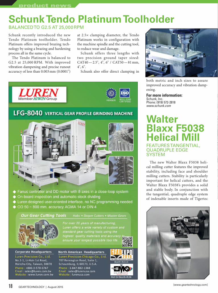
Schunk Tendo Platinum ToolholderBALANCED TO G2.5 AT 25,000 RPM
Schunk recently introduced the new Tendo Platinum toolholder. Tendo Platinum offers improved brazing tech-nology by using a brazing and hardening process all in the same cycle.
The Tendo Platinum is balanced to G2.5 at 25,000 RPM. With improved vibration dampening and precise runout accuracy of less than 0.003 mm (0.0001")
at 2.5× clamping diameter, the Tendo Platinum works in configuration with the machine spindle and the cutting tool, to reduce wear and damage.
Schunk offers three lengths with two precision ground taper sized: CAT40 — 2.5", 4", 6" / CAT50 — 81 mm, 4", 6".
Schunk also offer direct clamping in
both metric and inch sizes to assure improved accuracy and vibration damp-ening.For more information:Schunk, Inc.Phone: (919) 572-2818www.schunk.com
Walter Blaxx F5038 Helical MillFEATURES TANGENTIAL, QUADRUPLE EDGE SYSTEM
The new Walter Blaxx F5038 heli-cal milling cutter features the improved stability, including face and shoulder milling cutters. Stability is particularly important for helical cutters, and the Walter Blaxx F5038’s provides a solid and stable body. In conjunction with the tangential, quadruple edge system of indexable inserts made of Tigertec
18 GEAR TECHNOLOGY | August 2015[www.geartechnology.com]
product news
SEE IT IN YOUR RESULTS
ARROW GEAR’S COMMITMENT TO QUALITYWHEN FAILURE ISN’T AN OPTION
When you’re hovering at 5,000 feet, gearbox failure is simply not an option. In fact, few applications demand the quality and precision crucial to the helicopter industry.
For more than 60 years, Arrow Gear has remained an industry leader by consistently supplying aerospace gears that meet the most demanding quality requirements. Today, our products can be found in critical in-flight applications around the world. It’s no wonder that top suppliers of civilian and military helicopters trust in Arrow for the gears that keep them flying. Because especially in aerospace, quality is crucial.
See it in Your Results.Call 630-969-7640 or visit arrowgear.com
2301 CURTISS STREET, DOWNERS GROVE, IL 6051 5 | 630-969-7640 | ARROWGEAR.COM

19August 2015 | GEAR TECHNOLOGY
SEE IT IN YOUR RESULTS
ARROW GEAR’S COMMITMENT TO QUALITYWHEN FAILURE ISN’T AN OPTION
When you’re hovering at 5,000 feet, gearbox failure is simply not an option. In fact, few applications demand the quality and precision crucial to the helicopter industry.
For more than 60 years, Arrow Gear has remained an industry leader by consistently supplying aerospace gears that meet the most demanding quality requirements. Today, our products can be found in critical in-flight applications around the world. It’s no wonder that top suppliers of civilian and military helicopters trust in Arrow for the gears that keep them flying. Because especially in aerospace, quality is crucial.
See it in Your Results.Call 630-969-7640 or visit arrowgear.com
2301 CURTISS STREET, DOWNERS GROVE, IL 6051 5 | 630-969-7640 | ARROWGEAR.COM

Silver, users of the new Walter Blaxx F5038 helical milling tool achieve top values in process reliability and cost effi-ciency. In comparison to convention-al tool solutions of this type, machin-ing times have been reduced by up to 30%. The accurately arranged, preci-sion indexable inserts produce step-free shoulders.For more information:Walter USA, LLCPhone: (800) 945-5554www.walter-tools.com
Products for the Aircraft
Manufacturing Industry
Christmas Tree Forms BroachCreate highly accurate form on turbine rotor disk blade of aircraft, ships and generators.
Surface Broaching MachineHigh performance and speed
production of gas turbine rotors.
Visit Our New Production Facilities ~717 Pushville Rd.
Greenwood, IN 46143
Dave Petrimoulx586-764-2263
www.nachiamerica.com
Products for the Aircraft
Manufacturing Industry
Cimcool Cimperial 861 Metalworking FluidINCREASES TOOL LIFE AND PROVIDES SUPERIOR LUBRICITY
Cimcool recently announced the release of Cimperial 861 with InSol technology, a hybrid lubricity, semi-synthetic met-alworking fluid, which recently received approval under Boeing BAC5008 RevU.
Cimperial 861 with InSol technology
is designed for heavy-duty machining of non-ferrous and ferrous metals includ-ing 6,000 and 7,000 series aluminum, stainless steels, titanium and other exotic alloys. It can also be used for grinding and is formulated to deliver extended sump life. The product is designed to increase tool life and provide superi-or lubricity while remaining low foam-ing for today’s demanding high-pressure applications. In addition, Cimperial 861 with InSol technology has low chemical odor and is mild to the skin.
“Cimcool Fluid Technology has devel-oped a hybrid semi-synthetic to maxi-mize tool life without the compromis-ing part quality on aerospace alloys,” Aerospace Product Manage Kyle Walker said. “The benefit will be one fluid that handles machining needs by delivering superior cooling and lubricity direct-ly to the point of cut. Cimperial 861 with InSol technology is a great exam-ple of how we support customers in the aerospace industry using technology approved by Boeing. The hybrid com-bination of InSol Technology in a semi-synthetic metalworking fluid delivers superior performance when compared to other semi-synthetic or micro-soluble technology.”
By design, Cimperial 861 with InSol technology is stain resistant when tested on 6,000 and 7,000 series aluminum, titanium and stainless steels alloys.For more information:Cimcool Fluid TechnologyPhone: (888) 246-2665www.cimcool.com
20 GEAR TECHNOLOGY | August 2015[www.geartechnology.com]
product news
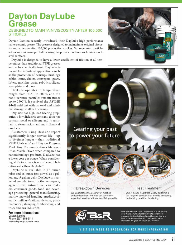
Dayton DayLube GreaseDESIGNED TO MAINTAIN VISCOSITY AFTER 100,000 STROKES
Dayton Lamina recently introduced their DayLube high-performance nano-ceramic grease. The grease is designed to maintain its original viscos-ity and adhesion after 100,000 production strokes. Nano-ceramic particles act as sub-microscopic ball bearings to provide continuous lubrication to steel surfaces.
DayLube is designed to have a lower coefficient of friction at all tem-peratures than traditional PTFE greases and to be chemically inert. DayLube is meant for industrial applications such as the protection of bearings, bushings cables, cams, chains, conveyors, gears, lifters, machine parts, robotics, slides, wear plates and more.
DayLube operates in temperature ranges from -40°F to 800°F, and the nano-ceramic particles remain intact up to 2500°F. It survived the ASTME 4-ball weld test with no weld and mini-mal damage to all ball bearings.
DayLube has high load-bearing prop-erties, a low dielectric constant, does not contain metal or silicone and is resis-tant to steam, acids, and most chemical products.
“Customers using DayLube report significantly longer service life — up to 10-times longer — than traditional PTFE lubricants” said Dayton Progress Marketing Communications Manager Brian Marsh. “Even when compared to nanotechnology products, DayLube has a lower cost per ounce. When consider-ing all factors there is not a better lubri-cating value than DayLube.”
DayLube is available in 16-ounce tubes and 16-ounce jars, as well as 1-gal-lon and 5-gallon pails. DayLube is mar-keted mainly towards the aerospace, agricultural, automotive, can mak-ers, consumer goods, food and bever-age processing, general manufacturing, marine, material handling, medical/sci-entific, military/national defense, phar-maceutical, stamping & fabricating, and truck and bus industries.For more information:Dayton LaminaPhone: (937) 859-5111www.daytonprogress.com
21August 2015 | GEAR TECHNOLOGY

Mitutoyo Legex 4 CNC MachinePROVIDES HIGH-ACCURACY MEASUREMENTS
Mitutoyo Amer ica C or p orat ion recently released the latest Legex CNC coordinate measuring machine (CMM). The Legex 4 delivers accu-rac y in length measurement of E0,MPE = (0.28+L/1000) μm.
With the advancement of scientific and industrial technologies and driving demand for improvements in high-accuracy manufacturing, Mitutoyo Legex produces applications such as ultra-precise molds, components and aspherical lenses in the automo-tive, aviation and medical instrument industries, and calibration of master gages for research institutes. To meet these needs, Mitutoyo started from the elemental technology level and worked upward, with the aim of eliminating all possible sources of measurement error.
Key features include: sources of stat-ic and dynamic error minimized to realize measurement accuracy of 0.28 μm; fixed-bridge structure with mov-ing table; base is made from spheroidal graphite (ductile) cast iron in a sealed-structure design to provide high rigidity
and
v i b r a t i o n -attenuating char-
a c t e r i s t i c s ; high-rigidity structure and feed mechanisms increase accura-cy and improve cycle times; thermally symmetric structure features full covers around the main body to reduce possible impact in ambient temperature changes; vibration-dampening unit is standard; an air server stabilizes the air tempera-ture to 20°C±0.1°C.For more information:Mitutoyo America CorporationPhone: (888) 6488-9696www.mitutoyo.com
Mahr MarShaft Scope 250MEASURES PARTS UP TO 250 MM IN LENGTH
Mahr Federal recently introduced a new addition to its growing family of opti-cal shaft measurement systems. The MarShaft Scope 250 plus features an accurate matrix camera with four mil-lion pixels. The system measures parts up to 250 mm in length and 40 mm in diameter. It features an MPE (Maximum Permissible Error) of less than 1.5 microns + L/40 when measuring diam-eter and 3 microns + L/125 when mea-suring length.
“The MarShaft Scope 250 plus is a very compact, attractively designed sys-tem that provides out-of-the-box func-tionality,” said Patrick N. Nugent, vice
president of metrology systems for Mahr Federal. “It is extremely easy to use, and very fast. In our lab here in Providence,
22 GEAR TECHNOLOGY | August 2015[www.geartechnology.com]
product news

Reishauer AGZürich / Switzerland+41 44 832 22 [email protected]
Gear Grinding in Swiss Precision
Since Reishauer Switzerland invented Continuous Generat-ing Gear Grinding, we have constantly been pushing the per-formance of our machines to new heights: Higher produc-tivity – higher accuracy. That‘s why the leading automotive companies rely on Reishauer.
Reishauer CorporationElgin IL / USA+1 847 888 38 [email protected]
Gear Technology_EN_203x273+3_SeptemberProposal.indd 1 18.03.2014 13:23:52
BOOTH #2242

we measured 28 features on a sample shaft in less than ten seconds, and a cus-tomer part with only seven required fea-tures in less than three seconds.”
One key to the system’s speed is the high-resolution CMOS matrix cam-era with a live image field of view of 40 × 24 mm, enabling it to capture an entire part diameter in a single view. With Z-axis positioning speeds of up to 200 mm/second and an image acqui-sition rate of over 120 images per sec-ond, measurements are performed faster than the blink of an eye. Zoom func-
tions allow measurement of the small-est details such as chamfers and radii, which can be difficult and in some cases even impossible to test, with convention-al measuring methods.
MarShaft Scope 250 plus can be oper-ated entirely on the integrated touch screen, or via a keyboard and mouse if desired. MarWin-based EasyShaft soft-ware enables the precision measure-ment of diameters, lengths, contour fea-tures, and form and position tolerances in accordance with standards, and offers many new evaluation and documen-
tation options. EasyShaft runs on the Windows operating system and is com-patible with other Windows applications and printers.For more information:Mahr Federal, Inc.Phone: (401) 784-3100www.mahr.com
Dillon 1018 CR Steel Full Grip JawsREDUCE DISTORTION AND PROVIDE MORE FRICTION
Dillon Manufacturing recently intro-duced full grip jaws made of 1018 CR steel from 6" to 15" in diameter, with heights of 2", 4" and 6". These heat treat-able and weldable steel jaws allow for complete gripping of the work piece - to maintain repetitive accuracy. This type of jaw reduces distortion and provides more friction for drives during turning operations.
With close tolerances and concentric-ity maintained, they are meant for appli-cations such as valves, cylinders, special-ty wheels and gears, housings and enclo-sures, adaptors and connectors, alumi-num and steel shells, flanges, retainer rings, and other thin-walled parts such as automotive smog control air pump rotors, gas turbine parts, thin-wall tub-ing and cylinder liners for diesel engines and more.For more information:Dillon Manufacturing, Inc.Phone: (800) 428-1133www.dillonmfg.com
24 GEAR TECHNOLOGY | August 2015[www.geartechnology.com]
product news

Siemens Sinumerik Blackline PanelsENABLE RAPID INTERACTION WITH THE USER INTERFACE
The Sinumerik blackline panels OP 015 black and OP 019 black are a new generation of operator panels for the Sinumerik 840D sl CNC system and offer new options for machine operation. The inductive sensor technology enables rapid interaction with the user interface even when the operator is wearing gloves. Similarly, it prevents incorrect entries, for example caused by the heel of the operator‘s hand.
The 19-inch display of the OP 019 black can show all the entries made in widescreen format at a glance. The OP 015 black also features an alphanu-merical keypad on the right that can be operated via touch control. This feature means that the 15-inch display is not restricted by the superimposed keypad during data entry, which ensures clear and efficient operation. Both black-line panels also have an integrated glass panel on the front side and are designed with IP65 (OP 019 black) and IP66 (OP 015 black) degrees of protection. They are resistant to liquids and dust and can be operated even under harsh indus-trial conditions. An integrated key lock helps safeguard against operating errors. The operator panel can provide a basic machine display, with three or four channels showing up to 13 axes.
The blackline panels also feature durable LED background lighting, pro-viding 40 percent energy-savings com-pared to conventional neon lamps.
In combination with the Sinumerik 840D sl control, for use on high-end milling, turning, grinding and laser cut-ting machine tools, the blackline panels can be used as an operating and pro-gramming station for aerospace com-posite machining, power generation and medical part manufacturing, in addition to tool- and mold-making, rotary index-ing machines and in shopfloor manufac-turing.For more information:Phone: (800) 879-8079www.usa.siemens.com
Manufacturers of:Broaches— Spline Broaches— Fine Pitch Gear Broaches— Form Broaches— Serration— BearingsShaper Cutters— Disk Shapers— Shank Shapers— Hex and Square Cutters— Special Form CuttersInspection— Master Gears— Go–No Go Gages— Posiloc Arbors— “Quick Spline” Software
1605 Industrial DriveAuburn, CA 95603Phone: (530) 885-1939Fax: (530) 885-8157
and Universal Gear
Call 530-885-1939 or visit www.broachmasters.com
PRECISION PERFORMANCE PERFECTIONEvery Time, The First TimeThe quality and precision of our broaches and gears have won customers world-wide (and beyond!) – from the smallest gearshop to NASA and the Mars Rover to the F35.
Precision manufacturing, modern equipment, advanced technology, and quality control, balanced with talented craftsmanship, means you get nothing but the very best.
For our engineers, troubleshooting and design flexibility are standard
procedure. Having the ability to manufacture and repair tooling while running prototype and
production parts gives you a distinct advantage
over your competition.
As a complete source for all your tooling and production needs,
Broach Masters/Universal Gear will supply you with the highest quality products and services that you and your customers expect.
25August 2015 | GEAR TECHNOLOGY

Birchwood Cold Presto Black ProcessFORMS NON-DIMENSIONAL COATING THICKNESS OF 0.5 MICRON
Birchwood Technologies now offers three mini systems for use in small batch metal finishing at low temperatures. Mini systems are designed for manu-facturers looking to add in house capa-bilities but do not have the necessary volume or space for a full sized process line. Birchwood Technologies offers these blackening solutions for the Presto Black and TruTemp processes for iron and steel parts, and the Lumiclad process for aluminum parts.
The cold Presto Black process forms a non-dimensional coating thickness of less than 0.5 micron thickness and is designed for components that require a black finish for visual appeal. Presto Black is a short fifteen-minute process that provides high corrosion resistance and is tested for up to 800 hours humid-ity exposure when sealed with appro-priate rust preventive. The Presto Black process offers a friable crystal structure that serves as a sacrificial barrier on slid-ing surfaces to protect the underlying steel itself from galling and deformation.
The low temperature TruTemp pro-cess forms a durable satin black magne-tite coating, 0.5 micron thick, with no effect on material hardness or tensile strength. The sealed finish withstands up to 100 hours of neutral salt spray or several hundred hours of humidity, and protects the metal surface during ship-
ment & storage as well as in service. TruTemp black oxide operates effective-ly with alkaline chemistry that does not embrittle metal or create unsightly salt bloom in and around recessed part areas.
The Lumiclad process forms a non-dimensional black oxide finish on all aluminum surfaces that is durable, clean and tightly adherent to the metal sub-strate. The Lumiclad process develops a uniform coating thickness of 1.5 microns that will not close down hole diameters or change critical part dimensions. The smooth black finish has a slightly porous crystal structure that absorbs an optional topcoat such as a dry-to-touch sealant, light oil, or clear polymer.
All three processes utilize a conven-tional seven-tank immersion process line, and operate at low or room temper-ature, making the processes easy and safe to operate in-house. Mini systems are designed for short run sporadic produc-tion because the lines can be sealed and stored, with the chemicals in the buck-ets, for six to twelve months.For more information:Phone: (952) 937-7931www.birchwoodtechnologies.com
26 GEAR TECHNOLOGY | August 2015[www.geartechnology.com]
product news

POWERFUL CONNECTIONS
REGISTER TODAY FOR THE DRIVE TECHNOLOGY SHOW OF THE YEAR!
OCTOBER 20-22, 2015 DETROIT, MI
COBO CENTER
THE DRIVE TECHNOLOGY SHOW
GEAR EXPO 2015 brings together the full range of experts — design, manufacturing, application engineering — all in the same place — Cobo Center, Detroit, October 20–22.
From a single gear to complex drives, GEAR EXPO covers it all…
• More exhibitors — from gear making machines to systems integrators.
• More education sessions — from metallurgy and geometry to maximizing power density.
• More attendees — buyers and makers from automotive, construction, mining, agriculture — wherever high-performance drives are critical.
• More solutions — meet the experts and evaluate your capabilities.
GEAR EXPO 2015 is the place to be.
• Make powerful connections.
• See the latest technology in action.
• Get the inspiration you need to take your products to the next level.
Improved drive technology is critical to achieving higher efficiencies and longer service life. All the information and answers you need will be at GEAR EXPO 2015.
VISIT www.gearexpo.com/GETECHUse code GETECH when registering.

TDM Global Line SoftwareTAILORED TO INTERNATIONAL MANUFACTURERS WITH GLOBAL PRODUCTION SITES
TDM Systems recently launched its new software module, TDM Global Line. TDM Global Line is tailored to interna-tional manufacturers with global pro-duction sites. With new software archi-tecture and data compression, all of the centrally defined tool data and graphics are available at each production facility with the click of a mouse. Customers of TDM Systems can expand their central
application to other plants. TDM Global Line is compat-ible with the exist-ing TDM database applications.
In addit ion to performance, TDM Systems placed an emphasis on user-friendly handling. For example, the Google-l ike tool s e arch prov ides
quick results that can be listed by item, tool assembly and tool list. The cus-tomer can also individually configure their information view on the screen using widgets, depending on their own requirements. A completely new and modern software design has been devel-oped for TDM Global Line.
With the new software module, cus-tomers can manage user rights and man-
dates in one central location. When entering data, concurrent data valida-tion also recognizes incorrect entries and forgotten mandatory fields. TDM cus-tomers can also use the initial booking functions that are already included in the first module 1.0. This allows the tool usage to be recorded in the connected plants.For more information:Phone: (847) 605-1269www.tdmsystems.com
Mitutoyo MeasurLink 8.0RE-INTRODUCES THE GAGE MANAGEMENT MODULE
Mitutoyo America Corporation recent-ly announced the latest version of MeasurLink software with a variety of functional improvements. MeasurLink 8.0 builds on the previous version, allow-ing an operator to collect data from most measuring instruments and analyze, monitor and manage the results in real-time.
The latest version of the data man-agement software reintroduces the gage management module, along with sup-port for managing multiple measure-ment specifications. The gage manage-ment module assists users in develop-ing, maintaining, organizing and manag-ing information about the gages, includ-ing service intervals, GR&R dates, recall dates and general gage event history.
MeasurLink is available with floating/concurrent license options for multi-seat packages. This is an option to include more users without purchasing addition-al seats. Upgrades can be integrated dur-ing installation or added to an existing installation.For more information:Mitutoyo America CorporationPhone: (630) 820-9666www.mitutoyo.com
28 GEAR TECHNOLOGY | August 2015[www.geartechnology.com]
product news
WELL MAINTAINEDMachine Tools
from Germany
Think SMART and ECONOMICAL
TECO Werkzeugmaschinen GmbH & Co. KGWestring 1, 40721 Hilden, Germany
Tel.: +49 2103/3682-0 / Fax: +49 2103/3682-20E-mail: [email protected]
see details + pictures underwww.teco-germany.com
And also gear hobbers, shapers + other machine tools
Our machines run through tests, are supplied with certificates and to be seen under power
BORERS, HBM• CNC SKODA, 1990 / 2007, spindle
250 mm, X / Y / Z / W = 7000 / 6100 / 2000 / 1600 mm, Z + W = 3600 mm, latest CNC
• CNC TITAN, 1984 / 2010, spindle 200 mm, X / Y / Z / W = 9000 / 4000 / 1200 / 800 mm, Z + W = 2000 mm, latest CNC
• UNION, 1984 / 2011, spindle 110 mm, table type, table 1600 × 1400 mm, latest DRO
GEAR MACHINES• CNC REISHAUER RZ 400, 2002, in
state-of-the art, gear grinder gear-Ø/module 400/8 mm
• CNC REISHAUER RZ 150, 2004, in state-of-the-art, gear grinder gear-Ø/module 150/3 mm
• CNC REISHAUER RZ 362, 2000, test-ed + certified, gear grinder gear-Ø/module 360/7 mm
• CNC SAMPUTENSILI S100, 2004 gear-Ø 100mm, module 3, gear hobber

www.stresstechgroup.com
GearScan 500
Be sure your gears are perfect
Grinding quality and heat treatment control by Barkhausen NoiseResidual stress measurement by X-ray diffraction
Gear_ad_2015.indd 1 2015-03-06 9:13:02 AM

When it came to picking a per-sonal favorite booth at Gear Expo, AGMA Vice President of Marketing Jenny Blackford donned her proverbial TAG Heuer watch and embroidered silk apron and decided to keep her allegiance neutral.
“I’m going to play Switzerland,” she says.
And really, can you blame her?With approximately 200 total exhibi-
tors and 55,000 square feet of showroom space, trying to crunch the robust num-bers of the biennial event down into one bite-sized numeral can be a bit like ice skating uphill. And even if Blackford did have a favorite (not that we’re alleg-ing anything of the sort), it’s unlikely she would ever fess up — you see, offending relatives isn’t part of her MO.
“I’ve heard people refer to Gear Expo as a ‘family reunion,’” Blackford says. “If you’ve been in the industry for a long time, you’ll see a lot of people — both exhibitors and other people just walking the aisles –that you haven’t seen in two years or even longer.
“It’s a great place to touch base with people you already know in the indus-try, but even more importantly it’s your opportunity to see the latest and great-est technologies, services and companies that are serving the industry. So there’s sort of a level of enthusiasm that you get at [Gear Expo] that you don’t get else-where.”
The Players Come TogetherSince 1986, Gear Expo — the “Drive Technology show” that consistent-ly brings out an impressive throng of power transmission profession-als — has rotated around the country every two years to industrial meccas like Indianapolis, Cincinnati, Columbus and Nashville. This year’s show stops at Detroit’s Cobo Center, a gleaming, glass-walled convention center featuring 623,000 square feet of contiguous exhi-bition space that’s eternally guarded by
a statue of the great Black Bottom slug-ger Joe Louis, who stands crouched and loaded, ready to throw one of his leg-endary “brown bombs” at unsuspecting passerby.
The three-day event hosted by AGMA takes place from October 20-22, giv-ing attendees and exhibitors ample time to build relationships and absorb the latest industry information. Co-located with the ASM Heat Treating Society Conference & Exposition, Gear Expo promises to provide solutions to stream-line workflow, reduce errors and increase productivity for attendees, according to Blackford.
“It’s a place where all the players come together and just converse and see the latest innovations, technologies, features and processes,” says Amir Aboutaleb, AGMA technical division vice president. “It’s really a networking opportunity for the members and players within the gearing industry.
“The manufacturers are there; the designers are there; the engineers are there; buyers, sellers, makers — every-body is there. That’s the biggest value of the show.”
Attendees represent a large contingent of tangentially connected industries, including automotive, oil and gas, aero-space, off-highway, agriculture and con-struction, while exhibitors will display more than 750,000 pounds of machinery on the show floor.
On top of the general, meet-and-greet opportunities that Gear Expo provides, there will also be several returning com-ponents to the show’s program.
“One of our most popular features is the Solutions Center,” Blackford says. “It’s an education space that’s on the show floor, and exhibitors give presen-tations every half hour during the show. You have a chance, for free, to come hear the latest solutions people have to offer. Then you can ask questions to the pre-senter, and if it’s a more involved ques-tion you can go back to their booth with them and find out more.
“Also at the Solutions Center, we have keynote presentations once a day that are on larger topics. They’re on emerg-ing technologies or business issues that speak to pretty much everybody that would attend the show.”
Some of the educational course
The Gear Industry’s Family ReunionGear Expo 2015 to feature familiar faces, new exhibitsErik Schmidt, Assistant Editor
This year's Gear Expo will display over 750,000 pounds of machinery.
30 GEAR TECHNOLOGY | August 2015[www.geartechnology.com]
feature
All Photos by David Ropinski
BOOTH #1722
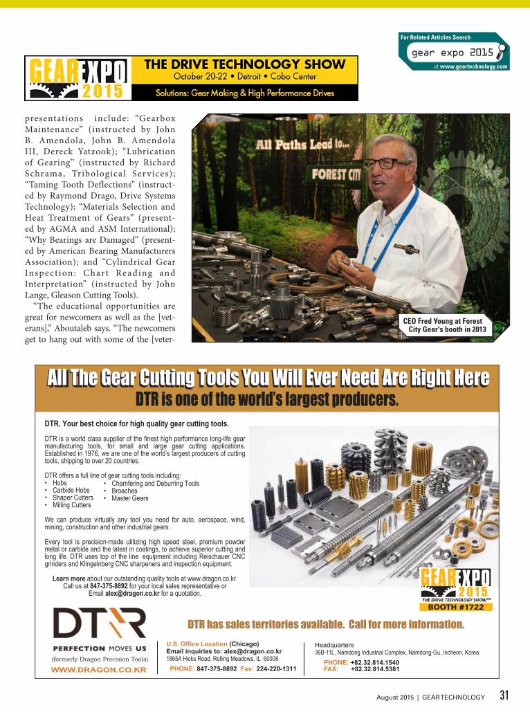
presentations include: “Gearbox Maintenance” (instructed by John B. Amendola, John B. Amendola III, Dereck Yatzook); “Lubrication of Gearing” (instructed by Richard Schrama, Tribological Ser vices) ; “Taming Tooth Deflections” (instruct-ed by Raymond Drago, Drive Systems Technology); “Materials Selection and Heat Treatment of Gears” (present-ed by AGMA and ASM International); “Why Bearings are Damaged” (present-ed by American Bearing Manufacturers Association); and “Cylindrical Gear Insp ec t ion : Char t Reading and Interpretation” (instructed by John Lange, Gleason Cutting Tools).
“The educational opportunities are great for newcomers as well as the [vet-erans],” Aboutaleb says. “The newcomers get to hang out with some of the [veter-
CEO Fred Young at Forest City Gear's booth in 2013
31August 2015 | GEAR TECHNOLOGY
U.S. Office Location (Chicago)Email inquiries to: [email protected] Hicks Road, Rolling Meadows, IL 60008 PHONE: 847-375-8892 Fax: 224-220-1311
DTR has sales territories available. Call for more information.
WWW.DRAGON.CO.KR(formerly Dragon Precision Tools)
DTR. Your best choice for high quality gear cutting tools.
DTR is a world class supplier of the finest high performance long-life gear manufacturing tools, for small and large gear cutting applications. Established in 1976, we are one of the world’s largest producers of cutting tools, shipping to over 20 countries.
DTR offers a full line of gear cutting tools including:• Hobs• Carbide Hobs• Shaper Cutters• Milling Cutters
We can produce virtually any tool you need for auto, aerospace, wind, mining, construction and other industrial gears.
Every tool is precision-made utilizing high speed steel, premium powder metal or carbide and the latest in coatings, to achieve superior cutting and long life. DTR uses top of the line equipment including Reischauer CNC grinders and Klingelnberg CNC sharpeners and inspection equipment.
Learn more about our outstanding quality tools at www.dragon.co.kr. Call us at 847-375-8892 for your local sales representative or
Email [email protected] for a quotation.
Headquarters36B-11L, Namdong Industrial Complex, Namdong-Gu, Incheon, Korea PHONE: +82.32.814.1540 FAX: +82.32.814.5381
All the Gear Cutting Tools You Will Ever Need are Right HereAll the Gear Cutting Tools You Will Ever Need are Right HereAll The Gear Cutting Tools You Will Ever Need Are Right HereAll The Gear Cutting Tools You Will Ever Need Are Right HereDTR is one of the world’s largest producers.
• Chamfering and Deburring Tools• Broaches• Master Gears
BOOTH #1722
gear expo 2015
For Related Articles Search
at www.geartechnology.com
ans] and learn from their experiences. Just sitting in the class and listening to the lectures — it’s part of the game — but the opportunity to speak with the guys who have 10, 15 years of experience and ask-ing them questions is the biggest part.”
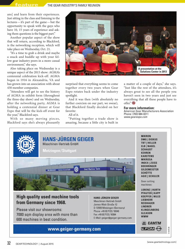
Another popular aspect of the show that will return, according to Blackford, is the networking reception, which will take place on Wednesday, Oct. 21.
“It’s a time to grab a drink and maybe a snack and huddle up with your fel-low gear industry peers in a more casual environment,” she says.
Also taking place on Wednesday is a unique aspect of the 2015 show: AGMA’s centennial celebration kick-off. AGMA began in 1916 in Alexandria, VA and has grown into an association with about 430 member companies.
“Attendees will get to see the history of AGMA in exhibit form (throughout the three-day show) and on Wednesday, after the networking party, AGMA is holding a centennial dinner at Gear Expo that will be the kick-off event for the year,” Blackford says.
With so many moving pieces , Blackford says she’s always pleasantly
surprised that everything seems to come together every two years when Gear Expo rotates back under the industry spotlight.
And it was then (with absolutely no further coercion on our part, we swear), that Blackford finally decided on her favorite:
All of it.“Putting together a trade show is
amazing, because a little city is built in
a matter of a couple of days,” she says. “Just like the rest of the attendees, it’s always great to see all the people you haven’t seen in two years and just see everything that all these people have to offer.” For more information:American Gear Manufacturers AssociationPhone: (703) 684-0211www.gearexpo.com
A presentation at the Solutions Center in 2013
32 GEAR TECHNOLOGY | August 2015[www.geartechnology.com]
feature THE GEAR INDUSTRY’S FAMILY REUNION

Register now for our Gear Technology
Webinar.3M.com/GearTechnologyWebinar
Visit us at Gear Expo 2015, Booth 1622

Anyone even remotely involved with the gear industry knows that Gear Expo is B-I-G. Every two years, it is an invaluable opportunity for buy-ers, sellers and just-lookers to come together and glorify gearing.
But one can’t help wondering how many exhibitors and attendees even think about the two days that pre-cede the show, i.e. — the Fall Technical Meeting. It must be important, because they convene this gathering every year — not every other year. And important it surely is — today more than ever. With the ongoing dearth of new and qualified workers for the gear industry, educating and re-educating the people we do have in our corner of the work world is paramount. With that in mind, let’s see what’s on offer for the 2015 Annual Fall Technical Meeting. (Go to www.gearexpo.com/Detroit for course pricing.)
Register for an education course and receive a complimentary pass to the exhibit hall. Bring colleagues along to qualify for group pricing and benefits. Monitor www.gearexpo.com/Detroit for upcoming information on group pric-ing.
AGMA’s Fall Technical Meeting is a great opportunity for anyone in the gear industry who is interested in the latest research and technical develop-ments in gearing. The 2015 FTM will have 25 presentations divided into five sessions over three days.
Authors and AbstractsSession I — Materials & Heat TreatmentInfluence of Surface Finishing on the Load Capacity of Coated and Uncoated Spur Gears
Philip Konowalczyk: M.Sc., Laboratory for Machine Tools and Production Engineering (WZL) of RWTH Aachen University
PVD/PECVD coatings have been prov-en to increase the pitting and scuff-ing resistance of materials. However, due to concerns that the application process of PVD/PECVD coatings leads to a reduction in tooth root strength, as well as high production costs, the use of these coatings have not been adopted by the gear industry. The aim of this work is to investigate and determine the influence of sur-face finishing processes — specifically, the impact of PVD/PECVD coatings applied using an optimized coating process on the pitting load capacity of gears.
Improved Materials and Enhanced Fatigue Resistance for Gear Components
Dr. Volker Heuer, ALD Vacuum Technologies
To answer the demand for fuel-efficient vehi-cles, modern gear-boxes are built much lighter. Improving fatigue resistance is a key factor to allow for the design of thin components used in advanced transmissions. The choice of mate-rial and the applied heat treat pro-cess are of key importance to enhance the fatigue resistance of gear com-
ponents. This presentation shows the latest progress in steel grades and case hardening technology for gear components.
Practical Approach to Determining Effective Case Depth of Gas Carburizing
March Li, Lufkin Industries, LLC
This presentation shows calculations of the effective case depth governed by carburizing temperature, time, carbon content of steel, and carbon potential of atmosphere. This method provides simple and practical guidance of opti-mized gas carburizing and has been applied to plant production.
Case-Hardening for Mass Production of Gears with Minimal Distortion and Maximum Repeatability
Maciej Korecki, Seco/Warwick
This presentation looks at the major causes of deforma-tion during traditional heat treatment and methods of their control, correction, and elimination. A case-hardening system will be pre-sented which allows individual adjust-ment to the size and shape of the par-ticular gear, in order to minimize hard-ening distortion and ensures ideal repeatability of results throughout the gear series. Additionally, this pre-sentation will discuss the operational aspects, the costs and productivity.
GEAR EXPO 20152015 Fall Technical Meeting (FTM) and PresentationsPresented by: American Gear Manufacturers Association Sunday, October 18 — Tuesday, October 22 8:00 a.m. — 5:00 p.m.
34 GEAR TECHNOLOGY | August 2015[www.geartechnology.com]
feature

Innovative Steel Design and Gear Machining of Advanced Engineering Steel
Lily Kamjou, Ovako
This presentation will describe how shot peening may be eliminated in high cleanliness, as-carburized steel components using an alternative com-position. The fatigue performance of such a solution is compared to con-ventional grades used today, both with and without shot peening. It will also deal with the production pro-cess, including quantitative machining trials and the importance of tooling selection.
Powder Metal Gear Technology: A Review of the State of the Art
Anders Flodin, Höganäs AB
Several hurdles had to be overcome to put powder metal gears into automotive trans-missions, such as fatigue data genera-tion on gears, verification of calcula-tion methods, production technology, materials development, heat treat-ment recipes, design development, and cost studies. The advancements needed—and achieved—to overcome these hurdles will be discussed, and examples of current vehicles using powder metal gears in transmissions will be shown.
Session II — ManufacturingIndustry 4.0 and its Implication to Gear Manufacturing
Dr. Hermann J. Stadtfeld, The Gleason Works
This presentation will provide an overview of the Industry 4.0 ini-tiative and discuss the four industrial periods from the viewpoint of gear manufacturing. It will discuss in depth the techniques and elements of the “cyber physical production systems” and how they will change the way of industrial manufacturing.
Proposed Pre-Finished Cylindrical Gear Quality Standard
Peter Chapin, The Gleason Works
Final gear quality can be vastly different from pre-finish qual-ity. Using finished gear quality class such as ANSI/AGMA ISO 1328 is not recom-
mended or even appropriate for pre-finish gear quality evaluation. This presentation will outline a proposed standard for pre-finished cylindrical gear quality for typical finishing oper-ations. It proposes to only include the inspection elements that are impor-tant to properly evaluate pre-finished gear quality as it applies to the finish-ing operation.
35August 2015 | GEAR TECHNOLOGY
Visit us at GearExpo 2015! Booth# 2307
QUALITY. Over and over again.
AUTOMATED GRINDINGOF GEAR SHAFTS AND BORES
LOAD, GRIND, MEASURE, PERFECT AND REPEAT.With cutting-edge cylindrical grinders that increase performance, enhance efficiency and generate cost-effective processes, whatever “GEAR” you’re in, turn to Weldon Solutions.
www.weldonsolutions.com

Influence of Hobbing Tool Generating Scallops on Root Fillet Stress Concentrations
Benjamin Sheen and Matthew Glass, Eaton Corporation
This paper will discuss the specific example of parallel-sided splines manufactured with a finish hobbing process and the effects of generat-ing root fillet stress concentrations. To estimate the value of the stress con-centrations, finite element analysis was performed on the components for two unique hobbing tool designs. The FEA results were then correlated to actual components with known field service lives.
Selecting the Proper Disc Cutter Design for Milling of High Quality Parallel Axis, Cylindrical Gears and Splines
Brent Marsh, Sandvik Coromant
This presentation will provide a comprehen-sive view of topics such as tool selection, material selection, and surface finish requirements to assist the manufac-turing engineer or process planner in successfully choosing the design of disc mill cutters, in order to make cost effective cylindrical gears to the appropriate quality.
Simulation of Hobbing and Generation Grinding to Solve Quality & Noise Problems
Prof. Dr.-Ing. Günther Gravel, Institute for Production Engineering, Hamburg University of Applied Sciences (HAW)
When deviations occur during genera-tion manufacturing of gear teeth, it is not easy to pinpoint the causes due to the tool design and complex kinemat-ics. A simulation tool has been devel-oped to allow the simulation of typi-cal faults that occur during hobbing
and generation grinding to help solve quality and noise problems. This pre-sentation will discuss practical exam-ples to demonstrate applications for the simulation program.
Session III — Gear ApplicationThermal Capacity of a Multi-stage Gearbox
Benny Wemekamp, SKF Engineering Research Centre
In many industrial gearbox applica-tions, the thermal rating is a key fac-tor in the practical utilization of the gearbox. A simulation tool that goes beyond traditional thermal estimation methods, such as those found in ISO/TR 14179, by calculating the inter-action between heat losses, thermal expansions, and (bearing) pre-load-ing, has been used to understand the interaction between mechanical and thermal equilibrium.
Minimum Backlash of Helical Gear Pairs in Complex Shaft Gearbox Systems
Dr. Carlos Wink, Eaton Corporation - Vehicle Group
Increasingly, there has been pres-sure on gearbox designers to reduce the noise produced from a gearbox, especially in the truck market where engines are running at lower speeds to increase fuel efficiency. An analyti-cal model was developed to deter-mine the minimum backlash of each gear pair when not transmitting load, and thus susceptible to generating a noise, at lower transmission power paths.
New Refinements to the Use of AGMA Load Reversal and Reliability Factors
Ernie Reiter, P. Eng., Web Gear Services Ltd.
Information will be presented on two ways to calculate a load reversal fac-tor, which will be material specific, based either on Modified Goodman or Gerber failure theories. This presen-tation will further provide a method of calculating the reliability factors which very closely match the tables found in ANSI/AGMA 2101-D04.
36 GEAR TECHNOLOGY | August 2015[www.geartechnology.com]
feature 2015 FALL TECHNICAL MEETING (FTM) AND PRESENTATIONS

THE PERFECTGEARED-ASSEMBLYFor your Medical, Laboratory,Instrument, Robotics, Semi-Conductor, Automation or otherPrecision application
CUSTOM SOLUTIONSFully integrated, turnkey solutionsincluding manufacturing,engineering, assembly, testing andcustom machining
Phone: (800) 243-0986Or Call: (203) 775-4877
Turnkey solutions with ahigher level of intelligence
STOCK SOLUTIONSChoose from over 31,000 standardcomponents, including bearings,belts, couplings, fasteners, gears,gearboxes, linear motion, racks,sprockets, worms and more
QUALITY SOLUTIONSSINCE1960
nordex_August.qxp_Nordex_August 7/20/15 9:41 P
Harmonized Assessment of the Design Reliability of Wind Turbine Gearboxes
Douglas Guthrie, Vestas Wind Systems
This presentation posits a new approach for assessing design reli-ability of wind turbine gearboxes. The deterministic approach in prevailing standards does not allow designers to predict failure rates over time, but expresses strength by a safety fac-tor for a given duty cycle. This paper suggests a harmonized method for assessing the design reliability of wind turbine gearboxes.
Homogeneous Geometry Calculation of Arbitrary Tooth Shapes — Mathematical Approach and Practical Applications
Dipl.-Ing. Maximilian Zimmer, Gear Research Centre (FZG), Technical University of Munich
This presentation will outline a mathematical framework, and its implementation, for calculat-ing the tooth geometry of arbitrary gear types, based on the basic law of gear kinematics. The mathematical algorithms are summarized in imple-mented software modules for the par-ticular gear types.
Rating for Asymmetric Tooth Gears
Dr. Alexander L. Kapelevich, AKGears, LLC
This presentation will describe a rating approach for asymmetric tooth gears by their bending and contact stress levels in comparison with equivalent symmetric tooth gears, whose rating is defined by standards. This approach applies FEA for bending stress defini-tion and the Hertz equation for con-tact stress definition. It defines equiv-alency factors for practical asymmet-ric tooth gear design and rating.
Session IV — Lubrication, Efficiency, Noise & VibrationWorm Gear Efficiency Estimation and Optimization
Massimiliano Turci, Studio Tecnico Turci
This presentation will outline the com-parison of efficiencies and of transmissible torques of worm gear drives with cen-ter distance sized from 28 mm to 150 mm and single reduction from 5 to 100, calculated by several standards (AGMA, ISO, DIN, BS). It will also out-line the experimental works required for the calibration of an analytical model, now used for bevel and cylin-drical gears only, but ready to become suitable to predict worm gear drive efficiency too.
Investigations on the Efficiency of Worm Gear Drives
Dipl. Ing. Eva Maria Reitinger, Gear Research (FZG), Technical University of Munich
This presentation will examine the efficiency and the load carrying capacity of worm gears. The tests per-formed consisted of generally pair-ing a bronze worm wheel with a case hardened worm with center distances between a 65 and 315 mm. In the course of these investigations, overall gearbox efficiencies of up to η = 96% were achieved.
Polish Grinding Gears for Higher Transmission Efficiency
Walter Graf, Reishauer AG
This presentation introduces a new gear polish grinding pro-cess and describes its multiple benefits, especially to mak-ers of automotive transmissions. The overall increase in efficiency realized through the new polish grinding pro-cess has been demonstrated through independent scientific studies and field trials. The production process and economic considerations of this new process will also be discussed.
37August 2015 | GEAR TECHNOLOGY

Development of a New Class of Industrial Gear Oil
David B. Gray, Evonik Oil Additives
A new class of indus-trial gear lubricants, based on alterna-tive synthetic materi-als, has been developed to satisfy the critical market performance expec-tations, ensure global supply chain security, and address both economic and performance challenges. This pre-
sentation will describe the technical aspects of the novel synthetic gear oil lubricant approach.
Noise Reduction in an EV Hub Drive Using a Full Test and Simulation Methodology
Dr. Owen Harris, Smart Manufacturing Technology, Ltd.
With the current trend towards electric vehicles more work is being conducted in the area of noise
reduction specific to these vehicles. This presentation will outline a series of tests and simulations that have been performed to specifically look at noise reduction in an EV hub drive. A detailed methodology is presented, combining both a full series of tests and advanced simulation to trouble-shoot and optimize an EV hub drive for noise reduction.
Tribological Coating Wear and Durability Performance Guideline for Gear Applications
Randy Kruse, The Timken Company
It is important to understand the per-formance enhancement limits of DLC tribological coatings so that gear and bearing engineers can accurately spec-ify and predict system life. This presen-tation reports the results of testing a tungsten incorporated diamond-like carbon coating as applied to SAE4320 and AMS6308 gear materials using a ball on disk test machine under condi-tions that simulate the contact stresses and sliding velocities of gears.
Session V — Gear Wear & FailureAn Experimental Evaluation of the Procedures of the ISO TR 15144 Technical Report for the Prediction of Micropitting
Donald R. Houser, The Ohio State University
This presentation will provide practical information on some of the idiosyncrasies of using the ISO/TR 15144 micropit-ting prediction methodology. A review of the ISO methodologies is presented and its application in a spreadsheet analysis using contact stresses pre-dicted from load distribution predic-tion is discussed.
Calculating the Risk of Micropitting Using ISO Technical Report 15144-1:2014 –Validation with Practical Applications
Dr. Burkhard Pinnekamp, RENK AG
This presentation describes the cal-culation method in ISO Technical Report 15144-1:2014 and its application to examples where micropitting has
38 GEAR TECHNOLOGY | August 2015[www.geartechnology.com]
feature 2015 FALL TECHNICAL MEETING (FTM) AND PRESENTATIONS
eXPECT MORE
Our team is committed to keeping our promises and ensuring your complete
satisfaction from inquiry to delivery.
Fast Quoting
Exceptional Product Quality
On-Time Delivery
1.800.569.1420
McInnesRolledRings.com/ExpectMore
“I’ll get your quote within 4 hours.”Brandy - Inside Sales Associate

either occurred or not. The exam-ples give evidence that the Technical Report reliably predicts the risk of micropitting where it is later found on the gear flanks, and it does not do so when the gears run without micropit-ting.
Wear: A New Approach for an ‘Old’ Failure Phenomenon of Gears
Dr. Ing. Ulrich Kissling, KISSsoft AG
This presentation out-lines research con-ducted on gear wear and how it affects the performance of the gear over time. The progress of wear is calcu-lated step by step because the tooth form changes as it becomes worn, and therefore the load distribution will change over the meshing. This new calculation method predicts the modification of the tooth contact area through wear and the consequences for the gear behavior.
Application of Advanced Mesh Analysis to Eliminate Pinion Field Failures
Terry Klaves, Power Transmission Solutions — Regal Beloit America, Inc.
This presentation will walk through a specific case study involving field macro pitting failures on production helical gearing. It will include evaluation of the pitting fail-ures for root cause, review of gear-ing service factors, and application of advanced mesh analysis tools to define root cause of the failures.
Tooth Flank Fracture — Influence of Macro- and Micro-geometry
Dr. Stefan Beermann, KISSsoft AG
This presentation discusses the first results obtained from a systematic varia-tion of gear parameters — both for the macro geometry, (mainly the pressure angle) and the micro geometry (with tip reliefs of various kinds and profile crowning)–to show the influence of these parameters as modeled by the
method being developed by ISO/TC 60 Working Group 6.
In addition to the regular FTM presen-tations, AGMA is also offering a num-ber of educational courses:• Gearbox Maintenance • Why Bearings are Damaged • How to Specify a Gear System • Lubrication of Gearing • High Profile Contact Ratio Gearing:
Concept, Advantages, Comparison & Cautions
• Design of Net Shape Gears using Plastic and Powder Metal Materials
• Basics of Gearing • Counterfeit Bearings: What You
Need to Know • Taming Tooth Deflections: The Case
for Profile Modifications • Materials Selection and Heat
Treatment of Gears • Cylindrical Gear Inspection: Chart
Reading and Interpretation
For a full list of course titles and descriptions, visit www.gearexpo.com/education
39August 2015 | GEAR TECHNOLOGY
PEOPLE AND TECHNOLOGY MAKE THE DIFFERENCE
At Presrite, our experience, innovation and expertise
ensure that you get the best net and near-net forgings.
Our new Tech Center has state-of-the-art design,
engineering technology and die-making capabilities.
• Dedicated state-of-the-art facility
• Presses up to 6,000 tons of capacity
• .008-.060 stock allowance on gear blanks
• ISO 9001:2008
• TS 16949:2009
www.presrite.com • 216-441-5990
PRS-041_HalfPg.Ad-GearTech.indd 1 3/10/14 10:16 AM

Looking ahead to Gear Expo? Visit Gleason Booth #1017
Technologies on display include:3 300GMS®P Inspection System, bringing lab-level inspection to the shop floor.
3 Genesis® 200GX Threaded Wheel Grinding Machine, the new high-performance solution for high-volume gear production.
3 Quik-Flex®Plus workholding system, cutting cylindrical gear changeover time to less than 30 seconds.
For worldwide sales locations and additional information, visit: www.gleason.com • [email protected]
EXPERIENCE THE GEAR SOLUTIONS FORUM IN ROCHESTER, NY – the industry’s single most important
educational event. It’s a unique opportunity to learn more about the latest technologies and trends in the world of gearing – and how to apply them to your applications.
VIEW THE COMPLETE AGENDA AND REGISTER NOW AT:
www.etouches.com/gleasongsf2015
THE FUTURE OF GEARING – THERE’S AN ‘APP’ FOR THAT

An Arena of Color, Light and ConceptsGet Poetic and Pragmatic at Gear Expo’s sister show, Heat Treat 2015Erik Schmidt, Assistant Editor
When you look at the floor plan for the Cobo Center (Detroit, MI) from Oct. 20-22, the names on the lineup really shouldn’t come as a great surprise.
Gear Expo and the ASM Heat Treating Society Conference & Exposition are both present and accounted for, co-located in the same showroom like peas in a very large pod — two differ-ent shows cut from the same cloth (or, if you want to be more on the nose: a high-powered gear grinder).
The industries really do go hand-in-hand (no heat treating, no gears, after all), and so it makes a perfect sort of sense that their respective biennial shows would exist side-by-side, con-joined at the hip.
Gears and heat treating — well, it just seems to work doesn’t it?And for even more serendipitous symmetry, get this: The
show’s host, the ASM International Heat Treating Society (HTS), was founded in 1913 in Detroit.
“Heat Treat 2015 is the premiere event organized by the HTS, the world’s largest network of heat treaters,” said Kelly Thomas,
CEM, CMP senior manager of global events and exhibit sales for ASM. “HTS members work to provide events and services to serve their worldwide membership of captive and commer-cial heat treaters, equipment manufacturers, researchers, gov-ernments and technicians. We are excited to bring our mem-bers back to [Detroit] for Heat Treat 2015.”
According to Thomas, the 28th Heat Treat Expo will feature nearly 200 exhibitors and 5,500 attendees covering 100,000 gross square feet of show floor.
“The HTS Exposition is a fun and exciting place to be,” said Professor Richard Sisson, chairperson of the Heat Treat 2015 Organizing Committee. “The exhibitors are presenting their latest and greatest products. This is a chance to meet with the experts and learn the latest developments and future products and services that are in the works. If you are looking to pur-chase a new system, service or even software, this is the place for one-stop shopping. I learn something new with every visit to the show floor.
The show floor at the ASM Heat Treat Society Conference & Exposition.
42 GEAR TECHNOLOGY | August 2015[www.geartechnology.com]
feature
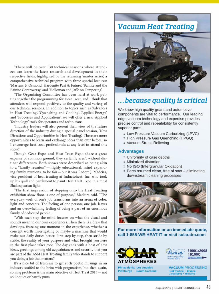
For more information or an immediate quote, call 1-855-WE-HEAT-IT or visit solaratm.com
We know high quality gears and automotive components are vital to performance. Our leading edge vacuum technology and expertise provides precise control and repeatability for consistently superior parts.
» Low Pressure Vacuum Carburizing (LPVC) » High Pressure Gas Quenching (HPGQ) » Vacuum Stress Relieving
» Uniformity of case depths » Minimized distortion » No IGO (Intergranular Oxidation) » Parts returned clean, free of soot – eliminating downstream cleaning processes
Advantages
. . .because quality is critical
9100CAS
9001:2008ISO
registeredHeat Treating | BrazingHardness Testing
VACUUM PROCESSINGHeat Treating • Brazing Carburizing • Nitriding
Philadelphia Pittsburgh
Los Angeles South Carolina
Vacuum Heat Treating
“There will be over 130 technical sessions where attend-ees can learn the latest research and development in their respective fields, highlighted by the returning ‘master series’, a comprehensive technical program with three special lectures: ‘Martens & Osmond: Hardenite Past & Future’, ‘Bainite and the Bainite Controversy’ and ‘Holloman and Jaffe on Tempering’.
“The Organizing Committee has been hard at work put-ting together the programming for Heat Treat, and I think that attendees will respond positively to the quality and variety of our technical sessions. In addition to topics such as ‘Advances in Heat Treating’, ‘Quenching and Cooling’, ‘Applied Energy’ and ‘Processes and Applications’, we will offer a new ‘Applied Technology’ track for operators and technicians.
“Industry leaders will also present their view of the future direction of the industry during a special panel session, ‘New Directions and Opportunities in Heat Treating’. There are more opportunities to learn and exchange ideas than ever before, so I encourage heat treat professionals at any level to attend this show.”
Though Gear Expo and Heat Treat Expo share a great expanse of common ground, they certainly aren’t without dis-tinct differences. Both shows were described as being akin to a “family reunion” — highly educational, mind expand-ing family reunions, to be fair — but it was Robert J. Madeira, vice president of heat treating at Inductoheat, Inc, who took up his quill and parchment to paint Heat Treat Expo in a most Shakespearian light.
“The first impression of stepping onto the Heat Treating exhibition show floor is one of purpose,” Madeira said. “The everyday work of one’s job transforms into an arena of color, light and concepts. The feeling of one person, one job, leaves and an overwhelming feeling of being a part of an enormous family of dedicated people.
“With each step the mind focuses on what the visual and sounds mean to our own experiences. Then there is a draw that develops, freezing one moment in the experience, whether a concept worth investigating or maybe a machine that would make our daily duties better. First step by step, then stride by stride, the reality of your purpose and what brought you here in the first place takes root. The day ends with a host of new ideas, greetings among old acquaintances and security that you are part of the ASM Heat Treating family who stands to support you doing a job that matters.”
It’s a nice bit of fresh air to get such poetic musings in an industry stuffed to the brim with pragmatism, but then again, solving problems is the main objective of Heat Treat 2015 — not soliloquies or bawdy puns.
43August 2015 | GEAR TECHNOLOGY

www.atagears.fi
ATA Gears sells, designs and produces spiral bevel gears for the most demanding marine and industrial applications. We look forward to meeting you and your specific power transmission needs!
Spiral Bevel Gears & Technical Customer Services
ATA_ad_184x120,5mm_geartechn_130315_FINAL.indd 1 13.3.2015 9.31
And on top of several returning educa-tional programs, there will be a handful of new learning opportunities for attendees to gather information to apply to their busi-nesses back home.
“This year, we are highlighting the work of the LIFT Consortium (Lightweight Innovations for Tomorrow) during a special plenary session with Dr. Alan Taub, LIFT chief technical officer,” said Thomas. “Since the conference was in Detroit, we really wanted to highlight a local organization that is doing great work for the industry.
“We are also featuring live demos and workshops. Attendees can learn about the latest equipment and technology through live demos on the expo floor — for free. It’s also important that we continue to encourage the younger generation to explore a career in materials science and engineering. With that in mind, we have put together a ‘This is Heat Treat’ student program, which will provide students with a unique opportunity to net-work with professionals in the industry and learn about all aspects of the field through technical programs.”
So come and learn and listen and then depart on Oct. 22 with
knowledge in your mind and poetry in your heart, leaving both Gear Expo and Heat Treat Expo behind until 2017, proclaim-ing to no one and everyone in eloquent tongue like the Bard of Avon:
Good night, good night! Parting is such sweet sorrow. For more information:ASM InternationalPhone: (440) 338-5151www.asminternational.org
Many heat treaters will be displaying furnaces on the show floor.
44 GEAR TECHNOLOGY | August 2015[www.geartechnology.com]
feature AN ARENA OF COLOR, LIGHT AND CONCEPTS
Photo by David Ropinski

Transport your business 5,878,499,810,000 miles Ahead of the competition with ipsen.
Find out how at ASM Heat Treat booth #701

show stoppers GEAR EXPO / HEAT TREAT - VIP EXHIBITORS
The Hardinge Grinding Group consists of six brands of products offering you the following grinding solutions: • Universal OD / ID • Surface, Profile & Creep feed • Production OD / ID • CNC Jig
www.HardingeGrindingGroup.com800-843-8801
www.Galdabini.it [email protected] (800) 314-0913
Let’s Get Something Straight!
Uncompromising Excellence in Gear Straightening Technology for Over 125 Years
VISIT US AT BOOTH #2346
46 GEAR TECHNOLOGY | August 2015[www.geartechnology.com]
Broaching Machine Specialties (BMS) is proud to announce that BMS will act as the US and Canadian sales and service organization for
the following product lines from Ekin of Balbao, Spain:
• HELICAL BROACHING MACHINES AND TOOLS• HARD BROACHING MACHINES AND TOOLS• DRY BROACHING MACHINES AND TOOLS• CNC BROACH SHARPENING MACHINES• SPLINE ROLLING MACHINES AND TOOLSContact BMS President Matt Egrin at Gear Expo or anytime for additional information on Ekin and BMS!
VISIT US AT BOOTH #1734VISIT US AT BOOTH #2317

Innovative
grinding fluidsto get your production into gear.oelheld U.S., Inc.1760 Britannia Drive # 1 Elgin, IL 60124phone: +1–(847)–531-8501 fax: +1–(847)–531-8511E-Mail: [email protected]
Banyan GlobalTechnologies
VACUUM PROCESSINGHeat Treating • Brazing
Carburizing • Nitriding
Vacuum Heat Treating
» Over 50 vacuum furnaces – lab-sized to 40’ long
» Argon, nitrogen and helium quenching up to 20 bar
» Operating range of -320°F to +3,600°F
» On-site metallurgical testing lab
» 24/7 responsive service
» Four convenient locations – Philadelphia, Pittsburgh, Los Angeles, South Carolina
. . .because quality is critical
ISO9001:2008 | AS9100C
Nadcap Accredited
MedAccred Accredited
ITAR Certified
1-855-WE-HEAT-ITsolaratm.com
47August 2015 | GEAR TECHNOLOGY
VISIT US AT BOOTH #2301
VISIT US AT BOOTH #2404 VISIT US AT ASM BOOTH #738

show stoppers GEAR EXPO / HEAT TREAT - VIP EXHIBITORS
AS
K-T
HE
-EX
PE
RT !
LIV
E
• GEAR GRINDING — Tuesday, 10/20 — 10:30 a.m.
• CUTTING TOOLS — Tuesday, 10/20 — 2 p.m.
• GEAR DESIGN — Wednesday , 10/21 — 10:30 a.m.
• ASK ANYTHING — Wednesday, 10/21 — 2 p.m.
Have a question? Send it in advance to [email protected]
Come to booth #2030 during Gear Expo to get your gear-related questions answered, live and in-person, by our panel of experts:
48 GEAR TECHNOLOGY | August 2015[www.geartechnology.com]
Strength revealed
12 Months Working SafePlug & Press
Quenching Available
VISIT US AT BOOTH #1443
866-PAULO [email protected]
HEAT TREATING SINCE 1943
CLEVELAND · KANSAS CITY · MURFREESBORONASHVILLE · ST. LOUIS
VISIT US AT ASM BOOTH #232
• Hardeningsolutionsforvirtuallyanydimensionofbearings,raceways,balltracksandgears
• Gap-by-gap,tooth-by-toothandsingle-shot(spinning)• Patentedseamlesshardeningsolution• Maintenance,logistics,trainingandspareservices
www.efd-induction.com
Gear hardening The benefits of induction heating
Putting the smarter heat to smarter use

!
• Complete archive of back issues and articles, 1984-today
• Directory of suppliers of machine tools, services and tooling
• Product and Industry News updated daily• Exclusive online content in our e-mail
newsletters• Calendar of upcoming events• Comprehensive search feature helps you
find what you’re looking for—fast!
Hungry for More?
®
www.geartechnology.com
Everything you need to be a world-class gear manufacturer—the suppliers, the technical information and the market intelligence—can be found online
FREESUBSCRIPTIONS

Hermann J. Stadtfeld
Development of a Face-Milled Spiral Bevel GearsetThe following data are given for this example:Method single indexing with Gleason straddle cutTooth depth along face width parallelShaft angle Σ = 90°Offset a = TTX = 0 mmNumber of pinion teeth z1 = 13Number of ring gear teeth z2 = 35Outer ring gear pitch diameter D02 = 190 mmFace width b1 = b2 = 30 mmMean spiral angle β1 = β2 = 30°Pinion hand of spiral HOSP1 = left-handNominal cutter radius Rw = 76.2 mm (6")Pressure angle αC = αD = 20°Profile shift factor x = x1 = –x2 = 0Tooth depth factor fDepth = 1Top-root-clearance factor fCL = 0.2Profile side shift factor xS = xS1 = –xS2 = 0Pinion addendum hK1 = (fDepth + x) × mn = 1.0mn
Pinion dedendum hF1 = (fDepth + fCL – x) × mn = 1.2mn
Ring gear addendum hK2 = (fDepth − x) × mn = 1.0mn
Ring gear dedendum hF2 = (fDepth + fCL + x) × mn = 1.2mn
Wanted are the design data of the pinion and ring gear blanks, as well as the cutter specifications and basic machine settings.
Calculation of Blank DataThe calculation begins with the computation of the ring gear blank data. The geometrically relevant parameters are shown in Figure 1. The position of the teeth relative to the blank coordi-nate system of a bevel gear blank is satisfactorily defined with
the following data: RAUR; RINR; γ; ZFKR; ZTKR; and ZKKR. Those blank data are calculated from the given data as follows:
(1)z1 / z2 = sinγ1 / sinγ2
(Regarding Eq.1, see also Eq.’s 10–12, Chapter 1)The sum of the pitch angles of spiral bevel gears is equal to the
shaft angle:γ1 + γ2 = Σ –> γ1 = Σ − γ2
In case of a 90° shaft angle the relationship will simplify to:(2)
γ1 = arctan (z1 / z2) = 20.38
Figure 1 Graphical specification of ring gear blank.
Bevel Gear TechnologyChapter 2This article is the third installment in Gear Technology's series of excerpts from Dr. Hermann J. Stadtfeld's book, Gleason Bevel Gear Technology. The first two excerpts can be found in our June 2015 and July 2015 issues.
The goal of the following sections is to develop a deeper understanding of the function, limits and possibly the not fully utilized possibilities of bevel and hypoid gears.
The gear mathematics developed by the author is based on a triangular vector model that presents a comprehensive tool for simple observations in the generating gear, up to complex three-dimensional developments. Many types of bevel and hypoid gears can be observed and manipulated with this model — without alteration of the notation. However, at the most complex level the lengths and directions of the vectors change according to higher-order functions, depending on the rotational position of the generating gear (Refs. 1–2).
The first chapter of this book — “Nomenclature and Definition of Symbols” — should help to avoid or minimize the interrup-tion of the flow in the gear theoretical developments with definitions of formula symbols.
At the beginning of this chapter the development of a face-milled, conjugate spiral bevel gearset is conducted. Next, an ana-logue face-hobbed bevel gearset is derived that in a third step is converted to a non-generated (Formate) version. In step four an offset is added to the Formate spiral bevel gearset that results in a hypoid gearset. Consequences regarding the introduction of the hypoid offset and unique facts regarding general spatial transmissions are also discussed in this chapter. At the end of this chapter, length and profile crowning are added to the Formate bevel gearset that delivers a practical-use, angular transmission as it is used in industrial gear boxes; the reader will be able to apply the derivations to any other bevel and hypoid gearset. With the results of each calculation step, basic settings are computed as they are commonly used by modern CNC bevel gear generators in order to cut or grind real bevel gearsets. —Hermann J. Stadtfeld
Gear Mathematics for Bevel & Hypoid Gears
50 GEAR TECHNOLOGY | August 2015[www.geartechnology.com]
technical

(3)γ2 = 90° − γ1 = 69.62°
Now the different cone distances, normal module, and mean pitch diameter can be calculated:
(4)RM = D02 / 2 / sinγ2 − b2 / 2 = 86.34 mm
(5)d02 = 2 × RM × sinγ2 = 161.87 mm
(6)mf = d02 / z2 = 4.63 mm
(7)mn = mf × cosβ2 = 4.00 mm
(8)hK2 = 1.0 × mn = 4.00 mm
(9)hF2 = 1.2 × mn = 4.80 mm
(10)RINR2 = RM − b2/2 − hF2 / tanγ2 = 69.56 mm
(11)RAUR2 = RINR2 + b2 = 99.56 mm
The positions of the cone apexes, the whole depth and the maximal ring gear diameter are:
(12)ZFKR2 = +hF2 / sinγ2 = 5.12 mm
(13)ZKKR2 = –hK2 / sinγ2 = – 4.27 mm
(14)ZTKR2 = 0.00 mm
(15)HGER = hK2 + hF2 = 8.80 mm
(16)DUMR2 = 2(RAUR2 × sinγ2+HGER × cosγ2) = 192.78 mm
Pinion pitch angle and mean cone distance RM (which is equal for pinion and gear) have already been calculated in the course of the gear blank calculations. Only the inner and outer cone distance — as well as the cone apex positions — remain in the pinion blank calculation (Fig. 2). The value for addendum and dedendum is equal to the ring gear values, since no profile shift was applied to the present example:
(17)hK1 = 1.0 × mn = 4.00 mm
(18)hF1 = 1.2 × mn = 4.80 mm
(19)RINR1 = RM − b1/2 − hF1 / tanγ1 = 58.42 mm
(20)RAUR1 = RINR1 + b1 = 88.42 mm
The positions of the pinion cone apexes are:(21)
ZFKR1 = + hF1 / sinγ1 = 13.78 mm(22)
ZKKR1 = –hK1 / sinγ1 = –11.49 mm(23)
ZTKR1 = 0.00 mm
All bold-printed parameters in this section are required for the definition of the toothed cones relative to the remaining pin-ion and gear blank. Those design data are summarized in Tables 1 and 2.
Calculation of Cutter Head GeometryThe nominal cutter radius was chosen a little bit smaller than the mean cone distance RM. This seems to be a good choice for a face-milled (single indexing process) bevel gearset if large load-affected deformations are anticipated.
Although the nominal cutter radius is already given, the actual radii of inside and outside blades for gear and pinion cutter head have to be calculated depending on the chosen cut-
Figure 2 Pinion blank specification.
Table 1 Numerical ring gear blank specificationsRing Gear - Blank Data
Variable Explanation Value Dimensionz2 number of ring gear teeth 35 -
RINR2 inner cone distance (along root line) 69.56 mmRAUR2 outer cone distance (along root line) 99.56 mm
GATR2 = γ2 pitch angle 69.62 °GAKR2 face angle 69.62 °GAFR2 root angle 69.62 °ZTKR2 pitch apex to crossing point 0.00 mmZKKR2 face apex to crossing point –4.27 mmZFKR2 root apex to crossing point 5.12 mm
DOMR2 = mf2 face module 4.63 mmHGER whole depth of teeth 8.80 mm
Table 2 Numerical pinion blank specificationsPinion - Blank Data
Variable Explanation Value Dimensionz1 number of teeth pinion 13 -
RINR1 inner cone distance (along root line) 58.42 mmRAUR1 outer cone distance (along root line) 88.42 mm
GATR1 = γ1 pitch angle 20.38 °GAKR1 face angle 20.38 °GAFR1 root angle 20.38 °ZTKR1 pitch apex to crossing point 0.00 mmZKKR1 face apex to crossing point –11.49 mmZFKR1 root apex to crossing point 13.78 mm
DOMR1 = mf1 face module 4.63 mmHGER whole depth of teeth 8.80 mm
51August 2015 | GEAR TECHNOLOGY
bevel gears
For Related Articles Search
at www.geartechnology.com

ting method. Since the method is Gleason straddle cut, the pin-ion blades cut a tooth slot while the gear blades are cutting a tooth — i.e., two proceeding “half-slots.”
Figure 3 shows (left) the corresponding blades of pinion and ring gear (see also Figs. 12–15, Chap. 1, Part II, July Gear Technology). The generating plane intersects with the blades at the height of the calculation point. In order to generate the cor-rect tooth thickness, the distance from the calculation point on the inside blade to the calculation point on the outside blade has to be equal to one-half of the normal pitch, plus one-half of the normal backlash. The blade tips extend about the tooth deden-dum (hF) — beyond the generating plane (blade dedendum). The blade contours in Figure 3 are therefore not exactly con-gruent to each other, but by the backlash values different on the flanks and by the clearance values different at the roots (tips).
Since the aim in this first flank generating example is to achieve a conjugate pair, it seems appropriate to set the backlash SPLF for this example to zero.
As a result the following calculations will sufficiently deter-mine the required cutter head and blade parameters:
(24)tB = π × mn = 12.57 mm
(25)SPLF = 0.00 mm
Table 3 Cutter head and blade specificationsCutter Head and Blade Data
Variable Explanation Value DimensionS89011,2 reference point to blade tip pinion 4.80 mmS89033,4 reference point to blade tip gear 4.80 mmWAME1 blade phase angle pinion convex 0.00 °WAME2 blade phase angle pinion concave 0.00 °WAME3 blade phase angle ring gear convex 0.00 °WAME4 blade phase angle ring gear concave 0.00 °XSME1,2 blade offset in pinion cutter head 0.00 mmXSME3,4 blade offset in ring gear cutter head 0.00 mmRCOW1 cutter point radius pinion inside blade 74.80 mm
RCOW2cutter point radius pinion outside
blade 77.59 mm
RCOW3cutter point radius ring gear inside
blade 81.09 mm
RCOW4 cutter point radius ring gear outside
blade 71.31 mm
ALFW1 blade angle pinion inside blade 20.00 °ALFW2 blade angle pinion outside blade 20.00 °ALFW3 blade angle ring gear inside blade 20.00 °ALFW4 blade angle ring gear outside blade 20.00 °
Figure 3 Pinion and ring gear blade geometry.
Figure 4 Ring gear, basic machine model: upper graphic — front view; lower graphic — top view.
52 GEAR TECHNOLOGY | August 2015[www.geartechnology.com]
technical

(26)ALFW1 = ALFW2 = ALFW3 = ALFW4 = α = 20.00°
(27)RCOW1 = RW − tB/4 − SPLF/4 + hF1 × tanALFW1 = 74.80 mm
(28)RCOW2 = RW + tB/4 + SPLF/4 − hF1 × tanALFW2 = 77.59 mm
(29)RCOW3 = RW + tB/4 − SPLF/4 + hF2 × tanALFW3 = 81.09 mm
(30)RCOW4 = RW − tB/4 + SPLF/4 − hF2 × tanALFW4 = 71.31mm
(31)S8901 = S8902 = hF1 = 4.80 mm
(32)S8903 = S8904 = hF2 = 4.80 mm
All parameters printed in bold are required for the definition of the pinion and ring gear cutter heads required. Those results are summarized in Table 3.
Calculation of Basic Settings for the Cutting MachineThe basic machine, as defined by Weck and Schriefer (Ref. 3), follows a clear systematic with 10 coupled Cartesian coordinate systems, beginning with system 1, which defines the work gear position via system 4 which defines the generating gear plane with its axes axis X4–Z4 and the generating gear axis with its axis Y4 to system 10, which defines the cutter head axis with Y10 and the position of the blade origin (blade tip) with Z10.
Figure 4 only includes the systems 1, 4, 9 and 10 — which are required for the basic bevel gear calculation covered in this chapter.
The observations and machine setting calculation are first conducted for the ring gear and then the pinion. First we observe the generating gear plane X4–Z4 (Fig. 4), in which the mean cone distance RM is drawn from the origin of the coordi-nate system along the positive Z4 axis. At the tip of the RM vector, the mean face position is located, which is the point of a curved tooth, where the spiral angle β has to be equal 30°. The spi-ral direction shown in Figure 4 is consistent with a right-hand ring gear that has a mating pinion with a left-hand spiral direc-tion (the view in Figure 4 is directed to the back-side of the ring gear). The spiral angle in each point of a flank is the angle in the generating gear plane between the flank tangent and the con-necting line to the generating gear axis. In Figure 4 it is the angle β between flank tangent and Z4 axis. This now allows the posi-tioning of the cutter radius vector RW with its tip perpendicular to the flank tangent. The solution vector in this observation is the eccentricity vector EX, which already includes a number of machine settings.
(33)→EX =
→RM −
→RW
(34)With:
→RM = {0., 0., RM} = {0., 0., 86.34}
(35)→RW = RW {–cos β, 0., sin β}
(36)→RW = {– RW cos β, 0., RW sin β} = {–65.99, 0., 38.10}
(37)Resulting in:
→EX = {65.99, 0., 48.24}
Utilizing the EX vector, the following machine settings can be calculated:
(38)Center roll position: W4503,4 = arctan (EXX / EXZ) = 53.83°
(39)Radial distance: TZMM3,4 = √EXX² + EXZ² = 81.74 mm
(40)Sliding base: TYMM3,4 = EXY = 0.00 mm
Additional machine settings can be found from the graphical relationship in Figure 4:
(41)Machine root angle: AWIM3,4 = –90° – γ2 = –159.62°
(42)Machine center to crossing point: TZ2M3,4 = 0.00 mm
(43)Offset in the machine: TX2M3,4 = 0.00 mm
Further values such as cutter head tilt WXMM3,4 and tilt ori-entation WYMM3,4 are also zero in the observed conjugate design.
For the exact definition of the ring gear to be generated, the ratio of roll between generating gear and work gear is still miss-ing. Using (Chapter 1, Part II, July Gear Technology) Equations 11 and 12, the ratio of roll can be computed with:
(44)UDIF3,4 = sinγ2 = 0.937404
The ratio of roll number requires at least a mantissa with 6 digits, since the influence onto the gear geometry is correspond-ingly sensitive.
The second part of the machine setting calculations, the dem-onstrated gear calculations are repeated analogous for the pin-ion. At first, we observe the generating gear plane X4–Z4 (Fig. 5) in which the mean cone distance RM is plotted from the coordi-nate origin along the positive Z4 axis.
At the tip of the RM vector, the mean face position of a curved tooth is located whose tangent in this point should show a spiral angle β of 30°. The spiral direction shown in Figure 5 is consis-tent with a left-hand pinion (in Fig. 5 (top) the view is directed from the back to the pinion). The spiral angle in each point of a flank is the angle in the generating gear plane between the flank tangent and the connecting line to the generating gear axis. In Figure 5 it is the angle β between flank tangent and Z4 axis. This allows now the positioning of the cutter radius vector RW with its tip perpendicular to the flank tangent. The solution vector
Figure 5 Pinion basic machine model: upper graphic — front view; lower graphic — top view.
53August 2015 | GEAR TECHNOLOGY

in this observation is the eccentricity vector EX, which already includes a number of machine settings.
(45)With:
→RW = {RWcosβ, 0., RWsinβ} = {65.99, 0., 38.10}
(46)Resulting in:
→EX = {–65.99, 0., 48.24}
By means of the EX vector the following machine settings can be calculated:
(47)Center of roll: W4501,2 = arctan (EXX / EXZ) = –53.83°
(48)Radial distance: TZMM1,2 = √EXX² + EXZ² = 81.74 mm
(49)Sliding base: TYMM1,2 = EXY = 0.00 mm
Additional machine settings can be found from the graphical relationship in Figure 5:
(50)Machine root angle: AWIM1,2 = –90°–γ1 = –110.38°
(51)Machine center to crossing point: TZ2M1,2 = 0.00 mm
(52)Offset in the machine: TX2M1,2 = 0.00 mm
Further values, such as cutter head tilt XMM1,2 and tilt orien-tation WYMM1,2 are also zero in the observed conjugate design.
For the exact definition of the pinion to be generated, the ratio of roll between generating gear and work gear is still missing. From (Chap. 1, Part II, July Gear Technology) Equations 11 and 12, the ratio of roll can be computed with:
(53)UDIF1,2 = sinγ12 = 0.348245
All bold-printed values calculated in this section are input values for a bevel gear cutting simulation program, whose functionality is discussed in the next section. The machine settings are summarized in Table 4.
Simulation of the Gear Cutting Process and Tooth Contact Analysis of Face-Milled Spiral Bevel Gearset ExampleA typical example of a simulation program is the FVA Bevel-Gear-Chain, which was developed at the Machine Tool Laboratory of the University of Aachen (Ref. 3). Some of today’s commercially avail-able software systems for bevel gear calculation and optimization have been developed on the basis of this universal software tool. The analysis and experi-mentation, introduced in the following chapters, are also based on an advanced version of the FVA Bevel-Gear-Chain. This software utilizes the same data as is used in modern free-form bevel gear cutting and grinding machines for the manufacture of real bevel
gear sets. The core of this program is a flank generating module that applies the coordinate systems of Figures 4 and 5 to model a generating gear.
In the generating gear system Xc–Yc–Zc (system Sc) in Figure 6, a generating gear flank point is given by position vector PcSa and normal vector N. The application of the gearing law (Chap. 1, Eq. 1, June Gear Technology) delivers the rotation angle φac into the contact position (system Sa), in which the solution point Pc and the solution normal vector –N is found in a coor-
Table 4 Geometrical and kinematical machine settingsMachine Basic Settings
Variable Explanation Value DimensionWXMM1,2 cutter head tilt pinion 0.00 °WXMM3,4 cutter head tilt ring gear 0.00 °WYMM1,2 swivel angle pinion 0.00 °WYMM3,4 swivel angle ring gear 0.00 °W4501,2 center of roll position pinion –53.83 °W4503,4 center of roll position ring rear 53.83 °
TYMM1,2 sliding base position pinion 0.00 mmTYMM3,4 sliding base position ring gear 0.00 mmTZMM1,2 radial distance pinion 81.74 mmTZMM3,4 radial distance ring gear 81.74 mmAWIM1,2 machine root angle pinion –110.38 °AWIM3,4 machine root angle ring gear –159.62 °TX2M1,2 pinion offset in the machine 0.00 mmTX2M3,4 ring gear offset in the machine 0.00 mmTZ2M1,2 machine center to crossing point pinion 0.00 mmTZ2M3,4 machine center to crossing point gear 0.00 mmUTEI1,2 indexing ratio of pinion cutting 0.00 -UTEI3,4 indexing ratio of ring gear cutting 0.00 -UDIF1,2 ratio of roll for pinion cutting 0.348245 -UDIF3,4 ratio of roll for gear cutting 0.937404 -
Figure 6 Kinematical relationships to solve gearing law equation.
54 GEAR TECHNOLOGY | August 2015[www.geartechnology.com]
technical

dinate system Xb–Yb–Zb (system Sb) as position vector PcSb. In order to find a comprehensive flank as a result of computing a larger amount of individual points, which are necessary in order to define an entire flank (symbolized with surface Ab), the solution point has to be rotated “back” in its final position (system Sd). The angle φbd between the contact position and the final position is found by multiplication of the rotation angle φac (in the generating gear system) with the ratio of roll. Figure 6 also shows that in the contact position the relative veloci-ties vab = va − vb — and therefore the sliding and rolling veloci-ties — can be determined rather easily.
The cutting edges, which are defined in the input data as lines, are treated in the flank surface generation program as a summation of discrete points; the rotation of the cutter head delivers a velocity vector in the respective cutting edge point. The vector product between the velocity vector and the cutting edge tangential vector results in a normal vector, which togeth-er with the cutting edge point, by solving the gearing law (as explained in Fig. 6), delivers a point and a normal vector of the work gear flank that is subject to the generating process. In a do loop the given number of cutting edge points — YP10 — are pro-cessed for each angular cutter head position (Fig. 7).
The result is the so-called “natural flank grid,” which ends at the root fillet but extends beyond the tooth boundaries in all other directions. It becomes evident from Figure 7 that the dis-tortions of the natural flank grid are caused by the changing generating conditions. In order to achieve a flank grid — which fits the real tooth boundaries — the desired flank grid, known until now only in the YRI-ZRI plane, is correlated to the natu-ral grid (projected into the YRI-ZRI plane). The distance of a respective point of the flank grid to the closest point of the natu-ral grid leads to new given cutter head angle φ89Y and cutting edge point YP10. The generating process with this new point will reduce the distance between the desired flank point and the actual generated point. This procedure is repeated in a semblance of an iteration until the distance lies within an iteration limit of usually 0.0002 mm. Flank sur-face points calculated with this method show an accuracy of 10-5 mm. The normal directions within the flank working area without undercut have deviations below half an angular minute.
The resulting flank surfaces are interpo-lated with bi-cubical spines in order to pro-vide any in-between point with high accu-racy during the following roll simulation between pinion and gear.
For the roll simulation the pinion flanks with their coordinate system XRI-YRI-ZRI are located in the correct position relative to the ring gear flanks with their coordinate system XRA-YRA-ZRA. This relative position is defined by the shaft offset vector TT and the shaft angle Σ. The signified blanks of pinion and ring gear are shown in Figure 8. In the pres-ent example the shaft angle is 90° and the
Figure 7 Flank grid and natural flank grid.
Figure 8 Arrangement of pinion and ring gear for roll simulation.
Figure 9 Graphical results of roll simulation (TCA) of face-milled gearset.
55August 2015 | GEAR TECHNOLOGY

TT vector is zero — which defines a spiral bevel gearset without hypoid offset. In order to evaluate the properties of the gearset under load with deflected gear box housing, it is possible to use shaft angles that deviate from 90° together with any offset vector TT. The results of a roll simulation are Ease-Off, tooth contact pattern, and motion transmission error. In order to correlate those results in a meaningful way with the tooth flanks of the evaluated gearset, the flank projection into the plane ZRA-YRA (points A, B, C and D) is defined as presentation plane (Fig. 8). The Ease-Off is a three-dimensional graphic of the flank devia-tions from a conjugate pair; it is calculated by rolling the pinion flank “into” the gear coordinate system according to the gearing law, resulting in a virtual gear flank that is conjugate to the actu-al pinion flank. This conjugate gear flank will then be compared to the present gear flank, where all differences in arc length are plotted point-by-point in ordinate direction into the Ease-Off graphic.
If both mating bevel gears have conjugate manufacturing data, then the Ease-Off graphic has no deviations in ordinate direc-tion. Also, if the pinion flanks and gear flanks have spiral angle errors of equal amounts, the Ease-Off graphic will not show any deviation. And although the individual gears are considered incorrect in this case, they will roll conjugate with each other, which subsequently leads to an Ease-Off without any ordinate values. Further explanations regarding roll simulation and tooth contact analysis results are presented in Chapter 4 (Nov.-Dec. Gear Technology).
The roll simulation analyses results of the bevel gearset cal-culated in this chapter (in its theoretical zero position) can be observed in Figure 9. In the left column the results of the coast-side are shown, which is the combination of the convex pinion flank and the concave ring gear flank. In the right column the results of the drive-side are shown, which is the combination of the concave pinion flanks and the convex ring rear flanks. The drive-side is the preferred flank combination; the reasons for the superior rolling conditions of the drive-side are discussed in Chapter 4.
Just like the theoretical goal, a conjugate gear pair with zero Ease-Off was created. The motion graphs in the middle section of Figure 9 only show some “numerical noise” along the abscissa of the diagrams, meaning there is no transmission error in any of the roll positions. The contact bearings in the lower section of Figure 9 show contact lines, which extend inside the entire flank working areas.
The flank working area is the common surface between the active pinion flank that is rolled with the active ring gear flank. For a better understanding of the flank working area, the previ-ously mentioned rolling of the pinion flank into the ring gears coordinate system can be employed. If the resulting conjugate ring gear flank is projected into the presentation plane (rota-tional projection) where it overlays the area of the actual ring gear flank (which is already projected into the presentation plane), then the working area is defined as the area where both the conjugate gear flank and the real gear flank exist. It seems obvious that no flank contact or correct rolling outside of this area is possible. On the heel and toe borders only “air” is present outside of the working area of one of the two flanks (or both). At top and root either the rolled on top edge of the one flank, or
the border to the root fillet of the other flank is the limitation. Caution is required if the root fillet border is the limitation. In many cases this leads to interferences that can cause noise and surface damage. The flank working areas in Figure 9 end along the horizontal coordinate axis (coast-side on the top, drive-side on the bottom) that represent the transition line between flank and ring gear root fillet.
On the opposite sides (coast-side on the bottom, drive-side on the top) exists a non-working area between ring gear face edge and tooth contact zone, pointing to a “pulled-up” pinion root transition that migrates into undercut in the toe region. A pulled-up pinion root transition is more dangerous than under-cut, since interferences can occur that can lead to flank surface damage, as mentioned above. The result in many cases is the population of pitting and even tooth fracture. Intentionally, no profile shift was applied in the present example in order to dem-onstrate the motivation to introduce a profile shift. In a simpli-fied observation a negative ring gear profile shift with a magni-tude equal to the white zone at the top of the ring gear tooth is required (app. 1.75 mm).
Profile shift:(54)
Δh = x2 × mn = x2 × 4.00 mm = –1.75 mm(55)
x2 = –0.448In bevel and hypoid gears, generally the V0 system is applied,
which allows determination of the pinion profile shift as:(56)
V0 x1 + x2 = 0.00 − > x1 = –x2 = 0.448
This will shorten the gear addendum and lengthen the gear dedendum, which will result in a match between the common flank area and the active flank working area. The region with incorrect roll conditions along the pinion root will be eliminat-ed by using the optimal part of the involute. The white region along the ring gear top will now be filled with contact lines and the active flank working area will be maximized.
Dr. Hermann J. Stadtfeld received in 1978 his B.S. and in 1982 his M.S. degrees in mechanical engineering at the Technical University in Aachen, Germany; upon receiving his Doctorate, he remained as a research scientist at the University’s Machine Tool Laboratory. In 1987, he accepted the position of head of engineering and R&D of the Bevel Gear Machine Tool Division of Oerlikon Buehrle AG in Zurich and, in 1992, returned to academia as visiting professor at the Rochester Institute of Technology. Dr. Stadtfeld returned to the commercial workplace in 1994 — joining The Gleason Works — also in Rochester — first as director of R&D, and, in 1996, as vice president R&D. During a three-year hiatus (2002–2005) from Gleason, he established a gear research company in Germany while simultaneously accepting a professorship to teach gear technology courses at the University of Ilmenau. Stadtfeld subsequently returned to the Gleason Corporation in 2005, where he currently holds the position of vice president, bevel gear technology and R&D. A prolific author (and frequent contributor to Gear Technology), Dr. Stadtfeld has published more than 200 technical papers and 10 books on bevel gear technology; he also controls more than 50 international patents on gear design, gear process, tools and
machinery.
56 GEAR TECHNOLOGY | August 2015[www.geartechnology.com]
technical


Tooth Flank Fracture – Basic Principles and Calculation Model for a Sub-Surface-Initiated Fatigue Failure Mode of Case-Hardened GearsDipl.-Ing. I. Boiadjiev, Dr.-Ing. J. Witzig, Dr.-Ing. T. Tobie and Prof. Dr.-Ing. K.StahlCracks initiated at the surface of case-hardened gears may lead to typical life-limiting fatigue failure modes such as pitting and tooth root breakage. Furthermore, the contact load on the flank surface induces stresses in greater material depth that may lead to crack initiation below the surface if the local material strength is exceeded. Over time the sub-surface crack propagation may lead to gear failure referred to as “tooth flank fracture” (also referred to as “tooth flank breakage”). This paper explains the mechanism of this subsurface fatigue failure mode and its decisive influence factors, and presents an overview of a newly developed calculation model.
IntroductionCase-hardened gears are highly loaded machine elements used for power transmission in many field applications. But one fac-tor that can limit the life cycle of such highly loaded gears is load-carrying capacity. To ensure safe operation of these gears, reliable calculation and test methods are needed. With a varia-tion in material type and heat treatment parameters, it is pos-sible to influence the flank load-carrying capacity. Extensive theoretical and experimental investigations have been carried out in order to derive calculation methods and an optimized heat treatment — most-ly for the fatigue failure pitting mode that occurs as a result of cracks initiated at or just below the flank surface. What is more, in many field applications of highly loaded, case-hardened gears, failures also occur due to primary crack initiation deep below the material surface. Affected are not only case-hardened cylindrical gears but also bevel and hypoid gears for different applications. Such failures were also found in nitrided and induction-hardened gears. The conse-quence of such failures with crack initia-tion below the flank surface is, in almost all cases, the spontaneous and complete loss of drive of the affected gear set. Because the crack propagates below the surface, it is almost impossible to detect at an early stage with visual inspections. Whether a failure occurs at the surface or at greater mate-rial depth, it is influenced by local contact load that depends on the gear flank geom-etry — in particular the equivalent radi-us of curvature — and by the local mate-rial strength. The in-depth strength of the material results primarily due to heat treat-
ment. To predict a failure, the load curve has to be set in relation to the strength curve over the material depth. On gear sets with relatively small equivalent radius of curvature, the maximum Hertzian stress occurs relatively near the surface. Furthermore, the influences of oil and surface roughness should be taken into account, as they can lead to a substantial increase of the local loads in this area. Under the condition of constant Hertzian stress, a larger equivalent radius of curvature results in shifting the maximum Hertzian stress towards a larger material depth
This paper was originally presented at the 2014 International Gear Conference, Lyon Villeurbanne, France and is republished here with the authors’ permission.
Figure 1 Typical surface gear failure examples – pitting (left) and tooth root breakage (right)
Figure 2 Examples of tooth flank fracture – test gear from (19) (left), turbine gear from (2) (right)
58 GEAR TECHNOLOGY | August 2015[www.geartechnology.com]
technical

and a flatter load curve beneath the surface. This leads to higher stresses in greater material depth, whereas the influences on the flank surface remain nearly the same. If the material strength below the surface is exceeded due to these shifted stresses, a crack can be initiated in this area. With time the crack propaga-tion through the material may result in a gear failure sometimes referred to as “tooth internal fatigue fracture” (TIFF), tooth flank fracture or subsurface fatigue that can eventually lead to the total damage of the gear set. Such sub-surface fatigue failures were observed — even at loads below the rated allowable ones based on standard calculation procedures for pitting and bend-ing strength. This fact indicates a different failure mechanism. There was so far basically no common understanding about the failure mechanism and its influence factors. Furthermore, due to lack of consequent investigations, there was no adequate calcu-lation method present, so the risk of tooth flank fracture could not be quantified. For this reason, investigations in the field of subsurface fatigue were of a great importance.
In recent years extensive theoretical and experimental investi-gations have been conducted in order to achieve a better under-standing of the failure mechanism and to isolate the decisive influence factors on the failure mode of tooth flank fracture. From the results of these investigations a calculation method was derived that allows the evaluation of the material expo-sure — not only at the loaded flank surface — but also in greater material depth. The model sets the in-depth shear stress, result-ing from the Hertzian load on the flank surface in relation to the local material strength, which is directly derived from the local hardness profile. In this way a local material exposure for every volume element below the surface can be calculated. Based on gear geometry, operating conditions, and material proper-ties — which also include the residual stresses as a decisive influ-ence parameter — the risk of sub-surface fatigue failure can be determined.
Failure Mechanism of Tooth Flank FractureGears with tooth flank fracture show characteristic features
that differentiate them from gears that failed due to pitting, micropitting or tooth root breakage. For example, Figure 1 shows two gears that failed due to pitting and tooth root break-age, which have in common the fact that the crack was initiated at or close to the surface. Figure 2 shows two example gears — a test and a turbine gear — with tooth flank fracture. These are only two examples, among many others, showing that sub-sur-face fatigue failures, such as tooth flank fracture, can occur in almost every field application. Failures due to tooth flank frac-ture are reported in wind and steam turbines, truck gearboxes, bevel gears for heavy machinery, and test gearboxes. Typical failure mode for tooth flank fracture is that the crack initiation is normally located below the flank surface in an approximate depth of the case-core transition (Fig. 3a and b) in the active flank area. The primary crack is often initiated at non-metallic inclusions that have significantly different Young’s modulus compared to the normal material structure. Such imperfec-tions below the surface act as stress risers during the roll off of the flank because of the notch effect. If the material strength is locally exceeded, a crack with growth potential could be initi-ated in the material that can lead to tooth flank fracture later.
After a crack has been initiated below the surface, it slowly propagates during operation in an angle of 40° to 50° relative to the flank surface — but without direct connection to the surface. During the crack propagation a so called “fish eye” can occur due to relative microscopic movement of the cracked surfaces. The primary crack propagates from the crack starter towards the surface of the loaded flank, and into the tooth core towards the opposite tooth root section. The crack propagation rate towards the loaded flank is smaller in comparison to the core, due to the higher hardness. After the primary crack has grown enough so the tooth stiffness is reduced, secondary cracks may occur under load. A distinctive feature of these cracks is that they normally start at the flank surface and propagate parallel to the tooth tip into the material. As shown in Figure 3a) and b), after the secondary crack meets the primary one, particles from the active flank might break out. As the main crack reaches the
Figure 3 Characteristic features of tooth flank fracture (19)
a)
b)
c)
d)
59August 2015 | GEAR TECHNOLOGY

loaded flank surface the remaining cross section of the tooth that carries the load is rapidly decreased. When a critical cross-section is reached, the upper tooth piece is separated from the gear. The final breakage of the tooth is due to overload break-age (Fig. 3c). On the fracture area, a typically shiny crack lens around the crack starter and a zone of rough overload breakage can be observed (Fig. 3c and 3d). Due to the given characteris-tics, the failure type of tooth flank fracture can be differentiated from other failure types such as tooth root breakage and tooth interior fatigue fracture (TIFF) that show a crack progression over the tooth cross-section as well. The failure type of tooth root breakage is characterized by a crack in the 30°-tangent area on the tooth root fillet. According to (Ref. 3) the load on the tooth leads to a complex, multi-axial stress condition. The bend-ing stress in the tooth root changes over time when the load on the flank moves towards the tooth tip or the tooth root, respec-tively. Due to the bending moment, stresses in the tooth root cross-section are induced, which are tensile on the loaded and compressive on the unloaded flank side. These stresses have their maximum at the surface, so the risk of a crack initiation is greatest there. The two main differences between the failure modes of tooth flank and tooth root breakage are location of the failure in tooth height direction and location of the initial crack. The typical endangered area for tooth flank fracture can be found at half tooth height of the active flank, whereas tooth root breakage normally occurs below the active flank in the 30°-tan-
gent area on the tooth fillet. Furthermore, the crack initiation of the tooth root breakage happens mostly at, or just below the surface, and not in greater material depth like the initial crack of the tooth flank fracture. The failure type of tooth interior fatigue fracture is most common on gears with alternating loads, where both tooth flanks are used to transmit torque. A characteristic feature of TIFF (Fig. 4) is that the crack propagation path runs nearly parallel to the tooth tip surface with small drops near the surface. The causes for TIFF are not only the alternating loads on both sides on the tooth, but also the tensile residual stresses in the tooth core resulting from the heat treatment. Also typical for TIFF is that the upper tooth segment is normally separated along a plateau at half tooth height.
Influence Factors on the Failure Type Tooth Flank FractureGeneral stress conditions in the tooth. The induced stresses inside the loaded tooth are shown in Figure 5. Considering an ideal, smooth flank surface, the general stress condition inside the tooth is composed of following components:• Stresses due to the normal force resulting from the transmit-
ted torque• Shear stresses on the flank surface due to friction• Thermal stresses caused by the thermal gradient• Bending stresses and shear stresses due to shear load caused
by the normal force• Residual stresses
Figure 5 shows the stress components acting in a considered element below the surface. In Figure 5a) the stress distribution due to the normal force is shown, where the contact stress can be described according to the Hertzian theory. The effects of the relative sliding between the two gear flanks are considered with the friction force. Figure 5b illustrates the bending stress distri-bution over the tooth cross-section. Due to the normal force, tensile stress is induced on the side of the loaded flank and com-pressive stress on the back flank. In comparison to the bending stress, which is nearly linear over the tooth cross-section, the stresses due to shear load can be approximated by a parabolic dis-tribution with a maximum at the middle of the tooth. In Figure 5d the residual stresses are shown. As a result of the heat treat-ment, compressive stresses normally occur in the case area, and are compensated by tensile stresses in the tooth core. Unlike the stresses in 5a, b and c, the residual stresses are load-independent and constant over time if the load is not too high. The residual stresses and the load induced stresses can be superimposed if the different time dependence of the stress components is considered.
Figure 4 Schematic visualization of tooth interior fatigue fracture (TIFF).
Figure 5 Stress conditions inside the tooth (19).
60 GEAR TECHNOLOGY | August 2015[www.geartechnology.com]
technical

Stress conditions in the rolling contact. On a loaded tooth flank the rolling direction × can also be seen as the time axis. For each considered element in the material the stress conditions change due to the relative motion of the mating tooth flanks. Figure 6 illustrates schematically the rolling contact with the induced stress (one component of the 3-axis stress condition) below the surface. Under the assumption of constant equiva-lent radius of curvature and normal force, all volume elements in the same material depth are exposed to equal stresses, but at different times during the roll-over process. Furthermore, a single volume element is subjected to different stresses at dif-ferent times, so when the material exposure is calculated in a considered element below the surface, the stresses have to be considered over the whole time axis (x-axis). However, the dif-ficulty in this observation is the turning of the principal coor-dinate system during the rolling contact, resulting in a variation of the absolute stress values as well as the direction of the prin-cipal stresses for each volume element. The stress distribution over the material depth is mainly influenced by the maximum Hertzian pressure p0 resulting from the Hertzian contact load and the local equivalent radius of curvature ρc. As shown in Figure 7, the shear stress τH below the surface increases with an increasing equivalent radius of curvature ρc — even if the maxi-mum contact pressure p0 and maximum shear stress τH remain the same. Because the relative radius of curvature increases not only with increasing center distance, but also with increas-ing pressure angle or increasing addendum modification factor, an increased shear stress τH below the surface can be expected in these gear configurations. Furthermore, based on the fact that the local strength profile derived from the hardness profile remains constant, the remaining strength reserve erodes and the risk of a crack initiation below the surface increases.
Multi-axial stress conditions are commonly described by means of equivalent stresses. Theoretical investigations in (Ref. 7) have shown that many of the common equivalent stress hypotheses, such as the distortion energy hypothesis, shear stress hypothesis and alternating shear stress hypothesis, are not suitable for alternating stresses and stress conditions with a rotating principal coordinate system. In (Ref. 7) various hypoth-
eses are discussed to their applicability for rating the material exposure in rolling contacts. In (Ref. 7) it could be shown that the so called shear stress intensity hypothesis (SIH) is applicable to loaded rolling contacts. The shear stress intensity τeff can be calculated according to Equation 1; it considers all maximum shear stresses τγα in each sectional plane γα of the considered volume element.
(1)
τeff =√ 1 ∫πγ=0 ∫2π
α=0 τ2γα sin γd αd γ4π
Local material strength. Another decisive influence factor, beside the stress conditions in the rolling contact, is the local material strength limiting the load carrying capacity. Tooth flank fracture can occur if the material strength below the sur-face is exceeded. According to (Ref. 7) the material strength can be determined based on material-physically relations where the local strength values are calculated out of the local Vickers hard-ness. An alternative, simpler method is used in (Refs. 6; 12–14; 16; 19) where the material strength is assumed to be directly proportional to the local hardness. Further influences due to grain size and segregation cannot be considered by the actual state of the art.
Calculation ModelBasic formulae. A calculation model was developed at FZG to determine the risk of tooth flank fracture. The model consid-ers different volume elements below the surface to determine the local material exposure as a comparison of the local occur-ring equivalent stress and the local strength that is derived from the hardness profile. Using Equation 2, the occurring local stress based on the equivalent stress according to the shear stress intensity hypothesis (SIH) can be calculated:
(2)τeff, DA = τeff, Last, ES − τeff, ES
Both τeff, Last, ES and τeff, ES can be calculated using Equation 1. However, different stress components are considered. For the cal-culation of τeff, Last, ES all stress components due to external loads as well as components due to residual stresses are used, whereas the determination of τeff, ES is done only with the quasi-static residual
Figure 6 Time-dependent stress in the rolling contact (7).
Figure 7 Influence of the equivalent radius of curvature on the shear stress below the surface (19).
61August 2015 | GEAR TECHNOLOGY

stresses. Basically the decisive equivalent stress τeff, DA can be taken as an oscillating stress with the double amplitude (Eq. 2). For the calculation of the material exposure besides the occurring local stress, the local strength derived from the hardness profile below the surface is required:
(3)τzul (y) = Kτzul ∙ HV(y)
Although there is no generally valid relation between the per-missible shear strength and the local hardness, simplified it can be assumed that the material strength, especially on case-hard-ened gears, is directly proportional to the local hardness. The factor describing the linear relation between the Vickers hard-ness and material strength has a constant value of 0.4, which was derived from gear running tests and results from industry gearboxes. This value is valid for case-carburized gears made of typical case-hardening steels and with adequate heat treat-ment. With τeff, DA and τzul the material exposure AFB for each vol-ume element below the surface can be determined according to (Ref. 19) using Equation 4:
(4)
AFB = τeff, DA
τzul
With the calculation of the material exposure AFB over the material depth at different points from the tooth root towards the tooth tip the risk of tooth flank fracture can be evaluated for different mesh positions considering the local equivalent radius of curvature, the local contact pressure and the local hardness. The limit for the material exposure AFB, above which tooth flank fracture should be expected, was set to 0.8. This critical value was derived from gear running tests on test gears and recalcula-tion of gearboxes from different industry applications.
Figure 8 shows the comparison of two calculated material exposure curves for two example gearboxes. The material expo-sure maximum AFB, max for gearbox 1 is reached near the surface, whereas the maximum exposure AFB, max for gearbox 2 can be observed in greater material depth. The location of the peak is mainly influenced by the equivalent radius of curvature, by the occurring contact loads and by the heat treatment parameters. Depending on the location of the maximum material exposure, the failure type can be predicted. High material exposure values at the surface indicate pitting whereas material exposure peaks in greater depth can be interpreted as at high risk of tooth flank fracture. Figure 9 shows a variation calculation of the material exposure for one contact point with and without consideration of the compressive residual stresses near the surface. By neglect-ing the compressive residual stresses in the case their positive effect on the material exposure is lost, which always leads to a maximal exposure close to the surface. By using the reduced cal-culation model without consideration of the residual stresses the tooth flank fracture failure, which has its initial crack in greater material depth, cannot be reproduced. This indicates a decisive influence of the residual stresses on the calculation results. Thus fatigue failures due to tooth flank fracture can only be evaluated correctly if the residual stresses are considered during the calcu-lation. As shown in Figure 10 the reduction of the case-harden-ing depth (curve 1) leads to an increase of the maximum mate-rial exposure in greater material depth, whereas the local maxi-mum near the surface remains almost unchanged. Furthermore
Figure 8 Comparison of the calculated material exposure curves for two example gearboxes (19).
Figure 9 Material exposure curve for one contact point calculated with and without residual stresses (19).
Figure 10 Influence of the CHD on the calculated material exposure (19).
62 GEAR TECHNOLOGY | August 2015[www.geartechnology.com]
technical

the maximum of the material exposure shifts towards the surface. Because of the reduced CHD, the core hardness is already achieved in smaller material depth while the hardness near the surface remains the same. An increase of the CHD has the effect that the maxi-mum value of the material exposure is decreased and shifted towards greater depth. All three curves indi-cate a strong influence of the case hardening depth on the maximum material exposure and its location below the surface. The local peak near the surface is not significantly changed by the CHD variation.
The presented calculation model has the following features and capabilities:• Check if the maximum material exposure occurs
near the surface of the loaded flank or in greater material depth;
• Check if the maximum material exposure is exceed-ed;
• Predict how deep below the surface an initial crack may occur and consequently which type of failure can be expected;
• Evaluate the risk of tooth flank fracture;
The most decisive influence factors that can be optimized in order to reduce the risk of tooth flank fracture are the gear geometry, represented by the local equivalent radius of curvature, the gear external loads, and the heat treatment.
Validation of the calculation model with test results. A number of tests with test gears especially designed to fail due to tooth flank fracture were car-ried out in order to prove the applicability of the cal-culation model, and to verify the critical value of 0.8 of the material exposure. On these test gears the fail-ure of tooth flank fracture was dominant, as it could be reproduced repeatedly during the tests. All failed gears had a maximum material exposure in mate-rial depth which was higher than the limit of 0.8. Examinations of the fracture area showed that in almost all cases the initial crack occurred in the case-core transition at non-metallic inclusions, such as aluminum-oxides and/or manganese-sulfides, in an approximate material depth between 0.8 and 1.9 mm. Hereby, the different operating conditions and case-hardening depths of the test gears have to be considered.
Figure 11 shows example comparison between test result from the gear running tests and the corresponding calculated material exposure. Because of characteristic features, the failure could be identified as tooth flank fracture (Fig. 11, left). The ini-tial crack occurred at flank mid-height in a depth of ca. 1.25 mm below the loaded flank surface, which equals nearly twice the case hardening depth. In Figure 11, right, the calculated mate-rial exposure curve for mesh position 5 is plotted over the mate-rial depth. The maximum value of AFB, max = 0.92 occurring in a depth of 1.17 mm exceeds the limit of 0.8 and therefore indicates a significant risk of tooth flank fracture. The critical material depth derived from the gear test was very well represented by the calculation as well.
For comparison, a test gear used for pitting investigations
(mn = 5 mm, a = 91.5 mm, z1.2 = 17/18) is shown in Figure 12. The pitting failure, as illustrated on the left, occurred during the test run near the tooth root at mesh position 4. The maximum material exposure of AFB, max = 0.99 in this position is found just below the loaded flank surface, while the material exposure in greater material depth is slightly below the limit for tooth flank fracture of 0.8 and therefore still non-critical regarding tooth flank fracture. Consequently a good correlation between the test and the calculation results is present.
Figure 13 summarizes the results from calculation studies regarding tooth flank fracture, including gearboxes from dif-ferent applications such as wind turbines, water turbines, high-speed gearboxes and roller mills. For all examined gearboxes the calculated global maximal material exposure is given. The gearboxes on the left failed due to tooth flank fracture and for all gearboxes on the right side no damage or failures due to
Figure 13 Calculated maximum material exposure for different industrial applications (19).
Figure 11 Comparison of test result and calculated material exposure (example for tooth flank fracture).
Figure 12 Comparison of test result and calculated material exposure (example for pitting).
63August 2015 | GEAR TECHNOLOGY
flank breakage were reported. A good correlation can be found between the calculated maximum material exposures and the observations of the different industrial gearboxes. The compari-son confirms tooth flank fracture failures when the critical value of 0.8 of the material exposure is exceeded. All other gearboxes, where no flank breakage occurred, lie beneath 0.8. In general a good applicability of the calculation method could be observed.
ConclusionsTooth flank fracture is a sub-surface fatigue failure mode observed on case hardened gears. One characteristic feature of tooth flank fracture is that in comparison to pitting and tooth root breakage, the initial crack can be found below the loaded surface, in greater material depth. Tooth flank fracture leads in almost all cases to the complete breakdown of the gear set. Due to the fact that the crack is propagating inside the material, the failure occurs spontaneously and often without any indica-tions. Standardized calculation methods for pitting and tooth root breakage according to ISO 6336 do not cover this kind of failure. Because of the different failure mechanism, systematic investigations and the development of a new calculation meth-od were of a great importance. The risk of tooth flank fracture can be described with the so called material exposure, which is defined as a relation of the local equivalent shear stress and the local material strength in each volume element in mate-rial depth. One distinctive feature of tooth flank fracture is that the crack initiation is normally located below the flank sur-face in an approximate depth of the case-core transition due to high material exposure — mostly at stress risers like non-metallic inclusions. With time the initiated crack propagates bi-directionally towards the loaded flank and the tooth fillet of the unloaded flank. When the primary crack reaches the sur-face, the upper tooth part is separated within a short time due to overload breakage. Both the crack propagation and the over-load breakage can be observed on the fracture area — typical for tooth flank fracture. Extensive experimental investigations have shown that the gear geometry, operating conditions, gear mate-rial and heat treatment are the decisive factors that influence the risk of tooth flank fracture. A new calculation method was developed in order to calculate the material exposure below the flank surface. It enables the evaluation of the risk of tooth flank fracture and the optimization of the gear design considering all important influence parameters. The validation of the new cal-culation method shows good correlation with the results from gear running tests and from industrial gear boxes. Because of the fact that tooth flank fracture is a sub-surface fatigue failure that can occur in any application of highly loaded case-hard-ened gears, the risk should always be considered during the gear design. The new calculation model based on the material exposure below the surface enables the prediction of tooth flank fracture and the optimization of the geometry, material and heat treatment so the risk of a failure can be reduced significantly. Although the newly developed calculation method is based on simplified approaches and assumptions, it allows the evalua-tion of the tooth flank fracture risk and stays in good correlation with experiences from the field. Goals of future studies are the investigation of further influence factors and their numerical quantification.
References1. Bauer, E. “Beispiele für Verzahnungsschäden, Ausgehend von
Innenliegenden Fehlstellen,” Allianz Report 68, Heft 6, 1995, S. 230–238.2. Bauer, E. “Flankenbrüche bei Hochleistungsgetrieben,” Allianz Report 2,
1998, S. 79-87.3. Bretl, N., T. Tobie and P. Oster. “Load Carrying Capacity of Nitrided
Gears: Mechanical Properties, Main Influencing Factors and Critical Evaluation of the Application in Gear Transmissions,” Tagung Nitrieren und Nitrocarburieren, Aachen, 2010.
4. (4) DIN 3990: Teil 1-5, Berlin, Beuth Verlag, 1987, Tragfähigkeitsberechnung von Stirnrädern.
5. (5) DNV: Tooth Interior Fatigue Fracture for Case Hardened Gear Wheels & Pinion, Technical Information Newsletter No. 01/2009.
6. (6) Elkholy, A. “Case Depth Requirements in Carburized Gears,” Wear 88, 1983.
7. (7) Hertter, T. “Rechnerischer Festigkeitsnachweis der Ermüdungstragfähigkeit Vergüteter und Einsatzgehärteter Zahnräder,” Dissertation TU München, 2003.
8. (8) ISO 6336: Calculation of Load Capacity of Spur and Helical Gears, Teil 1-5, Genf, 2003.
9. (9) Lang, O.R. “Berechnung und Auslegung induktiv gehärteter Bauteile,” Berichtsband zur AWT-Tagung, Induktives Randschichthärten, Darmstadt, 1989.
10. Mack Aldener, M. “Tooth Interior Fatigue Fracture and Robustness of Gears,” Dissertation KTH Stockholm, 2001.
11. Oster, P. “Beanspruchung der Zahnflanken unter Bedingungen der Elastohydrodynamik,” Dissertation, TU München, 1982.
12. Pederson, R. and R.L. Rice. “Case Crushing of Carburized and Hardened Gears,” Trans. SAE, 1961.
13. Sandberg, E. “A Calcualtion Method for Sub-Surface Fatigue,” International Symposium on Gearing and Power Transmissions, Tokyo, Volume 1, 1981.
14. Sharma, V.K., D.H. Breen and G.H. Walter. “An Analytical Approach for Establishing Case Depth Requirements in Carburized and Hardened Gears,” Trans. of ASME, DETC, Chicago, 1977.
15. Tobie, T., B.-R. Höhn and K. Stahl. “Tooth Flank Breakage — Influences on Subsurface Initiated Fatigue Failures of Case Hardened Gears,” Proceedings of the ASME 2013 International Design Engineering Technical Conferences and Computers and Information in Engineering Conference, Oregon, 2013.
16. Tobie, T. Zur Grübchen- und Zahnfußtragfähigkeit Einsatzgehärteter Zahnräder, Einflüsse aus Einsatzhärtungstiefe, Wärmebehandlung und Fertigung bei unterschiedlicher Baugröße, Dissertation, TU München, 2001.
17. Wirth, C., B.-R. Höhn and C. Braykoff. “New Methods for the Calculation of the Load Capacity of Bevel and Hypoid Gears,” AGMA Technical Paper 12FTM15, 2012.
18. Witzig, J. Entwicklung eines erweiterten Berechnungsverfahrens zur Ermittlung optimaler Zahnflankentragfähigkeit bis in den Bereich großer Werkstofftiefen, FVA Forschungsheft Nr. 1000, Frankfurt a. M.: Forschungsvereinigung Antriebstechnik e.V., 2011.
19. Witzig, J. “Flankenbruch. Eine Grenze der Zahnradtragfähigkeit in der Werkstofftiefe,” Dissertation TU München, 2012.
64 GEAR TECHNOLOGY | August 2015[www.geartechnology.com]
technical
failure
For Related Articles Search
at www.geartechnology.com

16 – 18 September 2015, Marriott Hotel Parkview, Shanghai, China
Plus: Transmission Expo
CTI SymposiumAutomotive Transmissions, HEV and EV Drives
4th International
From the Organizer of the World’s Most Outstanding Automotive Transmission Meeting Place
Simultaneous Translation English ChineseConference documentations in English & Chinese
Keynote Speakers
Prof. Ye Shengji (Senior Engineer), Vice General Secretary, China Association of Automobile Manufactures (CAAM), China
Zhibin Yang, Director, Chongqing Changan Automobile Stock Co. Ltd., China
Dr Stefan Heller, Head of Development Hybrid Transmission Inline, BMW Group, Germany
Qingwen Li, Chairman of China Energy & AutoMobile Media Group Ltd.
Liu Wenbo, Director, Shanghai New Energy Center for Technology Transfer and Industry Promotion, China
Michael Schöffmann, Head of Transmission Development, AUDI AG, Germany
Dr Rolf Gall, Head of R&D, Asia Pacifi c; Head of Engineering Center, ZF (China) Investment Co., Ltd, China
Shengqi Li, Secretary General of China Gear Manufacturing Association
Prof. Dr-Ing. Ferit Küçükay, Managing Director, Institute of Automotive Engineering, Technical University of Braunschweig, Germany
Chairman Expert presentations e. g. by:
Sponsor:
CTI Symposium World Series2,200+ in China, USA & Europe in 2014!Representatives from over 20 countries!
Programme in English and Chinese available at: www.transmission-symposium.com/china
Welcome Address
P2300405anz_Gear_Technology_en_203_2x273 mm_korr2.indd 1 15.07.2015 11:58:02

Gear Noise Prediction in Automotive TransmissionsJ. Bihr, Dr. M. Heider, Dr. M. Otto, Prof. K. Stahl, T. Kume and M. KatoDue to increasing requirements regarding the vibrational behavior of automotive transmissions, it is necessary to develop reliable methods for noise evaluation and design optimization. Continuous research led to the development of an elaborate method for gear noise evaluation. The presented methodology enables the gear engineer to optimize the microgeometry with respect to robust manufacturing.
NomenclaturexTE(t) mm mesh deflection
F N mesh force in the direction of line of action
Czi(t)N local tooth stiffness for the
contact point i at the time tmm
Xfi(t) mmdeviation from the ideal
involute for the contact point i at the time t
C Nm Stiffness matrix including nonlinear gear stiffnessrad
M kgm2 mass matrix
K Nsm damping matrixrad
F Nm torque vector
X m displacement vector
IntroductionBecause of success in the reduction of engine and wind noise, gear noise has become even more important. For an efficient design process, it is necessary to have calculational methods for gear noise prediction.
The main cause of gear noise is the mesh excitation resulting from the time-variant mesh stiffness and deviations from the ideal involute. Deviations are distinguished by design flank modifica-tions and arbitrary manufacturing errors. The resulting flank topology is a com-plex geometry. The gear mesh excitation results in structure-borne noise from shafts, bearings and housing. Primary action to reduce gear noise is to reduce mesh excitation. A common way regard-ing mesh excitation is to calculate trans-mission error (Refs. 2, 8 and 5). A more detailed way regarding the dynam-ic behavior of the surrounding parts of
gears is to calculate dynamic tooth force; in most of the literature only the nominal flank deviations are regarded.
At the Gear Research Center (FZG), ongoing investigation leads to a com-puter-based method for calculating transmission error and dynamic tooth force based on measured flank topol-ogy (Ref. 4); this method is used in a comparison with noise measurement for automotive transmissions. The presented methodology enables the gear engineer to optimize the microgeometry with respect to robust manufacturing.
Method for Gear Noise EvaluationThe fundament of all mesh calculations is the accurate calculation of mesh stiff-nesses in the mesh contact. According to Weber/Banaschek (Ref. 9) and Schmidt (Ref. 7), this stiffness can be calculated based on elastic beam and plate theory. In Figure 1 the abstract models are shown. For a special mesh position at the time t the points of contact are determined in a geometrical model (Fig. 1(a)). The line of
contact is discretized to several calcula-tion points with the index i. The model is then transferred into the mechanical substitute model in Figure 1(b), where the analytical plate deformation theory can be applied to solve the problem in form of a calculational model in Figure 1(c). The result of this calculation is the local tooth stiffness Czi(t) for all points i on a line of contact at time t. Alternatively there are several other methods to determine the mesh stiffness (e.g. FEM (Ref. 1) ), but the shown theory is well proved within more than 50 years of gear calculation and experimental testing. This theory is very fast and has been implemented in special software programs. For the assess-ment of the excitation behavior of gears based on the stiffness calculations, several methods are used to determine the excita-tion characteristics. The most important methods are the calculation of transmis-sion error (static: n ⇒ 0) and dynamic cal-culations. For all these methods it is nec-essary to calculate the mesh condition in the full field of action with a sufficient
Figure 1 Models for determination of local mesh stiffnessess Czi at the contact point (i = 1…n) for one special mesh position at the time t (acc. Weber/Banaschek (Ref. 9) and Schmidt (Ref. 7)).
This paper was originally presented at the 2014 International Gear Conference, Lyon Villeurbanne, France and is republished here with the authors’ permission.
66 GEAR TECHNOLOGY | August 2015[www.geartechnology.com]
technical

resolution. In this case we calculated with at least 18 points on the line of contact for 60 different mesh positions-per-pitch for the static calculations and with about 150 to 250 different mesh positions-per-pitch for the dynamic cases.
Static calculation of mesh excitation. The transmission error is the variation of the deflection in the path of contact between pinion and wheel under load. It is calculated under static conditions for several meshing positions (n ⇒ 0). Therefore the transmission error does not contain dynamic effects and is indepen-dent of the dynamic behavior of the sur-rounding system. The transmission error xTE(t) as shown in Equation 1 can be cal-culated by using the local mesh stiffness-es Czi(t) at the points i and all flank devia-tions at the points xfi(t). In the deviations, the flank corrections, the deviations of manufacturing and the deflection of all shafts, bearings and housing were con-sidered.
(1)
xTE = F − ∑i[czi(t) ∙ xfi(t)]∑i czi(t)
Dynamic tooth force calculation. The excitation from gear mesh can be opti-mized by flank corrections. The influence of load on the excitation can be calcu-lated quickly. But the dynamic behav-ior of the gear box also depends on the rotational speed. To consider the influ-ence of natural vibrations in the present-ed methodology lumped-mass torsional vibration systems are used. Because of the nonlinear gear stiffness function the equations of motion have to be solved by numerical integration. For each integra-tion step the gear stiffness has to be cal-culated and the stiffness matrix C has to be built. Equation 2 represents the system of the equations of motion. It is a sys-tem of nonlinear differential equations of the second order; the damping of the gear mesh is also calculated. According to Gerber (Ref. 6), it is dependent on center distance, oil viscosity and speed.
(2)M ∙ x(t) + K ∙ x(t) + C(t) ∙ x(t) = f
Use of the Presented Method to Predict Gear Noise for Automotive TransmissionsDescription of examined gear boxes. Two similar gearboxes have been analyzed with the aim of comparing and improv-ing gear noise excitation. Both gearboxes
(A and B) are automatic transmissions for vehicles with transverse motor configura-tion. One gear stage that is permanently engaged and critical in terms of mesh excitation has been analyzed in detail. Note that parts of the automated trans-mission, torque converter, planetary gear sets and several clutches, are not exam-ined in this project. The power is trans-mitted by two stages, which are always engaged. These two stages are called counter gear stage and differential gear stage. In this project only the effect of counter gear stage is considered, as men-tioned above.
Modelling of shafts, bearings and housing. For the gear noise calculation, it is important to capture the elastic envi-ronment of the gear wheels. The FVA Program RIKOR (Ref. 3), which provides load capacity calculations, considers the:• shafts• bearings• housing
for static deformation analysis.Among other calculation results,
RIKOR calculates the load distribution. For the integrated bearing calculation in RIKOR, the geometrical data of the bear-ings are used (e.g., ball diameter, angle of taper, etc.). The load distribution between the rolling elements and race way in the bearing is calculated. Then the data are provided for other calculations, such as the mesh calculation used in this project.
Comparison of mesh excitation for designed and measured microgeome-
try — determination of microgeometry. The microgeometry is one of the most important influence parameters on vibra-tion excitation of gears. Therefore it is necessary to model gear microgeome-try as accurately as possible. Since the designed microgeometry is often not sufficient, the microgeometry has to be measured topologically. All teeth on both flanks were measured topologically with 30 points in face width direction and 30 points in tooth profile direction using a Klingelnberg P40 measuring center. This topological data was converted for use as microgeometry in the calculation pro-gram.
Figure 2 shows the designed microge-ometry of the two examined drive gears. In Figure 3 the averaged microgeometry of the examined drive gear from topo-logical measurement in the whole field of action is shown. There are some dif-ferences between the designed microge-ometry and the measured microgeom-etry — which could influence the excita-tion. Since the deviation of individual teeth is even greater than the averaged microgeometry, the influence on excita-tion can be increased additionally.
Transmission error. The calculation of transmission error has been done for both designed and measured microge-ometry; the time-dependent curves were transformed into the frequency domain. In the generated spectra the excit-ing characteristics of the mesh could be analyzed properly. In Figures 4 and
Figure 2 Nominal microgeometry of counter drive gear.
Figure 3 Measured microgeometry of counter drive gear.
67August 2015 | GEAR TECHNOLOGY

5 the results are shown for the design microgeometry. Both gearboxes show comparable exciting characteristics. The amplitudes of transmission error are very low level from 0.03 μm to 0.2 μm for 1st order. The results of the trans-mission error calculation with measured microgeometry are shown in Figures 6 and 7; the calculation was done with the individual measured flank geometry for each tooth (no averaging). Because every tooth is different in this calcula-tion, more orders are visible — not only integer orders. Therefore in the pic-tures of full order spectra (Figs. 6 and 7) there is shown only the shape of ampli-tudes, but no development of ampli-tudes of TE with increasing load (dif-ferent colors). For this reason the details of the spectra are displayed in Figures 6 and 7. When comparing the trans-mission error with designed microge-ometry and measured microgeometry, there are different statements between the gearbox A and B. Regarding gear-box A, the excitation of tooth order and its harmonics decreases down to 50% of the amplitudes at design microge-ometry for high loads (see Figs. 4 and 6 details). Regarding gearbox B the exci-tation of tooth order and its harmonics increases to 150% of the amplitudes of design microgeometry (see Figs. 5 and 7 details). The amplitudes of transmission error with amounts of around 0.1 μm are very small and the manufacturing of the real gears will change the trans-mission error only by 0.1 μm to 0.2 μm. But in analyzing lower frequency excita-tion there can be seen some additional excitation due to manufacturing errors. This additional excitation at low fre-quencies is typical for calculation with measured microgeometry data. In this case the amplitudes of mesh excitation for very low order increase up to 3 times the value of 1st order of mesh excitation, and even the 0.3 mesh order gets an amount of 2 times 1st order amplitude. This effect leads to the assumption that manufacturing errors probably have sig-nificant influence on excitation and will excite some frequencies that are not in tooth frequency.
Dynamic tooth force. Since the geom-etry of shafts for gearbox A and B are very similar, it is possible to perform dynamic calculations for both with the
Figure 4 Transmission error with the designed microgeometry for gearbox A counter drive stage at different load.
Figure 5 Transmission error with the designed microgeometry for gearbox B counter drive-stage at different load.
Figure 6 Transmission error with the measured microgeometry for gearbox A counter drive-stage at different load.
68 GEAR TECHNOLOGY | August 2015[www.geartechnology.com]
technical

same dynamic model. It consists of eight rotational degrees-of-freedom. The gear mesh stiffness is calculated internally by DZP (Ref. 4) for every integration step. For comparison, the resonance curves of dynamic tooth force factor Kv have been calculated. The dynamic tooth force fac-tor Kv with measured microgeometry for gearbox A is clearly lower at resonance frequency (2,400 rpm) than Kv with the designed microgeometry. Looking at gearbox B, the dynamic tooth force factor at resonance frequency is higher for the calculation with measured microgeome-try in comparison to the calculation with nominal microgeometry; these results match the transmission error results.
All in all, calculation with design microgeometry shows comparable noise excitation of gearbox A and B. But regarding measured microgeometry, noise excitation of gearbox B is higher than noise excitation of gearbox A.
Noise measurement results. In the pro-duction facility, 100 gearboxes have been tested on their airborne noise behav-ior. Then the gearbox with the highest noise level was measured on the same test bench. The result of each type is shown in Figure 12. Gearbox A (Fig. 12(a)) has a broad frequency range of high noise behavior between 2,000 Hz and 2,500 Hz. For the gearbox B (Fig. 12(b)) there is shown a constant increasing noise behav-ior with higher frequency. Comparing the curves, the noise of gearbox B is ultimate-ly higher than in gearbox A. This could be reproduced by calculations with the presented calculational method with the program DZP (Ref. 4). It can be shown that highly optimized design needs much effort in manufacturing because small deviations may have a big impact on noise excitation.
ConclusionIn this paper a method for gear noise prediction is presented. This method is used in a comparison between the mea-surement and calculation of gear noise excitation for two automotive gearboxes. After modelling the gear meshes with their nominal main and microgeometry, transmission error and dynamic tooth force were calculated. In the first step the mesh excitation of nominal and topologi-cally measured microgeometry was com-pared. As a result the difference between
Figure 7 Transmission error with the measured microgeometry for gearbox B counter drive-stage at different load.
Figure 8 Resonance curve with designed microgeometry for gearbox A.
Figure 9 Resonance curve with designed microgeometry for gearbox B.
69August 2015 | GEAR TECHNOLOGY
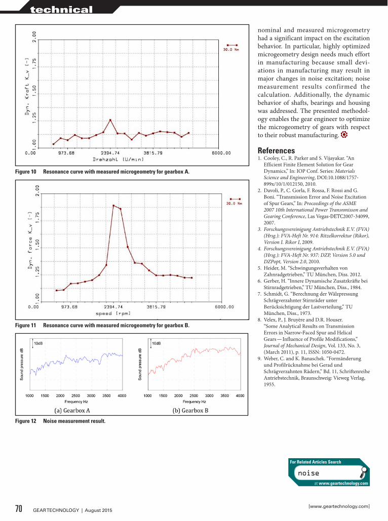
nominal and measured microgeometry had a significant impact on the excitation behavior. In particular, highly optimized microgeometry design needs much effort in manufacturing because small devi-ations in manufacturing may result in major changes in noise excitation; noise measurement results confirmed the calculation. Additionally, the dynamic behavior of shafts, bearings and housing was addressed. The presented methodol-ogy enables the gear engineer to optimize the microgeometry of gears with respect to their robust manufacturing.
References1. Cooley, C., R. Parker and S. Vijayakar. “An
Efficient Finite Element Solution for Gear Dynamics,” In: IOP Conf. Series: Materials Science and Engineering, DOI:10.1088/1757-899x/10/1/012150, 2010.
2. Davoli, P., C. Gorla, F. Rossa, F. Rossi and G. Boni. “Transmission Error and Noise Excitation of Spur Gears,” In: Proceedings of the ASME 2007 10th International Power Transnmisson and Gearing Conference, Las Vegas-DETC2007-34099, 2007.
3. Forschungsvereinigung Antriebstechnik E.V. (FVA) (Hrsg.): FVA-Heft Nr. 914: Ritzelkorrektur (Rikor), Version I. Rikor I, 2009.
4. Forschungsvereinigung Antriebstechnik E.V. (FVA) (Hrsg.): FVA-Heft Nr. 937: DZP, Version 5.0 und DZPopt, Version 2.0, 2010.
5. Heider, M. “Schwingungsverhalten von Zahnradgetrieben,” TU München, Diss. 2012.
6. Gerber, H. “Innere Dynamische Zusatzkräfte bei Stirnradgetrieben,” TU München, Diss., 1984.
7. Schmidt, G. “Berechnung der Wälzpressung Schrägverzahnter Stirnräder unter Berücksichtigung der Lastverteilung,” TU München, Diss., 1973.
8. Velex, P., J. Bruyère and D.R. Houser. “Some Analytical Results on Transmission Errors in Narrow-Faced Spur and Helical Gears — Influence of Profile Modifications,” Journal of Mechanical Design, Vol. 133, No. 3, (March 2011), p. 11, ISSN: 1050-0472.
9. Weber, C. and K. Banaschek. “Formänderung und Profilrücknahme bei Gerad und Schrägverzahnten Rädern,” Bd. 11, Schriftenreihe Antriebstechnik, Braunschweig: Vieweg Verlag, 1955.
Figure 12 Noise measurement result.
Figure 10 Resonance curve with measured microgeometry for gearbox A.
Figure 11 Resonance curve with measured microgeometry for gearbox B.
70 GEAR TECHNOLOGY | August 2015[www.geartechnology.com]
technical
noise
For Related Articles Search
at www.geartechnology.com

COBO HALLDETROIT, MICHIGAN
October 20 & 21, 2015Gear Technology Presents
An All-Star Review, Featuring Some of the TOP NAMES in Gear Technology.Bring your toughest gear manufacturing questions and get the answers, LIVE on the show floor:
Booth # 2030, Gear ExpoCobo Hall, Detroit Michigan
ASK-THE-EXPERT!LIVE
NO SEATS RESERVED
• GEAR GRINDING — Tuesday, 10/20 — 10:30 a.m.• CUTTING TOOLS — Tuesday, 10/20 — 2:00 p.m.• GEAR DESIGN — Wednesday , 10/21 — 10:30 a.m.• ASK ANYTHING — Wednesday, 10/21 — 2:00 p.m.

DVS GroupLAUNCHES AMERICAN DIVISION
“Wherever gears, engines and drivetrains for passenger cars and com-mercial vehicles are produced around the world, our technicians for service, technology and sales provide support for our customers,” says Bernd Rothenberger, Chief Sales Officer of the DVS Group.
“Local presence, competent communication, an understand-ing for custom requirements and direct access to the DVS devel-opment departments form the basis for successful collaboration,”
Rothenberger says.For these reasons, the group has founded
DVS Technology America Inc. in Michigan. The new company will bring together the group affiliates Buderus, Diskus, Präwema, Pittler, WMZ and Naxos to serve the automo-tive industry in North America.
The German DVS Group is a supplier of machine tools, automation solutions and tools for machining drivetrain components. DVS is an acronym stemming from the German words drehen (turning), verzahnen (gear cut-ting) and schleifen (grinding), describing the comprehensive range of know-how within the machine tool construction group.
Under the management of Ralf-Georg Eitel, the company will con-tinue to expand its presence in North America, in cooperation with the sales and service partners already established in the United States.
Timken Company ResearchersRECEIVE 2015 WILBUR DEUTSCH MEMORIAL AWARD
Research conducted by The Timken Company to address a crit-ical issue for wind turbine operators received the 2015 Wilbur Deutsch Memorial Award from the Society of Tribologists and Lubrication Engineers (STLE). Timken researchers used their technological expertise to solve customer problems in the wind energy sector and underscored the value of Timken wear-resis-tant bearings in helping to prevent smearing damage to turbine gearbox bearings.
Dr. Ryan Evans, manager of engineering fundamentals and physical testing at Timken, led a team of researchers in inves-tigating the root cause of smearing damage to turbine gearbox bearings manufactured by various companies. It was known that lightly-loaded, high-speed shaft bearings (usually cylindri-cal roller bearings, or CRBs) in turbine gearboxes sometimes exhibited smearing damage in bands across various surface areas. These smeared areas can be initiation points for much more severe damage over the service life of a bearing.
The specific bearing assembly dynamics that caused the smearing were not well understood, and other researchers had been unable to reproduce the damage on full-size CRBs in a laboratory.
“It took us a few months and some creative test-rig settings and instrumentation to determine how to generate the smear-ing damage. In addition, we recognized the importance and
value of measuring key bearing dynamic attributes like cage slip in real time,” Evans said. “We took it a step further and were able to model the test conditions using the Timken CAGEDYN dynamic model, which led to a proposed ‘smearing criterion’ that can be used to assess smearing risk in other bearings and
72 GEAR TECHNOLOGY | August 2015[www.geartechnology.com]
industry news
Ralf-Georg Eitel (left) and Bernd Rothenberger

dynamic situations.“As that was the only way we could reproduce the damage in
a laboratory, others outside Timken increasingly point to the same mechanism as an explanation for not only smearing, but other types of bearing damage in real wind turbines.”
Comet SolutionsPARTNERS WITH BRIAN WILSON
Comet Solutions, Inc. recent-ly announced a partnership with Brian Wilson of Advanced D r i v e t r a i n E n g i n e e r i n g & Technology (ADET). This part-nership is expected to strengthen Comet’s commitment to providing solutions to designers and manufac-turers of transmissions, axles, indus-trial gearboxes, and other power transmission products.
Wilson brings to Comet over 25 years of experience in the design, testing and analysis of rotating machinery. His experi-ence includes Romax Technology, Inc. where he served as chief technology officer, Ford Motor Company where he held the position of NVH technical specialist and work as a consultant for SDRC (now Siemens PLM). He currently serves as vice-chair on the AGMA Sound & Vibration Committee and sits on ASME’s Power and Transmission Gearing Committee.
Wilson will focus on expanding the market for Comet’s exist-ing drivetrain-related SimApps and guiding Comet product line expansion in order to broaden coverage of drivetrain engineer-ing. In addition, the partnership delivers technical support and service for Comet customers to receive the most impact from their investment in Comet.
“We are excited that Brian will join our team and add his cre-dentials to Comet’s list of expert resources,” said Dan Meyer, Comet Solution president and CEO. “Leveraging Brian’s CAE software, test systems, and consulting expertise further advanc-es Comet’s commitment to deliver innovation within practi-cal applications. Brian is a natural fit for our organization and vision, and we look forward to the many benefits he brings to our growing customer base.”
“Comet is emerging as a key player within the world of sim-ulation-led new product development,” Wilson added. “After a thorough investigation of Comet’s unique approach to CAE engineering, it was apparent to me that we share a common interest of putting advanced tools and technology in the hands of designers and analysts. I am excited to add my experience with that of Comet to further automate and streamline drive-train-development processes.”
73August 2015 | GEAR TECHNOLOGY
[ ]• Spur / Helical up to 59" O.D. – 26" Face• Accurate quotes – Competitive prices –
Fast turn-around• Emergency “breakdown” support• Support system for OEM parts
• Full complement of testing equipment for complete and comprehensive charting. Calibrated and certified on a regular schedule.
PRECISION GEAR GRINDING
tel.773-376 4906 fax.773-376 4946
Accudrive http://www.accudrv.com/index.html
1 of 2 9/24/2013 11:25 AM
Trusted by OEM, MRO and Gear Job Shop customers for nearly two decades.Your project is as important to us as it is to you.
(773) 376-4906www.Accudrv.com
KISSsoft USA, LLC3719 N. Spring Grove Road
Johnsburg, Illinois 60051Phone (815) 363 8823
Release 03/2015
NEW
KISSsoft Highlights● Risk assessment of flank fracture for cylindrical gears● Contact analysis for bevel gears● Planet carrier deformation with FE calculation● Housing stiffness in KISSsys● Modal analysis of shaft systems● And many more ...
Get your free trial version at www.KISSsoft.com
GearTech_KISSsoft_Rel_03_2015_Highlights_89x120_5mm.indd 1 19.03.2015 15:18:24

Joel RadnerNAMED SALES MANAGER OF SECO’S ROUND TOOL DIVISION
Seco Tools, LLC recently named Joel Radner sales manager for its round tools division in North America. Radner brings more than seven years of Seco experience to the position, having previously served as the company’s market segment spe-cialist for aerospace and power gen-eration.
In his new role, Radner will be responsible for all North American sales activities as they pertain to the company’s solid round tool product offerings, which include items from the Jabro and Niagara Cutter lines.
His primary directives involve establishing realistic sales goals, maximizing sales revenues and managing sales person-nel — all while following “The Seco Way,” principles that guide how the company applies global resources to help customers overcome unique machining challenges.
Radner began his Seco career in April 2008, as a technical specialist responsible for the application and sale of indexable solid carbide cutting tools in the Northeastern portion of the United States.
According to Mike Parker, director of national sales for Seco Tools, LLC, Radner’s proven performance record along with his industry expertise will allow Seco to continue moving forward with its aggressive market share growth plan.
“Joel has always been a valued member of the Seco team,” said Parker. “He easily identifies with our customers and has a successful track record when it comes to establishing win-win relationships. I am confident he will put us in the best possible position to better serve our customers and take our round tool sales to the next level.”
Roger JonesRECEIVES 2015 HTS GEORGE H. BODEEN HEAT TREATING ACHIEVEMENT AWARD
Roger Jones, corporate presi-dent of Solar Atmospheres, Inc., Souderton, PA, was recently named the recipient of the 2015 George H. Bodeen Heat Treating Achievement Award.
Established in 1996, the award recognizes distinguished and sig-nificant contributions to the field of heat treating through leadership, management, or engineering devel-opment of substantial commercial impact. Jones was recog-nized “for advancing the thermal processing industry through technological developments in fixturing materials, methods,
and the application of partial pressure atmospheres in vacuum furnaces for ferrous, stainless steels, and brass alloys.”
After graduating from Hocking Technical College, Jones joined ABAR Corp. in 1975. In 1978, he joined Vacuum Furnace Systems Corp., founded by his father William R. Jones, FASM. In 1983, he helped found Solar Atmospheres, Inc., serving as vice president. He became president in 1993 and became corporate president in 2001. He has been a member of the Metal Treating Institute since 1983, serving on the Board of Trustees (1998-2004, and 2009-present), and as president (2004-2005).
Roger has been a member of the ASM Philadelphia Liberty Bell Chapter since 1983, and served as chapter chair from 1993-1994. He was chair of the ASM Heat Treating Society (HTS) Immediate Needs Committee and the HTS Education Committee, served on the Nominating Committee for two terms, and is a member of the HTS Technology & Programming Committee. He was elected to the HTS Board in 2005, served as vice president (2011-2013) and is the cur-rent president of HTS. He received the chapter’s William Hunt Eisenman Award in 2001 and Distinguished Service Award in 2004. Under his leadership, Solar Atmospheres received the chapter’s “Outstanding Company Support Award” in 1996 and 2006.
The Bodeen award will be presented at the HTS General Membership Meeting on Oct. 21, at the ASM Heat Treating Society Conference and Exposition in Detroit.
Gary HulianNAMED EMCO MAIER/MECOF PRESIDENT
E MC O Mai e r / E MC O Me c of Corporation (Novi, MI) recent-ly named Gary Hulihan its new president, according to Dr. Stefan Hansch, EMCO Group CEO.
Hulihan has held key positions with German-based machinery manufacturers including EMAG, Ex-Cell-O and Eldec.
Hulihan said the chief compa-ny goal is to continue the EMCO Maier/Mecof tradition of serving their customers with cost-effective manufacturing solutions and world class service sup-port. EMCO Maier/Mecof has supplied CNC milling, turn-ing and multitasking machines for a wide span of industries, including educational, die/mold, mechanical components, auto-motive, aerospace, medical, hydraulic, power generation and more.
“We have a solid core group of highly competent associates and dealers and we will continue to work hard to exceed the expectations of our customers with the highest quality machine tools and professional competence in applications engineering and service,” Hulihan said.
74 GEAR TECHNOLOGY | August 2015[www.geartechnology.com]
industry news

Scott SheaNAMED NEW CHIEF OPERATING OFFICER OF CRP INDUSTRIES
CRP Industries Inc. recently named Scott Shea its new chief operating officer (COO). Daniel N. Schildge, CEO of CRP Industries Inc., noted that this was a newly created execu-tive role in the company. As COO, Shea will be responsible for supply chain management, operations, the CRP Industrial Group and CRP de Mexico.
“We are p o s i t i on i ng C R P Industries for long term growth and the potential for inte-grating future business opportunities,” Schildge said. “Scott Shea will play a key role in helping us to not only continue the momentum that we have built here at CRP, but also help us to achieve our goals for growth and expansion. Scott brings us a wealth of experience and expertise in leading high performing, medium-size companies serving mass market and independent retailers, wholesale distributors, and end users.”
Shea comes to CRP Industries after serving as the chief oper-ating officer for Astriva, LLC since 2010. Prior to that, Shea worked for CSS Industries, Inc., serving as the divisional presi-dent for Berwick Offray, LLC. Before joining CSS Industries, Shea spent 14 years at E.I. DuPont where he held several man-agement and engineering positions.
Shea holds a B.S. in mechanical engineering from Michigan State University. Shea is also a current member of the Board of Trustees for the Berwick Hospital Center (Berwick, PA) and the Berwick YMCA (Berwick, PA).
ABB RoboticsTO BECOME FIRST GLOBAL INDUSTRIAL ROBOTICS COMPANY TO MANUFACTURE ROBOTS IN THE UNITED STATES
ABB recently announced that it is to start producing robots in the United States, making it the first global industrial robot-ics company to fully commit and invest in a North American robotics manufacturing footprint. The company made the announcement at the opening of a new robotics plant at its facility in Auburn Hills, MI. Production is to commence imme-diately.
The new plant is ABB’s third robotics production facil-ity, alongside Shanghai, China, and Västerås, Sweden, and will manufacture ABB robots and related equipment for the North American market.
The United States is ABB’s largest market with $7.5 billion in sales. The company has invested more than $10 billion in local R&D, capital expenditure and acquisitions since 2010, taking local employment from 11,500 to 26,300.
75August 2015 | GEAR TECHNOLOGY
TO WORK FOR YOU
GEAR DESIGN
PUTTING A LIFETIME
OF
EXPERIENCE
•Reverseengineering•Gearboxupgrades•Customgearboxdesign•Specificationdevelopment•Projectmanagement•Vendorqualification
•Designreviews•Bidevaluations•Toolingdesign•Customizedgeartraining•Equipmentevaluation•Custommachinedesign
Charles D. [email protected]
[630] 209-1652
www.beytagear.com

calendar
August 10-12 — MPIF’s Basic PM Short Course Penn Stater Conference Center Hotel, State College, PA. This intensive 3-day course is designed especially for you, if you are starting out in the field and looking for an introduction to powder metallurgy (PM); updating your knowledge of recent developments in PM; seeking to expand your current knowledge of the PM industry; a user of PM parts or are considering PM. This course is designed for engineers, tool designers, metallurgists, supervisors and technicians. For more information, visit www.mpif.org.
September 13-15 — TECHINDIA 2015 Bombay Exhibition Centre, Mumbai, India. TECHINDIA will be the ultimate facilitator for b2b cooperation between manufactur-ers and consumers of all hues connected to the engineering, machinery and manufacturing industry. This leading business event is co-located with five other industry events to make it an extended platform for metal, engineering, manufacturing and machine tools industry: World of Metal – International Exhibition on Metal Producing, Metal Processing and Metal Working Industry; CWE – International Exhibition on Cutting and Welding Equipment; IMEX – International Exhibition on Machine Tools and Engineering Products; UMEX – International Exhibition on Used Machineries; Hand Tools and Fasteners Expo – International Exhibition on Hand Tools and Fasteners. The co-location of industry events will maximize business opportunities for industry professionals. For more information, visit techindiaexpo.com.
September 21-23 — Gear Failure Analysis Big Sky Resort, Big Sky, MT. Explore gear failure analysis in this hands-on seminar where students not only see slides of failed gears but can hold and examine those same field samples close up. Experience the use of microscope and take your own contact pat-tern from field samples. Cost is $1,600 for members and $2,100 for non-members. For more information, visit www.agma.org.
September 29-October 1 — 2015 Gear Manufacturing Seminar Hyatt Regency, Rochester, NY. This seminar provides the gear design engineer with a broad understanding of the methods used to manufacture and inspect gears and how the resultant information can be applied and interpreted in the design process. Following this seminar, partic-ipants will be able to identify methods of manufacturing external and internal spur, single and double helical, and bevel and worm gears, describe the methodology ad underlying theory for basic manufacture and inspection of each, and much more. Cost is $1,430 for member and $1,930 for non-members. For more infor-mation, visit www.agma.org.
October 4-7 — Euro PM2015 Congress & Exhibition Reims Congress Centre, Reims, France. Europe’s annual powder metallurgy congress and exhibition, organized and sponsored by the European Powder Metallurgy Association, will return to France in 2015. The combination of a world class technical program and state-of-the art exhibition will provide the ideal networking opportunity for suppliers, producers and end-users. The program of plenary and keynote addresses, oral and poster presentations and special interest seminars will focus on: additive manufacturing; hard materials and diamond tools; hot isostatic pressing; new materials and applications; and more. Alongside the technical sessions the Euro PM2015 Exhibition will be an excellent opportunity for international suppliers to the PM industry to network with new and existing customers from the powder metallurgy and associated sectors. For more infor-mation, visit www.europm2015.com.
October 7-8 — Design & Manufacturing Philadelphia Pennsylvania Convention Center, Philadelphia, PA. As the United States’ first major industrial city, Philadelphia continues to grow into a leading design and manufacturing hub across a wide variety of industries. With manufactured goods exports increasing twice as fast as the overall stateSeconomy, accounting for 87.8% of all state total exports, now is the time to bring everyone within this com-munity to one dedicated design and manufacturing event to spark new ideas and partnerships. See the newest technologies, equipment, products, and services and get real time answers to your questions from industry experts. The educational offer-ings bring you the latest in manufacturing trends and applica-tions with comprehensive full day conferences across both days of Design & Manufacturing Philadelphia. For more informa-tion, visit www.dmphilly.designnews.com.
October 20-22 — Gear Expo 2015 Cobo Center, Detroit, MI. Gear Expo was recognized by Trade Show Executive magazine as one the 50 fastest-growing shows in 2013. For more than two decades, power transmission profession-als — including CEOs, owners, presidents, engineers, marketing and sales managers, consultants and other executives have come to Gear Expo to learn the latest industry information and see firsthand technology, products, and services that help them expand and streamline their business. Attendees repre-sent a variety of industries including off-highway, industrial applications, automotive, and oil and gas as well as aerospace, agriculture and construction. They come from around the United States, international manufacturing hubs, and emerging markets to conduct profitable business transactions and col-laborate on the innovations that make their operations more streamlined. Exhibitors have the opportunity to meet face-to-face with attendees. For more information, visit www.gearexpo.com.
October 27-29 — Modern Furnace Brazing School Brazing Engineering Center, Wall Colmonoy Aerobraze Division, Cincinnati, OH. The late Robert Peaslee’s tradition continues with the return of the brazing school. The Brazing Engineering Center provides engineering services and training, as well as offering new practical experience on the shop floor. For over 60 years, Wall Colmonoy engineers have gained practi-cal experience on actual problems in brazing plants around the world. Knowledge and practical application will be taught by industry-leading brazing experts. In 1950, Peaslee developed the first nickel-based brazing filler metal, Nicrobraz. Modern Furnace Brazing School will allow you to apply workable solu-tions to your brazing needs. For more information or to register, contact [email protected].
October 27-29 — Discover 2015 Florence, KY. Mazak Corporation encourages those involved in the metalworking industry to attend its Discover 2015 technology and education event. Here, the machine tool builder plans to spotlight new technologies and trends that will change how part manufactur-ers operate, including unconventional ways to drive operational efficiency via additive manufacturing, CNC technology and the Industrial Internet of Things (IIoT) concept. Additive manu-facturing is creating a shift in the way engineers and designers think about product development, and Mazak is leading the way with its additive-capable Integrex i-400AM. The Hybrid Multi-Tasking machine will make its North American debut at Discover 2015. For more information, visit www.MazakUSA.com/DISCOVER2015.
76 GEAR TECHNOLOGY | August 2015[www.geartechnology.com]

FREE SUBSCRIPTIONGear Technology, is the world’s leading publication on gear design, engineering and manufacturing. To sign up or renew your FREE SUBSCRIPTION use the form below.
Company Name: ______________________________________________________
Address: ______________________________________________________________
_______________________________________________________________________
_______________________________________________________________________
City: __________________________________________________________________
State/Province: ___________________ ZIP+4/Postal Code: __________________
Country: ______________________________________________________________
Telephone: __________________________Fax: ______________________________
E-mail: _______________________________________________________________
Website: ______________________________________________________________
(print)
❏ Corporate Executive (B)❏ Manufacturing Production Management (C)❏ Manufacturing Production Department (D)❏ Manufacturing Engineering Management (E)❏ Manufacturing Engineering Department (F)❏ Product Design, R&D Management (H)❏ Product Design, R&D Department (I)
❏ Purchasing (L)❏ Marketing, Sales or Communications (M)❏ Quality Control Management (P)❏ Quality Control Department (Q)❏ Other (Please describe) (N)
______________________________
What is your primary JOB FUNCTION(check ONLY one)
FAX TO 1-847-437-6618 orVISIT US ONLINE AT
www.geartechnology.com/subscribe.htm
❏ YES, I want to be notified each issue when Gear Technology is available online
❏ YES, I would like to receive Gear Technology’s monthly e-mail newsletter
❏ YES, I would like to receive Gear Technology’s twice monthly e-mail Product Alerts
❏ YES, I would like to receive 3rd-party e-mails from Gear Technology’s advertisers and partners
❏ YES, I would like to receive subscription renewal notices by e-mail
❏ No, I do not wish to be contacted by e-mail.
(So we can notify you when the online edition is available)SAVE a TREE!
I ONLY want the digital edition (e-mail required)
DIGITAL SUBSCRIPTIONS
1
YES I want to receive/continue to receive Gear Technology FREE!
No thank you.
Name:_________________________________________JobTitle/Position: ___________________________
Signature _____________________________________________________ Date: ______________________
2 E-mail __________________________________________________________
3 Please update your contact information orattach you business card here. (No Staples)
4
FIND THE EXACT SUBJECTS YOU ARE LOOKING FOR: Subscribers now get access to the 30 years of searchable articles in our online archive.
(required)
My company MAKES gears (20) My company BUYS gears (22) I DESIGN gears (23) I am a SUPPLIER to the GEAR INDUSTRY
(please specify product or service) (24) _______________________________________
6 How are YOU involved with gears (check all that apply)?
Is there a colleague within your company that might benefit from having their own copy of Gear Technology magazine?
Name: _______________________________________________
Title: ________________________________________________
5 My company’s principal product or service is:________________________

ad index
GLEASONGEAR EQUIPMENT
www.gearmachineryexchange.com
GENERATORSModel 645 Hypoid Generators,
loaded with every option, from Aircraft 1980
Model 26 Hypoid, Rough & Finish Cams, Modified Roll, from
AircraftModel 642 G-Plete, Hypoid 13" (330 mm), Helical Motion,
FORMATE, Excellent, 1982Model 116 & 118 Hypoid,
Rough & finish Cams, FORMATE, from Aircraft 1967 & 1966Model 106 & 108 Hypoid, Rough & finish Cams, Helical
Motion, FORMATE, from Aircraft 1960 & 1964
Model 14 Coniflex Straight Rough & Finish, Complete
TESTERSModel 27M Hypoid
30.5" (925 mm), #60/#39 Tapers, From Aircraft, 1961Model 502 Hypoid
10.5"/6" (270 mm/155 mm)#39/#14 Tapers
From Aircraft, 1964Model 13 Universal,
13" (335 mm) #18From Aircraft
Model 6 Split Head Universal,7.5" (190 mm)
From Aircraft, 1958 & 1966Model 6 Solid Head Universal,
7.5" (190 mm), From Aircraft
3M Abrasive Systems Division – Page 33www.3m.com/EXTREMEPrecisionPowertrain
Accu-Drive Inc. – Page 73www.accudrv.com
AGMA – Page 27www.agma.org
All Metals & Forge Group, LLC – Page 36www.steelforge.com
Arrow Gear Co. – Page 19www.arrowgear.com
ATA Gears Ltd. – Page 44www.atagears.fi
B&R Machine and Gear Corp. – Page 21www.brgear.com
Banyan Global Technologies – Page 47www.banyangt.com
Beyta Gear Service – Page 75www.beytagear.com
Bourn & Koch, Inc. – Page 15www.bourn-koch.com
Brevini Wind USA – Page 22brevinigear.com
The Broach Masters & Universal Gear – Page 25www.broachmasters.com
Broaching Machine Specialties –Page 46www.broachingmachine.com
Circle Gear – Page 79www.circlegear.com
DTR USA Corp. – Page 31www.dragon.co.kr
EFD Induction – Page 48www.efd-induction.com
Excel Gear – Page 14www.excelgear.com
Foerster Instruments, Inc. – Page 4www.foerstergroup.de
Forest City Gear – Page 7www.forestcitygear.com
The Gear Machinery Exchange – Page 78www.gearmachineryexchange.com
Gleason Corporation – Page 40-41www.gleason.com
GMTA - German Machine Tools of America – Page 13www.gmtamerica.com
Hans-Juergen Geiger Maschinen-Vertrieb GmbH – Page 32www.geiger-germany.com
Hardinge Group – Pages 11, 46www.hardingegrindinggroup.com
Heavy Carbon Company – Page 79www.heavycarbon.com
Heiko Machine Tools – Page 46www.heikomachine.com
Index Technologies – Page 79www.gallenco.com
Ingersoll Cutting Tools – Page 57www.ingersoll-imc.com
Ipsen International – Page 45www.ipsenusa.com
Kapp Technologies – Page 3www.kapp-usa.com
KissSoft USA, LLC – Page 73www.kisssoft.ch
Klingelnberg – Outside Back Coverwww.klingelnberg.com
Koepfer America LLC – Page 24koepferamerica.com
Koro Sharpening Service – Page 79www.koroind.com
Liebherr – Page 5www.liebherr.us
Luren Precision – Page 18www.luren.com.tw
Mcinnes Rolled Rings – Page 38www.mcinnesrolledrings.com
Micro Surface Corporation – Page 79www.microsurfacecorp.com
Midwest Gear & Tool, Inc. – Page [email protected]
Mitsubishi Heavy Industries America – Page 8www.mitsubishigearcenter.com
Mitsubishi Materials – Page 26www.mmus.com
Nachi America – Page 20www.nachiamerica.com
Nordex Inc. – Page 37www.nordex.com
Oelheld U.S., Inc. – Page 47www.oelheld.com
Paulo Products – Page 48www.paulo.com
Pentagear Products – Page 12www.gearinspection.com
Phoenix Tool & Thread Grinding – Page 79www.phoenixthreadgrinding.com
Presrite Corp. – Page 39www.presrite.com
Rave Gears & Machining – Page 17www.ravegears.com
Reishauer – Page 23www.reishauer.com
Schnyder S.A. – Page 4www.hanikcorp.com
SMT—Smart Manufacturing Technology – Inside Back Covermasta.smartmt.com
Solar Atmospheres – Pages 43, 47solaratm.com
Star SU LLC – IFC-Page 1, Page 79www.star-su.com
Stresstech Oy – Page 29www.stresstechgroup.com
TECO Werkzeugmaschinen GmbH – Page 28www.teco-germany.com
Weldon Solutions – Page 35www.weldonsolutions.com
CORRECTIONIn the July issue feature, “New Transmissions Make the Grass Greener,” the company name — Ricardo Incorporated — was mistakenly listed. Gear Technology sincerely regrets the error.
CORRECTIONIn the July issue of Gear Technology we incorrectly attributed a photo of a batch furnace on page 34 of the article “Don’t Get Burned” to Applied Process, Inc. The photo should have been attributed to AFC Holcroft. Gear Technology regrets this error.
78 GEAR TECHNOLOGY | August 2015[www.geartechnology.com]

SHARP HOBSChange Downtime To Productivity
You Need Your Tools Back FAST– Eliminating Downtime &Tuned To Meet or Surpass Original Design Specsand That’s Where We Come In
• Stripping & Re-Coating
• Gear Shaper Sharpening
• Milling Cutter Sharpening
• Gear Tool Certifications
Tel: 216-642-5900 • Fax: 216-642-8837 • 5755 Canal Road • Valley View, OH 44125Email: [email protected] WWW.GALLENCO.COM
4760 Briar Rd, Cleveland, OH 44135Phone: 216-433-7008 Fax: 216-433-7067
• CNC External Thread Grinding Specialists• Emergency Service Available
• Any thread form• Any lead• Multiple starts
PHOENIXTOOL & THREAD GRINDING
Dry Lube Coating
Call on MicroSurfacefor unbeatable prices!
CALL: (408) [email protected]
• WS2• MoS2• PTFE
MS 1-9pgAd.indd 1 3/4/15 3:12:22 PM
Circle Gear and Machine
• Reverse Engineering• Design Analysis• Complete Machine Shop Including CNC Machining
Documented Quality Control Program
Inspection Lab including Complete
Gear Tooth Diagnostics
1501 South 55th Ct. • Cicero, IL 60804Ph: 708-652-1000 • Fax: 708-652-1100
Quality Custom Gearing Since 1951
Please email your inquiries to [email protected] • www.circlegear.com
Tooth Cutting, Grinding & Shaving Services Available
CG C
C I R C LE
G E A R C O
QUALITY CUSTOM GEARING!
All Sizes & Configurations
QUALITY CUSTOM GEARING!
For the Highest QualityGear Heat Treating
The Endocarb System fromThe Heavy Carbon Co. LLC
• Carburize 30% Faster• 50% Less energy
• Retrofit on existing furnace
Effective case depthStandard Carburizing140 hours = .263 ECD
Endocarb100 hours = .262 ECD
See for yourself and send us your gears to test!
See us at the ASM Heat Treat Detroit Show – Booth 114Co-located with Gear Expo
79August 2015 | GEAR TECHNOLOGY
classified

Look at that picture right over there on the right. That’s one of the Bronze Wheels of Peru. Looks like a gear, doesn’t it? If you knew nothing about it or the culture it sprang from and just happened to see it on the street, you’d probably label it as such. So many people have had that same thought, in fact, that the set has picked up another name: the Bronze Gears of Peru.
Here’s the thing: they aren’t gears. Despite appearances, the Bronze Wheels of Peru are actually mace heads.
Much like with our own modern culture, everything is con-nected to everything in the ancient civilizations archaeologists study. The issue, and the reason that myths like these “gears” pop up, is that the archaeologists know enough to put those connections together, while the laymen just look at the Bronze Wheels and dub them gears.
Here’s where things get even dicier. If the Bronze Wheels were, in fact, gears, they would be what peo-ple call an “out-of-place artifact.” Out-of-place arti-facts are basically archaeological “finds” that, accord-ing to the years of study and evidence that forms our under-standing of conventional archaeology, just plain shouldn’t exist. The Bronze Wheels of Peru, for example, were created in a time and place where gears aren’t recorded existing.
The problem is that out-of-place artifacts aren’t exactly sci-entific. They’re basically fodder for every conceivable form of pseudoscience and conspiracy theory you can think of, from aliens giving us technology in ancient times to the actual, literal existence (or rather, former existence) of Atlantis. The reason many out-of-place artifacts “shouldn’t exist” isn’t because we’ve never found any of them before, but because there’s a wealth of evidence actively pointing out that, in fact, they shouldn’t. Often, these artifacts are touted about as incredible new dis-
coveries that will revolutionize our view of an entire culture, but the reason they go against the grain is usually because one person screwed up and made a faulty leap of logic rather than because all of generally accepted archaeology is wrong.
People sensationalize and cling to these artifacts for the same reason that sci-fi in almost every form of media loves to drop the line “Einstein was wrong!” It’s exciting! It fundamentally changes something about the way the world works! And unless you dig deeper than that enthusiastic Facebook post, it makes perfect sense! When looking at the logic behind the Bronze Wheels of Peru and other out of place artifacts as a wholly insular bubble, it holds up solely because there’s nothing to contradict it.
In the Bronze Wheels’ case, yes, they look like gears. This is how archaeologists and regular people alike jump to incorrect conclusions. But remember: In archaeology, as with any other culture, everything informs everything, and in the case of the Bronze Wheels, everything else points to a different explana-tion.
Everywhere the Bronze Wheels are referred to as gears, the name Rafael Larco Hoyle also comes up. Hoyle was a profes-sor and museum curator who lived in the 20th century. His book, “Peru,” is one of the first sources to ever mention the Wheels. The only problem with conspiracy theorists that name drop Hoyle is that he has never, at any point, referred to them as gears. In fact, he states in his book that they are mace heads belonging to the pre-Columbian Vicus culture, putting him in agreement with conventional archaeologists.
The moral of the story? Don’t trust everything you find on the Internet, and always dig a little deeper than just a single
post. Otherwise, you might get caught up in a con-spiracy theory about aliens giving us gears.
A Gear is a Gear is a Gear,Except When it Isn’tAlex Cannella
Copper mace head, 200 B.C - A.D. 200, from the Vicus culture of Peru. Photo courtesy of the Metropolitan Museum of Art (Bequest of Jane Costello Goldberg, from
the Collection of Arnold I. Goldberg, 1986).
These bronze mace heads were first described in the book Peru, by Rafael Larco Hoyle. Unfortunately, they've also been described
as gears on a number of conspiracy sites online.
80 GEAR TECHNOLOGY | August 2015
addendum

Visit our demonstration stand at booth 2207
All over the world gear manufacturers highly appreciate Klingelnberg
solutions. With an Oerlikon spiral bevel gear cutting machine C 50 for
gears up to 500 mm in diameter you “draw the bow” like no one else.
Combined with a Klingelnberg P 65 measuring center, wich totally fi ts
to the Oerlikon cutting machine C 50 due to interacting software
components, you “hit the mark” with the highest precision.
Take your advantages in gear manufacturing
with the accuracy of Klingelnberg solutions.
Hit The Mark: KLINGELNBERG America, Inc.
www.klingelnberg.com p. +1 734 470 6278
www.hofl er.com e. [email protected]
HIT THE MARK.MAXIMUM ACCURACY SOLUTIONS
FOR BEVEL GEAR MANUFACTURERS
BY KLINGELNBERG
SUB
JEC
T TO
CH
AN
GES
.
NEXT FAIRS:
EMO MILANOOct 5-10, 2015Hall 4 Booth D23Milano, Italy
GEAR EXPOOct 20-22, 2015Booth 1410Detroit, USA
MEASURING TECHNOLOGY
KLINGELNBERG
CYLINDRICAL GEAR TECHNOLOGY
HÖFLERDRIVE TECHNOLOGY
KLINGELNBERG
BEVEL GEAR TECHNOLOGY
OERLIKON