DT 48 Dethatcher Manual
12
L-1763-B OWNER'S MANUAL For the latest product updates and setup tips: Visit us on the web! www.brinly.com MODEL: Important: This manual contains information for the safety of persons and property. Read it carefully before assembly and operation of the equipment! Assembly Installation Operation Repair Parts DETHATCHER DT-48 BH
-
Upload
khangminh22 -
Category
Documents
-
view
1 -
download
0
Transcript of DT 48 Dethatcher Manual

L-1763-B
O W N E R ' S M A N U A L
For the latest product updates and setup tips:
Visit us on the web!www.brinly.com
MODEL:
Important: This manual contains information for the safety of persons and property. Read it carefully before assembly and
operation of the equipment!
AssemblyInstallationOperationRepair Parts
D E T H A T C H E R
DT-48 BH

L-1763-BL-1763-B2. 11.
________________
________________
________________
CONGRATULATIONS on the purchase of your Dethatcher! Your Dethatcher has been designed, engineered and manufactured to give you the best possible dependablility and performance.
CUSTOMER RESPONSIBILITIESPlease read and retain this manual. The instructions enables you to assemble and maintain your dethatcher properly. And please, always observe the "Safety" instructions.
TABLE OF CONTENTS SAFETY ............ ..............................................................2-3 PARTS REFERENCE ......................................................4 PARTS LIST......................................................................4 ASSEMBLY ......................................................................5-9 OPERATION.....................................................................10 SERVICE..........................................................................10
PRODUCT IDENTIFICATION
PRODUCT COMPATIBLIITYThis dethatcher is designed for use with lawn tractors and lawn and garden tractors.
RECORD PURCHASE INFORMATIONRecord your purchase information in the spaces provided below.
DATE OF PURCHASE:
COMPANY NAME:
COMPANY PHONE:
SERIAL NUMBER:
SAFETY LABELSUNDERSTANDING THE MACHINE SAFETY LABELS
The machine safety labels shown in this section are placed in important areas on your machine to draw attention to potential safety hazards.
On your machine safety labels, the words DANGER, WARNING, and CAUTION are used with this safety-alert symbol. DANGER identifies the most serious hazards.
The operator's manual also explains any potential safety hazards whenever necessary in special safety messages that are identified with the word, CAUTION, and the safety-alert symbol.
________________
Safety-Alert Symbol

L-1763-B 3.
TO HELP PREVENT BODILY INJURY DUE TO LOSS OF STABILITY OR CONTROL.
Do not exceed maximum towing capacity of towing vehicle listed in the vehicle operator's manual.
Do not exceed 5 mph with this machine.
Do not tow this machine behind a motor vehicle such as a car, truck or ATV.
Do not tow this machine behind a ZTR (Zero Turn Radius) Mower.
SAFETYRead the general safety operating precautions in your towing vehicle operator's manual for additional safety information.
Operate Safely
Use dethatcher for intended purpose only.
This machine is intended for use in lawn care and home applications. Do not tow behind a vehicle on a highway or in any high speed applications. Do not tow at speeds higher than maximum recommended towing speed.
Towing speed should always be slow enough to maintain control. Travel slowly over rough ground.
Do not let children or an untrained person operate machine.
Do not let anyone, especially children, ride on this machine or the towing vehicle. Riders are subject to injury such as being struck by foreign objects and being thrown off. Riders may also obstruct the operator's view, resulting in this machine being operated in an unsafe manner.
Check towing vehicle brake action before you operate. Adjust or service brakes as necessary.
Keep all parts in good condition and properly installed. Fix damaged parts immediately. Replace worn or broken parts. Replace all worn or damaged safety and instruction decals.
Do not modify the machine or safety devices. Unathorized modifications to the towing vehicle or machine may impair its function and safety, and void the warranty.
Keep all nuts, bolts and screws tight.
TOWING SAFELYStopping distance increases with speed and weight of towed load. Travel slowly and allow extra time and distance to stop.
Total towed weight must not exceed limits specified in towing vehicle operator's manual.
Excessive towed load can cause loss of traction and loss of control on slopes. Reduce towed weight when operating on slopes.
Never allow children or others in or on towed equipment.
Use only approved hitches. Tow only with a towing vehicle that has a hitch designed for towing. Do not attach this machine except at the approved hitch point.
Follow the manufacturer's recommendations for weight limits for towed equipment and towing on slopes. Use counterweights or wheel weights as described in the towing vehicle operator's manual.
Do not turn sharply. Use additional caution when turning or operating under adverse surface conditions. Use care when reversing. To avoid jack-knifing, do not allow towing vehicle wheels to contact drawbar.
Do not shift to neutral and coast downhill.
Protect BystandersKeep bystanders away when you operate this machine
Before you back look carefully behind for bystanders.
Before you operate any feature of this machine, observe your surroundings and look for bystanders.
Keep Riders Off Towed AttachmentKeep riders off towed attachment.
Riders on a towed attachment are subject to injury, such as being struck by objects and being thrown off the attachment during sudden starts, stops and turns.
Riders obstruct the operator's view, resulting in the attachment being used in an unsafe manner.
Keep riders off of hitch bracket.
Keep Body Parts From Under Drawbar
Before you disconnect this machine from towing vehicle hitch plate:
• Stop on level ground.
• Stop towing vehicle engine.
• Lock towing vehicle park brake.
• Block wheels of the machine.
• Make sure body parts are not under drawbar.
SAFETY

L-1763-B4.
Exploded View
18
14
9
18 24
18
19
21 22
13 6 18
17
12
2
3
21
19
19 21
54
15
1623
23 20
819 21
11
Tools Required for Assembly: * 1/2" wrench (2)
* Medium Size Adjustable Wrenches or * Adjustable Wrench and set of open wrenches
* Pair of pliers
REF. NO.
1234567891011121314151617181920212223
DESCRIPTION
Logo DecalDrawbar PinHairpin Cotter, 1/8"TineSpecial WasherTray Mount BracketWarning DecalWheel Mount BracketEnd Plate (R.H.)End Plate (L.H.)WheelClevisPull BarTine TraySafety WireHex Head Bolt, 1/2" x 3"Carriage Bolt, 5/16" x 2"Carriage Bolt, 5/16" x 1"Hex Nut, 5/16"Hex Nut, 1/2"Lock Washer, 5/16" Flat Washer, 5/16"Flat Washer, 1/2"
QTY.
1111212 212112221222283043044
Parts List
PART NO.DT-48B-3686B-3861D-146PR-616R-618R-713-10R-1541R-2479-10R-889-10R-890-10R-891R-892-10R-1455-10R-1456-10R-15041M1648P10M1032P11M1016P30M1000P30M1600P40M1000P45M1111P45M1717P
STOPINSTALLATIONQUESTIONS?
MISSING PARTS?REPLACEMENT PARTS?
DON’T GO BACK TO THE STORE!Please call our Customer Service
Department Toll-Free at 877.728.8224
orwww.customerservice
@brinly.com
To Order Parts Call:877-728-8224
Visit us on the web:www.brinly.com

L-1763-B 5.
Figure 1.
Figure 2.
Dimples up
5/16" Hex NutQty. 10
195/16" Lock Washer
Qty. 10
21
5/16" x 1" Carriage BoltQty. 10
18
1921
5
18
Special WasherQty. 10
5
15 15
15
FRONT
NOTE: Insert each of the two safety wires(13) through the coils as shown.Be sure each end is bent completely over the straight portion of the safety wire.
!Failure to install safety wires can resultin personal injury if a tine should dis-engagefrom the tine tray.
WARNING!
Safety Wire bent end

L-1763-B6.
Figure 3.
Figure 4.
5/16" Hex NutQty. 4
5/16" Lock WasherQty. 4
21
5/16" x 1" Carriage BoltQty. 4
18
5/16" x 1" Carriage BoltQty. 4
18
5/16" Lock WasherQty. 4
21
5/16" Hex NutQty. 4
19
5/16" Flat WasherQty. 4
22
NOTE: Hand tighten drawbarfasteners until final adjustmentsare complete. (see fig. 9)
18
2221
19
19
21
18
NOTE: Tine and Tray MountBracket share the back, lefttray hole.
19

L-1763-B 7.
Figure 5.
5/16" Hex NutQty. 4
195/16" Lock Washer
Qty. 4
21
5/16" x 1" Carriage BoltQty. 4
18
Figure 6.
18
21
19
5/16" Lock WasherQty. 2
215/16" x 2" Carriage Bolt
Qty. 2
17
Drawbar PinQty. 1
2 Hairpin Cotter, 1/8"Qty. 1
3
5/16" Hex NutQty. 2
17
2
21
19 3
19

L-1763-B8.
Figure 8.
Figure 7.
1/2" Flat WasherQty. 4
231/2" x 3", Hex BoltQty. 2
161/2" Hex Nut
Qty. 4
20
16
20
2023
23
5/16" Hex NutQty. 4
195/16" Lock Washer
Qty. 4
21
5/16" x 1" Carriage BoltQty. 4
1819
2118

L-1763-B 9.
OPERATION
Tine ACTION- Grass should be less than 3" tall for proper tine action.
When in use, all tines on the De-thatcher should deflect back and "flip" the thatch forward as shown in Fig. 6.
If the tines seem to drag without flipping forward, the tine tray is too low and should be raised.
If all the tines stay in the free position, the tray should be lowered.
Make adjustments as necessary, up or down, by no more than 1/4" each time, until proper results are achieved.
MAINTENANCE
The key to years of trouble-free service is to keep your Sweeper clean and dry.
Occasionally check all moving parts for free movement and, if necessary, lubricate with oil.
Should rust develop, sand lightly and then paint area with enamel.
Periodically check all fasteners for tightness.
!
!
Level Adjustment
Height Adjustment
Flat Surface 1/2” Shim (board)
Figure 9.
Select a smooth flat surface such as a driveway, sidewalk, garage floor etc.
Attach the Dethatcher to your rider tractor using Drawbar Pin (2) and Hairpin Cotter (3)
Place tines on 1/2” shim to support the front andback row of tines.
Wheels must be on the flat surface as shown
Tighten all bolts from Fig. 2 and Fig. 6 to hold this position
MOUNTING AND ADJUSTMENT

L-1763-B10.
SERVICE
MAINTENANCE AND SERVICE NOTES
1. After the first 30 minutes of use check all fasteners for tightness.
2. Dethatching Tines are manufactured with special steels and are heat treated to resist wear of abrasive soil. Striking objects can cause tine breakage. Contact our Customer Service Department to purchase replacement Tines (Part# R-616)
SPECIFICATIONS
Maximum Towing Speed................................................5 mph
Empty Weight..........................................................37 Pounds
Maximum Towed Weight.........................................37 Pounds
GETTING QUALITY SERVICE
Quality Continues with Quality Service
We provide a process to handle your questions or problems.
Follow the steps below to get answers to any questions you mayhave about your product.
1. Refer to your attachment and machine operator manuals
2. In North America or Canada, call 1-866-288-6084 and provide product serial number and model number.
OPERATION
CAUTION: Avoid injury! Make sure feet and hands are clear of Tine Tips.
CAUTION: Avoid injury! Excessive towed load cancause loss of control on slopes. Stopping distance increases with speed and weight of towed load.
Total towed weight must not exceed combined weight of towing vehicle, ballast and operator.
INSTALLING DETHATCHER OPERATING
1. Lock towing vehicle in park. (See Towing Vehicle Manual)2. Align clevis with towing vehicle drawbar.3. Install clevis pin through clevis and vehicle drawbar and secure wih a locking pin
REMOVING DETHATCHER1. Secure towing vehicle parking brake.2. Remove all weight from the tray.
3. Remove cotter pin and drawbar pin.4. Push Dethatcher away from towing vehicle.5. Install drawbar pin and cotter pin roller towbar for storage.
CAUTION: Avoid injury! Keep feet away fromunder drawbar.
For best results, grass should be less than 3” tall. Shorter grass will improve tine action.
Tine Recommended Height:When in use the tine will engage the thatch and deflect to the rear as the Dethatcher is pulled forward. The spring will overcome the tension of the embedded thatch, and pull the thatch upward. If the tines are too low, the tine will not “flip” forward as desired.
Figure 1 shows the proper sequence of tine action.
Make adjustments as necessary up or down, by no more than 1/4” each time to achieve the desired result.
Speed:The best operating speed is 3mph or less.
Frequency:Dethatching is not accomplished in a single pass. It will normally take several passes over the lawn. Alternating the direction by 90 degrees will improve the dethatching effect.

L-1763-B 11.
L-1763-B
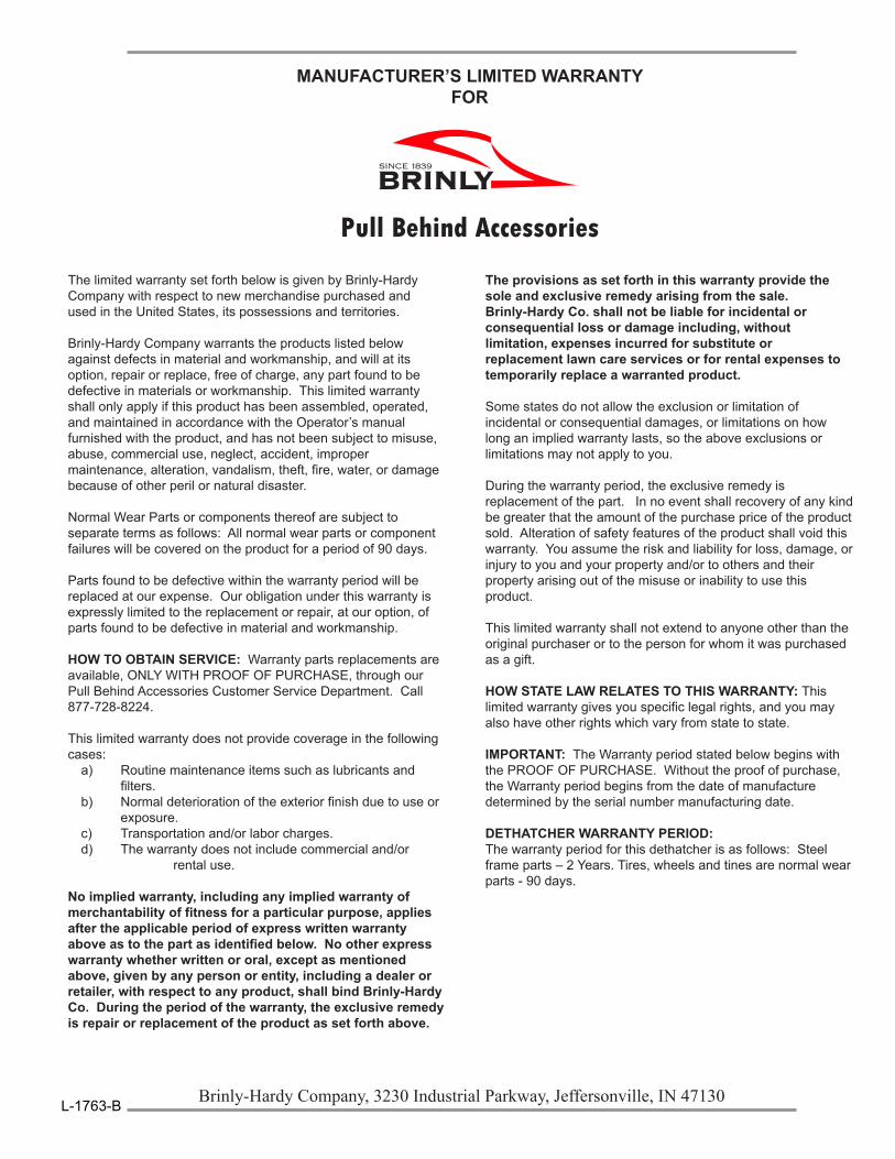
The limited warranty set forth below is given by Brinly-Hardy Company with respect to new merchandise purchased and used in the United States, its possessions and territories.
Brinly-Hardy Company warrants the products listed below against defects in material and workmanship, and will at its option, repair or replace, free of charge, any part found to be defective in materials or workmanship. This limited warranty shall only apply if this product has been assembled, operated, and maintained in accordance with the Operator’s manual furnished with the product, and has not been subject to misuse, abuse, commercial use, neglect, accident, improper maintenance, alteration, vandalism, theft, fire, water, or damage because of other peril or natural disaster.
Normal Wear Parts or components thereof are subject to separate terms as follows: All normal wear parts or component failures will be covered on the product for a period of 90 days.
Parts found to be defective within the warranty period will be replaced at our expense. Our obligation under this warranty is expressly limited to the replacement or repair, at our option, of parts found to be defective in material and workmanship.
HOW TO OBTAIN SERVICE: Warranty parts replacements are available, ONLY WITH PROOF OF PURCHASE, through our Pull Behind Accessories Customer Service Department. Call 877-728-8224.
This limited warranty does not provide coverage in the following cases:
a) Routine maintenance items such as lubricants and filters.b) Normal deterioration of the exterior finish due to use or exposure.c) Transportation and/or labor charges.d) The warranty does not include commercial and/or
rental use.
No implied warranty, including any implied warranty of merchantability of fitness for a particular purpose, applies after the applicable period of express written warranty above as to the part as identified below. No other express warranty whether written or oral, except as mentioned above, given by any person or entity, including a dealer or retailer, with respect to any product, shall bind Brinly-Hardy Co. During the period of the warranty, the exclusive remedy is repair or replacement of the product as set forth above.
MANUFACTURER’S LIMITED WARRANTY FOR
Pull Behind Accessories
The provisions as set forth in this warranty provide the sole and exclusive remedy arising from the sale. Brinly-Hardy Co. shall not be liable for incidental or consequential loss or damage including, without limitation, expenses incurred for substitute or replacement lawn care services or for rental expenses to temporarily replace a warranted product.
Some states do not allow the exclusion or limitation of incidental or consequential damages, or limitations on how long an implied warranty lasts, so the above exclusions or limitations may not apply to you.
During the warranty period, the exclusive remedy is replacement of the part. In no event shall recovery of any kind be greater that the amount of the purchase price of the product sold. Alteration of safety features of the product shall void this warranty. You assume the risk and liability for loss, damage, or injury to you and your property and/or to others and their property arising out of the misuse or inability to use this product.
This limited warranty shall not extend to anyone other than the original purchaser or to the person for whom it was purchased as a gift.
HOW STATE LAW RELATES TO THIS WARRANTY: This limited warranty gives you specific legal rights, and you may also have other rights which vary from state to state.
IMPORTANT: The Warranty period stated below begins with the PROOF OF PURCHASE. Without the proof of purchase, the Warranty period begins from the date of manufacture determined by the serial number manufacturing date.
DETHATCHER WARRANTY PERIOD:The warranty period for this dethatcher is as follows: Steel frame parts – 2 Years. Tires, wheels and tines are normal wear parts - 90 days.
Brinly-Hardy Company, 3230 Industrial Parkway, Jeffersonville, IN 47130