Enclousre-21 TECHNICAL SPECIFICATION कायª का वणªन ...
87
Tender No: 1900000110 1 | Page Enclousre-21 TECHNICAL SPECIFICATION काय का वणन DESCRIPTION OF WORK Supply, Installation, Testing & Commissioning of Fire Fighting System in Anik Chembur Yard, MDL, Mumbai.
-
Upload
khangminh22 -
Category
Documents
-
view
6 -
download
0
Transcript of Enclousre-21 TECHNICAL SPECIFICATION कायª का वणªन ...

Tender No: 1900000110
1 | P a g e
Enclousre-21
TECHNICAL SPECIFICATION
काय� का वण�न
DESCRIPTION OF WORK
Supply, Installation, Testing &
Commissioning of Fire Fighting System in
Anik Chembur Yard, MDL, Mumbai.

Tender No: 1900000110
TECHNICAL SPECIFICATION
2 | P a g e
Contents
A. FIRE PROTECTION WORK ..................................................................................................... 7
1.0 SCOPE OF WORK ............................................................................................................................... 7
2.0 SPECIFICATION: ................................................................................................................................. 8
2.1 General Requirements: ................................................................................................................... 8
2.2 PIPING: .............................................................................................................................................. 11
2.3 VALVES: ............................................................................................................................................. 12
2.4 YARD / EXTERNAL HYDRANT: ......................................................................................................... 12
2.5 INTERNAL HYDRANT (LANDING VALVES): ................................................................................. 13
2.6 HOSES: ............................................................................................................................................... 13
2.7 HOSE REEL: ........................................................................................................................................ 13
2.8 BRANCH PIPES: ................................................................................................................................ 13
2.9 HOSE CABINETS ( HOSE BOX ): ................................................................................................... 14
2.10 AIR RELEASE VALVE: ........................................................................................................................ 14
2.11 FIRE BRIGADE INLET CONNECTION: ............................................................................................. 14
2.12 SYSTEM DRAINAGE: ........................................................................................................................ 14
2.13 VALVE CHAMBERS: ......................................................................................................................... 14
2.14 HYDRANT SYSTEM: ........................................................................................................................... 14
2.15 PRESSURE GAUGE: ........................................................................................................................... 15
2.16 PRESSURE SWITCHES: ....................................................................................................................... 15
2.17 SPECIFICATION FOR PUMPS AND ANCILLARY EQUIPMENT ...................................................... 15
2.17.1 Scope of work: ..................................................................................................................... 15
2.17.2 General Requirement: ....................................................................................................... 16
2.17.3 Fire and Jockey Pumps: .................................................................................................... 16
2.17.4 Base Plate: ............................................................................................................................ 19
2.18 SPRINKLER SYSTEM:.......................................................................................................................... 19
2.19 FIRE BRIGADE CONNECTION:........................................................................................................ 21
2.20 TESTING OF THE HYDRANT SYSTEM: .............................................................................................. 21
2.21 START-UP/SYSTEM TESTING:............................................................................................................ 22
2.22 COMMISSIONING OF SYSTEM: ...................................................................................................... 22
2.23 HANDING OVER: ............................................................................................................................. 23
2.24 On Site Training ............................................................................................................................... 23
2.25 PREVENTIVE MAINTANCE OF THE PUMP ROOM EQUIPMENT ................................................... 23
2.26 PREFERRED MAKE LIST ..................................................................................................................... 23
B. ELECTRICAL WORK RELATED TO FIRE PROTECTION SYSTEM .................... 24

Tender No: 1900000110
TECHNICAL SPECIFICATION
3 | P a g e
1.0 LT PANEL ............................................................................................................................................ 24
1.1 Scope of Work ............................................................................................................................. 24
1.2 General Specifications .............................................................................................................. 24
1.3 Standards and Codes ................................................................................................................ 24
1.4 Construction ................................................................................................................................ 25
1.5 Components ................................................................................................................................ 29
1.6 Digital Multi-Function Meter: .................................................................................................... 32
1.7 Shop Drawings:............................................................................................................................ 32
1.8 Inspection..................................................................................................................................... 32
1.9 Test Certificates ........................................................................................................................... 32
2.0 LT XLPE CABLE .................................................................................................................................. 33
2.1 Scope of Work ............................................................................................................................. 33
2.2 Codes & Standards..................................................................................................................... 33
2.3 Design Basis & Site Conditions ................................................................................................. 33
2.4 Technical Requirements ............................................................................................................ 34
2.4.1 General Constructional Features .................................................................................... 34
2.4.2 Material ................................................................................................................................. 34
2.5 Drawings & Information ............................................................................................................. 35
2.6 Inspection and Testing .............................................................................................................. 35
2.7 Method of Measurement .......................................................................................................... 36
2.8 Transport, Delivery and Storage .............................................................................................. 36
2.9 Guarantee of Performance ...................................................................................................... 36
3.0 CABLE TRAYS .................................................................................................................................... 36
3.1 Scope: ........................................................................................................................................... 36
3.2 Codes and Standards ................................................................................................................ 36
3.3 Design and Manufacturing Requirements............................................................................. 36
3.4 Inspection and Testing .............................................................................................................. 37
3.4.1 Tests for Cable Trays ................................................................................................................... 38
3.5 Packing and shipping ................................................................................................................ 38
3.6 Guarantee of Performance ...................................................................................................... 39
4.0 SUPPLY OF LIGHT FIXTURE ............................................................................................................... 39
4.1 Scope ............................................................................................................................................ 39
4.2 Referred Standards ..................................................................................................................... 39
4.3 Construction ................................................................................................................................ 40
4.4 Drawings & Information ............................................................................................................. 41

Tender No: 1900000110
TECHNICAL SPECIFICATION
4 | P a g e
4.5 Inspection and Testing .............................................................................................................. 41
4.6 Method of Measurement .......................................................................................................... 41
4.7 Transport, Delivery and Storage .............................................................................................. 42
4.8 Guarantee and Warranty .......................................................................................................... 42
4.9 Space ............................................................................................................................................ 42
5.0 SUPPLY OF EARTHING SYSTEM ....................................................................................................... 42
5.1 Scope of work ............................................................................................................................. 42
5.2 Code & Standards ...................................................................................................................... 42
5.3 Design Basis & Site Conditions ................................................................................................. 43
5.4 Technical Requirements ............................................................................................................ 43
5.5 Drawings & Information ............................................................................................................. 44
5.6 Inspection and Testing .............................................................................................................. 45
5.7 Method Of Measurement .......................................................................................................... 45
5.8 Transport, Delivery and storage ............................................................................................... 45
5.9 Guarantee & Warranty .............................................................................................................. 45
5.10 Materials Required ..................................................................................................................... 46
5.11 Installation of System ................................................................................................................. 46
6.0 APPROVED MAKE LIST ..................................................................................................................... 46
C. FIRE DETECTION & VESDA SYSTEM ............................................................................ 47
1.0 ADDRESSABLE FIRE ALARM SYSTEM .............................................................................................. 47
1.1 General Scope of Works ........................................................................................................... 47
1.2 Performance Requirements ...................................................................................................... 49
2.0 LT PANEL ............................................................................................................................................ 57
2.1 Scope of Work ............................................................................................................................. 58
2.2 General Specifications .............................................................................................................. 58
2.3 Standards and Codes ................................................................................................................ 58
2.4 Construction ................................................................................................................................ 58
2.5 Components ................................................................................................................................ 63
2.6 Digital Multi Function Meter : .................................................................................................... 65
2.7 Shop Drawings:............................................................................................................................ 65
2.8 Inspection..................................................................................................................................... 65
2.9 Test Certificates ........................................................................................................................... 65
3.0 LT XLPE CABLE .................................................................................................................................. 67
3.4.1 General Constructional Features .................................................................................... 67
3.4.2 Material ................................................................................................................................. 67

Tender No: 1900000110
TECHNICAL SPECIFICATION
5 | P a g e
4.0 DISTRIBUTION BOARDS ................................................................................................................... 70
4.1 Scope of Work ............................................................................................................................. 70
4.2 Codes & Standards..................................................................................................................... 70
4.3 Design Basis & Site Conditions ................................................................................................. 70
4.4 Technical Requirements ............................................................................................................ 70
4.4.1 System .................................................................................................................................... 70
4.4.2 Construction ......................................................................................................................... 70
4.4.3 Painting .................................................................................................................................. 71
4.5 Drawing & Information ............................................................................................................... 71
4.6 Method of Measurement .......................................................................................................... 71
4.7 Transport, Delivery & Storage ................................................................................................... 72
4.8 Guarantee & Warranty .............................................................................................................. 72
4.9 Spares ........................................................................................................................................... 72
5.1 Scope ............................................................................................................................................ 72
5.2 Cable description ....................................................................................................................... 72
5.3 Codes & standards ..................................................................................................................... 72
5.4 Specifications: ............................................................................................................................. 72
5.5 Method of Measurement .......................................................................................................... 73
5.6 Transport, Delivery and Storage .............................................................................................. 73
5.7 Guarantee of Performance ...................................................................................................... 73
6.0 UPS SYSTEM....................................................................................................................................... 73
6.1 Scope ............................................................................................................................................ 74
6.2 UPS Description ........................................................................................................................... 74
6.3 References ................................................................................................................................... 75
6.4 As per Make of Material............................................................................................................ 76
6.5 Construction ................................................................................................................................ 78
6.6 UPS in Parallel Configurations .................................................................................................. 78
6.7 Execution ...................................................................................................................................... 82
6.7.1 Factory Testing If Applicable ............................................................................................ 82
6.7.2 Installation............................................................................................................................. 82
6.7.3 Field Quality Control ........................................................................................................... 82
D. FIRE SUPPRESSION SYSTEM ................................................................................................ 84
1.0 SCOPE OF WORK ............................................................................................................................. 84
2.0 CODES & COMPLIANCE ................................................................................................................. 85
3.0 SPECIFICAITONS: ............................................................................................................................. 85

Tender No: 1900000110
TECHNICAL SPECIFICATION
6 | P a g e
4.0 SUBMITTAL FROM SUCESSFUL BIDDER:.......................................................................................... 87

Tender No: 1900000110
TECHNICAL SPECIFICATION
7 | P a g e
A. FIRE PROTECTION WORK
1.0 SCOPE OF WORK
1.1 Work under this section shall consist of furnishing all labour, materials, fabrication, equipment
and appliances necessary and required to completely install wet riser, fire hydrant & sprinkler riser system as required by the drawings and specified here in after or given in the Bill of Quantities.
1.2 Without restricting to the generality of the foregoing, 1.3 The fire protection work shall include the following: -
a) Fire Hydrant pump with motor, Diesel Engine driven pump, Jockey pump with motor & Air Vessel in the Fire Pump Room
b) GI Class ‘C’ suction, delivery & header pipe, fittings, flanges, strainers, bellows & valves, inside the Pump Room
c) GI Class ‘C’ pipe External Fire Hydrant line from Pump Room to the each Shed.
d) Yard hydrants, Landing valves, hose reels, hose cabinets, branch pipe, nozzles, valves, orifice along with orifice flanges etc.
e) Design of orifice and furnishing the same so as to allow required flow of water at various locations and each hydrant.
f) Fire brigade inlets
g) GI Class ‘C’ Sprinkler risers, Alarm valve, air release valve, orifice plates etc. with fittings.
h) Single Headed Hydrant Valve, Fire Hose & Hose Reel Drum in each shed.
i) Up right Fire Sprinklers, Pendent Fire Sprinkler, In Rack Fire Sprinkler & Flow Switches with accessories.
j) Pressure Gauges, Pressure switches with accessories.
k) Fire Extinguisher in Pump Room & each shed.
l) Mounting hardware’s, companion flanges, Nuts & bolts, Gaskets, etc.
m) Supports, clamps, anchoring with wall, ceiling, slab
n) Excavation, trenching, refilling, dewatering, etc., valve chambers & required civil work to complete the job
o) Painting, anti-corrosive tape wrapping & coating, hydraulic testing at 1.5 times the working pressure for minimum 2 hrs.
p) Electrical System for the above installation like panel with starter, control, protections & indications, cables, Pump room area light fixtures & Power sockets, Earthing.
q) Contractor shall prepare detail shop drawings for FF systems as per NFPA and obtain prior
approval of the same from the Client / Consultant. Contractor shall obtain all
NOC/Approvals/Completion certificates with respect to firefighting system installation from
the Local Fire Authority required for occupancy of the building.
r) Latest revisions including amendments of codes and standards to be followed.

Tender No: 1900000110
TECHNICAL SPECIFICATION
8 | P a g e
2.0 SPECIFICATION:
2.1 General Requirements:
2.1.1 All the materials shall be of approved, best quality conforming to the specifications and subject
to the approval of the Consultant / Client or his representative. If so directed, materials shall be tested in an approved testing laboratory & the contractor shall produce the test certificate in original to the Engineer-in-charge of consultant / client & the entire charges for original as well as repeated tests shall be borne by the Contractor.
2.1.2 Before welding, the pipe faces shall be cleared & then shall be welded conforming to IS: 9595. The electrodes used for welding shall comply with IS: 814. The laying of welded pipe shall also comply to IS 5822. The welding joints shall be tested in accordance to IS:3600, Part 1973.
2.1.3 Pipes and fittings shall be fixed truly vertical, horizontal or in slopes as required in a neat workman
like manner.
2.1.4 Pipes shall be fixed in a manner as to provide easy accessibility for repair and maintenance and shall not cause obstruction in shafts, passages etc.
2.1.5 Pipes shall be securely fixed to walls, and ceilings by suitable clamps or supported at every 2.0 mtr. & at change of direction as required. Additional clamps/supports to be provided wherever required as per the directives of Client/Consultant without additional cost to MDL. Only approved type of anchor fasteners shall be used for RCC ceiling and walls. Additional, supports should be provided on both the sides of valves as per directives of the Consultant/Client to avoid vibrations during valve operation.
2.1.6 Valve and other appurtenances shall be so located that they are easily accessible for operations, repairs and maintenance.
2.1.7 For examination and testing of materials and works at the site contractor shall provide all testing and gauging equipment necessary but not limited to the following: Steel tapes, painting/coating thickness gauge, plum bobs, spirit levels, hammers, micrometers, vernier calipers, hydraulic test machines, pressure gauges, flow meters, clamp-on ammeters, megger, “Holiday Test” machine. Contractor shall submit calibration test certificates for all such equipments/instruments. Further, if required by the Consultant/Client calibration test certificate of any laboratory may have to be submitted by the Contractor. All testing equipment shall be available at site. All tests whether on the site or outside concerning the execution of the work and supply of material by the Contractor shall be carried out by the Contractor at his own cost. The Contractor shall provide for purpose of inspection access ladders, lighting and necessary instruments at his own cost. All results of inspection and tests shall be recorded in the inspection reports, Performa of which will be approved by the Consultant/Client.
2.1.8 Contractor shall perform all such test may be necessary and required by the local authorities to meet statutory requirements and bye-laws in force at his own cost.
2.1.9 Contractor shall from time to time, clear away all debris and excess material at site.
2.1.10 After all the fixtures, equipment and appliances have been installed and commissioned, Contractor shall clean up the same and remove plaster, paint, stains, stickers and other foreign material and discoloration leaving the system in ready to use condition.
2.1.11 The welding procedure, types of electrodes etc. shall be in accordance with the following IS codes/specifications. Welding procedure – IS: 823 Welding electrodes – IS: 814, but of approved makes only (ESAB, Advani Oerlikon)

Tender No: 1900000110
TECHNICAL SPECIFICATION
9 | P a g e
Testing of welders – IS: 817 Qualified welders having qualification certificates shall be deployed at site for welding work.
2.1.12 Painting shall be done only after completion of fabrication work and testing. The instructions of paint manufacturer shall be followed. Paint and primer brands to be approved by the Consultant and Client before procurement and before starting the painting work. All rust, dust, scales, welding slag or any other foreign materials shall be removed fully, so that a clean and dry surface is obtained prior to painting. Any other oily traces shall be removed by use of solvent prior to surface cleaning. Coat of primer must be applied immediately within 3 hours of cleaning. Two coats of approved shade (Post office red) of enamel paint over a coat of approved primer to be applied.
2.1.13 All underground piping shall be protected by coating and wrapping. The materials and workmanship shall in general confirm to IS: 10221 or as directed by the Consultant/Client. The pipes shall be cleaned thoroughly to remove dust, rust, scales, oil, grease etc. by wire brush and scrappers. The work includes coat of approved primer for underground pipes and providing and fixing corrosion protection tape including supply and application of pipe coating and spiral Wrapping for underground piping (wrapping should have overlap of 15 to 20 mm) etc. complete as required as per ASTM standards/IS: 10221 for corrosion protection of pipes for the underground installation and as per manufacturer's instructions. The 'Holiday Test’ is to be conducted for detecting any entrapped air or any other defect. The contractor is to arrange for the Holiday Test and to rectify the defects if found any.
Drawings
The Fire Fighting (FF) Drawings issued with tender, are diagrammatic only and indicate arrangement of various systems and the extent of work covered in the contract. These Drawings under no circumstances shall be scaled. Execution & Erection drawings to be prepared by the Contractor based on the Tender drawing. The contractor shall follow the tender drawings in preparation of his shop drawings, and for subsequent installation work. He shall check the drawings of other trades to verify spaces in which his work will be installed. The contractor shall examine all interior, structural, plumbing, HVAC, electrical and other services drawings and check the existing works. Before starting the work, Contractor shall report to the Client / Architect / Consultant about any discrepancies and obtain clarification. Any changes found essential to coordinate installation of his work with other services and trades, shall be made with prior approval of the Client – MDL / Architect / consultant without additional cost to the Client – MDL. Technical Data Sheet
Contractor shall submit the technical data sheet for all the items, equipment’s after award of
Contract and get it approved before procurement of the items. Execution Drawings
All the Execution, installation, shop drawings shall be prepared by the Contractor on computer through AutoCAD System based on Tender Drawings. Within two week of the award of the contract, contractor shall furnish, for the approval of the Client – MDL / Architect / Consultant, three sets of detailed Execution drawings in A1 color printout of all equipment and materials including detailed showing exact location of all the FF items. These Execution drawings shall contain all information required to complete the Project as per specifications and as required by the Client – MDL/ Architect / consultant.

Tender No: 1900000110
TECHNICAL SPECIFICATION
10 | P a g e
Each Execution drawing shall contain tabulation of all measurable items of equipment / materials / works and progressive cumulative totals from other related drawings to arrive at a variation-in-quantity statement at the completion of all execution drawings. Minimum 4 sets of
drawings ‘A1’ size color printout shall be submitted after final approval along with softcopy. Each item of equipment / material proposed shall be from the manufacturers given in list of makes and as per relevant standards and codes. When the Client – MDL / Architect / Consultant makes any amendments in the above drawings, the contractor shall supply three fresh sets of drawings with the amendments duly incorporated along with check prints, for approval. No material or equipment may be delivered or installed at the job site until the contractor has in his possession, the approved execution drawing for the material / equipment / installation. No claims for extension of time shall be entertained because of any delay in the work due to his failure to produce shop drawings at the right time, in accordance with the approved program. Manufacturers drawings, catalogues, pamphlets and other documents submitted for approval shall be in four sets. Each item in each set shall be properly labelled, indicating the specific services for which material or equipment is to be used, giving reference to the governing section and clause number and clearly identifying in ink the items and the operating characteristics. Data of general nature shall not be accepted. Also, wherever directed a mockup or sample installation shall be carried out for approval before proceeding for further installation. Approval of execution drawings shall not be considered as a guarantee of measurements or of building dimensions. Where drawings are approved, said approval does not mean that the drawings supersede the contract requirements, nor does it in any way relieve the contractor of the responsibility or requirement to furnish material and perform work as required by the contract. Where the contractor proposes to use an item of equipment, other than that specified or detailed on the drawings, which requires any redesign, all such re-design, and all new drawings and detailing required therefore, shall be prepared by the contractor at his own expense and get it approved from the Client – MDL / Architect / Consultant. Any delay on such account shall be at the cost of and consequence of the Contractor. Where the work of the contractor has to be installed in close proximity to, or will interfere with work of other trades, he shall assist in working out space conditions to make a satisfactory adjustment. If so directed by the Client – MDL/Architect/Consultant, the contractor shall prepare composite working drawings and sections at a suitable scale, not less than 1:100, clearly showing how his work is to be installed in relation to the work of other trades. Within two weeks of approval of all the relevant shop drawings, the contractor shall submit four copies of a comprehensive anticipated variation in quantity statement to Consultant/MDL.
2.1.14 Sanctions/Approvals from Statutory Authorities. Local Fire Department
The Contractor shall be fully responsible and shall carry out the following activities and will be the scope of work under FF system. • Submission of drawings • Obtaining the approval of the drawings • Arranging inspection of site by officials of the Authority

Tender No: 1900000110
TECHNICAL SPECIFICATION
11 | P a g e
• Obtaining the final no objection/completion certificate after submission of required documents
• Any other statutory approvals required
As Built Drawings
Contractor shall submit as built drawings as and when work in all respects is completed. These drawings shall be submitted in the form of two sets of CD’s and four set of Hard copy – ‘A1’ Size
color printout.
These drawings shall clearly indicate complete Fire Fighting system Equipment layouts and piping layouts, location of wiring and sequencing of automatic controls, location of all concealed piping, valves, controls, wiring and other services. Operating Instruction & Maintenance Manual
Upon completion and commissioning of system the contractor shall submit a draft copy of comprehensive operating instructions, maintenance schedule and log sheets for all systems and equipment included in this contract. This shall be supplementary to manufacturer’s operating and maintenance manuals. Upon approval of the draft, the contractor shall submit four (4) complete bound sets of operating instructions and maintenance manuals; one each for retention by Consultant and Client – MDL / Architect / Consultant and two for Client – MDL’s Operating Personnel. These manuals shall also include detailed technical data for each piece of equipment as installed, spare parts manual and recommended spares for period of maintenance of each equipment. Quiet Operation and Vibration Isolation
All equipment shall operate under all conditions of load without any sound or vibration which is objectionable in the opinion of the Client – MDL / Architect / Consultant. In case of rotating machinery, sound or vibration noticeable outside the room in which it is installed, or annoyingly noticeable inside its own room, shall be considered objectionable. Such conditions shall be corrected by the Contractor at his own expense. The contractor shall guarantee that the equipment installed shall maintain the specified NC levels. Further, any noise & vibration above specified industrial Standards / values shall not be accepted.
2.2 PIPING:
Pipes of the following types are to be used:
2.2.1 G.I. pipes as per IS : 1239, heavy duty (for pipes of sizes 150 mm N.B. and below) suitably lagged on the outside to prevent soil corrosion. M.S. pipes buried below ground shall be lagged as per IS:10211.
2.2.2 GI pipe lines up to 150 mm dia. shall have all fittings as per IS:1239, Part-II (heavy grade) while pipelines above 150 mm dia shall be fabricated from IS:3589 Gr.320 pipes as applicable or from steel plates.
2.2.3 For GI pipelines up to 40 mm dia. socket welded jointing shall be adopted, while for pipelines of 50 mm & above dia. butt welded or flanged construction is to be carried out.All GI Fittings should be of best quality conforming to the specifications and subject to the approval of the Consultant / Client or his representative.
2.2.4 All pipes shall be adequately supported from ceiling or walls by means of G.I anchor fasteners by drilling holes with electrical drill machine in an approved manner as recommended by manufacturer of the fasteners. All supports/clamps shall be fabricated from M.S structural like
Tender No: 1900000110
TECHNICAL SPECIFICATION
12 | P a g e
angles, channels, rods, flats etc. and shall be painted with 2 coats of enamel paint on one coat of primer. Hangers and supports shall be capable of carrying the sum of all concurrently acting loads. They shall be designed to provide the required supporting effects and allow pipeline movements as necessary. All guides, anchor, braces, dampener, expansion joint and structural steel to be attached to the building structure trenches etc. shall be provided. Hangers and components for all piping shall be approved by the Consultant / Client / Architect. The total
assembly of G.I Hangers & supports should be from a single preferred make amongst the
preferred makes list.
2.2.5 The piping system shall be capable of withstanding 150% of the working pressure including water hammer effects. Piping system to be hydro tested at 1.5 times of working pressure.
2.2.6 Flanged joints shall be used for connections to vessels, equipment, flanged valves and also on suitable straight lengths of pipeline of strategic points (@ at every 15-20 mtr.) to facilitate erection and subsequent maintenance work.
2.2.7 Excavation for pipe line shall be in open trenches. Pipes shall be buried at least one meter below ground level and shall have 230 mm x 230 mm masonry supports at least 300mm high at 3m intervals. Masonry work to have plain cement concrete foundation (1 cement: 4 coarse sand: 8 stone aggregate) of size 380 x 380 x 75 thick resting on firm soil.
2.2.8 Wherever required Contractor shall support all trenches or adjoining structures with adequate supports to prevent landslides during construction.
2.2.9 On completion of testing and painting trenches shall be refilled with excavated earth in 15 cm layers and compacted.
2.2.10 Contractor shall dispose off all surplus earth outside MDL at an authorized dumping area.
2.2.11 Contractor shall provide suitable cement concrete anchor blocks for overcoming pressure thrusts in underground / external pipes. Anchor blocks shall be of cement concrete 1:2:4 mix.
MEASUREMENT
Piping work shall be measured per linear meter of finished length as installed at site, along the
centre line and shall include all fittings (including flanges). Separate measurement of pipe,
fittings, flanges etc. shall not be done for measurement and for calculating the length. Finished
length of piping work as installed at site will only be measured.
Welding/joining/fixing/Painting/wrapping/coating/pipe-supports/testing of pipes shall be
included in the rate for piping work.
2.3 VALVES:
2.3.1 Valves shall be used to start, stop or control flow. Non-return valves shall be provided for unidirectional flow.
2.3.2 Butterfly valve conforming to BS 5155 or as indicated in BOQ will be used for isolation of flow in pipelines. For sizes up to 40 mm, gate valves shall be outside screw rising spindle type and shall be as per IS: 778 / 14846 Class-1 and Class-2, as applicable. For sizes 50mm to 200mm, Butterfly valve shall be as per IS: PN = 16. Non-return valves shall be swing check type. An arrow mark in the direction of flow shall be marked on the body of the valve. These valves shall conform to IS:5312 for swing type or API 596/598 for spring type check valves
2.3.3 Valves below 50 mm size shall have threaded ends while those of 50 mm and higher sizes shall
have flanged connections. Drain lines will have locks for draining. 2.4 YARD / EXTERNAL HYDRANT:

Tender No: 1900000110
TECHNICAL SPECIFICATION
13 | P a g e
Yard or External Hydrants shall be as per IS:908 or as per latest IS code and the valve as per IS:5290. The hydrant shall consist of stand post assembly and a masonry base 200 mm X 200 mm X 200 cm high and shall be made at the point where it comes out of the soil. The valve shall complete with hand wheel, quick coupling connection spring and blank cap with chain securing arrangement. The hydrant shall be laid on 150/100 dia main tee off to 100mm dia. Hydrant shall have oblique female instantaneous pattern 63 mm diameter outlet with caps and chains. The hydrant shall be of gunmetal and flange inlet and single outlet conforming to IS:5290, a duck foot bend and flanged riser of required height to bring the hydrant to level above ground. The valve spindle shall be of brass rod conforming IS:320 - 1962. The hand wheel shall be mild steel or cast iron, washers gaskets shall be of rubber conforming to IS:638 - 1965 or leather conforming to IS:581: 1969. Each external hydrant shall be provided with two nos. 63 mm. diameter 15 mtr. Long hose pipe with gunmetal male and female instantaneous type coupling, machined wound with G.I. wire hose of IS 636 type A and couplings to IS:903 with IS certification, gunmetal branch pipe with 20 mm nozzle conforming to IS:903.
2.5 INTERNAL HYDRANT (LANDING VALVES):
Internal hydrant shall be provided at each landing or at suitable location consisting of twin headed gunmetal landing valve as indicated in BOQ with 63 mm dia. outlet and 80 mm inlet (IS:5290-1969) with separate shut off valve. Landing valves shall be 63 mm dia. oblique female instantaneous pattern with caps and chains. Landing valves shall be of gunmetal and fitted with instantaneous coupling conforming to IS:901. The valve body, stop valve, check valve, nut, instantaneous female outlet and blank cap shall be of leaded-tin bronze conforming to Grade-II of IS:318-1962. The valve spindle shall be of brass rod conforming IS:320 - 1962. The hand wheel shall be mild steel or cast iron, washers gaskets shall be of rubber conforming to IS:638 - 1965 or leather conforming to IS:581 : 1969. The coupling shall be fitted with an internal plug secured by chain landing valves shall be installed on hydrant riser at a height of 1.0 to 1.2 meter from the floor level. Each internal hydrant shall be provided with 63 mm. Diameter 15 mtr. Long hose pipe (qty as per BOQ) with gunmetal male and female instantaneous type coupling, machined wound with G.I. wire hose of IS 636 type A and couplings to IS:903 with IS certification, gunmetal branch pipe with nozzle conforming to IS:903. Quantities of all the items are as per BOQ.
2.6 HOSES:
Hoses pipes shall be of fabric reinforced rubber lines as per IS:636 Type A or canvas hose as per IS:4927, with nominal size of 63 mm and lengths of 15 meter, as per quantities specified for in schedule or bill of quantity. All hose pipes shall carry ISI marking on the body of the hose. The hose shall have instantaneous spring lock-type coupling on ends. The instantaneous coupling shall be as per IS:901. It shall be fixed to each other by copper rivets and galvanized M.S. wires and leather bands. All coupling shall be interchangeable with each other, and shall bear ISI markings.
2.7 HOSE REEL:
The hose reel shall be directly tapped from the riser through a 25 / 32 mm dia pipe, the drum and the reel being firmly held against the wall by use of dash fasteners. The hose reel shall be swinging type (180 degrees) and the entire drum, reel etc. shall be as per IS:3876 and IS:884. The rubber tubing shall be of best quality and the brass nozzle shall be shut off type.
2.8 BRANCH PIPES:

Tender No: 1900000110
TECHNICAL SPECIFICATION
14 | P a g e
Branch pipe shall be gun metal and should conform to IS:903. One end of the branch pipe will receive the coupling while the other end shall have a nozzle screwed to it. It shall bear ISI marking.
2.9 HOSE CABINETS ( HOSE BOX ):
Each hydrant shall be housed in a Hose cabinet of suitable size. The hydrant cabinet shall hold double / single headed hydrant as specified, 2 hoses and one branch pipe as required. Internal hydrants shall normally fit the size of the niche made for it. The cabinet shall be of minimum 16 SWG M.S. sheet with centre opening, double glass front doors (cleat glass of 4mm thickness). The glass shall be firmly fixed by means of steel clips and screw with rubber beading. Hinges shall also be screwed and not welded. The corner members (frame) shall be of 25 x 25 x 3 mm thick angle. The hose box shall be firmly fixed to the wall/support by means of brackets and dash fasteners. The steel work shall have one coat of primer and two coats of red paint. The words “Yard Hydrant”, “Hydrant” etc. should be painted in white or red on the glass in 75 mm high letters. The hose box shall be lockable. The box to have water drain holes with slope.
2.10 AIR RELEASE VALVE:
Every wet riser shall be provided with an air release valve at its top most point. The air release valve shall be provided with an automatic air release cock and shut off valve.
2.11 FIRE BRIGADE INLET CONNECTION:
A fire brigade inlet connection with a non-return valve & butterfly valve shall be provided to facilitate the fire brigade to pump water into the installation by the use of their own equipment. Four way or 150 mm dia connection to the system shall comprise of four instantaneous pattern 63 mm dia. male inlets shall be with caps and chains complete with 150 mm dia. butterfly valves, non-return valve housed in a M.S. cabinet (16 Gauge) with glass fronted door. The cabinet shall be suitable for recess mounting. Two way or 100 mm fire brigade inlet connection to the system shall comprise of two instantaneous pattern 63 mm dia. male inlets shall be with caps and chains complete with 100 mm dia butterfly valve, non-return valve housed in a M.S. cabinet with glass fronted door. The cabinet shall be suitable for recess mounting. The locations of these Fire Brigade Inlet Connections shall be suitably decided with approval of consultant/Architect/Client and with a view that these are easily accessible to the Fire Brigade, without any possible hindrance.
2.12 SYSTEM DRAINAGE:
The systems shall be provided with suitable drainage arrangements with G.I. piping of 50 mm dia. complete with all accessories and provided with drain valve.
2.13 VALVE CHAMBERS:
A valve chamber shall be brick masonry chamber in cement mortar 1:5 (1 cement: 5 coarse sand) on cement concrete foundation 150 mm thick foundation 1:5:10 mix (1 cement : 5 fine sand : 10 graded stone aggregate 40 mm nominal size), 15 mm thick cement plaster inside and outside finished with a floating coat of neat cement inside with cast iron surface box approved by fire brigade including excavation, back filling, complete. The wall shall be 230 mm thick with heavy duty ISI marked C.I. manhole covers.
2.14 HYDRANT SYSTEM:

Tender No: 1900000110
TECHNICAL SPECIFICATION
15 | P a g e
2.14.1 The hydrant system shall comprise of AC motor driven pump sets, Diesel engine driven pump, Jockey pump etc. with all required accessories including valves, appurtenances, instrumentation and controls etc. complete in all respects as per Fire Norms. The system shall cover the entire area from independent pipe work from the fire water pump set. The hydrant work shall remain pressurized through the proposed Jockey pump taking care of any leakages in the system pipelines and valve glands. All pumps/motors/engines to be of makes as per preferred make list of the tender.
2.14.2 The hydrant system shall be kept charged by pressurized water at approximately 7.0 Kg/cm2 at
all times. In the event of fire when any of the hydrant valves in the network is opened, the resultant fall in header pressure should enable starting the Electric Motor driven fire water pumping set through pressure switches automatically. One Diesel Engine driven pump shall be a stand-by pump serving hydrant system& sprinkler both. In case of failure of electricity or failure of Elec. Pump to start on demand, the stand-by DG set operated pump shall automatically take over. Apart from the automatic starting of the pump sets, provision shall be kept for manual starting also. However shutting down of the pump sets shall be manual.
2.14.3 The hydrant system in the yard shall be furnished with external hydrants consisting of landing valves (positioned approx. 1.5 meter above ground level) fitted GI (Heavy) class flanged single headed standpipes installed on underground hydrant headers distributed 45 M apart approximately or as marked on the plan.
The entire system including all pumps, motors, diesel pump set and panels shall be of preferred make list of the tender.
2.15 PRESSURE GAUGE:
All pressure gauges shall be dial type with Borden tube element of SS 316. The dial size shall be of 150 mm diameter and scale division shall be in metric units marked clearly in black on a white dial. The range of pressure gauge shall be 0-10 kg.sq.cm or as specified in BOQ. The pressure gauges shall be complete with isolation cock, nipples, tail pieces, siphon tubing, etc.
2.16 PRESSURE SWITCHES:
(a) The pressure switch shall be industrial type single pole double throw electric pressure switch designed for starting or stopping of equipment when the pressure in the system drops or exceeds pre set limits. It shall comprise of a single pole change over switch, below element assembly and differential spindle.
(b) All pressure switches shall have ¼” BSP (F) inlet connection and screwed cable entry for fixing cable gland. All control cabling shall be provided.
2.17 SPECIFICATION FOR PUMPS AND ANCILLARY EQUIPMENT
2.17.1 Scope of work:
2.17.1.1 Work under this section shall consist of furnishing all labour, materials, equipment and appliances necessary and required to completely install electrically operated pumps, diesel engine driven pumps for fire hydrant installations as required by the drawings and specified hereinafter or given in the schedule of quantities.
2.17.1.2 Without restricting to generality of the foregoing the pumps and the ancillary equipment shall
include the following: a) Electrically operated pumps with motors base plate, vibration eliminator pads, foundation
bolts and accessories. b) Diesel engine driven pump.

Tender No: 1900000110
TECHNICAL SPECIFICATION
16 | P a g e
c) Pump suction and delivery headers, valves, air vessel and connections. d) Pressure gauges, pressure switch& Foot Valves. e) Alarm system with all accessories, wiring and connections. f) Supply and fixing of pre-charged air vessel (size 450mm dia x 2000 mm height) or equivalent
with due approval of Consultant / Client to meet the system requirement with adequate pressure switches with valves to operate as per operating sequence including 25 mm drain valve, air release valve with stop cock on top, 25 mm inlet with isolation valve & the vessel shall be painted inside & outside. The tank shall be fabricated from 8 to 10 mm thick MS plate with painting. Air vessel shall be designed as per IS 2825 code for Air Vessel design. Design
code will be full and final. g) Only single point 3 phase supply will be made available to the Contractor. From there, all
provision viz. Electrical switchboard, wiring, cabling, cable tray, control panel, earthing, etc. shall be made.
2.17.2 General Requirement:
a) Pumps shall be installed true to level on suitable concrete foundations. Base plate shall be
firmly fixed by foundation bolts properly grouted in concrete foundations. b) Pumps and motors shall be truly aligned with suitable instruments. c) All pump connections shall be standard flanged type with appropriate number of bolts. d) Manufacturer’s instructions regarding installation connections and commissioning shall be
followed with respect to all pumps, switchgear and accessories.
2.17.3 Fire and Jockey Pumps:
a) The main Fire hydrant & Sprinkler pumps shall be centrifugal end Suction Back Pull Out / Split
Casing type while Jockey pumps shall be of Centrifugal Monoblock Pump type having following specifications.
b) Pump shall be capable of delivering not less than 150% of rated capacity at a head of not
less than 65% of the rated head. The shut off head shall not exceed 120% of rated head.
MATERIALS OF CONSTRUCTION
Part Material
Casing Cast Iron Impeller Bronze IS:318, Gr. LTB 2 Casing Wearing Ring SS Shaft AISI – 410 / Stainless Steel Shaft Sleeve S.S. 316 Stuffing Box Mechanical Seal
c) Pumps shall be provided with pressure gauge of required range with isolation cock on the
delivery side.
d) Flanges to be provided at Inlet / Outlet of the pumps for the easy removal.
e) In case of motor driven pump the motor rating should be adequate to drive the pump at 150% of rated discharge.

Tender No: 1900000110
TECHNICAL SPECIFICATION
17 | P a g e
f) The pump and its prime mover (Electric motor or Diesel Engine) shall comply with all the
equipment Rules of the Tariff Advisory Committee (TAC) and the unit shall be design proven in fire protection services.
g) All pumps shall have positive suction & shall be provided with suction strainer of SS & CI bell mouth
A) JOCKEY PUMP:
Starting and stopping of Jockey Pump set shall be automatic at predetermined pressure through pressure switch. However, arrangements for manual start and stop of the pump shall also be made. Jockey Pump shall take care of small leakages in the piping system and pumps cushion tanks.
B) ELECTRIC DRIVEN:
Motors for the fire pumps shall meet all requirements of the Tariff Advisory Committee.
Electrically driven pumps shall be provided with totally enclosed fan cooled, foot mounted, squirrel cage induction motors suitable for fire pumps with IP-55 enclosure. Speed of the motors shall be compatible with the speed of pump.
The motors should be rated not to draw more than 4.5 times the starting current. Motors shall be atleast equivalent to the horsepower required to drive the pump at 150% of
its rates discharge. The motors shall be wound for class-F insulation and windings shall be vacuum impregnated
with heat and moisture resisting varnish, glass fiber insulated.
C) DIESEL FIRE PUMP
The diesel pump set shall be suitable for automatic operation complete with necessary operating gears, for starting on wet battery system and shall be complete with accessories. Both engine and the pump shall be assembled on a common base plate, fabricated from MS steel channel/sections in the factory.
Pump shall only be direct driven by means of flexible coupling. Coupling guard shall also be
provided. The speed shall be 1500/2900 RPM as specified in the BOQ. The fire pump shall be capable of delivering 2280 LPM against head of 70 M & to ensure
minimum pressure required as per code at highest and farthest outlet at specified flow & at specified head. Fire pump shall have C.I. casing, Cast Steel diffusers, bronze impeller (hard finished and dynamically balanced) and S.S. (304) Shaft with mechanical seal. The pump type should be horizontal mounted, centrifugal, split casing type, side suction & top discharge. Pump shall be capable of delivering not less than 150% of rated capacity at a head of not less than 65% of the rated head. The shut off head shall not exceed 120% of rated head.
DIESEL ENGINE
The engine shall conform to BS & IS standards all amended up to date. Diesel Engine must meet the requirement of latest emission standards in India and also meet the rules and regulations prevailing on date.

Tender No: 1900000110
TECHNICAL SPECIFICATION
18 | P a g e
Engine shall be cold starting, self-starting type without necessary of preliminary heating of the engine cylinders or combustion chamber. The engine shall be multi cylinder/vertical 4 stroke cycle, water cooled diesel engine, developing suitable HP at the operating speed specified to drive the fire pump. Continuous capacity available for the load shall be exclusive of the power requirement of auxiliaries of the diesel engine, and after correction for altitude, ambient temperature and humidity for specified environmental conditions. It shall also be capable of driving the pump at 150% of the rated discharge at 65% of rated head. The engine shall be capable of continuous non-stop operation of 8 hours. The engine shall have 10% overload capacity for one hour in any period of 12 hours continuous running. The engine shall accept full load within 15 seconds from the receipt of signal to start. Engine Accessories – The engine shall be c complete with the following accessories
Flywheel dynamically balanced Direct coupling for pump and coupling guard
Corrosion resistor Air cleaner, oil bath type/dry type Fuel service tank, semi-rotary pump and fuel oil filter with necessary pipe work Pump for lubricating oil and lube oil filter Elect. Starting battery (24 V) Exhaust silencer with necessary pipe work Governor Instrument panel housing all the gauges, including tachometer, hour meter and staring switch with key (for manual starting) Necessary safety controls Heat exchanger Starting System:
The starting system shall comprise of necessary batteries 24 volts, 24 volts starter motor of adequate capacity. The battery capacity shall be suitable for meeting the needs of the starting system. The battery capacity shall be adequate for 10 consecutive starts without recharging with cold engine under full compression. The scope shall cover all cabling, terminal, initial charging etc.
Exhaust System:
The exhaust system shall be complete with silencer suitable for outdoor installation, and silencer piping including bends and accessories needed to be taken out of the building as per statutory requirements. The Contractor is also advised to check the drawing and site to assess the length of the exhaust pipe required. The total back pressure shall not exceed the engine manufacturer’s recommendations. The exhaust piping shall be suitably lagged. All exhaust pipe properly covered with insulation and aluminum sheet cladding.
Engine shut down mechanism: This shall be manually operated and shall return automatically to the starting position after use with solenoid stop valve. Governing system:
The engine shall be provided with an adjustable governor to control the engine speed within 5% of its rated speed under all conditions of load up to full load. The governor shall be set to maintain rated pump speed at maximum pump load. Engine instrumentation: Engine instrumentation shall include the following Lube oil pressure gauge

Tender No: 1900000110
TECHNICAL SPECIFICATION
19 | P a g e
Lube oil temperature gauge Water pressure gauge Water temperature gauge Tachometer Hour meter The instrumentation panel shall be suitably mounted on the engine.
Engine Protection Devices: Following engine protection and automatic shut down facilities shall be provided Low lube oil pressure High cooling water temperature High lube oil temperature Over speed shutdown All pipeline with fittings and accessories shall be provided for fuel oil, lube oil and exhaust systems. Suitable anti-vibration mounting as per manufacturers design and recommendations shall be installed for mounting the unit so as to minimize the transmission of vibrations to the structure. The isolation efficiency achieved shall be clearly indicated. Necessary float and boot charger shall be incorporated in the control section of the power and control panel, to keep the battery under trim condition. Voltmeter to indicate the state of charge of the batteries shall be provided. Vibration Eliminators
Provide on all suction and delivery lines double flanged reinforced neoprene flexible pipe connectors. Connectors should be suitable for a working pressure of each pump and tested to the test pressure given in the relevant head. Length of the connector shall be as per manufacturer’s details.
2.17.4 Base Plate:
Pumps and motors shall be mounted on a common structural base plate and installed as per manufacturer’s instructions.
2.18 SPRINKLER SYSTEM:
A) SCOPE OF WORK:
To supply, install, testing and commissioning of sprinkler system of heavy class GI pipe for Fire sprinkler system with fittings, Pendent type Sprinkler, Up Right type Sprinkler, IN Rack Sprinkler, Extended coverage side sprinkler etc as per drawing. Work under this section shall consist of furnishing all labour, materials, fabrication, equipment and appliances necessary and required to completely install Fire sprinkler system as required by the drawings and specified here in after or given in the Bill of Quantities. Without restricting to the generality of the foregoing, the fire protection work shall include the following:- a) GI Class ‘C’ Sprinkler pipes with fittings b) Fire Sprinklers with accessories. c) Mounting hardwares, companion flanges, Nuts & bolts, Gaskets, etc. d) Supports, clamps, anchoring with wall / ceiling / slab

Tender No: 1900000110
TECHNICAL SPECIFICATION
20 | P a g e
B) SPECIFICATION:
a) SPRINKLER HEAD
Sprinkler heads shall be quartzite bulb type with bulb, valve assembly, yoke and the deflector. The sprinkler shall be of approved make and type with 15 mm nominal diameter outlets. Sprinkler heads shall be brass / gunmetal with quartz bulb with temperature rating of 68 degree C. Sprinkler heads shall be of type and quality approved by the local fire brigade authority/NFPA 13. The inlet shall be screwed. Sprinkler heads shall be pendent type, Up right type, In rack type, Extended coverage side wall type etc. All sprinklers shall conform to the specifications given by TAC, IS, NFPA, FOC, UL & FM. The bulb shall be made of corrosion free material strong enough to withstand any water pressure likely to occur in the system. The bulb shall shatter when the temperature of the surrounding air reaches at 68 degree Celsius. The bulb shall contain a liquid having freezing point below any natural climatic figure & a high coefficient of expansion. The temperature rating of the sprinkler shall be stamped on the deflector & the colour of the liquid filled in the bulb shall be according to the temperature rating as per NFPA standard. The sprinkler heads shall be of type & quality approved by the local fire brigade authority. The inlet shall be screwed. (Operational test of the system at site shall call for breaking of minimum four sprinkler heads during the test. In the event the test is not found satisfactory, testing shall be reoffered by the contractor including breaking of up to four sprinkler heads. After successful operational testing at site, all the broken sprinklers shall be replaced with new sprinklers by contractor without any extra cost to the client).
b) Flow Switch (UL/FM Approved)
Flow switch shall have a paddle made up of flexible material of the width to fit within the pipe bore. The terminal box shall be mounted over the paddle / pipe through a connecting socket. The switch shall be potential free in either NO or NC position as required. The switch shall be able to trip and make/ break contact on the operation of a single sprinkler head. The terminal box shall have connections for wiring to the Fire alarm panel. The seat shall be of stainless steel. The flow switch shall have IP: 55 protections.
The flow switch shall work at a minimum flow rate of 100 LPM. Further, it shall have a retard to compensate for line leakage or intermittent flows.
c) Butterfly Valve
The Butterfly valve shall be of CI (PN 16) as per BS 5155 suitable for waterworks. The valves shall fulfill the requirements of BIS (Indian Standard) BS: 5155 or AWWA C 504, API 609 and MSS-SP-67. The body shall be of cast iron to IS: 210 in circular shape and of high strength. The disc shall be heavy-duty cast iron with anti-Corrosive epoxy or nickel coating. The valve seat shall be high grade elastomer or nitrile rubber. The valve in closed position shall have complete contact between the seat and the disc throughout the perimeter. The elastomeric rubber shall have a long life and shall not give away on continuous applied water pressure. The shaft shall be of EN8 grade carbon steel. The valve shall be fitted between two flanges on either side of pipe flanges. The valve edge rubber shall be projected outside such that they are wedged within the pipe flanges to prevent leakages.

Tender No: 1900000110
TECHNICAL SPECIFICATION
21 | P a g e
The valve shall be supplied with manual gear operated opening/ closing system by lever.
d) Drain Valve
50 MM diameter G.I. pipe conforming to IS: 1239 (heavy grade) with 50 mm diameter gunmetal full way valve shall be provided for drainage of any water in the system in low pockets.
e) Installation Control Valve
Installation control valves shall comprise of the following: • One man stop valve of full way pattern with gunmetal pointer to indicate where
open/shut • Automatic alarm valve, fitted with handle and cover • Hydraulic alarm motor and gong for sounding a continuous alarm upon out-break
of fire • Combined waste and testing valve including required tubing and fittings • Alarm stop valve • Strainer • Drain plug • Padlock and strap • Wall box for installation of valve
2.19 FIRE BRIGADE CONNECTION:
4 Way - 63 mm Fire Brigade inlet connection shall be provided.
2.20 TESTING OF THE HYDRANT SYSTEM:
2.20.1 It should be ensured that no air is trapped inside complete piping system. Each section of the pipe shall be slowly filled with the water & allow to stand the water for few hours with the ends closed.
2.20.2 Flushing of underground connections: Underground mains and lead-in connections to system risers shall be flushed before connections made to piping in order to remove foreign materials which may have entered the underground piping during installation. For hydrant system, the flushing operation shall be continued until water is clear.
2.20.3 Underground mains and lead-in connection shall be flushed at a flow rate of not less than 480
ltrs. per minute. 2.20.4 Provision shall be made for the disposal of water issuing from test outlets to avoid property
damage. 2.20.5 Acceptance Test
At the time of taking over, the hydrant system shall fulfill the following acceptance tests:- a) Starting up of the pressure suction (Jockey Pump): The pressure switch shall be set at 5.5
kg/cm2 at the lower limit and 7.0 kg/cm2 at the upper limit. The system drain shall be opened to cause a drop in the pressure. The Jockey Pump shall start as soon as the pressure gauge needle falls down to 5.5 kg from 7.0. The Jockey pump shall also stop automatically when the system has been pressurised again up to 7.0 kg/cm2.

Tender No: 1900000110
TECHNICAL SPECIFICATION
22 | P a g e
b) The main electrical pump shall be set to start at 3.5 kg/cm2 at the lower limit and 5.5 kg/cm2
at the upper limit. An external hydrant valve using a single length of hose and branch pipe shall be fully opened to cause a drop of pressure in the system. At first, the jockey pump shall start when the pressure drops from 7.0 kg to 5.5 kg. Further, drop in the pressure should be allowed to test automatic start-up of the electrical pump. Once the main electrical pump starts, Jockey pump should stop automatically. The electrical pump shall continue to run atleast for 5 minutes and register rise in the pressure up to 7.0 kg/cm2. The electrical pump shall be stopped manually by pressuring the stop button.
c) Also, auto takeover of the Diesel pump shall be tested by shutting off the input current to main electrical pump. The Diesel pump shall take over automatically once the pressure drops to 3.5 kg/cm2 without electricity to main electrical pump.
d) The above pressure setting parameters will be finalised before procurement of pressure
switches and its accessories and should be adjustable in the pressure switches at site during testing and commissioning.
All these tests mentioned above shall be repeated after one-hour interval. The system has to satisfactorily withstand the above tests, without occurrence of Leakages, Vibrations & Noise beyond standard industrial acceptable norms.
2.21 START-UP/SYSTEM TESTING:
It will be the responsibility of the Contractor to undertake interim/stage inspection by the Local Fire Authority/S.F.O/Tariff Advisory Committee during execution of the work as and when required under intimation to the Consultant/Client/Architect and shall carry out any rectification / modification as may be suggested by the Local Fire Authority/Tariff Advisory Committee/State Fire Officer (SFO). Soon after the work is completed, the contractor shall inform the Local Fire Authority /TAC/SFO in writing with a copy to the Consultant/Client/Architect for getting the complete system including all sub system and instrumentation, control etc. thoroughly inspected and tested for satisfactory performance. After satisfactory completion of tests of the systems by the Local Fire Authority/TAC/SFO the contractor shall be required to submit as built drawings to the Consultant/Client which have been so approved. Contractor shall obtain all NOC/Approvals/Completion certificates with respect to fire fighting system installation from the Local Fire Authority/S.F.O/Tariff Advisory Committee required for occupancy of the building. In addition to Local Fire Authority /TAC, the contractor shall also be responsible for getting the system and equipment tested and approved by other Statutory Authorities like the Area Fire Officer or the State Fire Services as may be required.
2.22 COMMISSIONING OF SYSTEM:
2.22.1 Pressurize the fire hydrant system by running the main fire pump and after attaining the required pressure, shut off the pump.
2.22.2 Open by-pass valve and allow the pressure to drop in the system. Check that the jockey pump
cuts-in and cuts-out at the pre-set pressure. If necessary, adjust the pressure switch for the jockey pump. Close by-pass valve.
2.22.3 Open by-pass valve and allow the water to flow into the fire water tank to avoid wastage of
water. The main fire pump should cut-in at the preset pressure and should not cut-out automatically on reaching the normal line pressure. The main fire pump should stop only by manual push button. However, the jockey pump should cut out as soon as the main pump starts.

Tender No: 1900000110
TECHNICAL SPECIFICATION
23 | P a g e
2.22.4 When the fire pumps have been checked for satisfactory working on automatic controls, open fire hydrant simultaneously and allow the hose pipe to discharge water into the fire tank to avoid wastage. The electrically driven pump should run continuously for eight hours so that its performance can be checked.
2.22.5 Check each landing valve, male and female couplings and branch pipes for compatibility with
each other. Any fitting which is found to be incompatible and does not fit into the other properly, shall be replaced by the Contractor. Landing valves shall also be checked by opening and closing under pressure.
2.23 HANDING OVER:
2.23.1 All commissioning and testing shall be done by the Contractor to the complete satisfaction of
the Engineer-in-Charge of clients / Consultants, and the job handed over to the Client. 2.23.2 Contractor shall also hand over to the Client all operation and maintenance manuals and all
items as per the terms of the contract.
2.24 On Site Training
Upon completion of all work and all tests, the Contractor shall depute necessary qualified personnel, operators, labor and helpers for operating the entire Fire Fighting installation to enable the Client’s personnel to get acquainted with the operation of the system. During this period, the contractor shall train the Client’s nominated personnel in the operation, adjustment, lubrication, overhauling, repairs and routine maintenance of all equipment installed. The training period shall be adequate and mutually agreed upon by the Client, Consultant and Contractor. Nothing extra shall be paid to Contractor for training Client’s personnel.
2.25 PREVENTIVE MAINTANCE OF THE PUMP ROOM EQUIPMENT
Quarterly visit for servicing & preventive maintenance of the Pumps & all related accessories inside the pump room to be carried out by the Contractor during defect Liability period preferably through OEM or its authorized dealer without any extra cost to MDL.
2.26 PREFERRED MAKE LIST
SR. NO. ITEM PREFERRED MAKE
1 PIPES TATA / JINDAL
2 VALVES KIRLOSKAR/LEADER / L&T / AUDCO
3 LANDING VALVES NEWAGE / SAFEGUARD / SAFEX / WINCO
4 FIRE HYDRANTS NEWAGE / SAFEGUARD / SAFEX / WINCO
5 FIRE HOSE REEL NEWAGE / SAFEGUARD / SAFEX / WINCO
6 FIRE HOSE, COUPLING BRANCH PIPE, NOZZLES, FIRE BRIGADE INLET
MINIMAX / NEWAGE/SAFEGUARD/SAFEX/EVERSAFE
7 RRL HOSE MINIMAX/SUPREME/DUTRON/INDIAN RAYON / NEWAGE / FIRE MARSHAL
8 CP HOSE INDIAN RAYON / NEWAGE
9 PVC HOSE FOR HOSE REEL DUNLOP / SWASTIK / DUTRON
10 PUMPS KBL / GRUNDFOSS / WILO - MATHER & PLATT
11 MOTOR SIEMENS / CGL / ABB
12 DIESEL ENGINE KOEL / KIRLOSKAR / GREAVES / CUMMINS

Tender No: 1900000110
TECHNICAL SPECIFICATION
24 | P a g e
SR. NO. ITEM PREFERRED MAKE
13 SPRINKLER HEADS HD / TYCO / VIKING / NEWAGE / GEM
14 DELUGE VALVE HD / MATEHR & PLATT / VIKING
15 AIR RELEASE VALVE FOURSES / ARCO / ZOLOTO
16 PRESSURE SWITCHES SWITZER / INFOSS / DANFOSS
17 PRESSURE GAUGE BELLS / H GURU / PRICO / FIEBIG
18 FLOW SWITCHES FORBES MARSHALL/SWITZER/DANFOSS / SYSTEM SENSOR
19 COATING & WRAPPING PYPKOTE/ IWL / RUSTEK
20 FIRE EXTINGUISHERS MINIMEX / NEWAGE / SAFEX / CEASEFIRE
21 FIRE BRIGADE INLETS NEWAGE / SAFE GUARD / SAFEX / EVERSAFE/MINIMAX
22 HOSE BOX NEWAGE / EVERSAFE
23 Y STRAINER KIRLOSKAR/ SANT / LEADER /ZOLOTO
24 ALARM VALVE TYCO / VIKING / NEWAGE
25 CABLES POLYCAB/ FINOLEX / RRKABLE
26 GI FITTINGS JSL / NATIONAL FITTINGS / VIKING / GRINELL / VICTAULIC
27 PIPE HANGERS & SUPPORTS FISCHER / MUPRO
B. ELECTRICAL WORK RELATED TO FIRE PROTECTION SYSTEM
1.0 LT PANEL
1.1 Scope of Work
This scope shall cover design, manufacture, check test, and supply of medium and low voltage motor/power control Panel boards, MCB distribution boards etc. as described in this specification, as per drawings and schedule of quantities.
1.2 General Specifications
1.2.1 All the Panels shall be metal clad, totally enclosed, rigid, floor mounting, air insulated, cubicle
type suitable for operation on three phase / single phase, 415 V / 240 V, 50 Hz., neutral effectively grounded at transformer and short circuit level as mentioned in the drawings. All the outdoor panel shall be double door type with IP65 protection class construction. All the indoor panel shall have IP52 protection class construction. The painting of all the metal part shall be as per the painting specification defined in the datasheet.
1.2.2 The Panels shall be designed to withstand an heaviest condition at site, with maximum expected
ambient temperature of 45° c., 90% humidity and salty, dusty weather.
1.3 Standards and Codes

Tender No: 1900000110
TECHNICAL SPECIFICATION
25 | P a g e
The Panels shall comply with the latest edition of relevant Indian Standards and Indian Electricity Rules and Regulations. The following Indian standards shall be complied with:
IS: 4237: General requirements for switchgear and control gear for voltages not exceeding
1000 V AC or 1200 V D.C. IS: 375: Switchgear bus bars, main connection and auxiliary wiring, marking and
arrangement. IS: 2147: Degree of protection provided by enclosures for Low voltage switch gear and
control gear. IS: 8197: Terminal marking for electrical measuring instrument and their accessories. IS: 2551: Danger notice plates IS: 10118: Code of Practice for selection, installation and maintenance of switchgear and
control gear. IS: 8623: Specification for factory-built assemblies of switchgear and control gear for
voltage up to and including 1000 V AC and 1200 V D.C. IS: 8828: Miniature circuit breakers. IS: 2705: Current transformers IS: 3155: Voltage transformer IS: 3231: Electrical relay for protection IS: 1248: Indicating instruments IS: 722: Integrating instruments IS: 6875: Control switches and push buttons IS: 1822: AC motor starters of voltage not exceeding 1000 V Indian Electricity Act and Rules (as amended up to date) and approval of FIA of India. The Panels also require approval of the client / consultant at various stage of their manufacture such as design, selection, construction, testing, shipping etc.
1.4 Construction
1.4.1 Cunical Type Panels
a) Structure
The Panels shall be metal clad enclosed and be fabricated out of high quality CRCA sheet, suitable for indoor installation having dead front operated and floor mounting type. All CRCA sheet steel used in the construction of Panels shall be 2 mm. thick and shall be folded and braced as necessary to provide a rigid support for all components. Joints of any kind in sheet steel shall be seam welded, all welding slag grounded off and welding pits wiped smooth with plumber metal. The Panels shall be totally enclosed, completely dust and vermin proof and degree of protection being not less than IP: 51. Gaskets between all adjacent units and beneath all covers shall be provided to render the joints dust proof. All doors and covers shall be fully gasketed with foam rubber and /or rubber strips and shall be lockable. All panels and covers shall be properly fitted and secured with the frame and holds in the panel correctly positioned. Fixing screws shall enter into holes, taped into an adequate thickness of metal or provided with bolts and nuts. Self-threading screws shall not be used in the construction of Panels. A base channel of 100 mm. x 50 mm. shall be provided at the bottom. A clearance of 300 mm. between the floor of the Panels and the bottom of the lower most units shall be provided. Panels shall be preferably arranged in multi-tier formation. The Panels shall be of adequate size with a provision of 20% spare space to accommodate possible future additional switchgear. The size of the Panels shall be designed in such a way that the internal space is

Tender No: 1900000110
TECHNICAL SPECIFICATION
26 | P a g e
sufficient for hot air movement and the electrical component does not attain temperature more than 45°c. All the electrical component shall be derated for 50°c. The ratings indicated in the drawing are derated for 50°c. Knock out holes of appropriate size and number shall be provided in the Panels in conformity with the number, and the size of incoming and outgoing conduits / cables. Alternately, the Panels shall be provided with removable sheet steel plates at top and bottom to drill holes for cable / conduit entry at site. The Panels shall be designed to facilitate easy inspection, maintenance and repair. The Panels shall be sufficiently rigid to support the equipment without distortion under normal and under short circuit condition. They shall be suitably braced for short circuit duty.
b) Protection class:
All the indoor Panels shall have protection class of IP 51 for indoor installation and IP 54 for outdoor installation.
c) Painting:
The painting shall be with 2 coats of epoxy primer along with two coats of PU paint [Anti –
corrosive paint]. Paint shade shall be confirmed with the client. d) Circuit Compartments:
Each circuit breaker and switch fuse unit shall be housed in separate compartments and shall be enclosed on all sides. Sheet steel hinged lockable door shall be duly interlocked with the breaker / switch fuse unit in `ON’ and `OFF’ position. Safety interlocks shall be provided for air circuit breaker to prevent the breaker from being drawn out when the breaker is in `ON’ position. The door shall not form an integral part of draw out position of the circuit breaker. All instruments and indicating lamp shall be mounted on the compartment door. Sheet steel barriers shall be provided between the tiers in a vertical section.
e) Instrument Compartments: Separate adequate compartment shall be provided for accommodating instruments, indicating lamps, control contactors / relays and control fuses etc. These components shall be accessible for testing and maintenance without any danger of accidental contact with live parts of the circuit breaker / switch fuse unit, busbar and connections.
f) Busbars:
The busbar shall be air insulated and made of high quality, high conductivity, high strength Aluminum. The busbar shall be of 3 phases and neutral system with separate neutral and earth bar. The bus bar and interconnection between bus bars and various components shall be of high conductivity Aluminum. The busbar shall be of rectangular cross-section designed to withstand full load current for phase bus bars and half rated current for neutral bus bars and shall be extensible on either side. The busbar size shall be as per drawing. The busbar shall have uniform cross-section throughout the length. The bus bars and interconnections shall be insulated with heat shrinkable PVC sleeve and be colour coded in red, yellow, blue and black to identify the 3 phases and neutral of the system if specified in datasheet. The busbar shall be supported on unbreakable, non-hydroscopic SMC / DMC insulated supports at sufficiently close intervals to prevent bus bars

Tender No: 1900000110
TECHNICAL SPECIFICATION
27 | P a g e
sag and shall effectively withstand electromagnetic stresses in the event of short circuit capacity of 15 KA RMS symmetrical for 1 sec. and a peak short circuit withstand of 31.5 KA minimum. The bus bar shall be housed in a separate compartment. The bus bar shall be isolated with 3 mm. thick Bakelite sheet to avoid any accidental contact. The bus bar shall be arranged such that minimum clearance between the bus bars to be maintained as below: Between phases : 25 mm. minimum Between phases and neutral : 25 mm. Between phases and earth : 25 mm. Between neutral and earth : 20 mm. minimum All bus bar connections shall be done by drilling holes in bus bars and connecting by chromium plated or tinned plated brass bolts and nuts. Additional cross-section of bus bar shall be provided in all Panels to cover up the holes drilled in the bus bar. Spring and flat washers shall be used for tightening the bolts. All connections between bus bars and circuit breakers / switches and cable terminals shall be through aluminum strips of proper size to carry full rated current. These strips shall be insulated with insulating tapes.
g) Electrical Power and Control Wiring Connection:
i. Terminal for both incoming and outgoing cable connections shall be suitable for 1100 V
grade, aluminum / copper conductor PVC insulated and sheathed, armoured cable and shall be suitable for connections of solderless sockets for the cable size as indicated on the appended drawings for the Panels.
ii. Power connections for incoming feeders of the main Panels shall be suitable for 1100 V grade aluminum conductor (LT XLPE) cables.
iii. Both control and power wiring shall be brought out in cable alley for ease of external connections, operation and maintenance.
iv. Both control and power terminals shall be properly shrouded. v. 10% spare terminals shall be provided on each terminal block. Sufficient terminals shall
be provided on each terminal block, so that not more than one outgoing wire is connected per terminal.
Terminal strips for power and control shall preferably be separated from each other by suitable barriers of enclosures.
vi. Wiring inside the modules for power, control, protection and instruments etc. shall be done with use of 660 / 1100 V grade, PVC insulated copper conductor cables conforming to IS : 694 and IS : 8130. Power wiring inside the starter module shall be rated for full current raring of respective contactor, but not less than 4.0 sq.mm cross-section area. For current transformer circuits, 2.5 sq.mm copper conductor wires shall be used. Other control wiring shall be done with 1.5 sq.mm copper conductor wires. Wires for connections to the door shall be flexible. All conductors shall be crimped with solderless sockets at the ends before connections are made to the terminals.
vii. Control power for the Motor starter module shall be taken from the respective module switchgear outgoing. Control power wiring shall have control fuses, (HRC fuse type) for circuit protection. All indicating lamps shall be protected by HRC fuses.
viii. Particular care shall be taken to ensure that the layout of wiring is neat and orderly. Identification ferrules shall be fitted to all the wire termination for ease of identification and to facilitate checking and testing.
ix. Spring type washers shall be used for all copper and aluminum connections. x. Final wiring diagram of the Panels power and control circuit with ferrules numbers shall
be submitted along with the Panels as one of the documents against the contract.
h) Terminals:

Tender No: 1900000110
TECHNICAL SPECIFICATION
28 | P a g e
The outgoing terminals and neutral link shall be brought out to a cable alley suitably located and accessible from the panel front. The current transformers for instruments metering shall be mounted on the disconnecting type terminal blocks. No direct connection of incoming or outgoing cables to internal components of the distribution board is permitted; only one conductor may be connected in one terminal.
i) Wireways: A horizontal PVC wire way with screwed covers shall be provided at the top to take interconnecting control wiring between different vertical sections.
j) Cable Compartments:
Cable compartments of adequate size shall be provided in the Panels for easy termination of all incoming and outgoing cables entering from bottom or top. Adequate supports shall be provided in the cable compartments to support cables. All outgoing and incoming feeder terminals shall be brought out to terminal blocks in the cable compartment.
k) Earthing: GI earth bus of 32× 10 mm shall be provided in the Panels for the entire length of the panel. The framework of the Panels shall be connected to this earth bar. Provisions shall be made for connection from this earth bar on both sides of the panels to the main earthing bar coming from the earth pit. Door earthing shall be provided for all the compartments. The earth continuity conductor of each incoming and outgoing feeder shall be connected to this earth bar. The armour shall be properly connected with earthing clamp, and the clamp shall be made for connection from this earth pit on both sides of the Panels. The earth continuity conductor of each incoming and outgoing feeder shall be connected to this earth bar. The armour shall be properly connected with earthing clamp, and the clamp shall be ultimately bonded with the earth bar.
l) Labels: Engraved metal labels shall be provided on all incoming and outgoing feeders. Single line circuit diagram showing the arrangements of circuit inside the distribution board shall be pasted on inside of the panel door and covered with transparent laminated plastic sheet.
m) Name Plate: i. A name plate with the Panel’s designation in bold letters shall be fixed at top of the central panel. A separate name plate giving feeder details shall be provided for each feeder module door.
ii. Inside the feeder compartments, the electrical components, equipment’s, accessories like switchgear, control gear, lamps, relays etc. shall suitably be identified by providing stickers.
iii. Engraved name plates shall preferably be of 3 ply, (Red-White-Red or Black-White-Black) lamicold sheet. However, black engraved Perspex sheet name plates shall also be acceptable. Engraving shall be done with square groove cutters.
iv. Name plate shall be fastened by counter sunk screws and not by adhesives.
n) Danger Notice Plates:

Tender No: 1900000110
TECHNICAL SPECIFICATION
29 | P a g e
i. The danger notice plate shall be affixed in a permanent manner on operating side of the Panels.
ii. The danger notice plate shall indicate danger notice both in Hindi and English and with a sign of skull and bones.
iii. The danger notice plate, in general, meet the requirements of local inspecting
authorities.
iv. Overall dimensions of the danger notice plate shall be 200 mm. wide x 150 mm. high.
v. The danger notice plate shall be made from minimum 1.6 mm. thick mild steel sheet and after due pre-treatment to the plate, the same shall be painted white with vitreous enamel paint on both front and rear surface of the plate.
vi. The letters, the figures, the conventional skull and bones etc. shall be positioned on plate
as per recommendation of IS: 2551-1982.
vii. The said letters, the figures and the sign of skull and bones shall be painted in signal red colour as per IS: 5-1978.
viii. The danger plate shall have rounded corners. Location of fixing holes for the plate shall
be decided to suit design of the Panels.
ix. The danger notice plate, if possible, be of ISI certification mark.
x. Suitable Voltage rated rubber mates to be provided.
o) Internal Components: The Panels shall be equipped complete with all types of required number of auto transformer starters, switch fuse units, contactors, relays, fuses, meters, instruments, indicating lamps, push buttons, equipment, fittings, bus bars, cable boxes, cable glands etc. and all the necessary internal connections / wiring as required and as indicated on relevant drawings. Components necessary for the proper and complete functioning of the Panels but not indicated on the drawings shall be supplied and installed on the Panels. All parts of the Panels carrying current including the components, connections, joints and instruments shall be capable of carrying their specified rated current continuously, without temperature rise exceeding the acceptable values of the relevant specifications at the part of the Panels. All units of the same rating and specifications shall be fully interchangeable.
1.5 Components
1.5.1 General
The type, size and rating of the components shall be as indicated on the relevant drawings. While selection of the capacity of the components resulting from the prevailing conditions like ambient temperature shall be allowed for. The thermal and magnetic trip rating shall be compensated for the ambient temperature. The ratings indicated on the drawing are ratings anticipated at prevailing site conditions.
MINIATURE CIRCUIT BREAKERS:

Tender No: 1900000110
TECHNICAL SPECIFICATION
30 | P a g e
Miniature Circuit breakers shall be current limiting type conformed with British standard BS: 3871 (Part I) 1965 and IS: 8825. The housing of MCBs shall be heat resistant and having a high impact strength. The fault current of MCBs shall not be less than 9000 A at 230 V. The MCBs shall be flush mounted and shall be provided with trip free manual operating mechanism with mechanical `ON’ and `OFF’ indications. The circuit breaker dollies shall be of the trip free pattern to prevent closing the breaker on a faulty circuit. The MCB contacts shall be silver nickel and silver graphite alloy and tip coated with silver. Proper arc chutes shall be provided to quench the arc immediately. MCBs shall be provided with magnetic fluid plunger release for over current and short circuit protection. The overload or short circuit device shall have a common trip bar in the case of DP and TPN miniature circuit breakers. All the MCBs shall be tested and certified as per Indian Standards, prior to installation.
1.5.2 Fuse Fuses shall be of high rupturing capacity (HRC) fuse links and shall be in accordance with IS: 2000-1962 and having high rupturing capacity of not less than 35 MVA at 415 V. The back-up fuse rating for each motor / equipment shall be so chosen that the fuse does not operate on starting of motors / equipment. HRC fuses shall be of the make as specified in Make of Material.
1.5.3 Air Circuit Breaker a) Construction
The ACB shall have following features: - Motorised with 230 V A.C. motor. - 230 V A.C closing and shunt trip coil - Draw out type with "service", "test", "isolated" and "maintenance" position. - Safety shutter of Fibre glass / polycarbonate sheet of 2mm thickness shall be provided - Mechanically trip free plus anti-pumping feature is to be provided. - Electrical trip free plus anti pumping shall be provided with relay ONLY and not by
contactors. - Electrical/Mechanical operation counter shall be provided. - Door interlock with defeat features to be provided. - ACB shall be lockable in isolation position.
b) Release:
- Thermal Magnetic release shall be direct acting type, tripping ACB mechanically. - Short circuit, overload and earth fault protection shall be provided. - Vendor to suggest release type for feeders of supply range characteristic and accuracy.
c) ACB Performance:
- ACB performance inside panels at ambient 50 Degree. - Ith Symmetrical breaking, 35KA - Making capacity peak 87.5 KA - Short time rating, 1sec. 35KA
1.5.4 Moulded Case Circuit Breaker The moulded case circuit breaker (MCCB) shall be air break type and having quick make - quick break with trip free operating mechanism. Housing of the MCCB shall be of heat resistant and flame retardant insulating material.

Tender No: 1900000110
TECHNICAL SPECIFICATION
31 | P a g e
Operating handle of the MCCB shall be in front and clearly indicate ON/OFF/TRIP positions. The electrical contact of the circuit breaker shall be of high conducting non deteriorating silver alloy contacts. The MCCB shall be provided with thermal / magnetic type bi-metal overload release and electromagnetic short circuit protection device. All the releases shall operate on common trip busbar so that in case of operation of any one of the releases in any of the three phases, it will cut off all the three phases and thereby single phasing of the system is avoided. The MCCB wherever called for in the appended drawings shall provide an earth fault relay. The MCCB shall provide two sets of extra auxiliary contacts with connections for additional controls at future date. The electrical parameters of the MCCB shall be as per the description given in the appended drawings. The MCCB shall be provided with 230 V A.C motor for closing and tripping / switching off for the
feeders if indicated in single line diagram.
1.5.5 Contactors The contractors shall meet with the requirements of IS: 2959 and BS: 775. The contractors shall have minimum making and breaking capacity in accordance with utilisation category AC3 and shall be suitable for minimum Class II intermittent duty. If the contractor forms part of a distribution board then a separate enclosure is not required, but the installation of the contractor shall be such that it is not possible to make an accidental contact with live parts.
1.5.6 Current Transformer Where ammeters are called for C.T.s shall be provided for current measuring. Each phase shall be provided with separate current transformer of accuracy Class I and suitable VA burden for operation of associated metering and controls. Current transformer shall be in accordance with IS: 2705 - 1964 as amended upto date.
1.5.7 Push Button The push button unit shall comprise of the contact element, a fixing holder, and a push button actuator. The push button shall be momentary contact type. The contacts shall be of silver alloy and rated at 10 Amps. continuous current rating. The actuator shall of standard type and colour as per its usage for ON, OFF and TRIP.
1.5.8 Indicating Lamps Indicating lamps shall be transformer operated low voltage rated and shall be supplied complete with translucent covers to diffuse the lamp light. Colour shade for the indicating lamps shall be as below – the LED shall be 22.5 mm and self-coloured:
ON indicating lamp : Red OFF indicating lamp : Green

Tender No: 1900000110
TECHNICAL SPECIFICATION
32 | P a g e
TRIP indicating lamp : Amber PHASE indicating lamp : Red, Yellow, and Blue
1.6 Digital Multi-Function Meter:
The load manager shall be digital type with RS485 port. It should measure KW, KVA, KVAR, V, I, PF etc.
1.7 Shop Drawings:
Prior to fabrication of the Panels the supplier / contractor shall submit for consultant’s approval the shop / vendor drawing consisting of G.A. drawing, sectional elevation, single line diagram, bill of material etc. and design calculations indicating type, size, short circuiting rating of all the electrical components used, busbar size, internal wiring size, Panels dimension, colour, mounting details etc. The contractor shall submit manufacturer’s catalogues of the electrical components installed in the Panels.
1.8 Inspection
At all reasonable times during production and prior to transport of the Panels to site, the supplier / contractor shall arrange and provide all the facilities at their plant for inspection.
1.9 Test Certificates
Testing of Panels shall be carried out at factory and at site as specified in Indian standards in the presence of consultant. The test results shall be recorded on a prescribed form. The test certificate for the test carried out at factory and at site shall be submitted in duplicate to the consultant for approval. The items/quantities shall be measured and paid upon completion of the linked milestone as per schedule 10 for the respective item.
TECHNICAL DATA SHEET FOR LOW VOLTAGE DISTRIBUTION BOARD SR.
NO.
PARTICULARS
DESCRIPTION
1.0 Site Condition 1.1 1.2 1.3 1.4
Type Mounting Ambient Temperature Atmosphere
Indoor Floor 45° C. Non corrosive, Humid and Dusty
2.0 OPERATIVE CONDITION 2.1 2.2 2.3 2.4 2.5
Voltage No. Of Phase System Frequency System Fault Level Current
415 V ± 10 % 3 3 Ø , 4 WIRE 50 HZ, + 3 % / - 6 %. As per SLD
3.0 CONTROL SYSTEM 3.1 3.2 3.3
Voltage For Indication For Metering For Protection Control Supply Through Control Transformer Control Wiring
110 V A.C. 110 V A.C. 110 V A.C. 230 V A.C. only 2.5 MM² FRLS Cu. Wire 4.0 MM² FRLS cu. Wise for CT ckt.

Tender No: 1900000110
TECHNICAL SPECIFICATION
33 | P a g e
SR.
NO.
PARTICULARS
DESCRIPTION
4.0 BUSBAR 4.1 A. B. C.
D.
Phase Bus bar Material Support Insulation Insulating Barriers Current Density
Aluminium SMC/DMC Epoxy Moulded (Resin) Fibre Glass / Poly Carbonate of Minimum 1.5 Mm Thick and To Be of Fr4 Class 1.0 Amp. / mm²
4.2 4.3
Neutral Bus bar Material Earth Bus bar Material
Aluminum GI
5.0 Source changeover System Not Required
6.0 PAINTING 6.1 6.2 6.3 6.4 6.5
Sheet Should Be 7 Tank Processed, Oven Baked At 310°C. With Powder coating. Type of Primer Type of Paint Shade Exterior & Interior Degree of Protection Max. Temperature Rise Inside The Panel (°C.)
EPOXY PRIMER PU Shall be confirmed with client IP 52 35 ° C. above ambient
7.0 CONTROL WIRING 7.1 Wire Size 3 C 4.0 mm² as specified
3 C 2.5 mm² / 3 C 1.5 mm²/4 C x 1.5 mm²
8.0 HARDWARE ( ZINC PLATED ) YES 9.0 SPACE HEATER 230 V A.C.
10.0 POCKET FOR DRAWINGS AT DOOR YES
2.0 LT XLPE CABLE
2.1 Scope of Work
This section shall cover supply, laying, testing and commissioning of medium voltage XLPE cables. This specification gives the general requirement of cables. However, it is the responsibility of the
vendor to take the joint measurement and obtain client’s approval before the placement of
orders to the main supplier / manufacturer.
2.2 Codes & Standards
The following standards and rules shall be applicable:
Sr.
No Item Relevant IS Relevant IEC
1 XLPE insulated electric cables (heavy duty). IS: 7098 Part I 2 Recommended current ratings for cables. IS: 3961
3 Aluminium conductors for insulated cables IS: 8130 Indian Electricity Act and Rules.
2.3 Design Basis & Site Conditions

Tender No: 1900000110
TECHNICAL SPECIFICATION
34 | P a g e
All equipment and materials will be selected and rated for use at the following site conditions as per Raipur, Chattisgarh.
2.4 Technical Requirements
2.4.1 General Constructional Features
The medium voltage cables shall be supplied, laid, connected, tested and commissioned in accordance with the drawings, specifications, relevant Indian Standards specifications, manufacturer’s instructions. The cables shall be delivered at site in original drums with manufacturer’s name, size, and type, clearly written on the drums
2.4.2 Material
Medium voltage cable shall be XLPE insulated. PVC sheathed, aluminium or copper conductor, armoured conforming to IS: 7098 Part I. a) Type
The cables shall be circular, multi core, annealed copper or aluminium conductor, XLPE insulated and PVC sheathed, armoured or unarmoured.
b) Conductor
Uncoated, annealed copper / aluminium, of high conductivity up to 4mm.² size, the conductor shall be solid and above 4mm.², conductors shall be concentrically stranded as per IEC: 228.
c) Insulation
XLPE rated 70° c. extruded insulation d) Core Identification
Two core : Red and Black Three core : Red, Yellow and Blue Four core : Red, Yellow, Blue and Black Single core : Green, Yellow for earthing Black shall always be used for neutral.
e) Assembly
Two, three or four insulated conductors shall be laid up, filled with non-hygroscopic material and covered with an additional layer of thermoplastic material.
f) Armour
Galvanised steel flat strip / round wires applied helicaly in single layers complete with covering the assembly of cores. For cable size up to 25 Sq. mm. : Armour of 1.4 mm dia G.I. round wire For cable size above 25 Sq. mm. : Armour of 4 mm wide 0.8 mm thick G.I strip
g) Sheath
XLPE 70 deg.c. rated extruded.

Tender No: 1900000110
TECHNICAL SPECIFICATION
35 | P a g e
Inner sheath shall be extruded type and shall be compatible with the insulation provided for the cables. Outer sheath shall be of an extruded type layer of suitable PVC material compatible with the specified ambient temp. 50 deg. C and operating temperature of cables. The sheath shall be resistant to water, ultraviolet radiation, fungus, termite and rodent attacks. The colour of outer sheath shall be black. Sequential length marking required at every 1.0 mtr. interval on outer sheath Vendor has to furnish resistance / reactance / capacitances of the cable a) Rating: Up to and including 1100 Volts.
2.5 Drawings & Information
Contractor shall submit the as built drawing of the cable laying drawing. HANDINGOVER DOCUMENTS The supplier shall submit following: 1. Data sheet indicating results of tests 2. Test reports
2.6 Inspection and Testing
2.6.1 All cables shall be adequately protected against any risk of mechanical damage to which they
may be liable in normal conditions of handling during transportation, loading, unloading etc. The cable shall be supplied in single length i.e. Without any intermediate joint or cut unless specifically approved by the client.
The cable ends shall be suitably sealed against entry of moisture, dust, water etc. with cable compound as per standard practice.
2.6.2 Finished Cable Tests at Manufacturer’s Works
The finished cables shall be tested at manufacturer’s works. Following routine tests for each and every length of cable and copy of test results shall be furnished for each length of cable along with supply. If specified, the cables shall be tested in presence of client’s representative.
a) Voltage Test
Each core of cable shall be tested at room temperature at 3 KV A.C. R.M.S. for duration of 5 minutes.
b) Conductor Resistance Test
The D.C. Resistance of each conductor shall be measured at room temperature and the results shall be corrected to 20° c. to check the compliance with the values specified in IS 8130 - 1976.
2.6.3 Cable Test Before and After Laying of Cables at Site
a) Insulation Resistance test between phases and phase to Neutral and phase to earth.
b) Continuity test of all the phases, neutral and earth continuity conductor. c) Sheathing continuity test.

Tender No: 1900000110
TECHNICAL SPECIFICATION
36 | P a g e
d) Earth resistance test of all the phases and neutral.
2.7 Method of Measurement
The cables will be measured in meters. The unit rate shall include cutting the cable into required lengths, packing, loading, unloading, insurance, transportation, delivery to stores/site as per work order, stocking in stores, testing of cables at stores etc. of medium voltage cable. Total quantity in meters shall be measured lug to lug basis.
2.8 Transport, Delivery and Storage
2.8.1 The cable shall be supplied in the actual length as per detailed purchase order.
2.8.2 The cable shall be dispatched at client’s stores or at site as per detailed instructions given by
client at later stage.
2.8.3 The cable shall be loaded from the main vendor’s store and properly stacked as per instruction of client’s local representative. All such labour and transportation charges shall be clearly mentioned in the offer.
2.9 Guarantee of Performance
2.9.1 The quotes values of parameters shall be within given tolerance for given period of service life.
The items/quantities shall be measured and paid upon completion of the linked milestone as
per schedule 10 for the respective item.
3.0 CABLE TRAYS
3.1 Scope:
This specification covers the design, manufacture, inspection and testing at the BIDDER's works, packing, transportation, delivery and storage to site for proposed project. The scope of supply shall cover the follow
a. Perforated type Galvanized steel cable trays, cable tray covers, clamping bolts and other
cable tray accessories such as coupler plates, bends, tees, reducers, vertical elbows etc.
3.2 Codes and Standards
The Cabl e t r ay shall comply with the latest edition of relevant Indian Standards and Indian Electricity Rules and Regulations. The following Indian standards shall be complied with:
Sr. Item Relevant IS Relevant IEC
1. Steel IS:1079, IS:811, IS:513, IS:808, IS:1730, IS:8910
2. Welding IS:813, IS:816
3. Bolts, Screws, Nuts, Washers, Fasteners IS:1364, IS:1367, IS:1368, IS:2016
4. Hot dip galvanizing IS:2629, IS:2633, IS:4759, IS:4826
5 Electrical work IS:5216, IER, IS:1646, NEC-318
3.3 Design and Manufacturing Requirements

Tender No: 1900000110
TECHNICAL SPECIFICATION
37 | P a g e
3.3.1 Cable trays and the associated accessories including tray covers shall be Pre-fabricated type Galvanized steel sheets. a) The nominal width of cable trays selected is 150, 200mm. The cable trays shall be supplied in
standard lengths of 2500 mm.
b) Types of trays used are Perforated type. c) The Flange height shall be considered for Ladder Type as 50 mm & for perforated & solid type
trays as 100 mm.
d) The thickness for cable trays shall be considered 1.6 mm. e) Cable tray covers shall be provided for Perforated & solid type trays as indicated in the
project drawings. f) Accessories: The cable tray accessories are Vertical Elbows, Horizontal Bends, Adjustable
Bends, Crosses, Tees and Reducers, etc. g) The scope covers all these trays and special accessories including covers, coupler plates,
bolts, hinges for all type of trays as listed in items. h) Connecting piece or coupler plate is used to connect two trays & accessories. i) All finished cable trays and accessories shall be free from sharp edges, corners, burrs and
unevenness. j) Galvanizing: All cable trays, tray accessories, & tray supports including washers, etc. shall be
hot dip galvanized. Should the galvanizing of the samples be found defective the entire batch of steel shall be re-galvanized at BIDDER's cost.
k) Grounding conductors for Cable Trays 25 x 6 GS flat conductor shall run along the trays &
interconnecting the trays at every 2.5 m intervals. 95 Sq.mm stranded copper conductor shall be used to grounding trays at minimum two points and in addition at 25 meters interval for longer length of trays.
3.3.2 Accessories/ Fittings
a) The accessories/fittings shall be hot dip galvanized both inside and outside as per relevant
standards. The Pipes shall be of heavy-duty type.
b) All accessories/ fittings required for making the installation complete, including but not limited to normal and inspection tees and elbows, check-nuts, brass or galvanized steel end caps, PVC/brass bell mouths for water-proof/fire-proof sealing, pull boxes, saddles, spacers, couplers and required steel supporting work shall be supplied by the BIDDER.
c) Pipes shall be laid buried in ground, laid along the walls/structural members, along floors and
ceilings. Pipe sleeves which are required to be embedded in walls, roof slabs, floors, trench and tunnel walls, under roads and tracks etc., will in general be furnished in place wherever necessary by the PURCHASER. for the portion of civil work completed until the time the BIDDER for cabling work reaches site. However, in places where such pipe sleeves have not been provided by the PURCHASER, the BIDDER shall install pipe sleeves in place wherever necessary by breaking walls/floors as directed by the PURCHASER.
d) All pipes shall have their ends closed by caps until cables are pulled.
3.4 Inspection and Testing

Tender No: 1900000110
TECHNICAL SPECIFICATION
38 | P a g e
The BIDDER shall carry out all the shop tests and inspections specified in the following clauses in addition to those normally carried out by him. For equipment not covered by any code or specifically mentioned in this specification, the tests are to be agreed with the PURCHASER.
3.4.1 Tests for Cable Trays
Manufacturer shall perform metrological / chemical composition and mechanical test on random samples of raw materials i.e. sheet steel.
a) Routine Tests: The routine tests to be carried out by the BIDDER shall include but not be limited
to the tests listed below.
i. Visual inspection, dimensional checks and verification of bill of material as per approved drawings.
ii. The BIDDER shall perform test for galvanizing to ensure that materials and workmanship to
the relevant standards. iii. Zinc coating thickness test iv. Copper sulphate test (uniformity test). v. Stripping tests.
b) Type Tests The following Deflection test shall be performed. One piece of straight section of each type of cable tray shall be simply supported at the two ends. A uniformly distribution load of 120 Kg. per metre shall be applied along the length of the tray. The maximum deflection at the mid tray shall not exceed 7 mm.
c) Preliminary Checks for cable trays while installing:
i. Checking for proper painting / Galvanization and identification numbers of the cable
trays. ii. Checking for continuity of power, control and instrument cable trays over the entire route. iii. Checking all sharp corners, burrs and waste materials have been removed from the
cable trays. iv. Check for interference with reference to piping and ducting for proper clearance. v. Checking for earth continuity and earth connections of cable trays. vi. Check for physical damage.
3.5 Packing and shipping
a) All Equipment/ material shall be protected for inland transport, as the case may be, carriage at site and outdoor storage during transit and at the site, strictly according to the instructions given in this specification.
b) The BIDDER shall be responsible for any damage to the equipment during transit and storage in all climatic conditions due to improper and inadequate packing.
c) Bundled materials shall be strapped rigidly with steel band over the protective covering.
d) Fragile materials shall be securely braced within the containers or otherwise amply fastened and packed to prevent shifting or rattling. Soft non-hygroscopic packing materials shall be placed between the hard-packing materials and the fragile Equipment.
e) Loose material e.g. bolts; nuts, etc. shall be packed in gunny bags sealed in polyethene bags with proper tagging.

Tender No: 1900000110
TECHNICAL SPECIFICATION
39 | P a g e
f) All equipment shall be protected for the entire period of dispatch, long storage at site and
erection, against corrosion, incidental damage due to vermin, sunlight, rain, high temperature, humid saline atmosphere, rough handling in transit, and storage in the open including possible delays in transit.
g) No material shall be dispatched without prior consent in writing (shipping release) of the PURCHASER or his authorized representative. h. The equipment shall be transported from factory to project site by container by road cum rail or by road only, as may be applicable on door to door delivery basis.
3.6 Guarantee of Performance
The quotes values of parameters shall be within given tolerance for given period of service life. The items/quantities shall be measured and paid upon completion of the linked milestone as
per schedule 10 for the respective item.
4.0 SUPPLY OF LIGHT FIXTURE
4.1 Scope
The scope of work includes supply, installation, testing and commissioning of energy efficient luminaire complete with all accessories, LED lamps with suitable current control driver circuit including mounting arrangement for surface type & ceiling mounting arrangements. The luminaire shall be suitable for rugged service under the operational and environmental conditions.
4.2 Referred Standards
1. IEC 60529: Classification of degree of protections provided by enclosures. 2. EN 55015, CISPR15: Limits and methods of measurement of radio disturbance characteristic
of electrical lighting and similar equipment. 3. IEC 62031: LED modules for general lighting-Safety requirements 4. EN 61547: Equipment for general lighting purposes – EMC immunity requirement. 5. EN 60929: Performance, AC supplied electronics ballast for tubular fluorescent lamps
performance requirement. 6. IEC 60598-2-1: Fixed general-purpose luminaries 7. IEC 60598-1: Luminaires - General requirement and tests 8. IEC 61000-3-2: Electro Magnetic compatibility (EMC) -Limits for Harmonic current emission -–
(equipment input current ≤ 16 Amps. per phase. 9. IEC 60068-2-38: Environmental Testing: Test Z- AD: composite temperature/ humidity cyclic
test 10. IEC 61347-2-13: Lamp control gear: particular requirements for DC or AC supplied electronic
control gear for LED modules. 11. IEC 62384: DC or AC supplied electronic control gear for LED modules performance
requirements IEC/PAS 62612 Self-ballasted LED lamps for general lighting services- Performance requirements

Tender No: 1900000110
TECHNICAL SPECIFICATION
40 | P a g e
4.3 Construction
a. All the luminaires shall be finalized based on the performance feedback. The detailed
calculation for lux level with uniform distribution including the lux distribution curve /graph distribution shall be submitted in support of the dimensions selected and variation thereof. Housing, if not used as a heat sink shall be made of at least 0.8 mm thick sheet Steel conforming to IS: 513 (Grade O)/CRCA polyester powder coated of at least 60 microns) and high U.V. & corrosion resistance.
b. All luminaires shall be provided with toughened glass of min. 0.8 mm thickness of sufficient
strength and high efficiency (90%) prismatic diffuser under the LED chamber to protect the LED and luminaries. And shall not show yellowness during luminaire life time.
c. Suitable reflector / lenses may also be provided to increase the illumination uniformity and
distribution. d. Contractor will be solely responsible for testing and performance of the luminaries after
installation and shall also ensure the specified and uniform illumination and comfort level on the work desk/ floor.
e. Design of the thermal management shall be done in such a way that it shall not affect the
properties of the diffuser. 4.3.1 High power and high lumen efficient LEDs suitable for following features shall be used:
a. The efficiency of the LED lamps at 85 Deg C junction temperature shall be more than 85%. b. Adequate heat sink with proper thermal management shall be provided. c. Color temperature of the proposed white color LED shall be 4000 Kelvin d. The output of LED shall not be less than 100 lumen per watt at minimal operating current and
shall ensure guaranteed operation life of 50,000 burning hours. e. Lumen maintenance report as per LM 80 guidelines shall be produced for the power LEDs
used. f. Power factor of complete fitting shall be more than 0.9 at full load 240V. g. Thermal management shall be in such a way that LED soldering point temperature shall not
go beyond 75 degree centigrade. h. Input frequency range shall be between 50Hz ±3%. i. The LED luminaire shall be free of glare. j. Color rendering index CRI >=75
4.3.2 LED DRIVER specification:
a. Input voltage Range within 180Vrms to 270Vrms b. Operating input voltage 240Vrms c. No load power consumption ≤ 500mW d. Output voltage 105VDC±3%

Tender No: 1900000110
TECHNICAL SPECIFICATION
41 | P a g e
e. Output voltage ripple should be within 3% f. Output over voltage protection 125VDC g. Power factor 0.95 h. Full Load Efficiency ≥ 90% i. THD ≤8 % j. Hot swapping k. Load regulation ±5% l. Current waveform should meet EN 61000-3-2 m. Maximum Temperature rise <= 30ºC @ 45ºC with safety margin of 10o C n. The equipment should comply to IEC 61547 for EMC immunity requirements o. The control gear should be compliant to IEC 61347-2-13, IEC 62031 and IEC 62384 as per the
requirements p. The equipment should be compliant to IEC 60598-1, IEC 62031and IEC/PAS 62612 depending
on the type of luminaire.
4.4 Drawings & Information
As per of the proposal the bidder furnish relevant descriptive and illustrative literature on lighting fixtures and accessories and following drawings/ data for the respective lighting fixtures: 1. Dimensional Drawings. 2. Mounting details cable entry facilities and weights. 3. Light distribution diagrams (Zonal & Isokandora) 4. Light absorption and utilization factors. 5. Lamp output V/S temp. curves.
4.5 Inspection and Testing
Each fixture shall be tested at 1500 volts rms. 50 Hz for one minute and no flashover of breakdown shall occur between current carrying parts and ground Insulation resistance of each fixture shall be tested at 500 V.D.C. and the insulation resistances so measured shall not be less than 2 mega ohms between all current carrying parts and ground Each fixture complete with its proper lamp/lamps shall be shown to operate satisfactorily at its normal voltage and frequency Each fixture shall be examined visually to ensure that it is complete in all respects and satisfactorily finished
Type and routine test certificates shall be submitted for tests conducted as per relevant IS/BS for the fixture and accessories
4.6 Method of Measurement
Supply of the fixture including transport to site, loading and unloading etc. as specified will be treated as one unit for measurement and payment.

Tender No: 1900000110
TECHNICAL SPECIFICATION
42 | P a g e
4.7 Transport, Delivery and Storage
The prices shall be F.O.R. site basis including packing & forwarding charges. The quoted price must include all the costs for necessary mode of transportation up to the final location of fixture or site store. The fixture should be supplied with required storage arrangements suitable for placing in open storage yard. All incidental expenses during transportation shall be part of quoted prices including transit insurance. The charges for loading and unloading of equipment at site should form part of offer.
4.8 Guarantee and Warranty
The Bidder shall stand guarantee for the performance of entire fixtures and components for twelve (12) months from the date of commissioning or eighteen (18) months from the date of dispatch, whichever is earlier, as agreed up on and as reproduced in the purchase order within the tolerance specified or as permitted by the relevant standards for the equipment in his scope of supply. The Purchaser also reserves the right to use the rejected equipment or part thereof until the new equipment meeting the guaranteed performance is supplied by the Bidder.
4.9 Space
The bidder shall quote for minimum spares required for two years safe operation of light fixtures along with the offer separately.
The items/quantities shall be measured and paid upon completion of the linked milestone as
per schedule 10 for the respective item.
5.0 SUPPLY OF EARTHING SYSTEM
5.1 Scope of work
Design, assembling, testing, painting, supply, delivery at site with all related accessories as per the specifications as specified below. Compliance with the provisions of this specification shall not relieve the Bidder of the responsibility of furnishing apparatus and accessories of proper design, electrically and mechanically suited to meet the operating requirements under the specified service conditions and be suitable for the purpose of which they are intended.
5.2 Code & Standards
The design, material, assembling, inspection and testing shall comply with all currently applicable statutes, regulations and safety codes in the locality where the system will be installed. The equipment shall also conform to the latest applicable standards and codes of practice as mentioned below. Sr. Item Relevant IS / IEC
1 Code of Practice for Earthing IS 3043 2 Insulation Co-ordination Application Guide IS 3716
3 Code of Practice for Protection of Buildings and Allied Structures against Lightning
IS 2309
4 Indian Electricity Rules, 1956 5 Indian Electricity Act, 1910 6 National Electrical Code 7 Low Voltage Electrical Installations-Part 5-54: Selection & Erection of
Electrical equipment- Earthing arrangement & protective conductors.
IEC 60364
8 Protection Against Lightning –Part 3: Protection of structures & life Hazards
IEC 62305

Tender No: 1900000110
TECHNICAL SPECIFICATION
43 | P a g e
5.3 Design Basis & Site Conditions
All the equipment and components provided in the system and accessories shall be suitably designed for installation and satisfactory operation as per IS 3043.
5.4 Technical Requirements
5.4.1 The earth grid shall consist of main grounding grid conductors forming a closed ring network
with required number of Rod type earthing stations connected to it to provide a common earth for electrical equipments and metallic structures. Two distinct connections shall be made from each earthing station to the main grounding/earthing mat through GI/Cu. flat.
5.4.2 Earthing system should offer a resistance of less than 2 ohms throughout the year. In places where Soil resistivity is more, total length of the earthing rod has to be increased by adding 1m length rods (one over the other) to achieve low and stable resistance value. In rocky places, multiple earth rods have to be installed and inter-connected to get the required value.
Minimum length for each earthing station to be 3 meters.
5.4.3 The earth bus in required numbers shall be installed in various plant open areas and rooms. Each
earth bus shall be provided two distinct connections by GI/Cu flats / Cu. Flexible cable from the main grounding grid conductors available nearby. The plant/building equipment, metallic structures, tanks, etc. shall be brought to earth by providing two distinct connections between earth bus installed nearby and that equipments, tank, apparatus, etc.
5.4.4 Solid Copper coated rods are recommended as earth electrode than a pipe due to the fact
that solid rods have much longer life and can be easily driven by electric/hydraulic hammers. Copper has much longer life than all other materials as explained in IS 3043.
5.4.5 General Construction Details A. Plate Electrode Earth station
1. Earth pit of size 1-meter diameter and 3-meter depth shall be excavated. Excavation
of the rocky earth, soft murram, hard murram etc. and back filling with black cotton soil, charcoal/salt, Bentonite earthing chemical for the Earth pits.
2. After 3 meter depth, the size of the excavation shall be 900mm x 300mm x 900mm for burying copper / GI Plate.
3. A copper plate of 600 x 600 x 3mm or GI plate of 600 x 600 x 6mm shall be buried
vertically in depth as described above.
4. At bottom 150mm layer of Salt and charcoal shall be filled then copper plate shall be installed.
5. Minimum 120kg of Salt and charcoal each shall be used.
6. The Copper plate shall be connected to 25x3 mm Copper strip at minimum two points
and joint shall be protected by heavy coat of Bitumen.
7. The GI plate shall be connected to 25x6 mm GI strip at minimum two points and joint shall be protected by heavy coat of Bitumen
8. GI Pipe for watering shall be used of 50mm Dia. And 3 meter length and 5mm thick will
have holes of 12 mm diameter in zig zag manner starting from 15 cm away from bottom to 2 meter height.

Tender No: 1900000110
TECHNICAL SPECIFICATION
44 | P a g e
9. Funnel with a mesh shall be provided on the top portion of Earth electrode for watering purpose.
B. Inspection Chamber :
Should have an inner dimension of 250 mm X 250 mm X 250 mm made of FRP material. Flush Mounted, removable cover of the earth pit should be able to withstand moderate loads. The area inside the inspection chamber should be such that, the UNIVERSAL CLAMP/EBB/Bus bars not too deep inside the inspection chamber or projecting out of inspection chamber. The chamber should have facility for marking earth resistance and latest testing date by paint at the cover and previous recorded values inside the cover. If the earthing is shown in road ways subject to vehicular movement, the Inspection Chamber to be of Cast Iron Type to absorb the vehicular loads without any deformation / damage.
C. Earth Enhancement material: This is a conductive mineral compound to provide low resistance to the earth termination system. Earth enhancing compound should contain minerals which in normal use is reliable and without creating any hazards to persons and the surroundings. The material shall be chemically inert to sub soil and shall not pollute the environment. It shall provide a stable environment in terms of physical and chemical properties and exhibit low resistivity. It shall not be corrosive to the earth electrode itself. The material should have low resistivity less than 50 Ohm meter
5.4.6 Equipment Earthing
All apparatus and equipment transmitting or utilizing power shall be earthed in the following manner. Copper/G.I. Earth strips/wires shall be used unless other-wise indicated.
5.4.7 Electrical and Performance Requirements
A. Power Transmission Apparatus
1. Metallic conduit shall not be accepted as an earth continuity conductor. A separate
insulated continuity conductor of size 100% of the phase conductor subject to the minimum shall be provided.
2. Nonmetallic conduit shall have an insulated earth continuity conductor of the same size for metallic conduit. All metal junction and switch boxes shall have an inside earth stud to which the earth conductor shall be connected. The earth conductor shall be distinctly coloured (Green or Green / Yellow ) for easy identification
3. Armoured cable shall be earthed by two distinct earth connections to the armouring at both the ends and the size of connection being as for the metallic conduit.
4. In the case of unarmoured cable, an earth continuity conductor shall either be run
outside along with the cable or should form a separate insulated core of the cable
5. Three phase power panel and distribution boards shall have two distinct earth connections of the size correlated to the incoming cable size. In case of single phase DB’s a single earth connection is adequate
5.5 Drawings & Information

Tender No: 1900000110
TECHNICAL SPECIFICATION
45 | P a g e
Drawing for Plate Type Earthing Station – Annexure-1
5.6 Inspection and Testing
The entire earthing installation shall be tested as per requirements of Indian Standard Specification IS: 3043 The following earth resistance values shall be measured with an approved earth megger and recorded. 1. Each earthing station 2. Earthing system as a whole 3. Earth continuity conductors
Earth conductor resistance for each earthed equipment shall be measured which shall not exceed 1 ohm in each case. Measurements of earth resistance shall be carried out before earth connections are made between the earth and the object to be earthed All tests shall be carried out in presence of the consultant / client
5.7 Method Of Measurement
Provision of earthing station complete with excavation, electrode, watering pipe, soil treatment, chamber with cover etc. shall be treated as one unit of measurement. The following items of work shall be measured and paid per unit length covering the cost of the earth wires / strips, clamps, labour etc. 1. Main equipment earthing grid and connection to the earthing station. 2. Connection to the switch board, power panels, DB etc.
The cost of earthing the following items shall become part of the cost of the item itself and no separate payment for earthing shall be made. 1. Motors - earthing forming part of the cabling / writing for the motors. 2. Isolating switches and starters should form part of mounting frame, switch starter etc. 3. Light fittings - form part of installation of the light fittings. 4. Conduit wiring, cabling - should form part of the wiring or cabling. 5. Street lighting - should form part of the street light poles
5.8 Transport, Delivery and storage The prices shall be F.O.R. site basis including packing & forwarding charges. The quoted price must include all the costs for necessary mode of transportation up to the final location of earthing system or site store. All incidental expenses during transportation shall be part of quoted prices including transit insurance. The charges for loading and unloading of equipments at site should form part of offer.
5.9 Guarantee & Warranty The Bidder shall stand guarantee for the performance of entire equipment and components for twelve (12) months from the date of commissioning or eighteen (18) months from the date of dispatch, whichever is earlier, as agreed up on and as reproduced in the purchase order within

Tender No: 1900000110
TECHNICAL SPECIFICATION
46 | P a g e
the tolerance specified or as permitted by the relevant standards for the equipment in his scope of supply.
5.10 Materials Required
All required hardware such as bolts, nuts, washers (round and spring type), anchor fasteners, screws, etc. of sizes and type as required shall be conforming to relevant IS. All hardware shall be hot-dip galvanized or zinc passivated /cadmium plated as per requirement of work either mechanical fabrication or electrical jointing. All other items required for installation shall be as approved by site in-charge.
5.11 Installation of System
The plate electrode shall be kept clear of the building foundation and in no case, it shall be nearer by less than 2 M from outer face of the respective building wall / column. Construction of the earthing station shall in general be as shown in the drawing and shall conform to the requirement on earth electrodes mentioned in the latest edition of Indian Standard IS: 3043, Code of Practice for Earthing Installation. The earth conductors ( Strips / Wires, Hot dip G.I. / copper ) inside the building shall properly be clamped / supported on the wall with Galvanized Iron clamps and Hot Dip GI screws / bolts. The conductors outside the building shall be laid at least 600 mm. below the finished ground level/ The earth conductors shall either terminate on earthing socket provided on the equipment or shall be fastened to the foundation bolt and / or on frames of the equipment. The earthing connection to equipment body shall be done after removing paint and other oily substances from the body and then properly be finished. Over lapping of earth conductors during straight through in joints, where required, shall be of minimum 75mm. long and bitumen coated. The earth conductors shall be in one length between the earthing grid and the equipment to be earthed. Minimum distance of 2 mtr shall be maintained between other electric conductor, earthing conductor and the conductor laid for the lightning protection system. Earthing and lightning protection system conductors shall be bonded to each other to prevent side flashover in case of non-availability of adequate clearance. The earthing met conductors, risers, earthing cables, etc. passing through walls shall be covered with galvanized iron sleeves for the passage through wall. Water stop sleeves shall also be provided wherever the earthing conductor enters the building from outside. The items/quantities shall be measured and paid upon completion of the linked milestone as per schedule 10 for the respective item.
6.0 APPROVED MAKE LIST
SR.NO. ITEM STANDARD MAKE
1 LT PANEL BOARDS APJ ELECTRICAL / GOEL POWER / MARINE ELECTRICAL
2 DISTRIBUTION BOARDS LEGRAND / HAGER / SCHNEIDER
3 MEDIUM VOLTAGE CABLE RRCABLE / FINOLEX / POLYCAB
4 CABLE TRAY INDIANA / PROFAB / ASIAN
5 UPS EMERSON / APC / DELTA

Tender No: 1900000110
TECHNICAL SPECIFICATION
47 | P a g e
SR.NO. ITEM STANDARD MAKE
6 LT SWITCHGEAR (ALL RANGE) L&T / ABB / SCHNEIDER ELECTRIC / SEIMENS
7 LT ACB L&T / ABB / SCHNEIDER ELECTRIC / SEIMENS
8 LT MCCB L&T / ABB / SCHNEIDER ELECTRIC / SEIMENS
9 LT MCB, ELCB LEGRAND / ABB / L&T / SCHNEIDER ELECTRIC / SEIMENS
10 LT SFU L&T/ ABB / SCHNEIDER ELECTRIC / SEIMENS
11 LT CONTACTORS L&T/ ABB / SCHNEIDER ELECTRIC / SEIMENS
12 CHANGE OVER SWITCH SOCOMEC / HPL / ABB
13 METERS (DIGITAL) AE / ENERCON / SCHNEIDER / MECO / NIPPEN
14 LOAD MANAGER ENERCON / NIPPEN/ L & T
15 RELAYS SIEMENS / SCHNEIDER ELECTRIC / GE / L & T
16 INDICATING LAMPS SIEMENS / SCHNEIDER ELECTRIC / L & T / ABB
17 ELECTRIC TIMER SIEMENS / L&T/ ABB
18 SELECTOR SWITCH KEYCEE / SALZER / AE
19 APFC RELAY ENERCON / L & T / TRINITY
20 LT CAPACITORS L & T / EPCOS / SHREEM
21 LUGS DOWELLS / JAINSON / COMET
22 CABLE GLAND DOWELLS / JAINSON / COMET
23 PVC CONDUITS AND ACCESSORIES
ASTRAL / PRECISION / DIAMOND / AKG
24 CASING CAPING PRECISION / DIAMOND / LEGRAND
25 M.S. CONDUIT AND ACCESSORIES AKG / BEC / STEELCRAFT
26 MODULAR SWITCHES, SOCKETS & OTHER ACCESSORIES
MK-HONEYWELL / LEGRAND / SCHNEIDER
27 METAL CLAD SOCKET WITH MCB MDS / SIEMENS / LEGRAND
28 PVC JUNCTION BOX SINTEX / CLIPSAL / SPELSBERG
29 WIRES FOR INTERNAL WIRING POLYCAB / FINOLEX / RRKABLE
30 MULTICORE FLEXIBLE CABLE POLYCAB / FINOLEX / RRKABLE
31 LIGHT FIXTURES WIPRO / PHILLIPS / HAVELLS 32 CEILING FAN / EXHAUST FAN CROMPTON / BAJAJ / ORIENT / HAVELLS
C. FIRE DETECTION & VESDA SYSTEM
1.0 ADDRESSABLE FIRE ALARM SYSTEM
1.1 General Scope of Works
1. This section of the specification includes the furnishing, installation, and connection of a
microprocessor controlled; addressable fire alarm equipment required to form a complete coordinated system ready for operation. It shall include, but not be limited to, alarm initiating devices, alarm notification appliances, control panels, auxiliary control devices, annunciator, power supplies, and wiring as per shop drawings and specified herein.
2. The system shall be designed such that each loop shall limited to only 80% of its total capacity
at initial installation. 3. All equipment/components shall be new & the manufacturer's current model. The materials,
appliances, equipment and devices shall be tested and listed by a nationally recognized approvals agency for use as part of a protected premises protective signaling (fire alarm) system. The authorized representative of the manufacturer of the major equipment, such as control panels, shall be responsible for the satisfactory installation of the complete system.

Tender No: 1900000110
TECHNICAL SPECIFICATION
48 | P a g e
4. All equipment and components shall be installed in strict compliance with each manufacturer's recommendations. Consult the manufacturer's installation manuals for all wiring diagrams, schematics, physical equipment sizes, etc. before beginning system installation. Refer to the riser/connection diagram for all specific system installation/termination/wiring data.
5. All equipment shall be attached to walls and ceiling/floor assemblies and shall be held firmly
in place (e.g., detectors shall not be supported solely by suspended ceilings). Fasteners and supports shall be adequate to support the required load.
A Submittals and Shop drawings:
• Sufficient information shall be clearly presented and shall include manufacturer’s
name, model numbers, power requirements, equipment layout, device arrangement and complete wiring.
• Sequence and description of operation. • Product Data for each type of equipment, initiating device, signal device, peripheral
device and cable provided on the project. • Shop drawings shall include battery calculations, floor plans and wiring diagrams.
B Basic System
• The system shall be a complete, electrically supervised fire detection and alarm system with microprocessor based operating system having the following; capabilities, features and capacities:
• Communication between network nodes, each supporting an interactive, self-
standing, intelligent local control panel, with system wide displays.
• The local system shall provide status indicators and control switches for all of the following functions:
a. Audible and visual notification alarm circuit zone control. b. Status indicators for sprinkling system water-flow and valve supervisory devices. (
if any) c. Any additional status or control functions as indicated on the drawings, including
but not limited to; emergency generator functions, fire pump functions, door unlocking and security with bypass capabilities.
• Each intelligent addressable device or conventional zone on the system shall be
displayed at the fire alarm control panel by a unique alphanumeric label identifying its location.
C Approvals
All the equipment shall have proper listing and latest approvals and shall comply to the latest requirements of the following recognized agencies. UL – Underwriters Laboratories Inc. Or FM - Factory mutual The Fire Alarm Control Panel and all modules/devices shall meet the modular listing requirements of Underwriters Laboratories, Inc./ FM Factory Mutual Each subassembly, including all printed circuits, shall include the appropriate UL/ FM modular label. This includes all printed circuit board assemblies, power supplies, and enclosure parts.

Tender No: 1900000110
TECHNICAL SPECIFICATION
49 | P a g e
Systems that do not include modular labels may require return to the factory for system upgrades and are not acceptable.
D Quality Assurance:
a. Manufacturer:
• The manufacturer of the detection components shall have experience in the design and manufacture of similar types of detection systems and who refer to similar installations providing satisfactory service.
• The name of the manufacturer, part numbers and serial numbers shall appear on all
major components. • All detection devices, components and equipment shall be the products of the same
manufacturer. • All devices, components and equipment shall be new, standard products of the
manufacturer’s latest design and suitable to perform the functions intended. • All products ranging from PANEL to Detectors & Devices should be manufactured under
single source of manufacturer to usher continuous line of support round the year .
E Fire Alarm Condition:
• Sound an audible alarm and display a custom screen/message defining the building in alarm and the specific alarm point initiating the alarm in a LCD display.
• Log to the system history archives all activity pertaining to the alarm condition. • Print to system printer (where required) alarm condition information. • Sound the ANSI 117-1 signal with synchronized audible and synchronized strobes. • Audible/visual signals shall be silenced from the fire alarm control panel by an alarm
silence switch. • HVAC shut down shall, be accomplished by system operated duct detectors as per local
requirements. PAC units will be shut down by control relay modules in the loop. • Door closure devices shall operate by floor. • Tripping of Electrical Panels shall be done through Relay modules.
1.2 Performance Requirements
A General Performance: Comply with NFPA 72 and all contract documents and specification requirements.
B All interconnections between this system and the monitoring system shall be arranged so that the entire system can be UL-Certificated.
C System shall be a complete, supervised, non-coded, addressable multiplex fire alarm system
conforming to NFPA 72.
The system shall have Style 6 circuits for each floor. The system shall operate in the alarm mode upon actuation of any alarm initiating device. The system shall remain in the alarm mode until all initiating device(s) are reset and the fire alarm control panel is manually

Tender No: 1900000110
TECHNICAL SPECIFICATION
50 | P a g e
reset and restored to normal.
D The system shall be capable of the following configurations. Both configurations are permitted on the same network.
E The system shall support each loop of 250 addressable devices.
F The system shall provide an off-normal warning prior to reset for all active devices.
G The system shall be capable of remote monitoring, a proprietary software system that provides a graphical representation of the fire alarm control panel at a remote PC when connected to the system. The display will show the exact state of the panel, including blinking LEDs, and with menu buttons for control.
H The system shall be capable of being configured via a PC Tool. I The system shall provide the following functions and operating features:
• The FACP and auxiliary power panels shall provide power, annunciation, supervision and
control for the system. • Provide Class A initiating device circuits. • Provide Style 7 signaling line circuits for the network. • Provide two Class A notification appliance circuits. Arrange circuits to allow individual,
selective, and visual notification by zone. Notification appliance circuits shall be zoned to correspond with the building fire barriers and other building features.
• Strobes shall be synchronized throughout the entire building. • Provide electrical supervision of the primary power (AC) supply, presence of the battery,
battery voltage, and placement of system modules within the control panel.
J The system shall provide a field test function where one person can test the complete system or a specific area while maintaining full operational function of other areas not being tested. Alarms, supervisory signals, trouble signals shall be logged in system history during the walk-test.
K Alarm functions shall override trouble or supervisory functions. Supervisory functions shall override trouble functions.
1. Supervisory Condition:
• Display the origin of the supervisory condition report at the fire alarm control panel
graphic LCD display. • Activate supervisory audible and dedicated visual signal.
• Audible signals shall be silenced from the control panel by the supervisory
acknowledge switch.
• Record within system history the initiating device and time of occurrence of the event.
• Print to the system printer (where required) the supervisory condition.
2. Trouble Condition:
• Activate trouble audible and visual signals at the control panel and as indicated on the drawings.
• Audible signals shall be silenced from the fire alarm control panel by a trouble

Tender No: 1900000110
TECHNICAL SPECIFICATION
51 | P a g e
acknowledge switch.
• Trouble conditions that have been restored to normal shall be automatically removed from the trouble display queue and nor require operator intervention. This feature shall be software selectable and shall not preclude the logging of trouble events to the historical file.
• Record within system history, the occurrence of the event, the time of occurrence and the device initiating the event.
• Print to the system printer (where required) the trouble condition.
3. Security Condition:
• Display at the fire alarm control panel with LCD display, the origin of the security condition report. A dedicated security LED shall flash until the alarm has been acknowledged, then revert to a steady "ON" state.
• The control system shall be capable of bypassing the alarms from an individual security system installed within selected areas. The pass code allowing this function shall be assignable to individual security personnel and each bypass action shall be logged to system history. Intrusion alarms occurring during a bypass period shall be logged to history and displayed but no audible alarm shall occur at the control panel.
• Print to the system printer (where required) the security condition.
• The Fire Control Panel shall be “UL” 1076 listed for security purposes.
4. Control Panel
The fire alarm control panel shall be microprocessor based using multiple microprocessors throughout the system providing rapid processing of smoke detector and other initiation device information to control system output functions. • There shall be a watchdog circuit, which shall verify the system processors and the
software program. Problems with either the processors or the system program the panel shall activate a trouble signal, and reset the panel. The panel shall have degrade mode.
• The system modules shall communicate over multimode Fiber optic cable communications.
• The Fire panel shall support 250 addressable devices per loop.
• The control panel shall have minimum 600 Characters LCD display. The panel shall
have a built in power supply and battery charger. Battery charger shall be able to charge the system batteries up to 200 AH. The Panel shall have the capacity of connecting additional panels on network through multimode fiber network.
• The panel shall have capability to “ADD”, “DELETE” or “EDIT” any filed devices like
detectors, manual call points, modules etc. without using any special tool/programmer/dongle or PC. The end user shall be able to do all modification in the system without any dependency of special tool or service provider.
The system shall be capable of supporting twisted unshielded wiring applications.
5. System Components:

Tender No: 1900000110
TECHNICAL SPECIFICATION
52 | P a g e
. • The Signal Line Circuits (SLC) shall be tested for opens, shorts and communications
with all addressable devices installed before connection to the control panel. Systems without this capability shall have a test panel installed for initial testing to eliminate any possible damage short term or long term to the control panel.
• System response time from alarm to output shall be less than ten (10) seconds.
a. All system cards and modules shall have Flash memory for downloading the latest
module firmware.
b. Passwords: Technician Level Password - There shall be a 5 character password that a user
must enter into the control panel in order to perform such maintenance- and control-related functions at the panel as:
Arming and disarming devices. 1. Activating and deactivating the History Log function, and deleting obsolete
entries. 2. Changing the system time and date.
Maintenance Level Password - There shall be a 5 character password that a user must enter into the control panel in order to access the panel's reporting functions and walktest functions. Acknowledge Silence able Reset Access - There shall be a key required to open a locked cabinet that a system user must use in order to acknowledge events, turn silence able audible and visuals on and off, and perform panel resets.
6. Power Supply
• The system Power Supply shall be a 230V AC 5-amp that provides 24VDC power for
system operation. The power supply shall be filtered and regulated. The power supply provides power for all system operation, including signaling line circuits, auxiliary power, battery charger, and all optional modules. The power supply shall be rated for 240 VAC 50Hz.
• The battery charger shall be able to charge the system batteries up to 200 AH
batteries. Battery charging shall be microprocessor controlled and programmed to select battery sizes.
• Transfer from AC to battery power shall be instantaneous when AC voltage drops to a point where it is not sufficient for normal operation.
7. System Enclosures:
• Provide the enclosure needed to hold all the cards and modules as specified. The
enclosures shall be either black or red. The outer doors shall be capable of being a left hand open or a right hand open. The inner door shall have a left hand opening. System enclosure doors shall provide where required ventilation for the cards in the enclosure.
8. Network Repeater Panel:
• The network repeater panel shall be provided to display all system intelligent points.
The NCA shall be capable of displaying all information of entire fire alarm network. Network display devices, which are only capable of displaying a subset of network

Tender No: 1900000110
TECHNICAL SPECIFICATION
53 | P a g e
points, shall not be suitable substitutes. The network repeater panel shall have minimum 600 character LCD display & control keys. The repeater panel shall be part of peer to peer fire alarm network. The network repeater shall be networked with other panels through multimode fiber optic network. The network fire alarm panel shall not be CPU dependent of any fire alarm control panel. The failure any FACP from the network shall not affect the operation of network repeater panel.
9. Graphics User Interface:
• The Graphics User Interface (GUI) shall be provided full monitoring & control of entire fire alarm system networked system. The GUI have minimum 32 inch LED Monitor screen. The GUI shall be part of peer to peer fire alarm network. The GUI shall be networked with other panels through multimode fiber optic network. The GUI shall not be CPU dependent of any fire alarm control panel. The failure any FACP from the network shall not affect the operation of GUI. The GUI Workstation shall be as per following specifications: Intel® Core™ i7 2400 or better ,2.8GHz, OS - Genuine Microsoft Windows 10 Professional or above with Colour Monitor, RAM - 8GB DDR3, 667MHz SDRAM Memory - 1 TB HDD, Graphic Card - Integrated Intel Graphics Media Accelerator (Dedicated 1 GB in case of video Integration), Two(2) PCI-Express Expansion Slots 2/4 USB, 2 serial, and 2 HDMI/VGA Adaptor, CD/DVD ROM.; USB Keyboard and Mouse, UPS, associated cables etc complete as required along with 32 inch LED monitor.
10. Intelligent Initiation Devices:
• The intelligent multi-criteria detector shall be an addressable device that is designed to monitor a minimum of photoelectric and thermal technologies in a single sensing device. The detector design shall allow a wide sensitivity window, 0.5 to 4.0% per foot obscuration. This detector shall utilize advanced electronics that react to slow smoldering fires and thermal properties all within a single sensing device. The intelligent multi criteria detection device shall include the ability to combine the signal of the thermal sensor with the signal of the photoelectric signal in an effort to react hastily in the event of a fire situation. It shall also include the inherent ability to distinguish between a fire condition and a false alarm condition by examining the characteristics of the thermal and smoke sensing chambers and comparing them to a database of actual fire and deceptive phenomena. The microprocessor design shall be capable of selecting the appropriate sensitivity levels based on the environment type it is in (office, manufacturing, kitchen etc.) and then have the ability to automatically change the setting as the environment changes (as walls are moved or as the occupancy changes). The multi criteria detector shall be designed to meet UL 268 7th Edition.
• The intelligent Thermal/ Rate of Rise Detectors shall be addressable device rated at
135 degrees Fahrenheit (58 degrees Celsius) and have a rate-of-rise element rated at 15 degrees F (9.4 degrees C) per minute. The detectors shall be installed according to the requirements of NFPA 72 for open area coverage.
• The intelligent Photoelectric Smoke detector shall be addressable device use the photoelectric (light-scattering) principal to measure smoke density and shall, on command from the control panel, send data to the panel representing the analog

Tender No: 1900000110
TECHNICAL SPECIFICATION
54 | P a g e
level of smoke density. The detector shall have sensitivity range of 0.5% to 4.0 per foot obscuration.
The smoke detector is designed to meet UL 268 7th Edition.
• The intelligent Beam Smoke detector shall be single-ended reflected beam smoke detector. The detectors shall consist of a transmitter/receiver unit and a reflector and shall send data to the panel representing the analog level of smoke density. The detector shall be capable of being tested remotely via a key switch; It shall be equipped with an integral sensitivity test feature.
• The Beam Detectors shall be long range, projected beam type smoke detectors which consist of a Transmitter and receiver in a single unit and reflector on the other side. The Beam Detector shall have a range upto 100 mtrs. There shall be multiple sensitivity levels. Starting from 25 %, 30 %, 40 %, 50 % and acclimate levels also 30 % to 50 % and 40 % to 50 %. There shall be trouble alarm if obscuration block is more than 96 %.
• The intelligent Aspiration type Air Sampling Smoke Detector shall be IP 66 rated High Sensitive laser-Based Absolute Smoke Detection system suitable for Class 1 Division 2 applications(Groups A,B,C & D) with 4 pipe inlets, 2000 m2 coverage; Wide sensitivity range - 0.005%–20% obs/m ; 4 alarm levels ; High efficiency aspirator; Clean air barrier optics protection to reduce contamination of detection chamber; Easy to replace Intelligent Filter with Lint Trap for handling harsh environment conditions; Easy to replace secondary filter; Clean Air Zero aspirator inside the detection chamber to pump clean air to purge any contamination inside chamber; 5 Nos of inbuilt potential free relay outputs; supports linear pipe length of 90m per pipe (total 360m) or branched pipe up to 120m for 3 pipes. The detector shall be suitable for industrial application & shall SIL-2 approval as per IEC 61508. The shall be monitored by fire alarm system. The required sampling pipe for aspiration type air sampling smoke detector shall be 25mm OD, 18 to 21mm ID smooth bore PVC/UPVC/CVPC/ABS Plastic Pipe.
11. Manual Call Points OR Pull stations.
• Addressable manual call point shall send data to the panel representing the state of
the manual switch and the addressable communication module status. They shall use a key operated test-reset lock, and shall be designed so that after actual emergency operation, they cannot be restored to normal use except by the use of a key.
12. Monitor Module.
1. Addressable monitor modules shall be provided to connect alarm initiating devices (any N.O. dry contact device).
2. The monitor module shall mount in a 4-inch square (101.6 mm square), 2-1/8 inch (54 mm) deep electrical box or with an optional surface back box.
13. Addressable Control Module.
1. Addressable control modules shall be provided to supervise and control the operation of one conventional devices of compatible, 24 VDC powered polarized audio/visual notification appliances.
2. The control module shall be wired with up to 1 amp of inductive A/V signal, or 2 amps of resistive A/V signal operation.

Tender No: 1900000110
TECHNICAL SPECIFICATION
55 | P a g e
3. Audio/visual power shall be provided by a separate supervised power circuit from the main fire alarm control panel or from a supervised remote power supply.
14. Addressable Relay Module.
4. Addressable relay modules two form C relays rated at up to 2 Amps resistive and up to 2.0 Amps inductive.
5. The control module shall be wired with up to 1 amp of inductive A/V signal, or 2 amps of resistive A/V signal operation.
6. Audio/visual power shall be provided by a separate supervised power circuit from the main fire alarm control panel or from a supervised remote power supply.
15. Isolator Module
1. Isolator modules shall be provided to automatically isolate wire-to-wire short circuits on a loop Class A. The isolator module shall limit the number of modules or detectors that may be rendered inoperative by a short circuit fault on the loop segment or branch. At least one isolator module shall be provided for each set of detectors (max 19 numbers).
2. If a wire-to-wire short occurs, the isolator module shall automatically open-circuit (disconnect) the loop. When the short circuit condition is corrected, the isolator module shall automatically reconnect the isolated section.
3. The isolator module shall not require any address-setting, and its operations shall be totally automatic. It shall not be necessary to replace or reset an isolator module after its normal operation.
16. Notification Appliances:
The Horn or horn/strobe appliance as indicated on the drawings shall be a synchronized temporal horn with a synchronized strobe light with multiple candela taps to meet the intended application. The appliance shall be red or white as indicated on the drawings. The strobe light taps shall be adjustable for 15/75 and 110 candela. The appliance shall be red for wall mounted application.
17. Field Chargeable Remote Power Supply The Remote Power Supply shall operate on 240 VAC, 50 Hz, and shall provide 24VDC 5A power supply to notification appliances, aspiration detectors & beam detectors. The Power Supply shall provide a battery charger for 24 hours of standby & 30 minutes in alarm battery backup. The supply shall be capable of charging batteries ranging in capacity from 7-26 Ah within a 48-hour period. The power supply shall be monitored by fire alarm control panel.
18. EXECUTION
EXAMINATION
Examine areas and conditions for compliance with requirements for installation tolerances and other conditions affecting performance of the Work. Proceed with installation only after unsatisfactory conditions have been corrected.

Tender No: 1900000110
TECHNICAL SPECIFICATION
56 | P a g e
INSTALLATION:
Surface cabling should be neatly run and securely fixed at suitable intervals in accordance with the manufacturers recommendations. Joints in cables, other than those within equipment enclosures should be avoided wherever possible. Where a cable passes through an external wall it should be contained in a smooth bore sleeve of metal or other non-hygroscopic material sealed into the wall. This material will slope downwards towards the outside and should be sealed with a suitable waterproof compound. Where cables, conduits or trunking pass through floors, walls, partitions or ceilings the surrounding hole shall be made good with a fire stopping material with sufficient fire resistance to maintain the integrity of the construction. Each junction box will include the legend “Fire Alarm System” on its cover. All wires shall be provided with an identifying permanent label within 25mm of its termination. A consistent color code for fire alarm conductors will be used throughout the installation. Wiring within enclosures will be arranged to allow accessibility to equipment for adjustment & maintenance. BOXES, ENCLOSURES AND WIRING DEVICES
Boxes shall be installed plumb and firmly in position. Extension rings with blank covers shall be installed on junction boxes where required. Junction boxes served by concealed conduit shall be flush mounted. Upon initial installation, all wiring outlets, junction, pull and outlet boxes shall have dust covers installed. Dust covers shall not be removed until wiring installation when permanent dust covers or devices are installed. CONDUCTORS
Each conductor shall be identified as shown on the drawings at each with wire markers at terminal points. Attach permanent wire markers within 5 cm of the wire termination. Marker legends shall be visible. All wiring shall be supplied and installed in compliance with the requirements of the Electrical Code and that of the manufacturer. All splices shall be made using solderless connectors. All connectors shall be installed in conformance with the manufacturer recommendations. Crimp-on type spade lugs shall be used for terminations of stranded conductors to binder screw or stud type terminals. Spade lugs shall have upset legs and insulation sleeves sized for the conductors. The installation contractor shall submit for approval prior to installation of wire, a proposed color code for system conductors to allow rapid identification of circuit types. Wiring within sub panels shall be arranged and routed to allow accessibility to equipment for adjustment and maintenance.
DEVICES

Tender No: 1900000110
TECHNICAL SPECIFICATION
57 | P a g e
Wiring within enclosures will be arranged to allow accessibility to equipment for adjustment & maintenance. All devices shall be mounted to or in a suitable electrical box. COMMISSIONING
The entire system shall be inspected & tested to ensure that it operates in accordance with this specification and the country requirements. In particular that: All manual call points & automatic fire detectors function correctly. All devices carry an accurate identification label. All manual call points and automatic fire detectors when operated result in the correct text & zone indications at all necessary indicating equipment. That sound pressure levels meet as per requirements. That the systems cause and effects match the requirements of this specification. The sitting of all manual call points & automatic fire detectors meet the country requirements. System shall be programmed as per approved cause & effect logic. DOCUMENTATION
On completion of the system the contractor shall provide the following documentation: Complete listings of fitted devices, their programmed parameters, texts and assignments. Documentation of all programmed cause & effects. Documentation of actual field wiring topology. TRAINING
Training shall be provided as follows: The contractor shall provide full training on system operation & user responsibilities to at least two persons nominated by the customer. CERTIFICATION Upon completion the contractor will provide the following certificates in accordance with the country regulation: Installation certificate. Commissioning certificate. Acceptance certificate. Verification certificate.
2.0 LT PANEL

Tender No: 1900000110
TECHNICAL SPECIFICATION
58 | P a g e
2.1 Scope of Work
This scope shall cover design, manufacture, check test, and supply of medium and low voltage motor/power control Panel boards, MCB distribution boards etc. as described in this specification, as per drawings and schedule of quantities.
2.2 General Specifications
2.2.1 All the Panels shall be metal clad, totally enclosed, rigid, floor mounting, air insulated, cubicle
type suitable for operation on three phase / single phase, 415 V / 240 V, 50 Hz., neutral effectively grounded at transformer and short circuit level as mentioned in the drawings. All the outdoor panel shall be double door type with IP54 protection class construction. All the indoor panel shall have IP51 protection class construction. The painting of all the metal part shall be as per the painting specification defined in the datasheet.
2.2.2 The Panels shall be designed to withstand an heaviest condition at site, with maximum expected
ambient temperature of 45° c., 90% humidity and salty, dusty weather.
2.3 Standards and Codes
The Panels shall comply with the latest edition of relevant Indian Standards and Indian Electricity Rules and Regulations. The following Indian standards shall be complied with:
IS: 4237: General requirements for switchgear and control gear for voltages not exceeding
1000 V AC or 1200 V D.C. IS: 375: Switchgear bus bars, main connection and auxiliary wiring, marking and
arrangement. IS: 2147: Degree of protection provided by enclosures for Low voltage switch gear and
control gear. IS: 8197: Terminal marking for electrical measuring instrument and their accessories. IS: 2551: Danger notice plates IS: 10118: Code of Practice for selection, installation and maintenance of switchgear and
control gear. IS: 8623: Specification for factory built assemblies of switchgear and control gear for
voltage up to and including 1000 V AC and 1200 V D.C. IS: 8828: Miniature circuit breakers. IS: 2705: Current transformers IS: 3155: Voltage transformer IS: 3231: Electrical relay for protection IS: 1248: Indicating instruments IS: 722: Integrating instruments IS: 6875: Control switches and push buttons IS: 1822: AC motor starters of voltage not exceeding 1000 V Indian Electricity Act and Rules (as amended up to date) and approval of FIA of India. The Panels also require approval of the client / consultant at various stage of their manufacture such as design, selection, construction, testing, shipping etc.
2.4 Construction
2.4.1 CUNICAL TYPE PANELS
a) Structure

Tender No: 1900000110
TECHNICAL SPECIFICATION
59 | P a g e
The Panels shall be metal clad enclosed and be fabricated out of high quality CRCA sheet, suitable for indoor installation having dead front operated and floor mounting type. All CRCA sheet steel used in the construction of Panels shall be 2 mm. thick and shall be folded and braced as necessary to provide a rigid support for all components. Joints of any kind in sheet steel shall be seam welded, all welding slag grounded off and welding pits wiped smooth with plumber metal. The Panels shall be totally enclosed, completely dust and vermin proof and degree of protection being not less than IP: 51. Gaskets between all adjacent units and beneath all covers shall be provided to render the joints dust proof. All doors and covers shall be fully gasketed with foam rubber and /or rubber strips and shall be lockable. All panels and covers shall be properly fitted and secured with the frame and holds in the panel correctly positioned. Fixing screws shall enter into holes, taped into an adequate thickness of metal or provided with bolts and nuts. Self-threading screws shall not be used in the construction of Panels. A base channel of 100 mm. x 50 mm. shall be provided at the bottom. A clearance of 300 mm. between the floor of the Panels and the bottom of the lower most units shall be provided. Panels shall be preferably arranged in multi-tier formation. The Panels shall be of adequate size with a provision of 20% spare space to accommodate possible future additional switchgear. The size of the Panels shall be designed in such a way that the internal space is sufficient for hot air movement and the electrical component does not attain temperature more than 45°c. All the electrical component shall be derated for 50°c. The ratings indicated in the drawing are derated for 50°c. Knock out holes of appropriate size and number shall be provided in the Panels in conformity with the number, and the size of incoming and outgoing conduits / cables. Alternately, the Panels shall be provided with removable sheet steel plates at top and bottom to drill holes for cable / conduit entry at site. The Panels shall be designed to facilitate easy inspection, maintenance and repair. The Panels shall be sufficiently rigid to support the equipment without distortion under normal and under short circuit condition. They shall be suitably braced for short circuit duty.
b) Protection class:
All the indoor Panels shall have protection class of IP 51 for indoor installation and IP 54 for outdoor installation.
c) Painting:
The painting shall be with 2 coats of epoxy primer along with two coats of PU paint [Anti –
corrosive paint]. Paint shade shall be confirmed with the client. d) Circuit Compartments:
Each circuit breaker and switch fuse unit shall be housed in separate compartments and shall be enclosed on all sides. Sheet steel hinged lockable door shall be duly interlocked with the breaker / switch fuse unit in `ON’ and `OFF’ position. Safety interlocks shall be provided for air circuit breaker to prevent the breaker from being drawn out when the breaker is in `ON’ position.

Tender No: 1900000110
TECHNICAL SPECIFICATION
60 | P a g e
The door shall not form an integral part of draw out position of the circuit breaker. All instruments and indicating lamp shall be mounted on the compartment door. Sheet steel barriers shall be provided between the tiers in a vertical section.
e) Instrument Compartments: Separate adequate compartment shall be provided for accommodating instruments, indicating lamps, control contactors / relays and control fuses etc. These components shall be accessible for testing and maintenance without any danger of accidental contact with live parts of the circuit breaker / switch fuse unit, busbar and connections.
f) Busbars:
The busbar shall be air insulated and made of high quality, high conductivity, high strength Aluminum. The busbar shall be of 3 phases and neutral system with separate neutral and earth bar. The bus bar and interconnection between bus bars and various components shall be of high conductivity Aluminum. The busbar shall be of rectangular cross-section designed to withstand full load current for phase bus bars and half rated current for neutral bus bars and shall be extensible on either side. The busbar size shall be as per drawing. The busbar shall have uniform cross-section throughout the length. The bus bars and interconnections shall be insulated with heat shrinkable PVC sleeve and be colour coded in red, yellow, blue and black to identify the 3 phases and neutral of the system if specified in datasheet. The busbar shall be supported on unbreakable, non-hydroscopic SMC / DMC insulated supports at sufficiently close intervals to prevent bus bars sag and shall effectively withstand electromagnetic stresses in the event of short circuit capacity of 15 KA RMS symmetrical for 1 sec. and a peak short circuit withstand of 31.5 KA minimum. The bus bar shall be housed in a separate compartment. The bus bar shall be isolated with 3 mm. thick Bakelite sheet to avoid any accidental contact. The bus bar shall be arranged such that minimum clearance between the bus bars to be maintained as below: Between phases : 25 mm. minimum Between phases and neutral : 25 mm. Between phases and earth : 25 mm. Between neutral and earth : 20 mm. minimum All bus bar connections shall be done by drilling holes in bus bars and connecting by chromium plated or tinned plated brass bolts and nuts. Additional cross-section of bus bar shall be provided in all Panels to cover up the holes drilled in the bus bar. Spring and flat washers shall be used for tightening the bolts. All connections between bus bars and circuit breakers / switches and cable terminals shall be through aluminum strips of proper size to carry full rated current. These strips shall be insulated with insulating tapes.
g) Electrical Power and Control Wiring Connection:
xi. Terminal for both incoming and outgoing cable connections shall be suitable for 1100 V
grade, aluminum / copper conductor PVC insulated and sheathed, armoured cable and shall be suitable for connections of solderless sockets for the cable size as indicated on the appended drawings for the Panels.
xii. Power connections for incoming feeders of the main Panels shall be suitable for 1100 V grade aluminum conductor (LT XLPE) cables.
xiii. Both control and power wiring shall be brought out in cable alley for ease of external connections, operation and maintenance.
xiv. Both control and power terminals shall be properly shrouded.

Tender No: 1900000110
TECHNICAL SPECIFICATION
61 | P a g e
xv. 10% spare terminals shall be provided on each terminal block. Sufficient terminals shall be provided on each terminal block, so that not more than one outgoing wire is connected per terminal.
Terminal strips for power and control shall preferably be separated from each other by suitable barriers of enclosures.
xvi. Wiring inside the modules for power, control, protection and instruments etc. shall be done with use of 660 / 1100 V grade, PVC insulated copper conductor cables conforming to IS : 694 and IS : 8130. Power wiring inside the starter module shall be rated for full current raring of respective contactor, but not less than 4.0 sq.mm cross-section area. For current transformer circuits, 2.5 sq.mm copper conductor wires shall be used. Other control wiring shall be done with 1.5 sq.mm copper conductor wires. Wires for connections to the door shall be flexible. All conductors shall be crimped with solderless sockets at the ends before connections are made to the terminals.
xvii. Control power for the Motor starter module shall be taken from the respective module switchgear outgoing. Control power wiring shall have control fuses, (HRC fuse type) for circuit protection. All indicating lamps shall be protected by HRC fuses.
xviii.Particular care shall be taken to ensure that the layout of wiring is neat and orderly. Identification ferrules shall be fitted to all the wire termination for ease of identification and to facilitate checking and testing.
xix. Spring type washers shall be used for all copper and aluminum connections. xx. Final wiring diagram of the Panels power and control circuit with ferrules numbers shall
be submitted along with the Panels as one of the documents against the contract.
h) Terminals: The outgoing terminals and neutral link shall be brought out to a cable alley suitably located and accessible from the panel front. The current transformers for instruments metering shall be mounted on the disconnecting type terminal blocks. No direct connection of incoming or outgoing cables to internal components of the distribution board is permitted; only one conductor may be connected in one terminal.
i) Wireways: A horizontal PVC wire way with screwed covers shall be provided at the top to take interconnecting control wiring between different vertical sections.
j) Cable Compartments:
Cable compartments of adequate size shall be provided in the Panels for easy termination of all incoming and outgoing cables entering from bottom or top. Adequate supports shall be provided in the cable compartments to support cables. All outgoing and incoming feeder terminals shall be brought out to terminal blocks in the cable compartment.
k) Earthing: GI earth bus of 32× 10 mm shall be provided in the Panels for the entire length of the panel. The frame work of the Panels shall be connected to this earth bar. Provisions shall be made for connection from this earth bar on both sides of the panels to the main earthing bar coming from the earth pit. Door earthing shall be provided for all the compartments. The earth continuity conductor of each incoming and outgoing feeder shall be connected to this earth bar. The armour shall be properly connected with earthing clamp, and the clamp shall be made for connection from this earth pit on both sides of the Panels. The earth continuity conductor of each incoming and outgoing feeder shall be connected to this earth bar. The armour shall be properly connected with earthing clamp, and the clamp shall be ultimately bonded with the earth bar.

Tender No: 1900000110
TECHNICAL SPECIFICATION
62 | P a g e
l) Labels: Engraved metal labels shall be provided on all incoming and outgoing feeders. Single line circuit diagram showing the arrangements of circuit inside the distribution board shall be pasted on inside of the panel door and covered with transparent laminated plastic sheet.
m) Name Plate: v. A name plate with the Panel’s designation in bold letters shall be fixed at top of the
central panel. A separate name plate giving feeder details shall be provided for each feeder module door.
vi. Inside the feeder compartments, the electrical components, equipments, accessories like switchgear, control gear, lamps, relays etc. shall suitably be identified by providing stickers.
vii. Engraved name plates shall preferably be of 3 ply,(Red-White-Red or Black-White-Black) lamicold sheet. However, black engraved Perspex sheet name plates shall also be acceptable. Engraving shall be done with square groove cutters.
viii. Name plate shall be fastened by counter sunk screws and not by adhesives.
n) Danger Notice Plates:
xi. The danger notice plate shall be affixed in a permanent manner on operating side of
the Panels.
xii. The danger notice plate shall indicate danger notice both in Hindi and English and with a sign of skull and bones.
xiii. The danger notice plate, in general, meet the requirements of local inspecting
authorities.
xiv. Overall dimensions of the danger notice plate shall be 200 mm. wide x 150 mm. high.
xv. The danger notice plate shall be made from minimum 1.6 mm. thick mild steel sheet and after due pre-treatment to the plate, the same shall be painted white with vitreous enamel paint on both front and rear surface of the plate.
xvi. The letters, the figures, the conventional skull and bones etc. shall be positioned on plate
as per recommendation of IS: 2551-1982.
xvii. The said letters, the figures and the sign of skull and bones shall be painted in signal red colour as per IS: 5-1978.
xviii. The danger plate shall have rounded corners. Location of fixing holes for the
plate shall be decided to suit design of the Panels.
xix. The danger notice plate, if possible, be of ISI certification mark.
xx. Suitable Voltage rated rubber mates to be provided. o) Internal Components:
The Panels shall be equipped complete with all types of required number of auto transformer starters, switch fuse units, contactors, relays, fuses, meters, instruments, indicating lamps, push buttons, equipment, fittings, bus bars, cable boxes, cable glands etc. and all the necessary internal connections / wiring as required and as indicated on relevant drawings.

Tender No: 1900000110
TECHNICAL SPECIFICATION
63 | P a g e
Components necessary for the proper and complete functioning of the Panels but not indicated on the drawings shall be supplied and installed on the Panels. All parts of the Panels carrying current including the components, connections, joints and instruments shall be capable of carrying their specified rated current continuously, without temperature rise exceeding the acceptable values of the relevant specifications at the part of the Panels. All units of the same rating and specifications shall be fully interchangeable.
2.5 Components
2.5.1 General
The type, size and rating of the components shall be as indicated on the relevant drawings. While selection of the capacity of the components resulting from the prevailing conditions like ambient temperature shall be allowed for. The thermal and magnetic trip rating shall be compensated for the ambient temperature. The ratings indicated on the drawing are ratings anticipated at prevailing site conditions.
MINIATURE CIRCUIT BREAKERS:
Miniature Circuit breakers shall be current limiting type conformed with British standard BS: 3871 (Part I) 1965 and IS: 8825. The housing of MCBs shall be heat resistant and having a high impact strength. The fault current of MCBs shall not be less than 9000 A at 230 V. The MCBs shall be flush mounted and shall be provided with trip free manual operating mechanism with mechanical `ON’ and `OFF’ indications. The circuit breaker dollies shall be of the trip free pattern to prevent closing the breaker on a faulty circuit. The MCB contacts shall be silver nickel and silver graphite alloy and tip coated with silver. Proper arc chutes shall be provided to quench the arc immediately. MCBs shall be provided with magnetic fluid plunger release for over current and short circuit protection. The overload or short circuit device shall have a common trip bar in the case of DP and TPN miniature circuit breakers. All the MCBs shall be tested and certified as per Indian Standards, prior to installation.
2.5.2 Fuse Fuses shall be of high rupturing capacity (HRC) fuse links and shall be in accordance with IS: 2000-1962 and having high rupturing capacity of not less than 35 MVA at 415 V. The back-up fuse rating for each motor / equipment shall be so chosen that the fuse does not operate on starting of motors / equipment. HRC fuses shall be of the make as specified in Make of Material.
2.5.3 Air Circuit Breaker b) Construction
The ACB shall have following features: - Motorised with 230 V A.C. motor. - 230 V A.C closing and shunt trip coil - Draw out type with "service", "test", "isolated" and "maintenance" position. - Safety shutter of Fibre glass / polycarbonate sheet of 2mm thickness shall be provided - Mechanically trip free plus anti-pumping feature is to be provided. - Electrical trip free plus anti pumping shall be provided with relay ONLY and not by
contactors.

Tender No: 1900000110
TECHNICAL SPECIFICATION
64 | P a g e
- Electrical/Mechanical operation counter shall be provided. - Door interlock with defeat features to be provided. - ACB shall be lockable in isolation position.
b) RELEASE :
- Thermal Magnetic release shall be direct acting type, tripping ACB mechanically. - Short circuit, overload and earth fault protection shall be provided. - Vendor to suggest release type for feeders of supply range characteristic and accuracy.
c) ACB PERFORMANCE :
- ACB performance inside panels at ambient 50 Degree. - Ith Symmetrical breaking, 35KA - Making capacity peak 87.5 KA - Short time rating, 1sec. 35KA
2.5.4 Moulded Case Circuit Breaker The moulded case circuit breaker (MCCB) shall be air break type and having quick make - quick break with trip free operating mechanism. Housing of the MCCB shall be of heat resistant and flame retardant insulating material. Operating handle of the MCCB shall be in front and clearly indicate ON/OFF/TRIP positions. The electrical contact of the circuit breaker shall be of high conducting non deteriorating silver alloy contacts. The MCCB shall be provided with thermal / magnetic type bi-metal overload release and electromagnetic short circuit protection device. All the releases shall operate on common trip busbar so that in case of operation of any one of the releases in any of the three phases, it will cut off all the three phases and thereby single phasing of the system is avoided. The MCCB wherever called for in the appended drawings shall provide an earth fault relay. The MCCB shall provide two sets of extra auxiliary contacts with connections for additional controls at future date. The electrical parameters of the MCCB shall be as per the description given in the appended drawings. The MCCB shall be provided with 230 V A.C motor for closing and tripping / switching off for the
feeders if indicated in single line diagram.
2.5.5 Contactors The contractors shall meet with the requirements of IS: 2959 and BS: 775. The contractors shall have minimum making and breaking capacity in accordance with utilisation category AC3 and shall be suitable for minimum Class II intermittent duty. If the contractor forms part of a distribution board then a separate enclosure is not required, but the installation of the contractor shall be such that it is not possible to make an accidental contact with live parts.
2.5.6 Current Transformer

Tender No: 1900000110
TECHNICAL SPECIFICATION
65 | P a g e
Where ammeters are called for C.T.s shall be provided for current measuring. Each phase shall be provided with separate current transformer of accuracy Class I and suitable VA burden for operation of associated metering and controls. Current transformer shall be in accordance with IS: 2705 - 1964 as amended upto date.
2.5.7 Push Button The push button unit shall comprise of the contact element, a fixing holder, and a push button actuator. The push button shall be momentary contact type. The contacts shall be of silver alloy and rated at 10 Amps. continuous current rating. The actuator shall of standard type and colour as per its usage for ON, OFF and TRIP.
2.5.8 Indicating Lamps Indicating lamps shall be transformer operated low voltage rated and shall be supplied complete with translucent covers to diffuse the lamp light. Colour shade for the indicating lamps shall be as below – the LED shall be 22.5 mm and self-coloured:
ON indicating lamp : Red OFF indicating lamp : Green TRIP indicating lamp : Amber PHASE indicating lamp : Red, Yellow, and Blue
2.6 Digital Multi Function Meter :
The load manager shall be digital type with RS485 port. It should measure KW, KVA, KVAR, V, I, PF etc.
2.7 Shop Drawings:
Prior to fabrication of the Panels the supplier / contractor shall submit for consultant’s approval the shop / vendor drawing consisting of G.A. drawing, sectional elevation, single line diagram, bill of material etc. and design calculations indicating type, size, short circuiting rating of all the electrical components used, busbar size, internal wiring size, Panels dimension, colour, mounting details etc. The contractor shall submit manufacturer’s catalogues of the electrical components installed in the Panels.
2.8 Inspection
At all reasonable times during production and prior to transport of the Panels to site, the supplier / contractor shall arrange and provide all the facilities at their plant for inspection.
2.9 Test Certificates
Testing of Panels shall be carried out at factory and at site as specified in Indian standards in the presence of consultant. The test results shall be recorded on a prescribed form. The test certificate for the test carried out at factory and at site shall be submitted in duplicate to the consultant for approval. The items/quantities shall be measured and paid upon completion of the linked milestone as
per schedule 10 for the respective item.
TECHNICAL DATA SHEET FOR LOW VOLTAGE DISTRIBUTION BOARD

Tender No: 1900000110
TECHNICAL SPECIFICATION
66 | P a g e
SR.
NO.
PARTICULARS
DESCRIPTION
1.0 Site Condition 1.1 1.2 1.3 1.4
Type Mounting Ambient Temperature Atmosphere
Indoor Floor 43° C. Non corrosive, Humid and Dusty
2.0 OPERATIVE CONDITION
2.1 2.2 2.3 2.4 2.5
Voltage No. Of Phase System Frequency System Fault Level Current
415 V ± 10 % 3 3 Ø , 4 WIRE 50 HZ, + 3 % / - 6 %. As per SLD
3.0 CONTROL SYSTEM 3.1 3.2 3.3
Voltage For Indication For Metering For Protection Control Supply Through Control Transformer Control Wiring
110 V A.C. 110 V A.C. 110 V A.C. 230 V A.C. only 2.5 MM² FRLS Cu. Wire 4.0 MM² FRLS cu. Wise for CT ckt.
4.0 BUSBAR 4.1 A. B. C. D.
E.
Phase Bus bar Material Support Insulation Insulating Barriers Current Density
Aluminium SMC/DMC Epoxy Moulded ( Resin ) Fibre Glass / Poly Carbonate Of Minimum 1.5 Mm Thick And To Be Of Fr4 Class 1.0 Amp. / mm²
4.2 4.3
Neutral Bus bar Material Earth Bus bar Material
Aluminum GI
5.0 Source changeover System Not Required
6.0 PAINTING 6.1 6.2 6.3 6.4 6.5
Sheet Should Be 7 Tank Processed, Oven Baked At 310°C. With Powder coating. Type Of Primer Type Of Paint Shade Exterior & Interior Degree Of Protection Max. Temperature Rise Inside The Panel (°C.)
EPOXY PRIMER PU Shall be confirmed with client IP 51 35 ° C. above ambient
7.0 CONTROL WIRING 7.1 Wire Size 3 C 4.0 mm² as specified
3 C 2.5 mm² / 3 C 1.5 mm²/4 C x 1.5 mm²
8.0 HARDWARE ( ZINC PLATED ) YES 9.0 SPACE HEATER 230 V A.C.
10.0 POCKET FOR DRAWINGS AT DOOR YES

Tender No: 1900000110
TECHNICAL SPECIFICATION
67 | P a g e
3.0 LT XLPE CABLE
3.1 Scope of Work
This section shall cover supply, laying, testing and commissioning of medium voltage XLPE cables. This specification gives the general requirement of cables. However, it is the responsibility of the
vendor to take the joint measurement and obtain client’s approval before the placement of
orders to the main supplier / manufacturer. 3.2 Codes & Standards
The following standards and rules shall be applicable:
Sr.
No Item Relevant IS Relevant IEC
1 XLPE insulated electric cables (heavy duty). IS : 7098 Part I 2 Recommended current ratings for cables. IS : 3961
3 Aluminium conductors for insulated cables IS : 8130 Indian Electricity Act and Rules.
3.3 Design Basis & Site Conditions
All equipment and materials will be selected and rated for use at the following site conditions as per Rajkot, Gujarat.
3.4 Technical Requirements
3.4.1 General Constructional Features
The medium voltage cables shall be supplied, laid, connected, tested and commissioned in accordance with the drawings, specifications, relevant Indian Standards specifications, manufacturer’s instructions. The cables shall be delivered at site in original drums with manufacturer’s name, size, and type, clearly written on the drums
3.4.2 Material
Medium voltage cable shall be XLPE insulated. PVC sheathed, aluminium or copper conductor, armoured conforming to IS: 7098 Part I. a) Type
The cables shall be circular, multi core, annealed copper or aluminium conductor, XLPE insulated and PVC sheathed, armoured or unarmoured.
b) Conductor
Uncoated, annealed copper / aluminium, of high conductivity up to 4mm.² size, the conductor shall be solid and above 4mm.², conductors shall be concentrically stranded as per IEC: 228.
c) Insulation
XLPE rated 70° c. extruded insulation d) Core Identification

Tender No: 1900000110
TECHNICAL SPECIFICATION
68 | P a g e
Two core : Red and Black Three core : Red, Yellow and Blue Four core : Red, Yellow, Blue and Black Single core : Green, Yellow for earthing Black shall always be used for neutral.
e) Assembly
Two, three or four insulated conductors shall be laid up, filled with non-hygroscopic material and covered with an additional layer of thermoplastic material.
f) Armour
Galvanised steel flat strip / round wires applied helicaly in single layers complete with covering the assembly of cores. For cable size up to 25 Sq. mm. : Armour of 1.4 mm dia G.I. round wire For cable size above 25 Sq. mm. : Armour of 4 mm wide 0.8 mm thick G.I strip
g) Sheath
XLPE 70 deg.c. rated extruded. Inner sheath shall be extruded type and shall be compatible with the insulation provided for the cables. Outer sheath shall be of an extruded type layer of suitable PVC material compatible with the specified ambient temp. 50 deg. C and operating temperature of cables. The sheath shall be resistant to water, ultraviolet radiation, fungus, termite and rodent attacks. The colour of outer sheath shall be black. Sequential length marking required at every 1.0 mtr. interval on outer sheath Vendor has to furnish resistance / reactance / capacitances of the cable a) Rating: Up to and including 1100 Volts.
3.5 Technical Requirements Fire Survival Cables.
1. Fire survival cables shall be of annealed tinned High Conductivity Multistand Copper
conductor 2. Mica tape with overlap shall be provide over conductor. 3. Insulation shall be Silicon Rubber ( IE-5) as per IS 9968 – 1 & IS 6380. 4. Insulated core shall be laid up together Concentrically. 5. Inner sheath of Halogen Free Thermoset SHF-2 Compound as per IEC 60092 – 360 &
Minimum Thickness shall be as per IS 1554-1 6. Galvanised Steel Round Wire Over Inner Sheath with Min 90% Coverage as per IS : 1554-1. 7. Outer sheath of Halogen Free UV Resistance Thermoset SHF-2 Compound, as per IEC 60092
– 368 & Minimum Thickness shall be as per IS 1554-1. 8. The Cables shall be resistance to Fire resistance properties 750 deg C for 3 Hrs. 9. The cables shall not generate corrosive gases in when burnt. 10. Standard for Testing of fire survival shall be conforming to BS 6387 category C, W and Z. 11. Flammability Test shall be As per IEC – 60332-3 Cat A.
3.6 Drawings & Information
Contractor shall submit the as built drawing of the cable laying drawing. HANDINGOVER DOCUMENTS

Tender No: 1900000110
TECHNICAL SPECIFICATION
69 | P a g e
The supplier shall submit following: 1. Data sheet indicating results of tests 2. Test reports
3.7 Inspection and Testing
3.7.1 All cables shall be adequately protected against any risk of mechanical damage to which they
may be liable in normal conditions of handling during transportation, loading, unloading etc. The cable shall be supplied in single length i.e. Without any intermediate joint or cut unless specifically approved by the client.
The cable ends shall be suitably sealed against entry of moisture, dust, water etc. with cable compound as per standard practice.
3.7.2 Finished Cable Tests at Manufacturer’s Works
The finished cables shall be tested at manufacturer’s works. Following routine tests for each and every length of cable and copy of test results shall be furnished for each length of cable along with supply. If specified, the cables shall be tested in presence of client’s representative.
a) Voltage Test
Each core of cable shall be tested at room temperature at 3 KV A.C. R.M.S. for duration of 5 minutes.
b) Conductor Resistance Test
The D.C. Resistance of each conductor shall be measured at room temperature and the results shall be corrected to 20° c. to check the compliance with the values specified in IS 8130 - 1976.
3.7.3 Cable Test Before and After Laying of Cables at Site
a) Insulation Resistance test between phases and phase to Neutral and phase to earth.
b) Continuity test of all the phases, neutral and earth continuity conductor. c) Sheathing continuity test. d) Earth resistance test of all the phases and neutral.
3.8 Method of Measurement
3.8.1 The cables will be measured in meters. The unit rate shall include cutting the cable into required
lengths, packing, loading, unloading, insurance, transportation, delivery to stores/site as per work order, stocking in stores, testing of cables at stores etc. of medium voltage cable. Total quantity in meters shall be measured lug to lug basis.
3.9 Transport, Delivery and Storage
3.9.1 The cable shall be supplied in the actual length as per detailed purchase order.
3.9.2 The cable shall be dispatched at client’s stores or at site as per detailed instructions given by
client at later stage.

Tender No: 1900000110
TECHNICAL SPECIFICATION
70 | P a g e
3.9.3 The cable shall be loaded from the main vendor’s store and properly stacked as per instruction of client’s local representative. All such labour and transportation charges shall be clearly mentioned in the offer.
3.10 Guarantee of Performance
3.9.1 The quotes values of parameters shall be within given tolerance for given period of service life.
The items/quantities shall be measured and paid upon completion of the linked milestone as
per schedule 10 for the respective item.
4.0 DISTRIBUTION BOARDS
4.1 Scope of Work
This section relates to specifications for supply of Sma l l p ow e r distribution board (PDB) TPN/FP/DP/SP MCB isolator & ELMCB, Earthing terminal, connector strip for phase neutral and earth for each circuit, CRCA sheet steel housing and complete the item supply. Common banking of neutral and earth conductor is not allowed.
4.2 Codes & Standards
The Distribution Board shall comply with the latest edition of relevant Indian Standards and Indian Electricity Rules and Regulations. The following Indian standards shall be complied with:
Sr. tem Relevant IS Relevant IEC
1. General requirements for switchgear and control gear for voltages not exceeding 1000 V AC or 1200 V DC
IS: 4237
2. Switchgear bus bars, main connection and auxiliary wiring, marking and arrangement.
IS: 375
3. Terminal marking for electrical measuring instrument and their accessories.
IS: 8197
4. Miniature circuit breakers. IS: 8828
4.3 Design Basis & Site Conditions
All the equipment and components provided in the DB and accessories shall be suitably designed for installation and satisfactory operation as per conditions of Rajkot.
4.4 Technical Requirements
4.4.1 System
The lighting distribution boards shall be suitable for operation on 415/240-volt, 50 cycle per second, and A.C supply system. The lighting & power distribution boards MCB shall be capable of withstanding short circuit current of 10 KA.
4.4.2 Construction The DB’s shall be factory made and of those and as per the G.A. layout enclosed. General arrangement lay out of the DB’s shall be approved by the consultants in charge before starting the manufacture. The DB shall metal clad duly fabricated from 2mm. thick high quality CRCA sheet metal. The DB shall be wall mounted and dead front operated.

Tender No: 1900000110
TECHNICAL SPECIFICATION
71 | P a g e
The DB shall totally be enclosed and made dust, vermin and weather proof such that it meets to IP42 protection classification for installation. A detachable cover plate of 2 mm thick CRCA sheet to be provided on front of the board such that all live parts of the electrical accessories mounted on the board can be accessible only on removal of the said cover plate. 1. The cover plate shall be fixed to the board with adequate size zinc passivated machine
screws. 2. Above the detachable cover plate, one additional hinged door of 2 mm thick CRCA sheet
shall be provided with a suitable locking arrangement.
The hinged door shall be provided with a suitable gasket capable of withstanding corrosive & humid atmosphere and to maintain degree of enclosure protection to IP 42 as per IS: 13947 for installation. The DB shall have top/Bottom entry arrangement for incoming and outgoing cables/conduits. All hardware to be used in manufacture of the DB shall be S.S 304 to prevent corrosion due to humid atmosphere prevailing at the project site. All internal electrical connections shall be carried out using 660/1100 volt grade, FRLS insulated, Copper conductor of ISI approved make, having rated current carrying capacity to carry continuous full current of respective switch Fuse rating at operating conditions prevailing at the project site. The DB internals shall be earthed with use of Copper wires/strips running throughout the length. Size of the earthing strip/wire shall be as shown in the respective drawing. All non-current carrying metal surface of the DB’s shall adequately be treated and painted. The surface imperfection shall then be rectified with applications of putty. The DB’s shall be provided with electric components and accessories as per the details shown in the drawing for the respective electric distribution board. The circuit connection from all the circuit MCB shall be brought to connector provided on top or bottom of the DB with suitable lugs. The connector shall be suitable to receive phase, neutral and earth wire/cable coming from each individual circuit. The connector’s shall have circuit identification tag. Use of paper/fabric base laminates is not acceptable.
4.4.3 Painting The painting shall be as per "PAINTING" specification only.
4.5 Drawing & Information The following drawings shall be submitted along with the bid: General arrangement drawing showing overall dimensions, weight, internal arrangement and mounting details. Terminal chamber, showing bus-bar arrangement with all dimensions. Power wiring diagram.
4.6 Method of Measurement

Tender No: 1900000110
TECHNICAL SPECIFICATION
72 | P a g e
Supply of the Lighting DB including transport to site, loading and unloading etc. as specified will be treated as one unit for measurement and payment
4.7 Transport, Delivery & Storage
The prices shall be F.O.R. site basis including packing & forwarding charges. The quoted price must include all the costs for necessary mode of transportation up to the final location of Lighting DB on site store. The Lighting DB should be supplied with required storage arrangements suitable for placing in open storage yard. All incidental expenses during transportation shall be part of quoted prices including transit insurance. The charges for loading and unloading of equipment’s at site should form part of offer.
4.8 Guarantee & Warranty
The quotes values of parameters shall be within given tolerance for given period of service life.
4.9 Spares
The Bidder shall quote for minimum spares required for two years safe operation of Distribution Board along with the offer separately
5.0 OPTICAL FIBRE CABLE
5.1 Scope
This specification covers the design requirements and performance standard for the supply of optical fiber cable in the project.
5.2 Cable description
Optical fibre cable shall possess high tensile strength and flexibility in compact cable sizes. At the same time, it shall provide excellent optical transmission and physical performance.
5.3 Codes & standards
IEC 60793-1 Optical fiber Part 1: Generic specifications IEC 60793-2 Optical fiber Part 2: Product specifications IEC 60794-3-10 Outdoor cables- family specification for duct and directly buried optical telecommunication cable ITU-T G.650 Definition and test methods for the relevant parameters of single-mode fibers ITU-T G.652 Characteristics of a single-mode optical fiber and cable EIA/TIA 598 Color code of fiber optic cables
5.4 Specifications:
Details Specification Compliance Remarks
Technical Specification Sheet of Multimode 50/125 Indoor Unitube
Fibre Optic Cable 6 Core OM3
Outer Sheath LSZH Aqua Yes/No
Fiber/ Tuber identification
Single / Colour Coded Yes/No
Fiber Insulation Coloured Nylon Yes/No
Reinforcing Aramid Yarns Yes/No
Standards ISO/IEC 11801:2002 - 2nd Edition, Type OM3; AS/ACIF S008; AS/NZS 3080:2003,
Yes/No

Tender No: 1900000110
TECHNICAL SPECIFICATION
73 | P a g e
Details Specification Compliance Remarks
IEE 802.3ba, ANSI/TIA/EIA 568.C.3 Stds IEC 60332-1
Mechanical
Characteristics
Max Tensile strength – Short Term
0.6 k Yes/No
Minimum Bend Radius 10 X Overall diameter Yes/No
Crush Resistance – Short Term
1.0 kN/100mm Yes/No
Thermal Characteristics
Operating Temperature -10˚C to +60˚C Yes/No
Fibre property and
Transmission
Performance
Fiber Type (µm) 50/125µm Yes/No
Maximum Attenuation (db/km) 850/1300nm
<=3.0/1.0 Yes/No
Min. Bandwidth @ 850 nm
2000 Mhz
Min. Bandwidth @ 1300 nm
500 Mhz
RoHS Complaint Yes/No
Cable Dimensions and
Mass
Overall Cable(Nominal)
5.6 mm Yes/No
Mass(Nominal) 38kg/km Yes/No
5.5 Method of Measurement
The cables will be measured in meters. The unit rate shall include cutting the cable into required lengths, packing, loading, unloading, insurance, transportation, delivery to stores/site as per work order, stocking in stores, testing of cables at stores etc. of medium voltage cable. Total quantity in meters shall be measured lug to lug basis.
5.6 Transport, Delivery and Storage
5.6.1 The cable shall be supplied in the actual length as per detailed purchase order.
5.6.2 The cable shall be dispatched at client’s stores or at site as per detailed instructions given by client at later stage.
5.6.3 The cable shall be loaded from the main vendor’s store and properly stacked as per instruction of client’s local representative. All such labour and transportation charges shall be clearly mentioned in the offer.
5.7 Guarantee of Performance
5.6.4 The quotes values of parameters shall be within given tolerance for given period of service life.
The items/quantities shall be measured and paid upon completion of the linked milestone as
per schedule 10 for the respective item.
6.0 UPS SYSTEM

Tender No: 1900000110
TECHNICAL SPECIFICATION
74 | P a g e
6.1 Scope
a. The Contractor shall furnish and install a Single-phase continuous duty, on-line, double
conversion, solid-state uninterruptible power system, hereafter referred to as the UPS. The UPS shall operate in conjunction with the existing building electrical system to provide power conditioning, back-up and distribution for critical electrical loads. The UPS shall consist of, as required by the project, the UPS module, battery cabinet(s), and accessory, maintenance bypass, and distribution applications, and other features as described in this specification.
6.2 UPS Description
Standard UPS will include a minimum of (1) rectifier, (1) inverter, (1) static bypass, and (1) battery system. a. Components:
1. Rectifier 2. Inverter 3. Sealed Lead Acid Batteries 4. Battery Charger 5. Static Bypass 6. User Interface Panel 7. Serial (RS-232)/USB Communication Interface for service use 8. Communication Card Slots (2) 9. Environmental (Building Alarm) Inputs (3) 10. Hardwired Input, Output 11. External Battery Cabinets (or racks) 12. Communications Options
1. SNMP/Web adapter 2. RS-232 and relay contact interface 3. Modbus RTU interface
b. Modes of Operation: The UPS shall operate as an online, double-conversion UPS with the following modes: 1. Normal: During the Normal or Double-conversion Mode the rectifier shall derive power
as needed from the commercial AC utility or generator source and supply filtered and regulated DC power to the online inverter. The inverter shall convert the DC power to highly regulated and filtered AC power for the critical loads.
2. Battery: Upon failure of the AC input source, the critical load must continue to be supplied by the inverter without switching. The inverter must obtain its power from the battery. There must be no interruption in power to the critical load upon failure or restoration of the AC input source.
3. Recharge: Upon restoration of the AC input source, the rectifier/battery charger must
recharge the battery. The inverter shall, without interruption of power, regulate the power to the critical load.
4. High Efficiency: The static bypass switch will conduct, and the UPS rectifier and inverter
will be operated in a “suspended” mode, unless incoming power conditions require conventional double conversion operation. In High Efficiency mode the UPS input and output filters shall remain in-circuit to provide surge suppression. Transfer time from HE mode to Double Conversion mode, and vice versa, shall be typically less than 4ms.

Tender No: 1900000110
TECHNICAL SPECIFICATION
75 | P a g e
5. Bypass: The static bypass switch must be used for transferring the critical load to the AC utility supply without interruption, and shall be rated for continuous operation. Automatic re-transfer to normal operation must also be accomplished without interruption of power to the critical load. The static bypass switch must be capable of manual operation via the front panel controls. An optional integrated bypass back-feed protection contactor, in series with the static switch, shall prevent system voltages from bleeding backwards through the static switch and rectifier snubber components to the utility source in the event of a utility failure and shall also open upon detection of a short circuit static bypass SCR.
c. Optional internal load testing: The UPS system will be capable of utilising the Easy Capacity
Test (ECT) function, including internally adjustable load testing at the customer site, without the need for a load bank. Components: 1. Rectifier 2. Inverter 3. Sealed Lead Acid Batteries 4. Battery Charger 5. Static Bypass 6. User Interface Panel 7. Serial (RS-232)/USB Communication Interface for service use 8. Communication Card Slots (2) 9. Environmental (Building Alarm) Inputs (3) 10. Hardwired Input, Output 11. External Battery Cabinets (or racks) 12. Communications Options
1. SNMP/Web adapter 2. RS-232 and relay contact interface 3. Modbus RTU interface
6.3 References
The UPS and all components shall be designed, manufactured and tested in accordance with the latest applicable standards as follows. Where a conflict arises between these documents and statements made herein, the statements in this specification shall govern. Safety:
a. IEC 62040 or EN 62040 b. EN 60950
Emission and Immunity:
c. IEC62040-2-C3 (conducted and radiated) EN61000-4,-5, level 4 – 4 kV L-PE, 2kV L- Electrostatic discharge (ESD): 8 kV air discharge, 4 kV contact discharge (IEC 61000-4-2, level 4) - Electromagnetic field: IEC 61000-4-8 level 3
6.3.1 Submittals – For Review / Approval
Submit one copy of a concise operation and maintenance manual.
6.3.2 Submittals – For Construction Submit one copy of a concise operation and maintenance manual.
6.3.3 Qualifications 1. The manufacturer of the unit shall have a minimum of fourty years’ experience in the design,
manufacture and testing of Uninterruptible Power Supplies.

Tender No: 1900000110
TECHNICAL SPECIFICATION
76 | P a g e
2. For the equipment specified herein, the manufacturer shall be ISO 9001 certified for engineering/R&D and manufacturing facilities.
6.3.4 Regulatory Requirements
The UPS shall be CE marked.
6.3.5 Delivery, Storage and handling Equipment shall be handled and stored in accordance with manufacturer’s instructions. The UPS and accessory cabinets meet structural requirements of ASTM D4169. One (1) copy of these instructions shall be included with the equipment at time of shipment.
6.3.6 Operational & Maintenances manual Equipment operation and maintenance manuals shall be provided with each assembly shipped and shall include instruction leaflets, instruction bulletins and renewal parts lists where applicable, for the complete assembly and each major component products.
6.4 As per Make of Material
A. RATINGS B. SYSTEM RATING
a. The UPS module(s) shall have an output rating of: i. As per BOQ
C. SYSTEM INPUT 1. Input Voltage Operation Range
a. Nominal 230 (or 220 or 240 adjustable) VAC, b. -15% to +20% from nominal at 100% load
-50% to +20% from nominal at 50% load
2. Input Frequency a. 42 to 70 Hz auto-sensing
3. Input Power Factor: 0.99 typical 4. Input Current Distortion: 5% THD maximum at full rated linear load
5. Inrush Current:
a. ≤120% of rated current for ≤2 cycles
D. SYSTEM OUTPUT, NORMAL MODE -NOMINAL OUTPUT VOLTAGE, UPS ON UTILITY 1. 230, or 240VAC, Selectable through front panel or through serial port connection with
power management software
2. Output power factor rating: 0.7 lagging to 0.9 leading without de-rating.
3. Voltage regulation: +/-1% of selected output voltage in steady state Transient Voltage Response: Meets Class 1 performance of IEC62040-3 and VFI-SS-111; +/-5% for 100% step load change; recovery in <20ms.
4. Voltage THD: a. 2% Total Harmonic Distortion (THD) maximum phase to neutral into a maximum rated
linear load (5% phase to phase) b. 5% THD maximum phase to neutral and phase to phase into a non-linear load

Tender No: 1900000110
TECHNICAL SPECIFICATION
77 | P a g e
5. Nominal Frequency: 50 or 60 Hz selectable
6. Frequency Regulation:
a. 50/60 Hz +/- 4Hz, +/-1 to +/- 4 Hz selectable, synchronised to mains, +/- 0.005 Hz free running (single module) or +/- 0.07 Hz (parallel system)
7. Slew rate: a. 0.5 Hz per second b. Selectable up to 7 Hz/s for single units,<0.5 Hz/s for parallel units c. Generator Mode (6 / 7 Hz/s) for single units selectable through software parameters
that can be configured via LCD and service PC interface 8. Current Overload Capability without Bypass:
a. 102-125% for 10 min b. 126-150% for 1 min c. >151% for 150 ms
9. Short Circuit conditions: current limit at 2.5x nominal FL current for 300 ms. (as per UPS
Capacity) 10. Current Overload Capability with Bypass enabled:
a. 102-125% for 10 min b. 126-150% for 1 min c. >151% for 150 ms d. Short Circuit conditions: immediate transfer to bypass; then 115% continuous, with transient capability of 10x nominal for 20 ms.
11. Bypass:
a. Automatic bypass shall provide an alternate path to power in the case of overload, inverter failure or other UPS failure
b. Transfer time to and from any internal bypass shall be no-break, when UPS and Utility are in sync
c. Unit shall be able to detect bypass module failure. 12. Efficiency:
a. In Normal Mode, 100% linear load, with nominal line condition: ≥ 94.0% b. In Normal Mode, 75% linear load, with nominal line condition: ≥ 93.8% c. In Normal Mode, 50% linear load, with nominal line condition: ≥ 93.0% d. In High Efficiency mode: ≥98% at 100% linear load; ≥97% at 50% linear load
13. System Output, Battery Mode a. Nominal Output Voltage: This shall be the user-selected output voltage b. Voltage Regulation: +/-1% phase to neutral of selected nominal voltage (+/-2%
phase to phase) c. Transient Voltage Response d. Meets Class 1 performance of IEC62040-3 e. +/-5% for 100% step load change; recovery in <20ms f. Voltage THD: g. 2% Total Harmonic Distortion (THD) maximum into a maximum rated linear load h. 5% THD maximum phase to neutral into a maximum rated non-linear load (7.5%
phase to phase) i. Frequency Regulation: +/-0.1 Hz of selected nominal frequency j. Current Overload Capability k. 102-125% for 1 min l. 126-150% for 30 sec m. >151% for 150 ms

Tender No: 1900000110
TECHNICAL SPECIFICATION
78 | P a g e
6.5 Construction
i. The UPS system is initially provided as a single-module, non-redundant system. The UPS shall be field-upgradeable with additional parallel capacity up to 3+0 modules, or for redundant operation, up to 3+1 modules. Single UPS modules shall be capable of parallel operation and shall not require any hardware modifications in order to be paralleled with other modules in future.
ii. Converter (rectifier): Incoming power shall be filtered and converted to DC by a sine-wave
rectifier. The rectifier utilises IGBT technology to correct the input power factor to 0.99 and draws sinusoidal current (with less than 5% THD) from the utility. In the event of utility failure, the DC-DC converter shall be supplied power without interruption from the external batteries. In the event of utility sag down to -50% of nominal voltage the UPS shall continue to operate at up to 100% load in a power share mode that draws power from the utility and the battery.
iii. Inverter: The inverter utilizes IGBT technology and Digital Signal Processing to convert the DC power from the rectifier or converter to regulated AC power for output to critical loads.
b. Output Voltage: The inverter output voltage is specified in section 1.12.B. c. Voltage Regulation: The inverter steady state voltage regulation is +/- 1% phase to
neutral, 2% phase to phase. Dynamic regulation meets Class 1 performance of IEC62040-3.
d. Frequency Control: The inverter steady state frequency regulation is +/-0.1 Hz, free running in steady state. UPS is synchronized to the Utility bypass in normal operation.
iv. Mechanical Construction
1. All materials and components of the UPS shall be new, of current manufacture, and shall not have been in prior service except as required during factory testing. The UPS shall be constructed of replaceable subassemblies. All active electronic devices shall be solid-state.
2. The UPS unit is comprised of an input rectifier, battery charger, inverter, bypass, and battery consisting of the appropriate number of sealed battery modules, and shall be housed in a single freestanding enclosure. The UPS cabinet shall be cleaned, primed, and painted with the manufacturer's standard color. Wheels and leveling feet shall be provided as standard on systems.
3. The UPS cabinet shall have a rating of IP20.
4. The UPS shall be designed for forced-air cooling. Air inlets shall be on the front of the unit and shall be fitted with washable dust filters. Air outlets shall be at the rear. A minimum of 600mm rear clearance for ventilation and access to terminations for systems.
5. Cable access shall be through the bottom or rear of the UPS cabinet
6. Dimensions of standard UPS cabinets:
Enclosure Dimensions (H x W x D) Weight Mention in below datasheet
6.6 UPS in Parallel Configurations
UPS modules shall be capable of being paralleled to increase system power levels or to provide redundant power. The UPS shall be field-upgradeable with additional parallel capacity up to 3+0 modules, or for redundant operation, up to 3+1 modules. It shall be possible to convert a

Tender No: 1900000110
TECHNICAL SPECIFICATION
79 | P a g e
single module to a parallel module without any hardware modification. The parallel system shall have intelligence to automatically recognize the need for capacity and/or redundancy. Parallel systems shall utilise autonomous UPS power modules that do not rely on any control interconnections for synchronized operation. The individual modules shall operate in a peer-to-peer manner to provide automatic load sharing, synchronization, and selective tripping capabilities. “Master-slave” configurations are not acceptable.
The parallel system shall utilise a communications network to provide system information and status, such as operating mode and meter data. This network shall provide individual module information as well as total system information, and individual module information shall be available from any module’s front panel display. The loss of this system information network shall not cause the parallel units to transfer to bypass or drop the critical load.
6.5.1 System Input & Output Connections A. AC Input:
1. All UPS units shall be capable of utilising hardwired input. Input, Bypass, and/or output terminals may be placed in Option cabinets as determined by system configuration. Wiring between Option or external battery cabinets and UPS to be supplied by others.
2. The building/Utility input neutral is required for proper UPS operation unless input transformer option is used.
B. AC Output: 1. All UPS units shall be capable of utilising hardwired output
C. Extended Battery Connection: UPS module will include terminations for External battery
cabinets, if used.
D. Remote Emergency Power Off (REPO) Connection: The UPS shall provide a built-in landing for field connection of a Remote Emergency Power Off circuit. Upon initiation of the REPO circuit, the UPS shall open its input relays, and disengage the battery converter, preventing power from being delivered to the attached loads.
E. Serial (RS-232) Communication Interface: A 9-pin sub-D connector and USB connector shall
provide capability for communicating with manufacturer’s servicing software package. The UPS shall also provide plug-in communication options to provide signals for remote indication of UPS alarm status.
F. Communication Card Slots: The UPS shall provide (2) communication mini-slots in the front
of the UPS allowing for optional plug-in connectivity options, including SNMP/Web interface, 4x relay contacts & RS232 port, and Modbus capabilities.
G. Programmable Input Connections: The UPS shall provide built-in inputs for field connection
(environmental input). The inputs shall be parameter programmable to suit the needs of the application.
6.5.2 User Interface
A Front Panel Display: The UPS shall include a front panel display consisting of a graphical LCD
display with backlight, four status LED’s, and a six-key keypad.
B Graphical LCD display: Includes basic language (English and local selectable language), display of unit function and operating parameters. It shall be used to signify the operating

Tender No: 1900000110
TECHNICAL SPECIFICATION
80 | P a g e
state of the UPS, for indicating alarms, for changing operations control parameters and set points.
C Four status LED’s, which indicate:
1 Alarms, with a red LED 2 On Battery, with a yellow LED 3 On Bypass, with a yellow LED 4 Power On, with a green LED
D Six-Key Multifunction Keypad: UPS shall have keypad to allow user to adjust UPS parameters, view alarm and inverter logs, change UPS operational modes, and turn the UPS on and off. Keys will be marked as UP, DOWN, LEFT, RIGHT, ESC and ENTER
E Meters: When selected, the front display shall show individual screens of input parameters,
output parameters or bypass parameters including; voltage, current, frequency, true power, apparent power and power factor. The display shall also show DC Voltage and current.
Power Management Software Package: The UPS shall offer optional communications interface that provides the following communication capabilities:
F Monitor and graphically display input and output voltage and other operating characteristics
G Notify end-users in the event of a power anomaly via network, E-mail or page.
H Communication Ports:
i. Communication Card Slots: The UPS shall provide (2) communication mini-slots in the back of the UPS allowing for additional connectivity options, including SNMP/Web interface, 4x relay contacts, and RS-232 capabilities.
ii. Serial communications (via RS-232 or USB) with manufacturer’s service software package
6.5.3 Batteries
A. Battery Type: 12V, Valve Regulated Lead Acid (VRLA), 10-year standby design life at 25oC
with minimum two-year warranty. Approved makes : Exide / Rocket / Amara Raja
B. Holdover Time (Runtime): Each UPS system shall have the option of capability for matching battery cabinets to increase the holdover time. Please refer to datasheet for a list of runtimes. The battery times listed there are approximate and may vary depending on load configuration, temperature, battery age, and state of battery charge.
C. Battery Recharge Time: UPS system will have a typical recharge time of 10 times the length of the outage to 90% usable capacity @ nominal line voltage.
D. Battery Protection:
i. Short Circuit Protection: Over-current protection shall protect the batteries from all short circuit fault conditions
ii. Battery Module Protection: Internal battery contactor shall be provided.
iii. Under-voltage Protection: Battery operation shall be terminated when the battery voltage drops to the 1.67 VPC set point.

Tender No: 1900000110
TECHNICAL SPECIFICATION
81 | P a g e
iv. Over-voltage Protection: If the UPS system’s battery bus voltage exceeds the predetermined set point then the UPS will disable the charger and alarm a “check battery” condition.
E. Battery Management System:
The UPS shall contain a battery management system which has the following features: 1 The battery management system shall charge the batteries using an intermittent
charging cycle. The active battery charger states are constant-current (charge mode), constant-voltage (float mode) and no-charge (rest mode). The charge mode shall equalise and charge the batteries to near full capacity before entering into float mode. In float mode a constant voltage float charge shall charge the batteries for a minimum of 48 hours or until the batteries are fully charged. The batteries are then put into rest mode. The battery shall be monitored whilst in rest mode and the charge cycle shall automatically re-start should the battery voltage drop below pre-determined levels. The charging control system shall activate an alarm should the battery capacity drop below the pre-determined levels. The charge cycle will automatically restart after a utility disturbance. The batteries shall not be physically disconnected from the UPS DC bus during the charge cycle and shall be available at all times to supply the inverter.
2 Battery Runtime Monitoring: UPS shall monitor batteries and provide status to end user of battery remaining capacity via front panel icon, remote communications, or both. Runtime calculations to be based on load demand and analysis of battery health.
3 Battery Health Monitoring: UPS shall periodically test and monitor battery health and
provide warnings visually, audibly and/or remotely when battery capacity falls below 80% of original capacity. Battery testing may also be user initiated via front panel or serial communications.
6.5.4 Name Plates
Provide a printed nameplate for each UPS
6.5.5 Environmental Conditions
The UPS shall meet IEC 61000-4-6 Level 3, and IEC 62040-2 C3, and FCC A15J for Emissions Audible Noise: a. Less than or equal to 70 dB (A weighted) at one (1) metre from all sides in normal mode at
less than or equal to 75% load.
A. Ambient Temperature
1. Operating: UPS: 0 deg C to +40 deg C, (preferred temperature for batteries: 15 to 25 deg C.
2. Storage: UPS -25 deg C to +55 deg C. 3. Transportation: -25 to 60 deg C
B. Relative Humidity
1. Operating: 5 to 95% non-condensing. 2. Storage: 5 to 95% non-condensing. 3. Transportation: 5 to 95% non-condensing
C. Altitude
1. Operating: To 1000 metres, de-rating or reducing operating temperature range may be required for higher altitudes
2. Transit: To 10,000 metres

Tender No: 1900000110
TECHNICAL SPECIFICATION
82 | P a g e
D. Electrostatic Discharge: The UPS shall be able to withstand a minimum 8 kV without damage and without affecting the critical load
6.7 Execution
6.7.1 Factory Testing If Applicable
B The following standard factory tests shall be performed on the equipment provided under
this section. All tests shall be in accordance with the latest version of NEMA and UL standards. 1. Standard Computer-automated UPS system test 2. Hipot test
6.7.2 Installation
The Contractors shall install all equipment per the manufacturer’s recommendations
6.7.3 Field Quality Control Provide the services of a qualified factory-trained manufacturer’s representative to assist the Contractor in installation and start-up of the equipment specified under this section for a period of XX working days. The manufacturer’s representative shall provide technical direction and assistance to the contractor in general assembly of the equipment, connections and adjustments, and testing of the assembly and components contained therein. The Contractor shall provide three (3) copies of the manufacturer’s field start-up report.
The items/quantities shall be measured and paid upon completion of the linked milestone as
per schedule 10 for the respective item.
Datasheet of 2.0 KVA Online UPS Systems with 30 min battery back up time
Sr
No. Description Technical Specification
Vendor
Compliance
(Yes / No)
Details if
any
deviations
1 Rating (in KVA) 2.0 KVA / 1.6 kW
2 Make
3 Model Vendor to Specify
[ A ] Input
1 Rectifier Design IGBT Based Rectifier
and Charger
2 Nominal Voltage 240 VAC
3 Nominal Frequency 50 Hz 4 Input Power Factor 0.99
5 Input Voltage Range -15%, + 10%
6 Frequency Range 45 to 65 Hz 7 THDi < 5%
[ B ] Output 1 Invertor Design IGBT Based Technology
2 Inverter Type DSP Based
3 Voltage 240 V AC
4 Waveform Pure Sine wave
5 Total Harmonic Distortion < 3% for linear load & <5 % for non linear load
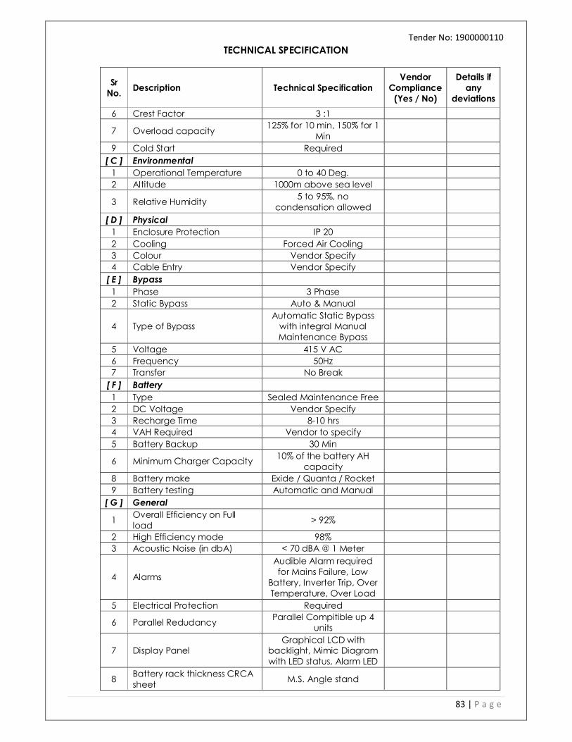
Tender No: 1900000110
TECHNICAL SPECIFICATION
83 | P a g e
Sr
No. Description Technical Specification
Vendor
Compliance
(Yes / No)
Details if
any
deviations
6 Crest Factor 3 :1
7 Overload capacity 125% for 10 min, 150% for 1
Min
9 Cold Start Required
[ C ] Environmental
1 Operational Temperature 0 to 40 Deg.
2 Altitude 1000m above sea level
3 Relative Humidity 5 to 95%, no
condensation allowed
[ D ] Physical
1 Enclosure Protection IP 20
2 Cooling Forced Air Cooling
3 Colour Vendor Specify 4 Cable Entry Vendor Specify
[ E ] Bypass 1 Phase 3 Phase
2 Static Bypass Auto & Manual
4 Type of Bypass Automatic Static Bypass with integral Manual Maintenance Bypass
5 Voltage 415 V AC
6 Frequency 50Hz 7 Transfer No Break
[ F ] Battery 1 Type Sealed Maintenance Free
2 DC Voltage Vendor Specify
3 Recharge Time 8-10 hrs 4 VAH Required Vendor to specify
5 Battery Backup 30 Min
6 Minimum Charger Capacity 10% of the battery AH
capacity 8 Battery make Exide / Quanta / Rocket
9 Battery testing Automatic and Manual
[ G ] General
1 Overall Efficiency on Full load
> 92%
2 High Efficiency mode 98% 3 Acoustic Noise (in dbA) < 70 dBA @ 1 Meter
4 Alarms
Audible Alarm required for Mains Failure, Low
Battery, Inverter Trip, Over Temperature, Over Load
5 Electrical Protection Required
6 Parallel Redudancy Parallel Compitible up 4
units
7 Display Panel Graphical LCD with
backlight, Mimic Diagram with LED status, Alarm LED
8 Battery rack thickness CRCA sheet
M.S. Angle stand

Tender No: 1900000110
TECHNICAL SPECIFICATION
84 | P a g e
Sr
No. Description Technical Specification
Vendor
Compliance
(Yes / No)
Details if
any
deviations
9 Painting Details for Battery Rack
Powder coated MS stand
[ H] Approx. Dimensions(mm)
A. UPS (mm)
1 Width Vendor Specify 2 Depth Vendor Specify
3 Height Vendor Specify
4 Approx. Weight (Kg) Vendor Specify B. Battery Stand (mm)
1 Width Vendor Specify
2 Depth Vendor Specify
3 Height Vendor Specify
4 Approx. Weight (Kg) Vendor Specify
[ I ] Standard
1 Classification IEC62040-3:1999, EN62040-3:2001
2 Electromagnetic Compatibility
IEC62040-2, EN50091-2
3 Marking CE [ J ] Protection
1 Battery Over voltage Required
2 Battery Under Voltage Required 3 DC High Required
4 Output Over/Under Voltage Required
5 O/P short Circuit Required
6 Inv Over Temp Required
7 Surge Required
[ L ] Warranty
UPS 2 Years Battery 2 Years
D. FIRE SUPPRESSION SYSTEM 1.0 SCOPE OF WORK
1.1 Work under this section shall consist of furnishing all labour, materials, fabrication, equipment
and appliances necessary and required to completely install, test & put in operational UL Listed FK-5-1-12 based Fire Suppression system, 42 bar UL Listed System Used with Seamless Cylinder as required by the drawings and specified here in after or given in the Bill of Quantities.
1.2 The fire suppression system shall include and not be limited to gas release control panel, UL/FM approved seamless cylinders, discharge valve (with solenoid or pneumatic actuator) as the case may be, discharge pipe, non-return valve and all other accessories required to provide a complete operation system meeting applicable requirements of NFPA 2001 or ISO standards and installed in compliance with all applicable requirements of the local codes and standards.
1.3 The Bidders should be OEM or any one the approved distributors of OEM for (FK-5-1-12) system.
In case of distributor is biding along with bid documents OEM authorization certificate to be submitted otherwise offer will not be qualified for this Tender

Tender No: 1900000110
TECHNICAL SPECIFICATION
85 | P a g e
1.4 The Bidder should have received Technical training on design, installations and commissioning of (FK-5-1-12) systems from the principal and training certificates to this account from the Principals / OEM should be submitted.
1.5 The system design should be based on the specifications contained herein, NFPA 2001 & in
accordance with the requirements specified in the design manual of the agent. The bidder shall confirm compliance to the above along with their bid.
1.6 The bidder shall submit the supporting letter from manufacturer for genuineness of material. The
specific letter Manufacturer Authorization Format (MAF) from OEM clearly indicating that the bidder is competent to sell & provide services for all the items mentioned in scope of supply given in tender document. The bidder shall submit letter of MAF from OEM.
2.0 CODES & COMPLIANCE
2.1 The design, installation, testing and maintenance of the Fire Suppression Systems, employing FK
1230 (FK-5-1-12), shall be in accordance with the following codes, standards and regulatory bodies: a) NFPA 2001 : Standard for Clean Agent Fire Extinguishing Systems. b) UL 2166 : Standard for Halocarbon Clean Agent Extinguishing System Units c) IS: 15493 : Gaseous Fire Extinguishing System - General Requirements d) IS: 15496 : Inspection and Maintenance of Gaseous Fire Extinguishing System - Code of
Practice e) ANSI B1.20.1: Standard for pipe threads, General Purpose, 1992 f) NFPA 70 - NEC – National Electrical Code g) NFPA 72 – National Fire Alarm Code h) Requirements of the local Authorities Having Jurisdiction (AHJ)
2.2 The manufacturer shall meet ISO 9001 requirements for the design, production and distribution
of the engineered fire suppression system. 2.3 All components of the total flooding suppression system shall be the products of the same
manufacturer or listed by that manufacturer as compatible with those devices, components and equipment.
3.0 SPECIFICAITONS:
Fire Suppression Systems shall include the following components:
3.1 Pipe and Fittings
Distribution piping, and fittings, shall be installed in accordance with NFPA 2001, approved piping standards and the engineered fire suppression system manufacturer’s requirements. Pipe: As per ASTM A-106, Sch 40, M. S. Seamless
3.2 Actuation Hardware The Clean Agent cylinder valve assembly shall be actuated using a electric control head (Solenoid) the actuator should have facility of manual actuation also. This electric control head should meet the requirement of NFPA 2001, Sec. 4.3.4.1. This regulation addresses the concern of proper installation of the actuator by providing the necessary supervision within the electric control head.
3.3 Distribution Nozzles Discharge nozzles shall be used to disperse the FK1230. The nozzles shall be made of brass with female NPT threads and available in ½” through 2” sizes. Each size shall come in two styles: 180 degree and 360-degree dispersion patterns.

Tender No: 1900000110
TECHNICAL SPECIFICATION
86 | P a g e
Minimum System Design Limits: Nozzles
a) Nozzles shall be of a brass, listed and approved for a maximum ceiling height of 16.4 feet (5
m) and a minimum ceiling height of 1 feet (0.31 m).
b) Nozzle area coverage for both 360-and 180-degree nozzles shall be a maximum of 42.65 ft. x 42.65 ft. square (13 m x 13 m).
3.4 Seamless Cylinders and Valve Assembles
FK 1230 shall be stored in seamless type Cylinders. Welded cylinders are not permitted. Agent cylinder operating pressure shall be at 360 PSIG @ 70°F (24.8 bar gauge @ 21°C). Offer Cylinder shall be manufactured and tested in accordance with IS 7285 Standard and approved by PESO for their use. Clean Agent storage cylinders shall be equipped with safety rupture disc and pressure gauge to display internal pressures. The gauge shall be an integral part of the equipment and shall be color-coded for fast referencing of pressure readings Cylinder Capacity
A. 34 litre Cylinder Capacity. B. 80 litre Cylinder Capacity. C. 120 litre Cylinder Capacity D. 140 litre Cylinder Capacity
3.5 Pressure Operated Control Head Pressure operated Control Head, should allow for Pressure actuation of Clean Agent storage FK 5-1-12 Cylinders. This should be mounted directly on top of the master or slave cylinder valve.
3.6 Master Cylinder Adapter Kit The Master Cylinder Adapter Kit, should provide a means to connect the flexible actuation hose to the master & slave cylinder valve assemblies.
3.7 Flexible Discharge Hose & Actuation Hose
a) Flexible Discharge Hose should route FK-5-1-12 agent from the storage cylinders to the discharge piping. This hose should be connected to the discharge outlet of the Clean Agent Cylinder Valve.
b) The Flexible Actuation Hose, should be usually used in multiple Cylinder Systems 3.8 Manifold Check Valve
Manifold check valves should be installed at the discharge manifold in a multiple cylinder arrangement to allow removal of any Clean Agent Cylinder from the manifold while still retaining a closed System.
3.9 Manifold Supervisory Switch

Tender No: 1900000110
TECHNICAL SPECIFICATION
87 | P a g e
Manifold Supervisory Switch, should operate from system pressure upon discharge of gas through piping network.
3.10 Re-Filling and Maintenance In case of any leakage or accidental discharge of the agent, it should be possible to re-fill the cylinders in Maharashtra itself. The contractor should indicate the source of re-filling and the time that will be taken for re-filling and replacement. Storage of Extinguishing Agent The agent shall be stored in liquid form at ambient temperature in high-pressure seamless cylinder containers designed for the purpose. The cylinder shall be high pressure, seamless. The cylinders shall be super-pressurized with dry Nitrogen to 42 Bar. All cylinders shall be adequately mounted and supported in a manner to facilitate individual servicing or content weighing. Cylinders installed shall be of the same size where possible and the manifold shall be provided with non-return or check valves to prevent back flow when any cylinder is being removed for maintenance.
4.0 SUBMITTAL FROM SUCESSFUL BIDDER:
4.1 Egineered Design Drawings
The OEM-authorized Distributor or OEM shall provide all required installation drawings per NFPA 2001.
4.2 Flow Calculation Reports The system flow calculations shall be carried out on certified software, suitable for the particular seamless cylinder container being offered for this project. Such System flow calculations carried out for this project shall be further vetted by the OEM for its accuracy, and the only such vetted calculations shall be admissible for approval by the Consultant.
4.3 Installation Drawings Four (4) sets of installation drawings for each installed engineered suppression system and one (1) set of the calculation report, owner’s manual and product data sheets shall be submitted to the end-user/owner. Upon completion of installation and commissioning acceptance, three (3) sets of “As-Built” installation drawings and One (1) set of the calculation report for each installed engineered suppression system shall be given to the owner/end-user for use and reference.
4.4 Operation and Maintenance Manuals
Three (3) copies of the Operation and Maintenance Manual shall be submitted after complete installation.