
II TECHNICAL SPECIFICATION M&E WORKS PART-1
485
MUNICIPAL CORPORATION OF GREATER MUMBAI TENDER DOCUMENT Proposed Construction of Multi-Specialty Hospital at land bearing C.T.S. No – 681A/8B, 681A/3, 681A/4 of village Nahur in S-Ward, Bhandup, Mumbai VOLUME – II TECHNICAL SPECIFICATION M&E WORKS PART-1 ____________________ _________________ M/S. SHASHI PRABHU & ASSOCIATES Wankhede Stadium, North Stand, ‘A2 & B1’ Block, ‘D’ Road, Churchgate, Mumbai-400 020. Email: - [email protected] Tel: - 022-66199999 Fax:- 022-66199900 Page 1
-
Upload
khangminh22 -
Category
Documents
-
view
0 -
download
0
Transcript of II TECHNICAL SPECIFICATION M&E WORKS PART-1

MUNICIPAL CORPORATION OF GREATER MUMBAI
TENDER DOCUMENT
Proposed Construction of Multi-Specialty Hospital at land bearing C.T.S. No – 681A/8B, 681A/3,
681A/4 of village Nahur in S-Ward, Bhandup, Mumbai
VOLUME – II TECHNICAL SPECIFICATION M&E
WORKS PART-1 ____________________ _________________
M/S. SHASHI PRABHU & ASSOCIATES Wankhede Stadium, North Stand, ‘A2 & B1’ Block,
‘D’ Road, Churchgate, Mumbai-400 020. Email: - [email protected]
Tel: - 022-66199999 Fax:- 022-66199900
Page 1
TECHNICAL SPECIFICATIONS –ELECTRICAL WORKS FOR FAIR RATE ITEM
SHASHI PRABHU & ASSOCIATES
MUNICIPAL CORPORATION OF GREATER MUMBAI
NAME OF PROJECT: - PROPOSED MULTI-SPECIALITY BHANDUP HOSPITAL AT LAND BEARING C.T.S.NO681A/88,681A/3,681A/4 OF
VILLAGE NAHUR IN S-WARD, BHANDUP MUMBAI
Page 2

SHASHI PRABHU & ASSOCIATES
Contractor Signature MCGM
H T P A N E L
1 SCOPE
This specification covers the requirements of supplying of HT OUTDOOR metal clad cubicle switch gear having Vacuum Circuit Breakers. These are general requirements of switchgear panel.
Shop Drawings:
The contractor shall prepare and submit to the Construction Manager/Consultants for his approval six (6) sets of detailed layout drawings of
all ELECTRICAL WORKS equipment’s and piping layouts.
He shall prepare shop drawings incorporating the details given by manufacturers for the items included in his contract and also Client supplied items and any other items which need to be coordinated with other contractors for interfacing.
Before starting the work, the contractor shall submit to the Construction Manager/Consultants for his approval in the prescribed manner, the
shop/execution drawings for the entire installation.
The Construction Manager/Consultants, reserves the right to alter or modify these drawings if they are found to be insufficient or not complying with the established technical standards or if they do not offer the most satisfactory
performance or accessibility for maintenance. Contractor shall supply in eight (8) sets of all approved shop drawings for execution.
Shop drawings shall be submitted under the following conditions:
Large scale drawings showing fixing detail equipment and showing coordination with other services.
Showing any change in layout in the ELECTRICAL WORKS drawings.
Equipment layout, ducting, piping and wiring/control diagram. Manufacturer’s or Contractor’s fabrication drawings for any materials or
equipment supplied by him. No work will be carried out without approval of shop drawings by the
Consultants.
"AS BUILT" DRAWINGS: At the completion of work and before issuance of certificate of completion the
contractor shall submit eight (8) sets to the Construction Manager/Consultants, layout drawing drawn at appropriate scale indicating the complete ELECTRICAL
WORKS system "as installed" and the same shall be approved by the Consultants before handing over to the Client.
Page 3
SHASHI PRABHU & ASSOCIATES
Contractor Signature MCGM
Instruction/Maintenance Manual:
The Contractor shall prepare and produce instruction, operation and maintenance manuals in English for the use, operation and the maintenance of the supplied
equipment and installations, and submit to the Construction Manager/Consultants in (8) copies at the time of handing over. The manual shall generally consist of the following:
Description of the project.
Operating instructions.
Maintenance instructions including procedures for preventive maintenance.
Manufacturers catalogues. Spare parts list.
Trouble shooting charts.
Drawings.
Type and routine test certificates of major items. One (1) set of reproducible `as built' drawings.
Completion Certificate:
On completion of the ELECTRICAL WORKS installation a certificate shall be furnished by the contractor countersigned by the licensed supervisor, under
whose direct supervision the installation was carried out. This certificate shall be in the prescribed form as required by the local supply authority. The contractor shall be responsible for getting the ELECTRICAL WORKS installation inspected
and approved by the local concerned authorities and for obtaining the necessary clearance certificates from the authorities.
Guarantee:
At the close of the work and before issuance of final certificate of completion by the Construction Manager/ Consultants, the contractor shall furnish written guarantee Indemnifying the Client against defective materials and workmanship
for a period of one year after completion. The contractor shall hold himself fully responsible for reinstallation or replacement, free of cost to Client, the following:
Any defective work or material supplied by the Contractor.
Any material or equipment supplied by the Client which is damaged or destroyed as a result of defective workmanship by the contractor.
Any material or equipment damaged or destroyed as a result of defective workmanship by the contractor.
Page 4

SHASHI PRABHU & ASSOCIATES
Contractor Signature MCGM
Staff:
The contractor shall employ competent fully licensed qualified, full time ELECTRICAL WORKS engineers to direct the work of ELECTRICAL WORKS
installation in accordance with the drawings and specifications. The engineers shall be available at all times at site to receive instructions from the
Construction Manager., in the day to day activities throughout the duration of contract. The engineer shall correlate the progress of the work in conjunction with
all the relevant requirement of the supply authority. Safety Barriers and Construction Safety:
The Contractor shall at his own cost provide for the protection and safety of the
persons working in the area, safety barriers around all openings in every location and at the periphery and edges of all slabs, staircases and stairwells, lift shafts, ducts etc., all to the approval and satisfaction of the Construction Manager.
However, contractor shall take appropriate safety precautions suitable for specific locations/ situations and as instructed by the Construction Managers.
The Contractor shall, in general, be fully responsible for all matters with regard to every form of safety during construction and in connection with the execution of
the Works, and the Contractor shall take all necessary precautions and provide at his cost everything necessary to ensure such safety at all times. Should any accidents occur due to the Contractor's failure to comply with such safety
requirements and to take all other safety measures necessary, the Contractor shall be fully responsible for all such accidents and he shall bear and pay for all costs and damages in connection therewith and as a consequence there of.
Disposal Of Rubbish From The Works And The Site And Provision Of Safety
Netting/Screens By Contractor: The Contractor shall at all times keep the Works and the site in clean, neat and
tidy condition. All rubbish from the Works and the site shall be collected and deposited in large bins provided on the site for such purpose by the Contractor at
his own cost. The rubbish from such bins shall be regularly carted away by the Contractor to rubbish tips and dump yards beyond the site.
At no time or stage shall any rubbish be thrown over the edges of slabs or through any openings or shafts or ducts or stairwells.
The Contractor shall, at his own cost and to the approval and satisfaction of the Construction Manager, provide safety netting/screens at the periphery of all slabs
and at all openings, shafts, ducts and stairwells and/or canopies to prevent any rubbish or material falling over or into such areas and endangering the safety of the persons working below. Should the Contractor fail to provide such safety
measures and to take other necessary precautions in accidents that may occur, he shall bear all costs and damages as decided by Construction Manager in
connection therewith and as a consequence there of. The Construction Manager shall have powers to withhold amounts from payment
certificates in case of Contractor's persistent noncompliance with provisions of
Page 5
SHASHI PRABHU & ASSOCIATES
Contractor Signature MCGM
this clause. Also the construction Manager is empowered to employ another
agency at Contractor's cost after one week's notice to implement this Clause in case of Contractor's noncompliance with provisions of this Clause.
Space For Contractor's Construction Yard, Stores Etc.: The Client shall provide adequate storage/office space to the contractor for his
use. The space has to be maintained/constructed by the contractor as per his usage requirements.
All spaces allotted to the contractor, as described above shall be vacated and all structures removed from site at any time as and when required and directed by
the relevant authorities or by the Client, unconditionally and without any reservation. The authorities or the Client will not be obliged to give any reason for
such removal. Upon receiving instructions to vacate the space, the contractor shall immediately remove all his structures, materials, etc., from the spaces and clear and cleanup the site to the satisfaction of the Construction Manager.
It shall be the specific responsibility of the Contractor to safeguard the site and ensure that no illegal encroachments are made by outside elements within the
area allotted to the Con tractor. Upon completion of the work or earlier as required by Client/Authorities, the Con tractor shall vacate the land totally without any
reservations. Necessary Bond to this effect on a stamp paper shall be signed by the contractor in a prescribed form.
The Performance Bond and/or guarantees towards retention amount furnished by the Con tractor shall not be released until the spaces allotted to the contractor are fully vacated and handed over to the Client as per the instructions of the Client.
Carrying Out Work Beyond Normal Working Hours Or In Shifts
In order to achieve the milestone and completion dates and to keep pace with the approved construction programme, the Contractor shall be permitted to carry out
his work beyond the normal working hours or in shifts. The Contractor shall be responsible for obtaining any necessary permission from the relevant authorities
that may be required for him to carry out the work beyond the normal working hours or in shifts. Also, the Contractor shall give prior notice to and make arrangements with the Construction Manager for the supervision of work carried
out beyond the normal working hours or in shifts. The Contractor shall make his own arrangements in respect of the provision of adequate lighting and any other facilities that may be required for carrying out the work beyond the normal
working hours or in shifts. No extra payments shall be made to the Contractor for or in connection with any such overtime or shift work. The Contractor will not be
required to bear the overtime expenses of the Construction Manager in respect of the supervision of such overtime or shift work of the Contractor.
Period And Time Limit For Completion Of Works:
The period and time limit for Completion of the Works shall be as per client’s requirement from the date of issue of Work Order to commence works or handing over of site in respect of the award of Contract. This time period shall be inclusive
of the mobilization period and monsoon period.
Page 6

SHASHI PRABHU & ASSOCIATES
Contractor Signature MCGM
Professional Integrity And Team Spirit: It is the intent of the Client, Architect and Construction Manager that this project
will be executed in a spirit of team and full professional integrity. Contractor is expected to cooperate with all the agencies involved in the project to fulfill this objective.
List Of Approved Makes:
Unless otherwise specified and expressly approved in writing by the Engineer in Charge/only material of makes and specifications as mentioned in the list of
approved makes attached with the specification shall be used.
The contractor shall clearly indicate the list of materials proposed to be used by him & enclose the same with the tender.
On Instruction of Engineer in Charge the Contractor shall submit samples of materials proposed to be used in the works. Approved samples shall be kept in the office of the Engineer in Charge and returned to the Contractor at the
appropriate time.
Before procurement, Contractor will discuss with Client for preferred makes. Water and electricity shall be supplied at one point.
Reference Points:
Contractor shall provide permanent bench marks, flag tops and other reference points for the proper execution of works and these shall be preserved till the end
of the work. All such reference points shall be in relation to the levels and locations, given in
the architectural and ELECTRICAL WORKS drawing.
Reference Drawings: The Contractor shall maintain one set of all drawings issued to him as reference
drawings. These shall not be used on Site. All important drawings shall be mounted on boards and placed in racks indexed, no drawings shall be rolled.
All correction, deviations and changes made on the site shall be shown on these reference drawings for final incorporation in the completion drawings. All
changes to be made shall be initialed by Engineer in Charge or Architect. Vendor shall prepare Shop Drawings with all details after checking the feasibility
at Site which shall be approved by the Consultants before execution. No work will be carried out without approval of Shop drawing by the Consultant.
Handing Over:
Contractor will be responsible for following:
Page 7
SHASHI PRABHU & ASSOCIATES
Contractor Signature MCGM
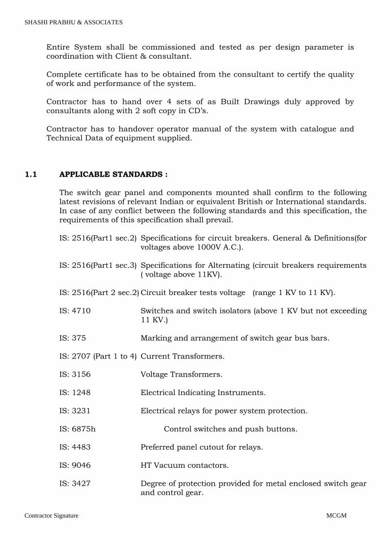
Entire System shall be commissioned and tested as per design parameter is coordination with Client & consultant.
Complete certificate has to be obtained from the consultant to certify the quality of work and performance of the system.
Contractor has to hand over 4 sets of as Built Drawings duly approved by consultants along with 2 soft copy in CD’s.
Contractor has to handover operator manual of the system with catalogue and Technical Data of equipment supplied.
1.1 APPLICABLE STANDARDS :
The switch gear panel and components mounted shall confirm to the following latest revisions of relevant Indian or equivalent British or International standards. In case of any conflict between the following standards and this specification, the
requirements of this specification shall prevail.
IS: 2516(Part1 sec.2) Specifications for circuit breakers. General & Definitions(for voltages above 1000V A.C.).
IS: 2516(Part1 sec.3) Specifications for Alternating (circuit breakers requirements ( voltage above 11KV).
IS: 2516(Part 2 sec.2) Circuit breaker tests voltage (range 1 KV to 11 KV).
IS: 4710 Switches and switch isolators (above 1 KV but not exceeding 11 KV.)
IS: 375 Marking and arrangement of switch gear bus bars.
IS: 2707 (Part 1 to 4) Current Transformers. IS: 3156 Voltage Transformers.
IS: 1248 Electrical Indicating Instruments.
IS: 3231 Electrical relays for power system protection.
IS: 6875h Control switches and push buttons. IS: 4483 Preferred panel cutout for relays.
IS: 9046 HT Vacuum contactors.
IS: 3427 Degree of protection provided for metal enclosed switch gear
and control gear.
Page 8

SHASHI PRABHU & ASSOCIATES
Contractor Signature MCGM
IS: 5578 Guide for marking of insulated conductors.
IS: 5082 Material for data for Aluminum conductors.
IS: 3618 Phosphate treatment of iron and steel for protection against corrosion.
IS: 6005 Code of practice of phosphating of iron and steel.
IS: 5 Painting. IS: 722 Integrating meters.
IS: 2544 Specifications for HV post insulators.
1.2 CONSTRUCTION:
1.2.1 The switch gear panel shall be metal enclosed, rigid, free standing, floor mounted, draw out, dead front type and fabricated from standard prefabricated, cold rolled sheet steel units. The vertical units shall be assembled in such away that uniform
height can be achieved while line up of each vertical units on floor.
1.2.2 The minimum thickness of the sheet steel shall not be less than 2.5 mm. Necessary stiffeners shall be provided.
1.2.3 The switchboard shall be totally enclosed, vermin -proof, except bus bar compartment. Degree of protection of enclosure shall be minimum IP56 as per IS: 3427. If necessary, openings for natural ventilation louvered with wire mesh shall
be provided. For bus bar compartment wire mesh shall be such as to protect against object of 1.0 mm size and above.
1.2.4 All doors, removable covers, gland plates and other openings shall be gasket all
round the perimeter with neoprene gaskets.
1.2.5 Switch gear shall be provided with an ISMC channel as a base frame. Minimum
height of the base frame shall be of 100 mm. 1.2.6 All doors shall be supported by strong hinges of concealed type and braced in
such a manner as to ensure freedom from sagging, bending and general distortion of panel or hinged parts.
1.2.7 Switchboards shall be suitable for site conditions as specified in the Technical Data Sheet.
1.2.8 Each unit of the switch gear shall be provided with necessary internal sheet metal
barrier to form separate components for buses/Indicating instruments/protective
relays/control and power cable connection etc. Compartment for cable connection shall allow adequate space for cable pulling, termination and connection work
with energised switch gear. Suitable arc propagation barrier shall also be provided. Preferably independent pressure release valves shall be provided for different compartments. Terminal strips for outgoing control cable connection
Page 9
SHASHI PRABHU & ASSOCIATES
Contractor Signature MCGM
should be accessible to facilitate working and testing with breaker in test/service
condition with the energised switchboard. 1.2.9 After isolation of the power and control connection of a circuit, it shall be possible
to safely carry out maintenance or a repair work in a compartment with the bus bars and adjacent circuits alive.
1.2.10 At a future date, it shall be possible to extend the switch gear in either direction. Ends of the bus bars shall be suitably drilled for this purpose. Panels at the
extreme ends shall have openings which shall be covered with plate screw to the panel with necessary gaskets.
1.2.11 Switch gear shall be vertical isolation and horizontal draw out type.
1.2.12 All draw out circuit breaker trucks/trolley of the same rating for all outgoing breakers shall be identically wired/equipped for complete interchangeability at site. `Service', `Test', `Draw Out' positions of the draw out carriage of the
switchboard shall be provided. Automatic safety shutters shall be provided to ensure the inaccessibility of all live parts after the breaker is drawn out.
1.2.13 Dummy panels required for rear extensions for cable terminations or to mount the components shall be included in the offer and details of each type of such panels
shall be furnished along with offer. 1.3 SAFETY INTERLOCKS:
It shall not be possible to draw out the carriage with circuit breaker closed. The
breaker feeder trolley shall remain inside the cubicle even in the `drawout'
position. There shall be distinct overall door for the breaker compartment and it should be lockable. Suitable interlocks to prevent following faulty operations shall
be provided. 1.3.1 `Plugging in' or `drawing out' of a closed breaker.
1.3.2 `Plugging in' a breaker with earthing isolator closed.
1.3.3 `Closing' of earthing isolator with breaker `Plugged in
1.3.4 Pulling out of auxiliary circuit plug with breaker in service position. 1.3.5 Pushing in breaker to service position with auxiliary circuit plug not in position.
1.3.6 Opening of compartment door with isolating switch in ON position and vice versa.
Necessary mechanical and electrical interlocks between H.T. and L.T. switch gears
shall be provided in closing and tripping circuits of breakers which shall be a part
of the specification. The total bill of material and scheme designed by the manufacturer will be subject to client/consultant's approval and any addition or
deletion shall be binding to the manufacturer on the basis of unit rates available in the offer.
1.4 ACCESSIBILITY:
Page 10
SHASHI PRABHU & ASSOCIATES
Contractor Signature MCGM
1.4.1 Checking and removal of components shall be possible without disturbing adjacent components. All components shall be easily accessible. It shall be possible to set all `measuring' and `protective' relays without de- energising the
switchboard. All mounted equipment shall have painted identification labels at the front & rear also. In addition to that identification numbers shall be painted on the panel wall to give permanent identification mark. Mounting of the relays for
a particular breaker panel shall be limited to that particular panel.
1.4.2 Unused CT secondary terminals must be short circuited and wired to the terminal block. All terminals shall be shrouded with plastic covers to prevent accidental contact.
1.5 BUS BAR ARRANGEMENT
1.5.1 The switchboard shall comprise 3 phase bus bars as indicated in the Technical
Data Sheet or SLD which shall extended through all units of the switch gear. All
phase bus bars shall be of uniform cross section throughout the switch gear and shall be sized to carry continuously the current specified in the Technical Data Sheet or SLD. Bus bars shall be housed in a separate air insulated chamber and
shall be accessible for inspection only with special tools. Wire guards/mesh shall be provided inside the sheet steel enclosure to allow visual inspection of bus bars,
CT's, PT's and cable terminations and to avoid accidental touch when rear cover is removed.
1.5.2 Bus bars shall be made of electrolytic aluminum/copper as indicated in the Technical Data Sheet or SLD and shall be sleeved and joints shall be shrouded. Fiber glass/metal sheet with cast resin bushing partitions shall be provided at
every junction between two adjacent cubicles. All bus bar joints shall be shrouded with shrouds having sufficient insulation level suitable for nominal system
voltage. 1.5.3 Bus bars shall be supported at regular intervals and both, bus bars and the
supports shall be adequately sized and braced to withstand the specified short circuit level without permanent deformation. Dynamic stresses shall be calculated
on the basis of the specified peak short circuit currents. All bus supports shall be of non carbonizing material resistant to acids and alkalis and shall have non hygroscopic characteristics such as SMC, DMC epoxy bonded fiber glass.
1.5.4 Thermal design of the bus bars shall be based on installation of the switch gear in
ventilated conditions. The cooling air volume shall take into account only the bus
enclosure.
1.5.5 The maximum operating temperature of the bus bars at the maximum design temperature inside the panel shall be as per IS: 1272 and IEC 298
1.5.6 Bus bars shall be sleeved with colour coded type sleeve having insulation level suitable for nominal system voltage. If the insulating sleeve is not coloured bus
bar shall be colour coded with coloured bands at suitable intervals.
Page 11
SHASHI PRABHU & ASSOCIATES
Contractor Signature MCGM
1.5.7 All bus bars joints and bus tap joints shall be of the bolted type and shall be
shrouded. Spring washers shall be provided to ensure good contact at the joint locations and suitable contact grease shall be applied just before making a joint.
1.5.8 Positive/live terminal or bus bar shall be located at the top or on the left for vertical and horizontal layout respectively.
1.5.9 Sequence of Red, Yellow, Blue phases shall be left to right and top to bottom for horizontal and vertical layout respectively.
1.6 POWER CABLE CONNECTION:
1.6.1 The incoming and outgoing power cable connection shall be through PILC/XLPE/PVC cables of various sizes as indicated in the Technical Data Sheet
or SLD. Ample space for connection for these cables shall be provided at the rear of the switchboard. In order to avoid accidental contact in the cable compartment while carrying out inspection by opening the back cover, a removable expanded
metal barrier shall be provided in the cable compartment. 1.6.2 The cable entry of the switchboard shall be from the bottom.
1.6.3 Cable lugs and the requisite bushes for sealing power cable entries shall be
supplied along with the switchboard. 1.6.4 `Cupal' washers shall be provided for copper busbar to aluminum cable
terminations. 1.6.5 The switchboard shall be supplied complete with supports for clamping outgoing
and incoming cables. Terminal blocks shall not be used to support cables. The distance available between cable gland plate and terminal lug shall not be less
than 750 mm for switchgear upto 11 KV. cables. 1.6.6 In case, cable termination cannot be accommodated in side the panel, a suitable
box for mounting at the rear side and at the bottom of panel shall be supplied. Earth strip shall also be brought to this box. In lieu of this a dummy panel may be
provided. 1.6.7 The individual switchgear panel shall have adequate space and terminal busbar
clearance for accommodating no. of cables as specified in Technical Data Sheet and SLD. The type of cable termination units to be considered shall be heat shrinkable type.
1.7 CONTROL WIRING AND TERMINALS:
1.7.1 Inside the cubicle the wiring for control, indication, signaling, protection and
instrument circuits shall be done with PVC insulated stranded conductors. The
insulation grade shall be 1.1 KV. The wiring shall preferably be enclosed in plastic channels or neatly bunched together.
1.7.2 10% spare terminals shall be provided on each terminal block. Conductors shall
be terminated with adequately sized compression type copper lugs for connection
to equipment terminal block. Terminal block shall be of Elemex/Connect well
Page 12

SHASHI PRABHU & ASSOCIATES
Contractor Signature MCGM
make. All auxiliary equipments terminals shall be made with pressure type
terminals. Sufficient terminals shall be provided on each terminal block to ensure that not more than one outgoing wire is connected per terminal. Terminal strips shall preferably be separated from power circuits by metal barriers or enclosures.
All spares contacts of aux. relays, timers etc. shall be wired upto the terminals. 1.7.3 Each wire shall be identified at both the ends by, correctly sized PVC ferrules.
Shorting links shall be provided for all CT terminals.
1.7.4 For CT circuits 2.5 sq. mm copper conductor shall be used. Other control wiring can be with 1.5 sq. mm copper conductors.
1.7.5 Control cables shall enter the switchgear from the bottom/ top. It shall be possible to have the control cable entry from both the left and right side corners at
the front portion of the switchgear without cutting any standard part of for these cables are also included in the scope of supply of the switchboard. The cable glands shall be compression type, supporting facilities shall be provided for
clamping the control cables. All control cables shall be with 2.5 sq. mm Cu stranded conductors.
1.7.6 All inter panel control wiring shall be done by the switchgear supplier. The inter panel wiring shall be taken through PVC sleeves or suitable grommets. Multi pin
plug shall be provided and should have scraping earth terminal. 1.7.7 Control cable cutout and gland plate shall be provided preferably at the place
where the power cable cutout will be provided. Gland plate for the control cables shall be separate from those provided for the power cables.
1.8 CONTROL AND INDICATION:
Breaker tripping and closing devices shall be operated on D.C. supply. The rated D.C. voltage shall be as specified in the Technical Data Sheet. The supply for breaker opening, closing and indication devices shall be provided as under:
a) One D.C. feeder shall be provided for each bus section. The Bus coupler panel
may be fed from any of the two supplies. b) One separate 240 V AC supply shall be provided for space heater etc.
Mechanical indication for breaker positions such as ON, OFF, spring charged, test
position/Service position shall be provided. Various Electrical indications with
colours are indicated below shall be provided.
a) Breaker `ON' - Green lamp b) Breaker `OFF' - Red Lamp
c) Breaker `Auto Trip' - White lamp
d) Trip circuit healthy - White lamp
e) DC fail - Blue lamp.
Page 13
SHASHI PRABHU & ASSOCIATES
Contractor Signature MCGM
f) Red phase ON - Red g) Yellow phase ON - Yellow
h) Blue phase ON - Blue
1.9 EARTHING CONNECTIONS:
1.9.1 Continuous earth bus-bar running throughout the length of the switchboard shall be provided. All doors and movable parts shall be connected to the earth bus with flexible copper connections. Provision shall be made to connect the earthing
busbar to the plant earthing grid at two ends. All non-current carrying metallic parts of the equipment shall be earthed . Earth bus shall be brought back to cable
compartment and earthing bolts shall be provided to ground cable Armour. Mating surfaces of all bolted parts shall be specifically zinc passivated to ensure continuity between them.
1.9.2 The material of the earth bus shall be copper or equivalent size of aluminum. The
earth bus size shall be minimum 180 mm2 copper upto short circuit withstand
capacity of 31.5 KA and 300 mm2 above 31.5 KA.
1.9.3 All instruments, relays and other components shall be connected to earth busbar by means of 650 V grade, PVC insulated, stranded tinned copper conductor of 2.5 sq.mm.
1.10 LABELS AND NAMEPLATES:
1.10.1 A nameplate with the switchgear designation at the top of the central panel and separate nameplate giving feeder details shall be provided at front and rear side of
each panel. 1.10.2 Name plates shall be provided for each equipment ( Lamps, PBs, Switches, Relays,
Auxiliary contactors etc.) mounted on the switchboard. Special warning plates shall be provided on all removable covers or doors giving access to high voltage
cables, bus bars. Special warning label shall be provided inside the switchboard also, wherever considered necessary. Identification tags shall be provided inside the panels matching with those shown on the circuit diagram.
1.10.3 Engraved nameplates shall preferably be of 3-ply (Red-white- red or
Black-white-Black lamicoid sheets or anodized aluminum or back engraved
Perspex sheet nameplates shall be provided. Engraving shall be done with square groove cutters. Hard paper nameplates will not be acceptable. Name plates shall
be fastened by Screws and not by adhesives. 1.11 SHEET STEEL TREATMENT AND PAINT:
1.11.1 All metal surfaces shall be thoroughly cleaned and digressed to remove mill scale,
rust, grease and dirt. Fabricated structure shall be pickled and then rinsed to remove any trace of acid . The under surface shall be prepared by applying a coat of phosphate paint, and a coat of yellow zinc chromate’s primer. The under
Page 14
SHASHI PRABHU & ASSOCIATES
Contractor Signature MCGM
surface shall be made free from all imperfections before undertaking the finishing
coat. 1.11.2 After preparation of the under surface, the switchboard shall be spray painted
with two coats of final paint. Colour shade of final paint shall be smoke gray shade no. 631 as per IS: 5 unless otherwise specified. The finished panels shall be dried in stovings ovens in dust-free atmosphere. Panel finish shall be free from
imperfections like pinholes, orange peels, runoff, paint etc. The supplier shall furnish painting procedure details along with the offer.
1.11.3 All unpainted steel parts shall be cadmium plated or suitable treated to prevent
rust corrosion. If these parts are moving elements, then these shall be greased.
1.12 SPACE HEATERS:
1.12.1 Each vertical cubical shall be provided with space heater to prevent moisture
condensation and maintain required temperature. The space heaters shall be
located at the bottom of the switchboard and shall be controlled through a thermostat with an adjustable setting with single pole MCB with overload and short circuit release in the phase, link in the neutral. The thermostat shall
preferably be located in the metering/ relay chamber.
1.12.2 Space heater shall be of strip type rated for operation on a 240 V, single phase, 50 Hz., A.C. supply system.
1.13 BASE FRAME: 1.13.1 The switchboard shall be suitable to be installed on a base frame supplied in one
piece along with foundation bolts. These base channels shall be dispatched two months in advance from the date of dispatch of switchboard so that they can be
buried and grouted in the concrete floor. Ample dimensioned oblong holes shall be provided at the bottom of all the switchboards for their installation of base frame. In addition, the switchboard shall have an additional base channel at the
bottom with smooth surface.
1.14 BREAKERS: 1.14.1 Vacuum circuit breaker shall be used in the switchboard. Exact type and rating
shall be as indicated in the Technical Data Sheet. 1.14.2 10% spare VCB bottles of each ratings shall be supplied along with the
switchboard.
1.14.3 Vacuum circuit breaker shall be designed with low switching over voltage level and long switching life. The interrupter shall be leak free with a target value of vacuum life as 25 years.
1.14.4 The breakers shall have at least 8 NO + 8 NC spare auxiliary contacts. If these are
not available an auxiliary contactor shall be used to multiply the auxiliary contacts of the breakers. All auxiliary contacts shall be wired to the terminal block. Auxiliary contacts and limit switches shall be in dust tight enclosures.
Page 15
SHASHI PRABHU & ASSOCIATES
Contractor Signature MCGM
1.14.5 The breaker shall have motor operated spring charged mechanism. In addition to
this, it shall be possible to charge the springs manually, if required. In case the limit spring fails to cut out the spring charging motor when the springs are fully charged the motor shall be automatically decoupled and annunciation for this
shall be provided. The control circuit shall be suitable for local as well as remote control. Breaker shall trip free and shall have an anti pumping device. Breaker operating duty shall be 0-3'-CO-3'-CO except for switchgear line up having motor
feeders stage wise, receleration feature in which case the duty shall be 0-0.3"- CO-3'-CO. Whenever a PT is mounted on the breaker carriage all auxiliary wiring
shall be done in PVC flexible conduits. 1.14.6 Adequate provision shall be made in Vacuum circuit breaker for motor switching
to limit the over voltage.
1.14.7 Mechanical trip push buttons shall be provided for all the breakers. Mechanical closing device will not be acceptable for motor feeders. Complete motor assembly should have interchangeability with identical rating of the breaker. Each motor
breaker feeder shall be provided with an operation counter. 1.14.8 All integral earthing system or separate earthing carriage be provided. After
withdrawing the circuit breaker, this can be inserted to facilitate earthing of the cables. Unit rate in the panel shall be furnished.
1.15 SWITCHBOARD COMPONENTS:
1.15.1 CURRENT TRANSFORMER: Current transformers shall generally conform to IS: 2075. and of cast resin type
and shall be mounted on the switchgear stationary part. The C.T. ratings shall be as shown in the Technical Data Sheet or SLD. For general guidance, the
protective current transformers shall have an accuracy class `5P' and an accuracy limit factor greater than `10'. Low reactance C.T.s shall be used for protection. Current transformers for instruments shall have an accuracy class 0.5 and an
accuracy limit factor less than 5.0. If a metering load is fed from a protection C.T., suitable 1/1 or 5/5 ratio interposing C.T.s shall be used.
1.15.2 VOLTAGE TRANSFORMERS:
a. The voltage transformers shall be cast resin and draw out type and provided with primary and secondary fuses.
b. The draw-out mechanism shall disconnect the bus bars and V.T. primary and secondary terminals shall be earthed. The primary connection shall be
disconnected before the V.T. or its primary fuses become accessible. c. The voltage transformers shall have an accuracy class 1.0 from 10% to 120% of
normal voltage.
d. Secondary and tertiary windings of voltage transformer shall be rated for a three phase line to line voltage of 110 V except as noted.
1.16 MEASURING INSTRUMENTS:
Page 16
SHASHI PRABHU & ASSOCIATES
Contractor Signature MCGM
All measuring and recording instruments shall be of square pattern 144 mm x 144 mm flush mounted type. Instruments shall be provided wherever specified in the Technical Data Sheet or SLD. All auxiliary equipment such as shunts, trans-
ducers C.T.s, V.T.s that are required shall be included in the supply of switchboard.
1.16.1 AMMETERS, VOLTMETERS, KW METERS
These shall be of moving iron type. The accuracy class shall be 1.0 as per IS: 1248. The range shall be as indicated in the Technical Data Sheet or on the SLD. Ammeters for motor feeders shall have non linear compressed scale at the end to
indicate motor starting current.
The KW meter shall be suitable to measure unbalanced loads on a 3 phase 3 wire system. The KW and the voltmeter shall operate of a V.T. secondary of 110 volts.
1.16.2 RECORDING INSTRUMENTS: Unless stated otherwise these shall be of direct writing type with automatic chart
by means of a synchronous motor. The minimum chart length shall be of 24 hours. The chart speed shall be 30 mm/hour.
1.16.3 TRIVECTO METERS: (DIGITAL)
The KWH meter shall be 144 mm x 144 mm square, flush mounted, preferably in
a draw-out case. It shall be suitable for operation on 3 phase 3 wire system.
1.16.4 FREQUENCY METERS:
These shall be direct reading or digital type square pattern 144 mm x 144 mm
size, suitable for flush mounting and shall operate off a V.T. secondary voltage of
110 volts. The standard range shall be 45-50-55 Hz.
1.16.5 POWER FACTOR METER: The power factor meter shall also be square pattern 144 mm x 144 mm size,
suitable for flush mounting and of digital type. The meter shall operate off 110 volts C.T. secondary voltage. The C.T. secondary current shall be as shown on the SLD or Technical Data Sheet. The standard range shall be 0.5-1.0-0.5.
1.17 AUXILIARY EQUIPMENTS:
1.17.1 AUXILIARY RELAYS/CONTACTORS:
Auxiliary relays/contactors shall generally be used for interlocking and multiplying contacts. Auxiliary contacts shall be capable of carrying the maximum
estimated current. In any case their rating must not be less than 5A - for 230 volts A.C. at a power factor between 0.3 and 1, and 2A for 110 volts D.C.(inductive load).
Page 17
SHASHI PRABHU & ASSOCIATES
Contractor Signature MCGM
1.17.2 TRIPPING RELAYS:
All tripping relays shall be lockout type with hand reset contacts and shall be
suitable to operate off the specified d.c. voltage. These relays shall have self coil
cut - off contacts and shall be provided with hand reset operation indicators. Tripping relays will be acceptable in non draw-out cases. The number of contacts shall be as shown on the approved schematic drawings.
1.17.3 PROTECTIVE RELAYS:
All protective relays shall be back connected, draw-out type, suitable for flush
mounting and fitted with dust tight covers. Alternatively, `plug in' type of relays
will also be acceptable. The relay cases shall have provision for insertion of test plug at the front for `testing' and calibration' using an external power supply,
without disconnecting the permanent wiring. It shall be possible to short the C.T.'s through the test plugs. Non protection relays can be in fixed execution.
All relays shall preferably be mounted in front of the panel and shall be as specified in the Technical Data Sheet or SLD. The cur rent and voltage coils shall be rated as specified.
All measuring relays shall have `built in' flags to indicate relay operation. It shall
be possible to reset the flag without opening the relay case. Anti fungus treatment shall be provided for all relays.
1.17.4 PUSH BUTTONS: Push button colours shall be as follows:
Stop, Open, Emergency - Red
Start - Close - Green
Trip circuit `Healthy' check -Black
Red push buttons shall be on the left side and green push buttons on the right side. Push button ratings shall be 5A at 240 V AC or 2A at 110 V DC (inductive load). Emergency stop push buttons shall be lockable in the operated position.
The key shall be released from the push button in both `Released' and `Operated'
positions and operation of the push button shall be possible in the key release
position. Push button knobs for emergency stop push buttons shall be released to prevent accidental operation.
1.17.5 CONTROL SWITCHES:
All control switches shall be rotary, back connected type having a cam operated contact mechanism. Phosphor bronze contacts shall be used on the control
switches. Unless otherwise stated, circuit breaker control switches shall be 3 position spring return to `neutral' from both `ON' and `OFF' positions. They shall have `pistol grip' handle. Number of ways, locking system, lost motion device if re-
quired etc. Two spare ways shall be provided on these switched.
Page 18

SHASHI PRABHU & ASSOCIATES
Contractor Signature MCGM
Ammeter and Voltmeter selector switches shall have ` make before break' feature on its contacts. The selector switch shall generally have four positions, three for reading three phase currents and phase to phase voltages respectively and the
fourth as off position. 1.17.6 INDICATING LAMPS:
Switchboard type low consumption indicating lamps shall be used. Indicating
lamps shall be suitable for the voltage indicated in the Technical Data Sheet. Lamps shall be supplied complete with the necessary current limiting resistor duly tested for its rating. Aging test for the resistors shall have been carried out.
Lamps shall be provided with translucent lamp covers to diffuse light.
1.17.7 CUBICLE LIGHTING: Each cubicle of switchgear shall be provided with interior lighting by means of a
20 W fluorescent tube lighting fixture with ON - OFF switch. The lighting fixture shall be suitable for operation from a 240 V, single phase, 50 Hz, A.C. supply. A 240 V, single phase, 15 A A.C. plug point shall be provided in the interior of each
cubicle with an ON - OFF switch for connection of hand lamps.
1.18 TESTS AND INSPECTION:
1.18.1 During fabrication, switchgear shall be subject to inspection by Owner/Consultant or by an agency authorized by the Owner. Manufacturer shall furnish all necessary information concerning the supply to inspectors.
The client/ Contractor has right to witness the test carried out on all the equipment.
1.18.2 Tests shall be carried out at the manufacturers' works under his care and
expense.
1.18.3 All routine tests as specified by the applicable standard code shall be conducted.
Type test certificates for the switchgear panel and CB from a recognized testing organization shall be furnished with the offer. If client / consultant wishes type test shall be carried out at laboratory in the suppliers region in clients /
consultants presence. The supplier shall also submit a list of guaranteed technical particulars with the offer.
1.25 In addition specific tests shall be conducted to check mechanical and electrical operation and switchboard wiring to this specification and approved schematic
drawings. 1.18.5 These tests shall be provisionally conducted at manufacturer's works by providing
temporary connection to switchgear units in order to simulate the actual conditions.
1.18.6 Shop tests shall be witnessed by an inspector of Owner / Consultant or of an
agency authorized by owner.
Page 19
SHASHI PRABHU & ASSOCIATES
Contractor Signature MCGM
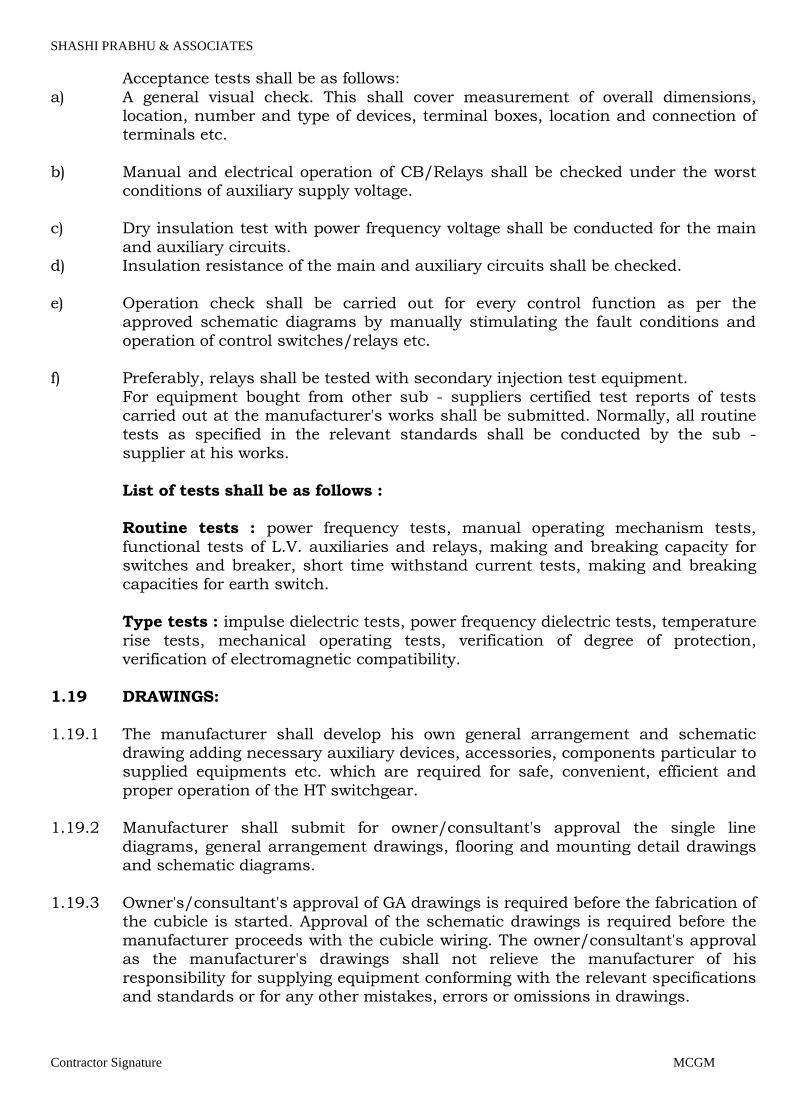
Acceptance tests shall be as follows:
a) A general visual check. This shall cover measurement of overall dimensions, location, number and type of devices, terminal boxes, location and connection of terminals etc.
b) Manual and electrical operation of CB/Relays shall be checked under the worst
conditions of auxiliary supply voltage.
c) Dry insulation test with power frequency voltage shall be conducted for the main
and auxiliary circuits. d) Insulation resistance of the main and auxiliary circuits shall be checked.
e) Operation check shall be carried out for every control function as per the approved schematic diagrams by manually stimulating the fault conditions and
operation of control switches/relays etc. f) Preferably, relays shall be tested with secondary injection test equipment.
For equipment bought from other sub - suppliers certified test reports of tests carried out at the manufacturer's works shall be submitted. Normally, all routine tests as specified in the relevant standards shall be conducted by the sub -
supplier at his works.
List of tests shall be as follows : Routine tests : power frequency tests, manual operating mechanism tests,
functional tests of L.V. auxiliaries and relays, making and breaking capacity for switches and breaker, short time withstand current tests, making and breaking capacities for earth switch.
Type tests : impulse dielectric tests, power frequency dielectric tests, temperature
rise tests, mechanical operating tests, verification of degree of protection, verification of electromagnetic compatibility.
1.19 DRAWINGS:
1.19.1 The manufacturer shall develop his own general arrangement and schematic drawing adding necessary auxiliary devices, accessories, components particular to supplied equipments etc. which are required for safe, convenient, efficient and
proper operation of the HT switchgear. 1.19.2 Manufacturer shall submit for owner/consultant's approval the single line
diagrams, general arrangement drawings, flooring and mounting detail drawings and schematic diagrams.
1.19.3 Owner's/consultant's approval of GA drawings is required before the fabrication of
the cubicle is started. Approval of the schematic drawings is required before the
manufacturer proceeds with the cubicle wiring. The owner/consultant's approval as the manufacturer's drawings shall not relieve the manufacturer of his
responsibility for supplying equipment conforming with the relevant specifications and standards or for any other mistakes, errors or omissions in drawings.
Page 20
SHASHI PRABHU & ASSOCIATES
Contractor Signature MCGM
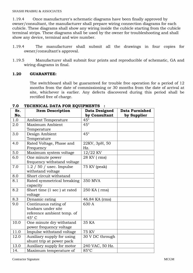
1.19.4 Once manufacturer's schematic diagrams have been finally approved by
owner/consultant, the manufacturer shall prepare wiring connection diagrams for each cubicle. These diagrams shall show any wiring inside the cubicle starting from the cubicle terminal strips. These diagrams shall be used by the owner for troubleshooting and shall
show any device, terminal and wire number. 1.19.4 The manufacturer shall submit all the drawings in four copies for
owner/consultant's approval.
1.19.5 Manufacturer shall submit four prints and reproducible of schematic, GA and wiring diagrams in final.
1.20 GUARANTEE:
The switchboard shall be guaranteed for trouble free operation for a period of 12 months from the date of commissioning or 30 months from the date of arrival at site, whichever is earlier. Any defects discovered during this period shall be
rectified free of charge. 7.0 TECHNICAL DATA FOR EQUIPMENTS :
Sr. No.
Item Description Data Designed by Consultant
Data Furnished by Supplier
1.0 Ambient Temperature 45°
2.0 Maximum Ambient
Temperature
45°
3.0 Design Ambient
Temperature
45°
4.0 Rated Voltage, Phase and
Frequency
22KV, 3pH, 50
Hz.
5.0 Maximum system voltage 12/22 KV
6.0 One minute power frequency withstand voltage
28 KV ( rms)
7.0 1.2 / 50 / usec. Impulse withstand voltage
75 KV (peak)
8.0 Short circuit withstand
8.1 Rated symmetrical breaking
capacity
350 MVA
8.2 Short time (1 sec ) at rated
voltage
250 KA ( rms)
8.3 Dynamic rating 46.84 KA (rms)
9.0 Continuous rating of busbars under site reference ambient temp. of
45° C
630 A
10.0 One minute dry withstand
power frequency voltage
35 KA
11.0 Impulse withstand voltage 75 KV
12.0 Auxiliary supply for using shunt trip at power pack
30 V DC through
13.0 Auxiliary supply for motor 240 VAC, 50 Hz.
14. Maximum temperature of 85°C
Page 21
SHASHI PRABHU & ASSOCIATES
Contractor Signature MCGM
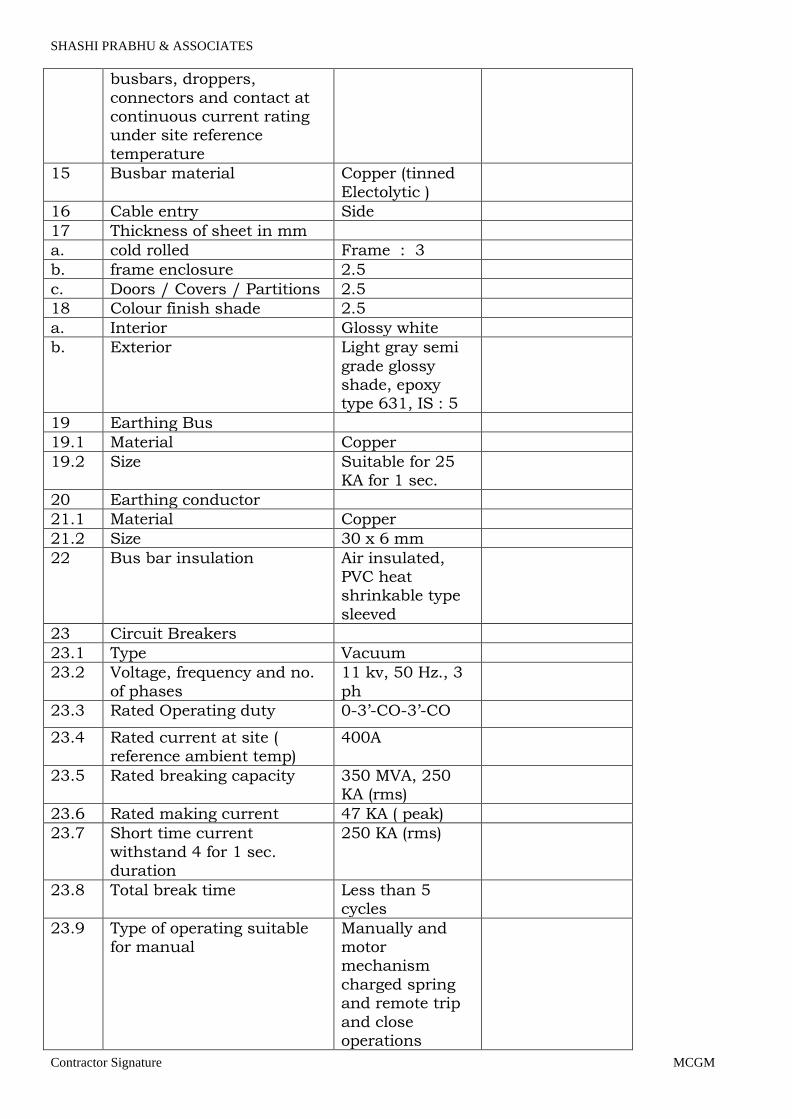
busbars, droppers,
connectors and contact at continuous current rating under site reference
temperature
15 Busbar material Copper (tinned
Electolytic )
16 Cable entry Side
17 Thickness of sheet in mm
a. cold rolled Frame : 3
b. frame enclosure 2.5
c. Doors / Covers / Partitions 2.5
18 Colour finish shade 2.5
a. Interior Glossy white
b. Exterior Light gray semi
grade glossy shade, epoxy type 631, IS : 5
19 Earthing Bus
19.1 Material Copper
19.2 Size Suitable for 25 KA for 1 sec.
20 Earthing conductor
21.1 Material Copper
21.2 Size 30 x 6 mm
22 Bus bar insulation Air insulated, PVC heat shrinkable type
sleeved
23 Circuit Breakers
23.1 Type Vacuum
23.2 Voltage, frequency and no.
of phases
11 kv, 50 Hz., 3
ph
23.3 Rated Operating duty 0-3’-CO-3’-CO
23.4 Rated current at site ( reference ambient temp)
400A
23.5 Rated breaking capacity 350 MVA, 250 KA (rms)
23.6 Rated making current 47 KA ( peak)
23.7 Short time current
withstand 4 for 1 sec. duration
250 KA (rms)
23.8 Total break time Less than 5 cycles
23.9 Type of operating suitable for manual
Manually and motor mechanism
charged spring and remote trip
and close operations
Page 22

SHASHI PRABHU & ASSOCIATES
Contractor Signature MCGM
23.10 Minimum no. of auxiliary 8 NP, 8 NC on
fixed contacts part of breaker for owner’s use.
23.11 Withstand test voltage One minute power
28
23.12 Frequency KV(rms) 1.2/50 u sec impulse KV (peak)
75
24 Auxiliary control voltage
24.1 For closing coil for tripping
coil 30 V DC through power pack
240V, pph, 50
Hz.
24.2 For space heaters and lighting AC with MCB and
thermostat unit
240V, 1 Ph, 50 Hz.
24.3 Motor type Universal
24.4 Anti Pumping feature Both electrical and mechanical shall be provided
24.5 Circuit breaker operation Local control switch for trip
and close. Remote electrical trip and close for
testing manual
24.6 Protection required panel As per single line
diagram / Requirement of
breaker
25 Current Transformers
25.1 Type Cast resin, bar primary
25.2 System voltage and frequency
22 KV, 50 Hz.
25.3 Class of insulations Class “E” or better
25.4 Rated primary current ratio 300/5/5 – for
both incomer & 120/5/5 for all
outgoing
25.5 Short time 1 sec. current
rating
25 KA (rms)
25.6 Dynamic rating 47 KA (peak)
26 Voltage Transformers
26.1 Type Cast resin
26.2 Rated voltage – primary 22000 / 3 volts
Rated voltage – secondary 110 / 3 volts
26.3 Method of connection
Primary Star
Secondary Star
26.4 Rated Voltage factor 1.1 constant
Page 23

SHASHI PRABHU & ASSOCIATES
Contractor Signature MCGM
1.5 for 30 sec.
26.5 Class of insulation Class “E” or better
26.6 VA burden and accuracy As per the single line dia / specs
requirement of breaker panel
26.7 Withstand test voltage one
minute power frequency
28
1.2 / 50 / u impulse KV
(peak)
75 KV (peak)
27 Make of material
27.1 HRC Fuse Siemens, L&T, Schneider,
Havells Or As per MCGM SOR
27.2 Fuse base Siemens, L&T, Schneider, Havells As per
MCGM SOR
27.3 Voltmeter AE As per
MCGM SOR
27.4 Ammeter AE As per
MCGM SOR
27.5 Indication lamps Teknic As per
MCGM SOR
27.6 Relays Siemens, L&T, Schneider,
Havells As per MCGM SOR
27.7 Power factor meter ( Electronic type)
AE As per MCGM SOR
27.8 Frequency meter (Electronic type )
AE As per MCGM SOR
27.9 Selector switch Kaycee As per MCGM SOR
27.10 Breaker control switch GEC Alsthom As per MCGM SOR
27.11 L – R Swithc Kaycee As per MCGM SOR
27.12 Terminal Block Elmex / Connect
well / As per MCGM SOR
Technoplast
27.13 Wires Finolex or
approved or equivalent As per MCGM SOR
27.14 Trivector Secure, Enercon As per MCGM
SOR
Page 24

SHASHI PRABHU & ASSOCIATES
Contractor Signature MCGM
27.15 Digital KWH meter Enercon As per
MCGM SOR
27.16 CT / PT AE . Indcoil /
Kappa As per MCGM SOR
27.17 Push Buttons Teknic As per MCGM SOR
28 Cable Box arrangement
Incomer 2 Nos. 22 KV 3c x 240 mm² XLPE
Armoured Al. cable
Outgoing 4 Nos. 22 KV 3c x 185 mm² XLPE
Armoured Al. cable
29 Requirements of Breaker
Panel
29.1 Panel description 3 x 1600 KVA
transformer
29.2 Quantity 1 No.
29.3 Basic rating of breaker 800 Amps.
29.4 Type of Breaker VCB
29.5 Red, Amber, Green indicating lamps
1 set
30 Potential transformer, three phase, Epoxy cast resin
type, 1100 volts / root 3/110 volts / root 3, 100 VA burden, Accuracy class
0.5h
1 set
31 A44 mm² 0- 15 KV
voltmeter
1 No.
32 Voltmeter selector switch 1 No.
33 144 mm² 0 – 100 A ammeter
1 No.
34 Ammeter selector switch 1 No.
35 Electronic type power factor
meter
1 No.
36 Trivector meter (digital) with
KVA / KVARH / KVAH with maximum demand indication in KVA
1 No.
37 Electronic type frequency meter
1 No.
38 Epoxy cast resin type current transformer having
details as under
38.1 60/5/5 ratio of Class 1
and burden of 15 VA.
60 / 1 Amp.
38.2 Accuracy class of metering 0.5
Page 25
SHASHI PRABHU & ASSOCIATES
Contractor Signature MCGM
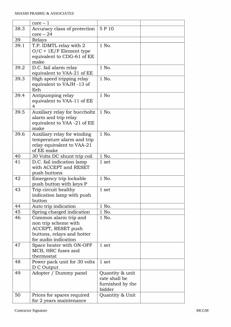
core – 1
38.3 Accuracy class of protection core – 24
5 P 10
39 Relays
39.1 T.P. IDMTL relay with 2
O/C + 1E/F Element type equivalent to CDG-61 of EE make
1 No.
39.2 D.C. fail alarm relay equivalent to VAA-21 of EE
1 No.
39.3 High speed tripping relay equivalent to VAJH -13 of
Eeh
1 No.
39.4 Antipumping relay
equivalent to VAA-11 of EE 4
1 No
39.5 Auxiliary relay for buccholtz alarm and trip relay equivalent to VAA -21 of EE
make
1 No.
39.6 Auxiliary relay for winding
temperature alarm and trip relay equivalent to VAA-21 of EE make
1 No.
40 30 Volts DC shunt trip coil 1 No.
41 D.C. fail indication lamp with ACCEPT and RESET push buttons
1 set
42 Emergency trip lockable push button with keys P
1 No.
43 Trip circuit healthy indication lamp with push
button
1 set
44 Auto trip indication 1 No.
45 Spring charged indication 1 No.
46 Common alarm trip and
non trip scheme with ACCEPT, RESET push buttons, relays and hotter
for audio indication
1 No.
47 Space heater with ON-OFF
MCB, HRC fuses and thermostat
1 set
48 Power pack unit for 30 volts D C Output
1 set
49 Adopter / Dummy panel Quantity & unit rate shall be furnished by the
bidder
50 Prices for spares required
for 2 years maintenance
Quantity & Unit
Page 26
SHASHI PRABHU & ASSOCIATES
Contractor Signature MCGM
free operation rate shall be
furnished by the bidder
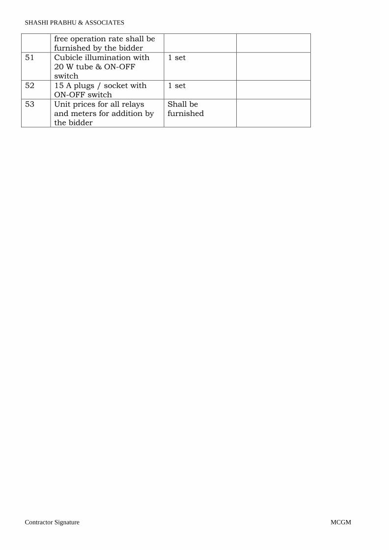
51 Cubicle illumination with
20 W tube & ON-OFF switch
1 set
52 15 A plugs / socket with ON-OFF switch
1 set
53 Unit prices for all relays
and meters for addition by the bidder
Shall be
furnished
Page 27

SHASHI PRABHU & ASSOCIATES
Contractor Signature MCGM
1.0 DRY TYPE TRANSFORMER
2.1 SCOPE
This specification covers performance, design, material, construction,
manufacture, inspection, testing, packing forwarding, delivery at site, testing and
commissioning of resin cast Dry Type Distribution Transformer with all accessories complete in all respects as described in this specification.
2.2 CODES AND STANDAPDS
A design, manufacture and performance of equipment shall comply with all
currently applicable statutory regulations and safety codes in the locality where the equipment will be installed. Nothing in this specification shall be constructed to relieve the vendor of his responsibility.
B Unless otherwise specified equipment shall conform to the following latest
applicable I.S.
Sr. No. Code No. Title
1. IS-5 Colours of ready mixed paints and enamels
2. IS-694 PVC insulated cables for working voltages upto and including 1100V.
3. IS-1271 Thermal evaluation arid classification of electrical insulation.
4. IS-1893 Criteria for earthquake resistant design of structures.
5. IS-2026 Power Transformers
6. IS-2062 Steel for general structural purposes.
7. IS-2099 Bushings for alternating voltages above l000 V
8. IS-2147 Degrees of protection provided by enclosures for low voltage switchgear and control gear.
9. IS-2707 Current transformers
10. IS-2848 Industrial platinum resistance thermometer
sensors.
11. IS-3043 Code of practice for earthing
12. IS-3144 Mineral wool thermal insulation method of test.
13. IS-3639 Fittings and accessories for power transformers
14. IS-3716 Application guide for insulation co ordination.
15. IS-6005 Code of practice for phosphating of iron and steel
16. IS-6160 Rectangular conductors for electrical machines.
1 7. IS-7421 Porcelain bushings for alternating voltage upto and including 1000V.
18. IS-8183 Bonded mineral wool
19. IS-10028 Code of practice for selection, installation and maintenance of transformers.
20. IS-I 1171 Dry type power transformers.
21. IS-14000 Quality Systems — Guidelines for selection and
use of standards on Quality Systems.
Page 28
SHASHI PRABHU & ASSOCIATES
Contractor Signature MCGM
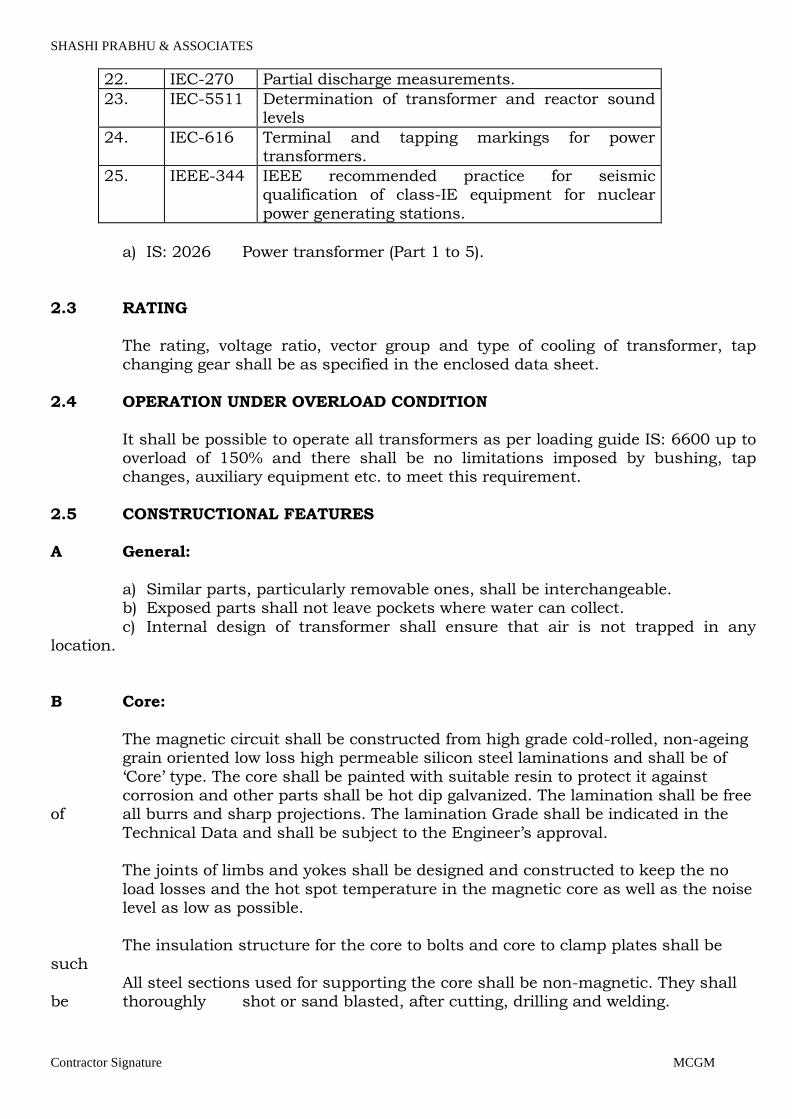
22. IEC-270 Partial discharge measurements.
23. IEC-5511 Determination of transformer and reactor sound levels
24. IEC-616 Terminal and tapping markings for power transformers.
25. IEEE-344 IEEE recommended practice for seismic qualification of class-IE equipment for nuclear
power generating stations.
a) IS: 2026 Power transformer (Part 1 to 5).
2.3 RATING
The rating, voltage ratio, vector group and type of cooling of transformer, tap changing gear shall be as specified in the enclosed data sheet.
2.4 OPERATION UNDER OVERLOAD CONDITION
It shall be possible to operate all transformers as per loading guide IS: 6600 up to overload of 150% and there shall be no limitations imposed by bushing, tap changes, auxiliary equipment etc. to meet this requirement.
2.5 CONSTRUCTIONAL FEATURES
A General:
a) Similar parts, particularly removable ones, shall be interchangeable. b) Exposed parts shall not leave pockets where water can collect.
c) Internal design of transformer shall ensure that air is not trapped in any location.
B Core:
The magnetic circuit shall be constructed from high grade cold-rolled, non-ageing grain oriented low loss high permeable silicon steel laminations and shall be of
‘Core’ type. The core shall be painted with suitable resin to protect it against corrosion and other parts shall be hot dip galvanized. The lamination shall be free of all burrs and sharp projections. The lamination Grade shall be indicated in the
Technical Data and shall be subject to the Engineer’s approval. The joints of limbs and yokes shall be designed and constructed to keep the no
load losses and the hot spot temperature in the magnetic core as well as the noise level as low as possible.
The insulation structure for the core to bolts and core to clamp plates shall be such
All steel sections used for supporting the core shall be non-magnetic. They shall be thoroughly shot or sand blasted, after cutting, drilling and welding.
Page 29
SHASHI PRABHU & ASSOCIATES
Contractor Signature MCGM
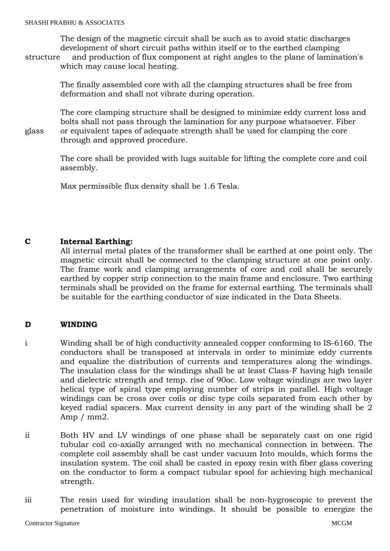
The design of the magnetic circuit shall be such as to avoid static discharges
development of short circuit paths within itself or to the earthed clamping structure and production of flux component at right angles to the plane of lamination's which may cause local heating.
The finally assembled core with all the clamping structures shall be free from deformation and shall not vibrate during operation.
The core clamping structure shall be designed to minimize eddy current loss and
bolts shall not pass through the lamination for any purpose whatsoever. Fiber glass or equivalent tapes of adequate strength shall be used for clamping the core through and approved procedure.
The core shall be provided with lugs suitable for lifting the complete core and coil
assembly. Max permissible flux density shall be 1.6 Tesla.
C Internal Earthing: All internal metal plates of the transformer shall be earthed at one point only. The
magnetic circuit shall be connected to the clamping structure at one point only.
The frame work and clamping arrangements of core and coil shall be securely earthed by copper strip connection to the main frame and enclosure. Two earthing terminals shall be provided on the frame for external earthing. The terminals shall
be suitable for the earthing conductor of size indicated in the Data Sheets.
D WINDING
i Winding shall be of high conductivity annealed copper conforming to IS-6160. The conductors shall be transposed at intervals in order to minimize eddy currents
and equalize the distribution of currents and temperatures along the windings. The insulation class for the windings shall be at least Class-F having high tensile and dielectric strength and temp. rise of 90oc. Low voltage windings are two layer
helical type of spiral type employing number of strips in parallel. High voltage windings can be cross over coils or disc type coils separated from each other by keyed radial spacers. Max current density in any part of the winding shall be 2
Amp / mm2.
ii Both HV and LV windings of one phase shall be separately cast on one rigid tubular coil co-axially arranged with no mechanical connection in between. The complete coil assembly shall be cast under vacuum Into moulds, which forms the
insulation system. The coil shall be casted in epoxy resin with fiber glass covering on the conductor to form a compact tubular spool for achieving high mechanical
strength. iii The resin used for winding insulation shall be non-hygroscopic to prevent the
penetration of moisture into windings. It should be possible to energize the
Page 30
SHASHI PRABHU & ASSOCIATES
Contractor Signature MCGM
transformer without predrying even after a long period of service interruption. The
resin used shall be self-extinguishing and void free and shall be suitable for temperate climate and 100% air humidity.
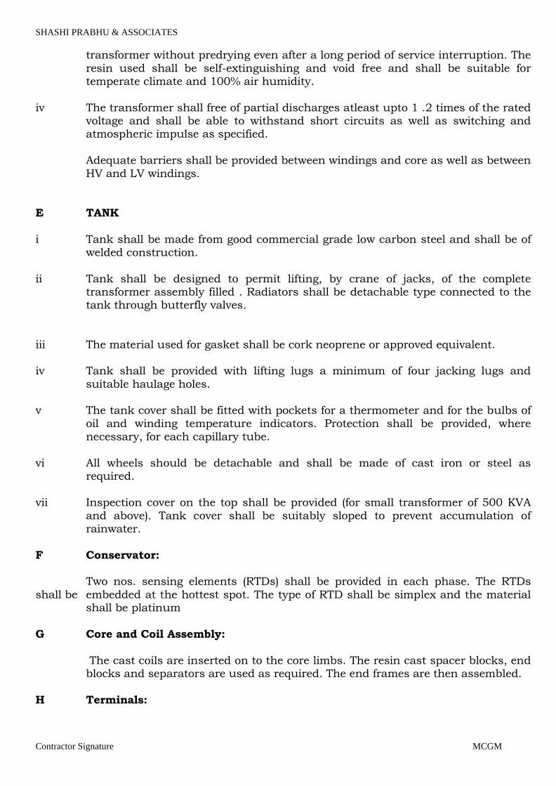
iv The transformer shall free of partial discharges atleast upto 1 .2 times of the rated voltage and shall be able to withstand short circuits as well as switching and atmospheric impulse as specified.
Adequate barriers shall be provided between windings and core as well as between
HV and LV windings.
E TANK
i Tank shall be made from good commercial grade low carbon steel and shall be of welded construction.
ii Tank shall be designed to permit lifting, by crane of jacks, of the complete transformer assembly filled . Radiators shall be detachable type connected to the tank through butterfly valves.
iii The material used for gasket shall be cork neoprene or approved equivalent. iv Tank shall be provided with lifting lugs a minimum of four jacking lugs and
suitable haulage holes. v The tank cover shall be fitted with pockets for a thermometer and for the bulbs of
oil and winding temperature indicators. Protection shall be provided, where necessary, for each capillary tube.
vi All wheels should be detachable and shall be made of cast iron or steel as
required.
vii Inspection cover on the top shall be provided (for small transformer of 500 KVA
and above). Tank cover shall be suitably sloped to prevent accumulation of rainwater.
F Conservator:
Two nos. sensing elements (RTDs) shall be provided in each phase. The RTDs
shall be embedded at the hottest spot. The type of RTD shall be simplex and the material shall be platinum
G Core and Coil Assembly:
The cast coils are inserted on to the core limbs. The resin cast spacer blocks, end blocks and separators are used as required. The end frames are then assembled.
H Terminals:
Page 31
SHASHI PRABHU & ASSOCIATES
Contractor Signature MCGM
The HV side termination facility to be provided on the transformer shall be
designed for connecting 11KV XLPE (E) (240 sq.mm. 3 core Al. cable) insulated cables terminated with crimping type lugs. The cable entry shall be from the bottom. HV bushing terminals shall be extended upto the cable terminals by means of
busbars. These busbars shall be located in the upper side of the transformer at a convenient height. Busbars shall be supported by supporting insulators from the top frame of the enclosure, clearing the ventilation hood. HV line end busbar terminals shall
facilitate termination of cables with heat shrinkable sleeves. Formation of delta on the HV side is in the scope of transformer manufacturer. Only cable termination
shall be at site. No modification / formation of and windings shall be done on site. Phase to phase and phase to ground clearances shall be as specified in data
sheets.
The LT side terminals for the transformer shall be connected directly to switchgear bus by direct bus bars. Horizontal/Vertical connections to busbars shall be straight and without unnecessary joints. For bus connection the LV terminals shall be
extended upto the switchgear by bus bars. These bus bars will be connected to the switchgear bus bars through copper flexible suitable for 100% rating. Formation of star on the LV side is in the scope of transformers manufacture. The LV terminals
shall be located in such a manner to suit the level of LT switchgear bus bars (top entry).
Tap changing links provided on a separate mounting plate than on cast resin MV windings so as to avoid any burnings of the links and resin arising out of loose connections due to frequent changing of the links or due to human error.
The transformer shall have terminals designed to suite any special requirements for BESCOM over & above IS. The HT/LT cable boxes shall be detachable type.
Flange for bus bar termination shall be provided at LT box as per the busbar used from transformer to LT switchgear.
The neutral of the star connected winding shall be in two branches and shall be brought out to two separate bushing terminals. One neutral bushing shall be
provided to facilitate leading the earth conductor down to the ground level. The terminal shall be suitable for connecting to two separate earthing pads. Suitable
lugs shall be supplied by the Contractor for connecting the earthing conductors. The second bushing shall be provided by side of the phase terminals for connecting neutral to neutral bus bar in the switchgear buses. Location of the CTs for the
earth fault protection shall be in the common portion of the neutral i.e. before bifurcation of the neutral in two branches
I Two earthing terminal of required size shall be provided.
J Rating and diagram plates shall be provided as per IS: 2026.
2.7 VOLTAGE CONTROL
A type of control and No. of taps shall be as specified in data sheet.
Page 32

SHASHI PRABHU & ASSOCIATES
Contractor Signature MCGM
B ON LOAD TAP Changer: OLTC with AVR and RTCC panel shall be provided if
required. REQUIRED FOR THIS APPLICATION. 2.8 BUSHING INSULATORS AND CABLE BOXES
A Transformer shall be fitted either with bushing insulators or with cable boxes, as
specified. Cable box should be air insulated type.
B Cable box shall have sufficient space to facilitate termination if more than one
cable terminations are specified, and to accommodate all cable joint fittings or sealing ends including stress/cones etc. Links shall be provided of suitable length for easy termination of cables. Necessary glands and cable sockets shall be
provided. Box shall have a drain plug to enable the filling medium removal quickly. Armor earthing pads(2 nos.) shall be provided along-with cable
termination kit support. C Non-magnetic cable gland plate shall be provided in the cable box, whenever
single core cables are specified. 2.9 BUSDUCT TERMINATION
When bus-duct termination is specified a flanged throat or equivalent connection
shall be provided to suit purchaser's bus-ducts. The LV winding termination shall be on outdoor type of bushings.
2.10 TEMPERATURE INDICATING DEVICES AND ALARM A device for measuring the hot spot temperature of the winding shall be provided
winding temperature indicators consisting of:
Temperature sensing elements. The no. of sensing elements shall be provided as indicated in 1.7.
Local indicating instrument with four adjustable electrically independent ungrounded contacts brought out to separate terminals for winding temperature
high alarm and trip. One indicating instrument shall be provided for each phase.
The tripping contact of winding temperature indicators shall be adjustable to close between 60°C and 120°C and alarm contacts to close between 50°C and 100°C and both shall reopen when the temperature falls by about 10°C.
Connections shall be brought from the device to marshaling box.
Separate MCBs shall be provided for control supply (alarm and trip circuits). Control supply shall not be taken from secondary side of the transformer
2.11 Marshalling Box :
The contractor shall provide a marshalling box and shall mount the winding
temperature indicators in the marshalling box and shall marshalling to it all the
contacts/terminals of CT secondary and winding temperature indicators required
Page 33
SHASHI PRABHU & ASSOCIATES
Contractor Signature MCGM
for the transformer. The contractor shall provide the interconnection cabling
between the above equipment and the marshalling box. The winding temperature indicator shall be flush mounted on the marshalling box door. This interconnection shall be through wires in GI conduits or through armoured
cables. The insulation for the wires/cables shall be consistent with the ambient temperature in the housing. Compression type brass cable glands required for these interconnections shall be supplied by the contractor.
The marshalling box shall be mounted on the transformer housing. All doors,
covers and plates shall be provided with neoprene gaskets. Bottom of the marshalling box shall be at least 600mm above floor level and provided with removable bolted, un-drilled gland plate.
All contacts for alarm, trip and indication circuits shall be electrically free, wired
for auxiliary supply as specified and brought out to separate terminals at the terminal block in the marshalling box. Terminal blocks shall be preferably of GE power controls/Elmex. Terminals shall be rated for 10A. Wiring shall be with PVC
insulated, stranded, copper, conductor of sizes not smaller than 1.5 Sq mm for control and 2.5 Sq mm of CT circuits. CT terminals shall be provided with shorting facility. Engraved identification ferrules, marked to correspond with the
approved wiring diagrams shall be fitted to each wire. Ferrules shall be of yellow colour with black lettering.
2.12 PAINTING
The inside of the enclosure shall be treated with matt paint of semi-glossy white. Steel surfaces exposed to the weather shall be thoroughly cleaned and applied first coat of zinc chromate, second coat of oil and weather resistant paint and final
coat of glossy oil and weather resistant non fading paint of shade no 632 of IS :5 (epoxy paint)
2.13 TESTS
A Routine tests : Routine test such as ratio test, open circuit test, short circuit
test, no load test, induced high voltage test, insulation resistant test, measurement of winding resistance etc. shall be conducted as per IS : 2026. Including CT polarity test, earth continuity test, OLTC operation test, oil dielectric
test. Type tests : Type tests if required by client / consultant shall be carried out at
certified laboratory of the suppliers area shall be carried out. If not required by
client certificates for type test carried out for similar rating of transformer shall be submitted by the supplier. Type tests shall be carried out for temp. Rise, impulse
voltage and short circuit analysis. B Test certificates : Five copies of the routine test and type test certificates shall be
submitted for purchaser's record before dispatch of transformer, including test certificates of bought out items.
2.14 INSPECTION
Page 34
SHASHI PRABHU & ASSOCIATES
Contractor Signature MCGM
A Inspection including witnessing routine tests will be carried out by purchaser or
his authorized representative. B Vendor shall notify purchaser or his authorized representative in writing atleast
fifteen days prior to vendor's scheduled inspection tests. 2.15 GUARANTEE
Vendor shall guarantee design, materials workmanship and performance for a
period of 12 months from the date of commissioning or 30 months after delivery at job site, for all goods to be supplied under order, till whichever date shall occur first.
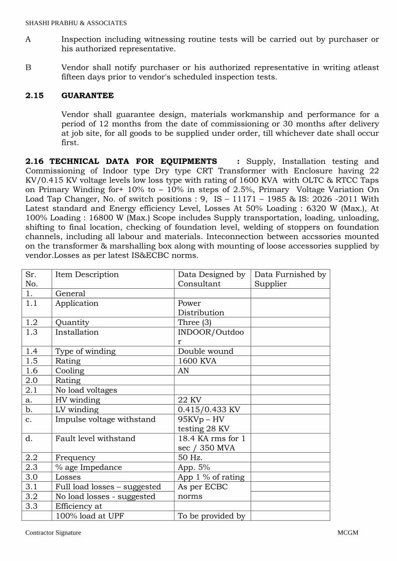
2.16 TECHNICAL DATA FOR EQUIPMENTS : Supply, Installation testing and
Commissioning of Indoor type Dry type CRT Transformer with Enclosure having 22 KV/0.415 KV voltage levels low loss type with rating of 1600 KVA with OLTC & RTCC Taps on Primary Winding for+ 10% to – 10% in steps of 2.5%, Primary Voltage Variation On
Load Tap Changer, No. of switch positions : 9, IS – 11171 – 1985 & IS: 2026 -2011 With Latest standard and Energy efficiency Level, Losses At 50% Loading : 6320 W (Max.), At 100% Loading : 16800 W (Max.) Scope includes Supply transportation, loading, unloading,
shifting to final location, checking of foundation level, welding of stoppers on foundation channels, including all labour and materials. Inteconnection between accssories mounted
on the transformer & marshalling box along with mounting of loose accessories supplied by vendor.Losses as per latest IS&ECBC norms.
Sr. No.
Item Description Data Designed by Consultant
Data Furnished by Supplier
1. General
1.1 Application Power
Distribution
1.2 Quantity Three (3)
1.3 Installation INDOOR/Outdoor
1.4 Type of winding Double wound
1.5 Rating 1600 KVA
1.6 Cooling AN
2.0 Rating
2.1 No load voltages
a. HV winding 22 KV
b. LV winding 0.415/0.433 KV
c. Impulse voltage withstand 95KVp – HV testing 28 KV
d. Fault level withstand 18.4 KA rms for 1 sec / 350 MVA
2.2 Frequency 50 Hz.
2.3 % age Impedance App. 5%
3.0 Losses App 1 % of rating
3.1 Full load losses – suggested As per ECBC
norms
3.2 No load losses - suggested
3.3 Efficiency at
100% load at UPF To be provided by
Page 35
SHASHI PRABHU & ASSOCIATES
Contractor Signature MCGM
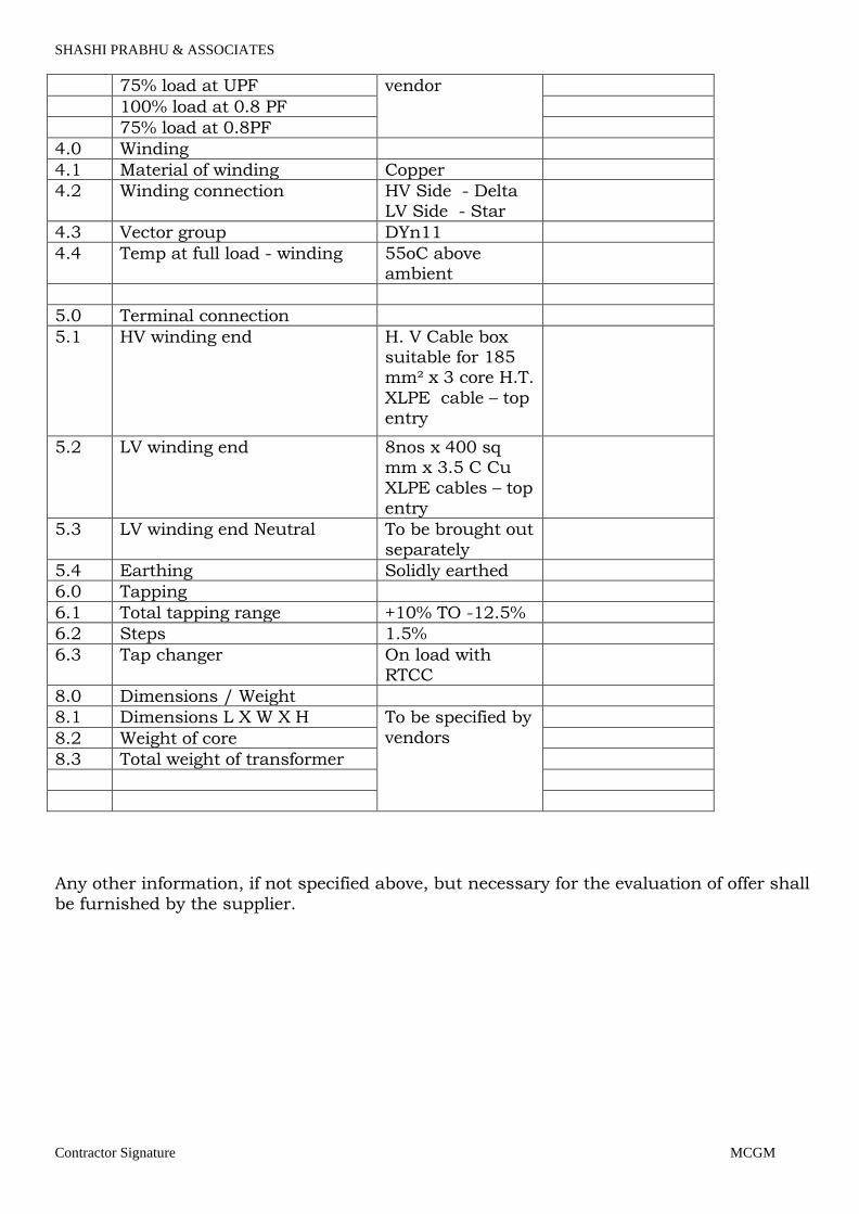
75% load at UPF vendor
100% load at 0.8 PF
75% load at 0.8PF
4.0 Winding
4.1 Material of winding Copper
4.2 Winding connection HV Side - Delta LV Side - Star
4.3 Vector group DYn11
4.4 Temp at full load - winding 55oC above ambient
5.0 Terminal connection
5.1 HV winding end H. V Cable box suitable for 185 mm² x 3 core H.T.
XLPE cable – top entry
5.2 LV winding end 8nos x 400 sq mm x 3.5 C Cu
XLPE cables – top entry
5.3 LV winding end Neutral To be brought out separately
5.4 Earthing Solidly earthed
6.0 Tapping
6.1 Total tapping range +10% TO -12.5%
6.2 Steps 1.5%
6.3 Tap changer On load with RTCC
8.0 Dimensions / Weight
8.1 Dimensions L X W X H To be specified by
vendors
8.2 Weight of core
8.3 Total weight of transformer
Any other information, if not specified above, but necessary for the evaluation of offer shall
be furnished by the supplier.
Page 36

SHASHI PRABHU & ASSOCIATES
Contractor Signature MCGM
3.0 DIESEL GENERATOR SET WITH ACOUSTIC CANOPY
1.0 GENERAL :
1.1 SCOPE : This general specification together with the equipment sheets and attachments
defines the minimum requirements the design, performance, inspection, testing and supply diesel engines for general industrial purposes.
1.2 The construction, design and rating of the diesel engine shall meet fully, the
requirements of the specified driven machine and the Vendor shall select and provide
the requisite ancillaries and controls with the diesel engine for its safe and satisfactory operation.
1.3 No deviations or exceptions from this specification shall be permitted without the
written approval of the purchaser. Intended deviations supported by reasons there of
shall be separately listed by the vendor and submitted with the bid for the consideration of the Purchaser.
1.4 Compliance with this specification shall not relieve the vendor of the responsibility of furnishing equipment and accessories of proper design, materials and workmanship
to meet the specified operating conditions. 1.5 This general specification supplements the specific requirements contained in the
attached equipment data sheets. In the event of any contradiction between the two, the information contained in the latter shall govern.
1.6 Other attachments of the Material Requisition from a apart of this specification.
1.7 TERMS AND DEFINITIONS: 1.7.1 The Net Calorific value of fuel is defined as the heat resulting from the complete
combustion of a unit quantity of fuel oil and air, without condensation of the water vapor. A net calorific value of 9,720 Kcal/Kg (As per IS : 1460 Rev.2) shall be
considered while declaring the fuel consumption and for testing purposes. 1.7.2 The unit of horse power as defined in this specification is the metric horse power
equivalent to 4,500 n-Kg/Min. The horse power in F.P.S. system is equal to 1.014 metric horse powers.
1.7.3 Other terms used in this specification or in the equipment data sheets are as defined in the latest edition of British Standard-5514.
2.0 STANDARD OPERATING CONDITIONS:
2.1 The standard operating conditions shall be defined in the latest edition of B.S.-5514 unless otherwise mentioned specifically in the equipment data sheet.
3.0 RATED POWER OUTPUT AND SPEED:
Page 37

SHASHI PRABHU & ASSOCIATES
Contractor Signature MCGM
3.1 The diesel engine rating shall be the net output in brake horse power, which the
engine is capable of delivering continuously at the stated crank shaft speed under the conditions specified under Clause 2.0 above, provided the engine is maintained in good operating condition and is serviced / overhauled regularly as per the
schedules laid down by the Manufacturer. 3.2 No negative tolerance shall be allowed on the diesel engine rating specified by the
Vendor in the equipment data sheets.
3.3 The engine shall be capable of satisfactorily providing an output 10 percent in excess
of the continuous rating defined above, at the same speed for one hour in any period of 12 hours consecutive running.
3.4 The normal power requirement of the engine driven radiator fan or the coolant pump and the battery charging dynamo shall be clearly stated for the engine which is so
equipped. 3.5 Unless otherwise specified in the equipment data sheets, the site rating of the engine
shall be worked out considering the duration’s specified under the latest edition of B.S.-5514 and the power absorb by all the engine driven ancillaries shall also be deducted.
4.0 DESIGN & CONSTRUCTION:
4.1 GENERAL:
4.1.1 The Diesel engine offered shall be of the regular production models of the manufacturer for industrial applications and already type tested either at the manufacturer's works or outside. The type test report shall be furnished to the pur-
chaser for his review if so desired.
In case the proposed engine model has not been type tested, vendor shall furnish with the offer, a reference list of its existing industrial installation and at least three of these engines, should have completed, 5,000 houses of running at site.
4.1.2 Unless otherwise specified in the equipment data sheets, the diesel engine shall be
provided with class A2 governing as per the latest edition of B.S. 5514. 4.1.3 The "Cyclic irregularity" of the diesel engine for direct coupling to an electric
generator, "angular deviation of p73 A.C. generators " driven by diesel engine for parallel operation, and the "engine governor speed droop characteristics ", shall be restricted to the values specified under the latest edition of B.S.-5514.
4.1.4 In case diesel engines are required to drive generators in parallel, the governor fuel
injection pumps provided should have identical characteristics and the speed-load curves shall be made available to the purchaser's inspector for his scrutiny and approval prior to load testing. The vendor shall maintain proper record for such
curves to ensure additional diesel engines if required in future with identical characteristics, could be made available to the purchaser. A set of the said curves
shall also be furnished to the purchaser. 4.1.5 The vendor shall be responsible for carrying out torsion analysis of the dynamic
system as specified in the latest edition of British Standard-5514. The results in the
Page 38
SHASHI PRABHU & ASSOCIATES
Contractor Signature MCGM
fork of a report shall be submitted to the purchaser for scrutiny and reference, if
desired. 4.1.6 Vendor shall provide the flexible exhaust connection /s to connect the engine
exhaust to the exhaust piping. The required size of the exhaust piping should be clearly specified by the Vendor.
4.1.7 If specified, the common base plate for mounting the diesel engine and the driven equipment as well as the flexible coupling, shall be supplied by the vendor.
4.1.8 Vendor shall indicate in the bid, the ISO Noise Level rating of the diesel engine with
the offered exhaust silencer/s.
4.2 ENGINE STARTING : 4.2.1 Diesel engines shall be capable of starting without the use of cold starting aids so
long the ambient temperature at the site is not below 4 oC. The vendor shall provide suitable cold starting aids with diesel engine for quick starting below 4oC of ambient and such aids shall be clearly detailed out along with the offer.
4.2.2 Where the diesel engine is specified / offered with battery starting arrangement, the
starter motor shall be capable of starting the engine without having to disengage the driven machine with the help of a clutch. Where the diesel engine is equipped with a dual starter the synchronizing switch and the corresponding wiring / connection
with the starter motor shall be provided by the vendor. In case of diesel engines driving fire water pumps, besides the engine mounted
dynamo and voltage regulator, the Vendor shall also provide automatic battery charging equipment suitable for taking power from an alternating current power
source and mounted on a free standing type of a panel. The battery charger if specified in the equipment data sheet, shall be capable of
delivering a current equal to 100 percent of the 20 hour discharge rate of the battery and also equipped with charging rate selector device.
4.2.3 Where the diesel engine is specified / offered with compressed air starting, the
Vendor shall also provide the air compressor driven by a diesel engine / electric
motor and equipped with necessary instruments and controls as specified in the equipment data sheets.
The air receiver supplied by the vendor shall provide batteries and battery charging equipment (see clause B. above) for operating the electrical controls of the diesel
engine. 4.2.4 If as specified in the data sheets, the diesel engine is required to start / stop
automatically, the vendor shall provide the necessary controls (automatic-cum-manual) in the engine panel and the interconnecting wiring and
piping from the panel to the engine and starting equipment. A pilot lamp shall be provided in the line side of the starting equipment circuit to indicate that the controller is in the automatic position. In the event the engine does not start after
three attempts have been made, the controller shall stop all further cranking and
Page 39
SHASHI PRABHU & ASSOCIATES
Contractor Signature MCGM
operate the audiovisual alarm. AD.C. motor driven per lubrication pump with timer
suitably interlocked with the starting system shall be provided by the vendor. Whenever the unit is arrange for automatic shut down, a running period time set for a specific time interval, and shall be provided.
4.3 ENGINE COOLING:
4.3.1 When radiator cooled engines are offered, the diesel engine shall be provided with a radiator for mounting on the common base plate, complete with the suction / blower
fan, temperature control valve and a radiator guard. 4.3.2 Where the engine cooling is achieved by closed circuit cooling water system, the
vendor shall provide the complete jacket water (primary water) circuit, heat exchanger with the make-up tank and its piping, as well as the raw water (secondary
water) circuit including but not limited to the following : 4.3.2.1 Raw water pump with driver, unless the raw water is required to be obtained
from the discharge of the pump driven by the diesel engine. 4.3.2.2 Raw water piping (prefabricated ) and fittings, as specified in the equipment
date sheets.
4.3.2.3 Instruments and controls as specified in the equipment data sheets. 4.4 ENGINE FUEL SYSTEM:
4.4.1 A fuel float (surge) tank if recommended by the manufacturer, shall be supplied with
the diesel engine along with its interconnecting piping / hoses.
4.4.2 The daily service fuel tank shall be equipped with as air breather, shielded level
gauge, strainer and a hand hole of not less than 150 mm diameter, besides the required fuel connections and a drain plug. The capacity of tank shall be as specified in the equipment data sheets.
4.4.3 The inside surfaces of the fuel tank and the float tank shall be coated with Enamel
Red or Black of I.C.I. or its equivalent and the outside surface to be given two coats of the oil resistant primer paint. Both the fuel tank and the float tank, shall be hydrostatic tested at a pressure not less than 0.35 kg /Cm2.
5.0 INSPECTION & TESTING:
5.1 The inspector representing Purchaser shall have entry to the plant while and wherever work for the equipment is being performed.
5.2 The vendor shall have the responsibility of providing purchaser's inspector with all
requisite facilities / equipment for carrying out satisfactory testing.
5.3 The diesel engines shall be tested in the presence of purchaser's inspector in
accordance with the latest edition of B.S. -5514 or any other equivalent standard as agreed to with the purchaser before the finalization of order.
5.4 The routine load and fuel consumption test shall be of the following duration :
Page 40
SHASHI PRABHU & ASSOCIATES
Contractor Signature MCGM
5.5 Unless otherwise specified, 10% overload provision shall be kept while setting the fuel stop for the site running.
5.6 The hydrostatic test certificates for the heat exchanger / intercoler , fuel tanks and other pressure vessels shall be furnished to the purchaser's inspector for his review and approval at the time of load testing of the diesel engine.
5.7 The engine control panel/s after assembly and wiring, shall be functionally tested in
the presence of the purchaser's inspector. 6.0 PREPARATION FOR SHIPMENT :
6.1 Immediately upon completion of all tests and inspections, all exposed machined
surfaces shall be cleaned and coated with a suitable rust preventive by the vendor and the unmachined surface shall be painted by at least two coats of red oxide primer.
6.2 Diesel engines shall be transported assembled as far as possible.
6.3 All untapped opening shall be provided with 4mm thick metal closures with full rubber gaskets and bolted by not less than 4 bolts. All connections including those
for instruments, instrument leads, lubricating oil and the like shall be identified with securely attached tags indicating the type of connection, the instrument or the line description as applicable.
6.4 The equipment shall be crated for domestic / export shipment as specified in the data sheets considering for storage at job site for at least 6 months. Lifting load-out, and handling instructions shall be securely attached to the exterior of the largest
packing in a well marked weather proof container. Upright position lifting points, weight (including packing and dimensions shall be clearly identified with item no.,
serial no., package no., and the names of the equipment.) 7.0 PROPOSAL :
7.1 Proposals shall be accompanied with completely filled in Data Sheets. The vendor
shall not use his own data sheets. 7.2 The proposals must include either a specified statement that all equipment is in
accordance with the purchaser's specifications or exceptions, if any, to this general
specification including attachments shall be clearly brought out by the vendor on separate sheets, supported with suitable reasons thereof for the consideration of the purchaser.
7.3 Additions or exclusions from the scope of supply shall be clearly brought out on
separate sheets giving reasons for such deviations for the purchaser's approval. 7.4 Rating (HP) curves for the diesel engine for different duties and their interpretation as
per the applicable standard, shall accompany the proposal.
7.5 The drawings and data as listed under "prints with Quote" on the vendor data requirement sheet attached with this specification shall be provided.
Page 41

SHASHI PRABHU & ASSOCIATES
Contractor Signature MCGM
7.6 The vendor shall also submit a separate proposal for carrying out supervision of the
installation and commissioning of diesel engine/s offered indicating per item rates, no. of specialists proposed to be deputed, completion time and a list indicating nature and quantity of consumable/ tools required and any other terms.
8.0 SCOPE:
8.1 This specification define the requirements of design, manufacture, testing and supply of self excited emergency generator complete with automatic voltage regulator,
control panel, generator breaker and other accessories as specified in the material requisition.
8.2 Unless otherwise specified the emergency generator shall be supplied complete with
a) Brush less excitation system complete with AVR. b) Electric panel including control cubicle and associated auxiliary devices, relay panel
and generator breaker battery and charger (unless otherwise specified). c) Air inlet and outlet for generator cooling (inlet shall be oriented to suit local plant
layout).
d) Lifting arrangement for the machine. e) Foundation frame complete with foundation bolts and base frame.
f) Lube oil system integral with the prime mover lube oil system.
g) Spares for commissioning
h) Spares for two years of operation and maintenance. i) Any other part / accessories not specifically mentioned above but considered
necessary for safe and reliable operation.
9.0 CODES AND STANDARDS: Unless they are in variance with the clause of this specification the diesel engine
driven generator and their components shall comply with the latest edition of the applicable standards listed below:
IS : 22534 Designation for type of construction and mounting arrangement of rotating electrical machines.
IS : 46914 Degree of protection providing by enclosures of rotating electrical
machinery.
IS : 47284 Terminal marking of rotating electrical machines.
IS : 71324 Guide for testing 3 Ph. synch. Machines. IS : 54224 Turbine type generators.
Page 42
SHASHI PRABHU & ASSOCIATES
Contractor Signature MCGM
IS : 48894 Methods of determination of efficiency of rotating electrical machines.
IS : 12714 Insulating materials for Electric machinery and apparatus in relation to
their thermal stability service, classification of
IS : 47224 Specification for rotating electrical machines.
IS : 25164 A.C. Circuit breakers.
Other codes shall be : AS2789, BS4999, BS5000, DIN6271, EGSA101P, IEC34/1, IS4722, ISO3046/1, ISO8528, NEMAMG1-22, SAEJ1349.
10.0 PERFORMANCE REQUIREMENTS :
10.1 Operative Conditions : Generators shall be suitable for operating satisfactorily in humid and corrosive
atmosphere found in pump house. Service conditions shall be as specified in the data sheet. The generator shall operate satisfactorily under sudden load application. Generator rating indicated in the data sheet shall be the net output of the set after
accounting for all auxiliaries for the prime mover and generator.
10.2 Transient Voltage performance The dip or rise in system voltage load variations is dependent on the leakage voltage
drop of the machine which shall be kept to the minimum. In case of sudden application of full load at rated power factor the voltage drop shall
not exceed 15% of the rated voltage. The rated voltage shall be restored within 0.5 to 0.8 second depending on the size of the machine.
10.3 Voltage Regulation
The voltage regulation of the machine shall be within +/- 2 % of the nominal voltage under following conditions :
a). Between no load and nominal load with p.f. of 0.8 lag to unity. b). With the machine cold or warm.
c). At a speed drop of approximately 3% of the nominal speed. 10.4 Voltage setting range :
The generator terminal voltage shall be adjustable with a continuously variable
potentiometer. The adjustment range shall be +/- 5% of the nominal voltage with a possible extension to +/- 10%.
10.5 Harmonic Content
The maximum permissible deviation from the sine wave shall be 5%. The harmonic content of the voltage shall be less than 3% measured between phases off load and up to nominal rating for a power factor of 0.8 lag to unity and with symmetrical
distortion free consumers in circuit.
Page 43
SHASHI PRABHU & ASSOCIATES
Contractor Signature MCGM
10.6 Frequency limits The Generator shall be suitable for continuous operation at rated load for frequency
variation of +/- 3% of rated value in addition the vendor shall furnish the short time under-frequency operating limits.
10.7 Overloads :
The generator shall be capable of withstanding without injury the effect of a 10% overload for one hour and 50% overload for one minute.
10.8 Short Circuit Conditions :
The generator shall be capable of withstanding without damage, a three phase, a line to line, line to earth or two line to earth short circuit for a period of 3 seconds when operating at rated speed and with an excitation corresponding to 5% over voltage at
no load. 10.9 Parallel operation :
Generator sets shall be suitable for parallel operation amongst themselves, or with
other generating sets or with other sources (Grid supply) at operating voltage and under load conditions up to rated value. The set shall be provided with Electronic governor system.
10.10 Excitation support system
Excitation system shall be provided with short circuit support equipment (Series compounding) to maintain three times the rated current for three seconds in case of
short circuit to ensure proper fault clearance in outgoing feeders. 11.0 DESIGN AND CONSTRUCTION :
11.1 The generator design shall meet the requirement specified in data sheet and shall be
suitable for the site conditions specified therein. 11.2 The generator shall be mounted on a common base frame together with the prime
mover unless otherwise agreed. The generator shall be provided with necessary lifting hooks and two earth terminals for connection to main earth grid.
11.3 The generator winding shall be class "F" insulation with temperature limitation for class "B" the windings and overhangs shall be braced to withstand the short circuit
forces. For machines rated 1000 KW and above shall have six no. RTDs suitably distributed in stators winding.
11.4 The stators windings shall be brought out to six insulated terminals in two separate terminal boxes. The alternator shall, therefore, be provided with three separate
terminal boxes i.e. for the line and neutral stators connections and for control connections. The terminal box for the line terminals shall have sufficient space for the termination of cable size specified in data sheet. The neutral box shall in addition
to space for neutral earthing cable have sufficient room for current transformers
Page 44
SHASHI PRABHU & ASSOCIATES
Contractor Signature MCGM
used for protection of generator. Star connection shall be formed in the neutral side
terminal box. The terminal box for control cables shall contain properly marked terminals for all internal equipment e.g. embedded temperature detectors etc. All terminals shall be stud type. The terminal boxes shall be complete with lugs and
double compression cable glands. Current transformers shall be as specified in data sheet.
11.5 All parts and accessories shall be suitable to withstand stresses due to over speed / overload / short circuit conditions specified.
11.6 Bearings shall be double shielded and relubricated. Grease in the bearing enclosure
shall provide additional lubrication to bearing as well as provide sealing against dust
and moisture.
11.7 The generator shall be air cooled unless otherwise agreed generator enclosure shall be as specified in data sheet.
11.8 The direction of rotation of the rotor of the machine shall be compatible with that of the prime mover. A clear indication of the direction of rotation shall be given on either end of the machine.
11.9 Space heaters shall be installed within the enclosure, location and max. surface
temperature of the heaters shall be such that no damage can be caused to any insulation. Heaters shall suitable for operation on a single phase 240V AC supply unless otherwise specified.
A suitable double pole switch shall be mounted on or adjacent to the stators frame or
enclosure for the manual switching off of the heaters.
11.10 Field winding shall have class "F" insulation with excellent electrical and mechanical
properties. The field winding shall be capable of operating at a field voltage of 125% of rated load field voltage for at least one minute starting from stabilized temperatures at rated conditions.
11.11 All cabling on the generator set skid shall be in GI cable trays/ conduits. All cables shall be identified close to their termination point. Double compression type cable
glands shall be used for cable termination. 11.12 A rating plate of corrosion resistant material shall be fixed on the generator frame
and shall give the following information: a) Manufacturer's name.
b) Serial Number, Type and frame reference c) Rated output in MVA & MW
d) Rated power factor, frequency and voltage e) Rated stators current and speed in Rev. / Min. f) Class of insulation
g) Phase rotation (CW or CCW) h) Customer's indent no.
i) Year of manufacture j) Weight rotor and stators in KG.
Page 45

SHASHI PRABHU & ASSOCIATES
Contractor Signature MCGM
12.0 EXCITATION SYSTEM : The generator shall be provided with brush less type solid state excitation system
with automatic voltage regulator. The excitation system shall include the automatic voltage regulator, AC exciter and rotary rectifier. The field of the exciter shall be fed from the stators winding through a suitable transformer and AVR. AC Voltage
generated in the AC exciter shall be rectified by the rotary rectifier assembly and fed to the main field circuits. The rotor windings of the AC exciter, the rectifier assemble,
main field winding of the generator and other accessories on rotor part shall be rigidly fastened to the shaft and the connection with different items shall be anti-loosening type.
The exciter capacity shall be at least 20% more than the maximum requirement at
any time. The exciter winding shall be insulated with class "F" insulation. Automatic solid state voltage shall be provided with the following features as a
minimum. - Under frequency protection.
- short circuit protection. - Manual voltage control switch with adjuster.
- Cross current compensation for parallel operation. - Voltage build up circuitry. - Stators current limited.
- Field current limited. The Current and potential transformers required to feed the AVR from the generator
terminal shall be adequately rated.
13.0 SYSTEM OPERATION The emergency generator set shall normally be in an unattended area. The Control
system shall operate in fail safe mode and shall include all controls and protection necessary for the safe operation of the package. The generator set shall function as
per one of the following schemes: - Auto main failure scheme (AMF).
- Manual start in service mode. - Manual test mode.
14.0 GENERATOR CONTROL PANEL :
14.1 The Local generator control panel for the generator set shall comprise of the following unless otherwise specified in the attached data sheet.
(a) Automatic Voltage Regulator.
(b) Protection and metering equipment’s. (c) Indicating instruments.
Page 46
SHASHI PRABHU & ASSOCIATES
Contractor Signature MCGM
(d) Local breaker for DG set (Siemens / Schneider)
(e) Control gear for generator set auxiliaries.
Any other accessory require to make the generator set operational as a package shall be included in scope of supply . If required the generator control panel shall be split into various functional sections viz. protection, metering and control, regulation etc.
The generator break shall also be part of the control panel unless otherwise
specified. The breaker rating shall be as specified in the drawing. The protective relays in the Gen. Control panel shall act to trip this breaker on fault conditions unless otherwise specified. This breaker also serves the purpose of
local isolation.
All motor starters for generator set auxiliaries shall be DOL type. Unless otherwise specified , the DC control supply required for relays , controls,
closing/tripping of generator breaker, annunciation circuit and for any other purpose shall be met by a DC system consisting of battery and battery charger of suitable capacity to be supplied by the generator set manufacturer . The battery shall
be sized for two hours load cycle a maximum. Battery charger shall be of the constant voltage type with current limiting feature and facilities for automatic and
manual, normal and quick charging of batteries . Charger shall be sized for boost charging of batteries with 10 to 14 hours.
14.2 The panel shall be free standing , metal enclosed, dust and vermin proof type with a hinged door and having a degree of protection IP 51 as per IS:51 as per IS:2147 unless otherwise specified . Power and control equipment shall be segregated inside
the panel as far as practicable. The maximum light of the operation handle/switches shall not exceed 1000 mm. and the minimum height not below 300 mm. All
hardware shall be corrosion resistant and bolts, nuts and washers shall be made of galvanized zinc passivated of cadmium plated high quality steel. Unless otherwise specified the panel shall be suitable for bottom cable entry. Necessary glands shall be
provided with the panel.
All auxiliary devices for control, indication, measurement and alarm such as push buttons control/selector switches, indicating lamps, metering instruments, annunciation’s etc. shall be mounted on the front door of the panel. Adequate
number of potential free contacts shall be provided in the control panel for any remote control, monitoring of the generator set.
14.3 All switches shall be load - break, heavy duty type. All fuses shall be non-deteriorating HRC cartridge pressure filled, link type. The contractor shall be
air-break type having AC-3 duty rating. Thermal overload relays shall be three element, positive acting, ambient temperature compensated type with adjustable setting range and built in protection feature against single phasing. All indicating
instruments shall be moving iron, flush mounting type and of 96 mm x 96 mm square pattern. All control / selector switches shall be rotary back connected type
having a cam-operated contact mechanism with knob type handle. "STOP" push buttons shall be stay put type.
Page 47
SHASHI PRABHU & ASSOCIATES
Contractor Signature MCGM
14.4 Wiring for power, control and signaling circuits shall be done with PVC insulated
copper conductors having 660 / 1100 V grade insulation. Minimum size of control wires shall be 2.5 mm "ELEMEX" type terminals shall be acceptable for wires up to 10mm2 size and for conductors larger than 10 mm2 bolted type terminals with
crimping lugs shall be provided. A minimum of 10% spare terminals shall be provided on each terminal block.
14.5 An adequately sized earth bus shall be provided in the panel for connection to the main earth grid. All non current carrying metallic parts of the mounted equipment’s
shall be earthed. Doors and movable parts shall be earthed using flexible copper connections.
14.6 Engraved nameplates shall be provided for all devices mounted on the front of the panel. Nameplate or polyester adhesive stickers shall be provided for each equipment
mounted inside the panel. 15.0 PAINTING, PACKING AND TRANSPORT:
15.1 All metal surfaces shall be thoroughly cleaned of scale, rust and grease etc. prior to
painting. Cleaned surfaces shall be given two coats of primer and prepared for final
painting. Final finish shall be free from all sorts of blemishes.
15.2 The equipment shall be shipped to site suitably packed to prevent any damage. Each package shall have labels to show purchaser's name, purchase order and equipment no. suitable lifting lugs etc. shall be provided and lifting points shall be clearly
marked on the package. Packing shall be suitable for storage at site for a minimum period of 6 months.
16.0 TESTS AND INSPECTION :
16.1 The owner or his authorized representative may visit the works during manufacture of equipment to assess the progress of work as well as to ascertain that only quality raw materials are used for the same. He shall be given all assistance to carry out the
inspection.
16.2 Detailed test procedure along with the facilities available at vendors works shall be furnished along with the bid Owner's representative shall be given minimum four weeks advance notice for witnessing the final testing. Test certificates including test
records and performances curves etc. shall be furnished by the vendor. 16.3 Tests
Equipment shall be tested to conform to the appropriate standards and the following
tests shall be conducted in the presence of purchaser's: 16.3.1 Functional tests, continuity tests and high voltage test on control panel to
establish the performance called for in the specification. 16.3.2 Power frequency voltage test on switch gear and mechanical / electrical
operational check. 16.3.3 Routine tests for alternator as per IS : 4722. 16.3.4 Over speed test (1.2 times the rated speed for 2 minutes)
Page 48
SHASHI PRABHU & ASSOCIATES
Contractor Signature MCGM
16.3.5 Transient response tests for sudden application and rejection of loads of 25%,
50%, 75% and 100% of rated capacity. 16.3.6 Wave form test (type test results are acceptable) 16.3.7 Phase sequence test.
16.3.8 Vibration test 16.3.9 Noise level test. 16.3.10 Dimensional and alignment test.
16.3.11 String test.
17. SPECIFICATIONS FOR UNDER GROUND DIESEL TANK WORKS 1 HSD STORAGE TANK :
Scope :
The contractor shall design, supply, install test and commission the HSD tank, fittings and accessories as per requirements of the following BIS codes :
IS 10987 / IS 823 / IS 1239 Rules and regulation of the chief inspector / Controller of Explosives India. Petroleum rules 1936
All site welding shall be carried out by fusion welding as per IS 823. for all butt welds, the roof run and final run shall be carried out.
TANK
The U.G. tank shall conform to IS 10987-1992 with respect to lining, corrosion, storage under ambient temperature, atmospheric conditions, stresses, design fabrication and installation.
The compliance of the above standards does not absolve the manufacturer from
compliance of statutory norms and provisions by Dept of explosives, CCOE and / or concerned statutory inspection agencies.
The Welding process shall conform to IS 813-1986. All welding shall be double butt welds. When the shell length is produced from more than one single plate, the
longitudinal seams shall break point at intermediate circumferential seams. In case of longitudinal seams, such seams shall be situated at the upper third or top center line. All end plates shall be stiffened.
The plates used shall conform to IS 1730-1989. The thickness of plates used shall have a corrosion allowance of 1.5 mm.
The pipe and pipe couplings shall conform to IS 1978-1982
Bolts and nuts shall conform to IS 1367 (Part III) and IS 1367 (Part VI) 1980.
The tank shall be designed for a pressure of 0.05mPA when full of water. The tank design shall be capable of withstanding the earth pressure of 1.40mPA when tank is
empty. UG tanks shall have hinged and bolted manhole of minimum 500 mm diameter,
fabricated in water proof manner.
Page 49

SHASHI PRABHU & ASSOCIATES
Contractor Signature MCGM
The UG tank shall be provided with lifting hooks. For filling of tanks from top, necessary fill connection pipe with 45 degrees
champers shall be provided. The fill up shall terminate at 100 mm above bottom of tank.
Provisions for sensing low level of fuel and transmitting the same to building automation system shall be envisaged.
The tank shall have calibrated dip rod of non sparking brass material of size 12 mm square.
The tank shall be fitted with vent pipe of not less than 4 M height, bending
downwards and the tip covered with two layers of non corrodible metal wire mesh of 11 meshes.
Two nos earthing bolts of minimum 12 mm size shall be provided on the end plate of either side of tank at about 200 to 300 mm below top level to facilitate 50 x 6 GI earth strip terminations.
The external surfaces of the tank shall be thoroughly cleaned free of rust scale,
grease etc and painted with one coat of approved primer paint. The entire interior surface shall be cleaned of rust, scales, grease etc and shall be
primed twice with fuel prior to dispatch. The tolerance in diameter of the tank shall be within plus or minus 0.35% of
specified diameter.
Tank shall be subjected to Hydraulic test at a pressure of 0.05mPA and thoroughly checked for leakages.
The HSD tank shall be MS construction, horizontal cylindrical in shape with dished ends.
The tank shall be all welded construction and shall be suitable for storage of HSD up to maximum temperature of 40 deg. C at atmospheric pressure. Shell thickness
of tank shall be 6 mm and thickness of dished ends 8 mm. Tanks shall be painted externally and internally to prevent corrosion. The internal
surface of the storage tanks shall be thoroughly cleaned with wires brush / emery paper to remove rust, scale etc and treated with coat of suitable oil resistant paint.
The external surface of the tank shall be thoroughly cleaned with wire brush / emery paper to remove rust, scale etc. and painted with one coat of zinc chromate primer followed by two coats of finishing paint (Bitumen based).
All the oil supply pip shall be MS heavy class as per IS 1239 Part 1. All fittings shall
be of heavy duty. Flanges shall be conforming to ASA class 150 weld necks and material to IS 226.
Page 50
SHASHI PRABHU & ASSOCIATES
Contractor Signature MCGM
All valves shall be ball type and of body bonnet, gland nut of bronze material with
brass or SS ball only. The strainers shall be of cast iron body with FM or bronze mesh for fine filtration of
the oil. The HSD supply pipes from HSD yard to respective day oil storage tank shall be laid
underground. These pipes shall be provided with corrosion proof and weather proof treatment.
CLEANILINESS
The area around the vessels shall be kept free from readily ignitable materials, such as weeds and long dry grass by providing stone pitching.
EARTHING
HSD tank and pipe lines shall be provided with copper earthing and earthed in efficient manner.
NO SMOKING
A permanent notice with letters minimum 5 cms high prohibiting smoking and naked lights shall be fixed to the fence surrounding the area.
FIRE PROTECTION The area where tanks, pumping equipment, loading and unloading facilities are
provided; shall be well protected from fire by providing fire hydrants and fire extinguishers. (Shall be part of FFTG tender)
INSPECTIONS, APPROVALS AND LICENCE
The contractor shall arrange the inspection, approval and license for the proposed HSD oil installation by the Chief Inspector / Controller of Explosives as given below:
Pre – Installation Approval
The contractor shall upon the award of the work shall prepare working drawings for the HSD installation and submit the drawings to the consultants for their provisional approval. The drawings so approved by the consultants shall be
submitted to the Chief inspector / Controller of Explosives for his scrutiny and approval.
Procedures if required to be followed from local CFO office shall be followed.
Test & Safety Certificates.
It shall be the responsibility of the contractor to arrange test and safety certificates under rules 126 after the installation is commissioned.
Inspection / Storage License
Page 51
SHASHI PRABHU & ASSOCIATES
Contractor Signature MCGM
It shall be the responsibility of the Contractor to arrange for inspection of the installation by the Chief inspector / Controller of Explosives and carry out any modifications / additions if required by the chief inspector / controller of explosives
and obtain storage license and submit the same to owners. FUEL OIL PIPING
Scope
The scope of this section comprises the supply and laying of pipes, pipe fittings and valves. Testing and balancing of all HSD piping required for the complete
installation as shown on the drawings. All piping inclusive of fittings and valves shall follow the applicable BIS codes.
1. Pipes shall be MS class “B” and fittings shall be welded type fittings conforming
to relevant BIS codes. All jointing in the pipe system shall generally be by
welding flanges, unless otherwise mentioned or directed at site. All welding shall be done by qualified welders and shall strictly conform to BIS code of procedure for manual metal arc welding of mild steel.
2. All pipes and their steel supports shall be thoroughly cleaned and given on primary coat of red oxide paint before being installed. All welded piping shall be
subject to the approval at site. 3. Threaded joint fittings shall be malleable casting of pressure rating suitable for
the piping system. Fittings used on welded piping shall be of the wieldable type.
4. Tee-off connections shall be through equal or reducing tees otherwise ferrules welded to the main pipe shall be used. Drilling and tapping of the walls of the main pipes shall not be resorted to.
MOTORS AND PUMPS
SCOPE
This specification covers the design, manufactures and testing of three phase medium voltage squirrel cage induction motors.
STANDARDS
Unless they are at variance with the clauses of this specification, the squirrel
cage induction motors and their components shall comply with the latest applicable Indian standards listed below. Where Indian standards do not exist, the relevant IEC, British or German (VDE) standards shall apply.
2.1 IS – 325 Three phase induction motors.
2.2 IS – 1076 Preferred numbers.
2.3 IS – 1231 Dimensions of three phase, foot mounted induction motors.
2.4 IS – 1271 Insulating materials for electric machinery and apparatus in relation to their therminal stability in service, classification of.
Page 52
SHASHI PRABHU & ASSOCIATES
Contractor Signature MCGM
2.5 IS – 2148 Flame proof enclosures of electrical apparatus.
2.6 IS – 2223 Dimensions of flange mounted AC Induction motors.
2.7 IS – 2253 Types of construction and mounting of motors. 2.8 IS – 2254 Dimensions of vertical shaft motors for pumps.
2.9 IS – 2968 Slide rails for electric motors, dimensions of.
2.10 IS – 4029 Guide for testing three phase induction motors.
2.11 IS – 4691 Degrees of protection provided by enclosures for routing electrical machinery.
2.12 IS – 4722 Specification for rotating electrical machines.
2.13 IS – 4728 Terminal marking for rotating electrical machinery. 2.14 IS – 4889 Methods if determination of efficiency of rotating electrical
machines.
2.15 IS – 6362 Methods of cooling for rotating electrical machines. 2.16 IS – 6381 Constructions and testing of electric apparatus with type of
protection ‘e’. 2.17 IS – 7389 Pressurized enclosure of electrical equipment for use in
hazardous area.
2.18 IS – 7816 Guide for testing insulation resistance of rotating machines.
2.19 IS – 8223 Dimensions and output ratings for foot mounted rotating electrical machines with frame numbers 355 to 1000.
2.20 IS – 8289 Specification for electrical equipment with type of protection ‘n’.
2.21 IS – 8789 Values of performance characteristics for three phase induction motors,
2.22 IS – 9283 Motors for submersible pump sets.
2.23 IS – 9628 Specification for three phase induction motors with type of protection ‘n’.
2.24 IS – 12075 Mechanical vibration of rotating Electrical Machines.
2.25 IS – 12065 Permissible limits of noise level for rotating electrical machines. 2.26 IS – 12802 Temperature rise measurement of rotating electrical machines.
Page 53
SHASHI PRABHU & ASSOCIATES
Contractor Signature MCGM
2.27 IS – 13529 Guide on effects of unbalanced voltages on the performance of
three phase cage induction motors. 2.28 IS – 13555 Guide for selection and application of three induction motors for
different types driven equipment. 3. OPERATING CONDITIONS
3.1 Ambient Conditions
Motors shall be suitable for operating satisfactorily in humid and corrosive atmosphere found in Refineries, Petrochemical complex, fertilizer and metallurgical plants. Service conditions shall be as specified in the data sheets.
If not specifically mentioned therein, a maximum ambient temperature of 40o C and an altitude not exceeding 1000 meters above mean sea level, shall be taken
into consideration.
3.2 Frequency and Voltage Variations Unless otherwise agreed motors shall be designed for continuous, satisfactory operation at rated output under the following conditions:
a) The terminal voltage differing from its rated value by not more than +/- 6 %,
or b) The frequency differing from its rated value by not more the +/- 3 % or c) Any combination of (a) and (b).
3.3 Starting
Unless otherwise specified motors shall be designed for direct –on-line starting.
Motors shall be designed for re-acceleration under full load after a momentary loss of voltage with the residual voltage being 100% out of phase.
Minimum locked rotor thermal withstand time at rated voltage shall be 10 seconds under cold conditions and 8 seconds under hot conditions. The starting
time of the motor shall be less than the hot thermal withstand time ( time tE in case of increased safety motors) to permit application of conventional bimetal
relays or thermal release against locked rotor and overload conditions. Unless otherwise specified, all motors shall be suitable for starting under
specified load conditions with 75 percent of the rated voltage at the terminals. Motors shall be designed to allow the minimum number of consecutive starts
indicated below : TABLE – I
Starts Min no. of consecutive starts No of consecutive start-ups with initial temp. : 3
of the motor at ambient level (cold)
NO of consecutive start-ups with initial temp. : 2 of the motor at full load operating level (hot).
3.4 Direction of Rotation
Page 54

SHASHI PRABHU & ASSOCIATES
Contractor Signature MCGM
Motors shall be suitable for their direction of location. In case unidirectional fan
is provided for motors, direction of rotation for which the motor is designed shall be permanently indicated by means of an arrow. A painted arrow shall not be acceptable. directional arrow should be manufactured from corrosion resistant
material. When a motor is provided with bi-directional fans, a double headed arrow should be provided.
4. PERFORMANCE
4.1 Motors shall be rated for continuous duty (SI) unless otherwise specified. 4.2 The starting current (as % rated current) shall not 600% for motors upto and
including 75 KW and 550% for motors above 75 KW subject to tolerance.
4.3 Starting torque and minimum torque of the motor shall be compatible with
speed torque curve of the driven equipment under specified operating conditions. For heavy duty drives such as blowers, crushers etc. high starting torque motors shall be provided. In case where characteristics of driven equipment are not
available while selecting the motor, minimum starting torque shall be 110% of rated value for motors up to 75KW and shall be 90% of rated value for motors above 75 KW.
4.4 The pull out torque at the rated voltage shall be not less than 175 percent of the
rated load torque with no negative tolerance. Unless otherwise agreed, the pull out torque shall not exceed 300 percent of the rated load torque.
In case of motors driving equipment with pulsating loads ( e.g. reciprocating compressors) the minimum value of pull out torque at 75 percent of the rated voltage shall be more than the peak value of pulsating torque and the current
pulsation shall be limited to 40%.
4.5 The minimum value for product of efficiency and power factors for motors rated upto and including 37 KW shall be as per IS – 8789.
The minimum value for product of efficiency and power factors of 2 pol, 4-pole, and 6-pole motors rated above 37 KW shall be as given below.
Rated Output Product of efficiency and power factor at rated
load (minimum)
2-POLE 4-POLE 6-POLE 45 KW 0.82 0.80 0.79 55 KW 0.82 0.80 0.79
75 KW 0.82 0.80 0.80 90 KW 0.82 0.80 0.80
110 KW 0.86 0.80 0.80 125 KW 0.86 0.80 0.80 160 KW 0.86 0.81 0.80
180 KW 0.86 0.83 0.80 200 KW 0.86 0.83 0.80
Efficiency and power-factor figures for motors having synchronous speeds of 750 r.p.m. and below shall be as agreed between the purchaser and manufactured.
Page 55
SHASHI PRABHU & ASSOCIATES
Contractor Signature MCGM
5. GENERAL REQUIRMENTS AND CONSTRUCTIONAL DETAILS
5.1 Windings a) Insulations and bracing
Unless otherwise specified in the data sheet motors shall be provided with
class ‘B’ insulation as a minimum. In case of motors with class ‘F’ insulation the permissible temperature rise as measured by resistance method above the specified ambient temperature shall be limited to those specified in the
applicable Indian standards for class ‘B’ insulation.
The winding shall be tropicalized. The windings shall preferably be vacuum impregnated. Alternately the windings shall be suitably varnished, baked and treated with epoxy gel for operating satisfactorily in humid and corrosive
atmospheres.
Windings shall be adequately braced to prevent any relative movement during operation and in this respect, particular care shall be taken for the stator windings of direct-on-line starting squirrel cage motors. Insulation shall be
provided between coils of different phases which lie together. Core laminations must be capable of withstanding burnout for rewind at 400oC without damage or loosening.
In case of motors driving equipment with pulsating loads, special attention
shall be paid to the joints of rotor bars and end rings to avoid premature failure due to induced fatigue stresses.
b) Phase Connections The windings shall be connected in delta. However, for motors rated 2.2 KW and below, star connection may be accepted.
If star- delta starting is required, this will be specified in the data sheet and
the motor windings shall be fully insulated for delta connection.
c) Winding Terminations
The ends of the windings shall be brought out into a terminal box. They shall be terminated by means of terminals mounted on an insulating base made of
no-hygroscopic and non-flammable material. All motors shall be with six terminals and suitable links to connect them in
star or in delta except for motors rated up to and including 202 KW which may be accepted with three terminals.
All terminals shall be adequately designed. Line terminals shall be thoroughly insulated from the frame with material resistant to tracking.
Anti-loosening, anti-vibration type of terminals shall be provided in case of increased safety (Type ‘e’) and non-sparking (Type ‘n’) type of motors.
d) Terminal Box and Cable Entries
Unless otherwise specified, the terminal box shall be located on the right hand side as viewed from the driving (coupling) end. It shall be rotatable in steps of 90o to allow cable entry from any direction.
Page 56
SHASHI PRABHU & ASSOCIATES
Contractor Signature MCGM
The terminal box shall be of sturdy construction and large enough to facilities
easy connection of the cables. Terminal box cover shall be provided with handles to facilitate easy removal.
An adequately sized earth terminal shall be provided in the motor terminal box for termination of the forth core of specified cables.
The terminal box shall be provided with cables lugs and entries for suitable cables glands corresponding to the number and size of specified cable. Nickel
glands shall be supplied along with the motor for mentioned cable sizes. Equipment and accessories provided shall confirm to the hazardous area
classification and the environmental conditions wherever required as specified in the motor data sheet.
Unless otherwise specified the terminals, cable lugs, terminal box, cable entries and cable glands shall be suitable for the cable sizes as specified
below for 2 pole, 4 pole or 6 pole motors : Motor rating upto and including Sizes of phase conductor (mm2)
2.2 KW and below 4 Al./2.5 cu
3.7 KW 6 Al./4.0 cu 5.5 KW 10 Al./6.0 cu 7.5 KW 10 Al./6.0 cu
9.3 KW 16 Al./10.0 cu 11.0 KW 16 Al./10.0 cu
NOTE : Cable sizes motors having synchronous speeds 750 rpm and below shall be as agreed between the purchase and
manufacturer. Cable Type
Cables used are of 650/1100 V grade aluminium conductor, XLPE insulated,
PVC extruded inner sheath, armoured with overall PVC sheath for conductor cross- sections of 35 mm2 & above. However for cables upto & including 16 mm2 cross-section cables used may be with copper or aluminium conductor
as indicated in the data sheet. The terminal box shall be capable of withstanding internal short circuit
conditions without danger to personnel or plane from the emission if hot gases or flame or due to excessive disfortion or damage o the terminal
enclosure. e) Phase Marking
appropriate phase markings as per IS : 4728 shall be provided inside the terminal box. The marking shall be non-removable and indelible.
5.2 Motor Casting and Type of Enclosure
Page 57

SHASHI PRABHU & ASSOCIATES
Contractor Signature MCGM
Motors for use in safe areas shall be normal industrical degree of motor
enclosures including terminal boxes and bearing housing shall be IP 55 as per IS : 4691.
Motors for use in hazardous areas (Zone 1 or Zone 2) shall have type of protection Ex(d) Or Ex(e) or Ex (n) as specified in the data sheet and shall meet the requirements of applicable Indian standards. Ex(d) type of motors shall have
a BIS marking on the name plate.
Motors for outdoor use shall be suitable for installation and satisfactory operation without any protective shelter or canopy. Motor casing shall be provided with a suitable drain for removal of condensed moisture except in case
of flameproof motors.
Vertical motors with downward shaft shall be provided with fully covering rain canopies. Vertical motors with upward shaft e.g. on fin-fan coolers, shall be adequately protected, (such as cowls/canopies) against ingress of water into the
enclosure or the bearing housing even when standing still for long periods of time. Motors designed to handle external thrust from the pump shall be supplied with a thrust bearing at the non-driving end.
All internal and external metallic parts which may come into contact with
cooling air, shall be of corrosion resistant material or appropriately treated to resist the corrosive agents which may be present in the atmosphere. Screws and bolts shall be hot dip galvanized or zing passivated to protect against corrosion.
Unless otherwise agreed, motors shall have standard frame size for various output ratings as stipulated in IS : 1231.
5.3 Bearing and Lubrication
Motors shall have grease lubricated ball or roller bearings. In all cases, the bearings shall be chosen to provide a minimum L-10 rating life of 5 years, (40
000 hours) at rated operating conditions. (The L-10 rating life is the number of hours at constant speed that 90% of a group of identical bearings will complete
or exceed before the first evidence of failure). Unless otherwise specified the bearing shall be adequate to absorb axial thrust produced by the motor itself or due to shaft expansion. Vertical motors shall be provided with thrust hot liquids
where the driven machine operates at high temperatures, bearings shall be cooled by a shaft mounted fan. This shall ensure efficient ventilation of the bearing and disperse the heat transmitted from the driven object by conduction
or convention. For motors operating in hazardous areas fans shall be of an anti-static non-sparking material.
Bearing shall be capable of grease injection from outside without removal of covers with motors in the running conditions. The bearing boxes shall be
provided with necessary features to prevent loss of grease or entry of dust or moisture e.g. labyrinth seal. Where grease nipples are provided, these shall be
associated, where necessary, with appropriately located relief devices which ensure passage of grease through the bearing. Pre-lubricated sealed bearings may be considered provided a full guarantee is given for 4 to 5 years of trouble-
free service without the necessity of re-lubrication.
Page 58

SHASHI PRABHU & ASSOCIATES
Contractor Signature MCGM
5.4 Cooling System All motors shall be self ventilated, fan cooled. Fans shall be corrosion resistant or appropriately protected. They shall be suitable for motors rotation in either
direction without affecting the performance of the motor. If this is not possible for large outputs, it shall be possible to reverse the fan without affecting the balancing of the motor.
5.5 Rotor The rotor shall be of squirrel cage type, dynamically balanced to provide a low vibration level and long service life for the bearings. The accepted values of peak
to peak vibration amplitudes for a motor at rated voltage and speed on a machined surface bedplate with the motor leveled and with a half-key or
coupling fitted shall not exceed those given in IS-12075. Die cast aluminium rotors for motors in hazardous areas may be accepted provided the same are type tested and approved by competent authorities.
5.6 Shaft Extension
Motors shall be provided with a single shaft extension with key-way and full key.
Motor shaft shall be sized to withstand 10 times the rated design torque.
5.7 Lifting Hook All motors except for fractional horse power motors shall be provided with lifting hooks of adequate capacity
5.8 Earth Terminals
Two earth terminals located preferably on diametrically opposite points shall be
provided for each motors. Unless otherwise specified, the size of each earth stud shall be as given below :
Motor Rating Stud size
Upto and including 3.7KW 6 mm 5.5KW to 30 KW 10 mm
Above 37KW 12 mm
Necessary nuts and spring washers shall be provided for earth connection.
An additional earth terminals shall be provided inside the terminal box as stated in 5.1
6 MISCELLANEOUS ACCESSORIES
6.1 Anti-Condensation Heaters All motors rated above 30KW shall be provided with 240 V anti-condensation
heaters, sized and located so as to prevent condensation of moisture during shut-down periods. Motors rated 30 KW and below shall be provided with anti-
condensation heaters if specified in the requisition. Motors meant for humid location such as cooling tower fans, sump pump motors etc. shall be provided with space heaters irrespective of the motor rating in the motor data sheet. The
Page 59
SHASHI PRABHU & ASSOCIATES
Contractor Signature MCGM
heaters shall permanently remain ‘ON’ when the motor is not in service and as
such shall not cause damage to the windings. The heater leads shall be brought out to separate terminal box of the same
specification and grade of protection as the main power terminal box excepting that the cable glands provided shall be suitable for two core 4 sq. mm aluminum conductor, armored cable or 3 x 2.5 sq. mm. copper conductor armored cable.
A warning label with indelible red inscription shall be provided on the motor to
indicate that the power line and the heater supply shall be isolated before carrying out any work on the motor.
6.2 Name Plates
A stainless steel name plate manufactured from series 300 stainless steel and as required under specification IS-325 shall be provided on each motor. In addition to the motor rating plate a separate motor plant equipment number plate shall
be fixed in a readily visible position. This number shall be indicated in the data sheets attached with purchase requisition.
Additional information as stipulated in applicable Indian standards shall be included in the name plate for motors meant for use in hazardous atmospheres
as per IS:13408
7. NOISE LEVEL
The permissible noise level shall not exceed the stipulations laid down in IS – 12065.
8. MOTOR VIBRATIONS Motor vibrations shall be within the limits of IS – 12075 unless otherwise
specified for the driven equipment.
9. CRITICAL SPEEDS
The first actual critical speed of stiff rotors shall not be lower than 125% of the synchronous speed. For flexible rotors this shall be between 60% and 80% of the
synchronous speed; the second actual critical speed shall be above 125% of the synchronous speed.
10. PAINTING Internal and external parts of the casing and all metal parts likely to come in contact with the surrounding air shall be protected with anti-acid paint that will
resist the particular ambient condition.
All external surfaces shall be given a coat of epoxy based paint. 11. INSPECTION AND TESTING
The vendor shall allow purchaser or his authorized representative to visit the works during manufacture of motors to assess the progress of work as well as to
ascertain that only quality raw material is used for the same. He shall be given all assistance to carry out the inspection.
Page 60

SHASHI PRABHU & ASSOCIATES
Contractor Signature MCGM
The vendor shall give at least 4 weeks advance notice to the purchaser,
regarding the date of testing to enable him or his representative to witness the tests.
The motors shall be tested in accordance with IS : 325 and IS : 4029. Type test including any specific test to ascertain compliance with these specification shall be carried out on one sample from each KW rating and frame size. Routine tests
shall be carried out on all motors. In addition measurement of vibration and noise level (if desired) shall form a part of route tests.
Test on completely assembled motor shall be carried out in the presence of purchaser or his representative. The result shall be tabulated and signed by
both vendor and purchaser or their representatives. Though the motors shall be accepted on the basis of the satisfactory result of the test at the works, it shall
not absolve the vendor from liability regarding the proper functioning of the motor coupled to the driven equipment at site.
12. DRAWING AND DATA 12.1 Following minimum information shall be furnished along with Bid:
a) KW rating, make, frame size, full load speed, mounting, enclosure type and
specific type of construction Ex(d), Ex(n) etc.. b) For heavy duty drives starting torque, starting time and lock rotor withstand
time of the motor shall also be furnished.
12.2 After placement of order, vendor shall furnish all necessary data / drawings / documents including but not limited to the following:
a) Completed motor data sheet. b) GA, Dimension and mounting details.
c) Details of terminal box and auxiliaries. d) Performance characteristics viz. speed v/s current and speed v/s torque. e) Thermal withstand curves under hot and cold conditions.
Subsequent to completion of satisfactory inspection and testing, duly signed test
certificates, installation, operation and maintenance manual shall be furnished by the vendor to complete the contractual obligations.
Page 61
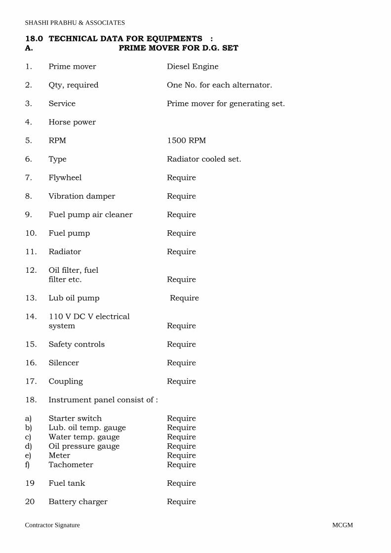
SHASHI PRABHU & ASSOCIATES
Contractor Signature MCGM
18.0 TECHNICAL DATA FOR EQUIPMENTS :
A. PRIME MOVER FOR D.G. SET 1. Prime mover Diesel Engine
2. Qty, required One No. for each alternator.
3. Service Prime mover for generating set.
4. Horse power 5. RPM 1500 RPM
6. Type Radiator cooled set.
7. Flywheel Require
8. Vibration damper Require 9. Fuel pump air cleaner Require
10. Fuel pump Require
11. Radiator Require
12. Oil filter, fuel filter etc. Require
13. Lub oil pump Require
14. 110 V DC V electrical system Require
15. Safety controls Require
16. Silencer Require 17. Coupling Require
18. Instrument panel consist of :
a) Starter switch Require b) Lub. oil temp. gauge Require
c) Water temp. gauge Require d) Oil pressure gauge Require e) Meter Require
f) Tachometer Require
19 Fuel tank Require 20 Battery charger Require
Page 62

SHASHI PRABHU & ASSOCIATES
Contractor Signature MCGM
21. Engine testing Require
a) At shop b) At site
22. Tool kits Require 23. Literature Require
a) Operation & maintenance manual
b) Parts catalogue/list Note :
1. The engine HP. should be selected so as to achieve required KW rating to be
generated considering derating of engine due to altitude, temp. Humidity etc. 2. The engine test shall be witnessed by the client's representative.
Page 63

SHASHI PRABHU & ASSOCIATES
Contractor Signature MCGM
ALTERNATOR
DATA SHEET - B
1. Make : 2. Rating : 1010KVA
3. Power factor : 0.8
4. Rated voltage : 415 V
5. Voltage regulation : As required
6. Rated current : 7. Speed : 1500 RPM.
8. Frequency : 50 Hz.
9. Field current at rated output and power factor : to be specified by tenderer
10. Field voltage at rated output and power factor : to be specified by tenderer
11. Method of excitation and Regulation : Self
12. Class of insulation : A) Starter - F with temp.rise of Cl.B
B) Rotor - F --- do ------ 13. Degree of protection : Screen protected, drip proof.
14. Base plate : The Engine & alternator shall
be mounted and alignedon a common base plate fabricated from steel.
15. Control Panel AMF : Consist of 1. ACB / MCCB with O/L, E/F and shunt trip releases
2. On/off indicator. 3. Auxiliary switch.
4. Ammeter & Voltmeter with assessors 5. KWH meters with CTs. 6. Over voltage relay
7. Under Voltage relay 8. Reverse & Forward Power relay.
9. Over & Under frequency Relay 10. KVA meter 11. Frequency meter.
12. Annunciation windows.
Page 64

SHASHI PRABHU & ASSOCIATES
Contractor Signature MCGM
13. LED Lamp indicator.
14. Auto load sharing and synchronizing relay for 3 sets
16. Change over switch Auto synchronizing with load sharing.
Page 65
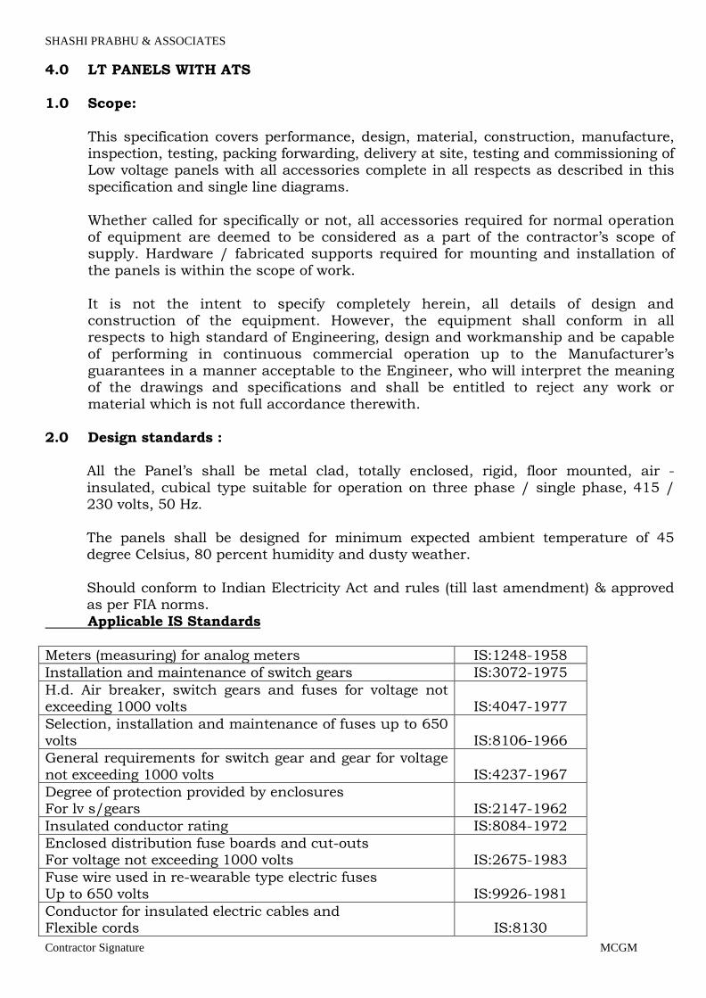
SHASHI PRABHU & ASSOCIATES
Contractor Signature MCGM
4.0 LT PANELS WITH ATS
1.0 Scope:
This specification covers performance, design, material, construction, manufacture, inspection, testing, packing forwarding, delivery at site, testing and commissioning of Low voltage panels with all accessories complete in all respects as described in this
specification and single line diagrams.
Whether called for specifically or not, all accessories required for normal operation of equipment are deemed to be considered as a part of the contractor’s scope of supply. Hardware / fabricated supports required for mounting and installation of
the panels is within the scope of work.
It is not the intent to specify completely herein, all details of design and construction of the equipment. However, the equipment shall conform in all respects to high standard of Engineering, design and workmanship and be capable
of performing in continuous commercial operation up to the Manufacturer’s guarantees in a manner acceptable to the Engineer, who will interpret the meaning of the drawings and specifications and shall be entitled to reject any work or
material which is not full accordance therewith.
2.0 Design standards : All the Panel’s shall be metal clad, totally enclosed, rigid, floor mounted, air -
insulated, cubical type suitable for operation on three phase / single phase, 415 / 230 volts, 50 Hz.
The panels shall be designed for minimum expected ambient temperature of 45 degree Celsius, 80 percent humidity and dusty weather.
Should conform to Indian Electricity Act and rules (till last amendment) & approved
as per FIA norms.
Applicable IS Standards
Meters (measuring) for analog meters IS:1248-1958
Installation and maintenance of switch gears IS:3072-1975
H.d. Air breaker, switch gears and fuses for voltage not exceeding 1000 volts IS:4047-1977
Selection, installation and maintenance of fuses up to 650 volts IS:8106-1966
General requirements for switch gear and gear for voltage not exceeding 1000 volts IS:4237-1967
Degree of protection provided by enclosures For lv s/gears IS:2147-1962
Insulated conductor rating IS:8084-1972
Enclosed distribution fuse boards and cut-outs For voltage not exceeding 1000 volts IS:2675-1983
Fuse wire used in re-wearable type electric fuses Up to 650 volts IS:9926-1981
Conductor for insulated electric cables and Flexible cords IS:8130
Page 66

SHASHI PRABHU & ASSOCIATES
Contractor Signature MCGM
Shunt capacitors for power systems IS:2834-1954
Hrc cartridge fuses and links up to 660 volts IS:2208
Hrc fuses having rupturing capacity of 50 ka IS:9224
Ac electricity meters: part – 1 general requirements And tests IS:772 PART 1
Direct acting electrical indicating instruments IS:1248
Current transformers IS:2705
Electrical relays for power systems protection IS:3231
Phosphate treatment of iron and steel for protection Against corr0sion IS:3618
Guide for marking of insulated conductor IS:5578
Code of practice of phosphating of iron and steel IS:6005
Factory built assemblies of switchgear and control-Gear for voltages upto and including 1000v ac and 1200v dc. IS:8623
Guide for uniform system marking and identification Of conductors and apparatus terminals IS:11353
Low voltage fuses IS:13703
Lv switchgear and control gear (part 1 to part 5) IS:13947
Structure construction (IP-54) IS:2147
Miniature circuit breaker (MCB) BS:3871 PART-1 1965 IS:8825
(1996)
Fuse IS:2000-1962
Air circuit breaker IS:2516 PART 1,2,3
Contactors IS:2959 & BS:775
Digital meter IS:13779
Electrical power & control wiring connection Wiring inside
themodule for power, control Protection IS:694 & IS:8130
Danger notice plate IS:2551-1982 &
IS:5-1978
MCCB IEC 60439-2 /
IS:8623-2
SFU IS:13947 (PART-
3) & IEC 60947-3
ELCB BS 3871 & 4293,
IS.,CEE 27
2.1 Construction :
Switchboard connection All connection and tap offs shall be through adequately sized connectors appropriate
for fault level at location. This shall include tap off to feeders and instrument/control transformers.
For unit ratings upto & including 63 amps, PVC insulated copper conductor wires of adequate size to carry full load current shall be used. The terminations of such
Page 67

SHASHI PRABHU & ASSOCIATES
Contractor Signature MCGM
interconnections shall be crimped. Solid connections (busbars) shall be used for all
rating above 63A. All connections, tapings, clamping, shall be made in an approved manner to ensure
minimum contact resistance. All connections shall be firmly bolted and clamp with even tension. Before assembly joint surfaces shall be filed or finished to remove burrs, dents and oxides and silvered to maintain good continuity at all joints. All
screws, bolts, washers shall be zinc plated. Only 8.8 grade nuts and bolts shall be used for busbar connections.
All nut bolts for busbar shall be high tensile cadmium plated with 2 plain washer and
1 spring washer. Hardware should be provided at cable termination end.
Switchboard Construction and operation
The low-voltage electrical switchboards shall be made up of identified functional
volumes including the busbar compartment, switchgear and control gear component
compartment, connection compartment and auxiliaries compartment. The different busbars shall be the main busbars, distribution busbars and auxiliary
busbars.
The busbars shall be made of electrolytic Al. with current density of 0.8A/Sqmm. The compartments shall be located inside a metal enclosure with walls providing
protection against direct contact with live parts and guaranteeing a degree of protection IP 2X. The frame, the external panels (doors, side and rear panels, tops) and internal elements (ducts) shall be made of 2 mm thick steel sheet metal and
protected by an epoxy-paint coating.
The max height of panel shall be 2375mm including the base channel of 75 x 40 mm ISMC coloured black.
All the panels shall be as per form 3B construction.
Sheet metal elements in the immediate proximity of high current flow generating potential eddy current shall be made of aluminium.
Drawers or air circuit breakers shall have four different positions: connected, test, disconnected and removed. With drawability of upstream and downstream power circuits and of auxiliary circuits shall be total, i.e. in compliance with standard IS –
8326.
The switchboard cover panels shall be removable. The construction system shall provide a complete set of elements for installing fixed
or with drawable switching and protective devices, measurement devices and control / monitoring devices in the switchboard.
The drawers shall be designed such that the rated degree of protection (IP, as per IS
2147: 1962) is maintained whatever their position (connected, test, disconnected,
removed).
Page 68

SHASHI PRABHU & ASSOCIATES
Contractor Signature MCGM
Switchboard Compartmentalization For compartmentalized switchboards, separate totally enclosed compartments shall
be provided for horizontal busbars, vertical busbars, ACBs, MCCBs, and cable alleys. Sheet steel hinged lockable doors for each separate compartment shall be provided
and duly interlocked with the breaker in "ON" and "OFF" position.
For all Circuit Breakers separate and adequate compartments shall be provided for accommodating instruments, indicating lamps, control contactors and control MCB etc. These shall be accessible for testing and maintenance without any danger of
accidental contact with live parts of the circuit breaker, busbars and connections. Panel should be single front operated and cable Entry should be at TOP. Busbar and
cable allay access should be from front only. LDB/PDB should be with double door arrangement. Acrylic cover to be considered on
front hinged door. Inside cover should be fixed plate type with MCB cutout features. Each switchgear cubicles shall be fitted with label in front and back identifying the
circuit, switchgear type, rating and duty. All operating device shall be located in front of switchgear only.
A horizontal wire way with screwed cover shall be provided at the top to take
interconnecting control wiring between vertical sections.
Separate cable compartments running the height of the switchboard in the case of
front access boards shall be provided for incoming and outgoing cables. Outgoing all
control and power terminals should be KUT type. Cable compartments shall be of adequate size for easy termination of all incoming
and outgoing cables entering from bottom or top. The construction shall include necessary and adequate and proper support shall be provided in cable compartments to support and clamping the cable in the cable alley / cable chamber.
Min size shall be as follows;
a. Basbar Chamber should be min. 300mm. b. Cable Alley should be min. 300mm wide for termination of one side section(
6 Starters). For LDB/PDB, cable alley should be min 400 mm
c. Feeder operating height should be max. 1950mm d. Feeder width should be min 450mm and higher as per rating e. Horizontal dummy chamber at top min 150mm
f. Feeder height min. – SFU / MCCB, S/D, DOL-300mm and higher as per rating
g. Minimum Depth -450mm h. Only one compartment feeder for PLC/BMS IOs (Marshelling box). Section
to section wiring connected with plug in type accessories. ( If asked)
i. Control busbar to be required for control bus. j. Lighting (Holder & CFL) + Heater with thermostat to be considered in cable
alley with separate control MCB in each alley. Min fabrication standards shall be as follows;
a. Load bearing members – Frame-2.0mm
Page 69
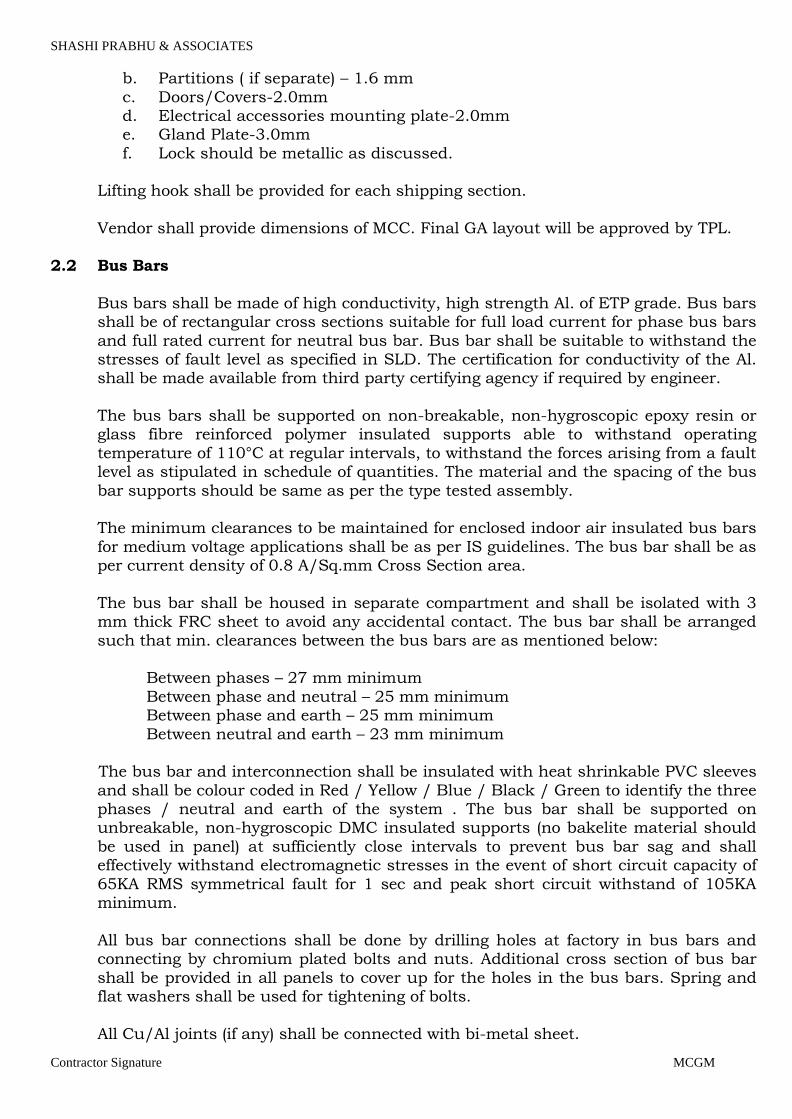
SHASHI PRABHU & ASSOCIATES
Contractor Signature MCGM
b. Partitions ( if separate) – 1.6 mm
c. Doors/Covers-2.0mm d. Electrical accessories mounting plate-2.0mm e. Gland Plate-3.0mm
f. Lock should be metallic as discussed. Lifting hook shall be provided for each shipping section.
Vendor shall provide dimensions of MCC. Final GA layout will be approved by TPL.
2.2 Bus Bars
Bus bars shall be made of high conductivity, high strength Al. of ETP grade. Bus bars shall be of rectangular cross sections suitable for full load current for phase bus bars
and full rated current for neutral bus bar. Bus bar shall be suitable to withstand the stresses of fault level as specified in SLD. The certification for conductivity of the Al. shall be made available from third party certifying agency if required by engineer.
The bus bars shall be supported on non-breakable, non-hygroscopic epoxy resin or
glass fibre reinforced polymer insulated supports able to withstand operating
temperature of 110°C at regular intervals, to withstand the forces arising from a fault level as stipulated in schedule of quantities. The material and the spacing of the bus
bar supports should be same as per the type tested assembly. The minimum clearances to be maintained for enclosed indoor air insulated bus bars
for medium voltage applications shall be as per IS guidelines. The bus bar shall be as per current density of 0.8 A/Sq.mm Cross Section area.
The bus bar shall be housed in separate compartment and shall be isolated with 3 mm thick FRC sheet to avoid any accidental contact. The bus bar shall be arranged
such that min. clearances between the bus bars are as mentioned below: Between phases – 27 mm minimum
Between phase and neutral – 25 mm minimum Between phase and earth – 25 mm minimum
Between neutral and earth – 23 mm minimum The bus bar and interconnection shall be insulated with heat shrinkable PVC sleeves
and shall be colour coded in Red / Yellow / Blue / Black / Green to identify the three phases / neutral and earth of the system . The bus bar shall be supported on unbreakable, non-hygroscopic DMC insulated supports (no bakelite material should
be used in panel) at sufficiently close intervals to prevent bus bar sag and shall effectively withstand electromagnetic stresses in the event of short circuit capacity of
65KA RMS symmetrical fault for 1 sec and peak short circuit withstand of 105KA minimum.
All bus bar connections shall be done by drilling holes at factory in bus bars and connecting by chromium plated bolts and nuts. Additional cross section of bus bar
shall be provided in all panels to cover up for the holes in the bus bars. Spring and flat washers shall be used for tightening of bolts.
All Cu/Al joints (if any) shall be connected with bi-metal sheet.
Page 70

SHASHI PRABHU & ASSOCIATES
Contractor Signature MCGM
Neutral link in each feeder to be considered in each TP feeder. 2.3 Instrument Accommodation
All voltmeter and ammeter and other instruments shall be flushed mounted type of
size 96X96 mm conforming to class 1.0 to IS 1248 for accuracy. All voltmeter shall be
protected with suitable SCPD device.
Instruments and indicating lamps shall not be mounted on the Circuit Breaker Compartment (in case of ACB) door for which a separate and adequate compartment shall be provided and the instrumentation shall be accessible for testing and
maintenance without danger of accidental contact with live parts of the Switchboard.
For MCCBs, instruments and indicating lamps can be provided on the compartment doors.
The current transformers for metering and for protection shall be mounted on the solid copper bus bars with proper supports.
On all the incomers of switch boards ON/OFF indicators lamps shall be provided suitable for operation on AC 230 volts supply. All lamps shall be protected with
proper protection device. Where phase indicator lamps are to be provided, these shall be associated with necessary ON/OFF toggle switch. All the lamps shall have testing facility.
For instruments control MCB shall be used (Fuse with link not accepted)
2.4 Wiring
All wiring for relays and meters shall be with PVC insulated copper conductor wires. The wiring shall be coded and labelled with approved ferrules for identification. The minimum size of copper conductor control wires shall be 1.5 sq. mm. Runs of wires
shall be neatly bunched and suitably supported and clamped. Means shall be provided for easy identification of wires. Identification ferrules shall used at both end
of wires. All control wires meant for external connections are to be brought out on a terminal board. The cables shall be suitable for withstanding 105 deg C.
2.5 Space Heaters Anti- condensation heaters shall be fitted in each cubicle together with an ON/OFF
isolating switch suitable for electrical operation at 230 volts A.C 50 Hz single phase of sufficient capacity to raise the internal ambient temperature by 5º C. The electrical
apparatus so protected shall be designed so that the maximum permitted rise in temperature is not exceeded if the heaters are energized while the switchboard is in operation. As a general rule, the heaters shall be placed at the bottom of the cubicle.
2.6 Ventilation Fans
The Switchboard shall be provided with panel mounting type ventilation fans in each
panel with switchgear rated for 2000 amp and above or as required by engineer. The
fan shall be interlocked with switchgear operation. The degree of enclosure protection
Page 71
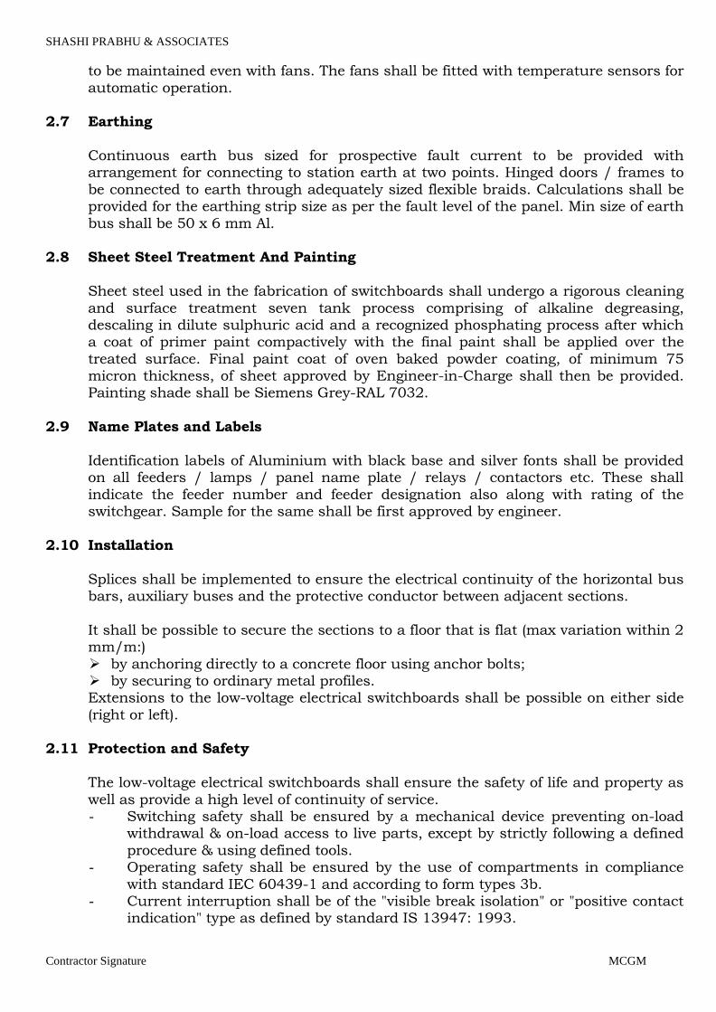
SHASHI PRABHU & ASSOCIATES
Contractor Signature MCGM
to be maintained even with fans. The fans shall be fitted with temperature sensors for
automatic operation. 2.7 Earthing
Continuous earth bus sized for prospective fault current to be provided with
arrangement for connecting to station earth at two points. Hinged doors / frames to
be connected to earth through adequately sized flexible braids. Calculations shall be provided for the earthing strip size as per the fault level of the panel. Min size of earth
bus shall be 50 x 6 mm Al. 2.8 Sheet Steel Treatment And Painting
Sheet steel used in the fabrication of switchboards shall undergo a rigorous cleaning
and surface treatment seven tank process comprising of alkaline degreasing, descaling in dilute sulphuric acid and a recognized phosphating process after which a coat of primer paint compactively with the final paint shall be applied over the
treated surface. Final paint coat of oven baked powder coating, of minimum 75 micron thickness, of sheet approved by Engineer-in-Charge shall then be provided. Painting shade shall be Siemens Grey-RAL 7032.
2.9 Name Plates and Labels
Identification labels of Aluminium with black base and silver fonts shall be provided
on all feeders / lamps / panel name plate / relays / contactors etc. These shall
indicate the feeder number and feeder designation also along with rating of the switchgear. Sample for the same shall be first approved by engineer.
2.10 Installation
Splices shall be implemented to ensure the electrical continuity of the horizontal bus bars, auxiliary buses and the protective conductor between adjacent sections.
It shall be possible to secure the sections to a floor that is flat (max variation within 2 mm/m:)
by anchoring directly to a concrete floor using anchor bolts; by securing to ordinary metal profiles.
Extensions to the low-voltage electrical switchboards shall be possible on either side
(right or left). 2.11 Protection and Safety
The low-voltage electrical switchboards shall ensure the safety of life and property as
well as provide a high level of continuity of service. - Switching safety shall be ensured by a mechanical device preventing on-load
withdrawal & on-load access to live parts, except by strictly following a defined
procedure & using defined tools. - Operating safety shall be ensured by the use of compartments in compliance
with standard IEC 60439-1 and according to form types 3b. - Current interruption shall be of the "visible break isolation" or "positive contact
indication" type as defined by standard IS 13947: 1993.
Page 72

SHASHI PRABHU & ASSOCIATES
Contractor Signature MCGM
In view of reducing the risk of electrical shock:
- Power and control circuits shall be separate and completely isolated; - Auxiliary circuits shall be of the extra-low voltage type.
- Aux. contacts / Auxiliary contactor should be used for feeder ( Relays are not
preferred) The low-voltage electrical switchboards shall be equipped with two types of
mechanical locking compatible with the different positions of drawers. The locking
system shall be partially mobile and implement three padlocks.
Optionally, the safety of persons shall be enhanced by a version complying with the requirements of standard IEC 61641 concerning the propagation of an arc inside electrical switchboards. Test certificates shall be available.
Provisions must be made, around the equipment critical zones, for visual/infrared
inspection during equipment operation, with respect to operator safety. Earthed metal or insulated shutters shall be provided between drawout and fixed
portion of the switchgear such that no lives parts are accessible with equipment drawn out. Degree of protection within compartments shall be at least IP 2X.
Overall IP rating of panel shall be IP 52 (except VFD starter).
IP rating for all PCC’S/MCCB in wet area like pump room shall be IP-65. (to be confirmed with engineer before quoting)
2.12 Internal Components: The panels shall be equipped complete with all type of required number of air circuit
breakers, switch fuse unit, contactor, relays, fuses, meters, instruments, indicating lamps, push buttons, equipment, fittings, busbar, cable boxes, cable glands etc. and
all the necessary internal connections /wiring as required and as indicated on relevant drawings. Components necessary for proper complete functioning of the panels but not indicated on the drawings shall be supplied and installed on the
panels.
All part of the panels carrying current including the components, connections, joints and instruments shall be capable of carrying their specified rated current continuously, without temperature rise exceeding the acceptable values of the
relevant specifications at any part of the panels. All units of the same rating and specifications shall be fully interchangeable.
2.13 L. T. Switchgears:
2.13.1 General: The type, size, and rating of the components shall be as indicated on the relevant
single line diagrams0. 2.13.2 Miniature Circuit Breaker (MCB) / MPCB / ELCB:
MCB / MPCB shall be quick make and break and break type conform with IS: 8828
(1996). The housing shall be heat resistant and having high impact strength. The
fault current of MCBs / MPCBs shall not be less than 10000 amps, at 230 volts.
Page 73
SHASHI PRABHU & ASSOCIATES
Contractor Signature MCGM
The MCBs shall be flush mounted and shall be provided with trip free manual
operating mechanism with mechanical "ON" and "OFF" indications. The circuit breaker dollies shall be of trip free pattern to prevent closing the breaker
on a faulty current. The MCB / MPCBs contact shall be silver nickel and silver graphite alloy and tip
coated with silver. Proper arc chutes shall be provided to quench the arc immediately. MCB's / MPCBs shall be provided with magnetic fluid plunger relay for
over current and short circuit protection. The over load or short circuit devices shall have a common trip bar in the case of DP and TPN miniature circuit breakers. All the MCB's / MPCBs shall be tested and certified as per Indian Standard, prior to
Installation.
MPCB with extended support should be consider along with front operating mechanism. MPCB should be with all accessories like; auxiliary contacts, door rotary mechanism etc.
The RCCB should suffices all the requirements of IS as per code IS - 12640 - 1988. The RCA should be current operated and not on line voltage.
The RCCB should ensure mainly the following functions:
i) Measurement of the fault current value.
ii) Comparison of the fault current with a reference value.
iii) The RCCB should have a torroidal transformer witch has the main conductors of
primary (P - N) which check the sum of the current close to zero.
iv) All metal parts should be inherently resistant to corrosion and treated to make
them corrosion resistant.
v) It should be truly current operated.
vi) It should operate on core balance torroidal transformer.
vii) Its accuracy should be ± 5 %.
viii) It should operate even in case of neutral failure.
ix) It should trip at a present leakage current within 100 mA
x) Its enclosure should be as per IP 30.
xi) Its mechanical operation life should be more than 20,000 operations.
xii) It should provide full protection as envisaged by IE rules - 61-A, 71 - ee, 73 - ee, 1985 and also rule 50 of IE rule1956.
It should conform to all national and international standards like IS: 8828-1993, IS:
12640-1988, BS 4293 - 1983, CEE 27 (International commission Rules for the
approved of electrical equipment).
Page 74
SHASHI PRABHU & ASSOCIATES
Contractor Signature MCGM
2.13.3 Fuse:
Fuses shall be of high rupturing capacity (HRC) fuse links and shall be in accordance
with IS : 2000-1962 and having rupturing capacity of not less than 35 MVA at 415
Volts. Fuse link to be considered along with SFU.
2.13.4 Air Circuit Breaker:
The ACB shall meet with IS : 2516 part I, II and III. Each pole of the ACB's shall be equipped with over current, earth fault and short circuit release. The ACB's shall be equipped with under voltage trip only on those used as main incomer of all sources,
bus coupler and inter connector. The trip devices shall be direct acting.
Disconnecting devices of approved type shall be provided to facilitate the removal of the circuit breakers from the housing for test and maintenance purpose.
The ACB's shall have an arc-quenching device on each pole. The ACB's shall have auxiliary contacts for signalling, interlocking etc. The ACB's shall have slow close facilities for checking contact operation and contact gap adjustment.
All contacts subject to arcing shall be tipped with arc resisting material. Main
contacts shall be silver plated, multi-finger and spring-loaded type. Facilities shall be provided to isolate the circuit breaker for inspection purpose.
Interlocks shall be provided to: Prevent the breaker from being isolated unless it is in the "OFF" position.
Prevent the breaker from being racked in to the service position unless it is in the
"OFF" position. Prevent the breaker from being accidentally pulled completely "OFF" the guide rail.
Safety shutters of insulating material shall be provided to prevent access to all live contacts, when the breaker is in the inspection position or completely withdrawn.
Facilities shall be provided for earthing the circuit breaker.
Air circuit breaker shall be capable of clearing the maximum fault current, which can occur.
The breaker plates shall have an ON-OFF indicators, spring charge indicators, provision to padlock manual handle and provision to lock draw-out mechanism.
Electrically operated breaker shall have provision for emergency manual closing by inserting a tool through the fuse plate. A control isolating switch shall be provided on the fuse plate to isolated the supply to the charging motor.
The breaker shall be have feature such as to indicate voltage status / trip / fault
alarm indicators / remote operation from BMS – ON/OFF, shunt trip release and motorised reclosing / contacts for remote indication of open / close / trip wired to BMS, communication modules providing LAN interface with BMS and draw out
pattern with test facility provision.
Page 75

SHASHI PRABHU & ASSOCIATES
Contractor Signature MCGM
All ACB releases shall be with long time + short time + instantaneous + earth fault selective protection.
2.13.5 Moulded Case Circuit Breaker:
2.13.5.1 General
Moulded-Case Circuit Breakers (MCCB) shall comply with IS 13947: 1993 standards.
- they shall be of utilisation category A on all the operational voltage range – till
250A and category B on all the operational voltage range – for any rating with
adjustable short time delay (if specified) with a rated service breaking capacity (Ics) equal to the ultimate breaking capacity (Icu) up to 500V for the greater ratings
- They shall have a rated operational voltage of 690 V AC (50/60 Hz),
- They shall have a rated insulation voltage of 800 V AC (50/60 Hz), - They shall be suitable for isolation, as defined by IS 13947: 1993 for the
Overvoltage Category IV for a rated insulation voltage up to 690 V . MCCBs shall be designed according to Eco-design complying with ISO 14062
Especially MCCB’s materials shall be of halogen free type. They shall be supplied in recyclable packing complying with European Directives.
The manufacturer shall implement non polluting production processes that do not make use of chlorofluorocarbons, chlorinated hydrocarbons, ink for cardboard
markings, etc MCCBs shall be mounted in panel as fixed type versions in 3-pole and 4-pole
versions. A safety trip shall provide advanced opening to prevent connection and disconnection of a closed circuit breaker
MCCBs shall be designed for both vertical and horizontal mounting, without any
adverse effect on electrical performance. It shall be possible to supply power either
from the upstream or downstream side MCCBs shall provide class II insulation between the front and internal power
circuits 2.13.5.2 Construction, Operation, Environment
For maximum safety, the power contacts shall be insulated in an enclosure made of
a thermosetting. material from other functions such as the operating mechanism, the case, the trip unit and auxiliaries
All poles shall operate simultaneously for circuit breaker opening, closing and tripping.
MCCBs shall be actuated by a toggle or handle that clearly indicates the three
positions: ON, OFF and TRIPPED.
In order to ensure suitability for isolation complying with IS 13947: 1993:
- the operating mechanism shall be designed such that the toggle or handle can only be in OFF position (O) if the power contacts are all actually separated,
- In OFF position, the toggle or handle shall indicate the isolation position.
Page 76
SHASHI PRABHU & ASSOCIATES
Contractor Signature MCGM
Isolation shall be provided by a double break on the main circuit.
MCCBs shall be able to receive a device for locking in the “isolated” position, with
up to 3 padlocks, Ø8 maximum.
MCCBs shall be equipped with a “push to trip” button in front to test operation and
the opening of the poles.
MCCB rating, “push to trip” button, performances and contact position indication
must be clearly visible and accessible from the front, through the front panel or the door of the switchboard.
2.13.5.3 Current Limitation, Discrimination, Durability
MCCBs shall be capable of greatly limiting currents. For short-circuits, the
maximum thermal stress I²t shall be as per IEC / IS. These characteristics will allow high cascading performance with moulded-case or
miniature circuit-breakers downstream MCCBs shall be equipped with a tripping unit independent of the thermo-magnet or
electronic one. This unit will trip the circuit-breaker for high value short-circuits
currents. The breaking will be carried out in less than 10ms for short-circuit currents above 25In.
MCCBs shall comprise a device, designed to trip the circuit-breaker in the event of
high-value short-circuit currents. This device shall be independent of the thermal-
magnetic or electronic trip unit. MCCBs, the current ratings of which are identical with the ratings of their trip
units, shall ensure discrimination for any fault current up to at least 35 kA rms, with any downstream circuit-breaker having a current rating less or equal to 0.4
times that of the upstream circuit-breaker. The electrical durability of MCCBs, as defined by IS 13947: 1993 standard.
MCCBs shall be equipped with a self-test of the connection between the
electronic trip unit, the current transformers and the actuator, that will not cause the circuit-breaker to trip. The self-test will be of positive logic and visible through the flashing of a green LED in case the self-test occurred
correctly and the extinction of the LED in case the self-test failed. The MCCB shall trip in case the environmental conditions of the circuit-
breaker get out of their specified range. However, it will be possible to overrule this feature.
2.13.5.4 Auxiliaries and Accessories It shall be possible to equip MCCBs with a motor mechanism for electrically
controlled operation if specified in SLD. An “auto/manual” switch in front shall, when set to the “manual” position, lock out electrical control; when set to “auto”,
lock out the manual control; remote indication of “manual” or “auto” mode shall be possible. It shall also be possible to seal the access to the “auto” control.
Closing shall take place in less than 80 ms.
Page 77

SHASHI PRABHU & ASSOCIATES
Contractor Signature MCGM
Following tripping due to electrical faults (overload, short-circuit, earth fault if
mentioned in SLD), remote reset shall be inhibited. It shall however be possible if opening was initiated by a voltage release.
The operating mechanism shall be of the stored-energy type only
The addition of a motor mechanism or a rotary handle shall in no way affect circuit breaker characteristics:
- Only three stable tripping mechanism positions (ON, OFF and TRIPPED) shall be possible with the motor mechanism,
- Suitability for isolation shall be provided by positive contact indication (ON and
OFF) in front of the motor mechanism module
MCCBs shall be designed to enable safe on-site installation of auxiliaries such as voltage releases (shunt and under voltage releases) and indication switches as follows:
- They shall be separated from power circuits, - All electrical auxiliaries shall be of the snap-in type and fitted with terminal
blocks,
- All auxiliaries shall be common for the entire range, - Auxiliary function and terminals shall be permanently engraved on the case of the
circuit breaker and the auxiliary itself, - The addition of auxiliaries shall not increase the volume of the circuit breaker. - MCCB should be with all accessories like; spreads links, shrouding terminals,
auxiliary contacts, phase barrier, door rotary mechanism etc. Spreader links should be copper with Ni-Cr plated
- Outgoing terminal of MCCB should be 3Ph+N+E.
The addition of a motor mechanism module or a rotary handle, etc., shall not mask
or block device settings It shall be possible to assemble earth fault protection moulded-case circuit breakers
by adding a residual current device (RCD) directly to the circuit breaker case. The resulting device shall:
- comply with IS 13947: 1993 standard, - be immunised against nuisance tripping, - be capable of working normally down to -25 °C ambient temperature,
- operate without an auxiliary power supply, i.e. it shall be capable of operating normally on any 2-phase or 3-phase power network with a voltage between 200 V and 440 V, and of tripping the circuit-breaker even in the event of voltage dips down
to 80 V
It shall be possible to equip MCCBs with devices indicating faults without tripping the circuit breaker
2.13.5.5 Protection Functions
General Recommendations
MCCBs with ratings up to & including 250 A shall be equipped with fully
interchangeable trip units in order to ensure the protection against overcharge and short-circuit. The trip units shall be of thermal magnetic adjustable type.
Page 78

SHASHI PRABHU & ASSOCIATES
Contractor Signature MCGM
MCCBs with ratings over 250 A shall be equipped with microprocessor based trip
units with O/C / S/C & E/F. 2.13.5.6 Common Features
Electronic and thermal-magnetic trip units shall be adjustable and it shall be possible to fit lead seals to prevent unauthorised access to the settings
Electronic trip units shall comply with IS 13947: 1993 standard (measurement of rms current values, electromagnetic compatibility, etc.)
Protection settings shall apply to all circuit breaker poles
The trip units shall not augment overall circuit breaker volume
All electronic components shall withstand temperatures up to 125 °C. 2.13.5.7 Microprocessor Trip Units
Characteristics - Long time protection (LT)
Selectable Ir threshold settings from 36% to 100 % of the trip unit rating - Short time protection (ST)
Isd threshold shall be adjustable from 1,5 to 10 times the thermal setting Ir, The time delay shall be either adjustable or fixed at 40 ms, - Instantaneous protection
The threshold shall be either adjustable or fixed (starting from 1.5 times In and up
to a value between 11 and 15 times In, depending on the rating)
Four-pole devices shall be equipped for neutral protection:
- as standard with a 3-position setting : - neutral not protected - neutral tripping threshold equal to half the phase value - neutral threshold equal to the phase value
- if required by harmonic 3 neutral current circulation with a specific 4-position setting - neutral not protected - neutral tripping threshold equal to half the
phase value - neutral threshold equal to the phase value - neutral setting according to the rating of the phases in a ratio 1.6 (Oversized Neutral).
Load Monitoring Function The following monitoring functions shall be integral parts of electronic trip units:
- 2 LED for load indication, one lighted above 90 % of Ir, and one lighted above 105 % of Ir
- a test connector shall be installed for checks on electronic and tripping mechanism operation using an external device.
Thermal Memory
In the event of repeated overloads, the electronic trip unit shall optimise protection of cables and downstream devices by memorising temperature variations.
Options:
Page 79
SHASHI PRABHU & ASSOCIATES
Contractor Signature MCGM
It shall be possible to install all options for the electronic trip unit:
- High-threshold earth-fault protection, - Auxiliary contact to indicate the cause of tripping (long time, short time,
instantaneous, earth fault if requested),
- Data transmission via a BUS, in particular all the trip unit settings, current measurements for each phase, tripping causes, circuit breaker status.
It shall be possible to install a specific module that can provide the data transmission, in particular all the trip unit settings, all electrical parameters
(current, energy, THD, voltage, etc.) measurements for each phase, tripping causes, circuit breaker status, control and alarms.
Software that allows these data to be analysed on PC shall be provided by the manufacturer.
2.13.6 Contactors / Relays / Starter : 2.13.6.1 The contactor shall meet with the requirements of IS: 2959.
2.13.6.2 Contactors shall be air break and electromagnetic type rated for uninterrupted duty as defined in relevant IS.
2.13.6.3 The main contacts shall be of silver or silver alloy. 2.13.6.4 The insulation for the coils shall be of class ‘f’. 2.13.6.5 Each contactors shall be provided with 2 normally open and 2 normally closed
auxiliary contacts. 2.13.6.6 The contactors shall be in accordance to type 2 co-ordinations for short circuit
protection.
2.13.6.7 The contactor shall be suitable for uninterrupted duty (AC3) category. 2.13.6.8 All 3 Contactor sizes should be identical rating in Star-Delta feeders.
2.13.6.9 The electrical and mechanical endurance shall be as specified in IS code. 2.13.6.10 For all starters, component sizing shall be as per type-II co-ordination chart
prescribed by switchgear manufacturer + Contactor shall be one rating higher
than specified in type-2 coordination. 2.13.6.11 Remote start, stop, interlock wire should be wire up at terminals apart than
PLC/BMS/SCADA signals/commands.
2.13.6.12 Outgoing terminal of Starter should be 3Ph+E. 2.13.6.13 Auto-Manual Status and ON-OFF-Trip potential free signal required for
BMS/PCL wherever asked. 2.13.6.14 Thermal overload relays shall be of three elements positive acting ambient
temperature compensated type with adjustable settings.
2.13.6.15 Thermal overload relays shall be of self/hand reset type as specified in the schedule.
2.13.6.16 All control terminals to OCS / PLC shall wired to single compartment. (marshalling box).
2.13.6.17 Separate control terminal blocks shall provide for control wiring.
- From MCC to field in cable chamber. - From MCC to OCS / PLC in marshalling jb. - Al, Ao, Di & Do shall be provided on separate terminal block.
2.13.6.18 Following control signal exchange between OCS / PLC & MCC panel shall be considered for AHU panel & package systems in process mcc —
a. From MCC panel to DES / PLC - On, off & trip feedback — separate continuous potential free contacts. - For VFD feeders — 4—2oma speed (rpm) feedback.
- Potential free contact for remote selection.
Page 80

SHASHI PRABHU & ASSOCIATES
Contractor Signature MCGM
b. From DES / PLC to MOE panel
- Start & stop command — single latched contact. - For VFD feeders only — 4—2oma reference current for speed control. - Start permissive in local & remote mode.
2.13.6.19 Following control signal exchange between push button station & mcc panel shall be considered. a. On, off & trip feedback — separate continuous potential free contacts.
b. Start & stop command — seperate continuous potential free contacts. 2.13.6.20 Control philosophy
a. Under local mode selection start command will be executed from push button station near motor.
b. Under remote mode selection start command will be executed from PLC
panel. c. Stop command can be executed without selection.
2.13.6.21 Motor feeder shall have motor protection circuit breaker (MPCB) with S/C and O/C release.
2.13.6.22 Heavy duty bmr to be provided for blowers & fan application.
2.13.7 Multi Function Meter:
Flush mount 96 x 96 x 80 mm load manager type CONSERV EM 6400 or equivalent meter of accuracy class 1 as per IS 13779 shall be provided. The meter shall be
accurate on distorted waveforms; simultaneous sampling of voltage and amperes shall be done. It shall have low burden on PT and CT shall have bright display, shall view 3 parameters together shall have auto scaling from kilo to mega to giga units,
shall have programmable CT, PT ratios with built in phase analyser. Auto scrolling shall be programmable as per user choice and communication with PC; PLC DCS shall be possible through RS 485 serial port. It shall be dust proof, tamper proof
with data import export option and 10 years back up of integrated data.
Parameters to be monitored shall be Frequency, Line to line and average and line to neutral and average voltage, phase wise and average current, phase wise and total KVA, KW and P.F. reading and KWH monitoring.
User programmable facility for delta 2e and star 3e measurement, C.T. and P.T.
ratios, sliding window auto sync. And auto scrolling of parameters shall be available.
Sensing shall be 3 phase, 4 wire measuring True RMS with voltage input range of 110 to 415 V nominal and current input of 5 amps or 1 amps as per field configuration. Current range shall be from 50 mA to 7.5 A and burden on PT or CT
shall be app 0.2 VA.
Accuracy for kW / kWh shall be as per IS 1377 / CBIP88 and for all other parameters shall be +/- 0.5% of full scale + 0.5% of reading + 1 digit. Digital readout shall be of 3 rows of 4 digits each (12.5 mm size) with 7 segments bright
red LED. Input frequency shall be 50Hz / 60Hz +/- 5%. Power factor range shall be 0.5 lag – unit – 0.8 lead.
Resolution for power parameters shall be for 4 digits and energy parameters shall
be 8 digits. Display update shall be at every 15 seconds for demand parameters and
Page 81

SHASHI PRABHU & ASSOCIATES
Contractor Signature MCGM
1 sec for other parameters. Display sequence shall be parameter followed by value.
Temperature range shall be 0-50oC and humidity <95% non-condensing.
Display pages shall be as follows: Instantaneous – VLL, A avg., F VLn, A avg., F
KVA, kW, PF Individual pages of above parameters.
Integrated - kVAh KWh Run hours
On hours Interruption
2.13.8 Current Transformer: Where called for, CT's shall provide for current measuring. Each phase shall be
provided with separate CT of class I accuracy and VA burden as shown in SLD for operation of associated metering and controls. Current transformer shall be in accordance with IS: 2705 - 1964 as amended up to date.
Separate CT for each protection devices and instrumentation device shall be
provided. The CT shall be able to withstand max short time withstands current indicated for
the assembly.
The CT shall be cast resin type. Test links at secondary – to facilities testing of instruments / meters and protection
device.
2.13.9 Push Button & Indicating Lamp :
The push button unit shall comprise of the contact element, a fixing holder, and push button actuator. The push button shall be momentary contact type. The contacts shall be of silver alloy and rated at 10 Amps continuous current rating. The
actuator shall be of stranded type and colour as per its usage for ON, OFF and Trip.
Indicating Lamp shall be LED type and shall supplied complete with translucent covers to diffuse the lamp light. Indicating lamps shall be part of push buttons where ever both are required and shall have testing facilities. Protection in form of MCB /
HRC fuse shall be provided for the lamps.
Colour shade for the indicating lamps shall be as below: ON indicating lamp : Green
OFF indicating lamp : Red TRIP indicating lamp : Amber PHASE indicating lamp : Red, Yellow, and Blue.
2.13.10 Selector Switches:
Selector Switches shall be of the heavy duty rotory type, with plates clearly marked to
show the operating position. They shall be of the semi-flush mounted type with only
the front plate and operating handle projecting.
Page 82
SHASHI PRABHU & ASSOCIATES
Contractor Signature MCGM
Circuit breaker control switches shall be of the spring return to neutral type.
2.14 All panels short circuit integration:
The panel vendor / contractor shall be responsible for carrying out necessary study for type 2 co-ordination for complete system with fault discrimination. All the data considered for the study shall be discussed with the engineer.
2.15 Testing
2.15.1 CPRI Testing
Switchboard configurations offered shall be subject to CPRI testing (Testing if required by the User). In case of no CPRI testing request by E/C, copies of the CPRI
test certificates shall be submitted with the tender for the similar rated busbar panel. 2.15.2 Routine Test:
a) Physical variation and dimensional check – To cross check dimensions with
approved GA drawings.
b) Verification of bill of material – Physically count all the components. c) Continuity test – shall be carried out for complete busbar system with
continuity tester or actual charging. d) Functional check – Operation of all the switchgears and control logic to be
checked after charging at works.
e) HV test – 2500 V for 1 minute shall be applied and no tripping / Arching / Flashing shall occur.
f) IR test – 1000 V shall be applied through meggar and the value shall be more
than 30 M ohms. g) Polarity and Phase sequence test – Shall be checked for each feeder with phase
sequence meter. 2.15.3 Type Test:
Type test certificates for all switchgears and panel of similar rated busbar shall be
provided for a) Short circuit withstand test b) IP protection.
c) All switchgears and other components. d) Temperature rise test
Page 83

SHASHI PRABHU & ASSOCIATES
Contractor Signature MCGM
2.16 415V Auto Transfer Switch - ATS 1.1 General
1.1.1 Scope
This specification covers performance, design, material, construction, manufacture,
inspection, testing, packing forwarding, delivery at site, testing and commissioning of microprocessor controlled Auto transfer switches – with double throw power transfer switch mechanism as per single line diagrams, with all accessories complete in all
respects as described in this specification. Whether called for specifically or not, all accessories required for normal operation
of equipment are deemed to be considered as a part of the contractor’s scope of supply. Hardware / fabricated supports required for mounting and installation of
the ATS is within the scope of work. It is not the intent to specify completely herein, all details of design and
construction of the equipment. However, the equipment shall conform in all respects to high standard of Engineering, design and workmanship and be capable
of performing in continuous commercial operation up to the Manufacturer’s guarantees in a manner acceptable to the Engineer, who will interpret the meaning of the drawings and specifications and shall be entitled to reject any work or
material which is not full accordance therewith. 1.1.2 Codes and Standards
The automatic transfer switches and controls shall conform to the requirements of: UL 1008 - Standard for Transfer Switch Equipment IEC 947-6-1 - Low-voltage Switchgear and Control gear; Multifunction
equipment; Automatic Transfer Switching Equipment NFPA 70 - National Electrical Code NFPA 99 - Essential Electrical Systems for Health Care Facilities NFPA 110 - Emergency and Standby Power Systems IEEE Standard 446 - IEEE Recommended Practice for Emergency and Standby
Power Systems for Commercial and Industrial Applications NEMA Standard ICS10-1993 (formerly ICS2-447) - AC Automatic Transfer Switches UL 508 - Industrial Control Equipment
1.2 Products
1.2.1 Mechanically Held Transfer Switch The transfer switch shall be electrically operated and mechanically held. The electrical operator shall be a momentarily energized, single-solenoid mechanism. Main operators which include overcurrent disconnect devices, linear motors or gears shall not be acceptable. The switch shall be mechanically interlocked to ensure only two possible positions, normal or emergency. The switch shall be rated for AC-33A duty cycle for mixed load application as mentioned in IEC 60947-6-1.
Page 84
SHASHI PRABHU & ASSOCIATES
Contractor Signature MCGM
All transfer switch sizes shall use only one type of main operator for ease of maintenance and commodity of parts. The switch shall be positively locked and unaffected by momentary outages, so that contact pressure is maintained at a constant value and contact temperature rise is minimized for maximum reliability and operating life. All main contacts shall be silver composition. Switches rated 600 amperes and above shall have segmented, blow-on construction for high withstand and close-on capability and be protected by separate arcing contacts.
Inspection of all contacts shall be possible from the front of the switch without disassembly of operating linkages and without disconnection of power conductors. Switches rated 600 amps and higher shall have front removable and replaceable contacts. All stationary and moveable contacts shall be replaceable without removing power conductors and/or bus bars. Designs utilizing components of moulded-case circuit breakers, contactors, or parts thereof, which are not intended for continuous duty, repetitive switching or transfer between two active power sources are not acceptable. Where neutral conductors must be switched as shown on the plans, the AS shall be provided with fully rated complete overlapping neutral transfer contacts. The neutrals of the normal and emergency power sources shall be connected together only during the transfer and retransfer operation and remain connected together until power source contacts close on the source to which the transfer is being made. The overlapping neutral contacts shall not overlap for a period greater than 100 milliseconds. Neutral switching contacts which do not overlap are not acceptable.
Where neutral conductors are to be solidly connected as shown on the plans, a neutral conductor plate with fully rated CU pressure connectors shall be provided.
1.2.2 Microprocessor Controller
The controller’s sensing and logic shall be provided by a single built-in microprocessor for maximum reliability, minimum maintenance, and the ability to communicate serially through an optional serial communication module. A single controller shall provide twelve selectable nominal voltages for maximum application flexibility and minimal spare part requirements. Voltage sensing shall be true RMS type and shall be accurate to 1% of nominal voltage. Frequency sensing shall be accurate to 0.2%. The panel shall be capable of operating over a temperature range of -20 to +60 degrees C and storage from -55 to +85 degrees C. The controller shall be connected to the transfer switch by an interconnecting wiring harness. The harness shall include a keyed disconnect plug to enable the controller to be disconnected from the transfer switch for routine maintenance. Sensing and control logic shall be provided on multi-layer printed circuit boards. Interfacing relays shall be industrial grade plug-in type with dust covers. The panel shall be enclosed with a protective cover and be mounted separately from the transfer switch unit for safety and ease of maintenance. The protective cover shall include a built-in pocket for storage of the operator’s manuals. All customer connections shall be wired to a common terminal block to simplify field-wiring connections. The controller shall meet or exceed the requirements for Electromagnetic Compatibility (EMC) as follows: EN 55011:1991 Emission standard - Group 1, Class A
EN 50082-2:1995 Generic immunity standard, from which:
Page 85

SHASHI PRABHU & ASSOCIATES
Contractor Signature MCGM
EN 61000-4-2:1995 Electrostatic discharge (ESD) immunity
ENV 50140:1993 Radiated Electro-Magnetic field immunity
EN 61000-4-4:1995 Electrical fast transient (EFT) immunity
EN 61000-4-5:1995 Surge transient immunity
EN 61000-4-6:1996 Conducted Radio-Frequency field immunity
IEEE472 (ANSI C37.90A) Ring Wave Test.
1.3 Operation
1.3.1 Controller Display and Keypad
A four line, 20 character LCD display and keypad shall be an integral part of the controller for viewing all available data and setting desired operational parameters. Operational parameters shall also be available for viewing and limited control through the serial communications input port. The following parameters shall only be adjustable via DIP switches on the controller: Nominal line voltage and frequency
Single or three phase sensing
Operating parameter protection
Transfer operating mode configuration (Open transition, Closed transition or Delayed transition)
All instructions and controller settings shall be easily accessible, readable and accomplished without the use of codes, calculations, or instruction manuals.
1.3.2 Voltage, Frequency and Phase Rotation Sensing
Voltage and frequency on both the normal and emergency sources (as noted below) shall be continuously monitored, with the following pickup, dropout and trip setting capabilities (values shown as % of nominal unless otherwise specified): Parameter Sources Dropout / Trip Pickup / Reset Undervoltage N&E,3 70 to 98% 85 to 100% Overvoltage N&E,3 102 to 115% 2% below trip Underfrequency N&E 85 to 98% 90 to 100% Overfrequency N&E 102 to 110% 2% below trip Voltage unbalance N&E 5 to 20% 1% below dropout
Repetitive accuracy of all settings shall be within ± 0.5% over an operating temperature range of -20C to 60C. Voltage and frequency settings shall be field adjustable in 1% increments either locally with the display and keypad or remotely via serial communications port access. The controller shall be capable (when activated by the keypad or through the serial port) of sensing the phase rotation of both the normal and emergency sources. The source shall be considered unacceptable if the phase rotation is not the preferred rotation selected (ABC or CBA). Source status screens shall be provided for both normal & emergency to pro-vide digital readout of voltage on all 3 phases, frequency, and phase rotation.
1.3.3 Time Delays
Page 86
SHASHI PRABHU & ASSOCIATES
Contractor Signature MCGM
An adjustable time delay of 0 to 6 seconds shall be provided to override momentary normal source outages and delay all transfer and engine starting signals. Capability shall be provided to extend this time delay to 60 minutes by providing an external 24 VDC power supply. A time delay shall be provided on transfer to emergency, adjustable from 0 to 60 minutes, for controlled timing of transfer of loads to emergency. Two time delay modes (which are independently adjustable) shall be provided on re-transfer to normal. One time delay shall be for actual normal power failures and the other for the test mode function. The time delays shall be adjustable from 0 to 60 minutes. Time delay shall be automatically bypassed if the emergency source fails and the normal source is acceptable. A time delay shall be provided on shut down of engine generator for cool down, adjustable from 0 to 60 minutes. A time delay activated output signal shall also be provided to drive an external relay(s) for selective load disconnect control. The controller shall have the ability to activate an adjustable 0 to 5 minute time delay in any of the following modes: Prior to transfer only.
Prior to and after transfer.
Normal to emergency only.
Emergency to normal only.
Normal to emergency and emergency to normal.
All transfer conditions or only when both sources are available.
The controller shall also include the following built-in time delays for optional Closed Transition and Delayed Transition operation: 1. 1 to 5 minute time delay on failure to synchronize normal and emergency
sources prior to closed transition transfer.
2. 0.1 to 9.99 second time delay on an extended parallel condition of both power sources during closed transition operation.
3. 0 to 5 minute time delay for the load disconnect position for delayed transition operation.
All time delays shall be adjustable in 1 second increments, except the extended parallel time, which shall be adjustable in .01 second increments. All time delays shall be adjustable by using the LCD display and keypad or with a remote device connected to the serial communications port.
1.3.4 Additional Features
A three position momentary-type test switch shall be provided for the test / automatic / reset modes. The test position will simulate a normal source failure. The reset position shall bypass the time delays on either transfer to emergency or retransfer to normal. A SPDT contact, rated 5 amps at 30 VDC, shall be provided for a low-voltage engine start signal. The start signal shall prevent dry cranking of the engine by requiring the generator set to reach proper output, and run for the duration of the cool down
Page 87

SHASHI PRABHU & ASSOCIATES
Contractor Signature MCGM
setting, regardless of whether the normal source restores before the load is transferred. Auxiliary contacts, rated 10 amps, 250 VAC shall be provided consisting of one contact, closed when the ATS is connected to the normal source and one contact closed, when the ATS is connected to the emergency source. LED indicating lights (16 mm industrial grade, ttyyppee 1122) shall be provided; one to indicate when the ATS is connected to the normal source (green) and one to indicate when the ATS is connected to the emergency source (red). LED indicating lights (16 mm industrial grade, type 12) shall be provided and energized by controller outputs. The lights shall provide true source availability of the normal and emergency sources, as determined by the voltage sensing trip and reset settings for each source. The following features shall be built-in to the controller, but capable of being activated through keypad programming or the serial port only when required by the user: Provide the ability to select “commit/no commit to transfer” to determine whether the load should be transferred to the emergency generator if the normal source restores before the generator is ready to accept the load. Terminals shall be provided for a remote contact which opens to signal the ATS to transfer to emergency and for remote contacts which open to inhibit transfer to emergency and/or retransfer to normal. Both of these inhibit signals can be activated through the keypad or serial port. An In phase monitor shall be provided in the controller. The monitor shall control transfer so that motor load inrush currents do not exceed normal starting currents, and shall not require external control of power sources. The in phase monitor shall be specifically designed for and be the product of the ATS manufacturer. The controller shall be capable of accepting a normally open contact that will allow the transfer switch to function in a non-automatic mode using an external control device.
1.3.5 Engine Exerciser The controller shall provide an internal engine exerciser. The engine exerciser shall allow the user to program up to seven different exercise routines. For each routine, the user shall be able to: 1. Enable or disable the routine.
2. Enable or disable transfer of the load during routine.
3. Set the start time - time of day - day of week - week of month (1st, 2nd, 3rd, 4th, alternate or every)
4. Set the duration of the run.
At the end of the specified duration the switch shall transfer the load back to normal and run
the generator for the specified cool down period. A 10-year life battery that supplies power to the real time clock in the event of a power loss will maintain all time and date information.
1.3.6 System Status
Page 88
SHASHI PRABHU & ASSOCIATES
Contractor Signature MCGM
The controller LCD display shall include a “System Status” screen which shall be readily accessible from any point in the menu by depressing the “ESC” key a maximum of two times. This screen shall display a clear description of the active operating sequence and switch position. For example, Normal Failed Load on Normal TD Normal to Emerg 2min15s Controllers that require multiple screens to determine system status or display “coded” system status messages, which must be explained by references in the operator’s manual, are not permissible.
1.3.7 Self Diagnostics
The controller shall contain a diagnostic screen for the purpose of detecting system errors. This screen shall provide information on the status input signals to the controller which may be preventing load transfer commands from being completed.
1.3.8 Communications Interface The controller shall be capable of interfacing, through an optional serial communication module, with a network of transfer switches, locally (up to 4000 ft.) or remotely through modem serial communications. Standard software specific for transfer switch applications shall be available by the transfer switch manufacturer. This software shall allow for the monitoring, control and setup of parameters.
1.3.9 Data Logging The controller shall have the ability to log data and to maintain the last 99 events, even in the event of total power loss. The following events shall be time and date stamped and maintained in a non-volatile memory:
1. Event Logging
1. Data and time and reason for transfer normal to emergency. 2. Data and time and reason for transfer emergency to normal. 3. Data and time and reason for engine start. 4. Data and time engine stopped. 5. Data and time emergency source available. 6. Data and time emergency source not available. 2. Statistical Data
1. Total number of transfers. 2. Total number of transfers due to source failure. 3. Total number of days controller is energized. 4. Total number of hours both normal and emergency sources are available.
1.3.10 Communications Module A full duplex RS485 interface & Ethernet TCP/IP RJ45 socket shall be installed in the ATS controller to enable serial communications. The serial communications shall be capable of a direct connect or multi-drop configured network. This module shall allow for the seamless integration of existing or new communication transfer devices through Modbus open protocol. The proprietary protocols are not acceptable.
1.4 Additional Requirements
Page 89

SHASHI PRABHU & ASSOCIATES
Contractor Signature MCGM
1.4.1 Withstand and Closing Ratings
The ATS/BPS shall be rated to close on and withstand the available RMS symmetrical short circuit current at the ATS/BPS terminals with the type of overcurrent protection shown on the plans. The ATS/BPS shall be UL-1008 and IEC-60947-6-1 complied & in accordance with UL 1008 listing and be labeled in accordance with that standard's 1½ and 3 cycle, long-time ratings. ATS/BPS which are not tested and labeled with 1½ and 3 cycle (any breaker) ratings and have series, or specific breaker ratings only, are not acceptable. The ATS rated 800A and above must be tested for 18/30 cycles short time withstand capacity matching breaker fault level to enable use of ACB as a back up protection device with short time delay setting for providing discrimination with the downstream breakers.
1.5 POWER FACTOR CORRECTION
1.0 Scope :
This specification covers design, manufacture, supply, installation, testing,
commissioning of thyristorised zero crossing – Real Time Power Factor Correction (RTPFC) system with capacitor banks and harmonic filters suitable for continuous duty. The capacities given in SLD are for reference only and are to be verified by
contractor after doing complete reactive load analysis and also necessary changes if required in the rating of capacitors and harmonic filters is within scope of
contractor. All necessary hardware / supports required for installation of the panel is scope of the works.
2.0 Standards :
The design, manufacture and performances of the power factor correction panel with capacitor banks shall comply with all currently applicable statutes, regulations and safety codes in the locations of installations. The capacitors used will also
conform to the latest applicable Indian / British / IEC standards. In particular, the equipment shall conform to the latest revisions of the following.
IS : 13340 , 13341 & 12672 Capacitors for power system.
IS : 2208 , 13703 HRC cartridge fuse and links upto 600V IS : 8828 MCB
IS : 13947 MCCBs
When the above standards are in conflict with these specifications, this
specification shall prevail. 3.0 Capacitor Bank
Capacitor bank shall comprise of identical three phase capacitors in case of RTPFC.
The individual capacitor unit shall be manufactured out of MPP design, comprising of bi-axially oriented metalised polypropylene film. Capacitor shall be tubular (Cylindrical) MPP self filling type. The capacitor shall consist of many such elements
in series / parallel combinations for getting desired kVAr output. The dielectric losses of capacitor shall be restricted to 0.5 watts per kVAr. The phase terminal
connections of the capacitor unit shall be brought out at the top, for suitable connections. The capacitor shall be provided with suitably rated discharge resistor.
Page 90

SHASHI PRABHU & ASSOCIATES
Contractor Signature MCGM
The capacitor shall be provided with over pressure interrupter mechanism, which
will automatically disconnect faulty capacitor unit from the network without bursting, bulging or exploding the capacitor. The rating of the step should be decided by due consideration of de-rating due to
harmonic reactors, so as to ensure that each capacitor feeder delivers net output equivalent to the step rating. PF capacitors should be rated for minimum 480/525 VAC, 3-ph, 50 Hz and shall be suitable to operate continuously with the harmonic
filters.
4.0 Harmonic Filter Reactors
Each feeder shall be provided with 7 % detuned harmonic filter reactor 440 V, 3-
phase, 50 Hz of step rating. This reactor should be anti-resonance type, copper wound, low noise with high linearity-low loss core (CRGO lamination of 46/51
grade insulation class F). The linearity of the reactor should not be less than 1.5 In and suitable for continuous operation at system voltage without excess heating. One no temperature switch should be provided internally with terminals brought
outside for control.
5.0 Capacitor Panel
The capacitor control panel shall operate in Automatic mode as specified in the data
sheet. The panel for capacitor shall be fabricated from 2 mm thick sheet steel and shall be finished with 7tank process followed by powder coating. Earthing terminal shall be provided as per clause No 4.0 of this specification. The
panel shall be provided with suitably rated T.P. copper bus bar supported on epoxy insulator. Each capacitor unit shall be connected to main bus bar through thyristor of suitable rating with safety margin. Protective HRC/MCBs /MCCBs fuses of
suitable rating shall be provided with base / holder as mentioned in the drawing. Connection shall be made with PVC insulated flexible copper cables having
crimped copper lugs. All capacitor units shall be earthed; sufficient ventilation shall be provided to limit the temperature rise to maximum 85oC. Cooling fans shall be provided to each heat sink as per requirement. Suitable exhaust fans shall be
provided in order to dissipate the internal heat of the panel and maintain the internal temperature rise of the panel within safe limits. The operation of fans shall
be automatic with temperature sensor. Drawing pocket shall be provided at the door of each panel. A 15-amp switch & socket and the lamp holder shall also be provided for panel illumination at the suitable location.
The main Bus bar shall be terminated on suitably rated SFU /MCCB /SDU / ACB. Detachable gland plates shall be provided with suitable knockout for incoming cable connection from bottom/top as specified. Capacitor unit shall be mounted a frame of
adequate strength construction. The panel shall be mounted on MS channel section at the bottom for easy
installation. The panel shall be provided with lifting hooks /eye bolts for handling. Automatic Power Factor Correction Relay shall be provided with all related circuits and three load CT’s for each phase in order to control/ achieve target Power Factor
OR unity as per setting.
The controller shall be capable of correcting Power Factor within 2 to 120 sec in case of RTPFC. The capacitor shall be switched ON and OFF using thyristors from APFC controller.
Page 91

SHASHI PRABHU & ASSOCIATES
Contractor Signature MCGM
Average compensation required and compensation supplied shall be continuously
monitored for all the three phase simultaneously and total low kVAr requirement shall be calculated accordingly. It would automatically switch ON and OFF the capacitor bank so as to attain the set target power factor. The panel shall be
provided as per respective drawing.
The thyristoried switching system shall have following minimum features.
1. Capacitor switching shall be at zero crossing and shall be smooth and
surgeless, as demonstrated at the test bench. 2. No electromagnetic contactor/ relays/ moving parts shall be used in the
switching circuit or parallel to the switching device;
3. Forced cooling system to thyristor shall be provided; 4. Diagnostic capability shall be provided to analyse and indicate type of fault;
5. Power factor controlling shall be on cycle-to-cycle basis. Proportionate correction or cutting A.C. waveform will not be allowed;
6. The controller shall be capable to work at phase to phase voltage between 200
to 440 volts; 7. Digital controller shall be provided which minimum indication of line voltage
and current, capacitor current, Power factor, active power /reactive power/
apparent power, injected capacitive kVAr, uncompensated capacitive kVAr, CT ratio selected, switching time;
8. LED indication for capacitor bank step switch ON, power factor lag/lead shall be provided.
The thyristorised switching system shall inclusive of following facilities.
1. Over voltage protection.
2. Under voltage protection. 3. Over temperature protection.
4. Voltage imbalance protection in each phase. 5. Facility of manually operating capacitor bank on First-in-First out basis
6.0 EARTHING
The enclosure of capacitor unit shall be provided with 2 nos. 10 mm earth terminals or strip, each complete with two plain and one spring washer, nuts etc. These terminals shall be effectively bonded to the common sheet steel framework.
Each bank in case of APFC will have two external terminals in the bus bar chambers complete with hardware.
Page 92
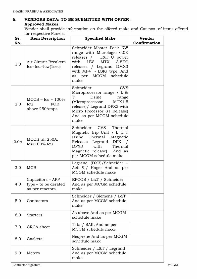
SHASHI PRABHU & ASSOCIATES
Contractor Signature MCGM
6. VENDORS DATA: TO BE SUBMITTED WITH OFFER :
Approved Makes: Vendor shall provide information on the offered make and Cat nos. of items offered for respective Panels:
Sr. No.
Item Description Specified Make Vendor Confirmation
1.0 Air Circuit Breakers Ics=Icu=Icw(1sec)
Schneider Master Pack NW range with Micrologic 6.0E
releases / L&T U power with UW MTX 3.5EC releases / Legrand DMX3
with MP4 - LSIG type. And as per MCGM schedule make
2.0
MCCB – Ics = 100%
Icu FOR above 250Amps
Schneider CVS Microprocessor range / L &
T Dsine range (Microprocessor MTX1.5
release)/ Legrand DPX3 with Micro Processor S1 Release) And as per MCGM schedule
make
2.0A MCCB till 250A, Ics=100% Icu
Schneider CVS Thermal
Magnetic trip Unit / L & T Dsine Thermal Magnetic Release) Legrand DPX /
DPX3 with Thermal Magnetic release) And as
per MCGM schedule make
3.0 MCB Legrand (DX3)/Schneider – Acti 9)/ Hager And as per
MCGM schedule make
4.0
Capacitors – APP
type – to be derated as per reactors.
EPCOS / L&T / Schneider
And as per MCGM schedule make
5.0 Contactors Schneider / Siemens / L&T And as per MCGM schedule make
6.0 Starters As above And as per MCGM schedule make
7.0 CRCA sheet Tata / SAIL And as per MCGM schedule make
8.0 Gaskets Neoprene And as per MCGM schedule make
9.0 Meters Schneider / L&T / Legrand And as per MCGM schedule
make
Page 93
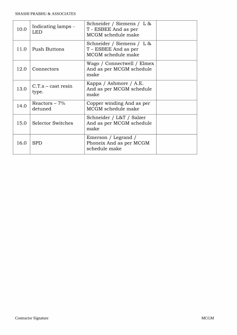
SHASHI PRABHU & ASSOCIATES
Contractor Signature MCGM
10.0 Indicating lamps - LED
Schneider / Siemens / L &
T - ESBEE And as per MCGM schedule make
11.0 Push Buttons Schneider / Siemens / L & T – ESBEE And as per MCGM schedule make
12.0 Connectors Wago / Connectwell / Elmex And as per MCGM schedule
make
13.0 C.T.s – cast resin type.
Kappa / Ashmore / A.E.
And as per MCGM schedule make
14.0 Reactors – 7% detuned
Copper winding And as per MCGM schedule make
15.0 Selector Switches Schneider / L&T / Salzer And as per MCGM schedule make
16.0 SPD Emerson / Legrand / Phoneix And as per MCGM
schedule make
Page 94
SHASHI PRABHU & ASSOCIATES
Contractor Signature MCGM
5. LIGHT FIXTURES A. SPECIFICATIONS
Light fixtures as mentioned in the BOQ with the catalogue nos and makes shall be installed. The fixtures shall be complete with ballast and shall be prewired by the
manufacturer.
Fans of the approved makes and size shown in the drawing shall be used and install in the hook type M.S. box used by the CLIENT.
B. WORKMANSHIP
The fixture shall be installed on wall / ceiling as directed and as per manufacturer's instruction, with necessary accessories for surface, concealed, suspended from ceiling, bracket mounting etc. The job also includes connection of fixture with
respective outlet point with heat resistant wires through heat resistance sleeve and PVC connector. The exhaust fan shall be installed complete with M.S. angle iron mounting frame/ ring, G.I. louvers, wire mesh and plug at the end of the cord
including wiring & earthing etc. Proper earthing shall be provided to the fixtures
C. MODE OF MEASUREMENT
The unit rate shall be considered for fitting one fixture. The rate shall include
following
All fixing accessories, mounting bracket, ballast condensers and control gear
wherever applicable. Supplying and fixing Ball and socket joints wherever required.
Earthing of fittings. Electrical connections to fittings/fans from the junction box/ceiling rose. Installation and interconnection of Electronic regulators for ceiling fans.
Supplying and fixing 300 mm. GI down rod for ceiling fans.
Page 95

SHASHI PRABHU & ASSOCIATES
Contractor Signature MCGM
6.0 UPS
1.0 Scope
The present special contract specifications constitute a call for best offers for the supply of:
Uninterruptible Power System(s) (hereinafter referred to as UPS) rated at 4 X 250kVA + 3 X 100KVA, featuring NiCad batteries housed in one or more external
racks/cubicles and providing a minimum autonomy as defined under "Batteries" herein.
The present specifications contain minimum requirements. All offers must be completed strictly in accordance therewith, either by confirming data or by filling in
the spaces provided, where requirements are not met. Any deviations or exceptions to the minimum requirements must appear in the
offer. Where no exceptions are shown, the requirements of the present specifications will
be considered as accepted.
RELEVANT REFERENCE STANDARDS
The choice of materials and components, engineering developments and the
construction of the equipment must comply with current directives and standards. The UPS will have a CE mark as specified by Directives 73/23, 93/68, 89/336,
92/31 and 93/68. The UPS will be designed and produced according to the following specifications:
• IEC/EN 62040-1-1 "General and safety requirements for UPS used in
operator access areas."
• EN 62040-2 “Electromagnetic compatibility (EMC) requirements”
• IEC/EN 62040-3 “Performance requirements and test methods”
3.1 Design Specifications
The Uninterruptible Power System (UPS) will include the following operational
components:
• Full IGBT Rectifier/battery charger
• IGBT Inverter
• Maintenance bypass switch
• Static switch
• Batteries. 3.2 IGBT Rectifier/Battery charger
The IGBT Rectifier/Battery charger will have an input isolating switch and a PWM digital vector control system (DSP based) which, in addition to normal functions
Page 96
SHASHI PRABHU & ASSOCIATES
Contractor Signature MCGM
(AC/DC conversion), will automatically correct the input power factor to a value >
0.90 and limit the harmonic rejection to the mains at a THDI value < 3% at full output load, and a THDi value < 7% for any other condition.
For the battery charger function, this converter will include built-in fuses and a control circuit for the voltage and battery recharging current. The ripple current to the batteries will be less than 0.05 C10. A microprocessor control function will
perform the following operations:
• Test the battery by automatically performing a partial battery discharge at weekly
intervals or at intervals defined by the user
• Adjust battery float voltage as a function of ambient temperature
• Calculate the remaining battery autonomy time during discharge
• Automatically compensate battery shutdown voltage as a function of the time for
prolonged discharges. 3.3 IGBT Inverter
The IGBT inverter will have a PWM digital vector control system (DSP based), capable of converting DC voltage from the IGBT rectifier or battery into AC voltage.
A rated output filter will create an output voltage sinusoidal envelope. The control circuit, in addition to normal functions, will automatically adjust
nominal output power in accordance with ambient temperature. Inverter should be able to deliver full active power at Unity power factor (KVA=KW)
3.3.1 UPS compatibility to Load Power factor
UPS should support the full Power factor range (Lagging & leading) of load without any deration in power rating
3.4 Static bypass switch
The static bypass switch will feature a separate power input and will consist of the following:
• Static switches (SCR type), which can support overloads and short circuits
downstream of the UPS
• A back feed detection circuit as specified by IEC/EN 62040-1-1, clause 5.1.4
• A bypass and maintenance bypass input isolating switch with auxiliary
indicator contact
• An output load switch.
The control logic will be handled by digital algorithms (using vector control
techniques), similar to those used for the rectifier and the inverter. The static bypass shall be equipped with a back feed protection device compliant with clause
5.1.4 of IEC/EN 62040-1-1; and a relay signal contact for the control of the external back feed isolator to be installed on the bypass line upstream from the UPS.
3.5 Batteries
Page 97

SHASHI PRABHU & ASSOCIATES
Contractor Signature MCGM
The VRLA, WET or NiCad batteries will feature an enclosure made of self-
extinguishing material. The batteries will be housed in one or more racks/ cubicles and will be protected by fuses located on each pole and via a dedicated switch.
4.0 OPERATING MODES
This section describes the different operating modes of the Uninterruptible Power System.
The UPS, using the above-mentioned digital vectorial control (DSP system), will be able to operate both in double conversion and digital interactive modes.
The operating mode may be factory set by the manufacturer during testing or by the
customer using the appropriate diagnostic and control software. The IGBT inverter will be synchronized with the bypass line so that the load can be
transferred from the inverter (conditioned line) to the bypass supply (direct line) and vice versa without any break in the supply to the load.
In all operating modes, the battery charger will provide the power necessary to keep the battery fully charged.
4.1 Double conversion operation
In this operating mode, under normal service conditions, the load will always be supplied from the inverter, guaranteeing maximum protection for the load.
Upon failure or reduction of the primary AC source, the load will be supplied by the battery through the inverter. During this phase, power will be drawn from the
battery. Visible and audible signals will alert the user to this operating state. The remaining autonomy time will be calculated by a diagnostic algorithm.
Upon return of the primary AC source to within tolerance limits, the Uninterruptible Power System will recommence operating in normal mode.
In the event of an inverter overload, manual stop or failure or temporary overload downstream of the UPS, the load will be automatically transferred to the bypass
supply source without interruption. In the event of an overload with an unsuitable supply, the Uninterruptible Power
System will not transfer the load but will continue to supply it from the inverter for a period of time dependent upon the extent of the overload and the characteristics
of the UPS. The user will be alerted of these anomalous operating conditions via the alarm.
4.2 Digital interactive mode
In this operating mode, under normal service conditions, the load will always be supplied from the direct line through the bypass static switch. The quality of the
direct line will be monitored constantly using algorithms operated in real time by the
Page 98

SHASHI PRABHU & ASSOCIATES
Contractor Signature MCGM
DSP control system.
If the direct line is outside the permitted tolerances, the load will be automatically transferred to the conditioned line (inverter) without interruption.
In the absence of power supply to the direct and conditioned lines, the battery will supply power to the loads through the inverter. During this phase, power will be
drawn from the battery and the battery charge will be reduced. Visible and audible signals will alert the user to this operating state. The remaining autonomy time will
be calculated by a diagnostic algorithm. When the quality and reliability of the direct line return within permitted limits, the
UPS will automatically start supplying the load from the direct line.
4.3 Maintenance bypass switch
The UPS will be equipped with a bypass switch capable of transferring the load to
the bypass supply without interruption so as to enable the UPS to be switched off and isolated for maintenance operations. The supply to the load will be maintained.
4.4 Controls and diagnostics
The controls for the electronic power supply modules will guarantee the following:
• A three-phase power supply which is ideal for the load
• Controlled battery recharging
• Minimum harmonic rejection to the upstream mains power supply (THDi<3% at full load, THDi<7% in any other condition).
The UPS will feature a digital vector control based on a DSP (Digital Signal
Processor). The special DSP algorithms must be designed to ensure rapid and flexible processing of the detected data, allowing rapid generation of controlled variables. It must also be
possible to run the control for the electronic inverter devices in real time to:
• Improve short-circuit behavior (300% In for 10 ms, 150% In up to 5 s)
• Have a synchronised (precise phase) angle between UPS output and bypass network, in the event of mains voltage distortion
• Highly flexible parallel operation.
5 . 0 Microprocessor control and diagnostics
Operation and control of the UPS should be provided through the use of micro-processor-controlled logic. Indications, measurements and alarms, together with battery autonomy, will be shown on a graphic liquid crystal display (LCD). The
procedures for start up, shutdown and manual transfer of the load to and from bypass will be explained in clear step-by-step sequences on the LCD display.
Warning/fault: this page contains information regarding various anomalies concerning power converters such as the bypass, rectifier, inverter and
booster/charger. In addition to this there is also warning and fault information relating to the battery and the load. Events log: displays the date and time of important UPS events, alarms and other
warnings.
Page 99
SHASHI PRABHU & ASSOCIATES
Contractor Signature MCGM
Measurements: this page holds the full set of measurements for each functional
block (rectifier, bypass, booster/charger, batteries, inverter and load). Battery: displays the battery status/values including temperature, cell voltage, capacity and run time as well as commands for allowing the user to configure
battery testing. Tools: this page allows users to customize the settings of the LCD display and to select the desired language, choosing between 15 languages.
5.1 Controls
The UPS will be provided with the following controls:
• Inverter start
• Inverter stop
• Reset faults
• Buzzer/mute alarm
• 5.2 Measurements
The UPS will provide the measurements (voltage, current and frequency) for every single internal functional block and this information will be directly accessible on
the display, via the measurements button. 5.3 Signals and alarms
The UPS must provide signals and alarms for every single functional block. These signals must be directly accessible via the display, by clicking the warning and fault
button. The UPS will also:
• Clearly display, upon mains failure, the remaining battery autonomy which will be a function of battery status and charge (discharge curve, degradation,
operating temperature, etc)
• Have three serial RS232 ports for compatibility and communications with special peripheral units and for remote connections
• Be able to support remote graphic measurement and signalling software
• Be able to interface with a network monitoring system using SNMP slot-in cards
• Provide a Tele-monitoring function (see description under section 6.0 "Tele-monitoring")
A voltage-free input will also be provided to disable the static switches and all power
converters (EPO) in case of emergency. Programmable I/O contacts (at least 4 voltage-free outputs and 2 inputs).
6.0 TELEMONITORING This section defines the requirements of the system for remote monitoring and control from the Service Centre.
6.1 Monitoring and control from service centre
The system will be capable of analysing UPS operation and electrical supply in order to identify faults and thus prevent the occurrence of conditions likely to damage the equipment protected by the UPS.
The system will guarantee single or parallel UPS surveillance, 24 hours a day for
Page 100
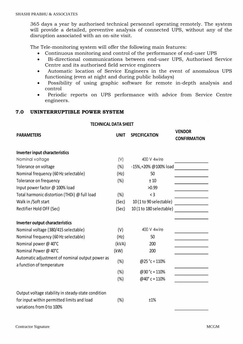
SHASHI PRABHU & ASSOCIATES
Contractor Signature MCGM
365 days a year by authorised technical personnel operating remotely. The system
will provide a detailed, preventive analysis of connected UPS, without any of the disruption associated with an on-site visit.
The Tele-monitoring system will offer the following main features:
• Continuous monitoring and control of the performance of end-user UPS
• Bi-directional communications between end-user UPS, Authorised Service Centre and its authorised field service engineers
• Automatic location of Service Engineers in the event of anomalous UPS functioning (even at night and during public holidays)
• Possibility of using graphic software for remote in-depth analysis and control
• Periodic reports on UPS performance with advice from Service Centre engineers.
7.0 UNINTERRUPTIBLE POWER SYSTEM
PARAMETERS UNIT SPECIFICATIONVENDOR
CONFIRMATION
Inverter input characteristics
Nominal voltage (V) 400 V 4wire
Tolerance on voltage (%) -15%,+20% @100% load
Nominal frequency (60 Hz selectable) (Hz) 50
Tolerance on frequency (%) ± 10
Input power factor @ 100% load >0.99
Total harmonic distortion (THDi) @ full load (%) < 3
Walk in /Soft start (Sec) 10 (1 to 90 selectable)
Rectifier Hold OFF (Sec) (Sec) 10 (1 to 180 selectable)
Inverter output characteristics
Nominal voltage (380/415 selectable) (V) 400 V 4wire
Nominal frequency (60 Hz selectable) (Hz) 50
Nominal power @ 40°C (kVA) 200
Nominal Power @ 40°C (kW) 200
Automatic adjustment of nominal output power as
a function of temperature(%) @25 °c = 110%
(%) @30 °c = 110%
(%) @40° c = 110%
Output voltage stability in steady-state condition
for input within permitted limits and load
variations from 0 to 100%
(%) ±1%
TECHNICAL DATA SHEET
Page 101

SHASHI PRABHU & ASSOCIATES
Contractor Signature MCGM
PARAMETERS UNIT SPECIFICATIONVENDOR
CONFIRMATION
Stability in dynamic conditions for 100% load step
variations (%) ±5%
Load crest factor without derating 3:1
Output voltage distortion with 100% linear load (%) <1
Output voltage distortion with non-linear load as
specified by IEC/EN 62040-3(%) <3
Output frequency stability in synchronization with
mains (± 2 ± 3 ± 4 selectable)(%) ±1
Output frequency stability with internal clock (%) ±0.1
Frequency slew rate (Hz/sec) <1
Permitted overload:
for 10 minutes (%) 125
for 60 seconds (%) 150
Short circuit current:
300% In (ms) 10
150% In (s) 5
Characteristics of electronic static changeover
switch
Nominal voltage (380/415 selectable) (V) 400
Tolerance on voltage (± 5 ¸ ± 15 selectable) (%) ±10
Nominal frequency (60 Hz selectable) (Hz) 50
Tolerance on frequency (± 2 ± 3 ± 4 selectable) (%) ±1
UPS characteristics
Maximum UPS cabinet dimensions WxHxD (mm)
Noise level measured @ 1 meter and @ 100% load
according to ISO 3746(dBA) 70 dba
AC/AC efficiency – double conversion mode @
100% load(inbuilt K13 iso. Transformer)(%) 94.5
Efficiency in digital interactive mode @ 100% load (%) 98
EMC compatibility as per EN 62040-2 Class C3
Degree of protection IP 20
Frame colour RAL 7021
The constructional and functional characteristics of UPS must be in line with the
state-of-the-art technology in this field. The supplying company must be able to provide proof that it is ISO 9001-2000 and ISO 14001 certified for design and manufacturing and for the provision of services.
The UPS will be guaranteed for one year during which time the Supplier will provide technical assistance.
The offer must include:
Page 102

SHASHI PRABHU & ASSOCIATES
Contractor Signature MCGM
• a draft maintenance contract providing for 24 hour service with guaranteed minimum service call response time of 4 hours (references are required)
• the addresses of all Service Centres, divided according to geographical areas, and the number of engineers working for each centre
• Indication of main Tele-monitoring installations in operation.
7. LIGHTING ARREST0R SYSTEM
1.0 GENERAL
1.1 The lightning protection system shall be of the enhanced type which is designed to attract lightning to a preferred point and safely convey the lightning energy to ground with minimal risk of side flashing via a predetermined route.
Page 103

SHASHI PRABHU & ASSOCIATES
Contractor Signature MCGM
1.2 The complete lightning protection system will comprise the following key components.
(a) Advanced lightning rod (b) Mounting support (c) High voltage shielded cable
(d) Lightning Strike Recorder (e) Dedicated earthing system
2.0 THE LIGHTNING ROD
2.1 The advanced lightning rod shall be of a “Controlled Advanced Triggering” type and will respond dynamically upon leader activity in the near area.
2.2 The advanced lightning rod shall be configured as a spheroid which is comprised of
separate electrically isolated panels surrounding an earthed central finial.
2.3 The insulation material used to electrically isolate the panels shall be comprised of
a base polymer which provides high ozone and UV resistance with a dielectric
strength of 24 – 38 KV/mm.
2.4 The external shape of the advanced lightning rod shall be such that it will limit the development of sharp point corona discharge under static thunderstorm conditions.
2.5 The upper section of the central finial shall be rounded to provide a blunt surface. 2.6 The upper section of the central finial shall be rated to withstand 200KA.
2.7 An air gap shall be provided between the individual electrically isolated panels (4
panels) and the blunt configured tip of the central rod. Dome shapes and pointed central rods will not be acceptable.
2.8 Arcing shall occur between the panel sections of the spheroid and the blunt configured finial tip only upon the progression of a lightning leader.
2.9 The advanced lightning rod shall have no moving parts and will have no
dependence on external power supply or batteries. There should be no high
impedance static drain unit between the central rod and the panels. 2.10 Under a normal atmosphere all components of the advanced lightning terminal
shall be non corroding.
2.11 The advanced lightning rod shall be installed at a minimum of 10 metres from the ground.
2.12 The advanced lightning rod shall be insulated from all surrounding points and features of the structure being protected.
2.13 The advanced lightning rod shall not be installed in a corrosive environment unless
the manufacturers written approval has first been granted.
Page 104
SHASHI PRABHU & ASSOCIATES
Contractor Signature MCGM
2.14 The advanced lightning rod shall be installed as per the manufacturers
instructions. 2.15 The advanced lightning rod shall not be of the ESE type and all lightning terminals
claiming compliance to NF C17-102 shall not be considered suitable. 2.16 The advanced lightning rod shall have been tested to the following standard IEC
601:1989.
2.17 The lightning rod shall be shown to have withstood a minimum current impulse of a 180kA 8/20 μs waveform as per the test standard IEC 60-1:1989.
3.0 MOUNTING SUPPORT OF LIGHTNING ROD
3.1 The mounting pole used to support the lightning rod shall be a circular insulating fibreglass tube at a minimum height of 2 metres. The pole will have an outside diameter of 68mm.
3.2 The mounting pole and supports shall be securely fixed with brackets and guy
wires where required.
3.3 The downconductor shall pass through the centre of the insulating pole for the
entire length of the pole. 4.0 HIGH VOLTAGE SHIELDED CABLE
4.1 The high voltage shielded cable shall consist of a core filler, stranded copper
conductor, insulation material, outer copper conductor with external conductive
sheath.
4.2 The main copper conductor within the high voltage shielded cable shall have a minimum cross sectional area of 50mm².
4.3 The outer diameter of the high voltage shielded cable shall be less than 38mm.
4.4 The high voltage shielded cable shall have a maximum inductance of 25 nH/m.
4.5 The main copper conductor shall allow for direct connection to the lightning rod through the use of a compression lug.
4.6 The high voltage shielded cable shall be fixed to the structure through the use of suitable saddles every two metres for the length of the cable route.
4.7 The high voltage shielded cable shall be installed as per manufacturers instructions
and shall not be subject to bends of less than 0.6 metres radius.
4.8 The high voltage shielded cable shall have been tested to the following standard IEC 60-1:1989.
Page 105

SHASHI PRABHU & ASSOCIATES
Contractor Signature MCGM
4.9 The high voltage shielded cable shall have been subjected and successfully
withstood a maximum voltage of 280kV in compliance to IEC test standard, IEC 600601, 2nd edition, 1989-11.
5.0 EVENT RECORDING DEVICE 5.1 All systems shall be installed complete with the lightning strike recorder.
5.2 The lightning strike recorder shall contain a mechanical 6 digit display which will
register all lightning discharges with a sensitivity of 1500A 8/20 μs peak current impulse.
5.3 The lightning strike recorder shall be housed in a IP 67 rated enclosure and will operate without reliance on batteries or an external power source.
5.4 The lightning strike recorder shall be installed as per the manufacturers instructions.
5.5 It shall be shown that the event recording device has been successfully tested under
test standard IEC 60-1:1989.
6.0 EARTHING 6.1 The earthing system shall incorporate the following individual components or a
combination of the following – 25 x 1mm flat copper tape buried to a depth of not more than 800mm or by deep driven copper bonded steel core earth rods. All components of the earthing system shall be electrically connected to the central
injection rod which is securely connected to the lower end of the high voltage shielded cable.
6.2 The earthing system shall be installed so that the final impedance reading does not
exceed 10 Ohms unless otherwise stipulated by the lightning protection
manufacturer or consulting engineer.
6.3 It is recommended that the earthing system is bonded to all structural reinforcing steel of the building, along with all connecting services.
6.4 The use of ground resistance improvement material shall be applied in order to
reduce the resistivity levels of the earthing system.
Page 106

SHASHI PRABHU & ASSOCIATES
Contractor Signature MCGM
8. AUTOMATIC TRANSFER SWITCH
1.0 415V Auto Transfer Switch 1.1 General
1.1.1 Scope
This specification covers performance, design, material, construction, manufacture, inspection, testing, packing forwarding, delivery at site, testing and
commissioning of microprocessor controlled Auto transfer switches – with double throw power transfer switch mechanism as per single line diagrams, with all
accessories complete in all respects as described in this specification. Whether called for specifically or not, all accessories required for normal
operation of equipment are deemed to be considered as a part of the contractor’s scope of supply. Hardware / fabricated supports required for mounting and installation of the ATS is within the scope of work.
It is not the intent to specify completely herein, all details of design and
construction of the equipment. However, the equipment shall conform in all respects to high standard of Engineering, design and workmanship and be capable of performing in continuous commercial operation up to the
Manufacturer’s guarantees in a manner acceptable to the Engineer, who will interpret the meaning of the drawings and specifications and shall be entitled to reject any work or material which is not full accordance therewith.
1.1.2 Codes and Standards
The automatic transfer switches and controls shall conform to the requirements of:
UL 1008 - Standard for Transfer Switch Equipment
IEC 947-6-1 - Low-voltage Switchgear and Control gear; Multifunction equipment; Automatic Transfer Switching Equipment
NFPA 70 - National Electrical Code NFPA 99 - Essential Electrical Systems for Health Care Facilities
NFPA 110 - Emergency and Standby Power Systems
IEEE Standard 446 - IEEE Recommended Practice for Emergency and Standby
Power Systems for Commercial and Industrial Applications
NEMA Standard ICS10-1993 (formerly ICS2-447) - AC Automatic Transfer Switches
UL 508 - Industrial Control Equipment
1.2 Products
Page 107
SHASHI PRABHU & ASSOCIATES
Contractor Signature MCGM
1.2.1 Mechanically Held Transfer Switch The transfer switch shall be electrically operated and mechanically held. The
electrical operator shall be a momentarily energized, single-solenoid mechanism. Main operators which include overcurrent disconnect devices, linear motors or gears shall not be acceptable. The switch shall be mechanically interlocked to
ensure only two possible positions, normal or emergency. The switch shall be rated for AC-33A duty cycle for mixed load application as mentioned in IEC 60947-6-1.
All transfer switch sizes shall use only one type of main operator for ease of maintenance and commodity of parts.
The switch shall be positively locked and unaffected by momentary outages, so that
contact pressure is maintained at a constant value and contact temperature rise is minimized for maximum reliability and operating life.
All main contacts shall be silver composition. Switches rated 600 amperes and above shall have segmented, blow-on construction for high withstand and close-on capability and be protected by separate arcing contacts.
Inspection of all contacts shall be possible from the front of the switch without
disassembly of operating linkages and without disconnection of power conductors. Switches rated 600 amps and higher shall have front removable and replaceable contacts. All stationary and moveable contacts shall be replaceable without
removing power conductors and/or bus bars. Designs utilizing components of moulded-case circuit breakers, contactors, or parts
thereof, which are not intended for continuous duty, repetitive switching or transfer between two active power sources are not acceptable.
Where neutral conductors must be switched as shown on the plans, the AS shall be provided with fully rated complete overlapping neutral transfer contacts. The
neutrals of the normal and emergency power sources shall be connected together only during the transfer and retransfer operation and remain connected together
until power source contacts close on the source to which the transfer is being made. The overlapping neutral contacts shall not overlap for a period greater than 100 milliseconds. Neutral switching contacts which do not overlap are not acceptable.
Where neutral conductors are to be solidly connected as shown on the plans, a
neutral conductor plate with fully rated CU pressure connectors shall be provided.
1.2.2 Microprocessor Controller
The controller’s sensing and logic shall be provided by a single built-in microprocessor for maximum reliability, minimum maintenance, and the ability to
communicate serially through an optional serial communication module.
A single controller shall provide twelve selectable nominal voltages for maximum application flexibility and minimal spare part requirements. Voltage sensing shall
be true RMS type and shall be accurate to 1% of nominal voltage. Frequency
Page 108

SHASHI PRABHU & ASSOCIATES
Contractor Signature MCGM
sensing shall be accurate to 0.2%. The panel shall be capable of operating over a temperature range of -20 to +60 degrees C and storage from -55 to +85 degrees C.
The controller shall be connected to the transfer switch by an interconnecting wiring harness. The harness shall include a keyed disconnect plug to enable the controller to be disconnected from the transfer switch for routine maintenance.
Sensing and control logic shall be provided on multi-layer printed circuit boards. Interfacing relays shall be industrial grade plug-in type with dust covers. The panel shall be enclosed with a protective cover and be mounted separately from the
transfer switch unit for safety and ease of maintenance. The protective cover shall include a built-in pocket for storage of the operator’s manuals.
All customer connections shall be wired to a common terminal block to simplify field-wiring connections.
The controller shall meet or exceed the requirements for Electromagnetic Compatibility (EMC) as follows:
EN 55011:1991 Emission standard - Group 1, Class A
EN 50082-2:1995 Generic immunity standard, from which: EN 61000-4-2:1995 Electrostatic discharge (ESD) immunity
ENV 50140:1993 Radiated Electro-Magnetic field immunity
EN 61000-4-4:1995 Electrical fast transient (EFT) immunity EN 61000-4-5:1995 Surge transient immunity
EN 61000-4-6:1996 Conducted Radio-Frequency field immunity IEEE472 (ANSI C37.90A) Ring Wave Test.
1.3 Operation
1.3.1 Controller Display and Keypad
A four line, 20 character LCD display and keypad shall be an integral part of the
controller for viewing all available data and setting desired operational parameters. Operational parameters shall also be available for viewing and limited control through the serial communications input port. The following parameters shall only
be adjustable via DIP switches on the controller:
Nominal line voltage and frequency Single or three phase sensing Operating parameter protection
Transfer operating mode configuration (Open transition, Closed transition or Delayed transition)
All instructions and controller settings shall be easily accessible, readable and
accomplished without the use of codes, calculations, or instruction manuals.
1.3.2 Voltage, Frequency and Phase Rotation Sensing
Voltage and frequency on both the normal and emergency sources (as noted below)
shall be continuously monitored, with the following pickup, dropout and trip setting capabilities (values shown as % of nominal unless otherwise specified):
Parameter Sources Dropout / Trip Pickup / Reset Undervoltage N&E,3 70 to 98% 85 to 100%
Page 109

SHASHI PRABHU & ASSOCIATES
Contractor Signature MCGM
Overvoltage N&E,3 102 to 115% 2% below trip
Underfrequency N&E 85 to 98% 90 to 100% Overfrequency N&E 102 to 110% 2% below trip
Voltage unbalance N&E 5 to 20% 1% below dropout Repetitive accuracy of all settings shall be within ± 0.5% over an operating
temperature range of -20C to 60C.
Voltage and frequency settings shall be field adjustable in 1% increments either locally with the display and keypad or remotely via serial communications port access.
The controller shall be capable (when activated by the keypad or through the serial
port) of sensing the phase rotation of both the normal and emergency sources. The source shall be considered unacceptable if the phase rotation is not the preferred rotation selected (ABC or CBA).
Source status screens shall be provided for both normal & emergency to pro-vide digital readout of voltage on all 3 phases, frequency, and phase rotation.
1.3.3 Time Delays
An adjustable time delay of 0 to 6 seconds shall be provided to override momentary normal source outages and delay all transfer and engine starting signals.
Capability shall be provided to extend this time delay to 60 minutes by providing an external 24 VDC power supply.
A time delay shall be provided on transfer to emergency, adjustable from 0 to 60 minutes, for controlled timing of transfer of loads to emergency.
Two time delay modes (which are independently adjustable) shall be provided on re-transfer to normal. One time delay shall be for actual normal power failures and
the other for the test mode function. The time delays shall be adjustable from 0 to 60 minutes. Time delay shall be automatically bypassed if the emergency source
fails and the normal source is acceptable. A time delay shall be provided on shut down of engine generator for cool down,
adjustable from 0 to 60 minutes.
A time delay activated output signal shall also be provided to drive an external relay(s) for selective load disconnect control. The controller shall have the ability to activate an adjustable 0 to 5 minute time delay in any of the following modes:
Prior to transfer only. Prior to and after transfer.
Normal to emergency only. Emergency to normal only.
Normal to emergency and emergency to normal. All transfer conditions or only when both sources are available.
The controller shall also include the following built-in time delays for optional Closed Transition and Delayed Transition operation:
Page 110
SHASHI PRABHU & ASSOCIATES
Contractor Signature MCGM
1. 1 to 5 minute time delay on failure to synchronize normal and emergency sources prior to closed transition transfer.
2. 0.1 to 9.99 second time delay on an extended parallel condition of both
power sources during closed transition operation. 3. 0 to 5 minute time delay for the load disconnect position for delayed
transition operation.
All time delays shall be adjustable in 1 second increments, except the extended
parallel time, which shall be adjustable in .01 second increments. All time delays shall be adjustable by using the LCD display and keypad or with a
remote device connected to the serial communications port.
1.3.4 Additional Features A three position momentary-type test switch shall be provided for the test /
automatic / reset modes. The test position will simulate a normal source failure. The reset position shall bypass the time delays on either transfer to emergency or retransfer to normal.
A SPDT contact, rated 5 amps at 30 VDC, shall be provided for a low-voltage engine
start signal. The start signal shall prevent dry cranking of the engine by requiring the generator set to reach proper output, and run for the duration of the cool down setting, regardless of whether the normal source restores before the load is
transferred. Auxiliary contacts, rated 10 amps, 250 VAC shall be provided consisting of one
contact, closed when the ATS is connected to the normal source and one contact closed, when the ATS is connected to the emergency source.
LED indicating lights (16 mm industrial grade, ttyyppee 1122) shall be provided; one to indicate when the ATS is connected to the normal source (green) and one to indicate
when the ATS is connected to the emergency source (red).
LED indicating lights (16 mm industrial grade, type 12) shall be provided and energized by controller outputs. The lights shall provide true source availability of the normal and emergency sources, as determined by the voltage sensing trip and
reset settings for each source. The following features shall be built-in to the controller, but capable of being
activated through keypad programming or the serial port only when required by the user:
Provide the ability to select “commit/no commit to transfer” to determine whether the load should be transferred to the emergency generator if the normal source
restores before the generator is ready to accept the load.
Terminals shall be provided for a remote contact which opens to signal the ATS to transfer to emergency and for remote contacts which open to inhibit transfer to emergency and/or retransfer to normal. Both of these inhibit signals can be
activated through the keypad or serial port.
Page 111
SHASHI PRABHU & ASSOCIATES
Contractor Signature MCGM
An In phase monitor shall be provided in the controller. The monitor shall control transfer so that motor load inrush currents do not exceed normal starting currents, and shall not require external control of power sources. The in phase monitor shall
be specifically designed for and be the product of the ATS manufacturer. The controller shall be capable of accepting a normally open contact that will allow
the transfer switch to function in a non-automatic mode using an external control device.
1.3.5 Engine Exerciser
The controller shall provide an internal engine exerciser. The engine exerciser shall allow the user to program up to seven different exercise routines. For each routine,
the user shall be able to: 1. Enable or disable the routine.
2. Enable or disable transfer of the load during routine. 3. Set the start time
- time of day
- day of week - week of month (1st, 2nd, 3rd, 4th, alternate or every)
4. Set the duration of the run.
At the end of the specified duration the switch shall transfer the load back to normal
and run the generator for the specified cool down period. A 10-year life battery that supplies power to the real time clock in the event of a power loss will maintain all time and date information.
1.3.6 System Status
The controller LCD display shall include a “System Status” screen which shall be
readily accessible from any point in the menu by depressing the “ESC” key a maximum of two times. This screen shall display a clear description of the active operating sequence and switch position. For example,
Normal Failed Load on Normal
TD Normal to Emerg 2min15s
Controllers that require multiple screens to determine system status or display “coded” system status messages, which must be explained by references in the
operator’s manual, are not permissible.
1.3.7 Self Diagnostics
Page 112

SHASHI PRABHU & ASSOCIATES
Contractor Signature MCGM
The controller shall contain a diagnostic screen for the purpose of detecting system
errors. This screen shall provide information on the status input signals to the controller which may be preventing load transfer commands from being completed.
1.3.8 Communications Interface The controller shall be capable of interfacing, through an optional serial
communication module, with a network of transfer switches, locally (up to 4000 ft.) or remotely through modem serial communications. Standard software specific for
transfer switch applications shall be available by the transfer switch manufacturer. This software shall allow for the monitoring, control and setup of parameters.
1.3.9 Data Logging
The controller shall have the ability to log data and to maintain the last 99 events, even in the event of total power loss. The following events shall be time and date stamped and maintained in a non-volatile memory:
1. Event Logging 1. Data and time and reason for transfer normal to emergency.
2. Data and time and reason for transfer emergency to normal. 3. Data and time and reason for engine start.
4. Data and time engine stopped. 5. Data and time emergency source available. 6. Data and time emergency source not available.
2. Statistical Data 1. Total number of transfers.
2. Total number of transfers due to source failure. 3. Total number of days controller is energized.
4. Total number of hours both normal and emergency sources are available.
1.3.10 Communications Module
A full duplex RS485 interface & Ethernet TCP/IP RJ45 socket shall be installed in the ATS controller to enable serial communications. The serial communications shall be capable of a direct connect or multi-drop configured network. This module
shall allow for the seamless integration of existing or new communication transfer devices through Modbus open protocol. The proprietary protocols are not acceptable.
1.4 Additional Requirements
1.4.1 Withstand and Closing Ratings
The ATS/BPS shall be rated to close on and withstand the available RMS symmetrical short circuit current at the ATS/BPS terminals with the type of
overcurrent protection shown on the plans. The ATS/BPS shall be UL-1008 and IEC-60947-6-1 complied & in accordance with
UL 1008 listing and be labeled in accordance with that standard's 1½ and 3 cycle,
Page 113
SHASHI PRABHU & ASSOCIATES
Contractor Signature MCGM
long-time ratings. ATS/BPS which are not tested and labeled with 1½ and 3 cycle
(any breaker) ratings and have series, or specific breaker ratings only, are not acceptable.
The ATS rated 800A and above must be tested for 18/30 cycles short time withstand capacity matching breaker fault level to enable use of ACB as a back up protection device with short time delay setting for providing discrimination with the
downstream breakers.
9 BUSDUCT
Scope:
The specifications comprises of performance, design, material, construction,
manufacture, inspection, testing, packing forwarding, delivery at site, testing and commissioning of medium voltage sandwich type bus duct / rising mains,
indoor/outdoor type as per site requirement for interconnection between indoor M.V. switchgear & outdoor transformer.
Whether called for specifically or not, all accessories required for normal operation of equipment are deemed to be considered as a part of the contractor’s
scope of supply. Hardware / fabricated supports required for mounting and installation of the busducts / rising mains is within the scope of work.
Page 114
SHASHI PRABHU & ASSOCIATES
Contractor Signature MCGM
It is not the intent to specify completely herein, all details of design and
construction of the equipment. However, the equipment shall conform in all respects to high standard of Engineering, design and workmanship and be capable of performing in continuous commercial operation up to the
Manufacturer’s guarantees in a manner acceptable to the Engineer, who will interpret the meaning of the drawings and specifications and shall be entitled to reject any work or material which is not full accordance therewith.
General
The current rating of bus duct shall be as indicated in the specific requirements/schedule of quantities/drawing.
The size of the neutral bus bar shall 100% of the phase busbar.
Note: Before fabrication and installation of the bus duct is taken up, the layout of the M.V. switchgear and transformer shall be got approved by Engineer and the bus
duct layout properly co-ordinated. Standards
The following standards shall be recognized:
IS : 8623 – 1993 I & II – Busbar trunking system IS : 4237 - General requirement of switchgear.
IS: 375 - Marking arrangement for switchgear, busbar. IS: 5 - Colours for ready mixed paints IS: 2147- Degree of protection provided by the enclosure for L.V. switchgear.
IS: 158 – Ready mixed water and hear resistant paint for general purposes.
Rating details: (I) Rated 3 Phase voltage: 415 volt, IP 54 Category (II) Standard insulation withstand for one minute: 1000 v
(III) Rated frequency: 50 HZ (IV) Asymmetrical short circuit current: 60 KA r.m.s.
(V) Maximum bubar operating temperature at full rated current above ambient: 55oC (VI) Maximum ambient temperature: 500 C
(VII) Current rating: 3500 A TPN EC grade sleeved Cu busbars busduct. (VIII) Rated impulse withstand voltage – 12 KV at 1000 V
9.1 Enclosures
9.1.1 Construction
The eclosure shall be made from 16 SWG GI / CRCA sheet steel powder coated to
shade RAL 7032 (or such other shade) or from extruded aluminium sheet. Busbars would be in sandwich construction and the conductors shall be individually insulated with four layers of insulating film. Inner layer shall be of glass MICA and
outer layer shall be of polyester material of Class F. Alternatively extrusion of class
Page 115
SHASHI PRABHU & ASSOCIATES
Contractor Signature MCGM
F material in form of epoxy insulation may be provided. No drilling of busbars is
permitted. Copper conductors shall be of 99.9% purity and ETP grade with radialised edges. Lengths of section shall be limited to max 3 meters. Busbars of one section shall be connected to busbars of adjacent section by uniblock joint
system removable as separate sub assembly so that it can be inserted or removed without disturbing the adjacent sections.
9.1.2 Installation as rising mains
For installation as rising mains / vertical installation at each floor a set consisting of 2 spring hangers shall be provided for fixing it on channels grouted in wall. At the start of run hangers without springs may be used for the rigid support. In
addition horizontal supports shall be provided -2 nos per floor to hold busbars in position. On rising mains on front face of the busbar trunking Tap Off points shall
be provided for inserting plug in boxes. No. of tap of points at each floor shall be as per requirement given in BOQ / SLD; but min distance between tap off points shall be kept around 500 mm. Each tap off opening closed by insulated shutters forming
part of BBT, when not occupied by plugin boxes. Neutral cross section shall be same as phase cross section. Necessary vertical / horizontal bends / Tees / fire barriers etc shall be provided as required by the layout.
Busbar trunking shall be rigidly fixed to the side walls or suspended from ceiling by
supports as per requirements detailed in the shop layout. At the termination either on the transformer side / generator end / switchgear end,
busduct shall be provided with flange end / adaptor box / copper flexible (preferably multisheath types) / phase change overs if required to connect busbars of busduct to the busbars of switchgears / transformers / generator terminals.
Expansion units shall be installed after every 50 mtrs of uninterrupted run for
composite expansion of complete bus trunking run. 9.1.3 Earth Bus
Integral Earth Bus of copper should be provided for entire length of the bus trunk.
Suitable copper links shall be provided at the joints of bus duct. Earth bus at the point of wall entry should have suitable arrangement as approved by the purchaser. Size of earth bus shall be as per IEC 60439.
9.2 Plug In Boxes:
These are required for rising Mains. Plug in boxes will be of draw out type. Contacts will be of silver plated copper and spring loaded. Earth connection will be the first
to make and last to break during insertion and withdrawal. Plug in box will be made from 1.6mm CRCA sheet steel powder coated or GI. Inside the plug in boxes MCCB / ACB will be located as per requirements. The operating handle will be
interlocked with plug in box cover so that MCCB can be operated only with suitable cover in closed position. If required the plug in box will be interlocked with bus bar
trunking so that it could be inserted or removed with the plug in box lid opened. MCCB/ACB will be of 4 pole type unless otherwise specified in BOQ. Short circuit breaking capacity of MCCB in PIB should preferably be same as short circuit with
stand for one second of bus bar trunking.
Page 116
SHASHI PRABHU & ASSOCIATES
Contractor Signature MCGM
9.3 End Feed Unit:
The End feed unit will be manufactured from 1.6mm thick steel with powder
coating to shade RAL 7032 or of GI. Inside the End feed unit MCCB/ACB of required rating and specification will be located. End feed units at top will be connected to Bus bars of Rising Mains through solid connections. Terminals at the
bottom will be provided to accept cable connections as required. The operating handle of MCCB/ACB will be interlocked so that the door can be opened only when
MCCB or ACB are in off position. The current rating of MCCB should correspond with current rating of bus bar trunking and short circuit breaking capacity with one second short circuit withstand of bus bar trunking.
9.4 Transposition:
Transposition of bus bars should be done preferably in ACB adaptor chamber. Cost of adaptor chamber should be included in indoor bus duct. The tenderer should
indicate clearly for any extra prices if required, for adaptor chamber and the length of adaptor chamber in that case should be indicated clearly. Terminal arrangement of transformers will be furnished to the successful tenderer at a later date.
9.5 Current Rating Of Bus Duct:
The tenderer must furnish complete data for the bus duct for calculating the net current
rating of bus duct.
Details of bus duct:
The following data must be furnished along with the tender: (a) Material of bus bars and its purity.
(b) Overall size of the bus duct enclosure. (c) No of bus bars for each phase and neutral and bus bar size (d) Clearance between bus bars of same phase.
(e) Sketch showing arrangements of bus bars. (f) Net current ratings of bus duct.
9.6 Drawing:
Detailed layout and fabrication drawings showing the sizes of bus bars enclosure, fixing, details, supports, bends, joints, wall entry assembly etc. shall be submitted by the Contractor for approval of Engineer in charge/purchaser’s comments
/modifications suggested by; the Purchaser shall be incorporated by the Contractor. Actual fabrication of the bus duct shall be carried out only after the approval
of the purchaser, with respect to actual physical location of main panel incomer and transformer L.T. cable box for dimensions (i.e. cross checking of dimensions and phase sequence shown in panel / transformer GA drawings)
Page 117
SHASHI PRABHU & ASSOCIATES
Contractor Signature MCGM
10. 1.1 KV GRADE L.T. CABLES AND CABLE TERMINATION
L. T. XLPE CABLE : - FRLSH CU CATEGORY
GENERAL :
The medium voltage cables shall be supplied, laid, connected, tested and
commissioned in accordance with the drawings, specifications, relevant Indian Standards specifications, manufacturer’s instructions. The cables shall be delivered
at site in the original drums with manufacturer’s name, size and type clearly written on the drums.
All cables shall be adequately protected against any risk of mechanical damage to which they may be liable in normal conditions of handling during transportation, loading, unloading etc.
The cable shall be supplied in single length i.e. without any intermediate joint or
cut unless specifically approved by the client. The cable ends shall be suitably sealed against entry of moisture, dust, water etc.
with cable compound as per standard practice.
CONDUCTOR :
Uncoated, annealed copper of high conductivity, upto 4 mm2 size the conductor
shall be solid and above 4 mm2 the conductors shall be concentrically stranded as per IEC : 228.
INSULATION :
Cross link polyethylene (XLPE) extruded insulation rated at 70oc.
CORE INDENTIFICATION :
Two core : Red and Black Three core : Red, Yellow and Blue
Four core : Red, Yellow, Blue and Black Single core : Green, Yellow for earthing.
Black shall always be used for neutral.
ASSEMBLY :
Two, three or four insulated conductors shall be laid up, filled with non-hygroscopic material and covered with an additional layer of thermoplastic material.
ARMOUR :
Page 118
SHASHI PRABHU & ASSOCIATES
Contractor Signature MCGM
Galvanised steel flat strip / round strips applied helically in single layers complete with covering the assembly of cores.
For cable size upto 10 sq mm : Armour of 1.4 mm dia G.I. round wire
For cable size above 10 sq mm : Armour of 4 mm wide 0.8 mm thick GI strip
SHEATH :
ST -2 PVC along with polypropylene fillers to be provided.
Inner sheath shall be extruded type and shall be compatible with the insulation
provided for the cables.
Outer sheath shall be of an extruded type layer of suitable PVC material compatible
with the specified ambient temp. of 50oc and operating temperature of cables. The sheath shall be resistant to water, ultra violet radiation, fungus, termite and rodent attacks. The colour of outer sheath shall be black.
Sequential length marking along with size and other standard parameters shall be
required at every 1.0 mtr on the outer sheath.
The product should be coded as per IS :- 7098 Part-I as follows :-
Aluminium Conductor A XLPE Insulation 2X
Steel round wire armour W Steel flat strip armour F
Steel Double round wire armour WW Steel Double flat strip armour FF Non-magnetic (Al.) round wire armour Wa
Non-magnetic (Al.) flat strip armour Fa PVC outer sheath Y
TESTING :
Finished cable tests at manufacturers works : The finished cables shall be tested at
manufacturer’s works for all the routine tests for all the length and size of cables to
be delivered at site and the certificate for the same shall be furnished to client. If required the cables shall be tested in presence of the client’s representative.
Voltage test : Each core of cable shall be tested at room temperature at 3 KV A.C.
R.M.S. for duration of 5 minutes.
Conductor resistance test : The D.C. resistance of each conductor shall be measured at room temperature and the results shall be corrected to 20oc to check
the compliance with the values specified in the Is 8130 – 1976. Cable tests before and after laying cables at site : Insulation resistance test between phases, phase to neutral and phase to earth.
Continuity test of all the phases, neutral and earth continuity conductor.
Page 119
SHASHI PRABHU & ASSOCIATES
Contractor Signature MCGM
Earth resistance test of all the phases and neutral.
All the tests shall be carried out in accordance with the relevant IS code of practise
and Indian Electricity Rules. The vendor shall provide necessary instruments,
equipments and labour for conducting the above tests and shall bear all the expenses in connection with such tests. All tests shall be carried out in the presence of client and the results shall be prescribed in forms and submitted.
CABLE MARKING :
The outer sheath shall be legibly embossed at every meter with following legend :
ELECTRIC CABLE : 1100 V, SIZE :___C X ____ MM2 with Manufacturers name, year of manufacturing and ISI symbol.
SEALING DRUMMING AND PACKING :
After tests at manufacturer’s woks, both ends of the cables shall be sealed to
prevent the ingress of moisture during transportation and storage. Cable shall be supplied in length of 500 mtrs or as required in non-returnable
drums of sufficiently sturdy construction. Cables of more than 250 meters shall also be supplied in non-returnable drums. The spindle hole shall be minimum 110 mm in diameter.
Each drum shall bear on the outside flange, legibly and indelibly in the Englist
literature, a distinguishing number, the manufacturer’s name and particulars of the
cable i.e. voltage grade, length, conductor size, cable type, insulation type, and gross weight shall also be clearly visible. The direction for rolling shall be indicated
by an arrow. The drum flange shall also be marked with manufacturer’s name and year of manufacturing etc.
CABLE TERMINATION:
Cable terminations shall be made with aluminium crimped type solder less lugs for all aluminium cables and stud type terminals. For copper cables copper crimped solder less lugs shall be used.
Crimping shall be done with the help of hydraulically operated crimping tool. For joints where by cable is with aluminium conductor and busbars are aluminium,
bimetallic lugs shall be used with compound. CUPAL type of washers shall be used.
Crimping tool shall be used for crimping any size of cable.
CABLE GLANDS:
Cable glands shall be of brass single compression type. Generally single
compression type cable glands shall be used for indoor protected locations and double compression type shall be used for outdoor locations.
FERRULES:
Page 120

SHASHI PRABHU & ASSOCIATES
Contractor Signature MCGM
Ferrules shall be of self-sticking type and shall be employed to designate the
various cores of the control cable by the terminal numbers to which the cores are connected, for ease in identification and maintenance.
CABLE JOINTS:
Kit type joint shall be done and filled with insulating compound. The joint should
be for 1.1 KV grade insulation.
WORKMANSHIP Cables shall be laid in the routes marked in the drawings. Where the route is not
marked, the Contractor shall mark it out on the drawings and also on the site and obtain the approval of the CLIENT AND/OR ITS ARCHITECT before laying the cable.
Procurement of cables shall be on the basis of actual site measurements and the quantities shown in the schedule of work shall be regarded as a guide only.
Cables shall be laid on walls, cable trays, inside shafts or trenches. Saddling or support for the cable shall not be more than 500 mm apart. Plastic identification tags shall be provided at every 30 m.
Cables shall be bent to a radius not less than 12 (twelve) times the overall diameter of the cable or in accordance with the manufacturer's recommendations whichever is
higher. In the case of cables buried directly in ground, the cable route shall be parallel or perpendicular to roadways, walls etc unless marked on drawing by architect /
consultant. Cables shall be laid on an excavated, graded trench, over a sand or soft earth cushion to provide protection against abrasion. Cables shall be protected with brick or cement tiles on all the three sides as shown on drawings. Width of
excavated trenches shall be as per drawings. Back fill over buried cables shall be with a minimum earth cover of 750 mm to 1000 mm. The cables shall be provided with cables
markers at every 10 meters and at all loop points. All cables shall be full runs from panel to panel without any joints or splices.
Cables shall be identified at end termination indicating the feeder number and the Panel/Distribution board from where it is being laid. Cable termination for
conductors up to 4 sq.mm. may be insertion type and all higher sizes shall have compression type lugs. Cable termination shall have necessary brass glands. The end termination shall be insulated with a minimum of six half-lapped layers of PVC tape.
Cable armouring shall be earthed at both ends. In case of cables entering the buildings. It would be done duly only through pipes.
The pipes shall be laid in slant position, so that no rainwater may enter the building. After the cables are tested the pipes shall be sealed with M. seal & then
tarpaulin, shall be wrapped around the cable for making the entry watertight.
Testing : MV cables shall be tested upon installation with a 500 V `Meggar and the
following readings established: Continuity on all phases.
Insulation Resistance. between conductors. all conductors and ground.
Page 121
SHASHI PRABHU & ASSOCIATES
Contractor Signature MCGM
All test readings shall be recorded and shall form part of the completion
documentation. Cable joints shall be done as per regular practice and check shall be carried out for loose connections and leakages. Insulation cutting shall be done properly taking
care that no area of the conductor remains exposed. Crimping shall be done with the help of hydraulic tool. Proper insulation tape shall be applied at the cable and lug joint.
Format for cable testing certificate :
a. Drum no. from which cable is taken : b. Cable from _________ to _________ c. Length of run of this cable ______ mtr
d. Insulation resistance test between core 1 to earth _______mega-ohm
between core 2 to earth _______mega-ohm between core 3 to earth _______mega-ohm between core 1 to core 2 _______mega-ohm
between core 2 to core 3 _______mega-ohm between core 1 to core 3 _______mega-ohm duration used :
e. High voltage test : Voltage Duration between core and earth
between individual cores 3 FACTORY ACCEPTANCE TEST FOR ALL BOUGHT OUT ITEMS
client, his consultant and their authorized representative shall have the right to inspect and test or get inspected and tested the goods at the works of the Seller or
its sub suppliers any time during manufacture and prior to dispatch and to inspect within a reasonable time after arrival of goods at the ultimate destination and
during and after erection, testing and commissioning. The goods shall not be deemed accepted until after the said inspection, testing and commissioning and signing of the Acceptance Certificate. Failure to make any inspection of or payment
for or acceptance of goods shall in no way impair client right to reject non-conforming goods or to avail itself of any other remedies to which client may be
entitled, notwithstanding client knowledge of the nonconformity, its substantiality in the case of its discovery. In the event of failure of Seller to remove the rejected goods within the time allowed, client shall have the right to dispose of the same at
the seller’s risk and cost. During the time the rejected goods lie with client awaiting removal by the seller, they will so lie at the seller’s risk. All goods rejected by client after receipt at the destination shall be removed by the seller within a reasonable
time allowed by client, not exceeding 30 (thirty) days at seller’s expense and risk.
The Seller will permit client Inspectors, Consultant and their authorized representatives free access during normal working hours to his works, godown, storage or loading spot etc. and will give them all necessary assistance to perform
their task including free use of all accessories, testing and control instruments. The seller shall ensure that the same facilities are granted by his sub-suppliers.
Unless specifically stated to the contrary in the order, all expenses relevant to the preparation and performance of testing, inspection and preparation of any test
reports or certificates shall be borne by the Seller EXCEPT for the salaries, fees,
Page 122

SHASHI PRABHU & ASSOCIATES
Contractor Signature MCGM
traveling, lodging and boarding expense of the Consultant’s / client’s
representatives. However, if the visit duration of Consultant’s / client’s representatives is extended for the reasons not attributable to Consultant / client, the cost of the extended period of visit shall be borne by the seller.
The sellers shall carry out tests related to performance tests as described in the specifications and specified in the order. All such performance tests shall be at
supplier costs. Supplier shall also provide all the tests certificates and documents as demanded by the Inspector for his satisfaction that the order has been executed
as per PO specifications. All such certificates, documents in original shall be submitted to the Client before dispatch of material. The goods shall be dispatched from suppliers shop only after written confirmation from clients / or its authorized
representative.
The contractor shall consider all cost towards inspection of goods by consultant / EIC at factory / manufacturers works prior to shipping for 2 persons. (travelling (Air / 1st AC) / stay etc complete)
Page 123
SHASHI PRABHU & ASSOCIATES
Contractor Signature MCGM
Technical Specification for Lightning Protection Devices as per IEC 62305 at
different protection level. Standards: IEC 62305- 2 – Risk Management
IEC 62305-3 – Protection against Lightning. IS/IEC 62305 - Protection Against Lightning Part 2 Risk Management. IS 2309 – Code of Practice for the protection of Building.
IEC 62561 -2 & 7 – Earthing and Bonding.
Lightning Protection: This part of IEC 62305 provides the requirements for protection of a structure
against physical damage by means of a lightning protection system (LPS), and for
protection against injury to living beings due to touch and step voltages in the
vicinity of an LPS.
Lightning is one of the most devastating natural phenomena. There are many
discharges during lightning storms and some of them can even reach hundreds of
kilo amperes. The electrical discharges are a great hazard to people, animal,
buildings and electronic equipment’s. Until now, there is no device that can prevent
lightning formation or lightning strikes. However, it is possible to create a path
(divert) for the lightning discharge to the ground which will minimise the damage to
the environment through a well-designed Lightning Protection System (LPS). The
purpose of a lightning protection system is to protect buildings from direct lightning
strikes and possible fire or from the consequences of lightning currents (non-
igniting flash). If national regulations such as building regulations, special
regulations or special directives require lightning protection measures, they must
be implemented. If these regulations do not specify a class of LPS, a lightning
protection system which meets the requirements of class of LPS III according to IEC
62305-3 (EN 62305-3) is recommended as a minimum. In principle, a risk analysis,
which is described in the IEC 62305-2 (EN 62305-2) standard (see chapter 3.2.1),
should be performed for an overall assessment.
An external LPS is intended to:
a) intercept a lightning flash to the structure (with an air-termination system);
b) conduct the lightning current safely towards earth (using a down-conductor
system);
c) disperse the lightning current into the earth (using an earth-termination system).
Page 124

SHASHI PRABHU & ASSOCIATES
Contractor Signature MCGM
An internal LPS prevents dangerous sparking within the structure using either
equipotential bonding or a separation distance (and hence electrical insulation)
between the external LPS components and other electrically conducting elements
internal to the structure.
Lightning Current & Protection levels.
In order to define lightning as a source of interference, lightning protection levels I
to IV are laid down. Each lightning protection level requires a set of
• maximum values (dimensioning criteria used to design lightning protection
components to meet the demands expected to be made of them).
• minimum values (interception criteria necessary to be able to determine the areas
with sufficient protection against direct lightning strikes (radius of rolling sphere).
Maximum value of rolling sphere radius, mesh size and protection angle corresponding to the class of LPS
Protection Method
Class of LPS Rolling Sphere Radius r m
Mesh size W m
Protection angle α
I 20 5 x 5 As per figure below
II 30 10 x 10
III 45 15 x 15
IV 60 20 x 20
Page 125
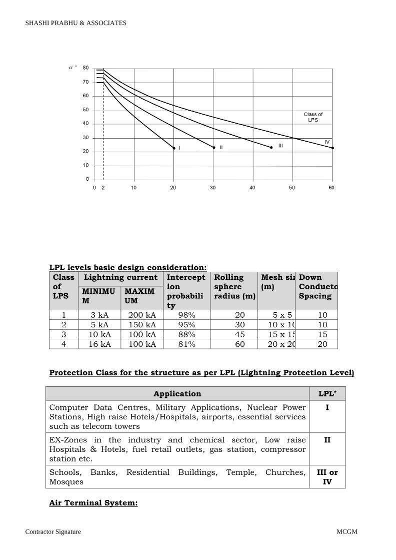
SHASHI PRABHU & ASSOCIATES
Contractor Signature MCGM
LPL levels basic design consideration:
Class of LPS
Lightning current Interception probabili
ty
Rolling sphere radius (m)
Mesh size (m)
Down Conductor Spacing
MINIMU
M
MAXIM
UM
1 3 kA 200 kA 98% 20 5 x 5 10
2 5 kA 150 kA 95% 30 10 x 10 10
3 10 kA 100 kA 88% 45 15 x 15 15
4 16 kA 100 kA 81% 60 20 x 20 20
Protection Class for the structure as per LPL (Lightning Protection Level)
Application LPL*
Computer Data Centres, Military Applications, Nuclear Power Stations, High raise Hotels/Hospitals, airports, essential services
such as telecom towers
I
EX-Zones in the industry and chemical sector, Low raise Hospitals & Hotels, fuel retail outlets, gas station, compressor
station etc.
II
Schools, Banks, Residential Buildings, Temple, Churches,
Mosques
III or
IV
Air Terminal System:
Page 126

SHASHI PRABHU & ASSOCIATES
Contractor Signature MCGM
An air-termination system shall be installed to protect the upper part of tall
structures from direct lightning strike (i.e. typically the topmost 20 % of the height of the structure) and the equipment installed on it. for positioning air-termination systems on roofs shall also apply to those upper
parts of structures. In addition, for structures taller than 120 m, all parts which may be endangered above 120 m
should be protected.
Materiel Description: For Mesh (Horizontal) arrangement 8 mm dia Aluminium round conductor. For Vertical Air terminal: 25mm dia, 16 mm dia, 10 mm dia APS make copper
plated pipe.
Connectors & Joints:
Materiel details Connector Type
Aluminium to
Aluminium
Aluminium, Gun Metal
Aluminium to Steel Gun Metal
Round conductor Holder:
For Concrete / RCC Roof: The fixing of roof conductor holder with DMC insulator min height of 50 mm 8 mm round at every 1 meter and The Holder can be fixed with glue and screw.
For Metal shed.
If any structure like AC panel, Vent, ducts etc need to protect from Vertical Air Terminal after calculation of separation distance.
Down Conductor: In order to reduce the probability of damage due to lightning current flowing in the LPS, the down-conductors shall be arranged in such a way that from the point of
strike to earth:
a) several parallel current paths exist; b) the length of the current paths is kept to a minimum; c) equipotential bonding to conducting parts of the structure is performed according
to the requirements.
Typical value of the distance between down- conductor and between ring conductors according to the class of LPS
Class of LPS Typical distance
m
Page 127

SHASHI PRABHU & ASSOCIATES
Contractor Signature MCGM
I 10
II 10
III 15
IV 20
Down Conductor Holder:
For Concrete wall: The fixing of roof conductor holder with DMC insulator min height of 50 mm 8 mm round at every 1 meter and The Holder can be fixed with glue and screw.
For Metal shed.
Test Joint: At the connection of the earth termination, a test joint should be fitted on each down conductor,
except in the case of natural down-conductors combined with foundation earth electrodes.
For measuring purposes, the joint shall be capable of being opened with the aid of a tool. In normal use it shall remain closed. The test joint shall be in IP 65 rated box and
copper bus bar of 25 x 3 x 150 mm. Earthing arrangement:
An earthing system or grounding system connects specific parts of that installation with the Earth's conductive surface for safety and functional purposes.
For earth-termination systems, two basic types of earth electrode arrangements apply.
Type A arrangement: This type of arrangement comprises horizontal or vertical earth electrodes installed outside
the structure to be protected connected to each down-conductor. In type A arrangements, the total number of earth electrodes shall be not less than two.
Type B arrangement
This type of arrangement comprises either a ring conductor external to the structure to be Protected, in contact with the soil for at least 80 % of its total length, or a foundation earth electrode. Such earth electrodes may also be meshed.
Materiel used for Type A and B:
Earthing Rod: Low carbon high tensile copper bonded ground rod ul listed & CPRI Tested of dia 25.4 mm, length 3000 mm with pure copper 99.9 % coating of 250 micron as per IEC 62561 – 2. CPRI Tested 50 KA peak.
JK Reslow Earth Enhance Material as per IEC 62561 – 7 is used along with the ground rod to reduce earth resistance value.
Lightning Counter: At least two lightning strike counters need to installed in down conductors as per IEC 62561. The Counter shall have facility to record 6
digits nexus.
Page 128
SHASHI PRABHU & ASSOCIATES
Contractor Signature MCGM
16. SOLAR PV SYSTEM:
16.1 SCOPE OF WORK
The job involves designing, manufacturing, supply, installation, testing
and commissioning with complete warranty of Solar PV Grid connected
power plant in interactive operation with existing power system. The
scope of work shall include the followings.
Design, manufacture, supply, installation and commissioning of Solar PV
Grid connected Power Plant including supply of all sundry materials as
per approved list of material as required for installation and
commissioning of the system. Complete commissioning of plant includes
the integration of solar PV plant with existing grid.
Detailed planning and smooth execution of the project. Energy yield report
for the designed system showing month-wise energy yield and loss
diagram. Detailed engineering document consisting of layout, single line
diagram and component specifications.
Performance testing of the complete system for faultless operation from the date of plant commissioning
Replacement warranty for 12 months for any damaged/broken modules & BOS etc. However, the solar PV modules and inverter shall continue to
carry their respective warranties (i.e 25 years and 5 years respectively) as
per practice over & above the 12 months complete system warranty.
Risk liability of all personnel associated with the implementation/realization of
the project.
16.2 MISCELLANEOUS TECHNICAL REQUIREMENTS
The vendor to provide yield report (kWh/kWp) and loss diagram of the
proposed grid connected system being offered to Client
The Vendor to specify the space needed for installing the system.
Lowest space usage will be preferred.
Provide Single Line Diagram ( SLD) of the system
16.3 TECHNICAL OFFER/COMPLIANCE STATEMENT:
The Vendor shall submit the technical offer complete in all respect and as
per the items of technical data sheet
The Vendor shall submit enclose compliance statement against the
technical specifications sheet clearly mentioning YES or NO along with
duly signed & seal.
Page 129
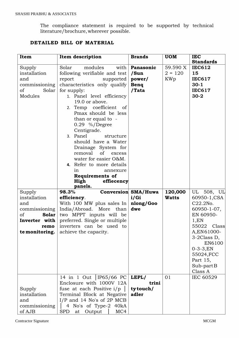
SHASHI PRABHU & ASSOCIATES
Contractor Signature MCGM
The compliance statement is required to be supported by technical
literature/brochure, wherever possible.
DETAILED BILL OF MATERIAL
Item Item description Brands UOM IEC
Standards
Supply
installation
and
commissioning
of Solar
Modules
Solar modules with
following verifiable and test
report supported
characteristics only qualify
for supply:
1. Panel level efficiency
19.0 or above.
2. Temp coefficient of
Pmax should be less
than or equal to -
0.29 %/Degree
Centigrade.
3. Panel structure
should have a Water
Drainage System for
removal of excess
water for easier O&M.
4. Refer to more details
in annexure
Requirements of High effiecency panels.
Panasonic
/Sun
power/
Benq
/Tata
59.590 X 2 = 120 KWp
IEC612
15
IEC617
30-1
IEC617
30-2
Supply
installation
and
commissioning
of Solar
Inverter with
remo
te monitoring.
98.3% Conversion efficiency.
With 100 MW plus sales In
India/Abroad. More than
two MPPT inputs will be
preferred. Single or multiple
inverters can be used to
achieve the capacity.
SMA/Huwa
i/Gi
nlong/Goo
dwe
120,000
Watts
UL 508, UL
60950-1,CSA
C22.2No.
60950-1-07,
EN 60950-
1,EN
55022 Class A,EN 61000-
3-2Class D, EN6100
0-3-3,EN 55024,FCC Part 15,
Sub-part B Class A
Supply
installation
and
commissioning
of AJB
14 in 1 Out IP65/66 PC
Enclosure with 1000V 12A
fuse at each Positive i/p
Terminal Block at Negative
I/P and 14 No's of 2P MCB
4 No's of Type-2 40kA
SPD at Output MC4
LEPL/
trini
ty touch/
adler
01 IEC 60529
Page 130
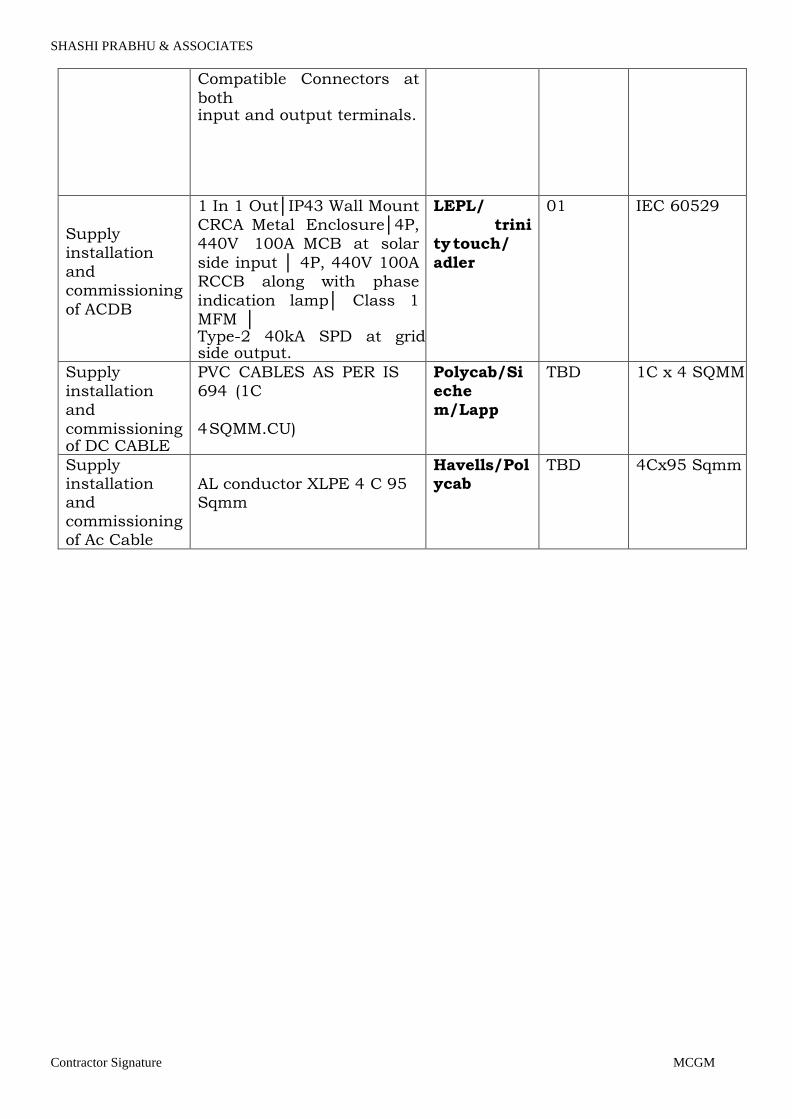
SHASHI PRABHU & ASSOCIATES
Contractor Signature MCGM
Compatible Connectors at
both input and output terminals.
Supply
installation
and
commissioning
of ACDB
1 In 1 OutIP43 Wall Mount
CRCA Metal Enclosure4P,
440V 100A MCB at solar
side input 4P, 440V 100A
RCCB along with phase
indication lamp Class 1
MFM Type-2 40kA SPD at grid side output.
LEPL/
trini
ty touch/
adler
01 IEC 60529
Supply
installation
and
commissioning of DC CABLE
PVC CABLES AS PER IS
694 (1C
4 SQMM.CU)
Polycab/Si
eche
m/Lapp
TBD 1C x 4 SQMM
Supply installation and
commissioning of Ac Cable
AL conductor XLPE 4 C 95 Sqmm
Havells/Polycab
TBD 4Cx95 Sqmm
Page 131
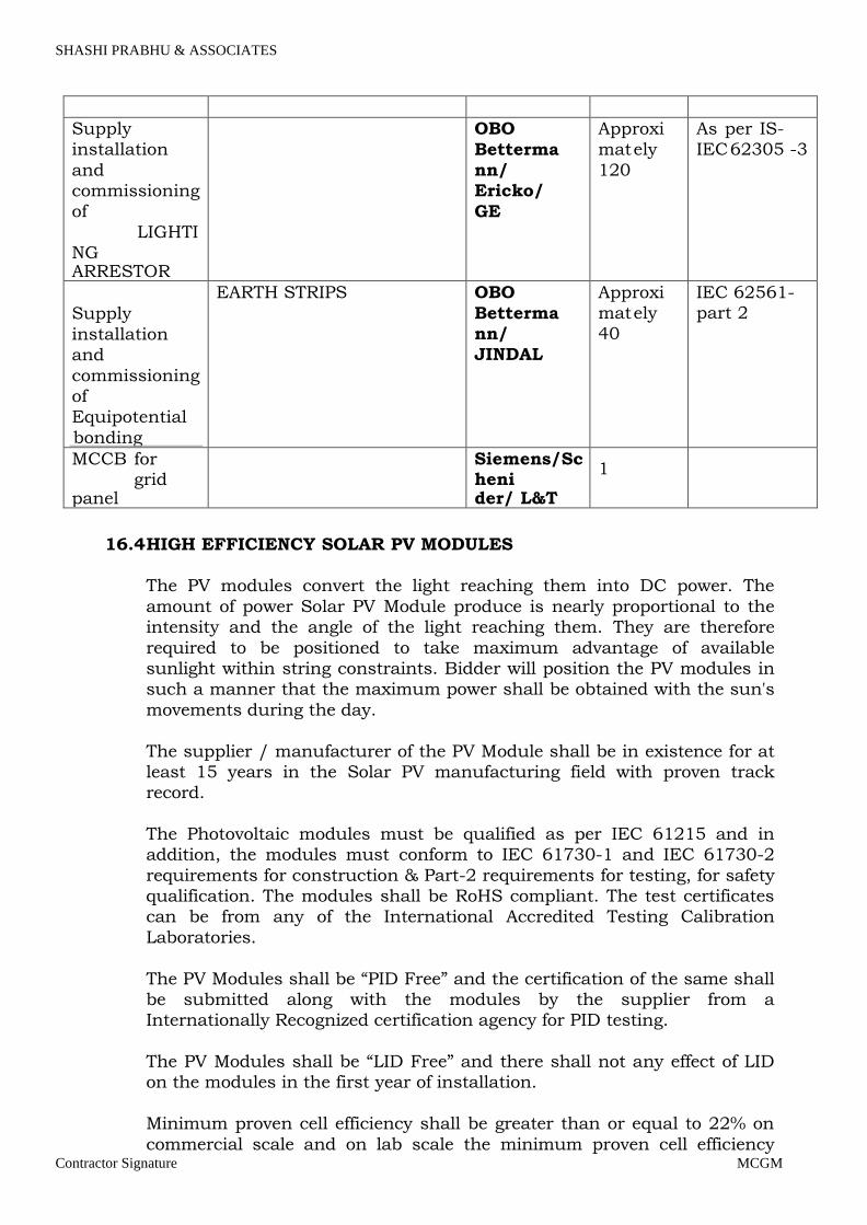
SHASHI PRABHU & ASSOCIATES
Contractor Signature MCGM
Supply
installation
and
commissioning
of
LIGHTI
NG ARRESTOR
OBO
Betterma
nn/
Ericko/
GE
Approxi
mat ely
120
As per IS-
IEC 62305 -3
Supply
installation
and
commissioning
of
Equipotential
bonding
EARTH STRIPS OBO
Betterma
nn/
JINDAL
Approxi
mat ely
40
IEC 62561- part 2
MCCB for grid panel
Siemens/Scheni der/ L&T
1
16.4 HIGH EFFICIENCY SOLAR PV MODULES
The PV modules convert the light reaching them into DC power. The
amount of power Solar PV Module produce is nearly proportional to the
intensity and the angle of the light reaching them. They are therefore
required to be positioned to take maximum advantage of available
sunlight within string constraints. Bidder will position the PV modules in
such a manner that the maximum power shall be obtained with the sun's
movements during the day.
The supplier / manufacturer of the PV Module shall be in existence for at
least 15 years in the Solar PV manufacturing field with proven track
record.
The Photovoltaic modules must be qualified as per IEC 61215 and in
addition, the modules must conform to IEC 61730-1 and IEC 61730-2
requirements for construction & Part-2 requirements for testing, for safety
qualification. The modules shall be RoHS compliant. The test certificates
can be from any of the International Accredited Testing Calibration
Laboratories.
The PV Modules shall be “PID Free” and the certification of the same shall
be submitted along with the modules by the supplier from a
Internationally Recognized certification agency for PID testing.
The PV Modules shall be “LID Free” and there shall not any effect of LID
on the modules in the first year of installation.
Minimum proven cell efficiency shall be greater than or equal to 22% on
commercial scale and on lab scale the minimum proven cell efficiency
Page 132

SHASHI PRABHU & ASSOCIATES
Contractor Signature MCGM
shall be greater than or equal to 25%.
The minimum efficiency of the module shall be greater than or equal to
19.0%. Supplier shall follow the latest engineering practice; ensure long-
term compatibility requirements and continuity of equipment supply and
the safety of the operating staff.
The PV Modules shall be Salt Mist Corrosion Tested Panels of min
severity level 5 or above, since the modules may be installed very close to
seashore or factories emitting pollutant gases or harsh environmental
conditions.
The optimum generation of electricity of PV capacity installed vis-à-vis
available solar radiation at the site may be obtained through use of
either a seasonal tilt structural arrangement or single axis solar tracking
system, lower cable losses, maximization of power transfer from PV
modules to electronics, maximization of power generation by enhancing
incident radiation by optional methods like seasonally changing tilt angles
etc.
The manufacturer of the modules shall provide certification on qualification of PV modules.
The SPV cells shall be manufactured using unique highly efficient
diffusion process or any other technology in vogue so as to ensure
uniform diffusion profiler to achieve close spread and higher efficiency for
each cell.
Stabilized net output of the Solar PV Array for the Solar Power System
shall not be less than the Nominal design level for the System under
Standard Test Condition.
The PV module shall perform satisfactorily in humidity up to 100 % with
temperature between - 20 deg. C to +40 deg C and with stand wind dust
up to 150 km/h from back side of the panel. Photo / electrical conversion
efficiency of the modules of SPV module shall be greater than or equal to
19.0 %. Since the modules would be used in a low/medium voltage
circuit, the insulation test shall be carried out on each module and a test
certificate to that effect provided. The bidder shall indicate minimum
efficiency. PV modules used in solar power plants/ systems must be
warranted for minimum 90% output of Pmin capacity for the first ten
years and 80% output of Pmin capacity at the end of 25 years. The
product workmanship shall be guaranteed for 10 years. The warrantee
shall be given in judicial stamp paper.
The panel shall have positive tolerance of Maximum output power and the
maximum voltage shall not exceed 1000V. The negative temperature
coefficient of power max shall be equal to or less than -0.3% per deg C
temperature.
The PV modules shall be suitable for continuous outdoor use.
Page 133
SHASHI PRABHU & ASSOCIATES
Contractor Signature MCGM
The material used for constructing the PV module shall be selected in
such a way that its gives the maximum efficiency and the latest
technology shall be adopted for the construction of PV module.
PV module shall be provided with frame of Anodized Aluminum (either
Black or Other) channels for size and simplicity in installation offered as a
single module or series parallel combination of modules. The module
frame, if any, shall be made of a corrosion-resistant material which shall
be electrolytic ally compatible with the structural material used for
mounting the modules.
The PV modules shall be made of light weight cells, resistant to
abrasion, hail impact, rain, water and environmental pollution. The PV
modules shall be provided with Anti Reflection Coating and the Glass shall
be AR Coated tempered glass.
The PV module shall use lead wire with weatherproof connector for output terminal.
The power output of the PV system under Standard Test Conditions
(STC) should be sufficient to meet the requirement and the required power
made of suitable module size depending upon manufacturer prudent
practice with required output voltage. The number of modules to be
supplied shall be worked out accordingly. Module less than 240 Wp
capacity shall not be supplied or installed.
In order to optimize the overall structural cost, each of the PV Modules
shall be less than or equal to 18 Kg weight in order to reduce the overall
civil cost of the project.
Test report from any Indian Lab or agency Like NISE will be preferred.
16.5 JUNCTION BOXES (JBs):
The junction boxes to be provided in the PV array for termination of
connecting cables. The Juction Boxes (JBs) shall be made of
GRP/FRP/Powder Coated Aluminium /cast aluminium alloy with full
dust, water & vermin proof arrangement. All wires/cables must be
terminated through cable lugs. The JBs shall be such that input & output
termination can be made through suitable cable glands.
Copper bus bars/terminal blocks housed in the junction box with suitable termination thread
Conforming to IP65 standard and IEC 62208 Hinged door with EPDM
rubber gasket to prevent water entry. Single/double compression cable
glands shall be provided for cable connections and entry to the junction
boxes or panel. Provision of earthings with placement of 5 feet height or
above for ease of accessibility.
Page 134
SHASHI PRABHU & ASSOCIATES
Contractor Signature MCGM
Each Junction Box shall have High quality Suitable capacity Metal
Oxide Varistors (MOVs) / SPDs, suitable Reverse Blocking Diodes. The
Junction Boxes shall have suitable arrangement monitoring and
disconnection for each of the groups.
Suitable markings shall be provided on the bus bar for easy identification
and the cable ferrules must be fitted at the cable termination points for
identification
16.6 DC DISTRIBUTION BOARD
DC Distribution panel shall receive the DC output from the array field.
DC DPBs shall be of enclosed dust & vermin proof conform to IP 65
protection. The bus bars shall be made of copper in required sizes and
ratings. Suitable capacity MCBs/MCCB shall be provided for controlling
the DC power output to the PCU along with necessary surge arrestors.
16.7 AC DISTRIBUTION PANEL BOARD
AC Distribution Panel Board (DPB) shall control the AC power from PCU/
inverter with necessary surge arrestors. Interconnection required from
ACDB to mains at LT Bus bar while in grid tied mode. All switches, circuit
breakers and connectors shall conform to IEC 60947, part I, II and III/
IS60947 part I, II and III.
The changeover switches, cabling work shall be undertaken by the bidder
as part of the project. All the Panel’s shall be metal clad, totally enclosed,
rigid, floor mounted, air - insulated, cubical type suitable for operation on
three phase / single phase, 415 or 230 volts, 50 Hz
The panels shall be designed for minimum expected ambient temperature
of 50 degree Celsius, 100 percent humidity and dusty weather.
All indoor panels shall have protection of IP54
All outdoor panels shall have protection of IP65 and conform to Indian
Electricity Act and rules (till last amendment).
All the 415 AC or 230 volts devices / equipment like bus support
insulators, circuit breakers, SPDs and VTs etc., mounted inside the
switchgear shall be suitable for continuous operation and satisfactory
performance under the supply voltage +/- 10 % Variation in supply
frequency
+/- 3 Hz
Page 135

SHASHI PRABHU & ASSOCIATES
Contractor Signature MCGM
16.8 PCU/ Inverter:
SPV array produce direct current electricity, it is necessary to convert this
direct current into alternating current and adjust the voltage levels to
match the grid voltage. Conversion shall
be achieved using an electronic Inverter and the associated control and
protection devices. A these components of the system are termed the
“Power Conditioning Unit (PCU)”. In addition, the PCU shall also house
MPPT (Maximum Power Point Tracker) an interface between Solar PV
array & the Inverter to the power conditioning unit/inverter shall also
be DG set interactive. The Inverter output shall be compatible with the
grid frequency. Typical technical features of the inverter shall be as
follows:
Switching devices : IGBT
Control : Microprocessor /DSP
Nominal AC output voltage and frequency: 415V, 3 Phase, 50 Hz
(In case single phase inverters offered, suitable arrangement for
balancing the phases must be made.) Output frequency : 50 Hz
Grid Frequency Synchronization range : + 3 Hz or more
Ambient temperature considered : -20Deg
C to 50Deg C Humidity : 95 % Non-
condensing
Protection of Enclosure : IP-20(Minimum) for indoor, IP-
65(Minimum) for outdoor. Grid Frequency Tolerance range : +
3 or more
Grid Voltage tolerance : - 20% & + 15 %
No-load losses : Less than 1% of rated
power Inverter efficiency (minimum) : >93% ( In case of
10kW or above ) THD : < 3% PF > 0.9
Three phase PCU/ inverter shall be used with each power plant system
(10kW and/or above) PCU/inverter shall be capable of complete
automatic operation including wake-up, synchronization & shutdown.
The output of power factor of PCU inverter is suitable for all voltage ranges
or sink of reactive power, inverter shall have internal protection
arrangement against any sustainable fault in feeder line and against the
lightning on feeder.
Built-in meter and data logger to monitor plant performance through
external computer shall be provided.
The power conditioning units / inverters shall comply with applicable
Page 136

SHASHI PRABHU & ASSOCIATES
Contractor Signature MCGM
IEC/ equivalent BIS standard for efficiency measurements and
environmental tests as per standard codes IEC 61683/IS 61683 and IEC
60068- 2(1,2,14,30) /Equivalent BIS Std.
Page 137

SHASHI PRABHU & ASSOCIATES
Contractor Signature
MCGM
The charge controller (if any) / MPPT units environmental
testing shall qualify IEC 60068-2(1, 2, 14, 30)/Equivalent
BIS std. The junction boxes/ enclosures shall be IP 65(for
outdoor)/ IP 54 (indoor) and as per IEC 529 specifications.
The PCU/ inverters should be tested from the MNRE
approved test centers / NABL /BIS /IEC accredited testing-
calibration laboratories. In case of imported power
conditioning units, these should be approved by
international test houses.
16.9 INTEGRATION OF PV POWER WITH GRID:
The output power from SPV would be fed to the inverters
which converts DC produced by SPV array to AC and feeds
it into the main electricity grid after synchronization. In case
of grid failure, or low or high voltage, solar system shall be
out of synchronization and shall be disconnected from the
grid. Once the DG set comes into service PV system shall
again be synchronized with DG supply and load requirement
would be met to the extent of availability of power. 4 pole
isolation of inverter output with respect to the grid/ DG
power connection need to be provided.
Page 138

TECHNICAL SPECIFICATIONS FOR HVAC SYSTEM
SHASHI PRABHU & ASSOCIATES
MUNICIPAL CORPORATION OF GREATER MUMBAI
NAME OF PROJECT: - PROPOSED MULTI-SPECIALITY BHANDUP HOSPITAL AT LAND BEARING C.T.S.NO681A/88,681A/3,681A/4 OF
VILLAGE NAHUR IN S-WARD, BHANDUP MUMBAI
Page 139
SHASHI PRABHU & ASSOCIATES
Contractor Signature MCGM
INDEX
1. SPECIAL CONDITION OF CONTRACT
2. WATER COOLED SCREW CHILLER
3. PUMPS
4. VARIABLE FREQUENCY DRIVES
5. COOLING TOWER
6. AIR HANDLING UNIT, TREATED FREAH AIR
7. HYDRAULIC CASSETTE UNIT
8. PRECESSION AIRCONDITIONG SYSTEM
9. VRV/VRF SYSTEM
10. SPLIT UNIT- DX SYSTEM
11. STP- DEODOURIZATION SYSTEM
12. VENTILATION FANS
13. DRY SCRUBBER
14. TWO STAGE EVAPORATIVE COOLING SYSTEM
15. PIPE WORK AND VALVE STATIONS
16. AIR DISTRIBUTION SYSTEM
17. INSULATIONS
18. HVAC ELECTRICAL SYSTEM
19. TEST AT SITE AND FACTORY
20. DETAIL OF TEST OF TO BE CARRIED OUT AT SITE
21. MODE OF MEASUREMENT
22. LIST OF APPROVED MAKE
Page 140

SHASHI PRABHU & ASSOCIATES
Contractor Signature MCGM
1 SPECIAL CONDITIONS OF CONTRACT General
These special conditions are meant to amplify the specifications and
General Conditions of Contract The materials, design and workmanship shall satisfy the specifications
contained herein and Codes Referred to. Where the technical specifications stipulate the requirement in addition to those contained in the Standard Codes and specifications those additional requirements
shall also be satisfied. In the absence of any Standard/ Specifications covering any part of the work covered in this tender document, the
instructions/ directions of Construction Manager will be binding on the contractor.
The scope of this section is to describe materials and systems for HVAC installations of building which form together with the project documents, a complete volume of work and quality description.
All HVAC installations shall be of high quality, complete and fully
operational including all necessary items and accessories whether or not specified herein. All HVAC work shall be completed in accordance with the regulations and standards to the satisfaction of the Construction
Manager/ Consultants. The general provisions, special provisions and general requirements apply to the entire installation.
The work shall be carried out simultaneously with building work and shall be continued till it is completed satisfactorily along with the
completion of essential portions of the building works. All installed HVAC works shall be protected till the end by the HVAC contractor.
During the progress of work, completed portion of the building may be occupied and be put to use by the Client but the contractor shall remain
fully responsible for the maintenance of HVAC works till the entire work covered by this contract is satisfactorily completed by him and handed over to the Client.
Scope of Work:
The general character and the scope of work to be carried out under this contract are illustrated in the drawings, specifications. The Contractor
shall carryout and completes the said work under this contract in every respect in conformity with the rules and regulations of the Local Authority. The contractor shall furnish all labour, supply and install all
new materials, appliances, equipment necessary for the complete provision and testing of the complete HVAC services installation as
specified herein and in accordance with relevant codes. This al so includes any material, appliance, equipment not specifically mentioned here in or noted on the drawings as being furnished or installed but
which are necessary and customary to make a complete installation. In
Page 141
SHASHI PRABHU & ASSOCIATES
Contractor Signature MCGM
general, the work to be performed under this contract shall comprise but not limited to the following:
a) Without restricting to the generality of the foregoing, the HVAC Installations shall
Include but not limited to the following: 1. Air-conditioning works
2. Toilet Ventilation Works 3. Kitchen Ventilation Works 4. Smoke Extraction works
5. Pressurization works 6. Miscellaneous, unforeseen & client requirement’s Works
All incidental jobs connected with HVAC services installation such as excavation in trenches and back filling, cutting chases in concrete and
brick and making good, cutting/ drilling holes through walls, floors and fixing of fixtures, small equipment foundation, Structural supports &
other supports as required at site shall be part of HVAC works. Contractor shall submit the samples/ catalogues of each
material/equipment giving technical data. Only after written approval of samples/ catalogues, the Contractor shall place the order.
Preparation of shop/ working drawings Contractor shall submit the detailed shop/Working drawings after detailed design calculations,
coordinating with structural, architectural and other services drawings/ service agencies. All structural openings & pipe sleeves shall be identified. Shop/ working drawings shall be furnished complete in all
respect along with all relevant details.
Contractor shall furnish and install complete HVAC services installation as per approved shop drawings and as described in this specification.
Before starting the work at site the contractor shall examine all services drawings and report to client/ Consultant for discrepancies and
obtain clarifications. Any work done without regard for consultation with other trades, shall be removed by the contractor without additional cost
to the Client. Cleaning of all fixtures/ equipment and piping including flushing of
all pipe work to remove any foreign matter shall be carried out in sections as the work progresses.
Contractor shall temporarily cover & protect all fixtures & accessories, equipment’s & open pipe/ Duct ends etc. It is the responsibility of the
Contractor to protect all the installed fixtures/ fittings and all equipment’s until the time of testing, commissioning & handing over to the Clients.
Page 142

SHASHI PRABHU & ASSOCIATES
Contractor Signature MCGM
Painting of all concealed and exposed pipes, equipment as specified including weather proof treatment on exposed & treatment of buried pipe work shall be part of this contract, even if it is implicitly/ explicitly not
specified.
Testing & commissioning of all systems including submission of test reports.
Contractor shall submit as installed drawings, operation and maintenance manual for all equipment’s/ operations etc. Framed operating & maintenance instructions shall be provided in plant room.
All equipment shall be of the class most suitable for working under
the conditions specified and shall withstand the atmospheric conditions without deterioration. All the material selection will be done for maximum life span of the equipment’s and system.
Work And Workmanship: To determine the acceptable standard of workmanship, the Construction
Manager/Consultant may order the Contractor to execute certain portions of works and services under the close supervision of the Construction Manager/ Consultant. On approval, these items shall be
labelled by them as guiding samples so that further works are executed to conform to these samples.
Co-Ordination With Other Contractors And Agencies:
The Contractor during the execution of the Works shall coordinate with other Contractors, and other Agencies associated with the Project and
shall work in harmony with them without causing any hindrance or obstruction or impeding the progress of their work in any way.
Protection Of Other Contractor's Works And Safety Of Personnel At Site:
Since many other contractors and agencies will be engaged on site and working simultaneously, the Contractor shall ensure at all times that
during the execution of his work or during the operations and movements of equipment’s and supply vehicles and machinery, no dam age or injury is caused to the work or property or personnel of other contractors and
agencies.
In case of any such loss or damage the Contractor shall take full responsibility for same and shall bear all cost and expenses thereof. Also, the Contractor shall be responsible and liable for all delays caused due to
such damage and or injury and for the consequences which the other Contractors and Agencies may have to face or to which they may be subjected to or be accountable for as a result of such delays.
Page 143
SHASHI PRABHU & ASSOCIATES
Contractor Signature MCGM
Safety of Materials: The contractor shall provide proper and adequate storage facilities to
protect all the materials and equipment including those issued by the Client against damage from any cause whatsoever.
Materials Supplied By the Client:
The Contractor shall conduct all checks and carry out all tests and obtain test certificates necessary to ascertain and ensure that the Client supplied materials are in conformity with the requirements stipulated in
the Contract Documents. Should any of the Client supplied materials obtained from any supplier not be in conformity with the requirements
stipulated in the Contract Documents then the Contractor shall not take acceptance of such materials and he shall not incorporate them in the Works unless so specifically authorized by the Construction Manager/
Consultants and it shall be the Contractor's responsibility to bring this matter to the immediate attention of the Construction Manager/
Consultants and seek his instructions in respect of the disposal of such materials. Should the Contractor fail to com ply with this procedure then all costs and/or delays which are a result and consequence thereof shall
be to the account of the Contractor. With respect to reconciliation of Client supplied materials, the quantities
of such materials allowed towards consumption for the Works by the Contractor shall be the theoretical requirement plus permissible wastage.
The theoretical requirement shall be determined by measurements made in accordance with the dimensions shown on the Drawings to which the Works shall be executed. Client supplied materials used due to any
reason whatsoever for replacement and/or rectification work shall not be deemed to be theoretical requirement, and the costs in respect of these
materials used for such work shall be borne by the Contractor. Actual Route Of Pipe Lines:
The location of the AC pipe lines, indicated in the drawing is only indicative. The actual route of AC pipe lines may differ from the plans
according to the details of the building construction and the conditions of executions of the installations.
The contractor shall supply and install at his expense all secondary materials and special fittings found necessary to overcome the
interference and to supply the modifications on the route of HVAC pipe lines that are found necessary during the work, to the complete
satisfaction of the Construction Manager/Consultants. Rating:
Rating of all items shall be appropriate for the conditions on the particular site on which the item will be used. All the equipment shall be
fit for continuous work under the most severe conditions of site.
Page 144

SHASHI PRABHU & ASSOCIATES
Contractor Signature MCGM
Inspection and Testing:
The Construction Manager reserves the right to request inspection and testing at manufacturer's works at all reasonable times during
manufacture of items for this contract. Tests on site of completed works shall demonstrate, among other things:
That the equipment installed complies with specification in all particulars and is of the correct rating for the duty and site conditions. VRV & AHU unit shall be tested in factory with client & consultant. All Expenses shall
be in contractor scope.
That all items operate efficiently and quietly to meet the specified requirements.
The contractor shall provide all necessary instruments and labour for testing, shall make ad equate records of test procedures and readings,
shall repeat any tests requested by the Construction Manager/Consultants and shall provide test certificates signed by a properly authorized person. Such test shall be conducted on all materials
and equipment’s and on completed work as called for by the Construction Manager/Consultants.
If it is proved that the installation or part thereof is not satisfactorily carried out then the contractor shall be liable for the rectification and
retesting of the same as called for by the Construction Manager/ Consultants at the cost of the contractor. The Construction Manager/Consultants decision as to what constitutes a satisfactory test
shall be final.
The above general requirements as to testing shall be read in conjunction with any particular requirements specified elsewhere. All tests shall be carried out by a test house approved by the Construction
Manager/Consultants. Samples And Catalogues:
Before ordering the material necessary for these installations, the
contractor shall submit sample/ technical data sheets to the Construction Manager/Consultants for approval.
Also contractor shall ensure that the dimensional details of the equipment fit into the allot ted space provided in the building.
Shop Drawings:
The contractor shall prepare and submit to the Construction Manager/Consultants for his approval six (6) sets of detailed layout drawings of all HVAC equipment’s and piping layouts.
Page 145
SHASHI PRABHU & ASSOCIATES
Contractor Signature MCGM
He shall prepare shop drawings incorporating the details given by manufacturers for the items included in his contract and also Client supplied items and any other items which need to be coordinated with
other contractors for interfacing.
Before starting the work, the contractor shall submit to the Construction Manager/Consultants for his approval in the prescribed manner, the shop/execution drawings for the entire installation.
The Construction Manager/Consultants, reserves the right to alter or modify these drawings if they are found to be insufficient or not
complying with the established technical standards or if they do not offer the most satisfactory performance or accessibility for maintenance.
Contractor shall supply in eight (8) sets of all approved shop drawings for execution.
Shop drawings shall be submitted under the following conditions:
Large scale drawings showing fixing detail equipment and showing coordination with other services.
Showing any change in layout in the HVAC drawings. Equipment layout, ducting, piping and wiring/control diagram.
Manufacturer’s or Contractor’s fabrication drawings for any materials or
equipment supplied by him. No work will be carried out without approval of shop drawings by the
Consultants.
"AS BUILT" DRAWINGS: At the completion of work and before issuance of certificate of completion
the contractor shall submit eight (8) sets to the Construction Manager/Consultants, layout drawing drawn at appropriate scale indicating the complete HVAC system "as installed" and the same shall be
approved by the Consultants before handing over to the Client.
Instruction/Maintenance Manual: The Contractor shall prepare and produce instruction, operation and
maintenance manuals in English for the use, operation and the maintenance of the supplied equipment and installations, and submit to
the Construction Manager/Consultants in (8) copies at the time of handing over. The manual shall generally consist of the following:
Page 146
SHASHI PRABHU & ASSOCIATES
Contractor Signature MCGM
Description of the project. Operating instructions.
Maintenance instructions including procedures for preventive
maintenance. Manufacturers catalogues.
Spare parts list.
Trouble shooting charts.
Drawings. Type and routine test certificates of major items.
One (1) set of reproducible `as built' drawings.
Completion Certificate:
On completion of the HVAC installation a certificate shall be furnished by the contractor countersigned by the licensed supervisor, under whose direct supervision the installation was carried out. This certificate shall
be in the prescribed form as required by the local supply authority. The contractor shall be responsible for getting the HVAC installation
inspected and approved by the local concerned authorities and for obtaining the necessary clearance certificates from the authorities.
Guarantee:
At the close of the work and before issuance of final certificate of completion by the Construction Manager/ Consultants, the contractor shall furnish written guarantee Indemnifying the Client against defective
materials and workmanship for a period of one year after completion. The contractor shall hold himself fully responsible for reinstallation or replacement, free of cost to Client, the following:
Any defective work or material supplied by the Contractor.
Any material or equipment supplied by the Client which is damaged or destroyed as a result of defective workmanship by the contractor.
Any material or equipment damaged or destroyed as a result of defective
workmanship by the contractor. Staff:
The contractor shall employ competent fully licensed qualified, full time HVAC engineers to direct the work of HVAC installation in accordance
with the drawings and specifications.
Page 147
SHASHI PRABHU & ASSOCIATES
Contractor Signature MCGM
The engineers shall be available at all times at site to receive instructions from the Construction Manager., in the day to day activities throughout
the duration of contract. The engineer shall correlate the progress of the work in conjunction with all the relevant requirement of the supply
authority. Safety Barriers and Construction Safety:
The Contractor shall at his own cost provide for the protection and safety of the persons working in the area, safety barriers around all openings in
every location and at the periphery and edges of all slabs, staircases and stairwells, lift shafts, ducts etc., all to the approval and satisfaction of the
Construction Manager. However, contractor shall take appropriate safety precautions suitable for specific locations/ situations and as instructed by the Construction Managers.
The Contractor shall, in general, be fully responsible for all matters with
regard to every form of safety during construction and in connection with the execution of the Works, and the Contractor shall take all necessary precautions and provide at his cost everything necessary to ensure such
safety at all times. Should any accidents occur due to the Contractor's failure to comply with such safety requirements and to take all other safety measures necessary, the Contractor shall be fully responsible for
all such accidents and he shall bear and pay for all costs and damages in connection therewith and as a consequence there of.
Disposal Of Rubbish From The Works And The Site And Provision Of Safety Netting/Screens By Contractor:
The Contractor shall at all times keep the Works and the site in clean,
neat and tidy condition. All rubbish from the Works and the site shall be collected and deposited in large bins provided on the site for such purpose by the Contractor at his own cost. The rubbish from such bins
shall be regularly carted away by the Contractor to rubbish tips and dump yards beyond the site.
At no time or stage shall any rubbish be thrown over the edges of slabs or through any openings or shafts or ducts or stairwells.
The Contractor shall, at his own cost and to the approval and satisfaction of the Construction Manager, provide safety netting/screens at the
periphery of all slabs and at all openings, shafts, ducts and stairwells and/or canopies to prevent any rubbish or material falling over or into
such areas and endangering the safety of the persons working below. Should the Contractor fail to provide such safety measures and to take other necessary precautions in accidents that may occur, he shall bear
all costs and damages as decided by Construction Manager in connection therewith and as a consequence there of.
The Construction Manager shall have powers to withhold amounts from
Page 148

SHASHI PRABHU & ASSOCIATES
Contractor Signature MCGM
payment certificates in case of Contractor's persistent noncompliance with provisions of this clause. Also the construction Manager is empowered to employ another agency at Contractor's cost after one
week's notice to implement this Clause in case of Contractor's noncompliance with provisions of this Clause.
Space For Contractor's Construction Yard, Stores Etc.:
The Client shall provide adequate storage/office space to the contractor for his use. The space has to be maintained/constructed by the contractor as per his usage requirements.
All spaces allotted to the contractor, as described above shall be vacated
and all structures removed from site at any time as and when required and directed by the relevant authorities or by the Client, unconditionally and without any reservation. The authorities or the Client will not be
obliged to give any reason for such removal. Upon receiving instructions to vacate the space, the contractor shall immediately remove all his
structures, materials, etc., from the spaces and clear and cleanup the site to the satisfaction of the Construction Manager.
It shall be the specific responsibility of the Contractor to safeguard the site and ensure that no illegal encroachments are made by outside elements within the area allotted to the Con tractor. Upon completion of
the work or earlier as required by Client/Authorities, the Con tractor shall vacate the land totally without any reservations. Necessary Bond to
this effect on a stamp paper shall be signed by the contractor in a prescribed form.
The Performance Bond and/or guarantees towards retention amount furnished by the Con tractor shall not be released until the spaces
allotted to the contractor are fully vacated and handed over to the Client as per the instructions of the Client.
Carrying Out Work Beyond Normal Working Hours Or In Shifts In order to achieve the milestone and completion dates and to keep pace
with the approved construction programme, the Contractor shall be permitted to carry out his work beyond the normal working hours or in
shifts. The Contractor shall be responsible for obtaining any necessary permission from the relevant authorities that may be required for him to carry out the work beyond the normal working hours or in shifts. Also,
the Contractor shall give prior notice to and make arrangements with the Construction Manager for the supervision of work carried out beyond the
normal working hours or in shifts. The Contractor shall make his own arrangements in respect of the provision of adequate lighting and any other facilities that may be required for carrying out the work beyond the
normal working hours or in shifts. No extra payments shall be made to the Contractor for or in connection with any such overtime or shift work. The Contractor will not be required to bear the overtime expenses of the
Construction Manager in respect of the supervision of such overtime or
Page 149

SHASHI PRABHU & ASSOCIATES
Contractor Signature MCGM
shift work of the Contractor. Period And Time Limit For Completion Of Works:
The period and time limit for Completion of the Works shall be as per
client’s requirement from the date of issue of Work Order to commence works or handing over of site in respect of the award of Contract. This time period shall be inclusive of the mobilization period and monsoon
period.
Professional Integrity And Team Spirit:
It is the intent of the Client, Architect and Construction Manager that
this project will be executed in a spirit of team and full professional integrity. Contractor is expected to cooperate with all the agencies involved in the project to fulfill this objective.
List Of Approved Makes:
Unless otherwise specified and expressly approved in writing by the Engineer in Charge/only material of makes and specifications as
mentioned in the list of approved makes attached with the specification shall be used.
The contractor shall clearly indicate the list of materials proposed to be used by him & enclose the same with the tender.
On Instruction of Engineer in Charge the Contractor shall submit samples of materials proposed to be used in the works. Approved samples
shall be kept in the office of the Engineer in Charge and returned to the Contractor at the appropriate time.
Before procurement, Contractor will discuss with Client for preferred makes.
Water and electricity shall be supplied at one point.
Reference Points:
Contractor shall provide permanent bench marks, flag tops and other reference points for the proper execution of works and these shall be preserved till the end of the work.
All such reference points shall be in relation to the levels and locations,
given in the architectural and HVAC drawing. Reference Drawings:
The Contractor shall maintain one set of all drawings issued to him as reference drawings. These shall not be used on Site. All important
drawings shall be mounted on boards and placed in racks indexed, no
Page 150
SHASHI PRABHU & ASSOCIATES
Contractor Signature MCGM
drawings shall be rolled. All correction, deviations and changes made on the site shall be shown
on these reference drawings for final incorporation in the completion drawings. All changes to be made shall be initialed by Engineer in Charge
or Architect. Vendor shall prepare Shop Drawings with all details after checking the
feasibility at Site which shall be approved by the Consultants before execution. No work will be carried out without approval of Shop drawing by the Consultant.
Handing Over:
Contractor will be responsible for following:
Entire System shall be commissioned and tested as per design parameter is coordination with Client & consultant.
Complete certificate has to be obtained from the consultant to certify the quality of work and performance of the system.
Contractor has to hand over 4 sets of as Built Drawings duly approved by consultants along with 2 soft copy in CD’s.
Contractor has to handover operator manual of the system with
catalogue and Technical Data of equipment supplied. General Provisions
Description
The scope of works for all HVAC works and system comprises supply, installation, testing and commissioning, handover, training, maintenance
as described or reasonably implied. Contractor is obliged to provide fully functioning works and systems in
conformance with the requirements of the Contract. In the event certain items are not fully described or indicated in the Contract, but deemed
essential by the Engineer’s Representative (in all reason ableness) for the performance of the works and systems, then the provision of such items shall form part of the Contractors scope of works at no additional cost to
the Employer.
Contractor shall be responsible to coordinate the equipment and services with all other discipline and shall produce properly coordinated shop drawings to demonstrate the installation & comply with the performance
requirement with shop drawing, calculations and de tails. Shop drawings shall take into account actual measurement and setting
out dimensions/levels obtained and determined by the Contractor on
Page 151

SHASHI PRABHU & ASSOCIATES
Contractor Signature MCGM
site, actual equipment/material used, actual routing of services, coordination with all installation, and site conditions/constraints.
Page 152

SHASHI PRABHU & ASSOCIATES
Contractor Signature MCGM
2 WATER COOLED SCREW CHILLER WITH VFD (AHRI Certified) General
System Description
Microprocessor controlled water cooled chiller utilizing a mono / twin rotor, 2960 rpm (50 HZ), direct drive semi hermetic, one or multiple
screw compressor using refrigerant 134A. Quality assurance
Unit shall be rated in accordance with ARI / Eurovent standard.
Unit construction shall comply with European directives Machinery directive 98/37/EC, modified.
Low voltage directive 73/23/EEC, modified. Electromagnetic compatibility directive 89/336/EEC, modified, and the applicable recommendation of European standard.
Machine safety electrical equipment in machines, general regulations, EN 602041.
Electromagnetic emission EN 500812. Electromagnetic immunity EN 500822.
Unit shall be designed, manufactured and tested in a facility with a quality assurance system certified ISO 9001.
Unit shall be manufactured in a facility with an environment management system certified ISO 14001. Unit shall be tested at the
factory. Delivery, storage and handling
Unit controls shall be capable of withstanding 55°C storage temperatures
in the control compartment. Products
Equipment General
Factory assembled, single piece, air cooled liquid chiller contained within the unit cabinet shall be all factory wiring, piping, controls, refrigerant
charge (HFC – 134a), required prior to field startup. Unit Cabinet
Frame shall be made of U steel beam and protected by three layers of
paint. The control box plates shall be steel with an oven baked polyester paint finish, and be capable of withstanding a 500hour salt spray test in
accordance with the ASTM B117 standard (U. S. A.).
Page 153
SHASHI PRABHU & ASSOCIATES
Contractor Signature MCGM
Compressors
Unit shall have semi hermetic mono / twin screw, gear driven compressors with internal muffler and check valve.
Each compressor shall be equipped with a discharge shutoff valve. Capacity control shall be provided by pilot operated solenoid valve, capable of reducing unit capacity to 20% of full load. Compressor shall
start in unloaded condition. Motor cooling shall be provided by direct liquid injection and protected by internal overload thermistor.
Lube oil system shall include pre filter and internal filter capable of filtration to 3 microns.
Evaporator
Unit shall be equipped with a single evaporator.
Evaporator shall be tested and stamped in accordance with applicable European pressure code for a refrigerant side operating pressure of 1700 kPa (service des Mines units) and for a maximum waterside pressure of
1000 kPa. Shall be mechanically cleanable shell and tube type with removable heads.
Tubes shall be internally enhanced, seamless copper type, and shall be rolled into tube sheets.
Shall be equipped with Victaulic water connections (accessory flanges on request). Shell shall be insulated with 19 mm closed cell, polyvinylchloride foam
with a maximum K factor of 0.28. Shall incorporate two independent refrigerant circuits.
Shall have an evaporator drain and vent. Shall incorporate a refrigerant level control system.
Condenser Coil shall be Water cooled with integral sub cooler and shall be
constructed of aluminium fins mechanically bonded to internally finned copper tubes. The tubes are then cleaned, dehydrated and sealed.
Condenser tubes shall be leak tested and shall be pressure tested at 3400 kPa.
Refrigeration Circuits
Refrigeration circuit components shall include oil separators, high and low side pressure relief devices (according to applicable standards), discharge and liquid line shutoff valves, filter driers, moisture indicating
sight glasses, electronic expansion devices, refrigerant economizers and complete operating charges of both refrigerant and compressor oil.
Page 154

SHASHI PRABHU & ASSOCIATES
Contractor Signature MCGM
Controls, Safeties and Diagnostics
Controls
Unit controls shall include as a minimum; the microprocessor board, and a 6digit diagnostic display with keypad.
Shall be capable of performing the following functions Automatic changeover between compressors.
Capacity control based on leaving chilled fluid temperature with return fluid temperature sensing.
Limiting the chilled fluid temperature pulldown rate at startup an adjustable range of 0.1°C to 1.1°C per minute to prevent excessive
demand spikes at startup.
Enable adjustment of leaving chilled water temperature according to the return water temperature or by means of a 0 – 10 V signal to the outdoor temperature.
Provide a dual set point for the leaving chilled water temperature activated by a remote contact closure signal.
Enable a 2level demand limit control (between 0 and 100%), activated by
a remote contact closure signal. Control water pump(s) operation.
Enable automatic lead lag of two chillers in a single system.
Diagnostics Display module shall be capable of displaying set points, system status
(including temperatures, pressures, run time and percent loading), and any alarm or alert conditions.
Control Module, in conjunction with the microprocessor, shall be capable of displaying the output of a full load run test to verify operation of every
switch, sensor, fan and compressor before the chiller is started, and carrying out a diagnosis and preventive maintenance (incorrect water loop, oil filter dirty etc.)
Safeties
Unit shall be equipped with all necessary components and in conjunction with the control system shall provide the unit with protection against the
following Loss of refrigerant charge.
Reverse rotation.
Page 155
SHASHI PRABHU & ASSOCIATES
Contractor Signature MCGM
Low chilled water temperature. Low oil pressure (per compressor). Current imbalance.
Thermal overload. High pressure.
Electrical overload. Loss of phase.
Fan motors shall be individually protected by a circuit breaker. Control shall provide general alarm remote indication for each refrigerant circuit. Control system shall have a RS485 serial output port (option and
accessory).
Operating characteristics Unit shall be capable of starting and running at full load at outdoor
ambient temperatures from 0°C to 46°C. Unit shall be capable of starting up with 25°C entering fluid temperature
to the evaporator. Electrical characteristics
Unit electrical power supply shall enter the unit at one or two locations. Unit shall operate on 3phase power supply without neutral.
Control voltage shall be supplied by a factory installed transformer. Unit shall be supplied with factory installed electrical disconnect switch
/ circuit breaker. Finishing
Electrical cabinet colour – as per manufacturer. Compressor / heat
exchanger colour – as per manufacturer Low voltage unit mounted starter
A reducer voltage delta or double / solid state starter shall be supplied. The compressor motor starter shall be factory mounted, wired, and tested
prior to shipment by the chiller manufacturer. Customer electrical connection for compressor motor power shall be limited to main starter
power connection only. Solid state starter shall provide stepless compressor motor accelerating
and limit motor in rush current to 150 300% of compressor motor RLA. The starter shall include 6 Silicon Control Rectifiers (SCR) with integrally
mounted bypass contactors to provide SCR by pass once the motor has achieved full voltage and speed. The starter shall also include automatic acceleration kick circuitry which monitors motor current subsides and
automatically ramps voltage up at a faster rate to eliminate the instability that occurs at the break away torque point.
Starter shall be UL and CSA approved and shall include
Page 156

SHASHI PRABHU & ASSOCIATES
Contractor Signature MCGM
• NEMA 1 enclosure with integral fan cooling and lockable hinged doors.
• Main power disconnects (non fused type)
• solid state 3phase over load relay with manual reset.
• 2 KVA control / oil heater transformer
• Branch circuit breaker for control power and oil heater
• 5 pilot relays for control of chilled water pump. Condenser water pump, tower fan, customer remote alarm, shunt trip, and main power
disconnect. The shut trip shall be energized by the SMM during unauthorized operation (such as loss of communication) between the SSM (Starter Management Module) and PSIO (Processor Sensor Input /
Output Module).
Solid state starters also include the following standard features
• Current imbalance detector which monitors 3 phase motor current to provide the following protection Phase loss
Phase reversal Phase imbalance Ground fault
Shorted SCR Current flow while stopped protection
• Diagnostic LED’s shall be provided to indicate: Starter on Run (up to voltage)
Phase correct Over temperature fault
SCR gates energized Ground fault Current imbalance fault
Shorted SCR. I²T fuses the solid state circuitry at 200,000 amp interrupting capacity.
Electrical requirements
The contractor shall supply and install main electrical power line, disconnect switches, circuit breakers, electrical protection devices per
local code requirements and as indicated necessary by the chiller manufacturer.
The contractor shall wire the water flow switches to the chiller control circuit to ensure that chiller will not operate until flows are established &
maintained as per contractor’s / consultant’s specifications. The contractor shall supply and install electrical wiring and devices
required to interface the chiller controls.
Page 157
SHASHI PRABHU & ASSOCIATES
Contractor Signature MCGM
Piping requirements – instrumentation and safeties
The contractor shall supply and install pressure gages in readily
accessible locations in piping adjacent to the chiller such that they can be easily read from a standing position on the floor. Gages shall be very accurate. Scale range shall be such that design valves shall be indicated
at approximately midscale. Gauges shall be installed in the entering and leaving water lines of the
cooler and condenser.
HVAC contractor shall supply & install flow detection devices in chilled water and condenser water piping. Switches shall make contact when flow is established. Flow switches shall be installed in horizontal runs at
least 5 pipe diameters downstream from any bend or tee.
Insulation Chilled water piping and cooler water boxes shall be installed by the
HVAC contractor. Chiller shall be insulated at factory. Final layer of insulation shall be
installed at the job site by the HVAC contractor along with cladding.
Chiller insulation shall confirm to UL standard 94, classification 94 HBF and should be suitable for positive temperature operation.
Vibration isolation
Chiller manufacturer shall furnish neoprene isolator pads for mounting equipment on a level concrete surface.
Startup The manufacturer shall provide a factory trained representative,
employed by the chiller manufacturer, to perform the startup, operation and maintenance manual provided by the chiller manufacturer.
After the above services have been performed, the same factory trained, representative shall be available for a period of class room instruction
(not to exceed 4 hours) to instruct the chiller owner’s personnel in the proper operation and maintenance of the chiller.
Manufacturer shall supply the following literature
a. Startup, operation and Maintenance Instructions. b. Installation Instructions c. Field Wiring Diagrams
d. Maintenance manual showing maintenance based on calendar
Page 158
SHASHI PRABHU & ASSOCIATES
Contractor Signature MCGM
basis and hourly basis. Quality Assurance
Chiller performance shall be rated in accordance with AHRI Standard
550/590/ Euroven Standard, latest edition. Equipment and installation shall be in compliance with ANSI/ASHRAE 15 (latest edition).
Cooler and condenser shall be ASME "U" stamped and nameplate certifying compliance with ASME Section VIII code for unfired pressure vessels.
Centrifugal compressor impellers shall be dynamically balanced and over speed tested by the manufacturer at a minimum of 120% design
operating speed. Each compressor assembly shall undergo a mechanical run in test to verify vibration levels, oil pressures, and temperatures are within acceptable limits.
Each compressor assembly shall be proof tested at a minimum 204 psig (1406 kPa) and leak tested at 185 psig (1276 kPa) with a tracer gas
mixture. Entire chiller assembly shall be proof tested at 204 psig (1406 kPa) and leak tested at 185 psig (1276 kPa) with a tracer gas mixture on the
refrigerant side. The water side of each heat exchanger shall be hydrostatically tested at 1.5 times maximum working pressure. Prior to shipment, the chiller automated controls test shall be executed to
check for proper wiring and ensure correct controls operation. Factory testing
Capacity& Efficiency:
Factory Testing - 4-point load test shall be carried out in presence of
representatives of department at factory at 100%, 75%, 50% & 25% for one chiller of same capacity at constant condenser water temperature
(given below) to check stable operation and efficiency of chiller. 5th point load test shall be carried out at 100% load in AHRI condition to verify COP of chiller. Chiller manufacturer must have in-house AHRI certified
test bed for above mentioned capacity chiller for testing at site condition & AHRI condition. Manufacturer must provide AHRI certificate.
Design Parameters:
• Ref. Capacity - 450 TR (Actual)
• Chilled Water O/I Temp - 7° / 11.14°C
• Cooling Water, I/O Temp - 32° / 36°C
• Fouling Factor Evap. - 0.00050 FPS
• Fouling Factor Cond - 0.001 FPS
• Chilled Water Flow - 1456 USGPM
• Condenser Water Flow - 1750 USGPM
• Maximum power consumed at 100% (Design) ≤ 280 KW
• Full load energy efficiency (AHRI COP) ≥ 6.3
• Full load energy efficiency (Design Condition COP) 5.9
• Part load energy efficiency (AHRI IPLV) ≥ 0.35 IK/TR
Page 159
SHASHI PRABHU & ASSOCIATES
Contractor Signature MCGM
• Sound Pressure Level @ 1m - 85 db(A)
• Refrigerant - 134A
• Chiller Pr. drop - Not more than 32 feet
• Condenser pr. Drop - Not more than 25 feet
• Preferred Type of Compressor & motor & chiller: Semi hermetic
• Preferred Number of Compressors: One/Multi.
Note:
1) The contractor will select the performance parameters of the chiller in
accordance with requirement of green building as specified. 2) Above performance parameters will be minimum.
AUTO TUBE CLEANING SYSTEM, DEDICATED OR CENTRALIZED SYSTEM FOR CONDENSERS
Ball Trape
The ball shall be mounted between two flanges - (BS Table 10 E) Grade B, 15 days 100 lbs capacity, at the outlet line of the condenser. The casing shall be made from a MS material of IS2062 Grade B. The Ball trap shall
be galvanized & have epoxy based finished paint. The screen inside is made from stainless steel SS304L perforated metal sheet.
The Ball Trap should have pressure drop of less than 800 mm of WC. The body of the Ball trap shall be of size as nozzle or flange size or the
pipeline size in which Ball trap must be installed. For example, if the pipeline size is 10 inches the Ball trap body should be of 10 inches. The Ball Trap shall have Race Face Flange with gasket on only inner dial of
pipe and should not be on the entire flange dia to avoid leakage.
Ball Collector The Ball shall be made of suitable size capable of storing all the sponge
balls required and should be made from MS material of IS2062 Grade B. The Ball collector should be galvanized & have epoxy based finished
paint. The Ball Collector should have a sight glass for monitoring the balls. Toughened glass should be used and should be mounted by Allen key fasteners or SS nut bolt.
Skid with Pump and Valve
The skid should have pipe and flanges of MS material IS2062 Grade B and should be galvanized. All welding of Skid shall be performed by
Argon weld. The Skid frame should be of MS material of same IS2062 grade B. The Skid valves should be of diaphragm type or equivalent with all joints to be flanged and bolted. The valves used for injection and
collection from respective chillers shall be of actuator type with minimum IP54 protection and less tan10s running time for open or close function with NEMA –II protection. The valve should be suitable to work in high
humid environment up to 95% (Non-condensing) RH. All fasteners shall
Page 160

SHASHI PRABHU & ASSOCIATES
Contractor Signature MCGM
be of high-tension grade 9.8, 10.9, 12.9. Pumps shall be from reputed makes like Grundfos/Xylem/Amstrong. Motorized Valves shall be from reputed makes like Belimo/Siemens/Honeywell.
Control Panel Control Panel should be PLC based with LCD depiction of injection and
collection cycle. The touch display should show system wise running along with pump running and off condition. The alarms and faults shall be indicated on the screen in case of any issue in operation. Display must
be Touch type, graphical presentation, and with multi-level security passwords with defined functional authorities. The HMI shall be from
reputed makes like Delta/ABB/Honeywell. Work principle – activity sequence
The operation is based on the circulation of the sponge ball through the
condenser tube. The sponge ball must be pushed to the condenser inlet in not more than 5 seconds by a high flow of water (min. 7L/S) which can be produced by a high-pressure source at least 2bar higher than the
injection point at the condenser inlet. The source can be obtained by a single water injection pump in water injection system. Water injection system will be operated by a PLC controller which is pre-programmed to
execute the cleaning process in two consecutive steps. They are ball injection cycle and ball collection cycle.
Step-01
PLC shall activate the cleaning process by detecting the on/off status of the corresponding chiller (or condensing water isolating valve). If the
chiller is on, the PLC shall command the control valves to open to manage the injection. The check valves shall be installed in the location as shown on the scheme above and as close as possible to the collector to
ensure correct water flow direction during the injection cycle and the collection cycle.
Step-02
The ejection cycle, the PLC shall command the injection control valve to open for couple of seconds (the collection control valve kept closed in the cycle) and then close. The water pressure from the pump shall be used to
push the water inside the injector to the collector and force all balls in the collector to the condenser.
Step-03
The Cycle shall be completed until the ball passing through the condenser where it should clean all the deposits on internal surface of the tubes. After leaving condenser the balls shall be trapped inside the
ball trap unit.
Page 161

SHASHI PRABHU & ASSOCIATES
Contractor Signature MCGM
Step-04
After injection cycle is finished, the PLC shall command the collection
control valve to open for couple of seconds (the injection control valve kept closed in the cycle) and then close. The negative pressure shall let the ball return from the ball trap unit back to the collector where the
rinsing of the balls is carried out and then water is discharged to the outlet header of Condenser which goes to cooling tower. The ball shall wait in the collector until the next injection cycle. The time of the
collection cycle is normally pre-set at 27 minutes.
5. A single pump should be on skid and shall be running during injection and collection cycles. 6. The pressure drop across ball trap shall not be more than 800mm.
7. The Valves shall give feedback to Control PLC of functioning.
8. The Control PLC shall raise an alarm in case of any malfunctioning of system
9. The total time of the whole cycle (injection and collection cycle) shall be 3 - 4 minutes.
10. A maximum number of 4 Condensers should be controlled by single
skid / multi skid and Control Panel. If the number of Condenser increases beyond 4, additional Skid with Control Panel should be considered and should be followed consequently.
CHILLER PLANT OPTIMISER
Set of Hardware and software tools, integrated and programmed to optimize the total chiller plant room operation”. The prime function of a
Chiller Plant manager is to optimize the operation of Chillers, Chilled water pumps, cooling water pumps and cooling tower, to exactly meet Building load during operation with minimum energy consumption. For
Seamless integration between the Chillers and CPO system, Chiller manufacturer only shall take responsibility of ensuring it is set right and
programmed in order to meet best efficiency. This shall also have 3rd party interface on BMS (Bacnet IP / Modbus) freely available. Also, Hardware and software combination shall be such that sufficient
graphics, reporting, dashboards along with auto data storage can be employed. The data transfer shall be faster and less loss of data during
physical data transfer. Chiller plant manager shall essentially be able to perform the functions as described in schedule of work.
Page 162
SHASHI PRABHU & ASSOCIATES
Contractor Signature MCGM
DATA POINT SUMMARY FORC HILLER PLANT OPTIMIZER
(IO Points s required)
Sr. No
Description
Qt
y
Total Points Required Signal
DI DO AI AO SW
A Chiller Plant(Water Cooler chiller))
1 Chiller On/Off command
Software Integration signal
2 Chiller Run status Software Integration signal
3 Chiller Fault/Alarm status
Software Integration signal
4
Chiller CHW
Temperature Reset Set point
Software Integration signal
5 Chiller Current Limit
Set point
Software Integration
signal
6 Chiller inlet isolation valve
NO/NC Relay Command
7
Chiller inlet isolation valve Open / Closestatus
NO/NC Potential free Contact rom Valve
8
CW inlet isolation valve Open/Close command
NO/NC Relay Command tovalve
9 CW inlet isolation valve Open/ Closestatus
NO/NC Potential free Contact from Valve
10
Common CHW supply header temperature
TE-632AM-1+WZ1000-5
11
Common CHW return header temperature
TE-632AM-1+WZ1000-5
12
Flow transmitter 0-10VDCor 4-
20mAfrom Flow Meter
13
Supply/return header Bypass valve cmd
NO/NC Relay Command to Valve
14
Diff. pressure
0-10V DC from Press. Sensor(P499VAP-105K)
15
Outside Air Temp/Humidity
0-10VDCfromRHcum Temp sensor(HE-67N3-
Page 163
SHASHI PRABHU & ASSOCIATES
Contractor Signature MCGM
# Total points for Chiller Plant
D
Condenser Water Pumps
(CWP)
DI
DO
AI
AO
SW
1 Pump Auto/Manual status
Software Integration signal 2 Pump On/Off command Software Integration signal 3 Pump run status Software Integration signal 4 Pump trip status Software Integration signal
#
Total points for Condenser
Water Pumps
E Cooling Tower (CT)
1 Fan Auto/Manual status
Software Integration signal 2 Fan On/Off Command Software Integration signal 3 Fan Run status Software Integration signal 4 Fan Trip status Software Integration signal 5 CT inlet/outlet
Isolation valve
Open command
NO/NC Relay Command to
Valve 6
6
CT inlet/outlet Isolation valve
Open/close status
NO/NC Potential free contact from Valve 7 Common CW
supply
header temperature
TE-632AM-1+WZ 1000-5 8 Common CW
return
header Temperature
TE-632AM-1+WZ 1000-5 9 CT VFD command Software Integration signal 10 CT VFD feedback Software Integration signal # Total points for Cooling
Tower
G Chiller Diagnostic Points
1 Leaving chilled liquid - setpoint
2 Motor current limit -setpoint
3
3
Leaving chilled liquid -
Temperature
4
4
Entering chilled liquid -
Temperature
5
5
Leaving condenser liquid -
Temperature
6
6
Entering condenser liquid -
Temperature
7 Evaporator pressure
8 Condenser pressure
9 Oil – low differential pressure
120
Motor FLA current
13 Discharge pressure
14 Operating hours
15 Unit safety fault code
16 Unit cycling fault code
17 Operation code
18 Evaporator – low pressure
19 Evaporator – low-pressure –
smart freeze
20 Evaporator – transducer or
leaving liquid probe
21 Condenser – high pressure
22 Condenser – pressure
transducer out of range
23 Discharge – low temperature
24 Oil – high temperature
25 Oil – low differential pressure
Page 164
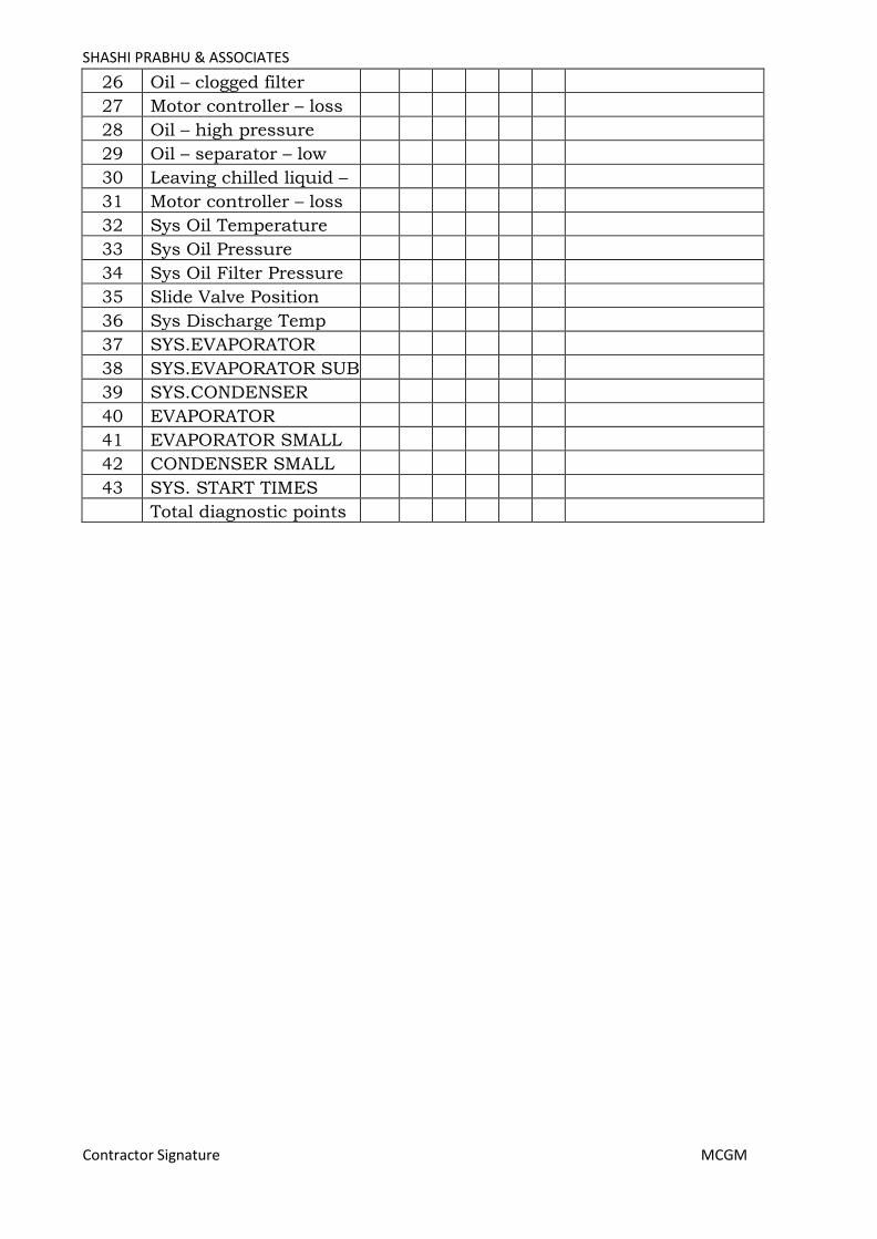
SHASHI PRABHU & ASSOCIATES
Contractor Signature MCGM
26 Oil – clogged filter
27 Motor controller – loss of current
28 Oil – high pressure
29 Oil – separator – low level
30 Leaving chilled liquid – low
temperature
31 Motor controller – loss of current
32 Sys Oil Temperature
33 Sys Oil Pressure
34 Sys Oil Filter Pressure
35 Slide Valve Position
36 Sys Discharge Temp
37 SYS.EVAPORATOR
SATURATION
TEMPERATURE
38 SYS.EVAPORATOR SUB
TEMPERATURE
39 SYS.CONDENSER SATURATION
TEMPERATURE
40 EVAPORATOR REFRIGERANT
TEMPERATURE
41
41
EVAPORATOR SMALL
TEMPERATURE
DIFFERENCE
42
42
CONDENSER SMALL TEMPERATURE
DIFFERENCE
43 SYS. START TIMES
Total diagnostic points
Page 165
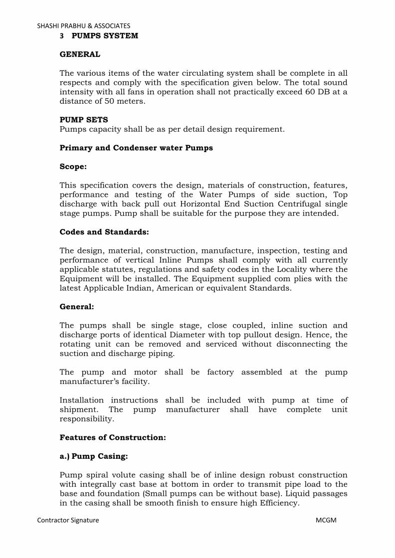
SHASHI PRABHU & ASSOCIATES
Contractor Signature MCGM
3 PUMPS SYSTEM GENERAL
The various items of the water circulating system shall be complete in all
respects and comply with the specification given below. The total sound intensity with all fans in operation shall not practically exceed 60 DB at a distance of 50 meters.
PUMP SETS Pumps capacity shall be as per detail design requirement.
Primary and Condenser water Pumps
Scope:
This specification covers the design, materials of construction, features, performance and testing of the Water Pumps of side suction, Top discharge with back pull out Horizontal End Suction Centrifugal single
stage pumps. Pump shall be suitable for the purpose they are intended.
Codes and Standards: The design, material, construction, manufacture, inspection, testing and
performance of vertical Inline Pumps shall comply with all currently applicable statutes, regulations and safety codes in the Locality where the
Equipment will be installed. The Equipment supplied com plies with the latest Applicable Indian, American or equivalent Standards.
General: The pumps shall be single stage, close coupled, inline suction and
discharge ports of identical Diameter with top pullout design. Hence, the rotating unit can be removed and serviced without disconnecting the
suction and discharge piping. The pump and motor shall be factory assembled at the pump
manufacturer’s facility.
Installation instructions shall be included with pump at time of shipment. The pump manufacturer shall have complete unit responsibility.
Features of Construction:
a.) Pump Casing:
Pump spiral volute casing shall be of inline design robust construction with integrally cast base at bottom in order to transmit pipe load to the base and foundation (Small pumps can be without base). Liquid passages
in the casing shall be smooth finish to ensure high Efficiency.
Page 166
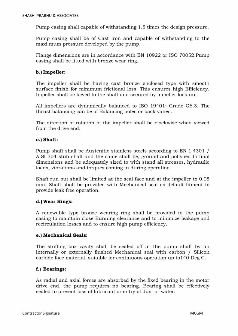
SHASHI PRABHU & ASSOCIATES
Contractor Signature MCGM
Pump casing shall capable of withstanding 1.5 times the design pressure.
Pump casing shall be of Cast Iron and capable of withstanding to the maxi mum pressure developed by the pump.
Flange dimensions are in accordance with EN 10922 or ISO 70052.Pump casing shall be fitted with bronze wear ring.
b.) Impeller:
The impeller shall be having cast bronze enclosed type with smooth surface finish for minimum frictional loss. This ensures high Efficiency.
Impeller shall be keyed to the shaft and secured by impeller lock nut. All impellers are dynamically balanced to ISO 19401: Grade G6.3. The
thrust balancing can be of Balancing holes or back vanes.
The direction of rotation of the impeller shall be clockwise when viewed from the drive end.
c.) Shaft: Pump shaft shall be Austenitic stainless steels according to EN 1.4301 /
AISI 304 stub shaft and the same shall be, ground and polished to final dimensions and be adequately sized to with stand all stresses, hydraulic
loads, vibrations and torques coming in during operation. Shaft run out shall be limited at the seal face and at the impeller to 0.05
mm. Shaft shall be provided with Mechanical seal as default fitment to provide leak free operation.
d.) Wear Rings:
A renewable type bronze wearing ring shall be provided in the pump casing to maintain close Running clearance and to minimize leakage and recirculation losses and to ensure high pump efficiency.
e.) Mechanical Seals:
The stuffing box cavity shall be sealed off at the pump shaft by an internally or externally flushed Mechanical seal with carbon / Silicon
carbide face material, suitable for continuous operation up to140 Deg C.
f.) Bearings: As radial and axial forces are absorbed by the fixed bearing in the motor
drive end, the pump requires no bearing. Bearing shall be effectively sealed to prevent loss of lubricant or entry of dust or water.
Page 167

SHASHI PRABHU & ASSOCIATES
Contractor Signature MCGM
g.) Coupling:
The pump coupling should be of close coupled type with stub shaft.
h.) Motors:
Motor shall be a flange mounted, totally enclosed fan cooled motors with main dimensions according to IEC standards. Electrical tolerances are to
IEC
60034. Motor shall be IE2motor for normal mode & fir mode equipment’s with IE2 motor. Motor shall be to with IP 55 enclosure. The class of
insulation shall be F with temperature rise limited to Class B. Motor shall be suitable for operation on a 415 V (± 10% variation), 50Hz ±
5%, and 3phase AC supply. Pump and motor shall be factory aligned, and shall be realigned by the contractor as per factory recommendations
after installation. i.) Name plates:
Each pump shall be provided with a name plate indicating the following de tails:
Pump type designation
Pump Model Rated flow Rated head
Pressure rating/max temperature Rated speed
j.) Working pressure:
Maximum allowable working pressure for all the pressure containing parts shall in no case be less than the maximum discharge pressure produced by the pump at shut off (including tolerances), at the max
suction pressure, for the maximum impeller diameter and the maximum continuous speed. Pump shall be rated at actual required working
pressure but not less than 16 bar working pressure. Cast Iron with PN16 flanges for working pressure to 12bar at 65°C and Ductile Iron with PN25 flanges for working pressures to 25 bar at 65°C.
Pumps for working pressure higher than 16 bar shall be PN25 with ductile iron flanges for working pressure up to 25 bar at 65°C, if called
for Suction and discharge connections shall be flanged and the same size and shall be drilled and tapped for seal flush and gauge connections.
k.) Vibration: The pump(s) vibration limits shall conform to Hydraulic Institute ANSI/HI
1.1 1.51994 or ISO 10816.
Page 168

SHASHI PRABHU & ASSOCIATES
Contractor Signature MCGM
Painting:
The equipment shall be thoroughly cleaned and greased. All rust sharp edges and scales shall be removed. All external and exposed cast iron
parts of pumps have an epoxy based coating made in a cathodic electrode position (CED) process which is high quality dip painting process and
which would prevent rusting and corrosion. The color code for the finished product is NCS 9000/RAL 9005. The pump shaft shall not be painted.
PUMP & MOTOR SELECTION:
The pumps shall be factory manufactured, assembled and hydrostatically tested as per Hydraulic Institute standards in an ISO 9001 approved
facility. Motor should be of variable Frequency drive compatible. Motor should be selected as no overloading type.
Inspection & Testing of Various Items: Following inspections and tests as per relevant ISO/IS/HI standards
shall be carried out.
1. Hydrostatic Testing 2. Performance Test (Single point / Duty point) 3. Dynamic balancing for pump impeller.
Tender Drawings:
The following drawings shall be submitted by the Contractor:
Preliminary outline dimensional drawing of pump and motor (Suction and discharge Connections).
Performance curves (capacity Vs total head, efficiency, NPSH and KW requirement) ranging from zero to maximum capacity.
Technical Data sheet for Pumps.
Variable Speed Pumping System For Primary CHW Pumps:
Variable speed pump should provide stable and predictable flow rate over a wide variation of head pressure including the following:
The control system shall include programmable logic pump controller, adjustable frequency drive(s) and Differential pressure transmitters as indicated in the design. Provide additional items as specified or as
required to properly execute the sequence of operation.
The variable speed pump logic controller, adjustable frequency drives(s), AFD by pass and re mote sensor/ transmitter(s) shall ship as individual components to the job site.
Page 169
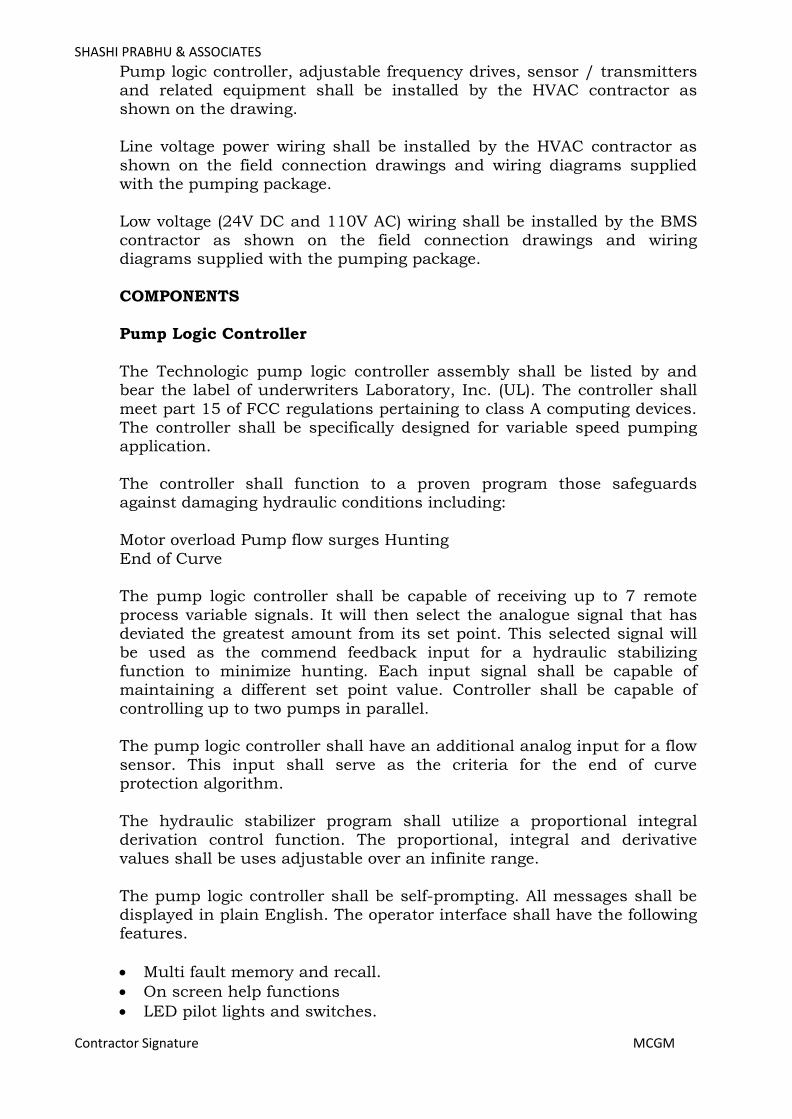
SHASHI PRABHU & ASSOCIATES
Contractor Signature MCGM
Pump logic controller, adjustable frequency drives, sensor / transmitters and related equipment shall be installed by the HVAC contractor as shown on the drawing.
Line voltage power wiring shall be installed by the HVAC contractor as
shown on the field connection drawings and wiring diagrams supplied with the pumping package.
Low voltage (24V DC and 110V AC) wiring shall be installed by the BMS contractor as shown on the field connection drawings and wiring diagrams supplied with the pumping package.
COMPONENTS
Pump Logic Controller
The Technologic pump logic controller assembly shall be listed by and bear the label of underwriters Laboratory, Inc. (UL). The controller shall
meet part 15 of FCC regulations pertaining to class A computing devices. The controller shall be specifically designed for variable speed pumping application.
The controller shall function to a proven program those safeguards against damaging hydraulic conditions including:
Motor overload Pump flow surges Hunting
End of Curve The pump logic controller shall be capable of receiving up to 7 remote
process variable signals. It will then select the analogue signal that has deviated the greatest amount from its set point. This selected signal will
be used as the commend feedback input for a hydraulic stabilizing function to minimize hunting. Each input signal shall be capable of maintaining a different set point value. Controller shall be capable of
controlling up to two pumps in parallel. The pump logic controller shall have an additional analog input for a flow
sensor. This input shall serve as the criteria for the end of curve protection algorithm.
The hydraulic stabilizer program shall utilize a proportional integral derivation control function. The proportional, integral and derivative
values shall be uses adjustable over an infinite range.
The pump logic controller shall be self-prompting. All messages shall be displayed in plain English. The operator interface shall have the following features.
• Multi fault memory and recall.
• On screen help functions
• LED pilot lights and switches.
Page 170
SHASHI PRABHU & ASSOCIATES
Contractor Signature MCGM
• Soft touch membrane keypad switches.
The readout shall be two lines of forty 0.25” backlit LCD super twist characters capable of displaying the following values:
• Differential pressure in PSIG
• Pressure in PSIG
• Flow in GPM
• Temperature in degrees F or C
• Differential temperature in degree F or C The following communication features shall be provided to the BAS:
• Remote system start/stop
• Failure of any system component
• Process variable
• AFD Speed
• Equipment’s/ Controllers shall be compatible with existing BMS
ADJUSTABLE FREQUENCY DRIVE. The adjustable frequency drive (s) shall be pulse width modulation (PWM)
type, microprocessor controlled design.
The AFD including all factory installed options shall have CSA approval. Enclosure shall be NEMA 1 ventilated for installation as a wall mounted
of free standing unit, depending on the amp rating. A hand off auto switch and speed potentiometer shall be function via AFD key pad.
AFD shall utilize a diode bridge rectifier to convert three phase AC to a fixed DC voltage. Power factor shall remain above 0.98 regardless of
speed or load. AFDs employing power factor correction capacitors shall not be acceptable.
Insulated gate bipolar transistors shall be used in the inverter section to convert the fixed DC voltage to a three phase, adjustable frequency, AC
output. An internal line reactor shall be provided to lower harmonic distortion of the power line to increase the fundamental power factor.
The following customer modifiable adjustments shall be provided:
• Accel time: 0.1 to 1800 seconds
• Decel time: 0.1 to 1800 seconds
• Minimum frequency: 0 HZ
• Analog input filter: 0.1 to 10 seconds
• Analog outputs: 10 to 1 gain Speed reference signal shall be customer selectable for 010VDC or 420 mA.
Page 171
SHASHI PRABHU & ASSOCIATES
Contractor Signature MCGM
The AFD shall be suitable for elevations to 3300 feet above sea level without derating. Maximum operating ambient temperature shall not be less than 104 degrees F.AFD shall be suitable for operation in
environments up to 95% non condensing humidity.
The AFD shall be capable of displaying the following information in plain English via a 40-character alphanumeric display:
• Frequency
• Voltage
• Current
• Kilowatts per hour
• Fault identification
• Percent torque
• Percent power
• RPM
SENSOR/TRANSMITTERS:
Provide adequate Nos. field mounted differential pressure sensor transmitter(s) as required at site. Unit shall transmit an isolated 420A mA DC signal indicative of process variable to the pump logic controller
via standard two wire 24 DC system. Unit shall have a corrosion resistant steel body with 1/8” NPT process connection. It shall have a NEMA 1electrical enclosure capable of withstanding 450 PSI static pressure.
Accuracy shall be within 0.5% of full span.
SEQUENCE OF OPERATION The system shall consist of a technologic pump logic controller, one duty
pump /AFD set; with duty standby pump selection, automatic alternation and automatic transfer to the standby pump.
The pumping system shall start upon the closure of customer’s contact when the pump logic controller Mode of Operation selector switch is in
the REMOTE position. When the pump logic controller selector switch is in the LOCAL position,
the pumping system shall operate automatically. Sensor/transmitters shall be provided as indicated on the plans.
Each sensor/transmitter shall send a 420mA signal to the technologic pump logic controller, indicative of process variable condition.
The Technologic pump logic controller shall compare each signal to the
independent, engineer/user determined set points. When all set points are satisfied by the process variable, the pump speed
shall remain constant at the optimum energy consumption level. The technologic pump logic controller shall continuously scan and
compare each process variable to its individual set point and control to
Page 172
SHASHI PRABHU & ASSOCIATES
Contractor Signature MCGM
the least satisfied zone. As the worst case zone deviates from set point, the pump logic controller
shall send the appropriate analog signal to the AFD to speed up or slow down the pump/motor.
The redundant variable speed system shall be started through the pump logic controller.
In the event of a system differential pressure failure due to a pump or AFD fault, the pump logic controller automatically initiates a times
sequence of operation to start the redundant pump/AFD set in the variable speed mode.
In the event of the failure of a zone sensor/transmitter, its process variable signal shall be removed from the scan / compare program.
Alternative zone sensor /transmitters, if available, shall remain in the scan/compare program for control.
The zone number corresponding to the failed sensor/ transmitter shall be displayed on the operator interface of the pump logic controller.
In the event of failure to receive all zone process variable signals, the AFD shall maintain 100% speed; reset shall be automatic upon correction of
the zone failure.
Pump or AFD fault shall be continuously scrolled through the display on the operator interface of the pump logic controller until the fault has been corrected and the controller has been manually reset.
Manual override arrangement for all control system to be provided.
PUMPS SUITABLE FOR VARIABLE SPEED
Pumps shall be single stage, end suction design with a foot mounted volute to allow servicing of the impeller and bearing assembly without disturbing piping connections.
Pump volute shall be class 30 cast iron with integrally cast pedestal
support feet. The impeller shall be cast bronze enclosed type, dynamically balanced keyed to the shaft and secured by a locking cap screw.
The liquid cavity shall be sealed off at the pump shaft by an internally flushed mechanical seal with ceramic seal seat and carbon seal ring,
suitable for continuous operation at 225o F.A. replaceable bronze shaft sleeve shall completely cover the wetted area under the seal.
Pump shall be rated for minimum of 16 bar working pressure. Volute shall have gauge tapings at the suction and discharge nozzles and vent and drain tapings at the top and bottom.
Page 173
SHASHI PRABHU & ASSOCIATES
Contractor Signature MCGM
Base plate shall be structural steel or fabricated steel channel with fully enclosed sides and ends, and securely welded cross members. Grouting area shall be fully opened. A flexible type, center drop put design coupler,
capable of absorbing torsional vibration shall be employed between the pump and motor. Coupler shall be shielded by a coupler guard securely
fastened to the base. Motor shall be energy efficient, totally enclosed fan cooled, class ‘F’
insulation and suitable for operation on AFD (only for secondary side). Motor shall be specially designed for quite operation and its speed shall
not exceed 1450 RPM. The motor rating shall be such as to ensure non over loading of the motor throughout its capacity range. Motor shall be
suitable for 415 ± 10% volts, 3 phase, 50 cycles AC power supply. Suction Guides
Furnish and install on the suction of each pump Suction Guide, with Outlet
Flow Stabilizing Guide Vanes, removable Stainless-Steel Strainer and Fine
Mesh Start-up Strainer. Supply suction guide with Ductile Iron body, with
BSPT inlet and PN16 outlet connections. The mechanical contractor shall
inspect the strainer prior to activating the pump and, further, shall remove
the Fine Mesh Start-up Strainer after a short running period. (24 hours
maximum). Space shall be provided for removal of the Strainer and
connection of a Blow-down Valve.
Page 174

SHASHI PRABHU & ASSOCIATES
Contractor Signature MCGM
4 VARIABLE FREQUENCY DRIVES
PART 1: GENERAL REQUIREMENTS
This specification covers complete variable frequency drives (VFDs)
designated on the drawing schedules to be variable speed. All standard and optional features shall be included within the VFD.
The frequency converter shall not be a general purpose product, but a dedicated HVAC engineered design.
The VFD and its options shall be factory mounted and tested as a single unit under full load before dispatch.
The VFD shall be tested to UL 508C. The appropriate UL label shall be applied. VFD shall be manufactured in ISO 9000, 2000 certified facilities.
The VFD shall be CE marked and conform to the European Union Electro Magnetic Compatibility directive.
The VFD shall be UL listed for a short circuit current rating of 100 kA
and labeled with this rating. The frequency converter shall be supported locally by the manufacturer
who will provide full technical support, spares holding and troubleshooting capability from their own local facility. A training course
shall be provided by the manufacturer to the Engineer in Charge / contractor / maintenance engineers.
PART 2: TECHNICAL REQUIREMENTS The VFD shall convert incoming fixed frequency three phase AC power
into an adjustable frequency and voltage for controlling the speed of three phase AC motors. The motor current shall closely approximate a sine
wave. Motor voltage shall be varied with frequency to maintain desired motor magnetization current suitable for the driven load and to eliminate the need for motor derating when properly sized, the VFD shall allow the
motor to produce full rated power at rated motor voltage, current, and speed without using the motor's service factor. VFDs utilizing sine
weighted/coded modulation (with or without 3rd harmonic injection) must provide data verifying that the motors will not draw more than full load current during full load and full speed operation.
The VFD shall convert incoming fixed frequency three phase AC power into an adjustable frequency and voltage for controlling the speed of three
phase AC motors. The motor current shall closely approximate a sine wave. Motor voltage shall be varied with frequency to maintain desired
motor magnetization current suitable for the driven load and to eliminate the need for motor derating.
When properly sized, the VFD shall allow the motor to produce full rated
Page 175

SHASHI PRABHU & ASSOCIATES
Contractor Signature MCGM
power at rated motor voltage, current, and speed without using the motor's service factor. VFDs utilizing sine weighted/coded modulation (with or without 3rd harmonic injection) must provide data verifying that
the motors will not draw more than full load current during full load and full speed operation.
The VFD shall include an input full wave bridge rectifier and maintain a fundamental (displacement) power factor near unity regardless of speed
or load. The VFD shall have a dual 5% impedance DC link reactor (harmonic
filters) on the positive and negative rails of the DC bus to minimize power line harmonics and protect the VFD from power line transients. The
chokes shall be non-saturating. Swinging chokes that do not provide full harmonic filtering throughout the entire load range are not acceptable.
VFDs with saturating (nonlinear) DC link reactors shall require an additional 5% AC line reactor to provide acceptable harmonic
performance at full load, where harmonic performance is most critical. IEEE519, 1992 recommendations shall be used for the basis of
calculation of total harmonic distortion (THD) at the point of common coupling (PCC). On request VFD manufacturer shall provide THD figures for the total connected load. The contractor shall provide details of supply
transformer rating, impedance, short circuit current, short circuit impedance etc. to allow this calculation to be made.
All VFDs upto 90 KW shall contain integral EMC Filters to attenuate Radio Frequency Interference conducted to the AC power line. The VFDs
shall comply with the emission and immunity requirements of IEC 618003: 2004, Category C1 with 50meter. The suppliers of VFDs shall
include additional EMC filters if required to meet compliance to this requirement.
The VFD’s full load output current rating shall meet or exceed the normal rated currents of standard IEC induction motors. The VFD shall be able to provide full rated output current continuously, 110% of rated current
for 60 seconds and 120% of rated torque for up to 0.5 second while starting.
The VFD shall provide full motor torque at any selected frequency from 20 Hz to base speed while providing a variable torque V/Hz output at
reduced speed. This is to allow driving direct drive fans without high speed derating or low speed excessive magnetization, as would occur if a
constant torque V/Hz curve was used at reduced speeds. Breakaway current of 160% shall be available.
A programmable automatic energy optimization selection feature shall be provided as standard in the VFD. This feature shall automatically and continuously monitor the motor’s speed and load to adjust the applied
voltage to maximize energy savings.
Page 176
SHASHI PRABHU & ASSOCIATES
Contractor Signature MCGM
The VFD must be able to produce full torque at low speed to operate direct driven fans.
Output power circuit switching shall be able to be accomplished without
interlocks or damage to the VFD. An Automatic Motor Adaptation algorithm shall measure motor stator
resistance and reactance to optimize performance and efficiency. It shall not be necessary to run the motor or decouple the motor from the load to perform the test.
Galvanic isolation shall be provided between the VFD’s power circuitry
and control circuitry to ensure operator safety and to protect connected electronic control equipment from damage caused by voltage spikes, current surges, and ground loop currents. VFDs not including either
galvanic or optical isolation on both analog I/O and discrete digital I/O shall include additional isolation modules.
VFD shall minimize the audible motor noise through the used of an adjustable carrier frequency. The carrier frequency shall be automatically
adjusted to optimize motor and VFD operation while reducing motor noise. VFDs with fixed carrier frequency are not acceptable.
The VFD shall allow up to at least 100 meters of SWA (Single Wire Armour) cable to be used between the FC and the motor and allow the
use of MICS (Mineral Insulated Copper Sheath) cable in the motor circuit for fire locations.
PART 3: PROTECTIVE FEATURES
A minimum of Class 20 I2t electronic motor overload protection for single motor applications shall be provided. Overload protection shall automatically compensate for changes in motor speed.
Protection against input transients, loss of AC line phase, output short circuit, output ground fault, over voltage, under voltage, VFD over
temperature and motor over temperature. The VFD shall display all faults in plain language. Codes are not acceptable.
Protect VFD from input phase loss. The VFD should be able to protect itself from damage and indicate the phase loss condition. During an input
phase loss condition, the VFD shall be able to be programmed to either trip off while displaying an alarm, issue a warning while running at
reduced output capacity, or issue a warning while running at full commanded speed. This function is independent of which input power phase is lost.
Protect from under voltage. The VFD shall provide full rated output with an input voltage as low as 90% of the nominal. The VFD will continue to
operate with reduced output, without faulting, with an input voltage as
Page 177

SHASHI PRABHU & ASSOCIATES
Contractor Signature MCGM
low as 70% of the nominal voltage. VFD shall include current sensors on all three output phases to
accurately measure motor current, protect the VFD from output short circuits, output ground faults, and act as a motor overload. If an output
phase loss is detected, the VFD will trip off and identify which of the output phases is low or lost.
If the temperature of the VFD’s heat sink rises to 80°C, the VFD shall automatically reduce its carrier frequency to reduce the heat sink temperature. It shall also be possible to program the VFD so that it
reduces its output current limit value if the VFD’s temperature becomes too high.
In order to ensure operation during periods of overload, it must be possible to program the VFD to automatically reduce its output current
to a programmed value during periods of excessive load. This allows the VFD to continue to run the load without tripping.
The VFD shall have temperature controlled cooling fan(s) for quiet operation, minimized losses, and increased fan life. At low loads or low
ambient temperatures, the fan(s) may be off even when the VFD is running.
The VFD shall store in memory the last 10 alarms. A description of the alarm, and the date and time of the alarm shall be recorded.
when used with a pumping system, the VFD shall be able to detect noflow situations, dry pump conditions, and operation off the end of the
pump curve. It shall be programmable to take appropriate protective action when one of the above situations is detected.
PART 4: INTERFACE FEATURES
Hand Off and Auto keys shall be provided on the control panel to start and stop the VFD and determine the source of the speed reference. It shall be possible to either disable these keys or passwords protect them
from undesired operation.
There shall be an “Info” key on the keypad. The Info key shall include “online” context sensitive assistance for programming and troubleshooting.
The VFD shall be programmable to provide a digital output signal to
indicate whether the VFD is in Hand or Auto mode. This is to alert the Building Automation System whether the VFD is being controlled locally or by the Building Automation System.
Password protected keypad with alphanumeric, graphical, backlit display can be remotely mounted. Two levels of password protection shall be
provided to guard against unauthorized parameter changes.
Page 178

SHASHI PRABHU & ASSOCIATES
Contractor Signature MCGM
All VFDs shall have the same customer interface. The keypad and display shall be identical and interchangeable for all sizes of VFDs.
To set up multiple VFDs, it shall be possible to upload all setup
parameters to the VFD’s keypad, place that keypad on all other VFDs in turn and download the setup parameters to each VFD. To facilitate setting up VFDs of various sizes, it shall be possible to download from the
keypad only size independent parameters. Keypad shall provide visual indication of copy status.
Display shall be programmable to communicate in multiple languages including English.
A red FAULT light, a yellow WARNING light and a green POWERON light shall be provided. These indications shall be visible both on the keypad
and on the VFD when the keypad is removed.
A quick setup menu with factory preset typical HVAC parameters shall be provided on the VFD.
A three feedback PID controller to control the speed of the VFD shall be standard.
This controller shall accept up to three feedback signals. It shall be programmable to compare the feedback signals to a common set point or
to individual set points and to automatically select either the maximum or minimum deviating signal as the controlling signal. It shall also be possible to calculate the controlling feedback signal as the average of all
feedback signals or the difference between a pair of feedback signals.
The VFD shall be able to apply individual scaling to each feedback signal. For fan flow tracking applications, the VFD shall be able to calculate the
square root of any or all individual feedback signals so that a pressure sensor can be used to measure air flow.
The VFD’s PID controller shall be able to actively adjust its set point based on flow. This allows the VFD to compensate for a pressure
feedback sensor which is located near the output of the pump rather than out in the controlled system.
The VFD shall have three additional PID controllers which can be used to control damper and valve positions in the system and to provide set point
reset. Floating point control interface shall be provided to increase/decrease
speed in response to contact closures. Five simultaneous meter displays shall be available. They shall be
selectable from (at a minimum), frequency, motor current, motor voltage,
Page 179
SHASHI PRABHU & ASSOCIATES
Contractor Signature MCGM
VFD output power, VFD output energy, VFD temperature in degrees, feedback signals in their own units, among others.
Programmable Sleep Mode shall be able to stop the VFD. When its output frequency drops below set “sleep” level for a specified time, when an
external contact commands that the VFD go into Sleep Mode, or when the VFD detects a noflow situation, the VFD may be programmed to stop. When the VFD’s speed is being controlled by its PID controller, it shall be
possible to program a “wakeup” feedback value that will cause the VFD to start. To avoid excessive starting and stopping of the driven equipment, it shall be possible to program a minimum run time before sleep mode can
be initiated and a minimum sleep time for the VFD.
A run permissive circuit shall be provided to accept a “system ready” signal to ensure that the VFD does not start until dampers or other auxiliary equipment are in the proper state for VFD operation. The run
permissive circuit shall also be capable of initiating an output “run request” signal to indicate to the external equipment that the VFD has
received a request to run. VFD shall be programmable to display feedback signals in appropriate
units, such as inches of water column (inwg), pressure per square inch (psi) or temperature (°F). Examples can be room temperature in 0C, return air temperature in 0C, supply air temperature in 0C, CO²
concentration in ppm, pressure in bar, differential pressure in PSI etc.
VFD shall be programmable to sense the loss of load. The VFD shall be programmable to signal this condition via a keypad warning, relay output and/or over the serial communications bus. To ensure against nuisance
indications, this feature must be based on motor torque, not current, and must include a proof timer to keep brief periods of no load from falsely
triggering this indication. Standard Control and Monitoring Inputs and Outputs
Four dedicated, programmable digital inputs shall be provided for interfacing with the systems control and safety interlock circuitry.
Two terminals shall be programmable to act as either as digital outputs
or additional digital inputs. Two programmable relay outputs, Form C 240 V AC, 2 A, shall be
provided for remote indication of VFD status.
Each relay shall have an adjustable on delay / off delay time. Two programmable analog inputs shall be provided that can be either
director reverse acting. Each shall be independently selectable to be used with either an analog
voltage or current signal.
Page 180

SHASHI PRABHU & ASSOCIATES
Contractor Signature MCGM
The maximum and minimum range of each shall be able to be independently scalable from 0 to 10 V dc and 0 to 20 mA.
A programmable low pass filter for either or both of the analog inputs
must be included to compensate for noise. The VFD shall provide front panel meter displays programmable to show
the value of each analog input signal for system setup and troubleshooting,
One programmable analog current output (0/4 to 20 mA) shall be provided for indication of VFD status. This output shall be programmable
to show the reference or feedback signal supplied to the VFD and for VFD output frequency, current and power. It shall be possible to scale the minimum and maximum values of this output.
It shall be possible to read the status of all analog and digital inputs of
the VFD through serial bus communications. It shall be possible to command all digital and analog output through the
serial communication bus. Optional Control and Monitoring Inputs and Outputs
It shall be possible to add optional modules to the VFD in the field to
expand its analog and digital inputs and outputs. These modules shall use rigid connectors to plug into the VFD’s control
card.
The VFD shall automatically recognize the option module after it is powered up. There shall be no need to manually configure the module. Modules may include such
items as: Additional digital outputs, including relay outputs Additional digital inputs
Additional analog outputs
Additional analog inputs, including Ni or Pt temperature sensor inputs It shall be possible through serial bus communications to control the
status of all optional analog and digital outputs of the VFD.
Standard programmable firefighter’s override mode allows a digital input to control the VFD and override all other local or remote commands. It shall be possible to program the VFD so that it will ignore most normal
VFD safety circuits including motor overload. The VFD shall display FIREMODE whenever in firefighter’s override mode. Fire mode shall allow selection of forward or reverse operation and the selection of a speed
source or preset speed, as required to accommodate local fire codes,
Page 181

SHASHI PRABHU & ASSOCIATES
Contractor Signature MCGM
standards and conditions. A real time clock shall be an integral part of the VFD.
It shall be possible to use this to display the current date and time on the
VFD’s display. Ten programmable time periods, with individually selectable ON and OFF
functions shall be available. The clock shall also be programmable to control start/stop functions, constant speeds, PID parameter set points and output relays. Is shall be possible to program unique events that
occur only during normal work days, others that occur only on nonwork days, and others that occur on specific days or dates. The manufacturer
shall provide free PC based software to set up the calendar for this schedule.
All VFD faults shall be time stamped to aid troubleshooting.
It shall be possible to program maintenance reminders based on date and time, VFD running hours, or VFD operating hours.
The realtime clock shall be able to time and date stamp all faults recorded in the VFD fault log.
The VFD shall be able to store load profile data to assist in analyzing the system demand and energy consumption over time.
The VFD shall include a sequential logic controller to provide advanced control interface capabilities. This shall include:
Comparators for comparing VFD analog values to programmed trigger
values Logic operators to combine up to three logic expressions using Boolean algebra Delay timersA 20step programmable structure
PART 5: SERIAL COMMUNICATIONS The VFD shall include a standard EIA485 communications port and
capabilities to be connected to the following serial communication protocols at no additional cost and without a need to install any
additional hardware or software in the VFD: Modbus/ Bacnet/RTU
VFD shall have standard USB port for direct connection of Personal
Computer (PC) to the VFD. The manufacturer shall provide no charge PC software to allow complete setup and access of the VFD and logs of VFD operation through the USB port. It shall be possible to communicate to
the VFD through this USB port without interrupting VFD communications to the building management system.
The VFD shall have provisions for an optional 24 V DC backup power
Page 182

SHASHI PRABHU & ASSOCIATES
Contractor Signature MCGM
interface to power the VFD’s control card. This is to allow the VFD to continue to communicate to the building automation system even if power to the VFD is lost.
PART 6: ADJUSTMENTS
The VFD shall have a manually adjustable carrier frequency that can be adjusted in 0.5 kHz increments to allow the user to select the desired
operating characteristics. The VFD shall also be programmable to automatically reduce its carrier frequency to avoid tripping due to thermal loading.
Four independent setups shall be provided.
Four preset speeds per setup shall be provided for a total of 16. Each setup shall have two programmable ramp up and ramp down times.
Acceleration and deceleration ramp times shall be adjustable over the range from 1 to 3,600 seconds.
Each setup shall be programmable for a unique current limit value. If the output current from the VFD reaches this value, any further attempt to
increase the current produced by the VFD will cause the VFD to reduce its output frequency to reduce the load on the VFD. If desired, it shall be possible to program a timer which will cause the VFD to trip off after a
programmed time period.
If the VFD trips on one of the following conditions, the VFD shall be programmable for automatic or manual reset: external interlock, under voltage, overvoltage, current limit, over temperature, and VFD overload.
The number of restart attempts shall be selectable from 0 through 20 or
infinitely and the time between attempts shall be adjustable from 0 through 600 seconds.
An automatic “start delay” may be selected from 0 to 120 seconds. During this delay time, the VFD shall be programmable to either apply no voltage to the motor or apply DC braking current if desired.
Four programmable critical frequency lockout ranges to prevent the VFD
from operating the load at a speed that causes vibration in the driven equipment shall be provided. Semiautomatic setting of lockout ranges shall simplify the setup.
PART 7: OPTIONAL FEATURES
7.1 All optional features shall be built and mounted by VFD manufacturer as an inbuilt factory solution. All optional features shall be
UL listed by the VFD manufacturer as a complete assembly and carry a UL label.
Page 183
SHASHI PRABHU & ASSOCIATES
Contractor Signature MCGM
PART 8: SERVICE CONDITIONS
Ambient temperature at full speed, full load operation with continuous
drive rated output current:
10 to 45°C for ratings upto 90 kW without derating 10 to 40°C for ratings 110 kW and higher without derating
Relative Humidity: 0 to 95%, noncondensing.
Elevation: Up to 3,300 feet without derating.
AC line voltage variation: + 10% of nominal with full output. VFDs upto 90 KW rating Enclosure protection: IP 55, integral, with Mains
Disconnect with no additional cabinets. Side Clearances: No side clearance shall be required for cooling.
All power and control wiring shall be done from the bottom.
All VFDs shall be plenum rated.
PART 9: QUALITY ASSURANCE
To ensure quality, the complete VFD shall be tested by the manufacturer. The VFD shall drive a motor connected to a dynamometer at full load and speed and shall be cycled during the automated test procedure.
All optional features shall be functionally tested at the factory for proper operation.
Page 184
SHASHI PRABHU & ASSOCIATES
Contractor Signature MCGM
5 COOLING TOWER GENERAL DESCRIPTION
The specifications to follow cover general requirements of design,
preparation of detailed drawings, supply of material, manufacture, testing, inspection, packing, forwarding, transportation, transit insurance, and delivery at site, installation, testing and commissioning at
site and carrying out acceptance test of the equipment, materials and services as per enclosed documents.
SCOPE OF WORK
The scope shall include development of a total system and design of their sub-systems as per concepts and parameters given herein, providing engineering drawings and data for approval by Customer / Consultants.
This will consist of supply, installation, balancing, testing & commissioning of the following in conformity with the tender, General
Terms & Conditions, Special Conditions, Specifications, Bill of Quantities, attached drawings, drawings to be submitted by the Contractor and
approved by the Consultant. The Contractor shall carry out the said work under the Contract in every respect in conformity with the Contract documents and with the directions of and to the satisfaction of the
supervisor. The Contractor shall furnish all labour, materials and equipment (except those to be supplied by the owner) as listed under
‘schedule of quantities’ and specified otherwise, transportation etc., for supply, installation, testing and commissioning of complete HVAC system as described in specifications and shown on drawings. This also includes
any material, equipment, work not specifically mentioned in the drawings / documents but which are necessary to make a complete installation. Additionally:
1. Scope shall be inclusive of approval from Authority for required statutory
approval required for Works. 2. Contractor will need to submit technical data sheet of each and every
equipment and ancillaries to MEP Consultant & get approval prior to
procurement 3. All Equipment shall be factory inspected by MEP Consultant and Client
Representative prior to dispatch on site. 4. All necessary site housekeeping, material security, site construction
lighting etc. required for site work shall be inclusive in the scope of
vendor.
COOLING TOWER SPECIFICATIONS
SCOPE
This section covers the supply, installation, testing and commissioning of Induced draught cooling towers in accordance with the approved
drawings and ‘Schedule of Quantities’.
Page 185

SHASHI PRABHU & ASSOCIATES
Contractor Signature MCGM
CODES AND STANDARDS
The design, manufacture, testing and performance of the cooling tower shall comply with all currently applicable statues, regulations and safety
codes in the locality where it is to be installed. The cooling tower shall also conform to the latest applicable Indian Standards and Publications of the cooling Tower Institute. Nothing in this specification shall be
construed to relieve the contractor of his responsibility. TYPE
The cooling tower shall be of Mechanical draft type. Fan on Mechanical
draft towers may be on the inlet air side or exit air side. In case of former it is called forced draft type and in case of later it is called Induced draft type. On the basis of direction of air flow and water flow, Mechanical draft
cooling tower can be counter flow or cross flow type as per the manufacturer design.
This may be of any of the following construction as may be specified in the tender specifications: -
a) In wooden construction with wood or PVC fill and RCC basin, b) In fibre glass reinforced plastic (FRP) construction with PVC fill and
FRP basin, c) In masonry construction.
The mechanical draft cooling towers of wooden construction and masonry construction, being un-common now, have been excluded from the scope
of these specifications.
Cooling tower shall be fiberglass – reinforced plastic type suitable for outdoor installation. Tower shall be Induced draught type, vertical, counter / cross flow type in fiberglass reinforcement plastic construction
complete with fan, motor, eliminators, steel supports, HDG ladder etc. DESIGN:
Rating: The cooling tower shall be rated for the heat rejection capacity
specified in the tender specifications. All cooling towers shall be certified by CTI (Cooling Tower Institute).
Range: The Cooling tower shall be designed to cool the requisite quantity of water through 7.0-degree C or as specified in the tender specifications,
against the prevailing wet bulb temperature. Wet Bulb approach: The cooling tower shall be selected for a wet bulb
approach of not more than 5.0-degree C. Outlet temperature: The cold water temperature from the cooling tower
shall match the entering temperature for which the condenser selection is
Page 186
SHASHI PRABHU & ASSOCIATES
Contractor Signature MCGM
made. Flow rate: The water flow rate through the cooling tower shall match that
through the condenser.
Multi cell design: The induced draft cooling tower shall be of one or more cells.
Drive Motor: The fan motor shall be premium efficiency IE3 class, as per IS 12615.
MATERIAL
STRUCTURE The structural framework of the cooling tower including all members
shall be designed for the load encountered during the normal operation of the cooling tower and its maintenance. The structure shall be rugged and
rigid to prevent distortion and shall include tie arrangements as may be necessary. The supporting framework for the tower casing and the water basin shall
be made of hot dip galvanized steel and it shall be further protected with epoxy painting.
SIDE CASING
The side casing shall be made of FRP with smooth surface for minimum resistance to airflow. It should have sufficient structural strength to withstand high wind velocity and vibrations. The casing shall be installed
in the fiberglass-reinforced basin. The tower supporting structure shall be made out of hot dipped galvanized frame. The tower shall have FRP
panels reinforced with embedded steel frame. AIR INTAKE
The air intake shall be from openings all along the circumference of the casing near its base in case of circular shape. Air Intake shall be along
the sides in case of square or octagonal/ rectangular cooling tower. These openings shall be covered with hot dip galvanized expanded metal mesh
screens. COLD WATER BASIN
Basin shall be FRP on which cooling tower structure shall be supported
and shall be complete with following: - Bottom outlet
Suction screen Drain outlet Over flow
Make up water connection with ball valve & float valve
Page 187

SHASHI PRABHU & ASSOCIATES
Contractor Signature MCGM
Equalizer connection where required Quick fill. The basin shall be watertight without the use of any fillets, paints
or sealing compounds
The basin shall have a holding capacity adequate for operation for at least 30 minutes without addition of make-up water to the basin. The construction should be such as to eliminate the danger of drawing air
into the pump when operating with minimum water in the basin. Suitable provision shall be made in the tower for cable supports and for
fixing galvanized steel flats as earthing and lightning protection.
DISTRIBUTION SYSTEM Distribution system shall be thru self-rotating or fixed type nozzles or
thru balancing, sub balancing and spread thru ensuring uniform water loading and distribution. The water distribution may be either through
self-rotating or fixed type sprinklers or through balancing, sub balancing and spreader troughs (unpressurised system) open gravity type with polypropylene nozzle, ensuring uniform water loading and distribution of
water over the fill. All pipes and fittings shall be of PVC. The sprinklers shall operate from the residual velocity head at the headers. Due care shall be taken with regard to corrosive effects and maintainability in the
design of the water distribution system.
FILLINGS The filling shall be of PVC. Thickness of PVC fills shall not be less than
0.2mm. Fillings shall be made of corrosion proof and rigid film in cross-fluted design and arranged in square/rectangular form and shall be
elevated from floor of the cold-water basin to facilitate cleaning and easy replacement. They shall be arranged in such a manner to ensure negligible resistance to airflow and to eliminate backwater spots and
prevent fouling through scales that may form. In order to reduce carry over losses through entrainment of moisture drops in air stream, PVC drift eliminators shall be of high efficiency. Drift eliminators of PVC shall
be provided for maximum removal of entrained water droplets. The spacers and tie rods used shall be of plastic material.
MECHANICAL EQUIPMENT
Fan shall be made of cast aluminum alloy and propeller type lightweight rotor fitted with multiple aerofoil blades. The entire fan assembly shall be
statically balanced fan shall be direct driven by motor suitable for 415 ± 10% Volts, 3 phase, 50 cycle per second AC supply, TEAO, weather proof construction (IP:56) designed to operate in humid air stream fan shall be
protected by fan guard and shall be easily accessible for inspection and maintenance. A service ladder fabricated out of hot dipped galvanized material shall be provided. The mechanical equipment assembly shall be
supported on a rugged steel base welded to tubular support for vibration
Page 188

SHASHI PRABHU & ASSOCIATES
Contractor Signature MCGM
free support. Fan shall be provided to prevent birds from nesting during idling periods. All fans shall be direct driven with low RPM motor. The fan drive shall be from a three phase induction motor of efficiency class IE3
as per IS 12615. The entire drive arrangement shall be designed for a minimum noise and it shall be rigidly supported to the tower structure.
Tower from 175 TR onwards shall have twin fans with low RPM motors of 720/600 RPM suitable for low noise application. Maximum noise level within One (1) meter of the source shall not exceed 75 dBA.
OTHER ACCESSORIES
To ensure safety of personnel at the time of working on cooling tower a steel ladder shall be provided in such a manner and location as
necessary to give safe and complete access to all the parts of the cooling tower requiring inspection or adjustments. The ladder shall be bolted to the tower at the top and grouted in masonry at the bottom end.
INSTALLATION
The cooling tower shall be installed on M.S. girders fixed in masonry foundations with cement concrete footing. Second class brick work and
cement mortar having one part cement & six parts sand shall be used for the masonry work. 12mm sand cement plaster shall be provided over the brickwork.
These may be located at a well-ventilated place either at ground level and
contiguous to the plant room, or on the terrace of the building in consultation with the Architect. In case the cooling towers are located on the terrace of the building, the structural loading of the terrace shall be
considered. For this respective columns are to be raised by two feet at the terrace. Cooling towers shall be installed in such a way that their load is
transferred directly to the columns for which necessary Mild steel-I sections shall be provided by the air- conditioning contractor. The cooling towers shall be rested on Mild Steel-I sections & not on terrace slab.
Sufficient free space shall be left all around for efficient operation of the cooling tower.
Cooling tower shall be not less than 75cm above the ground/ floor level unless otherwise stated in the tender specifications. 6mm neoprene pads
shall be placed between the tower and the girder for vibration isolation whereas directed by the Engineer-in-charge. Guy-wires of suitable sized shall be used to secure firmly to its base wherever necessary.
PAINTING
The cooling tower shall be procured of colour strictly in accordance with written approval of Architect/Consultants. All exposed surfaces shall be
given three (3) coats of epoxy paint and colour finish as per standards.
Page 189
SHASHI PRABHU & ASSOCIATES
Contractor Signature MCGM
ACCESSORIES
a) Cold-water basin common outlet header shall have pot strainer. The
strainer shall have handles for easy removal.
b) The cooling tower basin shall have automatic float valve with a stop valve for continuous Make up water flow, quick fill arrangement with stop valve, over flow and drain connections with stop valves.
c) A hot water bleed connection to drain line through a stop valve shall be
provided and shall be connected to drain line below the drain stop valve.
d) Hot dipped galvanized steel ladder made of 40mm x 40mm x 6mm HDG
angle sides and e) 16mm HDG straps shall be provided for complete access to tower. The
ladder shall be bolted to tower on top and grouted in masonry at bottom
side.
f) Hot dipped galvanized bird-screen shall be fixed on top to prevent any bird entering into
g) Cooling tower.
h) All hardware used inside the cooling tower shall be of stainless steel. All
pipe
i) Connections shall be hot dipped galvanized and double flanged.
j) Equalizer line to be provided for cooling towers.
TESTING
Complete performance ratings and power consumption at varying outdoor
wet bulb temperature shall be submitted and verified at the time of testing and commissioning of the installation. Capacity of the cooling tower shall be computed from the measurements of water flow, incoming/outgoing
water temperature and ambient air wet bulb / temperature using accurately calibrated mercury in glass thermometers. Computed ratings shall conform to the specified capacities and quoted ratings. Power
consumption for induced draft cooling towers shall be computed from measurements of incoming voltage and input current.
Page 190

SHASHI PRABHU & ASSOCIATES
Contractor Signature MCGM
6 AIR HANDLING UNITS (AHUS) GENERAL
The scope of this section comprises the supply, erection, testing and
commissioning of double construction air handling units, conforming to these specifications and in accordance with requirements.
FLOOR MOUNTED AIR HANDLING UNITS The air handling units shall be double skin construction, draw thru type
comprising of various sections such as pre-filter section, coil section and fan section.
CAPACITY
The air handling capacities, maximum motor horsepower and static pressure shall be as per requirements.
CASING
Frame work shall be of Hollow extruded aluminum profile/thermal break extruded aluminum profile as per application & location of AHU to be placed. AHUs Panels shall be double skinned panel fabricated with
anodized extruded aluminum construction section framework bolted together with sandwich panel having 22/20 gauge pre plasticized outer
skin and 22/20 gauge plain GI inner skin injected with 25/43 mm thick CFC free PU foam insulation as per application & location having density not less than 40 + 2 kg/ m3 to ensure mechanical strength as
per class D1 of EN 1886, air leakage as per class L1 of EN 1886,thermal bridging of minimum TB2 class and thermal transmittance of minimum T2 class as per EN 1886. For floor mounted AHU the entire frame shall
be mounted on a sheet steel channel base of 100 mm height. The panels shall be sealed to the framework by heavy duty `O' ring gaskets held
captive in the framed extrusion. The acoustic performance of the panels shall have been tested by an independent laboratory per ASTM C423, mounting Type A and E79593.
All panels shall be detachable or hinged. Hinges shall be made of die
cast aluminum. Nylon plastic with stainless steel pivots, handles shall be made of hard nylon and be operational from both inside and outside of the unit. Units supplied with various sections shall be suitable for
onsite assembly with continuous foam gasket. All fixing and gaskets shall be concealed.
Units shall have hinged quick opening access doors in the fan and filter section. Access doors shall also be double skin type.
Condensate drain pan shall be fabricated from 18-gauge stainless steel sheet. It shall be isolated from bottom floor panel through PU foam
Page 191
SHASHI PRABHU & ASSOCIATES
Contractor Signature MCGM
insulation as per manufacturer standard. AHU’s such as TFA units, AHU with mixing box having return air ducted
shall be provided with thermal break casing. Also these AHU’s shall be provided with 43 + 2 mm thick panel.
MOTOR AND DRIVE
Fan motors shall be energy efficient and shall be 415±10% volts, 50 cycles, three phases, totally enclosed fan cooled class F and shall have premium efficiency i.e. Minimum IE-3, with IP55 protection. Motors
shall be especially designed for quiet. Drive to fan shall be provided through direct drive arrangement. Frequency converter (VFD) for energy
saving, shall be supplied by the AHU manufacturer for all AHUs with direct driven fans.
FAN
EC Fan The fan section shall be equipped with a Single Inlet Centrifugal Impeller with High Efficiency backward curved blades and external rotor EC (Electronically Commutated) motor, energy optimized for operation for high efficiency and favorable acoustic behavior. Impeller: The high efficiency backward curved impeller made of welded aluminum sheet or high performing composite material with external rotor motor balanced together statically and dynamically according to ISO 1940. The EC fan should be capable of being fitted in horizontal position in the AHU. Motor: The minimum efficiency class of the motor shall be IE-/4.The motor shall be permanent magnet external rotor motor with integrated electronics and suitable for continuous operation. The
speed of the motor shall be varied with an external 0-10V/ PWM control signal. The fan in totality shall be of most efficient type so that the power consumption and noise level is minimal. The motor
shall be minimum IP54 protection class.
Direct Driven Plug Fan
Fans shall be backward curved Plenum plug fan with aero-foil design blades so as to give maximum efficiency for given duty condition. In case of Plug fan, the AHU will be certified by a reputed 3rd party internationally acclaimed certifying body like Eurovent / AHRI, and the entire Fan + Motor assembly will be balanced at supplier’s works before dispatch. Fans driven by variable frequency drive shall be backward inclined irrespective of static pressure value. Fans shall be selected for minimum efficiency of 70%. Fan wheels shall be made of MS epoxy coated/composite material in case of plug fans. Fan array with multiple fans should be used for capacities more than 15000 CMH. Plug fans in fan array shall have individual VFDs for
Page 192

SHASHI PRABHU & ASSOCIATES
Contractor Signature MCGM
every motor fan set. Certified Computerized selection for AHU shall be with fan selection and sound level spectrum. Complete AHU sound level should be given in computerized selection sheet instead of sound level of bare fan.
Motors shall be mounted inside the AHU casing on rigid frame/ slide rails for alignment, and be totally enclosed, fan cooled, to be class `F’
insulation and shall have premium efficiency i.e. minimum IE-3.
Heavy duty anti-vibration mounts shall be provided for isolating the
unit casing. Fire retardant, waterproof silicone rubber impregnated flexible connection shall be provided at the fan inlet/ discharge.
COOLING COILS
CHW Cooling coils shall have 12mm dia. (O.D) tubes minimum 0.5 mm thick with sine wave aluminum fins firmly bonded to copper tubes assembled in zinc coated steel frame. Face and surface areas shall be
such as to ensure rated capacity from each unit and such that the air velocity across the coil shall be around 155 meters per minute. The coil
shall be pitched in the unit casing for proper drainage. Each coil shall be factory-tested at 21 kg per sq. m air pressure underwater. Tubes shall be mechanically expanded for minimum thermal contact resistance with fins.
Fin spacing shall be 4 - 5 fins per cm. No drop should be observed indicating any leaks.
The depth of the coil shall be such as to suit the requirements, viz. re- circulated air applications, or 100 % fresh air applications and the bypass
factor required shall be specified in the tender specifications. The coil shall be 6 rows deep for normal/general area re-circulated air application and 8 rows deep for all critical/TFA and for outdoor air application, unless
otherwise specified in the tender specifications. In case of 8 rows deep coils, it shall be made of 2x4 rows deep coils with a spacing of 200mm between
the two coils, access door and independent drain pan. In case of AHU/TFA has multiple coil stacked one above another,
intermediate insulated condensate drain tray of SS 304 (18 gauge) shall be provided so that upper level of coil drains into this tray. Copper / SS 304 piping shall be provided from this tray up-to main bottom tray.
U bends shall be of copper, jointed to the tubes by brazing, soft soldering
shall not be used. Each section of the coil shall be fitted with flow and return headers to feed
all the passes of the coil properly. The headers shall be of copper and shall be complete with water in/out connections, vent plug on top and drain at
the bottom. The coil shall be designed to provide water velocity between 0.6 to 1.8 m/s in the tubes.
The fins shall be of aluminum. The minimum thickness of the fins shall be 0.15 mm nominal. The no. of fins shall not be less than 4.7 per cm length
Page 193
SHASHI PRABHU & ASSOCIATES
Contractor Signature MCGM
of coil. Fins may be of either spiral or plate type. The tubes shall be mechanically expanded to ensure proper thermal contact between fins and tubes. The fins shall be evenly spaced and upright. The fins bent during
installation shall be carefully realigned. For coastal areas fins shall be phenolic coated for re-circulated and 100% F.A. application fins shall be
hydrophilic type. The coil shall be suitable for use with the refrigerant specified or with water
as specified in schedule of quantities. Refrigerating coils shall be designed for the maximum working pressure under the operating conditions. Water coils shall be designed for a maximum working pressure of 10 kg./sq.cm.
Shut off and regulating valves at the inlet and outlet of water shall be
provided. In the case of DX coils, solenoid valve and expansion valves shall be provided at the inlet of coil.
Computerized cooling coil and Heating coil selection output shall be submitted. Coil rating shall be certified as per ARI-410/2006.
Certified Computerized selection for AHU/TFA shall be with coil selection.
UVGI FOR COIL AHU MOUNT ULTRA VIOLET GERMICIDAL IRRADIATION SYSTEM
UVGI system shall provide effective destruction and prevention of growth of bacteria, virus, mold, fungi and microbiological species on the cooling coil.
Intensity of UVC rays shall envelope the entire surface area of the cooling coil within the high kill rate zone of the UV glow. Where specified by the Engineering Consultant, an additional UVGI Fixture or set of Fixtures along
the width of the Cooling Coil shall be provided, and this shall be mounted near the base of Cooling Coil directed to destroy bacteria and mold in the
drain pan. The UVGI frame shall be installed in close proximity to cooling coil so as to
provide effective bactericidal ability on the entire surface area of the cooling coil and large part of the drain pan.
Sufficient number of UVGI units shall be provided to cover the entire surface area of the Cooling Coil.
Each UVGI unit or fixture shall contain at least 2 lamps, to ensure UVC rays penetrate deep into the rows of the Cooling Coil to enable bacteria
destruction in the inner rows of the Coil. Units or Fixtures with single lamp is not acceptable due to its limited ability to penetrate into the depth of the
Cooling Coil. The system shall comprise one or more number of individual units or
fixtures, all mounted on factory provided metallic frame complete with vertical support channels. The vertical channels shall be telescopic to cover cooling coil of any height. All necessary materials for frame, top and bottom
Page 194

SHASHI PRABHU & ASSOCIATES
Contractor Signature MCGM
mounting cups, pre drilled vertical telescopic channels, screws, and hardware shall be factory provided.
Each UVGI unit or fixture shall comprise at least two lamps, installed over a properly profiled aluminum reflector. The reflector shall be mirror surface
specular reflectivity 86%. The enclosure shall be not less than 0.04 Inch (1 mm) thick Aluminum.
Interconnecting cable between the ballast and lamps shall be covered in UL Listed water proof and fire resistant sleeve to prevent exposure to moisture from Cooling Coil. The interconnect cable and protective sleeve shall be UL
Listed. Cables and ballasts shall be fully enclosed in metallic case. No cable shall be exposed.
The lamps shall be high output type 425 mA each. Energy output of the lamp measured 3'3"(1M) from the Lamp shall not be less than 144
μwpercm². The lamps shall be rated for useful lamp life not less than 9,000 hours.
The lamps shall not operate at wave length 180 nM or lower, to ensure no uncontrolled ozone is put out by the lamps.
All electrical connections within the fixture shall be factory ready, ending on terminals. All fixtures within an AHU shall be daisy looped at site. All
electrical cables shall be UL Listed. It shall be possible to connect all the UV fixtures within an AHU easily and quickly with minimum labor time,
opening the terminal box alone, and without opening the fixtures. The Ballast shall be electronic type, fully encapsulated, and confirm to the
following; UL Listed (Class P, Type 1, Outdoor)
Tested and certified to comply with fire and smoke safety to UL 2043 Sound Rated A Compliance to FCC Part 18 (Class A) for EMI and RFI (non-consumer limits)
ANSI Standard C62.41 Each lamp shall be housed individually in a quartz sleeve equivalent to GE
214 to ensure high rate of transmission of UV intensity. The quartz sleeve shall cover the entire length of the lamp and lamp holders, with annular air
gap of 1/8" (3 mm). The quartz sleeve is essential to ensure multiple beneficial features; a. Prevent carry over moisture from Cooling Coil from contacting lamp
surface. b. Prevent dust particles settling on lamp surface
c. Ensure lamp surface is maintained at constant temperature and to prevent cooling of lamp surface due to passage of air and moisture over it. d. Contain and hold mercury from spilling into the AHU section and ducts,
in the event of breakage of lamp. This is required to ensure compliance to environmental codes.
Page 195
SHASHI PRABHU & ASSOCIATES
Contractor Signature MCGM
Facilitate environmentally safe disposal of broken lamp. Installation of vertical telescopic support structure in AHU and mounting of UVGI Fixtures to the frame shall be easy and quick using minimum labor hours.
All installation materials shall be factory supplied. No material shall be field supplied, except one power input cable for each AHU and inter connect
cable between fixtures. Installation of UV fixtures on vertical telescopic support structures shall
allow easy movement of lamp fixtures as needed to cover the entire surface area of Cooling Coil and drain pan with UV radiation.
Final finished UV Fixture shall be Listed or Classified to UL1995.
Final finished UV Fixture shall be tested and certified by UL to comply with Fire and Smoke Safety to UL 2043.
DRAIN PAN :
Condensate drain pan shall be fabricated from 1.25mm thick SS304 stainless steel sheet and a minimum of 25mm deep with all corners welded. It shall be isolated from bottom floor panel through 10 mm thick closed cell
Polyethylene foam insulation or elastomeric nitrile rubber or puff with necessary dual slope to facilitate fast removal of condensate. Necessary supports will be provided to slide the coil in the drain pan.
FILTER:
The air used in an air-conditioning system must be filtered to maintain a clean atmosphere in the conditioned space. The concentration of
contaminants in the air and the degree of cleanliness required in the conditioned space will determine the type of filter or filters that must be
used. TYPES OF FILTERS:
PRE-FILTERS COMBINATION FILTER (MERV-5 & 7):
Cleanable metallic viscous type filter made out of aluminium wire mesh or of dry cleanable synthetic type minimum 50mm thick, shall be provided on
the suction side of AHU as standard equipment with the unit. These filters shall have the efficiency of 90% down to 10 micron& 10micron particle size. When these filters become loaded or full of dirt, it is removed from service
and replaced by another filter. The dirty filter can then be washed in a cleaning solution in a tank, dried and then given a bath of viscous oil. Face
velocity across these filters shall not exceed 155 MPM. DRY FABRIC (FINE) FILTER (MERV-3):
These filters shall have greater efficiency of 99% down to 3-micron particle size as per MERV-3 standard. When these filters become loaded or full of
Page 196

SHASHI PRABHU & ASSOCIATES
Contractor Signature MCGM
dirt, it is removed from service and replaced by another filter. The dirty filter can then be washed in a cleaning solution in a tank, dried and then given a bath of viscous oil. Face velocity across these filters shall not
exceed 155 MPM.
Page 197

SHASHI PRABHU & ASSOCIATES
Contractor Signature MCGM
ABSOLUTE (HEPA) FILTERS: (MVRV-17) These filters shall have efficiency of 99.99% up-to 0.3-micron particle size
as per MERV-17 standard & are required for applications like operation theatre, PE, AII, Combined isolation room etc. These are also provided in
the AHU after fan section or at terminal point and always must be backed by fine filters & pre filters as per tender documents. These filter after they become dirty, cannot be reused and have to be thrown away. Face velocity
across these filters shall not exceed 25-35 MPM. These filters shall be separately measured & paid for.
General constructions of filters
Each AHU shall be provided with a factory assembled filter section containing pre-filters made of cleanable metal viscous filters made of corrugated aluminum wire mesh, or dry cleanable synthetic filters. These
shall be minimum 50 mm thick with a frame work of aluminum.
The filter area shall be made up of panels of size convenient for handling. The filter panels shall be held snugly within suitable aluminum framework made out of minimum 1.6 mm aluminum sheet with sponge neoprene
gaskets by sliding the panels between the sliding channels so as to avoid air leakage. In order to indicate the condition of these filters while in operation, a
manometer shall be provided to indicate the pressure drop across the fine filters and absolute filters.
Special filters, if any specified in the tender specifications shall be provided in addition to the above filters. In that event, the latter shall function as
pre-filters.
Each fine and HEPA filter shall carry test certificate from manufacturer. LIMITATIONS:
The air velocity across the cooing coil shall not exceed 155 MPM. The fan outlet velocity shall not exceed 610MPM. (Subject to Fan Noise Level not
exceeding 75dBA at 2-meter distance from AHU/TFA etc.) The air velocity across the filters shall not exceed 155MPM.
COIL AND FILTER SECTION:
The cooling coils, special and standard filters, etc., shall all be housed in a separate section of suitable size and length. The inspection doors shall
have double synthetic rubber seals doors and locking arrangements. The gaps between filter frames and housing shall have synthetic rubber packing, to eliminate any air leakage. All filter frames shall be epoxy
painted. The flat filter section shall be suitable for mounting filters vertically.
Page 198
SHASHI PRABHU & ASSOCIATES
Contractor Signature MCGM
FRESH AIR INTAKES:
Fresh air dampers shall be of the interlocking, opposed-blade louver type. Blades shall be made of extruded aluminum construction and shall be
rattle-free. Dampers shall be similar to those specified in “DAMPERS”. Fresh air intakes shall be as per the requirements of Schedule of
Quantities. INSTRUMENTS AND VALVES:
The following instruments shall be provided at the specified locations in the AHUs for the chilled water / hot water system: -
Pressure gauges at the inlet and outlet of the coil with tubing and gauge cock.
Stem type thermometers at the inlet & outlet of coil with tubing & gauge cock. Butterfly / Ball Valve at inlet and outlet of coil.
Y-Strainer at the inlet of coil. 2-Way PIBCV valve along with proportionate thermostat with bypass Butterfly/ Ball valve.
VIBRATION ISOLATORS:
Vibration isolators shall be provided with all air handling units. Vibration isolators shall be cushy foot mounting type.
NOISE LEVEL:
Noise level of air handing should be as follows:
For Floor mounted AHU: Not more than 75 dBA at 2 Mtr. Distance For Ceiling suspended AHU: Not more than 55 db at 1 Mtr. Distance
ACCESSORIES:
Each air handling unit shall be complete with the following as part of AHU price.
Flexible connection between the fan outlet and duct. Vibration isolators of 90% efficiency.
Opposed blade damper at supply air, return air & fresh air point in AHU/TFA section.
MIXING BOX AHU’s requiring mixing boxes shall be made of same construction as of
AHU, complete with fresh and return air dampers.
Page 199

SHASHI PRABHU & ASSOCIATES
Contractor Signature MCGM
DAMPER Dampers shall be opposed blade type. Blades shall be made of double
skinned aero foil aluminum sections with integral gasket and assembled within a rigid extruded aluminum alloy frame. All linkages and
supporting spindles shall be made of aluminum or nylon, turning in Teflon bushes. Manual dampers shall be provided with a Bakelite knob for locking the damper blades in position. Linkages shall be extended
wherever specified for motorized operation. Damper frames shall be sectionalized to minimize blade warping. Air leakage through dampers when in the closed position shall not exceed 1.5% of the maximum
design air volume flow rate at the maximum design air total pressure.
ACCESSORIES Each air handling unit shall be provided with manual air vent at high
point in the cooling coil and drain plug in the bottom of the coil.
Water resistance IP 68 light with power cabling & limit switch. Fire retardant flexible canvass connections at the connection ends.
ISOLATORS
Vibration isolators shall be provided with all air handling units. Vibration isolators shall be ribbed rubber pads.
All ceiling suspended air handlers shall have additional vibration isolators (In addition to the fan isolator in the AHU casing), on the
suspenders.
SAFETY FEATURES The Fan access door shall be equipped with micro switch inter locked
with fan motor to enable switching of the fan motor automatically in the event of door opening. The access door shall have further wire mesh screen as an added safety
feature bolted on the unit frame. All the screw used for panel fixing shall be covered with PVC caps to
avoid human injury. Fan & motor should be properly earthed.
FRESH AIR INTAKES
Extruded aluminum construction duly anodized (20microns and above) fresh air louvers with bird screen and dampers shall be provided in the clear openings in masonry walls of the air handling unit room shaving
atleast one external wall. Louvers, damper, prefilters, duct sand fresh air fan with speed regulator shall be provided as shown on Drawings and in Schedule of Quantities. Fresh air dampers shall be of the interlocking,
Page 200
SHASHI PRABHU & ASSOCIATES
Contractor Signature MCGM
opposed blade louver type. Blades shall be made of extruded aluminum construction and shall be rattle free. Dampers shall be similar to those specified in “Air Distribution”. Fresh air fans and fresh air intakes shall
be as per the requirements of Schedule of Quantities.
PAINTING Shop coats of paint that have become marred during shipment or
erection shall be cleaned off with mineral spirits, wire brushed and spot primed over the affected areas, then coated with paint to match the finish over the adjoining shop painted surface.
PERFORMANCE DATA
Air handling unit shall be selected for the lowest operating noise level as per ASHRAE standard (Sound and Vibration Control) of the equipment.
Fan performance rating and power consumption data, with operating points clearly indicated shall be submitted and verified at the time of
testing and commissioning of the installation. Computerized selection
for air handling units shall be provided through 3rd party certified software for all the Floor Mounted AHUs.
TESTING
Cooling capacity of various air handling unit models be computed from the measurements of air flow and dry and wet bulb temperatures of air entering and leaving the coil. Flow measurements shall be by an
anemometer and temperature measurements by accurately calibrated mercury in glass thermometers. Computed results shall conform to the specified capacities and quoted ratings. Power consumption shall be
computed from measurements of incoming voltage and input current.
LIMITATIONS
The air velocity across the coil shall not exceed 50mtr/minute. The fan outlet velocity shall not exceed 600 mtr / minute.
FAN COIL UNITS
SCOPE This section covers the technical requirements for manufacture, testing
at works, and delivering at site, testing after installation, commissioning of fan coil units conforming to these specifications and in accordance
with the requirement of the drawings and ‘Schedule of Quantities’. TYPE
The fan coil unit shall be suitable for chilled water application,
Page 201

SHASHI PRABHU & ASSOCIATES
Contractor Signature MCGM
horizontal Powder coated type to be mounted within ceiling space. The units shall have horizontal discharge and complete with chilled water coil, one or more centrifugal fans and motors, synthetic cleanable pre-
filters, double skin insulated (CFC & HCFC FREE) condensate drain pan. Horizontal fan coil units shall be provided with auxiliary secondary
condensate drain pan. CAPACITY
The air moving and coil capacities shall be as shown on Drawings and indicated in Schedule of Quantities.
CABINETS
Cabinets shall be constructed of 18gauge die-formed cold-rolled galvanized sheet steel, bowdlerized and painted with approved shade of
powder coating finish and shall have access doors to piping and controls. Access panels shall have positive locking fasteners for easy
removal. Horizontal furred-in type units mounted within ceiling space shall be provided with a cabinet housing, the coil and fan section with provision to mount filters within the fan section.
INTERIOR CHASSIS
The interior chassis shall be constructed of not less than 16 gauge cold rolled galvanized sheet steel bowdlerized and painted with approved
shade of powder coating finish. All ceiling suspended fan coil units shall be securely mounted from the building structure with top panel set dead level in both directions. In case of ceiling suspended horizontal units,
fan deck and cooling coil shall be easily removable from FCU without lowering down of the FCU or disturbing the other installation.
FAN SECTION
This shall consist of two lightweight aluminum impellers of forward curved type, both statically and dynamically balanced, along with properly designed GI sheet casings.
The two impellers shall be directly mounted on to a double shaft, single phase multiple winding motor capable of running at three speeds.
Powder coated GI flange of 25 mm wide face shall be fitted to the FCU mouth outlet for fixing 45-degree Al. Extruded supply air grill.
COOLING COIL
The coil shall be of seamless copper tube with aluminum fins of minimum 10 mm OD and wall thickness shall be minimum 0.5 mm. All bends and joints shall be enclosed within insulated end sections of the
base unit for protection against sweating. Each coil shall be provided with air vent. All coils shall be factory tested at 21 kg per sq.cm. (300psig) air pressure when submerged in water. Fin spacing shall be 4
Page 202
SHASHI PRABHU & ASSOCIATES
Contractor Signature MCGM
to 5 fins per cm. Tubes shall be mechanically/ hydraulically expanded for minimum thermal contact resistance with fins. Air vent shall be provided in headers at a level higher than coils. The cooling coil shall be
easily removable from backside of FCU without disturbing the other installations. The copper tube or pipe should not be manufactured from
reprocessed or recycled copper. The coil circuit should be sized for adequate water velocity but not exceeding 1.8 m/s. The air velocity across the coil shall not exceed 155 m/min.
DRAIN PANS
Primary drain pan shall be of double skin construction fabricated from 18 gauge stainless steel-304 with all corners enclosed. An additional
inner bottom panel of 18 G thick stainless steel sheet shall be provided to prevent damage to insulation. The pan shall be insulated with minimum 15mm thick expanded polyethylene insulation sandwiched
between top and bottom panels to prevent condensation. The pan shall be of sufficient size to accommodate cooling coil supply and return water
header and bends and control valves. The auxiliary condensate drain pan shall be similar in construction to
primary drain pan and size larger than primary drain pan to catch all overflows in case primary drain pan gets choked. Drain from auxiliary drain pan shall be connected to drain from primary drain pan through a
tee connection and piped to vertical risers.
MOTOR Motor shall be 220 ± 6% volts, 50 cycle, single phase, six poles, shaded
pole type, rpm not exceeding 1000 at maximum airflow. Motor shall have three speed windings and shall be factory wired to a terminal block
mounted within the fan section. Motors shall have extended shaft on both sides.
SPEED CONTROL A sturdy switch shall be provided with the unit complete with wiring, for
ON/OFF operation and with minimum three speed control of the fan.
AIR FILTER The filter shall be cleanable type 15mm thick with 90% efficiency down
to 10 micron of dry cleanable synthetic type AL. wire mesh and mounted behind the pan in a filter plenum of GI sheet.
WATER CONNECTIONS
The water lines shall be finally connected to the coil of the fan coil unit, by at least 300mm long, type `L‘ seamless solid drawn copper tubing, with flare fittings and connections.
Page 203

SHASHI PRABHU & ASSOCIATES
Contractor Signature MCGM
PAINTING
The fan coil units shall be powder coated in approved color.
CONTROLS All units shall be complete with following controls as a part of unit
supply WITH FACTORY FITTED ASSEMBLY with minimum PN16 Rating: Entire valve package including all 2 way control valve (Spring return
type) of PN16 rating complete with motor 220/230 volt of actuator of suitable torque
Control valves, Brass Ball valves with brass made 'Y' strainer, ball valve& Air vent to be supplied along with FCU. Wall mounted Digital thermostat containing three speed and on/off
control for fan, speed and temperature control for summer/ winter air conditioning. The valve should be IEC 534 compliant and should have
20 mm stroke. PERFORMANCE DATA
Fan coil units shall be selected for the lowest operating noise level having standard sound level rating of NC 30 at low speed and NC 35 at
medium / high speed. Fan performance rating and power consumption data, with operating points clearly indicated, shall be submitted by the
Contractor and verified at the time of testing and commissioning of the installation.
TESTING
Cooling capacity of various fan coil unit models shall be computed from the measurements of airflow and dry and wet bulb temperatures of entering and leaving the coil. Flow measurements shall be by
anemometer and temperature measurements by accurately calibrated mercury -in-glass thermometers. Computed ratings shall conform to the specified capacities and quoted ratings. Power consumption shall be
computed from measurements of incoming voltage.
GENERAL Scope shall be inclusive of approval from Authority for required
statutory approval required for Works Contractor will need to submit technical data sheet of each and every
equipment and ancillaries to MEP Consultant & get approval prior to procurement All Equipment shall be factory inspected by MEP Consultant and Client
Representative prior to dispatch on site. All necessary site housekeeping, material security, site construction lighting etc. required for site work shall be inclusive in the scope of
Page 204

SHASHI PRABHU & ASSOCIATES
Contractor Signature MCGM
vendor.
Page 205
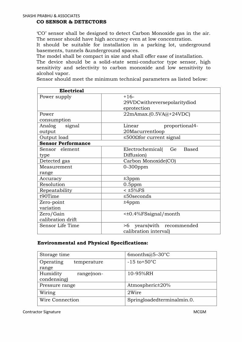
SHASHI PRABHU & ASSOCIATES
Contractor Signature MCGM
CO SENSOR & DETECTORS ‘CO’ sensor shall be designed to detect Carbon Monoxide gas in the air.
The sensor should have high accuracy even at low concentration. It should be suitable for installation in a parking lot, underground
basements, tunnels &underground spaces. The model shall be compact in size and shall offer ease of installation. The device should be a solid-state semi-conductor type sensor, high
sensitivity and selectivity to carbon monoxide and low sensitivity to alcohol vapor. Sensor should meet the minimum technical parameters as listed below:
Electrical
Power supply +16-29VDCwithreversepolaritydiod
eprotection
Power
consumption
22mAmax.(0.5VA@+24VDC)
Analog signal
output
Linear proportional4-
20Macurrentloop
Output load ≤500Ωfor current signal
Sensor Performance
Sensor element
type
Electrochemical( Ge Based
Diffusion)
Detected gas Carbon Monoxide(CO)
Measurement range
0-300ppm
Accuracy ±3ppm
Resolution 0.5ppm
Repeatability < ±5%FS
t90Time ≤50seconds
Zero-point variation
±4ppm
Zero/Gain calibration drift
<±0.4%FSsignal/month
Sensor Life Time >6 years(with recommended calibration interval)
Environmental and Physical Specifications:
Storage time 6months@5–30°C
Operating temperature range
-15 to+50°C
Humidity range(non-condensing)
10-95%RH
Pressure range Atmospheric±20%
Wiring 2Wire
Wire Connection Springloadedterminalmin.0.
Page 206

SHASHI PRABHU & ASSOCIATES
Contractor Signature MCGM
25mm2tomax.2.5mm2
Mounting Wall mounting
Relative Gas Density 0.97(Air=1)
Mounting Height 1.5to1.8meter
Recommended Coverage Area
400m2to750m2,ideal condition assumed
Dimensions(sensor
cartridge only)
38mm(L)xM25mountingdia
meter
Weight(sensor cartridge only)
30g
Sensor Cartridge PolycarbonateIP65
Optional Housings Specifications:
F:ABS,IP44,UL94:V0,weight:0.1KgD:Polycarbonate,
IP65, UL94:V2, weight:0.15KgK:DHousingw
ith DuctKit,weight:0.1Kg
Standards and Approval Compliance:
• EMC Directives2014/30/EU
• CE • IP65/66 (EN60529 / DINVED–0470-1) • Impact Resistant IK08 (DINEEN5012/VDE0470seg.100
• UL508 / CSA Certified C22.2 No.94.1-07-Enclosure for Electrical Equipment
• UL50 / CSA22.2 Certified Enclosure for Electrical Equipment DEMAND CONTROL VENTILATION SYSTEM
VAQ station made out of heavy gauge extruded aluminum of 1.5 mm nominal thickness consists of low leakage extruded aluminum volume
control damper; Rapid Average Pitot tube; Air Flow Straightener (Honeycomb patterned). The VAQ stations shall incorporate air pressure
pickups mounted on station and shall control the minimum amount of outside air as recommended by National Building Code -2016. Motorized assembly for dampers with programmable single space DCV
controller complete with CO2 sensor; shall be able to control VFD, supply air damper; shall communicates on EIA- 485 through Modbus; differential pressure sensor; & step-down transformer of 24V & control
cabling.
Page 207

SHASHI PRABHU & ASSOCIATES
Contractor Signature MCGM
CO2 SENSORS & DETECTORS TECHNICALSPECIFICATION:
Gas detected Carbon Dioxide(CO2)
Sensing element Non-Dispersive Infrared Detector (NDIR) , Gold Plated IR wave guide
(Dual Beam Infra-Red)
Accuracyat25oC(77
oF), 2000ppm
±40ppm+3% reading
Stability <2%of FS over life of sensor (15yr. typical)
Calibration interval ABC Logic Self Calibration System
(Automatic Background Calibration)
Response time <2minutesfor90%step change24 hours(first time)
Warm uptime 10minutes(operation)
CO2 measuring
range 0~2,000ppm(std.)/
0~50,000ppm (std.)
(opt:0~5,000ppm Or
0~20,000ppm)selectable in orders
Power supply 24VAC/24VDC
Consumption 1.5Wmax.; 0.8Wavg.
Analog outputs 0~10VAC or4~20mAselectable by
jumpers
Flow rates 80~ 120cc/min
Operation conditions
0~50oC(32~122oF);0~95%RH,noncondensing
Storage conditions -40~70oC(-40~158oF)
NDIR life 15 years
PHYSICALSPECIFICATIONS:
Net weight 180g
Dimensions 100mm×80mm×28mm
Installment standard 65mm×65mmor 2”×4”wirebox
Wiring Connection Wiring terminals or the power plug(optional)
Standard Approval CE-Approval
Page 208

SHASHI PRABHU & ASSOCIATES
Contractor Signature MCGM
EXPANSION TANK AND AIR SEPERATOR: Pressurized Cold water expansion tank (PN16) suitable for total volume of
water in Cold water circuits along with necessary accessories such as pressurization unit etc. in order to keep Cold water system under (+)
pressure and to prevent entrapment of pressure and to prevent entrapment of air in the system. The system shall also include a fully automatic pressurization unit with 2 pumps (1 Working + 1 Standby) with IP56
protection giving 2 CMH flow rate @ 25m with pressure switch/transmitter, flow meter, interconnecting piping, wiring & control panel completely assembled on skid with all necessary valves & manifolds. The tank shall be
pre-charged steel expansion tank with replaceable heavy duty butyl rubber bladder. The tank shall have a system connection with isolation valve,
drain connections with ball valves and charging valve connection to facilitate the onsite charging of the tank to meet system requirement. The expansion tank shall have pressure gauges fitted with isolation valves and
high capacity auto air vents with isolation valves. The tank shall have safety valve, 50 mm system connection and 20 mm drain and charging
valve connection to facilitate the onsite charging of the tank to meet system requirement. The tank shall be fitted with lifting rings and a floor mounting skirt for vertical installation. The tanks shall be coated with two coats of
anti-corrosive paint (LOW VOC). Two coats of lag coating (Anti-fungal & vapour barrier -5590 standard). It shall be covered with Nitrile Rubber thermal insulation (density 45-60 kg/m3, CFC/HCFC FREE) with
laminated one sided thick glass woven cloth with suitable adhesive. The Adhesive used for shall be of low volatile organic compound. Two coats of
lag coating (Anti-fungal & vapour barrier -5590 standard).The contractor shall submit calculations for total system volume and tank sizing calculations and accordingly expansion tank capacity shall be finalized.
The contractor shall furnish material test certificates of various components & performance test certificates carried out by manufacturer.
Page 209
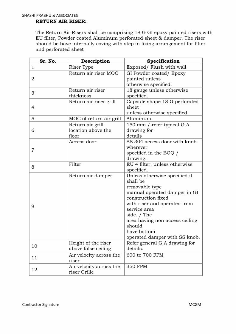
SHASHI PRABHU & ASSOCIATES
Contractor Signature MCGM
RETURN AIR RISER:
The Return Air Risers shall be comprising 18 G GI epoxy painted risers with
EU filter, Powder coated Aluminum perforated sheet & damper. The riser should be have internally coving with step in fixing arrangement for filter
and perforated sheet
Sr. No. Description Specification
1 Riser Type Exposed/ Flush with wall
2 Return air riser MOC GI Powder coated/ Epoxy
painted unless
otherwise specified.
3 Return air riser
thickness
18 gauge unless otherwise
specified.
4
Return air riser grill Capsule shape 18 G perforated
sheet unless otherwise specified.
5 MOC of return air grill Aluminum
6 Return air grill location above the
floor
150 mm / refer typical G.A drawing for
details
7
Access door SS 304 access door with knob wherever
specified in the BOQ / drawing.
8 Filter EU 4 filter, unless otherwise
specified.
9
Return air damper Unless otherwise specified it shall be
removable type manual operated damper in GI construction fixed
with riser and operated from service area side. / The
area having non access ceiling should
have bottom operated damper with SS knob.
10 Height of the riser above false ceiling
Refer general G.A drawing for details.
11 Air velocity across the riser
600 to 700 FPM
12 Air velocity across the riser Grille
350 FPM
Page 210

SHASHI PRABHU & ASSOCIATES
Contractor Signature MCGM
7 HYDRONIC CHILLED WATER CASSETTE UNITS GENERAL
The Cassette units shall be ceiling hung type. Ceiling hung units shall
have 4 way directional air discharges. All units shall be complete with chilled water coil, fins centrifugal fans and motor, cleanable fabric filters, condensate drain pump, drain pan & grill.
CABINETS
Cabinets for Ceiling mounted cassette units shall be constructed of anticorrosive treated galvanized sheet steel, bonderized and insulated
externally. The cabinets shall be of sufficient size to enclose centrifugal turbine fan with direct drive, cooling coil in all 4 directions, with insulated drain pan with condensate pump.
DRAIN PAN
Drain pan shall be fabricated from 20-gauge stainless steel with insulation.
COOLING COIL
All cooling coils shall be standard three row staggered seamless copper tube with aluminum fins. The coil shall be fitted with for connection
with MS pipes. Tubes shall be minimum 9 mm OD of required thickness. Fin spacing shall be between 4 to 5 fins per cm. All bends and joints shall be enclosed within insulated end sections of the base
unit for protection against sweating. Tubes shall be mechanically/hydraulically expanded for minimum thermal contact resistance with fins. The cooling coil shall be easily removable without
disturbing the other Installations. The coil circuit should be sized for adequate water velocity but not exceeding 1.8 M/s. (6 F.P.S.). The fins
shall be uniformly bounded to the tubes by hydraulic expansion of the tubes. The fins material shall be anticorrosive blue coted aluminum.
FANS
Fans shall be forward curved centrifugal type. There shall be one number fan only. The Fan should statically and dynamically balance to give the required air flow.
MOTOR
Motor shall be 220±5% volts, 50 cycles single phase, energy efficient,
speed not exceeding 1000 rpm at maximum airflow. Motors shall have two speed windings and shall be factory wired to a terminal block mounted within the fan section.
Page 211

SHASHI PRABHU & ASSOCIATES
Contractor Signature MCGM
INSTALLATION
Ceiling suspended units and units mounted within the ceiling mounting shall be hung through rubber in shear vibration isolator suspenders.
ACCESSORIES
All Cassette coil units shall be equipped with copper piping connections. In addition, the following accessories are required at coil units;
• LCD Wireless Controller • Auto Restart
WATER CONNECTIONS
The water lines shall be finally connected to the coil of the fan coil unit,
by at least 300mm long, type L seamless solid drawn copper tubing with flare fittings and connections.
Page 212
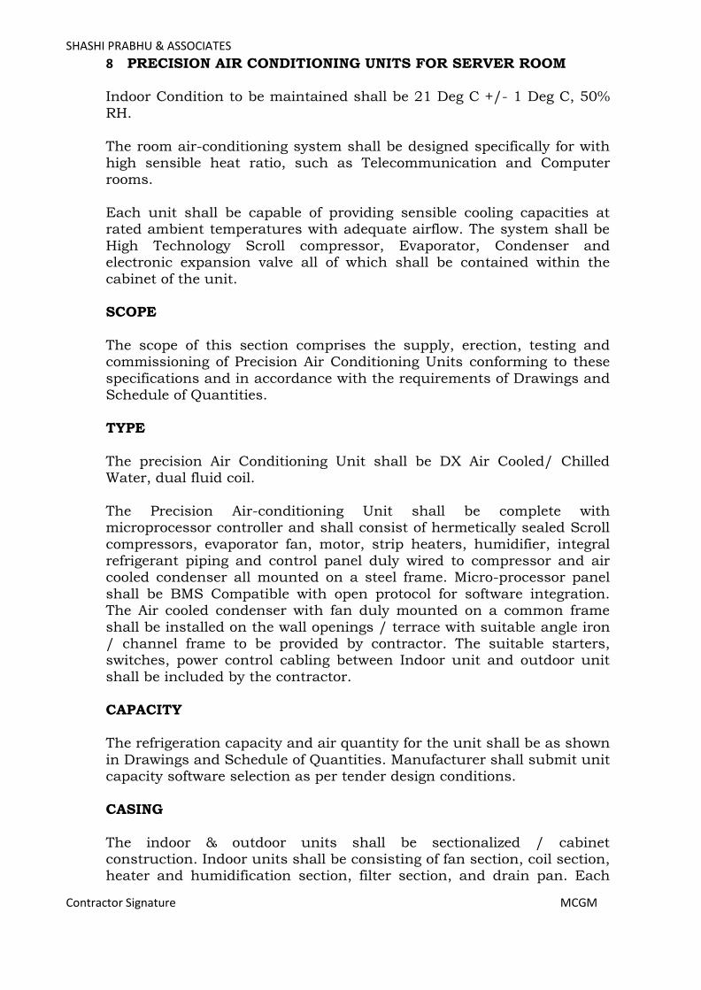
SHASHI PRABHU & ASSOCIATES
Contractor Signature MCGM
8 PRECISION AIR CONDITIONING UNITS FOR SERVER ROOM Indoor Condition to be maintained shall be 21 Deg C +/- 1 Deg C, 50%
RH.
The room air-conditioning system shall be designed specifically for with high sensible heat ratio, such as Telecommunication and Computer rooms.
Each unit shall be capable of providing sensible cooling capacities at rated ambient temperatures with adequate airflow. The system shall be
High Technology Scroll compressor, Evaporator, Condenser and electronic expansion valve all of which shall be contained within the
cabinet of the unit. SCOPE
The scope of this section comprises the supply, erection, testing and commissioning of Precision Air Conditioning Units conforming to these
specifications and in accordance with the requirements of Drawings and Schedule of Quantities.
TYPE
The precision Air Conditioning Unit shall be DX Air Cooled/ Chilled Water, dual fluid coil.
The Precision Air-conditioning Unit shall be complete with microprocessor controller and shall consist of hermetically sealed Scroll
compressors, evaporator fan, motor, strip heaters, humidifier, integral refrigerant piping and control panel duly wired to compressor and air cooled condenser all mounted on a steel frame. Micro-processor panel
shall be BMS Compatible with open protocol for software integration. The Air cooled condenser with fan duly mounted on a common frame
shall be installed on the wall openings / terrace with suitable angle iron / channel frame to be provided by contractor. The suitable starters, switches, power control cabling between Indoor unit and outdoor unit
shall be included by the contractor.
CAPACITY The refrigeration capacity and air quantity for the unit shall be as shown
in Drawings and Schedule of Quantities. Manufacturer shall submit unit capacity software selection as per tender design conditions.
CASING
The indoor & outdoor units shall be sectionalized / cabinet construction. Indoor units shall be consisting of fan section, coil section, heater and humidification section, filter section, and drain pan. Each
Page 213
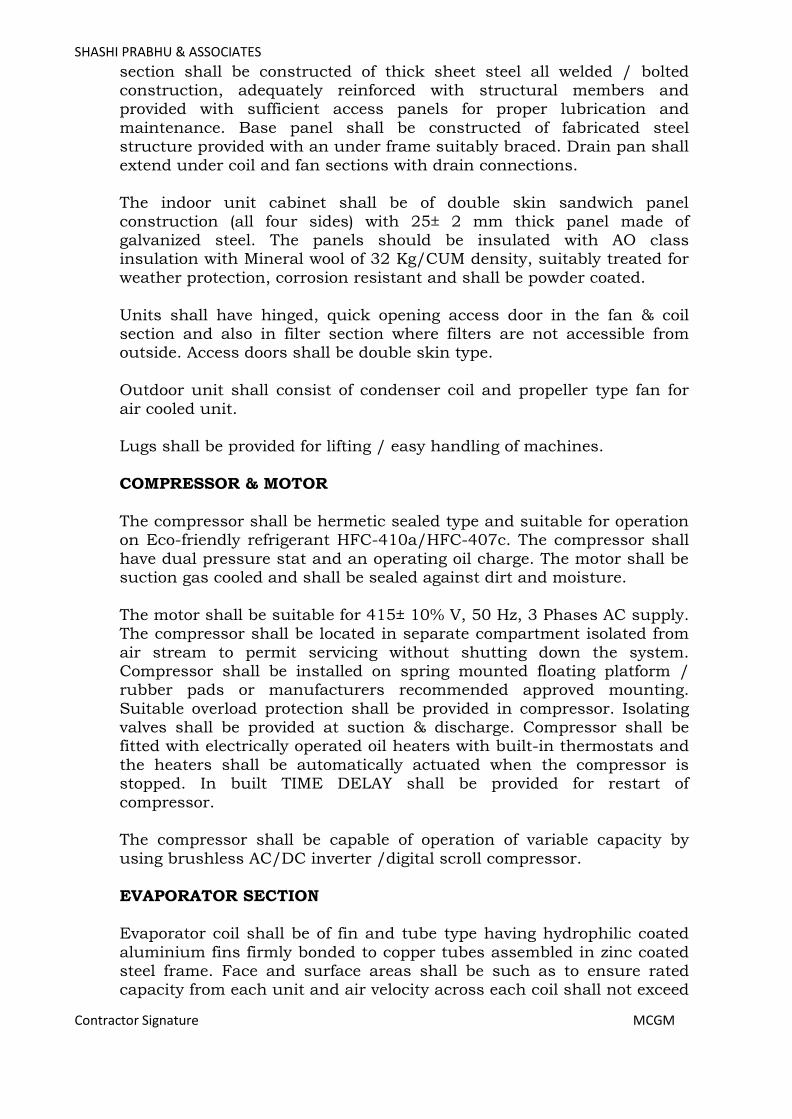
SHASHI PRABHU & ASSOCIATES
Contractor Signature MCGM
section shall be constructed of thick sheet steel all welded / bolted construction, adequately reinforced with structural members and provided with sufficient access panels for proper lubrication and
maintenance. Base panel shall be constructed of fabricated steel structure provided with an under frame suitably braced. Drain pan shall
extend under coil and fan sections with drain connections. The indoor unit cabinet shall be of double skin sandwich panel
construction (all four sides) with 25± 2 mm thick panel made of galvanized steel. The panels should be insulated with AO class insulation with Mineral wool of 32 Kg/CUM density, suitably treated for
weather protection, corrosion resistant and shall be powder coated.
Units shall have hinged, quick opening access door in the fan & coil section and also in filter section where filters are not accessible from outside. Access doors shall be double skin type.
Outdoor unit shall consist of condenser coil and propeller type fan for
air cooled unit. Lugs shall be provided for lifting / easy handling of machines.
COMPRESSOR & MOTOR
The compressor shall be hermetic sealed type and suitable for operation on Eco-friendly refrigerant HFC-410a/HFC-407c. The compressor shall
have dual pressure stat and an operating oil charge. The motor shall be suction gas cooled and shall be sealed against dirt and moisture.
The motor shall be suitable for 415± 10% V, 50 Hz, 3 Phases AC supply. The compressor shall be located in separate compartment isolated from
air stream to permit servicing without shutting down the system. Compressor shall be installed on spring mounted floating platform / rubber pads or manufacturers recommended approved mounting.
Suitable overload protection shall be provided in compressor. Isolating valves shall be provided at suction & discharge. Compressor shall be fitted with electrically operated oil heaters with built-in thermostats and
the heaters shall be automatically actuated when the compressor is stopped. In built TIME DELAY shall be provided for restart of
compressor. The compressor shall be capable of operation of variable capacity by
using brushless AC/DC inverter /digital scroll compressor.
EVAPORATOR SECTION Evaporator coil shall be of fin and tube type having hydrophilic coated
aluminium fins firmly bonded to copper tubes assembled in zinc coated steel frame. Face and surface areas shall be such as to ensure rated capacity from each unit and air velocity across each coil shall not exceed
Page 214
SHASHI PRABHU & ASSOCIATES
Contractor Signature MCGM
500 FPM. The coil shall be minimum 3 row deep for DX coil. For dual feed unit, chilled water coil shall be provided in addition to DX
coil. Chilled water coil shall be minimum 4 rows deep. Coils shall be pitched in the unit casing for proper drainage. Each coil shall be factory-
tested at 21 Kg. per sq.cm air pressure under water. Tube shall be mechanically / hydraulically expanded for minimum thermal contract resistance with fins. The number of fins per cm. shall be 4 to 5.
Chilled Water Coil shall be supplied with 2-way Motorized valve integrated with the unit, controlled for operation on chilled water circuit.
A condensate drip tray of stainless steel construction of minimum 18
SWG thick, duly insulated shall be provided. Dehumidification shall be achieved by reducing the air flow of the EC
fans which thereby would reduce the ADP of the cooling coil to achieve dehumidification.
The Microprocessor panel should be able to perform auto changeover from Chilled water to DX mode and vice versa as and when required due to start and stop of the chilled water. The controller should also be able
to start unit on DX mode, in case the chilled water temperature rises and is unable to maintain inside conditions. Manual change over provision shall also be provided.
BLOWER SECTION
The unit shall be under floor / top discharge type and should be able to deliver between 550-600 CFM per ton. Total external static pressure
shall be of minimum 5 mm of WG for top discharged units. Units with top discharge shall be designed for required static pressure as per actual
ducting arrangement. The units should be equipped with direct driven backward curved plug
fans with electronically commutated brushless motors suitable for 415 ± 10% V, 3 Phase, 50 Hz AC supply. The motor’s high efficiently should make for less energy absorption, especially at partial loads and during
starting. The motor shall be of IP 54 grade. The fan shall be directly coupled having a maximum speed of 1400 R.P.M. The fan speed shall be
controlled through microprocessor panel based on temperature & humidity set points. Fan motor assembly shall be statically and hydraulically balanced and designed for quite operation.
HUMIDIFIER & HEATERS
The humidifier and heaters shall be a built in feature in each machine individually. Humidification shall be provided by boiling water in steam
generator/infrared humidifiers. The steam shall be evenly distributed into the supply air stream of the Air Conditioning Unit. The humidifier shall be self-cleaning and capable of delivering variable capacity steam
Page 215
SHASHI PRABHU & ASSOCIATES
Contractor Signature MCGM
from 30 % to 100% of its total capacity with help of microprocessor. The humidifier shall be fully serviceable with replaceable electrodes. Waste water shall be flushed from the humidifier by initiation of water supply
valve via U-trap. The microprocessor should be able to display the current drawn and actual steam output in the microprocessor.
Heater should be of minimum two stages & heating circuit shall include dual safety protection through loss of air and manual reset high
temperature controls. Electric strip heaters shall be of the low temperature totally enclosed
strip type fitted with radiation fins and suitable for operating at black heat. If overheating occurs, a safety thermostat should cut off the
voltage supply to the heaters and triggers an alarm. Microprocessor should be able to control the humidification and heating through suitable sensors.
FILTERS
Each unit shall be provided with a factory assembled filter section containing washable synthetic type air filters having anodized
GI/aluminum frame. The media shall be supported with HDP mesh on one side and aluminum mesh on other side. Filter banks shall be easily accessible and designed for easy withdrawal and renewal of filter cells.
Filter framework shall be fully sealed and constructed either from aluminum alloy or GI powder coated. Filter banks face velocities shall
not exceed 150 Mt. / minute. The filter shall be suitable for high efficiency dust filtration of minimum MERV 8.
REFRIGERANT PIPING & CONTROLS
Refrigerant piping and fittings within the unit shall be of copper and valves shall be of brass / gunmetal construction. Piping thickness shall be designed based on type of refrigerant and superheated gas pressure
at full load, corresponding to ambient dry bulb temperature of 45ºC. The refrigeration system shall be of the Single/Multiple circuit direct
expansion type and incorporate hermetic scroll compressors. The system shall include a manual reset high pressure control; auto reset low
pressure switch, safety valve, and charging/access ports in each circuit. Each refrigerant circuit shall include the following items:
a. Electronic Expansion Valve with transducers to enable display of
Discharge, Suction Pressures along with Superheat on the microprocessor.
b. Liquid line drier / filter.
c. Liquid Line Sight Glass with Moisture indicator. d. Hand shut off valves / Shredder valves. e. Liquid line receiver.
Page 216
SHASHI PRABHU & ASSOCIATES
Contractor Signature MCGM
f. Liquid Line Solenoid Valve for interception of Liquid Refrigerant The serviceable / removable components shall have union connection
for easily removal / assembly.
All external pipe work shall be carried out with 18G refrigerant quality copper tube and where bends are required; the same shall be completed using either a proprietary bending tool or radius fittings.
AIR COOLED CONDENSER
Each condenser unit shall consist of a heat rejecting coil block constructed from copper tubes expanded on to straight aluminum fins.
The coil shall be factory epoxy coated for protection against corrosive environment.
The fan shall be selected for low speed quiet operation. The fan shall be directly driven by a motor of speed not exceeding 1000 RPM and
constructed from sheet and cast aluminum. When compressor stops condenser fan shall also stop after a suitable time delay.
The fan should be complete with an automatic step-less fan speed controller to maintain constant head under varying ambient conditions. The housing for fan speed controller & isolator shall be of IP 65 grade.
The condenser shall be flexible for mounting in both horizontal and
vertical positions. The entire assembly shall be supported by a corrosion treated frame
having four legs.
ELECTRICAL SYSTEM The electrical power system shall confirm to relevant IS standard. A
main isolator (MCB) shall be provided by the side of each unit, sized to meet the system total power requirement.
Within the panel individual power loads shall be distributed equally across the three phases.
All individual wires shall be of cross linked polythene insulated; armoured Copper cabling, with a low smoke and flame sheath (XLPE)
and colour coded or shall be numbered at their point of termination to facilitate servicing. Low voltage control wiring and power wiring shall be
segregated from each other. The following shall be incorporated:
a. Contactors for automatic Micro Processor Control b. Single phase preventers
Page 217
SHASHI PRABHU & ASSOCIATES
Contractor Signature MCGM
c. Separate over load preventer for all individual components. SAFETY CONTROLS
Following minimum safety controls shall be provided for each unit:
High pressure trip - Manual reset (for each compressor) Low pressure trip - Manual reset (for each compressor)
SAFETY INTERLOCKS
Operation of heaters & humidifier shall be possible only when blower fan is in operation.
Condenser fan shall stop after a suitable time delay on Compressor’s stopping.
MICROPROCESSOR CONTROLS
Following information shall be available on the display on the units. a. Room temperature and humidity.
b. Supply fan working status c. Compressor working status d. Condenser fans working status.
e. Electric heaters working status f. Humidifier working status.
g. Manual / Auto unit status. h. Clogged Filter status i. Temperature set point.
j. Humidity set point. k. Working hours of main component i.e. compressors, fans,
humidifier etc. l. Unit working hours. m. Current date and time.
n. Type of alarm (with automatic reset or block) o. The last 100 intervened alarms.
The microprocessor shall be able to perform following functions:
a. Testing of the working of display system. b. Password for unit calibration values modification. c. Automatic re-starts of program.
d. Cooling capacity control. e. Compressor starting timer.
f. Humidifier capacity limitation. g. Date and time of last 100 intervened alarms. h. Start / Stop status storage.
i. Random starting of the unit. j. Outlet for the connection to remote system. k. Temperature and humidity set point calibration.
Page 218
SHASHI PRABHU & ASSOCIATES
Contractor Signature MCGM
l. Delay of General Alarm activation. m. Alarm calibration.
PAINTING
Units shall be factory finished with durable alkyd spray enamel. Shop coats of low VOC paint that have become marred during shipment or erection shall be cleaned off with mineral spirits, then coated with
enamel paint to match the finish over the adjoining shop-painted surface.
PERFORMANCE RATING
The unit shall be selected for the lowest operating noise level (65 dBA at 3m). Capacity rating and power consumption with operating points clearly indicated shall be submitted with the tenders and verified at the
time of testing and commissioning of the installation. For site verification of working of humidification / dehumidification systems, set
point RH shall be changed below / above (respectively) actual RH. Similar procedure shall be adopted for temperature control system. Test report shall indicated selected set point for RH and temperature and
achieved values of these process variables after humidification / dehumidification cycles are activated.
Page 219
SHASHI PRABHU & ASSOCIATES
Contractor Signature MCGM
9 VARIABLE REFRIGERANT VOLUME/FLOW SYSTEM SCOPE
The scope of this section comprises the supply, erection testing and
commissioning of 100 % inverter based Variable Refrigerant Flow System with hermetically sealed Scroll/ Rotary Compressor conforming to these specifications and in accordance with the requirements.
TYPE
Outdoor units shall be air cooled, variable refrigerant flow air conditioner of R410A gas based consisting of one outdoor unit and
multiple indoor units. Each indoor units having capability to cool independently for the requirement of the rooms.
It shall be possible to connect minimum 20 indoor units on one refrigerant circuit. The indoor units on any circuit can be of different type and also controlled individually. Following type of indoor units shall
be connected to the system:
• Ceiling mounted Four-way flow cassette type • Ceiling mounted Ductable type
• Wall mounted type
• Dx type air handling unit
Compressor installed in outdoor unit shall be equipped with 100 % inverter compressor. The system shall be capable of changing the rotating speed of inverter compressor by inverter controller to follow
variations in cooling and heating load.
Outdoor unit shall be suitable for mix match connection of all type of indoor units.
The refrigerant piping between indoor units and outdoor unit shall be extendable up to 165m actual piping length for outdoor unit with
maximum 50m level difference without any oil traps and total piping length with 1000m.
Both indoor units and outdoor unit shall be factory assembled, tested and filled with first charge of refrigerant before delivering at site.
OUTDOOR UNIT
The outdoor unit shall be factory assembled unit housed in sturdy weather proof casing, constructed from heavy gauge mild steel panels and coated with baked enamel finish. The Unit should be completely
factory wired tested with all necessary controls and switch gears:
Page 220

SHASHI PRABHU & ASSOCIATES
Contractor Signature MCGM
All outdoor units above 8 HP shall have minimum two scroll/ rotary compressors and be able to operate even in case one of compressor is
out of order.
In case of outdoor units above 14HP, the outdoor unit shall have at least 2 inverter compressors so that the operation is not disrupted with failure of any compressor.
All outdoor units must be equipped with optimized heat exchanger.
All outdoor units must be equipped with night time quite operation function which results in less sound level in night time operations of the
outdoors. The nighttime quiet operation shall be with three modes automatic, manual and combined mode.
It should also be provided with duty cycling for switching starting sequence of multiple outdoor units.
The noise level shall not be more than 68 dB (A) at normal operation, measured horizontally 1m away and 1.5m above ground level.
The outdoor unit shall be modular in design and should be allowed for side by side installation.
The unit shall be provided with its own microprocessor control panel.
The outdoor units shall be complete with safety devices namely –high/ low pressure switch, fan driver overload protector, over current relay,
inverter overload protector.
The oil mechanism shall be capable of oil film control by high thrust mechanism.
The heat transfer circuit should perform super cooling before the expansion process in the indoor units.
The outdoor unit’s side panel and outer panel shall be alloyed hot dip zinc coated steel plate with powder polyester resin coating on the inner
and outer surfaces in the thickness of 32 micron. The outdoor unit’s bottom frame shall be hot dip aluminum; zinc and
silicone coated steel plate.
The outdoor unit should be fitted with low noise, aero spiral and aero asymmetrical design fan with multiple speed DC motor. The fan shall be coated with styrene acrylonitrile res in(glass fiber filled) The fan shall be
covered with aero smooth grille which shall be three dimensional, integrated, soft woven steel covered with plastic coating. The fan protective net shall be coated with weather resistant polypropylene
resin.
Page 221
SHASHI PRABHU & ASSOCIATES
Contractor Signature MCGM
INVERTER COMPRESSOR The compressor shall be highly efficient reluctance DC scroll/ rotary
type with neodymium magnets and capable of inverter control. It shall change the speed in accordance to the var iation in cooling load
requirement: The inverter shall be IGBT type for efficient and quiet operation.
All outdoor units shall have step less of capacity control to meet load fluctuation and in door unit individual control. All parts of compressor
shall be sufficiently lubricated. Forced lubrication may also be employed.
Oil heater shall be provided in the compressor casing.
HEAT EXCHANGER
The heat exchanger shall be constructed with copper tubes mechanically bonded to aluminum fins to form a cross fin coil.
The aluminum fins shall be covered by anticorrosion resin film of special acrylic resin. The coils shall be integrally coated with Blygold PoluAl (Aluminum hydroxide, 2530 microns’ thickness) after fins
stamping process or equivalent coating material asrecom mended by manufacturer. The Cu/Al metallic couple will wholly isolate from the
corrosive atmosphere by aluminum coating to raise the ability of anticorrosion.
The unit shall be provided with necessary number of direct driven low noise level propeller type fans arranged for vertical discharge. Each fan
shall have a safety guard. REFRIGERANT CIRCUIT
The refrigerant circuit shall include liquid & gas shutoff valves and a solenoid valve at con denser end.
All necessary safety devices shall be provided to ensure the safe
operation of the system. SAFETY DEVICES
All necessary safety devices shall be provided to ensure safe operation of
the system. Following safety devices shall be part of outdoor unit; high pressure
switch, low pressure switch, fuse, crankcase heater, fusible plugs, over load relay, protection for inverter, and short recycling guard timer.
Page 222

SHASHI PRABHU & ASSOCIATES
Contractor Signature MCGM
OIL RECOVERY SYSTEM Unit shall be equipped with an oil recovery system to ensure stable
operation with long refrigeration piping.
INDOOR UNIT This section deals with supply, installation, testing, commissioning of
various type of indoor units confirming to general specification and suitable for the duty selected. The type, capacity and size of indoor units shall be in
GENERAL
Indoor units shall be either ceiling mounted cassette type, or ceiling mounted ductable type or wall mounted type. These units shall have
electronic control valve to control refrigerant flow rate in response to load variations of the room.
a) The address of the indoor unit shall be set automatically in case of individual and group control
b) In case of centralized control, it shall be set by liquid crystal remote controller
c) The fan shall be dual suction, aerodynamically designed turbo,
multi blade type, statically & dynamically balanced to ensure low noise and vibration free operation of the system. The fan shall be direct driven type, mounted directly on motor shaft having supported from housing.
The cooling coil shall be made out of seamless copper tubes and have continuous aluminum fins. The fins shall be spaced by collars forming
an integral part. The tubes shall be staggered in the direction of airflow. The tubes shall be hydraulically/ mechanically expanded for minimum thermal contact resistance with fins. Each coil shall be factory tested at
21kg/sqm air pressure under water. Noise level should not be more than 42 db at high speed for Hiwall unit.
Noise level should not be more than 40 db at high speed for cassette. Noise level should not be more than 45 db at high speed for Ductable
unit. Unit shall have cleanable type filter fixed to an integrally molded plastic
frame. The filter shall be slide away type and neatly inserted.
Each indoor unit shall have computerized PID control for maintaining design room temperature. Each unit shall be provided with microprocessor thermostat for cooling and heating.
Each unit shall be with wired LCD type remote controller. The remote controller shall memorize the latest malfunction code for easy
maintenance. The controller shall have self-diagnostic features for easy
Page 223

SHASHI PRABHU & ASSOCIATES
Contractor Signature MCGM
and quick maintenance and service. The controller shall be able to change fan speed and angle of swing flat individually as per requirement.
CEILING MOUNTED CASSETTE TYPE UNIT (FOUR WAY TYPE)
The unit shall be ceiling mounted type with four directional flow. The unit shall include pre filter, fan section and DX-coil section. The housing
of the unit shall be powder coated Galvanized steel. The body shall be light in weight and shall be able to suspend from four corners.
Unit shall have an external attractive panel for supply and return air. Unit shall have four-way supply air grilles on sides and return air grille
in center. Each unit shall have high lift drain pump, fresh air intake provision (if
necessary) Low gas detection system and very low operating sound.
All the indoor units regardless of their difference in capacity should have same panel size for harmonious aesthetic point of view. The sound absorbing thermal insulation material shall be polyurethane foam.
CONTROLS & ACCESSORIES
For connection with Dx-type AHU, necessary kit for connection to the VRV/VRF based refrigerant circuit, expansion valve & dries,
thermostat etc. as required shall be provided HIGH WALL TYPE INDOOR UNIT
The unit shall be high wall mounted type. The unit shall include pre-
filters, fan section and DX coil section. The housing of the unit shall be powder coated galvanized steel. The body shall be light in weight and shall be able to suspend from four comers. The fan shall be aero
dynamically designed diffuser turbo fan type. Unit shall have an external attractive panel for supply and return air.
REFRIGERANT PIPING
All refrigerant piping for the air conditioning system shall be constructed from soft seamless upto 19.1mm and hard drawn seamless copper
refrigerant pipes for above 19.1mm with copper fittings and silver soldered joints. The refrigerant piping arrangements shall be in
accordance with good practice within the air conditioning industry, and are to include expansion valves, charging connections, suction line insulation and all other items normally forming part of proper
refrigerant circuits. All joints in copper piping shall be sweat joints using low temperature
brazing and or silver solder. Before joining any copper pipe or fittings, its
Page 224

SHASHI PRABHU & ASSOCIATES
Contractor Signature MCGM
interiors shall be thoroughly cleaned by passing a clean cloth via wire or cable through its entire length. The piping shall be continuously kept clean of dirt etc. while constructing the joints. Subsequently, it shall be
thoroughly blown out using nitrogen.
The air-conditioning system supplier shall design sizes and erect proper interconnections of the complete refrigerant circuit.
The suction line pipe size and the liquid line pipe size shall be selected according to the manufacturers specified outside diameter. All refrigerant pipes shall be properly supported and anchored to the
building structure / cable tray using steel hangers, anchors, brackets and supports which shall be fixed to the building structure by means of
inserts or expansion shields of adequate size and number to support the load imposed thereon.
After the refrigerant piping installation has been completed, it shall be evacuated, for carrying out the air tightness test. The refrigerant piping
system shall then be pressure tested using Nitrogen, gas at a pressure of 4.0 MPaG (580 PSIG) which will be gradually increased. Pressure of 4.0 MPaG (580 PSIG) shall be maintained in the system for atleast 24 hours.
If there is no pressure drop, the system will be considered as having passed the test. If a drop in pressure is detected, search for the leak site by applying soapy water to surface of the piping connections (flares,
brazed joints etc.) and charge the hose connections. A pressure between 0.2 and o.3 MPa G in the piping shall be allowed
after conducting the air tightness test so as to prevent contamination in the piping.
Vacuum drying of the system has to be carried out after passing of air tightness test and will be carried out with a Vacuum Pump which can
bring the pressure below – 100.7 KPaG (755 mm Hg). During Vacuum test, evacuation from both the liquid and gas piping must be carried out. The system in a vacuum state below – 100.7 KPaG (755 mm Hg) shall be
left for atleast 4 hours and in case the gauge indicator does not rise the test will be considered successful. If the gauge indicator rises, there may be moisture remaining or a leak in the circuit.
After completing the vacuum drying, charge the calculated additional
refrigerant from the gas cylinder via the liquid side stop valve service port using pressure difference. The refrigerant must be charged in a liquid state. Digital scale shall be used for measuring the additional
refrigerant quantity.
Page 225

SHASHI PRABHU & ASSOCIATES
Contractor Signature MCGM
10 SPLIT TYPE AIR CONDITIONED UNITS: SCOPE
The scope of this section comprise the design supply, erection, testing
and commissioning of air-cooled package units conforming to these specifications and in accordance with the requirements.
TYPE The units shall consist of hermetic / semi hermetic scroll / Rotary
compressor, motor, evaporator, evaporator fan, air cooled condenser, integral refrigerant piping, microprocessor control panel and wiring.
Indoor unit shall be housed in insulated cabinet consisting of motor, cooling coil, blower with motor, filter & insulated drain pan.
Outdoor unit to be installed on terrace/as directed by engineer in charge, shall consist of compressor, air cooled condenser coil with fans,
all mounted on a anti corrosive treated steel frame.
The machine should be capable of operating with a total piping of 2x50 Meter (Return and supply) out of which the vertical distance can be up to 25 Meters. (Single run)
The machine shall be capable of operating at 45°C ambient.
The total derating on all accounts will not exceed more than 10%.
CAPACITY The refrigeration capacity of air-cooled package units shall be as per
requirements.
COMPRESSOR AND MOTOR Compressor shall be hermetic / semi hermetic scroll/rotary type and
shall have dual pressure stat, and fan operating oil charge. The motor shall be suction gas cooled and shall be sealed against dirt and
moisture. The motor shall be suitable for 3 phase, 50 Hz ±3%, AC supply and provided with necessary safety devices to withstand voltage fluctuation from 340 V to 440 V.
REFRIGERANT PIPING AND CONTROLS:
Refrigerant piping and fitting interconnecting compressor, condenser shall be all cop per and valves shall be brass / gunmetal construction.
Each refrigerant circuit shall include refrigerant filter drier, liquid line valve and thermostatic expansion valve.
Page 226
SHASHI PRABHU & ASSOCIATES
Contractor Signature MCGM
CASING The indoor & outdoor units shall be sectionalized/ cabinet construction.
Indoor units shall be consisting of v, motor, fan section, coil section, filter section, and drain pan. Outdoor unit consist of compressor,
condenser coil & fan. Each section shall be constructed of not less than 18 gauge thick sheet steel all welded/bolted construction, adequately reinforced with structural members and provided with sufficient access
panels for proper lubrication and maintenance. Base panel shall be constructed of fabricated steel structure, provided with an under frame suitably braced. Each unit shall include one-piece drain pipe
constructed of 18 gauge galvanized sheet steel plate. Drain pan shall be extending under coil and fan sections with drain connections.
Removable panels in fan and coil sections shall provide access to all internal parts.
Panel shall be internally lined with 2.5 cm thick fiberglass/or equivalent as per section “Insulation” for the thermal insulation and acoustic
lining. FAN MOTOR AND DRIVE
Fan motor shall be TEFC suitable for 1/3 phase, 50 Hz ±3%, AC supply and provided with necessary safety devices to withstand voltage
fluctuation from 160250 ( for single phase machines) and 340 V to 440V (for 3 phase machines). Motor shall be provided with soft Starters of
required capacities. Motors shall be especially designed for quiet operation and motor speed shall not exceed 1440 rpm. Drive to fan shall be provided either directly or through belt drive with an adjustable
motor sheave. Belts shall be of the oil resistant type.
FAN Fan wheels and housing shall be fabricated from minimum 18G sheet
steel. Fan wheels shall be of double width, double inlet forward curve, multi speed, multi blade type enclosed in a housing with electrical heating with strip heater and mounted on a common shaft. Fan
housings shall be made of deformed steel sheets with stream lined inlets to ensure smooth air flow into the fans. Fan shaft bearing shall be
oil/grease lubricated. Bearing shall be mounted externally for servicing without dismantling of the unit. All rotating parts shall be dynamically balanced individually, and the complete assembly shall be statically and
dynamically balanced. Fan speed shall not exceed 1000 rpm and maximum fan outlet velocity shall be 550 meters per minute.
COOLING COIL
Cooling coil shall be fin and tube type having aluminum fins firmly bonded to copper tubes assembled in zinc coated steel frame. Face and surface areas shall be such as to ensure rated capacity from each unit
and air velocity across each coil shall not exceed 150 meters per minute.
Page 227
SHASHI PRABHU & ASSOCIATES
Contractor Signature MCGM
The coil shall be pitched in the unit casing for proper drain age. Each coil shall be factory tested at 21 kg. Per sq.cm. air pressure under water. Tube shall be mechanically / hydraulically expanded for minimum
thermal contact resistance with fins. The no. of fins per cm. shall be 4 to 5.
VIBRATION ISOLATORS
The indoor and outdoor units shall be provided with vibration isolators. PAINTING
Package units shall be factory finished with durable alkyd spray enamel.
Shop coats of paint that have become marred during shipment or erection shall be cleaned off with mineral spirits, then coated with enamel paint to match the finish over the adjoining shop painted surface.
PERFORMANCE RATING
The unit shall be selected for the lowest operating noise level. In all air conditioned spaces noise level should not exceed NC35, 2m away from
face of supply air outlet. Capacity ratings and power consumption with operating points clearly indicated shall be submitted with the tenders and verified at the time of testing and commissioning of the installation.
TEMPERATURE CONTROLS
Each unit shall be provided with a temperature control assembly complete with cooling thermostat etc. All the controls except remote
thermostat shall be factory wired and located in a weather proof enclosure. These shall include fuses, selector switch, safety controls,
SPP, winding over heat protection and any other controls as may be necessary for safe and trouble free operation of the unit. Packaged unit shall have interlocking with the condenser fans.
MISCELLANEOUS
• Necessary charge of refrigerant gas and lubricant oil.
• Necessary concrete pedestals with vibration isolators for the unit as approved by the engineer.
• Continuous purge system with automatic purging of non-condensable gases/refrigerant
• Flexible connection at the fan outlet.
• Control wiring from unit to remote thermostat.
• Suction, discharge and oil pressure gauge in refrigerant circuit.
• Refrigerant flow control shall be provided.
• In Case of Dx type AHU, the Condensing unit shall be provided with all necessary accessories required for connections like –Expansion valve, driers, control thermostat etc.
Page 228

SHASHI PRABHU & ASSOCIATES
Contractor Signature MCGM
11 STP EXHAUST AIR TREATMENT (DEODORIZATION SYSTEM) The system shall comprise individual compartments for Ozone
Generator, Fan, and Electrical/ Instrumentation Components. The equipment shall be UL listed.
Ozone Generator Compartment shall comprise set of multi plate, double sided corona discharge plates operating in unison to produce adequate
quantity of ozone at medium concentration. Material of construction of all parts shall be Stainless Steel.
The system shall not require any replacement consumable except air filter, and maintenance shall be minimum or near zero subject to timely
replacement of intake air filter to the unit. The ozone generating corona and ozone wetted parts shall be confined in
a fully welded stainless steel enclosure to prevent ozone leaks. It shall be provided with openable glass or plexi glass panel for inspection of corona plates while the equipment is in operation. The outer enclosure of the
equipment shall be provided with lockable doors to provide easy access to the glass inspection panel.
The corona chamber shall not have any trace of exhaust air while it starts and operates. Necessary ROHS compliant and UL listed electrical
relay shall be provided to ensure this safety feature. The electrical compartment shall be isolated from all other compartments, and rated
to NEMA 4X (IP 66). The transformer shall be electrical induction type, UL listed. It shall not damage, burn, or elevate in temperature even if short circuit occurs. Shall revert to normal operation upon removal of
short circuit. The transformer shall be fully encapsulated and housed in metallic enclosure for safety against moisture and water impregnation.
Passage of high voltage conductors across metallic enclosure shall be through UL listed liquid tight connectors.
For deodorization of exhaust air from STP, system compliance to NFPA 820 or classified area (Class 1, Div 1 II) shall be attainable by installing
the equipment outside the plant room and by duct connection to exhaust air from the plant room.
High voltage cable shall be silicon insulated, ozone and corona resistant, rated for 20 KV, and UL listed with UL flame test rating.
Following accessories shall be provided in the electrical compartment;
a. UL listed Manual Regulator to modulate production of ozone.
b. UL listed Hour Meter housed in NEMA 4 enclosure for timely maintenance. c. Air Pressure Manometer for measurement of air pressure in fan
chamber.
Page 229
SHASHI PRABHU & ASSOCIATES
Contractor Signature MCGM
d. UL listed switches such as DPST Main On Off Switch, Fan On Off Switch, Indicating Lamps, and Terminal Block.
Fan chamber shall comprise backward curved non overloading fan driven by thermal protected, UL listed TEFC motor to inject ozonized air
into exhaust air stream. External static pressure of the fan shall be rated for injection into airstreams from 0.25” WG (60 Pa) up to 2” WG (500 Pa). Air intake shall be through grille with filter track and UL listed
MERV 11 filter. Contact Chamber of stainless steel construction of adequate volume
shall be field or manufacturer provided for design contact volume.
The system shall be rated for operation on 220/240 V, 1 Ph, 50/60 Hz & supplied with Control Panel H2S Monitor, DLC Controller, and Ozone Monitor Listed to UL 867A, for automatic modulation. The system shall
Delivers 0 – 10 VDC for BMS interface.
Page 230

SHASHI PRABHU & ASSOCIATES
Contractor Signature MCGM
12 VENTILATION FAN GENERAL (FANS)
Fans shall be of the type, size, arrangement and capacity as indicated in
the schedule and/or as shown on the drawings.
Unless specified, fan performance rating data shall be tested accordance
with AMCA Standard 210-85 (Air Moving and Conditioning Association), ANSI/ASHRAE Standard 51-1985 “Laboratory Methods of Testing Fans for Rating”. Sound ratings shall conform to AMCA Standard 300-85,
“Reverberant Room Method for Sound Testing of Fans”.
A computer printout of fan performance rating corresponding to the AMCA licensed data, with corrected ratings for altitude and temperature, fan operating speed, bearing life, etc. shall be submitted for approval.
All fans shall be dynamically trim-balanced to ISO1940 and AMCA 204/3 - G2.5 quality grade after assembly. A computer printout with the vibration
spectrum analysis shall be attached to the fans.
Fan motors shall comply in all respects with continuous rating in accordance with IEC34 or equivalent. Motor bearings shall be of ball or roller type, grease or lubricant sealed for life. Fan and drive shall be
earthed to prevent accumulation of static charge.
Kitchen exhaust fan shall be of Bifurcated Axial or SISW Centrifugal direct or belt driven type. DIDW Centrifugal and Direct Drive Axial Flow Fan where belts or motor are in the air stream are not acceptable.
Fans shall be installed at staircase or lobby where fresh air intake is free from any obstruction and shall be energized only by fire alarm system. Fan
shall be of Axial Flow Fan or DIDW Centrifugal Fan. Protective wire mesh with MERV-7 fresh air filter at the suction of the fan is required.
Fans for elevated temperature (Smoke Extraction Fans) with components rated for high temperature (250C, 2Hrs) service, with belt drive assemblies
exposed to the air stream are not acceptable.
For Smoke Extraction Fans where motor is in the air stream with electrical/electronic temperature limit switch for motor protecting shall not be used.
Anti-condensation heater is recommended to be installed for all Pressurization and Smoke Spill Fans, and the control circuit shall be arranged such the way that the heater is off when the starter is on and vice
versa. Heaters shall be wired from the respective local motor control panel
Page 231
SHASHI PRABHU & ASSOCIATES
Contractor Signature MCGM
or motor control console.
Fan should be of G-90 high grade galvanized steel or carbon steel with
epoxy coat.
If fan is open to atmosphere, Fans shall be with pure polyester powder
coating for minimum thickness of 60 microns.
IN-LINEFANS:
Circular/Cabinet Inline fans shall be complete with DIDW forward/backward curved centrifugal impeller fitted with external rotor
motor of galvanized steel, insulated or un-insulated housing, belt/direct driven motor, vibration isolators, direction of discharge and rotation position
shall be as per the job requirement and shall be marked on the fan assembly.
Housing shall be constructed of hot rolled GSS sheet metal construction. Housing metal parts shall be either spot-welded or screwed or mounted
together with rivets. Indication showing rotation arrow and make, model number and duty conditions of the fan shall be available on the housing. The fan shall be of double skin construction with 20-gauge GI outer skin
with 25 mm glass wool wrapped tissue paper and covered with 20 gauge perforated GI sheet from inside shall be as specified in schedule of quantities.
Fan wheel shall be DIDW forward/backward curved type, statically and
dynamically balanced. The fan shall be provided with ball bearings can be used in any mounting
position at maximum indicated temperature. The bearing lubricant shall be suitable for a minimum ambient temperature of minus 150C (admissible for
a short time without reaching dew point at minus 300C). For applications at maximum indicated ambient temperature life expectancy shall be 40000 hours minimum.
Motor shall be with minimum IE3 rating. Fan motor, fans shall be supplied with built-in-thermal contact (TK) at the critical high temperature point (“B”
= 1300C. The thermal contact shall open and break the power supply to the fan; Fan motors have insulation class “B” and protection class IP54. Motor
shall be suitable for external power supply 200~220V/50Hz/Single Phase OR 415+10% v/50Hz/Three Phase.
Fans shall be belt/direct driven type.
Fan should be provided with factory made built in hanging clits bolted firmly on fan body with the holes for installation. Direction of rotation to be marked firmly on fan body.
All fan shall be electronic speed regulator & wiring with 3 pin plug top
Page 232
SHASHI PRABHU & ASSOCIATES
Contractor Signature MCGM
between fan & speed regulator for single phase fans. In case of 3-phase fan with DOL starter panel & FRLS power cabling, earthing etc. between starter panel & fan. The incoming power supply to speed regulator/ starter panel
shall be provided by electrical contractor. Wire guard and bird-screen
Gravity louvers at fan discharge duct outlet.
Single-phase preventers for 3 phase fans.
Wiring between regulator and fan motor including termination at both
ends.
PROPELLER FANS: Propeller fans shall be direct driven, three or four blade type mounted on a
steel mounting plate with orifice ring. Mounting plate shall be of steel construction, square with streamlined
venture inlet coated with baked enamel paint. Mounting plate shall be of standard size, constructed of 12 to 16 gauge steel sheet depending upon the
fan size. Orifice ring shall be correctly formed by spinning or stamping to provide easy passage of air without turbulence and to direct the air stream.
Fan blades shall be constructed of aluminum or glass reinforced polypropylene. Fan hub shall be of heavy welded steel construction with
blades bolted to the hub fan blades and assembly shall be statically and dynamically balanced.
Shaft shall be of steel accurately ground and shall not pass through first critical speed through entire range of specified fan speed.
Motor shall be with minimum IE3 rating. Motor shall be standard permanent split capacitor of shaded pole for small sizes, totally enclosed
with pre-lubricated sleeve or ball bearings, designed for a quiet operation with a maximum speed of 1000 RPM for fans 60 cm dia or larger and 1440 RPM for fans 45 cm dia and smaller. Motors for larger fans shall be suitable
for 415 ± 6% volts. 50 cycle 3-phase power supply and for smaller fans shall be suitable for 220 ± 6% volts, 50 cycles single-phase power supply. Motors
shall be suitable for horizontal or vertical service as indicated in drawings and Schedule of Quantities.
Propeller fans shall be provided with following accessories: -
Wire guard and bird-screen
Gravity louvers at outlet
Regulator for controlling fan speed for single-phase fan motor.
Page 233
SHASHI PRABHU & ASSOCIATES
Contractor Signature MCGM
Single-phase preventers for 3 phase fans.
Wiring between regulator and fan motor including termination at
both ends.
3 pin plug top with power cable with earthling from fan motor to 3 pin socket shall be
Included in installation cost of fan.
SMOKE SPILL TUBE AXIAL FLOW FANS (DIRECT DRIVE) :
Fans shall be licensed to bear the AMCA Air and Sound Certified Ratings Seal. The test standard used shall be ANSI/AMCA 210-85, ANSI/ASHRAE Standard 51-1985 “Laboratory Method of Testing Fans for Rating” and
AMCA 300 “Reverberant Room Method for Sound Testing of fans”. To achieve the minimum and equal clearance between the blade tips and
casing, tube casing shall maintain its roundness by means of using one piece of sheet metal with 90 edge flanging up.
Fan motor base support shall be properly secured (locked and sealed) to the fan housing and be of adjustable type to have precise control of motor
shaft central position as well as running clearance between blade tips and casing. Motor (KW/HP) shall be able to be changed or upgraded at site
without changing fan housing or ducting construction. Fans supplied shall be complete with factory fabricated mounting bracket
(ceiling or foot mounted) and suction/discharge matching flanges as accessories.
All hubs shall be cast Aluminum alloy (Grade LM2) unless for Smoke Extractor Fans where high temperature (250C/2Hrs) air is expected then
Aluminum alloy or steel fan impeller blades are required. Otherwise impeller blade material with Polypropylene (PP), Glass-reinforced Polypropylene (PPG) and Glass-reinforced Polyamid (PAG), to provide self-
balancing, anti-static, anti-sparking characteristic is preferable.
Running clearance between blade tips and casing shall not exceed 1% of the impeller diameter, and 2% for smoke spill high temperature fan where mechanical expansion coefficient is different from normal ambient
temperature. Fan manufacturer shall provide the fan assembled with the dame clearance between blade tips and casing of the tested prototype. Note that the air performance and pressure loss are greatly affected by this
clearance.
Impellers shall be secured to the drive shaft by a key and keyway. Axial location shall be provided by a collar or shoulder on the drive shaft together with a retaining washer and screw fitted into a tapped hole at the end of
the shaft and locked in position. Blades shall be secured in place to the
Page 234
SHASHI PRABHU & ASSOCIATES
Contractor Signature MCGM
angle setting by setscrews, locking nuts or setting pins. Fan motor shall be totally enclosed and external terminal box of at least
IP56 shall be provided.
Motor shall be with minimum IE3 rating. Fans shall not exceed 1500 RPM.
All fans after assembly shall be dynamically trim-balanced to ISO1940 and AMCA 204/3 - G2.5 quality grade. A computer printout with vibration
spectrum analysis shall be attached to the fans.
Fan should be of G.S.S., the Steel sheet should be JFE Galva zinc (Base metal cold rolled), JIS G3302, SGCC with Z22 (minimum coating weight on both sides @ 220 g/m2) zinc coating & Zero Spangle, skin
passed, chromate and dry.
TUBE AXIAL FLOW FANS (DIRECT DRIVE): Fan shall be complete with motor, motor mount, direct driven and vibration
isolation type, suspension arrangement as per approved for construction shop drawings. Fresh air fans shall be equipped with filters as specified in schedule of quantity.
Casing shall be constructed of heavy gauge sheet steel. Casing shall be
provided with hinged door enabling easy replacement of wheel, shaft and bearings. A small inspection door with handle and neoprene gasket shall also be provided. Casing shall have flanged connection on both ends for
ducted applications. Support brackets for ceiling suspension shall be welded to the casing for connection to hanger bolts. An inspection door
with handle and neoprene gasket shall be provided. Casing shall have flanged connection on both ends for ducted applications. Fan casing are with internal punched inlet and outlet flanges to prevent air leakage, for
size up to 1600 mm dia. and shall be constructed of rolled steel with a continuous seam welded. Support brackets for ceiling suspension shall be welded to the casing for connection to hanger bolts. Straightening vanes
shall be aerodynamically designed for maximum efficiency by converting velocity pressure to static pressure potential and minimizing turbulence.
Casing shall be bonderized, primed (minimum 2 coats of rust-proof primer) and finish coated with enamel paint or powder coated after phosphating process.
Straightening vanes shall be aerodynamically designed for maximum
efficiency by converting velocity pressure to static pressure potential and minimizing turbulence. Casing shall be de-rusted, cleaned, primed and finish coated with enamel paint.
Rotor hub and blades shall be of cast aluminum, or cast steel construction. Blades shall be die-formed aero foil shaped for maximum efficiency and
shall vary in twist and width from hub to tip to effect equal air distribution
Page 235
SHASHI PRABHU & ASSOCIATES
Contractor Signature MCGM
along the blade length. Fan blade mounting on the hub shall be statically and dynamically balanced. Extended grease leads for external lubrication shall be provided. The fan pitch control may be manually re-adjustable at
site, upon installation, for obtaining actual airflow values, as specified.
Motor shall be with minimum IE3 rating. Motor shall be of 3 phase squirrel-cage totally enclosed, fan cooled type. Motor and starter shall be conform to IS: 1822 ―Motor starters of voltage not exceeding 1000 volts‖
and shall be air insulated and suitable for 415 volts, + 10%, 50 Hz., 3 phase AC supply. Enclosures shall have protection of IP 54.
Starter for the motor shall be direct on line (D.O.L) for motors up to and including 7.5 H.P. rating and automatic star-delta close transition type for
motors of higher ratings unless otherwise specified in the tender specifications. Starters shall be rated for intermittent duty. Starting current should not exceed two times the full load current.
The starter shall be mounted on the main electrical control panel/ unit
mounted/ self-mounted as specified. Each starter shall be provided with the following protections: -
a) Thermal overload on all the three phases with adjustable settings, b) Under voltage protection, and c) Independent single phasing preventer. (current sensing type)
Adequate number of extra NO/ NC contacts for interlocks, indicating lamps
etc. shall be provided on the starter/ contactor. The speed of fan shall not exceed 1000 RPM for fans with impeller diameter
above 450 mm, and 1450 RPM for fans with impeller diameter of 450 mm and less.
Vibration Isolation
Base shall be provided for each fan. Base for both fan and motor shall be built as an integral part and shall be mounted on a concrete foundation through cushy foot vibration isolators. The concrete foundations shall be at
least 15 cm above the finished floor level and shall be further isolated from the structural floor through 5 cm. Thick layers of sand all around, topped
with bitumen. In case ceiling hung fan within the ceiling shall be provided Vibration Isolation Suspension (VIS) shall be provided in each of string.
CENTRIFUGAL FANS
Centrifugal fans shall be of double-width, double-inlet construction, with bearing on both sides, complete with access door, squirrel-cage induction motor, V-belt drive, belt guard etc.
The Fan &motor assembly should be weatherproof, suitable for outdoor mounting and application. Fan to be UL 762 certified for kitchen &
restaurant exhaust application all fans should be AMCA rated and UL
Page 236
SHASHI PRABHU & ASSOCIATES
Contractor Signature MCGM
listed Housing shall be of heavy gauge sheet steel in welded construction. It shall
be rigidly reinforced and supported by structural angles. Split casing shall be provided on larger sizes of fans. However neoprene/ asbestos packing
shall be provided throughout split joints to make it airtight. 1.2 mm galvanized wire mesh inlet guard, of 5 cms sleeves shall be provided on both inlets. Housing shall be provided with access door with quick locking
tension handles and neoprene gasket. Rotation arrow shall be clearly marked on the housing.
Fan wheel shall be of GSS and backward curved non-overloading type unless otherwise specified. Fan wheel and housing shall be statically and
dynamically balanced. Fan outlet velocity shall not exceed 610 meters per minute.
Shaft shall be constructed of steel, turned, ground and polished.
Bearings shall be of the sleeve/ball bearing type mounted directly on the fan housing. Bearing shall be self-aligned, oil grease packed, pillow block type.
Drive to fan shall be provided from 3 phase electric motor through belt with adjustable motor sheave and belt guard. Belt shall be of the oil resistant
type. The number of belts shall be not less than two.
Motor shall be with minimum IE3 rating and TEFC type. Motor shall be of 3 phase squirrel-cage totally enclosed, fan cooled type. Motor and starter shall be conform to IS: 1822 ―Motor starters of voltage not exceeding 1000
volts‖ and shall be air insulated and suitable for 415 volts, + 10%, 50 Hz., 3 phase AC supply. Enclosures shall have protection of IP 54.
Starter for the motor shall be direct on line (D.O.L) for motors up to and including 7.5 H.P. rating and automatic star-delta close transition type for
motors of higher ratings unless otherwise specified in the tender specifications. Starters shall be rated for intermittent duty. Starting current should not exceed two times the full load current.
The starter shall be mounted on the main electrical control panel/ unit
mounted/ self-mounted as specified. Each starter shall be provided with the following protections: -
a) Thermal overload on all the three phases with adjustable settings, b) Under voltage protection, and
c) Independent single phasing preventer. (current sensing type) Adequate number of extra NO/ NC contacts for interlocks, indicating lamps
etc. shall be provided on the starter/ contactor. CABINET FANS (BELT DRIVEN)
Page 237
SHASHI PRABHU & ASSOCIATES
Contractor Signature MCGM
The impellers of the fan or fan shall be of GI sheets, double inlet backward curved centrifugal design, both statically and dynamically balanced. The fan housing shall be of sturdy construction made from double skinned GSS
casing having 0.6mm pre-coated GI sheet outside and plain 0.6mm thick GI sheet inside with 25 mm thick puff insulation with smooth air inlets.
The fan shall be mounted on properly aligned shaft and mounted on self-aligning bearing blocks. The casing of the cab section shall be made of 16 G (1.6mm) GI sheets suitably reinforced to provide rigidity. The frame work
shall either be folded G.I. sheets or of hot dipped galvanized iron. Fresh air fans shall be equipped with filters as specified in schedule of quantity
The fan section shall be complete with V belt drive, belt guard and motor mounting base in case of Belt driven type.
Drive to fan shall be provided from 3 phase electric motor through belt with adjustable motor sheave and belt guard. Belt shall be of the oil resistant type. The number of belts shall be not less than two.
Motor shall be with minimum IE3 rating. Motor shall be of 3 phase
squirrel-cage totally enclosed, fan cooled type. Motor and starter shall be conform to IS: 1822 ―Motor starters of voltage not exceeding 1000 volts‖ and shall be air insulated and suitable for 415 volts, + 10%, 50 Hz., 3
phase AC supply. Enclosures shall have protection of IP 54. Starter for the motor shall be direct on line (D.O.L) for motors up to and
including 7.5 H.P. rating and automatic star-delta close transition type for motors of higher ratings unless otherwise specified in the tender
specifications. Starters shall be rated for intermittent duty. Starting current should not exceed two times the full load current.
The starter shall be mounted on the main electrical control panel/ unit mounted/ self-mounted as specified.
Each starter shall be provided with the following protections: - a) Thermal overload on all the three phases with adjustable settings,
b) Under voltage protection, and c) Independent single phasing preventer. (current sensing type)
Adequate number of extra NO/ NC contacts for interlocks, indicating lamps etc. shall be provided on the starter/ contactor.
CABINET FANS (DIRECT DRIVEN)
Cabinet Inline/Cabinet backward curved type direct driven fans installed in ICU/HDU and other clinical areas. The impellers of the fan or fan shall be
of GI sheets. The fan housing shall be of sturdy construction made from double skinned GSS casing having 0.6mm pre-coated GI sheet outside and plain 0.6mm thick GI sheet inside with 25 mm thick puff insulation with
smooth air inlets. The fan shall be mounted on properly aligned shaft and mounted on self-aligning bearing blocks. The casing of the cab section shall be made of 16 G (1.6mm) GI sheets suitably reinforced to provide rigidity.
The frame work shall either be folded G.I. sheets or of hot dipped
Page 238
SHASHI PRABHU & ASSOCIATES
Contractor Signature MCGM
galvanized iron. The fan section shall be complete with brushless EC motor mounting base.
Drive to fan shall be provided from 3 phase electric motor through direct drive type complete with Brushless EC motor.
Motor shall be with minimum IE3 rating. Motor shall be of 3 phase squirrel-cage totally enclosed, fan cooled type. Motor and starter shall be
conform to IS: 1822 ―Motor starters of voltage not exceeding 1000 volts‖ and shall be air insulated and suitable for 415 volts, + 10%, 50 Hz., 3 phase AC supply. Enclosures shall have protection of IP 54.
The Fan speed must be 100% adjustable with the potentiometer placed in
the connection box. Fan should be send Analogue input with terminals in the terminal box to control the fan with 0-10V input signal. Models are suitable for mounting in any orientation and operation within ambient air
temperatures between -20ºC up to +40ºC
Starter for the motor shall be direct on line (D.O.L) for motors up to and including 7.5 H.P. rating and automatic star-delta close transition type for motors of higher ratings unless otherwise specified in the tender
specifications. Starters shall be rated for intermittent duty. Starting current should not exceed two times the full load current.
The starter shall be mounted on the main electrical control panel/ unit mounted/ self-mounted as specified.
Each starter shall be provided with the following protections: - a) Thermal overload on all the three phases with adjustable settings,
b) Under voltage protection, and c) Independent single phasing preventer. (current sensing type)
Adequate number of extra NO/ NC contacts for interlocks, indicating lamps etc. shall be provided on the starter/ contactor.
Page 239
SHASHI PRABHU & ASSOCIATES
Contractor Signature MCGM
13 DRY SCRUBBER UNIT GENERAL:
The scrubber shall be made to take care of the kitchen exhaust which
shall comprise mainly of Black soot; unburnt oil and odour of roasted food from tandoor etc. Care will be taken to handle high volume of gases and P/V (Pollutants / Volumetric flow rate) ratio less than 0.001 means
size of particulate matter which is reason for foul smell. TECHNICAL PARAMETERS:
The unit shall provide efficiency of 90% or better for single pass base on
ASHRAE test method at flow rates of 800 – 1300 CFM per module (supported by sample test report by a US laboratory).Multiple units can
be joined together for increased volume. The system shall be suitable to connect to fan section with average velocity of 500 FPM across air
cleaner. The unit shall be CE-certified. EQUIPMENT SPECIFICATIONS:
The unit shall be designed and constructed and supplied by a specialized manufacturer capable of issuing complete data of the
product. UNIT HOUSING:
Housing shall be 16gauge zinc coated steel construction to protect
against rust and corrosion. Each section shall include single door access, located one side of the unit. The access door shall be mounted
on steel hinges and secured with adjustable, gasket sealed lever latches allowing for component access and removal. All doors shall be provided with gasket to prevent air leakage. Doors to charged high voltage
components shall be equipped with electrical interlocks, for interconnection into the primary power supply, to prevent access when the components are energized. The housing shall be furnished
completely assembled for ease of shipment and installation. Between each section, a permanent 1/8” thick gasket shall be installed to prevent
leakage. The bottom drain pan under ESP section containing integral washing systems shall be pitched downward 1/4“per foot minimum towards a 3” NPT drain nipple. The casing of the Fan assembly shall be
double skin, same as of fan section units.
BLOWER SECTION: The blower section shall comprise of Centrifugal Backward Curved SISW
fan wheel of totally GI Construction with Inlet Cones and shall be complete with individual motor and drive and shall be mounted on C Channel frame and Cushy Foot or Spring Mounts. The fan shall have a
capacity not less than the specified in the catalogues and shall be
Page 240

SHASHI PRABHU & ASSOCIATES
Contractor Signature MCGM
constructed and rated based on delivery against the rated static pressure with the media and filters in place. The fan will be of riveted construction and made with GI sheet of required thickness. The fan
wheel will be of the multi blade type and mounted on two self-aligning pillow block bearings of the requisite size. The fan shall be run with the
help of “V” Groove drives as per the re-commendation of the drive supplier. The blower housing will of the Pittsburg joint construction and the drive will be provided by a motor of adequate capacity. The motor
plate will be constructed out of 12 G MS or heavier metal with slotted holes, which permit belt adjustment in both the directions. The outlet velocity of the blowers will be kept low.
Fan motors shall be 415 ±10% volts, 50 cycles, 3 phase, AC squirrel –
cage, totally enclosed fan cooled with class F Insulation and IP – 55 protections. Motor shall be especially designed for quiet operation and motor speed shall not exceed 1450 RPM. Drive to fan shall be provided
through v-belt – drive arrangement. Belts shall be of the oil resistant type. The whole fan & motor assembly shall be isolated with other air
scrubber system. BASE CONSTRUCTION:
The sections are to be mounted on a structural C-channel or floor
mounting or ceiling suspension. Lifting lugs shall be incorporated in the base channel to allow for rigging, if or dared.
FINISH:
The external casing finish shall be a durable industrial grade semi-gloss
bakedon epoxy ester, not less than 3 mill minimum thickness.
CELLS WASH MODULE:
The Cells Wash module shall incorporate mechanical filtration. The stationary filter from the direction of airflow will be a metal mesh filters with single, gasket access doors. Wash manifolds and headers are
supplied to wash the module during the normal wash cycle.
ELECTROSTATIC PRECIPITATOR MODULE: The electronic air cleaner shall be the two stage dual voltage plate type
cells, rated at not less than 90% efficiency as per the ASHRAE test standards for dry particulate (supported by sample test report by a US laboratory). The collection cells shall be in Single Pass arrangement to
provide for maximum collection efficiency.
IONIZING COLLECTION CELL: Ionizing Collecting cell(s) shall be of one-piece construction 14.23”
inches deep in direction of airflow. All support framing, end plates and
Page 241

SHASHI PRABHU & ASSOCIATES
Contractor Signature MCGM
ionizer ground electrodes shall be 0.090-inch-thick aluminum. Both repelling and collector plates shall be 0.020-inch-thick aluminum, 9.125 inch deep in direction of airflow and rigidly retained in place with
tubular spacers and tie rods. Spacing between plates shall be no less than 0.175 inch. Ionizing electrodes shall be 24-gauge stainless steel
spiked design, ionization wires are not acceptable, rigidly supported both vertically and laterally. High voltage support insulators shall be of self-glazing Cordierite ceramic with all surfaces, including center hole,
glazed to enhance dielectric strength and retard tracking. Insulators shall be mounted out of the airstream, to reduce contaminant buildup. All high voltage electrical connections within each tier of cells, shall be
between cells and automatically made when cells are installed. All electrical connections between unit tiers and high voltage connections
between power packs and cells shall be located on the access door end of the cabinet and manually connected for ease of service.
POWER SUPPLIES:
Power supplies shall be 100% solid state, UL Listed. operate on 200 to 240 VAC, 50 HZ, 1Phase input and provide a dual high voltage output of (+) 12 to 13 KVDC for the ionizer and (+) 6.0 to 6.5 KVDC for the
collector. A regulated output of up to 5.5 MA shall be supplied to maintain the specified collection efficiency. Integrally mounted electrical interlocks shall be provided to prevent access to the high voltage
components without first interrupting the primary input power. The power supply shall operate over a temperature range of 32 degrees F to
140 degrees F, be self-protecting and accommodate an LED light indicating the performance status of the ionizing/collecting cell. High voltage output leads shall be sealed and a bleed resistor incorporated to
remove stored electrical charge where the power supply(s) are de energized. Module ofcapacityabove3000CFMshallbe equipped with Pulse
width modulating (PWM) to maintain the specified collection efficiency by maintaining a constant charge in the event of Low/High Voltage from source thus ensuring that the unit functionality is not affected with
these voltage fluctuations. Power Consumption should not be more that 50 watts per ESP cell.
All power supply components shall be designed or ease of mounting and servicing. High voltage power cables shall be of one continuous length,
splicing is not acceptable. SYSTEM CONTROLS:
Programmable Logic Controller (PLC) shall be housed in a NEMA12 type enclosure. Controller shall be shipped for remote mounting and must be
installed indoors or other means of weather protection provided if installed. Terminals shall be provided to inter connect the system fan and shall sequence the detergent wash, soak, rinse fan force dry and
return to operation cycle. All sequence times shall be factory set. Control initiation shall be semiautomatic, push button initiated, or fully automatic by time clock, with semi-automatic push button override.
Page 242

SHASHI PRABHU & ASSOCIATES
Contractor Signature MCGM
A remote mounted Sleep Mode Reset Switch (momentary contact push button type) shall be supplied to be installed at the kitchen hood
location to reenergize the air cleaning system after the wash system has completed. The switch may optionally be installed on the panel of the
ATS control enclosure. AUTOMATIC TIME CLOCK:
The control cabinet shall be furnished with a factory installed and wired 7day initiator clock with battery backup.
WATER WASH/DETERGENT SYSTEM:
Detergent wash and rinse will be accomplished with manifolds located on the air entering sides of the (pre-filter wash collar if supplied) i o n i z
i n g /collecting cell tier through spray nozzles delivering a cone shaped pattern. The detergent reservoir, pump, motor and by pass valve shall be
provided as a prepackaged assembly with an adjustable detergent volume setting. The detergent pump motor shall be 0.75kW TEFV motor, 220v/50hz/1ph,with pump of positive displacement self-priming and
deliver not less than 6 GPM at 50PSIG minimum outlet pressure. Pump motor shall contain built in overload protection. Main water line strainer and solenoid valves are to be factory furnished with the system.
Detergent system shall a 30gallon tank for remote mounting with initial supply of biode gradable detergent as per unit manufacturer’s
recommendations. STATIC PRESSURE DROPS:
The pressure drop shall not exceed the following (inches H2O):
ESP Section 0.14” Metal Mesh prefilter or after filter 0.10”. The ESP section must have both an internal prefilter and an after filter, select
and add for each. External losses for ductwork, exhaust hoods, manufacturing equipment
with associated entry losses, kitchen hoods, etc. must be added with the above internal equipment losses to calculate total fan static pressure
required. ADSORBER MODULE:
The Absorber Module shall be designed to utilize required number of
23.38”x 23.38”x 2” deep trays that are powder painted for corrosion resistance, may be reused and are se cured in a Vbank arrangement on steel slide tracks. Trays shall be charged with 18.25 lbs. of activated
carbon granules. SAFETY FEATURES
Page 243

SHASHI PRABHU & ASSOCIATES
Contractor Signature MCGM
Each unit must have safety features as under:
The fan access door shall be equipped with port hole window and micro switch inter locked with fan motor to enable switching off the fan motor
automatically in the event of door opening. The Access Door shall further have GI 8 SWG wire mesh screen as on
added safety feature bolted on to the unit frame. Fan and motor base shall be properly earthed.
PERFORMANCE DATA
The Air scrubber unit shall be selected for the lowest operating noise level of the equipment. Fan performance rating and power consumption
data, with operation points clearly indicating shall be submitted and verified at the time of testing commissioning of the installation.
Page 244
SHASHI PRABHU & ASSOCIATES
Contractor Signature MCGM
14 TWO-STAGE EVAPORATIVE COOLING UNIT FOR KITCHEN FRESH AIR
SCOPE
The scope of this section comprises the supply, erection, testing and commissioning of two stage evaporative direct/indirect cooling unit for use in kitchen fresh/make-up air.
Evaporative coolers are cooling systems that use only water and a blower to circulate air. In the system, warm, dry air is pulled through a
water-soaked pad. As the water evaporates, a cooling effect on the surrounding air occurs. Evaporative coolers use only a fraction of the
energy of traditional air conditioning systems. Unfortunately, except for in very dry climates, they may increase humidity to a level that makes occupants uncomfortable. Two-stage evaporative coolers do not produce
humidity levels as high as that produced by traditional single-stage evaporative coolers.
Features
In the first stage of a two-stage cooler, warm air is pre-cooled indirectly without adding humidity (by passing inside a heat exchanger that is cooled by evaporation on the outside).
In the direct stage, the pre-cooled air passes through a water-soaked
pad and picks up humidity as it cools. Because the air supply to the second stage evaporator is pre-cooled, less humidity is added to the air (because cooler air can‘t hold as much moisture as warmer air).
This result in a cool air with a relative humidity between 50 and 70 percent, depending on the climate, compared to a traditional system
that produces about 80 percent relative humidity air.
An advanced two-stage evaporative cooler uses 100 percent outdoor air and a variable speed blower to circulate cool air.
Benefits
Two-stage evaporative coolers can reduce energy consumption by 60 to 75 percent over conventional air conditioning systems.
This relative improvement depends on location and application. Evaporative coolers work best in very dry climates.
TYPE
The evaporative units shall be double skin construction, draw-thru type comprising of various sections, filter section, direct/indirect cooling section, fan and motor section as per required application as mentioned
Page 245

SHASHI PRABHU & ASSOCIATES
Contractor Signature MCGM
in BOQ in suitable horizontal configuration. As shown on drawings and included in schedule of quantities.
CAPACITY
The air-moving capacity of unit shall be as shown on Drawings and in Schedule of Quantities and as per kitchen consultants.
The evaporative unit capacity of the cooling and air quantity from the blower fan and static pressure of blower fan shall be as laid down in the tender documents. Where these parameters as calculated by the
tenderer exceed the specified values, the blower fan shall satisfy these calculated values.
The designed face velocity of air not exceeding 155 m/min.
The requisite static pressure demanded by the air circuit shall be developed by the fan at the selected operating speed. The static pressure
value shall not in any case be less than 65 mm water gauge in evaporative case, The fan motor HP shall be suitable to satisfy these requirements and the drive losses.
CASING:
Double skinned panels shall be 40+/-2 mm thick double Skin Panels with thermal break profile, shall be made of 0.63mm Pre-coated GI on
outside and 0.63mm GI inside with CFC – FREE polyurethane foam insulation of 40 (+/- 5%) kg/Cu M injected in between with an internal gasket between the skins to interrupt the thermal bridge of the panel.
The entire framework shall be mounted on an aluminum
alloy/galvanized steel or heavy duty engineering composite material (depending on size) channel base as per manufacturer’s recommendation. Panels shall be assembled together to form an
enclosure that is capable of low air leakage potential, conforming to class A of EN 1886:2007. Handles shall be made of hard nylon and all access panels should be open-able with Allen key arrangement. Units
supplied with various sections shall be suitable for on-site assembly with continuous foam gasket. All fixing and gaskets shall be concealed.
Units shall have hinged or removable type quick opening access door in the fan section and also in filter section where filters are not accessible
from outside. Access doors shall be double skin type. All the section of air handling units should be accessible for easy maintenance.
Internal panels shall be fabricated so that there are no gaps between the panel and frame work. Fabrication clearances shall be closed with
blank-off pieces or with sealant. Partitions shall be of sufficient thickness to prevent deflection and vibration during unit operation. Manufacturer shall provide suitable stiffening by means of box type
Page 246

SHASHI PRABHU & ASSOCIATES
Contractor Signature MCGM
members across the same. Unit shall be with clean inside surfaces with beveled corners to the best
possible extent without crevices as may allow growth of algae / fungus. In case on internal fittings such as dampers, the same shall be with
beveled edges and without sharp corners to prevent operator injury. There shall be no screws projecting into unit or air stream. If the same is unavoidable, the tips shall be fitted with rubber caps to prevent operator
injury. Unit panels shall be factory fitted with pressure ports for DPT
installation. The number and size of these shall be confirmed in the unit technical approval stage. In case opening is to be made in unit panel,
the same shall be with C-channel all around to prevent entry of PUF into air stream. The channels shall be cut at 45 degrees at the corners to avoid overlap. Material for the channel shall be same as that of internal
skin of unit.
Rubber grommets shall be provided at all entry points into unit such as piping connection, cable entry etc. The same shall be double lip tight fitting to prevent air leakage.
All access doors shall be outward opening. For doors provided downstream of the fan, especially in high static units, additional clamps
shall be provided along periphery of door to maintain constant pressure and ensure proper sealing.
DAMPER:
Dampers shall be opposed blade type. Blades shall be made of 16 G double skinned airfoil aluminum sections with integral gasket and
assembled within a rigid extruded aluminum alloy frame. All linkages and supporting spindles shall be made of aluminum or nylon, turning in teflon bushes. Manual dampers shall be provided with a bakelite knob
for locking the damper blades in position. Linkages shall be extended wherever specified for motorized operation. Damper frames shall be sectionalized to minimize blade warping. Air leakage through dampers
when in the closed position shall not exceed 1.5% of the maximum design air volume flow rate at the maximum design air total pressure.
Damper construction shall be such a that there is no rattling noise, when damper is partially (close to 50%) closed &unit is ON.
MOTOR & DRIVE:
Fan motors shall be energy efficient (IE-3) and shall be 415±10% volts, 50±5% cycles, three phases, totally enclosed fan-cooled class F, with IP-55 protection. Motors shall be especially designed for quiet operation.
Belt driven backward cured DIDW fans shall be used for SA. Provision for cable entry to the motor shall be made at the factory itself. Drilling of holes at site shall not be acceptable. Limit switch arrangement along
Page 247
SHASHI PRABHU & ASSOCIATES
Contractor Signature MCGM
with wiring shall be provided, so that when access doors opens, fan stops. Motor shall be epoxy painted.
BACKWARD CURVED DIDW FAN:
Fans shall be belt drive backward curved DIDW fan with aerofoil design blades for kitchen exhaust areas of floor mounted units. The entire fan with casing will be certified by a reputed 3rd party internationally
acclaimed certifying body like Eurovent, or AHRI or AMCA, and the entire Fan + Motor assembly will be balanced at supplier’s works before dispatch. Fans drive shall be suitable for variable frequency drive shall
be backward inclined irrespective of static pressure value. Fans shall be selected for minimum efficiency of 70%. MS epoxy coated in case of
backward curved DIDW fans. For DIDW Fan shaft shall be grounded C40 carbon steel and supported in self-aligning Plummer block operating less than 75% of first critical speed, grease lubricated
bearings. Fan wheels and pulleys shall be individually tested and precision balanced dynamically. Fan motor assembly shall be statically
and dynamically balanced to G6.3 grade as per relevant ISO/AMCA standard. Certified Computerized selection for unit shall be with fan selection and sound level spectrum. Complete unit sound level should
be given in computerized selection sheet instead of sound level of bare fan.
Motors shall be mounted inside the unit casing on rigid frame/ slide rails for alignment, and be totally enclosed, fan cooled, to be class `F’
insulation. Heavy duty anti-vibration mounts shall be provided for isolating the unit
casing. Fire retardant, waterproof silicone rubber impregnated flexible connection shall be provided at the fan inlet/ discharge.
DRAIN PAN:
Condensate drain pan shall be fabricated from 1.25mm thick SS304 stainless steel sheet and a minimum of 25mm deep with all corners welded. It shall be isolated from bottom floor panel through 10 mm thick
closed cell Polyethylene foam insulation or elastomeric nitrile rubber or puff with necessary dual slope to facilitate fast removal of condensate.
Necessary supports will be provided to slide the coil in the drain pan. FILTER:
The air used in a system must be filtered to maintain a clean
atmosphere in the conditioned space. The concentration of contaminants in the air and the degree of cleanliness required in the conditioned space will determine the type of filter or filters that must be
used. PRE-FILTERS (MERV-8) :
Page 248
SHASHI PRABHU & ASSOCIATES
Contractor Signature MCGM
Cleanable metallic viscous type filter made out of aluminium wire mesh or of dry cleanable synthetic type minimum 50mm thick, shall be
provided on the suction side of AHU as standard equipment with the unit. These filters shall have the efficiency of 90% down to 10 micron
particle size. When these filters become loaded or full of dirt, it is removed from service and replaced by another filter. The dirty filter can then be washed in a cleaning solution in a tank, dried and then given a
bath of viscous oil. Face velocity across these filters shall not exceed 155 MPM.
COOLING PAD:
The cooling pads shall be of honey comb design to provide extended and sufficient wetted surface to give a water absorbing efficiency of at least 80% at an air velocity of 3.0 m/sec.
The cooling pads shall be made of either acetate paper or high impact
PVC. The cross section and depth shall be sufficient for specified efficiency. The cooling pad section shall be of 16 G (1.6mm) G.I. sheet similar to fan section. It shall be complete with galvanized supports for
mounting the pads and a water distribution through the uniform supply of water over the entire surface.
Sensible Heat Exchanger
The fresh air taken shall be cooled sensibly before mixing of water to the air stream. This is the first heat exchanger in an IDEC unit. The construction of it should be such that the air being sensibly cooled (i.e.
without adding water/air to it) should not get in contact with scavenging air.
The heat exchanger shall have peak wet bulb efficiency of 80%. This heat exchanger module shall be made of engineering polymer with a
cellulosic media thermally fused. The velocity within the heat exchanger should not exceed 450 FPM(2.3 m/s) at any given cross section on heat exchanger face area. These need to be stacked up modularly to required
air capacity. These heat exchanger modules shall facilitate a secondary air passage without mixing with the primary air flow. The heat
exchanger shall be UL type tested. Adiabatic Heat Exchanger
This shall be of imported cellulose paper pads and of cross fluted
configuration assembled in self-supporting pads in a light weight construction. The pads shall be able to redistribute the water and shall be impregnated with insoluble anti-rot salts, rigidifying saturates and
wetting agents with built in eliminators. The velocity across the fill shall not exceed 450 fpm (2.3 m/s) and shall not allow carryover of water. Minimum thickness of fill shall be 200 mm and minimum efficiency of
Page 249

SHASHI PRABHU & ASSOCIATES
Contractor Signature MCGM
pads 90%.
Page 250

SHASHI PRABHU & ASSOCIATES
Contractor Signature MCGM
WATER SUMP: The water sump below the pad section shall be of minimum 1mm SS
304. The tank shall be complete with makeup, overflow and drain connections. A float valve shall be provided for makeup water line.
The pump set shall be of construction, with end suction and top discharge with flanged connections, bronze impeller and casing all
mounted directly on a squirrel cage, drip proof induction motor of suitable capacity. Distribution pumps (1W+1S) shall be provided for both stages. Internal distribution piping of GI IS-1239 Class-C with
nozzles shall be included for efficient water distribution. Necessary valves and strainer shall be provided for pumps.
Power for pumps, scavenger fan etc. shall be obtained from starter panel along with internal power cabling.
MISCELLANEOUS:
Necessary accessories shall be provided wherever necessarily required for proper operation and shall also include:
1) Necessary GI piping for water circulation 2) Vibration isolations pads for the blowers and pumps 3) Canvass connections at the outlet of each fan
4) Nuts, bolts, shims etc. as required for the grouting of the equipment 5) Float valves in the air washer tank, along with quick fill connection
VIBRATION ISOLATORS:
Vibration isolators shall be provided with all air handling units. vibration isolators shall be cushy-foot mounting type.
NOISE LEVEL:
For Floor mounted unit: Not more than 75 dBA at 2 Mtr. Distance ACCESSORIES:
Each air handling unit shall be complete with the following as part of
Unit price. Flexible connection between the fan outlet and duct.
Vibration isolators of 90% efficiency. Opposed blade damper at supply air, return air & fresh air point in unit
section. PANITING:
Shop coats of low VOC paint that have become marred during shipment or erection shall be cleaned off with mineral spirits, wire brushed and
Page 251

SHASHI PRABHU & ASSOCIATES
Contractor Signature MCGM
spot primed over the affected areas, then coated with paint to match the finish over the adjoining shop painted surface.
INSTALLATION:
Unit installation shall be carried out as per manufacturer’s recommendation and mounted on serrated rubber pads/neoprene pads/vibration isolating spring in case of floor mounted units and GI
hangers of suitable sizes shall be used for hanging ceiling suspend units.
PERFORMANCE DATA:
Unit shall be selected for the lowest operating noise level of the equipment. Fan performance rating and power consumption data with operating points clearly indicated shall be submitted and verified at the
time of testing, commissioning of the installation. Computerized selection for unit shall be provided through 3rd party certified software
for all the FMUs.
TESTING:
Capacity of unit shall be computed from the measurements of airflow and dry and wet bulb temperatures of air entering and at outlet.
Flow measurements shall be by anemometer and temperature
measurements by accurately calibrated mercury in glass thermometer. Computed result shall conform to the specified capacities and quoted ratings. Consumption shall be computed from measurements of incoming
voltage and input current.
Witness test by MEP consultant and client shall be required at manufacturer place prior to dispatch of material on site.
Page 252
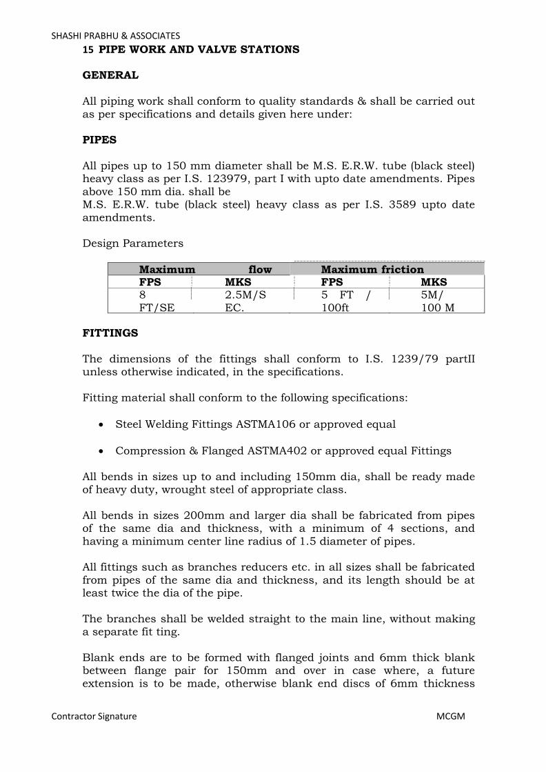
SHASHI PRABHU & ASSOCIATES
Contractor Signature MCGM
15 PIPE WORK AND VALVE STATIONS GENERAL
All piping work shall conform to quality standards & shall be carried out
as per specifications and details given here under: PIPES
All pipes up to 150 mm diameter shall be M.S. E.R.W. tube (black steel) heavy class as per I.S. 123979, part I with upto date amendments. Pipes
above 150 mm dia. shall be M.S. E.R.W. tube (black steel) heavy class as per I.S. 3589 upto date
amendments. Design Parameters
Maximum flow
velocity
Maximum friction FPS MKS FPS MKS 8
FT/SEC
2.5M/S
EC.
5 FT /
100ft Water
Run
5M/
100 M Water
Run
FITTINGS
The dimensions of the fittings shall conform to I.S. 1239/79 partII unless otherwise indicated, in the specifications.
Fitting material shall conform to the following specifications:
• Steel Welding Fittings ASTMA106 or approved equal
• Compression & Flanged ASTMA402 or approved equal Fittings
All bends in sizes up to and including 150mm dia, shall be ready made of heavy duty, wrought steel of appropriate class.
All bends in sizes 200mm and larger dia shall be fabricated from pipes of the same dia and thickness, with a minimum of 4 sections, and
having a minimum center line radius of 1.5 diameter of pipes. All fittings such as branches reducers etc. in all sizes shall be fabricated
from pipes of the same dia and thickness, and its length should be at least twice the dia of the pipe.
The branches shall be welded straight to the main line, without making a separate fit ting.
Blank ends are to be formed with flanged joints and 6mm thick blank between flange pair for 150mm and over in case where, a future
extension is to be made, otherwise blank end discs of 6mm thickness
Page 253

SHASHI PRABHU & ASSOCIATES
Contractor Signature MCGM
are to be welded on, with additional cross stiffeners from 50mm x 50mm M.S. heavy angles, for sizes upto 350mm, all ends larger than 400mm dia. shall have dished ends.
For Condenser pipe 4mm FRP quoting is required.
FLANGES All flanges shall be of mild steel as per I.S. 6392/71 and shall be steel
slip on type, welded to the pipes, flanges thickness shall be to suit class II, pressures.
Flanges may be tack welded into position, but all final welding shall be done with joints dismounted, 3mm thick gaskets shall be used with all
flanged joints. The gaskets shall be fiber reinforced rubber as approved by the department. Special adhesive com pound shall be used between flanges of steam, air and gas lines.
Flanges shall be used as follows:
Counter flanges for equipment having flanged connections.
Flanged pairs shall be used on all such equipment, which may require to be isolated or removed for service e.g. pumps, refrigeration machines, air handling units etc.
All threaded valves shall be provided with nipples and flanged pairs on
both sides to permit flange connections, for removal of valves from main lines for re pair/replacement.
Flanges shall be of the same pressure rating as the fittings and valves in each service category. Welding neck flanges or slip on flanges shall be
used with flanged valves, equipment, etc., on welded lines. All flanges shall be drilled in conformance with pressure rating requirements and shall be faced and spot faced. Welding flanges shall be of steel.
Flanged pair shall be provided at all such equipment which may require isolation or removal for services e.g.; pumps, chiller, Air Handling units,
etc.
Provide flanged joints and 6 mm thick blank insertion of rubber gasket between flanged pair at blank ends for 150mm and above pipe. Provide end disc of 6 mm thickness with additional cross stiffness from 50 mm x
50 mm MS heavy angle for up to 400 mm. All ends larger than 400 mm diameter shall have dished ends.
VALVES
BUTTERFLY VALVES The butterfly valve shall consist of Cast Steel body preferably in two-
Page 254
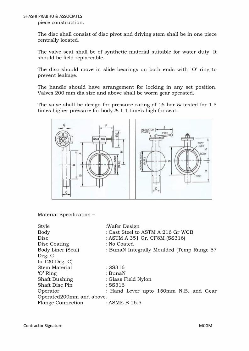
SHASHI PRABHU & ASSOCIATES
Contractor Signature MCGM
piece construction. The disc shall consist of disc pivot and driving stem shall be in one piece
centrally located.
The valve seat shall be of synthetic material suitable for water duty. It should be field replaceable.
The disc should move in slide bearings on both ends with `O' ring to prevent leakage.
The handle should have arrangement for locking in any set position. Valves 200 mm dia size and above shall be worm gear operated.
The valve shall be design for pressure rating of 16 bar & tested for 1.5 times higher pressure for body & 1.1 time’s high for seat.
Material Specification – Style :Wafer Design
Body : Cast Steel to ASTM A 216 Gr WCB Disc : ASTM A 351 Gr. CF8M (SS316) Disc Coating : No Coated
Body Liner (Seal) : BunaN Integrally Moulded (Temp Range 57 Deg. C
to 120 Deg. C) Stem Material : SS316 ‘O’ Ring : BunaN
Shaft Bushing : Glass Field Nylon Shaft Disc Pin : SS316 Operator : Hand Lever upto 150mm N.B. and Gear
Operated200mm and above. Flange Connection : ASME B 16.5
Page 255

SHASHI PRABHU & ASSOCIATES
Contractor Signature MCGM
BALANCING VALVES These valves shall have built in pressure drop measuring facility to
compute flow rate across the valve.
The test cocks shall be long enough to protrude out of pipe insulation. To measure flow rate, differential pressure will be measured with
calibrated instruments – Digital or Mercury Manometer. Balancing Tools shall have a programmed to provide the following functions:
- To balance the HVAC installation and calculate the necessary valve settings based on
the systems data as observed prior to balancing exercise. - To log measured values from a valve (differential pressure and flow rate)
To store the results of balancing
- Presetting position of Balancing Valves - Design Flow for each Balancing Valves - Flow at Balancing Valves
- Flow Ratio pre balancing based on actual flow / design flow - Flow Ratio post balancing and Actual Flow
5.1.4 The valve shall be design for pressure rating of 16 bar & tested for 1.5 times higher pressure for body & 1.1 time’s high for seat.
Material Specification –
Valves 25mm to 50mm (End Construction) Style : Globe Type BSP Threaded Screwed End
Construction Body : IS 318 LTB 2 (Gun Metal)
Page 256
SHASHI PRABHU & ASSOCIATES
Contractor Signature MCGM
Bonnet : 25mm n brass and 32 mm to 50mm in IS 318 LTB 2 (Gun Metal)Plug : IS 318 LTB 2 (Gun Metal) / Brass IS 319 Stem : IS 319 TypeI (Brass)
Temperature : 46 Degree C to 200 Degree C Gland Nut : Brass
Hand Wheel : Nylon Gr. 66Pressure Test Cocks : Brass
Valves 65 mm to 300mm (Cast Iron Flanged End Construction) Style : Globe Type Flanged End Construction
Body : Ductile (SG) Iron to IS 1865 Gr. 450/10/ Cast Steel
Bonnet : Ductile (SG) Iron to IS 1865 Gr. 450/10 Hand Wheel : M S Fabricated. Stem : SS316
Disc : SS316 Sealing Disc : BunaN
Temp Range 40 Deg. C to 120 Deg. C) Pressure Test Cocks : Steel Chrome Plated End Connection: IS : IS 6392 Table 17
All valves shall be tested for flow vs. pressure drop within + 5% accuracy and data be furnished as part of Test Certificate.
Valves Size 350mm to 1000mm Body : Cast Steel to ASTM A 216 Gr. WCB
Disc : ASTM A 351 Gr. CF8M (SS316) Seal : BunaN elastomer
Stem : SS316 Trim : SS316 (CF8M) Measuring Ring: SS316 (CF8M)
Worm : SS 410 Wafer Type Dual Plate Check Valves
Dual Plate Check Valves (Wafer Type) with spring loaded as per API 594.
Inspection and testing conforms to API 598. The detailed material of construction as given below: Style : Wafer Design
Body : Cast Steel to ASTM A 216 Gr WCB Plates : ASTM A 351 Gr. CF8M (SS316)
Plate Coating : Integrally Body Lining : BunaN / Nitrile (Temp. Range 57 Deg. C to 120 Deg. C)
Hinge/Stop Pin : AISI SS316 Spring(s) : SS316 Retainer : Carbon Steel
Page 257

SHASHI PRABHU & ASSOCIATES
Contractor Signature MCGM
Body Bearing : AISI SS316 Plate Bearing : AISI SS316 Spring Bearing : AISI SS316
End Connection : ASTM A 16.5
Page 258
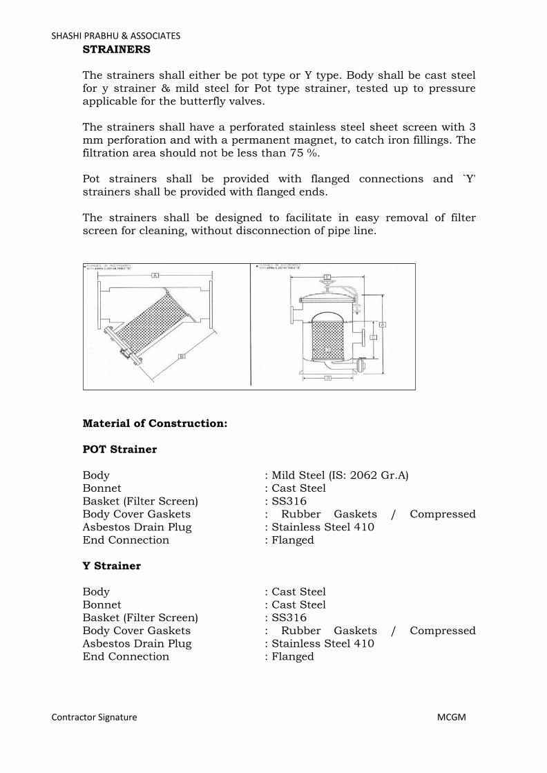
SHASHI PRABHU & ASSOCIATES
Contractor Signature MCGM
STRAINERS The strainers shall either be pot type or Y type. Body shall be cast steel
for y strainer & mild steel for Pot type strainer, tested up to pressure applicable for the butterfly valves.
The strainers shall have a perforated stainless steel sheet screen with 3 mm perforation and with a permanent magnet, to catch iron fillings. The
filtration area should not be less than 75 %. Pot strainers shall be provided with flanged connections and `Y'
strainers shall be provided with flanged ends.
The strainers shall be designed to facilitate in easy removal of filter screen for cleaning, without disconnection of pipe line.
Material of Construction:
POT Strainer
Body : Mild Steel (IS: 2062 Gr.A) Bonnet : Cast Steel
Basket (Filter Screen) : SS316 Body Cover Gaskets : Rubber Gaskets / Compressed
Asbestos Drain Plug : Stainless Steel 410 End Connection : Flanged
Y Strainer Body : Cast Steel
Bonnet : Cast Steel Basket (Filter Screen) : SS316
Body Cover Gaskets : Rubber Gaskets / Compressed Asbestos Drain Plug : Stainless Steel 410 End Connection : Flanged
Page 259
SHASHI PRABHU & ASSOCIATES
Contractor Signature MCGM
BALL VALVES:
All ball valves shall be forged brass body construction with chrome plated with the pressure rating PN 16 as per schedule of quantity and
handle of stainless steel constructions & shall be covered with Plastic material. End connections of ball valve to be screwed type & shall be applicable for 15mm to 40mm in dia. The ball valve shall be coated with
two coats of zinc chromate paint (LOW VOC) for its antirust properties and then shall be finally painted with epoxy paint of required colour
including all fittings like valves, flanges & unions. The valves used for both HW and CHW application shall be covered with insulation(CFC,HCFC FREE)/lag coating/glass cloth as specified in
schedule of quantity. The Adhesive used for shall be of low volatile organic compound. Pressure testing of valves shall be done at
manufacturer’s works. The contractor shall furnish material test certificates of various components of the valve & performance test certificates carried out by manufacturer
RUBBER EXPANSION JOINT
The rubber expansion joint should be of rubber with elastic properties textile reinforcements and integrated with alienable floating steel flanges
to provide a flexible pipe joint. The flange should be powder coated. The rubber bellow should be with following properties;
• Compensates for axial movements due to thermal changes & misalignment.
• Compensates for lateral, torsional and angular movements.
• Isolates vibrations, dampens noise and pressure surges.
• Suitable for suction and discharge.
• Higher flexibility & lower stiffness.
• 100% EPDM for longer life.
The flexible joints should be factory tested for pressure & vacuum. Before installation the proper selection of expansion joints as per the pipe dia should be done.
Full Way Type Screwed End Ball Valves
Material Specification –
Ball Brass with Diamond Polished and Chrome Plated
Spindle Brass Stuffing Box Brass Lever Galvanized Steel PVCGrip with“Pad
Printing” asper EN13828 O Ring 2 x NBR PTFE Seal
Page 260
SHASHI PRABHU & ASSOCIATES
Contractor Signature MCGM
The ball valve with strainer of nominal bores between 15mm and 40mm shall be sup plied with 316 stainless steel screen.
JOINTING
All pipe lines shall be welded type. Square cut plain ends will be welded for pipes upto and including
100mm dia. All pipes 125mm dia or larger will be beveled by 35 deg for welding.
MISCELLANEOUS
Providing all piping, required to make the apparatus connected, complete and ready for regular and safe operation, unless otherwise
noted, connect all apparatus and equipment in accordance with manufacturer's standard details, as approved by Engineer in Charge.
Consult drawings and specifications to determine number and requirements of all items of equipment, requiring piping, such as bend, drain, relief etc., wherever equipment is provided with connections for
such piping. Unless otherwise specified, pitch the lines of piping as follows:
All condensation drainage, including air handling unit and fan coil unit
shall be pitched in the direction of flow to ensure adequate drainage, with an adequate trap seal to prevent leakage of air due to static pressure developed by air conditioning units. Pitch, 20mm per meter
wherever possible, but not less than 10mm/ meter. Drains from other equipment shall be pitched similarly without trap seal.
Provide valves and capped connections for all low points in piping system, necessary or required for draining systems. Provide for all risers
isolating valves and drain valves to permit repairs without interfering with the rest of the system.
During construction, temporarily close, open ends of pipes with sheet metal caps, where necessary, or required to prevent debris from entering
piping system. Support piping independently of all equipment so that the equipment is
not stressed by the piping weight or expansion.
To facilitate the maintenance, repair and replacement; Unions, if used, shall be flanged, as required, where indicated and in
connections to all equipment’s, apparatus and specialties requiring disconnection for repairs or replacement. Locate unions between shutoff valves and equipment as directed by Engineer in charge.
Page 261
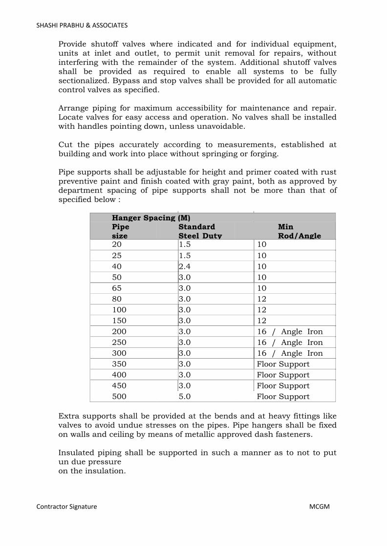
SHASHI PRABHU & ASSOCIATES
Contractor Signature MCGM
Provide shutoff valves where indicated and for individual equipment, units at inlet and outlet, to permit unit removal for repairs, without
interfering with the remainder of the system. Additional shutoff valves shall be provided as required to enable all systems to be fully
sectionalized. Bypass and stop valves shall be provided for all automatic control valves as specified.
Arrange piping for maximum accessibility for maintenance and repair. Locate valves for easy access and operation. No valves shall be installed with handles pointing down, unless unavoidable.
Cut the pipes accurately according to measurements, established at
building and work into place without springing or forging. Pipe supports shall be adjustable for height and primer coated with rust
preventive paint and finish coated with gray paint, both as approved by department spacing of pipe supports shall not be more than that of
specified below :
Hanger Spacing (M) Pipe size O.D.(m
m)
Standard Steel Duty :Water
Pip
e
Min Rod/Angle Size (mm) 20 1.5 10
25 1.5 10
40 2.4 10
50 3.0 10
65 3.0 10
80 3.0 12
100 3.0 12
150 3.0 12
200 3.0 16 / Angle Iron Support 250 3.0 16 / Angle Iron Support 300 3.0 16 / Angle Iron Support 350 3.0 Floor Support
400 3.0 Floor Support
450 3.0 Floor Support
500 5.0 Floor Support
Extra supports shall be provided at the bends and at heavy fittings like valves to avoid undue stresses on the pipes. Pipe hangers shall be fixed
on walls and ceiling by means of metallic approved dash fasteners.
Insulated piping shall be supported in such a manner as to not to put un due pressure on the insulation.
Page 262
SHASHI PRABHU & ASSOCIATES
Contractor Signature MCGM
Where pipes are to be buried under ground, they should be coated with one coat of bituminous paint without any extra charge. The top of the pipes shall not be less than 75 cms. from the ground level. Where this is
not practical permission of department shall be obtained for burying the pipes at lesser depth. The pipes shall be surrounded on all sides by sand
cushions of not less than 15 cms. After the pipes have been laid and top sand cushions provided, the trench shall be refilled with the excavated soil. Excess soil shall be removed from the site of work by the
contractor. HANGERS & SUPPORTS
Hangers and supports shall be provided and installed for all piping and
tubing wherever indicated, required or otherwise specified. Wherever necessary, additional hangers and supports shall be provided to prevent vibration or excessive deflection of piping and tubing.
All hangers and supports shall be made of steel and painted as required.
Wood, wire or perforated strap iron shall not be used as permanent hangers or supports.
Hangers shall be supported from structural steel, concrete inserts and pipe racks, specifically approved.
No hangers shall be secured to underside of light weight roof decking and light weight floor glass.
Mechanical equipment shall be suspended midway between steel joists and panel points.
Drilling or punching of holes in steel joist members will not be
permitted. SLEEVES
Where pipes pass through floors, provide galvanized steel pipe sleeves 50mm larger than outside diameter of pipe. Where pipes are insulated,
sleeves shall be large enough to provide ample clearance for insulation.
Where pipes pass through outside walls or foundations, the space between pipe and sleeve shall be caulked with lead wool and oakum.
The center pipes shall be in the center of sleeves, and sleeves shall be flush with the finished surface.
Floor sleeves shall project 50mm above finished floor level.
EXPANSION OR CONTRACTION The contractor shall provide for expansion and contraction of all piping
Page 263

SHASHI PRABHU & ASSOCIATES
Contractor Signature MCGM
installed by the use of expansion loops.
Page 264

SHASHI PRABHU & ASSOCIATES
Contractor Signature MCGM
ARRANGEMENT AND ALIGNMENT OF PIPING All piping shall be arranged and aligned in accordance with the
drawings as specified. Where special conditions are encountered in the field, the arrangement and alignment of piping shall be as directed by
the Engineer in Charge. The piping shall be installed in a uniform manner, parallel to or
perpendicular to walls or ceilings, and all changes in directions shall be made with fittings. The horizontal piping shall be run at right angles and shall not run diagonally across rooms or other piping. Wherever possible
all piping shall be arranged to provide maximum head room.
All piping shall be installed as directly as possible between connecting points in so far as the work of other trades permits. Where interference occurs with another trade whose work is more difficult to route, this
contractor shall reroute his pipes as required to avoid interference, at the discretion of the Engineer in Charge.
All piping shall be carefully installed to provide for proper alignment, slope and expansion.
The stresses in pipe lines shall be guided and pipes shall be supported in such a manner that pipe lines shall not creep, sag or buckle.
Anchors and supports shall be provided wherever necessary to prevent
any misalignment of piping. Small tubing gauges, controls or other equipment installed on any
apparatus, shall not be coiled nor excessive in length, but shall be installed neatly, carefully bent at all changes in direction, secured in
place and properly fastened to equipment at intervals to prevent sagging. The piping shall be grouped wherever practical and shall be installed
uniformly in straight parallel lines in either vertical or horizontal positions.
TESTING
In general, tests shall be applied to piping before connection of equipment and appliances. In no case shall piping equipment or appliances be subjected to pressures exceeding their test ratings.
The tests shall be completed and approved before any insulation is
applied. Testing of segments of pipe work will be permitted, provided all open ends are first closed, by blank offs or flanges.
After tests have been completed the system shall be drained and flushed 3 to 4 times and cleaned of all dust and foreign matter. All strainers, valves and fittings shall be cleaned of all dirt, fillings and debris.
Page 265

SHASHI PRABHU & ASSOCIATES
Contractor Signature MCGM
All piping shall be tested to hydraulic test pressure of at least one and half times the maximum operating pressure for a period of not less than
24 hours. All leaks and defects in the joints revealed during the testing shall be rectified to the satisfaction of the Engineer in charge without
any extra cost. All the valves shall be tested to hydraulic test pressure of at least one and half times the maximum design operating pressure.
All the piping systems shall be tested in the presence of the department or his authorized representative. Advance notice of test dates shall be given and all equipment’s, labour, materials required for inspection, and
repairs during the test shall be provided by the contractor. A test shall be repeated till the entire systems are found satisfactory by the above
authority. The tests shall be carried out for a part of work if required by department in order to avoid hindrance in the work of the insulation contractor.
The contractor shall make sure that proper noiseless circulation is
achieved through all piping systems. If due to poor air bond, proper circulation is not achieved, the contractor shall bear all expenses for carrying out the rectification work including finishing of floors, walls and
ceiling damaged in the process of rectifications.
The contractor shall provide all labours and materials to make provision
for removing water and throwing it at the proper place during the testing or/and after the testing to avoid damages to employer or other
contractor’s properties. Any damages caused by the contractor to the employer or other contractors properties, shall be borne by the contractor.
COPPER PIPING (Wherever required)
Heavy gauge soft copper tubing, type M shall be used to make connections to equipment, wherever required or specified by Engineer in
Charge. Flare fittings e.g. flare nuts, tees, elbows, reducers etc. shall all be of
brass.
DRAIN PIPING The drain piping shall be medium class Hot dipped galvanized steel as
per IS 1239/1979 with up to date amendments.
Rigid PVC pipes may be used for drain pipe. (Option only for single story building)
The fittings shall be of `R' brand forged with screwed connections. The gate valves shall be of gun metal as described earlier.
Page 266

SHASHI PRABHU & ASSOCIATES
Contractor Signature MCGM
Pipe crosses shall be provided at bends, to permit easy cleaning of drain line.
The drain line shall be provided up to the nearest drain trap and pitched
towards the trap. Drain lines shall be provided at all the lowest points in the system, as
well as at equipment, where leakage of water is likely to occur or to remove condensate and water from pump glands.
The pipes shall be laid in proper slope for efficient drainage of condensate water. A downward gradient of atleast 1/100 will be
provided for the drain piping. For proper drainage of condensate, U Trap shall be provided in the drain
piping (wherever required). All pipe supports shall be of prefabricated & pre painted slot ted angle supports, properly installed with clamps etc.
The main drain pipe should be connected to the vertical drain pipe through a Yjoint or Tjoint. A vent pipe should be installed at the top of
the vertical to improve the drain water flow. Vent pipe should be provided with insect screen. Cost for these accessories is deemed to be included in the rates quoted by the tenderer.
PAINTING
All pipes support, hangers, etc., shall be given two coats of red oxide primer.
All pipes, which are not to be insulated, shall then be given two coats of
finish paint, of a type and colour, as approved by the Engineer in Charge.
CONTROLS VALVE AND ACCESSORIES 2-WAY PRESSURE INDEPENDENT BALANCING AND CONTROL
VALVE (MOTORIZED) :
For AHUs:
2 way motorized shall be of MODULATING valve of PN16 rating as mentioned in schedule of quantity and complete with motor actuator of
suitable torque & control power wiring from individual thermostat at Return air path of each AHU to each related actuator of 2 way valve with controller & its related wiring (including step down transformer and
required accessories with internal wiring for converting 220volt AC single phase power up to 10 volt DC or as required for modulation of
2way control valve actuator- the same arrangement to be inbuilt in controller panel only which are in other scope). The valve should be IEC
Page 267
SHASHI PRABHU & ASSOCIATES
Contractor Signature MCGM
534 compliant, have 20 mm stroke and insulated. The valve shall be coated with two coats of zinc chromate paint (LOW VOC) for its anti-rust properties and then shall be finally painted with
epoxy paint of required colour including all fittings like valves, flanges & unions. The valves used for both HW and CHW application shall be
covered with insulation (CFC,HCFC FREE)/lag coating/glass cloth as specified in schedule of quantity. The Adhesive used for shall be of low volatile organic compound.
In case BMS is provided in the building then, only the valve with actuator shall be in the scope of HVAC vendor and rest of all control and
power wiring and sensors etc. shall be excluded from HVAC vendor scope.
For FCUs: 2 way motorized shall be of on/off type valve and operated on 230 volts and
of PN rating as mentioned in schedule of quantity complete with motor actuator of suitable torque & control power wiring from individual thermostat of each FCU to each related actuator of 2 way valve with
controller & its related wiring. The valve should be IEC 534 compliant, have 20 mm stroke and insulated as suitable.
In case of BMS is provided in the building then only valve with actuator shall be in the scope of HVAC vendor and rest of all control and power wiring and sensors etc. shall be excluded from HVAC vendor scope.
Temperature Gauges (Dial type)
Temperature gauges of 4"dia. with stainless steel SS-304 bulb and thermowell shall be used, the length of the thermowell shall be in
accordance to the condenser water pipe diameter. The temperature gauge should in range of 0-50 Deg.C & it's to be filled will red oil liquid. Gauges shall be suitable for 15mm connection and for condenser line they shall
have long stem.
Water Pressure Gauges (Dial Type)
Water pressure gauges 4"dia. made out of stainless steel SS-304 all
parts are made from copper alloy and stainless steel to prevent from corrosion attack. Dial shall be in white colour and number shall be in the black and red colour for the visibility, gauges shall have ‘A’ stainless
steel ‘U’ tube of 6mm dia. x 400mm in length both side threaded with stainless steel nut, A pet cock along with SS syphon tubing shall be
provided at one end of tube for protecting gauge during testing of system Flow Switches
Sockets or necessary arrangements to be made by HVAC Contractor for
bellow type flow switches shall be provided in condensing water outlet and chilled water outlet at the water chilling machines, and at the water
Page 268
SHASHI PRABHU & ASSOCIATES
Contractor Signature MCGM
cooled condensing units for refrigeration load. The flow switch shall prevent the compressor from starting unless the water flow is established in condensing water lines, and chilled water flow is
established chilled water lines. ULTRASONIC FLOW METER:
Water flow meters shall be Ultrasonic type of PN16 rating. Ultrasonic Inline Flow Meter shall be suitable to be installed in Chilled Water Return line to
each chiller with necessary fittings and isolation valves etc. The valve shall be suitable for integration with Chiller Plant Manager /Variable Primary Pump Logic Controller. The precision of flow measurement shall not be
lower than +/- 2%.
The housing shall have IP 55 protection. Vendors shall have to get their design/ selection approved by the Consultant, prior to the supply. The exact ranges to be set shall be determined by the contractor at the time
of commissioning. It should be possible to ‘zero’ the flow meter without any external instruments.
The stem shall be coated with two coats of zinc chromate paint (LOW VOC) for its antirust properties and then shall be finally painted with epoxy paint of required colour including all fittings like valves, flanges & unions. Also
the stem shall be covered with insulation (CFC & HCFC FREE)/lag coating/glass cloth as specified in schedule of quantity. The Adhesive used for shall be of low volatile organic compound.
The contractor shall furnish material test certificates of various components of the valve & performance test certificates carried out by
manufacturer. Motorized Butterfly Valves with actuator
ON/OFF Motorized butterfly valve & Actuator
Motorized valve for chillers, Chilled water piping shall be 2 position ON/OFF type Butterfly valve with standard train. The valve shall be controlled by an electric actuator mounted directly on the valve. The
actuator shall have a reversible synchronous motor and generate the desired stoke by gear train. It shall be suitable for hook up to any major BMS.
The valve & Actuator shall comprise & suitable as follows:
• The valve should be able to operate at 0…95 oC working temperature.
• The design pressure of the valve shall be PN16 rating & body shall be tested at 1.5 times & seat shall be 1.1 time’s higher than the design pressure.
• Leakage rate through the valve disc should be Rate A Bubble tight to EN122661.
• The valve seat should be ball profile style which eliminates elastomer movement and reduces seat ring tearing or fatiguing due to bunching.
• The valve should comprise of a double seal construction to prevent
Page 269
SHASHI PRABHU & ASSOCIATES
Contractor Signature MCGM
media coming into the valve.
• The gearbox of the actuator should comprise of hardened planetary gears. The gear drive mechanism should provide efficient, smooth operation while allowing easy manual override at any time.
• There should be a provision of hand wheel or lever to operate the valve manually.
• There should be a provision of two stop screws for limiting the manual operation of actuator.
• Valves & actuator should be supplied with IP54 protection rated (for indoor application) and with IP67 protection rated actuators
(for outdoor application).
• Two position or open/closed actuators shall accept 24 V AC/DC or 230V AC power supply and should be UL listed. Butterfly isolation and other valves, as specified in the sequence of operations, shall
be furnished with adjustable end switches to indicate open/closed position or be hard wired to start/stop the associated pump or chiller.
• The actuators of motorized butterfly valve shall be BMS compatible.
• The disc should be nylon coated to offer a good corrosion resistance, superior resistance to a broad range of chemical
environments as well as very low coefficient of friction and excellent resistance to impact and ultraviolet radiation. For higher temperatures and rust proof operations.
• The valve body should be according to ISO 5211 actuator mounting and shaft connection standards.
• The valve should have a square stem head for form fit attachment of the Rotary actuator.
• The butterfly valve shall be operated by rotary electric actuator for maintenance free application.
• The material of construction should be: Valve Body : Cast Steel to ASTM A 216 Gr WCB
Disc : ASTM A 351 Gr. CF8M (SS316)
Seat : EPDM seat ring Stem : Stainless steel 416
Body Liner (Seal) : BunaN Integrally Moulded (Temp Range 57 °C
to 120°C)‘O’ Ring : BunaN
Page 270
SHASHI PRABHU & ASSOCIATES
Contractor Signature MCGM
Shaft Bushing : Glass Field Nylon Shaft Disc Pin : SS316
Flange Connection : ASME B 16.5
Page 271
SHASHI PRABHU & ASSOCIATES
Contractor Signature MCGM
16 AIR DISTRIBUTION WORKS General
The work under this part shall consist of furnishing labour materials,
equipment and appliances as specified necessary and required to install all sheet metal and other allied work to make the air conditioning supply, ventilating, and exhaust system ready for operation as per
drawings. Duct Design Parameters: (Air Conditioning & Ventilation)
Maximum Velocity Maximum Friction Rate
1350 to 1800 FPM 0.1 inch WG/100 Ft.
Duct Design Parameters: (For Fire mode application)
Maximum Velocity
2500 FPM
Rectangular Duct Work
The ducts shall be fabricated from galvanized steel sheets class VIII conforming to ISS: 2772003 (revised).
The steel sheets shall be hot dip galvanized with coating of minimum 220 GSM of Zinc (Total coating on both sides)
All duct work, sheet metal thickness and fabrication unless otherwise directed, shall strictly meet requirements as described SMACNA
standard for factory fabricated duct. The minimum thickness of fabricated GSS duct shall be 24 G & for Al 22 G.
Raw Material
All ducting shall be fabricated of LFQ (Lock Forming Quality) grade prime G.I. raw material furnished with accompanying Mill test
Certificates. In addition, if deemed necessary, samples of raw material, selected at
random by client’s site representative shall be subject to approval and tested for thickness and zinc coating at con tractor’s expense.
The G.I. raw material should be used in coilform (instead of sheets) so as to limit the longitudinal joints at the edges only irrespective of cross
section dimensions.
Page 272

SHASHI PRABHU & ASSOCIATES
Contractor Signature MCGM
Duct Connectors and Accessories All transverse duct connectors (flanges/cleats) and accessories/related
hardware are such as support system shall be zinc coated (galvanized).
Fabrication Standards All ductwork including straight sections, tapers, elbows, branches, show
pieces, collars, terminal boxes and other transformation pieces must be factory fabricated. Equivalency will require fabrication by utilizing the following machines and processes to provide the requisite equality of
ducts and speed of supply.
Coil lines to ensure location of longitudinal seams at comes/folded edges only to obtain the required duct rigidity and low leakage characteristics. No longitudinal seams permitted along any face side of the duct.
All ducts, transformation pieces and fittings to be made on CNC profile
cutlers for required accuracy of dimensions, location and dimensions of notches at the folding lines.
All edges to be machine treated using lock formers, flanges and roller for fuming up edges.
Sealant dispensing equipment for applying built in sealant in Pittsburgh lock where sealing of longitudinal joints are specified.
Selection of G.I. Gauge and Transverse Connectors
All transverse connectors shall be the 4bolt slipon flange system with built in sealant if any to avoid any leakage additional sealant to be used.
The specific class of transverse connector and duct gauge for a given duct dimensions will be up to 2” (500 pa) low pressure class. If required,
Specific ventilation duct may as per medium pressure class. Nontoxic, AC applications grade P.E. or PVC casketing is required
between all mating flanged joints. Gasket sizes should conform to flange manufacturer’s specification.
Duct Construction
The fabricated duct dimensions should be as per approved drawings and all connecting sections are dimensionally matched to avoid any gaps.
Dimensional Tolerances: All fabricated dimensions will be within ± 1.0 mm of specified dimension. To obtain required perpendicularity,
permissible diagonal tolerances shall be ± 1.0 mm per meter. Ducts shall be straight and smooth on the inside Longitudinal seams
Page 273

SHASHI PRABHU & ASSOCIATES
Contractor Signature MCGM
shall be airtight and at corners only, which shall be either Pittsburgh or Snap Button Punch to ensure air tightness.
Changes in dimensions and shape of ducts shall be gradual (between 1:4 and 1:7). Turning vanes or air splitters shall be installed in all bends
and duct collars designed to permit the air to make the turn without appreciable turbulence.
Plenums shall be shop/factory fabricated panel type and assembled at site.
Changes in section of ductwork shall be affected by tapering the ducts with as long a taper as possible but not less than 600mm. All branches
shall be taken off at not more than 450. Branch shoe shall be provided in each branch section. Angle from the axis of the main duct unless otherwise approved by the Engineer In Charge.
All ducts shall be supported from the ceiling/slab by means of M.S. Rods of 10 mm (3/8") DIA with M.S. Angle at the bottom up to 2200 mm
size & 12 mm for above 2200 mm size. The rods shall be anchored to R.C. Slab using metallic expansion fasteners.
All nuts, bolts and washers shall be zinc plated steel. All rivets shall be galvanized or shall be made of magnesium aluminum alloy.
MISCELLANEOUS
• All ducts above 450mm are to be cross broken to provide rigidity to the ducts.
• All duct work joints are to be true right angle or approaching with all sharp edges re moved.
• Sponge rubber gaskets also to be provided behind the flange of all grilles.
• Each shoot from the duct, leading to a grille, shall be provided with an air deflector to divert the air into the grills through the shoot.
• Inspection doors measuring at least 450mm x 450mm are to be provided in each system at an appropriate location, as directed by Engineer in Charge.
• Diverting vanes must be provided at the bends exceeding 600mm and at branches connected into the main duct without a neck.
• Proper hangers and supports should be provided to hold the duct rigidly, to keep them straight and to avoid vibrations. Additional supports are to be provided where required for rigidity or as directed by
Page 274

SHASHI PRABHU & ASSOCIATES
Contractor Signature MCGM
Engineer in Charge.
• The ducts should be routed directly with a minimum of directional change.
• The duct work shall be provided with additional supports/hangers, wherever required or as directed by the Engineer in Charge, at no extra
cost.
• All duct supports, flanges, hangers and damper boxes etc. shall be given 2 coats of red oxide paint before installation and one coat of aluminum
paint after the erection, at no extra cost.
• All angle iron flanges to be welded electrically and holes to be drilled.
• All the angle iron flanges to be connected to the G.S.S. ducts by rivets at 100mm centers.
• All the flanged joints, to have a 4mm thick felt packing stack to the flanges with shellac varnish. The holes in the felt packing are to be
burnt through.
• The G.S.S. ducts should be lapped 6mm across the flanges.
• Sheet metal connection pieces, partitions and plenums required, shall be constructed of
• 1.25 (18 gauge) sheet thoroughly stiffened with 40mm x 40mm x 6mm angle iron braces and fitted with access doors.
TRANSFORMATION
Duct transformation shall be made with a side slope of 10mm to 70mm. However, if the duct Cross section area need to be reduced, a maximum
reduction of 20% of the original area shall be allowable. CIRCULAR DUCT WORK
The exposed type duct shall be double skin type spiral round metal ducts in low pressure range. The ducting shall comply with NFPA
90A1989, "Standard for the Installation of Air Conditioning and Ventilating Systems”.
The contractor is required to submit all Product data including details of construction materials, dimensions of individual components, profiles,
and finishes for duct, sealing materials, and fires topping materials in addition to the Shop drawings detailing Plans, elevations, sections,
details of components, and attachments to duct work. Duct layout, indicating pressure classifications and sizes in plain view. Details of Fittings, Reinforcement and spacing. Seam and joint construction
details. Penetrations through fire rated and other partitions.
Page 275

SHASHI PRABHU & ASSOCIATES
Contractor Signature MCGM
Fabrication: "Basic Round Diameter" as used in this article is the diameter of the size of round duct that has a circumference equal to the
perimeter of a given sized of flat oval duct. Except where interrupted by fittings, provide round and flat oval ducts in lengths not less than 12
feet. Ducts shall be fabricated with standard spiral lock seams (without intermediate ribs) or with butt welded longitudinal seams in gauges listed in SMACNA "HVAC Duct Construction Standards", Table 34. The
flat oval ducts shall be sandwich type with 19mm thick cross linked poly ethylene insulation between 2 layers of ducts.
Fittings: Following fittings shall be used.
90Degree Tees and Laterals and Conical Tees: Fabricated to conform to SMACNA "HVAC Duct Construction Standards", 1985 Edition, Figures 34 and 35 and with metal thicknesses specified for longitudinal seam
straight duct.
Diverging Flow Fittings: Fabricated with a reduced entrance to branch taps with no excess material projecting from the body onto branch tap entrance.
Elbows: Fabricated in die-formed, gored, pleated, or mitered construction. The bend radius of die-formed, gored, and pleated elbows
should be 1.5 times the elbow diameter. Unless elbow construction type is indicated, provide elbows meeting the following requirements:
Mitered Elbows: Fabricated mitered elbows with welded construction in gauges specified below shall be provided. Unless otherwise indicated, the
elbow shall comply with SMACNA "HVAC Duct Construction Standards", Table 31.
Round Mitered Elbows: Solid welded and with metal thickness listed below for pressure classes from minus 2 inches to plus 2 inches. The
entire duct shall be fabricated as per SMACNA standard. Flat Oval Mitered Elbows: The elbows shall be solid welded and with the
same metal thickness as longitudinal seam flat oval duct. 90Degree, 2Piece, Mitered Elbows shall be used for supply systems, or exhaust
systems only where space restrictions do not permit the use of 1.5 bend radius elbows. These will be fabricated with single thickness turning vanes.
Round Elbows for duct sizes 8 Inches and Smaller shall be Die-formed
for 45 and 90degree elbows and pleated for 30, 60, and 90 degrees only. Fabricated nonstandard bend angle con figurations or 1/2" diameter (e.g. 31/2 and 41/2inch) elbows shall be with gored construction.
Round Elbows for sizes 9 Through 14 Inches shall be gored or pleated elbows for 30, 45, 60, and 90 degrees, except where space restrictions require a mitered elbow.
Page 276
SHASHI PRABHU & ASSOCIATES
Contractor Signature MCGM
Fabricated nonstandard bend angle configurations or 1/2" diameter (e.g. 91/2 and 101/2inch) elbows shall be with gored construction. Round
Elbows larger than 14 Inches and All Flat Oval Elbows shall be Gored elbows, except where space restrictions require a mitered elbow.
Die Formed Elbows for Sizes through 8 Inches and All Pressures shall be minimum 20 gauge with 2piece welded construction. Round Gored
Elbows shall be fabricated out of the gauges as specified for non-elbow fittings above. For Flat Oval Elbows the gauges shall be same of the longitudinal seam flat oval duct.
The ducts shall be Installed with the fewest possible joints. Fabricated
fittings for all changes in directions, changes in size and shape, and connections shall be used. The couplings shall be secured tightly to duct wall surface with projections into duct at connections shall be kept to a
minimum. Ducts shall be running, except as otherwise indicated, vertically and horizon tally, parallel and perpendicular to building lines
and shall avoid diagonal runs. There shall be a clearance of 1 inch where furring is shown for enclosure or concealment of ducts, plus allowance for insulation thickness, if any.
The flat oval ducts shall be supported with support systems as indicated in SMACNA "HVAC Duct Construction Standards", tables 41 through 43
and Figures 41 through 48. The support for horizontal ducts shall be within 2' of each elbow and within 4' of each branch inter section.
Support for vertical ducts shall be at a maximum interval of 16' and at each floor. All connections to and from the duct to the equipment, air terminals and branches etc. shall be as recommended by SMACNA
"HVAC Duct Construction Standards", Figures 27 to 219.
TAKEOFF All branch takeoff and collars shall be provided with turning vanes.
Straightening vanes shall be provided in the collars. DAMPERS & SPLITTERS
Butterfly Dampers shall be provided in the duct work for proper control
and balancing of air distribution. Dampers shall of louver type of robust connection. Dampers shall have easily accessible operating mechanism. The operating mechanism shall consist of links, levers and quadrants as
required for proper control and setting in a desired position. The position of the handle of damper operating mechanism shall be clearly
visible and it shall indicate the position of the damper in the duct. Dampers, splitters and their operating mechanism shall be fabricated of GS sheets of two gauges heavier then duct piece having these fittings
and shall be easily accessible through suitable access doors in the ducts.
Page 277

SHASHI PRABHU & ASSOCIATES
Contractor Signature MCGM
Dampers shall be installed in duct at all required locations such as chutes, branches etc.
Page 278
SHASHI PRABHU & ASSOCIATES
Contractor Signature MCGM
INSTALLATIONS
• During the construction, the contractor shall temporarily close duct openings with sheet metal covers to prevent debris entering ducts and to maintain opening straight and square, as per
direction of Engineer In Charge.
• All duct work shall be of high quality approved galvanized sheet steel with at least 180 GSM coating of galvanization and
guaranteed not to crack or peel on bending or fabrication of ducts. All joints shall be air tight and shall be made in the direction of air flow.
• The ducts shall be reinforced with structured members where necessary, and must be secured in place so as to avoid vibration of the duct on its support.
• All air turns of 45 degrees or more shall include curved metal blades or vanes arranged so as to permit the air to make the abrupt turns without an appreciable turbulence. Turning vanes shall be securely fastened to prevent noise or vibration.
• The duct work shall be varied in shape and position to fit actual conditions at building site. All changes shall be subjected to the approval of the Engineer In Charge. The con tractor shall verify all measurements at site and shall notify the Engineer In Charge of
any difficulty in carrying out his work before fabrication.
• Joints, seams, sleeves, splitters, branches, takeoffs and supports are to be as per duct details as specified, or as decided by
Engineer In Charge.
• Joints requiring bolting or riveting may be fixed by Hexagon nuts and bolts, stove bolts or buck bolts, rivets or closed center top rivets or spot welding. Self-tapping screws must not be used. All
jointing material must have a finish such as cadmium plating or Galvanized as appropriate.
• Fires retarding flexible joints are to be fitted to the delivery of all fans. The material is to be normally double heavy canvass.
• The flexible joints are to be not less than 75 mm and not more than 200 mm between faces.
• The duct work should be carried out in a manner and at such time as not to hinder or delay the work of the other agencies
especially the boxing or false ceiling contractors.
• Duct passing through brick or masonry, wooden frame work shall be provided within the opening. Crossing duct shall have heavy
Page 279

SHASHI PRABHU & ASSOCIATES
Contractor Signature MCGM
flanges, collars on each side of wooden frame to make the duct leak proof.
ACCESS PANEL
• A hinged and gasket access panel shall be provided on duct work before each control device that may be located inside the duct
work.
MISCELLANEOUS
• All ducts above 450mm are to be cross broken to provide rigidity to the ducts.
• All duct work joints are to be true right angle or approaching with all sharp edges re moved.
• Each shoot from the duct, leading to a grille, shall be provided with an air deflector to divert the air into the grills through the shoot.
• Inspection doors measuring at least 450mm x 450mm are to be provided in each system at an appropriate location, as directed by Engineer in Charge.
• Diverting vanes must be provided at the bends exceeding 600mm and at branches connected into the main duct without a neck.
• Proper hangers and supports should be provided to hold the duct rigidly, to keep them straight and to avoid vibrations. Additional supports are to be provided where required for rigidity or as
directed by Engineer in Charge.
• The ducts should be routed directly with a minimum of directional change.
• The duct work shall be provided with additional supports/hangers, wherever required or as directed by the
Engineer in Charge, at no extra cost.
• All duct supports, flanges, hangers and damper boxes etc. shall be given 2 coats of red oxide paint before installation and one coat of
aluminum paint after the erection, at no extra cost.
• All angle iron flanges to be welded electrically and holes to be drilled.
• All the angle iron flanges to be connected to the G.S.S. ducts by rivets at 100mm centers.
Page 280
SHASHI PRABHU & ASSOCIATES
Contractor Signature MCGM
• All the flanged joints, to have a 4mm thick felt packing stack to the flanges. The holes in the felt packing are to be burnt through.
• The G.S.S. ducts should be lapped 6mm across the flanges.
• The entire air distribution system shall be balance with the help of an anemometer. The measured air quantities at fan discharge and the various outlets should be within range of +5 %.
VOLUME CONTROL DAMPERS
• At the junction of each branch duct with main duct and split of main duct, volume dampers must be provided.
• Dampers shall be two gauges heavier than gauge of the large duct, and shall be rigid in construction to the passage of air.
• The volume dampers shall be of an approved type, lever operated and complete with locking devices which will permit the dampers
to be adjusted and locked in any positions.
• The dampers shall be of splitter, butterfly or louver type. The damper blade shall not be less than 1.25mm (18 gauge);
reinforced with 25mm angles 3mm thick along any unsupported side longer than 250mm. Angles shall not interfere with the operation of dampers, nor cause any turbulence.
• Automatic and manual volume opposed blade dampers shall be complete with frames and bronze bearings as per drawings, dampers frames shall be constructed of 1.5mm steel and blades
shall not be over 225mm wide.
• The dampers for fresh air inlet shall additionally be provided with fly mesh screen, on the outside, of 0.8mm thickness with fine mesh spacing.
• Wherever required for system balancing, provide a volume balancing opposed blade damper with quadrant and thumb screw lock. Provide damper rod and damper block with upset screws.
• After completion of the duct work, dampers are to be adjusted and set to deliver the required amounts of air as specified on the
drawings.
FIRE CUM SMOKE MOTORIZED DAMPER
• The fire dampers shall be made from heavy gauge galvanized steel in multi plate construction. The damper shall be provided with Jam seal (compression type) on sites to prevent spread of smoke
Page 281

SHASHI PRABHU & ASSOCIATES
Contractor Signature MCGM
and fire. Dampers shall meet the requirements of the latest edition of NFPA 90A, 92A, and 92B.
• Fire dampers shall be provided in supply air ducts and return air duct (wherever provided), return air passage in the air handling
unit’s room and all floor crossings.
• Fire dampers shall be multi blade type. The blade remains in the air stream in open position& shall allow maximum free area to
reduce pressure drop & noise in the air passage. The blade & frame shall be constructed with minimum 1.6 mm thick galvanized sheet & shall be factory fitted in a sleeve made out of
1.6 mm galvanized sheet of minimum 400 mm long. It shall be complete with locking device, motorized actuator & control panel.
• The motorized damper shall activate on a signal or either an electronic thermal sensor UL stamped mounted in the air stream or from the smoke detector system. The fire dampers and smoke detectors are to be installed in supply air duct & return air duct.
• The dampers shall be equipped with a well-designed control panel, using high components which consume less power. It shall operate at 24 volts obtained through a step down transformer or suitable for 240 V AC supply. The panel is protected against surge
currents or short circuits through a Fuse connected on the PCB. The panel shall have an optional power supply of 24 V AC. The
control panel shall be well protected against wrong switching.
• All fire cum smoke damper shall be CBRI tested & certified for 90-minute rating against flame penetration as per UL standard 5551995. Each damper shall be equipped with a factory installed
UL approved damper actuator.
• Dampers shall have a Leakage rating of Class I and a Temperature rating of 350 F as per UL555S. Damper actuators shall be factory
mounted and qualified for use with the damper in accordance with UL555S.
• Necessary wiring from fire alarm panel up to AHU electrical panel shall be provided by concerned department & from AHU panel to
fire damper shall be provided by HVAC contractor.
• Each damper shall be provided with its own control panel. This control panel shall be suited for spring return actuator & shall
have at least the following features: Potential free contacts for AHU On / Off & remote alarm indication.
Accept signal from external smoke / fire detection system for tripping the actuator. Test & reset facility.
Page 282

SHASHI PRABHU & ASSOCIATES
Contractor Signature MCGM
Page 283
SHASHI PRABHU & ASSOCIATES
Contractor Signature MCGM
GRILLES The supply and return air grilles shall be fabricated from aluminum
extruded sections. The supply air grilles shall have single louvers (which shall be used for air conditioning) & ventilation grille shall be of double
louvers. The front horizontal louvers shall be of extruded section, fixed type. The rear vertical louvers shall of aluminum sheet and adjustable type. The return air grille shall have single horizontal extended section
fixed louvers. The grilles may or may not be with an outer frame. The aluminum grilles shall have opposed blade dampers of black
anodized extruded aluminum sections, which shall be key operated from the grille face wherever required.
The adjustable grille louvers shall be fabricated from extruded aluminum sections. The damper blades shall be of black anodized
extruded aluminum sections and shaped to form air tight joints. Grills longer than 450mm shall have intermediate sup ports for the horizontal
louvers. DIFFUSERS
The ceiling type round or square diffusers shall be of extruded aluminum sections with anti-smudge ring to prevent dust collection on
ceiling around the diffusers.
The diffusers shall be die formed for proper air diffusion & shall have removable inner core.
All supply diffusers shall be provided with extruded aluminum dampers, with knobs for adjustment from the bottom.
VAQ Station
All the VAQ (Variable Air Quality) Station shall be Pressure Independent type with Direct Digital Controls to regulate and monitor the primary air flow rate between the scheduled minimum and maximum values to
achieve the specified comfort level and ventilation rates within acceptable noise criteria.
The VAQ Station shall control air to provide desired zone temperature, and required minimum volume of outdoor air for proper ventilation. The
controller shall measure the pressure, position of the damper blades, and temperature of the air flowing through the damper.
The VAQ Station shall have an air measuring station with an ultralow leak, high performance control damper similar to AMCA Class-II
leakage. The complete assembly shall be factory assembled and tested to provide effective set point monitoring and adjustment. The unit shall come standard with a pressure transducer, with the output signal
Page 284
SHASHI PRABHU & ASSOCIATES
Contractor Signature MCGM
proportional to CFM and factory fitted standalone DDC controller. VAQ Station Outdoor Air (For non ducted application)
In this application, an air measuring control damper shall provide
Outdoor, Return and Exhaust air control based on a demand signal. The demand signal shall be determined by a set schedule or by occupancy sensors. Examples of demand signals are carbon dioxide (CO2)
concentration, a binary signal from a motion detector, or a manual switch.
Construction
The casing shall be single skin made out of galvanized sheet steel with acoustic lining from inside. Casing leakage rate shall be Similar to AMCA class II leakage. All VAQ Station shall have rectangular duct
connection with 25 mm. flange connections at the outlet of the station.
The VAQ Station shall have airflow straighter of 3” deep hexagonal pattern at the inlet of the station to provide necessary laminar air flow suitable for measurement, and a multi leaf opposed blade damper with
aluminum, aerofoil blade construction, width 100 mm. and exposed gear driven. The damper spindle shall be made of steel (10 mm. diameter), rotating in self-lubricating Nylon bearings.
Each VAQ Station shall be factory fitted with a multipoint, averaging air
flow sensor in the inlet of the terminal. This air flow sensor shall amplify the air pressure signal linearly with an amplification factor of at least 3.0. The air flow sensor shall contain not less than 2x8 sensing points,
which shall be arranged in a perpendicular axis of sensing. The points shall be arranged in such a way that they are located at the center of
equal areas not more than 150 mm apart. The signal shall be averaged and measured from the center of the sensor. And the accuracy shall be within 5% even with irregular duct approach.
Controller shall be a programmable logic controller (PLC) with 100BaseT Ethernet capability each unit shall have with numerous analog and
digital I/O. Multiple units shall be distributed on an Ethernet network allowing I/O expansion.
Controller shall be compatible with existing/future BMS system with Ethernet or Mod bus.
It should also have a connection facility for commissioning Diagnostic
socket for operating devices. JET NOZZLE (double skin type)
The jet nozzle assembly is designed to cater high air volumes. These are designed for the cooling application with side wall installation. Each
Page 285
SHASHI PRABHU & ASSOCIATES
Contractor Signature MCGM
nozzle shall be manually adjusted to supply air to the specific zone. Each nozzle shall be manually adjusted in 30º vertically upwards and 30º vertically downwards. The set angle position shall be held by friction
held fixing as standard supply. The nozzle shall be fitted with mounting plate which will allow each nozzle to rotate at 360º giving it wider air
discharge pattern. The Multiple Jet Nozzle shall comply following material and performance
data The jet nozzle shall be constructed from concentric steel tubes mounted
on steel face plate with angle flanged border made from extruded aluminum sections compete with countered punched holes for screw
fixing. The jet nozzle with mounting plate and shall throw at 25m distance.
The jet nozzle should be tested in ISO 9000 certified test lab with
international standards. The acoustic data shall be as per ISO 5219 and ISO 3741.
SOUND ATTENUATORS
Attenuators may be installed in ducts in accordance with requirements.
Attenuators shall be of steel construction with casings out of minimum 22 G galvanized steel. Acoustic fill shall be inert, no hygroscopic, vermin proof, fiberglass of required density adequately protected against
corrosion and covered with 26 gauge perforated aluminium sheet. Attenuators shall be supplied complete with flanges.
• Acoustic performance of the attenuators (net insertion loss) shall meet or exceed the values listed below :
OCTAVE BAND CENTRE FREQUENCY HZ
63 125 250 500 1K 2K 4K 8K
Insertion loss dB
900 mm long
attenuat
ors
2 7 12
19
23
23
18
9
Insertion loss dB
1500 mm long
attenuat
ors
6 8 18
30
42
34
23
12
The pressure drop values of the silencers shall be indicated for each
duty.
Page 286
SHASHI PRABHU & ASSOCIATES
Contractor Signature MCGM
Manufacturers shall submit a test certificate for acoustic and aerodynamic performance of the attenuators. Attenuators shall be tested in accordance with ACMA test methods/BS 4718 and insertion loss and
self-generated noise for each octave band and pressure drop shall be stated in the schedule.
CO2 Sensor
Co2 sensor shall be Non dispersive infrared type shall have range of 02000 PPM with accuracy of + 30PPM. The warm up time shall be of 2 minutes and response time within 120 seconds. The sensor shall be
suitable for 24Vac or 24Vdc+20 %, 50 Hz power supply & supplied with necessary step down transformer. The range of the sensor shall be
approx.100 sq.m. The protection class shall be IP30 & suitable for operation at 050°C and 095 % RH range. The life of sensor should be greater than 10 years.
VENTILATION LOUVERS
Ventilation air intake louvers for interior application shall be suitable for high free area and low air flow resistance. The louvers for external wall
application shall be drainable type louvers combined with back draft damper & bird mesh. The blades are inclined at 45°on a 40 mm blade pitch to minimize water ingress. The lowest blade of the assembly shall
extend out slightly to facilitate disposal of rain water without falling in door/wall on which it is mounted. All the louvers shall be made of
extruded aluminum construction. DOCUMENTATION TO MEASUREMENTS
Duct measurements shall be taken before application of insulation.
Grille, diffusers shall be measured by the cross sectional area excluding the flanges.
For each drawing, all supply of ductwork must be accompanied by computer generated detailed bill of material indicating all relevant duct sizes, dimensions and quantities. In addition, summary sheets are also
to be provided showing duct areas by gauge and duct size range as applicable.
Measurement sheet covering each fabricated duct piece showing dimensions and external surface area (internal skin surface area for
double skin duct) along with summary of external surface area of duct gauge wise.
All duct pieces to have a part number, which should correspond to the serial number, assigned to it in the measurement sheet. The above
system will ensure speedy and proper site measurement, verification and approvals.
Page 287

SHASHI PRABHU & ASSOCIATES
Contractor Signature MCGM
After duct installation, a part of duct section (approximately 5% of total ductwork) may be selected at random and tested for leakage. The procedure for leak testing should be followed “HVAC Air Duct Leakage
Test Manual: (First Edition).
Page 288

SHASHI PRABHU & ASSOCIATES
Contractor Signature MCGM
17 INSULATION WORKS
General
The Insulation of chilled water piping, air handling unit’s rooms, ducting etc., shall be carried out as per specifications given below:
Materials The materials to be used for insulation shall be as per specification
unless some other material is specifically mentioned elsewhere. The detailed specifications of the materials are listed under respective sub
heads. FOR G.I. DUCTING
SPECIFICATION FOR THERMAL & ACOUSTIC INSULATION
SCOPE
The scope of this section comprises the supply and application of insulation conforming to these Specifications.
A ) DUCT THERMAL INSULATION( EPDM THERMAL INSULATION):
Insulation material for Duct insulation shall be closed cell anti-fungus,
anti-microbial EPDM (CFC/HCFC FREE) on one side with factory laminated glass cloth. Thermal conductivity of the insulation material shall not exceed 0.033 W/mºK at an average temperature of 0ºC. Density of the EPDM shall
be 40-60 Kg/m³. The product shall have temperature range of -40 ºC to 105ºC. The insulation material shall be fire rated for Class O as per BS 476 Part 6: 1989 for fire propagation test and for Class 1 as per BS 476 Part 7,
1987 for surface spread of flame test. Water vapor permeability shall be not less than 0.024 per inch (1.74 x 10⁻¹⁴ Kg/m.s. Pa i.e. µ=10000: Water
vapor diffusion resistance). Thickness of the insulation shall be as specified for the individual
application. Each lot of insulation material delivered at site shall be accompanied with manufacturer’s test certificate for thermal conductivity
values, density, water vapor permeability and fire properties. Samples of insulation material from each lot delivered at site may be selected by Owner’s site representative and gotten tested for thermal conductivity and
density at Contractor’s cost. Adhesive used for sealing the insulation shall be not-flammable, vapor proof adhesive (LOW VOC) strictly as per manufacturer’s recommendations.
Ducting insulation thickness shall be as follows.
• SUPPLY AIR DUCT -19/25 mm thick insulation
Page 289
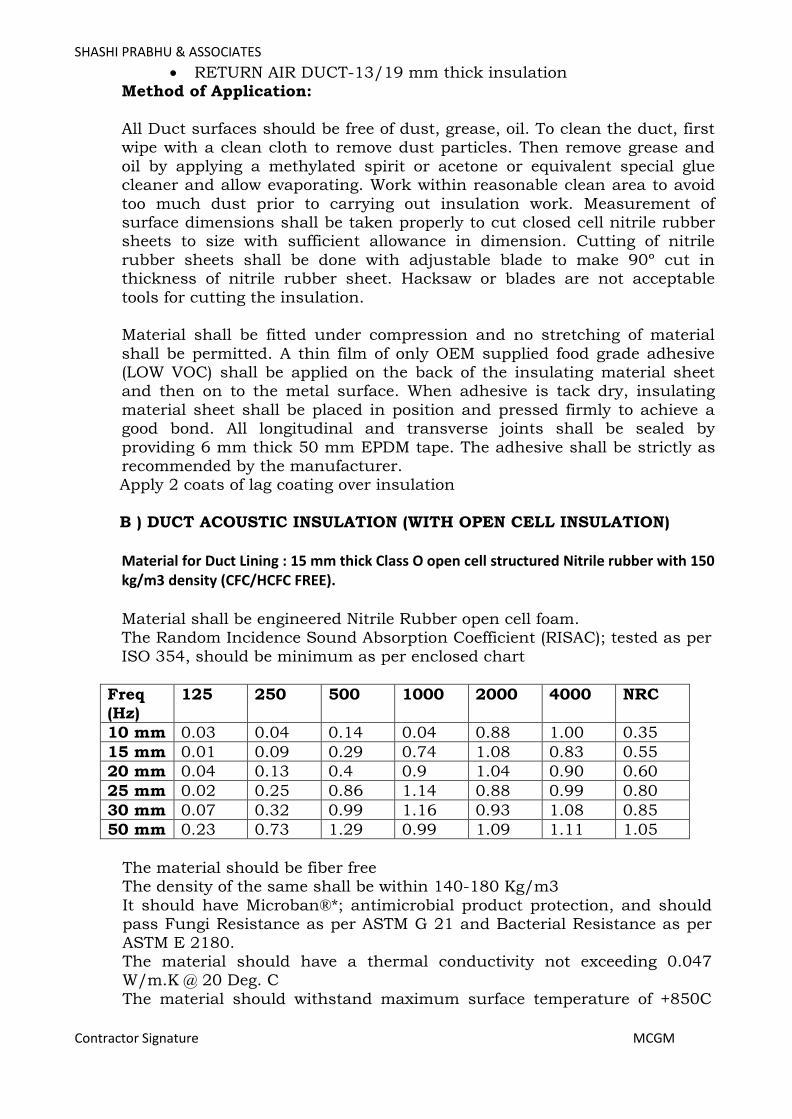
SHASHI PRABHU & ASSOCIATES
Contractor Signature MCGM
• RETURN AIR DUCT-13/19 mm thick insulation Method of Application:
All Duct surfaces should be free of dust, grease, oil. To clean the duct, first wipe with a clean cloth to remove dust particles. Then remove grease and
oil by applying a methylated spirit or acetone or equivalent special glue cleaner and allow evaporating. Work within reasonable clean area to avoid
too much dust prior to carrying out insulation work. Measurement of surface dimensions shall be taken properly to cut closed cell nitrile rubber sheets to size with sufficient allowance in dimension. Cutting of nitrile
rubber sheets shall be done with adjustable blade to make 90º cut in thickness of nitrile rubber sheet. Hacksaw or blades are not acceptable
tools for cutting the insulation. Material shall be fitted under compression and no stretching of material
shall be permitted. A thin film of only OEM supplied food grade adhesive (LOW VOC) shall be applied on the back of the insulating material sheet and then on to the metal surface. When adhesive is tack dry, insulating
material sheet shall be placed in position and pressed firmly to achieve a good bond. All longitudinal and transverse joints shall be sealed by
providing 6 mm thick 50 mm EPDM tape. The adhesive shall be strictly as recommended by the manufacturer. Apply 2 coats of lag coating over insulation
B ) DUCT ACOUSTIC INSULATION (WITH OPEN CELL INSULATION)
Material for Duct Lining : 15 mm thick Class O open cell structured Nitrile rubber with 150 kg/m3 density (CFC/HCFC FREE). Material shall be engineered Nitrile Rubber open cell foam. The Random Incidence Sound Absorption Coefficient (RISAC); tested as per
ISO 354, should be minimum as per enclosed chart
Freq
(Hz)
125 250 500 1000 2000 4000 NRC
10 mm 0.03 0.04 0.14 0.04 0.88 1.00 0.35
15 mm 0.01 0.09 0.29 0.74 1.08 0.83 0.55
20 mm 0.04 0.13 0.4 0.9 1.04 0.90 0.60
25 mm 0.02 0.25 0.86 1.14 0.88 0.99 0.80
30 mm 0.07 0.32 0.99 1.16 0.93 1.08 0.85
50 mm 0.23 0.73 1.29 0.99 1.09 1.11 1.05
The material should be fiber free The density of the same shall be within 140-180 Kg/m3
It should have Microban®*; antimicrobial product protection, and should pass Fungi Resistance as per ASTM G 21 and Bacterial Resistance as per
ASTM E 2180. The material should have a thermal conductivity not exceeding 0.047 W/m.K @ 20 Deg. C
The material should withstand maximum surface temperature of +850C
Page 290

SHASHI PRABHU & ASSOCIATES
Contractor Signature MCGM
and minimum surface temperature of -200C The material should conform to Class 1 rating for surface spread of Flame in accordance to BS 476 Part 7 & UL 94 (HBF, HF 1 & HF 2) in accordance
to UL 94, 1996. The insulation should pass Air Erosion Resistance Test in accordance to
ASTM Standard C 1071-05 (section 12.7).
Thickness of the material shall be as specified for the individual
application. The insulation should be installed as per manufacturer’s recommendation.
• Microban is a registered trademark of the Microban Products Company, USA.
Method of Application:
Duct surfaces shall be cleaned to remove all grease, oil, dirt, etc. prior to carrying out insulation work. Measurement of surface dimensions shall be taken properly to cut closed cell Elastomeric rubber sheets to size with
sufficient allowance in dimension insulating material sheet and then on to the metal surface. Apply OEM supplied food grade adhesive (LOW VOC) on duct surface and insulation sheet and when adhesive is tack dry,
insulating material sheet shall be placed in position and pressed firmly to achieve a good bond. All longitudinal and transverse joints shall be sealed
by providing 6 mm thick 50 mm wide Nitrile rubber tape. The adhesive shall be strictly as recommended by the manufacturer and should be of low volatile organic compound. Acoustic insulation to be applied for both
supply & return air duct/PLENUM up to 3 mtr. in length from AHU.
Internal duct acoustic insulation shall not be applicable for OT & Positive isolation room of supply & return air duct.
(C) FALSE CEILING INSULATION The false ceiling shall be insulated with 50 mm thick fiberglass slab of
16 Kg. / Cu. M. density. The fiberglass slab shall be wrapped in polyethylene bags.
(D) UNDERDECK INSULATION FOR RCC ROOF
Underdeck 25mm thick insulated with cross-linked polyolefin foam with factory applied reinforced aluminum foil and acrylic adhesive backing.
Insulation shall have Density of 25 kg/m3 (foam core only), Thermal Conductivity (ASTM C518) of Maximum 0.032 W/m.°K at mean temperature 23°C, Water Vapour permeability (ASTM E96): Maximum
2.3 x 10⁻¹⁵ kg/Pa.s.m, (µ>80,000), Water absorption: <0.2 % v/v. Complies with Class 0 to BS476 Parts 6 and 7, Euro class B-S2,d0 classification according to EN 13501Part 1, NFPA 90A and B (ASTM
E84 25/50 rating), FM 4924 fire performance criteria and “FM Approved” by FM Approvals certification body and Zero mould growth
Page 291

SHASHI PRABHU & ASSOCIATES
Contractor Signature MCGM
when tested to ASTM G21. Seal all joints with 75mm reinforced aluminums foil tape.
(E) AHU ROOM ACOUSTIC INSULATION.
Material shall be engineered NITRILE RUBBER open cell foam The Random Incidence Sound Absorption Coefficient (RISAC); tested as per ISO 354, should be minimum as per enclosed chart
Freq
(Hz)
125 250 500 1000 2000 4000 NRC
20 mm 0.04 0.13 0.4 0.9 1.04 0.90 0.60
The material should be fiber free
The density of the same shall be within 140-180 Kg/m3 It should have antimicrobial product protection, and should pass Fungi Resistance as per ASTM G 21 and Bacterial Resistance as per ASTM E
2180. The material should have a thermal conductivity not exceeding 0.047 W/m.K @ 20 Deg. C
The material should withstand maximum surface temperature of +850C and minimum surface temperature of -200C
The material should conform to Class 1 rating for surface spread of Flame in accordance to BS 476 Part 7 & UL 94 (HBF, HF 1 & HF 2) in accordance to UL 94, 1996.
The insulation should pass Air Erosion Resistance Test in accordance to ASTM Standard C 1071-05 (section 12.7).
Thickness of the material shall be as specified for the individual application. The insulation should be installed as per manufacturer’s
recommendation. EQUIPMENT INSULATION
The complete shell of the chiller as well as its two heads shall be factory
insulated. The chilled water pumps shall be insulated with 38 mm thick closed cell
Nitrile rubber (class "O") insulation having minimum 32 kg/cum density and cladded with aluminum sheets of 0.63 mm thickness and properly clamped to pump in two semicircular
sections.
The Expansion tank/ air separator shall be insulated with 75mm thick T.F quality expended polystyrene of 20 kg/cum density & covered with a layer of 120 gm/sqm polythene sheet (vapor barrier) and finally finished
with 26 G aluminum sheet.
PIPING INSULATION
Page 292
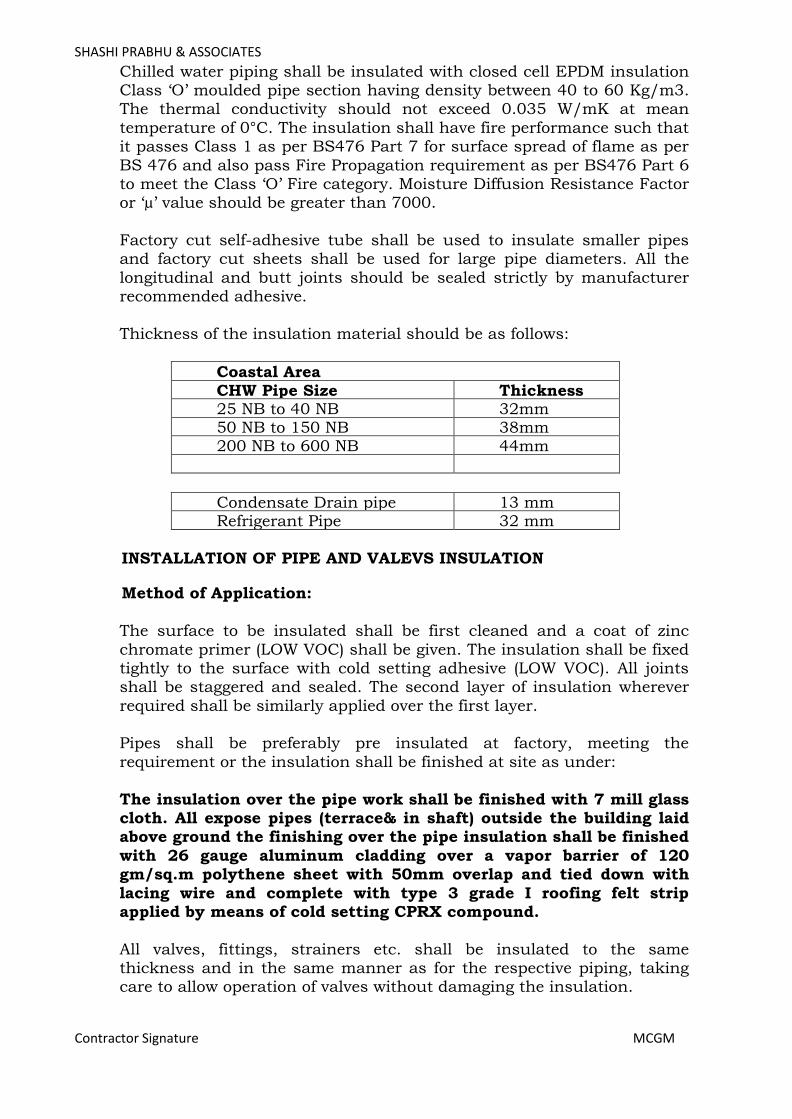
SHASHI PRABHU & ASSOCIATES
Contractor Signature MCGM
Chilled water piping shall be insulated with closed cell EPDM insulation Class ‘O’ moulded pipe section having density between 40 to 60 Kg/m3. The thermal conductivity should not exceed 0.035 W/mK at mean
temperature of 0°C. The insulation shall have fire performance such that it passes Class 1 as per BS476 Part 7 for surface spread of flame as per
BS 476 and also pass Fire Propagation requirement as per BS476 Part 6 to meet the Class ‘O’ Fire category. Moisture Diffusion Resistance Factor or ‘µ’ value should be greater than 7000.
Factory cut self-adhesive tube shall be used to insulate smaller pipes and factory cut sheets shall be used for large pipe diameters. All the
longitudinal and butt joints should be sealed strictly by manufacturer recommended adhesive.
Thickness of the insulation material should be as follows:
Coastal Area CHW Pipe Size Thickness 25 NB to 40 NB 32mm 50 NB to 150 NB 38mm 200 NB to 600 NB 44mm
Condensate Drain pipe 13 mm Refrigerant Pipe 32 mm
INSTALLATION OF PIPE AND VALEVS INSULATION
Method of Application:
The surface to be insulated shall be first cleaned and a coat of zinc
chromate primer (LOW VOC) shall be given. The insulation shall be fixed tightly to the surface with cold setting adhesive (LOW VOC). All joints shall be staggered and sealed. The second layer of insulation wherever
required shall be similarly applied over the first layer. Pipes shall be preferably pre insulated at factory, meeting the
requirement or the insulation shall be finished at site as under:
The insulation over the pipe work shall be finished with 7 mill glass cloth. All expose pipes (terrace& in shaft) outside the building laid above ground the finishing over the pipe insulation shall be finished
with 26 gauge aluminum cladding over a vapor barrier of 120 gm/sq.m polythene sheet with 50mm overlap and tied down with
lacing wire and complete with type 3 grade I roofing felt strip applied by means of cold setting CPRX compound.
All valves, fittings, strainers etc. shall be insulated to the same thickness and in the same manner as for the respective piping, taking care to allow operation of valves without damaging the insulation.
Page 293

SHASHI PRABHU & ASSOCIATES
Contractor Signature MCGM
MEASUREMENT OF INSULATION Unless otherwise specified measurement for duct and pipe insulation for
the project shall be as per CMMRDA specification for HVAC Work.
Page 294

SHASHI PRABHU & ASSOCIATES
Contractor Signature MCGM
18 ELECTRICAL INSTALLATIONS GENERAL
Work shall be carried out in accordance with the specifications, local
rules, Indian Electricity act 1910 as amended up to date, and rules issued there under, regulations of the Fire Insurance Company and Indian Standard Code of practice No. 7321963 (revised). For items of
work not covered by any of the above regulations, wiring rules in the 13th edition of the Institution of Electrical Engineers (London) shall apply. Definition of terms shall be as per the rules of the Institution of
Electrical Engineers,
The following exclusion from this contract may be provided by department. Through other agencies, as per special conditions of contract:
31/2 core XLPE insulated PVC sheathed Aluminum conductor Armoured cable along with two independent earth connection up to the
incoming breakers in the Air conditioning plant room main panel only.
SCOPE The scope of work covered under this section shall be inclusive but not
limited to followings, and everything necessary to complete the work shall be provided by the contractor within the rates quoted by him for
the electrical package on turnkey basis. All electrical panels including the main panel, local electrical panel
boards (EPB) and distribution boards whether indicated in the drawings or not/ as required for proper functioning of the system.
All aluminum conductor armoured power distribution cables starting from main electrical panel in the plant room up to the final outlet.
All copper conductor armoured control cables from the final outlets up to the main control console.
A centralized control console to indicate the condition of various
drives/equipment and also to control various feeders/drives/equipment. WIRING SYSTEM
All power wiring shall be carried out with 650/ 1100 volts grade PVC insulated, armoured, overall, PVC sheathed aluminum conductor cables.
Cables shall be sized for starting current and by applying proper derating factor. All control wiring shall be carried out by using 650/
1100 volts FRLS insulated copper conductor wires in wire trays or in conduit. Minimum size of control wiring shall be 1.5 sq.mm. FRLS insulated copper conductor wires. Minimum size of conductor for power
Page 295
SHASHI PRABHU & ASSOCIATES
Contractor Signature MCGM
wiring shall be 4 sq.mm. 650/1100 volts grade PVC insulated aluminum conductor wires in conduit.
SPECIFICATION FOR LT PANEL SWITCHBOARD
This Specification covers the requirements for the design, construction, assembly, mechanical installation and testing of a Main Low Voltage switchboard:
The Specification shall be read in conjunction with the accompanying Annexure and the Principal’s drawings listed therein.
The Low Voltage Switchboard shall be with aluminium bus bars, indoor
type, free standing, with Plinth, floor mounting type, extensible on either side.
SITE CONDITIONS:
Max. Peak room temperature in shade: 40degC. Altitude – Mumbai Sea Level
STANDARDS: The design, manufacture & testing of the various items are covered by
the following standards:
IEC 61943 : For Main LT panels Low voltage switchgear And Control gear Assemblies IS 42371967 : General requirement for Switchgear and
Control gear for Voltages not exceeding 1000V.
IS 21471962 : Degree of protection provided by enclosure for low voltage switchgear and Control gear. IS 36191966) : Phosphate treatment.
IS 60051970) IS 51978 : Colour for ready mixed paints & enamels. IS 50821969 : Wrought aluminium for electrical purpose.
BS162 : Clearance & creepage for bus systems. IS 3751963 : Marking arrangement for busbar/cable.
IS 55781970 IS 42371967 : Clearances & Cree pages for Part I & II devices.
IS 6875 : Push buttons & related control switches including control Contactors.
IS 9224 Part I & Part II – 1973 : HRC Fuses. IS 2516 Part I & II – 1979/
IEC609471&2 : alternating current circuit breakers (ACB). II Sec. I – 1977 : Voltage not exceeding 1000V AC or 1200V DC.
Page 296
SHASHI PRABHU & ASSOCIATES
Contractor Signature MCGM
IS 32311965 : Protective relays. IS 31561965 : Voltage transformers. IS 27051981 : Current transformers.
IS 12481968 : Elect. indicating instruments.
SPECIFICATIONS: Rated System : AC nominal system voltage 240/415
with the tolerance of ± 10 percent as given in IS 12360 upto date.
Rated insulation level : 660V rms. HV withstand level : 6 kV for power circuit.
(for 1 min). : 4kVfor control circuit Horizontal bus bar : As per detail design drawings rating. / Drawings.
Rated short time : Up to 65/50kA rms for 1 sec. 110kA Rating of H.Bus & peak
(50MVA). V. Bus. ( shall be calculated at detail design stage & considered accordingly)
Degrees of Protection : as specified in the specs. Report& as per standards
General
• Switchboards shall in accordance with the standards (IEC 614391 & 2 (Low Voltage switchgear and control gear assemblies) for Main LT switchboards & other Front operating switchboards suitable for operation at three phase 4 wire, 415 volt, 50 Hz, neutral solidly
grounded at transformer system with a short circuit level withstand as per detail design drawings. The main distribution
boards shall be suitable for operating voltage up to 690 V and Insulation voltage of 1000V.
• Switchboards shall comply to Form 3B for Main compartmentalized board sand Form 1 for non compartmentalized
distribution boards as per BS 5486 Part I – 1990 and IEC 4391.
• All the major components like enclosure, switchgear component and bus bar support shall be supplied by OEM manufacturer to the franchise assembler.
• The enclosures shall be designed to take care of normal stress as well as abnormal electromechanical stress due to short circuit conditions. All covers and doors provided shall offer adequate
safety to operating persons and provide ingress protection of IP 54 & for external panels IP66 unless otherwise stated. Ventilating openings and vent outlets, if provided, shall be arranged such that
Page 297

SHASHI PRABHU & ASSOCIATES
Contractor Signature MCGM
same ingress protection of IP specified retained. Suitable pressure relief devices shall be provided to minimize danger to operator during internal fault conditions.
• Entire switchgear used in switchboards shall be completely fuse free. No fuses shall be used anywhere in the installation.
• All accessible bares terminals shall be provided with integral shrouds and shall be finger touch proof.
• Bimetallic connectors shall be provided for termination of cable with aluminium conductors on copper bus bars.
• Main distribution boards shall be assembled only by a franchisee of the original manufacturer and approved by the consultant.
• Panel builder / assembler shall have a minimum experience of 10years in the field of switchgear assembly
• The panels shall be factory manufactured by OEM
• The Main LV (above 800A rated) & external placed panel cubicles shall have structural steel frame work. It is enclosed on all sides and top by Cold Rolled sheet steel of minimum outer thickness of
2.5 mm.
• Intrinsic load bearing member shall be used as per design verified assembly and should have min. thickness of 2 mm. Load bearing members to be supplied by OEM or by approved supplier of OEM.
• The panels shall have integral base frame.
• The LV panel shall have provision for top / bottom in coming and bottom / top out going
• respectively to suit site conditions of cable entries.
• The maximum and minimum height of the operating handles from floor level shall be as 1800/ 250 mm respectively.
• All components like, circuit breakers, switches etc. shall be compatible with the short-circuit levels.
• All internal wiring shall be with suitable stranded copper conductor FRLS insulated wire.
• The busbars shall be colour coded using identifying colour rings at regular interval. Red,
• Yellow & Blue colour shall be used for phases & Black for neutral for each shipping section of panels. The earth Busbar shall be
Page 298

SHASHI PRABHU & ASSOCIATES
Contractor Signature MCGM
identified with Green color rings at regular intervals.
• The Busbar sizes shall be determined taking into consideration the continuous rat ing and fault level indicated, as applicable, without exceeding the temperature raise limits as per IEC, over
ambient temperature. Feeder in adjacent vertical to be feed with common vertical busbar / dropper.
• Bus bar supporting systems shall withstand the short circuit forces circuits, without deflection or deformation.
• The busbars shall be supported of regular intervals using SMC or DMC insulators as per the tested design. It should have minimum Comparative Tracking Index (CTI) of 600 V as per IS 2824).
• Minimum clearance between phases / live parts shall be 25 mm and phases / live parts /
• neutral to ground shall be 19 mm except on the equipment terminals.
Switchboard Configuration
• The Switchboard shall be configured with Air Circuit Breakers,
MCCB's, and other equipment as called for in the system requirement.
• The MCCB's shall be arranged in multitier formation whereas the Air Circuit Breakers shall be arranged in Single tier
formation only to facilitate operation and maintenance.
• The Switchboards shall be of adequate size with a provision of
25% spare space to accommodate possible future additional switch gear.
i. DESIGN CONSIDERATIONS
• The main distribution boards shall be of standard, natural air cooled, well tested and proven design which ensures maximum
safety to personnel, maximum service reliability and economic operations for a lifetime of at least 20years. Design and construction shall be simple, well laid out and shall provide good
accessibility to components and parts.
• Unless specified otherwise, the form of construction for the main distribution board shall comply with Form3b requirements of IEC
614391.
• Unless specified otherwise, the main distribution board shall be fixed version, main incoming switching devices shall be withdraw able type and the outgoing switching devices shall be fixed type.
Page 299
SHASHI PRABHU & ASSOCIATES
Contractor Signature MCGM
• Main distribution boards shall be rated on the basis of voltage, current, frequency and the symmetrical breaking capacity of incorporated switching de vices.
• The electrical system for all main distribution boards shall be 415 / 380V, 50 Hz 3phase and neutral, 4wire solidly earthed. The
main distribution boards shall be suitable for operating voltage up to 690 V and Insulation voltage of 1000V.
• Unless specified otherwise, the fault level withstand capacity of the main panel board bus bar system rated up to 4000Amps shall be 65/50KA(as per detail de sign) RMS for 1second as minimum standard. The breaking capacity of the switching devices shall be
65/50KA as minimum standard. The type test certificate shall be submitted for consultant engineer verification, to prove the fault
level withstand capacity of the main distribution boards. Even under extreme conditions of short circuit or mal operation there shall be no danger to persons in the vicinity of the assembly.
• All equipment and components of the main distribution boards shall be capable of continuous operation at their full current and voltage ratings and without detriment or malfunction at system continuous deviation of up to and including the following
percentages of the normal values. Voltages ± 10%
Frequency± 5%
• All components shall be capable of withstanding the dynamic, thermal and di electric stresses resulting from prospective short circuit currents without dam age or injury to personnel.
Equipment Specifications
All equipment used to configure the Switchboard shall comply to the relevant Standards and Codes of the Bureau of International / Local Standards and to the detailed technical specifications as
included in this tender document.
General Arrangement & Assembly
L.V Panel shall comprise of free standing enclosure, bus bar
system, switching devices such as ACB/ MCCB, metering equipment’s, all necessary current transformers and the like as required. Panel shall be assembled in a systematic manner such as Transformer Incomer
section, Generator Incomer section (if applicable), Bus coupler section (if applicable), Incomer Metering / Indication section and Outgoing section.
Unless otherwise specified the panels shall be designed to accept bottom/top entry of cables and shall be of rear access type. The rear
access shall only be provided for access for termination of cables, all
Page 300

SHASHI PRABHU & ASSOCIATES
Contractor Signature MCGM
other equipment’s shall be accessible / operable from the front of panel. Where front access type is specified, the panel shall be designed completely for front access only.
Each section shall be arranged typically as described below and as per
the details shown in the drawings: Incomer section
Incomer panel shall be a 3 compartment enclosure with Top & Bottom compartment dedicated for metering / controls and the Middle compartment shall be dedicated for the circuit breaker. It shall comprise
of but not limited to the following: Bottom Compartment
- Incomer supply cables Middle Compartment - Main Incoming circuit breakers with rating and type as per the drawing. Top Compartment
− Any control component for Incoming circuit breaker.
− Digital power meter to indicate various electrical parameters − Phase indication lamps (R, Y, B) wired to the line side of the circuit breaker.
− Power factor meter (If required as per local authority requirement).(not in DG case) − KWH energy meter (If location of KWh is approved by local
authority).
Bus coupler / Bus Tie section – (If applicable) The Bus Tie / Bus Coupler Panel shall be a 3 compartment enclosure to
match with the incomer panels. The Top & Bottom compartment can be used for accommodating the common controls of the incoming and the
bus tie circuit breakers. The Middle compartment shall be dedicated for the circuit breaker. It shall comprise of but not limited to the following:
− Where ACB’s are used as incoming or bus coupler, the front face of the ACB shall be accessible for operation from the front without opening the feeder door.
− Where MCCB’s are used as incoming or bus coupler circuit
breakers and Direct Rotary handle shall be provided at the front face of the MCCB which is operated from front door. All such handles shall be door interlocked wherever required.
Outgoing section(s)
The outgoing section(s) enclosure shall accommodate the outgoing circuit breakers which shall be arranged in a systematic and
symmetrical manner. It shall comprise of but not limited to the following:
Page 301

SHASHI PRABHU & ASSOCIATES
Contractor Signature MCGM
Each panel shall have various fixed compartments with individual doors for each compartment and each compartment shall accommodate the following:
Circuit breakers with rating and type as specified in the drawings.
Any other controls, which may be part of the outgoing circuit breakers. Notes: All circuit breakers and other controls pertaining to a feeder shall be
accommodated in its own compartment, which shall have its own feeder doors. Keys for all such External door shall be common.
Moulded case circuit breaker in each compartment shall be equipped with a Direct operating handle extended to the front face of the door for
operation. All such door handles shall be door interlocked, wherever required.
Air circuit breaker front face shall be accessible without opening the door.
Circuit breakers and other control components shall be fully accessible after opening the panel door; however, no live parts shall be exposed.
All the bus bar connections / terminations to the outgoing circuit breakers shall be taken from the rear side of the circuit breaker, which
shall be shrouded properly using metallic / poly carbonate sheets. All the mccb terminals shall be fully shrouded with original terminal
shrouds from the mccb manufacturer, in such a way that no live parts are exposed, when the front door is opened.
Opening of the front door shall give access to the circuit breaker for rating adjustments etc.
Maximum 1 nos. air circuit breakers shall be installed in one enclosure, provided that sufficient space for cable termination is provided.
Maximum 3 nos. moulded case circuit breakers, rated at 800Amps shall be installed in one tier formation, provided that sufficient space for cable
termination is provided also duration shall be considered as per manufacturer standards.
Maximum 4 nos. moulded case circuit breakers, rated below 800Amps shall be installed in one tier formation, provided that sufficient space for
cable termination is provided also duration shall be considered as per manufacturer standards.
All Partitioning and shrouding shall comply the requirements of Form3b, construction as per IEC standards.
Enclosure manufacturing
Page 302

SHASHI PRABHU & ASSOCIATES
Contractor Signature MCGM
Main distribution board enclosure shall be a branded catalogue product from approved manufacturer. Enclosure shall be made out of electro galvanized steel sheets conforming to international specification. AluZinc
coating shall be provided on the sheets, which shall prevent rust formation during storage and handling for processing, in addition to
giving corrosion protection to the finished product. The sheets have a fine surface finish, which gives good presentation to the painted components of the enclosure.
The enclosure system shall be Modular in nature with Bolt on construction.
The enclosure shall be powder coated to an approved colour. The
painting process shall include removal of moisture on the sheet steel surface using and applying thermosetting polyester powder using automatic guns. Polymerization of the powder shall take place when the
components are cured at about 180ºC, forming a continuous integrated coating. A fairly uniform coating of atleast 7080 microns shall be
provided. The pretreated and powder coated sheet steel components shall be
atleast tested randomly at regular intervals for coating thickness measurement, adhesion test, bend test, impact test, hardness test, salt spray test etc.
Enclosure construction
Main distribution board enclosure shall be a branded catalogue product from approved manufacturer. The assembler shall assemble the
prefabricated elements of the enclosure system, bus bar system, switching devices and other equipment to complete the main
distribution board. Main distribution boards (above 800A rated) & external placed panel’s
enclosure shall be fabricated of minimum 2.5 outer body 2 mm internal (including doors), thick electro galvanized sheet steel folded construction. The enclosure shall be of simple and robust construction
designed for a variety of dimensions obtainable by means of standardized basic elements. Main distribution board shall consist of
several enclosures of equal height and depth mounted side by side to form a composite board of uniform assembly.
Enclosure structure composition shall be based on a supporting frame consisting of cross members, vertical members and panels fastened one
another by means of bolts. The basic structure shall be completed by the addition of a compartment for the connections which may be located at rear or at side depending on the access. A single piece base shall
allow anchoring of the unit to the floor. The complete assembly shall be rigid self supporting structure which is deformable and unaffected by shocks. The structure shall be completed by a metal partition made of
Page 303

SHASHI PRABHU & ASSOCIATES
Contractor Signature MCGM
one or more pieces between two sections depending on the depth of the compartment. The lower part of structure shall be closed by means of bolted plates that can be removed whenever the assembly of cable
glands is required. The switchgear components contained in sections shall be installed on mounting plates. Each door panel shall be equipped
with integral key lock and the key shall be common for all such locks. All door hinges to be of concealed type and it shall be possible to remove the door panel whenever required. All doors, bold on cover, partitions,
mounting plates and metallic shrouds shall be effectively connected to earth. Flexible earth wires shall be used for removable covers and hinged doors.
The structure and the partitions shall be protected by a durable scratch
resistant textured paint finish, epoxy powder polymerized at high temperatures to an approved color.
Adequate care shall be taken while designing the main distribution board connection spaces for the external cables. Sufficient cable
supports shall be provided for routing the cables inside the enclosure. Enclosure system shall effectively dispose the heat produced by the
main circuits and shall integrate a high performance natural ventilation system which shall be aimed at regulating the internal temperature based on the actual capacities of the components.
Enclosure shall be readily suitable for future extension on either side
without any modifications (after installation at site). Form 3B construction assembly shall provide protection against contact
with internal live parts and components. Bus bars, functional units and cable termination shall be segregated from each other as given below:
Bus bars shall be separated from functional units;
Functional units / switching devices shall be separated from each other; Cable termination and functional units / switching devices shall be separated from each other;
Incoming and outgoing terminals shall be separated from each other.
Busbars shall be accommodated in a separate chamber/alley with metallic shrouds and partitions to avoid accidental external contacts. All CT’s & PT’s shall be resin cast unless specified otherwise or as
approved Incoming switching device shall be located in separate section and
outgoing switching devices in other sections, wherever applicable. Each switching device shall be segregated from each other and located in individual compartment with hinged door.
External cable termination to the switching device terminals shall be outside the functional unit / switching device compartment. Segregation
Page 304

SHASHI PRABHU & ASSOCIATES
Contractor Signature MCGM
shall be made between the switching device terminal and the switching device within its compartment by means of rigid barriers and partitions.
All segregation shall be achieved by means of rigid metallic sheet partitions. Segregation and partition shall ensure protection against
contact with live parts and limitation of the faults within each of the functional unit compartment.
Page 305
SHASHI PRABHU & ASSOCIATES
Contractor Signature MCGM
Constructional Features The Switchboards shall be metal clad totally enclosed, floor mounted
free standing type of modular extensible design suitable for indoor mounting. The Switchboards shall be designed for a temperature rise
restricted to 40 Deg C above ambient of 45 Deg C. Switchboards shall be either compartmentalized unless otherwise
specified. Switchboards shall be made up of requisite vertical sections, which
when coupled together, shall for continuous dead front switchboards.
Switchboard shall be readily extensible on both sides by addition of vertical sections after removal of the end covers.
The switchboards shall be designed for use in high ambient temperature and high humid tropical conditions as specified. Ease of inspections,
cleaning and repairs while maintaining continuity of operation shall be provided in the design.
‘U’ Channels forming switchboard frames shall be fabricated from 2.5 mm thick electro galvanized MS sheets. All joints shall be neatly formed and finished flush with adjacent surfaces by grinding. No joints shall be
located in corners. Bare edges shall be lipped. Structural members and bracings where ever required shall be welded or bolted to the frame. The
frame shall be of modular design and extensible. All doors and covers shall also be fully gasketed with metal based
neoprene gaskets to ensure proper compression of the gaskets. The
hinged door shall open a maxi mum of 1500. All hinged doors shall have earth braid connected to the cubicle. Good quality door handles fitted
with toggles to operate rods to latch with suitable slots in both top and bottom of switchboards shall be provided. Latching rods and associated brackets shall be cadmium plated.
Each vertical section shall be provided with a rear/ side cable chamber housing the cable end connections and power/control cable
terminations. There should be generous availability of space for ease of installation and maintenance with adequate safety for working in one
vertical section without coming into contract with any liver parts. Switchboard panels and cubicles shall be fabricated with CRCA Sheet
Steel of thickness not less than 2.5(outer) ,2 mm (internal) and shall be folded and braced as necessary to provide a rigid support for all
components. The doors and covers shall be fabricated from CRCA sheet steel of thickness not less than 2.5(outer) ,2 mm (inter nal). Joints of any kind in sheet metal shall be seam welded and all welding slag
ground off and welding pits wiped smooth with plumber metal.
Page 306

SHASHI PRABHU & ASSOCIATES
Contractor Signature MCGM
All panels and covers shall be properly fitted and square with the frame. The holes in the panel shall be correctly positioned.
Fixing screws shall enter holes tapped into an adequate thickness of metal or provided with hank nuts. Self-threading screws shall not be
used in switchboards. All electrical contacts between dissimilar metals (eg. aluminium
conductor of cables connected to copper terminals of breakers etc.) shall be through bimetallic connection.
Type test certificates shall be available for the proposed type of enclosure and the bus bar system. The type test certificates shall be
clearly state type, model and main characteristics of the assembly, references of the standards applied for the tests, results obtained and the observations made during & after the tests.
All Panels/ distribution board shall fully comply with requirements of
TTA equipment (Type Tested Assemblies) as per IEC 61439. Design drawings, component catalogues and type test certificates shall
be submitted for consultant approval prior to placement of order for the panels/distribution boards.
Switchboard Compartmentalization
For compartmentalized switchboards, separate totally enclosed compartments shall be provided for horizontal bus bars, vertical bus bars, ACBs, MCCBs and cable alleys.
Earthed metal or insulated shutters shall be provided between draw out
and fixed portion of the switchgear such that no live parts are accessible with equipment drawn out. Degree of protection within compartments shall be at least IP 4X.
Sheet steel hinged lockable doors for each separate compartment shall be provided and duly interlocked with the breaker in "ON" and "OFF"
position.
For all Circuit Breakers separate and adequate compartments shall be provided for accommodating instruments, indicating lamps, control contactors and control MCB etc. These shall be accessible for testing
and maintenance without any danger of accidental contact with live parts of the circuit breaker, bus bars and connections.
Each switchgear cubicles shall be fitted with label in front and back identifying the circuit, switchgear type, rating and duty. All operating
device shall be located in front of switchgear only. Minimum height from floor level for any device mounted on panel cover shall be 250 mm.
Page 307

SHASHI PRABHU & ASSOCIATES
Contractor Signature MCGM
A horizontal wire way with screwed cover shall be provided at the top to take inter connecting control wiring between vertical sections.
Separate cable compartments running the height of the switchboard in the case of front access boards shall be provided for incoming and
outgoing cables. Cable compartments shall be of adequate size for easy termination of all
incoming and outgoing cables entering from bottom or top. Adequate and proper support shall be provided in cable compartments
to support cables.
Spare Provision i.2025% spare cubicles/ space shall be provided in all switchboards to
cater for future use.
Switchboard Bus Bars Bus bars shall be made of high conductivity, high strength aluminium
alloy, complying with requirements of grade E 91E as per International IEC/BS and local norms. Design of bus bar system shall comply to IEC relevant standards. Bus bars shall be of rectangular cross sections
suitable for full load current for phase bus bars as also neutral bus bar .The maximum current density shall be 1 amp per Sq. mm. Bus bar
shall be suitable to withstand the stresses of fault level as per detail design & standards.
Bus bars shall be insulted with heat shrink PVC sleeves of 1.1 kV grade and bus bar joints provided with clip on shrouds.
The bus bars shall be extensible on either side of the switchboard.
The bus bars shall be supported on non-breakable, no hygroscopic epoxy resin or glass fiber reinforced polymer insulated supports able to
withstand operating temperature of 110O C at regular intervals, to withstand the forces arising from a fault level of 50/35 MVA(as per
detail design) at 415 volts for 1 second or as per detail de sign.
All bus bars shall be colour coded. Auxiliary buses for control power supply, space heater power supply or
any other specified service shall be provided. these buses shall be insulated, adequately supported and sized to suit specific requirement.
The material for auxiliary supply bus will be electrolytic copper. Additional cross sectional area to be added to the bus bar to compensate
for the holes.
Page 308
SHASHI PRABHU & ASSOCIATES
Contractor Signature MCGM
The busbar system shall be designed as per the predefined guidelines provided by the original manufacturer. The busbar system shall be type tested by the manufacturer at reputed laboratory for short circuit with
stand capacity. The neutral and earth busbars shall also be type tested for the short circuit withstand capacity. The fault level rating of the
busbar system shall be as per the drawings however the minimum short circuit withstand capacity shall be 65/50KA RMS for 1second. Neutral busbar shall be able to withstand a thermal stress of atleast 50%,
corresponding to the main phase busbar rated short circuit withstand capacity.
The busbar system shall be supported adequately at regular intervals as per manufacturer guidelines based on the type test results on a specially
designed busbar supports. The supports shall be independently fixed to structure to strengthen the busbar arrangement. Wherever required additional intermediate supports shall be provided between the busbars.
All vertical droppers shall also be adequately supported as per the manufacturer guidelines and the test results. The distribution bus bars
shall be connected to the main busbars by suitable sized and graded bolt & nut and contact washers. Clamp type arrangements for connections will not be permit ted. Connections to the switching devices
to the main or distribution busbars shall be carried out using rigid bars of adequate and standard sizes. It shall be possible to replace the switching devices with different rating with same frame sizes without
changing the interconnection busbars.
The main busbars shall be accommodated on a separate busbar chamber running horizontally at top or bottom or middle of the panel. Main busbars running behind the functional units (the switching device
mounting plates) will not be permitted. Distribution busbars are permitted at the back of the switching device compartments only where
with drawable versions are used The dimensioning of the busbar system shall be as per the rated current
of the main switching device, the short circuit current, the maximum rated permissible temperature at permanent operation and the ambient temperature around the busbars. The selection of busbars shall be
supported by calculations and recommendations from the original manufacturer.
The neutral busbar shall run along with the phase busbars and shall outgoing switching devices neutral connection terminal shall be provided
with in the switching de vice compartment.
Earth busbar shall be running throughout the panel fitted directly on to the structure for connection of the protective conductors to provide equipotential bonding of ex posed conductive parts. Earth busbar shall
be located at the bottom of the panel and in the cable chamber/ alley to facilitate easy connection of protective conductor.
Page 309

SHASHI PRABHU & ASSOCIATES
Contractor Signature MCGM
Switchboard Interconnection All connection and tap offs shall be through adequately sized connectors
appropriate for fault level at location. This shall include tap off to feeders and instrument/control transformers. Alternatively, current limiters of
approved make and type shall be used. For unit ratings up to 100 amps, FRLS PVC insulated copper conductor
wires of adequate size to carry full load current shall be used. The terminations of such interconnections shall be crimped. Solid connections shall be used for all rating of 100 amps and above.
All connections, tapping’s, clamping, shall be made in an approved
manner to ensure minimum contact resistance. All connections shall be firmly bolted and clamp with even tension.
Before assembly joint surfaces shall be filed or finished to remove burrs, dents and oxides and silvered to maintain good continuity at all joints.
All screws, bolts, washers shall be cadmium plated. Approved spring washers shall be used with cadmium plated high tensile steel bolts with BSF threads.
All connectivity and tap offs shall have bimetallic connectors as required, finger touch proof terminals & integral switchgear shrouds.
Draw out Features
Air Circuit Breakers shall be provided in fully draw out cubicles, unless otherwise stated. These cubicles shall be such that draw out is possible
without disconnection of the wires and cables.
The power and control circuits shall have self-aligning and self-isolating contacts. The fixed and moving contacts shall be easily accessible for operation and maintenance. Mechanical interlocks shall be provided on
the draw out cubicles to ensure safety and compliance to relevant Standards. The MCCB's shall be provided in fixed type cubicles.
Instrument Accommodation
Instruments and indicating lamps shall not be mounted on the Circuit Breaker Compartment door for which a separate and adequate compartment shall be provided and the instrumentation shall be
accessible for testing and maintenance without danger of accidental contact with live parts of the Switchboard.
For MCCB's instruments and indicating lamps can be provided on the compartment doors.
The current transformers for metering and for protection shall be mounted on the solid copper/aluminium bus bars with proper supports.
Page 310
SHASHI PRABHU & ASSOCIATES
Contractor Signature MCGM
Wiring
All wiring for relays and meters shall be with FRLS PVC insulated copper conductor wires. The wiring shall be coded and labelled with approved
ferrules for identification. The minimum size of copper conductor control wires shall be 2.5 sq. mm. Wiring shall be terminated with ferrules on terminal block. CTs shall be provided with shorting facilities
Cable Terminations
Knockout holes of appropriate size and number shall be provided in the Switchboard in conformity with the location of incoming and outgoing
conduits/cables.
The cable terminations of the Circuit Breakers shall be brought out to
terminal cable sockets suitably located in the cable chamber
The cable terminations for the MCCB's shall be brought out to the rear in the case of rear access switchboards or in the cable compartment in the case of front access Switchboards.
The Switchboards shall be complete with tinned brass cable sockets, tinned brass compression glands, gland plates, supporting clamps and
brackets etc for termination of 1100-volt grade aluminium conductor XLPE cables.
Removable gland plates shall be provided for power and control cables. The gland plates shall be 3 mm thick and for single core cables shall be
of nonmagnetic material.
Space Heaters Anti-condensation heaters shall be fitted in each cubicle together with
an ON/OFF isolating switch suitable for electrical operation at 230 volts A.C 50 Hz single phase of sufficient capacity to raise the internal
ambient temperature by 5₀C. The electrical apparatus so protected shall be designed so that the maximum permitted rise in temperature is not
exceeded if the heaters are energized while the switchboard is in operation. As a general rule, the heaters shall be placed at the bottom of
the cubicle. Ventilation Fans
The Switchboard shall be provided with panel mounting type ventilation fans in each panel with switchgear rated for 800 amps and above. The
fan shall be interlocked with switchgear operation. If ventilation fans cannot be provided for maintaining the required degree of ingress
protection, the design of switch board cubical shall incorporate suitable measures like decreasing current density of conductors, increasing
Page 311

SHASHI PRABHU & ASSOCIATES
Contractor Signature MCGM
cubical volume for effective heat dissipation etc. in order to restrict temperature rise to within the required limit.
Page 312
SHASHI PRABHU & ASSOCIATES
Contractor Signature MCGM
Earthing
Continuous internal copper earth bus sized for prospective fault current
to be provided with arrangement for connecting to station earth at two points. Hinged doors / frames to be connected to earth through
adequately sized flexible braids. Sheet Steel Treatment And Painting
Sheet steel used in the fabrication of switchboards shall undergo a rigorous cleaning and surface treatment seven tank process comprising
of alkaline degreasing, descaling in dilute sulphuric acid and a recognized phosphating process after which a coat of primer paint
compactively with the final paint shall be applied over the treated surface. Final paint coat of oven baked powder coating, of minimum 80-micron thickness, of sheet approved by Architect/Client shall then be
provided.
Name Plates And Labels Suitable engraved white on black name plates and identification labels
of metal for all Switchboards and Circuits shall be provided. These shall indicate the feeder number and feeder designation.
Local Authorities Requirement
All other requirements by the local Authority that are imposed in course of execution of the work, particularly those listed below shall be provided.
Danger Signs Rubber floor mats will be provided all around the panels as per IS
156522007 amended up to date. A dry chemical type fire extinguisher of 9 kg capacity with approved label
Framed single line diagram with minimum A1 size First Aid Demonstration sign.
CPRI TESTING Switchboard configurations offered shall be CPRI tested. Copies of the
CPRI test certificates shall be submitted with the tender. TESTING AT WORKS
Copies of type test carried out at ACB/MCCB manufacturers works and routine tests carried out at the switchboard fabricators shop shall be
furnished along with the delivery of the switchboards. Client reserves the right to get the switchboard inspected by their representative at fabricators works prior to dispatch to site to witness the routine tests
Type Test
Page 313
SHASHI PRABHU & ASSOCIATES
Contractor Signature MCGM
The main distribution board and the components as applicable shall be type tested in accordance with the IEC standards to verify the specified fault level withstand capacity from a reputed and approved type testing
laboratory and certified by an competent authority.
The tests as specified in IEC 614391 standards to comply with requirements of TTA equipment shall be carried out at recognized test laboratories and certificates from approved test witnessing authority
shall be provided for each type test: Type test certificates shall be submitted to the client for
verification.
Routine test The panel assembler shall perform the routine test and provide the test
certificates as de fined in IEC standards. The routine test shall include but not limited to the following:
Inspection of the assembly including inspection of wiring and electrical operational test (IEC Clause 8.3.1); Dielectric test & Insulation resistance test (IEC Clause 8.3.2 & 8.3.4);
Checking of protective measures and of the electrical continuity of the protective circuits (IEC Clause 8.3.3) Functional test as per the approved test procedure.
Routine test certificates and test readings shall be submitted to the
consultant engineer for verification. INSTALLATION
The foundations prepared as per the manufacturers drawings shall be
levelled, checked for accuracy and the Switchboard installed. All bus bar connections shall be checked with a feeler gauge after installation. The cable end boxes shall be sealed to prevent entry of moisture. The main
earth bar shall be connected to the substation earths. Antistatic rubber mat ting of approved make conforming to IEC/BS relevant standards, of minimum 1000 mm width 10 mm thickness shall be provided in front of
and along the full length of the Switchboard. The rubber mat shall withstand 15 KV for 1 minute and leakage current shall not exceed 160
mA/sq. meters. After installation the Switchboard shall be tested as required prior to commissioning.
TESTING AT SITE
Pre-commissioning tests as required and as per manufacturers recommendations shall be carried out on each switchboard at site before energizing the switchboards including but not restricted to the following:
Physical checking of the switchboards including checking alignment of panels, inter connection of Bus bars, tightness of bolts/connections and
Page 314

SHASHI PRABHU & ASSOCIATES
Contractor Signature MCGM
evidence of dam age/cracks in any components. Physical checking and inspections of Inter panel wiring Checking free movement of ACBs/MCCBs/SFUs
Checking of operation of breakers Insulation tests of bus bar supports and control wiring etc. with 1.1 kV
megger. Primary & secondary injection tests of relays and CTs. Checking of Interlocking function.
AIR CIRCUIT BREAKER
General Points
The ACB shall conform to IS/IEC 609472. The ACBs shall be type tested & certified for compliance to standards. All ACBs shall have “CE” Marking
All ACBs shall be suitable for continuous operation at Ambient
Temperature of 50ºC without any deration. All ACBs shall have Icu=Ics=Icw for 1 Second with Combined Test
Sequence Certification from Independent Testing Approved Authorities CPRI/ERDA/ASTA/KEMA.
All ACBs shall have Rated Impulse withstand voltage of the main circuit of not less than 12kV (Uimp) & Rated Insulation Voltage of not less than
1000 V. Neutral Pole shall be of 100% Current Rating as Phase pole (In case of 4
Pole ACBs). However, in case where 3 Pole ACBs with O/L, S/C, E/F (Inbuilt E/F mandatory in all ACBs) are specified, vendor to provide
Neutral CT from ACB manufacturer. The release shall be equipped with Inbuilt Thermal Memory.
All ACBs shall be provided with Door Interlock and Racking Interlock. One shall not be allowed to open the panel door without ensuring that
the ACB is in “ISOLATED” position
All ACBs shall be provided with Mechanical Operation Counter. All ACBs shall have provision of removing Arc Chutes without use of any
tool thus facilitating quick inspection of electrical contacts.
All ACBs equipped with Shunt Release shall have the operating voltage range from 10% Unto 110% Un to ensure intentional tripping even at high voltage drops during short circuit.
Lockable Trip Push Button shall be provided wherever Interlock between ACBs is specified.
Page 315
SHASHI PRABHU & ASSOCIATES
Contractor Signature MCGM
All ACBs shall have sealable sliding shutters to prevent unauthorized access to “TRIP” and “CLOSE” push buttons
All ACBs shall have their Electrical Life with maintenance = Mechanical
Life. Minimum no. of operational life shall be as follows: For Ratings up to 2500A: 20,000 Operations; For 3200A & 4000A:
10,000 Operations; For 5000A & 6300A: 5,000 Operations
It shall be possible to terminate Aluminium Links directly (without any adaptors) as specified in IS139472
All ACBs shall have protection against O/L, S/C & E/F and shall provide indication of cause of tripping for individual faults.
For safety of users, interlock shall be provided between breaker
operating mechanism & the arc chutes to prevent closing of ACB in case the arc chutes are not properly secured.
All Electrical Draw Out breakers shall have inbuilt electrical anti pumping
All ACBs shall provide at least last 5 trip data history & last 10 event history for analysis
All ACBs shall have 2 storable sets of LSIG protection settings to provide adequate protection against loads varying as per time (E.g. Day Time –
different protection parameter set and night time – different protection parameter set) & source changeover from Transformer to DG.
All ACBs shall have Double Short Circuit Selectivity and the same shall be with Adjustable Time Delay.
All Incomer ACB releases shall have LED Display showing all Power Parameters & Harmonic Metering (I, Imax, %loading, Iavg, V, Freq, PF,
W, VAr, VA, Wh, VArh, Vah, MD Active, MD Reactive, MD Apparent, Temperature in each Phase Deg C, %THD). They shall also give ad
additional protection against Undercurrent, Current Unbalance, Under Voltage, Over voltage, Under frequency, Over frequency, Reverse Power, Lead/Lag PF, MD Exceed, Wrong Phase sequence, Breaker Failure.
All Outgoing ACB releases shall have LED Display for all Current
Parameters All Main Incomer ACBs shall have inbuilt Temperature rise protection
for protection against abnormal temperature rise at ACB terminals. The ACB shall confirm to the requirements of IEC 609472 & 3 (FOR
Page 316
SHASHI PRABHU & ASSOCIATES
Contractor Signature MCGM
SWITCH DISCONNEC TION) / relevant local standards and shall be type tested & certified for compliance to standards from–authorized/ any accredited international lab. The circuit breaker shall be suit able for
service voltage 690, 3 Phase 50 Hz supply system. Air Circuit Breakers shall be with moulded housing flush front, draw out type and shall be
provided with a trip free manual operating mechanism or in accordance with requirements with mechanical "ON" "OFF" “TRIP” indications.
The ACB shall be 3/ 4 pole with modular construction, draw out, manually or electrically operated version as specified. The circuit breakers shall be for continuous rating and service short Circuit
Breaking capacity (Ics) shall be as specified on the single line diagram and should be equal to the Ultimate breaking capacity(Icu) and short
circuit withstand values(Icw) for 1 sec. Circuit breakers shall be designed to ‘close' and `trip' without opening the circuit breaker compartment door. The operating handle and the mechanical trip push
button shall be at the front of the breakers panel. Inspection of main contacts should be possible without using any tools. The ACB shall be
provided with a door interlock. i.e. door should not be open when circuit breaker is closed and breaker should not be closed when door is open.
However, door interlock should have defeat mechanism for On line testing of ACB. All current carrying parts shall be silver plated and suitable arcing contacts with proper arc chutes shall be provided with to
protect the main contacts. The ACB shall have double insulation (ClassII) with moving and fixed contacts totally enclosed for enhanced
safety and in accessibility to live parts. All electrical closing breaker shall be with electrical motor wound stored energy spring closing mechanism with mechanical indicator to provide ON/OFF status of the
ACB.
The auxiliary contacts blocks shall be so located as to be accessible from the front. The auxiliary contacts in the trip circuits shall close before the main contacts have closed. All other contacts shall close simultaneously
with the main contacts. The auxiliary contacts in the trip circuits shall open after the main contacts open . Minimum 6 NO and 6 NC auxiliary contacts shall be provided on each breaker. Rated insulation voltage
shall be 1000 volts AC and impulse withstands voltage equal to 12KV. ACB shall confirm compliance to ROHS/WEEE guidelines. All ACB’s
shall be compatible to IBMS having the communication port as per de tail design/requirement.
CRADLE
The cradle shall be so designed and constructed as to permit smooth withdrawal and insertion of the breaker into it. The movements shall be free from jerks, easy to operate and shall be on steel balls/rollers and
not on flat surfaces. There shall be 4 distinct and separate position with self-locking
Page 317
SHASHI PRABHU & ASSOCIATES
Contractor Signature MCGM
arrangement of the circuit breaker on the cradle. Racking Interlock in Connected/Test/Disconnected Position.
Service Position: Main Isolating contacts and control contacts of the
breaker are engaged. Test Position: Main Isolating contacts are isolated but control contacts
are still engaged. Isolated Position: Both main isolating and control contacts are isolated.
There shall be provision for locking the breaker in any or all of the first
three positions. The following safety features shall be incorporated: Withdrawal or engagement of Circuit breaker shall not be possible unless it is in open condition.
Operation of Circuit breaker shall not be possible unless it is fully in
service, test or drawn out position. All modules shall be provided with safety shutters operated
automatically by movement of the carriage to cover exposed live parts when the module is withdrawn.
All Switchgear module front covers shall have provision for locking.
Switchgear operating handles shall be provided with arrangement for locking in ‘OFF’ position.
PROTECTIONS
The breaker should be equipped with microcontroller based release to offer accurate and versatile protection with complete flexibility and shall offer complete over current protection to the electrical system in the
following four zones Long time protection.
Short time protection with intentional delay. Instantaneous protection.
Ground fault protection. The protection release shall have following features and settings:
True RMS Sensing
The release shall sample the current at the rate of 16 times per cycle to monitor the actual load current waveform flowing in the system and
shall monitor the true RMS value of the load current. It shall take into account the effect of harmonics also.
Page 318

SHASHI PRABHU & ASSOCIATES
Contractor Signature MCGM
Thermal Memory When the breaker shall reclose after tripping on overload, then the
thermal stresses caused by the overload if not dissipated completely, shall get stored in the memory of the release and this thermal memory
shall ensure reduced tripping time in case of subsequent over loads. Realistic Hot/Cold curves shall take into account the integrated heating effects to offer closer protection to the system.
Defined time current characteristics:
A variety of pickup and time delay settings shall be available to define the current thresh olds and the delays to be set independently for
different protection zones thereby achieving a closet ideal protection curve.
Trip Indication
Individual fault indication for each type of fault should be provided by LEDs for fault diagnosis.
Self powered The release shall draw its power from the main breaker CTs (hog slay
type) and shall require no external power supply for its operation.
Zone Selective Interlocking The release shall be suitable for communication between breakers to
enable zone selective interlocking. This feature shall be provided for both short circuit and ground fault protection zones to offer total
discrimination between breakers. This feature enables the clearance of fault conditions, thereby reducing the thermal and dynamic stresses produced during fault conditions and thus minimizes the damage to the
system. To implement ZSI manufacturer should supply all related equipment like power supply, wiring etc.
On Line change of settings should be possible. It should be possible to carry out testing of re lease without tripping the breaker.
The release shall meet the EMI / EMC requirements.
Derating factor In panel there shall not be any derating up to 50 degree Centigrade. Manufactures shall provide the derating table/chart and
ambient temperature. 4P ACB shall have 100% Neutral as same of Phase conductor with
protection setting (setting of 50%, 100%, 200% and Off)
ACB release shall have 1st –ON/OFF setting to coordinate with HT
Page 319

SHASHI PRABHU & ASSOCIATES
Contractor Signature MCGM
breakers. ACB release shall have inbuilt “Auto protection” against excessive
heating at terminals.
Combined accuracy (Sensor + Release) ≤ 1.5% as per international code of practice.
The setting range of release shall be as follows as per SLD : The release should provide local indication of actual %age loading of
individual phase at any instant. The release should be able to communicate on MODBUS RTU protocol using inbuilt RS485 port and
shall be integral part of supply with trip unit. Parameters of the Protection Release should be changeable from Release as well as thru communication network.
ACB should have rating plug
This type of release should be equipped with data logger and information about last20 trips including cause of trip, value of interrupted current
with date and real time stamping, should be stored in the memory with this type of release.
The release should also be equipped with protection against phase unbalance and over temperature.
Setting range of protection release
Overload protection shall have adjustable setting from 40% to 100% of the ACBs rated current.
Short time Short circuit protection shall have adjustable current setting from 100% to 1000% of the overload setting and adjustable time delay setting for fault discrimination from 50800 m sec.
Instant short circuit protection shall have a adjustable current setting from 150% to 1500% of the overload setting. E/F protection if specified will have adjustable current setting from 20%
to 100% of ACB rated current and adjustable time setting from 100800m sec.
Metering Function – Phase/ Neutral/ Ground Currents Voltage and power
Power Factor Frequency & Peak Factor
Energy (Active, Reactive, Apparent) Signaling/ Alarm Function –
Warning Alarm Temperature LSIG Protection Fault release mechanical failure
Page 320
SHASHI PRABHU & ASSOCIATES
Contractor Signature MCGM
Under Voltage & over Voltage (Timing & trip) Reverse Power Protection (Timing & Trip) Under Frequency & Over Frequency (Timing & Trip)
Available Data/ Event/ Operating Mechanism
Circuit Breaker Status (Open, close) Circuit Breaker Position (Racked In, Racked Out) Mode (Local, Remote) Event Status – Status changes in CB and in all alarms Reset Alarms
Setting of Curves and protection thresh hold Synchronization of system time
Maintenance Data
Total no. of operations Total no. of Trips No. of Trip test No. of manual operation
No. of separate trip for each trip protection function
Contact Wear (%) Record Data of last trip
SAFETY FEATURES The safety shutter shall prevent inadvertent contact with isolating
contacts when breaker is withdrawn from the Cradle.
It shall not be possible to interchange two circuit breakers of two different thermal ratings. For Draw out breakers, an arrangement shall be provided to prevent rating mismatch between breaker and cradle.
There shall be provision of positive earth connection between fixed and
moving portion of the ACB either thru connector plug or sliding solid earth mechanism. Earthing bolts shall be provided on the cradle or body of fixed ACB.
The incoming panel accommodating ACB shall be provided with indicating lamps for ON OFF positions, digital voltmeter and ammeter of
size not less than 96 mm x 96 mm, se lector switches, MCB for protection circuit and measuring instrument circuits.
It shall be possible to bolt the draw out frame not only in connected position but also in TEST and DISCONNECTED position to prevent
dislocation due to vibration and shocks.
Draw out breakers should not close unless in distinct Service/Test/Isolated positions.
The insulation material used shall conform to Glow wire test as per IEC60695.
Page 321

SHASHI PRABHU & ASSOCIATES
Contractor Signature MCGM
The ACB shall provide in built electrical and mechanical antidumping. MOULDED CASE CIRCUIT BREAKER (MCCB)
The MCCB should be current limiting type with trip time of less than 10
milli sec under short circuit conditions. The MCCB should be either 3 or 4 poles as specified in report, specs. & as per detail design. MCCB shall comply with the requirements of the relevant standards IEC 609472 and
should have test certificates for Breaking capacities (Ics=Icu=100%) from independent test authorities of or any accredited international lab.
MCCB shall comprise of Quick Make break switching mechanism, arc extinguishing de vice and the tripping unit shall be contained in a
compact, high strength, heat resistant, flame retardant, insulating moulded case with high withstand capability against thermal and mechanical stresses
The breaking capacity of MCCB shall be as per detail design. The rated
service breaking capacity (Ics) should be equal to rated ultimate breaking capacities (Icu). MCCBs for mo tor application should be selected in line with Type2 Coordination as per IEC 609472 . The
breaker as supplied with ROM should meet IP54 degree of protection.
For Motor application, motor duty type MCCBs shall be selected with reference to Type 2 coordination chart provided by the manufacturer.
a) All MCCBs shall have Phase Barriers & Extended Rotary Operating Handles with door interlocks.
All MCCBs shall have Aux Contact (For On Off Indication), Trip Alarm Contact (For Trip Indication) and Shunt / UVR Release as specified
All MCCBs shall have Icu=Ics = 25/35kA/50kA/70kA Breaking Capacity at 415V as specified & as per detail designed calculations.
• MCCB shall be suitable for positive Isolation as per IEC 609472
• MCCB shall comply with “ClassII front facia as per IEC 61140” • MCCB shall be provided with continuously rated coils.
• All Incomer MCCB & Outgoings (where specified) shall have Earth Fault as inbuilt/extra built feature
Current Limiting & Coordination
The MCCB shall employ maintenance free minimum let through energies and capable of achieving discrimination up to the full short circuit capacity of the downstream MCCB. The manufacturer shall provide
both the discrimination tables and let through energy curves for all. It shall be responsibility of Panel builder & OEM to carry out the discrimination study at the time of drawing approval.
Page 322

SHASHI PRABHU & ASSOCIATES
Contractor Signature MCGM
Protection Functions
MCCBs with ratings up to 250 A(Wherever earth fault asked shall be inbuilt) shall be equipped with Thermal magnetic (thermal for overload
and magnetic for short circuit protection) trip units Microprocessor MCCBs with ratings above 250A shall be equipped with microprocessor based trip units. (both variable setting) Microprocessor and thermal
magnetic trip units shall be adjustable and it shall be possible to fit lead seals to prevent unauthorized access to the settings Microprocessor trip units shall comply IEC 609472 standard (measurement of rms current
values, electromagnetic compatibility, etc. Protection settings shall apply to all poles of circuit breaker. All Microprocessor components shall
withstand temperatures up to 25 to +70 °C Testing
Original test certificate of the MCCB as per IEC 609471 &2 shall be
furnished. Pre-commissioning tests on the switch board panel incorporating the
MCCB shall be done as per standard specifications. Interlocking
Moulded, case circuit breakers shall be provided with the following
interlocking devices for interlocking the door of a switch board. Handle interlock to prevent unnecessary manipulations of the breaker.
Door interlock to prevent the door being opened when the breaker is in ON position.
Defeat interlocking device to open the door even if the breaker is in ON position.
The MCCB shall be current limiting type and comprise of quick make – Break switching mechanism. Microprocessor MCCBs shall be capable of defined variable over load adjustment.
All MCCB with microprocessor based release unit, the protection shall
be adjustable Overload, Short circuit and earth fault protection with time delay. The trip command shall override all other commands.
MOTOR PROTECTION CIRCUIT BREAKER (MPCB)
Motor circuit breakers shall conform to the general recommendations of standard IEC 60947 1,2 and 4 (VDE 660, 0113 NF EN 60 947124, BS
4752). The devices shall be in utilization category A, conforming to IEC 9472 and AC3 conforming to IEC 60947 4.MPCB shall have a rated operational and insulation voltage of 690V AC (50 Hz) and MPCB shall
Page 323
SHASHI PRABHU & ASSOCIATES
Contractor Signature MCGM
be suitable for isolation conforming to standard IEC 609472 and shall have a rated impulse withstand voltage (U imp) of 6 kV. The motor circuit breakers shall be designed to be mounted vertically or
horizontally without derating.
Power supply shall be from the top or from the bottom. In order to ensure maximum safety, the contacts shall be isolated from other functions such as the operating mechanism, casing, releases,
auxiliaries, etc, by high performance thermoplastic chambers. The operating mechanism of the motor circuit breakers must have snap action opening and closing with free tripping of the control devices. All
the poles shall close, open, and trip simultaneously. The motor circuit breakers shall accept a padlocking device in the “isolated” position.
The motor circuit breakers shall be equipped with a “PUSH TO TRIP” device on the front enabling the correct operation of the mechanism and
poles opening to be checked. The auxiliary contacts shall be front or side mounting, and both arrangements shall be possible. The front mounting
attachments shall not change the breaker surface area. Depending on its mounting direction the single pole contact block could be NO or NC. All the electrical auxiliaries and accessories shall be equipped with
terminal blocks and shall be plug in type. The motor circuit breakers shall have a combination with the downstream contactor enabling the provision of a perfectly coordinated motor starter. The contactor should
be selected as per type 2 coordination or 140% of FLC (for DOL starters) or 140% of Star and Delta Current respectively (for SD starters),
whichever is higher. This combination shall enable type 1 or type 2 coordination of the protective devices conforming to IEC 6094741.Type 2 coordination shall be guaranteed by tables tested and certified by an
NABL certified laboratory:
The motor circuit breakers, depending on the type, could be equipped with a door mounted operator. The motor circuit breakers shall be equipped with releases comprising a thermal element assuring overload
protection and a magnetic element for short circuit protection for DOL starters. For SD starters the MPCB should be with magnetic element for short circuit protection only. Overload protection shed be provided
through separate relay In order to ensure safety and avoid unwanted tripping, the magnetic trip threshold (fixed) shall be factory set to an
average value of 12 Ir. All the elements of the motor circuit breakers shall be designated to
enable operation at an ambient temperature of 60°C without derating. The thermal trips shall be adjustable on the front by a rotary selector.
The adjustment of the protection shall be simultaneous for all poles. Phase unbalance and phase loss detection shall be available.
CONTROL WIRING: All control wiring shall be done as a standard, using 1.5sq.mm. Multi
Page 324
SHASHI PRABHU & ASSOCIATES
Contractor Signature MCGM
stranded PVC insulated FRLS copper wires. These shall be black in color for AC and grey in color for DC. The C.T. connections shall be done using 2.5 sq.mm. Multi stranded PVC insulated copper wires of red
color.
The outgoing control wires shall be terminated from the equipment terminals to control terminal block in cable chamber. Whenever required PVC channels shall be used for wire routing. On either ends of these
wires self-locking yellow ferrules with black letters shall be provided. Multi stranded wire termination shall be provided with crimping type lugs.
INTERMODULE WIRING:
The control wiring between modules located in the same vertical section shall be connected at the respective terminal blocks/ terminals. These
shall be routed through the cable duct in PVC wire channels. Inter connections between adjacent cubicle in the same shipping sections
shall be done in a similar way. CURRENT TRANSORMERS:
Current transformer meant for metering & protection shall be mounted on the bus links either on the incoming side or outgoing side as the case
may be. They shall be wired and terminated suitably for external connection.
FUSES
All fuses shall be of the HRC cartridge type, conforming to IS: 2208 mounted on plugin type of fuse bases having a prospective current
rating of not less than 50 KA. Fuses shall be provided with visible operation indicators to show that they have operated. Insulated fuse pulling handle shall be supplied with each control panel.
INDICATING INSTRUMENTS & METERS
Electrical indicating instruments shall be flush mounted digital type having min. 96 mm square dial.
CONTROL AND SELECTOR SWITCHES
Control and instrument switches shall be of the rotary type and shall be provided with properly designated plate. Control switches shall have
momentary contacts spring return to centre with pistol grip handle. Instrument and selector switches shall have stay put contacts.
PUSH BUTTONS All push buttons shall be of push to actuate type having 2 `NO' and 2
Page 325
SHASHI PRABHU & ASSOCIATES
Contractor Signature MCGM
`NC' self reset contacts. They shall be provided with designation plates, engraved with their functions. Push button contacts shall be rated for 10 amps at 415V A.C. and 0.6 Amp. Inductive breaking at 220V D.C.
DRAWINGS
The contractor shall provide the following drawings for approval to the department before commencement of supply/ fabrication.
i) General layout Plan, section, elevations ii) Foundation
iii) Wiring Power& Control
ROTARY SWITCHES Switches upto 60amps shall be rotary type with compact and robust
construction, build up from one or more stacks with contacts and a positioning mechanism with stop as required. The terminals shall be
shrouded with insulation to prevent accidental contact with live parts. Rotary switches shall be backed up with moulded type HRC fuse fittings of appropriate rating.
SELECTOR SWITCH
When called for, selector switches of rated capacity shall be provided in control panel, to give the choice of operating equipment in selective
mode. STARTERS
Each motor shall be provided with a starter of suitable rating. Starters
shall be in accordance with IS: 18221967. Direct on line starters shall be provided for motors upto 7.5 HP. Star
Delta type starters shall be provided for motors of 10.0 HP and above capacity.
Starters contactors shall have 3 main and 3 auxiliary contacts and shall be air break type suitable for making and breaking contact at minimum
power factor of 0.38. `For design con side ration of contactors, the starting current of connected motor shall be assumed to be 6 times the full load current of the motor in case of direct online starters, and 3
times the full load current of the motor in case of star delta/Reduced Voltage Starters.
Main and auxiliary contacts shall be silver or silver alloy. The insulation for contactor coils shall be of class "B". Operating coils of contactors
shall be suitable for 220/415 ± 10% volts AC, 50 cycles supply system. The contactors shall drop out when voltage drops to 80% of the rated voltage. The housing of the contactors shall be heat resistant and having
Page 326

SHASHI PRABHU & ASSOCIATES
Contractor Signature MCGM
high impact strength. Each starter shall have thermal overload protection on all three phases and also single phasing preventing relay.
OVER LOAD RELAYS
Contactors shall be provided with a three element, positive acting ambient temperature compensated time lagged hand reset type thermal over load relay with adjustable setting. Handreset button shall be flush
with the front door for resetting with starter compartment door closed; Relays shall be directly connected for motors upto 150 HP capacity. C.T. operated relays shall be provided for motors above 150 HP capacity.
Heater circuit contactors shall also be provided with overload relays.
SINGLE PHASE PREVENTERS
Single phase preventers shall be provided on all the three phase motor starters and shall be in conformity with relevant ISI standards. Single
phase preventers shall act when the supply voltage drops down to 90% of the rated voltage or on failure of one or more phases.
TIME DELAY RELAYS Time delay relays shall be adjustable type with time delay adjustment
from 0180 seconds and shall have one set of auxiliary contacts for indicating lamp connection.
TOGGLE SWITCH
Toggle switches, where called for, shall be in conformity with IS 38541969 and shall be of 5 amps rating.
PUSH BUTTON STATIONS
Push button stations shall be provided for manual starting and stopping of motors/equipment as called for, `RED' and `GREEN' colour push buttons shall be provided for `starting' and `stopping' operations. `Start'
or stop indicating flaps shall be provided for push buttons. Push buttons shall be suitable for panel mounting and accessible from front
without opening door, dock lever shall be provided for `Stop' push button. One set of normally open and one set of normally closed contacts shall be provided in push button stations. The push buttons
contacts shall be suitable for 15 amps current capacity.
WIRES, CABLES & CONDUITS All Cabling, Wiring & Conduits work shall be done for wiring as per
Electrical Specification part of this tender. All Fire case fans & AHU’s & other equipment’s shall strictly be supplied with Fire survival MICC/MICA cables on GI/SS cable trays as detailed out in the electrical
Page 327

SHASHI PRABHU & ASSOCIATES
Contractor Signature MCGM
part of tender specifications. Cable Laying
Cable shall be laid generally in accordance with Indian standard code of
practice. Cables shall be laid on 14 gauge perforated M.S. sheet cable trays as approved by the Supervisor. Easy access to all cables shall be provided to allow cable withdrawal/replacement in the future. Where
more than one cable is running, proper spacing shall be provided to minimize the loss in current carrying capacity.
Cables shall be suitably supported with wooden cleats when run on wall/floor ducts. When buried, they shall be covered with a layer of soft
sifted sand and protected with cement concrete tiles. Special care shall be taken to ensure that the cable is not damaged at bends. The radius of bend of the cables when installed shall not be less than 12 times the
diameter of cable.
Cable Sizes Power Wiring shall be of the copper/ aluminium conductor steel
armored XLPE insulated PVC sheathed FRLS cables ISI marked. Sizes of the cables shall be selected considering all required parameters at detail design stage/ system requirement.
All the switches, contactors, push button stations, indicating lamps
shall be distinctly marked with a small description of the service installed. Circuit wiring diagram of control panel shall be fixed to the cover of control panel for verification. The following capacity contactors
and overload relays shall be provided for different capacity motors:
DRAWINGS Shop drawings for control panel sand wiring of equipment showing the
route of conduit/cable shall be submitted by the contractor for approval of purchasers before starting the fabrication of panel and starting the work. On completion, four sets of completion/"As installed" drawings
incorporating all details like, conduit routes, number of wires in conduit, location of panels, switches, junction/pull and cable route etc. shall be
furnished by the Con tractor. PAINTING
All sheet steel work shall undergo a process of degressing, thorough
cleaning, and painting with a high corrosion resistant primer. All panels shall then be backed in an oven. The finishing treatment shall be by application of synthetic enamel paint of approved shade.
TESTING
Page 328

SHASHI PRABHU & ASSOCIATES
Contractor Signature MCGM
Before commissioning of the equipment, the entire electrical installation shall be tested in accordance with code of Practice IS:7321963 (Revised) and test report furnished by a qualified and authorized person.
All tests shall be carried out in the presence of Engineering Charge.
MISCELLANEOUS
The final connections to the equipment shall be through flexible connections in case of conduit wiring and also where the equipment is likely to be moved back and forth, such as on slide rails.
An isolator switch shall be provided at any motor which is separated
from the main switch panel by a wall or partition or other barrier or is more than 15 meters away from the main panel.
Two separate and distinct earthing conductors shall be connected from the equipment upto the main switch board panel.
The branch lines from the main panel to each equipment shall be separated and should not cross other lines.
The entire installation shall be tested as per electricity rules and IS:7321963 with amendments 1,2 & 3 prior to the commissioning of the
plant and a suitable test report furnished by a competent and authorized person. The test report will be obtained by contractor himself
at his own expenses. All exposed switch board panels, conduits; hangers etc. shall be given 2
coats of suitable paint of approved colour, when all work has been completed.
Page 329

SHASHI PRABHU & ASSOCIATES
Contractor Signature MCGM
19 TESTS AT SITE & FACTORY GENERAL
The contractor must perform all inspection and tests of the system as a
whole and of components individually as required, under the supervision of the
Purchaser’s/ Engineering charge in accordance with the provisions of the applicable ASHRAE / SMACNA / ARI standards or approved equal
and as per load requirements.
EVAPORATORS/ PUMPS ETC.
• Identification of materials in accordance with test certificates.
• Inspection of various laboratory test certificates for physical properties and technical composition conducted on test samples of materials to be used for fabrication, forging etc. for all important components of various
equipment.
• Hydraulic test for important components and assembled equipment’s at 1.5 times de sign pressure or double the operating pressure whichever
is higher.
• Pneumatic leak test after assemblies at design pressure.
• Inspection of assemblies and disassembly of various parts of equipment’s and complete equipment’s themselves as desired by Engineer in Charge.
• Mechanical running test on test bed at factory for various equipment’s in presence of Engineer in Charge for at least 8 hours for each equipment.
• Testing of oil passages in compressor at 1.5 times pump discharge pressure.
• Vibration test for various rotating/reciprocating equipment.
• Noise level test for various rotating/reciprocating equipment.
• Pressure drop test for condenser and evaporator.
Page 330
SHASHI PRABHU & ASSOCIATES
Contractor Signature MCGM
AIR HANDLING UNITS BLOWERS
• Identification of materials in accordance with test certificates.
COILS
• Identification of materials in accordance with test certificates.
• Pneumatic test. FILTERS
• Manufacturer’s test certificates are to be produced for the assembled A.H.U. final dimensional check will be done. Inspection
will be done during assembly of components for quality of workmanship, painting etc.
PIPING : Materials check for specifications and size.
VALVES
Hyd./pneumatic test certificates.
MOTORS Manufacturer's test certificate as per motor data sheet.
INSTRUMENTS AND CONTROLS
Visual examination.
FOR ASSOCIATES WORKS AT SITE
• All electrical items will be subjected to inspection at any stage during manufacturing activity. Routine electrical test as per relevant codes. Inspection of manufacturer's test certification.
• Inspection of raw materials to be used for fabrication and assembly and inspection of manufacturer's certificates.
• Pressure testing of pipe fittings used for the refrigerant and water services.
• Pressure testing, leak testing of complete piping network for chilled water. Condenser water and refrigerant/services.
• Checking of electrical circuits (power & controls) and checking
Page 331
SHASHI PRABHU & ASSOCIATES
Contractor Signature MCGM
functioning of controls of refrigerant systems and other circuits of air conditioning plant.
• Checking of assemblies for electrical control panel, instruments panels, local panels (dimensional and functional) annunciator panels etc.
• Inspection of complete electrical installation at site. Performance testing of complete A.C. plant as per specifications.
The above inspection procedure is given for general guidance and information of vendors and inspection of purchaser is strictly not limited
to these and inspection engineer of purchaser will have full right to have detailed inspection at any stage right from placement of order to
completion of project as desired by inspection engineer, coordination of inspection agency of purchaser with his factory/sub contractor's factory/ erection site will be the sole responsibility of successful con
tractor after placement of order for complete air conditioning plant covered under these technical specifications.
PIPING SYSTEM
• In general pressure tests shall be applied to piping only before connection of equipment and appliances. In no case shall piping,
equipment or appliances be subjected to pressures exceeding their test ratings.
• Tests shall be completed and approved before any insulation is applied.
• After tests have been completed, the system shall be drained and cleaned of all dust and foreign matter. All strainers, valves and fittings shall be cleaned of all dirt, fit tings, and debris.
WATER PIPING
All water piping shall be tested and proven tight under hydrostatic pressure of 1 1/2 times the design pressure unless stated otherwise in the specifications. Prescribed pressure shall be maintained for four
hours.
DUCT WORK
• All branches and outlets shall be tested for air quantity, and the total of the air quantities shall be within plus five percent (5%) of fan capacity.
• Fire dampers, volume dampers and splitter dampers shall be tested for proper operation.
Page 332

SHASHI PRABHU & ASSOCIATES
Contractor Signature MCGM
Page 333

SHASHI PRABHU & ASSOCIATES
Contractor Signature MCGM
BALANCING AND ADJUSTMENT All air handling ventilation equipment, duct work and outlets shall be
adjusted and balanced to deliver the specified air quantities indicated, at each inlet and outlet, on the drawings. If these air quantities cannot be
delivered without exceeding the speed range available horse power, the department shall be notified before proceeding with the balancing of air distribution system.
ELECTRICAL EQUIPMENT
• All electrical equipment shall be cleaned and adjusted on site before application of power.
• The following tests shall be carried out :
• Wire and cable continuity tests.
• Insulation resistance tests, phase to phase and phase to earth, on all circuits and equipment, using a 500 volt meggar. The meggar reading shall be not less than one meg. ohm.
• Earth resistance between conduit system and earth must not exceed half (1/2) Ohm.
• Phasing out and phase rotation tests.
• Operating tests on all protective relays to prove their correct operation before engineering the main equipment.
• Operating tests on all starters, circuit breakers, etc. PERFORMANCE TESTS
The installation as a whole shall be balanced and tested upon completion, and all relevant information, including the following shall be submitted to the purchasers.
• Air volume passing through each unit, duct, grilles, aperures.
• Differential pressure readings across each filter, fan and coil, and through each pump.
• Electrical current readings, in amperes of full and average load running, and starting, together with name plate current of each
electrical motor.
• Continuous recording over a specified period, of ambient wet and dry bulb temperatures under varying degrees of internal heat loads and use and occupation, in each zone of each part of the
Page 334
SHASHI PRABHU & ASSOCIATES
Contractor Signature MCGM
building.
• Daily records for a period of seven should be maintained of hourly readings, taken under varying degrees of internal heat load and use and occupation, of wet and dry bulb temperatures, upstream
"oncoil" of each cooling coil. Also suction temperatures and pressures for each refrigerating unit. The current and voltage
drawn by each machine.
• Any other readings shall be taken which may subsequently be specified by the client.
MISCELLANEOUS
• The above tests are mentioned herein for general guidance and information only but not by way of limitation to the provisions of
conditions of contract and specification.
• The date of commencement of all tests listed above shall be subject to the approval of the purchaser, and in accordance with the requirements of this specification.
• The contractor shall supply the skilled staff and all necessary instruments and carry out any test of any kind on a piece of equipment, apparatus, part of system or on a complete system if the purchaser requests such a test for determining specified or
guaranteed data as given in the specification or on the drawings.
• Any damage resulting from the tests shall be repaired and/or damaged material re placed, to the entire satisfaction of the
department.
• In the event of any repair or any adjustment having to be made, other than normal running adjustment, the tests shall be void and shall be recommended after the adjustment or repairs have been
completed.
• The contractor must inform the department when such tests are to be made, giving sufficient notice, in order that the purchaser or his
nominated representative maybe present.
• Complete records of all tests must be kept and 3 copies of these and location drawings must be furnished to the department.
• The contractor may be required to repeat the test as required, should the ambient conditions at the time not given, in the opinion of the purchaser, sufficient and suit able indication of the effect and
performance of the installation as a whole or of any part, as required.
• In case of equipment’s being supplied by the contractor from a place outside India for which department may or may not be able to send
Page 335
SHASHI PRABHU & ASSOCIATES
Contractor Signature MCGM
its representative, the manufacturers test certificates (for all acceptance test) for inspection of material and witnessing the various tests at the factory as carried out by the manufacturer have to be
submitted along with the supply of equipment’s. This must be witnessed by a representative of the contractor.
NOTES:
A. TEST INSTRUMENTS
• All instruments for testing shall be provided by the air conditioning contractor.
• Thermometer used for measurement of temperature of
water/refrigerant shall have graduations of 0.1oC and shall be
got calibrated from N.P.L. or any recognized test house before hand.
• Thermometers used in the psychrometers shall have graduations of 0.2° C and shall be calibrated as at (2) above.
• Pressure gauges shall also be got calibrated from a recognized test houses.
• Where ever the flow rate vs. pressure drop curves for the heat exchangers of the same mode, as installed, certified by department on the basis of tests conducted at manufacturer's
works are produced, flow meters for measuring water flow rate through these may not be provided. Actual water flow shall in such a case, be computed with reference to these curves and
the actual pressure drop measured at site.
• Integrating type flow meters may be used for measuring water flow through the individual air handling units.
• Air flow rates shall measure in the supply duct using pilot tube.
CAPACITY COMPUTATIONS 1. AIRHANDLING UNITS
The capacity shall be computed from the water temperature and water
flow measurements. A tolerance of ± 5% from the A/T value shall be acceptable in the capacity to computed. Air quantity shall be measured in the supply duct and checked with the quantity specified in the A/T. A
tolerance of ±10% in the air quantity shall be acceptable. The enthalpy difference of air entering and leaving the coil shall be computed from air temperature. The capacity of TFA/HR Units shall be computed 75% both
sensible and latent.
Page 336

SHASHI PRABHU & ASSOCIATES
Contractor Signature MCGM
20 DETAILS OF TESTS TO BE CARRIED OUT AT SITE
CONDITIONS /ITEM UNIT TEST RESULT
Ambient conditions − Date/Day/Time − Temp. DB/WB °C − RH % CHILLER Chiller Make/Model N
am
e/N
o.
Water flow rate LP
M
Water temp. entering °C Water temp. leaving °C Water pressure entering m
m
HG
Water pressure leaving m
m H
G
Refrigerant Suction Temp. °C Refrigerant Suction Pressure m
m HG
Capacity specified K
cal/hr
.
Capacity stipulated at 100% K
ca
l/hr
.
load on the compressor Capacity specified K
cal/
hr.
COMPRESSOR Compressor Make/Model N
am
e/N
o.
Speed R
PM
Refrigerant suction pressure K
g/Sq.
cm
Refrigerant discharge pressure K
G/S
q.cm
Refrigerant discharge temp. °C Oil pressure K
g/S
q.c
m.
Capacity specified T
R.
Capacity stipulated at various loading
steps
T
R.
COMPRESSOR MOTOR Motor make/Model N
am
e/N
o.
Speed R
PM
Voltage V
olts
Motor rating K
W
Current at 100% load Am
ps
Current down at various loading steps. A
mps
CONDENSER Condenser Make/Model N
a
me/
No.
Refrigerant condensing pressure K
g/S
q.c
m.
Refrigerant condensing temp. °C Air entring temperature °C
Page 337

SHASHI PRABHU & ASSOCIATES
Contractor Signature MCGM
CONDITIONS /ITEM UNIT TEST RESULT
No. of condenser fan Nos Motor Make/Model Nam
e/No.
Motor rating KW Current Amp. Capacity specified TR. Capacity stipulated at 100% TR. load on the compressor PUMPS (Pressure to be tested of existing pumps after installation of gauges for
performance)
Pumps Make/Model Nam
e/No.
Impeller diameter mm Speed RPM Water pressure entering Kg/S
q.cm.
Water pressure leaving Kg/Sq.cm.
Motor rating KW Motor current at full load Amp
s
Motor voltage at full load Volts Water flow rate (specified) LPM Water flow rate (computed) LPM AIR HANDLING UNITS (To be tested after changing of filters and
capacity of AHU to evaluate whether they are sufficient to give required tonnage).
AHU Make/Model Nam
e/No
.
Fan speed RPM Fan Motor rating (specified) KW Fan Motor current drawn Amp
s
Line voltage Volt Fan capacity (specified Air qty.) CFM Fan capacity (computed Air qty.) CFM Coil face area Sq.m
.
Air temp. entering − Dry bulb °C − Wet bulb °C Water temp. entering °C Water temp. leaving °C Water pressure entering Kg/S
q.cm.
Water pressure leaving Kg/S
q.cm.
Water flow rate LPM Motor rating KW Motor current at full load Amp
s
Total cooling capacity (specified) TR. Cooling capacity (Computed) TR.
Page 338
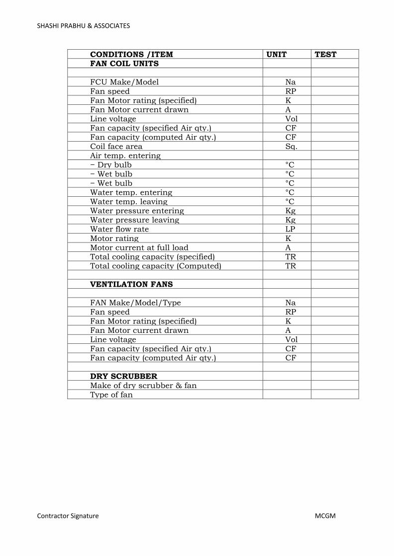
SHASHI PRABHU & ASSOCIATES
Contractor Signature MCGM
CONDITIONS /ITEM UNIT TEST RESULT
FAN COIL UNITS FCU Make/Model Na
me
/No.
Fan speed RP
M
Fan Motor rating (specified) KW
Fan Motor current drawn A
mps
Line voltage Vol
t
Fan capacity (specified Air qty.) CF
M
Fan capacity (computed Air qty.) CFM
Coil face area Sq.
m.
Air temp. entering − Dry bulb °C − Wet bulb °C − Wet bulb °C Water temp. entering °C Water temp. leaving °C Water pressure entering Kg
/Sq.c
m.
Water pressure leaving Kg
/Sq.cm.
Water flow rate LP
M
Motor rating KW
Motor current at full load A
mps
Total cooling capacity (specified) TR
.
Total cooling capacity (Computed) TR
.
VENTILATION FANS FAN Make/Model/Type Na
me/N
o.
Fan speed RP
M
Fan Motor rating (specified) K
W
Fan Motor current drawn Amp
s
Line voltage Vol
t
Fan capacity (specified Air qty.) CFM
Fan capacity (computed Air qty.) CF
M
DRY SCRUBBER Make of dry scrubber & fan Type of fan
Page 339
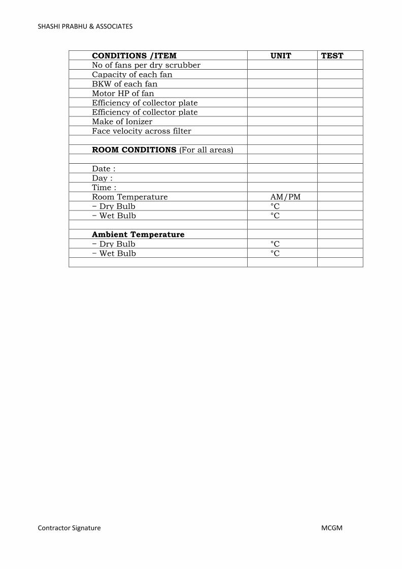
SHASHI PRABHU & ASSOCIATES
Contractor Signature MCGM
CONDITIONS /ITEM UNIT TEST RESULT
No of fans per dry scrubber Capacity of each fan BKW of each fan Motor HP of fan Efficiency of collector plate Efficiency of collector plate Make of Ionizer Face velocity across filter ROOM CONDITIONS (For all areas) Date : Day : Time : Room Temperature AM/PM − Dry Bulb °C − Wet Bulb °C Ambient Temperature − Dry Bulb °C − Wet Bulb °C
Page 340
SHASHI PRABHU & ASSOCIATES
Contractor Signature MCGM
21 MODE OF MEASUREMENTS
UNIT PRICES
The unit price shall be held to include everything necessary to complete the work covered by this item in accordance with the specifications and
drawings. The sum to tal of all the individual item prices shall represent the total price of the installation ready to be handed over.
The unit price of the various items shall include the following:
• All equipment, machinery, apparatus and materials required as well as the cost of any tests which EIC may request in addition to
the tests generally required to prove quality and performance of equipment.
• All the labour required to supply and install the complete installation in accordance with the specifications/drawings.
• Use of any tools, equipment, machinery, lifting tackle, scaffolding, ladders etc. required by the contractor to carry out his work.
• All the necessary measures to prevent the transmission of vibration.
• The necessary material to isolate equipment foundations from the building structure, wherever necessary.
• Storage and insurance of all equipment apparatus and materials. The contractor's unit price shall include all equipment, apparatus,
material and labour indicated in the drawings and/or specifications in conjunction with the item in question, as well as all additional equipment, apparatus, material and labour usual and necessary to
make in question on its own (and within the system as a whole) complete even though not specifically shown, described or otherwise
referred to. The contractor's unit price shall also include all taxes, duties, octrois,
works contract tax etc. as applicable.
MEASUREMENTS METAL DUCTS, GRILLES/ DIFFUSERS ETC. SHEET METAL DUCTS
• All duct measurements shall be taken as per actual outer duct surface area including bends, tees, reducers, collars, vanes & other fittings. Gaskets, nuts, bolts, vibration reducing pads are included in the basic duct items of the SOQ./ or as per IS code.
Page 341
SHASHI PRABHU & ASSOCIATES
Contractor Signature MCGM
• The unit of measurements shall be the finished sheet metal surfaces area in meters squares. No extra shall be allowed for laps and wastage.
• All the guide vanes, deflectors in duct elbows, branches, grille collars quadrant dampers etc. shall be measured for actual sheet metal surface and paid for at the same rate as duct of same
thickness.
• The unit duct price shall include all the duct hangers and supports, exposing of concrete reinforcement for supports and making good of the same as well as any materials and labour
required to complete the duct frame. GRILLES/DIFFUSERS
All grilles/diffusers as per tender requirements shall be measured as
follows.
• All measurements of grilles/diffusers shall be the actual outlet size excluding the outer flanges.
• The square or rectangular grills/diffusers shall be measured in sq.m.
• All round diffusers shall be measured by their diameters in cm.
• All linear diffusers shall be measured as per actual length in metres.
MEASUREMENTS OF PIPING, FITTINGS, VALVES, FABRICATED ITEMS
PIPE
• All pipes shall be measured in linear meter (to the nearest cm) along the axis of the pipes and rates shall be inclusive of all
fittings e.g. tees, bends, reducers, elbows etc. Deduction shall be made for valves in the line.
• The rate quoted shall be inclusive of cutting holes, exposing reinforcement in wall and ceiling and floors and making good the
same and inclusive of all items as specified in specification.
• Rates quoted shall be inclusive of providing and fixing vibration pads and wooden pieces, wherever specified or required by the Engineer in charge.
Page 342
SHASHI PRABHU & ASSOCIATES
Contractor Signature MCGM
• Flexible connections, wherever required or specified shall be measured as part of straight length of same diameter, with no additional allowance being made for providing the same.
• The length of the pipe for the purpose of payment will be taken through the center line of the pipe and all fittings (e.g. tees,
bends, reducers, elbows, etc.) as through the fittings are also resumed to be pipe lengths. Nothing extra whatsoever will be paid
for over and above for the fittings. For valves and flanges, section 3.2 below app lies.
VALVES AND FLANGES
• All the extra CI & CM flanged valves shall be measured according to the nominal size in mm and shall be measured by number. Such valves shall not be counted as part of pipe length hence
deduction in pipe length will be made wherever valves occur.
• All gun metal (gate & globe) valves shall include two Nos. of flanges and two numbers 150mm long MS nipples, with one side
threaded matching one of the valves,
• and other welded to the M.S. slip on flange. Rate shall also include the necessary number of bolts, nuts and washers, 3 mm thick insertion gasket of required temp. grade and all items
specified in the specifications.
• The rates quoted shall be inclusive of making connections to the equipment, tanks, pumps etc. and the connection made with an
installed pipe line shall be included in the rates as per the B.O.Q. STRUCTURAL SUPPORTS
Structural supports including supports fabricated from pipe lengths for
pipes shall be measured as part of pipe line and hence no separate payment will be made. Rates shall be inclusive of hoisting, cutting, jointing, welding, cutting of holes and chases in walls, slabs or floors,
painting supports and other items as described in specifications or as required at site by Engineer in Charge.
COPPER CONNECTIONS FOR FAN COIL UNITS (Wherever required)
Copper connection assembly for making connections to the fan coil units shall be measured, as part of the fan coil unit price and shall include brass flare nuts, brass straight connector, brass tees, brass
reducing fittings, fixing of automatic 3 way valve, making connection and leak testing, complete assembly as per specifications and drawings, nothing extra shall be payable on account of any variation in the length
of copper pipe.
Page 343

SHASHI PRABHU & ASSOCIATES
Contractor Signature MCGM
INSULATION
The measurement for vessels, piping, and ducts shall be made over the
bare un insulated surface area of the metal.
PIPES, DUCTS & VESSELS
PIPES
The measurements for insulation of piping shall be made in linear metres through all valves, flanges, and fittings. Pipes/bends shall be
measured along the centerline radius between tangent points. If the outer radius is R1 and the inner radius is R2. The center line radius
shall be measure as (R1+R2)/2. Measurement of all valves, flanges and fittings shall be measure with the running metre of pipe line as if they are also pipe lengths. Nothing extra over the above shall be payable for
insulation over valves, flanges and fittings in pipe line/routings. Fittings that connect two or more different sizes of pipe shall be measured as part of the larger size.
DUCTS
The measurements for insulation of ducts shall be made in actual square metres of bare un insulated duct surface through all dampers,
flanges and fittings. In case of bends the area shall be worked out by taking an average of inner and outer lengths of the bends.
Measurements for the dampers, flanges, fittings shall be for the surface dimension for the connecting duct, nothing extra over the above shall be payable for insulation over dampers, flanges and fittings in duct
routing. VESSELS
The area of standard dished and flat ends of vessels shall be the square
of the diameter of the uninsulated body of the shell. Areas for other shapes shall be the actual calculated area. There shall be no deduction or additions for nozzles, handles ribs, dampers, expansion joints etc. All
projections on vessels or tanks shall be measured separately as pipe/duct.
ACCESSORIES INSULATION
• The unit of measurement for accessories such as expansion tank, pumps, chiller heads etc. shall be uninsulated area in square
meters.
• In case of curved or irregular surfaces, measurements shall be taken along the curves.
• The unit insulation price shall include all necessary adhesives,
Page 344

SHASHI PRABHU & ASSOCIATES
Contractor Signature MCGM
vapour proofing and finishing materials as well as additional labour and material required for fixing the insulation.
ACOUSTIC DUCT LINING
• In case of acoustic lining of air ducts, measurements of the bare inside duct surface in square meters, shall be final for billing purposes.
• The insulation/acoustic panels shall include cost of battens, supports, adhesives, vapour proofing, finished tiles/boards sheets
as well as additional labour and material required for completing the work.
Page 345
TECHNICAL SPECIFICATION FOR FIRE ALARM, PUBLIC ADDRESS, ACCESS CONTROL, CCTV, PASSIVE SECURITY & DATA VOICE
NETWORKING SYSTEM
SHASHI PRABHU & ASSOCIATES
MUNICIPAL CORPORATION OF GREATER MUMBAI
NAME OF PROJECT: - PROPOSED MULTI-SPECIALITY BHANDUP HOSPITAL AT LAND BEARING C.T.S.NO681A/88,681A/3,681A/4 OF
VILLAGE NAHUR IN S-WARD, BHANDUP MUMBAI
Page 346

SHASHI PRABHU & ASSOCIATES
Contractor Signature MCGM
OVERVIEW & OBJECTIVES OF EXTRA LOW VOLTAGE SYSTEM
OVERVIEW:
Extra-low Voltage (ELV) is an electricity supply voltage in a range which carries a low risk of dangerous electrical shock. There are various standards that define extra-voltage. The IEC and IET go on to define actual types of extra-low voltage
systems. Extra-low voltage system is consisting of all the systems which operates on low voltages like Telecommunication Systems, Enterprise Networking
Systems, Audio Visual Systems, Fire Alarm & Detection Systems, Public
Addressing Systems, Access Control Systems, Video Surveillance Systems.
Shop Drawings:
The contractor shall prepare and submit to the Construction
Manager/Consultants for his approval six (6) sets of detailed layout drawings
of all ELVequipment’s and piping layouts.
He shall prepare shop drawings incorporating the details given by
manufacturers for the items included in his contract and also Client supplied
items and any other items which need to be coordinated with other
contractors for interfacing.
Before starting the work, the contractor shall submit to the Construction
Manager/Consultants for his approval in the prescribed manner, the
shop/execution drawings for the entire installation.
The Construction Manager/Consultants, reserves the right to alter or modify
these drawings if they are found to be insufficient or not complying with the
established technical standards or if they do not offer the most satisfactory
performance or accessibility for maintenance. Contractor shall supply in
eight (8) sets of all approved shop drawings for execution.
Shop drawings shall be submitted under the following conditions:
Large scale drawings showing fixing detail equipment and showing
coordination with other services.
Showing any change in layout in the ELVdrawings.
Equipment layout, ducting, piping and wiring/control diagram.
Manufacturer’s or Contractor’s fabrication drawings for any materials or
equipment supplied by him.
Page 347

SHASHI PRABHU & ASSOCIATES
Contractor Signature MCGM
No work will be carried out without approval of shop drawings by the
Consultants.
"AS BUILT" DRAWINGS:
At the completion of work and before issuance of certificate of completion
the contractor shall submit eight (8) sets to the Construction
Manager/Consultants, layout drawing drawn at appropriate scale indicating
the complete ELVsystem "as installed" and the same shall be approved by
the Consultants before handing over to the Client
Instruction/Maintenance Manual:
The Contractor shall prepare and produce instruction, operation and
maintenance manuals in English for the use, operation and the
maintenance of the supplied equipment and installations, and submit to the
Construction Manager/Consultants in (8) copies at the time of handing
over. The manual shall generally consist of the following:
Description of the project.
Operating instructions.
Maintenance instructions including procedures for preventive maintenance.
Manufacturers catalogues
Spare parts list
Trouble shooting charts.
Drawings.
Type and routine test certificates of major items
One (1) set of reproducible `as built' drawings.
Completion Certificate:
On completion of the ELVinstallation a certificate shall be furnished by the
contractor countersigned by the licensed supervisor, under whose direct
supervision the installation was carried out. This certificate shall be in the
prescribed form as required by the local supply authority. The contractor
shall be responsible for getting the ELVinstallation inspected and approved
by the local concerned authorities and for obtaining the necessary clearance
certificates from the authorities.
Page 348
SHASHI PRABHU & ASSOCIATES
Contractor Signature MCGM
Guarantee:
At the close of the work and before issuance of final certificate of completion
by the Construction Manager/ Consultants, the contractor shall furnish
written guarantee Indemnifying the Client against defective materials and
workmanship for a period of one year after completion. The contractor shall
hold himself fully responsible for reinstallation or replacement, free of cost
to Client, the following:
Any defective work or material supplied by the Contractor.
Any material or equipment supplied by the Client which is damaged or
destroyed as a result of defective workmanship by the contractor.
Any material or equipment damaged or destroyed as a result of defective
workmanship by the contractor.
Staff:
The contractor shall employ competent fully licensed qualified, full time
ELVengineers to direct the work of ELVinstallation in accordance with the
drawings and specifications.
The engineers shall be available at all times at site to receive instructions
from the Construction Manager., in the day to day activities throughout the
duration of contract. The engineer shall correlate the progress of the work
in conjunction with all the relevant requirement of the supply authority.
Safety Barriers and Construction Safety:
The Contractor shall at his own cost provide for the protection and safety of
the persons working in the area, safety barriers around all openings in
every location and at the periphery and edges of all slabs, staircases and
stairwells, lift shafts, ducts etc., all to the approval and satisfaction of the
Construction Manager. However, contractor shall take appropriate safety
precautions suitable for specific locations/ situations and as instructed by
the Construction Managers.
The Contractor shall, in general, be fully responsible for all matters with
regard to every form of safety during construction and in connection with
the execution of the Works, and the Contractor shall take all necessary
precautions and provide at his cost everything necessary to ensure such
safety at all times. Should any accidents occur due to the Contractor's
failure to comply with such safety requirements and to take all other safety
measures necessary, the Contractor shall be fully responsible for all such
Page 349

SHASHI PRABHU & ASSOCIATES
Contractor Signature MCGM
accidents and he shall bear and pay for all costs and damages in
connection therewith and as a consequence there of.
Disposal Of Rubbish From The Works And The Site And Provision Of
Safety Netting/Screens By Contractor:
The Contractor shall at all times keep the Works and the site in clean, neat
and tidy condition. All rubbish from the Works and the site shall be
collected and deposited in large bins provided on the site for such purpose
by the Contractor at his own cost. The rubbish from such bins shall be
regularly carted away by the Contractor to rubbish tips and dump yards
beyond the site.
At no time or stage shall any rubbish be thrown over the edges of slabs or
through any openings or shafts or ducts or stairwells.
The Contractor shall, at his own cost and to the approval and satisfaction of
the Construction Manager, provide safety netting/screens at the periphery
of all slabs and at all openings, shafts, ducts and stairwells and/or
canopies to prevent any rubbish or material falling over or into such areas
and endangering the safety of the persons working below. Should the
Contractor fail to provide such safety measures and to take other necessary
precautions in accidents that may occur, he shall bear all costs and
damages as decided by Construction Manager in connection therewith and
as a consequence there of.
The Construction Manager shall have powers to withhold amounts from
payment certificates in case of Contractor's persistent noncompliance with
provisions of this clause. Also the construction Manager is empowered to
employ another agency at Contractor's cost after one week's notice to
implement this Clause in case of Contractor's noncompliance with
provisions of this Clause.
Space For Contractor's Construction Yard, Stores Etc.:
The Client shall provide adequate storage/office space to the contractor for
his use. The space has to be maintained/constructed by the contractor as
per his usage requirements.
All spaces allotted to the contractor, as described above shall be vacated
and all structures removed from site at any time as and when required and
directed by the relevant authorities or by the Client, unconditionally and
without any reservation. The authorities or the Client will not be obliged to
give any reason for such removal. Upon receiving instructions to vacate the
space, the contractor shall immediately remove all his structures, materials,
Page 350

SHASHI PRABHU & ASSOCIATES
Contractor Signature MCGM
etc., from the spaces and clear and cleanup the site to the satisfaction of
the Construction Manager.
It shall be the specific responsibility of the Contractor to safeguard the site
and ensure that no illegal encroachments are made by outside elements
within the area allotted to the Con tractor. Upon completion of the work or
earlier as required by Client/Authorities, the Con tractor shall vacate the
land totally without any reservations. Necessary Bond to this effect on a
stamp paper shall be signed by the contractor in a prescribed form.
The Performance Bond and/or guarantees towards retention amount
furnished by the Con tractor shall not be released until the spaces allotted
to the contractor are fully vacated and handed over to the Client as per the
instructions of the Client.
Carrying Out Work Beyond Normal Working Hours Or In Shifts
In order to achieve the milestone and completion dates and to keep pace
with the approved construction programme, the Contractor shall be
permitted to carry out his work beyond the normal working hours or in
shifts. The Contractor shall be responsible for obtaining any necessary
permission from the relevant authorities that may be required for him to
carry out the work beyond the normal working hours or in shifts. Also, the
Contractor shall give prior notice to and make arrangements with the
Construction Manager for the supervision of work carried out beyond the
normal working hours or in shifts. The Contractor shall make his own
arrangements in respect of the provision of adequate lighting and any other
facilities that may be required for carrying out the work beyond the normal
working hours or in shifts. No extra payments shall be made to the
Contractor for or in connection with any such overtime or shift work. The
Contractor will not be required to bear the overtime expenses of the
Construction Manager in respect of the supervision of such overtime or shift
work of the Contractor.
Period And Time Limit For Completion Of Works:
The period and time limit for Completion of the Works shall be as per
client’s requirement from the date of issue of Work Order to commence
works or handing over of site in respect of the award of Contract. This time
period shall be inclusive of the mobilization period and monsoon period.
Professional Integrity And Team Spirit:
It is the intent of the Client, Architect and Construction Manager that this
project will be executed in a spirit of team and full professional integrity.
Page 351

SHASHI PRABHU & ASSOCIATES
Contractor Signature MCGM
Contractor is expected to cooperate with all the agencies involved in the
project to fulfill this objective.
List Of Approved Makes:
Unless otherwise specified and expressly approved in writing by the
Engineer in Charge/only material of makes and specifications as mentioned
in the list of approved makes attached with the specification shall be used.
The contractor shall clearly indicate the list of materials proposed to be used
by him & enclose the same with the tender.
On Instruction of Engineer in Charge the Contractor shall submit samples of
materials proposed to be used in the works. Approved samples shall be kept
in the office of the Engineer in Charge and returned to the Contractor at the
appropriate time.
Before procurement, Contractor will discuss with Client for preferred makes.
Water and electricity shall be supplied at one point.
Reference Points:
Contractor shall provide permanent bench marks, flag tops and other
reference points for the proper execution of works and these shall be
preserved till the end of the work.
All such reference points shall be in relation to the levels and locations, given
in the architectural and ELVdrawing.
Reference Drawings:
The Contractor shall maintain one set of all drawings issued to him as
reference drawings. These shall not be used on Site. All important drawings
shall be mounted on boards and placed in racks indexed, no drawings shall
be rolled.
All correction, deviations and changes made on the site shall be shown on
these reference drawings for final incorporation in the completion drawings.
All changes to be made shall be initialed by Engineer in Charge or Architect.
Vendor shall prepare Shop Drawings with all details after checking the
feasibility at Site which shall be approved by the Consultants before
execution. No work will be carried out without approval of Shop drawing by
the Consultant.
Page 352

SHASHI PRABHU & ASSOCIATES
Contractor Signature MCGM
Handing Over:
Contractor will be responsible for following:
Entire System shall be commissioned and tested as per design parameter is
coordination with Client & consultant.
Complete certificate has to be obtained from the consultant to certify the
quality of work and performance of the system.
Contractor has to hand over 4 sets of as Built Drawings duly approved by
consultants along with 2 soft copy in CD’s.
Contractor has to handover operator manual of the system with catalogue
and Technical Data of equipment supplied.
OBJECTIVES:
Structure Cabling Systems:
To build an ELV System an agile, redundant and scalable structure cabling
system is required.
Networking Systems:
To achieve highly available and consistence network for various equipment to
communicate and seamlessly store or retrieve the data as and when required.
Telecommunication Systems:
To provide a stable and reliable Telephone / Communication network to the
users of the organization or campus within or outside the campus.
Fire Alarm & Detection Systems:
To safeguard peoples and property from the risk of fire, timely detection and
alarm is the essence of any campus.
Public Addressing Systems:
To help administration by providing Announcement System for General and Emergency Announcements.
Time Attendance & Access Control Systems: To help administration by providing time Attendance systems and prevention of
unauthorized access in critical areas like Operation Theatres, Intensive Care
units (ICU), Auditoriums, Classrooms, Lifts and Elevators, Offices etc.
Video Surveillance Systems:
Page 353
SHASHI PRABHU & ASSOCIATES
Contractor Signature MCGM
To help administration by providing real time monitoring system to maintain
discipline, safeguard public and to detect any suspicious activities.
Operation Theatre Audio Visual Navigation/Teaching Solution: To enable Operation Theatre a live Teaching / Demo Room and Enable Students
to study Medical concept in visual format over the Network across Globe.
TECHNICAL SPECIFICATION FOR ELV SYSTEMS
General:
The ELV System (Structure Cabling System, Enterprise Networking Systems,
Telecommunication Systems, Audio Visual Systems, Fire Alarm & Detection Systems, Public Addressing Systems, Access Control Systems, Video
Surveillance Systems) shall be seamlessly integrated. The rates quoted by bidder shall include such costs to ensure compatibility
and seamless integration.
The OEM should submit the authorization letter covering below mentioned points, before commencing the work by the Bidder:
o OEM should confirm that the items quoted by the bidder are in
production and would be serviceable for at least Seven Years. o OEM should confirm that the quoted items are not obsolete products.
o OEM should confirm that the quoted items are produced within One Year before the date of Supply.
1. Structure Cabling System – UTP Copper (Cat6) Cables and Components, Fiber Optics Cable and Components, Network Enclosures:
Structure Cabling shall be design, built and installed as per the best practices
of Structure Cabling System, using all the components (Copper and Fiber)
from a single OEM for the assurance of consistent performance. The structure cabling system shall be serve as a highway for transport of Data, Voice Telephony and Video traffic over a common network throughout the network.
Structure Cabling System designed such as 10G backbone OFC network with ring topology for redundancy and network endpoint / host should be
connected on 1G Copper network. Two separate network to be designed for Hospital Premises and College
Premises, however it should be integrated with each other at Core Level.
Two separate network to be designed as (i) Data (Wired & Wireless), communication System, Telepresence & Collaboration System and Audio Visual Systems, (ii) Utilities like IP Based Video Surveillance, Access Control
System, Public Addressing System, Fire Alarm & Detection System and Integrated Building Management System.
Installation, identification and termination of cables between information outlets and network rack shall be considered as a part of bidder’s work.
Page 354

SHASHI PRABHU & ASSOCIATES
Contractor Signature MCGM
Cabling utilized for Voice and Data Nodes shall originate from Network Racks and terminated at Information Outlets at Wall.
All cables and IOs shall be identified at both the ends (IO & Rackside) with appropriate ferruling.
All balanced twisted pair cables laying and termination shall comply and be tested as per TIA/EIA 568-B series standard for Cat5, Cat5E and Cat6 installations.
UTP Cabling system conforming to ANSI/TIA/EIA 568-B series and ISO/IEC 11801 2nd edition, EN-50173-1.
The bidder carrying out the SITC work shall make the system entirely
operational for its intended use, by addition of components specific to its make/model even if not specifically mentioned in the BOQ.
It shall be the responsibility of the installer and OEM to ensure that the Passive Components of structured cabling system will be free from manufacturing defects in material and workmanship under normal and
proper use. The site should be duly certified by OEM for a period of 20 years from the
date of installation or issuance of the registration certificate, whichever is earlier.
20-year systems performance guarantee by the OEM along with actual test
results conducted at site such as attenuation, return loss, NEXT & ACR. Permanent link shall be tested for minimum guaranteed performance as per standards at 500 MHZ operation as minimum.
The final branch connections with single cables in conduit & the maximum no. of cables in each conduit shall be as per given in below table:
General Scenario Of Considering Data Points:-
Data Point need to be consider at each and every hospital and medical
college staff sitting / desk locations.
For higher designated staff like Principal / Dean, Medical Superintendent,
RMO, AHA, HODs two data points need to be place.
For Nurse Station locations in hospital, 2 data points need to be
considered. However it should be changed as per person sitting capacity.
In Operation Theatre (i.e. Minor and Major OT), minimum two data points
need to be place.
In Laboratories, minimum of one data points need to be consider; however
concern of end customer should not be compromise.
General Scenario Of Considering Voice Points:-
Voice points need to be considering at each and every hospital and college
staff sitting / desk locations.
For higher designated staff like Principal / Dean, Medical Superintendent,
RMO, AHA, HODs two voice points need to be place.
Page 355
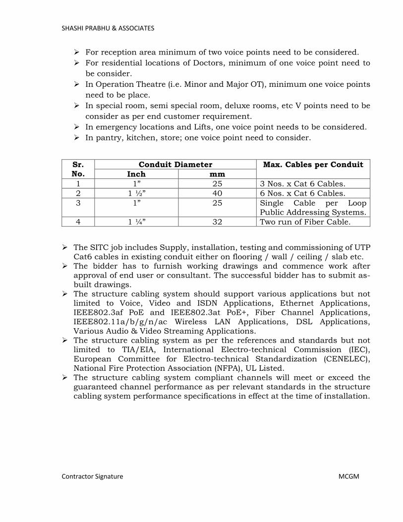
SHASHI PRABHU & ASSOCIATES
Contractor Signature MCGM
For reception area minimum of two voice points need to be considered.
For residential locations of Doctors, minimum of one voice point need to
be consider.
In Operation Theatre (i.e. Minor and Major OT), minimum one voice points
need to be place.
In special room, semi special room, deluxe rooms, etc V points need to be
consider as per end customer requirement.
In emergency locations and Lifts, one voice point needs to be considered.
In pantry, kitchen, store; one voice point need to consider.
Sr. No.
Conduit Diameter Max. Cables per Conduit
Inch mm
1 1” 25 3 Nos. x Cat 6 Cables.
2 1 ½” 40 6 Nos. x Cat 6 Cables.
3 1” 25 Single Cable per Loop Public Addressing Systems.
4 1 ¼” 32 Two run of Fiber Cable.
The SITC job includes Supply, installation, testing and commissioning of UTP
Cat6 cables in existing conduit either on flooring / wall / ceiling / slab etc. The bidder has to furnish working drawings and commence work after
approval of end user or consultant. The successful bidder has to submit as-
built drawings. The structure cabling system should support various applications but not
limited to Voice, Video and ISDN Applications, Ethernet Applications,
IEEE802.3af PoE and IEEE802.3at PoE+, Fiber Channel Applications, IEEE802.11a/b/g/n/ac Wireless LAN Applications, DSL Applications,
Various Audio & Video Streaming Applications. The structure cabling system as per the references and standards but not
limited to TIA/EIA, International Electro-technical Commission (IEC),
European Committee for Electro-technical Standardization (CENELEC), National Fire Protection Association (NFPA), UL Listed.
The structure cabling system compliant channels will meet or exceed the guaranteed channel performance as per relevant standards in the structure cabling system performance specifications in effect at the time of installation.
Page 356
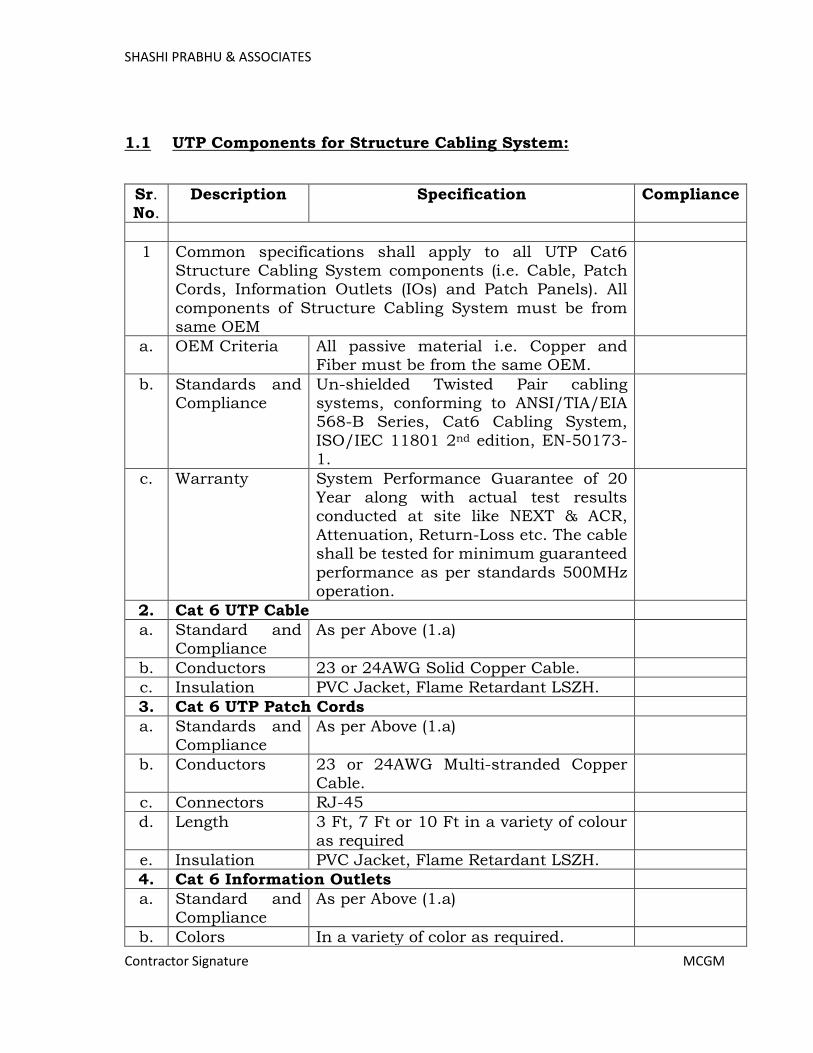
SHASHI PRABHU & ASSOCIATES
Contractor Signature MCGM
1.1 UTP Components for Structure Cabling System:
Sr. No.
Description Specification Compliance
1 Common specifications shall apply to all UTP Cat6 Structure Cabling System components (i.e. Cable, Patch Cords, Information Outlets (IOs) and Patch Panels). All
components of Structure Cabling System must be from same OEM
a. OEM Criteria All passive material i.e. Copper and Fiber must be from the same OEM.
b. Standards and Compliance
Un-shielded Twisted Pair cabling systems, conforming to ANSI/TIA/EIA 568-B Series, Cat6 Cabling System,
ISO/IEC 11801 2nd edition, EN-50173-1.
c. Warranty System Performance Guarantee of 20 Year along with actual test results conducted at site like NEXT & ACR,
Attenuation, Return-Loss etc. The cable shall be tested for minimum guaranteed
performance as per standards 500MHz operation.
2. Cat 6 UTP Cable
a. Standard and Compliance
As per Above (1.a)
b. Conductors 23 or 24AWG Solid Copper Cable.
c. Insulation PVC Jacket, Flame Retardant LSZH.
3. Cat 6 UTP Patch Cords
a. Standards and Compliance
As per Above (1.a)
b. Conductors 23 or 24AWG Multi-stranded Copper Cable.
c. Connectors RJ-45
d. Length 3 Ft, 7 Ft or 10 Ft in a variety of colour as required
e. Insulation PVC Jacket, Flame Retardant LSZH.
4. Cat 6 Information Outlets
a. Standard and Compliance
As per Above (1.a)
b. Colors In a variety of color as required.
Page 357
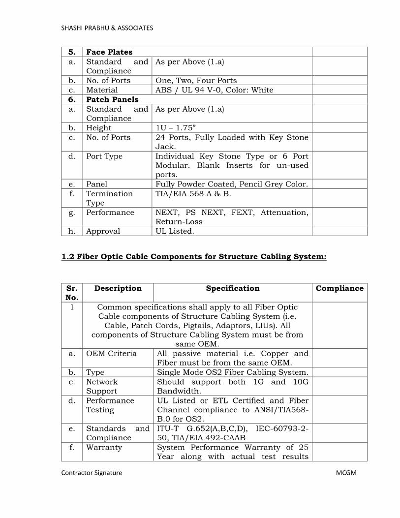
SHASHI PRABHU & ASSOCIATES
Contractor Signature MCGM
5. Face Plates
a. Standard and Compliance
As per Above (1.a)
b. No. of Ports One, Two, Four Ports
c. Material ABS / UL 94 V-0, Color: White
6. Patch Panels
a. Standard and
Compliance
As per Above (1.a)
b. Height 1U – 1.75”
c. No. of Ports 24 Ports, Fully Loaded with Key Stone Jack.
d. Port Type Individual Key Stone Type or 6 Port Modular. Blank Inserts for un-used ports.
e. Panel Fully Powder Coated, Pencil Grey Color.
f. Termination Type
TIA/EIA 568 A & B.
g. Performance NEXT, PS NEXT, FEXT, Attenuation, Return-Loss
h. Approval UL Listed.
1.2 Fiber Optic Cable Components for Structure Cabling System:
Sr.
No.
Description Specification Compliance
1 Common specifications shall apply to all Fiber Optic
Cable components of Structure Cabling System (i.e. Cable, Patch Cords, Pigtails, Adaptors, LIUs). All
components of Structure Cabling System must be from
same OEM.
a. OEM Criteria All passive material i.e. Copper and
Fiber must be from the same OEM.
b. Type Single Mode OS2 Fiber Cabling System.
c. Network Support
Should support both 1G and 10G Bandwidth.
d. Performance Testing
UL Listed or ETL Certified and Fiber Channel compliance to ANSI/TIA568-B.0 for OS2.
e. Standards and Compliance
ITU-T G.652(A,B,C,D), IEC-60793-2-50, TIA/EIA 492-CAAB
f. Warranty System Performance Warranty of 25 Year along with actual test results
Page 358
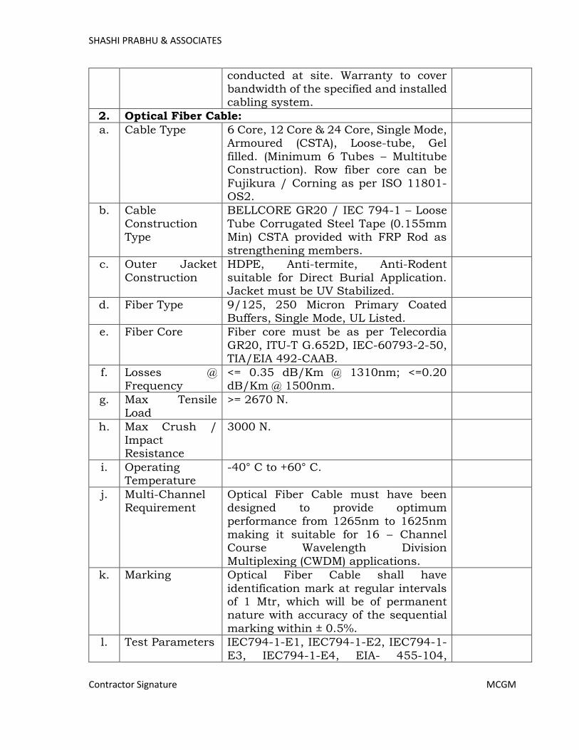
SHASHI PRABHU & ASSOCIATES
Contractor Signature MCGM
conducted at site. Warranty to cover
bandwidth of the specified and installed cabling system.
2. Optical Fiber Cable:
a. Cable Type 6 Core, 12 Core & 24 Core, Single Mode, Armoured (CSTA), Loose-tube, Gel
filled. (Minimum 6 Tubes – Multitube Construction). Row fiber core can be
Fujikura / Corning as per ISO 11801-OS2.
b. Cable
Construction Type
BELLCORE GR20 / IEC 794-1 – Loose
Tube Corrugated Steel Tape (0.155mm Min) CSTA provided with FRP Rod as
strengthening members.
c. Outer Jacket
Construction
HDPE, Anti-termite, Anti-Rodent
suitable for Direct Burial Application. Jacket must be UV Stabilized.
d. Fiber Type 9/125, 250 Micron Primary Coated Buffers, Single Mode, UL Listed.
e. Fiber Core Fiber core must be as per Telecordia
GR20, ITU-T G.652D, IEC-60793-2-50, TIA/EIA 492-CAAB.
f. Losses @ Frequency
<= 0.35 dB/Km @ 1310nm; <=0.20 dB/Km @ 1500nm.
g. Max Tensile Load
>= 2670 N.
h. Max Crush / Impact Resistance
3000 N.
i. Operating Temperature
-40° C to +60° C.
j. Multi-Channel Requirement
Optical Fiber Cable must have been designed to provide optimum
performance from 1265nm to 1625nm making it suitable for 16 – Channel Course Wavelength Division
Multiplexing (CWDM) applications.
k. Marking Optical Fiber Cable shall have
identification mark at regular intervals of 1 Mtr, which will be of permanent nature with accuracy of the sequential
marking within ± 0.5%.
l. Test Parameters IEC794-1-E1, IEC794-1-E2, IEC794-1-
E3, IEC794-1-E4, EIA- 455-104,
Page 359

SHASHI PRABHU & ASSOCIATES
Contractor Signature MCGM
IEC794-1-E7, IEC794-1-E10, IEC794-
1-E11, IEC794-1-F5.
3. Optical Fiber Pigtails:
a. Standards and Compliance
ITU-G65.B–Bend Insensitive Fiber. Fully Compliance with JIS C5973 F04 Type, Meet or exceed ITU Specifications,
UL Listed.
b. Type,
Connectors & Length
Single Mode, LC-Style, Simplex, 1 Mtrs
Length.
c. Durability (500 Matting’s): < 0.2dB Max.
d. Attenuation Not more than 0.75dB per mated pair.
e. Ferrules Pre-radius Ceramic Zirconia Ferrule. Bayonet Coupling: 2.5 mm Zirconia
Ferrule
f. Operating Temperature
-40° C to +60° C.
4. Optical Fiber Patch Cords:
a. Standards and Compliance
ITU-G657.B - Bend Insensitive Fiber.
b. Cable &
Connector Type and Outside
Diameter
Single Mode, LC-LC type. Available in
either 1.6mm x 3mm (Simplex) or 1.6mm x 3.3mm (Duplex) Zipcord.
c. Fiber Type and
Fiber Cores
Single mode 9/125 250 micron primary
coated buffers. One Core for Simplex and Two Core for Duplex.
d. Length 1, 2, 3 or 5 Mtrs length.
e. Operating Temperature
-40° C to +60° C.
5. 19”, Rack Mounted Fiber Shelf / LIUs.
a. Fiber Optic Shelf / LIUs
19”, Rack Mounted Fiber Optic Shelf, 2U Height.
b. No. of Fibers 6, 12, 24, 48 Cores.
c. No. of OSP Cables for
Termination.
Minimum Two.
d. Cable
Management Rings
Front and Rear Cable management
rings, pre-loaded.
e. Adapter Plates 6 Port adapter plates with each plate loaded with Single Mode Couplers as required.
f. Grounding 2 x Earthing Lugs, Pre-loaded.
Page 360
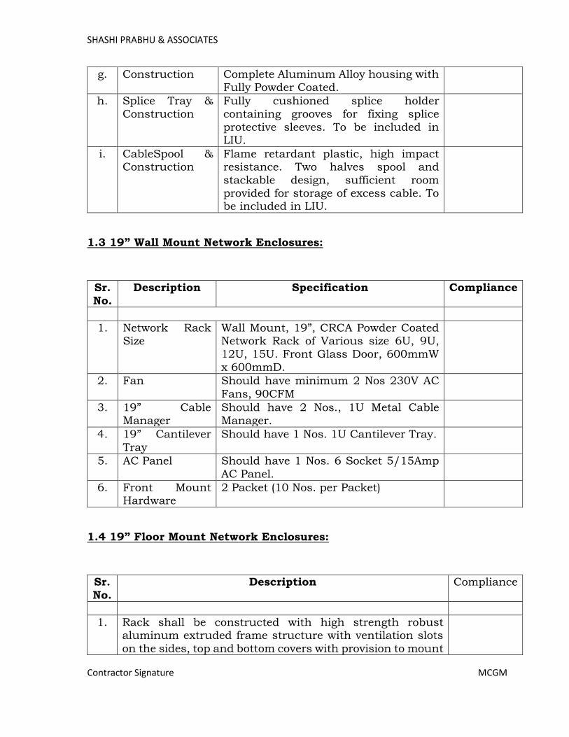
SHASHI PRABHU & ASSOCIATES
Contractor Signature MCGM
g. Construction Complete Aluminum Alloy housing with
Fully Powder Coated.
h. Splice Tray & Construction
Fully cushioned splice holder containing grooves for fixing splice
protective sleeves. To be included in LIU.
i. CableSpool & Construction
Flame retardant plastic, high impact resistance. Two halves spool and
stackable design, sufficient room provided for storage of excess cable. To be included in LIU.
1.3 19” Wall Mount Network Enclosures:
Sr.
No.
Description Specification Compliance
1. Network Rack Size
Wall Mount, 19”, CRCA Powder Coated Network Rack of Various size 6U, 9U, 12U, 15U. Front Glass Door, 600mmW
x 600mmD.
2. Fan Should have minimum 2 Nos 230V AC
Fans, 90CFM
3. 19” Cable
Manager
Should have 2 Nos., 1U Metal Cable
Manager.
4. 19” Cantilever
Tray
Should have 1 Nos. 1U Cantilever Tray.
5. AC Panel Should have 1 Nos. 6 Socket 5/15Amp
AC Panel.
6. Front Mount Hardware
2 Packet (10 Nos. per Packet)
1.4 19” Floor Mount Network Enclosures:
Sr.
No.
Description Compliance
1. Rack shall be constructed with high strength robust aluminum extruded frame structure with ventilation slots
on the sides, top and bottom covers with provision to mount
Page 361
SHASHI PRABHU & ASSOCIATES
Contractor Signature MCGM
4 nos. fans on top cover. Load carrying capacity – between
500 – 750 kg.
2. The other components except vertical profiles are made of CRCA Steel. CRCA steel used is as per “IS 513 Gr D”
Standard. The Thickness of the CRCA sheets used for Doors is 1.2mm and foe Side Panels is 1mm.
3. The cabinet shall be made of high impact CRCA steel as per IS 513 Gr D standard and design confirming to DIN 41494
or EIA 310D standards.
4. Top Covers and Bottom Covers and Side panels shall be of sheet steel and powder coated. The top and bottom covers
shall be provided with number of 50mm and 75mm round cable knockouts for cable entry and cable knockouts shall
be edge protected with rubber grommets.
5. Fully adjustable 19” equipment mounting angles. Two pairs
of 19” Equipment mounting angles with mounting holes conforming to IEC 2973.
6. Vertical 19” metric panel mounts and door trims shall be of sheet steel and powder coated
7. Perforation area should be 70% of the total door area.
Perforation for full or split doors the style should be “Honeycomb” type of perforation for maximum air
circulation and stiffness.
8. Side Panels – must contain slam latches for locking purpose
and option of providing slam locks, if required.
9. The rack should support various Locks Options like Slam Lock - Common Key or Unique Key, Swing Handle Lock,
Digital Keypad operated locks, Bio-metric locks. Lockable Industrial Grade Castors with Foot Brakes.
10. Cabinet can be capable of dismantling and reassemble at the site.
11. Front Glass door made of toughened glass, tinted with easily detachable hinges.
12. Two Pair of slotted vertical cable manager shall be provided at front and back for managing Cables.
13. Rack shall be supplied with 4 Nos. 90 CFM fans at top, or optionally 250cfm
14. Rack shall be supplied with equipment mounting hardware
in pack of 100s such as mounting nuts and screws either 12-24 or M6 type as applicable
15. Minimum 2 nos. of 10 x 5/15 Amps power distribution unit, 2 nos. of vertical cable managers and 2 no. of 19” 1U size
horizontal cable managers.
Page 362

SHASHI PRABHU & ASSOCIATES
Contractor Signature MCGM
16. Finish – cabinet shall be black or grey epoxy powder-coated
of durable quality. The Powder coating of the racks is as per Nano Technology process with “Zirconium Coating”.
17. Manufacturer must be ISO Standard Plants. The product
must be UL Listed and certified for use in IT/CE. Environmental Safety – the rack must be RoHS compliant.
18. EIA standard pattern design with 12-24 tapped holes (EIA-310-E compliant) or EIA standard pattern design with 3/8’
(9.5mm) square punches for Cage Nuts for mounting.
19. Rack should have dimension of at least 18U, 24U, 27U, 32U, 36U, 42U usable height, 600mmWx600mmD,
600mmWx800mmD, 800mmWx800mmD, 800mmWx1000mmD or 1000mmWx1000mmD.
20. Powder Coating thickness should be min 80 to 100 Microns with Scratch Resistance properties. Rack to be powder
coated with Nano ceramic pre-treatment process using a zirconium coat and the process should be RoHS compliant.
21. The Network Racks must have unit prices for its individual knocked down items such as Main Frame, Front Glass Door, Rear Perforated Steel Door, Vented Side Panels,
4x90cfm Fans & Fan Tray, 2 No.x10 Socket 5A/15A PDU with MCB, 1U Cable Manager, Sliding Shelf, Keyboard Trey, Cantilever Shelf, Heavy Duty Stationery Shelf, Castors,
Vertical Cable Manager, mounting hardware etc. It must be possible to configure the enclosure as per specific needs for
a customized installation for every rack.
Page 363
SHASHI PRABHU & ASSOCIATES
Contractor Signature MCGM
2. Active Components – Core Switch, Distribution Switches, Access
Switches, Small-Form Factor Port Modules, Stacking Modules, Wireless LAN Controller, WiFi Access Points, Firewall / Unified Threat
Management System.
Description & Design:
It is a high performance networking design keeping in mind real time
applications and reliability.
Key considerations for network are - gigabit connectivity to each user from the server room to various users/departments/devices in a topology
consisting of a central switch followed by the distribution and edge/access switches with multiple 10G ring topology. In a single 10G ring maximum Eight Locations to be consider.
The network shall have a mix of components for supporting PoE+ as well as non-PoE devices.
A robust fiber optics based backbone is being provided. It shall be based on ring topology using single mode fiber optics cable. The vendor shall ensure that the networking switches shall be populated with the necessary
transceivers for achieving this design objective. Two separate network to be designed for Hospital Premises and College
Premises, however it should be integrated with each other at Core Level.
Two separate network to be designed as (i) Data (Wired & Wireless), communication System, Telepresence & Collaboration System and Audio
Visual Systems, (ii) Utilities like IP Based Video Surveillance, Access Control System, Public Addressing System, Fire Alarm & Detection System and Integrated Building Management System.
Several applications are proposed to run on this network – IP-based voice communications supporting voice-data-video, network based cameras and
storage, integrated audio-video, video conferencing, interactive learning, integrated building management systems and important services integration such as fire detection.
All Switches, SFP Modules, SFP+ Modules, Stacking Modules and Stacking Cables, Wireless Controller and Wireless Access Points be from same OEM.
All Switches, Wireless Access Points and Existing Wireless LAN Controllers
should have capability to manage, configure and troubleshoot from a single Network management system i.e. single pane of glass.
OEM for equipment like Switches and Wireless Controller, Wireless Access Points should be listed in the leader’s quadrant of the Gartner Magic
Quadrant.
Page 364

SHASHI PRABHU & ASSOCIATES
Contractor Signature MCGM
2.1 Core Switch – Layer 3 (Type-1):
Sr. No.
Description Compliance
1. Switch should support the complete STACK of IP V4 and IP V6 services
2. Switch with different modules should function line rate and should not have any port with oversubscription ratio applied
3. Switch should support non blocking, wire speed performance per access and uplink ports
4. The switch should be standard rack mountable
5. Switch should have the following interfaces: A.16 SFP+ ports
B. Network Module slot for 8 SFP+ Fiber Uplink Ports
6. Switch should have console port
7. Switch should have management interface for Out of Band Management
8. Switch should have hardware health monitoring capabilities and should provide different parameters through SNMP
9. Switch should support IEEE Link Aggregation and Ethernet Bonding functionality to group multiple ports for redundancy
10. Switch should have the capability of holding multiple OS images to support resilience & easy rollbacks during the
version upgrades etc and should support in service software upgrade including: a. Multiple System image b. Multiple system configuration c. Option of Configuration roll-back.
11. Switch should have all access ports support Auto MDI and MDI-X and Auto/Manual Speed negotiation
12. Switch should have Internal redudant power supply
13. Switch should have single Management Stack facility
14. Switch should support Spanning Tree Protocol (802.1D, 802.1W, 802.1S)
15. Switch should support for centralised VLAN management for the connected layer 2 domain, which propagated VLAN
information
16. Switch should support up to 4000 number of VLAN including
data for providing segregartion of different group ports for data traffic so that one group can only communicate as per allowed policy
Page 365
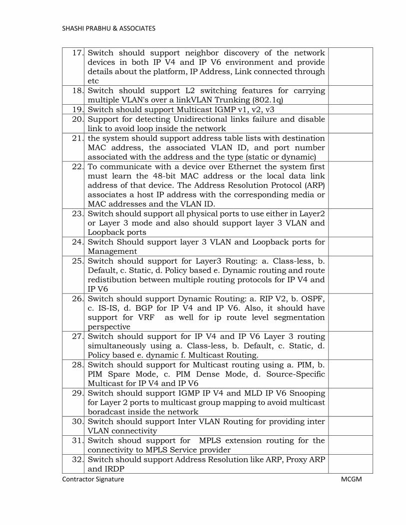
SHASHI PRABHU & ASSOCIATES
Contractor Signature MCGM
17. Switch should support neighbor discovery of the network
devices in both IP V4 and IP V6 environment and provide details about the platform, IP Address, Link connected through etc
18. Switch should support L2 switching features for carrying multiple VLAN's over a linkVLAN Trunking (802.1q)
19. Switch should support Multicast IGMP v1, v2, v3
20. Support for detecting Unidirectional links failure and disable
link to avoid loop inside the network
21. the system should support address table lists with destination
MAC address, the associated VLAN ID, and port number associated with the address and the type (static or dynamic)
22. To communicate with a device over Ethernet the system first must learn the 48-bit MAC address or the local data link address of that device. The Address Resolution Protocol (ARP)
associates a host IP address with the corresponding media or MAC addresses and the VLAN ID.
23. Switch should support all physical ports to use either in Layer2 or Layer 3 mode and also should support layer 3 VLAN and Loopback ports
24. Switch Should support layer 3 VLAN and Loopback ports for Management
25. Switch should support for Layer3 Routing: a. Class-less, b. Default, c. Static, d. Policy based e. Dynamic routing and route
redistibution between multiple routing protocols for IP V4 and IP V6
26. Switch should support Dynamic Routing: a. RIP V2, b. OSPF, c. IS-IS, d. BGP for IP V4 and IP V6. Also, it should have support for VRF as well for ip route level segmentation
perspective
27. Switch should support for IP V4 and IP V6 Layer 3 routing
simultaneously using a. Class-less, b. Default, c. Static, d. Policy based e. dynamic f. Multicast Routing.
28. Switch should support for Multicast routing using a. PIM, b. PIM Spare Mode, c. PIM Dense Mode, d. Source-Specific Multicast for IP V4 and IP V6
29. Switch should support IGMP IP V4 and MLD IP V6 Snooping for Layer 2 ports to multicast group mapping to avoid multicast
boradcast inside the network
30. Switch should support Inter VLAN Routing for providing inter
VLAN connectivity
31. Switch shoud support for MPLS extension routing for the
connectivity to MPLS Service provider
32. Switch should support Address Resolution like ARP, Proxy ARP
and IRDP
Page 366

SHASHI PRABHU & ASSOCIATES
Contractor Signature MCGM
33. Switch should have line rate forwarding capacity
34. Switch should support Multichassis Ethercannel
35. Switch should support 60000 MAC addresses
36. Switch should support 4000 Layer 2 VLAN ID and 1000 Layer 3 VLAN
37. Switch should support jumbo frame of 9198 bytes
38. Switch should support Stateful Switchover when switching
over from active to standby switch in a stack or equivalent
39. Switch should support IP Flow version-9 for identify users and
user traffic flows in order to identify potential attackers and take corrective action at the access layer
40. Switch should support dual stack for Layer 2 and Layer 3 IP V4 and IP V6 at the same time
41. Switch should have adequate DRAM, Flash Memory, CPU and
other hardware to support all the services configured
42. Switch should have adequate flash memory and other
hardware to ensure storage of multiple operating system images, configuration file backups, event logs etc.
43. Furhter the switch should have adequate memory, storage, processing power, other components so that switch should be able to upgrade, patch the operating system till the end of
support date without any additional hardware requirement such as flash memory, storage etc
44. Switch should support Uplink Redundancy & Bandwidth Aggregation for Higher bandwidth and reliability for uplinks as
per 802.3ad (LACP)
45. Switch should support Gateway Redunancy Support using
VRRP/HSRP for IP V4 and IP V6
46. Switch should support feature to set and verify services guanantee related to connectivity and availability of network
connectivity and application usage as per business requirement using IP SLA
47. Switch should support to storm control Broadcast/Multicast/Unicast based storm due to network
attacks and vulnerabilities
48. Switch system should support 802.1P classification and marking of packet using: a. CoS (Class of Service) b. DSCP
(Differentiated Services Code Point) c. Source physical interfaces d. Source/destination IP subnet e. Protocol types
(IP/TCP/UDP) f. Source/destination TCP/UDP ports
49. Switch should support methods for identifying different types
of traffic for better management and resilience
50. Switch should support for different type of QoS features for ream time
Page 367
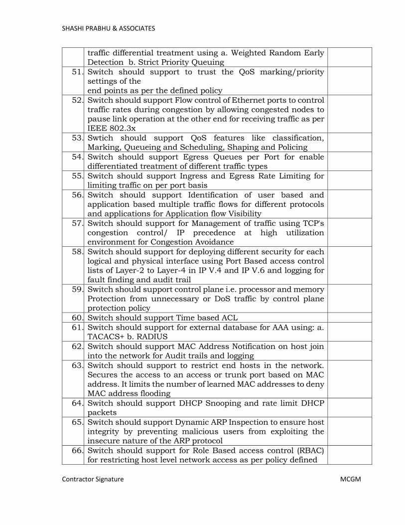
SHASHI PRABHU & ASSOCIATES
Contractor Signature MCGM
traffic differential treatment using a. Weighted Random Early
Detection b. Strict Priority Queuing
51. Switch should support to trust the QoS marking/priority settings of the
end points as per the defined policy
52. Switch should support Flow control of Ethernet ports to control
traffic rates during congestion by allowing congested nodes to pause link operation at the other end for receiving traffic as per
IEEE 802.3x
53. Swtich should support QoS features like classification, Marking, Queueing and Scheduling, Shaping and Policing
54. Switch should support Egress Queues per Port for enable differentiated treatment of different traffic types
55. Switch should support Ingress and Egress Rate Limiting for limiting traffic on per port basis
56. Switch should support Identification of user based and application based multiple traffic flows for different protocols
and applications for Application flow Visibility
57. Switch should support for Management of traffic using TCP's
congestion control/ IP precedence at high utilization environment for Congestion Avoidance
58. Switch should support for deploying different security for each logical and physical interface using Port Based access control lists of Layer-2 to Layer-4 in IP V.4 and IP V.6 and logging for
fault finding and audit trail
59. Switch should support control plane i.e. processor and memory
Protection from unnecessary or DoS traffic by control plane protection policy
60. Switch should support Time based ACL
61. Switch should support for external database for AAA using: a. TACACS+ b. RADIUS
62. Switch should support MAC Address Notification on host join into the network for Audit trails and logging
63. Switch should support to restrict end hosts in the network. Secures the access to an access or trunk port based on MAC
address. It limits the number of learned MAC addresses to deny MAC address flooding
64. Switch should support DHCP Snooping and rate limit DHCP packets
65. Switch should support Dynamic ARP Inspection to ensure host integrity by preventing malicious users from exploiting the insecure nature of the ARP protocol
66. Switch should support for Role Based access control (RBAC) for restricting host level network access as per policy defined
Page 368
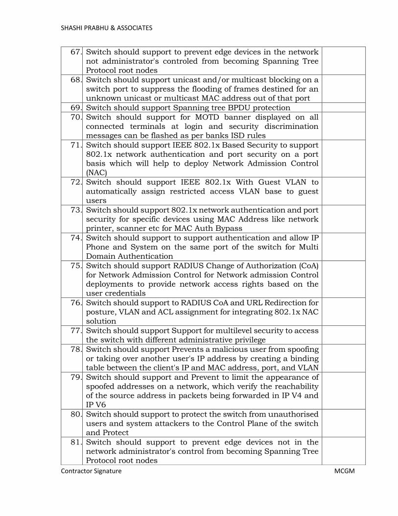
SHASHI PRABHU & ASSOCIATES
Contractor Signature MCGM
67. Switch should support to prevent edge devices in the network
not administrator's controled from becoming Spanning Tree Protocol root nodes
68. Switch should support unicast and/or multicast blocking on a
switch port to suppress the flooding of frames destined for an unknown unicast or multicast MAC address out of that port
69. Switch should support Spanning tree BPDU protection
70. Switch should support for MOTD banner displayed on all
connected terminals at login and security discrimination messages can be flashed as per banks ISD rules
71. Switch should support IEEE 802.1x Based Security to support 802.1x network authentication and port security on a port basis which will help to deploy Network Admission Control
(NAC)
72. Switch should support IEEE 802.1x With Guest VLAN to
automatically assign restricted access VLAN base to guest users
73. Switch should support 802.1x network authentication and port security for specific devices using MAC Address like network printer, scanner etc for MAC Auth Bypass
74. Switch should support to support authentication and allow IP Phone and System on the same port of the switch for Multi
Domain Authentication
75. Switch should support RADIUS Change of Authorization (CoA)
for Network Admission Control for Network admission Control deployments to provide network access rights based on the user credentials
76. Switch should support to RADIUS CoA and URL Redirection for posture, VLAN and ACL assignment for integrating 802.1x NAC
solution
77. Switch should support Support for multilevel security to access
the switch with different administrative privilege
78. Switch should support Prevents a malicious user from spoofing
or taking over another user's IP address by creating a binding table between the client's IP and MAC address, port, and VLAN
79. Switch should support and Prevent to limit the appearance of spoofed addresses on a network, which verify the reachability of the source address in packets being forwarded in IP V4 and
IP V6
80. Switch should support to protect the switch from unauthorised
users and system attackers to the Control Plane of the switch and Protect
81. Switch should support to prevent edge devices not in the network administrator's control from becoming Spanning Tree Protocol root nodes
Page 369

SHASHI PRABHU & ASSOCIATES
Contractor Signature MCGM
82. Switch should support to restricting Edge of switching Network
and prevent to connect to the network
83. Switch should be able to generate Flows that give visibility of the network activities for Detecting network reconnaissance
and attacks initiated for TCP and UDP port scanning across multiple hosts
84. Switch should have capability to control network basline and the policy enforcer, for which it should support to get integrated
with central security policy managers
85. Switch should be embedded with classification and policy enforcement functions. Capability to segment the network and
enforce role-based, topology-independent, and access-independent access control.
86. Switch should support for automatic policy enfored by central security enforcer for granting right access and limits the impact
f data breanch thorugh software-defined segmentation and real-time threat response
87. Switch ports should support macsec as per IEEE standards
88. Switch should support Embedded RMON Software Agent Support to collect of performance statistics
89. Switch should support to capture traffic flow using netflow version 9 up to 24000 flows, on all ports of the switch for
ingress and Egress traffic
90. Switch should support DNS protocol the Domain Name System
(DNS), a distributed database with which you can map hostnames to IP addresses of network devices
91. Switch should support Secure and remote administration of switches using SSH2 & TELNET
92. Switch should have ability to capture packets Local and remote port mirroring for troubleshooting to identify network based attacks, application performance and traubleshooting
93. Switch should support SNMP v. 2 & SNMPV3 Based Administration & Monitoring
94. Switch should support Link layer media protocol to identify endpoints in the network. For example IP Phones and other
devices (LLDP & LLDP-MED)
95. Switch should support Layer 2 and Layer 3 traceroute to aid troubleshooting
96. Switch should support to sync time on all network devices to synchronize the log collection and events using NTP V.4
97. Switch should support Auto configuration to aid error free configuration and upgradation
98. Switch should support to function as a DHCP server and relay for IP V4 and IP V6
Page 370

SHASHI PRABHU & ASSOCIATES
Contractor Signature MCGM
2.2 24 SFP+ Ports Distribution Switch – Layer 3 (Type - 2):
Sr. No.
Specification Compliance Yes / No
Hardware Architecture:
1. Switch should have Stackable Architecture to provide Scalable network.
2. Switch should be stackable switch at least eight switch should be stack with a minimum stacking bandwidth of 80 Gbps.
3. Switch should have Resilient Stacking Architecture.
99. Switch should support to capture packets using Wireshark in
real time for traffic analysis and fault finding
100. Switch should support to configure switch port based on detection of end points in the network. For example IP Phone
requires separate QoS policies than PC workstations etc.
101. Switch should support to check cabling faults, crimping faults,
length of cables etc. (TDR or Time domain Reflectometer for layer 1 or cabling layer troubleshooting)
102. Switch should support programmability with netconf-yang data models to have automated way of configuration and operations
103. Switch should be certified ready logo of IPv6 of Phase II
104. Switch sould support Network management based on IPv6 access using SNMP over IPv6
105. Switch sould support SYSLOG over IPv6 for Network management based on IPv6 access
106. Switch should support IPv6 Stateless Auto Config to provide
auto configured IPv6 address
107. Switch should support NTPv4 over IPv6 Network time sync
capability of IPv6
108. Switch should support IPv6 QoS trust to trust IPv6 QoS
markings
109. Switch should support RFC4292/RFC4293 MIBs for IPv6
traffic for IPv6 management
110. Switch should support IPv6: HPPT, HTTPS, ICMPv6, TCP/UDP
over IPv6, DNS Lookup for IPv6 access
111. Switch should support IPv6 Applications:
Ping/Traceroute/VTY/SSH/TFTP for IPv6 troubleshooting
112. Switch should support IPv6: Option processing and fragmentation
113. Switch should support Support for IPv6 RA guard, DHCPv6 guard, IPv6 Snooping to prevent any man-in-middle attack
Page 371
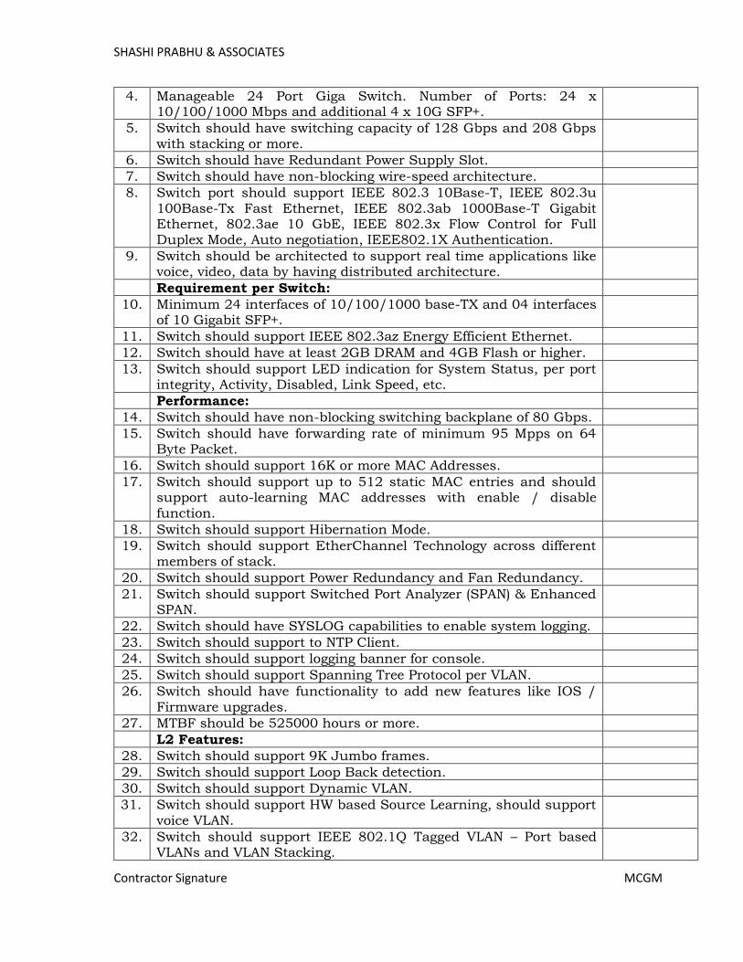
SHASHI PRABHU & ASSOCIATES
Contractor Signature MCGM
4. Manageable 24 Port Giga Switch. Number of Ports: 24 x 10/100/1000 Mbps and additional 4 x 10G SFP+.
5. Switch should have switching capacity of 128 Gbps and 208 Gbps with stacking or more.
6. Switch should have Redundant Power Supply Slot.
7. Switch should have non-blocking wire-speed architecture.
8. Switch port should support IEEE 802.3 10Base-T, IEEE 802.3u 100Base-Tx Fast Ethernet, IEEE 802.3ab 1000Base-T Gigabit Ethernet, 802.3ae 10 GbE, IEEE 802.3x Flow Control for Full Duplex Mode, Auto negotiation, IEEE802.1X Authentication.
9. Switch should be architected to support real time applications like voice, video, data by having distributed architecture.
Requirement per Switch:
10. Minimum 24 interfaces of 10/100/1000 base-TX and 04 interfaces of 10 Gigabit SFP+.
11. Switch should support IEEE 802.3az Energy Efficient Ethernet.
12. Switch should have at least 2GB DRAM and 4GB Flash or higher.
13. Switch should support LED indication for System Status, per port integrity, Activity, Disabled, Link Speed, etc.
Performance:
14. Switch should have non-blocking switching backplane of 80 Gbps.
15. Switch should have forwarding rate of minimum 95 Mpps on 64 Byte Packet.
16. Switch should support 16K or more MAC Addresses.
17. Switch should support up to 512 static MAC entries and should support auto-learning MAC addresses with enable / disable function.
18. Switch should support Hibernation Mode.
19. Switch should support EtherChannel Technology across different members of stack.
20. Switch should support Power Redundancy and Fan Redundancy.
21. Switch should support Switched Port Analyzer (SPAN) & Enhanced SPAN.
22. Switch should have SYSLOG capabilities to enable system logging.
23. Switch should support to NTP Client.
24. Switch should support logging banner for console.
25. Switch should support Spanning Tree Protocol per VLAN.
26. Switch should have functionality to add new features like IOS / Firmware upgrades.
27. MTBF should be 525000 hours or more.
L2 Features:
28. Switch should support 9K Jumbo frames.
29. Switch should support Loop Back detection.
30. Switch should support Dynamic VLAN.
31. Switch should support HW based Source Learning, should support voice VLAN.
32. Switch should support IEEE 802.1Q Tagged VLAN – Port based VLANs and VLAN Stacking.
Page 372

SHASHI PRABHU & ASSOCIATES
Contractor Signature MCGM
33. Switch should support for at least 1K Active VLAN’s.
34. Switch should support 1500 ACLs or Higher.
35. Switch should support Spanning Tree Protocol per VLAN.
36. Switch should support 802.1d STP, 802.1s MSTP and 802.1w RSTP Protocols.
37. Switch should support IPv4: IGMP V1, V2 Snooping and V3 awareness.
38. Switch should support IPV4 and IPv6: MLD V1/V2 awareness.
39. Switch should support Link Aggregation based on 802.3ad across the switches
40. Switch should support latency < 4µ seconds.
41. Switch should support IPv4 and IPv6 Features.
Quality of Service:
42. Switch should support QoS based on 802.1p Priority - 8 hardware queues per port.
43. Switch should support Ingress Policing and Egress Shaping.
44. Switch should support 802.1p / ToS / DiffServ marking and mapping.
45. Switch should support CoS based on 802.1p priority, VLAN, MAC Address, Ether type, IP address, DSCP, Protocol type, TCP/UDP Port Number, DSCP of IPv6 Traffic Class and IPv6 flow label.
46. Switch should support WRR and SP.
Security:
47. Switch should support Broadcast / Multicast / Unicast Storm Control.
48. Switch should support DHCP Snooping
49. Switch should support Dynamic ARP Inspection.
50. Switch should support IP Source Guard.
51. Switch should support SSH for IPv4 and IPv6.
52. Switch should support SSL for IPv4 and IPv6.
53. Switch should support IP-MAC port binding.
54. Switch should support 802.1x Authentication on all ports.
55. Switch should support 802.1x with Guest VLAN allows guests without 802.1x client to have limited network access on the guest VLAN.
56. Switch should support RADIUS and TACACS + authentication for switch access.
57. Switch should support scanning of network attacks based on behavioral analysis.
58. Switch should support Port Mirroring, Remote Port Mirroring and Policy-based Mirroring.
59. Switch should support Standard and extended ACLs on all ports.
60. Switch should support system event logging.
61. Switch should support real time multi-port statistics.
62. Switch should support MAC / IP Address Finder.
63. Device and Port Grouping for Navigation and Policy Management.
64. The Switch should be able to discover the neighbouring device of the same vendor giving the details about the platform, IP Address, Link
Page 373
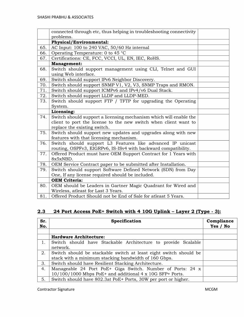
SHASHI PRABHU & ASSOCIATES
Contractor Signature MCGM
connected through etc, thus helping in troubleshooting connectivity problems.
Physical/Environmental:
65. AC Input: 100 to 240 VAC, 50/60 Hz internal
66. Operating Temperature: 0 to 45 °C
67. Certifications: CE, FCC, VCCI, UL, EN, IEC, RoHS.
Management:
68. Switch should support management using CLI, Telnet and GUI using Web interface.
69. Switch should support IPv6 Neighbor Discovery.
70. Switch should support SNMP V1, V2, V3, SNMP Traps and RMON.
71. Switch should support ICMPv6 and IPv4/v6 Dual Stack.
72. Switch should support LLDP and LLDP-MED.
73. Switch should support FTP / TFTP for upgrading the Operating System.
Licensing:
74. Switch should support a licensing mechanism which will enable the client to port the license to the new switch when client want to replace the existing switch.
75. Switch should support new updates and upgrades along with new features with that licensing mechanism.
76. Switch should support L3 Features like advanced IP unicast routing, OSPFv3, EIGRPv6, IS-ISv4 with backward compatibility.
77. Offered Product must have OEM Support Contract for 1 Years with 8x5xNBD.
78. OEM Service Contract paper to be submitted after Installation.
79. Switch should support Software Defined Network (SDN) from Day One, If any license required should be included.
OEM Criteria:
80. OEM should be Leaders in Gartner Magic Quadrant for Wired and Wireless, atleast for Last 3 Years.
81. Offered Product Should not be End of Sale for atleast 5 Years.
2.3 24 Port Access PoE+ Switch with 4 10G Uplink – Layer 2 (Type - 3):
Sr. No.
Specification Compliance Yes / No
Hardware Architecture:
1. Switch should have Stackable Architecture to provide Scalable network.
2. Switch should be stackable switch at least eight switch should be stack with a minimum stacking bandwidth of 160 Gbps.
3. Switch should have Resilient Stacking Architecture.
4. Manageable 24 Port PoE+ Giga Switch. Number of Ports: 24 x 10/100/1000 Mbps PoE+ and additional 4 x 10G SFP+ Ports.
5. Switch should have 802.3at PoE+ Ports, 30W per port or higher.
Page 374
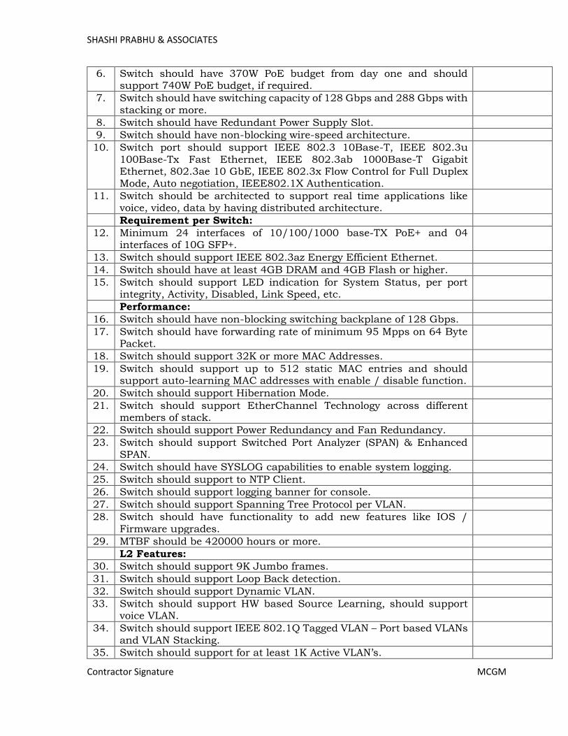
SHASHI PRABHU & ASSOCIATES
Contractor Signature MCGM
6. Switch should have 370W PoE budget from day one and should support 740W PoE budget, if required.
7. Switch should have switching capacity of 128 Gbps and 288 Gbps with stacking or more.
8. Switch should have Redundant Power Supply Slot.
9. Switch should have non-blocking wire-speed architecture.
10. Switch port should support IEEE 802.3 10Base-T, IEEE 802.3u 100Base-Tx Fast Ethernet, IEEE 802.3ab 1000Base-T Gigabit Ethernet, 802.3ae 10 GbE, IEEE 802.3x Flow Control for Full Duplex Mode, Auto negotiation, IEEE802.1X Authentication.
11. Switch should be architected to support real time applications like voice, video, data by having distributed architecture.
Requirement per Switch:
12. Minimum 24 interfaces of 10/100/1000 base-TX PoE+ and 04 interfaces of 10G SFP+.
13. Switch should support IEEE 802.3az Energy Efficient Ethernet.
14. Switch should have at least 4GB DRAM and 4GB Flash or higher.
15. Switch should support LED indication for System Status, per port integrity, Activity, Disabled, Link Speed, etc.
Performance:
16. Switch should have non-blocking switching backplane of 128 Gbps.
17. Switch should have forwarding rate of minimum 95 Mpps on 64 Byte Packet.
18. Switch should support 32K or more MAC Addresses.
19. Switch should support up to 512 static MAC entries and should support auto-learning MAC addresses with enable / disable function.
20. Switch should support Hibernation Mode.
21. Switch should support EtherChannel Technology across different members of stack.
22. Switch should support Power Redundancy and Fan Redundancy.
23. Switch should support Switched Port Analyzer (SPAN) & Enhanced SPAN.
24. Switch should have SYSLOG capabilities to enable system logging.
25. Switch should support to NTP Client.
26. Switch should support logging banner for console.
27. Switch should support Spanning Tree Protocol per VLAN.
28. Switch should have functionality to add new features like IOS / Firmware upgrades.
29. MTBF should be 420000 hours or more.
L2 Features:
30. Switch should support 9K Jumbo frames.
31. Switch should support Loop Back detection.
32. Switch should support Dynamic VLAN.
33. Switch should support HW based Source Learning, should support voice VLAN.
34. Switch should support IEEE 802.1Q Tagged VLAN – Port based VLANs and VLAN Stacking.
35. Switch should support for at least 1K Active VLAN’s.
Page 375
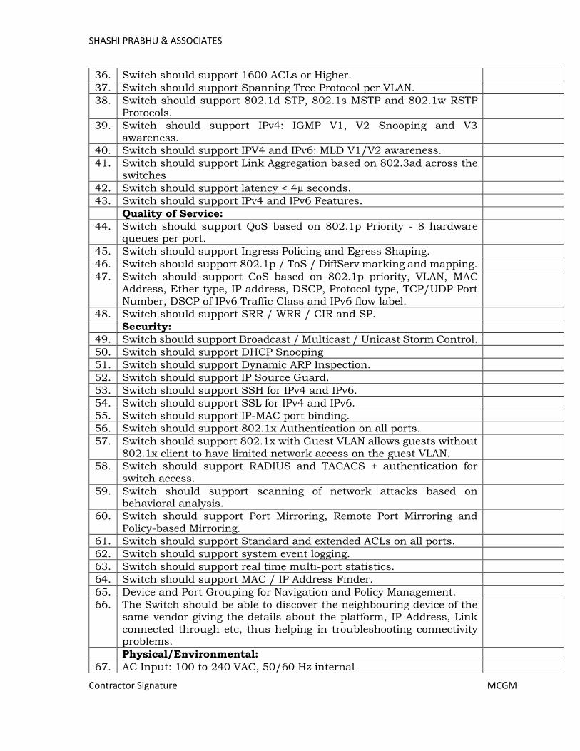
SHASHI PRABHU & ASSOCIATES
Contractor Signature MCGM
36. Switch should support 1600 ACLs or Higher.
37. Switch should support Spanning Tree Protocol per VLAN.
38. Switch should support 802.1d STP, 802.1s MSTP and 802.1w RSTP Protocols.
39. Switch should support IPv4: IGMP V1, V2 Snooping and V3 awareness.
40. Switch should support IPV4 and IPv6: MLD V1/V2 awareness.
41. Switch should support Link Aggregation based on 802.3ad across the switches
42. Switch should support latency < 4µ seconds.
43. Switch should support IPv4 and IPv6 Features.
Quality of Service:
44. Switch should support QoS based on 802.1p Priority - 8 hardware queues per port.
45. Switch should support Ingress Policing and Egress Shaping.
46. Switch should support 802.1p / ToS / DiffServ marking and mapping.
47. Switch should support CoS based on 802.1p priority, VLAN, MAC Address, Ether type, IP address, DSCP, Protocol type, TCP/UDP Port Number, DSCP of IPv6 Traffic Class and IPv6 flow label.
48. Switch should support SRR / WRR / CIR and SP.
Security:
49. Switch should support Broadcast / Multicast / Unicast Storm Control.
50. Switch should support DHCP Snooping
51. Switch should support Dynamic ARP Inspection.
52. Switch should support IP Source Guard.
53. Switch should support SSH for IPv4 and IPv6.
54. Switch should support SSL for IPv4 and IPv6.
55. Switch should support IP-MAC port binding.
56. Switch should support 802.1x Authentication on all ports.
57. Switch should support 802.1x with Guest VLAN allows guests without 802.1x client to have limited network access on the guest VLAN.
58. Switch should support RADIUS and TACACS + authentication for switch access.
59. Switch should support scanning of network attacks based on behavioral analysis.
60. Switch should support Port Mirroring, Remote Port Mirroring and Policy-based Mirroring.
61. Switch should support Standard and extended ACLs on all ports.
62. Switch should support system event logging.
63. Switch should support real time multi-port statistics.
64. Switch should support MAC / IP Address Finder.
65. Device and Port Grouping for Navigation and Policy Management.
66. The Switch should be able to discover the neighbouring device of the same vendor giving the details about the platform, IP Address, Link connected through etc, thus helping in troubleshooting connectivity problems.
Physical/Environmental:
67. AC Input: 100 to 240 VAC, 50/60 Hz internal
Page 376

SHASHI PRABHU & ASSOCIATES
Contractor Signature MCGM
68. Operating Temperature: 0 to 45 °C
69. Certifications: CE, FCC, VCCI, UL, EN, IEC, RoHS.
Management:
70. Switch should support management using CLI, Telnet and GUI using Web interface.
71. Switch should support IPv6 Neighbor Discovery.
72. Switch should support SNMP V1, V2, V3, SNMP Traps and RMON.
73. Switch should support ICMPv6 and IPv4/v6 Dual Stack.
74. Switch should support LLDP and LLDP-MED.
75. Switch should support FTP / TFTP for upgrading the Operating System.
Licensing:
76. Switch should support a licensing mechanism which will enable the client to port the license to the new switch when client want to replace the existing switch.
77. Switch should support new updates and upgrades along with new features with that licensing mechanism.
78. Switch should support L3 Features like advanced IP unicast routing, OSPFv3, EIGRPv6, IS-ISv4 with backward compatibility.
79. Switch should support Software Defined Network (SDN) from Day One, If any license required should be included.
80. Offered Product must have OEM Support Contract for 1 Years with 8x5xNBD.
81. OEM Service Contract paper to be submitted after Installation.
OEM Criteria:
82. OEM should be Leaders in Gartner Magic Quadrant for Wired and Wireless, atleast for Last 3 Years.
83. Offered Product Should not be End of Sale for atleast 5 Years.
2.4 24 Port Access Switch with 4 10G Uplink – Layer 2 (Type - 4):
Sr. No.
Specification Compliance Yes / No
Hardware Architecture:
1. Switch should have Stackable Architecture to provide Scalable network.
2. Switch should be stackable switch at least eight switch should be stack with a minimum stacking bandwidth of 160 Gbps.
3. Switch should have Resilient Stacking Architecture.
4. Manageable 24 Port Giga Switch. Number of Ports: 24 x 10/100/1000 Mbps and additional 4 x 10G SFP+ Ports.
5. Switch should have switching capacity of 128 Gbps and 288 Gbps with stacking or more.
6. Switch should have Redundant Power Supply Slot.
7. Switch should have non-blocking wire-speed architecture.
Page 377
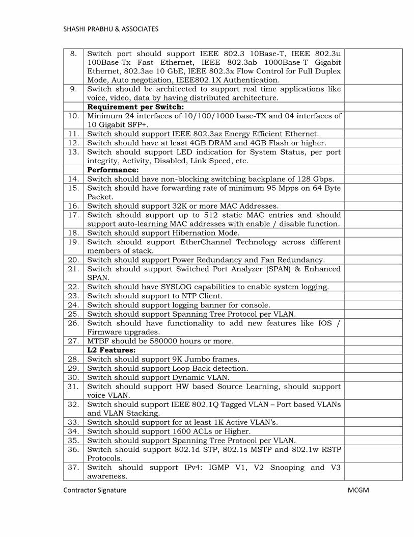
SHASHI PRABHU & ASSOCIATES
Contractor Signature MCGM
8. Switch port should support IEEE 802.3 10Base-T, IEEE 802.3u 100Base-Tx Fast Ethernet, IEEE 802.3ab 1000Base-T Gigabit Ethernet, 802.3ae 10 GbE, IEEE 802.3x Flow Control for Full Duplex Mode, Auto negotiation, IEEE802.1X Authentication.
9. Switch should be architected to support real time applications like voice, video, data by having distributed architecture.
Requirement per Switch:
10. Minimum 24 interfaces of 10/100/1000 base-TX and 04 interfaces of 10 Gigabit SFP+.
11. Switch should support IEEE 802.3az Energy Efficient Ethernet.
12. Switch should have at least 4GB DRAM and 4GB Flash or higher.
13. Switch should support LED indication for System Status, per port integrity, Activity, Disabled, Link Speed, etc.
Performance:
14. Switch should have non-blocking switching backplane of 128 Gbps.
15. Switch should have forwarding rate of minimum 95 Mpps on 64 Byte Packet.
16. Switch should support 32K or more MAC Addresses.
17. Switch should support up to 512 static MAC entries and should support auto-learning MAC addresses with enable / disable function.
18. Switch should support Hibernation Mode.
19. Switch should support EtherChannel Technology across different members of stack.
20. Switch should support Power Redundancy and Fan Redundancy.
21. Switch should support Switched Port Analyzer (SPAN) & Enhanced SPAN.
22. Switch should have SYSLOG capabilities to enable system logging.
23. Switch should support to NTP Client.
24. Switch should support logging banner for console.
25. Switch should support Spanning Tree Protocol per VLAN.
26. Switch should have functionality to add new features like IOS / Firmware upgrades.
27. MTBF should be 580000 hours or more.
L2 Features:
28. Switch should support 9K Jumbo frames.
29. Switch should support Loop Back detection.
30. Switch should support Dynamic VLAN.
31. Switch should support HW based Source Learning, should support voice VLAN.
32. Switch should support IEEE 802.1Q Tagged VLAN – Port based VLANs and VLAN Stacking.
33. Switch should support for at least 1K Active VLAN’s.
34. Switch should support 1600 ACLs or Higher.
35. Switch should support Spanning Tree Protocol per VLAN.
36. Switch should support 802.1d STP, 802.1s MSTP and 802.1w RSTP Protocols.
37. Switch should support IPv4: IGMP V1, V2 Snooping and V3 awareness.
Page 378
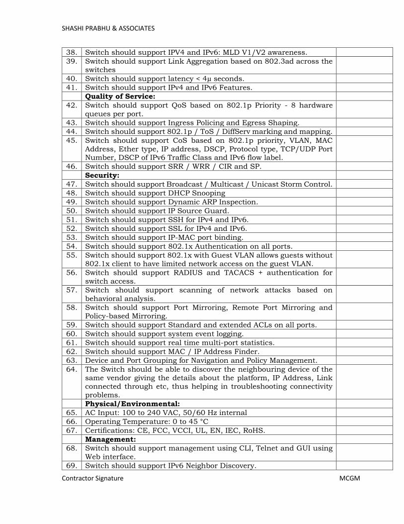
SHASHI PRABHU & ASSOCIATES
Contractor Signature MCGM
38. Switch should support IPV4 and IPv6: MLD V1/V2 awareness.
39. Switch should support Link Aggregation based on 802.3ad across the switches
40. Switch should support latency < 4µ seconds.
41. Switch should support IPv4 and IPv6 Features.
Quality of Service:
42. Switch should support QoS based on 802.1p Priority - 8 hardware queues per port.
43. Switch should support Ingress Policing and Egress Shaping.
44. Switch should support 802.1p / ToS / DiffServ marking and mapping.
45. Switch should support CoS based on 802.1p priority, VLAN, MAC
Address, Ether type, IP address, DSCP, Protocol type, TCP/UDP Port Number, DSCP of IPv6 Traffic Class and IPv6 flow label.
46. Switch should support SRR / WRR / CIR and SP.
Security:
47. Switch should support Broadcast / Multicast / Unicast Storm Control.
48. Switch should support DHCP Snooping
49. Switch should support Dynamic ARP Inspection.
50. Switch should support IP Source Guard.
51. Switch should support SSH for IPv4 and IPv6.
52. Switch should support SSL for IPv4 and IPv6.
53. Switch should support IP-MAC port binding.
54. Switch should support 802.1x Authentication on all ports.
55. Switch should support 802.1x with Guest VLAN allows guests without 802.1x client to have limited network access on the guest VLAN.
56. Switch should support RADIUS and TACACS + authentication for switch access.
57. Switch should support scanning of network attacks based on behavioral analysis.
58. Switch should support Port Mirroring, Remote Port Mirroring and Policy-based Mirroring.
59. Switch should support Standard and extended ACLs on all ports.
60. Switch should support system event logging.
61. Switch should support real time multi-port statistics.
62. Switch should support MAC / IP Address Finder.
63. Device and Port Grouping for Navigation and Policy Management.
64. The Switch should be able to discover the neighbouring device of the same vendor giving the details about the platform, IP Address, Link connected through etc, thus helping in troubleshooting connectivity problems.
Physical/Environmental:
65. AC Input: 100 to 240 VAC, 50/60 Hz internal
66. Operating Temperature: 0 to 45 °C
67. Certifications: CE, FCC, VCCI, UL, EN, IEC, RoHS.
Management:
68. Switch should support management using CLI, Telnet and GUI using Web interface.
69. Switch should support IPv6 Neighbor Discovery.
Page 379
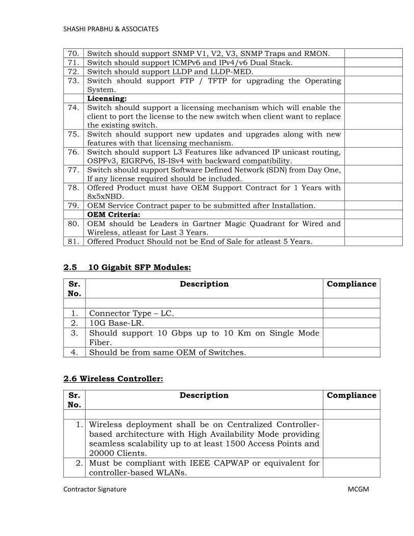
SHASHI PRABHU & ASSOCIATES
Contractor Signature MCGM
70. Switch should support SNMP V1, V2, V3, SNMP Traps and RMON.
71. Switch should support ICMPv6 and IPv4/v6 Dual Stack.
72. Switch should support LLDP and LLDP-MED.
73. Switch should support FTP / TFTP for upgrading the Operating System.
Licensing:
74. Switch should support a licensing mechanism which will enable the client to port the license to the new switch when client want to replace the existing switch.
75. Switch should support new updates and upgrades along with new features with that licensing mechanism.
76. Switch should support L3 Features like advanced IP unicast routing, OSPFv3, EIGRPv6, IS-ISv4 with backward compatibility.
77. Switch should support Software Defined Network (SDN) from Day One, If any license required should be included.
78. Offered Product must have OEM Support Contract for 1 Years with 8x5xNBD.
79. OEM Service Contract paper to be submitted after Installation.
OEM Criteria:
80. OEM should be Leaders in Gartner Magic Quadrant for Wired and Wireless, atleast for Last 3 Years.
81. Offered Product Should not be End of Sale for atleast 5 Years.
2.5 10 Gigabit SFP Modules:
Sr.
No.
Description Compliance
1. Connector Type – LC.
2. 10G Base-LR.
3. Should support 10 Gbps up to 10 Km on Single Mode Fiber.
4. Should be from same OEM of Switches.
2.6 Wireless Controller:
Sr. No.
Description Compliance
1. Wireless deployment shall be on Centralized Controller-
based architecture with High Availability Mode providing seamless scalability up to at least 1500 Access Points and
20000 Clients.
2. Must be compliant with IEEE CAPWAP or equivalent for
controller-based WLANs.
Page 380
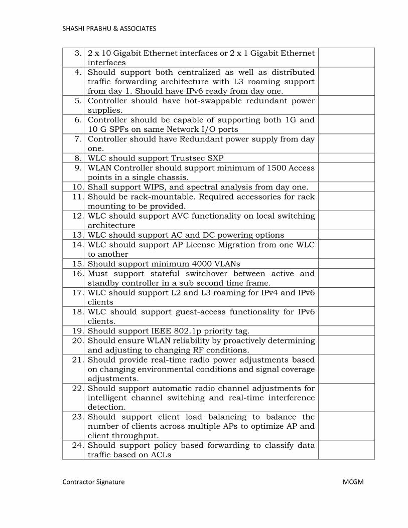
SHASHI PRABHU & ASSOCIATES
Contractor Signature MCGM
3. 2 x 10 Gigabit Ethernet interfaces or 2 x 1 Gigabit Ethernet
interfaces
4. Should support both centralized as well as distributed traffic forwarding architecture with L3 roaming support
from day 1. Should have IPv6 ready from day one.
5. Controller should have hot-swappable redundant power
supplies.
6. Controller should be capable of supporting both 1G and
10 G SPFs on same Network I/O ports
7. Controller should have Redundant power supply from day
one.
8. WLC should support Trustsec SXP
9. WLAN Controller should support minimum of 1500 Access points in a single chassis.
10. Shall support WIPS, and spectral analysis from day one.
11. Should be rack-mountable. Required accessories for rack
mounting to be provided.
12. WLC should support AVC functionality on local switching
architecture
13. WLC should support AC and DC powering options
14. WLC should support AP License Migration from one WLC to another
15. Should support minimum 4000 VLANs
16. Must support stateful switchover between active and
standby controller in a sub second time frame.
17. WLC should support L2 and L3 roaming for IPv4 and IPv6 clients
18. WLC should support guest-access functionality for IPv6 clients.
19. Should support IEEE 802.1p priority tag.
20. Should ensure WLAN reliability by proactively determining
and adjusting to changing RF conditions.
21. Should provide real-time radio power adjustments based
on changing environmental conditions and signal coverage adjustments.
22. Should support automatic radio channel adjustments for intelligent channel switching and real-time interference detection.
23. Should support client load balancing to balance the number of clients across multiple APs to optimize AP and
client throughput.
24. Should support policy based forwarding to classify data
traffic based on ACLs
Page 381
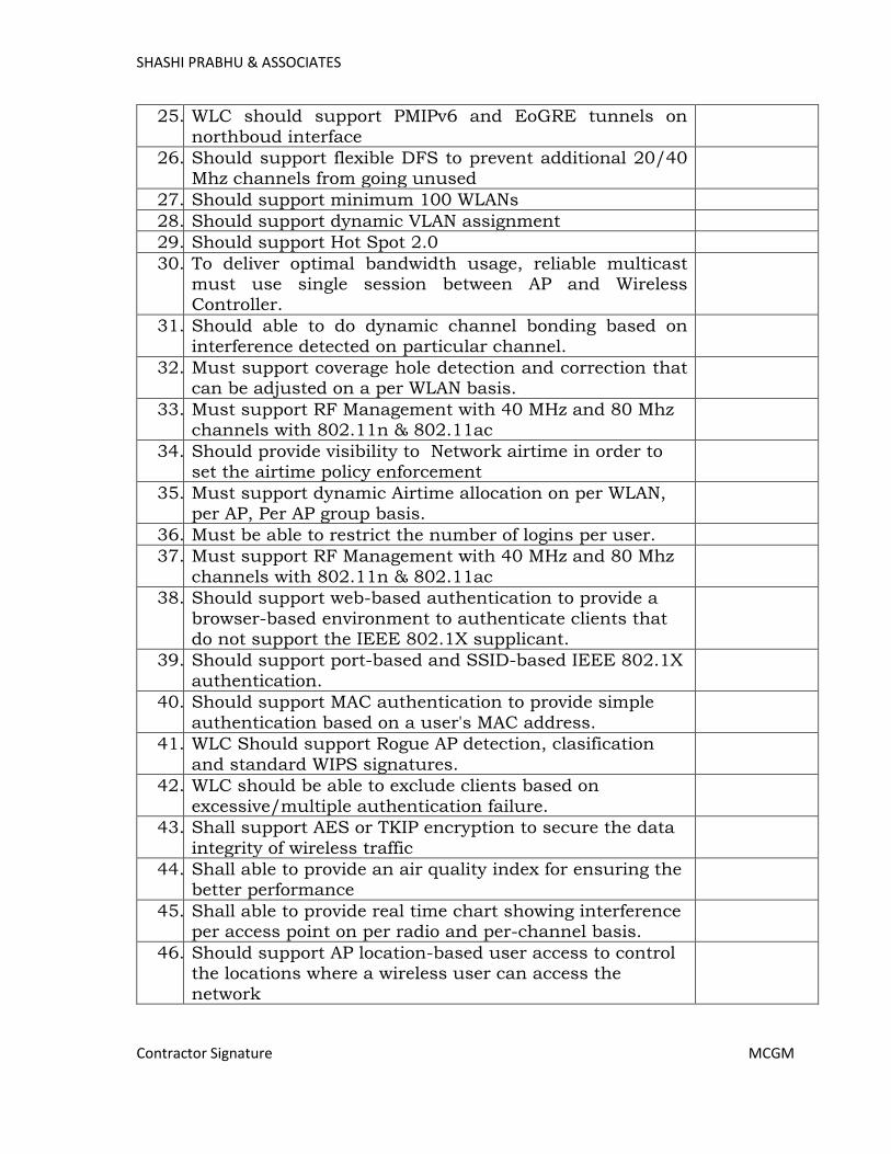
SHASHI PRABHU & ASSOCIATES
Contractor Signature MCGM
25. WLC should support PMIPv6 and EoGRE tunnels on
northboud interface
26. Should support flexible DFS to prevent additional 20/40 Mhz channels from going unused
27. Should support minimum 100 WLANs
28. Should support dynamic VLAN assignment
29. Should support Hot Spot 2.0
30. To deliver optimal bandwidth usage, reliable multicast must use single session between AP and Wireless Controller.
31. Should able to do dynamic channel bonding based on interference detected on particular channel.
32. Must support coverage hole detection and correction that can be adjusted on a per WLAN basis.
33. Must support RF Management with 40 MHz and 80 Mhz channels with 802.11n & 802.11ac
34. Should provide visibility to Network airtime in order to set the airtime policy enforcement
35. Must support dynamic Airtime allocation on per WLAN, per AP, Per AP group basis.
36. Must be able to restrict the number of logins per user.
37. Must support RF Management with 40 MHz and 80 Mhz
channels with 802.11n & 802.11ac
38. Should support web-based authentication to provide a
browser-based environment to authenticate clients that do not support the IEEE 802.1X supplicant.
39. Should support port-based and SSID-based IEEE 802.1X
authentication.
40. Should support MAC authentication to provide simple
authentication based on a user's MAC address.
41. WLC Should support Rogue AP detection, clasification
and standard WIPS signatures.
42. WLC should be able to exclude clients based on
excessive/multiple authentication failure.
43. Shall support AES or TKIP encryption to secure the data
integrity of wireless traffic
44. Shall able to provide an air quality index for ensuring the better performance
45. Shall able to provide real time chart showing interference per access point on per radio and per-channel basis.
46. Should support AP location-based user access to control the locations where a wireless user can access the
network
Page 382

SHASHI PRABHU & ASSOCIATES
Contractor Signature MCGM
47. Should support Public Key Infrastructure (PKI) to control
access
48. Must be able to set a maximum per-user bandwidth limit on a per-SSID basis.
49. Should support SNMPv3, SSHv2 and SSL for secure management.
50. Should support encrypted mechanisum to securely upload/download software image to and from Wireless
controller.
51. Should provide visibility between a wired and wireless
network using IEEE 802.1AB Link Layer Discovery Protocol (LLDP) and sFlow/equivalent.
52. Should support AP Plug and Play (PnP) deployment with zero-configuration capability
53. Should support AP grouping to enable administrator to easily apply AP-based or radio-based configurations to all the APs in the same group
54. Should support selective firmware upgrade APs, typically to a group of APs minimize the impact of up-gradation
55. Should have a suitable serial console port.
56. Should have Voice and Video Call Admission and Stream
prioritization for preferential QOS
57. Controller should have Deep Packet Inspection for Layer
4-7 traffic for user for all traffic across the network to analyses information about applications usage and prioritization
58. Controller should have profiling of devices based on protocols like HTTP, DHCP and more to identify the end
devices on the network.
59. Should support visibly and control based on the type of
applications
2.7 Wireless Access Points Medium Density (Type – 1):
Sr. No.
Description Compliance
1. Access Points proposed must include radios for 2.4 GHz
and 5 GHz with 802.11ac Wave 2 with Connection rate of upto 1 Gbps with Dual Radio.
2. Must have a robust design for durability, without visible vents
3. Mounting kit should be standard from OEM directly.
Page 383
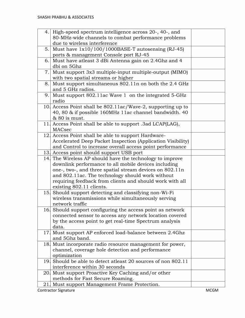
SHASHI PRABHU & ASSOCIATES
Contractor Signature MCGM
4. High-speed spectrum intelligence across 20-, 40-, and
80-MHz-wide channels to combat performance problems due to wireless interference
5. Must have 1x10/100/1000BASE-T autosensing (RJ-45)
ports & management Console port RJ-45
6. Must have atleast 3 dBi Antenna gain on 2.4Ghz and 4
dbi on 5Ghz
7. Must support 3x3 multiple-input multiple-output (MIMO)
with two spatial streams or higher
8. Must support simultaneous 802.11n on both the 2.4 GHz
and 5 GHz radios.
9. Must support 802.11ac Wave 1 on the integrated 5-GHz
radio
10. Access Point shall be 802.11ac/Wave-2, supporting up to
40, 80 & if possible 160MHz 11ac channel bandwidth. 40 & 80 is must.
11. Access Point shall be able to support .3ad LCAP(LAG),
MACsec
12. Access Point shall be able to support Hardware-
Accelerated Deep Packet Inspection (Application Visibility) and Control to increase overall access point performance
13. Access point should support USB port
14. The Wireless AP should have the technology to improve
downlink performance to all mobile devices including one-, two-, and three spatial stream devices on 802.11n and 802.11ac. The technology should work without
requiring feedback from clients and should work with all existing 802.11 clients.
15. Should support detecting and classifying non-Wi-Fi wireless transmissions while simultaneously serving network traffic
16. Should support configuring the access point as network connected sensor to access any network location covered
by the access point to get real-time Spectrum analysis data.
17. Must support AP enforced load-balance between 2.4Ghz and 5Ghz band.
18. Must incorporate radio resource management for power, channel, coverage hole detection and performance optimization
19. Should be able to detect atleast 20 sources of non 802.11 interference within 30 seconds
20. Must support Proactive Key Caching and/or other methods for Fast Secure Roaming.
21. Must support Management Frame Protection.
Page 384

SHASHI PRABHU & ASSOCIATES
Contractor Signature MCGM
22. Should support locally-significant certificates on the APs
using a Public Key Infrastructure (PKI).
23. Must operate as a sensor for wireless IPS
24. Should support non-Wi-Fi detection for off-channel rogues and Containment for both radio
25. Access Points must support a distributed encryption/decryption model.
26. Access Points must support Hardware-based DTLS encryption on CAPWAP Standard or equivalent
27. Must support the ability to serve clients and monitor the
RF environment concurrently.
28. Same model AP that serves clients must be able to be
dedicated to monitoring the RF environment.
29. Must support telnet and/or SSH login to APs directly for
troubleshooting flexibility.
30. Must Support 802.3at /PoE+ as the source of power for
POE through Switch or POE Injector
31. 802.11e and WMM
32. Must support QoS and Video Call Admission Control capabilities.
33. Access Point should 802.11 DFS certified
2.8 Firewall / Unified Threat Management System:
Sr. No.
Description Compliance
1. The Firewall solution offered must be rated as in the latest
Magic Quadrant for Firewall published by Gartner.
2. The appliance based security platform should be capable
of providing firewall, application visibility, IPS, Anti-APT and URL filtering functionality in a single appliance from day one.
3. The appliance should support atleast 8 * 1G ports and 2 * 1G Fiber ports from Day one
4. The appliance hardware should be a multicore CPU architecture with a hardened 64 bit operating system to
support higher memory (minimum 16GB from day one).
5. Proposed Firewall should not be proprietary ASIC based
in nature & should be open architecture based on multi-core cpu's to protect & scale against dynamic latest security threats.
6. Should support atleast 2 Gbps of production performance / multiprotocol combined firewall & ips throughput
Page 385

SHASHI PRABHU & ASSOCIATES
Contractor Signature MCGM
7. Firewall should support atleast 10M concurrent
connections
8. Firewall should support atleast 12,000 new connections per second
9. Firewall should support atleast 1024 VLANs
10. Firewall should provide application detection for DNS, FTP, HTTP, SMTP,ESMTP, LDAP, MGCP, RTSP, SIP, SCCP, SQLNET, TFTP, H.323, SNMP
11. Firewall should support creating access-rules with IPv4 & IPv6 objects simultaneously
12. Firewall should support operating in routed & transparent mode
13. Should support Static, RIP, OSPF, OSPFv3 and BGP
14. Firewall should support manual NAT and Auto-NAT,
static nat, dynamic nat, dynamic pat
15. Firewall should support Nat66 (IPv6-to-IPv6), Nat 64
(IPv6-to-IPv4) & Nat46 (IPv4-to-IPv6) functionality
16. Firewall should support Multicast protocols like IGMP,
PIM, etc
17. Should support security policies based on security group names in source or destination fields or both
18. Should support capability to limit bandwidth on basis of apps / groups, Networks / Geo, Ports, etc
19. Firewall should support Active/Standby failover
20. Firewall should support ether channel functionality for the failover control & date interfaces for provide additional level of redundancy
21. Firewall should support redundant interfaces to provide interface level redundancy before device failover
22. Firewall should support 802.3ad Ether channel functionality to increase the bandwidth for a segment.
23. Should support Reputation- and category-based URL filtering offering comprehensive alerting and control over suspect web traffic and enforces policies on more than
280 million of URLs in more than 80 categories.
24. Should have identification support for atleast 3000
applications and the identification should be regardless of ports. The application needs to be predefined on the box.
25. Solution should provide granual control of applications.
26. The solution should be able to mitigate sophisticated
client-side attacks by providing controlled access to URLs.
27. Firewall should support integrated Reputation & dynamic category based web filtering.
Page 386

SHASHI PRABHU & ASSOCIATES
Contractor Signature MCGM
28. Support manual URL filtering that specify individual
URLs, groups of URLs, and URL lists and feeds to achieve granular, custom control over web traffic.
29. The solution must support creation of user-defined
application protocol detectors.
30. Should have the capability of passively gathering
information about virtual machine traffic, network hosts and their activities, such as operating system, services,
open ports, client applications, and vulnerabilities, to assist with multiple activities, such as intrusion event data correlation, elimination of false positives, and policy
compliance.
31. The device shall allow administrators to create Custom
IPS signatures
32. Should be capable of dynamically tuning IDS/IPS
sensors (e.g., selecting rules, configuring policies, updating policies, etc.) with minimal human intervention.
33. Should be capable of automatically providing the appropriate inspections and protections for traffic sent over non-standard communications ports.
34. Should be able to link Active Directory and/or LDAP usernames to IP addresses related to suspected security
events.
35. Should be capable of detecting and blocking IPv6 attacks.
36. Should support the capability to quarantine end point
37. Solution should support full-featured NBA capability to
detect threats emerging from inside the network. This includes the ability to establish “normal” traffic baselines through flow analysis techniques (e.g., NetFlow) and the
ability to detect deviations from normal baselines.
38. The solution must provide IP reputation feed that
comprised of several regularly updated collections of poor repuration of IP addresses determined by the proposed security vendor
39. Solution must support IP reputation intelligence feeds from third party and custom lists of IP addresses
including a global blacklist.
40. Should must support URL and DNS threat intelligence
feeds to protect against threats
41. Should support safe search for YouTube EDU
enforcement
42. Solution must be capable of passively gathering details
unique to mobile devices traffic to identify a wide variety of mobile operating systems, mobile applications and associated mobile device hardware.
Page 387
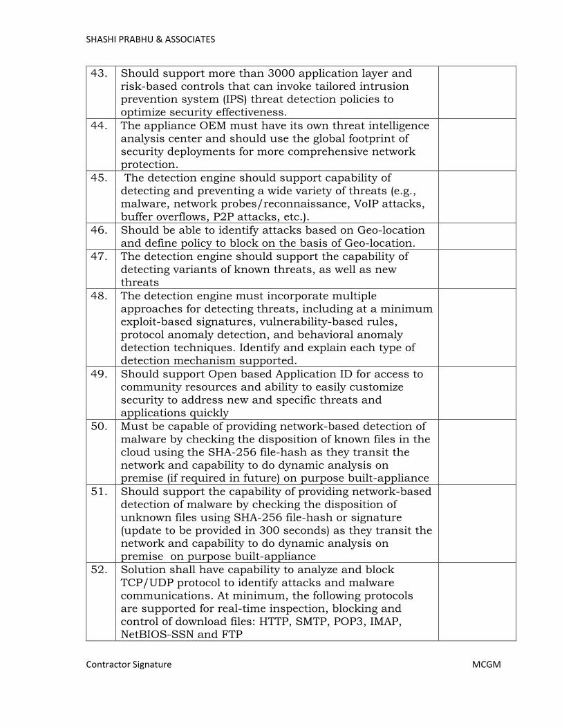
SHASHI PRABHU & ASSOCIATES
Contractor Signature MCGM
43. Should support more than 3000 application layer and
risk-based controls that can invoke tailored intrusion prevention system (IPS) threat detection policies to optimize security effectiveness.
44. The appliance OEM must have its own threat intelligence analysis center and should use the global footprint of
security deployments for more comprehensive network protection.
45. The detection engine should support capability of detecting and preventing a wide variety of threats (e.g., malware, network probes/reconnaissance, VoIP attacks,
buffer overflows, P2P attacks, etc.).
46. Should be able to identify attacks based on Geo-location
and define policy to block on the basis of Geo-location.
47. The detection engine should support the capability of
detecting variants of known threats, as well as new threats
48. The detection engine must incorporate multiple approaches for detecting threats, including at a minimum exploit-based signatures, vulnerability-based rules,
protocol anomaly detection, and behavioral anomaly detection techniques. Identify and explain each type of detection mechanism supported.
49. Should support Open based Application ID for access to community resources and ability to easily customize
security to address new and specific threats and applications quickly
50. Must be capable of providing network-based detection of malware by checking the disposition of known files in the cloud using the SHA-256 file-hash as they transit the
network and capability to do dynamic analysis on premise (if required in future) on purpose built-appliance
51. Should support the capability of providing network-based detection of malware by checking the disposition of
unknown files using SHA-256 file-hash or signature (update to be provided in 300 seconds) as they transit the network and capability to do dynamic analysis on
premise on purpose built-appliance
52. Solution shall have capability to analyze and block
TCP/UDP protocol to identify attacks and malware communications. At minimum, the following protocols are supported for real-time inspection, blocking and
control of download files: HTTP, SMTP, POP3, IMAP, NetBIOS-SSN and FTP
Page 388

SHASHI PRABHU & ASSOCIATES
Contractor Signature MCGM
53. Proposed solution shall have required subscription like
Threat Intelligence for proper functioning
54. Centralized management should be separate appliance. It should be VM appliance or Hardware appliance
55. The management platform must be accessible via a web-based interface and ideally with no need for additional
client software.
56. The management platform must be capable of role-based
administration, enabling different sets of views and configuration capabilities for different administrators subsequent to their authentication.
57. The management platform must include a scheduling subsystem to facilitate automation of routine tasks, such
as backups, upgrades, report creation, and policy application.
58. Centralised management can do contextual threat intelligence service accelerates analysis, correlation of
events. This can be on apliance or can be cloud services
59. The management platform must be capable of automatically receiving rule updates published by the
vendor and automatically distributing and applying those rule updates to sensors.
60. The Centralised management platform must provide robust reporting capabilities, including a selection of pre-
defined reports and the ability for complete customization and generation of new reports. Report can be consolidated or can be generate individual NGFW
61. Logging of Administrative Changes that provides an audit trail for administrative activities.
62. The management platform must provide a highly customizable dashboard.
63. The management platform must be capable of integrating third party vulnerability information into threat policy adjustment routines and automated tuning workflows
64. The management platform must be capable of role-based administration, enabling different sets of views and
configuration capabilities for different administrators subsequent to their authentication.
65. Should support REST API for monitoring and config programmability .
66. The management platform must provide multiple report output types or formats, such as PDF, HTML, and CSV.
67. The management platform must support multiple mechanisms for issuing alerts (e.g., SNMP, e-mail, SYSLOG).
Page 389

SHASHI PRABHU & ASSOCIATES
Contractor Signature MCGM
68. The management platform must risk reports like
advanced malware, attacks and network
69. The management platform must include an integration mechanism, preferably in the form of open APIs and/or
standard interfaces, to enable events and log data to be shared with external network and security management
applications, such as Security Information and Event Managers (SIEMs), and log management tools.
Page 390

SHASHI PRABHU & ASSOCIATES
Contractor Signature MCGM
3. Telecommunication System:-
3.1 EPABX System
Sr. No.
Description Specification Compliance
1. System Features The telephony system should be a converged
communication System with ability to run TDM and IP on the same platform using same software load based on server and
Gateway architecture. The system should be capable of support Analog and IP SIP based phones. The communication server should be appliance based; no card based processor should be quoted.
2. The Telephony system shall have all the
hotel / hospitality features including integration with PMS system.
3. The system should support duplicated
databases such that it is possible to make administrative changes to the system even during outage of primary server/database.
4. EPBX system shall have valid TEC
compliance
5. The system should have support for 1800
users from day 1 and should be scalable upto 10,000 users on the single server.
6. The system should support complete UC
functionality including soft phone, IM, presence and collaboration for 500 users from day 1.
7. The system should be based on server
gateway architecture with external appliance server. No card based processor systems should be quoted.
8. The system should be modular, scalable and
distributable in nature.
9. The system to have distributed architecture
and the centralized control for all the IP PBX entities in the network. It should be possible to have centralized applications like voice mail, UC for the network users
10. The system shall be configured for SIP and
IP trunk interfaces without any external interfaces or adapters.
11. The Call Server should able to handle traffic
minimum 300K BHCC
Page 391
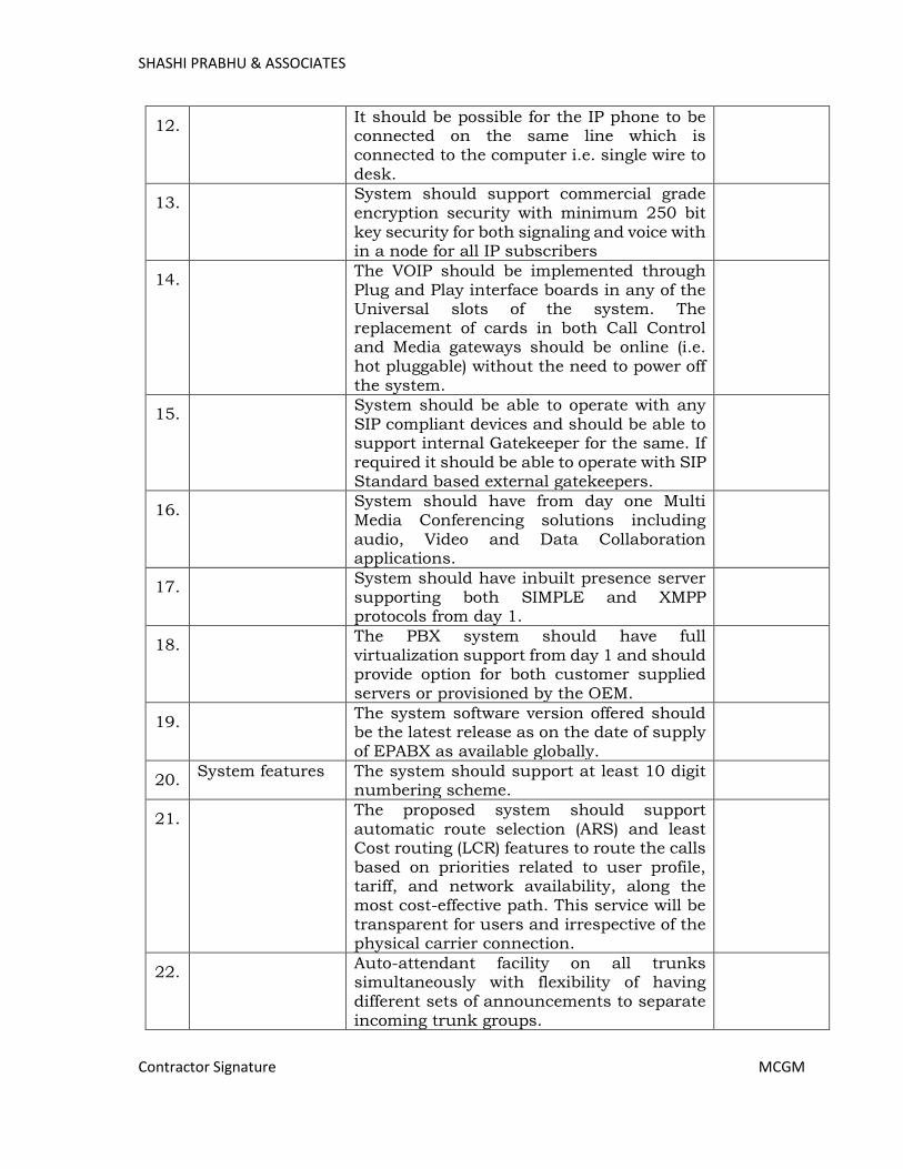
SHASHI PRABHU & ASSOCIATES
Contractor Signature MCGM
12. It should be possible for the IP phone to be
connected on the same line which is connected to the computer i.e. single wire to desk.
13. System should support commercial grade
encryption security with minimum 250 bit key security for both signaling and voice with in a node for all IP subscribers
14. The VOIP should be implemented through
Plug and Play interface boards in any of the Universal slots of the system. The replacement of cards in both Call Control and Media gateways should be online (i.e. hot pluggable) without the need to power off the system.
15. System should be able to operate with any
SIP compliant devices and should be able to support internal Gatekeeper for the same. If required it should be able to operate with SIP Standard based external gatekeepers.
16. System should have from day one Multi
Media Conferencing solutions including audio, Video and Data Collaboration applications.
17. System should have inbuilt presence server
supporting both SIMPLE and XMPP protocols from day 1.
18. The PBX system should have full
virtualization support from day 1 and should provide option for both customer supplied servers or provisioned by the OEM.
19. The system software version offered should
be the latest release as on the date of supply of EPABX as available globally.
20. System features The system should support at least 10 digit
numbering scheme.
21. The proposed system should support
automatic route selection (ARS) and least Cost routing (LCR) features to route the calls based on priorities related to user profile, tariff, and network availability, along the most cost-effective path. This service will be transparent for users and irrespective of the physical carrier connection.
22. Auto-attendant facility on all trunks
simultaneously with flexibility of having different sets of announcements to separate incoming trunk groups.
Page 392
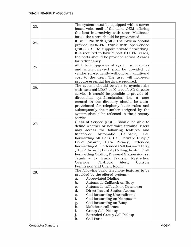
SHASHI PRABHU & ASSOCIATES
Contractor Signature MCGM
23. The system must be equipped with a server
based voice mail of the same OEM, offering the best interactivity with user. Mailboxes for all the users should be provisioned
24. ISDN – PRI with QSIG. The EPABX should
provide ISDN-PRI trunk with open-ended QSIG (ETSI) to support private networking. It is required to have 2 port E1/ PRI cards, the ports should be provided across 2 cards for redundancy.
25. All future upgrades of system software as
and when released shall be provided by vendor subsequently without any additional cost to the user. The user will however, procure essential hardware required.
26. The system should be able to synchronize
with external LDAP or Microsoft AD director service. It should be possible to provide bi-directional synchronization i.e. a user created in the directory should be auto-provisioned for telephony basis rules and subsequently the number assigned by the system should be reflected in the directory service
27. Class of Service (COS). Should be able to
define whether or not voice terminal users may access the following features and functions: Automatic Callback, Call Forwarding All Calls, Call Forward Busy / Don’t Answer, Data Privacy, Extended Forwarding All, Extended Call Forward Busy / Don’t Answer, Priority Calling, Restrict Call Forwarding Off-Net, Personal Station Access, Trunk – to Trunk Transfer Restriction Override, Off-Hook Alert, Console Permission and Client Room.
28. The following basic telephony features to be
provided by the offered system:- a. Abbreviated Dialing b. Automatic Callback on Busy c. Automatic callback on No answer d. Direct Inward Station Access e. Call forwarding Unconditional f. Call forwarding on No answer g. Call forwarding on Busy h. Malicious call trace i. Group Call Pick up j. Extended Group Call Pickup k. Call Park
Page 393
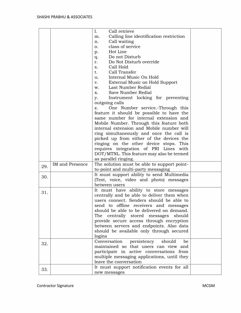
SHASHI PRABHU & ASSOCIATES
Contractor Signature MCGM
l. Call retrieve m. Calling line identification restriction n. Call waiting o. class of service p. Hot Line q. Do not Disturb r. Do Not Disturb override s. Call Hold t. Call Transfer u. Internal Music On Hold v. External Music on Hold Support w. Last Number Redial
x. Save Number Redial y. Instrument locking for preventing outgoing calls z. One Number service.-Through this feature it should be possible to have the same number for internal extension and Mobile Number. Through this feature both internal extension and Mobile number will ring simultaneously and once the call is picked up from either of the devices the ringing on the other device stops. This requires integration of PRI Lines with DOT/MTNL. This feature may also be termed as parallel ringing.
29. IM and Presence The solution must be able to support point-
to-point and multi-party messaging
30. It must support ability to send Multimedia
(Text, voice, video and photo) messages between users
31. It must have ability to store messages
centrally and be able to deliver them when users connect. Senders should be able to send to offline receivers and messages should be able to be delivered on demand.
The centrally stored messages should provide secure access through encryption between servers and endpoints. Also data should be available only through secured logins
32. Conversation persistency should be
maintained so that users can view and participate in active conversations from multiple messaging applications, until they leave the conversation
33. It must support notification events for all
new messages
Page 394
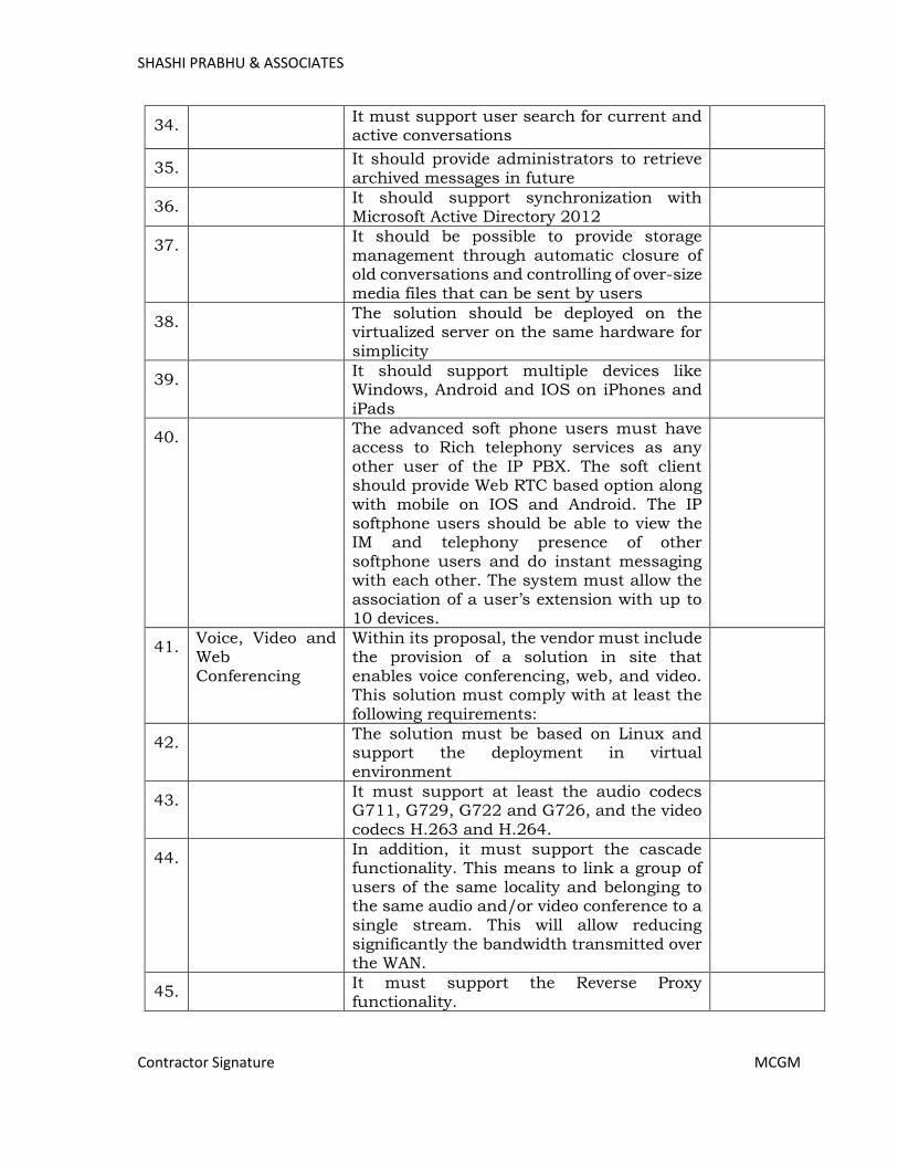
SHASHI PRABHU & ASSOCIATES
Contractor Signature MCGM
34. It must support user search for current and
active conversations
35. It should provide administrators to retrieve
archived messages in future
36. It should support synchronization with
Microsoft Active Directory 2012
37. It should be possible to provide storage
management through automatic closure of old conversations and controlling of over-size media files that can be sent by users
38. The solution should be deployed on the
virtualized server on the same hardware for simplicity
39. It should support multiple devices like
Windows, Android and IOS on iPhones and iPads
40. The advanced soft phone users must have
access to Rich telephony services as any other user of the IP PBX. The soft client should provide Web RTC based option along with mobile on IOS and Android. The IP softphone users should be able to view the IM and telephony presence of other softphone users and do instant messaging with each other. The system must allow the association of a user’s extension with up to 10 devices.
41. Voice, Video and Web Conferencing
Within its proposal, the vendor must include the provision of a solution in site that enables voice conferencing, web, and video. This solution must comply with at least the following requirements:
42. The solution must be based on Linux and
support the deployment in virtual environment
43. It must support at least the audio codecs
G711, G729, G722 and G726, and the video codecs H.263 and H.264.
44. In addition, it must support the cascade
functionality. This means to link a group of users of the same locality and belonging to the same audio and/or video conference to a single stream. This will allow reducing significantly the bandwidth transmitted over the WAN.
45. It must support the Reverse Proxy
functionality.
Page 395
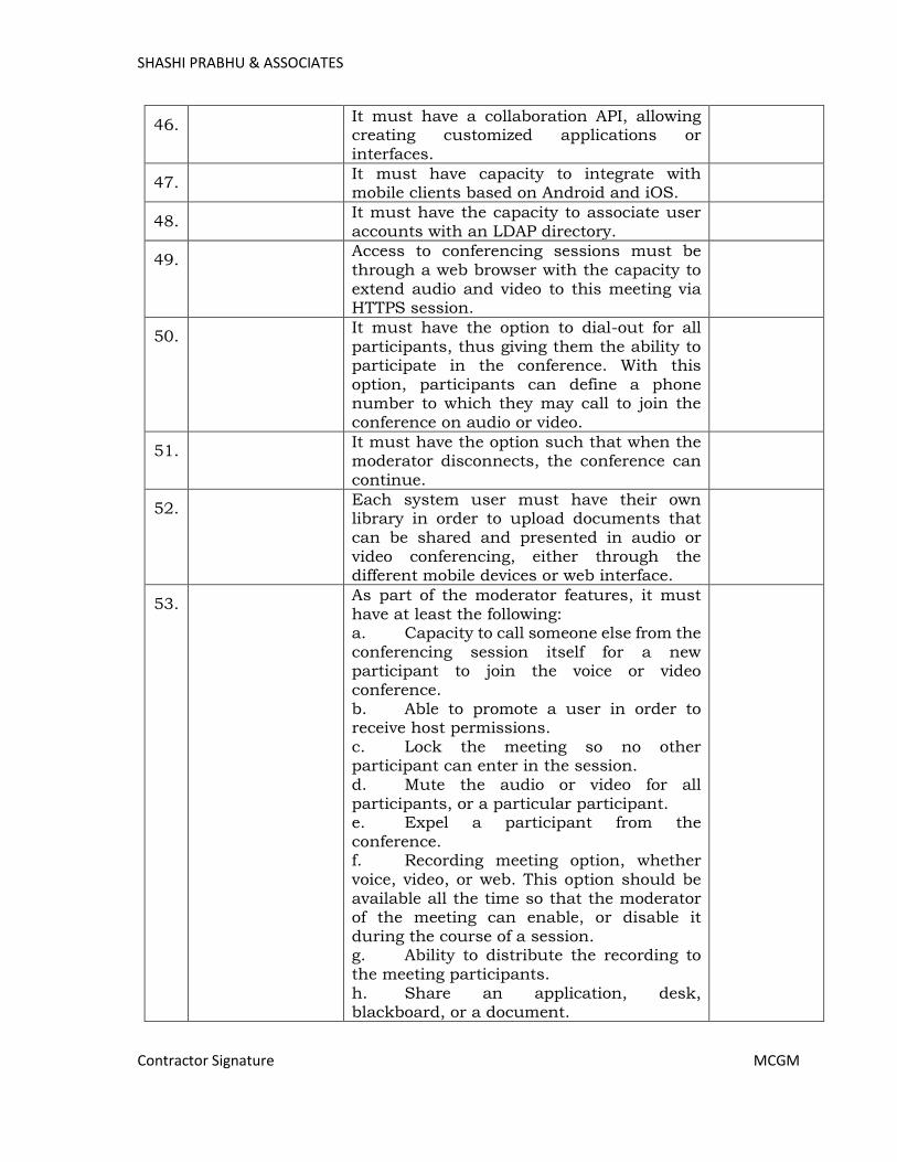
SHASHI PRABHU & ASSOCIATES
Contractor Signature MCGM
46. It must have a collaboration API, allowing
creating customized applications or interfaces.
47. It must have capacity to integrate with
mobile clients based on Android and iOS.
48. It must have the capacity to associate user
accounts with an LDAP directory.
49. Access to conferencing sessions must be
through a web browser with the capacity to extend audio and video to this meeting via HTTPS session.
50. It must have the option to dial-out for all
participants, thus giving them the ability to participate in the conference. With this option, participants can define a phone number to which they may call to join the conference on audio or video.
51. It must have the option such that when the
moderator disconnects, the conference can continue.
52. Each system user must have their own
library in order to upload documents that can be shared and presented in audio or video conferencing, either through the different mobile devices or web interface.
53. As part of the moderator features, it must
have at least the following: a. Capacity to call someone else from the conferencing session itself for a new participant to join the voice or video conference. b. Able to promote a user in order to receive host permissions. c. Lock the meeting so no other participant can enter in the session.
d. Mute the audio or video for all participants, or a particular participant. e. Expel a participant from the conference. f. Recording meeting option, whether voice, video, or web. This option should be available all the time so that the moderator of the meeting can enable, or disable it during the course of a session. g. Ability to distribute the recording to the meeting participants. h. Share an application, desk, blackboard, or a document.
Page 396
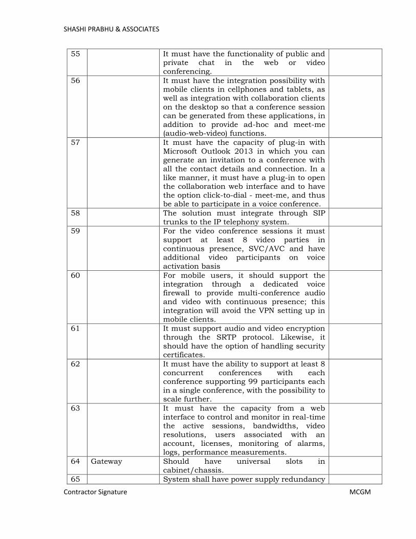
SHASHI PRABHU & ASSOCIATES
Contractor Signature MCGM
55 It must have the functionality of public and private chat in the web or video conferencing.
56 It must have the integration possibility with mobile clients in cellphones and tablets, as well as integration with collaboration clients on the desktop so that a conference session can be generated from these applications, in addition to provide ad-hoc and meet-me (audio-web-video) functions.
57 It must have the capacity of plug-in with Microsoft Outlook 2013 in which you can generate an invitation to a conference with all the contact details and connection. In a like manner, it must have a plug-in to open the collaboration web interface and to have the option click-to-dial - meet-me, and thus be able to participate in a voice conference.
58 The solution must integrate through SIP trunks to the IP telephony system.
59 For the video conference sessions it must support at least 8 video parties in continuous presence, SVC/AVC and have additional video participants on voice activation basis
60 For mobile users, it should support the integration through a dedicated voice firewall to provide multi-conference audio and video with continuous presence; this integration will avoid the VPN setting up in mobile clients.
61 It must support audio and video encryption through the SRTP protocol. Likewise, it should have the option of handling security certificates.
62 It must have the ability to support at least 8 concurrent conferences with each conference supporting 99 participants each in a single conference, with the possibility to scale further.
63 It must have the capacity from a web interface to control and monitor in real-time the active sessions, bandwidths, video resolutions, users associated with an account, licenses, monitoring of alarms, logs, performance measurements.
64 Gateway Should have universal slots in cabinet/chassis.
65 System shall have power supply redundancy
Page 397
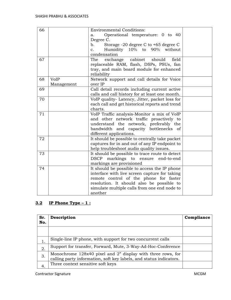
SHASHI PRABHU & ASSOCIATES
Contractor Signature MCGM
66 Environmental Conditions: a. Operational temperature: 0 to 40 Degree C. b. Storage -20 degree C to +65 degree C c. Humidity 10% to 90% without condensation
67 The exchange cabinet should field replaceable RAM, flash, DSPs, PSUs, fan tray, and main board module for enhanced reliability
68 VoIP Management
Network support and call details for Voice over IP
69 Call detail records including current active calls and call history for at least one month.
70 VoIP quality- Latency, Jitter, packet loss for each call and get historical reports and trend charts.
71 VoIP Traffic analysis-Monitor a mix of VoIP and other network traffic proactively to understand the network, preferably the bandwidth and capacity bottlenecks of different applications.
72 It should be possible to centrally take packet captures for in and out of any IP endpoint to help troubleshoot audio quality issues.
73 It should be possible to trace route to detect DSCP markings to ensure end-to-end markings are provisioned
74 It should be possible to access the IP phone interface with live screen capture for taking remote control of the phone for faster resolution. It should also be possible to simulate multiple calls from one end node to another
3.2 IP Phone Type – 1 :
Sr. No.
Description Compliance
1. Single-line IP phone, with support for two concurrent calls
2. Support for transfer, Forward, Mute, 3-Way-Ad-Hoc-Conference
3. Monochrome 128x40 pixel and 2” display with three rows, for calling party information, soft key labels, and status indicators.
4. Three context sensitive soft keys
Page 398

SHASHI PRABHU & ASSOCIATES
Contractor Signature MCGM
5. Fixed hard buttons for Mute, Transfer, Conference, Flash, Voice-Mail, Speaker, Volume, and Directory
6. Directory with up to 500 contacts, and Call History with up to 200 entries
7. G.722 wideband audio, handset and headset (with wideband headsets)
8. Full duplex speakerphone
9. Wall-Mount and Desk-Mount stand.
10. Headset port (RJ9 connector)
11. Message Waiting Indicator
12. Navigation buttons for easy manipulation.
13. Dual Ethernet port operating at 10/100 Mbps speed.
14. TLS and SRTP support
15. Power over Ethernet capable
3.3 Basic CLI Phone:
Sr.
No.
Description Compliance
1. No. of Lines-1
2. Incoming & Outgoing Call memory Storage
3. Flash Programmable
4. LCD Contrast adjustable
5. Min 16 Digit Single Line Display
6. Two Way Speaker supported
1. Network Unified Threat Management (UTM) Firewall
Sr.
No.
Item Description Compliance
1. Should have support to connect upto 1000 con-current
users and 20000000 concurrent connection with
unrestricted user license
2 Should have capability to connect 2,00,000 new
connection per second
3 Should have 8 x 1Gb Ethernet port and 2 x 10 Gb SFP+
Page 399

SHASHI PRABHU & ASSOCIATES
Contractor Signature MCGM
Port
4 Should have Antivirus throughput of 6 Gbps or higher
5 Should have IPS throughput of 8 Gbps or higher
6 Should have 2 Flexi Port Slots
7 Should have VPN throughput of 4Gbps or higher
8 Should have 3 Nos. USB 3.0 and 1 Nos. HDMI Port
9 Should have firewall throughput of 40Gbps or higher
10 Should have option of external power supply
11 Should have integrated inbuilt SSD hard disk for firewall
log storage
12 Should have 3 years OEM support from day 1 to upgrade
firmware, virus database, etc
Page 400

SHASHI PRABHU & ASSOCIATES
Contractor Signature MCGM
4. Fire Alarm System Solution: -
General Scenario Of Considering Fire Alarm Devices:-
In public premise in Hospital Where each and every location should be
cover under Fire Alarm Devices with Automatic (i.e., Detectors) and
Manual Alarm (i.e., MCP) devices.
Fire Alarm Panel should be as per latest UL addition.
Wherever Electric cablling are passing and false ceiling is there, at that
locations above ceiling detectors need to be consider.
Each and every passage should be cover with Above and Below ceiling
detector devices need to be consider.
At every entry and exit point Manual Call Points need to be placed.
In longer passages Manual Call Points need to be placed at appropriate
distance (i.e. not greater than 30 Mtr).
Sound Initiating devices need to be place that no locations are excluded
from the alarming conditions.
In highly critical locations like Operation Theatres Aspiration Smoke
Detection system need to be placed.
Fire Standards for India (NFPA or whichever applicable) and Local Fire
Authority rules need to be strictly followed.
Fire Alarm Panels need to be placed at locations where Administration /
Security / Fire officers can easily access in case of emergency.
Repeater Panels need to be placed from where Fire officer can easily access
the same in case of emergency.
For each and every building, Fire Alarm Panel need to be place individually
and separately to avoid non-working conditions due to damaged
Fire Alarm Panel should be integrated with critical applications like Lifts,
Access Control and at time of emergency trigger should be generated to
them.
Fire Alarm Panel should be integrated with Public Address Systems to
evacuate people from premise in case emergency with priority type zoning.
For higher humidity and dusty locations like pantry, parking, kitchen area
Heat Detectors need to be considered.
For placement of Detector NFPA standard should be followed on strictly
basis. However in ideal conditions distance between two detectors should
not be more than 7 Mtrs.
In public gathering place like waiting area, reception area, etc advance
smoke detectors need to be considered.
Page 401
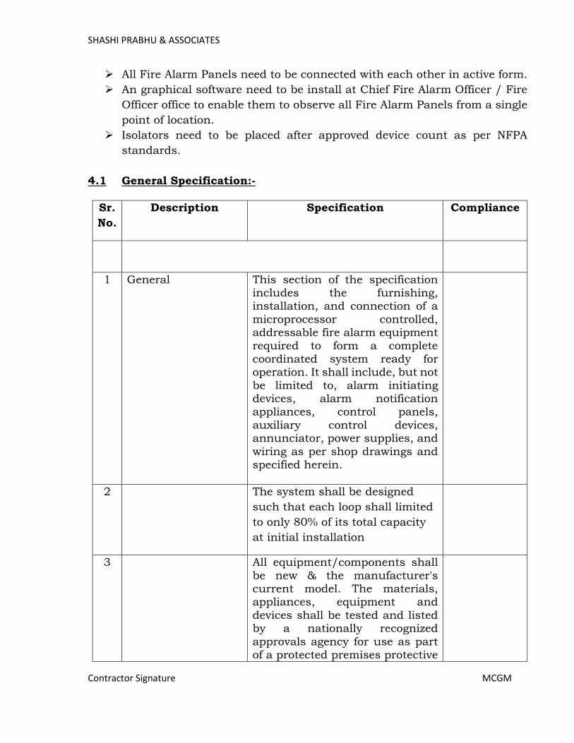
SHASHI PRABHU & ASSOCIATES
Contractor Signature MCGM
All Fire Alarm Panels need to be connected with each other in active form.
An graphical software need to be install at Chief Fire Alarm Officer / Fire
Officer office to enable them to observe all Fire Alarm Panels from a single
point of location.
Isolators need to be placed after approved device count as per NFPA
standards.
4.1 General Specification:-
Sr.
No.
Description Specification Compliance
1 General This section of the specification includes the furnishing, installation, and connection of a
microprocessor controlled, addressable fire alarm equipment
required to form a complete coordinated system ready for operation. It shall include, but not
be limited to, alarm initiating devices, alarm notification appliances, control panels,
auxiliary control devices, annunciator, power supplies, and
wiring as per shop drawings and specified herein.
2 The system shall be designed
such that each loop shall limited
to only 80% of its total capacity
at initial installation
3 All equipment/components shall
be new & the manufacturer's current model. The materials, appliances, equipment and
devices shall be tested and listed by a nationally recognized
approvals agency for use as part of a protected premises protective
Page 402
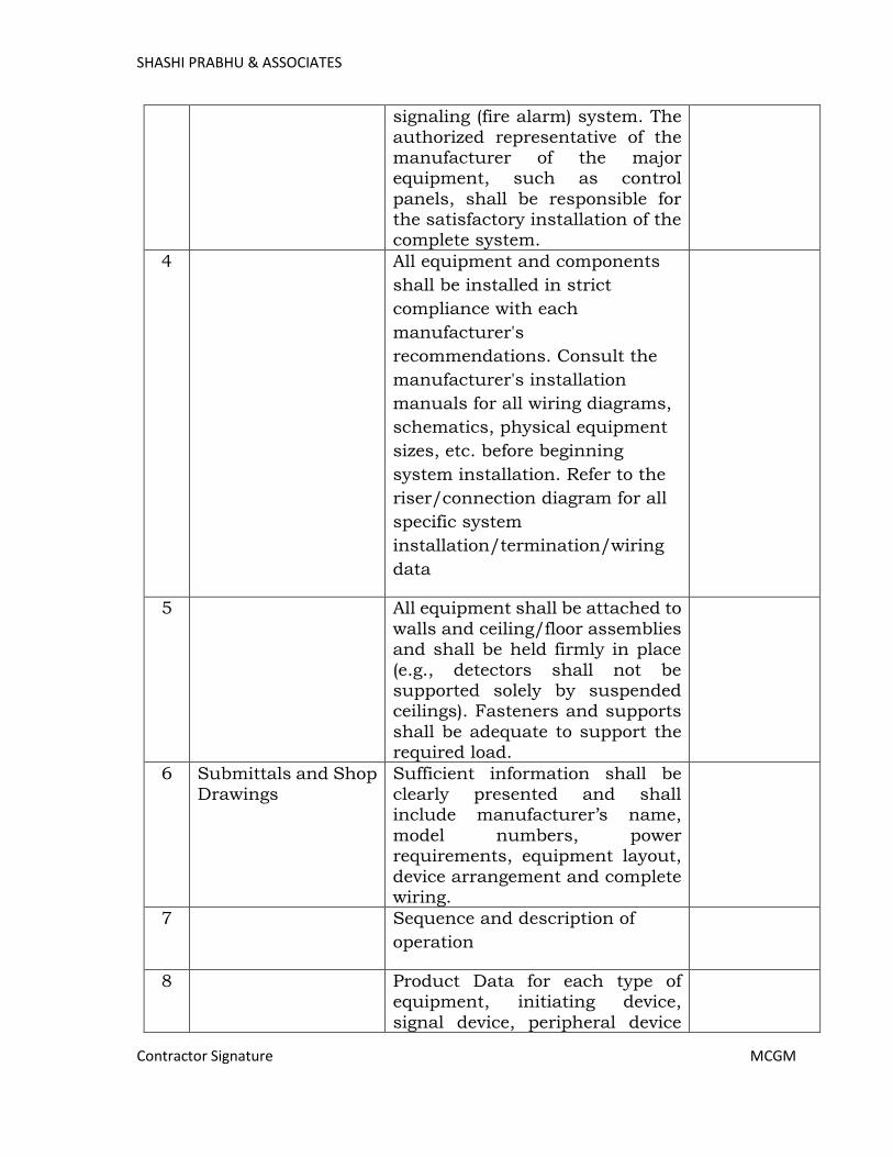
SHASHI PRABHU & ASSOCIATES
Contractor Signature MCGM
signaling (fire alarm) system. The
authorized representative of the manufacturer of the major equipment, such as control
panels, shall be responsible for the satisfactory installation of the complete system.
4 All equipment and components
shall be installed in strict
compliance with each
manufacturer's
recommendations. Consult the
manufacturer's installation
manuals for all wiring diagrams,
schematics, physical equipment
sizes, etc. before beginning
system installation. Refer to the
riser/connection diagram for all
specific system
installation/termination/wiring
data
5 All equipment shall be attached to
walls and ceiling/floor assemblies and shall be held firmly in place
(e.g., detectors shall not be supported solely by suspended ceilings). Fasteners and supports
shall be adequate to support the required load.
6 Submittals and Shop Drawings
Sufficient information shall be clearly presented and shall include manufacturer’s name,
model numbers, power requirements, equipment layout,
device arrangement and complete wiring.
7 Sequence and description of
operation
8 Product Data for each type of equipment, initiating device,
signal device, peripheral device
Page 403
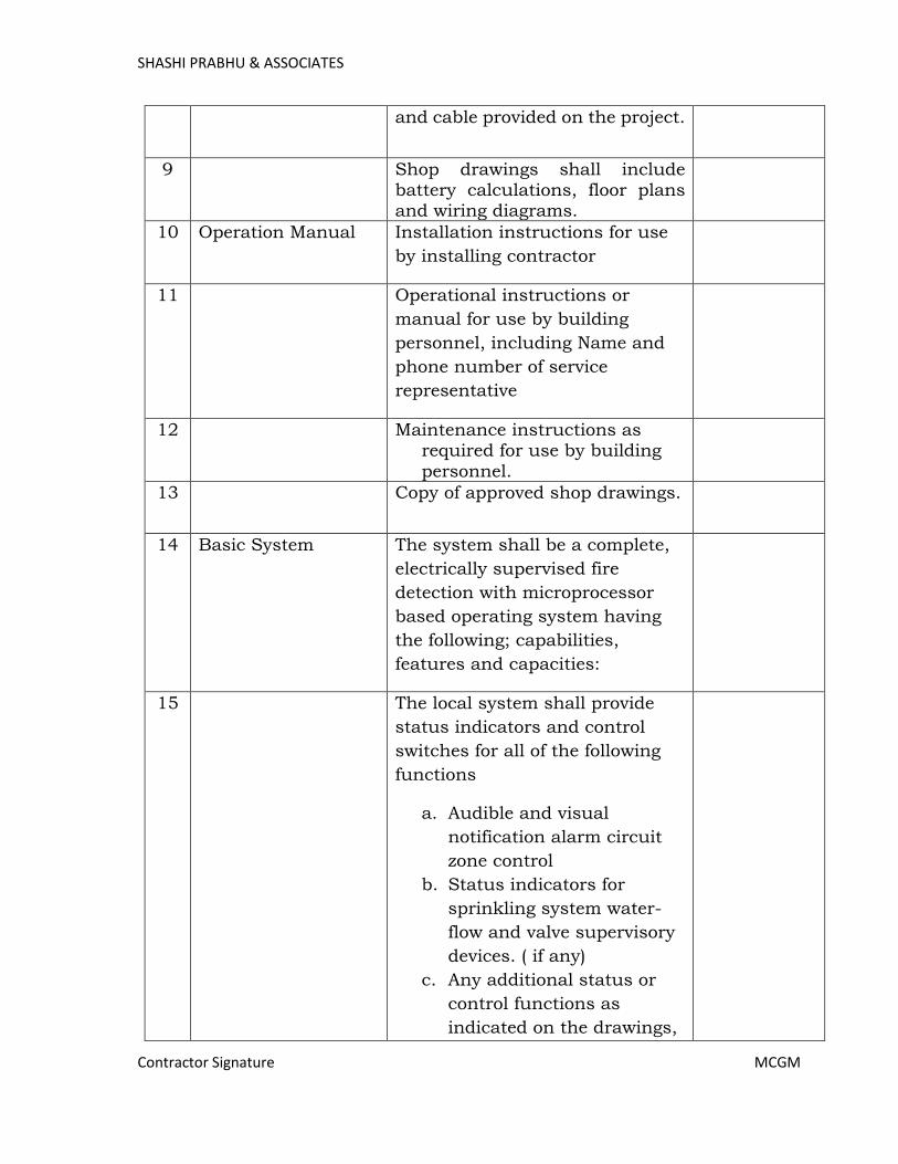
SHASHI PRABHU & ASSOCIATES
Contractor Signature MCGM
and cable provided on the project.
9 Shop drawings shall include battery calculations, floor plans and wiring diagrams.
10 Operation Manual
Installation instructions for use
by installing contractor
11 Operational instructions or
manual for use by building
personnel, including Name and
phone number of service
representative
12 Maintenance instructions as required for use by building
personnel.
13 Copy of approved shop drawings.
14 Basic System The system shall be a complete,
electrically supervised fire
detection with microprocessor
based operating system having
the following; capabilities,
features and capacities:
15 The local system shall provide
status indicators and control
switches for all of the following
functions
a. Audible and visual
notification alarm circuit
zone control
b. Status indicators for
sprinkling system water-
flow and valve supervisory
devices. ( if any)
c. Any additional status or
control functions as
indicated on the drawings,
Page 404

SHASHI PRABHU & ASSOCIATES
Contractor Signature MCGM
including but not limited
to; emergency generator
functions, fire pump
functions, door unlocking
and security with bypass
capabilities
16 Each intelligent addressable
device or conventional zone on
the system shall be displayed at
the fire alarm control panel by a
unique alphanumeric label
identifying its location
17 Specification This specification is intended to
set out in general outline the
minimum requirements and
standards of installation for the
various units of equipment and
works it covers. Provision set out,
or claim made in the successful
tender which are in excess of, or
improved upon the basic
requirements of the specification
shall unless otherwise
determined by the client become
part of the requirements of the
specification whether or not they
are subsequently incorporated in
addenda to the specification
18 The client shall be the sole judge
of what constitute an
improvement upon or exceeds
the requirements of the
specification
19 The specification shall be read in conjunction with the tender
drawings (as per schedule of drawings) and are intended to be
Page 405
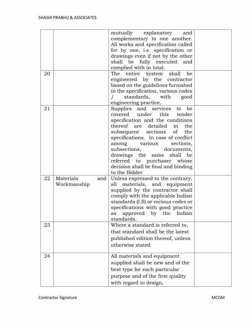
SHASHI PRABHU & ASSOCIATES
Contractor Signature MCGM
mutually explanatory and
complementary to one another. All works and specification called for by one, i.e. specification or
drawings even if not by the other shall be fully executed and complied with in total.
20 The entire system shall be engineered by the contractor
based on the guidelines furnished in the specification, various codes
/ standards, with good engineering practice.
21 Supplies and services to be
covered under this tender specification and the conditions
thereof are detailed in the subsequent sections of the specifications. In case of conflict
among various sections, subsections, documents,
drawings the same shall be referred to purchaser whose decision shall be final and binding
to the Bidder
22 Materials and
Workmanship
Unless expressed to the contrary,
all materials, and equipment supplied by the contractor shall comply with the applicable Indian
standards (I.S) or various codes or specifications with good practice
as approved by the Indian standards.
23 Where a standard is referred to,
that standard shall be the latest
published edition thereof, unless
otherwise stated
24 All materials and equipment
supplied shall be new and of the
best type for each particular
purpose and of the first quality
with regard to design,
Page 406
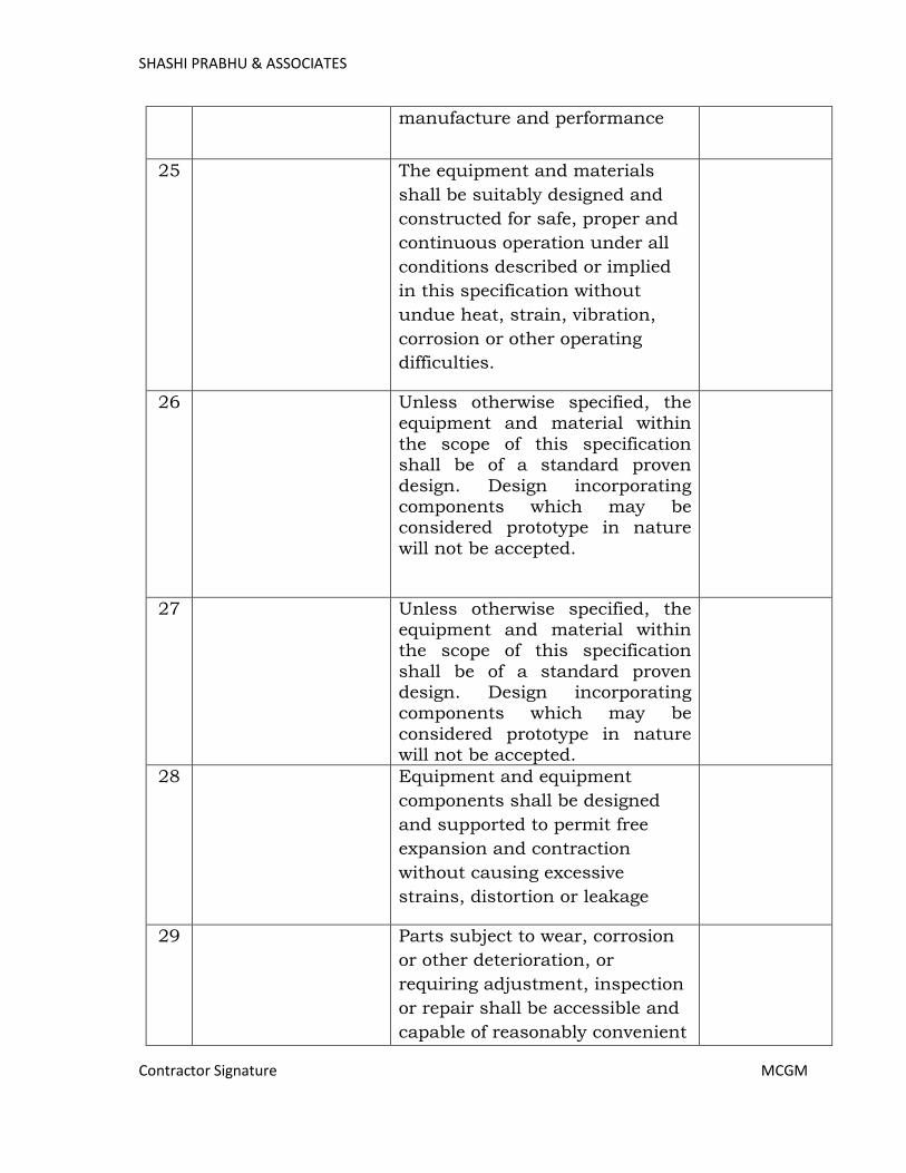
SHASHI PRABHU & ASSOCIATES
Contractor Signature MCGM
manufacture and performance
25 The equipment and materials
shall be suitably designed and
constructed for safe, proper and
continuous operation under all
conditions described or implied
in this specification without
undue heat, strain, vibration,
corrosion or other operating
difficulties.
26 Unless otherwise specified, the equipment and material within
the scope of this specification shall be of a standard proven
design. Design incorporating components which may be considered prototype in nature
will not be accepted.
27 Unless otherwise specified, the equipment and material within the scope of this specification
shall be of a standard proven design. Design incorporating components which may be
considered prototype in nature will not be accepted.
28 Equipment and equipment
components shall be designed
and supported to permit free
expansion and contraction
without causing excessive
strains, distortion or leakage
29 Parts subject to wear, corrosion
or other deterioration, or
requiring adjustment, inspection
or repair shall be accessible and
capable of reasonably convenient
Page 407

SHASHI PRABHU & ASSOCIATES
Contractor Signature MCGM
removal, replacement and repair.
All such parts shall be of suitable
material for keeping maintenance
to a minimum
30 The equipment shall be designed to permit replacement of parts and ease of access during
inspection, maintenance and repair.
31 Approvals The system shall have proper
listing and/or approval from the
internationally recognized UL-
Underwriters Laboratories Inc/
FM Factory Mutual
32 Quality Assurance The manufacturer of the detection components shall have experience in the design and manufacture of similar types of detection systems and who refer to similar installations providing satisfactory service.
33 The name of the manufacturer, part numbers and serial numbers shall appear on all major components.
34 All detection devices, components
and equipment shall be the products of the same manufacturer
35 All devices, components and equipment shall be new,
standard products of the manufacturer’s latest design and suitable to perform the functions
intended
38 Operation &
Maintenance:
The contractor shall train the
employer's operating personnel in the operation and maintenance of
the plants
Page 408

SHASHI PRABHU & ASSOCIATES
Contractor Signature MCGM
39 Scope of work This section of the specification
includes the furnishing, installation, and connection of a microprocessor controlled,
addressable fire alarm equipment required to form a complete coordinated system ready for
operation. It shall include, but not be limited to, alarm initiating
devices, alarm notification appliances, control panels, auxiliary control devices,
annunciator, power supplies, and wiring as per shop drawings and
specified herein.
40 The system shall be designed such that each loop shall limited
to only 80% of its total capacity at initial installation
41 All equipment/components shall be new & the manufacturer's
current model. The materials, appliances, equipment and devices shall be tested and listed
by a nationally recognized approvals agency for use as part of a protected premises protective
signaling (fire alarm) system. The authorized representative of the
manufacturer of the major equipment, such as control panels, shall be responsible for
the satisfactory installation of the complete system.
42 All equipment and components shall be installed in strict
compliance with each manufacturer's
recommendations. Consult the manufacturer's installation manuals for all wiring diagrams,
schematics, physical equipment sizes, etc. before beginning
system installation. Refer to the
Page 409

SHASHI PRABHU & ASSOCIATES
Contractor Signature MCGM
riser/connection diagram for all
specific system installation/termination/wiring data.
All equipment shall be attached to walls and ceiling/floor assemblies and shall be held firmly in place
(e.g., detectors shall not be supported solely by suspended
ceilings). Fasteners and supports shall be adequate to support the required load
43 Operation Manual:
Operation manual shall include: a. Installation instructions for
use by installing contractor b. Operational instructions or
manual for use by building
personnel, including c. Name and phone number of
service representative d. Maintenance instructions
as required for use by
building personnel e. Copy of approved shop
drawings
44 Fire Alarm
Condition:
Sound an audible alarm and
display a custom screen/message defining the
building in alarm and the specific alarm point initiating the alarm in a graphic/LCD 600
character display.
45 Log to the system history archives all activity pertaining to the alarm condition
46 Sound a pre announce tone
followed by a field programmable
digitized custom message as
required for the system. The
visual signals operate in a
similar pattern
Page 410
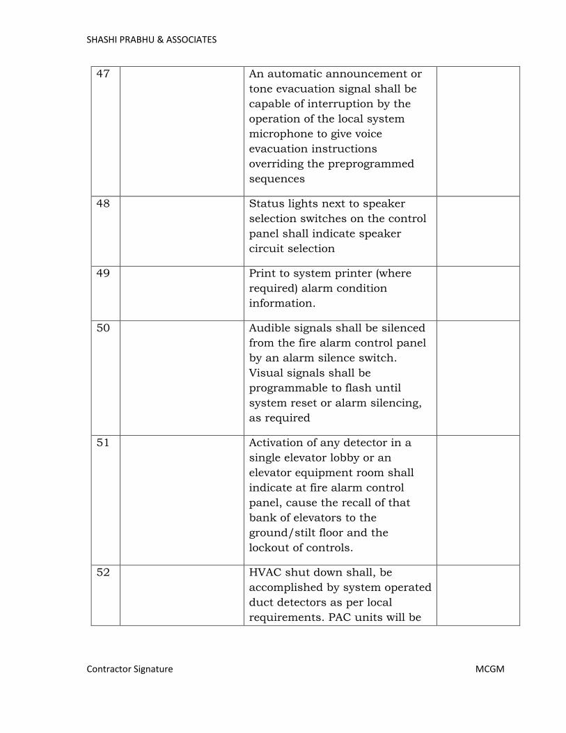
SHASHI PRABHU & ASSOCIATES
Contractor Signature MCGM
47 An automatic announcement or
tone evacuation signal shall be
capable of interruption by the
operation of the local system
microphone to give voice
evacuation instructions
overriding the preprogrammed
sequences
48 Status lights next to speaker
selection switches on the control
panel shall indicate speaker
circuit selection
49 Print to system printer (where
required) alarm condition
information.
50 Audible signals shall be silenced
from the fire alarm control panel
by an alarm silence switch.
Visual signals shall be
programmable to flash until
system reset or alarm silencing,
as required
51 Activation of any detector in a
single elevator lobby or an
elevator equipment room shall
indicate at fire alarm control
panel, cause the recall of that
bank of elevators to the
ground/stilt floor and the
lockout of controls.
52 HVAC shut down shall, be
accomplished by system operated
duct detectors as per local
requirements. PAC units will be
Page 411
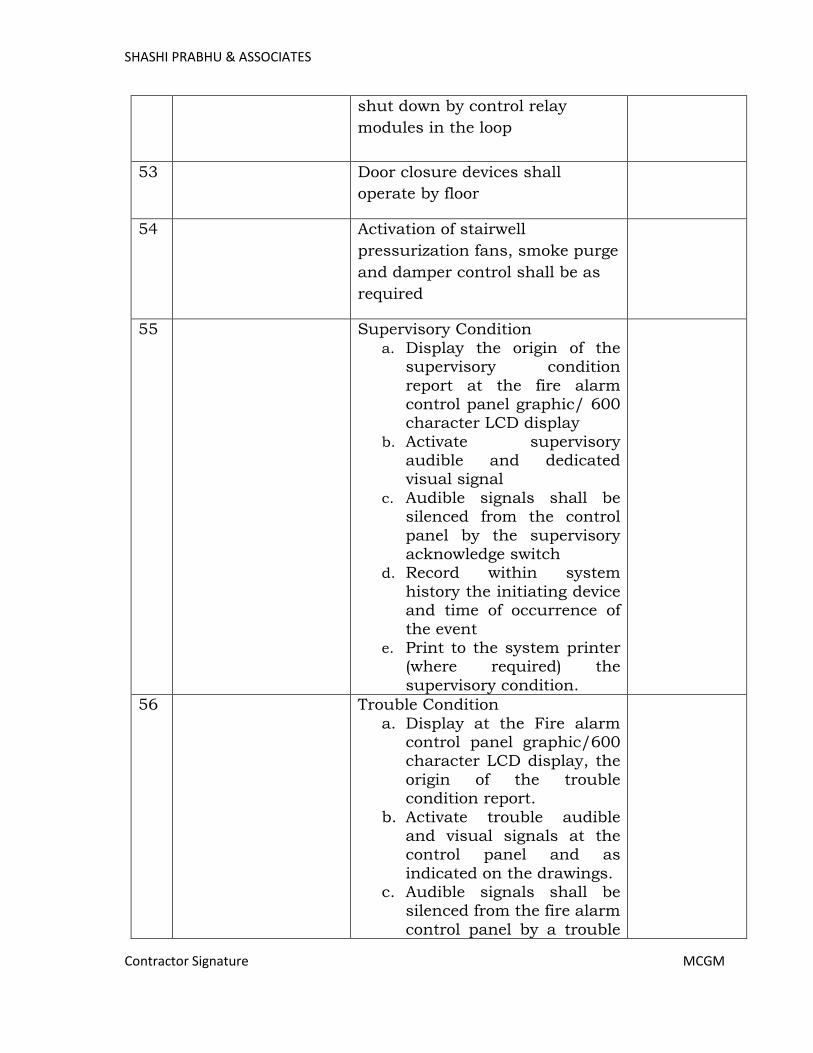
SHASHI PRABHU & ASSOCIATES
Contractor Signature MCGM
shut down by control relay
modules in the loop
53 Door closure devices shall
operate by floor
54 Activation of stairwell
pressurization fans, smoke purge
and damper control shall be as
required
55 Supervisory Condition
a. Display the origin of the supervisory condition
report at the fire alarm control panel graphic/ 600 character LCD display
b. Activate supervisory audible and dedicated visual signal
c. Audible signals shall be silenced from the control
panel by the supervisory acknowledge switch
d. Record within system
history the initiating device and time of occurrence of
the event e. Print to the system printer
(where required) the
supervisory condition.
56 Trouble Condition
a. Display at the Fire alarm control panel graphic/600 character LCD display, the
origin of the trouble condition report.
b. Activate trouble audible and visual signals at the control panel and as
indicated on the drawings. c. Audible signals shall be
silenced from the fire alarm
control panel by a trouble
Page 412
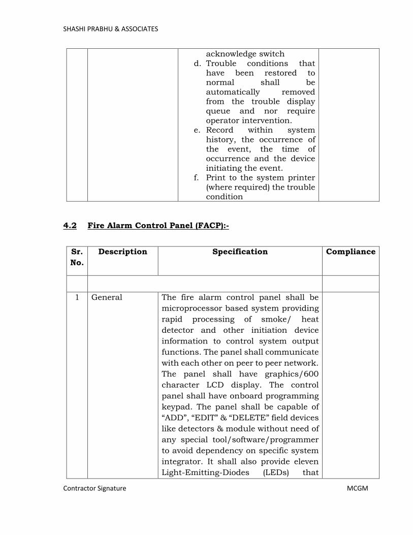
SHASHI PRABHU & ASSOCIATES
Contractor Signature MCGM
acknowledge switch
d. Trouble conditions that have been restored to normal shall be
automatically removed from the trouble display queue and nor require
operator intervention. e. Record within system
history, the occurrence of the event, the time of occurrence and the device
initiating the event. f. Print to the system printer
(where required) the trouble condition
4.2 Fire Alarm Control Panel (FACP):-
Sr.
No.
Description Specification Compliance
1 General The fire alarm control panel shall be
microprocessor based system providing
rapid processing of smoke/ heat
detector and other initiation device
information to control system output
functions. The panel shall communicate
with each other on peer to peer network.
The panel shall have graphics/600
character LCD display. The control
panel shall have onboard programming
keypad. The panel shall be capable of
“ADD”, “EDIT” & “DELETE” field devices
like detectors & module without need of
any special tool/software/programmer
to avoid dependency on specific system
integrator. It shall also provide eleven
Light-Emitting-Diodes (LEDs) that
Page 413
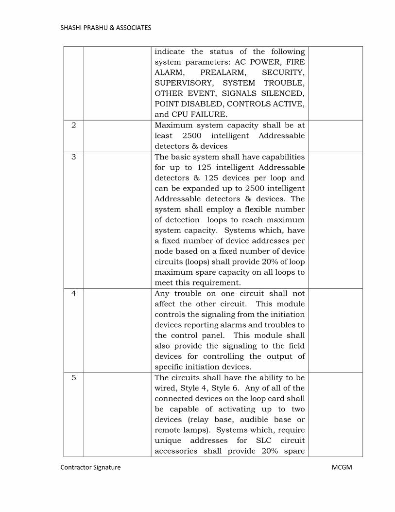
SHASHI PRABHU & ASSOCIATES
Contractor Signature MCGM
indicate the status of the following
system parameters: AC POWER, FIRE
ALARM, PREALARM, SECURITY,
SUPERVISORY, SYSTEM TROUBLE,
OTHER EVENT, SIGNALS SILENCED,
POINT DISABLED, CONTROLS ACTIVE,
and CPU FAILURE.
2 Maximum system capacity shall be at
least 2500 intelligent Addressable
detectors & devices
3 The basic system shall have capabilities
for up to 125 intelligent Addressable
detectors & 125 devices per loop and
can be expanded up to 2500 intelligent
Addressable detectors & devices. The
system shall employ a flexible number
of detection loops to reach maximum
system capacity. Systems which, have
a fixed number of device addresses per
node based on a fixed number of device
circuits (loops) shall provide 20% of loop
maximum spare capacity on all loops to
meet this requirement.
4 Any trouble on one circuit shall not
affect the other circuit. This module
controls the signaling from the initiation
devices reporting alarms and troubles to
the control panel. This module shall
also provide the signaling to the field
devices for controlling the output of
specific initiation devices.
5 The circuits shall have the ability to be
wired, Style 4, Style 6. Any of all of the
connected devices on the loop card shall
be capable of activating up to two
devices (relay base, audible base or
remote lamps). Systems which, require
unique addresses for SLC circuit
accessories shall provide 20% spare
Page 414
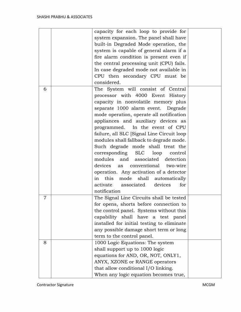
SHASHI PRABHU & ASSOCIATES
Contractor Signature MCGM
capacity for each loop to provide for
system expansion. The panel shall have
built-in Degraded Mode operation, the
system is capable of general alarm if a
fire alarm condition is present even if
the central processing unit (CPU) fails.
In case degraded mode not available in
CPU then secondary CPU must be
considered.
6 The System will consist of Central
processor with 4000 Event History
capacity in nonvolatile memory plus
separate 1000 alarm event. Degrade
mode operation, operate all notification
appliances and auxiliary devices as
programmed. In the event of CPU
failure, all SLC [Signal Line Circuit loop
modules shall fallback to degrade mode.
Such degrade mode shall treat the
corresponding SLC loop control
modules and associated detection
devices as conventional two-wire
operation. Any activation of a detector
in this mode shall automatically
activate associated devices for
notification
7 The Signal Line Circuits shall be tested
for opens, shorts before connection to
the control panel. Systems without this
capability shall have a test panel
installed for initial testing to eliminate
any possible damage short term or long
term to the control panel.
8 1000 Logic Equations: The system
shall support up to 1000 logic
equations for AND, OR, NOT, ONLY1,
ANYX, XZONE or RANGE operators
that allow conditional I/O linking.
When any logic equation becomes true,
Page 415
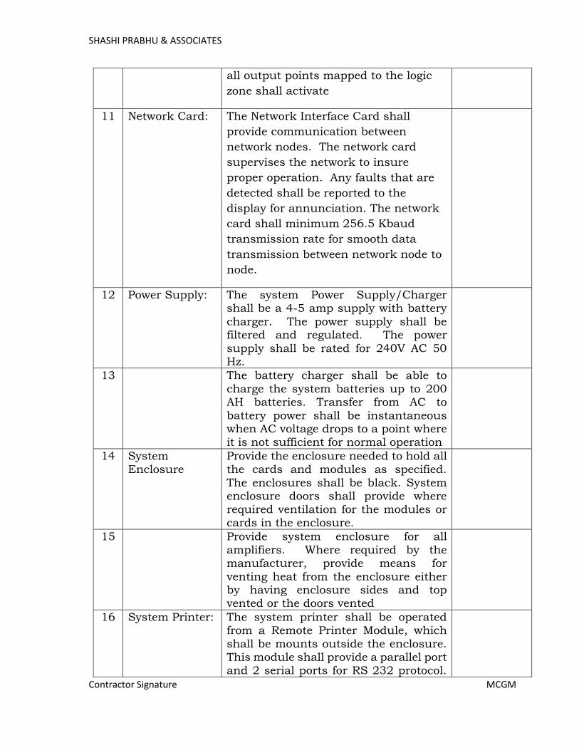
SHASHI PRABHU & ASSOCIATES
Contractor Signature MCGM
all output points mapped to the logic
zone shall activate
11 Network Card: The Network Interface Card shall
provide communication between
network nodes. The network card
supervises the network to insure
proper operation. Any faults that are
detected shall be reported to the
display for annunciation. The network
card shall minimum 256.5 Kbaud
transmission rate for smooth data
transmission between network node to
node.
12 Power Supply:
The system Power Supply/Charger shall be a 4-5 amp supply with battery
charger. The power supply shall be filtered and regulated. The power
supply shall be rated for 240V AC 50 Hz.
13 The battery charger shall be able to
charge the system batteries up to 200 AH batteries. Transfer from AC to
battery power shall be instantaneous when AC voltage drops to a point where it is not sufficient for normal operation
14 System Enclosure
Provide the enclosure needed to hold all the cards and modules as specified.
The enclosures shall be black. System enclosure doors shall provide where required ventilation for the modules or
cards in the enclosure.
15 Provide system enclosure for all
amplifiers. Where required by the manufacturer, provide means for
venting heat from the enclosure either by having enclosure sides and top vented or the doors vented
16 System Printer:
The system printer shall be operated from a Remote Printer Module, which
shall be mounts outside the enclosure. This module shall provide a parallel port and 2 serial ports for RS 232 protocol.
Page 416
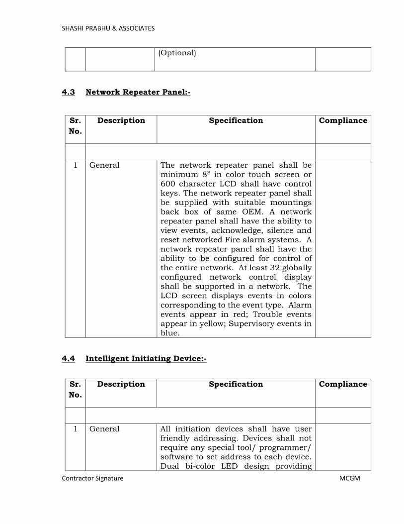
SHASHI PRABHU & ASSOCIATES
Contractor Signature MCGM
(Optional)
4.3 Network Repeater Panel:-
Sr.
No.
Description Specification Compliance
1 General The network repeater panel shall be minimum 8” in color touch screen or
600 character LCD shall have control keys. The network repeater panel shall
be supplied with suitable mountings back box of same OEM. A network repeater panel shall have the ability to
view events, acknowledge, silence and reset networked Fire alarm systems. A network repeater panel shall have the
ability to be configured for control of the entire network. At least 32 globally
configured network control display shall be supported in a network. The LCD screen displays events in colors
corresponding to the event type. Alarm events appear in red; Trouble events appear in yellow; Supervisory events in
blue.
4.4 Intelligent Initiating Device:-
Sr.
No.
Description Specification Compliance
1 General All initiation devices shall have user friendly addressing. Devices shall not
require any special tool/ programmer/ software to set address to each device. Dual bi-color LED design providing
Page 417
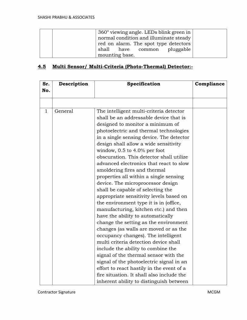
SHASHI PRABHU & ASSOCIATES
Contractor Signature MCGM
360° viewing angle. LEDs blink green in
normal condition and illuminate steady red on alarm. The spot type detectors shall have common pluggable
mounting base.
4.5 Multi Sensor/ Multi-Criteria (Photo-Thermal) Detector:-
Sr.
No.
Description Specification Compliance
1 General The intelligent multi-criteria detector
shall be an addressable device that is
designed to monitor a minimum of
photoelectric and thermal technologies
in a single sensing device. The detector
design shall allow a wide sensitivity
window, 0.5 to 4.0% per foot
obscuration. This detector shall utilize
advanced electronics that react to slow
smoldering fires and thermal
properties all within a single sensing
device. The microprocessor design
shall be capable of selecting the
appropriate sensitivity levels based on
the environment type it is in (office,
manufacturing, kitchen etc.) and then
have the ability to automatically
change the setting as the environment
changes (as walls are moved or as the
occupancy changes). The intelligent
multi criteria detection device shall
include the ability to combine the
signal of the thermal sensor with the
signal of the photoelectric signal in an
effort to react hastily in the event of a
fire situation. It shall also include the
inherent ability to distinguish between
Page 418
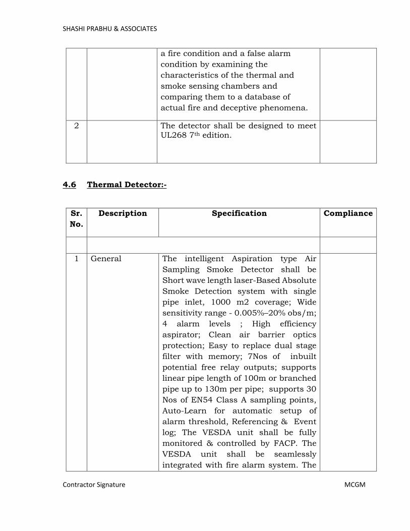
SHASHI PRABHU & ASSOCIATES
Contractor Signature MCGM
a fire condition and a false alarm
condition by examining the
characteristics of the thermal and
smoke sensing chambers and
comparing them to a database of
actual fire and deceptive phenomena.
2 The detector shall be designed to meet UL268 7th edition.
4.6 Thermal Detector:-
Sr.
No.
Description Specification Compliance
1 General The intelligent Aspiration type Air
Sampling Smoke Detector shall be
Short wave length laser-Based Absolute
Smoke Detection system with single
pipe inlet, 1000 m2 coverage; Wide
sensitivity range - 0.005%–20% obs/m;
4 alarm levels ; High efficiency
aspirator; Clean air barrier optics
protection; Easy to replace dual stage
filter with memory; 7Nos of inbuilt
potential free relay outputs; supports
linear pipe length of 100m or branched
pipe up to 130m per pipe; supports 30
Nos of EN54 Class A sampling points,
Auto-Learn for automatic setup of
alarm threshold, Referencing & Event
log; The VESDA unit shall be fully
monitored & controlled by FACP. The
VESDA unit shall be seamlessly
integrated with fire alarm system. The
Page 419
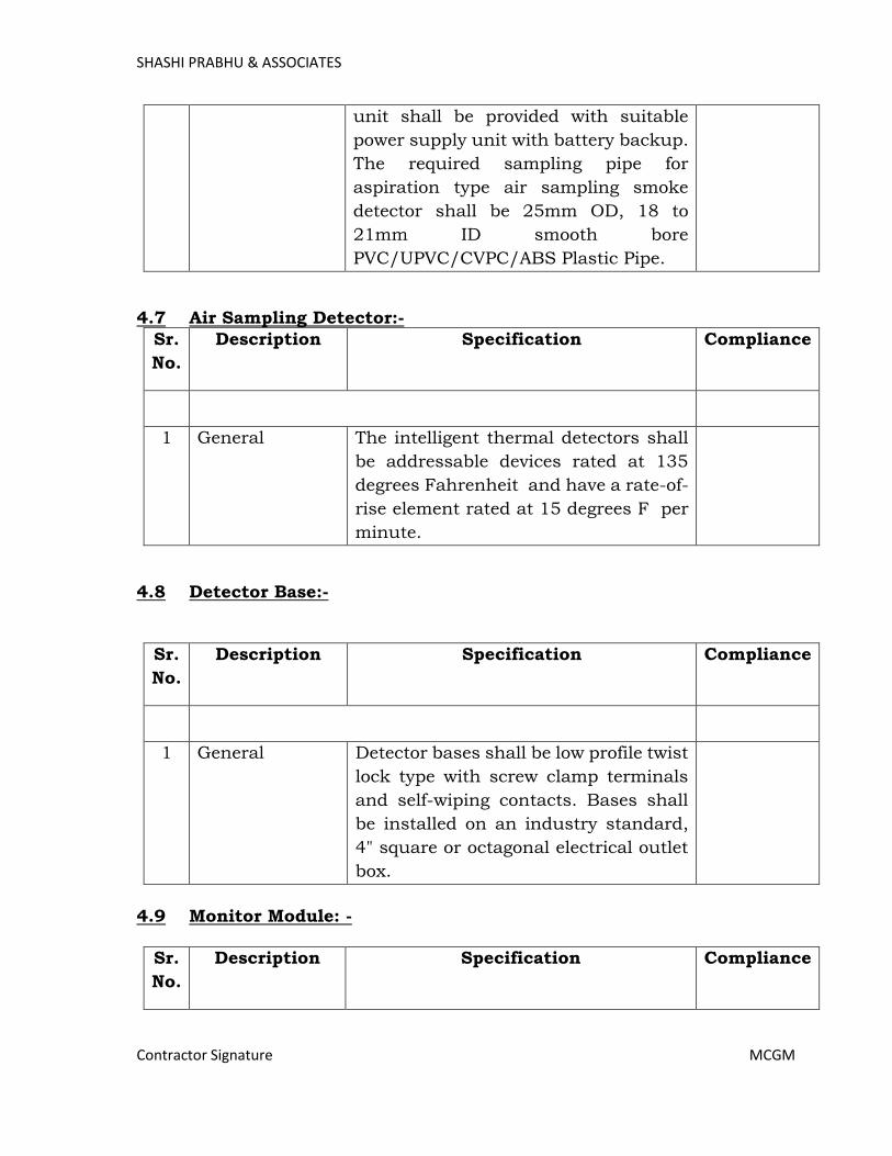
SHASHI PRABHU & ASSOCIATES
Contractor Signature MCGM
unit shall be provided with suitable
power supply unit with battery backup.
The required sampling pipe for
aspiration type air sampling smoke
detector shall be 25mm OD, 18 to
21mm ID smooth bore
PVC/UPVC/CVPC/ABS Plastic Pipe.
4.7 Air Sampling Detector:-
Sr.
No.
Description Specification Compliance
1 General The intelligent thermal detectors shall
be addressable devices rated at 135
degrees Fahrenheit and have a rate-of-
rise element rated at 15 degrees F per
minute.
4.8 Detector Base:-
Sr.
No.
Description Specification Compliance
1 General Detector bases shall be low profile twist
lock type with screw clamp terminals
and self-wiping contacts. Bases shall
be installed on an industry standard,
4" square or octagonal electrical outlet
box.
4.9 Monitor Module: -
Sr.
No.
Description Specification Compliance
Page 420

SHASHI PRABHU & ASSOCIATES
Contractor Signature MCGM
1 General Addressable monitor modules shall be
provided to connect & monitor any
N.O. dry contact device.
2 The device shall have an LED which
shall blink in normal state & get
steady on activation to monitor the
health status of the device. Module
shall be supplied with mounting plate
from OEM for ease of installation &
maintenance.
4.10 Addressable Control/Relay Module:-
Sr.
No.
Description Specification Compliance
1 General The Addressable control modules shall
provide supervised NAC output rated
at 24V DC, 1A to connect sounder,
sounder cum strobes. The device shall
have an LED which shall blink in
normal state & get steady on
activation to monitor the health status
of the device. Module shall be supplied
with mounting plate from OEM for
ease of installation & maintenance.
2 The Addressable relay modules shall
provide DPDT dry contact rated at 24V
DC, 1A for AHU tripping, Access
Control integration etc. The device
shall have an LED which shall blink in
normal state & get steady on
activation to monitor the health status
Page 421
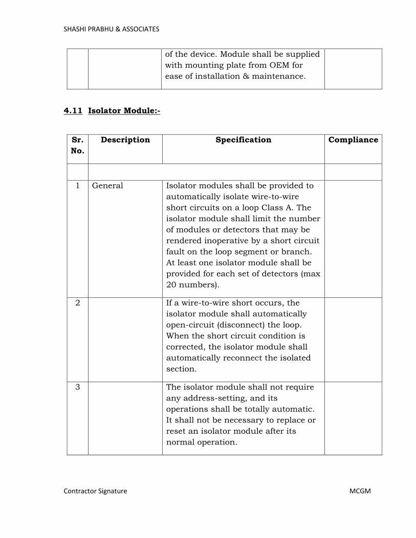
SHASHI PRABHU & ASSOCIATES
Contractor Signature MCGM
of the device. Module shall be supplied
with mounting plate from OEM for
ease of installation & maintenance.
4.11 Isolator Module:-
Sr.
No.
Description Specification Compliance
1 General Isolator modules shall be provided to
automatically isolate wire-to-wire
short circuits on a loop Class A. The
isolator module shall limit the number
of modules or detectors that may be
rendered inoperative by a short circuit
fault on the loop segment or branch.
At least one isolator module shall be
provided for each set of detectors (max
20 numbers).
2 If a wire-to-wire short occurs, the
isolator module shall automatically
open-circuit (disconnect) the loop.
When the short circuit condition is
corrected, the isolator module shall
automatically reconnect the isolated
section.
3 The isolator module shall not require
any address-setting, and its
operations shall be totally automatic.
It shall not be necessary to replace or
reset an isolator module after its
normal operation.
Page 422
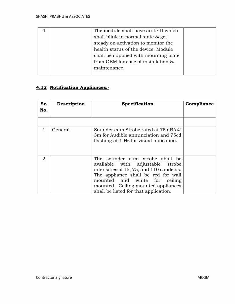
SHASHI PRABHU & ASSOCIATES
Contractor Signature MCGM
4 The module shall have an LED which
shall blink in normal state & get
steady on activation to monitor the
health status of the device. Module
shall be supplied with mounting plate
from OEM for ease of installation &
maintenance.
4.12 Notification Appliances:-
Sr.
No.
Description Specification Compliance
1 General Sounder cum Strobe rated at 75 dBA @ 3m for Audible annunciation and 75cd
flashing at 1 Hz for visual indication.
2 The sounder cum strobe shall be available with adjustable strobe
intensities of 15, 75, and 110 candelas. The appliance shall be red for wall mounted and white for ceiling
mounted. Ceiling mounted appliances shall be listed for that application.
Page 423

SHASHI PRABHU & ASSOCIATES
Contractor Signature MCGM
5. Public Addressing System:-
General Scenario Of Considering Public Address Points:-
Public Address system should be cover in all the passages of the buildings,
internal roads of campus.
Wherever false ceiling is available at that locations ceiling speakers need
to be consider and except that locations wall mount cabinet speaker need
to be consider.
Speaker’s intensity and placement should be like that it should not disturb
the patients or study of doctors. However no area in Hospital and College
should be out of reach as it will also work as Emergency Evacuations
System.
Zoning should be done in such a way that common passage, public
gathering place (i.e. reception, case register area, waiting area, etc) should
be in common zone and wards, rooms, offices in a common zone.
Building wise common locations should be identify to place zone based
microphone.
5.1 Network Controller:
Sr.
No.
Description Specification Compliance
1 System
Features
The network controller shall have 4
analogue audio inputs. The controller
shall be digital & IP based.
2 There shall be 8 control inputs, which
are freely programmable. These can be
programmed for actions to be done in
the system and assigned priorities
3 The network controller shall have 4
analogue audio line outputs.
4 The audio line outputs shall have a
monitoring signal.
5 The control output shall be freely programmable for faults and calls.
6 The network controller shall connected with another IP based controller or IP
Page 424
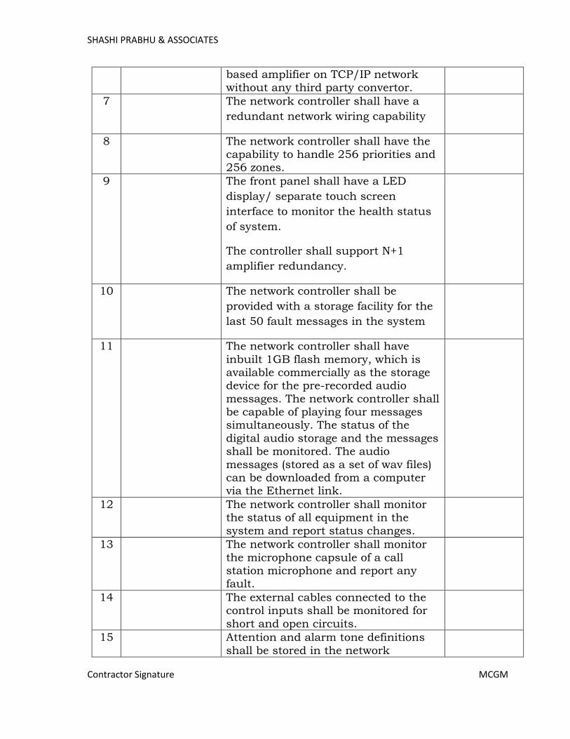
SHASHI PRABHU & ASSOCIATES
Contractor Signature MCGM
based amplifier on TCP/IP network
without any third party convertor.
7 The network controller shall have a
redundant network wiring capability
8 The network controller shall have the capability to handle 256 priorities and 256 zones.
9 The front panel shall have a LED
display/ separate touch screen
interface to monitor the health status
of system.
The controller shall support N+1
amplifier redundancy.
10 The network controller shall be
provided with a storage facility for the
last 50 fault messages in the system
11 The network controller shall have
inbuilt 1GB flash memory, which is available commercially as the storage device for the pre-recorded audio
messages. The network controller shall be capable of playing four messages simultaneously. The status of the
digital audio storage and the messages shall be monitored. The audio
messages (stored as a set of wav files) can be downloaded from a computer via the Ethernet link.
12 The network controller shall monitor the status of all equipment in the
system and report status changes.
13 The network controller shall monitor
the microphone capsule of a call station microphone and report any fault.
14 The external cables connected to the control inputs shall be monitored for
short and open circuits.
15 Attention and alarm tone definitions
shall be stored in the network
Page 425
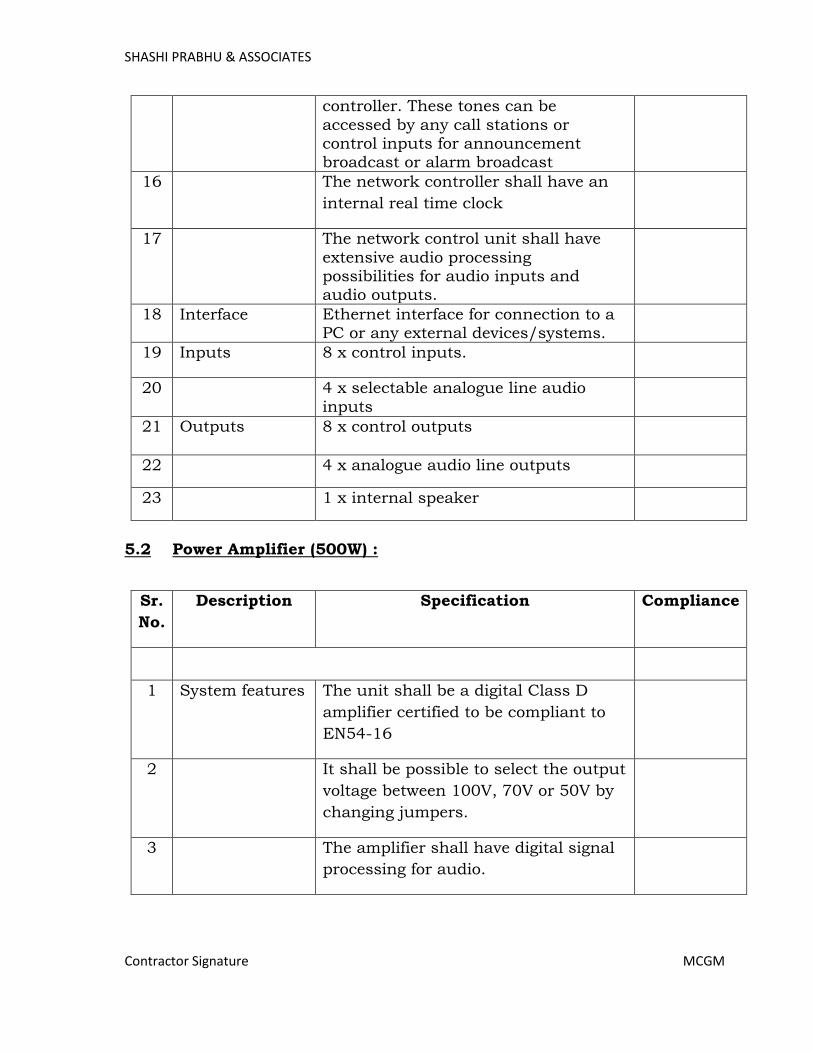
SHASHI PRABHU & ASSOCIATES
Contractor Signature MCGM
controller. These tones can be
accessed by any call stations or control inputs for announcement broadcast or alarm broadcast
16 The network controller shall have an
internal real time clock
17 The network control unit shall have
extensive audio processing possibilities for audio inputs and audio outputs.
18 Interface Ethernet interface for connection to a PC or any external devices/systems.
19 Inputs 8 x control inputs.
20 4 x selectable analogue line audio
inputs
21 Outputs 8 x control outputs
22 4 x analogue audio line outputs
23 1 x internal speaker
5.2 Power Amplifier (500W) :
Sr.
No.
Description Specification Compliance
1 System features The unit shall be a digital Class D
amplifier certified to be compliant to
EN54-16
2 It shall be possible to select the output
voltage between 100V, 70V or 50V by
changing jumpers.
3 The amplifier shall have digital signal
processing for audio.
Page 426
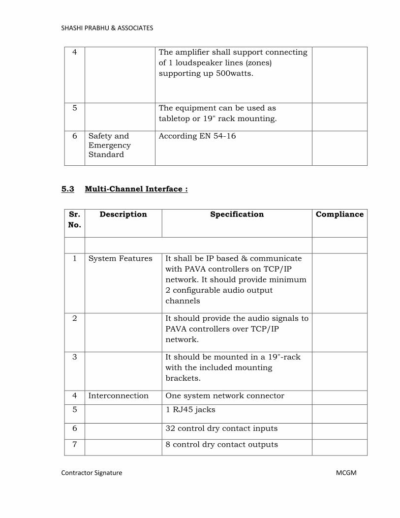
SHASHI PRABHU & ASSOCIATES
Contractor Signature MCGM
4 The amplifier shall support connecting
of 1 loudspeaker lines (zones)
supporting up 500watts.
5 The equipment can be used as
tabletop or 19" rack mounting.
6 Safety and
Emergency
Standard
According EN 54-16
5.3 Multi-Channel Interface :
Sr.
No.
Description Specification Compliance
1 System Features It shall be IP based & communicate
with PAVA controllers on TCP/IP
network. It should provide minimum
2 configurable audio output
channels
2 It should provide the audio signals to
PAVA controllers over TCP/IP
network.
3 It should be mounted in a 19"-rack
with the included mounting
brackets.
4 Interconnection One system network connector
5 1 RJ45 jacks
6 32 control dry contact inputs
7 8 control dry contact outputs
Page 427

SHASHI PRABHU & ASSOCIATES
Contractor Signature MCGM
8 Mains power
supply
Mains socket Voltage 230 VAC
±10%, 50/60 Hz
9 Performance Frequency response 60 Hz to 16 kHz
S/N >85 dB (without pilot tone)
10 Control inputs Connectors Removable screw
terminals Operation Closing contact (with
supervision)
11 Control outputs Connectors Removable screw terminals Operation Change over
contact (SPDT) voltage free relay Rating 24 V, 1 A Physical
characteristics
12 Safety and Emergency
Standard
EN54-16
5.4 Digital Call Station :
Sr.
No.
Description Specification Compliance
1 System features The call station shall be IP based
touch screen with 7" TFT LCD screen. The call station shall support up to 256 zones.
2 Analogue-to-digital audio conversion shall be performed at the call station.
3 The call station shall also have a digital signal processor, which can be
used for audio processing.
4 The inbuilt monitoring loudspeaker
shall be on when that particular call station activates a chime or pre-recorded message and will be switched
off when its own live audio channel is open.
5 System shall be in free topology to connect call station with any equipment Controller or with a call
Page 428

SHASHI PRABHU & ASSOCIATES
Contractor Signature MCGM
station over TCP/IP network.
6 The call station shall have a gooseneck microphone to transmit speech over
the network and a press-to-talk key
7 Interfaces 1 x system network connection
8 Safety and
Emergency
Standard
EN54-16
5.5 Digital Call Station Expansion Keypad :
Sr.
No.
Description Specification Compliance
1 System features The digital call station extension keypad should have 8 keys
2 Control system functions: recall of selection, live speech call, cancel selection, BGM off, BGM volume
control, programmable key for any action.
3 Select resources: BGM selection, pre-recorded message selection, attention and alarm tone selection.
4 Zone selection, system control output selection
5 Each key at the call station keypad shall have 2 color LEDs.
6 The call station keypad shall be provided with in and out connections for serial data and power supply.
7 The keys are to be provided with a label slot for indicating the name of
the action assigned to that particular key.
8 The power supply for the call station keypad shall be provided from the call station basic unit.
Page 429

SHASHI PRABHU & ASSOCIATES
Contractor Signature MCGM
9 The call station keypad key can be
programmed for momentary or toggle operation.
10 Interfaces Serial data and power supply
interfaces for call station keypad units/call station basic.
11 Indications and
controls
The call station keypad has one 2-color LED per key for providing status
indication.
12 Remote Call
Station
It Should Connects to call station
interface via CAT-5 /CAT-6 cable.
13 Up to 1 km from digital public address optical network.
14 Uses standard keypads for extension.
15 Built-in limiter.
16 Powered via CAT-5 and/or local power supply and complete supervision.
17 Safety and
Emergency
Standard
The unit shall be certified to be compliant to IEC60849 and compliant to other relevant local standards
5.6 Volume Controller :
Sr.
No.
Description Specification Compliance
1 System features Volume Controllers have the
following variants available: 6W,
30W
2 It should support minimum 3 Volume
level control
3 It should applicable 3-wire & 4-wire
system
Page 430
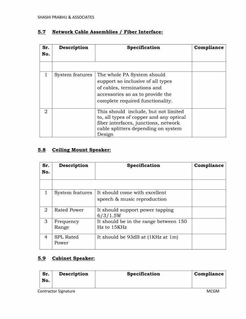
SHASHI PRABHU & ASSOCIATES
Contractor Signature MCGM
5.7 Network Cable Assemblies / Fiber Interface:
Sr.
No.
Description Specification Compliance
1 System features The whole PA System should
support so inclusive of all types
of cables, terminations and
accessories so as to provide the
complete required functionality.
2 This should include, but not limited to, all types of copper and any optical
fiber interfaces, junctions, network cable splitters depending on system
Design
5.8 Ceiling Mount Speaker:
Sr.
No.
Description Specification Compliance
1 System features It should come with excellent
speech & music reproduction
2 Rated Power It should support power tapping 6/3/1.5W
3 Frequency
Range
It should be in the range between 150 Hz to 15KHz
4 SPL Rated
Power
It should be 93dB at (1KHz at 1m)
5.9 Cabinet Speaker:
Sr.
No.
Description Specification Compliance
Page 431
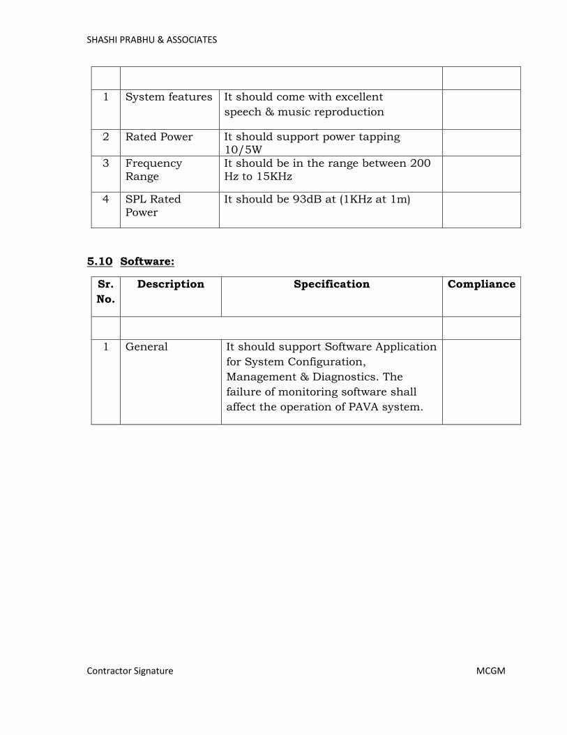
SHASHI PRABHU & ASSOCIATES
Contractor Signature MCGM
1 System features It should come with excellent
speech & music reproduction
2 Rated Power It should support power tapping 10/5W
3 Frequency
Range
It should be in the range between 200
Hz to 15KHz
4 SPL Rated
Power
It should be 93dB at (1KHz at 1m)
5.10 Software:
Sr.
No.
Description Specification Compliance
1 General It should support Software Application
for System Configuration,
Management & Diagnostics. The
failure of monitoring software shall
affect the operation of PAVA system.
Page 432
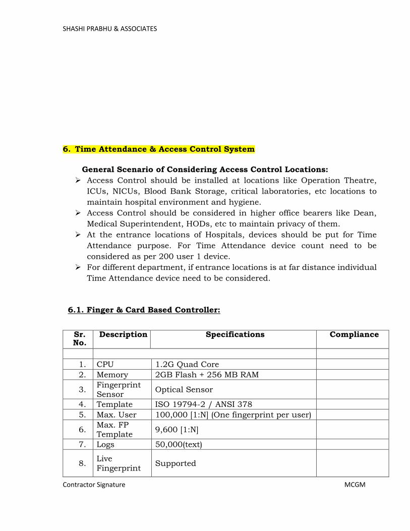
SHASHI PRABHU & ASSOCIATES
Contractor Signature MCGM
6. Time Attendance & Access Control System
General Scenario of Considering Access Control Locations:
Access Control should be installed at locations like Operation Theatre,
ICUs, NICUs, Blood Bank Storage, critical laboratories, etc locations to
maintain hospital environment and hygiene.
Access Control should be considered in higher office bearers like Dean,
Medical Superintendent, HODs, etc to maintain privacy of them.
At the entrance locations of Hospitals, devices should be put for Time
Attendance purpose. For Time Attendance device count need to be
considered as per 200 user 1 device.
For different department, if entrance locations is at far distance individual
Time Attendance device need to be considered.
6.1. Finger & Card Based Controller:
Sr. No.
Description Specifications Compliance
1. CPU 1.2G Quad Core
2. Memory 2GB Flash + 256 MB RAM
3. Fingerprint Sensor
Optical Sensor
4. Template ISO 19794-2 / ANSI 378
5. Max. User 100,000 [1:N] (One fingerprint per user)
6. Max. FP Template
9,600 [1:N]
7. Logs 50,000(text)
8. Live
Fingerprint Supported
Page 433
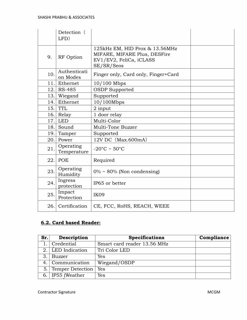
SHASHI PRABHU & ASSOCIATES
Contractor Signature MCGM
Detection(
LFD)
9. RF Option
125kHz EM, HID Prox & 13.56MHz MIFARE, MIFARE Plus, DESFire EV1/EV2, FeliCa, iCLASS
SE/SR/Seos
10. Authenticati
on Modes Finger only, Card only, Finger+Card
11. Ethernet 10/100 Mbps
12. RS-485 OSDP Supported
13. Wiegand Supported
14. Ethernet 10/100Mbps
15. TTL 2 input
16. Relay 1 door relay
17. LED Multi-Color
18. Sound Multi-Tone Buzzer
19. Tamper Supported
20. Power 12V DC(Max.600mA)
21. Operating Temperature
-20°C ~ 50°C
22. POE Required
23. Operating Humidity
0% ~ 80% (Non condensing)
24. Ingress protection
IP65 or better
25. Impact Protection
IK09
26. Certification CE, FCC, RoHS, REACH, WEEE
6.2. Card based Reader:
Sr. No.
Description Specifications Compliance
1. 1 Credential Support
Smart card reader 13.56 MHz
2. 2 LED Indication Tri Color LED
3. 3 Buzzer Yes
4. 4 Communication Wiegand/OSDP
5. 5 Temper Detection Yes
6. 6 IP55 (Weather Proof)
Yes
Page 434
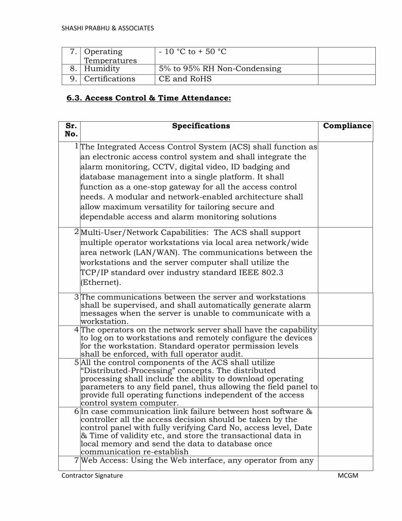
SHASHI PRABHU & ASSOCIATES
Contractor Signature MCGM
7. 7 Operating Temperatures
- 10 °C to + 50 °C
8. 8 Humidity 5% to 95% RH Non-Condensing
9. 9 Certifications CE and RoHS
6.3. Access Control & Time Attendance:
Sr. No.
Specifications Compliance
1 The Integrated Access Control System (ACS) shall function as
an electronic access control system and shall integrate the
alarm monitoring, CCTV, digital video, ID badging and
database management into a single platform. It shall
function as a one-stop gateway for all the access control
needs. A modular and network-enabled architecture shall
allow maximum versatility for tailoring secure and
dependable access and alarm monitoring solutions
2 Multi-User/Network Capabilities: The ACS shall support
multiple operator workstations via local area network/wide
area network (LAN/WAN). The communications between the
workstations and the server computer shall utilize the
TCP/IP standard over industry standard IEEE 802.3
(Ethernet).
3 The communications between the server and workstations shall be supervised, and shall automatically generate alarm messages when the server is unable to communicate with a workstation.
4 The operators on the network server shall have the capability to log on to workstations and remotely configure the devices for the workstation. Standard operator permission levels shall be enforced, with full operator audit.
5 All the control components of the ACS shall utilize “Distributed-Processing” concepts. The distributed processing shall include the ability to download operating parameters to any field panel, thus allowing the field panel to provide full operating functions independent of the access control system computer.
6 In case communication link failure between host software & controller all the access decision should be taken by the control panel with fully verifying Card No, access level, Date & Time of validity etc, and store the transactional data in local memory and send the data to database once communication re-establish
7 Web Access: Using the Web interface, any operator from any
Page 435
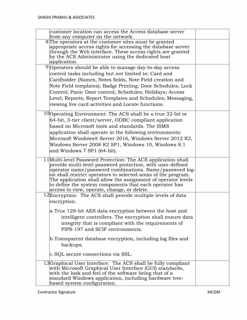
SHASHI PRABHU & ASSOCIATES
Contractor Signature MCGM
customer location can access the Access database server from any computer on the network.
8 The operators at the customer sites must be granted appropriate access rights for accessing the database server through the Web interface. These access rights are granted by the ACS Administrator using the dedicated host application.
9 Operators should be able to manage day-to-day access
control tasks including but not limited to: Card and
Cardholder (Names, Notes fields, Note Field creation and
Note Field templates); Badge Printing; Door Schedules; Lock
Control; Panic Door control; Schedules; Holidays; Access
Level; Reports; Report Templates and Schedules; Messaging,
viewing live card activities and Locate functions.
10. Operating Environment: The ACS shall be a true 32-bit or
64-bit, 3-tier client/server, ODBC compliant application
based on Microsoft tools and standards. The ISMS
application shall operate in the following environments:
Microsoft Windows® Server 2016, Windows Server 2012 R2,
Windows Server 2008 R2 SP1, Windows 10, Windows 8.1
and Windows 7 SP1 (64-bit).
11. Multi-level Password Protection: The ACS application shall provide multi-level password protection, with user-defined operator name/password combinations. Name/password log-on shall restrict operators to selected areas of the program. The application shall allow the assignment of operator levels to define the system components that each operator has access to view, operate, change, or delete.
12. Encryption: The ACS shall provide multiple levels of data
encryption.
a. True 128-bit AES data encryption between the host and
intelligent controllers. The encryption shall ensure data
integrity that is compliant with the requirements of
FIPS-197 and SCIF environments.
b. Transparent database encryption, including log files and
backups.
c. SQL secure connections via SSL.
13. Graphical User Interface: The ACS shall be fully compliant with Microsoft Graphical User Interface (GUI) standards, with the look and feel of the software being that of a standard Windows application, including hardware tree-based system configuration.
Page 436

SHASHI PRABHU & ASSOCIATES
Contractor Signature MCGM
14. Online Help: The ACS user interface shall include an Online
Help which shall require only one click to activate. The
standard special function key “F1” shall have the capability
to be programmed to provide access to the help system.
15. Database Partition: The ACS application shall allow support for multiple Partitions allowing separate access to the card database, badge layout, operator access, and reporting. Physical hardware may be filtered by operator level into sites. Sites may reside in multiple Partitions. The system shall allow control of common areas between Partitions. Access levels and time zones shall be global to allow for easy administration.
16. Relational Database Management System: The ACS System
shall support industry standard relational database
management systems. This shall include relational database
management system Microsoft SQL Server 2016 Standard
Edition. The RDBMS shall provide edit, add, delete, search,
sort, and print options for records in the selected databases
17. Access Control Functions: The ACS shall include the following access control functions: validation based on time of day, day of week, holiday scheduling, site code and card number verification, automatic or manual retrieval of cardholder photographs, and access validation based on positive verification of card, card and PIN, card or pin, pin only and Site Code only.
18. Hardware Configuration Changes: After installation of ACS application, the customer shall be able to perform hardware configuration changes.
19. These hardware configuration changes shall include, but not be limited to, door open time, door contact shunt time, point and reader names, when and where a cardholder is valid, and the ability to add or modify card databases as desired.
20. Levels of System Operation: The ACS shall include a feature to define the levels of system operation for each individual operator using passwords. System operation for individual operators shall restricted time periods for login, available accounts and default language selection at login.
21. Operator actions range from no view or control rights to basic monitoring including the ability to block the viewing of card and or personal identification numbers, to full control of the system including programming.
22. Alarm Events: The system shall include a feature where alarm events with defined priorities pop-up automatically in an Alarm event window for operator attention. An event counter shall also display the number of times the event was reported to the Alarm event monitor prior to Acknowledgement or Clearing the event. Event instructions shall be made available by double clicking on the event.
Page 437
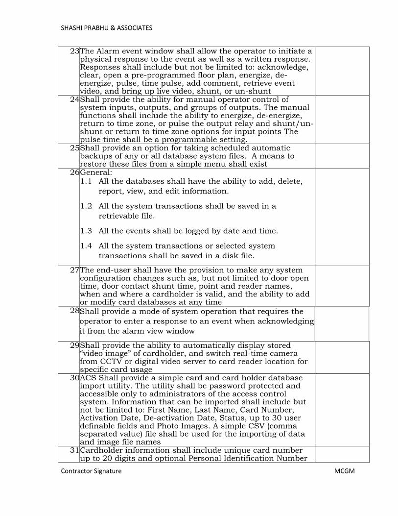
SHASHI PRABHU & ASSOCIATES
Contractor Signature MCGM
23. The Alarm event window shall allow the operator to initiate a physical response to the event as well as a written response. Responses shall include but not be limited to: acknowledge, clear, open a pre-programmed floor plan, energize, de-energize, pulse, time pulse, add comment, retrieve event video, and bring up live video, shunt, or un-shunt
24. Shall provide the ability for manual operator control of system inputs, outputs, and groups of outputs. The manual functions shall include the ability to energize, de-energize, return to time zone, or pulse the output relay and shunt/un-shunt or return to time zone options for input points The pulse time shall be a programmable setting.
25. Shall provide an option for taking scheduled automatic backups of any or all database system files. A means to restore these files from a simple menu shall exist
26. General: 1.1 All the databases shall have the ability to add, delete,
report, view, and edit information.
1.2 All the system transactions shall be saved in a
retrievable file.
1.3 All the events shall be logged by date and time.
1.4 All the system transactions or selected system
transactions shall be saved in a disk file.
27. The end-user shall have the provision to make any system configuration changes such as, but not limited to door open time, door contact shunt time, point and reader names, when and where a cardholder is valid, and the ability to add or modify card databases at any time
28. Shall provide a mode of system operation that requires the
operator to enter a response to an event when acknowledging
it from the alarm view window
29. Shall provide the ability to automatically display stored “video image” of cardholder, and switch real-time camera from CCTV or digital video server to card reader location for specific card usage
30. ACS Shall provide a simple card and card holder database import utility. The utility shall be password protected and accessible only to administrators of the access control system. Information that can be imported shall include but not be limited to: First Name, Last Name, Card Number, Activation Date, De-activation Date, Status, up to 30 user definable fields and Photo Images. A simple CSV (comma separated value) file shall be used for the importing of data and image file names
31. Cardholder information shall include unique card number up to 20 digits and optional Personal Identification Number
Page 438

SHASHI PRABHU & ASSOCIATES
Contractor Signature MCGM
up to 10 digits
32. Shall allow multiple cards, mobile access credentials or
finger print enrollment per cardholder.
33. Shall allow multiple cards per cardholder. Every card can be assigned with 32 Access Levels
34. Upon editing card information, the updated information shall
be sent automatically to the appropriate access control
panel, when hardwired, with no other user intervention
35. Shall provide a card “Trace” function. The Trace function shall allow normal access control, but will provide a tracking alarm at the system monitor
36. Shall provide the ability to store digital images of cardholder
or other digital images such as property or family members
37. Integrated biometric enrollment functions shall be managed directly inside the ACS UI without the need to use a 3rd party software
38. Integrated assignment/managing/enrollment of mobile
access credentials shall be accomplished inside the ACS UI
without the need to external or 3rd party portals or software
39. ACS shall have a separate Alarm Monitoring screen, which shall display alarms in real time, incoming alarms shall display in the upper pane according to priority and time. Once an alarm is received by Alarm monitor it should pop up the alarm window and continuous to beep the sound until it is acknowledged or operator can silence the beeper for 60 seconds without acknowledging the alarm, this feature can be enabled or disabled as per requirement for every client station
40. Shall provide color and icon shapes for each specific alarm point action of “Alarm”, “Normal”, “Trouble”, and “Shunted”
41. Shall provide the ability to access the default floor plan graphic for any active alarm point by a right click option
42. ACS shall have a capability to force the operator to enter an acknowledge message while processing an alarm and it shall be possible to print or export these reports for later analysis if required
43. Shall provide the ability to access the default floor plan
graphic for any active alarm point by a right click option
44. ACS shall have a provision that allows acknowledge alarms to be automatically cleared
45. Shall provide a mode of system operation that does not allow the operator to clear an alarm before prior to it being restored to normal
46. Floor Plan: Shall provide the ability to import floor plan
Page 439
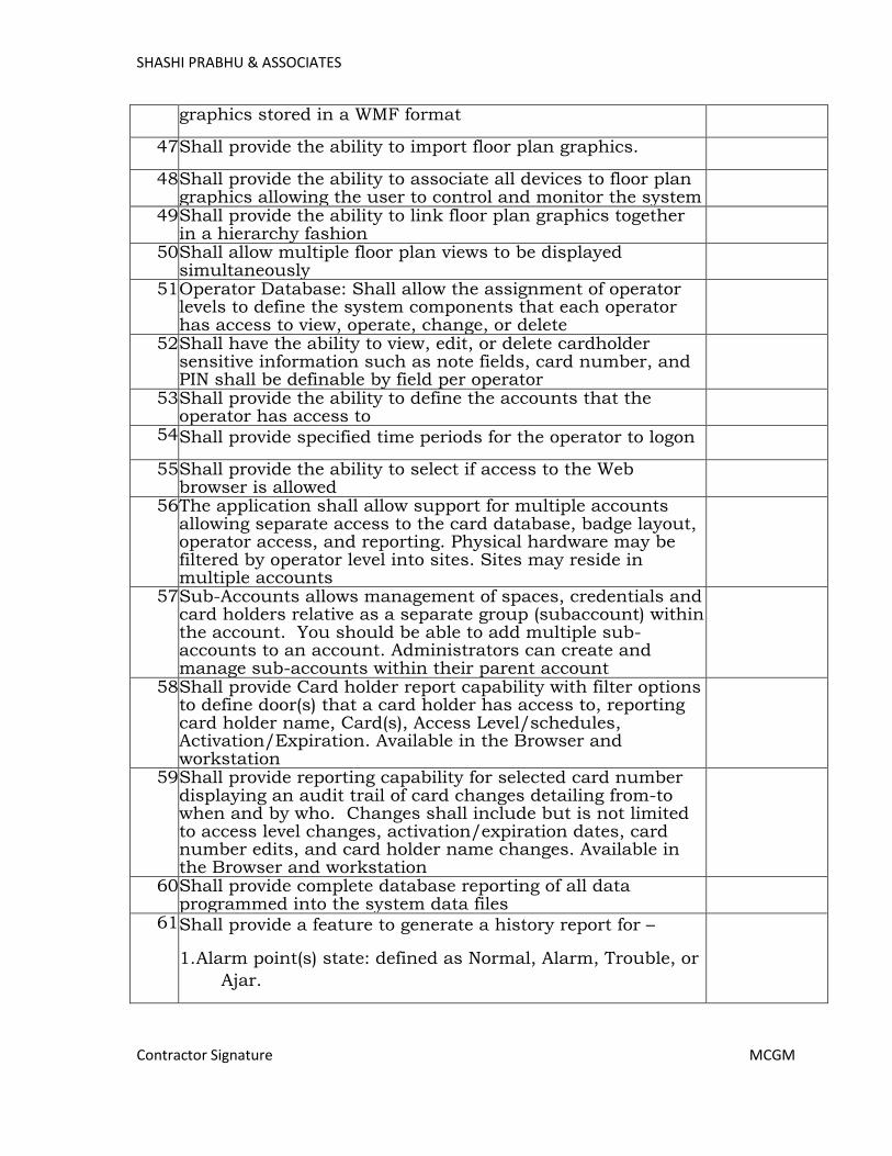
SHASHI PRABHU & ASSOCIATES
Contractor Signature MCGM
graphics stored in a WMF format
47. Shall provide the ability to import floor plan graphics.
48. Shall provide the ability to associate all devices to floor plan graphics allowing the user to control and monitor the system
49. Shall provide the ability to link floor plan graphics together in a hierarchy fashion
50. Shall allow multiple floor plan views to be displayed simultaneously
51. Operator Database: Shall allow the assignment of operator levels to define the system components that each operator has access to view, operate, change, or delete
52. Shall have the ability to view, edit, or delete cardholder sensitive information such as note fields, card number, and PIN shall be definable by field per operator
53. Shall provide the ability to define the accounts that the operator has access to
54. Shall provide specified time periods for the operator to logon
55. Shall provide the ability to select if access to the Web browser is allowed
56. The application shall allow support for multiple accounts allowing separate access to the card database, badge layout, operator access, and reporting. Physical hardware may be filtered by operator level into sites. Sites may reside in multiple accounts
57. Sub-Accounts allows management of spaces, credentials and card holders relative as a separate group (subaccount) within the account. You should be able to add multiple sub-accounts to an account. Administrators can create and manage sub-accounts within their parent account
58. Shall provide Card holder report capability with filter options to define door(s) that a card holder has access to, reporting card holder name, Card(s), Access Level/schedules, Activation/Expiration. Available in the Browser and workstation
59. Shall provide reporting capability for selected card number displaying an audit trail of card changes detailing from-to when and by who. Changes shall include but is not limited to access level changes, activation/expiration dates, card number edits, and card holder name changes. Available in the Browser and workstation
60. Shall provide complete database reporting of all data programmed into the system data files
61. Shall provide a feature to generate a history report for –
1. Alarm point(s) state: defined as Normal, Alarm, Trouble, or
Ajar.
Page 440

SHASHI PRABHU & ASSOCIATES
Contractor Signature MCGM
2. System alarms: defined by panel and include information:
communication, ground fault, power, panel reset, low
voltage, panel tamper, and loop communication.
3. Card(s) state: defined as Normal, Trace, and Not Found,
Anti-Passback Violation, PIN Violation, Time Zone
Violation, Site Code Violation, or Expired card,
Verification Failed.
4. Operator(s) activities: defined as acknowledged and cleared
transactions, camera control, door mode, door and relay
control such as unlock, lock; door and input control
such as shunt, Un-shunt; login, logout, panel
initialization, panel buffer and panel Un-buffer.
62. Shall provide feature to generate a report based on the
frequency of usage of a card defining a minimum and maximum usage limit. The cards meeting the filtering criteria shall be acted upon based on but not be limited to: Report only, De-activate the card or Re-assign to a specified an access level. This report shall be available in the event scheduler
63. Shall provide an option to create report templates. Report templates available in the Browser and Workstation shall include, but not be limited to, Access Level, Card, Card History, Door, Holiday, Time Schedules and Card Holder information. The templates shall be able to be assigned to a scheduler to run automatically per the scheduler settings
64. Tracking/Muster Report
• A tracking feature shall allow the system operator to
identify an area and the person(s) in that area.
• Areas shall be defined by readers representing an IN or
OUT read status.
• Defined areas shall provide an automatic update of how
many cardholders are in the area.
• An area defined as an exit shall remove the person from
the tracking area.
• A Muster area shall be defined by a reader(s) used to
“muster” individuals in the event of an emergency.
Page 441
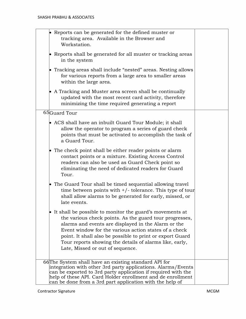
SHASHI PRABHU & ASSOCIATES
Contractor Signature MCGM
• Reports can be generated for the defined muster or
tracking area. Available in the Browser and
Workstation.
• Reports shall be generated for all muster or tracking areas
in the system
• Tracking areas shall include “nested” areas. Nesting allows
for various reports from a large area to smaller areas
within the large area.
• A Tracking and Muster area screen shall be continually
updated with the most recent card activity, therefore
minimizing the time required generating a report
65. Guard Tour
• ACS shall have an inbuilt Guard Tour Module; it shall
allow the operator to program a series of guard check
points that must be activated to accomplish the task of
a Guard Tour.
• The check point shall be either reader points or alarm
contact points or a mixture. Existing Access Control
readers can also be used as Guard Check point so
eliminating the need of dedicated readers for Guard
Tour.
• The Guard Tour shall be timed sequential allowing travel
time between points with +/- tolerance. This type of tour
shall allow alarms to be generated for early, missed, or
late events.
• It shall be possible to monitor the guard’s movements at
the various check points. As the guard tour progresses,
alarms and events are displayed in the Alarm or the
Event window for the various action states of a check
point. It shall also be possible to print or export Guard
Tour reports showing the details of alarms like, early,
Late, Missed or out of sequence.
66. The System shall have an existing standard API for integration with other 3rd party applications. Alarms/Events can be exported to 3rd party application if required with the help of these API. Card Holder enrollment and de enrollment can be done from a 3rd part application with the help of
Page 442

SHASHI PRABHU & ASSOCIATES
Contractor Signature MCGM
these API
6.4. Time Attendance Module:
Sr. No.
Specifications Compliance
1. The attendance module shall work as a report generation module for the employee’s / swipes data acquired by Access Control System along with Employee Leave Management System clubbed with it as an independent module
2. It should have a utility to import all masters and swipe
data from various swipe card and biometric systems to
its own database automatically
3. It shall allow complete flexibility in defining the rules for attendance facilitating data keeping with a range of reports, catering to user requirements on a regular or periodic basis. It shall allow the attendance rules logic to be set dynamically by the administrator
4. The system will allow visually setting rules relating to swiping data, attendance record (Present, late etc.), shifts and leave and over time etc. It shall be a Web browser-based application with password protection for security
5. The application shall support multiple shifts and shall take due care of the shifts which cross during the midnight
6. The application shall be capable of supporting unlimited cardholders
7. Shift allocation employee and department wise, defining periodic rotation pattern shall also possible
8. Manual updating of attendance / leaves / Outdoor duty shall be possible
9. Reports can be sorted one or all shift / date / employees’ wise etc. The system shall be capable of exporting the data into *. csv, *.xls, *.xlsx & HTML formats
The software shall have the following features: 10. Employee Management
Employee Joining Details, Employee Date Of Birth, Employee Resignation Details, Employee Reporting Details, Employee Access Card Details Weekly Off Details
11. Leave Management (Online Application & Approval)
o Leave definitions with different criteria Leave
administration by Admin / HR Leave adjustments by Admin / HR.
o Auto generation of mails for each activity (apply, sanction & rejection)
Page 443
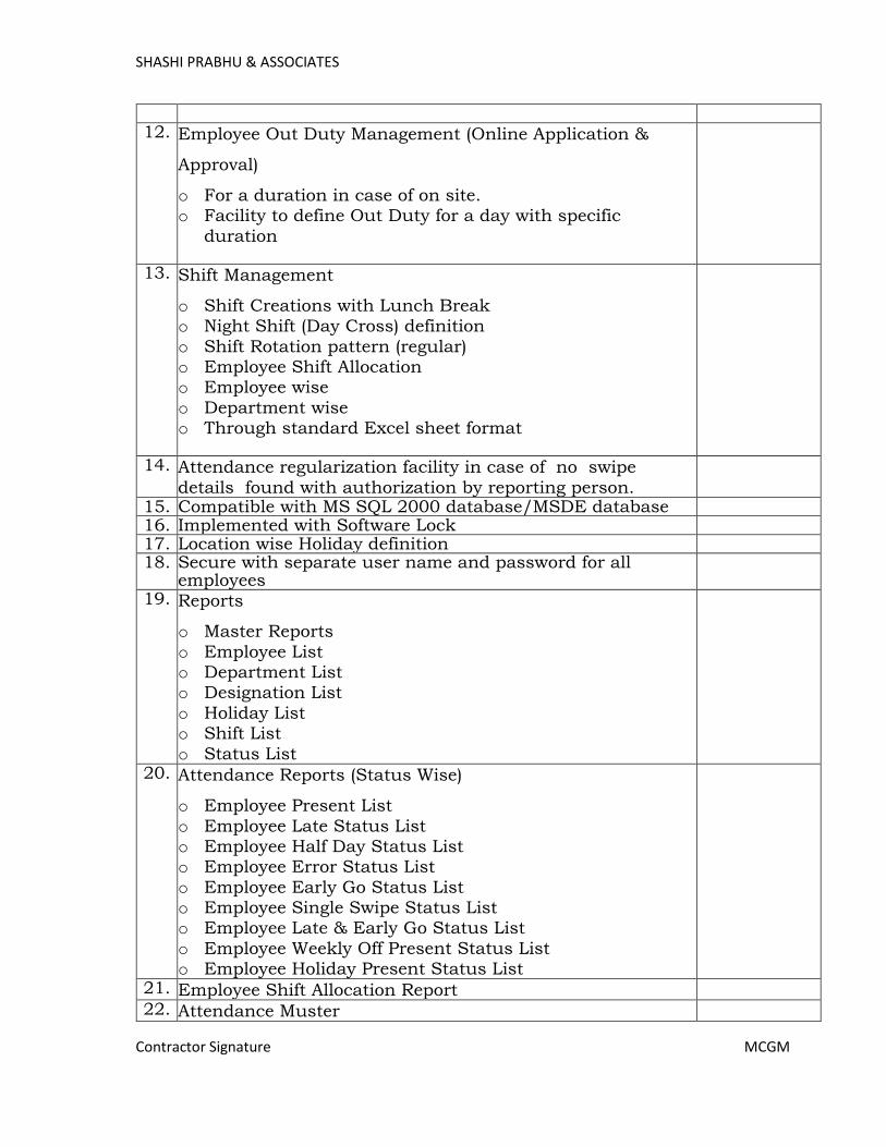
SHASHI PRABHU & ASSOCIATES
Contractor Signature MCGM
12. Employee Out Duty Management (Online Application &
Approval)
o For a duration in case of on site. o Facility to define Out Duty for a day with specific
duration
13. Shift Management
o Shift Creations with Lunch Break o Night Shift (Day Cross) definition
o Shift Rotation pattern (regular) o Employee Shift Allocation o Employee wise
o Department wise o Through standard Excel sheet format
14. Attendance regularization facility in case of no swipe
details found with authorization by reporting person.
15. Compatible with MS SQL 2000 database/MSDE database 16. Implemented with Software Lock 17. Location wise Holiday definition 18. Secure with separate user name and password for all
employees
19. Reports
o Master Reports
o Employee List o Department List o Designation List
o Holiday List o Shift List
o Status List
20. Attendance Reports (Status Wise)
o Employee Present List
o Employee Late Status List o Employee Half Day Status List o Employee Error Status List
o Employee Early Go Status List o Employee Single Swipe Status List o Employee Late & Early Go Status List
o Employee Weekly Off Present Status List o Employee Holiday Present Status List
21. Employee Shift Allocation Report
22. Attendance Muster
Page 444

SHASHI PRABHU & ASSOCIATES
Contractor Signature MCGM
23. Employee Attendance Status Report
24. Employee Overtime Report
25. Employee Wise Attendance Report
26. Leave Reports
o Leave Applications o Leave Sanction Applications
o Leave Rejected Applications o Leave Summary o Leave Balance
27. Attendance Regularization Reports
o Attendance Regularization Applications o Attendance Regularization Sanction Applications
o Attendance Regularization Rejected Applications
28. Out Duty Reports
o Out Duty Applications
o Out Duty Sanction Applications o Out Duty Rejected Applications
29. Employee Working Hours Report
Page 445
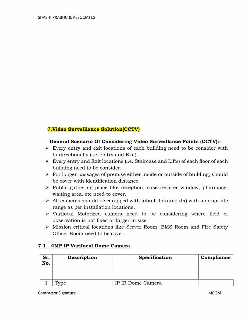
SHASHI PRABHU & ASSOCIATES
Contractor Signature MCGM
7.Video Surveillance Solution(CCTV)
General Scenario Of Considering Video Surveillance Points (CCTV):-
Every entry and exit locations of each building need to be consider with
bi-directionally (i.e. Entry and Exit).
Every entry and Exit locations (i.e. Staircase and Lifts) of each floor of each
building need to be consider.
For longer passages of premise either inside or outside of building, should
be cover with identification distance.
Public gathering place like reception, case register window, pharmacy,
waiting area, etc need to cover.
All cameras should be equipped with inbuilt Infrared (IR) with appropriate
range as per installation locations.
Varifocal Motorized camera need to be considering where field of
observation is not fixed or larger in size.
Mission critical locations like Server Room, BMS Room and Fire Safety
Officer Room need to be cover.
7.1 4MP IP Varifocal Dome Camera
Sr.
No. Description Specification Compliance
1 Type IP IR Dome Camera
Page 446
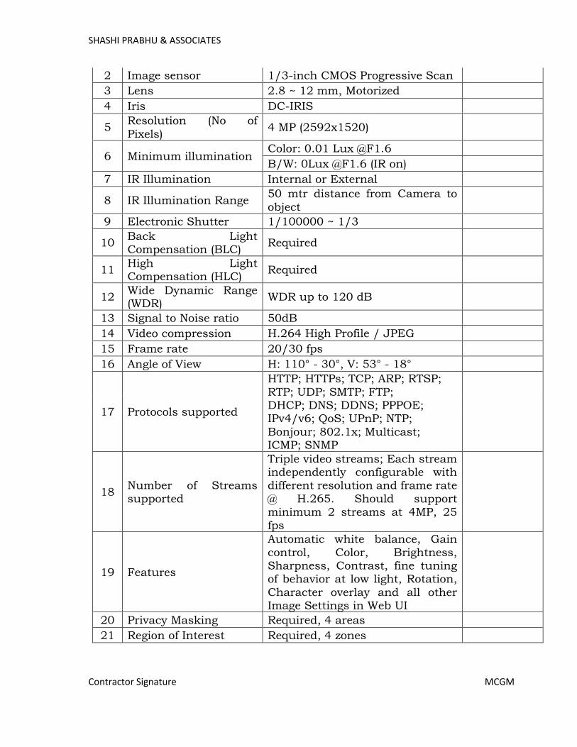
SHASHI PRABHU & ASSOCIATES
Contractor Signature MCGM
2 Image sensor 1/3-inch CMOS Progressive Scan
3 Lens 2.8 ~ 12 mm, Motorized
4 Iris DC-IRIS
5 Resolution (No of
Pixels) 4 MP (2592x1520)
6 Minimum illumination Color: 0.01 Lux @F1.6
B/W: 0Lux @F1.6 (IR on)
7 IR Illumination Internal or External
8 IR Illumination Range 50 mtr distance from Camera to
object
9 Electronic Shutter 1/100000 ~ 1/3
10 Back Light Compensation (BLC)
Required
11 High Light Compensation (HLC)
Required
12 Wide Dynamic Range (WDR)
WDR up to 120 dB
13 Signal to Noise ratio 50dB
14 Video compression H.264 High Profile / JPEG
15 Frame rate 20/30 fps
16 Angle of View H: 110° - 30°, V: 53° - 18°
17 Protocols supported
HTTP; HTTPs; TCP; ARP; RTSP;
RTP; UDP; SMTP; FTP; DHCP; DNS; DDNS; PPPOE; IPv4/v6; QoS; UPnP; NTP;
Bonjour; 802.1x; Multicast; ICMP; SNMP
18 Number of Streams
supported
Triple video streams; Each stream independently configurable with different resolution and frame rate
@ H.265. Should support minimum 2 streams at 4MP, 25
fps
19 Features
Automatic white balance, Gain
control, Color, Brightness, Sharpness, Contrast, fine tuning of behavior at low light, Rotation,
Character overlay and all other Image Settings in Web UI
20 Privacy Masking Required, 4 areas
21 Region of Interest Required, 4 zones
Page 447
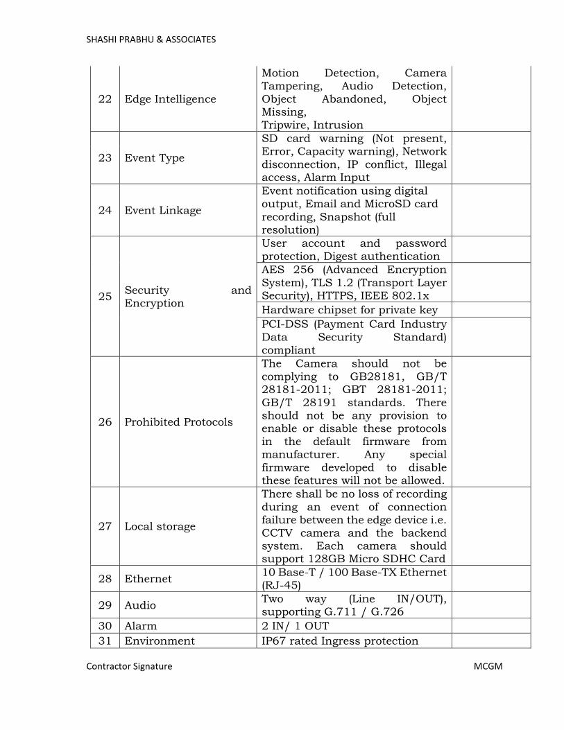
SHASHI PRABHU & ASSOCIATES
Contractor Signature MCGM
22 Edge Intelligence
Motion Detection, Camera Tampering, Audio Detection,
Object Abandoned, Object Missing,
Tripwire, Intrusion
23 Event Type
SD card warning (Not present, Error, Capacity warning), Network
disconnection, IP conflict, Illegal access, Alarm Input
24 Event Linkage
Event notification using digital output, Email and MicroSD card
recording, Snapshot (full resolution)
25 Security and Encryption
User account and password
protection, Digest authentication
AES 256 (Advanced Encryption
System), TLS 1.2 (Transport Layer Security), HTTPS, IEEE 802.1x
Hardware chipset for private key
PCI-DSS (Payment Card Industry
Data Security Standard) compliant
26 Prohibited Protocols
The Camera should not be
complying to GB28181, GB/T 28181-2011; GBT 28181-2011;
GB/T 28191 standards. There should not be any provision to enable or disable these protocols
in the default firmware from manufacturer. Any special
firmware developed to disable these features will not be allowed.
27 Local storage
There shall be no loss of recording
during an event of connection failure between the edge device i.e.
CCTV camera and the backend system. Each camera should support 128GB Micro SDHC Card
28 Ethernet 10 Base-T / 100 Base-TX Ethernet (RJ-45)
29 Audio Two way (Line IN/OUT), supporting G.711 / G.726
30 Alarm 2 IN/ 1 OUT
31 Environment IP67 rated Ingress protection
Page 448

SHASHI PRABHU & ASSOCIATES
Contractor Signature MCGM
32 Impact Protection IK10 rated Vandal resistance
33 Heater and Fan Required
34 Defog On/Off
35 Input voltage 12 VDC, 24 VAC, POE (802.3at,
Class 4)
36 Aux. Power Out 12VDC, 2W
37 Power Consumption Max 15W
38 ONVIF Compliance ONVIF Profile S
39 Operating Temperature -30°C to 60°C
40 Operating Humidity less than 95% (non-condensing)
41 Compliance
UL 60950-1, CE (EN 50130-4, EN
55032), FCC Part 15, UL CAP/PCI-DSS & RoHS
Page 449
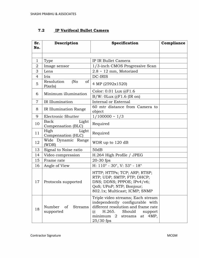
SHASHI PRABHU & ASSOCIATES
Contractor Signature MCGM
7.2 IP Varifocal Bullet Camera
Sr.
No. Description Specification Compliance
1 Type IP IR Bullet Camera
2 Image sensor 1/3-inch CMOS Progressive Scan
3 Lens 2.8 ~ 12 mm, Motorized
4 Iris DC-IRIS
5 Resolution (No of
Pixels) 4 MP (2592x1520)
6 Minimum illumination Color: 0.01 Lux @F1.6
B/W: 0Lux @F1.6 (IR on)
7 IR Illumination Internal or External
8 IR Illumination Range 60 mtr distance from Camera to object
9 Electronic Shutter 1/100000 ~ 1/3
10 Back Light Compensation (BLC)
Required
11 High Light Compensation (HLC)
Required
12 Wide Dynamic Range (WDR)
WDR up to 120 dB
13 Signal to Noise ratio 50dB
14 Video compression H.264 High Profile / JPEG
15 Frame rate 20-30 fps
16 Angle of View H: 110° - 30°, V: 53° - 18°
17 Protocols supported
HTTP; HTTPs; TCP; ARP; RTSP; RTP; UDP; SMTP; FTP; DHCP; DNS; DDNS; PPPOE; IPv4/v6;
QoS; UPnP; NTP; Bonjour; 802.1x; Multicast; ICMP; SNMP
18 Number of Streams supported
Triple video streams; Each stream independently configurable with
different resolution and frame rate @ H.265. Should support minimum 2 streams at 4MP,
25/30 fps
Page 450
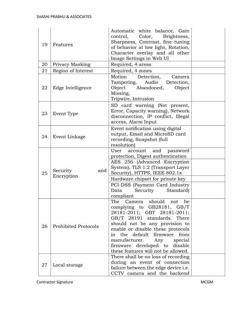
SHASHI PRABHU & ASSOCIATES
Contractor Signature MCGM
19 Features
Automatic white balance, Gain control, Color, Brightness,
Sharpness, Contrast, fine tuning of behavior at low light, Rotation,
Character overlay and all other Image Settings in Web UI
20 Privacy Masking Required, 4 areas
21 Region of Interest Required, 4 zones
22 Edge Intelligence
Motion Detection, Camera
Tampering, Audio Detection, Object Abandoned, Object Missing,
Tripwire, Intrusion
23 Event Type
SD card warning (Not present,
Error, Capacity warning), Network disconnection, IP conflict, Illegal access, Alarm Input
24 Event Linkage
Event notification using digital output, Email and MicroSD card recording, Snapshot (full
resolution)
25 Security and
Encryption
User account and password
protection, Digest authentication
AES 256 (Advanced Encryption
System), TLS 1.2 (Transport Layer Security), HTTPS, IEEE 802.1x
Hardware chipset for private key
PCI-DSS (Payment Card Industry Data Security Standard)
compliant
26 Prohibited Protocols
The Camera should not be
complying to GB28181, GB/T 28181-2011; GBT 28181-2011;
GB/T 28191 standards. There should not be any provision to enable or disable these protocols
in the default firmware from manufacturer. Any special firmware developed to disable
these features will not be allowed.
27 Local storage
There shall be no loss of recording
during an event of connection failure between the edge device i.e.
CCTV camera and the backend
Page 451
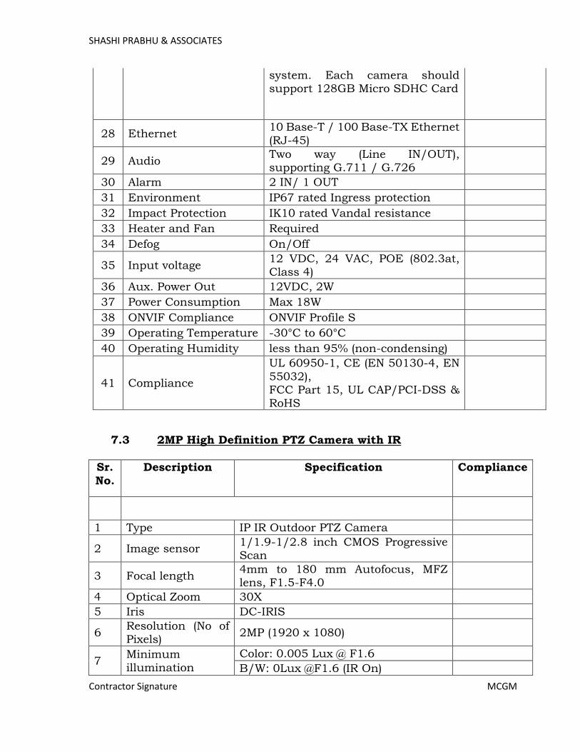
SHASHI PRABHU & ASSOCIATES
Contractor Signature MCGM
system. Each camera should support 128GB Micro SDHC Card
28 Ethernet 10 Base-T / 100 Base-TX Ethernet
(RJ-45)
29 Audio Two way (Line IN/OUT), supporting G.711 / G.726
30 Alarm 2 IN/ 1 OUT
31 Environment IP67 rated Ingress protection
32 Impact Protection IK10 rated Vandal resistance
33 Heater and Fan Required
34 Defog On/Off
35 Input voltage 12 VDC, 24 VAC, POE (802.3at, Class 4)
36 Aux. Power Out 12VDC, 2W
37 Power Consumption Max 18W
38 ONVIF Compliance ONVIF Profile S
39 Operating Temperature -30°C to 60°C
40 Operating Humidity less than 95% (non-condensing)
41 Compliance
UL 60950-1, CE (EN 50130-4, EN
55032), FCC Part 15, UL CAP/PCI-DSS & RoHS
7.3 2MP High Definition PTZ Camera with IR
Sr.
No.
Description Specification Compliance
1 Type IP IR Outdoor PTZ Camera
2 Image sensor 1/1.9-1/2.8 inch CMOS Progressive Scan
3 Focal length 4mm to 180 mm Autofocus, MFZ lens, F1.5-F4.0
4 Optical Zoom 30X
5 Iris DC-IRIS
6 Resolution (No of Pixels)
2MP (1920 x 1080)
7 Minimum illumination
Color: 0.005 Lux @ F1.6
B/W: 0Lux @F1.6 (IR On)
Page 452

SHASHI PRABHU & ASSOCIATES
Contractor Signature MCGM
8 IR Illumination Internal or External
9 IR Illumination
Range
200 mtr distance from Camera to
object
10 Electronic Shutter 1/100000 ~ 1/1
11
Back Light
Compensation (BLC)
Required
12 High Light Compensation (HLC)
Required
13 Wide Dynamic Range (WDR)
WDR up to 120 dB
14 Signal to Noise ratio
55dB
15 Video compression
H.264 / MJPEG
16 Frame rate 25/30 fps
17 Angle of View H: 70.3° - 1.8°; V: 37° - 1°
18 Protocols supported
HTTP; HTTPs; TCP; ARP; RTSP; RTP; UDP; SMTP;NFS; FTP; NTP; DHCP;
DNS; DDNS; PPPOE; IPv4/v6; QoS;UPnP;NTP; Bonjour; 802.1x;
Unicast ; Multicast; ICMP; SNMP
19 Number of Streams
supported
Primary, secondary and tertiary video streams; Each stream independently
configurable with different resolution and frame rate @ H.265
20 Features
Automatic Tracking White Balance, Automatic Gain control, 3D Noise
reduction, Cropping, Color, Brightness, Sharpness, Contrast, fine tuning of behavior at low light,
Rotation, On-Screen Display, Picture Overlay and all other Image Settings in Web UI
21 Built-in Intelligence
Motion Detection, Camera tampering
22 Event Type
SD card warning (Not present, Error, Capacity warning), Network
disconnection, IP conflict, Illegal access, Alarm Input
23 Event Action Trigger Relay Output, SD card Recording, Email, Snapshot
Page 453
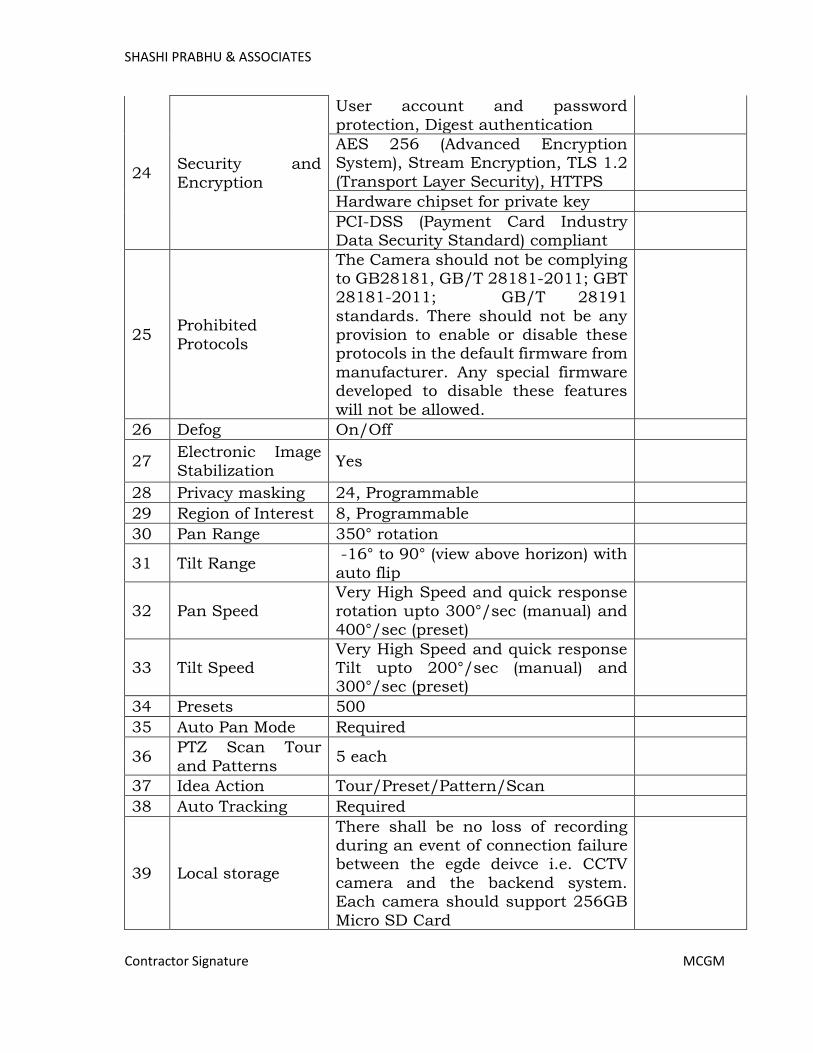
SHASHI PRABHU & ASSOCIATES
Contractor Signature MCGM
24 Security and
Encryption
User account and password
protection, Digest authentication
AES 256 (Advanced Encryption System), Stream Encryption, TLS 1.2
(Transport Layer Security), HTTPS
Hardware chipset for private key
PCI-DSS (Payment Card Industry Data Security Standard) compliant
25 Prohibited
Protocols
The Camera should not be complying to GB28181, GB/T 28181-2011; GBT 28181-2011; GB/T 28191
standards. There should not be any provision to enable or disable these protocols in the default firmware from
manufacturer. Any special firmware developed to disable these features
will not be allowed.
26 Defog On/Off
27 Electronic Image
Stabilization Yes
28 Privacy masking 24, Programmable
29 Region of Interest 8, Programmable
30 Pan Range 350° rotation
31 Tilt Range -16° to 90° (view above horizon) with
auto flip
32 Pan Speed
Very High Speed and quick response
rotation upto 300°/sec (manual) and 400°/sec (preset)
33 Tilt Speed Very High Speed and quick response Tilt upto 200°/sec (manual) and 300°/sec (preset)
34 Presets 500
35 Auto Pan Mode Required
36 PTZ Scan Tour
and Patterns 5 each
37 Idea Action Tour/Preset/Pattern/Scan
38 Auto Tracking Required
39 Local storage
There shall be no loss of recording during an event of connection failure between the egde deivce i.e. CCTV
camera and the backend system. Each camera should support 256GB
Micro SD Card
Page 454

SHASHI PRABHU & ASSOCIATES
Contractor Signature MCGM
40 Ethernet 10 Base-T / 100 Base-TX Ethernet (RJ-45)
41 Audio Two-way (Line IN/OUT) supporting G.711 / G.726 / G.729
42 Alarm 2 In and 1 Relay out
43 Environment Protection
IP66 rated outdoor protection
44 Impact Protection IK10 rated vandal protection
45 Circuit Protection TVS 6000V, Lightning/Surge
protection
46 Heater Yes
47 Fan Yes
48 Input voltage 24 VDC / 24 VAC, PoE+ (802.3at)
49 Power Consumption
Max 21 W (IR and Heater On)
50 ONVIF
Compliance ONVIF Profile S
51 Operating
Temperature -40°C to 60°C
52 Operating
Humidity 0-95% (non-condensing)
53 Compliance UL, CE, FCC
7.4 Video Management Software
Sr.
No.
Description Specification Compliance
1 Platform
VMS should support and run on
64-bit Windows® Server 2019/ Server 2016 / Server 2012 STD
2 Scalability
VMS shall include a fully scalable enterprise-class media management
system to enable simultaneous live monitoring from multiple stations and be configurable for storage both
on and off site
The number of recorders and
switchers shall be scalable within a network to handle any size of
installation.
Page 455
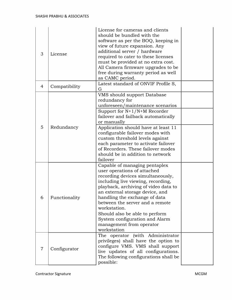
SHASHI PRABHU & ASSOCIATES
Contractor Signature MCGM
3 License
License for cameras and clients should be bundled with the
software as per the BOQ, keeping in view of future expansion. Any
additional server / hardware required to cater to these licenses must be provided at no extra cost.
All Camera firmware upgrades to be free during warranty period as well as CAMC period.
4 Compatibility Latest standard of ONVIF Profile S,
G
5 Redundancy
VMS should support Database
redundancy for unforeseen/maintenance scenarios
Support for N+1/N+M Recorder failover and failback automatically
or manually
Application should have at least 11
configurable failover modes with custom threshold levels against each parameter to activate failover
of Recorders. These failover modes should be in addition to network
failover
6 Functionality
Capable of managing pentaplex
user operations of attached recording devices simultaneously, including live viewing, recording,
playback, archiving of video data to an external storage device, and
handling the exchange of data between the server and a remote workstation.
Should also be able to perform System configuration and Alarm
management from operator workstation
7 Configurator
The operator (with Administrator privileges) shall have the option to
configure VMS. VMS shall support live updates of all configurations. The following configurations shall be
possible:
Page 456

SHASHI PRABHU & ASSOCIATES
Contractor Signature MCGM
· Option to add/edit/delete Recorders, Cameras, Monitors,
Keyboard, Site, Workstation, Partition and Event group.
· Associate cameras to a recorder or switcher and map to a
site, partition or event group.
· Add monitor to a site,
partition, event group or keyboard. It shall provide an option to add a digital monitor and associate it with
a workstation with provision to configure a digital monitor with a
default salvo and startup in full screen.
· Support of bulk event association to enable/disable and
adjust events for recorders and inputs in bulk.
· System Macro Configuration: Option to add/edit/delete macros. Option to restore macros. Execute
button option to trigger selected macros provides mechanism for
testing written macros.
8 Recording
Should support Audio / Video
recording.
Continuous, scheduled, manual,
event and alarm-based recording. All modes shall be disabled and enabled using scheduled configuration.
Different recording speeds (fps) and
resolution for each recording mode for each camera shall be possible.
Software Should support ANR (Automatic Network replenishment) Feature where camera should
Record to Camera SD card during it gets disconnects from Storage. Once
connection is established recording in SD card can be replenished automatically to storage.
The Recording System, once configured, shall run independently
Page 457
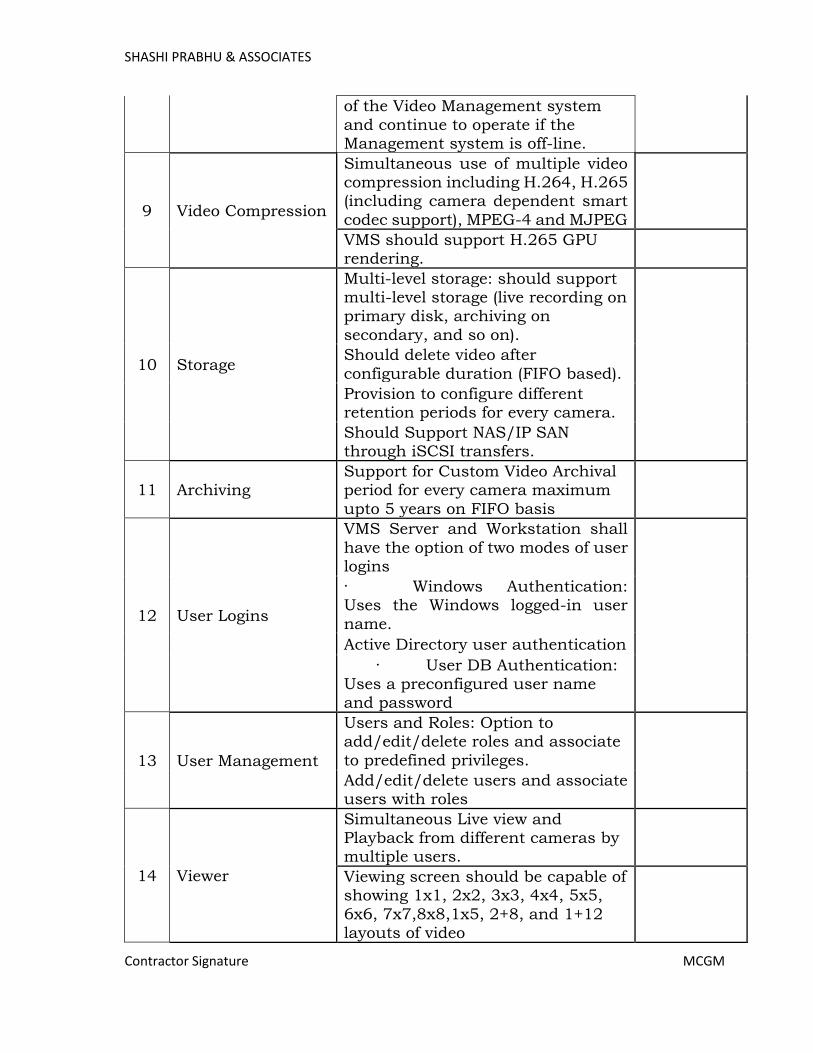
SHASHI PRABHU & ASSOCIATES
Contractor Signature MCGM
of the Video Management system
and continue to operate if the Management system is off-line.
9 Video Compression
Simultaneous use of multiple video compression including H.264, H.265 (including camera dependent smart
codec support), MPEG-4 and MJPEG
VMS should support H.265 GPU rendering.
10 Storage
Multi-level storage: should support multi-level storage (live recording on primary disk, archiving on
secondary, and so on).
Should delete video after
configurable duration (FIFO based).
Provision to configure different retention periods for every camera.
Should Support NAS/IP SAN through iSCSI transfers.
11 Archiving Support for Custom Video Archival period for every camera maximum
upto 5 years on FIFO basis
12 User Logins
VMS Server and Workstation shall
have the option of two modes of user logins
· Windows Authentication: Uses the Windows logged-in user
name.
Active Directory user authentication
· User DB Authentication: Uses a preconfigured user name and password
13 User Management
Users and Roles: Option to add/edit/delete roles and associate
to predefined privileges.
Add/edit/delete users and associate users with roles
14 Viewer
Simultaneous Live view and Playback from different cameras by multiple users.
Viewing screen should be capable of showing 1x1, 2x2, 3x3, 4x4, 5x5,
6x6, 7x7,8x8,1x5, 2+8, and 1+12 layouts of video
Page 458
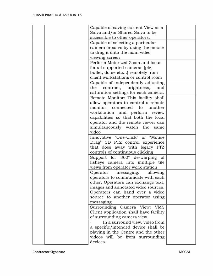
SHASHI PRABHU & ASSOCIATES
Contractor Signature MCGM
Capable of saving current View as a Salvo and/or Shared Salvo to be
accessible to other operators.
Capable of selecting a particular
camera or salvo by using the mouse to drag it onto the main video
viewing screen
Perform Motorized Zoom and focus
for all supported cameras (ptz, bullet, dome etc…) remotely from client workstations or control room
Capable of independently adjusting
the contrast, brightness, and saturation settings for each camera.
Remote Monitor: This facility shall allow operators to control a remote monitor connected to another
workstation and perform review capabilities so that both the local
operator and the remote viewer can simultaneously watch the same video
Innovative “One-Click” or “Mouse Drag” 3D PTZ control experience
that does away with legacy PTZ controls of continuous clicking
Support for 360° de-warping of fisheye camera into multiple tile
views from operator work station
Operator messaging: allowing
operators to communicate with each other. Operators can exchange text,
images and annotated video sources. Operators can hand over a video source to another operator using
messaging
Surrounding Camera View: VMS
Client application shall have facility of surrounding camera view.
· In a surround view, video from a specific/intended device shall be
playing in the Centre and the other videos will be from surrounding devices.
Page 459
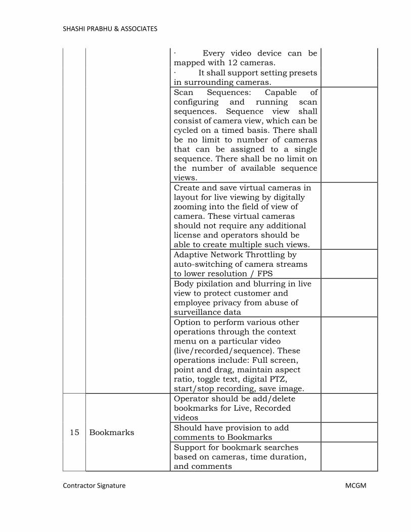
SHASHI PRABHU & ASSOCIATES
Contractor Signature MCGM
· Every video device can be mapped with 12 cameras.
· It shall support setting presets in surrounding cameras.
Scan Sequences: Capable of
configuring and running scan sequences. Sequence view shall consist of camera view, which can be
cycled on a timed basis. There shall be no limit to number of cameras that can be assigned to a single
sequence. There shall be no limit on the number of available sequence
views.
Create and save virtual cameras in
layout for live viewing by digitally zooming into the field of view of
camera. These virtual cameras should not require any additional license and operators should be
able to create multiple such views.
Adaptive Network Throttling by
auto-switching of camera streams to lower resolution / FPS
Body pixilation and blurring in live view to protect customer and
employee privacy from abuse of surveillance data
Option to perform various other operations through the context menu on a particular video
(live/recorded/sequence). These operations include: Full screen,
point and drag, maintain aspect ratio, toggle text, digital PTZ, start/stop recording, save image.
15 Bookmarks
Operator should be add/delete bookmarks for Live, Recorded
videos
Should have provision to add comments to Bookmarks
Support for bookmark searches based on cameras, time duration, and comments
Page 460

SHASHI PRABHU & ASSOCIATES
Contractor Signature MCGM
16 Time Line
Ability to display/manage the timeline of the recording device,
which provides camera recording statistics with Min 8 color recording
indications,
Mark in/out (with looping facility),
snapshot, time slider, time search, time jump, and play controls.
Timeline control shall also include dedicated buttons for step reverse and step forward and keyboard
shortcuts for playback operations.
17 Event Management
Register event associated video and alert operator
Motion detection and camera tampering events should be alerted to the operator
Ability to slue PTZ cameras to
alarm-generated areas
In case of an alarm operator should
be able to view the video during pre-alarm, on-alarm, post-alarm, and also view live video from the camera
which triggered the alarm through a single 2x2 salvo
18 Search and
Playback
Should be able to search video based multiple filters like
Recorders, Cameras, Date/Time, Type/Event
Calendar Search with thumbnail image preview of recording and
quick export of video clips
Should have advanced, smart
search function performing quick Motion Detection search on recorded video for multiple user
defined region of interest
Should support sync playback
between multiple recorders
Playback with speeds ranging from 1/64X to 256X.
Support for smooth reverse playback at 2x (Recorder Dependent)
Page 461
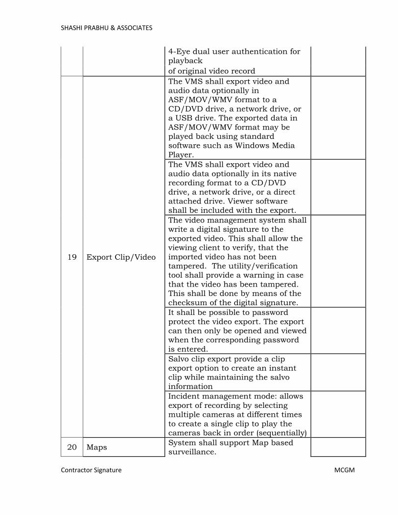
SHASHI PRABHU & ASSOCIATES
Contractor Signature MCGM
4-Eye dual user authentication for playback
of original video record
19 Export Clip/Video
The VMS shall export video and audio data optionally in ASF/MOV/WMV format to a
CD/DVD drive, a network drive, or a USB drive. The exported data in
ASF/MOV/WMV format may be played back using standard software such as Windows Media
Player.
The VMS shall export video and
audio data optionally in its native recording format to a CD/DVD
drive, a network drive, or a direct attached drive. Viewer software shall be included with the export.
The video management system shall write a digital signature to the
exported video. This shall allow the viewing client to verify, that the
imported video has not been tampered. The utility/verification tool shall provide a warning in case
that the video has been tampered. This shall be done by means of the
checksum of the digital signature.
It shall be possible to password
protect the video export. The export can then only be opened and viewed when the corresponding password
is entered.
Salvo clip export provide a clip export option to create an instant clip while maintaining the salvo
information
Incident management mode: allows
export of recording by selecting multiple cameras at different times
to create a single clip to play the cameras back in order (sequentially)
20 Maps System shall support Map based surveillance.
Page 462

SHASHI PRABHU & ASSOCIATES
Contractor Signature MCGM
· Maps navigation with site / building / floorplan
hierarchy
· Easy configuration:
Drag and drop a camera on to a floorplan
· Provision to Zoom In or Zoom Out the map
· Camera alarm indication and alarm status (latest
10) on map
· Analyze the alarms and playback the associated video
· Perform PTZ and preset actions on relevant cameras
· Instant Playback with easy forward/reverse
enhanced with calendar selection
· Undock Popup
View: Drag freely across map to avoid overlapping / covering other icons and views
· Full Screen View of Cameras to capture details of HD
video
21 Cyber Security
· Enhanced password security – non-recoverable passwords, enforcing complex passwords,
password expiry, and no default passwords.
· Secured firewall configuration.
· Secured Web client – enabled HTTPS and TLS 1.2, and protection
from CSRF and XSS attacks.
· Restricted folder and Registry
access to operators.
· Secured Assemblies – Digital
signing.
· Secure communication with Cameras using TLS 1.2
22 Report It shall be possible to get reports on past events by querying the databases.
Page 463

SHASHI PRABHU & ASSOCIATES
Contractor Signature MCGM
· System Report - Event history reports for cameras,
Monitors, Recorders
· Operator Log reports
based on operator activities like log In / Log Out , creating clip, adding
bookmark etc
Health Report
Failover Reports
Configuration reports
Create and save custom reports as per pre define and frequent format
with in VMS or Various other format
Log reports shall be exported in RPT, XLS, DOC, RFT, PDF formats
and
Email for alarms and failover
7.5 Video Management Server
Sr.
No. Description Specification Compliance
1 Processer 1 Intel Xeon Gold 6130 2.1G
2 Operating System
Windows Server 2019 x64 Standard/Datacenter
3 Memory 16G DDR4
4 Storage Up to 400GB SSD SATA Read Intensive
6Gbps
5 RAID Should Supports RAID 0,1,5,6 & 10
6 NIC 1GbE
7 Chassis Rack Mount or Tower
8 Power Supply Should be Redundant from Day 1
9 Hypervisor support
Microsoft Windows Server with Hyper-V® VMware® vSphere® ESXi®
Page 464

SHASHI PRABHU & ASSOCIATES
Contractor Signature MCGM
7.6 Video Recording Server
Sr.
No. Description Specification Compliance
1 Make& Model
Vendor has to specify, data sheet to be
supplied.
2 Processor
Intel® Xeon Silver 4210R, 2.4GHz
3 RAM 32 GB
4 OS Hard Drive
2 * 250 GB SATA/SSD HDD; Protected by
RAID 1
5
Operating System
Win 10 IoT/Enterprise 64 Bit/ Windows
Server 2016 R2 Microsoft SQL Server/Express 2019, Server/Express 2017
6 Graphics Card
Minimum In-built Processor Graphics (GPU): Intel® HD Graphics 630 or
equivalent
7 Video Output VGA / HDMI
8 Maximum bandwidth
Total (Input +Output) 800 Mbps
9 Networking
4x1GbE LAN ports
10 Accessories
Keyboard, Mouse
11 Video Storage Drive
Video rated or Enterprise drive, 7200 RPM
SATA/SAS recommended
12
Storage
Internal SAS/ SATA/ SSD drives
supporting Up to 12 bays, 16TB each HDD.
- The Contractor has to submit the
storage calculation Simultaneous play back and recording at full duplex operation.
13 RAID Controller
Supported RAID levels 0, 1, 5, 6, 10, 50, 60;
Hot Spare support
14 Power Supply
1+ 1, Hot Plug, Redundant Power Supply
15 Chassis with locking bezel
2U, including rack mounting kit
Page 465
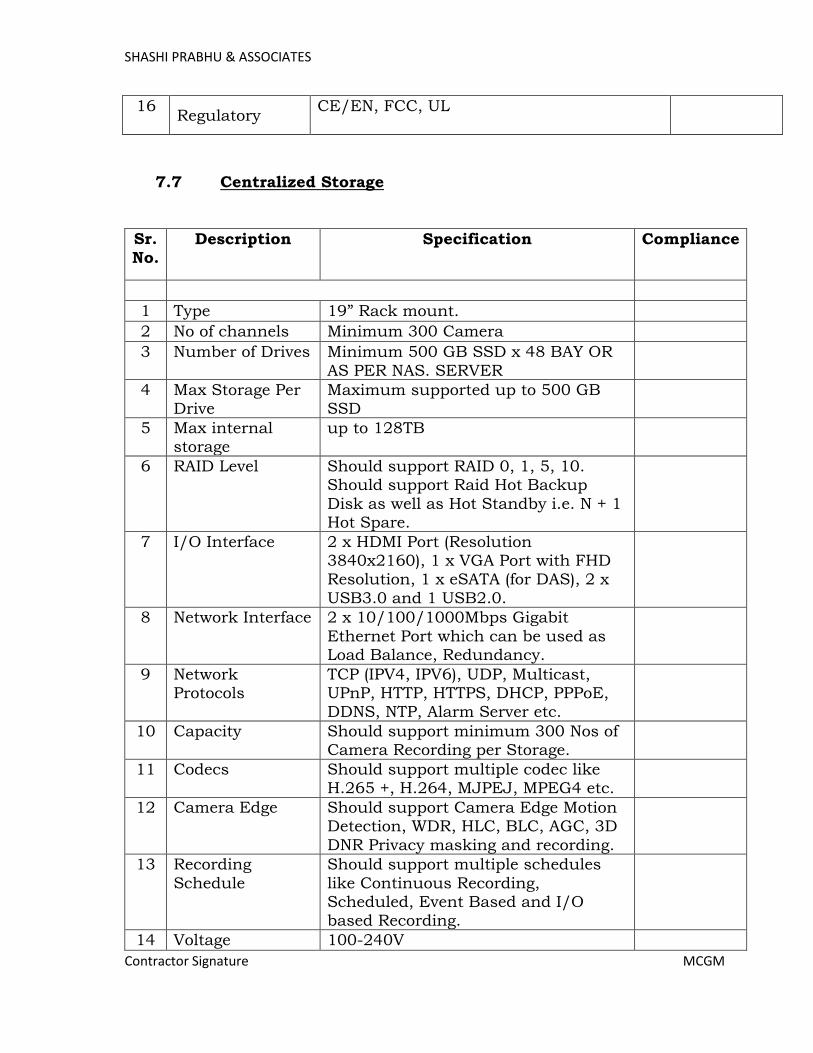
SHASHI PRABHU & ASSOCIATES
Contractor Signature MCGM
16 Regulatory
CE/EN, FCC, UL
7.7 Centralized Storage
Sr.
No. Description Specification Compliance
1 Type 19” Rack mount.
2 No of channels Minimum 300 Camera
3 Number of Drives Minimum 500 GB SSD x 48 BAY OR
AS PER NAS. SERVER
4 Max Storage Per Drive
Maximum supported up to 500 GB SSD
5 Max internal storage
up to 128TB
6 RAID Level Should support RAID 0, 1, 5, 10. Should support Raid Hot Backup
Disk as well as Hot Standby i.e. N + 1 Hot Spare.
7 I/O Interface 2 x HDMI Port (Resolution 3840x2160), 1 x VGA Port with FHD Resolution, 1 x eSATA (for DAS), 2 x
USB3.0 and 1 USB2.0.
8 Network Interface 2 x 10/100/1000Mbps Gigabit
Ethernet Port which can be used as Load Balance, Redundancy.
9 Network Protocols
TCP (IPV4, IPV6), UDP, Multicast, UPnP, HTTP, HTTPS, DHCP, PPPoE, DDNS, NTP, Alarm Server etc.
10 Capacity Should support minimum 300 Nos of Camera Recording per Storage.
11 Codecs Should support multiple codec like H.265 +, H.264, MJPEJ, MPEG4 etc.
12 Camera Edge Should support Camera Edge Motion Detection, WDR, HLC, BLC, AGC, 3D
DNR Privacy masking and recording.
13 Recording
Schedule
Should support multiple schedules
like Continuous Recording, Scheduled, Event Based and I/O based Recording.
14 Voltage 100-240V
Page 466
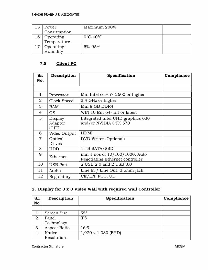
SHASHI PRABHU & ASSOCIATES
Contractor Signature MCGM
15 Power
Consumption
Maximum 200W
16 Operating Temperature
0°C-40°C
17 Operating Humidity
5%-95%
7.8 Client PC
Sr.
No. Description Specification Compliance
1 Processor Min Intel core i7-2600 or higher
2 Clock Speed 3.4 GHz or higher
3 RAM Min 8 GB DDR4
4 OS WIN 10 Ent 64- Bit or latest
5 Display Adaptor
(GPU)
Integrated Intel UHD graphics 630 and/or NVIDIA GTX 570
6 Video Output HDMI
7 Optical Drives
DVD Writer (Optional)
8 HDD 1 TB SATA/SSD
9 Ethernet
min 1 nos of 10/100/1000, Auto Negotiating Ethernet controller
10 USB Port 2 USB 2.0 and 2 USB 3.0
11 Audio Line In / Line Out, 3.5mm jack
12 Regulatory CE/EN, FCC, UL
2. Display for 3 x 3 Video Wall with required Wall Controller
Sr. No.
Description Specification Compliance
1. Screen Size 55”
2. Panel Technology
IPS
3. Aspect Ratio 16:9
4. Native
Resolution
1,920 x 1,080 (FHD)
Page 467
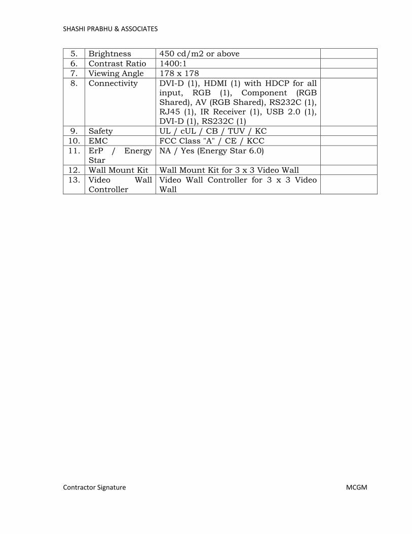
SHASHI PRABHU & ASSOCIATES
Contractor Signature MCGM
5. Brightness 450 cd/m2 or above
6. Contrast Ratio 1400:1
7. Viewing Angle 178 x 178
8. Connectivity DVI-D (1), HDMI (1) with HDCP for all input, RGB (1), Component (RGB
Shared), AV (RGB Shared), RS232C (1), RJ45 (1), IR Receiver (1), USB 2.0 (1), DVI-D (1), RS232C (1)
9. Safety UL / cUL / CB / TUV / KC
10. EMC FCC Class "A" / CE / KCC
11. ErP / Energy Star
NA / Yes (Energy Star 6.0)
12. Wall Mount Kit Wall Mount Kit for 3 x 3 Video Wall
13. Video Wall
Controller
Video Wall Controller for 3 x 3 Video
Wall
Page 468
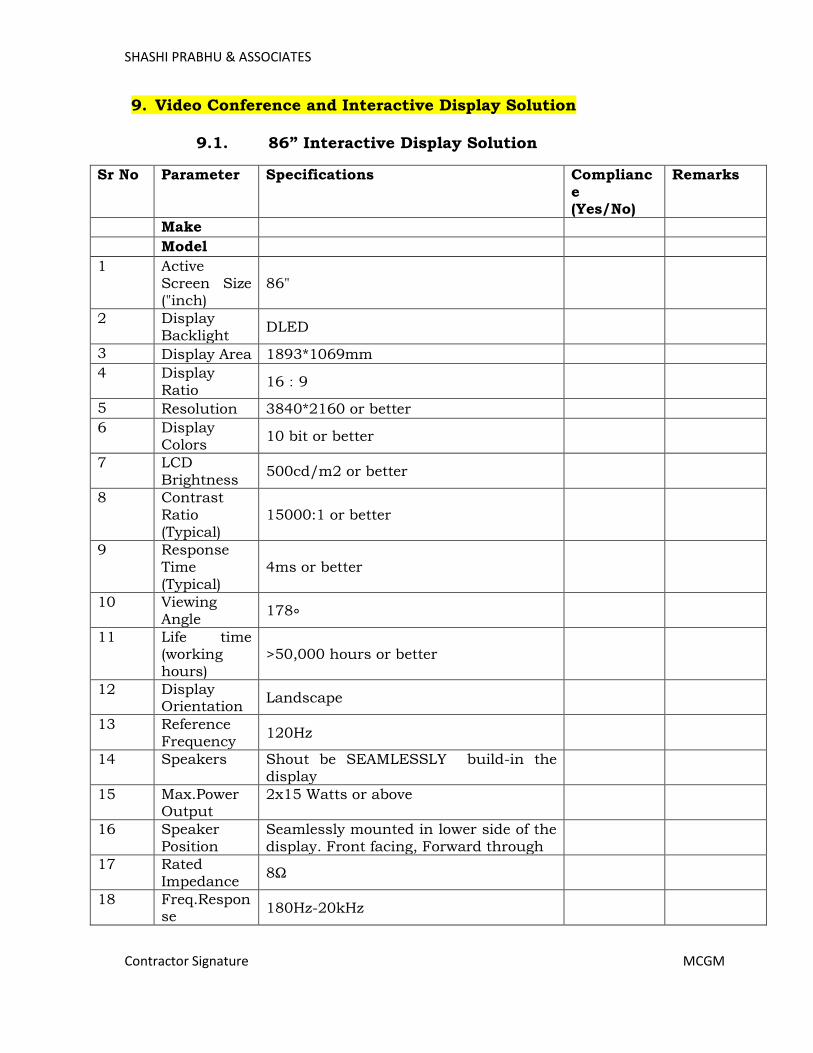
SHASHI PRABHU & ASSOCIATES
Contractor Signature MCGM
9. Video Conference and Interactive Display Solution
9.1. 86” Interactive Display Solution
Sr No Parameter Specifications Compliance (Yes/No)
Remarks
Make
Model
1 Active Screen Size ("inch)
86"
2 Display Backlight
DLED
3 Display Area 1893*1069mm
4 Display Ratio
16:9
5 Resolution 3840*2160 or better
6 Display Colors
10 bit or better
7 LCD Brightness
500cd/m2 or better
8 Contrast Ratio (Typical)
15000:1 or better
9 Response Time (Typical)
4ms or better
10 Viewing Angle
178∘
11 Life time (working hours)
>50,000 hours or better
12 Display Orientation
Landscape
13 Reference Frequency
120Hz
14 Speakers Shout be SEAMLESSLY build-in the display
15 Max.Power Output
2x15 Watts or above
16 Speaker Position
Seamlessly mounted in lower side of the display. Front facing, Forward through
17 Rated Impedance
8Ω
18 Freq.Response
180Hz-20kHz
Page 469
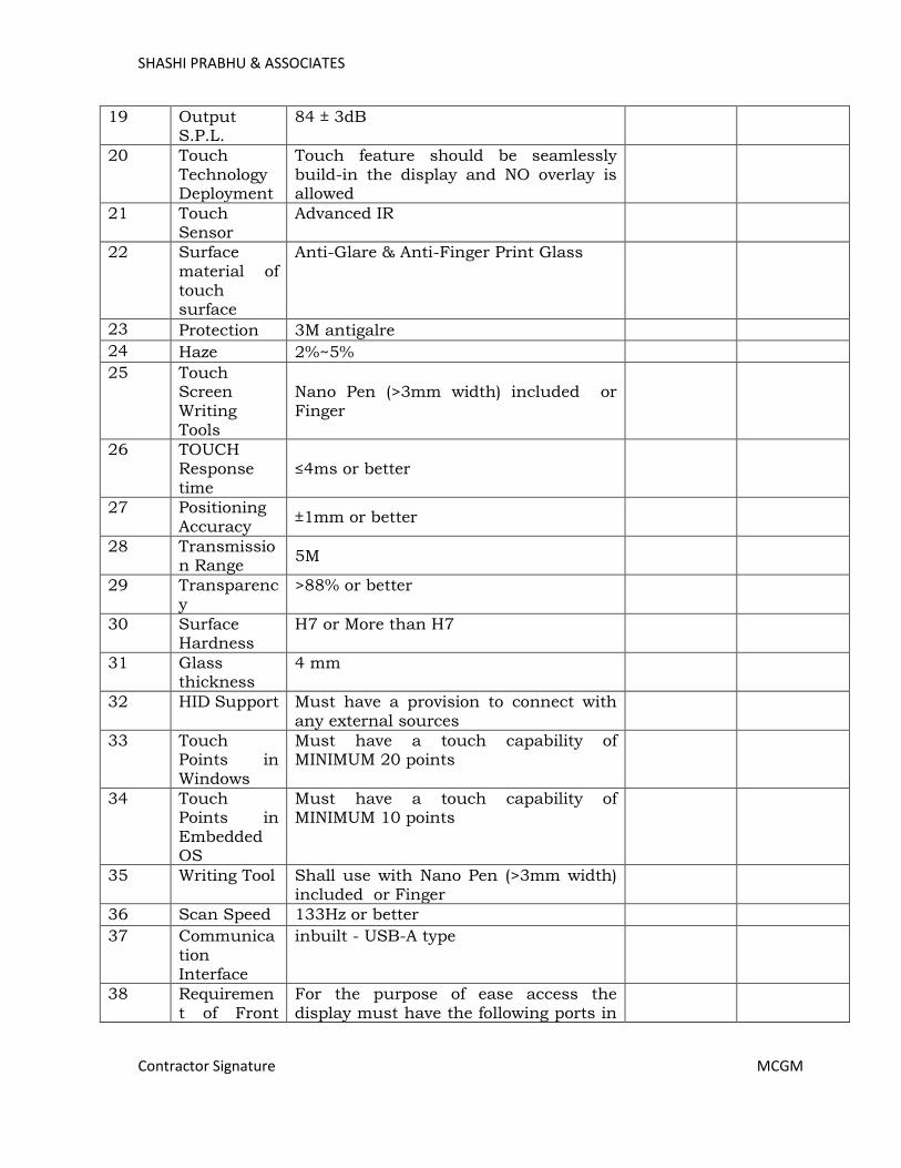
SHASHI PRABHU & ASSOCIATES
Contractor Signature MCGM
19 Output S.P.L.
84 ± 3dB
20 Touch Technology Deployment
Touch feature should be seamlessly build-in the display and NO overlay is allowed
21 Touch Sensor
Advanced IR
22 Surface material of touch surface
Anti-Glare & Anti-Finger Print Glass
23 Protection 3M antigalre
24 Haze 2%~5%
25 Touch Screen Writing Tools
Nano Pen (>3mm width) included or Finger
26 TOUCH Response time
≤4ms or better
27 Positioning Accuracy
±1mm or better
28 Transmission Range
5M
29 Transparency
>88% or better
30 Surface Hardness
H7 or More than H7
31 Glass thickness
4 mm
32 HID Support Must have a provision to connect with any external sources
33 Touch Points in Windows
Must have a touch capability of MINIMUM 20 points
34 Touch Points in Embedded OS
Must have a touch capability of MINIMUM 10 points
35 Writing Tool Shall use with Nano Pen (>3mm width) included or Finger
36 Scan Speed 133Hz or better
37 Communication Interface
inbuilt - USB-A type
38 Requirement of Front
For the purpose of ease access the display must have the following ports in
Page 470
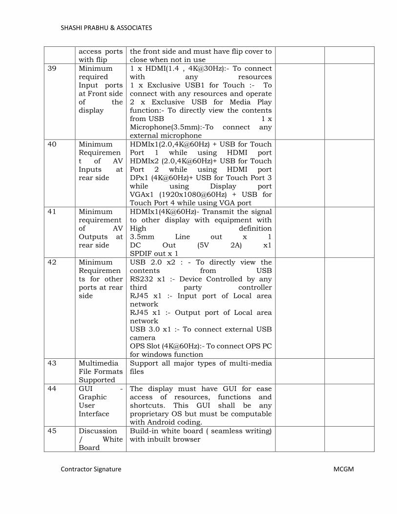
SHASHI PRABHU & ASSOCIATES
Contractor Signature MCGM
access ports with flip
the front side and must have flip cover to close when not in use
39 Minimum required Input ports at Front side of the display
1 x HDMI(1.4 , 4K@30Hz):- To connect with any resources 1 x Exclusive USB1 for Touch :- To connect with any resources and operate 2 x Exclusive USB for Media Play function:- To directly view the contents from USB 1 x Microphone(3.5mm):-To connect any external microphone
40 Minimum Requirement of AV Inputs at rear side
HDMIx1(2.0,4K@60Hz) + USB for Touch Port 1 while using HDMI port HDMIx2 (2.0,4K@60Hz)+ USB for Touch Port 2 while using HDMI port DPx1 (4K@60Hz)+ USB for Touch Port 3 while using Display port VGAx1 (1920x1080@60Hz) + USB for Touch Port 4 while using VGA port
41 Minimum requirement of AV Outputs at rear side
HDMIx1(4K@60Hz)- Transmit the signal to other display with equipment with High definition 3.5mm Line out x 1 DC Out (5V 2A) x1 SPDIF out x 1
42 Minimum Requirements for other ports at rear side
USB 2.0 x2 : - To directly view the contents from USB RS232 x1 :- Device Controlled by any third party controller RJ45 x1 :- Input port of Local area network RJ45 x1 :- Output port of Local area network USB 3.0 x1 :- To connect external USB camera OPS Slot (4K@60Hz):- To connect OPS PC
for windows function
43 Multimedia File Formats Supported
Support all major types of multi-media files
44 GUI - Graphic User Interface
The display must have GUI for ease access of resources, functions and shortcuts. This GUI shall be any proprietary OS but must be computable with Android coding.
45 Discussion / White Board
Build-in white board ( seamless writing) with inbuilt browser
Page 471
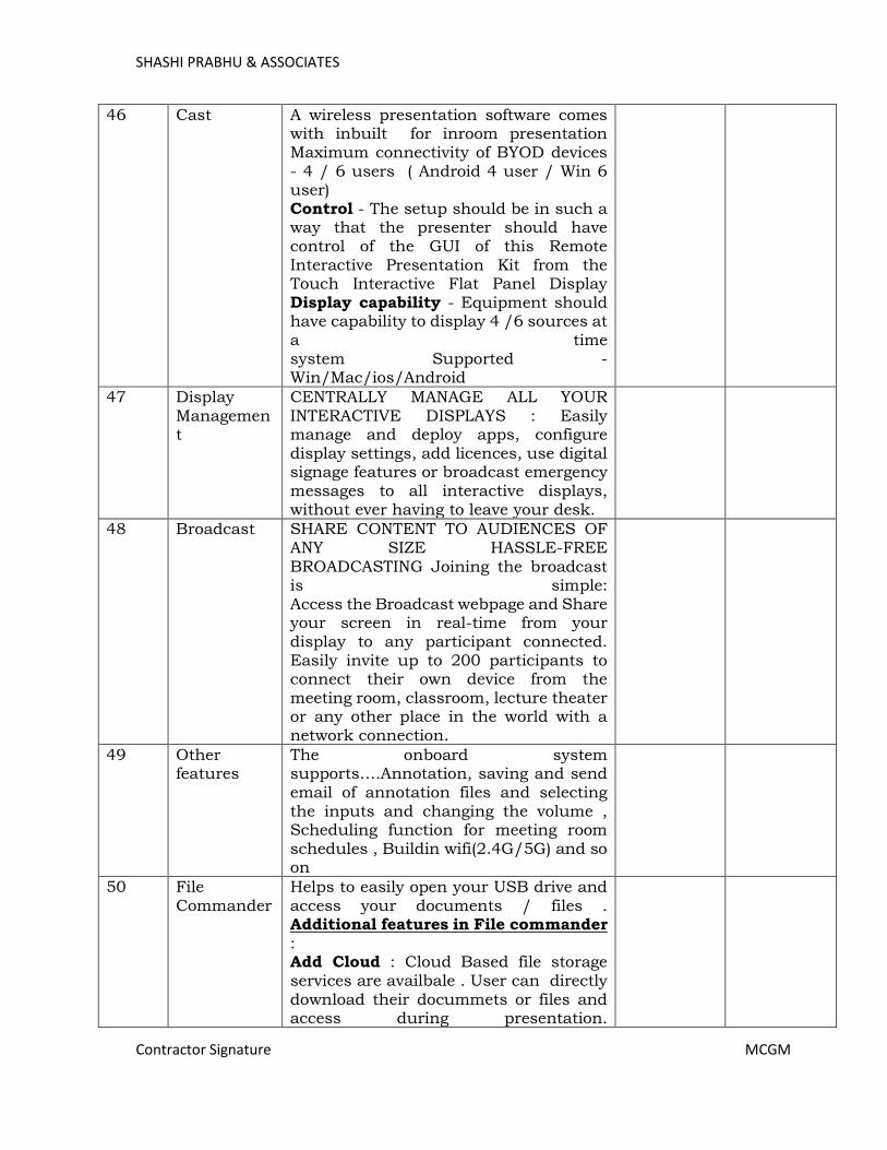
SHASHI PRABHU & ASSOCIATES
Contractor Signature MCGM
46 Cast A wireless presentation software comes with inbuilt for inroom presentation Maximum connectivity of BYOD devices - 4 / 6 users ( Android 4 user / Win 6 user) Control - The setup should be in such a way that the presenter should have control of the GUI of this Remote Interactive Presentation Kit from the Touch Interactive Flat Panel Display Display capability - Equipment should have capability to display 4 /6 sources at
a time system Supported - Win/Mac/ios/Android
47 Display Management
CENTRALLY MANAGE ALL YOUR INTERACTIVE DISPLAYS : Easily manage and deploy apps, configure display settings, add licences, use digital signage features or broadcast emergency messages to all interactive displays, without ever having to leave your desk.
48 Broadcast SHARE CONTENT TO AUDIENCES OF ANY SIZE HASSLE-FREE BROADCASTING Joining the broadcast is simple: Access the Broadcast webpage and Share your screen in real-time from your display to any participant connected. Easily invite up to 200 participants to connect their own device from the meeting room, classroom, lecture theater or any other place in the world with a network connection.
49 Other features
The onboard system supports….Annotation, saving and send
email of annotation files and selecting the inputs and changing the volume , Scheduling function for meeting room schedules , Buildin wifi(2.4G/5G) and so on
50 File Commander
Helps to easily open your USB drive and access your documents / files . Additional features in File commander : Add Cloud : Cloud Based file storage services are availbale . User can directly download their docummets or files and access during presentation.
Page 472

SHASHI PRABHU & ASSOCIATES
Contractor Signature MCGM
FTP : File Transfer Protocol (FTP) is the commonly used protocol for exchanging files over the Internet Local Area Network : A local area network (LAN) is a group of computers and associated devices that share a common communications line or wireless link to a server.
51 Email support
Pre loaded Aqua mail - you can easily email your whiteboard content to anyone
52 Business calendar
A pre loaded business calenser is available you can set schedules and synchronize with Google calendar for meeting room schedules
53 Customized GUI
User can easily customized their own background and logo's
54 Multimedia File Formats Supported
Support all major types of multi-media files
55
Object Regonisation
This product supports object recognition and produces different effects according to the diameter and size of the input objects. Fist/palm: identified as an eraser (100 pt). Fine Pen (3mm): suggested to use while writing. Thick Pen ( ≥ 8 mm)/ finger: suggested to use when you want to highlight
56 OTA (Over-the-Air) Update
Upgrade the latest firmware for your displays through our OTA Update support and keep them running smoothly at all times
57 Smart Eye production
Smart Eye Protact keep your eye vision safe from IFPD's light
58 Blue light filter
Blue light contributes to digital eye strain; IFPD's glasses that block blue light may increase comfort for users
59 Chipset MTK8386 or higher
60 CPU
ARMv8 A73*2+A53*2 ( A53 : 1.05-1.3GHz; A73 : 1.15-1.5GHz) or higher
61 GPU Mali-G51MP2 650 MHz or higher
62 RAM 3GB or higher
63 ROM 16GB build in or higher
64 External Memory
32GB TF card (build in) or higher
Page 473

SHASHI PRABHU & ASSOCIATES
Contractor Signature MCGM
65 Total In-built Memeory
48GB ( Inbuilt TF Card slot support max 64GB) or higher
66 Android Version
8.0.0 or higher
67 Android resolution
4K
68 Working Voltage
AC 100-240V, 50/60Hz
69 Power Consumption
Maximum ≤450W Standby Mode ≤0.5W
70 Storage Temperature/Humidity
-15~55/20~90%RH(Non
coagulation)
71 Working Temperature/Humidity
0-40/20~80%RH(Non coagulation)
72 Mounting Capabilities
Display must have facility to mount on floor stand or wall brackets
73 Self shutdown
Must self shutdown during abnormal temperature
74 Inbuilt Soft features
The touch interactive display must have inbuilt onboard writing software. Thus, this software shall has the capability to write some thing on the display and store in on-board system even WITHOUT any PC/Laptop/External device
75 The display must have the facility of send the written contents by mail, take printout and transfer to pen drive as well
76 This software which is embedded in the On-Board system shall have capability to write(Annotate) on top the contents that are shown from Pen drive direct /
External PC / Any such sources
77 External software
Touch interactive display shall also be supplied with specialised software which shall be installed in PC/Laptop. This software should have features of different writing capabilities like Pen, Highlighter, laser pen, geometric pen, text pen and so on. The software shall also have features of Screen record, screen capture, import files, export files and saving the content in different versions and so on.
78 Inbuilt Internet access
The touch interactive diplay mush have inbuilt WiFi (2.4G/5G). So that the presenter shall visit the internet to
Page 474
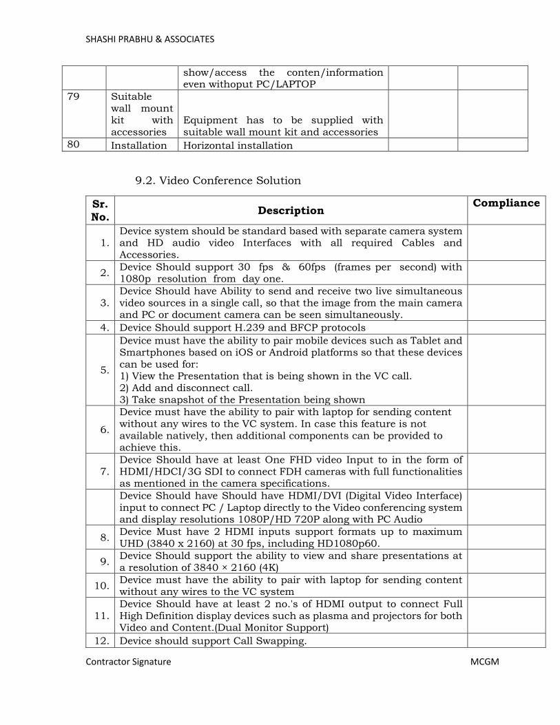
SHASHI PRABHU & ASSOCIATES
Contractor Signature MCGM
show/access the conten/information even withoput PC/LAPTOP
79 Suitable wall mount kit with accessories
Equipment has to be supplied with suitable wall mount kit and accessories
80 Installation Horizontal installation
9.2. Video Conference Solution
Sr.
No. Description
Compliance
1. Device system should be standard based with separate camera system and HD audio video Interfaces with all required Cables and Accessories.
2. Device Should support 30 fps & 60fps (frames per second) with 1080p resolution from day one.
3. Device Should have Ability to send and receive two live simultaneous video sources in a single call, so that the image from the main camera and PC or document camera can be seen simultaneously.
4. Device Should support H.239 and BFCP protocols
5.
Device must have the ability to pair mobile devices such as Tablet and Smartphones based on iOS or Android platforms so that these devices can be used for: 1) View the Presentation that is being shown in the VC call. 2) Add and disconnect call. 3) Take snapshot of the Presentation being shown
6.
Device must have the ability to pair with laptop for sending content without any wires to the VC system. In case this feature is not available natively, then additional components can be provided to achieve this.
7. Device Should have at least One FHD video Input to in the form of HDMI/HDCI/3G SDI to connect FDH cameras with full functionalities as mentioned in the camera specifications.
Device Should have Should have HDMI/DVI (Digital Video Interface) input to connect PC / Laptop directly to the Video conferencing system and display resolutions 1080P/HD 720P along with PC Audio
8. Device Must have 2 HDMI inputs support formats up to maximum UHD (3840 x 2160) at 30 fps, including HD1080p60.
9. Device Should support the ability to view and share presentations at a resolution of 3840 × 2160 (4K)
10. Device must have the ability to pair with laptop for sending content without any wires to the VC system
11. Device Should have at least 2 no.'s of HDMI output to connect Full High Definition display devices such as plasma and projectors for both Video and Content.(Dual Monitor Support)
12. Device should support Call Swapping.
Page 475

SHASHI PRABHU & ASSOCIATES
Contractor Signature MCGM
13. Device should able to view presentation from two laptops on each of the screen so that users can collaborate when not in a VC Call.
14. Device Should support G.711, G.722, G.722.1, 64 kbps MPEG-4 AAC-LD.
15. Device Should support Noise Reduction, Automatic Gain control, Acoustic Echo Canceller, Active Lip synchronization
16. Device Should support 3 Microphone inputs to connect 3 microphones and Should supply 02 Microphones from Day 1.
17. Device should have the pickup of the microphones at least 10 feet from the microphone.
18. Device Should have Echo Cancellation for every input.
19. Device Should support audio output.
20. Device Should have 01 x Gigabit Ethernet Interface.
21. Device should have Min. upto 6 Mbps H323/SIP on point-to-point Calls.
22. Device Should Support Packet Loss Based Down speeding.
23.
Device Should Support QoS—Diff Serve, IP adaptive bandwidth management (including flow control), Auto Gatekeeper discovery, Auto Network Address Translation (NAT), Standards based- Packet Loss Recovery feature.
24. Device must support IPv4 and IPv6 from day one on both H.323 and SIP.
25. Device Should support URL Dialing.
26. Device Should support for H.245 DTMF tones in H.323.
27. Device Should have Password protected system menu.
28. Device Should have ITU-T standards based Encryption of the video call.
29. Device Call should be encrypted end-to-end on IP.
30.
Device Should support Standards-based: H.235 v3 and AES Encryption via Automatic key generation and exchange. The same should be available in a call with Video with presentation (dual video).
31. Device Should have Ability to manually turn encryption ON/ OFF should be there.
32. Device Must have Capability to Block the Spam Calls.
33. Device Should support Automatic key generation and exchange.
34. Device Should have System Management using HTTPS and SSH.
35.
Device Should have PTZ camera with 1080p60 or better, 12x Zoom (12x Optical Zoom and 12x digital Zoom), 1920X1080 Resolution @60FPS, Field View 70 degree or better, Interface USB 3.0 port/HDMI/3G SDI Port.
36. Device cameras should be suitable for a large conference room of about Min. 7m in length with 15 people.
37. Device Camera should have Min. 1920 x 1080 pixels progressive @ 60fps.
38. Device Camera and codec should be from the same manufacturer.
39. Device Camera Should have at least 71 degrees horizontal field of view.
Page 476

SHASHI PRABHU & ASSOCIATES
Contractor Signature MCGM
40. Device Should support Local and Global directories.
41. Device Should support LDAP and H.350 protocols for directory transfer.
42. Device Should support built-in Multi conference capability to connect at least 1+3 sites at 720p30fps in a continuous presence mode
43.
Device Should have Capability to view all sites in a continuous presence mode with rate matching and transcoding such that different sites may connect at different speeds and protocols and still maintain a resolution of at least 720p.
44. In order to provide a good user experience, the unit must be equipped with an intuitive Touch Screen/Panel for controlling the VC unit.
45.
Device Must have ability to browse the directory, search a contact, Enable / disable speaker tracking, change layouts, mute/ unmute, increase-decrease volume.
46.
Device user should have the ability to select between two presentation sources such as a fixed PC and a laptop from the user interface. Users should also have the ability to share presentation wirelessly.
47.
Must have the capability to integrate with external control systems to control Blinds, Lights, air conditioning using the API’s. The User interface must have the necessary icons for controlling the external devices
48. Device Should be with 1 Years OEM Support.
49. Bidder should submit OEM Authorization certificate of the quoted device.
Audio/ Video / Web Conferencing Services:
Sr.
No. Description
Compliance
1. Proposed Solution should be Cloud-based Audio / Video / Web conferencing services
2. Proposed Solution should be Opex based / Subscription licensing
model.
3. Proposed Solution provided should be simple, secure collaboration and scalable.
4.
Proposed Solution Should Support for up to 1,000 concurrent users in a single meeting: Up to 200 SIP or H.323 video conferencing devices. Up to 500 additional Meetings video participants. Up to 1,000 additional Audio-only users.
5. Proposed Solution Should support One Button to Push join from On-Prem registered video systems, controlled by On-Prem Management and cloud registered apps and devices.
6. Proposed Solution should be have interoperability with Skype for Business and Lync from Day 1.
Page 477

SHASHI PRABHU & ASSOCIATES
Contractor Signature MCGM
7. Proposed Solution should have Video IVR with visual cues for a more intuitive join experience.
8.
Desktop, Mobile and Browser Apps -- Click-to-join from invitations. Enter meeting number for ad-hoc join. Use your computer or a telephone for audio. Or, have the cloud call your SIP based video system for full audio, video, content share experience.
9.
Proposed Solution should have following features In-meeting controls using Dual-Tone Multi-Frequency (DTMF) controls, Mute and unmute self , Mute and unmute all (host), Lock/unlock meeting (host), Record meeting (host), Change own video layout, SIP video systems require at least one of the following capabilities: RFC 2833 RTP Payload Type, In-band DTMF audio tones, Key Press Markup Language (KPML), H.323 video systems require at least one of the following capabilities: H.245 User Input Indicator, RFC 2833 RTP Payload Type, In-band DTMF audio tones, Users on video systems that cannot negotiate DTMF will only be able to join a meeting after the host starts it Recording status indicator Audio line mute state change prompts.
10.
Proposed Solution should have Desktop, Mobile and Browser Applications with Following features - Full participant list, Recording status indicator, Meeting lock status indicator, Mute/unmute audio of participants (host), Expel participant from meeting (host), Lock/unlock meeting (host), Record meeting (host), Transfer host role to another participant (host).
11. Proposed Solution should support Min. Main video at up to 720p at 30 frames per second (fps), Content sharing up to 1920x1200 at 3 fps, Video Aspect Ratios - 16:9 widescreen, 4:3 standard.
12. Proposed Solution should support Video Codec - H.261, H.263, H.263+, H.264 AVC, H.263 (CIF) or H.264 UC (720p/30) for Skype for Business and Lync clients.
13. Proposed Solution should support Audio for Video Systems - G.711 (m-law and a-law), MPEG-4 AAC-LD, Opus, G.722, G.728, G.722.1, G.729 (with and without Annex B), MPEG-4 AAC-LC (TIP calls only).
14. Proposed Solution should support Audio Codec for Applications – Opus, Internet Low Bitrate Codec (iLBC), G.722.
15.
Proposed Solution should support Audio Access Methods for Applications - Call-in (dial into the meeting), Call-back (meeting calls you) and video call-back, VoIP (use your computer microphone and speakers or your smartphone data connection).
16.
Proposed Solution should support Advanced Encryption Standard (AES) 128-bit encryption, Signaling protocol support: SIP, SIP Transport Layer Security (TLSv1.2), Binary Floor Control Protocol (BFCP), Content share (dual video) protocol support: BFCP for SIP Video Systems.
17. Proposed Solution should support ITU-T H.323 standards-based video systems, AES 128-bit encryption, Signaling protocol support:
Page 478
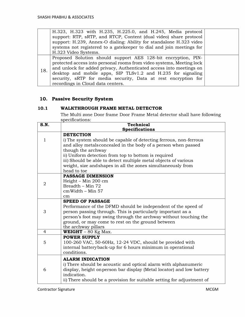
SHASHI PRABHU & ASSOCIATES
Contractor Signature MCGM
H.323, H.323 with H.235, H.225.0, and H.245, Media protocol support: RTP, sRTP, and RTCP, Content (dual video) share protocol support: H.239, Annex-O dialing: Ability for standalone H.323 video systems not registered to a gatekeeper to dial and join meetings for H.323 Video Systems.
18.
Proposed Solution should support AES 128-bit encryption, PIN-protected access into personal rooms from video systems, Meeting lock and unlock for added privacy, Authenticated access into meetings on desktop and mobile apps, SIP TLSv1.2 and H.235 for signaling security, sRTP for media security, Data at rest encryption for recordings in Cloud data centers.
10. Passive Security System
10.1 WALKTHROUGH FRAME METAL DETECTOR
The Multi zone Door frame Door Frame Metal detector shall have following specifications:
S.N. Technical Specifications
1
DETECTION i) The system should be capable of detecting ferrous, non-ferrous and alloy metals concealed in the body of a person when passed though the archway ii) Uniform detection from top to bottom is required iii) Should be able to detect multiple metal objects of various weight, size and shapes in all the zones simultaneously from head to toe
2
PASSAGE DIMENSION Height – Min 200 cm Breadth – Min 72 cm Width – Min 57 cm
3
SPEED OF PASSAGE Performance of the DFMD should be independent of the speed of person passing through. This is particularly important as a
person’s foot may swing through the archway without touching the ground, or may come to rest on the ground between the archway pillars
4 WEIGHT – 80 Kg Max.
5 POWER SUPPLY 100-260 VAC, 50-60Hz, 12-24 VDC, should be provided with internal battery back-up for 6 hours minimum in operational conditions.
6
ALARM INDICATION i) There should be acoustic and optical alarm with alphanumeric display, height on person bar display (Metal locator) and low battery indication. ii) There should be a provision for suitable setting for adjustment of
Page 479

SHASHI PRABHU & ASSOCIATES
Contractor Signature MCGM
volume of the audible alarm to overcome the ambient noise present in the vicinity
7 SENSITIVITY DFMD should have multi-zone capability with uniform sensitivity in all zones
8 ZONES: - Not less than eight real horizontal detection zones, covering full height of the equipment
9 CALIBRATION: - DFMD shall have inbuilt feature of both manual and automatic calibration
10
SECURITY: - i) There should be provision to secure the access to the control unit by a password protected alpha numeric keypad ii) DFMD should reset itself within 3 sec after alarm condition iii) Unit should have traffic and alarm counter. The equipment should work in bidirectional mode
11
OTHER FEATURES: - i) High discrimination between small masses and personal metallic objects ii) Automatic synchronization for DFMDs located close to each other up to a distance of one feet side by side
12
STATIC METAL COMPENSATION: - DFMD installed closed to fixed sheet or pieces of metal which form part of the building or its fittings. The DFMD should compensate for the presence of such metal and its performance should not be degraded by the presence of metal as stated above
13
HEALTH AND SAFETY: - i) Magnetic field should be harmless to magnetic media, electronic devices and should be film safe, (Supplier shall submit test certificates from national / international accredited lab) ii) Operation of DFMD shall not be affected by infrared, ultraviolet, electromagnetic or RF radiation. Offered equipment shall comply with CE or equivalent safety/ immunity standard (Supplier shall submit test certificates from national / international accredited lab) iii) DFMD should be harmless to pacemaker and pregnant woman (Supplier shall submit test certificates from national / international accredited lab as per ICNIRP guidelines)
14
INTERFERENCE REJECTION: - i) Interference, which is ‘mains-borne’ or radiated by an external source, should not cause the DFMD to raise the alarm spuriously. It should be possible to use equipment such as radio, portable telephone, walkie-talkie sets, X-ray monitors etc. at a distance of
Page 480

SHASHI PRABHU & ASSOCIATES
Contractor Signature MCGM
onemtr from the archway without causing spurious alarms. ii) Moving metal beyond 1 mtr from DFMD should not affect performance of the DFMD. It should be possible to move metallic items like trolleys, metallic gate opening/ closing one mtr away from the DFMD without the generation of false alarm
15
OPERATING TEMP:- DFMD shall work satisfactory without any deterioration in performance within the temperature range -20 degrees to (+)55 degrees, RH up to 90% non condensing.
16
ACCESSORIES TO PROVIDE: - i) Operating manual for the user ii) Standard test piece (STP) for testing of equipment to be provided by the supplier with each equipment. iii) Should have a ruggedized polypropylene shock proof container for safe transportation of product compliant to IP-65 and latest Mil Std.
10.2 HANDHELD METAL DETECTOR
Handheld Metal Detector shall have following specifications:
S. No.
Parameter
Specifications 1 Dimensions
Length Maximum 500mm
Probe width
Maximum 120mm
Body width Maximum 65mm
2 Weight Maximum 500gms
3 Power source Alkaline battery 3 volt (1.5x2) volt, should run minimum 550 hrs on 10% detection rate
4 Battery protection
To be provided against damage due to reverse polarity
5
Indication
a) Single LED based audio and visual multiple indication for-
i. SWITCH ON ii. METAL DETECTION
iii. LOW BATTERY INDICATION 6 Operation Single push button operation
7 Construction Should be rugged and impact resistant ABS moulded casing
8 Scan rate Minimum 3” to 24”/sec
9
Detection
Should be able to detect Ferrous and Non-Ferrous metals
Page 481

SHASHI PRABHU & ASSOCIATES
Contractor Signature MCGM
- Pistol .22 at min 6”
- Cartridge .22 at min 2” - Razor blade at min 1”
10 Tuning Automatic to ensure equal results on wide range of metals and alloys
11
Miscellaneous- The firm should be able to provide the following, as applicable, along with the equipment: -Cleaning kit technical manual giving full description of the item. User’s handbook
A. Battery charger with spare rechargeable battery set B. Technical manual giving full description of the item. C. User’s handbook D. Battery charger with spare rechargeable battery set
10.3 LARGE SIZE BAGGAGE INSPECTION SYSTEM 2.1. Minimum Tunnel size– 100cmW (Width) x 100cm H (Height)(+/-10%) 2.2. Conveyor belt speed should be between 0.18 and 0.3meter per second. Conveyor movement bidirectional. 2.3. All machines should operate on 230 VAC, 50 Hz power supply and should be able to withstand voltage fluctuations in the range of 170V to 260V. Single Phase, 3 to 5 Amp 2.4. Conveyor capacity – 200kg or more 2.5. Through put should be 200 bags per hour or more 2.6. Sensors >1000 diodes, L-shaped detector (Folded array type), In case defective diode arrays, scanning should be disabled, and error message should be displayed on the screen. 2.7. X-ray voltage – 160 kV or more 2.8. X-ray Source/Generator – It should be capable to operate smoothly for a period of at least six years. 2.9. Duty Cycle- 100% 2.10. The X-ray beam divergence should be such that the complete image at maximum size of bag is displayed without corner cuts 2.11. The radiation level should not exceed accepted health standard (0.1m R/Hr at a distance of 5 CM from external housing). Relevant certificate from AERB 2.12. The operating temperature should be -10deg C to 50 deg C. 2.13. Storage Temperature -20 Degree C to 50 degree C 2.14. Humidity- 90% non-condensing 2.15. Resolution: The machine should be able to display single un-insulated tinned copper wire of 42-SWG or 38 AWG. All penetration and resolution condition should be met without pressing any functional key and should be online. 2.15. Resolution: The machine should be able to display single un-insulated tinned copper wire of 42-SWG or 38 AWG. All penetration and resolution condition should be met without pressing any functional key and should be online. 2.16. Penetration should be 27 mm thickness of steel (Guaranteed) or more. 2.17. Continuous Electronic Zoom facility should be available to magnify the chosen area of an image eight times (8X) or more. Image features shall be keyboard controllable.
Page 482

SHASHI PRABHU & ASSOCIATES
Contractor Signature MCGM
2.18. Video display – 17’’ or better LCD Monitor SVGA High resolution, low
radiation, flicker free, resolution at least 1280 x 1024, 24-bit colour real time processing. 2.19. The machine should have features of Multi-energy X-ray imaging facility where materials of different atomic numbers will be displayed in different colours to distinguish between organic and inorganic materials. With this method to distinguish high density organic materials including explosives. Machine should have variable colour or materials stripping to facilitate the operator to monitor images of organic materials for closure scrutiny. All suspicious items (Explosives, High density, material narcotics) should be displayed in one mode and that should be online. 2.20. Radiation safety: - The machine must comply with requirements of health and safety regulations with regard to mechanical electrical and radiation hazards. Before installation of the machine, the supplier/ manufacturer should furnish relevant certificate from Atomic Energy Regulatory Board of India regarding radiation safety. The company manufacturing the equipment should have ISO certification for manufacturing and servicing of X-Ray Screening machines. 2.21. Film Safety: - Guaranteed safety for high-speed films upto ISO1600. The machines should be film safe. In other works, photographic films must not be damaged due to x-ray examination. 2.22. Machine should be properly sealed from all sides for pest proof. Dust proof cover is to be provided for covering when system is not in use. 2.23. Facility of variable contrast must be incorporated to allow enhancement of lighter and darker portion of the image. 2.24. The machine should be so designed that the software enhancement can be easily implemented to take care of new technique in image processing and pattern recognition. 2.25. Full diagnostic built in test facility. All models should have software controlled diagnosis report facility and system should give printout if printer is connected 2.26. All software features of the machine should be online and password protected. 2.27. Machine should be capable of recalling 15 or more previous images 2.28. It should have the capability of archiving 2000 or more images with date & time stamp. 2.29. Control desk with security housing and locking provision should be available. The operator personal identification number can be entered the keyboard along with generation of
log. 2.30. Facility of image enhancement should be available 2.31. All models should have online recording facility and images can be recorded in CD R/W or/and USB and should be able to view images so recorded on stand-alone PC. 2.32. Lead impregnated safety screen should be available at either ends of the tunnel. This should be covered by relevant AERB certificate. Idle rollers to be provided at either ends of the tunnel to facilitate the placing of baggage at input and output 2.33. All software features should be controlled from key board of machine only. Keyboard function should be user friendly. To enable/ disable the software features system should not be rebooted. 2.34. If the machine fails to penetrate a particular item then an alarm video and audio both should be generated to notify the operator.
Page 483
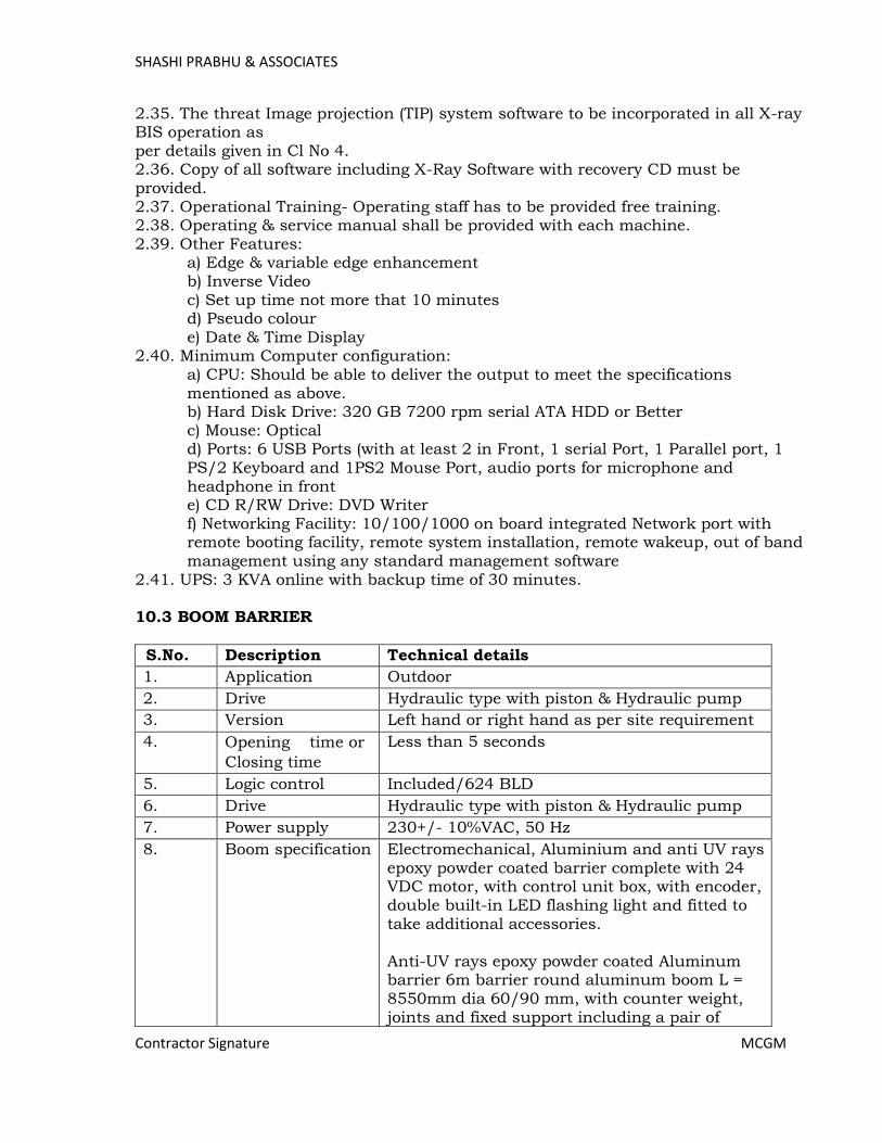
SHASHI PRABHU & ASSOCIATES
Contractor Signature MCGM
2.35. The threat Image projection (TIP) system software to be incorporated in all X-ray BIS operation as per details given in Cl No 4. 2.36. Copy of all software including X-Ray Software with recovery CD must be provided. 2.37. Operational Training- Operating staff has to be provided free training. 2.38. Operating & service manual shall be provided with each machine. 2.39. Other Features:
a) Edge & variable edge enhancement b) Inverse Video c) Set up time not more that 10 minutes d) Pseudo colour
e) Date & Time Display 2.40. Minimum Computer configuration:
a) CPU: Should be able to deliver the output to meet the specifications mentioned as above. b) Hard Disk Drive: 320 GB 7200 rpm serial ATA HDD or Better c) Mouse: Optical d) Ports: 6 USB Ports (with at least 2 in Front, 1 serial Port, 1 Parallel port, 1 PS/2 Keyboard and 1PS2 Mouse Port, audio ports for microphone and headphone in front e) CD R/RW Drive: DVD Writer f) Networking Facility: 10/100/1000 on board integrated Network port with remote booting facility, remote system installation, remote wakeup, out of band management using any standard management software
2.41. UPS: 3 KVA online with backup time of 30 minutes. 10.3 BOOM BARRIER
S.No. Description Technical details
1. Application Outdoor
2. Drive Hydraulic type with piston & Hydraulic pump
3. Version Left hand or right hand as per site requirement
4. Opening time or
Closing time
Less than 5 seconds
5. Logic control Included/624 BLD
6. Drive Hydraulic type with piston & Hydraulic pump
7. Power supply 230+/- 10%VAC, 50 Hz
8. Boom specification Electromechanical, Aluminium and anti UV rays epoxy powder coated barrier complete with 24 VDC motor, with control unit box, with encoder, double built-in LED flashing light and fitted to take additional accessories. Anti-UV rays epoxy powder coated Aluminum barrier 6m barrier round aluminum boom L = 8550mm dia 60/90 mm, with counter weight, joints and fixed support including a pair of
Page 484
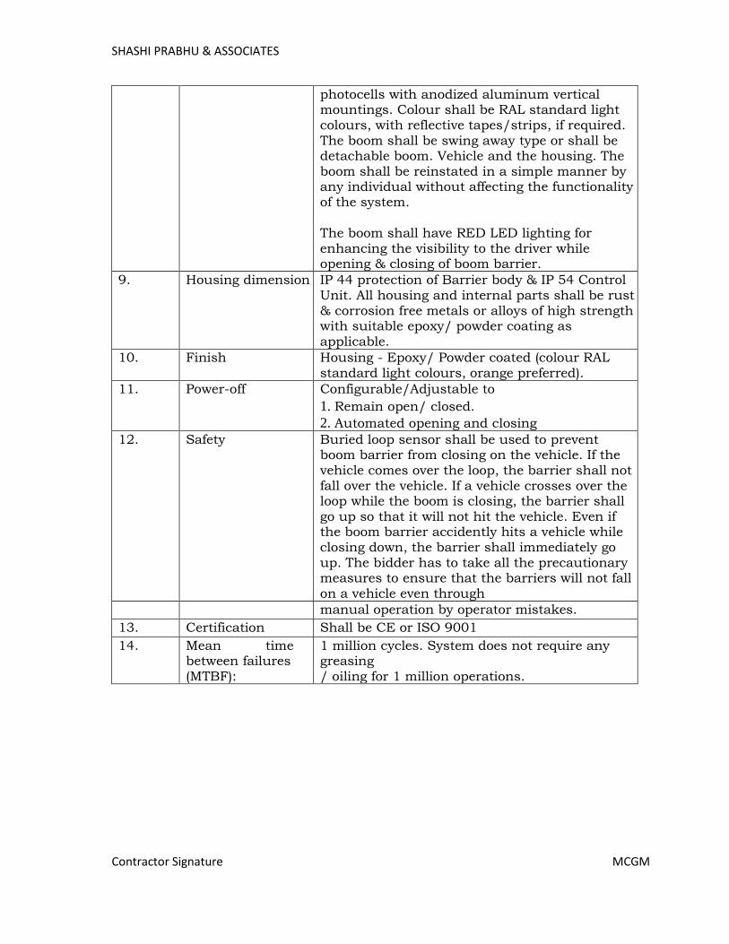
SHASHI PRABHU & ASSOCIATES
Contractor Signature MCGM
photocells with anodized aluminum vertical mountings. Colour shall be RAL standard light colours, with reflective tapes/strips, if required. The boom shall be swing away type or shall be detachable boom. Vehicle and the housing. The boom shall be reinstated in a simple manner by any individual without affecting the functionality of the system. The boom shall have RED LED lighting for enhancing the visibility to the driver while opening & closing of boom barrier.
9. Housing dimension IP 44 protection of Barrier body & IP 54 Control Unit. All housing and internal parts shall be rust & corrosion free metals or alloys of high strength with suitable epoxy/ powder coating as applicable.
10. Finish Housing - Epoxy/ Powder coated (colour RAL standard light colours, orange preferred).
11. Power-off Configurable/Adjustable to
1. Remain open/ closed.
2. Automated opening and closing
12. Safety Buried loop sensor shall be used to prevent boom barrier from closing on the vehicle. If the vehicle comes over the loop, the barrier shall not fall over the vehicle. If a vehicle crosses over the loop while the boom is closing, the barrier shall go up so that it will not hit the vehicle. Even if the boom barrier accidently hits a vehicle while closing down, the barrier shall immediately go up. The bidder has to take all the precautionary measures to ensure that the barriers will not fall on a vehicle even through
manual operation by operator mistakes.
13. Certification Shall be CE or ISO 9001
14. Mean time between failures (MTBF):
1 million cycles. System does not require any greasing / oiling for 1 million operations.
Page 485