Technical specification for 6.6kV swgr DG protection Relays ...
60
NUCLEAR POWER CORPORATION OF INDIA LIMITED (A Government of India Enterprise) KAIGA GENERATING STATION UNITS-1&2 TECHNICAL SPECIFICATION FOR RETROFITTING OF NUMERICAL RELAYS IN EXISTING 6.6kV DIESEL GENERATOR INCOMER FEEDER PROTECTION PANEL REF. USI NO: 52311 REVISION NO. : R0 DATE OF ISSUE : (MONTH/YEAR) July, 2018 TOTAL NO. OF PAGES : (Including Cover Sheet) 60 (Refer Revision Control Sheet for details of revisions)
-
Upload
khangminh22 -
Category
Documents
-
view
7 -
download
0
Transcript of Technical specification for 6.6kV swgr DG protection Relays ...
NUCLEAR POWER CORPORATION OF INDIA LIMITED (A Government of India Enterprise)
KAIGA GENERATING STATION UNITS-1&2
TECHNICAL SPECIFICATION FOR RETROFITTING OF NUMERICAL RELAYS IN EXISTING 6.6kV DIESEL GENERATOR
INCOMER FEEDER PROTECTION PANEL
REF. USI NO: 52311
REVISION NO. : R0
DATE OF ISSUE : (MONTH/YEAR)
July, 2018
TOTAL NO. OF PAGES : (Including Cover Sheet)
60
(Refer Revision Control Sheet for details of revisions)

REVISION CONTROL SHEET
DOCUMENT TYPE: TECHNICAL SPECIFICATION
TITLE: TECHNICAL SPECIFICATION FOR RETROFITTING OF NUMERICAL RELAYS IN EXISTING 6.6kV DIESEL GENERATOR INCOMER
FEEDER PROTECTION RELAY PANEL
REV. NO. & DATE
DESCRIPTION OF REVISION
REVISED BY NAME &
SIGNATURE
BY NAME & SIGNATURE CHECKED
REVIEWED BY NAME & SIGNATURE
APPROVED BY NAME & SIGNATURE
R-0, 26/07/18
-- A Niranjan D Mukherjee R V Manohar D Subbarao

NPCIL PROPRIETARY
This document contains confidential and protected information and that the same are the intellectual property of Nuclear Power Corporation of India Limited (NPCIL). No part of this document including notably any editorial elements, verbal and figurative marks and images included herein, shall be reproduced or transmitted or utilized or published or stored in any form or by any means now known or hereinafter invented, electronic, digital or mechanical, including photocopying, scanning, recording or by any information storage or retrieval system, without prior written permission from NPCIL, by any person or entity. Unauthorized use, disclosure or copying is strictly prohibited and may constitute unlawful act and can attract legal action.

TABLE OF CONTENTS SECTION TITLE PAGE NO.
1 Scope of Specifications 5 2 Applicable Codes & Standards 5 3 Specification of Numerical Relay 6 4 Equipment Construction and Design Details 10 5 Inspection and Testing 13 6 Quality Control Plan & General Guidelines for Bidder 15 7 Tests at Site 15 8 Acceptance Requirements For Relays
16
9 Special Tools & Tackles for Erection & Maintenance 16 10 Enclosures Annexure-1 : Single line diagram 17 Annexure-2: DG Schematics drawings 18 Annexure-3: Details of activities for Independent
Verification & Validation (IV & V) of computer/PLC based system of Completely Of the Shelf Type (COTS)
19
Annexure-4 : Bill of material 46 Annexure-5 : Quality Control Plan 47 14 Section-D 49-50

Nuclear Power Corporation of India Limited Kaiga Generating station-1&2
Technical Specification for Retrofitting of Numerical Relays in 6.6kv Diesel Generator Incomer Feeder Protection Panel
Page 5 of 60 Rev-0
1.0 SCOPE:
The scope of this specification covers the technical requirement of ‘6.6 KV switchgear numerical relays for Diesel generator protection’ for Kaiga Generating station (KGS # 1&2). This specification covers the design, material, construction features, manufacture, assembly, stage inspection and testing at CONTRACTOR’s / SUB-CONTRACTOR’s works, packing for shipment, transportation and delivery, associated accessories for retrofit on existing relay panel & removal of old relays/wiring, retrofit of 3 numerical relay and its wiring as per wiring scheme, testing and commissioning of the equipment covered in this specification for KGS-1&2. The scope also includes performance guarantee of 12 months from the date of commissioning.
Numerical relays shall be subjected to Independent Verification and Validation (IV&V) at factory and also at site. IV&V tests at factory will be carried out after completion of all required documentation and inspection/tests by NPCIL at factory and IV&V tests at site will be conducted after completion of site commissioning tests. Detailed scope of IV&V shall be as described in the annexure-3.
2.0 APPLICABLE CODES AND STANDARDS:
Sl. No
Standard Number
Standard title
1.0 Bureau Of Indian Standards
IS 3231 Electrical relays for power system protection IS 3842 Application guide for electrical relays for ac
systems IS 8714 Electrical Protective Relays for use in seismic
areas IS/IEC 60898 Electrical Accessories - Circuit-Breakers for
Overcurrent Protection for Household and Similar Installations
2.0 International Standards IEEE 344 Recommended practice for seismic
qualification of Class-IE equipment for Nuclear Power Generating Stations
ANSI/ IEEE-983
Standard for software quality assurance plan
IEEE 1012 IEEE Standards for Software verification & validation plan
IEEE Std 7-4.3.2
IEEE Standard Criteria for digital computers in safety systems of Nuclear Power Generating Stations

Nuclear Power Corporation of India Limited Kaiga Generating station-1&2
Technical Specification for Retrofitting of Numerical Relays in 6.6kv Diesel Generator Incomer Feeder Protection Panel
Page 6 of 60 Rev-0
IEC-60068 Environmental testing procedure IEC 60255 Electrical Relays IEC 61000-6-5
Electromagnetic Compatibility (EMC)
ISO 9000 International Standards for Quality Management
3.0 SPECIFICATION OF NUMERICAL RELAY:
1.00 System Particulars 1.01 Nominal System Voltage 6.6 kV 1.02 Highest System Voltage 7.2 kV 1.03 Frequency 50 Hz 1.04 System Grounding Non-effectively earthed through resistance limiting
earth fault current to 400A for CL-IV system & 40 A for CL-III system.
2.00 Data Sheet – Protective Relays 2.01.00 Common Requirements for Numerical Relays 2.01.01 Functional requirements Electrical protection relays shall be provided with
(a) Protection functions, (b) metering functions for Current, Voltage (c) facilities for fast transient recording functions for all the analog inputs to the relay, (d) Facilities for CT secondary circuit and trip circuit supervision, (e) provision for the programmable logic outputs (f) Facilities for software uploading/down loading, (g) Fault diagnostics, (h) Time synchronization with external clock, (i) Multi level password protection security and (j) Watchdog facility. Only protection function is of safety class (IB), all other functions are of class NINS. The protection function being the critical function shall have the highest priority.
2.01.02 Inputs 1A/5A from CT secondary and/or 110 V AC from VT secondary as required.
2.01.03 Outputs Potential free contacts having: 1. Making current capability: 30A for 3 seconds. 2. Breaking current capability: 1A inductive at
250V DC (L/R=40ms) 3. Continuous current capability: 5A 4. Mechanical durability: >10000 operations. 5. Contact performance: According to IS-12083
2.01.04 Accuracy ± 0.2% at In (Phase current input). Timers: ± 2% or 10ms whichever is lower.
2.01.05 Over Current capability (a) 100In for 1 second (b) 30In for 10 seconds (c) 4In continuous.

Nuclear Power Corporation of India Limited Kaiga Generating station-1&2
Technical Specification for Retrofitting of Numerical Relays in 6.6kv Diesel Generator Incomer Feeder Protection Panel
Page 7 of 60 Rev-0
2.01.06 Over Voltage capability (a) 2.6 Vn- 10 sec (Vn-Rated Voltage) (b) 2 Vn- continuous
2.01.07 Type of mounting Flush Mounting 2.01.08 Auxiliary supply voltage 220V DC, +10% and –30% variation. 2.01.09 Self-testing and diagnostic
features (a) Hard-wired watchdog timer feature shall be
provided with contacts for external alarm. (b) Internal Auxiliary power supply monitoring
with contacts for external alarm. 2.01.10 Password Protection Multi-level password protection required. 2.01.11 Energy measurement
provision (kWH) Required.
2.01.12 Local Display LCD/LED Display required for indicating (a) Relay status (b) Measured quantities. (c) Set values. (d) Quantities at the instant of relay operation.
2.01.13 Power off withstand 50ms power interruption without de-energizing as per IEC60255-11.
2.02.00 Environmental Requirements 2.02.01 Climatic conditions (a) Operating temperature: 50C to 550C
(b) Storage temperature: 500C to 700C (c) Humidity: 93% RH at 400C
2.02.02 Seismic Conditions Seismic Category-1. Relays are mounted on the existing seismic qualified M/s. ABB make relay panel door and have to withstand the forces likely to be generated under seismic condition at relay location without malfunctioning. Hence the relays have to be qualified for the maximum forces likely to be experienced. Relays shall conform to IS-8714/ IEC-60255-21
2.02.03 EMI/EMC Levels To comply with IEC 61000: 1) Enclosure Port (a) Power frequency magnetic
field
30A/m as per IEC 61000-4-8, Performance criteria-A
(b) Radio-frequency electromagnetic field. AM modulated
As per IEC 61000-4-3 80-1000MHz: 10V/m 1.4GHz-2.0GHz: 3V/m 2.0-2.7 GHz: 1V/m Performance criteria-A
(c) Electrostatic discharge ±8kV as per IEC 61000-4-2, Performance Criteria-B
2) Signal Ports
Nuclear Power Corporation of India Limited Kaiga Generating station-1&2
Technical Specification for Retrofitting of Numerical Relays in 6.6kv Diesel Generator Incomer Feeder Protection Panel
Page 8 of 60 Rev-0
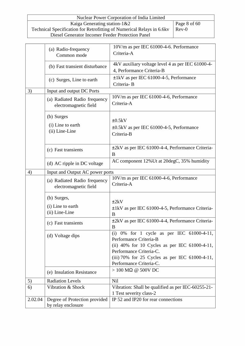
(a) Radio-frequency Common mode
10V/m as per IEC 61000-4-6. Performance Criteria-A
(b) Fast transient disturbance 4kV auxiliary voltage level 4 as per IEC 61000-4-4, Performance Criteria-B
(c) Surges, Line to earth ±1kV as per IEC 61000-4-5, Performance Criteria- B
3) Input and output DC Ports (a) Radiated Radio frequency
electromagnetic field
10V/m as per IEC 61000-4-6, Performance Criteria-A
(b) Surges
(i) Line to earth (ii) Line-Line
±0.5kV
±0.5kV as per IEC 61000-4-5, Performance Criteria-B
(c) Fast transients ±2kV as per IEC 61000-4-4, Performance Criteria-B
(d) AC ripple in DC voltage AC component 12%Ut at 20degC, 35% humidity
4) Input and Output AC power ports (a) Radiated Radio frequency
electromagnetic field
10V/m as per IEC 61000-4-6, Performance Criteria-A
(b) Surges,
(i) Line to earth (ii) Line-Line
±2kV ±1kV as per IEC 61000-4-5, Performance Criteria-B
(c) Fast transients ±2kV as per IEC 61000-4-4, Performance Criteria-B
(d) Voltage dips (i) 0% for 1 cycle as per IEC 61000-4-11, Performance Criteria-B (ii) 40% for 10 Cycles as per IEC 61000-4-11, Performance Criteria-C. (iii) 70% for 25 Cycles as per IEC 61000-4-11, Performance Criteria-C.
(e) Insulation Resistance > 100 MΩ @ 500V DC
5) Radiation Levels Nil 6) Vibration & Shock Vibration: Shall be qualified as per IEC-60255-21-
1 Test severity class-2 2.02.04 Degree of Protection provided
by relay enclosure IP 52 and IP20 for rear connections

Nuclear Power Corporation of India Limited Kaiga Generating station-1&2
Technical Specification for Retrofitting of Numerical Relays in 6.6kv Diesel Generator Incomer Feeder Protection Panel
Page 9 of 60 Rev-0
2.03.00 Numerical Relay specificification (51V, 51N, 27, 32, 40, 46, 59, 67P, 81, 87)
2.03.01 Type Numerical relays
2.03.02 Type of protections
i) 27- Under voltage protection ii) 32- Reverse power protection iii) 40- Loss of excitation protection iv) 46- Negative phase sequence v) 59- Over voltage protection vi) 67P- Over power protection vii) 81- Under Frequency protection viii) 87-Differential protection ix) 51V- Voltage restrained over current protection x) 51N- Earth fault protection
2.03.02 Under voltage protection (27) i) Voltage setting range First stage with IDMT & definite
time. Second stage with settable definite time. a) 10–120 V in steps of 1V-first stage b) 10-120 V in steps of 1V -second stage
ii) Time delay range Time delay range a) First stage-0-100 s in steps of 0.1s b) Second stage-0-100 s in steps of 0.1s
2.03.03 Reverse power protection (32) i) Setting range 0.5-25% ii) Time delay range 0-100 s in steps of 0.1s iii) External timer 0-10 s in steps of 0.1s
2.03.04 Loss of excitation protection (40) i) Circle diameter 25-325 Ohms in steps of 1 ohm ii) Offset 0-40 Ohms in steps of 0.5 ohms iii) Time delay 0-100 s in steps of 0.1s
2.03.05 Unbalance protection (46) i) Negative sequence current threshold a) 0.03In- 0.5In in steps of 0.01In-
alarm b) 0.05- 0.5In in steps of 0.01In- Trip ii) Time delay 2-60 sec in steps of 0.1s
2.03.06 Over voltage protection (59) i) Voltage setting range 1.2-1.4 times Vn in steps of 1V ii) Time delay 0-100 s in steps of 0.01s
2.03.07 Overpower protection (67P) i) Setting range 100-150 % ii) Time delay range 0-100 s in steps of 0.1s
2.03.08 Under frequency protection (81) i) Setting range 45-65 Hz in steps of 0.01 Hz ii) Time delay range 0.1-100s in steps of 0.01s
2.03.09 Differential protection (87)

Nuclear Power Corporation of India Limited Kaiga Generating station-1&2
Technical Specification for Retrofitting of Numerical Relays in 6.6kv Diesel Generator Incomer Feeder Protection Panel
Page 10 of 60 Rev-0
i) Type High impedance ii) Setting range 5 – 50% In in steps of 1% In iii) Operating time Less than 25 ms iv) Stabilising resistors Required v) Non-linear resistors Required
2.03.10 Voltage Restrained over current Protection (51V)
i) Setting range 80% to 200% in steps of 1%In ii) Operating time TMS range:0.025 to 1.2 in steps of
0.01 2.03.11 Earth fault Protection (51N)
i) Setting range 20% to 80% in steps of 1% ii) Operating time TMS range:0.025 to 1.2 in steps of
0.025
2.03.12 Number of output relays Minimum 32 Note:
1. Protection mentioned above shall be complete in all respects. 2. Minimum 2 sets of contacts shall be made available from relay for alarm and SCADA
in addition to tripping requirements. Auxiliary relays as required shall be included in the scope.
3. For general requirements of relay refer clause-4. 4. The setting ranges indicated are recommendatory. The actual setting ranges available
shall meet the protection requirements. Existing setting attached for reference annexure
5. Three set of Numerical relay shall include as a spare item with this tender.
4.0 Equipment Construction and Design Details:
4.1 Relays shall be provided with degree of protection as specified in clause -3.
4.2 Relays shall be mounted flush on the existing ABB relay panel hinged door of the panel compartment (Existing cut out details & panel photo attached).
4.3 Protections relay shall be of numerical type with following general specifications.
4.3.1 Numerical relays to be built with minimum 16 bit with reasonable clock frequency to meet the response requirement of relay.
4.3.2 Numerical relays shall be provided with (a) Required Protection functions, (b) metering functions for (i) Current, (ii) Voltage, (iii) kWh and (iv) kVARh, (c) facilities for fast transient recording functions for all the analog inputs to the relay, (d) facilities for CT secondary circuit and trip circuit supervision, (e) programmable logic outputs (f) facilities for software uploading/down loading/ fault diagnostics, time tagging, time synchronization with external clock, multi-level pass word protection security and (g) Watchdog facility.
4.3.3 It shall be possible to adjust pre-fault and post-fault recording times. Trip circuit supervision for one of the trip coil circuits shall be provided by this relay.

Nuclear Power Corporation of India Limited Kaiga Generating station-1&2
Technical Specification for Retrofitting of Numerical Relays in 6.6kv Diesel Generator Incomer Feeder Protection Panel
Page 11 of 60 Rev-0
4.3.4 The sampling (per cycle) rate of CT/PT inputs and digital inputs shall be adequate to process the inputs and generate outputs with the required accuracy. The system shall use non-volatile memories and shall not require any loading of software after it is inspected at factory works. Relays shall not require battery for storing data or software. The operating time for instantaneous type protections, Time delayed and IDMT protections shall be suitable for applications specified. Deviations, if any, shall be brought out clearly in the offer.
4.3.5 Necessary provisions shall be made in the relay so that the configuration can be changed at site, if required.
4.3.6 Ports shall be provided to connect the numerical relay to PC (MMI/Programming) and SCADA. In addition, the relay facia shall have LCD/LED displays with functional keys to program the relay for relay settings and configuration. Communication protocol shall confirm to IEC 61850 Std.
4.3.7 The bidder shall indicate clearly in their offer, the various protections for which multi-function numerical relays are offered. Bidders shall also confirm the arrangement and specification of CTs in the enclosed single line diagram. Any deviation in this respect shall be brought clearly in their offer.
4.3.8 Rating of digital outputs shall be suitable for energizing / de-energising tripping relays offered and tripping of circuit breakers.
4.3.9 All numerical relays shall have self-diagnostic facilities to indicate the failure or unhealthiness of relay including its power supply. LEDs shall be provided on the facia of relay for the above In addition to this, it should be possible to easily identify the faulty module and perform further diagnostics. Unhealthy condition of relay shall not energise output relays for tripping i.e a protective relay failure shall not result in spurious trip.
4.3.10 The relay shall be suitable for accepting pps (pulse per second), minute pulses or hour pulses from station electrical system GPS clock.
4.3.11 The programming of the relay shall be easily implementable at site and shall not require special programming knowledge by the relay setting engineer.
4.3.12 Multi-level Password protection shall be provided for implementing changes in the relay settings and configuration to prevent any unauthorized change, which could affect the ability of the relay.
4.3.13 One portable evaluation station (Lap top PC of 7th generation Typical specification for reference INTEL i7 Processor, 4GB DDR3-1066Mhz RAM, CACHE L1 256kb, CACHE L2 1MB, CACHE L3 8MB. 1TB SATA Hard disk. 4 USB PORTS Rear and 2 USB PORTS FRONT, 1 serial port, 1 parallel port, 2 port 100 Mbps Ethernet slot. Keyboard, Optical Mouse, DVD RW ports) shall be supplied. Analysis software and software required for setting of relays and other software required for various functions including relay fault diagnostics shall be included in the scope of supply. Communication cables, connectors shall also be supplied with Evaluation Stations (PCs). The associated equipment shall be suitable for 240 V single phase AC supply.

Nuclear Power Corporation of India Limited Kaiga Generating station-1&2
Technical Specification for Retrofitting of Numerical Relays in 6.6kv Diesel Generator Incomer Feeder Protection Panel
Page 12 of 60 Rev-0
4.3.14 Numerical relays shall comply with EMC levels as defined in IEC 61000-6-5: EMC immunity of apparatus in power generating stations and high voltage substations and electromagnetic compatibility criteria as per IEC-60255. In addition relays shall also be qualified for climatic conditions as per applicable IEC standards. All necessary test reports shall be submitted.
4.3.15 After placement of order, before finalization of relay, CONTRACTOR shall provide the simplified algorithms and formulae used in the relay software for effective understanding of the relay operation.
4.3.16 Specific requirements of numerical relay for DG protection are as follows:
2250 KW (e) DG shall have protections as given in single line diagram (attached with specification) and clause-3 of this specification. All protections shall be provided in three equivalent relays and tripping command shall be generated be connecting output contacts in two out of three logic. Setting for a particular protection is all the three relays shall be same.
4.3.17 All relays shall conform to the requirements as specified in the data sheets and schematics.
4.3.18 All relays shall conform to the requirements of IS-3231 and IS-8714 or equivalent. All protective relays, relays having flag indication and relays with manual resetting feature shall be -flush mounted All other relays can be projection mounted inside the relay compartment. Relays shall have dust tight enclosure with transparent covers removable from the front.
4.3.19 It is the responsibility of CONTRACTOR to select the relays properly whose characteristics shall match with the equipment characteristics and also to obtain proper discrimination. Calculations for relay settings shall be submitted for Purchaser’s approval. In case the characteristics of the relay are not suitable for ensuring proper discriminative protection and, or do not adequately protect the equipment, then CONTRACTOR shall replace the relay with suitable relay at no extra cost to the PURCHASER.
4.3.20 All protective relays shall be in draw out cases (depending on availability) with built in test
facilities. Necessary test plugs shall be supplied loose and shall be included in CONTRACTOR’S scope of supply. Test blocks and switches shall be located immediately below each relay for testing.
4.3.21 All Numerical protection relays shall have pairs of contacts as specified in respective data sheets of this specification / schematic drawings. Relay cases shall have adequate number of terminals for making potential free connections to the relay coils and contacts including spare contacts. Relay case size shall be so chosen as not to introduce any limitations on the use of available contacts of the relay due to inadequacy of terminals.
4.3.22 All relays shall be self-reset type unless otherwise specified as electrical/hand reset type in the respective data sheet/schematic drawings.
4.3.23 Provision shall be made for easy isolation of contacts of each relay from the trip circuits for
the purpose of testing and maintenance.
4.3.24 Auxiliary seal in units provided on the protective relays shall be shunt reinforcement type.

Nuclear Power Corporation of India Limited Kaiga Generating station-1&2
Technical Specification for Retrofitting of Numerical Relays in 6.6kv Diesel Generator Incomer Feeder Protection Panel
Page 13 of 60 Rev-0
4.3.25 Relay contacts shall be silver faced with spring action and shall be free of contact bounce.
4.3.26 The TENDERER shall note that the relays mounted on the existing seismic qualified M/s. ABB relay panel have to withstand the forces likely to be generated under seismic condition at relay location without malfunctioning. As panel and relay individually seismic qualified. However if CONTRACTOR relay has already qualified for some specific spectra and seismic testing is not required than he shall demonstrate this by analysis/extrapolation as per IEEE-344 for the integral panel seismic condition. Hence the relays have to be qualified for the maximum forces likely to be experienced. Relays shall conform to IS-8714. Applicable documentary evidence shall be submitted during detailed engineering for seismic test for analysis/extrapolation as per IEEE-344.
4.3.27 All relays shall be suitable for continuous operation for ambient temperature at the location
of mounting e.g. relays located in breaker cubicle etc. Resistors used in the circuits shall be de-rated to at least 50% percent of their rating and so located that heat generated from them do not adversely affect other components and wiring.
4.3.28 Contacts of relays shall be suitable for electrical circuitry in which they are wired subject to meeting the minimum ratings indicated in this specification or applicable standards. Existing setting sheet Annexure -1 and schematic drawing
4.3.29 For All Numerical relays used for diesel generator (Cl-III system), independent verification and validation (IV&V) shall be performed. The scope includes preparation and submission of all necessary documentation and performance of tests at factory after the relays are inspected and cleared by quality surveillance and also at site. Details of the scope of work are indicated in annexure-3.
4.4 Grounding Requirements
Relay metallic cases shall be connected to the earth bus by copper wires of size not less than 2.5 sq. mm. The color code for the earthing wire shall be green. Earthing wire shall be connected on terminals with suitable clamp connector; soldering will not be permitted.
4.5 Wiring requirements: Wiring shall be done as per existing scheme requirement.
4.6 Insulation Requirements: Relay shall qualify Dielectric withstand tests as per relevant standards.
4.7 Termination requirements: Relay cases shall have adequate number of terminals for making potential free connections to the relay coils and contacts including spare contacts.
5.0 INSPECTION AND TESTING:
5.1 The routine tests, acceptance tests, special tests and type tests are covered in this section. Inspections and tests at raw material stage, semi-finished, component level or module level are detailed in the typical QAP given in clause-6.
5.2 All the relays offered should have been successfully type tested as per the relevant standards, amended up to date. In case the relay of the type and design offered has already been typed tested, bidder shall furnish type test reports before proceeding with manufacture. Type tests must not have been conducted earlier than five years from the date of opening of

Nuclear Power Corporation of India Limited Kaiga Generating station-1&2
Technical Specification for Retrofitting of Numerical Relays in 6.6kv Diesel Generator Incomer Feeder Protection Panel
Page 14 of 60 Rev-0
bids. In case the type tests were conducted earlier than five years, such type tests shall be repeated by the successful bidder free of cost before commencement of supply. The undertaking to this effect shall be furnished along with the offer without which the offer shall be liable for rejection. As a part of technical offer, bidder shall include a tabulation detailing various type tests on each type of relay along with applicable type test certificate number, details of the relay subjected to type test, place of testing, severity levels and final results.
5.3 The purchaser reserves the right to demand repetition of some or all the type tests in the presence of his representative. For this purpose the bidder shall quote unit rates for carrying out each type test. If there are changes in the components or in the design/type already type tested and the design/type offered against this specification, the purchaser reserves the right to demand repetition of tests without any extra cost before commencement of supply. The bidder shall bring out in his offer all such changes made in components, materials, design etc. as the case may be and likely effects of such changes on type qualification.
5.4 Routine Tests
Routine tests shall be carried out on all numerical relays of each type as per latest IEC standards.
5.4.1 Visual inspection, dimensional checks, verification of bill of material and wiring as per approved schematics for all DG feeders and continuity tests.
5.4.2 Functional tests on all relays (IEC 60255-100)
5.5 Type test:
Report for the following tests for each type of numerical relays covered under this specification shall be submitted for the PURCHASER’s approval:
5.5.1 Insulation test (IR > 100 M ohms at 500 V dc) (IEC 60255-27:2005). 5.5.2 High Voltage (Dielectric) Withstand Tests (IEC 60255-27) 5.5.3 Impulse withstand Test (IEC 60255-27:2005) 5.5.4 DC supply interruption (IEC 60255-11) 5.5.5 AC Ripple on DC supply (IEC 60255-11). 5.5.6 AC Voltage Dips and Short Interruptions (IEC 61000-4-11). 5.5.7 Electromagnetic compatibility (EMC) test:
1. 1MHz Burst High Frequency Disturbance (IEC 60255-22-1). 2. Electrical Fast Transient Disturbance (IEC 60255-22-4). 3. 100 KHz Damped oscillatory Test (IEC 61000-4-18). 4. Surge Withstand Capability test (IEEE C37.90.1:2002). 5. Surge Immunity (IEC 61000-4-5). 6. Electrostatic Discharge (IEC 60255-22-2) 7. Radio Frequency Electromagnetic Field Compatibility Test (IEC 60255-22-2/ IEC
60255-26)
5.5.8 Atmospheric Environment Tests
- Temperature (IEC 60255-6) and Humidity (IEC 60068-2-3)
Nuclear Power Corporation of India Limited Kaiga Generating station-1&2
Technical Specification for Retrofitting of Numerical Relays in 6.6kv Diesel Generator Incomer Feeder Protection Panel
Page 15 of 60 Rev-0
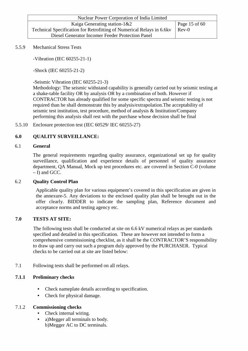
5.5.9 Mechanical Stress Tests
-Vibration (IEC 60255-21-1)
-Shock (IEC 60255-21-2)
-Seismic Vibration (IEC 60255-21-3) Methodology: The seismic withstand capability is generally carried out by seismic testing at a shake-table facility OR by analysis OR by a combination of both. However if CONTRACTOR has already qualified for some specific spectra and seismic testing is not required than he shall demonstrate this by analysis/extrapolation.The acceptability of seismic test institution, test procedure, method of analysis & Institution/Company performing this analysis shall rest with the purchase whose decision shall be final
5.5.10 Enclosure protection test (IEC 60529/ IEC 60255-27)
6.0 QUALITY SURVEILLANCE:
6.1 General
The general requirements regarding quality assurance, organizational set up for quality surveillance, qualification and experience details of personnel of quality assurance department, QA Manual, Mock up test procedures etc. are covered in Section C-0 (volume – I) and GCC.
6.2 Quality Control Plan
Applicable quality plan for various equipment’s covered in this specification are given in the annexure-5. Any deviations to the enclosed quality plan shall be brought out in the offer clearly. BIDDER to indicate the sampling plan, Reference document and acceptance norms and testing agency etc.
7.0 TESTS AT SITE:
The following tests shall be conducted at site on 6.6 kV numerical relays as per standards specified and detailed in this specification. These are however not intended to form a comprehensive commissioning checklist, as it shall be the CONTRACTOR’S responsibility to draw up and carry out such a program duly approved by the PURCHASER. Typical checks to be carried out at site are listed below:
7.1 Following tests shall be performed on all relays.
7.1.1 Preliminary checks
• Check nameplate details according to specification.
• Check for physical damage.
7.1.2 Commissioning checks • Check internal wiring. • a)Megger all terminals to body.
b)Megger AC to DC terminals.

Nuclear Power Corporation of India Limited Kaiga Generating station-1&2
Technical Specification for Retrofitting of Numerical Relays in 6.6kv Diesel Generator Incomer Feeder Protection Panel
Page 16 of 60 Rev-0
• Check operating characteristics by secondary injection.
• Check minimum pick up voltage on DC coils.
• Check operation of electrical/mechanical targets.
• Relay settings.
• Check CT and VT connection with particular reference to their polarities for directional relays.
• Verify all functions of the relay as per the requirements specified, in particular- configuration, settings, watchdog function, measuring, supervision, transient recording function, relay fault diagnostics etc.
• Independent Verification and Validation Tests based on documents detailed in annexure-3.
8.0 ACCEPTANCE REQUIREMENTS FOR RELAYS:
Numerical relays should have been type qualified as per applicable IS/IEC and valid type test reports shall be produced. The relay shall also comply with the requirements specified in this document. All the routine tests, functional tests as per IS/IEC and IV&V procedure shall be carried out at manufacturer’s premises and at site.
9.0 SPECIAL TOOLS AND TACKLES FOR COMMISSIONINING AND MAINTENANCE: All necessary retrofit unit, software, hardware and laptop computer required for loading and reading the setting of protection relays and analyzing, down loading transient and steady state stored data from the protection relays, fault diagnosis of protection relays etc.

Nuclear Power Corporation of India Limited Kaiga Generating station-1&2
Technical Specification for Retrofitting of Numerical Relays in 6.6kv Diesel Generator Incomer Feeder Protection Panel
Page 17 of 60 Rev-0
Annexure-1
1. Existing Setting sheet

Nuclear Power Corporation of India Limited Kaiga Generating station-1&2
Technical Specification for Retrofitting of Numerical Relays in 6.6kv Diesel Generator Incomer Feeder Protection Panel
Page 18 of 60 Rev-0
Annexure--2 LIST OF SCHEMATIC DIAGRAMS (THIS DRAWING IS NOT ENCLOSED HERE SAME WILL BE PROVIDED TO THE SUCCESSFUL BIDDER)
Sr. No.
220V DC scheme drawings Title
1 KAIGA-1-52311-2529-ED KAIGA-1-52311-2530-ED
Typical Control schematic for 6.6 kV CL-III DG Incomer Feeder

Nuclear Power Corporation of India Limited Kaiga Generating station-1&2
Technical Specification for Retrofitting of Numerical Relays in 6.6kv Diesel Generator Incomer Feeder Protection Panel
Page 19 of 60 Rev-0
Anexure-3
Details of activities for Independent Verification & Validation (IV & V) of computer/PLC based system of completely off the Shelf Type (COTS) item
1 Independent verification & validation (IV & V) activity shall cover the review, verification and validation of computer/PLC based system in phase of procurement, development, manufacturing, testing at factory (after completion of the PURCHASER’s inspection but before issuing the shipping release), testing at plant site (after fully integrated and commissioned at plant site) and change/modification stages of the hardware & software of the computer/PLC based system.
2 The IV & V activity shall ensure the proposed system is built as per the system requirements, functionally tested at factory, functionally tested at plant site after fully integration with plant systems, fail-safe operation of the system for safety of the equipment and the safety of the plant and finally fulfill all the regulatory requirements.
3 On placement of Purchase Order, PURCHASER’S IV & V Task Force (IV&V-TF) shall carry out the verification and validation tests at VENDOR’S factory and at PURCHASER’S site as per the approved system validation procedure at factory (SVP-F) and system validation procedure at site (SVP-S). VENDOR shall ensure all the tools and resources while conducting the validation tests at factory as well as at plant site. If already qualified IV&V relays are offered, IV&V may be limited to site related documentation, verification and testing.
4 VENDOR shall prepare and submit the minimum five copies of each of the following documents for IV & V requirement:
A.1 Product Specification Compliance (PSC)
A.2 Fitness For the Purpose (FFP)
A.3 System Build (SB)
A.4 Application Programming Requirements and application program (APR and AP)
A.5 User Documentations (UD)
A.6 System Validation Procedure at Factory (SVP-F)
A.7 System Validation Procedure at Plant site (SVP-S)
A.8 Hardware Reliability Analysis (HRA)
A.9 System Safety Analysis Report (SSAR)
A.10 Configuration Management Plan-Manufacturer (CMP-M)
A.11 Verification Plan for Application Software (VP-AS/W)
Nuclear Power Corporation of India Limited Kaiga Generating station-1&2
Technical Specification for Retrofitting of Numerical Relays in 6.6kv Diesel Generator Incomer Feeder Protection Panel
Page 20 of 60 Rev-0
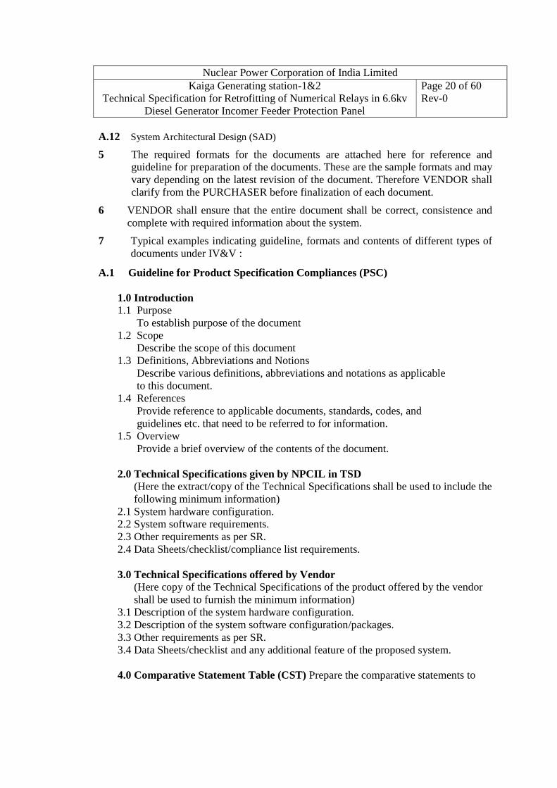
A.12 System Architectural Design (SAD)
5 The required formats for the documents are attached here for reference and guideline for preparation of the documents. These are the sample formats and may vary depending on the latest revision of the document. Therefore VENDOR shall clarify from the PURCHASER before finalization of each document.
6 VENDOR shall ensure that the entire document shall be correct, consistence and complete with required information about the system.
7 Typical examples indicating guideline, formats and contents of different types of documents under IV&V :
A.1 Guideline for Product Specification Compliances (PSC)
1.0 Introduction 1.1 Purpose
To establish purpose of the document 1.2 Scope
Describe the scope of this document 1.3 Definitions, Abbreviations and Notions
Describe various definitions, abbreviations and notations as applicable to this document.
1.4 References Provide reference to applicable documents, standards, codes, and guidelines etc. that need to be referred to for information.
1.5 Overview Provide a brief overview of the contents of the document.
2.0 Technical Specifications given by NPCIL in TSD (Here the extract/copy of the Technical Specifications shall be used to include the following minimum information)
2.1 System hardware configuration. 2.2 System software requirements. 2.3 Other requirements as per SR. 2.4 Data Sheets/checklist/compliance list requirements.
3.0 Technical Specifications offered by Vendor
(Here copy of the Technical Specifications of the product offered by the vendor shall be used to furnish the minimum information)
3.1 Description of the system hardware configuration. 3.2 Description of the system software configuration/packages. 3.3 Other requirements as per SR. 3.4 Data Sheets/checklist and any additional feature of the proposed system.
4.0 Comparative Statement Table (CST) Prepare the comparative statements to

Nuclear Power Corporation of India Limited Kaiga Generating station-1&2
Technical Specification for Retrofitting of Numerical Relays in 6.6kv Diesel Generator Incomer Feeder Protection Panel
Page 21 of 60 Rev-0
compare one to one clause for compliance between the technical specifications given by the purchaser and the technical specifications given by the Contractor/supplier.
5.0 Approved deviation reports (DR), if any (approved copy shall be enclosed). 6.0 List of Annexures. 6.1 Guaranteed technical particulars (GTP) for the offered system by Vendor. 6.2 Bill of the material including spare parts to be delivered. 6.3 Simplified /block/context diagram of the proposed system. 6.4 Copy of the purchase order (un-priced).
7.0 Conclusion.
A.2 Guideline for Fitness for Purpose (FFP)
1.0 Introduction 1.1 Purpose
Describe the standard manufacturing processes of the product for establishing the suitability and quality of the offered product in the desired application. This should also cover the operating field experience in the similar product.
1.2 Scope Describe the scope of this document
1.3 Definitions, Abbreviations and Notations Describe various definitions, abbreviations and notations as applicable to this document.
1.4 References and Applicable Documents Provide reference to applicable documents, standards, codes, and guidelines etc. that need to be referred to for information.
1.5 Overview Provide a brief overview of the contents of the document.
2.0 About the Manufacturer/Organization 2.1 Organization Role & Responsibilities. 2.2 Organization structure. 2.3 Organization level quality assurance plan. 2.4 Quality certification like ISO 9000 or equivalent 2.5 Any reorganization/award by the industry 2.6 Experience in the similar field
3.0 Manufacturing process: 3.1 Hardware manufacturing process:
3.1.1 Description of design and planning process 3.1.2 Description of manufacturing process

Nuclear Power Corporation of India Limited Kaiga Generating station-1&2
Technical Specification for Retrofitting of Numerical Relays in 6.6kv Diesel Generator Incomer Feeder Protection Panel
Page 22 of 60 Rev-0
3.1.3 Description of testing and acceptance process 3.1.4 List of governing standards and procedures followed during above
processes 3.1.5 Mechanism for reporting and disposition of non-conformance to standards
and procedures 3.1.6 List of Certification
3.2 Software development process:
3.2.1 Description of software design & planning process 3.2.2 Description of software development/coding and testing process 3.2.3 Description of software testing and acceptance process 3.2.4 List of governing standards and procedure followed in
Design/coding/testing of software like: a) Software Quality Assurance standard b) Configuration Management standard c) SEI-CMM level qualification or equivalent, if any
3.2.5 Mechanism for reporting and disposition of non-conformance to standards and procedures 3.2.6 List of certification, if any. 4.0 Product suitability Product Suitability shall describe the following: 4.1. The functional characteristics of product in line with the desired functions of system. 4.2. The performance characteristics of product in line with the desired performance of system 4.3. The list of unintended or unused functions/modules, if any. The procedure/methods and thereafter the demonstration (during testing) shall be included to ensure that the unused functions are eliminated or disabled permanently without affecting the performance and safety of the system. 4.4. The list of modifications/changes, if any. This should describe that the modifications/changes are implemented as per configuration management plan and procedure and tested. The records shall be included in the document. 5.0 Product quality Product quality shall include various available documentary evidences, to establish the quality of the product. This shall include 5.1. The documentary evidence to demonstrate that the product has been designed & developed as per the standard development process. 5.2. The test results and correction, if any, to compensate the deficiencies in compliance to standard development process. 5.3. The product certification (UL, CE etc.) by third party or any other evidence to establish the quality of the product.

Nuclear Power Corporation of India Limited Kaiga Generating station-1&2
Technical Specification for Retrofitting of Numerical Relays in 6.6kv Diesel Generator Incomer Feeder Protection Panel
Page 23 of 60 Rev-0
5.4. Product reliability figures (MTBF, MTTR & Failure rate) 6.0 Operating experiences This should describe the operating experience data with validity on the identical or similar products which are already being used by many customers. This shall include the manufacturer’s policies and procedures for error tracking, error resolving and feedback mechanism from/to customers, number of installation, product serial/model number, number of system-operation years completed, change/modification/upgradation carried out during operating period, availability of the system, hardware version, software version, etc. 7.0 Maintenance support from the manufacturer (after sale) This should describe the maintenance support policy and procedure of the manufacturer/supplier throughout the operating life of the product. This include the details of the service centres and standard process to extend the maintenance service supports at the operating site on per call basis, annual maintenance contract (AMC) basis and comprehensive annual maintenance contract (CAMC) basis. This shall also include the recommendation for maintaining the minimum maintenance spares for the proposed product. 8.0 List of annexure 9.0 Conclusion
A.3 Guideline for System Build (SB) 1. Introduction 1.1 Purpose To provide the information about the hardware package, software package and implementation of hardware & software as per the system requirements 1.2 Scope Describe the scope of this document. 1.3 Definitions, Abbreviations and Notations Describe various definitions, abbreviations and notations as applicable to this document. 1.4 References and Applicable Documents Provide reference to applicable documents, standards, codes, and guidelines etc. that need to be referred to for information. 1.5 Overview Provide a brief overview of the contents of the document. 2. Overall System Architecture

Nuclear Power Corporation of India Limited Kaiga Generating station-1&2
Technical Specification for Retrofitting of Numerical Relays in 6.6kv Diesel Generator Incomer Feeder Protection Panel
Page 24 of 60 Rev-0
Describe the system architecture with necessary diagram/drawing 3. System Decomposition Describe the system decomposition from top level to module level. If system is consist of multiple subsystems then decompose each subsystem up to module level. Enclose the logical diagram. 4. Hardware Build Describe the hardware build from system level to subsystems level. The hardware build should include list of hardware modules/items, unique ID/version, quantity, brief description of each hardware module and their integration procedure/drawings. This should also include the applicable hardware setting (jumper/switch/software), embedded software details (If applicable), interface/cable connectivity with supporting drawings. The embedded software in the hardware module should include the name of software modules/components, software unique ID/Version, location media (HDD/RAM/EPROM), memory occupied and free available space, interface/access details and its customization process if applicable. 5. Software Build Describe the software build from system level to subsystems level. The software build should include name of software modules/components, unique ID, software version, location media (HDD/RAM/EPROM), memory occupied and free available space, software user license details as applicable, brief description of each software component and their implementation process. The brief description of software should also include the OS/RTOS version and service settings, compiler version; compile time options, library versions, and environment variables. This should also include the name of the software development/customization tools, HMI software development tools or any other software used for the customization/implementation along with version details. The software details can be segregated as per system level, subsystem level, HMI level, Programming unit level for ease of identification. 6. Hardware and software integration procedure Describe the hardware and software integration procedure in brief and furnish the list of the reference documents used for integration. 7. List of the applicable software documents with version number List out all the software related documents with document ID and version details 8. List of the Annexure 9. Conclusion
A.4 Guideline for Application Programming Requirements (APR) and Application

Nuclear Power Corporation of India Limited Kaiga Generating station-1&2
Technical Specification for Retrofitting of Numerical Relays in 6.6kv Diesel Generator Incomer Feeder Protection Panel
Page 25 of 60 Rev-0
Program (AP) (Typical for PLC/Controller -Based Systems) 1.0 Introduction 1.1 Purpose Describe the purpose of this document 1.2 Scope Describe the scope of this document 1.3 Definitions, Abbreviations and Notations Describe various definitions, abbreviations and notations as applicable to this document. Define the miscellaneous terminology used in the PLC/Controller like Scan Time, Response Time, Accuracy, Resolution, etc. 1.4 References and Applicable Documents Provide reference to applicable documents, standards, codes, and guidelines etc. that need to be referred to for information. 1.5 Overview Provide a brief overview of the contents of the document. 2.0 Brief overview of system Describe the brief overview of the system with respect to hardware and software configuration in line of the system requirement. 3.0 Software Customization/Application Programming Requirements 3.1 Description of requirements to be programmed/customized in the software in the form of Logic Scheme/Engineering Diagram/Block Logic Diagram (as described in the SR document). The copy of ED/LD/BLD shall be enclosed herewith. 3.2 List of Human Machine Interfaces (HMI)/Operator Interfaces to be customized 3.3 List of Field Inputs and Outputs to be programmed for their addresses scheme, data type and text variables/mapping 3.4 Software Symbol/Variable list to be used in the application software 3.5 List of the event messages and alarm messages to be customized with priority, if any. 3.6 List of diagnostic messages to be customized for both hardware and software 3.7 List of the process parameters with reference value, alarm value and trip value are to be customized 3.8 List of the communication ports/interfaces with other subsystem/system and frequency of information and the type of the information to be communicated with the required format 4.0 Brief description of Software customization/programming Tool Provide a brief description of the software customization/programming tools used for the customization of the application software along with the version & license details.The user manual for this tool shall be included in the User Documentation.
5.0 Brief description of HMI Customization/Programming Tool

Nuclear Power Corporation of India Limited Kaiga Generating station-1&2
Technical Specification for Retrofitting of Numerical Relays in 6.6kv Diesel Generator Incomer Feeder Protection Panel
Page 26 of 60 Rev-0
Provide a brief description of the HMI software customization/programming tools along with version& license details used for the customization of the parameters, text messages for events/alarms, diagnostic messages etc. to be displayed along with various color code and date & time stamping. The user manual for this tool shall be included in the User Documentation. 6.0 Brief description of Application Program (AP) to be deployed in PLC/Controller Provide a brief description of the application program (AP) to be deployed after customization. This should include the file name with extension, version detail, type and allocation of the memory to be used for AP, any supported firmware/system software details, type of real time operating system with version details, effect of the failure of the AP memory and corruption of the application program on the safety of the system. The final copy of the final customized application program (in the form of FBD/STLLDD) shall be provided along with this document. 7.0 Traceability requirements between SR and APR 8.0 List of the Annexure i. Engineering Diagram/Block Logic Diagram ii. List of field Inputs and Outputs along with mapping iii. List of the events and alarm messages iv. List of the diagnostics generated by hardware and software v. Application Program in the form of FBD/STL/LLD 9.0 Conclusion
A.5 Guideline for User Documentation (UD) 1. Introduction 1.1 Purpose Provide the purpose of preparing this document 1.2 Scope Describe the scope of this document 1.3 Definitions, Abbreviations and Notations Describe various definitions, abbreviations and notations as applicable to this document. 1.4 References and Applicable Documents Provide reference to applicable documents, standards, codes, and guidelines etc. that need to be referred to for information. 1.5 Overview Provide a brief overview of the contents of the document.

Nuclear Power Corporation of India Limited Kaiga Generating station-1&2
Technical Specification for Retrofitting of Numerical Relays in 6.6kv Diesel Generator Incomer Feeder Protection Panel
Page 27 of 60 Rev-0
2. Description of the manuals with ID details List out all the user manuals, operational manuals, installation and commissioning manuals along with document ID (End documents) and related drawings The contents of each manual shall be described in brief to trace out the related information. The list of these documents shall be attached here with for completeness of the UD documents and it should cover the followings Information 2.1 Information for Installation of the system This shall include the information related to installation and related drawing of the system/subsystems. 2.2 Information for Commissioning of the system Refer WDs, SB configuration drawing, BOM. Sequence of steps to be followed for commissioning of the system/subsystem, hardware and software environment settings such as jumper/switch settings, communication port configuration, IP address schemes for networking etc. 2.3 Information for Operation of the system Write the details on start-up procedure, normal operation procedure, shutdown procedure and operating procedures in different operating modes of the system, commands, options, error and diagnostic messages, help facilities, operation of utilities provided for the operating staff like, test utilities, test tools available, etc. This should also include the testing and calibration procedure. 2.4 Information for Maintenance of the system Describe possible failures and its symptoms, possible known cause of the failures, details of fault/error codes, describe the fault tree analysis and trouble-shooting procedure for the above. This shall include the procedure to bring up the system after troubleshooting. Cover test program, diagnostics for checking healthiness, etc.
2.5 Information for System Interface with Field and other systems: Describe the field interfaces in line with the input and output list applicable to the system. 2.6 List of the system drawings, diagrams etc List out all the applicable GA drawings, BM, wiring diagram, schematics etc. applicable to the system 2.7 Information regarding System Access Control for security This shall include the software access control procedure with various level and rights. This should also include the procedure for change of the passwords. 3. List of the Annexure 4. Conclusion

Nuclear Power Corporation of India Limited Kaiga Generating station-1&2
Technical Specification for Retrofitting of Numerical Relays in 6.6kv Diesel Generator Incomer Feeder Protection Panel
Page 28 of 60 Rev-0
A.6 Guideline for System Validation Procedure at Factory (SVP-F) 1. Introduction 1.1 Purpose Provide the purpose of preparing this document 1.2 Scope Describe the scope of this document. The validation test shall be carried out on standalone equipment after completion of the QA test at factory 1.3 Definitions, Abbreviations and Notations Describe various definitions, abbreviations and notations as applicable to this document. 1.4 References and Applicable Documents Provide reference to applicable documents, standards, codes, and guidelines etc. that need to be referred to for information. 1.5 Overview Provide a brief overview of the contents of the document. 2. Test Team Details and Test Duration Give the requirement of test team members, their roles and responsibilities for carrying out the System Validation test at factory and specified the expected test duration under following heads 2.1 Test Team Members (from IV&V-Team, Vendor Team) 2.2 Test team members Role and Responsibilities 2.3 Test Duration 3. Infrastructure and resource requirements Give the infrastructure and resources requirements for the system validation under the following heads. 3.1 Infrastructure requirement 3.2 Resources requirements 3.2.1 QA inspection test procedure and test reports 3.2.2 Vendor’s QA test reports 3.2.3 Copy of the purchase orders with bill of the material 3.2.4 Test certificates by third party/principal suppliers 3.3 Standard Test Setup with diagram 3.4 Manpower Requirement 4.0 System Validation Test Plan The system validation tests should be carried out as per following plan

Nuclear Power Corporation of India Limited Kaiga Generating station-1&2
Technical Specification for Retrofitting of Numerical Relays in 6.6kv Diesel Generator Incomer Feeder Protection Panel
Page 29 of 60 Rev-0
4.1 Checking of QA reports, Type test reports/certificates, vender’s internal test reports/certificates on system and test reports on bought out items for completeness/any pending deficiency/comments 4.2 Verification of System Build (SB) 4.3 Verification of the User Documentation 4.4 Hardware validation Tests • Hardware failure tests • Hardware based self diagnostics tests • Hardware functional tests • Hardware redundancy tests • Hardware interface test with other CBS 4.5 Software validation tests • Off line verification of software logics • Off line simulation of the software logics • Off line verification of the software variables, set pints/reference parameters • Simulation and testing of all the inputs and outputs • On line simulation of the software logics • Testing of software access control • Validation tests on HMI software • Testing of all the alarms and events generated by software 5.0. System Validation Test Procedure System validation procedure shall be written for each of the test case/plan by the manufacturer. If already test procedure is available, then same can be used during validation tests at factory. 5.1. Checking of test reports and certificates: Vendor shall offer all the test reports and certificates to check the pending deficiency/comments if any and for completeness of the test reports. This shall include the followings • NPCIL QA reports as per the QAP, • Type test reports/certificates • Vender’s internal test reports/certificates on system • Vendors test reports on bought out items, etc. 5.2 Verification of System under test for System Build Verify and confirm that the system H/W and S/W is built according to the System Build document under the following heads. 5.2.1 Confirmation of System Hardware Build All the hardware details shall be verified and confirmed with model/type number, ID/version number, make, etc. • General hardware • Hardware Modules

Nuclear Power Corporation of India Limited Kaiga Generating station-1&2
Technical Specification for Retrofitting of Numerical Relays in 6.6kv Diesel Generator Incomer Feeder Protection Panel
Page 30 of 60 Rev-0
5.2.2 Confirmation of the System Software Build All the software unit/modules shall be verified and confirmed with the software name, version, license (if applicable), location (type of memory) and memory size, etc. This should include the list of the software used for development, loading/unloading tools, etc. • Real Time Operating System/Operating System software • System software • Application software development tools/software manager (complete sets). • Application software. • List of the firmware deployed • HMI software • Anti-virus software, if any • Any other relevant software 5.2.3 Confirmation of the system Integration with hardware and software Verify and confirm that the software and hardware are integrated as per the standard engineering drawings/documents 5.3 Verification of User Documentation for system under test Verify the list of the documents and content of each document as per the UD. This shall include the descriptions in the user documents as implemented in the system. Ex: Operating procedures, modes, command options, error messages, help, utilities, etc. 5.4 System Hardware Validation Tests (Hardware performance test) The hardware validation test shall be carried out on the standalone equipment using simulator. The brief description about the simulator shall also be included in the procedure. This shall include the test cases, its procedure, expected test results and test success criteria on all the hardware. This shall be prepared in line of system requirement and its expected performance in case of single failure and common cause failure for fail safe operation. The minimum test cases shall be included in the hardware validation tests: • Hardware failure tests • Hardware based self diagnostics tests • Hardware functional tests • Hardware redundancy tests • Hardware interfaces tests with other subsystems/systems 5.5 System Software Validation Tests The software validation tests shall be carried out for each open loop as well as closed loop logic using the simulators or test tools like automatic functional testers, TDR etc.

Nuclear Power Corporation of India Limited Kaiga Generating station-1&2
Technical Specification for Retrofitting of Numerical Relays in 6.6kv Diesel Generator Incomer Feeder Protection Panel
Page 31 of 60 Rev-0
All the logics 100% shall be tested. The minimum test cases shall be included in the software validation tests: • Offline verification of application s/w with software logic requirements • Offline validation of the application s/w on workstation (simulation mode) • Verification of all the inputs and outputs by simulation
• Validation of the software database used for I/O, events/alarm messages, etc. • Validation of the software timers/counters for its setting & its accuracy • Validation of the software security access control • Validation of the software based system self-diagnostics features in case of faults. • Validation of the memory allocation for application s/w and available free memory. • Validation of the critical parameters (software dependent) • Validation of Application Software by simulation for open & close loops • Validation of Application Software by simulation in test/fail safe modes • Validation of Application Software by simulation for various subsystems/system interfaces • Validation of the software database to be transferred to other subsystem/system over a given communication protocol 6.0 List of Annexure This shall include the test set up diagram, simulation procedure for testing of system software logics (for all inputs and outputs), list of Inputs and corresponding variable name used in s/w, List of Outputs and corresponding variable name used in s/w etc. 7.0 Traceability requirements 7.1 Forward Traceability Generate a forward traceability matrix between System Requirements (SR) and the System validation Procedure (SVP-F) to ensure that all requirements mentioned in System Requirements document has been taken as a test cases in the system validation tests in the SVP-F. 7.2 Backward Traceability Generate a backward traceability matrix between SVP-F document and the SR document to ensure that all the possible test cases has been included in the SVP-F to cover all the system requirement mentioned in the SR document. There could be certain extra test cases as per the system verification and validation plan.
8.0 Conclusion A.7 Guideline for System Validation Procedure at Site (SVP-S): 1. Introduction 1.1 Purpose

Nuclear Power Corporation of India Limited Kaiga Generating station-1&2
Technical Specification for Retrofitting of Numerical Relays in 6.6kv Diesel Generator Incomer Feeder Protection Panel
Page 32 of 60 Rev-0
Provide the purpose of preparing this document 1.2 Scope Describe the scope of this document. Validation tests at site should be carried out on fully integrated system after completion of the installation, commissioning and commissioning tests. 1.3 Definitions, Abbreviations and Notations Describe various definitions, abbreviations and notations as applicable to this document. 1.4 References and Applicable Documents Provide reference to applicable documents, standards, codes, and guidelines etc. that need to be referred to for information. 1.5 Overview Provide a brief overview of the contents of the document. 2. Test Team Details and test duration Give the details of test team members, their roles and responsibilities for carrying out the System Validation test at plant site and specified the expected test duration under following heads a. Test Team details: IV&V team and site team b. Test team members Role and Responsibilities c. Test Duration 3. Infrastructure and resource requirements Give the infrastructure and resources requirements for the system validation under the following heads. 3.1. Infrastructure requirement 3.2. Resources requirements 3.3. Standard Test Setup 3.4. Manpower Requirement 3.5. Necessary clearances from Shift Charge Engineer/Control room 4. System Validation Test Plan The system validation test shall be carried out as per the following plan: 4.1 Checking of approved Commissioning Report for pending deficiency/comments 4.2 Verification of remedial action noted during system validation tests at factory 4.3 Verification for System Build for system under test 4.4 Confirmation of the system Integration with plant systems. 4.5 Hardware validation test on integrated system 4.6 Software Validation tests on integrated system 4.7 Functional testing of logic schemes for all possible test cases 4.8 Functional testing of man machine interfaces and other computer base subsystem. 5.0 System Validation Test Procedure

Nuclear Power Corporation of India Limited Kaiga Generating station-1&2
Technical Specification for Retrofitting of Numerical Relays in 6.6kv Diesel Generator Incomer Feeder Protection Panel
Page 33 of 60 Rev-0
This should cover all the possible functional test cases to demonstrate the performance of the system hardware and software by actuating the actual field inputs and observe the field outputs. This includes the test cases on performance of the hardware, execution of software logics/program, signal processing, response time, audio-visual alarms at local control panel (LCP) and in main control room (MCR), event/message recording, interface with other computer base systems, synchronization with master clock, testing of the hardware and software based self diagnostic features, software access control, etc. under following heads: 5.1 Checking of the approved Commissioning Report The approved commissioning report on the system under test shall be checked for any pending deficiency/comments. Credit can be given for identical test cases, if results are acceptable to the IV&V team. 5.2 Verification of remedial action for deficiency, if any, noted during system validation tests at factory Verify that all the deficiencies are rectified as per the recommendation of the SVR at factory. Any modification in hardware/software is to be revalidated at plant site. This should also include the balance tests, if any to be carried out at plant site. 5.3 Verification of System Build for the system under test Confirm that the system H/W and S/W is built according to the System Build document and it is installed, integrated with the plant systems under the following heads. 5.3.1 Confirmation of System Hardware • Panel wise hardware Modules • General hardware at panel level • Plant Interface with panel/hardware modules 5.3.2 Confirmation of the System Software • Operating System software with licensing • System software. • Application software development tools/software manager. • Application software. • System firmware, if any • Antivirus software, if any • Any other related software loaded in the system 5.4 Confirmation of the system integration with plant systems Confirm that the system is fully installed, commissioned and integrated with plant systems. 5.5 Hardware validation test on integrated panel • Hardware performance tests (sample test)

Nuclear Power Corporation of India Limited Kaiga Generating station-1&2
Technical Specification for Retrofitting of Numerical Relays in 6.6kv Diesel Generator Incomer Feeder Protection Panel
Page 34 of 60 Rev-0
• System self-diagnostics features in case of faults. • Redundancy/failure test 5.6 Software Validation tests on integrated panel • Validation of the software logics as per clause 5.7 under functional tests • Validation of the software security access control and creation of the users and their rights based on the site requirements • Verification of allocated memory and available free memory for software. 5.7 Functional tests: Include all the functional test cases on the logics and man machine interfaces in line with the system requirements. There may be overlapping in the test cases. This overlapping of the test cases is to be taken care appropriately during execution. 5.7.1 Functional testing of logic schemes for all possible test cases. The functional testing of the logic scheme shall be carried out as per the test cases given in the Annexure-XX 5.7.2 Functional testing of man machine interfaces and other computer base Sub systems/systems • Testing of all the Field Inputs by actuating from the field and observing in the software program on the screen of the programming unit • Testing of all the Field outputs by actuating from the software of the programming unit and observing in the field • Functional testing of window annunciation provided on LCP and MCR panel. o Functional testing of Hand Switches and lamp indications provided on LCP and MCR Panel. o Functional testing of window annunciation, meters, and switches provided on LCP and MCR Panel. • Functional testing of MCC interface • Functional testing of SCADA interface • Functional testing of event message printing with time and date stamping • Functional testing of system synchronization with Master Clock 5.8 Validation of the software timers/counters for its setting based on the field response time. Based on the field requirements the setting of software timer may change. The same shall be recorded and corrected during validation test at site. 5.9 Transfer of the application software from RAM to UV-EPROM (If applicable) After final testing of all the test case and satisfactorily operation of the system under test the application software shall be transferred from RAM to UV-EPROM using EPROM programmer and associated software. Do the sample tests after installation of UV-EPROM. Also take the back up on HDD as well as on the CD for the future reloading /reference.

Nuclear Power Corporation of India Limited Kaiga Generating station-1&2
Technical Specification for Retrofitting of Numerical Relays in 6.6kv Diesel Generator Incomer Feeder Protection Panel
Page 35 of 60 Rev-0
6.0 List of Annexure This shall include the following: • Test set up diagram, • List of the test cases for the functional testing of the logic scheme, • List of field inputs & outputs with its types (Digital/Analogue), state (NO/NC) and software address scheme 7.0 Conclusion. A.8 Guideline for Hardware Reliability Analysis (HRA) 1. Introduction 1.1 Purpose Provide the purpose of preparing this document 1.2 Scope Describe the scope and coverage of this document 1.3 Definitions, Abbreviations and Notations Describe various definitions, abbreviations and notations as applicable to this document. 1.4 References and Applicable Documents Provide reference to applicable documents, standards, codes, and guidelines etc. that need to be referred to for information. 1.5 Overview of the system Provide a brief overview of the contents of the document 2 System Description Describe the system architecture in terms of decomposition into sub-systems (if any) with inter connectivity and the inputs and outputs connected to each sub-system under following heads: 2.1 Introduction 2.2 System architecture diagram/schematics 2.3 System Functional description 2.4 System hardware configuration 2.5 System input & output details 3. Reliability Analysis of system Describe the reliability analysis of the components, modules, subsystems and system level under the following heads: 3.1 Reliability prediction/calculation methods adopted for analysis 3.2 Assumptions &Boundary conditions

Nuclear Power Corporation of India Limited Kaiga Generating station-1&2
Technical Specification for Retrofitting of Numerical Relays in 6.6kv Diesel Generator Incomer Feeder Protection Panel
Page 36 of 60 Rev-0
3.3 Reliability data (MTBF, MTTR and Failure Rates)with its sources for hardware components, modules, subsystems and system with failure criteria (environmental conditions) 3.4 Reliability block diagram of the subsystem/system 3.5 Fault Tree Analysis for subsystem/system 3.6 Importance and sensitivity analysis for subsystem/system 3.7 Event Tree analysis for subsystem/system 3.8 Maintainability predictions for subsystem/system 3.9 Domain cut set of subsystem/system
4. Reliability analysis based on field experience (if applicable) Provide the reliability data (MTBF, MTTR and Failure Rates) based on the field experience for already installed hardware components, modules, subsystems and system with failure criteria (environmental conditions). Compare these field data with the calculated data to demonstrate that the correctness. 5. Results of above Analysis Here the results of all the methods shall be summarized 6. List of the Annexure Enclosed the Annexure as required in the document for all the possible calculation & results of the reliability data 7. Conclusion A.10 Guideline for System Safety Analysis Report (SSAR): 1. Introduction 1.1 Purpose Provide the purpose of preparing this document 1.2 Scope Describe the scope of this document 1.3 Definitions, Abbreviations and Notations Describe various definitions, abbreviations and notations as applicable to this document. 1.4 References and Applicable Documents Provide reference to applicable documents, standards, codes, and guidelines etc. that need to be referred to for information. 1.5 Overview of the system Provide a brief overview of the contents of the document

Nuclear Power Corporation of India Limited Kaiga Generating station-1&2
Technical Specification for Retrofitting of Numerical Relays in 6.6kv Diesel Generator Incomer Feeder Protection Panel
Page 37 of 60 Rev-0
2 Brief overview of System Architecture Describe the system architecture in terms of decomposition into sub-systems and module level with interconnectivity and the field inputs and outputs connected to each sub-system/ module. This should include the description about the implementation of the system safety functions in the hardware modules as well as software to achieve the safety requirements of the system. 3 Description of System Interfaces Describe all the interfaces of system and subsystem with the plant as well as with other computer based digital I&C system 3.1. Interface of system/subsystem with Plant 3.1.1. Plant Inputs This section should list the description of all the inputs 3.1.2. Plant Outputs This section should list the description of all the outputs 3.2. Interface with other subsystems This section should list the connectivity of the system/sub-system with other sub-systems 3.3. Interface with other systems This section should list the connectivity of the system/sub-system with other systems 3.4. Interfaces with power supplies This section should list the connectivity of the system/sub-system with power supplies and power sources. 4. Single Failure Analysis (SFA): Applicable for Safety Class-IA& IB This should include all the possible type/source of single failures (failure of the smallest hardware/software component onward) with in subsystem/system and accordingly the analysis shall be carried out for each single failure within PDS as a part of the digital I & C system to demonstrate fulfilment of single failure criteria and determine the effect of failure on the safety of the system/equipment and safety of the plant. It should also include the analysis for unused functions/modules, if any, will not affect the performance and safety of the system as well as safety of the plant. 5. Common Cause Failure Analysis (CCFA): Applicable for Safety Class-IA This should include the identification of all the possible type/source of common cause failures (failure of the smallest hardware or software component onward) with in PDS as part of the digital I and C system. Accordingly analysis should be carried out for each identified common cause failure to determine the effect of the failure on the safety of the system/equipment and the safety of the plant. This analysis should also include the analysis of the possible effects of these CCF with respect to each PIE and confirmation that adequate diversity is provided to eliminate possibilities of CCF. 6 Effect of Failures of System Safety Functions: Applicable for Class IA, IB & IC

Nuclear Power Corporation of India Limited Kaiga Generating station-1&2
Technical Specification for Retrofitting of Numerical Relays in 6.6kv Diesel Generator Incomer Feeder Protection Panel
Page 38 of 60 Rev-0
This section should include the identification of all the implemented safety functions within the PDs as part of the digital I&C system (From the sensor to actuator) and accordingly the system safety analysis should be carried out for all known possible type of the faults in the system to determine the effect of the failure on the safety of the system/equipment and the safety of the plant. This analysis should include the type of the known faults (like failure of power supply module, input channel, output relay contact etc.), possible mode/cause of failure, implemented fault detection mechanism, implemented fault display mechanism, impact of the failure on the safety of the equipment/system and the impact on the safety of the plant. This should cover the failure modes in both partial as well as total failures state to analyse the effects on the output of the system. This section should identify the affected outputs, mention about their state during the failure and the maximum time to reach that state 7. Traceability requirements A traceability between the safety requirements as specified in the SR document and the implementation of these safety functions as described in SSA document shall be prepared and included as an annexure to this document.
8 List of the Annexure Annexure should be prepared describing the type of the failure, mode/cause of the failure, fault detection mechanism, fault display mechanism, Effect of the failure on the safety of the system equipment and Effect of the failure on the safety of plant. 8 Conclusion
A.10 Guideline for Configuration Management Plan-Manufacturer (CMP-M): 1. Introduction 1.1 Purpose Provide the purpose of preparing this document 1.2 Scope Describe the scope of this document. This should include all the configuration management plans, procedure & activities for identifications, storage, changes in hardware & software components of the PDS along with associated documents and tools during manufacturing phase. 1.3 Definitions, Abbreviations and Notations Describe various definitions, abbreviations and notations as applicable to this document. 1.4 References and Applicable Documents Provide reference to applicable documents, standards, codes, and guidelines etc. that need to be referred to for information. 1.5 Overview Provide a brief overview of the contents of the document.

Nuclear Power Corporation of India Limited Kaiga Generating station-1&2
Technical Specification for Retrofitting of Numerical Relays in 6.6kv Diesel Generator Incomer Feeder Protection Panel
Page 39 of 60 Rev-0
2. Configuration Management (CM): Role and Responsibilities 2.1 Structure – CM roles, responsibilities and reporting lines 2.2 Resource requirements 2.3 Interactions with other agencies 3. Configuration Management Plans/Activities This should include the followings 3.1 Configuration identification, storage and release of CI Describe the standard activities/procedure followed for systematic identification and storage of each Configuration Item (CI) with a unique name and version number. This should include the procedure for the derived CI for the complex systems and its associated tools and documents. This should also describe the CM activity to make release of the CI as and when required for the given system& project. 3.2 Configuration change control of CI Describe the systematic activities/procedure followed for configuration change/modification in the CI. This shall include the generation of formal change request, generation of impact analysis report, approval of the controlling agency, implementation of the changes, testing, validation and release of version for the modified CI. 3.3 Configuration status tracking/reporting of CI Describe the procedure to keep a systematic track on all the CI which have been created, stored and released with their unique name and version number, status of change requests, status of the modified CI based on the change request, etc. This should include tracking tools, a set of libraries and the methods to capture & store. 3.4 Configuration of third party’s CI Describe the procedure to accommodate the externally supplied CI (Third party CI)) for the bought out hardware/software components, subsystems tools or documents for the manufacturing of the required system. 4. List of Annexure 5. Conclusion
A.11 Guideline for Verification Plan for Application Software (VP-S/W) (Typical for PLC/Controller language) 1. Introduction 1.1 Purpose Provide the purpose of preparing this document

Nuclear Power Corporation of India Limited Kaiga Generating station-1&2
Technical Specification for Retrofitting of Numerical Relays in 6.6kv Diesel Generator Incomer Feeder Protection Panel
Page 40 of 60 Rev-0
1.2 Scope Describe the scope and coverage of this document 1.3 Definitions, Abbreviations and Notations Describe various definitions, abbreviations and notations as applicable to this document. 1.4 References and Applicable Documents Provide reference to applicable documents, standards, codes, and guidelines etc. that need to be referred to for information. 1.5 Overview of the system Provide a brief overview of the contents of the document 2 Verification Plan/Activity The verification plan/activity for the application software depends upon the selection of the programming languages and corresponding programming guide lines and applicable standards. This section shall include the verification plans for the software language like General Purpose Languages (GPL), Application Oriented Languages (AOL), Functional Block Diagram (FBD) or programmable components like CPLDs, FPGAs, DCS, ASIC, etc. used in the PDS. The applicable plan should be described. Here the verification plan for AOL/FBD based application software used in the PLC/controllers is described. 3. AOL/FBD based application software In case of AOL/FBD, the verification/review activities shall include the followings: 3.1. Off line verification of the program with application programming requirements/software customization requirements 3.2. Verification of unused functions or memory flags and the procedure for permanent deletion or disable of these functions/flags 3.3. Plan for functional testing of application program 3.4. Tools & technique required for verification and functional testing. 3.5. Limitation of verification and testing 3.6. Compliance to design and implementation guidelines of IEC-6 IEC 61131-3 for PLC 3.7. Traceability of application programs with system requirements. 4. List of the Annexure 5. Conclusion
A.12 Guideline for System Architectural Design (SAD) 1. Introduction 1.1 Purpose

Nuclear Power Corporation of India Limited Kaiga Generating station-1&2
Technical Specification for Retrofitting of Numerical Relays in 6.6kv Diesel Generator Incomer Feeder Protection Panel
Page 41 of 60 Rev-0
Provide the purpose of preparing this document 1.2 Scope Describe the scope of this document 1.3 Definitions, Abbreviations and Notations Describe various definitions, abbreviations and notations as applicable to this document. 1.4 References and Applicable Documents Provide reference to applicable documents, standards, codes, and guidelines etc. that need to be referred to for information. 1.5 Overview Provide a brief overview of the contents of the document. 2 Brief description of the System Specifications Provide brief description of the specifications of the proposed system in line of the System Requirement document. 3 System Architecture 3.1 General Describe the architecture of the system with the help of overall architecture diagram to include the subsystems, hardware modules and software modules. The module level interfaces (internal as well as external) shall be defined clearly. 3.2 Decomposition description of the system Describe various subsystems that form the overall system then describe various modules (both hardware & software) that form the subsystem. Here role and functionality of each subsystem and then allocation of functions to individual modules should be described. Also describe how the system will work based on proposed partitioning of the System. Description for all system states / modes should be given. 4. Subsystem Specification In this section identify the number of subsystems to be created and describe the purpose of each subsystem. This should include the subsystem wise various requirements under the following heads: 4.1. Functional requirements 4.2. Performance requirements 4.3. Operational requirements 4.4. Safety requirements 4.5. Fault tolerant requirement 4.6. Security requirements 4.7. Self-diagnostic requirements 4.8. Testability requirements 4.9. Reliability requirements

Nuclear Power Corporation of India Limited Kaiga Generating station-1&2
Technical Specification for Retrofitting of Numerical Relays in 6.6kv Diesel Generator Incomer Feeder Protection Panel
Page 42 of 60 Rev-0
4.10. Availability requirements 4.11. Maintainability requirements 4.12. General requirements • Power supply requirements • Environmental requirements • Installation requirements • Quality requirements 4.13. Interface requirements The interfaces may be hardware and/or software. These interfaces are broadly divided into four categories. • Plant interfaces • Interfaces with station master clock • Human computer interfaces • Interface with other subsystems (If any of the above sub clauses are not applicable it should be explicitly stated in the document.) 5. Hardware & software package specifications (This clause is applicable only if subsystem is further allocated into different packages in the system architectural design.) First identify the number of packages both hardware & software under each Sub system and describes rationale for creating this package. Now describe the package wise various requirements under the following heads: 5.1 Functional requirements: The portions of subsystems function which are done by this package are to be listed serially and described here. 5.2 Performance requirement Performance requirements of package are described here. 5.3 Other requirements 5.3.1 Operational requirements 5.3.2 Safety requirements/Fault tolerant requirement 5.3.3 Security requirements 5.3.4 Self-diagnostic requirements 5.3.5 Testability requirements 5.3.6 Reliability requirements 5.3.7 Availability requirements 5.3.8 Maintainability requirements 5.4 General requirements (Here details given in subsystem can be referred if no additional details are required.) 5.4.1 Power supply requirements 5.4.2 Environmental requirements 5.4.3 Installation requirements

Nuclear Power Corporation of India Limited Kaiga Generating station-1&2
Technical Specification for Retrofitting of Numerical Relays in 6.6kv Diesel Generator Incomer Feeder Protection Panel
Page 43 of 60 Rev-0
5.4.4 Quality requirements 5.5 Interfaces These interfaces may be hardware and/or software. These interfaces are broadly divided into four categories. Only those interfaces, which are applicable to this package, should be described here. Plant interfaces Interface with master clock (if applicable) Human computer interfaces Interfaces with other packages 5.6 Dependency State use of resources provided by other packages, information sharing, initiation & order of execution, timing & termination. A graphical technique is preferable for better understanding. 5.7 Resources In this specific resource requirements of the package shall be given. 5.8 Constraints Specified the applicable constrains, if any, for each package 5.9 Prototype This subsection describes the prototype details, if a prototype is to be developed for this package. 6. Design Rationalization Provide details about various alternate designs that were considered. Provide results of analyses of various alternative strategies / solutions, which results in choice of present architecture and package decomposition. Explain various issues (e.g. functional requirements, requirements of redundancy, diversity, fault tolerance, geographical distribution, constraints, tradeoffs etc.), which have gone into design decisions. Description of test ability fault diagnosis and fail-safe design features of the selected architecture shall also be provided here. Explain how the selected architecture meets all the requirements. 7. Traceability 7.1 Forward Traceability Generate a cross-reference matrix of all requirements mentioned in System Requirements to various packages to confirm that all system requirements have been included in this document (SAD). 7.2 Backward Traceability Generate a cross-reference matrix of all requirement mentioned in this document to those listed in System Requirements. If some requirements have been added to facilitate system architectural design these should be also listed. A.13 Format for System Validation Report at Factory/Site (SVR-F/S) 1.0 Report No:

Nuclear Power Corporation of India Limited Kaiga Generating station-1&2
Technical Specification for Retrofitting of Numerical Relays in 6.6kv Diesel Generator Incomer Feeder Protection Panel
Page 44 of 60 Rev-0
2.0 Date: 3.0 Project: 4.0 USI No: 5.0 System: 6.0 Safety Classification: 7.0 Validation Requirements: 8.0 Documents Used: a) System Validation Procedure at Site (Ref….) b) System Validation Procedure at Factory (Ref….) c) Application Programming Requirement& AP (Ref…..) d) System Build (Ref…..) e) User Documentation (Ref……) 9.0 Duration of Testing: 10.0 Venue: 11.0 Validation Team: Task Force Members: i) ii) Manufacturer’s/Developer’s Team: i) ii) Project/Site’s Team: i) ii) 12.0 Designer: 13.0 Manufacturer/Developer: 14.0 System under Test (SUT): 15.0 Test Setup 16.0 System Verification & Validation Plan/Activity: 17.0 Test Reports

Nuclear Power Corporation of India Limited Kaiga Generating station-1&2
Technical Specification for Retrofitting of Numerical Relays in 6.6kv Diesel Generator Incomer Feeder Protection Panel
Page 45 of 60 Rev-0
Test report is enclosed as Annexure-I 18.0 Tests Not Conducted 19.0 Test Results Summary 20.0 Test incidences& recommendations, if any: 21.0 Signatures of IV&V Task Force: Approved By: Chairman-IV&V-PC (…)

Nuclear Power Corporation of India Limited Kaiga Generating station-1&2
Technical Specification for Retrofitting of Numerical Relays in 6.6kv Diesel Generator Incomer Feeder Protection Panel
Page 46 of 60 Rev-0
Annexure-4
Bill of Material for Numerical relay:
Sl. No. Item Description Qty Unit
1.0
Design, inspection , testing at CONTRACTOR’s / SUB-CONTRACTOR’s works, and Supply of Comprehensive Numerical Generator protection relay along with retrofit kit material for instalation of 9NOs Generator protection relay in existing DG Incomer feeder breaker relay panel , Instalation , associated wiring and commissioning of 9 Nos relay in 3 DG Incomer feeder breaker relay panel ( 3Nos relay per panel) in 2/3 logic design, as per attached technical specification including supply of 03 Nos spare relay of above and one number Evaluation station (Laptop).
1 Set
Breakup
1.1
Design, inspection , testing at CONTRACTOR’s / SUB-CONTRACTOR’s works, and Supply of Comprehensive Numerical Generator protection relay along with retrofit kit material for instalation of 9NOs Generator protection relay in existing DG Incomer feeder breaker relay panel as per technical specification
9 Nos
1.2
Instalation of 9NOs Generator protection relay in existing DG Incomer feeder breaker relay panel (3 Nos relay per DG with 2/3 logic design), associated wiring, testing and commissioning of the relay as per attached technical specification
9 Nos
1.3 Spare relay for DG as per Sl no 1.1 3 Nos
1.4 Evaluation station as per technical specification (Laptop) 1 Set

Nuclear Power Corporation of India Limited Kaiga Generating station-1&2
Technical Specification for Retrofitting of Numerical Relays in 6.6kv Diesel Generator Incomer Feeder Protection Panel
Page 47 of 60 Rev-0
Annexure-5
QUALITY CONTROL PLAN FOR 6.6 kV NUMERICAL RELAY FOR DEISEL GENERATOR
Scope and Purpose: This document indicates the requirements expected from the contractor/manufacturer of the above equipment. Subsequent to the placement of Purchase Order contractor / manufacturer shall submit for purchaser’s approval, a quality assurance plan in line with this document incorporating specific document numbers for “format of records”, “acceptance norms” and “reference documents”.
Abbreviations: V Verified by P Performed by W Witnessed by (After lapse of due notice to NPCIL, manufacturer may proceed with manufacture) H - Hold (Unless a written clearance is obtained from NPCIL, manufacturer shall not proceed to next stage) 1 - NPCIL QS/Engineer 2 - Prime Supplier / EPC Contractor 3 - Approved External Laboratory or Sub Vendor QC (if vendor QC / facility not available.)
AD NPCIL Approved Document such as Tender Document, Purchase order, Drawings & Test Procedures TR Test Report PS Plant Standard CHP - Customer Hold Point (Customer is NPCIL) IS - Indian Standards IEC - International Electro technical Commission standards IEEE - Institute of Electronics and Electrical Engineers standards NOTES: Wherever V & W are both indicated, NPCIL to witness test or review TRs.
TRs not more than five year old from date of purchase order for identical switchgear shall only be acceptable. Otherwise test shall be carried out without any extra cost to PURCHASER.
Minor: The characteristic of a component, process or operation whose failure neither materially reduce the usability of the product in operation, nor does it affect the aesthetic aspects.
Major: The characteristic of a component, process or operation whose failure may cause operation failure which cannot be readily corrected at site or cause substandard performance, increased erection and maintenance cost, reduced life or seriously affect aesthetics or ergonomics.
Critical: The characteristics of a component, process or operation failure of which will surely cause operating failure or intermittent troubles which is difficult to rectify at site or render the unit unfit for use or safety hazards.
‘‘Failure ‘’ of a characteristic means failure to meet the ‘acceptance norms ‘. Sampling: Generally in accordance with IS: 2500. If 100% “witness” is carried out by “Prime contractor”, NPCIL will witness on sample basis, or
if 100% “witness” of tests is carried out by “sub-contractor”, “Prime contractor” will witness on sample basis. Any deviations to this QAP shall be brought out by the vendor in his offer failing which this QAP shall be complied with fully.

Nuclear Power Corporation of India Limited Kaiga Generating station-1&2
Technical Specification for Retrofitting of Numerical Relays in 6.6kv Diesel Generator Incomer Feeder Protection Panel
Page 48 of 60 Rev-0
Sl. No.
Component
Characteristics checked
Category Method of check
Extent of check
Reference document
Acceptance norms
Format of record
AGENCY
Remark
V P W
H
1. Protection Relays
1. Type tests 2. Routine test
includes a) Visual b) Functional c) HV test
3.Environment tests 4.EMC tests
Critical Critical Critical Critical
Measurement Measurement Measurement Measurement
Sample 100%
Sample Sample
IS /IEC IS / IEC
IEC IEC
IS / IEC IS /IEC
PS / AD IEC
TR TR TR TR
1,2 1,2 1,2
3 3 3 3
CHP CHP CHP CHP

Nuclear Power Corporation of India Limited Kaiga Generating station-1&2
Technical Specification for Retrofitting of Numerical Relays in 6.6kv Diesel Generator Incomer Feeder Protection Panel
Page 49 of 60 Rev-0
Annexure-D
D.1 GUARANTEED TECHNICAL PARTICULARS-Relays Bidder shall furnish following guaranteed technical particulars for the relay of the type offered. Following data to be furnished by the TENDERER along with the tender. 1.0 General Particulars for Relay 1.1 MANUFACTURER’s Name and country 1.2 Applicable standards 2.0 Indicate Make and type and attach detailed catalogue high- lighting those features
indicated in the catalogues but not included in the offer)
Protective Relays 2.1 Numerical relay for DG protection Comprehensive relay (27, 32, 40, 46, 59, 67P 81, 87, 51V, 51N) 2.3 Relay is in draw out type Yes/No 2.4 Test plugs for draw out relays provided Yes/No 2.5 Applicable standard 2.6 Detailed literature for all the above relays furnished Yes/No 2.7 Time-current and voltage time characteristics of the relays furnished Yes/No 2.8 Whether numerical relays have all Yes/No the features as specified?
2.9 Whether numerical relays Yes/No have kWH, kVAR measurement provi- -son suitable for energy audit metering?

Nuclear Power Corporation of India Limited Kaiga Generating station-1&2
Technical Specification for Retrofitting of Numerical Relays in 6.6kv Diesel Generator Incomer Feeder Protection Panel
Page 50 of 60 Rev-0
3.0 General
3.1 Reliability Requirements for relay in this specification:
Equipments
MTBF Recommended Test Frequency
Impact of ageing on components
Life of component Recommended calibration frequency
Number of Cycles
Years
Relays
3.2 Whether all relays proposed to be used are type qualified as per applicable standards?
3.3 Whether compliance to QAP specified is agreed?
3.4 Whether all tests/checks at site as per specification will be carried out?
3.5 Whether seismic qualification of DG relay will be carried out?
3.6 Whether special tests as specified in the tender will be carried out?
3.7 Whether all spares and tools as specified are included in the scope of supply?
3.8 Whether the components/equipment meets the EMC immunity levels specified in IEC 61000-6-5.
3.9 Whether all components are suitable for the ambient conditions specified and qualified in accordance with IEC 60068 standards?

Nuclear Power Corporation of India Limited Kaiga Generating station-1&2
Technical Specification for Retrofitting of Numerical Relays in 6.6kv Diesel Generator Incomer Feeder Protection Panel
Page 51 of 60 Rev-0
D.2 SCHEDULE OF PROPOSED EQUIPMENT MANUFACTURER’S GENERAL PARTICULARS
The TENDERER shall furnish here the following general particulars:
1.0 Name of the TENDERER/ MANUFACTURER :
2.0 Address of the MANUFACTURER :
3.0 Telegraphic and telex addresses of the MANUFACTURER :
4.0 Name and designation of the Officer of the
MANUFACTURER / to whom all reference shall be made for expeditious technical co-ordination :
5.0 If equipment is manufactured in foreign collaboration please
furnish necessary details :
6.0 Place of manufacture & assembly : 7.0 Whether service facilities available, if so details :
8.0 Whether sufficient spares are available in stock :
SIGNATURE ------------------
DESIGNATION ------------------
COMPANY ------------------
DATE ------------------
SEAL OF COMPANY

Nuclear Power Corporation of India Limited Kaiga Generating station-1&2
Technical Specification for Retrofitting of Numerical Relays in 6.6kv Diesel Generator Incomer Feeder Protection Panel
Page 52 of 60 Rev-0
D.3 SCHEDULE OF MANUFACTURER’S EXPERIENCE : The TENDERER / MANUFACTURER shall furnish here, a list of all similar jobs executed by him to whom a reference may be made by the PURCHASER in case the PURCHASER considers such a reference necessary.
Sr. No.
Description Of work Including Qty. of Items
Work Order Or P.O. No. & Date
Value Of work
Delivery Date as Per P.O.
Actual Date of Delivery
Contact Address Of Purchaser
SIGNATURE _________________ DESIGNATION _________________ COMPANY _________________ DATE _________________ SEAL OF COMPANY

Nuclear Power Corporation of India Limited Kaiga Generating station-1&2
Technical Specification for Retrofitting of Numerical Relays in 6.6kv Diesel Generator Incomer Feeder Protection Panel
Page 53 of 60 Rev-0
D.4 DRAWINGS TO BE SUBMITTED ALONGWITH THE TENDER
As part of the proposal the TENDERER shall furnish the following for preliminary study:
a) Detailed literature/catalogues for all type of relays being offered under this contract
b) Dimensional drawings showing front side and plan views outline dimensions, floor/wall/structure fixing arrangements, earthing terminals and weights.
c) Any other drawings necessary for the correct and complete understanding of the proposal.
NOTE All drawings and data shall be annotated in English. SIGNATURE _________________ DESIGNATION _________________ COMPANY _________________ DATE _________________ SEAL OF COMPANY

Nuclear Power Corporation of India Limited Kaiga Generating station-1&2
Technical Specification for Retrofitting of Numerical Relays in 6.6kv Diesel Generator Incomer Feeder Protection Panel
Page 54 of 60 Rev-0
D.5 PERFORMANCE DATA INCLUDING PERFORMANCE CURVES E TC TO BE SUBMITTED ALONG WITH THE TENDER As a part of technical offer, the Tenderer shall enclose the following data, curves etc. Detailed type test certificates shall not be attached:
1) Tabulation indicating list of type tests performed on the type of equipment offered (Details of tests performed on equipment which are not offered against this tender shall not be indicated), Reference standards, severity levels to which they have been tested, date of testing, place of testing, results.
2) Modifications, if any carried out to the type tested equipment.
3) Tabulation indicating list of type tests carried out on numerical relays shall also be indicated on above lines.
SIGNATURE _________________ DESIGNATION _________________ COMPANY _________________ DATE _________________ SEAL OF COMPANY
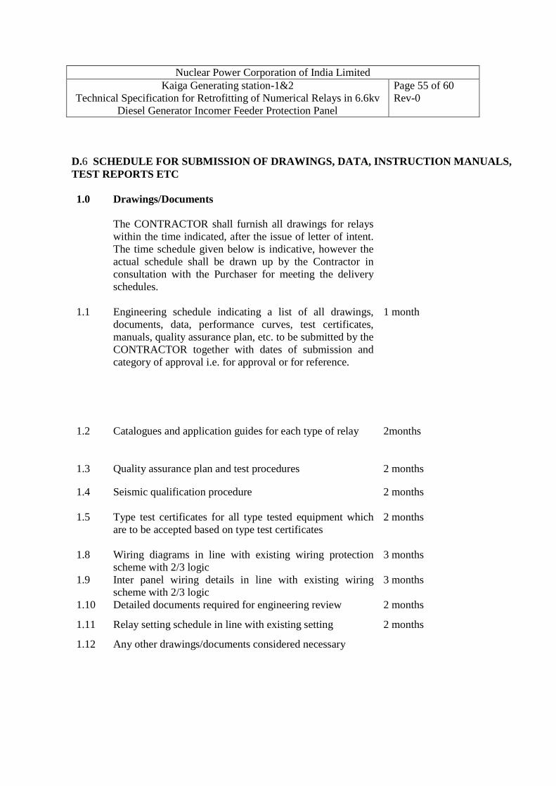
Nuclear Power Corporation of India Limited Kaiga Generating station-1&2
Technical Specification for Retrofitting of Numerical Relays in 6.6kv Diesel Generator Incomer Feeder Protection Panel
Page 55 of 60 Rev-0
D.6 SCHEDULE FOR SUBMISSION OF DRAWINGS, DATA, INSTRUCT ION MANUALS, TEST REPORTS ETC 1.0 Drawings/Documents
The CONTRACTOR shall furnish all drawings for relays within the time indicated, after the issue of letter of intent. The time schedule given below is indicative, however the actual schedule shall be drawn up by the Contractor in consultation with the Purchaser for meeting the delivery schedules.
1.1 Engineering schedule indicating a list of all drawings, documents, data, performance curves, test certificates, manuals, quality assurance plan, etc. to be submitted by the CONTRACTOR together with dates of submission and category of approval i.e. for approval or for reference.
1 month
1.2 Catalogues and application guides for each type of relay
2months
1.3 Quality assurance plan and test procedures 2 months
1.4 Seismic qualification procedure 2 months
1.5 Type test certificates for all type tested equipment which are to be accepted based on type test certificates
2 months
1.8 Wiring diagrams in line with existing wiring protection scheme with 2/3 logic
3 months
1.9 Inter panel wiring details in line with existing wiring scheme with 2/3 logic
3 months
1.10 Detailed documents required for engineering review 2 months
1.11 Relay setting schedule in line with existing setting 2 months
1.12 Any other drawings/documents considered necessary

Nuclear Power Corporation of India Limited Kaiga Generating station-1&2
Technical Specification for Retrofitting of Numerical Relays in 6.6kv Diesel Generator Incomer Feeder Protection Panel
Page 56 of 60 Rev-0
2.0 Test Certificates, Instruction manuals, end documents etc
For all items offered Within 1 month of despatch
SIGNATURE ______________ DESIGNATION______________ COMPANY ______________ DATE ______________ SEAL OF COMPANY

Nuclear Power Corporation of India Limited Kaiga Generating station-1&2
Technical Specification for Retrofitting of Numerical Relays in 6.6kv Diesel Generator Incomer Feeder Protection Panel
Page 57 of 60 Rev-0
D.7 SCHEDULE OF PERFORMANCE GUARANTEE:
The TENDERER shall furnish performance guarantee in respect of the following:
1.0 All equipment/accessories supplied shall conform to the requirements listed in this specification as well as the requirements of all applicable standards. Not meeting any of these requirements will result in rejection of the equipment/accessories.
SIGNATURE ________________ DESIGNATION ________________ COMPANY ________________ DATE ________________ SEAL OF COMPANY

Nuclear Power Corporation of India Limited Kaiga Generating station-1&2
Technical Specification for Retrofitting of Numerical Relays in 6.6kv Diesel Generator Incomer Feeder Protection Panel
Page 58 of 60 Rev-0
D.8 SCHEDULE OF DEVIATIONS FROM TECHNICAL SPECIFICA TION All deviations from the technical specification shall be filled in by the TENDERER
clause by clause in this schedule.
Section Clause No Deviation
The TENDERER hereby certifies that the above mentioned are the only
deviations from the technical specification of the enquiry. SIGNATURE ________________ DESIGNATION ________________ COMPANY ________________ DATE ________________ SEAL OF COMPANY

Nuclear Power Corporation of India Limited Kaiga Generating station-1&2
Technical Specification for Retrofitting of Numerical Relays in 6.6kv Diesel Generator Incomer Feeder Protection Panel
Page 59 of 60 Rev-0
D.9 SCHEDULE OF MANUFACTURING, DELIVERY AND OTHER R ELATED ACTIVITIES The TENDERER shall indicate the time for manufacture, delivery and other activities of each equipment as shown below:
Equipment Time
from date of order to works test
Time for works test, dismantling, packing & ready for dispatch from works
Time required for shipment to site
Total time from date of order to receipt at site
Time required for Installation / time required for testing and commissioning
(Months)
(Months) (Months) (Months) (Months)
We, the undersigned hereby undertake to meet the above time schedule from the date of order. SIGNATURE _____________ DESIGNATION _____________ COMPANY _____________ DATE _____________ SEAL OF COMPANY

Nuclear Power Corporation of India Limited Kaiga Generating station-1&2
Technical Specification for Retrofitting of Numerical Relays in 6.6kv Diesel Generator Incomer Feeder Protection Panel
Page 60 of 60 Rev-0
D.10 SCHEDULE OF PERSONNEL FOR INSTALLATION, TESTIN G & COMMISSIONING The Tenderer shall indicate below the number and category of personnel required for erection, start-up and performance testing and commissioning. Category Installation Testing & Commissioning
Number Number Expatriate Personnel
Local Recruitment
Expatriate
Personnel Local Recruitment
The Tenderer shall also indicate here those section of works or items for which specialist services on site are required. SIGNATURE _____________ DESIGNATION _____________ COMPANY _____________ DATE _____________ SEAL OF COMPANY