TECHNICAL SPECIFICATION FOR THE SUPPLY ...
294
1 NAME OF ITEM / WORK : DESIGN, SUPPLY, ERECTION, INSTALLATION, TESTING AND COMMISSIONING OF 50 TLPD CAPACITY NEW DAIRY PLANT AT THOOTHUKUDI DCMPU LTD., UNDER DIDF SCHEME TENDER REFERENCE NO : 1111/Proj.4/2022, Dated:28.02.2022 PART - I TECHNICAL BID The Dy. General Manager (Engg.). Tender document issued to M/s.___________________________________ Cost of Tender document remitted under receipt No. __________ Date ___________ (or) Tender downloaded from website on __________ at free of cost
-
Upload
khangminh22 -
Category
Documents
-
view
1 -
download
0
Transcript of TECHNICAL SPECIFICATION FOR THE SUPPLY ...
1
NAME OF ITEM
/ WORK
: DESIGN, SUPPLY, ERECTION, INSTALLATION,
TESTING AND COMMISSIONING OF 50 TLPD
CAPACITY NEW DAIRY PLANT AT
THOOTHUKUDI DCMPU LTD., UNDER DIDF
SCHEME
TENDER REFERENCE NO
: 1111/Proj.4/2022, Dated:28.02.2022
PART - I TECHNICAL BID
The Dy. General Manager (Engg.).
Tender document issued to
M/s.___________________________________
Cost of Tender document remitted under
receipt No. __________ Date ___________
(or)
Tender downloaded from website on __________
at free of cost
2
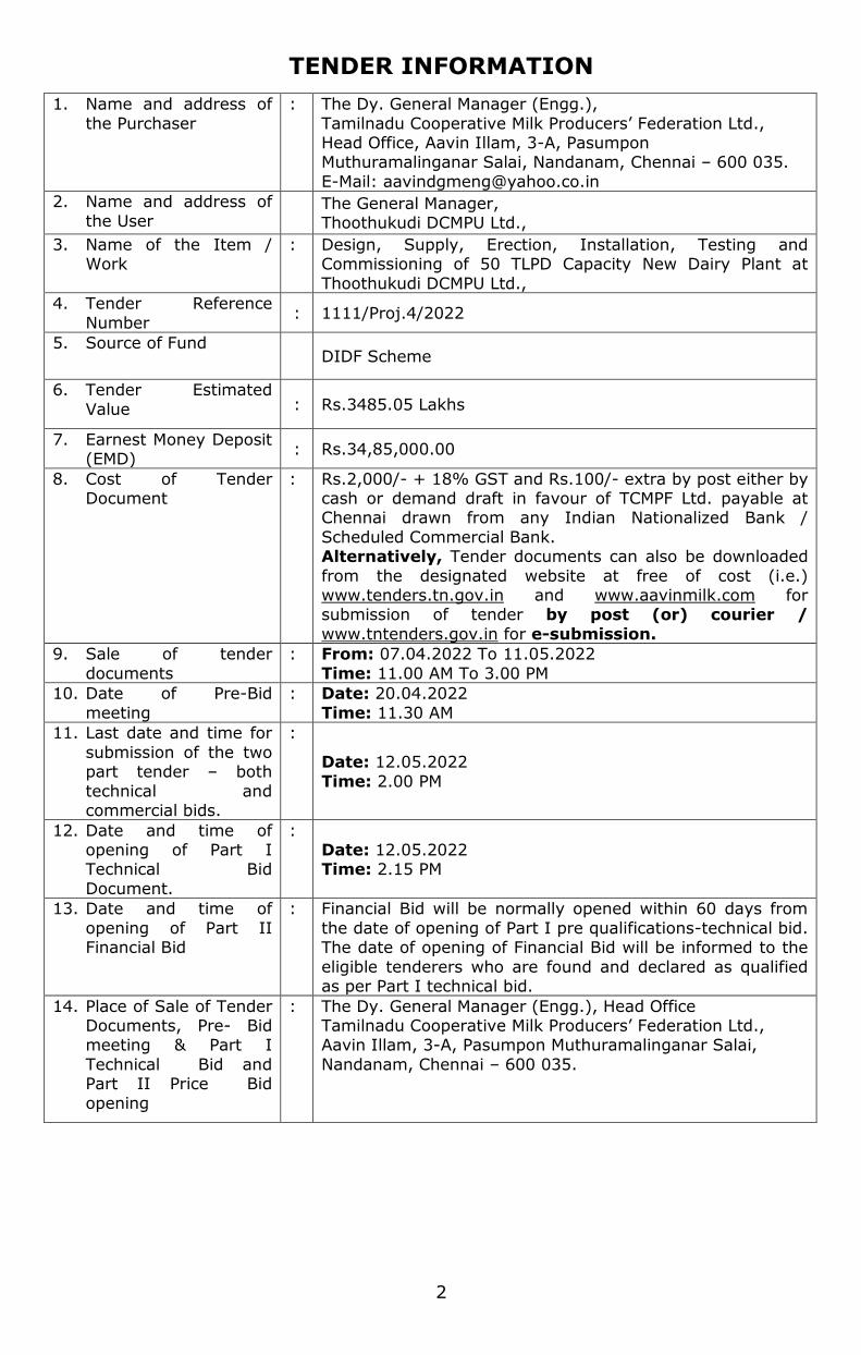
TENDER INFORMATION
1. Name and address of
the Purchaser
: The Dy. General Manager (Engg.),
Tamilnadu Cooperative Milk Producers’ Federation Ltd., Head Office, Aavin Illam, 3-A, Pasumpon Muthuramalinganar Salai, Nandanam, Chennai – 600 035.
E-Mail: [email protected]
2. Name and address of
the User
The General Manager, Thoothukudi DCMPU Ltd.,
3. Name of the Item / Work
: Design, Supply, Erection, Installation, Testing and Commissioning of 50 TLPD Capacity New Dairy Plant at
Thoothukudi DCMPU Ltd.,
4. Tender Reference
Number : 1111/Proj.4/2022
5. Source of Fund DIDF Scheme
6. Tender Estimated
Value : Rs.3485.05 Lakhs
7. Earnest Money Deposit (EMD)
: Rs.34,85,000.00
8. Cost of Tender Document
: Rs.2,000/- + 18% GST and Rs.100/- extra by post either by cash or demand draft in favour of TCMPF Ltd. payable at Chennai drawn from any Indian Nationalized Bank /
Scheduled Commercial Bank. Alternatively, Tender documents can also be downloaded
from the designated website at free of cost (i.e.) www.tenders.tn.gov.in and www.aavinmilk.com for submission of tender by post (or) courier /
www.tntenders.gov.in for e-submission.
9. Sale of tender
documents
: From: 07.04.2022 To 11.05.2022
Time: 11.00 AM To 3.00 PM
10. Date of Pre-Bid
meeting
: Date: 20.04.2022
Time: 11.30 AM
11. Last date and time for
submission of the two part tender – both
technical and commercial bids.
:
Date: 12.05.2022
Time: 2.00 PM
12. Date and time of opening of Part I Technical Bid
Document.
: Date: 12.05.2022 Time: 2.15 PM
13. Date and time of
opening of Part II Financial Bid
: Financial Bid will be normally opened within 60 days from
the date of opening of Part I pre qualifications-technical bid. The date of opening of Financial Bid will be informed to the
eligible tenderers who are found and declared as qualified as per Part I technical bid.
14. Place of Sale of Tender Documents, Pre- Bid meeting & Part I
Technical Bid and Part II Price Bid
opening
: The Dy. General Manager (Engg.), Head Office Tamilnadu Cooperative Milk Producers’ Federation Ltd., Aavin Illam, 3-A, Pasumpon Muthuramalinganar Salai,
Nandanam, Chennai – 600 035.
3
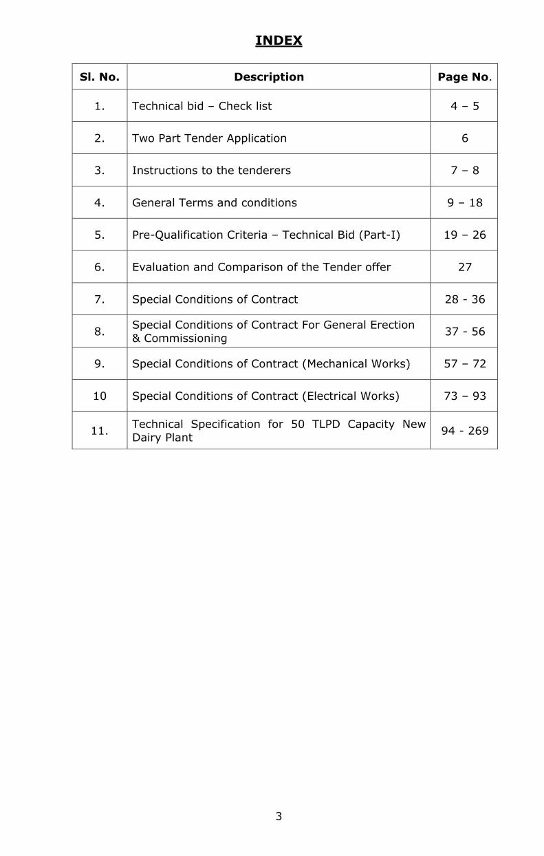
INDEX
Sl. No. Description Page No.
1. Technical bid – Check list 4 – 5
2. Two Part Tender Application 6
3. Instructions to the tenderers 7 – 8
4. General Terms and conditions 9 – 18
5. Pre-Qualification Criteria – Technical Bid (Part-I) 19 – 26
6. Evaluation and Comparison of the Tender offer 27
7. Special Conditions of Contract 28 - 36
8. Special Conditions of Contract For General Erection
& Commissioning 37 - 56
9. Special Conditions of Contract (Mechanical Works) 57 – 72
10 Special Conditions of Contract (Electrical Works) 73 – 93
11. Technical Specification for 50 TLPD Capacity New
Dairy Plant 94 - 269
SIGNATURE OF THE TENDERER WITH SEAL
4
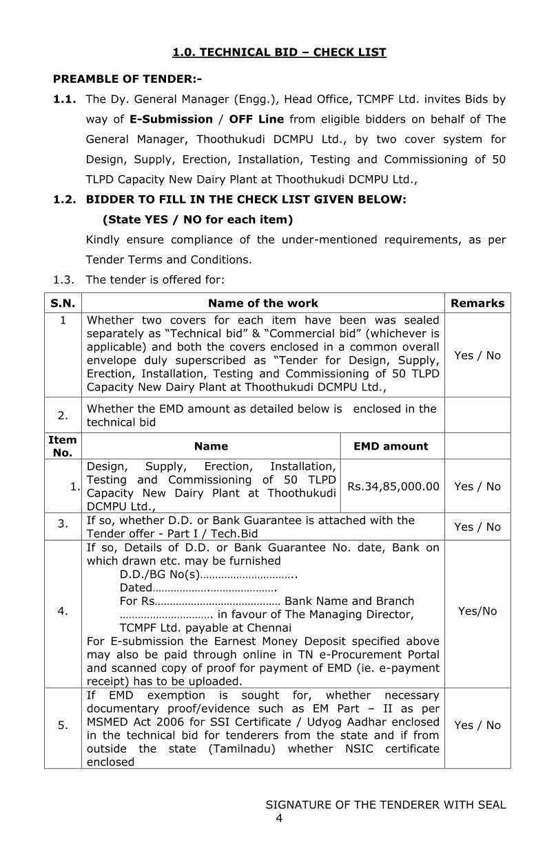
1.0. TECHNICAL BID – CHECK LIST
PREAMBLE OF TENDER:-
1.1. The Dy. General Manager (Engg.), Head Office, TCMPF Ltd. invites Bids by
way of E-Submission / OFF Line from eligible bidders on behalf of The
General Manager, Thoothukudi DCMPU Ltd., by two cover system for
Design, Supply, Erection, Installation, Testing and Commissioning of 50
TLPD Capacity New Dairy Plant at Thoothukudi DCMPU Ltd.,
1.2. BIDDER TO FILL IN THE CHECK LIST GIVEN BELOW:
(State YES / NO for each item)
Kindly ensure compliance of the under-mentioned requirements, as per
Tender Terms and Conditions.
1.3. The tender is offered for:
S.N. Name of the work Remarks
1 Whether two covers for each item have been was sealed separately as “Technical bid” & “Commercial bid” (whichever is
applicable) and both the covers enclosed in a common overall
envelope duly superscribed as “Tender for Design, Supply, Erection, Installation, Testing and Commissioning of 50 TLPD
Capacity New Dairy Plant at Thoothukudi DCMPU Ltd.,
Yes / No
2. Whether the EMD amount as detailed below is enclosed in the
technical bid
Item
No. Name EMD amount
1.
Design, Supply, Erection, Installation,
Testing and Commissioning of 50 TLPD Capacity New Dairy Plant at Thoothukudi
DCMPU Ltd.,
Rs.34,85,000.00 Yes / No
3. If so, whether D.D. or Bank Guarantee is attached with the Tender offer - Part I / Tech.Bid
Yes / No
4.
If so, Details of D.D. or Bank Guarantee No. date, Bank on which drawn etc. may be furnished
D.D./BG No(s)………………………….. Dated……………….………………….
For Rs…………………………………… Bank Name and Branch …………………………. in favour of The Managing Director,
TCMPF Ltd. payable at Chennai
For E-submission the Earnest Money Deposit specified above may also be paid through online in TN e-Procurement Portal
and scanned copy of proof for payment of EMD (ie. e-payment receipt) has to be uploaded.
Yes/No
5.
If EMD exemption is sought for, whether necessary documentary proof/evidence such as EM Part – II as per
MSMED Act 2006 for SSI Certificate / Udyog Aadhar enclosed in the technical bid for tenderers from the state and if from
outside the state (Tamilnadu) whether NSIC certificate enclosed
Yes / No
SIGNATURE OF THE TENDERER WITH SEAL
5
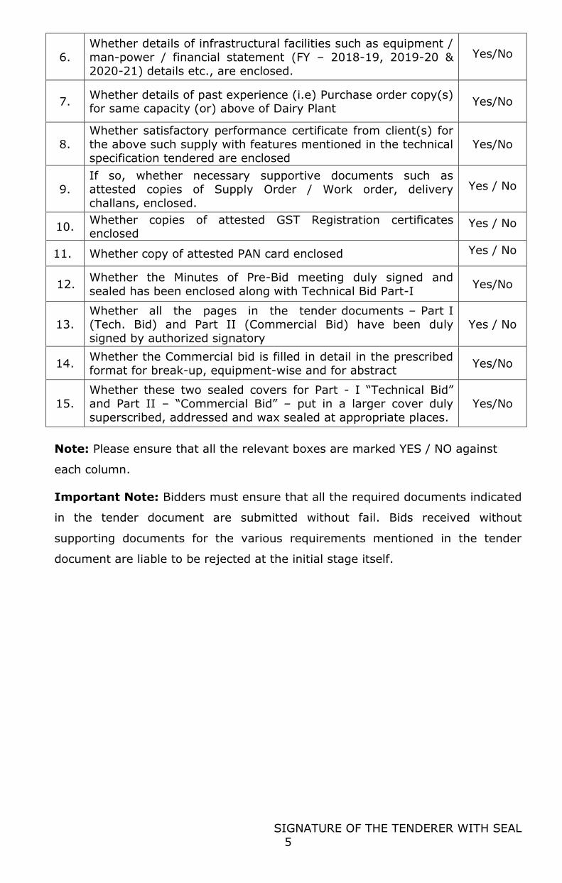
6.
Whether details of infrastructural facilities such as equipment /
man-power / financial statement (FY – 2018-19, 2019-20 & 2020-21) details etc., are enclosed.
Yes/No
7. Whether details of past experience (i.e) Purchase order copy(s) for same capacity (or) above of Dairy Plant
Yes/No
8. Whether satisfactory performance certificate from client(s) for the above such supply with features mentioned in the technical
specification tendered are enclosed
Yes/No
9.
If so, whether necessary supportive documents such as
attested copies of Supply Order / Work order, delivery challans, enclosed.
Yes / No
10. Whether copies of attested GST Registration certificates enclosed
Yes / No
11. Whether copy of attested PAN card enclosed Yes / No
12. Whether the Minutes of Pre-Bid meeting duly signed and sealed has been enclosed along with Technical Bid Part-I
Yes/No
13. Whether all the pages in the tender documents – Part I (Tech. Bid) and Part II (Commercial Bid) have been duly
signed by authorized signatory
Yes / No
14. Whether the Commercial bid is filled in detail in the prescribed
format for break-up, equipment-wise and for abstract Yes/No
15. Whether these two sealed covers for Part - I “Technical Bid” and Part II – “Commercial Bid” – put in a larger cover duly
superscribed, addressed and wax sealed at appropriate places.
Yes/No
Note: Please ensure that all the relevant boxes are marked YES / NO against
each column.
Important Note: Bidders must ensure that all the required documents indicated
in the tender document are submitted without fail. Bids received without
supporting documents for the various requirements mentioned in the tender
document are liable to be rejected at the initial stage itself.
6
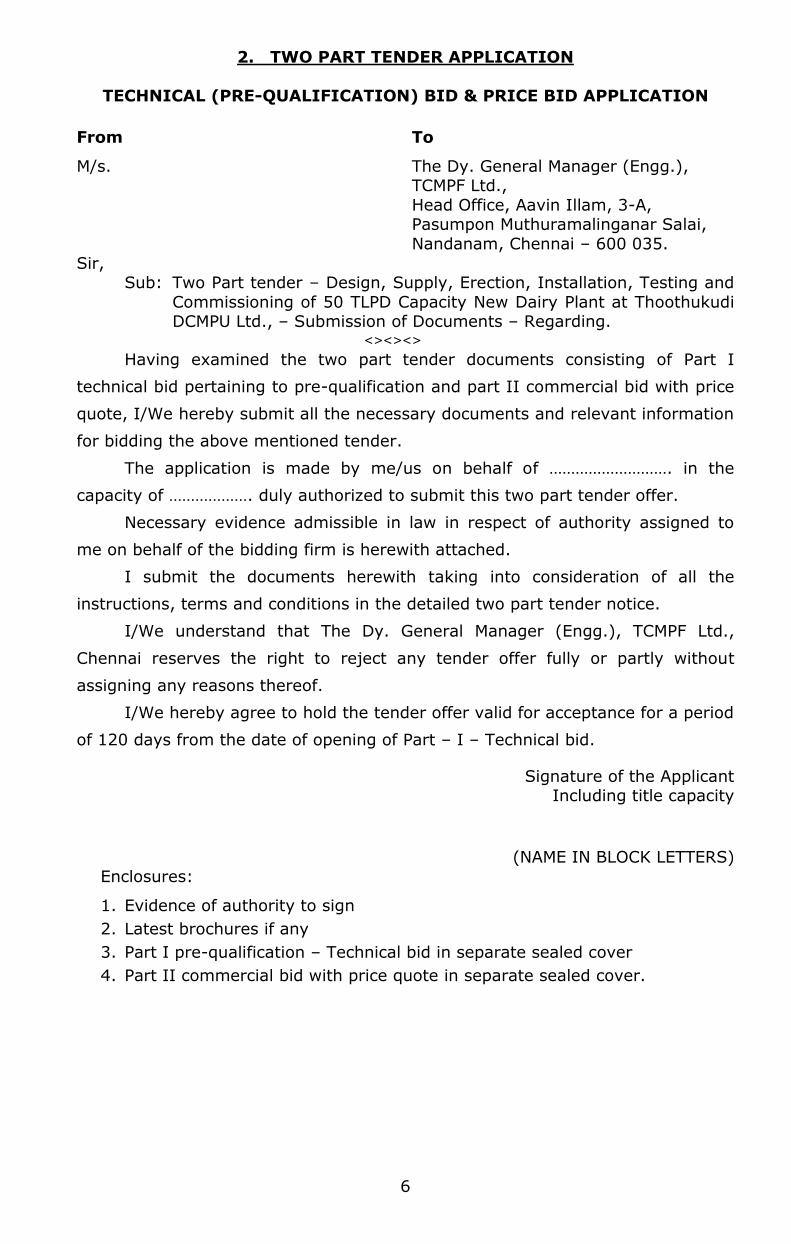
2. TWO PART TENDER APPLICATION
TECHNICAL (PRE-QUALIFICATION) BID & PRICE BID APPLICATION
From To
M/s. The Dy. General Manager (Engg.), TCMPF Ltd.,
Head Office, Aavin Illam, 3-A, Pasumpon Muthuramalinganar Salai,
Nandanam, Chennai – 600 035.
Sir, Sub: Two Part tender – Design, Supply, Erection, Installation, Testing and
Commissioning of 50 TLPD Capacity New Dairy Plant at Thoothukudi DCMPU Ltd., – Submission of Documents – Regarding. <><><>
Having examined the two part tender documents consisting of Part I
technical bid pertaining to pre-qualification and part II commercial bid with price
quote, I/We hereby submit all the necessary documents and relevant information
for bidding the above mentioned tender.
The application is made by me/us on behalf of ………………………. in the
capacity of ………………. duly authorized to submit this two part tender offer.
Necessary evidence admissible in law in respect of authority assigned to
me on behalf of the bidding firm is herewith attached.
I submit the documents herewith taking into consideration of all the
instructions, terms and conditions in the detailed two part tender notice.
I/We understand that The Dy. General Manager (Engg.), TCMPF Ltd.,
Chennai reserves the right to reject any tender offer fully or partly without
assigning any reasons thereof.
I/We hereby agree to hold the tender offer valid for acceptance for a period
of 120 days from the date of opening of Part – I – Technical bid.
Signature of the Applicant Including title capacity
(NAME IN BLOCK LETTERS)
Enclosures:
1. Evidence of authority to sign
2. Latest brochures if any
3. Part I pre-qualification – Technical bid in separate sealed cover
4. Part II commercial bid with price quote in separate sealed cover.
I agree to abide by the above instructions
SIGNATURE OF THE TENDERER
7
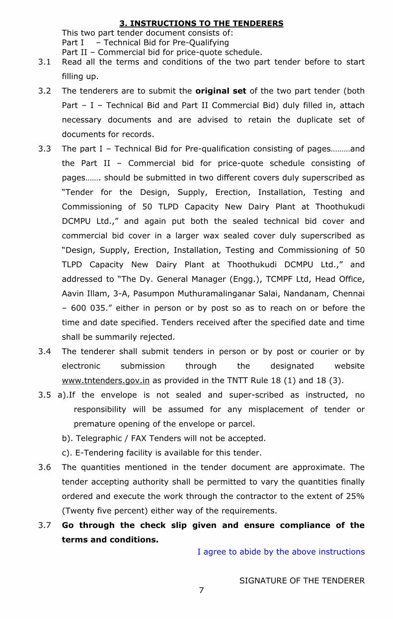
3. INSTRUCTIONS TO THE TENDERERS
This two part tender document consists of:
Part I – Technical Bid for Pre-Qualifying
Part II – Commercial bid for price-quote schedule. 3.1 Read all the terms and conditions of the two part tender before to start
filling up.
3.2 The tenderers are to submit the original set of the two part tender (both
Part – I – Technical Bid and Part II Commercial Bid) duly filled in, attach
necessary documents and are advised to retain the duplicate set of
documents for records.
3.3 The part I – Technical Bid for Pre-qualification consisting of pages………and
the Part II – Commercial bid for price-quote schedule consisting of
pages……. should be submitted in two different covers duly superscribed as
“Tender for the Design, Supply, Erection, Installation, Testing and
Commissioning of 50 TLPD Capacity New Dairy Plant at Thoothukudi
DCMPU Ltd.,” and again put both the sealed technical bid cover and
commercial bid cover in a larger wax sealed cover duly superscribed as
“Design, Supply, Erection, Installation, Testing and Commissioning of 50
TLPD Capacity New Dairy Plant at Thoothukudi DCMPU Ltd.,” and
addressed to “The Dy. General Manager (Engg.), TCMPF Ltd, Head Office,
Aavin Illam, 3-A, Pasumpon Muthuramalinganar Salai, Nandanam, Chennai
– 600 035.” either in person or by post so as to reach on or before the
time and date specified. Tenders received after the specified date and time
shall be summarily rejected.
3.4 The tenderer shall submit tenders in person or by post or courier or by
electronic submission through the designated website
www.tntenders.gov.in as provided in the TNTT Rule 18 (1) and 18 (3).
3.5 a).If the envelope is not sealed and super-scribed as instructed, no
responsibility will be assumed for any misplacement of tender or
premature opening of the envelope or parcel.
b). Telegraphic / FAX Tenders will not be accepted.
c). E-Tendering facility is available for this tender.
3.6 The quantities mentioned in the tender document are approximate. The
tender accepting authority shall be permitted to vary the quantities finally
ordered and execute the work through the contractor to the extent of 25%
(Twenty five percent) either way of the requirements.
3.7 Go through the check slip given and ensure compliance of the
terms and conditions.
I agree to abide by the above instructions
SIGNATURE OF THE TENDERER
8
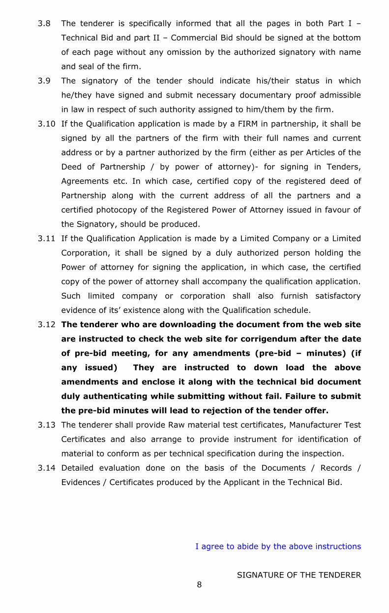
3.8 The tenderer is specifically informed that all the pages in both Part I –
Technical Bid and part II – Commercial Bid should be signed at the bottom
of each page without any omission by the authorized signatory with name
and seal of the firm.
3.9 The signatory of the tender should indicate his/their status in which
he/they have signed and submit necessary documentary proof admissible
in law in respect of such authority assigned to him/them by the firm.
3.10 If the Qualification application is made by a FIRM in partnership, it shall be
signed by all the partners of the firm with their full names and current
address or by a partner authorized by the firm (either as per Articles of the
Deed of Partnership / by power of attorney)- for signing in Tenders,
Agreements etc. In which case, certified copy of the registered deed of
Partnership along with the current address of all the partners and a
certified photocopy of the Registered Power of Attorney issued in favour of
the Signatory, should be produced.
3.11 If the Qualification Application is made by a Limited Company or a Limited
Corporation, it shall be signed by a duly authorized person holding the
Power of attorney for signing the application, in which case, the certified
copy of the power of attorney shall accompany the qualification application.
Such limited company or corporation shall also furnish satisfactory
evidence of its’ existence along with the Qualification schedule.
3.12 The tenderer who are downloading the document from the web site
are instructed to check the web site for corrigendum after the date
of pre-bid meeting, for any amendments (pre-bid – minutes) (if
any issued) They are instructed to down load the above
amendments and enclose it along with the technical bid document
duly authenticating while submitting without fail. Failure to submit
the pre-bid minutes will lead to rejection of the tender offer.
3.13 The tenderer shall provide Raw material test certificates, Manufacturer Test
Certificates and also arrange to provide instrument for identification of
material to conform as per technical specification during the inspection.
3.14 Detailed evaluation done on the basis of the Documents / Records /
Evidences / Certificates produced by the Applicant in the Technical Bid.
Noted and agreed to the above
SIGNATURE OF THE TENDERER
9
4.0.GENERAL TERMS & CONDITIONS
4.1. Tender under sealed two part tender system (i.e.) Technical Bid
(Prequalification) & Price Bid (item rate tenders) are invited for and on
behalf of The General Manager, Thoothukudi DCMPU Ltd., by The Dy.
General Manager (Engg.), Head Office, TCMPF Ltd. for the Design, Supply,
Erection, Installation, Testing and Commissioning of 50 TLPD Capacity New
Dairy Plant at Thoothukudi DCMPU Ltd.,
4.2
4.2.1.The tenderer should be a sole bidder / lead bidder or consortium partner
(maximum two consortium partner is allowed )
4.2.2.The term tenderer / bidder in this document refers to sole bidder / lead
bidder or consortium partner
4.2.3.The tenderer should be manufacturer / supplier of Dairy Plant
4.2.4. The tenderer should have previous experience in having designed,
supplied, installed and commissioned same capacity (or) above of Dairy
Plant , in India either to any cooperative institution or reputed dairies /
firms.
4.2.5. The tenderer should have designed, supplied, installed and commissioned
same capacity (or) above of Dairy Plant, for which tender called for, and
enclose copies of purchase order / supply order within a period of 5 years.
4.2.6.The performance certificate for above such supply for which Purchase
Order / Supply order furnished as per 4.2.5 from the reputed purchaser
shall be enclosed in the technical bid part – I. The performance certificate
received from purchaser / client should be of within a period of 3 years.
4.2.7.The Tenderer should have minimum experience of 5 Years in the
manufacturing, designed, supplied, installed and commissioned of Dairy
Plant. Copies of Registration of firms with list of activities/GST registration
certificate etc. should be enclosed as supporting document.
4.2.8.If the tenderer is an authorized dealer / supplier of original equipment
manufacturer (OEM), the tenderer shall furnish the authorization letter
from the original equipment manufacturer (OEM) for supply of Dairy Plant.
The original equipment manufacturer (OEM) can authorize only one dealer
/ supplier
4.2.9.If the tenderer is an authorized dealer / supplier for Dairy Plant then the
experience of the manufacturer for supply of Dairy Plant, their performance
and sales turnover shall be taken for evaluation of technical bids, even if
Noted and agreed to the above
SIGNATURE OF THE TENDERER
10
the supply has been made either by the manufacturer directly or through
other agencies.
4.3.
4.3.1 PART I TECHNICAL BID, wherein the pre-qualification, based on various
factors such as supply, capacity etc., suitability and eligibility of the
tenderer will be evaluated, considered and decided prior to opening of
commercial Bids under PART II of the tender.
4.3.2.THE PART I technical bid shall be opened on 12.05.2022 at 02.15 PM. in
the presence of the tenderers or their authorized representative who opt to
be present during the opening.
4.4.
4.4.1. The PART II Commercial Bid of the tenderers who do not satisfy any/all
the terms and conditions specifically so mentioned under PART I technical,
shall not be considered and shall not be opened as non responsive.
4.4.2.PART II Commercial Bid, wherein the rates tendered by those who qualify
for and are selected as per the terms and conditions prescribed in PART I
TECHNICAL BID only will be considered and decided for the award of the
contract for the Design, Supply, Erection, Installation, Testing and
Commissioning of 50 TLPD Capacity New Dairy Plant at Thoothukudi
DCMPU Ltd.,
4.5. The Part II commercial bids shall normally be opened within 60 days from
the date of opening of the Part I pre-qualification/ technical bid in the
presence of tenderers or their authorized representatives who opt to be
present. The date of such opening of commercial bid will be informed
separately to those who qualify in the PART I technical bid.
4.6. The tenderer is specifically informed that all the pages in both Part I –
Technical Bid and Part II – Commercial Bid should be signed at the bottom
of each page without any omission by the authorized signatory with name
and seal of the firm.
4.7. The tender forms are not transferable or assignable.
4.8. The signatory of the tender should indicate his/their status in which
he/they have signed and submit necessary documentary proof admissible
in law in respect of such authority assigned to him/them by the firm. If
the tender opening day is declared as a holiday, the tenders shall be
received and opened immediately on the next working day at the same
time and place.
Noted and agreed to the above
SIGNATURE OF THE TENDERER
11
4.9 E.M.D. PAYABLE:
4.9.1 Tender must be accompanied with the prescribed amount of EMD along
with tender, if e-tender, the EMD DD should be dropped in the tender
box before closure time or may be paid through online in TN e-
Procurement Portal and scanned copy of proof for payment of EMD
(ie. e-payment receipt) has to be uploaded.
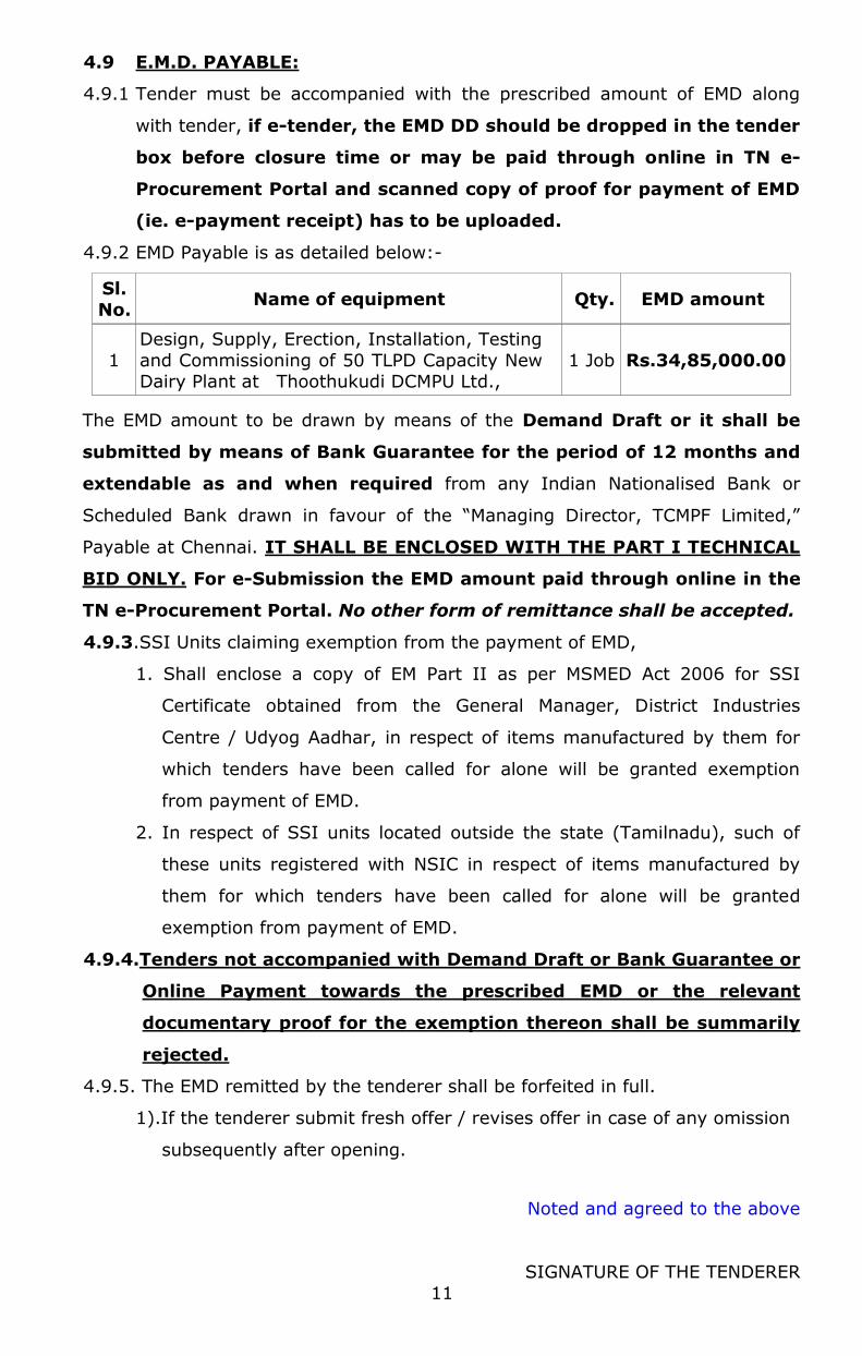
4.9.2 EMD Payable is as detailed below:-
Sl.
No. Name of equipment Qty. EMD amount
1
Design, Supply, Erection, Installation, Testing
and Commissioning of 50 TLPD Capacity New Dairy Plant at Thoothukudi DCMPU Ltd.,
1 Job Rs.34,85,000.00
The EMD amount to be drawn by means of the Demand Draft or it shall be
submitted by means of Bank Guarantee for the period of 12 months and
extendable as and when required from any Indian Nationalised Bank or
Scheduled Bank drawn in favour of the “Managing Director, TCMPF Limited,”
Payable at Chennai. IT SHALL BE ENCLOSED WITH THE PART I TECHNICAL
BID ONLY. For e-Submission the EMD amount paid through online in the
TN e-Procurement Portal. No other form of remittance shall be accepted.
4.9.3.SSI Units claiming exemption from the payment of EMD,
1. Shall enclose a copy of EM Part II as per MSMED Act 2006 for SSI
Certificate obtained from the General Manager, District Industries
Centre / Udyog Aadhar, in respect of items manufactured by them for
which tenders have been called for alone will be granted exemption
from payment of EMD.
2. In respect of SSI units located outside the state (Tamilnadu), such of
these units registered with NSIC in respect of items manufactured by
them for which tenders have been called for alone will be granted
exemption from payment of EMD.
4.9.4.Tenders not accompanied with Demand Draft or Bank Guarantee or
Online Payment towards the prescribed EMD or the relevant
documentary proof for the exemption thereon shall be summarily
rejected.
4.9.5. The EMD remitted by the tenderer shall be forfeited in full.
1).If the tenderer submit fresh offer / revises offer in case of any omission
subsequently after opening.
Noted and agreed to the above
SIGNATURE OF THE TENDERER
12
2).If withdraws his tender or backs at before the expiry of validity period or
after acceptance.
3).If revises any of the terms quoted during validity period.
4.9.6. MODIFICATION AND WITHDRAWAL OF BIDS
4.9.6.1. No Tenderer shall be allowed to withdraw the tenders after submitting
the tender.
4.9.6.2 A Tenderer may submit a modified Tender before the last date for receipt
of tender: Provided that where more than one Tender is submitted by
the same Tenderer, the lowest eligible financial tender shall be
considered for evaluation.
4.9.6.3 Each bidder’s modification notice shall be prepared, sealed, marked and
delivered with the outer and inner envelops additionally marked
MODIFICATION as appropriate.
4.9.6.4 No bid may be modified after the deadline for submission of Bids.
4.9.7 Bidders shall submit offers that comply with the requirements of the
bidding documents, as indicated in the technical specifications.
“Alternatives will not be considered”.
4.9.8 Communication to the unsuccessful Bidders will be sent after the
communication sent to the successful Bidder. Within 90 (Ninety) days from
the date of the receipt of refund vouchers duly stamped and signed from
the unsuccessful Bidder, refund of Earnest Money Deposit will be made.
4.10.PAN/GST REGISTRATION/CLEARANCE CERTIFICATE:
4.10.1.Tenderers shall furnish attested Photostat copies of valid GST Registration
Certificates along with the tender technical bid Part-I.
4.10.2.Tenderers shall furnish attested Photostat copy of PAN Registration
Certificates along with the tender technical bid Part-I.
4.10.3.Tenderers have to furnish the latest valid S.T. Clearance Certificate before
issuance of final orders.
4.11. ENCLOSURES: The tenderer should submit the following documents duly
attested by Notary Public along with the Part – I technical bid.
1). Purchase orders as supportive documents to show the past supply
having supplied to any of the reputed dairies / firm(s) /coop(s) in
India.
2). Satisfactory performance certificate from client(s) for the above
equipments tendered.
Noted and agreed to the above
SIGNATURE OF THE TENDERER
13
3). If the tenderer is an authorized suppliers of a manufacturer, the
tenderer shall furnish the authorization letter from the manufacturer
for supply of Dairy Plant
4). Photostat copies of valid GST Registration Certificate, PAN Certificate.
5). Infrastructure facilities – Capacity of Firm / Supplier:-
(i). Structure and Organization with details of Technical Personnel
etc. – Annexure – A
(ii). Financial Capability Statement – Annexure – B (iii). Building, Plant and Equipments
(iv). Details of Abandonment of work Litigation / debarring done – Annexure – C
(v). Affidavit – Annexure – D (vi). Credit Facilities – Bank Certificate – Annexure – E
4.12. SECURITY DEPOSIT
The successful tenderers would be required to sign an agreement
and furnish a Security Deposit of 5% of the order value, drawn by means
of Demand Draft or it shall be submitted by means of Bank Guarantee for
the period of 18 months and extendable as and when required from any
Indian Nationalised Bank or Scheduled Bank drawn in favour of “Managing
Director, TCMPF Ltd” payable at Chennai within 15 days of notifying them.
The EMD already paid along with tender shall be adjusted against SD to be
paid by the successful tenderer.
No exemption will be given from payment of Security deposit under
any circumstances as per TNTT Act and the same should be remitted by
above means. Any other form of remittance will not be accepted..
4.12.1.The security deposit will be refunded only after the expiry of 6 months
from the date of satisfactory completion of the contract satisfactorily
complying to the specification of the equipment to take care of the
workmanship of the agency.
4.13. AGREEMENT:
The successful tenderer has to execute an agreement on Rs.100/-
non-judicial stamp paper incorporating the terms and conditions of the
contract and the specification within 15 days from the date of intimation
of the acceptance of the tender. In case of default of either of the
conditions (i.e) remitting the security deposit or execution of the
agreement within the time allowed, the EMD paid is likely to be forfeited
by the Federation.
Noted and agreed to the above
SIGNATURE OF THE TENDERER
14
4.13.1. If the contractor fails to execute the contract satisfactorily at the
tendered rate, the security deposit will be forfeited by the Federation.
4.13.2. If the Federation incurs any loss / additional expenditure due to the
negligence of the contractor in connection with the work during the
period of contract, the same shall be recovered together with all charges
and expenses from the contractor.
4.13.3. The breakages or damages, if any, caused by the contractor to the
property of the Federation, the cost will be recovered from the
contractor.
4.13.4. RATES AND PRICE: This is a fixed price contract. Price adjustment
clause (to account for raise or fall in the money value / statutory taxes
during the contract period) is not operatable for this contract. However
any variation in the statutory levies and Taxes by State Government /
Central Government shall be effected on the end price to the benefit of
either the contractor or Federation as the case it may be.
4.13.5. No interest shall be paid on Earnest Money Deposit/Security Deposit.
4.13.6. The Agreement in Rs.100/- non-judicial stamp paper shall be signed and
returned within 15 days of receipt of the Design, Supply, Erection,
Installation, Testing and Commissioning order along with the D.D. for
Security Deposit.
4.14. DELIVERY SCHEDULE:-
4.14.1. Supply : 5 – 6 months from the date of
receipt of purchase order (or) 1 month from the readiness of site
whichever is later 4.14.2. Erection,
Installation, Testing and Commissioning
:
4 – 6 months from the readiness of
site (or) receipt of Materials at site whichever is later.
4.15. PAYMENT TERMS:
4.15.1. SUPPLY:
a). If the single order of any successful tenderers is over Rs.1 crore., an
advance payment of 10% of the basic value of the order will be considered
against irrevocable bank guarantee for a period till completion of entire
supply of Dairy Plant Machinery / Equipments and such advance shall be
recovered with interest applicable at the time of recovery from the bills
payable at the time of release of 70% basic price + taxes and other
charges.
(OR)
Noted and agreed to the above
SIGNATURE OF THE TENDERER
15
70% of basic price + taxes and other charges shall be released on
receipt of the Dairy Plant Machinery/Equipments wise in good condition at
site.
b). The remaining 30% payment shall be released after the Erection and
satisfactory commissioning of the Dairy Plant Machinery/Equipments wise
at site.
(OR)
If the site is not ready due to unavoidable circumstances for carrying
out the Erection, Installation, Testing and Commissioning of the
equipments within 3 months period, then the balance 30% payment on
supply will be considered for release on submission of irrevocable Bank
Guarantee for a value equal to 30% of supply order value, for one year and
extendable for another one more year with an agreement on a non-judicial
stamp paper to a value of Rs.100/- (Rupees hundred only) for execution of
project subsequently without altering the Erection, Installation, Testing and
Commissioning charges.
4.15.2. ERECTION, INSTALLATION, TESTING AND COMMISSIONING:
a). 70% of the Erection, Installation, Testing and Commissioning charges shall
be released on satisfactory completion of the Erection, Installation, Testing
and Commissioning of the Dairy Plant
b). Balance 30% of Erection, Installation, Testing and Commissioning charges
shall be released after 3 months from the date of satisfactory
commissioning and performance of the Dairy Plant.
N.B: NO OTHER TERMS OF PAYMENT WILL BE ENTERTAINED.
PENALTY CLAUSE:
4.15.3. If the tenderer / Contractor fails in his due performance of the contract
within the time fixed in the schedule accompanying the order or
extension of time granted:-
(a) Liquidated damages will be levied at 1% per month for the number of
days that the supply / work has been delayed for the contract value
less than Rs.50,00,000/- (Rupees fifty lakhs) as below subject to:-
(i). The Liquidated Damages be imposed on the value of undelivered
/ delayed supply of materials / machineries instead of total value
of contract, if the tender is for the Design, Supply, Erection,
Installation, Testing and Commissioning of two or more number
Noted and agreed to the above
SIGNATURE OF THE TENDERER
16
of machineries and where the materials / machineries can be put
into use separately.
(OR) (ii). The Liquidated Damages be imposed on the total value of the
contract for delayed supply / completion of material / work as per
the milestone fixed in the tender (i.e) turnkey job inclusive of
Civil work, supply of Mechanical/Electrical item, Erection etc.,
since the machineries partly supplied could not be put into
operation and affect the functioning of system and other
accessories as per plan.
(b). The Liquidated Damages be imposed for the delayed supply /
Erection, Installation, Testing and commissioning at 0.5% per month,
if the contract value is more than Rs.50.00 Lakhs (Rupees fifty
lakhs). The maximum deduction is limited to 5% on LD.
4.15.4. Time being the essence of contract no variation shall be permitted in the
delivery time as prescribed in the delivery schedule. If the tenderer fails
to supply and execute the work in full or part of the order as per the
delivery schedule, the Federation shall reserve the right to cancel the
order besides forfeiture of Security Deposit.
4.15.5. Notwithstanding anything contained in the tender schedule, no obligation
rests on the Federation to accept the lowest tender and the Federation
shall also have the right to accept or reject any or all the tenders fully or
partly without assigning any reasons.
4.15.6. For violation of any of the terms and conditions of the contract, the
Federation reserves the right to terminate the contract, with or without
notice as applicable.
4.15.7. On termination of contract, the Security Deposit is liable to be forfeited
and any of the resultant loss beyond Security Deposit will be recovered
from the contractor by legal means apart from forfeiture of any amount
due to the contractor.
4.15.8. (a). If the tenderer defaulted in any of the previous tenders to execute
agreement or to pay Security Deposit or to supply ordered quantity
either in part or full will not be eligible from participating in this
tender.
(b). If the successful tenderer either in federation TCMPF or in the
DCMPU defaulted to execute agreement or to pay Security Deposit or
Noted and agreed to the above
SIGNATURE OF THE TENDERER
17
to supply ordered quantity either in part or full shall be debarred
from participating in the subsequent tenders for a period of 3 years.
4.16. WARRANTY:
A warranty certificate shall be furnished on the workmanship, parts and
performance of the Dairy Plant for a period of 18 months from the date of supply
or 12 months from the date of satisfactory commissioning whichever is later. If
any defects are noticed in the equipments during the warranty period the same
should be rectified at site at free of cost and charges.
4.17. FORCE MAJEURE:
Failure or delay in the part of tenderer for supply due to force majeure
causes enumerated here under shall be considered, provided the supplier
produces documentary evidence.
a. Any cause which is beyond the reasonable control of the tenderer.
b. Natural phenomena, such as floods, drought, earthquakes and
epidemics.
c. Act of any Govt. Authority, domestic or foreign, such as wars declared
or undeclared quarantines, embargoes licensing control on production or
distribution restrictions.
d. Accident and disruptions such as fire, explosion, increase in power cut
with respect to date of tender opening etc.,
e. Strikes, slow down and lockouts.
The cause of force majeure condition will be taken into consideration only if
the supplier notifies within 30 days from the occurrence of such eventualities.
The purchaser shall verify the facts and grant such extension as the facts justify.
For extension due to force majeure conditions, the supplier shall submit his
representation with documentary evidence for scrutiny by the purchaser and
decision of the purchaser shall be binding on the time.
4.18. DISPUTES AND ARBITRATION:
In case of disputes arising out of this tender, an arbitrator as
mutually acceptable to the tenderer and Federation will be appointed by
the Managing Director, TCMPF Limited. The arbitrator’s decision shall be
final, conclusive and binding on both the parties.
Noted and agreed to the above
SIGNATURE OF THE TENDERER
18
4.19. LEGAL JURISDICTION
In case if either party to the tender is aggrieved by the award of the
arbitrator so appointed as per clause 4.18 or otherwise, they can appeal to
Court of Deputy Registrar (Dairying), Thiruvallur. The legal jurisdiction will
be only Deputy Registrar (Dairying), Thiruvallur Court.
4.20. PERFORMANCE GUARANTEE:
If the value of supply order is Rs.50 lakhs or more, the contractor
shall provide a performance guarantee at the time of getting 70% payment
for the 10% of the supply order value of the Dairy Plant ordered as Bank
Guarantee from a Nationalized Bank / Scheduled Banks for a period of one
year and extendable to one more year if needed.
4.21. INSPECTION:
After issue of purchase order to L1 Firm, the material inspection will be
conducted at Supplier’s site and Purchaser’s by TCMPF Ltd., / Third Party
agency as the case it may be.
Noted and agreed to the above
SIGNATURE OF THE TENDERER
19
5.0. PRE QUALIFICATION CRITERIA – TECHNICAL BID (PART-I)
The pre-qualification tender/PART-I technical bid will contain the under
mentioned aspects pertaining to the prospective suppliers about their suitability,
capacity, financial status, antecedents, past performance etc. The conditions
are:-
5.1. Tenders not accompanied with Demand Draft or Bank Guarantee or
Online Payment towards the prescribed EMD or the relevant
documentary proof for the exemption thereon shall be summarily
rejected
5.1.1.The tenderer should be manufacturer / supplier of Dairy Plant
5.2. The tenderer should have previous experience in having designed,
supplied, installed and commissioned same capacity (or) above of Dairy
Plant, in India either to any cooperative institution or reputed dairies /
firms.
5.3. The tenderer should have designed, supplied, installed and commissioned
same capacity (or) above of Dairy Plant, for which tender called for, and
enclose copies of purchase order / supply order within a period of 5 years.
5.4. The performance certificate for above such supply for which Purchase
Order / Supply order furnished as per 5.3 from the reputed purchaser shall
be enclosed in the technical bid part – I. The performance certificate
received from purchaser / client should be of within a period of 3 years.
5.5. The Tenderer should have minimum experience of 5 Years in the
manufacturing, designed, supplied, installed and commissioned of Dairy
Plant. Copies of Registration of firms with list of activities/GST registration
certificate etc. should be enclosed as supporting document
5.6. If the tenderer is an authorized dealer / supplier of original equipment
manufacturer (OEM), the tenderer shall furnish the authorization letter
from the original equipment manufacturer (OEM) for supply of Dairy Plant.
The original equipment manufacturer (OEM) can authorize only one dealer
/ supplier.
5.7. If the tenderer is an authorized dealer / supplier for Dairy Plant, then the
experience of the manufacturer for supply of Dairy Plant, their performance
and sales turnover shall be taken for evaluation of technical bids, even if
the supply has been made either by the manufacturer directly or through
other agencies.
5.8. The tenderer who are downloading the document from the web site
are instructed to check the web site for corrigendum after the date
of pre-bid meeting, for any amendments (pre-bid – minutes) (if
any issued) They are instructed to down load the above
Noted and agreed to the above
SIGNATURE OF THE TENDERER
20
amendments and enclose it along with the technical bid document
duly authenticating while submitting without fail. Failure to submit
the pre-bid minutes will lead to rejection of the tender offer.
5.9. FINANCIAL: The tenderer shall have average annual sales turn-over
for the last three financial years (2018-19, 2019-20 & 2020-21)
equal to the tender estimated value and minimum annual sales
turn-over in each of the last three financial years (2018-19, 2019-
20 & 2020-21) shall not be less than 50% of the tender estimated
value.
5.10. VALIDITY OF PRICE TENDER:
a). The tender offer shall be kept for acceptance for a period of 120 days
from the date of opening of Part – I Technical bid. The offers with
lower validity period are liable for rejection.
b). Further the tenderer shall agree to extend the validity of the bids
without altering the substance and prices of their bid for further period,
if any required by Federation (i.e) The Price Bid shall be valid for a
period of at least 90 days (Ninety Days) from the date, notified for
opening of Price Bid.
5.11. DEVIATION:
a). The offers of the tenderers with deviations on technical / commercial
terms of the tender will be rejected.
b). No alternate offer will be accepted.
5.12. Even though the bidders meet the above qualifying criteria, they are
subject to be disqualified if they have:
a). Made misleading or false representations in the forms, statements and
attachments submitted in proof of the qualification requirements;
and/or
b). Record of poor performance such as abandoning the works, not
properly completing the contract, inordinate delays in completion,
litigation history, or financial failures etc.; and/or
c). Participated in the previous bidding for the same work and had quoted
unreasonably high bid prices and could not furnish rational justification
to the employer.
5.13.The bidder should submit the proposed tentative P and I drawing, General
plan for the above Dairy Plant in the Technical bid.

SIGNATURE OF THE TENDERER WITH SEAL
21
Annexure – A
STRUCTURE AND ORGANISATION
1 Name of the Applicant :
2
Status :
Individual contractor :
Sole Proprietary Firm :
Firm in Partnership :
Private Limited Company :
Public Limited Company :
3 Head Office/Registered office address
with phone / Telex / Fax Number :
4
Contact Person Name
Address Mobile No
Email Address
:
5 Regional Office address with Phone /
Telex / Fax Number :
6 Local office (if any) address with Phone
/ Telex / Fax Number :
7
Field of activity of the Applicant as per deed of Partnership / Memorandum of
Association / Articles of associates (Civil) Engineering Contractor / General
Engineering Contractor / Electrical Items - Engineering Contractor etc,
should be specified.)
:
8 Country and year of incorporation :
9 Main line of Business :
10
Name, position, status, capacity etc, of the Key personnel/ directors of the
company (Attach organization chart showing the structure of the company /
firm)
:
11
Name, capacity and address of the signatory who has Signed the
Qualification Application. Attested copy of authorization issued (either by power
of attorney or as per articles of Partnership Deed / Memorandum of
Association) in favour of the signatory to sign the qualification Application
price Tender/ Agreement should be appended.
:
SIGNATURE OF THE TENDERER WITH SEAL
22
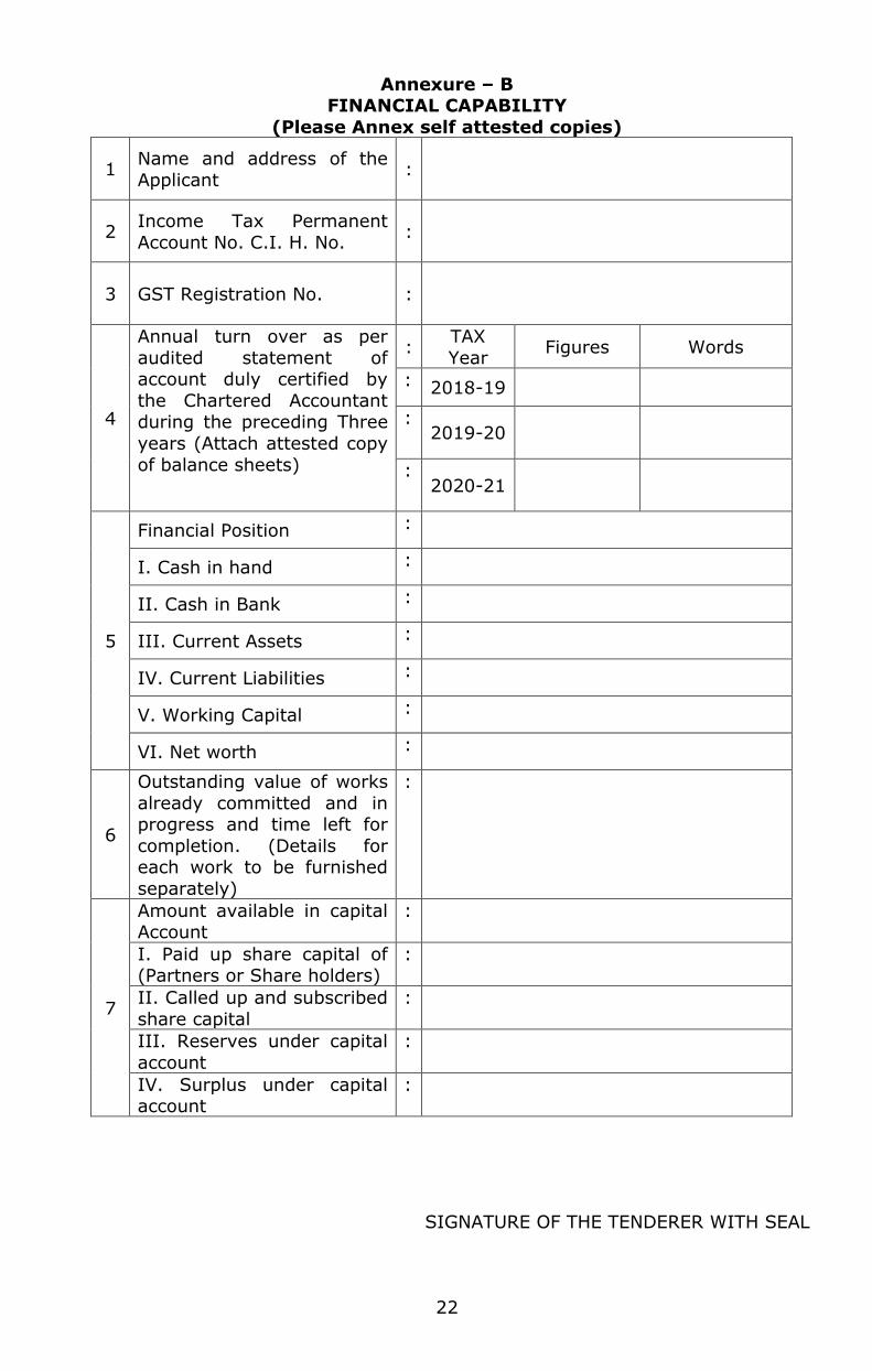
Annexure – B FINANCIAL CAPABILITY
(Please Annex self attested copies)
1 Name and address of the
Applicant :
2 Income Tax Permanent
Account No. C.I. H. No. :
3 GST Registration No. :
4
Annual turn over as per
audited statement of account duly certified by
the Chartered Accountant during the preceding Three
years (Attach attested copy
of balance sheets)
: TAX
Year Figures Words
: 2018-19
: 2019-20
: 2020-21
5
Financial Position :
I. Cash in hand :
II. Cash in Bank :
III. Current Assets :
IV. Current Liabilities :
V. Working Capital :
VI. Net worth :
6
Outstanding value of works
already committed and in progress and time left for
completion. (Details for each work to be furnished
separately)
:
7
Amount available in capital Account
:
I. Paid up share capital of (Partners or Share holders)
:
II. Called up and subscribed
share capital
:
III. Reserves under capital
account
:
IV. Surplus under capital account
:
SIGNATURE OF THE TENDERER WITH SEAL
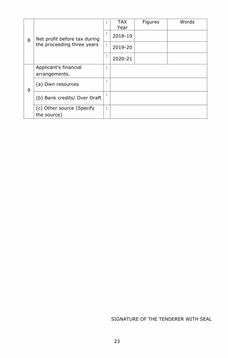
23
8 Net profit before tax during the proceeding three years
: TAX
Year
Figures Words
: 2018-19
: 2019-20
: 2020-21
9
Applicant’s financial
arrangements.
:
(a) Own resources :
(b) Bank credits/ Over Draft :
(c) Other source (Specify
the source)
:
24
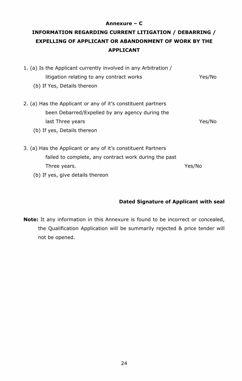
Annexure – C
INFORMATION REGARDING CURRENT LITIGATION / DEBARRING /
EXPELLING OF APPLICANT OR ABANDONMENT OF WORK BY THE
APPLICANT
1. (a) Is the Applicant currently involved in any Arbitration /
litigation relating to any contract works Yes/No
(b) If Yes, Details thereon
2. (a) Has the Applicant or any of it’s constituent partners
been Debarred/Expelled by any agency during the
last Three years Yes/No
(b) If yes, Details thereon
3. (a) Has the Applicant or any of it’s constituent Partners
failed to complete, any contract work during the past
Three years. Yes/No
(b) If yes, give details thereon
Dated Signature of Applicant with seal
Note: It any information in this Annexure is found to be incorrect or concealed,
the Qualification Application will be summarily rejected & price tender will
not be opened.
25
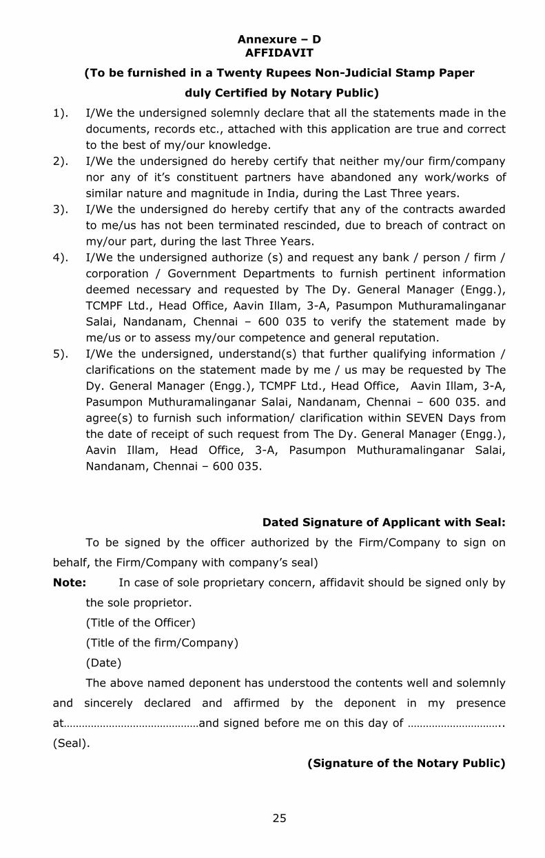
Annexure – D
AFFIDAVIT
(To be furnished in a Twenty Rupees Non-Judicial Stamp Paper
duly Certified by Notary Public)
1). I/We the undersigned solemnly declare that all the statements made in the
documents, records etc., attached with this application are true and correct
to the best of my/our knowledge.
2). I/We the undersigned do hereby certify that neither my/our firm/company
nor any of it’s constituent partners have abandoned any work/works of
similar nature and magnitude in India, during the Last Three years.
3). I/We the undersigned do hereby certify that any of the contracts awarded
to me/us has not been terminated rescinded, due to breach of contract on
my/our part, during the last Three Years.
4). I/We the undersigned authorize (s) and request any bank / person / firm /
corporation / Government Departments to furnish pertinent information
deemed necessary and requested by The Dy. General Manager (Engg.),
TCMPF Ltd., Head Office, Aavin Illam, 3-A, Pasumpon Muthuramalinganar
Salai, Nandanam, Chennai – 600 035 to verify the statement made by
me/us or to assess my/our competence and general reputation.
5). I/We the undersigned, understand(s) that further qualifying information /
clarifications on the statement made by me / us may be requested by The
Dy. General Manager (Engg.), TCMPF Ltd., Head Office, Aavin Illam, 3-A,
Pasumpon Muthuramalinganar Salai, Nandanam, Chennai – 600 035. and
agree(s) to furnish such information/ clarification within SEVEN Days from
the date of receipt of such request from The Dy. General Manager (Engg.),
Aavin Illam, Head Office, 3-A, Pasumpon Muthuramalinganar Salai,
Nandanam, Chennai – 600 035.
Dated Signature of Applicant with Seal:
To be signed by the officer authorized by the Firm/Company to sign on
behalf, the Firm/Company with company’s seal)
Note: In case of sole proprietary concern, affidavit should be signed only by
the sole proprietor.
(Title of the Officer)
(Title of the firm/Company)
(Date)
The above named deponent has understood the contents well and solemnly
and sincerely declared and affirmed by the deponent in my presence
at………………………………………and signed before me on this day of …………………………..
(Seal).
(Signature of the Notary Public)

26
Annexure – E
SAMPLE FORMAT FOR EVIDENCE OF ACCESS TO OR AVAILABILITY OF
CREDIT FACILITIES
BANK CERTIFICATE
This is to certify that M/s ………………………………… is a reputed company with
a good financial standing.
If the contract for the work, namely, ___________________ is awarded to
the above firm, we shall be able to provide overdraft/credit facilities to the extent
of Rs.……………. to meet their working capital requirements for executing the
above contract.
Signature of Senior Bank Manager ……………….
Name of the senior Bank Manager ……………….
Address of the Bank ………………………………..
Stamp of the Bank
Note: Certificate should be on the letter head of the bank.

Noted and agreed to the above
SIGNATURE OF THE TENDERER
27
6.0 EVALUATION AND COMPARISON OF THE TENDER OFFERS
6.1. The tenders will be evaluated strictly as per the Tamilnadu Transparency in
Tenders Act 1998 and the Tamilnadu Transparency in Tenders Rules 2000
and amendments made thereon in the Act & Rules by the Government.
6.2. The tender offers received will be examined to determine whether they are
in complete shape, all required data’s have been furnished, properly signed
and generally in order and confirms to all the terms and conditions of the
specification without any deviation.
6.3. For the purpose of evaluation of tender offers, the following factors will be
taken into account for arriving the evaluation price.
a). The quoted price will be corrected to arithmetical errors.
b). In case of discrepancy between the price quoted in words and figures,
lower of the two shall be considered.
c). The evaluation of offer will be computed by taking into account Design,
Supply, Erection, Installation, Testing and Commissioning put together.
6.4 Bidders should quote their rates both in figures and in words for each item
per unit and amount for each item of work for full quantity. Grand total of
the whole contract should be furnished without fail in the Price Quote
Schedule of Price Bid.
6.5 The bidder shall fill in rates and prices and line item total (both in figures
and words) for all the items of the works described along with total bid
price (both in figures and words). Items for which no rate or price is
entered by the bidder will not be paid for by the purchaser when executed.
6.6 The evaluation for L1 shall be on total end price of all items.

Noted and agreed to the above
SIGNATURE OF THE TENDERER
28
7.0.SPECIAL CONDITIONS OF CONTRACT
Contents
1. Definitions
2. Performance Security
3. Inspection and Tests
4. Delivery and Documents
5. Insurance
6. Incidental services
7. Spare Parts
8. Warranty/Guarantee
9. Payment
10. Resolution of Disputes
11. Notices
Noted and agreed to the above
SIGNATURE OF THE TENDERER
29
The following Special Conditions of Contract shall supplement the General
Conditions of Contract. Whenever there is a conflict, the provisions herein shall
prevail over those in the General Conditions of Contract. The corresponding
clause number of the General Conditions is indicated in parentheses:
1. Definitions (Clause 1)
1.1 The Purchaser is Tamilnadu Cooperative Milk Producers’ Federation Ltd.,
and would include the term "Owner"
1.2 The Bidder/Supplier is (Name of Bidder/Supplier).
1.3 Equivalency of Standards and Codes (Clause 4)
1.4 Wherever reference is made in the contract to the respective standards
and codes in accordance with which goods and materials are to be
furnished, and work is to be performed or tested, the provisions of the
latest current edition or revision of the relevant standards and codes in
effect shall apply, unless otherwise expressly set forth in the Contract.
Where such standards and codes are national in character, or relate to a
particular country or region, other authoritative standards which ensure an
equal or higher quality than the standards and codes specified will be
accepted subject to the Purchaser's prior review and written approval.
Differences between the standards specified and the proposed alternative
standards must be fully described in writing by the Bidder/Supplier and
submitted to the Purchaser at least 30 days prior to the date when the
Bidder/Supplier desires the Purchaser's approval. In the event the
Purchaser determines that such proposed deviations do not ensure equal or
higher quality, the Bidder/Supplier shall comply with the standards set
forth in the documents.
2. Performance Security
2.1 The Performance Security shall be in the amount of 10% of the Contract
price up to sixty days after the date of completion of performance
obligations including warranty obligations.
3. Inspection and Tests
3.1 The inspection of the Goods shall be carried out to check whether the
Goods are in conformity with the technical specifications attached to the
purchase order form and shall be in line with the inspection/test
Noted and agreed to the above
SIGNATURE OF THE TENDERER
30
procedures laid down in the Schedule of Specifications and the Contract
conditions.
4. Delivery and Documents
4.1 For imported goods: Upon shipment, the Bidder/Supplier shall notify
the Purchaser and the Insurance Company by email / fax / ink the full
details of the shipment including purchase order number, description of
goods, quantity, the vessel, the bill of lading number and date, port of
loading, date of shipment, port of discharge, etc. The Bidder/Supplier shall
mail the following documents to the Purchaser, with a copy to the
Insurance Company:
4.2 For imported goods: Original and three copies of:
The Supplier's invoice showing purchase order no., Goods description,
quantity, unit price, total amount;
The negotiable, clean, on-board bill of lading marked freight prepaid and
three copies of non-negotiable bill of lading;
Packing list identifying contents of each package;
Insurance certificate;
Manufacturer's/Bidder/Supplier's guarantee certificate;
Inspection certificate, issued by the nominated inspection agency and
the Bidder/Supplier's factory inspection report; and
Certificate for Country of origin.
The Supplier's certificate certifying that the defects pointed out during
inspection have been rectified.
4.3 The Purchaser shall receive the above documents at least one week before
arrival of the Goods at the port and, if not received, the Bidder/Supplier
will be responsible for any consequent expenses.
4.4 For Domestic Goods: Original and three copies of:
The Supplier's invoice showing purchase order no., Goods' description,
quantity, unit price, total amount;
Delivery note/packing list/lorry receipt;
Manufacturer's/Bidder/Supplier's guarantee certificate;
Inspection Certificate issued by the nominated inspection agency, and
the Bidder/Supplier's factory inspection report;
Excise gate pass/ Octroi receipts, wherever applicable, duly sealed
indicating payments made; and
Noted and agreed to the above
SIGNATURE OF THE TENDERER
31
Any other document evidencing payment of statutory levies.
Single MCE insurance policy shall cover the entire project.
4.5 Note: The nomenclature used for the item description in the invoice/s,
packing list/s and delivery note/s etc. should be identical to that used in
the purchase order/contract. The dispatch particulars including name of
transporter, LR Number and date should also be mentioned in the
invoice/s.
5. Insurance
5.1 The marine/transit insurance shall cover an amount equal to 110% of the
FOR destination value of the goods from "warehouse to warehouse" on "All
Risks" basis including War Risks and Strike clauses valid for a period not
less than 3 months after the date of arrival of Goods at final destination.
5.2 The Insurance charges shall be paid by successful Bidder/Supplier towards
all risks during storage, erection, testing, commissioning and up to
acceptance of the plant.
6. Incidental services
6.1 The incidental services shall be provided as per the requirements outlined
in the Schedule of Specifications and as covered under Clause 3.13. The
cost shall be included in the contract price, if provided for in the scope of
the Contract.
7. Spare Parts
7.1 Bidder/Suppliers shall carry sufficient inventories to assure ex-stock supply
of consumable spares such as gaskets, plugs, washers, belts, etc. Other
spare parts and components shall be supplied as promptly as possible but
in any case within three months of placement of order. Basic Spare
part list already provided in the technical section which is mandatory to
supply.
8. Notices
For the purpose of all the notices, the following shall be the address of the
Purchaser and Supplier.

Noted and agreed to the above
SIGNATURE OF THE TENDERER
32
The Dy. General Manager (Engg.),
Tamilnadu Cooperative Milk Producers’ Federation Ltd.,
Aavin Illam, 3-A, Pasumpon Muthuramalinganar Salai,
Nandanam, Chennai – 600 035.
9. SALIENT FEATURES OF SOME MAJOR LABOUR LAWS APPLICABLE TO
ESTABLISHMENTS ENGAGED IN BUILDING AND OTHER
CONSTRUCTION WORK.
(The law as current on the date or bid opening will apply to the bidder for
executing the tendered project)
a) Workmen Compensation Act 1923: The Act provides for
compensation in case of injury by accident arising out of and during the
course of employment.
b) Payment of Gratuity Act 1972: Gratuity is payable to an employee
under the Act on satisfaction of certain conditions on separation if an
employee has completed 5 years’ service or more or on death the rate
of 15 days wages for every completed year of service. The Act is
applicable to all establishments employing 10 or more employees.
c) Employees P.F. and Miscellaneous Provision Act 1952: The Act
Provides for monthly contributions by the employer plus workers @
10% or 8.33%. The benefits payable under the Act are:
(i) Pension or family pension on retirement or death, as the case may be.
(ii) Deposit linked insurance on the death in harness of the worker.
(IV) Payment of P.F. accumulation on retirement/death etc.
d) Maternity Benefit Act 1951: The Act provides for leave and some
other benefits to women employees in case of confinement or
miscarriage etc.
e) Contract Labour (Regulation & Abolition) Act 1970: The Act
provides for certain welfare measures to be provided by the Contractor
to contract labour and in case the Contractor fails to provide, the same
are required to be provided, by the Principal Employer by Law. The
Principal Employer is required to take Certificate of Registration and the
Contractor is required to take license from the designated Officer. The
Act is applicable to the establishments or Contractor of Principal
Employer if they employ 20 or more contract labour.
Noted and agreed to the above
SIGNATURE OF THE TENDERER
33
f) Minimum Wages Act 1948: The Employer is supposed to pay not
less than the Minimum Wages fixed by appropriate Government as per
provisions of the Act if the employment is a scheduled employment.
Construction of Buildings, Roads, Runways are scheduled employments.
g) Payment of Wages Act 1936: It lays down as to by what date the
wages are to be paid, when it will be paid and what deductions can be
made from the wages of the workers.
h) Equal Remuneration Act 1979: The Act provides for payment of
equal wages for work of equal nature to Male and Female workers and
for not making discrimination against Female employees in the matters
of transfers, training and promotions etc.
i) Payment of Bonus Act 1965: The Act is applicable to all
establishments employing 20 or more employees. The Act provides for
payments of annual bonus subject to a minimum of 8.33% of wages
and maximum of 20% of wages to employees drawing Rs.3500/-per
month or less. The bonus to be paid to employees getting Rs.2500/-
per month or above upto Rs.3500/- per month shall be worked out by
taking wages as Rs.2500/-per month only. The Act does not apply to
certain establishments. The newly set-up establishments are exempted
for five years in certain circumstances. Some of the State Governments
have reduced the employment size from 20 to 10 for the purpose of
applicability of this Act.
j) Industrial Disputes Act 1947: The Act lays down the machinery and
procedure for resolution of Industrial disputes, in what situations a
strike or lock-out becomes illegal and what are the requirements for
laying off or retrenching the employees or closing down the
establishment.
k) Industrial Employment (Standing Orders) Act 1946: It is
applicable to all establishments employing 100 or more workmen
(employment size reduced by some of the States and Central
Government to 50). The Act provides for laying down rules governing
the conditions of employment by the Employer on matters provided in
the Act and get the same certified by the designated Authority.
l) Trade Unions Act 1926: The Act lays down the procedure for
registration of trade unions of workmen and employers. The Trade

Noted and agreed to the above
SIGNATURE OF THE TENDERER
34
Unions registered under the Act have been given certain immunities
from civil and criminal liabilities.
m) Child Labour (Prohibition & Regulation) Act 1986: The Act
prohibits employment of children below 14 years of age in certain
occupations and processes and provides for regulation of employment
of children in all other occupations and processes. Employment of Child
Labour is prohibited in Building and Construction Industry.
n) Inter-State Migrant workmen’s (Regulation of Employment &
Conditions of Service) Act 1979: The Act is applicable to an
establishment which employs 5 or more inter-state migrant workmen
through an intermediary (who has recruited workmen in one state for
employment in the establishment situated in another state). The Inter-
State migrant workmen, in an establishment to which this Act becomes
applicable, are required to be provided certain facilities such as
housing, medical aid, travelling expenses from home upto the
establishment and back, etc.
o) The Building and Other Construction workers (Regulation of
Employment and Conditions of Service) Act 1996 and the Cess
Act of 1996: All the establishments who carry on any building or
other construction work and employs 10 or more workers are covered
under this Act. All such establishments are required to pay cess at the
rate not exceeding 2% of the cost of construction as may be modified
by the Government. The Employer of the establishment is required to
provide safety measures at the Building or construction work and other
welfare measures, such as Canteens, First-Aid facilities, Ambulance,
Housing accommodations for workers near the work place etc. The
Employer to whom the Act applies has to obtain a registration
certificate from the Registering Officer appointed by the Government.
p) Factories Act 1948: The Act lays down the procedure for approval at
plans before setting up a factory, health and safety provisions, welfare
provisions, working hours, annual earned leave and rendering
information regarding accidents or dangerous occurrences to designated
authorities. It is applicable to premises employing 10 persons or more
with aid of power or 20 or more persons without the aid of power
engaged in manufacturing process.

Noted and agreed to the above
SIGNATURE OF THE TENDERER
35
10. PROTECTION OF ENVIRONMENT:
The contractor shall take all reasonable steps to protect the environment
on and off the Site and to avoid damage or nuisance to persons or to
property of the public or others resulting from pollution, noise or other
causes arising as a consequence of his methods of operation.
During continuance of the contract, the contractor and his sub-
contractors shall abide at all times by all existing enactments on
environmental protection and rules made thereunder, regulations,
notifications and bye-laws of the State or Central Government, or local
authorities and any other law, bye-law, regulations that may be passed or
notification that may be issued in this respect in future by the State or
Central Government or the local authority.
Salient features of some of the major laws that are applicable are
given below:
The Water (Prevention and Control of Pollution) Act, 1974, This
provides for the prevention and control of water pollution and the
maintaining and restoring of wholesomeness of water. 'Pollution' means
such contamination of water or such alteration of the physical, chemical or
biological properties of water or such discharge of any sewage or trade
effluent or of any other liquid, gaseous or solid substance into water
(whether directly or indirectly) as may, or is likely to, create a nuisance or
render such water harmful or injurious to public health or safety, or to
domestic, commercial, industrial, agricultural or other legitimate uses, or to
the life and health of animals or plants or of aquatic organisms.
The Air (Prevention and Control of Pollution) Act, 1981, This provides
for prevention, control and abatement of air pollution. 'Air Pollution' means
the presence in the atmosphere of any 'air pollutant', which means any solid,
liquid or gaseous substance (including noise) present in the atmosphere in
such concentration as may be or tend to be injurious to human beings or
other living creatures or plants or property or environment.
Noted and agreed to the above
SIGNATURE OF THE TENDERER
36
The Environment (Protection) Act, 1986, this provides for the protection
and improvement of environment and for matters connected therewith, and
the prevention of hazards to human beings, other living creatures, plants
and property. 'Environment' includes water, air and land and the inter-
relationship which exists among and between water, air and land, and
human beings, other living creatures, plants, microorganism and property.
The Public Liability Insurance Act, 1991, This provides for public liability
insurance for the purpose of providing immediate relief to the persons
affected by accident occurring while handling hazardous substances and for
matters connected herewith or incidental thereto. Hazardous substance
means any substance or preparation which is defined as hazardous
substance under the Environment (Protection) Act 1986, and exceeding such
quantity as may be specified by notification by the Central Government.
[Employers should note that the Loan Agreement between IBRD and the
borrowing country may establish specific measures to be taken during
construction of the Works for the protection of the environment. Sub-clause
16.2 should be modified/expanded to take into account such specific
measures or other measures considered appropriate by the Employer]
Purchaser
Tamilnadu Cooperative Milk Producers’ Federation Ltd.,
Supplier
Bidders to provide details.
Noted and agreed to the above
SIGNATURE OF THE TENDERER
37
8.0. Special Conditions of Contract for General Erection & Commissioning
Contents
1. Sufficiency Of Tender
2. Programme Of Installation & Commissioning
3. Preparation of Drawings for Approval
4. Superintendence, Team And Conduct
5. Purchaser's Instructions
6. Right Of The Purchaser
7. Bidder/Supplier’s Functions
8. Variations
9. Duties of the Bidder/Supplier Vis-a-Vis the Purchaser
10. Supply Of Tools, Tackles And Materials
11. Protection Of Plant
12. Unloading, Transportation And Inspection
13. Storage Of Equipment
14. Approvals
15. Review & Co-Ordination of Erection Work
16. Extension of Time for Completion
Table 1 List of Drawings required Submission
Noted and agreed to the above
SIGNATURE OF THE TENDERER
38
1. Sufficiency of Tender
1.1 The Bidder/Supplier by bidding shall be deemed to have satisfied himself
as to all the conditions and circumstances affecting the Contract Price, as
to the possibility of executing the works as shown and described in the
Contract, as to the general circumstances at the site of the works, as to
the general labour position at site and to have determined the prices
accordingly.
2. Programme of Installation & Commissioning
2.1 As soon as practicable after the acceptance of the bid, the Bidder/Supplier
shall submit to the Purchaser for his approval a comprehensive
programmed in the form of bar chart showing the sequence of order in
which the Bidder/Supplier proposes to carry out the works including the
design, manufacture, delivery to site, Erection, Installation, Testing and
Commissioning thereof. After submission to and approval by the Purchaser
of such programmed, the Bidder/Supplier shall adhere to the sequence of
order and method stated therein. The submission to and approval by the
Purchaser of such programmed shall not relieve the Bidder/Supplier of any
of his duties or responsibilities under the Contract. The programmed
approved by the Purchaser shall form the basis of evaluating the pace of all
works to be performed by the Bidder/Supplier. The Bidder/Supplier shall
update the PERT Network every month, submit it to the Purchaser and
shall inform the Purchaser the progress on all the activities falling on
schedule for the next reporting date.
3. Preparation of Drawings for Approval
3.1 The Bidder/Supplier should visit the site to acquaint himself in respect of
existing site conditions and to know the details/information required for
understanding the nature and type of civil construction works involved in
the project. The Bidder/Supplier shall submit to the Purchaser for approval:
Within the time given in the specification or in the program, such
drawings, samples, patterns and models as may be called for therein,
and in numbers therein required.
During the progress of works and within such reasonable times as the
Purchaser may require such drawings of the general arrangement and
details of the works as the Purchaser may require.
Noted and agreed to the above
SIGNATURE OF THE TENDERER
39
During the progress of works and before the start of the erection
activities, Supplier to submit the intelligent 3D for entire plant in the
freeware software format for the approval to the Purchaser/Consultant
3.2 Wherever necessary, the Bidder/Supplier would be provided with a set of
architectural drawings for the buildings where the erection works would be
carried out and also the equipment details/ drawings of various
equipment’s handed over to the Bidder/Supplier by the Purchaser.
3.3 The specifications/ conditions concerning the submission of drawings by
the Bidder/Supplier are detailed as under:
3.4 Bidder/Supplier shall furnish a list of all necessary drawings, which the
Bidder/Supplier shall submit for approval, identifying each drawing by a
serial number and descriptive title and expected date of submission. A brief
list of drawings is given in Table 1. This list shall be revised and extended if
necessary, during the progress of work depending on the nature of the
contract also.
3.5 The Purchaser shall signify his approval or disapproval of all drawings or
such drawings that would affect progress of the contract as per the agreed
programmed.
3.6 The purchaser shall issue, within four weeks of time in all circumstances,
any drawing requested by the Bidder/Supplier and required to be provided
by us. If the Bidder/Supplier suffers delay and/ or incurs costs due to delay
on purchaser’s part in this regard, then the Purchaser shall take such delay
into account in determining any extension of time to which the
Bidder/Supplier is entitled under Clause 15 hereof and the Bidder/Supplier
shall be paid the amount of such cost as shall be reasonable.
3.7 P&I Drawings, Plant Layout and GA Drawings submitted for approval shall
be signed by responsible representative of Bidder/Supplier and shall be to
any one of the following sizes in accordance with Indian Standards: “ A0,
A1, A2, A3 and A4”.
3.8 All drawings shall show the following particulars in the lower right hand
corner in addition to Bidder/Supplier’s name:
Name of the Purchaser
Project Title Title of drawing
Scale
Date of drawing
Drawing number Space for drawing number
Drawing Revision Number 3.9 In addition to the information provided on drawings, each drawing shall
carry a revision number, date of revision and brief description of revision
Noted and agreed to the above
SIGNATURE OF THE TENDERER
40
carried out. Whenever any revision is carried out, correspondingly revision
number must be updated.
3.10 All dimensions on drawings shall be in metric units.
3.11 Drawings (three sets) submitted by the Bidder/Supplier for approval will
be checked, reviewed by the Purchaser, and comments, if any, on the
same will be conveyed to the Bidder/Supplier. It is the responsibility of
the Bidder/Supplier to incorporate correctly all the comments conveyed by
the Purchaser on the Bidder/Supplier's drawings. The drawings, which are
approved with comments, are to be re-submitted to the Purchaser for
purpose of records. Such drawings will not be checked / reviewed by the
Purchaser to verify whether the Bidder/Supplier has incorporated all the
comments. If the Bidder/Supplier is unable to incorporate any comments
in the revised drawings, Bidder/Supplier shall clearly state in his forwarding
letter such non-compliance along with the valid reasons.
3.12 Drawings prepared by the Bidder/Supplier and approved by the Purchaser
shall be considered as a part of the specifications. However, the
examination of the drawings by the Purchaser shall not relieve the
Bidder/Supplier of his responsibility for engineering design, workmanship,
and quality of materials, warranty obligations and satisfactory performance
on installation covered under the contract.
3.13 If at any time before completion of the work, changes are made
necessitating revision of approved drawings, the Bidder/Supplier shall
make such revisions and proceed in the same routine as for the original
approval.
3.14 Date of submission: In the event, the drawings submitted for approval
require many revisions amounting to redrawing of the same, and then the
date of submission of the revised drawings would be considered as the
date of submission for approval.
3.15 The Bidder/Supplier shall furnish to the Purchaser before the works are
taken over, Operating and Maintenance instructions together with
Drawings of the works as completed, in sufficient detail to enable the
Purchaser to maintain, dismantle, reassemble and adjust all parts of the
works. Unless otherwise agreed, the works shall not be considered
completed for the purposes of taking over until such instructions and
drawings have been supplied to the Purchaser.
Noted and agreed to the above
SIGNATURE OF THE TENDERER
41
4. Superintendence, Team and Conduct
4.1 The Bidder/Supplier shall employ one or more competent representatives,
whose name or names shall have previously been communicated in writing
to the Purchaser by the Bidder/Supplier, to superintend the carrying out of
the works on the site. The said representative or if more than one shall be
employed, then one of such representatives shall be present on the site
during all times, and any orders or instructions which the Purchaser may
give to the said representative of the Bidder/Supplier shall be deemed to
have given to the Bidder/Supplier. The said representative shall have full
technical capabilities and complete administrative and financial powers to
expeditiously and efficiently execute the work under the contract.
4.2 The Bidder/Supplier shall, execute the works with due care and diligence
within the time for completion and employ Bidder/Supplier’s team
comprising qualified and experienced engineers together with adequate
skilled, semi-skilled and unskilled workmen in the site for carrying out the
works. The Bidder/Supplier shall ensure adequate workforce to keep the
required pace at all times as per the schedule of completion.
Bidder/Supplier shall also ensure availability of competent engineers during
commissioning/start up, trial runs, Operation of the plant/equipment till
handing over of the plant.
4.3 The Bidder/Supplier shall furnish the details of qualifications and
experience of their senior supervisors and engineers assigned to the work
site, including their experience in supervising Erection, Installation, Testing
and Commissioning of plant and equipment of comparable capacity.
4.4 When the Bidder/Supplier or Bidder/Supplier's representative is not
present on any part of the work where it may be desired to give directions
in the event of emergencies, orders may be given by the Purchaser and
shall be received and observed by the supervisors or foremen who may
have charge of the particular part of the work in reference to which orders
are given. Any such instructions, directions or notices given by the
Purchaser shall be deemed given to the Bidder/Supplier.
4.5 The Bidder/Supplier shall furnish to the Purchaser a fortnightly labour force
report showing by classifications the number of employees engaged in the
work. The Bidder/Supplier's employment records shall include any
Noted and agreed to the above
SIGNATURE OF THE TENDERER
42
reasonable information as may be required by the Purchaser. The
Bidder/Supplier should also display necessary information as may be
required by statutory regulations.
4.6 None of the Bidder/Supplier’s supervisors, engineers, or laborers may be
withdrawn from the work without notice to the Purchaser and further no
such withdrawals shall be made if in the opinion of the Purchaser, it will
adversely affect the required pace of progress and/or the successful
completion of the work.
4.7 The Purchaser shall be at liberty to object to any representative or person,
skilled, semi-skilled or unskilled worker employed by the Bidder/Supplier in
the execution of or otherwise about the works who shall, in the opinion of
the Purchaser, misconduct himself or be incompetent, or negligent or
unsuitable, and the Bidder/Supplier shall remove the person so objected
to, upon receipt of notice in writing from the Purchaser and shall provide in
that place a competent representative at Bidder/Supplier's own expense
within a reasonable time.
4.8 In the execution of the works no persons other than the Bidder/Supplier,
sub-Bidder/Supplier and their employees shall be allowed on the site
except by the written permission of the Purchaser.
5. Purchaser's Instructions
5.1 The Purchaser may, in his absolute discretion, issue from time to time
drawings and/ or instructions, directions and clarifications, which are
collectively referred to as Purchaser's instructions in regard to:
Any additional drawing and clarifications to exhibit or illustrate details.
Variations or modifications of the design, quality or quantity of work or
the additions or omissions or substitution of any work.
Any discrepancy in the drawings or between the schedule of quantities
and/or specifications.
Removal from the site of any material brought there by the
Bidder/Supplier, which are unacceptable to the Purchaser and the
substitution of any other material thereof.
Removal and/or re-execution of any work erected by the
Bidder/Supplier, which are unacceptable to the Purchaser.
Noted and agreed to the above
SIGNATURE OF THE TENDERER
43
Dismissal from the work of any persons employed there upon who shall
in the opinion of the Purchaser, misconduct him, or be incompetent or
negligent.
Opening up for inspection of any work covered up.
Amending and making good of any defects.
6. Right of the Purchaser 6.1 Right to direct works
The Purchaser shall have the right to direct the manner in which all
works under this contract shall be conducted, in so far as it may be
necessary to secure the safe and proper progress and specified quality
of the works. All work shall be done and all materials shall be furnished
to the satisfaction and approval of the Purchaser.
Whenever in the opinion of the Purchaser, the Bidder/Supplier has made
marked departures from the schedule of completion or when
circumstances or requirement force such a departure from the said
schedule, the Purchaser, in order to ensure compliance with the
schedule, shall direct the order, pace and method of conducting the
work, which shall be adhered to by the Bidder/Supplier.
If in the judgment of the Purchaser, it becomes necessary at any time
to accelerate the overall pace of the plant erection work, the
Bidder/Supplier, when directed by Purchaser, shall cease work at any
particular point and transfer Bidder/Supplier’s men to such other point
or points and execute such works, as may be directed by the Purchaser
and at the discretion of the Purchaser.
6.2 Right to order modifications of methods and equipment
If at any time the Bidder/Supplier's methods, materials or equipment
appear to the Purchaser to be unsafe, inefficient or inadequate for
securing the safety of workmen or the public, the quality of work or the
rate of progress required, the Purchaser may direct the Bidder/Supplier
to ensure safety, and increase their efficiency and adequacy and the
Bidder/Supplier shall promptly comply with such directives. If at any
time the Bidder/Supplier's working force and equipment are inadequate
in the opinion of the Purchaser, for securing the necessary progress as
stipulated, the Bidder/Supplier shall if so directed, increase the working
force and equipment to such an extent as to give reasonable assurance
Noted and agreed to the above
SIGNATURE OF THE TENDERER
44
of compliance with the schedule of completion. The absence of such
demands from the Purchaser shall not relieve the Bidder/Supplier of
Bidder/Supplier's obligations to secure the quality, the safe conducting
of the work and the rate of progress required by the contract. The
Bidder/Supplier alone shall be and remain liable and responsible for the
safety, efficiency and adequacy of Bidder/Supplier’s methods, materials,
working force and equipment, irrespective of whether or not the
Bidder/Supplier makes any changes as a result of any order or orders
received from the Purchaser.
6.3 Right to inspect the work
The Purchaser’s representative shall be given full assistance in the form
of the necessary tools, instruments, equipment and qualified operators
to facilitate inspection.
The Purchaser reserves the right to call for the original test certificates
for all the materials used in the erection work.
In the event the Purchaser's inspection reveals poor quality of
work/materials, the Purchaser shall be at liberty to specify additional
inspection procedures if required, to ascertain Bidder/Supplier's
compliance with the specifications of erection work.
Even though inspection is carried out by the Purchaser or Purchaser's
representatives, such inspection shall not, however, relieve the
Bidder/Supplier of any or all responsibilities as per the contract, nor
prejudice any claim, right or privilege which the Purchaser may have
because of the use of defective or unsatisfactory materials or bad
workmanship.
7. Bidder/Supplier’s Functions
7.1 The Bidder/Supplier shall provide everything necessary for proper
execution of the works, according to the drawings, schedule of quantities
and specifications taken together whether the same may or may not be
particularly shown or described therein, provided that the same can
reasonably be inferred there from and if the Bidder/Supplier finds any
discrepancy therein, Bidder/Supplier shall immediately refer the same to
the Purchaser whose decision shall be final and binding on the
Bidder/Supplier.

Noted and agreed to the above
SIGNATURE OF THE TENDERER
45
7.2 The Bidder/Supplier shall proceed with the work to be performed under this
contract in the best and workman like manner by engaging qualified and
efficient workers and finish the work in strict conformance with the
drawings and specifications and any changes/modifications thereof made
by the Purchaser.
8. Variations
8.1 The Purchaser shall make any variation of the form, quality or quantity of
the Works or any part thereof that may, in his opinion, be necessary and
for that purpose, or if for any other reason it shall, in his opinion be
desirable, he shall have power to order the Bidder/Supplier to do and the
Bidder/Supplier shall do any of the following:
Increase or decrease the quantity of any work included in the contract,
Omit any such work,
Change the character or quality or kind of any such work,
Change the levels, lines, position and dimensions of any part of the
works
Execute additional work of any kind necessary for the completion of the
works and no such variation shall in any way vitiate or invalidate the
contract, but the value, if any, of all such variations shall be taken into
account in ascertaining the amount of the Contract price.
8.2 The Bidder/Supplier shall make no such variations without an order in
writing of the Purchaser. Provided that no order in writing shall be required
for increase or decrease in the quantity of any work where such increase or
decrease is not the result of an order given under this clause, but is the
result of the quantities exceeding or being less than those stated in the
Contract/Bill of Quantities. Provided also that if for any reason the
Purchaser shall consider it desirable to give any such order verbally, the
Bidder/Supplier shall comply with such order and any confirmation in
writing of such verbal order given by the Purchaser, whether before or
after the carrying out of the order, shall be deemed to be an order in
writing within the meaning of this clause. Provided further that if the
Bidder/Supplier shall within seven days confirm in writing to the Purchaser
and the Purchaser shall not contradict such confirmation in writing within
14 days, it shall be deemed to be an order in writing by the Purchaser.
Noted and agreed to the above
SIGNATURE OF THE TENDERER
46
8.3 All extra or additional work done or work omitted by order of the Purchaser
shall be valued at the rates and prices set out in the contract if in the
opinion of the Purchaser, the same shall be applicable. If the contract does
not contain any rates or prices applicable to the extra or additional work,
then suitable rates or prices shall be agreed upon between the Purchaser
and the Bidder/Supplier. Any Extra Work, carried out by the
Bidder/Supplier would be at mutually agreed cost (Landed cost + 15%
service charge).
8.4 Provided that if the nature or amount of any omission or addition relative
to the nature or amount of the whole of the works or to any part thereof
shall be such that, in the opinion of the Purchaser, the rate or price
contained in the contract for any item of the works is, by reason of such
omission or addition, rendered unreasonable or inapplicable, then a
suitable rate or price shall be agreed upon between the Purchaser and the
Bidder/Supplier. In the event of disagreement the Purchaser shall fix such
other rate or price as shall, in his opinion, be reasonable and proper having
regard to the circumstances.
8.5 Provided also that no increase or decrease mentioned above or variation of
rate or price shall be made unless, as soon after the date of the order as is
practicable and, in the case of extra or additional work, before the
commencement of the work or as soon thereafter as is practicable, notice
shall have been given in writing:
By the Bidder/Supplier to the Purchaser of his intention to claim extra
payment or a varied rate or price, or
By the Purchaser to the Bidder/Supplier of his intention to vary a rate or
price
8.6 If, on certified completion of the whole of the works, it shall be found that
a reduction or increase greater than 15 per cent of the sum named in the
Letter of Acceptance results from the aggregate effect of all Variation
Orders but not from any other cause, the amount of the contract price shall
be adjusted by such sum as may be greed between the Bidder/Supplier
and the Purchaser or, failing agreement, fixed by the Purchaser having
regard to all material and relevant factors, including the Bidder/Supplier's
site and general overhead costs of the contract.
Noted and agreed to the above
SIGNATURE OF THE TENDERER
47
8.7 The Bidder/Supplier shall send to the Purchaser’s representative once in
every month an account giving particulars, as full and detailed as possible,
of all claims for any additional payment to which the Bidder/Supplier may
consider himself entitled and of all extra or additional work ordered by the
Purchaser which he has executed during the preceding month.
8.8 No final or interim claim for payment for any such work or expense will be
considered which has not been included in such particulars. Provided
always that the Purchaser shall be entitled to authorize payment to be
made for any such work or expense, notwithstanding the Bidder/Supplier's
failure to comply with this condition, if the Bidder/Supplier has, at the
earliest practicable opportunity, notified the Purchaser in writing that he
intends to make a claim for such work.
8.9 The work shall be carried out as approved by the Purchaser or his
authorized representative/s from time to time, keeping in view the overall
schedule of completion of the project. The Bidder/Supplier’s job schedule
must not disturb or interfere with Purchaser’s or the other
Bidder/Supplier’s schedules of day-to-day work. The Purchaser will provide
all reasonable assistance for carrying out the jobs.
8.10 Night work will be permitted only with prior approval of the Purchaser. The
Purchaser may also direct the Bidder/Supplier to operate extra shifts over
and above normal day shift to ensure completion of contract as per
schedule. Adequate lighting wherever required should be provided by the
Bidder/Supplier at no extra cost. The Bidder/Supplier should employ
qualified electricians and wire-men for these facilities. In case of
Bidder/Supplier’s failure to provide these facilities and personnel, the
Purchaser has the right to arrange such facilities and personnel and to
charge the cost thereof to the Bidder/Supplier.
8.11 In order to enable the Purchaser to arrange for insurance of all items
received at the site including the items of supply covered under this
contract, the Bidder/Supplier shall furnish necessary details of all the
equipment immediately on its receipt at site, to the Purchaser. Any
default on the part of the Bidder/Supplier due to which any item does not
get covered under the insurance of the Purchaser; the cost of such
equipment shall be charged to the Bidder/Supplier.
Noted and agreed to the above
SIGNATURE OF THE TENDERER
48
8.12 The Purchaser shall not be liable for or in respect of any damages or
compensation payable at law in respect or in consequence of any accident
or injury to any workman or other person in the employment of the
Bidder/Supplier or any sub-Bidder/Supplier, save and except an accident or
injury resulting from any act or default of the Purchaser, his agents, or
servants. The Bidder/Supplier shall indemnify and keep indemnified the
Purchaser against all such damages and compensation, save and except as
aforesaid and against all claims, proceedings, costs, charges and expenses
whatsoever in respect thereof or in relation thereto.
Purchaser shall be liable for and shall indemnify bidder/supplier against all
losses, expenses or claims in respect of loss of or damage to any physical
property or of death or personal injury whenever occurring, to the extent
caused by any negligence or breach of statutory duty of purchaser or its
employees, contractors or agents.
8.13 The Bidder/Supplier shall ensure against such liability with an insurer
approved by the Purchaser, which approval shall not be unreasonably
withheld, and shall continue such insurance during the whole of the time
that any persons are employed by him on the works shall, when required,
produce to the Purchaser or Purchaser’s representative such policy of
insurance and the receipt for payment of the current premium. Provided
always that, in respect of any persons employed by any sub-
Bidder/Supplier, the Bidder/Supplier's obligations to ensure as aforesaid
under this sub-clause shall be satisfied if the sub-Bidder/Supplier shall
have insured against the liability in respect of such persons in such manner
that the Purchaser is indemnified under the policy, but the Bidder/Supplier
shall require such sub-Bidder/Supplier to produce to the Purchaser or
Purchaser's representative, when required such policy of insurance and the
receipt for the payment of the current premium.
8.14 Whenever proper execution of the work under the contract depends on the
jobs carried out by some other Bidder/Supplier, the Bidder/Supplier should
inspect all such erection and installation jobs and report to the Purchaser
regarding any defects or discrepancies. The Bidder/Supplier's failure to do
so shall constitute as acceptance of the other Bidder/Supplier's
installation/jobs as fit and proper for reception of Bidder/Supplier's works
except those defects which may develop after execution. Bidder/Supplier
Noted and agreed to the above
SIGNATURE OF THE TENDERER
49
should also report any discrepancy between the executed work and the
drawings. The Bidder/Supplier shall extend all necessary help/cooperation
to other Bidder/Suppliers working at the site in the interest of the work.
8.15 Bidder/Supplier shall carryout final adjustments of foundations, levelling
and dressing of foundation surfaces, bedding and grouting of anchor bolts,
bed plates etc. required for seating of equipment in proper position. The
Bidder/Supplier shall be responsible for the reference lines and proper
alignment of the equipment. However, all civil works like making cut-outs
in walls, floors and ceilings for pipelines shall be done by the purchaser.
Adjustment & levelling are to be carried out by the Bidder/Supplier at no
extra cost. The Purchaser shall arrange the necessary refilling/repairs of
these cut-outs and pockets. The Bidder/Supplier should arrange for laying
the supports, cut-outs, grouting of bolts, etc. When the civil works are in
progress, so as to avoid refilling/repair works. The Purchaser at
Bidder/Supplier’s costs shall make the damages occurring to civil and other
works good. For fixing of piping/equipment supports on wall/beams/roof
floor etc., preferably anchor bolts shall be used by the Bidder/Supplier.
Drilling of holes for fixing anchor bolts & supply of anchor bolts is in the
scope of Bidder/Supplier without any extra cost.
8.16 The Bidder/Supplier shall keep a check on deliveries of the equipment
covered in the scope of erection work and shall advise the Purchaser well in
advance regarding possible hold-up in Bidder/Supplier's work due to the
likely delay in delivery of such equipment/components to enable him to
take remedial actions.
9. Duties of the Bidder/Supplier Vis-à-Vis the Purchaser
9.1 The equipment and the items, if any, to be supplied by the Purchaser for
erection, testing and commissioning shall be as listed in the contract.
9.2 Besides the utilities/ services as specified in battery limits, Purchaser shall
also provide the following assistance/ facilities to the Bidder/Supplier for
carrying out the installation work:
Plant building ready for installation of equipment/items.
9.3 If the Bidder/Supplier suffers delay and/or incurs costs from failure on the
part of the purchaser to give possession of the civil works in accordance
with the mutually agreed schedule, the purchaser shall determine:
Noted and agreed to the above
SIGNATURE OF THE TENDERER
50
Any extension of time to which the Bidder/supplier is entitled due to
delay caused by Purchaser.
Any extension of time to which the Bidder/Supplier is entitled under
clause 20 of GCC (General Conditions of Contract).
10. Supply of Tools, Tackles and Materials
10.1 The Bidder/Supplier shall, at his own expense, provide all the necessary
equipment, tools and tackles, haulage power, consumables necessary for
effective execution and completion of the works during Erection,
Installation, Testing and Commissioning.
11. Protection of Plant
11.1 The Purchaser shall not be responsible or held liable for any damage to
person or property consequent upon the use, misuse or failure of any
erection tools and equipment used by the Bidder/Supplier or any of
Bidder/Supplier's Sub-Bidder/Suppliers even though such tools and
equipment may be furnished, rented or loaned to the Bidder/Supplier or
any of Bidder/Supplier’s Sub-Bidder/Suppliers. The acceptance and/or use
of any such tools and equipment by the Bidder/Supplier or
Bidder/Supplier's Sub-Bidder/Supplier shall be construed to mean that the
Bidder/Supplier accepts all responsibility for and agrees to indemnify and
save the Purchaser from any and all claims for said damages resulting from
the said use, misuse or failure of such tools and equipments.
11.2 The Bidder/Supplier and Bidder/Supplier’s Sub-Bidder/Supplier shall be
responsible, during the works, for protection of work, which has been
completed by other Bidder/Suppliers. Necessary care must be taken to see
that the Bidder/Supplier’s men cause no damage to the same during the
course of execution of the work.
11.3 All other works completed or in progress as well as machinery and
equipment that are liable to be damaged by the Bidder/Supplier's work
shall be protected by the Bidder/Supplier and protection shall remain and
be maintained until the Purchaser directs its removal.
11.4 The Bidder/Supplier shall effectively protect from the effects of weather
and from damages or defacement and shall cover appropriately, wherever
required, all the works for their complete protection.
Noted and agreed to the above
SIGNATURE OF THE TENDERER
51
11.5 The Bidder/Supplier shall carry out the work without damage to any work
and property adjacent to the area of Bidder/Supplier's work to whomsoever
it may belong and without interference with the operation of existing
machines or equipment.
11.6 Adequate lighting, guarding and watching at and near all the storage
handling, fabrication, pre-assembly and erection sites for properly carrying
out the work and for safety and security shall be provided by the
Bidder/Supplier at Bidder/Supplier's cost. The Bidder/Supplier should
adequately light the work area during night time also. The Bidder/Supplier
should also engage adequate electricians/wiremen, helper etc to carry out
and maintain these lighting facilities. If the Bidder/Supplier fails in this
regard, the Purchaser may provide lighting facilities as he may deem
necessary and charge the cost thereof to the Bidder/Supplier.
11.7 The Bidder/Supplier shall take full responsibility for the care of the works
or any section or portions thereof until the date stated in the taking over
certificate issued in respect thereof and in case any damage or loss shall
happen to any portion of the works not taken over as aforesaid, from any
cause whatsoever, the same shall be made good by and at the sole cost of
the Bidder/Supplier and to the satisfaction of the Purchaser. The
Bidder/Supplier shall also be liable for any loss of or damage to the works
occasioned by the Bidder/Supplier or the Bidder/Supplier’s Sub-
Bidder/Supplier in the course of any operations carried out by the
Bidder/Supplier or by the Bidder/Supplier’s Sub-Bidder/Suppliers for the
purpose of completing any outstanding work or complying with the
Bidder/Supplier's obligations.
12. Unloading, Transportation and Inspection
12.1 The Bidder/Supplier shall be required to unload all the materials/equipment
from the carriers, those received at site after Bidder/Supplier's team
arrives at site. Bidder/Supplier shall be paid extra for unloading of the
equipment being supplied by the purchaser whereas no extra payment for
unloading of the equipment/piping shall be paid to
Bidder/Supplier for the equipment being supplied by the Bidder/Supplier.
The Bidder/Supplier shall plan in advance, based on the information
received from the Purchaser, Bidder/Supplier's requirement of various
Noted and agreed to the above
SIGNATURE OF THE TENDERER
52
tools, tackles, jacks, cranes, sleepers etc. required to unload the
material/equipment promptly and efficiently. The Bidder/Supplier shall
ensure that adequate and all measures necessary to avoid any damage
whatsoever to the equipment at the time of unloading are taken.
12.2 Any demurrage/detention charges incurred due to the delay in unloading
the material/equipment and releasing the carriers shall be charged to the
Bidder/Supplier's account.
12.3 The Bidder/Supplier shall be responsible for the reception on site of all
plant and Bidder/Supplier's equipment delivered for the purposes of the
contract.
12.4 The Bidder/Supplier shall safely transport/shift the unloaded
materials/equipment by the Bidder/Supplier to the storage area.
12.5 All the materials/equipment received by the Purchaser prior to arrival of
the Bidder/Supplier at site shall be handed over to the Bidder/Supplier and
there upon the Bidder/Supplier shall inspect the same and furnish the
receipt to the Purchaser. The manner in which the inspection shall be
carried out is enumerated below:
12.6 The materials/equipment would be carefully unpacked by opening the
wooden cases/other modes of pickings as the case may be.
12.7 Detailed inventory of various items would be prepared clearly listing out
the shortages, breakage/damages after checking the contents with respect
to the Bidder/Supplier's packing list, the Purchaser's purchase order and
approved equipment drawings. The Bidder/Supplier shall also check each &
every equipment for any shortage/shortcoming that may eventually create
difficulty at the time of installation or commissioning.
12.8 All the information and observations by the Bidder/Supplier shall be
furnished in the form of `INSPECTION REPORT' to the Purchaser with
specific mention/suggestions which in the opinion of the Bidder/Supplier
should be given due consideration and immediate necessary actions, to
enable the Purchaser to arrange repair or replacement well in time and
avoid delays due to non-availability of equipment and parts at the time of
their actual need.
12.9 The inspection for all the equipment handed over to the Bidder/Supplier
shall be completed within three week's period.
Noted and agreed to the above
SIGNATURE OF THE TENDERER
53
12.10 The protection, safety and security of the materials so taken over from the
Purchaser shall be the responsibility of the Bidder/Supplier, until they are
handed over to the Purchaser after erection, commissioning and testing as
per the terms of the Contract.
13. Storage of Equipment
13.1 The Bidder/Supplier shall be responsible for the proper storage and
maintenance of all materials/equipment under Bidder/Supplier's
custody. Bidder/Supplier shall take all required steps to carry out frequent
inspection of equipment/materials stored as well as erected equipment
until the same are taken over by the Purchaser. The following procedure
shall apply for the same.
13.2 The Bidder/Supplier’s inspector shall check stored and installed
equipment/materials to observe signs of corrosion, damage to protective
coating to parts, open ends in pipes, vessels and equipment, insulation
resistance of electrical equipment etc. The Bidder/Supplier shall
immediately arrange a coat of protective painting whenever required. A
record of all observations made on equipment, defects noticed shall be
promptly communicated to the Purchaser and Purchaser's advice taken
regarding the repairs/rectification. The Bidder/Supplier shall there upon
carry out such repairs/ rectification at Bidder/Supplier’s own cost. In case
the Bidder/Supplier is not competent to carry out such repairs/
rectification, the Purchaser reserves the right to get this done by other
competent agencies at the Bidder/Supplier's responsibility and risk and the
entire cost for the same shall be recovered from the Bidder/Supplier's bills.
13.3 The Bidder/Supplier's inspector shall also inspect and provide lubrication to
the assembled equipment. The shafts of such equipment shall be
periodically rotated to prevent rusting as well as to check freeness of the
same.
13.4 The Inspector shall check for any signs of moisture or rusting in any
equipment.
13.5 If the commissioning of equipment is delayed after installation of the
equipment, the Bidder/Supplier shall carry out all protective measures
suggested by the Purchaser during such period.
13.6 Adequate security measures shall be taken by the Bidder/Supplier to
prevent theft and loss of materials handed over to the Bidder/Supplier by
Noted and agreed to the above
SIGNATURE OF THE TENDERER
54
the Purchaser. The Bidder/Supplier shall carry out periodical inventory
checks of the materials received, stored and installed by the
Bidder/Supplier and any loss noticed shall be immediately reported to the
Purchaser. The Bidder/Supplier shall maintain a proper record of these
inventories. The Bidder/Supplier should not sell, assign, mortgage,
hypothecate or remove equipment or materials which has been installed or
which may be necessary for completion of the work without the written
consent of the Purchaser.
13.7 Suitable grease recommended for protection of surfaces against rusting
(refined from petroleum oil with lanolin minimum (70 0C) and water in
traces) shall be applied over all equipment as required once in every six
months.
13.8 All equipment shall be stored inside a closed shed or in the open depending
upon whether they are of indoor or outdoor design. The space heaters
where provided into the electrical equipment shall be kept connected with
power supply irrespective of their type of storage. Where space heaters are
not provided adequate heating with bulb is recommended. For
transformers heating of oil shall be done by giving 440 V supply and short-
circuiting the LT terminals. Frequent checks on insulation resistance are
essential for all electrical equipment and record of the inspection reports
and mugger readings shall be maintained equipment wise. Such records
shall be presented to the Purchaser whenever demanded.
13.9 All the necessary items/goods required for the Bidder/Supplier as described
above shall arrange protection and such cost shall be included in the
Contract price.
14. Approvals
14.1 The Bidder/Supplier shall obtain the necessary approvals of the Boiler
Inspector, Electrical Inspector, Weights & Measures Inspector, Explosive
Inspector and any other state and local authorities as may be required and
the cost of obtaining such approvals shall be included in the contract price.
14.2 The Bidder/Supplier will furnish all the necessary details, drawings, and
submission of application and proofreads to the Purchaser for verification/
signature. The Bidder/Supplier on behalf of the Purchaser shall submit the
necessary application duly filled-in, together with the prescribed fees to the
Noted and agreed to the above
SIGNATURE OF THE TENDERER
55
appropriate authorities. However all the actual statutory prescribed fees
paid by the Bidder/Supplier shall be reimbursed by the Purchaser upon
production of the receipt/vouchers.
14.3 The bidder shall arrange for approval from concerned statutory authority
on behalf of the AAVIN and the statutory fees shall be reimbursed by the
AAVIN at actuals on production of receipts.
14.4 Bidder/Supplier shall provide all necessary documents/details to the
Purchaser for obtaining the necessary approval of Factory Inspector and
related area.
15. Review & Co-Ordination of Erection Work
15.1 The Bidder/Supplier shall depute senior and competent personnel to
attend the site co-ordination meetings that would generally be held at the
site every month or at such frequency as the purchaser may decide
from time to time. The Bidder/Supplier shall take necessary action to
implement the decisions arrived at such meetings and shall also update the
erection schedule.
16. Extension of Time for Completion
16.1 Should the amount of extra or additional work of any kind or any cause
of delay referred to in these conditions, or exceptional adverse climatic
conditions, or other special circumstances of any kind whatsoever which
may occur, other than through a default of the Bidder/Supplier, be such as
fairly to entitle the Bidder/Supplier to an extension of time for the
completion of the works, the Purchaser shall determine the amount of such
extension and shall notify the Bidder/Supplier accordingly. Provided that
the Purchaser is not bound to take into account any extra or additional
work or other special circumstances unless the Bidder/Supplier has within
twenty eight days after such work has been commenced, or such
circumstances have arisen, or as soon thereafter as is practicable,
submitted to the Purchaser full and detailed particulars of any extension
of time to which he may consider himself entitled in order that such
submission may be investigated at the time.
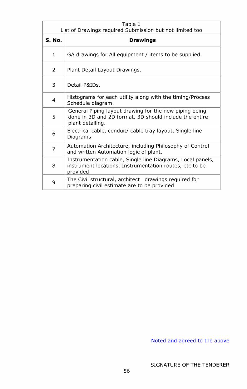
Noted and agreed to the above
SIGNATURE OF THE TENDERER
56
Table 1 List of Drawings required Submission but not limited too
S. No. Drawings
1 GA drawings for All equipment / items to be supplied.
2 Plant Detail Layout Drawings.
3 Detail P&IDs.
4 Histograms for each utility along with the timing/Process Schedule diagram.
5
General Piping layout drawing for the new piping being
done in 3D and 2D format. 3D should include the entire plant detailing.
6 Electrical cable, conduit/ cable tray layout, Single line Diagrams
7 Automation Architecture, including Philosophy of Control and written Automation logic of plant.
8
Instrumentation cable, Single line Diagrams, Local panels,
instrument locations, Instrumentation routes, etc to be
provided
9 The Civil structural, architect drawings required for preparing civil estimate are to be provided
Noted and agreed to the above
SIGNATURE OF THE TENDERER
57
9.0. SPECIAL CONDITIONS OF CONTRACT FOR MECHANICAL WORKS
Contents
1. Scope
2. General Installation
3. Service Piping Installation
4. Special Instructions And Specifications
5. Insulation of Piping and Equipment
6. Interconnections of Services
7. Guidelines For Expansion Work
8. Cleaning Chemicals and Lubricants
9. Testing, Commissioning and Start-Up
10. Trouble shooting during the trial period
11. Painting
12. Training of Personnel
13. Code of Practice for Painting Service Pipe Lines
Table 1 Painting of Equipment & Structural Work
Table 2 Colour Code For Pipelines as per BIS 2379-1963
Table 3 Testing Pressures for Various Pipelines
1. Scope
General installation i.e. positioning and installing all the production,
miscellaneous and service equipment as per approved layout drawings and
as per the contract.
1.1 Supply and installation of structural platforms and tables.
1.2 Supply and installation of all service and product piping including ancillary
items.
1.3 Insulation and cladding of piping, equipment including supply of materials.
1.4 Interconnections of services and Electrical with equipment.
1.5 Guide line for expansion work.
1.6 Clean up of work site.
1.7 Supply of all cleaning chemicals and lubricants.
1.8 Testing, commissioning and start-up.
1.9 Painting including supply of paints as approved by the Purchaser.
1.10 Training of personnel.
1.11 Detailed specifications are given in the subsequent clauses.

Noted and agreed to the above
SIGNATURE OF THE TENDERER
58
2. General Installation
2.1 Positioning of Equipment
The work involves preparation of access for moving of the plant and
equipment including their fittings from the work site godown or from the
place within the site where they have been unloaded, to the place of
erection, de-crating and placing on the foundation wherever required.
The Purchaser shall arrange all the civil foundations as per the
manufacturer/Bidder/Supplier’s drawings. The Bidder/Supplier
shall place the equipment and carry out final adjustment of the
foundations including alignment.. The Bidder/Supplier shall be
responsible for obtaining correct reference lines for the purpose of fixing
the alignment of various equipments from master benchmarks provided.
Tolerances shall be as specified in equipment manufacturer's drawings
or as stipulated by the Purchaser's Engineer. No equipment shall be
permanently bolted down to foundations or structure until the
Bidder/Supplier has checked the alignment and witnessed by the
Purchaser. The Bidder/Supplier shall carry out minor alterations in the
anchor bolts, pockets etc., at no extra cost and set the equipment
properly as per approved layout, drawings and manufacturer's
instructions. The Bidder/Supplier shall supply all the necessary
foundation/anchor bolts and bedplates if required without extra cost if
these have not been provided with main equipment.
The Bidder/Supplier shall supply, fix and maintain, at his own cost,
during the erection work, all the necessary cantering, scaffolding,
staging required not only for proper execution and protection of the said
work but also for protection of the surrounding plant and equipment.
The Bidder/Supplier shall take out and remove any or all such cantering,
scaffolding, staging planking etc., as occasion shall require or when
ordered to do so and shall fully reinstate and make good all things
disturbed during execution of the work, to the satisfaction of the
Purchaser. The Bidder/Supplier shall be paid no additional amount for
the above.
Noted and agreed to the above
SIGNATURE OF THE TENDERER
59
2.2 Structural Platforms and Tables
Structural platforms shall be required to provide access for various
equipment. Tables shall be required for handling products. These
platforms and tables shall be fabricated keeping stability and other
functional as well as aesthetic requirements into consideration as
approved by the Purchaser. The payment shall be made on the basis of
the actual weight executed and the unit rates agreed upon or as per
provisions made in the contract for such items.
3. Service Piping Installation
3.1 General Guidelines
All piping systems shall comply with the latest editions as applicable.
3.2 Scope of Supply
The Bidder/Supplier shall supply all piping materials like pipes, fittings,
flanges, measuring instruments and all other items as shown in the P&I
diagram/specifications and schedule of quantities. All the pipes & fittings
and insulation material etc. should be of class and make as approved by
the Purchaser. The Bidder/Supplier, for the class and make of all
materials, must obtain prior approval of the Purchaser. The
Bidder/Supplier should furnish the details of makes selected by him, in
the pro forma given in Table 5.
3.3 Scope of Piping Erection
The scope of erection for piping, includes all system covered in the flow
diagrams and specifications. The Bidder/Supplier's work commences/
terminates at the pipe connections with valves or flanges as specified in
flow diagrams/ battery limits.
The Bidder/Supplier shall also install necessary piping and any
specialties furnished with or for equipment such as relief valves, built-
in-bypass, primary elements for flow measurements, control valves and
on-line metering equipment.
The Bidder/Supplier shall perform necessary internal machining of pipes
for installing orifices, flow nozzles, control valves etc. The
Bidder/Supplier shall install all pipes, valves and specialties being
procured from other sources.

Noted and agreed to the above
SIGNATURE OF THE TENDERER
60
3.4 Testing of Piping
The Bidder/Supplier shall test sample piping systems including valves
and specialties and instruments as required.
All piping shall be internally cleaned and flushed by the
Bidder/Supplier after erection in a manner suited to the service.
For hydrostatic testing and water flushing, the Bidder/Supplier shall
furnish necessary pumps, equipment, instruments and piping etc, if
required.
3.5 Other Guidelines
Colour code shall be used to identify pipe material. The Bidder/Supplier
shall be able to identify on request all random piping prior to field
fabrication.
The Bidder/Supplier shall be responsible for the quality of welding
done by them and shall conduct tests to determine the suitability of the
welding procedure by him.
All piping supports, guides, anchors, hangers, rollers with structural
framework shall be supplied and erected by the Bidder/Supplier. The
kinds of pipe supports like CI clamps, wooden saddles, roller supports
and support framework shall be as per the design approved by the
Purchaser prior to taking up the work.
All piping shall be suspended, guided and anchored with due regard to
general requirements and to avoid interference with other pipes,
hangers, electrical conduits and their supports, structural members and
equipment and to accommodate insulation and conform to buildings
structural limitations. It is the responsibility to the piping
Bidder/Supplier to avoid all interference while locating hangers and
supports.
Anchors and/or guides for pipelines or for other purposes shall be
furnished, when specified, for holding the pipeline in position for
alignment. Hangers shall be designed fabricated and assembled in such
a manner that any movement of the support pipes cannot disengage
them.
All piping shall be wire brushed and purged with air blast to remove
all rust, mill scale from inner surface. The method of cleaning shall be
Noted and agreed to the above
SIGNATURE OF THE TENDERER
61
such that no material is left on the inner or on outer surfaces, which will
affect the serviceability of the pipes.
Effective precautions such as capping and sealing shall be taken to
protect all pipe ends against ingress of dirt and damage during transit or
storage. The outside of the steel pipes (black) shall be painted with two
coats of red oxide paint or as directed by the Purchaser.
4. Special Instructions and Specifications
4.1 Steam Piping
Steam piping work can be classified into two categories:
High-pressure steam piping when the working pressure of steam is
more than 3.5 kg/cm2.
Low-pressure steam piping when the working pressure of steam is
up to 3.5 kg/cm2.
All the pipes and fittings used for high pressure steam piping work
should conform to IBR and they should be IBR certified and also to be
identified with number and mark showing that they are tested by
the Boiler Inspector and supported with duly authentic certificates to
this effect. ALL HIGH PRESSURE STEAM PIPES SHALL BE SEAMLESS
TYPE, with required SCHEDULE of pipe.
The high-pressure steam piping work should also include fabrication and
installation of pressure reducing stations strictly conforming to IBR.
For low pressure, prevailing laws as per IBR/ISO shall be followed.
4.2 Other Piping
ALL THE PIPING FOR CHILLED WATER,/GLYCOL,/AMMONIA, RO,SOFT
AND RAW WATER, H.P. AND L.P. STEAM, AIR AND LSHS PIPING SHALL
GENERALLY BE OF WELDED CONSTRUCTION. Whenever welding is
done for pipes of smaller size special care should be exercised to avoid
clogging of flow area with the welding material.
5. Insulation of Piping and Equipment
5.1 Cold Insulation of Chilled Water/Glycol /Ammonia Pipeline
All the chilled water, glycol & ammonia pipelines shall be insulated by
PUF pipe sections. The insulation shall be carried out in the following
manner:

Noted and agreed to the above
SIGNATURE OF THE TENDERER
62
Before starting insulation work all pipelines shall be tested as specified.
The surface of the pipes to be insulated should be properly cleaned.
Hot bitumen of 85/40 or 85/25 conforming to IS 702 should be
applied uniformly @ 1.5 kg/m2 on the surface of the pipes.
A similar layer of bitumen should be applied on the inner surface and
on the edges of the insulation sections.
The sections should then be stuck to the coated pipes with joints
staggered. Adjacent sections should be tightly pressed together. All
joints should be properly sealed with bitumen.
A thick vapour seal with hot bitumen @ 2.5 kg/m2 should be applied
uniformly on the outer surfaces of the pipe sections and allowed to dry.
The thickness of insulation shall be as required.
Alternatively Armaflex insulation materials can be used for cold
insulation of piping and equipment. Armaflex insulation materials shall
have silver colour outer film so as to protect the Armaflex and to give
the metal-look surface.
The outer silver colour metal-look surface shall effectively protect the
insulation material against mechanical impact. It shall be able to
recover from blows, and shall leave no dents in the surface. Shall be
suitable for both indoor and outdoor applications. Shall be UV and
weather proof. Shall have high Puncture and tear resistance
5.2 Insulation of Chilled Water Tank
The surfaces shall be cleaned with the help of brushes to remove any
loose particles.
A coat of bitumen of 85/40 or 85/25 conforming to IS [email protected]
kg/m2 shall be applied over the flooring and walkathon sheets shall
be press-laid to act as a vapour barrier.
Bitumen shall then be applied on the walkathon sheets and one side and
edges of the insulation slabs to ensure total rate of 2.00 kg/m2
between contacting surfaces. The slabs shall then be fixed in position,
making sure that there shall be no joints between slabs.
For double layers insulation bitumen shall again be applied on all
contacting surfaces to ensure a total rate of 1.5 kg/m2 between
contacting surfaces.
Noted and agreed to the above
SIGNATURE OF THE TENDERER
63
A coat of bitumen at 1.5 kg/m2 shall be applied over the insulation
surfaces.
5.3 Hot Insulation of Steam, Condensate & Hot Water Pipe Lines
All the steam and hot water pipelines shall be insulated with mineral
wool or equivalent of specified thickness. The insulation shall be carried
out in the following manner and should be supplied in the form of
properly required sizes.
Clean the surfaces to be insulated. Apply a coat of red oxide primer
and fix glass wool/mineral wool of specified thickness, tightly to the
pipes, butting all joints and tie with lacing wire.
It should then be covered with GI wire netting of 20 mm x 24 SWG.
In case the insulation does not have the desired insulation properties,
the entire insulation will have to be redone at the Bidder/Supplier's
cost to give the desired results.
In case of condensate return piping all the steps mentioned above
shall be executed except that thickness of the insulation shall be
minimum 25 mm.
5.4 Aluminium Cladding / Armaflex Cladding
The chilled water, glycol, ammonia, water, steam & hot water lines after
insulations shall be covered by Aluminium/ Armaflex cladding.
Aluminium cladding will be done with 22 gauge aluminium sheet with
proper grooves and overlaps and screwed in position with 12 mm self-
tapping parker screws.
Armaflex insulation materials shall have silver colour outer film so as to
protect the Armaflex and to give the metal-look surface. The outer silver
colour metal-look surface shall effectively protect the insulation material
against mechanical impact. It shall be able to recover from blows, and
shall leave no dents in the surface. Shall be suitable for both indoor
and outdoor applications. Shall be UV and weather proof. Shall have
high Puncture and tear resistance. Shall have required thickness of
cladding material.
6.0 Interconnections of Services
6.1 The Bidder/Supplier shall lay service piping and provide connections with
the equipment complying strictly with the equipment manufacturers'
Noted and agreed to the above
SIGNATURE OF THE TENDERER
64
instructions. The Bidder/Supplier shall also carry out all the interconnecting
service piping with the various items of plant/system. The work shall be
complete with capillary piping if required and connections with
instruments and controls supplied with the equipment.
6.2 The Bidder/Supplier shall also carry out electrical connections for
equipment with the control panels including equipment lighting as per the
wiring diagrams of the equipment Bidder/Suppliers. Connection shall be
made for small electrically operated devices on equipment installed as
accessories to, or assembled with equipment. Connections regarding
instruments, float switches, limit switches, pressure switches, thermostats
and other miscellaneous equipment shall be done as per manufacturers'
drawings & instructions.
7.0 Guidelines for Expansion Work
7.1 Shutdowns
Plant shutdown shall be required for making tapings/ interconnections of
the new equipment/ piping, to be installed under expansion, with the
pending new equipment/piping in case of delay. These shut downs should
be planned carefully well in advance to enable the Purchaser to take
suitable actions for minimum shutdown period. The details of shut downs,
the numbers and duration should be worked out and intimated to the
Purchaser for approval. The Bidder/Supplier should ensure completion of all
the necessary works well within the allowed time so that no inconvenience
is caused in regular operation and working of the existing plant.
7.2 Cleanliness
Wherever the Bidder/Supplier is required to work in existing plant area
he should take due care and extra precautions to ensure absolute
cleanliness and minimum hindrance for proper working of the existing
plant.
7.3 Change over
The programmers for change over from existing plant system to new
plant system should be prepared by the Bidder/Supplier and should be got
approved by the Purchaser.
7.4 Modifications and rectification of existing plant and equipment and any
other Extra Work not specified in the Original Contract.
Noted and agreed to the above
SIGNATURE OF THE TENDERER
65
During expansion work, the Bidder/Supplier shall be required to carry out
modifications, repairs/replacement of the existing equipment or any other
extra work. The alterations/modifications not specified in the
contract/order or any other Extra Work, will be carried out by the
Bidder/Supplier at mutually agreed cost (Landed cost + service charge).
7.5 Clean Up of Works Site
All soils, filth or other matters of an offensive nature taken out of any
trench, drain or other places shall not be deposited on the surfaces, but
shall at once be carted away by the Bidder/Supplier from the site of work
for proper disposal.
The Bidder/Supplier shall not store or place the equipment, materials or
erection tools on the drive ways and passages and shall take care that his
work in no way restricts or impedes traffic or passage of men and materials
during erection, the Bidder/Supplier shall without any additional payment,
at all-time keep the working and storage area used by him free from
accumulation of dust or combustible materials, waste materials rubbish
packing, wooden planks to avoid fire hazards and hindrance to other
works.
If the Bidder/Supplier fails to comply with these requirements in spite of
written instructions from the Purchaser, the Purchaser will proceed to clear
these areas and the expenses incurred by the Purchaser in this regard shall
be payable by the Bidder/Supplier. Before completion of the work, the
Bidder/Supplier shall remove or dispose off in a satisfactory manner all
scaffolding, temporary structures, waste and debris and leave the promises
in a condition satisfactory to the Purchaser. Any packing materials received
with the equipment shall remain as the property of the Purchaser and may
be used by the Bidder/Supplier on payment of standard charges to the
Purchaser and with prior approval of the Purchaser. At the completion of
his work and before final payment, the Bidder/Supplier shall remove and
shall restore the site to neat workman like conditions at his cost.
8.0 .Cleaning Chemicals and Lubricants
8.1 The necessary quantities of cleaning chemicals, lubricants etc., required for
the installation, commissioning, testing and start-up of all the equipment
till handing over are to be supplied the Bidder/Supplier and nothing extra
would be paid for these.
Noted and agreed to the above
SIGNATURE OF THE TENDERER
66
9.0. Testing, Commissioning and Start-up
9.1 The Bidder/Supplier shall operate, maintain and give satisfactory trial run
of the plant for the design product satisfactorily for a maximum period of
one week or as mutually agreed by Bidder/Supplier/purchaser/Purchaser of
the plant at the rated output. The Bidder/Supplier should carry out all
rectification of damages/defects and routine troubleshooting during
commissioning with the help of purchaser’s staff.
9.2 During this period, Bidder/Supplier shall incorporate/execute necessary
minor modifications during the trial period for maximizing operational
efficiency. The Bidder/Supplier should also execute minor modifications as
may be suggested by the manufacturer/Purchaser, if required. The
Bidder/Supplier shall suggest recommended log sheet proofread for
recording necessary operating data and pass it on to the Purchaser in proof
of satisfactory rated output and performance of the equipment/plant.
9.3 The commissioning shall also include, for all the equipments, the
following:
Field disassembly and assembly
Clean out of lubrication system including chemical cleaning wherever
required. Circulation of lubricant to check flow.
Clean out and check out of all the service lines
Check out and commissioning of instruments, equipment and plants, filtering of transformer and other oils so that if deteriorated, they
shall attain the required properties/standards, specified tests in this regard must be carried out by approved authorities and their
satisfactory reports submitted to the Purchaser before start-up. Recharging or make-up filling of lubricant oil up to the desired level in
the lubrication system of individual machine. Operation in empty condition to check general operation details
wherever required and wherever possible. Closed loop dynamic testing with water wherever required.
Operation under load and gradual load increase to attain maximum rated output.
10.0. Trouble shooting during the trial period
10.1 The Bidder/Supplier shall demonstrate proper working of all mechanical
and electrical controls; safety and protective device, in presence of the
Purchaser's engineer and the same should be duly recorded.
10.2 After conducting testing, in case a particular equipment is not working
properly or not giving rated output the Bidder/Supplier will furnish a

Noted and agreed to the above
SIGNATURE OF THE TENDERER
67
detailed report to the Purchaser stating therein the detailed account on the
performance of the equipment with possible reasons for improper or not
working of the same.
10.3 The Purchaser after receipt of report from the Bidder/Supplier would take
up the matter with the manufacturers and if required would invite the
representative of original manufacturers. In case the Purchaser considers
that the non-performance of equipment is only due to inexperience of the
Bidder/Supplier, then the charges incurred for the manufacturer's
representative visit would be debited to the Bidder/Supplier's account.
10.4 Further, before the commencement of testing or commissioning, the
Purchaser reserves the right to invite the original manufacturer's
representative at the cost of the Bidder/Supplier for start-up help, assist
and guide the Bidder/Supplier during commissioning in the following cases:
The Bidder/Supplier has no previous experience of commissioning and
start-up of the similar equipment.
The Purchaser is of the opinion that the Bidder/Supplier is not capable to
commission and start-up of certain specific equipment.
10.5 However, in either of the cases the manufacturer's representatives would
be called with prior information to the Bidder/Supplier and the
Bidder/Supplier will have to extend all co-operation to such representatives
in good spirit and in the interest of the work.
10.6 After satisfactory commissioning and start-up the Bidder/Supplier shall
keep his representatives under whose supervision the Purchaser's staff
shall be operating and maintaining the plant and equipment for a
minimum period of one month. The Bidder/Supplier's representatives
should be present at all times during the running and operation of plant
and equipment. During this period the Bidder/Supplier shall ensure proper
working of complete plant and equipment and attend any works required to
be done and shall also take complete responsibility for proper operation
and maintenance of the complete plant and equipment.
11.0 Painting
11.1 All the equipment/ machineries like motors, pumps, HT/ LT panel,
transformer, switch boards, starters, junction boxes, isolators, storage
tanks, supporting structures, pipe supports and MS/ GI pipes and all
Noted and agreed to the above
SIGNATURE OF THE TENDERER
68
exposed and visible iron parts included in the scope of erection/
commissioning shall be given double coat of paint of approved shade
over a double coat of anticorrosive primer wherever necessary
irrespective of the condition of original paint of equipment/ machineries/
structures/ supports. All surfaces wherever required must be properly
cleaned from scale, dirt and grease prior to painting. Spray painting
must preferably be used on all the equipment/ machineries and wherever
practicable. Suitable and necessary cleaning/ wiping of sight/ dial
glasses, other non-metallic parts, flooring, walls and other surfaces which
have been spoiled by paint during painting must also be carried out by the
Bidder/Supplier.
11.2 Lettering and other markings, including capacity and flow direction
markings, shall also be carried out by the Bidder/Supplier on the tanks,
pipe lines, starters, motors, isolators and wherever else necessary, as
directed and as per the standard practice of installation. ISI colour codes
and colour charts as mentioned in Table 3& Table 2must be adhered to.
11.3 Supply of all paints and all other materials required is included in the scope
of supply of the Bidder/Supplier under this contract/order.
12.0 Training of Personnel
12.1 The Bidder/Supplier for operating the plant as may be deputed by the
Purchaser shall train necessary staff. The personnel will be associated for
the training during the installation; testing, commissioning and start-up
period and the training tenure shall be extended for a minimum period of
one month from the date of commissioning and start-up.
13.0 Code of Practice for Painting Service Pipe Lines
13.1 On Non-insulated Pipe Line & Insulated Pipeline without Aluminium
Cladding
13.1.1.Ground colour to be applied throughout the length of the pipeline.
13.1.2.Colour bands to be applied near every valve and branch connection as
well as in every room near the entry.
13.1.3.The 1st band should be 4" wide and the second band should be 1" wide.
13.1.4.On the 1st band a white arrow to be put to indicate the direction of flow.
Noted and agreed to the above
SIGNATURE OF THE TENDERER
69
13.1.5.The arrows should be put on the bottom of the pipelines so that the
same are visible from below in case of horizontal bank of pipes and on
sides in case of vertical bank of pipes.
13.1.6.The valves should be painted with the same colour as the ground colour
of the pipeline.
13.2 On Insulated Pipeline with Aluminium Cladding
13.2.1.Ground colour to be applied in a length of 500 mm of the pipe all round
near every valve and branch connections as well as in every room near
the entry. The complete length of the pipeline should not be painted.
13.2.2.Colour bands should be applied in the middle of every ground colour
strip. The 1st Colour band should be 4" wide and the second band
should be 1" wide.
13.2.3.On the 1st band a white arro is to be put to indicate the direction of
flow of the fluid.
13.2.4.The arrows should be put on the bottom of the pipelines, so that the
same are visible from below in case of horizontal bank of pipes and on
sides in case of vertical bank of pipes.
13.2.5.The valves should be painted with the same colour as the ground colour.
13.2.6 The ground colours and the colours of the 1st and 2nd colour bands
have been indicated on the enclosed list for the pipelines carrying
various types of fluids and gases. The list also indicates the shade nos.
of the colours to be used. In case the exact shade is not available, the
nearest possible shade in the same colour may be selected.
13.2.7. Only synthetic enamel paint should be used for the painting and band
markings on the Pipelines and it should be ensured that the finish
should be glossy.
13.2.8. Where no colour bands have been recommended, only the ground colour
is to be applied as per the above procedure. If only one colour band is
recommended the same should be 4" wide and applied on the ground
colour. In case of 2 nos. colour bands, the 1st band should be 4" wide
and second band 1" wide and should be applied on the ground colour.
13.2.9.To avoid mixing of colours, it is recommended to apply the bands only
after the ground colour paint is dry and subsequently to apply the arrow
only after the 1st band paint is dry.
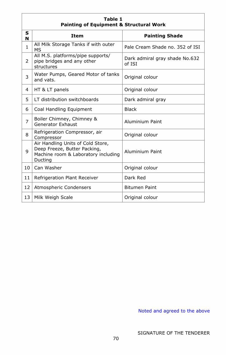
Noted and agreed to the above
SIGNATURE OF THE TENDERER
70
Table 1 Painting of Equipment & Structural Work
S
N Item Painting Shade
1 All Milk Storage Tanks if with outer MS
Pale Cream Shade no. 352 of ISI
2 All M.S. platforms/pipe supports/ pipe bridges and any other
structures
Dark admiral gray shade No.632 of ISI
3 Water Pumps, Geared Motor of tanks
and vats. Original colour
4 HT & LT panels Original colour
5 LT distribution switchboards Dark admiral gray
6 Coal Handling Equipment Black
7 Boiler Chimney, Chimney & Generator Exhaust
Aluminium Paint
8 Refrigeration Compressor, air Compressor
Original colour
9
Air Handling Units of Cold Store, Deep Freeze, Butter Packing,
Machine room & Laboratory including
Ducting
Aluminium Paint
10 Can Washer Original colour
11 Refrigeration Plant Receiver Dark Red
12 Atmospheric Condensers Bitumen Paint
13 Milk Weigh Scale Original colour
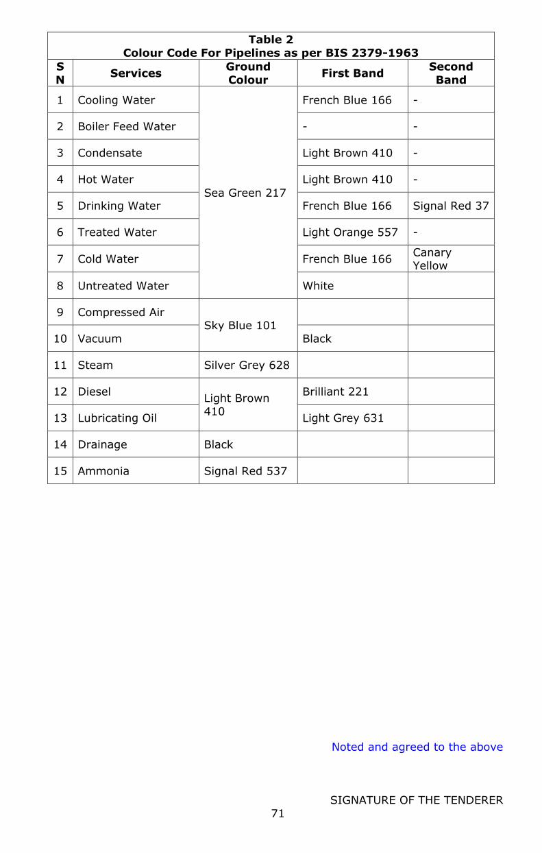
Noted and agreed to the above
SIGNATURE OF THE TENDERER
71
Table 2
Colour Code For Pipelines as per BIS 2379-1963
S
N Services
Ground
Colour First Band
Second
Band
1 Cooling Water
Sea Green 217
French Blue 166 -
2 Boiler Feed Water - -
3 Condensate Light Brown 410 -
4 Hot Water Light Brown 410 -
5 Drinking Water French Blue 166 Signal Red 37
6 Treated Water Light Orange 557 -
7 Cold Water French Blue 166 Canary Yellow
8 Untreated Water White
9 Compressed Air Sky Blue 101
10 Vacuum Black
11 Steam Silver Grey 628
12 Diesel Light Brown 410
Brilliant 221
13 Lubricating Oil Light Grey 631
14 Drainage Black
15 Ammonia Signal Red 537
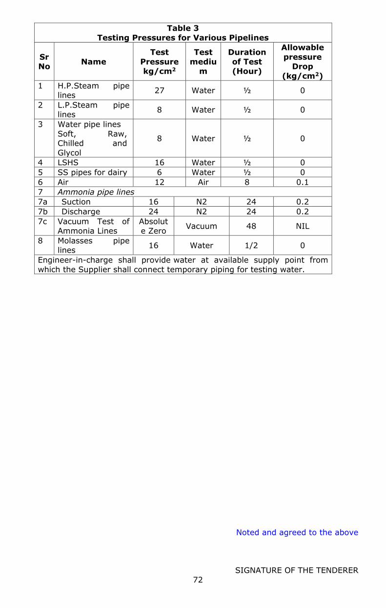
Noted and agreed to the above
SIGNATURE OF THE TENDERER
72
Table 3
Testing Pressures for Various Pipelines
Sr No
Name
Test
Pressure kg/cm2
Test
medium
Duration
of Test (Hour)
Allowable
pressure Drop
(kg/cm2)
1 H.P.Steam pipe lines
27 Water ½ 0
2 L.P.Steam pipe lines
8 Water ½ 0
3 Water pipe lines
Soft, Raw, Chilled and
Glycol
8 Water ½ 0
4 LSHS 16 Water ½ 0
5 SS pipes for dairy 6 Water ½ 0
6 Air 12 Air 8 0.1
7 Ammonia pipe lines
7a Suction 16 N2 24 0.2
7b Discharge 24 N2 24 0.2
7c Vacuum Test of Ammonia Lines
Absolute Zero
Vacuum 48 NIL
8 Molasses pipe lines
16 Water 1/2 0
Engineer-in-charge shall provide water at available supply point from
which the Supplier shall connect temporary piping for testing water.

Noted and agreed to the above
SIGNATURE OF THE TENDERER
73
10.0.SPECIAL CONDITIONS OF CONTRACT FOR ELECTRICAL WORKS
Contents 1. Scope
2. Standards 3. Equipment And Accessories Specifications
4. Power Cables (HT) 5. Power Cables (LT)
6. Control Cables 7. Cable Trays
8. Cable Glands 9. Cable Connectors
10. Cable Route Markers 11. Cable Indicators
12. Pipes for Cables
13. Motor Isolators 14. Motor Junction Box / Control Junction box
15. Remote Push Button Stations (for other projects) 16. Erection Of Equipment
17. Not Relevant in this tender. 18. Not Relevant in this tender.
19. Erection and Testing of Motors 20. Installation of Cable Network
21. General Requirements for handling of Cables 22. Laying of Cable Network
23. Laying of Cable (Underground System) 24. Laying of Cable Under Floors
25. Laying of Cable in Masonry trenches 26. Laying of Cable in Cable Trays
27. Laying of Cables on Building Surface/Structure
28. Termination & Jointing of cables 29. Dressing of Cables Inside the Equipment
30. Cable between Isolators/Junction Box and Motor/Control 31. Testing of cables
32. Earthing Network 33. Earth Pit with Electrode
34. Earth Bus, Earthing Lead and Earth Wire/Strip 35. Erecetion Procedure Guidelines for Instrumentation & Control System
Table 1 Bureau Indian Standards (BIS)
Table 2 Pro forma for PCC, DB, Motor Control Centres Test Table 3 Pro forma for motor testing
Table 4 Pro forma for Testing Cables Table 5 Recommended Cables Sizes For Industrial Wiring
Table 6 Sizing of Earthing Lead/ Wire
Noted and agreed to the above
SIGNATURE OF THE TENDERER
74
1. Scope
1.1 The intent of this specification is to define the requirements for the
installation, testing and commissioning of the electrical system like high-
tension switchyard with accessories and equipment, transformers, HT.
Panels, oil circuit breakers, LT. Panels and power control centres,
distribution boards, capacitor banks & panels, power & control cables,
remote push button stations, motors, earthing network, etc. Requirement
of a particular project shall be as specified in schedule of
quantities/approved drawings or as per the battery limits fixed in the
contract.
2. Standards
2.1 The work shall be carried out in the best workmanship in conformity with
this specification, the relevant specification/codes of practice of the Bureau
of Indian Standards, approved drawings and the instructions issued by the
Engineer-in-charge or his authorized representative, from time to time.
Some of the relevant Bureau of Indian Standards is listed in Table 1.
2.2 In addition to these standards, all works shall also confirm to the
requirements of the followings:
Indian Electricity Act and Rules framed there under. Fire Insurance Regulations.
Regulations lay down by the Chief Electrical Inspector of the State/State Electricity Board.
Regulations lay down by the Factory Inspector of the State. Any other regulations lay down by the local authorities.
Installation & operating manuals of original manufacturers of equipment.
3. Equipment and Accessories Specifications
3.1 This defines specifications and requirements mainly for the equipment and
accessories which are generally supplied by the erection agency and do not
cover the specification of main electrical equipment such as Transformers,
HT and LT panels, switchboards and motors etc which may be supplied by
the Owner.
3.2 All materials, fittings and appliances to be supplied by the Bidder/Supplier
shall be of best quality and shall conform to the specification given
hereunder. The equipment shall be manufactured in accordance with
current Bureau of Indian Standard Specifications wherever they exist or
Noted and agreed to the above
SIGNATURE OF THE TENDERER
75
with the BS or NEMA specifications, if no such BIS are available. In the
absence of any specification, the materials shall be as approved by the
Owner or his authorized representative.
3.3 All similar materials and removable parts shall be uniform and
interchangeable with one another.
3.4 You must furnish makes of bought out items.
4. Power Cables (HT)
4.1 Specifications as per Section V Sub-Section 6
5. Power Cables (LT)
5.1 Specifications as per Section V Sub-Section 6
6. Control Cables
6.1 Specifications as per Section V Sub-Section 6
7. Cable Trays
7.1 Specifications as per Section V Sub-Section 6
8. Cable Glands
8.1 These shall be provided at both ends of armoured/ Unarmoured electrical
cables. Cable glands to be manufactured as per performance requirements
of BS 6121 amended as on date, with BRASS material accurately machined
and NICKEL finish. Single compression cable glands to be complete with
checkout, gland body, 3 nose metal washers, and outer seal rubber ring
and compression nut. Double compression glands to be complete with
checkout, gland body, neoprene outer ring, Armour clamping cone, Armour
clamping ring, Armour clamping nut, neoprene outer ring, skid washer &
outer seal nut. Sample of cable gland to be got approved from the Site In
charge before supply For instruments MOC of cable gland shall be
polyamide.
9. Cable Connectors
9.1 Cable connectors, lugs/sockets, shall be of copper/Aluminium alloy,
suitably tinned, soldering less, crimping type. These shall be suitable for
Noted and agreed to the above
SIGNATURE OF THE TENDERER
76
the cable being connected and type of function (such as power, control or
connection to instruments, etc.)
10. Cable Route Markers
10.1 These shall be galvanized Cast Iron plate with marking (LT/HT) diameter
150 mm with 600 mm long 25x25 mm MS. angle riveted/bolted with this
plate. Sample to be got approved before use.
11. Cable Indicators
11.1 Individual symbols / numbers printed on yellow strips of glossy PVC should
be used for cable indicator.
12. Pipes for Cables
12.1 For lying of cables under floor, G.I. class 'A' pipes shall be used. MS.
conduits are not acceptable for this purpose. For laying cable in air
whereas cable trays are not being used, MS `B' class pipe shall be used.
Size of pipe shall depend upon the overall outer diameter of cable to be
drawn through pipe. To determine the size of pipe, assume that 40% area
of pipe shall be free after drawing of cable. In dairy's process area
wherever required SS-304 pipe, 1.6 mm thick shall be used.
13. Motor Isolators
13.1 These shall be in Aluminium cast housing, completely dust, vermin and
weather proof (IP 55), suitable for 30/25 A, 415 volts, 50 Hz with rotary
type switch complete with cable gland for incoming and outgoing cables.
For dairy's process area SS-304 motor isolator shall be used. Final finish of
housing to be buffer mirror for SS and powder coated gray for Aluminium
housing. Sample to be got approved before supply.
14. Control Junction Box
14.1 These shall be in Aluminium cast housing, completely dust, vermin and
weather proof (IP 55). For dairy's process area SS-304 junction box shall
be used. Final finish of housing to be buffer mirror for SS and powder
coated gray for Aluminum housing. Sample to be got approved before use.
Noted and agreed to the above
SIGNATURE OF THE TENDERER
77
15. Remote Push Button Stations
15.1 These shall be used for remote OFF for motors, away from MCC. These
shall be suitable for surface/structure mounting in Cast Aluminium housing
having IP-55 class of protection i.e. completely weather proof. For dairy's
process area SS-304 push button shall be used. Final finish of housing to
be buffer mirror for SS and powder coated gray for Aluminum housing.
Sample to be got approved before supply.
15.2 Riveted type bi-colour plastic nameplate to be provided for each feeder.
15.3 For outdoor installation suitable canopy to be provided.
16. Erection of Equipment
16.1 The cases containing the equipment (being supplied by the purchaser shall
be handed over to the Bidder/Supplier. The Bidder/Supplier shall make his
own arrangements for safe transportation of all the items to the erection
site and also carry out complete loading/unloading during transportation.
Equipment shall not be removed from packing cases unless the floor has
been made ready for installing them. The cases shall be opened in
presence of the Engineer-in-charge or his authorized representative. These
empty packing cases shall be returned to the storage space identified by
engineer in charge and any document if found with the equipment shall be
handed over to the Engineer-in- charge. Any damage or shortage noticed
shall be reported to the Engineer-in-charge in writing immediately after
opening of packing cases.
17. Erection and Testing of Motors
17.1 Erection and coupling of motors with machines will be done under the
mechanical erection. However, earthing, cable termination, testing and
commissioning are covered under this section. Before starting, the
alignment and coupling of motors with machines and the insulation
resistance of the motors will be measured and recorded by the
Bidder/Supplier. The direction of the rotation of the motor shall also be
checked before the driven equipment is finally coupled. Motor bearings are
to be checked and rectified including supply and changing of grease if
required, checking of fans coupling with bodies etc. The Bidder/Supplier
shall take adequate precaution and care while executing the work. For all
Noted and agreed to the above
SIGNATURE OF THE TENDERER
78
damage due to negligence etc. the Bidder/Supplier shall be responsible to
replace/repair at his own cost.
17.2 Before connecting power cables to motors the insulation resistance of all
motor windings shall be measured. Measurement shall be repeated after
power cable terminations are completed and before first charging.
17.3 Motors shall be operationally tested together with the starting gear
and auxiliary apparatus such as push button stations, the contractors,
level and pressure controls, signal and alarm apparatus, power and control
circuits etc.
17.4 Check the anti-condensation heater and its circuit (if installed).
17.5 Check the setting of the thermal overload protection / single phase prevent
or. Testing of these devices is to be done wherever required as per the
instructions of the Engineer-in-charge.
17.6 Run all motors uncoupled for a maximum period of 4 hours before
the driven equipment is placed in regular service. Fill up Test Certificate as
per Table 3.
17.7 All outdoor-installed motors must be shrouded with cover made out of 14
gauge GI sheet with lifting hook and louvers as approved by AAVIN.
18. Installation of Cable Network
18.1 Cable network shall include power, control and lighting cables which shall
be laid in underground trenches, home pipes, open trenches, cable trays,
GI pipes, or on building structure surfaces as detailed in the relevant
drawings, cable schedules or as per the Engineer-in-charge's instructions.
Supply and installation of cable trays, GI pipes/ conduits, cable gland
sockets at both ends, isolators, junction boxes, remote push buttons
stations, etc shall be under the scope of the Bidder/Supplier. For selection
of cable size please refer to Table 5.
19. General Requirements for Handling of Cables
19.1 Before laying cables, these shall be tested for physical damage, continuity
absence of cross phasing, insulation resistance to earth and between
conductors. Insulation resistance tests shall be carried out with 500/1000
volt Megger.
Noted and agreed to the above
SIGNATURE OF THE TENDERER
79
19.2 The cables shall be supplied at site, wound on wooden drum as far as
possible. For smaller length and sizes, cables in properly coiled form can be
accepted. The cables shall lie by mounting the drum of the cable on drum
carriage. Where the carriage is not available, the drum shall be mounted
on a properly supported axle, and the cable laid out from the top of the
drum. In no case the cable will be rolled on, as it produces kinks, which
may damage the conductor.
19.3 Sharp bending and kinking of cables shall be avoided. The bending radius
for PVC insulated and sheath armoured cable shall not be less than 10 D
Where `D' is overall diameter of the cable.
19.4 While drawing cables through GI pipes, conduits, RCC pipe, ensure that
size of pipe is such that, after drawing cables, 40 % area is free. After
drawing cable, the end of pipe shall be sealed with cotton/bituminous
compound.
19.5 High voltage (11 kV and above), medium voltage (230 V and above) and
other control cables shall be separated from each other by adequate
spacing or running through independent pipes/trays.
19.6 Armoured cables shall never be concealed in walls/floors/roads without GI
pipes, conduits RCC pipes.
19.7 Joints in the cable throughout its length of lying shall be avoided as far as
possible and if unavoidable, prior approval of site engineer shall be taken.
If allowed, proper straight through epoxy resin type joint shall be made,
without any additional cost.
19.8 A minimum loop of 3 M shall be provided on both ends of the cable, or
after every 50 M of uncounted length of cable and on both ends of straight
through cable joint. This additional length shall be used for fresh
termination in future. Cable for this loop shall be paid for supply and lying.
19.9 Cable shall be neatly arranged in the trenches/trays in such a manner so
that crises crossing are avoided and final take off to the motor/switchgear
is facilitated. Arrangement of cables within the trenches/trays shall be the
responsibility of the Bidder/Supplier.
19.10 All cable routes shall be carefully measured and cable cut to the required
lengths and undue wastage of cables to be avoided. The routes indicated in
the drawings are indicative only and the same may be rechecked with the
Engineer-in-charge before cutting of cables. While selecting cable routes,
Noted and agreed to the above
SIGNATURE OF THE TENDERER
80
interference with structures, foundations, pipeline, future expansion of
buildings, etc. should be avoided.
19.11 All temporary ends of cables must be protected against dirt and moisture
to prevent damage to the insulation. For this purpose, ends of all PVC
insulated cables shall be taped with an approved PVC or rubber insulating
tape. Use of friction type or other fabric type tape is not permitted. Lead
sheathed cables shall be plumbed with lead alloy.
19.12 Wherever cable rises from underground/concrete trenches to
motors/switchgears/push buttons, these shall be taken in G.I./MS pipes of
suitable size, for mechanical protection unto 300 mm distance of concerned
cable gland or as instructed by the Engineer-in-charge.
19.13 Where cables pass through foundation/walls of other underground
structures, the necessary ducts or openings will be provided in advance for
the same. However, should it become necessary to cut holes in existing
foundations or structures the electrical Bidder/Supplier shall determine
their location and obtain approval of the Engineer-in-charge before cutting
is done.
20. Laying of Cables (Underground System)
20.1 Cables shall be so laid in ground that these will not interfere with other
underground structures. All water pipes, sewage lines or other structures,
which become exposed by excavation, shall be properly supported and
protection from injury until the filling has been rammed solidly in places
under and around them. Any telephone or other cables coming in the way
are to be properly shielded diverted as directed by the Owner.
20.2 Cables shall be laid at minimum depth of 750 mm in case of LT & 1200 mm
in case of HT, from ground level. Excavation will be generally in ordinary
alluvial soil. The width of the trench shall be sufficient for lying of required
number of cables.
20.3 Sand bedding 75 mm thick shall be made below and above the cables. A
layer of bricks (full size) shall be laid on the edge, above sand bedding on
the sides of cables and a flat brick to cover cable completely. More than
one cable can be laid in the same trench by providing a brick on edge
between two cables. However the relating location of cables in trench shall
be maintained till termination. The surface of the ground after back filling
Noted and agreed to the above
SIGNATURE OF THE TENDERER
81
the earth shall be made good so as to conform in all respects to the
surrounded ground and to the entire satisfaction to the Engineer-in-charge.
20.4 For all underground cables, route markers should be used
20.5 Separate cable route markers should be used for LT, HT and telephone
cables.
20.6 Route markers should be grounded in ground with 1:2:4 cement concrete
pedestal size 230 x 230 x 300 mm.
20.7 Cable markers should be installed at an interval not exceeding 50 M along
the straight routes of cables at a distance of 0.5 M away from centre of
cable with the arrow marked on the cable markers plate indicating the
location of cable. Cable markers should also be used to identify change in
direction of cable route and for location of every joint in underground
cable.
20.8 RCC Hume pipe for crossing road in cable laying shall be provided by
Owner. No deduction shall be made for cable lying in home pipe for not
providing bricks, sand and excavation. RCC home pipe at the ends shall be
sealed by bituminous compound after laying and testing of cable by
electrical Bidder/Supplier without any extra charge.
21. Laying of Cables under Floors
21.1 GI class a pipe shall be used for lying of outgoing cables under floors from
distribution boards to motors, isolators/junction boxes of motors, starter of
motors and push button stations. Preferably one cable shall be drawn
through one pipe. Size of pipe shall be such that after drawing of cable 40
% area is free. If length of pipe is more than 30 M, free area may be
increased to 50 %.
21.2 Use of elbows is not allowed at all and number of bends shall be kept
minimum. Instead of using bends with sockets, pipe-bending machine shall
be used for making long smooth bends at site.
21.3 Ends of pipe shall be sealed temporarily while laying with cotton/ jute/
rubber stopper etc to avoid entry of building material.
21.4 Exact location of equipment motor/ isolator/ push buttons etc shall be
ascertained prior to lying of pipe.
Noted and agreed to the above
SIGNATURE OF THE TENDERER
82
22. Laying of Cable in Masonry Trenches
22.1 Masonry/ concrete trenches for lying of cable shall be provided by Owner.
However steel members such as MS angles/ flats etc shall be provided &
grouted by electrical Bidder/Supplier to support the cables without any
extra charge. Cables shall be clamped to these supports with Aluminium
saddles/ clamps. More than one tier of cables can be provided in the same
trench if the number of cables is more. If required cable trays can also be
provided in trenches.
22.2 Entry of cables in trenches shall be sealed with bituminous MASTIC
compound to stop entry of water in trenches.
23. Laying of Cables in Cable Trays
23.1 Cable trays and supporting steel members such as MS angle/ channel/ flats
etc shall be provided and fixed by the Bidder/Supplier.
23.2 Cables shall be fixed in cable trays in single tier formation and cables shall
be clamped with Aluminium flat clamps and galvanized bolts/unit.
23.3 Earthing flat/ wire can also be laid in cable tray along with cables.
23.4 After lying of cables minimum 20 % area shall be spare.
24. Laying of Cables on Building Surface/ Structure
24.1 Such type of cable lying shall be avoided as far as possible and will be
allowed only for individual cables or small group of cables, which run along
structure.
24.2 Cables shall be rigidly supported on structural steel/masonry using
individual cast/malleable iron galvanized saddles and these supports shall
be approximately 400 to 500 mm for cables unto 25 mm overall diameter
and maximum 1000 mm for cables larger than 25 mm. Unsightly sagging
of cables shall be revenged. Only/GI clamps with GI bolts/nuts shall be
used.
24.3 If drilling of steel structure must be resorted to, approval must be secured
from the Engineer-in-charge and steel must be drilled where the minimum
weakening of the structure will result.
Noted and agreed to the above
SIGNATURE OF THE TENDERER
83
25. Termination & Jointing of Cables
25.1 Use of Glands: All PVC cable unto 1.1 kV grade, armoured or Unarmoured
shall be terminated at the equipment/junction box/ isolators/push
buttons/control accessories, etc. by means of suitable size single/double
compression type cable glands. Armour of cable shall be connected to
earth point. The Bidder/Supplier shall drill holes for fixing glands wherever
necessary. Wherever threaded cable gland is to be screwed into threaded
opening of different size, suitable galvanized threaded reducing bushing
shall be used for approved type.
25.2 In case of termination of cables at the bottom of the panel over a cable
trench having no access from the bottom, a close fit holes should be drilled
in the bottom plate for all the cables in one line, then bottom plate should
be split in two parts along the centre line of holes. After installation of
bottom plate and cables with glands, it shall be sealed with cold sealing
compound.
25.3 Use of Lugs/Sockets: All cable leads shall be terminated at the equipment
terminals, by means of crimped type solder less connectors unless the
terminals at the equipment ends are suitable for direct connecting without
lugs/sockets.
25.4 The following is the recommended procedure for crimped joints and the
same shall be followed:
Strip off the insulation of the cable end with every precaution, not to
severe or damage any strand. All insulation to be removed from the
stripped portion of the conductor and ends of the insulation should be
clean and square.
The cable should be kept clean as far as possible before assembling it
with the terminal/socket. For preventing the ingress of moisture and
possibility of re-oxidation after crimping of the aluminium conductors,
the socket should be fitted with corrosion inhibiting compound. This
compound should also be applied over the stripped portion of the
conductor and the palm surface of socket.
Correct size and type of socket/ ferrule/ lug should be selected
depending on size of conductor and type of connection to be made.
Make the crimped joint by suitable crimping tool. If after crimping the
Noted and agreed to the above
SIGNATURE OF THE TENDERER
84
conductor in socket/ lug, some portion of the conductor remains without
insulation the same should be covered sufficiently with PVC tape.
26. Dressing of Cable inside the Equipment
26.1 After fixing of cable glands, the individual cores of cable shall be dressed
and taken along the cableways (if provided) or shall be fixed to the panels
with polyethylene straps. Cable shall be dressed in such a manner that
small loop of each core is available inside the panel.
26.2 For motors of 20 HP and above, terminal box if found not suitable for
proper dressing of Aluminium cables, the Bidder/Supplier shall modify the
same without any additional cost. Cables inside the equipment shall be
measured and paid for.
27. Identification of Cables/ Wires/ Cores
27.1 Power cables shall be identified with red, yellow & blue PVC tapes for trip
circuits identification, additional red ferrules shall be used only in the
particular cores of control cable at the termination points in the
switchgear/control panels and control switches.
27.2 In case of control cables all cores shall be identified at both ends by their
wire numbers by means of PVC ferrules or self-sticking cable markers, wire
numbers shall be as per schematic/connection drawing. For power circuit
also wire numbers shall be provided if required as per the drawings of
switchgear manufacturer.
28. Cable between Isolators/ Junction box & Motors/ Controls
28.1 Wherever possible Copper cables with glands shall be used between
isolator/junction box (installed near motor/controls) and motors/controls.
If terminal box of the motor or control switch is not suitable for accepting
armoured cable or it is difficult to lay, copper conductor, multi-core,
Unarmoured flexible cable in PVC flexible conduit steel (reinforced) with
flexible conduit glands shall be used.
29. Testing of Cables
29.1 Before energizing, the insulation resistance of every circuit shall be
measured from phase to phase and from phase to ground. This requires 3
measurements if one side is grounded and 6 measurements for 3 phase
circuits.
Noted and agreed to the above
SIGNATURE OF THE TENDERER
85
29.2 Where splices or terminations are required in circuits rated above 650
volts, measure insulation resistance of each length of cable before splicing
and/or terminating. Report measurements after splices and/or terminations
are complete.
29.3 DC High Voltage test shall be made after installation on all 1100 Volts
grade cables in which straight through joints have been made and all
cables above 1100 V grade.
29.4 For record purposes test data shall include the measured values of leakage
current versus time. The DC High Voltage test shall be performed as
detailed below:
29.5 Cables shall be installed in final position with the entire straight through
joints complete. Terminations shall be kept unfinished so that motors,
switchgear, transformer etc are not subjected to test voltage.
29.6 The test voltage and duration shall be as per relevant codes and practices
of Indian Standards Institution. Fill up the Test Certificate as per Table 4.
30. Earthing Network
30.1 The entire earthing installation shall be done in accordance with the
earthing drawings, specification and instructions of the Engineer-in-charge.
The entire earthing system shall fully comply with the Indian Electricity Act
and Rules framed there under. The Bidder/Supplier shall carry out any
changes desired by the electrical inspector or the Owner in order to make
the installation conform to the Indian Electricity Rules, at no extra cost.
The exact location of the earth pits, earth electrode and conductors and
earthing points of the equipments shall be determined at site, in
consultation with the Engineer-in-charge. Any change in the methods,
routing, size of conductor etc. shall be subject to approval of the
owner/engineer-in-charge before execution.
31. Earth Pit with Electrode
31.1 Plate or pipe type earth electrode with earth pit shall be provided for this
work unless otherwise advised by the Engineer-in-charge due to typical
site conditions. Earthing electrode and pit shall be as per IS: 3043-1966
(code of practices for Earthing). All earth electrodes shall preferably be
driven to a sufficient depth to reach permanent moist soil.
Noted and agreed to the above
SIGNATURE OF THE TENDERER
86
31.2 Prior approval of the engineer-in-charge shall be taken for selecting type of
earth electrode (pipe or plate).
31.3 Earth pit centre shall be at a minimum distance of 2 m from nearest
building, unless otherwise advised. The minimum 3 m distance shall be
maintained between centres of 2 earth pits.
32. Earth Bus, Earthing Lead & Earth Wire/ Strip
32.1 All electrical equipment is to be doubly earthed by connecting two-earth
strip/ wire conductor from the frame of the equipment to an earthing pit/
main earthing ring. The earthing ring will be connected via links to several
earth electrodes. The cable armoured will be earthed through the cable
glands. Conductor size for connection to various equipments shall be as
specified in the drawing or as instructed by the Engineer-in-charge.
However, the length of the branch leads from equipment to earthing grid/
ring shall not be more than 10 to 15 meters.
32.2 All hardware for earthing installation shall be hot dip galvanized. Spring
washers shall be used for all earthing connections of equipment having
vibrations.
32.3 Size of earthing lead/ wire shall be as specified in schedule of quantities/
drawings. Table 6 may be considered as general guidelines.
32.4 When earthing wire is to be drawn under floor/in underground, Aluminium
wire 10 mm dial. With PVC insulation shall be used. Instead of GI wire, PVC
insulated copper conductor wires can also be used.
32.5 However, while deciding type & size of earth lead, the resistance between
the earthing system and the general mass of the earth shall be as per IS
code of practice. The earth loop impedance to any point in the electrical
system shall not be in excess of 1.0 ohms in order to ensure satisfactory
operation of protective devices.
32.6 G.I. wire/ Aluminium wire shall be connected to the equipment by
providing crimping type socket/ lug.
32.7 Wherever earthing strip to be provided in cable tray, it shall be suitably
bolted on cable tray and electrically bonded to the cable tray at regular
interval.
32.8 Excavating & refilling of earth, necessary for laying underground earth bus
loops shall be the responsibility of the Bidder/Supplier.
Noted and agreed to the above
SIGNATURE OF THE TENDERER
87
32.9 Wherever earth leads/ strips/ wire are laid in cable trenches, these shall be
firmly and suitably cleared to the walls/ supporting steel structure on which
cable is clamped.
32.10 The neutral of the transformer shall be connected to earth pit
independently and earth pit shall have copper earth plate.
32.11 Long runs of GI strip shall be connected at each end with lap type welding
to ensure continuity.
33. Erection Procedure Guidelines of Instrumentation & Control System
The erection of Instrumentation & Control System shall be carried
out generally conforming to General Technical Standards as
described herein. However, the Bidder shall select and adopt
methods and procedures for equipment erection to suit the nature of
equipment and erection work, involved according to the best modern
practice and his own experience.
Shop tests as well as Site tests shall be performed to ensure that all
equipment / sub-systems / systems furnished are manufactured and
tested conforming to the requirements of the specification and
approved Quality Assurance Program.
All assembly and erection procedures adopted by the supplier shall
be open for inspection and approval by the Client. Acceptance of
erection procedures shall not in any way relieve the supplier of his
responsibility for proper erection of the equipment.
Transmitters, converters and pressure & temperature switches shall
generally be installed on Instrument Stands made of 2” SS pipes
located at convenient points. Level transmitters shall normally be
flanged for direct mounting in the tank / equipment.
Temperature / Pressure Stub on equipment and pipelines shall
preferably be of same material or higher grade of material
Suitable Root Valves shall be provided with every tap-off point.
Installation of Pressure and Differential Pressure Transmitter shall be
as per standard engineering practice incorporating Drain Valves,
Isolation Valves, 2/3-Valve Manifold, Syphon etc. as applicable.
For instrument air, SS. Pipe shall be used for air distribution from
Battery Limit to the designated point of use. Take-off connections to
Noted and agreed to the above
SIGNATURE OF THE TENDERER
88
instruments / actuators shall be with suitable size nipples and shut-
off valves. Individual air supply shall be provided by 6 mm OD PU
tube through an isolating needle valve and air filter regulator.
Perforated Aluminium Trays (minimum 2 mm thick) shall be utilized
for routing of signal tubing / cables in field. All cables / tubes in the
supporting trays / channels shall be tagged properly. The loading of
the cable trays shall not exceed 60 % of the available space. Proper
gap between the electrical trays, as per the voltage level, shall be
maintained in the cable tray layout. Tray numbers shall be provided
at suitable intervals.
Rigid and flexible conduits along with necessary fittings shall be used
for cable laying from instrument to JB or instrument to trays etc.
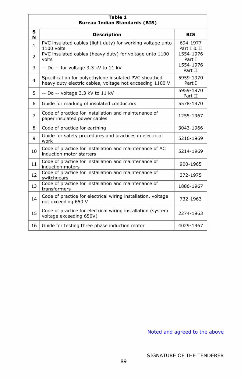
Noted and agreed to the above
SIGNATURE OF THE TENDERER
89
Table 1
Bureau Indian Standards (BIS)
S
N Description BIS
1 PVC insulated cables (light duty) for working voltage unto
1100 volts
694-1977
Part I & II
2 PVC insulated cables (heavy duty) for voltage unto 1100
volts
1554-1976
Part I
3 -- Do -- for voltage 3.3 kV to 11 kV 1554-1976
Part II
4 Specification for polyethylene insulated PVC sheathed heavy duty electric cables, voltage not exceeding 1100 V
5959-1970 Part I
5 -- Do -- voltage 3.3 kV to 11 kV 5959-1970
Part II
6 Guide for marking of insulated conductors 5578-1970
7 Code of practice for installation and maintenance of
paper insulated power cables 1255-1967
8 Code of practice for earthing 3043-1966
9 Guide for safety procedures and practices in electrical work
5216-1969
10 Code of practice for installation and maintenance of AC
induction motor starters 5214-1969
11 Code of practice for installation and maintenance of induction motors
900-1965
12 Code of practice for installation and maintenance of switchgears
372-1975
13 Code of practice for installation and maintenance of
transformers 1886-1967
14 Code of practice for electrical wiring installation, voltage
not exceeding 650 V 732-1963
15 Code of practice for electrical wiring installation (system voltage exceeding 650V)
2274-1963
16 Guide for testing three phase induction motor 4029-1967

Noted and agreed to the above
SIGNATURE OF THE TENDERER
90
Table 2
Pro forma for PCC, DB, Motor Control Centres Test
SN Test Report
1 Circuit (Breaker/Bidder/Supplier Module
Designation/Bus Number)
2 Insulation resistance (Contacts open, breaker Racked in position)
a. Between each Phase & Bus (Mega Ohm)
b. Between each phase and earth (Mega Ohm)
c. DC and AC control & auxiliary circuits (Mega Ohm)
d. Between each phase of CT/PT and between CT & PT
circuit if any (Mega Ohm)
3 CT Checks
a. CT ratio
b. CT secondary resistance
c. CT polarity check
4 Check for contact alignment and wipe
5 Check/test all releases/ relays
6 Check mechanical interlocks
7 Check electrical interlocks
8 Check switchgear/control panel wiring
9 Checking breaker/Bidder/Supplier circuits for
a. Closing- local and remote (wherever applicable)
b. Tripping-local and remote (wherever applicable)
10 Opening time of breaker/ contactor
11 Closing time of breaker/ contactor
Signature and seal of Engineer-
in-charge of TCMPF Ltd.,
Signature and seal of Engineer-in-charge of
Bidder/Supplier
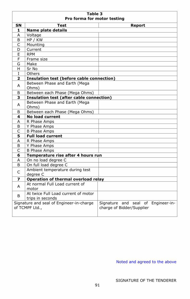
Noted and agreed to the above
SIGNATURE OF THE TENDERER
91
Table 3
Pro forma for motor testing
SN Test Report
1 Name plate details
A Voltage
B HP / KW
C Mounting
D Current
E RPM
F Frame size
G Make
H Sr No
I Others
2 Insulation test (before cable connection)
A Between Phase and Earth (Mega Ohms)
B Between each Phase (Mega Ohms)
3 Insulation test (after cable connection)
A Between Phase and Earth (Mega
Ohms)
B Between each Phase (Mega Ohms)
4 No load current
A R Phase Amps
B Y Phase Amps
C B Phase Amps
5 Full load current
A R Phase Amps
B Y Phase Amps
C B Phase Amps
6 Temperature rise after 4 hours run
A On no load degree C
B On full load degree C
C Ambient temperature during test degree C
7 Operation of thermal overload relay
A At normal Full Load current of motor
B At twice Full Load current of motor
trips in seconds
Signature and seal of Engineer-in-charge
of TCMPF Ltd.,
Signature and seal of Engineer-in-
charge of Bidder/Supplier

Noted and agreed to the above
SIGNATURE OF THE TENDERER
92
Table 4
Pro forma for Testing Cables
Sr
No Test Report
1 Date of Test
2 Drum Number (from which cable is
taken)
3 Cable From -> To
4 Length of run of this cable (meter)
5 Insulation resistance test (In Mega Ohm)
A Voltage of Megger Volts
B Between core-1 to earth
C Between core-2 to earth
D Between core-3 to earth
E Between core-1 to core-2
F Between Core-2 to Core-3
G Between Core-3 to Core-1
6 High Voltage Test (Voltage Duration)
A Between Cores and Earth
B Between Individual Cores
Signature and seal of Engineer-in-charge of TCMPF Ltd.,
Signature and seal of Engineer-in-charge of Bidder/Supplier
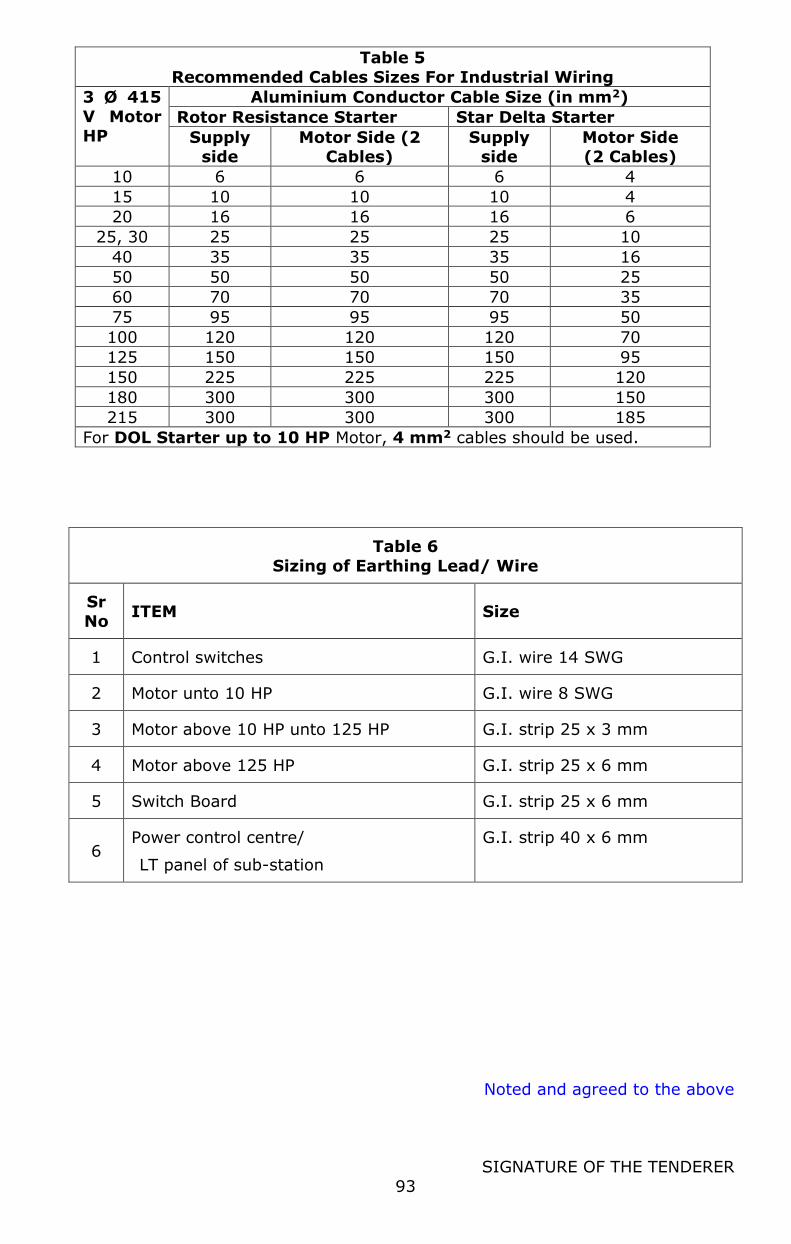
Noted and agreed to the above
SIGNATURE OF THE TENDERER
93
Table 5
Recommended Cables Sizes For Industrial Wiring
3 Ø 415
V Motor HP
Aluminium Conductor Cable Size (in mm2)
Rotor Resistance Starter Star Delta Starter
Supply side
Motor Side (2 Cables)
Supply side
Motor Side (2 Cables)
10 6 6 6 4
15 10 10 10 4
20 16 16 16 6
25, 30 25 25 25 10
40 35 35 35 16
50 50 50 50 25
60 70 70 70 35
75 95 95 95 50
100 120 120 120 70
125 150 150 150 95
150 225 225 225 120
180 300 300 300 150
215 300 300 300 185
For DOL Starter up to 10 HP Motor, 4 mm2 cables should be used.
Table 6
Sizing of Earthing Lead/ Wire
Sr
No ITEM Size
1 Control switches G.I. wire 14 SWG
2 Motor unto 10 HP G.I. wire 8 SWG
3 Motor above 10 HP unto 125 HP G.I. strip 25 x 3 mm
4 Motor above 125 HP G.I. strip 25 x 6 mm
5 Switch Board G.I. strip 25 x 6 mm
6 Power control centre/
LT panel of sub-station
G.I. strip 40 x 6 mm
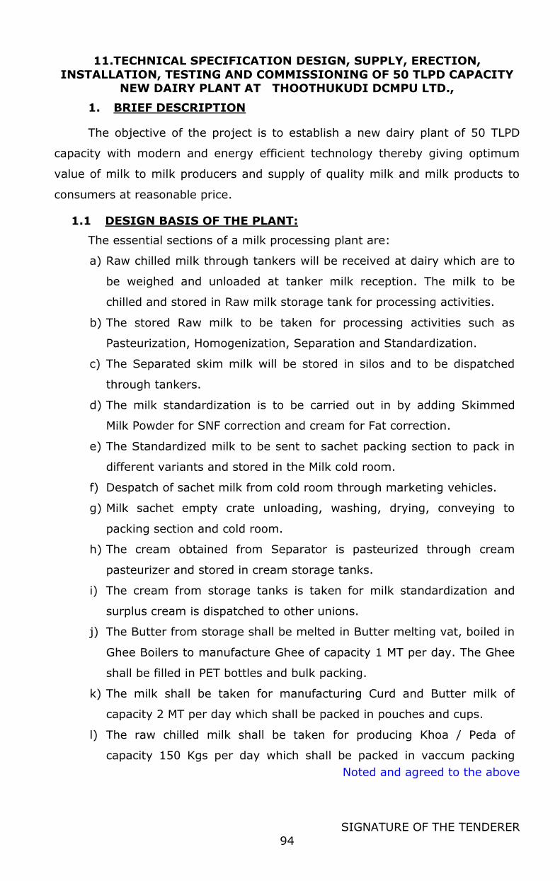
Noted and agreed to the above
SIGNATURE OF THE TENDERER
94
11.TECHNICAL SPECIFICATION DESIGN, SUPPLY, ERECTION,
INSTALLATION, TESTING AND COMMISSIONING OF 50 TLPD CAPACITY NEW DAIRY PLANT AT THOOTHUKUDI DCMPU LTD.,
1. BRIEF DESCRIPTION
The objective of the project is to establish a new dairy plant of 50 TLPD
capacity with modern and energy efficient technology thereby giving optimum
value of milk to milk producers and supply of quality milk and milk products to
consumers at reasonable price.
1.1 DESIGN BASIS OF THE PLANT:
The essential sections of a milk processing plant are:
a) Raw chilled milk through tankers will be received at dairy which are to
be weighed and unloaded at tanker milk reception. The milk to be
chilled and stored in Raw milk storage tank for processing activities.
b) The stored Raw milk to be taken for processing activities such as
Pasteurization, Homogenization, Separation and Standardization.
c) The Separated skim milk will be stored in silos and to be dispatched
through tankers.
d) The milk standardization is to be carried out in by adding Skimmed
Milk Powder for SNF correction and cream for Fat correction.
e) The Standardized milk to be sent to sachet packing section to pack in
different variants and stored in the Milk cold room.
f) Despatch of sachet milk from cold room through marketing vehicles.
g) Milk sachet empty crate unloading, washing, drying, conveying to
packing section and cold room.
h) The cream obtained from Separator is pasteurized through cream
pasteurizer and stored in cream storage tanks.
i) The cream from storage tanks is taken for milk standardization and
surplus cream is dispatched to other unions.
j) The Butter from storage shall be melted in Butter melting vat, boiled in
Ghee Boilers to manufacture Ghee of capacity 1 MT per day. The Ghee
shall be filled in PET bottles and bulk packing.
k) The milk shall be taken for manufacturing Curd and Butter milk of
capacity 2 MT per day which shall be packed in pouches and cups.
l) The raw chilled milk shall be taken for producing Khoa / Peda of
capacity 150 Kgs per day which shall be packed in vaccum packing
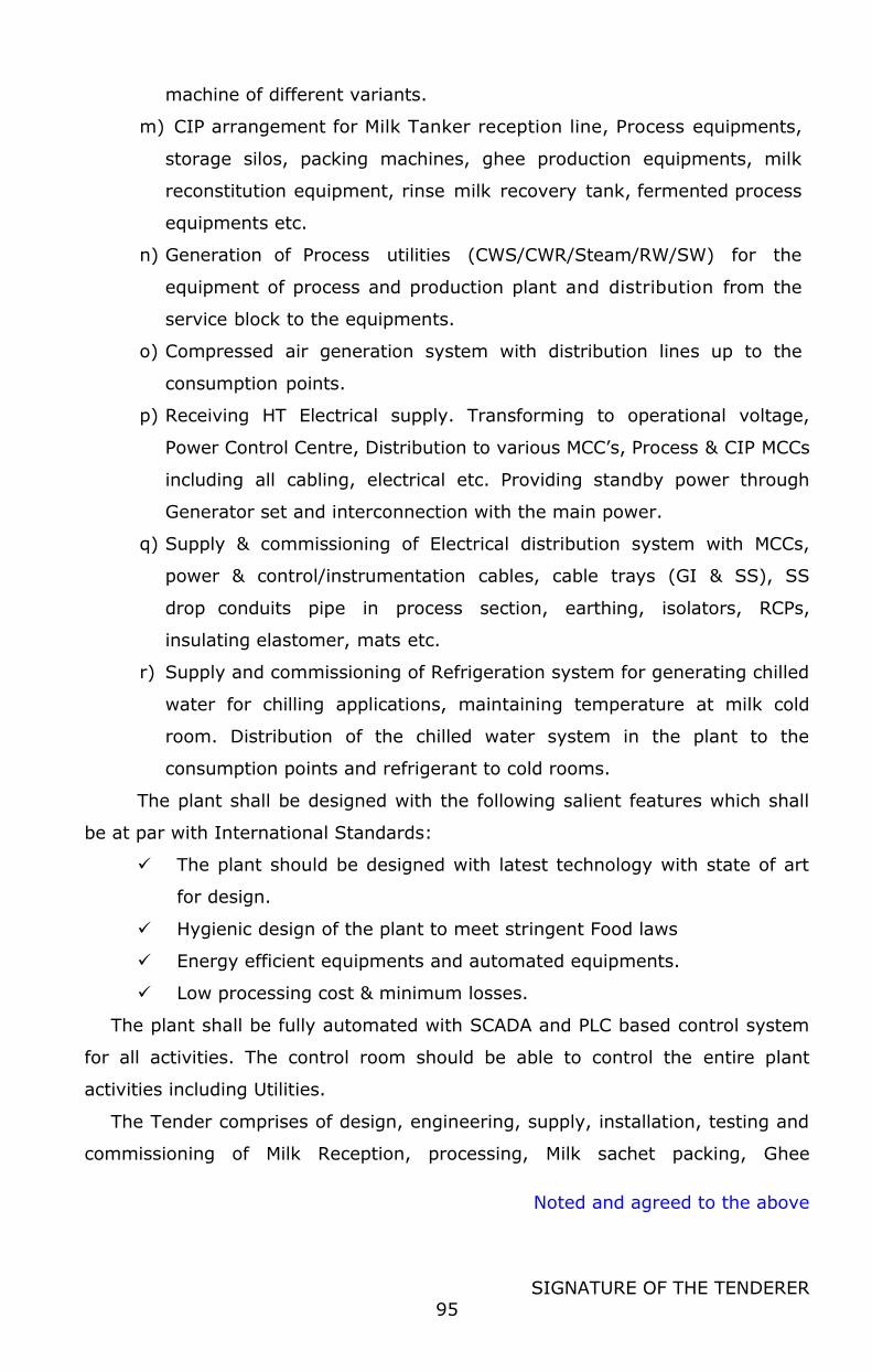
Noted and agreed to the above
SIGNATURE OF THE TENDERER
95
machine of different variants.
m) CIP arrangement for Milk Tanker reception line, Process equipments,
storage silos, packing machines, ghee production equipments, milk
reconstitution equipment, rinse milk recovery tank, fermented process
equipments etc.
n) Generation of Process utilities (CWS/CWR/Steam/RW/SW) for the
equipment of process and production plant and distribution from the
service block to the equipments.
o) Compressed air generation system with distribution lines up to the
consumption points.
p) Receiving HT Electrical supply. Transforming to operational voltage,
Power Control Centre, Distribution to various MCC’s, Process & CIP MCCs
including all cabling, electrical etc. Providing standby power through
Generator set and interconnection with the main power.
q) Supply & commissioning of Electrical distribution system with MCCs,
power & control/instrumentation cables, cable trays (GI & SS), SS
drop conduits pipe in process section, earthing, isolators, RCPs,
insulating elastomer, mats etc.
r) Supply and commissioning of Refrigeration system for generating chilled
water for chilling applications, maintaining temperature at milk cold
room. Distribution of the chilled water system in the plant to the
consumption points and refrigerant to cold rooms.
The plant shall be designed with the following salient features which shall
be at par with International Standards:
The plant should be designed with latest technology with state of art
for design.
Hygienic design of the plant to meet stringent Food laws
Energy efficient equipments and automated equipments.
Low processing cost & minimum losses.
The plant shall be fully automated with SCADA and PLC based control system
for all activities. The control room should be able to control the entire plant
activities including Utilities.
The Tender comprises of design, engineering, supply, installation, testing and
commissioning of Milk Reception, processing, Milk sachet packing, Ghee

Noted and agreed to the above
SIGNATURE OF THE TENDERER
96
production, fermented production area, khoa production, Utilities, services and
waste water treatment plant. The design and layout of the facilities, selection of
equipment and services, methodology of plant execution, testing and
commissioning shall be carefully planned and executed with the knowledge of
normal operational & processing routines of Milk Processing plant.
The general technical specification of the major components
and the ancillary items described in the technical section, its
capacities and quantities proposed by the Purchaser are furnished
in the ‘Basis of Design’ and ‘Bill of Quantities (BOQ)’. These are only
for the guidance of the bidders to quote their prices on comparable
basis. However, it shall be construed and understood that bidder is
familiar / acquainted about the nature and the quantum of work
involved and has submitted his offer without deviating the basic
configuration of the plant.
The capacity and quantity of the machinery, equipments, pipes,
fittings, valves, cables, cable trays, earthing, instruments, structural and
supports etc. are to be offered based on the actual requirement at site.
The bidder shall have to work out the details based on the system
offered
1.2 REQUIREMENTS OF THE PROCESS PLANT:
Plant basis and Utility basis:
Plant operations 24 hours a day
Electricity Charges Rs. 8.5/KW unit
Steam Charges Rs. 4 / Kg of Steam
Source of Water River and Well
Building New building.
Raw Milk Received through Tankers.
1.3 WORKING CONDITIONS:
Site work of every nature has to be planned and executed with the knowledge
of site conditions. The design and layout of the new facilities, selection of
equipment and services, methodology of project execution, testing and
commissioning should all be carefully planned with this point in mind.

Noted and agreed to the above
SIGNATURE OF THE TENDERER
97
1.4 PROJECT TIME SCALE:
The Plant should be completed in time as specified in the IFB of this tender.
Product trials are to be commenced at the end of this period.
1.5 SITE CONDITIONS:
Altitude above Mean Sea Level (Meters): Approx. 4
Average Ambient Temperature (Deg C) : 35 - 40 max
Minimum Ambient Temperature (Deg C) : Around 25
Relative Humidity (%) : 74
1.6 SITE ADDRESS:
The plant shall be installed in Thoothukudi.
Noted and agreed to the above
SIGNATURE OF THE TENDERER
98
2. INSTRUCTIONS TO BIDDER
2.1 This Sub - Section of the tender defines the way that bidder is
required to structure the presentation of the technical section
of their bid.
2.2 All technical data required by the tender is to be provided in
the format given in this Sub - Section. If no format is given for
any specific item the bidder may submit bid in their format
2.3 Any bidder not following the required bid document structure
of presenting technical data that is not in the required format is
liable to be deemed non- responsive
2.4 BID STRUCTURE OF TECHNICAL SECTION
2.4.1 The technical section of the bid is to be structured in the same
order as Tender Document. Each statement is to be numbered with
the same Sub-section and paragraph number as in the Tender
Document. Every page of the technical section of the bid is to be
numbered. Section number is also indicated in every page. The
general structure, therefore, is to be as follows:
Sub – Section
Subject
1 Introduction
2 Instruction to the Bidders
3 Design Basis
4 Responsibilities
5 Project Management
6 Scope of Supply and Technical Specifications ( Tender package)
7 List of Preferred Makes of Major Bought Out Items
8 Battery Limits
9 Deviations from Technical Requirements
10 Optional Items
11 Drawings, data and Documentation Submission
Noted and agreed to the above
SIGNATURE OF THE TENDERER
99
2.5 The bidder is to cover each requirement of the Tender
Document by statements, technical data and descriptive material and, in particular to detail the following section
SUB - SECTION 1 INTRODUCTION
Brief Introduction of the tender is given including the site working
conditions.
SUB - SECTION 2 INSTRUCTIONS TO THE BIDDER
Instructions are provided but not limited to the bidder to provide the
technical bid in line with the tender sequence and details.
SUB - SECTION 3 DESIGN BASIS
Preamble
The bidder is to describe his technical proposal in details, stating the
processes and systems, which he has applied in designing the plant. Also
to highlight any special technical innovations that the bidder proposes to
include in the plant that will improve the performance, reduce operating
cost or improve product quality. The “Preamble” should commence at the
start of the process and work logically through the process. Any such
highlights should be cross-referenced with the Bid sub-Section and
paragraph number to which they apply.
The bidder is required to follow the Basic of Design in the tender
and indicate clearly where additional processes or alternative
processes of equipment are considered to be necessary or
desirable to achieve optimum plant operation efficiency, optimum
product quality within the standards specified, and optimum plant
operation convenience.
Under the utilities section, the peak and daily loads of each utility has
been quantified.
Noted and agreed to the above
SIGNATURE OF THE TENDERER
100
SUB – SECTION 4 RESPONSIBILITIES
Responsibilities of the Bidder
The bidder is required to specifically state his acceptance or non-
acceptance of each clause in this sub-section. Non acceptance shall be
deemed a deviation from the tender and should be mentioned in
deviations, Sub - Section 8.
Responsibilities of Client
The bidder is required to state here any additional responsibilities that he
consider are to be borne by Client besides those described in the tender.
SUB – SECTION 5 PROJECT MANAGEMENT
Time Schedule
The bidder is to state in this subsection the proposed program of
implementation from receipt of order to commencement of product trials,
to be provided as per Sub - Section 10.
Management Team
The bidder is to provide detail of the management team in terms of
designation, accordance with this Sub - Section of the tender. Also to
quantify the support that will be given by foreign collaborators, with
designation and man months of attendance in India and at site.
This bidder is to ensure that the following Sub - Sections are fully detailed
and quantify the duration and manpower supplied to each.
Commissioning
Product trials
Training
SUB – SECTION 6 SCOPE OF SUPPLY & TECHNICAL SPECIFICATIONS
(TENDER PACKAGE)
The bidder is required to follow the sequence of the tender Document and
to make a statement on each paragraph. Do not leave any item without a
clarify statement.
Noted and agreed to the above
SIGNATURE OF THE TENDERER
101
SUB – SECTION 7 LIST OF PREFERRED MAKES OF BOUGHT OUT
ITMES
Bidder to strictly follow the list of preferred makes of Bought out items
and shall select a make for supply out of the list only. Make selected by
the bidder other than the said list shall be considered as Deviation from
the tender and should be mentioned in deviations. All given makes are
preferred however the bidder to get the approval from the
consultant/client before placement of order to the sub-vendor during
execution.
SUB – SECTION 8 BATTERY LIMITS
Battery limits for the plant are mentioned in this sub Section.
SUB – SECTION 9 DEVIATIONS
All technical deviations are to be stated. This is mandatory, and failures to
comply with make the bid liable to be deemed non-responsive
SUB – SECTION 10 OPTIONAL ITEMS
Items that the bidder includes in this Sub - Section that are considered by
evaluation team to be essential to the satisfactory operation of the plant,
shall be included in the commercial evaluation of the bid.
SUB – SECTION 11 DRAWINGS, DATA & DOCUMENTS SUBMISSION
The list of drawings and technical documents required for technical
evaluation is included in this Sub - Section. These include a number of
data sheet formats to be completed by the bidder. The completion of this
format is mandatory, and failure to comply will make the bid liable to be
deemed non-responsive.
Noted and agreed to the above
SIGNATURE OF THE TENDERER
102
3. DESIGN BASIS:
3.1
3.1.1 INTRODUCTION :
TCMPF Ltd is setting up a DAIRY PROCESSING PLANT OF CAPACITY 50
TLPD AT THOOTHUKUDI .
3.1.2 SCOPE
The Tender comprises of Design, Supply, Erection, Installation,
Commissioning and Testing of Tanker Milk Reception, processing, Milk
sachet packing, Ghee production, fermented production area, khoa
production, Utilities, services and waste water treatment plant Milk
Reception, processing, Milk sachet packing, reconstitution of milk with
Skimmed milk powder and cream / butter, Ghee manufacturing and
packing, curd and buttermilk production and packing, khoa production and
packing, storage of sachet milk, utilities such as Refrigeration, Boiler,
Electrical, Hydro flow, ETP, Compressed air Etc for operation of the plant.
The bidder has to design the Dairy plant consisting of process system,
packing, storage, mechanical structures, utilities, automation required for
the process. The available space should be effectively utilized with
minimum ground works. The bidder should design the plant with latest
processing technology, design for the milk process, product
manufacturing, packing and storage activities. The design should be
energy efficient with minimum handling losses. The plant shall be fully
automatic with SCADA controls in the control room.
The bidder has to prepare necessary drawings for obtaining Factory
License, Consent to Establish/ Operate from TNPCB, Explosives License etc
as per state and central statutory requirements.
3.1.3 The scope of work includes:
The basis for the proposed dairy and the various sections shall be as
given below.
The proposed dairy shall be capable of receiving & storage raw chilled
milk, processing, standardizing and storage of milk, transfer to the
Noted and agreed to the above
SIGNATURE OF THE TENDERER
103
Pouch milk packing section, Cream handling, storage. The required
amount of milk shall be standardized for transfer to the Milk packing
section and balance milk shall be utilized for by product preparation. The
cream generated shall be pasteurized and stored. The pasteurized skim
milk shall be transferred to other dairies through road milk tankers for
drying. The processed cream is utilized for standardization and dispatched
to other Dairies. Ghee manufacturing consists of butter melting, ghee
boiling, clarification, storage and packing. All utilities and services shall
also be designed accordingly.
The plant shall be automatic type with centralized control of reception,
processing & CIP. However, other product sections and all utility sections
are controlled through localized control system with PLC/hard wired as
per technical specifications.
The various sections shall be as follows
A. Milk Processing and Packing
1. Tanker Reception.
2. Reconstitution section. 3. Milk processing, Past milk & Past. skim milk Storage.
4. Sachet milk packing. 5. Cream Pasteurization &storage
6. Rinse Milk Recovery Section 7. Ghee making and packing section.
8. Curd and Butter milk manufacturing and packing 9. Khoa / Peda production and packing
10. Centralized CIP system consisting of Tanker CIP and Process CIP 11. Instrumentation & Automation
B. Utilities:
1. Refrigeration plant. 2. Electricals
3. Steam Generation and distribution
4. Compressed air section. 5. Water treatment plant
6. ETP
The plant shall have the following salient features as in table below:
Reception, Processing & Packing of milk, CIP operations through
Centralized control system. Rinse milk, Reconstitution, Cream processing, storage, and skim milk
through centralized control system. Localized control system as per table below to be considered
Hygienic design of the plant to meet stringent Food laws Energy efficient equipment
Low processing cost & minimum losses
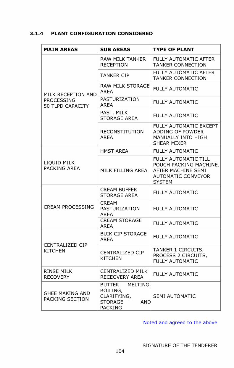
Noted and agreed to the above
SIGNATURE OF THE TENDERER
104
3.1.4 PLANT CONFIGURATION CONSIDERED
MAIN AREAS SUB AREAS TYPE OF PLANT
MILK RECEPTION AND
PROCESSING 50 TLPD CAPACITY
RAW MILK TANKER RECEPTION
FULLY AUTOMATIC AFTER TANKER CONNECTION
TANKER CIP FULLY AUTOMATIC AFTER
TANKER CONNECTION
RAW MILK STORAGE AREA
FULLY AUTOMATIC
PASTURIZATION
AREA FULLY AUTOMATIC
PAST. MILK STORAGE AREA
FULLY AUTOMATIC
RECONSTITUTION AREA
FULLY AUTOMATIC EXCEPT
ADDING OF POWDER MANUALLY INTO HIGH
SHEAR MIXER
LIQUID MILK PACKING AREA
HMST AREA FULLY AUTOMATIC
MILK FILLING AREA
FULLY AUTOMATIC TILL
POUCH PACKING MACHINE. AFTER MACHINE SEMI
AUTOMATIC CONVEYOR SYSTEM
CREAM PROCESSING
CREAM BUFFER
STORAGE AREA FULLY AUTOMATIC
CREAM PASTURIZATION
AREA
FULLY AUTOMATIC
CREAM STORAGE
AREA FULLY AUTOMATIC
CENTRALIZED CIP KITCHEN
BUIK CIP STORAGE AREA
FULLY AUTOMATIC
CENTRALIZED CIP KITCHEN
TANKER 1 CIRCUITS, PROCESS 2 CIRCUITS,
FULLY AUTOMATIC
RINSE MILK
RECOVERY
CENTRALIZED MILK
RECEOVERY AREA FULLY AUTOMATIC
GHEE MAKING AND
PACKING SECTION
BUTTER MELTING,
BOILING, CLARIFYING,
STORAGE AND PACKING
SEMI AUTOMATIC
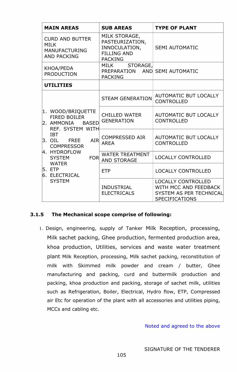
Noted and agreed to the above
SIGNATURE OF THE TENDERER
105
MAIN AREAS SUB AREAS TYPE OF PLANT
CURD AND BUTTER
MILK MANUFACTURING
AND PACKING
MILK STORAGE,
PASTEURIZATION, INNOCULATION,
FILLING AND PACKING
SEMI AUTOMATIC
KHOA/PEDA
PRODUCTION
MILK STORAGE, PREPARATION AND
PACKING
SEMI AUTOMATIC
UTILITIES
1. WOOD/BRIQUETTE FIRED BOILER
2. AMMONIA BASED
REF. SYSTEM WITH IBT
3. OIL FREE AIR COMPRESSOR
4. HYDROFLOW SYSTEM FOR
WATER 5. ETP
6. ELECTRICAL SYSTEM
STEAM GENERATION AUTOMATIC BUT LOCALLY CONTROLLED
CHILLED WATER GENERATION
AUTOMATIC BUT LOCALLY CONTROLLED
COMPRESSED AIR AREA
AUTOMATIC BUT LOCALLY CONTROLLED
WATER TREATMENT
AND STORAGE LOCALLY CONTROLLED
ETP LOCALLY CONTROLLED
INDUSTRIAL ELECTRICALS
LOCALLY CONTROLLED
WITH MCC AND FEEDBACK SYSTEM AS PER TECHNICAL
SPECIFICATIONS
3.1.5 The Mechanical scope comprise of following:
1. Design, engineering, supply of Tanker Milk Reception, processing,
Milk sachet packing, Ghee production, fermented production area,
khoa production, Utilities, services and waste water treatment
plant Milk Reception, processing, Milk sachet packing, reconstitution of
milk with Skimmed milk powder and cream / butter, Ghee
manufacturing and packing, curd and buttermilk production and
packing, khoa production and packing, storage of sachet milk, utilities
such as Refrigeration, Boiler, Electrical, Hydro flow, ETP, Compressed
air Etc for operation of the plant with all accessories and utilities piping,
MCCs and cabling etc.
Noted and agreed to the above
SIGNATURE OF THE TENDERER
106
2. Labour charges and consumables for installation, testing and
commissioning of Tanker Milk Reception, processing, Milk sachet
packing, Ghee production, fermented production area, khoa
production, Utilities, services and waste water treatment plant
Milk Reception, processing, Milk sachet packing, reconstitution of milk
with Skimmed milk powder and cream, Ghee manufacturing and
packing, curd and buttermilk production and packing, khoa production
and packing, storage of sachet milk, utilities such as Refrigeration,
Boiler, Electrical, Hydro flow, ETP, Compressed air Etc for operation of
the plant with all accessories and utilities piping, MCCs and cabling
etc.
All the equipment for the plant/systems shall be designed,
engineered, supplied and installed in accordance with the prevailing and
applicable standards in general all major equipment and processes should be in
line with fssai requirements.
3.2 BASIS OF DESIGN : GENERAL DESCRIPTION
The plant has been designed with the following basis:
3.2.1 MILK RECEPTION SECTION:
The total Raw milk received shall be as per the following proportion
respectively
Raw milk data received through Tanker:
Milk fat content (Avg.) : 4.0%
Milk solids non fat content (Avg.) : 8.0%
Temperature –Tanker milk : < 10 deg. C
Smell and taste: Good and pass Organoleptic tests
Tanker reception : 50,000 liters per day
Tanker capacity : 9KL, 15KL, 25KL & 30 KL
Tanker reception time: 60% in the Morning & 40% in the evening
Total line for tanker reception: Capacity &qty as per BOQ
3.2.2 LIQUID MILK PROCESSING
The Dairy Plant shall receive raw chilled milk from tanker reception. The
tankers (either filled or empty) shall be weighed with one weigh bridge
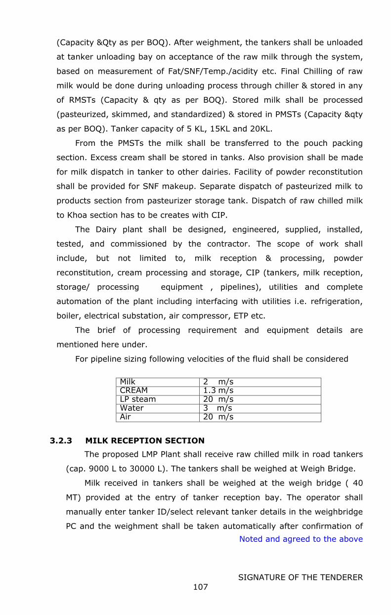
Noted and agreed to the above
SIGNATURE OF THE TENDERER
107
(Capacity &Qty as per BOQ). After weighment, the tankers shall be unloaded
at tanker unloading bay on acceptance of the raw milk through the system,
based on measurement of Fat/SNF/Temp./acidity etc. Final Chilling of raw
milk would be done during unloading process through chiller & stored in any
of RMSTs (Capacity & qty as per BOQ). Stored milk shall be processed
(pasteurized, skimmed, and standardized) & stored in PMSTs (Capacity &qty
as per BOQ). Tanker capacity of 5 KL, 15KL and 20KL.
From the PMSTs the milk shall be transferred to the pouch packing
section. Excess cream shall be stored in tanks. Also provision shall be made
for milk dispatch in tanker to other dairies. Facility of powder reconstitution
shall be provided for SNF makeup. Separate dispatch of pasteurized milk to
products section from pasteurizer storage tank. Dispatch of raw chilled milk
to Khoa section has to be creates with CIP.
The Dairy plant shall be designed, engineered, supplied, installed,
tested, and commissioned by the contractor. The scope of work shall
include, but not limited to, milk reception & processing, powder
reconstitution, cream processing and storage, CIP (tankers, milk reception,
storage/ processing equipment , pipelines), utilities and complete
automation of the plant including interfacing with utilities i.e. refrigeration,
boiler, electrical substation, air compressor, ETP etc.
The brief of processing requirement and equipment details are
mentioned here under.
For pipeline sizing following velocities of the fluid shall be considered
Milk 2 m/s CREAM 1.3 m/s LP steam 20 m/s Water 3 m/s Air 20 m/s
3.2.3 MILK RECEPTION SECTION
The proposed LMP Plant shall receive raw chilled milk in road tankers
(cap. 9000 L to 30000 L). The tankers shall be weighed at Weigh Bridge.
Milk received in tankers shall be weighed at the weigh bridge ( 40
MT) provided at the entry of tanker reception bay. The operator shall
manually enter tanker ID/select relevant tanker details in the weighbridge
PC and the weighment shall be taken automatically after confirmation of
Noted and agreed to the above
SIGNATURE OF THE TENDERER
108
position of the tanker by sensor provided. After completion of milk
unloading & CIP, the empty tankers would also be weighed at the
weighbridge. The data would be transmitted through network to
automation/SAP system for record /MIS/ printing of truck slip & payment
purpose. Un manned operation of the weighbridge will be facilitated.
During tanker unloading operation, milk would also be measured
through mass flow meters in the unloading line for inventory/material
balancing/functional requirement and shall be analysed for Density, Temp.
The raw chilled milk received and unloaded at 6-10°C shall be chilled
to 4 °C through plate type chillers and stored in 2x 20 KL Raw milk
storage silos.
Milk samples from the tankers shall be taken manually and fed to
online testing equipment for measurement of fat, SNF, acidity and
temperature etc. through rapid test instruments. Based on the acceptable
parameters, actual results and the tanker consignment shall be accepted
or rejected automatically by the system. The test results shall be
transferred through the automation network to the automation system for
acceptance of raw milk/inventory purpose. The communication from milk
analyzer and acidometer to the central automation system shall be
established by the bidder. Milk samples collected from the plant shall be
analyzed separately in another set of milk analyzer/acidometer
(connected with automation communication network) of main laboratory
& weighbridge reading would be considered for payment/mass balancing
purpose.
No substandard milk shall be accepted at the Dairy. The automation
system will provide indication for rejection of milk is having fat, SNF,
temperature & acidity/pH etc. not conforming to acceptable range (to be
set by the Dairy management). However, the Dairy manager will have
authority to override the logic and accept any tanker as per his discretion.
Tanker shall be connected manually to the unloading line. Each
tanker shall be emptied to the selected raw milk silo. The milk reception
capacity of the line shall be designed for 10,000 LPH. The average fat &
SNF percentage in the raw milk shall be 4 % and 8.0 % respectively. After
milk unloading operation, tankers would be moved forward for CIP.
Noted and agreed to the above
SIGNATURE OF THE TENDERER
109
The tankers reception bay shall receive one tanker at a time. The
milk shall be transferred to any of the raw milk silos (2 x 20 KL) through
20 KLPH PHE chiller & valve battery system.
The tanker unloading system shall have provision to de-aerate any
entrapped air in the milk and to filter the milk by Inline pipe in pipe type
filter. A pipe in pipe type simplex filter shall also be provided at the outlet
of the tanker unloading pumps. All measures shall be kept to ensure
unloading of the tanker and hose up to the pneumatic on/off valve
smoothly and completely. Immediately after unloading operation,
pressurized water flushing facility of milk tankers with RO water (Spray
ball type) system shall be provided to recover milk solid particles from the
vessel & transfer the same to raw milk silos. For the flushing purpose,
predetermined quantity (minimum) of water shall be used to prevent
dilution of raw milk in storage silos. The tanker reception line shall have
one hose and one flushing unit with spray ball arrangement. CIP of the
tanker reception line with hose would be carried out through a pneumatic
valve based & suitable sensor for hose connection.
Automatic RO water purging/pushing of reception milk lines as per
pre-set interval & rinse recovery system shall be provided. Water purging
of all other milk transfer lines shall also be provided. The water purging
system shall be flow meter / timer based. Rinse water flushing of
pipelines/ tanks/equipment & recovery of the same in rinse milk collection
tank shall also be provided before CIP operations. The rinse milk recovery
system shall be flow meter/ timer & turbidity based.
In the event of automation failure, suitable simple and quick manual
system to be provided to clear the stored milk from the raw milk silo
through the raw milk tanker dispatch line. HMI operation for tanker
unloading and loading from tanker reception dock may be provided.
Valve manifold shall be designed to ensure the flexibility in operation
& secured (fool proof) against mixing of two different flows/CIP fluids in
case of malfunctioning in system/equipment or power failure. Pasteurized
milk transfer facility from PMSTs to RMSTs for re-pasteurization shall be
provided. The lateral headers of the valve battery shall have independent
Noted and agreed to the above
SIGNATURE OF THE TENDERER
110
water flushing & CIP facility without affecting any other operation except
that silo.
The RMST valve battery shall consist of self-cleaning type mix proof
valves with 3 solenoids each. The valve battery shall have a SS-304 tray
below the valves.
Total no. of headers at the RMST silo valve battery shall be as
follows:
1. Loading Headers:
01 Nos for milk reception lines.
01 No transfer of milk from PMST to RMST header /RMST inter silo transfer /Reconstituted milk dosing
2. Unloading Headers:
01 Nos for milk unloading to 5 KLPH MPLs
01 No for Inter silo transfer
3. 1 No CIP return header Pneumatically operated drain valves would be provided at all lowest
points/suitable locations in the piping system to ensure complete draining
of entrapped water/very diluted mixed phase from the system.
All equipment, valves, pipes, fittings, instruments shall be sanitary
type. Welded connections should be provided wherever practical, to
minimize the use of fittings. Hygienic Sampling valves (easy to
operate/self-clean type) shall be provided at required points. Necessary
controls and instrument including flow meters, level transmitters/sensors,
conductivity transmitters, pressure/ temperature sensors/ transmitters,
flow switches, turbidity meter, proximities etc. shall be provided as per
functional requirement.
All reception operations shall be normally performed, controlled &
monitored from reception field HMIs/control room. However, there should
be a facility to carry out these operations from the central control room
also.
SS platform fabricated from chequered plate, box section and
staircase with skirting & pipe railing shall be provided for all tanker milk
reception & tanker CIP. Necessary supports for the tanker bays platform
shall be taken from the RCC columns/ beams/ slab in tanker bays. SS
Noted and agreed to the above
SIGNATURE OF THE TENDERER
111
collapsible type platform extension with SS railing shall be provided in
each bay to approach the tanker man way(s).
3.2.4 MILK RECONSTITUTION / RECOMBINATION SECTION
Milk reconstitution with proportionate blending system before
pasteurization shall require making up SNF level of milk in PMST /
balancing tank of pasteurizer.
It would be used for reconstituting milk from Rinse / RO water and
whole milk powder or skim milk powder continuously at a temperature of
around 30-45 deg C using high shear turbo mixer. Water addition shall be
based on level transmitter as well as magnetic flow meter based. PHE of
10 KLPH capacities for heating of water/reconstituted milk up to 35-45
degree for effective reconstitution of powder shall be provided. Also,
chillier shall be provided to chill reconstitute milk up to 6-7 deg before
transferring to RMST/MPL. The powder shall be dumped manually to
hopper of high shear mixer. Capacity of high shear turbo mixer for
reconstitution shall be 1000Kg per hour with 30% T.S. Two RCM
preparations cum storage tanks of 2 X 5 KL capacity shall be used for
preparation of RCM through a 10 KLPH circulation pump (with VFD), 10
KLPH PHE heaters and chiller. Suitable heating mechanism should be
provided to warm water or milk up to 55°C.
Chilled reconstituted milk shall be stored in reconstitute milk storage
tank. From this reconstituted milk storage tank through 10 KLPH capacity
pump and mass flow meter reconstituted milk shall be dosed in the
PMSTs/ balance tank of pasteurizer.
The RCM valve battery shall consist of self-cleaning type mix proof
valves with 3 solenoids each. The system shall also utilize rinse milk for
RCM preparation. The valve battery shall have a SS-304 tray below the
valves. The lateral headers of the valve battery shall have independent
water flushing & CIP facility without affecting any other operation except
that tank. Butter pre melting tank with proper dosing system should be
provided for adjusting fat in case of non-availability of cream.
Total no. of headers at the recon preparation tank valve battery shall
be as follows:
Noted and agreed to the above
SIGNATURE OF THE TENDERER
112
1. Loading Headers:
01 No for blending line/Inter transfer/rinse milk
2. Unloading Headers:
01 Nos for transfer to MPLs with suitable capacity pumps, one of
this shall be used for transfer in RMST
3. 1 No CIP return header
The milk reconstitution operations shall be normally performed,
controlled & monitored from PLC control room. However, there should be
a facility to carry out these operations from the central control room also.
One no HMI shall be provided for local operation/control of the entire milk
reconstitution activity
3.2.5 MILK PROCESSING SECTION
The raw milk at 4°C (max.) shall be drawn from any of the two raw
milk silos to balance tank of the milk pasteurization plant for
pasteurization, cream separation, and standardization. Homogenized milk
cream index should not more than 10.
The capacity of the Milk Processing Line (MPL) along with Tri-purpose
Centrifuge unit shall be 5000 LPH.
The milk separator shall be solid bowl type. Separator and
homogenizer bypass arrangement & duplex pipe in pipe type filter (with
auto changeover facility from HMI) is included in the scope. CIP of both
pipe in pipe type duplex filters shall be done simultaneously in line with
plant CIP with use of special type valve arrangement. Final standardizing
with cream only would be carried out in PMSTs if required. The
pasteurized milk at 4 °C shall be stored in any processed milk outdoor
silos (2x20KL)
Milk pasteurizer shall have a regeneration efficiency of not less than
93% and would have a re-generative cream chilling section designed for
cream outlet temperature at 8°C through a separate plate pack. Sanitary
design control valve shall be provided to control the milk flow for cream
chiller. A separate hot water generator (PHE/THE) and Milk heating unit
(PHE) type with both side SNAP/CLIP ON EPDM/Viton gaskets) having
Noted and agreed to the above
SIGNATURE OF THE TENDERER
113
accurate control of hot water temperature with suitable automatic
pumping type condensate trap (APT) for complete recovery of condensate
ensuring minimum steam consumption to maintain steady temperature as
per process requirement to be provided.
Magnetic type flow meter is to be provided in the milk processing
lines, other transfer lines / other places inside the plant for inventory/
material balancing/ functional requirement. Magnetic meter shall be
provided for RMST to MPL transfer line. The milk transfer pumps from
RMSTs to balance tank of the MPLs shall be VFD operated.
Piping & automation system shall be provided as per the
requirement. The standardized milk shall be transferred to packing
sections from PMSTs only. For inter-silo transfer facility necessary mix
proof self-cleaning type valves (one row) shall provided /installed in PMST
valve battery for processed milk transfer to any of the PMSTs without
affecting any other operation except the silo to which it is being
transferred. All the transfer lines shall have water push / flushing for TS
recovery & CIP facility. Facility to carryout CIP of the lateral header
independently shall be provided.
Arrangement for pushing milk lying in dispatch line into tanker
through water push & rinse milk recovery is included in the scope.
However, system shall be provided for complete emptying of PMST header
up to valve battery to minimize the TS loss. Weighment (tare & gross) of
the milk tankers would be carried out in the weigh bridge to measure the
outgoing milk quantity accurately for billing purpose & transfer the data
through network to automation system/ MIS/ SAP. The milk
analyzer/acidometer would measure fat/ SNF/ Temp/ Acidity/ pH etc. of
milk & the data would also be transferred through the network to
automation system for recording, printing of truck slip & billing purpose.
RO water purging/pushing of all milk transfer lines & solid recovery
system shall be provided. The water purging system shall be volumetric
flow meter/timer based. Rinse water flushing of
pipelines/tanks/equipment & recovery of the same in rinse milk collection
tank shall also be provided before CIP operations. The rinse milk recovery
system shall be volumetric flow meter/timer/turbidity/CT based.
Noted and agreed to the above
SIGNATURE OF THE TENDERER
114
There shall be facility for blending of chilled rinse milk in the
reconstitution tank /recon milk preparation tank shall be provided with
VFD operated pump and flow meters. All the dosing lines shall have RO
water push/flushing arrangement for TS recovery & CIP facility.
Facility for inter silo transfer of milk, Past. Milk transfer facility from
PMSTs to RMSTs for re-pasteurization post mil transfers to product section
shall be provided by a separate common header. A common VFD operated
pump may be used for the purpose. In the event of automation failure,
suitable simple and quick manual system to be provided to clear the
stored milk from the storage silos/tanks through tankers. Separate
dispatch line for SSM or pasteurized whole milk to road milk tankers
should be provided.
Pneumatically operated drain valves would be provided at all lowest
points/suitable locations in the piping system to ensure complete draining
of entrapped water/very diluted mixed phase from the system.
All equipment, valves, pipes, fittings, instruments shall be sanitary
type. Welded connections should be provided wherever practical, to
minimize the use of fittings. Sampling valves (3A Sanitary, FDA approved,
easily sterile and clean type) to be provided at required points. Necessary
controls and instrument for safety of the product and system including
flow meters, level transmitters/ sensors, conductivity transmitters,
pressure/ temperature sensors/ transmitters, flow switches, proximities
etc. shall be provided as per functional requirement.
Valve manifolds to be designed to ensure the flexibility in operation
& secured (fool proof) against mixing of two different flows/CIP fluids in
case of malfunctioning in system/equipment or power failure. The lateral
headers of the valve battery shall have independent water flushing & CIP
facility without affecting other operations except that silo.
PMST Valve Battery shall have following number of loading &
unloading headers:
1. Loading Headers:
1 Nos. for filling milk from MPL. 01 no cream dosing from CRT /for reconstituted milk Dosing.
1 No. for Inter silo
Noted and agreed to the above
SIGNATURE OF THE TENDERER
115
2. Unloading Headers:
1 No. for Pouch packing
1 No for skim milk / condensed milk transfer to tankers.
1 No. for Intersilo/ Transfer to RMST for re pasteurization
3. 1 No CIP return header
Future Provision shall also be made in the layout, valve battery,
piping, CIP facility & automation system for addition of Valve battery at
the PMSTs shall be provided with distance piece to add 1X5 KLPH MPL ,
1x20 KL pasteurized milk storage silos. For future expansion distance
piece is to be kept in the valve battery.
Unloading header shall be designed for two simultaneous dispatches
from one PMST
The PMST valve battery shall consist of self-cleaning type mix proof
valves with 3 solenoids each. The valve battery shall have a SS-304 tray
below the valves.
All milk processing & inter sectional transfer/dispatch operations shall
be normally performed, controlled & monitored from reception ¢ral
control room.
3.2.6 CREAM PROCESSING SECTION
The cream shall be collected at 8°C in each cream buffer tank (1
x 500 L) from the cream separator through cream chillers and shall be
pasteurized in cream pasteurizer of 1 KLPH capacity. The raw cream feed
pump (1 KLPH) to cream pasteurization unit balance tank shall be VFD
operated.
The cream buffer tank valve battery shall consist of self-cleaning type
mix proof valves with 3 solenoids each. The valve battery shall also
receive cream from cream storage/ripening tank for re-processing. The
valve battery shall have a SS-304 tray below the valves. The lateral
headers of the valve battery shall have independent water flushing & CIP
facility without affecting any other operation except that tank. For future
expansion of one cream processing line, distance piece is to be kept in the
valve battery.
Noted and agreed to the above
SIGNATURE OF THE TENDERER
116
Cream buffer tank valve battery shall have following number of
loading & unloading headers:
1. Loading Headers:
1 No. from cream separator
1 from cream from CRT to CBT for re pasteurization of cream. 01 no. future from cream separator (Only provision of distance
piece without valves)
2. Unloading Headers:
01 No to cream processing line
01 no. Future CPL. (Only provision of distance piece without valves)
3. 1 No CIP return header.
The plate pack for cream pasteurizer shall be for 1 KLPH. Pasteurized
Cream shall be stored in 1 X 2 KL insulated and jacketed cream storage
tanks.
Cream pasteurizer would have a separate hot water generation unit
(PHE/THE type with both side SNAP/CLIP ON EPDM/Viton gaskets) having
accurate control of hot water temperature with suitable automatic
pumping type condensate trap for complete recovery of condensate
ensuring minimum steam consumption to maintain steady temperature as
per process requirement to be provided.
Piping & automation system shall be provided as per the
requirement. RO water purging/flushing of all cream transfer lines & solid
recovery system shall be provided. The water purging system shall be
volumetric flow meter & timer based. Rinse water flushing of
pipelines/tanks/equipment & recovery of the same in rinse milk collection
tank shall also be provided (to be done before CIP operations). The rinse
cream recovery system shall be volumetric flow meter/timer/Turbidity/CT
based.
Magnetic meters shall be provided in cream processing & dispatch
lines inside the plant for inventory/ material balancing/ functional
requirement. Necessary mix proof self-cleaning type valves to be provided
/installed in CRT valve battery to meet the functional requirement.
Pressure transmitter shall be provided at outlet of all Lobe
pump/Positive displacement pump to safeguard forward line/equipment.
Noted and agreed to the above
SIGNATURE OF THE TENDERER
117
Pneumatically operated drain valves would be provided at all lowest
points/suitable locations in the piping system to ensure complete draining
of entrapped water/very diluted mixed phase from the system.
All equipment, valves, pipes, fittings, instruments shall be sanitary
type. Welded connections should be provided wherever practical, to
minimize the use of fittings. Sampling valves (easy to open/easy clean
type) to be provided at required points. Necessary controls and
instrument including flow meters, level transmitters/sensors, conductivity
transmitters, pressure/ temperature sensors/ transmitters, flow switches,
Proximities etc. shall be provided as per functional requirement.
Valve manifold shall be designed to ensure the flexibility in
operation/easy expansion (with dummy housing) in future & secured (fool
proof) against mixing of two different flows/CIP fluid in case of
malfunctioning in system/equipment or power failure.
The CRT valve battery shall consist of self-cleaning type mix proof
valves with 3 solenoids each. The valve battery shall have a SS-304 tray
below the valves. For future expansion, distance piece is to be kept in the
valve battery. The lateral headers of the valve battery shall have
independent water flushing & CIP facility without affecting any other
operation except that tank.
Cream ripening tank valve battery has following number of loading &
unloading headers:
1. Loading Headers: 01 for cream loading from cream processing line (CPL)/ inter silo 01 Future for CPL (Only provision of distance piece without valves)
2. Unloading Headers: 1 No for cream transfer to MPL balance tank 1 No for Butter churn /re-pasteurization of stored cream
3. 1 No CIP return header.
All cream processing & transfer/dispatch operations shall be normally
performed, controlled & monitored from central and reception control
room.
Noted and agreed to the above
SIGNATURE OF THE TENDERER
118
3.2.7 MILK POUCH PACKING
Total packaging requirement considered is 50,000 LPD in two shift
operation.
The pasteurized and standardized milk at 4 to 60 C shall be drawn
from any of the PMSTs to any of the Horizontal Milk Storage Tanks
(capacity &qty as per BOQ) through independent transfer headers. PHE
for deep chilling of milk from 6 deg C to 3 deg C in each of the transfer
header shall be provided. HMSTs shall be kept at one floor (minimum)
above the pouch filling section. Standardized milk from HMSTs shall be
kept on first floor and fed by gravity to the insulated balance tanks of FFS
pouch filling machines.
However, filling of HMSTs cannot be started until and unless the
PMSTs shall be cleared by the computerized quality control system
through laboratory personal.
There shall be unloading headers (capacity &qty as per BOQ) from
HMSTs. Any HMSTs shall feed milk to any/all of packing line unloading
headers through valve matrix.
HMSTs shall have milk inlet nozzle at the top with no foam
arrangement and outlet nozzle at the bottom to facilitate simultaneous
loading and unloading of the HMSTs. Effective cleaning/CIP of top loading
line with no foam inlet shall be provided.
Piping & automation system shall be provided as per the functional
requirement.
There shall be facility to transfer balance milk of HMST to rinse milk
recovery tank through the leaky pouch tank. All the unloading and
transfer lines shall have CIP facility.
Valve manifold shall be designed to ensure the flexibility in operation
& secured (fool proof) against mixing of two different flows/CIP fluids in
case of malfunctioning in system/equipment or power failure.
The HMST valve battery shall consist of self-cleaning type mix proof
valves with 3 solenoids each. The valve battery shall have a SS-304 tray
below the valves.
Noted and agreed to the above
SIGNATURE OF THE TENDERER
119
Pneumatically operated drain valves would be provided at all lowest
points/suitable locations in the piping system to ensure complete draining
of entrapped water/very diluted mixed phase from the system.
Required facilities shall be provided for handling leaky pouches and
recovery of milk of the same. There shall be set of leaky pouch milk
recovery systems as per BOQ which consists of circular insulated, Hinged
cover type of tank of capacity mentioned in BOQ, with suitable cover and
perforated SS screen for cutting of leaky pouches manually. Milk collected
from leaky pouch shall be stored in this tank and pumped through inline
filter and chiller with capacity as per BOQ to rinse milk recovery tank.
Water used for jaw cooling of packing machines shall be used after
chilling in close loop. Necessary pump with chiller, balance tank with level
control and temperature control, Pressure transmitter shall be provided
The CIP of HMSTs, pipelines and pouch filling machines after milk
solid recovery shall be done from the central CIP system. Necessary CIP
hose adaptors, CIP return lines and pump shall also be provided for
carrying out CIP for pouch packing machines.
All equipment, valves, pipes, fittings, instruments shall be sanitary
type. Welded connections should be provided wherever practical, to
minimize the use of fittings. Sampling valves (easy to operate/easy clean
type) to be provided at required points. Necessary controls and
instrument including flow meters, level transmitters/ sensors, conductivity
transmitters, pressure/ temperature sensors/ transmitters, flow switches,
proximities etc. shall be provided as per functional requirement. All milk
transfer and unloading operations shall be normally performed, controlled
& monitored from central control room.
3.2.8 MILK POUCH PACKING - CRATE WASHING – EMPTY CRATE
CONVEYING - CRATE FILLING – FILLED CRATE TRANSFER TO
COLD STORE:
Double head, high Speed, servo motor operated and PLC controlled
pouch filling machines (capacity & qty as per BOQ) shall be provided for
packing of liquid milk in pouches. These machines shall have a packing
capacity of 10000 pouches/ hr on 500 ml pouch. The machine shall be
Noted and agreed to the above
SIGNATURE OF THE TENDERER
120
PLC and servo operated and shall have modem facility for
interfacing/communication with main plant CPU and SCADA/HMI station.
Each pouch filling machine shall be provided with SS chute. Packed milk
pouches shall be collected in a tray and manually stacked in the empty
crates received through the conveyor. The filled crates are sent to cold
room through conveyors.
Necessary SS platforms with SS railing for operation & maintenance
of the packing machines and suitable approach to filling machine balance
tank shall be provided. SS cross over bridge wherever required in the
pouch packing section shall also be provided.
SS crate conveyors shall be provided for transfer of both empty and
filled milk pouch crates right from reception up to cold store. Dirty crates
shall be loaded manually to the fully SS construction crate washer and the
washed crates from the crate washer to be conveyed up to the pouch
filling area through a set of SS crate conveyors.
Crate washing shall be done with single track crate washers (capacity
& quantity as per BOQ) with pre rinsing, detergent washing, after rinse,
drying and shall have 3 pumps in each line (Inline type energy efficient)
to ensure proper cleaning. The washed crates shall be fed to crate filling
area through suitable conveying system.
Crate conveying from the outlet of crate washer up to the bottom of
the hopper for pouch filling shall be automatic. Packed pouches from the
machines falling on the trays will be stacked manually in the crates and
loaded in the conveyor to transfer to the cold room. Double decker
conveying system shall be used for transferring cleaned crates to packing
machine and filled crates from packing machine to cold store.
The filled crates received through conveyor at cold room will be
manually moved in a crate trolley to cold room.
3.2.9 RINSE MILK RECOVERY & DOSING SYSTEM:
Rinse water flushing of all pipelines/tanks/equipment & recovery of
the same in rinse milk collection tank shall be provided before CIP
operations. The rinse milk flushing system shall be volumetric flow meter
with Conductivity Transmitter before collection tank. The system shall be
Noted and agreed to the above
SIGNATURE OF THE TENDERER
121
designed in such a way that flushing is completed with minimum quantity
of water (to minimize dilution).
The rinse milk recovery tank shall be used to collect the pre rinse
milk up to a pre-determined concentration/ dilution (pre-programmed)
from various milk pipelines, equipment, and storage tanks over the day.
Once the SNF concentration level goes below the preset level, the
conductivity sensor mounted over the CIP return line will sense it and
automatically divert the rinse water to drain.
There shall be separate rinse milk collection tank of capacity
mentioned in BOQ to recover rinse milk from lines and tanks through CIP
lines. A transfer pump of with chiller shall be provided to transfer
collected rinse milk to rinse milk storage tank of capacity mentioned in
the BOQ
The rinse milk shall be collected & stored in an insulated storage tank
(capacity &qty as per BOQ). The rinse milk shall be blended with raw milk
in reconstitution tank through pump for further processing.
The system would be operated, monitored & controlled from main
control room. Necessary valves, piping, controls, and instrument including
flow meters, level sensor, conductivity transmitters, temperature sensors
etc. shall be in scope of supply.
3.2.10 Ghee production
The Butter is melted in Butter melting vat of capacity 1 KL PHE type
and pumped to the pre-stratification tank of capacity 500 L. On draining
the residue the molten butter is pumped to Ghee Boiler of capacity 500 L
for boiling and stored in settling tank of capacity 500 L. The ghee from
settling tank is clarified through a 500 LPH Ghee clarifier and stored in 1
KL Ghee settling tank. The ghee from the storage tank is fed to the
Automatic Ghee PET jar filling machine for packing. Necessary SS packing
tables, leaky ghee collecting system should be provided. All the above
equipment should be provided with auto CIP arrangements.
From the ghee settling tank the ghee without residue is transferred
to a storage cum buffer tank of capacity 500 ltrs. And which is connected
to ghee filling machine.
Noted and agreed to the above
SIGNATURE OF THE TENDERER
122
Fat recovery system with butter melting tank, transfer lobe pump
and fat recovery tank shall be installed to recover the fat.
3.2.11 Curd and Butter milk manufacturing and packing
The raw chilled milk shall be taken for the fermented product
preparation along with the reconstituted milk and shall be stored in
separate storage tank of capacity 2 KL. The milk then taken for processing
as per the required product production plan. The milk is homogenized and
pasteurized using a 500 LPH Process line constitute of 500 LPH Pasteurizer
and homogenizer. The pasteurizer should be designed in such a way that
the milk should be heated to 90 C and holding it for 20 minutes (The
holding coil should be designed in such a way that it can also hold only for
10 minutes also). The pasteurizer shall also be used as an HTST
pasteurizer for flavored milk. Additional holding coil of 15 sec duration also
to be provided.
The milk for curd should be pasteurized and cooled in different cycles
as mentioned below.
1). 4 0 C to 90 0 C for 20 minute/10 minutes and cooled to 40 0 C.
2). 4 0 C to 90 0 C for 20 minutes/10 minutes and cooled to 4 o C and stored.
3). 4 0 C to 40 0 C using as a pre heater for inoculation.
The pasteurized milk shall be either directly fed to the Innoculation
tank at 40 o C or to the curd milk storage tank of capacity 1 KL at 4 o C.
The product push and water push should be done with only
pasteurized water and provision should be given in the pasteurizer skid. All
the above equipment should be provided with auto CIP arrangements.
The milk stored in curd milk storage tank at 4 C is preheated using
the preheater provision in the curd pasteurizer and shall feed to the
Innoculation tank. The milk at 45 C is fed to the two 500 Liter capacity
Innoculation tank where mixing of culture is carried out. The inoculated
milk is fed to Cup filling machine / sachet packing machine for packing in
cups and sachets.
The milk from pre heater is connected to two 500 L inoculation tanks
for adding culture and connected to a 5000 sachets/hour sachet packing
machine to pack in sachets and 2400 cups per hour cup filling machine to
pack in cups. There should be facility to pack inoculated milk in both

Noted and agreed to the above
SIGNATURE OF THE TENDERER
123
sachet and cups simultaneously. There should not be any collar fitting
and plug valves in the culture inoculated lines. All the lines are TIG
welded. There should be facilities like platforms for adding culture in the
inoculation tank.
3.2.12 Butter Milk
The processed milk from curd milk pasteurizer or from storage tank
after preheating to 40o C shall be stored in Butter milk mixing tank of
capacity 500 Liters where innoculation of culture and setting of curd will
be carried out. On setting of curd addition of chilled water shall be carried
out through PHE type chiller which is also used for chilling the Butter
milk. A shear pump of 2 KLPH capacity shall be used for circulating and
preparing Butter milk. The prepared butter milk shall be packed in the
sachet packing machine. Provision to add the masala preparations in the
tank to be provided.
All the above equipment should be provided with auto CIP
arrangements.
3.2.13 CIP SYSTEM
There shall be centralized automatic CIP system for Process and Tanker.
Dedicated circuit for road milk tankers(to be installed near tanker reception bay)
Dedicated with suitable no. of circuits for liquid milk reception and storage, liquid milk processing and storage, cream processing, storage, HMST for pouch milk, Pouch packing
machines, Rinse milk section and fermented product section. All the circuits of the CIP systems should be able to operate
simultaneously and independently, with the set of CIP tanks, tubular
heaters (THEs), filters, pumps, valves & fittings, instruments etc. All the
THEs and equipments, pipeline directly in contact with acid and lye should
be fabricated with SS 316 H material.
All CIP forward & return lines shall be provided with hot insulation
over with aluminum cladding as per relevant BIS code.
The CIP operations including receiving concentrate chemicals shall be
normally operated, controlled and monitored from the reception control
room. However, there should be a facility to carry out these operations
from the central control room also.

Noted and agreed to the above
SIGNATURE OF THE TENDERER
124
The system shall be equipped with necessary valves, piping, controls
and instrument including flow meters, level sensor, conductivity
transmitters, temperature sensors/ transmitters, flow switches, proximities
etc.
The system shall be totally secured (fool proof) against mixing of the
cleaning solutions with the products in case of malfunctioning in
system/equipment or power failure. The system shall be fully automatic
and pre-programmed with facilities of selecting and modifying the cleaning
sequence and duration from the reception as well as main control room.
Necessary facility shall be provided to keep the solution in the tank
at the required temperature and concentration all the time/as per
requirement. This facility may be provided by using THE installed in the
forward circuit. The facility of carrying out CIP of the CIP tanks should also
be provided.
CIP Chemical Storage:
Acid and lye shall be received in bulk in road tankers and shall be
unloaded into bulk storage tanks. Two numbers of bulk storage tanks (one
for acid and one for lye) having capacity and qty. as per BOQ shall be
provided. Chemical unloading of tankers shall be done with the help of
independent pumps as required. For measuring/recording consumption of
lye/acid, magnetic flow meters shall be provided.
Concentrated chemical storage tank should not have any nozzle for
chemical inlet and outlet. There shall be elevation unit to draw concentrate
chemical from storage tank and transfer to acid and lye dosing tank.
Diaphragm type pump shall be provided for transfer of concentrated
chemicals as and when required to the dosing tank based on the level of
the dosing tanks. Gravity dosing into respective CIP solution tank based on
its conductivity transmitter reading.
The tank shall be provided with top mounted high-level switch.
Vapour outlet from the acid storage tank shall be provided with water seal
arrangement (integrated with air-vent). The tanks shall be provided with
radar type (roof mounted) Level indicator cum Transmitter. No separate
low level switch would be required in the storage tanks. Low level signals

Noted and agreed to the above
SIGNATURE OF THE TENDERER
125
from the level transmitter would be used as interlock for stopping of the
transfer pumps/elevation unit.
Also, there shall be a lye flakes dissolving tank (capacity as per BOQ
/ MOC: SS-316 with agitator) and an acid carboy unloading tank (capacity
as per BOQ / MOC : SS-316) with suitable SS-304 unloading platform. The
tanks would be unloaded with the help of chemical tanker unloading pumps
only.
The concentrated acid and lye from the bulk storage tanks shall be
pumped through Diaphragm type metering pumps (1W+1Standby) for
each type of chemical to dosing tank from where these chemicals shall be
dosed to respective CIP tanks based on the concentration/conductivity
measurement. All concentrated acid/lye handling equipment/ tanks/ piping
shall be of SS-316 only.
3.2.14 Tanker CIP: One circuit
The tankers shall undergo CIP operations fully or partly depending on
the requirement. The tanker slip will show the status whether a tanker has
undergone CIP or not.
The CIP plant shall be provided with fresh water tank (capacity and
qty as per BOQ,MOC: SS-304 single walled), lye solution tank (capacity
and qty as per BOQ/MOC: SS-3I6, insulated &SS-304 cladded), hot water
tank (capacity and qty as per BOQ/ MOC: SS-304, insulated &SS-304
cladded) & recuperation or rinse water tank (capacity and qty as per
BOQ/MOC: SS-316 insulated &SS-304 cladded). Conductivity transmitter
shall be provided for feeding of desired quantity of lye concentrate from
dosing tank to lye solution tank. A pump (capacity and qty as per BOQ)
based circulation system shall be provided for preparation of uniform
solution in the lye solution tank.
Heating of solution would be done in THE ( capacity and qty as per
BOQ/ plate MOC: SS-316, frame cladded with SS-304, both side SNAP-ON
type gasket, suitable for 20 deg. C temp. rise in one cycle) with steam
heating control arrangement (PID type). There shall be suitable diversion
valves in all the circuits at the discharge of the CIP heaters for diverting
and recirculation of CIP solution through return line in case the forward
temperature drops below set-point for quick heating of the solution instead
Noted and agreed to the above
SIGNATURE OF THE TENDERER
126
of circulating the cold CIP solution in the equipment to be CIP. (The
process CIP tanks shall be used for tanker CIP )
CIP forward pumps (capacity and qty as per BOQ-VFD operated) and
CIP self-priming type return pumps (capacity and qty as per BOQ) shall be
provided with suitable head. The contact parts of the pumps shall be AISI-
316. The pumps shall be centrifugal type and sanitary design complete
with motor. CIP return pumps shall be self-priming type.
Tanker CIP shall be pressure based instead of flow-based system. For
this purpose, there shall be a Pressure Transmitter and forward Pump VFD
control (PID based) system to be provided.
CIP program shall ensure that the line connection for the tankers is
made and the man way is open before starting the CIP operation. For
proper cleaning, CIP connection to spray ball(s) fitted with each tanker
manhole shall be provided through suitable flexible hose. In all bays,
double hose arrangement would be required for cleaning of tankers with
single / multiple compartments.
Suitable tanker hoses shall also be provided for collection of CIP
solution from the out let of the tankers. Simplex angular type (Pipe-in-
pipe) strainers with proximity sensors to be provided in forward line of
each tanker CIP circuit to filter out the impurities from CIP solution at
pump discharge to avoid chocking of the spray balls in the tanker. The CIP
return line shall have duplex bucket filters with manual changeover valves.
Proximity switches for safety interlocks shall be provided. The bucket filter
shall remove all the impurities in the CIP solution before returning it to the
respective tanks.
Drain from all CIP tanks shall be connected to SS 304 header of
adequate size and discharged to drainage manhole outside the CIP room.
Similarly, drain from all return circuits shall be connected to separate SS
304 header of adequate size through a collection funnel and discharged to
drainage manhole outside the CIP room.
SS platform made of dimpled/ chequered plate, box section and
staircase with skirting & pipe railing shall be provided tanker CIP bays &
kitchen. Necessary supports for the tanker bays platform shall be taken
from the RCC columns/beams/slab in tanker bays.
Noted and agreed to the above
SIGNATURE OF THE TENDERER
127
SS collapsible/adjustable type platform extension with SS railing
shall be provided in each CIP bay to approach the tanker man way(s).
3.2.15 Process CIP: Two Circuits
The CIP plant shall be provided with one each fresh water tank
(capacity and qty as per BOQ /MOC: SS- 304 single walled), lye solution
tank (capacity and qty as per BOQ /MOC: SS-3I6, insulated & SS-304
cladded), acid solution tank (capacity and qty as per BOQ /MOC: SS-3I6,
insulated & SS-304 cladded), hot water tank (capacity and qty as per BOQ
/MOC: SS-304, insulated & SS-304 cladded) & recuperation or rinse water
rank (capacity and qty as per BOQ /MOC: SS- 316). Conductivity
transmitters shall be provided for feeding of desired quantity of lye & acid
concentrate from dosing tank to the respective solution tanks.
Forward circuits (capacity and qty as per BOQ) with supply pumps
(VFD operated) and CIP return pumps (suitable flow rate) of required head
as per the design of plant shall be provided considering present/future
requirement. Forward flow control arrangement would be done with
frequency drives with close loop feedback from flow meters etc. CIP
solution distribution piping/circuits shall be designed in such a manner to
maintain required velocity in the pipeline/up to the spray balls/nozzles. The
CIP return line shall have duplex bucket filters with manual changeover
valves. Proximity switches for safety interlocks shall be provided. The
bucket filter shall remove all the impurities in the CIP solution before
returning it to the respective tanks.
The contact parts of the pumps shall be AISI 316. Pump shall be
centrifugal type and sanitary design complete with motor. CIP return
pumps shall be self-priming type with AISI 316 contact parts & to be
provided at various locations to ensure effective cleaning of
pipelines/equipment & tanks as per requirement.
Distribution of CIP circuit & number of routes in each circuit shall be
provided as per functional requirement.
Heating of solution would be done in PHE (plate MOC: SS-316, frame
cladded with SS-304, both side suitable gaskets, Suitable for 20 Deg. C.
temp. rise) with steam heating control arrangement (PID type). There shall
Noted and agreed to the above
SIGNATURE OF THE TENDERER
128
be suitable diversion valves in all the circuits at the discharge of the CIP
heaters for diverting and recirculation of CIP solution through return line
in case the forward temperature drops below set- point for quick
heating of the solution instead of circulating the cold CIP solution through
set of equipment to be CIP.
Drain from all CIP tanks shall be connected to SS 304 header of
adequate size and discharged to drainage manhole outside the CIP room.
Similarly, drain from all return circuits shall be connected to separate SS
304 header of adequate size through a collection funnel and discharged to
drainage manhole outside the CIP room. CIP of flush water tank is included
in the scope.
SS platform made of chequered plate, box section and staircase with
skirting & pipe railing shall be provided for CIP tanks. Necessary supports
for the platform shall be taken from the RCC columns/beams/slab of CIP
room.
Cleaning / Controls / Program
The CIP system (applicable to available CIP Kitchens) shall generally
comprise the following sequence.
Water pre rinse for TS recovery
Pre- Rinse with recuperation water
Hot detergent circulation
Hot/Cold water rinse
Hot acid circulation
Fresh water rinse
Hot water sterilization etc.
Cold Sterilization by using suitable agent (by using sterilization tank)
Further to above basic steps, each step shall be divided into 4 sub-
steps like “Push-in”, “Emptying”, “Push- out” and “Circulation” with
respective interlocks for start/stop/skip a particular step timer to avoid
dilution, maximum recovery of chemicals and effective use of CIP solution
& time.
All CIP steps with timers shall be pre-programmed and shall be
defined in Recipes as per various combinations. Based on selection of the
Noted and agreed to the above
SIGNATURE OF THE TENDERER
129
recipe before starting a CIP operation, the program shall execute in
respective steps automatically.
At the end of detergent and acid cleaning, the solution shall be
recovered with the help of sensors provided in the return line and
substandard solution shall be automatically diverted to drain/ recuperation
tank.
Intermediate rinse shall be with plain fresh water and this shall be
recovered and re-used after acid circulation.
The alkaline/Acidic traces shall be removed with the help of fresh
water. Hot water rinse shall ensure satisfactory cleaning of the lines and
equipment. Final rinse water shall be recovered in the recuperation tank.
Concentration of Alkali and acid solutions shall be maintained with
the help of an automatic dosing system equipped with necessary
conductivity probes. Foam control arrangement shall be taken care in
designing the system. Dosing shall be done based on the strength of the
solution measured by the conductivity meters installed on the re-circulation
lines /respective chemical solution tanks. Duration of the re circulation of
the solution shall be carried out such that the homogeneous strength of the
solution is obtained.
Suitable flow meters would be required in each circuit to measure the
forward flow rate during circulation. In each return line there should be
flow switches for sensing blockage in the path & conductivity transmitters
for recovery purpose. Temperature transmitters would also be required in
each return circuit for monitoring return solution temp.
The completion of CIP of every circuit shall be signalled with an
audio-visual alarm in OS.
The temperature and concentration of cleaning solution shall be
continuously monitored and corrected automatically. In case of
noncompliance of any of the parameters, the sequence shall remain
suspended for such time and resume to “NORMAL” when corrected.
The route for CIP circulation shall be pre-programmed. The solution
spray shall be through spray balls/turbines. CIP solution shall be returned
to CIP tanks through self-priming CIP return pumps in each route.
Noted and agreed to the above
SIGNATURE OF THE TENDERER
130
If the program execution stops at step due to power failure of fault,
then commencement of program execution, after rectification, should be
from the same step where the program was terminated.
Sequence of operation and detergent/acid consumption shall be
automatically recorded in the process computer and shall be recalled on
the screen on demand.
All water/ air header/ distribution lines in CIP kitchen shall be of SS-
304. The steam header / distribution lines in CIP kitchen shall be cladded
with SS - 304 sheet of suitable gauge.
3.2.16 LABORATORY
A Laboratory is to be established with the equipments listed. The Lab
should be connected to the main control room through SCADA and all the
reports and actions should be monitored and controlled.
3.2.17 AUTOMATION
To cover design, project engineering, control philosophy, software
development, manufacture, assembly, shop testing, packing,
transportation to site, unloading at site, storage, erection, site testing &
pre-commissioning, commissioning, initial & successful operation and
performance testing of the entire Control & Instrumentation package of
the Dairy on turn-key basis.
3.2.18 AUTOMATION DESCRIPTION
The control system proposed for the new Dairy plant shall be
automatic using DCS/ High end PLC controls. All the operations from milk
reception to pouch Packing including CIP operations are automated and
are controlled from control system with some manual interventions. All
the data referring to raw materials, products and utilities are made
available for transfer to the main MIS server.
The automatic control should include starting operation, operation on
product, shut down and CIP.
The automation system should be capable of operating continuously
in the ambient temperature experienced in the plant. The system should
be able to record and report all the production parameters. The
automation system should be also capable of interfacing with the other
Noted and agreed to the above
SIGNATURE OF THE TENDERER
131
section PLC (for plant view) and Utility sections like Refrigeration, Boiler
etc. Supplier has to consider necessary hardware for interfacing the above
Automated Systems.
All the independent automation systems (other than main DCS / PLC
system) shall have communication port suitable for the main automation
system all the systems shall be seamlessly connected to the main system.
There shall be no hardware hand shake signals with the main DCS / PLC
systems. All the systems must communicate digitally to have better
information exchange.
The automation system for the Dairy shall control all operations in
the plant, and monitor log and produce management reports.
The Dairy automation shall include all operations involved in tanker
milk reception, laboratory measurements, chilling and processing, milk
storage and transfer, Cream separation, processing, cream storage, and
cream aging system. The system shall also control all CIP operations on
the plant, and tanker CIP cleaning.
The system shall also send/receive data for MIS report generation
from all other PC's connected on same Network; these PC's are located at
the product dispatch, stores, Weighbridge, Laboratory and services.
Wherever the data is not possible to acquired automatically, manual data
entry at all these PC's and MIS reports are to be generated.
The system shall be expandable for eventual inclusion of all data and
controls required for the dairy expansion up to 1.0 LLPD.
3.2.19 Automation of milk tanker reception
a) Milk Measurement:
Milk mass measurement shall be determined by weighbridge system
and also cross checked by mass flow meters system. However for
commercial purpose, only weigh bridge data shall be valid. While for MIS
report generation and quantity transfer, flow meter data shall be used.
b) Flow meters:
Milk tankers shall be driven after weighment at Weighbridge and
collection of milk samples at the reception lab. The driver shall report to
the reception laboratory where details of the consignment, milk route, and
Noted and agreed to the above
SIGNATURE OF THE TENDERER
132
tanker identity shall be typed into the system. After completion of the
reception, the automation system shall print out all details of the
consignment.
c) Calculation of fat content:
The system will calculate the expected average Fat% in the tanker
milk, from the consignment note details of individual loads collected from
Societies. i.e. Volume x fat % at each pick up point, and check this while
unloading the tanker. Authorized person shall take appropriate decision in
case the difference is more than acceptable limit.
d) Milk sampling:
The reception laboratory operator shall manually take samples from
the tanker, and enter the set of rapid testing system for measurement of
fat %, SNF%, pH and temperature. The operator shall manually enter the
results to the laboratory PC. The PC will compare the test results with the
set values and shall reject the consignment: -
- If the milk is too acid
- If calculated and measured fat% are different
- If SNF% is below specified limits
If the tanker is rejected by the system, the laboratory operator shall
advise the plant manager, who may decide to reject or accept the milk.
Override of the reject system shall be by the manager’s password.
e) Accepted milk:
The tanker bay shall have a control panel with press buttons and
indicator lights. The driver shall disconnect the tanker hose from the
flush/CIP point, and connect to the tanker. When he is ready to discharge
milk he shall press the-Ready-button. The central control room will then
receive the signal
a) That his consignment is accepted and
b) That he is ready to discharge
f) Milk reception:
The central control room shall initiate reception to pre-selected raw
milk silos, during which the- Running-light shall illuminate on the tanker
Noted and agreed to the above
SIGNATURE OF THE TENDERER
133
bay control panel. The system shall control milk in take until the tanker is
empty, when the-Finished-light shall illuminate. The driver then transfers
the hose from the tanker to the flush/CIP point. i.e. The hose is always
connected to the flush/CIP line when not connected to a tanker.
g) Hose flushing:
If the tanker reception point is not reused within a preset time, the
line will automatically flush or blow milk through to the chillers to prevent
milk spoilage in the reception lines.
Tanker CIP operations.
After unloading, the tanker shall be moved to the CIP position, and
the dummy man way and spray head lowered by electric hoist. Full tanker
CIP shall be carried out, and milk solids recovered to milk recovery
system. Suppliers are required to state their Proposed CIP program for
road milk tankers.
h) Reception pumps and milk chillers:
Facilities shall be provided to purge milk through to the chillers, to
flush through to silos, and to recover milk solids to the recovery system.
All operations shall be controlled by the system.
i) Tank and silo pre-selection:
There shall be one group of raw milk silos, and one group of silos for
pasteurized milk. The pasteurized milk silos may contain skim milk or
standardized milk for dispatch through road milk tankers.
All vessels in a group shall be pre-selectable for filling and emptying
operations. When the first selected vessel is full, the second selected
vessel commences filling. When the first selected vessel is emptied, the
second selected vessel commences emptying. No vessels excepting
balance tanks may be filled and emptied simultaneously. It shall be
possible to transfer milk from one silo to any other silo with in a group,
and to empty any silo to a road milk tanker in case of emergency. This
arrangement does not need to be automated, but may be on a manual
flow plate basis.
Noted and agreed to the above
SIGNATURE OF THE TENDERER
134
j) Tank and silo operations:
The system shall maintain a continuous log of tank and silo contents,
all operating parameters, and the status (emptying/filling etc) of the
vessel and also the type of product, and temperature. The system shall be
capable of an instantaneous inventory check of all vessels in the plant.
Agitator operation shall be automatically selected by the system.
k) Valve Manifold:
All liquid milk and cream handling and CIP operations shall be by mix
proof sanitary spillage free pneumatic valves and not by using bends or
flow plates.
l) Tank and Silo CIP cleaning:
At completion of emptying a vessel the system shall display- Empty /
Dirty- on the display, and prompt the operator to commence CIP cleaning.
The time of this warning shall be logged. No vessel shall be reused
without CIP cleaning excepting by use of the managers override
password.
m) Milk processing:
When the first selected silo is full, the system shall prompt the
operator to commence pasteurizing. Pasteurizing can be commenced at
any time, but the prompt shall be logged as an event. The automation
system shall start all the processing equipment except separators which
shall be started locally at the machine, for mechanical safety checks.
n) Pasteurization:
Pasteurization parameters shall be fully controllable from the
automation system. Temperatures shall be logged for each stage of
process and service sections, and trend charts retained by the system.
The milk pasteurizers shall be fitted with differential temperature sensors
between hot water and milk sections to detect plate fouling. Pasteurizers
shall close down and -short clean-at pre-selected intervals (about 6 to 8
hours) or when the differential temperature sensors indicate the need to
clean. Full CIP cleaning shall be selected by the operator only at the end
of the days run.
Noted and agreed to the above
SIGNATURE OF THE TENDERER
135
o) Cream separators:
Solid bowl separators shall be provided with timer based cleaning
cycles. Separator manual cleaning shall be taken up when solid losses
through de-sludging operation becomes excessive. Separator PLC shall
have communication through suitable bus system to main DCS / PLC
system.
p) Cream Pasteurization and Storage
Cream Pasteurization and transfer operation are to be carried out
from main control room
q) Utilities monitoring:
None of the services shall be controlled from this automation system.
Each services section shall have local control loops and local control
panels. The services shall, however, send data to the processing system
for data logging, monitoring, and analysis. This shall include pressures,
temperatures, flow rate, voltage, current, kW etc. from the services plant,
and from each section of the process plant (excepting steam and
compressed air which will be monitored for each of the plants as detailed
above).
There would be separate control rooms/operating panel (preferably
touch screen) in the refrigeration plant & steam generation plant. The
refrigeration plant & Steam generation plant automation systems shall
also send generation and consumption data for monitoring, analysis and
MIS report generation.
NOTE: Connectivity with following PLCs to be considered in the
scope;
(a) Boiler PLC
(b) Refrigeration PLC
(c) Air compressor PLC
(d) Electrical System
(e) ETP plant PLC
(f) WTP plant PLC
(g) Main Lab PLC etc
Noted and agreed to the above
SIGNATURE OF THE TENDERER
136
3.3 DESIGN OBJECTIVE
The entire Control & Instrumentation (C&I) system shall be designed,
supplied and commissioned to enable the operator to operate the Dairy in
a safe, efficient and reliable manner, without exceeding plant operational
limit sand ensuring the overall performance guarantee conditions.
The C&I System shall be designed utilizing state-of-the-art
technology to ensure:
High degree of System avail ability and reliability
Extensive diagnostic capability to pinpoint failure areas
Low down time and high mean time between failures
System flexibility and modular expansion capability
Safety of the main equipment, system and operating personnel
Open connectivity using OPC (Client Server architecture)
Hot swappable system modules
3.3.1 Control & Monitoring Philosophy
The C&I Systems hall be configured to perform the following basic
functions: -
Start-up and shutdown of major equipment of the plant maintaining
the operating conditions
Regulation function for various valves to achieve guaranteed
performance. Acquisition, display and archiving of plant data and
generation of reports.
The entire operation and monitoring under all regimes of operation
i.e. start-up, normal operation, shutdown etc. shall be possible through
operator’s consoles in Control Room.
HMI (Human Machine Interface) panel shall be used for control &
monitoring of milk reception activity and shall be connected to the main
control network for interfacing with the main DCS / PLC system.
3.4 Scope of Work
The Supplier shall include in their proposal and shall furnish all
equipment and services, which may not be specifically stated here in, but
are needed for completeness of the system operability, maintainability
Noted and agreed to the above
SIGNATURE OF THE TENDERER
137
and reliability of the total work to meet the intent and requirement of this
specification.
3.4.1 Scope of Supply
The Supplier is to supply the hardware and software for high end PLC
/ DCS.
The envisaged System configuration is as per the attached Appendix-
2, however supplier my come out with alternate system configuration.
The system shall support Client Server Architecture with Fiber Optics
as a backbone. All the Personnel Computers (PC) shall have latest
configuration at the time of ordering.
Man Machine Interface (MMI) PC shall have 24”” color TFT-LED
display. All the PC’s other than MMIPC’s shall have 21“color TFT- LED
display.
Quantity and technical requirement of each item shall be as per the
text of the specification.
The DCS / PLC system shall be backboned by remote I/O panel
located at strategic points of the plant based on ease of operation and
maintenance. From PLC / DCS, suitable type field bus to be used to hook
up all the remote I/O panel. Field bus shall have Ring topology to ensure
redundancy at panel level.
3.4.1.1 Automation hardware DCS / PLC System:
Qty : As per BOQ
Microprocessor based High end PLC system / Distributed Control
System (DCS) shall be used for centralized operation of the plant.
The DCS / PLC system offered shall have open architecture and shall
use common engineering tool for operator station, automation system,
communication system, engineering system and I/O. Sub systems are
integrated together with standard & proven networks with fully
optimized& standard open protocols. All the components using led at a
base.
Scalability: The offered system should be suitable for future
expansion.
Noted and agreed to the above
SIGNATURE OF THE TENDERER
138
Comprehensive self-diagnostic features shall be provided to facilitate
easy fault location and detection of failure without individually checking
each module. On-line testing facility of control system while the unit is in
operation shall be provided with suitable indication for easy identification
of faulty module.
The process / final control element interface section of PLC / DCS
shall comprise of various signal interface cards suitable for digital
communication with distributed I/O stations, local control panel, and
other PLCs.
Sensors will be checked for open and short circuit conditions. Failure
of sensor/transmitter shall not lead to malfunction of the corresponding
control system as shown in the configuration diagram.
3.4.1.2 Human Machine Interface (HMI) Operator Console PC (2
OS+1 ES in control room & 1 OS in pouch packing section)
Qty : As per BOQ
Type : LED type
Size : 24”
Configuration : 5thgeneration Intel core processor with 8 GB RAM, 4
GB graphics memory (Dedicated) and 1 TB SSD
Note : Both the OS in control room shall have dual monitor.
ES + OS at pouch packing section shall have single monitor.
All the PC for HMI shall be server grade only.
3.4.1.3 MIS server PC
Quantity : As per BOQ
Server will store all the relevant information from the DCS / PLC and
all networked computers connected and will generate the MIS reports.
Necessary RDBMS software either ORACLE or SQL Server and D2K or
Visual Basis as front end will be considered for data storage and MIS
reports generation.
3.4.1.4 Weigh Bridge PC
Quantity : As per BOQ
Noted and agreed to the above
SIGNATURE OF THE TENDERER
139
Weigh bridge shall be connected to this PC via.
USB/RS232portandwill read the weights from the load cell transmitter and
will freeze the value into the corresponding fields. Necessary driver
software will be developed for communication between weighbridge
transmitter and the computer. System will generate the weighment slip
in a specified format, which forms the basis of payments. If there is
failure in weighbridge communication the operator can manually enter
data looking into declared value or weighbridge local display. Only after
tanker entry is completed the data will be transferred to file server. Before
going to unloading bay weighbridge operator will give unloading slip for
tanker driver with a unique number generated by system. The driver after
unloading must get final print out indicating the milk quantity unloaded
along with the process parameters.
3.4.1.5 Reception Lab PC
Quantity : As per BOQ
Reception Lab PC will be located in Reception Laboratory and will be
connected on same network. Two instruments (Milko-Scanand
Acidometer) are connected to this PC via. USB/ RS232Cport for analysis of
Milk. Necessary driver software is to be developed for connectivity of
these instruments via. RS232Cport. Manual data entry of various test
results is also possible in case communication fails between computer and
instruments.
Once operator inputs the value and gives analysis command for the
particular product code, values read from instruments are compared with
the limit setting. This record will then be saved along with the warning.
The remarks will appear in their port. Only after test results are
completed the data will OK the Sample OK will appear against the Remark
Column, else warning will be given.
3.4.1.6 Main laboratory PC
Quantity : As per BOQ
Main Lab PC will be located in Main Lab and will be connected on
same network. Two instruments (Milko- Scan and Acidometer) are
Noted and agreed to the above
SIGNATURE OF THE TENDERER
140
connected to this PC via. RS232Cport for analysis of Milk. Necessary
driver software is to be developed for connectivity of these
instruments via.RS232Cport. Manual data entry of various test results is
also possible in case communication fails between computer and
instruments. This PC shall be used to generate analytical information of
the Milk and Powder in all storage tank in the Plant all these data shall
be transferred to file server for report generation.
3.4.1.7 Dispatch PC
Quantity : As per BOQ
Dispatch PC will be located in milk dispatch dock and will be
connected on same network. This will be manual data entry terminal. All
the dispatch report and schedules will be generated here.
3.4.1.8 Printers
A3 Laser B/W - 1 No. A4 Laser B/W-2 Nos., A4 Color Inkjet -1 No
3.4.1.9 Network hardware
Fiber Optic Cable (if required) –1Lot UTP/STP Cables–1Lot
Switches–As required
3.4.1.10 Automation / System software
Qty : 1 Lot
The system software will preferably be based on open architecture
and shall support minimum32bitprocessingplatform.Fornetworking TCP/IP
or ISO-OSI model will be in use. It shall be latest object-oriented
software, which result in fully saleable system. Original license version of
the latest release of software shall be used.
3.4.1.11 MIS Software
Qty : 1 Lot
This shall be based on RDBMS software. Following minimum reports
are envisaged from the system. Necessary forms to developed on the
networked PC’s for entering the data. All the reports shall be developed
after the discussion with the customer, however following minimum
reports are to be consider for development.

Noted and agreed to the above
SIGNATURE OF THE TENDERER
141
Weigh bridge reports
Milk Analysis report Milk Reception report
Milk Transfer report Utility consumption report
CIP log report Milk production report
Online histogram graphs for all critical plant data Lab reports
NOTE:
A.All the data shall be stored and available for 6 month period.
3.4.1.12 Control desk and cabinet
Qty : 1 Lot
The design of all console/panels/cabinet sand layout shall be based
on human engineering considerations, fully keeping in view of the
convenience of operation and maintenance personnel.
Operator’s Consoles shall be free-standing type. All keyboards and
other cursor control devices will be mounted on the horizontal part of the
console. The monitors will be mounted on the raised part of the Console.
All system modules, power supply components as required for
completeness of the system shall be housed in System Cabinets. The
cabinets shall be totally enclosed free-standing type equipped with full
height front and rear doors. Cabinets shall be designed for front access to
system modules and rear access to wiring. The cabinets shall be, in
general, designed for bottom entry of cables and shall have non-welded
construction only.
No. of Consoles for main control room: Single modular (with
all electrical points)
3.4.2 Scope of Services:
3.4.2.1 System Design and Engineering.
Development of Application Software including data base graphics,
mimics, log sand report format generation etc.
Development of Management Information Software ( MIS ) software.
Factory and site testing, Performance guarantee testing
Noted and agreed to the above
SIGNATURE OF THE TENDERER
142
Erection and commissioning of the entire Control &Instrumentation
system Dry testing of the system
Commissioning for the system
Providing guarantee for performance of the equipment supplied
Training of Operators, systems engineers and maintenance engineers
Manuals and documentation, including submission of I/O List, loop
diagram, logic diagram, specification /data sheets and other necessary
drawings in printed and electronic medium for approval of Owner in
multiple sets.
3.4.2.2 General Technical Requirements
All equipment, system and accessories furnished shall be from latest
proven product range of established/ reputed manufacturers and shall
conform to applicable national and international standards. A list of
proven/ reputed Vendor for Control &Instrumentation items is enclosed as
general guideline.
The design of various control systems and related equipment shall
adhere to the principle of fail safe operation implying that loss of signal,
loss of power supply or failure of any component will not lead to
hazardous conditions, while at the same time, prevent occurrence off ales
and unrelated trips.
3.4.2.3 Climatic Condition:
The instruments / control system shall be suitable for environmental
conditions that are normally encountered in utilities in India. All
equipment /system /sub-system etc. shall be fully tropicalized.
Ambient Temp. 55 deg C
Relative humidity 95% at <55 deg C
3.4.2.4 UPS System for Automation
3.4.2.5 System Power Supply Condition:
For applications requiring AC power, 240 V AC, 50 Hz un interrupted
power supply shall be made available by supplier from redundant type
Noted and agreed to the above
SIGNATURE OF THE TENDERER
143
UPS with common battery backup complete with voltage and frequency
regulators.
The UPS power supply should be considered for DCS / PLC power
supply. On total failure of the incoming A.C. supply to the plant, sufficient
battery back-up has been envisaged to allow all control and
instrumentation equipment to operate for at least 60 minutes to allow
safe shut down of the plant.
24 V DC power supply shall be used wherever applicable for Control
System and will be derived from UPS, Any other voltage level required for
the system shall be the responsibility of the Supplier along with all
required hardware.
3.4.3 FIELD INSTRUMENTS
3.4.3.1 General
Field Instruments shall be suitable for area in which these are
located. In general, field instruments shall be weather proof, dust tight
and corrosion resistant with Protection Class IP- Field instruments shall be
suitably mounted, supported and terminated in RIO panel (smart JB) in
SS304 panel, wherever required during detailed engineering. Die cast
aluminum or stainless-steel casing shall be used as case material in
general. Dial size for all pressure and temperature gauges 150 mm and
any lower size selection specific to the application shall be subject to the
Owner/Engineer’s approval. In general the minimum accuracy of the
instruments shall be as elaborated in detail specifications
All SS pneumatic valves shall be with Asi bus connectivity.
Balance all field instruments shall be hard wired type (4-20mA,
24VDC) signal output type connected to PLC through remote I/O
panel. A Profinet / Ethernet with ring topology shall connect all
remote I/o panels to main DCS / PLC system.
The repeatability of pressure, temperature, level and flow switches
shall be±2.0% of FSD.
Temperature stub to be welded on process pipe/ vessel and shall
match with thermowell process connection and size. Thermowell shall be
drilled out of bar stock and the length & construction shall comply with
Noted and agreed to the above
SIGNATURE OF THE TENDERER
144
process requirement/relevant standards. Material of construction of
thermowell shall be AISI 316. Suitable for the application.
The cable inlet at the instruments mounted on the plant will have a
female threaded connection for protection pipe with nominal diameter1/2”
NPTF.
The instruments pneumatic connections will be1/4”NPT female.
All field instruments /equipment shall be provided with stainless steel
(AISI304) tag plates with engraved tag no. and service description. The
tag plate shall be secured to the instrument /equipment with SS chain.
3.4.3.2 Process transmitters
Quantity : 1Lot
All the Process Transmitters will be connected to PLC RIO panel
(smart JB) through Hard wired communication (4-20 mA,24V DC).
Transmitters shall be provided with integral Digital Indicator except TT.
However, if specifically asked in tender for local display of TT, it shall be
provided.
Following TT shall be considered with panel mounting type local
digital indicator
1. All milk silo
2. All past. (Milk & Cream)
3. All cream tanks
Measuring range of transmitters shall be selected in such a way that
the rated value of the measuring variables appears at approx.50-70% of
the span.
The sensing elements and internal parts shall be constructed with
AISI316. In case of stock and corrosive fluid application, diaphragm seal
type transmitter with capillaries foreseen.
Transmitters shall generally be installed on Instrument Stands made
of 2” SS pipe at convenient points
3.4.3.3 Process gauges
Quantity:1Lot

Noted and agreed to the above
SIGNATURE OF THE TENDERER
145
Process gauges shall be provided for local indication on all utility
lines. Pressure gauge sensing element shall be Bourdon/ Bellow/
Diaphragm
Type in general depending upon the process condition. Direct reading
Pressure /Differential Pressure gauges shall be used of SS316 sensing
element and AISI304 movement material.
All accessories, such as 2-valve manifold etc. shall be provided with
pressure gauges according to application. Where process temperature
exceeds70C, siphon loops shall be utilized.
Local temperature measurement shall be done bi-metal Temperature
gauges. Temperature gauges may be direct mounted type (multi-angle)
or with SS capillary extension (at least 3Mtrs) as per the application area.
The sensing element / bulb / capillary etc. shall be of SS 316 for
temperature gauges.
3.4.3.4 Temperature elements
Quantity:1Lot
All Temperature Sensors Elements shall be of Duplex type with SS
316 sheath and MgO filled. Depending on temperature ranges, Pt-100
Resistance Temperature Detector (RTD) or thermos couple shall be used
Thermocouple /RTD heads, with chain holder, shall be of the
waterproof type, with duplex terminal block, gasketed cover and
stainless-steel chain. Screwed covers shall be used.
3.4.3.5 Process switches
Quantity :1Lot
Local switches for pressure, differential pressure, temperature, level
etc. shall be blind type and shall be suitable for 24 V DC switching Set
points shall be adjustable throughout the range. Switching differential
shall be adjustable.
3.4.3.6 Magnetic flow meters
Quantity :1Lot
Noted and agreed to the above
SIGNATURE OF THE TENDERER
146
Magnetic flow meters shall be considered with Hardwired
communication (4-20mA,24VDC) through local junction box to PLC RIO
panel. The flow tube material shall beofAISI304withPTFElining. The
electrode material shall be either SS 316L or Hastelloy depending upon
process condition. In general, SMS type process connection may be used
for magnetic flow meters.
Accuracy of magnetic flow meter shall be plus or minus 0.5% of flow
rate or better. Integral / remote digital flow rate as well as totalizer
display shall be provided.
Earth ring of SS 316 shall be provided for proper grounding of mag
flow meter.
3.4.3.7 Mass / Density flow meters
Quantity :1Lot
The Mass flow meter shall be used for evaporator inlet & outlet
service. The Mass flow meter envisaged shall be Coriolis Curved tube
type. The Mass flow meter shall be capable of measuring mass flow rate,
density, temperature, volumetric flow rate and totalized flow. Integral /
remote digital flow rate as well as totalizer display shall be provided.
Mass flow meters shall be smart type with Hard wired communication
(4-20 mA,24 VDC) through local junction box to PLC RIO panel. The flow
tube/ wetted parts material shall be SS 316/SS 316Lorasper the
requirement of process fluid. SMS type process connection may be used
for mass flow meters.
Accuracy of Mass flow meter plus or minus 0.2% of flow rate or
better.
3.4.3.8 Vortex flow meters
Type : Vortex flow
Capacity : Suitable Qty : 1 Lot
Duty : For flow measurement of air
Accuracy : +/-1% of FSD
Transmitter : with 4-20 mA output Local Display : integral or remote mounting type required
Noted and agreed to the above
SIGNATURE OF THE TENDERER
147
3.4.3.9 Level instruments
Quantity :1Lot
Flange mounted diaphragm seal type level transmitters shall be used
for level measure men ton tanks. The wetted parts shall be of SS 316 or
suitable material to suit process fluid. The process connection with the
tank/ vessel shall be3” flanged.
For clean liquid, water, condensate service etc. (other than milk
applications) normal differential pressure type level transmitters shall be
used.
Level gauges shall be of the reflex/ transparent/ tubular type as per
the application and made of stainless steel and fitted with toughened
borosilicate glass. Each gauge shall be fitted with top and bottom-isolating
valves with full bore drain valve at the bottom and plugged vent at the
top. Flanged connections, rated same as the vessel, shall be used. Gauges
shall be arranged so that the visible length is in excess of the maximum
operating range.
Displacement/ float type instruments and switches shall be mounted
in external cages with flanged connections, rating same as the vessel.
This type of instrument shall not be used for applications involving
viscous, corrosive or flashing liquids. The cage material shall be carbon
steel in accordance with vessel material and the float shall be of 316 SS.
Drain and vent shall be provided on the cage.
3.4.3.10 Conductivity analyser
Quantity :1Lot
The conductivity analyser may be installed on-line or at a distance
connected by sampling line. The necessary mounting of analyser
electronic unit shall be taken care suitably. The process connection shall
be SMS type.
The conductivity analyser shall be microprocessor based. The
electrode and cell material shall be of SS 316.
Automatic temperature compensation shall be provided with the
analyser. The meter shall have 4-20 mA output
Special cable for connection between electrode and transmitter
Noted and agreed to the above
SIGNATURE OF THE TENDERER
148
3.4.3.11 Control valves
Quantity:1Lot
Pneumatic control valves complete with conventional hard-wired type
electro- pneumatic positioners.
The control valve sizing shall be done in such a way that the
calculated noise level at worst operating condition shall not be more than
85dBAat1m distance.
Valve trim material shall be harder than, but compatible with, the
pipe in which it is installed.
All control valves shall have sufficient overload range. At maximum
operation, the control valves shall be at 75-80% open. Valve bodies shall
be no more than two (2)line sizes smaller than the pipe in which they are
installed.
Leakage class ANSI IV
All control valves stroke/ through put characteristic shall, dependent
on the purpose. The valves tems shall be well guided and the valves shall
operate without excessive vibration and noise. The above shall achieve as
table fluid control over the entire flow range. Control valve design and
location shall take in to account flashing and cavitation conditions.
In case of failure of electric or pneumatic supply or in case of failure of the
controller output signal, the actuators shall remain locked in actual position
or shall reach as a deposition, depending on the case.
3.4.4 UTILITY
3.4.4.1 COMPRESSED AIR SYSTEM
Compressed air system shall supply oil free compressed air to plant
and utility areas which is part of scope of tender. Two number of Screw
type oil free air compressor of capacity 130 CFM one working and one
spare as per BOQ for the generation of oil & moisture free air suitable for
instruments. The compressor shall have PLC control system for capacity
control and for performance. The compressor shall have advanced control
system for capacity control and for performance monitoring with VFD
operated high efficiency motor. Cooling air duct would be required for
proper functioning of the air compressor. The hot air exhaust duct (as
Noted and agreed to the above
SIGNATURE OF THE TENDERER
149
recommended by OEM) shall be fabricated from GI sheet material and shall
be considered in the scope of supply. The ducting for each compressor
would be independent.Necessary oil filter is to be provided for oil free air.
Air flow meters shall be installed on the main air delivery line and shall give
feedback to DCS.
Integrated/standalone refrigerated Air Dryers of matching the
capacity of the air compressor for ensuring the quality of air suitable for
instrumentation, a common MS air receiver (capacity and qty as per BOQ)
with automatic moisture separator and automatic drain valve is included in
the scope of work. The scope also includes additional receivers near the
major consumption areas as required.
The compressed air shall be distributed up to various sections as per
battery limits. The headers and pipelines from receiver to all area shall be
of SS-304 (with 1.6 mm thickness) with isolation diaphragm valves for
servicing. Flexible piping shall be used for maximum 1.5 meter.
Measurement and recording of instrument air pressure with suitable
pressure transmitter shall be provided for total generation/usage. The data
shall be made accessible at the central control room. The system would be
operated, monitored & controlled from local panel & necessary
arrangements shall be made for taking feedback for automation
interface/MIS. FRL units shall be provided at all distribution headers near
all consumption points inside the plant. Measurement of the air is required
at main header level only.
Necessary valves, piping, controls and instrument
Pressure/temperature sensors etc. shall be in scope of supply. Every
branch should have the separate valves to control the airflow.
The distribution network for compressed air shall be designed in such
a way so as to maintain uniform required pressure at all consumption
points to meet the flow rate without any hammering in pipeline. Preferably
ring main system may be considered. The main header size will be
calculated considering future expansions also.
Noted and agreed to the above
SIGNATURE OF THE TENDERER
150
3.4.4.2 Specifications
3.4.4.3 Screw, Oil free Type Air compressor with PLC and Frequency
Drive with integrated/Standalone Refrigerated Type Air
Dryer
Quantity : As per BOQ
Capacity : As per BOQ
Type : Screw Type, Oil Free, Air- cooled design
Controls : Suitable for automatic operation with variable frequency drive
& necessary Instruments for energy saving.
Accessories : Pre‐filter, after cooler, VFD and control panel, ducts for
hot air and fresh air, terminal filters, bird guard etc.
The compressor should have all controls for auto operation and data
transmission of air Consumption and pressure monitoring to DCS.
3.4.4.4 Air Receiver (MS)
Capacity : As per BOQ
Quantity : As per BOQ
Material : Mild steel
Type : Vertical cylindrical.
Mounting : Self‐supporting.
Accessories : Inlet & outlet nozzles, auto drain valves, pressure
transmitter, pressure gauge, safety valves, condensate drainpipe etc.
3.4.4.5 Air Receiver (SS)
Capacity : As per BOQ
Quantity : As per BOQ
Material : Stainless‐steel
Type : Vertical cylindrical
Mounting : Self‐supporting
Accessories : Inlet & outlet nozzles, auto drain valves, pressure
transmitter, pressure & temp gauge, safety valves, condensate drain
pipe etc.
Note: This receiver shall be kept in process section and fermented process
section.
Noted and agreed to the above
SIGNATURE OF THE TENDERER
151
3.4.4.6 Compressed air distribution piping & supports
Quantity : 1 Lot
Complete air distribution shall be through SS 304 pipe line From main
line, a line should be tapped for particular sections and accessories
considered are isolating valve, air filter regulator and distribution
plate. From distribution plate, nylon tube should be provided to
connect to the utility points.
Instruments tubing more than 1 meters should be laid in protective
flexible hose conduit.
3.4.5 WATER TREATMENT AND DISTRIBUTION SYSTEM
The Water Treatment Plant (WTP) of suitable capacity is to be designed,
supplied, erected and commissioned for feeding water to the production
area for various applications. The Hydro flow distribution P and I diagram
should be prepared and approval to be obtained from the purchaser
before executing the work.
Raw water shall be made available to new proposed dairy at one
point area. Further distribution up to consumption point shall be in
scope of tender and further do all required treatment and distribution
as per new plant requirements. The main header size will be
calculated considering future expansions also
Water treatment plant shall include following:
Raw water hydroflow system
Soft water hydroflow system.
R.O water hydro flow system
Raw and soft water distribution piping
Raw water from overhead tank shall be used mainly for floor cleaning
and general purpose. Soft water shall be used for the entire dairy plant
process, milk/product pushes/purges, tanker flushing CIP & hot water
generation for milk pasteurizers, etc. RO water shall be used for
preparation of reconstituted milk, product mixing etc,.
Noted and agreed to the above
SIGNATURE OF THE TENDERER
152
The bidder has to supply softening plant and RO plant of adequate
capacity to carry out the treatment of the raw water and necessary storage
tanks of adequate capacity is to be supplied for storing and distribution
Pumping of filtered raw water to distribution of raw/ soft water
through hydro flow/ pressure pumping systems, (constant pressure
system) up to various utility points included in the scope including headers
up to utilities along with necessary MCC & other electrical/automation is
included in the scope of the work. Pressure pumping systems (Hydro flow
system) for raw/ soft water comprising of 2 sets of vertical inline
multistage SS pumps and pressure/ diaphragm tanks (cap. around 500 L
each) with necessary valves, pipes, level probes, pressure transmitters,
gauges, controls & electricals etc. The pumps of each system shall be
controlled by VFD through multiple pump control system. The pumps shall
also have soft starter for operation on VFD by-pass mode. Pumps shall be
interlocked with respective pressure transmitter.
The raw, filtered & soft water pumps shall have SS-304 contact parts
with CI body.
Water distribution piping up to all the consumption points for the
plant along with isolation valves is included in the scope of work. Water
distribution header sizes shall be designed for plant and related Utilities
and other miscellaneous/general use. The header shall be designed
keeping in mind the future requirements of the new plant also. The
distribution network for raw/ soft water shall be designed in such a way so
as to maintain uniform required pressure at all consumption points to meet
the flow rate without any water hammering. Ring main system (or
additional diaphragm tank) may be considered if necessary.
All water line drops (for Raw and soft) from headers for distribution
in reception & process area and other areas shall be of SS-304 with manual
isolation valves.
Necessary valves, piping, controls and instrument including flow
meters etc. for the entire Water distribution system shall be in scope of
supply. The entire Hydro flow system should be connected to the control
room and the flow quantities should be monitored and controlled. All the
Noted and agreed to the above
SIGNATURE OF THE TENDERER
153
water pumps shall be of high efficiency type & selected based on best
efficiency available for the duty with Eff.-4 motors.
Note:
No Raw water analysis report is available, Bidder to collect the
sample from dairy site and shall test water at their own. In case silica
content is observed bidder to provide the suitable equipment’s at their own
cost for the removal of silica.
3.4.5.1 TECHNICAL SPECIFICATION FOR RAW AND SOFT WATER
GENERATION & DISTRIBUTION
3.4.5.2 RAW WATER PUMPS
Capacity : As per BOQ
Qty : As per BOQ
Type :Self priming, Centrifugal / High efficiency vertical pump
Duty : To pump raw water from raw water storage tank / Bore well line
to UG filtered water storage tank through duplex filtration plant.
Motor : Efficiency (IE4 or above)
Material : Body & working parts SS 304 with cast iron base.
Valves : Suction Side Manual Butterfly Valve- 01 no each Discharge Side
Non Return Valve - 01 no each Discharge Side Manual Butterfly Valve
- 01 no each
3.4.5.3 MULTI GRADE FILTERS (MGF)
Capacity : As per BOQ
Qty : As per BOQ
Duty : To filter raw water for further treatment
The incoming raw water is passed through a multigrade filter to reduce
the suspended solids present in the raw water. This filter is to be
provided to keep a check on the suspended solids. The suspended
particles in the raw water get entrapped in the filter media
Type : Manual duplex type with indication of differential pressure and
alarm for manual change over
Material : MS with outside anti-corrosive paint & inside rubber lined
(MSRL)
Noted and agreed to the above
SIGNATURE OF THE TENDERER
154
3.4.5.4 NAOCL DOSING SYSTEM
Capacity : As per BOQ
Qty : As per BOQ
Duty : to dose NAOCL in the raw water for killing of any bacteria from
the raw water
One Electronic diaphragm type-metering pump
One chemical solution tank with lid
One Foot valve with strainer fitted on pump suction assembly
One Tank level switch fitted on pump suction assembly.
One No. : UPVC Sch.40 Interconnecting pipe work as per our
specifications.
One No. : Water Meter
One No. : MCC panel with cabling as per our specifications.
3.4.5.5 ACTIVATED CARBON FILTERS
Capacity : As per BOQ however Suitable for raw water flow rate of 20
KLPH
Qty : As per BOQ
Duty : For dechlorination of chlorinated raw water for further treatment
Type : Manual Duplex type with indication of differential pressure and
alarm for manual change over
Material : MS with outside anti-corrosive paint & inside rubber lined
(MSRL)
3.4.5.6 FILTERED WATER PUMP FOR SOFTNER
Capacity : As per BOQ
Qty : As per BOQ
Type : Self priming, Centrifugal / High efficiency vertical inline pump
Material : Body & working parts SS 304 with cast iron base
Duty : To pump filtered water from UG storage tank to softening plant
3.4.5.7 SOFTENING PLANT
Capacity : As per BOQ (OBR- 100 Cu. M. between two regenerations)
Qty : As per BOQ
Type : Duplex type with semi automatic changeover/re-generation
facility based on flow meter (Output) with alarm system
Duty : To soften raw water for process application/boiler requirement
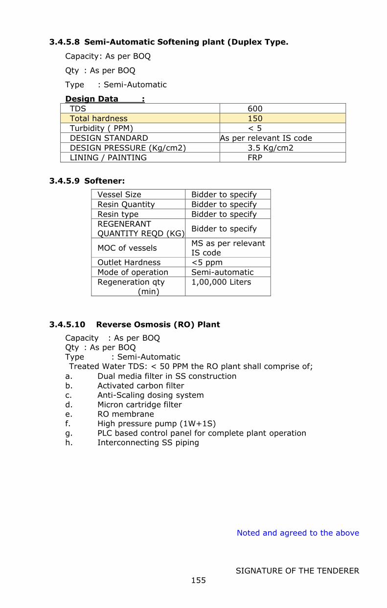
Noted and agreed to the above
SIGNATURE OF THE TENDERER
155
3.4.5.8 Semi-Automatic Softening plant (Duplex Type.
Capacity : As per BOQ
Qty : As per BOQ
Type : Semi-Automatic
Design Data :
TDS 600
Total hardness 150
Turbidity ( PPM) < 5
DESIGN STANDARD As per relevant IS code
DESIGN PRESSURE (Kg/cm2) 3.5 Kg/cm2
LINING / PAINTING FRP
3.4.5.9 Softener:
Vessel Size Bidder to specify
Resin Quantity Bidder to specify
Resin type Bidder to specify
REGENERANT
QUANTITY REQD (KG) Bidder to specify
MOC of vessels MS as per relevant IS code
Outlet Hardness <5 ppm
Mode of operation Semi-automatic
Regeneration qty
(min)
1,00,000 Liters
3.4.5.10 Reverse Osmosis (RO) Plant
Capacity : As per BOQ Qty : As per BOQ
Type : Semi-Automatic Treated Water TDS: < 50 PPM the RO plant shall comprise of;
a. Dual media filter in SS construction
b. Activated carbon filter c. Anti-Scaling dosing system
d. Micron cartridge filter e. RO membrane
f. High pressure pump (1W+1S)
g. PLC based control panel for complete plant operation h. Interconnecting SS piping
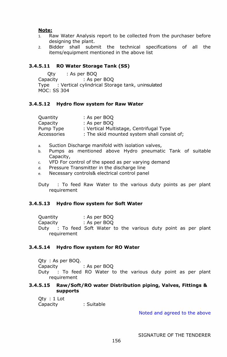
Noted and agreed to the above
SIGNATURE OF THE TENDERER
156
Note: 1. Raw Water Analysis report to be collected from the purchaser before
designing the plant.
2. Bidder shall submit the technical specifications of all the items/equipment mentioned in the above list
3.4.5.11 RO Water Storage Tank (SS)
Qty : As per BOQ
Capacity : As per BOQ Type : Vertical cylindrical Storage tank, uninsulated
MOC : SS 304
3.4.5.12 Hydro flow system for Raw Water
Quantity : As per BOQ
Capacity : As per BOQ
Pump Type : Vertical Multistage, Centrifugal Type Accessories : The skid mounted system shall consist of;
a. Suction Discharge manifold with isolation valves, b. Pumps as mentioned above Hydro pneumatic Tank of suitable
Capacity, c. VFD For control of the speed as per varying demand
d. Pressure Transmitter in the discharge line e. Necessary controls& electrical control panel
Duty : To feed Raw Water to the various duty points as per plant
requirement
3.4.5.13 Hydro flow system for Soft Water
Quantity : As per BOQ Capacity : As per BOQ
Duty : To feed Soft Water to the various duty point as per plant requirement
3.4.5.14 Hydro flow system for RO Water
Qty : As per BOQ.
Capacity : As per BOQ
Duty : To feed RO Water to the various duty point as per plant requirement
3.4.5.15 Raw/Soft/RO water Distribution piping, Valves, Fittings & supports
Qty : 1 Lot Capacity : Suitable
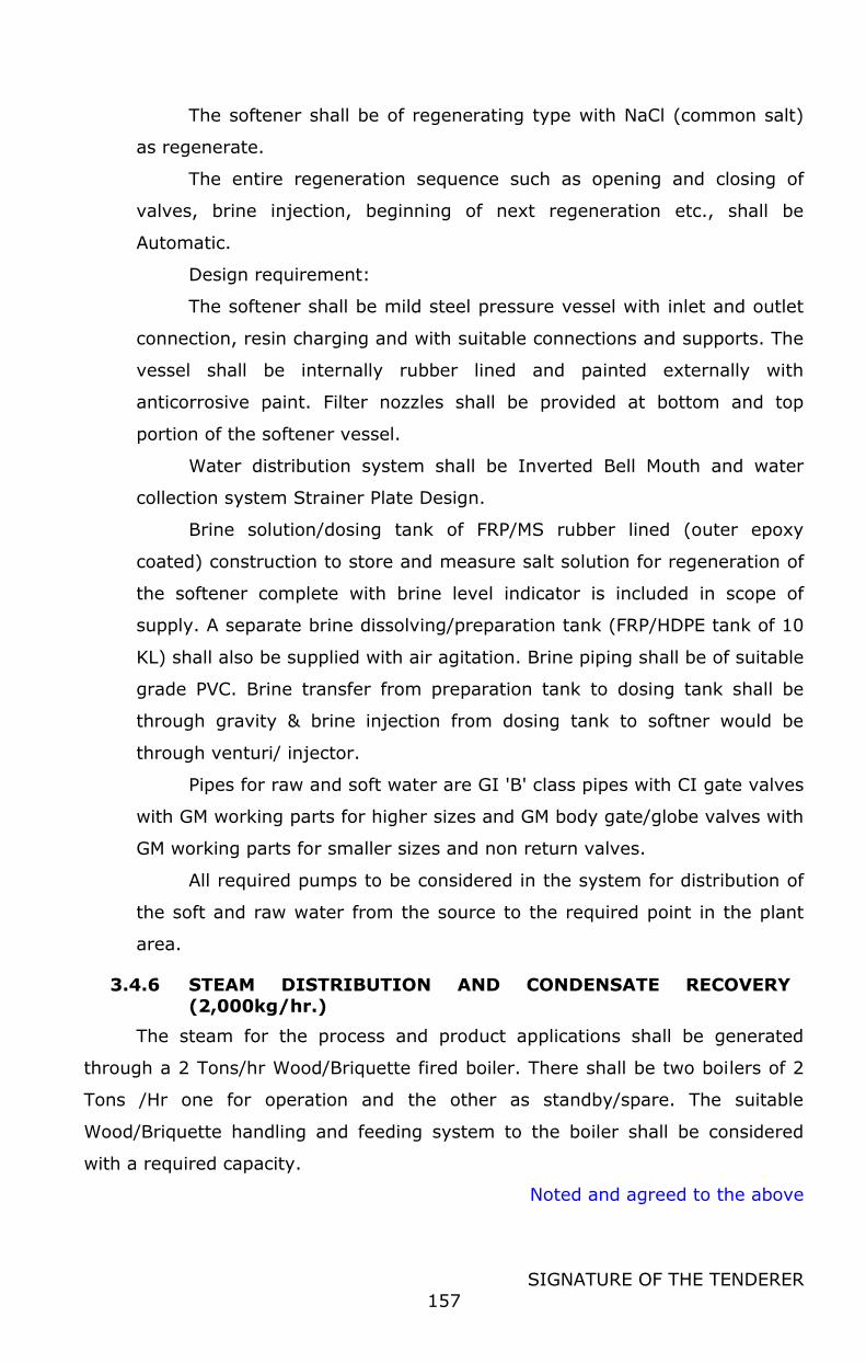
Noted and agreed to the above
SIGNATURE OF THE TENDERER
157
The softener shall be of regenerating type with NaCl (common salt)
as regenerate.
The entire regeneration sequence such as opening and closing of
valves, brine injection, beginning of next regeneration etc., shall be
Automatic.
Design requirement:
The softener shall be mild steel pressure vessel with inlet and outlet
connection, resin charging and with suitable connections and supports. The
vessel shall be internally rubber lined and painted externally with
anticorrosive paint. Filter nozzles shall be provided at bottom and top
portion of the softener vessel.
Water distribution system shall be Inverted Bell Mouth and water
collection system Strainer Plate Design.
Brine solution/dosing tank of FRP/MS rubber lined (outer epoxy
coated) construction to store and measure salt solution for regeneration of
the softener complete with brine level indicator is included in scope of
supply. A separate brine dissolving/preparation tank (FRP/HDPE tank of 10
KL) shall also be supplied with air agitation. Brine piping shall be of suitable
grade PVC. Brine transfer from preparation tank to dosing tank shall be
through gravity & brine injection from dosing tank to softner would be
through venturi/ injector.
Pipes for raw and soft water are GI 'B' class pipes with CI gate valves
with GM working parts for higher sizes and GM body gate/globe valves with
GM working parts for smaller sizes and non return valves.
All required pumps to be considered in the system for distribution of
the soft and raw water from the source to the required point in the plant
area.
3.4.6 STEAM DISTRIBUTION AND CONDENSATE RECOVERY (2,000kg/hr.)
The steam for the process and product applications shall be generated
through a 2 Tons/hr Wood/Briquette fired boiler. There shall be two boilers of 2
Tons /Hr one for operation and the other as standby/spare. The suitable
Wood/Briquette handling and feeding system to the boiler shall be considered
with a required capacity.
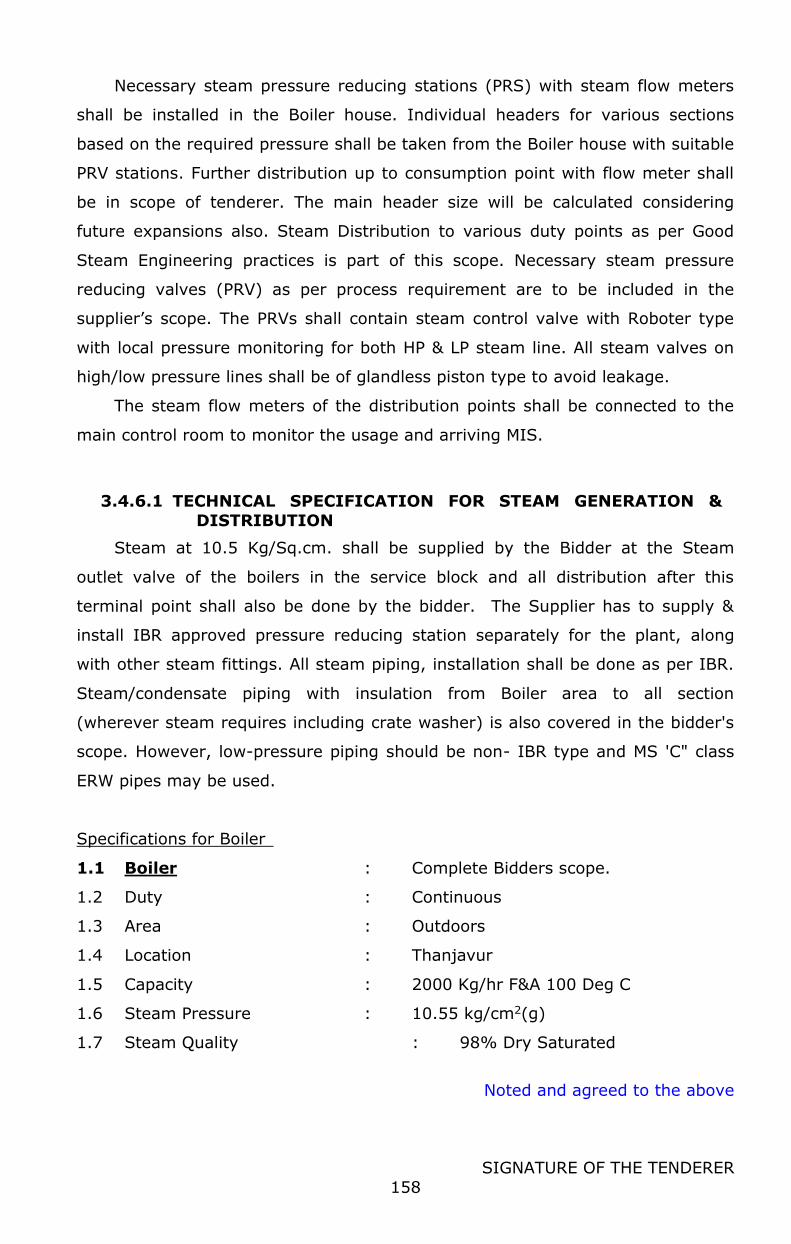
Noted and agreed to the above
SIGNATURE OF THE TENDERER
158
Necessary steam pressure reducing stations (PRS) with steam flow meters
shall be installed in the Boiler house. Individual headers for various sections
based on the required pressure shall be taken from the Boiler house with suitable
PRV stations. Further distribution up to consumption point with flow meter shall
be in scope of tenderer. The main header size will be calculated considering
future expansions also. Steam Distribution to various duty points as per Good
Steam Engineering practices is part of this scope. Necessary steam pressure
reducing valves (PRV) as per process requirement are to be included in the
supplier’s scope. The PRVs shall contain steam control valve with Roboter type
with local pressure monitoring for both HP & LP steam line. All steam valves on
high/low pressure lines shall be of glandless piston type to avoid leakage.
The steam flow meters of the distribution points shall be connected to the
main control room to monitor the usage and arriving MIS.
3.4.6.1 TECHNICAL SPECIFICATION FOR STEAM GENERATION &
DISTRIBUTION
Steam at 10.5 Kg/Sq.cm. shall be supplied by the Bidder at the Steam
outlet valve of the boilers in the service block and all distribution after this
terminal point shall also be done by the bidder. The Supplier has to supply &
install IBR approved pressure reducing station separately for the plant, along
with other steam fittings. All steam piping, installation shall be done as per IBR.
Steam/condensate piping with insulation from Boiler area to all section
(wherever steam requires including crate washer) is also covered in the bidder's
scope. However, low-pressure piping should be non- IBR type and MS 'C" class
ERW pipes may be used.
Specifications for Boiler
1.1 Boiler : Complete Bidders scope.
1.2 Duty : Continuous
1.3 Area : Outdoors
1.4 Location : Thanjavur
1.5 Capacity : 2000 Kg/hr F&A 100 Deg C
1.6 Steam Pressure : 10.55 kg/cm2(g)
1.7 Steam Quality : 98% Dry Saturated
Noted and agreed to the above
SIGNATURE OF THE TENDERER
159
1.8 Type : Smoke Tube
1.9 Fuel : Wood / Briquette (average calorific
value – 3500 Kcal/Kg and 12 to 14 %
moisture)
1.10 Water Quality : Soft Water
1.0 Design Requirements
a. Boiler should be horizontal, shell type fully packaged 3- pass smoke tube
design, automatically controlled, tested and proven under rigorous conditions
and subject to the strictest quality control procedures. The boiler should be in
modular construction with the feed water tank mounted on the platform or
near by area.
b. The boiler should be of genuine three-pass flue path. Flue gases should pass
through the furnace (first pass) whereas second and thirds passes should be
formed by nests of smoke tubes. At the end of the furnace the flue gas
reverses into second pass tubes.
(i) The boiler shall be complete with all mountings, accessories, controls
etc.
(ii) Boiler construction shall be in accordance with the latest revision of
Indian Boiler Regulations 1950, Act 1923 applicable and in conformity
with AOTC requirements for unattended boilers. All materials used shall
be approved and tested as per relevant existing codes. All the welded
joints shall be as per code requirement.
(iii) The boiler should be of modern compact design and be genuinely
packaged design. The design source should confirm to international
design.
(iv) The fire tubes in the tubes nest should be plain without any restriction
inside. These tubes should be easily accessible both from inside as well
as outside for inspection and maintenance. These tubes are to be tightly
expanded in the tube plate and seal welded. The required number of
stay tubes and stay bars are to be fitted the boiler. The stay tubes
should be seamless & strength-welded to tube plates.
(v) All working parts of the boiler should be accessible for ease of inspection
and maintenance. On the shell, one elliptical mandoor and on tube plate
Noted and agreed to the above
SIGNATURE OF THE TENDERER
160
one mud hole must be provided. Access to the combustion chamber
should be through bolted refractory lined access door whereas tube nest
should be exposed through hinged mounted front door.
(vi) Boiler front door is lined with ceramic fiber blanket with SS sheeting on
the tube side of the door.
(vii) The boiler mountings shall be as per the Extent of Supply.
(viii) The boiler shall be designed and constructed to generate steam at
efficiency of 89% on net calorific valve (NCV) basis. Efficiency shall be
demonstrated as per standard BS – 845 Part 1 Indirect method.
(ix) The insulated cylindrical shell of the boiler shall be housed in
rectangular box shaped sheet metal cover frame. Therefore the top of
the boiler serves as platform and facilitates ease of movement for
maintenance at elevation. A movable ladder shall be provided which can
be moved as per convenience.
(x) Boiler and accessories shall be mounted on a single base frame.
Individual systems such as feed water pump etc. may be on separate
base plates welded to the boiler base frame.
(xi) The boiler shall not require any special foundation for the boiler and its
mountings/fittings. It should be able to be mounted on simple PCC
foundation.
c. Burner : This shall be suitable for handling the fuel specified. The burner
should be suitable for firing Briquette / wood. The entire burner shall be
mounted on the front door of the boiler.
d. Feed water System: 2 nos. electrically driven vertical centrifugal multistage
pumps mounted on the boiler frame itself with motor capable of using feed
water at temperature of 120 deg C with all SS internals, interconnected
pipework between pumps and feed check valves. Feed water day tank (by
customer) shall be placed at an elevation of 3.5m approx. from finished floor
level.
e. Blowdown system: Automatic Blowdown Control System based on
conductivity principle with pneumatically actuated valve for efficient control
of TDS level within the boiler shell. This system shall be installed in parallel to
the manual blowdown valve.
Noted and agreed to the above
SIGNATURE OF THE TENDERER
161
f. Drum Level Control System, 2 Sets
Type – 2 Nos Magnetic Level controller
g. Online Boiler Efficiency Monitoring System, 1 Sets
Complete with instruments to be provided for the Boiler Efficiency Monitoring
shall be as under but not limited to
Steam Flow Meter, Vortex Type with Pressure and Density Compensation.
TDS Based Automatic Blowdown Control System - TDS based Automatic
Blow down Control System based on conductivity principle with
pneumatically actuated valve for efficient control of TDS level within the
boiler shell. This system shall be installed in parallel to the manual blow
down valve
Temperature Transmitters – 1 Set
The boiler efficiency along with other parameters shall be monitored on the
touchscreen panel complete with trends and with storage capability of 12
months data.
h. Controls : The electro-mechanical compact control system shall be
provided. The relay based control panel cum MCC shall be mounted on the
same boiler frame.
(i) Interlocking of the feed water pumps and water level in the boiler
(ii) Audio–visual alarm for danger level of water in the boiler and also for
flame failure.
(iii) Programmer controller to ensure sequence of boiler start-up after
ensuring required temperature and pressure of air etc.
(iv) MCB’s and contactors shall be provided for all electrical drives for the
boiler
(v) Pilot lamp to indicate operating status of the various equipment.
(vi) Complete internal wiring to ensure power supply at a single point on the
panel.
(vii) Indicating lamps/ Audio alarm shall be provided for the following
parameters -
- Low water level in the boiler
Noted and agreed to the above
SIGNATURE OF THE TENDERER
162
- Burner flame failure
- Feed water pumps failure
- Damper closed position
(viii) Pressure switch should be provided for burner interlock.
The control panel shall be mounted on the boiler and shall not be separate.
The cabling between the boiler and the panel shall be done from the vendors
factory.
i. MS Self Supported Chimney, 1 Nos
Type – MS Self Supported designed as per IS 6533
Corrosion Allowance – 3 mm
The chimney shall be designed for a boiler capacity of 1 X 2 TPH working.
The chimney shall be complete with
Type Cylindrical
Position Vertical
End Top Open with Canopy
Finish Clean & painted with three coats of Silver - heat resistance
paints (300° C to 350° C)
Two Coat of black resistance paint inside Surface of Chimney
Brief Scope items & Material of Construction
1 Shell - IS 2062 GR.B
2. Top cone pieces - S.S.304 (1500 mm L )
3. Flanges IS 2062- Gr.B
4. All nozzles - IS 2062 Gr.B.
5. Ladder & Structural (2 Nos Platform included)IS 2062 Gr.B.
6. Earthing Strips – Copper Strips - 25 mm x 6 mm x 40 mtr long – 2
nos
8. Railing pipe - ISI 1239 Class- B
The chimney should consist of all the accessories and the minimum
requirement. Few of them are as follows:
a) Base plate with gussets plate (minimum thickness of 8 mm) and
base stool.
Noted and agreed to the above
SIGNATURE OF THE TENDERER
163
b) Inspection door with minimum size of 500 W x 800 W shall be
provided. The door shall have handles and all associated accessories. The cutout
made on the chimney should have stiffeners of not less than 50 x 50 x 6 mm
angles welded on the periphery of the cutout in the chimney.
c) Access ladder with protection cage:
The ladder should start from 3 meter from the base of the chimney and it
should be up to the top of the chimney. The ladder shall be supported from the
chimney with structural members of not less than 50 x 50 x 6 mm ISA and the
ladder rung should be located at a distance of 250mm from the chimney. The
ladder rung should be made of 20 mm dia rod, the width of the rung should be of
minimum 400 mm and the ladder step should be at a frequency of 200 mm C/C.
Safety enclosure or cage shall be provided for the ladder.
d) Platform for flue gas sampling and inspection:
e) Painter's trolley.
f) Conical cowl with cowl stays:
The minimum cowl diameter should be 1.5 times the dia of the top of the
chimney section.
g) Twin aviation lights and warning lights.
Aviation obstruction light fixture shall be made of aluminum alloy casing
with separate galleries to house two 100 watts GLS on BC type bulb holder. The
lamp fixture shall have suitable red domes on the galleries and the lamp fixture
shall be of reputed make.
Aviation obstruction light-point should be connected from the lighting circuit
available in the boiler plant room with 3 x 2.5 Sq.mm., PVC sheathed, PVC
insulated copper cable. The circuit cable shall be run on the rigid steel conduit,
and shall be fixed on the chimney surface with suitable saddles and clamps
mounted on the epoxy based insulators.
h) Lightning arrester:
The lightning arrester should be of GI with minimum 5 prongs, the
lightening arrester should be connected to the two earth stations. The earthling
conductor should be of size should not less than GI 25 X 6mm / or of equivalent
size and conductor material as approved by the local statutory authorities. The
Noted and agreed to the above
SIGNATURE OF THE TENDERER
164
earthling conductor should be mounted on the epoxy based insulators and not
directly fixed to the chimney surface. Two earthling conductor should run parallel
from the lightening arrester and each connected to the independent earth
stations. The earth stations in turn should be interconnected with one another.
i) Flue gas inlet:
Flue gas ducting shall be provided from the boiler to the chimney; it should
be made from MS sheet of thickness not less than 3mm and should be provided
with baffle plates. The cutout made on the chimney should have stiffeners of not
less than 50 x 50 x 6mm angles welded on the periphery of the cutout. The
opening made on the chimney for the flue gas duct should be extended by 200 to
300mm and terminated on counter flanges to facilitate connection of the ducting
on the chimney.
j) Helical strakes to reduce wind exited oscillations for the top 2/3rd
height of the chimney.
k) Chimney bottom up to 3 M height should be insulated by 50mm
white mineral wool followed by cladding with 3mm MS sheet. The mild steel
cladding should be of butt welded construction.
l) All MS parts of the chimney shall be given initial surface treatment
including degreasing, de- rusting etc., then a coat of primer shall be applied. The
chimney should be finally painted with three coats of suitable heat resistant paint
at site.
m) Foundation bolt of adequate length and diameter shall be provided
along with the anchoring channel of section ISMC 150 on the bolt base. Template
shall be provided suitable for the foundation bolts for casting the chimney
foundation.
Note:
Statutory approvals - Necessary drawing & other formalities required for
MPPCB to be carried out by bidder. When MPPCB appoints Sub regional officer for
Noted and agreed to the above
SIGNATURE OF THE TENDERER
165
Smoke nuisance dept, the same papers to be Submitted to MPPCB & get the
approvals for Chimney from the concerned Sub Regional officer. This all shall be
in bidder’s scope.
j. MS Flue Gas Ducting, 1 Set
Type – Circular with thickness of 5 mm
The ducting shall be installed between the boiler and the chimney. The
ducting shall be complete with
(a) Expansion Bellows
(b) Supports
(c) Insulation & cladding.
k. Feed water tank – MS Feed water tank fabricated out of 6 mm thick
MS sheet – 5 KL with 3 point level control system, atmospheric deaerator,
insulation and cladding.
l. MS structural Supports, 1 Set
Type – MS Structural Supports complete with 1 coat of primer to be
supplied for the following installations/ mountings.
MS Structural Supports for
(a) Feed water tank
(b) Flue Gas Ducting
(c) Boiler House Piping
(d) Boiler House Electricals
(e) Access Platforms for Meters
m. CONDENSATE RECOVERY SYSTEM
Maximum recovery & utilization of steam condensate from all process
equipment shall be made. The system shall consist of facilities for receiving
condensate in collection/buffer tank(s) of centrifugal pump(s) and pumping to an
overhead condensate storage tank. From the overhead condensate storage tank,
condensate water to be transferred through gravity/pumping to boiler feed water
tank of boiler house.
Noted and agreed to the above
SIGNATURE OF THE TENDERER
166
Condensate recovery tank, equal to one-hour operation of boiler at full
capacity, shall be provided to collect the clean condensate from plant. The
quantity collected shall be measured through a Vortex type flow meter and data
shall be transferred to Boiler PLC and also to central control room. The
condensate collection lines from various steam traps to be led & connected with
adjacent header lay on pipe rack for transferring to collection tank by centrifugal
pump. The pumping traps of all water heaters/ CIP heaters etc. shall be of
compact design. The milk/cream pasteurizer steam traps shall be selected to
ensure complete clearing of condensate with the help of minimum quantity of
motive steam against back pressure without effecting process heat requirement.
Similarly, the TD-3 trap assembly for all steam headers/distribution lines shall be
of compact design/single piece. Wherever possible the condensate from main
steam headers/ distribution lines would be recovered for utilization. MOC of all
condensate transfer piping shall be SS316 with hot insulation.
N. Boiler House Piping - 1 Set
The vendor shall deliver boiler house piping as detailed under.
(a) Feed Water Piping from the Feed Water Tank to the individual feed
water pumps complete with inlet Isolation Valves – 2 Nos and
Strainers – 2 Nos. Inclusive of Insulation & Cladding.
(b) Safety Valve Exhaust Piping from the outlet of the Safety Valves to
outside of the boiler house, complete with insulation & cladding.
(c) Blowdown piping from the outlet of the blowdown control system to
the Blowdown pit.
(d) Drain Piping from the boiler drain points, drain from the feed water
tank shall also be delivered by the Vendor.
(e) Steam piping and condensate piping of entire plant with all necessary
valves, fittings and insulation shall be in the scope of the bidder.
2.0 Extent of Supply
The package boilers for specified duty shall be supplied complete with all
accessories in all respects, but not limited, to the following, within vendor’s
battery limit.
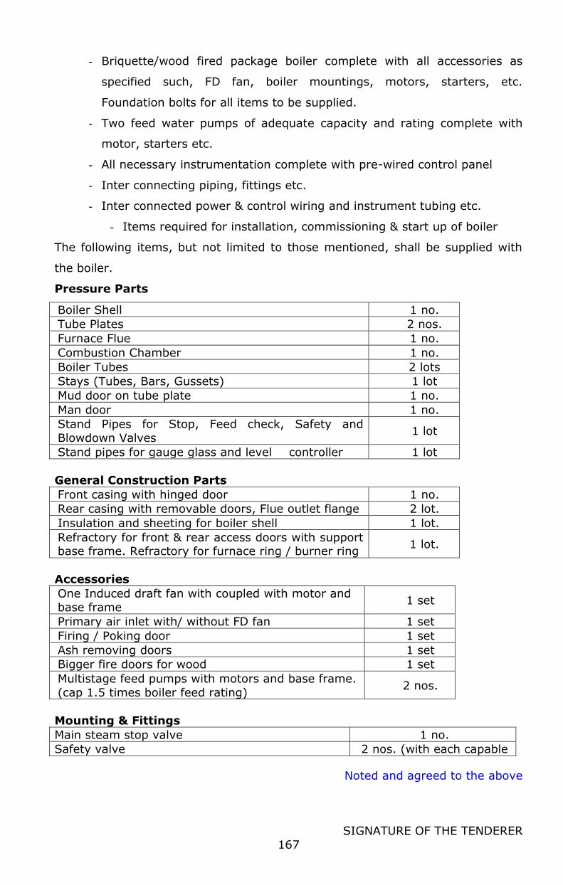
Noted and agreed to the above
SIGNATURE OF THE TENDERER
167
- Briquette/wood fired package boiler complete with all accessories as
specified such, FD fan, boiler mountings, motors, starters, etc.
Foundation bolts for all items to be supplied.
- Two feed water pumps of adequate capacity and rating complete with
motor, starters etc.
- All necessary instrumentation complete with pre-wired control panel
- Inter connecting piping, fittings etc.
- Inter connected power & control wiring and instrument tubing etc.
- Items required for installation, commissioning & start up of boiler
The following items, but not limited to those mentioned, shall be supplied with
the boiler.
Pressure Parts
Boiler Shell 1 no.
Tube Plates 2 nos.
Furnace Flue 1 no.
Combustion Chamber 1 no.
Boiler Tubes 2 lots
Stays (Tubes, Bars, Gussets) 1 lot
Mud door on tube plate 1 no.
Man door 1 no.
Stand Pipes for Stop, Feed check, Safety and
Blowdown Valves 1 lot
Stand pipes for gauge glass and level controller 1 lot
General Construction Parts
Front casing with hinged door 1 no.
Rear casing with removable doors, Flue outlet flange 2 lot.
Insulation and sheeting for boiler shell 1 lot.
Refractory for front & rear access doors with support base frame. Refractory for furnace ring / burner ring
1 lot.
Accessories
One Induced draft fan with coupled with motor and
base frame 1 set
Primary air inlet with/ without FD fan 1 set
Firing / Poking door 1 set
Ash removing doors 1 set
Bigger fire doors for wood 1 set
Multistage feed pumps with motors and base frame.
(cap 1.5 times boiler feed rating) 2 nos.
Mounting & Fittings
Main steam stop valve 1 no.
Safety valve 2 nos. (with each capable

Noted and agreed to the above
SIGNATURE OF THE TENDERER
168
of 50% venting capacity)
Non return valve on feed water pump discharge line
2 nos.
Stop valves on feed water pump discharge line 2 nos.
isolation valves on suction side of feed water pump
2 nos.
Air vent valve 1 no.
Isolating valve for pressure gauge on feed water line
1 no.
Auxillary valve 1 no.
Blowdown valve with Automatic Blowdown Control System
1 no.
Isolating valve for water level controllers 2 nos.
Isolating valve for pressure switches and pressure gauge
2 nos.
Drain valve for water level controller 2 nos.
Sight glass assembly 1 set
Instrumentation
Water level controllers for feed pump operation and low water level alarm
Over-ride controller for lockout under extra low water level alarm
Water pressure gauge with cock
For display of boiler feed water pressure
Steam pressure gauge
with cock For display of boiler steam pressure
Water level gauge
assembly For display of water level in the boiler
Switch gears, relays, connectors
For individual controls of equipment through control panel
Audio / visual alarm In case of unsafe operation for lockout under extreme conditions
Pressure and temp gauge
with thermostat for burner operation
Steam pressure switch For combustion control
Control panel For housing above instruments and switchgears
Temperature indicator For monitoring high flue gas temperature
Controls & Safeties
Pressure switch For firing positions of burner
UV Cell Flame failure and audio visual alarm
Sequence controller To control sequence of firing, pre-purging etc.
Level controller To regulate feed water pump operation and trip burner in case of very low level with audio visual
alarm.
Safety Interlocks
Unsafe condition Instrument Action
High water level Level controller No. 1 Feed water pump trip.
Low water level Level controller No. 1 Alarm & Burner Shut down
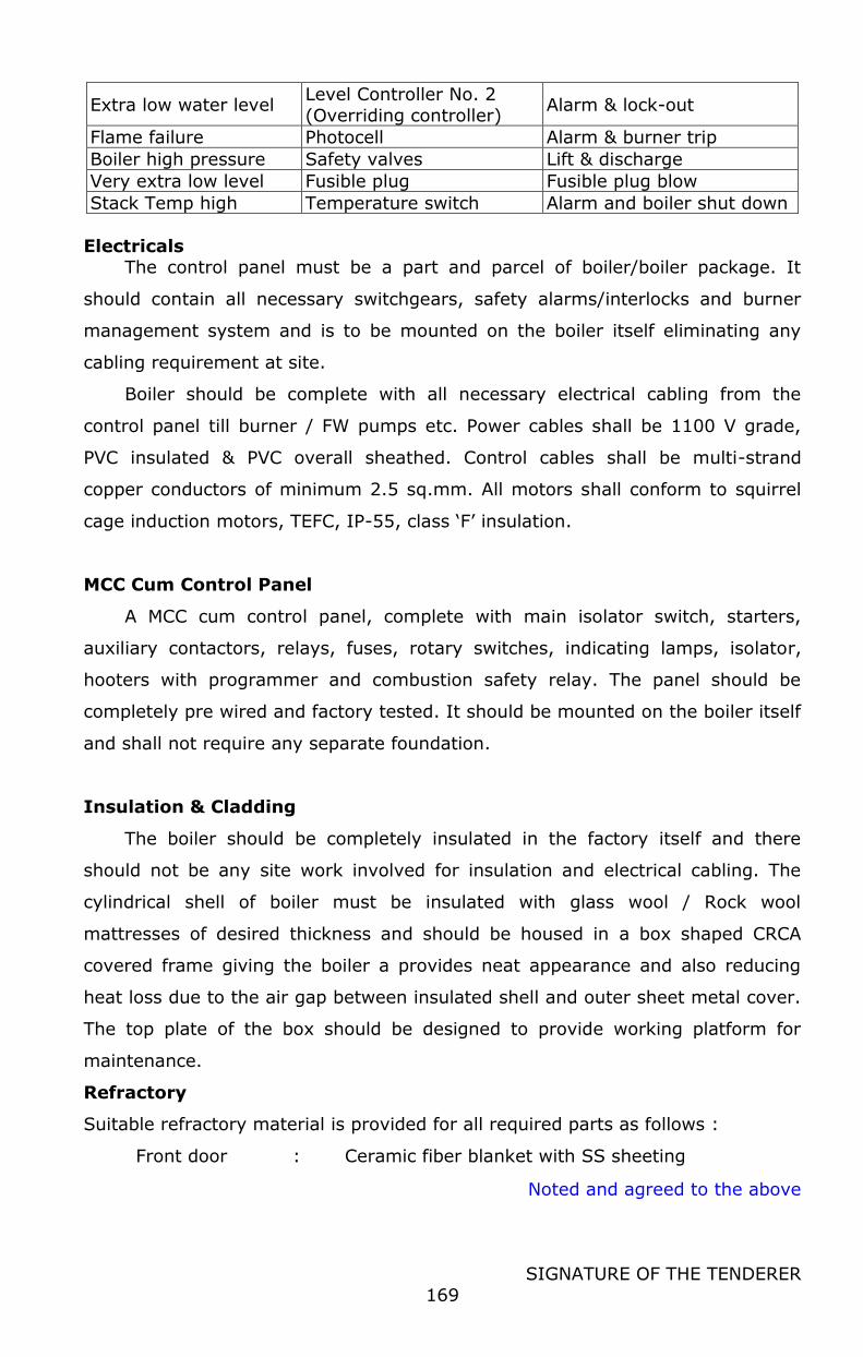
Noted and agreed to the above
SIGNATURE OF THE TENDERER
169
Extra low water level Level Controller No. 2
(Overriding controller) Alarm & lock-out
Flame failure Photocell Alarm & burner trip
Boiler high pressure Safety valves Lift & discharge
Very extra low level Fusible plug Fusible plug blow
Stack Temp high Temperature switch Alarm and boiler shut down
Electricals The control panel must be a part and parcel of boiler/boiler package. It
should contain all necessary switchgears, safety alarms/interlocks and burner
management system and is to be mounted on the boiler itself eliminating any
cabling requirement at site.
Boiler should be complete with all necessary electrical cabling from the
control panel till burner / FW pumps etc. Power cables shall be 1100 V grade,
PVC insulated & PVC overall sheathed. Control cables shall be multi-strand
copper conductors of minimum 2.5 sq.mm. All motors shall conform to squirrel
cage induction motors, TEFC, IP-55, class ‘F’ insulation.
MCC Cum Control Panel
A MCC cum control panel, complete with main isolator switch, starters,
auxiliary contactors, relays, fuses, rotary switches, indicating lamps, isolator,
hooters with programmer and combustion safety relay. The panel should be
completely pre wired and factory tested. It should be mounted on the boiler itself
and shall not require any separate foundation.
Insulation & Cladding
The boiler should be completely insulated in the factory itself and there
should not be any site work involved for insulation and electrical cabling. The
cylindrical shell of boiler must be insulated with glass wool / Rock wool
mattresses of desired thickness and should be housed in a box shaped CRCA
covered frame giving the boiler a provides neat appearance and also reducing
heat loss due to the air gap between insulated shell and outer sheet metal cover.
The top plate of the box should be designed to provide working platform for
maintenance.
Refractory
Suitable refractory material is provided for all required parts as follows :
Front door : Ceramic fiber blanket with SS sheeting
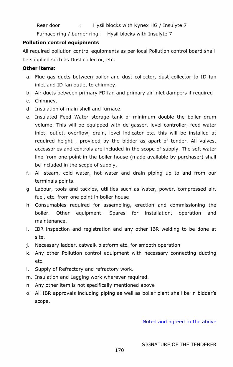
Noted and agreed to the above
SIGNATURE OF THE TENDERER
170
Rear door : Hysil blocks with Kynex HG / Insulyte 7
Furnace ring / burner ring : Hysil blocks with Insulyte 7
Pollution control equipments
All required pollution control equipments as per local Pollution control board shall
be supplied such as Dust collector, etc.
Other items:
a. Flue gas ducts between boiler and dust collector, dust collector to ID fan
inlet and ID fan outlet to chimney.
b. Air ducts between primary FD fan and primary air inlet dampers if required
c. Chimney.
d. Insulation of main shell and furnace.
e. Insulated Feed Water storage tank of minimum double the boiler drum
volume. This will be equipped with de gasser, level controller, feed water
inlet, outlet, overflow, drain, level indicator etc. this will be installed at
required height , provided by the bidder as apart of tender. All valves,
accessories and controls are included in the scope of supply. The soft water
line from one point in the boiler house (made available by purchaser) shall
be included in the scope of supply.
f. All steam, cold water, hot water and drain piping up to and from our
terminals points.
g. Labour, tools and tackles, utilities such as water, power, compressed air,
fuel, etc. from one point in boiler house
h. Consumables required for assembling, erection and commissioning the
boiler. Other equipment. Spares for installation, operation and
maintenance.
i. IBR inspection and registration and any other IBR welding to be done at
site.
j. Necessary ladder, catwalk platform etc. for smooth operation
k. Any other Pollution control equipment with necessary connecting ducting
etc.
l. Supply of Refractory and refractory work.
m. Insulation and Lagging work wherever required.
n. Any other item is not specifically mentioned above
o. All IBR approvals including piping as well as boiler plant shall be in bidder’s
scope.
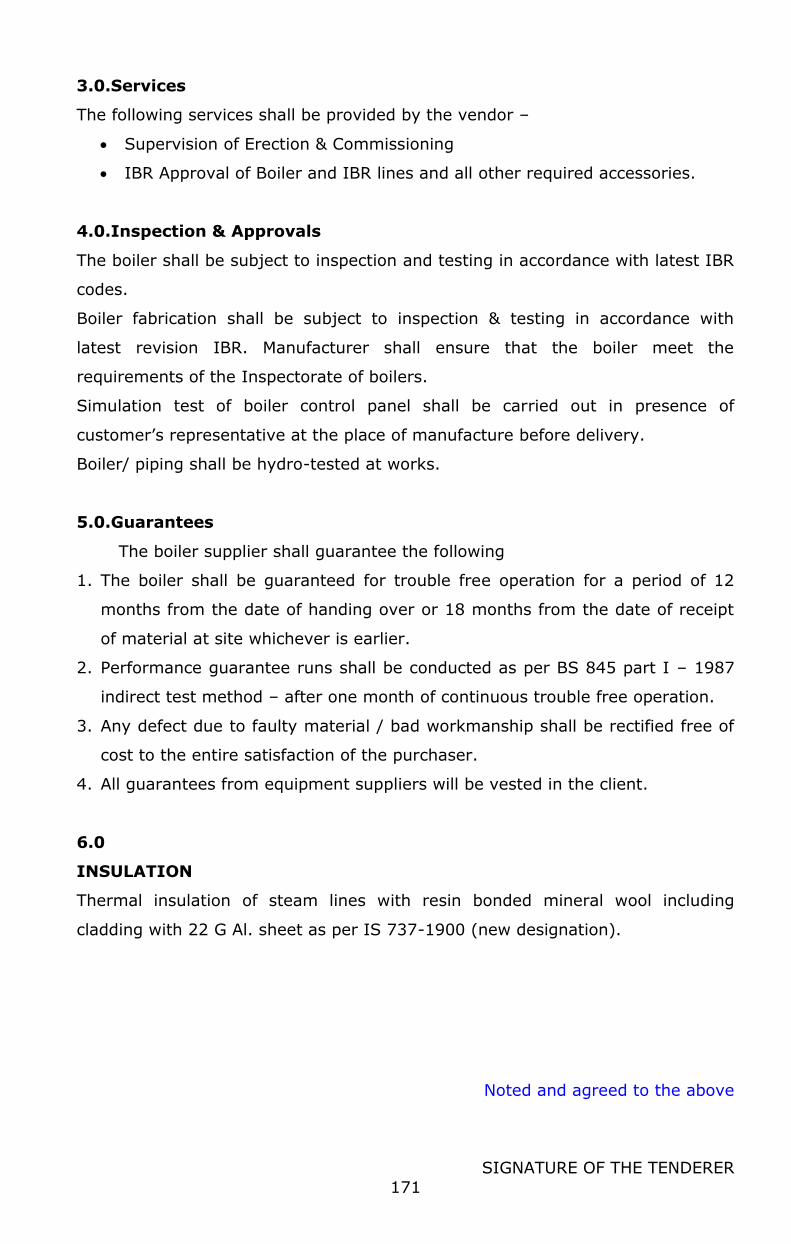
Noted and agreed to the above
SIGNATURE OF THE TENDERER
171
3.0.Services
The following services shall be provided by the vendor –
Supervision of Erection & Commissioning
IBR Approval of Boiler and IBR lines and all other required accessories.
4.0.Inspection & Approvals
The boiler shall be subject to inspection and testing in accordance with latest IBR
codes.
Boiler fabrication shall be subject to inspection & testing in accordance with
latest revision IBR. Manufacturer shall ensure that the boiler meet the
requirements of the Inspectorate of boilers.
Simulation test of boiler control panel shall be carried out in presence of
customer’s representative at the place of manufacture before delivery.
Boiler/ piping shall be hydro-tested at works.
5.0.Guarantees
The boiler supplier shall guarantee the following
1. The boiler shall be guaranteed for trouble free operation for a period of 12
months from the date of handing over or 18 months from the date of receipt
of material at site whichever is earlier.
2. Performance guarantee runs shall be conducted as per BS 845 part I – 1987
indirect test method – after one month of continuous trouble free operation.
3. Any defect due to faulty material / bad workmanship shall be rectified free of
cost to the entire satisfaction of the purchaser.
4. All guarantees from equipment suppliers will be vested in the client.
6.0
INSULATION
Thermal insulation of steam lines with resin bonded mineral wool including
cladding with 22 G Al. sheet as per IS 737-1900 (new designation).
Noted and agreed to the above
SIGNATURE OF THE TENDERER
172
A) STEAM VALVES AND FITTINGS
The following shall be provided wherever required between boiler outlet and
steam utility points : Cast steel flanged globe/ ball valves, CI strainers with brass
screen, thermodynamic steam traps, needle valves, moisture separators, safety
valves, non return valves (GM with SS Working Parts), dial type pressure gauges
for HP and LP steam etc. Steam trap set-ups shall be complete with by-pass
valves.
Steam flow meter to measure steam feed to various sections of the plant.
Temperature sensor shall simultaneously give feed back to DCS for real time
control for conditioning. A pneumatic operated steam control valve shall
automatically control the feed rate of steam to the controller, regulated by the
feed back received from the temperature sensor in the controller. By pass of the
control valve shall be provided.
B) WOOD FEEDING SYSTEM TO BOILER
Suitable manual wood handling and feeding system to boiler shall be considered.
This shall be required to ease up the process of feeding fuel to the boiler
3.4.7 REFRIGERATION SYSTEM FOR CHILLED WATER AND COLD ROOMS.
The required chilled water at 1 C for the process and product
manufacturing activities shall be generated through a Ammonia refrigeration
system with required compressors with standby provision. Adequate number of
Ice Bank Tanks each of 50 KL capacity shall be used to store the Chilled water.
The system shall be equipped with necessary ammonia receivers, pumps,
Evaporative condensers, Electrical motors etc for effective operation.
The cold rooms are equipped with ammonia evaporators to maintain the
required temperature.
Further distribution up to consumption point shall be in scope of tenderer.
The system should be forced feed refrigerant type provided with necessary
refrigerant liquid receivers, pumps, Economizers, prechillers etc for satisfactory
operation
3.4.7.1 Design, supply, erection, testing & commissioning of
Refrigeration system as per the requirement indicated
below.
The scope of work includes following.

Noted and agreed to the above
SIGNATURE OF THE TENDERER
173
Design, supply, erection, testing & commissioning of Reciprocating
ammonia Compressor packages for high stage operation of Chilled
water system & various cold rooms, Evaporative type Condensers,
HP & LP Receivers, Ammonia Pumps, IBT tank with Hot dip
Galvanized Coil, Chilled water pumps for various chilled water
systems, ACU for various Proposed Cold rooms, Electrical MCC panel,
Controls systems, Control panels, Control instruments, Power /
Control / Instrumentation Cabling, Safety systems, inter locking etc.,
Design, supply, erection, testing & commissioning of all the electrical
equipments, pipelines, valves, fittings for entire refrigeration system,
pipe supports inside cold rooms and machine rooms, chequered
plate for trench covers, Painting for new system's equipments & for
un-insulated pipes etc., wherever required for the entire work.
Fixing the PUF Panels Panel with both sides of PCGI Sheets with
suitable size and thickness doors for various Cold rooms as per the
room size and providing internal lighting, Safety System wherever
required.
Design supply, erection, testing & commissioning of MCC Panel with
Power & Control wiring for proposed Refrigeration system
equipments including feeders / suitable type starters for Future
Equipments.
3.4.7.2 Details of Direct Expansion Refrigeration Loads for various Cold Rooms
Milk Cold
Room
Curd
Incubation Room
Curd Cold Room
Cud Blast Room
Size of each chamber
: 6.77 x 6 x 3.8-m Ht
4.5 x 2.77 x 3.8-m
4.5 x4.77 x 3.8-m
4.5 x 3.77 x 3.8–m
No of Chambers : Two One One One
Ante room Details 2.23 x 6 x
3.8-m
4.5 x 2 x
3.8 -m --
Incoming load /
Batch
: 50,000 Ltrs.-
Totally 2000 Kgs 2000 Kgs
2,000 Kgs.
Max
Product temp. to be
maintained
: 3 to 4 C 40 to 42 C 4 C 18 C
Incoming product temp.
: 18 C 42 C
Room temp to be : 0 to 2 C 0 to 2 C 0 to 2 C 0 to 2 C
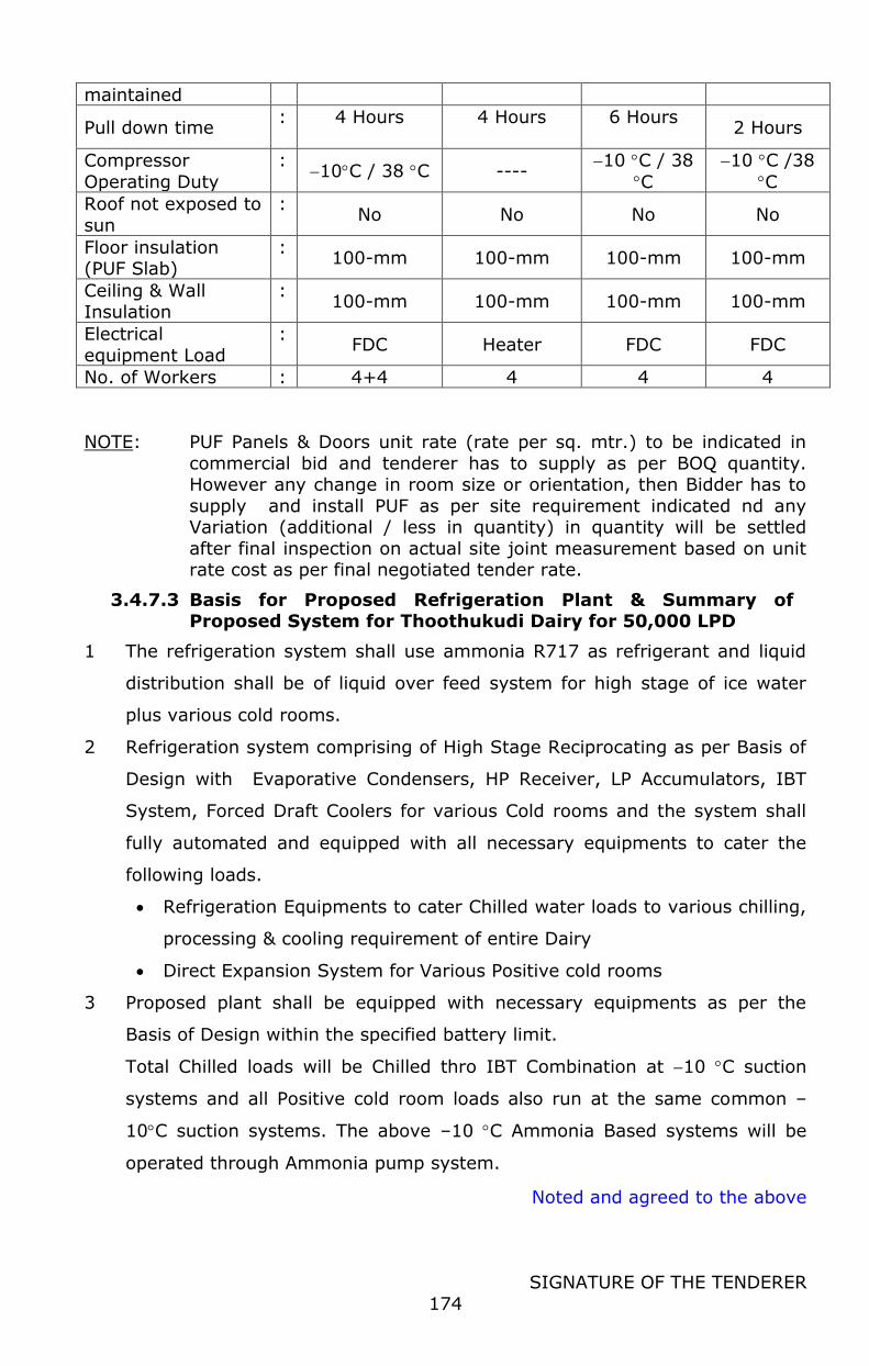
Noted and agreed to the above
SIGNATURE OF THE TENDERER
174
maintained
Pull down time : 4 Hours
4 Hours
6 Hours
2 Hours
Compressor
Operating Duty
: 10C / 38 C ----
10 C / 38
C
10 C /38
C
Roof not exposed to
sun
: No No No No
Floor insulation (PUF Slab)
: 100-mm 100-mm 100-mm 100-mm
Ceiling & Wall Insulation
: 100-mm 100-mm 100-mm 100-mm
Electrical
equipment Load
: FDC Heater FDC FDC
No. of Workers : 4+4 4 4 4
NOTE: PUF Panels & Doors unit rate (rate per sq. mtr.) to be indicated in
commercial bid and tenderer has to supply as per BOQ quantity. However any change in room size or orientation, then Bidder has to
supply and install PUF as per site requirement indicated nd any Variation (additional / less in quantity) in quantity will be settled
after final inspection on actual site joint measurement based on unit rate cost as per final negotiated tender rate.
3.4.7.3 Basis for Proposed Refrigeration Plant & Summary of Proposed System for Thoothukudi Dairy for 50,000 LPD
1 The refrigeration system shall use ammonia R717 as refrigerant and liquid
distribution shall be of liquid over feed system for high stage of ice water
plus various cold rooms.
2 Refrigeration system comprising of High Stage Reciprocating as per Basis of
Design with Evaporative Condensers, HP Receiver, LP Accumulators, IBT
System, Forced Draft Coolers for various Cold rooms and the system shall
fully automated and equipped with all necessary equipments to cater the
following loads.
Refrigeration Equipments to cater Chilled water loads to various chilling,
processing & cooling requirement of entire Dairy
Direct Expansion System for Various Positive cold rooms
3 Proposed plant shall be equipped with necessary equipments as per the
Basis of Design within the specified battery limit.
Total Chilled loads will be Chilled thro IBT Combination at 10 C suction
systems and all Positive cold room loads also run at the same common –
10C suction systems. The above –10 C Ammonia Based systems will be
operated through Ammonia pump system.
Noted and agreed to the above
SIGNATURE OF THE TENDERER
175
4 Proposed system consists of totally Two nos Reciprocating compressor of
each 65 TR for at 10 C Suction for all Chilled water and Positive cold room
loads system, out of two nos, one shall act as common stand by
compressor.
Suppliers/ Bidders scope includes supply of 2 nos. x 120 TR (1 w + 1 s)
Evaporative type Condenser with SS Basin, 1 Nos. H.P Receivers of 4,000
Liters. each capacity, suitable size Ice Bank Tank with Hot Dip Galvanized
Coil of 1,536 rmt x 1 Set , 2 Nos. x 60 M3/hour at 40 MWH Vertical inline
Chilled Water Pump for process Load ,out of which one shall act as stand
by.
Bidder scope includes New MCC Panel, Ammonia Pump system for 10C
application, Automation PLC Panel etc., Air Cooling Units (ACU) for Various
cold rooms & PUF Panels for flooring, Walls & Ceiling with Accessories.
5 Condenser shall be imported make with SS Water Basin. Condenser to be
selected with 28 C WBT and 37 C condensing temp and ensure to be
selected with extra large heat transfer area felicitate to reduce power
consumption in fan & pump . All condenser fan and pump motors shall be
IE-4 with 1.15% safety factor. Condenser to be selected with Large capacity
Heat transfer coil surface area to reduce connected Fan and pump Load.
6 Scope includes common Ice Bank Tank made of Hot Dip Galvanized
Seamless tubes of SA 106 Grade with r.m.t of 1,536 x 1 sets.
Scope includes necessary PUF Tank cover, Liquid feed assembly & Agitators
for proposed New IBT. Bidder has to Provide new ice thickness controller for
each IBT and providing control / instrument cabling from new central
control panel, as well as to solenoid valves of liquid feed assembly for
controlling / monitoring from central control panel.
7 Bidder to supply suitable capacity Two nos each Vertical Inline Multi stage
pump for chilled water application for Processing as per flow rate and Head
indicated in tender, all pumps shall be VFD drive with minimum rating of IE-
4 Motors and shall be supplied with standby pumps as per BOQ quantity.
8 Bidder scope includes additional valves in the Headers for future / standby
compressor & condensers in each application so that future equipments to
be connected without any interruption of running plant in future. Also
Noted and agreed to the above
SIGNATURE OF THE TENDERER
176
Supplier has to consider necessary valves in Priority Vessels & LP receiver
for future connections and all drawing to be get approved prior to
commence / process of equipments and during drawing approval any
additional valves required considering future interconnection, then
successful supplier / bidder has to includes / incorporate the same in the
quoted price without any additional cost.
9 Similarly Chilled water supply and return Headers to be designed for all
proposed pumps working + additional same capacity and same no of pumps
working in future.
10 All ammonia pumps shall be Seal free Hermetic types. Bidder scope includes
new ACU made of SS tubes with Al Fins as per tender specified capacity for
various cold rooms with Powder coating casing or SS Casing and scope
including Liquid feed assemblies comprising Strainer, Liquid Solenoid Valve,
Isolating Valve, valves Bypass, Metering Valve, Pump-out connection, valves
& plugged, pressure gauge connection with isolation valve and Pressure
Gauge. Scope includes power, signal and control wiring from proposed new
MCC/ Sub MCC for the all ACU. The bidder has to supply of new Air cooling
units with Fins space shall be of as per tender specifications. All positive
and Negative application room ACU shall be suitable for pump system. ACU
Fan motors shall be IE-3 Specification.
11 Bidder scope includes suitable rating SS Made Room Heaters for Curd
Incubation room.
12 Also, necessary refrigerant Pipe Insulation inside all Cold Rooms & inside
processing hall (if refrigerant routing pass thro inside processing hall) shall
be SS cladding. Like that all supports for piping and equipments inside
various / all cold rooms shall be SS Box type supports. Outside Cold room &
machine room shall be With PUF insulation & Al cladding .All supports
outside cold rooms & machine room shall be spray Galvanized. Like SS
cladding inside cold rooms, all Cable trays inside cold rooms shall be SS
Cage type SS trays. All Drain lines inside Negative temp rooms to be
provided with Heating tape and then to be insulated with cladding.
13 Supply of MCC Panel for proposed Refrigeration system including space/
spare Feeders for future loads of refrigeration system and provision of I/O

Noted and agreed to the above
SIGNATURE OF THE TENDERER
177
modules for various proposed system's stand by equipments, Air curtains,
Lighting loads.
14 All motors above 3.7 KW (5 HP) to be supplied with soft starter/ VFD as per
details and below 3.7 KW ( 5 HP) shall be DOL Starters
15 All Compressor motors are Super Premium energy efficient IE-4 efficiency &
all VFD Panels are IP-54 covers of OEM.
16 Minimum Efficiency to be considered for various motors are as follows:
Compressor motor & Condenser Fan and Pump and Chilled water pumps
: IE-4
Ammonia pumps, Agitator & all Air cooling unit fan motors of above 0.37
KW : IE-3
17 All pipelines are Seamless SA106 Sc.40 up to –19 °C and SA 333 for below –
20 °C
18 All pressure vessels are 100% radio graphed and made of SA 516 Gr. 70
plates. Bidder or their Authorized Agency should have “U” Stamping
certificate for manufacturing Pressure Vessels and has to produce certificate.
19 Floor insulation to be done by successful bidder as per tender quantity and
specification. The concreting below & above floor insulation where ever
required and any specialized floor finishing are required to be done by other
agencies as per tender scope battery limits.
20 Complete Room PUF Insulation, necessary Doors, Air Curtain, Internal
Lighting, Safety Systems for various Cold Rooms & Deep Freeze are part of
supplier’s scope and the same is as per BOQ and specification. PUF Panels
shall be 0.5-mm thick PCGI (with SMP coating) Coated on both sides with
100-mm thickness for various Cold rooms and 120-mm for negative
temperature rooms.
21 Providing 4 sets of as-build drawings, detailed operation and maintenance
manuals (along with soft copies of same).
22 Implant training to the operating personnel in systematic operation and
maintenance of the complete plant and its components in efficient and safe
manner and successful bidder to train and supervise round O clock for One
Months from the date of commissioning (max one person per shift).
23 Providing required First charge of refrigerant to attain designed
temperature which is part of erection work. Scope includes supply of first
Noted and agreed to the above
SIGNATURE OF THE TENDERER
178
charge of lubricating oil for proposed compressors, as required by
compressor OEM recommendation and all consumables as required for initial
testing commissioning and trial run.
24 It is necessary to keep Bye pass lines valves and controls, hot gas valves
outside cold rooms but if room orientation is not suit to keep outside then
successful bidder to finalize the same with purchaser during final layout
approval. Purchaser will do necessary rain protected cover for this on later
stage. All Drain line inside cold room area to be insulated and supplied with
heating tape and height of drain line not less than 1.5 m from finished floor
level.
25 All power cables should be armored cables as per standard size, but not less
than 2.5 sq. mm. All cold rooms, PHE chiller and IBT are to be provided with
local Temperature indicator on refrigerant and water side with IP-66
Enclosure.
26 Bidder scope includes necessary Harmonic Filter to maintain THiD Level with
in Limit, which generated in the system of the proposed all VFD’s. Limit of
current Harmonic less than 8 % and Voltage Harmonic less than 5 % as set
by CEA. This may be common Panel and type of Filter (Active or Passive)
shall be decided during Detailed Engg drawing approval and the same to be
supplied on quoted price without any additional cost
27 The schedule of major items required for the proposed refrigeration plant at
purchaser site is listed in BOQ. The capacity, sizes, rating of the
equipments / system components mentioned in therein are the minimum
requirements. The bidders are required to verify the equipment selection
for the proposed plant, based on the basis of design given in this section, so
as to guarantee the required performance. In case the capacity / size /
rating of various equipment specified in BOQ is not adequate to meet the
design / performance requirement, as per the bidder’s estimation, then
bidder shall propose and quote for suitable higher capacity units (wherever
necessary), duly supported by technical details. However, in case the
actual requirement works out lower than that specified in BOQ, then bidder
shall provide the equipment as per the BOQ only, without any deviation.
28 Bidder scope includes necessary one set of Special Tools & Kits for
compressor, Condensers, Ammonia pumps, and standard recommended

Noted and agreed to the above
SIGNATURE OF THE TENDERER
179
tools for various other refrigeration equipments and the same to be supplied
in enclosed safety Box.
29 Bidder to supply one set of recommended spares for major equipments like
all Compressors, condensers, Motors, Ammonia pumps, Instrumentations
and its price to be included in individual equipments price itself.
30 All Condenser area and LP Receiver area to be provided with galvanized plat
form by Bidder for ease of maintenance and necessary drawing to be
approved by Purchaser before commence the work.
31 Scope includes one no Water flow meter in return water header and suitable
size and qty ammonia flow meter where ever required to measure flow and
the same to be in readable format in PLC system.
3.4.7.4 Further Points to be noted by bidder while making offer and
during execution of work
a. Prior approval is required for layout plan, elevation, pipeline and
instrumentation drawing before execution / starting of the work and any
additional valves / pipes required for inter connection / modification of the
system then the same to be supplied in quoted price itself.
b. Since it is Turnkey job, it is successful bidder’s responsibility to supply and
commission the plant in all respects and any changes in pipe routing at site
during drawing finalization with successful bidder or any missed out items, but
must/required to commission the system, then successful bidder has to supply
and commission the same in all respects on quoted price itself to get desired
design parameters in all respects.
c. All pipes shall be internally cleared and flushed by the Contractor during
erection & for hydro static testing and flushing wherever required, the
contractor shall arrange all tools and tackles and carry out all the pre
commissioning procedure testing.
d. The pipes, cables rates should be quoted as per site condition on LOT basis to
commission the plant and any variation and additional quantity due to change
in routing as well as for any change in location of equipments will be not
entitled to claim for additional payments, but to supply and commissioned the
plant in all respects.
e. The successful Bidder/ contractor shall be fully responsible to execute all the
work involved in implementing the project, within the battery limits,

Noted and agreed to the above
SIGNATURE OF THE TENDERER
180
confirming to high standards of engineering design & workmanship and be
capable of performing in continuous commercial operation to meet agreed
performance standards in a manner acceptable to the union / client.
f. Only for PUF Panels & Doors unit rate (rate per sq. mtr.) to be indicated in
commercial bid and tenderer has to supply and install PUF as per site
requirement and any Variation (additional / less in quantity) in quantity will be
settled after final inspection on actual site joint measurement based on unit
rate cost as per final negotiated tender rate. However no other items will be
entitled to claim for any variation in price or additional in quoted price.
g. Any necessary modifications, augmentation with supply of required materials
which are not specifically mentioned above, however for satisfactory operation
of liquid over feed system, as well as integration with the centralized
automation and control system in all respect is included in the scope of bidder
h. The proposed refrigeration plant load has mentioned above and Bidder has
advised to work out Heat load calculation for all the above loads with 10%
safety margin while estimating the refrigeration loads. The bidder has to submit
detailed Heat load calculation for chilled water load and for each and every cold
rooms with justification for selection of equipments.
3.4.7.5 BOQ/ Schedule of Equipments with Brief Specification
3.4.7.5.1 Part – A : Refrigeration System
Sl.
No. Qty Item Description Data
1. 2 Nos.
High Stage Reciprocating
Compressor operating at ─10 °C SST / 38 °C SDT with all
associated accessories. (One
shall act as standby.)
Min. Compressor Capacity of 65 TR
2. 2 Nos. Motor for compressor
Min 90 KW with Premium EFF
IE–4, 4 Pole, suitable for VFD compatibility.
3. 2 Nos. VFD for the above motors
Suitable for the above
compressor motor built in an IP 54.
4. 2 Nos.
Evaporative type Condenser with IE-4 Eff. Pump & Fan
motors c/w all accessories (1w + 1s)
Min. suggested capacity 120 TR. Design condensing temp.
is 37 °C, when the ambient WBT is 28 °C with SS Basin
5 1 No. High Pressure Liquid Receiver
with all valves and accessories
Suitable for the system (min.
4,000 L).
6. 1 No ─10 °C Low Pressure Liquid Suitable capacity including
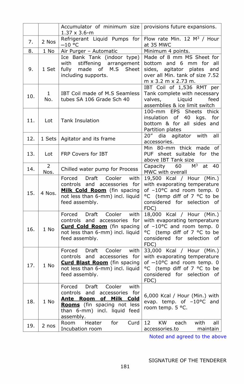
Noted and agreed to the above
SIGNATURE OF THE TENDERER
181
Accumulator of minimum size
1.37 x 3.6-m
provisions future expansions.
7. 2 Nos Refrigerant Liquid Pumps for
─10 °C
Flow rate Min. 12 M3 / Hour
at 35 MWC
8. 1 No Air Purger – Automatic Minimum 4 points.
9. 1 Set
Ice Bank Tank (indoor type)
with stiffening arrangement fully made of M.S Sheet
including supports.
Made of 8 mm MS Sheet for
bottom and 6 mm for all sides, agitator plates and
over all Min. tank of size 7.52 m x 3.2 m x 2.73 m.
10. 1
No. IBT Coil made of M.S Seamless tubes SA 106 Grade Sch 40
IBT Coil of 1,536 RMT per
Tank complete with necessary valves, Liquid feed
assemblies & ice limit switch
11. Lot Tank Insulation
100-mm EPS Sheets thick
insulation of 40 kgs. for
bottom & for all sides and Partition plates
12. 1 Sets Agitator and its frame 20” dia agitator with all accessories.
13. Lot FRP Covers for IBT
Min 80-mm thick made of
PUF sheet suitable for the above IBT Tank size
14. 2
Nos. Chilled water pump for Process
Capacity 60 M3 at 40 MWC with overall
15. 4 Nos.
Forced Draft Cooler with
controls and accessories for Milk Cold Room (fin spacing
not less than 6-mm) incl. liquid feed assembly.
19,500 Kcal / Hour (Min.)
with evaporating temperature of –10°C and room temp. 0
°C (temp diff of 7 °C to be considered for selection of
FDC)
16. 1 No
Forced Draft Cooler with
controls and accessories for Curd Cold Room (fin spacing
not less than 6-mm) incl. liquid feed assembly.
18,000 Kcal / Hour (Min.)
with evaporating temperature of –10°C and room temp. 0
°C (temp diff of 7 °C to be considered for selection of
FDC)
17. 1 No
Forced Draft Cooler with controls and accessories for
Curd Blast Room (fin spacing not less than 6-mm) incl. liquid
feed assembly.
33,000 Kcal / Hour (Min.) with evaporating temperature
of ─10°C and room temp. 0 °C (temp diff of 7 °C to be
considered for selection of FDC)
18. 1 No
Forced Draft Cooler with
controls and accessories for Ante Room of Milk Cold
Rooms (fin spacing not less than 6-mm) incl. liquid feed
assembly.
6,000 Kcal / Hour (Min.) with
evap. temp. of –10°C and room temp. 5 °C.
19. 2 nos Room Heater for Curd
Incubation room
12 KW each with all
accessories.to maintain
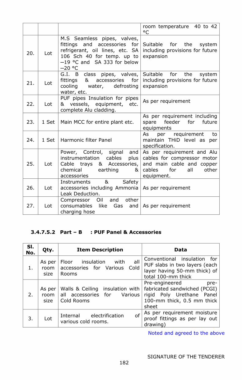
Noted and agreed to the above
SIGNATURE OF THE TENDERER
182
room temperature 40 to 42
°C
20. Lot
M.S Seamless pipes, valves,
fittings and accessories for refrigerant, oil lines, etc. SA
106 Sch 40 for temp. up to
─19 °C and SA 333 for below ─20 °C
Suitable for the system including provisions for future
expansion
21. Lot
G.I. B class pipes, valves, fittings & accessories for
cooling water, defrosting water, etc.
Suitable for the system including provisions for future
expansion
22. Lot
PUF pipes Insulation for pipes
& vessels, equipment, etc. complete Alu cladding.
As per requirement
23. 1 Set Main MCC for entire plant etc. As per requirement including spare feeder for future
equipments
24. 1 Set Harmonic filter Panel As per requirement to maintain THiD level as per
specification.
25. Lot
Power, Control, signal and
instrumentation cables plus Cable trays & Accessories,
chemical earthing & accessories
As per requirement and Alu
cables for compressor motor and main cable and copper
cables for all other equipment.
26. Lot
Instruments & Safety
accessories including Ammonia Leak Deduction.
As per requirement
27. Lot Compressor Oil and other consumables like Gas and
charging hose
As per requirement
3.4.7.5.2 Part – B : PUF Panel & Accessories
Sl.
No. Qty. Item Description Data
1.
As per
room
size
Floor insulation with all
accessories for Various Cold
Rooms
Conventional insulation for PUF slabs in two layers (each
layer having 50-mm thick) of total 100-mm thick
2. As per room
size
Walls & Ceiling insulation with all accessories for Various
Cold Rooms
Pre-engineered pre-
fabricated sandwiched (PCGI) rigid Poly Urethane Panel
100-mm thick, 0.5 mm thick sheet
3. Lot Internal electrification of various cold rooms.
As per requirement moisture proof fittings as per lay out
drawing)
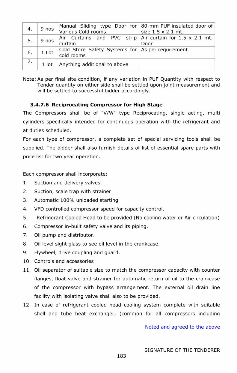
Noted and agreed to the above
SIGNATURE OF THE TENDERER
183
4. 9 nos Manual Sliding type Door for
Various Cold rooms.
80-mm PUF insulated door of
size 1.5 x 2.1 mt.
5. 9 nos Air Curtains and PVC strip
curtain
Air curtain for 1.5 x 2.1 mt.
Door
6. 1 Lot Cold Store Safety Systems for cold rooms
As per requirement
7.
1 lot Anything additional to above
Note: As per final site condition, if any variation in PUF Quantity with respect to Tender quantity on either side shall be settled upon joint measurement and
will be settled to successful bidder accordingly.
3.4.7.6 Reciprocating Compressor for High Stage
The Compressors shall be of "V/W" type Reciprocating, single acting, multi
cylinders specifically intended for continuous operation with the refrigerant and
at duties scheduled.
For each type of compressor, a complete set of special servicing tools shall be
supplied. The bidder shall also furnish details of list of essential spare parts with
price list for two year operation.
Each compressor shall incorporate:
1. Suction and delivery valves.
2. Suction, scale trap with strainer
3. Automatic 100% unloaded starting
4. VFD controlled compressor speed for capacity control.
5. Refrigerant Cooled Head to be provided (No cooling water or Air circulation)
6. Compressor in-built safety valve and its piping.
7. Oil pump and distributor.
8. Oil level sight glass to see oil level in the crankcase.
9. Flywheel, drive coupling and guard.
10. Controls and accessories
11. Oil separator of suitable size to match the compressor capacity with counter
flanges, float valve and strainer for automatic return of oil to the crankcase
of the compressor with bypass arrangement. The external oil drain line
facility with isolating valve shall also to be provided.
12. In case of refrigerant cooled head cooling system complete with suitable
shell and tube heat exchanger, (common for all compressors including
Noted and agreed to the above
SIGNATURE OF THE TENDERER
184
future compressors installed at suitable height above high pressure liquid
receiver), instruments and controls for maintaining proper temperature of oil
returning to compressor with necessary control valves, isolating valves, inter
connecting pipelines, safety features, oil drain arrangement, etc., complete
as required.
13. Crank case heater with protection fuse and automatic thermostat to CUTIN
automatically when the compressor is in OFF mode and CUT-OUT
automatically when the compressor is in ON mode, so as to maintain the oil
temperature in the crank case at the desired level and as recommended by
the compressor manufacturer.
14. The compressor and the motor along with drive coupling and coupling guard
shall be mounted on a machined surface embedded on to a common base
frame with alignment locating points, factory established to ensure correct
positioning of motor and compressor, when mounted at site.
15. Discharge and suction gas thermometer pockets.
Compressor Controls, Panels and Accessories
Each compressor shall be provided with local gauge control panel with:
1. HMI for automatic capacity controller panel with pressure transmitter in
suction line of each compressors. The pressure transmitters should be
provided for display in HMI of oil & discharge pressure and safety interlocks
for each compressor.
2. Pressure gauges showing suction, discharge, and oil pressures and
temperature gauges showing suction gas and discharge gas temperature.
Liquid filled gauges for pressure application and plain dial type gauges for
temperature application shall be used.
3. Safety cutout switches for:
- High refrigerant pressure
- Low refrigerant pressure
- Low oil pressure
These safety cutouts shall be of manual reset type and shall incorporate contacts
for failure indication.
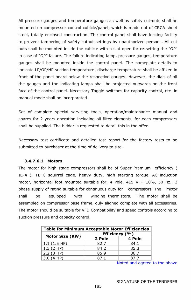
Noted and agreed to the above
SIGNATURE OF THE TENDERER
185
All pressure gauges and temperature gauges as well as safety cut-outs shall be
mounted on compressor control cubicle/panel, which is made out of CRCA sheet
steel, totally enclosed construction. The control panel shall have locking facility
to prevent tampering of safety cutout settings by unauthorized persons. All cut
outs shall be mounted inside the cubicle with a slot open for re-setting the "OP"
in case of “OP” failure. The failure indicating lamp, pressure gauges, temperature
gauges shall be mounted inside the control panel. The nameplate details to
indicate LP/OP/HP suction temperature; discharge temperature shall be affixed in
front of the panel board below the respective gauges. However, the dials of all
the gauges and the indicating lamps shall be projected outwards on the front
face of the control panel. Necessary Toggle switches for capacity control, etc. in
manual mode shall be incorporated.
Set of complete special servicing tools, operation/maintenance manual and
spares for 2 years operation including oil filter elements, for each compressors
shall be supplied. The bidder is requested to detail this in the offer.
Necessary test certificate and detailed test report for the factory tests to be
submitted to purchaser at the time of delivery to site.
3.4.7.6.1 Motors
The motor for high stage compressors shall be of Super Premium efficiency (
IE-4 ), TEFC squirrel cage, heavy duty, high starting torque, AC induction
motor, horizontal foot mounted suitable for, 4 Pole, 415 V + 10%, 50 Hz., 3
phase supply of rating suitable for continuous duty for compressors. The motor
shall be equipped with winding thermistors. The motor shall be
assembled on compressor base frame, duly aligned complete with all accessories.
The motor should be suitable for VFD Compatibility and speed controls according to
suction pressure and capacity control.
Table for Minimum Acceptable Motor Efficiencies
Motor Size (KW) Efficiency (%)
2 Pole 4 Pole
1.1 (1.5 HP) 82.7 84.1
1.5 (2 HP) 84.2 85.3
2.2 (3 HP) 85.9 86.7
3.0 (4 HP) 87.1 87.7
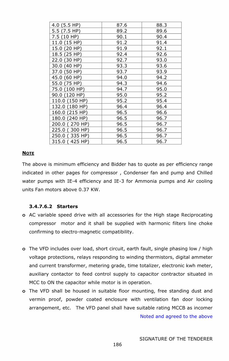
Noted and agreed to the above
SIGNATURE OF THE TENDERER
186
4.0 (5.5 HP) 87.6 88.3
5.5 (7.5 HP) 89.2 89.6
7.5 (10 HP) 90.1 90.4
11.0 (15 HP) 91.2 91.4
15.0 (20 HP) 91.9 92.1
18.5 (25 HP) 92.4 92.6
22.0 (30 HP) 92.7 93.0
30.0 (40 HP) 93.3 93.6
37.0 (50 HP) 93.7 93.9
45.0 (60 HP) 94.0 94.2
55.0 (75 HP) 94.3 94.6
75.0 (100 HP) 94.7 95.0
90.0 (120 HP) 95.0 95.2
110.0 (150 HP) 95.2 95.4
132.0 (180 HP) 96.4 96.4
160.0 (215 HP) 96.5 96.6
180.0 (240 HP) 96.5 96.7
200.0 ( 270 HP) 96.5 96.7
225.0 ( 300 HP) 96.5 96.7
250.0 ( 335 HP) 96.5 96.7
315.0 ( 425 HP) 96.5 96.7
NOTE
The above is minimum efficiency and Bidder has to quote as per efficiency range
indicated in other pages for compressor , Condenser fan and pump and Chilled
water pumps with IE-4 efficiency and IE-3 for Ammonia pumps and Air cooling
units Fan motors above 0.37 KW.
3.4.7.6.2 Starters
o AC variable speed drive with all accessories for the High stage Reciprocating
compressor motor and it shall be supplied with harmonic filters line choke
confirming to electro-magnetic compatibility.
o The VFD includes over load, short circuit, earth fault, single phasing low / high
voltage protections, relays responding to winding thermistors, digital ammeter
and current transformer, metering grade, time totalizer, electronic kwh meter,
auxiliary contactor to feed control supply to capacitor contractor situated in
MCC to ON the capacitor while motor is in operation.
o The VFD shall be housed in suitable floor mounting, free standing dust and
vermin proof, powder coated enclosure with ventilation fan door locking
arrangement, etc. The VFD panel shall have suitable rating MCCB as incomer
Noted and agreed to the above
SIGNATURE OF THE TENDERER
187
with copper bus bars, inter connection, power / control terminal blocks with
adequate space for termination of power / control cable.
3.4.7.6.3 Evaporative Condenser
Condenser designed for compressor load plus 10 to 15% safety factor
.Condenser will be induced draft counter flow design ammonia condensers
suitable for vertical discharge comprising coil section, drain section, fan section,
water distribution with eliminators and louvers. The condensers supplied with
necessary air inlet screen, float control water valve, hot gas inlet connection with
valve and liquid outlet connection with valve.
All cold water basin components including vertical supports and air inlet louver
frames are constructed of Stainless Sheet. Casing, channels and angle supports
are constructed of heavy gauge mill hot dip galvanized steel. All galvanized
steel is coated with a minimum of 2.35 ounces of zinc per square foot of area
(G235 designation). During fabrication, all galvanized steel panel edges are
coated with a 95% pure Zinc Rich compound for superior protection against
corrosion.
3.4.7.6.4 Coil:
Thermal pack coil design of all prime surface steel tubes encased in steel
frame work with entire assembly hot dipped galvanized after fabrication. Tubes
will be sloped for liquid drainage. Coil(s) will be pressure tested to 375 psig air
under water.
3.4.7.6.5 Fan with Fan Motor
Fan of axial propeller type constructed of aluminum alloy complete with
suitable rating, totally enclosed air over type with 1.15% service factor & IE-4
Specification. The fan drive is a multi-groove, solid pack and the sheave
constructed of aluminum alloy.
3.4.7.6.6 Water Distribution System
Heavy duty molded nylon ZM spray nozzles with large 1–5/16” diameter
opening and internal sludge ring to eliminate clogging. ZM nozzles are threaded

Noted and agreed to the above
SIGNATURE OF THE TENDERER
188
into Schedule –40 Polyvinyl Chloride headers equipped with removable end plugs
for ease of cleaning.
3.4.7.6.7 Eliminators
The eliminators are constructed entirely of Polyvinyl Chloride (PVC) in easily
handled section. Design incorporates three changes in air direction and limits
the water carry over to a maximum of 0.001% of the circulating water rate.
3.4.7.6.8 Pump
Closed coupled centrifugal pump of suitable rating as per OEM with
mechanical seal with pump motor which is totally enclosed with protective cover.
The pump shall be supplied with metering valve and it shall be IE-4 Specification.
3.4.7.6.9 Air Inlet Louvers
The air inlet louvers are constructed from UV inhibited Polyvinyl Chloride
(PVC) and incorporate a framed inter locking design that allows for easy removal
of louvers for access to the entire basin area for maintenance. The louvers have
a minimum of two changes in air direction and are of a non-planar design to
prevent splash out, block direct sun light and debris from entering the basin
(Patent Pending).
The condenser shall be supplied with necessary make up float valve assembly,
Pan Strainer. The condenser having provision of hinged door for easy
maintenance.
Scope includes necessary electronic water level control system in the basin with a
solenoid activated valve in the makeup line.
Our scope of supply includes the following accessories:
o Gas & Liquid inlet & outlet valve
o Dual safety valve with housing material with low temperature steel. Safety
valve as back pressure dependent 2 nos.
o Isolating valve for pumping out
o Air Purge connection
o Pressure Gauge with valve
Noted and agreed to the above
SIGNATURE OF THE TENDERER
189
o Make up water connection with all fittings
Any Base frame where ever required as a structural members (all in galvanized
steel construction) shall be included in the scope of work
3.4.7.6.10 HP Receiver
Ammonia liquid Receiver complete with:
liquid inlet and outlet valves, Charging valve
Dual safety valve with housing material with low temperature steel. Safety
valve , 2 nos. purge valve,
Quick drain valve with built in integral relief opening for safety, pressure
gauge,
Liquid gauge glass indicator with valve.
The HP receives will be inter connected with suitable isolating valve in order to
act as single vessel. All Gauges and controls shall be directly mounted on needle
valves, thereby eliminating additional weld joints. The receiver shall be
complete with M.S. saddle supports.
All Ammonia valves & controls shall be manufactured from low temperature steel
in accordance to EN 12284 / Equivalent standards. All valves and controls shall
be preferably weld able valves to avoid leakage through flange joints.
The vessel shall be of IS: 2002 / SA 516 and IS: 2002 Clause –I and all the
welding joints are tested 100% radiographed.
3.4.7.6.11 Air Purger
Multi point electronic Air Purger operating on 220 Volts, 50 Hz. The purger
includes gauge glass, one no. electronic purger controller, solenoid valve,
thermostatic expansion valve, strainer, liquid seal trap and metering Valve.
3.4.7.6.12 LP Receiver
The Refrigeration bidder to design separate LP Receivers for 10 °C. Necessary
provision shall be made for future expansion fabrication / manufacturing of Pump
Noted and agreed to the above
SIGNATURE OF THE TENDERER
190
Separator shall be carried out as per IS Code 2825 "Unfired Pressure Vessel - All
weld joints shall be 100% radio graphically tested.
o LP Receiver to be Supplied / Fitted With
a. Suction gas outlet shall be of dome type provided with mist eliminator.
The gas outlet from the dome shall be with valve.
b. Suction gas inlets (wet return) with valves
c. Liquid outlets to circulating pumps with valves. (two spares for future pumps)
d. Oil drains connection with valve and with suitable receiver at the bottom. A
receiver of approx. Capacity 50 lit. Shall be provided with level indicator and
all accessories at the bottom for collection of oil with oil drain facility using
Quick Drain valve. Including provision for electrical heater for rectification of
oil with necessary safety valves and all accessories as required. Plugged
bottom drain.
e. Liquid level control tapings, 2 Nos., valves. The liquid level manifold shall be
provided for mounting Electronic liquid level transmitter cum sensor and
high level electro Magnetic float switches shall have oil drain pot and provision
to drain oil through oil drain valve. This header shall be insulated for
better function of float controls. The header pipe diameter shall be
minimum of 125 mm.
f. Motorized Expansion valve controlled by liquid Level controller in the main
liquid line from receiver shall be provided. The conventional valve train
comprising of inlet Stop valve, Filter, solenoid valve with manual opener,
Expansion valve and outlet stop valve can be replaced by ICF block type
valves, which can reduce the number of weld joints from 10 to 2 and also
brings in life time savings through lower operation cost and minimal down
time in case of service / maintenance / break down.
g. Liquid level gauge tapings, 2 No., valves. The branches to the gauge shall
include isolation valves and automatic shut-off for gauge breakage.
h. Mounting pads for. Level switches, high safety.
i. Vapors vent connection from circulating pumps, with valves.
j. Dual safety valve, housing material with low temperature steel. Safety valve ,
2 nos. purge valve,
k. Pressure gauge tapping with needle valve isolating the pressure gauge.
Noted and agreed to the above
SIGNATURE OF THE TENDERER
191
l. Manual fill connection with valve.
m. Pressure stat connection with needle valve.
n. Pump-out connection, valves and plugged.
o. Suitable purge pipe arrangement to receive discharge gas from low stage
compressor, with valve.
p. Two nozzles shall be extra for gas returns from pressure differential switches
and oil vessel. The vessel shall be supported on saddles adequately braced
and gusseted to the shell. All mild steel support parts shall be hot dip
galvanized after fabrication. The supporting structure, platforms and ladder
are included in the scope of supply. Thermal barrier of approved construction
to be incorporated.
Each accumulator vessel shall be provided with:
Liquid level control: A suitable Electronic liquid level transmitter (AKS Series or
Equivalent type controls of Radar based technology) with suitable standalone
controller to monitor and control the liquid level. The level transmitter shall
give continuous feedback to Central PLC panel for dynamic display of the actual
liquid level in the vessel. The controller shall give required input to the
modulating Motorized expansion valve (ICM with ICAD actuator or Equivalent type /
model controls) to maintain the desired liquid level accurately in the accumulator
using in built PID functionality.
High level Safety switches: Electromagnetic micro switch mechanically
operated,
Pressure Sensor: Fit a modulating pressure controller of all-steel construction
and rated for the operating pressures on each accumulators. The vessels shall
be mounted outdoor (in such height that it meets the requirement of the
minimum Net Positive Suction Head (NPSH) of the Liquid Ammonia Pumps
installed below the vessel manual type oil rectifier of vertical type with M.S. shell
of size 500–mm dia x 1,400–mm long complete with inlet valves, outlet Quick
drain valves, gauge glass, pressure gauge with valve, safety valve, electrical
heater with thermostat and hot gas heating arrangement.
Noted and agreed to the above
SIGNATURE OF THE TENDERER
192
3.4.7.6.13 Ice Bank Tank & Accessories
Ice Bank Tank fabricated out of MS sheets of 6mm thick for all sides & agitator
plates and 8 mm for bottom plates with Single compartment. The tank shall be
complete with necessary stiffening arrangements. The tank shall include a
central baffle and guide end plates at all corners of the tank.
The tank shall be complete with flanged outlet, return water connections, over
flow and make up water inlet with float valve, etc. However necessary concrete
floor over insulation as well as Brick walls around the sides of IBT Tank to be
done/ arranged by purchaser. The supplier shall thoroughly re-rust the IBT side
walls after fabrication and after leak testing apply 1 coat of 100 microns thick
epoxy based high built primer followed by 2 coat of high built epoxy based paint
of 100 micron thick for each coat of paint of approved make. Scope includes
painting inside existing IBT Tanks
3.4.7.6.14 Ice Bank Tank Coil
Ice accumulation coil fabricated out of 32 mm Seamless SA 106, Sch. 40 pipe.
The coil shall be designed suitable for Over Feed System with necessary liquid
inlet / outlet and gas inlet / outlet valves and the coil will be ‘I’ type (ASTRA
type). The Coil Shall Be Spray Galvanized after its Fabrication.
For each compartment including for existing IBT Tanks to be supplied with Liquid
feed assemblies comprising of Strainer, Liquid Solenoid Valve, Metering Valve,
Isolating Valve, valved By-pass, Pump out connection, valved & plugged
complete with Automatic Ice thickness switch.
3.4.7.6.15 IBT Tank Insulation
Ice Bank Tank insulation with 100-mm thick (2 layers of 50 mm each) heavy
density EPS Sheet of 24 Kgs. / M3 for the bottom and 100 mm thick (2 layers of
50 mm each) normal density of 18 Kgs. / M3 UF Sheet for the sides. The scope of
supply includes sufficient quantity of bitumen and a layer of tarfelt as vapour
barrier for the bottoms.
3.4.7.6.16 Agitator
Agitator of minimum 20” with motor suitable for the above Ice Bank Tank
Noted and agreed to the above
SIGNATURE OF THE TENDERER
193
3.4.7.6.17 IBT Cover
FRP cover suitable for Indoor type complete with PUF slab inside of 80-mm thick
and the size shall be suit to ice Bank tank and it shall be supplied with 2 nos. SS
collapsible handles
3.4.7.6.18 Forced Draft Cooler (Air Cooling Unit)
Cold rooms (All Cold Rooms) of the Dairy are to be maintained at required
operating conditions by forced draft coolers. Forced draft coolers shall be supplied
by a specialist manufacturer as fully assembled units. The manufacturer shall
warrant performance. All Low temp. ACU shall be supplied with Fan heater and tray
heaters.
All Positive cold room's ACU to be designed for Pumped system
The coolers required are of ceiling suspended cross draft type specifically
intended to operate with pumped liquid supply. Cooling coils shall be made of
stainless steel tubes with Aluminium fins with Pre coated /PCGI Casing as per
approved make suppliers standard MOC for casing. All Fan motors shall be IE-3
Efficiency for above 0.37 KW fans and below 0.37 KW fans with normal efficiency.
Fin spacing shall be:
Ante Room & All Cold Store : Not less than 6 mm
Water defrosts spurge pipes and header shall be provided, arranged to be self-
draining.
For the Deep Freeze units,(Freon Unit) Electronic defrosting arrangement shall
be provided. Also the Deep freeze FDC units shall be provided with hot gas
heater pipes elements for drain tray. The system includes slow closing solenoid
valves, pressure regulation valves, pressure gauge, timers and other necessary
items required.
For cold rooms, off cycle defrost / water defrosting arrangement shall be
provided with automatic controls.
Room Temp controller. Each room shall be provided with Room temperature
controller ERC 211/ Equivalent type with Sensor with controlling room temp thro
PLC. Once the desired temp is maintained in the room, the controller will close
the liquid line solenoid valve and open the room temp is raised again.
The casing shall be of either Powder coated or stainless steel. Induced draft fans
Noted and agreed to the above
SIGNATURE OF THE TENDERER
194
shall be axial, direct coupled to motors. Belt drives are not acceptable. Fans and
motors shall be dynamically balanced. Fans made of Poly amide glass fibre
reinforced material are acceptable. Fan and motor assemblies shall be resiliently
mounted and effectively guarded. Motors and bearings shall be suitable for
operation at an ambient temperature of –35°C, and motors shall have degree of
protection IP55 or better.
The drain tray shall be of heavy gauge galvanized sheet, cross broken to provide
falls, and arranged to intercept condensation from the casing. The drain tray
shall be suitably insulated. The outlet shall be vertical. Fixing of the unit shall be
by adequate number of suspension rods attached to substantial lugs on the
casing
Suspension members for the units shall incorporate a thermal break within the
thickness of the insulation. The detailed arrangement and supply of this is
the responsibility of the bidder to suspend the evaporators, level and lock the
suspension nuts.
Pipe Connections
To each evaporator supply and install a liquid feed assembly, this shall
preferably be mounted outside the cold room. The liquid feed assembly
comprising of
Strainer
Liquid solenoid valve
Metering valve
Isolating valves
Valve by-pass
Pump-out connection, valves and plugged –SNV needle valves.
Pressure gauge with isolating valve –SNV needle valves.
All controls as per functional requirement.
The metering valve shall be of a type purpose-made for liquid control in a
pumped liquid system, and comprising a manual adjustable regulating cone for
Noted and agreed to the above
SIGNATURE OF THE TENDERER
195
minimum pressure drop. The make and type are subject to approval.
All water pipelines (drain & supply) inside low temperature zone shall be
electrically heat traced, with thermostatic controls and insulated. The defrost
water assembly shall be generally as detailed and subject to approval.
Connect:
To the supply, spurge pipe with a section of hose fastened with stainless
clamps. To the drain, with a funnel and water “U” seal of approved construction,
outside low temperature area. The details of Unit, capacity and scheme are to
be furnished in the bid.
3.4.7.6.19 Pumps for various equipments
Cooling Water for Evaporative Condenser: As provided by the OEM of
the evaporative type condenser.
Chilled Water: This shall be vertical inline Multi stage pump of SS construction
for the water contact areas. Connections shall be flanged. Pumps shall be
provided with energy efficient IE-4 motors.
Refrigerant Liquid: All pumps shall be of Hermetic Type. Construction
materials in contact with ammonia shall not contain copper and the Pump shall be
immune from vapour binding. A casing vent shall be fitted, if necessary. Each
pump shall be provided with a strainer and pressure differential control system.
Positive displacement or centrifugal pumps may be offered; if the former a
relief valve shall be provided to meet closed delivery operation. The supplier is
responsible to determine pump operating conditions and to select appropriate
pumps, which shall be subject to approval of purchaser.
Driving motors shall have continuous ratings in IP 55 enclosure, exceeding the
limit load of the connected pump. Pumps and motors shall be mounted on
common base plates, with alignment locating points factory established to ensure
correct positioning of motor when mounted on site.

Noted and agreed to the above
SIGNATURE OF THE TENDERER
196
3.4.7.6.20 Refrigerant & Water Piping.
Supply and install all required piping such as refrigerant, oil drain, defrost
water cooling water lines for condensers, chilled water, etc., necessary for the
operation of total refrigeration system installed by the Refrigeration Contractor.
Required valves and NRV's, bends, support materials, etc. as needed, are
included in the scope of the contractor and also to be supplied and installed by the
Supplier within the contract value.
Suction and delivery main headers piping of High stage Compressors should
be sized for simultaneous operation of all the compressors specified in
Column 2 including standby plus Two more compressor of similar capacity
proposed to be installed in future. Similarly, the main headers of condenser
piping, oil cooler piping, etc. Shall be designed suitable for all proposed pumps
plus one future pump. Chilled water supply and return Headers to be designed
for all proposed pumps working + additional same capacity and same no of
pumps working in future. Ie Headers to be designed for double the capacity of
current peak flow rates. These headers shall be provided with necessary
trappings and isolating valves duly dummied and suitable to hook up the future
compressors, condensers, ammonia pumps, chilled water pumps, IBT, etc.
readily.
The maximum velocity of the fluids/gas shall be considered as under:
a. Suction gas line (NH3) 15.0 m/sec
b. Discharge line (NH3) 18.0 m/sec
c. Liquid line (NH3) condenser to
0.5 - 0.6 m/sec receiver
d. Liquid line (NH3) receiver to 1.0 m/sec system
e. Wet return line (NH3) 10 m/sec
f. Suction line (H20) 1.0 to 1.2 m/sec
g. discharge line (H20) 2.0-2.5m/sec
All refrigerant, oil piping, the contractor shall use "seamless heavy duty class
scheduled 80/40 pipes" as per international standard depending on size of pipe, of
SA 53 grade/ SA 106 grade as applicable.
Noted and agreed to the above
SIGNATURE OF THE TENDERER
197
All refrigerant, oil piping shall be SA 106 for –19 °c & SA 333 for below –20 ° c
application. All water line/chilled water line will be G.I medium B class pipes
All vessel plates are steel plate & specification will be is: 2002 / SA516 Gr.70 & IS:
2825, class: 1
In case of hot dip galvanization wherever specified in the tender specification, the
minimum zinc coating required is 75 to 80 microns uniform thickness all around
the surfaces.
In case of spray galvanization wherever specified in the tender specification, the
minimum zinc coating required is 120 to 125 microns uniform thickness all around
in surfaces.
For all refrigerant lines, the Supplier shall follow the welding procedure based on
international Code of Practice. It is expected to follow the procedure that the
first route run welding shall be carried out by argon/nitrogen arc welding by
filling argon/nitrogen gas inside the pipe and subsequent runs may be carried
out by arc welding process.
All the refrigeration vessels in the system such as oil separator, condenser,
receiver, pump separator (LP accumulator) shall be considered as class I vessel
according to IS 2825 or equivalent British or American code and all weld joints
shall be tested for 100% radiography.
3.4.7.6.21 Line & Vessel Insulation
Insulation for pipe lines shall be Rigid Poly Urethane Foam of Density 40 kgs /
cb.mt (minimum) and equipments shall be carried out as per special condition
(mechanical) and minimum recommended insulation thicknesses are as follows.
Minimum thickness of Rigid Poly Urethane Foam for Ammonia Pipe/Chilled Water
Pipe Insulation
NOM. Pipe Dia in MM
15 20 25 32 40 50 65 80 100 125 150
Temp –10°C & above
30 30 30 30 40 40 50 50 65 65 80
Temp Below –10
°C 50 50 50 50 65 75 75 100 100 100 100
The insulated pipelines shall be supported using high density PUF block
(minimum 80 kg/cum) or using seasoned teak wood as approved. These

Noted and agreed to the above
SIGNATURE OF THE TENDERER
198
insulating supports shall be enclosed in the vapour barrier. The pipe surface shall
be thoroughly de-rusted and cleaned followed by 2 coats of approved primer prior
to insulation.
An outer vapour seal on ammonia/chilled water pipelines shall comprise an
approved vapour barrier sheath (preferably aluminum coated polyester film of
50 micron thick) with joints lapped and sealed with self adhesive tape
Insulate the pump separator (LP Accumulator) with suitable thickness as
insulation as but not less than 120 mm and insulation for 10 deg C
application of the outer vessel operation below ambient condition. An outer
vapour seal over the insulation using an approved sheet material (preferably
aluminum coated polyester film of minimum 50 micron thick) with joints lapped
and sealed with self-adhesive tape. Finished with Aluminium cladding of 24 SWG
over the insulation shall be done in an approved manner. However, Inside of all
cold rooms and deep freeze rooms shall be cladded with SS sheets instead of AL
sheets.
3.4.7.7 Electrical (MCC Panel, Power & Control Wiring, Cable Tray,
Earthing, Etc.)
It shall be as per the specifications mentioned in the Electrical system.
Power Factor Improvement Panel with APFCR Relay:
It shall be as per the specifications mentioned in the Electrical system.
3.4.7.7.1 Instrumentation & Safety System
Pressure Gauges: Pressure gauges shall be of Bourdon tube type, conforming
to the requirements of IS:3624. Also in front of various cold rooms and deep freeze
rooms, are to be provided with one set of Digital temperature Indicators each.
Ammonia Leak Deduction system
Ammonia leak detection system with ammonia sensors, controls, audio visual
alarm to detect the leakage of ammonia shall be supplied and installed in the
plant room, condenser area, all deep freeze rooms.
Noted and agreed to the above
SIGNATURE OF THE TENDERER
199
Bidder scope of supply includes 2 nos. gas masks with oxygen cylinder for 30
minutes in lockable enclosure. Also our scope includes necessary drench shower
with eye / face wash with fountain
Emergency Ventilation System
One no. Fixed type emergency ventilation system for the refrigeration plant
room comprising of axial fan / blowers of suitable capacity to cater plant room
volume multiplied by 10 complete with flame proof electrical motor and
necessary cabling. The system shall have provision for switching on from the
outside of the refrigeration plant room. Once the system is switched on all the
electrical connections shall be switched off automatically.
The scope of this bid also includes supply, installation and demonstration of
following safety accessories:
a. Two sets of Ammonia gas mask (with oxygen cylinder for 30 min), in
conformity with IS:660 and provided with a wall-mounted
lockable enclosure approved by the purchaser at an accessible location
just outside the refrigeration plant room and 2 stes of air tight safety
suits.
3.4.7.7.2 Compressor Oil & Consumables
The system shall be located outside the compressor room suitable to charge
ammonia from the cylinder and shall consist of following items:
Two sets of quick mounting attachment each with stop cum check valve,
flexible piping and end connection suitable for the cylinder and charging port
of ammonia loading station Ammonia pressure gauge. Filter.
First charge of compressor oil for the proposed all compressors. Scope includes
sufficient quantity of ammonia gas for total refrigeration system commissioning.
3.4.7.7.3 Sandwiched Panels
3.4.7.7.3.1 For Ceiling and Wall Column
The wall and ceiling of the insulated cold rooms are to be constructed using pre-
fabricated, self-supported, sandwich panels insulated with rigid polyurethane foam
of required thickness.
Noted and agreed to the above
SIGNATURE OF THE TENDERER
200
Sandwiched Panel shall be CFC free, manufactured using high pressure foam
injection equipment in a precise ratio and proportion. The properties of the
polyurethane insulation shall be as under
Injected density : 40 + 2 kg/m3
Thermal conductivity : 0.023 W/mt/deg K.(Aged)
Compressive strength : 155 Kpa
Closed cell contents : 90 to 95 %
Operation temperature range : minus 60° C to 80° C
The skin material for the wall and ceiling panels shall of galvanized sel sheet
(minimum grade 275 gsm) of minimum 0.5-mm thick with grooved profile
to enhance strength and aesthetics. The external surface of sheet shall be
pre-painted with minimum 25-micron thick with Silicon Modified Polyester
coating.
The joining system of the panels shall be designed to ensure a quick and secure
assembly at site, with the help of tongue and groove joints with eccentric cam
locks or any other approved arrangement. The joints shall be made hermetic
and perfectly vapour tight by use of silicone sealants. The wall panels shall be
in single lengths to match the room height, and width of ceiling/wall panels shall
be 1.2 mt., in order to pprox. the number of joints. The configuration shall
incorporate factory made standard L shape panels for corners and TEE shape
panels for partitions.
The system shall be complete with all ancillary items like, ceiling panels
suspension system complete with insulated beam, suspension chain/hardware,
suitable corner pieces, pre-painted steel/aluminium profiles for inner/outer
junctions and joint corners, pressure relief valves, silicone sealants, foam
chemicals and all other components & accessories as required. The costs of
these ancillary items are to be included in the respective rates for
installation of ceiling/wall panels and no separate payment shall be made for
this items.

Noted and agreed to the above
SIGNATURE OF THE TENDERER
201
3.4.7.7.3.2 Floor Insulation
The floor insulation shall be made of rigid polyurethane foam slabs in two layers
of required thickness. The properties of polyurethane foam insulation shall be as
mentioned above. The insulation shall be carried out in 1the following
manner.
Coat of bituminous primer shall be applied over the finished PCC floor, after
thorough cleaning and drying.
Tarfelt of 2.4 mm thick shall be applied on the concrete surface below the
insulation layer as vapour barrier with bitumen as Adhesive. The joints shall be
staggered having minimum 100 mm overlap thoroughly sealed to make it
perfect vapour barrier. The ends shall be turned up the outer wall
above the height of protective curb and completely sealed with silicone
sealant.
A coat of bitumen shall be applied on the outer surface of tarfelt and fix the
first layer of rigid polyurethane foam insulation slabs (of required thickness)
with the joints staggered. All joints sealed completely using hot bitumen.
A coat of bitumen shall be applied on the surface of first layer of insulation
and fix the second layer of rigid polyurethane foam insulation slabs with
cross-wise joints staggered. Seal all joints completely using hot bitumen.
Provide tarfelt of 2.4 mm thick above the insulation layer using bitumen as
adhesive. The joints shall be staggered and shall have minimum 100mm
overlap thoroughly sealed to make it waterproof barrier. The ends shall be
turned up the inner wall above the height of protective curb ( pprox..
height 500 mm above finished floor level) and completely sealed with silicone
sealant.
3.4.7.7.3.3 Sliding Door
Milk / product cold store shall be provided with manual sliding type doors. The
doors shall be of PUF or Styrofoam insulated with both side covered with
impact resistant glass fiber reinforced food safe polyester complete with all
accessories properly engineered and made by specialist manufacturer broadly
meeting following requirements.
Noted and agreed to the above
SIGNATURE OF THE TENDERER
202
The insulated doors shall be manually operated, horizontally sliding/hinge type,
easy to mount, mechanically reinforced for heavy duty usage complete with all
required fittings, sliding rails/hinges, bottom guide, rollers etc. mounted on a
suitable frame. Necessary heavy-duty handle for easy opening and closing of
doors shall be provided. Door pad Locking arrangement, emergency exit lock
release knob/wheel shall be provided.
Sliding rail arrangement shall be easy to operate constructed so that the door
drops a little down and towards the frame uniformly while closing to achieve a
hermetic seal.
Shafts, nuts for roller shall be made out of SS. The gasket material shall be
durable and shall not harden at low temperature. The doors shall have
padlocking arrangement from outside. Safety release provision shall be made
for opening door from inside, even with padlock in place. Kick plate made of
SS chequered plate shall be provided up to a height of about 900 mm
from bottom for mechanical impact protection.
The doors for butter deep freeze (sub-zero) application shall be equipped with
electrical doorframe heaters with thermostat control with wiring.
Sil portion of main insulated door openings and hatch door openings shall be
finished with pre coated sheet as per the requirement. Sil insulation shall be
provided for the three sides of opening for main door openings and all the four
sides in case of hatch door openings. The refrigeration contractor shall be
responsible to finish the SIL portion of the Hinge/sliding door area with PUF
insulation of appropriate thickness and cladded with pre coated sheet, flashing,
angles at the corner, etc.
In front of each sliding door (on closing and opening condition) a set of
metallic guard made out of heavy duty `c’ class pipe of 100 mm dia (stand type)
and 50 mm dia `C’ class pipe for brazing the stand pipes shall be supplied and
installed by the contractor to protect the sliding doors from the external
damages. The drawings shall be approved by the purchaser.

Noted and agreed to the above
SIGNATURE OF THE TENDERER
203
3.4.7.7.3.4 Air Curtain
The air curtain shall be installed on each cold store doors consists of a case for
air canalizing, conveniently shaped permitting a rational arrangement of the
outgoing air. It shall consist of a set of deflectors for good distribution of the
jet of air of adequate velocity on the whole door span surface to avoid loss of
refrigeration.
The blower fan shall be made of Stainless steel and dynamically balanced to
prevent vibration. The bearing shall be pre-lubricated & sealed for life and
maintenance free, suitable for low temperature application. The fan motor
shall be suitable for 415 V, 3 phase AC supply.
There shall be a limit switch with required accessories, contactors, etc in
weather proof enclosure for automatic operation of blowers whenever the door
is opened. Electrical cabling to be done from MCC.
Air Shield curtains with each air curtain, provide a transparent PVC air shield
curtain having flaps (rounded edge) of minimum thickness 3 mm with 50%
overlap between adjacent flaps. The strip curtain shall be complete with all
accessories made of material suitable for low application and the PVC strips shall
remain soft up to operating temperature of minus 25 °C.
Each cool room (all cold store and deep freeze stores) shall have a safety pilot
light outside indicating the presence of people in distress in the room and
electric bells shall be provided for distress signaling. The sirens shall be
installed at approved locations-one in Refrigeration Plant room and other
in outside cold room corridor. The siren push switch shall be of self-illuminated
type. The `EXIT’ light provided inside the cold room shall be mounted
adjacent to the exit hatch door/main door to indicate the “EXIT DOOR” its
location. The safety pilot lights, sirens etc. shall work on 230 V through the
UPS (Uninterrupted Power Supply).
The circuits for sirens, safety pilot lights, and safety illumination shall be
independent of the mains power supply.
Noted and agreed to the above
SIGNATURE OF THE TENDERER
204
3.4.7.7.3.5 Lighting
Milk and Other cold store and ante rooms are to be provided with suitable
moisture proof fittings as per the room layout. Necessary wiring from the DB to
the fittings shall be made as per requirement.
The light fittings for the cold rooms shall be 2 x 18 or 2 x 36 vapour proof
fluorescent lamp fitting with IP 65 polycarbonate body with double gasket, UV
stabilized polycarbonate diffuser with transparent prismatic interior and smooth
exterior, double compression cable gland cable gland, with built-in switch
gears consisting of super low loss electronic ballast and all accessories
including lamps.
Conduits inside the cold rooms shall be made of heavy duty PVC conduit with
ISI mark. Wiring shall be using 3 core 2.5 sq.mm flexible copper cables.
The conduits shall be suitably concealed using Pre-coated flashing of
matching shade with panel.
All end terminations shall be vapour tight to prevent ingress of moisture
inside light fitting.
All conduit entries, cutouts made in insulation panel shall be thoroughly sealed
to make it vapour proof, by in-situ injection of PUF/silicone sealants.
Power supply for the lighting shall be made available at one point near cold
rooms in a MCB distribution board. The contractor shall carry out the
complete internal wiring from the DB, including providing necessary control
switches as required for the light points. Liquid ammonia charging system
3.4.7.7.3.6 Safety System for Cold Rooms
Safety system for cold room (one no. for each cold rooms) comprising of safety
pilot light, 2 nos. sirens, one at outside the cold rooms / corridor and another at
plant room, electric bell and safety illumination. The system shall work on 230
Volts through UPS. The UPS shall be provided with free-sealed batteries of 500
Watts capacity for 30 minutes battery back up on continuous operation and an
inverter to convert DC to AC supply.

Noted and agreed to the above
SIGNATURE OF THE TENDERER
205
The exit light provided inside cold room near / adjacent to the door to indicate
exit door location. In case peoples inside cold room in distress condition, they
can locate “EXIT” and press the self illuminated push button.
3.4.7.7.3.7 Special Instruction For Carrying Out Mechanical
Instruction
Scope of supplier work includes positioning, installation of the equipment as per
approved drawing with necessary provision for expansion work, insulation and
cladding, cleaning, painting, etc.
All the civil works, foundations are shall be arranged by the owner as per supplier’s
drawing. The supplier shall be responsible for all correct reference lines / codes
for various equipments.
Civil contractor shall carry out all foundation, holding centering, scaffolding and
they are responsible for remove and clean the site.
Structural (MS BOX) supports shall be required for various equipment to be part of
supplier scope and any plat form, bridges / gantry if required to be arranged by
owner.
Pipe Welding & Testing
The piping should be TIG welded for 1st route of run and subsequent runs may
be carried out by ARC welding process.
The successful bidder has to testing of all pipes like raw water, chilled water,
ammonia piping. Piping should be cleaned inside very neatly and flushed after
erection under supervision of Federation staff.
The recommended testing pressures for various pipelines are as follows.
Sl. No.
Name Test Pressure Test Medium
a. Water Pipelines 8 Kgs / M2 Water
b. Ammonia Pipelines
i. Suction 14 – 16 Kgs / M2 Nitrogen
ii. Discharge 20 – 22 Kgs / M2 Nitrogen
iii. For Complete Absolute 0 System for 48 Hours
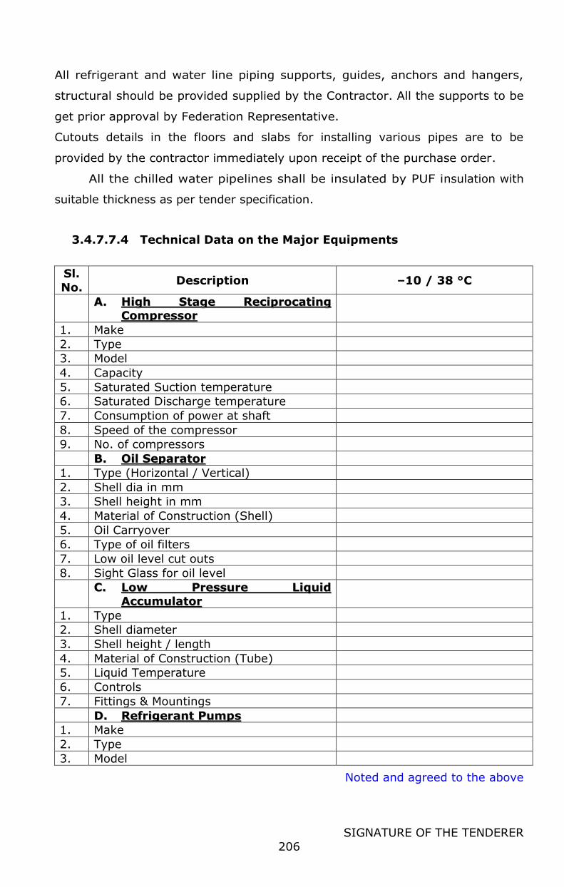
Noted and agreed to the above
SIGNATURE OF THE TENDERER
206
All refrigerant and water line piping supports, guides, anchors and hangers,
structural should be provided supplied by the Contractor. All the supports to be
get prior approval by Federation Representative.
Cutouts details in the floors and slabs for installing various pipes are to be
provided by the contractor immediately upon receipt of the purchase order.
All the chilled water pipelines shall be insulated by PUF insulation with
suitable thickness as per tender specification.
3.4.7.7.4 Technical Data on the Major Equipments
Sl.
No. Description –10 / 38 °C
AA.. HHiigghh SSttaaggee RReecciipprrooccaattiinngg
CCoommpprreessssoorr
1. Make
2. Type
3. Model
4. Capacity
5. Saturated Suction temperature
6. Saturated Discharge temperature
7. Consumption of power at shaft
8. Speed of the compressor
9. No. of compressors
BB.. OOiill SSeeppaarraattoorr
1. Type (Horizontal / Vertical)
2. Shell dia in mm
3. Shell height in mm
4. Material of Construction (Shell)
5. Oil Carryover
6. Type of oil filters
7. Low oil level cut outs
8. Sight Glass for oil level
CC.. LLooww PPrreessssuurree LLiiqquuiidd
AAccccuummuullaattoorr
1. Type
2. Shell diameter
3. Shell height / length
4. Material of Construction (Tube)
5. Liquid Temperature
6. Controls
7. Fittings & Mountings
DD.. RReeffrriiggeerraanntt PPuummppss
1. Make
2. Type
3. Model
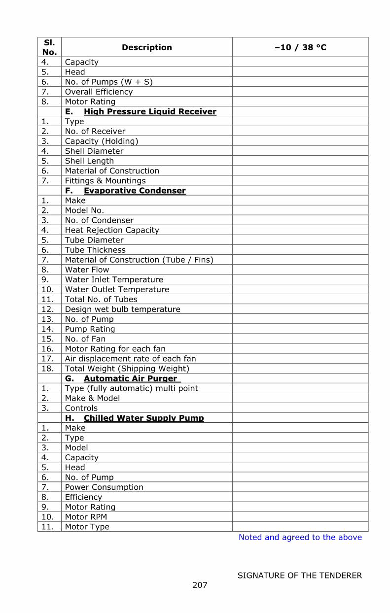
Noted and agreed to the above
SIGNATURE OF THE TENDERER
207
Sl.
No. Description –10 / 38 °C
4. Capacity
5. Head
6. No. of Pumps (W + S)
7. Overall Efficiency
8. Motor Rating
EE.. HHiigghh PPrreessssuurree LLiiqquuiidd RReecceeiivveerr
1. Type
2. No. of Receiver
3. Capacity (Holding)
4. Shell Diameter
5. Shell Length
6. Material of Construction
7. Fittings & Mountings
FF.. EEvvaappoorraattiivvee CCoonnddeennsseerr
1. Make
2. Model No.
3. No. of Condenser
4. Heat Rejection Capacity
5. Tube Diameter
6. Tube Thickness
7. Material of Construction (Tube / Fins)
8. Water Flow
9. Water Inlet Temperature
10. Water Outlet Temperature
11. Total No. of Tubes
12. Design wet bulb temperature
13. No. of Pump
14. Pump Rating
15. No. of Fan
16. Motor Rating for each fan
17. Air displacement rate of each fan
18. Total Weight (Shipping Weight)
GG.. AAuuttoommaattiicc AAiirr PPuurrggeerr
1. Type (fully automatic) multi point
2. Make & Model
3. Controls
HH.. CChhiilllleedd WWaatteerr SSuuppppllyy PPuummpp
1. Make
2. Type
3. Model
4. Capacity
5. Head
6. No. of Pump
7. Power Consumption
8. Efficiency
9. Motor Rating
10. Motor RPM
11. Motor Type
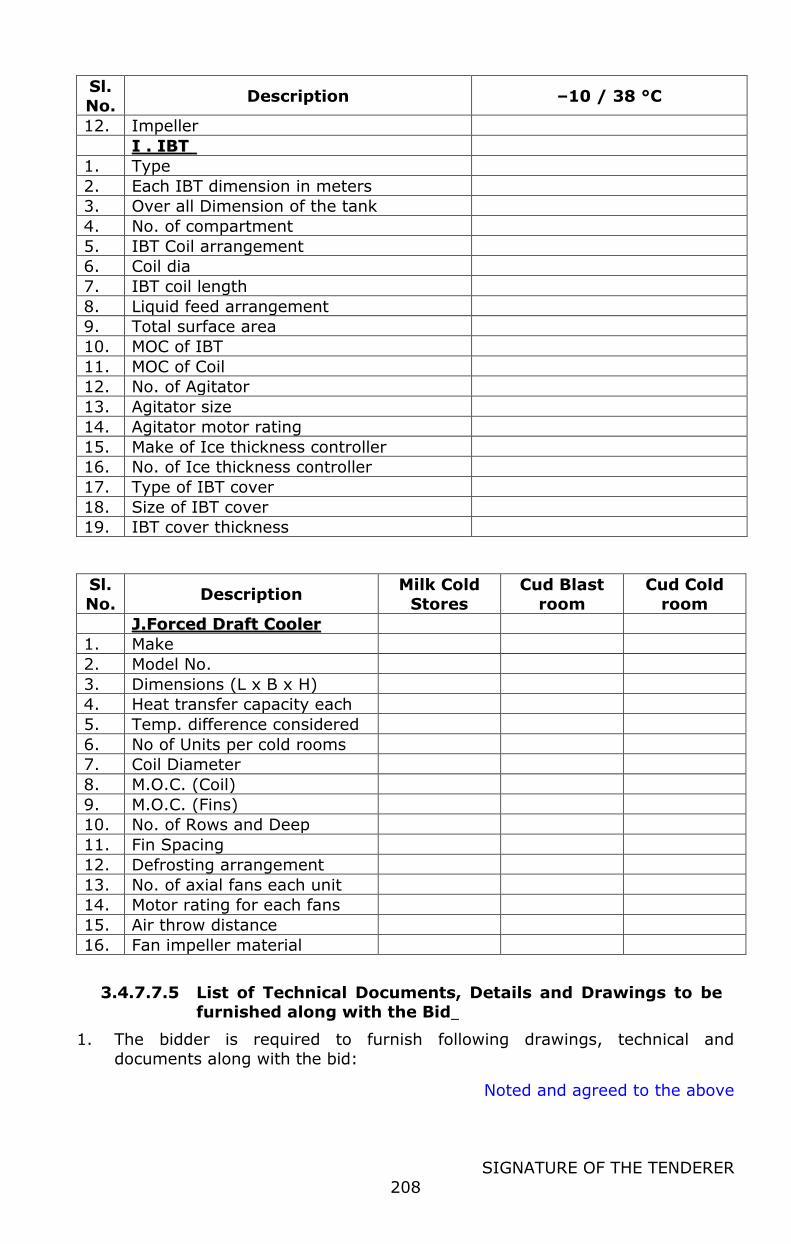
Noted and agreed to the above
SIGNATURE OF THE TENDERER
208
Sl.
No. Description –10 / 38 °C
12. Impeller
II .. IIBBTT
1. Type
2. Each IBT dimension in meters
3. Over all Dimension of the tank
4. No. of compartment
5. IBT Coil arrangement
6. Coil dia
7. IBT coil length
8. Liquid feed arrangement
9. Total surface area
10. MOC of IBT
11. MOC of Coil
12. No. of Agitator
13. Agitator size
14. Agitator motor rating
15. Make of Ice thickness controller
16. No. of Ice thickness controller
17. Type of IBT cover
18. Size of IBT cover
19. IBT cover thickness
Sl.
No. Description
Milk Cold
Stores
Cud Blast
room
Cud Cold
room
JJ..FFoorrcceedd DDrraafftt CCoooolleerr
1. Make
2. Model No.
3. Dimensions (L x B x H)
4. Heat transfer capacity each
5. Temp. difference considered
6. No of Units per cold rooms
7. Coil Diameter
8. M.O.C. (Coil)
9. M.O.C. (Fins)
10. No. of Rows and Deep
11. Fin Spacing
12. Defrosting arrangement
13. No. of axial fans each unit
14. Motor rating for each fans
15. Air throw distance
16. Fan impeller material
3.4.7.7.5 List of Technical Documents, Details and Drawings to be furnished along with the Bid
1. The bidder is required to furnish following drawings, technical and
documents along with the bid:
Noted and agreed to the above
SIGNATURE OF THE TENDERER
209
2. Layout drawings showing proposed refrigeration plant equipments like
condenser, HP receiver, LP accumulator, pumps 3. Detailed machinery layout for the compressor room, control room, cold
rooms. 4. P & I diagram for the ammonia refrigeration system, cooling water & Chilled
water piping with line sizes 5. G A drawings for the electrical power distribution
6. Automation system configuration
Also bidder has to furnish the following
1. Chilled water load (indirect system) 2. Direct expansion system load
3. Room-wise cold room load calculation sheet 4. Histogram for chilled water load demand / direct expansion load
and the refrigeration input from the compressors (hourly basis showing
peak demand, on 24 hour scale) 5. Calculation for the condenser capacity required
6. Electricity consumption data with operating time schedule for all the equipment and histogram (hourly basis showing peak demand, on 24 hour
scale) 7. List of technical Literatures covering general and technical information for all
the major equipment offered. viz compressor, condenser, FDC, pumps, purger, Falling Film Chiller, control valves, instrumentations, PLC automation
system, soft starter, VFD, 8. Bar chart for project execution
9. Category-wise staff requirement for operating the plant 10. List of recommended spare for One year operation with break-up cost in
commercial bid
3.4.7.7.6 Latest Applicable Indian Standards for Ammonia,
Electrical & Mechanical
A. Mechanical
IS: 660 Safety code for mechanical refrigeration IS: 661 Code of practice for thermal insulation of cold storages
IS: 662 Anhydrous ammonia IS:702 Industrial bitumen
IS:778 Gunmetal gate, globe and check valves for general purposes IS:1703 Ball valves including floats for water supply purposes
IS:1239 Mild steel tubes, tubular and other wrought steel pipe fittings IS:2041 Steel plates for pressure vessels used at moderate and low
temperatures IS:2379 Colour code for the identification of pipelines
IS:2494 V-belts for industrial purposes IS:2629 Hot-dip galvanizing of iron and steel
IS:2825 Code for unfired pressure vessels
IS:3233 Glossary of terms for safety and relief valves IS:3503 Steel for pressure vessels and welded structures
IS:3601 Steel tubes for mechanical and general engineering purposes IS:3615 Glossary of terms used in refrigeration and air-conditioning
Noted and agreed to the above
SIGNATURE OF THE TENDERER
210
IS:3624 Pressure and vacuum gauges
IS:3696 Safety code for scaffolds and ladders IS:4049 Formed ends for tanks and pressure vessels
IS:4503 Shell and tube type heat exchangers IS:4544 Code of safety for ammonia
IS:4671 Expanded polystyrene for thermal insulation purposes IS:4736 Hot-dip zinc coating on steel tubes
IS:4831 Units and symbols for refrigeration IS:4984 HDPE pipes for potable water supplies, sewage and industrial
effluents IS:5428 Gauge glasses
IS:5905 Specification for sprayed Aluminium and zinc coating on iron and steel surfaces.
IS:6392 Steel pipe flanges IS:8008 Injection moulded HDPE fittings for potable water supplies
IS:8172 Vertical steel ladders
IS:8188 Treatment of water for industrial cooling systems IS:9520 Nominal sizes for valves
IS:9623 Selection, use and maintenance of respiratory protective devices IS:9762 Polythene floats for ball valves
IS:9890 General-purpose ball valves IS:10005 SI units
IS:10234 Recommendations for general pipeline welding IS:11132 Ammonia valves
IS:11329 Finned type heat exchanger for room air conditioner IS:11330 Refrigeration oil separators
BS:3059 MS tubes for vertical condenser
B. Electrical
IS:325 Three-phase induction motors
IS:248 Electrical measuring instruments and their accessories IS:2705 Current transformers
IS:2968 Dimensions of slide rails of electric motors IS:3480 Flexible steel conduits for electrical wiring
IS:4064 Air-break switches IS:8544 Motor starters for voltages not exceeding 1000 V
IS:9537 Conduits for electrical installation IS:10028 Selection, installation & maintenance of transformers
IS:10118 Selection, installation & maintenance of switchgear & control gear SP: 30 National Electrical Codes
C. Refrigeration Piping and Heat Transfer Components – ASME B 31.5
3.4.7.8 ELECTRICAL SYSTEM
Electrical distribution system shall be part of this project and the bidder should
design the Electrical substation, transformers, Generators, distribution etc based on the
total load of the plant with future expansion. The system should be suitable to
Noted and agreed to the above
SIGNATURE OF THE TENDERER
211
operate, control, and maintain all the parameters required for Dairy Milk
reception, Processing, Packing, Utilities, cold rooms etc.
Following are responsibility, but not limited to, of Bidder as part of scope of
this tender:
a) The HT substation to receive 11/22 KV electrical supply with necessary
step down transformers, Power control centre (PCC), Generator sets etc
Changeover panels etc should be provided.
b) Required number of Motor Control Centers (MCC) and ancillary panels with
complete switchgears as per the requirement of the equipment shall be
provided for effective and safe operation of the Dairy plant and utilities.
Spare feeder minimum 10 % of the capacity to be provided in all the MCC
for future expansion.
c) Single phase redundant UPS for Automation system.
d) Required quantity of armored aluminium (PCC to Sub PCC & Sub PCC to
MCCs) & copper power cable, copper control cable, instrument cable, cable
trays in all processing & product making sections, SS/GI drop conduit pipes
in other sections, plate type earth pit, earthing network, earthing
conductors, load break Isolators/ plug & sockets with Push Button station
near motors for emergency isolation, rubber mats for panels etc. shall be
provided. All power cables from MCC to motors, control cables shall be of
flexible copper steel braided type up to 50 sq.mm, above 50 sq.mm
Armoured copper conductor , XLPE insulated , PVC sheathed cable & rodent
proof of suitable size with derating factor as applicable to be considered for
multiple cables laid together on cable trays (cable selection chart
enclosed). For all cable distribution inside the plant (including vertical
drops) SS cage (mesh) type trays shall be provided. Cable trays outside
the plant building, inside MCC room, utility area including main cable from
PCC to MCCs shall be GI perforated/ladder type with cover.
e) All necessary documents and statutory fees required will be borne by/paid
by the bidder and shall be reimbursed by Purchaser to bidder upon
producing receipt of the same.
f) Approval for LT electrical work with State Electricity Board, Electrical
Inspector is Bidder’s responsibility.
Noted and agreed to the above
SIGNATURE OF THE TENDERER
212
The electrical LT distribution system specification is detailed in specification
section.
3.4.7.8.1 TECHNICAL SPECIFICATIONS FOR ELECTRICALS
Following to be considered in the scope of supply: All electrical load values given
are indicative and the system shall be supplied for actual values only. Entire
electrical shall be in the scope of this tender.
3.4.7.8.1.1 HT Sub-Station – 2 Pole/4Pole structure: suitable for 500 KVA transformer-1no.
Two / Four Pole Structure:
Type : Outdoor
Quantity : One Set
Function : To receive power from State Electricity Board. HT cable will connect
GO switch in the structure with VCB in substation.
Civil : ISMB 200 x 100 to be grouted in concrete 1:2:4 for at least 1/5th
length i.e. 2 meters. Size of concrete pedestal -500 x 500 mm. All
necessary civil works such as excavation, centering, concreting and
back filling is included in vendor's scope.
Rating : Suitable for 11 /22 kV, 500 KVA load
Incoming : Conductor from State Electricity Board.
Instrumentation: VCB shall be provided with microprocessor based protection
relay.
3.4.7.8.1.2 HT CABLE:
Type : 11/22 KV, XLPE Size : Suitable for 500 KVA load and considering
Fault level of 35 KA or State Electricity Board fault level whichever is higher Quantity : As required
Cable size : As required
3.4.7.8.1.3 General Specifications:
Applicable Standards:
The cable shall conform to this specification, the latest issue of the relevant
Indian standard specifications or the equivalent specification of the country of
Noted and agreed to the above
SIGNATURE OF THE TENDERER
213
origin or IEC specification. The cable shall comply with the latest edition of IS
7098 (Part II).
General Construction:
Power cable for 11 / 22 kV, shall be aluminium conductor, XLPE insulated
screened, sheathed, armoured & overall PVC sheathed. The conductor shall be
stranded & compacted circular complying to IS 7098.The cable shall be provided
with both conductor screening & insulation screening. The conductor shall be
provided with non-metallic extruded semi conducting shielding. The core
insulation shall be cross linked polyethylene insulating compound applied by
extrusion. It shall be free from voids & shall withstand all mechanical & thermal
stresses under steady state & transient operating condition. The insulating
shielding shall consist of non-metallic extruded semi conducting compound in
combination with a non-magnetic metallic screening of copper.
The copper screen shall be capable of carrying the single line to ground fault
current. The vendor shall furnish the calculation in support of selection of the
size of copper screen. The conductor screen, XLPE insulation & insulation screen
shall be extruded in one operation by triple extrusion process to ensure perfect
bonding between the layers. The core identification shall be coloured strips or by
printed numbers. The inner sheath shall be applied over the laid up cores by
extrusion & shall conform to the requirement of type ST2 compound of IS: 5831.
The extruded inner sheath shall be of uniform thickness. The armouring shall
be by galvanised steel strip. The outer sheath of the cable shall be applied by
extrusion over the armouring & shall be PVC compound conforming to the
requirement of type ST2 compound of IS : 5831.The dimension of the insulation,
inner sheath & armour material shall be governed by values given in table 2, 3 &
4 (Method “b”) of IS: 7098 Part II. The cable shall be suitable for laying in trays,
trenches, ducts & conduits & for underground buried installation with
uncontrolled backfill & possibility of flooding by water & chemicals.
Outer sheath of all PVC & XLPE cables shall be black in colour & the
minimum value of oxygen index shall be 29 at 27+/- 2°C. In addition suitable
chemicals shall be added into the compound of the outer sheath to protect the
cable against the rodent & termite attack. The cable shall be flame retardant.
The outer sheath of XLPE cable shall posses flame propagation properties
meeting requirements as per IEC-332-3.Sequential marking of the length of the
Noted and agreed to the above
SIGNATURE OF THE TENDERER
214
cable shall in meters shall be provided in the outer sheath at every one-meter.
The embossing shall be legible & indelible.
3.4.7.8.1.4 HT panel and protection system:
The HT Panel is required to receive HT grid power from two/four pole steel
structure with GO switch & then feed high-tension electric power to distribution
transformer.
Quantity : 1 Set
Capacity : Suitable for 500 KVA
Feeders : Incomer from GO switch and outgoing to Transformer
Standards:
The equipment shall conform to this specification, the latest issue of the relevant
Indian standard specifications or the equivalent specification of the country of
origin or IEC specification.
Design Requirements:
The design, construction, manufacture & performance of HT panel shall conform
to the latest applicable Indian standard & comply with all currently applicable
statutory requirements & safety codes in the locality where the equipment will be
installed.
3.4.7.8.1.5 Basic Design
The HT panel shall have vacuum circuit breakers, which shall be connected
to incoming grid power & outgoing to distribution transformer.
The HT panel shall be indoor type in sheet steel enclosure, floor mounting
type, dust & vermin proof, totally enclosed, compartmentalized design with
suitable electrolytic copper busbars duly insulated & shrouded with epoxy based
insulating materials for high voltage grade, with sliding carriage for circuit
breaker, with mechanical & electrical interlocking & automatic safety operating &
service/ test condition, earthing busbar of electrolytic copper & provisions etc.
conforming to IEC: 298, IS: 3427, BS5227 & VDE 0670 Part 6/5.76 ( Read with
latest versions) thermostatically controlled space heaters suitable for 240V AC
supply shall be incorporated in all breaker panels to prevent all ingress of
moisture.
Noted and agreed to the above
SIGNATURE OF THE TENDERER
215
3.4.7.8.1.6 Transformer:
Capacity : 500 KVA. Quantity : 1 No.
Type : Suitable for outdoor installation, oil cooled. Duty : 11/ 22 KV to 433 V.
Instruments & controls : Oil and winding temp Indicator and control, Buchholtz
relay, on-load tap changer etc.
Accessories : Air breather, conservator, explosion vent, radiator, Marshalling
box etc.
Efficiency : Not less than 98 % at full load
Transformers should be with on load tap changer.
Transformers are to be manufactured as per BS: 171 & BIS: 2026
(amended as on date) specifications, Indian Electricity Rules.
Capacity 500 KV A, 11 /22 KV / 433 V
Housing Details:
The transformer tanks shall be fabricated of good quality mild steel plates
and stiffened with suitable mild steel sections to ensure structural rigidity.
Standard Accessories Required
The transformers shall be core type, double wound copper conductor, oil
immersed, natural cooled, 3 phase, 50 Hz, having DYN 11 connection. The
transformer will have CRGO Core.
Remarks
When LT cable box is provided, a neutral bushing shall be brought out for solid
earthing. Bus links shall be provided in the cable box for proper cable
terminations. Transformers shall be complete including first charge of oil. Oil can
be supplied separately filled in sealed drums. Oil dielectric strength should be
better than 40 KV.
The transformer shall be painted as under:
Internally with oil resisting varnish paints.
Externally with 2 coats of zinc chromate primer followed by two
coats of enamel paint of approved shade.
Test certificates shall be furnished for all the routine tests conducted on the
transformers at the manufacturers' premises.
Noted and agreed to the above
SIGNATURE OF THE TENDERER
216
RATINGS & ADDITIONAL ACCESSORIES: The transformer rating shall be as under
KVA 500 KV A-1nos., Frequency 50 cycles/see
Voltage HT : 11 / 22 KV
L T : 433 V
Phase 3 (three)
Installation Outdoor
Additional accessories shall be provided as mentioned below:
1. L T box suitable for L T bus duct termination
2. HT cable box
3. 150 mm dial thermometer with 2-meter capillary and alarm contacts with
maximum reading pointer and high oil temperature alarm and trip contacts.
4. Double float Bucholtz relay with alarm, trip contacts, testing & sampling cocks
and 2 nos. oil shut off valves.
5. Magnetic oil level gauge indicator with low-level alarm contacts. Min. size 150
mm.
6. Jacking pads
7. Marshalling box to house dial thermometer and terminals with wiring complete
from Buchholtz relay and dial thermometer up to marshalling box.
CABLE DETAILS
HT Suitable size
LT Suitable size L T bus duct, TPN
Type of HT cable 11 / 22 KV, XLPE, aluminium conductor
Type of L T bus duct AI. conductor, TPN, totally enclosed, IP-55 protection, suitable for 25 KA fault
level
GUARANTEED PERFORMANCE TO BE PROVIDED BY THE BIDDER
No load losses at rated voltage & frequency (Watts)
Full load losses at rated current at 75 o C (Watts)
Impedance at rated current & frequency at 75o C (%)
Efficiency at full load with pF 0.8 lagging at 75o C (%)
Approximate quantity of oil required for first filling (liters)
Maximum winding temperature (Above Ambient temperature o C)
Noted and agreed to the above
SIGNATURE OF THE TENDERER
217
3.4.7.8.1.7 LT Bus Duct/Cable
Type : Suitable for outdoor mounting, for connecting transformer output to PCC installation
FUNCTIONAL REQUIREMENTS:
L T bus ducts shall be electrically connecting the distribution transformer to the incoming feeder of the power control centre (PCC). The bus duct shall be
suitable to operate on 3 phase and neutral (neutral being solidly grounded), 415 V: i: 10%, 50 Hz :i: 3%, AC supply system.
3.4.7.8.1.8 DESIGN REQUIREMENTS AND SCOPE OF SUPPLY
Statutory Requirements
The design, construction, manufacture and performance of the bus ducts
shall comply with all relevant currently applicable Indian Standards, Indian
Electricity Rules and also statutory requirements and safety codes in the locality
where the equipment would be installed and as per the detailed specification
hereunder. Bus ducts to be manufactured as per IS: 8623 (PART II) -1993.
Bus bar Enclosure
Outdoor type enclosure shall be fabricated from minimum 14 gauge CRCA
sheet steel, stiffened and reinforced by sturdy angle iron frame to form a rigid
structure. The section of bus duct shall be rectangular. All G.I. hardware shall be
supplied along with the bus duct. The terminal enclosures shall be provided with
flanged ends to suit flanges of transformer / PCC. The bus duct shall be totally
enclosed, dust, weather and vermin proof and shall have the construction to
conform to protection class IP 55. top cover for outside installation to have slope
on both edges for draining of rainwater.
The bus duct MS fabrication shall be pre-treated as per standard practice
and then finished with stove enamel paint. Inside surface of MS fabrication shall
be painted with black mat finish, while external surface shall be finished with
epoxy paint of shade no. 631 of IS: 5.
3.4.7.8.1.9 Bus bars &Supports
Bus bars shall be of electric grade aluminum alloy conforming to grade E 91
E, IS-5082 and their sizes are to be selected on the basis of current density 0.8
Amp. per Sq.mm.
Section of buses shall be uniform and rectangular. The main buses of the
bus ducts shall be designed to carry continuously the current specified in the
Noted and agreed to the above
SIGNATURE OF THE TENDERER
218
design data, while the neutral shall be of at least half the section of phase bus.
Bus bars shall be provided with heat shrinkable insulating sleeve of high
dielectric strength which should be noninflammable, non-hygroscopic and self
extinguishing type. The temperature rise of buses shall be limited to 40 deg. C
above an ambient of 45 deg. C.
For electrical connections of the bus duct at both ends, copper braided
flexible strips of suitable rating shall be provided.
The bus bar supports shall be of suitable size non-hygroscopic and non-
inflammable epoxy compound cast blocks (SMC or DMC blocks), adequate
numbers and size to avoid sags in bus bars and these shall be capable of
withstanding stresses due to short circuit currents of the associated switchgear.
Main bus bars shall have rupturing capacity of 50KA.
The bus duct shall be complete with two nos. continuous earth buses of hot
dip GI flats of suitable size to its entire length.
GA drawings for Bus Duct shall be prepared by the supplier and submitted to
the purchaser for approval before start of the fabrication activity.
Making cut outs of required size in the walls, if required, and making good
the same shall be in the scope of the contractor.
3.4.7.8.1.10 BUS BAR CLEARANCE
The supplier must ensure that there is no crossover of the bus bars while
connecting between transformer and the PCC. Minimum clearance between main
bus bars phase to phase 25mm and between phases to earth 20mm, is to be
maintained.
3.4.7.8.1.11 Testing
All routine tests as specified in the applicable Standards and Codes shall be
conducted and test results of the same shall be submitted along with supply.
3.4.7.8.1.12 EARTHING SYSTEM
The transformer, bus duct shall be provided with double earthing as per
relevant IS and IE rules. The entire earthing system comprising plate type earth
pits, 'earthing grid, connecting earthing strips/wires complete as required shall
be provided by the supplier.
Noted and agreed to the above
SIGNATURE OF THE TENDERER
219
The transformer neutral shall be provided 2 Nos. copper plate Earth Sets for
neutral earthing and 2 Nos. GI plate Earth Sets for body earthing.
3.4.7.8.1.13 STATUTORY APPROVAL:
The bidders shall be responsible for arranging all requisite approvals from
concerned authorities on behalf of the purchaser. The statutory fees shall,
however, be reimbursed on production receipt.
3.4.7.8.1.14 Power Control Center PCC:
The PCC shall have incoming feeders for the transformer and outgoing feeders
for the various sections. The bidder has to design the PCC based on the load and
Motor control centers. All the incoming and outgoing feeders are to be connected
to power monitoring system which in turn connected to the control room for
monitoring. The change over panels for the Generator sets and necessary control
panels are to be provided. The Generators shall be equipped with automatic start
and stop with changeover arrangements during failure of the EB supply.
Instruments and controls: Ammeters & voltmeters for individual feeders.
Energy Meter shall be provided on incomer of PCC for total power measurement.
All controls shall be built-in type. Rigid mechanical and electrical interlocking
wherever required.
Suitable cable & bus alleys shall be provided. Cable alleys shall be provided
with hinged doors. Adequate number of slotted cable supports shall be provided
in the cable alley. All doors shall be provided with concealed type hinges &
captive screws. Rear doors also shall be openable. Gaskets of durable material
shall be provided all round the parameters of adjacent panel, panel & base
frame, removable covers & doors & cutouts.
All components shall be front operated. The PCC shall be single front type
with bottom cable entry. For draw out modules only handles of switches, knobs,
cutout for lamps & meters shall be arranged on the front doors to permit
operation without opening the doors. Relays of circuit breaker shall be mounted
on front doors of the compartments. Other accessories of VCB shall be mounted
on with drawable chassis.
Noted and agreed to the above
SIGNATURE OF THE TENDERER
220
In addition to outgoing feeders indicated above, suitable One No.
outgoing feeder for APFC Panel is also to be provided in PCC. APFC Panel shall
have APFC Relay, Capacitor Banks of suitable capacity, necessary feeders with
switchgears and accessories for auto/manual operation of the capacitor units.
Supply, installation and commissioning of heavy duty APP type power
capacitors as required are included in the scope of this contract.
3.4.7.8.1.15 Power Factor Improvement Panel with APFCR Relay:
Bidder to provide APFC system centrally at PCC level for entire dairy plant.
Active harmonic filter system shall also be provided at PCC level.
Power Factor Correction Panel with Microprocessor based Automatic Power
Factor Controlling Relay and bank of capacitors as given in the data
sheet shall be provided for PCC to continuously measure and monitor the
power factor of the electrical system by sensing the total load from the
incomer and switch ON / OFF bank of power capacitors to bring the power factor
of the system to a preset value. The APFCR shall have a digital power factor
meter with 4 digit LCD/ LED display.
Panel to be fabricated with 14 SWG thick cold rolled sheet steel structure,
indoor type, floor/wall mounted, weather and vermin proof.
Panel should be suitable for 415 volt, 50 Hz, 3 phase supply. It would consist of
An automatic power factor correction relay, microprocessor based, with
arrangement for sensing the power factor of the inductive load (minimum
16 channels/outputs considering future) and giving signal to the feeders
of power capacitors as per the setting of P.F. and electronic circuit to
ensure that once a capacitor gets cut off, it is not put on at least for a
minute. The relay should automatically manage capacitor banks
according to the reactive power required to correct the power factor of the
load to the power factor set on the relay. The capacitors must be turned
“on” and “off” to correct the power factor of the load to the power factor
set on the relay. The relay should have automatic and manual mode of
operation with an LED to indicate the operating mode. The auto/manual
function makes it possible to turn the capacitor banks “on” and “off”
manually regardless of the line value measured

Noted and agreed to the above
SIGNATURE OF THE TENDERER
221
For each of capacitor feeder one set of suitable rating MCCB, contactor,
pair of ON/OFF push button and indication lamp shall be provided. MCCBs
for power capacitors shall be provided with thermo magnetic release only.
Flush mounted, 96 mm x 96 mm square, digital Power Factor meter having
4 digits LCD or LED display.
Selector switch and CT operated digital Ammeter of size 96 mm x 96 mm.
Selector switch and digital Voltmeter of size 96 mm x 96 mm.
Auto-manual switch and connected circuit to ensure that in manual
mode each capacitor can be put ‘ON/‘OFF’ manually also
Incoming feeder of APFC Panel: 4 Pole, 415 V, 50 Hz, MCCB of 630 A
rating with built-in microprocessor based programmable protection.
Suitable 3 phase and neutral bus bars.
Panel shall have sufficient spare cubicles (space only- for future provision of
capacitors & switch gear and shall be decided at the time of drawing
approval of APFCR panel)
Wiring for all above accessories / functions should be complete and ready for
use. The details of each capacitor bank rating, no. of capacitor banks for power
factor improvement shall be as per details given in the data sheet and
schedule of quantities.
All power cabling between PCC and capacitor banks panel and cabling of
each capacitor are included in the scope of work of this package. Power
improvement capacitor banks shall be housed in the APFC Panel itself and
provided with adequate louvers with ventilation fans, prewired through MCB
switch for adequate ventilation
3.4.7.8.1.16 Power Capacitors Banks:
The power capacitor banks shall be used to improve the power factor of an
electrical system and shall be housed in the APFC panel itself and provided with
adequate louvers for proper ventilation
3.4.7.8.1.17 Design Requirements:
Each basic unit is to be built up with a number of elements. These elements
shall be of two layer dielectric design (non-self-healing) using
heavy Polypropylene Film, Aluminium Foil and Capacitor Tissue Paper as
required; to ensure that total dielectric thickness is more than 14 micron.
Capacitor element must be completely sealed with epoxy resins to provide

Noted and agreed to the above
SIGNATURE OF THE TENDERER
222
maximum humidity protection and highest insulation. The capacitor elements
are to be given adequate outside insulation and should be put in all welded
surface treated MS containers. The outer surface shall be provided with a coat of
protective primer followed by two coats of synthetic enamel paint of
approved shade. These capacitors shall be impregnated with special grade of
capacitor oil under high vacuum. The metal case shall be equipped with
porcelain bushings to permit connection between power lines and active
capacitors. The unit shall have built-in internal individual fuses.
All capacitors shall be of APP (All Polypropylene) Heavy Duty Type.
Externally each capacitor unit shall have two separate earthing points, name
plate confirming to the requirements of IS-2834 (amended up to date),
discharge resistances etc. Each capacitor should be suitable for operation on
440 V, 3 Phase, 50 Hz AC power supply.
3.4.7.8.1.18 TECHNICAL REQUIREMENTS:
Total bank capacity for each panel : As per requirement
Power Factor control and active harmonic filter system
REQUIRED QUANTITY: 1 Set.
RATING: Minimum 200 KVAR Bidder to calculate
The Brief Technical Descriptions of major items to be supplied shall be as follows;
1. Load Details
Load Voltage : 3 Phase, 415 V Load Power : 350 kW (min) /
Type of Connected Load : Linear + Non Linear inductive type Load Power Factor
:0.85 Lagging
2. Technical Details of APFC Panel& active harmonic panel
Rated voltage: 415volts
TSC panel rating: bidder to specify
System Frequency: 50Hz, +/-1Hz
Number of steps : Five (min)
Reactor in series with capacitor: As per design to limit the inrush current
Incoming Switchgear: ACB- suitable rating kVAR of each branch: Bidder to
specify TSC branch connection: Internal Delta Over load rating
Current: 20% of the designed value
Voltage: 10% continuous, 15% for 30 minutes with 50% duty cycle Switching
device : Thyristor

Noted and agreed to the above
SIGNATURE OF THE TENDERER
223
Control of switching: Auto / Manual override
Tuning: Tuned to avoid the harmonic current to enter in. Panel
Temp. : 50° Maximum
Insulation: 2.5 kV rms for one minute
First level protection: HRC fuse
Second level protection: ACB- suitable rating
Type of conductor: Copper
Type of bus bar: Aluminum electrolytic grade
Type of inductor: Gapped Iron Core
Type of Capacitor: Metalized polypropylene (MPP) self-healing type
Fuse: HRC
Controller: Bidder to specify Protection CT : 1200/1Amp. Protection PT:
415/8.6Volts
Measurement PT: XXXX / 110 volt (11 kV side)
Measurement CT: XXX / 1amp, 11 kV side, burden 5VA (max)
Cooling: Forced Air
Communication with panel: profibus/profinet port should be available at
controller, Discharge device on Capacitor:
Residual voltage : 50 volts Time : 3 minutes
Panel : CRCA with powder coating, with Siemens GRAY color shade (RAL-7032)
Dimensions of panel : Bidder to specify
Capacitor Details
Rated voltage : 415
Rated frequency : 50 Hz
Dielectric : Polypropylene Phase : Single
Container : Aluminium
Mounting arrangement : Stud type
Maximum over voltage : 1.2 times
Maximum over current : 1.3 times Capacitance tolerance : +10%
Maximum ambient temp. : 55Deg
Internal connection : Single phase
Discharge devices : Resistor
Capacitor type : MPP dielectric
Watt losses per unit : <0.2watts / kvar
Noted and agreed to the above
SIGNATURE OF THE TENDERER
224
Unit Kvar Capacity : 10
Protection class : IP – 43
Protection against over voltages & transients: Yes Protection against harmonics,
Stringent harmonic duty Capacitor: Heavy duty
Capacitor bushing details: Pin type connector Terminal detail: Two stud at top of
the capacitor.
Tests on capacitor:
Following tests shall be carried out for selected capacitor; Routine tests as per IS
2834 / IS 13585.
Visual inspection Sealing Test
Test for Output & Capacitance Insulation resistance test.
Voltage test between Terminals.
Voltage Test between terminals & containers. Test for efficiency of discharge
device
Measurement of Tangent of dielectric loss angle (Tan delta) Type Test
Thermal stability test.
Tan delta & capacitor loss test Capacitance discharge test.
Paintings & Nameplate:
All metal surfaces shall be thoroughly cleaned & degreased to remove all
scales, rust, grease & dust. Fabricated structure shall be prickled & treated to
remove any trace of acid. The undersurface shall be prepared by applying
phosphate paint & a coat of yellow zinc primer. The undersurface shall be made
free from all imperfections before undertaking the final coat. After preparation of
the undersurface the panel shall be spray painted/powder coated with final two
coats of RAL-7032 paint shade. The finished panels shall be dried in strong ovens
in dust free atmosphere, panel finish shall be free from imperfections like
pinhole, orange peels, run of paint etc.
Nameplates for all incoming & outgoing feeders shall be provided on the
doors of each compartment. Nameplate shall be fixed by screw only. Special
danger plate shall be provided as per requirement. Inside panels, sticker shall be
provided for all components giving identification number as per detailed wiring
diagram.
Noted and agreed to the above
SIGNATURE OF THE TENDERER
225
Busbar Sizing Connection & Supports:
The busbars shall be made of high conductivity electrolytic aluminium alloy
conforming to grade E91E IS5082. Buses shall have uniform cross section
throughout the length of the panel & upto the incoming feeder terminal.
Maximum current density permissible for this plant shall be 0.8 Amps/ sq. mm
for busbar area above 500 sq. mm & 1 amps/ sq. mm for busbar area below
500-sq. mm. A suitable section earthing busbar (300-sq. mm) shall be provided
outside the PCC at back bottom throughout the length of the PCC. Busbar shall
be provided with heat shrinkable insulating sleeve of high dielectric strength,
which shall be non-inflammable & self-extinguishing type in fast colours to
indicate phases. The busbar shall be adequately supported by epoxy compound
cast blocks, adequate numbers & size to avoid sags in busbars & these shall be
capable of withstanding stresses due to short circuit current of the associated
switchgear. Main busbar shall have rupturing capacity of 35KA.Minimum
clearance between main busbars phase to phase shall be 25mm & between
phase to earth 20mm.
Power Connection:
Interconnection between the main busbars & individual units shall be made
by using copper or aluminium busbar strips of adequate rating. These
interconnection & terminal shall also be fully shrouded. The outgoing power
connection from PCC will be through PVC insulated aluminium conductor
armoured cable. The cable entry shall also be totally isolated from switchgear by
suitable partition plates. For outgoing feeders above 100A, cable termination
directly at switchgear terminals shall not be allowed & hence panel builder shall
made provision by suitable bus links by switchgear terminals so that the required
number of cables could be connected to this links.
Auxiliary Wiring:
Wiring for all controls, metering, protection, signalling etc. inside the switchboard
shall be done with 1100/650 volts grey colour PVC insulated copper conductors.
Minimum size of the control wire shall be 1.5 sq. mm. All control wiring shall be
provided with necessary sockets/lugs at both the ends. Each terminal shall be
identified at both the ends by PVC ferrule having numbers corresponding to the
control circuit diagram

Noted and agreed to the above
SIGNATURE OF THE TENDERER
226
MOTOR CONTROL CENTRE (SHEET STEEL ENCLOSURE)
FUNCTIONAL REQUIREMENTS
To receive, control and distribute electrical power at 440 V, 50 Hz, AC in a sheet
steel housing.
Design Requirement and Scope of Supply
Statutory Requirements
Motor Control Centre is to be manufactured / assembled as per the latest ISI
Specification, Indian Electricity Rules, including special requirements of
concerned State Electricity Inspectorate and detailed specification mentioned
below.
MCC shall be suitable for indoor type.
Bus Bar Rating shall be capable of carrying 1.2 times of full load current of
the total load in the MCC. For calculating full load current, the connected load
of MCC including future load provisions and 20% spare feeders shall have to be
considered.
Incomer: Four Pole, ACB / MCCB manual operated (draw out type) of suitable
rating/ type with and with single phasing, over current, short circuit and earth
fault protection relay. Also the incomer shall have Digital Load Manager
Bidder has to supply and install separate SUB-MCC near cold room / Deep Freeze
areas for ease of maintenance
Out-going Feeder: Required number of feeders to feed all power loads
and controls for the entire motors connected in the MCC.
Additional 20% spare feeders (but not less than one spare feeder in each
rating) of different rating suitable for future compressor, condenser pumps/fan,
chilled water pumps, NH3 pumps, cooling water pumps, forced draft cooler
fans, as well as for IBT Agitators etc to be provided either in the refrigeration
MCC or Sub MMC (If required). The spare feeders shall be fully equipped with all
components and wired.
Necessary feeders required for 3 phase air curtains, electrical heat tracing,
doorframe heater, etc are to be provided either in the refrigeration MCC or Sub

Noted and agreed to the above
SIGNATURE OF THE TENDERER
227
MMC (If required). All equipments having distance behind 5 –m from MCC or Sub-
MCC panel should have remote Isolating Switch near to respective units including
for all existing equipments.
In addition to outgoing feeders indicated above, Successful bidder either has
to provide suitable Du Tuned Type Shunt Capacitor for above 100 HP rating
All out-going feeders shall have isolation facilities such as fuse-switch units,
contactors, thermal/magnetic over load protection and necessary operating
control etc.
Supply and providing of 5-MM thick M.S Chequered plats including Painting
for masonry / concrete trenches where ever required, 12.5-mm thick rubber
mats in front of all electrical panel as per latest IS/ IER requirement
including M.C.C.’s
All earthing mains shall be galvanized. The earthing to the equipment will be with
the help of copper/ GI wire for motors up to 60 HP. For motor 60 HP and above
the earthing shall be done with GI strip and the end connections shall be using
tinned copper flexible connections of adequate rating
An earth pits and earthing system of instrumentation, computers and PLC controls
shall not share the elec. Load earthing system of electrical power equipment
and a separate copper plate earthlings as per statutory rules with copper
interconnection strips/wire shall be supplied and erected. All related works are
in the scope of Supplier including the earth pit civil works and painting, etc.
MCC PANEL
Motor control center is to be manufactured / assembled as per the latest
ISI Specification, Indian Electricity Rules, including special requirements of
concerned State Electricity Inspectorate and the detailed specification
mentioned below. The manufacturer of the panel must possess a type test
certificate/ accreditation from CPRI.
The switchboard shall be fabricated using pressed and shaped cold rolled
steel sections structure of adequate thickness. The sheet steel used for panel
shall be min. 14 SWG sheet except that the partition plates and inter-panel

Noted and agreed to the above
SIGNATURE OF THE TENDERER
228
barriers may be made of 16 SWG. The switchboard shall consist of free
standing front open-able panels arranged to form a continuous line-up of
uniform height. Cold rolled sheets shall be used for doors and front covers.
Front doors shall be hinged type and bus bars and cable alleys covers shall be
bolted type.
Switch Board shall be extensible at both the ends by addition of vertical
sections. Ends of the bus bars shall be suitably drilled for this purpose. Panels
at extreme ends shall have openings, which shall be covered with plates screwed
to the panel. The switchboard shall be provided with integral base frame. The
cable gland plate shall be 2.5 mm thick.
The switchboard shall be totally enclosed, dust, weather and vermin proof. The
switchboard shall conform to degree of protection not less than IP 44. Gaskets of
durable material shall be provided for doors and other openings. Suitable hooks
shall be provided for lifting the boards. These hooks when removed shall not
leave any opening in the board.
All hardware shall be corrosion resistant. All joints and connections shall be
made by galvanized zinc passivated or cadmium plated high tensile strength
steel bolts & nuts. Spring washers shall be provided to secure against loosening.
The switchboard shall be in cubicle design (each feeder components are housed
in individual cubicle) suitable for indoor installation. The switchboard shall be
non-draw out type except for ACB cubicles. Suitable cable & bus bar alleys
shall be provided. In case plant room dimensions prohibit provision of
cable/bus alleys in front, panel depth may be increased suitably to accommodate
cables/buses on back of MCC. All components of the switchboard shall
generally be approachable from front. However, MCC can be in double front
execution also if specifically asked for. The maximum and minimum operating
handle/push button height of any feeder shall not be more than 1900 mm or
less than 300 mm with reference to panel bottom. Supporting arrangement
for dressing of power and control cables in cable alleys also shall be provided.
Maximum shipping length of MCC shall be 2500 mm.
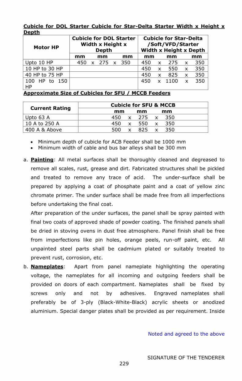
Noted and agreed to the above
SIGNATURE OF THE TENDERER
229
Cubicle for DOL Starter Cubicle for Star-Delta Starter Width x Height x
Depth
Motor HP
Cubicle for DOL Starter
Width x Height x Depth
Cubicle for Star-Delta
/Soft/VFD/Starter Width x Height x Depth
mm mm mm mm mm mm
Upto 10 HP 450 x 275 x 350 450 x 275 x 350
10 HP to 30 HP 450 x 550 x 350
40 HP to 75 HP 450 x 825 x 350
100 HP to 150 HP
450 x 1100 x 350
Approximate Size of Cubicles for SFU / MCCB Feeders
Current Rating Cubicle for SFU & MCCB
mm mm mm
Upto 63 A 450 x 275 x 350
10 A to 250 A 450 x 550 x 350
400 A & Above 500 x 825 x 350
Minimum depth of cubicle for ACB Feeder shall be 1000 mm
Minimum width of cable and bus bar alleys shall be 300 mm
a. Painting: All metal surfaces shall be thoroughly cleaned and degreased to
remove all scales, rust, grease and dirt. Fabricated structures shall be pickled
and treated to remove any trace of acid. The under-surface shall be
prepared by applying a coat of phosphate paint and a coat of yellow zinc
chromate primer. The under surface shall be made free from all imperfections
before undertaking the final coat.
After preparation of the under surfaces, the panel shall be spray painted with
final two coats of approved shade of powder coating. The finished panels shall
be dried in stoving ovens in dust free atmosphere. Panel finish shall be free
from imperfections like pin holes, orange peels, run-off paint, etc. All
unpainted steel parts shall be cadmium plated or suitably treated to
prevent rust, corrosion, etc.
b. Nameplates: Apart from panel nameplate highlighting the operating
voltage, the nameplates for all incoming and outgoing feeders shall be
provided on doors of each compartment. Nameplates shall be fixed by
screws only and not by adhesives. Engraved nameplates shall
preferably be of 3-ply (Black-White-Black) acrylic sheets or anodized
aluminium. Special danger plates shall be provided as per requirement. Inside
Noted and agreed to the above
SIGNATURE OF THE TENDERER
230
the panels, stickers should be provided for all components giving identification
no. as per detailed wiring diagram.
c. Bus bar Sizing Connection and Supports:
The bus bars shall be made from high conductivity electrolytic aluminium
conforming to grade E91E of IS 5082. The bus bars and supports shall be
capable of withstanding the rated and short circuit current stated in the single
line diagram/feeder details. Minimum size of power bus bars shall be 200
Amps rating.
Maximum current density permissible for Aluminium bus bars shall be 0.8
Amps/mm2 for bus bar area above 500 mm2 & 1.0 Amp/mm2 for bus bar
area below 500 mm2. An earthing bus bar of minimum 150 mm2 section
aluminium shall be provided outside panel at bottom throughout the length of
the panel. Provision shall be made to connect the earthing bus bar to the
plant earthing grid at two ends. All doors shall be earthed using flexible
copper connections to the fixed frame of the switchboard.
Maximum current density permissible for Copper bus bars shall be 1.2
Amps/mm2
The bus bars shall be provided with heat shrinkable PVC insulating sleeves of
1100V grade. Red, yellow and blue colour shall be used for phase bus bars
and black colour shall be used for neutral bus bars. Joints shall be shrouded
suitably. Supports for bus bars shall be made of suitable size non-hygroscopic
and noninflammable epoxy compound SMC/DMC blocks and these should be
adequate in number so as to avoid any sag in the bus bars.
Minimum clearance between phase to phase shall be 25 mm and
that between phase to neutral / earth shall be 20 mm.
d. Power Connection:
For power interconnection within the panel board:
Copper conductor PVC insulated cables of adequate cross section shall be
used. For current rating above 63 amps aluminium busbar strips of adequate
rating shall be used. Minimum size of copper conductor to be used shall be
Noted and agreed to the above
SIGNATURE OF THE TENDERER
231
4.0 mm2. Cable lugs/ sockets of suitable size and type shall be used for all
interconnections.
For all aluminium to copper connections: The copper surface will be silver-
plated and the aluminium surface will be properly cleaned and supplied with
oxide inhibiting grease.
For all outgoing motor feeders, the suitable size terminal blocks shall be
provided in cable alleys and wiring up to these from contactors shall be done
by panel supplier. These terminal blocks shall be heavy-duty type to
withstand high starting currents
For incoming & outgoing feeders of the MCC, aluminium conductor cable will
be used and hence the panel is to be designed for receiving these and
wherever required cable boxes with bus bar extensions for receiving more no.
of cables, shall be provided in panel by supplier. Removable gland plates of 12
SWG thicknesses shall be provided on top/ bottom of panel, for cable entries.
To prevent accidental contacts, all interconnecting cables / bus bars and all
terminals also shall be shrouded. Standard colour code of red, yellow and blue
for phases and black for Neutral to be followed for all bus bars / conductors.
e. Auxiliary wiring and Terminals:
Wiring for all controls, protection, metering, signaling etc. inside the
switchboard shall be done with 1100 volts gray colour PVC insulated FRLS
copper conductors. Minimum size of these conductors shall be 1.5 mm2.
However, CT circuit wiring shall be done with 2.5 mm2. Control wiring to
components fixed on doors shall be flexible type.
The complete panel would be subdivided into different sections by
purchaser and each section shall have its own control circuit with fuse and
indication. Terminal block (Minimum 3 ways) for control wiring shall be
provided for each outgoing Motor feeder in its cubical. 10% spare terminals
shall always be available in each terminal block. Control wiring up to these
terminal blocks shall be done by supplier.
All control wiring should be provided with necessary cable sockets /
lugs at both ends.

Noted and agreed to the above
SIGNATURE OF THE TENDERER
232
Conductors shall be terminated using compression type lugs. Each
termination shall be identified at both the ends by PVC ferrules. The
identification termination numbers should match with those on drawings.
Control wiring for motor feeders should be such that the “green” light
of motor feeder is “ON” only when control as well as power circuit of
feeders is “ON” and it shall have its own fuse.
For all motor starter feeders, provision for control wiring to remote
ON/OFF control is to be made. The auxiliary wiring for the same shall be
brought up to terminal block in the feeder’s cubicle.
f. Switchgears:
f.1 Air Circuit Breakers (ACBs):
These shall be manually operated, fully draw out type with built-in microprocessor
based programmable protection, and suitable for 415 V, 50 Hz. Supply.
Microprocessor based programmable protection unit shall have settings for
overload, short circuit, instantaneous and earth fault currents with time
delay and LED indicators to show various conditions such as Power ON,
Overload, Short-circuit, Instantaneous Earth fault, Percentage load, Self
Diagnostic Test etc. Mechanical spring charging mechanism stored energy
type shall be provided with mechanical indicators to show ‘Open’, ‘Closed’,
‘Service’ & ‘Test’ positions. The circuit breaker shall be provided with
mechanically operated emergency tripping device. This device shall be available
on the front of the panel. The control supply shall be 240 V AC. 6 NO + 6 NC
auxiliary contacts shall be provided.
The interlocks shall be as under:
It shall not be possible to plug in a closed circuit breaker or to draw out a
circuit breaker in closed position. It shall not be possible to operate a circuit
breaker unless it is in fully plugged-in, test or fully isolated position. In test
position, the breaker shall be tested without energizing the power circuit. The
ACB feeder cubical door cannot be opened when ACB is “ON”. However, it
Noted and agreed to the above
SIGNATURE OF THE TENDERER
233
shall be possible to defeat this interlock for inspection purpose. Closing and
trip coils shall work under the following voltage variation conditions:
Closing coils - 85 % to 110 % of rated voltage
Trip coils - 50 % to 130 % of rated voltage
For series tripping, overload, short circuit and under voltage/shunt trip release
shall be provided. While incoming feeder ACB shall be provided with under
voltage coil, the outgoing feeders ACBs shall be provided with shunt trip.
The built-in earth fault relay shall be provided for incoming feeders ACB.
Current rating, short circuit current, protection relays etc. shall be as specified
in feeder details
The circuit breaker position shall be indicated electrically. The following indicating
colour shall be used.
Breaker ‘close’ red
Breaker ‘open’ green
Breaker ‘auto trip’ amber
The circuit breaker shall be provided with mechanically operated emergency
tripping device. This device shall be available on the front of the panel
Note: The air circuit breaker for incoming feeder shall be of 4 pole
construction, unless stated otherwise.
f.2 Moulded Case Circuit Breakers (MCCB):
MCCBs shall always be provided with separate operating handle mechanism
with door interlocking. The MCCBs shall be of triple / four pole construction (as
required in the feeder details) arranged for simultaneous three/four pole
manual closing or opening and automatic instantaneous tripping on short
circuits. MCCBs shall be provided with adjustable type tripping
Noted and agreed to the above
SIGNATURE OF THE TENDERER
234
device with inverse time characteristics for over load protection. All MCCBs
are to be provided with operating handles interlocked with cubicle doors.
Closing mechanism shall be quick make, quick break and trip free type.
Operating handle shall give a clear `ON’, `OFF’ & `TRIP’ indication. Control
voltage for MCCB shall be 240 volts. The MCCBs shall be rated for continuous
maximum duty as specified. The rating of the MCCBs shall be as per the feeder
details.
Minimum rated breaking capacities shall be as under:
MCCBs upto 100 Amps : 35 KA
Above 100 Amps : 50 KA
Note: All feeders having 3 pole MCCB shall be provided with neutral link
complete with isolating link. However, the MCCBs for incoming and non-motor
feeders shall be of 4 pole construction, unless stated otherwise
f.3 Switches & fuse switches:
Switches or fuse switches shall be load break, heavy duty, air
break having continuous maximum rating type with manual quick make /
break mechanism. Mechanical interlock shall be provided to prevent opening of
door in switch ‘closed’ position and prevent closing of switch in door ‘open’
position. However, it should be possible to defeat this arrangement for testing
purpose.
f.4 Fuses:
These shall be non-deteriorating HRC cartridge link type with operation
indicator which will be visible without removing fuses for the service. These shall
be complete with Moulded phenolic fuse base and cover. Wherever required fuse
pullers shall be provided. The fuse base shall be so located in the modules to
permit insertion of fuse pullers and removal of fuse links without any problem.
One set of fuse pullers also shall be provided.
Noted and agreed to the above
SIGNATURE OF THE TENDERER
235
f.5 Contactors:
The rating of the power contactors shall be as required depending upon the
feeder rating indicated in the specifications and as per the feeder details table
provided in this specification below. Contactors coils shall be suitable for 240
volts, 50 Hz. Unless otherwise specified. All contactors shall be supplied with
minimum 2 NO + 2 NC auxiliary contacts. Additional contacts if required for
interlocking etc. shall also be provided. Minimum contactor rating for power shall
be 16 Amp and all contactors of Star Delta Starter to be of same rating.
Rating of contactor shall be based on feeder rating.
All contactors of motor starters shall be suitable for AC 3 duty unless specified
otherwise.
f.6 Protective Devises:
Bimetal overload relays with inbuilt single phase protection shall be provided for
all motor feeders. The relays shall be adjustable and self-reset type. Heavy duty
starters shall be provided with storable type current transformer
operated overload relays only, which shall be suitable for motor starting time of
15- 60 seconds.
Any other relays, if required for incoming & outgoing feeders shall be specified in
the feeder details
f.7 Timers:
The timers shall be continuously adjustable and electronic type, suitable for 240
V, 50 Hz. Supply. The timers for Star Delta automatic starters shall have time
delay of 0 to 60 seconds between change over of contacts.
f.8 Push Buttons (PBs):
Push buttons shall be complete with actuator and contact block and shall be
generally mounted on doors of the cubicles. Colours shall be as follow:
Stop / open / emergency : RED
Start / close : GREEN
It should have minimum 1 NO+1 NC contacts. Push buttons shall conform to IP-
65 protection against dust and water ingress.
Noted and agreed to the above
SIGNATURE OF THE TENDERER
236
f.9 Indication Lamps:
All outgoing & incoming feeders shall be provided with ‘ON’ indication lamps.
Colours shall be as under
Phases : Red, Yellow & Blue
ON : Red
OFF : green
TRIPPED : Yellow
Indication lamps shall be in the form of cluster of high intensity light
emitting diodes (LED) to give bright indication. These lamps shall be of
22.5 mm dia and having operating voltage of 240 V, AC.
f.10 Current Transformers (CTs):
CTs shall be cast resin insulated type. Primary and secondary terminals shall
be marked indelibly. CTs shall preferably be mounted on stationery parts.
These shall be capable of withstanding momentary short circuit and
symmetrical short circuit current for 1 second and shall have a minimum rating
of 10 VA. Neutral side of CTs shall be earthed.
Protection CTs shall be of low reactance, accuracy class “SP” and an accuracy
limit factor greater than “10”. Instrument CTs shall be of accuracy class
“1.0” and accuracy limit factor less than “5.0”. Separate CT’s to be provided for
protection and metering purpose.
f.11 Measuring Instruments:
These shall be of square pattern having approximate dimensions 96 mm x 96
mm, flush mounting type. Necessary auxiliary instruments like CTs etc. are also
included in the scope of supply.
All AC meters shall be of Digital type for displaying three phases reading.
Suitable selector switch shall be provided if the digital meter does not have
provision for simultaneous display of three phase readings. Voltmeter shall be
suitable for direct line connection. Voltmeters shall be connected through fuses
only

Noted and agreed to the above
SIGNATURE OF THE TENDERER
237
Intelligent Panel Meter shall be provided with incoming feeder of the MCC for
the measurement and digital display of Multifunctional Electrical Parameters
such as voltage, current, active power, reactive power, frequency, power factor,
active energy, reactive energy, etc.
All motor feeders of 15 HP and above shall be provided with ammeter. Ammeter
shall also be provided for all incoming & outgoing switches / MCCB / ACB of rating
100 A & above. Ammeters shall always be CT operated.
g. Special Requirements
a. All motor feeders above 5 HP ( 3.7 KW) rating shall have Soft starters
and up to 5 HP ( 3.7 KW) shall have DOL starters unless specified
otherwise.
b. All motor feeders up to 40 HP shall be provided with MPCB as specified in
the feeder details and motor feeders above 40 HP shall be provided with
MCCB having a minimum breaking capacity of 50 KA
The following selection table shall be followed for switches & contactors of
motor feeders unless otherwise specified.
Sl. No.
415 V. Motor HP Contactors
Rating
Amps.
Fuse Switch/MCCB
Rating Amps.
1. 0 to 10 HP 16 63
2. 12.5 to 15 HP 25 63
3. 20 to 25 HP 32 63
4. 30 HP 32 100
5. 40 to 45 HP 40 100
6. 50 to 60 HP 70 100
7. 65 to 70 HP 70 200
8. 75 to 90 HP 110 200
9. 100to 125 HP 110 250
10. 150 to 180 HP 160 400
Earthing: Main Earthing will be of Chemical earthing of ASHLOK make and to be
for both MCC Panel and PLC Panels severalty.
h. LT Power & Control Cables:
LT Power Cables:

Noted and agreed to the above
SIGNATURE OF THE TENDERER
238
All Power cables for use on 415 V system shall be of 1100 V grade, copper
cables XLPE insulated, PVC sheathed, armoured and overall PVC sheathed,
strictly as per IS: 7098 (Part I)-1988. Unarmored cable to be used only if
specifically mentioned in schedule of quantities.
Main cables from PCC to Refrigeration MCC and Refrigeration MCC to Sub MCC
shall be Aluminum cables of suitable run and sizes
LT Control Cables:
Control cables for use on 415 V system shall be of 1100 V grade, copper
conductor, XLPE insulated, PVC sheathed armoured and overall PVC sheathed,
strictly as per IS: 7098 (Part I) – 1988. Unarmored cables to be used only if
specifically mentioned in schedule of quantities. The size of various cables shall be
worked out by the contractor and details and indicated in single line diagram to
be submitted with their bids. The minimum conductor diameter shall be 1.5
mm2.
Harmonic Filter Panel
Supply one common Harmonic Filter Panel to maintain THiD level e within the
limit set by CEA( ie current harmonic less than 8%,voltage harmonic less than
5%) . These filter shall be either Common one to all proposed refrigeration
system or else Individual . Harmonic filter panel should show display panel
showing percentage of THiD
Battery & battery charger ( Inbuilt )
Suitable for HT & DG start up operation. Complete with battery & Charger
Conduits
For laying of cables under floor, GI class 'A' pipes shall be used. For laying cable
in air whereas cable trays are not being used, GI ‘A' class pipe shall be used.
Size of pipe shall depend upon the overall outer diameter of cable to be drawn
through pipe. No pipe less than 40 mm dia shall be used for this purpose.

Noted and agreed to the above
SIGNATURE OF THE TENDERER
239
In milk & milk product handling area conduit, in process / CIP / water
logged area and wherever required, of SS-304 tubes / SS304 wire mesh type
cable tray shall be used. Drop down conduit/ tray from horizontal cable tray to
individual motor within the plant building in process area shall be of AISI 304.
Outside process area & MCC room shall be GI.
ELECTRIC MOTOR
All electric motors shall be energy efficient motors and shall comply with the
following:
a) All poly phase motors of 0.375 kW or more shall have a minimum
acceptable nominal full load motor efficiency as per the IS 12615 –
2004(Rev 1) for Eff1 (IE 4) energy efficient motors.
b) Motor nameplates shall list the nominal full-load motor efficiencies and the
full-load power factor.
c) Certificates shall be obtained and kept on record indicating the motor
efficiency.
d) The motors which shall be operated on VFDs shall be designed for Inverter
application
The sizes of power cables for different capacity of loads / Motor rating shall be
as indicated in the cable selection charts. All the power & control cables shall be
laid through SS ladder type cable trays including the drops inside the plant &
through GI perforated cable trays outside the plant.
SS shrouds for all pumps & motors shall be provided.
Supply & placement of insulating mats of proper size as per the IS 15652 and
Tamilnadu State Electrical Inspectorate rules shall be provided.
Connection from plug & socket/isolator junction boxes to motor junction boxes
shall be with steel braided PVC insulated copper conductor cables.
GEARED MOTOR
FUNCTIONAL REQUIREMENTS
For driving various slow speed machines.
DESIGN REQUIREMENTS
Noted and agreed to the above
SIGNATURE OF THE TENDERER
240
The geared motor should use helical gears. The electric motor and helical
gear box should be built as one unit.
The geared motors should be suitable for minimum15 start/stops per hour
without undue heating, for continuous duty of at least 24 Hrs. and minimum
safety factor of 1.4.
All motors supplied shall be energy efficient type.
The electric motors used for geared motors should be TEFC, degree
protection IP-54,squirrel cage, induction type, with class `B' insulation suitable
for 415V,50Hz, 3 phase AC supply. Electric motors performance in general should
confirm to IS-325-1978.
SCOPE OF SUPPLY
Geared motors complete as per design requirements specified in 2.0. Each
geared motor to be provided with key the driven shaft, oil level indicator, oil
filling plug, oil breather and drain plug.
Suitable grade gear oil for first charge of geared motor. Gear Oil should not be
filled in the geared motor but should be packed separately in a drum and sent
along with geared motor. Gear oil would be filled at site.
ELECTRIC MOTORS FOR Gear DRIVEs.
FUNCTIONAL REQUIREMENTS
For driving various machines of the plant.
DESIGN REQUIREMENTS
The motors should be TEFC(Totally Enclosed Fan Cooled),squirrel cage, degree of
protection IP-54, horizontal foot mounted, induction type, rated for continuous
duty, suitable for operation on 415 volts( + 5% ), 50 Hz, 3 phase AC supply
Efficiency class IV and above.
All motors to have at least class 'B' insulation.
The performance of the motors should conform to Indian Standard IS-325- 1978
amended till date.
The starting torque of the motors shall beat least 2.5 times of the rated torque.

Noted and agreed to the above
SIGNATURE OF THE TENDERER
241
All The motors should be of Efficiency IE4 or above motors.
SCOPE OF SUPPLY
All Electric motors complete in all respects meeting above design requirements.
Each motor shall be provided with key in driving shaft, direction of rotation
marking, nameplate etc.
REMARKS
All motors above 25 HP shall be provided bigger terminal box to accommodate
Al. cables.
Thermistor to be provided in windings of 60 HP & above motors. The thermistors
shall be of two ranges, one being for the warning and the other for tripping the
motor if the fault persists.
LT Power & control cables
General Specifications for LT Power & control cables
Power Cables:
Applicable standards: Cables shall comply, as a minimum, with the latest issue
including all parts, revision and addends as on the date of the contract of Indian
Standard.
Operating Conditions: All cables shall be suitable for laying in open air exposed
to natural elements and in trenches and underground buried installation with
uncontrolled backfill and possibility of flooding by water. The outer sheath shall
be resistant to attack by vermin and rodents. Special treatment shall be given to
make the cables rodent proof.
Temperature rise: For the ambient and operating condition specified above, the
combination of ambient temperature and temperature rise due to load shall
result in a steady conductor temperature not exceeding 700 C.
Material Specification:
Conductor:
Noted and agreed to the above
SIGNATURE OF THE TENDERER
242
The conductor shall be composed of aluminium/copper wires complying with IS
8130.The conductor shall be without joints. The conductors for nominal cross
sectional area up to 10-sq. mm shall be solid, those greater than 10-sq. mm
shall be stranded. Conductors of nominal cross sectional area less than 25 sq.
mm shall be of circular shape whereas those greater than 25 sq. mm and above
shall be of sector shaped.
Insulation:
Cable insulation shall be of PVC compound as per IS 5831.It shall be extruded so
that it fits closely on the conductor and it shall be easily possible to remove it
without damage to the conductor. Minimum insulation thickness as well as
tolerance shall be as per IS 1554 (Part I).
Core Disposition:
Cores shall be identified by the colour of their PVC insulation with different colour
for each core as per IS 1554. The cores shall be laid up together with a suitable
lay. The outermost layer shall have right hand lay and successive layers shall be
of opposite lay. Wherever necessary, core interstices shall be filled up with non-
hygroscopic material
Inner Sheath:
Inner sheath shall be of type ST-1 PVC compound as per IS 5831 and shall be of
black colour. The inner sheath shall be so applied that it fits closely on the laid
up cores & this shall be as circular as possible. It shall be possible to remove the
inner sheath without damaging the insulation. The thickness of the inner sheath
shall be as per IS 1554.
Armouring:
Armouring shall be of either galvanised round steel wire/steel strip as per IS
3975. Armouring shall be applied as closely as possible over the insulation in
case of single core cable and over the inner sheath in the case of multi-core
cables. The direction of lay of the armour shall be left hand and the armour shall
consist of galvanised round / flat steel wires of dimensions as per IS 1554.
Noted and agreed to the above
SIGNATURE OF THE TENDERER
243
Outer Sheath:
The outer sheath shall be of PVC compound confirming to the requirement of
type ST-1 as per IS 5831.Rodent/termite proof treatment shall be given to the
outer sheath of the cables. The outer sheath shall be applied by extrusion over
the armouring. The colour of the outer sheath shall be grey for copper cable &
black for aluminium cable.
Identification:
The manufacturer's name or trade mark, cable size with type of cable shall be
either indented, printed or embossed on the outer sheath of the cable along the
length of the entire cable at regular intervals.
Packing:
The cable shall be packed in drums in continuous lengths.
Control Cable:
Applicable standards:
Cables shall comply, as a minimum, with the latest issue including all parts,
revision and addends as on the date of the contract of Indian Standard.
Operating Conditions:
All cables shall be suitable for laying in open air exposed to natural elements.
The outer sheath shall be resistant to attack by vermin and rodents.
Core / Pair Disposition:
The cores shall be laid up together with a suitable lay. The outermost layer shall
have right hand lay and successive layers shall be of opposite lay. Wherever
necessary, core interstices shall be filled up with non-hygroscopic material.
Binder Tape (for instrument signal cable):
A non-hygroscopic tape of minimum thickness 0.023-mm shall be applied over
the final layer with 50% overlap & offering 100% coverage.

Noted and agreed to the above
SIGNATURE OF THE TENDERER
244
Collective screen (for instrument signal cable):
A laminated screen tape shall be applied with the metallic side down in electrical
contact with the longitudinally run collective drain wire. The laminated tape shall
be AI foil having thickness of 0.08 mm & maximum pitch of 50 mm.
Earthing
To provide earth pits and earthing cables to all sections of the plant with a max.
earth resistance of one ohm or as per the regulations of local Electrical
Inspectorate.
The earth pits and earthing system of instrumentation, computers and controls
shall not share the earthing system of electrical power equipment.
All earthing mains shall be galvanized. The earthing to the equipment will be with
the help of PVC coated Copper cable.
Quantity : 1 Lot
General specifications:
Earthing Strips:
The earthing strips shall be of MS as per IS 2062.The MS strips shall undergo
surface treatment like derusting, degreasing before being processed for hot dip
galvanizing. The thickness of galvanizing shall be minimum 85 microns generally
as per IS 2633.
Earthing Plate For Pit:
Each set shall consist of following
One number of 600mm X 600mm X 6thick plate
One number of 50-mm diameter, 900 mm long GI pipe along with 80mm X
50mm GI funnel (made out of concentric reducer) & GI mesh.
One number of 300mm X 300mm X 10 thick CI hinged, lockable cover.
Item Application
25 mm x 6 mm hot dip galvanized strip
Switchboard, Earth Ring
25 mm X 3 mm hot dip galvanized strip
YD motor
8 SWG GI wire DOL motor
14 SWG GI wire PBs & isolator

Noted and agreed to the above
SIGNATURE OF THE TENDERER
245
For Transformer neutral, PLC system, Lightning arrestor copper earthing shall be
used.
Bidder shall provide earth pits and earthing cables to all sections of the plant
with a max. Earth resistance of one ohm or as per the regulations of local
Electrical Inspector.
The earth pits and earthing system of instrumentation, computers and controls
shall not share the earthing system of electrical power equipment.
All earthing mains shall be galvanized. The earthing to the equipment shall be
with the help of PVC coated aluminum cable.
UPS system for Automation system
Capacity : As per BOQ
Qty : As per BOQ
The scope of work and other technical specifications covered under automation
section
DG Set:
It is proposed to provide the standby power for carrying out essential operation
in case of power failure. The DG set as per the quantity (1 Nos) and capacity
(320 KVA) appearing in BOQ shall be considered with AMF system. The DG will
be selected for continuous duty operation. The facility shall be self-contained,
and it should be possible to hook up the power supply in to the power control
centre. The bidder should ensure that the DG supply is connected to the essential
feeders provided on the PCC. The division on essential and non- essential load
distribution on the PCC with isolation breaker will be the responsibility of the
bidder.
Type : Air and Water cooled DG set in Acoustic enclosure complete with silencer
and chimney
Construction : Standard packaged unit
Duty : 415 V AC
Capacity : As per BOQ ( 320 KVA )
QTY : As per BOQ
Instrumentation & Control: Standard as per the IE rules Rating: The capacity
mentioned in the BOQ is KVA electrical
Note: Diesel charging system to be included in the scope
Noted and agreed to the above
SIGNATURE OF THE TENDERER
246
Miscellaneous items
GI cable trays, min 2 mm thick
Isolators
Rubber mats, 1.5 mtr width & full length of MCC. Insulation as per IS
Conduits shall be 2 mm thick & 25 mm diameter with ISI mark only
Other items
GI cable trays, isolators, rubber insulated mats, rubber gloves, HT pole,GI pipe
conduits and other electrical miscellaneous items shall be supplied and installed
as per the requirement wherever necessary for complete electric circuits as per
IE rules. The entire scope under this item shall be measure as one lot and as
such the bidder are requested to analyze the quantum of work carefully before
quoting.
10.0 EFFLUENT TREATMENT PLANT 50 m3/day
The bidder has to Design, Supply, Erection, Commissioning, testing and
handover the ETP system including necessary Civil works. The bidder has to
design the ETP process with treated parameters and necessary approval from
TNPCB Consent to Establish should be obtained. On obtaining the CTE the ETP
works shall be started. The equipments as per the CTE approval shall be supplied
and installed. The plant shall be operated at rated flow and the treated water
performance shall meet the approved CTE values. The treated water should
comply with the standards of TNPCB. The Necessary TNPCB approval such as
consent to Establish (COE) and Consent to operate (COP) should be obtained.
The necessary statuary fees paid to the Government will be reimbursed on
production of receipt. The bidder should lay raw efficient line from the plant to
the inlet bar screen. The bidder shall level and clean the site for executing the
works including storm water drain. The plant lighting shall be in the scope of
bidder. The approach and internal roads site grading are in the scope of bidder
The ETP plant should be designed with Bio gas Digester and the generated gas
shall be used for canteen. The necessary gas pumps and lines to utility point is in
the scope of the bidder.
INDEX
Design Data & Effluent Characteristics Process Description
Scope Of Work Battery Limits
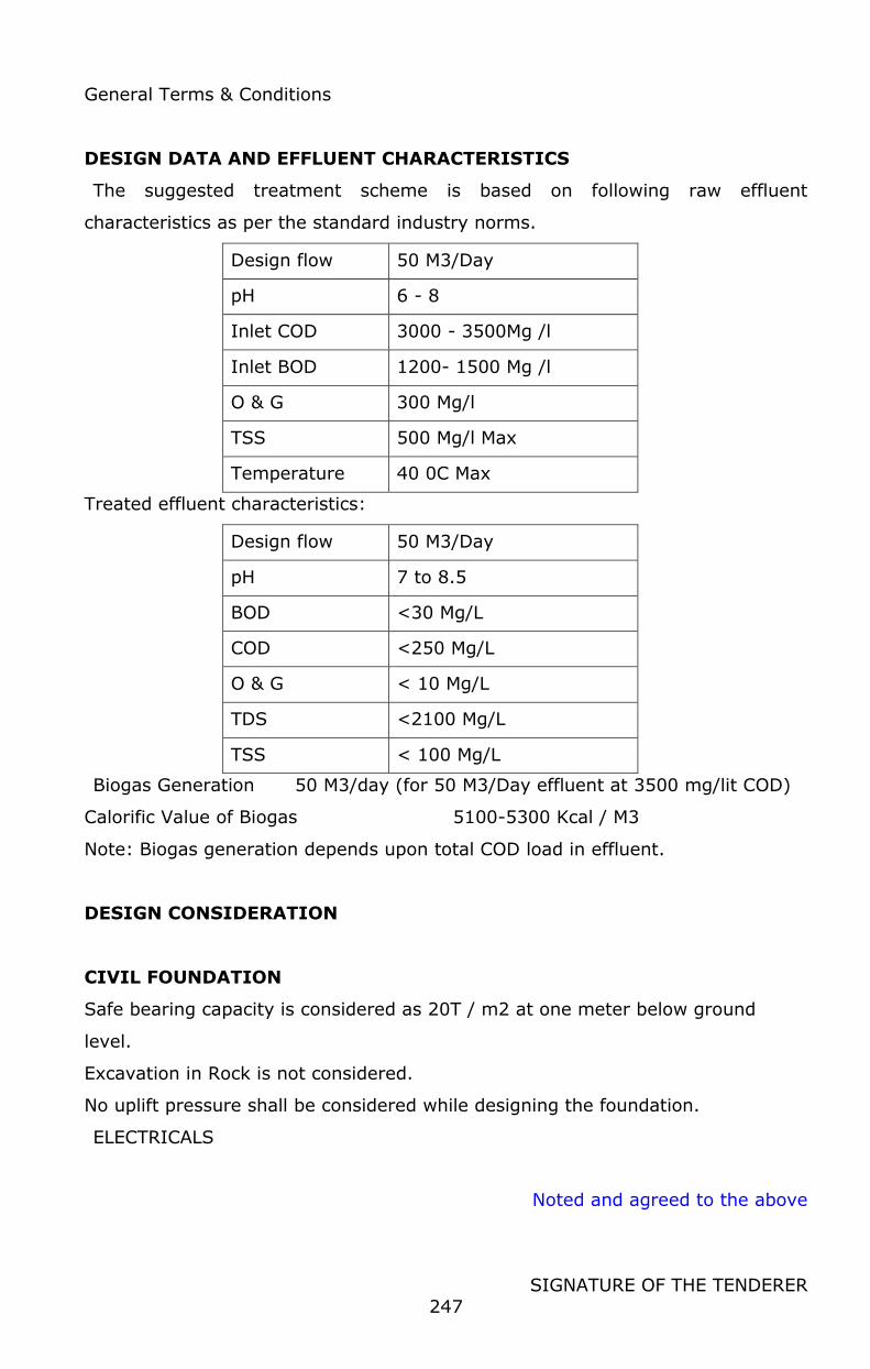
Noted and agreed to the above
SIGNATURE OF THE TENDERER
247
General Terms & Conditions
DESIGN DATA AND EFFLUENT CHARACTERISTICS
The suggested treatment scheme is based on following raw effluent
characteristics as per the standard industry norms.
Design flow 50 M3/Day
pH 6 - 8
Inlet COD 3000 - 3500Mg /l
Inlet BOD 1200- 1500 Mg /l
O & G 300 Mg/l
TSS 500 Mg/l Max
Temperature 40 0C Max
Treated effluent characteristics:
Design flow 50 M3/Day
pH 7 to 8.5
BOD <30 Mg/L
COD <250 Mg/L
O & G < 10 Mg/L
TDS <2100 Mg/L
TSS < 100 Mg/L
Biogas Generation 50 M3/day (for 50 M3/Day effluent at 3500 mg/lit COD)
Calorific Value of Biogas 5100-5300 Kcal / M3
Note: Biogas generation depends upon total COD load in effluent.
DESIGN CONSIDERATION
CIVIL FOUNDATION
Safe bearing capacity is considered as 20T / m2 at one meter below ground
level.
Excavation in Rock is not considered.
No uplift pressure shall be considered while designing the foundation.
ELECTRICALS
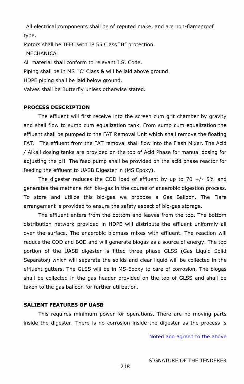
Noted and agreed to the above
SIGNATURE OF THE TENDERER
248
All electrical components shall be of reputed make, and are non-flameproof
type.
Motors shall be TEFC with IP 55 Class “B” protection.
MECHANICAL
All material shall conform to relevant I.S. Code.
Piping shall be in MS `C’ Class & will be laid above ground.
HDPE piping shall be laid below ground.
Valves shall be Butterfly unless otherwise stated.
PROCESS DESCRIPTION
The effluent will first receive into the screen cum grit chamber by gravity
and shall flow to sump cum equalization tank. From sump cum equalization the
effluent shall be pumped to the FAT Removal Unit which shall remove the floating
FAT. The effluent from the FAT removal shall flow into the Flash Mixer. The Acid
/ Alkali dosing tanks are provided on the top of Acid Phase for manual dosing for
adjusting the pH. The feed pump shall be provided on the acid phase reactor for
feeding the effluent to UASB Digester in (MS Epoxy).
The digester reduces the COD load of effluent by up to 70 +/- 5% and
generates the methane rich bio-gas in the course of anaerobic digestion process.
To store and utilize this bio-gas we propose a Gas Balloon. The Flare
arrangement is provided to ensure the safety aspect of bio-gas storage.
The effluent enters from the bottom and leaves from the top. The bottom
distribution network provided in HDPE will distribute the effluent uniformly all
over the surface. The anaerobic biomass mixes with effluent. The reaction will
reduce the COD and BOD and will generate biogas as a source of energy. The top
portion of the UASB digester is fitted three phase GLSS (Gas Liquid Solid
Separator) which will separate the solids and clear liquid will be collected in the
effluent gutters. The GLSS will be in MS-Epoxy to care of corrosion. The biogas
shall be collected in the gas header provided on the top of GLSS and shall be
taken to the gas balloon for further utilization.
SALIENT FEATURES OF UASB
This requires minimum power for operations. There are no moving parts
inside the digester. There is no corrosion inside the digester as the process is

Noted and agreed to the above
SIGNATURE OF THE TENDERER
249
anaerobic. The process can be restarted quickly once the power supply is
restored. The maintenance cost of the system is less.
This liquid effluent is then taken out as an over flow stream from UASB.
The effluent from the outlet of the UASB shall flow to the aeration tank.
We propose to install Diffused Aeration System with Retrievable
arrangement as a secondary treatment scheme to reduce the remaining COD &
BOD. Fine bubble diffusers shall be installed of silicone rubber material for longer
life. Twin lobe air blowers are provided for supplying the air to the diffusers the
secondary clarifier is provided for collecting the MLSS generated form the
aeration process. MLSS is recycled back to the aeration tank to maintain the
required concentration and excess sludge shall be sent to the sludge drying beds.
Further to remove the remaining suspended solids, odour and residual BOD we
propose Pressure Sand Filter and Activated Carbon Filter. The clear effluent form
the outlet of ACF can be used for gardening, floor washing, flushing etc.
Hypochlorite dosing shall be provided for disinfection of treated water.
A. SCOPE OF WORK (CIVIL) 1 BAR SCREEN CHAMBER
Capacity 0.6 m3
Qty 1
MOC RCC
2 EQUALIZATION TANK
Capacity 25 m3
Qty 1
MOC RCC
3 FAT REMOVAL UNIT
Capacity 5 m3
Qty 1
MOC RCC
4 ACID PHASE REACTOR
Capacity 15 m3
Qty 1
MOC RCC
5 UASB FOUNDATION
Capacity 62.5 m3
Qty 1
MOC Built up Foundation with RCC raft
6 PLATFORM BIOGAS BALLOON / HOLDER
Capacity Suitable for 5 m3 Biogas Balloon
Qty 1
MOC Suitable
7 AERATION TANK
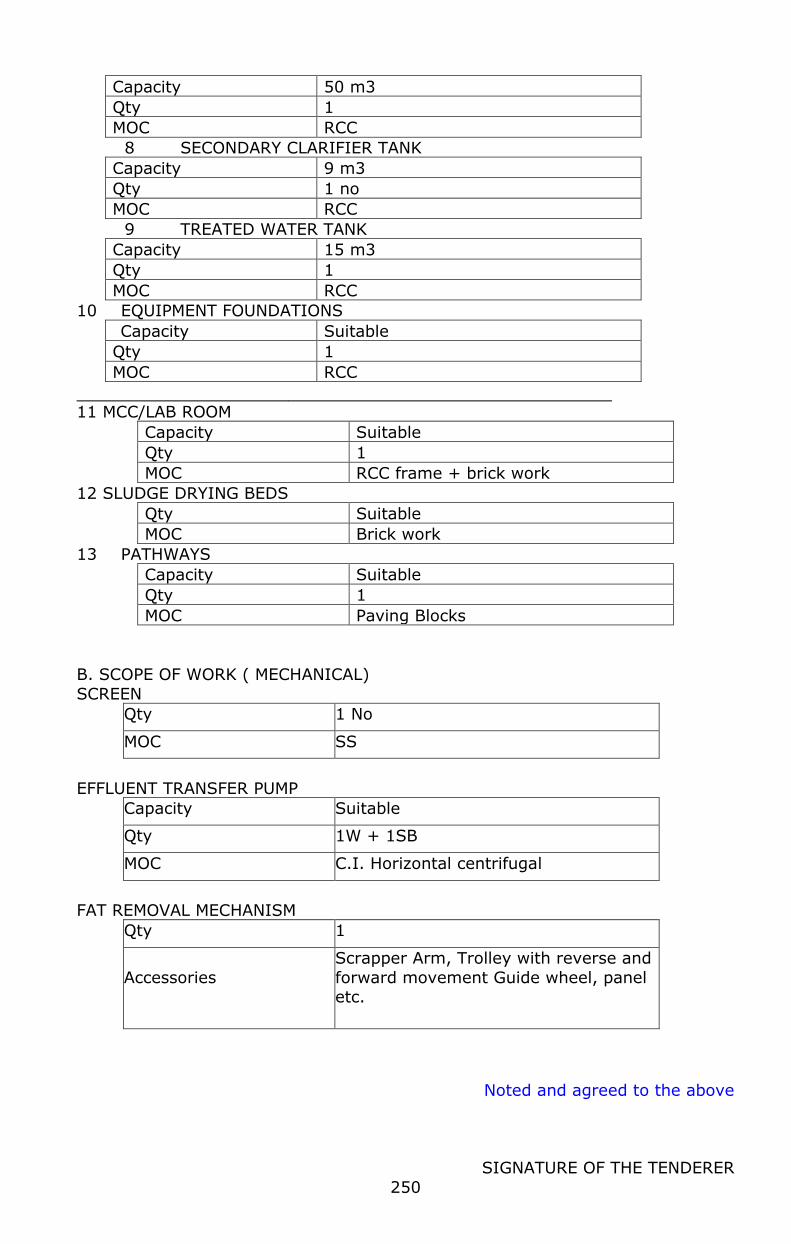
Noted and agreed to the above
SIGNATURE OF THE TENDERER
250
Capacity 50 m3
Qty 1
MOC RCC
8 SECONDARY CLARIFIER TANK
Capacity 9 m3
Qty 1 no
MOC RCC
9 TREATED WATER TANK
Capacity 15 m3
Qty 1
MOC RCC
10 EQUIPMENT FOUNDATIONS
Capacity Suitable
Qty 1
MOC RCC
11 MCC/LAB ROOM
Capacity Suitable
Qty 1
MOC RCC frame + brick work
12 SLUDGE DRYING BEDS
Qty Suitable
MOC Brick work
13 PATHWAYS
Capacity Suitable
Qty 1
MOC Paving Blocks
B. SCOPE OF WORK ( MECHANICAL)
SCREEN
Qty 1 No
MOC SS
EFFLUENT TRANSFER PUMP
Capacity Suitable
Qty 1W + 1SB
MOC C.I. Horizontal centrifugal
FAT REMOVAL MECHANISM
Qty 1
Accessories
Scrapper Arm, Trolley with reverse and
forward movement Guide wheel, panel etc.

Noted and agreed to the above
SIGNATURE OF THE TENDERER
251
FLASH MIXER AGITATOR
Qty 1
MOC SS 304
UASB FEED PUMPS WITH MOTORS
Capacity Suitable
Qty 1W + 1SB
MOC C.I. Horizontal centrifugal
UASB DIGESTER TANK
Capacity 62.5 m3
Qty 1 lot
MOC MSEP
The digester shall be erected on RCC raft without bottom plate and
designed based on IS 803, The shell will be sand blasted & epoxy painted, (SA
2.5 grade with 200 micron epoxy thereon TYP) The spiral staircase and all
around walkway with FRP grating shall be provided. Manhole will be provided at
suitable location. Safety Hand rails in MS Epoxy on staircase and outer side of
walkway shall be erected. The outside of the tank will be sand blasted and
painted primer followed with enamel paint.
SUPPORTING STRUCTURE FOR GSS
Qty 1 Lot
MOC
MS construction with sand blasting and epoxy painting
These are supports as per drawing to keep Gas solid separator at desired
location in UASB digester, these structures will be sand blasted and epoxy
painted.
EPOXY COATED GSS (3 mm thick)
Qty 1 lot
MOC MS EP
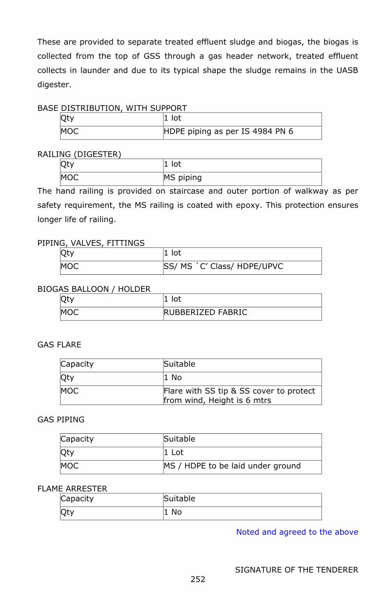
Noted and agreed to the above
SIGNATURE OF THE TENDERER
252
These are provided to separate treated effluent sludge and biogas, the biogas is
collected from the top of GSS through a gas header network, treated effluent
collects in launder and due to its typical shape the sludge remains in the UASB
digester.
BASE DISTRIBUTION, WITH SUPPORT
Qty 1 lot
MOC HDPE piping as per IS 4984 PN 6
RAILING (DIGESTER)
Qty 1 lot
MOC MS piping
The hand railing is provided on staircase and outer portion of walkway as per
safety requirement, the MS railing is coated with epoxy. This protection ensures
longer life of railing.
PIPING, VALVES, FITTINGS
Qty 1 lot
MOC SS/ MS `C’ Class/ HDPE/UPVC
BIOGAS BALLOON / HOLDER
Qty 1 lot
MOC RUBBERIZED FABRIC
GAS FLARE
Capacity Suitable
Qty 1 No
MOC Flare with SS tip & SS cover to protect from wind, Height is 6 mtrs
GAS PIPING
Capacity Suitable
Qty 1 Lot
MOC MS / HDPE to be laid under ground
FLAME ARRESTER
Capacity Suitable
Qty 1 No
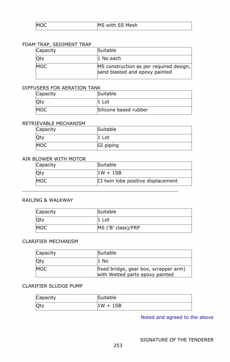
Noted and agreed to the above
SIGNATURE OF THE TENDERER
253
MOC MS with SS Mesh
FOAM TRAP, SEDIMENT TRAP
Capacity Suitable
Qty 1 No each
MOC MS construction as per required design, sand blasted and epoxy painted
DIFFUSERS FOR AERATION TANK
Capacity Suitable
Qty 1 Lot
MOC Silicone based rubber
RETRIEVABLE MECHANISM
Capacity Suitable
Qty 1 Lot
MOC GI piping
AIR BLOWER WITH MOTOR
Capacity Suitable
Qty 1W + 1SB
MOC CI twin lobe positive displacement
RAILING & WALKWAY
Capacity Suitable
Qty 1 Lot
MOC MS ('B' class)/FRP
CLARIFIER MECHANISM
Capacity Suitable
Qty 1 No
MOC fixed bridge, gear box, scrapper arm) with Wetted parts epoxy painted
CLARIFIER SLUDGE PUMP
Capacity Suitable
Qty 1W + 1SB
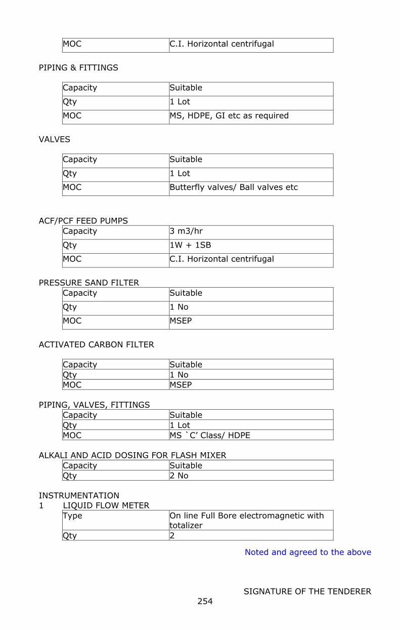
Noted and agreed to the above
SIGNATURE OF THE TENDERER
254
MOC C.I. Horizontal centrifugal
PIPING & FITTINGS
Capacity Suitable
Qty 1 Lot
MOC MS, HDPE, GI etc as required
VALVES
Capacity Suitable
Qty 1 Lot
MOC Butterfly valves/ Ball valves etc
ACF/PCF FEED PUMPS
Capacity 3 m3/hr
Qty 1W + 1SB
MOC C.I. Horizontal centrifugal
PRESSURE SAND FILTER
Capacity Suitable
Qty 1 No
MOC MSEP
ACTIVATED CARBON FILTER
Capacity Suitable
Qty 1 No
MOC MSEP
PIPING, VALVES, FITTINGS
Capacity Suitable
Qty 1 Lot
MOC MS `C’ Class/ HDPE
ALKALI AND ACID DOSING FOR FLASH MIXER
Capacity Suitable
Qty 2 No
INSTRUMENTATION
1 LIQUID FLOW METER
Type On line Full Bore electromagnetic with totalizer
Qty 2
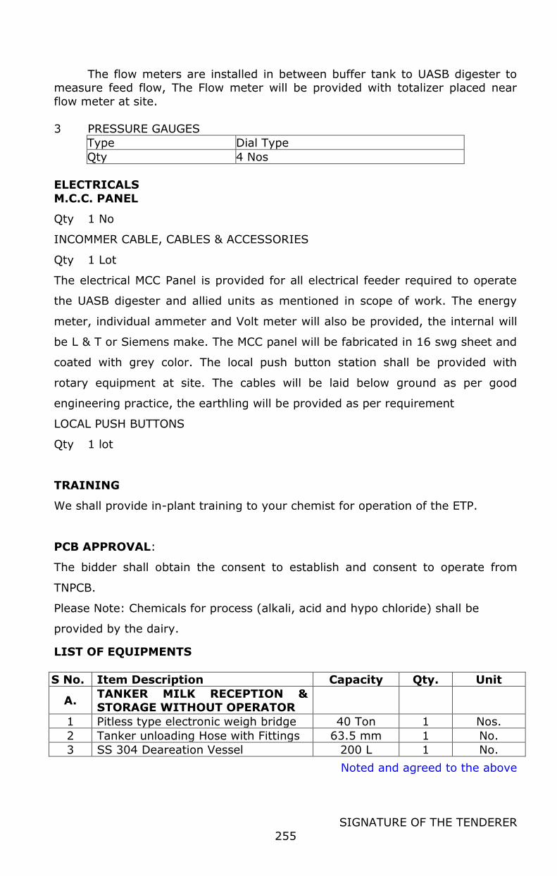
Noted and agreed to the above
SIGNATURE OF THE TENDERER
255
The flow meters are installed in between buffer tank to UASB digester to measure feed flow, The Flow meter will be provided with totalizer placed near
flow meter at site.
3 PRESSURE GAUGES
Type Dial Type
Qty 4 Nos
ELECTRICALS
M.C.C. PANEL
Qty 1 No
INCOMMER CABLE, CABLES & ACCESSORIES
Qty 1 Lot
The electrical MCC Panel is provided for all electrical feeder required to operate
the UASB digester and allied units as mentioned in scope of work. The energy
meter, individual ammeter and Volt meter will also be provided, the internal will
be L & T or Siemens make. The MCC panel will be fabricated in 16 swg sheet and
coated with grey color. The local push button station shall be provided with
rotary equipment at site. The cables will be laid below ground as per good
engineering practice, the earthling will be provided as per requirement
LOCAL PUSH BUTTONS
Qty 1 lot
TRAINING
We shall provide in-plant training to your chemist for operation of the ETP.
PCB APPROVAL:
The bidder shall obtain the consent to establish and consent to operate from
TNPCB.
Please Note: Chemicals for process (alkali, acid and hypo chloride) shall be
provided by the dairy.
LIST OF EQUIPMENTS
S No. Item Description Capacity Qty. Unit
A. TANKER MILK RECEPTION & STORAGE WITHOUT OPERATOR
1 Pitless type electronic weigh bridge 40 Ton 1 Nos.
2 Tanker unloading Hose with Fittings 63.5 mm 1 No.
3 SS 304 Deareation Vessel 200 L 1 No.
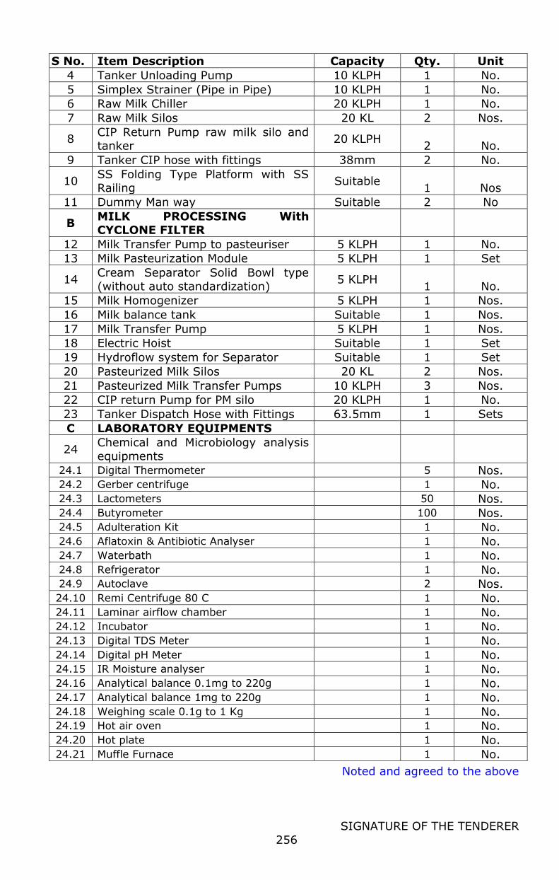
Noted and agreed to the above
SIGNATURE OF THE TENDERER
256
S No. Item Description Capacity Qty. Unit
4 Tanker Unloading Pump 10 KLPH 1 No.
5 Simplex Strainer (Pipe in Pipe) 10 KLPH 1 No.
6 Raw Milk Chiller 20 KLPH 1 No.
7 Raw Milk Silos 20 KL 2 Nos.
8 CIP Return Pump raw milk silo and tanker
20 KLPH 2 No.
9 Tanker CIP hose with fittings 38mm 2 No.
10 SS Folding Type Platform with SS Railing
Suitable 1 Nos
11 Dummy Man way Suitable 2 No
B MILK PROCESSING With CYCLONE FILTER
12 Milk Transfer Pump to pasteuriser 5 KLPH 1 No.
13 Milk Pasteurization Module 5 KLPH 1 Set
14 Cream Separator Solid Bowl type
(without auto standardization) 5 KLPH
1 No.
15 Milk Homogenizer 5 KLPH 1 Nos.
16 Milk balance tank Suitable 1 Nos.
17 Milk Transfer Pump 5 KLPH 1 Nos.
18 Electric Hoist Suitable 1 Set
19 Hydroflow system for Separator Suitable 1 Set
20 Pasteurized Milk Silos 20 KL 2 Nos.
21 Pasteurized Milk Transfer Pumps 10 KLPH 3 Nos.
22 CIP return Pump for PM silo 20 KLPH 1 No.
23 Tanker Dispatch Hose with Fittings 63.5mm 1 Sets
C LABORATORY EQUIPMENTS
24 Chemical and Microbiology analysis
equipments
24.1 Digital Thermometer 5 Nos. 24.2 Gerber centrifuge 1 No.
24.3 Lactometers 50 Nos.
24.4 Butyrometer 100 Nos. 24.5 Adulteration Kit 1 No.
24.6 Aflatoxin & Antibiotic Analyser 1 No.
24.7 Waterbath 1 No.
24.8 Refrigerator 1 No. 24.9 Autoclave 2 Nos.
24.10 Remi Centrifuge 80 C 1 No.
24.11 Laminar airflow chamber 1 No. 24.12 Incubator 1 No.
24.13 Digital TDS Meter 1 No.
24.14 Digital pH Meter 1 No. 24.15 IR Moisture analyser 1 No.
24.16 Analytical balance 0.1mg to 220g 1 No.
24.17 Analytical balance 1mg to 220g 1 No.
24.18 Weighing scale 0.1g to 1 Kg 1 No. 24.19 Hot air oven 1 No.
24.20 Hot plate 1 No.
24.21 Muffle Furnace 1 No.
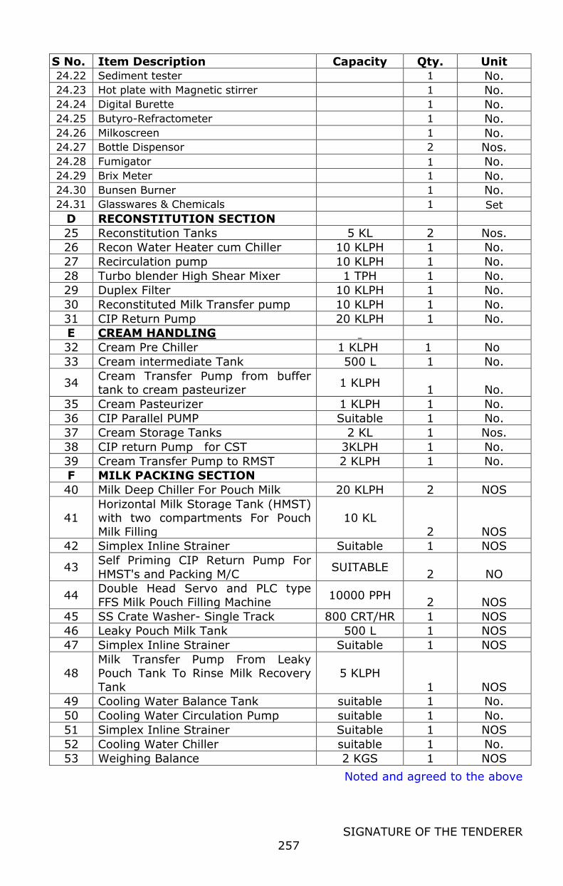
Noted and agreed to the above
SIGNATURE OF THE TENDERER
257
S No. Item Description Capacity Qty. Unit
24.22 Sediment tester 1 No.
24.23 Hot plate with Magnetic stirrer 1 No. 24.24 Digital Burette 1 No.
24.25 Butyro-Refractometer 1 No.
24.26 Milkoscreen 1 No. 24.27 Bottle Dispensor 2 Nos.
24.28 Fumigator 1 No.
24.29 Brix Meter 1 No.
24.30 Bunsen Burner 1 No.
24.31 Glasswares & Chemicals 1 Set
D RECONSTITUTION SECTION
25 Reconstitution Tanks 5 KL 2 Nos.
26 Recon Water Heater cum Chiller 10 KLPH 1 No.
27 Recirculation pump 10 KLPH 1 No.
28 Turbo blender High Shear Mixer 1 TPH 1 No.
29 Duplex Filter 10 KLPH 1 No.
30 Reconstituted Milk Transfer pump 10 KLPH 1 No.
31 CIP Return Pump 20 KLPH 1 No.
E CREAM HANDLING
32 Cream Pre Chiller 1 KLPH 1 No
33 Cream intermediate Tank 500 L 1 No.
34 Cream Transfer Pump from buffer tank to cream pasteurizer
1 KLPH 1 No.
35 Cream Pasteurizer 1 KLPH 1 No.
36 CIP Parallel PUMP Suitable 1 No.
37 Cream Storage Tanks 2 KL 1 Nos.
38 CIP return Pump for CST 3KLPH 1 No.
39 Cream Transfer Pump to RMST 2 KLPH 1 No.
F MILK PACKING SECTION
40 Milk Deep Chiller For Pouch Milk 20 KLPH 2 NOS
41 Horizontal Milk Storage Tank (HMST) with two compartments For Pouch
Milk Filling
10 KL
2 NOS
42 Simplex Inline Strainer Suitable 1 NOS
43 Self Priming CIP Return Pump For
HMST's and Packing M/C SUITABLE
2 NO
44 Double Head Servo and PLC type
FFS Milk Pouch Filling Machine 10000 PPH
2 NOS
45 SS Crate Washer- Single Track 800 CRT/HR 1 NOS
46 Leaky Pouch Milk Tank 500 L 1 NOS
47 Simplex Inline Strainer Suitable 1 NOS
48 Milk Transfer Pump From Leaky Pouch Tank To Rinse Milk Recovery
Tank
5 KLPH
1 NOS
49 Cooling Water Balance Tank suitable 1 No.
50 Cooling Water Circulation Pump suitable 1 No.
51 Simplex Inline Strainer Suitable 1 NOS
52 Cooling Water Chiller suitable 1 No.
53 Weighing Balance 2 KGS 1 NOS
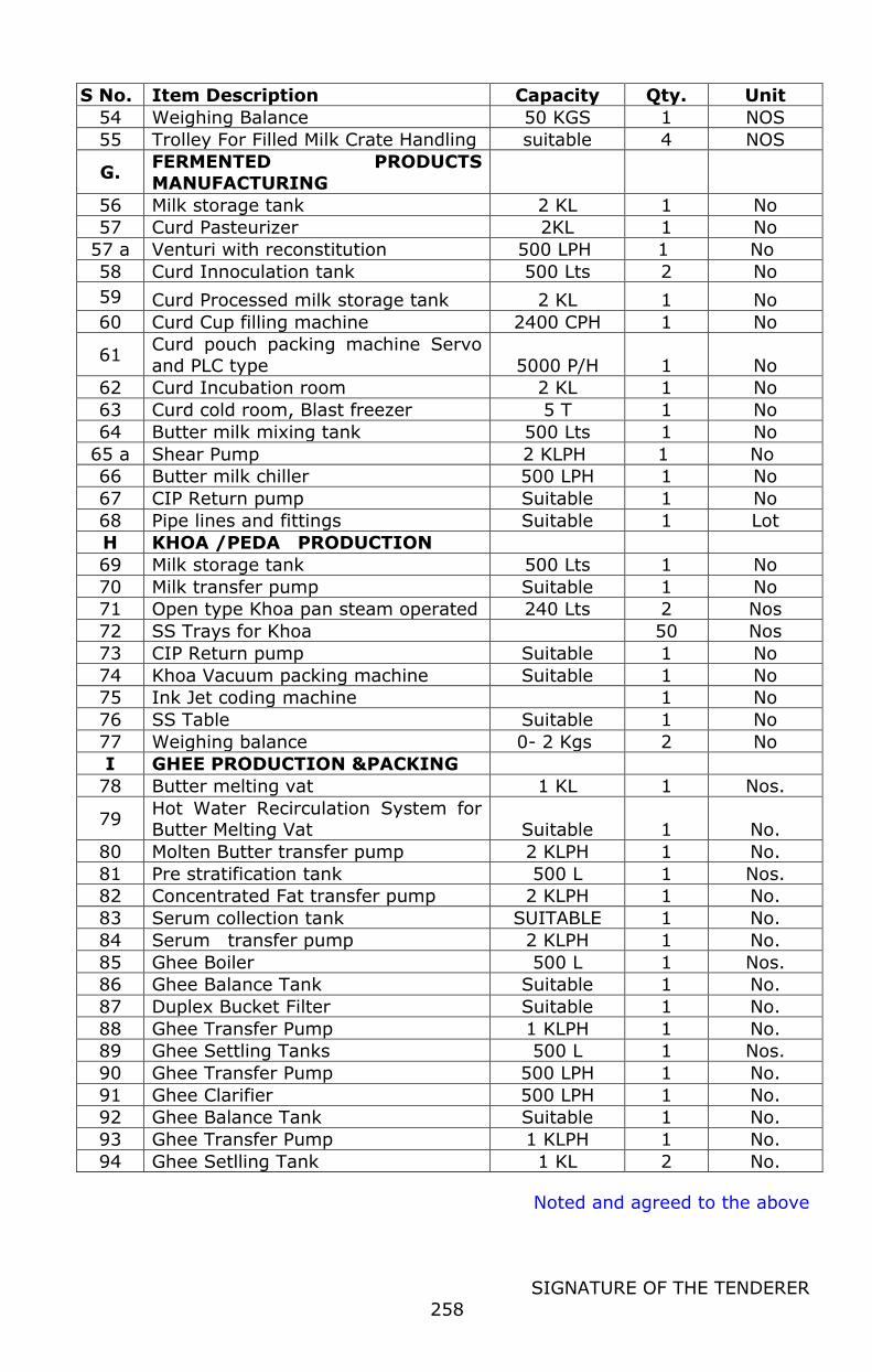
Noted and agreed to the above
SIGNATURE OF THE TENDERER
258
S No. Item Description Capacity Qty. Unit
54 Weighing Balance 50 KGS 1 NOS
55 Trolley For Filled Milk Crate Handling suitable 4 NOS
G. FERMENTED PRODUCTS
MANUFACTURING
56 Milk storage tank 2 KL 1 No
57 Curd Pasteurizer 2KL 1 No
57 a Venturi with reconstitution 500 LPH 1 No
58 Curd Innoculation tank 500 Lts 2 No
59 Curd Processed milk storage tank 2 KL 1 No
60 Curd Cup filling machine 2400 CPH 1 No
61 Curd pouch packing machine Servo
and PLC type 5000 P/H 1 No
62 Curd Incubation room 2 KL 1 No
63 Curd cold room, Blast freezer 5 T 1 No
64 Butter milk mixing tank 500 Lts 1 No
65 a Shear Pump 2 KLPH 1 No
66 Butter milk chiller 500 LPH 1 No
67 CIP Return pump Suitable 1 No
68 Pipe lines and fittings Suitable 1 Lot
H KHOA /PEDA PRODUCTION
69 Milk storage tank 500 Lts 1 No
70 Milk transfer pump Suitable 1 No
71 Open type Khoa pan steam operated 240 Lts 2 Nos
72 SS Trays for Khoa 50 Nos
73 CIP Return pump Suitable 1 No
74 Khoa Vacuum packing machine Suitable 1 No
75 Ink Jet coding machine 1 No
76 SS Table Suitable 1 No
77 Weighing balance 0- 2 Kgs 2 No
I GHEE PRODUCTION &PACKING
78 Butter melting vat 1 KL 1 Nos.
79 Hot Water Recirculation System for Butter Melting Vat Suitable 1 No.
80 Molten Butter transfer pump 2 KLPH 1 No.
81 Pre stratification tank 500 L 1 Nos.
82 Concentrated Fat transfer pump 2 KLPH 1 No.
83 Serum collection tank SUITABLE 1 No.
84 Serum transfer pump 2 KLPH 1 No.
85 Ghee Boiler 500 L 1 Nos.
86 Ghee Balance Tank Suitable 1 No.
87 Duplex Bucket Filter Suitable 1 No.
88 Ghee Transfer Pump 1 KLPH 1 No.
89 Ghee Settling Tanks 500 L 1 Nos.
90 Ghee Transfer Pump 500 LPH 1 No.
91 Ghee Clarifier 500 LPH 1 No.
92 Ghee Balance Tank Suitable 1 No.
93 Ghee Transfer Pump 1 KLPH 1 No.
94 Ghee Setlling Tank 1 KL 2 No.
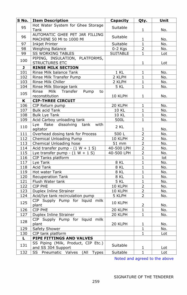
Noted and agreed to the above
SIGNATURE OF THE TENDERER
259
S No. Item Description Capacity Qty. Unit
95 Hot Water System for Ghee Storage Tank
Suitable 1 No.
96 AUTOMATIC GHEE PET JAR FILLING
MACHINE 50 Ml to 1000 Ml Suitable
1 No.
97 Inkjet Printer Suitable 1 No.
98 Weighing Balance 0-2 Kgs 2 No.
99 SS WORKING TABLES SUITABLE 1 Lot
100 PIPING, INSULATION, PLATFORMS,
STRUCTURES ETC 1 Lot
J RINSE MILK SECTION
101 Rinse Milk balance Tank 1 KL 1 No.
102 Rinse Milk Transfer Pump 2 KLPH 1 No.
103 Rinse Milk Chiller 2 KLPH 1 No.
104 Rinse Milk Storage tank 5 KL 1 No.
105 Rinse Milk Transfer Pump to
reconstitution 10 KLPH 1 No.
K CIP-THREE CIRCUIT
106 CIP Return pump 20 KLPH 1 No.
107 Bulk acid Tank 10 KL 1 No.
108 Bulk Lye Tank 10 KL 1 No.
109 Acid Carboy unloading tank 500L 1 No.
110 Lye flake dissolving tank with agitator
2 KL 1 No.
111 Overhead dosing tank for Process 500 L 2 No.
112 Chemical Unloading Pump 10 KLPH 2 No.
113 Chemical Unloading hose 51 mm 2 No.
114 Acid transfer pump - (1 W + 1 S) 40-500 LPH 2 No.
115 Lye transfer pump - (1 W + 1 S) 40-500 LPH 2 No.
116 CIP Tanks platform 1 lot
117 Lye Tank 8 KL 1 No.
118 Acid Tank 8 KL 1 No.
119 Hot water Tank 8 KL 1 No.
120 Recuperation Tank 8 KL 1 No.
121 Flush Water tank 5 KL 1 No.
122 CIP PHE 10 KLPH 2 No.
123 Duplex Inline Strainer 10 KLPH 2 No.
124 Acid/lye tank recirculation pump 5 KLPH 2 No.
125 CIP Supply Pump for liquid milk plant
10 KLPH 2 No.
126 CIP PHE 20 KLPH 1 No.
127 Duplex Inline Strainer 20 KLPH 1 No.
128 CIP Supply Pump for liquid milk plant 20 KLPH 1 No.
129 Safety Shower 1 No.
130 CIP tank platform 1 Lot
L PIPE FITTINGS AND VALVES
131 SS Piping (Milk, Product, CIP Etc.) and SS 304 Support
Suitable 1 Lot
132 SS Pneumatic Valves (All Types Suitable 1 Lot
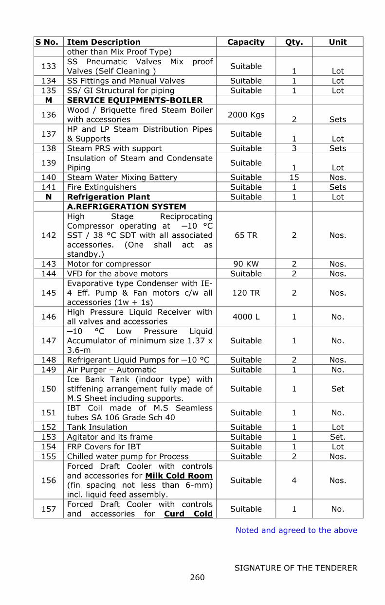
Noted and agreed to the above
SIGNATURE OF THE TENDERER
260
S No. Item Description Capacity Qty. Unit
other than Mix Proof Type)
133 SS Pneumatic Valves Mix proof Valves (Self Cleaning )
Suitable 1 Lot
134 SS Fittings and Manual Valves Suitable 1 Lot
135 SS/ GI Structural for piping Suitable 1 Lot
M SERVICE EQUIPMENTS-BOILER
136 Wood / Briquette fired Steam Boiler with accessories
2000 Kgs 2 Sets
137 HP and LP Steam Distribution Pipes
& Supports Suitable
1 Lot
138 Steam PRS with support Suitable 3 Sets
139 Insulation of Steam and Condensate
Piping Suitable
1 Lot
140 Steam Water Mixing Battery Suitable 15 Nos.
141 Fire Extinguishers Suitable 1 Sets
N Refrigeration Plant Suitable 1 Lot
A.REFRIGERATION SYSTEM
142
High Stage Reciprocating
Compressor operating at ─10 °C SST / 38 °C SDT with all associated
accessories. (One shall act as standby.)
65 TR 2 Nos.
143 Motor for compressor 90 KW 2 Nos.
144 VFD for the above motors Suitable 2 Nos.
145
Evaporative type Condenser with IE-
4 Eff. Pump & Fan motors c/w all accessories (1w + 1s)
120 TR 2 Nos.
146 High Pressure Liquid Receiver with
all valves and accessories 4000 L 1 No.
147
─10 °C Low Pressure Liquid
Accumulator of minimum size 1.37 x 3.6-m
Suitable 1 No.
148 Refrigerant Liquid Pumps for ─10 °C Suitable 2 Nos.
149 Air Purger – Automatic Suitable 1 No.
150
Ice Bank Tank (indoor type) with
stiffening arrangement fully made of
M.S Sheet including supports.
Suitable 1 Set
151 IBT Coil made of M.S Seamless
tubes SA 106 Grade Sch 40 Suitable 1 No.
152 Tank Insulation Suitable 1 Lot
153 Agitator and its frame Suitable 1 Set.
154 FRP Covers for IBT Suitable 1 Lot
155 Chilled water pump for Process Suitable 2 Nos.
156
Forced Draft Cooler with controls
and accessories for Milk Cold Room (fin spacing not less than 6-mm)
incl. liquid feed assembly.
Suitable 4 Nos.
157 Forced Draft Cooler with controls and accessories for Curd Cold
Suitable 1 No.
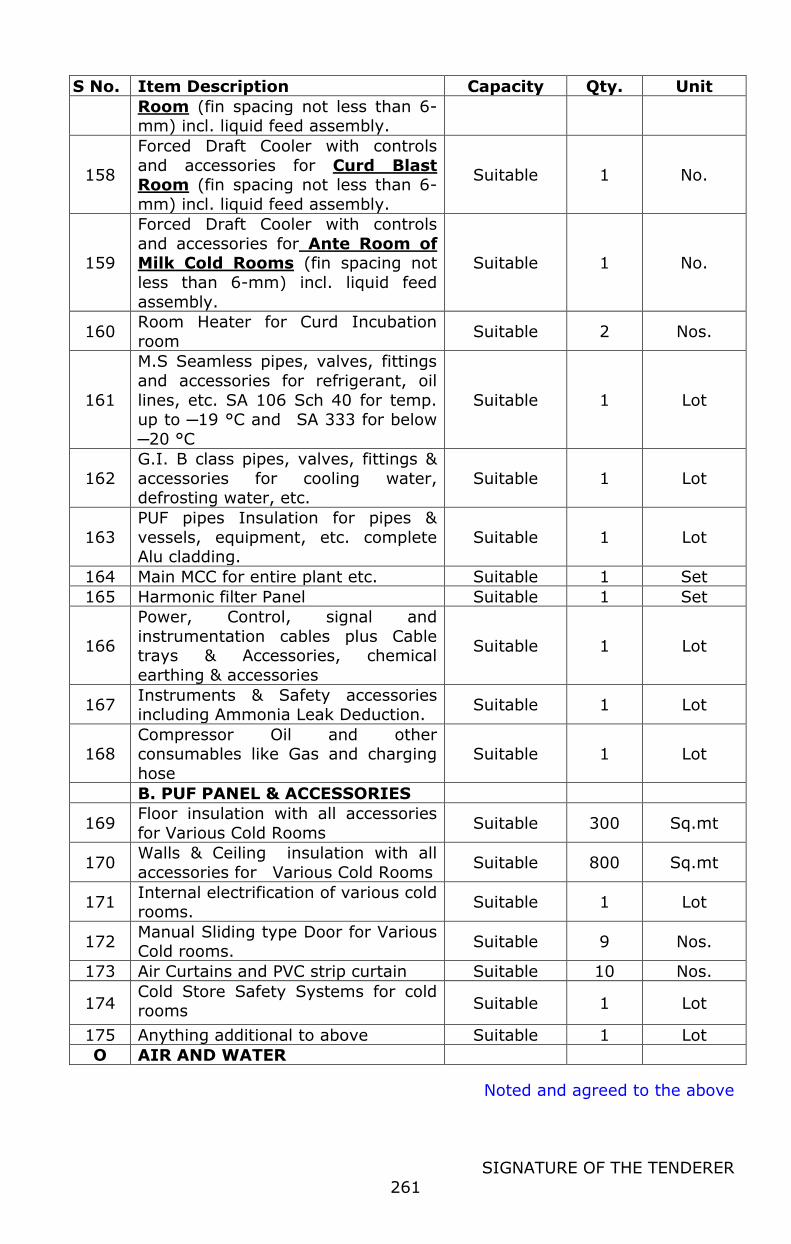
Noted and agreed to the above
SIGNATURE OF THE TENDERER
261
S No. Item Description Capacity Qty. Unit
Room (fin spacing not less than 6-mm) incl. liquid feed assembly.
158
Forced Draft Cooler with controls
and accessories for Curd Blast Room (fin spacing not less than 6-
mm) incl. liquid feed assembly.
Suitable 1 No.
159
Forced Draft Cooler with controls
and accessories for Ante Room of Milk Cold Rooms (fin spacing not
less than 6-mm) incl. liquid feed
assembly.
Suitable 1 No.
160 Room Heater for Curd Incubation
room Suitable 2 Nos.
161
M.S Seamless pipes, valves, fittings
and accessories for refrigerant, oil
lines, etc. SA 106 Sch 40 for temp. up to ─19 °C and SA 333 for below
─20 °C
Suitable 1 Lot
162
G.I. B class pipes, valves, fittings &
accessories for cooling water, defrosting water, etc.
Suitable 1 Lot
163
PUF pipes Insulation for pipes &
vessels, equipment, etc. complete Alu cladding.
Suitable 1 Lot
164 Main MCC for entire plant etc. Suitable 1 Set
165 Harmonic filter Panel Suitable 1 Set
166
Power, Control, signal and
instrumentation cables plus Cable trays & Accessories, chemical
earthing & accessories
Suitable 1 Lot
167 Instruments & Safety accessories including Ammonia Leak Deduction.
Suitable 1 Lot
168 Compressor Oil and other consumables like Gas and charging
hose
Suitable 1 Lot
B. PUF PANEL & ACCESSORIES
169 Floor insulation with all accessories
for Various Cold Rooms Suitable 300 Sq.mt
170 Walls & Ceiling insulation with all
accessories for Various Cold Rooms Suitable 800 Sq.mt
171 Internal electrification of various cold rooms.
Suitable 1 Lot
172 Manual Sliding type Door for Various Cold rooms.
Suitable 9 Nos.
173 Air Curtains and PVC strip curtain Suitable 10 Nos.
174 Cold Store Safety Systems for cold rooms Suitable 1 Lot
175 Anything additional to above Suitable 1 Lot
O AIR AND WATER
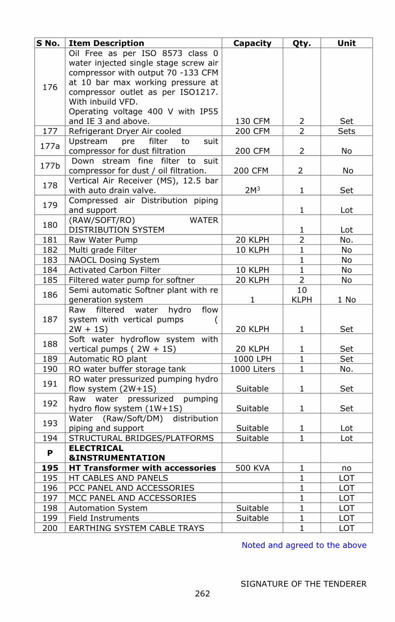
Noted and agreed to the above
SIGNATURE OF THE TENDERER
262
S No. Item Description Capacity Qty. Unit
176
Oil Free as per ISO 8573 class 0 water injected single stage screw air
compressor with output 70 -133 CFM at 10 bar max working pressure at
compressor outlet as per ISO1217.
With inbuild VFD. Operating voltage 400 V with IP55
and IE 3 and above. 130 CFM 2 Set
177 Refrigerant Dryer Air cooled 200 CFM 2 Sets
177a Upstream pre filter to suit
compressor for dust filtration 200 CFM 2 No
177b Down stream fine filter to suit
compressor for dust / oil filtration. 200 CFM 2 No
178 Vertical Air Receiver (MS), 12.5 bar
with auto drain valve. 2M3 1 Set
179 Compressed air Distribution piping and support 1 Lot
180 (RAW/SOFT/RO) WATER DISTRIBUTION SYSTEM 1 Lot
181 Raw Water Pump 20 KLPH 2 No.
182 Multi grade Filter 10 KLPH 1 No
183 NAOCL Dosing System
1 No
184 Activated Carbon Filter 10 KLPH 1 No
185 Filtered water pump for softner 20 KLPH 2 No
186 Semi automatic Softner plant with re generation system 1
10 KLPH 1 No
187 Raw filtered water hydro flow system with vertical pumps (
2W + 1S) 20 KLPH 1 Set
188 Soft water hydroflow system with vertical pumps ( 2W + 1S) 20 KLPH 1 Set
189 Automatic RO plant 1000 LPH 1 Set
190 RO water buffer storage tank 1000 Liters 1 No.
191 RO water pressurized pumping hydro
flow system (2W+1S) Suitable 1 Set
192 Raw water pressurized pumping hydro flow system (1W+1S) Suitable 1 Set
193 Water (Raw/Soft/DM) distribution piping and support Suitable 1 Lot
194 STRUCTURAL BRIDGES/PLATFORMS Suitable 1 Lot
P ELECTRICAL &INSTRUMENTATION
195 HT Transformer with accessories 500 KVA 1 no
195 HT CABLES AND PANELS 1 LOT
196 PCC PANEL AND ACCESSORIES 1 LOT
197 MCC PANEL AND ACCESSORIES 1 LOT
198 Automation System Suitable 1 LOT
199 Field Instruments Suitable 1 LOT
200 EARTHING SYSTEM CABLE TRAYS 1 LOT
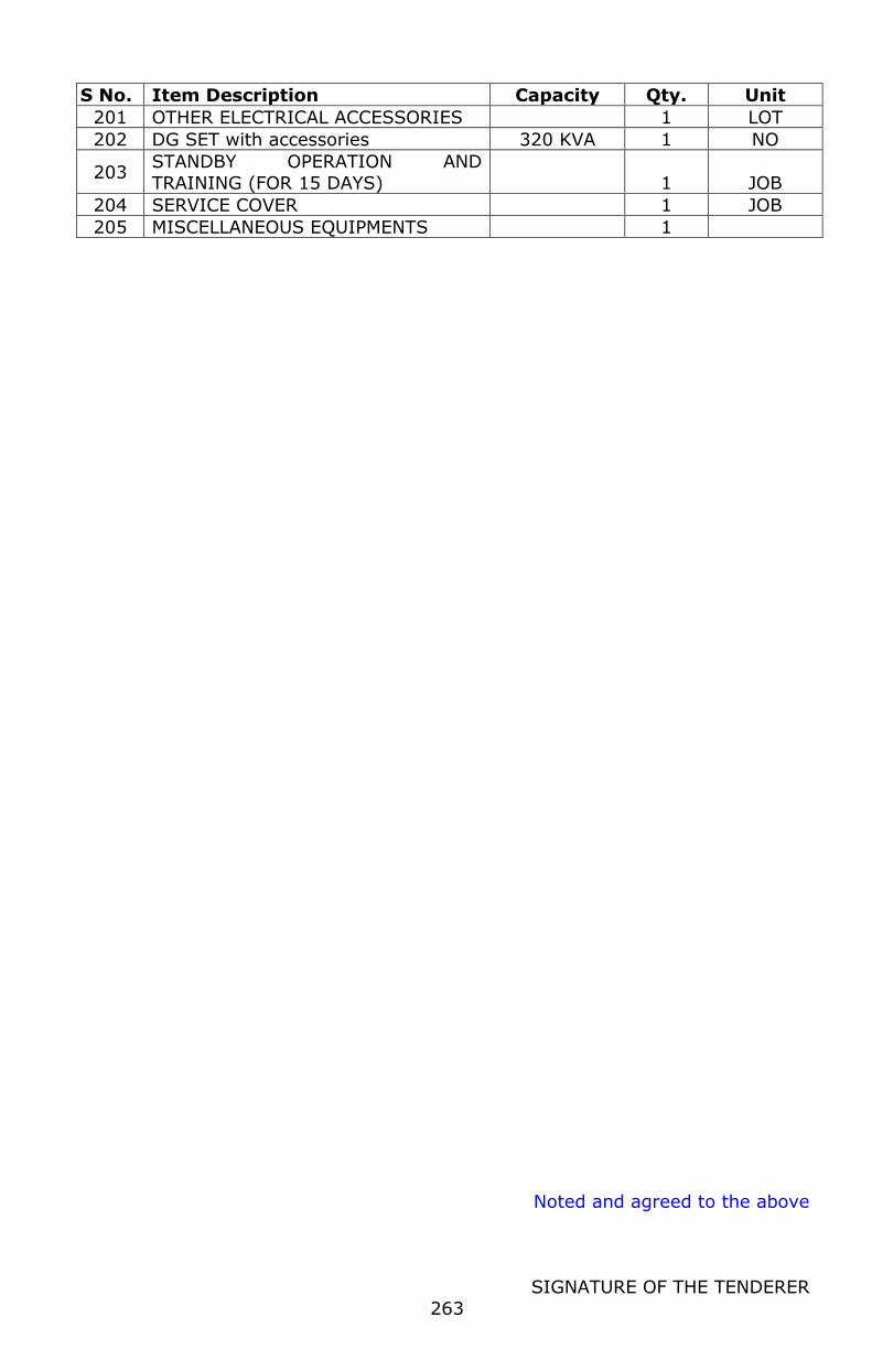
Noted and agreed to the above
SIGNATURE OF THE TENDERER
263
S No. Item Description Capacity Qty. Unit
201 OTHER ELECTRICAL ACCESSORIES 1 LOT
202 DG SET with accessories 320 KVA 1 NO
203 STANDBY OPERATION AND
TRAINING (FOR 15 DAYS) 1 JOB
204 SERVICE COVER 1 JOB
205 MISCELLANEOUS EQUIPMENTS 1
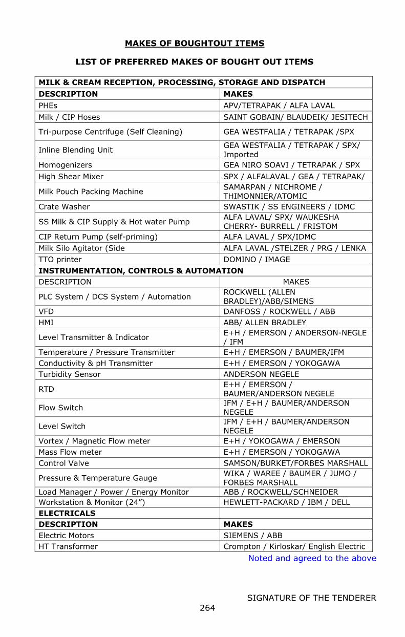
Noted and agreed to the above
SIGNATURE OF THE TENDERER
264
MAKES OF BOUGHTOUT ITEMS
LIST OF PREFERRED MAKES OF BOUGHT OUT ITEMS
MILK & CREAM RECEPTION, PROCESSING, STORAGE AND DISPATCH
DESCRIPTION MAKES
PHEs APV/TETRAPAK / ALFA LAVAL
Milk / CIP Hoses SAINT GOBAIN/ BLAUDEIK/ JESITECH
Tri-purpose Centrifuge (Self Cleaning) GEA WESTFALIA / TETRAPAK /SPX
Inline Blending Unit GEA WESTFALIA / TETRAPAK / SPX/
Imported
Homogenizers GEA NIRO SOAVI / TETRAPAK / SPX
High Shear Mixer SPX / ALFALAVAL / GEA / TETRAPAK/
Milk Pouch Packing Machine SAMARPAN / NICHROME / THIMONNIER/ATOMIC
Crate Washer SWASTIK / SS ENGINEERS / IDMC
SS Milk & CIP Supply & Hot water Pump ALFA LAVAL/ SPX/ WAUKESHA
CHERRY- BURRELL / FRISTOM
CIP Return Pump (self-priming) ALFA LAVAL / SPX/IDMC
Milk Silo Agitator (Side ALFA LAVAL /STELZER / PRG / LENKA
TTO printer DOMINO / IMAGE
INSTRUMENTATION, CONTROLS & AUTOMATION
DESCRIPTION MAKES
PLC System / DCS System / Automation ROCKWELL (ALLEN BRADLEY)/ABB/SIMENS
VFD DANFOSS / ROCKWELL / ABB
HMI ABB/ ALLEN BRADLEY
Level Transmitter & Indicator E+H / EMERSON / ANDERSON-NEGLE / IFM
Temperature / Pressure Transmitter E+H / EMERSON / BAUMER/IFM
Conductivity & pH Transmitter E+H / EMERSON / YOKOGAWA
Turbidity Sensor ANDERSON NEGELE
RTD E+H / EMERSON / BAUMER/ANDERSON NEGELE
Flow Switch IFM / E+H / BAUMER/ANDERSON NEGELE
Level Switch IFM / E+H / BAUMER/ANDERSON NEGELE
Vortex / Magnetic Flow meter E+H / YOKOGAWA / EMERSON
Mass Flow meter E+H / EMERSON / YOKOGAWA
Control Valve SAMSON/BURKET/FORBES MARSHALL
Pressure & Temperature Gauge WIKA / WAREE / BAUMER / JUMO /
FORBES MARSHALL
Load Manager / Power / Energy Monitor ABB / ROCKWELL/SCHNEIDER
Workstation & Monitor (24”) HEWLETT-PACKARD / IBM / DELL
ELECTRICALS
DESCRIPTION MAKES
Electric Motors SIEMENS / ABB
HT Transformer Crompton / Kirloskar/ English Electric
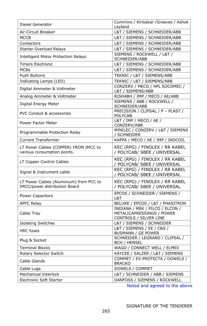
Noted and agreed to the above
SIGNATURE OF THE TENDERER
265
Diesel Generator Cummins / Kirloskar /Greaves / Ashok Leyland
Air Circuit Breaker L&T / SIEMENS / SCHNEIDER/ABB
MCCB L&T / SIEMENS / SCHNEIDER/ABB
Contactors L&T / SIEMENS / SCHNEIDER/ABB
Starter Overload Relays L&T / SIEMENS / SCHNEIDER/ABB
Intelligent Motor Protection Relays SIEMENS / ROCKWELL / L&T / SCHNEIDER/ABB
Timers Electronic L&T / SIEMENS / SCHNEIDER/ABB
MCBs L&T / SIEMENS / SCHNEIDER/ABB
Push Buttons TEKNIC / L&T / SIEMENS/ABB
Indicating Lamps (LED) TEKNIC / L&T / SIEMENS/ABB
Digital Ammeter & Voltmeter CONZERV / MECO / HPL SOCOMEC /
L&T / SIEMENS/ABB
Analog Ammeter & Voltmeter RISHABH / IMP / MECO / AE/ABB
Digital Energy Meter SIEMENS / ABB / ROCKWELL / SCHNEIDER/ABB
PVC Conduit & accessories PRECISION / CLIPSAL / P – PLAST / POLYCAB
Power Factor Meter L&T / IMP / MECO / AE / CONZERV/ABB
Programmable Protection Relay MINILEC / CONZERV / L&T / SIEMENS / SCHNEIDER
Current Transformer KAPPA / MECO / AE / IMP / INDCOIL
LT Power Cables (COPPER) FROM IMCC to
various consumption points.
KEC (RPG) / FINOLEX / RR KABEL
/ POLYCAB/ SBEE / UNIVERSAL
LT Copper Control Cables KEC (RPG) / FINOLEX / RR KABEL
/ POLYCAB/ SBEE / UNIVERSAL
Signal & Instrument cable KEC (RPG) / FINOLEX / RR KABEL
/ POLYCAB/ SBEE / UNIVERSAL
LT Power Cables (Aluminium) from PCC to IMCC/power distribution Board
KEC (RPG) / FINOLEX / RR KABEL / POLYCAB/ SBEE / UNIVERSAL
Power Capacitors EPCOS / SCHNEIDER / SIEMENS / L&T
APFC Relay BELUKE / EPCOS / L&T / PHASITRON
Cable Tray
INDIANA / MEK / PILCO / ELCON /
METALICAPRESSINGS / POWER CONTROLS / SILVER LINE
Isolating Switches L&T / SIEMENS / SCHNEIDER
HRC fuses L&T / SIEMENS / EE / C&S / BUSMANN / GE POWER
Plug & Socket SCHNEIDER / LEGRAND / CLIPSAL / BCH / HENSEL
Terminal Blocks WAGO / CONNECT WELL / ELMEX
Rotary Selector Switch KAYCEE / SALZER / L&T / SIEMENS
Cable Glands COMMET / EX-PROTECTA / DOWELS / BRACKO
Cable Lugs DOWELS / COMMET
Mechanical Interlock L&T / SCHNEIDER / ABB / SIEMENS
Electronic Soft Starter DANFOSS / SIEMENS / ROCKWELL
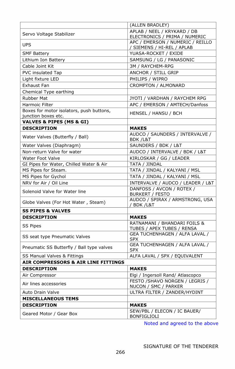
Noted and agreed to the above
SIGNATURE OF THE TENDERER
266
(ALLEN BRADLEY)
Servo Voltage Stabilizer APLAB / NEEL / KRYKARD / DB ELECTRONICS / PRIMA / NUMERIC
UPS APC / EMERSON / NUMERIC / REILLO
/ SIEMENS / HI-REL / APLAB
SMF Battery YUASA-ROCKET / EXIDE
Lithium Ion Battery SAMSUNG / LG / PANASONIC
Cable Joint Kit 3M / RAYCHEM-RPG
PVC insulated Tap ANCHOR / STILL GRIP
Light fixture LED PHILIPS / WIPRO
Exhaust Fan CROMPTON / ALMONARD
Chemical Type earthing
Rubber Mat JYOTI / VARDHAN / RAYCHEM RPG
Harmoic Filter APC / EMERSON / AMTECH/Danfoss
Boxes for motor isolators, push buttons,
junction boxes etc. HENSEL / HANSU / BCH
VALVES & PIPES (MS & GI)
DESCRIPTION MAKES
Water Valves (Butterfly / Ball) AUDCO / SAUNDERS / INTERVALVE / BDK /L&T
Water Valves (Diaphragm) SAUNDERS / BDK / L&T
Non-return Valve for water AUDCO / INTERVALVE / BDK / L&T
Water Foot Valve KIRLOSKAR / GG / LEADER
GI Pipes for Water, Chilled Water & Air TATA / JINDAL
MS Pipes for Steam. TATA / JINDAL / KALYANI / MSL
MS Pipes for Gychol TATA / JINDAL / KALYANI / MSL
NRV for Air / Oil Line INTERVALVE / AUDCO / LEADER / L&T
Solenoid Valve for Water line DANFOSS / AVCON / ROTEX / BURKERT / FESTO
Globe Valves (For Hot Water , Steam) AUDCO / SPIRAX / ARMSTRONG, USA / BDK /L&T
SS PIPES & VALVES
DESCRIPTION MAKES
SS Pipes RATNAMANI / BHANDARI FOILS & TUBES / APEX TUBES / RENSA
SS seat type Pneumatic Valves GEA TUCHENHAGEN / ALFA LAVAL / SPX
Pneumatic SS Butterfly / Ball type valves GEA TUCHENHAGEN / ALFA LAVAL / SPX
SS Manual Valves & Fittings ALFA LAVAL / SPX / EQUIVALENT
AIR COMPRESSORS & AIR LINE FITTINGS
DESCRIPTION MAKES
Air Compressor Elgi / Ingersoll Rand/ Atlascopco
Air lines accessories FESTO /SHAVO NORGEN / LEGRIS /
NUCON / SMC / PARKER
Auto Drain Valve ULTRA FILTER / ZANDER/HYDINT
MISCELLANEOUS TEMS
DESCRIPTION MAKES
Geared Motor / Gear Box SEW/PBL / ELECON / IC BAUER/ BONFIGLIOLI

Noted and agreed to the above
SIGNATURE OF THE TENDERER
267
Preferred make for refrigeration items
Sl. No.
Item Description Preferred Make
1. Reciprocating compressor package
FRICK INDIA/ MYCOM / KIRLOSKAR
2. Motor SIEMEN / ABB / BHARAT BIJLEE/
CROMPTON GREAVES
3. Electronic soft starter /VFD SIEMENS / ALLEN BRADLEY /L&T /
DANFOSS
4. Evaporative Type condensers FRICK INDIA/ STAR COOLER/ THERMAX/ EVAPCO /BALTIMORE
5. Forced draft coolers FRICK / STAR COOLER/ GUNTNER/ GOEDHART
6. Pre-fabricated insulating panels FRICK/ LLOYDS/ RINAC/ METECNO/
KINGSPIN JINDAL
7. Liquid ammonia pump FRICK/ TH.WITT/
HERMETIC/HYDRODYNE
8. Chilled water pump GRUNDFOS / CRI
9. Automatic air Purger FRICK/ ARMSTRONG / DANFOSS /GEA
10. Water Pipes TATA / JINDAL / ZENITH / MST / KALYANI
11. Air curtains RUSSEL /ALMONARD/ MITZVAH
12. Cold store e door (sliding ) METAFLEX / SALCO / MTH
13. EPS/PUF slab insulation material
FRICK/ LLOYDS/ RINAC/ METECNO
14. Saddles for cold insulation SUPERTHERM (LLOYDS) / BEARDSELL
15. Refrigerant / Oil pipes TATA / JINDAL /KALYANI /MSL / ISMT
16. SS & MS Structural channels &
angles SAIL / TATA STEEL /RINL / ESSAR
17. SS Coils & Plates SAIL / TATA STEEL / RINL / JINDAL/
ESSAR
18. SS Pipes and Tubes RATNAMANI / BHANDARI FOILS & TUBES / APEX / JINDAL QUALITY TUBULAR /
SHUBLAXMI / RENSA
19. Ammonia system valves (all
types)
PARKER /HERL-
KIRLOSKAR/HANSEN/REVALCO/DANFOSS
20. Water valves SAUNDERS / L&T (AUDCO) /BDK / INTERVALVE / CRESCENT / LEADER/
GEMU
21. Human Machine Interface
(HMI) ALLEN BRADLEY (ROCKWELL) / SIEMENS
22. Reflux type ammonia liquid level gauge
REVATHI / RK DUTTA
23. Dial type Pressure / Temperature gauges
H.GURU / PRICOL / FIEBIG/ WARREE
24. Digital temperature sensors/
indicator / controller
E&H / EMERSON / ANDERSON NEGELE /
IFM/ RADIX
25. Harmonic Filter
P2 SOLUTION/ L&T / SIEMENS /
SCHNEIDER / ABB / EMERSON / SCHAFNER

Noted and agreed to the above
SIGNATURE OF THE TENDERER
268
Sl.
No. Item Description Preferred Make
26. Digital temperature indicating DANFOSS / JONHSON CONTROLS/
DIXELL-EMERSON/ HONEYWELL 27. controller with defrost control
for packaged refrigeration units
28. Harmonic Filter L&T / SIEMENS / SCHNEIDER / ABB /
EMERSON / SCHAFNER
29. ACB / MCCB SIEMENS/ L&T/ SCHNEIDER / ABB
30. Switch fuse units SIEMENS/L&T/SCHINDER / ABB
31. MCB HAGER / SIEMENS / MDS – LEGRAND / SCHNEIDER / ABB
32. LT armored Power Cables KEC (RPG) / FINOLEX / RR KABEL /
POLYCAB/ SBEE / UNIVERSAL
33. LT armored Copper Control
Cables
KEC (RPG) / FINOLEX / RR KABEL /
POLYCAB/ SBEE / UNIVERSAL
34. LT steel braided copper power & control cables
LAPP KABEL / SBEE
35. Protective relays / Over-load relays / Bidders / Timer /
MPCB
L & T/SIEMENS/ SCHNEIDER/ABB
36. Push button L&T / SIEMENS / SCHNEIDER / ABB / TEKNIC / VAISHNAV / GE
37. LED type indication lamp L&T / SIEMENS / BINAY / TEKNIC / SCHNEIDER
38. Terminal block WAGO / LAPP INDIA / CONNECTWELL
39. HRC fuse L & T / SIEMENS /EE/GE POWER / C&S
40. Measuring instruments L&T / SIEMENS / IMP/ MECO / AE /
RISHAB
41. Resin Cast / Poly Carbonate Current transformer
KAPPA / BHARTI / L&T / NEWTEK / PRECISE / AE / SCHNEIDER
42. Description MAKE
43. Rotary switches L&T / SIEMENS/ SALZER /TEKNIC / KAYCEE
44. Capacitors EPCOS / SCHNEIDER / NEPTUNE DUCATI / L&T / KHATAU JANKAR / UNISTAR
45. Lugs DOWELLS/ COMET / LAPP KABEL
46. Gland DOWELLS/ COMMET / LAPP KABEL / BRAVO
47. LT Energy meter/ Digital
Voltmeter / Ammeter L&T/ ENERCON/ INDIAMETER /CADEL
48. Vapour proof Light fittings for
cold store /deep freezes PHILIPS / WIPRO
49. Personal Computer HEWLETT-PACKARD / DELL / LENOVO
50. UPS EMERSON / HI-REL / DB ELECTRONICS/
SOCOMEC / REILO
51. SMF Battery AMCO / EXIDE / AMARA RAJA / AMCO
YUASA
52. Plug & Socket LEGRAND / CLIPSAL / BCH
53. Package type Air Cooled
Condensing Unit
SOUTHERN REFRIGERATION/
FRICK/EMERSON
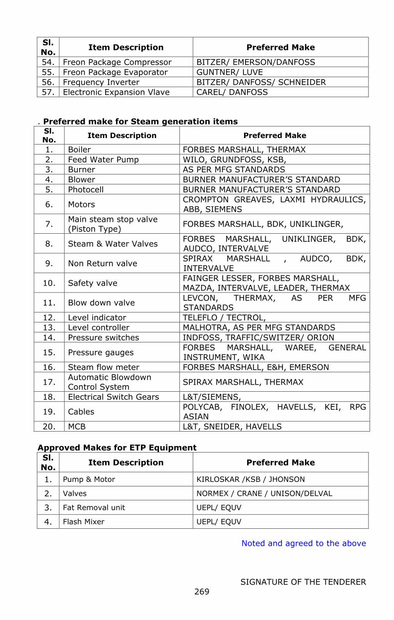
Noted and agreed to the above
SIGNATURE OF THE TENDERER
269
Sl.
No. Item Description Preferred Make
54. Freon Package Compressor BITZER/ EMERSON/DANFOSS
55. Freon Package Evaporator GUNTNER/ LUVE
56. Frequency Inverter BITZER/ DANFOSS/ SCHNEIDER
57. Electronic Expansion Vlave CAREL/ DANFOSS
. Preferred make for Steam generation items
Sl. No.
Item Description Preferred Make
1. Boiler FORBES MARSHALL, THERMAX
2. Feed Water Pump WILO, GRUNDFOSS, KSB,
3. Burner AS PER MFG STANDARDS
4. Blower BURNER MANUFACTURER’S STANDARD
5. Photocell BURNER MANUFACTURER’S STANDARD
6. Motors CROMPTON GREAVES, LAXMI HYDRAULICS,
ABB, SIEMENS
7. Main steam stop valve (Piston Type)
FORBES MARSHALL, BDK, UNIKLINGER,
8. Steam & Water Valves FORBES MARSHALL, UNIKLINGER, BDK, AUDCO, INTERVALVE
9. Non Return valve SPIRAX MARSHALL , AUDCO, BDK,
INTERVALVE
10. Safety valve FAINGER LESSER, FORBES MARSHALL,
MAZDA, INTERVALVE, LEADER, THERMAX
11. Blow down valve LEVCON, THERMAX, AS PER MFG STANDARDS
12. Level indicator TELEFLO / TECTROL,
13. Level controller MALHOTRA, AS PER MFG STANDARDS
14. Pressure switches INDFOSS, TRAFFIC/SWITZER/ ORION
15. Pressure gauges FORBES MARSHALL, WAREE, GENERAL INSTRUMENT, WIKA
16. Steam flow meter FORBES MARSHALL, E&H, EMERSON
17. Automatic Blowdown Control System
SPIRAX MARSHALL, THERMAX
18. Electrical Switch Gears L&T/SIEMENS,
19. Cables POLYCAB, FINOLEX, HAVELLS, KEI, RPG ASIAN
20. MCB L&T, SNEIDER, HAVELLS
Approved Makes for ETP Equipment
Sl.
No. Item Description Preferred Make
1. Pump & Motor KIRLOSKAR /KSB / JHONSON
2. Valves NORMEX / CRANE / UNISON/DELVAL
3. Fat Removal unit UEPL/ EQUV
4. Flash Mixer UEPL/ EQUV
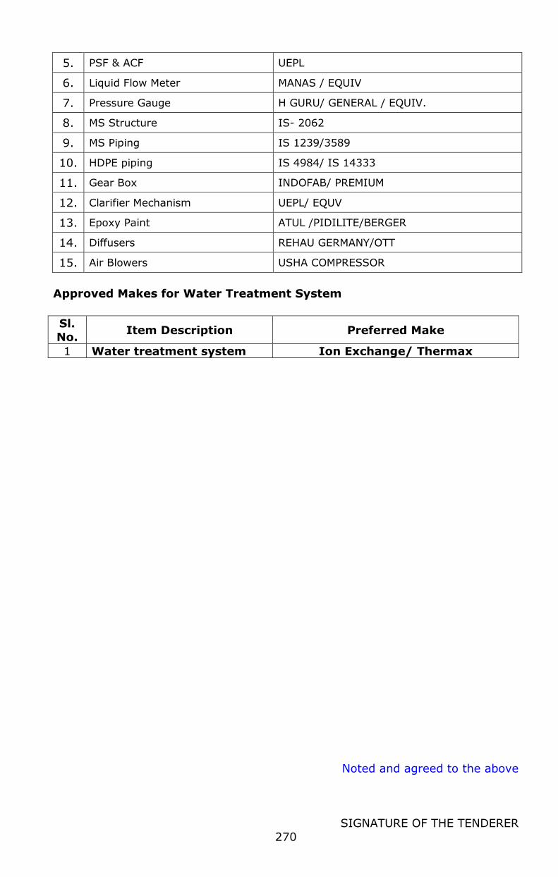
Noted and agreed to the above
SIGNATURE OF THE TENDERER
270
5. PSF & ACF UEPL
6. Liquid Flow Meter MANAS / EQUIV
7. Pressure Gauge H GURU/ GENERAL / EQUIV.
8. MS Structure IS- 2062
9. MS Piping IS 1239/3589
10. HDPE piping IS 4984/ IS 14333
11. Gear Box INDOFAB/ PREMIUM
12. Clarifier Mechanism UEPL/ EQUV
13. Epoxy Paint ATUL /PIDILITE/BERGER
14. Diffusers REHAU GERMANY/OTT
15. Air Blowers USHA COMPRESSOR
Approved Makes for Water Treatment System
Sl. No.
Item Description Preferred Make
1 Water treatment system Ion Exchange/ Thermax
1
SIGNATURE OF THE TENDERER
NAME OF ITEM /
WORK
: DESIGN, SUPPLY, ERECTION, INSTALLATION,
TESTING AND COMMISSIONING OF 50 TLPD
CAPACITY NEW DAIRY PLANT AT
THOOTHUKUDI DCMPU LTD.,
TENDER
REFERENCE NO
: 1111/Proj.4/2022, Dated:28.02.2022
PART – II
COMMERCIAL BID
2
SIGNATURE OF THE TENDERER
QUALIFICATION
The commercial offers of such of those tenderer who qualify themselves for
being considered for Design, Supply, Erection, Installation, Testing and
Commissioning of 50 TLPD Capacity New Dairy Plant at Thoothukudi
DCMPU Ltd., by fulfilling the entire terms and conditions as laid in Part I
“Technical Bid” of this tender, will be considered for the finalization of the tender.
Other commercial offers not qualifying as above will be rejected outright.
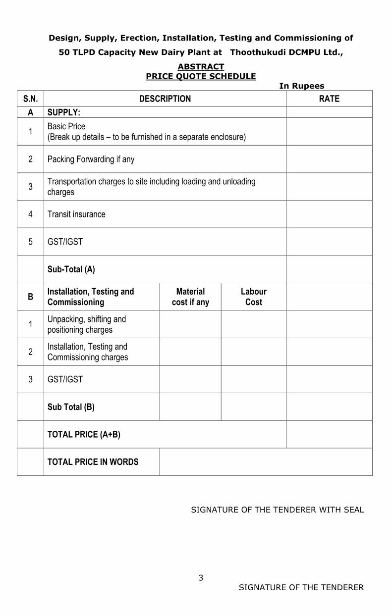
3
SIGNATURE OF THE TENDERER
Design, Supply, Erection, Installation, Testing and Commissioning of
50 TLPD Capacity New Dairy Plant at Thoothukudi DCMPU Ltd.,
ABSTRACT
PRICE QUOTE SCHEDULE In Rupees
S.N. DESCRIPTION RATE
A SUPPLY:
1 Basic Price (Break up details – to be furnished in a separate enclosure)
2 Packing Forwarding if any
3 Transportation charges to site including loading and unloading charges
4 Transit insurance
5 GST/IGST
Sub-Total (A)
B Installation, Testing and Commissioning
Material cost if any
Labour Cost
1 Unpacking, shifting and positioning charges
2 Installation, Testing and Commissioning charges
3 GST/IGST
Sub Total (B)
TOTAL PRICE (A+B)
TOTAL PRICE IN WORDS
SIGNATURE OF THE TENDERER WITH SEAL
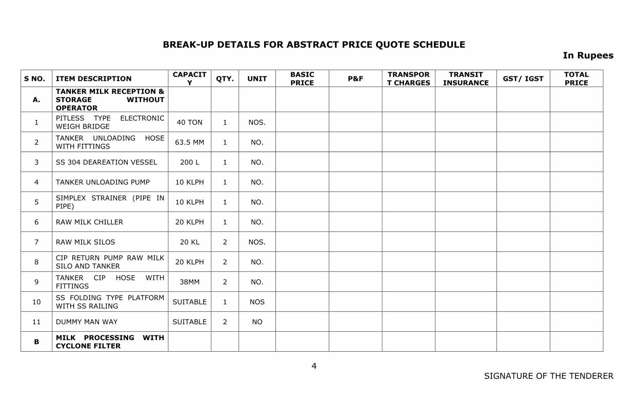
4
SIGNATURE OF THE TENDERER
BREAK-UP DETAILS FOR ABSTRACT PRICE QUOTE SCHEDULE
In Rupees
S NO. ITEM DESCRIPTION CAPACIT
Y QTY. UNIT
BASIC
PRICE P&F
TRANSPOR
T CHARGES
TRANSIT
INSURANCE GST/ IGST
TOTAL
PRICE
A.
TANKER MILK RECEPTION &
STORAGE WITHOUT
OPERATOR
1 PITLESS TYPE ELECTRONIC
WEIGH BRIDGE 40 TON 1 NOS.
2 TANKER UNLOADING HOSE
WITH FITTINGS 63.5 MM 1 NO.
3 SS 304 DEAREATION VESSEL 200 L 1 NO.
4 TANKER UNLOADING PUMP 10 KLPH 1 NO.
5 SIMPLEX STRAINER (PIPE IN
PIPE) 10 KLPH 1 NO.
6 RAW MILK CHILLER 20 KLPH 1 NO.
7 RAW MILK SILOS 20 KL 2 NOS.
8 CIP RETURN PUMP RAW MILK
SILO AND TANKER 20 KLPH 2 NO.
9 TANKER CIP HOSE WITH
FITTINGS 38MM 2 NO.
10 SS FOLDING TYPE PLATFORM
WITH SS RAILING SUITABLE 1 NOS
11 DUMMY MAN WAY SUITABLE 2 NO
B MILK PROCESSING WITH
CYCLONE FILTER
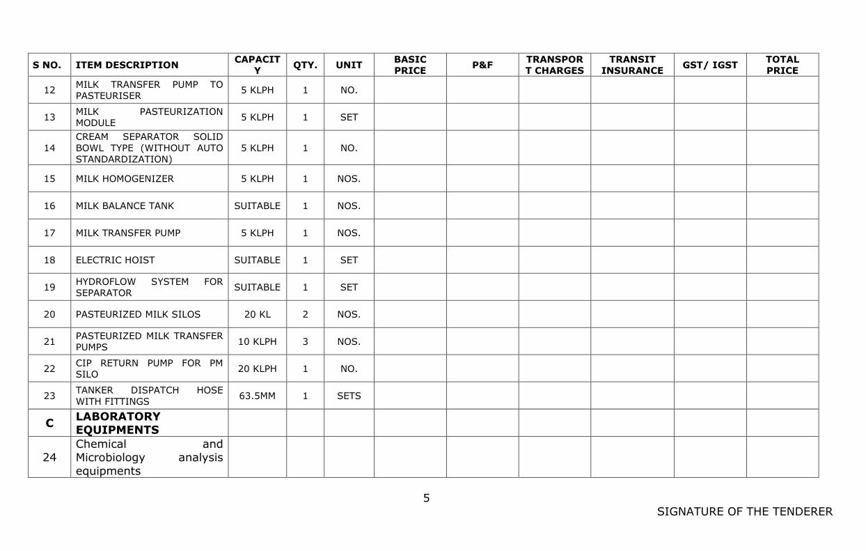
5
SIGNATURE OF THE TENDERER
S NO. ITEM DESCRIPTION CAPACIT
Y QTY. UNIT
BASIC
PRICE P&F
TRANSPOR
T CHARGES
TRANSIT
INSURANCE GST/ IGST
TOTAL
PRICE
12 MILK TRANSFER PUMP TO
PASTEURISER 5 KLPH 1 NO.
13 MILK PASTEURIZATION
MODULE 5 KLPH 1 SET
14
CREAM SEPARATOR SOLID
BOWL TYPE (WITHOUT AUTO
STANDARDIZATION)
5 KLPH 1 NO.
15 MILK HOMOGENIZER 5 KLPH 1 NOS.
16 MILK BALANCE TANK SUITABLE 1 NOS.
17 MILK TRANSFER PUMP 5 KLPH 1 NOS.
18 ELECTRIC HOIST SUITABLE 1 SET
19 HYDROFLOW SYSTEM FOR
SEPARATOR SUITABLE 1 SET
20 PASTEURIZED MILK SILOS 20 KL 2 NOS.
21 PASTEURIZED MILK TRANSFER
PUMPS 10 KLPH 3 NOS.
22 CIP RETURN PUMP FOR PM
SILO 20 KLPH 1 NO.
23 TANKER DISPATCH HOSE
WITH FITTINGS 63.5MM 1 SETS
C LABORATORY EQUIPMENTS
24 Chemical and Microbiology analysis
equipments
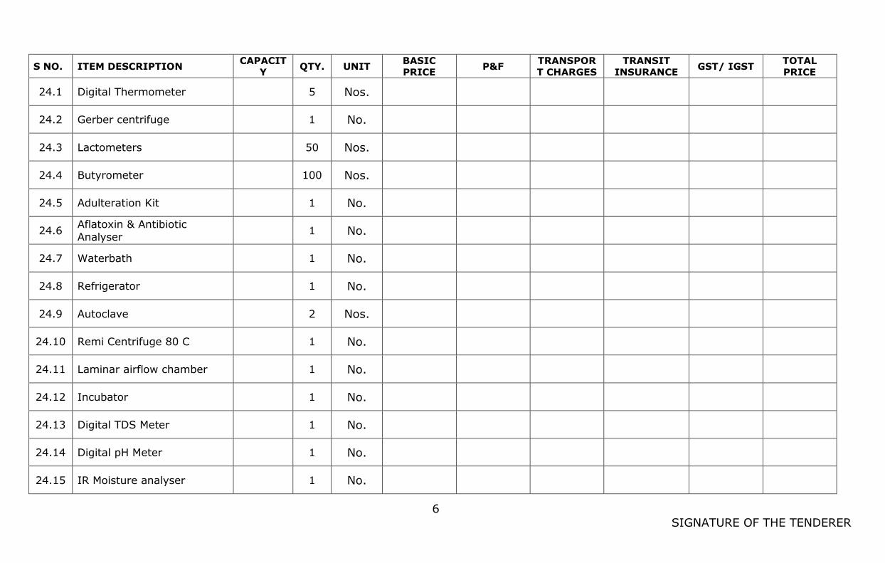
6
SIGNATURE OF THE TENDERER
S NO. ITEM DESCRIPTION CAPACIT
Y QTY. UNIT
BASIC
PRICE P&F
TRANSPOR
T CHARGES
TRANSIT
INSURANCE GST/ IGST
TOTAL
PRICE
24.1 Digital Thermometer
5 Nos.
24.2 Gerber centrifuge
1 No.
24.3 Lactometers
50 Nos.
24.4 Butyrometer
100 Nos.
24.5 Adulteration Kit
1 No.
24.6 Aflatoxin & Antibiotic
Analyser 1 No.
24.7 Waterbath
1 No.
24.8 Refrigerator
1 No.
24.9 Autoclave
2 Nos.
24.10 Remi Centrifuge 80 C
1 No.
24.11 Laminar airflow chamber
1 No.
24.12 Incubator
1 No.
24.13 Digital TDS Meter
1 No.
24.14 Digital pH Meter
1 No.
24.15 IR Moisture analyser
1 No.
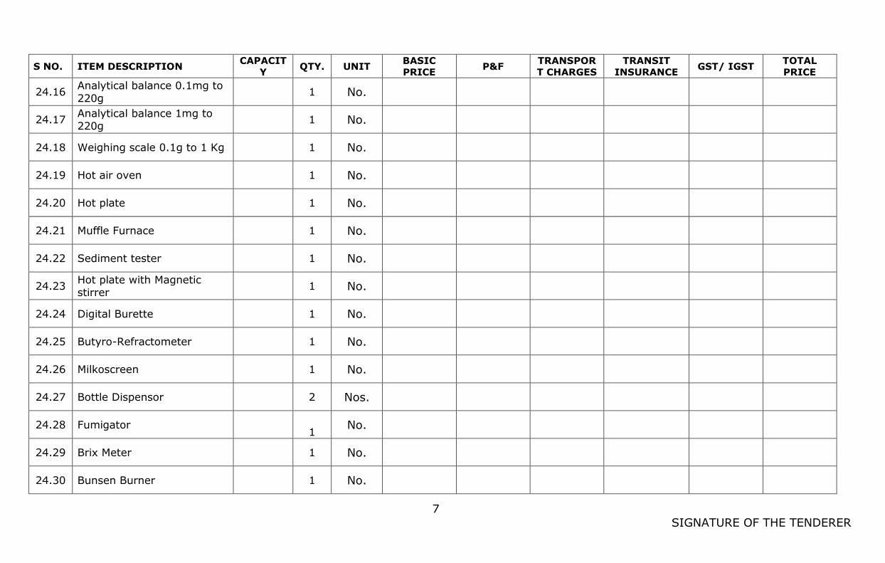
7
SIGNATURE OF THE TENDERER
S NO. ITEM DESCRIPTION CAPACIT
Y QTY. UNIT
BASIC
PRICE P&F
TRANSPOR
T CHARGES
TRANSIT
INSURANCE GST/ IGST
TOTAL
PRICE
24.16 Analytical balance 0.1mg to
220g 1 No.
24.17 Analytical balance 1mg to 220g
1 No.
24.18 Weighing scale 0.1g to 1 Kg
1 No.
24.19 Hot air oven
1 No.
24.20 Hot plate
1 No.
24.21 Muffle Furnace
1 No.
24.22 Sediment tester
1 No.
24.23 Hot plate with Magnetic stirrer
1 No.
24.24 Digital Burette
1 No.
24.25 Butyro-Refractometer
1 No.
24.26 Milkoscreen
1 No.
24.27 Bottle Dispensor
2 Nos.
24.28 Fumigator 1
No.
24.29 Brix Meter
1 No.
24.30 Bunsen Burner
1 No.
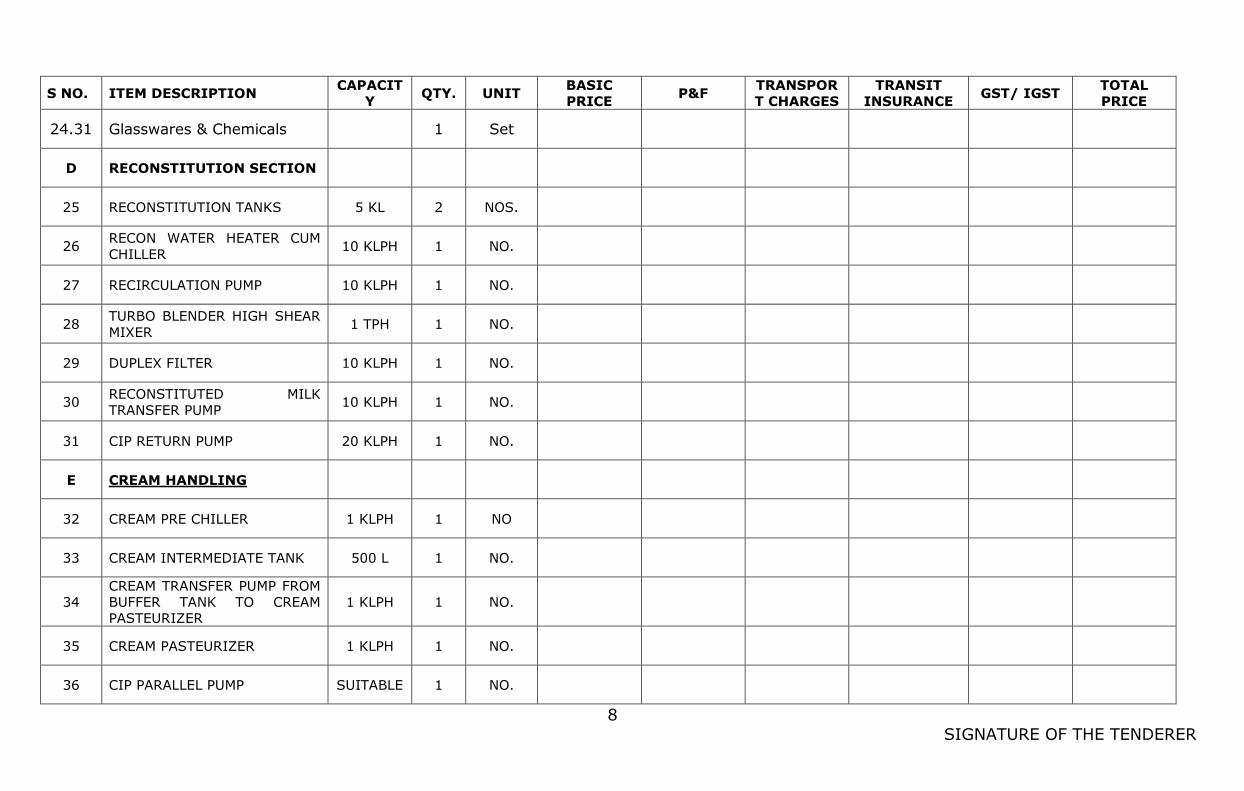
8
SIGNATURE OF THE TENDERER
S NO. ITEM DESCRIPTION CAPACIT
Y QTY. UNIT
BASIC
PRICE P&F
TRANSPOR
T CHARGES
TRANSIT
INSURANCE GST/ IGST
TOTAL
PRICE
24.31 Glasswares & Chemicals
1 Set
D RECONSTITUTION SECTION
25 RECONSTITUTION TANKS 5 KL 2 NOS.
26 RECON WATER HEATER CUM
CHILLER 10 KLPH 1 NO.
27 RECIRCULATION PUMP 10 KLPH 1 NO.
28 TURBO BLENDER HIGH SHEAR
MIXER 1 TPH 1 NO.
29 DUPLEX FILTER 10 KLPH 1 NO.
30 RECONSTITUTED MILK
TRANSFER PUMP 10 KLPH 1 NO.
31 CIP RETURN PUMP 20 KLPH 1 NO.
E CREAM HANDLING
32 CREAM PRE CHILLER 1 KLPH 1 NO
33 CREAM INTERMEDIATE TANK 500 L 1 NO.
34
CREAM TRANSFER PUMP FROM
BUFFER TANK TO CREAM
PASTEURIZER
1 KLPH 1 NO.
35 CREAM PASTEURIZER 1 KLPH 1 NO.
36 CIP PARALLEL PUMP SUITABLE 1 NO.
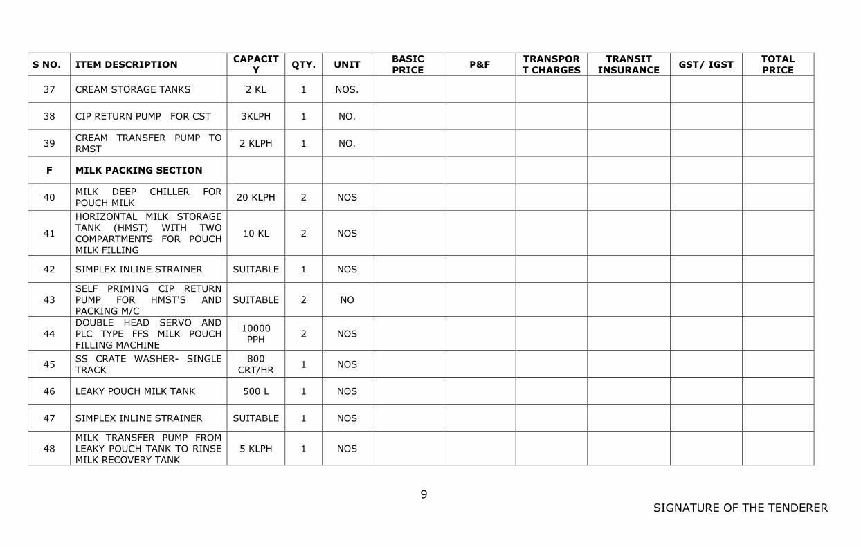
9
SIGNATURE OF THE TENDERER
S NO. ITEM DESCRIPTION CAPACIT
Y QTY. UNIT
BASIC
PRICE P&F
TRANSPOR
T CHARGES
TRANSIT
INSURANCE GST/ IGST
TOTAL
PRICE
37 CREAM STORAGE TANKS 2 KL 1 NOS.
38 CIP RETURN PUMP FOR CST 3KLPH 1 NO.
39 CREAM TRANSFER PUMP TO
RMST 2 KLPH 1 NO.
F MILK PACKING SECTION
40 MILK DEEP CHILLER FOR
POUCH MILK 20 KLPH 2 NOS
41
HORIZONTAL MILK STORAGE
TANK (HMST) WITH TWO
COMPARTMENTS FOR POUCH
MILK FILLING
10 KL 2 NOS
42 SIMPLEX INLINE STRAINER SUITABLE 1 NOS
43
SELF PRIMING CIP RETURN
PUMP FOR HMST'S AND
PACKING M/C
SUITABLE 2 NO
44
DOUBLE HEAD SERVO AND
PLC TYPE FFS MILK POUCH
FILLING MACHINE
10000
PPH 2 NOS
45 SS CRATE WASHER- SINGLE
TRACK
800
CRT/HR 1 NOS
46 LEAKY POUCH MILK TANK 500 L 1 NOS
47 SIMPLEX INLINE STRAINER SUITABLE 1 NOS
48
MILK TRANSFER PUMP FROM
LEAKY POUCH TANK TO RINSE
MILK RECOVERY TANK
5 KLPH 1 NOS
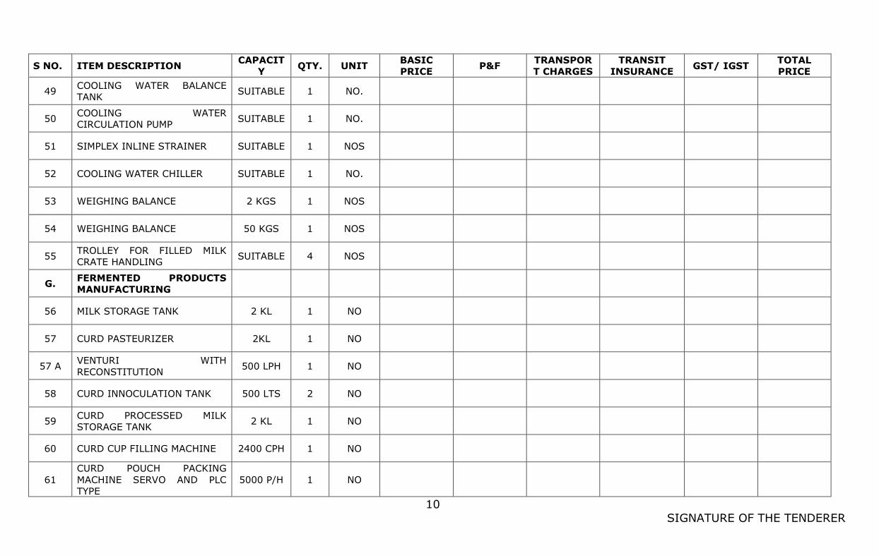
10
SIGNATURE OF THE TENDERER
S NO. ITEM DESCRIPTION CAPACIT
Y QTY. UNIT
BASIC
PRICE P&F
TRANSPOR
T CHARGES
TRANSIT
INSURANCE GST/ IGST
TOTAL
PRICE
49 COOLING WATER BALANCE
TANK SUITABLE 1 NO.
50 COOLING WATER
CIRCULATION PUMP SUITABLE 1 NO.
51 SIMPLEX INLINE STRAINER SUITABLE 1 NOS
52 COOLING WATER CHILLER SUITABLE 1 NO.
53 WEIGHING BALANCE 2 KGS 1 NOS
54 WEIGHING BALANCE 50 KGS 1 NOS
55 TROLLEY FOR FILLED MILK
CRATE HANDLING SUITABLE 4 NOS
G. FERMENTED PRODUCTS
MANUFACTURING
56 MILK STORAGE TANK 2 KL 1 NO
57 CURD PASTEURIZER 2KL 1 NO
57 A VENTURI WITH
RECONSTITUTION 500 LPH 1 NO
58 CURD INNOCULATION TANK 500 LTS 2 NO
59 CURD PROCESSED MILK
STORAGE TANK 2 KL 1 NO
60 CURD CUP FILLING MACHINE 2400 CPH 1 NO
61
CURD POUCH PACKING
MACHINE SERVO AND PLC
TYPE
5000 P/H 1 NO
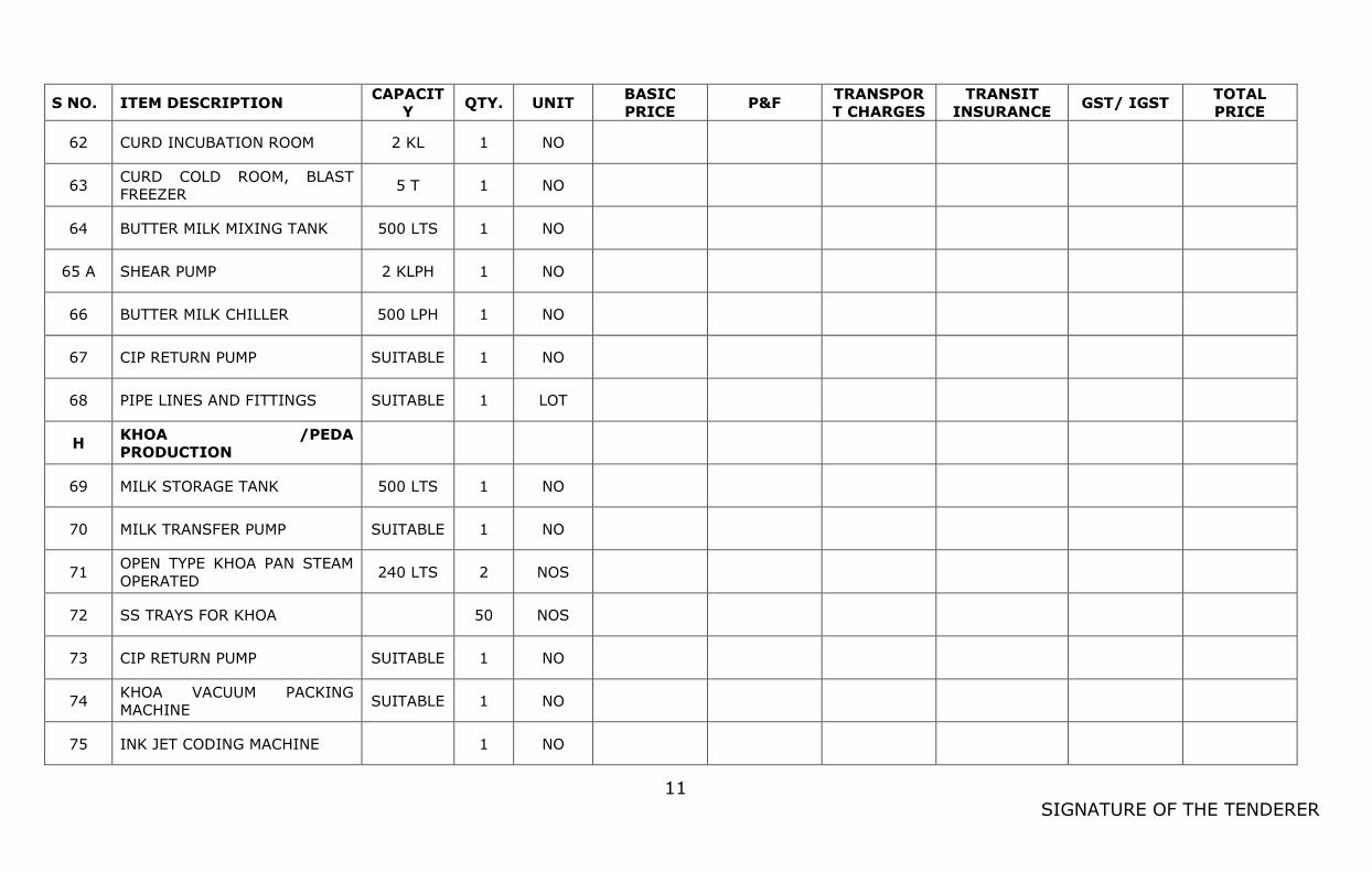
11
SIGNATURE OF THE TENDERER
S NO. ITEM DESCRIPTION CAPACIT
Y QTY. UNIT
BASIC
PRICE P&F
TRANSPOR
T CHARGES
TRANSIT
INSURANCE GST/ IGST
TOTAL
PRICE
62 CURD INCUBATION ROOM 2 KL 1 NO
63 CURD COLD ROOM, BLAST
FREEZER 5 T 1 NO
64 BUTTER MILK MIXING TANK 500 LTS 1 NO
65 A SHEAR PUMP 2 KLPH 1 NO
66 BUTTER MILK CHILLER 500 LPH 1 NO
67 CIP RETURN PUMP SUITABLE 1 NO
68 PIPE LINES AND FITTINGS SUITABLE 1 LOT
H KHOA /PEDA
PRODUCTION
69 MILK STORAGE TANK 500 LTS 1 NO
70 MILK TRANSFER PUMP SUITABLE 1 NO
71 OPEN TYPE KHOA PAN STEAM
OPERATED 240 LTS 2 NOS
72 SS TRAYS FOR KHOA
50 NOS
73 CIP RETURN PUMP SUITABLE 1 NO
74 KHOA VACUUM PACKING
MACHINE SUITABLE 1 NO
75 INK JET CODING MACHINE
1 NO
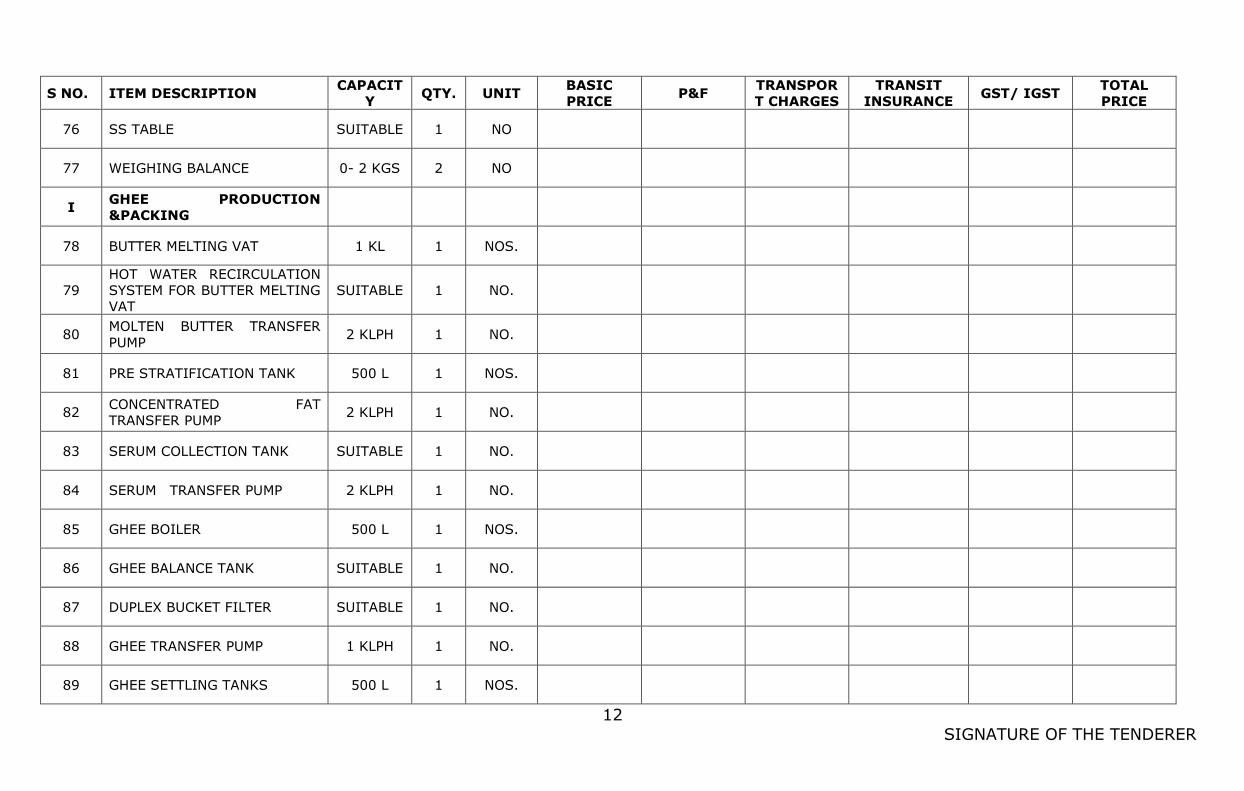
12
SIGNATURE OF THE TENDERER
S NO. ITEM DESCRIPTION CAPACIT
Y QTY. UNIT
BASIC
PRICE P&F
TRANSPOR
T CHARGES
TRANSIT
INSURANCE GST/ IGST
TOTAL
PRICE
76 SS TABLE SUITABLE 1 NO
77 WEIGHING BALANCE 0- 2 KGS 2 NO
I GHEE PRODUCTION
&PACKING
78 BUTTER MELTING VAT 1 KL 1 NOS.
79
HOT WATER RECIRCULATION
SYSTEM FOR BUTTER MELTING
VAT
SUITABLE 1 NO.
80 MOLTEN BUTTER TRANSFER
PUMP 2 KLPH 1 NO.
81 PRE STRATIFICATION TANK 500 L 1 NOS.
82 CONCENTRATED FAT
TRANSFER PUMP 2 KLPH 1 NO.
83 SERUM COLLECTION TANK SUITABLE 1 NO.
84 SERUM TRANSFER PUMP 2 KLPH 1 NO.
85 GHEE BOILER 500 L 1 NOS.
86 GHEE BALANCE TANK SUITABLE 1 NO.
87 DUPLEX BUCKET FILTER SUITABLE 1 NO.
88 GHEE TRANSFER PUMP 1 KLPH 1 NO.
89 GHEE SETTLING TANKS 500 L 1 NOS.
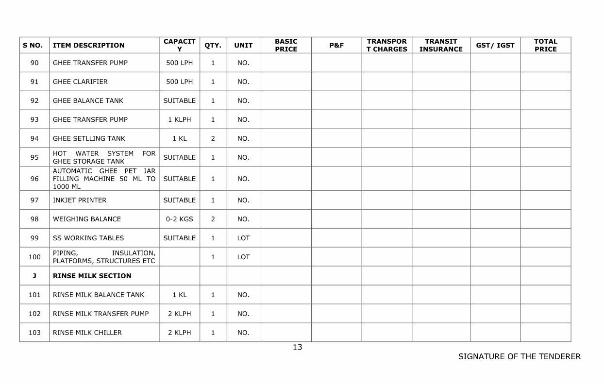
13
SIGNATURE OF THE TENDERER
S NO. ITEM DESCRIPTION CAPACIT
Y QTY. UNIT
BASIC
PRICE P&F
TRANSPOR
T CHARGES
TRANSIT
INSURANCE GST/ IGST
TOTAL
PRICE
90 GHEE TRANSFER PUMP 500 LPH 1 NO.
91 GHEE CLARIFIER 500 LPH 1 NO.
92 GHEE BALANCE TANK SUITABLE 1 NO.
93 GHEE TRANSFER PUMP 1 KLPH 1 NO.
94 GHEE SETLLING TANK 1 KL 2 NO.
95 HOT WATER SYSTEM FOR
GHEE STORAGE TANK SUITABLE 1 NO.
96
AUTOMATIC GHEE PET JAR
FILLING MACHINE 50 ML TO
1000 ML
SUITABLE 1 NO.
97 INKJET PRINTER SUITABLE 1 NO.
98 WEIGHING BALANCE 0-2 KGS 2 NO.
99 SS WORKING TABLES SUITABLE 1 LOT
100 PIPING, INSULATION,
PLATFORMS, STRUCTURES ETC 1 LOT
J RINSE MILK SECTION
101 RINSE MILK BALANCE TANK 1 KL 1 NO.
102 RINSE MILK TRANSFER PUMP 2 KLPH 1 NO.
103 RINSE MILK CHILLER 2 KLPH 1 NO.
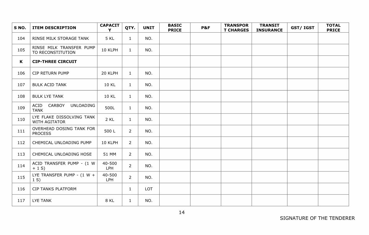
14
SIGNATURE OF THE TENDERER
S NO. ITEM DESCRIPTION CAPACIT
Y QTY. UNIT
BASIC
PRICE P&F
TRANSPOR
T CHARGES
TRANSIT
INSURANCE GST/ IGST
TOTAL
PRICE
104 RINSE MILK STORAGE TANK 5 KL 1 NO.
105 RINSE MILK TRANSFER PUMP
TO RECONSTITUTION 10 KLPH 1 NO.
K CIP-THREE CIRCUIT
106 CIP RETURN PUMP 20 KLPH 1 NO.
107 BULK ACID TANK 10 KL 1 NO.
108 BULK LYE TANK 10 KL 1 NO.
109 ACID CARBOY UNLOADING
TANK 500L 1 NO.
110 LYE FLAKE DISSOLVING TANK
WITH AGITATOR 2 KL 1 NO.
111 OVERHEAD DOSING TANK FOR
PROCESS 500 L 2 NO.
112 CHEMICAL UNLOADING PUMP 10 KLPH 2 NO.
113 CHEMICAL UNLOADING HOSE 51 MM 2 NO.
114 ACID TRANSFER PUMP - (1 W
+ 1 S)
40-500
LPH 2 NO.
115 LYE TRANSFER PUMP - (1 W +
1 S)
40-500
LPH 2 NO.
116 CIP TANKS PLATFORM
1 LOT
117 LYE TANK 8 KL 1 NO.
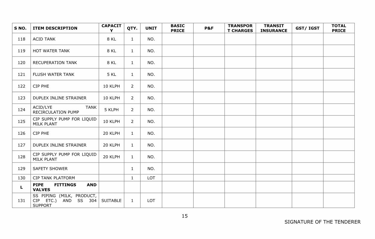
15
SIGNATURE OF THE TENDERER
S NO. ITEM DESCRIPTION CAPACIT
Y QTY. UNIT
BASIC
PRICE P&F
TRANSPOR
T CHARGES
TRANSIT
INSURANCE GST/ IGST
TOTAL
PRICE
118 ACID TANK 8 KL 1 NO.
119 HOT WATER TANK 8 KL 1 NO.
120 RECUPERATION TANK 8 KL 1 NO.
121 FLUSH WATER TANK 5 KL 1 NO.
122 CIP PHE 10 KLPH 2 NO.
123 DUPLEX INLINE STRAINER 10 KLPH 2 NO.
124 ACID/LYE TANK
RECIRCULATION PUMP 5 KLPH 2 NO.
125 CIP SUPPLY PUMP FOR LIQUID
MILK PLANT 10 KLPH 2 NO.
126 CIP PHE 20 KLPH 1 NO.
127 DUPLEX INLINE STRAINER 20 KLPH 1 NO.
128 CIP SUPPLY PUMP FOR LIQUID
MILK PLANT 20 KLPH 1 NO.
129 SAFETY SHOWER
1 NO.
130 CIP TANK PLATFORM
1 LOT
L PIPE FITTINGS AND
VALVES
131
SS PIPING (MILK, PRODUCT,
CIP ETC.) AND SS 304
SUPPORT
SUITABLE 1 LOT
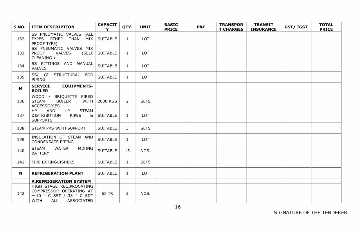
16
SIGNATURE OF THE TENDERER
S NO. ITEM DESCRIPTION CAPACIT
Y QTY. UNIT
BASIC
PRICE P&F
TRANSPOR
T CHARGES
TRANSIT
INSURANCE GST/ IGST
TOTAL
PRICE
132
SS PNEUMATIC VALVES (ALL
TYPES OTHER THAN MIX
PROOF TYPE)
SUITABLE 1 LOT
133
SS PNEUMATIC VALVES MIX
PROOF VALVES (SELF
CLEANING )
SUITABLE 1 LOT
134 SS FITTINGS AND MANUAL
VALVES SUITABLE 1 LOT
135 SS/ GI STRUCTURAL FOR
PIPING SUITABLE 1 LOT
M SERVICE EQUIPMENTS-
BOILER
136
WOOD / BRIQUETTE FIRED
STEAM BOILER WITH
ACCESSORIES
2000 KGS 2 SETS
137
HP AND LP STEAM
DISTRIBUTION PIPES &
SUPPORTS
SUITABLE 1 LOT
138 STEAM PRS WITH SUPPORT SUITABLE 3 SETS
139 INSULATION OF STEAM AND
CONDENSATE PIPING SUITABLE 1 LOT
140 STEAM WATER MIXING
BATTERY SUITABLE 15 NOS.
141 FIRE EXTINGUISHERS SUITABLE 1 SETS
N REFRIGERATION PLANT SUITABLE 1 LOT
A.REFRIGERATION SYSTEM
142
HIGH STAGE RECIPROCATING
COMPRESSOR OPERATING AT
─10 °C SST / 38 °C SDT
WITH ALL ASSOCIATED
65 TR 2 NOS.
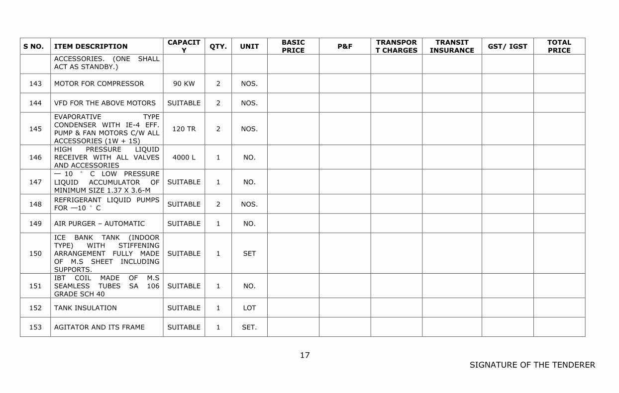
17
SIGNATURE OF THE TENDERER
S NO. ITEM DESCRIPTION CAPACIT
Y QTY. UNIT
BASIC
PRICE P&F
TRANSPOR
T CHARGES
TRANSIT
INSURANCE GST/ IGST
TOTAL
PRICE
ACCESSORIES. (ONE SHALL
ACT AS STANDBY.)
143 MOTOR FOR COMPRESSOR 90 KW 2 NOS.
144 VFD FOR THE ABOVE MOTORS SUITABLE 2 NOS.
145
EVAPORATIVE TYPE
CONDENSER WITH IE-4 EFF.
PUMP & FAN MOTORS C/W ALL
ACCESSORIES (1W + 1S)
120 TR 2 NOS.
146
HIGH PRESSURE LIQUID
RECEIVER WITH ALL VALVES
AND ACCESSORIES
4000 L 1 NO.
147
─ 10 ° C LOW PRESSURE
LIQUID ACCUMULATOR OF
MINIMUM SIZE 1.37 X 3.6-M
SUITABLE 1 NO.
148 REFRIGERANT LIQUID PUMPS
FOR ─10 °C SUITABLE 2 NOS.
149 AIR PURGER – AUTOMATIC SUITABLE 1 NO.
150
ICE BANK TANK (INDOOR
TYPE) WITH STIFFENING
ARRANGEMENT FULLY MADE
OF M.S SHEET INCLUDING
SUPPORTS.
SUITABLE 1 SET
151
IBT COIL MADE OF M.S
SEAMLESS TUBES SA 106
GRADE SCH 40
SUITABLE 1 NO.
152 TANK INSULATION SUITABLE 1 LOT
153 AGITATOR AND ITS FRAME SUITABLE 1 SET.
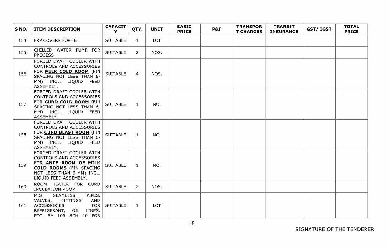
18
SIGNATURE OF THE TENDERER
S NO. ITEM DESCRIPTION CAPACIT
Y QTY. UNIT
BASIC
PRICE P&F
TRANSPOR
T CHARGES
TRANSIT
INSURANCE GST/ IGST
TOTAL
PRICE
154 FRP COVERS FOR IBT SUITABLE 1 LOT
155 CHILLED WATER PUMP FOR
PROCESS SUITABLE 2 NOS.
156
FORCED DRAFT COOLER WITH
CONTROLS AND ACCESSORIES
FOR MILK COLD ROOM (FIN
SPACING NOT LESS THAN 6-
MM) INCL. LIQUID FEED
ASSEMBLY.
SUITABLE 4 NOS.
157
FORCED DRAFT COOLER WITH
CONTROLS AND ACCESSORIES
FOR CURD COLD ROOM (FIN
SPACING NOT LESS THAN 6-
MM) INCL. LIQUID FEED
ASSEMBLY.
SUITABLE 1 NO.
158
FORCED DRAFT COOLER WITH
CONTROLS AND ACCESSORIES
FOR CURD BLAST ROOM (FIN
SPACING NOT LESS THAN 6-
MM) INCL. LIQUID FEED
ASSEMBLY.
SUITABLE 1 NO.
159
FORCED DRAFT COOLER WITH
CONTROLS AND ACCESSORIES
FOR ANTE ROOM OF MILK
COLD ROOMS (FIN SPACING
NOT LESS THAN 6-MM) INCL.
LIQUID FEED ASSEMBLY.
SUITABLE 1 NO.
160 ROOM HEATER FOR CURD
INCUBATION ROOM SUITABLE 2 NOS.
161
M.S SEAMLESS PIPES,
VALVES, FITTINGS AND
ACCESSORIES FOR
REFRIGERANT, OIL LINES,
ETC. SA 106 SCH 40 FOR
SUITABLE 1 LOT
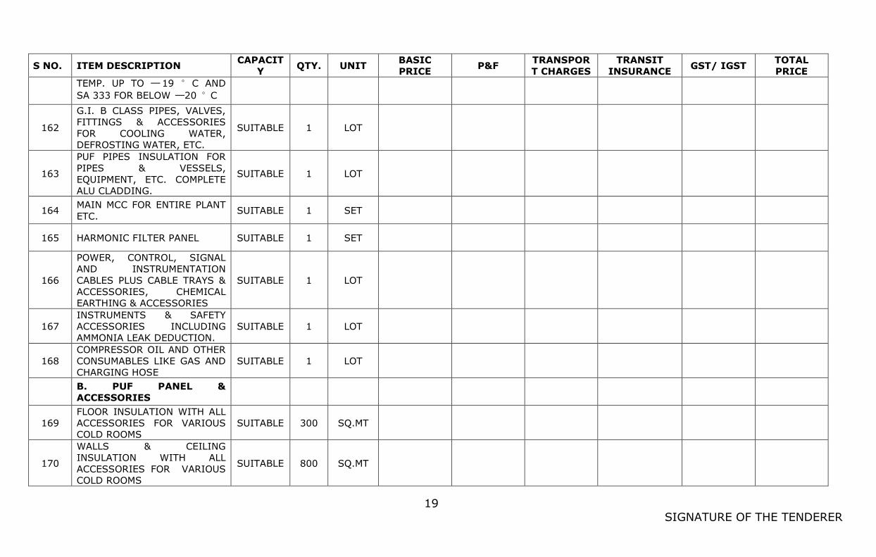
19
SIGNATURE OF THE TENDERER
S NO. ITEM DESCRIPTION CAPACIT
Y QTY. UNIT
BASIC
PRICE P&F
TRANSPOR
T CHARGES
TRANSIT
INSURANCE GST/ IGST
TOTAL
PRICE
TEMP. UP TO ─ 19 °C AND
SA 333 FOR BELOW ─20 °C
162
G.I. B CLASS PIPES, VALVES,
FITTINGS & ACCESSORIES
FOR COOLING WATER,
DEFROSTING WATER, ETC.
SUITABLE 1 LOT
163
PUF PIPES INSULATION FOR
PIPES & VESSELS,
EQUIPMENT, ETC. COMPLETE
ALU CLADDING.
SUITABLE 1 LOT
164 MAIN MCC FOR ENTIRE PLANT
ETC. SUITABLE 1 SET
165 HARMONIC FILTER PANEL SUITABLE 1 SET
166
POWER, CONTROL, SIGNAL
AND INSTRUMENTATION
CABLES PLUS CABLE TRAYS &
ACCESSORIES, CHEMICAL
EARTHING & ACCESSORIES
SUITABLE 1 LOT
167
INSTRUMENTS & SAFETY
ACCESSORIES INCLUDING
AMMONIA LEAK DEDUCTION.
SUITABLE 1 LOT
168
COMPRESSOR OIL AND OTHER
CONSUMABLES LIKE GAS AND
CHARGING HOSE
SUITABLE 1 LOT
B. PUF PANEL &
ACCESSORIES
169
FLOOR INSULATION WITH ALL
ACCESSORIES FOR VARIOUS
COLD ROOMS
SUITABLE 300 SQ.MT
170
WALLS & CEILING
INSULATION WITH ALL
ACCESSORIES FOR VARIOUS
COLD ROOMS
SUITABLE 800 SQ.MT
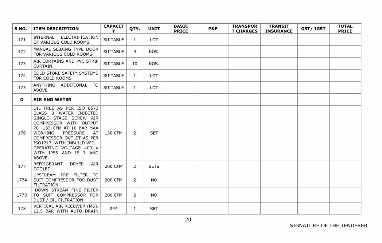
20
SIGNATURE OF THE TENDERER
S NO. ITEM DESCRIPTION CAPACIT
Y QTY. UNIT
BASIC
PRICE P&F
TRANSPOR
T CHARGES
TRANSIT
INSURANCE GST/ IGST
TOTAL
PRICE
171 INTERNAL ELECTRIFICATION
OF VARIOUS COLD ROOMS. SUITABLE 1 LOT
172 MANUAL SLIDING TYPE DOOR
FOR VARIOUS COLD ROOMS. SUITABLE 9 NOS.
173 AIR CURTAINS AND PVC STRIP
CURTAIN SUITABLE 10 NOS.
174 COLD STORE SAFETY SYSTEMS
FOR COLD ROOMS SUITABLE 1 LOT
175 ANYTHING ADDITIONAL TO
ABOVE SUITABLE 1 LOT
O AIR AND WATER
176
OIL FREE AS PER ISO 8573
CLASS 0 WATER INJECTED
SINGLE STAGE SCREW AIR
COMPRESSOR WITH OUTPUT
70 -133 CFM AT 10 BAR MAX
WORKING PRESSURE AT
COMPRESSOR OUTLET AS PER
ISO1217. WITH INBUILD VFD.
OPERATING VOLTAGE 400 V
WITH IP55 AND IE 3 AND
ABOVE.
130 CFM 2 SET
177 REFRIGERANT DRYER AIR
COOLED 200 CFM 2 SETS
177A
UPSTREAM PRE FILTER TO
SUIT COMPRESSOR FOR DUST
FILTRATION
200 CFM 2 NO
177B
DOWN STREAM FINE FILTER
TO SUIT COMPRESSOR FOR
DUST / OIL FILTRATION.
200 CFM 2 NO
178 VERTICAL AIR RECEIVER (MS),
12.5 BAR WITH AUTO DRAIN 2M3 1 SET
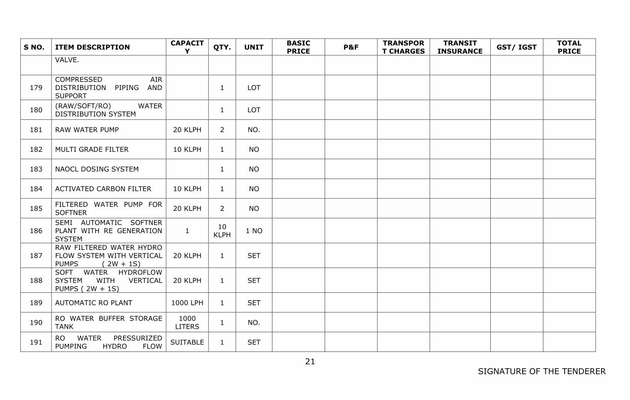
21
SIGNATURE OF THE TENDERER
S NO. ITEM DESCRIPTION CAPACIT
Y QTY. UNIT
BASIC
PRICE P&F
TRANSPOR
T CHARGES
TRANSIT
INSURANCE GST/ IGST
TOTAL
PRICE
VALVE.
179
COMPRESSED AIR
DISTRIBUTION PIPING AND
SUPPORT
1 LOT
180 (RAW/SOFT/RO) WATER
DISTRIBUTION SYSTEM 1 LOT
181 RAW WATER PUMP 20 KLPH 2 NO.
182 MULTI GRADE FILTER 10 KLPH 1 NO
183 NAOCL DOSING SYSTEM
1 NO
184 ACTIVATED CARBON FILTER 10 KLPH 1 NO
185 FILTERED WATER PUMP FOR
SOFTNER 20 KLPH 2 NO
186
SEMI AUTOMATIC SOFTNER
PLANT WITH RE GENERATION
SYSTEM
1 10
KLPH 1 NO
187
RAW FILTERED WATER HYDRO
FLOW SYSTEM WITH VERTICAL
PUMPS ( 2W + 1S)
20 KLPH 1 SET
188
SOFT WATER HYDROFLOW
SYSTEM WITH VERTICAL
PUMPS ( 2W + 1S)
20 KLPH 1 SET
189 AUTOMATIC RO PLANT 1000 LPH 1 SET
190 RO WATER BUFFER STORAGE
TANK
1000
LITERS 1 NO.
191 RO WATER PRESSURIZED
PUMPING HYDRO FLOW SUITABLE 1 SET
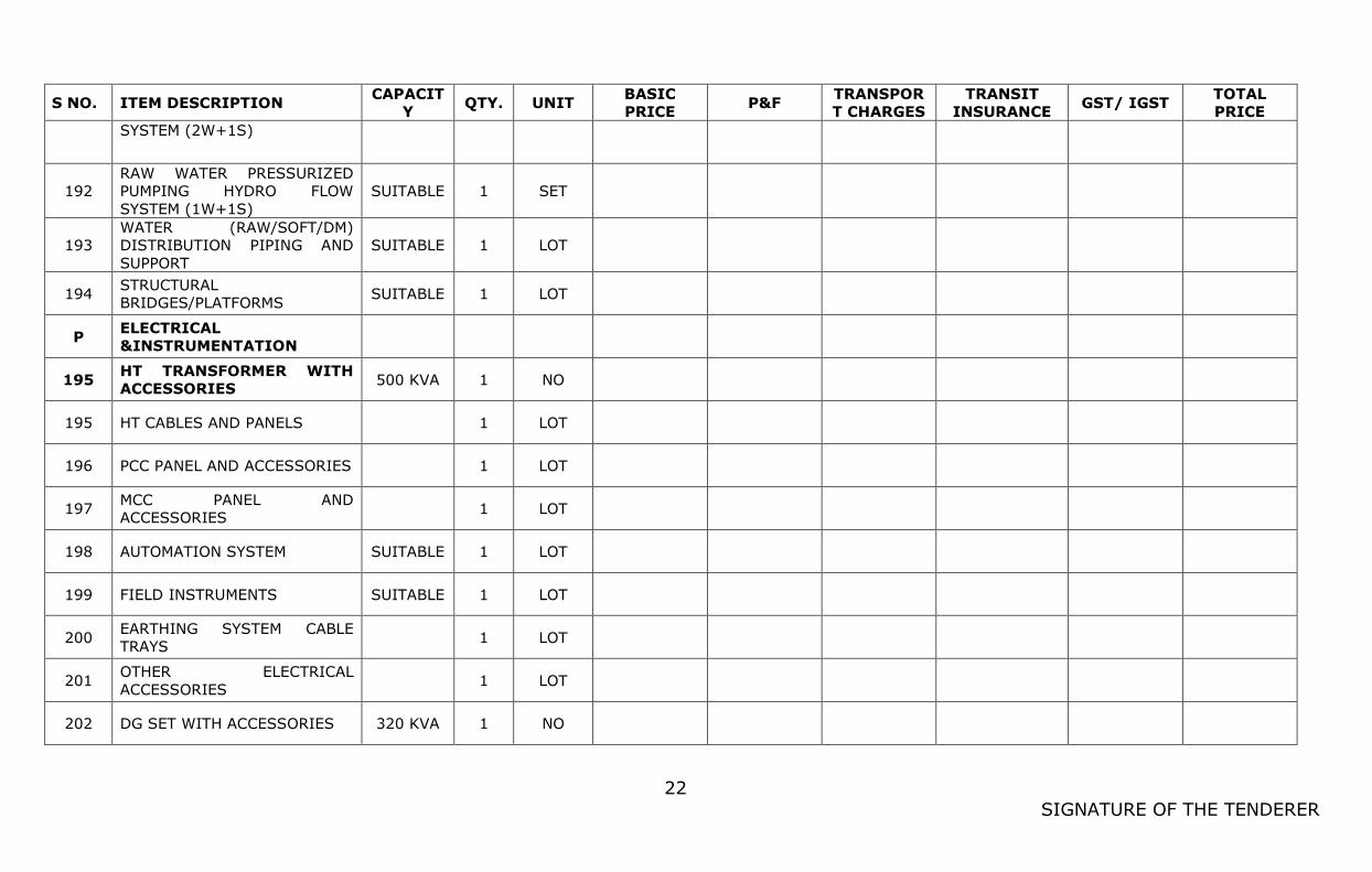
22
SIGNATURE OF THE TENDERER
S NO. ITEM DESCRIPTION CAPACIT
Y QTY. UNIT
BASIC
PRICE P&F
TRANSPOR
T CHARGES
TRANSIT
INSURANCE GST/ IGST
TOTAL
PRICE
SYSTEM (2W+1S)
192
RAW WATER PRESSURIZED
PUMPING HYDRO FLOW
SYSTEM (1W+1S)
SUITABLE 1 SET
193
WATER (RAW/SOFT/DM)
DISTRIBUTION PIPING AND
SUPPORT
SUITABLE 1 LOT
194 STRUCTURAL
BRIDGES/PLATFORMS SUITABLE 1 LOT
P ELECTRICAL
&INSTRUMENTATION
195 HT TRANSFORMER WITH
ACCESSORIES 500 KVA 1 NO
195 HT CABLES AND PANELS
1 LOT
196 PCC PANEL AND ACCESSORIES
1 LOT
197 MCC PANEL AND
ACCESSORIES 1 LOT
198 AUTOMATION SYSTEM SUITABLE 1 LOT
199 FIELD INSTRUMENTS SUITABLE 1 LOT
200 EARTHING SYSTEM CABLE
TRAYS 1 LOT
201 OTHER ELECTRICAL
ACCESSORIES 1 LOT
202 DG SET WITH ACCESSORIES 320 KVA 1 NO
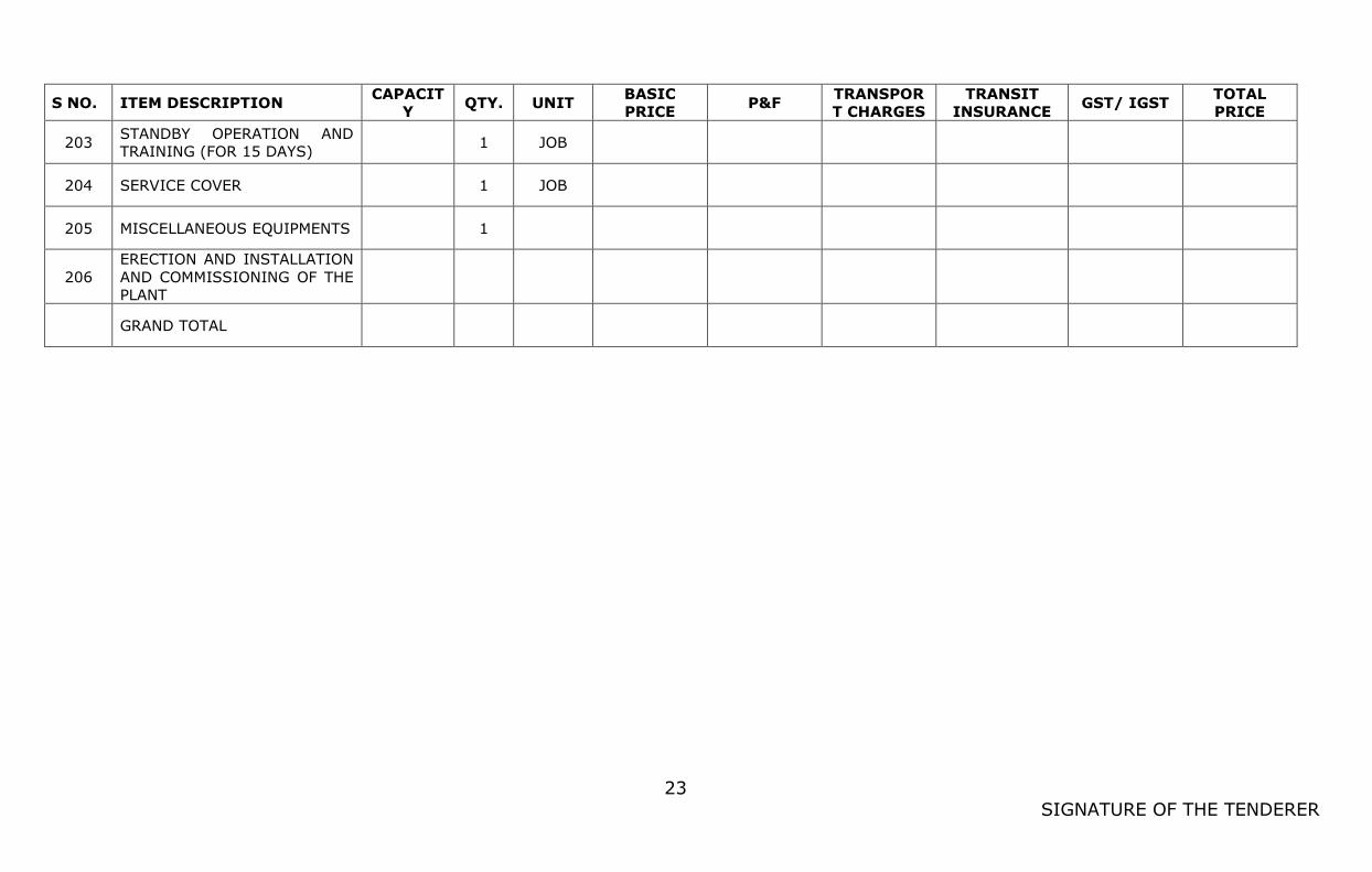
23
SIGNATURE OF THE TENDERER
S NO. ITEM DESCRIPTION CAPACIT
Y QTY. UNIT
BASIC
PRICE P&F
TRANSPOR
T CHARGES
TRANSIT
INSURANCE GST/ IGST
TOTAL
PRICE
203 STANDBY OPERATION AND
TRAINING (FOR 15 DAYS) 1 JOB
204 SERVICE COVER
1 JOB
205 MISCELLANEOUS EQUIPMENTS
1
206
ERECTION AND INSTALLATION
AND COMMISSIONING OF THE
PLANT
GRAND TOTAL

22
SIGNATURE OF THE TENDERER
Note:-
1). The rates should be quoted separately for equipment-wise with break-up of
Basic Price, Packing & Forwarding, Transportation charges, Loading and
unloading charges, Transit insurance, GST/IGST for supply, Unpacking,
shifting and positioning charges, Erection & commissioning charges,
GST/IGST for Erection & commissioning etc., which should be totaled and
mentioned in the Abstract of Price Quote Schedule.
2). The tenderer shall furnish break up details for the above in a separate
sheet for Price, GST/IGST, with the percentage.
3). All the rates should be only in terms of Indian Rupees.
4). Tenderer should indicate origin of country from which the equipment is
imported and has to produce authorization letter from OEM.
5). Phrases like `Extra’, `as applicable’, `at the prevailing rate’ etc. should not
be quoted to avoid ambiguity.
Seal of the firm Signature of the
tenderer
Witness:
1
2
Date: