IT Supplies Technical Specification Template - Mercell Group
17
March 2013 EDMS No.: 1262873 Group Code : BE-RF IT-3840/BE/HIE-ISOLDE The HIE-ISOLDE Project Invitation to Tender Technical Specification Supply of high precision copper RF cavities for the HIE- ISOLDE facility Abstract This technical specification concerns the supply of 1 with an option of up-to 4 OFE copper cavities, 101.28 MHz, for the HIE-ISOLDE project at CERN. The copper cavities will be coated on the inside with a superconducting Niobium film at CERN. The present invitation to tender is issued to qualified and selected firms for a contract to be awarded in the second quarter of 2013. University of Oslo Faculty of mathematics and natural sciences
-
Upload
khangminh22 -
Category
Documents
-
view
0 -
download
0
Transcript of IT Supplies Technical Specification Template - Mercell Group
March 2013
EDMS No.: 1262873 Group Code : BE-RF
IT-3840/BE/HIE-ISOLDE
The HIE-ISOLDE Project
Invitation to Tender
Technical Specification Supply of high precision copper RF cavities for the
HIE- ISOLDE facility
Abstract This technical specification concerns the supply of 1 with an option of up-to 4 OFE copper cavities, 101.28 MHz, for the HIE-ISOLDE project at CERN. The copper cavities will be coated on the inside with a superconducting Niobium film at CERN. The present invitation to tender is issued to qualified and selected firms for a contract to be awarded in the second quarter of 2013.
University of OsloFaculty of mathematics and natural sciences

EDMS No.: 1262873 i IT-3840/BE/HIE-ISOLDE
Table of Contents
1. INTRODUCTION ........................................................................................................................... 11.1 Introduction to CERN ....................................................................................................................... 1 1.2 Introduction to the HIE-ISOLDE intensity and energy upgrade ....................................................... 2 1.3 Superconducting RF and the BE/RF group ....................................................................................... 2 2. SPECIFICATION OF THE SUPPLY ........................................................................................... 22.1 Deliverables Included in the Supply ................................................................................................. 2 2.2 Items and Services Supplied by CERN ............................................................................................. 3 2.3 Options .............................................................................................................................................. 3 3. TECHNICAL REQUIREMENTS ................................................................................................. 33.1 General Description........................................................................................................................... 3 3.2 Design Criteria .................................................................................................................................. 4 3.2.1 Description ........................................................................................................................................ 4 3.2.2 Materials ........................................................................................................................................... 4 3.2.3 Considerations regarding manufacturing ......................................................................................... 4 3.2.4 Applicable documents ....................................................................................................................... 6 3.3 Dimensions and Tolerances .............................................................................................................. 6 3.4 Manufacturing and Tooling ............................................................................................................... 6 3.4.1 Joining and assembly ........................................................................................................................ 6 3.4.2 Handling ............................................................................................................................................ 9 3.5 Performance Requirements ............................................................................................................... 9 3.6 Safety Requirements ......................................................................................................................... 9 3.7 Operational Conditions ..................................................................................................................... 9 3.8 Information and Documentation ..................................................................................................... 10 4. EXECUTION OF THE CONTRACT ......................................................................................... 104.1 Delivery Schedule ........................................................................................................................... 10 4.1.1 Delivery within 4 weeks from the start of the contract .................................................................... 10 4.1.2 Delivery within 8 weeks from the date of acceptance of the production folder and the agreement
for pre-series production ................................................................................................................. 10 4.1.3 Delivery of the series produced cavities .......................................................................................... 11 4.2 Contract Follow-Up and Progress Monitoring ................................................................................ 11 4.2.1 Responsibility for Design, Components and Performance .............................................................. 11 4.2.2 Design Approval .............................................................................................................................. 11 4.3 Documentation Handling, Quality Control and Quality Assurance ................................................ 11 4.4 Tests ................................................................................................................................................ 12 4.4.1 Tests to Be Carried out at the Contractor’s Premises ..................................................................... 12 4.4.2 Tests to Be Carried out at CERN .................................................................................................... 12 4.4.3 Acceptance ...................................................................................................................................... 12 4.5 Packing and transport ...................................................................................................................... 12 4.6 Warranty .......................................................................................................................................... 13 5. CERN CONTACT PERSONS ..................................................................................................... 136. ANNEXES ...................................................................................................................................... 13ANNEX 1: LIST OF DRAWINGS .......................................................................................................... 13 ANNEX 2: MATERIAL SPECIFICATIONS ........................................................................................ 13 ANNEX 3: THERMO-MECHANICAL CALCULATIONS ................................................................ 14

ii EDMS No: 1262873 IT-3840/BE/HIE-ISOLDE
Table of acronyms: ASTM American Society for Testing and Materials β Ratio speed of particles relative to speed of light Cavity Electro-Magnetic Hollow Conductor Resonator CF Conflat ESHR Essential Health and Safety Requirements MTF Manufacturing- and Test Folder NCR Non-conformity report NDT Non-Destructive Testing OFE copper Oxygen-Free Electronic copper QC Quality Control RF Radio-Frequency SRF Superconducting Radio-Frequency US Ultra-Sound

EDMS No.: 1262873 1 IT-3840/BE/HIE-ISOLDE
1. INTRODUCTION
1.1 Introduction to CERNCERN, the European Organization for Nuclear Research, is an intergovernmental organization with 20 Member States1. Its seat is in Geneva but its premises are located on both sides of the French-Swiss border (http://cern.ch/fplinks/map.html). CERN’s mission is to enable international collaboration in the field of high-energy particle physics research and to this end it designs, builds and operates particle accelerators and the associated experimental areas. At present more than 10 000 scientific users from research institutes all over the world are using CERN’s installations for their experiments. The accelerator complex at CERN is a succession of machines with increasingly higher energies. Each machine injects the beam into the next one, which takes over to bring the beam to an even higher energy, and so on. The flagship of this complex is the Large Hadron Collider (LHC) as presented below:
Further information is available on the CERN website: http://cern.ch
1 The CERN Member States are currently Austria, Belgium, Bulgaria, the Czech Republic, Denmark, Finland, France, Germany, Greece, Hungary, Israel*, Italy, the Netherlands, Norway, Poland, Portugal, Romania**, the Republic of Serbia*, the Slovak Republic, Spain, Sweden, Switzerland and the United Kingdom. * Associate Member State in the pre-stage to Membership** Candidate for accession

2 EDMS No: 1262873 IT-3840/BE/HIE-ISOLDE
1.2 Introduction to the HIE-ISOLDE intensity and energy upgrade The HIE-ISOLDE project is a major upgrade of the ISOLDE and REX-ISOLDE facilities at CERN. The Radioactive ion beam EXperiment (REX) at ISOLDE has provided the nuclear physics community with a wide range of post-accelerated radioactive ion beams (RIBs) since 2001 and can currently deliver beams with energies up to 2.8 MeV/u using a normal conducting linear accelerator. The aim of the HIE-ISOLDE project is to greatly expand the physics programme compared to that of REX-ISOLDE. The most significant improvement will come from replacing most of the existing REX accelerating structure by a superconducting linear accelerator composed ultimately of four high energy and two low energy cryo-modules installed in series, containing superconducting RF quarter-wave resonators and solenoids. Together they will allow a maximum energy of 10 MeV/u to be attained with full energy variability of the RIBs. This would allow all ISOLDE beams to be accelerated to energies well below and significantly above the Coulomb barrier, facilitating a broad programme of nuclear structure and nuclear astrophysics studies using different classes of nuclear reactions.
1.3 Superconducting RF and the BE/RF group The Radio-Frequency Group inside the BE (Beams) department is responsible for the accelerating and damping systems in CERN. As part of the mandate the RF group is responsible for the design, production and operation of superconducting RF accelerating structures, the cavities, working at cryogenic temperature. These cavities are built from either sheet Nb material or from oxygen free (OFE) copper that is sputter coated with a thin Nb layer on the inner surface. The quality of the inner surface preparation is crucial for reaching the design properties.
2. SPECIFICATION OF THE SUPPLYThe successful bidder (hereinafter referred to as the “contractor”) shall deliver 1, with an option of up-to 4, HIE-ISOLDE high-beta (β=10.3%) cavities in OFE copper (Oxygen-Free Electronic), hereinafter referred to, in whole or in part, as the “supply” as defined in this technical specification and the documents and drawings attached to it. The supply shall originate from CERN Member States.
2.1 Deliverables Included in the Supply The supply shall include: • The schedule and the manufacturing concept incl. QC system (see §4.1);• The welding qualification;• Fifteen cavities in OFE copper according to drawing ISLACSCB0158 with an option of up-to
five more cavities;• Complete manufacture, control and inspection file for each unity produced, as defined in §3.8;• Packaging;• Transport to CERN;

EDMS No.: 1262873 3 IT-3840/BE/HIE-ISOLDE
The series production shall be preceded by the successful welding qualification first, and then by the production of one pre-series cavity. If the welding samples cannot be accepted no production of cavities shall be approved. If the first pre-series cavity cannot be accepted the supplier might produce another pre-series cavity at its own expenses in less than four weeks. Production of the series shall not start before CERN has given its formal approval of the pre-series in writing.
2.2 Items and Services Supplied by CERN CERN will supply the following items and services: • One set of OFE hot and cold forged copper pieces according to drawings ISLACSCB0126 and
ISLACSCB0127 in Annex 1;• Stainless steel 316LN forged plates, for the fabrication of flanges according to drawing
STDVFUHV0007 in Annex 1;• Copper tube material for the cryogenic connection according to drawing ISLACSCB0162 in
Annex 1.
The materials are supplied to the contractor in batches: a first batch of two sets for the pre-series (delivered one week after the agreement for pre-series production), then two batches of seven sets for the series production (one week after acceptance of the pre-series cavity; seven weeks after acceptance of the pre-series cavity). The copper for the welding samples will be provided within one week after signature of the contract. All left-over material, including major scrap, shall be returned to CERN at the end of the production. The contract allows for one set of copper pieces as scrap. Any additional need of raw material shall be requested by the contractor at its own expense.
2.3 Options UiO reserves the right to order up to four additional cavities as options before end of June 2014.
3. TECHNICAL REQUIREMENTS
3.1 General DescriptionThe HIE-ISOLDE high-beta RF cavities are so-called quarter-wave RF resonators, to be fabricated from special OFE hot and cold forged copper pieces as shown in drawings ISLACSCB0126 and ISLACSCB0127 in Annex A1, and from 316 LN stainless steel forged plates for the CF connection flanges. These cavities will be used, in the final state, after being coated on the inside with a thin Niobium (Nb) layer and tested at liquid He temperature at CERN, in a cryo-module assembly that will accelerate radioactive ion beams of various nature to higher kinetic energies. It is common to all super-conducting RF resonators or cavities used world-wide in very different applications, that a very high level of cleanliness and precision has to be respected in all phases of production and assembly. The details of these requirements will be developed in the respective chapters of this technical specification.
4 EDMS No: 1262873 IT-3840/BE/HIE-ISOLDE
3.2 Design Criteria
3.2.1 Description Drawing ISLACSCB0158 is giving a functional specification of the cavities to be supplied. In addition to the requirements for the geometrical shape and alignment of the items pos. 1 to pos. 4 of drawing ISLACSCB0158, there are several requirements for the successful operation of these cavities in the superconducting state (after Niobium coating inside performed by CERN) in a so-called cryo-module assembly: a) the leak tightness against super-fluid He of the central rod assembly; b) the most efficient thermal contact of the mating faces after shrinkage assembly of the components pos. 1 and pos. 2 in drawing ISLACSCB0158; c) the defect free smooth inner surface finish without any projections of the Electron Beam weld that connects the two items and which is located in an area of high RF fields; d) absence of contamination by thermal processes, liquids or other chemicals and/or inclusions of foreign material on the inner surface of the cavity; e) a fabrication/quality assurance procedure compatible with a later conformity procedure assessment of the final pressure equipment assembly, in which the cavities will be integrated (according to category II of the pressure equipment directive 97/23/EC). Details on all these requirements will be developed in the respective paragraphs.
3.2.2 Materials OFE high purity hot- and cold-forged copper (Cu-OFE, material number CW009A according to EN 13604 with a maximum oxygen content of 0.0005% in mass or UNS C10100 Grade 1 according to ASTM B 170): on details of the material please read the material specification in Annex 2. Stainless steel 316LN for the CF connection flanges: please consult the material specification in Annex 2.
3.2.3 Considerations regarding manufacturing The copper cavities can be considered as the assembly of three main components, for which the following naming convention will be adopted: - Position 1 in drawing ISLACSCB0158 – External tube; - Position 2 in drawing ISLACSCB0158 – Central rod; - Assembly of positions 3 and 4 in drawing ISLACSCB0158 – Helium feed. The specific procedure developed by the contractor for manufacturing any of the referred components and the assembly shall be sent to CERN for approval. CERN will then identify hold points, which shall be agreed in a meeting, to be organized by the contractor within four weeks from the date of award of contract. Things to be presented by the company in the meeting: • summary of the manufacture strategy;• complete break-down with all manufacture steps;• fabrication drawings showing the technical solutions adopted in order to meet the
functional requirements;• detailed control & testing strategies;• scheduling of main operations and tests;The following guidelines shall be taken into account for the elaboration of the procedure:

EDMS No.: 1262873 5 IT-3840/BE/HIE-ISOLDE
a. main materials are exclusively supplied by CERN (see 2.2) and full traceability shall beensured along the whole manufacturing process. Un-erasable marking techniques shall beadopted and approved by CERN;
b. both the central rod and the external tube shall be turned from rough pieces according todrawings ISLACSCB0126 and ISLACSCB0127. Sparse hardness measurements aiming atcontrolling the material’s homogeneity can be requested at an intermediate stage betweenhalf rough and fine machining of these components;
c. adequate machining and manipulation techniques shall be adopted to ensure that, oncemachined and adequately cleaned, the components shall not show any traces of foreignmaterials or chemical residues;
d. cutting fluids being in contact with copper shall be both Phosphor- and Sulphur-free;e. sanding, grinding, mechanical polishing or any other operation involving a potential
contamination of the machined parts with foreign materials is not accepted;f. any intermediate heat treatment shall be performed under vacuum at a background pressure
lower or equal to 1.10-3 mbar. Both operational conditions and manipulation proceduresshall be approved by CERN;
g. the records of any intermediate metrological control or other shall be supplied to CERNupon request;
h. all components shall be cleaned before being assembled exclusively by proceduresapproved by CERN;
i. the assembly of the antenna central rod into the outer cylinder external tube shall be madein two steps:- thermal shrink fit assembly with a theoretical interference greater or equal to Ø40 µm inboth diameter 195 and 203;- within 24h after assembly, electron beam welding of the antenna central rod to the outercylinder external tube shall be performed for avoiding heavy oxidation; if any transport toanother facility is envisaged by the contractor between thermal assembly and EB welding,CERN shall approve the conditioning for, and the means of transport to be used. Approvalby CERN of the transport does not release the contractor of its responsibility in thatrespect;
j. the components of the helium feed shall be vacuum brazed before being welded to thecentral rod. Only proven leak-tight and ultra-sound controlled brazed assemblies shall beused;
k. final precision machining operations on the outer cylinder external tube body or finalassembly are recommended to be performed with the cavity standing on its largestaperture, in the upright position.
CERN provides details on the production of the CERN prototype cavities as reference only. In case the contractor intends to produce with a different sequence of fabrication/assembly operations this shall be clearly highlighted in the tender documents including the motivation for the changes. CERN reserves the right to reject such changes.
6 EDMS No: 1262873 IT-3840/BE/HIE-ISOLDE
3.2.4 Applicable documents The latest version of the standards listed below is applicable. In case of conflict, the most restrictive one shall be considered. • ASTM E 1001 - Standard Practice for Detection and Evaluation of Discontinuities by the
Immersed Pulse-Echo Ultrasonic Method Using Longitudinal Waves;• EN 1321 – Destructive tests on welds in metallic materials – Macroscopic and microscopic
examination of welds;• EN 1418 – Welding personnel;• ISO 3834 – Quality requirements for fusion welding of metallic materials;• ISO 6520 – Welding and allied processes – Classification of geometrical imperfections in
metallic materials;• ISO 9712 - Non-destructive testing - Qualification and certification of personnel;• EN 12799 – Brazing – Non-destructive examination of brazed joints;• EN 13018 – Non-destructive testing – Visual testing – General principles;• EN 13133 – Brazing – Brazer approval;• EN 13134 – Brazing – procedure approval;• EN 13185 – Non-destructive testing: leak testing – tracer gas method;• ISO 13919 – Welding – Electron and laser-beam welded joints – Guidance on quality
levels for imperfections;• ISO 15609 - Specification and qualification of welding procedures for metallic materials –
welding procedure specification;• ISO 15614 – Specification and qualification of welding procedures for metallic materials –
welding procedure test;• ISO 17636 – Non-destructive testing of welds – Radiographic testing of fusion-welded
joints;• ISO 17637 – Non-destructive testing of welds – Visual testing of fusion-welded joints;• ISO 17672 – Brazing – Filler metals;• EN 1779- Non-destructive testing: leak testing - criteria for method and technique
selection;• EN 13185 - Non-destructive testing: leak testing – tracer gas method.
3.3 Dimensions and TolerancesAll relevant dimensions and tolerances are summarized in drawing ISLACSCB0158. CERN reserves the right to very minor changes on the drawings by the time of the placement of the contract.
3.4 Manufacturing and Tooling
3.4.1 Joining and assembly
3.4.1.1 Electron beam welding (EBW)
3.4.1.1.1 General considerations
EDMS No.: 1262873 7 IT-3840/BE/HIE-ISOLDE
The quality welding requirements of ISO 3834-1 shall be observed. Welding personnel for Electron Beam Welding (EBW) shall be qualified according to EN 1418:1998-3 section 4.2.1. The parts shall be prepared for welding by adopting an agreed procedure, which may involve ultrasonic degreasing and chemical polishing. Aiming at procedures approval, the general requirements of ISO 15614-11 to the level of acceptance B shall be fulfilled. Welding vacuum shall be equal or better to 5x10⁻⁴ mbar. Imperfections shall be within the quality requirements of ISO 13919-1 level B or specific criteria, whenever applicable. Non-destructive testing personnel shall be qualified to ISO 9712 to the minimum level 2, industrial sector welding. Visual tests shall be 100% in extent and comply with both ISO 17637 and EN 13018.
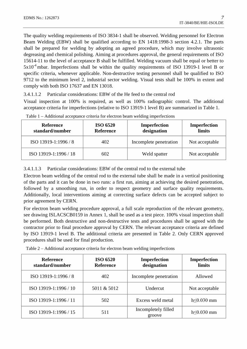
3.4.1.1.2 Particular considerations: EBW of the He feed to the central rod Visual inspection at 100% is required, as well as 100% radiographic control. The additional acceptance criteria for imperfections (relative to ISO 13919-1 level B) are summarized in Table 1.
Table 1 – Additional acceptance criteria for electron beam welding imperfections
Reference standard/number
ISO 6520 Reference
Imperfection designation
Imperfection limits
ISO 13919-1:1996 / 8 402 Incomplete penetration Not acceptable
ISO 13919-1:1996 / 18 602 Weld spatter Not acceptable
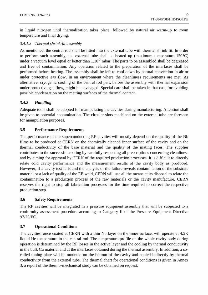
3.4.1.1.3 Particular considerations: EBW of the central rod to the external tube Electron beam welding of the central rod to the external tube shall be made in a vertical positioning of the parts and it can be done in two runs: a first run, aiming at achieving the desired penetration, followed by a smoothing run, in order to respect geometry and surface quality requirements. Additionally, local interventions aiming at correcting surface defects can be accepted subject to prior agreement by CERN. For electron beam welding procedure approval, a full scale reproduction of the relevant geometry, see drawing ISLACSCB0159 in Annex 1, shall be used as a test piece. 100% visual inspection shall be performed. Both destructive and non-destructive tests and procedures shall be agreed with the contractor prior to final procedure approval by CERN. The relevant acceptance criteria are defined by ISO 13919-1 level B. The additional criteria are presented in Table 2. Only CERN approved procedures shall be used for final production.
Table 2 – Additional acceptance criteria for electron beam welding imperfections
Reference standard/number
ISO 6520 Reference
Imperfection designation
Imperfection limits
ISO 13919-1:1996 / 8 402 Incomplete penetration Allowed
ISO 13919-1:1996 / 10 5011 & 5012 Undercut Not acceptable
ISO 13919-1:1996 / 11 502 Excess weld metal h≤0.030 mm
ISO 13919-1:1996 / 15 511 Incompletely filled groove h≤0.030 mm

8 EDMS No: 1262873 IT-3840/BE/HIE-ISOLDE
ISO 13919-1:1996 / 18 602 Weld spatter Not acceptable
3.4.1.2 Vacuum brazing
The stainless steel flange of the helium feed shall be assembled to the transition copper tube pos. 3 in drawing ISLACSCB0159 by vacuum brazing. After rough machining the flanges, a heat treatment at 900°C under vacuum for stress relieving, followed by a slow cool down, shall be performed. Final machining of the knife edges (drawing STDVFUHV0007) shall only be performed after this operation. Components shall be clean prior to vacuum brazing. If a silver-based alloy is used, nickel plating of stainless steel parts is recommended. The brazing alloy shall have a tightly controlled volatile impurity specification to grade V1 to ISO 17672:2010 and be approved by CERN. The adoption of a brazing alloy similar to Pallabraze™ 810 (Palladium based brazing filler metal) is recommended. The pressure inside the vacuum chamber shall be of the order of 1x10⁻⁶mbar when brazing. Brazing personnel shall be qualified according to EN 13133. Procedures shall be approved according to EN 13134 and the brazing cycle chart shall also be sent to CERN for prior approval. The additional criteria for visual testing are resumed in Table 3. The additional tests resumed in Table 4 shall be performed according to EN 12799 for procedure approval. Qualification assemblies and test records shall be provided to CERN upon request aiming final procedure approval.
Table 3 – Brazing procedure approval: additional acceptance criteria for visual testing
Defect Acceptance criteria
Fillet discontinuities Not acceptable
Concave fillets EN 12799:2000 – figure 2
Table 4 – Brazing procedure approval: acceptance criteria for additional tests
Testing method
Applicable documents Acceptance criteria
US control ISO 9712 ASTM E 1001
Channels Not acceptable
Combination of defects
The total projected area of defects shall not exceed 5% of the brazed area.
Leak testing EN 13185 Leak rate Less than 2.10-11Pa.m3/s
For final production, the quality of all brazed assemblies shall be controlled adopting the same NDT requirements used for qualification purposes (mainly US). All brazed assemblies (aiming both procedure approval and final production) shall undergo a minimum of five thermal cycles before being tested, each consisting of immersing the brazed joint
EDMS No.: 1262873 9 IT-3840/BE/HIE-ISOLDE
in liquid nitrogen until thermalization takes place, followed by natural air warm-up to room temperature and final drying.
3.4.1.3 Thermal shrink-fit assembly As mentioned, the central rod shall be fitted into the external tube with thermal shrink-fit. In order to perform such assembly, the external tube shall be heated up (maximum temperature 150°C) under a vacuum level equal or better than 1.10-3 mbar. The parts to be assembled shall be degreased and free of contamination. Any operation related to the preparation of the interfaces shall be performed before heating. The assembly shall be left to cool down by natural convection in air or under protective gas flow, in an environment where the cleanliness requirements are met. As alternative, cryogenic cooling of the central rod part, before the assembly with thermal expansion under protective gas flow, might be envisaged. Special care shall be taken in that case for avoiding possible condensation on the matting surfaces of the thermal contact.
3.4.2 Handling Adequate tools shall be adopted for manipulating the cavities during manufacturing. Attention shall be given to potential contamination. The circular slots machined on the external tube are foreseen for manipulation purposes.
3.5 Performance Requirements The performance of the superconducting RF cavities will mostly depend on the quality of the Nb films to be produced at CERN on the chemically cleaned inner surface of the cavity and on the thermal conductivity of the base material and the quality of the mating faces. The supplier contributes to the successful coating by carefully respecting all prescriptions concerning cleanliness and by aiming for approval by CERN of the required production processes. It is difficult to directly relate cold cavity performance and the measurement results of the cavity body as produced. However, if a cavity test fails and the analysis of the failure reveals contamination of the substrate material or a lack of quality of the EB weld, CERN will use all the means at its disposal to relate the contamination to a production process of the raw materials or the cavity manufacture. CERN reserves the right to stop all fabrication processes for the time required to correct the respective production step.
3.6 Safety Requirements The RF cavities will be integrated in a pressure equipment assembly that will be subjected to a conformity assessment procedure according to Category II of the Pressure Equipment Directive 97/23/EC.
3.7 Operational Conditions The cavities, once coated at CERN with a thin Nb layer on the inner surface, will operate at 4.5K liquid He temperature in the central rod. The temperature profile on the whole cavity body during operation is determined by the RF losses in the active layer and the cooling by thermal conductivity in the bulk Cu material and at the interfaces obtained during the thermal assembly. In addition, a so-called tuning plate will be mounted on the bottom of the cavity and cooled indirectly by thermal conductivity from the external tube. The thermal chart for operational conditions is given in Annex 3, a report of the thermo-mechanical study can be obtained on request.

10 EDMS No: 1262873 IT-3840/BE/HIE-ISOLDE
3.8 Information and Documentation The following data and documents shall be submitted to CERN before (a) and during (b) production: a) For the production readiness review:• A written program detailing the manufacturing and testing schedules, the foreseen delivery
dates and the end of contract date. The program shall include preliminary dates forinspections and tests;
• The manufacturing files incl. tooling design defining the processes and methods, which heintends to implement and the QC system;
b) as part of the MTF (Manufacturing and Test Folder):• Material certificates for non-supplied materials (including welding/brazing consumables);• complete records of the thermal treatments performed;• Welding/brazing procedures qualification records;• All the reports of tests performed for the quality assessment of welded/brazed joints (visual
tests, x-rays, ultrasounds or other);• The traceability records, travelers or other follow-up technical documentation for all units
produced;• All the reports of acceptance or intermediary tests which allow to demonstrate the
conformity of the final product to specifications (leak tests, metrology or other);• Any other technical documents requested in the application of the present document.
4. EXECUTION OF THE CONTRACT
4.1 Delivery ScheduleOnce the contractor is notified of the award of the contract, he shall deliver the supply according to the following delivery schedule:
4.1.1 Delivery within 4 weeks from the start of the contract
• A written program (see 3.8.a);• The manufacturing files (see 3.8.a);• The welding samples (see §3.4.1.1.3);
Once these items are submitted to CERN, a meeting shall be organized at the contractor’s or at CERN’s premises in view of the production readiness and the start-up of the pre-series production. Component ordering and equipment manufacture shall not start without CERN’s written approval.
4.1.2 Delivery within 8 weeks from the date of acceptance of the production folder and the agreement for pre-series production
• One pre-series cavity.Once the pre-series cavity is received at CERN, acceptance testing of the pre-series cavity will be performed.
EDMS No.: 1262873 11 IT-3840/BE/HIE-ISOLDE
4.1.3 Delivery of options (the series produced cavities)
• Depending on the placement of a second order, the series production of the options shallproceed within 30 weeks.
4.2 Contract Follow-Up and Progress Monitoring
4.2.1 Responsibility for Design, Components and Performance The contractor shall be responsible for the correct design and performance of all items and work supplied, irrespective of whether they have been chosen by the contractor or by CERN. CERN’s approval of the design and component choice does not release the contractor from his responsibilities in this respect. The contractor shall assign a technical responsible and his deputy for cases of absence, both able to communicate in English, for the execution of the contract and its follow-up throughout the duration of the contract. The contractor shall send a written progress report to CERN every month until completion of the contract. This report shall include all the necessary information, in particular: • Actual progress in comparison to the schedule;• Updates of the MTF;• Updates of the manufacturing documentation including, if required, change requests and non-
conformity reports (NCR).CERN and its representatives shall have free access during normal working hours to the manufacturing or assembly sites, including any subcontractor’s premises, during the contract period. The place of manufacture may only be changed after written approval by CERN.
4.2.2 Design Approval The detailed Manufacturing Documentation Folder (see § 3.8) shall be submitted to CERN for approval within four weeks of notification of the corresponding release order. CERN will give its approval or refusal of the complete file, in writing within two weeks. Component ordering and equipment manufacture shall not start without CERN’s written approval.
4.3 Documentation Handling, Quality Control and Quality Assurance The contractor shall plan, establish, implement and adhere to a documented quality assurance program that fulfils all the requirements described in this technical specification. In addition to the requirements of section 3, the contractor may propose any internationally recognised design standard, subject to prior written approval by CERN. The contractor shall state his intended method of design including applicable codes as part of his bid. CERN reserves the right to veto the use of certain codes or norms if it is considered that their application will not fulfil this technical specification. The contractor shall submit all documents produced in electronic format: • Drawings in CATIA®, AUTOCAD® and/or HP-GL format;• Text documents in Microsoft Word® and/or PDF format;• Cost breakdowns and equipment lists in Microsoft Excel® format;

12 EDMS No: 1262873 IT-3840/BE/HIE-ISOLDE
• Schedule in Microsoft Project® format.
4.4 Tests
4.4.1 Tests to Be Carried out at the Contractor’s Premises CERN reserves the right to be present, or to be represented by an organization of its choice, to witness any tests carried out at the contractor's or his subcontractors' premises. The contractor shall give at least 10 working days notice of the proposed date of any such tests. List of tests before acceptance: • Metrological measurements on the components and on the assembled cavity in its final state;• Preparation of welding samples and the analysis of samples;• Leak tightness shall be demonstrated at room temperature by adopting testing techniques similar
to EN 13185 group A.3 – tracer gas flowing into the object. Other techniques shall be selectedaccording to EN 1779. The maximum acceptable leak rate in such a test is 2.10-11 Pa.m3/s;
• X-ray checks of the welds;
4.4.2 Tests to Be Carried out at CERN List of tests: • Incoming inspection of the delivered cavities;• Metrology control measurements of the cavities;• Surface analysis and material control of the bulk;• Leak and pressure testing;• Frequency checks and tuning;
The contractor might want to be present at some of these tests at CERN. If any active participation of the contractor (Second category works) is envisaged he shall take into account and implement the rules and provisions defined in document ref. PSO/2011-001/Rev.2, https://edms.cern.ch/document/1155899/2.1 entitled Working on the CERN Site.
4.4.3 Acceptance The cavity shall be accepted on the basis of conforming metrology measurements and successful leak/pressure testing, if no traces of contamination or defects have been found on the inner surface or in the welds.
4.5 Packing and transport The contractor shall comply with professional regulations in matter of packing and transport, etc. In particular with the following: • The supply shall be protected against humidity, vapors and/or any environment that could cause
oxidation of the cavity;• The supply shall be protected against massive vibrations and shocks during transport;• The central rod shall be supported to avoid excitation of mechanical resonances.
The contractor is responsible for the packing and the transport to CERN. He shall ensure that the equipment is delivered to CERN without damage and any possible deterioration of cleanliness due to transport conditions.
EDMS No.: 1262873 13 IT-3840/BE/HIE-ISOLDE
4.6 Warranty The warranty shall be defined in the tender form.
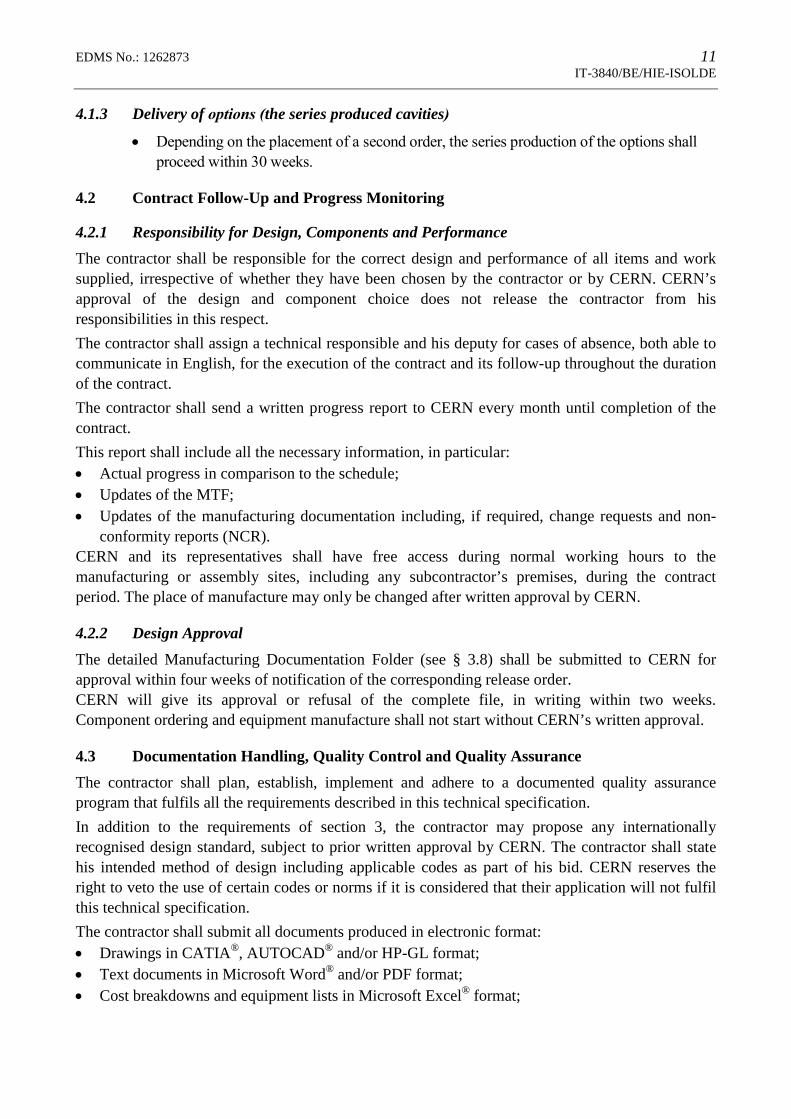
5. CERN CONTACT PERSONSPersons to be contacted for technical matters:
Name/Department/Group Tel-Fax Email
Mr. Karl-Martin Schirm Tel: +41 22 767 6770
Fax: +41 22 766 9486
In case of absence:
Mr. Luis Alberty Tel: +41 22 767 9296
Fax: +41 22 766 9813
L.Alberty @cern.ch
6. ANNEXES
Annex 1: List of Drawings1. Hollow shape forged copper, drawing ISLACSCB0126, Ind. B2. Hub like forged copper, drawing ISLACSCB0127, Ind. B3. HIE-ISOLDE high beta cavity, drawing ISLACSCB0158, Ind. D4. HIE-ISOLDE cavity EBW test piece for welding procedure qualification, drawing
ISLACSCB0159, Ind. A5. Hub-like forged copper with central hole, ISLACSCB0161, Ind. A6. Rod for Cu-Stainless steel transition, ISLACSCB0162, Ind. _7. UHV flange fixed 114/63, STDVFUHV0007, Ind. B
Annex 2: Material specifications 1. Forged blanks for vacuum applications stainless steel type X2CrNiMoN17-13-3
(1.4429, AISI 316LN);
14 EDMS No: 1262873 IT-3840/BE/HIE-ISOLDE
2. Technical Specification of Cu-OFE copper forgings for the production of the HIE-
ISOLDE high-β superconducting cavities;
Annex 3: Thermo-mechanical calculations 1. Steady-state thermal studies on the HIE-ISOLDE high-beta superconducting cavities;
Tech. Note; EDMS1245886.