TECHNICAL SPECIFICATION FOR THE SUB-STATION WORK
61
e-tender Notice No 37/2014 R/C 2014 Page 1/105 TECHNICAL SPECIFICATION FOR THE SUB-STATION WORK
-
Upload
khangminh22 -
Category
Documents
-
view
1 -
download
0
Transcript of TECHNICAL SPECIFICATION FOR THE SUB-STATION WORK
e-tender Notice No 37/2014 R/C 2014 Page 1/105
TECHNICAL SPECIFICATION
FOR THE SUB-STATION WORK
1.0 ELECTRICAL EQUIPMENT INSTALLATION AND COMMISSIONING
1.1 SCOPE
This chapter describes board guidelines for installations, testing and commissioning of
electrical equipment in OPTCL Sub Station in case of emergency and also during normal
work. The work shall, however, be carried out strictly as per the instruction of the
MANUFACTURER / EMPLPOYER.
1.2 CODES AND STANDARDS
The electrical installation work shall comply with the latest applicable standards,
regulations, electricity rules and safety codes of the locality where the installation is carried
out. Nothing in this specification shall be construed to relieve the CONTRACTOR OF HIS
RESPONSIBILITY
2.0 GENERAL
The CONTRACTOR shall transport the equipments where required in actual position.
Erect, assemble all parts of the equipments and test and commission the same.
The CONTRACTOR shall furnish all tools, welding equipment, rigging materials,
testing equipment, test connections and kits, etc. required for complete installation, testing
and commissioning of the items included in the contract work.
The EMPLOYER may engage specialist Employer to supervise the installation, testing and
commissioning of their equipment. The CONTRACTOR shall extend full co-operation to
these Employers and carry out the works as per their instructions. The
CONTRACTOR’S work shall include minor rewiring modifications as may be necessitated
during commissioning. Providing such assistance shall be deemed to be included in the
CONTRACTOR’S basic scope.
The CONTRACTOR shall co-operate through the EMPLOYER with other
contractors at site, in all matters of common interest, so as not to abstract operation of
others and to ensure the safety of all personnel and works covered under this specification.
It will be the CONTRACTORS responsibility to assist the OWNER to obtain approval/
clearance from local statutory authorities including electrical inspector, wherever applicable,
for conducting any work or for installation carried out which comes under the purview of
such authorities.
The work shall be carried out strictly as per the instructions and layout drawings of the
EMPLOYER/ manufacturer. In case of any doubt/ misunderstanding as to correct
interpretation of the drawings or instructions, necessary clarifications shall be obtained
from theEMPLOYER. The CONTRACTOR shall be held responsible for any damage to
the equipment consequent to not following the MANUFACTURER’S instructions
correctly. All necessary drawings. MANUFACTURER’S instructions correctly. All
necessary drawings. MANUFACTURER’S equipment manuals will be arranged by the
contractor/OPTCL.
All thefts of equipment/component parts till the including executed portion handed over to
the EMPLOYER shall be made good by the CONTRACTOR.
The CONTRACTOR shall have a separate cleaning gang to clean all equipment during
erection and as well as the work area and the project site at regular intervals to the
satisfaction of the EMPLOYER. In case the cleaning is not to the Employer’s satisfaction,
he will have the right to carry out the cleaning operations and any expenditure
incurred by the OWNER in this regard will be the CONTRACTOR’S account.
In order to avoid hazards to personnel moving around the equipment such as switchgear
etc. which is kept charged after installation before commissioning, such equipment shall be
suitably cordoned off to prevent any one accidentally going near it.
Safety of the Contractor’s personnel engaged in erection and commissioning job will be
Contractor’s responsibility.
The CONTRACTOR shall carry out touch-up painting on any equipment indicated by the
EXMPLOYER if the finish paint on the equipment is soiled for marred during installation
handling.
The CONTRACTOR shall ensure workmanship of good quality and shall assign qualified
supervisors/Employers and competent labour who are skilled, careful and experienced in
their several trades in similar works. The EMPLOYER shall reserve the right to reject non-
competent persons employed by the CONTRACTOR, if the workmanship is not of good
order.
It shall be the responsibility of the CONTRACTOR to obtain necessary Licence
/Authorization, Permit for work from the Licensing Board of the Locality/ state where the
work is to be carried out. The persons deputed by the CONTRACTOR’S firm should also
hold valid permits issued or recognized by the Licensing Board of the locality/State where
the work is to be carried out. A list of the personnel engaged in erection and commissioning
work should be submitted to the Employer before commencement of the work.
3.0 INSTALLATION WORK- SCOPE
Equipment shall be installed in neat, workmanlike manners so that it is level, plump, square
and properly aligned and oriented. Tolerances shall be established in the Manufacturer’s
drawings or as stipulated by the EMPLOYER. No equipment shall be permanently bolted
down to foundation or structure until the alignment has been checked and found acceptable
by the EMPLOYER.
Care shall be exercised in handling to avoid distortion to stationary structures, the marring
of finish, or damaging of delicate instruments or other electrical parts. Adjustment shall be
made as necessary to the stationary structures for plumb and level, for the sake of
appearance or to avoid twisting of frames, binding of hanged members, etc.
The CONTRACTOR shall move all equipment into the respective building through the
regular doors or floor opening provided specially for lifting the equipment.
All external cabling including end connections and earthling shall also be carried out.
4.0 POWER AND INSTRUMENT TRANSFORMERS
Physical inspection on receipt, storage, installation, testing and commissioning of
transformers shall be in accordance with the specified code of practice and Manufacturer’s
instructions.
Transformer may be delivered without oil filled with inert gas and without bushings and
external mounted accessories. As applicable, the CONTRACTOR shall.
a) Assemble the transformers with all fittings such as bushings, cooler banks, radiator,
conservators, valves, piping, cables boxes, marshalling boxes OLTC, cooling fans/pumps,
etc.
b) Arrange for oil filtration while filling.
c) Provide wedges/clamps to rigidly station all transformers on rails.
d) Connect up the transformer’s terminals.
e) Lay and terminate cables/ conduits between all the accessories mounted on the transformer
tank/cooler and the transformer-marshalling kiosk.
f) Pre commissioning checks shall be carried out as per relevant standards and Employer’s
instructions.
TRANSFORMER OIL FILTRATION
The CONTRACTOR shall arrange the oil filtration equipment if required and necessary
charges shall be deducted from the bill as per rule if OPTCL supplies the Filter Machine.
Electricity and all T&P shall be arranged by the contractor. Care shall be taken during
handling of insulating oil to prevent ingress of moisture or foreign matter. In the testing,
circulating, filtering or otherwise handling of oil, rubber hoses shall not be used, circulation
and filtering of oil, the heating of oil by regulated short-circuit current during drying runs
and sampling and testing of oil shall be in accordance with the MANUFACTURER’S
instructions and specified Code of Practice.
5.0 SWITCHGEAR, CONTROL/ RELAY PANELS
Switchgears and control relay panels/desks shall be installed in accordance with specified
Code of Practice and the Manufacturer’s instructions. The switchgear panels shall be
installed on finished surfaces or concrete or steel sills. The CONTRACTOR shall be
required to install and align and channel /angles etc which form part of the foundations. In
joining shipping sections of the switchgear/panels /control centers together with adjacent
housing or panes sections provided shall be bolted together after alignment has been
completed. Power bus, enclosures, ground and control splices of conventional nature shall
be cleaned and bolted together, being drawn up with torque wrench of proper size or by
other approved means. Tape or compound shall be applied where called for by the
MANUFACTURER’S drawings.
The CONTRACTOR shall take utmost care in handling instruments. Relays and other
delicate mechanisms. Wherever the instruments and relays are supplied separately, they shall
be mounted only after the associated control panel/desks have been erected and aligned. The
blocking materials/mechanism employed for the safe transit of the instruments and relays
shall be removed after ensuring that the panels/desks have been completely installed and no
further movement of the same would be necessary. Any damage to relays and instruments
shall be immediately reported to the EMPLOYER.
Pre-commissioning checks on relays have to be carried out on all relays in accordance with
manufacturers instruction and in presence of Employer.
6.0 BATTERY AND CHARGERS
Installation and testing of battery and battery chargers shall be done in strict compliance with
the manufacturer’s instructions. Each cell shall be inspected for break ate and condition of
cover seals as soon as received at site. Each cell shall be filled with electrolyte in accordance
with the MANUFACTURER’S instructions. Battery shall be set up on racks as soon as
possible after receipt, utilizing lifting devices supplied by the MANUFACTURER. The cells
shall not be lifted by the terminals. Contact surfaces of battery terminals and inter-cell
connectors shall be cleaned, coated with protective grease and assembled. Each connection
shall be properly tightened. Each cell shall be tested with hydrometer and results logged.
Freshening charge, if required, shall be added. When turned over to the EXPLOYER, the
battery shall be fully charged and electrolyte shall be at full level and of specified specific
gravity.
Battery shall be put in commercial use only after carrying out charge/discharge cycle as per
Manufacturer’s instruction.
7.0 SWITCHYARD
The CONTRACTOR shall carry out switchyard installation as required as per approved
i) The supplier shall install, test and commission the cables. Cables shall be laid on cable trays
and supports, in conduits and doctor or bare on walls, ceiling, etc. as required. The
supplier’s scope of work includes laying, fixing, jointing, bending and terminating cables.
The supplier shall also supply necessary materials and equipment required for jointing and
terminating of cables. The supplier shall prepare detailed layout drawing for cable trenches,
cable tray layouts for approval by Employer and construct cable routes strictly according to
these drawings.
ii) Sharp bending, twisting and kinking of cables shall be avoided. The bending radius for
various types of cables shall not be less than those specified by cable manufacturer.
iii) In each cable run, some extra length shall be kept at a suitable point to enable one or two
straight through joints to be made. Should the cable develop fault at a later date.
iv) Cable joints in the middle of the run for control cables will not be a accepted.
v) All cable terminations shall be made in a neat. Workmanlike manner. Terminations shall
be made for each type of wire or cable in accordance with instructions issued by cable
manufacturers and the Employer.
vi) Metal sheath and Armour of the cable shall be bounded to the earthing system of the sub-
station.
8.0 GENERAL REQUIREMENTS OF INSTALLATION FOR EARTHING AND LIGHTNING PROTECTION SYSTEMS
8.1 SCOPE OF INSTALLATION
i) The supplier shall install steel conductors and braids, as required for system and individual
equipment earthing. All work such as cutting, bending, supporting, painting coating drilling,
brazing/soldering/welding, clamping, bolting and connection on to structures, equipment
frames, terminals, rails or other devices shall be in the scope of work. All incidental
hardware and consumables such as fixing cleats/clamps. Anchor fasteners, lugs, bolts, nuts,
washers, bituminous compound, anticorrosive paints as required for the complete work
shall be deemed to to be included as part of the installation work.
ii) The quantities, sizes and material of earthing conductors and electrodes to be installed and
routes of the conductors and location of the electrodes shall be as per approved drawings.
iii) The scope of installation of earth conductors in outdoor areas, buried in ground shall
include excavation in earth at least upto 600 mm. Deep and 450 mm, wide (unless otherwise

stated), brazing/welding as required of main grid conductor joints as well as risers of 500
mm. Length above ground at required locations and backfilling. Backfilling material to be
placed over buried conductor shall be free from stones and other harmful mixtures. Backfill
shall be placed in layers of 150 mm, uniformly spread along the ditch and tempered
utilizing pneumatic tempers or other approved means.
vii) The scope of installation of earth connection leads to equipment and risers on steel
structures/walls shall include laying the conductors, welding/ cleating, at specified intervals,
welding/brazing to the main earth grids risers, bolting at equipment terminals and coating
welded/brazed joints by bituminous paint. Galvanized conductors shall be touched up with
zinc rich paint, where holes are drilled at site for holding to equipment/ structure.
viii) The electrodes shall be installed either directly in earth or in constructed earth pits as shown
in approved drawings.
ix) The scope of installation of lightning conductors on the roof of buildings shall include
laying, anchoring, fastening and cleating of horizontal conductors, grouting of vertical rods
where necessary, laying, fastening/cleating/welding of the down comers on the
walls/columns of the building and connection to the test links above the ground level.
x) The scope of installation of the test links shall include mounting of the same at specified
height on wall/column by suitable brackets and connections of the test link to the earth
electrodes.
Earthing connections:
i) All connections in the main earth conductors buried in earth/concrete shall be
welded/brazed type,. Connection between main earthing conductor and earth leads shall
also be of welded/brazed type.
ii) Welding and brazing operations and fluzes/alloys shall be of approved standards.
iii) All connections shall be of low resistance. Contact resistances shall also be minimum.
iv) All bi-metallic connections shall be treated with suitable compound to prevent moisture
ingress.
Earth Electrodes:
i) Electrodes shall as far as practicable, be embedded below permanent moisture level.
ii) Some electrodes shall be housed in test pits with concrete covers for periodic testing of
earthing resistively. Installation of rod/pipe plate electrodes in test pits shall be convenient
for inspection, testing and watering.
iii) Earth pits shall be treated with salt and charcoal.
iv) Soil, salt and charcoal placed around the electrode shall be finely graded free from stones
and other harmful mixtures. Backfill shall be placed in the layers of 250 mm. Thick

uniformly spread and compacted. If excavated soils are found unsuitable for backfilling, the
contractor shall arrange for a suitable soil from outside.
8.2 TESTING OF EARTHING SYSTEM
The Supplier shall ensure the continuity of all conductors and joints. The Purchaser
may ask for earth continuity tests, earth resistance measurements and other tests, which in
his opinion are necessary to prove that the system is in accordance with the design,
specifications and code of practices. The supplier shall have to bear the cost of all such
tests.
8.3 TESTING AND COMMISSIONING
All checks and tests as per the Manufacturer’s drawings/manuals, relevant code of
installation/erection practices and commissioning checks for various types of equipment
e.g. transformers, breakers, isolators, CTs, PTs, motors, relays, meters, etc. shall be carried
out by the CONTRACTOR as part of the installation work.
The owner may ask for such additional tests on site as in his opinion are necessary to
determine that the works comply with the specification, Manufacturer’s
guarantee/instructions or the applicable code of installation. The CONTRACTOR shall
carry out such additional tests also.
The CONTRACTOR shall perform operating tests on all switchgear and panels to verify
operation of switchgear/panels and correctness of the inter-connections between various
items of the equipment. This shall be done by applying normal AC or DC voltage to the
circuits and operating the equipment for functional checking of all control circuits e.g.
closing, tripping, control interlock supervision and alarm circuits. All connections in the
switchgear shall be tested from point for possible ground or short circuit.
Insulation resistance tests shall be carried out by following rating megger :
a) Control circuits up to 220 V : By 500 V Megger
b) Power circuits, busbars : By 5000 Motor
connections for 132 KV. Operated Megger.
c) Power circuits, busbars : By 5000 V Motor
connections above 220 KV. Operated Megger.
The Employer’s authorized representative shall be present during every test as called for by the
EMPLOYER. The CONTRACTOR shall record all test values and furnish the required copies of
the test data to the EMPLOYER. Electrical circuits and equipments shall be energized or used at
nominal operating voltage only after such reports have been accepted as satisfactory by the
EMPLOYER.
8.4 COMPLETION CHECKS
a) Name plate details according to approved drawings/ specifications.
b) Any physical damage or defect and cleanliness.
c) Tightness of all bolts, clamps and connections
d) Oil leakages and oil level.
e) Condition of accessories and their completeness.
f) Clearances.
g) Earthing connections.
h) Correctness of installation with respect to approved drawings/ specifications.
i) Lubrication Moving parts.
j) Alignment.
k) Correctness and condition of connections.
8.5 COMMISSIONING TESTS
a) Insulation resistance measurement of equipment, accessories, cabling/ wiring. etc.
b) Dielectric tests on equipment, accessories, cabling/wires. etc.
c) Phase sequence and polarity.
d) Voltage and current ratios.
e) Vector group.
f) Resistance measurement of winding. Contacts, etc.
g) Continuity tests.
h) Calibration of indicators, meters, relays etc.
i) Control and interlock checks.
j) Settings of equipment accessories.
k) Checking of accuracy/error.
l) Checking of operating characteristics, pick/up voltages and currents. Etc.
m) Operational and functional tests on equipment, accessories, control schemes,
alarm/trip/indication circuits, etc.
n) Measurement of guaranteed/approved design values including lighting levels, earth
resistance measurements, etc.
o) Complete system commissioning checks.
CIVIL WORKS TECHNICAL SPECIFICATION FOR SUBSTATION – CIVIL STRUCTURAL AND
ARCHITECTURAL WORKS. 9.0 GENERAL
This specification covers the general requirements for soil exploration, site grading,
design, fabrication, galvanizing supply and construction of civil, structural steel and
architectural works for substation., including setting out and survey work.The contractor
shall perform the works to meet the requirements of this specification, the attached bid
drawings and the relevant articles in this contract document. This specification is intended
for general description of quality and workmanship of materials and finished works. They
are not intended to cover minute details. It shall be specifically understood that the work
shall be executed in accordance with the best modern practices and with best quality of
materials and workmanship to the entire satisfaction of the employer. This specifications
shall generally have precedence in case anything contrary to this is stated anywhere in the
contract document but the decision of the Employer shall be final and binding on the
Contractor in respect of any issue arising out of such discrepancies.
9.1 STANDARD AND REFERENCES
All equipment, materials, fabrication, galvanizing, erection and test under these
Specifications shall conform to the latest Indian Standard Specifications. In absence
thereof, the work shall be executed according to the best prevailing State or Orissa
Public Works Department Practice or as per relevant International Standards. Codes,
Manuals and Specifications or to equivalent applicable international standards.
Manuals and specifications established and approved in the country of manufacturer
and as approved by Employer.
If the Contractor for any reasons proposes equivalents to or deviations from the above
standards, the Contractor shall state the exact nature of the change, the reason for
making the change and shall submit complete specifications of the materials, as well as
copies of pertinent standards, for the approval of the Employer and decision of the
Employer in the matter of acceptability will be final.
9.2 MATERIAL
a) General
All materials as far as possible shall be obtained from local sources and shall be subjected
to approval by the Employer prior to use.
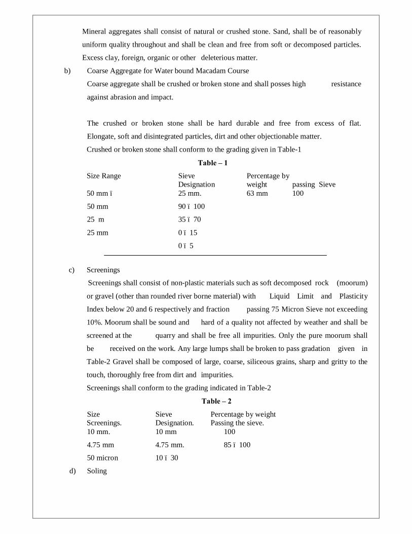
Mineral aggregates shall consist of natural or crushed stone. Sand, shall be of reasonably
uniform quality throughout and shall be clean and free from soft or decomposed particles.
Excess clay, foreign, organic or other deleterious matter.
b) Coarse Aggregate for Water bound Macadam Course
Coarse aggregate shall be crushed or broken stone and shall posses high resistance
against abrasion and impact.
The crushed or broken stone shall be hard durable and free from excess of flat.
Elongate, soft and disintegrated particles, dirt and other objectionable matter.
Crushed or broken stone shall conform to the grading given in Table-1
Table – 1
Size Range Sieve Percentage by Designation weight passing Sieve 50 mm – 25 mm. 63 mm 100
50 mm 90 – 100
25 m 35 – 70
25 mm 0 – 15
0 – 5
c) Screenings
Screenings shall consist of non-plastic materials such as soft decomposed rock (moorum)
or gravel (other than rounded river borne material) with Liquid Limit and Plasticity
Index below 20 and 6 respectively and fraction passing 75 Micron Sieve not exceeding
10%. Moorum shall be sound and hard of a quality not affected by weather and shall be
screened at the quarry and shall be free all impurities. Only the pure moorum shall
be received on the work. Any large lumps shall be broken to pass gradation given in
Table-2 Gravel shall be composed of large, coarse, siliceous grains, sharp and gritty to the
touch, thoroughly free from dirt and impurities.
Screenings shall conform to the grading indicated in Table-2
Table – 2
Size Sieve Percentage by weight Screenings. Designation. Passing the sieve. 10 mm. 10 mm 100
4.75 mm 4.75 mm. 85 – 100
50 micron 10 – 30
d) Soling

Soling shall be either trap/basalt/granite/locally available approved stone and shall be
hard, tough, sound, durable, dense, clean, of close texture and free from unsound material,
cracks, decay and weathering. Water absorption when tested shall be not more than 5%.
e) Stone Kerb
The stone shall in the smallest dimension be equal to the thickness of the soling course
specified with a tolerance of 25 mm. Soling stone shall be sufficiently flat bedded. Kerb
stones shall be clean, hard trap/basalt/granite/locally available approved stones free from
decay and weathering. The stones shall be hammer dressed on all sides. The size of the
stones shall be approximately 150 mm wide, e50 mm in depth and not less than 250 mm
in length
f) Precast Concrete Pipes
Precast Concrete Pipes of required sizes and are required invert levels as per approved
drawings shall be provided by the contractor under approach road so that flow, in the
natural drain running parallel to existing main road, remains undisturbed. These pipes
shall be of NP3 class and shall conform to IS: 458 and shall have adequate strength to
resist the anticipated traffic loads.
9.3 EARTH WORK IN EXCAVATION AND BACKFILL.
9.3.1 EARTH WORK IN EXCAVATION
Excavation shall conform to the dimension and elevation as sown on the approved
awings. Adequate side slope shall be provided, however, where the slope exceeds 1:1.5,
temporary supports to the sides of excavation shall be provided by means of timbering or
shoring.
When foundations rest on an excavated surface other than rock, special care shall be
taken not to disturb the bottom of the excavation. When sub-soil for foundations become
mucky on top due to construction operation or any other reasons, such sub-soil shall be
removed and replaced by one or more layers of compacted sand or compacted crushed rock,
as directed by the Employer.
Excavated material suitable for use as backfill shall be deposited by the Contractors in
storage area approved by Employer. However, surplus excavated materials shall also
be hauled and transported to the disposal area designated by Employer.
9.3.2 BACKFILL
The contractor shall place and compact the backfill materials to the lines, grades and
dimensions to be shown on the approved drawings. The materials to be used for
backfill, the quantity thereof and the manner of depositing the materials shall be
approved the Employer.
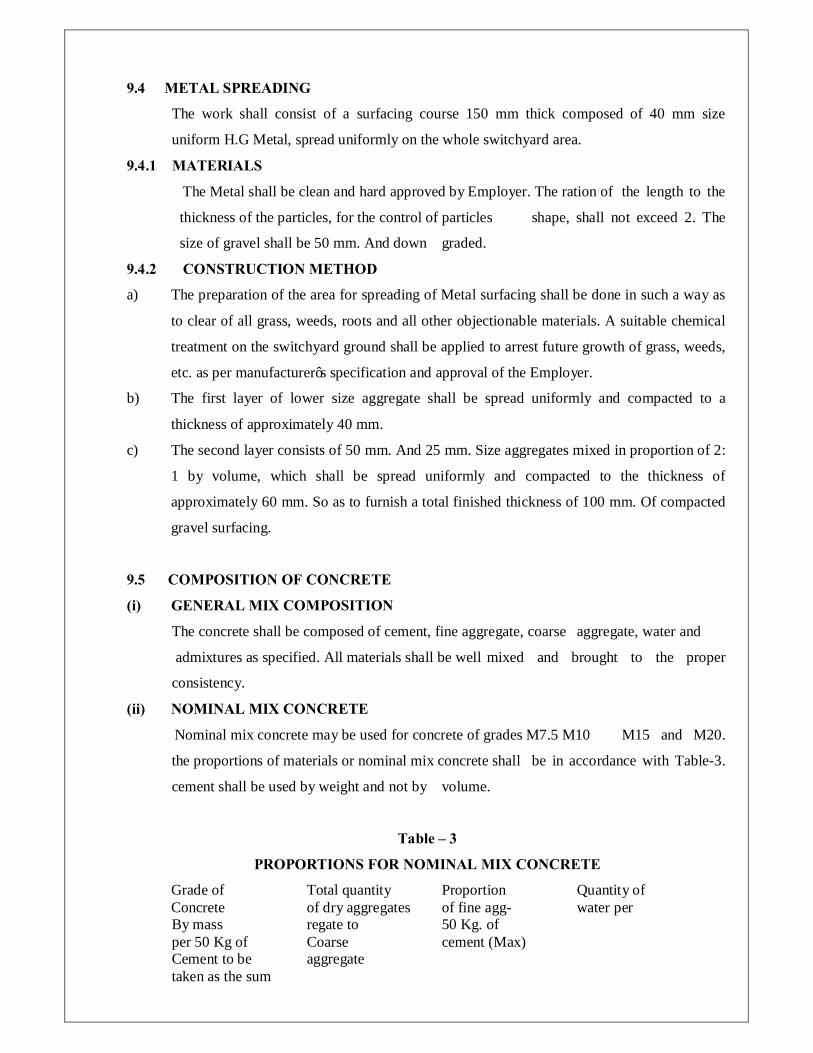
9.4 METAL SPREADING
The work shall consist of a surfacing course 150 mm thick composed of 40 mm size
uniform H.G Metal, spread uniformly on the whole switchyard area.
9.4.1 MATERIALS
The Metal shall be clean and hard approved by Employer. The ration of the length to the
thickness of the particles, for the control of particles shape, shall not exceed 2. The
size of gravel shall be 50 mm. And down graded.
9.4.2 CONSTRUCTION METHOD
a) The preparation of the area for spreading of Metal surfacing shall be done in such a way as
to clear of all grass, weeds, roots and all other objectionable materials. A suitable chemical
treatment on the switchyard ground shall be applied to arrest future growth of grass, weeds,
etc. as per manufacturer’s specification and approval of the Employer.
b) The first layer of lower size aggregate shall be spread uniformly and compacted to a
thickness of approximately 40 mm.
c) The second layer consists of 50 mm. And 25 mm. Size aggregates mixed in proportion of 2:
1 by volume, which shall be spread uniformly and compacted to the thickness of
approximately 60 mm. So as to furnish a total finished thickness of 100 mm. Of compacted
gravel surfacing.
9.5 COMPOSITION OF CONCRETE
(i) GENERAL MIX COMPOSITION
The concrete shall be composed of cement, fine aggregate, coarse aggregate, water and
admixtures as specified. All materials shall be well mixed and brought to the proper
consistency.
(ii) NOMINAL MIX CONCRETE
Nominal mix concrete may be used for concrete of grades M7.5 M10 M15 and M20.
the proportions of materials or nominal mix concrete shall be in accordance with Table-3.
cement shall be used by weight and not by volume.
Table – 3
PROPORTIONS FOR NOMINAL MIX CONCRETE
Grade of Total quantity Proportion Quantity of Concrete of dry aggregates of fine agg- water per By mass regate to 50 Kg. of per 50 Kg of Coarse cement (Max) Cement to be aggregate taken as the sum

of the individual Masses of Fine & Coarse aggregates (Max.)
(1) (2) Kg. (3) (4) Litres.
M 7.5 625 1:2 but subject 45
to an upper limit of 1 : 1,5 and a ower of 1:2:5 M 10 480 34
M 15 350 32
M 20 250 30
The detailed mix proportion shall be submitted to Employer for approval on the basis of
producing concrete having suitable workability, consistency, density, impermeability,
durability and required strength with concrete compressive strength test records.
(iii) CONSISTENCY
The detailed mix proportions shall be submitted to Employer for approval to secure
concrete of the proper consistency and to adjust for any variation in the moisture
content or grading of the aggregate as they enter the mixer. Addition of water to
compensate for stiffening of the concrete before placing will not be permitted.
Uniformity in concrete consistency from batch to batch will be required.
(iv) LEAN CONCRETE
Lean concrete shall be used under all foundations with the ratio of cement: fine
aggregate: coarse aggregate equal to 1:4:8 (by volume) and of 75 mm. thickness.
(v) CEMENT
Generally cement shall be ordinary Portland cement conforming to IS : 269, or Portland
slag cement conforming to IS : 455, or Portland possotona cement conforming to IS : 1489.
In special cases, rapid hardening Portland cement, low heat cement, etc. may be permitted
by the Employer.
9.6 COURSE AGGREGATE
(i) QUALITY
Coarse aggregate shall conform to IS: 383 and shall be hand/crusher broken granite natural
gravel or manufactured coarse aggregate. Coarse aggregate shall consist of well shaped clean,
arid, dense, durable granite rock fragments and shall not include elongated, flaky or
laminated pieces and any other impurities or deleterious material.
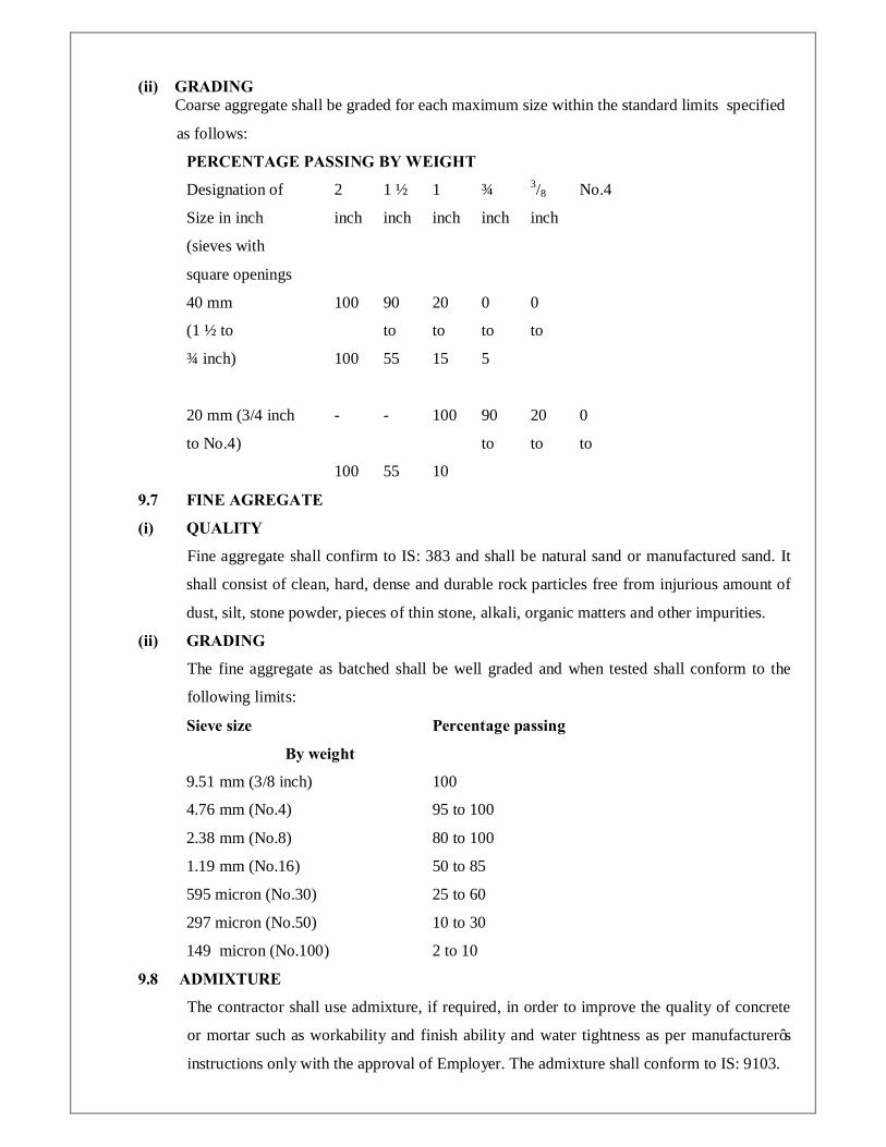
(ii) GRADING Coarse aggregate shall be graded for each maximum size within the standard limits specified
as follows:
PERCENTAGE PASSING BY WEIGHT
Designation of 2 1 ½ 1 ¾ 3/8 No.4
Size in inch inch inch inch inch inch
(sieves with
square openings
40 mm 100 90 20 0 0
(1 ½ to to to to to
¾ inch) 100 55 15 5
20 mm (3/4 inch - - 100 90 20 0
to No.4) to to to
100 55 10
9.7 FINE AGREGATE
(i) QUALITY
Fine aggregate shall confirm to IS: 383 and shall be natural sand or manufactured sand. It
shall consist of clean, hard, dense and durable rock particles free from injurious amount of
dust, silt, stone powder, pieces of thin stone, alkali, organic matters and other impurities.
(ii) GRADING
The fine aggregate as batched shall be well graded and when tested shall conform to the
following limits:
Sieve size Percentage passing
By weight
9.51 mm (3/8 inch) 100
4.76 mm (No.4) 95 to 100
2.38 mm (No.8) 80 to 100
1.19 mm (No.16) 50 to 85
595 micron (No.30) 25 to 60
297 micron (No.50) 10 to 30
149 micron (No.100) 2 to 10
9.8 ADMIXTURE
The contractor shall use admixture, if required, in order to improve the quality of concrete
or mortar such as workability and finish ability and water tightness as per manufacturer’s
instructions only with the approval of Employer. The admixture shall conform to IS: 9103.
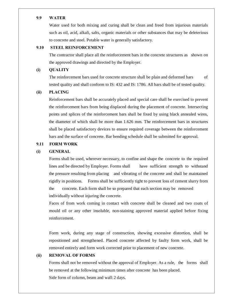
9.9 WATER
Water used for both mixing and curing shall be clean and freed from injurious materials
such as oil, acid, alkali, salts, organic materials or other substances that may be deleterious
to concrete and steel. Potable water is generally satisfactory.
9.10 STEEL REINFORCEMENT
The contractor shall place all the reinforcement bars in the concrete structures as shown on
the approved drawings and directed by the Employer.
(i) QUALITY
The reinforcement bars used for concrete structure shall be plain and deformed bars of
tested quality and shall conform to IS: 432 and IS: 1786. All bars shall be of tested quality.
(ii) PLACING
Reinforcement bars shall be accurately placed and special care shall be exercised to prevent
the reinforcement bars from being displaced during the placement of concrete. Intersecting
points and splices of the reinforcement bars shall be fixed by using black annealed wires,
the diameter of which shall be more than 1.626 mm. The reinforcement bars in structures
shall be placed satisfactory devices to ensure required coverage between the reinforcement
bars and the surface of concrete. Bar bending schedule shall be submitted for approval.
9.11 FORM WORK
(i) GENERAL
Forms shall be used, wherever necessary, to confine and shape the concrete to the required
lines and be directed by Employer. Forms shall have sufficient strength to withstand
the pressure resulting from placing and vibrating of the concrete and shall be maintained
rigidly in positions. Forms shall be sufficiently tight to prevent loss of cement slurry from
the concrete. Each form shall be so prepared that each section may be removed
individually without injuring the concrete.
Faces of from work coming in contact with concrete shall be cleaned and two coats of
mould oil or any other insoluble, non-staining approved material applied before fixing
reinforcement.
Form work, during any stage of construction, showing excessive distortion, shall be
repositioned and strengthened. Placed concrete affected by faulty form work, shall be
removed entirely and form work corrected prior to placement of new concrete.
(ii) REMOVAL OF FORMS
Forms shall not be removed without the approval of Employer. As a rule, the forms shall
be removed at the following minimum times after concrete has been placed.
Side form of column, beam and wall: 2 days.

Supporting form of floors and beam: 14 days
(Spanning upto 6 M)
Supporting form of floors and beam: 21 days
(Spanning over 6 M)
Before reuse, all forms shall be thoroughly scraped, cleaned, nails/ bolts removed, holes
suitably plugged, joints repaired and warped lumber resized to the satisfaction of Employer.
Contractor shall equip himself with enough shuttering to complete the job in time.
9.12 BATCHING AND MIXING
The contractor shall provide equipment and shall maintain and operate the equipment to
produce the required quality of concrete.
When any mixer produces unsatisfactory results, Employer may direct the contractor to
increase the mixing time or repair the mixing blades and the contractor shall promptly
carryout the directions of Employer.
The order feeding the materials into the mixer shall be subject to approval of Employer.
All concrete shall be machine mixed.
9.13 PLACING OF CONCRETE
(i) GENERAL
Prior to placing concrete, the contractor shall submit to Employer for approval the mix.
Proportion, the characteristics of each of the materials of concrete, the concrete placing
schedule, placing equipment and method of execution of work. No concrete shall be placed
until all formwork, treatment of surface, placing of reinforcement and other parts to be
embedded have been inspected and approved by the Employer.
(ii) TRANSPORTATION
The concrete which has remained more than 30 minutes after being discharged from the
mixer and/or in which slump loss exceeds 3.0 cm as it is delivered to the site for placing
shall be disposed off at the place designated by Employer. All such waste concrete shall
be at the contractor’s account. Concrete shall be placed with a vertical drop not
greater than 1.0 m except where suitable equipment is provided to prevent segregation or
where specifically authorized.
Concrete, which has segregated during transportation, shall be remixed.
(iii) PLACING
After the surface of unformed construction joint has been cleaned and the placing of
concrete has been approved by Employer in accordance with the provisions of the preceding
sub-articles, surface of unformed construction joint shall be covered with a layer of
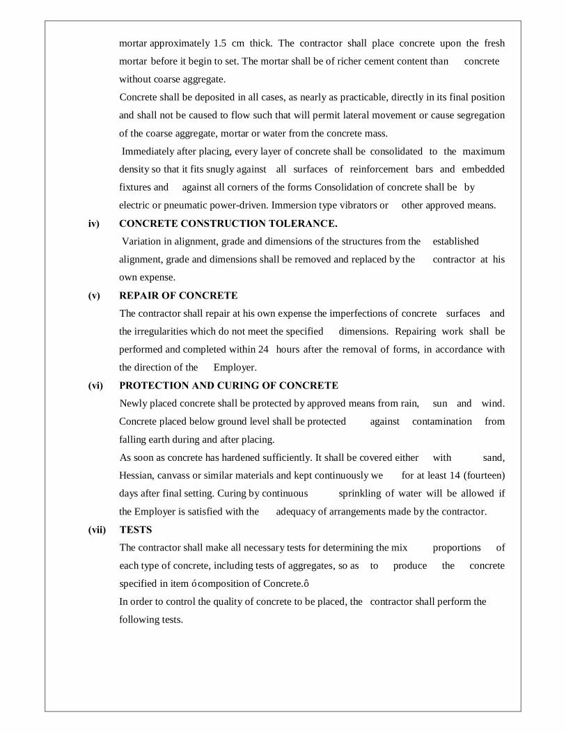
mortar approximately 1.5 cm thick. The contractor shall place concrete upon the fresh
mortar before it begin to set. The mortar shall be of richer cement content than concrete
without coarse aggregate.
Concrete shall be deposited in all cases, as nearly as practicable, directly in its final position
and shall not be caused to flow such that will permit lateral movement or cause segregation
of the coarse aggregate, mortar or water from the concrete mass.
Immediately after placing, every layer of concrete shall be consolidated to the maximum
density so that it fits snugly against all surfaces of reinforcement bars and embedded
fixtures and against all corners of the forms Consolidation of concrete shall be by
electric or pneumatic power-driven. Immersion type vibrators or other approved means.
iv) CONCRETE CONSTRUCTION TOLERANCE.
Variation in alignment, grade and dimensions of the structures from the established
alignment, grade and dimensions shall be removed and replaced by the contractor at his
own expense.
(v) REPAIR OF CONCRETE
The contractor shall repair at his own expense the imperfections of concrete surfaces and
the irregularities which do not meet the specified dimensions. Repairing work shall be
performed and completed within 24 hours after the removal of forms, in accordance with
the direction of the Employer.
(vi) PROTECTION AND CURING OF CONCRETE
Newly placed concrete shall be protected by approved means from rain, sun and wind.
Concrete placed below ground level shall be protected against contamination from
falling earth during and after placing.
As soon as concrete has hardened sufficiently. It shall be covered either with sand,
Hessian, canvass or similar materials and kept continuously we for at least 14 (fourteen)
days after final setting. Curing by continuous sprinkling of water will be allowed if
the Employer is satisfied with the adequacy of arrangements made by the contractor.
(vii) TESTS
The contractor shall make all necessary tests for determining the mix proportions of
each type of concrete, including tests of aggregates, so as to produce the concrete
specified in item ‘ composition of Concrete.’
In order to control the quality of concrete to be placed, the contractor shall perform the
following tests.

(viii) SLUMP TEST
A slump test will made from each of the first three batches mixed each day. An additional
slump test will be made for each additional 40 cubic meters of concrete placed in any
one day. Slump will be determined in accordance with IS : 1199.
(ix) COMPRESSION TEST
Two sets of three concrete compression test cubes 150 mm x 150 mm x 150 mm each
will be made every day when concrete is placed. One set of each group will be tested at an
age of 7 days and the other set will be tested at an age of 28 days.
Samples from fresh concrete shall be taken as per IS: 1199 and cubes shall be made,
cured and stored and tested in accordance with IS: 516.
(x) CONNECTIONS
a) Bolts
All connections shall be bolted and bolts shall be of property class 5.6 and nuts of property
class 5 conforming to IS: 1367 (Part-3)-1991 and IS: 6639 – 1972. For structural connections,
maximum of two bolt sizes may be used for each structure type provided the quantity of each
size is not less than 20 percent of the total requirement for the structure and the bolts in any
one connection are uniform in size. Dia of bolts for main Kg members shall be not less than
16 mm and bracing members not less than 12 mm
b) Splices
The number of splices shall be limited to practical minimum. No credit shall be allowed for
bearing on abutting areas. For splicing, dia of bolts shall not be less than 16 mm. The
design drawings shall show the following data and information :
(xi) QUALITY CONTROL
The contractor shall establish and maintain quality control procedures for different items
of work and material to ensure that all work is performed in accordance with the
specifications and best modern practice.
In addition to the contractor’s quality control procedures, materials and workmanship at all
times shall be subjected to inspection by the Employer. As far as possible, all inspection by
the Employer’s representative shall be made at the Contractor’s fabrication shop whether
located at site or elsewhere. The contractor shall co-operate with the Employer in permitting
access for inspection to all places where work is being done and in providing free of cost of
all necessary help in respect of tools and plants, instrument, labour and material required to
carry out the inspection. Materials or workmanship not in reasonable conformance with the
provisions of these specification maybe rejected at any time during the progress of the work.

(xii) GENERAL REQUIREMENT
The R.C.C. design of foundation for all the sub-station towers, electromechanical
equipments, control building, staff quarters, etc. and their super structure shall be designed
considering the following worst case load combinations.
a) All possible combinations of dead loads and service loads.
b) Windowed load as per IS:875 (Part-3) – 1987/IS:802(Part-I/Sec-I) – 1995 whichever is
critical.
c) Inertial forces induced due to seismic activities as per IS: 1893-1984.
d) Live loads as per IS: 875 (Part-2)-1987 and as per service requirement.
e) Loading due to thermal effects, wherever applicable shall be as per IS: 875 (Part – 5) –
1987.
All design of R.C.C. foundation and super structure shall conform to IS: 456-1978
and limit state method shall be adopted.
Usage of INHOUSE developed software shall not be permitted only standard widely used
and tested software i.e. STAAD-3, COSMOS, SAP-90 etc. shall be used analysis and
design of structures.
The contractor shall furnish design calculation and constructional drawings giving full
erection particulars with Photostat copies for employer’s approval. Factor of safety for
uplift force shall not be less than 2. The safe allowable bearing capacity for normal dry soil
shall be assumed as 10 T/SQM, at a depth of 2.5 meter with ground water table at a depth
3.0 M below FGL and 7.5 T/SQM at a depth 1.5 meter below FGL for bidding purpose only
and foundation shall be designed based on the actual soil investigation report conducted by
the Employer’s approved soil consultant after finalization of the bid. The density of the soil
shall be assumed to be 1.8 T/cum and the angle of propose shall be assumed as 15 degree.
Depth of foundation shall be not less than 1.5 meter below FGL
(xiii) DESIGN OF FUNDATIONS
a) Steel structure Foundations.
The foundations shall be designed such that the uppers structures shall be securely
supported. Any unequal displacement that may cause harmful effect to the upper structures
shall not be allowed. The safety factor for strength and stability of the foundations shall be
2.0 for normal condition and 1.5 for abnormal condition.
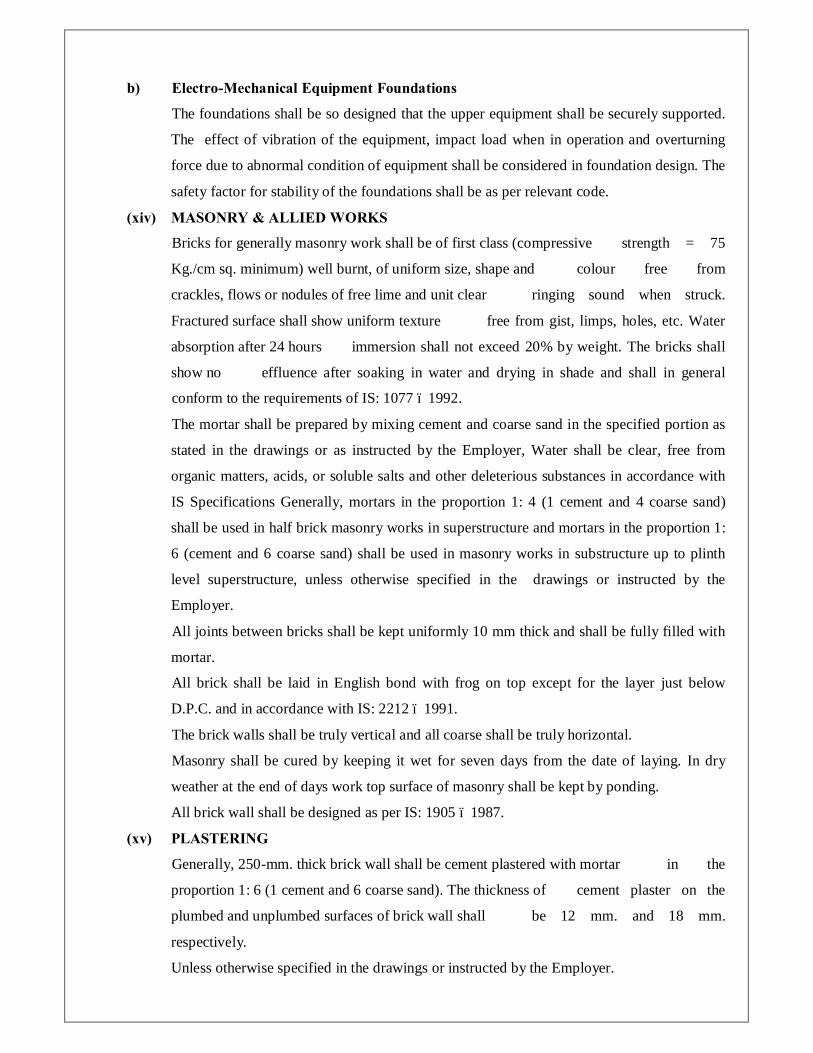
b) Electro-Mechanical Equipment Foundations
The foundations shall be so designed that the upper equipment shall be securely supported.
The effect of vibration of the equipment, impact load when in operation and overturning
force due to abnormal condition of equipment shall be considered in foundation design. The
safety factor for stability of the foundations shall be as per relevant code.
(xiv) MASONRY & ALLIED WORKS
Bricks for generally masonry work shall be of first class (compressive strength = 75
Kg./cm sq. minimum) well burnt, of uniform size, shape and colour free from
crackles, flows or nodules of free lime and unit clear ringing sound when struck.
Fractured surface shall show uniform texture free from gist, limps, holes, etc. Water
absorption after 24 hours immersion shall not exceed 20% by weight. The bricks shall
show no effluence after soaking in water and drying in shade and shall in general
conform to the requirements of IS: 1077 – 1992.
The mortar shall be prepared by mixing cement and coarse sand in the specified portion as
stated in the drawings or as instructed by the Employer, Water shall be clear, free from
organic matters, acids, or soluble salts and other deleterious substances in accordance with
IS Specifications Generally, mortars in the proportion 1: 4 (1 cement and 4 coarse sand)
shall be used in half brick masonry works in superstructure and mortars in the proportion 1:
6 (cement and 6 coarse sand) shall be used in masonry works in substructure up to plinth
level superstructure, unless otherwise specified in the drawings or instructed by the
Employer.
All joints between bricks shall be kept uniformly 10 mm thick and shall be fully filled with
mortar.
All brick shall be laid in English bond with frog on top except for the layer just below
D.P.C. and in accordance with IS: 2212 – 1991.
The brick walls shall be truly vertical and all coarse shall be truly horizontal.
Masonry shall be cured by keeping it wet for seven days from the date of laying. In dry
weather at the end of days work top surface of masonry shall be kept by ponding.
All brick wall shall be designed as per IS: 1905 – 1987.
(xv) PLASTERING
Generally, 250-mm. thick brick wall shall be cement plastered with mortar in the
proportion 1: 6 (1 cement and 6 coarse sand). The thickness of cement plaster on the
plumbed and unplumbed surfaces of brick wall shall be 12 mm. and 18 mm.
respectively.
Unless otherwise specified in the drawings or instructed by the Employer.

For sand and cement plaster, sand and cement in the specified proportion shall be mixed
dry on watertight platform and minimum water added to achieve working consistency.
Plaster when more than 12 mm. thick, shall be applied in two coats – a base coat
followed by the finishing coat. The base coat shall be allowed to dry and shrink before
applying the second coast of plaster.
The finished wall surface shall be true to plumb and the contractor shall without any extra
cost to the owner, make up any irregularity in the brickwork with plaster.
Before plastering all the mortar joints shall be raked out to a depth of at least 12 mm.
The exposed brick surface and the joints shall be thoroughly cleaned and washed
with clean water and should be kept wet for at least 12 hours before commencement of
plastering.
The plastering shall be started from top and worked towards the ground and ensure even
thickness and true surface. All corners edges and functioned shall be neatly finished.
All drips, grooves, moldings and cornices as shown on drawing or instructed by the
Employer shall be done with special care to maintain true lines, levels and profiles.
After plastering work is completed, all debris shall be removed and the area left clear.
All plastered surfaces after laying, shall be watered & curing done for minimum period of
seven days and shall be protected from excessive heat and sunlight by suitable approved
means. Moisturing shall commence as soon as the plaster has hardened sufficiently and not
susceptible to damage.
(xvi) FINISH
Wherever any special treatment to the plastered surface is indicated, the work shall be done
exactly as shown on the drawings, to the entire satisfaction of the Employer regarding the
texture, colour and finish.
Wherever punning is indicated, the interior plaster shall be finished rough. Otherwise, the
interior plaster shall generally be finished to a smooth surface. The interior surface shall
generally be finished with a wooden float.
Plastered surfaces, where an even smooth surface is specified, lime punning with 5 parts of
shell lime properly slaved, strained and aged, mixed with 1 part clean, washed, sieved,
strained volume shall be done. The thickness of lime punning shall be not less than 2 mm.
and more than 3 mm.
Materials for plaster of Paris punning shall be from approved manufacturers and approved
by the Employer. The thickness of the punning shall be 2 mm. and shall be applied by
skilled workmen. The finish shall be smooth, even and free from undulation, cracks, etc.
- E N D -
TECHNICAL SPECIFICATION FOR THE
TRANSMISSION LINE WORK
TRANSMISSION LINE WORKS
1.0 SCOPE-This chapter describes board guidelines for installations, testing and
commissioning of Transmission lines in OPTCL system in case of emergency and
also during normal work. The work shall, however, be carried out strictly as per the
instruction of the MANUFACTURER / EMPLPOYER.
2.0 SURVEY (detail & check, estimating of quantities & spotting of towers) 2.1 General: Preliminary route alignment in respect of the proposed transmission lines
has to be done by the contractor or been fixed by the employer subject to alteration of places due to way leave or other unavoidable constraints.
2.1.1 Provisional quantities/numbers of different types of towers have been estimated or to
be estimated and indicated/ to be indicated in the Activity Schedule given at the end of the specification. However final quantities for work shall be as determined by the successful bidder, on completion of the detail survey, preparation of route profile drawing and designing of the different types of towers as elaborated sin the specification and scope of work.
2.1.1.1 The contractor shall undertake detailed survey on the basis of the tentative alignment
fixed/ to be fixed by the employer. The said preliminary alignment may, however, change in the interest of economy to avoid forest and hazards in work. While surveying the alternative route the following points shall be taken care by the contractor.
(a) The line is as near as possible to the available roads in the area. (b) The route is straight and short as far as possible. ( c) Good farming areas, religious places, forest, civil and defense installations,
aerodromes, public and private premises, ponds, tanks, lakes, gardens, and plantations are avoided as far as practicable.
(d) The line is far away from telecommunication lines as reasonably possible. Parallelism
with these lines shall be avoided as far as practicable. (e) Crossing with permanent objects are minimum but where unavoidable preferably at
right angles. (f) Difficult and unsafe approaches are avoided. (g) The survey shall be conducted along the approved alignment only in accordance with
IS: 5613 (Part-II/Section-2), 1985.
(h) For river crossing: Taking levels at 25 metre interval on bank of river and at 50 metre interval at bed of river so far as to show the true profile of the ground and river bed. The levels may be taken with respect to the nearest existing towers, pile foundation of towers, base or railway/road bridge, road culvert etc. The levels shall be taken at least 100 m. on either side of the crossing alignment. Both longitudinal and cross sectional shall be drawn preferably to a scale of 1:2000 at horizontal and 1:200 vertical.
After completing the detailed survey, the contractor shall submit the final profile and
tower schedule for final approval of the employer. The final profile and tower schedule shall incorporate position of all type of towers. To facilitate checking of the alignment, suitable reference marks shall be provided. For this purpose, concrete pillars of suitable sizes shall be planted at all angle locations and suitable wooden/iron pegs shall be driven firmly at the intermediate points.; The contractor shall quote his rate covering these involved jobs.
Only approved sag template shall be used for tower spotting and the final profiles. 2.1.1.2 PROFILE PLOTTING AND TOWER SPOTTING
The profile shall be plotted and prepared to the scale 1 in 2,000 for horizontal and 1 in 200 for vertical on squared (mm) paper. If somewhere the difference in levels be too high, the chart may be broken up according to the requirements. A 10 mm overlap shall be shown on each following sheet. The chart shall progress from left to right for convenience in handling. The sheet size may be conveniently chosen.
With the help of sag template, final tower location shall be marked on the profiles and while locating the tower on survey chart, the following shall be kept in mind: (a) The number of consecutive span between the section points shall not exceed 10 in case
of straight run on a more or les plain stretch. (b) Individual span shall be as near as to the normal design ruling span. In different crossing the contractor shall take into consideration the prevailing
regulations of the respective authorities before finalizing type and location of the towers. While carrying out survey work, the contractor has to collect all relevant data, prepare and submit drawings in requisite number for obtaining clearance from the PTCC, road, aviation, railways, river and forest authorities.
The contractor shall remain fully responsible for the exact alignment of the line. If after
erection, any tower is found to be out of alignment, the same shall have to be dismantled and re-erected after corrosion by the contractor at his own cost, risk and responsibility, including installation of fresh foundation, if belt necessary by the employer.
After peg marking of the angle tower or tension towers, the contractor shall obtain
approval from the employer and thereafter pegging of suspension type tower shall be done by the contractor and pegging of all the four legs of each type of towers at all the locations shall be done.

2.1.1.3 SCHEDULE OF MATERIALS When the survey is approved, the contractor shall submit to the employer a complete
detail schedule of all materials to be used in the line. Size and length of conductor etc. are also to be given in the list. This schedule is very essential for finalizing the quantities of all line material. The contractor shall furnish the same.
2.1.1.4 CHECK SURVEY The contractor shall undertake the check survey during execution on the basis of the
alignment profile drawing and tower schedule approved by the employer. If during check survey necessity arises for minor change in route to eliminate way leave or other unavoidable constraints, the contractor may change the said alignment after obtaining prior approval from the employer.
The contractor, while carrying out the check survey, shall peg mark the power
position on ground conforming to the survey charts. In the process, it is necessary to have the pit centers marks according to the excavating marking charts to be prepared by the contractor and approved by the employer. The levels up or down of each pit center with respect to the center of the tower location shall be noted and recorded for determining the amount of earth work required to meet the design. At the charting point of the route survey, angle iron spite shall be driven firmly into the ground showing a little above the ground level.
2.1.1.5 WAY-LEAVE AND TREE CUTTING Way-leave permission which may be required by the contractor shall be arranged at
his cost. While submitting final-survey report for approval, proposals for way-leave right of way shall be submitted by the contractor. Employer may extend help to get the permission within a reasonable time as mutually agreed upon for which due notice shall be given by the contractor in such a way so that obtaining permission from appropriate authority do not hinder the continued and smooth progress of the work.
The employer shall not be held responsible for any claim on account of damage done
by the contractor or his personnel to trees, crops and other properties. The contractor shall take necessary precaution to avoid damage to any ripe and
partially grown crops and in the case of unavoidable damage, the employer shall be informed and necessary compensation shall be paid by the contractor.
In the event of any obstruction being encountered from local villagers or authorities,
the contractor shall immediately notify the employer who shall take steps, without any obligation to the contractor, as may be necessary, to clear the obstruction. The contractor or his representative shall not adopt antagonistic attitude towards the villagers or local authorities with whom employer for cases which cannot be settled amicably by them.
Trimming of tree branches or cutting of a few trees en-route during survey is within
the scope of survey to be done by the contractor. Contractor shall arrange for

necessary way-leave and compensation in this regard. During erection of the line, compensation for tree cutting, damage caused to crops, actual cutting and felling of the trees including way-leave permission for such route clearance shall be arranged by the contractor at his cost. The contractor will identify the number of trees and detail of obstructions to be removed for erection of the line and intimate the employer well in advance in case of any help. Other related works like construction of temporary approach roads, etc. as required, shall be done by the contractor and the same will lie within the scope of contractor’s work and such cost shall be considered to be included in the rates quoted by him.
While quoting the rate for detailed and check survey as per bidding activity
schedule, the contractor shall include all costs involved in different activities described herein earlier.
2.0 SUB-SOIL INVESTIGATION To ascertain soil parameters in various stretch inter, the contractor shall carry out sub-
soil investigation through reputed soil consultant as approved by the employer. 2.1 SCOPE OF WORK The scope of sub-soil investigation covers execution of complete soil exploration for
the transmission line under this contract including boring, drilling, collection of undisturbed soil sample where possible, otherwise disturbed samples, conducting laboratory test of soil samples to find out the various parameters as detailed in this specification and submission of detailed reports in 6 copies along with specific recommendation regarding suitable type of foundation for each bore-hole along with recommendation for soil improvement where necessary.
2.1.1 QUALIFYING REQUIREMENTS OF SOIL CONSULTANTS The soil consultants shall provide satisfactory evidence concerning the following as
and when asked for. That, he/they has/have adequate technical knowledge and previous practical
experience in carrying out complete soil investigation jobs in any kind of soil. That he/they has/have well equipped, modernized soil testing laboratory of his/their
own. If asked for by the employer, the contractor shall arrange inspection of such laboratory of the soil consultant by the representative of the employer.
If in the opinion of the employer, the soil consultant (proposed by the contractor) is
not well equipped or capable to undertake the sub-soil investigation job relating to this contract, then such soil consultant shall not be engaged to undertake the job. In that case, they shall have to engage other agency as will be approved by the employer.
2.1.2 TEST BORING The boring shall be done at the major locations/crossing, special towers if required by
the employer. However, it is desirable that there should be at least one sub-soil
investigation bore-hole for the line. Such locations for sub-soil investigation shall be selected and finalized in consultation with the employer.
The test boring through different layers of all kinds of soil shall have to be carried out
by the contractor through the approved soil consultant as briefed hereunder.
(a) Method of boring, selection of sampling tubes, sampling, recording of boring, protection, handling, leveling of samples shall be done as specified in IS: 1892/1977, if any, after obtaining approval from the employer. The contractor/consultant shall furnish in the soil report in details, the equipment and method of boring actually adopted.
(b) Depth of boring below ground level shall be 15 M. only unless continuous bedrock is
encountered earlier. In case rock is encountered at any depth within 15 M. adequate study of rock and assessment of strength characteristics shall be done and recommendation shall be given.
(c) Undisturbed soil samples shall be obtained for the initial 4M depths at every 1.5M
interval and at change of strata. After these initial 4M depths, samples shall be obtained preferably at every 3M or where there is a change of strata, or as advised by the employer.
(d) In case collection of undisturbed samples becomes difficult/impossible detailed soil
testing on remoulded soil samples is to be considered and reported in the soil report. (e) Standard penetration test as per IS: 2131 with latest amendment shall have to be
conducted in different strata and recorded properly. (f) The ground water table shall be recorded during boring operation and incorporated in
the bore log. If possible, the position of the water table just after monsoon period be ascertained from local people and indicated in the report.
(g) Plate Load test shall have to be conducted at special tower location. 3.0 LABORATORY TESTS OF SOIL SAMPLES
The method and procedure of testing of soil sample to be followed shall be as per relevant IS codes. Adequate volume of test samples shall be collected from site. Ample shall be properly sealed immediately after recovery as specified in relevant IS code and transported carefully to laboratory for carrying out necessary laboratory tests to find out the following parameters of every samples. Data and time of taking of the sample shall be recorded in the test report.
(a) Natural moisture content, Liquid limit, Plastic limit and Plasticity index. (b) Bulk, dry and buoyant density of soil. (c) Void ratio (e-long P curve shall be submitted) (d) Specific gravity. (e) Grain size distribution (Sieve analysis and hydrometer analysis) (f) Tri-axial and consolidation tests (consolidation undrained and consolidated drained as and when application in table, graph and drawing. (g) Permeability tests

(h) Chemical tests for both water and soil samples at different layers. (i) Evaluation of safe bearing capacity at different strata for square footings shall be done
for a maximum value of 25-mm. settlements. (j) At depts. From 3M to 10M be different strata. (k) Factor of safety shall be considered as 3 for evaluation of safe bearing capacity of soil. (l) Unconfined compression test for cohesive soil (=0) if encountered.
3.1 REPORT ON SUB-SOIL INVESTIGATION The contractor shall make analysis of soil samples and rock cores as collected by him
in the field and approved by the employer as collected by him in the field and approved by him in the field and approved by the employer as well as field tests and laboratory tests. A comprehensive report shall have to be prepared by him, finally incorporating all the data collected in proper tabular forms or otherwise along with the analysis.
The 3(three) copies of report in the draft form shall be submitted for employer’s
approval. 6(six) copies of final report incorporation employer’s comments, if any shall be submitted within 3(three) weeks after completion of this work.
Recommendations shall include but not be limited to the following items (a) to (p) (a) Geological information of the region. (b) Past observations and historical data, if available, for the area or for other areas with
similar profile or for similar structures in the nearby area. (c) Procedure of investigations employed and field and field as well as laboratory test
results. (d) Net safe bearing capacity and settlement computation for different types of foundations
for various widths and depths of tower and building. (e) Recommendations regarding stability of slopes, during excavations etc. (f) Selection of foundation types for towers, transformers and buildings etc. (g) Bore hole and trial pit logs on standard proforma showing the depths, extent of various
soil strata etc. (h) A set of longitudinal and transverse profiles connecting various boreholes shall be
presented in order to give a clear picture of the site, how the soil/rock strata is varying vertically and horizontally.
(i) Modulus of subgrade reaction from plate load test for pressure ranging upto 6 kg/cm. The recommended values shall include the effect of size, shape and depth of foundations.
(j) Deformation modulus from plate load test in various test depth/stratification. (k) Coefficient of earth pressure at rest. (l) Depth of ground water table and its effect on foundation design parameters. (m) Recommendations regarding stability of slopes, during shallow excavation etc. (n) Whether piles are necessary or not. If piles are necessary, recommendation of depth,
diameter and types of piles to be used. (o) Recommendations for the type of cement to be used and any treatment to the
underground concrete structure based on the chemical composition of soil and sub-soil water.

3.2 MEASUREMENT OF SOIL RESISTIVITY For the purpose of grounding design, soil resistance measurement shall be taken in the
locations as stated under clause 1.0 above and based on which the value of soil resistance shall be derived.
Wenner’s four (4) electrode method shall be used for earth resistance measurement in
accordance with the procedure and the calculation detailed in IS:3043 1987. At least 8(eight) test direction shall be chosen from the center of the locations to cover the whole site.
The employer reserves the right to carry out separate soil investigation at his cost by
engaging a separate agency for cross checking the result obtained by the contractor. In case the results are at variance, the soil parameters to be adopted for final design
will be at the sole discretion of the employer and such will be binding upon the contractor.
4.0 Foundation General Description 4.1 Design, construction and other relevant drawings shall be furnished by the tower
designer for all types of towers (including special towers) for different kinds of soil as detailed below. According to the locations foundations for towers shall be normally of the following types:
a) Soft/Loose Soil b) Hard/Dense soil c) Muddy soil d) soft / disintegrated rock e) Hard rock 4.2 For rock foundations the holes in rocks shall be made in an approved manner so as to
eliminate the possibility of serious cracking of the rock. The concrete block shall be properly secured to rock base by adequate no. of anchor bolts and further secured by concrete lodge section by the sides.
5 .0 ERECTION OF TOWER AND TOWER FOUNDATION 5.1.1 SCHEDULE OF ERECTION PROGRAMME After due approval of the detailed and check survey, the contractor shall submit to the
employer a complete detailed schedule of erection programme with a Bar-Chart for construction of the lines indicating therein the target date of completion.
5.1.2 DRAWINGS FOR TOWER AND FOUNDATIONS The same shall be supplied by the contractor.
5.1.3 TAKING OVER
Tower and tower accessories received at site stores are to be stored item-wise and mark-wise to facilitate joint inspection of the materials (with reference to packing list and detailed order). If the materials/equipment or any part thereof is damaged or lost during the transit, the replacement of such materials shall be effected by the contractor timely so as to maintain programme of work. However, the line under erection shall be taken over by the purchaser only when the entire line is completed in all respect and made ready for commissioning at rated voltage. Partly erected line will not be taken over. Taking over of the line shall be in no way relieve the contractor from his responsibility for satisfactory operation of the erected line in terms of the guarantee clause of the specification. 5.1.4 MATERIALS HANDLING AND INSURANCE The contractor shall deliver all equi9pment/materials against this contract to his site stores under cover of Transit Insurance to be taken in his name. Cost of such insurance is to be borne by the contractor. Cost of transportation of materials from contractor’s store to the site of work shall be borne by the contractor irrespective of made of transportation and site condition. The contractor has to bear the cost of premiums for all materials, tower accessories, total erection cost of the line including cement, torsteal for foundation. It will be the responsibility of the contractor to report to the concerned Police Station about all incidents of thefts and lodge, pursue and settle all claims with Insurance Company in case of damage/loss due to theft, pilferage, flood and fire etc. and the employer of the work shall be kept informed promptly in writing about all such incidents. The loss, if any, on this account shall be recoverable from the contractor if the claims are not lodged and properly pursued in time or if the claims are not settled by the insurance company due to lapses on the part of the contractor. The contractor shall have to replenish promptly damaged, stolen tower members and accessories conductors, earth wire, hardwares etc. and repair/re-erect the damaged lines, free of cost to the employer so as to maintain the programme of work. The employer will not be responsible in any way for such loss of materials.
4.1.2 EXCAVATION FOR FOUNDATION PITS, DE-WATERING AND SHORING SETS The contractor shall execute the open excavation job in the foundation pits in all type of
soil including latterite and or bounder mixed soil as detailed abelow including removing, spreading and/or stacking the excess spils (as directed by the employer). The item includes the necessary trimming of the sides, leveling, dressing and ramming (as necessary) the bottom of the pits including bailing out water, dewatering by manual and/or mechanical means by emplying water pumps including removing of slushes from foundation pits and nominal open plank shoring with vertical poling boards placed at suitable intervals as directed with required runners, struts, battens for framing as required complete. While quoting the unit rate for foundation as per the activity schedule, the contractor shall include cost of design, all cost of labour, materials, tools,

plants, incidentals for earth excavation, dewatering, cement, water, sand, coarse and find aggregates, steel reinforcement, steel angles, forms, mixing, finishing, protection and curing of concrete, back-filling with carried earth, if necessary, disposal of surplus, spoils, stub setting and template. The contractor shall also include in the quoted unit rate for foundation, all charges/costs for preparing the pit marking and foundation layout drawing, grounding of towers including supply of pipe/concrete pipe, earthing, measurement of ground resistance before often growing etc.
4.1.3 CEMENT CONCRETE (PLAIN OR REINFORCED), STUB SETTING
GROUNDING AND BACK FILLING A) Materials All materials whether to be consumed in the work or used temporarily shall conform to
relevant IS specification, unless stated otherwise, and shall be of the best approved quality.
B) Cement Cement to be used in the work under the contract shall generally conform to
IS:269/455-1989. Cement bags shall be stored by the contractor in a water tight well ventilated store sheds on raised wooden platform/dunnage (raised at least 150 mm above ground level) in such a manner as to prevent deterioration due to moisture or intrusion of foreign matter. Sub-standard or partly set cement shall not be used and shall be removed from the site by the contractor at his cost on receipt of approval from the Engineer.
C) Coarse Aggregates Stone chips or stone ballast 1.0 ERECTION: 1.1 Preliminary work: OPTCL has done the survey work. Two copies of key map, plan, profile drawings and
structure list, for the work covered by this contract shall be furnished to the contractor
after award of the contract. If no pillars will be available during execution of work, the
contractor should re-survey from angle point to angle point with free of cost. Only
check survey payment will be made.
1.2 Right of Way and Approach Road: (a) OPTCL will provide the necessary right of way by clearing forest and other obstruction
within the ROW. This will be done only once and the contractor shall maintain the
same for the entire period of contract. The contractor shall supply and install the
boundary posts on each side of the right of way at his own cost if it is required.
(b) Approach and construction roads: All existing roads, public roads for construction purpose shall be available for use of
the contractor. In case of private road, OPTCL will assist to get permission for use of
the same by the contractor. Approach roads to the tower location or to any other area
for construction of the line will have to be constructed by the contractor at his own cost.
In case extra amount towards head loading will be paid by OPTCL.
The OPTCL will only offer assistance for approach to the areas/locations demanding
intervention by law and other authorities. But all costs for construction of these roads,
payment towards royalty or rental charges, compensation etc. if any shall be borne by
the contractor in respect of approach roads and private roads. The contractor shall
provide and maintain during the entire contract period all access roads connecting to
existing public road system. All local taxes including royalty etc. should be borne by
the contractor.
( c) Jungle clearance: OPTCL would obtain forest clearance where necessary. There after the contractor
would complete clearance along the entire route covering the forest at their cost before
commencement of the work. This expenditure should not be construed as compensation
to be given by OPTCL
( d ) Erection notice: Erection notice shall be given by the contractor to the Engineer-in-charge wherever
required. In case of erection to be carried out across power, telephone lines or public
roads, water ways, canals etc., the Engineer-in-charge shall however furnish the
required drawings of the crossing for the purpose, minimum sixty days in advance to
contractor.
a. All necessary care shall be taken by the contractor to avoid damage to crops and trees
or properties while executing this contract. Un-avoidable cases shall be brought to the
notice of the Engineer-in-charge who will render necessary assistance to enable him to
proceed with the work. Whenever work is carried out under such circumstances, any
extra cost arising out of loss/damage to crops, trees, properties etc. shall be borne by the
contractor.
1.3 EARTH WORK FOR TOWER FOUNDATIONS: General Requirements:-The contractor shall provide all tools, plants, instruments, qualified supervisory personnel, labour materials, any temporary workers, consumables, and everything necessary, whether or not such items are specifically

stated herein, for completion of the project in accordance with specification requirement.
The excavation shall be done to correct lines and levels in accordance to the design
and drawings. This shall also includes, where required, proper shoring to
maintain excavations and also the furnishing, erecting and maintaining of substantial
barricades around excavated areas and warning lamps at night for ensuring safety of
lives and property.
(a) Scope also includes for dumping of excavated materials in regular heaps, bunds, rip rap
with regular slopes as directed by Engineer-in-charge within the lead specified and
leveling the same so as to provide natural drainage. Rock/soil excavated shall be
stacked properly all softer materials shall be laid along the center of the herpes, the
harder and more weather resisting materials forming the casing on the sides and the top.
Rocks shall be stacked separately.
(b) The area to be excavated /filled shall be cleared of trees, plants, stumps, bush,
vegetation rubbish etc. and other objectionable matter. If any roots or stumps or trees
are met during excavation, they shall be removed as directed by Engineer-in-charge.
(c) The contractor shall duly preserve all minerals archeological and other findings of importance, trees cut or precious stones during excavation.
1.4 Classification of soil is to be done by Engineer-in-charge as indicated
below: (i) Soft/Loose Soil: These shall include all kinds of soils containing Kankar, Sand, Silt and are removable
by ordinary pick axes, shovel and spade and which is not classified under “Dense/Compact” “soft dis-integrated” and “Hard Rock” category as defined below:
(ii) Dense/Compact Soil: Spoil removable by pick-axe, crowbar etc. Moorum or shingle, gravel, clay, loam peat
etc. (iii) Soft & Decomposed/Dis-integrtated Rock: This shall include rock, boulders, shale, chalk, slate, hard mica, schist, laterite and all
other materials which in the opinion of the Engineer-in-charge is rock, does not need
blasting and could be removed with picks, hammer, craw bars, wedges and pneumatic
breaking equipment. This shall also include rock boulders not longer than one metre in
any direction and not more than 500 mm in any one of the other two directions.
(iv) Hard Rock:- This shall include all rock occurring in continuous masses which cannot
be removed except by blasting for loosening it. Harder varieties of rock with or without
veins and secondary minerals, which in the opinion of the Engineer-in-charge require
blasting, shall be considered as hard work.
(v) Sub-merged Soil:- Where the subsoil water table is encountered within the range of
foundation depth, the soil below the water table and that at locations where pumping or
bailing out of water is required due to presence of surface water will be treated as wet
soil. Soil partially submerged and fully submerged shall also come under this category.
In case of pile foundation is submerged soil, the required sand filling should be done by
the contractor by his own cost.
(vi) Where soil at a tower foundation is of composite nature, classification will be according
to the type of soil, which is preponderant in the footing and the rate for the same will
apply for the composite foundation. The decision of the OPTCL Engineer-in-charge
shall be final and binding with reference to classification of soils.
(vii) All surplus excavated soil alongwith left over gradients if any “should be removed from
work site and dumped at any suitable place in such a manner that the landowner will
not object. A thin layer of nearly 200mm of surplus earthy can be stacked over the
excavated pits for future compaction”.
(viii) Standard penetration test to be carried out for long line one in ten support sites.
All organic or other foreign materials shall be removed from back fill earth. The earth shall be deposited in maximum 200mm. Layers, leveled and watered and rammed properly before another layer is deposited. The back filling should be such that enough moisture would be available for curing of the concrete embedded. Sufficient water shall be poured over the back filled earth for proper consolidation. All surplus excavated soil shall be stacked around the tower legs. In case of wet locations, de-watering, shoring and shuttering etc. if required shall be paid for based on unit rates indicated. The actual quantity shall be as approved by the Engineer-in-charge. The shoring and shuttering is to be done by very good quality planks and supports as approved by Engineer-in-charge.
2.0 Stub-Template setting, concreting of stubs and copping: (i) The stub shall be set correctly in accordance with approved method at the exact
location and alignment with the help of stub setting templates to be supplied by
OPTCL. The levels and alignment shall be checked and approved by Engineer-in-
charge for which adequate advance intimation shall be given by the contractor. The
approval shall not, however, relieve the contractor of his responsibility of correctness of
setting.

(ii) The bottom of the pits shall be free from loose earth and shall have about 150mm.
Thick layer of sand or a lean concrete [1:4:8] mat of required, before stubs are set for
concreting. The concrete shall be as specified in relevant I.S.S. for such work or as
directed by the Engineer-in-charge. It shall be 1:2:4 mix with proper quality of sand,
cement and granite ships as stated below: The concreting of stubs shall not be made in
parts and it should be a continuous process till completion. Foundations for black
cotton and sandy soil shall require reinforcement, as per approved drawings. In no case
the bottom most portion clits of stub should be more or less than 75mm from the
bottom finished level.
(iii) Concreting: (A) Sand:- The said to be used for concreting shall be coarse and from available local river
beds freed from clay or other undesirable materials like dust, lump, loam, mica, saline
and other deleterious substances.
(B) Coarse Aggregate:- The coarse aggregate to be used shall be of broken granite
rock/broken stone/river shingle varying in size from 20mm. To 40mm. to be approved
by the Engineer-in-charge [provided the resultant concrete shall meet the requirement
of IS:456-1964 M150 quality.
(C) Water:- Clear non-saline, free from oils, acids alkalis and organic materials water from
river tanks, well shall be used in concreting.
(D) Concreting:- The stock/condition of cement will be subject to inspection by the Engineer-in-charge at any time and at the time of use in the work.
For reconciliation of cement account, consumption of cement shall be considered as
under: 1:2:4 Mix. - 330kg/cum 1:3:6 Mix 225kg/cum 1:5 cement mortar- 87kg/cum 1:4:8 Mix. - 115kg/cum Mixing, Placing and Compacting of Concrete: The concrete shall be mixed properly, either in a mechanical mixer so as to ensure
proper consistency and strength. Normally, mixing shall be done close to the
foundation, but in case it is not possible the concrete may be mixed at the nearest
convenient place and shall be transported to the place of final deposit as rapidly as
practicable to prevent segregation or loss of ultimate quality/strength. The use of
vibrator during concreting is must.
The contractor shall provide equipment and shall maintain and operate the equipment
as required to accurately determining and control the amount of each separate
ingredient entering the concreting mixture. All batches of concrete mixture shall be
proportioned on the basis of integral sacks of cement unless the cement is weighed.
The amount of sand and each size coarse aggregate entering each batch of concrete
shall be determined by weighing and the amount of water shall be determined by
volumetric measurements. The concrete ingredients shall be mixed in a batch of
mixture for not less than two minutes after all the ingredients are in the mixture. In no
case head loading of materials, concrete mix etc. will be paid.
(iv) Before laying the concrete the stub shall be cleaned of rust, scale, mud etc with a steel
wire brush. The method of placement of concrete shall be such as not to result in loss of
workability or in segregation of concrete mix.
(v) In wet locations, the site must be kept completely dewatered, both during the placing of
the concrete and for 24 hours thereafter to protect the concrete from water during this
period.
(vi) Reinforced Cement Concrete:
The reinforcement steel, including pile foundation wherever required to be provided in
the cement concrete foundation, shall be supplied by OPTCL/ The Contractor as per
terms and conditions of the schedule. The steel reinforcement bar shall be fabricated
and placed in the position while concreting as shown in the approved foundation
drawing or as directed by the Engineer-in-charge. Before the steel reinforcement bars
are placed in position, the surface of the bars shall be cleared of rust, scale, dirt, grease
or other objectionable foreign substance.
The bending and fixing of bars for concrete reinforcements shall conform to S:2502/
1963 and IS: 5525/1969. Sufficient concrete coverage as indicated in the foundation
drawing or as per relevant ISS, where not shown in the drawing, should be provided.
(vii) Form Box:- Form box made out of steel sheets to confine and shape the concrete to the
required lines as shown in the foundation drawing shall be used. The form boxes shall
have sufficient strength and rigidity to hold the concrete and to withstand the necessary
pressure during concreting while nosing vibrator without deflection and allow the
desired finish to the concrete surface. The form boxes shall be procured by the
contractor in adequate number to allow smoothly working of the schedule of
construction. In any case shutters will be required, the contractor should provide at his
own cost.
(viii) Removal of form box and finishing of concrete:-
(a) Form boxes shall be removed not less than 24 hours after or as approved by the
Engineer-in-charge provided the concrete in sufficiently strong not to be injured
thereby. They shall be removed carefully so as not to damage the formed surface of the
concrete. On removal of the forms, the surface exposed shall be carefully examined.
(b) All honeycombed concrete exposed in the face shall be removed by chiseling to a
sufficient depth and refilled/repaired with appropriate mix of concrete or mortar ( the
mix should be richer than the concrete use, the extra cement to be used is of
contractor’s cost) as may be decided by the Engineer-in-charge. This should be done as
quickly as possible.
(ix) Copping:- After completion of back-filling the coping over the top surface of the
chimney shall be done as per the approved foundation drawing with 1:2:4 concrete with
a slight slope towards the outer edge to drain off any rain water falling on the coping.
The coping shall have a smooth and geometrical finish. In no case the height of copping
more or less than 350mm above the actual ground level.
(ix a) Black Bitumen paint of 2 coat of a length 400mm above the copping should be
provided by the contractor by his own cost.
(x) Curing:- Full care should be taken for curing of the concrete exposed over ground by
any conventional method. 10-14 days curing is required depending on weather and
location. The concrete under ground is expected to be cured from the moisture in the
backfill earth.
5.6 Earthing:- Every tower shall be suitably earthed so that the tower footing resistance
does not exceed 5
5.7 Ohms. Depending on the earth resistively of soil it is to be decided by the Engineer-in-
charge whether pipe type earthing or counterpoise earthing is to be provided, details of
which shall be indicated in the approved drawings. The earth electrode shall be 50mm.
dia 3 mtr. Long medium gauge GI pipe. The contractor shall supply 30 kg. of common
salt and 30 kg. Charcoal for each earth pit.
5.8 Protection of tower footing:- The work shall include all necessary RRHG stone or
brick revetment and earth filling above foundation level as decided by the Engineer in
charge. The rates; shall be given in the offer. In case of lower most pit is more than
750mm from the center of tower. The retaining wall may be provided less than the
above value, dry packing with excavated soil with grass patching to be made free of
cost. In case of location near nala, ditch if any RRHG masonry may be made for
protection of tower fittings.
5.9 Erection of superstructure with accessories:- (i) The super structure shall be erected as per approved structural drawings to be furnished
by the OPTCL. All members shall be carefully handled during transport and erection so
that the galvanizing is not scratched and the interior steel not exposed. In storage and at
tower site all tower steels shall be kept clear of the ground in a clean and tidy condition.
Contact with brackish water or other substances likely to attach galvanizing shall be
avoided. All superficial rust stains, corrosive salts and other corrosive foreign materials
deposited prior to or during installation of the tower shall be removed without causing
damage to the protective surfaces. Towers shall be erected in a workman like manner
and tower members shall not be strained or deformed during course of erection.
(ii) The method followed for the erection of towers shall ensure the points mentioned below:
(a) Straining of the members shall not be permitted for bringing them into position. It may,
however, be necessary to match hole positions at joints and to facilitate this, Tommy
bars not more than 450 mm. long may be used.
(b) Before starting erection of an upper section, the lower section shall be completely
braced and all bolts provided in accordance with approved drawings.
(c) All plan diagonals relevant to section of tower shall be placed in position before assembly of upper section is taken up.
(d) All bolts will have their bolt heads facing outside/inside of the tower as convenient, for
horizontal or nearly horizontal bolt connection and upwards for vertical bolt
connections.
(e) Slings and other equipments used for picking up members, portions of towers or
complete towers, shall be protected in such a manner as to prevent cuttings into the
corners of members, damaged the finish or portions of towers shall be raised in such a
manner that no dragging on the ground surface or against portions of the towers already
erected will occur.
(iii) Normally three types of towers will be used viz: ‘A’, ‘B’ & ‘C’ types or A,B,C and D type towers shall be used where ever required.
‘A’ Type – For straight runs and angles upto 2-degree deviation. ‘B’ Type – For angle upto 30 degree. ‘C’ Type - For angles above 30 degree and to 60 degree
Besides the above type of towers there will be special towers for river crossing. Any other towers that may be required will be specified during execution.
(iv) The method of erection is left to the contractor subject to his responsibility for any
damage done to the materials due to any cause. The erection of towers should not be
started earlier than 15 days after back fill of the stubs so that there is no disturbance or
damage to the concrete and also to allow it to acquire its full strength. Approval of the
Engineer-in-charge to start erection work shall be obtained. After the final tightening of
bolts and nuts the treads shall be punched so as to prevent loosening under temperature
changes or vibrations. The towers must be truly vertical after erection and no straining
will be permitted to bring them so. Towers shall be so erected that the vertical axis
through the center of the gravity shall not be out of plumb by more than one centimeter
for every 500 centimeter of height.
(v) Tightening and punching of bolts and nuts:- All nuts shall be tightened properly
using correct size spanners or torque wrenches. Before tightening, it shall be seen that
filler washers and plates are placed in relevant gaps between members bolts of proper
size and length are inserted under each nut and in case of steps bolts, spring washers
have been paced under the outer nut. The tightening shall progressively be carried out
from the top down wards and checked back from bottom upwards before punching care
being taken that all bolts at every level are tightened simultaneously. The minimum 3
thread should be projected after final tightening. After final tightening the projected
thread should be riveted by using hammer.
In the complete tower, the nuts for bots shall be tightened to the following torque. Size of bolts. Tightening torque
12 mm 600-800 kg-cum 16 mm 1000-1200 kg-cum 20 mm 1400-1800 kg-cum 24 mm 2000-2500 kg-cum
(vi) Fixation of insulators and hard wares:- Insulators shall be handled carefully in all stages of handling and be individually
checked for cracks, damage, and loss of glaze etc. before assembly and erection at site, which shall be according to the drawings approved by OPTCL. The rigging and hoisting of insulator strings shall be done very carefully so that no damage is caused to the insulators and hard wares. Discs with hairline cracks and chips and also those having glazing defects exceeding ½ cm sq. shall not be used. At all major high ways, Main River and utility line crossing double string of insulators shall be used. The contractor shall inspect insulators he draws from the OPTCL stores and satisfy himself to their soundness. If insulators issued to the contractor are later found to be scratched

or damaged is recoverable from the contractor at the then market price. Cost of damaged or scratched or lost prices as claimed by the Engineer-in-charge shall be final.
5.9 (i) Handling Transportation:- Care shall be taken during handling and transportation of reels of conductor to ensure no damage to reels and conductors.
(ii) Stringing Plan:- Not later than 2(two) months before commencing installation work
the contractor shall submit the stringing plan to the Engineer-in-charge for approval.
The plan shall describe the work schedule method of stringing, temporary guying,
scaffolding, personnel required in performing the work and list of tools and equipments
to be utilized.
In addition not later than 2(two) weeks before commencing string work of any
section of the line, the contractor shall submit the detail of unreeling section location
of reel, which, temporary guying scaffolding and length of conductor to be strung
to the Engineer-in-charge for approval.
(iii) Tools and equipments:- Tools and equipment shall be inspected at the site by the Engineer-in-charge after the approval of the stringing plan but prior to commencing the stringing work.
(a) Snatch Blocks:- Snatch blocks shall be designed especially for stringing the conductors and shall have groves of a shape and size to allow easy flow of conductor and ensure damaged free operation. The sheaves shall be equipped with high quality ball or roller bearings. The materials of the sheaves shall be aluminium alloy or material, lined with bonded neoprene or equivalents approved by the Engineer-in-Chief. The sheaves shall have free and easy movement in the blocks and be free of any damage to the conductor contract surface. Sheaves which do not run freely or which hinder the stringing operation shall be immediately replaced.
(b) Reel Stands:- Reel stands shall be heavily constructed and provision shall be made for braking the reels.
(c) Come – Along clamps:- Come- along clamps shall be of the automatic type that can be installed anywhere on the conductor to grip it more firmly when the holding power grows automatically as the tension of the conductor thereby increases.
(d) Compressors for joints and Dead-end Connector Assembly:- Suitable hydraulic compressors equipped with pressure gauge and dies shall be used for midspan tension joints and compression dead-end connector assemblies of the conductor.
(e) Lead Lines:- Lead lines shall be made of steel or manila rope or nylon or other material approved by OPTCL.

(f) Power Puller:- The power puller shall have capacity of not less than the maximum stringing tension of the conductor, puller should have powered winch with transmission gear for changing speed during stringing work.
(g) The suitable capacity dynamotors should be used during stringing for measurement of tension load, besides this sag boards should also provided during stringing operation. A separate register should be maintained during stringing in which the stringing stretch temperature, equivalent span, tension load, position of sag board in towers, ground clearance should be recorded and signed.
(iv) Scaffolding:- The contractor shall be responsible for acquiring permission to execute the work from administrators of facilities over which the transmission line is to pass, such as roads, railways, communication lines and power distribution lines.
The contractor shall, at his own expenses, provide suitable scaffoldings for the above purpose as well as at places where his work may inner injuries or damage to persons, livestock or third party property.
The scaffolding shall be sufficient strength to withstand wind pressure, vertical loads
and all other loads which may be anticipated, and shall be of such structure as to
prevent the conductor from coming within 7 mtr. from road and 1 mtr. from
telecommunication and distribution lines of upto 33 kV during unreeling of the
conductor. The scaffolding itself shall also have the above-mentioned clearance both by
Engineer-in-charge and by contractor or his authorized representative. The Xerox copy
of the above data should be furnished alongwith utilization certificate with JMC during
submission of bills failing which in any of the above, the bills will not be accepted.
(v) Conductor stringing:- Stringing of conductor shall, in no case be performed until
28(twenty-eight) days after concrete foundation has been completed and until assembly
and tightening of bolts of towers had been completed and inspected by Engineer-in-
charge. The stringing is to be done by the following methods.
(a) Moving real method.
(b) Lead lines method.
(c) Controlled tension method, for which the contractor shall have to specify to EIC.
Stringing of conductor and related operation shall be performed during day light hours.
Particular care shall be taken at all times to ensure that the conductors do not become
linked, twisted or abraded in any manner. The conductor shall not be dragged over the
ground, water rocks, fence wire or any object which may damage the conductor.
Suitable guards or sleeves or running wood rollers shall be used to protect the
conductor from damage in places where it would otherwise be in contact with objects
which may injure the conductor. Guards shall consist of materials over which the
conductors may slide without injury and shall be subject to the approval of the
Engineer-in-charge.
If the conductor is damaged by the contractor during operations, the contractor shall
repair or replace the additional materials, in a satisfactory manner and at no additional
cost to the Engineer-in-charge. All sections of the conductors damaged during stringing
work shall be repaired or replaced before the conductors are sagged in place. The
snatch blocks when suspended on the towers for sagging shall be so adjusted that the
conductor will lie in the sleeves at the same level as the suspension clamps to which
the conductor is to be secured. Any conductor found damaged due to mishandling by
the contractor or excess conductor found as scrap than the recommended by OPTCL/
erstwhile OSEB will be recovered from the contractor’s bills.
(vi) Jointing and repairing of conductor:- Jointing of all conductors shall be performed as
nearly as practicable at the same position. Tension sleeves, line splices, repair sleeves
and patch rods shall be installed to the conductor in accordance with the
recommendations of the manufacturers. All compression joints shall be filled and
finished with emery cloth to produce a smooth surface, free of flash and sharp points
which might be source of corona or radio interference. The contractor shall furnish all
necessary tools including compression tools required for installing tension sleeves, line
splices, repair sleeves, repair sleeves and patch rods. Anticorrosive paint should be used
over steel compression joint.
All conductor joints and repairs shall be located in the span at least 30 m. away from
suspension clamp or tension clamp or compression dead-end. The minimum distance
between two joints shall not be less than 600m. unless otherwise directed by the
Engineer-in-charge. No conductor shall contain more than one joint or repair in any one
span.
Jointing and repairing shall not be permitted in single span of tension towers and crossing and adjoining the following objects.
(1) Highways. (2) Rail rods. (3) Rivers and major canals. (4) Public utility lines.
(5) Telecommunication lines.
In addition conductor jointing and repairing shall conform to the following requirements.
Jointing of Conductor:- Jointing shall not be performed in the rain or in t he dark.
Jointing shall be performed by a method approved by the Engineer-in-charge using
approved tools and equipment. To develop rated mechanical strength and electrical
conductivity, the installation of compression joint shall be carefully supervised to
ensure that the sleeves are centered properly.
(A) Repairing of Conductor:- Compression type repair sleeves or patch rods may be used to repair minor damage to the conductor, provided that:-
(i) There is no broken strand.
(ii) Not more than one-third of the strands in the outer layer are damaged over a length or not more than 10cm. and
(iii) The cross sectional area of any of the strands is not reduced by more than 25 percent. Each such repair shall be subject to the approval of the Engineer-in-charge.
(iv) (iv) Sagging of conductor:- All conductor sagging shall be performed during day light
hours. Sagging operations shall not be permitted during high wind, or other adverse
weather conditions, which would impair the accuracy of the sagging. The conductor
shall be installed in accordance with the sag and tension tables furnished by the
Engineer-in-charge. After being pulled into the sleeves the conductor shall not be
allowed to hang in the snatch blocks for more than 48 hours before being pulled to the
specified sag. The length of conductor sagged in one operation shall be limited to the
length that can be sagged satisfactorily. After the conductors have been pulled to the
required sag, intermediate spans shall be checked to determine the sags are correct.
Where the distance between tension type towers is good great to permit the conductors
to be sagged in one operation, temporary intermediate dead-end shall be established. In
case of continuous stringing method, the over tensioning as approved by PMU OPTCL
may be used. In case of air conventional method pre-tensioning.
Measurement of Sag:- For several spans in each sagging section, the sag shall be measured selecting one near each end and one or two near the center. The total number of spans to be measured shall be as follows:
Sagging Section Span Number of Measurement 1
2 3
16 or more 4
The sag of all spans in excess of 500m. shall be measured. At the sharp vertical dip
angle spans, the sag shall be measured on both sides of the angle. The contractor
shall provide suitable dynamometer, sighting boards, the ode light and other suitable
devices to measure sagging as well as thermometers to measure the ambient
temperature to determine the conductor sag. Dynamometers are to be tested and if
necessary recalibrated.
(B) Tolerance of Sag:- A tolerance of plus or minus 15m in the sag in any one span will be permitted, provided that:-
(i) The maximum difference in sag between the phases in any span shall not exceed 15cm.
(ii) The necessary ground clearance is obtained at the stringing ambient temperature.
(iii) The conductor tension between successive sagging operations is equalized so that the suspension insulator assemblies will hang in the vertical position in the transverse plane of the tower when the conductor is clipped-in.
(C) Measurement of sagging temperatures:- The conductor or overhead ground wire temperature shall be determined by mounting one thermometer at every sag span. The thermometer shall be exposed to the full sun in free air for correct temperature reading.
(vii) Clipping-in of-conductor:- the contractor shall clip the conductor in after the
conductors have been sagged in accordance with these specifications, drawings and
stringing data. After being sagged, all conductors shall be accurately marked for
clipping at all structures on the same day that the conductors are sagged. Slipped in
marks shall be made on all conductors in the vertical plane thorough the transverse
centerline of the tower line of the tower at the time of clipping in.
The total time, which the conductor is allowed to remain the snatch blocks before eing clipping in, shall not exceed 72 hours.
After clipping in the contractor shall check to ensure that all bolts, nuts, cotter keys,
snatching of conductors at any point corona generation after each compression joint,
the sharp edges of joints should be made smooth by using suitable file or emery paper
in order to avoid corona generation and all items of insulator assemblies are installed
as required to avoid any point corona generation.
It if becomes necessary to change the point of attachment of the suspension
clamp by moiré than 7 cm on either ways from the mid point of the Armour rods after
they are installed, the rods shall be removed and installed so as to center on the point of
attachment. Under such circumstances the Armour rods may be re-used if not damaged.
The contractor will not be allowed any additional compensation for such removal, re-
installation, or replacement of Armour rods where required.
5.10 Stringing of overhead Ground wire:-
(i) General:- The overhead ground wire(s) shall be strung for the entire length of the transmission line, and shall be attached to the towers in accordance with the details same as for conductor(s). The equipment, methods, and limitations used for installing the overhead ground wire shall be the same as for installing the conductor.
(ii) Stringing of overhead ground wire:- The overhead ground wire shall be strung in advance of the conductors, and the method shall be the same as for conductor string. The same degree of care shall be exercised to avoid damage or injury of the overhead ground wire. If damaged, the contractor in a manner approved by the Engineer-in-charge shall replace them.
(iii) Jointing of overhead ground wire:- Compression type joints and clamps shall be installed in accordance with the printed instructions of the manufactures.
Galvanized tension sleeves shall, after jointing, be coated effectively with an approved rust preventive paint and shall further be furnished with a repair coat of paint after final passage through snatch blocks.
(iv) Sagging of overhead ground wire:- After being sagged, the overhead ground wire shall be clipped in the same manner as for conductor. Suspension clamps of overhead ground wire shall be installed in such a manner that earthling bond wires shall all face a given direction. The ends of bond wires shall be clamped with terminal clamps in an approved manner. In no case the sagging of the ground wire will be more than the conductor sag. The mid-span clearance between ground wire and power conductor should be more than the clearance near the tower in order to avoid flashover during lightening surge.
(v) Clipping in:- The same as conductor.
5.10.1 Fixing of conductor and ground wire accessories:- Vibration dampers and other conductor and ground wire accessories shall be installed by the contractor as per the design requirement and as per the respective manufactures instruction. Dampers shall be fastened securely, so that all dampers will hang in vertical planes. Vibration dampers shall be installed within 24 hours after the conductor has been clipped in.
5.10.2 Fixing of tower accessories:- All towers accessories such as anti climbing devices phase plate, number plate, danger plate etc. hall be fixed in an approved manner. The bird guard should be fixed in all X arms of tangient tower at the time of erection of tower.
5.10.3 Special works:- Special works which are not within the scope of this contract but come up during the execution of the works shall be carried out by the contractor at mutually agreed methods and rates to be decided before the commencement of such works.
5.10.4 All nuts upto the bottom cross arm shall be welded continuously to the bolt by the contractor using his own welding rod and skilled welder as per schedule of quantity.
6.0 SUPERVISION OF WORKS:- All the different phases of erection of transmission line shall be carried out in presence of the OPTCL Engineer-in-charge or his authorized representative, to his satisfaction. Necessary facilities are to be extended to him by the contractor to carryout the supervision of work.
7.0 PROGRAMME AND PROGRESS OF WORKS:- The bidder shall submit a detailed erection programme along with bid to match the
desired erection schedule. The program shall indicate all the necessary points including the followings:
(a) Number of batches to be deployed for each phase of erection work, i.e. survey
excavation, concreting, superstructure erection, stringing etc. (b) Number of qualified engineer, technicians and skilled workers to be engaged in each
batch. (c) Number of vehicles to be deployed. (d) Number of storing places, propose4d to be used. (e) Details of the equipments, proposed to be used in different phases of erection. (f) Anticipated progress of each batch in each phase of erection for different sections
terrains of execution.
8.0 Failure to abide by program of work and penalties:
8.1 The time allowed for carrying out the work as per program the contractor shall strictly
observe set out in the agreement. The work shall throughout the stipulated period of
contract be processed with all due diligence, time being the essence of the contract on
the part of the contractor. If the contractor at any stage of the program fails to complete
the work, the OPTCL shall be at liberty to adopt any one of the following courses after
sending written notice to the contractor.
(a) To employ labour paid by the OPTCL, to supply materials to carry out the work or any
part of the work debiting the contractor with the cost of labour and price of the material
and crediting him with the value of work done in all respects, in the same manner and
at the same rates as if it has been agreed out by the contractor under the terms of the
contract, and in that case, certificate of the Engineer-in-charge as to the value of the
work done being final and conclusive, against the contractor.
(b) To order the work of the contractor be measured and to take such part thereof, as shall
be unexecuted out of his hands and to give it to another contractor to complete the same
in which case any expense which may be incurred in excess of the same, which would
have been paid to the original contractor if the whole work had been executed by him
[as to the amount of which excess expense, the decision of the Engineer-in-charge shall
be final and conclusive] shall be deducted from any money due to his by the OPTCL
under the contract or otherwise from his security deposits, performance Bank
Guarantee.
(c) To allow the original contractor to continue the work, levying a penalty of half percent
per week subject to a maximum of 5(five) per cent of the contract value of such portion
remaining uncompleted within the stipulated period of completion.
(d) The levy of penalty is however, exempted when the extension of time is granted for the execution of the work.
Accounting of materials and return of surplus materials: The contractor shall maintain a running account of the materials received from the
OPTCL and their deployment. He shall submit such account to the Engineer-in-
charge every month after completion of the work, the contractor shall render the final
account of the materials received, materials used and permissible wastage as per clause
and return all the surplus materials in good condition at the nearest nominated OPTCL
stores. The OPTCL Engineer-in-charge shall have the right to inspect the site stores and
site materials account of the contractor without prior notice.
Unaccountable wastage:- The contractor shall make every effort to minimize the
breakages, losses and wastage of the line materials, supplied by the OPTCL during erection.
However, the contractor shall be allowed un-accountable wastage and losses during
erection not exceeding the percentage noted against each item below. The percentage
will be applicable on the quantities of materials supplied by the OPTCL.
1. Insulators - 1%
2. Conductor - 0.5% [inclusive of 0.2%
allowance, for increase in length due to sag]

3. Ground wire - 0.5% [inclusive of 0.2% allowance, for increase in length due to sag]
4. Fasteners and washers - 1%
5. Accessories for conductor Ground wire and insulators.
- 0.5%
6. For scrap ( both conductor and hardware) - 0.5%
Recovery of cost of materials:- Materials issued to the contractor and lost or
damaged noticed later shall be charged to him and its value at the prevailing market
rates as determined by the Engineer-in-charge shall be paid by the contractor within 30
days of notice issued by the OPTCL or will be recovered from his bills.
Empty cement bags and conductor drums shall not be returned to OPTCL but shall
be retained by the contractor. The contractor will pay the cost of these items at the
following rates to OPTCL.
1. Empty cement bags Rs.2.00 each 2. Empty conductor and earth wire drums Rs.250.00 each
9. RESTORATION/SHUTDOWNWORKS: Whenever required the
restoration/shutdown work to be carried out on emergency basis round the clock for
which incentive will be paid in shape of extra labour and mobilization charges over and
above normal rates as per actual work done. Bidders are requested to quote for the
above purpose in their price bid.
10. FIELD TEST OF ELECTRICAL EQUIPMENT After the completion of individual adjustments and tests of each equipment during
installation and upon all equipment being ready for operation, the Contractor shall
carry out the field tests, but not limited to those listed hereinafter, in the presence of
EIC.
10.1 ITEM OF FIELD TESTS
1. Measurement of insulation resistance
2. AC withstand voltage test
10.2 REQUIREMENTS FOR FIELD TESTS
The field tests shall be carried but in presence of Engineer in charge under the
following conditions:
10.3 Engineer in charge will make available power at 400/230 V, 50 Hz at one point for
carrying out the tests under this chapter. If power is required at other source and place,
the contractor will make his own arrangement.
10.4 AC withstand test voltage for conductors and outdoor equipment shall be normal
operation voltage of the transmission lines and withstand voltage test shall be carried
for ten (10) minutes by the normal voltage mentioned above.
10.5 The field tests shall be carried out, be the Contractor after measurement, adjustment and
individual tests of all the equipment have been completed.
10.6 The Contractor shall provide expendables and lead wires and other materials required
for the field tests. The Contractor shall be responsible for providing all measuring
instruments and tools required for the tests; however, the Engineer in charge subject to
prior agreement may loan the measuring instruments and tools for the test to the
Contractor.
10.7 Preparation of test record sheets and test reports shall be the responsibility of the
Contractor and the Contractor to Engineer in charge shall submit the results of field
tests for approval.
10.8 MEASUREMENT OF INSULATION RESISTANCE
Measurement of insulation resistance of the equipment shall be performed by 5 KV
megger under the following procedures:
Insulation resistance (phase to phase and phase to ground) of the equipment shall be
measured under the conditions that the 132 KV bus conductor, except for transmission
lines. In this case, the 132 KV circuit breakers and disconnecting switches shall be
closed for the test.
If required for the tests, the measurement of insulation resistance shall be performed
under the conditions that the 132 kV transmission lines are connected to the 132 KV
equipment.
11.0 AC WITHSTAND VOLTAGE TEST After completion of the measurement of insulation resistance mentioned above, AC
withstand voltage test shall be performed by the normal operation voltage of the
existing power system in accordance with the following procedure:
11.1 132 KV Main Circuit.
The 132 KV circuit breakers and 132 KV disconnecting switches, except for 132 KV
circuit breakers receiving power for the test from the existing power system through
132 KV transmission line, shall be closed, succeeding, normal operation voltage shall

be charged on the equipments and the bus conductors for ten (10) minutes for AC
withstand voltage test. The indication value of meters mounted on the board during the
Ac withstand voltage test shall be recorded on the test record sheets prepared by the
Contractor.
12.0 TEST OF PROTECTIVE RELAYS AND DEVICES
The Contractor shall perform the sequence test of all protective relays circuit and
device after that the fault simulation test of protective relay boards shall be performed
to confirm normal operation of protective relays and fault indication. The test shall be
performed prior to proceeding with the AC withstand voltage tests. The test shall
include:
a) Primary and secondary injection tests.
b) Sequence tests.
c) Characteristic and accuracy test.
d) Calibration and setting test.
e) Insulation tests.
The Contractor shall submit the final relay settings for approval. All settings shall be
coordinated with the existing relay settings.
13.0 OTHER TESTS
In addition to the tests above and those specified under appropriate ISSor BS Standard
and the manufacturer’s recommendations, the Contractor shall perform following field
tests:
a) Station earthing
b) Manual operation
c) Power operation and interlocks
d) System phasing
e) E.C. Station service
f) A.C. station service
g) Control cables.
14.0 Electrical Works to be Executed for S/S.
14.1 (i) Foundation and Erection of: Substation structures (Beams, Columns &
equipment structure).
(ii) Current Transformer (CT)
(iii) Lightening Arrestor (LA)
(iv) Circuit Breaker (CB)
(v) Isolators
(vi) Post Insulators
(vii) Wave Trap
(viii) Coupling Capacitor
(ix) Control Relay Panels
(x) Preparation cable schedules
(xi) Laying of control cables / construction of cable trench as required
(xii) Substation earthing
(xiii) Yard fencing / boundary wall (if necessary)
(xiv) Spreading of coarse sand (220 mm thick) and 50 mm size hard granite stone
metals (100 mm thick) in the S/S portion.
(xv) Transformer erection
(xvi) Jumpering of all equipment.
14.2 Erection of Structure and Equipments.
After the column/supporting structures are erected respective equipment (400
KV/220KV / 132KV /33KV) are to be erected carefully by suitable crane. But breaker
and isolators are to be erected as three phase unit basis and other item like 400 KV/220
KV / 132KV / 33KV CT, PT, CVT, LA, PI etc. are to be erected on I phase unit basis
and rigidly mounted on the supporting structures to be supplied by OPTCL
Simplex/Duplex control relay panels are to be mounted inside the control room in the
same order as in the switchyard.
After the earth mat design is finalized, the earth mats with 75 X 10 mm G.I. flat are to
be laid and connected for each equipment. Then flats are to be inter- connected with
each other (flats will be supplied by OPTCL).
132 KV, bus bars are to be strung after all the columns and beams are fitted. Both the
bus shall be of 2-bus type with suitable tension insulators (to be supplied by OPTCL).
On approval of cable schedules various sizes of PVC armoured and unarmoured control
cable and power cable as required are to be laid and connected with suitable supporting
devices after the various equipments, C.R. panels, AC/DC board, PT/CT console, etc.
are mounted. Before this work cable trenches are to be completed for the purpose. The
contractor for approval shall submit drawing showing cable schedule and connections
of both ends of control cables.
Control and power cables should not run on the same tray for safety and easy
maintenance. All the equipments of each 220 / 132 / 33 KV bays are to be connected by
suitable jumpers and clamps.
14.3 All the equipment’s / structures will be received by the contractor from the site
Engineer during erection after executing indemnity bond in the approved proforma for
the cost of the equipment and structures. Indemnity bond will be valid till successful
commissioning and handling over to be site Engineer or his authorized agency after
commissioning.
The equipment / structures shall be issued to the contractor at nearest OPTCL stores.
The contractor shall do the transportation from store to site and the cost of transport for
such equipments shall be included in his bid.
As safe custody the equipments will be under the scope of the contractor, he is advised
to take a composite insurance policy for the transit storage cum Erection for these
equipments to cover all the risks at his cost.
15.0 The contractor will employ adequate no. of skilled labor of required category for
Erection to achieve high standard workmanship. Experienced skilled staff such as
Supervisor / Electrician / Lineman possessing valid license from Electrical Licensing
Board of Orissa shall be engaged for carrying out Erection / testing and commissioning
work.
Ground mat design utilizing the available size of G.I flats / G.I earthing devices with
the purchaser shall be made and submitted for approval. The contractor shall do the
laying of ground mat and construction of earth pits. The materials like Charcoal, salt,
etc. required for earth pits shall be supplied by contractor. Equipment earthing shall be
done by contractor and G.I flats required shall be supplied by OPTCL.
16.0 Cabling / Cable schedule etc.
Contractor shall furnish a cable schedule for the work involved for approval of the
purchaser. Each cable / termination shall be numbered to facilitate easy identification.
Dowell’s make cable sockets viz. Copper ring tongue terminal ends or copper ring
tongue fork terminal ends for soldering less crimping to copper / aluminum conductors
shall be supplied as required by the contractor for use in control cable connection.
Likewise compression type aluminum tubular terminal ends for Aluminum
conductors for I.T power cables as required shall be supplied by the contractor at his
cost.

Number / letter ferrules required for cable connections shall be supplied by the
contractor.
17.0 All pre-commissioning tests on the equipment shall be carried out by the contractor.
Commissioning of equipments shall be carried out after receipt of clearance from the
site Engineer and Chief Electrical Inspector. Payment of Statutory Electrical Inspection
fees and filing of paper for such inspection shall be done by contractor. The contractor
at his cost shall supply all other materials required for erection testing and
commissioning. Services of commissioning Engineer where required would be on the
contractor’s account.
18.0 Work Schedule.
The work schedule for completion of erection of 400 KV/220 KV / 132 KV / 33 KV
substation including bay extension and commissioning shall be furnished to engineer in
charge within 1 months from the date of placement of L.O.I. Completion of erection
and commissioning to be done as per the approved work schedule (Pert Chart).
19.0 Whenever required the restoration or shut down works to be carried out in an
emergency basis round the clock for which incentive in shape of labor will be paid and
mobilization charges over and above the normal rates, as per actual work done. Bidders
are requested to quote for the above purpose in their price bid.
TECHNICAL SPECIFICATION FOR THE
PILE FOUNDATION
SCOPE- The work involved is to take up the pile foundation work of including stub setting
of special type tower. The detailed survey, soil investigation and the design has to be done
bidder and the design is to be approved by OPTCL, which shall be strictly followed by the
contractor. The contractor shall cast the foundation including stub setting as per the design,
the schedule of quantities enclosed and direction of engineer in charge.
1. The pile foundation shall be of RCC, Cast-in-situ bored piles as per IS:2911.Pile oring
shall be done using Rotary Hydraulic Rigs. Two stage flushing of pile bore shall be
ensured by airlift technique duly approved by the Employer
2. Minimum diameters of piles shall be 450/500mm (for under reamed piles)/ 600 mm
(for bored cast in situ piles).
3. Only straight shaft piles shall be used. Minimum cast length of pile above cutoff level shall be 1.0 m.
4. The bidder shall furnish design of piles (in terms of rated capacity, length, diameter,
termination criteria to locate the founding level for construction of pile in terms of measurable parameter, reinforcement for job as well as test piles, locations of initial test piles etc.) for Engineer’s approval.
5. The piling work shall be carried out in accordance with IS:2911 (Relevant part) and
accepted construction methodology. The construction methodology shall be submitted by the Contractor for Engineer's approval.
6 Number of initial load tests to be performed for each diameter and rated capacity of pile
shall be subject to minimum as under. Vertical Lateral : Minimum of 2 Nos. in each mode Uplift 7. The initial pile load test shall be conducted with test load up to three times the
estimated pile capacity. In case of compression test (initial test) the method of loading shall be cyclic as per IS:2911 (relevant part).
8 . Load test shall be conducted at pile cut of level (COL). If the water table is above the COL the test pit shall be kept dry through out the test period by suitable de-watering methods. Alternatively the vertical load test may be conducted at a level higher than COL. In such a case, an annular space shall be created to remove the effect of skin friction above COL by providing an outer casing of suitable diameter larger than the pile diameter
9. Number of routine pile load tests to be performed for each diameter/allowable capacity
of pile shall be as under : (i) Vertical : 0.5% of the total number of piles provided. (ii) Lateral : 0.5% of the total number of piles provided. 10 The routine tests on piles shall be conducted up to test load of one and half times the
allowable pile capacity. Piles for routine load tests shall be approved by the Employer. 11. In case, routine pile load test shows that the pile has not achieved the desired capacity
or pile(s) have been rejected due to any other reason, then the Contractor shall install additional pile(s) as required and the pile cap design shall accordingly be reviewed and modified, if required.
12. Testing of piles and interpretation of pile load test results shall be carried out as per
IS:2911 (Part-4). Contractor shall ensure that all the measuring equipment and instruments are properly calibrated at a reputed laboratory / institute prior to their use. Settlement / movement of the pile top shall be made by Linear Variable Differential Transducers (LVDT) having a least count of 0.01mm.
13. The test load on initial test piles shall be applied by means of reaction from anchor piles
/ rock anchors alone or combination of anchor piles / rock anchors and kentledge. 14. Low Strain Pile Integrity test shall be conducted on all test piles and job piles.
This test shall be used to identify the routine load test and not intended to replace the use of static load test. This test is limited to assess the imperfection of the pile shaft and shall be undertaken by an independent specialist agency. The test equipment shall be of TNO or PDI make or equivalent. The process shall confirm to ASTM.
1. Contribution of frictional resistance of filled up soil if any, shall not be
considered for computation of frictional resistance of piles. 2. The following shall be adhered to PILE FOUNDATION:
i) The pile foundation shall be of under reamed piles as per IS: 2911 part III or bored cast in situ piles as per IS 2911 part I sec2
ii) The minimum diameter of pile shall be 500 mm in case of under reamed piles and 600 mm in case of bored cast in situ piles.
ii) Under reamed piles shall be adopted only in case of clay black cotton soil or medium dense sandy soil is encountered. Design of under reamed shall be done strictly as per IS 2911 part III.

iv) The bidder shall furnish design of piles (in terms of rated capacity, length, diameter, termination criteria to locate the founding level for construction of pile in terms of measurable parameter, reinforcement for job as well as test piles, locations of initial test piles etc.) for Engineer’s approval.
v) The piling work shall be carried out in accordance with IS:2911 (Relevant part) and accepted construction methodology. The construction methodology shall be submitted by the Contractor for Engineer's approval.
vi) Number of initial load tests to be performed for each diameter and rated capacity of pile shall be subject to minimum as under.
Vertical
Lateral Minimum of 2 Nos. in each mode.
Uplift
vii) The initial pile load test shall be conducted with test load upto three times the estimated pile capacity. In case of compression test (initial test) the method of loading shall be cyclic as per IS:2911 (part IV).
viii) Load test shall be conducted at pile cut of level (COL). If the water table is above the COL the test pit shall be kept dry through out the test period by suitable de-watering methods. Alternatively the vertical load test may be conducted at a level higher than COL. In such a case, an annular space shall be created to remove the effect of skin friction above COL by providing an outer casing of suitable diameter larger than the pile diameter.
ix) Number of routine pile load tests to be performed for each diameter/allowable capacity of pile shall be as under :
i) Vertical : 0.5% of the total number of piles provided.
ii) Lateral : 0.5% of the total number of piles provided.
x) The routine tests on piles shall be conducted upto test load of one and half times the allowable pile capacity. Piles for routine load tests shall be approved by the Employer.
xi) In case, routine pile load test shows that the pile has not achieved the desired capacity or pile(s) have been rejected due to any other reason, then the Contractor shall install additional pile(s) as required and the pile cap design shall accordingly be reviewed and modified, if required.
xii) Testing of piles and interpretation of pile load test results shall be carried out as per IS:2911 (Part-4). Contractor shall ensure that all the measuring equipment and instruments are properly calibrated at a reputed laboratory / institute prior to their use. Settlement / movement of the pile top shall be made by Linear Variable Differential Transducers (LVDT) having a least count of 0.01mm.
xiii) The test load on initial test piles shall be applied by means of reaction from anchor piles / rock anchors alone or combination of anchor piles / rock anchors and kentledge.
xiv) Contribution of frictional resistance of filled up soil if any, shall not be considered for computation of frictional resistance of piles.
MATERIALS- Contractor shall supply cement, steel rod and stubs and all other materials
required. All coarse aggregates, fine aggregates are to be of very good quality and to be
approved by the engineer in charge.
Watch and Ward-The cost of watch and ward, site store, making of Islanding/platform for
the pile boring, stabilization of bore hole and all other activities incidental to successful
construction of the pile foundation are to be included in the cost of the tender and no
additional cost shall be paid separately on any additional component.
The cement, steel shall be supplied to the contractor at the nearest tore and the contractor
shall have to receive the same at designated stores and transport to site at his own cost.
The piling shall be done in presence of the engineer in charge and due certification to be done at the spot only. Standard followed and to be followed- Indian Title International and Standards(IS) Internationally Recognize Standard/Code IS:1080-1990 Codes of Practice for Design and Construction of Simple Spread Foundations IS: 1498-1992 Classification and ASTM D 2487/ Identification of ASTM D 2488 Soils for General Engineering Purposes. IS: 1892-1992 Code of Practice For Design and Construction of Foundation in Soils : General Requirements. IS: 2131-1992 Method of Standard ASTM D 1586 Penetration Soils IS: 2132-1992 Code of Practice ASTM D 1587

For Thin Walled Sampling of Soils IS: 2720-1992 Method of Test ASTM D 420 For Soils (Rele- vant Parts. IS: 2809-1991 Glossary of Terms ASTM D 653 And symbols Relating to Soil Engineering Indian Title International and Standards(IS) Internationally Recognize Standard/Code IS: 2911-1980 Code of Practice For Design and Construction of Pile Foundations (Relevant Parts). IS: 3025 Methods of Sampling And Testing (Physical And Chemical) for Water used in industry. IS: 3043-1991 Code or Practice for Indexing and Storage Of Drill Cores. IS: 4091-1987 Code of Practice for Design and Construction Of Foundations for Transmission Line Towers and Poles. IS: 4434-1992 Code of Practice for ASTM D 2573/ in-situ Vane Shear ASTM D 4648 Test for Soils. IS: 4453-1992 Code of Practice for Exploration by Pits, Trenches, Drifts and Shafts. IS: 4464-1990 Code of Practice for Presentation of Drilling Information and core Description in Foundation Investigation

IS: 4968 - Method for Subsurface (Part-II) – 1992 sounding for soils, dynamic method using cone and Bentonite slurry IS: 5313-1989 Guide for Core Drilling Observations. Indian Title International and Standards(IS) Internationally Recognize Standard/Code IS:6403-1990 Code of Practice for
Diamond Core Drilling for Site Investigation for River Valley Projects. IS: 6935-1989 Method of Determination of water level in a Bore
Hole. IS: 7422-1990 Symbols and Abbreviations for use in Geological Maps Sections and subsurface Exploratory Logs (Relevant Parts). IS:8009 Code of Practice for (Part-I)-1993 Calculation of Settlements of Foundations (Shallow Foundations subjected to symmetrical Vertical Loads). IS:8764-1991 Method of Determination of Point Load Strength Index of Rocks. IS: 9179-1991 Method of Determination ASTM D 2938 of Unconfined compressive Strength of Rock Materials. IS: 9179-1991 Method of Preparation ASTM D 4543 of Rock Specimen for Laboratory Testing. IS: 9259-1992 Specification for Liquid ASTM D 4318 Limit apparatus. IS: 9640-1992 Specification for Split ASTM D 1586 Spoon Sampler IS: 10050-1992 Method of Determination ASTM D 4644
of Slake Durability Index of Rocks. IS: 11315- Description of Discontinuities (Part-II)-1991 in Rock Mass-Core Recovery TESTS Tests as indicated in this specification and as may be requested by the Owner, shall be
conducted. There tests shall include but may not be limited to the following :
a) Tests of undisturbed and disturbed samples 1. Visual and engineering classification; 2. Sleeve analysis and hydrometric analysis; 3. Liquid, plastic and shrinkage limits; 4. Specific gravity; 5. Chemical analysis 6. Swell pressure and free swell index determination 7. Proctor compaction test. 1. Tests of undisturbed samples: 1. Bulk density and moisture content; 2. Relative density (for sand), 3. Unconfined compression test; 4. Box shear test (for sand); 5. Tri-axial shear tests (depending on the type of soil and field conditions on undisturbed or remoulded samples): i) Unconsolidated untrained; ii) Consolidated drained test;- Consolidation. c) Tests on rock samples 1. Visual classification: 6. Moisture content, porosity and density: 7. Specific gravity; 8. Hardness 9. Stake durability; 10. Unconfined compression test (both saturated and at in-situ water content; 11. Point load strength index; 12. Deformability test (both saturated and dry samples).