lt-cables-technical-specification-1591344681.pdf - Bharat ...
57
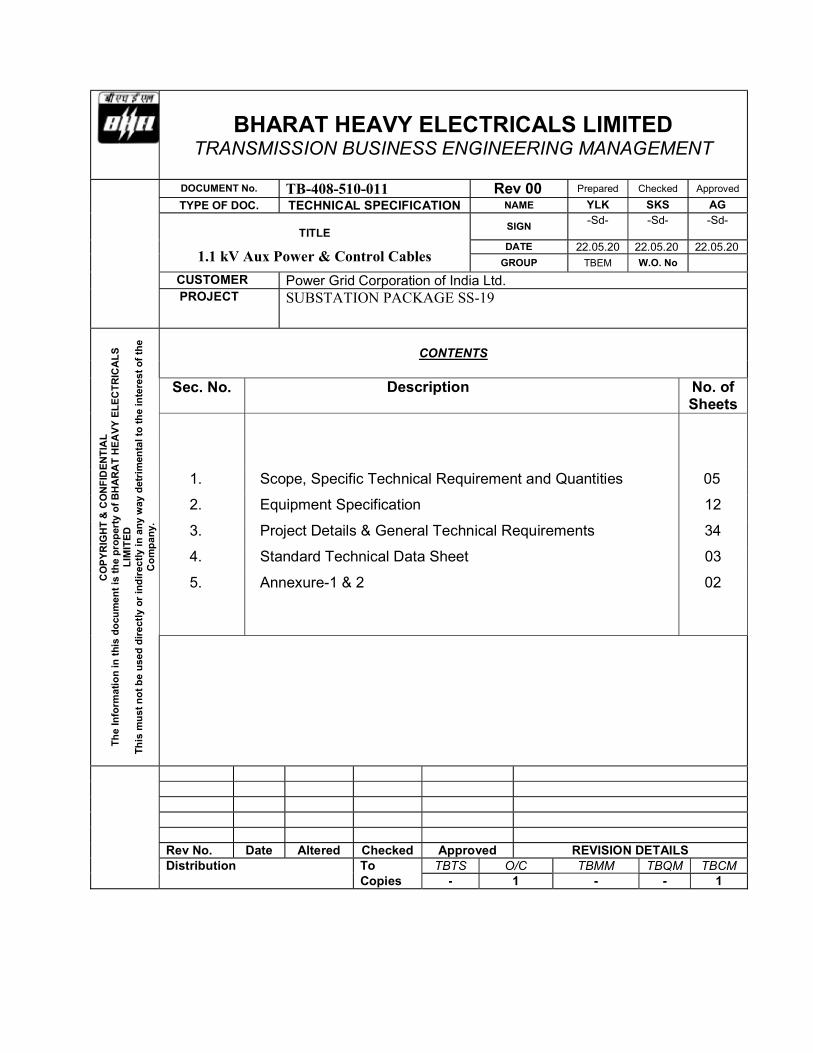
BHARAT HEAVY ELECTRICALS LIMITED TRANSMISSION BUSINESS ENGINEERING MANAGEMENT DOCUMENT No. TB-408-510-011 Rev 00 Prepared Checked Approved TYPE OF DOC. TECHNICAL SPECIFICATION NAME YLK SKS AG TITLE SIGN -Sd- -Sd- -Sd- 1.1 kV Aux Power & Control Cables DATE 22.05.20 22.05.20 22.05.20 GROUP TBEM W.O. No CUSTOMER Power Grid Corporation of India Ltd. PROJECT SUBSTATION PACKAGE SS-19 COPYRIGHT & CONFIDENTIAL The Information in this document is the property of BHARAT HEAVY ELECTRICALS LIMITED This must not be used directly or indirectly in any way detrimental to the interest of the Company. CONTENTS Sec. No. Description No. of Sheets 1. Scope, Specific Technical Requirement and Quantities 05 2. Equipment Specification 12 3. Project Details & General Technical Requirements 34 4. Standard Technical Data Sheet 03 5. Annexure-1 & 2 02 Rev No. Date Altered Checked Approved REVISION DETAILS Distribution To TBTS O/C TBMM TBQM TBCM Copies - 1 - - 1
-
Upload
khangminh22 -
Category
Documents
-
view
1 -
download
0
Transcript of lt-cables-technical-specification-1591344681.pdf - Bharat ...
BHARAT HEAVY ELECTRICALS LIMITED TRANSMISSION BUSINESS ENGINEERING MANAGEMENT
DOCUMENT No. TB-408-510-011 Rev 00 Prepared Checked Approved
TYPE OF DOC. TECHNICAL SPECIFICATION NAME YLK SKS AG
TITLE SIGN -Sd- -Sd- -Sd-
1.1 kV Aux Power & Control Cables DATE 22.05.20 22.05.20 22.05.20
GROUP TBEM W.O. No CUSTOMER Power Grid Corporation of India Ltd. PROJECT SUBSTATION PACKAGE SS-19
CO
PY
RIG
HT
& C
ON
FID
EN
TIA
L
Th
e In
form
ati
on
in t
his
do
cum
en
t is
th
e p
rop
erty
of
BH
AR
AT
HE
AV
Y E
LE
CT
RIC
AL
S
LIM
ITE
D
Th
is m
us
t n
ot
be
use
d d
ire
ctly
or
ind
irec
tly
in a
ny
way
det
rim
enta
l to
th
e in
tere
st
of
the
Co
mp
an
y.
CONTENTS
Sec. No. Description No. of
Sheets
1. Scope, Specific Technical Requirement and Quantities 05
2. Equipment Specification 12
3. Project Details & General Technical Requirements 34
4. Standard Technical Data Sheet 03
5. Annexure-1 & 2 02
Rev No. Date Altered Checked Approved REVISION DETAILS Distribution To TBTS O/C TBMM TBQM TBCM Copies - 1 - - 1

PGCIL SUBSTATION PACKAGE SS19 Bharat Heavy Electricals Ltd 1.1kV Auxiliary Power & Control Cable Doc. No. TB-408-510-011, Rev. No.-00
pg. 1
SECTION 1
SCOPE, SPECIFIC TECHNICAL REQUIREMENTS AND QUANTITIES 1.0 SCOPE
This technical specification covers the requirements of design, manufacture, testing at works, packing and dispatch of 1.1kV Control & Aux. Power Cables. This section covers the specific technical requirements of the cables. In case of any conflict between the technical details mentioned in this section and the remaining sections of this document, then Section-1 shall prevail and is to be considered as binding requirement.
1.1 The equipment is required for the following Project. Name of Customer : Power Grid Corporation of India Ltd.
Name of the Project : SUBSTATION PACKAGE SS-19 Refer Section – 2 : Equipment Specification. Section – 3 : Project Details and General Specifications. Section – 4: Standard Technical Data Sheet. Section – 5 : Checklist 2.0 SPECIFIC TECHNICAL PARTICULARS
2.1 PVC Insulated 1.1kV Control and Aux. Power cable :
The PVC (70oC) insulated 1100V grade Control & Aux. Power cables shall be of FR type, C1 category conforming to IS: 1554 (Part-I) and its amendments. S.No Parameters Control Cable Aux. Power Cable
1. Voltage grade of cable 1100 Volts
2. Material of conductor
Plain annealed, High conductivity, Stranded Copper Conductor Grade EC
Stranded Aluminium, Grade H2
3. Strands As per standard technical data sheet attached as Section-4
4. Conductor insulation. Extruded PVC compound Type A as per IS 5831
5. Filler (If required) Non-hygroscopic, fire retardant.
6. Inner Sheath Extruded PVC. Type ST-1 as per IS 5831
Non-hygroscopic, fire retardant. 7. Armour**
Round wire for Multi-core cables as per IS 1554 (Part I)
Aluminium wire (H4 grade) for Single core as per IS and Galvanised Steel wire/Strip for Multi-core cables as per IS 1554 (Part I)
8. Overall sheathing
PVC Extruded, FR. Type ST-1 as per IS 5831, C1 Category as per IS 1554
Oxygen Index > 29, Temperature Index > 250°C
PGCIL SUBSTATION PACKAGE SS19 Bharat Heavy Electricals Ltd 1.1kV Auxiliary Power & Control Cable Doc. No. TB-408-510-011, Rev. No.-00
pg. 2
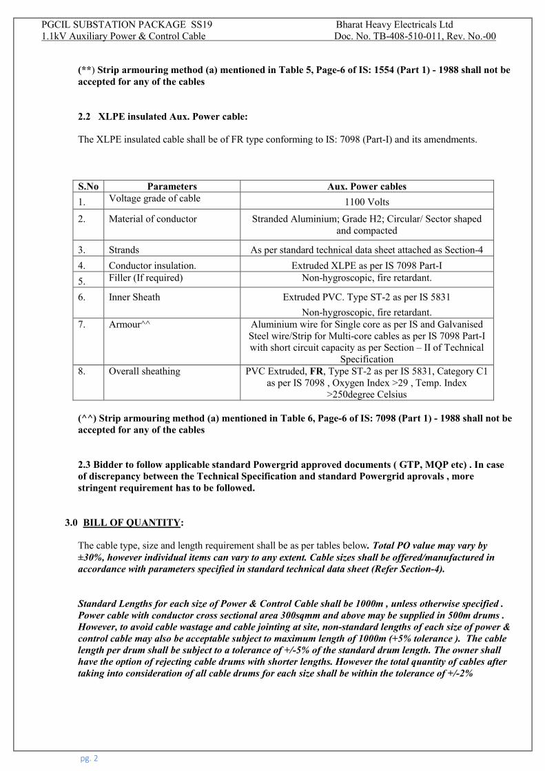
(**) Strip armouring method (a) mentioned in Table 5, Page-6 of IS: 1554 (Part 1) - 1988 shall not be accepted for any of the cables 2.2 XLPE insulated Aux. Power cable: The XLPE insulated cable shall be of FR type conforming to IS: 7098 (Part-I) and its amendments. S.No Parameters Aux. Power cables
1. Voltage grade of cable 1100 Volts
2. Material of conductor
Stranded Aluminium; Grade H2; Circular/ Sector shaped and compacted
3. Strands As per standard technical data sheet attached as Section-4
4. Conductor insulation. Extruded XLPE as per IS 7098 Part-I
5. Filler (If required) Non-hygroscopic, fire retardant.
6. Inner Sheath Extruded PVC. Type ST-2 as per IS 5831
Non-hygroscopic, fire retardant. 7. Armour^^
Aluminium wire for Single core as per IS and Galvanised Steel wire/Strip for Multi-core cables as per IS 7098 Part-I with short circuit capacity as per Section – II of Technical
Specification 8. Overall sheathing PVC Extruded, FR, Type ST-2 as per IS 5831, Category C1
as per IS 7098 , Oxygen Index >29 , Temp. Index >250degree Celsius
(^^) Strip armouring method (a) mentioned in Table 6, Page-6 of IS: 7098 (Part 1) - 1988 shall not be accepted for any of the cables 2.3 Bidder to follow applicable standard Powergrid approved documents ( GTP, MQP etc) . In case of discrepancy between the Technical Specification and standard Powergrid aprovals , more stringent requirement has to be followed.
3.0 BILL OF QUANTITY:
The cable type, size and length requirement shall be as per tables below. Total PO value may vary by ±30%, however individual items can vary to any extent. Cable sizes shall be offered/manufactured in accordance with parameters specified in standard technical data sheet (Refer Section-4). Standard Lengths for each size of Power & Control Cable shall be 1000m , unless otherwise specified . Power cable with conductor cross sectional area 300sqmm and above may be supplied in 500m drums . However, to avoid cable wastage and cable jointing at site, non-standard lengths of each size of power & control cable may also be acceptable subject to maximum length of 1000m (+5% tolerance ). The cable length per drum shall be subject to a tolerance of +/-5% of the standard drum length. The owner shall have the option of rejecting cable drums with shorter lengths. However the total quantity of cables after taking into consideration of all cable drums for each size shall be within the tolerance of +/-2%

PGCIL SUBSTATION PACKAGE SS19 Bharat Heavy Electricals Ltd 1.1kV Auxiliary Power & Control Cable Doc. No. TB-408-510-011, Rev. No.-00
pg. 3
3.1 PVC/XLPE insulated 1.1kV Aux Power Cables :
765KV
SOLAPUR
S/S
765KV
WARDHA
S/S
765KV
AURANGABAD
S/S
400KV
KHANDWA
S/S
400KV
RAJGARH
S/S
400KV
CHAMPA
S/S
400 & 220KV
JABALPUR
S/S
400/220K
V ITARSI
S/S (GIS)
Length Length Length Length Length Length Length Length
13.5C x 300 sq mm XLPE/
Al. Aux Power Cablem 1000 600 1600 600 500 500 500 500
23.5C x 70 sq mm PVC/ Al.
Aux Power Cable m 2400 2400 4400 2000 1000 1700 500 2600
500 500 500 600 500 500 500 500
3400 3400 5400 1000 1300 500 500 4500
1200 1700 500 500 500 500 500
62C x 6 sq mm PVC/ Al.
Aux Power Cablem 500 500 500 500 500 500 500 500
1000
S. No. Description Unit
33.5C x 35 sq mm PVC/Al.
Aux Power Cable m
44C x 16 sq mm PVC/ Al.
Aux Power Cablem
54C x 6 sq mm PVC/ Al.
Aux Power Cablem
3.2 PVC insulated 1.1kV Control Cables:
765KV
SOLAPUR
S/S
765KV
WARDHA
S/S
765KV
AURANGABAD
S/S
400KV
KHANDWA
S/S
400KV
RAJGARH
S/S
400KV
CHAMPA
S/S
400 & 220KV
JABALPUR
S/S
400/220K
V ITARSI
S/S (GIS)
Length Length Length Length Length Length Length Length
15C x 2.5 sq mm PVC/ Cu.
Control Cablem 3000 3000 3000 3700 1000 1400 11500 3600
27C x 2.5 sq mm PVC/ Cu.
Control Cable m 1500 1500 1500 1500 500 500 1600 500
800 800 800 500 500 500 500 2700
4000 3700 3700 3700 1000 1500 2000 2100
500 500 500 500 500 3500
6 m 2500 2700 2600 3300 600 1000 3000 50027C x 2.5 sq mm PVC/
Cu. Control Cable
500500
S.
No.Description Unit
310C x 2.5 sq mm PVC/
Cu. Control Cable m
414C x 2.5 sq mm PVC/
Cu. Control Cablem
519C x 2.5 sq mm PVC/
Cu. Control Cablem
4.0 TESTS :
All cables to be supplied of type tested quality. Cables shall conform to type tests including additional type tests as per technical specification and shall be subject to routine & acceptance tests in accordance with requirements stipulated under respective sections. Any other test as per manufacturers standard quality plan ( MQP) approved by Powergrid is deemed to be included. The type, acceptance and routine tests may be witnessed by purchaser/ purchaser’s representative. The prices for conducting all tests are deemed to be included in respective cable prices.
PGCIL SUBSTATION PACKAGE SS19 Bharat Heavy Electricals Ltd 1.1kV Auxiliary Power & Control Cable Doc. No. TB-408-510-011, Rev. No.-00
pg. 4
5.0 DRAWINGS APPROVAL:
The successful bidder shall have to extend all possible support like timely submission/re-submission of drawings, visit to end customer to facilitate documents approval without any commercial implications to BHEL. Acceptance of bidder’s documents shall be subject to end customer's approval. Submission of standard technical data sheets for these cables sizes are not required for approval. Only extension of the already approved drawings shall be given by Powergrid. In case of new vendor, then all the drawings/ documents like GTP, drum & cross sectional drawing etc. shall be submitted for approval. Date of Submission of first lot of drawings will be counted only from the date of submission of reasonably correct drawings. Approval of the following drawings will be required for technical clearance of manufacturing for each type of cable:
GTP Cross sectional Drawing Drum drawing
6.0 DEVIATIONS :
The bidder shall list all the deviation from the specification separately. Offers without specific deviation will be deemed to be totally in compliance with the specification and NO DEVIATION on any account will be entertained at a later date.
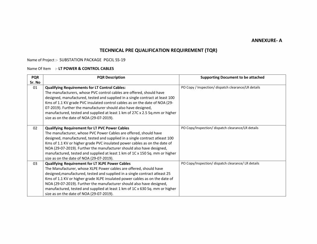
ANNEXURE- A
TECHNICAL PRE QUALIFICATION REQUIREMENT (TQR)
Name of Project :- SUBSTATION PACKAGE PGCIL SS-19
Name Of Item :- LT POWER & CONTROL CABLES
PQR Sr. No
PQR Description Supporting Document to be attached
01 Qualifying Requirements for LT Control Cables: The manufacturers, whose PVC control cables are offered, should have designed, manufactured, tested and supplied in a single contract at least 100 Kms of 1.1 KV grade PVC insulated control cables as on the date of NOA (29-07-2019). Further the manufacturer should also have designed, manufactured, tested and supplied at least 1 km of 27C x 2.5 Sq.mm or higher size as on the date of NOA (29-07-2019).
PO Copy / Inspection/ dispatch clearance/LR details
02 Qualifying Requirement for LT PVC Power Cables The manufacturer, whose PVC Power Cables are offered, should have designed, manufactured, tested and supplied in a single contract atleast 100 Kms of 1.1 KV or higher grade PVC insulated power cables as on the date of NOA (29-07-2019). Further the manufacturer should also have designed, manufactured, tested and supplied at least 1 km of 1C x 150 Sq. mm or higher size as on the date of NOA (29-07-2019).
PO Copy/Inspection/ dispatch clearance/LR details
03 Qualifying Requirement for LT XLPE Power Cables The Manufacturer, whose XLPE Power cables are offered, should have designed,manufactured, tested and supplied in a single contract atleast 25 Kms of 1.1 KV or higher grade XLPE insulated power cables as on the date of NOA (29-07-2019). Further the manufacturer should also have designed, manufactured, tested and supplied at least 1 km of 1C x 630 Sq. mm or higher size as on the date of NOA (29-07-2019).
PO Copy/Inspection/ dispatch clearance/ LR details
Latha
Text Box
SECTION-2


-$�'������"���!�#�'%#�!���%�%��/��'&B�#�:� �������� ������������� !�� �� � "#$�% ������& "#$�% ���� �����&"#$�% '�����& ())�% *�� ���& ())�% +�,����& ())�% -��.��& ())/00)�% 1����� 2())/00)�%3��������������� ����#�%&)�C��&0���#$)%#�!��,�#%0%#��%&)�������������&#� &���-C408C��1C�������"����
Page 1 of 71
SECTION-3
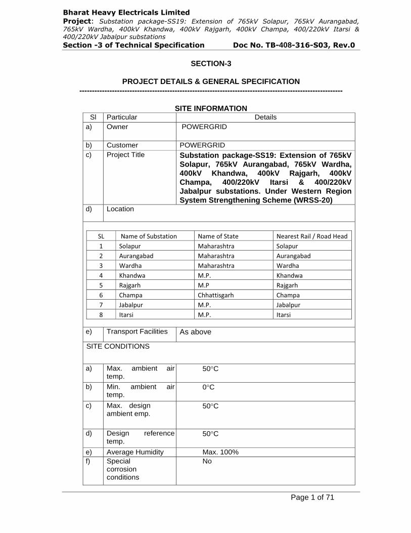
PROJECT DETAILS & GENERAL SPECIFICATION ---------------------------------------------------------------------------------------------------------
SITE INFORMATIONSl Particular Details
a) Owner POWERGRID
b) Customer POWERGRID c) Project Title Substation package-SS19: Extension of 765kV
Solapur, 765kV Aurangabad, 765kV Wardha, 400kV Khandwa, 400kV Rajgarh, 400kV Champa, 400/220kV Itarsi & 400/220kV Jabalpur substations. Under Western Region System Strengthening Scheme (WRSS-20)
d) Location
!�� ������#�!;D������ �� �����#�!����� ������1�� �&�1���������� !� �";��� 7������������ !� �";���'� 0;�� ?�D���� 7������������ 0;�� ?�D������ 9������� 7������������ 9��������� 3�� �+��� 7�-��� 3�� �+���%� 1�E?����� 7�-�� 1�E?������� 6���"��� 6�������?����� 6���"���$� F�D� ";��� 7�-��� F�D� ";����� *������� 7�-��� *�������
e) Transport Facilities As above
SITE CONDITIONS
a) Max. ambient air temp.
50�C
b) Min. ambient air temp.
0�C
c) Max. design ambient emp.
50�C
d) Design reference temp.
50�C
e) Average Humidity Max. 100% f) Special
corrosion conditions
No
1294334
Text Box
34

-$�'������"���!�#�'%#�!���%�%��/��'&B�#�:� �������� ������������� !�� �� � "#$�% ������& "#$�% ���� �����&"#$�% '�����& ())�% *�� ���& ())�% +�,����& ())�% -��.��& ())/00)�% 1����� 2())/00)�%3��������������� ����#�%&)�C��&0���#$)%#�!��,�#%0%#��%&)�������������&#� &���-C408C��1C�������"����
Page 2 of 71
g) Solar Radiation 1.2kW/sqmtr h) Atmospheric UV
radiation High
i) Altitude above sea level
Less than 1000meter
j) Pollution Severity Normal Pollution level k) Seismic Zone As per the seismic zone defined in the
relevant BIS / IEC-62271-300 but not less than 0.3g horrizontal
WIND DATA Wind velocity As per IS Average No. of thunderstorm days per annum
As per IS
Main Electrical Parameters:
Fault Levels:
SL Name of Substation Fault level 1 765kV Solapur 40kA for 1sec 2 765kV Aurangabad 40kA for 1sec3 765kV Wardha 40kA for 1sec 4 400kV Khandwa 40kA for 1sec 5 400kV Rajgarh 40kA for 1sec 6 400kV Champa 50kA for 1sec 7 400/220kV Jabalpur 40kA for 1sec 8 400/220kV Itarsi 40kA for 1sec
Minimum Creepage Distance
25mm/kV for all equipments i.e. BPI / Bushing, CB, Isolator, CT, CVT, LA, NCT etc.
31mm/kV. For string insulators
ENCLOSED – “SECTION-GTR (GENERAL TECHNICAL REQUIREMENT) REV.14” FOR DETAILS OF GENERAL TECHNICAL SPECIFICATION.
PLEASE READ TERMINOLOGY AS FOLLOWS - 1. Read "GTR" as "Section-3 of technical specification" 2. Read "Powergrid" as "BHEL/Powergrid". 3. Read "Employer" as "Powergrid". 4. Read "Contractor" as bidder
1294334
Text Box
34

SECTION-GENERAL TECHNICAL REQUIREMENTS (GTR)
____________________________________________________________________________Technical Specification: GTR Page 1 of 34 C/ENGG/SPEC/GTR (Rev. No.:-14, Jan 2017)
1.0 FOREWORD
The provisions under this section are intended to supplement requirements for the
materials, equipments and services covered under other sections of tender documents
and are not exclusive.
2.0 GENERAL REQUIREMENT
2.1 The contractor shall furnish catalogues, engineering data, technical information, design
documents, drawings etc., fully in conformity with the technical specification during
detailed engineering.
2.2 It is recognised that the Contractor may have standardised on the use of certain
components, materials, processes or procedures different from those specified herein.
Alternate proposals offering similar equipment based on the manufacturer’s standard
practice will also be considered provided such proposals meet the specified designs,
standard and performance requirements and are acceptable to Employer.
2.3 Wherever a material or article is specified or defined by the name of a particular brand,
Manufacturer or Vendor, the specific name mentioned shall be understood as
establishing type, function and quality and not as limiting competition.
2.4 Equipment furnished shall be complete in every respect with all mountings, fittings,
fixtures and standard accessories normally provided with such equipment and/or
needed for erection, completion and safe operation of the equipment as required by
applicable codes though they may not have been specifically detailed in the Technical
Specifications unless included in the list of exclusions. Materials and components
which are minor in nature and incidental to the requirement but not specifically stated
in the specification and bid price schedule, which are necessary for commissioning and
satisfactory operation of the switchyard/ substation unless specifically excluded shall
be deemed to be included in the scope of the specification and shall be supplied
without any extra cost. All similar standard components/parts of similar standard
equipment provided, shall be inter-changeable with one another.
2.5 The Contractor shall also be responsible for the overall co-ordination with internal
/external agencies; Supplier of Employer’s supplied equipments, project management,
training of Employer’s manpower, loading, unloading, handling, insurance, moving to
final destination for successful erection, testing and commissioning of the substation
/switchyard.
2.6 The bidder shall be responsible for safety of human and equipment during the working.
It will be the responsibility of the Contractor to co-ordinate and obtain Electrical
Inspector's clearance before commissioning. Any additional items, modification due to
observation of such statutory authorities shall be provided by the Contractor at no
extra cost to the Employer.
3.0 STANDARDS
3.1 The works covered by the specification shall be designed, engineered, manufactured,
built, tested and commissioned in accordance with the Acts, Rules, Laws and
Regulations of India.
3.2 The equipment to be furnished under this specification shall conform to latest issue
with all amendments (as on the originally scheduled date of bid opening) of standard
specified under Annexure-C of this section, unless specifically mentioned in the
specification.
3.3 The Bidder shall note that standards mentioned in the specification are not mutually
exclusive or complete in themselves, but intended to compliment each other.
������
Section-3
1294334
Text Box
34
1294334
Text Box
3
1294334
Text Box
3
SECTION-GENERAL TECHNICAL REQUIREMENTS (GTR)
____________________________________________________________________________Technical Specification: GTR Page 2 of 34 C/ENGG/SPEC/GTR (Rev. No.:-14, Jan 2017)
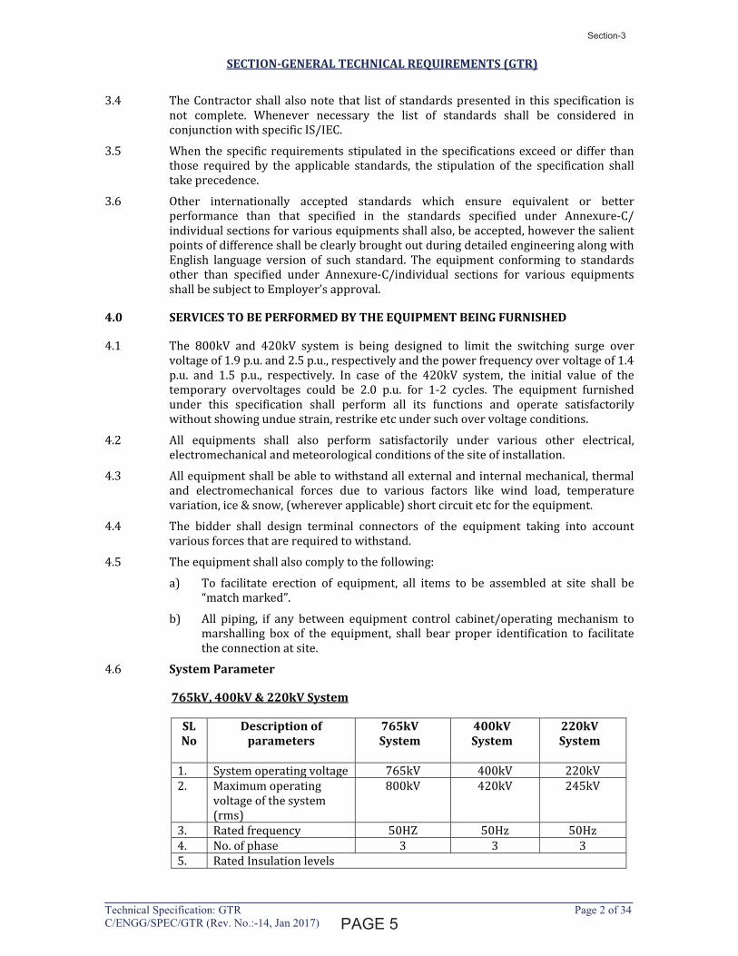
3.4 The Contractor shall also note that list of standards presented in this specification is
not complete. Whenever necessary the list of standards shall be considered in
conjunction with specific IS/IEC.
3.5 When the specific requirements stipulated in the specifications exceed or differ than
those required by the applicable standards, the stipulation of the specification shall
take precedence.
3.6 Other internationally accepted standards which ensure equivalent or better
performance than that specified in the standards specified under Annexure-C/
individual sections for various equipments shall also, be accepted, however the salient
points of difference shall be clearly brought out during detailed engineering along with
English language version of such standard. The equipment conforming to standards
other than specified under Annexure-C/individual sections for various equipments
shall be subject to Employer’s approval.
4.0 SERVICES TO BE PERFORMED BY THE EQUIPMENT BEING FURNISHED
4.1 The 800kV and 420kV system is being designed to limit the switching surge over
voltage of 1.9 p.u. and 2.5 p.u., respectively and the power frequency over voltage of 1.4
p.u. and 1.5 p.u., respectively. In case of the 420kV system, the initial value of the
temporary overvoltages could be 2.0 p.u. for 1-2 cycles. The equipment furnished
under this specification shall perform all its functions and operate satisfactorily
without showing undue strain, restrike etc under such over voltage conditions.
4.2 All equipments shall also perform satisfactorily under various other electrical,
electromechanical and meteorological conditions of the site of installation.
4.3 All equipment shall be able to withstand all external and internal mechanical, thermal
and electromechanical forces due to various factors like wind load, temperature
variation, ice & snow, (wherever applicable) short circuit etc for the equipment.
4.4 The bidder shall design terminal connectors of the equipment taking into account
various forces that are required to withstand.
4.5 The equipment shall also comply to the following:
a) To facilitate erection of equipment, all items to be assembled at site shall be
“match marked”.
b) All piping, if any between equipment control cabinet/operating mechanism to
marshalling box of the equipment, shall bear proper identification to facilitate
the connection at site.
4.6 System Parameter
765kV, 400kV & 220kV System
SL No
Description of parameters
765kV System
400kV System
220kV System
1. System operating voltage 765kV 400kV 220kV
2. Maximum operating
voltage of the system
(rms)
800kV 420kV 245kV
3. Rated frequency 50HZ 50Hz 50Hz
4. No. of phase 3 3 3
5. Rated Insulation levels
�����
Section-3
1294334
Text Box
4
1294334
Text Box
4
SECTION-GENERAL TECHNICAL REQUIREMENTS (GTR)
____________________________________________________________________________Technical Specification: GTR Page 3 of 34 C/ENGG/SPEC/GTR (Rev. No.:-14, Jan 2017)
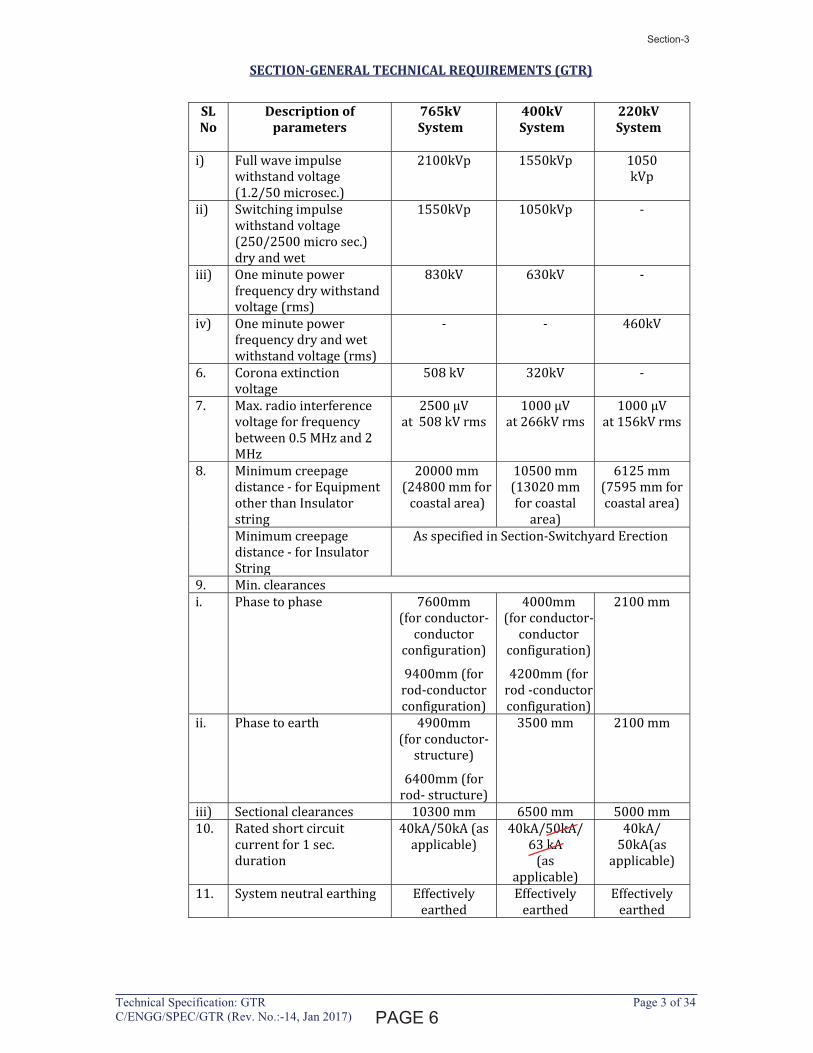
SL No
Description of parameters
765kV System
400kV System
220kV System
i) Full wave impulse
withstand voltage
(1.2/50 microsec.)
2100kVp 1550kVp
1050
kVp
ii)
Switching impulse
withstand voltage
(250/2500 micro sec.)
dry and wet
1550kVp
1050kVp
-
iii) One minute power
frequency dry withstand
voltage (rms)
830kV
630kV
-
iv) One minute power
frequency dry and wet
withstand voltage (rms)
-
-
460kV
6. Corona extinction
voltage
508 kV 320kV -
7. Max. radio interference
voltage for frequency
between 0.5 MHz and 2
MHz
2500 μV
at 508 kV rms
1000 μV
at 266kV rms
1000 μV
at 156kV rms
8. Minimum creepage
distance - for Equipment
other than Insulator
string
20000 mm
(24800 mm for
coastal area)
10500 mm
(13020 mm
for coastal
area)
6125 mm
(7595 mm for
coastal area)
Minimum creepage
distance - for Insulator
String
As specified in Section-Switchyard Erection
9. Min. clearances
i. Phase to phase
7600mm
(for conductor-
conductor
configuration)
9400mm (for
rod-conductor
configuration)
4000mm
(for conductor-
conductor
configuration)
4200mm (for
rod -conductor
configuration)
2100 mm
ii.
Phase to earth
4900mm
(for conductor-
structure)
6400mm (for
rod- structure)
3500 mm
2100 mm
iii) Sectional clearances 10300 mm 6500 mm 5000 mm
10. Rated short circuit
current for 1 sec.
duration
40kA/50kA (as
applicable)
40kA/50kA/
63 kA
(as
applicable)
40kA/
50kA(as
applicable)
11. System neutral earthing
Effectively
earthed
Effectively
earthed
Effectively
earthed
�����
Section-3
1294334
Text Box
5
1294334
Line
SECTION-GENERAL TECHNICAL REQUIREMENTS (GTR)
____________________________________________________________________________Technical Specification: GTR Page 4 of 34 C/ENGG/SPEC/GTR (Rev. No.:-14, Jan 2017)
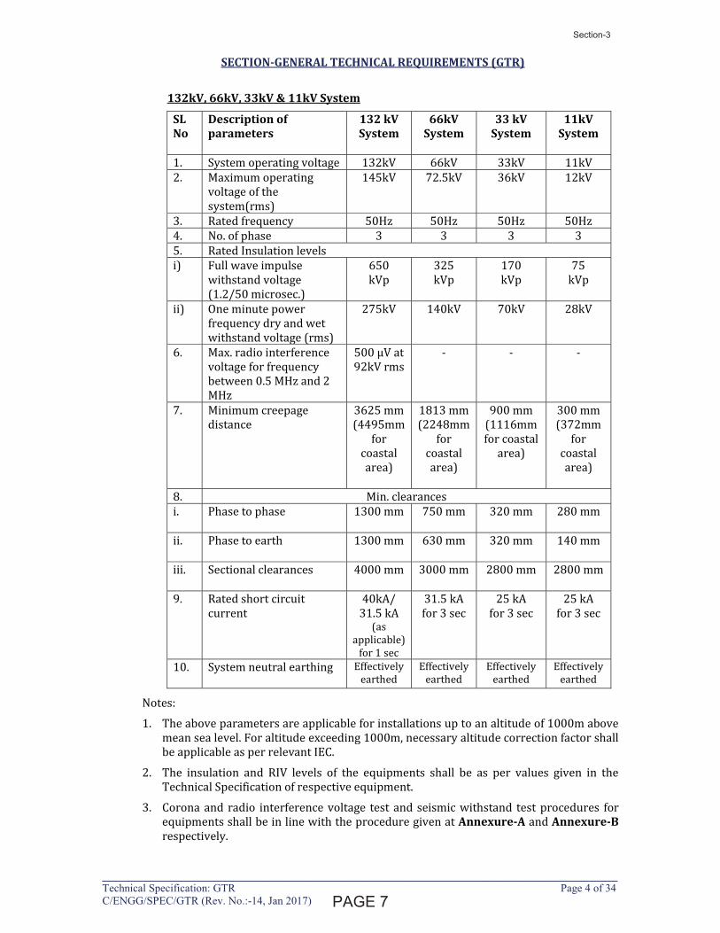
132kV, 66kV, 33kV & 11kV System
SL No
Description of parameters
132 kV System
66kV System
33 kV System
11kV System
1. System operating voltage 132kV 66kV 33kV 11kV
2. Maximum operating
voltage of the
system(rms)
145kV 72.5kV 36kV 12kV
3. Rated frequency 50Hz 50Hz 50Hz 50Hz
4. No. of phase 3 3 3 3
5. Rated Insulation levels
i) Full wave impulse
withstand voltage
(1.2/50 microsec.)
650
kVp
325
kVp
170
kVp
75
kVp
ii) One minute power
frequency dry and wet
withstand voltage (rms)
275kV 140kV 70kV
28kV
6. Max. radio interference
voltage for frequency
between 0.5 MHz and 2
MHz
500 μV at
92kV rms
- - -
7. Minimum creepage
distance
3625 mm
(4495mm
for
coastal
area)
1813 mm
(2248mm
for
coastal
area)
900 mm
(1116mm
for coastal
area)
300 mm
(372mm
for
coastal
area)
8. Min. clearances
i. Phase to phase
1300 mm
750 mm
320 mm
280 mm
ii.
Phase to earth
1300 mm
630 mm
320 mm
140 mm
iii. Sectional clearances
4000 mm 3000 mm 2800 mm 2800 mm
9. Rated short circuit
current
40kA/
31.5 kA (as
applicable)
for 1 sec
31.5 kA
for 3 sec
25 kA
for 3 sec
25 kA
for 3 sec
10. System neutral earthing
Effectively
earthed
Effectively
earthed
Effectively
earthed
Effectively
earthed
Notes:
1. The above parameters are applicable for installations up to an altitude of 1000m above
mean sea level. For altitude exceeding 1000m, necessary altitude correction factor shall
be applicable as per relevant IEC.
2. The insulation and RIV levels of the equipments shall be as per values given in the
Technical Specification of respective equipment.
3. Corona and radio interference voltage test and seismic withstand test procedures for
equipments shall be in line with the procedure given at Annexure-A and Annexure-B
respectively.
������
Section-3
1294334
Line
1294334
Text Box
6
SECTION-GENERAL TECHNICAL REQUIREMENTS (GTR)
____________________________________________________________________________Technical Specification: GTR Page 5 of 34 C/ENGG/SPEC/GTR (Rev. No.:-14, Jan 2017)
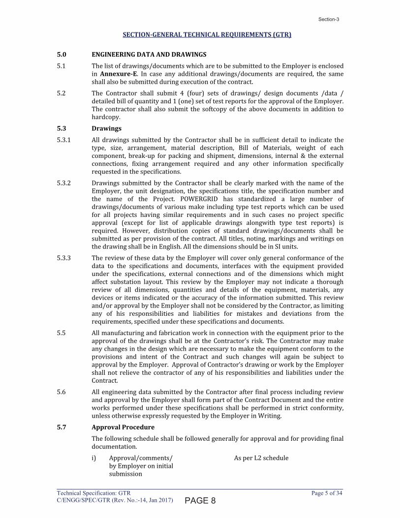
5.0 ENGINEERING DATA AND DRAWINGS
5.1 The list of drawings/documents which are to be submitted to the Employer is enclosed
in Annexure-E. In case any additional drawings/documents are required, the same
shall also be submitted during execution of the contract.
5.2 The Contractor shall submit 4 (four) sets of drawings/ design documents /data /
detailed bill of quantity and 1 (one) set of test reports for the approval of the Employer.
The contractor shall also submit the softcopy of the above documents in addition to
hardcopy.
5.3 Drawings
5.3.1 All drawings submitted by the Contractor shall be in sufficient detail to indicate the
type, size, arrangement, material description, Bill of Materials, weight of each
component, break-up for packing and shipment, dimensions, internal & the external
connections, fixing arrangement required and any other information specifically
requested in the specifications.
5.3.2 Drawings submitted by the Contractor shall be clearly marked with the name of the
Employer, the unit designation, the specifications title, the specification number and
the name of the Project. POWERGRID has standardized a large number of
drawings/documents of various make including type test reports which can be used
for all projects having similar requirements and in such cases no project specific
approval (except for list of applicable drawings alongwith type test reports) is
required. However, distribution copies of standard drawings/documents shall be
submitted as per provision of the contract. All titles, noting, markings and writings on
the drawing shall be in English. All the dimensions should be in SI units.
5.3.3 The review of these data by the Employer will cover only general conformance of the
data to the specifications and documents, interfaces with the equipment provided
under the specifications, external connections and of the dimensions which might
affect substation layout. This review by the Employer may not indicate a thorough
review of all dimensions, quantities and details of the equipment, materials, any
devices or items indicated or the accuracy of the information submitted. This review
and/or approval by the Employer shall not be considered by the Contractor, as limiting
any of his responsibilities and liabilities for mistakes and deviations from the
requirements, specified under these specifications and documents.
5.5 All manufacturing and fabrication work in connection with the equipment prior to the
approval of the drawings shall be at the Contractor’s risk. The Contractor may make
any changes in the design which are necessary to make the equipment conform to the
provisions and intent of the Contract and such changes will again be subject to
approval by the Employer. Approval of Contractor’s drawing or work by the Employer
shall not relieve the contractor of any of his responsibilities and liabilities under the
Contract.
5.6 All engineering data submitted by the Contractor after final process including review
and approval by the Employer shall form part of the Contract Document and the entire
works performed under these specifications shall be performed in strict conformity,
unless otherwise expressly requested by the Employer in Writing.
5.7 Approval Procedure
The following schedule shall be followed generally for approval and for providing final
documentation.
i) Approval/comments/ As per L2 schedule
by Employer on initial
submission
������
Section-3
Latha
Line
Latha
Line
1294334
Line
1294334
Line
1294334
Text Box
7

SECTION-GENERAL TECHNICAL REQUIREMENTS (GTR)
____________________________________________________________________________Technical Specification: GTR Page 7 of 34 C/ENGG/SPEC/GTR (Rev. No.:-14, Jan 2017)
5.8 The list of major drawings/documents to be approved to qualify for second advance as
per Section SCC, shall be as per Annexure–D.
6.0 MATERIAL/ WORKMANSHIP
6.1 General Requirement
6.1.1 Where the specification does not contain references to workmanship, equipment,
materials and components of the covered equipment, it is essential that the same must
be new, of highest grade of the best quality of their kind, conforming to best
engineering practice and suitable for the purpose for which they are intended.
6.1.2 In case where the equipment, materials or components are indicated in the
specification as “similar” to any special standard, the Employer shall decide upon the
question of similarity. When required by the specification or when required by the
Employer the Contractor shall submit, for approval, all the information concerning the
materials or components to be used in manufacture. Machinery, equipment, materials
and components supplied, installed or used without such approval shall run the risk of
subsequent rejection, it is to be understood that the cost as well as the time delay
associated with the rejection shall be borne by the Contractor.
6.1.3 The design of the Works shall be such that installation, future expansions,
replacements and general maintenance may be undertaken with a minimum of time
and expenses. Each component shall be designed to be consistent with its duty and
suitable factors of safety, subject to mutual agreements. All joints and fastenings shall
be devised, constructed and documented so that the component parts shall be
accurately positioned and restrained to fulfill their required function. In general, screw
threads shall be standard metric threads. The use of other thread forms will only be
permitted when prior approval has been obtained from the Employer.
6.1.4 Whenever possible, all similar part of the Works shall be made to gauge and shall also
be made interchangeable with similar parts. All spare parts shall also be
interchangeable and shall be made of the same materials and workmanship as the
corresponding parts of the Equipment supplied under the Specification. Where
feasible, common component units shall be employed in different pieces of equipment
in order to minimize spare parts stocking requirements. All equipment of the same
type and rating shall be physically and electrically interchangeable.
6.1.5 All materials and equipment shall be installed in strict accordance with the
manufacturer’s recommendation(s). Only first-class work in accordance with the best
modern practices will be accepted. Installation shall be considered as being the
erection of equipment at its permanent location. This, unless otherwise specified, shall
include unpacking, cleaning and lifting into position, grouting, levelling, aligning,
coupling of or bolting down to previously installed equipment bases/foundations,
performing the alignment check and final adjustment prior to initial operation, testing
and commissioning in accordance with the manufacturer’s tolerances, instructions and
the Specification. All factory assembled rotating machinery shall be checked for
alignment and adjustments made as necessary to re-establish the manufacturer’s limits
suitable guards shall be provided for the protection of personnel on all exposed
rotating and / or moving machine parts and shall be designed for easy installation and
removal for maintenance purposes. The spare equipment(s) shall be installed at
designated locations and tested for healthiness.
6.1.6 The Contractor shall apply oil and grease of the proper specification to suit the
machinery, as is necessary for the installation of the equipment. Lubricants used for
installation purposes shall be drained out and the system flushed through where
necessary for applying the lubricant required for operation. The Contractor shall apply
all operational lubricants to the equipment installed by him.
�������
Section-3
Latha
Line
1294334
Line
1294334
Text Box
8

SECTION-GENERAL TECHNICAL REQUIREMENTS (GTR)
____________________________________________________________________________Technical Specification: GTR Page 8 of 34 C/ENGG/SPEC/GTR (Rev. No.:-14, Jan 2017)
6.1.7 All oil, grease and other consumables used in the Works/Equipment shall be purchased
in India unless the Contractor has any special requirement for the specific application
of a type of oil or grease not available in India. If such is the case, he shall declare in the
proposal, where such oil or grease is available. He shall help Employer in establishing
equivalent Indian make and Indian Contractor. The same shall be applicable to other
consumables too.
6.2 Provisions For Exposure to Hot and Humid climate
Outdoor equipment supplied under the specification shall be suitable for service and
storage under tropical conditions of high temperature, high humidity, heavy rainfall
and environment favourable to the growth of fungi and mildew. The indoor
equipments located in non-air conditioned areas shall also be of same type.
6.2.1 Space Heaters
6.2.1.1 The heaters shall be suitable for continuous operation at 240V as supply voltage. On-
off switch and fuse shall be provided.
6.2.1.2 One or more adequately rated thermostatically connected heaters shall be supplied to
prevent condensation in any compartment. The heaters shall be installed in the
compartment and electrical connections shall be made sufficiently away from below
the heaters to minimize deterioration of supply wire insulation. The heaters shall be
suitable to maintain the compartment temperature to prevent condensation.
6.2.2 FUNGI STATIC VARNISH
Besides the space heaters, special moisture and fungus resistant varnish shall be
applied on parts which may be subjected or predisposed to the formation of fungi due
to the presence or deposit of nutrient substances. The varnish shall not be applied to
any surface of part where the treatment will interfere with the operation or
performance of the equipment. Such surfaces or parts shall be protected against the
application of the varnish.
6.2.3 Ventilation opening
Wherever ventilation is provided, the compartments shall have ventilation openings
with fine wire mesh of brass to prevent the entry of insects and to reduce to a
minimum the entry of dirt and dust.
6.2.4 Degree of Protection
The enclosures of the Control Cabinets, Junction boxes and Marshalling Boxes, panels
etc. to be installed shall comply with following degree of protection as detailed here
under:
a) Installed out door: IP- 55
b) Installed indoor in air conditioned area: IP-31
c) Installed in covered area: IP-52
d) Installed indoor in non-air conditioned area where possibility of entry of water is
limited: IP-41.
e) For LT Switchgear (AC & DC distribution Boards): IP-52
The degree of protection shall be in accordance with IS:13947 (Part-I)/IEC-60947
(Part-I)/IS 12063/IEC-60529. Type test report for IP-55 or higher degree of protection
test, shall be submitted for approval.
6.3 RATING PLATES, NAME PLATES AND LABELS
6.3.1 Each main and auxiliary item of substation is to have permanently attached to it in a
conspicuous position a rating plate of non-corrosive material upon which is to be
engraved manufacturer’s name, year of manufacture, equipment name, type or serial
�������
Section-3
Latha
Line
1294334
Line
1294334
Text Box
9
SECTION-GENERAL TECHNICAL REQUIREMENTS (GTR)
____________________________________________________________________________Technical Specification: GTR Page 9 of 34 C/ENGG/SPEC/GTR (Rev. No.:-14, Jan 2017)
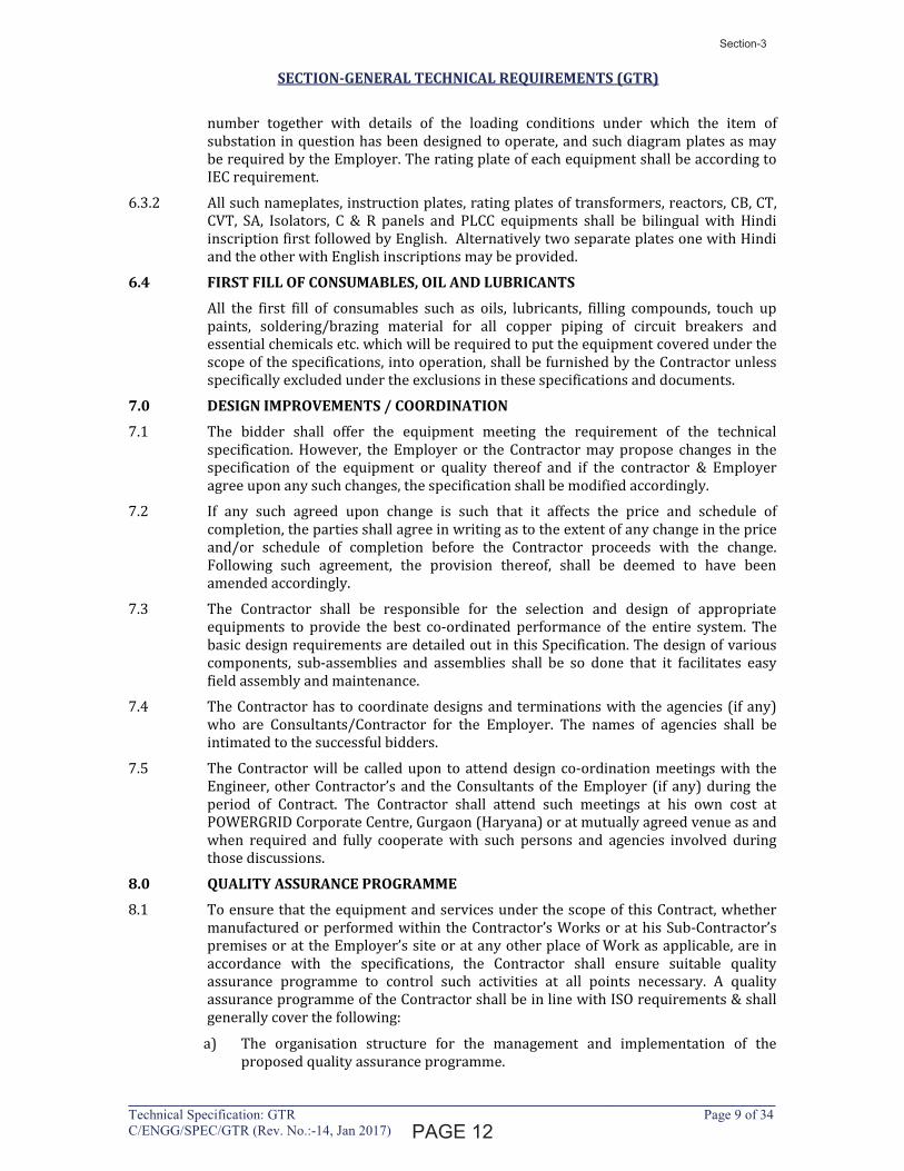
number together with details of the loading conditions under which the item of
substation in question has been designed to operate, and such diagram plates as may
be required by the Employer. The rating plate of each equipment shall be according to
IEC requirement.
6.3.2 All such nameplates, instruction plates, rating plates of transformers, reactors, CB, CT,
CVT, SA, Isolators, C & R panels and PLCC equipments shall be bilingual with Hindi
inscription first followed by English. Alternatively two separate plates one with Hindi
and the other with English inscriptions may be provided.
6.4 FIRST FILL OF CONSUMABLES, OIL AND LUBRICANTS
All the first fill of consumables such as oils, lubricants, filling compounds, touch up
paints, soldering/brazing material for all copper piping of circuit breakers and
essential chemicals etc. which will be required to put the equipment covered under the
scope of the specifications, into operation, shall be furnished by the Contractor unless
specifically excluded under the exclusions in these specifications and documents.
7.0 DESIGN IMPROVEMENTS / COORDINATION
7.1 The bidder shall offer the equipment meeting the requirement of the technical
specification. However, the Employer or the Contractor may propose changes in the
specification of the equipment or quality thereof and if the contractor & Employer
agree upon any such changes, the specification shall be modified accordingly.
7.2 If any such agreed upon change is such that it affects the price and schedule of
completion, the parties shall agree in writing as to the extent of any change in the price
and/or schedule of completion before the Contractor proceeds with the change.
Following such agreement, the provision thereof, shall be deemed to have been
amended accordingly.
7.3 The Contractor shall be responsible for the selection and design of appropriate
equipments to provide the best co-ordinated performance of the entire system. The
basic design requirements are detailed out in this Specification. The design of various
components, sub-assemblies and assemblies shall be so done that it facilitates easy
field assembly and maintenance.
7.4 The Contractor has to coordinate designs and terminations with the agencies (if any)
who are Consultants/Contractor for the Employer. The names of agencies shall be
intimated to the successful bidders.
7.5 The Contractor will be called upon to attend design co-ordination meetings with the
Engineer, other Contractor’s and the Consultants of the Employer (if any) during the
period of Contract. The Contractor shall attend such meetings at his own cost at
POWERGRID Corporate Centre, Gurgaon (Haryana) or at mutually agreed venue as and
when required and fully cooperate with such persons and agencies involved during
those discussions.
8.0 QUALITY ASSURANCE PROGRAMME
8.1 To ensure that the equipment and services under the scope of this Contract, whether
manufactured or performed within the Contractor’s Works or at his Sub-Contractor’s
premises or at the Employer’s site or at any other place of Work as applicable, are in
accordance with the specifications, the Contractor shall ensure suitable quality
assurance programme to control such activities at all points necessary. A quality
assurance programme of the Contractor shall be in line with ISO requirements & shall
generally cover the following:
a) The organisation structure for the management and implementation of the
proposed quality assurance programme.
�������
Section-3
Latha
Line
1294334
Line
1294334
Text Box
10

SECTION-GENERAL TECHNICAL REQUIREMENTS (GTR)
____________________________________________________________________________Technical Specification: GTR Page 10 of 34 C/ENGG/SPEC/GTR (Rev. No.:-14, Jan 2017)
b) System for Document and Data Control.
c) Qualification and Experience data of Bidder’s key personnel.
d) The procedure for purchases of materials, parts, components and selection of sub-
Contractor’s services including vendor analysis, source inspection, incoming raw
material inspection, verification of material purchases etc.
e) System for shop manufacturing and site erection controls including process
controls, fabrication and assembly control.
f) System for Control of non-conforming products including deviation
dispositioning, if any and system for corrective and preventive actions based on
the feedback received from the Customers and also internally documented system
for Customer complaints.
g) Inspection and test procedure both for manufacture and field activities.
h) System for Control of calibration of testing and measuring equipment and the
indication of calibration status on the instruments.
i) System for indication and appraisal of inspection status.
j) System of Internal Quality Audits, Management review and initiation of corrective
and Preventive actions based on the above.
k) System for authorising release of manufactured product to the Employer.
l) System for maintenance of records.
m) System for handling, storage and delivery.
n) A quality plan detailing out the specific quality control measures and procedure
adopted for controlling the quality characteristics relevant to each item of
equipment furnished and /or service rendered.
o) System for various field activities i.e. unloading, receipt at site, proper storage,
erection, testing and commissioning of various equipment and maintenance of
records. In this regard, the Employer has already prepared Standard Field Quality
Plan for transmission line/substation equipments as applicable, Civil/erection
Works which is required to be followed for associated works.
The Employer or his duly authorised representative reserves the right to carry out
quality audit and quality surveillance of the system and procedure of the
Contractor/his vendor’s quality management and control activities.
8.2 Quality Assurance Documents
The Contractor shall ensure availability of the following Quality Assurance Documents:
i) All Non-Destructive Examination procedures, stress relief and weld repair
procedure actually used during fabrication, and reports including radiography
interpretation reports.
ii) Welder and welding operator qualification certificates.
iii) Welder’s identification list, welding operator’s qualification procedure and
welding identification symbols.
iv) Raw Material test reports on components as specified by the specification and in
the quality plan.
�������
Section-3
1294334
Line
1294334
Text Box
11
SECTION-GENERAL TECHNICAL REQUIREMENTS (GTR)
____________________________________________________________________________Technical Specification: GTR Page 11 of 34 C/ENGG/SPEC/GTR (Rev. No.:-14, Jan 2017)
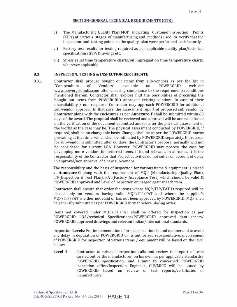
v) The Manufacturing Quality Plan(MQP) indicating Customer Inspection Points
(CIPs) at various stages of manufacturing and methods used to verify that the
inspection and testing points in the quality plan were performed satisfactorily.
vi) Factory test results for testing required as per applicable quality plan/technical
specifications/GTP/Drawings etc.
vii) Stress relief time temperature charts/oil impregnation time temperature charts,
wherever applicable.
8.3 INSPECTION, TESTING & INSPECTION CERTIFICATE
8.3.1 Contractor shall procure bought out items from sub-vendors as per the list in
“Compendium of Vendors” available on POWERGRID web-site
www.powergridindia.com after ensuring compliance to the requirements/conditions
mentioned therein. Contractor shall explore first the possibilities of procuring the
bought out items from POWERGRID approved existing vendors. In case of their
unavailability / non-response, Contractor may approach POWERGRID for additional
sub-vendor approval. In that case, the assessment report of proposed sub vendor by
Contractor along with the enclosures as per Annexure-F shall be submitted within 60
days of the award. The proposal shall be reviewed and approval will be accorded based
on the verification of the document submitted and/or after the physical assessment of
the works as the case may be. The physical assessment conducted by POWERGRID, if
required, shall be on chargeable basis. Charges shall be as per the POWERGRID norms
prevailing at that time, which shall be intimated by POWERGRID separately. If proposal
for sub-vendor is submitted after 60 days, the Contractor’s proposal normally will not
be considered for current LOA. However, POWERGRID may process the case for
developing more vendors for referred items, if found relevant. In all cases, It is the
responsibility of the Contractor that Project activities do not suffer on account of delay
in approval/non approval of a new sub-vendor.
The responsibility and the basis of inspection for various items & equipment is placed
at Annexure-G along with the requirement of MQP (Manufacturing Quality Plan),
ITP(Inspection & Test Plan), FAT(Factory Acceptance Test) which should be valid &
POWERGRID approved and Level of inspection envisaged against each item.
Contractor shall ensure that order for items where MQP/ITP/FAT is required will be
placed only on vendors having valid MQP/ITP/FAT and where the supplier’s
MQP/ITP/FAT is either not valid or has not been approved by POWERGRID, MQP shall
be generally submitted as per POWERGRID format before placing order.
Items not covered under MQP/ITP/FAT shall be offered for inspection as per
POWERGRID LOA/technical Specifications/POWERGRID approved data sheets/
POWERGRID approved drawings and relevant Indian/International standards.
Inspection Levels: For implementation of projects in a time bound manner and to avoid
any delay in deputation of POWERGRID or its authorized representative, involvement
of POWERGRID for inspection of various items / equipment will be based on the level
below:
Level –I: Contractor to raise all inspection calls and review the report of tests
carried out by the manufacturer, on his own, as per applicable standards/
POWERGRID specification, and submit to concerned POWERGRID
inspection office/Inspection Engineer. CIP/MICC will be issued by
POWERGRID based on review of test reports/certificates of
manufacturers.
�������
Section-3
Latha
Line
Latha
Line
Latha
Line
1294334
Line
1294334
Text Box
12

SECTION-GENERAL TECHNICAL REQUIREMENTS (GTR)
____________________________________________________________________________Technical Specification: GTR Page 12 of 34 C/ENGG/SPEC/GTR (Rev. No.:-14, Jan 2017)
Level – II: Contractor to raise all inspection calls and carry out the inspection on
behalf of POWERGRID on the proposed date of inspection as per
applicable standards/specification. However, in case POWERGRID wishes
to associate itself during inspection, the same would be intimated to
Contractor and CIP/MICC will be issued by POWERGRID. Else, Contractor
would submit their test reports/certificates to POWERGRID. CIP/MICC
will be issued by POWERGRID based on review of test reports/
certificates.
Level - III: Contractor to raise inspection calls for both, stage (as applicable) & final
inspection and carry out the stage inspections (if applicable) on behalf of
POWERGRID on the proposed date of inspection as per applicable
standards/specification. However, in case POWERGRID wishes to
associate itself during stage inspection, the same would be intimated to
Contractor and CIP will be issued by POWERGRID. Else, Contractor would
submit the test reports / certificates of stage inspection after their own
review and CIP will be issued by POWERGRID based on review of test
reports / certificates. Final inspection will be carried out by POWERGRID
and CIP/MICC will be issued by POWERGRID.
Level – IV: Contractor to raise inspection calls for both, stage (as applicable) & final
inspections. POWERGRID will carry out the inspection for both stage &
final inspection as per applicable standards/specification and CIP/MICC
will be issued by POWERGRID.
8.3.2 Contractor shall ensure that to implement the above inspection levels, particularly for
the quality control and inspection at sub-vendor’s works, they would depute sufficient
qualified & experienced manpower in their Quality Control and Inspection department.
Further, to assure quality of construction, Contractor shall have a separate workforce
having appropriate qualification & experience and deploy suitable tools and plant for
maintaining quality requirement during construction in line with applicable Field
Quality Plan (FQP).
8.3.3 The Employer, his duly authorised representative and/or outside inspection agency
acting on behalf of the Employer shall have at all reasonable times access to the
Contractor’s premises or Works and shall have the power at all reasonable times to
ensure that proper Quality Management practices / norms are adhered to, inspect and
examine the materials & workmanship of the Works, to carry out Quality/Surveillance
Audit during manufacture or erection and if part of the Works is being manufactured
or assembled at other premises or works. The Contractor shall obtain for the Employer
and for his duly authorised representative permission to inspect as if the works were
manufactured or assembled on the Contractor’s own premises or works. The
item/equipment, if found unsatisfactory with respect to workmanship or material is
liable to be rejected. The observations for improvements during product/ process
inspection by POWERGRID shall be recorded in Quality Improvement Register
(available & maintained at works) for review & timely compliance of observations.
8.3.4 Contractor shall submit inspection calls over internet through POWERGRID website.
The required vendor code and password to enable raising inspection call will be
furnished to the main Contractor within 30 days of award of contract on submission of
documents by Contractor. After raising the inspection calls, Contractor shall then
proceed as per the message of that particular call which is available on the message
board.
8.3.5 The Employer reserves the right to witness any or all type, acceptance and routine
tests specified for which the Contractor shall give the Employer/Inspector Twenty
one (21) days written notice of any material being ready for testing for each stage of
������
Section-3
1294334
Line
1294334
Text Box
13
SECTION-GENERAL TECHNICAL REQUIREMENTS (GTR)
____________________________________________________________________________Technical Specification: GTR Page 13 of 34 C/ENGG/SPEC/GTR (Rev. No.:-14, Jan 2017)
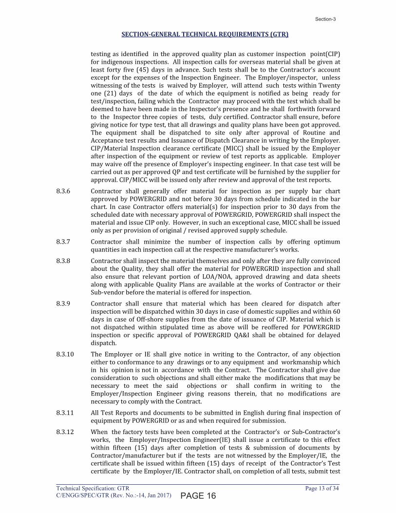
testing as identified in the approved quality plan as customer inspection point(CIP)
for indigenous inspections. All inspection calls for overseas material shall be given at
least forty five (45) days in advance. Such tests shall be to the Contractor’s account
except for the expenses of the Inspection Engineer. The Employer/inspector, unless
witnessing of the tests is waived by Employer, will attend such tests within Twenty
one (21) days of the date of which the equipment is notified as being ready for
test/inspection, failing which the Contractor may proceed with the test which shall be
deemed to have been made in the Inspector’s presence and he shall forthwith forward
to the Inspector three copies of tests, duly certified. Contractor shall ensure, before
giving notice for type test, that all drawings and quality plans have been got approved.
The equipment shall be dispatched to site only after approval of Routine and
Acceptance test results and Issuance of Dispatch Clearance in writing by the Employer.
CIP/Material Inspection clearance certificate (MICC) shall be issued by the Employer
after inspection of the equipment or review of test reports as applicable. Employer
may waive off the presence of Employer’s inspecting engineer. In that case test will be
carried out as per approved QP and test certificate will be furnished by the supplier for
approval. CIP/MICC will be issued only after review and approval of the test reports.
8.3.6 Contractor shall generally offer material for inspection as per supply bar chart
approved by POWERGRID and not before 30 days from schedule indicated in the bar
chart. In case Contractor offers material(s) for inspection prior to 30 days from the
scheduled date with necessary approval of POWERGRID, POWERGRID shall inspect the
material and issue CIP only. However, in such an exceptional case, MICC shall be issued
only as per provision of original / revised approved supply schedule.
8.3.7 Contractor shall minimize the number of inspection calls by offering optimum
quantities in each inspection call at the respective manufacturer’s works.
8.3.8 Contractor shall inspect the material themselves and only after they are fully convinced
about the Quality, they shall offer the material for POWERGRID inspection and shall
also ensure that relevant portion of LOA/NOA, approved drawing and data sheets
along with applicable Quality Plans are available at the works of Contractor or their
Sub-vendor before the material is offered for inspection.
8.3.9 Contractor shall ensure that material which has been cleared for dispatch after
inspection will be dispatched within 30 days in case of domestic supplies and within 60
days in case of Off-shore supplies from the date of issuance of CIP. Material which is
not dispatched within stipulated time as above will be reoffered for POWERGRID
inspection or specific approval of POWERGRID QA&I shall be obtained for delayed
dispatch.
8.3.10 The Employer or IE shall give notice in writing to the Contractor, of any objection
either to conformance to any drawings or to any equipment and workmanship which
in his opinion is not in accordance with the Contract. The Contractor shall give due
consideration to such objections and shall either make the modifications that may be
necessary to meet the said objections or shall confirm in writing to the
Employer/Inspection Engineer giving reasons therein, that no modifications are
necessary to comply with the Contract.
8.3.11 All Test Reports and documents to be submitted in English during final inspection of
equipment by POWERGRID or as and when required for submission.
8.3.12 When the factory tests have been completed at the Contractor’s or Sub-Contractor’s
works, the Employer/Inspection Engineer(IE) shall issue a certificate to this effect
within fifteen (15) days after completion of tests & submission of documents by
Contractor/manufacturer but if the tests are not witnessed by the Employer/IE, the
certificate shall be issued within fifteen (15) days of receipt of the Contractor’s Test
certificate by the Employer/IE. Contractor shall, on completion of all tests, submit test
������
Section-3
1294334
Line
1294334
Text Box
14

SECTION-GENERAL TECHNICAL REQUIREMENTS (GTR)
____________________________________________________________________________Technical Specification: GTR Page 14 of 34 C/ENGG/SPEC/GTR (Rev. No.:-14, Jan 2017)
reports within Ten (10) days to POWERGRID IE. Failure of the Employer/IE to issue
such a certificate shall not prevent the Contractor from proceeding with the Works.
The completion of these tests or the issue of the certificate shall not bind the Employer
to accept the equipment should, it, on further tests after erection, be found not to
comply with the Contract.
8.3.13 In all cases, where the Contract provides for tests whether at the premises or works
of the Contractor or of any Sub- Contractor, the Contractor, except where otherwise
specified, shall provide free of charge such items as labour, materials, electricity, fuel,
water, stores, apparatus and instruments as may be reasonably demanded by the
Employer/Inspector or his authorised representative to carry out effectively such tests
of the equipment in accordance with the Contract and shall give facilities to the
Employer/Inspection Engineer or to his authorised representative to accomplish
testing.
8.3.14 The inspection and acceptance by Employer and issue of Inspection Certificate thereon
shall in no way limit the liabilities and responsibilities of the Contractor in respect of
the agreed quality assurance programme forming a part of the Contract, or if such
equipment is found to be defective at a later stage.
8.3.15 The Employer will have the right of having at his own expenses any other test(s) of
reasonable nature carried out at Contractor’s premises or at site or in any other place
in addition of aforesaid type and routine tests, to satisfy that the material comply with
the specification.
8.3.16 The Employer reserves the right for getting any additional field tests conducted on the
completely assembled equipment at site to satisfy that material complies with
specifications.
8.3.17 Rework/ Re-engineering, if any, on any item/equipment shall be carried out only after
mutual discussions and in accordance with mutually agreed procedure. Contractor
shall submit Joint Inspection Report of equipments under Re-Work/Re-Engineering
alongwith procedure for the same to POWERGRID for approval, before taking up the
Re-Work/Re-Engineering, failing which POWERGRID reserves the right to reject the
equipment.
8.3.18 Contractor may establish a field test Laboratory to execute Civil Construction testing
requirements at site with the condition that all testing equipment shall be calibrated
from POWERGRID approved accredited Testing laboratories, with calibration
certificates kept available at site and all testing personnel employed in the Field
Testing Laboratories to be qualified and experienced Engineers or testing to be carried
out at POWERGRID approved Third Party Laboratories.
8.3.19 Contractor shall ensure that all possible steps are taken to avoid damages to the
equipment during transport, storage and erection.
8.3.20 Contractor shall implement additional stringent quality checks and preparation during
installation of GIS at site (if applicable) as per POWERGRID approved
guidelines/Technical specifications.
8.3.21 Contractor shall ensure commissioning of all CSDs along with Circuit Breakers
wherever applicable.
8.3.22 For EHV transformers/reactors:
Insulation oil shall be as per POWERGRID Technical specifications and same grade
shall be used for impregnation of the active part & testing at the works of
Transformer/Reactor Manufacturer and as well as for filling the Transformer/Reactors
at site. Contractor to ensure that windings for Transformer/Reactors are made in air-
conditioned environment. Core-coil assembly shall be performed in positive
�������
Section-3
Latha
Line
1294334
Line
1294334
Text Box
15

SECTION-GENERAL TECHNICAL REQUIREMENTS (GTR)
____________________________________________________________________________Technical Specification: GTR Page 15 of 34 C/ENGG/SPEC/GTR (Rev. No.:-14, Jan 2017)
pressurized dust controlled environment. Dust measurements shall be monitored
regularly at Transformer / Reactor Manufacturer works. Contractor shall ensure that
respective civil foundations & Fire walls for Transformer/Reactors units to be
commissioned, shall be made ready at concerned sites before receipt of
Transformer/Reactors units. All the requisite material for Neutral & Delta Bus
formation required for charging of complete bank of 765KV class 1-ph
Transformer/Reactor units shall be made available at the concerned sites before
receipt of the Transformer/Reactor units at site.
8.3.23 The Employer reserves the right to increase or decrease their involvement in
inspections at Contractor’s Works or at his Sub-Contractor’s premises or at the
Employer’s site or at any other place of Work based on performance of
Contractor/sub-Contractor.
9.0 TYPE TESTING & CLEARANCE CERTIFICATE
9.1 All equipment being supplied shall conform to type tests as per technical specification
and shall be subject to routine tests in accordance with requirements stipulated under
respective sections.
9.2 The reports for all type tests as per technical specification shall be furnished by the
Contractor alongwith equipment / material drawings. However, type test reports of
similar equipments/ material already accepted in POWERGRID shall be applicable for
all projects with similar requirement. The type tests conducted earlier should have
either been conducted in accredited laboratory (accredited based on ISO / IEC Guide
25 / 17025 or EN 45001 by the national accreditation body of the country where
laboratory is located) or witnessed by POWERGRID or representative authorized by
POWERGRID or Utility or representative of accredited test lab.
Unless otherwise specified elsewhere, the type test reports submitted shall be of the
tests conducted within last 10 (ten) years from the date of NOA. In case the test reports
are of the test conducted earlier than 10 (ten) years from the date of NOA, the
contractor shall repeat these test(s) at no extra cost to the Employer.
Further, in the event of any discrepancy in the test reports i.e. any test report not
acceptable due to any design/manufacturing changes or due to non-compliance with
the requirement stipulated in the Technical Specification or any/all type tests not
carried out, same shall be carried out without any additional cost implication to the
Employer.
The Contractor shall intimate the Employer the detailed program about the type tests
atleast two (2) weeks in advance in case of domestic supplies & six (6) weeks in
advance in case of foreign supplies.
9.3 The Employer intends to repeat those type tests which are indicated in the price
schedule and the same shall be payable as per provision of contract. The price of
conducting type tests shall be included in Bid price and break up of these shall be given
in the relevant schedule of Bid Proposal Sheets. These Type test charges would be
considered in bid evaluation. In case Bidder does not indicate charges for any of the
type tests or does not mention the name of any test in the price schedules, it will be
presumed that the particular test has been offered free of charge. Further, in case any
Bidder indicates that he shall not carry out a particular test, his offer shall be
considered incomplete and shall be liable to be rejected. The Employer reserves the
right to waive the repeating of type tests partly or fully and in case of waival, test
charges for the same shall not be payable.
�������
Section-3
Latha
Line
1294334
Line
1294334
Text Box
16
SECTION-GENERAL TECHNICAL REQUIREMENTS (GTR)
____________________________________________________________________________Technical Specification: GTR Page 16 of 34 C/ENGG/SPEC/GTR (Rev. No.:-14, Jan 2017)
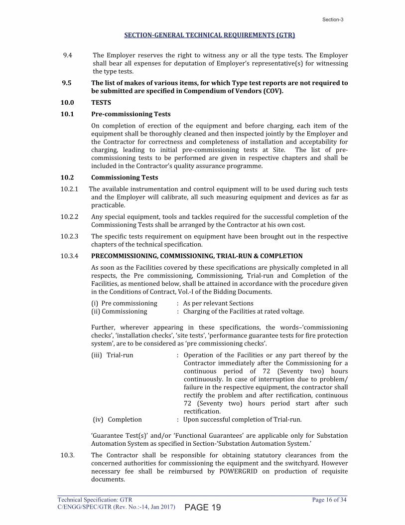
9.4 The Employer reserves the right to witness any or all the type tests. The Employer
shall bear all expenses for deputation of Employer’s representative(s) for witnessing
the type tests.
9.5 The list of makes of various items, for which Type test reports are not required to be submitted are specified in Compendium of Vendors (COV).
10.0 TESTS
10.1 Pre-commissioning Tests
On completion of erection of the equipment and before charging, each item of the
equipment shall be thoroughly cleaned and then inspected jointly by the Employer and
the Contractor for correctness and completeness of installation and acceptability for
charging, leading to initial pre-commissioning tests at Site. The list of pre-
commissioning tests to be performed are given in respective chapters and shall be
included in the Contractor’s quality assurance programme.
10.2 Commissioning Tests
10.2.1 The available instrumentation and control equipment will to be used during such tests
and the Employer will calibrate, all such measuring equipment and devices as far as
practicable.
10.2.2 Any special equipment, tools and tackles required for the successful completion of the
Commissioning Tests shall be arranged by the Contractor at his own cost.
10.2.3 The specific tests requirement on equipment have been brought out in the respective
chapters of the technical specification.
10.3.4 PRECOMMISSIONING, COMMISSIONING, TRIAL-RUN & COMPLETION
As soon as the Facilities covered by these specifications are physically completed in all
respects, the Pre commissioning, Commissioning, Trial-run and Completion of the
Facilities, as mentioned below, shall be attained in accordance with the procedure given
in the Conditions of Contract, Vol.-I of the Bidding Documents.
(i) Pre commissioning : As per relevant Sections
(ii) Commissioning : Charging of the Facilities at rated voltage.
Further, wherever appearing in these specifications, the words–‘commissioning
checks’, ‘installation checks’, ‘site tests’, ‘performance guarantee tests for fire protection
system’, are to be considered as ‘pre commissioning checks’.
(iii) Trial-run : Operation of the Facilities or any part thereof by the
Contractor immediately after the Commissioning for a
continuous period of 72 (Seventy two) hours
continuously. In case of interruption due to problem/
failure in the respective equipment, the contractor shall
rectify the problem and after rectification, continuous
72 (Seventy two) hours period start after such
rectification.
(iv) Completion : Upon successful completion of Trial-run.
‘Guarantee Test(s)’ and/or ‘Functional Guarantees’ are applicable only for Substation
Automation System as specified in Section-‘Substation Automation System.’
10.3. The Contractor shall be responsible for obtaining statutory clearances from the
concerned authorities for commissioning the equipment and the switchyard. However
necessary fee shall be reimbursed by POWERGRID on production of requisite
documents.
������
Section-3
1294334
Line
1294334
Text Box
17

SECTION-GENERAL TECHNICAL REQUIREMENTS (GTR)
____________________________________________________________________________Technical Specification: GTR Page 17 of 34 C/ENGG/SPEC/GTR (Rev. No.:-14, Jan 2017)
11.0 PACKAGING & PROTECTION
11.1 All the equipments shall be suitably protected, coated, covered or boxed and crated to
prevent damage or deterioration during transit, handling and storage at Site till the
time of erection. On request of the Employer, the Contractor shall also submit packing
details/associated drawing for any equipment/material under his scope of supply, to
facilitate the Employer to repack any equipment/material at a later date, in case the
need arises. While packing all the materials, the limitation from the point of view of
availability of Railway wagon sizes in India should be taken into account. The
Contractor shall be responsible for any loss or damage during transportation, handling
and storage due to improper packing. Any demurrage, wharfage and other such charges
claimed by the transporters, railways etc. shall be to the account of the Contractor.
Employer takes no responsibility of the availability of the wagons.
11.2 All coated surfaces shall be protected against abrasion, impact, discolouration and any
other damages. All exposed threaded portions shall be suitably protected with either a
metallic or a non-metallic protecting device. All ends of all valves and pipings and
conduit equipment connections shall be properly sealed with suitable devices to
protect them from damage.
12.0 FINISHING OF METAL SURFACES
12.1 All metal surfaces shall be subjected to treatment for anti-corrosion protection. All
ferrous surfaces for external use unless otherwise stated elsewhere in the specification
or specifically agreed, shall be hot-dip galvanized after fabrication. All steel conductors
including those used for earthing/grounding (above ground level) shall also be
galvanized according to IS: 2629.
12.2 HOT DIP GALVANISING
12.2.1 The minimum weight of the zinc coating shall be 610 gm/sq.m and minimum average
thickness of coating shall be 86 microns for all items having thickness 6mm and above and 900 gm/sq.m for coastal area (30km from sea shore approximately) or as specified in Section-Project. For items lower than 6mm thickness requirement of
coating thickness shall be as per relevant ASTM. For surface which shall be embedded
in concrete, the zinc coating shall be 610 gm/sq.m minimum and 900 gm/sq.m for coastal area as specified in Section-Project.
12.2.2 The galvanized surfaces shall consist of a continuous and uniform thick coating of zinc,
firmly adhering to the surface of steel. The finished surface shall be clean and smooth
and shall be free from defects like discoloured patches, bare spots, unevenness of
coating, spelter which is loosely attached to the steel globules, spiky deposits, blistered
surface, flaking or peeling off, etc. The presence of any of these defects noticed on visual
or microscopic inspection shall render the material liable to rejection.
12.2.3 After galvanizing, no drilling or welding shall be performed on the galvanized parts of
the equipment excepting that nuts may be threaded after galvanizing. Sodium
dichromate or alternate approved treatment shall be provided to avoid formation of
white rust after hot dip galvanization.
12.2.4 The galvanized steel shall be subjected to four numbers of one minute dips in copper
sulphate solution as per IS-2633.
12.2.5 Sharp edges with radii less than 2.5 mm shall be able to withstand four immersions of
the Standard Preece test. All other coatings shall withstand six immersions. The
following galvanizing tests should essentially be performed as per relevant Indian
Standards.
- Coating thickness
- Uniformity of zinc
�������
Section-3
1294334
Line
1294334
Text Box
18
SECTION-GENERAL TECHNICAL REQUIREMENTS (GTR)
____________________________________________________________________________Technical Specification: GTR Page 18 of 34 C/ENGG/SPEC/GTR (Rev. No.:-14, Jan 2017)
- Adhesion test
- Mass of zinc coating
12.2.6 Galvanised material must be transported properly to ensure that galvanised surfaces
are not damaged during transit. Application of touch-up zinc rich paint at site shall be
allowed with approval of Engineer Incharge.
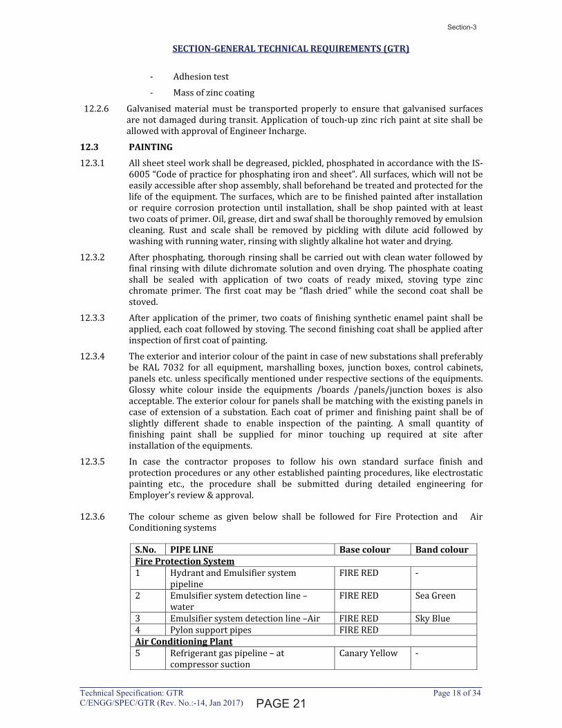
12.3 PAINTING
12.3.1 All sheet steel work shall be degreased, pickled, phosphated in accordance with the IS-
6005 “Code of practice for phosphating iron and sheet”. All surfaces, which will not be
easily accessible after shop assembly, shall beforehand be treated and protected for the
life of the equipment. The surfaces, which are to be finished painted after installation
or require corrosion protection until installation, shall be shop painted with at least
two coats of primer. Oil, grease, dirt and swaf shall be thoroughly removed by emulsion
cleaning. Rust and scale shall be removed by pickling with dilute acid followed by
washing with running water, rinsing with slightly alkaline hot water and drying.
12.3.2 After phosphating, thorough rinsing shall be carried out with clean water followed by
final rinsing with dilute dichromate solution and oven drying. The phosphate coating
shall be sealed with application of two coats of ready mixed, stoving type zinc
chromate primer. The first coat may be “flash dried” while the second coat shall be
stoved.
12.3.3 After application of the primer, two coats of finishing synthetic enamel paint shall be
applied, each coat followed by stoving. The second finishing coat shall be applied after
inspection of first coat of painting.
12.3.4 The exterior and interior colour of the paint in case of new substations shall preferably
be RAL 7032 for all equipment, marshalling boxes, junction boxes, control cabinets,
panels etc. unless specifically mentioned under respective sections of the equipments.
Glossy white colour inside the equipments /boards /panels/junction boxes is also
acceptable. The exterior colour for panels shall be matching with the existing panels in
case of extension of a substation. Each coat of primer and finishing paint shall be of
slightly different shade to enable inspection of the painting. A small quantity of
finishing paint shall be supplied for minor touching up required at site after
installation of the equipments.
12.3.5 In case the contractor proposes to follow his own standard surface finish and
protection procedures or any other established painting procedures, like electrostatic
painting etc., the procedure shall be submitted during detailed engineering for
Employer’s review & approval.
12.3.6 The colour scheme as given below shall be followed for Fire Protection and Air
Conditioning systems
S.No. PIPE LINE Base colour Band colour Fire Protection System 1 Hydrant and Emulsifier system
pipeline
FIRE RED -
2 Emulsifier system detection line –
water
FIRE RED Sea Green
3 Emulsifier system detection line –Air FIRE RED Sky Blue
4 Pylon support pipes FIRE RED
Air Conditioning Plant 5 Refrigerant gas pipeline – at
compressor suction
Canary Yellow -
�������
Section-3
1294334
Line
1294334
Text Box
19
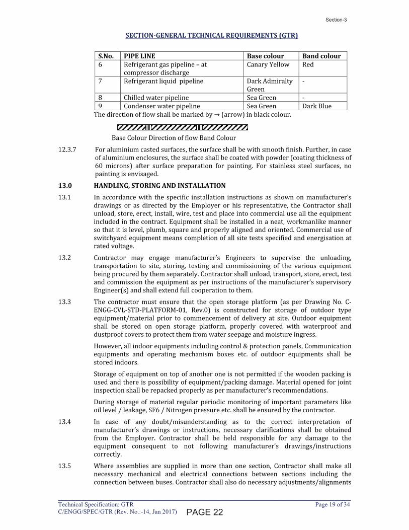
SECTION-GENERAL TECHNICAL REQUIREMENTS (GTR)
____________________________________________________________________________Technical Specification: GTR Page 19 of 34 C/ENGG/SPEC/GTR (Rev. No.:-14, Jan 2017)
S.No. PIPE LINE Base colour Band colour 6 Refrigerant gas pipeline – at
compressor discharge
Canary Yellow Red
7 Refrigerant liquid pipeline Dark Admiralty
Green
-
8 Chilled water pipeline Sea Green -
9 Condenser water pipeline Sea Green Dark Blue
The direction of flow shall be marked by � (arrow) in black colour.
Base Colour Direction of flow Band Colour
12.3.7 For aluminium casted surfaces, the surface shall be with smooth finish. Further, in case
of aluminium enclosures, the surface shall be coated with powder (coating thickness of
60 microns) after surface preparation for painting. For stainless steel surfaces, no
painting is envisaged.
13.0 HANDLING, STORING AND INSTALLATION
13.1 In accordance with the specific installation instructions as shown on manufacturer’s
drawings or as directed by the Employer or his representative, the Contractor shall
unload, store, erect, install, wire, test and place into commercial use all the equipment
included in the contract. Equipment shall be installed in a neat, workmanlike manner
so that it is level, plumb, square and properly aligned and oriented. Commercial use of
switchyard equipment means completion of all site tests specified and energisation at
rated voltage.
13.2 Contractor may engage manufacturer’s Engineers to supervise the unloading,
transportation to site, storing, testing and commissioning of the various equipment
being procured by them separately. Contractor shall unload, transport, store, erect, test
and commission the equipment as per instructions of the manufacturer’s supervisory
Engineer(s) and shall extend full cooperation to them.
13.3 The contractor must ensure that the open storage platform (as per Drawing No. C-
ENGG-CVL-STD-PLATFORM-01, Rev.0) is constructed for storage of outdoor type
equipment/material prior to commencement of delivery at site. Outdoor equipment
shall be stored on open storage platform, properly covered with waterproof and
dustproof covers to protect them from water seepage and moisture ingress.
However, all indoor equipments including control & protection panels, Communication
equipments and operating mechanism boxes etc. of outdoor equipments shall be
stored indoors.
Storage of equipment on top of another one is not permitted if the wooden packing is
used and there is possibility of equipment/packing damage. Material opened for joint
inspection shall be repacked properly as per manufacturer’s recommendations.
During storage of material regular periodic monitoring of important parameters like
oil level / leakage, SF6 / Nitrogen pressure etc. shall be ensured by the contractor.
13.4 In case of any doubt/misunderstanding as to the correct interpretation of
manufacturer’s drawings or instructions, necessary clarifications shall be obtained
from the Employer. Contractor shall be held responsible for any damage to the
equipment consequent to not following manufacturer’s drawings/instructions
correctly.
13.5 Where assemblies are supplied in more than one section, Contractor shall make all
necessary mechanical and electrical connections between sections including the
connection between buses. Contractor shall also do necessary adjustments/alignments
�������
Section-3
1294334
Line
1294334
Text Box
20

SECTION-GENERAL TECHNICAL REQUIREMENTS (GTR)
____________________________________________________________________________Technical Specification: GTR Page 20 of 34 C/ENGG/SPEC/GTR (Rev. No.:-14, Jan 2017)
for proper operation of circuit breakers, isolators and their operating mechanisms. All
components shall be protected against damage during unloading, transportation,
storage, installation, testing and commissioning. Any equipment damaged due to
negligence or carelessness or otherwise shall be replaced by the Contractor at his own
expense.
13.6 Contractor shall be responsible for examining all the shipment and notify the Employer
immediately of any damage, shortage, discrepancy etc. for the purpose of Employer’s
information only. The Contractor shall submit to the Employer every week a report
detailing all the receipts during the weeks. However, the Contractor shall be solely
responsible for any shortages or damages in transit, handling and/or in storage and
erection of the equipment at Site. Any demurrage, wharfage and other such charges
claimed by the transporters, railways etc. shall be to the account of the Contractor.
13.7 The Contractor shall be fully responsible for the equipment/material until the same is
handed over to the Employer in an operating condition after commissioning.
Contractor shall be responsible for the maintenance of the equipment/material while
in storage as well as after erection until taken over by Employer, as well as protection
of the same against theft, element of nature, corrosion, damages etc.
13.8 Where material / equipment is unloaded by Employer before the Contractor arrives at
site or even when he is at site, Employer by right can hand over the same to Contractor
and there upon it will be the responsibility of Contractor to store the material in an
orderly and proper manner.
13.9 The Contractor shall be responsible for making suitable indoor storage facilities, to
store all equipment which requires indoor storage.
13.10 The words ‘erection’ and ‘installation’ used in the specification are synonymous.
13.11 Exposed live parts shall be placed high enough above ground to meet the requirements
of electrical and other statutory safety codes.
13.12 The design and workmanship shall be in accordance with the best engineering
practices to ensure satisfactory performance throughout the service life. If at any stage
during the execution of the Contract, it is observed that the erected equipment(s) do
not meet the above minimum clearances the Contractor shall immediately proceed to
correct the discrepancy at his risks and cost.
13.13 Equipment Bases
A cast iron or welded steel base plate shall be provided for all rotating equipment
which is to be installed on a concrete base unless otherwise agreed to by the Employer.
Each base plate shall support the unit and its drive assembly, shall be of a neat design
with pads for anchoring the units, shall have a raised lip all around, and shall have
threaded drain connections.
14.0 TOOLS
14.1 TOOLS & PLANTS (T&P)
The Contractor shall arrange all T&P (such as necessary supports, cranes, ladders,
platforms etc.) for erection, testing & commissioning of the system at his own cost.
Further, all consumables, wastage and damages shall be to the account of contractor.
All such T&P shall be taken back by the contractor after commissioning of the system.
14.2 SPECIAL TOOLS AND TACKLES
The contractor shall supply all special tools and tackles required for Operation and
maintenance of equipment. The special tools and tackles shall only cover items which
�������
Section-3
1294334
Line
1294334
Text Box
21
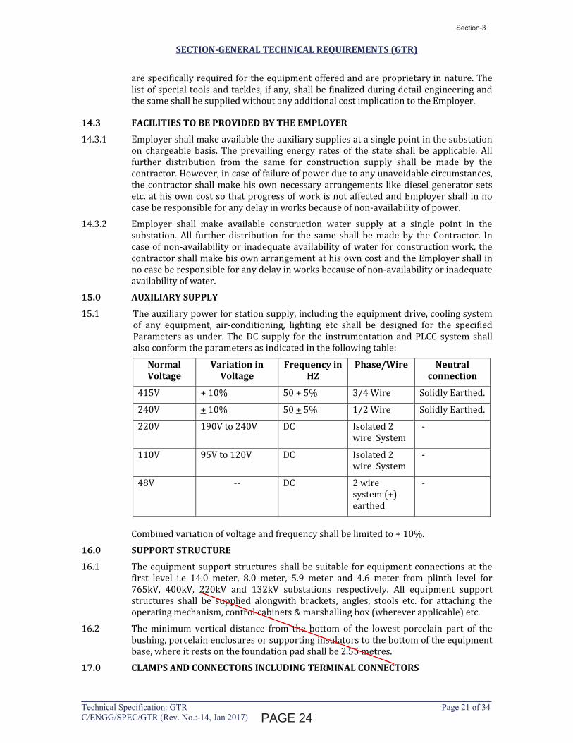
SECTION-GENERAL TECHNICAL REQUIREMENTS (GTR)
____________________________________________________________________________Technical Specification: GTR Page 21 of 34 C/ENGG/SPEC/GTR (Rev. No.:-14, Jan 2017)
are specifically required for the equipment offered and are proprietary in nature. The
list of special tools and tackles, if any, shall be finalized during detail engineering and
the same shall be supplied without any additional cost implication to the Employer.
14.3 FACILITIES TO BE PROVIDED BY THE EMPLOYER
14.3.1 Employer shall make available the auxiliary supplies at a single point in the substation
on chargeable basis. The prevailing energy rates of the state shall be applicable. All
further distribution from the same for construction supply shall be made by the
contractor. However, in case of failure of power due to any unavoidable circumstances,
the contractor shall make his own necessary arrangements like diesel generator sets
etc. at his own cost so that progress of work is not affected and Employer shall in no
case be responsible for any delay in works because of non-availability of power.
14.3.2 Employer shall make available construction water supply at a single point in the
substation. All further distribution for the same shall be made by the Contractor. In
case of non-availability or inadequate availability of water for construction work, the
contractor shall make his own arrangement at his own cost and the Employer shall in
no case be responsible for any delay in works because of non-availability or inadequate
availability of water.
15.0 AUXILIARY SUPPLY
15.1 The auxiliary power for station supply, including the equipment drive, cooling system
of any equipment, air-conditioning, lighting etc shall be designed for the specified
Parameters as under. The DC supply for the instrumentation and PLCC system shall
also conform the parameters as indicated in the following table:
Normal Voltage
Variation in Voltage
Frequency in HZ
Phase/Wire Neutral connection
415V + 10% 50 + 5% 3/4 Wire Solidly Earthed.
240V + 10% 50 + 5% 1/2 Wire Solidly Earthed.
220V 190V to 240V DC Isolated 2
wire System
-
110V 95V to 120V DC Isolated 2
wire System
-
48V -- DC 2 wire
system (+)
earthed
-
Combined variation of voltage and frequency shall be limited to + 10%.
16.0 SUPPORT STRUCTURE
16.1 The equipment support structures shall be suitable for equipment connections at the
first level i.e 14.0 meter, 8.0 meter, 5.9 meter and 4.6 meter from plinth level for
765kV, 400kV, 220kV and 132kV substations respectively. All equipment support
structures shall be supplied alongwith brackets, angles, stools etc. for attaching the
operating mechanism, control cabinets & marshalling box (wherever applicable) etc.
16.2 The minimum vertical distance from the bottom of the lowest porcelain part of the
bushing, porcelain enclosures or supporting insulators to the bottom of the equipment
base, where it rests on the foundation pad shall be 2.55 metres.
17.0 CLAMPS AND CONNECTORS INCLUDING TERMINAL CONNECTORS
�������
Section-3
Latha
Line
Latha
Line
1294334
Line
1294334
Text Box
22

SECTION-GENERAL TECHNICAL REQUIREMENTS (GTR)
____________________________________________________________________________Technical Specification: GTR Page 24 of 34 C/ENGG/SPEC/GTR (Rev. No.:-14, Jan 2017)
18.8 LED based illumination of minimum 9 watts shall be provided. The switching of the
fittings shall be controlled by the door switch.
For junction boxes of smaller sizes such as lighting junction box, manual operated
earth switch mechanism box etc., plug socket, heater and illumination is not required
to be provided.
18.9 All control switches shall be of MCB/rotary switch type and Toggle/piano switches
shall not be accepted.
18.10 Earthing of the cabinet shall be ensured by providing two separate earthing pads. The
earth wire shall be terminated on to the earthing pad and secured by the use of self
etching washer. Earthing of hinged door shall be done by using a separate earth wire.
18.11 The bay marshalling kiosks shall be provided with danger plate and a diagram showing
the numbering/connection/feruling by pasting the same on the inside of the door.
18.12 The following routine tests alongwith the routine tests as per IS:5039 shall also be
conducted:
i) Check for wiring
ii) Visual and dimension check
18.13 The enclosure of bay marshalling kiosk, junction box, terminal box and control cabinets
shall conform to IP-55 as per IS:13947 including application of 2KV rms for 1 (one)
minute, insulation resistance and functional test after IP-55 test.
19.0 DISPOSAL OF PACKING MATERIAL & WASTE FROM CONSTRUCTION SITE
After completion of the work, Contractor shall dispose-off all the packing & waste
materials including empty conductor drums, cable drums, wooden containers, oil
drums, gas cylinders and other waste/scrapped materials from construction site at his
own cost and shall make the substation area properly cleaned.
20.0 TERMINAL BLOCKS AND WIRING
20.1 Control and instrument leads from the switchboards or from other equipment will be
brought to terminal boxes or control cabinets in conduits. All interphase and external
connections to equipment or to control cubicles will be made through terminal blocks.
20.2 Terminal blocks shall be 650V grade and have continuous rating to carry the maximum
expected current on the terminals and non-breakable type. These shall be of moulded
piece, complete with insulated barriers, stud type terminals, washers, nuts and lock
nuts. Screw clamp, overall insulated, insertion type, rail mounted terminals can be used
in place of stud type terminals. But the terminal blocks shall be non-disconnecting stud
type except for the secondary junction boxes of Current Transformer and Voltage
Transformer.
20.3 Terminal blocks for current transformer and voltage transformer secondary leads shall
be provided with test links and isolating facilities. The current transformer secondary
leads shall also be provided with short circuiting and earthing facilities.
20.4 The terminal shall be such that maximum contact area is achieved when a cable is
terminated. The terminal shall have a locking characteristic to prevent cable from
escaping from the terminal clamp unless it is done intentionally.
20.5 The conducting part in contact with cable shall preferably be tinned or silver plated
however Nickel plated copper or zinc plated steel shall also be acceptable.
20.6 The terminal blocks shall be of extensible design, multilayer terminal arrangement is
not allowed in any junction box (Common MB, Individual MB, JB etc.). There should be
�������
Section-3
Latha
Line
1294334
Line
1294334
Text Box
23

SECTION-GENERAL TECHNICAL REQUIREMENTS (GTR)
____________________________________________________________________________Technical Specification: GTR Page 25 of 34 C/ENGG/SPEC/GTR (Rev. No.:-14, Jan 2017)
sufficient space at both sides of terminals so that ferrule number of wires / TB
numbers are clearly visible during wire removal or insertion.
20.7 The terminal blocks shall have locking arrangement to prevent its escape from the
mounting rails.
20.8 The terminal blocks shall be fully enclosed with removable covers of transparent, non-
deteriorating type plastic material. Insulating barriers shall be provided between the
terminal blocks. These barriers shall not hinder the operator from carrying out the
wiring without removing the barriers.
20.9 Unless otherwise specified terminal blocks shall be suitable for connecting the
following conductors on each side.
a) All circuits except Minimum of two of 2.5 sq mm
CT/PT circuits copper flexible.
b) All CT/PT circuits Minimum of 4 nos. of 2.5 sq mm
copper flexible.
20.10 The arrangements shall be in such a manner so that it is possible to safely connect or
disconnect terminals on live circuits and replace fuse links when the cabinet is live.
20.11 Atleast 20 % spare terminals shall be provided on each panel/cubicle/box and these
spare terminals shall be uniformly distributed on all terminals rows.
20.12 There shall be a minimum clearance of 250 mm between the First/bottom row of
terminal block and the associated cable gland plate for outdoor ground mounted
marshalling box and the clearance between two rows of terminal blocks shall be a
minimum of 150 mm.
20.13 The Contractor shall furnish all wire, conduits and terminals for the necessary
interphase electrical connections (where applicable) as well as between phases and
common terminal boxes or control cabinets. For equipments rated for 400 kV and
above the wiring required in these items shall be run in metallic ducts or shielded
cables in order to avoid surge overvoltages either transferred through the equipment
or due to transients induced from the EHV circuits.
20.14 All input and output terminals of each control cubicle shall be tested for surge
withstand capability in accordance with the relevant IEC Publications, in both
longitudinal and transverse modes. The Contractor shall also provide all necessary
filtering, surge protection, interface relays and any other measures necessary to
achieve an impulse withstand level at the cable interfaces of the equipment.
21.0 LAMPS & SOCKETS
21.1 Lamps & Sockets
All lamps shall use a socket base as per IS-1258, except in the case of signal lamps.
All sockets (convenience outlets) shall be suitable to accept both 5 Amp & 15 Amp pin
round Standard Indian plugs. They shall be switched sockets with shutters.
21.2 Hand Lamp:
A 240 Volts, single Phase, 50 Hz AC plug point shall be provided in the interior of each
cubicle with ON-OFF Switch for connection of hand lamps.
21.3 Switches and Fuses:
21.3.1 Each panel shall be provided with necessary arrangements for receiving, distributing,
isolating and fusing of DC and AC supplies for various control, signaling, lighting and
space heater circuits. The incoming and sub-circuits shall be separately provided with
miniature circuit breaker / switch fuse units. Selection of the main and Sub-circuit fuse
�������
Section-3
Latha
Line
1294334
Line
1294334
Text Box
24

SECTION-GENERAL TECHNICAL REQUIREMENTS (GTR)
ANNEXURE-C
____________________________________________________________________________Technical Specification: GTR Page 1 of 23 (Annexure-C) C/ENGG/SPEC/GTR (Rev. No.:-14, Jan’17)
LIST OF GENERAL STANDARDS AND CODES
CODES TITLE -- India Electricity Rules
-- Indian Electricity Act
-- Indian Electricity (Supply) Act
-- Indian Factories Act
IS-5 Colors for Ready Mixed Paints and Enamels IS-335 New Insulating Oils IS-617 Aluminium and Aluminium Alloy Ingots and Castings for General
Engineering Purposes
IS-1448 (P1 to P 145) Methods of Test for Petroleum and its Products
IS-2071 (P1 to P3) Methods of High Voltage Testing
IS-12063 Classification of degrees of protection provided by enclosures of
electrical equipment
IS-2165 ; P1:1997,
P2:1983
Insulation Coordination
IS-3043 Code of Practice for Earthing
IS-6103 Method of Test for Specific Resistance (Resistivity) of Electrical
Insulating Liquids
IS-6104 Method of Test for Interfacial Tension of Oil against Water by the
Ring Method
IS-6262 Method of test for Power factor & Dielectric Constant of Electrical
Insulating Liquids
IS-6792 Method for determination of electric strength of insulating oils
IS-5578 Guide for marking of insulated conductors
IS-11353 Guide for uniform system of marking & identification of
conductors & apparatus terminals.
IS-8263 Methods for Radio Interference Test on High voltage Insulators
IS-9224 (Part 1,2&4) Low Voltage Fuses
IEC-60060 (Part 1 to P4) High Voltage Test Techniques
IEC 60068 Environmental Test
IEC-60117 Graphical Symbols
IEC-60156 Method for the Determination of the Electrical Strength of
Insulation Oils
IEC-60270 Partial Discharge Measurements
IEC-60376 Specification and Acceptance of New Sulphur Hexafloride
IEC-60437 Radio Interference Test on High Voltage Insulators
IEC-60507 Artificial Pollution Tests on High Voltage Insulators to be used on
AC Systems
IEC-62271-1 Common Specification for High Voltage Switchgear & Control
gear Standards
IEC-60815 Guide for the Selection of Insulators in respect of Polluted
Conditions
������
Section-3
1294334
Line
1294334
Text Box
25

SECTION-GENERAL TECHNICAL REQUIREMENTS (GTR)
ANNEXURE-C
____________________________________________________________________________Technical Specification: GTR Page 2 of 23 (Annexure-C) C/ENGG/SPEC/GTR (Rev. No.:-14, Jan’17)
CODES TITLE IEC-60865 (P1 & P2) Short Circuit Current - Calculation of effects
ANSI-C.1/NFPA.70 National Electrical Code
ANSI-C37.90A Guide for Surge Withstand Capability (SWC) Tests
ANSI-C63.21, C63.3 Specification for Electromagnetic Noise and Field Strength
Instrumentation 10 KHz to 1 GHZ
C36.4ANSI-C68.1 Techniquest for Dielectric Tests
ANSI-C76.1/EEE21 Standard General Requirements and Test Procedure for Outdoor
Apparatus Bushings
ANSI-SI-4 Specification for Sound Level Meters
ANSI-Y32-2/C337.2 Drawing Symbols
ANSI-Z55.11 Gray Finishes for Industrial Apparatus and Equipment No. 61
Light Gray
NEMA-107T Methods of Measurements of RIV of High Voltage Apparatus
NEMA-ICS-II General Standards for Industrial Control and Systems Part ICSI-
109
CISPR-1 Specification for CISPR Radio Interference Measuring Apparatus
for the frequency range 0.15 MHz to 30 MHz
CSA-Z299.1-1978h Quality Assurance Program Requirements
CSA-Z299.2-1979h Quality Control Program Requirements
CSA-Z299.3-1979h Quality Verification Program Requirements
CSA-Z299.4-1979h Inspection Program Requirements
TRANSFORMERS AND REACTORS IS:10028 (Part 2 & 3) Code of practice for selection, installation & maintenance of
Transformers (P1:1993), (P2:1991), (P3:1991)
IS-2026 (P1 to P4) Power Transformers
IS-3347 (part 1 to Part 8) Dimensions for Porcelain transformer Bushings for use in lightly
polluted atmospheres
IS-3639 Fittings and Accessories for Power Transformers
IS-6600 Guide for Loading of oil immersed Transformers
IEC-60076 (Part 1 to 5) Power Transformers
IEC-60214 On-Load Tap-Changers
IEC-60289 Reactors
IEC- 60354 Loading Guide for Oil - Immersed power transformers
IEC-60076-10 Determination of Transformer and Reactor Sound Levels
ANSI-C571280 General requirements for Distribution, Power and Regulating
Transformers
ANSI-C571290 Test Code for Distribution, Power and Regulation Transformers
ANSI-C5716 Terminology & Test Code for Current Limiting Reactors
ANSI-C5721 Requirements, Terminology and Test Code for Shunt Reactors
Rated Over 500 KVA
ANSI-C5792 Guide for Loading Oil-Immersed Power Transformers upto and
including 100 MVA with 55 deg C or 65 deg C Winding Rise
������
Section-3
Latha
Line
1294334
Line
1294334
Text Box
26

SECTION-GENERAL TECHNICAL REQUIREMENTS (GTR)
ANNEXURE-C
____________________________________________________________________________Technical Specification: GTR Page 11 of 23 (Annexure-C) C/ENGG/SPEC/GTR (Rev. No.:-14, Jan’17)
CODES TITLE IS:1248 Indicating Instruments
IS:2208 HRC Fuses
IS:13947 (Part-3) Air break switches, air break disconnectors & fuse combination
units for voltage not exceeding 1000V AC or 1200V DC
IS:2147 Degree of protection provided by enclosures for low voltage
switchgear and control gear
IS:6005 Code of practice for phosphating of Iron and Steel
IS:3231 Electrical relays for power system protection
IS:3842 Electrical relay for AC Systems
IS:5 Colours for ready mix paint
IEEE-484 Recommended Design for installation design and installation of
large lead storage batteries for generating stations and
substations
IEEE-485 Sizing large lead storage batteries for generating stations and
substations
Wires and cables ASTMD-2863 Measuring the minimum oxygen concentration to support candle
like combustion of plastics (oxygen index)
IS-694 PVC insulated cables for working voltages upto and including
1100 Volts
IS-1255 Code of practice for installation and maintenance of power
cables, upto and including 33 kV rating
IS-1554 (P1 and P2) PVC insulated (heavy duty) electric cables (part 1) for working
voltage upto and including 1100 V
Part (2) for working voltage from 3.3 kV upto and including 11kV
IS:1753 Aluminium conductor for insulated cables
IS:2982 Copper Conductor in insulated cables
IS-3961 (P1 to P5) Recommended current ratings for cables
IS-3975 Mild steel wires, formed wires and tapes for armouring of cables
IS-5831 PVC insulating and sheath of electric cables
IS-6380 Elastometric insulating and sheath of electric cables
IS-7098 Cross linked polyethylene insulated PVC sheathed cables for
working voltage upto and including 1100 volts
IS-7098 Cross-linked polyethyle insulated PVC sheathed cables for
working voltage from 3.3kV upto and including 33 kV
IS-8130 Conductors for insulated electrical cables and flexible cords
IS-1753 Aluminum Conductors for insulated cables
IS-10418 Specification for drums for electric cables
IEC-60096 (part 0 to p4) Radio Frequency cables
IEC-60183 Guide to the Selection of High Voltage Cables
IEC-60189 (P1 to P7) Low frequency cables and wires with PVC insulation and PVC
sheath
������
Section-3
Latha
Line
1294334
Line
1294334
Text Box
27
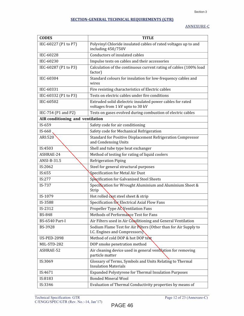
SECTION-GENERAL TECHNICAL REQUIREMENTS (GTR)
ANNEXURE-C
____________________________________________________________________________Technical Specification: GTR Page 12 of 23 (Annexure-C) C/ENGG/SPEC/GTR (Rev. No.:-14, Jan’17)
CODES TITLE IEC-60227 (P1 to P7) Polyvinyl Chloride insulated cables of rated voltages up to and
including 450/750V
IEC-60228 Conductors of insulated cables
IEC-60230 Impulse tests on cables and their accessories
IEC-60287 (P1 to P3) Calculation of the continuous current rating of cables (100% load
factor)
IEC-60304 Standard colours for insulation for low-frequency cables and
wires
IEC-60331 Fire resisting characteristics of Electric cables
IEC-60332 (P1 to P3) Tests on electric cables under fire conditions
IEC-60502 Extruded solid dielectric insulated power cables for rated
voltages from 1 kV upto to 30 kV
IEC-754 (P1 and P2) Tests on gases evolved during combustion of electric cables
AIR conditioning and ventilation IS-659 Safety code for air conditioning
IS-660 Safety code for Mechanical Refrigeration
ARI:520 Standard for Positive Displacement Refrigeration Compressor
and Condensing Units
IS:4503 Shell and tube type heat exchanger
ASHRAE-24 Method of testing for rating of liquid coolers
ANSI-B-31.5 Refrigeration Piping
IS:2062 Steel for general structural purposes
IS:655 Specification for Metal Air Dust
IS:277 Specification for Galvanised Steel Sheets
IS-737 Specification for Wrought Aluminium and Aluminium Sheet &
Strip
IS-1079 Hot rolled cast steel sheet & strip
IS-3588 Specification for Electrical Axial Flow Fans
IS-2312 Propeller Type AC Ventilation Fans
BS-848 Methods of Performance Test for Fans
BS-6540 Part-I Air Filters used in Air Conditioning and General Ventilation
BS-3928 Sodium Flame Test for Air Filters (Other than for Air Supply to
I.C. Engines and Compressors)
US-PED-2098 Method of cold DOP & hot DOP test
MIL-STD-282 DOP smoke penetration method
ASHRAE-52 Air cleaning device used in general ventilation for removing
particle matter
IS:3069 Glossary of Terms, Symbols and Units Relating to Thermal
Insulation Materials
IS:4671 Expanded Polystyrene for Thermal Insulation Purposes
IS:8183 Bonded Mineral Wool
IS:3346 Evaluation of Thermal Conductivity properties by means of
������
Section-3
Latha
Line
1294334
Line
1294334
Text Box
28

SECTION-GENERAL TECHNICAL REQUIREMENTS (GTR)
ANNEXURE-C
____________________________________________________________________________Technical Specification: GTR Page 13 of 23 (Annexure-C) C/ENGG/SPEC/GTR (Rev. No.:-14, Jan’17)
CODES TITLE guarded hot plate method
ASTM-C-591-69 Standard specification for rigid preformed cellular urethane
thermal insulation
IS:4894 Centrifugal Fans
BS:848 Method of Performance Test for Centrifugal Fans
IS:325 Induction motors, three-phase
IS:4722 Rotating electrical machines
IS:1231 Three phase foot mounted Induction motors, dimensions of
IS:2233 Designations of types of construction and mounting
arrangements of rotating electrical machines
IS:2254 Vertical shaft motors for pumps, dimensions of
IS:7816 Guide for testing insulation resistance of rotating machines
IS:4029 Guide for testing three phase induction motors
IS: 4729 Rotating electrical machines, vibration of, Measurement and
evaluation of
IS:4691 Degree of protection provided by enclosures for rotating
electrical machinery
IS:7572 Guide for testing single-phase ac motors
IS:2148 Flame proof enclosure for electrical apparatus
BS:4999(Part-51) Noise levels
Galvanizing IS-209 Zinc Ingot
IS-2629 Recommended Practice for Hot-Dip galvanizing on iron and steel
IS-2633 Methods for testing uniformity of coating of zinc coated articles
ASTM-A-123 Specification for zinc (Hot Galavanizing) Coatings, on products
Fabricated from rolled, pressed and forged steel shapes, plates,
bars and strips
ASTM-A-121-77 Zinc-coated (Galvanized) steel barbed wire
Painting IS-6005 Code of practice for phosphating of iron and steel
ANSI-Z551 Gray finishes for industrial apparatus and equipment
SSPEC Steel structure painting council
Fire protection system -- Fire protection manual issued by tariff advisory committee (TAC)
of India
HORIZONTAL CENTRIFUGAL PUMPS
IS:1520 Horizontal centrifugal pumps for clear, cold and fresh water
IS:9137 Code for acceptance test for centrifugal & axial pumps
IS:5120 Technical requirement – Rotodynamic special purpose pumps
API-610 Centrifugal pumps for general services
Hydraulic Institutes Standards
�������
Section-3
Latha
Line
Latha
Line
1294334
Line
1294334
Text Box
29
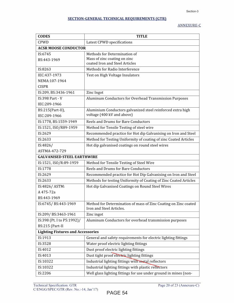
SECTION-GENERAL TECHNICAL REQUIREMENTS (GTR)
ANNEXURE-C
____________________________________________________________________________Technical Specification: GTR Page 20 of 23 (Annexure-C) C/ENGG/SPEC/GTR (Rev. No.:-14, Jan’17)
CODES TITLE CPWD Latest CPWD specifications
ACSR MOOSE CONDUCTOR IS:6745
BS:443-1969
Methods for Determination of
Mass of zinc coating on zinc
coated Iron and Steel Articles
IS:8263 Methods for Radio Interference
IEC:437-1973
NEMA:107-1964
CISPR
Test on High Voltage Insulators
IS:209, BS:3436-1961 Zinc Ingot
IS:398 Part - V
IEC:209-1966
Aluminum Conductors for Overhead Transmission Purposes
BS:215(Part-II),
IEC:209-1966
Aluminium Conductors galvanized steel reinforced extra high
voltage (400 kV and above)
IS:1778, BS:1559-1949 Reels and Drums for Bare Conductors
IS:1521, ISO/R89-1959 Method for Tensile Testing of steel wire
IS:2629 Recommended practice for Hot dip Galvanising on Iron and Steel
IS:2633 Method for Testing Uniformity of coating of zinc Coated Articles
IS:4826/
ASTMA-472-729
Hot dip galvanised coatings on round steel wires
GALVANISED STEEL EARTHWIRE IS:1521, ISO/R:89-1959 Method for Tensile Testing of Steel Wire
IS:1778 Reels and Drums for Bare Conductors
IS:2629 Recommended practice for Hot Dip Galvanising on Iron and Steel
IS:2633 Methods for testing Uniformity of Coating of Zinc Coated Articles
IS:4826/ ASTM:
A 475-72a
BS:443-1969
Hot dip Galvanised Coatings on Round Steel Wires
IS:6745/ BS:443-1969 Method for Determination of mass of Zinc Coating on Zinc coated
Iron and Steel Articles.
IS:209/ BS:3463-1961 Zinc ingot
IS:398 (Pt. I to P5:1992)/
BS:215 (Part-II
Aluminum Conductors for overhead transmission purposes
Lighting Fixtures and Accessories
IS:1913 General and safety requirements for electric lighting fittings
IS:3528 Water proof electric lighting fittings
IS:4012 Dust proof electric lighting fittings
IS:4013 Dust tight proof electric lighting fittings
IS:10322 Industrial lighting fittings with metal reflectors
IS:10322 Industrial lighting fittings with plastic reflectors
IS:2206 Well glass lighting fittings for use under ground in mines (non-
������
Section-3
Latha
Line
Latha
Line
1294334
Line
1294334
Text Box
30
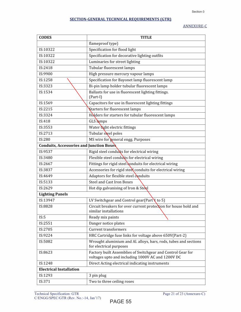
SECTION-GENERAL TECHNICAL REQUIREMENTS (GTR)
ANNEXURE-C
____________________________________________________________________________Technical Specification: GTR Page 21 of 23 (Annexure-C) C/ENGG/SPEC/GTR (Rev. No.:-14, Jan’17)
CODES TITLE flameproof type)
IS:10322 Specification for flood light
IS:10322 Specification for decorative lighting outfits
IS:10322 Luminaries for street lighting
IS:2418 Tubular fluorescent lamps
IS:9900 High pressure mercury vapour lamps
IS:1258 Specification for Bayonet lamp fluorescent lamp
IS:3323 Bi-pin lamp holder tubular fluorescent lamps
IS:1534 Ballasts for use in fluorescent lighting fittings.
(Part-I)
IS:1569 Capacitors for use in fluorescent lighting fittings
IS:2215 Starters for fluorescent lamps
IS:3324 Holders for starters for tubular fluorescent lamps
IS:418 GLS lamps
IS:3553 Water tight electric fittings
IS:2713 Tubular steel poles
IS:280 MS wire for general engg. Purposes
Conduits, Accessories and Junction Boxes IS:9537 Rigid steel conduits for electrical wiring
IS:3480 Flexible steel conduits for electrical wiring
IS:2667 Fittings for rigid steel conduits for electrical wiring
IS:3837 Accessories for rigid steel conduits for electrical wiring
IS:4649 Adaptors for flexible steel conduits
IS:5133 Steel and Cast Iron Boxes
IS:2629 Hot dip galvanising of Iron & Steel
Lighting Panels IS:13947 LV Switchgear and Control gear(Part 1 to 5)
IS:8828 Circuit breakers for over current protection for house hold and
similar installations
IS:5 Ready mix paints
IS:2551 Danger notice plates
IS:2705 Current transformers
IS:9224 HRC Cartridge fuse links for voltage above 650V(Part-2)
IS:5082 Wrought aluminium and Al. alloys, bars, rods, tubes and sections
for electrical purposes
IS:8623 Factory built Assemblies of Switchgear and Control Gear for
voltages upto and including 1000V AC and 1200V DC
IS:1248 Direct Acting electrical indicating instruments
Electrical Installation IS:1293 3 pin plug
IS:371 Two to three ceiling roses
�����
Section-3
Latha
Line
1294334
Line
1294334
Text Box
31
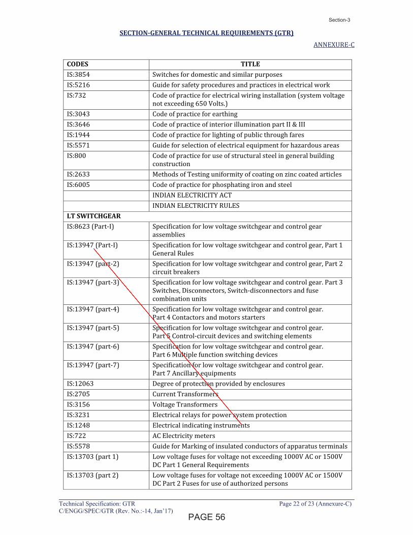
SECTION-GENERAL TECHNICAL REQUIREMENTS (GTR)
ANNEXURE-C
____________________________________________________________________________Technical Specification: GTR Page 22 of 23 (Annexure-C) C/ENGG/SPEC/GTR (Rev. No.:-14, Jan’17)
CODES TITLE IS:3854 Switches for domestic and similar purposes
IS:5216 Guide for safety procedures and practices in electrical work
IS:732 Code of practice for electrical wiring installation (system voltage
not exceeding 650 Volts.)
IS:3043 Code of practice for earthing
IS:3646 Code of practice of interior illumination part II & III
IS:1944 Code of practice for lighting of public through fares
IS:5571 Guide for selection of electrical equipment for hazardous areas
IS:800 Code of practice for use of structural steel in general building
construction
IS:2633 Methods of Testing uniformity of coating on zinc coated articles
IS:6005 Code of practice for phosphating iron and steel
INDIAN ELECTRICITY ACT
INDIAN ELECTRICITY RULES
LT SWITCHGEAR IS:8623 (Part-I) Specification for low voltage switchgear and control gear
assemblies
IS:13947 (Part-I) Specification for low voltage switchgear and control gear, Part 1
General Rules
IS:13947 (part-2) Specification for low voltage switchgear and control gear, Part 2
circuit breakers
IS:13947 (part-3) Specification for low voltage switchgear and control gear. Part 3
Switches, Disconnectors, Switch-disconnectors and fuse
combination units
IS:13947 (part-4) Specification for low voltage switchgear and control gear.
Part 4 Contactors and motors starters
IS:13947 (part-5) Specification for low voltage switchgear and control gear.
Part 5 Control-circuit devices and switching elements
IS:13947 (part-6) Specification for low voltage switchgear and control gear.
Part 6 Multiple function switching devices
IS:13947 (part-7) Specification for low voltage switchgear and control gear.
Part 7 Ancillary equipments
IS:12063 Degree of protection provided by enclosures
IS:2705 Current Transformers
IS:3156 Voltage Transformers
IS:3231 Electrical relays for power system protection
IS:1248 Electrical indicating instruments
IS:722 AC Electricity meters
IS:5578 Guide for Marking of insulated conductors of apparatus terminals
IS:13703 (part 1) Low voltage fuses for voltage not exceeding 1000V AC or 1500V
DC Part 1 General Requirements
IS:13703 (part 2) Low voltage fuses for voltage not exceeding 1000V AC or 1500V
DC Part 2 Fuses for use of authorized persons
�����
Section-3
Latha
Line
1294334
Line
1294334
Text Box
32
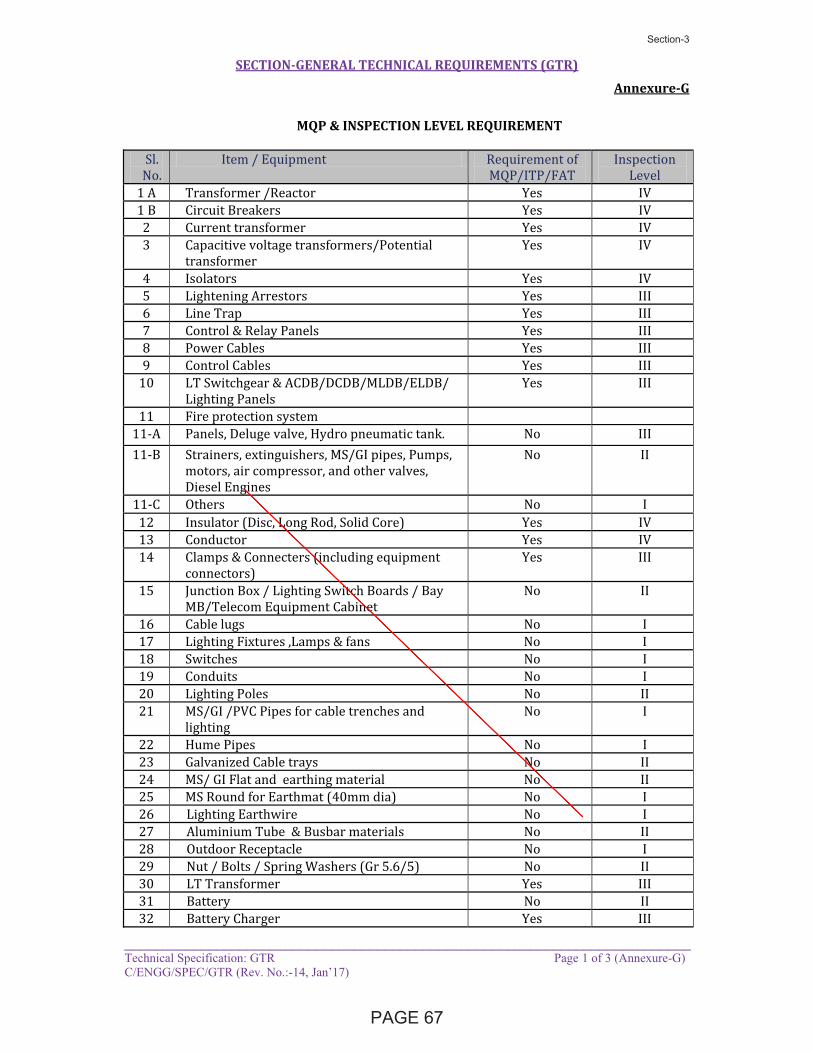
SECTION-GENERAL TECHNICAL REQUIREMENTS (GTR)
Annexure-G
__________________________________________________________________________Technical Specification: GTR Page 1 of 3 (Annexure-G) C/ENGG/SPEC/GTR (Rev. No.:-14, Jan’17)
MQP & INSPECTION LEVEL REQUIREMENT
Sl.
No.
Item / Equipment Requirement of
MQP/ITP/FAT
Inspection
Level
1 A Transformer /Reactor Yes IV
1 B Circuit Breakers Yes IV
2 Current transformer Yes IV
3 Capacitive voltage transformers/Potential
transformer
Yes IV
4 Isolators Yes IV
5 Lightening Arrestors Yes III
6 Line Trap Yes III
7 Control & Relay Panels Yes III
8 Power Cables Yes III
9 Control Cables Yes III
10 LT Switchgear & ACDB/DCDB/MLDB/ELDB/
Lighting Panels
Yes III
11 Fire protection system
11-A Panels, Deluge valve, Hydro pneumatic tank. No III
11-B Strainers, extinguishers, MS/GI pipes, Pumps,
motors, air compressor, and other valves,
Diesel Engines
No II
11-C Others No I
12 Insulator (Disc, Long Rod, Solid Core) Yes IV
13 Conductor Yes IV
14 Clamps & Connecters (including equipment
connectors)
Yes III
15 Junction Box / Lighting Switch Boards / Bay
MB/Telecom Equipment Cabinet
No II
16 Cable lugs No I
17 Lighting Fixtures ,Lamps & fans No I
18 Switches No I
19 Conduits No I
20 Lighting Poles No II
21 MS/GI /PVC Pipes for cable trenches and
lighting
No I
22 Hume Pipes No I
23 Galvanized Cable trays No II
24 MS/ GI Flat and earthing material No II
25 MS Round for Earthmat (40mm dia) No I
26 Lighting Earthwire No I
27 Aluminium Tube & Busbar materials No II
28 Outdoor Receptacle No I
29 Nut / Bolts / Spring Washers (Gr 5.6/5) No II
30 LT Transformer Yes III
31 Battery No II
32 Battery Charger Yes III
������
Section-3
Latha
Line
Latha
Line
1294334
Line
1294334
Text Box
33
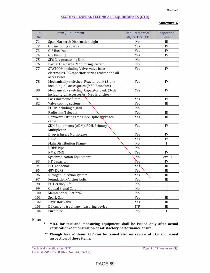
SECTION-GENERAL TECHNICAL REQUIREMENTS (GTR)
Annexure-G
__________________________________________________________________________Technical Specification: GTR Page 3 of 3 (Annexure-G) C/ENGG/SPEC/GTR (Rev. No.:-14, Jan’17)
Sl.
No.
Item / Equipment Requirement of
MQP/ITP/FAT
Inspection
Level
71 Span Marker & Obstruction Light No III
72 GIS including spares Yes IV
73 GIS Bus Duct Yes IV
74 GIS Bushing Yes IV
75 SF6 Gas processing Unit No II
76 Partial Discharge Monitoring System No II
77 STATCOM including Valve, valve base
electronics, DC capacitor, series reactor and all
accessories
Yes IV
78 Mechanically switched Reactor bank (3-ph)
including all accessories (MSR Branches)
Yes IV
80 Mechanically switched Capacitor bank (3-ph)
including all accessories (MSC Branches)
Yes IV
81 Pass Harmonic filters Yes IV
82 Valve cooling system Yes III
FODP including pigtail No II
Radio link Telecom Yes III
Hardware Fittings for Fibre Optic approach
cable
Yes III
SDH Equipments (ADM), PDH, Primary
Multiplexer
Yes IV
Drop & Insert Multiplexer Yes IV
DACS Yes IV
Main Distribution Frame No I
HDPE Pipe No II
NMS, TMN Yes IV
Synchronization Equipment No Level-I
93 HT Capacitor Yes IV
94 PLC Capacitor Yes III
95 48V DCPS Yes III
96 Nitrogen Injection system Yes III
97 Foundation/Anchor bolts Yes III
98 EOT crane/Lift No II
99 Optical Signal Column No II
100 Maintenance Platform No II
101 Spark Gap Yes III
102 Thyristor Valve Yes III
103 DC current & voltage measuring device ITP III
104 Furniture No I
Note: * MICC for test and measuring equipment shall be issued only after actual
verification/demonstration of satisfactory performance at site.
** Though level-2 items, CIP can be issued also on review of TCs and visual inspection of these items.
�����
Section-3
Latha
Line
1294334
Line
1294334
Text Box
34
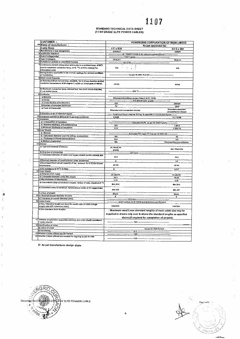
Latha
Text Box
SECTION 4
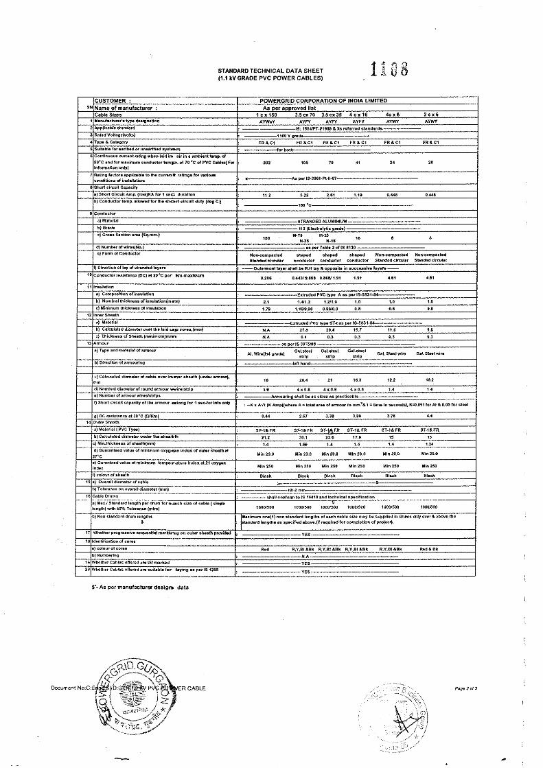
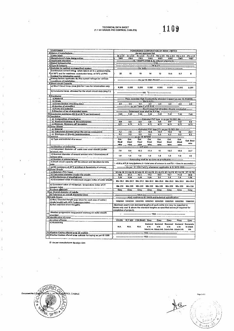

Bharat Heavy Electricals Limited Doc No. TB-408-510-011 1.1KV AUXILIARY POWER & CONTROL CABLE Section-5/ Annexure - 1
_____________________________________________________________________________________________________ Section 4: Annexure Page 1 of 1
ANNEXURE-1
COMPLIANCE CERTIFICATE OF TECHNICAL SPECIFICATION The bidder shall confirm compliance to the following by signing/ stamping this compliance certificate and furnishing same with the offer.
1. The scope of supply, technical details, construction features, design parameters etc. shall be as per technical specification & there are no exclusion/ deviation with regard to same.
2. There are no deviation(s) with respect to specification other than those furnished in the ‘schedule of deviations’.
3. Only those technical submittals which are specifically asked for in NIT to be submitted at tender
stage shall be considered as part of offer. Any other submission, even if made, shall not be considered as part of offer.
4. Any comments/ clarifications on technical/ inspection requirements furnished as part of bidder’s
covering letter shall not be considered by BHEL, and bidder’s offer shall be construed to be in conformance with the specification.
5. Any changes made by the bidder in the price schedule with respect to the description/ quantities
from those given in ‘BOQ’ of the specification shall not be considered (i.e., technical description & quantities as per the specification shall prevail).
Date: Bidder’s Stamp & Signature
Bharat Heavy Electricals Limited DOC.No. TB-408-510-011 1.1KV AUXILIARY POWER & CONTROL CABLE Section-5 / Annexure-2
_____________________________________________________________________________________________________ Section 4: Annexures Page 1 of 1
ANNEXURE – 2
SCHEDULE OF TECHNICAL DEVIATIONS Bidder shall list below all technical deviation clause wise w.r.t. tender specifications: S.No. Section/ Page No. Clause No. Deviation Reason / Justification Any deviation not specifically brought out in this section shall not be admissible for any commercial implication at later stage. Except to the technical deviations listed in this schedule, bidder’s offer shall be considered in full compliance to the tender specifications irrespective of any such deviation indicated / taken elsewhere in the submitted offer.
Date: Tenderer’s Stamp & Signature