
SECTION -7 TECHNICAL SPECIFICATION - AIFF
382
SECTION -7 TECHNICAL SPECIFICATION PROPOSED WORKS OF DRESSING ROOM & ALLIED WORKS(PHASE-2) FOR NATIONAL CENTER OF EXCELLENCE IN FOOTBALL AT RAJARHAT, KOLKATA, WB, INDIA FOR ALL INDIA FOOTBALL FEDERATION(AIFF) Football Federation, Football House, Sector 19, Phase 1 Dwarka, New Delhi: 110075 Telephone: 91-11-25308200/201/202/203/204/205 Fax: 91-11- 25308234,25308236 [email protected]
-
Upload
khangminh22 -
Category
Documents
-
view
2 -
download
0
Transcript of SECTION -7 TECHNICAL SPECIFICATION - AIFF

SECTION -7 TECHNICAL SPECIFICATION
PROPOSED WORKS OF DRESSING ROOM & ALLIED WORKS(PHASE-2) FOR NATIONAL
CENTER OF EXCELLENCE IN FOOTBALL AT RAJARHAT, KOLKATA, WB, INDIA
FOR
ALL INDIA FOOTBALL FEDERATION(AIFF)
Football Federation, Football House, Sector 19, Phase 1 Dwarka, New Delhi: 110075 Telephone: 91-11-25308200/201/202/203/204/205 Fax: 91-11- 25308234,25308236

Table of Contents CIVIL WORKS .................................................................................................................................. 4
MATERIAL & WORKMANSHIP ..................................................................................................... 4
I. GENERAL .................................................................................................................................. 4
II. TECHNICAL SPECIFICATIONS FOR STRUCTURE, CIVIL & FINISHING WORKS ........ 6
1. TECHNICAL SPECIFICATION FOR PILE FOUNDATION WORK ................................. 6
2. TECHNICAL SPECIFICATION FOR EARTHWORK EXCAVATION ............................ 20
3. TECHNICAL SPECIFICATION FOR ANTITERMITE TREATMENT ............................ 24
4. TECHNICAL SPECIFICATION FOR CONCRETE WORKS ............................................ 27
5. TECHNICAL SPECIFICATION FOR VACUUM DEWATER FLOORING ..................... 41
6. TECHNICAL SPECIFICATION FOR STEEL REINFORCEMENT .................................. 43
7. TECHNICAL SPECIFICATION FOR STRUCTURAL STEEL WORK ............................ 44
8. TECHNICAL SPECIFICATION FOR SPECIALISED PAINTING WORK ...................... 62
9. TECHNICAL SPECIFICATION FOR MASONRY WORKS ............................................. 63
10. TECHNICAL SPECIFICATION FOR BLOCK MASONRY .......................................... 67
11. TECHNICAL SPECIFICATION FOR FLOORING AND DADOING WORKS ........... 72
BASE CONCRETE .................................................................................................................. 74
12. TECHNICAL SPECIFICATION FOR STEEL DOORS .................................................. 83
INTERNAL DOORS ................................................................................................................ 84
13. TECHNICAL SPECIFICATION FOR ALUMINIUM WORKS ..................................... 87
14. TECHNICAL SPECIFICATION FOR DOORS/SHUTTERS/HATCHES INCLUDING IRON MONGERY ....................................................................................................................... 92
15. TECHNICAL SPECIFICATION FOR FRAMED PANEL CUBICLE PARTITION .... 102
16. TECHNICAL SPECIFICATION FOR PLASTERING WORKS .................................. 103
17. TECHNICAL SPECIFICATION FOR PAINTING WORKS ........................................ 106
18. TECHNICAL SPECIFICATION FOR WATERPROOFING TREATMENT ............... 114
19. TECHNICAL SPECIFICATION FOR EPOXY FLOOR AND WALL COATING ...... 117
20. TECHNICAL SPECIFICATION FOR PLASTER BOARD/ CEMENT BOARD/DRY LININGS/PARTITIONS/CEILINGS ......................................................................................... 119
21. TECHNICAL SPECIFICATIONS FOR PLASTICS/CORK/LINO/CARPET TILING / SHEETING ................................................................................................................................. 130
22. TECHNICAL SPEFICATION FOR GLAZED CURTAIN WALLING ........................ 133
23. TECHNICAL SPECIFICATION FOR GALVALUME DOUBLE SKIN INSULATED ROOFING SYSTEM .................................................................................................................. 158
24. TECHNICAL SPECIFICATION FOR DRY SAND STONE CLADDING .................. 159
25. TECHNICAL SPECIFICATION FOR ALUMINIUM COMPOSITE PANEL CLADDING ............................................................................................................................... 161
26. TECHNICAL SPECIFICATION FOR METAL FINS SYSTEM .................................. 169
27. TECHNICAL SPECIFICATION FOR RAILINGS ....................................................... 172

28. TECHNICAL SPECIFICATION FOR SPORTS FLOORING WORKS ....................... 177
III. TECHNICAL SPECIFICATION FOR ELEVATORS ........................................................... 177
IV. TECHNICAL SPECIFICATIONS FOR ELECTRICAL WORKS ........................................ 184
V. TECHNICAL SPECIFICATIONS FOR FIRE FIGHTING WORKS .................................... 216
VI. TECHNICAL SPECIFICATIONS FOR HVAC WORKS ..................................................... 275
VII. TECHNICAL SPECIFICATIONS FOR PLUMBING WORKS ............................................ 336
VIII APPROVED MAKES OF MATERIAL ..................................................................................... 1

CIVIL WORKS
MATERIAL & WORKMANSHIP I. GENERAL
Materials and Workmanship Specifications The specifications listed in this Part of the Employer’s Requirements may be modified by the Tenderer at the time of submitting the Tender to suit the requirements of the Tenderer’s design. Any such modifications shall be submitted with the Tender. When considering any changes, it shall be noted that the specifications given in this Part shall represent the minimum required standards for material and workmanship to be followed in the construction of the works. Where there is any discrepancy between this Part 4 of Employer’s Requirements and either Part 2 or Part 3 of the Employer’s Requirements, the requirements of Part2 and Part 3 shall take precedence. Standard of Works The whole of the materials employed in connection with the permanent work of the Contract shall be new and of the best quality and description of their respective kinds and, except where otherwise called for, shall be of the highest grade described in Indian or other relevant Standards for such materials and shall be tested as prescribed therein; similarly, the workmanship in every case shall be of the best character, and the whole shall be subject to the approval of the Engineer. Standards & Code Any Indian, British, American or other International Standard or Code of Practice referred to in the documents relating to the Contract shall be held to be the latest edition published at the time of Tender. Where alternative Standards or Codes of Practice have been published in metric units, these shall take precedence over the publication in imperial units. Equivalent Standards
a) Subject to the approval of the Engineer, materials may be supplied conforming with other recognised Standards which correspond closely with the relevant Specified Standards.
b) In the event that the Contractor proposes use of an alternative Standard he shall provide to the Engineer a copy of the Standard proposed together with an authoritative translation into English where the original is in a language other than English. Alternative Materials & Equipment
a) In all cases where the name of a particular type or make of equipment or material is referred to on the Drawings or elsewhere in this Specification, this is intended to indicate only the acceptable standard.
b) The Contractor may offer alternative materials to equipment to that specified and in all such cases the Contractor's offer shall be at least of equal quality. When alternatives are offered the Contractor shall submit to the Engineer for approval, a statement detailing the alternative(s) and shall include full technical descriptions, drawings, specifications, test certificates etc and shall provide such full information as is required to enable the Contractor to demonstrate to the Engineer that the alternative(s) is (are) equivalent to the item specified. Any further information that the Engineer may require shall be produced by the Contractor when called for. Approval of Materials & Items of Equipment
a) As soon as possible after the Contract has been awarded, the Contractor shall submit to the Engineer a list of suppliers from whom he proposes to purchase the materials required for the Works. Each supplier must be willing to admit the Engineer, or his

representative, to his premises during ordinary working hours for the purpose of obtaining samples or inspection of the works and processes. In addition, if required by the Engineer, the Contractor shall deliver samples to the offices of the Engineer or to nominated testing laboratories or to the site of the Works. The cost of such samples shall be borne by the Contractor.
b) The Contractor shall provide at least the following information when seeking approval of materials and items of equipment. - A Description of the material/item - Name of proposed supplier - Indian Standard, or other approved Standard applicable - Test Certificates as applicable
c) The Contractor shall use locally produced materials in preference to imported providing they comply with the requirements of the Specification. Supply of Samples
a) The whole cost of supplying adequate samples of any materials to be used in the Works for testing either at the Manufacturer's Works or at the site or at an independent Laboratory nominated by the Engineer, shall be deemed to be included in the rates or sums entered in the Price Schedule.
b) Samples shall be taken at regular intervals and tested in accordance with relevant standards. Material – General
a) Sources of supply : b) The sources of supply of materials shall not be changed from those approved without
the written permission of the Engineer. c) Quality of supply : d) Materials subsequently supplied shall be at least equal to the approved sample in all
respects. e) Rejected materials : f) Rejected materials are to be removed promptly from the Site. g) Copies of orders : h) The Contractor shall, at the Engineer’s request, forward to the Engineer copies of
orders for materials to be incorporated into the Works. i) Manufacturers instructions : j) All materials, goods etc., shall be used or installed in accordance with the instructions
of the Manufacturer or Supplier unless otherwise specified or instructed by the Engineer. Testing of Samples
a) At the Manufacturer's Works : b) The costs of testing at Manufacturer's Works of any materials to be used in the Works
and the supply of "proof" or test certificates by the Manufacturer shall be deemed to be included in the rates or sums entered in the Price Schedule.
c) At an Independent Laboratory : d) In addition to those tests required by the Employer’s Requirements and relevant
Standards, the Engineer may at any time instruct the Contractor to supply samples of materials to be used in the Works for test by an Independent Laboratory. The costs of transport to the Independent Laboratory and laboratory charges, fees of independent inspectors, etc, shall be paid for under the appropriate item in the Price Schedule, except where a sample is found not to be in accordance with the specified requirements, in which case the costs shall be borne by the Contractor.

e) Sampling and Testing frequency: The sampling and test frequencies shall be as per the relevant IS codes. Where the relevant IS code does not lay down any frequency for sampling and testing, the same shall be as given in the table below or as directed by the Engineer
II. TECHNICAL SPECIFICATIONS FOR STRUCTURE, CIVIL & FINISHING WORKS
1. TECHNICAL SPECIFICATION FOR PILE FOUNDATION WORK
PILE FOUNDATION
1.1Scope of W o rk
a) These specifications cover the works of providing pile foundations. Work included consists of all necessary services and furnishing of all labour material, tools, equipment and related items for the full and satisfactory performance of the contract, conforming to these specifications and as shown in the Contract Drawings or reasonably implied therein or any authorised conditions or alterations thereof. b) The Contractor shall visit the site and familiarise himself with the conditions at site. The Employer or Engineer’s representative shall not be held responsible for the accuracy of the site condition or sub-soil data, furnished in good faith with the contract. c) With the tender the Contractor shall submit the detailed method of construction to be used. For cast-in-situ concrete piles the Contractor shall indicate the methods he proposes to concrete the piles in order to prevent necking of piles. d) The items of work will generally be as follows: i. Boring/drilling including provision of temporary casing. ii. Supplying, fabrication, and placement of all reinforcing bars. iii. Casting
of concrete piles as per specifications. iv. Load testing of piles.
1.2 General
1.2.1 Piling Plant And Methods:
Suggested method for piling is cast in situ-bored piles with hydraulic drilling rigs using partial depth casing with Polymer and oscillator arrangement.
a) The Contractor shall submit to the Employer or Engineer’s representative,
full details of his proposed piling equipment and detailed method statements
for carrying out the Works in not less than 2 weeks before any piling work is
commenced. Details of casings and concreting methods in respect of bored
cast in place concrete piles are to be provided.
b) The Contractor shall not commence any piling until the methods which he
proposes to use have been approved but such approval shall not relieve
the Contractor from any of his obligations and responsibilities under the
Contract. If for any reason the Contractor wishes to make any change in
the methods of working, he shall not make any such change without

having first obtained the Employer or Engineer’s representative approval
thereof.
c) List and nos. of equipment & accessories proposed to be used for the
present job shall be submitted along with the technical bid/ Schedule of
quantities.
1.2.2 Records
The Contractor shall keep complete records of all data required by the Engineer covering the drilling, fabrication, driving and installation of each pile and shall submit two signed copies of these records to the Engineer not later than noon of the next working day after installation of the piles.
1.2.3 Progr am me and Pr ogress Repor t
a) The Contractor shall inform the Engineer each day of the programme of
piling for the following day and shall give adequate notice of his intention
to work outside normal hours and at weekends, w here approved. b) The Contractor shall submit to the Engineer on the first day of each week, or on such other date as the Engineer may decide, a progress report showing the rate of progress to that date and progress during the previous week or period of all main items of piling works, as required by the Engineer.
1.2.4 Setting Ou t
The Contractor shall establish and maintain permanent datum level points, base lines and grid lines to the satisfaction of the Engineer and shall set out with a suitable identifiable pin o r marker the position of each pile. The setting out of each pile shall be agreed with the Engineer at least 8 working hours prior to commencing work on a pile and adequate notice for checking shall be given by the Contractor.
Notwithstanding such checking and agreement, the Contractor shall be responsible for the correct and proper setting out of the piles and for the correctness of the positions, levels, dimensions, and alignment of the piles.
After all piles are cast and weak concrete is chipped out the C ontractor shall submit the drawing showing the exact location of piles with respect to the column centre line.
1.2.5 Disturb ance and D am ages During Cons truc tion
a) The Contractor shall take precautions adequate enough to avoid damage to
existing services and adjacent structures. IS: 2974 (Part 1) - 1969 may be used as
a guide for studying qualitatively the effect of vibration of persons and
structures. In case of deep excavation adjacent to piles, proper shoring or other suitable arrangement shall be done to guard against the lateral movement of soil
stratum or releasing the confining soil stress. Any such damage shall be repaired
by the contractor to the satisfaction of the Engineer.

b) The Contractor shall ensure that damage does not occur to complete piling wor
ks and shall submit to the Engineer for approval his proposed sequence and timing
for drilling, driving or boring piles having regard to the avoidance of damage to
adjacent piles.
1.2.6 Obstru ctions
If during the execution of the Works the Contractor encounters obstructions due to any reason whatsoever, he shall forthwith notify the Employer or Engineer’s representative accordingly and submit to him details of proposed methods for overcoming the obstruction and proceed according to the Engineer’s instructions.
1.3 Applicable S tan dar ds
The construction of piles shall be in accordance with the following Indian Standard Codes of Practice (latest revisions), for Design and Construction of Pile Foundations:
a) IS:2911 - Code of practice for Design and Construction of Pile Foundations - Part I (all sections)
b) IS: 5121 - Safety code for Piling and other deep foundations.
c) IS: 455 - Specifications for Portland Slag Cement.
d) IS: 456 - Code of Practice for Plain & Reinforced Cement Concrete. e) IS: 1786 - Code for Reinforcement Steels.
f) IS: 14593 - Code for Design and Construction of Bored Cast-in-situ Piles founded on rocks.
g) NBC:2005 – National Building Code of India
1.4 Materials
1.4.1 General
Unless otherwise specified in this section all materials shall conform to the requirements specified in separate sections for Concrete, Formwork and Reinforcement.
1.4.2 Cement
The cement to be used for piling and all foundation work shall be conforming to following Indian Standard Specifications- IS: 455, Specifications for Portland Slag Cement. Blending using GGBS shall be permitted subject to Max. of 30%.The cement shall be free from lumps and caking.
1.4.3 Concrete

a) Concrete Mix Design: The concrete shall be of grade as per Table 2 in this document. The maximum size of coarse aggregate shall not exceed 20mm. For cast-in-situ piles concrete with a slump of 150 to 175mm (consistent with the method of concreting) will be required. For slumps more than 150mm the workability should be tested by “determination of flow” as per IS: 9103. Minimum cement contents for design mix shall not be less than 400 kg/m3 of concrete in piling. For piling, quantity of cement shall be as per the design mix or the minimum cement content whichever is greater shall be used. The Contractor shall submit mix design calculations and get the same approved by the Engineer well before the starting of installation of piles and carry out adequate numbers of tests to ensure the minimum specified strength as indicated in drawings. b) Concrete Cube Test: Concrete cubes shall be cast, tested and evaluated
as specified in section 4.7 of this document.
1.4.4 Reinforcement
The reinforcement shall conform to the requirements specified in Section 6 extending for the full length of the pile and shall project 60 times bar diameters above the cut off level or as specified in the drawing. Only circular concrete cover blocks threaded on to the helix shall be used for ensuring the specified cover.
Joints in main longitudinal bars will be permitted only where, in the opinion of the Engineer, each bar cannot be supplied in one complete length. Where permitted, joints shall be provided at agreed centres, designed to develop the full strength of the bar across the joint, provided with adequate extra links or stirrups and staggered in position from those of adjacent longitudinal bars, all to the approval of the Engineer.
All main longitudinal bars shall be tack weld at lapping if any and to the pile cap/raft reinforcement. The last one circle of helical stirrups at each end shall be welded to main longitudinal bars.
1.4.5 Casings and Tremie Pipes
The casings and tremie pipes may be in mild steel or other equivalent material as approved by the Employer or Engineer’s representative. The type of liners shall depend upon the construction met hodology as per approved by the Employer or Engineer’s representative. The temporary casing plates and permanent liners shall have adequate wall thickness and strength to withstand driving stresses, stresses due to soil pressure, etc. without damage or distortion.
All joints shall be water tight. The internal diameter of the casing shall not be less than the nominal diameter of pile.
1.5 Cast I n - Situ D rilled/ B ored Piles
a) Diameters of the piles shall be the concrete shaft diameters and shall not
be less than the diameters specified in the drawing. b) These shall be formed by drilling to the founding strata specified on the drawings or as directed at site.During pilling in compacted backfill soil, the sides of the boring shall be prevented from collapsing by one of the following:
i. Permanent mild steel liner (cased pile)

Permanent steel liner of sufficient length shall be provided up to full length of compacted soil strata. The minimum thickness of steel liner shall be 6 mm for piles up to 1.2 m diameter, 8 m m for piles up to 1.5 m dia. The cost of permanent liner shall be paid as per BOQ.
c) Piles shall be constructed in a sequence approved by the Employer or
Engineer’s representative. During boring, the Contractor shall, where
required by the Engineer, take soil or rock samples and transport them to an
approved testing laboratory or carry out soil tests as directed.
d) The method adopted shall be chosen giving due consideration to the subsoil data, rock data and to the
other relevant conditions at site as well as to the presence of adjacent structures.
e) The bottom of the steel lining shall be sufficiently in advance of the
boring tool so as to prevent settlement of outside soil and formation
of cavities. f) Removable mild steel casings shall be used only with extreme caution. Individual casings shall be joined
together by screwing or any other approved method and not by
direct butting with external lug connections. The inner surface of
casings shall be smooth and free of all internal projections.
1.6 Drilling
1.6.1 General
Drilling is a cutting process that uses a drill bit to cut a hole of circular cross-section in solid materials. The drill bit is usually a rotary cutting tool, often multipoint. The bit is pressed against the work piece and rotated at rates from hundreds to thousands of revolutions per minute. This forces the cutting edge against the work piece, cutting off chips (swarf) from the hole as it is drilled.
Since it is required to bore holes in rock without damaging the rock strata, it is necessary that speciali zed techniques and personnel are brought on board. The cost of implementing the techniques and of using the services of trained personnel shall be borne solely by the contractor. Blasting technique and shock methods of drilling is not advised as it will damage the base rock and open up cracks and crevices for sea water to percolate in and affect the substructure.
The Contractor shall drill to the total appropriate depth that allows for the pile to be embedded into the rock based on the geotechnical information.
The Contractor may use any relevant rotary drilling technique that he feels applicable to achieve the depth and diameter required, provided that the techniques used are those specified in his proposal and are approved by the Employer or Engineers’ Representative. Drilling fluid additives must be approved

by the Employer or Engineers’ Representative, and must be of low solids, non-toxic degradable type.
The contractor shall insure that care is being taken while drilling is being done so that minimum damage to the rock occurs. Contractor shall ensure that rock debris (due to drilling and cutting of the rock) shall be removed from the core before piling work is to commence. One of the drilling techniques is mentioned below:
1.6.1. 1 Diamond Exploration Drilling
Diamond drill bits are specifically designed for use on very hard strata. The extremely hard nature of the strata requires that the diamond drill bits be used with proper drilling techniques. Improper use can overheat and damage the drill bit and may also cause heat fractures and material breakage. The three primary drilling actions namely: Drill Speed, Drill Pressure and Lubrication. These must work together to allow the drill bit to function without overheating from friction due to the extremely hard material. When used properly, the diamond drill bit should NEVER be HOT. The drill bit should never be more than warm, to the touch. If a bit becomes hot, it is an indication of inadequate lubrication, too fast a drill speed or too much pressure for the spe cific material being drilled.
1.6.2 Lubric ation
Water or coolant must always be used to cool and lubricate the tip. The lubrication reduces heat build-up, prolonging drill bit life and helps avoid heat fractures in the material. Water is most often used as the lubricant, since it works very well and has no additional cost. Oil based lubricants do not work well on diamond drill bits.
Good lubrication is critical. Minimal lubrication will keep the bit from burning up, but very good lubrication techniques will extend bit life by a factor of 5 or even 10.
1.6.3 Lubric ation Tips & Techniq ue
Various kinds of very specialized industrial water feed equipment are available for industrial production type work. But, when drilling with diamond bits, the primary concern is merely getting enough water lubrication on the cutting edge of the bit, no matter what method is used.
However, all lubrication methods are not equal. Since good lubrication extends drill bit life considerably, it is mandatory for the contractor to use a lubricant which is approved by the
Employer or Engineers’ Representative. One of the few techniques has been mentioned below.
1.6.3. 1 Hose or Water Drip Method The most basic method is to use a small hose that runs water onto the surface near the hole and down into the bore hole. To provide lubrication on a horizontal surface, one trick is to place a plastic jug or bottle with a small hole near the bottom of it, next to the drill hole. The water leaks out of the bottle and provides

continuous lubrication as you drill. Th e water needs to be pumped so that it reaches the tip and the tip does not over heat. Without proper pumping technique, the water will not reach the very tip of the drill bit.The contractor may adopt any other drilling technique. The technique(s) which s hall be used for rock boring/cutting shall be approved by the Employer or Engineers’ Representative.
1.6.4 Boring
a) Boring shall be done using hydraulic drilling rigs with oscillator
arrangement suiting to different kinds of strata encountered.
b) As a general guideline, size of cutting tool shall in no case be less than the diameter of the pile minus 75mm. However the size of cutting tool shall be chosen by contractor depending on the type of substrata and equipment employed by contractor so that executable pile shal l not have diameter less than nominal diameter of pile as specified in drawings. The contractor shall also ensure that there is no reduction in poured concrete quantities. These calculations shall be based on consumption of concrete poured in bore (as recorded in pour log) and actual concrete required in bore on theoretical basis i.e. based on nominal diameter of pile and actual bore hole length (based on actual sounding of founding level). Above 5% reduction in consumption of poured concrete quantities in pile may be rejected. In general piling shall be done by using hydraulic rig with temporary liner. Use of liner for top 4 to 6 metres from ground level or more depth, to protect loose soil falling in bore hole) as directed by engineer, is essential. No extra payment shall be made to the contractor for using temporary liner, over the item of piling as in BOQ. c) Use of drilling mud in stabilizing sides of the pile borehole may also be necessary together with temporary or permanent casing. However, this will be permitted only when deemed necessary by the Engineer. In such situations the properties of polymer used and quality control shall be as per requirement given below.
d) Table 1: Properties of polymer to be used in pilling
Parameters
Fresh mix
Reused Slurry
Prior to Concrete pour
Vi scosi ty Cone Ma rs h
65-140
55-140
50-140
Sa nd Content ( %)
-
Les s tha n or equal to 2%
Les s tha n or
pH
11-12
11-12
7-12
Note :- The percentage variation should be limited to 20%.
e) When using Polymer, flushing shall be done after lowering of inserting reinforcement cage and tremie before start of concreting with fresh Polymer slurry.When borehole is stabilised by casing and drilling mud or by maintaining water head using temporary/permanent casing, the bottom of the hole shall be cleaned very carefully before concreting work is taken up. Cleaning / flushing

methodology shall be submitted, approved by the Engineer prior to commencement of piling. The quantum of steel required in liners up to depth of cut off leve l shall be measured as per drawing though the liner might have been provided right from the level of the working platform on practical considerations, since the length of the permanent liner above the cut -off level has to be necessarily removed by gas-cutting for facilitating peeling of the top portion of the pile and for interlacing its reinforcement bars into the capping slab. There is however, no objection if the surplus pieces (if cut and removed carefully and then found reusable) are joined and are re -welded to required length for reuse in the same contract on some of the other piles. No claim shall be entertained for such pieces if the cut pieces cannot be reused by the Contractor in the aforesaid manner. f) As the piles are end bearing founded on the rock, the cutting of rock shall
be resorted to hydraulic rig using diamond bits. Scheme adopted shall be such that noise and vibration parameters, specified in tender document /Environmental manual, are not violated.
g) On completion of boring/drilling, loose disturbed or remolded soil/ rock
debris shall be removed from the base of bore.
h) In case of dry bores, inspection shall be carried out from the ground surface
for bores having diameter less than 750mm. For larger diameter bores
equipment shall be provided to enable the Contractor and the Engineer or
their representatives to descend into the boring for the purpose of inspection.
1.6.4. 1 Pen alt y o n Mishand ling of Po lymer
Mishandling of Polymer (like splashing of Polymer outside specified width of barricading or negli gence in cleaning of tyres of dumpers and transit mixers before leaving the piling site thereby making the road dirty etc.) is strictly prohibited . Noncompliance of same shall attract a penalty. Any other third party claims due to this negligence shall be borne by the Contractor.
1.7 Concreting
a) Prolonged delays in the commencement of concreting after the
completion of the drilling and boring shall not be permitted. The time
interval between the completion of drilling/boring and placing of
concrete shall not exceed 6 hour. b) The concrete shall have a minimum slump of 150mm in case of concreting in a water -free bore. Suitable precautions shall be taken for prevention of segregation. Internal vibrators shall not be used unless the Contractor is satisfied that segregation will not result because of vibration and unless the method of use has been approved by the Engineer.

c) The concrete for piles underwater or in drilling mud shall be placed with a
tremie pipe. The tremie pipe shall not be less than 200mm diameter for 20mm
aggregate. The joint between the hopper and tremie pipe as well as the joints in the tremie pipe shall be water tight and the tremie pipes shall be thoroughly
cleaned after each use. The concrete shall have a minimum slump of 150mm.
d) The Contractor shall ensure that heavily contaminated drilling mud has not
accumulated at the base of boring since this could impair free flow of
concrete from the tremie pipe.
e) The first charge of concrete shall be placed in the hopper over a sliding
plate of the bottom of the hopper. The charge should be adequate in volume to ensure flushing action to prevent mixing of water or drilling
mud and concrete. Alternatively floating plugs of approved specification may be used before the first charge of concrete.
f) The tremie pipe shall at all times penetrate the previously placed concrete
with adequate margin against accidental withdrawal. The tremie pipe shall
not be withdrawn until the completion of concreting. At all times a sufficient
quantity of concrete shall be maintained within the pipe to ensure that the
pressure from it exceeds that from the seepage water.
g) Spot measurements shall be taken at suitable intervals to check that the
tremie pipe has an adequate penetration into previous concrete. h) Concreting of the pile shall be in one single and continuous operation. In case of long piles of large diameter, large size mixers or more mixers shall be used so that the entire concreting operation is completed in not more than two hours.
i) The top of concrete in a pile shall be brought above the cut-off level since
the top concrete is loose and is weak because of contamination with
water/drilling mud. This ensures good concrete at the cut -off level. j) CUT OFF LEVEL (COL)
Cut off level of piles (75mm inside the pile cap) shall be indicate d in working drawings or as indicated by the Engineer. The top of concrete in pile shall be brought above the cut off level to remove all laitance & weak concrete and to ensure good concrete at cut off level. As general guidelines, for cut off level up to 1.5m below working level, the concrete shall be cast of 300mm above COL. For each additional 0.3m increase in depth of COL an additional coverage of 50mm shall be required In case of concrete being placed by tremie method and pile cut off level less than o ne meter below the ground level, concrete shall be cast to the piling platform level to permit overflow of concrete for visual inspection. In case COL of pile is more than one meter below working level then concrete shall be cast to a minimum

of one meter above COL. Before concreting contractor shall obtain the approval of the Engineer of the height above COL up to which the concrete is to cast. Any defective concrete in the head of the completed pile shall be cut away and made good with new concrete. k) When a casing is being extracted a sufficient quantity of concrete shall be
maintained within the bore to ensure that the soil is adequately supported.
Otherwise necking of the pile may result. A minimum embedment of 1.5 to
1.8 m is required.
l) No concreting shall be placed in the bore once the bottom of the casing has been lifted above the top of concrete. m) After each pile has been cast, any empty bore left shall be protected and
carefully backfilled as soon as possible with approved materials. n) Complete drilling, boring and concreting records shall be submitted to the Engineer for each pile. The records shall include the duration of concreting, tremie lengths (individual and cumulative), tremie pipe lengths removed, theoretical sounding, actual sounding, actual len gths of pile concreted and the volume of concrete placed, cut off level, founding levels etc. for piles with temporary casings, records of sequence of casing withdrawal and levels of concrete before and after withdrawal shall also be included in the reports.

1.8 Alignment of Piles
a) Piles shall be installed as accurately as possible according to the drawings either vertically or to
the specified batter. All deviations will be measured at the cut off level of the piles. The deviation from the true axis shall not be more than 1.5% for vertical piles and 4% for rake piles.
Piles should not deviate in location by more than 75mm when used in groups. For single or 2 piles used under columns, deviation shall not be more than 50mm.
b) The Contractor shall maintain a re cord of actual pile locations in the form of drawing and
submit the information to the Engineer at suitable intervals.
1.8.1 Pile Cap/R aft
Pile cap/ Raft shall be made of reinforced concrete. A minimum offset of 200 mm shall be provided beyond the outer faces of the outer most piles in the group. If the pile cap is in contact with the earth at the bottom, a levelling course of minimum 100 mm thickness of PCC of grade M15 shall be provided or as shown in the drawings. The attachment of the pile head to the pile cap/raft shall be adequate for the transmission of loads and forces. A portion of pile top may be stripped of concrete and the reinforcement anchored into the cap. Manual chipping may be permitted after three days of pile casting while pneumatic tools for c hipping shall not be used before seven days after pile casting. The top of pile after stripping shall project at least 75mm into the pile cap/raft. Concreting of the pile cap/raft shall be carried out in dry conditions. All the operations and tools required for making the pile in dry condition is included in the item.
1.8.2 Testing of Piles
1.8.2. 1 General
Scheme for pile load testing shall be submitted by the Contractor for approval prior to commencement of work.
a) The load tests shall be in accordance with the Indian Standard Code of Practice for Design and
Construction of Pile Foundations IS 2911 (Part IV) Load Tests on Piles. For initial load test, test
load will be 2.5 times the theoretical designed capacity of pile. For initial load, test arrangement
to be designed shall also cater for additional 25% above test load and nothing extra will be paid
on this account. Permissible stresses in test arrangement (steel truss or plate girder) to cater for
test load plus additional 25% load shall be within permissible stresses as per IS: 800 (as for
permanent structure). For test frame, steel of Grade –B conforming to IS: 2062 shall be used.
b) Scheme for pile load testing shall be submitted by the Contractor for approval prior to commencement of work.
Engineer will decide the locations of initial and routine horizontal and vertical load test. The contractor shall undertake test piles required for initial pile load test in the initial stages of work using the same methodology and equipment which will be subsequently used for working piles. These tests shall be undertaken well in advance of working pile. No working pile would be allowed to undertaken till initial pile load tests have been completed satisfactorily. Non -granting of permission for pile/ pile cap by

Engineer in such respect will not be considered as reason for delay or any claim thereof. The test arrangement to be employed shall be of nature which is quick to install and remove and easily transferable. c) Routine horizontal & vertical load tests are performed as a check on the load carrying capacity and settlements of the pile foundations. Routine tests shall be performed.
d) The Contractor shall give the Engineer at least 48 hours’ notice of the commencement of construction of these piles which are to be subjected to Initial Tests.
e) The load tests shall not normally be conducted unless the concrete is at least 28
days old. However in special circumstances, permission can be given by Engineer
for prior testing.
f) All testing shall be done under the direction of experienced personnel conversant
with the equipment and the testing procedure.
g) Before the commencement of the tests all the particulars regarding the test pile
including drilling/boring data and concrete cube strengths shall be made available
at site and shall form a part of the test report. h) On completion of each load test the Contractor shall submit a report of the load test which shall
include the following information.
i) Description of soil conditions, actual drilling, boring and installation records,
concrete cube test results .
j) Method of load application
k) Load settlement readings during
loading and unloading
l) Time load-settlement curve
m) All other observation relevant to the test being conducted.
1.8.2. 2 Methods of Testing
Two types of integrity tests shall be performed by the Contractor. They are as follows:
a) Dynamic Integrity Test - The Dynamic Integrity Test using pile driving analyzer
or approved equivalent for pile integrity shall be performed on all the piles. The top
of the pile shall be made accessible, chipped off up to hard concrete, levelled by
trimming it back as far as practicable. The reinforcing bars of the piles tested shall
be bent sideways. The test shall be performed after removal of bad/ weak concrete
at top so that the wave propagation is steady through hard concrete. The test shall

be carried out at minimum 3 locations on each pile in such a way that the entire
cross section of the pile is evenly covered. The test shall be conducted with a
minimum age of concrete of 15 days. A specialist approved agency shall be
employed for the test and the tests shall generally be as per recommendations of the
agency unless directed by the Engineer. A complete report indicating the graphical
display of wave propagation under each flow shall be submitted along with
interpretation of results showing discontinuities, cross-sectional changes or material
changes if any are to be co -related with Site data.
b) Sonic Integrity Test - The bored piles shall be tested to determine integrity by
Integrity Test. The tests shall be carried out with conse nted method and consented
specialist firm.
1.8.2. 2.1 General a) The integrity of each pile shall be examined prior to acceptance of the pile into the
Permanent Works.
b) At least 30 days prior to the commencement of integrity test, the Contractor shall
submit the testing method, equipment, and testing company to the Employer’s
Representative for his consent.
c) The Contractor shall demonstrate how the results obtained from the tests are to be interpreted in order that irregularities can be identified.
d) The equipment of tests shall be certified with recent calibration/set up of the
instrument and with curriculum vitae of those using the instrument and
interpreting the result.
1.8.2. 2.2 Criteria for acceptance a) Criteria for acceptance or non-acceptance of the piles shall be established befo re
starting the test in agreement between the Engineer and the Contractor, based on
specifications and experience records from the equipment supplier and the
specialized company performing the testing, and other available information.
b) In cases where there is doubt if the pile can be accepted based on the test results
an impartial expert appointed by the Engineer shall decide. c) Installation of piles for integrity test
d) Four units of vertical 50 mm exactly parallel steel pipes shall be inserted and
fastened to the inside of the reinforcement cage of up to 1.20 m diameter piles

before concreting, in the whole length of the pile and spaced at 90°. For 1.50 m
diameter piles, 5 units of 50 mm pipes, spaced at 60°, and for 2.0m diameter pile,
6 nos. of 50mm diameter pipes shall be used.
e) The elevation of the bottom ends of the pipes must be such that they are
embedded in concrete, and do not protrude below the base of the pile.
f) The parallel steel pipes shall be supported and braced securely so that they
maintain their position during the subsequent operations.
g) The 50 mm pipes, installed for sonic logging test, shall be arranged so that they
can be used for testing of the soil below the pile toe level and for compaction
grouting. The bottom of the pipes shall be closed with a neoprene plastic plug or
similar, which can be removed with boring equipment prior to soil testing.
1.8.2. 2.3 Testing a) The Contractor shall carry out the test by a specialized experienced company consented by the
Engineer for all bored piles or as directed by the Engineer.
b) Unless otherwise directed or consented by the Engineer, integrity tests shall not
be carried out until 7 days or more have elapsed since pile casting. All testing shall
be undertaken on pile heads before steel reinforcement for pile caps is placed.
c) The pile head shall be clean and free from water at the time of testing. All laitance
and contaminated concrete or concrete overspill shall be trimmed from each pile
prior to the commencement of testing.
d) The testing shall be carried out under presence of the Employer’s Representative.
1.8.2. 2.4 Reporting a) The Contractor shall submit to the Engineer the test results, associated
interpretive report and certificate for each tested pile within 10 days of the
completion of each test.
b) The interpretation of test results shall be carried out by competent specialist Engineers.
1.8.2. 2.5 Anomalies a) If any anomalies, which indicate unacceptable weaknesses in the concrete, are
reported as a result of integrity testing, the Contractor shall perform core

drilling for sampli ng and laboratory testing to prove if the quality and bearing
capacity of the concrete are adequate. The program for necessary core drilling
and testing shall be approved by the Engineer. b) If such anomalies are shown to be detrimental to the performance of the pile, remedial measures shall be in consent by the Engineer and undertaken by the Contractor to rectify this.
c) No covering over of the piles shall occur until the Engineer is satisfied with the
results of the testing and any remedial works.
1.8.2. 3 Defective Piles a) The Engineer reserves the right to reject any pile which in his opinion has not
been constructed in accordance with the specifications. b) The Contractor will not be paid for rejected piles. The increase in cost of the pile caps, tie beams and other measures adopted for strengthening as a result of rejection of defective piles shall be borne by the Contractor.
1.8.2. 4 As-Built Drawings
On completion of the work, the Contractor will submit a plan showing the exact location and length of each pile as constructed at site, as well as dates of concreting, cube test results etc.The original tracing of this drawing shall be submitted to the Engineer.
2. TECHNICAL SPECIFICATION FOR EARTHWORK EXCAVATION
This specification covers the general requirements of earthwork. The earthwork shall consist of all works involved in site grading, excavation, shoring, filling around foundations, filling in plinths, disposal of spoils as directed by the Engineer, and such other relevant items. The area to be excavated or filled with the excavated materials shall be clearly demarcated in the field by the Contractor. The earthwork shall also include, where required, temporary bracing and shoring to maintain excavation etc. All excavation work shall be inspected and approved by the Engineer before any further works in excavated areas are allowed to commence. Excavation shall be in all kinds of soils and shall include careful removal of all materials of whatever nature, whether dry or wet, necessary for the construction work, exactly in accordance with lines, levels, grades, curves etc. shown on the drawings. It shall be done to the exact length, width, depth and profile as shown in relevant drawings or as directed by the Engineer. Bottom of excavation shall be levelled both longitudinally and transverse direction and it shall be free of loose unconsolidated material. If excavated to greater length, width or depth, the contractor shall fill such extra excavation with M-10 grade

concrete at his own expense and well rammed. If permitted by the Engineer, the extra length and width shall be filled in with good excavated earth or murrom and well rammed as directed. Extra excavation shall not be measured for payment. All bottom of excavation shall be lightly watered and thoroughly rammed before laying the next required material layer. The contractor shall have full responsibility for the stability of the excavation. The method of excavation, sheet piling and or other strutting system and methods shall be in every case be subject to the approval of the Engineer. The contractor shall ensure the stability and safety of the excavations and protect the sides of foundation with proper strutting system. Any dewatering, shoring, strutting and timbering or cutting of extra width of trenches required for the work and safety of workmen and equipment shall be done by the Contractor at his expense. Water from the dewatering shall be drained off in such a way that it does not cause any damage to any property or any nuisance to others. The Contractor shall erect and maintain during progress of work temporary fences around dangerous excavations.
Excavation material required for filling shall be stacked or dumped where indicated by the Engineer. Excavated material not required for filling, unsuitable material (what is suitable and what is unsuitable is left to the sole discretion of the Engineer) and any surplus material from the stacks or dumps retained for filling, shall be removed and spread on the site where and as directed by the Engineer or carted away from the site as directed by the Engineer. Dumping of this surplus material shall be in an orderly manner and according to the levels/grades as indicated by Engineer.
Water accumulated within excavated areas from whatever causes shall be bailed or pumped out at Contractor's expense till such time, as backfilling operations are complete. Contractor shall take necessary measures for protection and maintenance of earthwork. Any damage to the earth work shall be made good at Contractor's cost. Backfilling around foundations in pits, trenches, plinth and under floors :
a) All clods of earth shall be broken or removed. Material for backfilling shall generally be obtained from the spoil of excavation. But, the Engineer shall have the option, in case of shortage of good selected earth obtained from excavation, to direct the Contractor to get the filling materials from approved borrow pits within the site. The Contractor shall make necessary access roads to borrow area at his own expense and maintain the same, if such access roads do not exist.
b) After the concrete or masonry in the foundation has fully set, the spaces around the foundation structure in pits and trenches shall be cleared of all debris, brick bats, mortar dropping etc. and filled with earth in layers not exceeding 15 cm each layer being watered, rammed and properly consolidated before the succeeding one is laid. Each layer shall be consolidated to the satisfaction of the Engineer. Back filling shall be done in such a manner as not to cause undue thrust on any part of the structures. The final surface shall be trimmed and levelled to proper profile as directed by the Engineer. Decision of the Engineer concerning proper consolidation shall be final and binding.
c) The plinth and under floors shall be similarly filled with approved materials as described herein before in layers not exceeding 15 cm watered and consolidated with mechanical machines to the satisfaction of the Engineer. When the filling reaches finished level, the surface shall be flooded with water for atleast 24 hours, allowed to dry and then rammed and consolidated, in order to avoid any settlement at a later stage. The finished level of the filling shall be trimmed to the level specified.

Site levelling Earth for area filling and levelling shall be obtained from the cut areas of work and if necessary the balance with approved good fill material from approved quarry or from any other source outside the boundary including all lifts and leads, laying in layers of 250 mm and below breaking clods, dressing to required lines, grades and levels, watering and compacting with power roller of 10 tonnes. Clearing site
a) The ground over which the cutting is to be done and the ground over which filling is to be formed shall be cleared of all trees, brushwood, loose stones, vegetation, bushes, stumps and all other objectionable materials. The holes dug up for grubbing roots etc. shall be filled with suitable excavated material and compacted. Materials obtained from clearing site shall be disposed off by burning or disposal to areas outside the boundary of the project in such a way that there is no chance of their getting mixed with materials for filling.
b) For removal of vegetation etc. crawler mounted dozer of adequate capacity shall be used. The work will be supplemented by using manual methods wherever required. The dozer shall have ripper attachment for removal of stumps, roots, etc. All trees, stumps etc. falling within excavation and fill area shall be cut to such depth below ground level that in no case these fall within 50 cm of the sub grade bottom. Setting out After clearing the site, the area shall be set out as shown on the plans or as directed in writing. The contractor shall provide all labour, tools, tackles, instruments and materials required for setting out and establishing bench marks and grid pillars. The contractor will be responsible for maintaining bench marks, profiles, grid pillars as long as they are required. Levels and sections shall be taken by the contractor in presence of the representative of the Main contractor before the excavation/filling is started.
Materials The contractor shall utilise all useful and acceptable material obtained from the cutting from anywhere within the site for filling of low areas anywhere within the site. The contractor shall obtain additional good quality material from approved quarries or from any other source. The filling material should be soil, murum or a mixture of soil, sand, murum, gravel, small boulders having laboratory dry density of at least 1.44 gm/cc. Rejected material if brought to site will be ordered to be removed at contractors cost. Any objectionable material found in the filling material shall be hand picked and removed.
The contractor shall be responsible for payment of rents, compensation, fees, royalty etc. and these are deemed to be included in the rates. The Main contractor shall remain indemnified regarding any claims that may be made by private owners. Equipment Pickaxes, crowbars, phawras and pans may be used for manual work. Scrapers, dozer, graders, dumpers, shovels, trucks, trolleys etc. may be used for mechanised work. Three wheeled 10 tonne power roller or sheep foot roller may be used for compaction. Mechanically driven tankers may be used for watering. Construction Methods Before any material is laid on the ground, the same shall be cleared of all rubbish etc. When the filling is to be laid on slopes, the existing slopes shall be ploughed deeply to give proper hold. The top layer of the ploughed surface shall be scarified and watered and compacted before any filling material is laid.

Whenever fill is to be deposited against the face of a natural slope, or sloping earthworks face including embankments, cuttings, other fills and excavations steeper than 1 vertical on 4 horizontal, such faces shall be benched as mentioned below immediately before placing the subsequent fill. Continuous horizontal benches, each at least 300 mm wide, shall be cut into the old slope for ensuring adequate bond with the fresh filling material to be added. However, when the existing slope against which the fresh material is to be placed in flatter than 1 vertical on 4 horizontal, the slope surface may only be ploughed or scarified instead of resorting to benching. All permanent faces of side slopes of cut and fill formed areas shall, subsequent to any trimming operations, be reworked and sealed to the satisfaction of the Engineer by tracking a tracked vehicle considered suitable by the Engineer, on slope or any other method approved by the Engineer. The finished side slopes of cut and fill formed areas shall be 2 to 1 (i.e. 2 horizontal to 1 vertical) slope or the slope required by the Engineer. When the fill level is higher than the adjacent area outside the boundary of the project then the layers shall be laid in a suitable slope upto the ground level at the boundary line. Laying the filling material Filling material shall be placed in successive horizontal layers of 250 mm consolidated thickness or in thickness less than 250 mm if required by the Engineer extending to the complete area of filling. The extra loose stuff at the edges shall be trimmed after completion of earthwork without extra cost. When boulders, broken stones and hand materials are mixed up with the filling materials, care shall be taken to see that they are distributed evenly and uniformly into the earth and no hollows are left near them. No stone or hard material shall project above the top of any layer. Each layer of filling shall be levelled, watered, compacted and tested before the succeeding layer is placed. The surface of the filling at all times shall shed water and prevent ponding. All clods, lumps, boulders, etc shall be broken to have a maximum size of 75 mm before filling and compaction. Protection The contractor shall take the necessary measures and precautions for the protection of the earthwork. Any damage to the earthwork shall be made good at the contractor's cost. The contractor will have to make his own arrangements so that water is adequately and effectively drained and this arrangement may left after completion of earthworks if so desired. Rolling The layers shall be compacted with Power driven rollers of 8 to 10 Tonnes capacity. The roller shall pass atleast twice over the same area once in forward move and the second time in backward move. Finishing The filling shall be finished and dressed smooth and even in conformity with the alignment, levels, cross-sections and dimensions shown on the drawings with due allowance for shrinkage. All damages caused by rain, movement of vehicles or any other reason shall be made good in the finishing operations. The contractor shall not excavate beyond the specified levels / dimensions on the drawings.

The finished cut and fill formation shall satisfy the permitted surface tolerances of +20 mm or -25 mm. Where the finished surfaces fall outside the above specified tolerances, the contractor shall be liable to rectify these in the manner described below and to the satisfaction of the Engineer. Where the surface is high, it shall be trimmed and suitably compacted. Where the same is low, the deficiency shall be corrected by scarifying the lower layer and adding fresh material and recompacting to the required density. Maintenance The contractor shall be responsible for maintaining the earth work satisfactorily at his cost till finally accepted including making good any damages. Excess excavation Any excess depth excavated below the specified levels shall be made good by dozing, grading and refilling with suitable material of similar characteristics to that removed and watered and compacted to achieve specified density. Compaction Only the compaction equipment approved by the Engineer shall be employed to compact the different material types encountered during execution. Smooth wheeled, vibratory, pneumatic tyred, sheep foot or pad foot rollers etc. of suitable size and capacity as approved by the Engineer shall be used for the different types and grades of materials required to be compacted either individually or in suitable combinations. The compaction shall be done with the help of vibratory roller of 8 to 10 tonne static weight with plain or pad foot drum or heavy pneumatic tyred roller of adequate capacity capable of achieving required compaction. The contractor shall demonstrate the efficiency of the equipment he intends to use by carrying out compaction trials. The procedure to be adopted for these site trials shall first be submitted to the Engineer for approval. Rollers of adequate capacity shall be used to achieve the required compaction by artificial watering and rolling. Subsequent layer shall be placed after each finished layer is approved. The level of compaction required is 90% of Standard Proctor Density for all areas except where Roads and Building works are to be provided. At such places the required compaction density of Standard Proctor shall be as given below : Roads : 95% Buildings Top Layer : 98% 500 mm below top layer : 95% Below 500 mm : 90% The top layer of filling shall be brought to the specified line, levels and grade as shown in the drawings or as directed.
3. TECHNICAL SPECIFICATION FOR ANTITERMITE TREATMENT SCOPE This specification covers the general requirements for pre-constructional anti-termite treatment to the buildings to protect against attack by sub-terranean termites by suitable chemical treatment measures. GENERAL REQUIREMENTS

All the buildings shall be adequately protected against attack by subterranean termites by suitable chemical treatment measures. The work shall be carried out by a specialist pest control agency approved by the Engineer. The work to be carried out by the specialist firm shall carry a guarantee for the satisfactory performance of the treatment for a minimum period of 10 years. The Contractor shall submit manufacturer’s literature, specifications and application instructions for insecticide materials for the reference of Engineer. The treatment shall be carried out generally in accordance with the stipulations laid down by IS 6313 - part ii (code of practice for anti-termite measures in buildings - Part II - pre-constructional chemical treatment measures) subject to the minimum requirements given in this specification. The earth filling immediately under the stone soling (under floors) bottom and side fills of all foundations (excepting foundations) and soil along external perimeter of all buildings shall be chemically treated against termites. The Contractor shall furnish all skilled and unskilled labour, plant, tools, tackle, equipment, men, materials, chemicals required for complete execution of the work in accordance with the specification as described herein and / or as directed by the Engineer. The Contractor shall strictly follow, at all stages of work, the stipulations contained in the Indian Standard Safety Code and the provisions of the Safety Rules as specified in the General Conditions of the Contract for ensuring safety of men and materials. CODES AND STANDARDS The applicable Indian Standard and Code is given below : IS : 6313 Part II : Code of practice for anti-termite measures in (Latest edition) buildings - pre-constructional chemical treatment measures. MATERIALS The chemicals to be used as insecticides for the treatment shall be chloropyriphos 20% EC bearing ISI certification or approved equivalent conforming to the requirement and concentration laid down in latest IS 6313 - Part II APPLICATION Latest IS 6313 (Part-II) shall be followed as general guidance for preparation and application of chemicals. The chemical solution shall be prepared by mixing the chemical with the appropriate quantity of water to obtain a chemical emulsion of the correct concentration as stipulated in IS : 6313 (Part - II). The application shall be as follows : Dilute 1 part of chloropyriphos 20% EC with 20 parts of water to get 1% emulsion. The prepared emulsion shall be applied by trained operators strictly in accordance with the Manufacturer’s Specifications / directions. Health and safety precautions recommended by manufacturer shall be observed during the treatment. The Contractor shall protect surfaces not intended to have treatment. To facilitate proper penetration of the chemical into the soil, a pressure pump of adequate capacity and sprayers shall be employed to apply the solution. RCC foundations and basement The treatment applied essentially to masonry foundations where there are voids in the joints through which termites are above to seek entry into buildings. Hence the foundations require to be completely enveloped by a chemical barrier. In the case of RCC foundations,

the concrete is dense being a 1:2:4 (Cement : Fine aggregates : Coarse aggregates, by volume) mix of richer, the termite are unable to penetrate it. It is, therefore, unnecessary to start the treatment from the bottom of excavations. The treatment shall start at a depth of 500 mm below the ground level except when such ground level is raised or lowered by filling or cutting after the foundations have been cast. In such cases, the depth of 500 mm shall be determined from the new soil level resulting from the filling or cutting mentioned above and soil in immediate contact with the vertical surfaces of RCC foundations shall be treated at the rate of 7.5 litres per Sq.metre. TOP SURFACE OF PLINTH FILLING The top surface of the consolidated earth within plinth walls shall be treated with chemical emulsion at the rate of 5 ltrs per sqm of the surface before the stone bed or sand bed is laid. If the filled earth has been well consolidated and the surface does not permit the emulsion to seep through, holes upto 50 to 75 mm deep at 150 mm centres both ways may be made with 12 mm dia. mild steel rod on the surfaces to facilitate saturation of the soil with the chemical emulsion. JUNCTION OF WALL AND FLOOR Special care shall be taken to establish continuity of the vertical chemical barrier on inner wall surfaces from ground level upto the level of the filled earth surface. To achieve this a channel of size 3x3 cm shall be made at all the junctions of walls and columns with the floor (before laying the sand or soling) and rod holes made in the channel upto the ground level at 15 cm. centres and the iron rod moved backward and forward to breakup the earth. The chemical emulsion is poured into the channel at the rate of 7.5 ltrs per sqm of the vertical surface and allowed to soak through the holes fully so that the soil is in contact with the chemical. The soil shall be tamped back into the channel after this operation and consolidation to original conditions. EXTERNAL PERIMETER OF BUILDING After the building is complete, the earth along the external perimeter of the building should be roded at intervals of 150 mm and to a depth of 300 mm. The rods should be moved backward and forward parallel to the wall to breakup the earth and chemical emulsion poured along the wall at the rate of 7.5 litres per square metre of vertical surfaces. After the treatment, the earth should be tamped back into place. Should the earth outside the building be graded on completion of building, this treatment should be carried out on completion of such grading. SOIL SURROUNDING PIPES Wherever any service pipes enter the soil inside the area of the foundation of any building, the soil surrounding the point of entry of each pipe at the foundation, floor etc. shall be fully soaked with the chemical solution for a distance of atleast one meter from the point of such entry. EXPANSION JOINTS Soil beneath expansion joints at ground floor level shall be specially treated as directed. The joint itself shall also be treated as directed by the Engineer. TREATMENT UNDER APRON The soil below the concrete for stone aprons to be provided around the perimeter walls of all buildings shall also be treated with the chemical solution. TREATMENT OVER DPC

Top of concrete damp proof course in external and internal walls shall be given a liberal coat of chemical solution when the concrete is still green. GUARANTEE The Contractor shall provide a written guarantee in the format given in the next page that the building covered in this contract will be protected from termites for a period of ten years from the date of substantial completion of work covered under this contract. At the end of the defect liability period the specialist membrane contractor must go on site to check and certify the tension of the fabric and if needed re-tension the fabric, if any reduction in the tension is observed, to ensure no flapping of fabric is taking place. The Contractor will provide 15 years manufacturer warranty draft based on the material manufacturer company for the proposed fabric. The Guarantee shall be in legal paper in an acceptable form.
4. TECHNICAL SPECIFICATION FOR CONCRETE WORKS This specification covers the general requirements for plain and reinforced cement concrete of different grades. The requirements for concrete shall be materials, storage of materials, design of concrete mix, sampling and testing, form and formwork, construction joints, preparation and placement of concrete including batching, mixing, conveying, depositing and curing, finishing, grouting, inspection, clean-up etc. The concrete shall generally comply with the requirements of latest IS : 456. Unless otherwise specified, the rates for all RCC will be exclusive of reinforcements. Reinforcements will be paid for separately. Unless otherwise specifically mentioned, the rates for all plain and RCC works shall be inclusive of formwork, centering and shuttering. MATERIALS :
Cement : Unless otherwise specified, ordinary Portland cement of 43 grade conforming to latest IS : 8112 shall be used for all concrete works. Test certificates from the manufacturers to show that the cement brought by the contractor to site for use in the works fully complies with the relevant IS Specification shall be submitted to the Engineer at the Contractor's own cost. In addition, field test shall be conducted for every consignment of cement for the purpose of concrete design mix. Cement shall be stored and neatly packed in piles not exceeding 10 bags high in weather proof sheds with raised wooden plank flooring to prevent deterioration by dampness or intrusion of foreign matter. It shall be stored in such a way as to allow the removal and use of cement in chronological order of receipt, i.e. the first received being first used. Cement deteriorated and/or clotted shall not be used on work but shall be removed at once from the site. Daily record of cement received and consumed shall be maintained by the contractor in an approved form and a copy submitted to the Engineer once a week. Not withstanding the above, the Engineer, for any reasons whatsoever, may at his discretion order to retest, the cement brought to site in an approved testing laboratory and fresh certificate of its soundness shall be produced at the Contractor's own cost. Cement ordered for retesting shall not be used for any work pending results of re-test.
Aggregates : Fine and coarse aggregates shall conform to IS 383. If required, the aggregates shall be washed and screened. Sampling and testing shall be as per IS : 2386.

Each size of aggregate shall be stored on a separate platform and shall avoid mixing and contamination with foreign material. Segregated aggregates shall be rejected. Cost of stacking, washing, screening and cost of all tests, sampling etc. shall be borne by Contractor.
Fine Aggregate : Sand shall conform to IS: 383. It shall pass through I.S sieve 4.75 mm (3/16 B.S) test seive, leaving a residue not more than 5%. It shall be from a natural source approved by the Engineer. It shall be washed if directed to reduce the percentage of deleterious substances to acceptable limits at Contractors own cost. Sand shall not contain any trace of salt and sand containing any trace of salt shall be rejected. The fine aggregate for concrete shall be graded within limits as specified in IS : 383 and the fineness modules shall range between 2.60 to 3.20.The fine aggregate shall be stacked carefully on a clean hard dry surface so that it will not get mixed up with deleterious foreign materials. If such a surface is not available a platform of planks or corrugated sheets or brick floor or concrete floor shall be prepared.
IS Sieve
Percentage Passing
Designation
Grading Zone I
Grading Zone II
Grading Zone III
Grading Zone Iv
10 mm
100 100 100 100
4.75 90 - 100
90 - 100
90 - 100
95 - 100
2.36 60 - 95
75 - 100
85 - 100
95 - 100
1.18 30 - 70
55 - 90
75 - 100
90 - 100
600 Micron
15 - 34
35 - 59
60 - 79
80 - 100
300 Micron
5 - 20 8 - 30 12 - 40
15 - 50
150 Micron
0 - 10 0 - 10 0 - 10 0 - 15
Coarse Aggregate : Coarse aggregate shall conform to IS : 383. It shall consist of crushed or broken stone, 95% of which shall be retained on 4.75 mm IS test sieve. It shall be obtained from crushed granite, trap, besalt or similar approved stones from approved quarry. Coarse aggregate shall be chemically inert when mixed with cement & shall be angular in shape and free from soft friable thin porous laminated or flaky pieces. It shall be free from dust and other

foreign matter. Gravel/shingle of desired grading may be permitted as a substitute in part or full in plain cement concrete if the Engineer is otherwise satisfied about the quality of aggregate.
IS Sieve
A B
Designation
% Passing for single sized aggregate of nominal size
% Passing of graded aggregate of nominal size
63 mm
40 mm
20 mm
16 mm
12.5 mm
10 mm
40 mm
20 mm
16 mm
12.5 mm
80 mm
100
- - - - - 100
- - -
63 mm
85 - 100
100
- - - - - - - -
40 mm
0 - 30
85 - 100
100
- - - 95 - 100
100
- -
20 mm
0 - 5
0-20
85 - 100
100
- - 30 - 70
95 - 100
100
100
16 mm
- - - 85 - 100
100
- - - 90 - 100
-
12.5 mm
- - - - 85 -
100
- - - 90 -

IS Sieve
A B
Designation
% Passing for single sized aggregate of nominal size
% Passing of graded aggregate of nominal size
63 mm
40 mm
20 mm
16 mm
12.5 mm
10 mm
40 mm
20 mm
16 mm
12.5 mm
100
100
10 mm
0-5
0-5
0-20
0-30
0-45
85 - 100
10-35
25-55
30-70
40-85
4.75 mm
- - 0-5
0-5
0-10
0-20
0-5
0-10
0-10
0-10
2.36 mm
- - - - - 0-5
- - - -
Unless otherwise specifically stated for all RCC works, the size of coarse aggregate shall be 20 mm and down size. Water : Water used for mixing concrete and curing shall be potable quality, fresh, clean, free from oil, salts, acids, alkali and shall be in accordance with the clause 4.3 of IS 456. The contractor shall produce test results of water proposed to be used on the job for approval by the Engineer for the mixing before casting any concrete. Reinforcement :Refer separate specification given elsewhere. Admixtures : The use of admixtures may be allowed only if approved by the Engineer and his decision in this regard shall be final. Concrete : Concrete shall be specified in various graded designations as M-10, M-15, M-20, M-25, M-30, M-40,M-45, M-50 etc. The letter 'M' refers to the mix and the number to the minimum compressive strength in N/Sq.mm to be established by 28 day of 15 cms works cube tests with the probability of not more than 1 test out of 10 falling below that minimum. The proportions of ingredients for concrete shall be such that in addition to complying with the strength requirement, the concrete shall have adequate workability and proper

consistency to permit it to be worked readily into the forms and around reinforcement, under the conditions of placement to be employed without excessive segregation or bleeding. All ingredients shall be proportioned and measured by weight using approved weigh-batching equipment. There shall be full field control of (1) predetermined grading of all aggregates that go into concrete (2) predetermined proportion of course aggregate, fine aggregate, cement and water for the required strength. Design Mix : The Contractor is responsible for the design of the concrete mix. The Contractor shall design the mix and submit for the approval of the Engineer. No concreting works shall be commenced without the approval of the design mix of concrete. The Contractor shall make trial mixes using coarse aggregates, sand, water and cement actually available at site to be used for making concrete. Before making trial mixes all the ingredients shall be tested in the field laboratory and should conform to the relevant IS Specifications. Suitable proportions of sand and the several sizes of coarse aggregates for each grade of concrete shall be selected to give as nearly as practicable the maximum density, this is to be determined by mathematical means, laboratory tests, field trials or other means. The minimum cement contents for design mix concrete of various grades shall be as per relevant IS 456:2000 The mix required to produce, place and compact the specified grade of concrete shall be designed by the Contractor. He shall carry out preliminary tests of specimen at his own cost at field laboratory as per IS : 456 and IS : 516 and he shall furnish to the Engineer a statement of proportions proposed to be used for various concrete mixes and grades of concrete for approval. The minimum strength requirements shall be as follows : Minimum compressive strength of 15 cm cubes at 7 days and 28 days after mixing, conducted in accordance with IS : 516.
Grade of Concrete
Preliminary Test N/Sqmm
Work Test N/Sqmm
At 7 days
At 28 days
At 7 days
At 27 days
M - 10 M - 20 M - 25
9.0 17.5 22.0
13.5 26 32
7.0 13.5 17.0
10 20 25
Once a mix including water cement ratio has been determined and specified for use by the Engineer, that W/C ratio shall be maintained.

Details of design mix concrete approved by the Engineer shall be submitted to the Engineer for record along with the results of sieve analysis and such other tests on cement, aggregates and water etc. The approved design mix shall then be followed for subsequent concreting operations at site till a variation in some characteristics of any ingredient is observed or till a variation in the degree of quality control necessitates a change in the mix. Batching and Mixing of Concrete : All materials for controlled concrete shall be batched as per approved design mix in suitable weigh batcher of adequate capacity and of approved design. Mixers for concrete may be stationary mixers of either the tilting or non-tilting type, or truck mixers of approved design. Thorough mixing of the concrete is essential and mixers shall be capable of combining the materials into a uniform mixture, uniform colour and of discharging this mixture without segregation. The mixers should always be operated at the speed and time recommended by the makers. The mixers shall be maintained in satisfactory operating condition, and mixer drums shall be kept free of hardened concrete. The consistency of the concrete produced from the mixers should have sufficient workability to enable it to be well consolidated, to be worked into the corners of the shuttering and around the reinforcements. The slump for concrete as determined by slump tests as per Indian Standard 1199 latest edition, shall not exceed the maximum slumps indicated below for each type of construction using high frequency vibration unless otherwise approved or directed by the Engineer. The contractor shall not place concrete having a slump outside the limits specified without the approval of the Engineer. Atleast one slump test shall be made for every compressive strength test carried out. More frequent tests shall be made if there is a distinct change in job conditions, or if required by the Engineer. Transporting : shall be conveyed from the place of mixing to the place of final deposit as rapidly as practicable by methods which will prevent segregation or loss of any of the ingredients. If segregation does occur during transport, the concrete shall be remixed before being placed. Normally not more than 30 minutes shall lapse between mixing and consolidation in position. All means of conveyance shall be adopted to deliver concrete of the required consistency and plasticity without segregation or loss of slump. Concrete should be transported only by transit mixers Placing : Method of placing shall be such as to preclude segregation and as far as practicable the placing shall be continuous. Special care shall be taken in accordance with latest IS : 456 while laying concrete under extreme weather. Concrete shall be transported by transit mixers and placed in position without segregation. It is important that the concrete be placed in its final position before the cement reaches its initial set. The concrete should normally be compacted in its final position within 30 min. of leaving the mixer, and once compacted, it should not be disturbed. Before the concrete is actually placed in position, the insides of the forms should be inspected to see that they have been cleaned and oiled, care being taken to see that the reinforcements do not get contaminated. Temporary openings should be provided to facilitate inspection, especially at the bottom of columns, to permit the removal of all sawdust, wood shavings etc. Openings should be placed so that the water used to flush the forms will drain away. No water should be left in the forms. The concrete should be spread evenly in the form to avoid segregation

and should completely fill all corners of the form work and the space between the reinforcement. Vibrator should not be used for spreading the concrete. Concreting should be carried on without interruption between predetermined construction joints. Compacting : The object of compacting concreting is to achieve maximum density. The concrete should therefor, be placed a little in excess of its specified depth so that after proper compaction its final desired depth is obtained. Manually rodding and tapping the concrete and tapping the form work on its external face shall be continuously carried out at the actual pouring head, while compacting the concrete with mechanical vibrators shall be done sufficient distance away from the pouring head, so that the vibrator is utilised only to compact the concrete and not to spread it. The Engineer may, however, at his absolute discretion, permit concreting by increasing the slump and correspondingly increasing the cement contents at contractor's cost. Except for shallow or inaccessible concrete the vibrator shall be penetrated vertically and at regular distance intervals, not at an angle and not at haphazard intervals. At corners, obstructions, embedded fixtures and congested reinforcement areas, the vibrators shall be manipulated with the utmost care and handled only by the most experienced workmen. The number and type of vibrator to be used shall be subject to the approval of the Engineer and in general immersion type vibrators shall be used. Consolidation by using immersion vibrator will be in accordance with IS Code : 3558. Sufficient number of reserve vibrators in good working condition shall be kept on hand at all times, so as to ensure that there is no slacking of interruption in compacting. Protection of Concrete : All freshly placed concrete surfaces shall be protected from damages by workmen equipment or any other cause. The surface shall be protected from dry wind and direct sun rays. The Contractor shall provide and use, where directed by the Engineer enough tarpaulins or other suitable materials to cover completely or enclose all freshly finished concrete. Curing : As soon as the concrete is hardened sufficiently, it shall be cured by maintaining the concrete in a damp condition by application of wet sacking or other approved moisture retaining covering for a period of 28 days after placing the concrete. In floors curing should be carried out by ponding and covering with polythene sheets to reduce evaporation losses. Extreme care should be taken to ensure that all surfaces are kept in a moist condition and no local area shall be allowed to dry out intermittently. Curing shall be done with potable water free from sediments of any kind. Construction Joints : Construction joints in exposed concrete work shall be made only where shown on the drawings or directed by the Engineer and shall be in accordance with the details shown or approved by the Engineer. The procedure given in clause 20.1.4.2 of IS : 456 shall be followed for general guidance. All foreign matters shall be removed from the concrete before it is allowed to fully harden. The removal shall be effected by scrubbing the concrete surface with wire and with bristle brushes and washing down to expose clearly the aggregate. However care shall be taken to avoid dislodgment of particles of aggregate. If concrete has been allowed to harden excessively the surface shall be chipped over its whole surface and thereafter thoroughly washed. Before fresh concrete is added on the

construction joints, the surface of the old concrete shall be thoroughly wetted and covered with a thin layer of cement mortar 1:1. Construction joints in concrete floors and walls of basement, water tanks or any other structures in contact with water or earth, shall be provided with PVC water stops of approved make coated on either side with hot asphalt. The longitudinal joints, in water stops, shall preferably be not welded or overlapped atleast 200 mm. Sampling and strength test of concrete : Sampling and testing of concrete shall be conducted in accordance with the latest issue of Indian Standard 1199, 516 and 456. During the progress of construction compression tests shall be made to determine whether the concrete being produced complies with the strength requirements specified. The test will be made in accordance with Indian Standard 516 latest edition. The minimum frequency of sampling of concrete of each grade shall be in accordance with the following :
Quantity of concrete in the work, Cum
Number of Samples
1 - 5 6 - 15 16 - 30 31 - 50 51 and above
1 2 3 4 4 Plus one additional sample for each additional 50 Cum or part thereof
NOTE : At least one sample shall be taken from each shift A set of six specimens from random mixer batches, shall constitute a test, three being tested for 7 days and three being tested for 28 days strength. The strength test result shall be the average strength of the three companion test specimens, tested at 28 days, except that, if one specimen in a test shows manifest evidence of improper sampling, moulding or testing the result shall be discarded and the remaining two strengths averaged. Separate procedures shall be established when cements other than Portland cement are used. Normally, 7 day and 28 day tests shall be made on specimens. For any mix, a correlation between 7 day and 28 day strengths may be made in the laboratory. Soon after a job starts, a similar correlation will evolve for samples of concrete taken from the mixer. After that correlation has been established, the results of the 7 day tests may be used as an indicator of the compressive strengths which should be expected at 28 days, provided such results are consistent. If 7 day tests show compressive strengths that are too low, measures shall be taken at once, at the Engineer's direction, without waiting for the results of the 28 day tests. A. The concrete shall be deemed to comply with the strength requirements if: a) every sample has a test strength not less than the characteristic value ; or b) the strength of one or more samples though less than the characteristic value, is in each case not less than the greater of ;
i) the characteristic strength minus 1.35 times the standard deviation; and

ii) 0.80 times the characteristic strength and the average strength of all the samples is not less than the characteristic strength plus _ _ | 1.65 | |1.65 - ------------------------- | times the standard | ------------------------- | deviation |_ number of samples _| B. The concrete shall be deemed not to comply with the strength requirements if : a) The strength of any samples is less than the greater of:
i. the characteristic strength minus 1.35 times the standard deviation and; ii. 0.80 times the characteristic strength; or
b) the average strength of all the samples is less than the characteristic strength plus _ _ | 3 | |1.65 - ------------------------- | times the standard | ------------------------- | deviation |_ number of samples _| C. Concrete which does not meet the strength requirements as specified in para (A) but has a strength greater than that required by para (B) may be accepted as being structurally adequate without further testing by the Engineer in consultation with designer. In the event that concrete tested in accordance with the requirements of the above clause, fails to meet the specification, the Engineer shall have the right to require any one or all the following : a) Changes in the concrete mix proportions for the remainder of the work b) Coring and testing of the concrete represented by the tests which failed as per IS : 456. c) Load tests on part of structures as per IS : 456. d)Removal and replacement of any such portions of the structure. e)Extended curing of the concrete represented by the specimen. The Contractor shall carryout all such measures as directed at his own expense, if the concrete cannot be accepted due to reasons attributable to the Contractor. The unit rate of concrete shall be inclusive of all tests and remedial measures. FORM WORK : The formwork shall conform to the shapes, lines and dimensions for all the elements as shown on the drawing. The formwork shall be designed and constructed so that the concrete can be properly placed and thoroughly compacted to obtain the required shape, position and level subject to specified tolerances. The designed formwork arrangement shall be got approved by the Engineer. Approval of the proposed formwork by the Engineer will not diminish the Contractor's responsibility for the satisfactory performance of the formwork, nor for the safety and co-ordination of all operations. Formwork for architectural shapes for columns, ring, beams, circular or spherical walls, shell roofs or bottoms in the case of water reservoirs or any other structure shall be made from approved wrought and put up timber or steel plates and frames. The form work to be used shall be of an approved system type

Wooden props are strictly prohibited. Note that all RCC works are form finished. Any rectification’s at Contractors Cost. Erection of Formwork : The following shall apply to all formwork. 1. The contractor shall obtain the approval of the Engineer for the design of forms and the type of material used before fabricating the forms. 2. All shutter planks and plates shall be adequately backed to the satisfaction of the Engineer by a sufficient number and size of walers or framework to ensure rigidity during concreting. All shutters shall be adequately strutted, braced and propped to the satisfaction of the Engineer to prevent deflection under deadweight of concrete and superimposed live load of workmen, materials and plant, and to withstand vibration and wind. No joints in props shall be allowed. 3 Vertical props shall be supported on wedges or other measures shall be taken where the props can be gently lowered vertically during removal of the formwork. Props for an upper storey shall be placed directly over those in the storey immediately below and the lowest props shall bear on a sufficiently strong area. 4. Care shall be taken that all formwork is set plumb and true to line and level or camber or batter where required and as specified by the Engineer. 5. If formwork is held together by bolts or wires, these shall be so fixed that no iron will be exposed on surface against which concrete is to be laid. In any case wires shall not be used with exposed concrete formwork. The Engineer may at his discretion allow the Contractor to use tie-bolts running through the concrete and the Contractor shall decide the location and size of such tie-bolts in consultation with the Engineer. Holes left in the concrete by these tie-bolts shall be filled as specified by the Engineer at no extra cost. No through tie will be permitted in all cases where water is likely to be retained and gas tightness of the structure is to be ensured. 6.Provision shall be made in the shuttering for beams, columns and walls for a port hole of convenient size so that all extraneous materials that may be collected could be removed just prior to concreting. 7. Formwork shall be arranged as to permit removal of forms without jarring the concrete Wedges, clamps and bolts shall be used wherever practicable instead of nails. 8. An approved mould oil or other material shall be applied to faces of formwork in contact with the wet concrete to prevent adherence of concrete. The use of oil which darkens the surface of the concrete shall not be allowed. Oiling shall be done before reinforcement has been placed and care shall be taken that no oil comes in contact with the reinforcement while it is being placed in position. The formwork shall be kept thoroughly wet during concreting and the whole time that it is left in place. 9. Formwork for beams and slabs shall be so erected that the shuttering on the side of the beams and soffits of slabs can be removed without disturbing the beam bottoms. Immediately before concreting is commenced, the formwork shall be carefully examined to ensure the following : a) Removal of all dirt, shavings, sawdust and other refuse by brushing and washing. b) The tightness of joints between panels of sheathing and between these and any hardened core. c) The correct location of tie bars, bracing and spacers, and especially connections of bracing.

d) That all wedges are secured and firm in position. e) That provision is made for traffic on formwork not to bear directly on reinforcing steel. The Contractor shall obtain the Engineer's approval for dimensional accuracies of the work and for the general arrangement of propping and bracing. It is imperative that for scaffolding heights of 3.6 M and above, timber posts or steel scaffolding be used with adequate bracings in horizontal and vertical planes. The Contractor shall be entirely responsible for the adequacy of propping and for keeping the wedges and other locking arrangements undisturbed through the decentering period. Formwork shall be continuously watched during the process of concreting. If during concreting any weakness develops and formwork shows any distress the work shall be stopped and remedial action taken.
Exposed Concrete Work : Exposed concrete surfaces shall be smooth and even, originally as stripped without any finishing or rendering. Where directed by the Engineer, the surface shall be rubbed with carborundum stone immediately on striking the forms. The Contractor shall exercise special care and supervision of formwork and concreting to ensure that the cast members are made true to their sizes, shapes and positions and to produce the surface patterns desired. No honeycombing shall be allowed. Honeycombed parts of the concrete shall be removed by the Contractor as directed by the Engineer and fresh concrete placed without extra cost, as instructed by the Engineer. All materials, sizes and layouts of formwork including the locations for their joints shall have the prior approval of the Engineer. Camber : Forms and falsework shall be generally cambered as indicated in the drawings or as instructed by the Engineer. However, for beams upto 5 M span and slabs upto 4 M span camber is not normally required to be provided. Age of Concrete at removal of formwork : Unless otherwise permitted in writing by the Engineer, the minimum period of keeping formwork in position after concreting the members in normal circumstances and where ordinary portland is used shall conform to the Indian Standard Specifications and shall be as follows : a) Walls, columns and vertical 24 to 48 hours as may be faces of all structural decided by the Engineer. members b) Slabs (props left under) 3 days c) Beam soffits (props left under) 7 days d) Removal of props under slabs : i. Spanning up to 4.5 m 7 days ii. Spanning over 4.5 m 14 days e) Removal of props under beams and arches i. Spanning up to 6 m 14 days ii. Spanning over 6 m 21 days For other cements, the stripping time recommended for ordinary Portland cement may be suitably modified.

The Engineer may vary the above period if he considers it necessary. Immediately after the forms are removed, they shall be cleaned with a jet of water and a soft brush. Stripping of Formwork : Formwork shall be removed carefully without jarring the concrete, and shall be eased off carefully in order to allow the structure to take up its load gradually and curing of the concrete shall be commenced immediately. Immediately after the shuttering is removed, all the defective areas such as honeycombed surfaces, rough patches, holes left by form bolts etc. shall be brought to the notice of Engineer who may permit patching of the defective areas or reject the concrete work. Rejected concrete shall be removed then replaced by Contractor at his own cost. After removing loose materials, the surface shall be prepared and saturated with water for 24 hours before patching is done with 1:1.5 CM. The use of epoxy for bonding fresh concrete shall be carried out as directed by Engineer. Concrete surfaces to be exposed shall, where required by the Engineer, be rubbed down with carborundum stone to obtain a smooth and even finish. Where the concrete requires plastering or other finish later the concrete surface shall be immediately hacked lightly all over as directed by the Engineer. No extra charge will be allowed to the Contractor for such work on concrete surfaces after removal of forms. In the case of folded plates and shell roofs the contractors should take approval for the pattern of centering and shuttering along with programme for deshuttering. Repropping : For multistoried buildings the floors may need repropping to support the loads of the upper floors under construction. The extent of such repropping shall be as directed by the Engineer. Such repropping shall not be paid for separately and the cost of such repropping shall be deemed to have been included in the Contractor's rates. Reuse of Forms : The Engineer may in his absolute discretion order rejection of any forms he considers unfit for use for a particular item, and order removal from the site of any forms he considers unfit for use in the works. Hacking-out : 1. Immediately after removal of forms, the concrete surfaces to be plastered shall be roughened with a brush-hammer or with chisel and hammer as directed by the Engineer to make the surfaces sufficiently coarse and rough to provide a key for plaster. This shall not be paid for separately and shall be deemed to have been included in the Contractor's rates. 2. No payment shall be made for temporary formwork used in concreting, nor for formwork required for joints or bulkheads, in floors, or elsewhere, whether such joints are to be covered later with concrete or mastic or other material. Inspection : All materials, workmanship and finished construction shall be subject to the continuous inspection and approval of Engineer. Materials rejected shall be replaced by Contractor immediately at his own cost. Clean-up : Upon the completion of concrete work, all forms, equipment, construction tools, protective coverings and any debris, scraps of wood etc. resulting from the work shall be removed and the premises left clean. PRECAST CONCRETE :

All precast concrete shall be cast over vibrating tables or by using form vibrators. Exposed surfaces of precast members shall be finished as called for on the drawings. All jointing surfaces shall be wire brushed and hosed down until the aggregate is free from cement slurry. Castellations shall be provided wherever called for. Leave grouting holes, grooves, inserts, projections, reinforcements, lifting hooks, etc., to conform to the erection procedure. All edges and delicate projections likely to be damaged during handling and erection shall be protected by means of wooden cover fillets, until placed in position. MATERIALS : The materials used for the construction shall conform to IS- 456 latest. MOULD : The mould used for manufacturing precast components normally consist of two parts, (a) bottom mould, and (b) side moulds. The bottom mould can be made out of timber, masonry, concrete, steel, FRP, plastic or any other material acceptable to the Engineer. The side moulds similarly can be of timber, steel, FRP, or plastic. When using masonry or concrete moulds, the top surface shall be finished to the required accuracy and made smooth. In case of masonry moulds, the use of chicken mesh or fibre reinforcements in the top surface will help in making the mould last longer for higher efficiency. In the case of cored units the voids can be created either by an extrusion process, by inflated tubes, Mild steel tubes, timber, cardboard / hard paper or any other materials. The castellations / depressions / roughening of required depth shall be provided in the sides of the precast units. Suitable provisions in the side shutters of the mould may create better keying between in situ concrete and precast concrete units at the joints. REINFORCEMENT COVER : Minimum cover for the reinforcement for precast units shall be as follows ; a) For reinforcement in the flange, 12 mm clear in all directions. This shall be increased to 15 mm when surfaces of precast members are exposed to corrosive atmosphere and b) For main reinforcement in the rib, 20 mm or diameter of bar whichever is greater. In case of corrosive atmosphere, this shall be increased to 25 mm, or diameter of bar, whichever is greater. It shall be ensured that the reinforcement cages are not in any way distorted during storage, handling, placement and casting. In the case of mass production in large precasting factories, the use of reinforcement ladders and mesh made by using a resistant welding machine will be advantageous for improving production. CONCRETE : The concrete mix used shall be minimum of M-15 grade in accordance with IS: 456 latest but M 25 and above grade of concrete is preferred for reinforced concrete units. The concrete mix as specified in the drawings shall be used for respective units in accordance with IS: 456 latest. CASTING & CURING OF UNITS : Mechanical vibration either through mould/table vibrators or screed vibrators is essential to ensure good compaction. Needle vibrators can be used for compacting concrete in the ribs and screed vibrators for compacting concrete in the flange. For larger factories, concrete placing machine, which level, vibrate and finish the concrete units can be advantageously utilized for this purpose.

Curing shall be done as per IS 456 latest. If necessary, low pressure steam curing may be provided to get early stripping / release strength. SAMPLING AND TESTING OF UNITS Sampling : Sampling shall be done in accordance with latest load test : Load tests shall be carried out in accordance with IS 456 latest. All the units passing the load test can be used in the constructions. TRANSPORTATION AND ERECTION OF PRECAST ELEMENTS : Lifting Hooks Wherever lifting hooks / holes are used these shall be provided at structurally advantageous points (for example, 1/5 of the length from the end of the element) to facilitate demoulding and erection of the precast unit. The lifting hooks can be formed out of normal Mild steel reinforcing bars with adequate carrying capacity to carry the self weight during demoulding, handling and erection. After erection, the hooks can either be cut or bent down inside the screed or joint concrete that will be laid subsequently. Lifting and removal of precast units shall be undertaken without causing shock, vibration or undue bending stress to or in the units. Lifting and handling positions should conform to the Engineers directions. Stacking of Units After removal from moulds the precast units shall be stacked over supports placed at about 1/6 of span from ends. Care shall be taken to see that no support is placed at the centre of span. Care also shall be taken to see that the main reinforcement is always at the bottom of stacked units. TRANSPORTATION : The units shall be transported always with the main reinforcement at the bottom. For transporting and erecting the units, rope slings shall be tied near the ends at 1/5 of the length from either end of the unit. In case the units are transported in trolleys, the over-hang of the units from the trolley shall not be more than 1/5 of the length. The unit shall be lifted manually or with the help of chain pulley blocks or mechanically with a hoist or a crane. PLACING AND ALIGNING : The units shall be placed and aligned side by side across the span to be covered. While placing the units, care shall be taken to see that they have the specified bearing on supporting wall / beam. Placing of units shall be started from one end of the building. BEARING : The precast units shall have a minimum bearing of 75 mm on the beams and 100 mm on the conventional masonry wall. CURING OF IN SITU CONCRETE IN JOINTS : The in situ concrete in the joint shall be cured for at least 7 days in accordance with IS 456 latest. The concrete shall then be allowed to dry for at least a week. A coat of cement slurry may be applied to the joints to fill the hairline cracks that might have developed. Joints shall be finished as specified in the drawings. FIXTURES : Designers shall indicate provisions for fixtures like fan hooks / inserts / electric conduits, etc., to be incorporated within the precast units or the in situ joints / screed concrete.

In case of concealed wiring, conduits may be placed within the joints along the length or within the screed before concreting. If adequate thickness is available this may be concealed within the floor / roof finish. Holes, openings and fixtures required to be provided within the precast units shall be fixed accurately with adequate embedment at the precasting stage. Drilling of holes / cutting of edges shall not be made unless permitted by the Engineer. DEFECTS IN CONCRETE : Immediately on removal of form work, the surface of the concrete shall be examined by the contractor and any honeycombs or other imperfections shall be brought to the notice of the Engineer. The acceptability or otherwise of such defective concrete shall be at the sole discretion of the Engineer who may direct the contractor to repair the defective work or ask for demolition and replacement of such defective work at the risk and cost of the contractor. PROTECTION OF CONCRETE : All concrete shall be protected from damage by workmen, equipment, overload or any other cause. All edges, corners and projections of concrete members likely to be damaged shall be protected by means of cover fillets or as directed by the Engineer. EQUIPMENT FOUNDATION : The contractor shall provide concrete foundations for the various equipments in accordance with the drawings. All concrete for equipment foundations shall be of specified grade as per drawing. Bolts, inserts and other anchoring features shall be left in their correctly assigned position to templates prepared for this purpose at the time of casting. Where it is not possible to leave bolts, etc., in position, pockets of suitable sizes shall be left in the concrete foundations to receive the bolts. Pockets shall be formed by suitable form work as directed by the Engineer. Bolts shall be grouted by expanding cement mortar, non-shrink grouting compound and finished neat. It is essential that the Engineer who is in-charge of the construction of all concrete work, whether plain or reinforced shall be well experienced in this class of work and shall superintend personally the whole construction and pay special attention to:- a) Quality Control in respect of selection of materials, proportioning and mixing, etc. b) Placing and consolidation of concrete. c) Accuracy in cutting, bending, placing and binding of reinforcement. d) Accuracy in fabrication, assembly and erection of form work. e) Casting, handling, transportation and erection of precast members.
5. TECHNICAL SPECIFICATION FOR VACUUM DEWATER FLOORING This specification covers the method and procedure to be adopted for vacuum dewatering the concrete flooring to improve the quality of concrete floors. The vacuum dewatering process consists of levelling, compacting and vacuum dewatering the concrete flooring by using vibrating screed, vacuum pumps, suction mats, filter pads, accessories etc. The sequence of operation shall be placing of concrete, vibration, vacuum treatment and floating and the operations shall follow immediately behind each other. The Contractor shall have persons well experienced in the vacuum dewatering process, and in the operation of all related equipments. All process equipment to be used shall be in good working condition and shall be subject to the approval of the Engineer.

The work should be planned well in advance with a view to determine areas to be concreted daily, the required number of equipment, size of vacuum mats, length of vacuum hoses, arrangement of rails, screeds etc. The area to be concreted shall be thoroughly cleaned, reinforcement checked and got approved by the Engineer. Then the specified grade of concrete shall be placed in position without any segregation and properly vibrated. Immediately after placement of concrete, the vibrating screed, fixed at the proper position to achieve the required specified finished level, shall be allowed to run over the concrete on a true surface to level the concrete. For better consolidation proper surcharge of concrete should be maintained infront of the leading edge of the screed and the vibrating screed shall be allowed to move forward rapidly. The concrete surface shall be screeded high by 2% of the slab's thickness to compensate for the compaction caused by the Vacuum dewatering process. (Slabs which have an aggregate hardner shall have compensation made to maintain elevation). Immediately after levelling, the concrete shall be covered with filter pads and suction mats in strict accordance with the recommendation of the Manufacturer to have the slab fully dewatered. The suction mat shall extend 100 mm beyond the edge of the filter pad on all sides. The pads shall extend to within 100 mm of the edges of concrete slab, and the mats shall cover entire slab. Before connecting the hose on the suction mat to the vacuum pump, the edges of the mat shall be smoothed to enable an airtight seal to be created. A vacuum shall then be applied to the mat. After a minute the gauge on the vacuum pump should indicate a minimum vacuum of 0.70 atmospheres (24.0 in Hg) and if not, the mat must be checked for leakage. For concrete that dewaters readily the vacuum should then be maintained at 0.70 - 0.80 atmosphere (24.0 - 25.5 in Hg). For concrete which dewaters less efficiently (eg. air-entrained concrete) the vacuum shall then be reduced to 0.50 - 0.60 atmospheres (15.0 - 18.0 in Hg). After approximately 10 minutes the vacuum can then be increased to 0.80 atmospheres. The vacuum shall be maintained for atleast 3 minutes per 25 mm of concrete thickness at 0.80 atmospheres. (Where aggregate hardners are specified, sufficient moisture shall be maintained to meet Manufacturer's requirements). The suction mats and filter pads shall then be removed and moved to the next section in a leapfrog manner. Stop the vacuum dewatering when light foot prints only are left in the concrete when stepped upon. A suitable suction time can also be checked with a Proctor-apparatus which should show 1.5 - 2 Kp/Sqcm. Upon removal of the suction mats and filter pads the concrete shall be power floated without delay until all imprints from the vacuum process are removed. If crusting occurs, the floating operation must be delayed till the concrete carries the machine. The higher speed is recommended for the floating operation. The passes with the floating disc should be made in the junction of two mats in order to avoid risk of cracking. The waiting time after the floating operation depends on concrete temperature and humidity and varies from 10 minutes to 2 hours. The trowelling operation cannot take place before the concrete has hardened enough to carry the machine ie. the trowelling blades will not leave any marks on the concrete. Repeated trowelling, with intervals between the passes, which are adapted to the setting of the concrete, greatly improves the surface characteristics. The surface will be more wear resistant and less dusty.

Atleast two passes are recommended for floors which are not to be covered. Vacuum dewatered concrete should be cured like any quality concrete in order to achieve a good final result. Use curing compounds, plastic sheets or wet burlap. The contractor has the responsibility for achieving the quality of concrete specified by controlling the concrete mixes, placing, vacuum process finishing and curing. The concrete technician in charge must be present at the site when work is in progress. The contractor shall be responsible for mix adjustments, performing necessary tests, correcting deficiencies and trouble shooting in general. The contractor shall be required to maintain control charts showing individual test results for aggregate gradation, slump, air content, cement content and compressive strength.
6. TECHNICAL SPECIFICATION FOR STEEL REINFORCEMENT This specification covers the general requirements of steel reinforcement. Steel reinforcement shall be either mild steel of tested quality high yield strength deformed bars of grade Fe-500D conforming to IS:1786 or as called for on the drawings. Fabric reinforcement where called for shall be of hard drawn mild steel wire mesh conforming to IS:1566. Bars shall be free from deleterious materials, mill scale, loose rust, oil or paint. The contractor shall submit bar bending schedules for approval of the Engineer prior to commencement of fabrication. These shall indicate the accurate dimensions and bending of bars as called for on the structural drawings. Fabrication shall be accurately done to the dimensions, spacing and ensuring minimum cover as called for on structural drawings. All reinforcing steel within the limit of a day's pour shall be in place and firmly wired atleast one day prior to the date of pour to permit inspection. The contractor shall also ensure that all conduits embedments and inserts are in position before placing concrete. Bending : All reinforcement bars shall be made straight before bending. Bars shall be bent cold gradually by machine or other approved means without the use of heat. Bars having cracks or splits on the bends shall rejected. Bars incorrectly bent once shall not be used without the approval of the Engineer. The Contractor shall prepare bar bending schedules as per details given in IS 2502 and get them approved before proceeding with cutting and bending of bars. All bars shall be carefully and accurately bent by the Contractor in accordance with the drawings and special care shall be taken such that : a) the depth of the crank is correct as per the drawing or the Bar Cutting and Bending Schedule. b) the rods are placed in exact positions. The bars should not be bent or straightened in any manner that will injure the material c) hooks where indicated shall be either a complete semi- circular turn with a radius of not less than four and not more than six bars diameters, plus an extension of atleast four bar diameters at the free end, or a 90 degree bend having a radius of not less than 4 bar diameters plus an extension of 12 bar diameters, as shown or implied on the drawings. No reinforcement shall be bent when in position in the works without approval whether or not it is partially embedded in hardened concrete. Lapping : As far as possible bars of maximum length available shall be used.

Unless otherwise specified or shown on the drawings, all laps shall be 50 times the diameter of bar. Not more than 33% (Thirty Three Percent) of the bars shall have lapped joints at the same location. Welding : Only where specifically shown on the drawings, reinforcement shall have welded joints. All welding shall be carried in accordance with IS : 2751. Only qualified welders shall be permitted to carry out such welding. The welding procedure shall be approved by the Engineer and tests shall be made to prove the soundness of the welded connection. Rate quoted for steel reinforcement work shall be deemed to include the cost of such weldings wherever specified. Cleaning, Placing and Fastening : All reinforcement shall be cleaned to remove loose mill scale, loose rust, oil and grease or any other harmful matter immediately before placing the concrete. Dowel bars will be provided where shown on drawing or where required. All steel reinforcement shall be accurately placed in position shown on the drawing tied with 18 gauge GI annealed steelwire and firmly held during the placing and setting of concrete. The vertical distance required between successive layers of bars shall be maintained by providing space bars, inserted at such intervals that main bars do not perceptibly sag between adjacent space bars. COVER FOR REINFORCEMENT : Reinforcement shall have cover as shown on the structural drawings and where not specified the thickness of cover shall be as follows. a) At each end of reinforcing bar not less than 25 mm. nor less than twice the diameter of such bar. b) For a longitudinal reinforcing bar in a column not less than 40 mm nor less than the diameter of such bar. In the case of columns of minimum dimension of 20 cm. or under whose reinforcing bars do not exceed 13 mm., the cover 25 mm shall be used. c) For longitudinal reinforcing bar in a beam not less than 25 mm., nor less than the diameter of such bar. d) For tensile, compressive, shear or other reinforcement in a slab not less than 13 mm., nor less than the diameter of such reinforcement. e) For any other reinforcement not less than 13 mm., nor less than diameter of such reinforcement. For giving the necessary covers, concrete cover blocks of same strength of concrete proposed for the structure shall be used. All cover blocks shall be secured firmly so that they are not disturbed during compaction.
7. TECHNICAL SPECIFICATION FOR STRUCTURAL STEEL WORK
General : This Specification covers the Supply, Fabrication, Painting, Transportation to site and Erection on prepared Foundations, Structural Steelwork consisting of Columns, Beams, Lattice girders, trusses, purlins, bracings, built-up sections, sag rods, girts, etc. Fabrication, Erection and approval of Steel Structures shall be in compliance with :

- These General Specifications, IS : 800 and other relevant Indian Standards as listed in clause 12. - Drawings and supplementary drawings to be supplied to the Contractor by Engineer during execution of the work. In case of conflict between the clauses mentioned here and the Indian Standards, those expressed in this Specification shall govern. Scope : The Fabrication and Erection of the Steelwork consist of accomplishing of all Works herein enumerated including providing all labour, tools and plants, all materials and consumables such as welding electrodes, bolts and nuts, oxygen and acetylene gases, oils for cleaning, etc. of approved quality as per relevant Indian Standards. The work shall be executed in a workman like manner to the complete satisfaction of Engineer. Fabrication Drawings : Fabrication and erection drawings shall be prepared by the Contractor on the basis of Design drawings supplied to him and submit the same to Engineer (EIC) for review in triplicate. Engineer may review at his option some, all or none of the Fabrication drawings. Wherever such reviews are carried out, the same shall be restricted to the following : - Structural layout, orientation and elevation of Structures and Members. - Sizes of members - Adequacy of critical connections and joints for required strength. - Shop / Field welding details from viewpoint of erection. In those cases where EIC carries out either full, or partial review, one copy of drawing submitted by the Contractor shall be returned to him and Contractor shall incorporate the amendments and submit further three copies of amended drawings for final review. In those cases where EIC does not review the drawings, he shall return 1 copy of drawings, stamped “Not reviewed proceed at Contractor’s responsibility”, to the Contractor for further action. Fabrication drawings shall include the following : - Structural layout and Elevations - Sizes of Structural Members - Adequacy of Connections and joints - Design and detailing of structural joints for required strength and erection - Type and dimension of welds and bolts - Shapes and sizes of edge preparation for welding - Details of shop and field joints included in the Assembly - Bill of Materials - Quality of Structural steel, welding electrodes, bolts, nuts and washers to be used
- Erection assemblies identifying all transportable parts and sub-assemblies associated with special erection instructions, if required. - Non Destructive Testing (NDT) Crane Girders - 20% Dye Penetrant Examination (DPE) of rootruns. - 10% radiography of all butt welds Others - 10% DPE Review by Engineer fully/partially or non-review of Fabrication drawings submitted by Contractors shall not absolve the Contractor of his responsibility and he shall modify /rectify the structures at any stage of work when pointed out by Engineer that such work is not in conformity with specification and/or standard practice.

Connections, splices etc. other details not specifically detailed in Design drawings shall be suitably given on Fabrication drawings considering normal detailing practices and developing full member strengths. Where asked for calculations for the same, these shall also be submitted for approval. Any alternate design or change in section is allowed only when approved in writing by the Engineer. However if any variation in the scheme is found necessary later, the Contractor shall incorporate these changes in his Shop Drawings, at no extra cost and resubmit for review. The contractor shall supply six prints each of the final reviewed drawings to Engineer within a week from the date of final review, at no extra cost, for reference and record of Main Contractor. The Engineer will verify the correct interpretation of his requirements. If any modification is made in the Design drawing during the course of execution of the work, revised Design drawings will be issued to the Contractor. Further changes arising out of these shall be incorporated by the Contractor in the Fabrication drawings already prepared at no extra cost and the revised Fabrication drawings shall be duly got reviewed as per the above clauses. MATERIALS : Rolled Sections The following grades of steel shall be used for steel structures. Structural steel shall conform to IS 2062 Gr. ‘A’ (for thickness upto 20 mm) & IS 2062 Gr. ‘B’ (for thickness above 20 mm). For purlins and girts cold rolled Z sections of TI Metal sections Ltd. or equivalent shall be used. Z sections shall be manufactured from tested HR coils to IS : 10748 and the sections shall conform to IS : 801 and IS : 811. The size and sectional properties shall be as follows : Span Size Thickness Zx Zx Zy (mm) (top) (bottom) cm3 cm3 cm3 4 M 150230 2.3 31.14 29.92 8.56 5 M 165255 2.55 36.40 35.55 8.26 6 M 230255 2.55 65.08 63.39 11.22 Z purlin shall be supplied with sleeves duly drilled / punched, sag rods and fasteners. WELDING MATERIALS : Welding Electrodes shall conform to IS : 814 & AWS E 6013 | For thickness upto 20mm | For thickness | above20mm-AWS | E7018 Approval of welding procedures shall be as per IS : 816 BOLTS, NUTS AND WASHERS : Bolts and nuts shall be as per IS 1363 & IS 1367 class 8.8. Washers shall be as per IS : 2016, IS : 5372 & IS : 5374.

All materials shall conform to their respective specifications. The use of Equivalent or higher grade or alternate materials will be considered only in very special cases subject to the approval of the Engineer in writing. Any defective material used, pointed out at any stage of work, shall be replaced by Contractor at his own expenses. Care shall be taken to prevent any damage to the other portion of work during removal. Receipt and Storing of Materials : Each rolled section must be marked for identification and each lot should be accompanied by Manufacturer’s quality certificate, confirming chemical analysis and mechanical characteristics. All steel parts furnished by Supplier shall be checked, sorted out, straightened and arranged by grades and qualities in stores. Structural with surface defects such as pitting, cracks, laminations etc. shall be rejected if the defects exceed the allowable tolerances specified in relevant Standards. Welding electrodes shall be stored separately by qualities and lots inside a dry and enclosed room, in compliance with IS : 816 and as per instructions given by Engineer. Electrodes shall be perfectly dry and drawn from an Electrode oven, if required. Checking of quality of bolts of any kind as well as storage of same shall be made conforming to relevant standards. Each lot of electrodes, bolts, nuts etc. shall be accompanied by Manufacturer’s test certificates. The Contractor may use alternative materials as compared to Design Specifications only with the written approval of Engineer. Material Tests : Contractor shall be required to produce Manufacturer’s quality certificate for the material or wherever quality certificates are missing or incomplete or when material quality differs from standard Specifications the Contractor shall conduct all appropriate tests as directed by the Engineer, at no extra cost, in approved test houses. Materials for which Test Certificates are not available or for which test results do not tally with relevant standard Specification, shall not be used. Fabrication : Fabrication shall be in accordance with IS : 800 Section - V in addition to the following : Fabrication shall be done as per approved Fabrication drawings adhering strictly to work points and work lines on the same. The connections shall be welded or bolted as per Design drawings. Work shall also include fabricating built up sections. (Fabrication of basic rolled sections equivalent from plates is not included). All the fabricated and delivered items shall be suitably packed to be protected from any damage during transportation and handling. Any damage caused at any time shall be made good by the Contractor at his cost. Any faulty fabrication pointed out at any stage of work shall be made good by the Contractor at his cost. Preparation of Materials : Prior to release for fabrication, all rolled sections warped beyond allowable limits shall be pressed or rolled straight and free from twists, taking care that uniform pressure is applied. Minor warpings, corrugations etc. in rolled sections shall be rectified by cold working.

The sections shall be straightened by hot working where the Engineer so directs and shall be cooled slowly after straightening. Warped members like plates and flats may be used as such only if wave like deformation does not exceed L/1000 but limited to 3 mm (L = Length). Surfaces of Members that are to be joined by lap or fillet welding or bolting shall be even so that there is no gap between overlapping surfaces. Marking : Marking of Members shall be made on horizontal pads, or on appropriate racks or supports in order to ensure horizontal and straight placement of such Members. Marking accuracy shall be within ± 1 mm. Cutting : Members shall be cut mechanically (by saw or shear) or by oxyacetylene flame. All sharp, rough, or broken edges, and all edges of joints which are subjected to tensile or alternating stresses, shall be ground. No electric metal arc cutting shall be allowed. All edges cut by oxyacetylene process shall be cleaned of impurities and slag prior to assembly. Cutting tolerances shall be as follows : a) For members connected at both ends ± 1 mm b) Elsewhere ± 3 mm. The edge preparation for welding of members more than 12 mm thick shall be done by flame cutting and grinding. Cut faces shall not have cracks or be rough. Edge preparation shall be as per IS : 816 Drilling : Bolt holes shall be drilled. Materials of thickness upto 16 mm, may be punched. Drilling shall be made to the diameter specified in drawings. No enlarging of holes by filing, mandrilling or oxyacetylene flame shall be allowed. Allowable variations for holes (out of roundness, eccentrically, plumb-line deviation) shall be as per IS : 800. - Maximum deviation for spacing of two holes on the same axis shall be ± 1 mm. - Two perpendicular diameters of any oval hole shall not differ by more than 1 mm. Drilling faults in holes may be rectified by reaming holes to the next upper diameter, provided that spacing of new hole centres and distance of hole centres to the edges of members are not less than allowed and that the increase of hole diameter does not impair the structural strength. Hole reaming shall be allowed if the number of faulty holes does not exceed 15% of the total number of holes for one joint. Unless otherwise noted in the drawing - Pitch of holes - 3D
Edge distance-Shear and edge - 1.5 D Rolled edge - 1.25 D Bending :
Bending of plates, flats and sections shall be carried out on bending rolls or in presses. Cold bending may be accepted when bending radius is equal or more than ; - 25 times member thickness for plates and flats
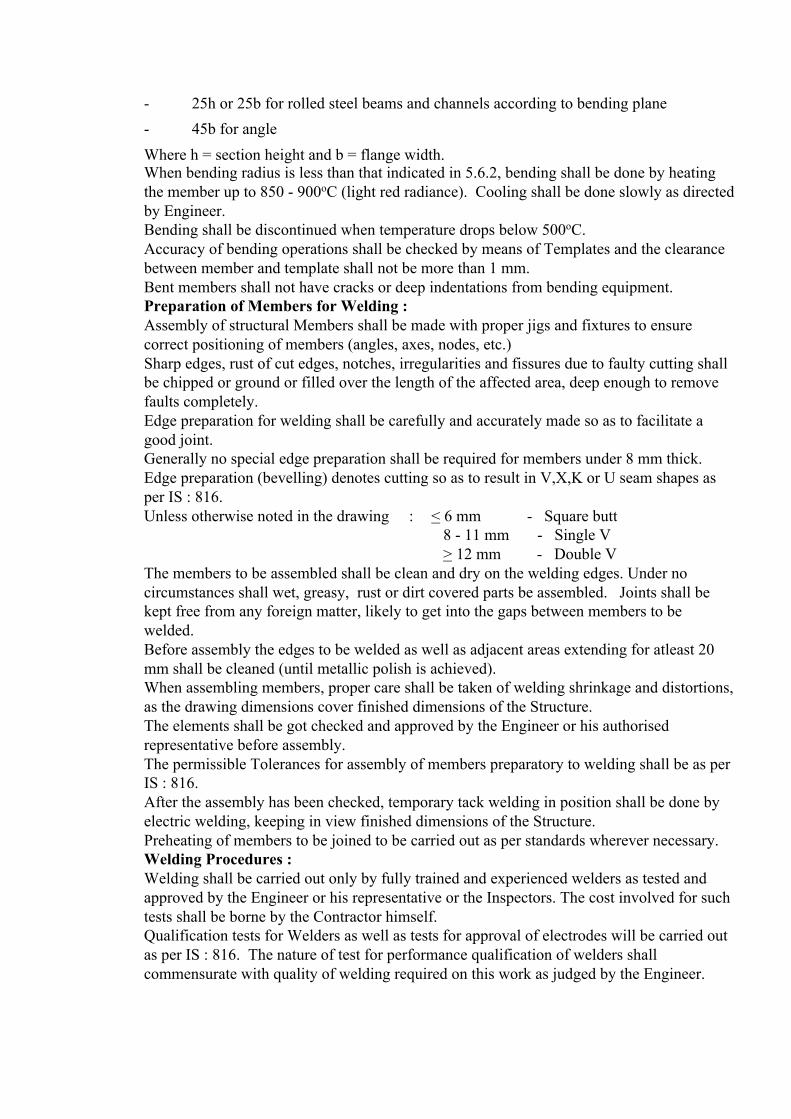
- 25h or 25b for rolled steel beams and channels according to bending plane - 45b for angle Where h = section height and b = flange width.
When bending radius is less than that indicated in 5.6.2, bending shall be done by heating the member up to 850 - 900oC (light red radiance). Cooling shall be done slowly as directed by Engineer. Bending shall be discontinued when temperature drops below 500oC. Accuracy of bending operations shall be checked by means of Templates and the clearance between member and template shall not be more than 1 mm. Bent members shall not have cracks or deep indentations from bending equipment. Preparation of Members for Welding : Assembly of structural Members shall be made with proper jigs and fixtures to ensure correct positioning of members (angles, axes, nodes, etc.) Sharp edges, rust of cut edges, notches, irregularities and fissures due to faulty cutting shall be chipped or ground or filled over the length of the affected area, deep enough to remove faults completely. Edge preparation for welding shall be carefully and accurately made so as to facilitate a good joint. Generally no special edge preparation shall be required for members under 8 mm thick. Edge preparation (bevelling) denotes cutting so as to result in V,X,K or U seam shapes as per IS : 816. Unless otherwise noted in the drawing : < 6 mm - Square butt 8 - 11 mm - Single V > 12 mm - Double V The members to be assembled shall be clean and dry on the welding edges. Under no circumstances shall wet, greasy, rust or dirt covered parts be assembled. Joints shall be kept free from any foreign matter, likely to get into the gaps between members to be welded. Before assembly the edges to be welded as well as adjacent areas extending for atleast 20 mm shall be cleaned (until metallic polish is achieved). When assembling members, proper care shall be taken of welding shrinkage and distortions, as the drawing dimensions cover finished dimensions of the Structure. The elements shall be got checked and approved by the Engineer or his authorised representative before assembly. The permissible Tolerances for assembly of members preparatory to welding shall be as per IS : 816. After the assembly has been checked, temporary tack welding in position shall be done by electric welding, keeping in view finished dimensions of the Structure. Preheating of members to be joined to be carried out as per standards wherever necessary. Welding Procedures : Welding shall be carried out only by fully trained and experienced welders as tested and approved by the Engineer or his representative or the Inspectors. The cost involved for such tests shall be borne by the Contractor himself. Qualification tests for Welders as well as tests for approval of electrodes will be carried out as per IS : 816. The nature of test for performance qualification of welders shall commensurate with quality of welding required on this work as judged by the Engineer.

Unless otherwise noted in the drawing : < 20 mm - Electrodes to AWS E 6013 > 20 mm - Electrodes to AWS E 7018 The Steel structures shall be automatically, semi-automatically or manually welded. Welding shall begin only after the checks shown under 5.7 have been carried out. Welding procedures and Tests for Welders skill shall be conducted as per IS : 816 and approved by the Engineer. The welder shall mark his Identification mark on each element welded by him. When welding is carried out in open air, steps shall be taken to protect the place of welding against wind or rain. The electrodes, wires and parts being welded shall be dry. Before beginning the welding operation, each joint shall be checked to ensure that the parts to be welded are clean and root gaps provided as per IS : 816. For continuing the welding of seams discontinued due to some reason, the end of the discontinued seam shall be melted in order to obtain a good continuity. Before resuming the welding operation, the groove as well as the adjacent parts shall be well cleaned for a length of approximately 50 mm. For single butt welds (in V,1/2V or U) and double butt welds (in K, double U, etc) the rewelding of the root butt is mandatory but only after the metal deposition on the root has been cleaned by back gouging or chipping. The welding seams shall be left to cool slowly. The Contractor shall not be allowed to cool the welds quickly by any method. For multi-layer welding, before welding the following layer, the formerly welded layer shall be cleaned by light chipping and wire brushing. Backing strips shall not be allowed.
The order and method of welding shall be so that : - no unacceptable deformation appears in the welded parts
- due margin is provided to compensate for contraction due to welding in order to avoid any high permanent stresses.
The defects in welds must be rectified according to IS : 816 and as per instruction of Engineer. Weld Inspection : The weld seams shall satisfy the following : - shall correspond to Design shapes and dimensions - shall not have any defects such as cracks, incomplete penetration and fusion, under-cuts, rough surfaces, burns, blow holes and porosity etc. beyond permissible limits (See Annexure-I). During the welding operation and approval of finished elements, inspections and tests shall be made as shown in Annexure - II. The mechanical characteristics of the welded joints shall be as in IS : 816. Preparation of Members for Bolting : The Members shall be assembled for bolting with proper jigs and fixtures to sustain the assemblies without deformation and bending. Before assembly, all sharp edges, shaving, rust, dirt etc. shall be removed. Before assembly, the contacting surfaces of the members shall be cleaned and given a coat of red oxide primer. The members which are bolt assembled shall be set according to drawings and temporarily fastened with erection bolts (minimum 4 pieces) to check the coaxiality of the holes.

The members shall be finally bolted after the deviations have been corrected, after which there shall not be gaps. Before assembly, the member shall be checked and got approved by the Engineer. The difference in thickness of the Sections that are butt assembled shall not be more than 3% or maximum 0.8 mm whichever is less. If the difference is large, it shall be corrected by grinding or filling. Reaming of holes to final diameter or cleaning of these, shall be done only after the parts have been check assembled. As each hole is finished to final dimensions (reamed if necessary) it shall be set and bolted up. Erection bolts shall not be removed before other bolts are set. Bolting Up : Final bolting of the members shall be done after the defects have been rectified and approval of joints obtained. The bolts shall be tightened starting from the centre of the joint towards the edge. Holes for Field Joints : Holes for field joints shall be drilled in the shop to final diameters and tested in the shop, with trial assemblies. Gas cutting of holes shall not be permitted. When three-dimensional assembly is not possible in the shop, the holes for field joints may be drilled in shop and reamed on site after Erection, on approval by the Engineer. For bolted steel structures, trial assembly in shop is mandatory. The tolerance for spacing of holes shall be ± 1 mm. Tolerances : All tolerances regarding dimensions, geometrical shapes and sections of Steel Sections, shall be as per IS 808 & IS 1852, if not specified in the drawing. Marking for Identification : All elements and members prior to despatch for Erection shall be shop marked. The members shall be visibly marked with a weatherproof light coloured paint. The size and thickness of the numbers shall be so chosen as to facilitate the identification of members. For the small members that are delivered in bundles or crates, the required marking shall be done on small metal tags securely tied to the bundle, while the crates shall be marked directly. Each bundle or crate shall be packed with members for one and the same assembly in the same bundle or crate, general utility members such as bolts, gussets, etc. may be packed. All bills of materials showing weight, quality and dimension of contents shall be placed in the crates. The members shall be marked with a durable paint, in a visible location, preferably at one end of the member so that these may be easily checked during storage and erection. The members shall be marked in the shop before inspection and acceptance. When the member is being painted, the marking area shall not be painted but bordered with white paint. The marking and job symbol shall be registered in all shop delivery documents (transportation, for erection etc.) Shop Test Pre-assembly : For Steel Structures that have the same type of welding the shop test pre-assembly shall be performed on one out of every 10 members minimum.

In case one member does not meet the limiting deviations specified in the general specification in pre-assembly shop test, all members shall be shop tested. For bolted Steel Structures, shop test pre-assembly is mandatory for all elements as well as for the entire structure in conformity with clause 5.12. Shop Inspection and Approval : General : The Engineer or his representative shall have free access at all reasonable times to the Contractor’s Fabrication Shop and shall be afforded all reasonable facilities for satisfying himself that the Fabrication is being undertaken in accordance with Drawings and Specifications. Technical approval of the Steel Structure in the shop by the Engineer is mandatory. The Contractor shall not limit the number and kinds of Tests, final as well as intermediate ones, or extra tests requested by the Engineer. The Contractor shall furnish necessary tools gauges, instrument etc. and technical and non-technical personnel for shop tests required by Engineer, free of cost. Shop Acceptance : The Engineer shall inspect and approve at the following stages. The following approvals may be given in shop : - Intermediate approvals of work that cannot be inspected later. - Partial approvals. - Final approvals. Intermediate approvals of work shall be given when a part of the work is performed later - Inspection would be difficult to perform and results not be satisfactory. - Cannot be inspected later Partial approval in the shop is given on members and assemblies of Steel Structures before the primer coat is applied and includes : - Approval of material - Approval of field joints - Approval of part with planed surface - Test Erection - Approval of members - Approval of markings - Inspection and approvals of special features, like rollers, loading platform mechanism etc. During the partial approval, intermediate approvals as well as former approvals shall be taken into consideration. Final Approval in the Shop : The final approval refers to all elements and assemblies of the Steel Structures with shop primer coat, ready for delivery from shop, to be loaded for transportation or stored. The final approval comprises : - Partial approvals. - Approvals for shop primer coat - Approval of mode of loading and transport - Approval of storage (for materials stored)
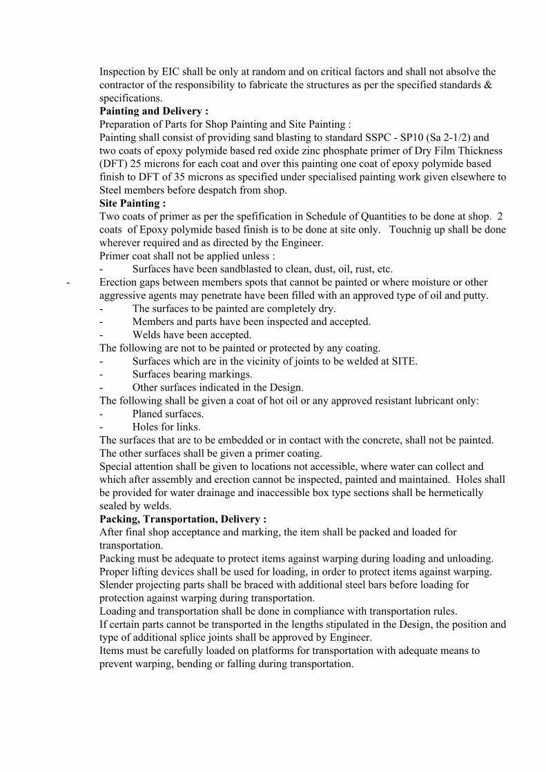
Inspection by EIC shall be only at random and on critical factors and shall not absolve the contractor of the responsibility to fabricate the structures as per the specified standards & specifications. Painting and Delivery : Preparation of Parts for Shop Painting and Site Painting : Painting shall consist of providing sand blasting to standard SSPC - SP10 (Sa 2-1/2) and two coats of epoxy polymide based red oxide zinc phosphate primer of Dry Film Thickness (DFT) 25 microns for each coat and over this painting one coat of epoxy polymide based finish to DFT of 35 microns as specified under specialised painting work given elsewhere to Steel members before despatch from shop. Site Painting : Two coats of primer as per the spefification in Schedule of Quantities to be done at shop. 2 coats of Epoxy polymide based finish is to be done at site only. Touchnig up shall be done wherever required and as directed by the Engineer. Primer coat shall not be applied unless : - Surfaces have been sandblasted to clean, dust, oil, rust, etc.
- Erection gaps between members spots that cannot be painted or where moisture or other aggressive agents may penetrate have been filled with an approved type of oil and putty. - The surfaces to be painted are completely dry. - Members and parts have been inspected and accepted. - Welds have been accepted. The following are not to be painted or protected by any coating. - Surfaces which are in the vicinity of joints to be welded at SITE. - Surfaces bearing markings. - Other surfaces indicated in the Design. The following shall be given a coat of hot oil or any approved resistant lubricant only: - Planed surfaces. - Holes for links. The surfaces that are to be embedded or in contact with the concrete, shall not be painted. The other surfaces shall be given a primer coating. Special attention shall be given to locations not accessible, where water can collect and which after assembly and erection cannot be inspected, painted and maintained. Holes shall be provided for water drainage and inaccessible box type sections shall be hermetically sealed by welds. Packing, Transportation, Delivery : After final shop acceptance and marking, the item shall be packed and loaded for transportation. Packing must be adequate to protect items against warping during loading and unloading. Proper lifting devices shall be used for loading, in order to protect items against warping. Slender projecting parts shall be braced with additional steel bars before loading for protection against warping during transportation. Loading and transportation shall be done in compliance with transportation rules. If certain parts cannot be transported in the lengths stipulated in the Design, the position and type of additional splice joints shall be approved by Engineer. Items must be carefully loaded on platforms for transportation with adequate means to prevent warping, bending or falling during transportation.

The small parts such as fish plates, gussets etc. shall be securely tied with wire to their respective parts. Bolts, nuts and washers shall be packed and transported in crates or bags. The parts shall be delivered in the order stipulated by the Engineer and shall be accompanied by documents showing : - Quality and quantity of structure of members - Position of member in the structure - Particulars of structure - Identification number/job symbol Field Erection : The Contractor shall satisfy himself about the levels, lines etc. of the Foundations well in advance, before starting the Erection. Minor chipping etc. shall be carried out by the Contractor at his expense. Any faulty Erection done by the Contractor, shall be made good at his cost. Approval by the Engineer or his representative at any stage of work does not relieve the Contractor of any of his required guarantees of the Contract. Storage and Preparation of Parts prior to Erection : The storage place for Steel Parts shall be prepared in advance and got approved by the Engineer before the Steel structures start arriving from the shop. A platform shall be provided by the Contractor near the Erection Site for preliminary Erection work. The contractor shall make the following verifications upon receipt of material at site. For Quality Certificates regarding Materials and Workmanship according to these general Specifications and Drawings. Whether parts received are complete without defects due to transportation, loading and unloading and defects, if any, are well within the admissible limit. For the above work sufficient space must be allotted in the storage area. Step shall be taken to prevent warping of items during unloading. The parts shall be unloaded, sorted and stored so as to be easily identified. The parts shall be stored according to construction symbol and markings so that these may be taken out in order of Erection. The parts shall be set at least 150 mm clear from ground on wooden or steel blocks for protection against direct contact with ground and to permit drainage of water. If rectification of members like straightening etc. are required, these shall be done in a special place allotted which shall be adequately equipped. The parts shall be clean when delivered for Erection. Erection and Tolerances : Erection in general shall be carried out as required and approved by the Engineer. Positioning and levelling of the structure, alignment and plumbing of the Stanchion and fixing every member of the structure shall be in accordance with the relevant drawings and to the complete satisfaction of the Engineer. The following checks and inspection shall be carried out before, during and after Erection. - Damages during transportation. - Accuracy of alignment of Structures - Erection according to Drawings and Specifications. - Progress and workmanship.

In case there be any deviations regarding positions of foundations, or anchor bolts, which would lead to Erection deviations, the Engineer shall be informed immediately. Minor rectifications in foundations, orientation of bolt holes etc. shall be carried out as a part of the work, at no extra cost. The various parts of the Steel Structure shall be so erected as to ensure stability against inherent weight, wind and Erection stresses. The structure shall be anchored and final erection joints completed after plan and elevation positions of the Structural members have been verified with corresponding drawings and approved by the Engineer. The bolted joints shall be tightened so that the entire surface of the bolt heads and nuts shall rest on the member. For parts with sloping surfaces, tapered washers shall be used. Site painting after erection shall be as per clause 7.1.1 Final Acceptance and Handling Over of Structure : At acceptance, the Contractor shall submit the following documents : a)Shop and Erection Drawings - either in tracings or reproducibles. b)6 copies each of the following. - Shop acceptance documents - Quality Certificates for Structurals, Plates, electrodes, welding wire, bolts, nuts, washers etc.
- List of Certified Welders, who worked on Erection of Structure. ( With documents or qualification tests) - Acceptance and Intermediate Control Procedure of Erection Operations. Approval by the Engineer at any stage of work does not relieve the Contractor of any of his required guarantees of the Contract. Miscellaneous Steelwork : Anchor Bolts : All materials supplied by the Contractor shall be of tested quality as per Specifications below and Test Certificates of raw materials shall be provided by the Contractor. Fabrication of Anchor Bolts shall be in compliance with the Specifications. Complete Anchor Bolt assembly shall be as per drawings, and will include the cost of sleeve pipes, bottom plates, and other fixtures including all welding work if involved. a) Bolts shall be turned from M.S rounds conforming to IS 2062 Gr ‘A’ b) Nuts shall be Hexagonal type conforming to IS 1363. c) Plain washers shall be of mild steel conforming to IS 2016/IS 2062 Grade ‘A’ d) Threads shall be of coarse type conforming to IS 1367 & IS 4218. The surface not to be covered with concrete shall be greased and protected from damage by wrapping and tying jute cloth/polythene. Tolerances allowed in the Erection of Plant Building without Cranes : The maximum tolerances for line and level of the Steelwork shall be ± 3.0 mm on any part of the Structure. The Structure shall not be out of plumb more than 5.0 mm on each 10 M section of height and not more than 8.0 mm per 30 M section. These tolerances shall apply to all parts of the Structure unless the Drawings issued for Erection purposes state otherwise.

Component
Description Variation Allowed
Main column and roof posts
a)
Shifting of column axis at foundation level with respect to building line :
i.
In longitudinal direction
± 5.00 mm
ii.
In lateral direction ± 5.00 mm
b)
Deviation of both Major Column Axis from Vertical between Foundation and Other Member connection Levels.
i.
For a Column upto and including 10 M height.
± 5.00 mm from True Vertical.
ii.
For a column greater than 10 M but less than 40 M height.
± 5.00 mm from True Vertical for any 10 M length measured between connection levels, but not more than ± 8.00 mm for upto 40 M height.
c)
For Adjacent Pairs of Columns across the width of the Building prior to placing of Truss.
± 5.00 mm of True Span.
d)
For individual Column Deviation of any
± 5.00 mm

Component
Description Variation Allowed
Bearing or resting level from levels shown on Drawings.
e)
For Adjacent Pairs of Columns either across the width of Building or Longitudinally Level Difference allowed between Bearing or Seating Level supposed to be at the same level.
± 5.00 mm
Trusses
a)
Deviation of Centre of Span or Upper Chord Member from Vertical Plane running through Centre of Bottom Chord.
1/1500 of the span or 10 mm whichever is less.
b)
Lateral Displacement of Top Chord at Centre of Span from Vertical Plane running through Centre of Supports.
1/250 of Depth of Truss or 20 mm whichever is less.
Crane girders and tracks
a)
Difference in levels of Crane rail measured between Adjacent columns.
± 2.0 mm
b)
Deviation to Crane rail gauge
± 3.0 mm
c)
Relative Shifting of Ends of Adjacent Crane Rail in Plan and Elevation after Thermit Welding.
± 2.0 mm
d)
± 3.5 mm
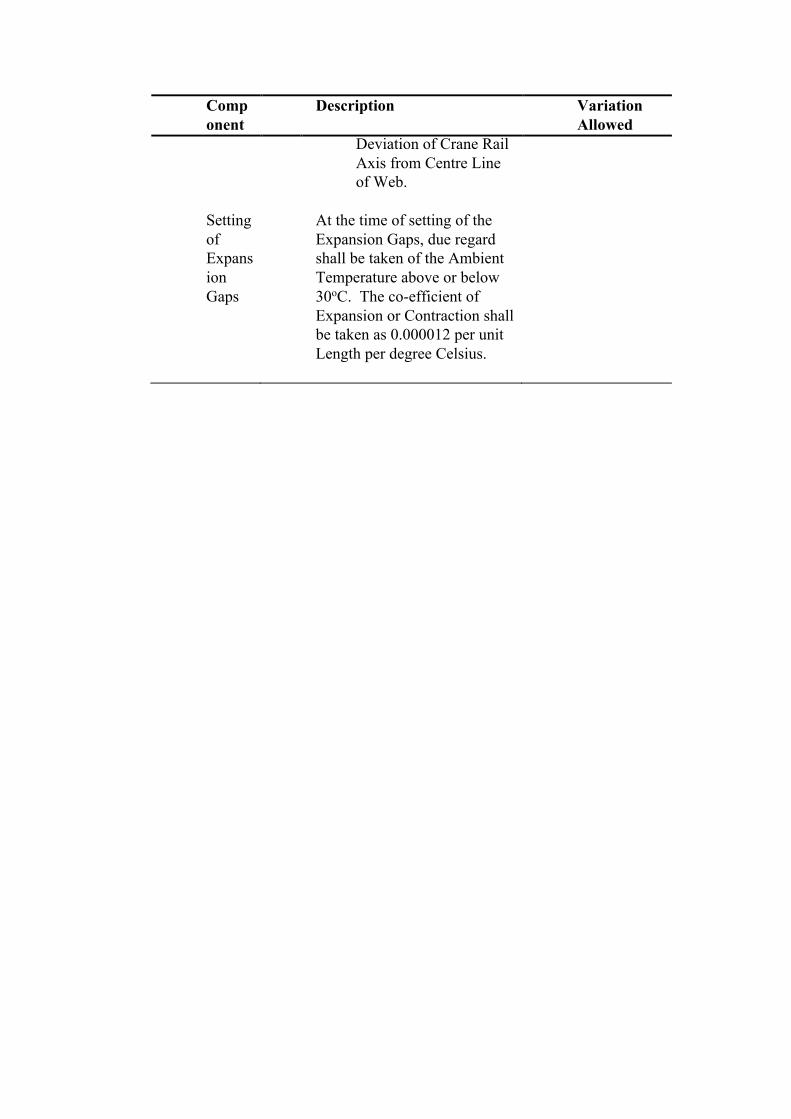
Component
Description Variation Allowed
Deviation of Crane Rail Axis from Centre Line of Web.
Setting of Expansion Gaps
At the time of setting of the Expansion Gaps, due regard shall be taken of the Ambient Temperature above or below 30oC. The co-efficient of Expansion or Contraction shall be taken as 0.000012 per unit Length per degree Celsius.
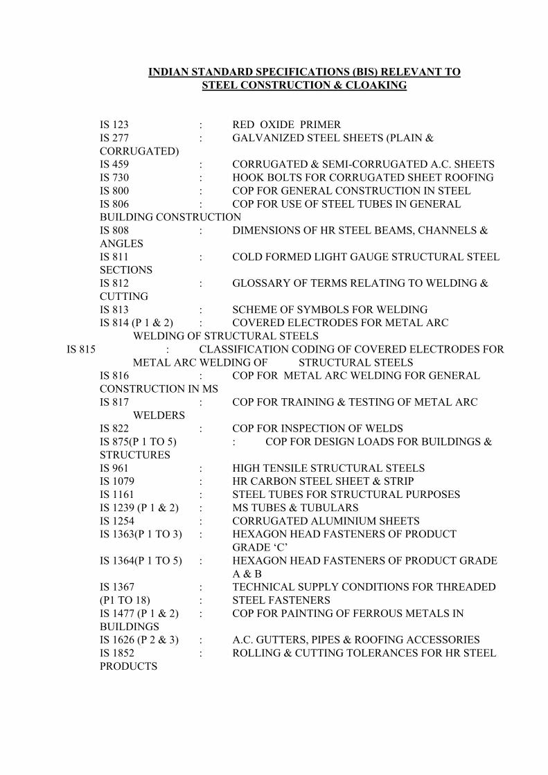
INDIAN STANDARD SPECIFICATIONS (BIS) RELEVANT TO STEEL CONSTRUCTION & CLOAKING
IS 123 : RED OXIDE PRIMER IS 277 : GALVANIZED STEEL SHEETS (PLAIN & CORRUGATED) IS 459 : CORRUGATED & SEMI-CORRUGATED A.C. SHEETS IS 730 : HOOK BOLTS FOR CORRUGATED SHEET ROOFING IS 800 : COP FOR GENERAL CONSTRUCTION IN STEEL IS 806 : COP FOR USE OF STEEL TUBES IN GENERAL BUILDING CONSTRUCTION IS 808 : DIMENSIONS OF HR STEEL BEAMS, CHANNELS & ANGLES IS 811 : COLD FORMED LIGHT GAUGE STRUCTURAL STEEL SECTIONS IS 812 : GLOSSARY OF TERMS RELATING TO WELDING & CUTTING IS 813 : SCHEME OF SYMBOLS FOR WELDING IS 814 (P 1 & 2) : COVERED ELECTRODES FOR METAL ARC WELDING OF STRUCTURAL STEELS
IS 815 : CLASSIFICATION CODING OF COVERED ELECTRODES FOR METAL ARC WELDING OF STRUCTURAL STEELS
IS 816 : COP FOR METAL ARC WELDING FOR GENERAL CONSTRUCTION IN MS IS 817 : COP FOR TRAINING & TESTING OF METAL ARC WELDERS IS 822 : COP FOR INSPECTION OF WELDS IS 875(P 1 TO 5) : COP FOR DESIGN LOADS FOR BUILDINGS & STRUCTURES IS 961 : HIGH TENSILE STRUCTURAL STEELS IS 1079 : HR CARBON STEEL SHEET & STRIP IS 1161 : STEEL TUBES FOR STRUCTURAL PURPOSES IS 1239 (P 1 & 2) : MS TUBES & TUBULARS IS 1254 : CORRUGATED ALUMINIUM SHEETS IS 1363(P 1 TO 3) : HEXAGON HEAD FASTENERS OF PRODUCT GRADE ‘C’ IS 1364(P 1 TO 5) : HEXAGON HEAD FASTENERS OF PRODUCT GRADE A & B IS 1367 : TECHNICAL SUPPLY CONDITIONS FOR THREADED (P1 TO 18) : STEEL FASTENERS IS 1477 (P 1 & 2) : COP FOR PAINTING OF FERROUS METALS IN BUILDINGS IS 1626 (P 2 & 3) : A.C. GUTTERS, PIPES & ROOFING ACCESSORIES IS 1852 : ROLLING & CUTTING TOLERANCES FOR HR STEEL PRODUCTS

IS 1977 : STRUCTURAL STEEL - ORDINARY QUALITY IS 2016 : PLAIN WASHERS IS 2062 : WELDABLE STRUCTURAL STEEL IS 2074 : RED OXIDE ZINC CHROME PRIMER IS 2339 : ALUMINIUM PAINT IS 2527 : COP FOR FIXING GUTTERS & RAIN WATER PIPE FOR ROOF DRAINAGE IS 2932 : SYNTHETIC ENAMEL PAINTS IS 3007 (P 1 &2) : COP FOR LAYING A.C. SHEETS IS 3444 : CRANE RAIL SECTIONS IS 3502 : STEEL CHEQUERED PLATES IS 3548 : COP FOR GLAZING IN BUILDING IS 4000 : COP FOR ASSEMBLY OF STRUCTURAL JOINTS USING HSFG FASTENERS IS 4923 : HOLLOW STEEL SECTIONS FOR STRUCTURAL USE IS 5372 : TAPER WASHERS FOR CHANNELS IS 5374 : TAPER WASHERS FOR BEAMS IS 5624 : FOUNDATION BOLTS IS 6639 : HEXAGONAL BOLTS FOR STEEL STRUCTURES IS 7205 : SAFETY CODE FOR ERECTION OF STRUCTURAL STEELWORK IS 7215 : TOLERANCES FOR FABRICATON IS 8869 : WASHERS FOR CORRUGATED SHEET ROOFING
IS 12093 : COP FOR LAYING & FIXING SLOPED ROOF COVERINGS USING PLAIN & CORRUGATED GALVANISED STEEL SHEETS
IS 12843 : TOLERANCES FOR ERECTION OF STEEL STRUCTURES COP : Code of Practice
COMMON WELD DEFECTS FOR FILLER WELDS IN STRUCTURAL STEEL FABRICATION 1. Incomplete Fusion - is defined as the failure to fuse together adjacent layers of weld metal or weld metal and base metal. Causes : i) Failure to raise the temperature of base metal (or previously deposited weld metal) to the melting point. ii) Improper cleaning of the oxides or other foreign material present on the surface to which the deposited metal must fuse. iii) In-experienced welders. 2. Inadequate Penetration is defined as the failure of the filler metal and base metal to fuse integrally at the root of the weld. Causes : Heat transfer conditions such as, i) Use of too large an electrode. ii) An abnormally high rate of travel.

iii) Use of insufficient welding current, is a frequent source of this defect. 3. Cracks : In multilayer welds, cracking mostly occurs in the first layer of the weld and unless repaired, will continue through other layers as they are deposited. Cracks may be longitudinal, transverse or crater cracks. Causes : i) Improper electrode manipulation or electrical conditions. ii) Higher speed of travel resulting in lesser thickness of the deposit. iii) Higher base metal thickness (which may require pre-heating.) iv) Wrong type of electrode. 4. Under cut - is defined as the melting away of the sidewall of a joint at the edge of a layer or bead thus forming a sharp recess in the sidewell. Causes : i) Too high a current ii) Too long an arc. iii) Magnetic arc below. 5. Slag inclusions - are defined as oxides and non-metallic solids that are entrapped in weld metal or between weld metal and base metal. Causes : i) High viscosity of the weld metal. ii) Rapid solidification of weld metal. iii) Too low a welding temperature. iv) Improper cleaning between passes. v) Improper electrode manipulation. 6. Porosity - is defined as gas pockets or voids, free of any solid material, that are frequently found in welds. It may be present as uniformly scattered porosity, cluster porosity or linear porosity. Causes : i) Excessive Current. ii) Excessive arc length. iii) Wet/unclean joint surfaces. iv) Eccentric burning of electrode. v) Frequent interruptions. 7. (a) Incorrect Weld Profiles. Causes : i) Desirable weld profile. ii) Acceptable fillet weld profile. iii) Insufficient lag. (b) Insufficient throat. (c) Excessive convexity. 8. Overlap - is the condition in which weld metal protrudes beyond the bond lines at the toe of a weld. Causes : i) Incorrect welding technique. ii) Improper electrical conditions i.e. excessive current or arc length
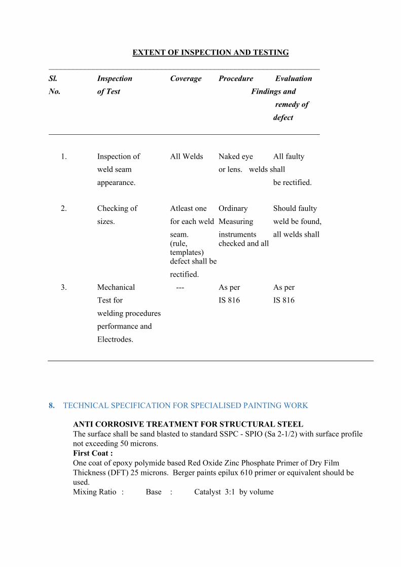
EXTENT OF INSPECTION AND TESTING ___________________________________________________________________ Sl. Inspection Coverage Procedure Evaluation No. of Test Findings and remedy of defect ___________________________________________________________________ 1. Inspection of All Welds Naked eye All faulty weld seam or lens. welds shall appearance. be rectified. 2. Checking of Atleast one Ordinary Should faulty sizes. for each weld Measuring weld be found, seam. instruments all welds shall (rule, checked and all templates) defect shall be
rectified. 3. Mechanical --- As per As per Test for IS 816 IS 816 welding procedures performance and Electrodes.
8. TECHNICAL SPECIFICATION FOR SPECIALISED PAINTING WORK
ANTI CORROSIVE TREATMENT FOR STRUCTURAL STEEL The surface shall be sand blasted to standard SSPC - SPIO (Sa 2-1/2) with surface profile not exceeding 50 microns. First Coat : One coat of epoxy polymide based Red Oxide Zinc Phosphate Primer of Dry Film Thickness (DFT) 25 microns. Berger paints epilux 610 primer or equivalent should be used. Mixing Ratio : Base : Catalyst 3:1 by volume

Application : Brush roller airless and conventional spray. Theoretical spreading rate : 13 Sqm / Ltr. Drying Time Touch Dry : 1 hour Dry to handle : 4 hours Hard Dry : Overnight Curing Time : 6 - 7 days Colour : Red Oxide Second Coat : Shall be as per first coat given above.
Third Coat : One coat of Epoxy Polymide based finish - Berger paints Epilux 4, Shalimar enamel or equivalent to DFT of 35 microns. Colour should be specified by the Engineer. Type : Two pack, cold cured Composition : Catalyzed epoxy resin suitably pigmented Mixing Ratio : Base : Catalyst 3:1 by volume Application : Brush, roller, airless & conventional spray Theoretical spreading rate : 13 Sqm / Ltr. Drying Time Touch Dry : 2 - 3 hours Dry to handle : 6 - 8 hours Hard Dry : Overnight Curing Time : 6 - 7 days Overcoating Interval Minimum : Overnight Maximum : 5 days Finish : Glossy Fourth Coat : Shall be as per third coat given above. TOTAL DRY FILM THICKNESS (DFT) - 120 MICRONS. The DFT shall be checked with Elcometer.
9. TECHNICAL SPECIFICATION FOR MASONRY WORKS The specification covers the general requirements for stone and brick masonry. MATERIALS : Cement : Ordinary Portland cement of 43 grade conforming to IS : 8112 (latest) shall be used for all masonry works. Cement shall be fresh when delivered at site. Sand : Sand shall conform to IS : 383 & IS : 2116. Sand shall be hard, durable, clean and free from dirt, clay, organic matter or other impurities. Sand shall not be too fine nor too coarse and shall fall within the grading zones I to IV given in Table III of IS : 383. The silt content of sand shall not exceed 5% by volume. Stones : Stones shall be the type specified and shall be of hard granite be salt or trap stone, of uniform colour and texture. It shall be hard, sound, durable, free from flaws, cracks,
injurious veins, decay and weathering and shall be freshly quarried from an approved quarry. Discoloured or distorted stones with boulders skin or earth or porous matter or stones with round surface shall not be used. The crushing strength of the rubble for use in the stone masonry should not be less than 150 Kg/Sqcm. The stones, when immersed in water for 24 hours, shall not absorb water by more than 5 percent of their dry weight when tested in accordance with IS : 1124. Bricks : Bricks shall conform to the requirements of IS : 1077. Bricks shall conform to the requirements of IS 1077. Bricks of normal size 8-3/4" x 4-1/2" x 2-3/4" shall be used. All bricks shall be chamber burnt and of first class quality sound, hard, well burnt throughout but not over burnt, of regular uniform size, shapes and colour (generally deep red or copper) homogenous in texture and free from flaws and cracks. They shall have plane rectangular faces with parallel sides and square, straight and sharply defined arisers. Brick shall not be broken, cracked, stratified, under burnt, over burnt or soft. A fractured surface shall show a compact fine grained, uniform and dense texture free from lumps of lime, laminations, cracks, air holes, grit, soluble salts causing efflorescence or other defects which may in any way impair the strength, durability appearance and usefulness of the brick. A clear metallic ringing sound shall be emitted when two bricks are struck together. After 24 hours immersion in cold water, water absorption by weight shall not exceed 20 percent of the dry weight of the brick. They shall not break when thrown on the ground on their flat face in a saturated condition from a height of 600 mm. The minimum compressive strength of bricks shall be 35 Kg/Sq.cm. The tolerance permitted in the accepted size of the bricks shall be plus or minus 3 mm in any dimension. Representative samples of bricks shall be submitted to the Engineer for approval before supply to site and the approved samples shall remain with the Engineer. All bricks proposed to be used shall conform to the approved samples in all respects. Any brick found not upto the specification shall be removed immediately from the site at the Contractor's cost. Water : Water used for mixing mortar and curing shall be clean and free from oil, acid, salt and other injurious materials and shall be in accordance with clause 4.3 of IS : 456. Water fit for drinking will generally be found suitable. Mortar Mixing : Mixing of mortar shall be done in a mechanical mixer. Hand mixing shall be resorted to only when specifically permitted by the Engineer. Cement and sand shall be mixed dry in specified proportions thoroughly and then water shall be added gradually. Wet mixing shall be continued till mortar of the consistency of a stiff paste and uniform colour is obtained. Only the quantity of mortar which can be used within thirty minutes of its mixing shall be prepared at a time. Mortar shall be used as soon as possible after mixing and before it has begun to set and in any case within thirty minutes after the water is added to the dry mixture. Mortar left unused for more than thirty minutes after mixing shall be rejected and removed from the site of work. SIZE STONE MASONRY :

Size stones shall be of hard granite, besalt or trap stone obtainable from approved quarry. The stones shall be clean and wetted before they are used. Height of course, shall not be less than 15 cms. and all courses shall be of uniform height. Unless otherwise instructed the depth of higher courses should not be more than the depth of lower courses. Bed and sides shall be hammer or chisel dressed from the face 75 mm and 35 mm respectively. No face stone shall be less in depth than in height or shall tail into the work to a length less than the height. Stones shall break joints atleast half the height of the course. Faces of stones shall be hammer dressed and bushing not be more than 25 mm. Thickness of joints shall not be more than 20 mm. edges of face stones of exposed faces shall be chiselled true to both longitudinal and vertical lines.Exposed faces of corner stones to be line dressed 50 mm wide. Bond or through stones shall be provided not exceeding 2.0 metre in each course and shall be staggered. Bond stone shall be from the front to the back of the walls. For wall upto 60 cms thick, bond stones shall be in one piece and for walls over 60 cms. thick they shall either be in one piece (if available locally) or be in the series of headers. Each header overlapping the adjoining one by not less than 150 mm. Alternatively bond stones may be provided with 9"*9" header.bond or through stones shall be marked as directed to enable their being easily detected even after having been built in position. The interior or filling shall be with flat bedded stones laid in mortar. Chips, spalls shall be used to avoid thick mortar joints and shall not exceed 10% of the quantity of stone masonry. Care is to be taken that no dry work or hollow spaces shall be left any where in the masonry. UNCOURSED RUBBLE MASONRY : The stones as received from quarry are to be set in work after knocking off weak corners and edges with mason's hammer. They are to be laid carefully so as to break joint as much as possible and shall be solidly bedded in mortar. No joint shall exceed 20 mm chips of stone and spalls shall be wedged into the work wherever necessary to avoid thick beds or joints of mortar. No dry work or hollow spaces shall be allowed, every stone whether large or small shall be set flush in mortar, smaller stones used in filling being carefully selected to fit snugly the interstices between the larger ones. The face stone shall be selected from the mass of quarry stones for proper size good beds and uniform colour and shall be laid as far as possible without pinning in front. One through stone shall be provided for every sq.m. of facing and shall run back into full depth of the work. The quoins for exposed corners unless otherwise specified shall be of selected stone neatly dressed with hammer and chisel to form required angle and laid header and stretcher alternatively.
RANDOM RUBBLE MASONRY :
The face stone shall be laid absolutely without pinnings on the face. Every stone shall be carefully fitted so as to form neat and close joints and if necessary the edges shall be dressed with chisel so as to ensure close joints work. The thickness of joint will be as specified for each work and in no case more than 20 mm. The thickness of joint should be uniform on the face variation being within 25%. Mortar in joints should be scraped 12 mm deep for pointing.

The stones shall be roughly chisel dressed to ensure equal size on face as far as possible. They shall be of uniform colour and they shall be carefully laid and solidly bedded in mortar and shall tail back and bond well into the backing and shall not be of greater than either breadth of face or length of tail into the work. One header or through stone shall be inserted for every square metre of face and shall run right through the wall. Stones shall be arranged to break joints as much as possible and long vertical lines of joining shall be avoided in face work. The quoins unless otherwise specified shall be of selected stones neatly dressed with hammer chisel to form required angle and laid header and stretcher alternatively. The masonry work has to be kept wet for 10 days In the case of cement mortar, the proportion specified is on volume basis. But cement shall be weighed on the assumption that one cubic metre of cement weighs 1440 kgs. The Engineer may also require the cement to be measured by volume but on the same assumption. Weep holes for Retaining wall shall be provided at the rate of one weep hole per one sq.metre.
BRICK WORK : Brick work shall conform to IS : 2212. Bricks shall be stacked in regular tiers, even as they are unloaded to minimise breakages and defacement bricks. Samples of each type of brick taken at random from the lot shall be deposited with the Engineer for his approval before being used in the work. All subsequent deliveries shall be upto the standard of the sample approved. First quality chamber burnt bricks shall conform to IS 1077. Bricks shall be thoroughly cleaned and well wetted. Bricks shall be soaked for at least 2 hours in fresh water before being used on the work. No bats or cut bricks shall be used. All brick work should be carried out as shown on the drawings with set backs, projections, cuttings, toothings etc. Wherever the proportion of cement mortar has not been specifically mentioned, cement mortar in the proportion of 1:6 shall be used. Flat brick arches shall be provided wherever required without any extra cost. Brick work shall be kept wet while in progress till mortar has properly set. On holidays or when the work is stopped, top of all unfinished masonry shall be kept wet. Should the mortar be dry, white or powdery, for want of curing, work shall be pulled down and rebuilt at the contractor's expense. Unless otherwise specified, brickwork shall be done in English bond with frog upwards. The bricks shall be bedded & joined with mortar in such a manner as not to leave voids. When laying the bricks shall be slightly pressed so that mortar can get into all the pores of the brick surface to ensure proper adhesion. Each brick shall be correctly bedded into position by tapping with the handle of the trowel, grouting of mortar slurry will not be allowed, except where necessary for special reasons and in such cases, prior permission of the Engineer shall be obtained. Care shall be taken that each course of brick work is truly horizontal & perfect in bond and the face of the wall is straight, plumb and even. Verticality of the walls and horizontality of the courses shall be checked very often with plumb-bob and spirit level respectively. The mortar joints shall be 10mm in thickness, except where extra thickness is required for the purpose of bringing the brick work to the required height or level. Half bricks or bats shall not be used except for obtaining the bond & where absolutely necessary. Brick work in 230 mm wall :

In the case of 230mm thick walls, if bricks are of size such that the width of the header course does not come equal to the width of the stretcher course, the difference shall be made up during construction of brick work itself by the same mortar as used for construction of masonry to provide a plane vertical surface. The surface should also be scarified to receive plaster. All junctions of walls and cross walls shall be carefully bonded into the main walls. The rate of laying masonry will be upto a height of 100 cm per day if cement mortar is used. Greater heights may be built only if permitted by the Engineer. During rains, the work shall be carefully covered to prevent mortar from being washed away, should any mortar or cement be washed away, the work shall be removed and rebuilt at the contractor's expense. MIX PROPORTION : The mortar shall consist of One part of cement and six parts of sand for brick work 230 mm thick and above or as specified in the Bill of Quantities (BOQ). For brick piers, half brick walls, honey combed brickwork and hollow (cavity) walls, the mortar mix shall consist of one part of cement and four parts of sand or as specified in the BOQ. HALF BRICK WORK : This work shall be set in cement mortar as specified. Unless otherwise specified the walls will be provided with R.C.C. binders reinforced with 2 nos. of 8 mm mild steel / tor steel bars with M.S. tie bars at 1 metre interval from floor level. The cost of half brick work shall include the cost of reinforcement and form work for binders. RCC band shall be of size 115mm wide x 80mm high and shall be continuous, unless where broken by openings in walls. CURING : All fresh brick work shall be protected from the effects of sun, rain, etc., by suitable covering. All brick works shall be kept constantly moist on all the faces for atleast 10 days. SCAFFOLDING : Unless otherwise instructed by the Engineer, double scaffolding having two sets of vertical supports shall be provided for all building work. The supports shall be sound, strong and tied together with horizontal pieces over which scaffolding planks shall be fixed. The contractor shall be responsible for providing and maintaining sufficiently strong scaffolding so as to with stand all loads likely to come upon it. No wooden scaffolding is allowed. Poles and platform other items should be steel / stronger / similar materials.
10. TECHNICAL SPECIFICATION FOR BLOCK MASONRY Indian Standards Work shall be carried out to Indian Standards and Code of Practices. In absence International Standards shall be followed. These shall be latest issue. List given hereunder is not to be considered as conclusive and is for reference and guidance only. Any discrepancies/ conflict noticed shall be directed to the ENGINEER for his direction/ approval. However, as a general rule more stringent specification shall take precedence. a) IS 269 Specification for ordinary and low heat portland cement grade 33. b) IS 383 Specification for Coarse and fine aggregates from natural sources for concrete. c) IS 455 Specification for Portland slag cement d) IS 456 Code of Practice for plain and reinforced concrete.

e) IS 2185 Specification for concrete masonry units Part – 1 Hollow and solid concrete blocksPart – 2 Hollow and solid light weight concrete blocks Part – 3 Autoclave Cellular (Aerated) concrete blocks f) IS 2572 Code of Practice for construction of hollow concrete block masonry. g) IS 2645 Specification for integral waterproofing compound. h) IS 8112 Specification for ordinary Portland cement grade 43. i) IS 9103 Specifications for admixtures for concrete. Scope of Work This section of the specification, when read in conjunction with the Tender Drawings, provides particular requirements with respect to the following: Provide, construct with specified strength, quality concrete block masonry conforming to IS Code of Practices,approved method of statement by ENGINEER, including providing leveling course PCC 1:3:6 to adjust with full size blocks, approved mix of mortar, construction and expansion joint fillers, metal reinforcement wherever required of type, size and shape, providing special bond adjusting blocks, reinforced patti (course runner) beams of concrete M 15 required double – legged scaffolds, etc complete. The concrete block masonry shall be finished with plaster, Plaster with ceramic tiles, metal clad, or left with natural fair face. Particular Interfacesi) Complete the Detailed Design of all interfaces with adjoining trades prior to commencement of manufacture.ii) Ensure that all interfaces are fully co-ordinated prior to commencement. Complete Detailed Design drawings of all control joints, movement joints, ties, restrains, tolerances prior to commencement of construction to be approved by Engineer. SYSTEM DESCRIPTION Concrete block walling Samples, Mock-ups, Prototypes and Quality Benchmarks Post Contract SamplesProvide post contract samples in accordance with Section A. Submittals: i) Concrete blocks of each size and type ii) Ties iii) Joint fillers iv) Reinforcing joint fillers v) All fixing types vi) Control joints, if any Mock-ups The contractor shall prepare and install mockup samples as per approved shop drawings. Mockup samples shall be to full size and shall be true representation of actual works to be carried out at site. Mockups may be part of completed work if undistributed. Test RequirementsCarry out test or provide published and certified data to demonstrate all structural performance requirements. Shop Drawings The contractor shall prepare shop drawings for layouts based on architectural concept drawings. Drawings shall include – a) Detail plan with material & sizes of each element. b) Details shall show expansion, contraction, control and isolation joints in Structure and finished surfaces.
c) Method of fixing. QUALITY ASSURANCE a) Contractor shall procure block from approved concrete block manufacturer. b) Block manufacturer should have minimum five years experience in manufacturing of blocks. c) Manufacturer shall give certificates that blocks manufactured are of specified minimum crushing strength conforming to IS and are fully cured. d) Manufacturer shall confirm materials used and method of casting, required plants, equipments meets conform to IS. MATERIAL Cement a) Cement used shall be ordinary Portland cement conforming to IS and shall be of grade 43 or 33. b) It shall be received in bags of 50 kg or loose in tankers and each batch shall be accompanied with a test certificate of the factory. Also it shall be tested before use to ascertain its strength, setting time, etc. In case cement has been stored for over 3 months or for any reasons the stored cement shows signs of deterioration or contamination, it shall be tested as per the direction of the Engineer prior to use in the works. c) Cement complying with any of the following Indian Standards may be used at the discretion of the Engineer : IS 269-1989, 455-1989, 1489-1999, 6909- 1990, 8041-1990, 8043-1991. When cement conforming to IS: 269-1989 is used, replacement of cement by fly ash conforming to 1S:3812-1981 may be permitted up to a limit of 20%. However, it shall be ensured that blending of fly ash with cement is as intimate as possible, to achieve maximum uniformity. Aggregates a) Aggregate shall conform to IS 383 requirements. Coarse aggregate shall be obtained from natural sources such as stone, gravel etc. crushed or uncrushed from approved quarries. Aggregate shall be hard, durable, clean and free from adherent coatings. Grading shall be as indicated in IS 383. Fineness modules of the combined aggregates shall be between 3.6 and 4. Coarse aggregates shall be free from harmful materials such as iron, pyrites, coal, mica, shale or similar laminated material, clay, alkali, soft fragments sea shells, organic impurities etc. Impurities present within acceptable limits shall not adversely affect strength and durability. b) Fine aggregatesSand shall be hard, durable, clean and free from adherentcoatings and organic matter and shall not contain any appreciable amount of clay. Sand shall not contain harmful impurities such as iron, pyrites, coal particles, lignite, mica shale or similar laminated material, alkali, and organic impurities in such form or quantities as to affect the strength or durability of concrete or mortar.When tested as per IS 2386 part I & II, fine aggregate shall not exceed permissible quantities of deleterious materials as given in IS 383 table1 “Limits of deleterious materials (Aggregate)”. Water a) Water used for mixing and curing shall be clean reasonably clear and free from objectionable quantities of selfs, silts, alkalies, acids etc. b) Water tested shall be in accordance with IS 3025. Maximum permissible limits of deleterious materials in water as given in IS 456. Concrete Block

a) Concrete blocks may be hollow (open or closed cavity) or solid and shall be referred to by its nominal dimension. The term nominal dimension includes the thickness of the mortar joint. Actual dimensions shall be 10 mm short of the nominal dimensions. b) Blocks shall be made in sizes and shapes to fit different construction needs. It includes stretcher, corner, double corner or pier, jambs, header, bull nose, partition block and concreted floor units. Nominal dimensions of concrete blocks shall be,Length - 400, 500, or 600 mmHeight - 200 or 100 mmWidth - 100, 150, 200, 250, or 300 mm c) Maximum variations in length shall be 5% in length and 3% in width and height. Face shells and webs shall not be less than the values given in IS 2185 Part I – Table 1 “Minimum face shell and web thickness”. d) Concrete shall be mixed in the mechanical mixer. Blocks shall be moulded, laid and compacted with automatic machines. No hand/manual compaction shall be permitted unless approved by the PM in writing for special blocks. Care shall be taken to see that the mix is placed in layers and each layer thoroughly tamped until the whole mould is filled up. Blocks shall be protected until they are sufficiently hardened to permit handling without damage. e) Blocks shall be cured in the curing yard by keeping them continuously moist for at least 14 days. Steam-cured blocks shall be preferred. Cured blocks shall be allowed to dry for a period of 4 weeks before being used. The blocks shall be allowed to complete their initial shrinkage before they are laid in the wall.Blocks may be manufactured either at construction site or in factory on a central casting platform using steel moulds with or without surface vibration for compaction of cement concrete. f) Mould Moulds shall be fabricated using mild steel plates and mild steel angles for stiffening the plates. The mould shall be either fixed type (box with four side walls fixed at corners, and top and bottom open) or split type. Split type may be either individual or gang mould. Where the compaction of the concrete is done manually, the mould may be either fixed type or split type. When the compaction of the blocks is done with surface vibrator, the mould shall be only split type (individual or gang mould). g) All blocks shall be sound and free of cracks or other defects. For exposed construction face or faces shall be free of chips, or other imperfections, and the overall dimensions of the blocks shall be in accordance to tolerance as specified. h) Number of Tests All the 20 blocks shall be checked for dimensions and inspected for visual defects. Out of the 20 blocks, 3 blocks shall be subjected to the test for block density, 8 blocks to the test for compressive strength, 3 blocks to the test for water absorption and 3 blocks to the test for drying shrinkage and later to the test for moisture movement. The remaining 3 blocks shall be reserved for retest for drying shrinkage and moisture movement if a need arises. i) Blocks shall be considered as per IS if requirements of conditions mentioned in 11.2 to 11.5 of IS 2185 (Part I) are satisfied.
1. The number of blocks with dimensions outside the tolerance limit and/ or with visual defects, among those inspected shall not be more than two.
2. Density and compressive strength shall be greater than or equal to the minimum limit specified in table 2 of IS 2185 (part I) “Physical requirements (Concrete blocks)”.
3. Drying shrinkage shall not exceed 0.1 percent. 4. Water absorption shall not be more than 10 percent by mass.

Light Weight Blocks
1. Light weight cement concrete blocks as manufactured by M/s Siporex or equivalent approved. Blocks are manufactured under patent and brand. Blocks sizes are 650x240x100mm 650x240x150mm 650x240x200mm
2. Blocks should have minimum crushing strength 15 Kg/ Sq cm for 100mm thick blocks and 30 Kg/ Sq cm for 150mm and 200mm thick blocks.
3. Block shall be manufactured conforming to IS 2185 Part-III. 4. All blocks shall be sound and free of cracks or other defects. For exposed construction face
or faces shall be free of chips, or other imperfections, and the overall dimensions of the blocks shall be in accordance to tolerance as specified
Admixtures Additives or admixtures may be added to the cement or concrete mix conforming to the following Indian Standard specifications. a) IS 9103 Specifications for admixtures for concrete. b) IS 3812 Specification for fly ash for use as pozzolana and admixture. c) IS 2645 Specifications for integral water proofing compound. Other additives or admixtures not being governed by Indian Standards shall be tested and checked that the same are not detrimental to durability. Any usage shall only be after the approval of the Engineer. Joint Fillers Bituminous impregnated, premoulded joint filler board shall be of approved quality, manufacturer and conform to IS 1838 part I. Metal Reinforcement Expanded metal used shall comply with IS 412. Delivery/ Storage a) Load, unload deliver, store all concrete blocks with due care, at site to be free from damage, dirt, intrusion of foreign materials etc. b) Store all concrete block units on raised solid platforms. c) Protect block from any excess of weather conditions SITE INSTALLATION GENERAL a) Concrete blocks shall not be wetted like brick masonry prior to use. In total dry climate top and sides may be slightly moistened to avoid absorption of water from mortar. b) Concrete block work shall be laid in English bond. Joints shall not be bigger than 10 mm and will be perfectly horizontal and vertical. Joints shall be raked 10 mm deep while mortar is green. c) Cut blocks shall not be used. Special solid precast blocks at site shall be cast well in advance to be used as spacers and to adjust breaking of vertical joints. d) Cracks in block masonry are due to shrinkage or expansion of blocks or due to load settlement, thermal expansion or changes in moisture content in the structural members enclosing the block walls. The following measures are recommended to prevent formation of cracks.
1. While curing, the block masonry should be lightly sprinkled with water and not made excessively wet.
2. Expansion joints shall be provided in walls exceeding 30 m in length. 3. Reinforcement should be provided in the bed joints in block work, one course above and one
course below windows and above doors in order to distribute the shrinkage/ temperature stresses occurring at the corners of openings, more uniformly throughout the walls.
4. In framed structures, erection of partition and panel walls should be delayed to take care of deformations due to structural loads.
5. Partition walls should be suitably reinforced in lower courses to strengthen against excessive deflections of floor slabs and should be separated from the ceiling by a layer of resilient material. Joint shall be carried out in plaster or any other finish. e) Where required damp proof course layer shall be laid as specified. Provisions for door and window frames a) A course of solid concrete block masonry shall be provided under door and window openings (or a 10cm thick pre-cast concrete sill block under windows). The solid course shall extend for at least 20cm beyond the opening on either side. For jambs of very large doors and windows either solid unit are used, or the hollows shall be filled in with concrete of mix 1:3:6 using 12.5 mm nominal size aggregates
b) Exposed faces and corners of masonry damaged during construction shall be removed and repaired as acceptable to Engineer
Scaffolding a) Scaffolding independent of block work i.e. double legged scaffolding shall be provided. It should be tied to block work or structure at suitable intervals in both directions. Two rows of planks shall be provided all around. Planks shall be at least 50 mm thick and well-tied to scaffolding. Railing to the outside face shall be provided. b) While erecting scaffolding, the following points must be noted and closely followed:
1. Minimum number of holes in the horizontal direction. 2. No holes near the skew backs of arches. 3. Scaffolding must be sound and strong and easy to maintain. 4. Holes left must be closed while finishing the plaster.
c) Raking back shall be carried out at an angle not steeper than 45 degrees in case all the block work is not raised together. d) The block should be of full height and no cut pieces shall be allowed. PCC leveling course shall be laid to fill up the gap.
11. TECHNICAL SPECIFICATION FOR FLOORING AND DADOING WORKS SCOPE This specification covers the general requirements for flooring and dadoing of various types of finishes including supplying, installation, finishing, curing, testing, protecting, maintaining until handing over. GENERAL REQUIREMENTS

The Contractor shall furnish all skilled and unskilled labour, plant, equipment, scaffolding, materials etc., required for complete execution of the work in accordance with the drawings and as described herein and / or as directed by the Engineer. The Contractor shall follow all safety requirements / rules during execution of the work. The Contractor should have adequate experience in execution of such works. Alternatively, he should engage specialised agency for executing the work after obtaining approval from the Engineer. All works shall be carried out as per relevant Indian Standard Specifications , as per the instructions of manufacturer and as directed by Engineer. The Contractor shall carryout all works including preparation of base, chipping extra concrete, roughening of surface and skin removing, cleaning, screeding, levelling, curing, protecting the slab / tile by using pop over plastic sheet etc. The commencement, scheduling and sequence of the finishing works shall be planned in details and must be specifically approved by the Engineer, keeping in view the activities of other agencies working in the area. However, the Contractor shall remain fully responsible for all normal precautions and vigilance to prevent and damage whatsoever till handing over to the Owner. Only approved make, colour, size of tiles / slabs to form any pattern in combination of any specified colour shall be used. CODES AND STANDARDS IS Codes Some of the important applicable Indian Codes for this section are listed below. Latest editions of these codes shall be followed : IS : 1237 - Cement concrete flooring tiles IS : 4457 - Ceramic unglazed vitreous acid resisting tiles IS : 5491 - Code of practice for laying of in-situ Granolithic concrete flooring topping
IS : 13753 - Dust pressed ceramic tiles with water absorption of E 10%. IS : 13755 - Dust pressed ceramic tiles with water absorption 3% of E 6% (Group B II.a)
MATERIALS Cement :Ordinary Portland cement of 43 Grade conforming to IS : 8112 and as
specified under concrete work of Technical Specification. Coarse Aggregate : As specified under concrete works and conforming to IS : 383. Fine Aggregates : As specified under concrete works and conforming to IS : 383. Water : As specified under concrete works
Special Materials Materials required for individual finishing items are specified under respective items. In general, all such materials shall be in accordance with the relevant IS Codes where applicable. In all cases these materials shall be of the best indigenous quality unless specified otherwise.

The materials for finishing items must be procured from well-reputed approved specialised manufactures and on the basis of approval of samples by the Engineer. The materials shall be ordered, procured and stored well in advance to avoid possible delays to the construction programme. STORAGE OF MATERIALS Storage of cement, aggregates and water shall be as specified under concrete works.
BASE CONCRETE
base concrete may be deposited as per specification and as directed. Before placing the concrete the sub-base shall be properly wetted and well rammed. The concrete shall then be deposited between the forms where necessary, thoroughly compacted and the surface finished level with the top edges of the forms. The surface of base concrete shall be left rough to provide adequate bond for the topping. Two or three hours after the concrete has been laid in position, the surface shall be brushed with a hard brush to remove any scum or laitance and swept clean so that coarse aggregate is exposed. WORKMANSHIP Workers specially experienced in particular items of finishing work shall carry out the work. Where such workers are not readily available, experienced supervisors recommended by the manufacturer shall be engaged with the prior permission and based on approval of the Engineer. In particular cases, Engineer may desire the installation of finishing items by the manufacturer. This arrangement shall be made by the Contractor. PREPARATION OF THE BASE SURFACE For all types of flooring, skirting, dado, the base (base concrete / structural slab / masonry wall / concrete wall etc.) to receive the finish shall be adequately roughened, joints raked, thoroughly cleaned of all dirt, grease, loose particle, caked mortar droppings, and laitance, if any by scrubbing with coir or steel wire brush before the operation of laying the topping is started. Where the concrete is hardened so much that roughening the surface by wire brush is not possible, the entire surface shall be roughened by chipping or hacking and the skin removed. The surface shall be thoroughly cleaned and soaked with water, atleast for twelve hours and the surplus water shall be removed by mopping immediately before the topping is laid in position. The prepared surface has to be approved by the Engineer before commencing the finishing work. GRANOLITHIC FLOORING General The work shall be carried out in accordance with Indian Standard Specification 5491 latest. The flooring shall be of specified thickness and shall consist of CC 1:1.5:3 granolithic flooring. Floor finish shall be divided into suitable panels so as to reduce and avoid the risk of cracking. The granolithic flooring shall be laid with the specified strips in panels not exceeding 20 Sqm in plan. The screed strips shall be fixed on the base concrete dividing it into suitable panels not exceeding 20 Sqm in plan. The intermediate panels shall be filled in after one or two days. If glass or aluminium or other metal strips are provided for effective separation of panels, the topping may be laid in all the panels simultaneously or as specified. Laying

Before the operation of laying the topping is started, the surface of base concrete shall be prepared as described earlier, screed strips shall be fixed over the base as divided. The flooring concrete shall be of using 6 to 10 mm graded crushed granite stone. The ingredients shall be thoroughly mixed with sufficient water to obtain the required plasticity. The free water on the surface of the base shall be removed and a coat of cement slurry of the consistency of thick cream shall be brushed on the surface. The prepared concrete shall be laid immediately after mixing on the fresh grouted base. The concrete shall be spread evenly and levelled carefully and compacted. Then the surface shall be tested with the straight edge and mason’s spirit level to detect any inequalities in the surface. Low places shall be filled, humps removed and the whole surface again levelled. The layer shall be thoroughly compacted to the finished thickness by ramming and power trowelled and allowed to set. Just sufficient trowelling shall be made to give a level surface. The surface should not be over trowelled as excessive trowelling will bring the cement to the surface which shall be strictly avoided. When the initial set takes place further compaction by power trowelling shall be done and final trowelling shall be done well before the topping becomes too hard. The surface shall be trowelled three times at intervals so as to produce a uniform, hard and smooth surface. No mortar or cement will be allowed to be added in this process. The screed strips should be removed the next day after the concrete has been deposited in the panels and the edges of panels shall be examined for any honeycombing or undulation which, if found, shall be repaired straight and smooth by cement mortar; if the intermediate panels are not to be filled the next day, the screed strips shall then be cleared and put back against the edge of panels till the concrete in the alternate panels is to be deposited. When the concrete is being deposited in the alternate panels the screed strips shall be removed. When the concrete is being compacted in new panels, care shall be taken to avoid damage to the panels already laid. When desired by the Engineer, the surface while still ‘green’ shall be intended by pressing strings. The markings and forming a groove shall be of even size and depth, in straight lines and the panels shall be of uniform and symmetrical patterns. Curing - As soon as the surface is hard enough, it shall be covered with sacking or sand and kept continuously wet for a period of atleast one week. Protection - The surface shall be protected with a layer of pop to a required thickness over a plastic sheet.
CERAMIC TILES Types of Ceramic Tile Glazed Ceramic Tiles Glazed ceramic tiles shall be highly pressed, single fired, red body, top glazed white or coloured, plain or with designs. The body of glazed ceramic tiles should consist of high grade clay and minerals and well pressed in hydraulic presses and glaze should be a combination of different minerals. Varied combination of the body materials, glaze coating and the firing temperature will give tiles of varied strength, abrasion resistance, surface hardness, antiskid properties. The top surface shall be glazed with stable gloss / semi gloss / matt finish of uniform colour and texture and free from flaws, cracks, chips, craze, specks, crawling or other imperfections. These shall be sound, true to shape with true and straight edges, non-absorbing and non-
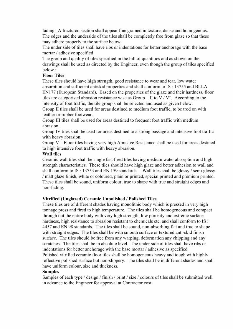
fading. A fractured section shall appear fine grained in texture, dense and homogenous. The edges and the underside of the tiles shall be completely free from glaze so that these may adhere properly to the surface below. The under side of tiles shall have ribs or indentations for better anchorage with the base mortar / adhesive specified The group and quality of tiles specified in the bill of quantities and as shown on the drawings shall be used as directed by the Engineer, even though the group of tiles specified below : Floor Tiles These tiles should have high strength, good resistance to wear and tear, low water absorption and sufficient antiskid properties and shall conform to IS : 13755 and BLLA EN177 (European Standard). Based on the properties of the glaze and their hardness, floor tiles are categorized abrasion resistance wise as Group – II to V / V+. According to the intensity of foot traffic, the tile group shall be selected and used as given below. Group II tiles shall be used for areas destined to medium foot traffic, to be trod on with leather or rubber footwear. Group III tiles shall be used for areas destined to frequent foot traffic with medium abrasion. Group IV tiles shall be used for areas destined to a strong passage and intensive foot traffic with heavy abrasion. Group V – Floor tiles having very high Abrasive Resistance shall be used for areas destined to high intensive foot traffic with heavy abrasion. Wall tiles Ceramic wall tiles shall be single fast fired tiles having medium water absorption and high strength characteristics. These tiles should have high glaze and better adhesion to wall and shall conform to IS : 13753 and EN 159 standards. Wall tiles shall be glossy / semi glossy / matt glaze finish, white or coloured, plain or printed, special printed and premium printed. These tiles shall be sound, uniform colour, true to shape with true and straight edges and non-fading. Vitrified (Unglazed) Ceramic Unpolished / Polished Tiles These tiles are of different shades having monolithic body which is pressed in very high tonnage press and fired to high temperature. The tiles shall be homogeneous and compact through out the entire body with very high strength, low porosity and extreme surface hardness, high resistance to abrasion resistant to chemicals etc. and shall conform to IS : 4457 and EN 98 standards. The tiles shall be sound, non-absorbing flat and true to shape with straight edges. The tiles shall be with smooth surface or textured anti-skid finish surface. The tiles should be free from any warping, deformation any chipping and any scratches. The tiles shall be in absolute level. The under side of tiles shall have ribs or indentations for better anchorage with the base mortar / adhesive as specified. Polished vitrified ceramic floor tiles shall be homogeneous heavy and tough with highly reflective polished surface but non-slippery. The tiles shall be in different shades and shall have uniform colour, size and thickness. Samples Samples of each type / design / finish / print / size / colours of tiles shall be submitted well in advance to the Engineer for approval at Contractor cost.

Approved sample tiles will be retained by the Engineer. All tiles procured should be exactly as per approved samples. Tiles shall be procured from a single approved source / manufacturers who can provide products of consistent quality and physical properties. The manufacturer of tiles should be an approved company specializing in ceramic tiles. Tiles of approved make, colour, design, finish, size etc. as stipulated in item description and /or as shown in the drawings only should be procured and used on the works. Storage of Materials The delivery of tiles shall be in original containers with seals unbroken. Adequate precaution shall be taken to prevent accidental damage to tiles while unloading and these shall be stored under cover in a manner approved by the Engineer. Adhesives shall be stored as per the manufacturers instructions. Laying and Finishing of Floor tiles Preparation of base shall be as specified under head “Preparation of Base Surface”. The under bed for flooring shall be of 20 mm average thick cement mortar 1:4 (1 part cement and 4 parts sand) or as specified in item specification. The bedding shall be laid evenly over the surface, tamped and corrected to desired levels and allowed to harden enough to offer a fairly rigid cushion to tiles. Before fixing the tiles, the bed mortar shall be roughened by scratching diagonal lines at closed intervals and grey cement slurry of honey like consistency shall be applied over the bedding. Tiles shall be well soaked in water washed clean and fixed in cement grout one after the other, each tile being gently tapped in its position with a wooden mallet till it is properly bedded and in level with the adjoining tiles. The joints shall be kept as thin as possible and in straight lines or to suit the required pattern. Where the full tiles cannot be fixed these shall be cut (sawn) to the required size and their edges rubbed smooth to ensure straight and true joints. When grouting the tiles special care shall be taken to prevent scratch. After the tiles have been laid, surplus cement grout shall be cleaned off. The joints shall be cleaned off the grey cement grout with a wire brush or trowel to a depth of 5 mm and all dust and loose mortar removed. Joints shall then be flush pointed with grout of white cement mixed with “Roff Rainbow Tile Mate” or approved equivalent, to match the colour of tiles as per Manufacturer’s specification. The floor shall then be kept wet for 7 days. After curing, the surface shall be washed with mild hydrochloric acid and clean water. The finished floor shall not sound hollow when tapped with a wooden mallet. Laying and Finishing of Wall Tiles Preparation of wall surface shall be as specified under head “Preparation of Base Surface” A 12 mm thick plaster of cement mortar 1:3 mix or as specified in item shall be applied and allowed to harden. The plaster shall be roughened with wire brushes or by scratching diagonal at closed intervals and cured properly. The tiles should be washed clean and a coat of cement slurry applied liberally at the back of tiles and set in the bedding mortar and for pointing the tiles. If specified in the item, chemical adhesive of approved make shall be used for setting the tiles in the bedding mortar. For maintaining uniform gap and alignment plastic spacer should be used. The tiles shall be tamped and corrected to proper plan and lines. The tiles shall be set in the required pattern and jointed true to plumb. The joints shall be as fine as possible. Top of skirting or dado shall be truly horizontal and joints truly vertical except where otherwise indicated or as directed by Engineer.

Skirting / dado shall rest on the top of the flooring where full size tiles cannot be fixed these shall be cut (swan) to the required size and height as specified and their edges rubbed smooth. The joints shall be cleaned off with wire / coir brush or trowel and all dust and loose mortar removed. Joints than shall be flush pointed with grout of white cement mixed with “Roff Rainbow Tile Mate” or approved equivalent to match the colour of tiles as per manufacturer specification. The work shall then be kept wet for 7 days. After curing, the surface shall be washed with mild hydrochloric acid and clean water. The finished work shall not sound hollow when tapped with a wooden mallet. The surface shall be protected with a layer of pop to a required thickness over a plastic sheet. CEMENT BASED COLOUR AND PATTERNED TILES Cement tile to be used for external and internal applications shall be manufactured using very high quality raw materials, high strength cement, colour pigments etc. to withstand all conditions of sever intensity in terms of temperature, vagaries of the nature, traffic, extreme heat and cold etc. and shall conform to IS 1237. The tiles shall be heavy, dense, homogeneous in texture with high strength and surface hardness, high resistance to abrasion and low porosity. Thickness of floor tiles shall be 22 mm and wall tiles shall be 12 mm. Tiles of approved make, colour, design, plain chequered or grooved pattern etc. as shown on the drawings, as specified in the Bill of Quantities shall be used in the works as directed by the Engineer. Laying of tiles in any pattern in combination of any colour tiles desired by the Engineer shall be carry out without any extra cost. Samples - Samples of each type / design / finish / print / size / colours of tiles shall be submitted well in advance to the Engineer for approval at Contractor cost. Approved sample tiles will be retained by the Engineer. All tiles procured should be exactly as per approved samples. Tiles shall be procured from a single approved source Tiles of approved make, colour, design, finish, size etc. as stipulated in item description and / or as shown in the drawings only should be procured and used on the works. Storage - Tiles shall be stacked and stored as per instructions of the manufacturer. Laying And Finishing Of Floor Tiles A bedding of 20 mm thick with cement mortar 1:4 (one part of cement and four parts of coarse sand) or as specified shall be laid over the prepared base after setting the levels for the floor. Neat cement slurry of honey like consistency shall be spread over the levelled base mortar. The tiles after wetting the reverse side, shall be fixed in the cement grout one after the other, each tile being gently tapped with a wooden mallet to obtain perfect levels. The laid surface shall be cleaned with water immediately with wet sponge. It shall be ensured that the cement grout which squeezes through joints does not settle on the tile. The joints, after cleaning, shall be pointed with white cement mixed with colour pigment of tile finish like “Roff Rainbow Tile make or approved equivalent. The surface shall be cured for 7 days. The surface shall be maintained by cleaning the tiles regularly with water and detergent. Laying and finishing of wall tiles - Laying of wall tiles shall be in the same manner as described above for floor tiles.

The surface shall be protected with a layer of pop to a required thickness over a plastic sheet. SHAHABAD, TANDUR, KOTAH AND CUDDAPAH FLOORING The slabs shall be of selected quality, hard sound, dense, homogenous in texture, free from cracks, decay, weathering and flaws and of thickness as specified. The top exposed faces should have been roughly polished before bringing it to site. Unless otherwise specified the slabs should be cut to the required shape and size, by machine cut as specified. All pieces should be of uniform colour. A bed of cement mortar 1:4 shall be laid and properly levelled to an average thickness of 20 mm and the surface should be kept slightly rough to form a satisfactory key for the tiles. Neat cement paste of honey like consistency shall be spread over mortar bed over such an area so that the paste will not harden before laying tiles. Slabs shall be soaked in water for 15 minutes and allowed to dry. The slabs shall then be fixed as per approved pattern with thin coat of cement paste on back of each slab. They will be tapped with a wooden mallet till it is properly bedded in level with adjoining slabs. Joints shall be kept as thin as possible and in straight lines or to suit the required pattern. The surplus cement grout that may have come out of the joints has to be wiped off gently and joints cleaned. The joints shall be filled up with grey or white cement with an admixture of pigments to match the shade of the slab. The flooring shall be cured for 14 days. Protection - The surface shall be protected with a layer of pop to a required thickness over a plastic sheet without any extra cost. GRANITE FLOORING / DADOING The slabs must be of uniform thickness as specified the variation in the thickness not exceeding 2 mm and must be from the same source. They shall be of uniform texture and colour free of any veins and streaks. All the edge shall be chiseled true to line, square and shape. The brushes in the joints are not more than specified thickness. Rough Finish The surface should be rough dressed/one line dressed/two lines dressed/three line dressed finish using palmane tools as specified. Rough dressing The stone surface to be chisel dressed to one plane by removing all bushings so that the maximum depression is not more than 6 mm. One line dressing - This is done after the rough dressing is completed by point chiselling so that the variations are not more than 4 mm. Work includes rough dressing also. Two line dressing This is done after one line dressing is done by chiselling so that variations are not more than 2.5 mm. Work includes rough and one line dressing also. Three lines dressing This is done after two lines dressing is over by chiselling so that the variations are not more than 1.5 mm. Work includes rough, one line & two line dressing also. Palmane dressing : After the three line dressing is over the surface is smoothened by using a special palmane tool to further even out the 3 line dressed surface so that the maximum
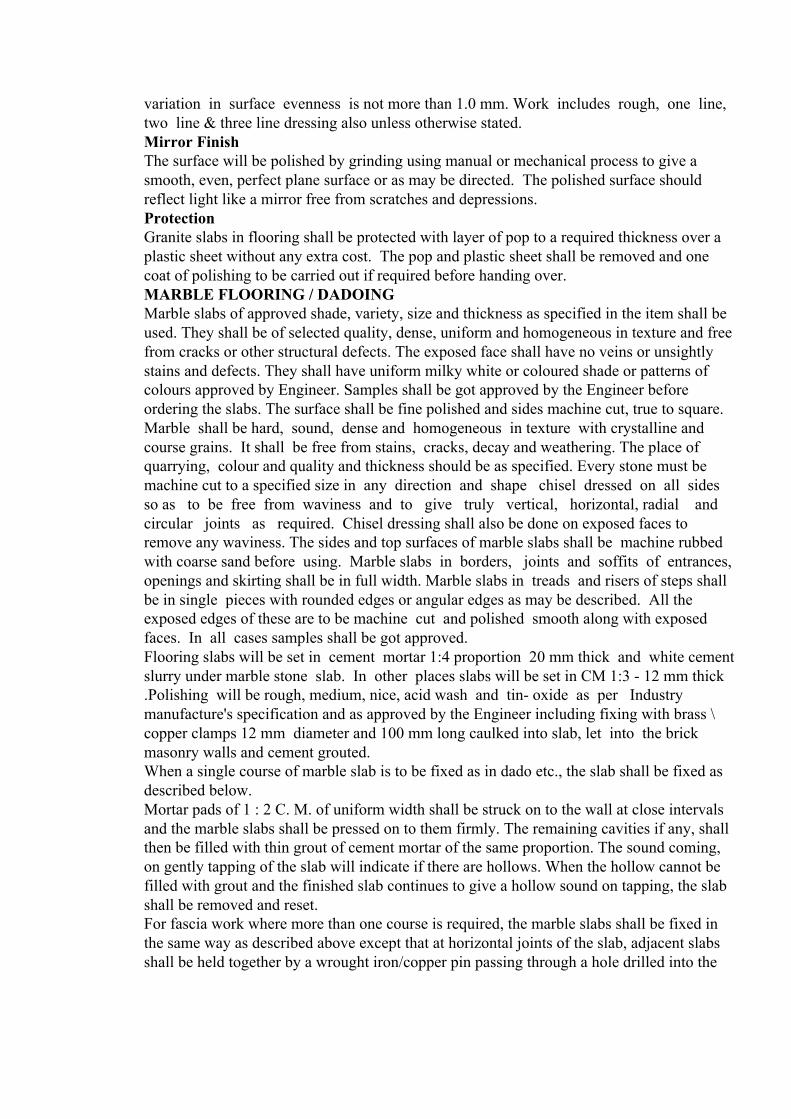
variation in surface evenness is not more than 1.0 mm. Work includes rough, one line, two line & three line dressing also unless otherwise stated. Mirror Finish The surface will be polished by grinding using manual or mechanical process to give a smooth, even, perfect plane surface or as may be directed. The polished surface should reflect light like a mirror free from scratches and depressions. Protection Granite slabs in flooring shall be protected with layer of pop to a required thickness over a plastic sheet without any extra cost. The pop and plastic sheet shall be removed and one coat of polishing to be carried out if required before handing over. MARBLE FLOORING / DADOING Marble slabs of approved shade, variety, size and thickness as specified in the item shall be used. They shall be of selected quality, dense, uniform and homogeneous in texture and free from cracks or other structural defects. The exposed face shall have no veins or unsightly stains and defects. They shall have uniform milky white or coloured shade or patterns of colours approved by Engineer. Samples shall be got approved by the Engineer before ordering the slabs. The surface shall be fine polished and sides machine cut, true to square. Marble shall be hard, sound, dense and homogeneous in texture with crystalline and course grains. It shall be free from stains, cracks, decay and weathering. The place of quarrying, colour and quality and thickness should be as specified. Every stone must be machine cut to a specified size in any direction and shape chisel dressed on all sides so as to be free from waviness and to give truly vertical, horizontal, radial and circular joints as required. Chisel dressing shall also be done on exposed faces to remove any waviness. The sides and top surfaces of marble slabs shall be machine rubbed with coarse sand before using. Marble slabs in borders, joints and soffits of entrances, openings and skirting shall be in full width. Marble slabs in treads and risers of steps shall be in single pieces with rounded edges or angular edges as may be described. All the exposed edges of these are to be machine cut and polished smooth along with exposed faces. In all cases samples shall be got approved. Flooring slabs will be set in cement mortar 1:4 proportion 20 mm thick and white cement slurry under marble stone slab. In other places slabs will be set in CM 1:3 - 12 mm thick .Polishing will be rough, medium, nice, acid wash and tin- oxide as per Industry manufacture's specification and as approved by the Engineer including fixing with brass \ copper clamps 12 mm diameter and 100 mm long caulked into slab, let into the brick masonry walls and cement grouted. When a single course of marble slab is to be fixed as in dado etc., the slab shall be fixed as described below. Mortar pads of 1 : 2 C. M. of uniform width shall be struck on to the wall at close intervals and the marble slabs shall be pressed on to them firmly. The remaining cavities if any, shall then be filled with thin grout of cement mortar of the same proportion. The sound coming, on gently tapping of the slab will indicate if there are hollows. When the hollow cannot be filled with grout and the finished slab continues to give a hollow sound on tapping, the slab shall be removed and reset. For fascia work where more than one course is required, the marble slabs shall be fixed in the same way as described above except that at horizontal joints of the slab, adjacent slabs shall be held together by a wrought iron/copper pin passing through a hole drilled into the

slabs. In addition, wrought iron/copper hold fasts/dowels shall be provided to anchor the slabs to the wall. The hold fasts shall be counter-sunk into the joints of the slab and it shall be located at a specified intervals subject to a minimum of one for each slab for each horizontal joint. The facing shall be fixed truly in plumb and in perfect line or curves as shown on the plans. The courses and joints shall be as directed by Engineer. The surface shall be protected from sun and rain and cured for ten days and shall be finally polished. Protection Marble slabs in flooring shall be protected with layer of pop to a required thickness over a plastic sheet. The pop and plastic sheet shall be removed and one coat of polishing to be carried out if required before handing over. VINYL FLOORING PVC based vinyl Tiles and Rolls set with adhesive on to a concrete or masonry base shall conform to latest IS : 3462. Materials Tiles The tiles should be calendered laminated solid resilient unbreakable and homogeneous flexible quartz reinforced PVC Vinyl tiles composed of 100% vinyl from face to back with alkaline resisting colour pigments and other plastic compounds in different shades and designs and in different sizes and thickness and shall conform to IS : 3462. Unless otherwise mentioned the tiles shall be squares of approved dimensions. Tiles shall have properties of a high wear resistance and resilience, designed to withstand high traffic and abrasion. The face of these tiles shall be free from porosity, blisters, cracks, embedded foreign matter, or other physical defects, which affect the appearance or impair the service ability of the tiles. All edges shall be cut true and square. The colour shall be non-fading and uniform in appearance, insoluble in water and resistant to alkalies cleaning agents and usual floor polishes. Cove base shall be extruded PVC (100% putty) with moulded top set cove colour and the height of the base shall be as indicated on the drawings, scheduling and / or as approved by Engineer. Samples of tile and cove base shall be submitted to the Engineer along with test certificate for approval. Rolls It should be calandered laminated solid resilient unbreakable and homogeneous quartz reinforced flexible PVC Vinyl Flooring in different shades and designs and in different width and thickness with inherent characteristics of wear resistance, dimensional stability, elegance etc and shall conform to IS : 3462. Each packet of tile or roll shall be legibly and indelibly marked with the manufacturer’s trade mark, thickness, size batch number and date of manufacture. Tiles shall be delivered securely packed and store in clean, dry, well ventilated places. Adhesive Synthetic rubber based adhesive to be used for fixing tiles shall be Dunlop S-758 or Fevicol SR-998 or equivalent or as recommended by the manufacturer. The adhesive shall have a short drying time and long life. Each container shall show the self life, date of manufacture and over age container shall be immediately removed from the site.
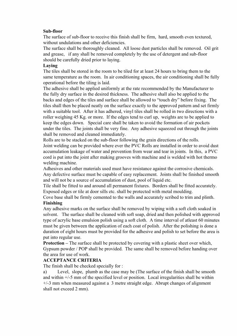
Sub-floor The surface of sub-floor to receive this finish shall be firm, hard, smooth even textured, without undulations and other deficiencies. The surface shall be thoroughly cleaned. All loose dust particles shall be removed. Oil grit and grease, if any shall be removed completely by the use of detergent and sub-floor should be carefully dried prior to laying. Laying The tiles shall be stored in the room to be tiled for at least 24 hours to bring them to the same temperature as the room. In air conditioning spaces, the air conditioning shall be fully operational before the tiling is laid. The adhesive shall be applied uniformly at the rate recommended by the Manufacturer to the fully dry surface in the desired thickness. The adhesive shall also be applied to the backs and edges of the tiles and surface shall be allowed to “touch dry” before fixing. The tiles shall then be placed neatly on the surface exactly to the approved pattern and set firmly with a suitable tool. After it has adhered, vinyl tiles shall be rolled in two directions with a roller weighing 45 Kg. or more. If the edges tend to curl up, weights are to be applied to keep the edges down. Special care shall be taken to avoid the formation of air pockets under the tiles. The joints shall be very fine. Any adhesive squeezed out through the joints shall be removed and cleaned immediately. Rolls are to be stacked on the sub-floor following the grain directions of the rolls. Joint welding can be provided where ever the PVC Rolls are installed in order to avoid dust accumulation leakage of water and prevention from wear and tear in joints. In this, a PVC cord is put into the joint after making grooves with machine and is welded with hot thermo welding machine. Adhesives and other materials used must have resistance against the corrosive chemicals. Any defective surface must be capable of easy replacement. Joints shall be finished smooth and will not be a source of accumulation of dust, pool of liquid etc. Tile shall be fitted to and around all permanent fixtures. Borders shall be fitted accurately. Exposed edges or tile at door sills etc. shall be protected with metal moulding. Cove base shall be firmly cemented to the walls and accurately scribed to trim and plinth. Finishing Any adhesive marks on the surface shall be removed by wiping with a soft cloth soaked in solvent. The surface shall be cleaned with soft soap, dried and then polished with approved type of acrylic base emulsion polish using a soft cloth. A time interval of atleast 60 minutes must be given between the application of each coat of polish. After the polishing is done a duration of eight hours must be provided for the adhesive and polish to set before the area is put into regular use. Protection – The surface shall be protected by covering with a plastic sheet over which, Gypsum powder / POP shall be provided. The same shall be removed before handing over the area for use of work. ACCEPTANCE CRITERIA The finish shall be checked specially for : a) Level, slope, plumb as the case may be (The surface of the finish shall be smooth and within +/-5 mm of the specified level or position. Local irregularities shall be within +/-3 mm when measured against a 3 metre straight edge. Abrupt changes of alignment shall not exceed 2 mm).

b) Pattern and symmetry c) Alignment of joints, dividing strips, etc. d) Colour, texture e) Surface finish f) Thickness of joints g) Details of edges, junctions, etc. h) Performance Precautions specified for durability
12. TECHNICAL SPECIFICATION FOR STEEL DOORS
This specification covers the general requirements for manufacture and erection of steel doors, steel sliding doors and steel rolling shutters and other miscellaneous steel works. GENERAL : The contractor shall furnish all materials, labour, operations, equipments, tools & plant and incidentals necessary and required for the completion of all metal work in connection with steel doors, windows and other glazings, railings, flashings, inserts, hangers and other items of metal works as called for in the drawings, specifications and bill of quantities cover the major requirements only. Anything called for in the tender documents shall be considered as applicable to the items of work concerned. The supply and installation of additional fastenings, accessory features and other items not specifically mentioned, but which are necessary to make a complete functioning installation shall form a part of this contract. All metal work shall be free from defects, imparing strength, durability and appearance and shall be of the best quality for purposes specified made with structural properties to withstand safely, strains, stresses to which they shall normally be subjected. All fittings shall be high quality brass chromium plated or as specified and as per approval of Engineer. SHOP DRAWINGS : The contractor shall submit shop drawings and / or samples of each type of doors, windows, railings and other items of metal work called for to the Engineer for his approval atleast thirty days ahead of their use at site and to conform to the C.P.M. Chart. The shop drawings shall show full size sections of doors, windows and other components, thickness of metal, details of construction, hardware as well as connection of doors, windows and other metal work to adjacent work/supports. Samples of all joints and methods of fastening and joining shall be submitted to the Engineer for approval well in advance atleast thirty days before commencing the work. SAMPLES : Samples of all typical metal work such as, doors, windows, railings and other metal components as called for shall be fabricated, assembled and erected or submitted to the Engineer as directed by him, for his approval atleast thirty days in advance of their use at site. APPROVED MANUFACTURER : All doors, windows, railings & other metal works as called for shall be manufactured by a manufacturer/fabricator approved by the Engineer. The entire work shall be carried out by workmen skilled in the kind of work as called for in a shop fully equipped to carry out all

phases of fabrication in accordance with the best accepted practices and as approved by the Engineer. INTERNAL DOORS : Internal door frames where called for shall be of pressed mild steel sections as per IS:4351 of the size and details as shown on drawings or other documents. The sections shall be pressed from 18 gauge mild steel sheet unless otherwise specified to the profile shown, by means of a mechanical press of adequate capacity. The pressed section shall be true to profile and also true to dimensions called for. The frame members shall be of one piece and the corners of the frames shall be mitred, electrically welded and ground smooth. Mechanical jointing of members may be accepted subject to approval of the jointing arrangement by the Engineer. Necessary provisions shall be made in the frames for fixing silencers, tower bolts, door closers and other hardwares. Slots for receiving lock and latch shall be shop punched and not made at site. The size and the location of the slots shall match the type of lock specified and at the height shown on the drawings / documents, hinges of specified type, make and size shall be fixed to the frames in the fabrication shop. The hinges shall be so fixed that the hinge flap is flush with the face of the frame. A reinforcing metal plate of 16 mm thickness with holes drilled and threaded to receive machine screws from the hinges shall be welded to the frames at hinge locations as shown on the drawings. Holdfasts where called for shall be of mild steel flats of shapes and sizes as shown on the drawings/documents and shall be welded to frames. The frames shall be phosphated and then given a coat of redoxide zinc chromate primer. The surfaces shall be as specified under 'PAINTING' as approved by the Engineer. Base ties of mild steel angles shall be provided for all door frames to retain the size and shapes of the frames during transportation, handling, storage at site and erection. FITTINGS : Hinges, locks, tower bolts, rubber buffers, door closers and other fittings shall be provided as given in Bill of Quantities. UNLOADING AND STACKING : The fabricated frames shall be transported, bundled, unloaded and stacked in a careful manner. They shall be stacked on edge on level bearers and supported evenly. All precautions shall be taken to ensure that the frames are not damaged or distorted in any manner. FIXING : The door frames shall be fixed at the top & bottom through M.S. cleats as shown on the drawings. M.S. cleats of size and detail as shown or called for shall be anchored to the floor and roof slab concrete at the time of casting the concrete. The frame shall be securely fixed to the outstanding leg after erecting in true and correct position. When the frames are to be fixed to column/wall faces, they shall be fixed with rawl bolts/expansion bolts of approved make. The frames shall be fixed into position true to line and level using adequate number of expansion machine bolts (RAWL BOLTS) of approved size and manufactured in an approved manner. The holes in concrete / masonry members for housing anchor bolts shall be drilled with an electric drill. The doors assembled as shown on drawings/documents shall be placed in correct final position in the openings and marks made on concrete members at jambs, sills, and heads against holes provided in the frames for anchoring. The frames shall then be removed
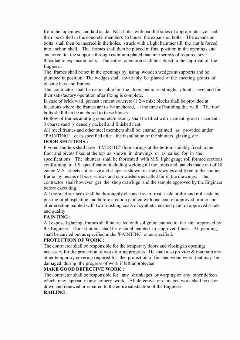
from the openings and laid aside. Neat holes with parallel sides of appropriate size shall then be drilled in the concrete members to house the expansion bolts. The expansion bolts shall then be inserted in the holes, struck with a light hammer till the nut is forced into anchor shell. The frames shall then be placed in final position in the openings and anchored to the supports through cadmium plated machine screws of required size threaded to expansion bolts. The entire operation shall be subject to the approval of the Engineer. The frames shall be set in the openings by using wooden wedges at supports and be plumbed in position. The wedges shall invariably be placed at the meeting points of glazing bars and frames. The contractor shall be responsible for the doors being set straight, plumb, level and for their satisfactory operation after fixing is complete. In case of brick wall, precast cement concrete (1:2:4 mix) blocks shall be provided at locations where the frames are to be anchored, at the time of building the wall. The rawl bolts shall then be anchored to these blocks. Hollow of frames abutting concrete/masonry shall be filled with cement grout (1 cement : 3 coarse sand ) densely packed and finished neat. All steel frames and other steel members shall be enamel painted as provided under "PAINTING" or as specified after the installation of the shutters, glazing, etc. DOOR SHUTTERS : Pivoted shutters shall have "EVERITE" floor springs at the bottom suitably fixed to the floor and pivots fixed at the top as shown in drawings or as called for in the specifications. The shutters shall be fabricated with M.S. light gauge roll formed sections conforming to I.S. specification including welding all the joints and panels made out of 18 gauge M.S. sheets cut to size and shape as shown in the drawings and fixed to the shutter frame by means of brass screws and cup washers as called for in the drawings. The contractor shall however get the shop drawings and the sample approved by the Engineer before executing. All the steel surfaces shall be thoroughly cleaned free of rust, scale or dirt and millscale by picking or phosphating and before erection painted with one coat of approved primer and after erection painted with two finishing coats of synthetic enamel paint of approved shade and quality. PAINTING : All exposed glazing, frames shall be treated with solignum stained to the tint approved by the Engineer. Door shutters, shall be enamel painted to approved finish. All painting, shall be carried out as specified under 'PAINTING' or as specified. PROTECTION OF WORK : The contractor shall be responsible for the temporary doors and closing in openings necessary for the protection of work during progress. He shall also provide & maintain any other temporary covering required for the protection of finished wood work that may be damaged during the progress of work if left unprotected. MAKE GOOD DEFECTIVE WORK : The contractor shall be responsible for any shrinkages or warping or any other defects which may appear in any joinery work. All defective or damaged work shall be taken down and renewed or repaired to the entire satisfaction of the Engineer. RAILING :

Railing to stairs and other locations where called for shall have hand rail of steel pipe or other material as called for of size as shown, supported by mild steel balusters anchored to concrete railing as shown on drawings. The mild steel verticals shall be 25 dia tube and as shown on drawings and shall be embedded & anchored in the concrete members in their correct assigned positions at the time of casting the concrete members. No breaking or disturbing of any completed concrete members shall be allowed. The hand rail shall be fixed to the baluster verticals by means of Tee joints as detailed on the drawing. The drilling of holes, counter sunking, etc., shall be carried out by skilled fitters in a precise,neat and workman like manner,as called for on the drawings and as directed by the Engineer. The finished railing shall be true to plumb, line and levels as called for. The mild steel balusters and other exposed mild steel members shall be painted as specified under 'PAINTING' or as specified. ROLLING SHUTTERS : The rolling shutters shall be fabricated from 18 gauge steel sheets and machine rolled with 75 mm rolling centres with effective bridge depth of 12 mm lathe sections, interlocked with each other and ends locked with malleable cast iron clips conforming to IS : 2108. The guides shall be either rolled or pressed deep channel sections, 75 mm and 25 mm wide, fitted with necessary fittings and fixtures. The suspension shaft of the roller shall be made of steel pipe to heavy duty of IS 1161 and of sufficient diameter so as to resist deflection due to the weight of the rolling shutter. The deflection shall not exceed 5 mm per metre width. The shaft shall be provided with CI pulleys and helical spring for counter balancing this weight of the shutter adequately. The spring shall be made of high tensile spring wire conforming to grade 2 of IS 4454. For large size rolling shutter the roller shall be provided with double row, self-aligning ball bearings. For wide openings, the roller shall be of fabricated cage type, the roller assembly shall be designed so as to be capable of producing sufficient torque to ensure easy operation of the rolling shutter in any position. the spring tension shall be adjusted by means of suitable adjustment holes on the rim of the pulleys. The hood cover shall be made of 20 gauge galvanised sheets with necessary stiffeners and frame work to prevent sag. The bottom lock plate shall be made of 5 mm thick MS plate and 95 mm wide reinforced with angle as T section, of suitable section with 6 mm dia. MS rivets interlocked with last strike of curtain. The locking arrangement shall consist of hasp and staple on the bottom plate lockable from both sides. The rolling shutters shall be of specified grade and approved make. Brackets shall be rigidly fixed to the lintel, wall or at any position as required to take the full load of the shutter. The shaft along with springs shall be fixed to the brackets. The shutter shall be laid on ground and the guide channels shall be bound with it, with ties. The shutter shall then be placed in position and the top fixed with suspension shaft. The side guide channels and cover frame shall then be fixed to the wall. Pockets shall be cut to fix the brackets, clamps, guide channels, etc. and shall be grouted with cement concrete, proportion 1:2:4, or these shall be fixed by any other method as directed by the Engineer or as specified by the Manufacturer, at the contractor's own cost. Fixing shall be done true to plumb and level such that the operation of the shutter is easy and smooth. SLIDING DOOR : The large size sliding doors shall be manufactured with M.S channels, angles, MS sheets etc. All the materials to be used for the manufacture of sliding doors shall conform to Indian Standard Specification. The sliding door may be of single leaf or double leaf

construction. Each leaf will have two wheels with double ball bearings at the bottom and guide rollers at the top. At the bottom the wheel shall slide over the rails fixed on the floor and at the top the guide roller shall move on the guide rails supported on the structural member. In the floor the rails shall be embedded in the concrete and the top of rail should be flush or slightly below the finished level of the floor but should not be projected above the floor level. The guide roller at the top of door shall have a hood cover in 18 G M.S sheet with necessary bracket supports. Bottom rail and top guide rail and hood cover shall extend 200 mm more on either side beyond the door in open position in the case of two leaf construction and in the case of single leaf one side shall be extended. The size of door to be manufactured shall be more than the size of structural opening of the door according to the site condition. But the payment shall be for the door opening only. The door shall be of manually operated or electrically operated. The door shall be sand blasted and painted with two coats of approved quality synthetic enamel paint over a coat of zinc chromate primer. The large size door construction shall generally consist of frame work with main members alround stiffened by horizontal and vertical members using M.S channel, angle sections and sheeting welded on both sides of frame using MS sheet with folded construction and sliding arrangements at bottom and top using wheel and guide roller with necessary supporting arrangement on the main frame. Necessary corner pieces and additional stiffners wherever necessary shall be provided to ensure structural stability of the door. Fabrication, welding, erection and painting shall be in accordance with relevant Indian Standard Specifications. The Contractor shall submit shop drawings from the manufacturer showing full details and wheel & guide roller arrangements to the Engineer for approval. The entire work shall be executed as per approved drawings and as directed by the Engineer. Necessary fittings shall be provided as specified.
13. TECHNICAL SPECIFICATION FOR ALUMINIUM WORKS GENERAL : This specification covers the general requirements for aluminium doors, windows and ventilators manufactured from extruded aluminium alloy sections of standard sizes and designs complete with fittings including supply, fabrication and installation in accordance with the drawings and specifications. The supply, fabrication and erection will include all parts such as but not restricted to frames, tracks, guides, mullions, styles, rails, couplers, transoms, plates, glazing bars, weather bars, glass, hinges, handles, pegstays, bolts, locks, latches, locking arrangements, spring catches, cord and pulley arrangements, door closers, floor springs etc., required for the whole work whether the parts/items are individually and specifically referred to in the schedule/specifications/drawings or not, provided that the supply and installation of such parts can be inferred therefrom and are necessary to make the work complete, unless separate provision is made in the bills of quantities for supply to such parts/items. Materials : Aluminium Sections : i. The members shall be made out of aluminium alloy corresponding to IS 733 (latest) and will consist of extruded sections and of other shapes, and to sizes and gauges as shown in the drawings/described in accordance with the relevant IS Codes. The

members shall be chosen to provide strength/stability and maximum resistance to wear and tear. ii. The sections shall be of INDAL, JINDAL, or equivalent extruded sections. As indicated in the drawings the tenderer should specifically mention which sections he is going to use. iii. The weight of sections and the corresponding catalogue numbers are mentioned. The IS specifications are to be strictly adhered. iv. The various tests of aluminium section shall be conducted in accordance with relevant IS Codes. v. The following sections shall be used for the fabrication of doors, windows and ventilators etc. INDAL/JINDAL Section No. Minimum Weight - Kg/RM 9200 1.974 9201 1.299 9202 1.202 9203 1.319 9807 1.757 4420 0.136 9771 1.054 8650 0.485 8732 1.055 8758 0.659 8765 0.558 8766 0.424 6358 0.617 6410 0.885
Finishing : i. The extruded aluminium section shall be mechanically finished to remove all scratches, extrusion marks etc and subsequently thoroughly cleaned in an alkali bath prior to anodising. ii. For anodising IS 1868 shall be strictly followed. iii. The anodising shall be in natural finish by electro chemical process as per IS Specification 7088 (latest) and thickness shall be 15 microns. Film thickness test for anodic coating shall be done in authorised test house and test results shall be submitted to the Engineer. iv. The anodised material shall be sealed properly and it should be wrapped in gummed tape before fabrication to avoid scratches during fabrication and erection and shall be kept protected till handing over. Fabrication : Before commencing the fabrication the contractor shall submit to the Engineer for his approval detailed fabrication drawings, based on the Engineer's drawings and specifications and corresponding to the finished openings left at site where the doors, windows, ventilators, partitions are to be fixed, junctions, fittings, accessories etc. such as hinges, flush bolts, locks, latches, latching arrangements, pegstays, rotor arms,

centre pivots, gaskets, rubber packings, door felts, mastic, sealant, etc., fixing and sealing arrangements, etc. and the type and method of scaffolding he intends to use, incorporating therein what he has offered and what has been accepted, and specified in the order. Fabrication shall be taken up only on approval of and in accordance with the approved drawings. Should there be any necessity, the Engineer may revise the sections of any door/ window / ventilator etc. and the same shall be followed for execution. However the rate quoted for the relevant finished item shall be adjusted only for the difference in weight of Aluminium sections in KG. between that specified by the tenderer at the time of tendering and that modified by the Engineer. All other elements of cost variation due to such modifications in the sections shall be deemed to have been included in the quoted rates. Fabrication shall be done true to the drawings to correspond to the finished openings at the site, the sections cut to lengths to suit, mitred at the corners, to true right angles with joints made neatly to hair lines, with concealed fasteners, wherever possible joints shall be made in concealed locations. All fabricated items shall be packed and carted properly before despatch to site to prevent damage in transit. On receipt at site they shall be carefully stacked in protected storage to avoid distortion/damage. Such items shall also be in the safe custody of the contractor. Construction : The units shall be factory built to precision, alignment, dimensional accuracy and strength. The outer frame shall be inter-fitted together by mechanical means of best fabrication technique. The interlocking members shall be accurately manufactured to close tolerances to ensure tight fit of the mating interlock profiles. There shall be minimum gap between shutter and frame to facilitate easy and smooth movement of the shutter. Field connections may be made with concealed screws, self tapping or other approved fasteners or may be made with weld due precautions being taken to avoid altogether distortion / discoloration of the finish. Details of construction of the doors, windows, ventilators partitions shall be as specified in the relevant I.S codes and in the absence of such details in any I.S. code, will correspond to the best engineering practice. Faces / Parts coming into contact with masonry in the construction shall before shipment to the site be given a heavy coat of an alkali resistance bitumen paint. Aluminium coming in contact with other incompatible metals shall be given similarly a thick coat of Zinc Chromate primer. The sliding shutters are to be fixed with nylon rollers with stainless steel ball bearings and stainless steel pin. The Stainless steel mosquito netting of approved quality with necessary fasteners are fixed in window frames at location as indicated in the drawings and complete in all respects. The frames to be fitted with wool pole as directed by the Engineer. The doors, windows, ventilators and partitions shall be supplied in natural colour (matt finish) anodising in the item specifications. Anodising shall be matt finish under electrically controlled conditions conforming to IS 6057, and to be minimum thickness as may be specified in the item specifications or if not so specified to a minimum thickness of 15 microns excepting on the fittings, hinges and such other moving parts

where it shall be to a minimum thickness of 20 microns. Any frames found short of microns film thickness of anodising shall be rejected. For installation a thick layer of clear transparent lacquer based or methacrylates or cellulose butyrate shall be applied by the supplier on the aluminium doors, windows ventilators and partitions to protect the surface. The coating shall be removed after installation is done. They shall be cleaned thoroughly with warm water to restore the finish. Scaffolding is the responsibility of the contractor and shall be done without causing any damage to the structure and the finishes therein. Glazing : Glazing shall be done with flawless sheet glass of SAINT GOBAIN Quality without waviness, distortion, coloration/discoloration, of specified thickness, in sizes as shown in the drawings, fixed as required with special glazing clips, putty, neoprene/PVC gaskets. The gasket shall be extruded EPDM synthetic rubber wrap around U channel type with bevelled edges to run continuously around the perimeter of the glass. All glass shall be cleaned thoroughly before they are fixed in position. The thickness of glass shall be as specified in the item specification under B.O.Q. and Drawings. The following types of glasses shall be used. 1. Office Building - Clear glass or tinted glass or as specified in the Schedule of Quantities. 2. Toilets & Kitchen - Clear glass or frosted or tinted glass or as specified in schedule of quantities. 3. Partitions - Clear or tinted or frosted float glass. 4. Sky light roofing - Frosted Glass Fitting : The handles shall be of cast aluminium anodised two point handles of high quality and of approved design and shape. Peg stays shall be of anodised wrought aluminium. All fittings shall be of high quality to design and / or type approved by the Engineer. Sealing : Sealing shall be done using a non-hardening silicon sealant single part gun applied to provide water tight seal between the window and the surrounding construction. Protection and Cleaning : The Contractor shall be responsible for the protection of all aluminium works during the course of construction of the building and for cleaning all aluminium works after painting and finishing of building is completed. The aluminium manufacturers shall give specific performance guarantee against defects in materials or workmanship for a period of one year from the date of installation. The rates quoted shall include :- a) Providing all aluminium doors, windows, ventilators, glazings, railings etc. of the best manufacture and as per prior approval of the Engineer. b) Providing necessary couplings, transoms and mullions. c) Providing a protective thick layer of clear transparent lacquer based on methaorylates or cellulose butyrate, for protection of surfaces of various units during transportation and installation and removal of the same after installation is complete.

d) Each shutter of sliding window shall have 2 Nos. Nylon sleeved rollers. Lock and handle shall be provided in Nylon / PVC / Aluminium samples of which shall be got approved to prevent air infiltration to openable shutters with stainless steel ball bearing. e) Sealing the junction of windows or glazing frame with openings and / or wooden base lining around the opening with epoxy resin or other approved sealant to make the junction water tight. f) Fixing of aluminium units in the openings with lugs 15 mm x 3.15 mm x 10 Cms long in cement concrete blocks of 15 mm x 10 mm x 10 Cms size 1:3:6 ( 1 cement : 3 coarse Sand:6 Hard stone aggregate 20 mm nominal size) or with wooden plugs and screws or with rawl plugs and screws or with bolts and nuts as required. g) Door shutters shall have heavy duty double action hydraulic floor springs pivoted top and bottom with a minimum of One year guarantee. h) Necessary locking arrangements of approved design shall be provided to door shutters including flush type tower bolts for each shutter as directed. i) The Contractor shall furnish detailed fabrication drawings to suit site installation for approval before taking up the work. Providing single row continuous, neoprene or PVC weather strip to prevent air infiltration to openable shutters. j) Hoisting and working at any height including required scaffolding etc., and protecting the aluminium sections and glass from any damage, scratches etc., till being taken over by the Engineer. Rate shall include final cleaning of all items to the Engineer Satisfaction before final handing over. k) The manufacture of the aluminium framed glazed doors & windows etc., shall conform to current Indian Standard. l) Aluminium Sections shall be of standard extrusion and shall conform to IS 733. and shall be in accordance with the Engineer's drawing. m) All Aluminium Sections shall be finished in natural colour electro chemical anodised to 15 microns and a piece of anodised materials shall be got approved before fabrication. n) All doors, windows, etc., shall be factory finished and the frame joints shall be absolutely water tight. All frames and shutters shall be properly jointed ensuring adequate mechanical strength and absolute right angleness. o) All doors shall be provided with Hi-bronze finish anodized aluminium push plates. p) The glasses for doors, windows fixed glazing shall be fixed with aluminium anodized hi-bronze finish snap on glazing chips and gasket rubber. PVC weather strip shall be provided. q) Matching Sections shall be perfectly aligned for compactness. r) Samples of Sections for outer frame, shutter frame, hardware etc., shall be produced for prior approval. s) The size and details of doors etc., shall generally be as per the drawings prepared by the Engineer. The Contractor shall take exact site measurements, for all the items before fabrication to avoid any discrepancies. t) The rates quoted shall be for supply, delivery and erection etc., complete including packing and all other incidental charges.

Detailed fabrication drawings shall be furnished to suit the site installation for approval before taking up the work.
14. TECHNICAL SPECIFICATION FOR DOORS/SHUTTERS/HATCHES INCLUDING IRON MONGERY
Indian Standards Work shall be carried out to Indian Standards and Code of Practices. In absence International Standards shall be followed. These shall be latest issue. List given hereunder is not to be considered as conclusive and is for reference and guidance only. Any discrepancies/conflict noticed shall be directed to the ENGINEER for his direction/ approval. However, as a general rule more stringent specification shall take precedence. a) IS 287 Recommendation for maximum permissible moisture content for timber used for different purposes in different zones. b) IS 401 Code of practice for preservation of timber. c) IS 848 Specification for synthetic resin adhesives for plywood (phenolic and amino plastic). d) IS 851 Specification for synthetic resin adhesive for construction (nonstructural) in wood. e) IS 852 Specification for animal glue for general wood working purposes. f) IS 1003 Specification for timber paneled and glazed shutters - Part 1 Door shutters. g) IS 1141 Code of practice for seasoning of timber. h) IS 1328 Specification for veneered decorative plywood. i) IS 1508 Specification for external for use in synthetic resin adhesives (urea-formaldehyde) plywood. j) IS 2036 Phenolic laminated sheet. k) IS 2202 Specification for wooden flush door shutter (Solid core type) � Part I Plywood face panels. � Part II Particleboard and hard board face panels. l) IS 2221 Method of test for Amino plastic moulding material. m) IS 4020 Method of tests for shutters - Part 1 to 15. n) IS 4021 Specification for timber doors, window and ventilator frames. o) IS 4913 Code of practice for selection, installation and maintenance of timber doors and windows. p) IS 7196 Specification for hold fasts. q) IS 7638 Method of sampling for plywood, fibre hardboard, insulation boards and particle boards. r) IS 9307 Method of Test for wood based structural sandwich construction.
• Part 2 Edgewise compression test.
• Part 3 Flat wise compression test.
• Part 4 Shear test s) IS 12120 Code of practice for preservation of plywood and other panel products. Ironmongery a) IS 204 Specification for tower bolts 1. Part – 1 Ferrous metal 2. Part – 2 Non-ferrous metal b) IS 205 Specification for non - ferrous metal butt hinges c) IS 208 Door handles d) IS 281 Specification for mild steel sliding door bolts for use with padlocks e) IS 362 Specification for Parliament hinges

f) IS 363 Specification for hasps and staples g) IS 364 Fanlight catch – Specification h) IS 452 Specification for door spring rat tail type i) IS 453 Double acting spring hinges – Specification j) IS1019 Specification for Rim latches k) IS 1341 Steel butt hinges – Specification l) IS 1823 Specification for floor door stoppers m) IS 2209 Specification for mortice locks (vertical type) n) IS 2681 Non-ferrous metal sliding door bolts (aldrop) for use with pad locks o) IS 3564 Hydraulically reagulated door closers – Specification p) IS 3818 Continuous (piano) hinges – Specification q) IS 3843 Steel back flap hinges r) IS 3847 Mortice night latches – Specification s) IS 4621 Specification for indicating bolts for use in public baths and lavatories t) IS 4992 Specification for door handles for mortice locks (vertical type) u) IS 5187 Specification for flush bolts v) IS 5899 Specification for bath room latches w) IS 5930 Specification for mortice latch (vertical type) x) IS 6315 Floor springs (hydraulically regulated) for heavy door –Specification y) IS 6343 Specification for door closers (Pneumatically regulated) for light door weighing upto 40kg z) 6607 Specification for rebated mortice locks (vertical type) aa) IS 7196 Specification for hold fast bb) IS 9197 Specification for double action floor springs (without oil check) for heavy doors cc) IS 7534 Specification for sliding locking bolts for use with padlocks dd) IS 7540 Specification for mortice dead locks ee) IS 8756 Specification for ball catches for use in wooden almirahs ff) IS 8760 Specification for mortice sliding door locks with lever mechanism gg) IS9899 Specification for Hat, coat and wardrobe hooks hh) IS 10090 Specification for numericals ii) IS 12817 Stainless steel butt hinges – Specification
Scope of works This section of the Specification, when read in conjunction with the Tender Drawings, provides particular requirements with respect to the following: a. Timber Frames i. Size of timber shall be specified in the BOQ. Frames shall be rebated to house the shutter. They may be rebated on both sides, or rounded or moulded, etc. as per drawing if specifically referred in BOQ. For single rebate, depth shall be 15 mm. Frames shall be finished smooth to receive paint, polish or any other specified finish. Surface abutting against masonry or concrete must be with anti-termite treatment and a coat of boiling coal tar or any other approved wood preservative or primer applied prior to placing in the final position. b. Flush Shutters
i. Provide solid core hot pressed using exterior adhesives and creating BWP quality ply faces, internally lipped approved quality and make flush shutter of size and thickness with required fire rating if any, required fittings and fixtures, and finished as specified in drawing / BOQ.

Work shall include testing at independent laboratory supervision submitting guarantee for quality, fire rating if any etc to Engineer for work and executed.
c. Providing, preparing, moulding teak wood architraves of details as given by the Engineer. Work shall including preparing, seasoning, moulding, cutting, fixing with headless nail, etc. all complete and approved painted or polished as specified by the Engineer. d. Ironmongery Schedule, provides particular requirements with respect to the Ironmongery. Particular Interfaces a) Complete the Detailed Design of all interfaces with adjoining trades prior to commencement of manufacture. b) Ensure that all interfaces are fully co-ordinated prior to commencement. SYSTEM DESCRIPTIONS Doors Laminate Timber doorset Ironmongery a) Fittings shall be of coloured matching Aluminium or Stainless steel uni-directional brushed satin finish as approved by the Engineer as specified in the Item Brief and Tender drawings. These shall conform to respective IS and for duty to be employed. Fittings shall be smooth, free from sharp edges, corners, flaws and other defects. Holes for screws shall be counter sunk finish. b) Screws for fittings shall be of same metal as of fittings and same finish. c) All fittings shall be conforming to IS standards applicable. Sampling shall be as specified for each case. Material, workmanship, manufacturing and finish shall conform to IS or exceeds minimum requirement given. All fittings shall be ―ISIǁ marked or approved manufacturer by the Engineer. Master Key Provision a) Unless explicitly stated to the contrary, all cylinders and locks shall be deemed to be under a master key plan or suited or a combination of both. b) Master Key and sautéing proposals shall be agreed in writing with the Enginer and manufacturer prior to order. Other Types a) Where any discrepancy, these material specification to take precedences. b) All stainless steel shall be authentic grade non-magnetic 1.4301 *CR/ 18NI minimum. c) Bolts to be Type 1.4301 d) SS washers 1.4301 e) Aluminium shall be HE9 if alloy. f) Each exposed surface shall be hand polished, then anodised to BS EN12373: Part I Grade AA, 15 micron thick g) Polished chrome plated steel finish to BS EN 12540. h) Back of House hinges to have satin chrome plated steel finish as approved by the Engineer. SUBMITTALS AND TESTING For approval the contractor shall submit with detail note: a) Literature/ Catalogue of product to be used. b) Test certificates from independent laboratories confirming that product meets standards specified. c) Manufacturers certification that product meets / exceeds specification for the project.

d) Samples i) Timber piece - 300x100x60 mm - 3 Nos. ii) Shutter - corner piers showing detail construction. iii) Veneers - 300x300mm iv) Laminates - 300x300 with shade samples v) Samples with polish / paint finish as specified. vi) Joinery Details vii) Contractor shall submit samples of all the proposed fittings along with allied materials from the manufacturer along with test reports to be approved by the Engineer. Quality Assurance a) Comply with standards specified for material and workmanship. b ) Supervision and workmen employed shall be experienced in field of carpentry works and shall be able to guarantee workmanship and finish of standards as established and approved by the Engineer. c) Shutters manufacturer shall have ISI certification and each shutter received at site shall bear stamp of ISI, manufacturer and type of product, batch no., etc. d) Shutter manufacturer shall have minimum 7 (seven) years experience in this product. Shop Drawings The contractor shall prepare joinery detail drawing for site measurement. Drawings shall indicate each material, its installation, fixing details, finishing, etc. all in plan, elevation, section and typical details Guarantee Contractor shall guarantee shutters and timber work for two years or warrantee as per main contract period against defective material, workmanship. Delivery,Storage and handling a) Protection to doors after and during installation shall be provided to the satisfaction of the PM b) Material received at site shall be with original packing and labeled. It shall be kept intact under lock and key till issued for use of site. c) Store all material on elevated platform under cover at dry location and safe from damage. MATERIALS/ PRODUCTS AND FABRICATION DOOR TYPE Timber a) Timber shall be of quality as specified in BOQ and well seasoned. When a kind of timber is not specified, good quality teak wood shall be used. It shall have uniform color, be free from defects such as cracks, dead knots, soft spongy spots and waves of injurious open shapes. Grains shall be reasonably straight. The individual hard and sound knot shall not be larger than 6 sq cm. The aggregate area of all knots shall not exceed 0.5% area of a piece. All timber is sawn unless otherwise stated. b) All timber shall be treated with chemical wood preservatives and be kiln seasoned to IS 1141 and conform to IS 287 for moisture content. Maximum permissible limit shall be + 3% for average moisture content of all samples from a given lot and + 5% for individual sample of the given lot. This is applicable when thickness of timber is more than 50 mm. Small size tolerance shall be + 2% and + 3% respectively.

c) Timber used shall be treated with a 10 years guaranteed and approved anti-termite treatment. Woodwork in contact with masonry or concrete shall be painted with hot bitumen collator before being placed in position. d) Timber received at site shall be marked and stamped for approval prior to being used at site. e) Sizes specified are not indicative and shall be correct finished sizes within allowable tolerances. f) All timber shall be finished to required dimension and texture prior to being treated for chemical preservation. g) No making good of Timber with resin pockets shall be acceptable. h) Discoloured sapwood Timber shall not be accepted. Plywood a) Plywood used shall be WBP type, of specified thickness and conforming to IS test as specified. Hardwood will not be accepted in lieu of plywood. Marine ply shall be used in damp and exposed weather location / conditions. b) Veneers of plywood faces to be painted or finished with similar treatment or inaccessible need not be totally free from knots, worm and beetle holes, splits, stains of glue or other acceptable defects. c) Plywood face to be natural face finished and shall be totally free from knots, worm and beetle, holes, stains of glue splits or other acceptable defects. Plastic Laminated Sheets a) Plastic laminated sheets shall be 1 mm thick with an amino plastic facing, cigarette-proof and shall comply with standards and specifications. b) Sheets shall be of approved manufacturer from his range in approved color. Flush Shutters a) Readymade flush shutters of natural ply or teak wood veneer finish or 1.2 mm thick melamine sheets shall be as specified and shall comply with respective code of practice. Manufacturer's certificate confirming that shutters supplied comply to IS shall have to be obtained and submitted to the ENGINEER. Also a copy of test certificate from an independent laboratory shall be obtained. Door shutters shall be tested from a laboratory to get confirmation that the door shutters comply to IS specifications. b) Shutters shall be of specified thickness. They will have natural ply or teak wood veneer finish or 1.2 mm thick melamine sheets as specified. These shall be hot pressed and bonded with water resistant formaldehyde synthetic resin of exterior quality as per IS specifications creating BWP ply faces. The adhesive used for bonding cross band to core and face veneers to cross band shall conform to IS 848 (Phenolic and Aminoplastic). Ensure that the adhesives are unaffected by any timber treatment. c) Tolerance on width and height shall be + 2 mm. Tolerance on thickness shall be + 1 mm. Thickness of shutter shall be uniform throughout. Variation permissible shall be 0.8 mm Fittings and Fixtures All fittings and fixtures shall be as specified in the Tender drawing schedule and in the Item Brief or as directed by the ENGINEER. It shall be conforming to IS and shall be of Stainless Steel Grade 316 of approved make. Fittings shall be guaranteed by the manufacturer for its performance. Woods screws shall be matching and of type as required for each fittings and shall conform to IS.

Notes for Ironmongeries:
i) No brass fittings shall be accepted. ii) As closely as possible, all ironmongery to match All Good D-Line in appearance and
quality. Nails/ Screws All nails, screws etc. shall be hot dip galvanized or of brass or non-ferrous material. Adhesives Adhesives and glue shall be as per IS for exterior quality and water repellent. Primer Approved primer and sealer for the paint shall be used. Sealant Sealant Generally a) Sealant: Silicone based to BS 5889, type B with fungicide. b) Colour: To match door frame finish. c) Prepare joints and apply sealant as Section Z22. d) Sealant joints with silicon shall be to agreed colours. Ironmongery HOLD FAST (HOTDIP GALVANISED) Hold fast shall conform to IS 7196 Hold fast shall be fabricated out of M.S. flats 40x5mm thick 300mm long. These shall free of dents and burns. M.S. flat bent at one and 50mm with a counter sunk hole of 11mm dia to receive wood screws. 100mm long other end shall be forked and bent right angles in opposite direction. Fabricated hold fast shall be hot dip galvanised. Hold fast shall be grouted into cement concrete mix 1:2:4 size of block to be 300x100x150mm high. Each hold fast shall be clearly and permanently marked with the name of the manufacturer or his trade-mark, if any. The product may also be marked with Standard mark. HINGES Material and finish shall be as specified in drawing or BOQ. These may be light duty, medium duty or heavy duty and as per location. These shall be fabricated from plates, cast or extrusion as case may be, but shall be strong and free of any flaws and defects. Number of knuckles shall be as required for location and duty. Hinge pin shall be strong and shall give free easy movement. It shall be free of any play and shake. Pins shall be riveted. Screw holes shall be counter sunk heads. Each hinge shall be clearly mark with the name of manufacturer or trade mark, if any. The hinge may also be marked with the Standard Mark SLIDING DOOR BOLTS Aluminium shall conform to IS 2681. Material and finish shall be as specified in BOQ or drawings along with sizes. Bolts shall be smooth, finish and free of any defects. Each sliding door bolt shall be stamped, preferably on the hasp, with the same manufacturer‘s name or trade mark. Sliding door bolt may also be marked with the standard mark. TOWER BOLTS These shall conform to IS 204. Bolts shall be strong made up of single piece, correct shape, smooth and free of any defects. Holes for fixing screws shall be counter sunk. Flush bolts shall conform to IS 5187. Sliding locking bolts shall conform to IS 7534.

Each tower bolt shall be clearly marked with the name of manufacturer or trade mark. The tower bolt may also be marked with the standard mark. DOOR LATCH These shall be of material, size and finish as specified. They shall be smooth, functionable and free of defects. INDICATING BOLT These shall be of aluminium specially provided for general/ mass use of toilets. Material, finish and design shall be as detailed in drawing or BOQ and as approved by the Engineer. MORTICE LOCK AND LATCH Mortice locks shall conform to IS 2209. Locks shall be 65, 75 or 100mm as specified. The measured length shall not vary more than 3mm. Material for various components and parts shall be as specified in IS. Locks shall have non-interchangeability higher the specified in IS i.e. minimum 250 locks to have non-interchangeability. Depth of body shall not be more than 15mm. For end clean plate free of rivets shall be provided locking bolts minimum section shall be 8 x 25mm. Minimum throw of locking bolt shall be 12mm. Lever locking mechanism shall be provided. Minimum levers shall be 6 (six) false dummy levers shall not be used. Guide pins, bolts shall be suitably coated and protected. Latch bolts shall be minimum 12 x16mm of recommended material. Bolts shall be reversible and of universal handing. Follower shall have square holes. Latch bolts shall have spring, smooth, bright or satin finish. Striking plates shall have two rectangular slots to suit locking bolts and latch bolt. Body shall be finished smooth and coated with coatings as specified / approved. Locks shall be supplied with three keys. It shall conform to IS. Locks shall be sample and tested as per IS 2209. Locks shall have markings - Manufacturers name, trade mark - Year of supply - Size of mortice lock - Number of levers - Country of origin MORTICE NIGHT LATCH These shall conform to IS 3847. Material shall as recommended in IS but shall be as specified in drawing or BOQ. This lock shall have a single spring bolt withdrawn from the outside by key and from inside by a handle and with an arrangement where by the lock can be prevented from being opened by its key from outside while night latch is use inside the room. All other details shall be same as mortice locks and latch given in clause here above. Each mortice night latch shall be stamped with the following information: a) Manufacturer‘s name, or trade-mark; b) Size of night latch; c) Number of leavers; d) Country of origin; and e) Year of supply, if specified by the purchaser. The mortice night latch may also be marked with the Standard Mark. The keys shall be stamped on the head with the serial number-of the night latch. HANDLES 1.1 Handles for mortice locks shall conform to IS 4992. Handles may be knob or handle type as specified/ approved by the ENGINEER. Material finish shall be as specified. These shall be suitable for locks and shutter. Handle shall be smooth with sharp edges removed. Finish shall be as specified and approved. It shall have marking such as name of manufacturer, year and country of origin. It shall be received at site in packed condition. It

shall be tested as per criteria given in IS. Each door handle shall be stamped with the following information: a) Name of the manufacturer or his trade-mark, b) Year of manufacture, and c) Country of origin. The door handle may also be marked with the ISI Certification Mark. 1.2 Handles for doors and windows shall conform to IS 208. Material, shape, finished shall be as specified in BOQ and drawings. All edges and corners shall be pencilled rounded and smooth. Handles shall be able to provide adequate strength and easy mechanical means to operate. It shall be free of all defects. 1.3 Each door handles shall bear the manufacturer‘s name or trade mark. The product may also be marked with standard mark. CUPBOARD OR WARDROBE LOCK This should generally conform to IS 729. The size of the cupboard lock shall be 40, 50, 65 & 75mm. This shall be made of Aluminium or SS and shall be of the best make of approved quality. These shall be finished bright or chromium plated or oxidised or as specified. The size of lock shall be denoted by the length of the face across the body in mm. These locks shall be fitted with four, five or six levers as specified. False (dummy) levers shall not be used. Each lock shall be stamped with the following information: a) Manufacturer‘s name or trade-mark, b) Number of levers, c) Size of the lock and grade, d) Serial number of the lock, and e) Year of supply (if specified by the purchaser). The lock may also be marked with the ISI Certification Mark. BALL CATCHES This should generally conform to IS 8756. These may be brass sheets or cast brass with steel balls of size 5, 6, 7, 9.5 or 12mm dia as specified. The size shall be denoted by the external diameter of the cylinder holding the steel ball with spring. When the almirah is in the closed position it shall be retained in that position by the spring section of the ball catch and shall be so in continuous usage. The door shall open only when it is pulled open. Each ball catch shall be clearly marked with the manufacturer‘s name or trade mark. Ball catch may also be marked with ISI certification mark. HANGING RUBBER DOOR STOPPER These shall be of Aluminium or SS, chromium plated or as specified. Aluminium stopper shall be anodised and the anodic coating shall not be less than grade AC-10 of IS1868. The size and pattern of the door stopper shall be approved by the ENGINEER. The size shall be determined by its length. PUSH HANDLES Exact type and manufacturer to be confirmed PUSH PLATES Exact type and manufacturer to be confirmed HYDRAULIC DOOR CLOSERS a) Pneumatically regulated door closers for use on light weight shutters weighing upto 40kg shall conform to IS 6343.

Hydraulic regulated exposed type door closer for use on shutter weighing upto 80kg shall conform to IS 3564. Hydraulic regulated concealed type in floor door closed for use on shutter weighing upto 125 kg shall conform to IS 6315. b) Closers shall be manufactured and tested as per specification. Preferably they shall be universal type. Material and finish shall be as specified in BOQ or drawings or as instructed by the Engineer. Closers shall satisfy – i) Correct type door closer shall be used for the location. ii) Door closer shall operate smoothly, quietly without any undue play during openings and closing operation. iii) Closer shall work satisfactorily at all temperatures with minor adjustment to regulating screw. iv) Closing time should be easily adjustable. v) Closers shall be easily repairable or replaceable. vi) All parts be tested and closer shall pass endurance test. a. Each closer shall be marked with the following information: vii) Manufacturer‘s name or trade-mark; viii) Right closer, left closer or universal closer or ‗R‘, ‗L‘ or ‗U‘ respectively; ix) Size of the closer; x) Type of the closer; and xi) Serial number. Each door closer may also be marked with the Standard Mark. HANDOVER OF KEYS Handing over of keys shall be as specified and directed by the Engineer. SITE INSTALLATION WORKMANSHIP General a) Timber brought at site shall be as approved by the ENGINEER. b) No timber shall be painted, tarred, oiled, etc. before its inspection by the ENGINEER. Any effort to hide the defects by plugging, painting, etc. shall render the piece to be rejected by the ENGINEER. c) All rejected timber shall be removed at once from the site of work. d) All sawing of timber shall be done in straight lines and planes of uniform thickness. e) No twisting or bowing after machining shall be acceptable. Surfaces shall be smooth and free from woolliness, chip bruising and any other machining defects. f) All joints shall be tongued and grooved or of the type shown in the drawings specified in the item or as directed by the ENGINEER. All joints shall be glued with approved water repellent adhesive. Joints shall be strong, neat and shall fit without wedging or filling. They shall be pinned with hard wood or bamboo pins of 10- 15 mm diameter after the members of the frame are glued and pressed together in a suitable vice-mechanism. Also jointing concealed pins shall be provided. g) Prior to jointing, wood members of frame shall be planed smooth and accurate to the full depth. Rebates, roundings, mouldings, etc. as shown in the drawing shall be done before the members are joined. h) No defects which reduce the strength of the connection are permitted at joints, bearing or assembly connections.

i) All timber items shall be subjected to inspection by the ENGINEER prior to any treatment to be carried out. No item shall be installed unless it is approved by the Engineer. Flush Shutters a) The timber used in core of flush door shall be from species specified in Appendix A of IS 2202 part I. For styles, rails and lapping timber specified in- group 2 of Appendix A shall be used. Moisture content in the timber shall not be more than 12% when tested according to IS 1708. b) Timber shall be seasoned, chemically treated and anti-termite treated. It shall be free from decay and insect attack. c) Plywood used in flush shutters shall conform to BWP grade. d) Cross band used in flush door shutters shall conform to the requirements laid down and shall create BWP grade plywood faces. e) Adhesives used shall be phenol formaldehyde synthetic resin conforming to BWP type. All bonding such as core members to one another including core frame, lapping, cross band and plywood to core and face veneers to cross band shall be with phenol formaldehyde or as approved exterior quality. f) Construction shall conform to specification given in IS 2202 Part I. I. A frame constructed of styles and rails shall be provided for holding the core. Width shall not be less than 50 mm and more than 100 mm inclusive of lapping if provided. II. Core may be of wooden strips, particleboard, combination of block board and particleboard. III. Styles and rails shall be made of one or more pieces glued together. IV. Levelling by planning of surfaces shall be carried out at each stage of construction to eliminate impressions of the core strips on the outside face. V. Face panel shall be formed by gluing using hot press process on both faces of the core. Face panels shall be minimum 3mm ply. Directions of grain on face to be vertical. VI. Lapping may be internal or as edge-band as specified and approved by the ENGINEER. External lapping shall be solid and minimum 6 mm thick on the face of the door. Edge band lapping shall have a total depth of minimum 25 mm. Joints shall not be permitted in lapping. VII. Double leaved shutters shall be rebated meeting either by splayed or square type. Thickness of lapping shall not be less than 35 mm. VIII. Opening for glazing and ventilation shall be provided if specified. Opening of glazing shall be lipped internally with solid timber. IX. Shutters shall be shop-prepared for taking mortice locks or latches as may be ordered. Sizes of block for fixing hardware shall conform to IS 2209. i) All four edges of shutters shall be square or free from twist or warp in its plane. Both faces shall be sanded to a smooth even texture. j) The shutters shall be sampled as per criteria given in Appendix B of IS 2202 part I and tested as per detail given in clause 9 of IS 2202 part I for i. End Immersion Test ii. Knife Test iii. Glue Adhesion Test Fire Rated Shutters

a) Fire rated shutters shall be as manufactured by M/s. Anand/ Shreeji or M/s Kutty or equivalent conforming to requirements of IS. b) Manufacturer shall certify that shutters are guaranteed for fire rating or as specified. c) Shutters shall be sampled and tested as per IS at independent laboratory as per direction of the ENGINEER. Where woods are required to receive fire retardant treatment, wood shall be seasoned and kiln dried after such treatment. d) Fire retardant treatment shall be applied to Timber or plywood after any matching. Fixtures and Fittings a) The fittings shall be as specified in BOQ or the drawings for door shutters. All fittings and fixtures shall be new, sound and strong; required screws for fixing shall be in the same colour and included in the pricing. Fittings and fixtures shall be as approved by the ENGINEER and conform to IS. Providing and fixing shall also include making grooves, chases, reinforcing, etc. Any fixtures damaged during fixing shall be removed and replaced with new one. INSTALLATION TOLERANCES Generally a) At the time of handover the visual requirements of the works shall be as follows: i) Doors to be flat and vertical/ plumb with correct relationship to surrounding construction ±1mm and between doors and frames. Flatness criterion shall be 1:1000. ii) Gaps to head and jambs of doors to frames shall be 3mm all round ±1mm. iii) Thresholds shall have a 7mm gap where located above a carpeted floor. iv) The maximum variation from plumb shall be ± 1.5mm. v) Cut-outs for interfacing works shall be to the dimensions shown on the Working Drawings ± 1mm. b) Take responsibility for checking dimensions on Site. c) The design shall accommodate any given tolerances and differences between actual site dimensions and dimensions indicated on the Tender Drawings. The Working Drawings shall state the tolerances intended to accommodate surrounding constructional elements in order to ensure that
15. TECHNICAL SPECIFICATION FOR FRAMED PANEL CUBICLE PARTITION III. General IV. The section covers fixing of toilet cubicles of width and depth as per specifications/ site drawings.
Cubicle height to be 1980 mm. Working Specimen V. A working specimen at the actual place of this detail as instructed by PMC, Architect & the Engineer in
Charge shall be treated for architectural finish and the work shall be done up to the satisfaction of the Architect. The further work shall be carried out strictly as per the working specimen and terms of finish and Tolerance.
VI. 1.2 Material VII. 1.2.1 PARTITION BOARD VIII. Made from solid grade compact high pressure laminate as per IS:2046 manufactured under high
specific pressure > 5 MPa and temperature >120oC with bunch of Kraft papers impregnated with thermosetting phenolic resin and decorative papers made of Alpha cellulose fiber impregnated with thermosetting melamine resin which provide superior scratch, abrasion, heat, chemical, impact, graffiti & moisture resistance along with anti-bacterial properties. Panels have a black core that when machined, presents a distinctive black edge. Panel thickness 12 mm. Design no. as specified by Arch. / Engr. in suede finish. Size of panels to be as per drawing.
IX. 1.2.2 HARDWARE & ACCESSORIES X. Rectangular head frame structure made from Stainless steel grade 304. Surface finish to be brush type.
A thin plastic film pasted for surface protection. XI. Corner joinery section made from Stainless steel grade 304. Surface finish to be brush type. A thin
plastic film pasted for surface protection. XII. Wall joinery section with hamming profile made from Stainless steel grade 304. Surface finish to be
brush type. A thin plastic film pasted for surface protection. XIII. Adjustable Palm Design Pedestal Footing of base diameter 64 mm made from Stainless steel grade 316
giving a clearance height of 150 mm. Surface finish to be matt type. XIV. Spring loaded Butt Hinges made from Stainless steel grade 304. Surface finish to be mat type. Covers to
be lacer coated. XV. Conical shape Coat hook with rubber stopper made from Stainless steel grade 304. Surface finish to be
matt type. XVI. Round Door knob diameter 30 mm with grooves for better hand grip made from Stainless steel grade
304. Surface finish to be matt type. XVII. Rotating Thumb-turn locking system with privacy indicator made from Stainless steel grade 304.
Surface finish to be matt type. XVIII. Anti-noise rubber padding of thickness 2 mm and width 10 mm Stainless
steel grade 304 screws.
XIX. Anti-rotation Nylon polyamide grade-6 expandable wall plugs.
16. TECHNICAL SPECIFICATION FOR PLASTERING WORKS This Specification covers the general requirements for wall and ceiling plastering. The contractor shall furnish all materials labour scaffolding equipments, tools, plant and incidentals necessary and required for the completion of all plaster and wall finishes, subject to approval by the Engineer. Plaster as herein specified shall be applied to all internal and external surfaces where called for. Glazed tile dado, terrazzo dado and other wall finishes shall be provided where indicated on drawings and schedule of finishes. Areas called for on drawings and typical shall be considered to apply to appropriate adjoining areas whether shown on same drawings or not and whether indicated or not. All plaster work and other wall finishes shall be executed by skilled workmen in a workmanlike manner and shall be of the best workmanship and in strict accordance with the dimensions on drawings subject to the approval of the Engineer. PLASTER WORK : The primary requirement of plasterwork shall be to provide absolutely water tight enclosure, dense, smooth and hard and devoid of any cracks on the interior and/or exterior. The contractor shall do all that is necessary to ensure that this objective is achieved. All plastering shall be finished to true plane, without any imperfections and shall be square with adjoining work and form proper foundation for finishing materials such as paint etc. Masonry and concrete surfaces which call for applications of plaster shall be clean, free from efflorescence, damp and sufficiently rough and keyed to ensure proper bond, subject to the approval of the Engineer. Wherever directed by the Engineer, all joints between concrete frames and masonry in filling shall be expressed by a groove cut in the plaster. The said groove shall coincide with the joints beneath as directed. Where grooves are not called for, the joints between

concrete members and masonry in filling shall be covered by 24 gauge galvanised chicken mesh strips 400 mm wide or as called for on drawings/ documents which shall be in position before plastering. CHASING & BREAKAGES : All chasing, installations of conduits, inserts boxes etc., shall be completed before any plastering or other wall finish is commenced on a surface. No chasing or cutting of plaster or other finish on a surface shall be permitted. Broken corners shall be cut back not less than 150 mm on both sides and patched with plaster of paris as directed. All corners shall be rounded to a radius of 8 mm or as directed by the Engineer. SAMPLES : Samples of each type of plaster & other wall finish shall be prepared well in advance of undertaking the work for approval by the Engineer. MATERIALS : CEMENT : Ordinary Portland cement of 43 Grade conforming to IS:8112 shall be usedand as specified under concrete work WATER : As specified under concrete work SAND : For internal plaster - washed fine sand. WATERPROOFING COMPOUND : CICO NO.1 or approved quality. PROPORTIONS : The materials used for plastering shall be proportioned by volume by means of gauge boxes. PREPARATIONS OF SURFACES : The joints in all walls, both existing and freshly built shall be raked to a depth of 15 mm, brush cleaned with wire brushes, dusted and thoroughly wetted before starting plastering work. Concrete surfaces to receive plaster shall be roughened by hacking over the entire surface so that the skin of the concrete is completely removed, as approved by the Engineer to ensure proper key for the plaster. PLASTER TO WALLS : Plaster to internal faces of walls shall be 12 to 15 mm thick comprising of one part cement and five part clean fine sand or as specified in the item specification. The external surfaces of external wall shall have plaster of 12 mm thickness comprising of one part of cement and five parts of clean fine sand or as specified in the item specification to form base for vapour barrier. MORTAR MIXING : Mixing of mortar shall be done in a mechanical mixer. Hand mixing shall be resorted to only when specifically permitted by the Engineer. Cement and sand shall be mixed dry thoroughly and then water shall be added gradually. Wet mixing shall be continued till mortar of the consistency of a stiff paste and uniform colour is obtained. Only the quantity of mortar which can be used within thirty minutes of its mixing shall be prepared at a time. Mortar shall be used as soon as possible after mixing and before it has begun to set and in any case within thirty minutes after the water is added to the dry mixture. Mortar left un-used for more than thirty minutes after mixing shall be rejected and removed from the site of work. APPLICATIONS :

Plaster application shall be commenced only after the preparatory work is approved by the Engineer. Correct thickness of plaster shall be obtained by laying plaster screeds (gauges) at intervals of 1.5 mtrs. as directed. Mortar shall be firmly applied, spread evenly well pressed into the joints, rubbed, smoothened with straight edge, wooden float and trowel and finished as approved by the Engineer to give a smooth, true and even surface. CURING : Finished plaster shall be kept wet for at least 10 days after completion. In hot weather, walls exposed to such shall be screened with matting kept constantly wet or by any other approved means. CEILING PLASTER : Plaster to ceilings, soffits or stairs flight slabs and similar locations, where called for, shall be 12 mm thick and comprise of one part of cement and three parts of clean fine sand or as specified in the item. PREPARATION OF SURFACE : The surfaces to be plastered shall be prepared as called for earlier. The surface shall be brushed, swept clean and thoroughly wetted before plastering. APPLICATIONS : Mortar shall be applied firmly, pressed to the surface rubbed and finished to a smooth and even surface subject to the approval of the Engineer. CHICKEN MESH TO WALLS : Galvanized chicken mesh (24 gauge, 12 mm size) shall be provided at junctions of brick masonry and concrete members, to be plastered and other locations 150 mm on either side of the junction in double fold or as called for, properly stretched and nailed, ensuring equal thickness of plaster on both sides of the mesh. The rate includes in the plaster works. CEMENT MORTAR : Cement mortar shall be of proportion specified for each type of work. It shall be composed of portland cement of 43 grade and sand. The ingredients shall be accurately gauged and shall be evenly mixed together in a mechanical mixer. Care should be taken not to add more water than necessary. If hand mix is allowed it shall be done on pucca waterproof platform. The gauged materials shall be put on platform, and thoroughly mixed dry. Water shall then be added and the whole mixed thoroughly until the mix is homogeneous and of uniform colour, quantity of mortar mixed should not be more than what can be consumed within half an hour of mixing. Cement mortar mix are specified as 1:2, 1:3, 1:4, 1:5 etc. The first figure will mean one part of portland cement by volume, the second figure will mean so many parts of sand by volume. For example, cement mortar 1:4 would mean one part of cement and four parts of sand. Cement & sand must conform to relevant IS specification. Plaster shall not in any place be thinner than specified. Any extra thickness of plaster required to be plastered in the case of brick masonry or extra thickness required due to raking of the joints or filling up depressions formed in concrete surface during the course of roughening or due to bad casting or centering shall not be paid separately, but shall be covered by the general rate for plastering. The rate for plastering shall include the cost of scaffolding (NO WOODEN SCAFFOLDING IS ALLOWED), platform, swing etc. needed for carrying out the plaster
work and shall cover the extra labour for plastering the joints, sills and soffits of openings. No extra payment shall be made for roughening the surface to obtain key for plastering work.
17. TECHNICAL SPECIFICATION FOR PAINTING WORKS PAINTING GENERAL : The specification covers the general requirements for various types of painting and finishing of all surfaces throughout the interior and exterior of the building. The scope shall include furnishing of all materials, labour, scaffolding, tools and appliances to do all painting and / or white / colour washing of both interior and exterior surfaces of plastering, ceiling and all carpentry works. This also include painting structural and miscellaneous steel, railings, gratings, steel doors and frames, steel sashes, windows, louvers and frames, steel rolling shutters, MS grills etc. The number of coats required in various situations and also the types of finish required for the several items of work such as cement based paint, plastic emulsion paint, oil bound distemper, synthetic enamel paint, etc., are specified in the schedule of quantities and specifications. Before the commencement of the work the contractor shall provide sample panels of painting at his own cost for the approval of the Engineer to enable him to keep an accurate check on the materials supplied and final shade to be painted. It is however the express responsibility of the contractor to provide any deviations and defects shall have to be rectified by the contractor at his own cost. Contractor shall protect not only his own work at all times but also all the adjacent work and materials by suitable covering, protection or other methods acceptable to the Engineer during progress of painting. It is the responsibility of the contractor upon completion of painting work to remove all paint and varnish spots from floors, walls, glass panes and other surfaces and restore them to the original conditions. The work generally to be touched up shall be attended to after all other workmen have left. All accumulated material, rubbish etc. have to be cleared and the premises left in clean, orderly and acceptable conditions. Contractor shall provide scaffolding wherever necessary erected on double supports tied together by horizontals, no ballies, bamboo’s or planks shall rest on or touch the surface which is being painted. Contractor is deemed to have considered the following while tendering and no extra claim on account of these will be entertained A) Supplying the paint and other materials required of approved colour and brand. B) Preparing the surfaces to be painted. C) Providing and erecting scaffolding and removing the same after completion of the work. D) Lifting of materials to any height and painting at all levels. E) Application of paint as per the specification & to manufacture's instructions. F) Curing, protecting the painted surface, adjacent work and thoroughly cleaning of the premises. All doors, partitions etc., shall be finished in the manner specified in the drawing, specifications and schedules, wherever painting and polishing are specified, although three coats finishes specified are to be included in the rates quoted, the contractor shall be required to carry out additional coats of paint/polish to obtain uniform and good finish at no extra cost, wherever such additional coats are considered necessary in the opinion of

the Engineer. If directed, putty shall be applied over the entire surface to ensure smooth and neat finish at no extra cost. MATERIAL : The paint shall generally conform to the chemical composition and other characteristics laid down in the relevant Indian standard specification. The entire materials required for painting work shall be obtained direct from approved manufacturers or their authorised agents and brought to site in original manufacturer's containers with seals unbroken. Paint shall be ready mixed and of 1st quality of the approved brand and manufacture. Mixing of paint by the contractor at site will not be allowed, except with preparation of ingredients and their quality shall be strictly maintained as per manufacturer's instructions and all as directed by the Engineer. All the materials shall be kept properly protected when not actually in use. Lids of containers shall be kept closed. Materials which have become stale or flat (in the opinion of the Engineer) shall not be permitted to be used on the works and shall be removed from site forthwith. Wherever the word 'approved' occurs in these specifications it shall mean that the competent authority for such approval is the Engineer. Any materials found not conforming to the relevant specification shall have to be removed by the contractor from the site at his own expenses. Colours shall be uniform and non-fading. Protruding timber fibres shall be removes and all holes shall be filled with teakwood batten. The nail marks shall be covered with putty. The work shall then be sanded first with G/80 sand paper followed by G/120 or G/150 sand paper. Sanding should be taken up only when it can be followed immediately by painting. The surface shall be thoroughly cleaned sand papered and / or rubbed with emery cloth if necessary to remove grease, mortar or any other foreign materials. In case of rusted surface, it shall be first cleaned with steel wire brushes till the corroded crust is removed. The cleaned surface shall be shiny and free from brush marks, patches, blisters and other irregularities. The surface thus finished shall be got approved before painting. Concrete / plaster and cement plastered surfaces shall be thoroughly cleaned of mortar droppings and other stickings. All loose scales and flakes shall be removed by rubbing with hessian cloth or sand papering. All holes shall be filled and the surface rubbed smooth to get evenness of the existing surface. Area to be distempered shall be applied with one coat of white chalk solution mixed with required quantity of glue or plaster of paris and shall be sand papered before distempering. The area to be cement painted shall be wetted by sprinkling of water with fine spray. The surface shall be sprayed several times with a few minutes intervals between each spraying to allow the moisture to seek into the surface. The sanded surface shall be dusted and a priming paint, brush coated in thin even layers. For all flush doors and teakwood approved aluminium wood primer shall be applied. If some time passes after priming another coat of primer shall be applied before under coating is done. The cleaned surface shall be dusted and a priming coat of anticorrosive paint shall be applied. Stopping and filling carpentry work should be done when the primer is just dry. For deep scratches, holes etc. stopping shall be done with putty of plastic wood (IS 423). Putty can be white lead with linseed oil base or synthetic metal putty. For all minor scratches and rough surfaces, like flush door's faces filling made out of one part of white lead, two parts of whiting (powdered chalk) mixed and kneaded in double

boiled linseed oil shall be evenly applied and rubbed down with G/220 or G/240 sand paper after allowing it to dry overnight. Painting shall be done by skilled labourers in a workmanlike manner. All materials shall be evenly applied so as to be free from sags, runs, crawls, or other defects. All coats shall be of proper consistency and shall be well brushed out, so that no brush marks are visible, except varnish and enamels which shall be uniformly flowed on. The brushes shall be cleaned and in good condition before application of paint. No work shall be done under conditions that are unsuitable for production of good results. The undercoating should be nearest to the specified colour of the finishing coat. Ready mixed synthetic enamel paint or fill paint may be used for the undercoat. The undercoat shall be uniform and free of all brush marks. Undercoats should be completely dry before finishing coat is taken up. For synthetic enamels overnight and for oil paints, a whole day shall be left between undercoat and finishing coat. The undercoat shall then be rubbed with G/240 sand paper and dusted clean. The finishing coat of approved paint shall then be applied. If the surface is not satisfactory additional finish coats shall be applied at no extra cost. The paints shall be applied with bristle brushes and not horse hair ones. WHITE WASHING WALLS AND CEILINGS : Lime used shall conform to IS 712. The wash shall be prepared from lime of approved quality.
White wash shall be prepared from fat lime or shell lime slaked on site mixed with just enough water to make a thick paste and allowed to remain for atleast 7 days before use. At the time of using, the paste shall be diluted with just sufficient water and stirred until the mixture attains the consistency of a thin cream and strained through clean and coarse cloth. Four kgs. of gum dissolved in hot water shall be added to each cu.metre of the lime used. Ultra marine blue shall be added to give required whiteness. The number of coats shall be specified in the bill of quantities and shall be applied by using flat brushes or spray pumps, on surface prepared. Before the wash is applied the surface shall be thoroughly cleaned of all dust, dirt, scales, marks and mortar drops. All holes and depressions shall be filled in with cement mortar 1:4 or lime putty. The wash shall be applied with brush with alternate coats of horizontals and verticals. When a coat is being given it shall be ensured that the previous one has dried up complete. Two or more coats of wash (as specified in the schedule of quantities) shall be applied to give uniform finished surface without any patches or cracks and brush marks. It should not come off when rubbed hard with hand. One coat of white wash shall consist of one stroke from top downwards, another from bottom upwards over the first stroke, and another from left to right before the previous one dries up. The final coat shall be perfectly uniform in appearance and free from brush marks.
COLOUR WASH : Colour wash shall be prepared by adding mineral colours or approved pigments not affected by lime or light. Colour wash shall be applied as specified under 'white wash'. Approval of the Engineer shall be obtained in regard to exact shade before applying colour wash. CEMENT PAINT : The number of coats shall be indicated in the bill of quantities. The surface to be cement painted shall be thoroughly cleaned of dust, dirt, grease, oils marks, cement marks, loose scales, etc. by the use of a stiff wire brush or by coir rope. The cleaned surface should be wetted with clean water either by spray gun or any other convenient method, to ensure

complete absorption. Cement paint shall not be applied on dripping or wet surface. All holes, depressions, cavities, etc. shall be filled in with cement mortar 1:4 or as directed by the Engineer, to render the entire surface smooth and even to receive the paint, at no extra cost. All fungus or organic matters, which may be present, shall be removed by scrapping and sand papering and the surface rendered smooth. The cement paint shall be prepared in exact conformity and workable consistency as per specifications of the manufacturer. Approval of the Engineer shall be obtained in regard to the exact shade and colour before applying the cement paint. Cement paint shall be applied with good quality flat brush horizontally or vertically to ensure perfect covering. The first coat should be well brushed into the surface to form a good film appearance. The second or subsequent coats shall be applied carefully to give a good final satisfactory finish and may be applied by brushing or spraying. Each cement paint application should be wetted at the end of the day with a fine water spray. Twentyfour hours after the first coat has been applied, saturate the surface with water and second or subsequent coats can be applied when the surface is damp to touch. Rewater the surface with ample water after 24 hours to ensure perfect setting of the paint film. PAINTING OIL/ENAMEL/ACRYLIC EMULSION ETC. : Ready mixed oil paint, acrylic emulsion paint, ready mixed synthetic enamel paint, Aluminium paint, etc. shall be brought in original containers and in sealed tins. If for any reason thinner is necessary the brand and quantity of thinner recommended by the manufacturer or as instructed by the Engineer shall be used. The surface shall be prepared as specified above and a coat of approved primer shall be applied. After 24 hours drying, specified quality paint shall be applied evenly and smoothly. If required a filler putty coating may be given to give smooth finish. Each coat shall be allowed to dry out thoroughly and then lightly rubbed down with sand paper and cleaned of dust before the next coat is applied. Number of coats shall be as specified in the item and if however the finish of the surface is not uniform additional coats as required shall be applied to get good and uniform finish at no extra cost. After completion no hair marks from the brush or clogging of paint puddles in the corners of panel angles of mouldings shall be left on the work. The glass panes floor etc., shall be cleaned of stains. When the final coat is applied, if directed, the surface shall be rolled with a roller or if directed it shall be stippled with a stippling brush.
The following multiplying factors for obtaining equivalent areas shall be adopted.
S.No. Description of How Measured Multiplying work Factor (1) (2) (3)
1. Panelled, or framed Measured flat (not 1.30 (for and braced or girthed),including each side) ledged and battened CHOWKAT or frame.

and braced joinery Edges, chocks, cleats, etc., shall be deemed to be included in the item. 2. Flush joinery Measured flat (not 1.20 (for girthed) including each side) CHOWKAT or Frame. Edges, chocks, cleats, etc., shall be deemed to be included in the item. 3. Fully glazed or Measured flat (not 0.80 (for gauzed joinery girthed), including each side) CHOWKAT or frame. Edges, chocks, cleats, etc., shall be deemed to be included in the item. 4. Partly Panelled Measured flat (not 1.00 (for and Partly glazed girthed), including each side) or gauzed joinery CHOWKAT or frame. Edges, chocks, cleats, etc., shall be deemed to be included in the item. 5. Fully venetioned Measured flat (not 1.80 (for or louvred joinery girthed), including each side) or gauzed joinery CHOWKAT or frame. Edges, chocks, cleats, etc., shall be deemed to be

included in the item. 6. Weather boarding Measured flat (not 1.20 (for girthed), support- each side) ing framework shall not be measured separately.
S.No. Description of How Measured Multiplying work Factor (1) (2) (3)
7. Wood shingle Measured flat (not 1.10 (for roofing girthed) each side) 8. Boarding with cover Measured flat (not 1.05 (for fillets and match girthed) each side) boarding. 9. Tile and slate Measured flat (not 0.80 (for battening. all) no deduction painting shall be made for all over) open spaces. 10. Trellis (or JAFRI Measured flat over 2.00 (for work) one-way or all; no deduction painting two-way. shall be made for all over) open spaces; supporting members shall not be measured separately. 11. Guard bars, Measured flat over 1.00 (for

balustrades,gates, all; no deduction painting gratings, grills shall be made for all over) expanded metal and open spaces; railings. supporting members shall not be measured separately. 12. Gates, and open Measured flat over 1.00 (for palisade fencing, all; no deduction painting including standards, shall be made for all over) braces, rails, open spaces; stays, etc. supporting members shall not be measured separately. 13. Carved or enriched Measured flat 2.00 (for work. each side) 14. Steel roller Measured flat (size 1.10 (for shutters of opening) Overall each side) Jamb guides, bottom rails and locking arrangement, etc. shall be included in the item (top cover shall be measured separately).
S.No. Description of How Measured Multiplying work Factor (1) (2) (3)
15. Plain sheet steel Measured flat (not 1.10 (for doors and windows. girthed) including each side)

frame, edges, etc. 16. Fully glazed or Measured flat (not 0.50 (for gauzed steel doors girthed) including each side) and windows. frame, edges, etc. 17. Partly Panelled and Measured flat (not 0.80 (for Partly glazed or girthed) including each side) gauzed steel doors. frame, edges, etc. 18. Collapsible gate. Measured Flat (size 1.50 (for of opening) painting all over)
NOTE : The height shall be taken from the bottom of the lowest rail, if the palisades do not go below it (or from the lower end of palisades, if they project below the lowest rail) upto the top of palisades, but not upto the top of the standards, if they are higher than the palisades. Similarly for gates depth of roller shall not be considered while measuring the height. TEXTURE PAINT:
(Work to be carried out as per Manufacturer Specification ) Providing and applying External Texture finish of approved makes as per approved design and pattern. Texture finish shall be applied over the plastered surface with required thickness shall 2 to 2.5 mm thickness to form the necessary approved design by using trowel / putty blade and it should be allowed for drying minimum 12 hrs before the application of top painting, 2 coats or more of external weather proof water based emulsion shall be applied over this and a coat of primer may be applied based on the approved texture pattern. Including surface preparation like through cleaning, prewetting & removal of loose mortars, etc. The quoted rate shall include the cost for all the above items including labours, tools & tackles, required scaffholding, platforms, etc. for all heights, all taxes, etc. The contractor shall supply all materials, labour, tools. ladders. scaffolding and other equipment necessary for the completion and protection of all texture work as herein specified shall be applied to all surfaces requiring texturing throughout the exterior of the building as given in the schedule of finishes or elsewhere. The texturing shall be carried out by a specialist sub-contractor, approved by the PMC. Care is to be taken that all surfaces to be textured are thoroughly cleaned and dry.

STORAGE Storage of materials to be used on the job shall be only in a single place approved by the Engineer-in-Charge. Such storage place, shall not be located within any of the buildings included in the contract. The paint shall be continuously stirred in the container so that its consistency is kept uniform throughout The painted surfaces shall present uniform appearance and semi-gloss finish free from steaks, blisters etc.
APPLICATION For new work, the surface shall be thoroughly cleaned off all mortar dropping, dirt dust, algae, fungus or moth, grease and other foreign matter of brushing and washing, pitting in plaster shall make good, surface imperfections such as cracks, holes etc. should be repaired using white cement. The prepared surface shall have received the approval of the Engineer - in- charge after inspection before painting is commenced.
Before pouring into smaller containers for use, the texture shall be stirred thoroughly in its container, when applying also the texture shall be continuously stirred in the smaller containers so that its consistency is kept uniform. Dilution ratio of texture with potable water can be altered taking into consideration the nature of surface climate and as per recommended dilution given by manufacturer. In all cases, the manufacturer's instructions and directions of the Engineer-in-charge shall be followed meticulously. The lids of texture drums shall be kept tightly closed when not in use as by exposure to atmosphere the texture may thicken and also be kept safe from dust.
18. TECHNICAL SPECIFICATION FOR WATERPROOFING TREATMENT SCOPE This specification covers the general requirements for water proofing to the underground structure, machinery foundation, pits, trenches, lift pits, roof slab, toilet sunken slab etc. GENERAL REQUIREMENTS Waterproofing treatment shall be done with waterproofing materials of approved reputed manufacturers and applied by specialist firms with long experience in the particular trade and proven track record. The Contractor shall furnish all skilled and unskilled labour, plant, tools, tackle, equipment, men, materials required for complete execution of the work in accordance with the drawings and as described herein and/or as directed by the Engineer. The Contractor shall strictly follow, at all stages of work, the stipulations contained in the Indian Standard Safety Code and the provisions of the Safety Rules as specified in the General Conditions of the Contract for ensuring safety of men and materials. Any approval, instructions, permission, checking, review etc. whatsoever by the Engineer shall not relieve the Contractor of his responsibility and obligation regarding adequacy, correctness, completeness, safety, strength, workmanship etc.
The treatment shall include both external and internal type at different stages of execution involving various operations of preparation, application and induction of chemicals as water proof barrier in order of sequence. The treatment shall be done as per the specifications and instructions of manufacturers including cost of all materials all leads and lifts, cleaning, scaffolding, curing, conducting, leakage test etc. All spaces underneath the tiered seating completely watertight and designed as habitable spaces CODES AND STANDARDS The applicable Indian Standard and Code is given below : IS : 2645 : Integral cement water proofing compounds. IS : 9103 : Admixtures for Concrete MATERIALS Cement : Ordinary Portland cement of 43 Grade conforming to IS : 8112 shall be used. Coarse Aggregate : Coarse aggregate shall conform to IS:383 Sand : Sand shall conform to IS : 383, IS :1542 and IS :2116 Water : Water shall conform to IS : 456. Water Proofing : Waterproofing compound shall conform to IS:2645 Compound SURFACE PREPARATION The surface to receive the waterproofing shall be cleaned of all dust, dirt, loose material, debris, mortar droppings, laitance, oil, grease or any other form of foreign matter which might affect adhesion and left in a saturated, surface dried condition and approval of Engineer taken before starting the work. The surface to be treated in underground structures shall be kept dry by continuous pumping of water. The surface preparation shall be done as per specification and instructions of the manufacturer. DIFFERENT STAGES OF TREATMENT TO UNDERGROUND STRUCTURES Treatment on PCC levelling course : Treatment on the top surface of PCC levelling course before casting of base slab : After laying of PCC to proper level and line, the surface shall be cured for the required period. The PCC surface shall be prepared as described above and kept dry by continuous pumping of water. 12 mm thick plaster with cement sand mortar (1:3) admixed with approved normal setting integral cement water proofing compound like CICO No.1 – (Normal Setting Integral Waterproofing Compound) Conforming to IS : 2645 @ 2% by weight of cement, or approved equivalent at the rate specified by the manufacturer shall be laid on top of the PCC surface as per specifications and instructions of the manufacturer. The plaster shall be finished smooth with a steel trowel and cured for 1day. The plastered surface shall then be coated with two (2) coats of TAPECRETE – Acrylic Polymer modified cementitous coating, or approved equivalent as per manufacturer's specification and instructions. The coating shall be cured with water for 1 day.
The surface shall then be covered with another 12 mm thick plaster as described under clause (c) above. The treated surface shall be cured for 5 days. Base slab concrete admixed with CICO No.1 (Normal Setting Integral Waterproofing Compound) Conforming to IS : 2645 or CICO SUPAPLAST Super Plasticiser-cum-High Range Water Reducing Admixture-Cum-Waterproofer conforming to IS : 9103 as Plasticiser and IS : 2645 as Integral Waterproofer as per recommended dosage or approved equivalent shall be laid over this treated surface. Note : Applicable to PCC levelling course below base slab of under ground sump, under ground structure, lift pit, machinery foundations, trenches etc. Chemical injection treatment to base slab : Chemical injection treatment in the form of pressure grouting to the concrete mass of base slab : The treatment shall be as per manufacturers specification adopting following general operation details : After casting of base slab and side wall, the surface shall be cured as per the standard practice. 18 mm dia. holes shall be drilled on top of base slab to required depth using pneumatic hammer drill in grid pattern at a spacing not exceeding 1 M centre to centre. Particular care should be taken to drill holes and fix nozzles along the construction joint line wherever it occurs and on other vulnerable areas. The depth of nozzles shall be adequate to push the grout at all depth. GI nozzles shall be fixed in the holes drilled using single component rapid setting mortar like CICO No.3, or approved equivalent. Cement slurry mixed with grout admixture like CICO Non-Shrink Polymer Waterproof Grouting Compound at 2% by weight of cement or approved equivalent as per specification and instruction of the manufacturer shall be prepared to the required consistency. The prepared slurry shall be injected through the prefixed nozzles under pressure using grout pump to fill all possible pores and gaps left within the concrete mass. When the flow of the grout stops the grout mains shall be disconnected. The GI nozzles shall be sealed off with single component rapid setting mortar like CICO NO. 3, or approved equivalent after the injection operation is over. The grout holes shall then be finished after cutting the projected nozzles. Note : Applicable to base slab of underground sump, underground structure, pile and pipe cap, lift pit, trenches etc. Treatment to side wall Treatment to side wall from exterior surface Casting of RCC walls shall be done with specified grade of concrete admixed with CICO No.1 (Normal Setting Integral Waterproofing Compound) Conforming to IS : 2645 or CICO SUPAPLAST Super Plasticiser-cum-High Range Water Reducing Admixture-Cum-Waterproofer conforming to IS : 9103 as Plasticiser and IS : 2645 as Integral Waterproofer as per recommended dosage or approved equivalent, shall be laid over this treated surface.

After casting of side wall to the required height, the surface shall be cured as per the standard practice. Chemical injection treatment in the form of pressure grouting shall be done as given below : 18 mm dia. holes shall be drilled on exterior surface of wall to required depth using pneumatic hammer drill in grid pattern at a spacing not exceeding 1 M centre to centre. Particular care should be taken to drill holes and fix nozzles along the construction joint line wherever it occurs and on other vulnerable areas. The depth of nozzles shall be adequate to push the grout at all depth. GI nozzles shall be fixed in the holes drilled using single component rapid setting mortar like CICO No.3, or approved equivalent. Cement slurry mixed with grout admixture like CICO Non-Shrink Polymer Waterproof Grouting Compound at 2% by weight of cement or approved equivalent as per specification and instruction of the manufacturer shall be prepared to the required consistency. The prepared slurry shall be injected through the prefixed nozzles under pressure using grout pump to fill all possible pores and gaps left within the concrete mass. When the flow of the grout stops the grout mains shall be disconnected. The GI nozzles shall be sealed off with single component rapid setting mortar like CICO NO. 3, or approved equivalent after the injection operation is over. The grout holes shall then be finished after cutting the projected nozzles. The outside surface of wall shall be prepared as described under head "Surface Preparation" after the chemical injection treatment is over. The prepared exterior surface shall be coated (2 coats) with TAPECRETE – Acrylic Polymer modified cementitous coating, or approved equivalent as per Manufacturer's Specification and instructions. The surface shall be cured with water for 1 day. On top of the coating a 12 mm thick plaster with cement sand mortar (1:3) admixed with CICO NO. 1 – Normal Setting Integral Waterproofing Compound conforming to IS : 2645, or approved equivalent at the rate specified by the manufacturer shall be applied as per specifications and instructions of the manufacturer. The plaster shall be finished smooth with a steel trowel and cured for 5 days. In case of nil accessibility owing to constructional hazards, etc. the interior surface of wall may be treated as mentioned above to produce same effect. Note : Applicable to side walls of underground sump, underground structure, trenches and retaining wall. In the case of underground sump interior surface of walls shall be treated. GUARANTEE Guarantee for watertight performance of the structure for a minimum period of 10 years from the date of completion shall be given in the prescribed form given below. This guarantee shall be in legal paper in an acceptable form. The guarantee shall be enforceable by the Owner. If, during the guarantee period, water leaks are noticed in the structure from the portions treated by the Contractor, the same shall be rectified when called upon immediately, all at no extra cost to the entire satisfaction of the Owner.
19. TECHNICAL SPECIFICATION FOR EPOXY FLOOR AND WALL COATING The specification covers the general requirements for Epoxy painting to floors and walls.

Epoxy painting to floors and walls shall be done with epoxy painting materials of approved reputed manufacturers and applied by specialist firms with long experience in the particular trade and proven track record. Surface Preparation : The concrete surface should be free from loose and friable particles, cement laitance, dust, dirt and other contaminant. It should be dry, dense and grippy. The surface preparation shall be done as per specifications and instructions of the manufacturer. Primer Coat : Over the prepared floor surface one coat of 2 - component, solvent free, non-toxic moisture insensitive epoxy primer like NITOPRIME (FOSROC) or approved equivalent shall be applied to a thickness of 50 microns. The primer coat shall be done as per the specification and instructions of the manufacturer. Finishing Coats : Over the primer coat two coats of 2 component high build, smooth, glossy, coloured epoxy resin based floor coating with high mechanical and good chemical resistance like NITOFLOR FE 145 (FOSROC) or approved equivalent shall be applied to a thickness of 200 - 240 microns (in two coats). The finishing coat shall be done as per the specification and instructions of the manufacturer. The two components shall be mixed thoroughly in the ratio specified by the manufacturer with electric drill fitted with a stirrer of 500 - 600 RPM for about 3 minutes until a smooth and even consistency is achieved. The surface to be coated should be prepared well before mixing of the two components. The mixed material should be applied by appropriate brush, roller and should be consumed within 2 hours after mixing at 30 Deg. C, the second finishing coat shall be given after 24 hours of the 1st coat. The coated surface shall be allowed for it's full air curing for a period of seven (7) days at 30 Deg.C and after it's full curing the surface can be put into use. The colour and make shall be decided by the Engineer. Wall Coating : Surface Preparation : The plastered surface should be absolutely smooth, free from loose and friable particles, cement laitance, dust dirt and other contaminant. The surface preparation shall be done as per specifications and instructions of the manufacturer. Primer Coat : Over the prepared wall surface one coat of solvent - free, water based, two component epoxy resin primer like NITOFLOR FC 145 (FOSROC) or approved equivalent shall be applied to a thickness of 60 - 80 microns. The primer coat shall be done as per the specification and instructions of the manufacturer. Finishing Coats : After 24 hours of application of primer coat, two coats of two component high build, solvent free, chemical resistant epoxy coating with high mechanical strength and good abrasion resistance like NITOFLOR FC 145 (FOSROC) or approved equivalent which will be easy to clean also shall be applied to a thickness of 200 - 300 microns (in two coats). The finishing coat shall be done as per the specifications andinstructions of the manufacturer.

The two components shall be mixed thoroughly in the ratio specified by the manufacturer with electric drill fitted with a stirrer of 400 - 500 rpm for about 3 to 5 mins until a smooth and even consistency is achieved without entrapping much air. The surface to be coated should be prepared well before mixing of the two components. The mixed materials should be applied by appropriate reputed brand brush/roller and should be consumed within 40 minutes after mixing at 30 Deg. C. The second finishing coat shall be given after 5 hours of the first coat. The coated surface shall be allowed for its full air curing for a period of seven (7) days at 30 Deg. C and after its full curing the surface can be put into use. The colour and make shall be decided by the Engineer.
20. TECHNICAL SPECIFICATION FOR PLASTER BOARD/ CEMENT BOARD/DRY LININGS/PARTITIONS/CEILINGS
Indian Standards Work shall be carried out to Indian Standards and Code of Practices. In absence International Standards shall be followed. These shall be latest issue. List given hereunder is not to be considered as conclusive and is for reference and guidance only. Any discrepancies/ conflict noticed shall be directed to the Engineer for his direction/ approval. However, as a general rule more stringent specification shall take precedence. a) IS 2547 Specification for Gypsum building plaster b) IS 2818 Specification for Indian Hessian c) IS 412 Specification for Expanded metal steel sheets for general purpose. d) IS 2095 Specification for Gypsum plaster boards Part 1 Plain Gypsum Plaster Boards; Part 2 Coated/ Laminated Gypsum Plaster Boards; Part 3 Reinforced Gypsum Plaster Boards (second revision). e) IS 2098 Specification for Asbestos cement building boards.
Scope of Work This section of the Specifications, when read in conjunction with the Tender Drawings, provides particular requirements with respect to thefollowing: a) Stud partitions. Impact resistant plasterboard shall be used for all areas heavily trafficked. b) Gypsum board ceiling c) Metal False Ceiling d) Calcium Silicate ceiling
System Descriptions/Types Internal Wall System Type 1 - Dry lining with high impact plasterboard on cement fibre board on both faces including insulation in Boxes. Internal Wall System Type-2 - Cement Fibre Board Partition to riser core/ plant areas - shaftwall system
Internal Wall System Type-3 - Moisture resistant waterproofing wall system of Cement Fibre Boards lined with Tiles in toilets on both faces with additional Metal frame supporting toilet fixtures. Ceilings - Gypsum board ceiling Samples, Mock-ups, Prototypes and Quality Benchmarks Samples & Submittals: a) 500mm x 500mm sample of all plasterboard types. b) 500mm lengths of all metal framing components.

c) Access panels, grilles, etc. d) All fixing types. e) All insulation material. f) Contractor shall submit samples of 300x300 specified gypboard ceiling system along with allied materials from the manufacturer along with test reports. g) Edging, expansion, etc special strips which are to be used. h) Cavity barrier material. Mock-ups The contractor shall prepare and install mockup samples as per approved shop drawings. Mockup samples shall be to full size and shall be true representation of actual works to be carried out at site. Mockups may be part of completed work if undistributed. Benchmark Requirements First structural bay of each type of partition, dry lining system, in locations to be agreed. Delivery, Storage and Handling a) Material received at site shall be with original packing and labeled. It shall be intact till issued for use of site. b) Store all material on elevated platform under cover at dry location and safe from damage. Test Requirements Carry out test or provide published and certified data to demonstrate all fire, structural and acoustic performance requirements. Shop Drawings The contractor shall prepare shop drawings for layouts based on architectural concept drawings. Drawings shall include – a) Detail plan with material & sizes of each element. b) Details shall show expansion, contraction, control and isolation joints in Structure and finished surfaces. c) Method of fixing. PERFORMANCE REQUIREMENTS Comply with the general performance of Section I. Environmental Conditions, and the following specific performance requirements. Structural General Specific Movements a) Any necessary joints shall accommodate the maximum movements likely to occur at that point. b) The works shall withstand all static and dynamic design loads imposed, without causing permanent deformation of components or the failure of components, and shall transmit such loads safely to the points of support. c) The works shall not deflect under loading in any way that is detrimental to any element of the works, adjacent structures or building elements. d) All components, couplings and fixings shall be installed in such a manner as to be capable of accommodating deflection and tolerances without distortion, deformation or failure. e) The works shall withstand all vibrations caused by wind effects or any other such shocks, strains, stresses and movements, including the vibrations of smoke extractors and other mechanical ventilation devices that may occur. These shall not cause fracture or

deterioration of any element, particularly to any movable or openable element. Suitable devices for absorbing or damping any such vibration shall be included. Specific Dead Loads
a) The works shall accommodate the following dead loads without any reduction in performance – i. The works own dead load to be accommodated locally, and without causing deflections or movements which adversely affect any component parts. ii. The dead loads derived from permanent fixtures or services attached to the surfaces of the works. Where indicated in the Specifications and shown on the Tender Drawings, the works shall sufficiently accommodate dead loads such as mirrors, glass, etc. fixed directly to its surface. iii.Loads associated with wall finishes such as surfaced fixed panelling, ceramic tiling and other finishes as specified.
b) Noggings, bearers and reinforcement to be provided as necessary within the partition thickness to accommodate all relevant dead loads. Co-ordinate with the M&E Specification and drawings and all other relevant information as necessary.
c) When calculating loads the worst combination shall be considered, taking account of the fact that the pressure coefficients at various locations may determine more than one design criterion
Specific Live Loads
a) Vertical partitions and dry lining shall be capable of accommodating the following live loads without any reduction in performance or distortion i. Horizontally applied loads acting on the surface of any component. The works shall sustain safely, without reduction in performance and without permanent deformation to any component, a static 500N load applied horizontally through a square of 100mm sides on any part of the framing. ii.A horizontal line load applied to the works, due to the occupants, in accordance with BS 6180 and BS 6399: Part 1. iii.Comply with the heavy duty category for all partition and lining types to comply with the requirements of BS 5234: Part 2. iv.Accommodate loads associated with door opening and closing to meet the heavy duty category
b) Horizontal dry lining shall be capable of accommodating without any reduction in performance or distortion, loads resulting from vibration caused by mechanical and electrical installations in ceiling and floor voids or loads induced by access walkways, etc
Deflection
a) Head deflection detail to be provided to accommodate the structural movements indicated in the Structural Engineer's Specification and Drawings.
b) Allowable deflection of stud members shall not exceed 1/ 240 of their length. Environmental Performance General The partitions including lining materials, framing and all components shall accommodate the relevant thermal and moisture related conditions as applicable to location without permanent deformation, delamination of paper linings, deterioration of plasterboard, linings, framing or any reduction in the specified performance both during construction and after for the design life specified. Fire

Particular Fire Ratings
a) The works shall be classified as 'materials of limited combustibility' as defined in the Building Regulations. Linings shall achieve a Class 0 rating when tested in accordance with BS 476: Parts 6 and 7.
b) Fire resistant partitions shall be designed by the Contractor to meet the Fire Strategy Drawings. Acoustic Performance Sound Insulation
a) The works shall provide the sound insulation levels specified, for the Hospitality boxes also to be used as meeting rooms with acceptable acoustical performance which shall be achieved on Site for each type, inclusive of all services penetrations and interfaces with other elements.
b) The Weighted Sound Reduction Index (Rw) and the Weighted Apparent Sound Reduction Index (R'w) shall be defined according to BS EN ISO 717. The partitions shall comply with the requirements of the Building Bulletin 93 in relation to sound insulation and shall conform to IS 11050(Part 1): Rating of sound insulation in buildings and of building elements: Part 1 Airborne sound insulation in buildings and of interior building elements and IS 11050(Part 2): Rating of sound insulation in buildings and of building elements: Part 2 Impact sound insulation.
c) Provide certificates from laboratory acceptable to the Engineer confirming that the wall constructions meet the laboratory performance requirements.
d) The suspended ceilings shall provide sound attenuation from room to room and contribute to sound insulation of floors and roofs
PRODUCTS AND FABRICATION MATERIALS Partition Studwork
a) The support system shall be as recommended by the manufacturer. b) Additional supports shall be provided at service outlet, access hatches, etc. positions. c) Metal studwork shall be fabricated from hot-dip zinc coated and iron zinc alloy coated sheet steel
to BS EN 10143, being not less than 0.55mm thick fixed by zinc or cadmium plated self-drilling and self-tapping countersunk headed screws from Everest Rondo Stud system or equivalent. The centre to centre distance of the stud system shall ensure the additional load of the Tiles, fixed on the outer face of the cement fibre boards, is incorporated and is approved by the Engineer.
Impact Resistant Plasterboard
a) Gypsum plasterboard with heavy duty paper facings and a higher density core from Gypsum India or acceptable equivalent. Conforming to IS 2095 Specification for Gypsum plaster boards Part 1 Plain Gypsum Plaster Boards; Part 2 Coated/ Laminated Gypsum Plaster Boards; Part 3 Reinforced Gypsum Plaster Boards (second revision).
High Performance Cement Fibre Board conforming to IS 14862
a) Specially formulated Cement Fibre board suitable for high humidity areas to receive ceramic tiling or similar bonded surface finish.
b) Minimum 1500kg/ m³ density. Gypboard
a) Gypboard Plain, Gypboard Fireline (mixed with Glass fiber providing superior fire protection performance) and Gypboard MR Ultra (high performance moisture resistant board) as

manufactured by India Gypsum Ltd. or equivalent approved. Board shall confirm to CBRI certification.
b) Gypboard are formed by enclosing and bonding together a core of set Gypsum plaster by two sheets of heavy paper.
c) Board shall be fire resistant, light weight, strong, durable, dimensionally stable, smooth surface finished such that ready to receive directly painting, wall papering.
d) The thickness of the board shall be 12.5/15 mm as specified in the BOQ item. e) Where specified one hour fire rating boards shall be used. f) Suspension system shall be as specified and approved. g) G.I. suspension system manufactured from pressed steel metal sheets such as angles, channels
“Tee” etc. shall be used. GI wire and rawl plug fasteners shall be as per manufacturers’ recommendation and also of approved size as per false ceiling drawing for desired location.
h) The suspended ceiling system shall inter alia comprise GI perimeter channel, intermediate channel, ceiling sections, connecting clips, painted MS suspenders, GI soffit cleats, expansion fasteners, nuts, bolts, countersunk screws, gypsum boards, paper tapes, jointing compound, GI perimeter channels for framing around light fixtures, air grilles, etc.
i) Jointing compound and jointing tapes etc. shall be as per the recommendation of the Manufacture Fire Protection
The Contractor shall furnish details of the construction of a suspended ceiling which has been tested for fire resistance, using the same materials as being used in the works, in accordance with BS: 476 Part-8. The same details shall also be incorporated in the shop drawings Fixing
a) Fixings shall be as recommended by the manufacturer being suitable and adequate to comply with the Tender Drawings and Specifications.
b) All fixings shall conform to all statutory requirements in respect of strength and type. c) Fixings within the framing components shall not be visible. d) Fixings shall be zinc or cadmium plated, self-drilling and self- tapping countersunk headed
screws. Insulation Void Filling Material
a) Use only material that is inert, durable, rot/ vermin-proof and non- degradable by temperature, moisture and water vapour.
b) Material shall be fixed so as not to bulge, sag, delaminate or detach. c) Mineral fibre mat to comply with BS 3958: Part 5. Accessories
Beads, Joints and Angles
a) Beads/ angles: Galvanised mild steel edge beads to suit the plasterboard thickness to form a positive perimeter edge.
b) Metal corner reinforcement angles to all exposed arises, to the board manufacturer’s written recommendations.

c) Galvanized mild steel dry lining movement control joints. d) Primary movement joints: 5mm gasket seals on aluminium extrusions. e) Sealant to joints in compliance with BS 8212. f) Style trims: Extruded aluminium or galvanized steel. g) Edge reveals: Extruded aluminium or galvanized steel edge reveals. h) Jointing tape: Minimum 53mm wide. i) Jointing compounds: Comply with BS 8212 with respect to shrinkage and consistency. j) Acoustic sealant to be applied at all junctions with walls, floors, ceilings and around openings
applied as a continuous bead leaving no gaps. k) Air pressure sealant to be applied to perimeter junctions with walls, floors and ceilings, air gaps
around openings and other potential leakage points including framing members and around fire stops, applied as continuous bead.
Partition Access Panels
a) Concealed frame vertical and horizontal access panel with plasterboard infill or moisture resisting board or pre-primed ready for site painting, to match the partition or ceiling type as follows:
i. Manufacturer India Gypsum or acceptable equivalent. ii. Reference: 'Gyproc Profilex Standard Panels'. iii. Hatch Size: Various as indicated on the Tender Drawings. iv. Frame: Galvanised mild steel.
b) Ironmongery: Budget lock with fully concealed side hung stainless steel hinges. c) For doors over 450mm x 450mm two budget locks shall be provided. d) Fire Rating: To match partition fire rating to BS 476: Part 22. e) Doors to include metal earthing tags. f) Finish to be treated to accept paint finish to match surrounding partition walls and ceilings. g) Access panels shall be insulated to achieve continuity of acoustic properties and fire rating for
the dry lined partitions and ceilings. h) Access panels shall be installed strictly in accordance with the manufacturer's written
instructions. Ceiling Access (Hatch) Panels
a) Where required, concealed frame access hatch within suspended plasterboard ceilings with plasterboard infill to match surrounding ceiling shall be provided as indicated on the Tender Drawings as follows:
i. Proprietary access hatch for moisture resistant plasterboard systems to provide a flush finish with the ceiling. ii. Access hatch to provide a minimal and uniform gap to all edges. iii. Access hatch to be hinged and capable of accepting 1 or 2 layer(s) of 12.5mm moisture resistant plasterboard to form access hatch flush with surrounding ceiling including all framing, support hangers fixed to structural soffit and all runners and bearers as required. iv. Frames to be concealed using on-site tape joints to the manufacturer's recommendations. v. Frames to be minimum 1.6mm electrogalvanised mild steel.

vi. Hatch size: Various as indicated on the Tender Drawings. vii. Access hatch to incorporate key operated or budget type lock as agreed with the ENGINEER. For hatch doors over 450mm x 450mm two budget locks shall be provided. viii. Doors to include metal earthing tags. ix. Installation to be in accordance with the manufacturer's recommendations including all necessary fixings and finishing requirements.
b) Access panels to be insulated to achieve continuity of acoustic properties for the surrounding plasterboard ceiling.
Finishes Joints to all plasterboard lining boards shall be taped and filled and surfaces of boards shall receive a primed and skimmed finish as specified herein. The final surface on the faces shall appear sufficiently smooth and flat in order to receive a decorative finish as specified.
Smooth Finish
a) The tapered edge of the boards shall be filled with Universal Board finish plaster and joint paper tape is embedded to complete the first application and finished with 2mm thick board finish plaster on the entire surface of the Gypboard to achieve a smooth and seamless finish or alternatively jointing compound and joint paper tape and two coats of dry wall top coat as per manufacture’s recommendation.
b) Painting to be in accordance with Section M60 of the Specifications. Skirtings Skirtings to comprise chamfered MDF board to BS EN 622: Part 5, with 18% moisture content, prepared to receive painted finish. All angle joints to be mitred.
Barriers Cavity Barriers (Fire Compartmentation)
Provide continuous vertical fire-rated barriers within the ceiling void to comply with the requirements of Building Regulations using plasterboard faced metal studwork fixed up to the structural substrate with non combustible (mineral wool) insulation or acceptable equivalent material. Ensure that all gaps are closed and the barrier is continuous and meets the required fire rating. Where barriers are required within partitions ensure that these are provided to achieve the required fire performance. Sound Barriers Where required within ceilings or partitions provide continuous acoustic barriers using mineral fibre/ wool or acceptable equivalent material of the required density. Ensure that all gaps are closed and the barrier is continuous and meets the required acoustic rating. Sealants Air Pressure Sealant a) Sealant: A type recommended by the board manufacturer. b) Location: To perimeter junctions with walls, floors and ceilings, air gaps around openings, and other potential air leakage points, including frame members prior to fitting core boards and around fire stops to horizontal joints. c) Apply as a continuous bead leaving no gaps Acoustic Sealant a) Sealant: A type recommended by the board manufacturer. b) Location: To perimeter junctions with walls, floors, ceilings and around openings.

c) Before fixing boarding, apply as a continuous bead to clean, dry, dust- free surfaces, leaving no gaps. d) After application of sealant, fill gaps greater than about 6mm with jointing compound recommended by the plasterboard manufacturer.
Torsion Spring, Aluminium, Perforated, Powder Coated Plank. 600x1200mm. Torsion spring Customized Perforated Woodgrain Finish Plank Ceiling System, comprising of Plank of 600mm wide and 1200mm long manufactured out of 0.9mm thick Aluminium Alloy 3105 perforated 2.5mm dia 5.5mm c/c. With 16% open area. The metal ceiling panels shall be downward accessible with a minimum of four torsion springs per panel. Torsion Spring panel with two side legs die formed and two end legs die formed and punched to receive torsion springs (min two springs each end orside) for secure engagement into Tee Grid main runners which are factory punched to receive torsion springs. Planks will be square edged. The metal ceiling panels shall be downward accessible with a minimum of four torsion springs per panel. The Plank shall be Polyester powder coated in white colour. Main Runners: 24mm deep, inverted “Tee” sections, 3m long, with factory punched flanges to receive torsion spring assembly. Main Tee on centre spacing to match panel length. Cross Runners: 24 mm deep, inverted “Tee” sections designed to interlock in to web of main tee section on designated spacing. Cross tee length to match panel length. Cross tees are spaced spacing 1200mm on centre maximum. Suspension System: As per manufacturer standard considering type of plenum and its height. Paint finish – The panels will be pre-treated in electro statically powder coated and cured with gas catalytic technology. (Wood grain Finish) Acoustic Felt: Non-woven felt made of glass-reinforced fibre glued over the perforation for sound absorption. NRC- 0.7 SITE INSTALLATION INSTALLATION Storage and Accuracy a) The works shall be installed using continuous profiles, being free from marks, defects, flaws, steps, waves, or damage of any nature. b) All elements of framework and associated beads and strips shall be stored on Site such that they shall not be damaged, distorted or weathered unevenly. c) All finished components shall be carefully packed in stillages or crates such that they are suitably separated and protected to prevent scratching, scuffing, or other surface damage d) All materials shall be stored on Site in accordance with the manufacturer's written recommendations. e) Dimensions and levels of the structure shall be verified before installation commences. f) Acceptance shall be obtained from the ENGINEER before drilling or cutting parts of the structure, other than where shown on the Tender Drawings. g) The works shall be installed square, regular to line, level and plane at all junctions fitting to the stated tolerance Preparation of Backgrounds a) All loose material shall be removed by thoroughly brushing the structure to be lined.

b) Noggings, bearers, etc. required to provide fixing points for heads of partitions running parallel with, but offset from main structural supports, or to support fixtures, fittings and services, shall be accurately positioned and securely fixed. After fixing boards, the positions of noggings and bearers shall be marked for following trades. c) All works shall be carried out in accordance with the board manufacturer's materials and workmanship recommendations. Fixing Requirements a) The fixing, jointing and finishing of the works, where not specified otherwise, shall be as recommended by the board manufacturer. b) Boards shall be fixed only in areas that have been made weather tight. c) Boards shall be cut neatly and accurately without damage to core or tearing of paper facing. Cut edges shall be kept to a minimum and positioned at internal angles wherever possible, with masked bound edges of adjacent boards at external corners. d) Boards shall be fixed securely and firmly to suitably prepared and levelled backgrounds, with heads of fastenings set in a depression, without breaking the paper or the gypsum core. Finishes shall appear flush, smooth and flat with surfaces free from bowing and abrupt changes of level. Damaged boards shall not be used. Fixing Using Dabs Plaster dabs shall be applied strictly in accordance with the board manufacturer's written recommendations using an appropriate adhesive recommended by the manufacturer. Installing Metal Stud Partitions a) Comply with the requirements of BS 5234. b) Metal stud partitions shall be fixed in accordance with the manufacturer's recommendations. c) Studs shall be positioned at equal centres, maintaining sequence across openings. d) Additional studs shall be provided as necessary to ensure support to all vertical edges of boards. e) Vertical joints shall be provided on opposite sides of partitions and be staggered. f) Where more than one layer of plasterboard is applied, joints between layers shall be staggered. g) Boards shall be fixed to each stud and along all edges with proprietary screws at appropriate centres, not less than 10mm from the edge of the board. Heads shall be set in a depression, without breaking the paper or the gypsum core. h) Where indicated on the Tender Drawings, as required for fire or acoustic purposes, or where required for integrity of the installation, partitions shall be extended up between recesses and services to the underside of the structure over. i) Where indicated on the Tender Drawings to provide support for handrails and/ or equipment, fixtures and fittings, provide additional support framing and fixings points within the partition. Movement Joints a) Movement joints shall be provided as necessary and/ or as shown on the Tender Drawings. b) Movement joints shall be installed in accordance with the manufacturer's written recommendations. c) Taping and finishing: All joints shall be taped and veneer skimmed in accordance with the manufacturer's written recommendations.

Joints in Plasterboard a) Joints between tapered edges of boards shall be lightly butted, leaving a 3mm gap where cut unbound edges occur. b) Horizontal joints shall not occur in surfaces exposed to view except where the height of the wall exceeds the maximum available length of the board. Precise joint positions not shown on the Tender Drawings shall be agreed with the ENGINEER. Horizontal joints in two layer boarding shall be offset by a minimum of 600mm and noggings shall be positioned to support the outer layer horizontal joints as recommended by the manufacturer. c) Where plasterboard edges abut dissimilar materials and at points of stress, appropriate edge beads shall be installed as recommended by the manufacturer. d) Control joints shall be provided in long runs of partitions and linings as recommended by the manufacturer in order to relieve stress. Taping and Finishing i) Cut edges of boards shall be lightly sanded to remove paper burrs with a PVAC sealer applied to exposed cut edges and any other plaster surface to which tape is applied. ii) Joints and gaps shall be filled and covered with continuous lengths of tape, and fully bedded. Where joints are to be covered with finish they shall be feathered out to provide a smooth seamless surface. iii) All external angles shall be protected by the use of drywall angle beads with plasterboard edge beads at all visible jointed abutments. Joint finish shall be applied to all external angles. When jointing is complete and dry, apply drywall primer to the complete surface ready to receive decoration. iv) All beads shall be flush with the board. v) Nail and screw depressions shall be filled with joint filler to provide a flush and smooth surface. vi) All minor indents shall be filled. vii) On completion of joint, angle and spotting treatments a surface finish shall be applied to provide a continuous consistent finish to the surface of boards. Fire Sealing of Building Services a) Install suitable fire barrier as recommended by the manufacturer. Barrier to provide fire protection to maintain the fire rating of works. All materials/ products shall be manufactured to BS EN ISO 9002 and tested to BS EN 1366 and installed to the manufacturer's instructions. b) All openings through the dry wall shall be framed out on all sides with metal studding and cross-braced to the metal stud uprights on two opposite sides where possible. c) Duct/ Dampers shall be restrained on all sides with metal angles or channels anchored to the soffit. Movement of the duct/ dampers shall be through penetrations to accommodate the movement range indicated by the deflection head. Fire Sealing to Top of Non-load bearing Walls Install suitable fire strip, to maintain the fire rating of the works. All materials/ products shall be manufactured to BS EN ISO 9002 and tested to BS EN 1364: Part 1 and installed to the manufacturer's instructions, unless indicated otherwise on the Tender Drawings. Fire Sealing Joints around Door Frames Install suitable fire seal, water based acrylic mastic to maintain the fire rating of the works. All materials/ products shall be manufactured to BS EN ISO 9002 and tested to BS EN 1366 and installed to the manufacturer's instructions.

Sound Barriers a) Align accurately with partition heads and fix tightly at all perimeters and joints in accordance with the manufacturer's recommendations and include steel support sections to ensure permanent stability and continuity with no gaps. b) Seal any gaps at junctions of sound barriers with partition head, suspended ceiling, structural soffit, walls, ducts, pipes, etc. using mineral wool or suitable sealants. Ceiling Suspension system a) Pressed GI metal sections in combination of GI wire/ section hangers fixed with anchor fasteners to ceiling providing basic hanging and suspension frame work. These are readily available or may be specially fabricated to suit site requirement. Hangers are provided @ 1200 mm c/c on both ways. Grid shall be adjusted to suit other requirements to approval of the Engineer. b) Use special corner metal studs and special metal trim corner beads at acute and obtuse corners of inter-sectioning walls and partitions. Aluminium angles / Tees and channels suspended in combination of GI/ Aluminium hangers are also provided for creating hanging and suspension framework. c) The GI perimeter channels shall be suspended so as to provide a gap of 10 mm from the face of the Concrete Block wall or RCC members. A gasket made of hollow circular rubber pipe of 15 mm outer diameter with wall thickness of about 2 mm shall be inserted in the 10 mm gap between the channel and the Concrete Block wall or RCC member to provide for seismic isolation. d) Intermediate channels shall be provided in the shorter direction at 1200/ 900mm centre to centre as approved by ENGINEER. e) The perimeter and the intermediate channels shall be suspended at every 900 mm centre to centre from the ceiling using GI cleats fixed to the ceiling with 6 mm diameter expansion fasteners (bolt size) having 75mm depth of embedment, fixed using epoxy/ polyester resin. f) Ceiling section shall be fixed to the intermediate channels with the help of GI connecting clips in a direction perpendicular to the intermediate channel at about 450 mm centre to centre. g) Thereafter, the 12.5 mm/ 15 mm thick gypsum board with tapered edge shall be screwed to the ceiling section with 25 mm long screws at 230 mm centre to centre. Screw fixing shall be done with drilling machines with suitable attachments. h) The tapered edge of the boards shall be filled with Universal Board finish plaster and joint paper tape is embedded to complete the first application and finished with 2mm thick board finish plaster on the entire surface of the Gypboard to achieve a smooth and seamless finish or alternatively jointing compound and joint paper tape and two coats of dry wall top coat as per manufacture’s recommendation. i) The system for the suspended ceiling shall be generally as recommended by India Gypsum Limited, or approved equivalent manufacturer or modified as directed by the Engineer for seismic isolation and anchoring. j) Points to be checked are - i) It shall be responsibility of the false ceiling contractor to prepare coordinated reflected ceiling layout and get them approved prior to start. He shall be responsible to provide and arrange required service doors, cut outs, fixing arrangements to receive light fitting, AC diffusers, Grills, etc. ii) Prior to start of false ceiling services work above false ceiling is completed.

iii) Edge angles are fixed to correct line and level. iv) Hangers are located allowing movement of services within false ceiling. v) Main and secondary runners are spaced with due care and perfect rigid frame work is achieved to correct line and level. vi) False ceiling panels shall be fixed with suspension by GI screws/ pins etc. Joints shall be well treated and neatly finished as detailed.
TOLERANCES Installation Tolerances
a) The works shall maintain the planning grid and distribute tolerances equally to achieve the following: i) Vertical walls maintaining the offset (ceiling to floor) within ±2mm of its notional setting-out position. ii) Straight lines and flat planes in all directions. iii) A final finished surface position within 5mm of its notional position when measured in accordance with BS 8212. b) All dimensions shall be checked on Site prior to commencement of installation. c) The installation shall accommodate all required tolerances including differences between actual Site dimensions and dimensions shown on the Tender Drawings. d) Account shall be taken of the installation tolerance requirements such that repetitive units are accurately located, relative to gridlines. e) The works shall be erected in alignment and in relation to established lines and grades as shown on the Tender Drawings. f) The maximum variation in height of any part of the works from given datum shall be ±2mm. g) The maximum offset in plane, level or section between any two adjacent sections shall be ±1mm. h) The maximum variation in plan over a distance of 1800mm shall not exceed ±2mm. i) Cut-outs for interfacing works shall comply with the dimensions shown on the Tender Drawings ±1mm. j) A detailed list of tolerances to which the works are to be installed shall be submitted for review by the ENGINEER prior to commencement of installation. As a minimum this shall include the following: i) Position on Plan. ii) Level. iii) Alignment. iv) Plumbness. k) Analysis of the erection sequence and overall method statement shall be produced to satisfy the ENGINEER that the installation tolerances Stated shall be met
21. TECHNICAL SPECIFICATIONS FOR PLASTICS/CORK/LINO/CARPET TILING / SHEETING
Indian Standards Work shall be carried out to Indian Standards and Code of Practices. In absence International Standards shall be followed. These shall be latest issue. List given hereunder is not to be considered as conclusive and is for reference and guidance only. Any discrepancies/conflict noticed shall be directed to the Engineer for his direction/approval. However as a general rule more stringent specification shall take precedence. a) IS 5756 Code for packaging of carpets b) IS 5884 Textile floor covering – Tufted carpets Specification c) IS 10466 Guide for care and maintenance of carpets
d) IS 11471 Method for determination of dimensional changes due to the effects of varied water and heat conditions for machine made carpets e) IS 12503 Coir mattings, mourzouks and carpets - General Scope of Work Providing and laying of carpet floor finish as per specification and colour pattern design as per Architect including a) Preparing shop drawings if any b) Preparing surfaces and gradients if any c) Laying of carpet floor in pattern if any d) Cleaning joints e) Sealing of joints f) Protecting the flooring till handing over
System Descriptions/Types Carpet Broadlooms. Samples, Mock-ups, Prototypes and Quality Benchmarks Technical data with the informations from the listed manufacturer’s product
a) 600mm x 600mm carpet broadloom samples b) All edge trims, covers and grippers c) Movement joint material minimum 300mm
Testing Testing Requirements a) Durability b) Appearance Retention c) Colour Fastness d) Static Control e) Flammability Quality Assurance a) Carpet broadloom manufacturer shall confirm that material is as per specification and within acceptable tolerances. b) Broadloom shall be homogeneous, of consistent quality, appearance and physical properties. c) The flooring shall incorporate a specially formulated primary and secondary backing, to assure quality. PRODUCTS AND FABRICATION Pile Reversal Provide information to the Engineer detailing the resistance to the effects of pile reversal of each carpet type. Include in the warranty the provision for guarding against pile reversal occurring. If pile reversal occurs before, during or following the installation of the carpet, all areas of carpet affected shall be replaced at no cost to the Employer MATERIALS Carpet flooring : Exact type / manufacturer to be confirmed Broadloom carpet, pile fibre made out of wool mixed with 15% nylon a) Manufacturer: Birla TransAsia Carpet Ltd, Milliken, or acceptable equivalent. b) Range/ Reference: Dynasty Velvet Deluxe tufted cut pile carpet or acceptable equivalent.

c) Background: Raised wooden floor/ concrete. d) Colour: From standard range. e) Underlay: Fire retardant backing of 10mm thk PU foam f) Adhesive: As manufacturer's recommendations. g) Accessories: Grippers etc Carpet broadloom, pile fibre made out of 100% nylon (Polyamide PA 6) a) Manufacturer: Carpet Splendor, Milliken, or acceptable equivalent. b) Range/ Reference: Exact type to be confirmed c) Background: Raised wooden floor/ concrete. d) Colour: From standard range. e) Underlay: Fire retardant backing of 10mm thk PU foam f) Adhesive: As manufacturer's recommendations. g) Accessories: Grippers etc Delivery and Storage a) Approved material conforming shall be procured by the contractor as per schedule. b) Each batch of material shall be received with manufacturers’ certificate confirming chemical and mechanical properties. c) All material shall be stored on elevated platforms under cover at dry location and safe from damage. d) Storage areas shall be maintained clean so as to avoid any contamination due to dust, mud, oil, grease etc. SITE INSTALLATION WORKMANSHIP General a) All bases shall be rigid, dry, sound, smooth and free from grease, dirt and other contaminants before coverings are applied. b) Finished coverings shall be accurately fitted, fixed at edge with grippers, tightly jointed, securely bonded, smooth and free from air bubbles, rippling, adhesive marks and stains. c) The setting out of the pattern shall be agreed with the ENGINEER before ordering the floor finish materials. d) The materials shall be delivered to Site in original packaging, clearly marked with the batch number. Where possible, the use of different batches adjacent to each other shall be avoided to ensure consistency of appearance. e) No materials shall be laid until the building is weather tight, wet trades have finished their work, the building has dried out, all paintwork is finished and dry, and floor service outlets, duct covers and other fixtures around which the materials are to be cut have been fixed. The Engineer shall be informed not less than 48 hours before commencing laying. f) Before laying commences the materials shall be thoroughly conditioned by unpacking and spreading out in the spaces where they are to be laid. Minimum time and temperature shall be as recommended in writing by the manufacturer. g) Before, during and after laying, the temperature and humidity shall be maintained at the approximate levels that will prevail after the building is occupied. h) Joints shall be made on the centre line of the door leaf unless specified otherwise. Installation of Carpet broadlooms Install in accordance with the Code of Practice as per BS codes Bases

The laying of coverings shall not occur until bases are suitable Dampness Where coverings are to be laid on new wet-laid bases it shall be ensured that: a) Drying aids have been turned off for not less than four days. b) Tests for moisture content, using an accurately calibrated hygrometer in accordance with BS 5325 or BS 8203 are taken. c) Readings are taken in all corners, along edges and at various points over the area being tested. d) Coverings are not laid until all readings show 75% relative humidity or less. Adhesive a) Adhesive and method of fixing shall be supplied and laid as per manufacturer’s recommendations. b) Primer shall be used where recommended by the adhesive manufacturer and allowed to dry thoroughly before applying adhesive. c) All surplus adhesive shall be removed from exposed faces of coverings as the work proceeds. d) Ridges and high spots caused by particles on the substrate shall be removed Seams a) Patterns shall be accurately matched at seams. b) Seams shall be cut in to ensure a tight joint, without gaps, and be bonded to the manufacturer's instructions. d) A neat, smooth, strongly bonded seam joint shall be formed flush with finished surface.
22. TECHNICAL SPEFICATION FOR GLAZED CURTAIN WALLING Scope of Work This section of the Specification, when read in conjunction with the Tender Drawings, provides particular requirements with respect to the following: a) Structural silicone glazed curtain walling/ cladding system. b) Integrated glazed doors including all associated ironmongery, actuators etc as specified. c) All associated bracketry, insulation, waterproofing, vapour barriers, breather membranes, flashings, trims, closure pieces, fixings and other associated works as specified. Interfaces a) Complete the Detailed Design of all interfaces with adjoining trades prior to commencement of manufacture. b) Ensure that all interfaces are fully co-ordinated prior to commencement. SYSTEM DESCRIPTIONS/ TYPES External Glazed Walling System – Type A External Glazed Walling Systems Capless vertical glazing including but not limited to Subconcourse VIP entrance, Concourse Viewing Areas and Bars, Hospitality Boxes, Committee Room, and Venue Management Area. Location, layout, profiles, configuration, etc.. a) External glazed walling system with double glazing structural silicone bonded (SSG) to aluminium framing. b) All visible aluminium to be polyester powder coated. c) Panels to be fixed lights. d) Double glazing units to have black spacer bars. e) Double glazed units to have flush glass-to-glass external appearance with sealant joints.

f) Where indicated, acid etched finish to agreed sample to glazed panels. Where indicated, factory applied paint/enamel finish to rear/interior of glazed panel to provide opacity to panel. Paint/enamel finish to be to agreed sample. Opacified glazing to match non-opacified glazing. g) Blinds to be manually operated venetian type as specified. External Glazed Walling System – Type B Vertical frameless double glazing (type GL-102) without mullions, including but not limited to Concourse Viewing Area at interface with Services Risers. Location, layout, profiles, configuration, etc. a) External glazed walling system with frameless double glazing structural silicone bonding (SSG). b) Patch plates, if required, to be in brushed stainless steel (grade 316). c) Panels to be fixed lights. d) Double glazing units to have black spacer bars. e) Double glazed units to have flush glass-to-glass external appearance with sealant joints. f) Where indicated, acid etched finish to agreed sample to glazed panels. Where indicated, factory applied paint or enamelled finish to rear/interior of glazed panel to provide opacity to panel. Paint finish to be to agreed sample. External Glazed Walling System – Type C Vertical sliding folding double glazing system including but not limited to Subconcourse Kiosk/Merchandising areas. Location, layout, profiles, configuration, etc. a) External glazed walling system with double glazing structural silicone bonded (SSG) to sliding and/or folding aluminium framing. b) All visible aluminium to be polyester powder coated. c) Double glazing units to have black spacer bars. d) Where indicated, acid etched finish to agreed sample to glazed panels. Where indicated, factory applied paint finish to rear/interior of glazed panel to provide opacity to panel. Paint finish to be to agreed sample. e) Blinds to be manually operated venetian type within glazing unit as specified. Glass Frameless double glazed units with low E coating as required to meet Mechanical Services specification. Where exposed to cricket balls or other projectiles, glazing to be toughened and laminated. Toughened only on non-cricket ball elevations. Acid etched where required to approved sample. Location, layout, profiles, configuration, etc Doors Door Type A - Single leaf, external, full height double glazed door without overpanel. Door Type B - Single leaf, external, full height double glazed door with overpanel. Door Type C - Double leaf, external, full height double glazed door without overpanel Door Type D - Double leaf, external, full height double glazed door with overpanel Samples, Mock-ups, Prototypes and Quality Benchmarks Provide post contract samples : a) 500mm length of each type of framing incorporating glazing with metal finishes proposed. b) 1200mm square sample of each and every type of glass panel and metal spandrel panel. c) Various extrusions at least 300mm in length.

d) Samples of metal finishes on 300mm lengths of extruded aluminium and 300mm square panels of pressed aluminium. e) Various ironmongery including hinges, budget locks and window and door handles. f) Samples of fixings, bolts, fastening devices and anchors, etc. g) Sliding switches, controls, operating mechanisms, track and wheels. Testing Previous/ Comparative Testing Certification a) The Contractor may provide certification to demonstrate that the cladding works have been previously tested to meet the criteria specified. b) When previous testing data is not representative of the project specific requirements or is not deemed to be satisfactory by the ENGINEER, laboratory tests shall be carried out to satisfy the requirements of the Specification. c) Test certificates do not relieve the Contractor of his responsibilities regarding the performance and service life requirements of the cladding works. Testing of Prototypes a) Supporting Frames: The prototypes shall be mounted in test rigs which have the same conditions of attachment and support as elements of the works, with a supporting structure similar in stiffness to that supporting the works. The prototypes to be tested shall not be influenced by the test chamber. b) Provide details of all jointing, sealing and glazing techniques, materials used, type, number and size of drainage/ ventilation apertures and section properties of the framing members. c) The Engineer shall be given at least 7 days notice prior to the erection and dismantling of the prototype construction, as the ENGINEER may elect to observe the assembly and dismantling of the test prototypes. d) Tests shall not be carried out without prior notice of at least 7 days being given to the Engineer. e) Prior to testing, sufficient time shall be allowed to permit all chemically curing sealants to achieve their proper cure as recommended by the sealant manufacturer. f) Before the test is begun, the external face of the specimen shall be thoroughly washed using a mild additive-free detergent and then rinsed. g) Testing shall be carried out by an independent laboratory acceptable to the Engineer. h) The prototypes shall be tested for air permeability, water leakage, and wind load resistance, plus additional structural loading tests as necessary to demonstrate through calculations/ drawings that the works are capable of accommodating the building movements without degrading the performance of the works. i) Details of the testing procedures shall be provided to the Engineer for review and comment. Standard Test Apparatus and Calibration Submit details of the following equipment intended for use in the testing process: a) Test chamber. b) Air system. c) Water spray system. d) Pressure measuring apparatus. e) Airflow-metering system. f) Water flow-metering system.

g) Deflection measuring devices. h) Calibration. Air Permeability Tests a) The prototypes shall be tested to determine the air infiltration per unit area for fixed panels, and per unit joint length for any opening lights. A check for regions of concentrated air leakage shall be made after the air permeability test has been completed and such areas marked upon the prototype drawings. b) Testing shall be carried out in accordance with BS EN 12153, for cladding, and BS EN 1026, for windows and doors, to a test pressure class of 600 Pa as defined in BS 6375. c) In addition, an air ex-filtration test shall be carried out on the prototype to check the performance in relation to the whole building's air leakage test requirements, at a rate of 50Pa to meet the criteria stated in the Building Regulations Part L2. Weatherproofing and Watertightness Tests a) Tests shall be carried out adopting both the static and the dynamic procedures set out below: i) Static Test Method carried out in accordance with BS EN 12155, for cladding, BS EN 1027, for windows and doors, and the requirements of the CWCT Standard for Systemised Building Envelopes. ii) Dynamic Test Method carried out in accordance with the requirements of the CWCT Standard for Systemised Building Envelopes or equivalent European Standard ENV 13050, for testing for water penetration using the dynamics method. iii) Resistance to water penetration when tested shall be in the test pressure class 600 Pa or 0.25 the design wind pressure, whichever is the greater, in accordance with the requirements of the CWCT Standard for Systemised Building Envelopes for testing for water penetration by the static and dynamic test method. b) Performance under Testing: i) There shall be no leakage into the internal face of the works at any time during the test or within 15 minutes of completion of the test. ii) At the completion of the test there shall be no standing water in locations intended to drain. Wind Resistance Tests a) A serviceability test shall be carried out in accordance with BS EN 12179, for cladding, and BS EN 12211, for windows and doors, as modified by the CWCT Standard for Systemised Building Envelopes. b) A safety test shall be carried out in accordance with the CWCT Standard for Systemised Building Envelopes. c) Test pressure: The peak test pressure shall be 1.5 times the design wind pressure for the Safety test, and 1.0 times the design wind pressure for the Serviceability test. d) Performance under Testing: i) At both positive and negative applications of the peak test pressure, there shall be no permanent damage to framing members, glass or glazing panels or anchors. Framing members shall not buckle, panels shall remain securely held, glass and glazing shall not be damaged and gaskets shall not be displaced. The glass itself shall not deflect such that edge cover is insufficient to restrain the glass under peak test pressure or such that spacers become visible.

ii) After loading to the positive and negative peak test pressure, permanent deformation to wall framing members shall not exceed 1/ 500 of the span measured between points of attachment to the building one hour after the loading has been removed. iii) The loads created by specified test conditions shall be accommodated safely, without detriment to the overall design, structural integrity and performance of the works. iv) The permanent fixings of any component shall be capable of resisting the combined dead load and maximum wind load with a factor of safety of at least 2.2. e) Tests shall also verify: i) That all components shall return to their original positions under zero load, providing that the elastic limit to the materials has not been exceeded. ii) That in all cases, the deflection of members shall not exceed specified tolerances. iii) That anchorage shall not show permanent signs of slackening off. The deflection of these members shall not be sufficient to damage non-loadbearing members of the inner wall assembly. iv) That no noise shall occur due to movement of components. Impact Testing A soft body impact test shall be carried out in accordance with BS 8200, conforming to category B requirements. Off-Site Test Sequence a) The Testing Authority shall witness the installation and dismantling of the prototypes, record any variations to the agreed details on a set of the prototype assembly drawings prepared by the Contractor and shall also record the extent of water penetration into the system. b) Test Sequence: i) Preliminary testing: Prior to the full test sequence, the prototypes shall be pre-tested under static pressure at 50% maximum design wind load, followed by water penetration test at 50% of the pressure specified for final tests. Deficiencies observed in the samples during testing shall be recorded, and appropriate corrections made. ii) The testing sequence shall be followed in accordance with the CWCT Standard for Systemised Building Envelopes Sequence B procedures. iii) Further tests shall be carried out in accordance with the CWCT Standard for Systemised Building Envelopes Discretionary Test procedures as necessary. c) No test shall be carried out unless all previous tests in the sequence have been passed to the satisfaction of the Testing Authority. d) If any modification is made to the prototype, repeat testing shall be undertaken as detailed in the relevant CWCT procedures. However, If any modification is undertaken that, in the opinion of the independent testing authority or witness, invalidates earlier test results, the sequence shall commence again at the first test. This requirement is not applicable to glass breakage during the wind resistance safety test when replacement of a pane of glass may be carried out without re-starting the whole sequence. Acoustic Testing Initial Advance Test a) Identify the glass configurations and incorporate any acoustically enhanced configurations that may be necessary to meet the Tender Drawings and Specifications. b) Immediately following the appointment of the curtain walling sub-contractor, arrange laboratory acoustic tests of the proposed glass configurations using similar framing to that

intended with similar dimensions and mass per metre run of framing. These prototypes will not be used as visual samples and will not include glass coatings or heat treatments, but are to be used to confirm compliance with the specified acoustic data. c) From initial results of acoustic testing, provide detailed acoustic assessment of each cladding type for review. Structural Silicone Testing and Maintenance a) General: i) Comply with the requirements of the Tender Drawings and Specifications with respect to the testing of the structural silicone application. ii) Provide the ENGINEER with documentary evidence that the selection of sealant takes into account any relevant recommendations by the sealant manufacturer as to the use of the sealant. iii) Compatibility: Submit to the ENGINEER test certificates to confirm compatibility of the sealant used with all substrate materials including aluminium, finishes, glass, glass coatings, gaskets, setting blocks, backing rods, etc. These certificates shall relate to tests carried out by the sealant manufacturer. b) Submit to the ENGINEER adhesion test data of production samples as tested in accordance with ASTM C 794. These shall establish adhesion performance over the temperatures specified in the Tender Drawings and Specifications. i) Where the structural silicone bonds glass to the cladding framework, the weakest element in the line of stress shall have a minimum strength of 600kPa or 6 times the design strength, whichever is the greater in accordance with ETAG 01/ 015 or ETAG 002 documents which set out the requirements for use of structural silicone. This criterion shall be proven with a statistical confidence of 99%. For each combination of substrate and design conditions, provide a report from the sealant manufacturer for the tests performed in the following manner: ii) Assemble and fully cure under production conditions (not laboratory conditions) a minimum of 12 samples. Each sample shall be a minimum of 150mm long. The sample shall be made of actual substrate material, i.e. glass with actual coating (low E and/ or fritting), aluminium sections with finishes, etc. The joint geometry shall be as accepted by the ENGINEER. • Double-sided tape or other spacer material shall be installed such that it does not add to the silicone joint strength. • Weather seals shall not be installed on the samples. • After full cure the samples shall be totally immersed in tap water at room temperature for 7 days. • Samples shall be tested in a tensometer 25 hours after removal from the water immersion tank. • Each sample shall be subjected to a tensile load test. The crosshead speed shall be 50mm per minute. Continue testing until failure occurs or until 830kPa or 6 times the design load, whichever is the greater, is applied to the samples. Report the maximum stress and mode of failure including percentage area of cohesive failure and any area of voids in the sealant for each sample. Adhesive failure area or void cross section area parallel to the substrate face greater than 20% is unacceptable.

• A statistical analysis of results shall indicate a design stress of not less than 600kPa or 6 times the design stress of the sealant, whichever is the greater, with a confidence of 99% over the temperature range as described in the Tender Drawings and Specifications. • If the sample set does not meet the requirements of the above criteria, the design of the failed element shall be revised and subjected to a re-test. This procedure shall continue until the above requirements have been met. • Prepare a report of the above testing. No fabrication shall commence until the results have been accepted by the ENGINEER. • Retain all test results with regard to the structural silicone glazing for a minimum period of 15 years from project completion. These shall be made available to the ENGINEER on request. c) Maintenance: i) Recommend a periodic maintenance regime for acceptance by the ENGINEER. This shall be incorporated into the O&M manual. Recommendations shall include: • Cleaning: Specify acceptable detergents, etc. and methods to be used. • Details and frequency of close visual inspection requirements, including methods to be employed. • Inspection: Provide forms to be filled out periodically, each pre-dated with the inspection date and an adequate quantity for the design life of the building. The form shall state the full procedure for the inspection. • Recommendations for periodic cut-out of structural seals and weather seals (if appropriate) to check shore hardness and tensile properties of the seal. ii) Each of the procedures shall clearly state pass/ fail criteria and indicate action required when a failure is obtained as a result. Site Hose Testing A Site water hose test shall be carried out in accordance with the recommendations of CWCT Standard for Systemised Building Envelopes. Testing of Fixings As the work proceeds, allow for bolts as required and witnessed by the Structural Engineer to be proof load tested. Results and Certificates a) Tests and inspection results shall be submitted immediately they are available. b) Submit certificates relating to the materials used in the work as confirmation of tests carried out in accordance with the relevant British Standards, and/ or other national standards as appropriate. c) Maintain, until the end of the defects liability period, records of all inspections and tests performed, material certification, inspection and test plans, drawings, and any other documentation to substantiate conformity with the Tender Drawings and Specifications, including those carried out by sub-contractors. d) The records shall be stored in such a way that they are identifiable to the component to which they refer and are retrievable. e) The records shall be available for inspection by the ENGINEER and copies of records shall be given to the ENGINEER upon request. At the end of the defects liability period they shall be submitted to the ENGINEER. PERFORMANCE REQUIREMENTS General

a) Comply with following specific performance requirements. b) The works generally shall be designed, constructed and installed to BS 8200 and the recommendations of the Centre for Window Cladding Technology (CWCT) Standard for Systemised Building Envelopes. c) Should two standards, or a standard and specification conflict, the Contractor should draw attention to this and the more onerous standard shall apply unless otherwise agreed. d) Mullions, transoms, louvres, head and base framing component sizes shall comply with the sizes (visual sight line requirements) as indicated on the Tender Drawings which represent the visual design intent. e) Co-ordinate the Detailed Design with that for all related works and accommodate the specified movements and tolerances for structural elements as specified in the Structural Engineer's specification. Be responsible for providing all shims and fixings to all primary and secondary structures. Structural Performance Specific Movements For movements, deflections and tolerances associated with the primary structure, refer to the Structural Specifications prepared by the Structural Engineer. Deflections a) The allowable deflection of any glazed element of the works, when carrying full design loads, shall comply with BS 6262 as applicable. b) Unless otherwise specified, the maximum allowable deflection for any general framing members, panels, glass components shall be in accordance with the requirements of the CWCT Standard for Systemised Building Envelopes and all relevant standards as applicable. c) The works shall not deflect under loading in any way that is detrimental to any element of the works or adjacent structural or building elements. d) All components, couplings and fixings shall be capable of accommodating all of the above deflection without permanent distortion, deformation or failure. e) The works shall accommodate defined differential structural movements arising from any loads imposed by adjacent structures. f) The magnitude of the allowable deflections shall be reduced if they are detrimental to any part of the works, their support structure or internal finishes. g) Calculations of deflections for structural aluminium shall recognise criteria contained in BS 8118: Part 1 limiting deflections. Design Loads a) The system shall be designed to withstand the loads as specified below without affecting the system's ability to meet the specified performance requirements and/ or the exceptional loads specified herein. Unless otherwise stated, the system shall also be designed to comply with all prevailing relevant British Standards as appropriate, including, but not necessarily limited to BS 6180 and BS 6399. b) When calculating design loads the worst combination shall be considered, taking account of the fact that the pressure coefficients at various locations may determine more than one design criterion. c) Self-weight Gravity Loads: The works shall be capable of accommodating the self-weight of the system including all of its framing and supporting system. Imposed Gravity Loads

The works shall be capable of accommodating loads imposed by adjacent and/ or attached elements that bear onto, are suspended from or fixed to the system. Refer to the Tender Drawings for information on such elements and/ or required load capacities. No elements from other trades shall be fixed to and/ or supported by the curtain wall, unless accurately specified, shown on the Tender Drawings and/ or agreed by the ENGINEER. Live Loads a) The works shall be capable of accommodating the following live loads without any reduction in performance: i) All loads resulting from movements of the building structure and cladding support structure. ii) Horizontally applied loads acting on the surface of framing members and glazing arising from maintenance and cleaning operations. The works shall sustain safely, without reduction in performance and without permanent deformation to any component, a static 500N load applied horizontally through a square of 100mm sides on any part of the framing. iii) A horizontal line load applied to the works, due to the occupants, in accordance with BS 6180 and BS 6399: Part 1. iv) Known impact loads, or transferred impact loads, that occur during its service life, without deterioration in performance and without sustaining non-repairable damage. v) Loads imposed during replacement of panels/ units. vi) Wind loads. vii) Horizontal and vertical loads of similar magnitude to those which are imposed upon adjacent or attached elements. Refer to the Tender Drawings for information on such elements and/ or required load capacities. Imposed Movements The works shall be capable of accommodating loads imposed upon the system by defined movements of its supporting structure and/ or other adjacent elements. Wind/ Air Pressure Loads a) The works shall be designed to withstand the effects of wind loads. Calculated pressure loads shall include the effect of internal air pressures within the building, taking into account the presence of significant openings, which might arise occasionally within the building enclosure. Thermal Movement a) Allow for local thermal movements exerted due to the psychrometric data. b) The works, including all necessary support structure, shall be designed to accommodate changes in dimension and shape of its components resulting from changes in service temperatures and from differential surface temperatures between the inside and outside of the building without any reduction in the specified performance. The design shall cater for all temporary and permanent conditions envisaged for the works. c) The annual surface temperature ranges for the materials used in the works shall be confirmed during the Detailed Design period, both for external surface temperatures and internal temperatures when the building is in normal use and when empty or out of use. Due regard shall be made to the effects of orientation of the building towards the sun and thermal stress calculations and risk assessments shall be submitted by the Contractor for review. Inertial Loads

The works shall be capable of accommodating inertial loads arising due to the acceleration/ deceleration of moving sections including opening lights, doors and vents of the building or enclosure. Exceptional Loads a) If specifically required by the ENGINEER, the system shall also be designed to withstand exceptional loads as follows. For such exceptional loads only, the system may be allowed to sustain a degree of damage. i) Vandal resistance: To be confirmed. ii) Impact loads: To be confirmed, including but not limited to the impact of flying cricket balls. Strength of Doors a) Ensure that the doors, including ironmongery, meet the 'heavy duty' category as defined in DD 171 or an equivalent international standard. At the same time doors shall comply with and not compromise the other stated performance criteria for the works. b) Provide evidence to demonstrate that the doors, including ironmongery, have been tested to meet the minimum acceptance criteria given in DD 171 for the following: i) Slamming shut impact. ii) Slamming open impact. iii) Heavy body impact. iv) Hard body impact. v) Torsion. vi) Download deformation. vii) Closure against obstruction. viii) Resistance to jarring and vibration. ix) Abusive forces on door handles. c) Glass in doors: i) Comply with BS 6262. ii) Impact performance to achieve class A (class 1B1) to BS 6206 and BS EN 12600. d) Ensure that the maximum opening pressures required to open fire rated or non-fire rated doors on disabled access routes are in accordance with the requirements of BS 8300. Thermal Performance Requirements a) Detail the works to minimise cold/warm bridging in any area of the system. The maximum thermal permitted transmittance (U-value) for the various areas of the works shall be as follows: i) Double glazed vision and translucent area for external façades: Refer to the glass types specified below. ii) The area weighted average U-value for solid panels, metal cladding and metal spandrel panels shall comply with the requirements of the Tender Drawings and Specifications. iii) The area weighted average U-value for the works (double glazed vision area and frames): Refer to the glass types specified below. b) The average U-value through the works shall comply with the above requirements and meet all Statutory requirements. c) Submit thermal calculations for the various components and the average thermal performance of the proposed works to comply with the specified requirements. d) Ensure that thermal movements shall not result in unacceptable levels of audible noise. Solar Performance Requirements

a) General: i) Data sheets for project specific glass build-ups in accordance with BS EN 410 (light transmittance, radiant transmittance of glazing) with tolerances of ±3% for flat glazing, shall be submitted in respect of solar and visible light performance confirming compliance with the Tender Drawings and Specifications. Facilities shall be maintained to evaluate and report on expected solar performance under varying conditions of solar radiation and external/ internal air velocity. ii) The works shall be designed to ensure that the glazing does not crack or distort or is damaged in any way through differences of temperature on the surfaces of the glazing. iii) All specified criteria are nominal values. b) Confirm the total solar transmission (G-value) for each glass type specified for review by the ENGINEER. Glass manufacturers and types shall be acceptable to the ENGINEER only if they meet the performance and visual requirements defined by the Tender Drawings and Specifications. c) Individual GL Types: i) Glass Type shall be double glazed clear glass units, as Saint-Gobain Cool-Lite SKN 174II, or acceptable equivalent, with low E coating meeting the following criteria: • Light transmission factor: Not less than 67%. • External light reflectance: Not greater than 11%. • Total solar transmission (G-value): Not greater than 41%. • Colour rendition index of glass: Not less than 92%. • U-value: To meet the requirements of the Mechanical Engineers’s Specification. • High performance coating: As required. • Low E coating: Yes. • Safety glass requirement: Inner pane and outer pane. • Acoustic treatment: tba d) Values indicated are regarded as the minimum the glass must achieve. e) All inner panes of the double glazed units are to be safety glass to BS 6206 and BS EN 12600. Air Permeability/ Infiltration a) The Detailed Design shall minimise airflow from the outside to the inside of the building through joints/ junctions to control concentrated airflow. b) The works shall resist the passage of air such that its air leakage rates, if measured in accordance with the CWCT Standard, shall not be exceeded in both the initial and repeat tests. c) The works shall have a maximum air infiltration rate of: i) 1.5 m3/ hr/ m2 for fixed lights. ii) 2.0 m3/ hr/ per metre length for opening lights/ smoke vents. iii) 3.0m3/ hr/ per metre length of opening for framed and rebated doors. d) Items i), ii) above shall be tested at a pressure of minimum 600 Pa when tested generally in accordance with the CWCT Standards. For lower pressures the performance shall follow the relevant graph in the CWCT Standard for Systemised Building Envelopes. e) Air leakage shall be distributed and not concentrated at any one location. f) Provide actual air leakage results from tests for acceptance.

g) Where appropriate, analyse details of pressure equalisation proposals for all areas of rainscreen cladding taking into account variable external pressure gradient for acceptance by the ENGINEER. Condensation a) Except under extreme conditions where the relative humidity is in excess of the value specified by the Services Engineer, condensation shall not form, either on internal or external surfaces of framing members, glazing, solid panels or louvres, or interstitially within the construction of infill panels forming a part of the works, such that it may lead to damage or staining under the psychrometric conditions specified. b) Condensation shall be permitted in non-visible drained and ventilated rebates subject to condensation not having a deleterious effect on performance or durability. c) Provide a condensation risk assessment with the Tender return based upon the psychrometric conditions specified, for review by the ENGINEER Capillarity The Detailed Design, gaskets, seals, etc. shall take into account and eliminate any possibility of water migration to the inside of the building due to capillarity. Weather and Water Penetration Resistance a) The works shall be weatherproof and watertight, ensuring the prevention of water leakage onto the internal face of the works and any other part of the system that may be adversely affected. b) The works, including flashings and junctions with adjacent parts of the building, connections to gutters etc shall be weatherproof and watertight under all conditions with full allowance made for deflections and other movements. c) The Detailed Design of the works shall not be based on a single line of defence. The cavities between the lines of defence shall be drained and ventilated to the exterior. Wet applied seals for the purpose of preventing the ingress of water shall not be accepted with the exception of the structural silicone seals or wet seals used for sealing the works against adjacent interfacing systems. d) The Detailed Design and construction of the works shall be such that all rigid or fixed joints shall remain rigid and accommodate all specified thermal, building structure or other movements and any applicable loads without compromising its watertightness. All movement joints shall also be finally designed and constructed to accommodate such loads or movements without compromising the glazing's watertightness. Local Factors a) Visit the Site in order to become familiar with local requirements. Local microclimatic conditions shall be taken into account and grades of materials assessed as suitably durable for the location shall be selected. b) An assessment of microclimatic conditions shall be made with due allowance for any factors likely to have an adverse effect on materials intended for the works. More appropriate materials shall be substituted if adverse effects are predicted. Acoustic Acoustic Performance Requirements a) The works shall effectively insulate the internal areas of the building from high levels of noise. b) The works shall provide internal sound reduction between floors.

c) The works shall provide internal sound reduction between adjoining areas on the same floor. d) Evidence shall be provided that the acoustic performance requirements given herein can be achieved. Flanking Transmission a) Flanking transmission requirements t.b.a. b) Any acoustic tests are to commence at a time agreed with the ENGINEER, in a recognised independent laboratory, with a comprehensive test report being submitted, in writing, to the ENGINEER within three weeks of completion of the tests. c) Where existing test data is available from a recognised independent laboratory, it shall be considered acceptable providing the tests have been carried out for the exact system being offered. Test data for similar constructions may be accepted if supporting computations are offered to account for any differences between the proposed and tested construction. Durability General The performance criteria shall be satisfied for the full service life of the works, as stated in the Tender Drawings and Specifications, provided always that the maintenance has been carried out as specified. Impact and Abrasion Resistance a) The works shall resist abrasion from agreed cleaning methods and maintenance systems without any noticeable change in surface appearance. Generally, surfaces shall be sufficiently hard (including glass coatings) to resist all reasonable impacts from hand-held objects in accordance with BS EN 356. b) Impact tests shall be carried out to all assemblies adjacent to pedestrian areas in accordance with the recommendations of BS 8200 . Tests shall conform to category B requirements. c) The extent of any damage determined through testing shall be recorded and, where possible, quantified. Samples shall also be submitted to the ENGINEER. Demountability a) Elements of the works shall be individually and independently removable ensuring access for maintenance and/ or replacement of glazed units in the event of breakage. b) The removal of glazed units shall not affect the performance or safety of adjacent or any other part of the works. Provide a method statement for removal and replacement of glass panels for acceptance. Fire General All elements of the works shall be either non-combustible or not easily ignitable with low flame spread characteristics, and shall not produce excessive quantities of smoke or toxic gases. Surface Spread of Flame a) The external wall, where necessary, shall meet unprotected limitations as specified in the Fire Strategy Report. b) All materials used internally and externally (excluding sealants and gaskets) shall have a Class 0 surface spread of flame classification when tested in accordance with BS 476: Parts 6 and 7, unless otherwise specified.

Fire and Smoke Stopping a) Be responsible for the provision of all cavity barriers in the external wall and for fire stopping, as specified, at the junction of the external wall with all other fire-resisting elements of the structure, to meet the requirements of the Building Regulations Approved b) All fire and smoke stops shall be positively fixed in position in such a manner that they shall not become dislodged in the event of a fire. The fixing shall secure the stop in position for a period at least equal to that required for the compartment wall or floor against which the works abut. Fire Resistance a) If fire resistance is required in the works for space separation purposes b) Where fire-resisting glass is required, comply with the specified fire ratings and Section Z25 and ensure that beadings, gaskets, etc. are suitable for the fire rating to be achieved. c) Each floor in the building is a fire-resisting compartment floor. The junction of the floor and the cladding shall preserve the integrity and insulation of compartmentation, to prevent fire spread from floor to floor. Materials used to complete the junction shall accommodate movement between slab edge and cladding, and their fire resisting performance shall not be affected by water from sprinkler discharge. d) Reaction to fire properties: The external surfaces of the cladding shall comply with functional requirements. e) Any insulation in the external wall construction that is exposed in a ventilated cavity shall be of limited combustibility Fire Stopping between Floors a) There shall be floor to floor fire separation at the perimeter of each level in accordance with the requirements of the Fire Strategy Report. b) Submit details of suitable products, including fire tests information complying with BS 476: Part 20, test method. Components Primary Components Primary components are all components with a predicted service life of not less than the Design life of the curtain wall without the need for maintenance (with the exception of glass), other than regular cleaning. The following components shall be considered primary components: a) All framing and its fixings and means of attachment to the structure. b) Panels and their fixings. c) Thermal insulation and vapour barriers. d) Flashings, gutters, cappings, and similar metal weathering elements. e) Support steelwork. f) Sealants, which are concealed within the system and which cannot be inspected without dismantling the works. g) Finishes to metal components. Secondary Components a) Secondary components are all components with a predicted service life of less than the design life of the curtain wall, assuming regular cleaning and maintenance in accordance with information to be provided by the curtain wall supplier. The following components shall be considered secondary components:
i) Internal linings. ii) Window and door equipment. iii) Gaskets and compression seals. iv) Other sealants. v) Glass and glazing components. vi) Motors, actuators and ancillaries. b) Secondary components shall be capable of replacement without dismantling the works, or compromising the structural or weatherproof integrity of the system. Components shall be capable of replacement without progressive dismantling of the works. c) The predicted service life of secondary components shall be stated and guidance on the required maintenance provided. Services Cables within Box Sections a) As specified, aluminium box sections shall be capable of containing electrical cables serving security/ access equipment to doors, activators to opening vents, others, as indicated on the Tender Drawings. b) Openings for the installation of cables shall be provided by the Contractor, after discussion and agreement with the PM. PRODUCTS AND FABRICATION MATERIALS AND COMPONENTS Frames Frames Generally a) Glass retaining frames shall be manufactured from extruded aluminium unless otherwise shown on the Design Drawings. Working Drawings shall show the final extrusion design while strictly maintaining the PM’s visual requirements. b) All corners shall be jointed and sufficiently flush, flat and true to comply with the specified tolerances. c) Frames shall be fully gasketed with vulcanised corners where in the same plane and forming the air and vapour barrier. No butting on Site shall be permitted. d) Frames shall be factory-glazed, delivered and installed in one piece. e) The frames shall safely and securely retain the glass by means of a combination of dry gaskets, structural silicone and/ or adequate aluminium/ stainless steel locating pieces. f) All framing shall utilise the minimum cross section necessary to maintain rigidity and performance. g) Framing shall include a glazing chamber separated by two seals, one outside the glazing chamber the other at the back. The glazing chamber shall be drained to the outside, this system shall comprise: i) An outer seal designed to prevent water ingress into glazing or other chambers to substantially inhibit water penetration and to prevent heavy wetting of the back seal. Designs having full width gasket seals shall incorporate capillarity breaks to prevent the ingress and entrapment of water between surfaces in continuous contact. ii) A back seal. This seal shall act as an air seal to minimise air permeability up to limits as specified. If subjected to light wetting in localised patches it shall prevent the ingress of this water to the inside face of the works. (Note: Designs relying upon single stage seals shall not be used). iii) State, in the Contractor's Proposals, the spacings of drainage outlets for acceptance by the PM and demonstrate the adequacy and suitability of such spacings. Frames (Structural Silicone Glazing System) a) Provide prefabricated, unitised, aluminium frames made of aluminium extrusions for the structural silicone glazed units including glazing gaskets between glass panels.

b) The concept of the framing shall be a four-sided structural silicone glazing system with minimal framing being visible from the outside. Gaskets to be mitred at junctions between vertical and horizontal panels. c) The framing shall be based on the pressure equalisation principle incorporating an external skin acting as a water and weather barrier and an internal skin providing the required air and vapour tight seal. Special openings in the framing shall comply with current glazing recommendations in size, spacing and location and shall be provided to the exterior of the frames in order to ventilate around the double glazing units, creating a drainage system for any water or moisture. All draining provisions shall be provided at the lowest level of the glazing rebates or framing system cavities to positively prevent any residue water from remaining within. d) Allow for all glazing frame members to consist of two separate aluminium profiles complying with all structural and surface treatment requirements. Such aluminium extrusions shall be assembled using composite framing profiles with a proven continuous thermal break material. The thermal break system shall minimise the thermal transmittance, noise transfer and shall inhibit condensation on any of the internal surfaces of the framing members, the composite metal panels or the glazing under the extremes of the design temperatures stated herein. e) Where structural silicone is specified as the preferred means of panel fixation, it is the visual intent achieved by this method of fixing that is required. Where secondary means of retention/ support are required to satisfy the performance requirements and/ or local statutory requirements, these shall be minimal and inconspicuous. All means of retention/ support shall be clearly indicated as part of the tender return and also after Detailed Design on the Working Drawings for acceptance by the PM. f) The aluminium profiles shall be detailed to allow for the secure attachment of continuous sealing, vapour and air seals within the glazing rebates and for the four-sided structural silicone glazing, fixing brackets, etc. All of this shall be with due consideration to the structural requirements, the specified type of surface treatment and to achieve the specified solar shading, thermal transmittance and sound reduction values. g) The aluminium profiles shall be factory assembled into unit frames by means of mitred corners, mechanically jointed with cleats or with butted corners and the appropriate additional sealant. The frames shall be structurally sound to fully comply with all applicable and specified wind and dead load forces that may act on them, in particular during transportation and erection on Site. The whole framing system shall be detailed to accommodate, without distortion or other adverse effects, any differential structural and thermal movements. h) Thermally broken or separated split mullion expansion joints shall be incorporated into the works wherever required to allow for the thermal movement within the assembly. The outside dimensions and appearance of these split mullions shall correspond exactly with the standard frame profiles so that there is no visual distinction between these components. The split mullions shall be rigid and able to safely withstand any additional forces which may act on the units, either during transportation or erection on Site, taking into account structural requirements, the surface treatment, thermal transmittance and sound reduction values. The entire split mullion system shall be detailed to accommodate, without distortion or other adverse effects, any differential structural and thermal movements.

i) Weather seals shall be provided at all interfacing connections. The vapour barrier shall always be installed on the warm side of the thermal insulation to provide a continuous air and vapour tight seal at all interfacing joints and intersections between the units and the building structure. j) All framing shall be detailed in order that any necessary replacement of damaged glazing units, as well as doors, windows and structural silicone glazed components, can be carried out from outside the building with minimum disturbance to occupants, except for any inner leaf single glazing and atrium glazing. Frames with Dry Pressure Glazing System (if required, and to the approval of the PM) a) Prefabricated, unitised, aluminium frames made of thermally broken or separated aluminium extrusions for the glazed units. b) The concept of all the framing shall be detailed to receive a fully pressure equalised glazing system. The principle shall incorporate an external skin surface acting as a water and weather barrier and an internal skin surface as an air and vapour tight seal. Special openings shall comply with the current glazing recommendations in size, spacing and location and be provided to the exterior of the horizontal glazing and cladding in order to guarantee air ventilation around the double glazing units and the insulated spandrel panels and to create a drainage system for any water or moisture. All draining provisions shall occur at the lowest level of the glazing rebates or framing system cavities to positively prevent any residue water from remaining within. c) All glazing frame members consisting of two separate aluminium profiles shall comply with all structural and surface treatment requirements. These aluminium extrusions shall be fixed to composite framing profiles with a proven continuous thermal break material. The thermal break system shall minimise the thermal transmittance and noise transfer while inhibiting condensation on any of the internal surfaces of the framing members. d) The aluminium profiles shall be detailed to incorporate any necessary glazing beads, continuous sealing gaskets, vapour and air seals, gaskets within the glazing rebates, connections for thermal break strips and provision for seals, connection spigots, corner cleats, clip-in aluminium profiles, fixing brackets, etc. All of this shall be with due consideration to the structural requirements, the specified type of surface treatment and to achieve the specified thermal transmittance sound reduction values. e) The thermally broken or separated aluminium profiles shall be factory assembled into unit frames by means of mitred corners, mechanically jointed with cleats and the appropriate additional sealant. The aluminium frames shall be structurally sound to fully comply with all applicable and specified wind and dead load forces, being sufficiently rigid to safely withstand any forces that may act on them during transportation and erection on Site. The whole framing system shall be detailed to accommodate, without distortion or other adverse effects, any differential structural and thermal movements. f) Weather seals shall be provided at all interfacing connections. The vapour barrier shall be installed on the warm side of the thermal insulation to provide a continuous air and vapour tight seal at all interfacing joints and intersections between the window and cladding units and the building structure and/ or the precast elements respectively. g) All aluminium window framing shall be detailed in order that any necessary replacement of double glazing units can be carried out from inside/ outside the building (To be agreed with the Construction Manager).

h) Special thermal break provisions shall be employed in the case of the curved window frames to achieve all of the specified performance requirements of these special window units. The curved aluminium profiles shall display a uniform radius and shall be free of any rolling marks, imprints, scratches or distortion. i) All aluminium extrusions and components shall be composite profiles or units with integral continuous thermal break provisions. Under extremes of design temperatures and relative humidity, no condensation shall appear on any internal surface of the framing member, the composite metal panels or the glazing. Glass to Glass Corners a) Glazed corners shall be cantilevered where the transoms cantilever horizontally to support elements of the cladding. Details shall accommodate movements of the building without compromising the weather resistance and watertightness. Corners shall stay rigid and maintain their appearance. b) Glass to glass corners shall have an internal aluminium extrusion for stability and sealing purposes. Joints Movement Joints a) The requirement for any movement joints within the works shall be ascertained to accommodate all movements stated herein. The works shall accommodate all movements of the joint in a manner that does not compromise weather resistance and watertightness. b) Maintenance of the works joints shall be by visual inspection. Externally and internally, vertical movement joints shall appear as similar to the standard glazing system joint as possible. The material used at the movement joint locations shall not be thermally broken or separated. Windows Opening/Sliding Windows/ Casements a) Provide prefabricated, unitised aluminium frames incorporating opening casements/ windows with structural silicone glazing, comprising thermally broken or separated aluminium. b) Where required, opening windows/ casements shall be fabricated using cantilevered front pane double glazing with aluminium inner framing (referred to as frameless). The glazing shall be supported using factory applied structural silicone jointing between back framing and glazing. All opening vents shall open to the outside/ inside as shown on the Tender Drawings. c) Opening casements shall comprise manually and automatically operated, top hung, opening out casements, with concealed restrictor stays being installed into the framing in lieu of the fixed light glazing, wherever indicated on the Tender Drawings. Smoke control provision shall be maintained in accordance with BS 5588: Parts 5 and 11 and BS EN 12101: Part 6 and as required by the District Surveyor/ Building Control Officer and/ or the Fire Brigade respectively. d) Where required to open automatically, opening windows shall be fitted with electrically powered actuators geared to open and close the windows automatically, and to retain them safely open. Opening windows shall be provided with a local control panel, to be mounted in location agreed with the ENGINEER, with control wiring from control panel to window actuator; all fire rated in accordance with BS 5839 and BS EN 54. Panels shall include

stand-by batteries for continuous operation of vents for a 3-hour period in the event of loss of mains power. e) Opening frames shall be mitred at the corners and sufficiently accurately cut to prevent the display of unfinished metal at mitre joints. f) Section profiles shall comply with glazing rebate depth, width and edge clearance specified by the glass sealed unit manufacturer or, in the absence of such specific recommendation, with the provisions of BS 6262. The sealed unit manufacturer's fabricating tolerances shall be accommodated. Frames shall be sufficient to restrain the glass under maximum positive and negative wind pressures. g) Include for all framing members of the opening casements to comprise two separate aluminium profiles, to comply with all structural and surface treatment requirements. The aluminium extrusions shall be fixed to composite framing profiles with a proven continuous thermal break. The thermal break system shall minimise the thermal transmittance noise transfer and shall inhibit condensation on any of the internal surfaces of the framing members. h) The external dimensions and appearance of the framing for the opening casements shall correspond exactly to the perimeter aluminium sub-frames for the fixed light glazing so that no visual distinction between these components can be made. The framing of the opening casements shall be fixed into the supporting window frames by means of heavy-duty aluminium or stainless steel hinges and concealed opening restrictor stays. The interfacing joint between the opening casements and the window frames shall be provided with a minimum of two perimeter sealing gaskets inserted into corresponding grooves in the aluminium profiles, creating an external rain barrier and the internal airtight vapour barrier required for a pressure equalised window system. The space between these gaskets shall be ventilated and drained to the outside of the assembly. i) Special aluminium extrusions shall be installed into corresponding grooves in the external side of the framing profiles of the opening casements to provide the loadbearing bonding surfaces between structural silicone joint and the supporting framework. j) Special aluminium extrusions shall be installed into corresponding grooves in the external side of the glazing sub-frame profiles to provide the dead loadbearing support for the cured silicone glass setting blocks. k) Special aluminium extrusions shall be installed from the outside to the perimeter glazing sub-frames to provide a slim perimeter mechanical safety restraint for the structural silicone glazed double glazing units. This continuous external perimeter glass restraint framing shall be detailed to provide minimal metal visible externally. The external surface of these perimeter safety restraints shall be flush with the external surface of the double glazing units. l) The aluminium extrusions for the framing of the opening casements shall be detailed to allow for the secure installation of continuous sealing gaskets, vapour and air seals, gaskets within the glazing rebates as well as connections for thermal break strips and provision for seals, corner cleats, clip-in aluminium profiles, such as the special natural anodised aluminium extrusions for the bonding of the structural silicone and the continuous perimeter aluminium safety rails for the four-sided structural silicone glazing, heavy-duty aluminium or stainless steel hinges, concealed stainless steel opening restraints, concealed multi-point locking devices with budget locks, etc. All of this under due consideration of the structural

requirements, the specified type of surface treatment and to achieve the specified thermal transmittance and sound reduction values. m) The frame profiles shall be factory assembled into opening casement unit frames by means of mitred corners, mechanically jointed with cleats and the appropriate additional sealant. The entire opening casement assemblies shall be structurally sound to fully comply with all applicable and specified wind and dead load forces. They shall be sufficiently rigid to safely withstand any additional forces that may act onto these assemblies, in particular during transport and erection on Site. The opening casements shall be detailed to accommodate, without distortion, water leakage, noise or other adverse effects and/ or any differential structural and thermal movements. n) All opening casements shall be detailed in order that they may be removed from outside the building in the event of replacement of damaged double glazing units, so as to create minimum disturbance to the occupants of the building. o) The heavy-duty hinges shall be manufactured from aluminium or austenitic stainless steel to fully comply with all applicable and specified wind and dead load forces. They shall be sufficiently rigid to safely withstand any additional forces which may act onto the opening casements whilst being operated or when they are in their closed or open position. p) The opening casements shall incorporate two fully concealed mechanical opening angle restrictors with a built-in mechanism to hold the opening casement rigidly in its open position under the full specified design wind load until the locking latch is manually released. Doors General All doors shall prevent unauthorised entry by removing hinges or locking devices and with fixings from secure side. a) Generally all doors to be of a robust nature. Where fire rated doors are required, these shall incorporate fire rated glazing and glazing methods including fire rated seals. b) The ENGINEER to advise on the mastering requirements. c) Comply with the requirements of BS 8300. d) All cables/ conduits to be integrated and concealed in door frames. Draw wires to be provided for connections by others. f) All doors opening outwards unless otherwise shown on the Tender Drawings. g) Door frames and associated glazing to achieve the required maximum air leakage rates, weathertightness, acoustic performance and U-values as specified. Framed Glazed Doors (if required and to the approval of the ENGINEER) a) Where forming solid doors within the system, doors shall be robust 'heavy-duty' grade doors, with frames designed to prevent the ingress of water and tested as specified for water penetration and air permeability. b) Provide prefabricated, unitised aluminium frames incorporating single leaf doors with structural silicone glazing, fabricated in thermally broken or separated aluminium extrusions. c) Doors shall be rebated and fixed into the supporting curtain walling frames and hung on heavy-duty grade 1.4401 stainless steel hinges or with heavy-duty pivoting mechanism and fully weather-stripped at head, jambs and sills with compression seals. d) Allow for all framing members for the leaf of the doors to comprise two separate standard aluminium profiles to comply with all structural and surface requirements. The

aluminium extrusions shall be assembled to composite framing profiles with a proven continuous thermal break material. The thermal break system shall minimise the thermal transmittance noise transfer and shall inhibit condensation on any of the internal surfaces of the framing members. e) The aluminium extrusions for the framing of the leaf for the doors shall be detailed to allow for the secure installation of continuous sealing gaskets, vapour, air seals and gaskets within the glazing rebates as well as connections for thermal break strips and provision for seals, corner cleats and clip-in aluminium profiles. f) All ironmongery shall be satin stainless steel, to be agreed with the ENGINEER. Framed Glazed Doors (if required and to the approval of the ENGINEER) a) Where forming solid doors within the system, doors shall be robust 'heavy-duty' grade doors, with frames designed to prevent the ingress of water and tested as specified for water penetration and air permeability. b) Provide prefabricated, unitised aluminium frames incorporating single leaf doors with structural silicone glazing, fabricated in thermally broken or separated aluminium extrusions. c) Doors shall be rebated and fixed into the supporting curtain walling frames and hung on heavy-duty grade 1.4401 stainless steel hinges or with heavy-duty pivoting mechanism and fully weather-stripped at head, jambs and sills with compression seals. d) Allow for all framing members for the leaf of the doors to comprise two separate standard aluminium profiles to comply with all structural and surface requirements. The aluminium extrusions shall be assembled to composite framing profiles with a proven continuous thermal break material. The thermal break system shall minimise the thermal transmittance noise transfer and shall inhibit condensation on any of the internal surfaces of the framing members. e) The aluminium extrusions for the framing of the leaf for the doors shall be detailed to allow for the secure installation of continuous sealing gaskets, vapour, air seals and gaskets within the glazing rebates as well as connections for thermal break strips and provision for seals, corner cleats and clip-in aluminium profiles. f) All ironmongery shall be satin stainless steel, to be agreed with the ENGINEER. Glazing Systems Generally a) Select all glazing materials and systems to comply with the performance requirements. b) Frit Types: i) FT-1: Frit percentage to be confirmed. ii) FT-2: Frit percentage to be confirmed. Blinds Venetian Blinds to Glazing a) Full height venetian blinds to all glazing at Subconcourse, Concourse, Box and Upper levels. b) Aluminium or steel perforated slats with natural anodised finish. Width of blinds as shown on the Tender Drawings. c) Blinds to be manually operated. d) Perforation types to be confirmed. e) Blind performance to suit the solar control requirements. f) Lower Rail: Width to suit slats, made of extruded aluminium profile, with anodised finish with end-caps to match.

Blinds Generally a) Profiles shall be true to the incline of the roof glazing as indicated on the Tender Drawings. The Contractor to provide all associated bracketry/ cleats and fixings to fix blinds to the primary structure. b) Obtain all blinds from a specialist manufacturer with a proven track record in supplying work of a similar scope and quality to the acceptance of the ENGINEER. c) No product names, manufacturer's names or reference numbers or identifying marks shall appear on the finished surface of any component. Drive Mechanisms for Blinds a) The operating mechanisms shall operate smoothly with concealed adjustable bi-directional slip clutch to allow blinds to stop in any position. b) Limit controls: Provide upper and lower stop limits to prevent overwinding. c) Manufacture blind control mechanisms with controls capable of being located at either end of the blinds. d) All moving parts shall move freely and shall be self-lubricating. Flashings a) Where required, aluminium flashings shall be provided. They shall be treated with anti-drumming insulation on the protected face if required. b) Flashings shall be polyester powder coated. c) Externally exposed flashings shall have continuation and interconnecting joints fully complying with the sealant manufacturer's written recommendations for movement joints; simple butt straps shall not be accepted. Fixings Fixings Requirements a) Refer to Section Z20 for fixings generally. b) Fixing components shall comply with all statutory requirements (and be to the acceptance of the District Surveyor/ Building Control Officer/ Structural Engineer) both as to strength and type and shall be designed to carry all dead, live and wind loading under due consideration of any applicable thermal movements. Select suitable components and fixings to meet the performance criteria specified. c) Any sheet mild steel, cleats, angles, fixing brackets, etc. used in the fixing assemblies shall comply with BS 7668, BS EN 10029, BS EN 10210 and BS EN 10025: Parts 1-4 and 6 and rolled sections shall be used wherever practicable or appropriate. Steel sections used shall be hot dip galvanised to the requirements of BS EN ISO 1461 after all cutting, drilling for holes and welding has been completed. d) Stainless steel fixing components for the works shall comprise components of high grade austenitic stainless steel exterior quality, grade 1.4401 to BS EN 10088, BS EN 10084 BS EN 10250: Part 4, BS EN 10095, BS EN 10048, BS EN 10051, BS EN ISO 9445, BS EN 10259 and BS 8298. e) All non-visible supporting aluminium sub-constructions shall be corrosion protected. Mill finished aluminium shall not be used. Aluminium sub-constructions shall be separated from concrete by bitumen paint or similar acceptable method. Austenitic stainless steel to BS EN 10088 may be used in lieu of aluminium for any supporting sub-constructions. f) Fixing bolts, nuts, screws, washers, etc. shall be manufactured from austenitic stainless steel complying with BS EN ISO 3506: Parts 1 and 2. All screw fixings and attachments shall be secured against vibrating loose.

Fixing Directly to Supporting Structure a) Provide and install all fixing devices, including framing, bearing brackets, movement fixings, etc. and carry out all necessary preparation work such as drilling, plugging, screwing, bolting, cutting for anchor bolts or sockets to be cast in, making good, including grouting-in of anchor bolts, and fixing whatsoever necessary. b) All fixings shall be co-ordinated with the superstructure design. c) Submit details of all fixings for review and acceptance by the ENGINEER. Sealants and Gaskets Sealants a) Sealant shall not leak or bleed causing any discolouration and runoff staining below or above horizontal joints shall be avoided either on stone facing or on elements. b) Structural Silicone Sealants: i) All glazing requiring structural silicone bonding shall be glazed under controlled factory conditions without any need for Site applied structural bonding sealant, unless accepted otherwise by the ENGINEER. ii) Structural sealant glazing design shall limit the design tensile stress of sealants to 138kPa. Gaskets a) Gaskets shall be made of either Ethylene Propylene material (EPDM/ EP) or of Silicone. The colour of all gaskets shall be black. b) All visible room side glazing gaskets shall have factory vulcanised corners. All other gaskets shall have overlapping joints with appropriate sealant in between. It is a condition that the internal sealant of the entire envelope system has a continuous vapour and air seal. This also includes all interfacing connections. Damp-proofing and Insulation Damp-proof Membrane a) The membrane shall be impermeable, rot-proof and resistant to specified extremes of movement and environmental temperatures. The membrane shall be vapour resistant, vapour permeable and airtight where necessary. b) Submit details of proposed materials for review. c) The material shall be composed of elastomer base (EPDM), or equivalent. d) Substrates to receive bonding shall be free from dust and grease, free of cavities, ridges and sharp projections and be primed to receive adhesive as recommended by the membrane manufacturer. Surfaces that are not suitable to receive membrane shall be reported to the ENGINEER. e) Membrane shall be lapped at least 100mm and bonded according to the manufacturer's full recommendations. f) Other materials/ testing standards may be put forward for review by the ENGINEER. Insulation a) Insulation behind cladding elements shall be inert, rot-proof, durable, vermin-proof, non-absorbent and not degradable by moisture or water vapour. b) Insulation shall achieve the performance requirements. c) Insulation shall be selected including its method of attachment to eliminate the risk of bulging, sagging, delamination or detachment of the insulation. Cladding Support Structure Supports - All Architectural Steelwork

Provide a structural steel cladding support structure, as necessary, having due regard for any requirements in excess of that shown on the Structural Engineer's Drawings and also any requirements shown on the Tender Drawings. The structural steelwork shall comply with the Structural Engineer's Steelwork Specification, including protective coatings FABRICATION Fabrication of Curtain Walling Systems a) Fabricate sections to accommodate and interface with work of other adjacent works by means of rabbets, interlocks, miscellaneous angles, trim and filler sections, as required. b) Reinforce mullions with aluminium or stainless steel sections as required. c) All gaskets shall be free from all contact and migration stain and compatible with all substrates, sealants and finishes with which they contact. d) Fabricate glazing recess of sufficient depth to cover glass edge-seal. Structural Glazing (SSG Bonding) a) Structural glazing shall only be carried out in the factory. No structural glazing shall be permitted on site, except for replacement of broken or sub-standard glass or for 'come back' work. b) Primers and cleaners and their application shall be strictly as recommended and approved by the silicone glazing manufacturer. c) Identify each curtain wall panel by a number, record the date of assembly, silicone type and batch, curing time, temperature and humidity within the plant at time of assembly. d) Refer and fabricate in accordance with Guideline for European Technical Approved for Structural Sealant Glazing Systems (SSGS) ETAG No. 002. Tolerances for Manufacture and Element Fabrication a) The physical fitting together of any assembly of sub-elements shall be properly allowed for in the Detailed Design of the corresponding sub-elements. b) The following tolerances apply to each individual panel manufactured, assembled and ready for installation: i) Length/ Width: Maximum allowed deviation is the lesser of 1.5mm up to 3000mm and 3.0mm above 3000mm of design dimension. ii) Thickness/ Depth (extrusion tolerances nominally): Maximum allowed deviation is +3mm, -0mm. iii) Squareness: Any diagonal length across the panel shall not deviate by more than the lesser of ±3mm or ±0.075% of design dimension. iv) Bow: The centre section of the element shall not bow by more than the lesser of 3mm or 0.075% of the length of the element measured from a straight line between the ends of the element. v) Straightness: Any surface or edge shall not deviate by more than +1.5mm from a 2m straightedge placed against it in a direction parallel to the long axis of the element. vi) Flatness: Any surface shall not deviate by more than +1.5mm from a 2m straightedge placed against it in any direction. vii) Twist: No section of the element may be twisted by more than 1° from the section at either end of the element. c) Tolerances shall not be cumulative. FINISHES Colours To be selected from non-standard BS or RAL range by the Engineer. SITE INSTALLATION Generally

a) All works shall be true to detail with continuous profiles, free from marks, defects, flaws, steps, waves, or damage of any nature. b) Dimensions and levels of the structure shall be verified. c) The glazing works shall be set out such that all framing members are installed in the correct position, within tolerance, and in the correct relationship to the building structure. d) All fixing bolts and anchors shall be installed in accordance with the manufacturer's recommended procedures. e) Materials shall be kept dry until fixed. f) Acceptance shall be obtained from the ENGINEER before drilling or cutting parts of the structure, other than where shown on the Working Drawings. g) Isolating tape, plastic washers or other suitable means shall be used to prevent bi-metallic corrosion between dissimilar metals. h) Bars shall be set out at evenly spaced centres, straight, parallel and truly aligned with other features where shown on the Working Drawings. i) The finished work shall be square, regular, true to line, level and plane with a satisfactory fit at all junctions. Installed Blinds Generally a) Provide the blinds in continuous lengths over the glazing except where indicated otherwise. b) Install blinds to minimise the light leakage through the installation in the closed position. c) Secure the blinds with appropriate fixing brackets to withstand all operating forces. Accurately level the head rail to ensure that the blinds hang parallel to the framing. d) Adjust the installation to ensure that the blinds hang correctly and operate smoothly with edges aligned and correctly spaced. When operated, the blinds must stop at the open, closed and predetermined intermediate position with their bottom edges aligned and parallel to the framing. e) Store installed blinds/ shades in their fully retracted position to avoid damage and accumulation of dust and dirt until Practical Completion. f) Retain the protective covering in position, for as long as is practicable. Each individual blind shall be signed off as in working order with the ENGINEER. TOLERANCES Installation a) The works shall be installed to meet the tolerances as specified below. These tolerances shall be adhered to for the works in its completed installed condition. Make due allowance for any structural deformations caused by the installation itself due, for example, to the effect of the self-weight of the cladding on its supporting structure. In this respect, refer to the Project Common Tolerance and Movement document. In the case of any doubt seek further advice from the Project Structural Engineer regarding the deformations which shall be allowed for in the Detailed Design and installation. b) Level: For cladding set out following horizontal bands, each corner of the panel shall be placed to within 2mm of the design dimension to the corresponding Location Reference Plane. Further, the bottom edge of each cladding panel, based on the mean level of the respective bottom corners, shall be placed to within ±1.2mm of the design dimensions from the corresponding Location Reference Plane. Unless otherwise stated, the Location Reference Plane shall be defined as the horizontal plane through the mean level of the tops

of the primary edge beam elements or slab edge to which each horizontal cladding panel band is placed/ suspended. c) Plumbness: For vertical cladding, each panel's reference face (exterior face for external cladding, visible face for single side exposure panels) shall be installed such that the respective offset distances of the top and bottom edges of the panel to an adjacent true vertical line (plumbline) do not differ by more than 2mm or 0.1% of the height of the panel, whichever is less. d) Panel Plan Alignment: For Curtain Walling/ Cladding installed following horizontal lines, the panels shall be installed such that the distances of its respective corners of its reference face to the cladding Location Reference Plane are within 3mm of the Design Dimension and do not differ from each other by more than 2mm. This applies both to the top and bottom edges of each panel. Unless otherwise stated, the Location Reference Plane shall be defined as the mean plane of the edges of the primary edge beams or slab edges corresponding to top and bottom widths of each cladding panel. e) Transom alignment: The misalignment between the edge of a cladding panel and its supporting transom shall not exceed 1mm. f) Joints: Where adjacent elements are designed to have edges, lines or surfaces which line through their common joint, the maximum allowed step across the joint is the lesser of ±2mm or ±10% of the joint width in any direction. g) The works shall be erected plumb and in proper alignment and relation to established lines and grades as shown on the Working Drawings. The erected system shall present true and accurate lines and flat planes. Deviations from lines, planes and verticality shall be limited to long wave formations of minimum wave length of 20m length with a rate of change not exceeding 1:1000 and a maximum amplitude of 3mm. All the above shall be measured from an optical or laser reference line. h) Submit a detailed list of tolerances to which the works shall be installed within the requirements of the Tender Drawings and Specifications for the overall geometric requirements. All tolerances shall be submitted for review by the ENGINEER. i) Tolerances shall not be cumulative. Site Erection a) Horizontal Plan Position: For any element at any level whose position is defined in relation to a primary reference grid, the maximum allowed deviation from the Design Dimension to that reference grid is ±2mm. b) Where a series of elements are arranged in an array of two or more, the maximum allowed deviation of the horizontal distance between any two adjacent elements is ±2mm from the corresponding Design Dimension. c) Verticality: For any element connecting two or more reference levels, the maximum allowed deviation of the relative plan position in any direction of that element at any two successive levels is ±2mm from the corresponding Design Dimension. d) Planarity: Any element or group of elements whose position is defined from a reference plane shall not deviate from the Design Dimension of the reference plane by more than ±2mm measuring perpendicular to the defined plane.
23. TECHNICAL SPECIFICATION FOR GALVALUME DOUBLE SKIN INSULATED ROOFING SYSTEM This specification covers the general requirements for Galvalume Double Skin Insulated roofing work

1. Top Sheet – Supply & Fixing of steel profile sheet of 1015 mm effective width and nominal 28.5 mm deep ribs with subtle square fluting in the five pans at nominal 203 mm center-to-center. The end rib shall be designed for anti- capillary action, to avoid any seepage of water through the lateral overlap. The feed material used as per AS/NZS 2728 Type 4 and of Tata BlueScope Steel make with nominal 0.45 mm Base Metal Thickness (0.50 mm TCT) (0.535 TPT) of Hi Strength with minimum 550 MPa yield strength, AZ150 (Min. 150 g/m2 total of both sides) hot dip metallic coating of 55% Aluminium- Zinc to AS 1397 (ZINCALUME® steel) and Lead free Super Durable paint top coat with inorganic pigment. The total paint coat thickness shall be nominal 35 μm, comprising of nominal 20 μm exterior coat on top surface and nominal 5 μm backer coat on reverse surface over nominal 5 μm primer coat on both surfaces of approved colour shade by concern authority. The feed material should have coil manufacturer’s product details marked at regular interval 2. Insulation Layer - Rockwool Insulation of 100 mm thickness x minimum 60kg/m3 density. K-value 0.038 W/mK as per standard ASTM C-518. Fire classification as per BS 476: Part 6&7 / EN-1350-1 / UL-273. 3. Vapour Control Layer – Double sided aluminium foil 0.15mm thick. 4. Sub girt - 1.5 mm thick Galvanized steel Sub Girt to be fixed to the bottom sheet with screws. 5. Bottom Sheet – Supply & Fixing of steel profile sheet of 1015 mm effective width and nominal 28.5 mm deep ribs with subtle square fluting in the five pans at nominal 203 mm center-to-center. The end rib shall be designed for anti- capillary action, to avoid any seepage of water through the lateral overlap. The feed material used as per AS/NZS 2728 Type 4 and of Tata BlueScope Steel make with nominal 0.45 mm Base Metal Thickness (0.50 mm TCT) (0.535 TPT) of Hi Strength with minimum 550 MPa yield strength, AZ150 (Min. 150 g/m2 total of both sides) hot dip metallic coating of 55% Aluminium- Zinc to AS 1397 ( steel) and Lead free Super Durable paint top coat with inorganic pigment. The total paint coat thickness shall be nominal 35 μm, comprising of nominal 20 μm exterior coat on top surface and nominal 5 μm backer coat on reverse surface over nominal 5 μm primer coat on both surfaces of approved color shade by concern authority. The feed material should have coil manufacturer’s product details marked at regular interval. 6. GALVALUME FLASHING IN 0.50 MM THICK FOR ROOF- Supply and Fixing of 0.50 mm thick Galvalume Flashing (Specification same as Sr. No. 1 above) maximum girth of 500 mm. 7.GUTTER- Supply and fixing of 2mm thk Aluminium Gutter. The Gutter will be butt joined with Aluminium welding, done by a trained welder. The Gutter will include spouts of 100mm to connect with Downtake pipes. Downtake Pipes can be of PVC or Aluminium as per the client’s requirement, but not included in this scope of work.
24. TECHNICAL SPECIFICATION FOR DRY SAND STONE CLADDING Scope of Work This scope includes design, engineering, supply, installation and testing of Dry Stone Cladding.
Material

Stone shall be 30mm thick sand stone as approved by the engineer in the item. It shall be hard, sound durable and tough free from cracks, decay and weathering and defects like cavities cracks, flaws, holes, veins, patches of soft or loose materials etc. Thickness of stone shall be as specified Stone shall be cut with the gang saw to the required size and shape on all beds and joints so as to free from any waviness and to give truly vertical horizontal surface as required. The exposed face and sides of stones forming joints shall be such that the straight edge laid along the face of the stone is in contact with every point on it. All the visible angle and edges shall be square and free from chipping. The dressed stone shall be of the thickness specified with permissible tolerance of + 2 mm. Before starting the work, the contractor shall get the samples of stone approved by Engineer. Approved sample shall be kept in custody of Engineer and stones supplied and used on the work shall conform to sample with regard to soundness, colour, veining and general texture. The stone shall be cut by gang saw into slabs of required thickness along the places parallel to the natural bed. When necessary double scaffolding for fixing the stone at greater heights, jib crane or other mechanical appliances shall be used to hoist the heavy pieces of stone and placed them into correct positions. Care shall have to be taken that corners of the stone are not damaged. Stone shall be covered with gunny bags before tying chain or rope is passed over and it shall be handled carefully. No pieces which has been damaged shall be used that work. Stacking and Storing Stone slabs are thin and brittle and should never be stacked flat across timber supports. They should therefore, be stacked on edge on timber or like runners. Packing pieces inserted between the slabs may be rope or timber. Slabs shall be well covered with plastic sheeting to protect them from any possible staining. Scaffolding As per specification above for Formwork & Scaffolding Fixing The size & shape of the cramps shall be as per drawing and as per directions of Engineer. The samples of steel cramps should be approved in advance before starting the stone cladding work. The cramp shall be attached to top and bottom of the stone. The cramps shall have inbuilt adjustment for vertical and horizontal alignment. The cramps used to hold support and transfer the load of stone unit to the supporting structured steel shall be designed by the manufacturer and approval of the same shall be obtained from the Engineer. The minimum number of clamps required shall be as per requirement of design to carry the load of individual stone slabs. The cramps shall be spaced not more than 60 cm horizontally and vertically along the stone side for insertion of pins / bolt attached with the steel cramps. Adequate cutting in stone shall be made with precision instrument to hold the cramps pins at the joints. Stone shall be secured with clamps with high quality workmanship. The walls shall be carried up truly plumb. All the courses shall be laid truly horizontal and all the vertical joints truly vertical. The sequence of execution for cladding work shall be approved by the Engineer. Jointing: Joints horizontal and vertical shall be filled with weather sealant of make as approved by Engineer with the help of pouring gun for filling the sealant. Before filling the joint with sealant, masking tape are required to be fixed on stones surface on both edges of joints of

the stones, so that sealant may not spoil the surface of the stone. When all the joints are filled and sealant has dried, the masking tape may be removed. Protection: Work shall be protected from rain by suitable covering. The work shall also be suitably protected from damage and rain during construction. STRUCTURAL STEEL FRAME WORK FOR DRY STONE CLADDING Specification of Structural Steel Works as mentioned above Fixing of Frame The properly designed structural frame for withstanding the weight of stone slab are fixed/supported on wall surface with the help of M.S. brackets/lugs of angle iron/flat etc. which is welded at each junctions of member of frame and also embedded in cement concrete block 1:2:4 (1 cement: 2 coarse sand: 4 graded stone aggregate 20 mm nominal size) of size 300 x 230 x 300 mm. The concrete block can be made by cutting the hole of size as mentioned in brick wall and filling the hole with cement concrete including provision of necessary centring/shuttering for holding of concrete. The frame can also be supported on RCC surface with the help of approved expansion hold fastener by drilling the holes in RCC surface. Steel cramps are either welded or bolted to the frame (by making necessary holes in frame work) for holding of stone ADJUSTABLE STAINLESS STEEL CRAMPS The cramps shall be stainless steel of make approved by the Engineer. The weight of the stainless steel clamp (including weight of nut and washer) shall not be less than 260 gms. Necessary holes at suitable locations are to be done on steel frame work for dry stone cladding to be fixed. Necessary recessed are required to be done in stone slab which is required to be supported by clamps. The one end of steel clamp is fixed on frame with nut and bolt and other end is inserted into recesses/hole for fixing the dry cladding stone on frame. The rate includes cost of materials and other operations mentioned as above.
25. TECHNICAL SPECIFICATION FOR ALUMINIUM COMPOSITE PANEL CLADDING GENERAL: SUMMARY Section Includes: Composite fire rated metal panels. Applications of composite fire rated panels include: Exterior installation of composite fire rated metal panels.
REFERENCES General: Standards listed by reference, including revisions by issuing authority, form a part of this specification section to the extent indicated. Standards listed are identified by issuing authority, authority abbreviation, designation number, title or other designation established by issuing authority. Standards subsequently referenced herein are referred to by issuing authority abbreviation and standard designation.

ASTM International: ASTM C297 Standard Test Method for Tensile Strength on Flat Sandwich Constructions in Flat wise Plane. ASTM D1781 Standard Test Method for Climbing Drum Peel for Adhesives. ASTM D1929 Standard Test Method for Determining Ignition Temperature of Plastics. ASTM E84 Standard Test Method for Surface Burning Characteristics of Building Materials. ASTM E119 Standard Test Methods for Fire Tests of Building Construction and Materials. American Architectural Manufacturers Association (AAMA): AAMA 2605 Specification for High Performance Organic Coatings on Architectural Extrusions and Panels. Uniform Building Code (UBC): UBC 26-3 Room Fire Test Standard for Interior of Foam Plastic Systems. UBC 26-9 Method of Test for the Evaluation of Flammability Characteristics of Exterior, No- load-bearing Wall Assemblies Containing Combustible Components Using the Intermediate- scale, Multistory Test Apparatus. International Organization for Standardization (ISO): ISO 9001-2000 Quality Management Systems - Requirements.
SYSTEM DESCRIPTION
Performance Requirements: Provide composite metal panels which have been manufactured, fabricated and installed to withstand loads from deflection and thermal movement and to maintain performance criteria stated by manufacturer without defects, damage or failure. Deflection and Thermal Movement: Provide systems that have been tested and certified to conform to the following criteria under wind loading of 2.1 kPa inward. Normal Deflection: Deflection of perimeter framing member not to exceed L/175 normal to plane of the wall; deflection of individual panels not to exceed L/60. Anchor Deflection: At connection points of framing members to anchors, anchor deflection in any direction not to exceed 1.6 mm. Thermal Movements: Allow for free horizontal and vertical thermal movement, due to expansion and contraction of components over a temperature range from 20-45°C Buckling, opening of joints, undue stress on fasteners, failure of sealants, or any other detrimental effects of thermal movement will not be permitted.

Fabrication, assembly and erection procedures shall take into account the ambient temperature range at the time of the respective operation. Water and Air Leakage: Provide systems that have been tested and certified to conform to the following criteria: Air Leakage (ASTM E283): Not more than 0.06 cfm per ft2 of wall area (0.003 (L/s m2), when tested at 1.57 psf (0.075 kPa). Water Penetration: No water infiltration under static pressure when tested in accordance with ASTM E331 at a differential of 10% of inward acting design load, 6.24 psf (0.299 kPa) minimum, after 15 minutes. Water penetration is defined as the appearance of uncontrolled water in the wall.
Wall design shall feature provisions to drain to the exterior face of the wall any leakage of water at joints and any condensation that may occur within the construction. Structural: Provide systems that have been tested in accordance with ASTM E330 at a design pressure of 2.1 kPa and have been certified to be without permanent deformation or failures of structural members. Fire Performance: Provide composite fire rated panels which have been evaluated and are in compliance with regulatory code agency requirements specified herein. SUBMITTALS
General: Submit listed submittals in accordance with Conditions of the Contract and Division 1 Submittal Procedures Section. Product Data: Submit product data, including manufacturer’s SPEC-DATA® sheet, for specified products. Shop Drawings: Submit shop drawings showing layout, profiles and product components, including anchorage, accessories, finish colors and textures. Include details showing thickness and dimensions of the various system parts, fastening and anchoring methods, locations of joints and gaskets, and location and configuration of joints necessary to accommodate thermal movement. Samples: Submit selection and verification samples for finishes, colors and textures. Selected Samples: Manufacturer’s color charts or chips illustrating full range of colors, finishes and patterns available for composite metal panels with factory-applied finishes. Verification Samples: Structural: 300mm × 300 mm sample composite panels in thickness specified, from an available stock color, including clips, anchors, supports, fasteners, closures and other panel accessories, for assembly approval. Include panel assembly samples not less than 610mm × 610 mm, showing 4-way joint.

Include separate sets of draw down samples on aluminium substrate, not less than 76mm × 127 mm, of each color and finish selected, for color approval. Larger samples of standard colors are available with production applied coatings. Quality Assurance Submittals: Submit the following: Test Reports: Certified test reports showing compliance with specified performance characteristics and physical properties. Certificates: Product certificates signed by manufacturer certifying materials comply with specified performance characteristics and physical requirements. Manufacturer's Instructions: Manufacturer’s installation instructions. Manufacturer’s Field Reports: Manufacturer’s field reports.
Closeout Submittals: Submit the following: Warranty: Warranty documents specified herein.
QUALITY ASSURANCE Qualifications: Installer Qualifications: Installer experienced in performing work of this section who has specialized in the installation of work similar to that required for this project. Certificate: When requested, submit certificate indicating qualification. Manufacturer Qualifications: Company with a minimum of 5 years of continuous experience manufacturing panel material of the type specified: Able to provide specified warranty on finish. Able to provide a list of 5 other projects of similar size, including approximate date of installation and name of Architect for each. Able to produce the composite material without outsourcing of the coating or laminating process. Able to provide a certificate of registration to ISO 9001-2000. Fabricator Qualifications: Company with at least 3 years of experience on similar sized metal panel projects and qualified by panel material manufacturer. Capable of providing field service representation during construction. Mock-Ups: Install at project site a job mock-up using acceptable products and manufacturer approved installation methods. Obtain Owner’s and Architect’s acceptance of finish color (draw down samples to be used for color approval of nonstandard coil coated colors), texture and pattern, and workmanship standard. Comply with Division 1 Quality Control (Mock-Up Requirements) Section. Mock-Up Size: [2.8mx 3m). Maintenance: Maintain mock-up during construction for workmanship comparison; remove and legally dispose of mock-up when no longer required. Incorporation: Mock-up may be incorporated into final construction upon Owner’s approval. Pre installation Meetings: Conduct pre installation meeting to verify project requirements, substrate conditions, manufacturer’s installation instructions and manufacturer’s warranty

requirements. Comply with Division 1 Project Management and Coordination (Project Meetings) Section.
DELIVERY, STORAGE & HANDLING General: Comply with Division 1 Product Requirements Sections. Ordering: Comply with manufacturer’s ordering instructions and lead time requirements to avoid construction delays. Delivery: Deliver materials in manufacturer’s original, unopened, undamaged containers with identification labels intact. Protection: Protect finish of panels by applying heavy duty removable plastic film during production. Delivery: Package composite wall panels for protection against transportation damage. Provide markings to identify components consistently with drawings. Handling: Exercise care in unloading, storing and installing panels to prevent bending, warping, twisting and surface damage. Storage and Protection: Store materials protected from exposure to harmful weather conditions and at temperature conditions recommended by manufacturer. Storage: Store panels in well-ventilated space out of direct sunlight. Protect panels from moisture and condensation with tarpaulins or other suitable weather tight covering installed to provide ventilation. Slope panels to ensure positive drainage of any accumulated water. Do not store panels in any enclosed space where ambient temperature can exceed 49 degrees C. Damage: Avoid contact with any other materials that might cause staining, denting or other surface damage. PROJECT CONDITIONS Field Measurements: Verify actual measurements/openings by field measurements before fabrication; show recorded measurements on shop drawings. Coordinate field measurements, fabrication schedule with construction progress to avoid construction delays. WARRANTY Project Warranty: Refer to Conditions of the Contract for project warranty provisions. Manufacturer’s Warranty: Submit, for Owner’s acceptance, manufacturer’s standard warranty document executed by authorized company official. Manufacturer’s warranty is in addition to, and not a limitation of, other rights Owner may have under the Contract Documents. Warranty Period: Panel Integrity: 10 years commencing on Date of Substantial Completion. Finish: 10 years commencing on Date of Substantial Completion.
COMPOSITE FIRE RATED METAL PANELS Manufacturer: ALCAN/MITSUBISHI/ALUCOPLA

Proprietary Product: ALUCOBOND/ALPOLIC/ALUCOPLA Composite Metal Panels, including: ALUCOBOND/fr or ALPOLIC/fr/ALUCOPLA/fr composite fire rated metal panels.
PRODUCT SUBSTITUTIONS Substitutions: No substitutions permitted. COMPOSITE METAL PANEL MATERIALS /fr or /fr Composite Fire Rated Metal Panels: Panel Thickness: 4 mm. Core: Thermoplastic core material with inorganic fillers that meets performance characteristics specified when fabricated into composite assembly. Face Sheets: Aluminum alloy PERALUMAN -100 (AlMg 1)for ALUCOBOND / Aluminium alloy 3005 H46 for Reynobond, 0.020 inch (0.51 mm) thick, and as follows: Coil coated with a fluoropolymer paint finish that meets or exceeds values expressed in AAMA 2605 where relevant to coil coatings. Spray coated with specified finish (quantities less than 7500 ft2 (700 m2)). Bond Integrity: Tested for resistance to delaminating as follows: Bond Strength (ASTM C297): 427 psi (2.9 MPa) minimum. Peel Strength (ASTM D1781): 27.6 in-lb/in (123 N-m/m) minimum. No degradation in bond performance after 8 hours of submersion in boiling water and after 21 days of immersion in water at 70 degrees F (21 degrees C). Thermally bonded in a continuous process, under tension, to the core material. Fire Performance:
Flame spread (ASTM E84): 0.
Smoke Developed (ASTM E84): 0 maximum.
Surface Flammability (Modified ASTM E108): Pass.
Ignition Temperature: Flash (ASTM D1929): 811 degrees F (433 degrees C), Ignition: 837 degrees F (447 degrees C). UBC 26-9 Intermediate Scale Multi-Story Apparatus Test: Passed.
UBC 26-3 Room Corner Test: Passed.
ASTM E119 One Hour and Two Hour Rated Walls: Passed. UBC 17-2 Potential Heat Release: Less than 6000 Btu/ft2.
CAN/ULC - 5134M (Canadian Full-Scale Test): Passed. Production Tolerances: Width: +/- 0.04 inch/3 feet (1 mm/m).

Length: +/- 0.04 inch/3 feet (1 mm/m).
Thickness (4 mm Panel): +/- 0.008 inch (0.2 mm).
Thickness (6 mm Panel): +/- 0.012 inch (0.3 mm).
Bow: Maximum 0.5% length or width.
Square ness: Maximum 0.2 inch (5.1 mm).
Edges of sheets shall be square and trimmed with no displacement of aluminum sheets or protrusion of core material.
ACCESSORIES
General: Provide fabricator’s standard accessories, including fasteners, clips, anchorage devices and attachments for specific applications indicated on contract documents.
RELATED MATERIALS
General: Refer to other related sections in Related Sections paragraph specified herein for related materials, including cold-form metal framing, flashing and trim, joint sealers, aluminum windows, glass and glazing, and curtain walls.
FABRICATION
General: Shop fabricate to sizes and joint configurations indicated on the drawings.
Where final dimensions cannot be established by field measurements, provide allowance for field adjustment as recommended by the fabricator. Form panel lines, breaks and angles to be sharp and true, with surfaces that are free from warp or buckle. Fabricate with sharply cut edges, with no displacement of aluminum sheet or protrusion of core. FINISHES
Factory Finish: Lumiflon-based fluoropolymer resin coating that meets or exceeds values expressed in AAMA 2605 where relevant to coil coatings. Color:
Type 1
Type 2

SOURCE QUALITY
Source Quality: Obtain composite panel products from a single manufacturer.
MANUFACTURER’S INSTRUCTIONS
Compliance: Comply with manufacturer’s product data, including product technical bulletins, product catalog installation instructions and product carton instructions.
EXAMINATION
Site Verification of Conditions: Verify that substrate conditions, which have been previously installed under other sections, are acceptable for product installation. PREPARATION
Surface Preparation: Providing Air salt Barrier for the surface.
INSTALLATION
General:
Install panels plumb, level and true, in compliance with fabricator’s recommendations.
Anchor panels securely in place, in accordance with fabricator’s approved shop drawings.
Comply with fabricator’s instructions for installation of concealed fasteners and with provisions of Section 07900 for installation of joint sealers. Installation Tolerances: Maximum deviation from horizontal and vertical alignment of installed panels: 0.25 inch in 20 feet (6.4 mm in 6.1 m), no cumulative. Related Products Installation Requirements: Refer to other sections in Related Sections paragraph herein for installation of related products. FIELD QUALITY REQUIREMENTS
Field Quality Control: Comply with panel system fabricator’s recommendations and guidelines for field forming of panels. Fabricator’s Field Services: Upon Owner’s request, provide fabricator’s field service consisting of product use recommendations and periodic site visit for inspection of product installation in accordance with fabricator’s instructions. Site Visits: Until complete installation of Panels at site and Handover to owner.
ADJUSTING

Adjusting:
Repair panels with minor damage such that repairs are not discernible at a distance of 3m.
Remove and replace panels damaged beyond repair.
Remove protective film immediately after installation of joint sealers and immediately prior to completion of composite metal panel work. Remove from project site damaged panels, protective film and other debris attributable to work of this section. CLEANING
Cleaning: Remove temporary coverings and protection of adjacent work areas. Repair or replace damaged installed products. Clean installed products in accordance with manufacturer’s instructions prior to owner’s acceptance. Remove construction debris from project site and legally dispose of debris. PROTECTION
Protection: Protect installed product’s finish surfaces from damage during construction.
Institute protective measures as required to ensure that installed panels will not be damaged.
26. TECHNICAL SPECIFICATION FOR METAL FINS SYSTEM GENERAL GENERAL R E Q U I R E M E N T S
Work of this Section, as shown or specified, shall be in accordance with the requirements of the Contract Documents.
SECTION INCLUDES
The Work of this Section includes all labour, materials, equipment and services necessary to complete the aluminium fins as shown on the drawings and/or specified herein, including but is not necessarily limited to the following:
Aluminium Fins
RELATED SECTIONS
A. Sealant work -Section 07900.
QUALITY ASSURANCE
Performance Requirements
Structural Performance: Provide exterior metal fins capable of withstanding the effects of loads and stresses from wind and normal thermal movement without evidencing permanent deformation of fins components including blades, frames, and supports; noise or metal fatigue caused by fins blade rattle or flutter or permanent damage to fasteners and anchors.
Wind Load: Uniform pressure (velocity pressure) of 2.1 Kpa, acting inward or outward.
Thermal Movements: Provide fins that allow for thermal movements resulting from the following maximum change (range) in ambient and surface temperatures by preventing buckling, opening of joints, overstressing of components, and other detrimental effects.
Temperature Change (Range): 29°C to 45°C, ambient; 45°C to 85°C, material surfaces.
Comply with SMACNA "Architectural Sheet Metal Manual" recommendations for fabrication, construction details and installation procedures, except as otherwise indicated.
Field Measurements: Verify size, location and placement of fins units prior to fabrication.
Shop Assembly: Coordinate field measurements and shop drawings with fabrication and shop assembly to minimize field adjustments, splicing, mechanical joints and field assembly of units. Preassemble units in shop to greatest extent possible and disassemble as necessary for shipping and handling limitations. Clearly mark units for reassembly and coordinated installation.
SUBMITTALS
Product Data: Submit manufacturer's specifications, certified test data, where applicable, and installation instructions for required products, including finishes.
Shop Drawings: Submit shop drawings for fabrication and erection of fins units and accessories. Include plans, elevations and details of sections and connections to adjoining work. Indicate materials, finishes, fasteners, joinery and other information to determine compliance with specified requirements. Samples: Submit 1 sq.ft. samples of each required finish. Prepare samples on metal of same gauge and alloy to be used in work. Where normal color and texture variations are to be expected, include 2 or more units in each sample showing limits of such variations.
PRODUCT HANDLING
Protection: Use all means necessary to protect the materials of this Section before, during and after installation and to protect the installed work and materials of all other trades.

Replacements: In the event of damage, immediately make all repairs and replacements necessary.
FINS MATERIAL
Provide storm resistant extruded aluminium Fins (ASTM B221), of profiles shown on drawings and approved by Architect.
Heads, sills, jambs and mullions to be one piece structural members of 6063-T6, alloy, 20.04mm min. thick, with integral caulking slot and retaining beads. Blades to be minimum 20.04mm min. thick. Closed cell PVC compression gaskets to be provided between bottom of mullion or jamb and top of sill to insure lead tight connections. Concealed structural supports to be designed by the fins manufacturer to carry a wind load of not less than 2.1 Kpa. All fasteners shall be of stainless steel.
Finishes
1.Where not installed in curtain wall framing, provide anodized finish to match Architect’s sample.
Fastenings: Fasteners for exterior application shall be stainless steel. Provide types, gauges and lengths to suit unit installation conditions. Use Phillips flat head machine screws for exposed fasteners, unless otherwise indicated.
Anchors and Inserts: Use non-ferrous metal or SS 316 grade anchors and inserts for exterior installations and elsewhere as required for corrosion resistance. Use steel or lead expansion bolt devices for drilled in place anchors. Furnish inserts, as required, to be set into concrete or masonry work.
FABRICATION, GENERAL
Fabricate frames including integral sills to suit adjacent construction with tolerances for installation, including application of sealants in joints between Fins and adjoining work.
Include supports, anchorages, and accessories required for complete assembly.
Provide sill extensions made of same material as Fins, where indicated, or required for drainage to exterior and to prevent water penetrating to interior.
Join frame members to one another and to stationary fins blades by welding, except where indicated otherwise or where field bolted connections between frame members are necessary by size of Fins. Maintain equal blade spacing, including separation between blades and frames at head and sill, to produce uniform appearance. INSPECTION

Examine the areas and conditions where aluminium Fins are to be installed and correct any conditions detrimental to the proper and timely completion of the work. Do not proceed with the work until unsatisfactory conditions are corrected to permit proper installation of the work.
PREPARATION Coordinate setting drawings, diagrams, templates, instructions and directions for the installation of anchorages which are to be embedded in masonry construction. Coordinate the delivery of such items to the project site.
INSTALLATION Locate and place fins units plumb, level and in proper alignment with adjacent work. Use concealed anchorages wherever possible. Provide stainless steel 316 grade washers fitted to screws where required to protect metal surfaces and to make a weather tight connection. Form tight joints with exposed connections accurately fitted together. Provide reveals and openings for sealants and joint fillers, as indicated. Repair finishes damaged by cutting, welding, soldering and grinding operations required for fitting and jointing. Restore finishes and prime coats of paint so that there is no evidence of corrective work. Return items which cannot be refinished in the field to the shop, make the required alterations, and refinish the entire unit, or provide new units, at Contractor's option. Protect aluminium surfaces from corrosion by application of a heavy coating of bituminous paint on surfaces which will be in contact with concrete, masonry or dissimilar metals. Provide concealed gaskets, flashings, joint fillers and insulations, and install as the work progresses to make the installations weather tight.
27. TECHNICAL SPECIFICATION FOR RAILINGS 1.1 Applicable codes The following Indian Standards Codes, unless otherwise specified herein, shall be applicable. In all cases, the latest editions including all applicable official amendments and revisions shall be referred to. IS 6603 Stainless steel sheets IS 6911 Stainless steel plates IS 1367 (part 14 – section 1 to 3) Corrosion resistance Stainless fasteners IS 1570 Welding in stainless steel sections

Working specimen A working specimen at the actual place of this detail as instructed by PMC, Architect & the Engineer in Charge shall be treated for architectural finish and the work shall be done upto the satisfaction of the Architect. The further work shall be carried out strictly as per the working specimen in terms of finishes and Tolerance. A specimen shall be done at one stair height and for two landings. 1.2 Stainless Steel Railing 1.2.1 General The system shall be engineered for the loading parameter mentioned below. The manufacturing workshop shall be accessible for inspection during the execution process. The system shall be factory made and fabricated only, miscellaneous necessary works such as welding for jointing the components such as top plates etc. and the grinding work for same only shall allowed at site for better quality control. 1.2.1.1 Related Sections All work related of this specification section should be coordinated with the works described in other specification sections, including: Structural concrete Exposed architectural concrete Flooring work Stone cladding work 1.2.2 Material 1.2.2.1 Stainless Steel All the components of the railing system including all fasteners and accessories shall be brushed finish stainless steel of 316 grade unless otherwise specified for 304 grade. The surface of the SS plates used shall be free from any depressions, the edges shall be straight one. The solid metal pipes shall be without any bend. The exposed ends of the solid pipes shall be properly treated and shall not have sharp edges. The stainless steel used of either 316 or 394 shall comply to the following properties.
Sr.No. Description Grade
1.00 Physical properties 304 316 1.1 Density
gm/cm*cm*cm 8 8.0
1.2 Specific Electrical Resistance at 20 degree Centigrade Micro-Ohm cm
72 74
1.3 Specific Heat (0-100 degree Centigrade) Joules/gm degree Centigrade
0.50 0.5
1.4 Thermal Conductivity 100 degree Centigrade W/m degree
16.33 16.33

Centigrade
1.5 Coeff. Of Thermal Expansion (Per degree Centigrade X 10-6) (0-100 degree Centigrade)
17.3 15.90
2.00 Mechanical Properties 2.1 Ut N/mm2 Min 515 515 2.2 0.2% Proof Street N/mm2 Min 205 205 2.3 %Elongation on 50 mm GL
Min 40 40
2.4 Hardness RB Max. 92 95 2.5 Condition 2.6 Melting Temp. Range degree
Centigrade 1400 - 1450 1370
2.7 Scaling Temp Degree Centigrade
900 900
3.00 Chemical Properties 3.1 C Max 0.08 0.08 3.2 Mn Max 2 2 3.3 Cr 18-20 16 – 18 3.4 Ni 8 – 10.50 10 – 14 3.5 P Max 0.045 0.045 3.6 S Max 0.030 0.030 3.7 Other Elements MO 2 – 3 3.8 Si Max 0.75 0.75
1.2.2.2 Anchor Fasteners Stainless Steel anchor fasteners of the approved make shall be used for the fixing. All fasteners shall have countersunk heads unless otherwise showed on the drawings.
1.2.3 Submittals 1.2.3.1 Shop drawings
A detailed Shop drawings showing the execution sequence of the system, Location of the designed support element (balustrades), fixing of the same to the concrete element in the suitable scale shall be submitted to the PMC, Architect & the Engineer in Charge for their review and approval prior to execution. The work shall be executed as per the approved shop drawings only. Any deviation from the approved shop drawings shall not be accepted.

1.2.3.2 Design The system shall be designed for the horizontal force of 100 Kg/Sq. Mt. at 1 meter level from the fixed end of the railing balustrade. The detail report consisting of the design calculation shall be submitted for the approval of the PMC.
The vertical post of the railing shall have a spacing of 4’, the overhang (free end) beyond the vertical post shall be 1’4 and at the end of wall it shall be 6”.
1.2.4 Installation The work shall be carried out as per the approved shop drawings only. The system essentially factory made shall be delivered at site in proper covering & the covering shall not be removed & maintain till the handing over. No materials or assembles units are to be left exposed to adverse weather conditions prior to erection at site. The work shall be protected from any and all damages from weather, spillage or work on adjacent surface. Any damage portion railing shall be replaced by contractor at his own cost.
Perfect line & level shall be maintained while fixing the same. The welded joints shall be grind to smooth, uniform finish & made good same as per the finish of the approved system sample. Any and all components containing defects or deviation from approved finish shall be rejected andremoved from the site. The contractor shall immediately replace such components at his own cost.
1.3 Stainless Steel angle nosing
This section of the specification covers fabricating and fixing of the stainless steel angle nosing embedded into the concrete. This work shall be coordinated with the concrete & rebar work.
1.3.1 Material
1.3.1.1 Stainless Steel nosing The stainless steel nosing shall be of angle section ISA 25 x 25 x 3 MM conforming to IS 6603 & 6911. The thickness of legs shall be 6 mm. The top face of the angle shall be provided with brushed finish. 1.3.1.2 Anchorage: The steel nosing shall be anchored to the deck by reinforcing bars, headed studs or bolts or anchor plates cast in concrete or a combination of anchor plate and reinforcing bars, headed studs or bolts. The spacing of the anchorages to the Stainless Steel angle shall be as per the drawing. Anchor bars, studs or bolts shall engage the main structural reinforcement of the concrete element and in case of anchor plates or anchor loops this shall be achieved by passing transverse bars through the loops or plates. On completion of the assembly the concrete is cast. Precaution should be taken to match the concrete top with the nosing angle top. Care should be taken while concreting to protect the angle from bending, scaling etc. After initial setting of the concreting work the angle should be clean intelligently without having scratch mark on the surface.

1.4 Glass railing
1.4.1 Material The glass shall be clear, toughened and free from scratches of the required thickness as per the drawings and specification. The glass shall be supplied at site with proper foam cover sheet & it shall be maintained up to handing over. The Contractor is required to check all glass on unpacking and ensure that there is no scratching or blemish to the surface. A record of all glass inspection is to be kept and a copy issued to the PMC on a regular basis as required. All glass, which breaks or sustains damage, shall be replaced. All edgework and notches in toughened glass shall be smoothened and completed before toughening and shall comply with AS 1288 toughened glass specification and shall be as follows: Dimensional tolerance of panel size will be within +/- 1 mm of the theoretical dimensions required Squareness of the panel will be within 4 mm i.e. the difference in the measurement of the diagonal dimensions. All glass panels shall be identified by the manufacturers marking and shall comply with the following codes of the practice: AS 1288-1994- Glass in Building AS 2208-1978- Safety glazing materials Handling of glass shall be kept to a minimum and all glass shall be carefully protected from soiling and from condensation and other moisture. Neoprene and glass materials including but not necessarily limited to extruded gaskets, glass settings blocks, tapes, joint filers and sealant backup gaskets shall be high quality ozone resistant, cured electrometric-virgin neoprene compounds. The shoe and the u channel shall be of stainless steel of 316 grade and shall be of brush finished. The SS shoe & the channel shall be factory made only. 1.4.2 Installation 1.4.2.1 SS Shoe installation The SS shoe shall be installed in correct line & level including necessary leveling of the surface in terms of chipping the limps, grinding the unevenness with the grinding machine. The shoe shall be fixed to the concrete with the expanding SS anchor fastener of approved grade. The work shall be coordinated with the flooring and cladding work wherever applicable to maintain correct level and line. The SS shoe shall be protected till the period of fixing of glass form debris, loose materials falling in. 1.4.2.2 Glass Installation The glass shall be installed in the recessed portion with the necessary setting blocks, neoprene gasket and shall be sealed at the joint with the silicon sealant of approved make. The SS U channel shall be fixed on the glass top with the epoxy based material. The joint pattern of the glass and the top SS U channel shall be as per the drawings provided. Installation of the glass with top U channel shall be carried out as and when directed by the PMC, Architect & the Engineer in Charge.

28. TECHNICAL SPECIFICATION FOR SPORTS FLOORING WORKS a. GYM FLOORING
Supply and laying GERFLOR or Equivalent Creation Clic 6 mm thick synthetic, decorative, flexible, antistatic, abrasion group floor covering available in planks 17.2cm x 100cm with bevelled edges. (wooden Look) made up of transparent wear layer 0.7mm thick, a design film, a compact reinforced under layer compressed and grained at high pressure etc complete as directed.
b. SPIKE & IMPACT RESISTANT EPDM FLOOR TILES Supply and installtion spike resistance rubber flooring for Locker room it consist of Black rubber granules and 30% synthetic EPDM granules floor should be Environmental friendly, non-toxic, Recycled , non-polluted, anti-slip and anti-fatigue Laid with adhesive as per manufacturer’s instruction over existing leveled surface with following Technical specification.(500x500 tile form)
Density (kg/m):1250/1400 Hardness (Shore a):65 Length (m):not less than 10 mtr Width (m):not less than 1 mtr Thickness (mm): 20mm (tolarance in thickness not less than ±0.3mm) Tensile Strength ASTM D41206A(2013) :- not less than 2MPa Tear strength ASTM D62400 (2012) :- not less than 10 kn/m Compression set ASTM D395-03(2008) Method B:-not less than 12%
III. TECHNICAL SPECIFICATION FOR ELEVATORS
TECHNICAL SPECIFICATION - ELEVATORS Quality Assurance - All works shall be performed in accordance with the latest Edition of the IS14655 Parts 1,2,3,4,5. IS 14671. IS 2147 & IS 2332. And such state & local codes as may be applicable S.No
Description Specifications
MRL Passenger Elevator - Supplying, installation, testing & commissioning of MRL 13 Passenger Elevator (Approx. Weight 844 kgs) having contract speed of 1.0 MPS serving different floors in the lift as per detailed specifications enclosed as under.

Including licensing & statutory approval shall to be taken from the concerned Authority.
A Basic 1. Lift designation As per requirement 2. Lift shaft lay out Architectural drawing 3. Capacity 13 Passengers 4. No of stops As per requirement 5. No of opening at
front All at front
6. No of opening at rear
Nil
7. Speed 1.0 mps 8. Floor serve As per requirment 9. Travel Height As per requirement 10. Shaft Size per lift As per Manufacturer’s guidelines 11. Overhead ht As per Manufacturer’s guidelines 12. Pit depth As per Manufacturer’s guidelines 13. Clear entrance size Preferably 900mm(w) x 2100 mm(h) 14. Machine Room MRL 15. Power Characteristi
cs 415 Volts, 3Phase, 50 Hertz, ±10%
230 Volts, 1 Phase, 50 Hertz ±10% B Equipment 1 Hoist Machine Gearless Traction 2 Roping type 2:1 3 Hoist Motor Permanent Magnet synchronous motor 4 Hoist motor insulat
ion Class ‘F’
5 Hoist motor drive control
Variable Voltage Variable Frequency with digital closed loop velocity encoder
6 Brake system Built in to machine electromagnetic 7 Leveling accuracy ± 4 mm at all load conditions 8 Speed variation ± 1 % of rated speed 9 Main controller Programmable microprocessor based 9 Group controller Not applicable 10
Simplex car group with all features
11
Door motor Motor to achieve minimum door opening speed of 1.5m/s
12
Door drive control Variable Voltage Variable Frequency control
13
Door controller Programmable microprocessor based
14
Car doors type Two panel side opening, 900mm x 2100mm on each door.

15
Door Protection Infra-red door detector covering full height width of entrance with variable timing, nudging limited door reversal.
16
Landing doors type Two panel side opening, 900mm x2100mm
17
Car and Landing sills
Polished hard aluminum extrusion with non-slip groove
18
Counterweight Cast iron fillers fitted in steel channel frame of
size and numbers as per manufacturers standard
19
Car and cwt. guide rails
Machined guide rails of suitable size and fish plates
20
Car and cwt. guide shoes
Shoes as per manufacturer. Spring loaded swivel types are preferred.
21
Load compensation Not applicable.
C Safety Features 1 Emergency manual Provision for manually releasing of brake
built in to hoist machine or in lift lobby controller.
2 Car safety Flexible guide clamp type. 3 Over speed protect
ion Over speed governor at shaft.
4 Landing door lock safety
Emergency door unlocking device with key.
5 Landing door lock Electromechanical 6 Door fire protectio
n One(l) hour
7 Safety buffers Oil buffers / Spring buffers / Concrete buffers. Oil Buffers preferred.
8 Automatic Rescue Device
Provide for each lift. ARD/ELD
D Operating & Signal features
1 Car Stainless Steel hair line finish. 1 nos COP’s arranged integrally with car
front return panel and side panel at low level for

Handicap 3mm thick plate consisting of:- a. Micro press self-
illuminating floor buttons. Vendal resistance.
b. Micro press door close/open button. Vendal resistance.
c. Micro press door alarm button. Vendal resistance.
e. Attendant /Normal with removable key and switch
f. Car ventilator control switch-auto fan and light
cut off feature. g. Inter communication switch/button h. Inbuilt speaker and microphone i. Capacity plate and emergency display j. Digital /scrolling LCD type car
position indicator and directional arrows
k. All buttons are to be of Braille type L. Lockable concealed service cont
rol buttons/switch box
2 Hall call station One riser floor Braille type Bottom terminal la
nding Micro press UP button. SS plate. Vendal resistance.
Intermediate landing
Micro press UP/DN buttons. SS plate. Vendal resistance.
Top terminal landing
Micro press DN button. SS plate. Vendal resistance.
3 Combined Hall position indicators. Hall. buttons at all floors
Highly visible horizontal digital position indicator combined with Hall Button.
E Finishes Car 1 Car side panels Stainless steel Hairline finish. 2 Car Rear panel Stainless steel Hairline finish. Mirror to
be provided above railing level.
3 Car front return panels
Stainless steel Hairline finish.

4 Car transom Stainless steel Hairline finish. 5 Car door panels Stainless steel Hairline finish. 6 Hand rails Stainless steel Hairline finish. 7 Flooring Standard 8 Kick plates 8mm (thick) x 20mm (w) in Stainless Ste
el Hairline finish.
9 False ceiling Standard 10
Lighting Indirect fluorescent type of 200 lux lighting
Landing 1 Landing door pane
ls Stainless steel Hairline finish.
2 Landing entrance frames
At main lobby& all floors
Standard. 50x50 mm jamb. Narrow type. Stainless steel hair line finish.
F Other Features 1 Number of start pe
r hour 180 start/stops
2 Communication system
Two way communication between car and 24 hours security desk with wiring from controller to security desk.
3 Car top inspection control
Located on car top easily accessible with common /up/dn/stop buttons
4 Car top safety barrier
On three sides of car top to as protection. 800 height.
5 Emergency car light
Battery pack for emergency light & car fan with min of 1(one)hours backup
6 Over load signal Visual signal in car with door open feature
7 Load nonstop feature
Fully loaded car travelling not to respond hall calls
8 Anti-nuisance feature
Required
9 Car ventilation fan Axial blow type 10
Safe landing To bring car and open door at slow speed in the event of any malfunctioning
11
Next landing In case doors fail to open during normal stop, lift

should move to immediate next floor and open door
12
Fireman service feature
Provide fireman service feature with fireman operation.
13
Car Toe Guard Provide as per safety standard.
14
Landing door fascia cover
Provide at all landing door as safety feature.
15
Travelling Cable Provide moisture proof flat type travelling cable
16
Emergency Bell Provide at ground floor
17
False call cancellation (Car Button)
If the wrong car button is pressed, it can be cancelled quickly pressing the same button again twice.
18
Energy Saving Feature
In no call condition for specific period, the car ventilation fan & light will be automatically turn off.
19
Wiring Provide copper wiring of suitable type and serial link system
20
Warranty 24 month warranty maintenance with 24x7 call back service within 30 minutes call reporting. If lift vendor fails to provide the assistance / service within 30 min on site then he will penalize Rs.1000 per hour delay and that will be deducted from retention money.
21
AMC Vendor should submit their offer inclusive of 1 Years comprehensive AMC
22
Post Completion Handing Over Documents.
a) As Built Drawings. 5 sets of hard copy + soft copy b) Installation & maintenance manuals of all equipment. c) Test & warranty certificates of all bought out items.

d) Test & Commissioning certificates for all installations. e) Statutory documents required for record. f) Testing & commissioning Documents in standard forms. g) Bill of Material
G Car Performance Car Speed ± 1% of contract speed under any loading
condition. Car Capacity Safely lower, stop & hold 125% of rated
load Car stopping zone ± 4 mm Under any loading condition Door Opening Tim
e Seconds from start to opening to fully open. Cars: 1.6 Seconds.
Car Ride Quality a. Horizontal acceleration within car during all riding & door operation conditions not more than 15mg peak to peak in the 1-10 Hz range. b. Accel creation & Deceleration: Smooth constant & not more than 1meter/second² with an initial remp between 0.5 to 0.75 speed. c. Sustained Jerk: Not more than 2meters/second³
Airborne Noise Measure noise level of elevator equipment during operation shall not exceed 50 dBA in lift lobbies & 60 dBA inside lift car under any condition including door operation & car ventilation exhaust blower on its highest speed.
H Conditions a. Power supply conditions: As supplied b
y Local Power Distribution Company. Any voltage stabilizer / UPS required should be provided by the supplier. b. Weather / Temperature / Humidity & other climatic conditions: As prevalent in Kolkata. c. Scaffolding: In lift vendor's scope.

d. All steel structure requirements & installation such as M/C beam, fascia plates, sills, angles, channels & pit ladder is in lift vendor's scope e. Any barricade requirement: Is in lift vendor's scope
NOTE – All stainless steel should be of 304 grade.
IV. TECHNICAL SPECIFICATIONS FOR ELECTRICAL WORKS
TECHNICAL SPECIFICATION ELECTRICAL WORK.
The Electrical installation work shall confirm to the following I.S. Standards (latest additions), Local Supply Authorities Rules and Regulations, Indian Electricity Act & rules, National Building code and Fire Safety Norms. All equipment including cables, wires & components thereof should be manufactured & installed as per standards specified by Bureau of Indian Standards (BIS), IEC, IEEE, BS Where such standards do not exist, then the covered items should be approved from Architects / Consultants /Clients prior to purchase & delivery to site.
1. IS: 732 Code of Practice for Electrical wiring installation (System Voltage not exceeding 650V)
2. IS: 1646 Code of Practice for fire safety of buildings - (General Electrical Installation).
3. IS: 9537, PART-II 1981 Rigid steel conduits for electrical wiring.
4. IS: 2667 Fittings for rigid steel conduits for electrical fittings.
5. IS: 2509 Rigid non-metallic conduits for electrical installations.
6. S: 1293 Pin Plugs and Sockets.
7. IS: 694 PVC insulated cables with copper conductors for voltages up to 1100 Volts.
8. IS: 9532 Specification for conduits for Electrical Installation
9. IS: 3854 5A & 15A Switches.
10. IS: 3043 Earthing.

11. Indian Electricity Act, 1956 and Rules and Fire Insurance Regulations.
12. IS: 2026 Specification for power transformer------ Not applicable.
13. IS: 2099 Specification for high voltage porcelain bushings. ------ Not applicable
14. IS: 355 Specification for insulating oil. ------ Not applicable

15. IS: 3639 Specification for fittings and accessories for power transformer. ------ Not applicable
16. IS: 2274 Electrical wiring installations (System voltage exceeding 650 volt)
17. IS :7752 Guide for improvement of power factor consumer’s installations
18. IS :5216 Guide for safety procedures & practices in electrical work
19. IS:3072 Installation & maintenance of Switch gear
20. IS:2551 Guide for danger notice plates
21. IS :8923 warning symbols for dangerous voltages
22. IS :13947 Specification for low-voltage switchgear & Control gear
23. IS :1777 Industrial luminaries with metal reflectors
24. IS :1913 General & safety requirement of luminaries
25. IS :116 Circuit Breakers for AC system
26. IS :3427 Metal enclosed switchgear & Control gear
27. IS: 3837 Accessories for rigid steel conduits.
28. Is:4047 Heavy duty Air break switches & composite switchfuse units for voltage exceeding 100 volts.
29. IS :4237 General requirements for switchgears not exceeding 1000 Volts
30. IS :4615 Switch socket outlets
31. IS:159: Busbars & busbars connections
32. IS :415 Marking & arrangement for switchgear boards main connections & auxiliary wiring.

33. IS :415 Tungsten filament lamp
34. IS : 722 Three phase watthour meter with MDI
35. IS:1248 Directing acting electrical indicating instruments
36. IS :1293 Three pin plugs & sockets outlets.
37. IS :1947 Floods lights
38. IS:2147 Degree of protection provided for enclosure for switchgear
39. IS:2418 Tubular fluorescent lamps for general lighting services
40. IS:2509 PVC electrical Conduits
41. IS 2075 Current Transformer
42. IS 2834 LT Capacitors
43. IS 3106 Code of practice for installation & maintenance of switchgear.
44. IS: 2607 Air break isolators for voltage not exceeding 1000 Volts
45. IS1753 aluminum Conductors for insulated conductor
46. IS: 3961 Recommended current ratings for cables
47. IS: 3480 Flexible steel conduits for electrical wiring
48. IS:1646 Code of fire safety of building ( General Electrical installation)
49. IS:1913 General & safety requirements for electric lighting fitting.
50. IS:1239 Mild steel tubular & other wrought steel pipe fitting
51. IS : 6381 Specifications for construction & testing of electrical apparatus.

52. IS: 1818 Isolator & Earthing switches

53. IS::3106 Code of practice for selection
54. IS:HRC Cartridge fuse unit up to 650 Volts
55. IS:10332 Part I to Part V Specification of Luminaires
56. IS:15652: 2006 Rubber Mat

1) POINT WIRING:
METAL (GaIvanised Iron /Mild Steel) CONDUITS:
All conduit pipes shall confirm to IS 9537 PART-II 1981 . Metal conduits shall be GI Conduit of 16 Guage, 20mm/25mm as the case may be depending upon the number of wires permitted as table-1. The conduits shall be fixed to walls/ceiling with Mild Steel saddles and spacers at an interval of 1 meter and on either side of bends.
All conduit accessories shall be 16 gauge & bends shall be of inspection type. All bends, couplers, threaded portions etc. shall be painted with anti-corrosive paint. Bends in the pipes shall be done with bending hickies.
All pipes shall be cleaned for sharp burrs. Switch boxes shall be of G.I. 16G/14G. The switch boxes shall be concealed as per site requirement & as per Architect’s/Consultant’s Instructions. Point shall be controlled with 10A switch or directly from DB as specified in schedule of quantities. Where plate type switches are not specified the switch board shall have 3mm thick hilum sheet on which switches shall be mounted.
The to standardize 2.5 wiring shall be carried out with multi stranded PVC insulated copper wires of 1.5 sq. mm. 2nos (Phase & Neutral) & 2.5sqmm (Earth) . In all cases the earth shall be of green color and neutral shall be black color. All wires used shall be of 650 grade. The point wiring shall be inclusive of circuit wiring from Distribution Board to the switch board unless otherwise stated in schedule of quantities. The circuit wiring shall be with 3 nos. of 2.5 sq. mm PVC insulated multi stranded copper conductors color coded as detailed above. The rate shall also be inclusive of any chasing as directed by the Architects/Consultant/NSEIL/PMC Engineer to conceal the drops and finishing the same.
In case of group control directly from Distribution Board, the primary point shall be from D.B. to the first point and secondary point from first point to the next point looped. The point shall terminate into three way junction box.( In case of wiring in PVC conduit the 3 plate-ceiling rose to be utilized)
While laying the conduits in the slab before casting the slab, all drops shall be laid accurately to fall in position of the switchboard. Junction boxes shall be sand filled. All joints shall be airtight. Conduits shall be fastened to the re-enforcement properly so that the conduits do not get dislocated while casting the slab. All conduits shall have 18 swg fish wire.
PVC/GI/Switch/ Box plate etc. cost will be included in the scope of work.
1.1 GI CONDUITS:

The GI Conduits shall confirm to latest to IS 9537 PART-II 1981 and shall be of 16 Gauge. The conduits shall be joined with threaded couplers / bends / junction boxes as required. The Conduits

shall be fixed to walls/ceilings with GI, Spacers and Saddles at an interval of 60 cms & on either side of bends. The number of wires drawn in the conduits shall be as per table 1. The point wiring shall be controlled as in (a) above. The wiring shall be done with 2nos. of 2.5 sq. mm (Phase & Neutral).& 2.5sqmm (earth) PVC Insulated, copper conductors, multi stranded and color coded with green as earth and black neutral.
The circuit wiring shall be with 3 nos. of 2.5 sq. mm PVC insulated, copper conductors, multi stranded from distribution board to switch board and the rate shall be included in the point wiring unless otherwise stated in the schedule of quantities . All other details shall be as for metal conduits.
1.2 PVC CONDUITS:
The PVC Conduits shall confirm to latest IS:2509 and shall be of wall thickness of 2mm. The conduits shall be joined with PVC adhesive at Joints. The Conduits shall be fixed to walls/ceilings with GI, Spacers and full Saddles at an interval of 60 cms & on either side of bends. The number of wires drawn in the conduits shall be as per table 1. The point wiring shall be controlled as in (a) above. The wiring shall be done with 2nos. of 2.5 sq. mm (Phase & Neutral).& 2.5sqmm (earth) PVC. Insulated, copper conductors, FR multi stranded and color coded with green as earth and black neutral. The circuit wiring shall be with 3 nos. of 2.5 sq. mm PVC insulated, copper conductors, multi stranded from distribution board to switch board and the rate shall be included in the point wiring unless otherwise stated in the schedule of quantities . All other details shall be as for metal conduits.
TABLE :1
Size of Wires (Made to Is 694) Capacity of conduit
20mm dia 25mm dia 2.5 sqmm 5 11 4.0 sqmm 4 8 6.0 sqmm 3 6 10.0 sqmm 2 4
2) DISTRIBUTION BOARDS:
This specification covers the Supply, Installation, Testing & Commissioning, assembly, testing at works, supply, installation and commissioning of distribution boards at site.

The system and accessories shall be complete in all respects and any device not included specifically in this specification, but essential for proper operation of the equipment and also to

meet statutory requirements shall deemed to be within the scope of the specification whether it is mentioned in the Technical Specification or not.
If the vendor finds that it is required to undertake any work which is not sufficiently defined in this specification, or discovers that this specification conflicts with any other codes, standards and regulations which shall be required to comply, the same shall be clarified in writing from the Consultant before undertaking work involved for avoiding the delay. Minimum clearances between Phase-Phase, Phase-Neutral , Phase- Earth, Neutral-earth to be adhered while designing the DB.
2.1 CONSTRUCTION
The distribution boards shall be fabricated out of 14 SWG sheet steel metal , totally enclosed dust damp and vermin proof IP42,dead front, hinged door type of bolted/welded construction suitable for wall or floor mounting. The board frames shall be fabricated using suitable mild steel structural sections or pressed & shaped cold rolled sheet steel of thickness not less than 2.0mm.The frames shall be enclosed by cold rolled sheet steel of thickness not less than 1.65 mm, smoothly finished, leveled & free from flaws. Doors & covers shall be made of cold rolled sheet steel of thickness not less than 1.65 mm .Stiffeners shall be provided wherever necessary.
2.2 BUSBARS
The bulbar shall be insulated and made up of high conductivity high strength aluminum or copper bus bars liberally sized with high safety factor for the required rating. The bus bars shall be either 99.99 % pure CU OR made up of high conductivity, electrolytic 99.99 % pure aluminum complying with the requirement of IS 5082:1981 and shall have a fault withstand capacity of 50 KA/1 Sec. Bus bars should be provided insulating sleeve. The current density shall not exceed 1.25 amp per sqmm for Copper & 0.8 amp per sqmm for Aluminum. The neutral bus shall be rated for full capacity of phase bus unless otherwise stated in schedule of quantities/drawings. However, the minimum size of bars shall be 25mmx3mm.The neutral bus bars shall have adequate number of terminals for all number of outgoing single phase
Circuits and the holes shall be suitable for multistrand wires. In the same way suitable earth bus shall be provided inside each distribution board for Earthing of the lighting/power
Circuits and also Earthing of distribution board. In case of 3 phase DB used for single phase outgoing, three independent neutral bars shall be provided. All busbar to be properly factory tinned to prevent corrosion and oxidation before shealthed insulation is applied on it.
Following Bus bar Temperature data to be followed for calculating busbar sizes.
o Operating Temperature of Bus bar (θ)=85°C. o Final Temperature of Bus bar during Fault (θ1)=185°C. o Temperature rise of Bus Bar Bar during Fault (θt=θ1-θ)=100°C. o Ambient Temperature (θn) =50°C.

o Maximum Bus Bar Temperature Rise=55°C.
2.3 MINIATURE CIRCUIT BREAKERS
Miniature circuit breakers (MCB) shall be of heat resistant, molded type designed, manufactured and tested as per IS-8828.
The MCBs shall have inverse tripping characteristic. Against overloads and instantaneous trip against short circuits. The curve selection to be made as per the design provided in Single line drawing.
All inductive loads will be provided with C type & Computer loads are to be provided with D curve MCBs.
The MCB shall be clip on type to the DIN rail. The ON & OFF positions of the switch handle shall be clearly marked. The MCB shall be suitable for operating in an ambient temperature of 45 deg C. without derating. The MCB shall be suitable for 415V, 3 phase, 50 Hz system with a fault level of 10 KA (RMS) symmetrical. The terminals of MCBs shall be suitable for use with eye lugs. The 4 pole, 3 pole and 2 poles MCBs knobs shall be trunked with adequate strength tandem pin.
Each distribution board shall have individual hinged/bolted gasketed doors with suitable screws. Removable conduit entry plates shall be provided at top and bottom of the DB to facilitate drilling the conduit holes at site to suit individual requirements or knock out shall be provided.
Protective insulated cover plate shall be provided inside the panel to shroud all the live parts. Only the operating handle of the switch and the operating knob of the miniature circuit breakers shall be projecting outside the cover plate in case of ordinary DB and shall be inside the front door in case of dust tight DB. The unused outgoing gap of DB shall be suitably blanked with PVC plates at no extra cost. The incoming switch terminal should be suitably shrouded to avoid accidental contact. Each outgoing in the MCB DB shall have shrouding between Phases. The distribution board shall be factory wired and assembled and local fabricated DB shall not be accepted.
If the Distribution Board shall be triple pole and neutral, shall be provided as incomer and for single phase and neutral Distribution Board, double pole isolator shall be provided. Earth leakage circuit breaker to be provided wherever called for. Suitable label shall be provided to mark the circuit number of outgoings circuits. MCCB shall in general conform to IS: 13947 part-2, All MCCB shall be of P2 duty.
MCCB shall be flush mounted on the AC/DC distribution boards.
MCCBs up to 250 Amps shall be provided with thermo-magnetic type release for over current and short circuit protection& Separate Earth fault release. The setting of the thermal release shall be

adjustable between 75% to 100% of the rated current. The magnetic release setting shall be adjustable between 300% to 600% of the thermal release setting at site.

2.4 EARTHING
The DBs shall be provided with two numbers brass Earthing terminals with suitable nuts, washers, etc., for connecting to earth bus outside the DB. In case of flush mounting DB, these shall be provided inside the DB.
2.5 PAINTING
The DB sheet steel surface shall be pretreated through seven tank process chemically cleaned to remove scale etc., rinsed dried and shall be finished with powder coated paint over two coats of red oxide primer.
2.6 TESTS
Following factory routine tests shall be performed on the equipment before dispatch. The test results shall be sent along with the supply of DB. Physical checking / Mechnical Operation HV test for one minute Insulation resistance at 500 volt DC before/after one minute HV test. Functional test including control, interlock functions, Automatic operation simulation
2.7 INSTALLATION The board shall be fixed at accessible heights. The boards shall be solidly fixed to walls/partitions, concealed or open as directed. All connections inside the distribution board shall be neatly arranged and tied with PVC strings. The distribution boards shall be suitably earthed. Legend shall be written on D.B. with paint for identification of D.B. & Circuits
3) RACEWAY SPECIFICATION
3.1 ALUMINIUM RACEWAYS
Aluminum raceways should be 2 mm thick square pipe made by at reputed aluminum foundry. The sections to be utilized as stipulated in the drawings.
3.2 LAYING PRACTICES OF ALUMINIUM RACEWAYS
Preparation of trenches up to 22" wide by carefully removing the floor tiles & malwa below the tiles for laying Raceways/conduits for power, telephones etc. The depth of the trenches shall be at least 2 inches from the finished floor level or up to RCC of the slab.
The raceways to be tied with a metal flat . Saddles to be provided at each joint of the raceways . All joints are to be treated for water & dust egress with PVC tape or spacers if required.
Contractor to clear the debris generated from the preparation of trenches & Filling the same with

PCC 1:2:3 ( Debris should be disposed at outside the premises as instruction given by Client

3.3 GI / MS RACEWAYS
GI / MS raceways should be 2 mm thick MS sheet or pregalvanised sheet at reputed fabricators. The sections to be utilized as stipulated in the drawings. The top cover also to be made of same section. Cover to be fixed with countersunk screws at each interval of 450 mm. Earthing stud to be provided for each standard length of the raceways Knock outs to be provided at each interval of 400 mm on both side of the raceways depth.
3.4 LAYING PRACTICES OF GI / MS RACEWAYS
Raceways to be fixed on the flooring with help of saddle made up of minimum 4mm thick GI flat based on the installation requirement at site.
Raceways to be fixed on celling with suitable size of threaded rods & GI slotted angle of 25mm x 25mm size. Raceways to be fixed with nut bolts on the angle .Threaded rods to be fixed to ceiling by suitable size of anchor fastener.
4) CABLES:
Cables shall confirm to latest IS 1554-1988. Cables shall be heavy duty, armored, all cables to be FR grade, XLPE insulated & PVC sheathed 1.1 KV grade aluminum or copper. Type test certificate of the cables from manufacturer’s for that particular drum shall be provided. Cable shall be fixed with G.I spacers & saddles at an interval of 45 cms and on every side of bends. The bending radii of cables shall be as per manufacturers instructions and in no case it shall be less than 12 times the overall diameter of the cable. Cable shall be so installed that they are not subject to mechanical damage. If there is a bend in the cable enclosed in a conduit, care has to be taken to prevent undue compression of insulation. This applies also to the top of vertical runs of longer than 5 meters where there could be compression caused by the weight of unsupported vertical cables. The cables run in cable trays shall be fixed with cable ties at intervals of not more than 30 cms. No joints in the cables shall be permitted unless otherwise approved by Client or consultant. Termination of the cables shall be done with heavy duty copper/Aluminum lugs and brass cable glands.
Cables laid under ground shall be to a minimum depth of 750 mm. It shall be ensured that cables laid underground are free of water lines, sewage lines etc. The trenches shall be at least 30 cm wide & filled with 10 cms thick of layer of dry sand on which the cable shall be laid. Further, 10 cms thick river sand layer shall be put on the cable over which a brick layer shall be kept. The trench shall than be back filled with soft earth, rammed and consolidated to original level. Cable route indicators made up of CI shall be laid at intervals of 20 meters and at all change in directions. Any cable slab to be provided on top of the cable before sand fill to prevent accidental excavation damage in future.

For cables laid on walls aluminum tags shall be fixed showing the size of the cable and the feeder number of the cable. These tags shall be at each ends and at least one or two places at intermediate positions.
Straight through joints to be avoided as far as possible .prior cable schedule to be submitted by Vendor. Heavy duty brass type compression glands to be used for all types of terminations. All LT cable joints in outdoor and humid atmospheres shall be done with double compression glands only / if done by Single compression Gland should be accommodated by PVC HOOD of Appropriate size.
1. Earth continuity. 2. Insulation resistance. 3. 1000 Volt megger shall be used for testing 3 phase 415 volt system.
Cables shall be meggered as soon as they are brought to site. Insulation resistance shall also be tested.
4. After cutting. 5. After laying and preparing the joint.
The mode of measurement of the cables shall be as follows: i) For top entry of the cable, the measurement shall be taken up to the bottom of that switch- gear. ii) For bottom entry of the cable, the measurement shall be taken up to the top of that switch board. No wastage shall be allowed for measurements.
CORE IDENTIFICATIONS
Cores of the cables shall be provided with following colour scheme of PVC insulations.
1. Single Core : Green, Yellow for earthing
2. Two Cores : Red & Black, Blue & Black, Yellow & Black
3. Three Cores : Red, Yellow & Blue
4. Four Cores : Red, Yellow, Blue & Black
5) CABLE TRAYS
The general scope of work comprises of design, manufacture, loading, unloading, fixing of cable tray as per drawings provided. All the cable tray i.e. perforated or ladder type are suitable for medium duty. The cable trays shall be made out of 2 mm thick slotted / perforated MS sheet as channel sections, single or double bended. The channel sections shall be supplied in convenient lengths and assembled at site to the desired lengths. These may be Hot dipped galvanized entire lengths. GI cable tray should be hot dip galvanized with 100 micron zinc coated. The pregalvanised sections if utilized then it should be minimum 40 micron zinc coated .Alternatively, where specified, the cable tray may be fabricated by two angle iron of 50mm x 50mm x 6mm as two longitudinal members, with cross bracings between

them by 50mm x 5mm flat welded / bolted to the angles at 1mtr spacing. 2mm thick MS perforated sheet shall be suitable welded / bolted to the base as well as on the two sides. Typically, the dimensions, fabrication detail etc are shown in CPWD general specifications for electrical works – Part II external, 1994. The jointing between the sections shall be made with coupler plates of the same material and thickness as the channel sections. Two coupler plates, each of minimum 200mm length shall be bolted on each of the two sides of the channel section with 8mm dia round headed bolts, nuts and Washers. In order to maintain proper earth continuity bond, the paint on the contact surfaces between the coupler plates and cable tray shall be scraped and removed before the installation. The maximum permissible uniformly distributed load for various sizes of cable trays and for different supported span are as per CPWD general specification of electrical work part II – 1994. The sizes shall be specified considering the same. The width of the cable tray shall be so chosen to accommodate all the cables in one tier, plus 30-50% additional width for the future expansion. The additional width shall be 100mm.
Factory fabricated bends, tees/cross junctions, reducers etc shall be provided as per good engineering practice of CPWD general specifications of electrical work part II-1994. The bending radius, junctions etc shall not be les than the minimum permissible radius of bending of the largest size of cable to be carried by the cable tray. The tray shall be fixed properly with channels, angles, tie rods, flats to the ceiling. The metal inserts for fixing channels, angles, tie rod, flats shall be put in place while casting the slab. If insert plates are not placed properly, anchor fasteners shall be used to support the cable tray. All the cable trays shall be co-ordinate with other services to avoid crisscross of all the services. While laying the cables on the tray, spacing between two cables shall be minimum 0.5 diameter of the cable. The minimum depth of the cable tray shall be 50mm. The width of the perforation shall be minimum 10mm spaced at maximum 20mm distance. The width of the cable tray shall be so chosen that it should accommodate required number of cables to be laid on it with spacing between the cables 0.5D of cable
6) POWER PANELS:
6.1 CONSTRUCTION:
The Power panels shall be fabricated from MS sheet steel 14 gauge and shall be of compartmental design. The main supporting framework shall be of angle iron. The panel shall be self-supporting design, dust and vermin proof, dead front and fully inter locked with isolating switches. The panel- mounted switches shall have Interlock defeat for testing and inspection.
The board frames shall be fabricated IP-52 using suitable mild steel structural sections or pressed & shaped cold rolled sheet steel of thickness not less than 2.0mm.The frames shall be enclosed by cold rolled sheet steel of thickness not less than 1.65 mm, smoothly finished, leveled & free from flaws. Doors & covers shall be made of cold rolled sheet steel of thickness not less than 1.65 mm .Stiffeners shall be provided wherever necessary.

The panel shall be powder coated comprising of seven tank pretreatment, degreasing and de- scaling in sulphuric acid etc & shall be finished with powder coated paint over two coats of red oxide primer. Powder coating synthetic enamel paint for smooth finish. The color of paint shall be Siemens grey. The panel shall be designed so as to facilitate inspection, cleaning and repairs. The clearance between phase to phase and phase to earth or metal parts shall be as per relevant IS standards. The metering instruments like volt meter, ammeter etc. shall be flush mounted and shall be of 1.0 class accuracy and of standard design size shall be 96 mm x 96. All indication lamps shall be of LED type & all metering should be digital type.
6.2 BUSBARS
The bus bars shall be either 99.99 % pure CU OR made up of high conductivity, electrolytic 99.99 % pure aluminum complying with the requirement of IS 5082:1981 and shall have a fault withstand capacity of 50 KA/1 Sec. Bus bars should be provided insulating sleeve. The current density shall not exceed 1.25 amp per sqmm for Copper & 0.8 amp per sqmm for Aluminum. All bus bars shall be fully screened by means of PVC sleeves in their own compartment running throughout the length of the Panel. Suitable allowance should be made for bus expansion. The panel shall have separate cable ally and a bus bar chamber. The bus bars shall be rigid hard drawn tinned electrolytic copper wherever specified & sleeved with heat shrinkable sleeves. The current density shall not exceed 1.25 amp per sqmm and the neutral bus shall be fully rated for capacity of phase bus unless otherwise stated in schedule of quantities/drawings. However, the minimum size of bars shall be 25mmx3mm. Minimum electrical clearance shall be maintained between phases, neutral and body as per IS 4237:1982.All Incoming / outgoing feeders shall have neutral link of appropriate capacity in the compartment of switching device.
Following Bus bar Temperature data to be followed for calculating busbar sizes.
o Operating Temperature of Bus bar (θ)=85°C. o Final Temperature of Bus bar during Fault (θ1)=185°C. o Temperature rise of Bus Bar Bar during Fault (θt=θ1-θ)=100°C. o Ambient Temperature (θn) =50°C. o Maximum Bus Bar Temperature Rise=55°C.
6.3 WIRING & PANEL ACCESSORIES
Wiring inside the switchgear shall be carried out with 1100 V grade, single core PVC insulated, stranded copper conductor wires. Minimum size of conductor for power circuit is 4.0 sqmm. Minimum size of conductor for control circuit is 1.5 sqmm. The size for CT circuit wiring should be of 2.5 sqmm. All measuring instruments (METERs) should be of digital type, minimum accuracy of 1.0 class & with RS485 port with all required software’s. All auxiliary contact of MCBs / MCCbs/ACBs / ATS / MTS / Contactors/ Timers / relays etc. & the RS485 ports of measuring instruments to be wired & brought in to a separate compartment dedicated for BMS connectivity. This compartment should b preferably at top section of the panel with a gland plate

The Panel shall be tested at site before commissioning. The Panel drawings shall be got first approved from Consultants before taking up for fabrication.
All wiring inside the panel shall be done with switchboard copper conductors/cables solid copper links. The insulators for supporting the Bus-Bars shall be epoxy based cast resin. All hinged doors shall be earthed with flexible braided copper earth. An earth bus of copper shall be fixed along the entire length of the panel at the lower section. Adequate ventilation for the panel shall be provided. Logic diagram of operation of switches shall be painted on the panel.
The name plates for each feeders shall be of engraved design and pasted to the respective switch gear. The letters shall not be less than 10 mm size for individual feeders and not less than 18 mm for the main feeders. All name plate wording to be approved by Client & Consultants before fabrication. All switchgear to be mounted in the panel shall be as per schedule of quantities.
Vendor to submit detailed General arrangement drawings of all panels & approval to be obtained from Consultants / clients prior to manufacturing.
6.4 POWER FACTOR CORRECTION PANEL:
The power factor correction panel shall be fabricated from sheet steel & powder coated. The panel shall be compartmentalized with tinned copper bus bars TPN as described for power panels. The capacitor housing should be well ventilated .
The power capacitors shall be APP type, low loss, 3 phase, delta connected & self discharged type. The power factor control shall be done by automatic power factor control relay for controlling the power factor within the set limits by auto switching of required capacitor Banks. The required Capacity /P.F Banks shall be as per schedule of quantities. The P.F. shall be automatically corrected to near Unity.
The C.T. ratio given in the Schedule/diagram is indicative. The same shall be matched for correct operation depending upon the operating load. The relay shall be totally microprocessor based for setting the desired target power factor band. The APFC relay shall have indications like power ON, low current etc & shall be of required stages as per schedule of quantities. The P.F Panel shall have Auto Manual switching facility.
The general specification shall be as follows:
i) System supply voltage 415 volts. ii) C.T. secondary rating 5 A, low. General metering CT to be of 1.0 accuracy and for kWH CT to be of 0.5 accuracy. All protection CT to be of 5P10. For main incoming switch board, the CT burden to be of minimum 15VA iii) Output switching capacity 5A at 230 V AC & 2A at 440 V AC, Operating temperature, 10 degree Centigrade to 50 degree Centigrade. Accuracy better than 1%. Low current release 10% of full rated C.T. iv) Switching time between stages 4 to 6 seconds. v) Range of indications of PF 0.5 lag to 0.5 lead digital. vi) Display LED indications. vii) Range of target P.F. setting 0.7 to 0.99. viii) Switch for auto/manual operation.

ix) Indications for selection of stages. x) Selection of dead band. xi) All metering to be digital type and able to connect to EPMS system for continuous power monitoring. Vendor to work closely with EMPS vendor for the monitoring coordination and provide all necessary software for interfacing. For constructional details refer the specifications mentioned at A.05 .the same are applicable for APFC panel.
6.5 ACB SPECIFICATION
ACB should be with safety shutter, Anti-pumping and rating error preventer. Cradle: Should be service, test, isolate & maintenance positions Racking handle should be stored in cradle. Electrical breaker should not close during travel from service and test position and vice versa.
Inter-phase clearance should be more than 25 mm after termination of bus bar/Cable lugs of appropiate size. 4) Neutral pole rating should be equal to breaker rating. 5) Electrical /Mechanical life: 15000 Cycles up to 2500A and 5000
cycle above 3200A. 6) Electrical-Mech interlock provision & castel lock facility extra. 7) Phase to phase barrier should be provided with ACB. Release: 1) All release in ACB should be microprocessor based and having over
load, Short circuit and earth fault protection. 2) Release should be operated through magnetic fluxing device direct
on tripping rod. 3) Release should be True RMS , self powered using CT.
4) Release should have zone selectivity facility. Breaking:
1) As per SLD ICU=100%ICS=ICW for 1 sec
2) Breaking should be tested by CPRI/ERDA and reputed international authority. 6.6 INSTRUMENT TRANSFORMERS
All CTs will be dry type. All current and voltage transformers shall be completely encapsulated cast resin insulated type suitable for continuous operation at the temperature prevailing inside the
Switchgear enclosure, when the switchboard is operating at its rated condition and the outside ambient temperature is 50deg. All instrument transformers shall be able to withstand the thermal and mechanical stresses resulting from the maximum short circuit and momentary current ratings of the associated switchgear.

All instrument transformer shall have clear indelible polarity markings. All secondary terminals shall be wired to a separate terminal on an accessible terminal block where star-point formation and earthing shall be done.
All CTs utilized in metering circuit will be of class 1.0 & burden of 10 VA minimum wherever not specified. kwh CT to be class 0.5 accuracy. All CTs utilized in protection circuit will be of class 5P10 & burden of 10 VA minimum wherever not specified. All CTs shall be earthed through a separate earth link.
6.7 TESTING
PANEL Factory Inspection: -. Rate to inclusive of to & fro travel, lodging & Boarding for 2 persons. Following tests to be carried out at factory
1. Insulation resistance test 2. HV test 3. Insulation resistance test after HV test 4. Interlock test 5. CT test 6. Circuits test 7. Relay trip test
Panels are to be tested for at site as stipulated in testing commissioning section.
7) EARTH PITS ( CHEMICAL EARTHING SPECIFICATION)
The scope of work include the digging in soft/hrad soil, putting earth electrode, making connection wit hearth strips, backfilling the same & preparation of chambers with associated accessories as required for earthing. The earthing should comply to IS; 3043 1966 code of practice.
The Earthing station shall be done as per latest IS 3043. All medium voltage equipment shall be earthed by two separate and distinctive connection with earth through an earth electrode. In the case of high and extra high voltages, the neutral points shall be earthed by not less than two separate and distinctive connections with earth each having its own electrode at the generating station or substation and may be earthed at any other point provided no interference is caused by such earthing. If necessary, the neutral may be earthed through a suitable impedance. All connections shall be carefully made; if they are poorly made or inadequate for the purpose for
which they are intended, loss of life or serious personal injury may result. Each earth system shall be so devised that the testing of individual earth electrode is possible. The resistance of earthing shall be kept minimum. It is recommended that the value of any earth system resistance shall not be more than 1 Ohms unless otherwise specified.
7.1 PREPARATION OF EARTH ELECTRODE

Electrodes should preferably be situated in a soil which has a fine texture and which is packed by watering and ramming as tightly as possible. Where practicable, the soil should be shifted and all lumps should be broken up and stones removed in the immediate vicinity of the electrodes. Recourse may be had to chemical treatment of soil to improve the conductivity. Common salt is generally used for this purpose and the addition of less than one part by weight of salt to 200 soil salt will wash away and reading will be higher after. Moisture has been found to reduce the resistivity by 80 percent but there is little advantage in increasing the salt content above 3 percent. Calcium chloride, sodium carbonate and other substances too have been found beneficial. But before chemical treatment is applied, it should be verified that no deleterious effect on the electrode material will result.
Use should be made, where possible, of natural salts in soils produced by bacteriological action on decaying plants. The resistivity of soil on which plants are growing will be lower than that of the same soil in the absence of plants. In places where the soil conditions appear to be extensively corrosive, the soil may be chemically examined before deciding the material of the earth electrode. 7.2 Earth electrode material
Although electrode material does not affect initial earth resistance, care should be taken to select a material which is resistant to corrosion in the type of soil in which it will be used. Under ordinary conditions of soil, use of copper, iron or mild steel electrodes is recommended. In cases where soil conditions points to excessive corrosion of the electrode and the connections, it is recommended to use either copper electrode or copper clad electrode or zinc coated (galvanized) iron electrodes. In direct current system, however due to electrolytic action which causes serious corrosion, it is recommended to use only copper electrodes. The electrode shall be kept free from paint, enamel and grease. It is recommended to use similar material for earth electrodes and earth conductors or otherwise precautions should be taken to avoid corrosion. 7.3 Type of Earth electrode
These electrodes shall be made of metal rod or pipe having a clean surface not covered by paint; enamel or poorly conducting material. Rod electrodes of steel or galvanized iron shall be at least 16mm in diameter and those of copper shall be at least 12.5mm in diameter. Pipe electrodes shall not be smaller than 38 mm internal diameter if made of galvanized iron or steel and 100 mm internal diameter, if made of cast iron. Electrodes shall, as far as possible, be embedded below permanent moisture level. The length of rod and pipe electrodes shall not be less than2.5 Meters. Except where rock is encountered, pipes and rods shall be driven to a depth of atleast 2.5 Mtrs. Where rock is encountered at a depth of less than 2.5 Mtrs, the electrodes may be buried inclined to the vertical. In this case too, the length of the electrodes shall be at least 2.5 Mtrs and inclination not more than 30 deg. from the vertical. Deeply driven pipes and rods are, however, effective where the soil resistivity decrease with depth or where substratum of low resistivity occurs at depth greater than those to which rods and pipes are normally driven. Pipes or rods, as far as possible, shall be one piece. For deeply driven rods, joints between sections shall be made by means of screwed coupling which should not be or greater diameter than that of the rods which it connects together. To reduce the depth of burial of an electrode without increasing the resistance, a number of rods or pipes shall be connected together in parallel. The resistance in this case is practically proportional

to the reciprocal of the number of electrodes used so long as each is situated outside the resistance of the other. The distance between two electrodes in such a case shall preferably be not less than twice the length of the electrode. If necessary, rod electrodes shall have a galvanized iron water pipe buried in the ground adjacent and parallel to the electrode itself. Its one end shall be atleast 5 cm. above the surface of the ground and need not be more than 10 cm. The difference between the lengths of the electrode and that of the pipe if under the earth’s surface shall not be more than 30 cm and in no case shall the length of the pipe exceed that of the electrode.
7.4 Strip / Conductor Electrode Strip electrodes shall not be smaller that 25 mm x 3mm if of copper and 25 mm x 6 mm if of galvanized iron or steel. If round conductors are used as earth electrodes, their cross- sectional area shall not be smaller that 3.0 mm sq. if of copper and 6 mmsq. if of galvanized iron or steel. The length of buried conductor shall be sufficient to give the required earth resistance. It shall, however, be not less than 15 Mtrs. These shall be buried in trenches or ditches not less than 0.5 Mtrs deep. The electrodes shall be as widely distributed as possible, preferably in a single straight or circular trench or in a number of trenches radiating from a point. If the conditions necessitate use of more than one strip, they shall be laid either in parallel trenches or in radial trenches. 7.5 EARTHING SYSTEM
All the main earth conductor above the ground level shall be painted with two coats of enamel paint. The following colour codes has to be followed:
(a) Main body earth bus - Green colour (b) Main neutral earth bus - Black colour
Earthing system of equipment earthing, neutral earthing and earthing should not be mixed together above the ground. These systems/connections shall be tested in accordance with IS 3043-1987. Earth resistance of the individual system shall be measured after connecting all the electrodes to the bus and the combined value shall be minimum of 1 ohms (One ohms).
7.6 MEASUREMENT OF EARTH LECTRODE
A certified earth megger should be used for measuring the resistance of the earth electrode. The details of meggers like Sr. No; make, year of manufacture etc should be noted during the megerring.
8)ELECTRICAL FIXTURES
All lighting fittings shall be complete with accessories & fixtures necessary for installation whether so detailed under item description or not. Fixture housing lamp, frame or canopy shall provide a suitable cover for the fixture outlet box or fixture opening. Fixtures shall be completely wired & constructed to comply with the regulations & standards for electrical lighting fixtures, unless otherwise specified. Fixtures shall bear manufacturer’s name & factory inspection label unless otherwise approved.

Wiring within the fixtures & for connection to the branch circuit wiring shall be not less than 1,5sqmm copper for 250 volt application. Wire insulation shall suit the temperature conditions inside. Metal used in lighting fixtures shall be not less than 22 SWG. Or heavier if so required to comply with specification of standards. Non reflective surfaces & trim shall be finished in baked enamel paint. Fixtures with visible frames shall have concealed hinges & catches. Recessed fixtures shall be constructed as to fit into an Armstrong /Gypsum/POP false ceiling.
Detail catalogue or, if so required by the architects, sample fixtures shall be submitted for approval to the Architect /Consultants. Shop drawings for non-standard fixtures shall be submitted for approval to the Architects.
8.1 INSTALLATION OF ELECTRIC FITTINGS:
Fixtures shall be installed at mounting heights as detailed on the drawings or as instructed on site by the Architect / Consultants
Fixtures or fixtures outlets boxes shall be provided with hangers to adequately support the complete weight of the fixture. Design of hangers & methods of fastening shall be submitted to the Architects for approval prior to execution at site.
All 600 mm x 600 mm or 200 mm x 300 mm fluorescent fixtures shall be fixed on chain & hook arrangement. Hook to be directly in the slab. Each lighting fixture connect to earth wire. Box type or strip type fitting to be fixed on wall with appropriate size of counter sunk head screws. Fixtures like down lighter, spot lights etc. shall be fixed to the false ceilings as per manufacturer’s recommendations.
8.2 TESTING OF ELECTRICAL INSULATION:
The following tests shall be carried out after completion of the electrical insulation work. 1) Insulation Resistance Test. 2) Polarity Test of Switches. 3) Earth Continuity Test. 4) Lt Breaker, Earth Loop Impedance Etc. Through Third Party Testing Agency With Primary & Secondary Injection Testing Kit.
1) Insulation Resistance Test: The insulation resistance shall be measured by applying between earth and whole system of conductors or any section thereof with all fuses in place and all switches closed (except in earthed concentric wiring) all lamps in position & both poles electrically connected together, or direct current pressure of not less than twice the working pressure, provided that it need not exceed 500 volts for medium voltage circuits, be applied. Where the supply is derived from 3 wires DC or Poly phase A.C. System, the neutral pole of which is connected to the earth either direct or through added resistance, the working pressure shall be deemed to be that which is maintained between the phase conductor and the neutral. The insulation resistance measured in mega ohms between all conductors connected to one pole of phase conductor of the supply and all the other conductors and switches in off position its value shall be not less than as specified below:

The insulation resistance measured in mega ohms shall not be less than 50 mega ohms divided by the number of outlets or when PVC insulated cables are used for wiring, 12.5 mega ohms divided by the outlet subject to a minimum value of 1 mega ohm.
A preliminary and similar test may be made before lamps etc. are installed and in this event the insulation resistance to earth shall not be less than 100 mega ohms divided by the number of outlets or when PVC insulated cables are used 25 mega ohms divided by the number of Outlets subject to a minimum of 1 mega ohm.
2) Polarity Test of Switches: In a 2 wire system a test shall be made to verify that all switches in every circuit are fitted in the same conductor through out and such conductors shall be labeled or marked for connection to the phase conductor or to the non earthed conductor of supply.
In a 3 wire or 4 wire insulation a test shall be made to verify that every non linked single pole
switch is fitted in a conductor which is labeled or marked to one of the phase conductor of supply.
3) Earth Continuity Test: The Earth Continuity Conductor including metal conduits and metallic envelopes of cables in all cases shall be tested for electric continuity and electrical resistance of the same along with the earthing lead but excluding any added resistance or earth leakage Circuit breaker measured from connection with earth electrode to any point in the earth continuity conductor in the completed insulation shall not exceed 1 ohm.
8. The Power Distribution Unit (PDU) conforming to CE, IEC 60950, EN 500822, IEC 61000-6-4 The PDU Shall be capable of make the following information available on the main line display panel & over Mod BUS
A ) Each Circuit Monitoring
Current per circuit Present current demand Max current demand Max current Power per circuit Present demand Max demand Energy per circuit (kWh) Power factor Harmonics 1st to 27th THD
B ) Mains Monitoring
Current, per phase Max current, per phase Present current demand, per phase Max current demand, per phase

Power and energy per phase for each auxiliary input kWh kW, Real power per phase Power Factor Per phase Voltage Line to line and average L-L of 3 phases Line to neutral and average L-N of 3 phases Frequency Harmonics 1st to 27th THD
C ) Alarm levels (per circuit and mains) High-high High Low Low-low Trip
The PDU should have the facility of monitoring individual branch circuits Current Parameters.
Each PDU shall be with built in monitoring features to monitor & display all electrical status including active & reactive current / Voltage ,power, power factor, neutral current / Voltage ,THDI, THDV. These status & readings shall also be monitored & accessible by the client through MODBUS to IP interface.
Each branch circuit in PDU shall be with built in monitoring feature to monitor & display current , over current status of each circuit. The monitoring feature shall be integrated into monitor & display features of the PDU. These status & ratings shall be monitored & accessible by the client through MODBUS to IP interface. ON/OFF/TRIP statuses are required for each branch.

Communication: RS 232 or RS 485 Modbus RTU link 2 dry-contact outputs. Environment: Degree of protection : IP 20 Operating temperature : 0 to 40 deg C Continuous. Standards Construction and safety : IEC 60950, IEC 60439-1 and IEC 60439-3 EMC Emissions Conducted, radiated : EN 55011 class A, IEC 61000-6-3 Immunity Electrostatic discharges : IEC 61000-6-2 / IEC 61000-4-2 level 3 Radiated fields : IEC 61000-6-2 / IEC 61000-4-3 level 3 Low energy pulses : IEC 61000-6-2 / IEC 61000-4-4 level 4 High energy surges : IEC 61000-6-2 / IEC 61000-4-6 Conducted immunity : IEC 61000-6-2 / IEC 61000-4-6 Immunity to HF fields : IEC 61000-6-2 / IEC 61000-4-8 Immunity to LF fields : IEC 61000-6-2 / IEC 61000-4-11 Design and manufacture : ISO 9001. Certification : CE.
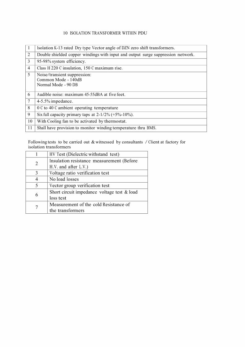
10 ISOLATION TRANSFORMER WITHIN PDU
1 Isolation K-13 rated Dry type Vector angle of DZN zero shift transformers. 2 Double shielded copper windings with input and output surge suppression network. 3 95-98% system efficiency. 4 Class H 220 C insulation, 150 C maximum rise. 5 Noise/transient suppression:
Common Mode - 140dB Normal Mode - 90 DB
6 Audible noise: maximum 45-55dBA at five feet. 7 4-5.5% impedance. 8 0 C to 40 C ambient operating temperature 9 Six full capacity primary taps at 2-1/2% (+5%-10%). 10 With Cooling fan to be activated by thermostat. 11 Shall have provision to monitor winding temperature thru BMS.
Following tests to be carried out & witnessed by consultants / Client at factory for isolation transformers
1 HV Test (Dielectric withstand test)
2 Insulation resistance measurement (Before H.V. and after L.V.)
3 Voltage ratio verification test 4 No load losses 5 Vector group verification test
6 Short circuit impedance voltage test & load
loss test
7 Measurement of the cold Resistance of the transformers

TECHNICAL SPECIFICATION OF TESTING AND COMMISSIONING
The scope of work for testing and commissioning of the total installation shall be for the capital equipments like transformers, switchgears, cables etc., and also for the associated equipments like relays CTs, PTs, etc.
The scope of work for testing and commissioning of electrical equipment for the above shall include but not be limited to the following:
Providing sufficient number of experienced Engineers, Supervisors, Electricians so that the installation can be commissioned in stipulated time.
All the instruments, tools and tackles required for carrying out the testing and commissioning shall be provided by the bidder. All tests instrument to be properly test and calibrated by accredited laboratory and valid calibration certificate to be submitted for verification.
The testing of electrical equipment shall be carried out as per the relevant Indian Standards/Code or Practices/Manufacturer's instructions.
Cleaning of electrical equipment, contacts cleaning and greasing etc. All the equipment and material required for above shall be supplied by the bidder. Correcting the panel/equipment wiring for proper functioning of the schemes required/called for. Installation and wiring of additional equipment on panels like auxiliary contactors, timers, etc. Which may be additionally required for proper functioning of the schemes.
Checking of equipment Earthing and system earthing as a whole. Testing of all the cables. Co-ordination with other contractors for testing and commissioning of interface
cables. TESTS TO BE CONDUCTED:
All tests shall be performed in the presence of the bidder and consultant. For all types of visual inspections, checking, pre-commissioning, commissioning test and acceptance tests, IS Code to be followed for the tests given therein in addition to the instructions in this technical specification. The intention of giving the few test procedures, described below, is to provide a guideline for the bidder. However, bidder shall not restrict themselves in carrying out only the tests described in this document.
Bidder shall submit their proposed test procedures for approval and shall not commence testing such approval is given.
Bidder shall check and test all electrical equipment and systems installed and supplied them, including equipment supplied by the Owner.
Bidder shall supply all necessary test equipment and personnel both craft and supervisory to carryout the work without danger to personnel or damage to equipment.
Bidder shall ensure that no tests are applied which may stress equipment above the limits for field testing recommended by the manufacturer. Bidder shall be responsible for any damage to personnel or equipment resulting from improper test procedure.

All defective materials furnished by the bidder and defects due to poor workmanship revealed through field testing, shall be corrected at bidder expense without affecting the completion of the project.
Consultant reserves the right to interpret and approve all test results prior to charging of circuits or apparatus.
Bidder shall visually inspect all equipment for defects immediately upon arrival at site including those supplied by the Owner.
Relay coordination chart and final setting
before/commissioning. MECHANICAL CHECKOUT
After installation, but before any power supply is connected, the contractor shall make a complete mechanical check of all installed electrical equipment and systems. This shall include but not being restricted to the following:
Check equipment numbers against drawings/documents.
Check name plates of transformers, switchgears, etc. for conformity with the data given in the drawings and specifications.
Check all equipment bus joints and connections for tightness. Check all cable and wire connections for tightness. Check phase sequence.
Check all bushings/insulators to ensure they are clean and un chipped. Inspect tank cooling tubes and radiators for leaks.
Check silica gel for dryness where breathers are supplied. If the colour of the silica gel is pink, remove from the breather and dry out following manufacturer's recommended procedure, until a light blue colour is restored and replace it.
Check valve in the connecting pipe between the conservator and transformer tank to ensure that valve is in 'open' position.
Check interlocking on access doors for mechanical and electrical safety. Check that key and electrical interlocking system functional and accomplish their purpose.
Check all plug in contacts for alignment and 'grip'. Check all contactors for free manual operation. Remove all locking devices installed for shipment. Check all the coils for their continuity and proper voltages.
Check the arc chutes, arcing horns, main contacts of breakers are clean and undamaged. Check the carriages ride smoothly and reliably on their guide rails. Check for proper operation of circuit breaker operation mechanism, controls and adjustments. Check the fuses are correctly rated and installed are clear, undamaged and fit for operation. Check all relays and instruments are clean, correctly connected and undamaged. Check

test plugs are installed in all protective relays. Check relays for free manual operation, if applicable.
Check instrument transformer ratings against drawings. Check for proper installation and connection.
Check interlock and auxiliary devices and the operation of the circuit breaker with the protection relay circuit.
Clean the equipment by vacuum cleaner before
energizing. EARTHING: Bidder shall test the buried earth grid and shall record the values.
Bidder shall inspect and test all earthing work carried out by him, including all interconnections between ground loops, grounding of equipment and ensure all connections are permanent and that the earthing circuit is continuous.
Bidder shall megger and record earth resistance at various earth connection
points. SWITCHGEAR: Switchgears rated 433 volts or more shall be tested with a 1000 volts megger. Auxiliary wiring rated less than 415 volts shall be tested with a 500 volts megger. All protective relays shall be tested at sufficient points to establish their proper functioning in accordance with the manufacturer's specification and curves. Operation checks and functional checks on all switchgear panels. Contact resistance for breaker contacts between male and female.
WIRES AND CABLES: Continuity testing of all cables.
Wires and cables rated 433 volts or more shall be tested with a 1000 volts megger. Cables rated less than 433 volts shall be tested with a 500 volts megger. No wires or cable having resistance between conductors or between conductors and ground of less than 100 Meg ohm shall be accepted.
FUNCTIONAL TESTING: All circuit breakers, contactors, relays, remote devices, etc., shall be checked for its operations.
POWER SOCKETS: All power sockets are to be tested for polarity & earth fault impendence test.
ELECTRICAL FAULT DISCRIMINATION STUDY: The entire electrical design system to be properly study with discrimination of all the electrical circuit breakers and fault setting. The fault discrimination study to be submitted prior to confirmation of type of circuit breakers and protection to be utilised and ordered. All fault discrimination study to be endorsed by certified electrical engineer.
V. TECHNICAL SPECIFICATIONS FOR FIRE FIGHTING WORKS

1.0 General All firefighting work should be carried out by competent licensed Fire contractor only, and the material and workmanship shall conform to the following IS Codes and relevant by-laws of local Municipal Authorities. All necessary approvals and completion certificates from Municipal. And other regulatory authorities shall be obtained by the contractor. 1.1.1 IS Codes and Reference Standard 1.1.2 Codes and reference standards referred to in the contract shall be understood to form a part of the contract. 1.1.3 The contractor shall be responsible for adherence to reference standard requirements by subcontractors and suppliers. Following are then design standards by which fire System is been designed; � IS Standard � TAC � NFPA 1.1.4 Scope of Work The scope of work includes the following as mentioned including supply, installation, testing, commissioning of entire fire protection installations and duly approved from competent authorities and handing over. � Sprinkler system � Internal Hydrant system � External Hydrant system

a) Excavation in soft soil, murrum, hard rock, laying of external G.I/M S heavy class pipe line, radio graphic test if required as per IS Standards, wrapping coating as per IS 10221 and Holiday test etc., pressure tests as per system design requirement etc. complete and obtain approval of Local Fire Officer / TAC / LPA / Client. Back fill the trenches ramming etc. complete in all respect. b) Supply, installation, testing & commissioning of main hydrant pump with motor duly coupled with driving arrangements, mounted on a common base plate with all accessories complete in all respect (as per TAC/LPA Regulation). c) Supply, installation, testing & commissioning of 1 No’s motor control centre with starter, isolator, etc. for hydrant pump all complete including earthing etc. d) Supply, installation, testing and commissioning of cables from common motor control centre to pump motors and all control cables for automatic operation as indicated in item no. ‘d’ above, including earthing as required. e) Supply, installation, testing and commissioning main courtyard hydrant system and internal hydrant for first floor with piping as per IS:1239 heavy class MS piping with all testing of piping and including radio graphic test, wrapping, coating as per IS 10221, holiday test as per Local Fire Officer / LPA / Client. f) Supply, installation, testing & commissioning main courtyard hydrant system including landing valves, hose reels, hose cabinets, isolation and non return valves air release valves etc. including all ancillary items to make the installation complete in all respect and to meet all requirements or relevant complete in all respect and to meet all requirements of relevant codes and regulation of fire and electricity authorities as well as guide line from Tariff Advisory committee and local building code of regulations. g) All types portable fire extinguishers and fire buckets, wherever necessary as per IS 2190/TAC/LPA Local Fire Officer. h) Preparation of execution and as built drawings duly approved by Local Fire Officer/TAC/LPA/Any other statutory authorities as required. i) Periodical material, installed work inspection and final approval by Insurance Authority competent authorities like Local Fire Officer / LPA/TAC any other statutory authorities / as required. j) Incorporating of any changes required to suit at site or becomes necessary to meet the requirement, after obtaining Architect approval should be without any extra cost. 1.1.5 All decisions as to the selection of contractor, award of work, will be made by the proprietor. All cost arising from the contractual services go to the account of the proprietors. 1.1.6 The one who is awarded the contract will be the “Contractor”. 1.1.7 The contractor has to carry out his work according to General Tender Drawings, Specifications and Bill of Quantities appended herewith in the tender. 1.1.8 The tenderer should study the various items of the Bill of Quantities in conjunction with the Technical Data and specifications as well as General Instructions as given hereinbefore.

1.1.9 The layout shall be as per appended drawings based on which the offer is to be submitted. 1.1.10 Quantities mentioned are approximate and are subject to variation as required for final execution. 1.2 Approval s a) Local Fire Officer / Authorities / Client approvals to be obtained by the contractor. b) Basic working drawings. c) Work in progress includes hydraulic tests etc. before backfilling of trenches. d) Testing of complete ring mains including pumps and motor. e) Final installation and “As Built” drawings. f) Final approval of total Fire Protection System by Local Fire Officer / LPA / Insurance Authority / any other Statutory Authorities. 1.2.1 All materials supplied should be Local Fire Officer / LPA / TAC / Insurance Authority / Client’s approved and as per ISI marked. 1.2.2 The supporting arrangement (pipe supports, etc.) for all the items, whenever / wherever required is to be included in the quoted rates for the items. No amount will be paid separately for supports. 1.2.3 Excavation in any type of strata backfilling and leading away and dumping and leveling etc. within the compound for all the items wherever required is to be included in he quoted rates for the items. No amount will be paid separately for excavation etc. (Not Applicable) 1.2.4 The privilege of authorship and ownership of drawings and designs of the structures remains with Proprietor. The drawings and design prepared by Proprietor shall be used only for the purpose specified in this Contract and all the drawings issued shall be returned to Proprietor on completion of work. 1.2.5 The Engineer, authorized by client to represent at site-of-work, is authorized to ask the Contractor to discontinue any work which does not meet the expected and/or specified requirements and/or work already executed, may be rejected and asked to be removed for the same reason. 1.2.6 In the event of any discrepancy between the details and/or description given in the Bill of Quantities, the drawings and the Technical Specifications, then the items shall be deemed to have been priced in accordance with the details and/or description given in the following order of procedure :- � The Bill of Quantities � The Drawings � The Technical Specifications.

In all the cases, it is understood that the details and/or description not specifically mentioned in the Bill of Quantities and/or the Drawings shall be same as those mentioned in the Technical Specifications. Any further interpretation of above clauses shall be at the discretion of the Proprietor whose decision shall be final and binding on the Contractor. 1.3 Technical Specifications 1.3.1 Work The work contemplated under this contract includes for general technical building installations as regards Fire Protection System for the aforesaid Project, all as detailed in the Bill of Quantities, Specifications and Drawings. Such other works, which are not included in the aforesaid Bill of Quantities, is generally intended to be executed through a separate agency. Notwithstanding the above, the clients reserve the right to order additional works under the same contract. The clients also reserve the right to omit any item of work included in the aforesaid Bill of Quantities and award the same to any other contractor or not perform it at all, at their discretion and the contractor shall not have any claim on the same. The contractor for this work shall be required to work in co-operation and co-ordination with other civil engineering, air-conditioning/ ventilation, electrical, etc. contractors and give them all reasonable assistance and help for the execution of the work in an efficient manner as directed. The words “Approved” or “As Directed” shall be deemed to convey approval or the directions of Proprietor. Obtaining all required statutory approvals from relevant authorities such as Local Fire Officer / LPA/ Insurance Association of India / Client, etc. is the responsibility of the contractor and only fees payable therefore to the concerned authorities shall be reimbursed on production of official receipts from concerned/statutory authorities. All other incidental costs for necessary approvals from all concerned are to be included in the quoted rates in the tender.

1.3.2 Indian and British Standard Specifications The particular specifications for the work is as detailed hereinafter. These specifications shall be read in conjunction with the relevant Indian Specifications and where not available with the relevant British/American Standards and the obtainable local practice as detailed in the various regional hand book of practice and the work shall be executed accordingly. Where the specifications in any of the standards are at variance with the specifications detailed herein, the specifications herein shall govern. 1.3.3 Quality of Materials & General Standards of Work The contractor under this contract commits himself to use first class materials and assumes full responsibility for the quality of all material incorporated or brought for incorporation in the work. The work shall be executed in accordance with best engineering practice and as per directions of the Proprietor. No water and power will be supplied, contractor shall arrange at his own cost and responsibility for fabrication, erection, testing and commissioning etc. 1.3.4 Measurements The mode of measurements whatever possible is specifically mentioned in these documents, where it has not been mentioned, it shall be as per provisions of the relevant Indian Standards. All measuring tapes and other accessories, necessary shall be provided by the contractor. 1.3.5 Sample & Patterns The contractor binds himself to supply samples of all types and other accessories for approval before installation of the same. They shall be of the required standards as laid down by the Rules and Regulations, ISI or BSS, as the case may be, and the work shall comply strictly with the by-laws, Rules and Regulations laid down for the same. Materials not conforming to these approved samples/standards are likely to be rejected without any claims.

2.0 Technical 2.1.1 Excavation in Trenches This shall comprise of all excavations not exceeding 2 meters in width. 2.1.2 Solids Any material requiring the application of pickaxes shovels, phowras and scarIfiers in executing the excavation. 2.1.3 Rock Any material for the excavation of mechanical plant or blasting or chiseling is necessarily required. The decision of proprietor in respect of the classification of soil and rocks shall be deemed to be conclusive. 2.1.4 Excavation Excavation of trenches shall be done to widths, lines and levels as shown in drawings or to such lesser or greater widths, lines and levels as directed. The bottom and sides of excavation shall be trimmed to require levels, profile, etc. watered and thoroughly rammed. Should any excavation be taken below the specified levels, the contractor shall at his own cost fill up such excavation with cement concrete M 50 to required levels. Filling in such excavation with excavated materials is prohibited unless specifically approved. Fees, royalties and any other levies attendant on such excavation work shall be entirely borne by the contractor. 2.1.5 Dewatering All water which may get accumulated in the excavations during the progress of work, from whatever cause or source, shall be bailed or pumped out as necessary. The rates for excavation shall be deemed to include for the same.

2.1.6 Timbering to Excavations (Shoring) Where the soil is soft and sides of excavation needs supporting, suitably designed planking and strutting shall be provided. The rates for excavation shall be deemed to include for all planking and strutting as necessary. 2.1.7 Blasting Where blasting has to be resorted to for rock cutting, it shall be the responsibility of the contractor to arrange for the following at his entire risk, cost and responsibility. The cost of which is to be included in the prices quoted in tender for excavation. Permission from all connected public authorities such as Municipal Corporation, Inspector of Explosives, Police, Highway Authorities, etc. shall be obtained by the contractor the cost of which is to be included in the quoted rates. All precautionary measures such as notice to adjoining property and other agencies working in and around the plot, signaling and watch etc. shall be strictly adhered to according to the various regulations in force. All risk insurance in respect of the blasting hazards to mean and materials within and in the vicinity of the plot. This insurance shall be apart from the contractors all risk insurance policy stipulated under general conditions unless the contractor incorporates blasting hazards and its coverage in the said generally policy. Storing of blasting materials is strictly as per explosive regulations. The tenderer must acquaint him with the site conditions, in regard to blasting, nature of rock likely to be met with, timing and other restrictions in regard to blasting. Etc. No. claims whatsoever in this regard shall be entertained. 2.1.8 Disposal of Surplus Excavated Material All material considered surplus, shall be removed to destinations and disposed off as directed. The disposal of the material can be in any of the following ways as directed by Proprietor.

1. Filling in low lying areas. 2. Filling in at places of filling such as under floors, in roads, etc. 3. Stacking of material in predestinated stacking yard. 4. Removal of material outside the plot for disposal at the discretion of the contractors. The cost of which is to be included in the rates quoted for excavation. 2.1.9 Back-Filling Filling under floors or other places indicated shall be done with approved material obtained from excavations or approved materials brought from outside by the contractor. The material should generally be good quality soft of hard murrum or other approved material, filling shall be done in layers not exceeding 30cm. thick and each layer shall be watered adequately and consolidated properly. The surface of filling shall be finished to lines and levels as required. The filling shall be compacted in such a manner as to guarantee full stability. 2.1.10 Scaffolding All scaffolding and ladders required for the proper execution of the work shall be provided by the contractor without any extra cost. 2.1.11 Openings and inserts Openings and inserts are to be provided exactly at positions indicated without any extra cost. Being a large complex with sophisticated services requirements openings and inserts (in slabs, walls, etc.) to a fairly large extent can be anticipated and the contractor should bear this in mind while quoting his rates. 2.1.12 Measurements Measurements for all excavation, filling, carting away and earth work shall be in solid measure. The rates quoted by the tenderer are thus for solid measure units. The following factors shall be applied to obtain quantities of solid measure: Excavation : No reduction in volume

Filling watered & consolidated in layers Loose measures (as In trucks) or dupings
: Volume of filling less 15% : Volume of loose measure Less 25%
Stack measure in rubble etc : Volume of slack less 40% The mode of measurement for various types of excavation shall be as under:- a) In case of pipe trenches and drains, measurement of width of trench shall be diameter of the pipe plus an allowance of 50cm. to allow for collars flanges etc. b) Excavation in rock shall be measured up to levels indicated or required. No undulations as physically appearing after excavation shall be taken into consideration while arriving at the quantities. The rates quoted by the contractor shall be deemed to include for this and no extra is admissible. c) All payments will be made on the basis of accurate Bill of Quantities. The quantities will be in metric units and sub-units. The work included in the documents of this contract and indicated by all the conditions, obligations, bill of quantities. d) Specifications and drawings enclosed will be contracted on between the proprietor and the contractor, on a basis of measuring and weighing according to the rates indicated in the article of the Bill of Quantities and the quantities executed in fact. e) The mode of measurement of installed pipe work shall be in running meters including fittings such as bends, elbow, tee, etc. Valves will be excluded from running meter measurement and will be measured and paid separately in numbers. f) Running meter measurement for pipe work along with fittings will be along the centre line run of the main pipe only. Branch on the fittings will be similarly measured only if they are further joined to a branch pipe. 2.1.13 Excavation for pipes and drains Before any excavation is started, the contractor shall ensure that the pipes line is properly established on the surface and the width of the pipe trench. Mode of measurement for pipe trenches is already specified hereinbefore. In case the

contractor desires to excavate to greater widths, this shall be at his own cost and the rates quoted by him are deemed to include for such extra allowances (over and above that specified hereinbefore) as desired. Prior to backfilling of trenches, the Proprietor shall be called upon in writing to inspect and accept the facilities. 2.1.14 Cement Cement for the work shall be ordinary Portland cement conforming to the latest Indian Standards and of the best normal setting quality. 2.1.15 Curing It is very important that all cement concrete work/pipe joints in cement mortar should be cured properly. All concrete work shall be covered with layer of sacking, canvas, Hessian or similar absorbent material and kept wet continuously for not less than a fortnight or as directed. Water used for curing shall also be free from any deleterious substances and shall generally be fit for drinking. The work shall be adequately protected from drying winds and direct sun rays. 2.1.16 Drawings Successful contractor shall prepare all fabrication detail drawings and openings required in the construction, which shall be checked by Proprietor / Consultant for approval. Drawing conforming to Rule and Regulations of the Insurance Association of India and to be submitted to Local / Regional Authorities for their approval In case, the contractor will suggest certain alterations, he has also to provide the necessary drawings. These drawings will be checked by Proprietor / Consultant for approval. In case Proprietor rejects these drawings, these will be considered as not having been done. The contractor is bound to review all plans under his responsibility as to their correctness.

By signing the contract, he assumed full responsibility for the project and its construction. Successful contractor shall also provide 4 sets of As Built/ Erected Drawings, prepare and hand over Operation & Maintenance Manual to operation team. Contractor should provide training to operation and maintenance team of the proprietor. The proprietor will give to the successful contractor, free of charge two sets of all drawings including soft copy necessary for preparation of shop drawings. Other prints can be obtained from the proprietor against receipt of actual costs. In case the contractor has any questions with regard to these drawings he should inform the proprietor in good time. The contractor is furthermore to inform the proprietor in writing in good time if any plans he may need have not been furnished to him yet. Where drawings and specifications conflict, the more stringent shall apply. The offer shall not be considered as complete unless accompanied by a list mentioning the maker of manufactures’ name of different items quoted by the tendered. In case, material brought by the contractor to the site will be rejected, it must not be used and is to be specially marked to that effect by the contractor by a wooden shield with full inscription. No material must be removed from the construction site unless a special order to that effect has been given by the client. In case the contractor has any doubts as to the suitability of materials, he is to bring these to the attention of the Employer and/or proprietor prior to submission of his bid, if possible and may submit alternate suggestions he may have to make. 2.1.17 Slopes The slopes of pipe lines are to be established in strict compliance with those indicated in pertinent plans. Pipe lines must be installed in absolutely straight alignment. No

zigzag is permissible. Prior to back filling of trenches, the construction management shall be called upon in writing to inspect and accept the facilities. The gradient shall be established by the establishment of proper stakes at necessary intervals. 2.1.18 Testing The contractor shall at his own cost get the pipes and other accessories tested and passed from the local fire officer / client and at his own cost and responsibility carryout experiments and tests that proprietor deem fit from time to time. Any material supplied which does not function properly and to the satisfaction of proprietor shall be replaced free of cost by the contractor. 2.1.19 Prices All prices quoted in the tender shall include the supply of material, delivery on site, complete laying and fixing in position all the accessories, on the works in complete working order according to the drawings and specifications. The prices shall also include all necessary accessories like bolts, nuts, screws, lead, solders, hump coil etc. that are required for the leak-proofing of the entire system and the proper functioning of the same. Fixing on position shall mean fixing on wall including chasing, fixing below slabs, fixing in ducts and cellars of the building, fixing underground etc. with necessary clamps, brackets, etc. as the case may be (brackets etc. being paid for separately). The item rates shall include chasing in walls, cutting holes in walls/slabs and making good the same and any scaffolding, if required. All arrangements for proper fixing, such as, rawl plugs wooden dowels, filler materials etc. have to be included in the prices. The prices shall include scaffoldings, fillings and such other works necessary to execute the contract in a perfect way and according to the technical and engineering principles. This applies without the contractor having for any reason whatsoever any right to ask the Employer / Proprietor for any addition or increase in the rates quoted by them.

Prices and rates indicated in the items of the Bill of Quantities include all the works that have to be done according to the stipulations in these documents including supplying, erection, transfer of materials, raising, workmanship, machines, pumps, raising water, necessary tubes and all other pertinent work necessary for the full and entire completion of the work under this contract. The prices shall also be deemed to include for all Octroi duties, sales tax, transit insurance and other taxes, royalties, etc. and no extra claim whatsoever on account of these shall be entertained. Quoted rates shall be firm till the completion of the contract. The quantities indicated in the bill of quantities or the items are only approximate and are liable to vary to any extended or item totally omitted. The contractor shall not have any claim on this account, and the contractors quoted rates shall not alter on account of any of these variations nor will it vitiate the contract in any way. Items which are not specially mentioned but which belong logically in BOQ and not covered as an item to the works have to be included in the price. Tenderer is requested to give unit rates also for items against which quantities are not mentioned in this tender. The contractor hereby confirms that he has given the entire work and obligations included under this contract a through accurate and inclusive study together with the general conditions, technical specifications, bill of quantities and the drawings enclosed, and that all of these complete each other. In the event of any discrepancy between the details of drawings, description in technical specifications and the Bill of Quantities, the item shall deemed to have been priced in accordance with the description in the Bill of Quantities. All what is indicated in the drawings or what they stand for has to be executed even if it were not stated in the other documents. The contractor further confirms that after having studied the site of the works on the spot and after having obtained from proprietor information about all the works included in this contract, he has a thorough knowledge of the importance of the works included in this contract and of what expenses he needs to execute the whole works included in this contract and of

what expenses he needs generally to fulfill all the responsibilities of this contract by himself. 2.1.20 Performance Guarantee The contractor must guarantee the works and their good execution in a perfect way for one year from the date of completion of the works. If a part of the work is found, during the period of guarantee, or during progress, to be unsound and defective. The contractor has to repair or make good the same at his own cost and responsibility. Any delay on the part of the contractor in doing so given the Proprietor the right to get the defect rectified through other agency and the cost for the same shall have to be borne by the contractor. 2.1.21 Approval The entire installation offered should be in accordance with the requirements of local fire service / LPA / Insurance Company / TAC / Client. It will be responsibility of the successful tenderer to get the layout plans of various installation approved from the concerned authorities. Final approvals of concerned authorities for the completed installation shall also be obtained by the successful tenderer. The successful contractor shall supply 4 sets of drawings and soft copy of the completed and finally approved installations for owner’s use and records. The completed installations shall be painted with 2 coats of Red Oxide and 2 coats of paint of any pigment as directed (Preferably Fire Red) and handed over in complete working order. (For exposed pipes) The contractor shall also supply r copies of operation/ maintenance manual one month before the schedule completion period for all the equipment supplied / installed at site.

2.2 Technical Specification for Fire Hydrant System 2.2.1 Hydrant System Data I) HAZARD CLASSIFICATION
: LOW HAZARD OCCUPANCIES AS PER NBC REGULATION
II) DESIGN STANDARD FOLLOWED
: FIRE PROTECTION MANUAL
IV) WATER SOURCE : UNDERGROUND RCC TANK CAPACITIES (AS SPECIFIED IN FIRE-NOC) V) HYDRANTS INTERNAL : SINGLE HEADED HYDRANT 63MM. DIA GUN METAL HYDRANT VALVE CONFORMING TO IS:5290 VI) HOSE : 1 NOS OF 30M LONG RRL HOSE PIPE OF 63MM DIA. CONFORMING TO IS 636 TYPE A FITTED WITH MALE AND FEMALE GM COUPLING. VII) BRANCH PIPE : GM 63MM DIA W ITH 20MM NOZZLES. VIII) LINE WATER PRESSURE
: 7.5 KG/CM2
IX) MINIMUM LINE PRESSURE
: 3.25 KG/CM2

X) FIRE HYDRANT MAIN (GI PIPE)
: 150MM DIA. / 100MM DIA. / 80MM DIA.
XII) ANTI CORROSIVE TREATMENT FOR G I PIPES
: AS PER IS – 10221 & TAC RULES
2.2.2 Hydrant Pump Removing of Hydrant Pump, valves, accessories and Priming tank from Existing location and Reinstallation, Testing and Commissioning at new location. Pumps shall be able to operate continuously. The head vs. capacity, input power vs. capacity characteristics, shall be such that the driven motor is not over loaded up to 150% or rated flows. In case the Pumps & Motors are from different manufactures, the Contractor shall assume full responsibility for pump and the drives as one unit and also obtain approvals. Pumps coupled with motor on a common base plate shall perform smoothly without any excessive noise or vibration. The electrical drive motor shall be totally enclosed. Squirrel cage, induction motor, conforming to IS: 325-178 and rated for continuous duty with class “F” insulation and enclosure of IP: 54 for Electrical motor driven. The Pumps and Motors shall be as per Schedule of Particulars enclosed. Deviations if any shall be clearly spelt out and subject except with to approval of the Engineer. 2.2.3 Pumps Casing The casing shall be of C.I. and designed to withstanding twice the working pressure of the pump.

2.2.4 Impeller The impeller shall be of bronze; and the wear rings of bronze of sufficient thickness. 2.2.5 Pump Shaft The shafts shall be of stainless steel ground and polished to final dimensions and shall be adequately sized to withstand all stresses from rotor weight, hydraulic loads, vibrations and torque’s coming in during operation. a. Length of the shaft sleeves must extend beyond the outer face of gland packing, or seal and plate, so as to distinguish between the leakage between shaft and shaft sleeve. b. Shaft sleeves shall be securely fastened to the shaft to prevent any leakage or loosening. Shaft and shaft sleeve assemblies should ensure concentric rotation. The sleeves shall be of stainless steel. 2.2.6 Couplings All shafts shall be connected with adequately sized flexible couplings of suitable approved design. Necessary guards shall be provided for the couplings. 2.2.7 Base Plates a. A common base plate for mounting, for the pump and drive electrical motor, shall be provided. The base plate shall be of Mild Steel of fabricated, as required. b. Base plate and pump supports shall be so constructed and the pumping unit so mounted as to minimize misalignment caused by mechanical force such as normal piping strain, hydraulic thrust etc. 2.2.8 Drive Motors a. The motors shall be a horizontal squirrel cage induction electric motor of TEFC type, wound for 3 Phase, 50 hertz and 415V Class F insulation. The motors shall be capable of operating continuously with an overload up to the maximum allowable horsepower listed for each motor rating in NFPA Standard No. 20, and as specified by FM Loss Prevention Data. b. The motors shall be designed not to draw starting current more than 3 times normal running current. It shall be designed for continuous full load duty. c. The cooling fans shall be directly driven from the motor shaft. d. The rating and design shall conform to relevant IS specification. e. The cable boxes and terminations shall be designed to enable easy disconnection and replacement of cables and for 1.1 KV grade power cable. 2.2.9 Control Equipment

a. The motor control shall be specifically approved for fire service/TAC service and shall be marked “Fire Pump Controller”. The control equipment shall be completely assembled, wired and tested and the factory. b. Equipment shall be enclosed in one or more approved drip-tight enclosures. 2.2.10 Sprinkler Pump Main Schedule of Particulars (Tender shall fill in the data which are marked as “By Tenderer”) REQUIRED
TYPE CENTRIFUGAL–TAC APPROVED
CASING
BY TENDERER
MAKE
: : KIRLOSKAR / MATHER & PLATT / C&R SUCTION : POSITIVE SUCTION SIZE : BY TENDERER DELIVERY SIZE : BY TENDERER IMPELLER TYPE : BY TENDERER DRIVE ARRANGEMENT : BY TENDERER RPM : BY TENDERER SEAL : BY TENDERER
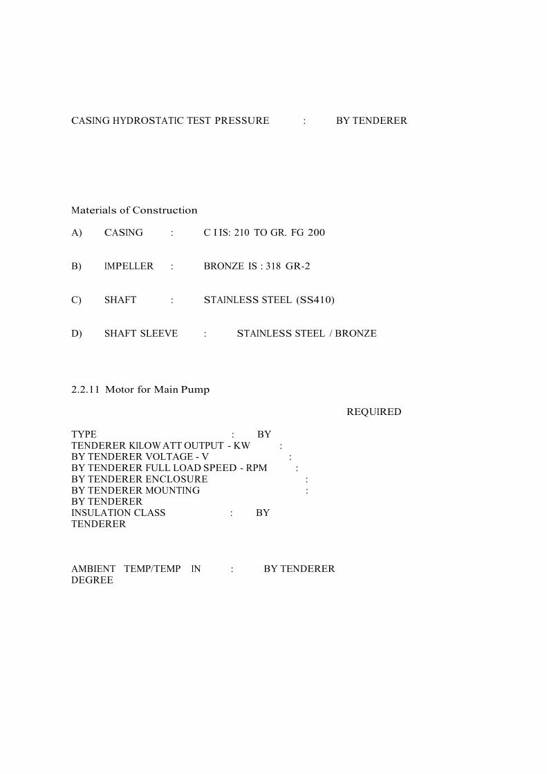
CASING HYDROSTATIC TEST PRESSURE : BY TENDERER Materials of Construction A) CASING : C I IS: 210 TO GR. FG 200 B) IMPELLER : BRONZE IS : 318 GR-2 C) SHAFT : STAINLESS STEEL (SS410) D) SHAFT SLEEVE : STAINLESS STEEL / BRONZE 2.2.11 Motor for Main Pump TYPE : BY TENDERER KILOW ATT OUTPUT - KW : BY TENDERER VOLTAGE - V : BY TENDERER FULL LOAD SPEED - RPM : BY TENDERER ENCLOSURE : BY TENDERER MOUNTING : BY TENDERER INSULATION CLASS : BY TENDERER
REQUIRED
AMBIENT TEMP/TEMP IN DEGREE
: BY TENDERER
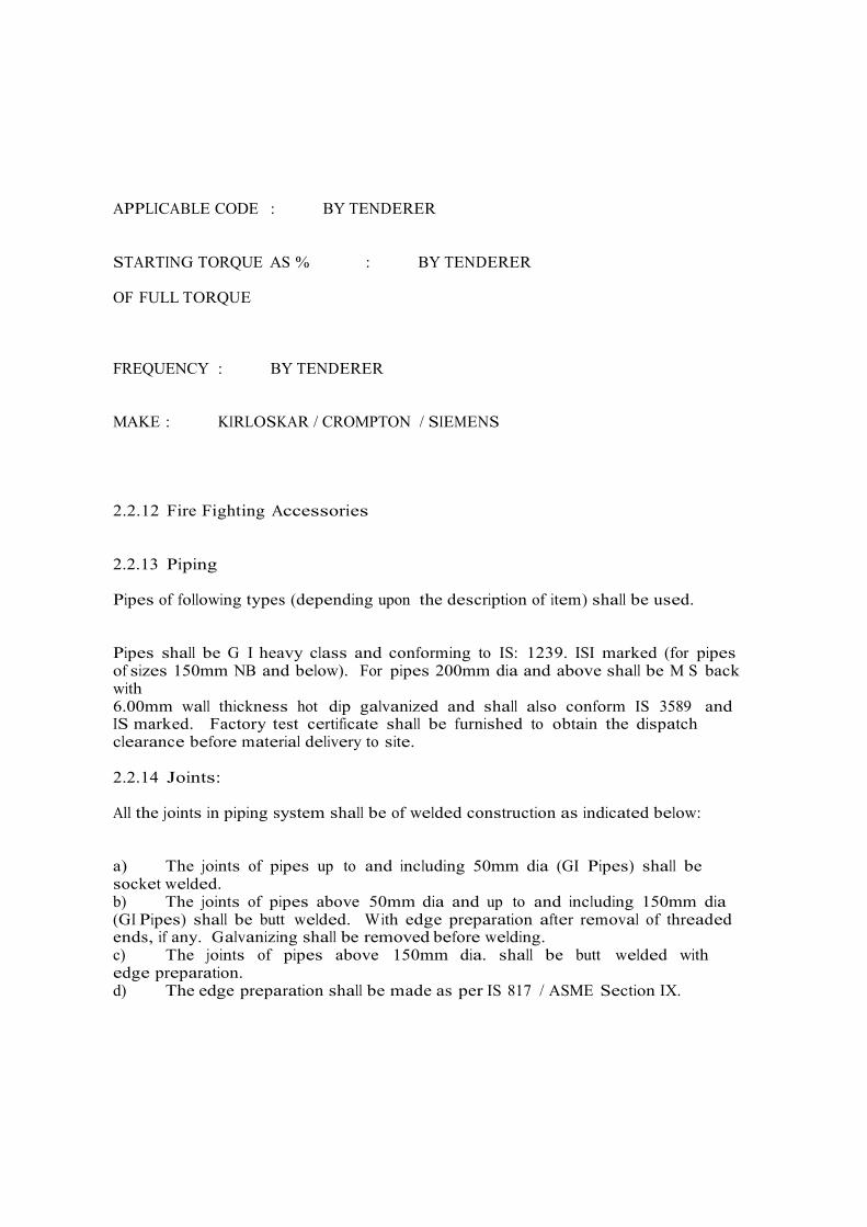
APPLICABLE CODE : BY TENDERER STARTING TORQUE AS % OF FULL TORQUE
: BY TENDERER
FREQUENCY : BY TENDERER MAKE : KIRLOSKAR / CROMPTON / SIEMENS 2.2.12 Fire Fighting Accessories 2.2.13 Piping Pipes of following types (depending upon the description of item) shall be used. Pipes shall be G I heavy class and conforming to IS: 1239. ISI marked (for pipes of sizes 150mm NB and below). For pipes 200mm dia and above shall be M S back with 6.00mm wall thickness hot dip galvanized and shall also conform IS 3589 and IS marked. Factory test certificate shall be furnished to obtain the dispatch clearance before material delivery to site. 2.2.14 Joints: All the joints in piping system shall be of welded construction as indicated below: a) The joints of pipes up to and including 50mm dia (GI Pipes) shall be socket welded. b) The joints of pipes above 50mm dia and up to and including 150mm dia (GI Pipes) shall be butt welded. With edge preparation after removal of threaded ends, if any. Galvanizing shall be removed before welding. c) The joints of pipes above 150mm dia. shall be butt welded with edge preparation. d) The edge preparation shall be made as per IS 817 / ASME Section IX.

e) Flanged joints shall be used for connections to vessels, equipment, flanged valves; flanged joints shall be provided at every branch pipe for above ground piping. 2.2.15 Fittings a. Flanges electro-galvanized fabricated from plate conforming to IS:2002 flat face, class 150/BS-10 Table F. Dimension ANSI B 16.5. b. Fittings for pipes shall be M S galvanized conforming to IS 1239 (Part – II) heavy class. c. Nuts and Bolts shall be Electro galvanized as per IS 1367. d. Gaskets 3mm thick conforming to IS 2712. 2.2.16 Hangers and Supports Hangers and supports shall be capable of carrying the sum total of all concurrently acting loads. They shall be designed to provide the required supporting effects and allow pipelines movements as necessary. All guides, anchors, braces, dampeners, expansion joints and structural steel to be attached to the building / structure, trenches etc. shall be provided by the contractor. Hangers and components for all piping shall be approved by the Engineers in charge. Hangers/ Supports to be used shall be as per the approved drawings. Anchor f a s t e n e r s shall be rated to take minimum 2-ton load and shall be as per approved make. 2.2.17 Pipe Laying- All piping above ground shall have cleaves type hanger supports from the ceiling with twin fas teners , for pipe headers of 100mm dia and above, additional wall/column mounted supports shall be taken. Cleaves type hanger supports shall be at 3.0m intervals. MS Angle supports at walls and columns shall be at approximately 3.0M intervals. The angles shall be cut by gas cutter and evened out by grinder. All welding to angles shall also be cleaned by grinder. Angles shall not be less than 50 x 50 x 6 mm size. The underground piping for the external hydrant system shall be laid at a depth of 1000mm from finished ground level in soil and soft rock. Whatever hard rock encountered its depth shall be restricted to 600mm. Suitable anchorage and concrete encasement at specified location shall be provided at such locations. Pipe to pipe jointing by welding shall be carried out over ground. Pipe lowering into the trench shall be carried out with utmost care to avoid damage to the joints. No back filling shall be carried out unless the pipes have been pressure tested or joint leakages and anti corrosive treatment for the field / position joints. For fixing of cleaves hanger and angle support only SS anchor fasteners shall be used.

Pipes in vertical shafts shall have MS angle brackets at each floor level. The bracket shall be mounted behind the pipe. A base plate of 100 wide x 6mm thick shall be welded to the bracket. The base plate shall be fixed to the wall by means of anchor fasteners. GI U clamps with Neoprene rubber pad/s of thickness not less than 3mm shall be used to fix the pipe to the bracket. The pipe shall be installed to in line, levels and plumb. Each down comers shall also be anchored to the floor slab with MS angles mounted on the slab. The angles shall be 50 x 50 x 6mm size, one mounted before the pipes and the other after the pipes. Extra cleat pipe pieces shall be welded to the pipes at this point which shall be welded to the angle iron support. Wherever two horizontal Headers are to run side by side the two Headers shall be located at different levels, if possible, so as to avoid unnecessary bends at tapping off from the Headers. Accordingly, the Supports shall also be staggered to support pipes at two levels. All pipes shall be treated for anti corrosive treatment as per IS 10221 and shall also be checked for line leakages. The test shall be carried out for the complete length and diameter of the pipe. The test shall be carried by contractor and records shall be made available for review by the Engineer. 2.2.18 Test Pressure The piping system and components including fittings shall be capable of withstanding 150 per cent of the working pressure including water hammer effects and test pressure will be 10.5 / cm2 and all the piping system and components shall be tested to this pressure. 2.2.19 Welding A welding shall be carried out by a certified welder only. The welders shall be qualified as per IS 817 / ASME Section IX and welders Qualification Certificate shall be produced. They need to go through a welding test at site and test pieces shall be radiographic at CSPL approved laboratories and the results shall be furnished to the Engineer in charge for permitting the welder to work at site. All these shall be carried out by the Contractor at no extra cost. Welding shall be carried out by 3 Phase Rectifier type Welding Set. Welding shall be on high Current Low Voltage basis. Conventional welding machines shall not be accepted. All pipe to pipe receiving edges shall be bevel finished to a clean edge by a electric grinder.

A Request gap determined by the thickness of the weld electrode shall be given between the joints before start of welding. Weld Electrodes shall be of CSPL approved make and shall be of grade E 6013. Joints shall be given a first weld in full width without burrs on the full dia of the pipe. Welding shall be earned out vertically from the surface to be welded. Weld fluxes shall not be so plastic such as to fall or drip down. After application of run the weld root shall be grounded and then another layer of welding shall be done. All pipe cutting shall be by oxy acetylene gas welding only. The cut surface shall be cleaned and ground by a electric grinder before further welding. Pipe cutting or welding in inaccessible areas shall be avoided. Pipes shall not welded in trenches unless the bottom edge of the pipe does not have clear space for working with electrode, For supports angle pieces shall be cut by oxy acetylene gas and cleaned by electric grinder. All cutting for bolt inserts shall be by electric drill. Pipe lifting to the ceiling shall be by chain pulley method. Before pipes are finally supported to the ceiling tripod type supports from the floor shall be used to hold up the pipe. Tapings (nipple pieces, etc.) for Hydrant from the down comers shall be fabricated separately and then welded to the down comers. A spool piece of 80mm dia or as required shall be first prepared one end shall be cut as per profile of down comers pipe on which it shall be finally welded. The other end shall have the flange welded to it. The flange holes shall be set so as to receive the Hydrant head correctly. Inside of the flange shall also receive a single layer of welding. The welding shall then be cleaned with a grinder. The spool piece shall then be welded to the down comers. The procedure shall also be applied for all flanges. All dead end of Headers in horizontal runs shall have blank flanges fixed at the ends. Complete with neoprene gasket and nut and bolt arrangement. Pipe supports shall not be welded to the truss framing (wherever the support on the truss is to be used). Supports shall only be clamped to the truss by an approved method.

Pipe laid along long lengths shall be checked for alignment. The pipe end to end shall be checked with length of taut thread before tacking is carried out. Rigid templates shall also be used for measurement. For bends rigid templates shall be used. Neoprene Gaskets of minimum 3mm thickness shall be used at all flanged connections Machine cut gaskets from approved makes shall be used. Nuts and bolts shall be Electro galvanized type. A drilling machine shall be used to bore holes in the MS angle hanger supports. Gs cutter shall not be employed for this purpose. U Clamps shall be bolted after use of washers on both sides. 2.2.20 Radiographic inspection At least 10% of all the welded joints shall be radiographically tested and half of the joints radiographed shall be field joints. This entire test to be performed in the presence of Engineer in charge, the joint record shall be maintained by contractor. 2.2.21 Corrosion Protection The corrosion protection for underground pipes shall consist of wrapping and coating wrapping of anti corrosive pipe coat tape made of polymer bitumen/ polyethylene layer/ polyester layer. 2.2.22 Preparation of Surface The pipeline shall be cleaned of all rust, grease, dirt, weld scale, weld burs etc. The pipe surface shall be scrubbed manually by wire brush or sander. The surface of the pipes shall be cleaned thoroughly. 2.2.23 Primer Primer shall be fiber and solvent based rubber modified bituminous primer of density 0.92 gm/cu.cm and viscosity of 500 to 1000 cps applied at 150 grams per m2 shall be applied by brushing so as to produce effecting bond between metal and subsequent coating of membrane. The dry time shall not be less than 24 hours. 2.2.24 Wrapping and Coating Wrapping tape shall be of approved make, minimum 4mm thick and 150mm wide wrapped spirally with 1/3” overlapping. The risers above ground shall also be treated as above for the height of 300mm above finished ground level.

2.2.25 Testing Before lowering the pipes in the trenches and before back filling the trenches the holiday test is to done at min. 20 KV. Defective area shall cleaned and re wrapped as per above. 2.2.26 Painting All the exposed surfaces of piping system and equipment and steel structures, brackets etc. shall be painted with two coats of superior quality of synthetic enamel paint over two coats or red oxide primer. 2.2.27 Fire Brigade Inlet 2.2.28 Siamese Connection 150mm dia. Fire Brigade Inlet Connection shall be taken directly to the internal ring. It shall comprise of four instantaneous male inlets coupling with plug and steel chain. The inlet shall have a non return valve and a butterfly valve on the line up to the ring. The Fire Brigade Inlet shall be complete with necessary components like special fittings, bends, flanged tees etc. The plug shall be of gun metal. This shall be located opp. Main gate on hydrant header. 2.2.29 Breaching Connection 150mm dia Fire Brigade inlet for tank filling by fire brigade shall be four way with flanged gun metal instantaneous male inlet coupling connection for connection with fire brigade vehicles or tanker. The inlets shall be provided with gun metal blank caps with chain and arrangement for attaching the blank cap & chain to the Fire Brigade inlet. 2.2.30 Sluice Valves Sluice valves 65mm dia. and above shall be cast iron double flanged having non-rising spindle. Sluice valve below ground shall be provided with wheel & cap suitable for operation by the key. Sluice valves in exposed locations e.g. pump house, at risers etc. shall be provided with cast iron wheels. Sluice valves shall be marked IS 780 Class PN-16 and tested to 20 Kg/cm sq. 2.2.31 Non Return Valve Non-return valves shall be cast iron spring action swing check type. An arrow mark in the direction of flow shall be marked on the body of the valve. The valve shall bear IS 5312 certification. The valve shall be of cast iron body and cover. The internal flap in the direction of water shall be of cast iron and hinged by a hinge pin of high tensile brass or stainless steel Cast iron parts shall be conform to IS:210 / 70, grade 200/ 260 type.

2.2.32 Gun Metal Valves Gun Metal Valves shall be used for smaller dia pipes, and for threaded connections. The Valves shall bear certification as per IS: 778, and shall be rated to 15kg / cm2 pressure. The body and bonnet shall be of gun metal to 13:318 grade LTB 2. The stem, gland and gland nut shall be of forged brass to IS: 319. The hand wheel shall be of cast iron to IS 210 grade FG 200/260. The Hand wheel shall be of high quality finish to avoid hand abrasions. Movement shall also be easy. The spindle shall be non rising type. 2.2.33 Hydrant Valve A Hydrants shall be marked IS 5290 (Type “A”) hydrant valve shall have single outlet having 75mm flanged inlet. Outlet female instantaneous type coupling having spring loaded lugs; internal parts shall be of copper or gunmetal. A cap with chain shall be provided on the outlet of the valve, which have 63mm instantaneous pattern female coupling confirming and marked IS-903. 2.2.34 Hose Pipes Hose pipes shall be externally elastomeric coated all synthetic jacked, rubberized fabric reinforced rubber lined (RRL) confirming to IS 636 type A, 1 Nos with 30m in length bearing IS:903 mark bound by copper wire & riveters, with gun metal instantaneous pattern heavy duty male and female delivery heavy duty hose coupling. 2.2.35 Branch Pipe with Nozzle Branch pipe shall be constructed from Gunmetal alloy as per IS:318, LTB 2 grade, and finished to a smooth polish, 63mm dia instantaneous type inlet at one end and second shall have threading. The nozzle shall be of gunmetal, 20mm internal dia. The screwed inlet fitted to the branch pipe. The branch pipe shall be marked IS 903. 2.2.36 First Aid Hose Reels First aid hose reel bracket shall be of swing type. The bracket shall swing 180 deg. The bracket can be made of cast iron or mild steel. Circular Hose drum shall be made of 2.00mm thick CRCA sheet. The hose reel assembly shall be as per IS 884. 30.0 Mt. long High pressure (Dunlop OR approved make) braided rubber hose of 20mm dia shall be as per IS: 1532/444 IS marked and provided with chrome plated jet type nozzle. 20mm dia shut off inlet valve shall be provided at the inlet of the first aid hose reel assembly. 2.2.37 Hose Cabinets (External) Fire hose cabinets shall be fabricated from 2.00mm thick CRCA sheet with locking arrangement. Size of hose cabinet shall be 450mm x 600mm x 250 mm painted Post Office RED Each hose cabinet shall accommodate 1 No. hydrant valve first air

hosereel, 1 nos. of 30 Mt. long hose-pipes and one no. of branch pipe with nozzle. The fire hose cabinet will have the legend “Fire Hose” painted prominently in the graphic style. 2.2.38 Hose Cabinet (Internal) Fire Hose Cabinets shall be fabricated from 2.00mm thick CRCA sheet with locking arrangement. Size of hose cabinet shall be 450mm x 600mm x 250mm or as per the opening provided in Architectural layout painted Post Office RED Each hose cabinet shall accommodate 1 No. hydrant valve first air hose reel, 1 nos. of 30Mt. long first air hose pipes & one no. of branch pipe with nozzle. The fire hose cabinet will have the legend “Fire Hose” painted prominently in the graphic style. 2.2.39 Pressure Gauges The pressure gauge shall provide gunmetal isolation cock tapping and connecting pipe and nipple. The gauge shall be installed at appropriate level and height for easy reading. Pressure gauge shall be of 100-mm dia pressure gauge with a scale range from 0 to 12kg / cm2 an shall be constructed as per IS:3624. Each pressure gauge shall have damper. 2.2.40 Pressure Switch The pressure switches shall be employed for starting and shutting down operation of the pumps automatically, dictated by line pressure. The pressure switches shall be diaphragm type and suitable for liquid pressure of 15kg/sq.cm. The scale ranges for cut in and cut out shall be from 0 t0 10 kg/cm sq. The pressure switches shall be suitable for consistent and repeated operations without change in values. It shall be provident waterproof and whether proof enclosure with IP 66 rating in Aluminium. All other parts including pressure element and wetted parts shall be Stainless Steel. The pressure switches shall be snap acting with 2 sets of NO + NC contacts. 2.2.41 Strainer The “Y” type Strainer shall have Cast Iron body confirming to IS 210 FG 200. Perforated Sheet shall be of Stainless Steel (SS 304) of 2mm thickness. The Screen open area shall be minimum four times cross sectional area at inlet. The strainer shall be suitable for minimum flow of 4505 LPM at 8.8 kg/cm. sq pressure. The flanges shall

be to IS 1538. The nut bolts and washers shall be galvanized confirming to IS 1367. The pressure loss shall not be more than 0.5kg/cm.sq. The Hydraulic Testing shall do at 15 kg/cm sq. for the duration of Two hours. 2.2.42 Gun Metal Gate Valve SR. NO PARTICULARS REQUIRED
I) WORKING PRESSURE
: 8.8 KG/CM2 II) CODE FOR DESIGN MFR. III) CODE FOR TESTING &ISPN.
: IS:778 : IS:778
IV) SIZES : 15 TO 50
NB V) PRESSURE RATING
: 15 TO 50
NB
MAKE : H SARKAR / KIRLOSKAR/ UPADHYAYA

Features SR. NO
PARTICULARS REQUIRED
I) TYPE FOR GATE VALVE II) STEM FOR GATE VALVE
: INSIDE SCREW ED IN BONNET : NON-RISING
III) BONNET : INSIDE SCREW ED IV) OPERATION : MANUAL V) HAND WHEEL
: CLOCKWISE
DIRECTION TO CLOSE VI) ENDS : SCREWED THREADED TO IS: 551. 2.2.42.1 Cast Iron Sluice Valve specifications SR. SR.NO PARTICULARS REQUIRED
I) WORKING SPECIFICATIONS
: 8.8 KG/CM. SQ.(G)
II) CODE FOR DESIGN MFT III) CODE FOR TESTING & INSPECTION
: IS:14846 : IS:14846

IV) SIZES : 50 NB TO 300 NB V) PRESSURE RATING : PN 16

VI) TYPE : NON-RISING SPINDLE VII) MAKE : H SARKAR/ KIRLOSKAR / UPADHYAYA Features
SR.NO PARTICULARS REQUIRED
I) STEAM : NON RISI INSIDE SCREW
NG, &
YOKE
II)
BONNET :
BOLTED
III)
DRAINAGE ARRGT. :
AS PER IS:780
IV)
BYE PASS VALVE :
AS PER IS:780
V)
ENDS :
FLANGED
Material of Construction SR. NO
PARTICULARS REQUIRED
I) BODY AND BONNET : CI TO IS:210 GR.

FG 200 II) WEDGE : CI TO IS 210 GR. FG 200 III) STEM : BRASS TO IS:320 GR. HT-2 IV) SEATING SURFACE & RINGS
: GM TO IS:318 GR. LTB– 2
V) HAND WHEEL : CI TO IS:210 GR. FG 200 2.2.43 Air Release Valve Specifications SR. NO
PARTICULARS REQUIRED
I) WORKING PRESSURE
: 8.8 KG/CM.SQ.(G)

II) PRESSURE RATING : PN 16 III) FUNCTION : TO RELEASE AIR Features I) TYPE : SINGLE BALL TYPE II) NO. OF BALLS : ONE III) TYPE OF BONNET : SCREWED (F) THREADED TO IS:554 Material of Construction I) BODY & BONNET : GM TO IS:318 GR.LTB-2 II) BALL : RUBBER 2.2.44 Hydrant Valves Specifications SR.NO PARTICULARS REQUIRED I) ITEM : ANGLED OUTLET SINGLE /SINGLE HYDRANT
II) WORKING PRESSURE
: 8.8 KG/CM. SQ

III) CODE FOR DESIGN MFR. : IS:5290 Features I) TYPE OF STEM : RISING II) TYPE OF INLET : FLANGED, 80 NB
III) TYPE OF OUTLET : FEMALE INSTANTANEOUS
COUPLING WITH SPRING INSTANTANEOUS CAP WITH CHAIN.
IV)
FLANGE DRILLING :
IS:1538 TABLE IV
V)
MAKE :
MINIMAX / FIREX / RADIANT/ NEWAGE
Material of Constructions I) BODY AND BONNET : LEADED TIN BRONZE TO IS:318 GR. LTB -2 II) STOP VALVE, VALVE SEAT : LEADED TIN BRONZE TO TRIM. IS: 318 GR. LTB – 2 III) CHECK NUT AND GLAND NUT : LEADED TIN BRONZE
TO IS:318 GR. LTB – 2

2.2.45 Hydrant Accessories SR. NO
PARTICULARS REQUIRED
I) INSTANTANEOUS MALE HALF COUPLING 63MM
: AS PER FIG 2 B OF IS:903 TO BE FIXED N HOSE (HYDRANT SIDE)
II) INSTANTANEOUS MALE HALF COUPLING
: AS PER FIT 2A OF IS: 903 TO BE FIXED ON HOSE (NOZZLE END.)
III) COUPLING : FOR CONNECTING 20MM DIA. HOSE Hydrant Accessories I) COUPLING, NOZZLE : GUN METAL TO IS:319 GR. LTB - 2 II) SPRING FOR COUPLING : STAINLESS STEEL TO
IS:6528

2.2.46 Fire Hoses Specifications PARTICULARS REQUIRED PROPOSED BY
TENDERER ITEM FABRIC REINFORCED
RUBBER LINED HOSE (RRL) / RUBBER PIPE
WORKING PRESSURE
8.8 KG/CM.SQ
CODE FOR DESIGN
636 (PART III/PART – A) – TYPE B
MFR. TYPE FABRIC REINFORCED RUBBER LINED ANTI FUNGUS TYPE
DIA. 65MM LENGTH 30M/ 7.5M ENDS - HYDRANT FITTED WITH
INSTANTANEOUS COUP GUN METAL / ADOPTER COUPLIN HYDRANT VALVE
- OTHER SIDE FITTED W ITH INSTANTANEOUS COUPLING OF GUN METAL
ENDS CONNECTION TIED WITH GI WIRE
Material of Construction I) HOSE : RRL TO IS-636 2.2.47 Branch Pipe
ITEM BRANCH PIPE WORKING PRESSURE 8.8 KG/CM2 (G) CODE OF MANUFACTURE IS:903 MATERIAL OF CONSTRUCTION GUN METAL TO IS:319 GR.LTB MAKE MINIMAX / NEWAGE / FIREX /
RADIANT 2.2.48 Hose Boxes. Specification

ITEM MS GALVANISED SHEET FABRICATED HOSE BOX
STORAGE SPACE REQUIRED FOR EXTERNAL & INTERNAL HYDRANT
- 1 NOS. 30M CANVAS HOSE -1 NOS. 30M CANVAS HOSE - 1 NO. BRANCH PIPE MATERIAL CONSTRUCTION - 18 GAUGE MS SHEET
GALVANIZED W ITH PAINTING AND GLASS FRONT AND FIRE MARKED IN FRONT & LOCK WITH KEY
- M.S SUPPORT FROM GROUND / W ALL AS REQUIRED
SIZE SPECIFIED IN DRAW ING APPROVAL APPROVED BY LOCAL FIRE OFFICER /
TAC MAKE REPUTED
2.2.49 Fire Brigade Connection
I) ITEM FIRE BRIGADE INLET CONNECTION FOR : - UNDERGROUND FIRE HYDRANT TANK - EXTERNAL HYDRANT MAIN
(SIAMESE CONNECTION) II) FEATURE 4 NOS. 63MM SIZE INSTANTANEOUS INLET
CONNECTION WITH CAP & GI CHAIN ETC. COMPLETE AND MOUNTED IN A MS RED PAINTED CABINET W ITH GLASS FRONTED DOOR
THE FIRE BRIGADE CONNECTION SHOULD BE WITH ONE ISOLATION VALVE AND NON-RETURN VALVE (FOR CONNECTING TO MAIN HYDRANT LINE) COMPLETE WITH MATCHING FLANGES, BOLTS, NUTS, GASKETS, ETC. COMPLETE IN ALL RESPECT. FOR UNDERGROUND TANK, ISOLATION VALVE AND NRV NOT REQUIRED
III) MATERIAL GUN METAL IV) APPROVAL TAC / LOCAL FIRE OFFICER V) MAKE MINIMAX / RADIANT / NEW AGE

2.2.50 Inspection & Testing (Fire Hydrant) 2.2.51 Testing Procedure The following procedure shall be adopted for site testing:- a) Pipe lines shall be adequately supported to take any additional load and springs and other flexible supports shall be temporarily blocked up to sustain the load. b) Relief valves, safety valves, orifice plate, expansion joint, flame arrestor and instruments which do not have test pressure indicated shall be removed from or blanked off in order to exclude them from the test. c) Lines shall be thoroughly purged with compressed air before and after test. d) Where a piping system contains vessels, in-line instruments, piping specialties, etc., those items shall be blanked off or replaced by spool pieces during the test. Upon completion of test the spool pieces or the blanks shall be removed and in o line equipment replaced. e) All blank-off shall be flanged or visibly marked so that they may be easily identified for removal after testing. f) All metal welds shall be hammer tested and all welds shall be visually inspected for leaks while at test pressure. Carpenters blue chalk shall be used to detect any leakage through welds. g) Holding time for tests shall be sufficient to allow inspection of all joints but in no case less than 1 hr. These shall be no drop in pressure shown on the test gauge during the ‘Hold” period. 2.2.52 Hydraulic Test a) All piping shall be hydrostatically tested either for the test pressure of 10kg/cm2 gauge (150 PSIG) or 1.5 times working pressure whichever is more. b) Piping to be buried insulated or otherwise made in accessible after installation shall be inspected and pressure tested before it is buried or installed. c) Lines repaired by welding subsequent to a pressure test shall be re-tested after repair at the test pressure original applied. d) System may be tested in sections in order to permit completion of work in an area. However, a section so tested shall be blanked and tagged accordingly and subsequently tested as a complete system prior to final acceptance.

e) Test reports shall in all cases be maintained on log sheets and duly certified by us / our Consultant. f) The test gauge shall be installed at the highest point of the pipe loop being tested and the test pump at the lowest level. g) In no case shall the test pressure be less than 1.5 times the working pressure. h) The test shall be carried out preferably during early morning and late afternoon hours of the day. 2.2.53 Pneumatic Test a) All piping shall be pneumatically tested for the (150 PSIG) pressure of 1.5 times more than working pressure. b) Piping to be buried, insulated or otherwise made inaccessible after installation shall be inspected and pressure tested before it is buried or installed. c) Lines repaired by welding subsequent to a pressure test shall be re-tested after repair at the test pressure originally applied. d) System may be tested in sections in order to permit completion of work in an area. However, a section tested shall be blanked and tagged accordingly and subsequently tested as a complete system prior to final acceptance. e) The pneumatic test pressure shall be 110% of the working pressure. f) The pressure shall be further increased gradually providing sufficient time to allow the piping to equalize strains during test and to check for leaks. 2.3 Technical Specification for Portable Fire Extinguishers a) Suitable locations for Fire Extinguishers Appliances have been indicated in the drawings appended herewith, which shall form the basis on which the offer is formulated. b) The quality of materials shall be the best of its kind available in the market and of the type approved by concerned authorities. All appliances shall conform to the relevant IS standards. c) The distribution of hand appliances for different departments shall be in accordance with the requirements of the Fire Brigade Authorities, IS 2190 TAC & Insurance Company. d) Materials generally approved in the installations are indicated hereinafter. The tenderers shall clearly stipulate the quality and make quoted for in the estimates and indicate below as given in the table. 2.3.1 Electrical The specification covers general requirements Codes / Standards / Rules All codes and standards as listed below:- Specification for heavy duty air break switches and fuses for voltage not exceeding 1000 V

IS:1818-1972 Specification for A. C. isolators and earthing switches IS:2607-1967 Air break isolators for voltage not exceeding 1000 V IS:2208-1962 HRC cartridge fuse links upto 650 V IS:3072-1965 Code of practice for installation and maintenance of switchgear IS:3106-1966 Code of practice for selection, installation and maintenance of fuses (voltages not exceeding 650 V) IS:4237-1967 General requirements for switchgear and control gear for voltages not exceeding 1000 V IS:375-1963 Marking and arrangement for switchgear bus bars, main connection & auxillary wiring IS:2705-1964 Current transformers IS:1248-1968 Direct acting electrical indicating instruments IS:2419-1963 Dimensions of electrical indicating instruments IS:3231-1965 Electrical relays for power system protection IS:2147-1962 Degree of protection provided by enclosures for low voltage 2.3.2 Hydrant Panel The panel shall be fabricated from 14/16 SWG CRCA M. S. Sheet Construction with Red Oxide Primer and finally with approved colour. The busbars shall be aluminium with PVC sleeve of appropriate colour code, have a minimum current carrying capacity as given below. The panel should be cubicle compartmentalized type with separate cable chamber & busbar chamber. The control terminals & power terminals should be separated and necessary ferrule markings, colour code shall be followed. A space for 300 mm shall be provided at the bottom of the panel and necessary M.S. channel of 50 x 6 mm for the foundation shall be provided. The ammeter & voltmeter shall be 96 mm sq. size. The busbar calculation shall be made for 1.5 sq. mm/Amp for aluminium. The necessary interlocks shall be provided as required. The panel shall be arranged so as to enable their operation and maintenance and ensure the necessary degree of safety. Provision shall be made in the panel for terminating all incoming cables as required. Provision shall also be made for permanently earthing the frames and other metal parts of the switchgear by two independent connections. The hydrant panel should essentially consist of the following: 2.3.3 Outgoing feeders : a) As given in BOQ.

b) Control Wiring from Pressure Switches of different settings for Hydrant Pump for sequence of operations shall be included to complete the system with ‘auto’ start signal. c) The wiring shall be PVC insulated aluminium conductor cable of 650/1100 volts grade conforming to IS:1554 as required from Fire Pump Board to motor and cable of suitable size. For cables lower than 6 sq. mm size, conductor shall be copper conductor. 2.3.4 Panels & MCC’s All wiring between the panel and field equipments is included in the scope of work under this tender. Only incoming power will be provided. Further specifications of panels is indicated below: a) The panels shall be of 450 V grade suitable for the system short circuit capacity and rated current carrying capacities and shall comply the following features:- � Incoming & outgoing feeders, starters. � Bus bars and feeders connections. � Meters, indicators and wiring. � Sheet steel enclosure b) Panel fabrication drawings should be got approved in writing before taking up the fabrication. 2.3.5 Cubicle Boards The cubicle boards shall comply with the following features:- a) Sheet steel enclosure having combination of 14 SWG sheet for main frame and 16 SWG sheets for doors/covers, free standing, totally enclosed, extensible modular construction, duct and vermin proof IP-52 for indoor and IP-55 with canopy for outdoor installation. b) Flush dead front, comments accessible from front for maintenance.

c) Panels having depth of 800 mm. and above can have accessibility for busbars and cables from rear subject to space availability at the rear. d) Independent vertical compartments f o r busbars, f e e d e r s and cables with partition between each other. e) Each feeder totally enclosed, self-sufficient with FSU unit, contractor, meters, relay, O/L indicators, interlocked doors, pad locking facility, labeled terminal block, engraved plastic labels for feeder details etc. with maximum height of operating handle 1750 mm. for Main Panel and minimum operating height of 350 mm. f) Earthing now current carrying metal to earth bar. g) Feeder connections of solid copper/aluminium strips/wires with bimetallic clamps wherever required, through lugs, nuts, bolts and spring washers. h) Earthing of now current carrying metallic components of each feeder to the earth busbar. i) All doors and covers shall be folded type with neoprene gasket. j) Provision of insulation covers on outgoing terminals for protection against accident touch. k) Base channel of ISMC-75 2.3.6 Busbars The busbars shall be of air insulated aluminium alloy or copper as indicated and shall comply the following features:- a) Uniform cross section with 35 Deg. C rise above ambient and with colour coded PVC sleeves with minimum 40% derating of bus bar sizes / amperage declared by busbar manufactures of reputed make i.e. 1 amp = 1.5 sq.mm. Copper busbar section should be 1 sq. mm. Cu = 1 Amp for all panels. b) Branch busbars rated for 75% of aggregate capacities of feeders connected. c) Neutral bar : 50% of phase bar. d) Earthing bar : 50% of phase bar e) Busbars should be supported by SMC insulators suitable to withstand thermal dynamic short circuit loads.

2.3.7 Switches and Switch Fuse Units The switches and SF units shall be of AC 23 duty and shall comply the following features:- a) Quick make, quick break, double break silver alloy contacts with arising horns or chutes. b) Common operating handle. c) HRC cartridge link type fuses suitable for breaking system fault levels and with visible indication. d) Switch fuse units of combination fuse switch type with fuses on phase circuit and copper solid links for neutral circuit for TPN and DP units. 2.3.8 Starters The starters for rotating machines shall be as follows:- a) All motors : Direct on line The starters shall comply the following features:- a) Main and auxiliary contacts of required capacity with coils and 2 nos. NC and NO spare contacts each. b) Bimetallic over loads relays, under voltage and single phase prevention. c) Illuminated start stop push with latch. d) Internal wiring and accessories including CT’s wherever required. 2.3.9 Instrument Transformers The current transformers shall be Epoxy moulded base mounted comply the following features:- a. Class l accuracy for metering and class 1 and 5 p 10 for protection with rated burden of 15/30 VA on secondary. b. Error limit to specific class of accuracy. c. Air or epoxy resin insulated with bar or wound primary. 2.3.10 Meters and Indicators The meters and relays shall comply the following:-

a) All motors will be provided with ammeters. b) MISC type with Class-l accuracy. c) Ammeter & Voltmeter shall be analogue type with 90° scale and compressed scale for starting current. d) A, V meters 144 x 144 mm. square or square bazal flush mounting type with selector switches and back up fuses for A & V meters. e) Maximum demand meters trivector with integration time of 30 minutes micro processor based Load Manager. f) Energy and demand meters to be tested by local supply co. g) Indicating lamps shall be LED type with fuses. Phase indicating lamps shall be colour coded. 2.3.11 Inspection and Testing The L.V. Switchgears shall be subject to factory inspection before finishing and dispatch unless inspection is waived. The following tests are to be carried out and necessary certificates submitted:- a) Routing certificate for major components. b) Insulation resistance test with 1000V meggar with all switchgear in closed position. i) Phase to Phase : 2.6 meg. Ohms ii) Phase to Neutral : 1.5 meg. Ohms c) Secondary wiring and apparatus should withstand 2000V for one minute. d) Meters and relay calibrated and tested through secondary injection tests. 3.0 Cabling 3.1 Scope The scope under this section covers the following:- 1. Power Cables. 2. Control Cables.

3.2 Standards The following standards shall be applicable amended upto date. IS:1554-1964 - PVC insulated electrical cables (heavy type) IS:1753-1967 - Aluminium conductors for insulated cables. IS:3961-1967 - Recommended current ratings for cables. 3.3 Pow er Cables The cables shall comply the following:- a) 650/1100V grade with standard aluminium conductors over 6 mm2 and stranded copper conductors upto 6 mm2. b) Colour coded PVC insulation applied over conductor by extrusion. c) PVC inner and outer sheathed applied by extrusion. d) Steel armouring between inner and outer sheathed. e) Size of cables to suit the duty and load section. 3.4 Control Cables Control cables shall be 1.1 KV grade multicore copper conductor with PVC insulation and armourning. 3.5 Installations a) Power cable laying shall strictly be as under:- � In full length without joints or splices. � Mark the routing on drawings and at site and got approved if the routes is not available on drawings. � Cable ladders or perforated cable trays to be used for cables laid indoors except for single cables.

� Spacing of cable support for self supported cables on wall, ceiling or trenches shall be as follows:-
Horizontal Run Vertical Run
Upto 10 mm2 350mm 450mm
16 to 95 mm2 350mm 500mm
120 to 400 mm2 700mm 600mm
� Plastic identification marks or every 15 m. for cables laid in doors Cables laid underground shall be at depth not less than 750 mm. with sand bedding and protective bricks or tiles extending 75 mm. on either side and non corroding lead identifications at 10 m. spacing in addition to markets above ground at bends, and crossing. � Provide hume pipes, trenches or tunnels at built-up areas and road crossings. � Provide loops of minimum 500 mm. radium at each ends. � Cable should be bend to radius of 20 times the diameter of the cables with a minimum of 12 diameters at space restrictions. b) Control cables shall be laid away from the power cables and shall be on suitable trays. c) The power cable termination shall have the necessary brass glands and shall be as under:- � Pressure clamp insertion type upto 4 mm2. � Tinned copper compression lugs for higher ratings. d) Control cable termination shall be through crimping type lugs. 3.6 Testing Power cables shall be tested after installation using 500V insulation resistance tester and the following readings recorded:-
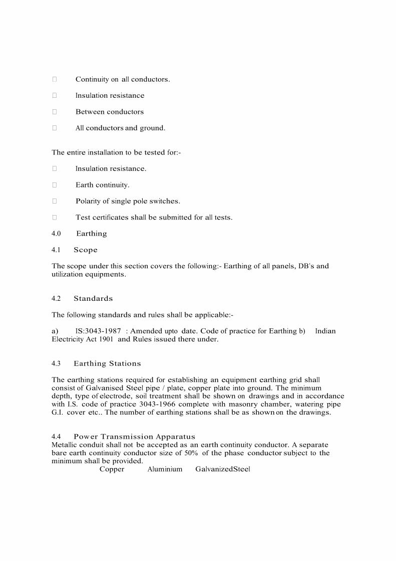
� Continuity on all conductors. � Insulation resistance � Between conductors � All conductors and ground. The entire installation to be tested for:- � Insulation resistance. � Earth continuity. � Polarity of single pole switches. � Test certificates shall be submitted for all tests. 4.0 Earthing 4.1 Scope The scope under this section covers the following:- Earthing of all panels, DB’s and utilization equipments. 4.2 Standards The following standards and rules shall be applicable:- a) IS:3043-1987 : Amended upto date. Code of practice for Earthing b) Indian Electricity Act 1901 and Rules issued there under. 4.3 Earthing Stations The earthing stations required for establishing an equipment earthing grid shall consist of Galvanised Steel pipe / plate, copper plate into ground. The minimum depth, type of electrode, soil treatment shall be shown on drawings and in accordance with I.S. code of practice 3043-1966 complete with masonry chamber, watering pipe G.I. cover etc.. The number of earthing stations shall be as shown on the drawings. 4.4 Pow er Transmission Apparatus Metallic conduit shall not be accepted as an earth continuity conductor. A separate bare earth continuity conductor size of 50% of the phase conductor subject to the minimum shall be provided.
Copper Aluminium Galvanized Steel

Minimum 2.5m2 4mm2 4mm2 The earth continuity conductor shall be clamped to the conduit at one meter intervals using approved earth clamps. Non-metallic conduit shall have an insulated earth continuity conductor of the same size as for metallic conduit. All metal junction and switch boxes shall have an inside earth stud to which the ECC shall be connected. The ECC shall be distinctly coloured (green) for easy identification. Armoured cables shall be earthed by a distinct connections to the armouring at both the ends and the size of connection being as for the metallic conduit. In the case of unarmoured cable, an earth continuity conductor shall either be run outside along the cable or should form a separate insulated core of the cable. 3 phase power panels and distribution boards shall have 2 distinct earth connections of the size shown or as co- related to the incoming cable size. In the case of 1 ph. DB’s single earth connection is adequate similarly for 3 ph. and 1 ph. isolating switches there shall be 2 and 1 earth connections respectively. Sizes of all earth connections shall be co-related to the incoming cables. 4.5 Utilizing Equipment 3 ph. motors and other 3 ph. apparatus shall have two distinct earth connections of size equal to 50% of the connecting cable are as follows:-
Copper Aluminium Galvanized Steel Minimum 6.5m2 10mm2 16mm2 Minimum 65m2 120mm2 200mm2
For 1 ph. motors and 1 ph. apparatus, the single earth connections shall be provided of the above size. For all light fittings and fans a single earth connections with 1.5 sq.mm. copper or 2.5 sq.mm. Aluminium shall be provided. Earthing for lightning conductors and street light ples shall be as shown on the drawings. An equipment earthing grid is established as shown on the drawings. All earth connections to all panels, DB’s and equipment shall be connected to the nearest point of the earthing grid.

4.6 Testing The following earth resistance values shall be measured with an approved earth meggar and recorded:- a) Each earthing station b) Earthing system as a whole c) Earth continuity conductors The panel shall consist of the following: a) Engine starting system: i. It shall be lead type acid of minimum 12 volts 180 Ah capacity Engine instruments and control panel: It shall be complete with required connections to set and compromising: � Inlet and outlet water temperature gauge (dial type) � Lubrication oil pressure gauge � Lubrication oil temperature gauge � Automatic start-stop device � Selectors switch for following shall also be provided � Manual: the engine can be manually operated by means of push buttons. � Start/stop and failure control device � Start key for manual starting � Stop push button for manual stopping of engine � Starting failure indication by lamp and horn unit. � Engine temperature very high indication by audio alarm and automatic
stopping of engine

� Engine set in operation indication by green lamp � Mains supply available indicated by yellow lamp � Push button for audio alarm reset � Push button failure indication by lamps � The panel shall also have an auto / manual / test / off selector switch Required Mounting : Floor Mounted Type : Free standing on floor Panels : 14/16 gauge CRCA stove enameled Incoming : 1 no. TPN SFU Rating by vendor Busbar : 4 Strips of aluminium bars Accessories (Incoming side)
: Ammeter 0 – 630 Amps. Voltmeter – 0.500V with ASS & control Fuse with VSS. Phase indicating lights.
Outgoing : As per BOQ Accessories (outgoing) Side
: BOQ
Power & Control wiring : As per specification Accessories with each MCCB (on outgoing side) on Starter feeder
: Single phase preventer start/stop button auto/manual button contactor Local/Remote switch On/Off PB Ammeter
Earthing : 50 x 8 mm GI Strip Other Accessories : Audio visual alarm with flasher and hooter and for Hydrant pump start, Jockey pump start, Hydrant mains pressure low and other off normal conditions Make : Reputed (TAC approved)

4.6.1 Hydrant Panel Schedule of particulars (To be filled in by Tenderer) 4.6.2 System Testing: The Contractor shall comply with the comments during interim stage inspection during execution of the works as and when so called for and shall carry out any rectification / modification as may be suggested by the Engineer in charge. Soon after the testing is completed, the contractor shall inform in writing to the Engineer in charge for getting the complete system including all sub-systems and instrumentation, control panels etc. thoroughly inspected and tested for satisfactory performance. After satisfactory completion of tests of the systems by the Engineer in charge, Contractor shall be required to carry out all start-up trials of the system. Any defects noticed during these tests shall be speedily rectified by the Contractor. 4.6.3 Hydrant System Testing After the hydrant system has been installed, it should be tested for any leakage prior to charging it with water. For this purpose, before fixing the hydrant valves, the system should flushed by water from a pump. After satisfactory flushing, the line shall be closed and Pressurized 1.5 times the working pressure whichever is higher by hand pump. The hand pump should be removed / disconnected from the hydrant piping. The entire system is to be kept for minimum 24 hours under pressure without any pressure drop. For the purpose of testing of the system minimum TWO pressure gauges must be installed, one at the point of pressurization point and second shall be at remotest point. The pressure gauges used for hydro testing should be calibrated. The calibration Certificate should be from the reputed test laboratory. 4.6.4 Handling Over a) At the time of taking over of the system by the Corporation, the hydrant system shall fulfill the following requirements. b) Entire piping (Loop Testing) is to be tested to 1.5 times the working pressure whichever is higher for 24 hours. c) Starting up of the pressurization by pump (Jockey pump) The drain / test valve shall be opened to cause the drop in the pressure. The Jockey pump shall start as soon as pressure gauge needle falls to 8.8 kg/sq.cm. The jockey pump shall automatically stop when the system has been pressurized again upto 8.8 kg./sq.cm. The indication of Jockey pump start / stop should appear in the control panel with alarm. The main electrical pump shall be set to start at 8.8 kg./sq.cm. an external hydrant valve using a single length of hose and branch pipe shall be fully opened to cause a drop of pressure in the system at first, the jockey pump shall start when the pressure drops below 8.8 kg./cm2. For further drop in the pressure upto 8.8

kg./cm2 should be allowed to test automatic start of the main pump. The jockey pump should stop automatically once the electrical driven main pump set into operation. The necessary interlocking circuit for jockey pump is to be provided in the control panel. The indication of main electrical pump running & jockey pump stop should appear in the control / annunciation panel with alarm. The electrical pump shall continue to run at least for 5 minutes and register a rise in the pressure upto 8.8 kg/sq.cm. The electrical pump and stand by pump shall be stopped manually only by pressing the stop button. The pressure and flow measuring instruments must be provided to the remotest and the nearest hydrant point of the pump (at riser as well as at external hydrant ring). During the running of the main pump the flow at the topmotest hydrant shall be available at the pressure of 3.5 kg./sq.cm. d) All pumps shall be tested for the shut off head and duty condition to satisfy the name plate rating & for both pumps & motor. e) All these tests mentioned above shall be repeated after one hour interval. The result of all the tests shall be confirming the required performance guaranteed by the contractor. System can be taken over from the contractor after satisfactory performance of the entire System. 4.6.5 Pump Testing One or more Hydrant Valve shall be opened with arrangement to take the discharge back to the under head fire tank. The pump testing shall continue at this pressure for twenty four hours. The pump shall not allow any undue stress. In case the pumps and / or prime mover fails to perform the equipment. It shall be necessary that the manufacturer’s representative shall be called to inspect and attend the defects and re testing of the system as per above procedure. The Bidder must include the cost of all testing as per the procedures in the Contract. 4.6.6 Operating Instruction & Maintenance Manual Before starting the testing contractor shall submit two sets of comprehensive operating instructions and maintenance manual. Maintenance schedules and log sheets and testing programmed for the entire system. This shall be supplementary to manufacturer’s operating and maintenance manuals. Upon approval of the draft, the contractor shall submit four (4) complete bound volumes / sets of operating instructions and maintenance manuals. These manuals shall also include basis of design, detailed technical data for each piece of equipment with Sr. No., spare parts manual and recommended spares for period of 1, 2 & 4 years of preventive maintenance of each equipment. 4.6.7 On site Training Upon completion of all work and tests, the contractor shall furnish necessary operators, labours and helpers for operating the entire installation for a period of thirty (30) working days of eight (8) hours each to enable the Owner’s staff to get acquainted with the operation of the system. During this period, the contractor shall train the Corporation’s personnel in the operation and maintenance of all equipments installed. However the system is to be maintained by the contractor during the defect liability period of 24 months by providing sufficient regular manpower.

4.6.8 Hydraulic Testing All piping in part and or the entire system (Loop) shall be tested to a pressure for 24 hours for 1.5 times the design pressure without drop in pressure. The contractor shall rectify leakages if any, and replace all defective components to the satisfaction of the Engineer In Charge and re-test system as per testing procedure. 4.6.9 Measurements Pipes shall be measured by linear meter and shall include linear measurements of all fittings. No separate payments shall be made for painting, testing, commissioning, flanges, fixtures, specials, jointing, welding, clamps, hangers, supports etc. shall be made. The rate quoted shall include for the all above requirements including all material necessary and required (whether specified or not) to complete the system and make it functional. Pump sets, Pressure switches, pressure gauges, Hoses, Hose reels, Hose boxes, Valves, etc., (Numerical Items) shall be measured by numbers and shall include matching flanges, gaskets, bolts and nuts, washers and all items necessary and required. Wherever the measurements is in “set”, the rate shall include all the material, labour etc., required for completion of the “set” of the work indicated in the relevant item. No additional payment shall be made on any account. No additional payment shall be admissible for cutting hole or chases in walls or floors or ceiling / slab and making good the same to the satisfaction of the Engineer in charge and making connections to pumps, various equipment’s or for making channels / trenches to complete the work. Excavation & backfilling in all type of soil shall be measured in cu. m.. Removing excess soil from the premises upto 4 km. radius is also included in the quoted rates. 10% of total contract value shall be deducted from every Bill as a special Retention money. 5% shall be paid only after completion of loop testing and balance. 5% after obtaining final approval of CFO. 5.0 Summary of Commercial Clauses SR. NO
DESCRIPTION OFFERED & ACCEPTED

1 SCOPE OF WORK DESIGN, MANUFACTURE, SUPPLY, INSTALLATION, ERECTION, TESTING AND COMMISSIONING OF FIRE PROTECTION SYSTEM AND OBTAIN APPROVAL FROM LPA/TAC AS MENTIONED IN TENDER DOCUMENT
2 PRICE BASIS FIRM PRICE TILL COMMISSIONING AND APPROVAL OF TOTAL SYSTEM OF W ORKS. PRICE ARE EXCLUSIVE, DUTIES, W ORK CONTRACT TAX ETC.
3 TYPE OF CONTRACT ITEM RATE WORKS CONTRACT, INCLUSIVE OF ALL TAXES, OCTROI, DUTIES EXCEPT INCLUDING INSURANCE, LOADING, UNLOADING, FREIGHT, ETC.
4 COMPLETION PERIOD 3 MONTHS FROM THE DATE OF ISSUE OF LETTER OF INTENT OR FIRM WORK ORDER W HICHEVER IS EARLY
5 DEFECT LIABILITY PERIOD
12 MONTHS FROM THE DATE OF COMMISSIONING, HANDING OVER & TAKING OVER BY US W ITH ISSUING OF COMPLETION CERTIFICATE.
6 LIQUIDATED DAMAGES ½% PER WEEK OR PART THEREOF SUBJECT TO A MAXIMUM OF 5% OF THE CONTRACT VALUE.
7 INSURANCE CONTRACTORS ALL RISK POLICY INCLUDING 3
RD PARTY LIABILITY MINIMUM ONE LAC PER INCIDENT, TRANSIT INSURANCE, W ORKMEN COMPENSATION.
DRAW INGS, MANUALS AND CATALOGUES
ALL W ORKING DRAW INGS AS REQUIRED FOR APPROVAL FROM US LPA/ TAC OR CONSULTANT TO BE SUPPLIED BY THE SUCCESSFUL BIDDER WITHIN 4 WEEKS FROM THE DATE OF ISSUE OF LETTER OF INTENT
APPROVAL ALL REQUIRED APPROVALS FROM US / OUR CONSULTANT/ LPA / TAC TO BE OBTAINED BY THE CONTRACTOR BEFORE STARTING WORK AND FINAL APPROVAL.
AS BUILT” DRAWINGS 4 COPIES OF “AS BUILT” DRAWING AND DULY APPROVED BY US/OUR CONSULTANT TO BE SUBMITTED W ITHIN 2 WEEKS AFTER SUCCESSFUL COMMISSIONING AND

HANDING OVER AND PRIOR TO SUBMITTING FINAL BILL.
ELECTRICAL POWER & WATER ELECTRICAL POWER NOT AVAILABLE AT SITE. CONTRACTOR HAS TO ARRANGE DIESEL POW ER GENERATING SET FOR FABRICATION AND INSTALLATION AS REQUIRED. WATER FOR TESTING WILL BE SUPPLIED AT ONE POINT. CONTRACTOR HAS TO MAKE OW N ARRANGEMENT FOR DISTRIBUTION.
STORAGE SPACE RENT FREE OPEN SPACE W ILL BE PROVIDED TO YOU AT SITE OF W ORK. RESPONSIBILITY OF STORAGE, WATCH AND WARD FOR YOUR MATERIALS WILL BE YOURS. NO AREA W ILL BE AVAILABLE TO HOUSE YOUR STAFF AND LABOUR.
SUPERVISION AT SITE YOU WILL PROVIDE COMPETENT ENGINEERING STAFF AT SITE FOR FULL TIME S U P E R V I S I O N OF YOUR W ORK. THEY SHOULD BE ABLE TO RECEIVE INSTRUCTIONS FROM US/OUR CONSULTANTS AND TAKE DECISIONS.
SAFETY SAFETY OF LABOUR TO BE TAKEN CARE BY CONTRACTOR WITH THE USE OF HELMETS, BELTS, EYES GOGGLE, SAFETY SHOES, E T C . WILL BE PART OF CONTRACT COST. NECESSARY W E L D I N G PERMITS, PERMIT FOR W ORKING AT HEIGHT WILL BE PREPARED BY CONTRACTOR BEFORE STARTI NG OF JOB EVERY DAY AS PER SAFETY REQUIREMENT OF PLANT.

General Instruction to the Contractors & Bill of Quantities 1.0 General Instruction to the Contractors 1.1 Enquiry for offer Price 1.1.1 Enquiry for offer shall be on lump sum basis equipment and material delivered, installed, tested and commissioned in accordance with the specification and accompanying drawings. 1.1.2 Enquiry for offer prices shall be inclusive of all taxes and levies, statuary changes, however in the quantum of taxes or duties for finished products only shall become adjustable in the final bill of the contractor. However no statutory changes in the quantum of the taxes or duties for raw materials and unfinished products will be entertained by the Owner. 2.0 Unit Rates & Quantities 2.1.1 Unit rates for piping sheet metal work etc., shall remain valid till the completion of the work in all respects and shall be free from variation due to increase or decrease in cost of materials, labor or any other reasons whatsoever. Unit rates shall become applicable only due to the changes/modifications in the drawings made by the Owner after award of contract. For the purpose of ascertaining the variation in the quantity, no site measurement is acceptable. Difference in quantities will be arrived from as-built drawings, for the particular area where changes have been carried out. Difference in cost due to variation will be arrived at from the unit rates quoted by the contractor. All variations will be adjusted in the final bill of the contractor. 2.1.2 Unit rates shall be inclusive of flanges, fittings, tees, bends, vanes, dampers, etc., and no additional payment will be made for these items.

2.1.3 For the purpose of ascertaining the difference in quantities for insulation, the relevant ISI standards shall apply. 2.1.4 Bill of quantities given in the enquiry for offer gives a brief description of the major equipment only. However, it will be the contractors responsibility to provide all necessary items like hangers, supports, bends, tees, flanges, etc., whether specifically mentioned or not in the bill of quantities so as to give a complete and a satisfactory working air conditioning ventilation and exhaust system as per detailed specifications and drawings. 2.1.5 Quantities of piping and sheet metal work given in the bill of quantities are average and are available for the contractor’s guidance and to provide uniform basis for enquiry. As the bill of quantities does not indicate separately items like flanges, bends, supports, etc., it will be the contractor’s responsibility to ascertain the quantities before tendering. No extra claim in this respect will be entertained once the enquiry for offer is accepted. 3.0 Schedule of Probable Bill of Quantities 3.1 The description of each item shall, unless otherwise categorically stated, be held to include: “Supply conveyance and delivery, unloading and storing, hoisting, fixing and constructing, all labor for finishing to required shape and size setting and fixing into position (as per Architects drawings and instruction) cutting and waste, return of packing, taxes and duties, overhead profit and other charges” The liability under each item in the schedule of probable bill of quantities shall be governed by the Indian Standard “Method of Measurements” of the relevant trade and its subsequent revisions if any, unless otherwise stated in the probable Bill of Quantities. This is the probable Bill of Quantities referred to in this contract Agreement made between us this day------------------.

3.2 Notes to BOQ Contractor shall provide necessary mounting frames and brackets together with vibration isolators for indoor and outdoor units of split units. Supports from structure shall be by means of approved anchor fasteners. All supporting structure to be hot dipped as approved by Architect. All fasteners to be galvanized. All welded joints or where galvanizing worn out to be covered with galvanizing spray, coating after installation. Contractor rate shall be inclusive of the C / I sections required for installing indoor and outdoor units. The outdoor units will be located in the shaft provided on North & South direction.

VI. TECHNICAL SPECIFICATIONS FOR HVAC WORKS TECHNICAL SPECIFICATIONS HVAC WORK
1.0 VARIABLE REFRIGERANT FLOW SYSTEM
1.1 SCOPE
The scope of this section comprises the supply, erection, testing and commissioning of Variable Refrigerant Volume System conforming to these specifications and in accordance with the requirements of Drawings and Schedule of quantities.
1.2 TYPE
Unit shall be air cooled, variable refrigerant volume air conditioner consisting of one outdoor unit and multiple indoor units. Each indoor unit having capability to cool independently for the requirement of the rooms.
It shall be possible to connect multiple indoor unit on one refrigerant circuit as shown in the drawings or as indicated in schedule of quantities. The indoor units on any circuit can be of different type and also controlled individually. Following type of indoor units shall be connected to the system :VRF System shall be based on Variable Evaporative technology.
� Ceiling mounted cassette type. � Ceiling mounted ductable type. � Wall mounted Hi-Wall type. � Floor mounted type.
Compressor installed in outdoor unit shall be equipped with capacity control mechanism, and capable of changing the rotating speed / mass flow rate of refrigerant by scroll / rotary compressor RPM to follow variations in cooling. Outdoor unit shall be suitable for mix-match connection of all type of indoor units.
The refrigerant piping between indoor units and outdoor units shall be extended upto 100m with maximum 50 m level difference without any oil traps. Oil recovery system shall be managed without disturbance to normal operation cycle of the system / compressor.
Both indoor unit and outdoor unit shall be factory assembled, tested and filled with first charge of refrigerant before delivery at site. All Outdoor Units shall have corrosion resistant ,Biofouling protection coating applied to Fins ,Tubes.Coating shall be Certified with ASTM B117,ASTM G85,ASTM G 87,ASTM D4798.
1.3 SELECTION CRITERIA FOR VRV UNIT
� The manufacturer to certify that the proposed unit shall be operational un-interrupted at temperature
3°C plus peak ambient dry bulb temperature of design city.
� Manufacturer to submit OEM letter for continuous operational range of the unit.
� Manufacturer to submit OEM de-rating charts for indoor and outdoor unit capacity rating at project specific design conditions and refrigerant piping lift and distance.
� ADP of unit selected should not be lower than 11.11°C (52°F) for high wall units and 10.56°C (51°F) for
concealed ductable and cassette units.
� Auto backup option shall be provided for all Indoor Units,
1.4 OUT DOOR UNIT
The outdoor unit shall be factory assembled, weather proof casing constructed from heavy gauge mild steel panels with powder coated finish.
All outdoor units above 8 HP rating shall have minimum two number scroll / rotary compressors.
In case of outdoor units with multiple compressor, the operation shall not be disrupted with failure of any compressor.
The noise level shall not be more than 60 dB (A) at normal operation measured horizontally 1m away and 1.5 m above ground level.
The outdoor unit shall be modular in design with possible future expansions. The
unit shall be provided with microprocessor control panel.
COP of the VRF Units shall be more than 3.1.
1.5 COMPRESSOR
The compressor shall be high efficiency scroll / twin rotary type and capable for capacity controlling. It shall change the speed / refrigerant mass flow rate in accordance to the variation in cooling load requirement. Refrigerant mass flow rate can be changed by speed modulation of compressor / mechanical control system. System shall incorporate liquid sub- cooling mechanism.
The inverter shall be IGBT (insulated gate bipolar transistor) type for efficient and quiet operation.
All outdoor units shall have multiple steps of capacity control to meet load fluctuation and indoor unit individual control. All parts of compressor shall be sufficiently lubricated. Forced lubrication may also be employed.
Oil heater shall be provided in the compressor casing.
1.6 HEAT EXCHANGER
The Heat Exchanger shall be constructed with copper tubes mechanically bonded to aluminium fins to form a cross fan coil and larger surface area.
The fins shall have anticorrosion treatment for Heat Exchanger Coil. The treatment shall be suitable for areas of high pollution, moisture and salt laden air.
The casings, fans, motors etc. shall also be with anti-corrosion treatment as a standard features.
The unit shall be provided with necessary number of direct driven low noise level propeller type fans arranged for vertical / horizontal discharge. Each fan shall have a safety guard.
1.7 REFRIGERANT CIRCUIT
The Refrigerant Circuit shall include a liquid receiver /accumulator, liquid & gas shut off valves and a solenoid valve. All necessary safety devices shall be provided to ensure the safety operation of the system.

1.8 SAFETY DEVICES
All necessary safety devices shall be provided to ensure safe operation of the system.
Following safety devices shall be part of the outdoor unit : high pressure switch, low pressure switch, fuse, crankcase heater, fusible plug, over current protection for inverter, and short recycling guard timer.
1.9 PIPING
All connections of Refrigerant piping shall be in high grade Copper of Refrigeration quality with Eddy Current Testing and material test Certificates.
All connections, tees, reducers etc. shall be standard make fittings.
Insulation of cold lines shall be carried out with nitrile rubber insulation sheets and tubes of appropriate thickness so that condensation does not occur.
For individual Piping 50 / 100 mm wide Aluminium Tape shall be used at joints of Piping with Bands for identification.
For outdoor piping, the finish shall be woven GRP Mat finished with coloured Epoxy paints to withstand outside ambient conditions and UV Radiation.
1.10 OIL RECOVERY SYSTEM
Unit shall be equipped with an oil recovery system to ensure stable operation with long refrigerant piping.
System shall be designed for proper oil return to compressor along with the distribution of oil to individual compressor.
The refrigerant piping shall be extended upped 100 M with 50-M level difference without oil traps.
1.11 INDOOR UNITS
Units shall be factory assembled, wired, piped and tested.
Units shall have DX coils with copper tubes and bonded aluminium fins for highly efficient heat transfer.
Units shall have Centrifugal fans for adequate amount of Air circulation and low Noise. Units
shall have inlet filters, which are easily cleanable and replaceable.
All components of Units are easily accessible for connection, repairs and maintenance. Units
shall have very low noise.
All units with Factory manufactured Units Grills shall have auto swing feature for proper Air distribution.
All unit shall be controlled by electronic Expansion Valves only.
All units mounted inside the ceiling shall have fans capable of sustaining duct connections, and special filters if necessary.
Visible indoor units shall have wireless remotes. Price of the same shall be included in cost of unit by default.

Concealed indoor units shall have sensor mounted on supply air grilles / diffusers which can be controlled with wireless remotes.
Anticorrosion treatment for avoiding corrosion of coils.
All units shall have adequate insulation or Lining to avoid condensation.
Cooling coil and refrigeration parameters shall be designed in such a way that supply air temperature shall not be less than 140C or 10C above room dew point temp, whichever is more. Contractor shall guarantee inside conditions with selected supply air temperature.
1.12 CEILING MOUNTED CASSETTE TYPE UNIT (MULTI-FLOW TYPE)
The unit shall be ceiling mounted type. The unit shall include pre-filter, fan section and DX- coil section. The housing of the unit shall be powder coated galvanised steel. The body shall be light in weight and shall be possible to suspend from four corners.
Unit shall have a external attractive panel for supply and return air. Unit shall have four way supply air grilles on sides and return air grille in centre.
Each unit shall have high lift drain pump, fresh air intake provision (if specified), and very low operating sound.
1.13 CEILING MOUNTED DUCTABLE TYPE UNIT
Unit shall be suitable for ceiling mounted type. The unit shall include pre filter, fan section & DX-coil section. The housing of unit shall be light weight powder coated galvanised steel. The unit shall have high static fan for ductable arrangement.
1.14 HIGH WALL MOUNTED UNITS
The units shall be high wall mounted type. The unit shall include pre-filter, fan section & DX coil section. The housing of unit shall be light weight powder coated galvanized steel.
Unit shall have an attractive external casing with supply and return air grills.
1.15 FLOOR MOUNTED UNITS
The unit shall be suitable for floor mounting. The unit shall include, prefilter fan section, DX. Coil section. The housing of unit shall be light weight powder coated galvanized / anodized aluminium panels. Unit shall have an attractive external casing with supply & return air grilles.
1.16 CENTRAL REMOTE CONTROLLER (OPTION IF SPECIFIED IN BOQ)
A multi-functional microprocessor based centralized controller (central remote controller) shall be supplied as an optional accessory.
The controller shall be able to control upto minimum 64 nos. of indoor units with zoning option and / or in case of larger installation should provide bigger controller with the following functions.
- Temperature setting for each zone, or group, or indoor unit.
- On/Off as a zone or individual unit. - Indication of operating condition.
- Select ON of all operation modes for each zone..

- The controller shall have wide screen liquid crystal display and shall be wired by a non polar 2 / 3 wire transmission cable to a distance of 1000m away from the indoor unit.
- The controller shall be integrated to BAS system thru software for monitoring & controlling of all above parameters including start/ stop of each indoor / out door unit. All necessary interface cards / units should be supplied as a part of the system to integrate to the BAS Software.
OR
The manufacturer needs to provide BAS gateway / interface device for software integration to BAS for monitoring and controlling of all above parameters including start / stop of each indoor / outdoor units. CRC controller shall not be required in this case.
1.17 UNIFIED ON/OFF CONTROLLER (OPTION IF SPECIFIED IN BOQ)
Unified ON / OFF controller shall be supplied as an optional accessory.
The controller shall be able to control minimum 2 groups (each group containing maximum 16 indoor units) or 128 nos. of indoor units with the following functions.
- On / Off as a zone or individual unit. - Indication of operation condition of each group. - Select one of 4 operation modes.
The controller shall be wired by a non-polar 2 wire transmission cable to distance of 1 km away from indoor unit.
The controller shall be integrated to BAS system thru software for monitoring & controlling of all above parameters including start/ stop of each indoor / outdoor unit. All necessary interface cards / units should be supplied as a part of the system to integrate to the BAS Software.
1.18 CONDENSATE:
25mm dia uPVC pipes, 40mm dia uPVC headers & fittings shall be used for condensate, from Evaporator Unit to drain point. The joints shall be properly sealed so that there is no water leakage. U-trap shall be provided at the end. Additional insulation drain tray shall be provided below the Evaporator Unit, if required.
Mounting
All indoor units shall be mounted with Brackets, Hangers etc. with proper size anchor Fasteners.
1.19. ELECTRICAL INSTALLATION
For Variable Refrigerant flow systems, power will be provided near outdoor unit location. HVAC Contractor to provide suitable distribution panel along with 3-phase power to outdoor units and single phase power to all indoor units fed by these outdoor units. Power / control cabling and earthing along with supports shall be included.

2. FANS
2.1 SCOPE
The scope of this section comprises the supply, erection, testing and commissioning of centrifugal, in-line and propeller type fans and roof mounted units conforming to these Specifications and in accordance with the requirement of Drawings and Schedule of Quantities.
2.2 TYPE
Centrifugal, in-line propeller fans and roof mounted units shall be of the type as indicated on Drawings and identified in Schedule of Quantities.
2.3 CAPACITY
The air-moving capacity of fans shall be as shown on Drawings and in Schedule of Quantities.
2.4 CENTRIFUGAL FAN
Centrifugal fan shall be DWDI / SWSI Class I construction arrangement 3 (i.e. bearings on both the sides) for DWDI fans complete with access door, squirrel-cage induction motor, V- belt drive, belt guard and vibration isolators, direction of discharge / rotation, and motor position shall be as per the Approved-for-Construction shop drawings.
a. Housing shall be constructed of 14 gage sheet steel welded construction. It shall be rigidly
reinforced and supported by structural angles. Split casing shall be provided on larger sizes of fans, however neoprene / asbestos packing should be provided throughout split joints to make it air-tight.
18 gauge galvanized wire mesh inlet guards of 5 cm sieves shall be provided on both inlets. Housing shall be provided with standard cleanout door with handles and neoprene gasket. Rotation arrow shall be clearly marked on the housing.
b. Fan Wheel shall be backward-curved non-over loading type. Fan wheel and housing shall be
statically and dynamically balanced. For fans upto 450 mm dia, fan outlet velocity shall not exceed 550 meter/minute and maximum fan speed shall not exceed 1450 rpm. For fans above 450 mm dia, the outlet velocity shall be within 700 meter/minute and maximum fan speed shall not exceed 1000 RPM. High static pressure fan speed shall be as per manufacturer.
c. Shaft shall be constructed of steel, turned, ground and polished.
d. Bearings : shall be of the sleeve / ball-bearing type mounted directly on the fan housing.
Bearings shall be designed especially for quiet operation and shall be of the self-aligning, oil / grease pack pillow block type.
e. Motor : Fan motor shall be energy efficient and suitable for 415±10% volts, 50 cycles, 3
phase AC power supply, squirrel-cage, totally enclosed, fan-cooled motor, provided with class F insulation, and of approved make. Motor name plate horsepower shall exceed brake horsepower by a minimum of 10%. Motor shall be designed especially for quiet operation and motor speed shall not exceed 1440 rpm. The fan and motor combination selected for the particular required performance shall be of the most efficient (smallest horse power), so that sound level is lowest. 000
HP POWER FACTOR EFFICIENCY
FL 3/4L 1/2L FL 3/4L 1/2L

0.50 0.71 0.62 0.50 73.00 73.00 68.00 0.75 0.74 0.64 0.50 78.00 78.00 70.00 1.00 0.76 0.67 0.55 82.50 82.50 77.00 1.50 0.77 0.70 0.57 83.80 83.80 80.00 2.00 0.77 0.70 0.57 85.00 85.00 81.00 3.00 0.82 0.74 0.60 86.40 86.40 84.00 5.00 0.82 0.78 0.63 88.30 88.30 86.00 7.50 0.85 0.80 0.71 89.50 88.50 88.00 10.00 0.86 0.83 0.76 90.30 90.30 89.00 12.50 0.84 0.82 0.73 90.50 90.50 88.00 15.00 0.85 0.83 0.76 91.50 91.50 89.50 20.00 0.85 0.83 0.76 92.20 92.20 91.00 25.00 0.85 0.82 0.76 92.40 92.40 91.00 30.00 0.85 0.80 0.72 92.80 92.80 92.00 40.00 0.86 0.85 0.80 93.20 93.20 91.00 50.00 0.87 0.85 0.77 93.60 93.60 91.60 60.00 0.88 0.86 0.78 93.90 93.90 91.90 75.00 0.87 0.85 0.78 94.20 94.20 92.80
f. Drive to fan shall be provided through belt with adjustable motor sheave and a standard
belt guard. Belts shall be of the oil-resistant type.
g. Vibration Isolation : MS base shall be provided for both fan and motor, built as an integral part, and shall be mounted on a concrete foundation through resistoflex vibration isolators. The concrete foundation shall be atleast 15 cm above the finished floor level, or as shown in approved-for-construction shop drawings.
a. Centrifugal fans for smoke extract application shall have external belt drive and motor.
Fan & casing shall be internally rated for 300oC for 2 hours.
2.5 AXIAL FLOW FAN
2.5.1 Axial Flow Fan (Standard)
Fan shall be complete with motor, motor mount, belt driven (or direct driven) and vibration isolation type, suspension arrangement as per approved for construction shop drawings.
a. Casing : shall be constructed of heavy gage sheet steel. Fan casing, motor mount and
straightening vane shall be of welded steel construction. Motor mounting plate shall be minimum 15 mm thick and machined to receive motor flange.
An inspection door with handle and neoprene gasket shall be provided. Casing shall have flanged connection on both ends for ducted applications. Fan casing are with internal punched inlet and outlet flanges to prevent air leakage, for size upto 1600 mm dia and shall be constructed of rolled steel with a continuous seam welded. Support brackets for ceiling suspension shall be welded to the casing for connection to hanger bolts. Straightening vanes shall be aerodynamically designed for maximum efficiency by converting velocity pressure to static pressure potential and minimizing turbulence. Casing shall be bonderized, primed (minimum 2 coats of rust-proof primer) and finish coated with enamel paint or powder coated after phosphating process.
b. Rotor : hub and blades shall be cast aluminium alloy or cast steel construction.
Blades shall be die-formed aerofoil shaped for maximum efficiency and shall vary in twist and width from hub to tip to effect equal air distribution along the blade length. Rotor shall be statically and dynamically balanced. Extended grease leads for external lubrication shall be provided. The fan pitch control may be manually readjusted at site upon installation, for obtaining actual air flow values, as specified and quoted. Taper lock bushing shall be used to mount the propeller to the motor

shaft. The impeller and fan casing shall be carefully matched and shall have precise running tolerances for maximum performance and operating efficiency.
c. Motor: shall be energy efficient squirrel-cage, totally-enclosed, fan cooled, standard frame, constant speed, continuous duty, single winding, suitable for 415±10% volts, 50 cycles, 3 phase AC power supply, provided with class `F’ insulation. Motor shall be specially designed for quiet operation. The speed of the fans shall not exceed 1000 RPM for fans with impeller diameter above 450 mm, and 1440 RPM for fans with impeller diameter 450 mm and less. For lowest sound level, fan shall be selected for maximum efficiency or minimum horsepower. Motor conduit box shall be mounted on exterior of fan casing, and lead wires from the motor to the conduit box shall be protected from the air stream by enclosing in a flexible metal conduit.
HP POWER FACTOR EFFICIENCY
FL 3/4L 1/2L FL 3/4L 1/2L 0.50 0.71 0.62 0.50 73.00 73.00 68.00 0.75 0.74 0.64 0.50 78.00 78.00 70.00 1.00 0.76 0.67 0.55 82.50 82.50 77.00 1.50 0.77 0.70 0.57 83.80 83.80 80.00 2.00 0.77 0.70 0.57 85.00 85.00 81.00 3.00 0.82 0.74 0.60 86.40 86.40 84.00 5.00 0.82 0.78 0.63 88.30 88.30 86.00 7.50 0.85 0.80 0.71 89.50 88.50 88.00
10.00 0.86 0.83 0.76 90.30 90.30 89.00 12.50 0.84 0.82 0.73 90.50 90.50 88.00 15.00 0.85 0.83 0.76 91.50 91.50 89.50 20.00 0.85 0.83 0.76 92.20 92.20 91.00 25.00 0.85 0.82 0.76 92.40 92.40 91.00 30.00 0.85 0.80 0.72 92.80 92.80 92.00 40.00 0.86 0.85 0.80 93.20 93.20 91.00 50.00 0.87 0.85 0.77 93.60 93.60 91.60 60.00 0.88 0.86 0.78 93.90 93.90 91.90 75.00 0.87 0.85 0.78 94.20 94.20 92.80
d. Drive : to fan shall be provided through belt drive with adjustable motor sheave and standard
sheet steel belt guard with vented front for heat dissipation. Belts shall be of oil-resistant type.
e. Vibration Isolation : The assembly of fan and motor shall be suspended from the slab by vibration isolation suspension of heavy duty spring isolators type.
f. Accessories : The following accessories shall be provided with all fans :
i. Outlet cone for static pressure regain. ii.
Inlet cone.
Fan silencers may be provided where specifically called for in Schedule of Quantities. Fans shall be factory assembled and shipped with all accessories factory-mounted.
Axial Flow Fan shall be AMCA certified for Air and Sound performance in accordance to AMCA 210 and AMCA 300. Fan shall be suitable for both indoor and outdoor application with all accessories. Base fan performance shall be at standard conditions (density 1.2 Kg/Cu.mt.)

2.5.2 Axial Flow Fan (UL Listed/ CE Certified)
Fan shall be suitable for mounting in duct or wall / floor / slab as required. Fan shall be complete with motor, motor mount, belt driven (or direct driven) and vibration isolation type, suspension arrangement as per approved for construction shop drawings.
a. Casing: shall be constructed of heavy gage sheet steel. Fan casing, motor mount and
straightening vane shall be of welded steel construction. Bolt construction is not acceptable. Motor mounting plate shall be of structural steel with minimum 15 mm thick and suitable to handle the weight of the motor and propeller, machined to receive motor flange.
An inspection door with handle and neoprene gasket shall be provided. Casing shall have flanged connection on both ends for ducted applications. Fan casing are with internal punched inlet and outlet flanges to prevent air leakage, for size upto 1600 mm dia and shall be constructed of rolled steel with a continuous seam welded confirming to UL standards. Support brackets for ceiling suspension shall be welded to the casing for connection to hanger bolts. Straightening vanes shall be aerodynamically designed for maximum efficiency by converting velocity pressure to static pressure potential and minimizing turbulence. Casing shall be bonderized, primed (minimum 2 coats of rust-proof primer) and finish coated with enamel paint or powder coated after phosphating process as prescribed in UL-705.
b. Rotor : hub and blades shall be cast aluminum alloy or cast steel construction.
Blades shall be die-formed aerofoil shaped for maximum efficiency and shall vary in twist and width from hub to tip to effect equal air distribution along the blade length. Rotor shall be statically and dynamically balanced. Extended grease leads for external lubrication shall be provided. The fan pitch control may be manually readjusted at site upon installation, for obtaining actual air flow values, as specified and quoted. Taper lock bushing shall be used to mount the propeller to the motor shaft. The impeller and fan casing shall be carefully matched and shall have precise running tolerances for maximum performance and operating efficiency.
c. Motor: shall be energy efficient squirrel-cage, totally-enclosed, fan cooled, standard frame,
constant speed, continuous duty, single winding, suitable for 415±10% volts, 50 cycles, 3 phase AC power supply, provided with class `F’ insulation. Motor shall be specially designed for quiet operation. The speed of the fans shall not exceed 1000 RPM for fans with impeller diameter above 450 mm, and 1440 RPM for fans with impeller diameter 450 mm and less. For lowest sound level, fan shall be selected for maximum efficiency or minimum horsepower. Motor shall pass elevated temperature test and other tests as per UL standards and shall be UL listed. Motor conduit box shall be mounted on exterior of fan casing, and lead wires from the motor to the conduit box shall be protected from the air stream by enclosing in a flexible liquid tight PVC conduit confirming to UL standards.

�
HP POWER FACTOR EFFICIENCY FL 3/4L 1/2L FL 3/4L 1/2L
0.50 0.71 0.62 0.50 73.00 73.00 68.00 0.75 0.74 0.64 0.50 78.00 78.00 70.00 1.00 0.76 0.67 0.55 82.50 82.50 77.00 1.50 0.77 0.70 0.57 83.80 83.80 80.00 2.00 0.77 0.70 0.57 85.00 85.00 81.00 3.00 0.82 0.74 0.60 86.40 86.40 84.00 5.00 0.82 0.78 0.63 88.30 88.30 86.00 7.50 0.85 0.80 0.71 89.50 88.50 88.00
10.00 0.86 0.83 0.76 90.30 90.30 89.00 12.50 0.84 0.82 0.73 90.50 90.50 88.00 15.00 0.85 0.83 0.76 91.50 91.50 89.50 20.00 0.85 0.83 0.76 92.20 92.20 91.00 25.00 0.85 0.82 0.76 92.40 92.40 91.00 30.00 0.85 0.80 0.72 92.80 92.80 92.00 40.00 0.86 0.85 0.80 93.20 93.20 91.00
HP POWER FACTOR EFFICIENCY FL 3/4L 1/2L FL 3/4L 1/2L
50.00 0.87 0.85 0.77 93.60 93.60 91.60 60.00 0.88 0.86 0.78 93.90 93.90 91.90 75.00 0.87 0.85 0.78 94.20 94.20 92.80
d. Drive : Fan shall be provided through direct / belt drive with adjustable motor sheave
and standard sheet steel belt guard with vented front for heat dissipation. Belts shall be of oil-resistant type.
e. Vibration Isolation : The assembly of fan and motor shall be suspended from the slab by
vibration isolation suspension of heavy duty spring isolators type.
f. Accessories : The following accessories shall be provided with all fans :
i. Outlet cone for static pressure regain. ii. Inlet cone.
Fan silencers may be provided where specifically called for in Schedule of Quantities. Fans shall be factory assembled and shipped with all accessories factory-mounted confirming to UL standards.
Complete fan assembly (fan, impeller, fan casing, motor base frame along with motor) shall be ensure mechanical, electrical, water safety as per UL standards.
Axial Flow Fan shall be AMCA certified for Air and Sound performance in accordance to AMCA 210 & AMCA 300 and shall be UL listed in accordance with UL 705 for both indoor and outdoor application with all accessories. Base fan performance shall be at standard conditions (density 1.2 Kg/Cu.mt.)
2.5.3 Axial Flow Fan (for Fire, Smoke and Heat exhaust )
Fan shall be suitable for mounting in duct or wall / floor / slab as required. Fan shall be complete with motor, motor mount, direct driven and vibration isolation type, suspension arrangement as per approved for construction shop drawings.
a. Casing : shall be constructed of heavy gage sheet steel and shall withstand 300°C for 2 hours.
Fan casing, motor mount and straightening vane shall be of welded steel construction. Bolt construction is not acceptable. Motor mounting plate shall be of structural steel with minimum 15 mm thick and suitable to handle the weight of the motor and propeller, machined to receive motor flange.

An inspection door with handle and neoprene gasket shall be provided. Casing shall have flanged connection on both ends for ducted applications. Fan casing are with internal punched inlet and outlet flanges to prevent air leakage, for size upto 1600 mm dia and shall be constructed of rolled steel with a continuous seam welded. Support brackets for ceiling suspension shall be welded to the casing for connection to hanger bolts. Straightening vanes shall be aerodynamically designed for maximum efficiency by converting velocity pressure to static pressure potential and minimizing turbulence. Casing shall be bonderized, primed (minimum 2 coats of rust-proof primer) and finish with 2 coats of high temperature paint or powder coated after phosphating process.
b. Rotor : hub and blades shall be cast aluminium alloy or cast steel construction and shall
withstand 300 °C for 2 hours. Blades shall be die-formed aerofoil shaped for maximum efficiency and shall vary in twist and width from hub to tip to effect equal air distribution along the blade length. Rotor shall be statically and dynamically balanced. Extended grease leads for external lubrication shall be provided. The fan pitch control may be manually readjusted at site upon installation, for obtaining actual air flow values, as specified and quoted. The impeller and fan casing shall be carefully matched and shall have precise running tolerances for maximum performance and operating efficiency.
� � c. Motor: shall be energy efficient squirrel-cage, totally-enclosed, fan cooled,
standard frame, constant speed, continuous duty, single winding, suitable for 415±10% volts, 50 cycles, 3 phase AC power supply. Motor shall be specially designed for quiet operation. The speed of the fans shall not exceed 1000 RPM for fans with impeller diameter above 450 mm, and 1440 RPM for fans with impeller diameter 450 mm and less. For lowest sound level, fan shall be selected for maximum efficiency or minimum horsepower. Motor for emergency fire, smoke and heat ventilation shall certified according to standard BS EN 12101-3:2002 for 300 °C for 2 hours. Motor conduit box shall be mounted on exterior of fan casing, and lead wires from the motor to the conduit box shall be protected from the air stream by enclosing in a flexible liquid tight PVC conduit.
�
HP POWER FACTOR EFFICIENCY FL 3/4L 1/2L FL 3/4L 1/2L
0.50 0.71 0.62 0.50 73.00 73.00 68.00 0.75 0.74 0.64 0.50 78.00 78.00 70.00 1.00 0.76 0.67 0.55 82.50 82.50 77.00 1.50 0.77 0.70 0.57 83.80 83.80 80.00 2.00 0.77 0.70 0.57 85.00 85.00 81.00 3.00 0.82 0.74 0.60 86.40 86.40 84.00 5.00 0.82 0.78 0.63 88.30 88.30 86.00 7.50 0.85 0.80 0.71 89.50 88.50 88.00
10.00 0.86 0.83 0.76 90.30 90.30 89.00 12.50 0.84 0.82 0.73 90.50 90.50 88.00 15.00 0.85 0.83 0.76 91.50 91.50 89.50 20.00 0.85 0.83 0.76 92.20 92.20 91.00 25.00 0.85 0.82 0.76 92.40 92.40 91.00 30.00 0.85 0.80 0.72 92.80 92.80 92.00 40.00 0.86 0.85 0.80 93.20 93.20 91.00 50.00 0.87 0.85 0.77 93.60 93.60 91.60 60.00 0.88 0.86 0.78 93.90 93.90 91.90 75.00 0.87 0.85 0.78 94.20 94.20 92.80
d. Drive : Fan shall be provided through direct drive. e. Vibration Isolation : The assembly of fan and motor shall be suspended from the slab by
vibration isolation suspension of heavy duty spring isolators type.
f. Accessories : The following accessories shall be provided with all fans :

i. Outlet cone for static pressure regain. ii.
Inlet cone.
Fan silencers may be provided where specifically called for in Schedule of Quantities. Fans shall be factory assembled and shipped with all accessories factory-mounted.
Complete fan assembly (fan, impeller, fan casing, motor base frame along with motor) shall be tested and approved by Exova Warringtonfire in accordance BS EN 12101-3:2002 standard for “Powered Smoke & Heat Exhaust Ventilators for Smoke Control Systems” for 300°C temperature for 2 hours of operation.
Axial Flow Fan shall be AMCA certified for Air and Sound performance in accordance to AMCA 210 and AMCA 300. Fan shall be suitable for both indoor and outdoor application with all accessories. Base fan performance shall be at standard conditions (density 1.2 Kg/Cu.mt.)
2.6 PROPELLER FAN
Propeller fan shall be direct-driven, three or four blade type, mounted on a steel mounting plate with orifice ring.
a. Mounting Plate shall be of steel construction, square with streamlined venturi inlet
(reversed for supply applications) coated with baked enamel paint. Mounting plate shall be of standard size, constructed of 12 to 16 gauge sheet steel depending upon the fan size. Orifice ring shall be correctly formed by spinning or stamping to provide easy passage of air without turbulence and to direct the air stream.
b. Fan Blades shall be constructed of aluminium or steel. Fan hub shall be of heavy welded
steel construction with blades bolted to the hub. Fan blades and hub assembly shall be statically and dynamically balanced at the manufacturer’s works.
c. Shaft shall be of steel, accurately ground and shall be of ample size for the load transmitted
and shall not pass through first critical speed thru the full range of specified fan speeds.
d. Motor shall be standard (easily replaceable) permanent split capacitor or shaded pole for small sizes, totally enclosed with prelubricated sleeve or ball bearings, designed for quiet operation with a maximum speed of 1000 rpm for fans 60 cm dia or larger and 1440 rpm for fans 45 cm dia and smaller. Motors for larger fans shall be suitable for 415±6% volts, 50 cycles 3 phase power supply, and for smaller fans shall be suitable for 220 ± 6% volts, 50 cycles single phase power supply. Motors shall be suitable for either horizontal or vertical service as indicated on Drawings and in Schedule of Quantities.
e. Accessories : The following accessories shall be provided with propeller fans :
i. Wire guard on inlet side and bird-screen at the outlet. ii. Fixed or gravity louvers built into a steel frame at the outlet. iii. Regulator for controlling fan speed for single phase fan motor. iv. Single phase preventers for 3 phase fans.
2.7 ROOF MOUNTED FAN
Roof mounted fan shall be propeller type or centrifugal fans, direct driven or belt driven as shown on drawing and in Schedule of Quantities, complete with motor drive, and housing with weather-proof cowl.

a. Housing: shall be constructed of 16 gage steel sheet. The housing shall have an adjustable flange to facilitate installation and shall be especially adapted to receive fan, motor, and drive. The housing shall have a low silhouette. For belt driven units, motor shall be installed in ventilated water proof housing outside the air stream. The discharge cowl shall be hinged along one edge for easy access to motor and drive, for inspection and maintenance. The entire assembly shall be weatherproof and raised from the roof terrace sufficiently to prevent down-flow of rain water accumulated on the terrace. 18 gage galvanized steel mesh bird-screen shall be provided on all discharge cowls around the outlet area.
b. Fans : shall be backwardly inclined centrifugal wheel or propeller type as required, designed
for maximum efficiency, minimum turbulence and quiet operation. Fan shall be statically and dynamically balanced.
c. Motor : shall be shaded pole, of split capacitor type with lubricated sleeve or ball bearings,
designed for quiet operation. Bearings shall be designed for vertical mounting. Motor name-plate horse-power shall be such that the motor shall not be overloaded in the entire range of rated speed. Motor and fan assembly shall be easily removable. Motor power supply characteristic and maximum speed shall be as specified for propeller fans and as indicated in the Schedule of Quantities.
d. Fan Bearings : shall be heavy duty, self-aligning sleeve/ball bearings designed for thrust load
and sealed for grease retention.
e. Backdraft Damper : Where called for in the Schedule of Quantities, roof-mounted fan shall be equipped with a rattle-free backdraft damper to prevent air from re- entering the fan when fan is not in operation, thus sealing completely in closed position. Damper shall be chatter proof under all conditions.
f. Vibration Isolation : The motor and fan assembly shall be isolated from the base with vibration
isolators.
2.8 CAR PARK VENTILATION & SMOKE EXTRACTION FANS
2.8.1 System description and functional responsibilities
The contractor shall provide a turnkey car park ventilation system that is consistent with the scheme as indicated on the drawings. The proposed scheme utilizes Jet / Induction / Impulse fans with main intake and exhaust fans located along the perimeter of the car park. The system shall serve both CO evacuation and smoke extract function.
The contractor shall provide a full engineering proposal that includes the following information for review by the Engineer.
CFD models for the car park allowing 3 number runs each for CO and Smoke Extract mode. Full bill
of materials to be utilized in the system implementation.
Specification, manufacturer’s data and performance data for all devices and equipment to be utilized in the system.
Control schematic for operation of the system.
All ancillary devices such as motorized dampers, silencers, smoke detectors, CO detectors, etc. that are required to ensure proper system operation in both the CO and smoke modes.
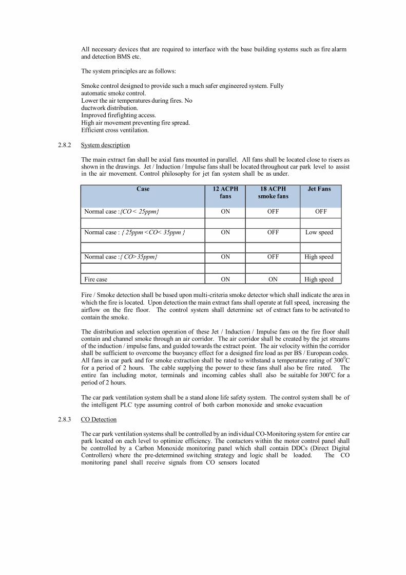
All necessary devices that are required to interface with the base building systems such as fire alarm and detection BMS etc.
The system principles are as follows:
Smoke control designed to provide such a much safer engineered system. Fully automatic smoke control. Lower the air temperatures during fires. No ductwork distribution. Improved firefighting access. High air movement preventing fire spread. Efficient cross ventilation.
2.8.2 System description
The main extract fan shall be axial fans mounted in parallel. All fans shall be located close to risers as shown in the drawings. Jet / Induction / Impulse fans shall be located throughout car park level to assist in the air movement. Control philosophy for jet fan system shall be as under.
Case 12 ACPH
fans 18 ACPH
smoke fans Jet Fans
Normal case :{CO < 25ppm} ON OFF OFF
Normal case : { 25ppm <CO< 35ppm } ON OFF Low speed
Normal case :{ CO>35ppm} ON OFF High speed
Fire case ON ON High speed
Fire / Smoke detection shall be based upon multi-criteria smoke detector which shall indicate the area in which the fire is located. Upon detection the main extract fans shall operate at full speed, increasing the airflow on the fire floor. The control system shall determine set of extract fans to be activated to contain the smoke.
The distribution and selection operation of these Jet / Induction / Impulse fans on the fire floor shall contain and channel smoke through an air corridor. The air corridor shall be created by the jet streams of the induction / impulse fans, and guided towards the extract point. The air velocity within the corridor shall be sufficient to overcome the buoyancy effect for a designed fire load as per BS / European codes. All fans in car park and for smoke extraction shall be rated to withstand a temperature rating of 3000C for a period of 2 hours. The cable supplying the power to these fans shall also be fire rated. The entire fan including motor, terminals and incoming cables shall also be suitable for 300oC for a period of 2 hours.
The car park ventilation system shall be a stand alone life safety system. The control system shall be of the intelligent PLC type assuming control of both carbon monoxide and smoke evacuation
2.8.3 CO Detection
The car park ventilation systems shall be controlled by an individual CO-Monitoring system for entire car park located on each level to optimize efficiency. The contactors within the motor control panel shall be controlled by a Carbon Monoxide monitoring panel which shall contain DDCs (Direct Digital Controllers) where the pre-determined switching strategy and logic shall be loaded. The CO monitoring panel shall receive signals from CO sensors located

throughout the levels at a spacing of no. more than 1 per 350 m2. The 24Vac power supply for the CO sensors shall be mounted in the same panel. The power supply shall be looped across the CO sensors. The proposed CO sensor shall provide a 0-10 VDC signal for measuring the CO level in the car park area.
CO monitoring devices shall be mounted remotely throughout the car parks. The devices shall be mounted in accordance with the manufacturers guidelines but no greater than 1.5 m above FFL.
The contractor should refer to the specific requirements of the sensor supplier for quantities of CO-detectors.
2.8.4. CO Sensor
The sensor shall be suitable for wall mount & capable of following features:
Digital display of the CO level : 0 to 200 ppm Analog output : 4 to 20 mA / 0-10VDC Low Voltage operation : 24 VAC / VDC Wall Mount Configurations Test Switch : Provides mode for system self test. Automatic Calibration (Field Calibration Kit) Over-range indication. Start-up mode : steps display and output through test ranges. Solid – Stat sensor : Life expectancy of 7 to 10 years. Multiple sensors with one power supply.
Carbon monoxide sensor shall comprise of a carbon monoxide meter and a 4-20mA/ 0-10 VDC transmitter an all electronic system that utilizes a microprocessor to measure carbon monoxide (CO) levels, calculate various calibration factors and analog output. The sensor shall averages samples over a time period and updates the output every 2 ½ minutes. The sensor shall be intended to be used in enclosed parking garages, where it provides CO data to building automation computers or controllers. A UL knockout box shall house the sensor and provide an easy-to-mount, study housing for the system.
Sensors shall be mounted on walls or columns about 1600 mm above the floor. Sensors shall
be evenly spaced and not put in corners, or directly in front of air inlets. Each sensor must have a cable directly to the control panel.
In addition to above CO-sensor shall comply with following :
Power 24 VAC / VDC @ 150 mA Colour Gray Measurement range 0 to 200 ppm of CO (4-20 mA) Electrical class General Purpose, non-hazardous. Operating temperature range 0 deg. To 125 deg.F (-18 deg. To 52 deg.C)
2.8.5 Fire / smoke detection
The car park ventilation system shall be designed based on 30 ACPH in fire mode.
The car park ventilation system shall interface with the fire alarm control panel to receive signals from the detectors.
The Contractor shall be responsible for the full integration of the fire alarm and car park ventilation control systems.
2.8.6 Control Panels
The manufacturers engineered solution shall allow for a stand alone intelligent PLC control system for both CO monitoring and smoke control. Each car park shall have individual PLC Control Panel. The PLC control system shall be seperate for each level of entire car parking and shall control all exhaust & jet fans located on each level. The broad logic shall be as follows:
PLC based Logic panel shall be provided to receive signals from the Carbon Monoxide Detector panel and the Fire Control Panel which will contain DDC (Direct Digital Controller) to give command to Jet and Exhaust fans for their operation on the basis of the logic provided to the PLC panel as shown below:-
Condition 1 Under normal ventilation conditions, when CO PPM level is below 25PPM, Jet fans will be OFF, 12 ACPH fans will be ON and 18 ACPH fire fans will be OFF.
Condition 2:. When CO level increases beyond 25PPM but less than 35PPM, jet fans will start at low speed, 12 ACPH fans would continue to be ON and 18 ACPH fire fans will continue to be OFF.
Condition 3:. When CO level goes beyond 35PPM, Jet fans will run on high speed, 12 ACPH fans would continue to be ON and 18 ACPH fire fans will continue to be OFF.
Condition 4:. In event that smoke is detected in the car park, Jet fans will run at high speed and both 12 ACPH and 18 ACPH fans will be ON.
2.9 PERFORMANCE DATA
All fans shall be selected for the lowest operating noise level. Capacity ratings, power consumption, with operating points clearly indicated, shall be submitted and verified at the time of testing and commissioning of the installation.
2.10 TESTING
Capacity of all fans shall be measured by an anemometer. Measured air flow capacities shall conform to the specified capacities and quoted ratings. Power consumption shall be computed from measurements of incoming voltage and input current.

3. PIPING
3.1 SCOPE
The scope of this section comprises the supply and laying of pipes, pipe fittings and valves, testing and balancing of all water and refrigerant piping required for the complete installation as shown on the Drawings. All piping inclusive of fittings and valves shall follow the applicable Indian Standards. All welders used for piping erection shall be well qualified (certificate should be submitted to Project Manager for approval) and shall have minimum 8 to 10 years’ experience.
3.2 PIPE SIZES
Pipe sizes shall be as required for the individual fluid flows. Various pipe sizes have been indicated on the Drawings, these are for Contractor’s guidance only and shall not relieve contractor of responsibility for providing smooth noiseless balanced circulation of fluids.
3.3 CHILLED, HOT AND CONDENSING WATER PIPING
Following material shall be used for pipes and fittings.
Pipes Nominal size (mm) Material Specification <150 IS 1239 Part-1 200 and above IS 3589 Gr. FE 410 (8mm thick) Fittings Nominal size (mm) Material Specification <40 Socket welded, ASTM A105 construction as per
ANSI B16.11 50-150 Butt welded, ASTM A234 Gr. WPB as per ANSI
B16.11 >200 Site fabricated from IS 3589 Gr. FE 410 (8mm thick) Flanges Nominal size (mm) Material Specification < 150 IS 2062 Gr.A construction as per ANSI B16.5 > 200 IS 2062 Gr.A, construction as per ANSI B16.5
All jointing in the pipe system shall generally be by welding, unless otherwise mentioned, or directed at site. All welding shall be done by qualified welders and shall strictly conform to BIS Code of practice for manual metal arc, welding of Mild Steel.
b. All welded joints (except pipe welded end-to-end) shall be made by use of one-piece welding
flanges, caps, nozzles, elbows, branch outlets and tees of approved make. Cut samples shall be submitted for approval, if directed. All such fittings etc., shall be of a type which maintain full wall-thickness at all points, simple radius and fillets, and proper bevels or shoulders at ends. All job welding shall be done by the electric arc welding process in accordance with the following:
� All joints shall have 45 degree bevel type, pipe mill-bevelled or machine- bevelled
by the contractor.
� All scale and oxide shall be removed with hammer, chisel or file and bevel left smooth and clean.
� Pipe lengths shall line up straight with abutting pipe ends concentric. � Both conductors from the welding machine shall be extended to locations at which
welding work is being done. The leads from welding machine to location of welding work shall be held together with tape or other approved means so as to prevent induced current in structural steel, in piping or in other metals within the building. The ground lead shall be connected to length of pipe through joints in pipe, structural steel of building or steel pipe supports.

c. All pipes and their steel supports shall be thoroughly cleaned and given one primary coat of red oxide paint before being installed. For vibration isolators premoulded polyurethane pipe sections of 160 Kg/m3 density with adhesive shall be fixed between pipe and MS support. 10 mm thick MS ‘U’ clamp with resistoflex shall be fixed on the pipe so that the pipe is kept in position. All welded piping shall be subject to the approval at site. All supports exposed to ambient shall be painted with two coats of epoxy. For condenser water piping running exposed to ambient, 2 coats of Epoxy paint shall be applied over piping . Then One coat of zinc chromate primer shall be applied. Finally colour painting shall be provided as per specification in identification of services.
d. Fittings shall be malleable casting of pressure rating suitable for the piping system.
Fittings used on welded piping shall be of the weldable type. These shall form part of piping and are not separately identified in Schedule of Quantities.
e. Tee-off connections shall be through equal or reducing tees, otherwise ferrules welded to
the main pipe shall be used. Drilling and tapping of the walls of the main pipe shall not be resorted to.
f. Ball and butterfly valves conforming to the following specifications shall be provided
as shown on Drawings :
------------------------------------------------------------------------------------------------------- Size Construction Ends Type ------------------------------------------------------------------------------------------------------- 15 to 40 mm Forged Brass Screwed Ball
50 mm and over Body Cast iron, Wafer Butterfly
Type and requirements shall be as indicated in Schedule of Quantities. Valves shall have non-rising spindles unless specified otherwise and shall be suitable for PN 16 (unless specified otherwise in SOQ) rating. Butterfly valve should be of wafer type long neck construction single stem design with centre lugs to ensure proper alignment of pipe flanges. Mount valve onto flanges only after flanges have been welded to pipes using a tool piece and cooled down to room temperature to prevent damage to resilient seat. The rubber liner should be fully supported by the valve flanges. Appropriate dimensions and thickness of Flanges and Bolts, as per the Flange Tables ANSI B16.5 should be used. The flanges should be properly aligned with each other so that bolts are exactly perpendicular to the flanges. Evenly tighten the flange bolts to secure the valves. Counter flanges with nut-bolts and gaskets shall be provided by valve manufacturer.
g. Butterfly valves shall perform the function of isolating valves and shall be suitable for PN 16
(unless specified otherwise in SOQ) rating. Butterfly valves shall have Epoxy Coated cast iron body with Integrally moulded EPDM liner of replaceable type. The liner shall be integrally moulded on hard backup ring and shall be suitable for PN 16 (unless specified otherwise in SOQ) rating. All butterfly valves shall be provided with locking devices. Valves 250 mm and above dia shall be gear driven.
h. Automatic balancing valves shall automatically control flow rates within ± 5% accuracy. Valve control mechanism shall consist of a stainless steel cartridge with a ported cup and coil / helical spring to avoid corrosion. Four operating ranges shall be available with the minimum range requiring less than 14 kPa to actuate the mechanism. Manufacturer shall provide independent laboratory tests verifying assurance of performance.
i. Balancing cum control valves shall be sized based on flow rates and pressure drops across
cooling coil.

j. Manual double regulating balancing valves shall be provided at chiller, condenser, various tapp-offs and each AHU outlet line as indicated in Schedule of Quantities. These valves shall have built-in pressure-drop measuring facility to compute flow rate across the valve. The test cocks shall be long enough to protrude out of pipe insulation. To enable accurate and practical operation, measurement of flow and differential pressure shall be made with a computerized balancing instrument which shall enable the operator to read the flow directly without the use of diagrams or tables. In addition to measuring flow rate, differential pressure and temperature, computerized balancing instrument shall have a computer programme to provide the following functions:
i. To balance the HVAC installation and calculate the necessary valve settings, based
on system measurements.
ii. To store the results of balancing.
iii. To log measured values from a valve (differential pressure, flowrate or temperature).
iv. To printout saved data in computerised measurement protocol (CMP)
consisting of : - Name and size of Balancing Valve (BV) - Presetting position of BV - �P at BV - Flow at BV - Design Flow
k. The supply of flanges shall form part of piping (not separately identified in Schedule
of Quantities) and shall also include supply of bolts, washers, nuts and suitable asbestos fibre / rubber insertion gaskets (minimum 3 mm thick). Flanges shall be as per ANSI B16.5.
l. All ball valves and ball valves with Y strainer shall be brass forged body construction with
chrome plated brass ball and handle of stainless steel constructions. These are separately identified in Schedule of Quantities.
m. Non return valves shall be dual plate check valve provided as shown on the Drawings,
and identified in Schedule of Quantities conforming to relevant Codes and in accordance with the following Specifications :
------------------------------------------------------------------------------------------------------ Size Construction Ends ------------------------------------------------------------------------------------------------------
40 to 300 mm Body: Grey Cast iron Flanged (Epoxy Coated), CI IS 210 Gr. FG 260 Plates: CF-8 (SS-304), Hinge/Stop Pin: SS-410 Spring(s): SS-316. Seal: EPDM
350 mm to 500 mm Body: Grey Cast iron Flanged (Epoxy Coated), CI IS 210 Gr. FG 260 Plates: SS-409. Hinge/Stop Pin: SS-410
Spring(s): SS-316.
Seal: EPDM
The bearing shall be PTFE material. Valves shall be PN 16 (unless specified otherwise in SOQ) rating.
n. Strainers shall be ‘Y’ type or Pot Strainer suitable for PN 16 (unless specified otherwise
in SOQ) rating as shown on drawings and included in SOQ. ‘Y’ Strainer shall be fabricated out of MS ‘C’ class pipe two sizes higher than that of Strainer pipe size. Flanges as per ANSI B16.5 shall be provided at inlet and outlet connectors. The body shall be hot dip galvanized. Permanent magnet shall be provided in the body of the Strainer to arrest MS particles. Filter element shall be of non magnetic 20 gage SS sheet with 3 mm perforation. Cartridge having five different type of filters made out of SS 304 with different mesh sizes shall be provided. These will be replaced so as to get good quality of water in system during commissioning. Strainers shall be provided at inlet of each Air Handling Unit and Pump as shown in drawings and included in SOQ.
Pot Strainers body shall be fabricated out of MS plate IS 2062. Thickness of sheet shall be as per size of the strainer chamfered pipes with flanges shall be provided at inlet /outlet connections of the strainer. The tangential entry of water shall create a centrifugal action and due to velocity shall separate sediments and deposit on the inner surface of Filter Element and at bottom of the Strainer. Butterfly valves shall be provided at inlet / outlet connections as shown in drawing and included in BOQ. The strainer body shall have two separate chambers properly sealed to avoid mixing of filtered and unfiltered water. A powerful magnet shall be provided in the body to arrest MS particles. Filter element of Pot Strainer shall be of non magnetic 18 gage SS sheet properly reinforced to avoid damage of the element. A cone with sufficiently large drain pipe with butterfly valve shall be provided at the bottom chamber to flush- out foreign particles. This arrangement shall avoid frequent opening of Pot Strainer for cleaning of filter element. Gage connection shall be provided at inlet and outlet connection.
Pot strainers shall be provided with automatic backwash system if called for in SOQ. This shall be with heavy duty reduction gear motor provided at top of upper lid. During backwash, motorised drain valve shall be opened along with vent cock. Power supply cabling with tray shall be included in cost of pot strainer. Entire operation shall be through BAS.
A set of MS flanges with tongue and groove arrangement and neoprene rubber gasket shall be provided on the top cover and Pot Strainer flange with sufficient bolts and nuts to make the joint water

light. Bearing loaded top cover lifting and swinging arrangement shall be provided. The Pot strainer body shall be properly de-rusted and epoxy coated from inside and outside.
Size of various Pot Strainer, Filter Element and Thickness of MS sheet shall be as under:
Pipe size (mm)
Pot Dia
(mm)
Pot HT
(mm)
Element Dia
(mm)
Element HT
(mm)
MS Plate Thickness
(mm) 50 300 400 200 240 6 80 350 450 250 250 6
100 450 500 300 280 6 125 500 600 330 340 8 150 540 700 360 390 8 200 610 815 400 470 8 250 800 955 550 510 8 300 1000 1105 750 580 8 350 1190 1300 895 678 12 400 1350 1500 1020 785 12 450 1518 1700 1060 890 12 500 1690 1800 1100 900 12 600 2000 2200 1500 1160 12
Each Port strainer shall be provided with a Manufacturer Test Certificate.
o. All chilled water piping & fittings, chilled water pumps, expansion tank and Air separator
shall be pressure tested, painted and then insulated as described under the section “Insulation”.
p. Grooved coupling : Grooved coupling shall have 3 main parts viz. Housing, Gasket and bolting arrangement. Housing shall be made out of ASTM-A 536 Grade 65-45- 12. The housing key shall engage into the grooves around the full pipe circumference, securing the pipe ends together with positive grip. Housing shall be designed to provide optimum combination of pressure, stress relief and end load conditions while maintaining reasonable weight. Gasket shall be of high sealing efficiency and shall be able to withstand upto (-) 0.35 Bar pressure. Bolt shall confirm to ASTM A183, while nut shall confirm to ASTM A194. Nut-bolt shall be electro- galvanized.
3.4 PRESSURE INDEPENDENT BALANCING CUM CONTROL VALVES
Each Air Handling Unit / Fan Coil Unit shall be provided with 2Way Pressure Independent Balancing Cum Control Valve Integrated in a single Body with Globe Type in Construction as indicated in SOQ.
Control – Valve should be equipped with electronic modulating actuator which can accept either 4(0)-20 mA / 2(0)-10 V DC signals. Operating voltage for actuator shall be 24V AC. Delta p controller should ensure 100% valve authority at all loads (part load Actuator shall be able to work against maximum closing pressure of 6 Bar at full load). With feedback signal to Control system. 230/24V transformer shall be included.
Balancing – Each Valve should have steeples adjustable maximum flow limitation as per the designed flow rate of coils. Balancing should be done only in Valve not in actuator so that at any given condition of failure, balancing is not lost and easily accessible.
All Valve actuator shall be microprocessor based with self calibrating feature. Valve should be of linear control characteristics with stepless characteristics.
VALVE SPECIFICATIONS

Description For 15 to 32 mm For 40 to 150 mm
Diff Pressure (P1-P3) 16 To 400 kPa 35 To 600 kPa
Media Temperature +1 ° to 110 °C, -10 ° to 120 °C, Body Material Brass Grey iron/Ductile iron
Test Ports Needle measuring nipple Needle measuring nipple
Shut off Leakage Max. 0.05% of Kvs Max. 0.05% of Kvs
Stem Seals EPDM EPDM
Cartridge Stainless Steel Stainless Steel
Maximum Close Off Pr Minimum Should be 400 kPaD, 600 kPaD
Pressure rating PN16 or above PN16 or above
ACTUATOR SPECIFICATIONS FOR ALL SIZES
Supply Voltage : 24V AC (230/24 Transformer shall be included) Power Consumption : 10V AC Max. Frequency : 50 HZ Control Input : 2-10V DC, 4-20mA, 3-point Selection. Position Output : 2-10V DC 4-20mA Body Housing Insulation : Non Corrosive - IP 40 or above
Valve Body and Characteristics:-
1. Pressure Controller Device should maintain the Pressure, irrespective of fluctuations in the
system with the help of a self adjusting diaphragm.
2. Control valve shall accurately control the flow, with help of Modulating Actuator
3. All Valve Sizes should have Testing Ports for verifying the flow with respect to the Differential Pressure.
Valve Actuator and Housing:-
1. Control/Dip Switch Setting should be easy to access for doing the balancing at site. 2. The valve should be mounted with the actuator above the valve to prevent condensation
water leaking into the actuator.
Valve Flow Balancing :
1. Balancing & Control: Balancing should be accomplished by the Diaphragm and Control should be taken care by Actuator receiving signals from Room Thermostats or BMS.
2. Manual Override facility shall be provided to either open or close the valve.
3. Flow Setting Balancing (Commissioning) for the Valves should be simple and not require
measuring devices.
4. Proper operation of the valve should not be dependent on additional operations like de- airing of the valve or flushing procedures
3.5 GROOVED PIPE JOINTING SYSTEM
a. References:
1. American Society for Testing Materials (ASTM)

a. ASTM A-53 – Pipe, Steel, Black and Hot-Dipped Zinc Coated, Welded and Seamless.
b. ASTM A-183 – Carbon Steel Track Bolts and Nuts c. ASTM A-234 – Standard Specification For Piping Fittings or Wrought
Carbon Steel and Alloy Steel. d. ASTM A-449 – Quenched and Tempered Steel Bolts and Studs e. ASTM A-536 – Ductile Iron Castings f. ASTM F-1476 - Standard Specification for Performance of Gasketed
Mechanical Couplings for Use in Piping Applications
2. American Society of Mechanical Engineers a. ASME B16.9 – Factory Made Wrought Butt Welded Fittings b. ASME B31.1 – Chemical Plant and Petroleum Refining Piping c. ASME B31.9 – Building Services Piping
3. American Water Works Association
a. AWWA C-606 – Grooved and Shouldered Joints
b. Quality Assurance
1. All grooved components (including couplings, fittings and accessories) to be supplied by one manufacturer. Grooving tools shall be of the same manufacturer as the grooved components.
c. Grooved Mechanical Couplings for Joining Carbon Steel Pipe
1. Grooved Mechanical Couplings: Manufactured in two segments of cast ductile
iron, conforming to ASTM A-536, Grade 65-45-12. Gaskets shall be pressure-responsive synthetic rubber, grade to suit the intended service, conforming to ASTM D-2000. (Gaskets used for potable water applications shall be UL classified in accordance with ANSI/NSF-61 for potable water service.) Mechanical Coupling bolts shall be zinc plated (ASTM B-633) heat treated carbon steel track head conforming to ASTM A-449 and ASTM A- 183, minimum tensile strength 110,000 psi (758450 kPa) as provided standard coupling.
a. Rigid Type: Coupling housings with offsetting, angle-pattern bolt pads shall be
used to provide system rigidity and support and hanging in accordance with ANSI B31.1, B31.9, and NFPA 13.
b. Flexible Type: Use in locations where vibration attenuation and stress relief are
required. Flexible couplings may be used in lieu of flexible connectors at equipment connections. Three Couplings shall be placed in close proximity to the vibration source.
2. Flange Adapters: For use with grooved end pipe and fittings.
3. Grooved couplings shall meet the requirements of ASTM F-1476.
5. Gasket: Synthetic rubber, wide width, conforming to steel pipe outside diameter and coupling
housing, manufactured of elastomers as designated in ASTM D-2000.
d. Grooved End Fittings: Fittings shall be cast of ductile iron conforming to ASTM A-536, Grade 65-45-12, forged steel conforming to ASTM A-234, Grade WPB 0.375" (9.53 mm) wall, or fabricated from Std. Wt. Carbon Steel pipe conforming to ASTM A-53, Type F, E or S, Grade B. Fittings provided with an alkyd enamel finish or hot dip galvanized to ASTM A-153. Zinc electroplated fittings and couplings conform to ASTM B633.
1. Grooved Hole-Cut Branch Outlets:

a. Bolted Branch Outlet: Branch reductions on 2"(DN50) through 8"(DN200) header piping. Bolted branch outlets shall be manufactured from ductile iron conforming to ASTM A-536, Grade 65-45-12, with synthetic rubber gasket, and heat treated carbon steel zinc plated bolts and nuts conforming to physical properties of ASTM A-183.
b. Strapless Outlet: 1/2"(DN15) or 3/4"(DN20) NPT outlet on 4" (DN100)
and larger header sizes rated for 300 PSI (2065 kPa).
c. Strapless Thermometer Outlet: To accommodate industrial glass bulb thermometers with standard 1-1/4"-18 NEF 2B extra fine thread and 6" (152mm) nominal bulb length on 4" (DN100) and larger header sizes rated for 300 PSI (2065 kPa).
3.6 COLD WATER AND DRAIN PIPING
a. All pipes to be used for cold water (makeup), drain, condensate drain and fittings shall be
GI / U-PVC as indicated in SOQ.
b. All jointing in the pipe system shall be by screwed joints and/or by screwed flanges using 3 mm 3 ply rubber insertion gaskets. Pipe threads and flanges shall be as per relevant BIS Codes.
c. All pipes supports shall be mild steel, thoroughly cleaned and given one primary coat of
red oxide paint before being installed.
d. Fittings shall be galvanized steel `medium class’ malleable casting of pressure rating suitable for the piping system. Supply of flanges shall include bolts, nuts, gaskets as required. Sufficient number of flanges and unions shall be provided for future cleaning and servicing of piping. Tee-off connection shall be through equal or reducing tees. All equipment and valve connections, or connections to any other mating pipes shall be through flanges required for the mating connections. Fittings & flanges shall form part of piping and are not separately identified in Schedule of Quantities.
e. Gate valves, globe valves, check valves and strainers shall be similar to those specified
for chilled, condensing and hot water piping.
f. For proper drainage of AHU Condensate, ‘U’ trap shall be provided in the drain piping.
g. All condensate drain piping shall be insulated and painted as per the section “Insulation” as indicated in Schedule of Quantities.

3.7 REFRIGERANT PIPING
a. All refrigerant pipes and fittings shall be hard drawn copper tubes and wrought copper / brass fittings suitable for connection with silver solder / phos-copper.
b. All joints in copper piping shall be sweat joints using low temperature brazing and / or silver
solder. Before jointing any copper pipe or fittings, its interiors shall be thoroughly cleaned by passing a clean cloth via wire or cable through its entire length. The piping shall be continuously kept clean of dirt etc. while constructing the joints. Subsequently, it shall be thoroughly blown out using carbon dioxide / nitrogen.
c. Refrigerant lines shall be sized to limit pressure drop between the evaporator and condensing
unit to less than 0.2 kg per sq.cm.
d. Sight glass with moisture indicator and removable type combination dryer cum filter with MS housing and brass wire mesh / punched brass sheet shall be installed in liquid line of the refrigeration system incorporating a three valve by pass. After ninety days of operation, liquid line drier cartridges shall be replaced.
e. Heat exchanger shall be MS heavy duty pipe in pipe type and without any joint in the inner pipe.
f. Horizontal suction line shall be pitched towards the compressor and no reducers shall be provided
for proper oil return.
g. After the refrigerant piping installation has been completed, the refrigerant piping system shall be pressure tested using Freon mixed with nitrogen / carbondioxide at a pressure of 20 kg per sq. cm (high side) and 10 kg per sq. cm (low side). Pressure shall be maintained in the system for a minimum of 12 hours. The system shall then be evacuated to a minimum vacuum of 70 cm of mercury and held for 24 hours. Vacuum shall be checked with a vacuum gage.
h. All refrigeration piping shall be installed strictly as per the instructions and
recommendations of air conditioning equipment manufacturer.
3.8 PIPING INSTALLATION
a. Design Drawings indicate schematically the size and location of pipes. The Contractor, on award of the work, shall prepare detailed shop drawings, showing the cross-section, longitudinal sections, details of fittings, locations of isolating and control valves, drain and air valves, and all pipe supports. He must keep in view the specific openings in the building through which pipes are designed to pass.
Pipe shall be cut only with hack saw blades and welding rods shall not be used for this purpose. All the pipes shall be cleaned and applied with one coat of Zinc chromate primer.
b. Piping shall be properly supported on, or suspended from, stands, clamps, hangers as specified
and as required. The Contractor shall adequately design all the brackets, saddles, anchors, clamps and hangers and be responsible for their structural sufficiency.
All pipes in HVAC plant room shall be supported with pipes and channels from floor only with necessary PUF pipe supports and resistoflex sheet.
c. Pipe supports shall be of steel, adjustable for height and Zinc chromate primer coated and finish coated black. Where pipe and clamps are of dissimilar materials, a gasket shall be provided in between. Spacing of pipe supports shall not exceed the following :

Pipe size Spacing between supports Rod Size
Upto 12 mm 1.5 Meter 10 mm
15 to 25 mm 2.0 meter 10 mm
30 to 150 mm 2.0 meter 10 mm
Over 150 mm 2.5 meter 12.5 mm
d. Vertical pipes passing through floors shall be plumb and parallel to wall. Pipes shall be supported on alternate floor. MS cleats shall be welded on pipes and rest on MS channel placed on the floor with 15 mm thick resistoflex pads between the cleat and channel. U clamps with resistoflex sheet shall be provided to keep the pipe in position.
e. Bull heading in water/refrigerant piping shall be avoided.
f. Pipe sleeves atleast 3 mm thick, 50 mm / 100 mm larger in diameter than condenser
/ chilled water pipes respectively shall be provided wherever pipes pass through retaining wall and slab. Annular space shall be filled with fibreglass and finished with retainer rings welded on the ends of the sleeve.
g. Wherever pipes pass through the brick or masonry / slab openings, the gaps shall be sealed with
fire sealant such as fire barrier caulks.
h. Insulated piping shall be supported in such a manner as not to put undue pressure on the insulation. 20 gage metal sheet shall be provided between the insulation and the clamp, saddle or roller, extending atleast 15 cm on both sides of the clamp, saddles or roller.
j. All piping work shall be carried out in a workmen like manner, causing minimum disturbance
to the existing services, buildings and structure. The entire piping work shall be organized, in consultation with other agencies work, so that laying of pipes, supports, and pressure testing for each area shall be carried out in one stretch.
k. Cut-outs in the floor slabs for installing the various pipes are indicated in the Drawings.
Contractor shall carefully examine the cut-outs provided and clearly point out where the cut-outs shown in the Drawings do not meet with the requirements.
l. The Contractor shall make sure that the clamps, brackets, clamp saddles and hangers
provided for pipe supports are adequate. Piping layout shall take due care for expansion and contraction in pipes and include expansion joints where required.
m. All pipes shall be accurately cut to the required size in accordance with relevant BIS Codes,
edges bevelled and burrs removed before laying. Open ends of the piping shall be closed as the pipe is installed to avoid entrance of foreign matter. Where reducers are to be made in horizontal runs, eccentric reducers shall be used for the piping to drain freely. In other locations, concentric reducers may be used.
n. Flanged inspection pieces 1.5 meters long, with bolted flanges on both ends, shall be provided
no more than 30 meters centres, or where-ever shown in Approved-for- Construction shop drawings, to facilitate future cleaning of all welded pipes.
o. All buried pipes shall be cleaned and coated with zinc chromate primer and bitumen
paint, and placed on concrete blocks with PUF saddles dipped in bitumen

at every 2 meters and wrapped with three layers of fibre glass tissue, each layer laid in bitumen.
q. Auto purge valves shall be provided at all highest points in the piping system for venting
air. Air valves shall be 15 mm pipe size with screwed joints.
Discharge from the air valves shall be piped through an equal sized mild steel or galvanized steel pipe to the nearest drain or sump. These pipes shall be pitched towards drain points.
r. Whenever services like piping, ducting and cabling are passing through floor slab, shaft or
fire zone wall, opening around services shall be closed with fire retardant material. Contractor shall use either fire compound or fire barriers for this purpose. Fire compound shall be in form of powder and shall be mixed with water in proportion suggested by OEM. Mixed compound shall be poured in shuttering and grid of 30 x 30 x 1.2mm angles placed as 150mm center to center. Minimum thickness of pour shall be 100mm and shall be for fire integrity of 120minutes. Angles shall be securely welded to building re-bars ( if left during construction) or fastened to concrete floor.
Fire barrier shall be in form of high density rock wool slabs with surface treated for fire retardation. Minimum thickness of the slab shall be 100mm and shall be for fire integrity of 120 minutes. Slabs shall be tightly friction fitted in the shaft to cover all open spaces.
Measurement will be on area basis of applied projected area (in m2 / ft2).
3.9 PRE-INSULATED PIPES
Pre insulated pipes, as called for in schedule of quantities shall be sourced from the factory in length of minimum 6m. Metered dose of Polyurethane foam shall be injected in annular space between pipe OD and outer jacket to achieve average density of 36 Kg/m3. After expanding, homogenous foam shall be formed between the cavity with no air gaps. Suitability of temperature range shall be from (-) 200C to 1200C.
Outer jacket shall be of AL as indicated in schedule of quantities.
3.10 PRE-INSULATED BURRIED PIPES
Pre-insulated buried chilled water MS ERW heavy class piping confirming to IS:1239/IS:3589 with necessary clamps, supports and fittings such as bends, tees, reducers etc. duly insulated with providing and applying CFC free Polyurethane Foam insulation Cast-in-Situ of density 45+15% kg/m3 and cladded with minimum 5mm thick HDPE cladding complete as per specifications. Thermal conductivity of Polyurethane Foam shall be 0.023 W/mK at 100C mean temperature and shall conform to IS :13205, IS: 12436.

3.11 PRESSURE GAGES AND THERMOMETERS
a. Pressure gages shall be stainless steel and shall be provided at suction and at discharge of each pump, at chilled water supply and return at each air handling unit, at each chillers and condenser, and as shown on the Drawings and included in Schedule of Quantities. Care shall be taken to protect pressure gages during testing.
Pressure gage sockets on insulated pipes and accessories shall be extended upto insulation to avoid damage of insulation for replacement of gages. Pressure gauges shall be provided with ball valve and syphon tube.
b. Thermometers shall be stainless steel and shall be provided at chilled water supply and return
at each air handling unit, at each chiller and condenser, and as shown on Drawings and included in Schedule of Quantities.
c. Thermometers on CHW lines shall be with long stem. Thermometer socket shall be extended
upto insulation thickness so that the thermometer shall be removable without damaging the insulation.
3.12 STEEL WIRE ROPE HANGERS & SUPPORTS:
Wire Hangers shall be used to suspend all static HVAC & Mechanical services.
Wire Hangers should consist of a pre-formed wire rope sling with a range of end fixings to fit various substrates and service fixings, these include a ferruled loop, permanently fixed threaded M6 (or M8, M10) stud, permanently fixed nipple end with toggle, at one end or hook or eyelet, cladding hook, barrel, wedge anchor, eyebolt anchor or any other end fixture type or size as per manufacturers recommendation and design. The end fixings and the wire must be of the same manufacturer with several options available. The system should be secured and tensioned with a Hanger self-locking grip (double channel lock) at the other end. Once the grip is locked for safety purpose unlocking should only be done by using a separate setting key and should not be an integral part of the self-locking grip. Only wire and/or supports supplied and/or approved, shall be used with the system.
a. Wire Hangers should have been independently tested by Lloyds Register. APAVE, TUV, UL
NEBS, CSA, Chiltern International fire, ADCAS, Intertek, ECA, and SMACNA, approved by ULC and CSA and comply with the requirements of DW/144 and BSRIA – wire Rope Suspension systems. Wire rope should be manufactured to BSEN 12385: 2002
b. The contractor shall select the correct specification of wire hanger to use for supporting
each particular service from Table 1 below. Each size is designated with a maximum safe working load limit (which incorporates a 5:1 safety factor).
The correct specification of wire hanger required is determined using the following formula.
Weight per meter of object suspended (kg) X distance between suspension points (m) = weight loading per Hanger suspension point (kg).
Where the installed wire rope is not vertical then the working load limit shall be reduced in accordance with the recommendations give in the manufacturer’s handbook.
The contractor shall select the correct length of wire rope required to support the service. Lengths from 1-10m lengths. Specials can be made, check with manufacturer. No in–line joints should be made in the rope.
Table. 1

Wire (Gripple) Hanger Safe Working Loads Hange rsize minimum breaking load of
Wire Rope (kg/lbs) working load limit
(kg/lbs) No. 1 80kg/176 lbs 0-10 kg / 0-22 lbs
No. 2 260kg/572 lbs 10-45 kg / 23-100 lbs
No. 3 580kg/1276 lbs 45-90 kg / 101-200 lbs
No. 4 1500kg/3300 lbs 90-225 kg / 210-495 lbs
No. 5 2160kg/4752 lbs 225-325 kg / 496-715 lbs
No. 6 2500kg/5500 lbs 325-500 kg / 715-1100 lbs
The standard range of Hanger Kits should contain galvanized high tensile steel wire rope or stainless steel wire rope as per the application, the minimum specification is as above and should be manufactured to BS 302 (1987), BSEN12385. Comply with manufacturer's load ratings and recommended installation procedures.
3.12.1 Mechanical Supports – Gripple Hanger Supports are suitable for: Water Pipes, Drainage
Pipes, Gas Pipes, Refrigeration Pipes, Condensation Water Pipes.
3.12.2 Piping Supports: Rigid supports may be used in conjunction with Gripple hangers to assist with alignment of services as per the Schedule. These can be at 30m intervals or so depending on the run of the service. Rigid support must also be used in conjunction with Gripple hangers with pipe work at each change of direction or connection or as per approved drawings. For insulated pipe, provide protective sleeve to protect the entire circumference of the pipe insulation. Stainless Steel Supports should be available for food, chemical and High Corrosion areas near coastlines.
3.12.3 Any other Gripple solution can be used based on manufacturer’s recommendation on site conditions
after prior approval. Support piping in accordance with Schedule I, II & III specified below:
3.12.4 For further technical information, refer to manufacturers catalogue and installation guide. Comply with manufacturer's load ratings and recommended installation procedures. All supporting system to be provided by same manufacturer.
SCHEDULE – I : BARE PIPE / PIPE INSULATED WITH NITRILE RUBBER
Pipe Size
(mm dia)
Wt. of Pipe + Water +
insulation (kg / mt)
Spacing between pipe supports (mt)
Total Wt of Pipe between two supports
(kg)
Gripple Hanger size
12-40 7 2 14 No. 2
50-65 15.22 2 30 No. 2
80 34.73 2 69 No. 3
100-200 73 2 146 No. 4
250 & above Rigid supports to be used as per pipe hanger Schedule – III

SCHEDULE – II : PIPE INSULATED WITH EXPANDED POLYSTERENE & COVERED WITH SAND CEMENT PLASTER
Pipe Size
(mm dia)
Wt. of Pipe + Water +
insulation (kg / mt)
Spacing between pipe supports (mt)
Total Wt of Pipe between two supports
(kg)
Gripple Hanger size
12-40 14 2 28 No. 2
50-65 20 2 40 No. 3
80 44.67 2 89.34 No. 4
100-200 83 2 166 No. 4
250 & above Rigid supports to be used as per pipe hanger Schedule – III
Pipe Hanger Schedule III:
Rigid Supports for pipes to be used in conjunction with wire supports:
Rigid supports if required in conjunction with wire hangers shall be of steel, adjustable for height and Zinc chromate primer coated and finish coated black. Where supports and clamps are of dissimilar materials, a gasket shall be provided in between.
PIPE SIZE (mm) PIPE SUPPORT
UP TO 50 Ø 40×40×6 M.S ANGLE 80Ø TO 100Ø 50×50×6 M.S ANGLE
PIPE SIZE (mm) HORIZONTAL SUPPORT VERTICAL SUPPORT
125Ø TO 200Ø 75×40 M.S CHANNEL 50×50×6 M.S ANGLE 250Ø TO 300Ø 100×50 M.S CHANNEL 75×40 M.S CHANNEL 300Ø TO 400Ø 150×75 M.S CHANNEL 100×50 M.S CHANNEL 450Ø TO 600Ø 200×75 M.S CHANNEL 200×75 M.S CHANNEL
3.13 TESTING
a. During construction , the contractor shall properly cap all lines, so as to prevent the entrance
of sand, dirt, etc. Each system of piping shall be flushed thoroughly after completion (for the purpose of removing dirt, grit, sand etc. from the piping and fittings) for as long a time as is required to thoroughly clean the system.
b. All piping shall be tested to hydrostatic test pressure of at least two times the maximum
operating pressure, but not less than 10 kg per sq. cm gage for a period of not less than 24 hours. All leaks and defects in joints revealed during the testing shall be rectified, retested and gotten approved
c. Piping repaired subsequent to the above pressure test shall be re-tested in the same manner. d. Piping may be tested in sections and such sections shall be securely capped, then
re-tested for the entire system.
e. The Contractor shall give sufficient notice to all other agencies at site, of his intention to test a section or sections of piping and all testing shall be witnessed and recorded by Owner’s site representative.
f. The contractors shall provide temporary pipe connections to initially by-pass condenser/chiller and circulate water through condenser/chilled water pipe lines for minimum 8 hours. Water should be drained out from the lowest point. The temporary lines shall be removed and blanked with dead flanges. Pot strainers and Y strainers shall be cleaned and fresh water filled in the circuits.
g. After regular flushing, as per ‘f’ above, all systems shall be chemically cleaned.
Chemical cleaning shall be carried out in 3 stages. In first stage biological cleaning shall be done to remove algae, bacteria, SRB etc which produces slimes. Second stage is pre-cleaning in which loose rust, oil, and debris are removed. Chemical addition and hold up time shall be as per chemical supply agencies recommendations. Third stage is passivation, in which chemicals will be added and passivation film will be formed over inside surfaces of piping system. Type of chemical used and quantity of the same along with detailed method statement shall be submitted by contractor for consultants’ approval before starting this activity.
Before handover Owner’s site representative shall be provided with certificate of cleaning of pipe systems, signed by the contractor.
h. After the piping has been installed, tested and run for at least three days of eight hours each,
all insulated exposed piping in plant room shall be given two finish coats, 3 mils each of approved colour, conforming to relevant BIS Codes. The direction of flow of fluid in the pipes shall be visibly marked with identifying arrows. For painting of insulated and clad pipes refer to Insulation section.
j. The Contractor shall make sure that proper noiseless circulation of fluid is achieved
through all coils and other heat exchange equipment in the system concerned. If proper circulation is not achieved due to air bound connection, the Contractor shall rectify the defective connections. He shall bear all expenses for carrying out the above rectifications including the tearing up and re-finishing of floors and walls if required.
k. The Contractor shall provide all materials, tools, equipment, instruments, services
and labour required to perform the test and to remove water resulting from cleaning and after testing.
3.14 BALANCING
a. After completion of the installation, all water system shall be adjusted and balanced to deliver the
water quantities as specified, quoted, or as directed.
b. All balancing valves, Automatic control valves and two-way diverting valves shall be set for full flow condition during balancing procedure. Each water circuit shall be adjusted thru balancing valves provided for this purpose; these shall be permanently marked after balancing is completed, so that they can be restored to their correct positions, if disturbed.
c. Complete certified balancing report shall be submitted for evaluation and approval by Owner’s
site representative. Upon approval, four copies of the balancing report shall be submitted with the as-installed drawings and completion documents.
3.15 VALVE IDENTIFICATION
Provide 30 mm dia brass valve tag, with embossed letters and number for each valve and attach the tag to valve handle by “S” hook or by suitable means. Contractor shall provide valve tag schedule and valve chart for each piping system, consisting of schematic drawing of piping layout, along with a valve list, showing and identifying each valve by number, service and location and describing its function.

The contractor shall frame under glass in the airconditioning plant room or as directed by Owner’s site representative two copies of valve chart. Two additional unmounted copies shall be supplied to the Owner’s site representative.
Tags shall correspond with the valve schedule and record drawings. In back of house areas, where ceilings are installed and the valve or valve tag is not visible, a self adhering tag with the valve number shall be installed on the wall or directly under the ceiling. For public area ceiling valves, these tags are to be installed in the service corridor, leading to the public areas.
3.16 MEASUREMENT FOR PIPING
Unless specified otherwise, measurement for piping for the project shall be on the basis of centre line measurements described herewith.
Piping sha l l be measured in units of length along the centre line of installed pipes including all pipe fittings, flanges (with gaskets, nuts, and bolts for jointing), unions, bends, elbows, tees, concentric and / or eccentric reducers, inspection pieces, expansion loops etc. The above accessories shall be measured as part of piping length along the centre line of installed pipes, and no special multiples of pipe lengths for accessories shall be permitted.
The quoted rates for centre line linear measurements of piping shall include all wastage allowances, pipe supports including hangers, MS channel, PUF supports, nuts, check nuts, vibration isolator suspension where specified or required, and any other item required to complete the piping installation as per the Specifications. None of these items will be separately measured nor paid for.
However, all valves (gate / globe / check / balancing / purge / butterfly / drain etc), strainers, thermometers, pressure gages shall be separately counted and paid as per their individual unit rates, which shall also include their insulation as per Specifications. Piping measurements shall be taken before application of the insulation.
Contractor shall get pressure testing of pipes/measurements etc verified by the Owners representative at site.

Rectangular Ducts G. S.
External Pressure 250 Pa Duct Section Length 1.2 m (4 ft)
Maximum Duct Size Gauge Joint Type Bracing Spacing 1–500 mm 26 C&S Connector Nil
501 – 750 mm 26 C&S Connector Nil 751 – 900 mm 26 TDF Flange Nil
901 – 1200 mm 24 TDF Flange Nil 1201 – 1500 mm 22 TDF Flange Nil 1501 – 1800 mm 22 TDF Flange JTR or ZEE BAR 1801 – 2100 mm 20 TDF Flange JTR or ZEE BAR
2101 – above 18 TDF Flange JTR or ZEE BAR
Rectangular Ducts G. S.
External Pressure 500 Pa Duct Section Length1.2 m (4 ft)
Maximum Duct Size Gauge Joint Type Bracing Spacing 1–400 mm 26 C&S Connector Nil
401-700 mm 24 C&S Connector Nil 701-900 mm 24 TDF Flange Nil
901-1000 mm 22 TDF Flange Nil 1001-1200 mm 22 TDF Flange JTR or ZEE BAR 1201-2100 mm 20 TDF Flange JTR or ZEE BAR
2101-above 18 TDF Flange JTR or ZEE BAR
4. AIR DISTRIBUTION
Alternate – I
(FOR DUCTS FABRICATED IN FACTORY AS PER “SMACNA” STANDARDS)
4.1 SCOPE
The scope of this section comprises supply fabrication, installation and testing of all sheet metal / aluminum ducts, supply, installation, testing and balancing of all grilles, registers and diffusers. All to be in accordance with these specifications and the general arrangement shown on the Drawings.
4.2 DUCT MATERIALS
4.2.1 Raw Materials
Galvanized steel sheets with Class - VII Galvanizing – light coating of zinc (Zinc coating shall be Lead free), nominal 180gm/sq.m surface area and Lock Forming Quality prime material along with mill test certificates. In addition, if deemed necessary, samples of raw material, selected at random by owner’s site representative shall be subject to approval and tested for thickness and zinc coating at contractor's expense.
4.2.2 Gauges, Bracing By Size Of Ducts
All ducts shall be factory fabricated from galvanized steel / aluminum of the following thickness, as indicated below :
4.2.2.1 For Ducts with External SP upto 250 Pa
To be used for Hotels & Commercial Projects
OR 4.2.2.2 For Ducts with External SP upto 500 Pa
For Hospital &
Clean room jobs, where AHU SP is
specified as 75 mm and above.
Not Suitable for
OTs
*Distance of reinforcement/bracing from each joint. Bracing material to be same as of material used for joining of duct sections.

FOR ALUMINUM DUCTS MATERIAL SHALL BE ONE COMMERCIAL GAUGE HIGHER WITH 22 G AS MINIMUM
4.2.3 For Round Ducts
Duct diameter mm
Upto 50 mm Wg static pressure (+ve)
51 – 250 mm Wg static pressure (+ve)
Upto 50 mm Wg static pressure (-ve)
Spiral seam gauge
Longitudinal seam gauge
Spiral seam gauge
Longitudinal seam gauge
Spiral seam gauge
Longitudinal seam gauge
Upto 650 26 24 24 22 24 22 651-900 24 22 22 20 22 20 901 – 1250 22 20 20 20 20 18 1251 – 1500 20 18 18 18 18 16 1501 – 2100 18 16 18 16 16 14
4.3 FABRICATION STANDARDS & EQUIPMENT
All duct construction and installation shall be in accordance with SMACNA standards. In addition ducts shall be factory fabricated utilizing the following machines to provide the requisite quality of ducts.
1. Coil (Sheet metal in Roll Form) lines to facilitate location of longitudinal seams at corners/folded edges only, for required duct rigidity and leakage free characteristics. No longitudinal seams permitted along any face side of the duct.
2. All ducts, transformation pieces and fittings to be made on CNC profile cutter for requisite
accuracy of dimensions, location and dimensions of notches at the folding lines.
3. All edges to be machine treated using lock formers, flangers and rollers for turning up edges.
4. Kitchen exhaust ducting shall be with 16 G MS welded construction. Suitable access doors shall be provided at every 3m. Provision shall be made for firefighting agency to install duct mounted sprinklers at every 3m. Generally exhaust ducts shall have slope towards kitchen hood. Spot Welded M.S Stuck-up pins shall be provided facilitating insulation of the Duct .
Laundry and dish washer extract duct shall be air and water tight construction manufactured from Aluminium sheets in accordance to BS 1470
4.4 DUCT CONSTRUCTION
4.4.1 All ducts shall be fabricated and installed in workmanlike manner, conforming to relevant
SMACNA codes.
a) Ducts so identified on the Drawings shall be acoustically lined and insulated from outside as described in the section “Insulation” and as indicated in schedule of Quantities. Duct dimensions shown on drawings, are overall sheet metal dimensions inclusive of the acoustic lining where required and indicated in Schedule of quantities. The fabricated duct dimensions should be as per approved drawings and care should be taken to ensure that all connecting sections are dimensionally matched to avoid any gaps.
b) Ducts shall be straight and smooth on the inside with longitudinal seams shall be airtight
and at corners only which shall be either Pittsburgh or snap button as per SMACNA practice, to ensure air tightness.
c) All ducts up to 75cms width within conditioned spaces shall have C&S connector. The internal ends of slip joints shall be in the direction of airflow. Care should be taken to ensure that Cleats are mounted on the longer side of the duct and Cleats on the shorter side. Ducts and accessories within ceiling spaces, visible from air- conditioned areas shall be provided with two coats of mat black finish paint.
d) Changes in dimensions and shape of ducts shall be gradual (between 1:4 and 1:7).
Air-turns (vanes) shall be installed in all bends and duct collars designed to permit the air to make the turn without appreciable turbulence.
e) Ducts shall be fabricated as per details shown on Drawings. All ducts shall be rigid and shall
be adequately supported and braced where required with standing seams, tees, or angles, of ample size to keep the ducts true to shape and to prevent buckling, vibration or breathing.
f) All sheet metal connection, partitions and plenums, required to confine the flow of air to and
through the filters and fans, shall be constructed of 18 gauge GSS / 16gauge aluminum, thoroughly stiffened with 25mm x 25mm x 3mm galvanized steel angle braces and fitted with all necessary inspection doors as required, to give access to all parts of the apparatus. Access doors shall be not less than 45cm x 45cm in size.
g) Plenums shall be shop/factory fabricated panel type and assembled at site. Fixing of galvanized
angle flanges on duct pieces shall be with rivets heads inside i.e. towards GS sheet and riveting shall be done from outside.
h) Self adhesive Neoprene rubber / UV resistant PVC foam lining 5mm nominal thickness
instead of felt, shall be used between duct flanges and between duct supports in all ducting installation.
i) All fire rated duct, smoke exhaust ducts shall be quoted with flamebar BWII or equivalent
to achieve the required fire rating also all the related accessories gaskets shall be suitable for the required fire rating.
ALTERNATE : II
5.1 SCOPE
The scope of this section comprises supply, fabrication, installation and testing of all sheet metal / aluminium ducts, supply installation testing and balancing of all grilles registers and diffusers, in accordance with these specifications and the general arrangement shown on the Drawings.
5.2 DUCT MATERIALS
All ducts shall be fabricated from galvanized steel sheets / aluminium sheets of the following thickness as indicated in Schedule of Quantities. For GI ducting, Zinc coating shall be Lead free.
G S S ALUMINIUM
Rectangular ducts upto 75 cm 24 gage 22 gage
Rectangular ducts 76 to 150 cm and all round ducts. 22 gage 20 gage
Rectangular ducts 151 to 225 cm 20 gage 18 gage
Rectangular ducts greater than 225 cm 18 gage 16 gage
5.3 Sheet metal ducts shall be fabricated out of galvanized steel sheets. Fabrication of ducts shall be
through well conditioned Triplex lock former or multiple lock formers, conforming to relevant BIS Codes. Sheets used shall be produced by Hot Dip Process and galvanizing shall be Class VII - Light Coating of zinc, Nominal 180 gm /Sq m surface area.
Samples of sheet from each lot selected at random by Owner’s site representative shall be subject to approval & gotten tested for thickness and zinc coating at contractor’s expenses.
5.4 All ducts shall be fabricated and installed in workmanlike manner, generally conforming to relevant
BIS Codes. Round exposed ducts shall be die-formed for achieving perfect circle configuration.
a. Ducts so identified on the Drawings shall be acoustically lined and insulated from outside as described in the section “Insulation” and as indicated in Schedule of Quantities. Duct dimensions shown on Drawings are overall sheet metal dimensions inclusive of the acoustic lining where required and indicated in Schedule of Quantities.
b. Ducts shall be straight and smooth on the inside with neatly finished joints. All joints
shall be made air tight.
c. All exposed ducts upto 60 cm width within conditioned spaces shall have slip joints - or flanged joints. The internal ends of slip joints shall be in the direction of air flow. Ducts and accessories within ceiling spaces, visible from air conditioned areas shall be provided with two coats of mat black finish paint.
d. Changes in dimensions and shape of ducts shall be gradual. Air-turns (Vanes) shall be
installed in all bends and duct collars designed to permit the air to make the turn without appreciable turbulence.
e. Ducts shall be fabricated as per details shown on Drawings. All ducts shall be rigid and
shall be adequately supported and braced where required with
standing seams, tees, or angles, of ample size to keep the ducts true to shape and to prevent buckling, vibration or breathing.
f. All sheet metal connection, partitions and plenums required to confine the flow of air to and
through the filters and fans shall be constructed of 18 gage GSS / 16 gauge aluminium, thoroughly stiffened with 25 mm x 25 mm x 3 mm galvanized steel angle braces and fitted with all necessary inspection doors as required, to give access to all parts of the apparatus. Doors shall be not less than 45 cm x 45 cm in size.
g. Plenums shall be panel type and assembled at site. Fixing of galvanized angle flanges on
duct pieces shall be with rivets heads inside i.e. towards G S sheet and riveting shall be done from outside.
h. Self adhesive rubber lining minimum 5 mm thick instead of felt, shall be used between
duct flanges and between duct and duct supports in all ducting installation.
i. Kitchen exhaust ducting shall be with 3mm thick MS sheet. Suitable access doors shall be provided at every 3m. Provision shall be made for fire fighting agency to install duct mounted sprinklers at every 3m. Generally exhaust ducts shall have slope towards kitchen hood. Spot Welded M.S Stuck-up pins shall be provided facilitating insulation of the Duct .
Laundry and dish washer extract duct shall be air and water tight construction manufactured from Aluminium sheets in accordance to BS 1470
5.5 (COMMON SPECIFICATIONS FOR ALTERNATE – I & ALTERNATE – II)
Pre-insulated ducts (if indicated in Schedule of Quantities)
Pre-Insulated Ducting shall be fabricated from 20 mm thickness air duct panel sheet having dimensions of 3000 (Length) mm by 1200 (Width) mm and produced and Sandwiched with Polyisocyanurate (PIR) first quality insulating Foam having 35 Kg / m3 density. The Ducting Sheet shall have Lacquered & Embossed Aluminium facing on both sides.
Insulating foam material shall be Expanded Rigid Polyisocyanurate foam having Closed cell content not less than 95%, CFC/ HCFC free, Non Toxic, Non combustible, zero ozone depletion, Zero Global Warming Potential and Non ignitable.
Ducting panels shall comply with following or equivalent standards and manufacturer should produce M1 & F1 certification for Fire & Toxicity test results.
� BS 476: PART 6--Fire Propagation for Products � BS 476: PART 7--- Surface Flame Spread (Class 1) � Class O Fire Rating as per Building Regulation requirements. � Thermal Conductivity Coefficient at 100C--0.022 W/m. K � Smoke Opacity Index—less than 10 � Rigidity class: 200000 Nm m2/mm � Water vapor permeability of laminations = 0
All required accessories; Connecting Flanges, Invisible Bayonet, Adhesive, Sealant, Duct Supports shall be part of ducting work for fabrication of the HVAC ducting in Square, rectangle, radius, offset construction etc., appropriate sizes of Aluminium flanges with self- adhesive good quality gasket shall be provided as a joinery or connection of duct pieces.
Excellent quality Silicon Neutral Sealant of Approved make along with fire rated PVC corners shall be used for sealing of all joints & corners.
Complete ducting shall be installed incorporating duct supports such as galvanized angles, threaded rods, self adhesive brackets, etc.

Panel Specifications: --
Description Internal Areas of Building
External Areas of Building
Dimensions of panel 3000 x 1200 mm 3000 x 1200 mm
Thickness of panel 20 mm 20/30 mm
Thickness of aluminium laminations
60/60 microns 60/200 microns
Density of the foam 35 kg/m3 35 kg/m3
Surface finish Embossed both sides Embossed both sides
Anti-rust lacquer 2 gm/m2 both sides 2 gm/m2 both sides
5.6 INSTALLATION PRACTICE
All ducts shall be installed generally as per tender drawings, and in strict accordance with approved shop drawings to be prepared by the Contractor:
a) The Contractor shall provide and neatly erect all sheet metal work as may be required to carry out
the intent of these Specifications and Drawings. The work shall meet with the approval of Owner’s site representative in all its parts and details
b) All necessary allowances and provisions shall be made by the Contractor for beams, pipes, or
other obstructions in the building, whether or not the same are shown on the drawings. Where necessary to avoid beams or other structural work, plumbing or other pipes, and conduits, the ducts shall be transformed, divided or curved to one side (the required area being maintained) all as per the site requirements.
c) If a duct cannot be run as shown on the drawings, the contractor shall install the duct between
the required points by any path available in accordance with other services and as per approval of owner’s site representative.
d) All ductwork shall be independently supported from building construction. All horizontal
ducts shall be rigidly and securely supported, in an approved manner, with hangers formed of galvanized steel wire ropes (as per clause 20.12) and galvanized steel angle/channel or a pair of brackets, connected by galvanized steel wire hangers under ducts, rigid supports may be provided at certain interval if need be. The spacing between supports should be not greater than 2.4 meter. All vertical ductwork shall be supported by structural members on each floor slab. Duct supports may be through galvanized steel insert plates or Toggle end wire fixing left in slab at the time of slab casting.
Galvanized steel cleat with a hole for passing the wire rope hanger shall be welded to the plates. Trapeze hanger formed of galvanized steel wire rope using Gripple shall be hung through these cleats. Wherever use of metal insert plates is not feasible, duct support shall be through dash/anchor fastener driven into the concrete slab by electrically operated gun. Wire rope supports shall hang through the cleats or wire rope threaded studs can be screwed into the anchor fasteners.
b) Alternatively, if mentioned in the SOQ, all ductwork shall be independently supported from
building construction. All horizontal ducts shall be rigidly and securely supported, in an approved manner, with trapeze hangers formed of galvanized steel

rods and galvanized steel angle/channel or a pair of brackets, connected by galvanized steel rod under ducts. The spacing between supports should be not greater than 2.0 meter. All vertical ductwork shall be supported by structural members on each floor slab. Duct supports may be through galvanized steel insert plates left in slab at the time of slab casting. Galvanized steel cleat with a hole for passing the hanger rods shall be welded to the plates. Trapeze hanger formed of galvanized steel rods shall be hung through these cleats. Wherever use of metal insert plates is not feasible, duct support shall be through dash/anchor fastener driven into the concrete slab by electrically operated gun. Hanger rods shall then hang through the cleats or fully threaded galvanized rods can be screwed into the anchor fasteners.
c) Ducting over furred ceiling shall be supported from the slab above, or from beams after
obtaining approval of Owner’s site representative. In no case shall any duct be supported from false ceiling hangers or be permitted to rest on false ceiling. All metal work in dead or furred down spaces shall be erected in time to occasion no delay to other contractor’s work in the building.
d) Where ducts pass through brick or masonry openings, it shall be provided with 25mm thick TF
quality expanded polystyrene around the duct and totally covered with fire barrier mortar for complete sealing.
e) All ducts shall be totally free from vibration under all conditions of operation.
Whenever ductwork is connected to fans, air handling units or blower coil units that may cause vibration in the ducts, ducts shall be provided with a flexible connection, located at the unit discharge. Flexible connections shall be constructed of fire retarding flexible heavy canvas sleeve at least 10cm long securely bonded and bolted on both sides. Sleeve shall be made smooth and the connecting ductwork rigidly held by independent supports on both sides of the flexible connection. The flexible connection shall be suitable for pressure at the point of installation.
f) Duct shall not rest on false ceiling and shall be in level from bottom. Taper pieces shall taper
from top.
5.7 DAMPERS
a. Dampers: All duct dampers shall be opposed blade louver dampers of robust 16 G GSS construction and tight fitting. The design, method of handling and control shall be suitable for the location and service required.
b. Dampers shall be provided with suitable links levers and quadrants as required for their proper
operation. Control or setting device shall be made robust, easily operable and accessible through suitable access door in the duct. Every damper shall have an indicating device clearly showing the damper position at all times.
c. Dampers shall be placed in ducts at every branch supply or return air duct connection,
whether or not indicated on the Drawings, for the proper volume control and balancing of the air distribution system.
d. Pressure relief dampers: Pressure relief dampers shall be constructed with 18G Aluminum
construction with parallel blade construction. Leafs shall be 100% air tight upon closure. Leafs shall be loaded with spring pressure of stiffness (k value) corresponding to set point pressure.
e. Non return damper (Back draft damper) : Non return damper shall be constructed out of 16G
GSS. Blades shall ensure 100% air leak proof performance on closure. Design shall ensure that no rattling noise is produced at design duty.
f. Constant Volume Regulator :

Constant volume regulators (KVR) shall be used to obtain constant air volume at a given pressure range.
The constant volume regulators (KVR) shall be of the circular type for high pressures and to be inserted into ductwork and suitable for vertical as well as horizontal mounting and it should be placed at a minimum distance of 3x the duct diameter from air supply grilles and minimum distance of 1x the duct diameter from air exhaust grilles
Constant volume regulator body, valve and piston shall be made out of flame retardant PVC, fire classification M1. They shall contain a self regulating PVC valve, piston, rubber strip for air tightness inside the duct and stainless steel calibrated spring and shall have preset air volume.
Constant volume regulator shall be made of PVC. The range covers an air flow range from 15 up to 1200 m³/h within a pressure range from 50 up to 600 Pa.
5.8 FIRE & SMOKE DAMPERS ( UL Listed Only )
a. All supply and return air ducts at AHU room crossings and at all floor crossings or as indicated in
the drawings shall be provided with Motor operated Fire & smoke damper of at least 90 minutes rating. These shall be of multi-leaf type and provided with Spring Return electrical actuator having its own thermal trip for ambient air temperature outside the duct and air temperature inside the duct. Actuator shall have Form fit type of mounting, metal enclosure and guaranteed long life span. The dampers shall meet the requirements of NFPA90A, 92A and 92B. Dampers shall have a fire rating of 1.5 Hrs. in accordance with latest edition of UL555 and shall be classified as Leakage Class 2 smoke damper in accordance with latest version of UL555S. Each fire/smoke damper shall be AMCA licensed and bear the AMCA seal for air Performance. Pressure drop shall not exceed 7.5Pa when tested at 300m/min face velocity on 600x600mm size damper. Actuator shall be UL listed.
b. Each damper shall be supplied with factory mounted sleeve of galvanized steel of thickness
as per SMACNA and of minimum 500mm long or as specified in schedule of quantities depending up on the wall thickness. The damper shall be fitted in to sleeve either using welding or self tapping screws. All welded joints shall be finished using heat resistance steel paint . UL listed and approved Silicon sealant shall be applied at all corners as well as at joints between damper frame and sleeve. Damper Frame shall be a roll formed structural hat channel , reinforced at corners, formed from a single piece of 1.6mm galvanized steel . Damper blades shall be airfoil shaped (equivalent to 2.3mm thickness strength) roll formed using 0.8mm thick single piece of galvanized sheet. Bearings shall be of stainless steel fitted in an extruded hole in the damper frame. Blade edge seals shall be silicone rubber and galvanized steel mechanically locked in to the blade edge (adhesive type seals are not acceptable). Side Jam seals of stainless steel and Top and bottom seals of galvanized steel shall be provided. All galvanized steel used shall be with minimum 180 gm / sqm Zinc coating. Bigger size Dampers shall be supplied in Multiple modules of sizes not exceeding in dimensions of certified module, jack shafted together. Multiple actuators shall be provided for large dampers with higher torque requirements as prescribed in UL.
c. The electric actuator shall be energized either upon receiving a signal from smoke detector
installed in AHU room supply air duct / return air duct. Electric Actuator of suitable Torque and as approved by UL shall be factory mounted and tested. The actuator shall be suitable for 24V AC supply.In addition actuator shall have elevated temperature rating of 250 deg.F. Electric Actuator shall have been energized hold open tested for a period of at least one year with no spring return failure. Each fire/smoke damper shall be equipped with a heat actuated release device which shall allow controlled closure of damper rather than instantaneous to prevent accident.( Electrical fusible link).The EFL shall allow the damper to reopen automatically after a

test, smoke detection or power failure condition. The damper shall be equipped with a device to indicate OPEN and CLOSE position of Damper blades through a link mounted on the damper blade.
d. Each damper shall be provided with its own control panel, mounted on the wall and suitable
for 240 VAC supply. This control panel shall be suitable for spring return actuator and shall have atleast the following features:
� Potential free contacts for AHU fan ON/ Off and remote alarm indication.
� Accept signal from external smoke / fire detection system for tripping the
electrical actuator.
� Test and reset facility.
� Indicating lights / contacts to indicate the following status:
� Power Supply On
� Alarm
� Damper open and close position.
e. Actuators shall be mounted on the sleeve by the damper supplier in his shop and shall furnish test certificate for satisfactory operation of each Motor Operated Damper in conjunction with it’s control panel. Control panel shall be wall mounted type.
f. It shall be HVAC Contractor’s responsibility to co-ordinate with the Fire Alarm System Contractor
for correctly hooking up the Motor Operated Damper to Fire Detection / Fire Management System. All necessary materials for hooking up shall be supplied and installed by HVAC Contractor under close co-ordination with the fire protection system contractor.
g. HVAC Contractor shall demonstrate the testing of all Dampers and its control panel after
necessary hook up with the fire protection / fire management system is carried out by energizing all the smoke detectors with the help of smoke.
h. HVAC Contractor shall provide Fire retardant cables wherever required for satisfactory
operation and control of the Damper.
j. HVAC Contractor shall strictly follow the instructions of the Damper Supplier or avail his services at site before carrying out testing and installation at site.
k. Fire/smoke damper shall be provided with factory fitted sleeves; however, access doors shall
be provided in the ducts within AHU room in accordance with the manufacturer’s recommendations.
l. The Contractor shall also furnish to the Owner, the necessary additional spare actuators
and temperature sensor (a minimum of 5% of the total number installed) at the time of commissioning of the installation.

TECHNICAL SPECIFICATIONS HVAC WORK
5.9 FIRE DAMPERS
All Fresh Air Ducts Entering into the AHU room shall be with Motorized Fire & Smoke damper of at least 90 minutes rating. These shall be of multi-leaf type and Provided with Spring Return electrical actuator having its own thermal trip for ambient Air temperature outside the duct and air temperature inside the duct. Dampers shall Be UL labelled for use in dynamic systems. The damper shall have a dynamic closure Airflow rating equal to or greater than the airflow at the damper's installed location and a dynamic closure pressure rating of 101.6 mm H2O. Damper actuators shall be factory Mounted and qualified for use with the damper in accordance with UL555S. Actuator shall Have Form fit type of mounting, metal enclosure and guaranteed long life Span. The Dampers shall meet the requirements of NFPA90A, 92A and 92B. Dampers Shall have a Fire rating of 1.5 Hrs. in accordance with latest edition of UL555 and shall be Classified as Leakage Class 1 smoke damper in accordance with latest version of UL555S. Each Fire/smoke damper shall be AMCA licensed and bear the AMCA seal for air Performance.
The Damper Manufacturer's submittal data shall certify all air performance pressure drop data is licensed in accordance with the AMCA Certified Ratings Program. Damper air performance data shall be developed in accordance with the latest edition of AMCA Standard 500-D.
Damper frames shall be galvanized steel formed into a structural hat channel shape with reinforced corners. Bearings shall be sintered bronze sleeve type rotating in extruded holes in the damper frame. Jamb seals shall be stainless steel compression type.
Each damper shall be provided with its own control panel, mounted on the wall and suitable for 240 VAC supply. This control panel shall be suitable for spring return actuator and shall have at least the following features:
• Potential free contacts for AHU fan ON/ Off and remote alarm indication. • Accept signal from external smoke / fire detection system for tripping the electrical actuator. • Test and reset facility. • Indicating lights / contacts to indicate the following status: • Power Supply On • Alarm • Damper open and close position.
It shall be HVAC Contractor’s responsibility to co-ordinate with the Fire Alarm System Contractor for correctly hooking up the Motor Operated Damper to Fire Detection / Fire Management System. All necessary materials including power cabling between control panels to fire dampers actuator for hooking up shall be supplied and installed by HVAC Contractor under close co-ordination with the fire protection system contractor.
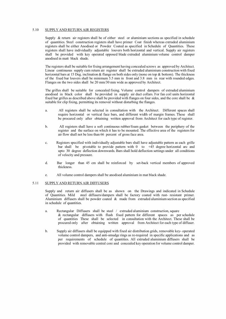
5.10 SUPPLY AND RETURN AIR REGISTERS
Supply & return air registers shall be of either steel or aluminium sections as specified in schedule of quantities. Steel construction registers shall have primer Coat finish whereas extruded aluminium registers shall be either Anodised or Powder Coated as specified in Schedule of Quantities. These registers shall have individually adjustable louvers both horizontal and vertical. Supply air registers shall be provided with key operated opposed blade extruded aluminium volume control damper anodised in matt black shade.
The registers shall be suitable for fixing arrangement having concealed screws as approved by Architect. Linear continuous supply cum return air register shall be extruded aluminium construction with fixed horizontal bars at 15 Deg. inclination & flange on both sides only (none on top & bottom). The thickness of the fixed bar louvers shall be minimum 5.5 mm in front and 3.8 mm in rear with rounded edges. Flanges on the two sides shall be 20 mm/30 mm wide as approved by Architect.
The grilles shall be suitable for concealed fixing. Volume control dampers of extruded aluminium anodised in black color shall be provided in supply air duct collars. For fan coil units horizontal fixed bar grilles as described above shall be provided with flanges on four sides, and the core shall be & suitable for clip fixing, permitting its removal without disturbing the flanges.
a. All registers shall be selected in consultation with the Architect. Different spaces shall
require horizontal or vertical face bars, and different width of margin frames. These shall be procured only after obtaining written approval from Architect for each type of register.
b. All registers shall have a soft continuous rubber/foam gasket between the periphery of the
register and the surface on which it has to be mounted. The effective area of the registers for air flow shall not be less than 66 percent of gross face area.
c. Registers specified with individually adjustable bars shall have adjustable pattern as each grille
bar shall be pivotable to provide pattern with 0 to +45 degree horizontal arc and upto 30 degree deflection downwards. Bars shall hold deflection settings under all conditions of velocity and pressure.
d. Bar longer than 45 cm shall be reinforced by set-back vertical members of approved
thickness.
e. All volume control dampers shall be anodised aluminium in mat black shade.
5.11 SUPPLY AND RETURN AIR DIFFUSERS
Supply and return air diffusers shall be as shown on the Drawings and indicated in Schedule of Quantities. Mild steel diffusers/dampers shall be factory coated with rust- resistant primer. Aluminium diffusers shall be powder coated & made from extruded aluminium section as specified in schedule of quantities.
a. Rectangular Diffusers shall be steel / extruded aluminium construction, square
& rectangular diffusers with flush fixed pattern for different spaces as per schedule of quantities These shall be selected in consultation with the Architect. These shall be procured only after obtaining written approval from Architect for each type of diffuser.
b. Supply air diffusers shall be equipped with fixed air distribution grids, removable key- operated
volume control dampers, and anti-smudge rings as re-required in specific applications and as per requirements of schedule of quantities. All extruded aluminium diffusers shall be provided with removable central core and concealed key operation for volume control damper.

c. Linear Diffuser shall be extruded aluminium construction with removable core, one or two way blow type. Supply air diffusers shall be provided with volume control/ balancing dampers within the supply air collar. Diffusers for different spaces shall be selected in consultation with the Architect, and provided as per requirements of schedule of quantities. All diffusers shall have volume control dampers of extruded aluminium construction anodised in mat black shade.
d. Slot Diffuser shall be extruded aluminium construction multislot type with air pattern controller
provided in each slot. Supply air diffusers shall be provided with Hit & Miss volume control dampers in each slot of the supply air diffusers. Diffusers for different spaces shall be selected in consultation with the Architect and provided as per requirement of Schedule of Quantities.
e. Data centers shall be provided with floor grilles. Grilles shall be of nominal size of 600mm x 600mm and shall be fitted in floor tile of false floor. Grille shall be with dampers for flow control. Grill shall be heavy duty 16G Aluminium and shall take care of human traffic load. Damper shall be operable in situ without requirement of removal of grille.
5.12 FIRE RATED DUCTWORK
Ducting for kitchen exhaust & fire evacuation, staircase pressurization if not in a separate shaft shall be fire rated as per following specifications.
a. All fire rated ductwork constructed for mechanical or dual ventilation / pressurization/ basement
car park/smoke extract systems and shall be fabricated from Lock Forming Quality grade prime galvanized steel sheet, constructed to enhanced SMACNA American / DW144 European standard to either low, medium or high velocity/ pressure.
b. Test requirement of fire rated ductwork should be tested to BS476: Part 24 [1987]
and ISO 6944 providing required fire rating for Stability and Integrity.
c. Stability: the ability of a duct, ductwork & the support system to remain intact & fulfill their intended function for a specified period of time, when tested to the requirements of BS476: Part 24 and ISO 6944.
d. Integrity: the ability of a duct or ductwork to remain free of cracks, holes or openings out side
the compartment in which the fire is present for a specified period of time, when tested to the requirements of BS476 Part 24 ISO 6944.
e. Insulation: the ability of a duct or ductwork to maintain its separating function without developing
temperatures on its external surface outside the compartment in which the fire is present, which exceeds, (i) 140OC as an average value above ambient & or, (ii) 180OC as maximum value above ambient at any point, when tested for a specified period of time to the requirements of BS476: Part 24 ISO 6944.
f. Its important that the fire rated ductwork has a smooth internal surface in order to minimize
the pressure loss within the fire rated ductwork system thereby reduce the power requirements.
g. All fire rated ducts for Smoke Extract shall have Stability / Integrity and Insulation for smoke temperatures up to 300OC upto 1.5 hrs, restriction of the duct due to twisting or buckling after the fire test shall not cause 25% or more reduction in cross sectional area proven by certification from an independent test house.
h. Each duct shall have fire rated coating. Fire rated coating compound used for construction of
fire rated ductwork shall be protected with minimum 0.7mm to 1mm nominal thickness tested to properties as per the requirements of BS 476: 6 & 7,

including non-combustibility Class O and fire propagation - Class 1 surface spread of flame & materials in accordance with Building Regulations.
i. Fire duct to be tested / assessed to BS476: Part 24 for all sizes up to 25 meters x 3 meters cross-
sectional area and fully certified to vertical and horizontal plane.
j. Fire rated duct fabricated to Method 3 of BS 5588: Part 9, factory produced. The coating compound shall be applied either offsite or onsite on the ground, dried and cured.
k. Fire duct expansion under fire conditions shall not exceed following:
- at 430OC an expansion of 0.006106mm per mm - at 600OC an expansion of 0.00852mm per mm - at 1100OC an expansion of 0.01562mm per mm.
5.13 STEEL WIRE ROPE HANGERS & SUPPORTS:
Wire Hangers shall be used to suspend all static HVAC Air Distribution services.
Wire Hangers should consist of a pre-formed wire rope sling with a range of end fixings to fit various substrates and service fixings, these include a ferruled loop, permanently fixed threaded M6 (or M8, M10) stud, permanently fixed nipple end with toggle, at one end or hook or eyelet, cladding hook, barrel, wedge anchor, eyebolt anchor or any other end fixture type or size as per manufacturers recommendation and design. The end fixings and the wire must be of the same manufacturer with several options available. The system should be secured and tensioned with a Hanger self-locking grip (double channel lock) at the other end. Once the grip is locked for safety purpose unlocking should only be done by using a separate setting key and should not be an integral part of the self-locking grip. Only wire and/or supports supplied and/or approved, shall be used with the system.
� Wire Hangers should have been independently tested by Lloyds Register. APAVE, TUV, UL NEBS,
CSA, Chiltern International fire, ADCAS, Intertek, ECA, and SMACNA, approved by ULC and CSA and comply with the requirements of DW/144 and BSRIA – wire Rope Suspension systems. Wire rope should be manufactured to BSEN 12385: 2002
� The contractor shall select the correct specification of wire hanger to use for supporting each particular
service from Table 1 below. Each size is designated with a maximum safe working load limit (which incorporates a 5:1 safety factor).
The correct specification of wire hanger required is determined using the following formula.
Weight per meter of object suspended (kg) X distance between suspension points (m) = weight loading per Hanger suspension point (kg).
Where the installed wire rope is not vertical then the working load limit shall be reduced in accordance with the recommendations give in the manufacturer’s handbook.
The contractor shall select the correct length of wire rope required to support the service. Lengths from 1-10m lengths. Specials can be made, check with manufacturer. No in–line joints should be made in the rope.
Table. 1

Wire (Gripple) Hanger Safe Working Loads Hanger size minimum breaking load of Wire Rope
(Kg / lbs) working load limit
(kg/lbs)
No. 1 80kg/176 lbs 0-10 kg / 0-22 lbs
No. 2 260kg/572 lbs 10-45 kg / 23-100 lbs
No. 3 580kg/1276 lbs 45-90 kg / 101-200 lbs
No. 4 1500kg/3300 lbs 90-225 kg / 210-495 lbs
No. 5 2160kg/4752 lbs 225-325 kg / 496-715 lbs
No. 6 2500kg/5500 lbs 325-500 kg / 715-1100 lbs
The standard range of Hanger Kits should contain galvanized high tensile steel wire rope or stainless steel wire rope as per the application, the minimum specification is as above and should be manufactured to BS 302 (1987), BSEN12385. Comply with manufacturer's load ratings and recommended installation procedures.

5.13.1 HVAC Supports
Gripple Hanger Supports are suitable for: Rectangular duct, Spiral Duct, Oval Duct, Fabric Duct, Diffusers, plenum boxes
5.13.2 Ducting Supports:
a. All ductwork shall be independently supported from building construction. All horizontal
ducts shall be rigidly and securely supported, in an approved manner, with hangers formed of galvanized steel wire ropes and galvanized steel angle/channel or a pair of brackets, connected by galvanized steel wire hangers under ducts, rigid supports may be provided at certain interval if need be. The spacing between supports should be not greater than 2.4 meter. All vertical ductwork shall be supported by structural members on each floor slab. Duct supports may be through galvanized steel insert plates or Toggle end wire fixing left in slab at the time of slab casting. Galvanized steel cleat with a hole for passing the wire rope hanger shall be welded to the plates. Trapeze hanger formed of galvanized steel wire rope using Gripple shall be hung through these cleats. Wherever use of metal insert plates is not feasible, duct support shall be through dash/anchor fastener driven into the concrete slab by electrically operated gun. Wire rope supports shall hang through the cleats or wire rope threaded studs can be screwed into the anchor fasteners. In case of PEB structure Loop and Catenary system can be used based on the site conditions as per approved suspension system drawings.
b. All horizontal ducts shall be adequately secured and supported. In an approved manner,
with trapeze Hangers formed of galvanized steel wire rope in a cradle support method (refer to typical drawings) under ducts at no greater than 3000mm centre, for 3001mm-above appropriate size angle along with neoprene pad in between the duct & MS angle should be used with prior approval. All vertical duct work shall be supported by structural members on each floor slab. Duct support shall be through dash / anchor fastener driven into the concrete slab by electrically operated gun. Hanger wires shall then hang around the ducting. Rigid supports shall be used in conjunction with wire rope hangers to assist with alignment of services where recommended for by the manufacturer. Rigid support must also be used in conjunction with wire rope hangers with duct work at each change of direction or connection or as per approved drawings. Support ducting in accordance with Schedule I specified below. Any other Gripple solution can be used based on manufacturer’s recommendation on site conditions after prior approval. In cases of Spiral ducting the wire can be wrapped directly around the ducting without the need for a spiral ducting clamp for sizes above 1100 a cradle support should be provided, refer to manufacturer’s recommendations.
c. Ducting over furred ceiling shall be supported from the slab above or from beams after
obtaining approval of Construction manager/consultant. In no case shall any duct be supported from false ceiling Hangers or be permitted to rest on false ceiling. All metal work in dead or furred down spaces shall be erected in time to occasion no delay to other Contractor’s work in the building. All supports of pipe shall be taken from structural slab/wall by means of fastener.
Catenary Supports: Refer to manufacturer’s recommendations on Catenary supports with C-clip, special care should be taken with tensioning of the wire and angles at which the installation of services are made.
d. Stainless Steel Supports should be provided for food, chemical and High Corrosion areas near
coastlines.
For further technical information refer to manufacturers catalogue and installation guide. Comply with manufacturer's load ratings and recommended installation procedures.

Schedule I: Duct Hanger Schedule
For ducts w ith external SP upto 250 Pa For ducts w ith external SP upto 500 Pa Maximum Duct Size
(mm) Gauge Gripple
Hanger size Maximum Duct Size
(mm) Gauge Gripple
Hanger size
1 - 500 26 No. 1 or 2 1–400 mm 26 No. 2 501 - 750 26 No. 1 or 2 401-700 mm 24 No. 2 or 3 751 - 900 26 No. 2 701-900 mm 24 No. 2 or 3
901 - 1200 24 No. 2 or 3 901-1000 mm 22 No. 3 or 4 1201 - 1500 22 No. 3 1001-1200 mm 22 No. 3 or 4 1501 - 1800 22 No. 3 or 4 1201-2100 mm 22 No. 3 or 4 1801-2100 20 No. 3 or 4 2101 - 3000mm 18 No. 4
2101-3000 18 No. 4 3001 - above (Trapeze type support
Arrangement)
18 No. 3 or 4
3001 - above (Tra pe ze type s upport Arra
ngement)
18 No. 3 or 4
Notes: All supports are considered at 2400 mm interval in above table and may vary as per the design but should not be greater than 2400mm.
All units shall be adequately secured and supported in an approved manner using wire hanger suspension Y fit solution as per manufacturers’ recommendation with prior approval.
Rigid Supports to be used in conjunction with wire supports:
Rigid supports if required in conjunction with wire hangers shall be of steel, adjustable for height and Zinc chromate primer coated and finish coated black. Where supports and clamps are of dissimilar materials, a gasket shall be provided in between. If the MS angle at the bottom if required as per design should be as per following table:
Longer size of Duct (mm)
Type of Joints
Up to 750 25x25x3 mm L angle with M8 nuts & bolts
751-1000 25x25x3 mm L angle with M8 nuts & bolts
1001-1500 40x40x5 mm L angle with M8 nuts & bolts
1501-2250 50x50x5 mm L angle with M10 nuts & bolts
2251 & above 50x50x6 mm L angle with M10 nuts & bolts
All the supporting system should be supplied from the same manufacturer.

5.14 VAV TERMINAL BOXES
VAV Terminal Boxes - General
All the VAV Terminals shall be Pressure Independent type with Direct Digital Controls to regulate the primary air flow rate between the scheduled minimum and maximum values to achieve the specified comfort level within acceptable noise criteria. A separation shall be made in Induction VAV Terminals and Standard VAV Terminals as detailed in the schedule.
The Induction VAV Terminals shall induce room air, without need of an assisting fan, and mix it with conditioned primary air, maintaining a near constant air volume to the room thus providing sufficient air movement necessary to maintain occupant comfort even in extreme load variations.
The VAV terminal shall have the controls, actuators and transformers, etc. pre-fitted, wired and calibrated at the factory and supplied with its appropriate digitally communicating thermostat. The supply of the VAV Terminals and the VAV controls, as well as the commissioning at the site, shall be done by the same specialist/local supplier.
VAV box shall be provided with terminal re-heater section if indicated in Schedule of Quantities.
VAV boxes shall be BMS compatible if such compatibility is specified in SOQ.
Construction of Standard Pressure Independent VAV Terminals
The casing shall be a double wall construction made from galvanized sheet steel (non spiral). Casing Leakage Rate shall be according to class II, VDI 3803/DIN 24 194. The insulation thickness shall be 25 mm. and the insulation material shall be fully enclosed by the metal casing. VAV Terminals with insulation materials in direct contact with the air flow will not be accepted.
The VAV Terminals shall have a low leakage, sandwich construction damper blade with SBR gasket and a solid aluminum damper shaft (diameter 12 mm.) with self lubricating Nylon bearings. The leakage shall be less than 2% of the nominal flow at 750 Pa. inlet static pressure. The duct sleeve connections at the inlet and outlet of the VAV Terminal shall be conform DIN 24 145 or DIN 24 146 respectively.
For large air volumes, Rectangular VAV Terminals shall be provided. These Rectangular VAV Terminals shall have a multi-leaf opposed blade damper with aluminum, aerofoil blade construction, width 50 mm. and external linkage. The damper spindle shall be made of steel (10 mm. diameter), rotating in self lubricating Nylon bearings. The VAV Terminal shall have 30 mm. flange connections at the inlet and outlet of the terminal.
Each VAV Terminal, Circular or Rectangular shall be factory fitted with a multipoint, averaging air flow sensor in the inlet of the terminal. This air flow sensor shall amplify the air pressure signal linearly with an amplification factor of at least 2.0. The air flow sensor shall contain not less than 2x12 sensing points, which shall be arranged in two perpendicular axis of sensing. The holes shall be arranged in such a way that each four points in a ring sense the air pressure across concentric circles of equal area in a round duct. The signal shall be averaged and measured from the center of the sensor. And the accuracy shall be within 2.5% even with irregular duct approach.

Construction of Induction VAV Terminals (Pressure Independent)
The casing shall be rectangular type made from galvanized sheet steel (thickness 1.25 mm.) with a circular inlet, two Induction openings at the sides of the terminal and a rectangular outlet. The duct sleeve connections at the inlet and outlet of the VAV Terminal shall be conform DIN 24 145 or DIN 24 146 respectively. The VAV Terminal shall have internal insulation (thickness 25 mm.), tested HF-1 (UL 94) flame test and erosion proof up to 50 m/s air velocity.
The terminals shall be fitted with a specially constructed jet-tronic damper to regulate the primary air flow between the scheduled minimum and maximum values. The same damper shall also generate and control the Induction effect through the acoustically lined induction chamber of the VAV Terminal. The damper shaft shall be solid aluminum (diameter 12 mm.), rotating in self lubricating Nylon bearings. The damper shall permit proper operation of the terminal over a range of 20 to 100% of maximum flow without the requirement of special VAV diffusers or assisting fans.
The Induction VAV Terminal shall be factory fitted with a multipoint, averaging air flow sensor in the inlet of the terminal. This air flow sensor shall amplify the air pressure signal linearly with an amplification factor of at least 2.0. The air flow sensor shall contain not less than 2x12 sensing points, which shall be arranged in two perpendicular axis of sensing. The holes shall be arranged in such a way that each four points in a ring sense the air pressure across concentric circles of equal area in a round duct. The signal shall be averaged and measured from the center of the sensor. And the accuracy shall be within 2.5% even with irregular duct approach.
5.15 DOCUMENTATION & MEASUREMENTS FOR DUCTING
All ducts fabricated and installed should be accompanied and supported by proper documentation viz:
a) Bill of material/Packing list for every duct section supplied.
Measurement sheet covering each fabricated duct piece showing dimensions and external surface area along with summary of external surface area of duct gauge- wise.
Each and every duct piece to have a tag number, which should correspond to the serial number, assigned to it in the measurement sheet. The above system will ensure speedy and proper site measurement and verification.
Unless otherwise specified, measurements for ducting for the project shall be on the basis of centerline measurements described herewith:
Ductwork shall be measured on the basis of external surface area of ducts. Duct measurements shall be taken before application of the insulation. The external surface area shall be calculated by measuring the perimeter comprising overall width and depth, including the corner joints, in the center of each duct section, multiplying with the overall length from flange face to flange face of each duct section and adding up areas of all duct sections. Plenums shall also be measured in a similar manner.
For tapered rectangular ducts, the average width and depth shall be considered for perimeter, whereas for tapered circular ducts, the diameter of the section midway between large and small diameter shall be adopted, the length of tapered duct section shall be the centerline distance between the flanges of the duct section.
For special pieces like bends, tees, reducers, branches and collars, mode of measurement shall be identical to that described above using the length along the centerline.

The quoted unit rate for external surface of ducts shall include all wastage allowances, flanges and gaskets for joints, nuts and bolts, hangers and angles with double nuts for supports, rubber strip 5mm thick between duct and support, vibration isolator suspension where specified or required, inspection chamber/access panel, splitter damper with quadrant and lever for position indication, turning vanes, straightening vanes, and all other accessories required to complete the duct installation as per the specifications. These accessories shall NOT be separately measured nor paid for.
b. Special Items for Air Distribution shall be measured by the cross-section area
perpendicular to air flow, as identified herewith :
i. Grilles and registers - width multiplied by height, excluding flanges. Volume control dampers shall form part of the unit rate for registers and shall not be separately accounted.
ii. Diffusers - cross section area for air flow at discharge area, excluding flanges.
Volume control dampers shall form part of unit rate for supply air diffusers and shall not be separately accounted.
iii. Linear diffusers - shall be measured by cross-sectional areas and shall exclude
flanges for mounting of linear diffusers. The supply air plenum for linear diffusers shall be measured with ducting as described earlier.
iv. Fire dampers - shall be measured by their cross sectional area perpendicular
to the direction of air flow. Quoted rates shall include the necessary collars and flanges for mounting, inspection pieces with access door, electrical actuators and panel. No special allowance shall be payable for extension of cross section outside the air stream.
v. Flexible connection - shall be measured by their cross sectional area perpendicular
to the direction of air flow. Quoted rates shall include the necessary mounting arrangement, flanges, nuts and bolts and treated-for- fire requisite length of canvas cloth.
vi. Kitchen Hoods - shall be measured by their cross sectional area at the capture
point of fumes, parallel to the surface of kitchen equipment. Quoted rates shall include the grease filters, provision for hood light, suspension arrangement for the hood, profile to direct the air to ventilation ducts and provision for removable drip tray.
5.16 UNDERFLOOR AIR DISTRIBUTION SYSTEM
a. Circular Swirl Floor Diffuser
Each diffuser shall produce a high induction turbulent vertical flow resulting inrapid te mperature equalization within the occupied zone.
The discharge airflow shall be adjustable from the face of the diffuser.
Minimum flow limit shall be adjustable from 0% to 50% of maximum flow using a mechanical stop.
The adjustable diffuser face shall have a positive interlock with the mounting hardwar e to reduce the chance of accidental adjustment due to foot traffic.
The diffusers core shall consist of circular slots with a removable core section with series of concentric rings supported by inclined air deflection vanes to distribute air in cyclonic “Swirl” discharge pattern.

High induction diffuser core assembly made up of die cast aluminum. The remaining components of the diffuser are made of NFPA 90A compliant plastic construction. The diffuser shall withstand the maximum mechanical loading of 590 Kg (1300 lbs).
Round floor diffusers shall be installed with Ring Nut / fastening and shall include da mper to prevent unauthorized removal of the diffuser. Assembly shall include black distributor to collect debris.
The performanance of the diffuser shall give 0.25 mt / sec. (50 fpm) at approx. 1meter height. The air flow shall be adjusted by manual rotation of center core.
b. Under floor Fan Powered Terminal Units:
The unit shall consist of casing, damper; fan section, controller and electrical connection. In addition to these, it also provided with air flow sensor grid and mesh wire filters. The primary air assemblies shall be pressure independent and reset to any airflow between zero and the maximum air volume as per requirement. Sound ratings of air distribution shall not exceed 36NC at maximum air flow.
Casing height shall not be higher than 300mm, permit installation beneath the raised floor. Casing and all associated ductwork and controls must fit between the floor pedestals of a conventional 600 mm x 600 mm (24”x24”) raised floor system. Floor pedestals must not be modified or relocated to accommodate installation of terminal unit. Mount the terminal unit on the main slab beneath the raised floor. The terminal unit shall not be suspended from the raised floor.
The air flow sensor shall be of a cross configuration located at the inlet of the assembly. The sensor shall have pressure sensing ports and a center averaging chamber designed to accurately average the flow across the inlet of the assembly. Sensor shall provide accuracy within 5% with a 90° sheet metal elbow directly at the inlet of the assembly. The air flow sensor shall amplify the sensed air flow signal. The assembly casing shall be constructed of steel, internally lined with 12mm (1/2 inch) thick, 24 Kg / m³ (1.5lb / ft³) minimum density fiberglass insulation.
Casing shall be a minimum 22 gauge. Unit casing shall have a top access door to allow removal of fan and servicing of the unit. Unit casing shall have a top access door to allow removal of fan and servicing of the unit.
The primary air valve damper shall be heavy gauge metal, with peripheral gasket, and solid steel shaft, pivoted in self-lubricating bearings. In the full closed position, air leakage past the closed damper shall not exceed 2% of the nominal catalogue rating at 75 mm w.g. (3”w.g.) inlet static pressure.

Fan blower shall be constructed of steel with forward curved blades, dynamically balanced wheels and direct drive motor. Motors shall be permanent split capacitor type, with lubricated bearings and thermal overload protection. Motor shall be designed for use with electronic fan speed controller. Provide isolation between motor and blower assembly.
The unit shall be fitted with compact VAV controller complete with pressure transducer and actuator. The air flow sensor fitted to the primary air inlet is connected to the pressure transducer on the VAV controller. The air temperature sensor is mounted behind the return air grille. This temperature sensor comes with room temperature set point function and fan speed controller. LED display to indicate return air temperature, fan speed setting and room set point temperature can be provided together with the temperature sensor mounted behind the return air grille.
The unit should be provided with electric air heater to complete with manual reset thermal cut-out switch for safety purpose.
c. Round Floor Turbulent Flow Diffuser
Each diffuser shall produce a high induction turbulent vertical flow resulting in rapid temperature equalization within the occupied zone.
The discharge airflow shall be adjustable from the face of the diffuser. Minimum flow limit shall be adjustable from 0% to 50% of maximum flow using mechanical stop.
The adjustable diffuser face shall have a positive interlock with the mounting hardware to reduce the chance of accidental adjustment due to foot traffic.
The diffuser core shall consist of multiple radial slots with an incline angle of 30 degrees. The 200 mm (8”) core shall be constructed of UL2043 Fire Rated Polyamide with permeating color able to withstand maximum mechanical loading of 590 Kg. (1300 lbs).
Round floor diffusers shall be installed with Ring Nut / fastening and shall include tamper protection to prevent unauthorized removal of the diffuser. Assembly shall include black p olycarbonate distributor Basket with Damper device.
d. Round Floor Displacement Diffuser
Each diffuser shall produce a low induction horizontal flow resulting in a stratified zone temperature distribution within the occupied zone. The discharge airflow shall be adjustable from the face of the diffuser. Minimum flow limit shall be adjustable from 0% to 50% of maximum flow using a mechanical stop.
The adjustable diffuser face shall have a positive interlock with the mounting hard ware to reduce the chance of accidental adjustable due to foot traffic. The 200 mm (8”) core shall be constructed to UL2043 Fire Rated polyamide with permeating color able to withstand maximum mechanical loading of 590 Kg (1300 lbs).
Round floor diffusers shall be installed with Ring Nut fastening and shall include tamper protection to prevent unauthorized removal of the diffuser. Assembly shall include black polycarbonate distributor Basket with Damper device.

e. Round Floor Inclined Diffuser
Each diffuser shall produce a high induction turbulent flow by utilizing radial and circular discharge slots to create a discharge of 30 degrees to vertical resulting in rapid temperature equalization within the occupied zone.
The diffuser core shall consist of multiple radial slots and circular slots with an incline angle of 30 degrees. The 200 mm (8”) core shall be constructed of aluminium able to withstand maximum mechanical loading of 1180 Kg (2600 lbs.) Round floor diffusers shall be installed with Ring Press Fit / Ring Claw fasteners and shall include tamper protection to prevent unauthorized removal of the round diffuser.
Assembly shall include black polyamide distributor Basket with Damper device / Short Basket / Extra Short Basket with Damper Device. Round floor diffusers shall be supplied with an RFB / RFBV boot mounted to the underside of the floor tile constructed of galvanized steel.
5.17 FLEXIBLE DUCT
Insulated flexible duct should be UL 181 CLASS I AIR DUCT LISTED AND LABELLED WITH NFPA 90A & 90B AND SEAL OF AIR DIFFUSION COUNCIL with double lamination of tough polyester which encapsulates steel helix wire forms the air tight inner core, double layer core wrapped in a multiple thickness of fiberglass wool with R Value 4.2, Green guard certification of fiberglass wool must. Reinforced and sheathed in a rugged and durable tridirectionally reinforced matlized polyester jacket.
Flexible duct connections should be made as per UL181 listing procedure with proper flexible right forming brace connection allowing right connections for flexible duct into energy efficient . and Strapping the flexible duct connections with flexible duct strap ties.
5.18 TESTING AND BALANCING
After the installation of the entire air distribution system is completed in all respects, all ducts shall be tested for air leaks by visual inspection.
The entire air distribution system shall be balanced using an anemometer. Measured air quantities at fan discharge and at various outlets shall be identical to or less/excess than 5 percent of those specified and quoted. Branch duct adjustments shall be permanently marked after air balancing is completed so that these can be restored to their correct position if disturbed at any time. Complete air balance report shall be submitted for scrutiny and approval, and four copies of the approved balance report shall be provided with completion documents.

6. INSULATION
6.1 SCOPE
The scope of this section comprises the supply and application of insulation conforming to these specifications. The insulation material shall be Closed Cell Elastomeric Nitrile Rubber / Polyethylene Foam / EPDM
6.2 MATERIAL
Thermal insulation material for Duct & Pipe insulation shall be with factory laminated black fiber glass cloth closed cell Elastomeric UV resistant. Thermal conductivity as per BS 874 part 2 – 86 (DIN 52613 52612) / DIN EN 12667 / EN ISO8497 of the insulation material shall not exceed 0.038 W/moK or 0.212 BTU / (Hr-ft2-oF/inch) at an average temperature of 30oC. Density of the nitrile rubber shall be 40-60 Kg/m3, for EPDM shall be 40-60 Kg/m3 & for polyethylene material it shall be 25-30 Kg/m3. The product shall have temperature range of – 40 oC to 105oC. The insulation material shall be fire rated for Class 0 as per BS 476 Part 6 : 1989 for fire propagation test and for Class 1 as per BS 476 Part 7, 1987 for surface spread of flame test. Water vapour permeability shall be not less than 0.024 per inch (2.48 x 10⁻¹³
Kg/m.s.Pa i.e. µ>7000: Water vapour diffusion resistance) as per DIN 53122 part 2, DIN 52615 / EN 12086 & EN13469.
In addition to above properties the insulation material for ducts shall be anti-microbial. Microbiological growth on insulation surface shall be in accordance with ASTM G-21 and bacterial resistance to ASTM2180.
The Material shall comply to ISO 5659 / BS 6853 / ABD 0031 for smoke density and toxicity values. The thermal conductivity of insulation material shall not be effected by aging as per DIN 52616 standard.
Insulation shall be with self Adhesive for ducting and piping and available in roles / sheets
Thickness of the insulation shall be as specified for the individual application. Each lot of insulation material delivered at site shall be accompanied with manufacturer’s test certificate for density and thickness. Samples of insulation material from each lot delivered at site may be selected by Owner’s site representative and gotten tested for thermal conductivity and density at Contractor’s cost. Adhesive used for sealing the insulation shall be non-flammable and with low VOC content (maximum 850 gm/l as per IGBC guide lines) strictly as per manufacturer’s recommendations.
Ducting insulation thickness shall be as per table below.
Ducting position Thk. for non-coastal places Thk. for coastal places
SA duct in RA path 13 mm 19 mm
Ducted return air system SA duct: 19 mm RA duct: 13 mm
SA duct: 25 mm RA duct: 19 mm
Both SA & RA exposed Both 25 mm Both 25 mm

6.3 DUCT INSULATION
External thermal insulation shall be provided as follows :
The thickness of insulation material shall be as shown on drawings or identified in the schedule of quantity. Following procedure shall be adhered to:
Duct surfaces shall be cleaned to remove all grease, oil, dirt, etc. prior to carrying out insulation work. Measurement of surface dimensions shall be taken properly to cut closed cell insulation to size with sufficient allowance in dimension. Cutting of insulation sheets shall be done with adjustable blade to make 900 cut in thickness of sheet. Hackshaw or blades are not acceptable tools for cutting the insulation.
Material shall be fitted under compression and no stretching of material shall be permitted. All longitudinal and transverse joints shall be sealed by providing 50 mm wide Fibre glass cloth laminated tape as per manufacturer recommendations. The insulation installers shall be certified by manufacture.
Where ducts/pipes penetrates walls / floor it shall be insulated with intumescent properties insulation material for fire protection. The treatment shall be minimum 500 mm extended on both sides.
6.4 PIPING INSULATION
All chilled water, refrigerant, and condensate drain piping shall be insulated in the manner specified herein. Before applying insulation, all pipe shall be brushed and cleaned. All MS pipes shall be provided with a coat of zinc chromate primer. Thermal insulation shall be applied as follows or as specified in drawings or schedule of quantity:
Piping Insulation thickness shall be as follows;
Pipe nominal bore Thk. for non-coastal places Thk. for coastal places
15 mm – 25 mm 19 mm 25 mm
32 mm – 80 mm 25 mm 32 mm
100 mm – 400 mm 32 mm 38 mm
Above 400 mm 45 mm 45 mm
Insulating material in tube form (minimum upto 100 dia pipes) shall be sleeved on the pipes. On piping, slit opened tube from insulating material shall be placed over the pipe and adhesive shall be applied as suggested by the manufacturer. Adhesive must be allowed to tack dry and then press surface firmly together starting from butt end and working towards centre. Wherever flat sheets shall be used it shall be with self adhesive and cut out in correct dimension using correct tools. Scissors or Hacksaw-blade shall not be allowed. All longitudinal and transverse joints shall be sealed by providing 50 mm wide fiber glass cloth laminated tape as per manufacturer recommendations. The adhesive shall be strictly as recommended by the manufacturer. The insulation shall be continuous over the entire run of piping, fittings and valves. All valves, fittings, joints, strainers etc. in chilled water piping shall be insulated to the same thickness as specified for the main run of piping and application shall be same as above. Valves bonnet, yokes and spindles shall be insulated in such a manner as not to cause damage to insulation when the valve is used or serviced.
Direct contact between pipe and hanger shall be avoided. Hangers shall pass outside the saddle. Manufacturer shall supply PUF saddles with pre-laminated insulation sheet of both side (PUF saddle sandwich between insulation material on both side) so that
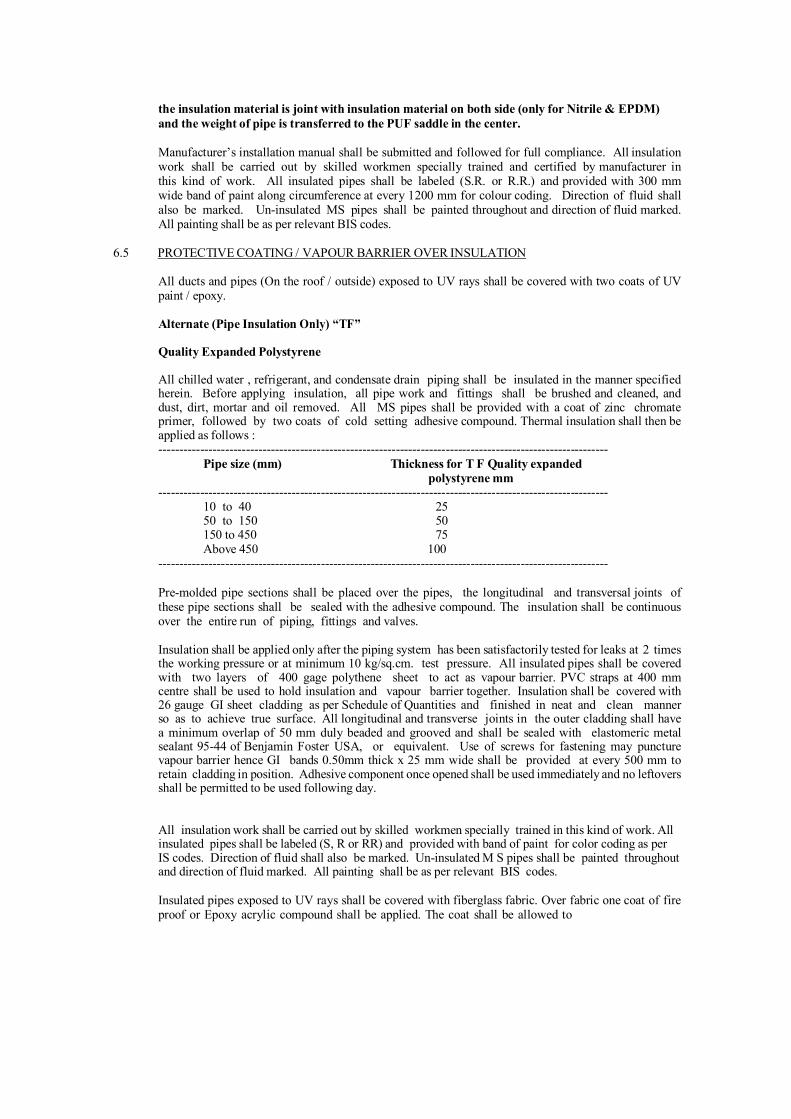
the insulation material is joint with insulation material on both side (only for Nitrile & EPDM) and the weight of pipe is transferred to the PUF saddle in the center.
Manufacturer’s installation manual shall be submitted and followed for full compliance. All insulation work shall be carried out by skilled workmen specially trained and certified by manufacturer in this kind of work. All insulated pipes shall be labeled (S.R. or R.R.) and provided with 300 mm wide band of paint along circumference at every 1200 mm for colour coding. Direction of fluid shall also be marked. Un-insulated MS pipes shall be painted throughout and direction of fluid marked. All painting shall be as per relevant BIS codes.
6.5 PROTECTIVE COATING / VAPOUR BARRIER OVER INSULATION
All ducts and pipes (On the roof / outside) exposed to UV rays shall be covered with two coats of UV paint / epoxy.
Alternate (Pipe Insulation Only) “TF”
Quality Expanded Polystyrene
All chilled water , refrigerant, and condensate drain piping shall be insulated in the manner specified herein. Before applying insulation, all pipe work and fittings shall be brushed and cleaned, and dust, dirt, mortar and oil removed. All MS pipes shall be provided with a coat of zinc chromate primer, followed by two coats of cold setting adhesive compound. Thermal insulation shall then be applied as follows : ------------------------------------------------------------------------------------------------------------
Pipe size (mm) Thickness for T F Quality expanded polystyrene mm
------------------------------------------------------------------------------------------------------------ 10 to 40 25 50 to 150 50 150 to 450 75 Above 450 100
------------------------------------------------------------------------------------------------------------
Pre-molded pipe sections shall be placed over the pipes, the longitudinal and transversal joints of these pipe sections shall be sealed with the adhesive compound. The insulation shall be continuous over the entire run of piping, fittings and valves.
Insulation shall be applied only after the piping system has been satisfactorily tested for leaks at 2 times the working pressure or at minimum 10 kg/sq.cm. test pressure. All insulated pipes shall be covered with two layers of 400 gage polythene sheet to act as vapour barrier. PVC straps at 400 mm centre shall be used to hold insulation and vapour barrier together. Insulation shall be covered with 26 gauge GI sheet cladding as per Schedule of Quantities and finished in neat and clean manner so as to achieve true surface. All longitudinal and transverse joints in the outer cladding shall have a minimum overlap of 50 mm duly beaded and grooved and shall be sealed with elastomeric metal sealant 95-44 of Benjamin Foster USA, or equivalent. Use of screws for fastening may puncture vapour barrier hence GI bands 0.50mm thick x 25 mm wide shall be provided at every 500 mm to retain cladding in position. Adhesive component once opened shall be used immediately and no leftovers shall be permitted to be used following day.
All insulation work shall be carried out by skilled workmen specially trained in this kind of work. All insulated pipes shall be labeled (S, R or RR) and provided with band of paint for color coding as per IS codes. Direction of fluid shall also be marked. Un-insulated M S pipes shall be painted throughout and direction of fluid marked. All painting shall be as per relevant BIS codes.
Insulated pipes exposed to UV rays shall be covered with fiberglass fabric. Over fabric one coat of fire proof or Epoxy acrylic compound shall be applied. The coat shall be allowed to
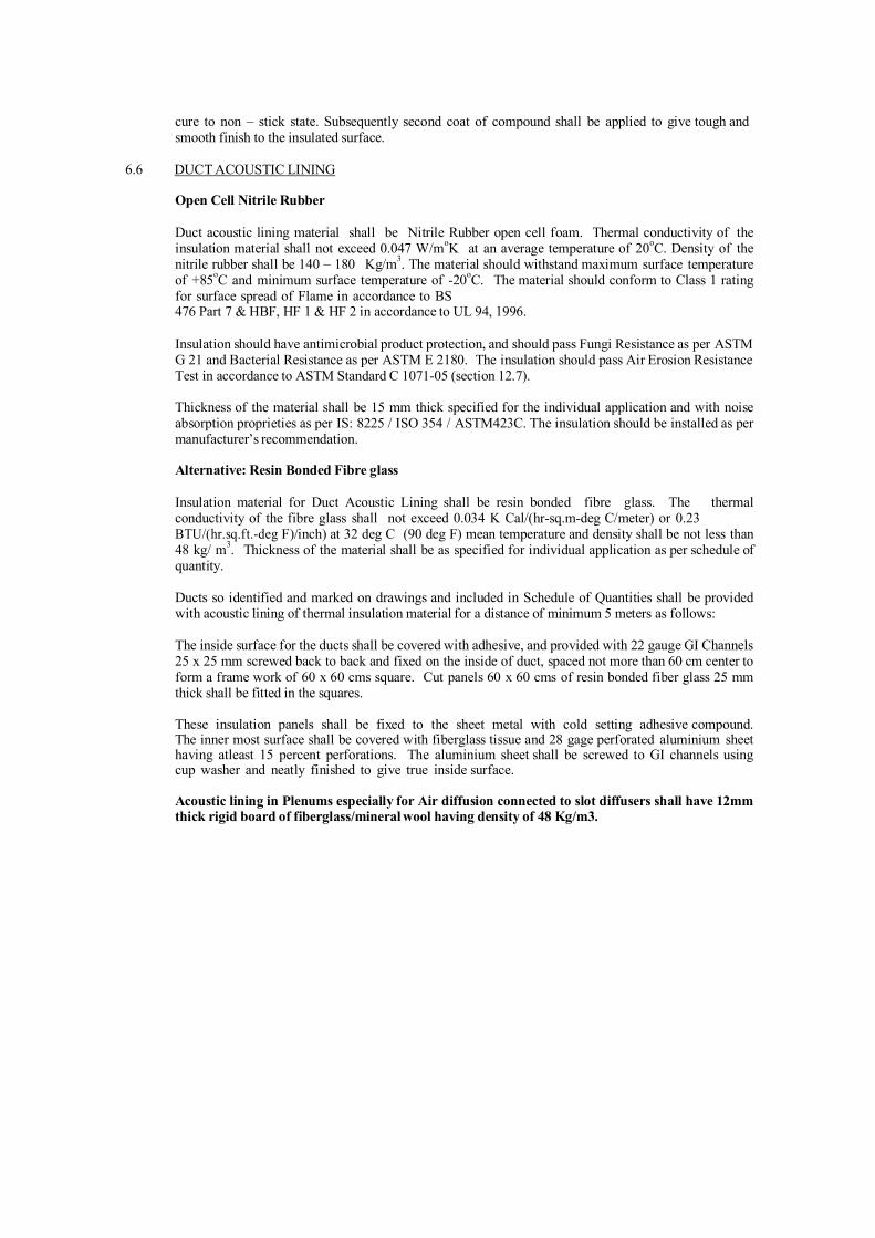
cure to non – stick state. Subsequently second coat of compound shall be applied to give tough and smooth finish to the insulated surface.
6.6 DUCT ACOUSTIC LINING
Open Cell Nitrile Rubber
Duct acoustic lining material shall be Nitrile Rubber open cell foam. Thermal conductivity of the insulation material shall not exceed 0.047 W/moK at an average temperature of 20oC. Density of the nitrile rubber shall be 140 – 180 Kg/m3. The material should withstand maximum surface temperature of +85oC and minimum surface temperature of -20oC. The material should conform to Class 1 rating for surface spread of Flame in accordance to BS 476 Part 7 & HBF, HF 1 & HF 2 in accordance to UL 94, 1996.
Insulation should have antimicrobial product protection, and should pass Fungi Resistance as per ASTM G 21 and Bacterial Resistance as per ASTM E 2180. The insulation should pass Air Erosion Resistance Test in accordance to ASTM Standard C 1071-05 (section 12.7).
Thickness of the material shall be 15 mm thick specified for the individual application and with noise absorption proprieties as per IS: 8225 / ISO 354 / ASTM423C. The insulation should be installed as per manufacturer’s recommendation.
Alternative: Resin Bonded Fibre glass
Insulation material for Duct Acoustic Lining shall be resin bonded fibre glass. The thermal conductivity of the fibre glass shall not exceed 0.034 K Cal/(hr-sq.m-deg C/meter) or 0.23 BTU/(hr.sq.ft.-deg F)/inch) at 32 deg C (90 deg F) mean temperature and density shall be not less than 48 kg/ m3. Thickness of the material shall be as specified for individual application as per schedule of quantity.
Ducts so identified and marked on drawings and included in Schedule of Quantities shall be provided with acoustic lining of thermal insulation material for a distance of minimum 5 meters as follows:
The inside surface for the ducts shall be covered with adhesive, and provided with 22 gauge GI Channels 25 x 25 mm screwed back to back and fixed on the inside of duct, spaced not more than 60 cm center to form a frame work of 60 x 60 cms square. Cut panels 60 x 60 cms of resin bonded fiber glass 25 mm thick shall be fitted in the squares.
These insulation panels shall be fixed to the sheet metal with cold setting adhesive compound. The inner most surface shall be covered with fiberglass tissue and 28 gage perforated aluminium sheet having atleast 15 percent perforations. The aluminium sheet shall be screwed to GI channels using cup washer and neatly finished to give true inside surface.
Acoustic lining in Plenums especially for Air diffusion connected to slot diffusers shall have 12mm thick rigid board of fiberglass/mineral wool having density of 48 Kg/m3.

6.7 ACOUSTIC LINING OF MECHANICAL ROOMS
Open Cell Nitrile Rubber
Two walls and ceiling of air conditioning plant room and air handling unit / fan rooms may be provided with acoustic lining. Material shall be processed from Nitrile rubber open cell foam.
The material should be fibre free. The density of the same shall be 140-180 Kg/m3. The material should have thermal conductivity not exceeding 0.05 W/Mk. The maximum surface temperature of material shall withstand is 1050C. and minimum temp shall be -200C. Thickness shall be as specified. The material should confirm to class 1 rating for surface spread of flame as per BS 476 Part 7 & HBF, HF1 & FH 2 in accordance with UL 94, 1996. Thickness, if not specified, shall be considered as 20mm.
Surface shall be cleaned and two coats of adhesive recommended by the manufacturer should be applied on the walls. The foam sheets should be cut to required size and a layer of adhesive should also be applied to it. When it is tack dry it is stuck to the walls / ceiling.
All longitudinal and transfer joint shall be covered with 22 gauge 50 mm wide GI strip with screws..
Acoustic lining of walls shall be terminated approximately 15 cm above the finished floor to prevent damage to insulation due to accidental water-logging in plant/AHU / fan rooms.
Alternative: Resin Bonded Fibre glass
Two walls and ceiling of air conditioning plant room and air handling unit / fan rooms may be provided with acoustic lining of resin bonded fibre glass as per Schedule of Quantities and as shown on the Drawings. The surface shall be cleaned and frame work of 22 gage GI fabricated Channels 25 mm x 50 mm screwed back to back at 60 cm centres shall be provided vertically and horizontally so that 60 x 60 cm squares are formed. The gaps between frames shall be filled with 50 mm thick about 60 cm x 60 cm cut panels of resin bonded fibre glass slabs. The entire surface shall then be covered with fibre glass tissue and 26 gage perforated aluminium sheet, 60 cm or 120 cm wide having atleast 15 percent perforations, fixed with sheet metal screws. Over-lapping of sheets shall be covered with aluminium beading. Acoustic lining of walls shall be terminated approximately 15 cm above the finished floor to prevent damage to insulation due to accidental water-logging in plant/AHU rooms.
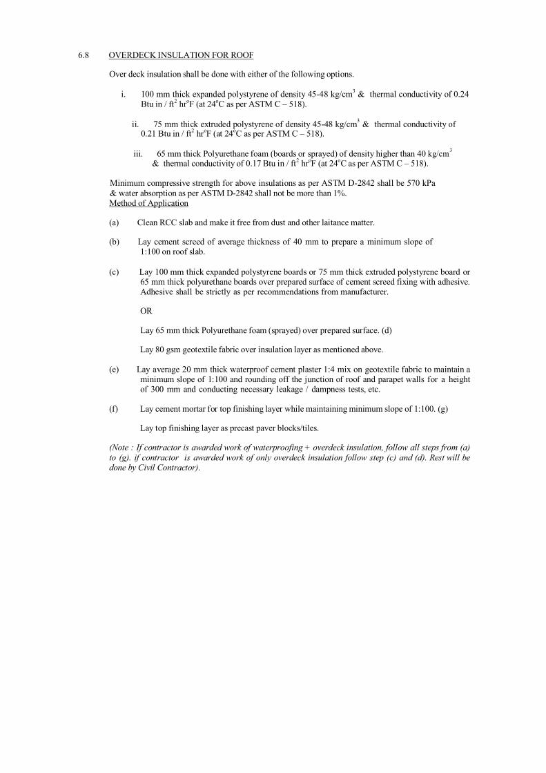
6.8 OVERDECK INSULATION FOR ROOF
Over deck insulation shall be done with either of the following options.
i. 100 mm thick expanded polystyrene of density 45-48 kg/cm3 & thermal conductivity of 0.24 Btu in / ft2 hroF (at 24oC as per ASTM C – 518).
ii. 75 mm thick extruded polystyrene of density 45-48 kg/cm3 & thermal conductivity of
0.21 Btu in / ft2 hroF (at 24oC as per ASTM C – 518).
iii. 65 mm thick Polyurethane foam (boards or sprayed) of density higher than 40 kg/cm3
& thermal conductivity of 0.17 Btu in / ft2 hroF (at 24oC as per ASTM C – 518).
Minimum compressive strength for above insulations as per ASTM D-2842 shall be 570 kPa & water absorption as per ASTM D-2842 shall not be more than 1%. Method of Application
(a) Clean RCC slab and make it free from dust and other laitance matter.
(b) Lay cement screed of average thickness of 40 mm to prepare a minimum slope of
1:100 on roof slab.
(c) Lay 100 mm thick expanded polystyrene boards or 75 mm thick extruded polystyrene board or 65 mm thick polyurethane boards over prepared surface of cement screed fixing with adhesive. Adhesive shall be strictly as per recommendations from manufacturer.
OR
Lay 65 mm thick Polyurethane foam (sprayed) over prepared surface. (d)
Lay 80 gsm geotextile fabric over insulation layer as mentioned above.
(e) Lay average 20 mm thick waterproof cement plaster 1:4 mix on geotextile fabric to maintain a minimum slope of 1:100 and rounding off the junction of roof and parapet walls for a height of 300 mm and conducting necessary leakage / dampness tests, etc.
(f) Lay cement mortar for top finishing layer while maintaining minimum slope of 1:100. (g)
Lay top finishing layer as precast paver blocks/tiles.
(Note : If contractor is awarded work of waterproofing + overdeck insulation, follow all steps from (a) to (g). if contractor is awarded work of only overdeck insulation follow step (c) and (d). Rest will be done by Civil Contractor).

6.9 MEASUREMENT OF INSULATION
Unless otherwise specified measurement for duct and pipe insulation for the project shall be on the basis of centre line measurements described herewith
a. Pipe Insulation shall be measured in units of length along the centre line of the installed pipe,
strictly on the same basis as the piping measurements described earlier. The linear measurements shall be taken before the application of the insulation. It may be noted that for piping measurement, all valves, orifice plates and strainers are not separately measurable by their number and size. It is to be clearly understood that for the insulation measurements, all these accessories including cladding, valves, orifice plates and strainers shall be considered strictly by linear measurements along the centre line of pipes and no special rate shall be applicable for insulation of any accessories, fixtures or fittings whatsoever.
b. Duct Insulation and Acoustic Lining shall be measured on the basis of surface area along the centre
line of insulation thickness. Thus the surface area of externally thermally insulated or acoustically lined be based on the perimeter comprising centre line (of thickness of insulation) width and depth of the cross section of insulated or lined duct, multiplied by the centre-line length including tapered pieces, bends, tees, branches, etc. as measured for bare ducting.
VII. TECHNICAL SPECIFICATIONS FOR PLUMBING WORKS TECHNICAL SPECIFICATION OF PLUMBING WORKS
1.0 General All storm drainage work should be carried out by competent licensed plumber only, and the material and workmanship shall conform to the following IS Codes and relevant by-laws of local Municipal Authorities. All necessary approvals and completion certificates from Municipal. and other regulatory authorities shall be obtained by the contractor 1.1 IS Codes and Reference Standards. 1.1.1 Codes and reference standards referred to in the contract shall be understood to form a part of the contract. 1.1.2 Alternative reference standards produced by different standards authorities may be specified in a Section. Standards of any of the specified authorities may be acceptable; however, materials specified in the Section shall be incorporated in the works from only one of the specified standards authority to ensure compatibility in the performance of the materials. 1.1.3 The contractor shall be responsible for adherence to reference standard requirements by subcontractors and suppliers. 1.1.4 Where edition date is not specified, consider that reference to manufacturer's and published codes, standards and specifications are made to the latest edition (revision or amendment) approved by the issuing organization current at issue date of the Tender. 1.1.5 The specified reference standards are INDIAN STANDARD CODES and are intended to establish the quality of materials and workmanship required for the works. Reference standards published in other countries may, in the sole judgment of the owner’s consultant, also be acceptable providing that the Contractor furnishes sufficient data for the Owner's Consultant to determine if the quality of materials and workmanship at least equals or exceeds all tests prescribed by the specified reference Indian Standards codes. Such other reference standards published by the following will be considered; BSI : British Standards Institute AFNOR : Association Francaise de Normalization DIN : Deutsche Industries Norman (German Standards) ANSI : American National Standards Institute ASTM : American Society for Testing and Materials

1.1.6 Reference standards and specifications are quoted in the specification to establish minimum standards. Works of quality or of performance characteristics that exceed these minimum standards will be considered to confirm. Should regulatory requirements or the contract conflict with specified reference standards or specifications, the more stringent in each case shall govern. 1.1.7 Where reference is made to manufacturer's directions, instructions or specifications they shall include full information on storing, handling, preparing, mixing, installing, erection, applying or other matters concerning the materials pertinent to their use in the works and their relationship to materials with which they are incorporated. 1.1.8 Contractor shall obtain copies of codes applying to the Work, manufacturer's directions and reference standards referred to in the contract within 90 days of signing the contract. 1.1.9 Contractor shall submit a copy of each code, reference standard and specification, manufacturer's directions, instructions and specifications, to which reference is made in the specification to the Owner's Authorized Representative's.
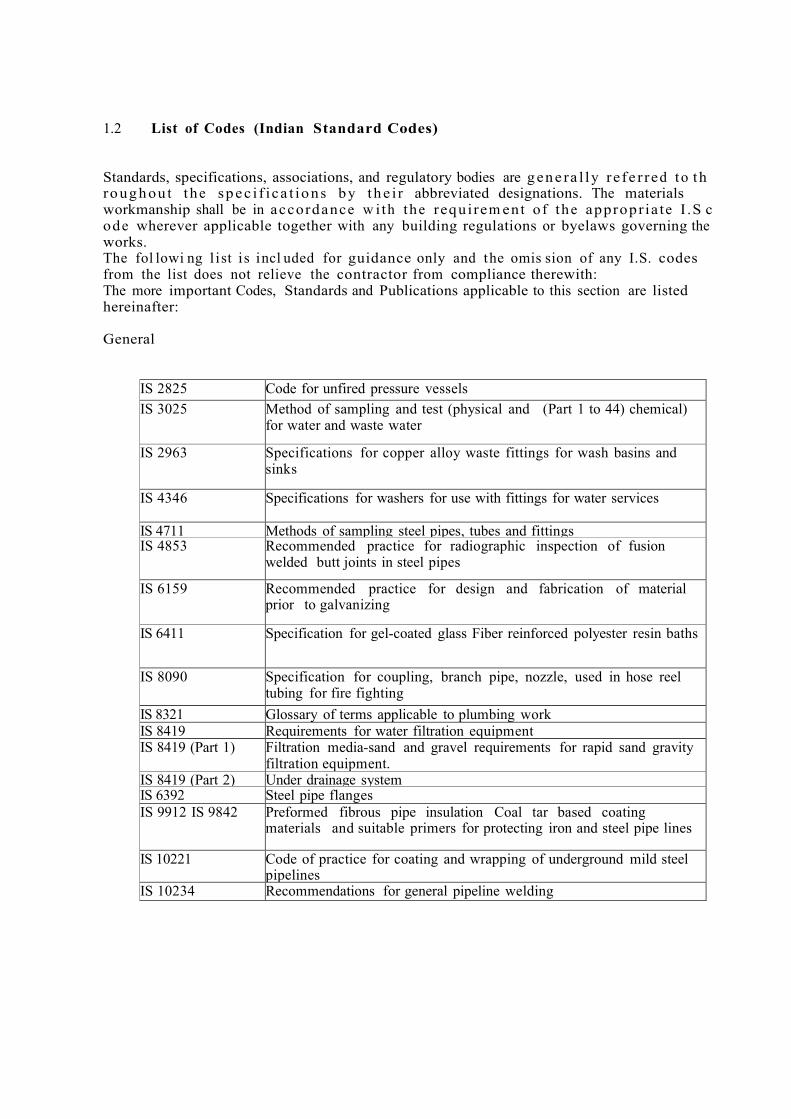
1.2 List of Codes (Indian Standard Codes) Standards, specifications, associations, and regulatory bodies are g e n e r a l l y r e f e r r e d t o t h r o u g h o u t t h e s p e c i f i c a t i o n s b y t h e i r abbreviated designations. The materials workmanship shall be in a c c o r d a n c e w i t h t h e r e q u i r e m e n t o f t h e a p p r o p r i a t e I . S c o d e wherever applicable together with any building regulations or byelaws governing the works. The fol lowi ng l i st i s i ncl uded for guidance only and t he omis sion of any I.S. codes from the list does not relieve the contractor from compliance therewith: The more important Codes, Standards and Publications applicable to this section are listed hereinafter: General
IS 2825 Code for unfired pressure vessels IS 3025 Method of sampling and test (physical and (Part 1 to 44) chemical)
for water and waste water
IS 2963 Specifications for copper alloy waste fittings for wash basins and sinks
IS 4346 Specifications for washers for use with fittings for water services
IS 4711 Methods of sampling steel pipes, tubes and fittings IS 4853 Recommended practice for radiographic inspection of fusion
welded butt joints in steel pipes
IS 6159 Recommended practice for design and fabrication of material prior to galvanizing
IS 6411 Specification for gel-coated glass Fiber reinforced polyester resin baths
IS 8090 Specification for coupling, branch pipe, nozzle, used in hose reel tubing for fire fighting
IS 8321 Glossary of terms applicable to plumbing work IS 8419 Requirements for water filtration equipment IS 8419 (Part 1) Filtration media-sand and gravel requirements for rapid sand gravity
filtration equipment. IS 8419 (Part 2) Under drainage system IS 6392 Steel pipe flanges IS 9912 IS 9842 Preformed fibrous pipe insulation Coal tar based coating
materials and suitable primers for protecting iron and steel pipe lines
IS 10221 Code of practice for coating and wrapping of underground mild steel pipelines
IS 10234
Recommendations for general pipeline welding

IS 10446 Glossary of terms relating to water supply and Sanitation
IS 11149 Rubber Gaskets IS 11790 Code of practice for preparation of butt-welding ends for pipes, valves
flanges and fittings IS 12011 Code of safety practice for domestic LPG installation IS 1200 Mode of Measurement IS 12183 (Part 1) Code of practice for plumbing in multi-storied buildings (Water
Supply) IS 12251 Code of practice for drainage of building basements IS 3844 Code of practice for installation and maintenance of internal fire
hydrants and hose reel on premises S P 7 National building code of India (Part IX plumbing services)
IS 27 Pig Lead IS 554 Dimensions for pipe threads where pressure light joints are required
on the threads IS 325 Three phase induction motors IS 694 PVC insulated cables for working voltages upto and including 1100
V. IS 779 Specification for water meters (domestic type) IS 1172 Code of Basic requirements for water supply drainage and sanitation.
IS 1367 Technical supply conditions for threaded steel fasteners: IS 1367 (Part 1) Introduction and general information IS 1367 (Part 2) Product grades and tolerances IS 1554 PVC insulated (heavy duty) electric cables: IS 1554 Part 1 For working voltages upto and including 1100 V. IS 1554 Part 2 For working voltages from 3.3 KV upto and including 11 kV IS 1726 Specification for cast iron manhole covers and frames IS 1979 High test line pipe IS 1742 Code of practice for building drainage IS 2064 Selection, installation and maintenance of sanitary appliances
IS 2065 Code of practice for water supply in buildings IS 2643 Dimensions for pipe threads for fastening purposes IS 2643 (Part 1) Basic profile and dimensions IS 2643 (Part 2) Tolerances IS 2643 (Part 3) Limits of sizes IS 2104 Specification for water meter boxes (domestic type) IS 2373 Specification for water meters (bulk type) IS 2379 Colour code for the identification of pipe lines.
IS 7558 Code of practice for domestic hot water installations IS 5329 Code of practice for sanitary pipe work above ground for buildings
IS 2527 Code of practice for fixing rainwater gutters and down pipes for roof drainage
IS 9668 Code of practice for provision and maintenance of water supplies and fire fighting
Pipes and Fittings

IS 3114 Code of practice for laying of cast iron pipes IS 3468 Pipe nuts IS 3589 Seamless or electrically welded pipes for water, gas and sewage
IS 4127 Code of practice for laying glazed stoneware pipes IS 1536 Centrifugally cast (spun) iron pressure pipes for water, gas and sewage
IS 7181 Specification for horizontally cast iron double flanged pipes for water, gas and sewage
IS 1729 Sand cast iron spigot and socket soil, waste and ventilating pipes, fittings and accessories
IS 3989 Centrifugally cast (spun) iron spigot and socket soil, waste and ventilating pipes, fittings and accessories
IS 3486 Cast iron spigot & socket pipes IS 1879 (Parts 1 to
Malleable cast iron pipe fittings IS 1538 (Parts 1 to 23)
Cast iron fittings for pressure pipes for water, gas and sewage
IS 6418 Cast iron and malleable cast iron flanges for general engineering practice.
IS 3589 Seamless or electrically welded steel pipes for water, gas and sewage (168.3 mm to 2032 mm OD)
IS 1239 Mild steel tubulars and other wrought steel pipe fittings. P a r t 1 Mild steel tubes Part 2 Mild steel tubulars and other wrought steel pipe fittings. IS 458 Specification for pressure concrete pipes (with and without
reinforcement) IS 2501 Copper tubes for general engineering purposes IS 651 Salt glazed stone-ware pipes and fittings Valves IS 780 Specification for sluice valves for water works purposes (50 to 300 mm
size) IS 2906 Specification for sluice valves for water works purposes (350 to 1200 mm
size) IS 1703 Specification copper alloy float valves (horizontal plunger type) for
water supply IS 778 Specification for copper alloy gate, globe and check valves for water
works purposes IS 3950 Specification for surface boxes for sluice valves IS 5312 Specification for reflux (non return) valves: IS 5312 (Part 1) Single door pattern IS 5312 (Part 2) Multi door pattern

2.0 General Requirements 2.1 Scope of work 2.1.1 T he f or m of C ontract shall be according t o t he "Conditions of Contract". The following clauses shall be considered as an extension and not in limitation of the obligation of the Contractor. 2.1.2 Work under this Contract shall consist of furnishing all labour, materials, equipm ent and applianc es necess ary and r equired. T he Cont ractor is required t o com plete ly f urnish all the plum bing and other specialized s e r v ic es a s d e s c r i b e d h e r e i n af t e r a n d a s s p e c if i e d in t h e s c h e d u l e o f q u a n t i t i e s a n d / o r s h o w n o n t h e p l u m b i n g d r a w i n g s . Without restricting to the generality of the foregoing, the sanitary installations shall include the following:- A. Plumbing works i) Rainwater Pipes & Fittings ii) Storm W at er Drainage B. Pumps and Allied Equipment i) Pum ping Sets iii) Piping and allied ancillary equipment Services rendered under this section shall be done without any extra charge. 2.2 Specifications 2.2.1 Work under this Contract shall be carried out strictly in accordance with specif ications attached with the tender. 2.2.2 I n c a s e o f it em s n o t c o ve r e d u n d e r t h e s e s p e c i f i c a t i o n s d u e t o a n y ambiguity or misprints, or additional works, the work shall be carried out as per s pecif ic ations of the lates t Central Public W ork s Depart m ent with up to date amendments as applicable in the Contract. 2.2.3 Works not covered under Para 2.1 and 2.2 shall be carried out as per relevant Indian Standards and in case of its absence as per British Standard Code of Practice. 2.3 Execution of work

2.3.1 The Contractor should visit and examine the site of work and satisfy himself as to the nature of the existing roads and other m eans of communication and other details pertaining to the work and local conditions and facilities for obtaining his own information on all matters affecting the execution of work. No extra charge made in consequence of any misunderstanding, incorrect information on any of these points or on ground of insufficient description will be allowed. 2.3.2 The work shall be carried out in conformity with the Plumbing drawings and within the requirements of architectural, HVAC, electrical, structural and other specialized services drawings. 2.3.3 The Contractor shall cooperate with all trades and agencies working on the site. He shall make provision for hangers, sleeves, structural openings and other requirements well in advance to prevent hold up of progress of the construction schedule. 2.3.4 On award of the work, Contractor shall submit a schedule of construction in the form of a PERT chart or BAR chart for approval of the Plumbing Consultants/Architect/Consultant. All dates and time schedule agreed upon shall be strictly adhered to, within the stipulated time of completion/commissioning along with the specified phases of work, if any. 2.4 Drawings 2.4.1 Plumbing drawings are diagrammatic but shall be followed as closely as actual construction permits. Any deviations made shall be in conformity with the architectural and other services drawings.
2.4.2 Architectural drawings shall take precedence over plumbing or other services drawings as to all dimensions. 2.4.3 Contractor shall verify all dimensions at site and bring to the notice of the Plumbing Consultants all discrepancies or deviations noticed. Decision of the Plumbing Consultants shall be final. 2.4.4 Large size details and manufacturers dimensions for materials to be incorporated shall take precedence over small-scale drawings. 2.4.5 Any drawings issued by the Architects/Consultant for the work are the property of the Architects/Consultant and shall not be lent, reproduced or used on any works other than intended without the written permission of the Architects/Consultant. 2.5 Inspection and testing of materials 2.5.1 Contractor shall be required, if requested, to produce m anuf acturer's test certificate for the particular batch of materials supplied to him. T he t ests ca rried out shall be as per the relevan t I ndian St andards. 2.5.2 For examination and testing of materials and works at the site Contractor shall provide all testing and gauging equipm ent necessary to conduct test of materials on site and test the work done 2.5.3 All such equipment shall be tested for calibration at any approved la b o r a t o r y, if r e q u i r e d b y t h e Pl u m bi n g C o n s u lt a n t s . 2.5.4 All testing equipment shall be preferably located in special room meant for the purpose. 2.5.5 Samples of all materials shall be got approved before placing order and t h e a p p r o v e d s a m p l e s s h a l l b e d e p o s i t e d w i t h t h e A r c h i t e c t s . A n y m aterials d eclar ed def ec tive by Plum bing Consultant s/Architec t/ C onsultant shall be removed f rom the site within 48 hours. 2.6 M etric conversion 2.6.1 All dimensions and sizes of materials and equipment given in the tender docum ent are com m ercial m etric sizes.

2.6.2 Any weights, or sizes given in the tender having changed due to metric conversion, the nearest equivalent sizes accepted by Indian Standards shall be accept able without any additional cost . 2.7 Reference points 2.7.1 C o n t r a c t o r s h a ll p r o vi d e p er m a n e n t b e n c h m a r k s , f la g t o p s a n d o t h e r reference points for the proper execution of work and these shall be preserved till t he end of t he work . 2.7.2 All such reference points shall be in relation to the levels and locations, given in the architectural and plumbing drawings. 2.8 Reference drawings 2.8.1 The Contractor shall maintain one set of all drawings issued to him as reference drawings. These shall not be used on site. All important drawings shall be m ount ed on boa rds and plac ed in rack s indexed. No drawings shall be rolled. 2.8.2 All corrections, deviations and changes made on the site shall be shown on thes e ref er ence drawings f or f inal incorporat ions in the c om pletion drawings. All changes to be made shall be initialed by the Plumbing Consultants or Architects. 2.9 Shop drawings 2.9.1 The Contractor shall submit to the Plumbing Consultants four copies of the final accepted shop drawings. Contractor shall ensure that shop drawing shall be prepared for specific areas solely on the basis of the latest architectural drawings. Plumbing Consultants will arrange issue of these drawings to the contractor to ensure that changes and equipment layout are planned within available space allotted for the particular equipment. 2.9.2 No shop drawings are to be submitted for general plumbing work if it is being executed as per the plumbing drawings issued by the owners or their consultants 2.9.3 Shop drawings shall be submitted under following conditions:- a. Showing any changes in layout in the plumbing drawings. b. Equipment layout, piping and wiring diagram.

c. Manufacturer's or Contractor’s fabrication drawings for any materials or equipment supplied by him. 2.9.4 The Contractor shall submit four copies of catalogues, manufacturer's drawings, equipment characteristics data or performance charts as required by the Plumbing Consultants. 2.10 Completion drawings 2.10.1 On completion of work, Contractor shall submit one complete set of original tracings and two prints of "as built" drawings to the Plum bing Consultants incorporating the changes recorded in the 'Reference Drawings'. These drawings shall have the following information. a. Run of all piping/pipe diameters on all floors, vertical stacks b. Layout plans of external services showing ground and invert levels of all drainage pipes together with location of all manholes and connections upto outfall. c. Run of all water supply lines with diameters, locations of control valves, access panels. d. Location of all mechanical equipment with layout and piping connections. e. System diagrams to indicate the system in its totality. 2.10.2 No completion certificate shall be issued unless the above drawings are submitted. 2.10.3 Contractor shall provide four sets of catalogues, service manuals manufacturer's drawings, performance data and list of spare parts together with the name and address of the manufacturer for all electrical and mechanical equipment provided by him. 2.10.4 All "warranty cards" given by the manufacturers shall be handed over to the Plumbing Consultants. 2.11 Contractor's rates 2.11.1 Rates quoted in this tender shall be inclusive of cost of materials (Except those designated and identified to be supplied by the owners), labour, supervision, erection, tools, plant, scaffolding, service connections, transport to site, taxes, octroi and levies, breakage, wastage and all such expenses as may be necessary and required to completely do all the items of work and put them in a working condition. 2.11.2 Rates quoted are for all heights and depths and in all positions as may be required for this work. 2.11.3 All rates quote d m ust be f or com plete it em s inclusive of all su ch accessories, fixtures and fixing arrangements, nuts, bolts, hangers as are a standard part of the particular item except where specially mentioned otherwise.

2.11.4 All rates quoted are inclusive of cutting holes and chases in walls and floors and making good the same with cement mortar / concrete / water proofing of appropriate mix and strength as directed by Plumbing Consultants. Contractor shall provide holes, sleeves, recesses in the concrete and masonry work as the work proceeds. 2.11.5 The Contractor shall furnish the Architects with vouchers & test certificates, on request, to prove that the materials are as specified and to indicate that the rates at which the materials are purchased in order to workout the rate analysis of non tendered items which he may be called upon to carryout. 2.12 T esting 2.12.1 Piping and drainage works shall be tested as specified under the relevant clauses of the specifications. 2.12.2 Tests shall be performed in presence of the Plumbing Consultants or their authorized representatives.

2.12.3 All materials and equipment found defective shall be replaced and whole work tested to meet the requirements of the specifications. 2.12.4 Cont ractor shall perf orm all s uch t ests as m ay be neces sary and required by the local authorities to meet municipal or other byelaws. 2.12.5 Contractor shall provide all labour, equipment and materials for the perf ormance of the tests. 2.13 Site clearance and cleanup 2.13.1 The Contractor shall, from time to time, clear away all debris and excess m aterials accumulated at the site. 2.13.2 After the fixtures, equipment and appliances have been installed and com m issioned, Cont ractor s hall clean-up the sam e and rem ove all plaster, paints, stains, stickers and other foreign m atter or discolouration leaving the s am e in a ready to use c ondit io n. 2.13.3 On completion of all works, Contractor shall demolish all stores, remove a l l s u r p lu s m a t e r ia l s a n d l e a ve t h e s i t e i n a b r o o m c l e an c o n d it i o n , failing which the same shall be done at Contractor's risk and cost. 2.14 License, permits and authorities 2.14.1 Contractor must hold a valid plumbing or any other as required license by the municipal authority or other competent authority under whose jurisdiction the work falls. 2.15 Recovery of cost for materials issued to Contractors free of cost 2.15.1 Employers shall issue such materials as designated and identified to be s upplied by t he owners and br oad lis ted bef ore t he cont ract is signed. M a t e r i a l i s s u e d w i l l b e e x a c t l y a s w i l l b e s u p p l i e d b y t h e V e n d o r / Manufacturer. 2.15.2 If any materials issued to the Contractor, free of cost, are damaged or pilf ered, the cost of the s am e shall be recovered f rom t he Cont ract or o n t h e b a s i s o f a c t u a l c o s t t o o wn e r wh i c h s h a ll in c lu d e a ll f r e i g h t a n d transportation, excise duty, sales tax, octroi, im port duty etc, plus 20% as overheads of the owners. T he decision on the actual cost given by the Em ployer shall be f inal and binding on the Contractor. 2.16 Cutting of Water Proofing Membrane

2.16.1 No walls at podium shall be c ut f or m ak ing and o pening af ter wate rproof ing has been done without written approval of Plumbing Consultants/Architects. Cutting of water proofing membrane shall be done very carefully so as other portion of water proofing is not damaged. On completion of work at such place, the water proofing membrane shall be made good and ensured that the opening/cutting is made fully waterproof as per specifications and details of waterproofing approved by Architects. 2.17 Cutting of structural members 2.17.1 No structural member shall be chased or cut without the written permission of the Plumbing Consultants. 2.18 M aterials supplied by employer 2.18.1 The Contractor shall verify that all materials supplied by the employer conform to the specifications of the relevant item in the tender. Any discrepancy found shall be brought to the notice of the Plumbing Consultants. 2.19 M aterials 2.19.1 Unless otherwise specified and expressly approved in writing by the Plumbing Consultants, only materials of makes and specification as mentioned in the list of approved makes attached with the specifications shall be used. 2.19.2 If required, the Contractor shall submit samples of materials proposed to be used in the works. Approved samples shall be kept in the office of the Plumbing Consultants and returned to the Contractor at the appropriate time. 3.0 Rainwater Pipes and Fittings 3.1 Scope of work 3.1.1 Work under this section shall consist of furnishing all labour, materials, equipm ent and applianc es nec essary and require d to com plet ely install all soil, waste, vent and rainwater pipes and fittings as required by the drawings, and given in the Schedule of Quantities. 3.1.2 Without restricting to the generality of the foregoing, the soil, waste, vent pipes sys tem shall include the f ollo wing: - ♦ Vertical and horizontal soil, waste and vent pipes, and fittings, joints, c lam ps, connect ions to f ixtures . ♦ Connection of all pipes to sewer lines as shown on the drawings.

♦ Basem ent draina ge, c hannels , grat in gs & f loor d rains . ♦ Floor traps, cleanout plugs, inlet fittings and rainwater heads/Khurras. ♦ Testing of all pipelines. 3.2 General requirements 3.2.1 All materials shall be new of the best quality conforming to specifications and s ubjec t t o the approval of Plum bin g Consultan ts. 3.2.2 Pipes and fittings shall be fixed truly vertical, horizontal or in slopes as required in a neat skillful manner. 3.2.3 Pipes shall be f ixed in a m anner as to provide easy accessibility for repair and maintenance and shall not cause obstruction in shafts, passages etc. 3.2.4 Pipes shall be securely fixed to walls and ceilings by suitable clamps at intervals specified. 3.2.5 Ac c e s s d o o r s f o r f i t t i n g s a n d c le a n o u t s s h a ll b e s o l o c a t e d t h a t t h e y a r e easily accessible for repair and maintenance. Any access panel required in t h e c i v i l s t r u c t u r e , f a l s e c e i l i n g o r m a r b l e c l a d d i n g e t c . s h a l l b e c l e a r l y reported to the Owner in the form of shop drawing so that other agencies are instructed to provide the sam e. 3.3 Piping System 3.3.1 Rainwater Pipes a. All open area shall be drained by rainwater vertical stacks. b. Rainwater in open courtyards shall be collected in catch basins / floor drains and connected to the Storm Water Drains. c. All rainwater at basement shall be drained to a sump from where it shall be pumped to external storm water drains. 3.3.2 Storm water Pipes & fittings a. All exposed locations, basement ceiling and under floors and such other shall be cast iron /uPVC pipes as specified below. b. All pipes shall be straight and smooth from inside free from irregular bore, blowholes, cracks and other manufacturing defects. c. Tolerances ♦ Wall thickness - 15% ♦ Length +/- 20 mm

♦ Weight - 10% d. Fittings ♦ Fittings shall conform to the same Indian Standard as for pipes. Pipes and fittings must be of matching I.S. Specification. Interchange of pipes of one standard with fittings on the other standard will not be permitted. e. Fixing ♦ All vertical pipes shall be fixed by galvanised clamps and galvanised angle brackets truly vertical. Branch pipes shall be connected to the stack at the same angle as that of the fittings. No collars shall be used on vertical stacks. Each stack shall be terminated at top with a cowl (terminal guard). ♦ Horizontal pipes running along ceiling shall be fixed on galvanized structural adjustable clamps of special design shown on the drawings or as directed. Horizontal pipes shall be laid to uniform slope and the clamps adjusted to the proper levels so that the pipes fully rest on them. ♦ Contractor shall provide all sleeves, openings, hangers, inserts during the construction. He shall provide all necessary information to the building Contractor for making such provisions in the structure as necessary. All damages shall be made good to restore the surfaces f. Clamps ♦ All pipe clamps, supports and hangers shall be galvanised. Factory made Pre fabricated clamps shall be preferred. Contractor may fabricate the clamps of special nature and galvanise them after fabrication but before installation. All nuts, bolts, washers and other fasteners shall be factory galvanized. ♦ Clamps shall be of approved designs and fabricated from M.S. flats (which shall be galvanised after fabrication) of thickness and sizes as per drawings or contractor’s shop drawings. Clamps shall be fixed in accordance to manufacturer's details / shop drawings to be submitted by the contractors. ♦ W hen required to be fixed on RCC columns, walls or beam they shall be fixed with approved type of galvanised expansion anchor fasteners (Dash fasteners) of approved design and size according to load.

♦ Structural clamps e.g. trapeze or cluster hangers shall be fabricated by Electro-welding from M.S. structural members e.g. rods, angles, channels flats as per Contractors shop drawing. They shall be galvanised after fabrication. All nuts, bolts and washers shall be galvanised. ♦ Galvanised slotted angle/channel supports on walls shall be provided wherever shown on drawings. Angles/channels shall be of sizes shown on drawings or specified in schedule of quantities. Angles/channels shall be fixed to brick walls with bolts embedded in cement concrete blocks and to RCC walls with anchor fasteners mentioned above. The spacing of support bolts on support members fixed horizontally shall not exceed 1 m. ♦ Table for spacing of pipe supports and clamps
Pipe Commercial Diameters S. No.
Pipes & Position
15/20
20/25
32/40
50
75/80
100/110
150/160
200
1 Vertical 1.1 GI / MS 2.4 2.4 3 3.6 4.5 4.5 5.4 5.4 1.2
CI Pipes IS 3989
X
X
3
3
3
3
3
3
2 Horizontal 2.1 GI / MS 2.0 2.0 2.4 3.0 3.6 4.0 4.5 4.5 2.2
CI Pipes IS 3989
X
X
X
X
3.0
3.0
3.0
3.0
3.4 Clean out plugs Clean out plug for Soil, Waste or Rainwater pipes laid under floors shall be provided near pipe junctions bends, tees, "Ys" and on straight runs at such intervals as required as per site conditions. Clean out plugs shall terminate flush with the floor levels. They shall be threaded and provided with key holes for opening. Clean out plugs shall be Cast Brass suitable for the Pipe dia. With screwed to a G.I. socket. The socket shall be lead caulked to the drainpipes. 3.5 Pipe Joints for C.I.Pipe Joints between pipes and fittings shall be lead caulked joints as given in para 4.10.6. The depth of the lead after caulking the spun yarn shall be 45mm deep after caulking the lead with caulking tools.

3.6 Encasing in Cement Concrete 3.6.1 Encasing of pipes is required to provide s tabi l i ty to the line and prevent i t s damage during construction. 3.7 Painting 3.7.1 Paints used shall be of approved quality and shade. Where d i r ec t ed pipes shall be painted in accordance with approved pipe color code. 3.7.2 G.I. waste p i pe s bur ied i n ground or fixed in chase shall be protected with 2 mm thick bitumen membrane tape with a final coat of hot or cold applied bitumen. Exposed waste pipes shall be painted with two or more coats of synthetic enamel paint. 3.8 Cutting and making good 3.8.1 Contractor shall provide all holes cutouts and chases in structural members necessary and required for the pipe work as building work proceeds. Wherever cutouts, holes are left in the original construction, they shall be made good with cement concrete 1:2:4 (1 cement: 2 coarse sand: 4 stone aggregate 20 mm nominal size) or cement mortar 1:2 (1 cement: 2 coarse sand) and the surface restored as in original condition. 3.9 Sleeves/ Cutouts. 3.9.1 Contractor shall buried all cutouts and sleeves provided during construction to prevent breaking. The annular space between the pipe and the sleeve shall be filled up with approved type of fire retardant sealant. When sleeves are misplaced or inaccurately located contractor shall make the holes in the wall or structural members with the prior permission of the Plumbing Consultants. 3.10 Testing 3.10.1 Before use at site, all soil pipes shall be tested by filling up with water for at least 10 minutes. After filling, pipes shall be struck with a hammer and inspected for blowholes and cracks. All defective pipes shall be rejected and removed from the site within 48 hours. Pipes with minor sweating may be accepted at the discretion of the Plumbing Consultants.
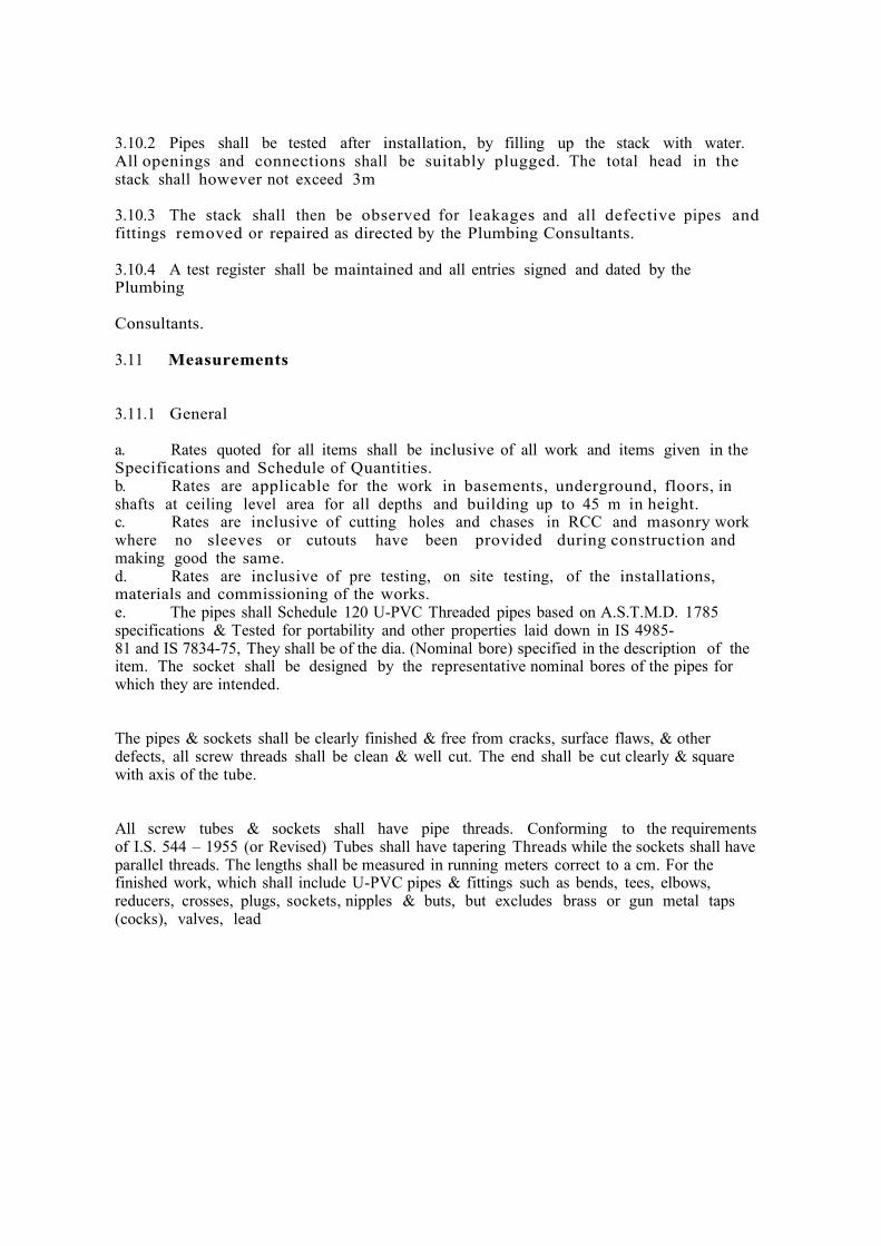
3.10.2 Pipes shall be tested after installation, by filling up the stack with water. All openings and connections shall be suitably plugged. The total head in the stack shall however not exceed 3m 3.10.3 The stack shall then be observed for leakages and all defective pipes and fittings removed or repaired as directed by the Plumbing Consultants. 3.10.4 A test register shall be maintained and all entries signed and dated by the Plumbing Consultants. 3.11 Measurements 3.11.1 General a. Rates quoted for all items shall be inclusive of all work and items given in the Specifications and Schedule of Quantities. b. Rates are applicable for the work in basements, underground, floors, in shafts at ceiling level area for all depths and building up to 45 m in height. c. Rates are inclusive of cutting holes and chases in RCC and masonry work where no sleeves or cutouts have been provided during construction and making good the same. d. Rates are inclusive of pre testing, on site testing, of the installations, materials and commissioning of the works. e. The pipes shall Schedule 120 U-PVC Threaded pipes based on A.S.T.M.D. 1785 specifications & Tested for portability and other properties laid down in IS 4985- 81 and IS 7834-75, They shall be of the dia. (Nominal bore) specified in the description of the item. The socket shall be designed by the representative nominal bores of the pipes for which they are intended. The pipes & sockets shall be clearly finished & free from cracks, surface flaws, & other defects, all screw threads shall be clean & well cut. The end shall be cut clearly & square with axis of the tube. All screw tubes & sockets shall have pipe threads. Conforming to the requirements of I.S. 544 – 1955 (or Revised) Tubes shall have tapering Threads while the sockets shall have parallel threads. The lengths shall be measured in running meters correct to a cm. For the finished work, which shall include U-PVC pipes & fittings such as bends, tees, elbows, reducers, crosses, plugs, sockets, nipples & buts, but excludes brass or gun metal taps (cocks), valves, lead

connection pries. The measurements shall be taken separately for internal and external work. The length shall be taken along the central line of the pipe & fittings. All Pipes & fittings shall be classified according to their diameters, method of jointing and fixing substance, quality & finish. The diameter shall be the nominal diameter of the internal bore, except PVC pipes in which case dia. Is specified as external dia. In case of fittings of unequal bore, the largest bore shall be measured unless otherwise specified fittings shall be enumerated. Digging and refilling of trenches shall be measured separately or clubbed with main item. Pipes laid in trenches (or without supports) and pipes fixed to walls, ceiling, etc. with supports shall be measured separately as the case may be. Inserts for R.C.C. tanks f. Gl pipes shall measured per running meter correct to a centimeter for the finished work which shall include fittings e.g. bends, tees, elbows, reducers, crosses, sockets, nipples and nuts. The length shall be taken along centre line of the pipes and f ittings. All pipes and f ittings shall be classified according to their diam eter, m ethod of jointing and fixing substance, quality, and finish. The diameters shall be nominal diameter of internal bore. ♦ Cement concrete around pipes shall be measured along the centre of the pipe line measured per linear meter and include any masonry supports, shuttering and centering, cutting complete as described in the relevant specifications. ♦ Slotted angles / channels shall be measured per linear meter of finished length and shall include support bolts and nuts embedded in masonry walls with cement concrete blocks and nothing extra will be paid for making good the same. 3.11.2 Fittings (excluding pipe fittings) (Unit of measurement by numbers) Cleanout plugs shall be m easured by number per piece and shall include all items described in the relevant Specifications and Schedule of Quantities. The fitting shall be of U-PVC High pressure schedule 80 type conforming to the requirement of ASTMD – 2464 threaded U-PVC plastic pipe fitting sch. 80 to IS 554 for thread dimension with a pressure rating of over 16 bar complying with all the appropriate requirements as specified. The fittings shall be designated by the respective nominal bore of the pipes for which they are intended.

The fittings shall have screw threads at the ends conforming to the requirements of IS:544-1955(or revised). Female threads on fitting shall be parallel & male threads (except on running nipples & collars of unions) shall be taper. 3.11.3 Painting Painting of pipes and fittings shall be measured per running meter and shall be inclusive of all fittings and clamps. No deduction for fittings shall be made. 3.11.4 Excavation for soil pipes N o e x t r a p a ym e n t s h al l b e a dm i s s i b le wi t h r e s p e c t t o e x c a v at io n , refilling and disposal of surplus earth for cast iron soil and waste pipes laid below ground, in sunken slabs or over basement rafts or for drainage pipes laid below ground. 3.12 Anchor Fasteners 3.12.1 All pipe supports, hangers, clamps to be fixed on RCC walls, beams, columns, slabs and masonry walls 230mm thick, and above by means of uried zed expandable anchor fasteners in drilled holes of correct size and model to carry the weight of pipes. Drilling shall be made only by approved type of power drill as recommend and approved by manufacturer of the anchor fasteners. Failure of any fastening devices shall be the entire responsibility and contractor shall redo or provide additional supports at his own cost. He shall also compensate the owner for any damage that may be caused by such failures.

4.0 Drainage (Storm Water Drains) 4.1 Scope of work 4.1.1 Work under this section shall consist of furnishing all labor, materials, equipment and appliances necessary and required to completely install all the drainage system as required by the drawings and specified hereinafter or given in the Schedule of Quantities. 4.1.2 Without restricting to the generality of the foregoing, the drainage system shall include:- ♦ Storm water drainage, excavation, pipelines, manholes, catch basins, drain channels and connections to the existing storm water drain. 4.2 General requirements 4.2.1 All materials shall be new of the best quality conforming to specifications and subject to the approval of the Plumbing Consultants. 4.2.2 Drainage Lines and open drains shall be laid to the required gradients and profiles. 4.2.3 All drainage work shall be done in accordance with the local municipal by-laws. 4.2.4 Contractor shall obtain necessary approval and permission for the drainage system from the municipal or any other competent authority. 4.2.5 Cutting, Laying & Jointing of U-PVC Pipes The pipes & fittings shall be inspected at site before use to ascertain that they conform the specification. The defective pipes shall be rejected. Where the pipes have to be cut or rethreaded, ensure square cut of pipe ends. The ends shall be carefully chamfered with file so that no obstruction to bore is offered. The proper size wooden plug in the end of the pipes shall be inserted then be threaded conforming to the requirements of IS544-1955 with pipe dies & taps carefully in such a manner as will not result in slackness of joints when the two pieces are screwed together. The sharp edges of gripping vice & other handling tools should be muffled with a suitable packing to prevent damage of pipe surface Non metallic tools should be used for jointing preferably. The taps & dies shall be used only for straightening screw threads which have become bend or damaged & shall not be used for turning of the threads so as to make them slack, as the later procedure may not result in water tight joint. The screw threads of pipes & fittings shall be protected from damage until they are fitted. The pipes shall be cleaned & cleared of all foreign matter before being laid. In jointing the pipes, the screwed end of the pipes shall be covered with proper layer of Teflon Tape

wrapped round the screwed end of the pipe. The joints shall be made with hand tightening of the fitting over the pipe & one or two turn over. Hand tightened joint shall then be screwed in the socket, Care should be taken that all pipes & fitting are properly jointed so as to make the joints completely water tight & pipes are kept at all time free form dust & dirt during the fixing. Burr from the joint shall be removed after laying, the open ends of the pipes shall be temporarily plugged to prevent access of water, solid or any other foreign matter. In normal case pipe shall be buried to depth of 450 mm from crown of pipe. Where external loading can be expected. The depth shall be 750 mm from crown of pipe crossing RCC Hume pipe or metallic pipe sleeve shall be provided for crossing The roads & driveways. All exposed horizontal pipes shall be supported at a distance of approximate 800 mm & vertical pipes shall be supported at a distance of 1200 mm with appropriate clips to allow for movement of the pipes during change in temperature. For temperature above 40 D.C. distances for clips shall be 500 mm for horizontal pipe & 900 mm for vertical pipe. For sealing of joints best quality Teflon tape or pipe joint sealing compound shall be used. Air release valve of ¼ th of main line diameter shall be provided at every sharp turn or at every 1000 feet interval in case of plain area. Only Readymade U-PVC fitting shall be used for turn, branch & tap connections. For tap connections standard service saddle shall be used. The pipes should not be subjected to rough handling. It is advisable that during transportation the height of the pipe stack shall not exceed 2 meters. For long time storage in racks the height of the U-PVC pipes shall not exceed 1 Meter. Testing All lengths of the sewer and drain shall be fully tested for water tightness by means of water pressure maintained for not less than 30 minutes. Testing shall be carried out from manhole to manhole. All pipes shall be subjected to a test pressure of at least 1.5-meter head of water. The test pressure shall, however, not exceed 6 meter head at any point. The pipes shall be plugged preferably with standard design plugs with rubber plugs on both ends. The upper end shall, however, be connected to a pipe for filling with water and getting the required head. Sewer lines shall be tested for straightness by: (i) inserting a smooth ball 12 mm less than the internal diameter of the pipe. In the absence of obstructions such as yarn or mortar projecting at the joints the ball should roll down the invert of the pipe and emerge at the lower end, (ii) means of a mirror at one and a lamp at the other end. If the pipeli ne is strai ght the full ci rcl e of li ght wi ll be seen otherwise obstruction of deviation will be apparent. The Contractor shall give a smoke test to the drains and sewer at his own expense and charges, if directed by the Plumbing Consultants. A test register shall be maintained which shall be signed and dated by Contractor, and Project Manager. 4.3 Reinforced cement concrete pipes (where applicable) 4.3.1 All underground storm water drainage pipes and sewer lines (other than those specified cast iron) shall be centrifugally spun S & S RCC pipes of specified class. Pipes shall be true and straight with uniform bore, throughout. Cracked, warped pipes shall not be used on

the work. All pipes shall be tested by the manufacturer and the Contractor shall produce, when directed, a certificate to that effect from the manufacturer. 4.3.2 Laying R.C.C. spun pipes shall be laid on cement concrete bed or cradles as specified and shown on the detailed drawings. The cradles may be precast and sufficiently cured to prevent cracks and breakage in handling. The invert of the cradles shall be left 12 m m below the invert level of the pipe properly placed on the soil to prevent any disturbance. The pipe shall then be placed on the bed concrete or cradles and set for the line and gradient by means of sight rails and bonding rods etc. Cradles or concrete bed may be omitted, if directed by the Project Manager. 4.3.3 Jointing A f t e r s e t t i n g o u t t h e p i p e s , t h e s o c k e t s h a l l b e c e n t e r e d o v e r t h e spigot and filled in with tarred gaskin, so that sufficient space is left on either side of the collar to receive the mortar. The space shall then be filled with cement mortar 1:2 (1 cement: 2fine sand) and caulked by means of proper tools. All joints shall be finished at an angle of 45 degrees to the longitudinal axis of the pipe on both sides of the collars neatly. 4.3.4 Testing All pipes shall be tested to a hydraulic test of 1.5 m head for at least 30 minutes at the highest point in the section under test. Test shall also be carried out similar to those for stoneware pipes given above. The smoke test shall be carried out by the Contractor, if directed by the Plumbing Consultants. A test register shall be maintained which shall be signed and dated by Contractor, / Plumbing Consultants / Representative.

5.0 Pumps & Equipment 5.1 Scope of work 5.1.1 Work under this section shall consists of furnishing all labour, m a t e r i a ls , e q u i p m e n t a n d a p p li a n c e s n e c e s s a r y a n d r e q u i r e d t o supply, install and comm ission the drainage a s d e s c r i b e d h e r e i n a f t e r a n d g i v e n i n t h e s c h e d u l e o f q u a n t it ie s a n d / o r s h o wn o n t h e d r a wi n g s . 5.2 General requirements 5.2.1 All materials shall be new of the best quality conform ing to spec if icat ion s and subj ect to the a pproval of Proj ect Manager. 5.2.2 All equipm e nt s hall be of t he bes t available m ak e m anuf act ured by reputed firms. 5.2.3 All equipment shall be in a neat skillful manner. 5.2.4 Equipment shall be so installed as to provide sufficient clearance be tween the end walls and between equipm ent to equipm ent. 5.2.5 E a c h p u m p i n g s e t s h a l l b e p r o v i d e d w i t h a b u t t e r f l y v a l v e o n t h e s u c t i o n a n d d e l i v e r y s i d e a n d a f l a p t yp e n o n - r e t u r n v a l v e o n t h e delivery side. 5.2.6 A l l p u m p c o u p l i n g s a n d b e l t g u a r d s f o r a i r c o m p r e s s o r s s h a l l b e totally enclosed with 5 mm m esh. 6.0 Specifications for Pumps 6.1 Drainage Pumps Drainage pumps shall be measured by numbers and shall include all items as given in the specifications and schedule of quantities to provide a complete working system. 6.2 Level controllers & Alarms Level controllers for each set of pumps shall be measured by number and inclusive of probes, cabling unto surface box near the pump and shall include all items as given in the specifications and schedule of quantities to provide a complete working system. 6.3 Piping Work 6.3.1 Suction and delivery headers for each pumping system shall be measured per linear meter of finished length and shall include all items as given in the schedule of quantities. Painting shall be included in rate of headers. 6.3.2 G.I. pipes between various equipment’s shall be measured per linear meter of the finished length and shall include all fittings, flanges, jointing, clamps for fixing

to walls or hangers and testing. Flanges shall include 3 mm thick insertion rubber gasket, nuts, bolts and testing. 6.3.3 Water Tank, Vibration eliminators, “ Y “ strainers, butterfly valves, slim non return valves shall be measured by numbers and shall include all items as given in the schedule of quantities and specifications 6.4 Painting and cleanup 6.4.1 On completion of the installation contractor shall scrub clean all pumps, piping, filters and equipment and apply one coat of primer. 6.4.2 Apply two or more coats of synthetic enamel paint of approved make and shade on steel pipes. 6.4.3 Provide painted identification legend and direction arrows on all equipment and piping as directed by engineer-in-charge. 6.4.4 On final completion of the work, contractor shall cleanup the site and filter room of all surplus materials rubbish and leave the place in a broom-clean condition. 6.5 Cables 6.5.1 Contractor shall provide all power and control cables from the motor control centre to various motors, level controllers and other control devices. 6.5.2 Cables shall conform to I.S. 1554 and Carry ISI mark. 6.5.3 Wiring cables shall conform to IS 694. 6.5.4 All power and wiring cables shall be aluminum conductor PVC insulate armoured and PVC sheathed of 1100 volts grade. 6.5.5 All control cables shall be copper conductor PVC insulated armoured and PVC sheathed 1100 vol. grade. 6.5.6 All cables shall have stranded conductors. The cables shall be in drums as far as possible and bear manufacturer’s name. 6.5.7 All cab le joints shall be m ade in an approved m anner as per st andard practice. 6.6 Cable trays 6.6.1 Contractor shall provide M.S. Slotted cable trays at locations as shown on the drawings and of sizes as given in the schedule of quantities.

6.6.2 Cables trays shall be supported from the bottom of the slab at intervals of 30 cms at both ends by welding support rods with insert plates or to reinforcement bars. Cutting of holes in the slab for exposing of reinforcement bars and making good the same after welding of support rods shall be included in the rate of the tray and no separate payment shall be made on this account. 6.6.3 6.14.3. Cost of clips, bolts, nuts, supports rods and any other materials required to fix the trays in proper manner shall be included in the rate for trays. 6.7 Measurement 6.7.1 General ♦ Unit rate for individual items, e.g., Pumps, MCC are for purposes of payments only. Piping, headers, valves, accessories, cabling and MCC to measured separately in this contract only. ♦ All items must include all accessories fittings as described in the specifications, BOQ and shown on the drawings.

VIII APPROVED MAKES OF MATERIAL
APPROVED MAKES OF MATERIAL Acceptable makes of materials to be used in the work are enclosed. In case of non- availability of these makes, after the approval of the Authority, the Contractor can use the alternative makes only BIS marked materials. Non BIS marked materials may be permitted by the Authority only when BIS marked materials are not manufactured
SR. NO.
NAME OF ITEM MAKE APPROVED
1) ORDINARY PORTLAND CEMENT GRADE 43/53
BIRLA, JK, ACC, ULTRATECH, JAYPEE, AMBUJA,
2) WHITE CEMENT
JK, BIRLA, ACC, JAYPEE, AMBUJA
3)
REINFORCEMENT STEEL
TATA , SAIL, RINL, JINDAL, JSW STEEL, SHYAM STEEL
4) PAINT/POLISH/ PRIMER/ WATER PROOFING PAINT
BERGER, ASIAN, DULUX, BRITISH PAINT
5)
SILICON / POLYURETHANE SEALANT
FOSROC / G.E. SILICONES / DOW-CORNING,/ WACHER SILICON, /HOLEX,/ DECOT, SIKA / CHOKSEY CHEMICALS
6) PVC PIPE FOR WEEP HOLES
PRINCE, SUPREME, FINOLEX
7)
CONCRETE ADMIXTURES, OTHER CONSTRUCTION CHEMICALS
M.C.BAUCHEMIE,FOSROC,PIDILITE,CICO,SIKA,BASF,ASIAN LABORATORIES,ULTRACON
8)
STRUCTURAL STEEL/MS
TATA , SAIL, RINL, JINDAL, JSW STEEL, SRMB
9) WATERPROOFING CHEMICALS/SYSTEM
BASF,SIKA,FOSROC,PIDLIE,CARLISLE,FIRE STONE
10) RHS/SHS CLOSED STRUCTURAL SAIL/TISCO / RINL /JSW

11) ALUMINIUM STRUCTURAL MEMBERS –WINDOWS, GLAZING AND PARTITIONS
JINDAL,INDALCO ,HINDALCO,NALCO,BHORUKA
12)
AAC BLOCK
AEROCON,BUILTECH,INSTABLOCK,J K,MAGICRETE
13) AAC MORTAR
FERROUSCRETE, ULTRATECH, JK
14) SHUTTERING PLY
ARCHID,CENTURY,MERINO,KITPLY
15) BRICKS
CLAY BRICKS,FLY ASH BRICKS
16)
COVER BLOCKS
FACTORY MADE CONCRETE COVER BLOCKS (ASTRA MAKE).
17)
READY MIX CONCRETE (RMC)
THE RMC SHALL BE PROCURED FROM THE SOURCE AS APPROVED BY ENGINEER – IN CHARGE.
DOORS & WINDOWS 18)
FLUSH DOOR
CENTURY,GREEN,MERINO,DURO,ARCHID,TRUWOOD.
19)
FRP DOOR
DIAMOND / KUTTY / CIL /FENESTA / WINTECH ALUPLAST OR EQUIVALENT
20)
GLASS
MODIGUARD, SAINT GOBAIN, ASAHI INDIA, CONTINENTAL
21)
FLOOR SPRINGS
SEVAX, DORMA, EVERITE, OMEGA, EVEREST UNIVERSAL 68, HINDUSHAN, GODREJ,RITZ, KICH, NEKI
22) HYDRAULIC / CONCEALED DOOR CLOSER
EVERITE, HINDUSTAN, OZONE, DORMA, GODREJ, RITZ/ARCH
23)
DOOR ACCESSORIES
DORSET /KICH /EBCOLAM /BLUM /EMTEK /KWIKSET /DELTANA

/OMNIA/GODREJ / SHALIMAR /RAMSON/ /RELIANCE/PUNIT/ARCH
24) CYLINDRICAL LOCK, RIM LOCK
GODREJ, EUROPA, DORMA, BLUM
25) SS MORTISE LOCK WITH ONE DEAD BOLT AND PAIR OF SS HANDLES STEEL GRADE –SS304
DORMA, HAFELE ,GODREJ, DORSET
26) SS TOWER BOLT
DORMA, HAFELE ,GODREJ
27) S. S. PATCH FITTINGS DORMA/GIESSE /CASMA 28)
S. S. FRICTION HINGES EBCO SECURISTILE, COTSWORLD
29)
S. S. HANDLES, HINGES
VISTA OR CONFIRMING TO ASTM 304 GRADE /ARCH / KICH/ DORMA/ INGERSOLL RAND /GODREJ
30) RESIN ANCHOR / ANCHOR FASTENERS
HILTI /FISCHER /CANNON
31)
LAMINATES
MERINO, GREENLAM,CENTURY,NOVAPAN,ARCHID,DURO
32)
PLYWOOD
MERINO, GREENLAM,CENTURY,NOVAPAN,ARCHID,DURO
33) VENEER
DURO / GREENPLY / CENTURY/VENTURA
34) FIRE RATED DOORS & FRAMES
NAVAIR / SHAKTIMET / GMP/ PROMAT / GODREJ
35) FIRE RATED GLASS
SAINT GOBIN, TORCH, GLABERWAL
36)
GLASS : MIRROR
SAINT GOBAIN/ ASAHI INDIA SAFETY / PILKINGTON
PAINTING 37)
PRIMER :EXTERIOR PRIMER
BP WHITE (BERGER),DECOPRIME WT (ASIAN),AKZONOBEL (DULUX),NEROLAC
38) PRIMER : INTERIOR PRIMER
BP WHITE (BERGER),DECOPRIME WT (ASIAN),

AKZONOBEL (DULUX),NEROLAC
39)
SYNTHETIC ENAMEL
AKZONOBEL (DULUX), ASIAN (APCOLITE),KANSAI NEROLAC(SYNTHETIC ENAMEL)), BERGER
40)
TEXTURED EXTERIOR PAINT
AKZONOBEL (DULUX), ASIAN (APEX ULTIMA),NEROLAC KANSAI (EXCEL),ULTRA TECH SPECTRUM, BERGER
41)
ACRYLIC EXTERIOR PAINT
ICI DULUX (WEATHER SHIELD MAX), BERGER (WEATHER COAT LONGLIFE), NEROLAC (EXCEL ANTI-PEEL FORMULA), ASIAN (APEX ULTIMA WEATHER PROOF), SURFACOATS (FINESSE), POLYGEL INDUSTRIES PVT. LTD. (ENDURA)
42) PREMIUM ACRYLIC EMULSION PAINTS
DULUX ,NEROLAC ,ASIAN PAINTS, BERGER
43)
STEEL /WOOD PRIMER
AKZONOBEL (DULUX), NEROLAC, ASIAN PAINTS, BERGER, JENSON & NICHOLSON
44) WALL PUTTY
BIRLA WALL CARE,, JK WHITE, SAINT GOBAIN,
45) FERROUSCRETE 46)
EPOXY PAINTS / PRIMER
KANSAI NEROLAC ,ASIAN AKZONOBEL (DULUX),FOSROC ,ICI
47) 48)
PRIMER FOR G.I. SURFACES
ALL TYPES / KINDS OF EPOXY PRIMER, ETCH PRIMER
CEMENT PRIMER 49)
FIRE PAINT ASIAN,JOTUS,AKZONOBEL
50)
GYPSUM PLASTER
FERROUS CRETE,ELITE(90), ULTRATECH
FLOORING
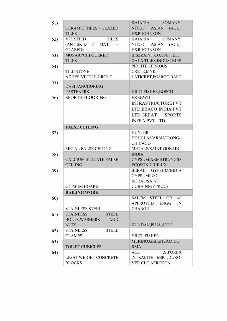
51) CERAMIC TILES / GLAZED TILES
KAJARIA, SOMANY, NITCO, ASIAN (AGL), H&R JOHNSON
52) VITRIFIED TILES (ANTISKID / MATT / GLAZED)
KAJARIA, SOMANY, NITCO, ASIAN (AGL), H&R JOHNSON
53) MOSAIC/CHEQUERED TILES
BISZZA,NITCO,UNITILE,DALA TILES INDUSTRIES
54) TILE/STONE ADHESIVE/TILE GROUT
PIDLITE,FERROUS CRETE,MYK LATICRET,FOSROC,BASF
55) DASH/ANCHORING FASTENERS HILTI,FISHER,BOSCH
56) SPORTS FLOORING FREEWILL INFRASTRUCTURE PVT LTD,EBACO INDIA PVT LTD,GREAT SPORTS INFRA PVT LTD
FALSE CEILING 57)
METAL FALSE CEILING
HUNTER DOUGLAS/ARMSTRONG/CHICAGO METALS/SAINT GOBAIN
58) CALCIUM SILICATE FALSE CEILING
INDIA GYPSUM/ARMSTRONG/DECOSONIC/HILUX
59)
GYPSUM BOARD
BERAL GYPSUM/INDIA GYPSUM/USG BORAL/SAINT GOBAIN(GYPROC)
RAILING WORK 60)
STAINLESS STEEL
SALEM STEEL OR AS APPROVED ENGG IN CHARGE
61) STAINLESS STEEL BOLTS,WASHERS AND NUTS KUNDAN,PUJA,ATUL
62) STAINLESS STEEL CLAMPS HILTI, FISHER
63) TOILET CUBICLES
MERINO,GREENLAM,DORMA
64) LIGHT WEIGHT CONCRETE BLOCKS
ACC ,SIPOREX ,XTRALITE ,EBR ,DURO-VER CLC,AEROCON

65)
FLOOR HARDENER
IRONITE, FOSROC, HARDONATE LATECRETE
66)
ANTI-TERMITE TREATMENT AGENCIES
PEST CONTROL OF INDIA, EXPRESS PESTICIDES CORP, FLITE CORP, TATA TERMEX, CHLOROPYRICHOS, VRINDAVAN AGRICULTURAL SERVICES, PEPSOP PEST CONTROL SERVICES
67)
ROOFING WORK-GALVALUME/ZINCALUME
KALZIP,BEMO,SANKYO, TATA BLUESCOPE, EVEREST, BHUSHAN, JSW , LLYOD, MANDERINE TILES,MAX ROOFING ROOFING SYSTEM,MCCOY, CHETANSOOD
68)
FAÇADE/ALUMINIUM FINS WORK
FAÇADE TESTING,HUNTER DOUGLAS, LINDNER,CHICAGO METALS,ALUCOBOND,RENOBOND
69) ALUMINIUM COMPOSITE CLADDING SYSTEM
ALUCOBOND,RENOBOND
PHE PIPES,EQUIPMENTS & ACCESSORIES
70) TRANSFER PUMPS (DOMESTIC AND FLUSHING )
GRUNDFOSS, ARMSTRONG
71) PRESSURE BOOSTING PUMPS (DOMESTIC AND FLUSHING )
GRUNDFOSS, ARMSTRONG
72) BOREWELL SUBMERSIBLE PUMPS (DOMESTIC AND FLUSHING )
GRUNDFOSS, ARMSTRONG
73) SUBMERSIBLE PUMPS (SURFACE SWD)
GRUNDFOSS, ARMSTRONG

74) SUBMERSIBLE PUMPS (SANITARY DRAINAGE)
GRUNDFOSS, ARMSTRONG
75) HYDROPNEUMATIC PUMPING SYSTEM
GRUNDFOSS, ARMSTRONG
76) MOTORS
KIRLOSKAR,SIEMENS,CROMPTON
77) BUTTERFLY VALVE AUDCO,ADVANCE,INTERVALVE
78) NON RETURN VALVE KIRLOSKAR,ADVANCE,INTERVALVE
79) FOOT VALVE KIRLOSKAR,LEADER,INTERVALVE
80) SOLENOID VALVE DANFOSS,AVCON
81) FLOAT VALVE TECHNO,HBD,ZOLOTO
82) "Y" STRAINER SANT,HAMMER,DANFOSS
83) SLUICE VALVE KIRLOSKAR,H. SARKAR,INDIAN VALVE COMPANY
84) BALL VALVE ( SCREWED END)
AUDCO,ADVANCE,INTERVALVE
85) AIR RELEASE VALVE KIRLOSKAR,ADVANCE,INTERVALVE
86) PRESSURE REDUCING VALVE
KIRLOSKAR,LEADER,INTERVALVE
87) THREEWAY MOTORISED VALVE
DANFOSS,AVCON
88) PRESSURE GAUGE H. GURU,FIEBIG,WAAREE
89) PRESSURE SWITCH INDFOSS,DANFOSS,VIKING
90) FLOW SWITCH/TAMPER SWITCH
DANFOSS,CIRRUS ENGG,AUTO PUMP
91) LEVEL CONTROLLER & INDICATOR
TECHNIKA TECHTROL,CIRRUS ENGG,AUTO PUMP
92) CPVC PIPES ( WATER SUPPLY)
ASTRAL,ASHIRWAD,AJAY
93) PPR PIPES ASTRAL,ASHIRWAD,AJAY

94) UPVC/SWR PIPES SUPREME,FINOLEX,PRINCE
95) G.I. PIPES TATA,JINDAL,ZENITH
96) C.I. PIPES NECCO,KAPILANSH,SAINT GOBIN
97) HDPE PIPES GEBERIT,DURALINE,RELIANCE
98) RCC PIPE INDIAN HUME PIPE,SPUN PIPE CO., SEMENTIA
99) STONEWARE PIPES AND FITTINGS
DALMIA,PARRY,
100) ASTOLAN PP PIPE ASTRAL,,
101) GI/MS PIPES TATA,JINDAL,ZENITH
102) STANDARD M.S. FITTINGS
INDUSTRIAL VALVE COMPANY,SEAMLESS FITTINGS, R BRAND
103) G.I FITTINGS R BRAND,ZOLOTO, HB
104) FORGED STEEL FITTINGS
VS ENGINEERING,JK FORGING, BHARAT FORGE
105) PIPE CLAMPS & SUPPORTS
HITECH,CHILLY,EURO CLAMP
106) FASTNERS FISHER,HILTI,
107) WELDING RODS L & T,ADVANI,COSMOS
108) MECHANICAL SEAL BERGMANN,SEALOL,AS PER PUMP MANUFACT.
109) ANTIVIBRATION MOUNTINGS & FLEXIBLE CONNECTIONS
DUNLOP,FLEXIONICS,RESISTOFLEX
110) FIRE SEALANT BIRLA 3M,HILTI,PROMAT
111) PAINTS ASIAN PAINTS,SHALIMAR,BERGER
112) MANHOLE COVERS (C.I./D.I)
NECO,KATAR PIPE & FITTINGS,KAPILANSH

113) MANHOLE COVERS (FRP/GRP)
THERMODRAIN,EVERLAST,H.P. INTERNATIONAL
114) WATER METER CAPSTAN,KRANTI,KAYCEE
115) G.M. FERRULE ZOLOTO,SANT,LEADER
116) DRIP SEAL VINOD CEMENT CO. CHANDIGARH,,
117) DRAIN CHANNEL FRP GRATING
THERMODRAIN,FIBROCAST,
118) INSULATION THERMAFLEX,ARMAFLEX,K-FLEX
119) GREASE TRAP ACO,WADE,PATEL PATTERN
120) RAIN WATER OUTLET/ KHURRA
ACO,WADE,ZURN
121) CABLE POLYCAB,PHINOLEX,RRK
122) MCCB/MCB L & T,SCHNEIDER ELECTRIC,Siemen
123) AIR CIRCUIT BREAKER L & T,SCHNEIDER ELECTRIC,GE ( Spectronic)
124) CHANGE OVER SWITCH L & T,SIEMEN,ABB
125) POWER/AUX. CONTACTOR
L & T,SIEMEN,ABB
126) CABLE GLANDS MULTI,DOWELLS,Commet
127) POWER DISTRIBUTION PANELS AND MCC
L & T,BALAJI ELECTRO CONTROLS,Elin Switchboard
128) DIGITAL METER L & T,ENERCON,Electrex
129) STARTER/CONTACTOR/B METAL RELAY
L & T,SCHNEIDER ELECTRIC,Siemen
130) CONTROL TRANSFORMER/POTENTIAL TRANSFORMER
KAPPA,AE,Pragati
131) RELAYS L & T,SIEMEN,ABB

132) VARIABLE SPEED DRIVES
DANFOSS,SIEMEN,ABB
133) CABLE TRAY/TRUNKING/LADDERS(FACTORY FABRICATED)
RICCO,PROFAB ENGINEER,Indiana
134) ELECTRICAL CONDUIT AND ACCESSORIES (M.S.)
DIAMOND,PRECISION,
135) FINAL DISTRIBUTION BOARD
L & T,LEGRAND,Siemen
136) MOTOR PROTECTION CIRCUIT BREAKER
L & T,SCHNEIDER ELECTRIC,Siemen
137) ELECTRONIC DIGITAL METER
L&T,CONSERVE,Enercon
138) TIMER L & T,SIEMEN,ABB
139) ELECTRICAL PANELS ELECMEC,SCOOT,Zenith
140) WATER CLOSET (WC) PARRYWARE,HINDWARE,KOHELLER
141) CI FIXTURTES ASHOK IRON WORKS,BOMBAY IRON WORKS, A HUSAINJI
142) URINALS PARRYWARE,HINDWARE,KOHELLER
143) BIDET PARRYWARE,HINDWARE,KOHELLER
144) WASH BASIN PARRYWARE,HINDWARE,KOHELLER
145) WATER CLOSET SEAT COVER
PARRYWARE,HINDWARE,KOHELLER
146) FLUSH VALVE JAQUAR,HINDWARE,KOHELLER
147) WC FLUSH TANK (EXPOSED)
PARRYWARE,HINDWARE,KOHELLER
148) WC FLUSH TANK (CONCEALED)
GEBERIT,HINDWARE,KOHELLER
149) BIB COCK JAQUAR,HINDWARE,KOHELLER
150) PILLAR COCK JAQUAR,HINDWARE,KOHELLER
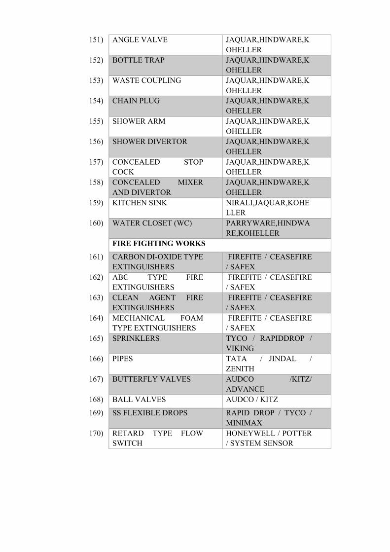
151) ANGLE VALVE JAQUAR,HINDWARE,KOHELLER
152) BOTTLE TRAP JAQUAR,HINDWARE,KOHELLER
153) WASTE COUPLING JAQUAR,HINDWARE,KOHELLER
154) CHAIN PLUG JAQUAR,HINDWARE,KOHELLER
155) SHOWER ARM JAQUAR,HINDWARE,KOHELLER
156) SHOWER DIVERTOR JAQUAR,HINDWARE,KOHELLER
157) CONCEALED STOP COCK
JAQUAR,HINDWARE,KOHELLER
158) CONCEALED MIXER AND DIVERTOR
JAQUAR,HINDWARE,KOHELLER
159) KITCHEN SINK NIRALI,JAQUAR,KOHELLER
160) WATER CLOSET (WC) PARRYWARE,HINDWARE,KOHELLER
FIRE FIGHTING WORKS
161) CARBON DI-OXIDE TYPE EXTINGUISHERS
FIREFITE / CEASEFIRE / SAFEX
162) ABC TYPE FIRE EXTINGUISHERS
FIREFITE / CEASEFIRE / SAFEX
163) CLEAN AGENT FIRE EXTINGUISHERS
FIREFITE / CEASEFIRE / SAFEX
164) MECHANICAL FOAM TYPE EXTINGUISHERS
FIREFITE / CEASEFIRE / SAFEX
165) SPRINKLERS TYCO / RAPIDDROP / VIKING
166) PIPES TATA / JINDAL / ZENITH
167) BUTTERFLY VALVES AUDCO /KITZ/ ADVANCE
168) BALL VALVES AUDCO / KITZ
169) SS FLEXIBLE DROPS RAPID DROP / TYCO / MINIMAX
170) RETARD TYPE FLOW SWITCH
HONEYWELL / POTTER / SYSTEM SENSOR
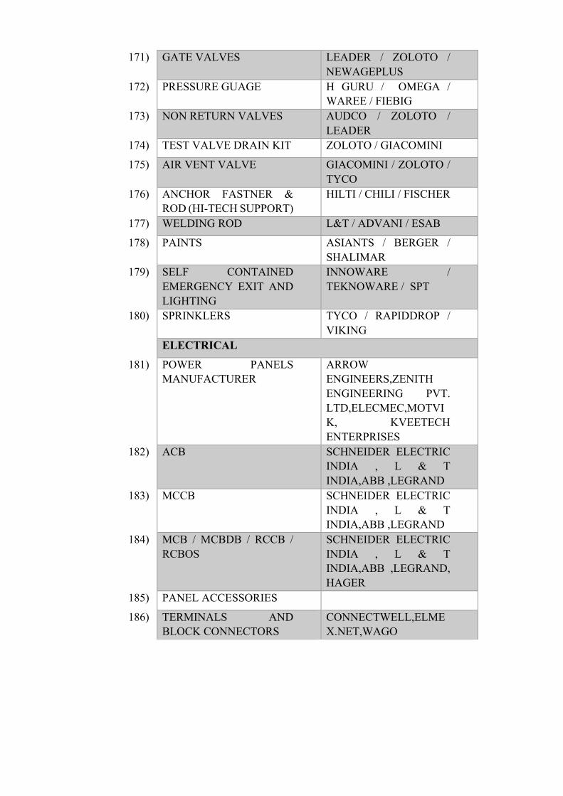
171) GATE VALVES LEADER / ZOLOTO / NEWAGEPLUS
172) PRESSURE GUAGE H GURU / OMEGA / WAREE / FIEBIG
173) NON RETURN VALVES AUDCO / ZOLOTO / LEADER
174) TEST VALVE DRAIN KIT ZOLOTO / GIACOMINI
175) AIR VENT VALVE GIACOMINI / ZOLOTO / TYCO
176) ANCHOR FASTNER & ROD (HI-TECH SUPPORT)
HILTI / CHILI / FISCHER
177) WELDING ROD L&T / ADVANI / ESAB
178) PAINTS ASIANTS / BERGER / SHALIMAR
179) SELF CONTAINED EMERGENCY EXIT AND LIGHTING
INNOWARE / TEKNOWARE / SPT
180) SPRINKLERS TYCO / RAPIDDROP / VIKING
ELECTRICAL
181) POWER PANELS MANUFACTURER
ARROW ENGINEERS,ZENITH ENGINEERING PVT. LTD,ELECMEC,MOTVIK, KVEETECH ENTERPRISES
182) ACB SCHNEIDER ELECTRIC INDIA , L & T INDIA,ABB ,LEGRAND
183) MCCB SCHNEIDER ELECTRIC INDIA , L & T INDIA,ABB ,LEGRAND
184) MCB / MCBDB / RCCB / RCBOS
SCHNEIDER ELECTRIC INDIA , L & T INDIA,ABB ,LEGRAND, HAGER
185) PANEL ACCESSORIES
186) TERMINALS AND BLOCK CONNECTORS
CONNECTWELL,ELMEX.NET,WAGO

187) CONTROL RELAYS/TIMERS
SELEC CONTROLS PVT. LTD, OMRON INDIA
188) SELECTOR SWITCHES L & T INDIA, KAYCEE SELECTOR SWITCHES, SURAJ ELECTRONICS AND ELECTRICALS
189) INDICATING LAMPS SCHNEIDER ELECTRIC INDIA , L & T INDIA,TEKNIC,VAISHNAV
190) CONTACTORS SCHNEIDER ELECTRIC INDIA , L & T INDIA,ABB
191) ALL HARDWARE COMPONENTS
ZINC PLATED WITH TENSILE STRENGTH OF 8.8 GRADE
192) ALUMINIUM BUS BAR HINDALCO LTD
193) COPPER BUS BAR PURITY SHOULD BE 99.9 %
194) CURRENT TRANSFORMERS
RECO TRANSFORMERS PVT.LTD,NEWTECK,TRANSPOWERTECH,TRINITY ENERGY
195) LOAD MANAGERS/MEASURING INSTRUMENTS
HPL, SECURE, ELMEASURE, SCHNEIDER ELECTRIC INDIA, RISHABH, NEWTEK ELECTRICALS
196) SPD'S CAPE ELECTRIC, OBO BETTERMANN ,ASCO,ABB,L& T INDIA,ZOTUP
197) ATS (AUTO TRANSFER SWITCH)
ASCO
198) MTS (MANUAL TRANSFER SWITCH)
SOCOMEC INNOVATIVE POWER SOLUTIONS , SCHNEIDER ELECTRIC INDIA, EATON
199) CAPACITORS NEPTUNE ELECTRICAL INDUSTRIES, L&T

INDIA, SCHNEIDER ELECTRIC INDIA, SUBODHAN ENGINEERS PUNE PVT. LTD
200) POWER FACTOR CORRECTION RELAY
EPCOS,L & T ,ABB
201) PROTECTIVE RELAYS L & T INDIA, SCHNEIDER ELECTRIC INDIA,ABB
202) BUSDUCT SCHNEIDER ELECTRIC , C & S, L &T,GODREJ
203) ARMOURED LT CABLES (FRLS & XLPE )
POLYCAB,HAVELLS,RR CABLE, KEI,APAR INDUSTRIES,GLOSTER,CENTURY
204) FRLS PVC INSULATED COPPER CONDUCTOR SINGLE/MULTI CORE STRANDED WIRES OF 1100 VOLT GRADE
POLYCAB,HAVELLS,RR CABLE, KEI,RAJANIGANDHA,GLOSTER,ANCHOR BY PANASONIC
205) LUGS DOWELLS, 3D BILLETE ,BRACO ELECTRICALS [ INDIA ] PVT. LTD,GLOBEX
206) GLANDS BRACO ELECTRICALS [ INDIA ] PVT. LTD,DOWELLS, HMI,COMET,RAYCHEM
207) PVC GLANDS GEWISS, RAYCHEM
208) GI CABLE TRAYS OBO BETTERMANN,PROFAB ENGINEERS PVT. LTD,ASIAN,IDIANA,INDIANA,PRAKASH FABCON
209) GI TRUNKING PRAKASH FABCON,PROFAB ENGINEERS PVT. LTD,ASIAN,IDIANA

210) GI /MS CONDUIT AND ACCESSORIES
BEC CONDUITS PVT. LTD,AKG
211) PVC CONDUIT AND ACCESSORIES
POLYCAB,PRECISION PLASTIC INDUSTRIES PVT LTD ,BEC CONDUITS PVT. LTD,AKG,ANCHOR BY PANASONIC
212) WEATHERPROOF JUNCTION BOXES
GEWISS, HENSEL
213) HALOGEN FREE FLEXIBLE CONDUIT
GEWISS
214) MODULAR SWITCH SOCKET OUTLETS,RG6 AND RJ 11 PORT
LEGRAND (ARTEOR, MYRIUS), CRABTREE INDIA (VERONA), HONEYWELL MK(CITRIC,BLENZE PLUS) ,PANASONIC
215) INDUSTRIAL SOCKETS SCAME,MENNEKES,LEGRAND,GEWISS,OBO BETTERMANN,PCE
216) FLOOR JUNCTION BOXES FOR MODULAR SWITCHES
DAVIS , LEGRAND, HONEYWELL MK
217) WORKSTATION CONNECTOR
WIELAND GERMANY
218) LED LIGHT FIXTURES PHILIPS LIGHTING,YALL,REGENT,BAJAJ ELECTRICALS,WIPRO,LANCE,HAVELLS,PANASONIC LIGHTING ,LIGHTING TECHNOLOGIES LTD,INDIABULLS GROUP,ARRAYSTORM
219) FLAMEPROOF LIGHT FIXTURES
PRATEEK EXPLOSIONPROOF PVT LTD,PROLITE
220) DECORATIVE LED LIGHT FIXTURES
PHILIPS LIGHTING,YALL,REGENT

221) LIGHTING SENSORS CAPE,PHILIPS LIGHTING, HONEYWELL MK ,HAGER
222) EXIT SIGNAGE'S PROLITE,LEGRAND,BAJAJ
223) DIMMERS SCHNEIDER ELECTRIC INDIA,SMARTEK,LUTRON,CRESTRON
224) EARTH ELECTRODE CAPE,OBO BETTERMANN,SCHNEIDER ELECTRIC INDIA
225) EARTH CONDUCTOR GI STRIP
THICKNESS OF GALVANISATION 86 MICRONS
226) EARTH CONDUCTOR CU STRIP
COPPER PURITY: 99.97 % (MIN)
227) ELASTOMERIC MAT PREMIER POLYFILM LED, POLYELECTROSAFE, CHALLENGER, RAYCHEM RPG
228) THIRD PARTY TESTING AND COMMISSIONING
T & C ENGINEERS, POWER ENGINEERS,OM ELECTROMECH
229) LIGHTING UPS SOCOMEC INNOVATIVE POWER SOLUTIONS, SCHNEIDER ELECTRIC INDIA, EMERSON NETWORK POWER, EATON
230) SEALED MAINTENANCE FREE BATTERY
QUANTA, ROCKET GLOBAL & YUASA BATTERY CO. LTD. KOREA,AMARA RAJA
231) PVC RACEWAYS MK,LEGRAND,OBO BETTERMANN
232) ALUMINIUM RACEWAYS
JINDAL ALUMINIUM LIMITEDL

233) HT SUBSTATION EQUIPMENT'S
234) VCB / SF6
ABB , SCHNEIDER ELECTRIC INDIA, C & S ELECTRIC
235) OIL TYPE TRANSFORMER
KIRLOSKAR ELECTRIC COMPANY LTD, RAKESH TRANSFORMER INDUSTRIES PVT. LTD, CG POWER AND INDUSTRIAL SOLUTIONS LTD, EMCO TRANSFORMERS LIMITED
236) DRY TYPE TRANSFORMER
KIRLOSKAR ELECTRIC COMPANY LTD, UNITED INSULATION INDUSTRIES, CG POWER AND INDUSTRIAL SOLUTIONS LTD, EMCO TRANSFORMERS LIMITED
237) HT CABLES POLYCAB ,KEI , HAVELLS ,GLOSTER
238) GOD/DOF POWER GRID SWITCHGEARS ,ELECTRTECH SYSTEMS
239) RMU SEIMENS / SCHNEIDER ELECTRIC INDIA / ABB / AREVA
240) PTS KAPPA,PRAGATHI
241) LIGHTNING PROTECTION
CAPE ELECTRIC,OBO BETTERMANN, ABB (FURSE),
242) STABILISER SERVO , KRYCARD,JINDAL
243) UPS SYSTEM SOCOMEC INNOVATIVE POWER SOLUTIONS,SCHNEIDER ELECTRIC INDIA,VERTIV (EMERSON NETWORK

POWER IS NOW VERTIV) ,EATON,ABB
244) UPS SMF BATTERIES QUANTA, ROCKET GLOBAL & YUASA BATTERY CO. LTD. KOREA,AMARA RAJA
245) ISOLATION TRANSFORMER
DATSON,POWER MATRIX,KRYCARD
246) DG SET STERLING & WILSON GENERATORS PVT LTD,GOEL POWER PVT LTD,POWERICA LTD. (CUMMINS ),VIBROPOWER GENERATORS (I) PVT. LTD.
247) NETWORKING SYSTEM
248) CAT-6 CABLES SYSTIMAX,LEGRAND ,MOLEX,SCHNEIDER ELECTRIC INDIA,R&M INDIA PRIVATE LIMITED
249) PVC CONDUIT AND ACCESSORIES
SYSTIMAX,LEGRAND ,MOLEX,SCHNEIDER ELECTRIC INDIA,R&M INDIA PRIVATE LIMITED
250) TELEPHONE AND WIRES DELTON,FINOLEX,ITL ,R&M INDIA PRIVATE LIMITED
251) RG59 OUTLETS SYSTIMAX,LEGRAND ,MOLEX,SCHNEIDER ELECTRIC INDIA,R&M INDIA PRIVATE LIMITED
252) RG59 COAXIAL CABLE POLYCAB,HAVELLS,RR CABLE, KEI,RAJANIGANDHA,R&M INDIA PRIVATE LIMITED

253) RJ45 CAT6 IO (QUAD & DUEL FACE PLATE)
SYSTIMAX,LEGRAND ,MOLEX,SCHNEIDER ELECTRIC INDIA,R&M INDIA PRIVATE LIMITED
254) GIGABYTE CAT6,24 PORT L TYPE PATCH PANEL
SYSTIMAX,LEGRAND ,MOLEX,SCHNEIDER ELECTRIC INDIA,R&M INDIA PRIVATE LIMITED
255) CAT-6 PATCH CORD SYSTIMAX,LEGRAND ,MOLEX,SCHNEIDER ELECTRIC INDIA,R&M INDIA PRIVATE LIMITED
256) SERVER/NETWORKING RACK
SYSTIMAX,LEGRAND ,MOLEX,SCHNEIDER ELECTRIC INDIA,R&M INDIA PRIVATE LIMITED
257) RISER & EPABX CABLE DELTON,FINOLEX,ITL ,R&M INDIA PRIVATE LIMITED,R&M INDIA PRIVATE LIMITED
258) 12 PORT LIU WITH CONNECTOR
SYSTIMAX,LEGRAND ,MOLEX,SCHNEIDER ELECTRIC INDIA,R&M INDIA PRIVATE LIMITED
259) PIGTAIL WITH CONNECTOR
SYSTIMAX,LEGRAND ,MOLEX,SCHNEIDER ELECTRIC INDIA,R&M INDIA PRIVATE LIMITED
260) OPTIC FIBRE PATCH CORDS
SYSTIMAX,LEGRAND ,MOLEX,SCHNEIDER ELECTRIC INDIA,R&M INDIA PRIVATE LIMITED
261) FIBER OPTIC CABLE SYSTIMAX,LEGRAND ,MOLEX,SCHNEIDER ELECTRIC INDIA,R&M

INDIA PRIVATE LIMITED
262) NETWORKING RACK LEGRAND , SCHNEIDER ELECTRIC INDIA,WELL RACK,R&M INDIA PRIVATE LIMITED
263) LIGHTING CONTROLLERS
LUTRON/CRESTRON/NIAGARA ELITE DALI
264) HVAC
265) AIR HANDLING UNITS TREATED FRESH AIR UNITS
ADVANTEK,EDGETECH,ZECO,VTS
266) HEAT PIPES SPC HEAT PIPES,AMERICAN HEAT PIPE
267) FANS KRUGER,GREENHECK,INFINEAIR
268) VRF MITSUIBISHI,DAIKIN,SAMSUNG,TOSHIBA
269) SHEETS SAIL,JINDAL HISSAR
270) PREFABRICATED G.I DUCTING
ASAWA,ZECO,DUCTOFAB
271) AIR FILTERS FAB TECH,DYNA FILTERS,AIRTECH
272) GRILLES , DIFFUSERS & VOLUME CONTROL DAMPERS.
ALDES,TROX,COSMOS
273) ANCHOR FASTENER,SUPPORTS
MUPRO,HILTI
274) WELDING ROD ESAB,L&T,ADVANI OERLIKON
275) DUCT INSULATION AND PIPE INSULATION (NITRILE RUBBER)
K FLEX,ARMAFLEX,VIDOFLEX
276) COPPER PIPING MANDEV TUBES,EQUIVALENT
277) CONSTANT AIR FLOW REGULATOR
ALDES
278) CABLING POLYCAB,FINOLEX

279) FIRE DAMPER (UL LISTED )
GREENHECK,SYSTEMAIR
280) CABLE TRAYS PROFAB,INDIANA
281) CORROSION PROTECTION COATING
PROMEK