technical specification for 11 & 33 kv outdoor type current ...
10
TECHNICAL SPECIFICATION FOR 11 & 33 KV OUTDOOR TYPE CURRENT TRANSFORMER SPECIFICATION NO. APDCL/PP&D/T&C/STS/HT OD CT/2020/1 1. INTRODUCTION This section covers the specification of 33 kV and 11kV Current Transformer suitable for outdoor service. Any other parts not specifically mentioned in this specification but otherwise required for proper functioning of the equipment should be included by the tender in the offer. The CTs should normally be installed above VCB. The VCB & CT should be installed on common mounting structure. In places, where VCB are not provided in the substation, separate CT mounting structure shall be provided with CTs. 2. APPLICABLE STANDARDS Unless otherwise modified in this specification, the Current Transformer shall comply with the latest version of relevant standards (IS 2165, IS 2705(I-IV), IS 2099, IS 5621, IS 2071, IS 335, IS 13947(part I), IEC 185, IEC 270, IEC 44(4), IEC 171, IEC 60, IEC 8263, IEC 815, Indian electricity Rules 2003) or better international standards. This list of standards is for guidance only. The contractor shall be solely responsible to design & manufacture the CT suitable for 33kV & /11 kV systems. 3. SERVICE CONDITIONS The CT supplied against these specifications shall be suitable for satisfactory continuous operation under the tropical conditions, as mentioned for power transformers. Maximum altitude above sea level 100m Minimum ambient air temperature 45°C Maximum daily average ambient air temperature 40° C Minimum ambient air temperature 2° C Maximum temperature attainable by an object exposed to the sun 60° C Maximum yearly weighted average ambient temperature 32° C Maximum relative humidity 98% Average number of thunderstorm days per annum (isokeraunic level) 4550(MV) Average number of rainy days per annum 120 Average annual rainfall 2200 mm Maximum annual rainfall 3500 mm Maximum wind pressure 260Kg/m² Seismic level(Horizontal acceleration) 0.24g to 0.48g Climatic condition Moderately hot and humid tropical climate conducive to rust and fungus growth.
-
Upload
khangminh22 -
Category
Documents
-
view
0 -
download
0
Transcript of technical specification for 11 & 33 kv outdoor type current ...

TECHNICAL SPECIFICATION FOR 11 & 33 KV OUTDOOR TYPE CURRENT TRANSFORMER
SPECIFICATION NO. APDCL/PP&D/T&C/STS/HT OD CT/2020/1
1. INTRODUCTION
This section covers the specification of 33 kV and 11kV Current Transformer suitable for
outdoor service. Any other parts not specifically mentioned in this specification but
otherwise required for proper functioning of the equipment should be included by the
tender in the offer. The CTs should normally be installed above VCB. The VCB & CT should
be installed on common mounting structure. In places, where VCB are not provided in the
substation, separate CT mounting structure shall be provided with CTs.
2. APPLICABLE STANDARDS
Unless otherwise modified in this specification, the Current Transformer shall comply with
the latest version of relevant standards (IS 2165, IS 2705(I-IV), IS 2099, IS 5621, IS 2071, IS
335, IS 13947(part I), IEC 185, IEC 270, IEC 44(4), IEC 171, IEC 60, IEC 8263, IEC 815,
Indian electricity Rules 2003) or better international standards. This list of standards is for
guidance only. The contractor shall be solely responsible to design & manufacture the CT
suitable for 33kV & /11 kV systems.
3. SERVICE CONDITIONS
The CT supplied against these specifications shall be suitable for satisfactory continuous
operation under the tropical conditions, as mentioned for power transformers.
Maximum altitude above sea level 100m
Minimum ambient air temperature 45°C
Maximum daily average ambient air temperature 40° C
Minimum ambient air temperature 2° C
Maximum temperature attainable by an object exposed to the sun 60° C
Maximum yearly weighted average ambient temperature 32° C
Maximum relative humidity 98%
Average number of thunderstorm days per annum (isokeraunic level) 4550(MV)
Average number of rainy days per annum 120
Average annual rainfall 2200 mm
Maximum annual rainfall 3500 mm
Maximum wind pressure 260Kg/m² Seismic level(Horizontal acceleration) 0.24g to 0.48g Climatic condition Moderately hot and humid tropical climate conducive to rust and fungus growth.
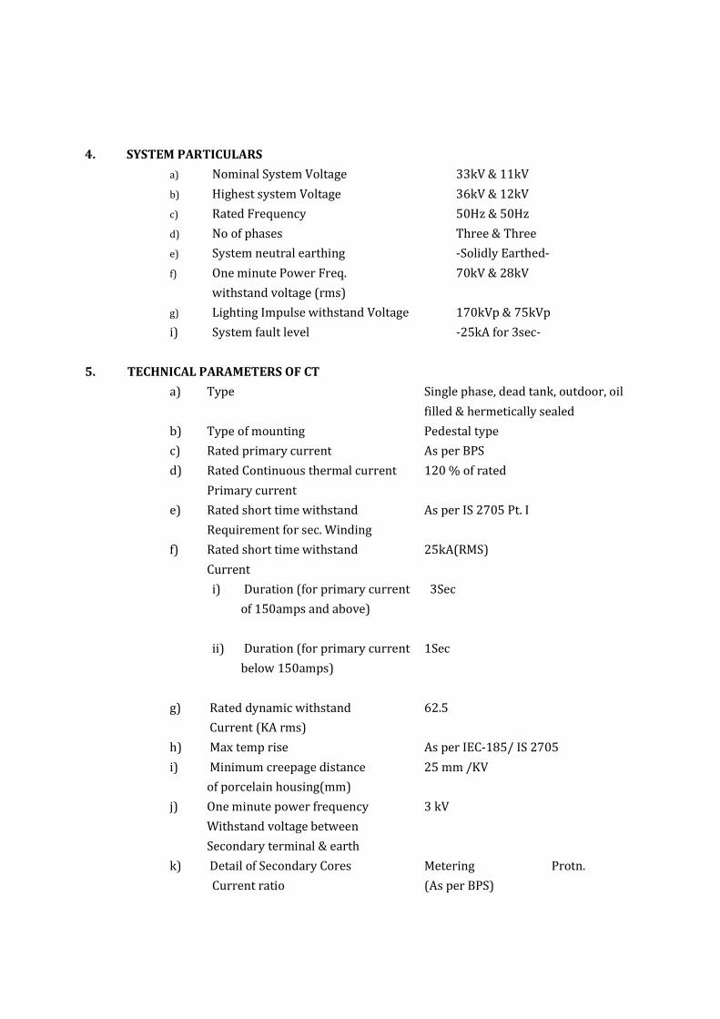
4. SYSTEM PARTICULARS
a) Nominal System Voltage 33kV & 11kV
b) Highest system Voltage 36kV & 12kV
c) Rated Frequency 50Hz & 50Hz
d) No of phases Three & Three
e) System neutral earthing -Solidly Earthed-
f) One minute Power Freq. 70kV & 28kV
withstand voltage (rms)
g) Lighting Impulse withstand Voltage 170kVp & 75kVp
i) System fault level -25kA for 3sec-
5. TECHNICAL PARAMETERS OF CT
a) Type Single phase, dead tank, outdoor, oil
filled & hermetically sealed
b) Type of mounting Pedestal type
c) Rated primary current As per BPS
d) Rated Continuous thermal current 120 % of rated
Primary current
e) Rated short time withstand As per IS 2705 Pt. I
Requirement for sec. Winding
f) Rated short time withstand 25kA(RMS)
Current
i) Duration (for primary current 3Sec
of 150amps and above)
ii) Duration (for primary current 1Sec
below 150amps)
g) Rated dynamic withstand 62.5
Current (KA rms)
h) Max temp rise As per IEC-185/ IS 2705
i) Minimum creepage distance 25 mm /KV
of porcelain housing(mm)
j) One minute power frequency 3 kV
Withstand voltage between
Secondary terminal & earth
k) Detail of Secondary Cores Metering Protn.
Current ratio (As per BPS)

Accuracy class 0.5 5P10
Burden (VA) 15 15
Instrument security Factor ≤5 -
Accuracy Limit Factor - 10
Note: The ratings indicated for instrument transformer are tentative only and may be
changed to meet the requirements.
6. INSULATION
The insulation of the CT shall be so designed that the internal insulation shall have higher electrical withstand capability than the external insulation. The designed dielectrics withstand values of external and internal insulations shall be clearly brought out in the GTP. The dielectric withstand values specified in this specification are meant for fully assembled CT. The temperature rise on any part of equipment shall not exceed the maximum temperature rise limits specified in the relevant standard.
7. PORCELAIN HOUSING
It shall be single piece of homogeneous, vitreous porcelain of high mechanical & dielectric strength. It will be glazed with uniform Brown or Dark brown colour with smooth surface finish. The Creepage distance for the porcelain housing shall be at least 25 mm per kV.
8. TANK & SURFACE FINISH
The metal tanks shall have bare minimum number of welded joints so as to minimize possible locations of oil leakage. The tank shall be fabricated of MS steel sheet of min. 3.15 mm for sides & 5 mm for top & bottom. The bottom of the tank shall be adequately accessible for periodical maintenance of open surface. The metal tanks shall be coated with at least two coats of zinc rich epoxy painting. The inner surface shall be painted with oil resistance white enamel paint. All the ferrous hardware, exposed to atmosphere, shall be hot dip galvanized. All other fixing nuts, bolts, washers in the electrical current path shall be made out of stainless steel.
9. GENERAL CONSTRUCTIONAL REQUIREMENTS
9.1 The CT shall be of dead tank design and shall be so constructed that it can be easily transported to site within the allowable transport limitation, even in horizontal position, if the transport limitation so demands. The C.T. shall be hermetically sealed and method of such sealing shall be detailed in the offer.
9.2 CT secondary terminals shall be brought out in a weatherproof terminal box. The terminal box shall be provided with removable gland plate and glands. The cable glands shall be suitable for 1100 volts grade PVC insulated, PVC sheathed multi core stranded 6 sq.mm copper conductor cable. This terminal box shall be dust and vermin proof. The dimensions of the terminal box and its opening shall be adequate to enable easy access and working space with the use of normal tools.

9.3 Polarity shall be invariably marked in each primary and secondary terminal. Facility shall be provided for short circuiting and grounding of the CT secondary terminals inside the terminal box.
9.4 The CT shall be provided with a rating plate with dimensions and marking as per IS-16227. The markings shall be punched and not painted. The serial number and code of the supplier shall also be punched on the tank to identify the unit in case of loss or damage to the rating plate.
9.5 The CT shall be vacuum filled with oil after processing and thereafter hermetically sealed to eliminate breathing and to prevent air and moisture entering into the tank. Oil filling and / or oil sampling cocks, if provided to facilitate factory processing should be permanently sealed before dispatching the CT. The method adopted for hermetic sealing shall be described in the offer.
10. WINDING
10.1. PRIMARY WINDING
It shall be made of high conductivity rigid copper wire. The primary winding current density shall not exceed the limit of 1.6 Amp per sq. mm for normal rating. The design current density for short circuit current as well as conductivity of metal used for primary winding shall be as per IS 2705. The calculation for the selection of winding cross section shall be furnished by contractor. The primary terminal shall be of standard size of 30 mm dia x 80 mm length of heavily tinned (min. thickness 15 micron) electrolytic copper of 99.9 % conductivity.
10.2 SECONDARY WINDING
Shall be made of insulated copper wire of electrolytic grade. Type of insulation used shall be described in the offer. For multi ratio design, the multi ratio will be achieved by reconnection of the primary winding or secondary winding. The excitation current of the CT shall be as low as possible. The contractor shall furnish the magnetization curves for all the cores. The terminal box shall be dust free & vermin proof. The size of the terminal box shall be big enough to enable easy access and working space with the use of normal tools. The secondary terminals studs shall be provided with at least 3 nuts and two plain washers, these shall be made of brass duly nickel plated. The min. stud outer dia shall be 6 mm & length 15 mm. The min spacing between the centres of the adjacent studs shall be 1.5 time the outer dia of the stud.
10.3 POLARITY The polarity shall be marked on each CT at the primary and secondary terminals.
11. INSULATION OIL
The first filling of oil in CT shall be in contractor’s scope. The oil shall be as per IS 335:2018. To ensure prevention of oil leakage, the manufacturer will give following details supported by drawings:

i) Location of emergence of Primary & Secondary terminals ii) Interface between porcelain & metal tanks iii) Cover of the secondary terminal box Any nut & bolt and screw used for fixation of the interfacing porcelain bushing for taking out the terminals shall be provided on flanges cemented to the bushings & not on the porcelain. If gasket joints are used, Nitrite Butyl Rubber gasket shall be used. The grooves shall be machined with adequate space for accommodating gasket under pressure. The CT shall be vacuum filled with oil after processing. It will be properly sealed to eliminate breathing & to prevent air & moisture from entering the tank. The sealing methods/arrangement shall be described by the contractor & be approved by the owner.
12. OIL LEVEL INDICATOR
The CT shall be fitted with prismatic type oil sight window at suitable location so that the oil level is clearly visible with naked eye to an observer standing at ground level. To compensate oil volume variation due to temperature variation, Nitrogen cushion or the stainless steel bellows shall be used. Rubber diaphragms are not permitted for this purpose.
13. EARTHING
Two earthling terminals shall be provided on the metallic tank of size 16 mm dia & 30 mm
length each with one plain washer & one nut for connection to the station earth mat.
14. JUNCTION BOX
The junction box shall be of MS sheet having thickness of 2mm, synthetic enamel painted as per procedure mentioned in General Technical Requirement (Min. thickness 55 micron). The shade of junction box shall be 697 of IS: 5. Disconnecting type terminal blocks for CT secondary lead shall be provided. The junction boxes shall be weather proof type with gaskets, as per section-I (Introduction and general technical requirements) conforming to IP-55 as per IS-13947 (Part-I).
15. LIFTING & MOUNTING ARRANGEMENT
The CT shall be provided with two lifting eyes to lift the CT. This shall be so positioned so as to avoid any damage to the CT during lifting for instillation or transportation purpose. This shall be detailed in General Arrangement drawing. The CT shall be of pedestal mounting type suitable for outdoor installation on steel/cement concrete structures. All the clamps, bolts, nut and washers etc. required for mounting the CT on the structure shall be supplied along with the CT and shall be galvanized. The contractor shall supply all the terminal connectors etc. required for connection to the CT.

16. TESTING
Type Test:
The Current Transformer design offered in the Bid should have been successfully type tested at NABL laboratories for the tests indicated as follow in line with the relevant standard and technical specification. These Type Tests should have been carried out within five years prior to the date of opening of tender. The bidder shall be required to submit complete set of the type test reports along with the offer. In case these type tests are conducted earlier than five years, all the type tests as per the relevant standard shall be carried out by the successful bidder at NABL in presence of purchaser's representative free of cost before commencement of supply. The undertaking to this effect should be furnished along with the offer without which the offer shall be liable for rejection. If there is any change in the design/ type of old type tested current transformers to be offered against this specification, then the offer is considered for placement of order. However, successful bidders have to carry out the said type tests on offered type equipment before commencement of supply at their own expense.
Sl.No. Type test Description A Schedule of Type Test for CT 1 Verification of terminal marking and polarity. 2 High voltage power frequency tests on primary windings. 3 High voltage power frequency tests on secondary windings. 4 Over voltage inter turn test.
5 Determination of error according to the requirement of appropriate accuracy class
6 Short time current test. 7 Impulse voltage test. 8 Temperature Rise Test.
9 Instrument Security Factor Test on Both phase of the CT as per Cl. No.7.1.2 of Is-2705 (Part-II).
10 High Voltage Power-frequency Wet withstand voltage test as per Cl. No.9.9 of IS-2705 (Part-I).
Acceptance & Routine Tests:- All acceptance and routine tests as stipulated in the respective applicable standards amended up-to-date for current transformer shall be carried out by the supplier in the presence of purchaser's representative without any extra cost to the purchaser before dispatch.
17. INSPECTION 17.1. The inspection may be carried out by the purchaser at any stage of manufacture. The
successful bidder shall grant free access to the purchaser’s representative at any reasonable time when the work is in progress. All facilities must be made available by supplier/

manufacturer for unrestricted inspection of the works, raw material & manufacture of all the accessories & for conducting necessary tests as declared therein.
17.2. No current transformer shall be dispatched from its point of manufacture unless the current transformer has been satisfactorily inspected and tested.
17.3. Inspection and acceptance of any current transformer under this specification by the purchaser shall not relieve the supplier of his obligation of furnishing current transformer in accordance with the specification and shall not prevent subsequent rejection, if the current transformer is found to be defective.
18. PERFORMANCE GUARANTEE
The equipment offered shall be guaranteed for satisfactory performance for a period of 66 months from the date of receipt of complete equipment at site in good condition or 60 months from the date of satisfactory commissioning, whichever is earlier. In case of failure within this period, the supplier shall make necessary repairs / replacement of the faulty current transformer at no extra cost to the purchaser.
19. DOCUMENTATION 19.1. List of Drawings & Documents :-
The bidder shall furnish two sets of the following drawings along with offer. a) General outline and assembly drawings of the equipment
b) Sectional views showing :-
i) General Constructional features of Current Transformer, dimensions of conductor, depth of insulation, clearance between paper insulation & the inside of porcelain, grading stages used for primary insulation, whether & how a semi conducting tape is used to cover metal foils etc.
ii) The Sectional view shall show the materials / gaskets / sealing used for perfect hermetic sealing and arrangement for compensation of oil volume variation.
iii) The insulation, the winding arrangements, method of connection of the primary / secondary winding to the primary / secondary terminals etc.
iv) Porcelain housing used and its dimensions along with the mechanical and electrical characteristics, as well as volume of oil.
c) Arrangement of secondary Terminal box & details of connection studs provided.
d) Name Plate
e) Schematic drawing
f) Type Test reports in case the equipment has already been type tested.
g) Test reports, literature, pamphlets of the bought out items, and raw material
h) Bill of material and packing list.
i) Pressure release device
j) Oil level indicator
k) Drain plug l)Bushing drawing

18.2 The successful bidders shall submit three sets of final versions of all the above said drawings in line with Technical Specifications.
18.3 Adequate copies of acceptance and routine Test Certificates, duly approved by APDCL shall accompany the dispatched consignment.
18.4 The manufacturing of the current transformers shall be strictly in accordance with the approved drawings and no deviation shall be permitted without the written approval of the APDCL. All manufacturing and fabrication work in connection with the current transformers prior to the approval of the drawing shall be at the supplier’s risk.
18.5 One set of nicely printed and bound volume of operation, maintenance and erection manuals in English language per Current Transformer of each voltage rating shall be submitted by the supplier to respective consignees along with the dispatch documents of each unit. The manual shall contain all the drawings and information required for erection, operation and maintenance of the Current Transformer. The manual shall also contain a set of all the approved drawings, Type Test reports etc.
18.6 Approval of drawings by APDCL shall not relieve the supplier of his responsibility and liability for ensuring correctness and correct interpretation of the drawings for meeting the requirement of the Technical Specification, latest revision of applicable standards, rules and codes of practices. The equipment shall conform in all respects to high standards of engineering, design, workmanship and latest revisions of relevant standards at the time of ordering and APDCL shall have the power to reject any work or materials which, in his judgment, is not in full accordance therewith.
19. PACKING & FORWARDING
19.1 The current transformers shall be packed in wooden crates of good quality and shall be suitable for vertical / horizontal transportation as the case may be, and suitable to withstand handling during transport and outdoor storage in stores before erecting. The supplier shall be responsible for any damage to the equipment during transit, due to improper and inadequate packing. The easily damageable material shall be carefully packed and marked with the appropriate caution symbols. Wherever necessary, proper arrangement for lifting, such as lifting hooks etc. shall be provided. Any material found short inside the packing cases shall be supplied by supplier without any extra cost.
19.2 Each consignment shall be accompanied by a detailed packing list containing the following information: a) Name of the consignee. b) Details of consignment. c) Destination. d) Total weight of consignment. e) Sign showing upper / lower side of the crate. f) Handling and unpacking instructions. g) Bill of material indicating contents of each package
19.3 The supplier shall ensure that the packing list and bill of material are approved by the APDCL before dispatch.

GUARANTEED TECHNICAL PARTICULARS OF CURRENT TRANSFORMER
Sl.No. Particular of GTP Parameter Bidders Confirmation 33kV CT 11kV CT
1 Manufacturer’s Name & address 2 Type of equipment 3 Type of Mounting 4 Equipment Conforming to Standards 5 Rated Voltage / Highest System Voltage in KV 6 Rated Primary Current (Amp) 7 Rated Secondary Current (Amp) 8 Frequency (HZ) 9 Ratio of Current Transformer
10 Details of Cores i) Number of Cores ii) Purpose iii) Burden (VA) iv) Class of Accuracy 11 Rated Short Time Withstand Current for 1 Sec. duration 12 Rated Dynamic Withstand Current (KAp) 13 Method of Earthing system to be connected to
14 One minute Dry Power Frequency Withstand Voltage (KV rms) of Primary Winding
15 One minute Wet Power Frequency Withstand Voltage (KV rms) of Primary Winding
16 1.2/50 micro-second Impulse Withstand Voltage (KVP)
17 The die-electric Withstand values (KVp)of external & internal insulation
18 One minute Power Frequency Withstand Voltage (KV rms) of Secondary Winding
19 Minimum Creepage Distance (mm) 20 Weight of oil (kg/Ltrs.) 21 Total Weight (kg) 22 Mounting details 23 Overall dimension 24 Type of Winding 25 Material of Winding 26 Size & Cross Section of Primary Winding 27 Size & Cross Section of Secondary Winding 28 No. of Primary Turns 29 No. of Secondary Turns
30 Current Density of Primary & Secondary Winding (max. – 1.6A/sq.mm)
31 Primary Terminal 32 Type of Insulation 33 Whether Current Transformer confirms to Temperature Rise

limits 34 Type of oil compensation 35 Type of pressure release device provided 36 Partial Discharge level
37 Rated continuous Thermal Current (120% of the rated Primary Current)
38 Instrument Security Factor (ISF ≤ 5) 39 Class of Insulation 40 Actual clearance between live part & ground (mm)
Seal and Signature of Bidder