SERVICE MANUAL Outdoor unit
120
SERVICE MANUAL SPLIT-TYPE, HEAT PUMP AIR CONDITIONERS SPLIT-TYPE, AIR CONDITIONERS CONTENTS 1. REFERENCE MANUAL··································2 2. SAFETY PRECAUTION··································3 3. FEATURES ·····················································6 4. SPECIFICATIONS···········································7 5. DATA ·······························································9 6. OUTLINES AND DIMENSIONS····················13 7. WIRING DIAGRAM ·······································16 8. WIRING SPECIFICATIONS ··························20 9. REFRIGERANT SYSTEM DIAGRAM ·············25 10. TROUBLESHOOTING ··································28 11. EASY MAINTENANCE FUNCTION ··············85 12. FUNCTION SETTING····································88 13. MONITORING THE OPERATION DATABY THE REMOTE CONTROLLER············96 14. DISASSEMBLY PROCEDURE ···················106 No.OCH429 R410A November 2007 [model names] PUZ-A18NHA2 PUZ-A24NHA2 PUZ-A30NHA2 PUZ-A36NHA2 PUZ-A42NHA2 PUZ-A18NHA2-BS PUZ-A24NHA2-BS PUZ-A30NHA2-BS PUZ-A36NHA2-BS PUZ-A42NHA2-BS PUY-A12NHA2 PUY-A18NHA2 PUY-A24NHA2 PUY-A30NHA2 PUY-A36NHA2 PUY-A42NHA2 PUY-A12NHA2-BS PUY-A18NHA2-BS PUY-A24NHA2-BS PUY-A30NHA2-BS PUY-A36NHA2-BS PUY-A42NHA2-BS [Service Ref.] PUZ-A18NHA2 PUZ-A24NHA2 PUZ-A30NHA2 PUZ-A36NHA2 PUZ-A42NHA2 PUZ-A18NHA2-BS PUZ-A24NHA2-BS PUZ-A30NHA2-BS PUZ-A36NHA2-BS PUZ-A42NHA2-BS PUY-A12NHA2 PUY-A18NHA2 PUY-A24NHA2 PUY-A30NHA2 PUY-A36NHA2 PUY-A42NHA2 PUY-A12NHA2-BS PUY-A18NHA2-BS PUY-A24NHA2-BS PUY-A30NHA2-BS PUY-A36NHA2-BS PUY-A42NHA2-BS NOTE: • This manual describes only service data of the outdoor units. • RoHS compliant products have <G> mark on the spec name plate. • For servicing RoHS compliant products, refer to the RoHS PARTS LIST. PUZ-A24/30/36NHA2 PUY-A24/30/36NHA2 Outdoor unit PARTS CATALOG (OCB429)
-
Upload
khangminh22 -
Category
Documents
-
view
1 -
download
0
Transcript of SERVICE MANUAL Outdoor unit
SERVICE MANUAL
SPLIT-TYPE, HEAT PUMP AIR CONDITIONERSSPLIT-TYPE, AIR CONDITIONERS
CONTENTS
1. REFERENCE MANUAL··································22. SAFETY PRECAUTION··································33. FEATURES ·····················································64. SPECIFICATIONS···········································75. DATA ·······························································96. OUTLINES AND DIMENSIONS····················137. WIRING DIAGRAM·······································168. WIRING SPECIFICATIONS ··························209. REFRIGERANT SYSTEM DIAGRAM ·············25
10. TROUBLESHOOTING ··································2811. EASY MAINTENANCE FUNCTION ··············8512. FUNCTION SETTING····································8813. MONITORING THE OPERATION DATA BY THE REMOTE CONTROLLER············9614. DISASSEMBLY PROCEDURE ···················106
No.OCH429
R410A
November 2007
[model names]PUZ-A18NHA2PUZ-A24NHA2PUZ-A30NHA2PUZ-A36NHA2PUZ-A42NHA2PUZ-A18NHA2-BSPUZ-A24NHA2-BSPUZ-A30NHA2-BSPUZ-A36NHA2-BSPUZ-A42NHA2-BS
PUY-A12NHA2PUY-A18NHA2PUY-A24NHA2PUY-A30NHA2PUY-A36NHA2PUY-A42NHA2PUY-A12NHA2-BSPUY-A18NHA2-BSPUY-A24NHA2-BSPUY-A30NHA2-BSPUY-A36NHA2-BSPUY-A42NHA2-BS
[Service Ref.]PUZ-A18NHA2PUZ-A24NHA2PUZ-A30NHA2PUZ-A36NHA2PUZ-A42NHA2PUZ-A18NHA2-BSPUZ-A24NHA2-BSPUZ-A30NHA2-BSPUZ-A36NHA2-BSPUZ-A42NHA2-BS
PUY-A12NHA2PUY-A18NHA2PUY-A24NHA2PUY-A30NHA2PUY-A36NHA2PUY-A42NHA2PUY-A12NHA2-BSPUY-A18NHA2-BSPUY-A24NHA2-BSPUY-A30NHA2-BSPUY-A36NHA2-BSPUY-A42NHA2-BS
NOTE:• This manual describes only
service data of the outdoor units.
• RoHS compliant products have <G> mark on the spec name plate.
• For servicing RoHS compliantproducts, refer to the RoHSPARTS LIST.
PUZ-A24/30/36NHA2PUY-A24/30/36NHA2
Outdoor unit
PARTS CATALOG (OCB429)
2
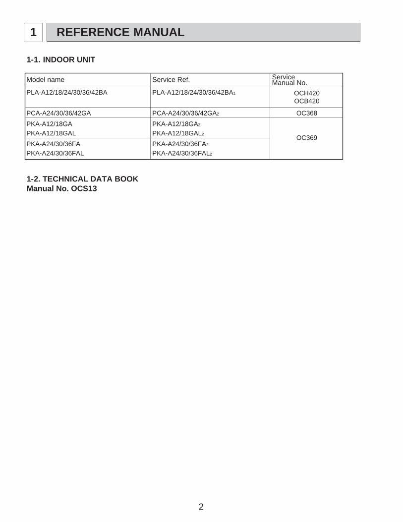
1-1. INDOOR UNIT
Model name Service Ref. ServiceManual No.
PLA-A12/18/24/30/36/42BA PLA-A12/18/24/30/36/42BA1 OCH420OCB420
PCA-A24/30/36/42GA PCA-A24/30/36/42GA2 OC368PKA-A12/18GA PKA-A12/18GA2
OC369PKA-A12/18GAL PKA-A12/18GAL2
PKA-A24/30/36FA PKA-A24/30/36FA2
PKA-A24/30/36FAL PKA-A24/30/36FAL2
1-2. TECHNICAL DATA BOOKManual No. OCS13
1 REFERENCE MANUAL
3
2 SAFETY PRECAUTION
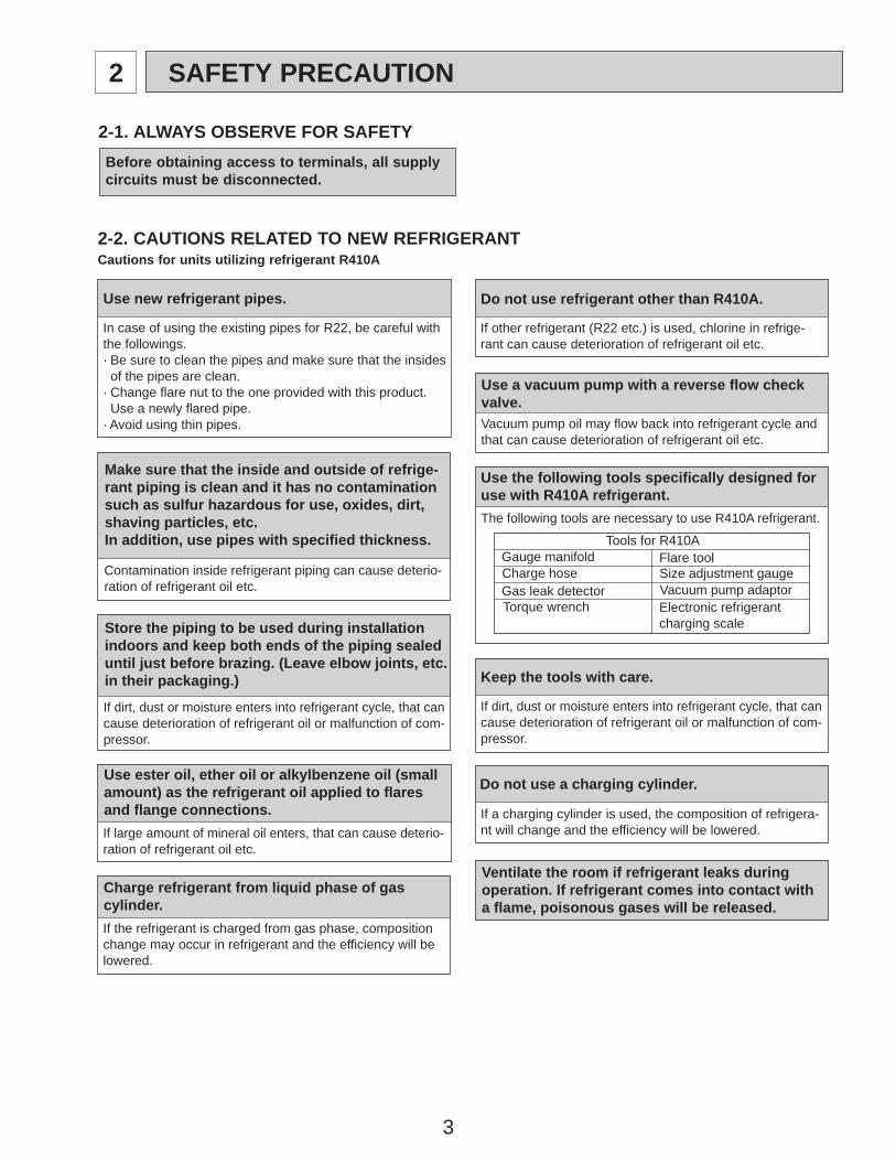
Cautions for units utilizing refrigerant R410A2-2. CAUTIONS RELATED TO NEW REFRIGERANT
Use new refrigerant pipes.
Make sure that the inside and outside of refrige-rant piping is clean and it has no contaminationsuch as sulfur hazardous for use, oxides, dirt, shaving particles, etc.In addition, use pipes with specified thickness.
Store the piping to be used during installationindoors and keep both ends of the piping sealed until just before brazing. (Leave elbow joints, etc. in their packaging.)
Use ester oil, ether oil or alkylbenzene oil (small amount) as the refrigerant oil applied to flares and flange connections.
In case of using the existing pipes for R22, be careful withthe followings.· Be sure to clean the pipes and make sure that the insides of the pipes are clean.· Change flare nut to the one provided with this product. Use a newly flared pipe. · Avoid using thin pipes.
Charge refrigerant from liquid phase of gascylinder.If the refrigerant is charged from gas phase, composition change may occur in refrigerant and the efficiency will be lowered.
Do not use refrigerant other than R410A.
If other refrigerant (R22 etc.) is used, chlorine in refrige-rant can cause deterioration of refrigerant oil etc.
Use a vacuum pump with a reverse flow check valve.Vacuum pump oil may flow back into refrigerant cycle and that can cause deterioration of refrigerant oil etc.
Use the following tools specifically designed for use with R410A refrigerant.The following tools are necessary to use R410A refrigerant.
Keep the tools with care.
If dirt, dust or moisture enters into refrigerant cycle, that cancause deterioration of refrigerant oil or malfunction of com-pressor.
Do not use a charging cylinder.
If a charging cylinder is used, the composition of refrigera-nt will change and the efficiency will be lowered.
Flare tool
Electronic refrigerant charging scale
Vacuum pump adaptorSize adjustment gauge
Gauge manifold
Torque wrenchGas leak detectorCharge hose
Tools for R410A
Contamination inside refrigerant piping can cause deterio-ration of refrigerant oil etc.
If dirt, dust or moisture enters into refrigerant cycle, that can cause deterioration of refrigerant oil or malfunction of com-pressor.
If large amount of mineral oil enters, that can cause deterio-ration of refrigerant oil etc.
Ventilate the room if refrigerant leaks during operation. If refrigerant comes into contact witha flame, poisonous gases will be released.
2-1. ALWAYS OBSERVE FOR SAFETYBefore obtaining access to terminals, all supplycircuits must be disconnected.
4
Gravimeter
Unit
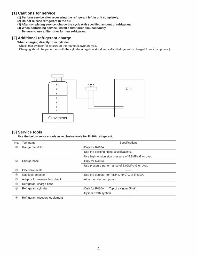
[3] Service toolsUse the below service tools as exclusive tools for R410A refrigerant.
No. Tool name Specifications1 Gauge manifold ·Only for R410A
·Use the existing fitting specifications.·Use high-tension side pressure of 5.3MPa·G or over.
2 Charge hose ·Only for R410A·Use pressure performance of 5.09MPa·G or over.
3 Electronic scale4 Gas leak detector ·Use the detector for R134a, R407C or R410A.5 Adaptor for reverse flow check ·Attach on vacuum pump.6 Refrigerant charge base7 Refrigerant cylinder ·Only for R410A ·Top of cylinder (Pink)
·Cylinder with syphon8 Refrigerant recovery equipment
[1] Cautions for service(1) Perform service after recovering the refrigerant left in unit completely.(2) Do not release refrigerant in the air.(3) After completing service, charge the cycle with specified amount of refrigerant.(4) When performing service, install a filter drier simultaneously.
Be sure to use a filter drier for new refrigerant.
[2] Additional refrigerant chargeWhen charging directly from cylinder· Check that cylinder for R410A on the market is syphon type.· Charging should be performed with the cylinder of syphon stood vertically. (Refrigerant is charged from liquid phase.)
5
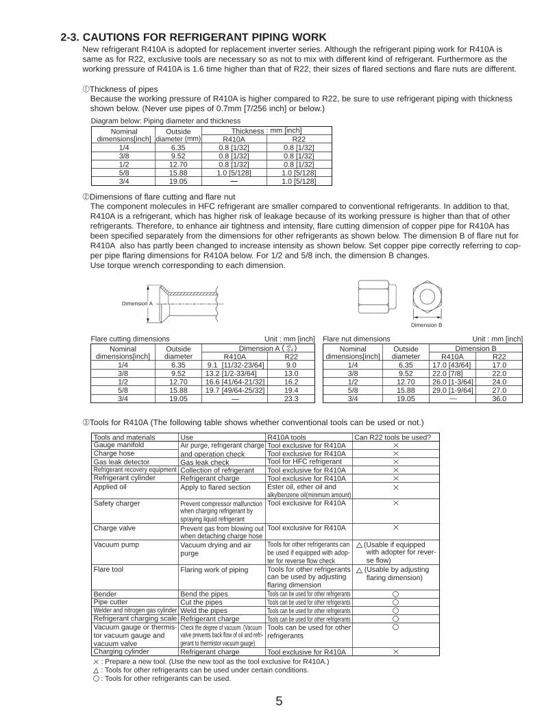
2-3. CAUTIONS FOR REFRIGERANT PIPING WORKNew refrigerant R410A is adopted for replacement inverter series. Although the refrigerant piping work for R410A issame as for R22, exclusive tools are necessary so as not to mix with different kind of refrigerant. Furthermore as theworking pressure of R410A is 1.6 time higher than that of R22, their sizes of flared sections and flare nuts are different.
1Thickness of pipesBecause the working pressure of R410A is higher compared to R22, be sure to use refrigerant piping with thicknessshown below. (Never use pipes of 0.7mm [7/256 inch] or below.)
2Dimensions of flare cutting and flare nutThe component molecules in HFC refrigerant are smaller compared to conventional refrigerants. In addition to that,R410A is a refrigerant, which has higher risk of leakage because of its working pressure is higher than that of otherrefrigerants. Therefore, to enhance air tightness and intensity, flare cutting dimension of copper pipe for R410A hasbeen specified separately from the dimensions for other refrigerants as shown below. The dimension B of flare nut forR410A also has partly been changed to increase intensity as shown below. Set copper pipe correctly referring to cop-per pipe flaring dimensions for R410A below. For 1/2 and 5/8 inch, the dimension B changes. Use torque wrench corresponding to each dimension.
3Tools for R410A (The following table shows whether conventional tools can be used or not.)
1/43/81/25/83/4
6.359.52
12.7015.8819.05
0.8 [1/32]0.8 [1/32]0.8 [1/32]
1.0 [5/128]—
0.8 [1/32]0.8 [1/32]0.8 [1/32]1.0 [5/128]1.0 [5/128]
Nominaldimensions[inch]
Diagram below: Piping diameter and thicknessOutside
diameter (mm)Thickness : mm [inch]
R410A R22
1/43/81/25/83/4
6.359.52
12.7015.8819.05
9.1 [11/32-23/64]13.2 [1/2-33/64]16.6 [41/64-21/32]19.7 [49/64-25/32] —
9.013.016.219.423.3
Nominaldimensions[inch]
Flare cutting dimensionsOutsidediameter
Dimension A ( )+0-0.4
Unit : mm [inch]
R410A R221/43/81/25/83/4
6.359.5212.7015.8819.05
17.0 [43/64]22.0 [7/8]26.0 [1-3/64]29.0 [1-9/64]
—
17.022.024.027.036.0
Nominaldimensions[inch]
Flare nut dimensionsOutsidediameter
Dimension BUnit : mm [inch]
R410A R22
Gauge manifoldCharge hoseGas leak detectorRefrigerant recovery equipmentRefrigerant cylinderApplied oil
Safety charger
Charge valve
Vacuum pump
Flare tool
BenderPipe cutterWelder and nitrogen gas cylinderRefrigerant charging scaleVacuum gauge or thermis-tor vacuum gauge and vacuum valveCharging cylinder
Air purge, refrigerant chargeand operation checkGas leak checkCollection of refrigerantRefrigerant chargeApply to flared section
Prevent compressor malfunction when charging refrigerant by spraying liquid refrigerantPrevent gas from blowing out when detaching charge hoseVacuum drying and airpurge
Flaring work of piping
Bend the pipesCut the pipesWeld the pipesRefrigerant chargeCheck the degree of vacuum. (Vacuum valve prevents back flow of oil and refri-gerant to thermistor vacuum gauge)Refrigerant charge
Tool exclusive for R410ATool exclusive for R410ATool for HFC refrigerantTool exclusive for R410ATool exclusive for R410AEster oil, ether oil andalkylbenzene oil(minimum amount)Tool exclusive for R410A
Tool exclusive for R410A
Tools for other refrigerants can be used if equipped with adop-ter for reverse flow checkTools for other refrigerants can be used by adjusting flaring dimensionTools can be used for other refrigerantsTools can be used for other refrigerantsTools can be used for other refrigerantsTools can be used for other refrigerantsTools can be used for otherrefrigerants
Tool exclusive for R410A
Tools and materials Use R410A tools Can R22 tools be used?
(Usable if equipped with adopter for rever- se flow) (Usable by adjusting flaring dimension)
: Prepare a new tool. (Use the new tool as the tool exclusive for R410A.): Tools for other refrigerants can be used under certain conditions.: Tools for other refrigerants can be used.
Dimension A
Dimension B
6
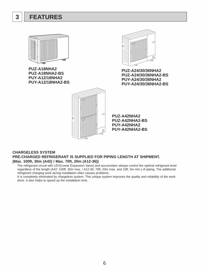
3 FEATURES
CHARGELESS SYSTEMPRE-CHARGED REFRIGERANT IS SUPPLIED FOR PIPING LENGTH AT SHIPMENT.(Max. 100ft, 30m (A42) / Max. 70ft, 20m (A12-36))
The refrigerant circuit with LEV(Linear Expansion Valve) and accumulator always control the optimal refrigerant levelregardless of the length (A42: 100ft, 30m max. / A12-36: 70ft, 20m max. and 16ft, 5m min.) of piping. The additionalrefrigerant charging work during installation often causes problems.It is completely eliminated by chargeless system. This unique system improves the quality and reliability of the workdone. It also helps to speed up the installation time.
PUZ-A24/30/36NHA2PUZ-A24/30/36NHA2-BSPUY-A24/30/36NHA2PUY-A24/30/36NHA2-BS
PUZ-A42NHA2PUZ-A42NHA2-BSPUY-A42NHA2PUY-A42NHA2-BS
PUZ-A18NHA2PUZ-A18NHA2-BSPUY-A12/18NHA2PUY-A12/18NHA2-BS
7
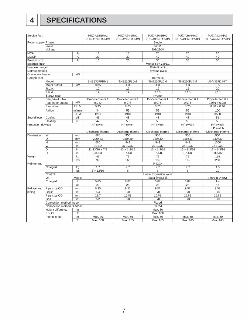
4 SPECIFICATIONS
Service Ref. PUZ-A18NHA2 PUZ-A24NHA2 PUZ-A30NHA2 PUZ-A36NHA2 PUZ-A42NHA2PUZ-A18NHA2-BS PUZ-A24NHA2-BS PUZ-A30NHA2-BS PUZ-A36NHA2-BS PUZ-A42NHA2-BS
Power supply Phase SingleCycle 60HzVoltage 208/230V
MCA A 13 18 25 25 26MOCP A 20 30 40 40 40Breaker size A 15 25 30 30 30External finish Munsell 3Y 7.8/1.1Heat exchanger Plate fin coilDefrost method Reverse cycleCrankcase heater kW -Compressor Hermetic
Model SNB130FPBM1 TNB220FLDM TNB220FLDM TNB220FLDM ANV33FDJMTMotor output kW 0.85 1.3 1.3 1.3 2.5R.L.A. 12 12 12 12 20L.R.A. 14 14 17.5 17.5 27.5Starter type Inverter
Fan Fan(drive) o No. Propeller fan o 1 Propeller fan o 1 Propeller fan o 1 Propeller fan o 1 Propeller fan o 2Fan motor output kW 0.040 0.075 0.075 0.075 0.086 + 0.086Fan motor F.L.A. 0.35 0.75 0.75 0.75 0.40 + 0.40Airflow m3/min 34 55 55 55 100
CFM 1200 1940 1940 1940 3530Sound level Cooling dB 46 48 48 48 51
Heating dB 47 50 50 50 55Protection devices HP switch HP switch HP switch HP switch HP switch
LP switchDischarge thermo Discharge thermo Discharge thermo Discharge thermo Discharge thermo
Dimension W mm 800 950 950 950 950D mm 300+23 330+30 330+30 330+30 330+30H mm 600 943 943 943 1350W in. 31-1/2 37-12/32 37-12/32 37-12/32 37-12/32D in. 11-13/16 + 7/8 13 + 1-3/16 13 + 1-3/16 13 + 1-3/16 13 + 1-3/16H in. 23-5/8 37-1/8 37-1/8 37-1/8 53-5/32
Weight kg 45 75 75 75 118lbs 99 165 165 165 260
Refrigerant R410ACharged kg 1.7 2.7 2.7 2.7 4.5
lbs 3 + 12/16 6 6 6 10
Ether (FV50S)Control Linear expansion valveOil Model Ester (MEL56)Charged L 0.65 0.87 0.87 0.87 1.4
oz 20 28 28 28 45Refrigerant Pipe size OD mm 6.35 9.52 9.52 9.52 9.52piping Liquid in. 1/4 3/8 3/8 3/8 3/8
Pipe size OD mm 12.7 15.88 15.88 15.88 15.88Gas in. 1/2 5/8 5/8 5/8 5/8Connection method Indoor FlaredConnection method Outdoor FlaredHeight difference m Max. 30IU - OU ft Max. 100Piping length m Max. 30 Max. 50 Max. 50 Max. 50 Max. 50
ft Max. 100 Max. 165 Max. 165 Max. 165 Max. 165
8
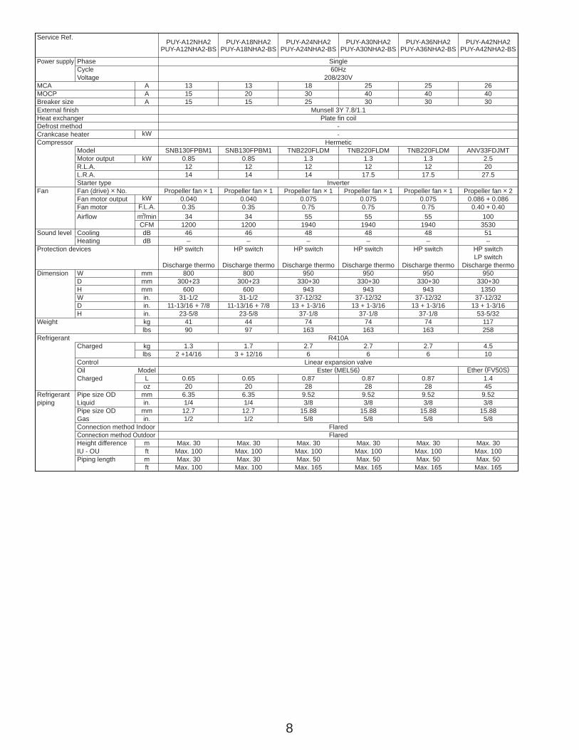
Service Ref.PUY-A12NHA2 PUY-A18NHA2 PUY-A24NHA2 PUY-A30NHA2 PUY-A36NHA2 PUY-A42NHA2
PUY-A12NHA2-BS PUY-A18NHA2-BS PUY-A24NHA2-BS PUY-A30NHA2-BS PUY-A36NHA2-BS PUY-A42NHA2-BS
Power supply Phase SingleCycle 60HzVoltage 208/230V
MCA A 13 13 18 25 25 26MOCP A 15 20 30 40 40 40Breaker size A 15 15 25 30 30 30External finish Munsell 3Y 7.8/1.1Heat exchanger Plate fin coilDefrost method -Crankcase heater kW -Compressor Hermetic
Model SNB130FPBM1 SNB130FPBM1 TNB220FLDM TNB220FLDM TNB220FLDM ANV33FDJMTMotor output kW 0.85 0.85 1.3 1.3 1.3 2.5R.L.A. 12 12 12 12 12 20L.R.A. 14 14 14 17.5 17.5 27.5Starter type Inverter
Fan Fan (drive) o No. Propeller fan o 1 Propeller fan o 1 Propeller fan o 1 Propeller fan o 1 Propeller fan o 1 Propeller fan o 2Fan motor output kW 0.040 0.040 0.075 0.075 0.075 0.086 + 0.086Fan motor F.L.A. 0.35 0.35 0.75 0.75 0.75 0.40 + 0.40Airflow m3/min 34 34 55 55 55 100
CFM 1200 1200 1940 1940 1940 3530Sound level Cooling dB 46 46 48 48 48 51
Heating dB – – – – – –Protection devices HP switch HP switch HP switch HP switch HP switch HP switch
LP switchDischarge thermo Discharge thermo Discharge thermo Discharge thermo Discharge thermo Discharge thermo
Dimension W mm 800 800 950 950 950 950D mm 300+23 300+23 330+30 330+30 330+30 330+30H mm 600 600 943 943 943 1350W in. 31-1/2 31-1/2 37-12/32 37-12/32 37-12/32 37-12/32D in. 11-13/16 + 7/8 11-13/16 + 7/8 13 + 1-3/16 13 + 1-3/16 13 + 1-3/16 13 + 1-3/16H in. 23-5/8 23-5/8 37-1/8 37-1/8 37-1/8 53-5/32
Weight kg 41 44 74 74 74 117lbs 90 97 163 163 163 258
Refrigerant R410ACharged kg 1.3 1.7 2.7 2.7 2.7 4.5
lbs 2 +14/16 3 + 12/16 6 6 6 10Control Linear expansion valveOil Model Ester (MEL56)Charged L 0.65 0.65 0.87 0.87 0.87 1.4
Ether (FV50S)
oz 20 20 28 28 28 45Refrigerant Pipe size OD mm 6.35 6.35 9.52 9.52 9.52 9.52piping Liquid in. 1/4 1/4 3/8 3/8 3/8 3/8
Pipe size OD mm 12.7 12.7 15.88 15.88 15.88 15.88Gas in. 1/2 1/2 5/8 5/8 5/8 5/8Connection method Indoor FlaredConnection method Outdoor FlaredHeight difference m Max. 30 Max. 30 Max. 30 Max. 30 Max. 30 Max. 30IU - OU ft Max. 100 Max. 100 Max. 100 Max. 100 Max. 100 Max. 100Piping length m Max. 30 Max. 30 Max. 50 Max. 50 Max. 50 Max. 50
ft Max. 100 Max. 100 Max. 165 Max. 165 Max. 165 Max. 165
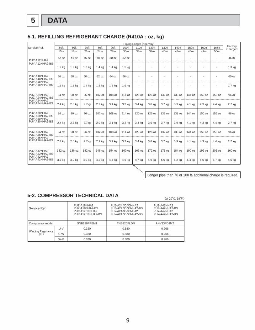
Piping Length (one way)
ChargedFactoryService Ref. 50ft 60ft 70ft 80ft 90ft 100ft 110ft 120ft 130ft 140ft 150ft 160ft 165ft
15m 18m 21m 24m 27m 30m 33m 37m 40m 43m 46m 49m 50m
PUY-A12NHA2-BSPUY-A12NHA2
42 oz 44 oz 46 oz 48 oz 50 oz 52 oz - - - - - - - 46 oz
1.2 kg 1.2 kg 1.3 kg 1.4 kg 1.4 kg 1.5 kg - - - - - - - 1.3 kg
PUY-A18NHA2-BSPUY-A18NHA2PUZ-A18NHA2-BSPUZ-A18NHA2 56 oz 58 oz 60 oz 62 oz 64 oz 66 oz - - - - - - - 60 oz
1.6 kg 1.6 kg 1.7 kg 1.8 kg 1.8 kg 1.9 kg - - - - - - - 1.7 kg
PUY-A24NHA2-BSPUY-A24NHA2PUZ-A24NHA2-BSPUZ-A24NHA2 84 oz 90 oz 96 oz 102 oz 108 oz 114 oz 120 oz 126 oz 132 oz 138 oz 144 oz 150 oz 156 oz 96 oz
2.4 kg 2.6 kg 2.7kg 2.9 kg 3.1 kg 3.2 kg 3.4 kg 3.6 kg 3.7 kg 3.9 kg 4.1 kg 4.3 kg 4.4 kg 2.7 kg
PUY-A30NHA2-BSPUY-A30NHA2PUZ-A30NHA2-BSPUZ-A30NHA2 84 oz 90 oz 96 oz 102 oz 108 oz 114 oz 120 oz 126 oz 132 oz 138 oz 144 oz 150 oz 156 oz 96 oz
2.4 kg 2.6 kg 2.7kg 2.9 kg 3.1 kg 3.2 kg 3.4 kg 3.6 kg 3.7 kg 3.9 kg 4.1 kg 4.3 kg 4.4 kg 2.7 kg
PUY-A36NHA2-BSPUY-A36NHA2PUZ-A36NHA2-BSPUZ-A36NHA2 84 oz 90 oz 96 oz 102 oz 108 oz 114 oz 120 oz 126 oz 132 oz 138 oz 144 oz 150 oz 156 oz 96 oz
2.4 kg 2.6 kg 2.7kg 2.9 kg 3.1 kg 3.2 kg 3.4 kg 3.6 kg 3.7 kg 3.9 kg 4.1 kg 4.3 kg 4.4 kg 2.7 kg
PUY-A42NHA2-BSPUY-A42NHA2PUZ-A42NHA2-BSPUZ-A42NHA2 132 oz 136 oz 142 oz 148 oz 154 oz 160 oz 166 oz 172 oz 178 oz 184 oz 190 oz 196 oz 202 oz 160 oz
3.7 kg 3.9 kg 4.0 kg 4.2 kg 4.4 kg 4.5 kg 4.7 kg 4.9 kg 5.0 kg 5.2 kg 5.4 kg 5.6 kg 5.7 kg 4.5 kg
Longer pipe than 70 or 100 ft, additional charge is required.
PUZ-A42NHA2Service Ref. PUZ-A42NHA2-BS
PUY-A42NHA2PUY-A42NHA2-BS
Compressor model SNB130FPBM1 TNB220FLDM ANV33FDJMT
(' )Winding Registance
U-V 0.320 0.880 0.266
U-W 0.320 0.880 0.266
W-V 0.320 0.880 0.266
(at 20˚C, 68˚F )
PUY-A12,18NHA2-BSPUY-A12,18NHA2PUZ-A18NHA2-BSPUZ-A18NHA2
PUY-A24,30,36NHA2-BSPUY-A24,30,36NHA2PUZ-A24,30,36NHA2-BSPUZ-A24,30,36NHA2
9
5-1. REFILLING REFRIGERANT CHARGE (R410A : oz, kg)
5-2. COMPRESSOR TECHNICAL DATA
5 DATA
10
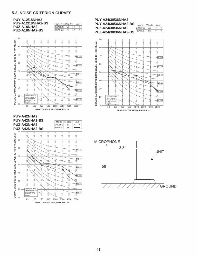
5-3. NOISE CRITERION CURVES
5ft
3.3ftMICROPHONE
UNIT
GROUND
90
80
70
60
50
40
30
20
1063 125 250 500 1000 2000 4000 8000
APPROXIMATETHRESHOLD OFHEARING FORCONTINUOUSNOISE
NC-60
NC-50
NC-40
NC-30
NC-20
NC-70
OC
TAVE
BA
ND
SO
UN
D P
RES
SUR
E LE
VEL,
dB
(0 d
B =
0.0
002
μbar
)
BAND CENTER FREQUENCIES, Hz
PUY-A12/18NHA2PUY-A12/18NHA2-BSPUZ-A18NHA2PUZ-A18NHA2-BS
COOLINGMODE
HEATING46
SPL(dB)
47
LINE
90
80
70
60
50
40
30
20
1063 125 250 500 1000 2000 4000 8000
APPROXIMATETHRESHOLD OFHEARING FORCONTINUOUSNOISE
NC-60
NC-50
NC-40
NC-30
NC-20
NC-70
OC
TAVE
BA
ND
SO
UN
D P
RES
SUR
E LE
VEL,
dB
(0 d
B =
0.0
002
μbar
)
BAND CENTER FREQUENCIES, Hz
PUY-A24/30/36NHA2PUY-A24/30/36NHA2-BSPUZ-A24/30/36NHA2PUZ-A24/30/36NHA2-BS
COOLINGMODE
HEATING48
SPL(dB)
50
LINE
90
80
70
60
50
40
30
20
1063 125 250 500 1000 2000 4000 8000
APPROXIMATETHRESHOLD OFHEARING FORCONTINUOUSNOISE
OC
TAVE
BA
ND
SO
UN
D P
RES
SUR
E LE
VEL,
dB
(0 d
B =
0.0
002
μbar
)
BAND CENTER FREQUENCIES, Hz
NC-60
NC-50
NC-40
NC-30
NC-20
NC-70
PUY-A42NHA2PUY-A42NHA2-BSPUZ-A42NHA2PUZ-A42NHA2-BS
COOLINGMODE
HEATING51
SPL(dB)
55
LINE
11
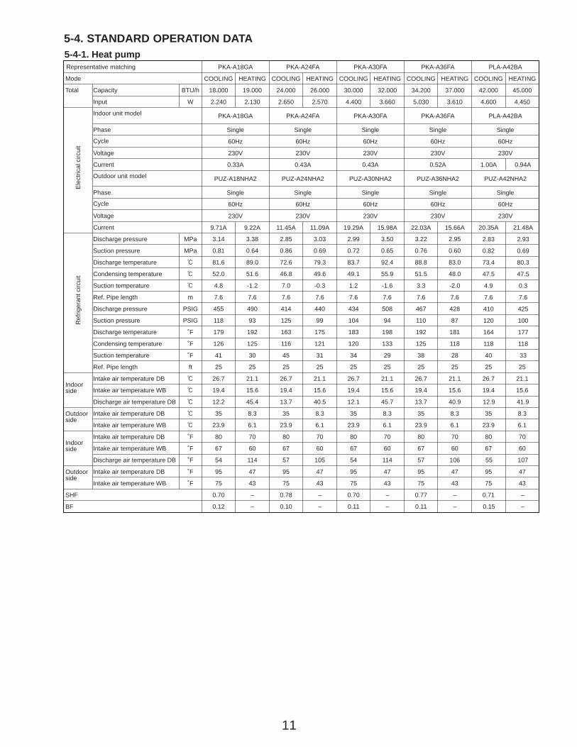
5-4. STANDARD OPERATION DATA5-4-1. Heat pumpRepresentative matching PKA-A18GA PKA-A24FA PKA-A30FA PKA-A36FA PLA-A42BA
Mode COOLING HEATING COOLING HEATING COOLING HEATING COOLING HEATING COOLING HEATING
Total Capacity BTU/h 18,000 19,000 24,000 26,000 30,000 32,000 34,200 37,000 42,000 45,000
Input W 2,240 2,130 2,650 2,570 4,400 3,660 5,030 3,610 4,600 4,450
Ele
ctric
al c
ircui
t
Indoor unit model PKA-A18GA PKA-A24FA PKA-A30FA PKA-A36FA PLA-A42BA
Phase Single Single Single Single Single
Cycle 60Hz 60Hz 60Hz 60Hz 60Hz
Voltage 230V 230V 230V 230V 230V
Current 0.33A 0.43A 0.43A 0.52A 1.00A 0.94A
Outdoor unit model PUZ-A18NHA2 PUZ-A24NHA2 PUZ-A30NHA2 PUZ-A36NHA2 PUZ-A42NHA2
Phase Single Single Single Single Single
Cycle 60Hz 60Hz 60Hz 60Hz 60Hz
Voltage 230V 230V 230V 230V 230V
Current 9.71A 9.22A 11.45A 11.09A 19.29A 15.98A 22.03A 15.66A
Ref
riger
ant c
ircui
t
Discharge pressure MPa 3.14 3.38 2.85 3.03 2.99 3.50 3.22 2.95
Suction pressure MPa 0.81 0.64 0.86 0.69 0.72 0.65 0.76 0.60
Discharge temperature : 81.6 89.0 72.6 79.3 83.7 92.4 88.8 83.0
Condensing temperature : 52.0 51.6 46.8 49.6 49.1 55.9 51.5 48.0
Suction temperature : 4.8 -1.2 7.0 -0.3 1.2 -1.6 3.3 -2.0
Ref. Pipe length m 7.6 7.6 7.6 7.6 7.6 7.6 7.6 7.6
20.35A
2.83
0.82
73.4
47.5
4.9
7.6
410
120
164
118
40
21.48A
2.93
0.69
80.3
47.5
0.3
7.6
425
100
177
118
33
Discharge pressure PSIG 455 490 414 440 434 508 467 428
Suction pressure PSIG 118 93 125 99 104 94 110 87
Discharge temperature ˚F 179 192 163 175 183 198 192 181
Condensing temperature ˚F 126 125 116 121 120 133 125 118
Suction temperature ˚F 41 30 45 31 34 29 38 28
Ref. Pipe length ft 25 25 25 25 25 25 25 25 25 25
sideIndoor
Intake air temperature DB : 26.7 21.1 26.7 21.1 26.7 21.1 26.7 21.1 26.7 21.1
Intake air temperature WB : 19.4 15.6 19.4 15.6 19.4 15.6 19.4 15.6 19.4 15.6
Discharge air temperature DB : 12.2 45.4 13.7 40.5 12.1 45.7 13.7 40.9 12.9 41.9
sideOutdoor Intake air temperature DB : 35 8.3 35 8.3 35 8.3 35 8.3 35 8.3
Intake air temperature WB : 23.9 6.1 23.9 6.1 23.9 6.1 23.9 6.1 23.9 6.1
sideIndoor
Intake air temperature DB ˚F 80 70 80 70 80 70 80 70 80 70
Intake air temperature WB ˚F 67 60 67 60 67 60 67 60 67 60
Discharge air temperature DB ˚F 54 114 57 105 54 114 57 106 55 107
sideOutdoor Intake air temperature DB ˚F 95 47 95 47 95 47 95 47 95 47
Intake air temperature WB ˚F 75 43 75 43 75 43 75 43 75 43
SHF 0.70 0.78 0.70 0.77 0.71
BF 0.12
–
–
–
–
–
–
–
–
–
– 0.10 0.11 0.11 0.15
12
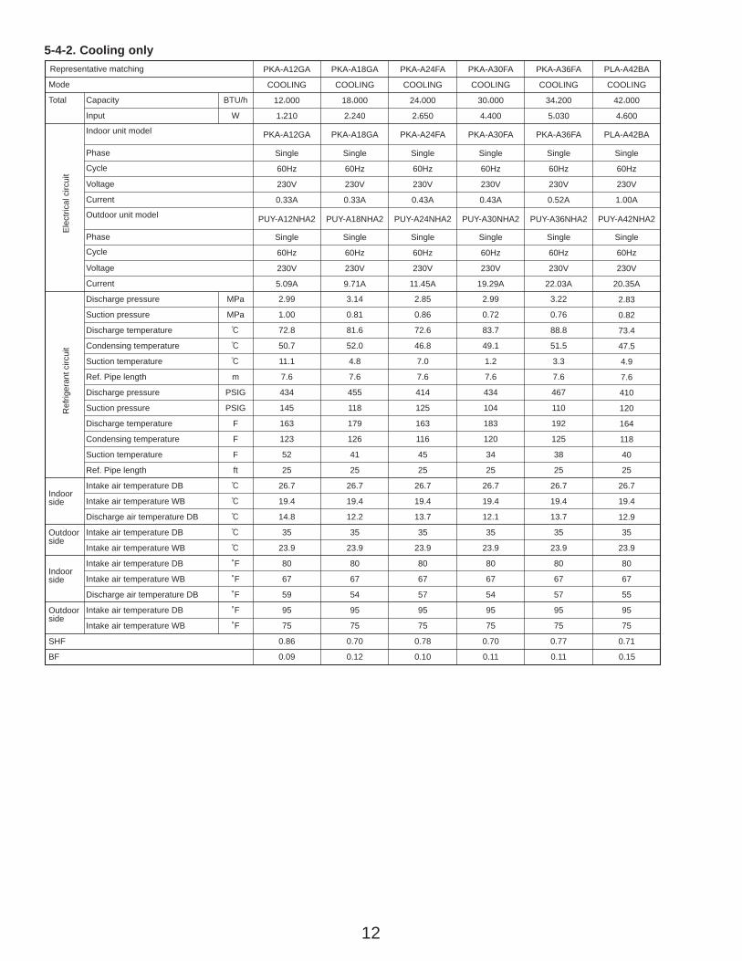
Representative matching PKA-A12GA PKA-A18GA PKA-A24FA PKA-A30FA PKA-A36FA PLA-A42BA
Mode COOLING COOLING COOLING COOLING COOLING COOLING
Total Capacity BTU/h 12,000 18,000 24,000 30,000 34,200 42,000
Input W 1,210 2,240 2,650 4,400 5,030 4,600
Ele
ctric
al c
ircui
t
Indoor unit model PKA-A12GA PKA-A18GA PKA-A24FA PKA-A30FA PKA-A36FA PLA-A42BA
Phase Single Single Single Single Single Single
Cycle 60Hz 60Hz 60Hz 60Hz 60Hz 60Hz
Voltage 230V 230V 230V 230V 230V 230V
Current 0.33A 0.33A 0.43A 0.43A 0.52A 1.00A
Outdoor unit model PUY-A12NHA2 PUY-A18NHA2 PUY-A24NHA2 PUY-A30NHA2 PUY-A36NHA2 PUY-A42NHA2
Phase Single Single Single Single Single Single
Cycle 60Hz 60Hz 60Hz 60Hz 60Hz 60Hz
Voltage 230V 230V 230V 230V 230V 230V
Current 5.09A 9.71A 11.45A 19.29A 22.03A 20.35A
Ref
riger
ant c
ircui
t
Discharge pressure MPa 2.99 3.14 2.85 2.99 3.22
Suction pressure MPa 1.00 0.81 0.86 0.72 0.76
Discharge temperature : 72.8 81.6 72.6 83.7 88.8
Condensing temperature : 50.7 52.0 46.8 49.1 51.5
Suction temperature : 11.1 4.8 7.0 1.2 3.3
Ref. Pipe length m 7.6 7.6 7.6 7.6 7.6
2.83
0.82
73.4
47.5
4.9
7.6
410
120
164
118
40
Discharge pressure PSIG 434 455 414 434 467
Suction pressure PSIG 145 118 125 104 110
Discharge temperature F 163 179 163 183 192
Condensing temperature F 123 126 116 120 125
Suction temperature F 52 41 45 34 38
Ref. Pipe length ft 25 25 25 25 25 25
sideIndoor
Intake air temperature DB : 26.7 26.7 26.7 26.7 26.7 26.7
Intake air temperature WB : 19.4 19.4 19.4 19.4 19.4 19.4
12.9Discharge air temperature DB : 14.8 12.2 13.7 12.1 13.7
sideOutdoor Intake air temperature DB : 35 35 35 35 35 35
Intake air temperature WB : 23.9 23.9 23.9 23.9 23.9 23.9
sideIndoor
Intake air temperature DB ˚F 80 80 80 80 80 80
Intake air temperature WB ˚F 67 67 67 67 67 67
55Discharge air temperature DB ˚F 59 54 57 54 57
sideOutdoor Intake air temperature DB ˚F 95 95 95 95 95 95
Intake air temperature WB ˚F 75 75 75 75 75 75
SHF 0.86 0.70 0.78 0.70 0.77 0.71
BF 0.09 0.12 0.10 0.11 0.11 0.15
5-4-2. Cooling only
13
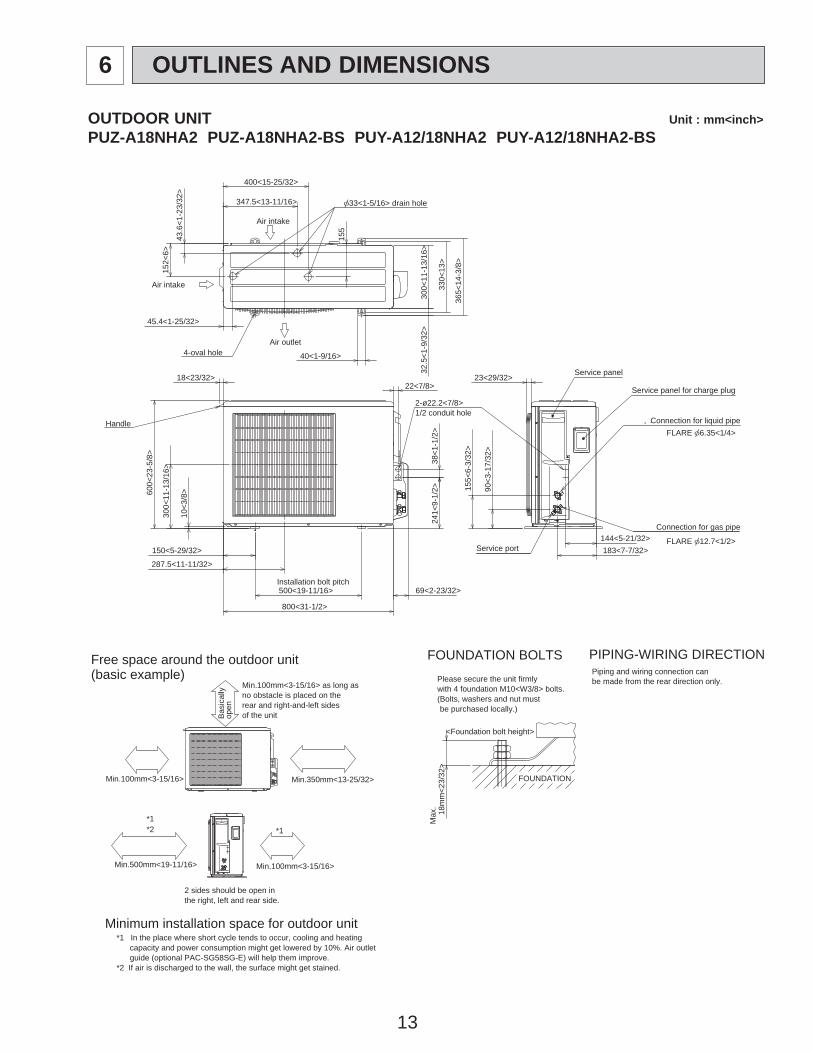
OUTDOOR UNIT Unit : mm<inch>PUZ-A18NHA2 PUZ-A18NHA2-BS PUY-A12/18NHA2 PUY-A12/18NHA2-BS
1/2 conduit hole
144<5-21/32>
2-ø22.2<7/8>
22<7/8>
38<1
-1/2
>24
1<9-
1/2>
Min.100mm<3-15/16>
Piping and wiring connection canbe made from the rear direction only.
*1 In the place where short cycle tends to occur, cooling and heating capacity and power consumption might get lowered by 10%. Air outlet guide (optional PAC-SG58SG-E) will help them improve.*2 If air is discharged to the wall, the surface might get stained.
2 sides should be open inthe right, left and rear side.
Min.100mm<3-15/16> as long as no obstacle is placed on therear and right-and-left sidesof the unit
*1*2 *1
Air intake
Air outlet4-oval hole
Air intake
Service panel
Connection for liquid pipe
Service panel for charge plug
Service port
Connection for gas pipe
Min.100mm<3-15/16>
Min.500mm<19-11/16>
Min.350mm<13-25/32>
Bas
ical
lyop
en
Max
.
<Foundation bolt height>
FOUNDATION
Please secure the unit firmlywith 4 foundation M10<W3/8> bolts.(Bolts, washers and nut must be purchased locally.)
18m
m<2
3/32
>
[33<1-5/16> drain hole
43.6
<1-2
3/32
>
152<
6>
155
400<15-25/32>
347.5<13-11/16>
45.4<1-25/32>
365<
14-3
/8>
330<
13>
300<
11-1
3/16
>
40<1-9/16>
Handle
600<
23-5
/8>
10<3
/8>
300<
11-1
3/16
>
150<5-29/32>
287.5<11-11/32>
500<19-11/16>
800<31-1/2>
69<2-23/32>
183<7-7/32>
90<3
-17/
32>
155<
6-3/
32>
23<29/32>
32.5
<1-9
/32>
18<23/32>
FLARE [12.7<1/2>
FLARE [6.35<1/4>
Installation bolt pitch
PIPING-WIRING DIRECTION
Minimum installation space for outdoor unit
Free space around the outdoor unit(basic example)
FOUNDATION BOLTS
6 OUTLINES AND DIMENSIONS
14
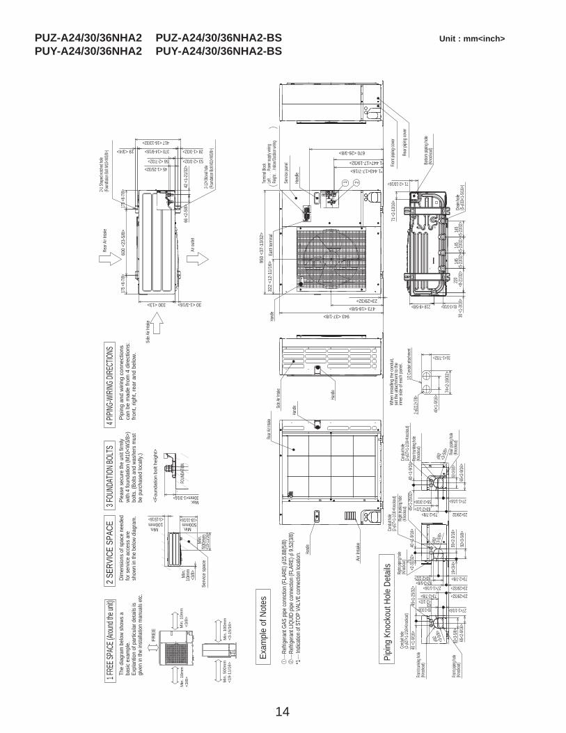
PUZ-A24/30/36NHA2 PUZ-A24/30/36NHA2-BS Unit : mm<inch>PUY-A24/30/36NHA2 PUY-A24/30/36NHA2-BS
�
����
������
�����
������
�����
����
��
����
����
����
��
����
�����
����
�
��
���
��
��
���
�����
������
�����
��
�
����
�����
������
�����
���
��
����
����
���
����
����
�
Min
. 10m
m
<3/
8>M
in. 1
0mm
<3/8
>
Min
. 100
mm
<3-1
5/16
>M
in. 5
00m
m<1
9-11
/16>
100mmMin.
<3-15/16>500mm
Min.
<19-11/16>
500m
mM
in.
<19-1
1/16>
10m
mM
in.
<3/8>
Serv
ice s
pace
���
����
���
����
���
��
Max.30mm<1-3/16>
FOUN
DATIO
N
<Fou
ndat
ion
bolt
heig
ht>
31<1-7/32>
74<2
-19/3
2>
40<1
-9/16
>
Whe
n ins
tallin
g th
e co
nduit
,se
t the
atta
chm
ent t
o th
e inn
er si
de o
f eac
h pa
nel.
1/2 Co
nduit
attach
ment
2-[22
.2<7/8
>
330 <13>
175 <
6-7/8>
600
<23-
5/8>
175 <
6-7/8>
53 <2-3/32>
28 <1-3/32>370 <14-9/16>19 <3/4>
56 <2-7/32>45 <1-25/32>
42 <
1-21
/32>
66 <
2-5/8
>
417 <16-13/32>
2-U Sh
aped
notch
ed ho
le(Fo
undfa
tion Bo
lt M10
<W3/8
>)
Side A
ir Inta
ke
Rear
Air In
take
Air ou
tlet
2-12o
36ova
l hole
(Foun
dation
Bolt M
10<W
3/8>)
30 <1-3/16>
Side A
ir Inta
ke
Hand
le
Rear
piping
cove
r
Fron
t pipi
ng co
ver
81<3-3/16>219 <8-5/8>
145
<5-23
/32>
220
<8-21
/32>
30 <1
-3/16
>14
5<5
-23/32
>
71 <2-13/16>
71 <2
-13/16
>
145
<5-23
/32>
Botto
m pip
ing ho
le(K
nock
out)
Drain
hole
(5-[3
3<1-5
/16>)
Hand
le
Hand
le
Rear
Air In
take
Air I
ntak
e
670 <26-3/8>
*1 443<17-7/16>
*1 447<17-19/32>
322
<12-
11/1
6>950
<37-
13/3
2>
473 <18-5/8>943 <37-1/8>
23<29/32>
21
Hand
le
Hand
le
Servi
ce pa
nel
Earth
term
inal
Left .
. . P
ower
supply
wirin
gRe
ight .
. Ind
oor/O
utdoo
r wirin
g
Term
inal B
lock
63<2-1/2> 73<2-7/8>
75<2
-31/32
>40
<1-9/
16>
92<3
-5/8>
92<3-5/8>27<1-1/16> 23<29/32>
55<2
-3/16
>19
<3/4>
Cond
uit ho
le (2-
[27<
1-1/16
>Kno
ckout)
Right
trunki
ng ho
le(Kn
ockou
t)Rig
ht pip
ing ho
le(Kn
ockou
t)
[92
<3-5/
8>
45<1
-25/32
>
65<2
-9/16
>92
<3-5/
8>
40 <1
-9/16
>
63<2-1/2>
23<29/32>73<2-7/8>
55<2-3/16> 27<1-1/16>
Cond
uit ho
le (2-
[27<
1-1/16
>Kno
ckout)
Front
trunki
ng ho
le(Kn
ockou
t)
Front
piping
hole
(Knock
out)
[92
<3-5/
8>
40 <1
-9/16
>45
<1-25
/32>
63<2-1/2>73<2-7/8> 23<29/32
55<2-3/16> 27<1-1/16>
92<3-5
/8>
65<2
-9/16
>
Cond
uit ho
le (2-
[27<
1-1/16
>Kno
ckout)
Rear
trunki
ng ho
le(Kn
ockou
t)
Rear
piping
hole
(Knock
out)
[92
<3-5/
8>
FRE
E
Pip
ing
and
wiri
ng c
onne
ctio
nsca
n be
mad
e fro
m 4
dire
ctio
ns:
front
, rig
ht, r
ear a
nd b
elow
.
Dim
ensio
ns o
f spa
ce n
eede
dfo
r ser
vice
acce
ss a
resh
own
in th
e be
low
diag
ram
.
Plea
se s
ecur
e th
e un
it fir
mly
with
4 fo
unda
tion
(M10
<W3/
8>)
bolts
. (Bo
lts a
nd w
ashe
rs m
ust
be p
urch
ased
loca
lly.)
The
diag
ram
bel
ow s
hows
aba
sic e
xam
ple.
Expl
antio
n of
par
ticul
ar d
etai
ls is
give
n in
the
inst
alla
tion
man
uals
etc.
1···
·Ref
riger
ant G
AS p
ipe co
nncti
on (F
LARE
) [15
.88(
5/8)
2···
·Ref
riger
ant L
IQUI
D pip
e co
nnec
tion
(FLA
RE) [
9.5
2(3/
8)*1
···· I
ndica
tion
of S
TOP
VALV
E co
nnec
tion
locat
ion.
Exam
ple
of N
otes
Pipin
g Kn
ocko
ut H
ole D
etail
s
1 FRE
E SPA
CE (A
round
the u
nit)2
SERV
ICE
SPAC
E3 F
OUND
ATION
BOLT
S4 P
IPING
-WIRI
NG DI
RECT
IONS
15
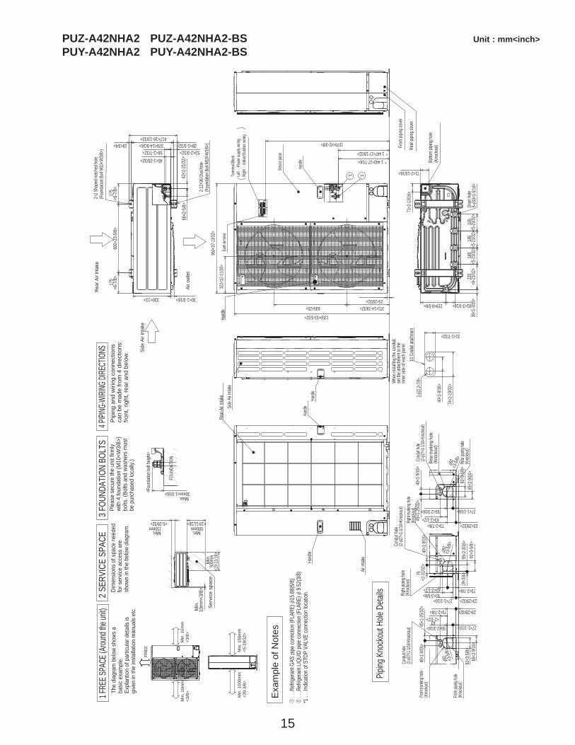
PUZ-A42NHA2 PUZ-A42NHA2-BS Unit : mm<inch>PUY-A42NHA2 PUY-A42NHA2-BS
Term
inal B
lock
Left ·
·· Pow
er su
pply
wiring
Right
··· Ind
oor/O
utdoo
r wirin
g
Earth
term
inal
Servic
e pan
el
Hand
le
1 2
1350<53-5/32>
23<29/32>
950<
37-13
/32>
1076<42-3/8>
* 1 447<17-19/32>
* 1 443<17-7/16>
371<14-19/32>635<25>
322<
12-11
/16>
Hand
le
�
����
������
������
������
����
���
�����
������
�����
����
��
���
�����
�����
���
���
�����
���
���
���
�
��
����
����
����
����
����
�
��
�����
�����
������
������
�����
����
�
���
�����
�����
���
�
�
����
������
�����
��
Min
. 100
0mm
<39-
3/8>
Min
. 150
mm
<5-2
9/32
>
Min
. 10m
m<3
/8>
Min
. 10m
m<3
/8>
FRE
E
Max.
Min
.
Min.Min.M
in.
Hand
le
Side A
ir Inta
ke
Fron
t pipi
ng co
ver
Rear
piping
cove
r
Air in
take
Rear
Air In
take
Hand
leHa
ndle
<Fou
ndati
on bo
lt heig
ht>
Air o
utle
t
Rear
Air
Inta
ke
Side
Air
Inta
ke
30mm<1-3/16>
FOUN
DATIO
N
150mm<5-29/32>
500mm<19-11/16>
500m
m<1
9-11/1
6>
10m
m<3
/8>
Ser
vice
spa
ce
40<1
-9/16
>
74<2
-19/32
>
31<1-7/32>
Whe
n ins
tallin
g the
cond
uit.
set th
e atta
chme
nt to
the
inner
side o
f eac
h pan
el.
2-[22
.2<7/8
>1/2
Cond
uit att
achme
nt
600<
23-5
/8>17
5<6
-7/8>
175
<6-7
/8>
330<13>
417<16-13/32>
42<1
-21/3
2>66
<2-5
/8>
53<2-3/32>56<2-7/32>45<1-25/32>
19<3/4> 28<1-3/32>370<14-9/16>
2-U S
hape
d notc
hed h
ole(F
ound
ation
Bolt
M10
<W3/8
>)
2-12o
36 O
val h
ole(F
ound
ation
Bolt
M10
<W3/8
>)
30<1-3/16>
45<1
-25/32
>40
<1-9/
16>
65<2
-9/16
>92
<3-5/
8>
27<1-1/16>55<2-3/16>
23<29/32>73<2-7/8>63<2-1/2>
Rear
piping
hole
(Knock
out)
Rear
trun
king h
ole(K
nock
out)
Cond
uit ho
le (2-
[27<
1-1/16
>Kno
ckout)
[92
<3-5/
8>19
<3/4>
55<2
-3/16
>92
<3-5/
8>
75<2
-31/32
>40
<1-9/
16>
73<2-7/8>63<2-1/2>
23<29/32>27<1-1/16>92<3-5/8>Rig
ht pip
ing ho
le(K
nock
out)
Right
trunki
ng ho
le(Kn
ockou
t)
Cond
uit ho
le (2-
[27<
1-1/16
>Kno
ckou
t)
[92
<3-5/
8>
92<3
-5/8>
65<2
-9/16
>
45<1
-25/32
>40
<1-9/
16>
27<1-1/16>55<2-3/16>
23<29/32>73<2-7/8>
63<2-1/2>
Front
piping
hole
(Knock
out)
Front
trunki
ng ho
le(Kn
ockou
t)
Cond
uit ho
le (2-
[27<
1-1/16
>Kno
ckout)
[92 <3-5/
8>
145
<5-23
/32>
145
<5-23
/32>
220
<8-21
/32>
30<1
-3/16
>14
5<5
-23/32
>
81<3-3/16>219<8-5/8>
71<2-13/16>
71<2
-13/16
>
Botto
m pip
ing ho
le(K
nock
out)
Drain
hole
5- [33
<1-5/
16>
The
diag
ram
bel
ow s
hows
aba
sic e
xam
ple.
Expl
antio
n of
par
ticul
ar d
etai
ls is
give
n in
the
inst
alla
tion
man
uals
etc.
Dim
ensio
ns o
f spa
ce n
eede
dfo
r ser
vice
acce
ss a
resh
own
in th
e be
low
diag
ram
.
Plea
se s
ecur
e th
e un
it fir
mly
with
4 fo
unda
tion
(M10
<W3/
8>)
bolts
. (Bo
lts a
nd w
ashe
rs m
ust
be p
urch
ased
loca
lly.)
1 .
. .Re
frige
rant
GAS
pipe
conn
ction
(FLA
RE) [
15.8
8(5/
8)2
. . .
Refri
gera
nt L
IQUI
D pip
e co
nnec
tion
(FLA
RE) [
9.5
2(3/
8)*1
. . .
Indic
ation
of S
TOP
VALV
E co
nnec
tion
locat
ion.
Pip
ing
and
wiri
ng c
onne
ctio
nsca
n be
mad
e fro
m 4
dire
ctio
ns:
front
, rig
ht, r
ear a
nd b
elow
.
Exa
mpl
e of
Not
es
1 FRE
E SPA
CE (A
round
the u
nit)
2 SE
RVIC
E SP
ACE
3 FOU
NDAT
ION
BOLT
S4 P
IPING
-WIRI
NG DI
RECT
IONS
Pipin
g Kno
ckou
t Hole
Deta
ils
16
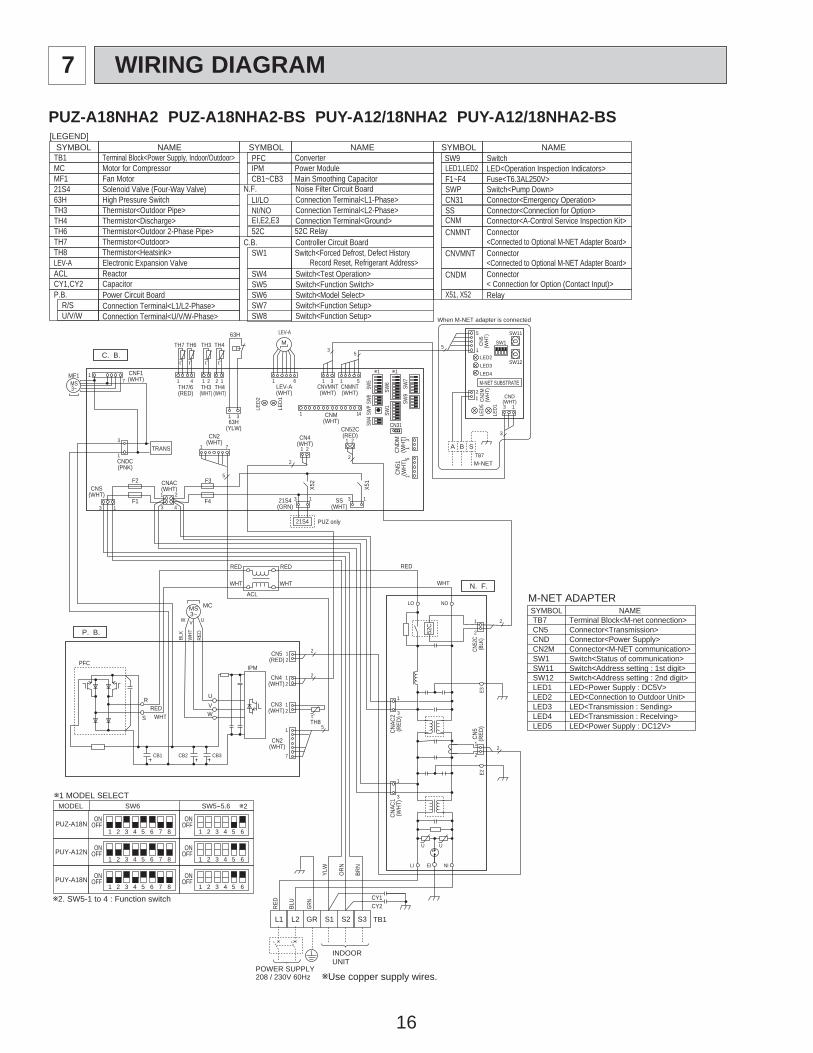
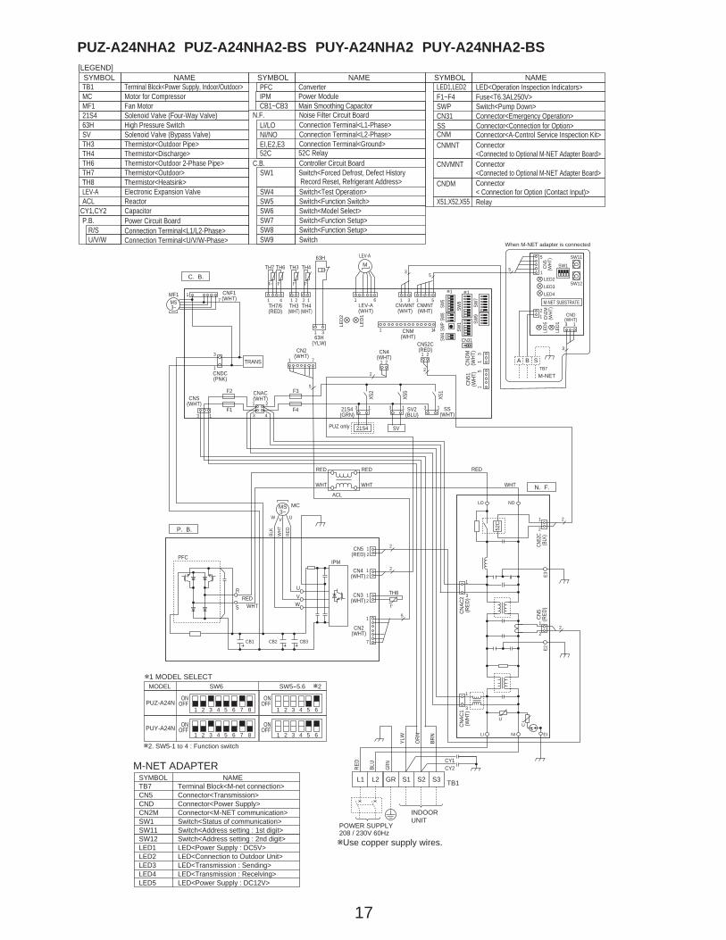
TB1MCMF121S463HTH3TH4TH6TH7TH8LEV-A
CY1,CY2
Terminal Block<Power Supply, Indoor/Outdoor>Motor for CompressorFan Motor Solenoid Valve (Four-Way Valve)High Pressure SwitchThermistor<Outdoor Pipe>Thermistor<Discharge>Thermistor<Outdoor 2-Phase Pipe>Thermistor<Outdoor>Thermistor<Heatsink>Electronic Expansion Valve
CapacitorACL Reactor
Power Circuit Board
Connection Terminal<U/V/W-Phase>
P.B.
U/V/W
Noise Filter Circuit BoardConnection Terminal<L1-Phase>
Connection Terminal<Ground>
N.F.LI/LO
Connection Terminal<L2-Phase>NI/NOEI,E2,E3
Fuse<T6.3AL250V>
Controller Circuit BoardSwitch<Forced Defrost, Defect History Record Reset, Refrigerant Address>Switch<Test Operation>Switch<Function Switch>
Switch<Function Setup>
Switch<Pump Down>Connector<Emergency Operation>
F1~F4
SW1
SW4SW5
SW7Switch<Function Setup>SW8
SWPCN31
CNM
CNVMNT
CNDM
Connector<A-Control Service Inspection Kit>
Connector<Connected to Optional M-NET Adapter Board>Connector< Connection for Option (Contact Input)>
C.B.
ConverterPFCPower ModuleIPMMain Smoothing CapacitorCB1~CB3
52C Relay52C
SYMBOL[LEGEND]
NAME SYMBOL NAME SYMBOL NAME
Connection Terminal<L1/L2-Phase>R/S
Connector<Connection for Option>SS
CNMNT Connector<Connected to Optional M-NET Adapter Board>
Switch<Model Select>SW6
SwitchSW9
X51, X52 Relay
SYMBOLM-NET ADAPTER
NAMETB7CN5CNDCN2MSW1SW11
Terminal Block<M-net connection>Connector<Transmission>Connector<Power Supply>Connector<M-NET communication>Switch<Status of communication>Switch<Address setting : 1st digit>
SW12LED1LED2LED3LED4LED5
Switch<Address setting : 2nd digit>LED<Power Supply : DC5V>LED<Connection to Outdoor Unit>LED<Transmission : Sending>LED<Transmission : Recelving>LED<Power Supply : DC12V>
LED1,LED2 LED<Operation Inspection Indicators>
P. B.
C. B.
CNF1(WHT)MF1
MS3~
71
TRANS
CNDC(PNK)
3
1
TH7/6(RED)
63H(YLW)
TH3(WHT)
TH4(WHT)
TH7 TH6 TH3 TH4
41 21 2 1
31
t° t° t° t°
63H
LEV-A(WHT)
LEV-A
M
LED
1
LED
2
61CNVMNT(WHT)
31
CNDM
(WHT
)CN
51(W
HT)
31
51
CNMNT(WHT)
CNM(WHT)
51
35
SW7
SW6
SW1
SW9
CN31
1
w1w1SW
5SW
8SW
4SW
P
14
X51
CNS(WHT)
CNAC(WHT)
SS(WHT)
21S4(GRN)
X52
F1
F2
F4
F3
21
43
21S4
3 1
13 13
CN4(WHT)
1 2
2
CN52C(RED)
2
2
1CN2
(WHT)71
5CN
5(W
HT)
3 1
LED2
SW1
SW11
SW12LED3LED4
TB7
LED1
LED5
21 CND
(WHT)CN2M
(WHT
)
M-NET SUBSTRATE
M-NET
A B S
When M-NET adapter is connected
5
3
5
1
WHT
U
LI EI NI
LO NO
E2E3
N. F.
2
21
3
1
1
3
2
12
CN5
(RED
)
CNAC
1(W
HT)
CNAC
2(R
ED)
CN52
C(B
LK)
52C
RED
U
POWER SUPPLY208 / 230V 60Hz
INDOORUNIT
TB1L1 L2 GR S1 S2 S3
RED
BLU
YLW
GRN
ORN
BRN
CY2CY1
CB1 CB2 CB3
UV
TH8
IPM
W
R
S
CN3(WHT)
CN2(WHT)
CN4(WHT)
CN5(RED)
1
7
12
12
12
2
2
5
t°WHTRED
PFC
RED
WHT
RED
WHT
ACL
MS3~
BLK
WHT
RED
UVW
MC
PUZ only
1 2 3 4 5 6OFFON
PUZ-A18N
MODEL SW6w1 MODEL SELECT
SW5-5.6
1 2 3 4 5 6OFFONPUY-A12N
PUY-A18N1 2 3 4 5 6
7 8
7 8
7 8OFFON
1 2 3 4 5 6OFFON
1 2 3 4 5 6OFFON
1 2 3 4 5 6OFFON
w2
w2. SW5-1 to 4 : Function switch
wUse copper supply wires.
PUZ-A18NHA2 PUZ-A18NHA2-BS PUY-A12/18NHA2 PUY-A12/18NHA2-BS
7 WIRING DIAGRAM
17
P. B.
C. B.
CNF1(WHT)
MF1MS3~
71
TRANS
CNDC(PNK)
3
1
TH7/6(RED)
63H(YLW)
TH3(WHT)
TH4(WHT)
TH7 TH6 TH3 TH4
41 21 2 1
31
t≈ t° t° t°
63H
LEV-A(WHT)
LEV-AM
LED
1
LED
2
61CNVMNT(WHT)
31
CNDM
(WHT
)CN
51(W
HT)
31
51
CNMNT(WHT)
CNM(WHT)
51
35
SW7
SW6
SW1 SW
9
CN31
1
w1w1
SW5
SW8
SW4
SWP
14
X51
CNS(WHT)
CNAC(WHT)
SS(WHT)
21S4(GRN)
X52
F1
F2
F4
F3
21
43
21S4
3 1
13 SV2(BLU)
X55
SV
13 13
CN4(WHT)
1 2
2
CN52C(RED)
2
2
1CN2
(WHT)71
5
CN5
(WHT
)
3 1
LED2
SW1
SW11
SW12LED3LED4
TB7
LED1
LED5
21 CND
(WHT)CN2M
(WHT
)
M-NET SUBSTRATE
M-NET
A B S
When M-NET adapter is connected
5
3
5
1
WHT
UU
LI EINI
LO NO
E2E3
N. F.
2
21
3
1
1
3
2
12
CN5
(RED
)
CNAC
1(W
HT)
CNAC
2(R
ED)
CN52
C(B
LK)
52C
RED
POWER SUPPLY208 / 230V 60Hz
INDOORUNIT
TB1S1 S2 S3
RED
BLU
YLW
GRN
ORN
BRN
CY2CY1
CB1 CB2 CB3
UV
TH8
IPM
W
R
S
CN3(WHT)
CN2(WHT)
CN4(WHT)
CN5(RED)
1
7
12
12
12
2
2
5
t°WHTRED
PFC
RED
WHT
RED
WHT
ACL
MS3~
BLK
WHT
RED
UVW
MC
PUZ only
L1 L2 GRSYMBOLM-NET ADAPTER
NAMETB7CN5CNDCN2MSW1SW11
Terminal Block<M-net connection>Connector<Transmission>Connector<Power Supply>Connector<M-NET communication>Switch<Status of communication>Switch<Address setting : 1st digit>
SW12LED1LED2LED3LED4LED5
Switch<Address setting : 2nd digit>LED<Power Supply : DC5V>LED<Connection to Outdoor Unit>LED<Transmission : Sending>LED<Transmission : Recelving>LED<Power Supply : DC12V>
TB1MCMF121S463H
TH3TH4TH6TH7TH8LEV-AACL
Terminal Block<Power Supply, Indoor/Outdoor>Motor for CompressorFan Motor Solenoid Valve (Four-Way Valve)High Pressure Switch
SV Solenoid Valve (Bypass Valve)Thermistor<Outdoor Pipe>Thermistor<Discharge>Thermistor<Outdoor 2-Phase Pipe>Thermistor<Outdoor>Thermistor<Heatsink>Electronic Expansion ValveReactor
Power Circuit Board
Connection Terminal<U/V/W-Phase>
P.B.
U/V/W
Noise Filter Circuit BoardConnection Terminal<L1-Phase>
Connection Terminal<Ground>
N.F.LI/LO
Connection Terminal<L2-Phase>NI/NOEI,E2,E3
Fuse<T6.3AL250V>
Controller Circuit BoardSwitch<Forced Defrost, Defect History Record Reset, Refrigerant Address>Switch<Test Operation>Switch<Function Switch>
Switch<Function Setup>
Switch<Pump Down>Connector<Emergency Operation>
F1~F4
SW1
SW4SW5
SW7Switch<Function Setup>SW8
SWPCN31
CNM
CNVMNT
CNDM
LED1,LED2 LED<Operation Inspection Indicators>
Connector<A-Control Service Inspection Kit>
Connector<Connected to Optional M-NET Adapter Board>Connector< Connection for Option (Contact Input)>
C.B.
ConverterPFC
52C Relay52C
SYMBOL[LEGEND]
NAME SYMBOL NAME SYMBOL NAME
Connection Terminal<L1/L2-Phase>R/S
CNMNT Connector<Connected to Optional M-NET Adapter Board>
Switch<Model Select>SW6
SwitchSW9
X51,X52,X55 Relay
Power ModuleIPMMain Smoothing CapacitorCB1~CB3
CY1,CY2 Capacitor
1 2 3 4 5 6OFFON
PUZ-A24N
MODEL SW6w1 MODEL SELECT
SW5-5.6
1 2 3 4 5 6OFFONPUY-A24N
7 8
7 8
1 2 3 4 5 6OFFON
1 2 3 4 5 6OFFON
w2
w2. SW5-1 to 4 : Function switch
Connector<Connection for Option>SS
wUse copper supply wires.
PUZ-A24NHA2 PUZ-A24NHA2-BS PUY-A24NHA2 PUY-A24NHA2-BS
18
SYMBOLM-NET ADAPTER
NAMETB7CN5CNDCN2MSW1SW11SW12LED1LED2LED3LED4LED5
Terminal Block<M-net connection>Connector<Transmission>Connector<Power Supply>Connector<M-NET communication>Switch<Status of communication>Switch<Address setting : 1st digit>Switch<Address setting : 2nd digit>LED<Power Supply : DC5V>LED<Connection to Outdoor Unit>LED<Transmission : Sending>LED<Transmission : Recelving>LED<Power Supply : DC12V>
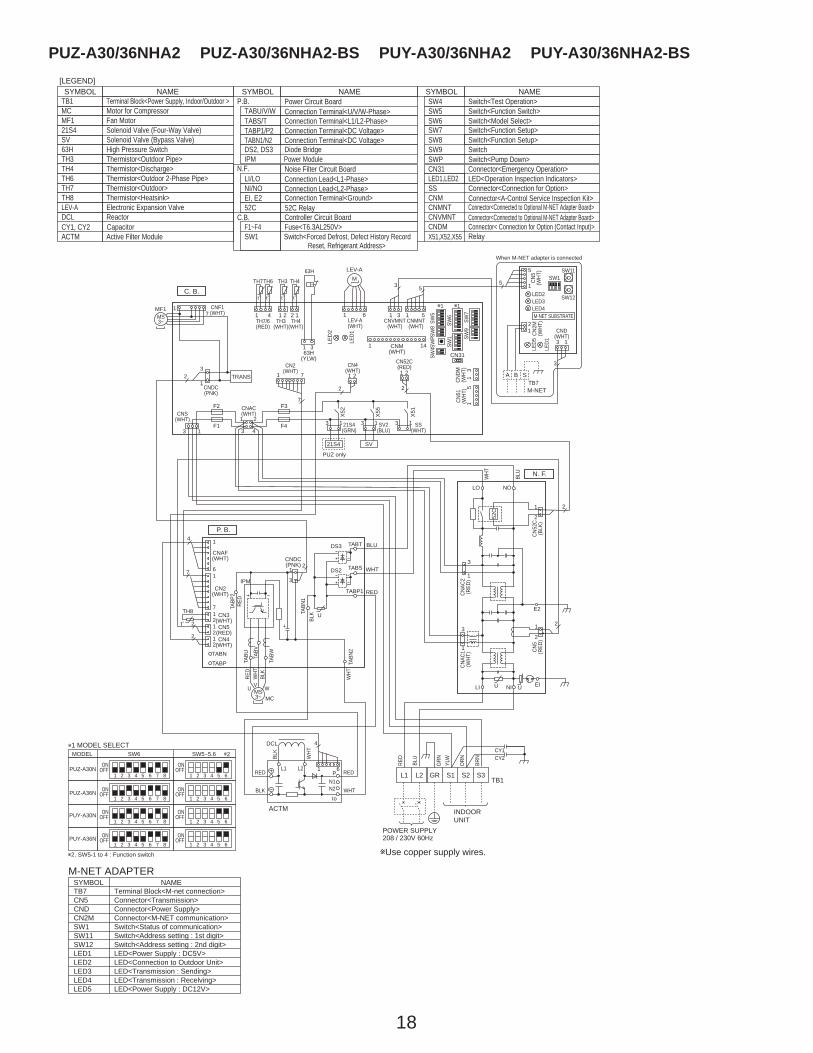
TB1MCMF121S4
63HTH3TH4TH6TH7TH8LEV-ADCL
52C
Terminal Block<Power Supply, Indoor/Outdoor >Motor for CompressorFan MotorSolenoid Valve (Four-Way Valve)
High Pressure SwitchSV Solenoid Valve (Bypass Valve)
Thermistor<Outdoor Pipe>Thermistor<Discharge>Thermistor<Outdoor 2-Phase Pipe>Thermistor<Outdoor>Thermistor<Heatsink>Electronic Expansion ValveReactor
52C Relay
ACTM Active Filter Module
Power Circuit BoardConnection Terminal<U/V/W-Phase>
Diode Bridge
P.B.TABU/V/W
Noise Filter Circuit BoardConnection Lead<L1-Phase>
Connection Terminal<Ground>
N.F.LI/LO
Connection Lead<L2-Phase>NI/NOEI, E2
Controller Circuit Board
Switch<Pump Down>Connector<Emergency Operation>
Switch<Function Setup>SW8
SWPCN31
C.B.
DS2, DS3Power ModuleIPM
SYMBOL[LEGEND]
NAME SYMBOL NAME SYMBOL NAME
Connection Terminal<L1/L2-Phase>Connection Terminal<DC Voltage>
TABS/TTABP1/P2
Connection Terminal<DC Voltage>TABN1/N2SwitchSW9
Fuse<T6.3AL250V>Switch<Forced Defrost, Defect History Record Reset, Refrigerant Address>
Switch<Model Select>
F1~F4SW1
SW6Switch<Function Setup>SW7
LED1,LED2 LED<Operation Inspection Indicators>
CNMCNMNTCNVMNTCNDM
Connector<A-Control Service Inspection Kit>Connector<Connected to Optional M-NET Adapter Board>Connector<Connected to Optional M-NET Adapter Board>Connector< Connection for Option (Contact Input)>
X51,X52,X55 RelayCY1, CY2 Capacitor
Switch<Test Operation>Switch<Function Switch>
SW4SW5
1 2 3 4 5 6OFFON
PUZ-A30N
PUZ-A36N
MODEL SW6w1 MODEL SELECT
SW5-5.6
1 2 3 4 5 6OFFON
1 2 3 4 5 6OFFONPUY-A30N
PUY-A36N1 2 3 4 5 6
7 8
7 8
7 8
7 8OFFON
1 2 3 4 5 6OFFON
1 2 3 4 5 6OFFON
1 2 3 4 5 6OFFON
1 2 3 4 5 6OFFON
w2
w2. SW5-1 to 4 : Function switch
Connector<Connection for Option>SS
wUse copper supply wires.
C. B.
CNF1(WHT)
MF1MS3~
71
TRANS
CNDC(PNK)
32
1
TH7/6(RED)
63H(YLW)
TH3(WHT)
TH4(WHT)
TH7TH6 TH3 TH4
41 21 2 1
31
t° t° t° t°
63H
LEV-A(WHT)
LEV-AM
LED1
LED
2
61CNVMNT
(WHT)
31
CNDM
(WHT
)CN
51(W
HT)
WHT
WHT
WHT
WHT
31
51
CNMNT(WHT)
CNM(WHT)
51
3 5
SW7
SW6
SW1 SW
9
CN31
1
w1w1
SW5
SW8
SW4S
WP
14
X51CNS
(WHT)
CNAC(WHT)
SS(WHT)
21S4(GRN)
X52
F1
F2
F4
F3
21
43
21S4
3 113 SV2
(BLU)
X55
SV
13 13
CN4(WHT)1 2
2
CN52C(RED)
2
2
1CN2
(WHT)71
7
CN5
(WHT
)
3 1
LED2
SW1SW11
SW12LED3LED4
TB7
LED1
LED5
21 CND
(WHT)CN2M
(WHT
)
M-NET SUBSTRATE
M-NET
A B S
When M-NET adapter is connected
5
3
5
1
PUZ only
P. B.
21
37 1
121212
7
6
2
2
CNDC(PNK)
DS2
DS3
TABN
TABP
IPM
U
TABP
2
TABV
TABW
TABN
2
TABN
1
TABS
TABP1
TABT
TABU
MS3~
U V W
MC
CN2(WHT)
4 1
CNAF(WHT)
CN4(WHT)
CN5(RED)
CN3(WHT)
TH8
t°
DCL
ACTM
L1
LO52
CNO
LI NI
CN5
(RED
)
L2
N2
Io
N1P
4
1 6
CNAC
2(R
ED)
CN52
C(B
LK)
CNAC
1(W
HT)
2
2
1
3
E2
EIUU
1
21
23
1
N. F.
POWER SUPPLY208 / 230V 60Hz
INDOORUNIT
TB1S1 S2 S3
RED
BLU
BLU
BLK
BLK
GRN
ORNYLW
BRN
L1 L2 GR
WHT
REDRED
RED
RED
BLU
WHT
RED
BLK
BLK
CY2CY1
PUZ-A30/36NHA2 PUZ-A30/36NHA2-BS PUY-A30/36NHA2 PUY-A30/36NHA2-BS

19
TB1MCMF1,MF221S463H63LTH3TH4TH6TH7TH8LEV-ADCL
Terminal Block<Power Supply, Indoor/Outdoor >Motor for CompressorFan Motor Solenoid Valve (Four-Way Valve)High Pressure SwitchLow Pressure SwitchThermistor<Outdoor Pipe>Thermistor<Discharge>Thermistor<Outdoor 2-Phase Pipe>Thermistor<Outdoor>Thermistor<Heatsink>Electronic Expansion ValveReactor
ACTM Active Filter ModuleCB Main Smoothing Capacitor
Power Circuit BoardConnection Terminal<U/V/W-Phase>
Diode Bridge
P.B.TABU/V/W
Noise Filter Circuit BoardConnection Lead<L1-Phase>
Connection Terminal<Ground>
N.F.LI/LO
Connection Lead<L2-Phase>NI/NO
52C Relay52CEI, E2
Controller Circuit Board
Switch<Pump Down>Connector<Emergency Operation>
SWPCN31
C.B.
DS2, DS3Power ModuleIPM
SYMBOL[LEGEND]
NAME SYMBOL NAME SYMBOL NAME
Connection Terminal<L1/L2-Phase>TABS/TConnection Terminal<DC Voltage>TABP1/P2/PConnection Terminal<DC Voltage>TABN1/N2/N Switch<Function Setup>SW8
SwitchSW9
Fuse<T6.3AL250V>Switch<Forced Defrost, Defect History Record Reset, Refrigerant Address>
Switch<Function Switch>Switch<Model Select>
F1~F4SW1
SW5SW6
Switch<Function Setup>SW7
LED1,LED2 LED<Operation Inspection Indicators>
CNMCNMNTCNVMNTCNDM
Connector<A-Control Service Inspection Kit>Connector<Connected to Optional M-NET Adapter Board>Connector<Connected to Optional M-NET Adapter Board>Connector< Connection for Option (Contact Input)>
X51,X52,X55 Relay
SYMBOLM-NET ADAPTER
NAMETB7CN5CNDCN2MSW1SW11SW12LED1LED2LED3LED4LED5
Terminal Block<M-net connection>Connector<Transmission>Connector<Power Supply>Connector<M-NET communication>Switch<Status of communication>Switch<Address setting : 1st digit>Switch<Address setting : 2nd digit>LED<Power Supply : DC5V>LED<Connection to Outdoor Unit>LED<Transmission : Sending>LED<Transmission : Recelving>LED<Power Supply : DC12V>
wUse copper supply wires.
CY1, CY2 Capacitor
Switch<Test Operation>SW4
1 2 3 4 5 6OFFON
PUZ-A42N
MODEL SW6w1 MODEL SELECT
SW5-5.6
1 2 3 4 5 6OFFONPUY-A42N
7 8
7 8
1 2 3 4 5 6OFFON
1 2 3 4 5 6OFFON
w2
w2. SW5-1 to 4 : Function switch
Connector<Connection for Option>SS
C. B.
CNF1(WHT)
MF1MS3~
71
CNF2(WHT)
MF2MS3~
71
TRANS
CNDC(PNK)
32
1
TH7/6(RED)
63L(RED)
TH3(WHT)
TH4(WHT)
TH7TH6 TH3 TH4
41 21 2 1
31
t° t° t° t°
63L
63H(YLW)
31
63H
LEV-A(WHT)
LEV-AM
LED1
LED
2
61CNVMNT
(WHT)
31
CNDM
(WHT
)CN
51(W
HT)
WHT
WHT
WHT
WHT
31
51
CNMNT(WHT)
CNM(WHT)
51
35
SW7
SW6
SW1 SW
9
CN311
w1w1
SW5
SW8
SW4S
WP
14
X51
CNS(WHT)
CNAC(WHT)
SS(WHT)
21S4(GRN)
X52
F1
F2
F4
F3
21
43
21S4
3 113 SV2
(BLU)X
5513 13
CN4(WHT)1 2
2
CN52C(RED)
2
2
1CN2(WHT) 71
7
CN5
(WHT
)
3 1
LED2
SW1SW11
SW12LED3LED4
TB7
LED1
LED5
21 CND
(WHT)CN2M
(WHT
)
M-NET SUBSTRATE
M-NET
A B S
When M-NET adapter is connected
5
3
5
1
w2 PUZ only
P. B.
21
37 1
121212
7
6
2
2
CNDC(PNK)
DS2
DS3
TABN
TABP
IPM
U
TABP
2
TABV
TABW
TABN
2
TABN
1
TABS
TABP1
TABT
TABU
M3~
U V W
MC
CB
CN2(WHT)
4 1
CNAF(WHT)
CN4(WHT)
CN5(RED)
CN3(WHT)
TH8
t°
DCL
ACTM
L1
LO
52C
NO
LI NI
CN5
(RED
)
L2
N2
Io
N1P
4
1 6
CNAC
2(R
ED)
CN52
C(B
LK)
CNAC
1(W
HT)
2
2
1
3
E2
EIUU
1
21
23
1
N. F.
POWER SUPPLY208 / 230V 60Hz
INDOORUNIT
TB1S1 S2 S3
RED
BLU
BLU
BLK
GRN
ORNYLW
BRN
L1 L2 GR
WHT
REDRED
RED
RED
BLU
WHT
RED
BLK
BLK
BLK
RED
WHT
CY2CY1
PUZ-A42NHA2 PUZ-A42NHA2-BS PUY-A42NHA2 PUY-A42NHA2-BS
20
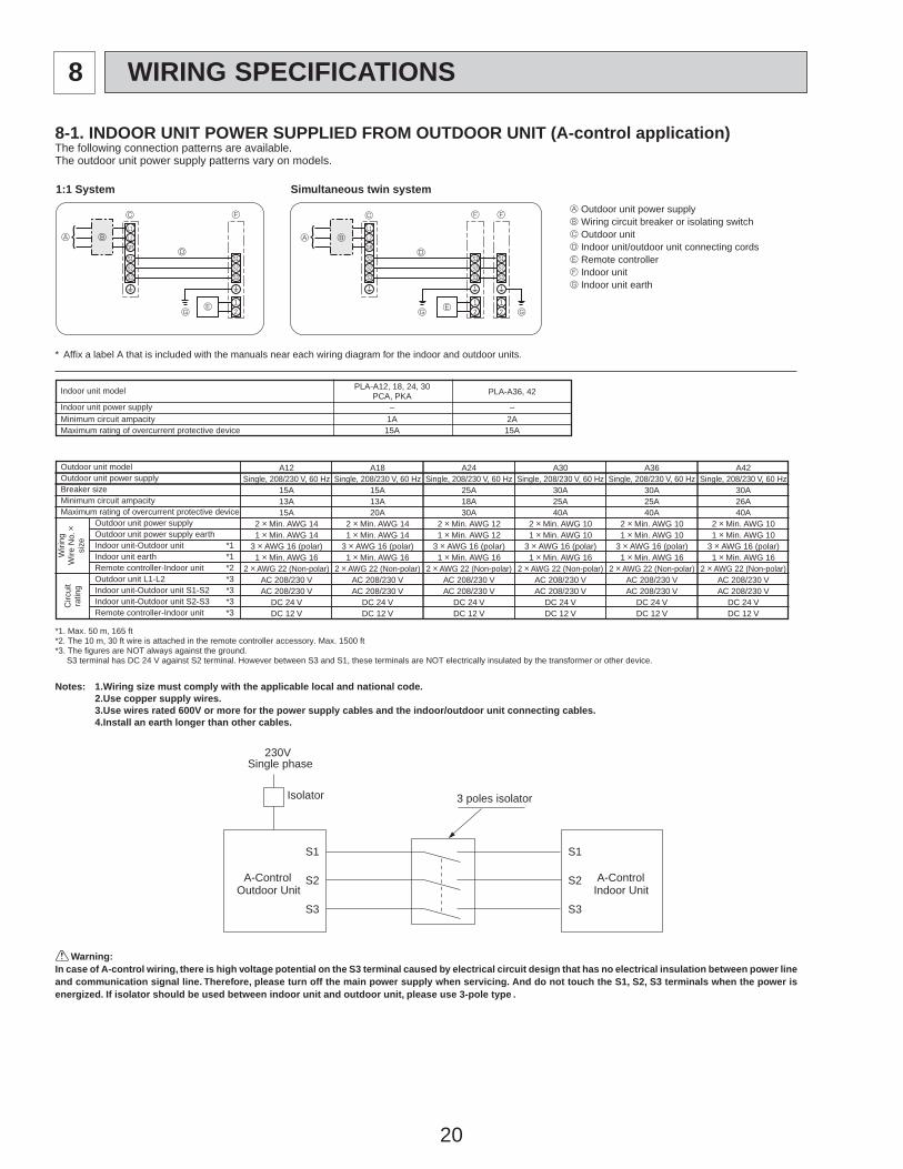
8 WIRING SPECIFICATIONS
8-1. INDOOR UNIT POWER SUPPLIED FROM OUTDOOR UNIT (A-control application)The following connection patterns are available.The outdoor unit power supply patterns vary on models.
1:1 System Simultaneous twin systemA Outdoor unit power supplyB Wiring circuit breaker or isolating switchC Outdoor unitD Indoor unit/outdoor unit connecting cordsE Remote controllerF Indoor unitG Indoor unit earth
S1S2
L1L2GR
12
S1S2S3S3
S1S2
L1L2GR
12
S1S2S3
12
S1S2S3S3
Warning:In case of A-control wiring, there is high voltage potential on the S3 terminal caused by electrical circuit design that has no electrical insulation between power lineand communication signal line. Therefore, please turn off the main power supply when servicing. And do not touch the S1, S2, S3 terminals when the power isenergized. If isolator should be used between indoor unit and outdoor unit, please use 3-pole type .
* Affix a label A that is included with the manuals near each wiring diagram for the indoor and outdoor units.
Indoor unit model PLA-A12, 18, 24, 30PCA, PKA PLA-A36, 42
1A 2A15A 15A
– –
A
C
B
D
E
A
C
B
D
E
FF F
GG G
Indoor unit power supplyMinimum circuit ampacityMaximum rating of overcurrent protective device
*1. Max. 50 m, 165 ft*2. The 10 m, 30 ft wire is attached in the remote controller accessory. Max. 1500 ft*3. The figures are NOT always against the ground. S3 terminal has DC 24 V against S2 terminal. However between S3 and S1, these terminals are NOT electrically insulated by the transformer or other device.
1.Wiring size must comply with the applicable local and national code.2.Use copper supply wires.3.Use wires rated 600V or more for the power supply cables and the indoor/outdoor unit connecting cables.4.Install an earth longer than other cables.
Notes:
Outdoor unit modelOutdoor unit power supplyBreaker sizeMinimum circuit ampacityMaximum rating of overcurrent protective device
Outdoor unit power supplyOutdoor unit power supply earthIndoor unit-Outdoor unit *1Indoor unit earth *1Remote controller-Indoor unit *2Outdoor unit L1-L2 *3Indoor unit-Outdoor unit S1-S2 *3Indoor unit-Outdoor unit S2-S3 *3Remote controller-Indoor unit *3
A12 A18 A24 A30 A36 A42Single, 208/230 V, 60 Hz Single, 208/230 V, 60 Hz Single, 208/230 V, 60 Hz Single, 208/230 V, 60 Hz Single, 208/230 V, 60 Hz Single, 208/230 V, 60 Hz
15A 15A 25A 30A 30A 30A13A 13A 18A 25A 25A 26A15A 20A 30A 40A 40A 40A
2 o Min. AWG 14 2 o Min. AWG 14 2 o Min. AWG 12 2 o Min. AWG 10 2 o Min. AWG 10 2 o Min. AWG 101 o Min. AWG 14 1 o Min. AWG 14 1 o Min. AWG 12 1 o Min. AWG 10 1 o Min. AWG 10 1 o Min. AWG 10
3 o AWG 16 (polar) 3 o AWG 16 (polar) 3 o AWG 16 (polar) 3 o AWG 16 (polar) 3 o AWG 16 (polar) 3 o AWG 16 (polar)1 o Min. AWG 16 1 o Min. AWG 16 1 o Min. AWG 16 1 o Min. AWG 16 1 o Min. AWG 16 1 o Min. AWG 16
2 o AWG 22 (Non-polar) 2 o AWG 22 (Non-polar) 2 o AWG 22 (Non-polar) 2 o AWG 22 (Non-polar) 2 o AWG 22 (Non-polar) 2 o AWG 22 (Non-polar)AC 208/230 V AC 208/230 V AC 208/230 V AC 208/230 V AC 208/230 V AC 208/230 VAC 208/230 V AC 208/230 V AC 208/230 V AC 208/230 V AC 208/230 V AC 208/230 V
DC 24 V DC 24 V DC 24 V DC 24 V DC 24 V DC 24 VDC 12 V DC 12 V DC 12 V DC 12 V DC 12 V DC 12 V
Wiri
ngW
ire N
o. o
size
Circ
uit
ratin
g
S1
S2
S3
S1
S2
S3
A-ControlOutdoor Unit
3 poles isolator
230VSingle phase
Isolator
A-ControlIndoor Unit
21
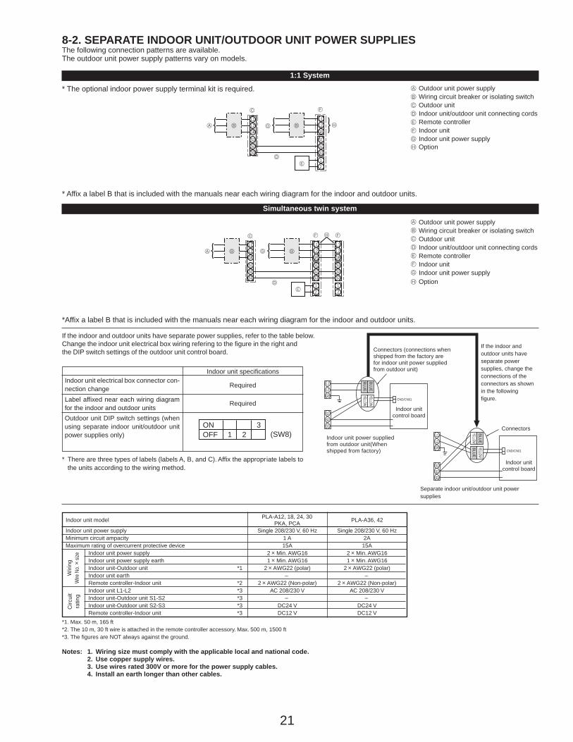
8-2. SEPARATE INDOOR UNIT/OUTDOOR UNIT POWER SUPPLIESThe following connection patterns are available.The outdoor unit power supply patterns vary on models.
1:1 System
S1S2
L1L2GR GR
12
L1L2
S1S2S3S3
* Affix a label B that is included with the manuals near each wiring diagram for the indoor and outdoor units.
* The optional indoor power supply terminal kit is required. Outdoor unit power supplyWiring circuit breaker or isolating switchOutdoor unitIndoor unit/outdoor unit connecting cordsRemote controllerIndoor unitIndoor unit power supply
Simultaneous twin system
If the indoor and outdoor units have separate power supplies, refer to the table below.Change the indoor unit electrical box wiring refering to the figure in the right and the DIP switch settings of the outdoor unit control board.
*Affix a label B that is included with the manuals near each wiring diagram for the indoor and outdoor units.
Outdoor unit power supplyWiring circuit breaker or isolating switchOutdoor unitIndoor unit/outdoor unit connecting cordsRemote controllerIndoor unitIndoor unit power supply
ONOFF 1 2 (SW8)
3
Indoor unit electrical box connector con-nection changeLabel affixed near each wiring diagramfor the indoor and outdoor unitsOutdoor unit DIP switch settings (whenusing separate indoor unit/outdoor unitpower supplies only)
Indoor unit specifications
Required
Required
*1. Max. 50 m, 165 ft*2. The 10 m, 30 ft wire is attached in the remote controller accessory. Max. 500 m, 1500 ft*3. The figures are NOT always against the ground.
Notes: 1. Wiring size must comply with the applicable local and national code.2. Use copper supply wires.3. Use wires rated 300V or more for the power supply cables.4. Install an earth longer than other cables.
Indoor unit model
Indoor unit power supplyMinimum circuit ampacityMaximum rating of overcurrent protective device
Indoor unit power supplyIndoor unit power supply earthIndoor unit-Outdoor unit *1Indoor unit earthRemote controller-Indoor unit *2Indoor unit L1-L2 *3Indoor unit-Outdoor unit S1-S2 *3Indoor unit-Outdoor unit S2-S3 *3Remote controller-Indoor unit *3
PLA-A12, 18, 24, 30PKA, PCA PLA-A36, 42
Single 208/230 V, 60 Hz Single 208/230 V, 60 Hz1 A 2A15A 15A
2 o Min. AWG16 2 o Min. AWG161 o Min. AWG16 1 o Min. AWG16
2 o AWG22 (polar) 2 o AWG22 (polar)
2 o AWG22 (Non-polar) 2 o AWG22 (Non-polar)AC 208/230 V AC 208/230 V
DC24 V DC24 VDC12 V DC12 V
Circ
uit
ratin
g
If the indoor andoutdoor units haveseparate powersupplies, change theconnections of theconnectors as shownin the followingfigure.
Connectors
Indoor unitcontrol board
Separate indoor unit/outdoor unit powersupplies
Indoor unitcontrol board
* There are three types of labels (labels A, B, and C). Affix the appropriate labels tothe units according to the wiring method.
S1S2
L1
GRL2
12
L1L2GR GRS1S2S3
12
L1L2
S1S2S3S3
S1S2S3
L1L2GR
BLUEBLUE
YELLOWYELLOW
CND/CN01
S1S2S3
L1L2GR
YELLOWBLUE
BLUEYELLOW
Wiri
ngW
ire N
o. o
size
– –
– –
A
B
C
D
E
F
G
OptionH
OptionH
A
B
C
D
E
F
G
A H
H
C
B B
D
E
F
G
A
C
B B
D
E
F F
G
CND/CN01
Connectors (connections when shipped from the factory are for indoor unit power supplied from outdoor unit)
Indoor unit power supplied from outdoor unit(When shipped from factory)
22
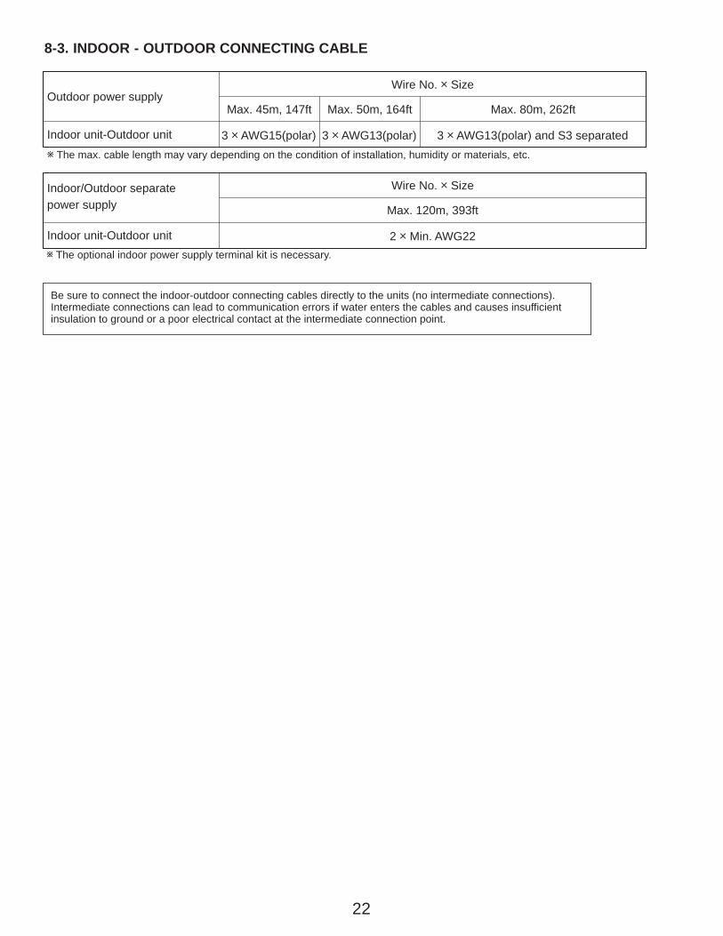
w The max. cable length may vary depending on the condition of installation, humidity or materials, etc.
Indoor unit-Outdoor unit
Outdoor power supplyMax. 45m, 147ft
3 o AWG15(polar)
Max. 50m, 164ft
3 o AWG13(polar)
Max. 80m, 262ft
3 o AWG13(polar) and S3 separated
Wire No. o Size
Be sure to connect the indoor-outdoor connecting cables directly to the units (no intermediate connections).Intermediate connections can lead to communication errors if water enters the cables and causes insufficient insulation to ground or a poor electrical contact at the intermediate connection point.
Indoor unit-Outdoor unit
Indoor/Outdoor separatepower supply Max. 120m, 393ft
2 o Min. AWG22
Wire No. o Size
w The optional indoor power supply terminal kit is necessary.
8-3. INDOOR - OUTDOOR CONNECTING CABLE
23
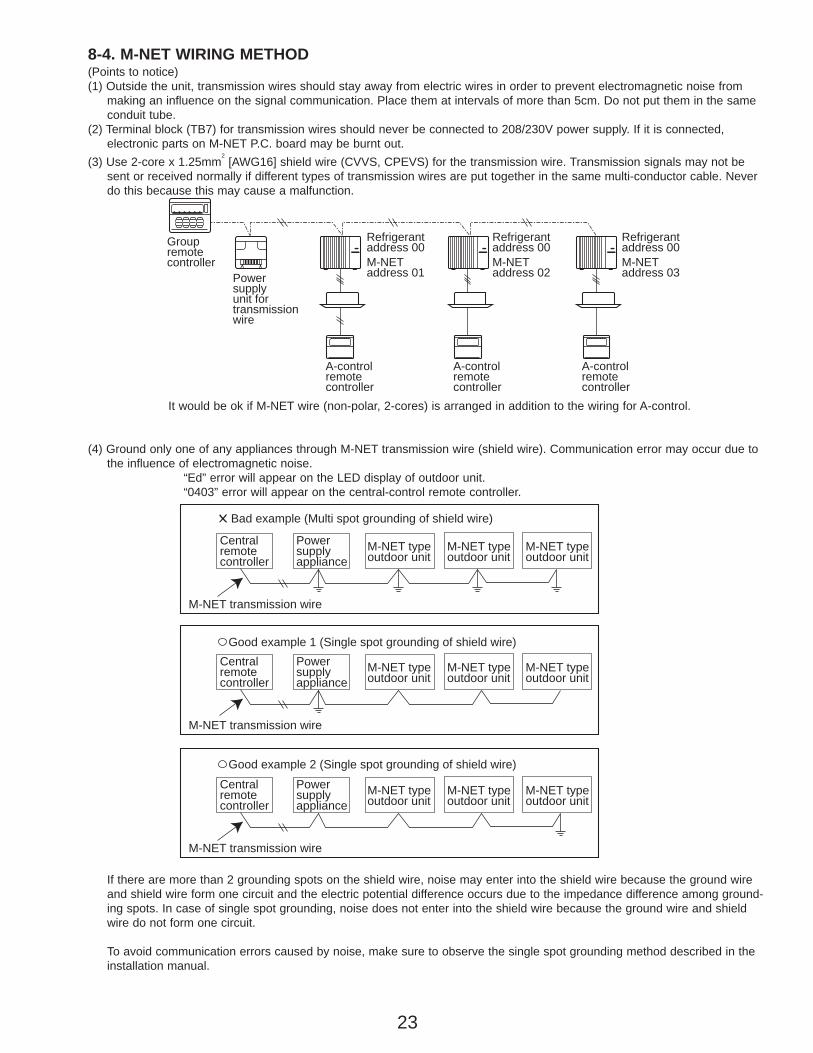
8-4. M-NET WIRING METHOD(Points to notice)(1) Outside the unit, transmission wires should stay away from electric wires in order to prevent electromagnetic noise from
making an influence on the signal communication. Place them at intervals of more than 5cm. Do not put them in the sameconduit tube.
(2) Terminal block (TB7) for transmission wires should never be connected to 208/230V power supply. If it is connected, electronic parts on M-NET P.C. board may be burnt out.
(3) Use 2-core x 1.25mm2
[AWG16] shield wire (CVVS, CPEVS) for the transmission wire. Transmission signals may not besent or received normally if different types of transmission wires are put together in the same multi-conductor cable. Neverdo this because this may cause a malfunction.
It would be ok if M-NET wire (non-polar, 2-cores) is arranged in addition to the wiring for A-control.
(4) Ground only one of any appliances through M-NET transmission wire (shield wire). Communication error may occur due tothe influence of electromagnetic noise.
“Ed” error will appear on the LED display of outdoor unit.“0403” error will appear on the central-control remote controller.
If there are more than 2 grounding spots on the shield wire, noise may enter into the shield wire because the ground wireand shield wire form one circuit and the electric potential difference occurs due to the impedance difference among ground-ing spots. In case of single spot grounding, noise does not enter into the shield wire because the ground wire and shieldwire do not form one circuit.
To avoid communication errors caused by noise, make sure to observe the single spot grounding method described in theinstallation manual.
Groupremotecontroller
Refrigerantaddress 00M-NETaddress 01
A-controlremotecontroller
A-controlremotecontroller
A-controlremotecontroller
Refrigerantaddress 00M-NETaddress 02
Refrigerantaddress 00M-NETaddress 03Power
supplyunit fortransmissionwire
Centralremotecontroller
M-NET transmission wire
✕ Bad example (Multi spot grounding of shield wire)
Good example 1 (Single spot grounding of shield wire)
Powersupplyappliance
M-NET typeoutdoor unit
Centralremotecontroller
Powersupplyappliance
M-NET typeoutdoor unit
M-NET typeoutdoor unit
M-NET typeoutdoor unit
M-NET transmission wire
M-NET typeoutdoor unit
M-NET typeoutdoor unit
Centralremotecontroller
Powersupplyappliance
M-NET typeoutdoor unit
M-NET transmission wire
M-NET typeoutdoor unit
M-NET typeoutdoor unit
Good example 2 (Single spot grounding of shield wire)
24
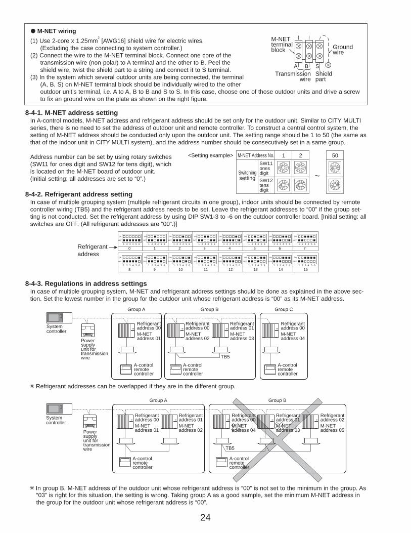
8-4-3. Regulations in address settingsIn case of multiple grouping system, M-NET and refrigerant address settings should be done as explained in the above sec-tion. Set the lowest number in the group for the outdoor unit whose refrigerant address is “00” as its M-NET address.
w Refrigerant addresses can be overlapped if they are in the different group.
w In group B, M-NET address of the outdoor unit whose refrigerant address is “00” is not set to the minimum in the group. As“03” is right for this situation, the setting is wrong. Taking group A as a good sample, set the minimum M-NET address inthe group for the outdoor unit whose refrigerant address is “00”.
8-4-1. M-NET address settingIn A-control models, M-NET address and refrigerant address should be set only for the outdoor unit. Similar to CITY MULTIseries, there is no need to set the address of outdoor unit and remote controller. To construct a central control system, thesetting of M-NET address should be conducted only upon the outdoor unit. The setting range should be 1 to 50 (the same asthat of the indoor unit in CITY MULTI system), and the address number should be consecutively set in a same group.
Address number can be set by using rotary switches (SW11 for ones digit and SW12 for tens digit), which is located on the M-NET board of outdoor unit. (Initial setting: all addresses are set to “0”.)
8-4-2. Refrigerant address settingIn case of multiple grouping system (multiple refrigerant circuits in one group), indoor units should be connected by remotecontroller wiring (TB5) and the refrigerant address needs to be set. Leave the refrigerant addresses to “00” if the group set-ting is not conducted. Set the refrigerant address by using DIP SW1-3 to -6 on the outdoor controller board. [Initial setting: allswitches are OFF. (All refrigerant addresses are “00”.)]
1234567890
1234567890
1234567890
1234567890
12345678901234567890
1 2
~
50M-NET Address No.<Setting example>
Switchingsetting
SW11onesdigitSW12tensdigit
OFF
ON
1 2 3 4 5 6 1 2 3 4 5 6 1 2 3 4 5 6 1 2 3 4 5 6 1 2 3 4 5 6 1 2 3 4 5 6 1 2 3 4 5 6 1 2 3 4 5 6
1 2 3 4 5 61 2 3 4 5 61 2 3 4 5 61 2 3 4 5 61 2 3 4 5 61 2 3 4 5 61 2 3 4 5 61 2 3 4 5 6
0Refrigerantaddress
OFF
ON
8
OFF
ON
1
OFF
ON
9
OFF
ON
10
OFF
ON
11
OFF
ON
12
OFF
ON
13
OFF
ON
14
OFF
ON
15
OFF
ON
2
OFF
ON
3
OFF
ON
4
OFF
ON
5
OFF
ON
6
OFF
ON
7
Systemcontroller
A-controlremotecontroller
Group A Group B Group C
A-controlremotecontroller
TB5
A-controlremotecontroller
Refrigerantaddress 00M-NETaddress 01
Refrigerantaddress 00M-NETaddress 02
Refrigerantaddress 01M-NETaddress 03
Refrigerantaddress 00M-NETaddress 04Power
supplyunit fortransmissionwire
A-controlremotecontroller
A-controlremotecontroller
TB5
Group A Group B
Refrigerantaddress 00M-NETaddress 01
Refrigerantaddress 01M-NETaddress 02
Refrigerantaddress 00M-NETaddress 04
Refrigerantaddress 01M-NETaddress 03
Refrigerantaddress 02M-NETaddress 05
Systemcontroller
Powersupplyunit fortransmissionwire
● M-NET wiring(1) Use 2-core x 1.25mm
2[AWG16] shield wire for electric wires.
(Excluding the case connecting to system controller.)(2) Connect the wire to the M-NET terminal block. Connect one core of the
transmission wire (non-polar) to A terminal and the other to B. Peel the shield wire, twist the shield part to a string and connect it to S terminal.
(3) In the system which several outdoor units are being connected, the terminal (A, B, S) on M-NET terminal block should be individually wired to the other outdoor unit’s terminal, i.e. A to A, B to B and S to S. In this case, choose one of those outdoor units and drive a screw to fix an ground wire on the plate as shown on the right figure.
Transmissionwire
Shieldpart
M-NET terminalblock Ground
wire
A B S
25
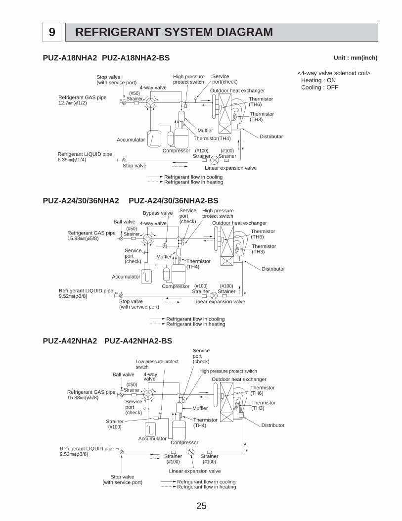
9 REFRIGERANT SYSTEM DIAGRAM
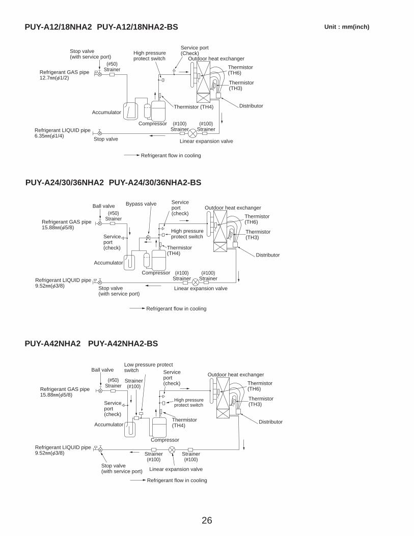
PUZ-A24/30/36NHA2 PUZ-A24/30/36NHA2-BS
Outdoor heat exchanger
Thermistor(TH3)
Thermistor(TH6)
Distributor
Serviceport(check)
Accumulator
Compressor
Refrigerant GAS pipe15.88A({5/8)
Refrigerant LIQUID pipe9.52A({3/8)
Stop valve(with service port)
4-way valve
Serviceport(check)
High pressureprotect switch
Refrigerant flow in coolingRefrigerant flow in heating
Linear expansion valve
Thermistor(TH4)
Muffler
Ball valve
Bypass valve
(#50)Strainer
(#100)Strainer
(#100)Strainer
PUZ-A18NHA2 PUZ-A18NHA2-BS
Accumulator
Stop valve(with service port)
Compressor
Refrigerant GAS pipe12.7A({1/2)
Refrigerant LIQUID pipe6.35A({1/4)
Stop valve
4-way valve
Serviceport(check)
High pressureprotect switch
Outdoor heat exchanger
Thermistor(TH3)
Thermistor(TH6)
DistributorMuffler
Thermistor(TH4)
Linear expansion valve
Refrigerant flow in coolingRefrigerant flow in heating
(#50)Strainer
(#100)Strainer
(#100)Strainer
<4-way valve solenoid coil>Heating : ONCooling : OFF
PUZ-A42NHA2 PUZ-A42NHA2-BS
Serviceport(check)
AccumulatorCompressor
Refrigerant GAS pipe15.88A({5/8)
Refrigerant LIQUID pipe9.52A({3/8)
4-wayvalve
Serviceport(check)
High pressure protect switch
Linear expansion valve
Muffler
Thermistor(TH4)
Refrigerant flow in coolingRefrigerant flow in heating
Ball valve
(#50)Strainer
Strainer(#100)
Strainer(#100)
Strainer(#100)
Low pressure protect switch
Stop valve(with service port)
Outdoor heat exchanger
Thermistor(TH3)
Thermistor(TH6)
Distributor
Unit : mm(inch)
26
Outdoor heat exchanger
Thermistor(TH3)
Thermistor(TH6)
Distributor
Serviceport(check)
Accumulator
Compressor
Refrigerant GAS pipe15.88A({5/8)
Refrigerant LIQUID pipe9.52A({3/8) Stop valve
(with service port)
Serviceport(check)
High pressureprotect switch
Refrigerant flow in cooling
Linear expansion valve
Thermistor(TH4)
Ball valve(#50)
Strainer
(#100)Strainer
(#100)Strainer
Bypass valve
PUY-A12/18NHA2 PUY-A12/18NHA2-BS
PUY-A42NHA2 PUY-A42NHA2-BS
Outdoor heat exchanger
Thermistor(TH3)
Thermistor(TH6)
Distributor
Service port(Check)
Accumulator
Compressor
Refrigerant GAS pipe12.7A({1/2)
Refrigerant LIQUID pipe6.35A({1/4) Stop valve
High pressureprotect switch
Thermistor (TH4)
Linear expansion valve
Refrigerant flow in cooling
Stop valve(with service port)
(#50)Strainer
(#100)Strainer
(#100)Strainer
Serviceport(check)
Accumulator
Compressor
Refrigerant GAS pipe15.88A({5/8)
Refrigerant LIQUID pipe9.52A({3/8)
Serviceport(check)
High pressureprotect switch
Thermistor(TH4)
Refrigerant flow in cooling
Stop valve(with service port) Linear expansion valve
Ball valve
(#50)Strainer
Strainer(#100)
Strainer(#100)
Strainer(#100)
Low pressure protect switch
Outdoor heat exchanger
Thermistor(TH3)
Thermistor(TH6)
Distributor
PUY-A24/30/36NHA2 PUY-A24/30/36NHA2-BS
Unit : mm(inch)
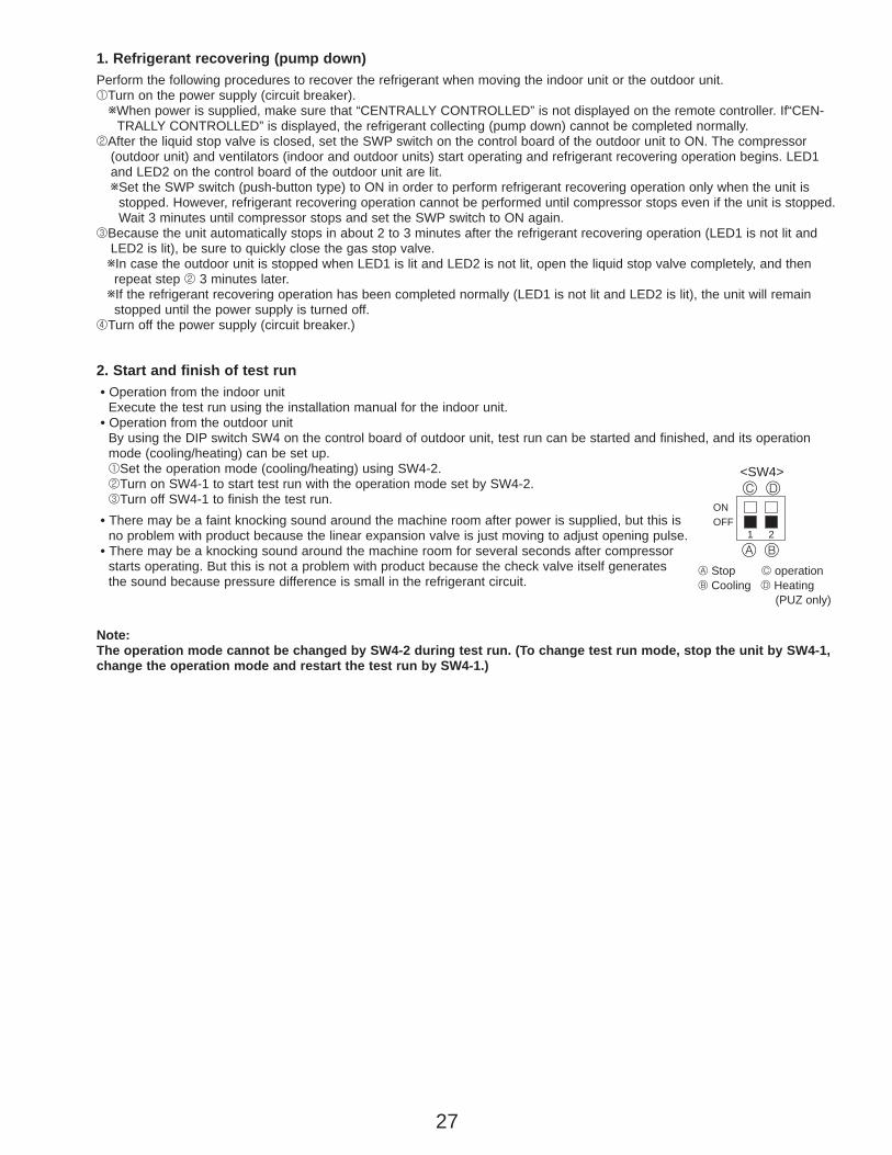
27
2. Start and finish of test run• Operation from the indoor unit
Execute the test run using the installation manual for the indoor unit.• Operation from the outdoor unit
By using the DIP switch SW4 on the control board of outdoor unit, test run can be started and finished, and its operation mode (cooling/heating) can be set up.1Set the operation mode (cooling/heating) using SW4-2.2Turn on SW4-1 to start test run with the operation mode set by SW4-2.3Turn off SW4-1 to finish the test run.
• There may be a faint knocking sound around the machine room after power is supplied, but this isno problem with product because the linear expansion valve is just moving to adjust opening pulse.
• There may be a knocking sound around the machine room for several seconds after compressor starts operating. But this is not a problem with product because the check valve itself generatesthe sound because pressure difference is small in the refrigerant circuit.
Note:The operation mode cannot be changed by SW4-2 during test run. (To change test run mode, stop the unit by SW4-1,change the operation mode and restart the test run by SW4-1.)
OFF1 2
ON
<SW4>
A B
C D
A Stop C operationB Cooling D Heating
(PUZ only)
1. Refrigerant recovering (pump down)Perform the following procedures to recover the refrigerant when moving the indoor unit or the outdoor unit.1Turn on the power supply (circuit breaker).wWhen power is supplied, make sure that “CENTRALLY CONTROLLED” is not displayed on the remote controller. If“CEN-
TRALLY CONTROLLED” is displayed, the refrigerant collecting (pump down) cannot be completed normally.2After the liquid stop valve is closed, set the SWP switch on the control board of the outdoor unit to ON. The compressor
(outdoor unit) and ventilators (indoor and outdoor units) start operating and refrigerant recovering operation begins. LED1and LED2 on the control board of the outdoor unit are lit.wSet the SWP switch (push-button type) to ON in order to perform refrigerant recovering operation only when the unit is
stopped. However, refrigerant recovering operation cannot be performed until compressor stops even if the unit is stopped.Wait 3 minutes until compressor stops and set the SWP switch to ON again.
3Because the unit automatically stops in about 2 to 3 minutes after the refrigerant recovering operation (LED1 is not lit andLED2 is lit), be sure to quickly close the gas stop valve.wIn case the outdoor unit is stopped when LED1 is lit and LED2 is not lit, open the liquid stop valve completely, and thenrepeat step 2 3 minutes later.
wIf the refrigerant recovering operation has been completed normally (LED1 is not lit and LED2 is lit), the unit will remainstopped until the power supply is turned off.
4Turn off the power supply (circuit breaker.)
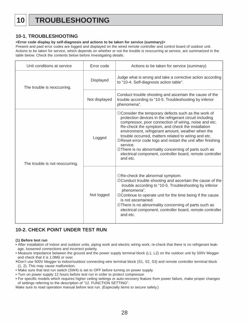
28
10 TROUBLESHOOTING
<Error code display by self-diagnosis and actions to be taken for service (summary)>Present and past error codes are logged and displayed on the wired remote controller and control board of outdoor unit.Actions to be taken for service, which depends on whether or not the trouble is reoccurring at service, are summarized in thetable below. Check the contents below before investigating details.
10-1. TROUBLESHOOTING
Unit conditions at service Error code Actions to be taken for service (summary)
The trouble is reoccurring.
Displayed
Not displayed
Judge what is wrong and take a corrective action accordingto “10-4. Self-diagnosis action table”.
Conduct trouble shooting and ascertain the cause of thetrouble according to “10-5. Troubleshooting by inferiorphenomena”.
The trouble is not reoccurring.
Logged
Not logged
1Consider the temporary defects such as the work of protection devices in the refrigerant circuit including compressor, poor connection of wiring, noise and etc. Re-check the symptom, and check the installation environment, refrigerant amount, weather when the trouble occurred, matters related to wiring and etc.2Reset error code logs and restart the unit after finishing service.3There is no abnormality concerning of parts such as electrical component, controller board, remote controller and etc.
1Re-check the abnormal symptom.2Conduct trouble shooting and ascertain the cause of the trouble according to “10-5. Troubleshooting by inferior phenomena”.3Continue to operate unit for the time being if the cause is not ascertained.4There is no abnormality concerning of parts such as electrical component, controller board, remote controller and etc.
10-2. CHECK POINT UNDER TEST RUN
(1) Before test run• After installation of indoor and outdoor units, piping work and electric wiring work, re-check that there is no refrigerant leak-
age, loosened connections and incorrect polarity.• Measure impedance between the ground and the power supply terminal block (L1, L2) on the outdoor unit by 500V Megger
and check that it is 1.0M" or over.wDon’t use 500V Megger to indoor/outdoor connecting wire terminal block (S1, S2, S3) and remote controller terminal block
(1, 2). This may cause malfunction.• Make sure that test run switch (SW4) is set to OFF before turning on power supply.• Turn on power supply 12 hours before test run in order to protect compressor.• For specific models which requires higher ceiling settings or auto-recovery feature from power failure, make proper changes
of settings referring to the description of “12. FUNCTION SETTING”.Make sure to read operation manual before test run. (Especially items to secure safety.)
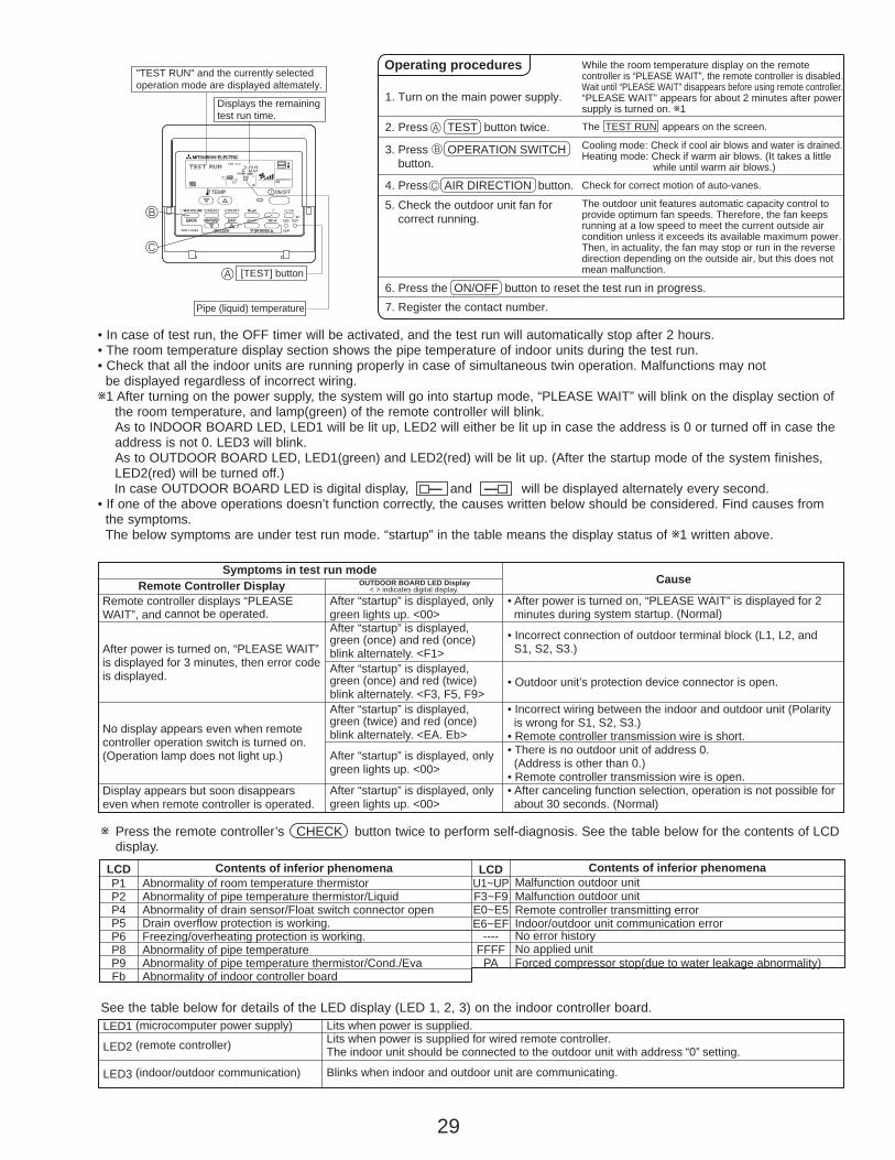
29
[TEST] button
Pipe (liquid) temperature
Displays the remainingtest run time.
"TEST RUN" and the currently selectedoperation mode are displayed altemately.
A
B
C
°F59
• In case of test run, the OFF timer will be activated, and the test run will automatically stop after 2 hours.• The room temperature display section shows the pipe temperature of indoor units during the test run.• Check that all the indoor units are running properly in case of simultaneous twin operation. Malfunctions may not
be displayed regardless of incorrect wiring.w1 After turning on the power supply, the system will go into startup mode, “PLEASE WAIT” will blink on the display section of
the room temperature, and lamp(green) of the remote controller will blink.As to INDOOR BOARD LED, LED1 will be lit up, LED2 will either be lit up in case the address is 0 or turned off in case the address is not 0. LED3 will blink.As to OUTDOOR BOARD LED, LED1(green) and LED2(red) will be lit up. (After the startup mode of the system finishes, LED2(red) will be turned off.)In case OUTDOOR BOARD LED is digital display, — and — will be displayed alternately every second.
• If one of the above operations doesn’t function correctly, the causes written below should be considered. Find causes from the symptoms.The below symptoms are under test run mode. “startup” in the table means the display status of w1 written above.
Remote Controller DisplaySymptoms in test run mode
OUTDOOR BOARD LED Display Cause
Remote controller displays “PLEASE WAIT”, and cannot be operated.
After power is turned on, “PLEASE WAIT” is displayed for 3 minutes, then error code is displayed.
No display appears even when remote controller operation switch is turned on.(Operation lamp does not light up.)
Display appears but soon disappears even when remote controller is operated.
• After power is turned on, “PLEASE WAIT” is displayed for 2 minutes during system startup. (Normal)
• Incorrect connection of outdoor terminal block (L1, L2, and S1, S2, S3.)
• Outdoor unit’s protection device connector is open.
• Incorrect wiring between the indoor and outdoor unit (Polarity is wrong for S1, S2, S3.)• Remote controller transmission wire is short.• There is no outdoor unit of address 0. (Address is other than 0.)• Remote controller transmission wire is open.• After canceling function selection, operation is not possible for about 30 seconds. (Normal)
After “startup” is displayed, only green lights up. <00>After “startup” is displayed, green (once) and red (once) blink alternately. <F1>After “startup” is displayed, green (once) and red (twice) blink alternately. <F3, F5, F9>After “startup” is displayed, green (twice) and red (once) blink alternately. <EA. Eb>
After “startup” is displayed, only green lights up. <00>
After “startup” is displayed, only green lights up. <00>
< > indicates digital display.
2. Press TEST button twice.
1. Turn on the main power supply.
3. Press OPERATION SWITCH button.
4. Press AIR DIRECTION button.
5. Check the outdoor unit fan for correct running.
6. Press the ON/OFF button to reset the test run in progress. 7. Register the contact number.
While the room temperature display on the remote controller is “PLEASE WAIT”, the remote controller is disabled. Wait until “PLEASE WAIT” disappears before using remote controller. “PLEASE WAIT” appears for about 2 minutes after power supply is turned on. w1
The outdoor unit features automatic capacity control to provide optimum fan speeds. Therefore, the fan keeps running at a low speed to meet the current outside air condition unless it exceeds its available maximum power. Then, in actuality, the fan may stop or run in the reverse direction depending on the outside air, but this does not mean malfunction.
Check for correct motion of auto-vanes.
Cooling mode: Check if cool air blows and water is drained.Heating mode: Check if warm air blows. (It takes a little while until warm air blows.)
The TEST RUN appears on the screen.
Operating procedures
B
C
A
w Press the remote controller’s CHECK button twice to perform self-diagnosis. See the table below for the contents of LCDdisplay.
LCD Contents of inferior phenomenaP1P2P4P5P6P8P9Fb
Abnormality of room temperature thermistorAbnormality of pipe temperature thermistor/LiquidAbnormality of drain sensor/Float switch connector openDrain overflow protection is working.Freezing/overheating protection is working.Abnormality of pipe temperatureAbnormality of pipe temperature thermistor/Cond./EvaAbnormality of indoor controller board
LCD Contents of inferior phenomenaU1~UPF3~F9E0~E5E6~EF
----FFFF
PA
Malfunction outdoor unitMalfunction outdoor unitRemote controller transmitting errorIndoor/outdoor unit communication errorNo error historyNo applied unitForced compressor stop(due to water leakage abnormality)
LED1 (microcomputer power supply)
LED2 (remote controller)
LED3 (indoor/outdoor communication)
Lits when power is supplied.Lits when power is supplied for wired remote controller.The indoor unit should be connected to the outdoor unit with address “0” setting.
Blinks when indoor and outdoor unit are communicating.
See the table below for details of the LED display (LED 1, 2, 3) on the indoor controller board.
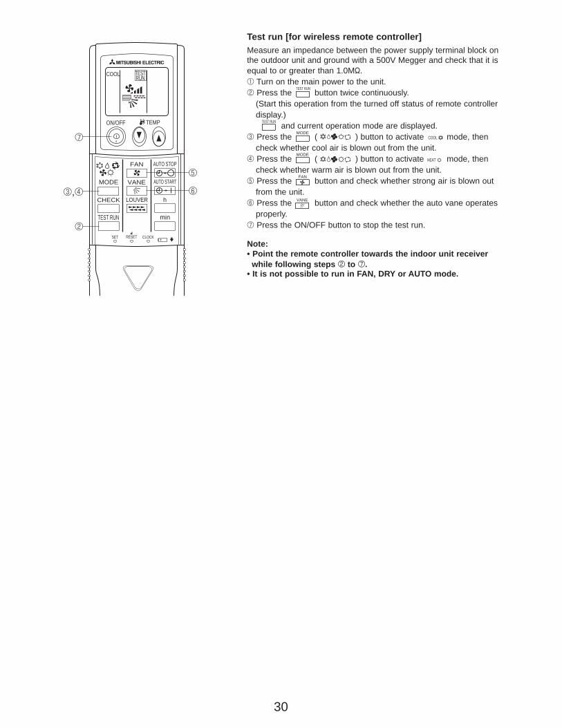
30
ON/OFF TEMP
FAN
VANEMODE
CHECK LOUVER
TEST RUN
AUTO STOP
AUTO START
h
min
RESETSET CLOCK
TESTRUNCOOL
7
5
6
2
3,4
Test run [for wireless remote controller]Measure an impedance between the power supply terminal block onthe outdoor unit and ground with a 500V Megger and check that it isequal to or greater than 1.0M".1 Turn on the main power to the unit.2 Press the button twice continuously.
(Start this operation from the turned off status of remote controllerdisplay.)
and current operation mode are displayed.3 Press the ( ) button to activate mode, then
check whether cool air is blown out from the unit.4 Press the ( ) button to activate mode, then
check whether warm air is blown out from the unit.5 Press the button and check whether strong air is blown out
from the unit.6 Press the button and check whether the auto vane operates
properly.7 Press the ON/OFF button to stop the test run.
Note:• Point the remote controller towards the indoor unit receiver
while following steps 2 to 7.• It is not possible to run in FAN, DRY or AUTO mode.
MODE
MODECOOL
HEAT
TEST RUN
FAN
VANE
TEST RUN
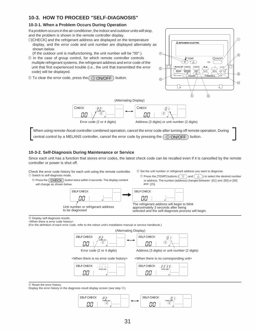
31
10-3. HOW TO PROCEED "SELF-DIAGNOSIS"10-3-1. When a Problem Occurs During OperationIf a problem occurs in the air conditioner, the indoor and outdoor units will stop,and the problem is shown in the remote controller display.1[CHECK] and the refrigerant address are displayed on the temperature
display, and the error code and unit number are displayed alternately asshown below.
(If the outdoor unit is malfunctioning, the unit number will be "00".)2 In the case of group control, for which remote controller controls
multiple refrigerant systems, the refrigerant address and error code of theunit that first experienced trouble (i.e., the unit that transmitted the errorcode) will be displayed.
3 To clear the error code, press the ON/OFF button.
When using remote-/local-controller combined operation, cancel the error code after turning off remote operation. Duringcentral control by a MELANS controller, cancel the error code by pressing the ON/OFF button.
10-3-2. Self-Diagnosis During Maintenance or ServiceSince each unit has a function that stores error codes, the latest check code can be recalled even if it is cancelled by the remotecontroller or power is shut off.
Check the error code history for each unit using the remote controller.1 Switch to self-diagnosis mode.
H Press the CHECK button twice within 3 seconds. The display contentwill change as shown below.
2 Set the unit number or refrigerant address you want to diagnose.
F Press the [TEMP] buttons ( and ) to select the desired numberor address. The number (address) changes between [01] and [50] or [00]
3 Display self-diagnosis results.<When there is error code history>(For the definition of each error code, refer to the indoor unit's installation manual or service handbook.)
4 Reset the error history.Display the error history in the diagnosis result display screen (see step 3).
F
E
G
C D
H
B
A
I
Error code (2 or 4 digits)
(Alternating Display)
Address (3 digits) or unit number (2 digits)
The refrigerant address will begin to blinkapproximately 3 seconds after beingselected and the self-diagnosis process will begin.
Unit number or refrigerant addressto be diagnosed
Error code (2 or 4 digits)
(Alternating Display)
Address (3 digits) or unit number (2 digits)
<When there is no error code history> <When there is no corresponding unit>
and [15].

32
Transmission data from remote controllerTransmission data on transmission path
When the number of data errors is "02":
D Press the ON/OFF button twice within 3 seconds. The self-diagnosisaddress or refrigerant address will blink.
When the error history is reset, the display will look like the one shown below.However, if you fail to reset the error history, the error content will be displayed again.
5 Cancel self-diagnosis.Self-diagnosis can be cancelled by the following 2 methods.
H Press the CHECK button twice within 3 seconds. ➔ Self-diagnosis will be cancelled and the screen will return to the previous state in effect before the startof self-diagnosis.
5 Press the ON/OFF button. ➔ Self-diagnosis will be cancelled and the indoor unit will stop.
10-3-3. Remote Controller Diagnosis
If the air conditioner cannot be operated from the remote controller, diagnose the remote controller as explained below.
1 First, check that the power-on indicator is lit.If the correct voltage (DC12 V) is not supplied to the remote controller, theindicator will not light.If this occurs, check the remote controller's wiring and the indoor unit.
2 Switch to the remote controller self-diagnosis mode.H Press the CHECK button for 5 seconds or more. The display content will
change as shown below.
A Press the FILTER button to start self-diagnosis.
3 Remote controller self-diagnosis result
[When the remote controller is functioning correctly]
Check for other possible causes, as there is no problem with the remotecontroller.
[When the remote controller malfunctions](Error display 1) "NG" blinks. ➝ The remote controller's transmitting-receiv-
ing circuit is defective.
The remote controller must be replaced with a new one.
[Where the remote controller is not defective, but cannot be operated.](Error display 2) [E3], [6833] or [6832] blinks. ➝ Transmission is not possible.
There might be noise or interference on the transmission path, or the indoor unitor other remote controllers are defective. Check the transmission path and othercontrollers.
(Error display 3) "ERC" and the number of data errors are displayed.➝ Data error has occurred.
The number of data errors is the difference between the number of bits sent fromthe remote controller and the number actually transmitted through the transmis-sion path. If such a problem is occurring, the transmitted data is affected by noise,etc. Check the transmission path.
4 To cancel remote controller diagnosisH Press the CHECK button for 5 seconds or more. Remote controller diagnosis will be cancelled, "PLEASE WAIT" and operation lamp will blink. After
approximately 30 seconds, the state in effect before the diagnosis will be restored.
Power on indicator
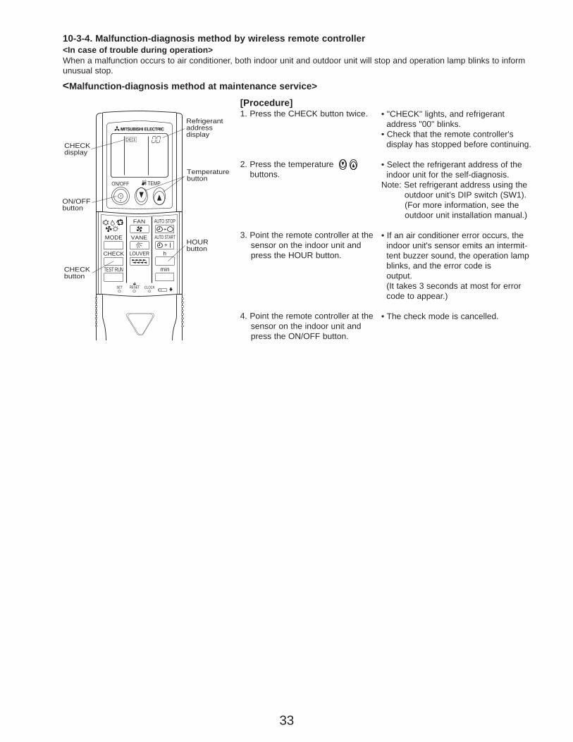
33
[Procedure]1. Press the CHECK button twice.
2. Press the temperaturebuttons.
3. Point the remote controller at the sensor on the indoor unit andpress the HOUR button.
4. Point the remote controller at thesensor on the indoor unit andpress the ON/OFF button.
• "CHECK" lights, and refrigerant address "00" blinks.
• Check that the remote controller'sdisplay has stopped before continuing.
• Select the refrigerant address of theindoor unit for the self-diagnosis.
Note: Set refrigerant address using the outdoor unit’s DIP switch (SW1).(For more information, see theoutdoor unit installation manual.)
• If an air conditioner error occurs, theindoor unit's sensor emits an intermit-tent buzzer sound, the operation lampblinks, and the error code isoutput.(It takes 3 seconds at most for error code to appear.)
• The check mode is cancelled.
<Malfunction-diagnosis method at maintenance service>
10-3-4. Malfunction-diagnosis method by wireless remote controller<In case of trouble during operation>When a malfunction occurs to air conditioner, both indoor unit and outdoor unit will stop and operation lamp blinks to informunusual stop.
ON/OFF TEMP
FAN
VANEMODE
CHECK LOUVER
TEST RUN
AUTO STOP
AUTO START
h
min
RESETSET CLOCK
CHECKCHECKdisplay
Temperaturebutton
CHECKbutton
Refrigerantaddressdisplay
HOURbutton
ON/OFFbutton
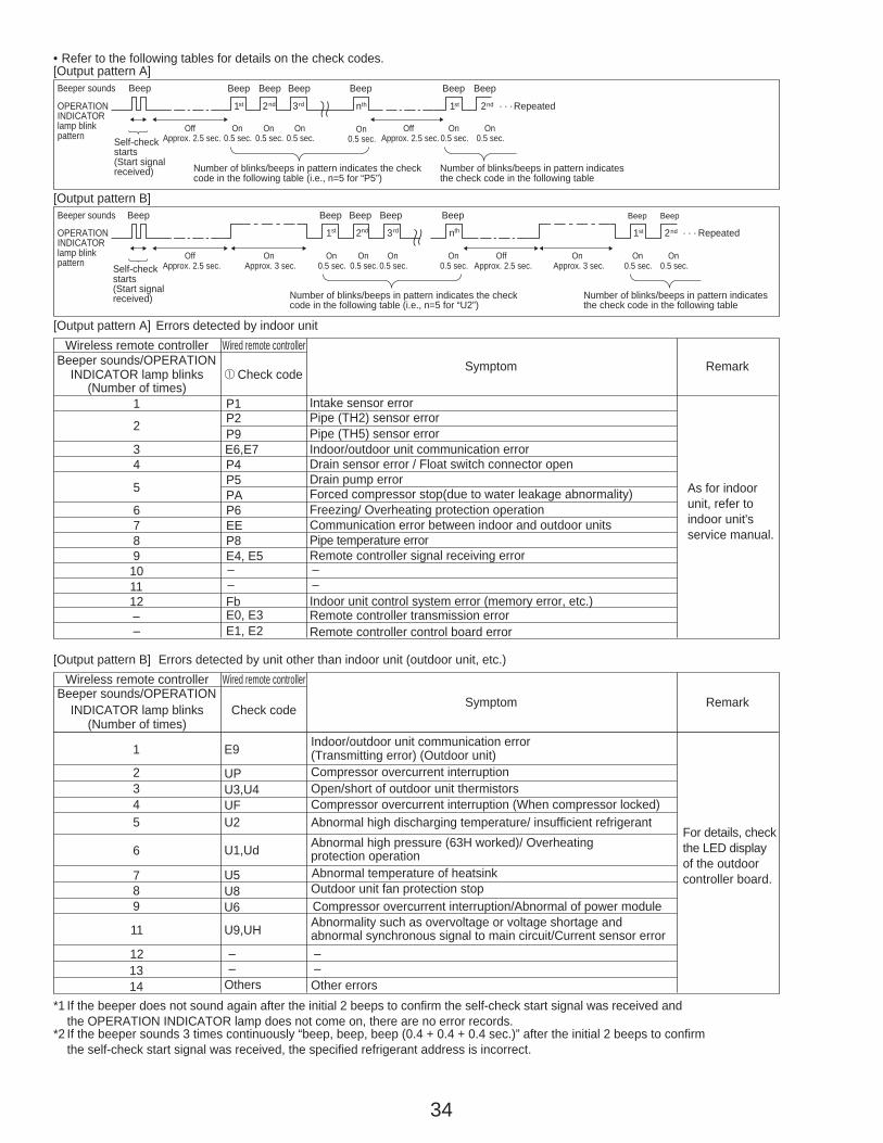
34
[Output pattern A] Errors detected by indoor unit
[Output pattern B]
E9
*1 If the beeper does not sound again after the initial 2 beeps to confirm the self-check start signal was received and the OPERATION INDICATOR lamp does not come on, there are no error records.
*2 If the beeper sounds 3 times continuously “beep, beep, beep (0.4 + 0.4 + 0.4 sec.)” after the initial 2 beeps to confirm the self-check start signal was received, the specified refrigerant address is incorrect.
OPERATIONINDICATORlamp blinkpattern
Beep Beep Beep Beep Beep Beep Beep
OffApprox. 2.5 sec.
OnApprox. 3 sec.
On0.5 sec.
On0.5 sec.
On0.5 sec.
On0.5 sec.
OffApprox. 2.5 sec.
OnApprox. 3 sec.
On0.5 sec.
On0.5 sec.
· · · Repeated
Number of blinks/beeps in pattern indicates the checkcode in the following table (i.e., n=5 for “U2”)
Number of blinks/beeps in pattern indicatesthe check code in the following table
nth1st 2nd 3rd 1st 2nd
Self-checkstarts(Start signalreceived)
Beeper sounds[Output pattern B]
OPERATIONINDICATORlamp blinkpattern
Beep Beep Beep Beep Beep Beep Beep
OffApprox. 2.5 sec.
On0.5 sec.
On0.5 sec.
On0.5 sec.
On0.5 sec.
OffApprox. 2.5 sec.
On0.5 sec.
On0.5 sec.
· · · Repeated
Number of blinks/beeps in pattern indicates the checkcode in the following table (i.e., n=5 for “P5”)
Number of blinks/beeps in pattern indicatesthe check code in the following table
nth1st 2nd 3rd 1st 2nd
Self-checkstarts(Start signalreceived)
Beeper sounds
• Refer to the following tables for details on the check codes.[Output pattern A]
Beeper sounds/OPERATIONINDICATOR lamp blinks Check code
(Number of times)
Wireless remote controller Wired remote controllerErrors detected by unit other than indoor unit (outdoor unit, etc.)
Symptom Remark
1 Indoor/outdoor unit communication error
2(Transmitting error) (Outdoor unit)
3 Open/short of outdoor unit thermistors4 Compressor overcurrent interruption (When compressor locked)5 Abnormal high discharging temperature/ insufficient refrigerant
6 Abnormal high pressure (63H worked)/ Overheating protection operation
7 Abnormal temperature of heatsink8 Outdoor unit fan protection stop9 Compressor overcurrent interruption/Abnormal of power module
11 Abnormality such as overvoltage or voltage shortage and abnormal synchronous signal to main circuit/Current sensor error
1213
U2
U5
UPU3,U4UF
U1,Ud
U8U6
U9,UH
Others
––
––
14 Other errors
For details, checkthe LED display of the outdoor controller board.
Compressor overcurrent interruption
Beeper sounds/OPERATIONINDICATOR lamp blinks 1 Check code Symptom Remark
(Number of times)
Wireless remote controller Wired remote controller
1 P1 Intake sensor error
P9 Pipe (TH5) sensor error2 P2 Pipe (TH2) sensor error
3 E6,E7 Indoor/outdoor unit communication error4 P4 Drain sensor error / Float switch connector open
5 P5PA
Drain pump errorForced compressor stop(due to water leakage abnormality)
6 P6 Freezing/ Overheating protection operation7 EE Communication error between indoor and outdoor units8 P8 Pipe temperature error9 E4, E5 Remote controller signal receiving error
10 –11 –
––
12 Fb Indoor unit control system error (memory error, etc.)– E0, E3– E1, E2 Remote controller control board error
Remote controller transmission error
As for indoor unit, refer to indoor unit's service manual.
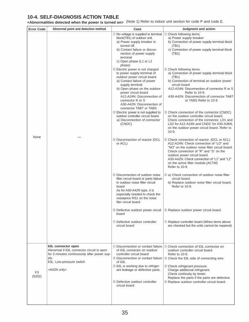
35
10-4. SELF-DIAGNOSIS ACTION TABLE<Abnormalities detected when the power is turned on> (Note 1) Refer to indoor unit section for code P and code E.
Error Code Abnormal point and detection method Case Judgment and action
None —
1 No voltage is supplied to terminalblock(TB1) of outdoor unit.a) Power supply breaker is
turned off.b) Contact failure or discon-
nection of power supply terminal
c) Open phase (L1 or L2phase)
2 Electric power is not chargedto power supply terminal ofoutdoor power circuit board.a) Contact failure of power
supply terminalb) Open phase on the outdoor
power circuit boardA12-A24N :Disconnection ofconnector R or SA30-A42N :Disconnection ofconnector TABT or TABS
3 Electric power is not supplied tooutdoor controller circuit board.a) Disconnection of connector
(CNDC)
4 Disconnection of reactor (DCLor ACL)
5 Disconnection of outdoor noisefilter circuit board or parts failurein outdoor noise filter circuitboardAs for A30-A42N type, it isespecially needed to check theresistance RS1 on the noisefiter circuit board.
6 Defective outdoor power circuitboard
7 Defective outdoor controller circuit board
1 Check following items.a) Power supply breakerb) Connection of power supply terminal block
(TB1)c) Connection of power supply terminal block
(TB1)
2 Check following items.a) Connection of power supply terminal block
(TB1)b) Connection of terminal on outdoor power
circuit boardA12-A24N: Disconnection of connector R or S
Refer to 10-9.A30-A42N: Disconnection of connector TABT
or TABS Refer to 10-9.
3 Check connection of the connector (CNDC)on the outdoor controller circuit board. Check connection of the connector, LD1 andLD2 for A12-A24N and CNDC for A30-A36N,on the outdoor power circuit board. Refer to10-9.
4 Check connection of reactor. (DCL or ACL)A12-A24N: Check connection of “LO” and “NO” on the outdoor noise filter circuit board.Check connection of “R” and “S” on the outdoor power circuit board.A30-A42N: Check connection of “L1” and “L2” on the active filter module.(ACTM) Refer to 10-9.
5 a) Check connection of outdoor noise filter circuit board.
b) Replace outdoor noise filter circuit board.Refer to 10-9.
6 Replace outdoor power circuit board.
7 Replace controller board (When items aboveare checked but the units cannot be repaired).
F3(5202)
63L connector openAbnormal if 63L connector circuit is openfor 3 minutes continuously after power sup-ply.63L: Low-pressure switch
<A42N only>
1 Disconnection or contact failureof 63L connector on outdoorcontroller circuit board
2 Disconnection or contact failureof 63L
3 63L is working due to refriger-ant leakage or defective parts.
4 Defective outdoor controller circuit board
1 Check connection of 63L connector on outdoor controller circuit board. Refer to 10-9.
2 Check the 63L side of connecting wire.
3 Check refrigerant pressure.Charge additional refrigerant.Check continuity by tester.Replace the parts if the parts are defective.
4 Replace outdoor controller circuit board.
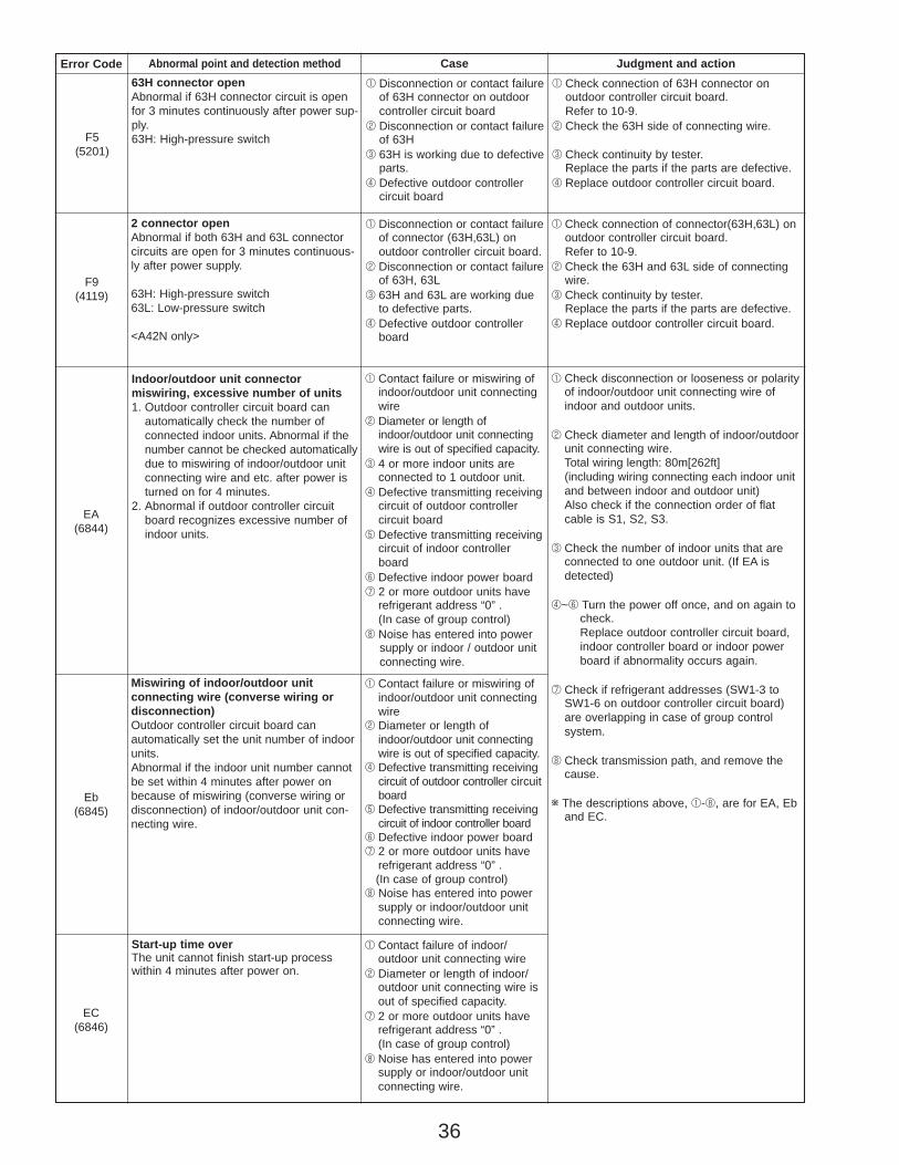
36
Error Code Abnormal point and detection method Judgment and action
Eb(6845)
Miswiring of indoor/outdoor unit connecting wire (converse wiring ordisconnection)Outdoor controller circuit board can automatically set the unit number of indoorunits.Abnormal if the indoor unit number cannotbe set within 4 minutes after power onbecause of miswiring (converse wiring ordisconnection) of indoor/outdoor unit con-necting wire.
EC(6846)
Start-up time overThe unit cannot finish start-up processwithin 4 minutes after power on.
Case
1 Contact failure of indoor/outdoor unit connecting wire
2 Diameter or length of indoor/outdoor unit connecting wire isout of specified capacity.
7 2 or more outdoor units haverefrigerant address “0” .(In case of group control)
8 Noise has entered into powersupply or indoor/outdoor unitconnecting wire.
1 Contact failure or miswiring ofindoor/outdoor unit connectingwire
2 Diameter or length ofindoor/outdoor unit connectingwire is out of specified capacity.
4 Defective transmitting receivingcircuit of outdoor controller circuitboard
5 Defective transmitting receivingcircuit of indoor controller board
6 Defective indoor power board7 2 or more outdoor units have
refrigerant address “0” .(In case of group control)
8 Noise has entered into powersupply or indoor/outdoor unitconnecting wire.
Indoor/outdoor unit connector miswiring, excessive number of units1. Outdoor controller circuit board can
automatically check the number of connected indoor units. Abnormal if thenumber cannot be checked automaticallydue to miswiring of indoor/outdoor unitconnecting wire and etc. after power isturned on for 4 minutes.
2. Abnormal if outdoor controller circuitboard recognizes excessive number ofindoor units.
1 Check disconnection or looseness or polarityof indoor/outdoor unit connecting wire ofindoor and outdoor units.
2 Check diameter and length of indoor/outdoorunit connecting wire.Total wiring length: 80m[262ft](including wiring connecting each indoor unitand between indoor and outdoor unit)Also check if the connection order of flatcable is S1, S2, S3.
3 Check the number of indoor units that areconnected to one outdoor unit. (If EA isdetected)
4~6 Turn the power off once, and on again to check.Replace outdoor controller circuit board, indoor controller board or indoor power board if abnormality occurs again.
7 Check if refrigerant addresses (SW1-3 toSW1-6 on outdoor controller circuit board)are overlapping in case of group control system.
8 Check transmission path, and remove thecause.
w The descriptions above, 1-8, are for EA, Eband EC.
1 Contact failure or miswiring ofindoor/outdoor unit connectingwire
2 Diameter or length ofindoor/outdoor unit connectingwire is out of specified capacity.
3 4 or more indoor units are connected to 1 outdoor unit.
4 Defective transmitting receivingcircuit of outdoor controller circuit board
5 Defective transmitting receivingcircuit of indoor controllerboard
6 Defective indoor power board7 2 or more outdoor units have
refrigerant address “0” .(In case of group control)
8 Noise has entered into powersupply or indoor / outdoor unit connecting wire.
EA(6844)
F5(5201)
63H connector openAbnormal if 63H connector circuit is openfor 3 minutes continuously after power sup-ply.63H: High-pressure switch
1 Disconnection or contact failureof 63H connector on outdoorcontroller circuit board
2 Disconnection or contact failureof 63H
3 63H is working due to defectiveparts.
4 Defective outdoor controller circuit board
1 Check connection of 63H connector on outdoor controller circuit board. Refer to 10-9.
2 Check the 63H side of connecting wire.
3 Check continuity by tester.Replace the parts if the parts are defective.
4 Replace outdoor controller circuit board.
F9(4119)
2 connector openAbnormal if both 63H and 63L connectorcircuits are open for 3 minutes continuous-ly after power supply.
63H: High-pressure switch63L: Low-pressure switch
<A42N only>
1 Disconnection or contact failureof connector (63H,63L) on outdoor controller circuit board.
2 Disconnection or contact failureof 63H, 63L
3 63H and 63L are working dueto defective parts.
4 Defective outdoor controllerboard
1 Check connection of connector(63H,63L) on outdoor controller circuit board. Refer to 10-9.
2 Check the 63H and 63L side of connectingwire.
3 Check continuity by tester.Replace the parts if the parts are defective.
4 Replace outdoor controller circuit board.
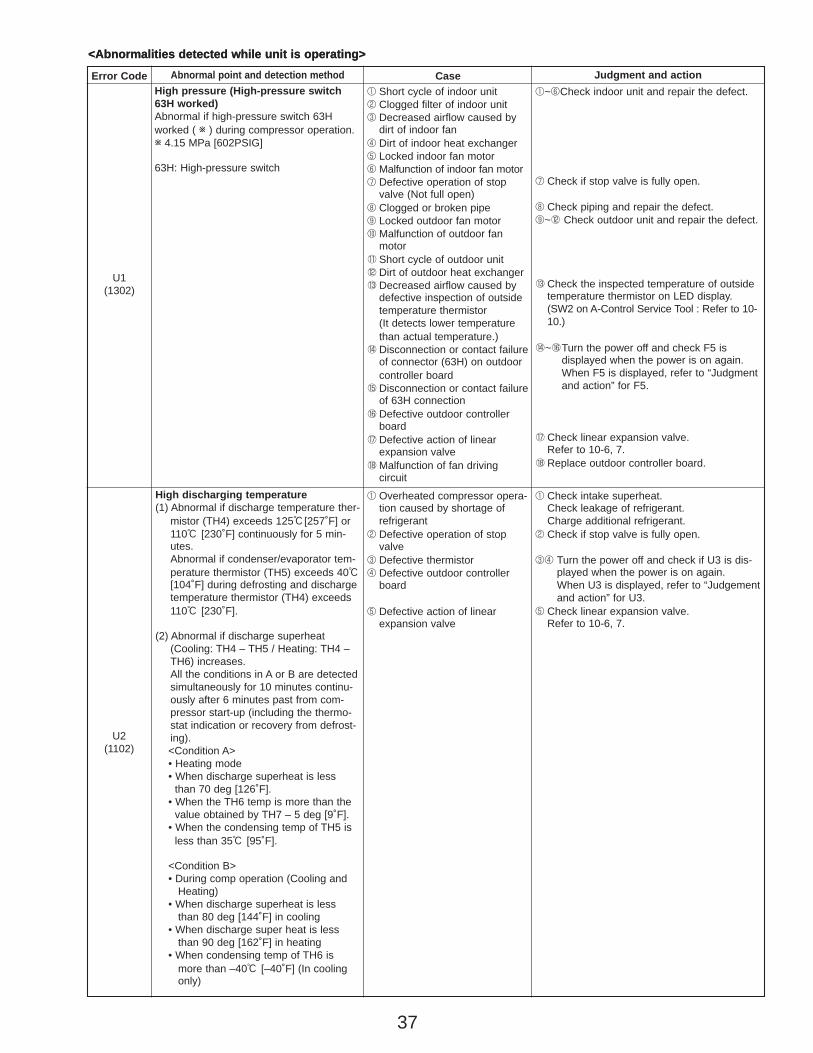
37
<Abnormalities detected while unit is operating>
Error Code Abnormal point and detection method Judgment and action
U1(1302)
High pressure (High-pressure switch63H worked)Abnormal if high-pressure switch 63Hworked ( w ) during compressor operation.w 4.15 MPa [602PSIG]
63H: High-pressure switch
1 Short cycle of indoor unit2 Clogged filter of indoor unit3 Decreased airflow caused by
dirt of indoor fan4 Dirt of indoor heat exchanger5 Locked indoor fan motor6 Malfunction of indoor fan motor7 Defective operation of stop
valve (Not full open)8 Clogged or broken pipe9 Locked outdoor fan motor0 Malfunction of outdoor fan
motor1 Short cycle of outdoor unit2 Dirt of outdoor heat exchanger3 Decreased airflow caused by
defective inspection of outsidetemperature thermistor (It detects lower temperaturethan actual temperature.)
4 Disconnection or contact failureof connector (63H) on outdoorcontroller board
5 Disconnection or contact failureof 63H connection
6 Defective outdoor controllerboard
7 Defective action of linearexpansion valve
8 Malfunction of fan driving circuit
1~6Check indoor unit and repair the defect.
7 Check if stop valve is fully open.
8 Check piping and repair the defect.9~2 Check outdoor unit and repair the defect.
3 Check the inspected temperature of outsidetemperature thermistor on LED display. (SW2 on A-Control Service Tool : Refer to 10-10.)
4~6Turn the power off and check F5 is displayed when the power is on again.When F5 is displayed, refer to “Judgmentand action” for F5.
7 Check linear expansion valve.Refer to 10-6, 7.
8 Replace outdoor controller board.
Case
U2(1102)
High discharging temperature(1) Abnormal if discharge temperature ther-
mistor (TH4) exceeds 125:[257˚F] or110: [230˚F] continuously for 5 min-utes.Abnormal if condenser/evaporator tem-perature thermistor (TH5) exceeds 40:[104˚F] during defrosting and dischargetemperature thermistor (TH4) exceeds110: [230˚F].
(2) Abnormal if discharge superheat(Cooling: TH4 – TH5 / Heating: TH4 –TH6) increases.All the conditions in A or B are detectedsimultaneously for 10 minutes continu-ously after 6 minutes past from com-pressor start-up (including the thermo-stat indication or recovery from defrost-ing).<Condition A>• Heating mode• When discharge superheat is less
than 70 deg [126˚F].• When the TH6 temp is more than the
value obtained by TH7 – 5 deg [9˚F].• When the condensing temp of TH5 is
less than 35: [95˚F].
<Condition B>• During comp operation (Cooling and
Heating)• When discharge superheat is less
than 80 deg [144˚F] in cooling• When discharge super heat is less
than 90 deg [162˚F] in heating• When condensing temp of TH6 is
more than –40: [–40˚F] (In coolingonly)
1 Overheated compressor opera-tion caused by shortage ofrefrigerant
2 Defective operation of stopvalve
3 Defective thermistor4 Defective outdoor controller
board
5 Defective action of linearexpansion valve
1 Check intake superheat.Check leakage of refrigerant.Charge additional refrigerant.
2 Check if stop valve is fully open.
34 Turn the power off and check if U3 is dis-played when the power is on again.When U3 is displayed, refer to “Judgementand action” for U3.
5 Check linear expansion valve.Refer to 10-6, 7.
<Abnormalities detected while unit is operating>
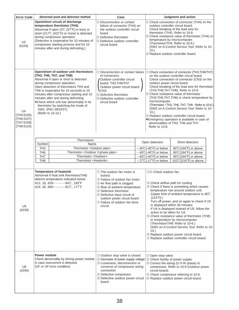
38
Thermistors Open detection Short detectionSymbol NameTH3TH6TH7TH8
– 40:[-40˚F] or below– 40:[-40˚F] or below– 40:[-40˚F] or below– 27:[-17˚F] or below
90:[194˚F] or above90:[194˚F] or above90:[194˚F] or above102:[216˚F] or above
Thermistor <Outdoor pipe>Thermistor <Outdoor 2-phase pipe>
Thermistor <Outdoor>Thermistor <Heatsink>
Error Code Abnormal point and detection method Case Judgment and action
U5(4230)
Temperature of heatsinkAbnormal if heat sink thermistor(TH8)detects temperature indicated below.A12, 18, 42N··············84:, 183˚FA24, 30, 36N··············81:, 177˚F
1 The outdoor fan motor islocked.
2 Failure of outdoor fan motor3 Air flow path is clogged.4 Rise of ambient temperature5 Defective thermistor6 Defective input circuit of
outdoor power circuit board7 Failure of outdoor fan drive
circuit
12 Check outdoor fan.
3 Check airflow path for cooling.4 Check if there is something which causes
temperature rise around outdoor unit.(Upper limit of ambient temperature is 46:[114˚F].)Turn off power, and on again to check if U5 is displayed within 30 minutes.If U4 is displayed instead of U5, follow the action to be taken for U4.
5 Check resistance value of thermistor (TH8)or temperature by microcomputer.(Thermistor/TH8: Refer to 10-6.)(SW2 on A-Control Service Tool: Refer to 10-10.)
6 Replace outdoor power circuit board.7 Replace outdoor controller circuit board.
U3(5104)
Open/short circuit of discharge temperature thermistor (TH4)Abnormal if open (3: [37˚F] or less) orshort (217: [422˚F] or more) is detectedduring compressor operation.(Detection is inoperative for 10 minutes ofcompressor starting process and for 10minutes after and during defrosting.)
1 Disconnection or contact failure of connector (TH4) onthe outdoor controller circuitboard
2 Defective thermistor3 Defective outdoor controller
circuit board
1 Check connection of connector (TH4) on theoutdoor controller circuit board.Check breaking of the lead wire for thermistor (TH4). Refer to 10-9.
2 Check resistance value of thermistor (TH4) ortemperature by microcomputer.(Thermistor/TH4: Refer to 10-6.)(SW2 on A-Control Service Tool: Refer to 10-10.)
3 Replace outdoor controller board.
U4(TH3:5105)(TH6:5107)(TH7:5106)(TH8:5110)
Open/short of outdoor unit thermistors(TH3, TH6, TH7, and TH8)Abnormal if open or short is detected during compressor operation.Open detection of thermistors TH3 andTH6 is inoperative for 10 seconds to 10minutes after compressor starting and 10minutes after and during defrosting.WCheck which unit has abnormality in its
thermistor by switching the mode of SW2. (PAC-SK52ST)(Refer to 10-10.)
1 Disconnection or contact failureof connectorsOutdoor controller circuit board: TH3,TH6/TH7Outdoor power circuit board:CN3
2 Defective thermistor3 Defective outdoor controller
circuit board
1 Check connection of connector (TH3,TH6/TH7)on the outdoor controller circuit board.Check connection of connector (CN3) on theoutdoor power circuit board.Check breaking of the lead wire for thermistor(TH3,TH6,TH7,TH8). Refer to 10-9.
2 Check resistance value of thermistor(TH3,TH6,TH7,TH8) or check temperature bymicrocomputer. (Thermistor / TH3, TH6, TH7, TH8 : Refer to 10-6.)(SW2 on A-Control Service Tool: Refer to 10-10.)
3 Replace outdoor controller circuit board.WEmergency operation is available in case of
abnormalities of TH3, TH6 and TH7. Refer to 10-8.
( )
U6(4250)
Power moduleCheck abnormality by driving power modulein case overcurrent is detected. (UF or UP error condition)
1 Outdoor stop valve is closed.2 Decrease of power supply voltage3 Looseness, disconnection or
converse of compressor wiringconnection
4 Defective compressor5 Defective outdoor power circuit
board
1 Open stop valve.2 Check facility of power supply.3 Correct the wiring (U·V·W phase) to
compressor. Refer to 10-9 (Outdoor powercircuit board).
4 Check compressor referring to 10-6.5 Replace outdoor power circuit board.
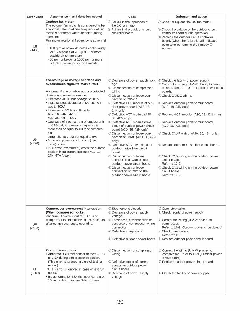
39
UH(5300)
Current sensor error• Abnormal if current sensor detects –1.5A
to 1.5A during compressor operation.(This error is ignored in case of test runmode.)w This error is ignored in case of test runmode.
• It’s abnormal for 38A the input current or10 seconds continuous 34A or more.
1 Disconnection of compressorwiring
2 Defective circuit of current sensor on outdoor power circuit board
3 Decrease of power supply voltage
1 Correct the wiring (U·V·W phase) to compressor. Refer to 10-9 (Outdoor power circuit board).
2 Replace outdoor power circuit board.
3 Check the facility of power supply.
Error Code Abnormal point and detection method Case Judgment and action
U8(4400)
Outdoor fan motorThe outdoor fan motor is considered to beabnormal if the rotational frequency of fanmotor is abnormal when detected during operation.Fan motor rotational frequency is abnormalif;
• 100 rpm or below detected continuously for 15 seconds at 20:[68˚F] or moreoutside air temperature
• 50 rpm or below or 1500 rpm or more detected continuously for 1 minute.
1 Failure in the operation of the DC fan motor
2 Failure in the outdoor circuit controller board
1 Check or replace the DC fan motor.
2 Check the voltage of the outdoor circuitcontroller board during operation.
3 Replace the outdoor circuit controller board. (when the failure is still indicated even after performing the remedy 1above.)
U9(4220)
Overvoltage or voltage shortage andsynchronous signal to main circuit
Abnormal if any of followings are detectedduring compressor operation;• Decrease of DC bus voltage to 310V• Instantaneous decrease of DC bus volt-
age to 200V• Increase of DC bus voltage to
A12, 18, 24N : 420V A30, 36, 42N : 400V
• Decrease of input current of outdoor unitto 0.5A only if operation frequency ismore than or equal to 40Hz or compres-sorcurrent is more than or equal to 5A.
• Abnormal power synchronous (zerocross) signal
• PFC error (overcurrent) when the currentpeak of input current increase A12, 18,24N: 47A (peak)
1 Decrease of power supply volt-age
2 Disconnection of compressorwiring
3 Disconnection or loose con-nection of CN52C
4 Defective PFC module of out-door power board (A12, 18,24N only)
5 Defective ACT module (A30,36, 42N only)
6 Defective ACT module drivecircuit of outdoor power circuitboard (A30, 36, 42N only)
7 Disconnection or loose con-nection of CNAF (A30, 36, 42Nonly)
8 Defective 52C drive circuit ofoutdoor noise filter circuitboard
9 Disconnection or loose connection of CN5 on the outdoor power circuit board
0 Disconnection or loose connection of CN2 on the outdoor power circuit board
1 Check the facility of power supply.2 Correct the wiring (U·V·W phase) to com-
pressor. Refer to 10-9 (Outdoor power circuitboard).
3 Check CN52C wiring.
4 Replace outdoor power circuit board. (A12, 18, 24N only)
5 Replace ACT module. (A30, 36, 42N only)
6 Replace outdoor power circuit board. (A30, 36, 42N only)
7 Check CNAF wiring. (A30, 36, 42N only)
8 Replace outdoor noise filter circuit board.
9 Check CN5 wiring on the outdoor power circuit board.Refer to 10-9.
0 Check CN2 wiring on the outdoor power circuit board.Refer to 10-9.
UF(4100)
Compressor overcurrent interruption(When compressor locked)Abnormal if overcurrent of DC bus or compressor is detected within 30 secondsafter compressor starts operating.
1 Stop valve is closed.2 Decrease of power supply
voltage3 Looseness, disconnection or
converse of compressor wiring connection
4 Defective compressor
5 Defective outdoor power board
1 Open stop valve.2 Check facility of power supply.
3 Correct the wiring (U·V·W phase) to compressor.Refer to 10-9 (Outdoor power circuit board).
4 Check compressor.Refer to 10-6.
5 Replace outdoor power circuit board.
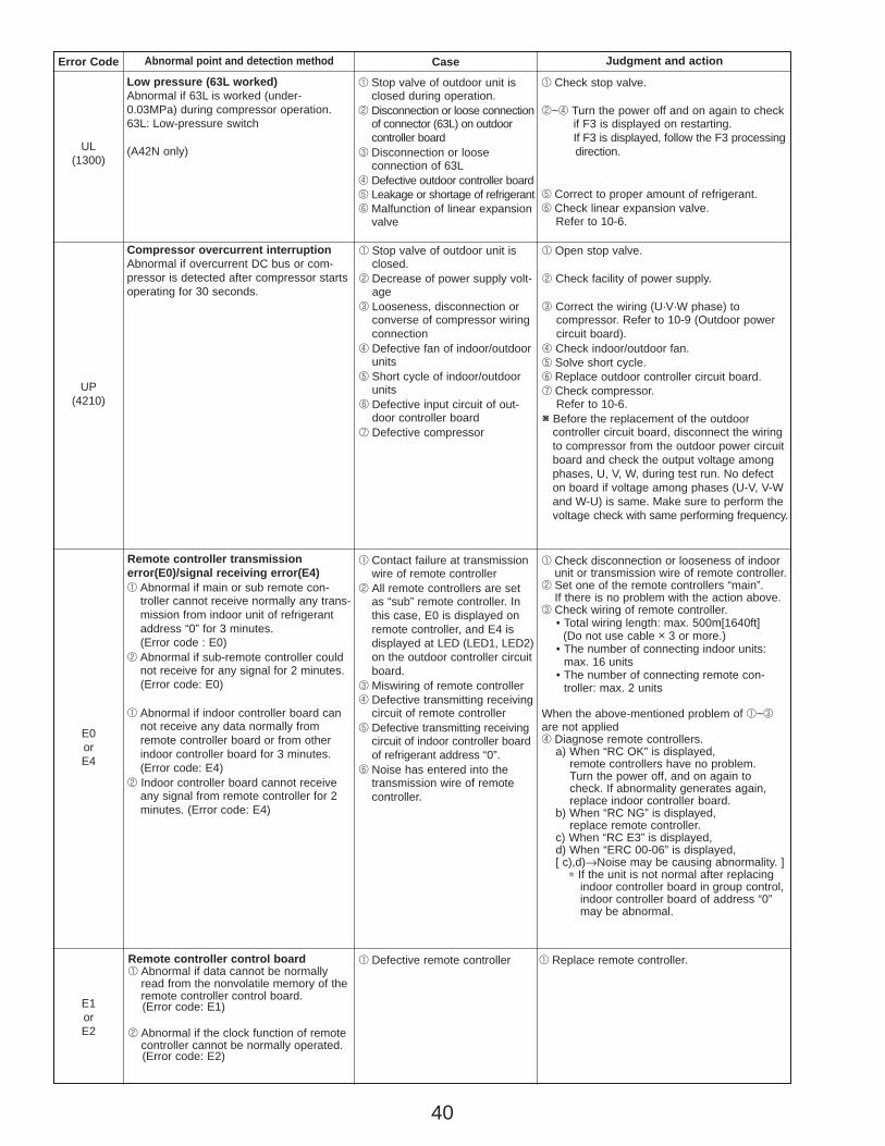
40
Error Code Abnormal point and detection method Judgment and action
UL(1300)
Low pressure (63L worked)Abnormal if 63L is worked (under-0.03MPa) during compressor operation.63L: Low-pressure switch
(A42N only)
1 Stop valve of outdoor unit isclosed during operation.
2 Disconnection or loose connectionof connector (63L) on outdoorcontroller board
3 Disconnection or loose connection of 63L
4 Defective outdoor controller board5 Leakage or shortage of refrigerant6 Malfunction of linear expansion
valve
1 Check stop valve.
2~4 Turn the power off and on again to check if F3 is displayed on restarting.If F3 is displayed, follow the F3 processingdirection.
5 Correct to proper amount of refrigerant.6 Check linear expansion valve.
Refer to 10-6.
Case
UP(4210)
Compressor overcurrent interruptionAbnormal if overcurrent DC bus or com-pressor is detected after compressor startsoperating for 30 seconds.
1 Stop valve of outdoor unit isclosed.
2 Decrease of power supply volt-age
3 Looseness, disconnection orconverse of compressor wiringconnection
4 Defective fan of indoor/outdoorunits
5 Short cycle of indoor/outdoorunits
6 Defective input circuit of out-door controller board
7 Defective compressor
1 Open stop valve.
2 Check facility of power supply.
3 Correct the wiring (U·V·W phase) to compressor. Refer to 10-9 (Outdoor power circuit board).
4 Check indoor/outdoor fan.5 Solve short cycle.6 Replace outdoor controller circuit board.7 Check compressor.
Refer to 10-6.W Before the replacement of the outdoor
controller circuit board, disconnect the wiring to compressor from the outdoor power circuit board and check the output voltage among phases, U, V, W, during test run. No defect on board if voltage among phases (U-V, V-W and W-U) is same. Make sure to perform the voltage check with same performing frequency.
E0orE4
Remote controller transmissionerror(E0)/signal receiving error(E4)1 Abnormal if main or sub remote con-
troller cannot receive normally any trans-mission from indoor unit of refrigerantaddress “0” for 3 minutes.(Error code : E0)
2 Abnormal if sub-remote controller couldnot receive for any signal for 2 minutes.(Error code: E0)
1 Abnormal if indoor controller board cannot receive any data normally fromremote controller board or from otherindoor controller board for 3 minutes.(Error code: E4)
2 Indoor controller board cannot receiveany signal from remote controller for 2minutes. (Error code: E4)
1 Check disconnection or looseness of indoorunit or transmission wire of remote controller.
2 Set one of the remote controllers “main”.If there is no problem with the action above.
3 Check wiring of remote controller.• Total wiring length: max. 500m[1640ft]
(Do not use cable o 3 or more.)• The number of connecting indoor units:
max. 16 units• The number of connecting remote con-
troller: max. 2 units
When the above-mentioned problem of 1~3are not applied4 Diagnose remote controllers.
a) When “RC OK” is displayed,remote controllers have no problem. Turn the power off, and on again tocheck. If abnormality generates again,replace indoor controller board.
b) When “RC NG” is displayed,replace remote controller.
c) When “RC E3” is displayed,d) When “ERC 00-06” is displayed,[ c),d)→Noise may be causing abnormality. ]
∗ If the unit is not normal after replacingindoor controller board in group control,indoor controller board of address “0”may be abnormal.
1 Contact failure at transmissionwire of remote controller
2 All remote controllers are setas “sub” remote controller. Inthis case, E0 is displayed onremote controller, and E4 isdisplayed at LED (LED1, LED2)on the outdoor controller circuitboard.
3 Miswiring of remote controller4 Defective transmitting receiving
circuit of remote controller5 Defective transmitting receiving
circuit of indoor controller boardof refrigerant address “0”.
6 Noise has entered into thetransmission wire of remotecontroller.
E1orE2
Remote controller control board1 Abnormal if data cannot be normally
read from the nonvolatile memory of theremote controller control board.(Error code: E1)
2 Abnormal if the clock function of remotecontroller cannot be normally operated.(Error code: E2)
1 Defective remote controller 1 Replace remote controller.
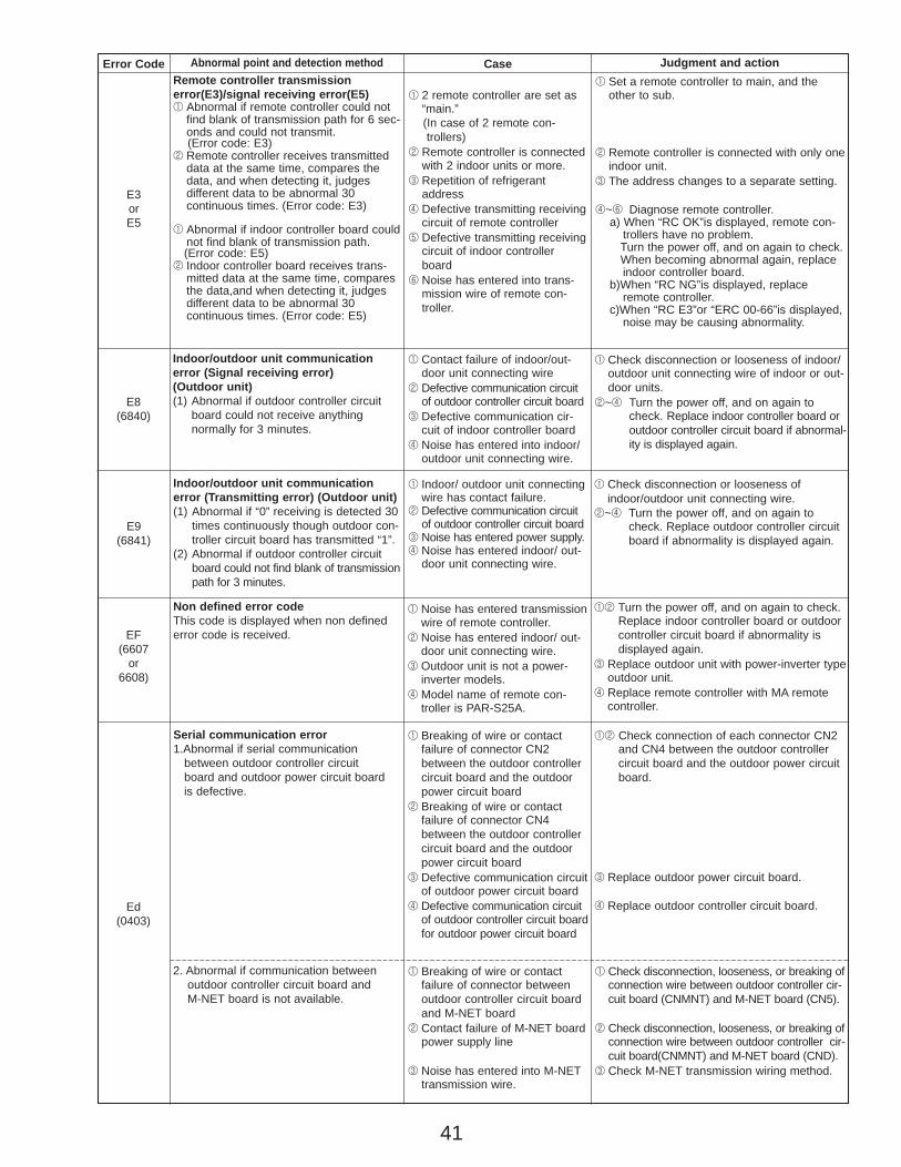
41
Error Code Abnormal point and detection method Judgment and action
E9(6841)
Indoor/outdoor unit communicationerror (Transmitting error) (Outdoor unit)(1) Abnormal if “0” receiving is detected 30
times continuously though outdoor con-troller circuit board has transmitted “1”.
(2) Abnormal if outdoor controller circuitboard could not find blank of transmissionpath for 3 minutes.
1 Indoor/ outdoor unit connectingwire has contact failure.
2 Defective communication circuitof outdoor controller circuit board
3 Noise has entered power supply.4 Noise has entered indoor/ out-
door unit connecting wire.
1 Check disconnection or looseness ofindoor/outdoor unit connecting wire.
2~4 Turn the power off, and on again tocheck. Replace outdoor controller circuitboard if abnormality is displayed again.
EF(6607
or6608)
Non defined error codeThis code is displayed when non definederror code is received.
1 Noise has entered transmissionwire of remote controller.
2 Noise has entered indoor/ out-door unit connecting wire.
3 Outdoor unit is not a power-inverter models.
4 Model name of remote con-troller is PAR-S25A.
12 Turn the power off, and on again to check. Replace indoor controller board or outdoorcontroller circuit board if abnormality is displayed again.
3 Replace outdoor unit with power-inverter typeoutdoor unit.
4 Replace remote controller with MA remotecontroller.
Case
Ed(0403)
Serial communication error1.Abnormal if serial communication
between outdoor controller circuit board and outdoor power circuit board is defective.
1 Breaking of wire or contact failure of connector CN2between the outdoor controllercircuit board and the outdoorpower circuit board
2 Breaking of wire or contact failure of connector CN4between the outdoor controllercircuit board and the outdoorpower circuit board
3 Defective communication circuitof outdoor power circuit board
4 Defective communication circuitof outdoor controller circuit boardfor outdoor power circuit board
12 Check connection of each connector CN2and CN4 between the outdoor controllercircuit board and the outdoor power circuitboard.
3 Replace outdoor power circuit board.
4 Replace outdoor controller circuit board.
1 Breaking of wire or contact failure of connector betweenoutdoor controller circuit boardand M-NET board
2 Contact failure of M-NET boardpower supply line
3 Noise has entered into M-NETtransmission wire.
2. Abnormal if communication between outdoor controller circuit board and M-NET board is not available.
1 Check disconnection, looseness, or breaking ofconnection wire between outdoor controller cir-cuit board (CNMNT) and M-NET board (CN5).
2 Check disconnection, looseness, or breaking ofconnection wire between outdoor controller cir-cuit board(CNMNT) and M-NET board (CND).
3 Check M-NET transmission wiring method.
E8(6840)
Indoor/outdoor unit communicationerror (Signal receiving error)(Outdoor unit)(1) Abnormal if outdoor controller circuit
board could not receive anything normally for 3 minutes.
1 Contact failure of indoor/out-door unit connecting wire
2 Defective communication circuitof outdoor controller circuit board
3 Defective communication cir-cuit of indoor controller board
4 Noise has entered into indoor/outdoor unit connecting wire.
1 Check disconnection or looseness of indoor/outdoor unit connecting wire of indoor or out-door units.
2~4 Turn the power off, and on again tocheck. Replace indoor controller board oroutdoor controller circuit board if abnormal-ity is displayed again.
E3orE5
Remote controller transmissionerror(E3)/signal receiving error(E5)1 Abnormal if remote controller could not
find blank of transmission path for 6 sec-onds and could not transmit.(Error code: E3)
2 Remote controller receives transmitteddata at the same time, compares thedata, and when detecting it, judges different data to be abnormal 30 continuous times. (Error code: E3)
1 Abnormal if indoor controller board couldnot find blank of transmission path.(Error code: E5)
2 Indoor controller board receives trans-mitted data at the same time, comparesthe data,and when detecting it, judgesdifferent data to be abnormal 30 continuous times. (Error code: E5)
1 Set a remote controller to main, and theother to sub.
2 Remote controller is connected with only oneindoor unit.
3 The address changes to a separate setting.
4~6 Diagnose remote controller.a) When “RC OK”is displayed, remote con-
trollers have no problem.Turn the power off, and on again to check.When becoming abnormal again, replaceindoor controller board.
b)When “RC NG”is displayed, replaceremote controller.
c)When “RC E3”or “ERC 00-66”is displayed,noise may be causing abnormality.
1 2 remote controller are set as“main.” (In case of 2 remote con-trollers)
2 Remote controller is connectedwith 2 indoor units or more.
3 Repetition of refrigerantaddress
4 Defective transmitting receivingcircuit of remote controller
5 Defective transmitting receivingcircuit of indoor controllerboard
6 Noise has entered into trans-mission wire of remote con-troller.
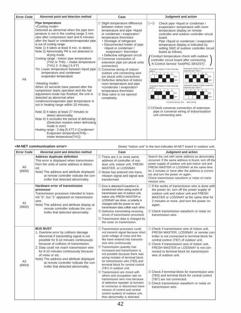
42
Error Code Abnormal point and detection method Case Judgment and action
A0(6600)
Address duplicate definitionThis error is displayed when transmissionfrom the units of same address is detect-ed.Note) The address and attribute displayed
at remote controller indicate the con-troller that detected abnormality.
1 There are 2 or more sameaddress of controller of out-door unit, indoor unit, FRESHMASTER, or LOSSNAY.
2 Noise has entered into trans-mission signal and signal wastransformed.
Search the unit with same address as abnormalityoccurred. If the same address is found, turn off thepower supply of outdoor unit and indoor unit andFRESH MASTER or LOSSNAY at the same timefor 2 minutes or more after the address is correct-ed, and turn the power on again.Check transmission waveform or noise on trans-mission wire.
A2(6602)
Hardware error of transmission processorTransmission processor intended to trans-mit “0”, but “1” appeared on transmissionwire.Note) The address and attribute display at
remote controller indicate the con-troller that detected abnormality.
1 Error is detected if waveform istransformed when wiring works oftransmission wire of outdoor unit,indoor unit, FRESH MASTER orLOSSNAY are done, or polarity ischanged with the power on andtransmission data collide each other.
2 Defective transmitting receivingcircuit of transmission processor
3 Transmission data is changed bythe noise on transmission.
1 If the works of transmission wire is done withthe power on, turn off the power supply ofoutdoor unit and indoor unit and FRESHMASTER or LOSSNAY at the same time for2 minutes or more, and turn the power onagain.
2 Check transmission waveform or noise ontransmission wire.
A3(6603)
BUS BUSY1. Overtime error by collision damage
Abnormal if transmitting signal is notpossible for 8-10 minutes continuouslybecause of collision of transmission.
2. Data could not reach transmission wirefor 8-10 minutes continuously becauseof noise or etc.
Note) The address and attribute displayedat remote controller indicate the con-troller that detected abnormality.
1 Transmission processor couldnot transmit signal because shortcycle voltage of noise and thelike have entered into transmis-sion wire continuously.
2 Transmission quantity hasincreased and transmission isnot possible because there waswiring mistake of terminal blockfor transmission wire (TB3) andterminal block for central control(TB7) in outdoor unit.
3 Transmission are mixed with others and occupation rate ontransmission wire rose becauseof defective repeater (a functionto connector or disconnect trans-mission of control and centralcontrol system) of outdoor unit,then abnormality is detected.
1 Check if transmission wire of indoor unit,FRESH MASTER, LOSSNAY, or remote con-troller is not connected to terminal block forcentral control (TB7) of outdoor unit.
2 Check if transmission wire of indoor unit,FRESH MASTER or LOSSNAY is not con-nected to terminal block for transmissionwire of outdoor unit.
3 Check if terminal block for transmission wire(TB3) and terminal block for central control(TB7) are not connected.
4 Check transmission waveform or noise ontransmission wire.
<M-NET communication error> (Note) “Indoor unit” in the text indicates M-NET board in outdoor unit.
Error Code Abnormal point and detection method Case Judgment and action
P8
1 Slight temperature differencebetween indoor room temperature and pipe <liquid or condenser / evaporator> temperature thermistor• Shortage of refrigerant• Disconnected holder of pipe
<liquid or condenser / evaporator> thermistor
• Defective refrigerant circuit2 Converse connection of
extension pipe (on plural unitsconnection)
3 Converse wiring of indoor/outdoor unit connecting wire(on plural units connection)
4 Defective detection of indoorroom temperature and pipe<condenser / evaporator> temperature thermistor
5 Stop valve is not opened completely.
Pipe temperature<Cooling mode>Detected as abnormal when the pipe tem-perature is not in the cooling range 3 min-utes after compressor start and 6 minutesafter the liquid or condenser/evaporator pipeis out of cooling range.Note 1) It takes at least 9 min. to detect.Note 2) Abnormality P8 is not detected in
drying mode.Cooling range : Indoor pipe temperature
(TH2 or TH5) – intake temperature(TH1) [ -3 deg [-5.4˚F]
TH: Lower temperature between liquid pipetemperature and condenser/evaporator temperature
<Heating mode>When 10 seconds have passed after thecompressor starts operation and the hotadjustment mode has finished, the unit isdetected as abnormal whencondenser/evaporator pipe temperature isnot in heating range within 20 minutes.
Note 3) It takes at least 27 minutes todetect abnormality.
Note 4) It excludes the period of defrosting(Detection restarts when defrostingmode is over)
Heating range : 3 deg [5.4˚F] [ (Condenser/Evaporator temperature(TH5) –intake temperature(TH1))
1~4 Check pipe <liquid or condenser /evaporator> temperature with room temperature display on remote controller and outdoor controller circuit board.Pipe <liquid or condenser / evaporator>temperature display is indicated by setting SW2 of outdoor controller circuitboard as follows.
23Check converse connection of extension pipe or converse wiring of indoor/outdoor unit connecting wire.
Conduct temperature check with outdoorcontroller circuit board after connecting ‘A-Control Service Tool(PAC-SK52ST)’.( )
1 2 3 4 5 6
ON
OFF
1 2 3 4 5 6ON
OFF
1 2 3 4 5 6ON
OFF
1 2 3 4 5 6ON
OFF
A-Control Service Tool SW2 setting
Temperature display of indoor liquid pipeIndoor 1
Temperature display of indoor liquid pipeIndoor 2
Temperature display of indoor condenser/evaporator pipe Indoor 1
Temperature display of indoor condenser/evaporator pipe Indoor 2
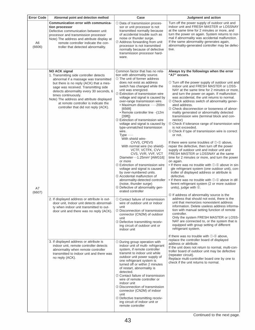
43
A6(6606)
Communication error with communica-tion processorDefective communication between unitprocessor and transmission processorNote) The address and attribute display at
remote controller indicate the con-troller that detected abnormality.
1 Data of transmission proces-sor or unit processor is nottransmitted normally becauseof accidental trouble such asnoise or thunder surge.
2 Address forwarding from unitprocessor is not transmittednormally because of defectivetransmission processor hard-ware.
Turn off the power supply of outdoor unit andindoor unit and FRESH MASTER or LOSSNAYat the same time for 2 minutes or more, andturn the power on again. System returns to nor-mal if abnormality was accidental malfunction.If the same abnormality generates again,abnormality-generated controller may be defec-tive.
Continued to the next page.
Error Code Abnormal point and detection method Case Judgment and action
A7(6607)
NO ACK signal1. Transmitting side controller detects
abnormal if a massage was transmittedbut there is no reply (ACK) that a mes-sage was received. Transmitting sidedetects abnormality every 30 seconds, 6times continuously.
Note) The address and attribute displayedat remote controller is indicate thecontroller that did not reply (ACK).
Common factor that has no rela-tion with abnormality source.1 The unit of former address
does not exist as addressswitch has changed while theunit was energized.
2 Extinction of transmission wirevoltage and signal is caused byover-range transmission wire.• Maximum distance ······200m
[656ft]• Remote controller line ··(12m
[39ft])3 Extinction of transmission wire
voltage and signal is caused bytype-unmatched transmissionwire.Type ······
With shield wire- CVVS, CPEVS
With normal wire (no shield)-VCTF, VCTFK, CVV CVS, VVR, VVF, VCT
Diameter····1.25mm2 [AWG16]or more
4 Extinction of transmission wirevoltage and signal is causedby over-numbered units.
5 Accidental malfunction ofabnormality-detected controller(noise, thunder surge)
6 Defective of abnormality gen-erated controller
2. If displayed address or attribute is out-door unit, Indoor unit detects abnormali-ty when indoor unit transmitted to out-door unit and there was no reply (ACK).
1 Contact failure of transmissionwire of outdoor unit or indoorunit
2 Disconnection of transmissionconnector (CN2M) of outdoorunit
3 Defective transmitting receiv-ing circuit of outdoor unit orindoor unit
Always try the followings when the error “A7” occurs.
1 Turn off the power supply of outdoor unit andindoor unit and FRESH MASTER or LOSS-NAY at the same time for 2 minutes or more,and turn the power on again. If malfunctionwas accidental, the unit returns to normal.
2 Check address switch of abnormality gener-ated address.
3 Check disconnection or looseness of abnor-mality generated or abnormality detectedtransmission wire (terminal block and con-nector)
4 Check if tolerance range of transmission wireis not exceeded.
5 Check if type of transmission wire is corrector not.
If there were some troubles of 1-5 above,repair the defective, then turn off the powersupply of outdoor unit and indoor unit andFRESH MASTER or LOSSNAY at the sametime for 2 minutes or more, and turn the poweron again.• If there was no trouble with 1-5 above in sin-
gle refrigerant system (one outdoor unit), con-troller of displayed address or attribute isdefective.
• If there was no trouble with 1-5 above in dif-ferent refrigerant system (2 or more outdoorunits), judge with 6.
6 If address of abnormality source is theaddress that should not exist, there is theunit that memorizes nonexistent addressinformation. Delete useless address informa-tion with manual setting function of remotecontroller.Only the system FRESH MASTER or LOSS-NAY are connected to, or the system that isequipped with group setting of differentrefrigerant system.
If there was no trouble with 1-6 above,replace the controller board of displayedaddress or attribute.If the unit does not return to normal, multi-con-troller board of outdoor unit may be defective(repeater circuit).Replace multi-controller board one by one tocheck if the unit returns to normal.
3. If displayed address or attribute isindoor unit, remote controller detectsabnormality when remote controllertransmitted to indoor unit and there wasno reply (ACK).
1 During group operation withindoor unit of multi- refrigerantsystem, if remote controllertransmit to indoor unit whileoutdoor unit power supply ofone refrigerant system isturned off or within 2 minutesof restart, abnormality isdetected.
2 Contact failure of transmissionwire of remote controller orindoor unit
3 Disconnection of transmissionconnector (CN2M) of indoorunit
4 Defective transmitting receiv-ing circuit of indoor unit orremote controller
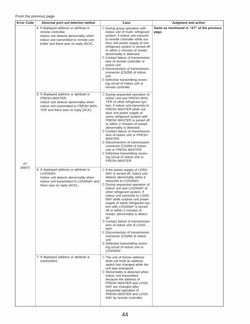
44
5. If displayed address or attribute isFRESH MASTER, Indoor unit detects abnormality whenindoor unit transmitted to FRESH MAS-TER and there was no reply (ACK).
1 During sequential operation ofindoor unit and FRESH MAS-TER of other refrigerant sys-tem, if indoor unit transmits toFRESH MASTER while out-door unit power supply ofsame refrigerant system withFRESH MASTER is turned offor within 2 minutes of restart,abnormality is detected.
2 Contact failure of transmissionwire of indoor unit or FRESHMASTER
3 Disconnection of transmissionconnector (CN2M) of indoorunit or FRESH MASTER
4 Defective transmitting receiv-ing circuit of indoor unit orFRESH MASTER
Error Code Abnormal point and detection method Case Judgment and action
A7(6607) 6. If displayed address or attribute is
LOSSNAY,Indoor unit detects abnormality whenindoor unit transmitted to LOSSNAY andthere was no reply (ACK).
1 If the power supply of LOSS-NAY is turned off, indoor unitdetects abnormality when ittransmits to LOSSNAY.
2 During sequential operation ofindoor unit and LOSSNAY ofother refrigerant system, ifindoor unit transmits to LOSS-NAY while outdoor unit powersupply of same refrigerant sys-tem with LOSSNAY is turnedoff or within 2 minutes ofrestart, abnormality is detect-ed.
3 Contact failure of transmissionwire of indoor unit of LOSS-NAY
4 Disconnection of transmissionconnector (CN2M) of indoorunit
5 Defective transmitting receiv-ing circuit of indoor unit orLOSSNAY
7. If displayed address or attribute isnonexistent,
1 The unit of former addressdoes not exist as addressswitch has changed while theunit was energized.
2 Abnormality is detected whenindoor unit transmittedbecause the address ofFRESH MASTER and LOSS-NAY are changed aftersequential operation ofFRESH MASTER and LOSS-NAY by remote controller.
From the previous page.
4. If displayed address or attribute isremote controller,Indoor unit detects abnormality whenindoor unit transmitted to remote con-troller and there was no reply (ACK).
1 During group operation withindoor unit of multi- refrigerantsystem, if indoor unit transmitto remote controller while out-door unit power supply of onerefrigerant system is turned offor within 2 minutes of restart,abnormality is detected.
2 Contact failure of transmissionwire of remote controller orindoor unit
3 Disconnection of transmissionconnector (CN2M) of indoorunit
4 Defective transmitting receiv-ing circuit of indoor unit orremote controller
Same as mentioned in “A7” of the previous page.
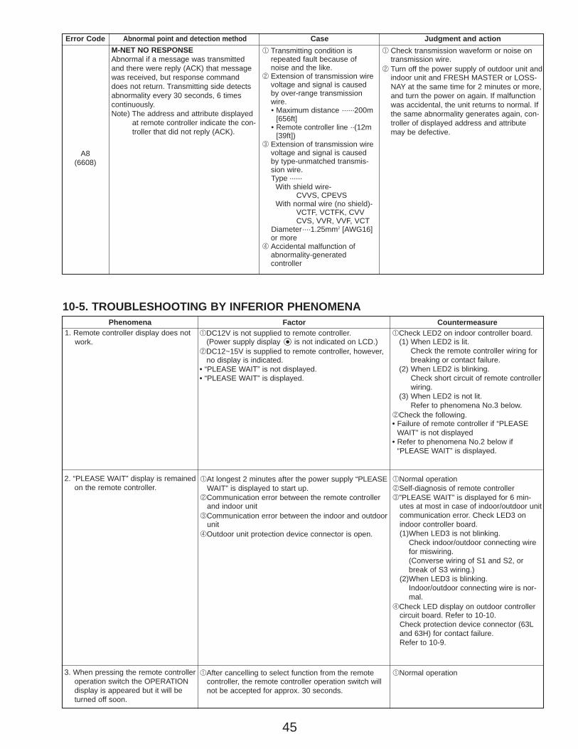
45
10-5. TROUBLESHOOTING BY INFERIOR PHENOMENAPhenomena Factor Countermeasure
1. Remote controller display does notwork.
2. “PLEASE WAIT” display is remainedon the remote controller.
3. When pressing the remote controlleroperation switch the OPERATIONdisplay is appeared but it will beturned off soon.
1After cancelling to select function from the remotecontroller, the remote controller operation switch willnot be accepted for approx. 30 seconds.
1Normal operation
1At longest 2 minutes after the power supply “PLEASEWAIT” is displayed to start up.
2Communication error between the remote controllerand indoor unit
3Communication error between the indoor and outdoorunit
4Outdoor unit protection device connector is open.
1DC12V is not supplied to remote controller.(Power supply display is not indicated on LCD.)
2DC12~15V is supplied to remote controller, however,no display is indicated.
• “PLEASE WAIT” is not displayed. • “PLEASE WAIT” is displayed.
1Check LED2 on indoor controller board.(1) When LED2 is lit.
Check the remote controller wiring forbreaking or contact failure.
(2) When LED2 is blinking.Check short circuit of remote controller wiring.
(3) When LED2 is not lit.Refer to phenomena No.3 below.
2Check the following.• Failure of remote controller if “PLEASE
WAIT” is not displayed• Refer to phenomena No.2 below if
“PLEASE WAIT” is displayed.
1Normal operation2Self-diagnosis of remote controller3”PLEASE WAIT” is displayed for 6 min-
utes at most in case of indoor/outdoor unitcommunication error. Check LED3 on indoor controller board.(1)When LED3 is not blinking.
Check indoor/outdoor connecting wirefor miswiring.(Converse wiring of S1 and S2, or break of S3 wiring.)
(2)When LED3 is blinking.Indoor/outdoor connecting wire is nor-mal.
4Check LED display on outdoor controller circuit board. Refer to 10-10.Check protection device connector (63Land 63H) for contact failure.Refer to 10-9.
Error Code Abnormal point and detection method Case Judgment and action
A8(6608)
M-NET NO RESPONSEAbnormal if a message was transmittedand there were reply (ACK) that messagewas received, but response commanddoes not return. Transmitting side detectsabnormality every 30 seconds, 6 timescontinuously.Note) The address and attribute displayed
at remote controller indicate the con-troller that did not reply (ACK).
1 Transmitting condition isrepeated fault because ofnoise and the like.
2 Extension of transmission wirevoltage and signal is causedby over-range transmissionwire.• Maximum distance ······200m
[656ft]• Remote controller line ··(12m
[39ft])3 Extension of transmission wire
voltage and signal is causedby type-unmatched transmis-sion wire.Type ······
With shield wire- CVVS, CPEVS
With normal wire (no shield)-VCTF, VCTFK, CVV CVS, VVR, VVF, VCT
Diameter····1.25mm2 [AWG16]or more
4 Accidental malfunction ofabnormality-generatedcontroller
1 Check transmission waveform or noise ontransmission wire.
2 Turn off the power supply of outdoor unit andindoor unit and FRESH MASTER or LOSS-NAY at the same time for 2 minutes or more,and turn the power on again. If malfunctionwas accidental, the unit returns to normal. Ifthe same abnormality generates again, con-troller of displayed address and attributemay be defective.
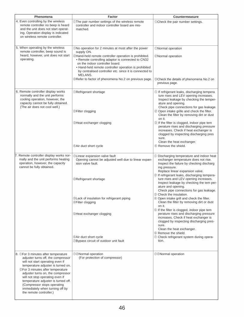
46
Phenomena Factor Countermeasure
7. Remote controller display works nor-mally and the unit performs heatingoperation, however, the capacitycannot be fully obtained.
1Linear expansion valve faultOpening cannot be adjusted well due to linear expan-sion valve fault.
2Refrigerant shortage
3Lack of insulation for refrigerant piping4Filter clogging
5Heat exchanger clogging
6Air duct short cycle 7Bypass circuit of outdoor unit fault
1 Discharging temperature and indoor heatexchanger temperature does not rise.Inspect the failure by checking discharging pressure.Replace linear expansion valve.
2 If refrigerant leaks, discharging tempera-ture rises and LEV opening increases.Inspect leakage by checking the tem per-ature and opening.Check pipe connections for gas leakage.
3 Check the insulation.4 Open intake grill and check the filter.
Clean the filter by removing dirt or duston it.
5 If the filter is clogged, indoor pipe temperature rises and discharging pressureincreases. Check if heat exchanger isclogged by inspecting discharging pres-sure.Clean the heat exchanger.
6 Remove the shield.7 Check refrigerant system during opera-
tion.
8. 1For 3 minutes after temperatureadjuster turns off, the compressor will not start operating even if temperature adjuster is turned on.
2For 3 minutes after temperature adjuster turns on, the compressor will not stop operating even if temperature adjuster is turned off.(Compressor stops operating immediately when turning off by the remote controller.)
12Normal operation(For protection of compressor)
12Normal operation
4. Even controlling by the wirelessremote controller no beep is heardand the unit does not start operat-ing. Operation display is indicatedon wireless remote controller.
1The pair number settings of the wireless remotecontroller and indoor controller board are mis-matched.
1Check the pair number settings.
5. When operating by the wirelessremote controller, beep sound isheard, however, unit does not startoperating.
1No operation for 2 minutes at most after the powersupply ON.
2Hand-held remote controller operation is prohibited.• Remote controlling adaptor is connected to CN32on the indoor controller board.
• Hand-held remote controller operation is prohibitedby centralised controller etc. since it is connected toMELANS.
3Refer to factor of phenomena No.2 on previous page.
1Normal operation
2Normal operation
3Check the details of phenomena No.2 onprevious page.
6. Remote controller display works normally and the unit performscooling operation, however, thecapacity cannot be fully obtained.(The air does not cool well.)
1Refrigerant shortage
2Filter clogging
3Heat exchanger clogging
4Air duct short cycle
1 If refrigerant leaks, discharging temperature rises and LEV opening increases.Inspect leakage by checking the temper-ature and opening.Check pipe connections for gas leakage.
2 Open intake grille and check the filter.Clean the filter by removing dirt or duston it.
3 If the filter is clogged, indoor pipe temperature rises and discharging pressureincreases. Check if heat exchanger isclogged by inspecting discharging pressure.Clean the heat exchanger.
4 Remove the shield.
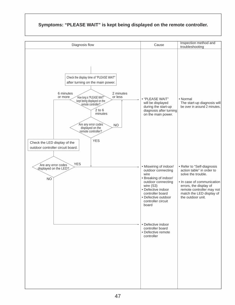
47
How long is “PLEASE WAIT” kept being displayed on the
remote controller?
6 minutes or more
2 minutes or less
2 to 6 minutes
NO
NO
YES
YES
Are any error codes displayed on the
remote controller?
Are any error codes displayed on the LED?
Symptoms: “PLEASE WAIT” is kept being displayed on the remote controller.
Check the display time of “PLEASE WAIT” after turning on the main power.
• “PLEASE WAIT” will be displayed during the start-up
diagnosis after turning on the main power.
• Normal The start-up diagnosis will
be over in around 2 minutes.
• Miswiring of indoor/ outdoor connecting wire• Breaking of indoor/ outdoor connecting wire (S3)• Defective indoor controller board• Defective outdoor controller circuit board
• Refer to “Self-diagnosis action table” in order to solve the trouble.
• In case of communication errors, the display of remote controller may not match the LED display of the outdoor unit.
• Defective indoor controller board• Defective remote controller
Check the LED display of the outdoor controller circuit board.
Diagnosis flow Cause Inspection method and troubleshooting
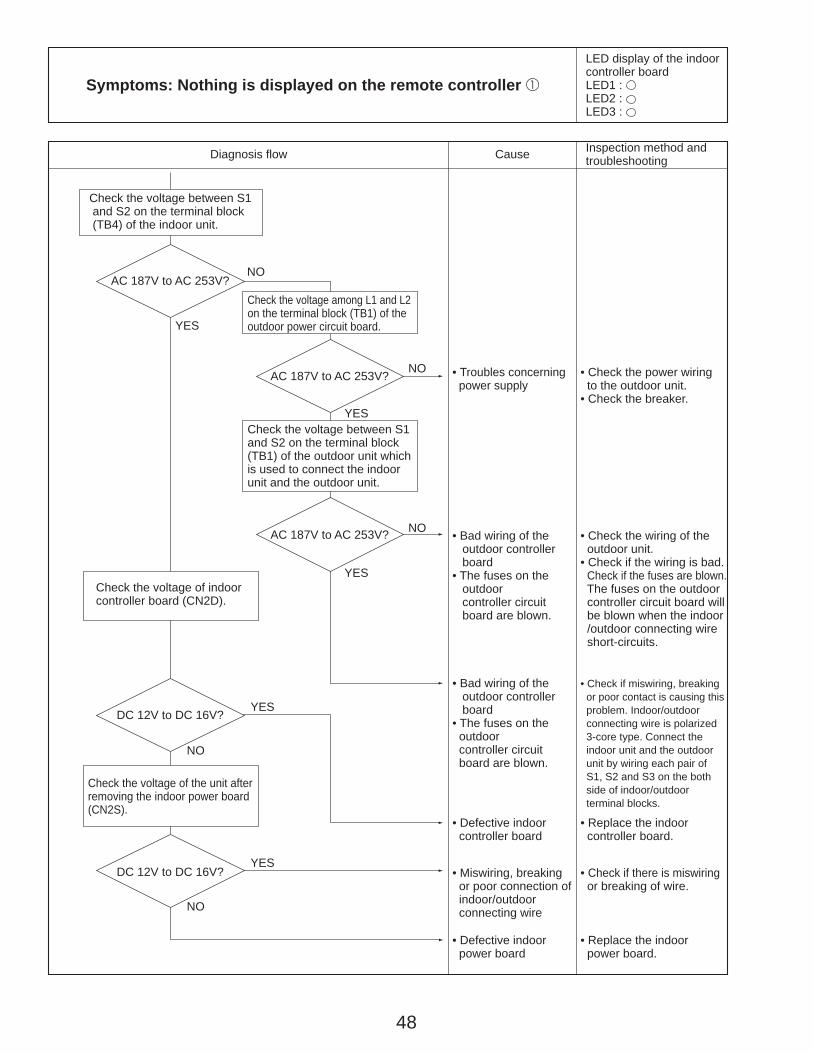
48
AC 187V to AC 253V?
AC 187V to AC 253V?
AC 187V to AC 253V?
DC 12V to DC 16V?
DC 12V to DC 16V?
NO
YES
NO
YES
NO
YES
YES
NO
YES
NO
Check the voltage between S1 and S2 on the terminal block (TB4) of the indoor unit.
Check the voltage among L1 and L2 on the terminal block (TB1) of the outdoor power circuit board.
Check the voltage of indoor controller board (CN2D).
Check the voltage of the unit after removing the indoor power board (CN2S).
Check the voltage between S1 and S2 on the terminal block (TB1) of the outdoor unit which is used to connect the indoor unit and the outdoor unit.
• Troubles concerning power supply
• Check the power wiring to the outdoor unit.• Check the breaker.
• Bad wiring of the outdoor controller board• The fuses on the outdoor controller circuit board are blown.
• Check the wiring of the outdoor unit.• Check if the wiring is bad.
Check if the fuses are blown. The fuses on the outdoor controller circuit board will be blown when the indoor /outdoor connecting wire short-circuits.
• Bad wiring of the outdoor controller board• The fuses on the outdoor controller circuit board are blown.
• Check if miswiring, breaking or poor contact is causing this
problem. Indoor/outdoor connecting wire is polarized 3-core type. Connect the indoor unit and the outdoor unit by wiring each pair of S1, S2 and S3 on the both side of indoor/outdoor terminal blocks.
• Defective indoor power board
• Replace the indoor power board.
• Defective indoor controller board
• Replace the indoor controller board.
• Miswiring, breaking or poor connection of indoor/outdoor connecting wire
• Check if there is miswiring or breaking of wire.
Symptoms: Nothing is displayed on the remote controller 1
Diagnosis flow Cause Inspection method and troubleshooting
LED display of the indoor controller boardLED1 :LED2 : LED3 :
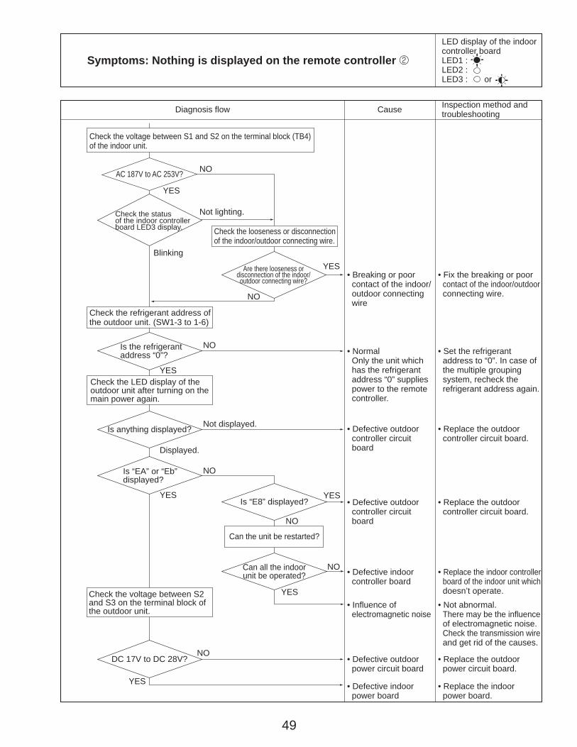
49
AC 187V to AC 253V?
Are there looseness or disconnection of the indoor/outdoor connecting wire?
Is anything displayed?
DC 17V to DC 28V?
Is “E8” displayed?
Can all the indoor unit be operated?
Check the voltage between S2 and S3 on the terminal block of the outdoor unit.
NO
YES
Not lighting.
Blinking
NO
YES
NO
YES
Not displayed.
Displayed.
YES
NO
YES
NO
Check the voltage between S1 and S2 on the terminal block (TB4) of the indoor unit.
Check the refrigerant address of the outdoor unit. (SW1-3 to 1-6)
Check the looseness or disconnection of the indoor/outdoor connecting wire.
Check the LED display of the outdoor unit after turning on the main power again.
Can the unit be restarted?
• Breaking or poor contact of the indoor/ outdoor connecting wire
• Fix the breaking or poor contact of the indoor/outdoor
connecting wire.
• Defective outdoor controller circuit board
• Replace the outdoor controller circuit board.
• Normal Only the unit which has the refrigerant address “0” supplies power to the remote controller.
• Set the refrigerant address to “0”. In case of the multiple grouping system, recheck the refrigerant address again.
• Defective indoor power board
• Replace the indoor power board.
• Defective outdoor power circuit board
• Replace the outdoor power circuit board.
• Defective indoor controller board
• Replace the indoor controller board of the indoor unit which
doesn’t operate.
• Defective outdoor controller circuit board
• Replace the outdoor controller circuit board.
• Influence of electromagnetic noise
• Not abnormal. There may be the influence
of electromagnetic noise. Check the transmission wire
and get rid of the causes.
Symptoms: Nothing is displayed on the remote controller 2
Diagnosis flow Cause Inspection method and troubleshooting
LED display of the indoor controller boardLED1 :LED2 : LED3 : or
Check the status of the indoor controller board LED3 display.
Is the refrigerant address “0”?
NO
YES
NO
YES
Is “EA” or “Eb” displayed?

50
DC 10V to DC 16V?YES
NO
Lighting
Blinking
Lighting
Blinking
Check the voltage of the terminal block (TB6) of the remote controller.
Check the status of the LED2 after disconnecting the remote controller wire from the terminal block (TB5) of the indoor unit.
• Defective remote controller
• Replace the remote controller.
• Breaking or poor contact of the remote controller wire
• Check if there is breaking or poor contact of the remote controller wire. Check the voltage of the terminal block (TB5) connecting the remote controller wire.
If it is not between DC 10V and DC16V, the indoor controller board must be defective.
• The remote controller wire short-circuits
• Check if the remote controller wire is short-circuited.
• Defective indoor controller board
• Replace the indoor controller board.
Diagnosis flow Cause Inspection method and troubleshooting
Symptoms: Nothing is displayed on the remote controller 3
LED display of the indoor controller boardLED1 :LED2 : or LED3 : —
Check the status of the LED2.
Check the status of the LED2.

51
1 The operating display of remote controller does not come on.
Phone Calls From Customers How to Respond Note1 Check if power is supplied to air conditioner.
Nothing appears on the display unless power is supplied.
2 Unit cannot be restarted for a while after it’s stopped.
2 Wait around 3 minutes to restart unit.The air conditioner is in a state of being protected by the microcomputer’s directive. Once the compressor is stopped, the unit cannot be restarted for 3 minutes. This control is also applied when the unit is turned on and off by remote controller or thermostat.
3 Error code appears and blinks on the display of remote controller.
Refer to “SELF-DIAGNOSIS ACTION TABLE”. Check if servicing is required for the error.
Display time of “FILTER” depends on the model. Long life filter: 2500 hrs.Regular filter: 100 hrs.
3 Error code will be displayed if any protection devices of the air conditioner are actuated.What is error code?
1 “PLEASE WAIT” is displayed on the screen.
1 Wait around 2 minutes.An automatic startup test will be conducted for 2 minutes when power is supplied to the air conditioner. “PLEASE WAIT” will be kept being
displayed while that time.
2 “FILTER” is displayed on the screen.
2 This indicates that it is time to clean the air filters. Clean the air filters. Press the FILTER button on the remote controller twice to clear “FILTER” from the display. See the operation manual that came with the product for how to clean the filters.
3 “STANDBY” is displayed on the screen.
3 This is displayed when the unit starts HEAT operation, when the thermostat puts the compressor in operation mode, or when the outdoor unit ends DEFROST operation and returns to HEAT operation. The display will automatically disappear around 10 minutes later.
While “STANDBY” is displayed on the remote controller, the airflow amount will be restricted because the indoor unit’s heat exchanger is not fully heated up. In addition to that, the up/down vane will be automatically set to horizontal blow in order to prevent cold air from directly blowing out to human body. The up/down vane will return to the setting specified by the remote controller when “STANDBY” is released.
4 “DEFROST” is displayed on the screen. (No air comes out of the unit.)
4 The outdoor unit gets frosted when the outside temperature is low and the humidity is high. “DEFROST” indicates the DEFROST operation is being performed to melt this frost. The DEFROST operation ends in around 10 minutes (at most 15 minutes). During the DEFROST operation, the indoor unit’s heat exchanger becomes cold, so the blower is stopped. The up/down vane will be automatically set to horizontal blow in order to prevent cold air from directly blowing out to human body. The display will turn into “STANDBY” when DEFROST operation ends.
Unit does not operate at all.
Remotecontroller
• Before repair Frequent calling from customers
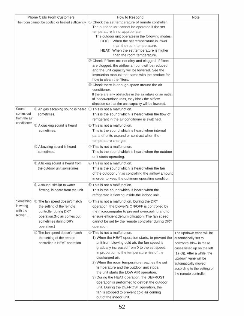
52
Phone Calls From Customers How to Respond Note1 Check the set temperature of remote controller. The outdoor unit cannot be operated if the set temperature is not appropriate.
The outdoor unit operates in the following modes. COOL: When the set temperature is lower than the room temperature. HEAT: When the set temperature is higher than the room temperature.2 Check if filters are not dirty and clogged. If filters are clogged, the airflow amount will be reduced and the unit capacity will be lowered. See the instruction manual that came with the product for how to clean the filters.3 Check there is enough space around the air conditioner.
If there are any obstacles in the air intake or air outletof indoor/outdoor units, they block the airflow
direction so that the unit capacity will be lowered.1 An gas escaping sound is heard sometimes.
1 This is not a malfunction. This is the sound which is heard when the flow of refrigerant in the air conditioner is switched.
2 A cracking sound is heard sometimes.
2 This is not a malfunction. This is the sound which is heard when internal parts of units expand or contract when the temperature changes.
3 A buzzing sound is heard sometimes.
3 This is not a malfunction. This is the sound which is heard when the outdoor unit starts operating.
4 A ticking sound is heard from the outdoor unit sometimes.
4 This is not a malfunction. This is the sound which is heard when the fan of the outdoor unit is controlling the airflow amount in order to keep the optimum operating condition.
5 A sound, similar to water flowing, is heard from the unit.
5 This is not a malfunction. This is the sound which is heard when the refrigerant is flowing inside the indoor unit.
2 The fan speed doesn’t match the setting of the remote controller in HEAT operation.
The up/down vane will be automatically set to horizontal blow in these cases listed up on the left (1)~3)). After a while, the up/down vane will be automatically moved according to the setting of the remote controller.
2 This is not a malfunction. 1) When the HEAT operation starts, to prevent the unit from blowing cold air, the fan speed is gradually increased from 0 to the set speed, in proportion to the temperature rise of the discharged air. 2) When the room temperature reaches the set temperature and the outdoor unit stops, the unit starts the LOW AIR operation. 3) During the HEAT operation, the DEFROST operation is performed to defrost the outdoor unit. During the DEFROST operation, the fan is stopped to prevent cold air coming out of the indoor unit.
Soundcomes out from the air conditioner.
1 The fan speed doesn’t match the setting of the remote controller during DRY operation.(No air comes out sometimes during DRY operation.)
1 This is not a malfunction. During the DRY operation, the blower’s ON/OFF is controlled by the microcomputer to prevent overcooling and to ensure efficient dehumidification. The fan speed cannot be set by the remote controller during DRY operation.
Somethingis wrong with the blower…..
The room cannot be cooled or heated sufficiently.
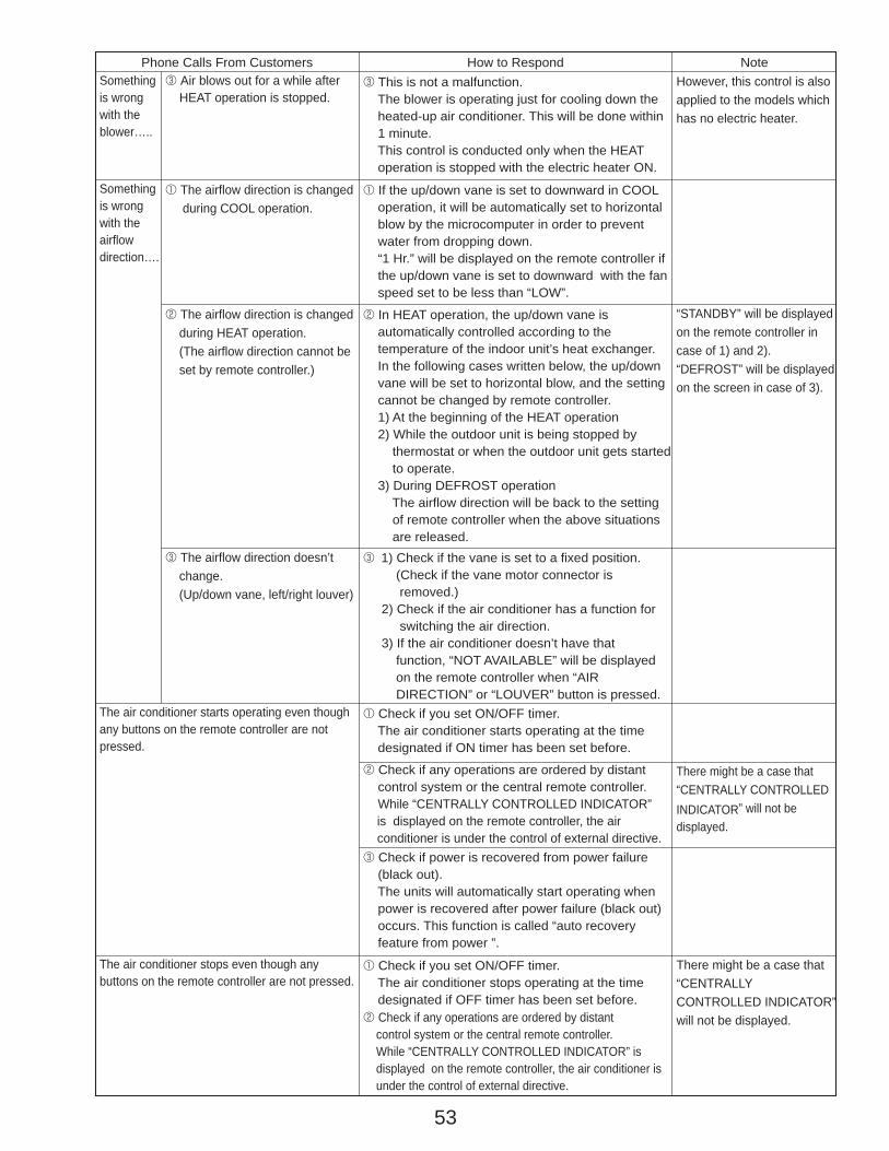
53
3 Air blows out for a while after HEAT operation is stopped.
Phone Calls From Customers How to Respond Note3 This is not a malfunction. The blower is operating just for cooling down the heated-up air conditioner. This will be done within 1 minute. This control is conducted only when the HEAT operation is stopped with the electric heater ON.
However, this control is also applied to the models which has no electric heater.
“STANDBY” will be displayed on the remote controller in case of 1) and 2).“DEFROST” will be displayed on the screen in case of 3).
1 The airflow direction is changed during COOL operation.
1 If the up/down vane is set to downward in COOL operation, it will be automatically set to horizontal blow by the microcomputer in order to prevent water from dropping down. “1 Hr.” will be displayed on the remote controller if the up/down vane is set to downward with the fan speed set to be less than “LOW”.
2 The airflow direction is changed during HEAT operation. (The airflow direction cannot be set by remote controller.)
2 In HEAT operation, the up/down vane is automatically controlled according to the temperature of the indoor unit’s heat exchanger. In the following cases written below, the up/down vane will be set to horizontal blow, and the setting cannot be changed by remote controller. 1) At the beginning of the HEAT operation 2) While the outdoor unit is being stopped by thermostat or when the outdoor unit gets started to operate. 3) During DEFROST operation The airflow direction will be back to the setting of remote controller when the above situations are released.
3 The airflow direction doesn’t change. (Up/down vane, left/right louver)
3 1) Check if the vane is set to a fixed position. (Check if the vane motor connector is removed.) 2) Check if the air conditioner has a function for switching the air direction. 3) If the air conditioner doesn’t have that function, “NOT AVAILABLE” will be displayed on the remote controller when “AIR DIRECTION” or “LOUVER” button is pressed.
Somethingis wrong with the blower…..
Somethingis wrong with the airflowdirection….
1 Check if you set ON/OFF timer. The air conditioner starts operating at the time designated if ON timer has been set before.
2 Check if any operations are ordered by distant control system or the central remote controller.
While “CENTRALLY CONTROLLED INDICATOR” is displayed on the remote controller, the air conditioner is under the control of external directive.
The air conditioner starts operating even though any buttons on the remote controller are not pressed.
1 Check if you set ON/OFF timer. The air conditioner stops operating at the time designated if OFF timer has been set before.
The air conditioner stops even though any buttons on the remote controller are not pressed.
There might be a case that “CENTRALLY CONTROLLED INDICATOR” will not be displayed.
There might be a case that “CENTRALLY CONTROLLED INDICATOR” will not be displayed.
3 Check if power is recovered from power failure (black out). The units will automatically start operating when power is recovered after power failure (black out) occurs. This function is called “auto recovery feature from power ”.
2 Check if any operations are ordered by distant control system or the central remote controller. While “CENTRALLY CONTROLLED INDICATOR” is displayed on the remote controller, the air conditioner is under the control of external directive.
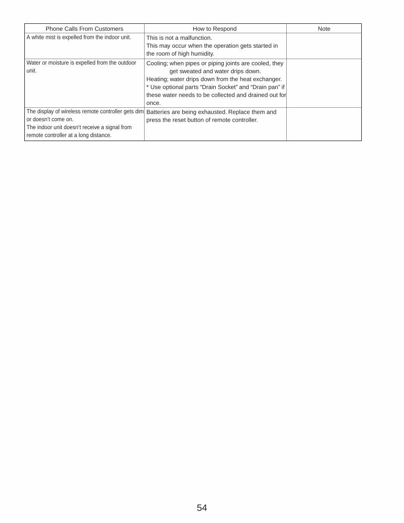
54
Phone Calls From Customers How to Respond NoteThis is not a malfunction.This may occur when the operation gets started in the room of high humidity.
A white mist is expelled from the indoor unit.
Cooling; when pipes or piping joints are cooled, they get sweated and water drips down.Heating; water drips down from the heat exchanger.* Use optional parts “Drain Socket” and “Drain pan” if these water needs to be collected and drained out for once.
Water or moisture is expelled from the outdoor unit.
Batteries are being exhausted. Replace them and press the reset button of remote controller.
The display of wireless remote controller gets dim or doesn’t come on.The indoor unit doesn’t receive a signal from remote controller at a long distance.
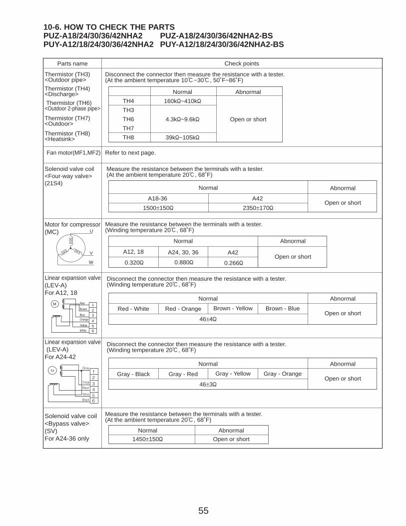
55
123456
MGray
Orange
Red
Yellow
Black
123456
M
Parts name Check points
Disconnect the connector then measure the resistance with a tester. (At the ambient temperature 10:~30:, 50˚F~86˚F)
Disconnect the connector then measure the resistance with a tester. (Winding temperature 20:, 68˚F)
Thermistor (TH3)<Outdoor pipe>Thermistor (TH4)<Discharge> Thermistor (TH6)<Outdoor 2-phase pipe>
Thermistor (TH7)<Outdoor>
Thermistor (TH8)<Heatsink>
Normal160k"~410k"
4.3k"~9.6k"
39k"~105k"
TH4TH3TH6TH7TH8
Abnormal
Open or short
Normal
Red - White Red - Orange Brown - Yellow Brown - Blue
Abnormal
46±4"
Measure the resistance between the terminals with a tester. (At the ambient temperature 20:, 68˚F)
Solenoid valve coil<Four-way valve> (21S4)
Motor for compressor(MC)
Linear expansion valve(LEV-A)For A12, 18
Linear expansion valve (LEV-A)For A24-42
Normal Abnormal
Open or shortA18-36 A42
Open or short
Disconnect the connector then measure the resistance with a tester. (Winding temperature 20:, 68˚F)
Measure the resistance between the terminals with a tester.(At the ambient temperature 20:, 68˚F)
Normal1450±150"
AbnormalOpen or short
Solenoid valve coil<Bypass valve>(SV)For A24-36 only
Refer to next page.Fan motor(MF1,MF2)
1500±150" 2350±170"
A12, 18 A42
0.320"
A24, 30, 36
0.880" 0.266"
Measure the resistance between the terminals with a tester. (Winding temperature 20:, 68˚F)
Normal Abnormal
Open or shortW
V
U
Red
Brown
BlueOrange
YellowWhite
Normal
Gray - Black Gray - Red Gray - Yellow Gray - Orange
Abnormal
46±3"Open or short
10-6. HOW TO CHECK THE PARTSPUZ-A18/24/30/36/42NHA2 PUZ-A18/24/30/36/42NHA2-BSPUY-A12/18/24/30/36/42NHA2 PUY-A12/18/24/30/36/42NHA2-BS
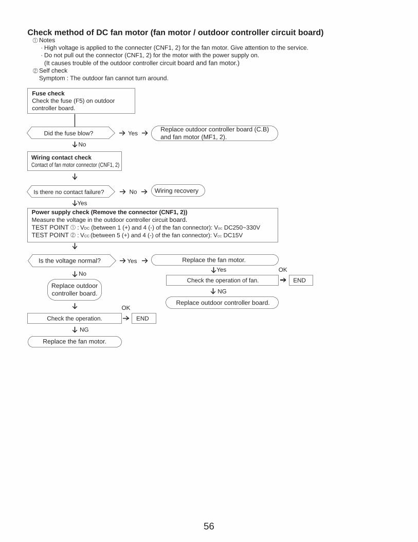
56
Notes · High voltage is applied to the connecter (CNF1, 2) for the fan motor. Give attention to the service. · Do not pull out the connector (CNF1, 2) for the motor with the power supply on. (It causes trouble of the outdoor controller circuit board and fan motor.)Self checkSymptom : The outdoor fan cannot turn around.
1
2
Check method of DC fan motor (fan motor / outdoor controller circuit board)
No
NG
NG
Wiring contact checkContact of fan motor connector (CNF1, 2)
Fuse checkCheck the fuse (F5) on outdoorcontroller board.
Power supply check (Remove the connector (CNF1, 2))Measure the voltage in the outdoor controller circuit board.TEST POINT 1 : VDC (between 1 (+) and 4 (-) of the fan connector): VDC DC250~330VTEST POINT 2 : VCC (between 5 (+) and 4 (-) of the fan connector): VCC DC15V
Wiring recovery
Replace outdoor controller board.
Replace the fan motor.
Replace outdoor controller board (C.B)and fan motor (MF1, 2).
Replace outdoor controller board.
Replace the fan motor.
Is the voltage normal?
Is there no contact failure?
Yes
Yes
No
Did the fuse blow?
No
Yes
Check the operation of fan. END
Yes OK
Check the operation. END
OK
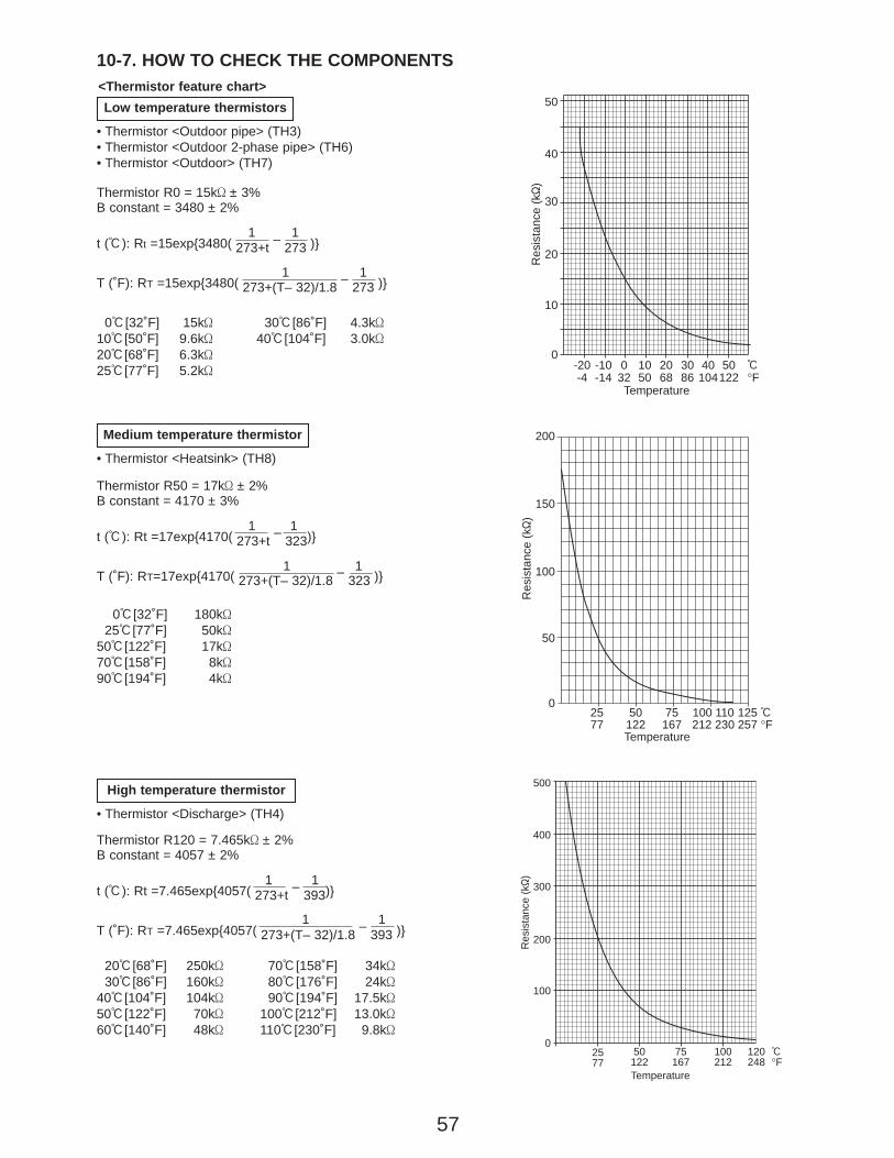
57
Thermistor R0 = 15k' ± 3%B constant = 3480 ± 2%
t (:): Rt =15exp{3480( 273+t – 273 )}
T (˚F): RT =15exp{3480( 273+(T– 32)/1.8 – 273 )}
10-7. HOW TO CHECK THE COMPONENTS<Thermistor feature chart>Low temperature thermistors
• Thermistor <Outdoor pipe> (TH3)• Thermistor <Outdoor 2-phase pipe> (TH6)• Thermistor <Outdoor> (TH7)
0:[32˚F] 15k'10:[50˚F] 9.6k'20:[68˚F] 6.3k'25:[77˚F] 5.2k'
30:[86˚F] 4.3k'40:[104˚F] 3.0k'
1 1
Thermistor R120 = 7.465k' ± 2%B constant = 4057 ± 2%
t (:): Rt =7.465exp{4057( 273+t – 393)}
T (˚F): RT =7.465exp{4057( 273+(T– 32)/1.8 – 393 )}
1 1
20:[68˚F] 250k'30:[86˚F] 160k'
40:[104˚F] 104k'50:[122˚F] 70k'60:[140˚F] 48k'
70:[158˚F] 34k'80:[176˚F] 24k'90:[194˚F] 17.5k'
100:[212˚F] 13.0k'110:[230˚F] 9.8k'
High temperature thermistor
• Thermistor <Discharge> (TH4)
0
10
20
30
40
50
-20 -10 0 10 20 30 40 50-4 -14 32 50 68 86 104122
:°F
Temperature
Res
ista
nce
(k"
)
500
400
300
200
100
025 50 75 100 12077 122 167 212 248
:°F
Temperature
Res
ista
nce
(k"
)
0:[32˚F] 180k'25:[77˚F] 50k'
50:[122˚F] 17k'70:[158˚F] 8k'90:[194˚F] 4k'
Thermistor R50 = 17k' ± 2%B constant = 4170 ± 3%
t (:): Rt =17exp{4170( 273+t – 323)}
T (˚F): RT=17exp{4170( 273+(T– 32)/1.8 – 323 )}
1 1
Medium temperature thermistor
• Thermistor <Heatsink> (TH8)
200
150
100
50
025 50 75 100 110 12577 122 167 212 230 257
:°F
Temperature
Res
ista
nce
(k"
)
1 1
1 1
1 1
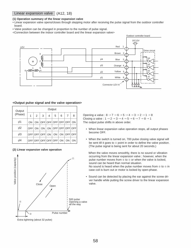
58
<Output pulse signal and the valve operation>
(2) Linear expansion valve operation
A
B
C
Open
Extra tightning (about 32 pulse)
Pulse number
500 pulseOpening a valveall the way
CloseValv
e po
sitio
n (c
apac
ity)
Opening a valve : 8 → 7 → 6 → 5 → 4 → 3 → 2 → 1 → 8Closing a valve : 1 → 2 → 3 → 4 → 5 → 6 → 7 → 8 → 1The output pulse shifts in above order.
• When linear expansion valve operation stops, all output phasesbecome OFF.
• When the switch is turned on, 700 pulse closing valve signal willbe sent till it goes to A point in order to define the valve position.(The pulse signal is being sent for about 20 seconds.)
When the valve moves smoothly, there is no sound or vibrationoccurring from the linear expansion valve ; however, when thepulse number moves from B to A or when the valve is locked,sound can be heard than normal situation.No sound is heard when the pulse number moves from B to A in case coil is burn out or motor is locked by open-phase.
• Sound can be detected by placing the ear against the screw dri-ver handle while putting the screw driver to the linear expansionvalve.
LEV
M
16
[4 [4
[3
[2
[1
2
1Red
Brown
Blue
Orange
Yellow
White
3
4
5
6
Connector LEV-A
DC12V
Outdoor controller board
Drive circuit
[3
[2
[1
3
2
54
Linear expansion valve(1) Operation summary of the linear expansion valve• Linear expansion valve opens/closes through stepping motor after receiving the pulse signal from the outdoor controller
board.• Valve position can be changed in proportion to the number of pulse signal.<Connection between the indoor controller board and the linear expansion valve>
1
ON
OFF
OFF
OFF
ON
ON
OFF
OFF
OFF
ON
OFF
OFF
OFF
ON
ON
OFF
[1
Output(Phase)
Output
[2
[3
[4
2 3 4 5 6 7 8
OFF
OFF
ON
OFF
OFF
OFF
ON
ON
OFF
OFF
OFF
ON
ON
OFF
OFF
ON
(A12, 18)

59
<Output pulse signal and the valve operation>
(2) Linear expansion valve operation
A
B
C
Open
Extra tightning (about 32 pulse)
Pulse number
500 pulseOpening a valveall the way
CloseValv
e po
sitio
n (c
apac
ity)
Opening a valve : 8 → 7 → 6 → 5 → 4 → 3 → 2 → 1 → 8Closing a valve : 1 → 2 → 3 → 4 → 5 → 6 → 7 → 8 → 1The output pulse shifts in above order.
• When linear expansion valve operation stops, all output phasebecome OFF.
• When the switch is turned on, 700 pulse closing valve signal willbe sent till it goes to A point in order to define the valve position.(The pulse signal is being sent for about 20 seconds.)
When the valve moves smoothly, there is no sound or vibrationoccurring from the linear expansion valve ; however, when thepulse number moves from B to A or when the valve is locked,sound can be heard than normal situation.No sound is heard when the pulse number moves from B to A in case coil is burn out or motor is locked by open-phase.
• Sound can be detected by placing the ear against the screw dri-ver handle while putting the screw driver to the linear expansionvalve.
LEV
M
16
[4 [4
[3
[2
[1
1Gray
Orange
Red
Yellow
Black
3
4
5
6
Connector LEV-A
DC12V
Outdoor controller board
Drive circuit
[3
[2
[1
3
2
54
Linear expansion valve(1) Operation summary of the linear expansion valve• Linear expansion valve opens/closes through stepping motor after receiving the pulse signal from the outdoor controller
board.• Valve position can be changed in proportion to the number of pulse signal.<Connection between the indoor controller board and the linear expansion valve>
1
ON
OFF
OFF
OFF
ON
ON
OFF
OFF
OFF
ON
OFF
OFF
OFF
ON
ON
OFF
[1
Output(Phase)
Output
[2
[3
[4
2 3 4 5 6 7 8
OFF
OFF
ON
OFF
OFF
OFF
ON
ON
OFF
OFF
OFF
ON
ON
OFF
OFF
ON
(A24, 30, 36, 42)
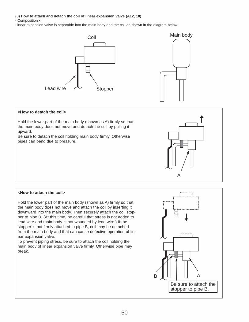
60
Main body
Lead wire Stopper
Coil
A
Be sure to attach thestopper to pipe B.
B A
(3) How to attach and detach the coil of linear expansion valve (A12, 18)<Composition>Linear expansion valve is separable into the main body and the coil as shown in the diagram below.
<How to detach the coil>
Hold the lower part of the main body (shown as A) firmly so thatthe main body does not move and detach the coil by pulling itupward.Be sure to detach the coil holding main body firmly. Otherwisepipes can bend due to pressure.
<How to attach the coil>
Hold the lower part of the main body (shown as A) firmly so thatthe main body does not move and attach the coil by inserting itdownward into the main body. Then securely attach the coil stop-per to pipe B. (At this time, be careful that stress is not added tolead wire and main body is not wounded by lead wire.) If thestopper is not firmly attached to pipe B, coil may be detachedfrom the main body and that can cause defective operation of lin-ear expansion valve.To prevent piping stress, be sure to attach the coil holding themain body of linear expansion valve firmly. Otherwise pipe maybreak.
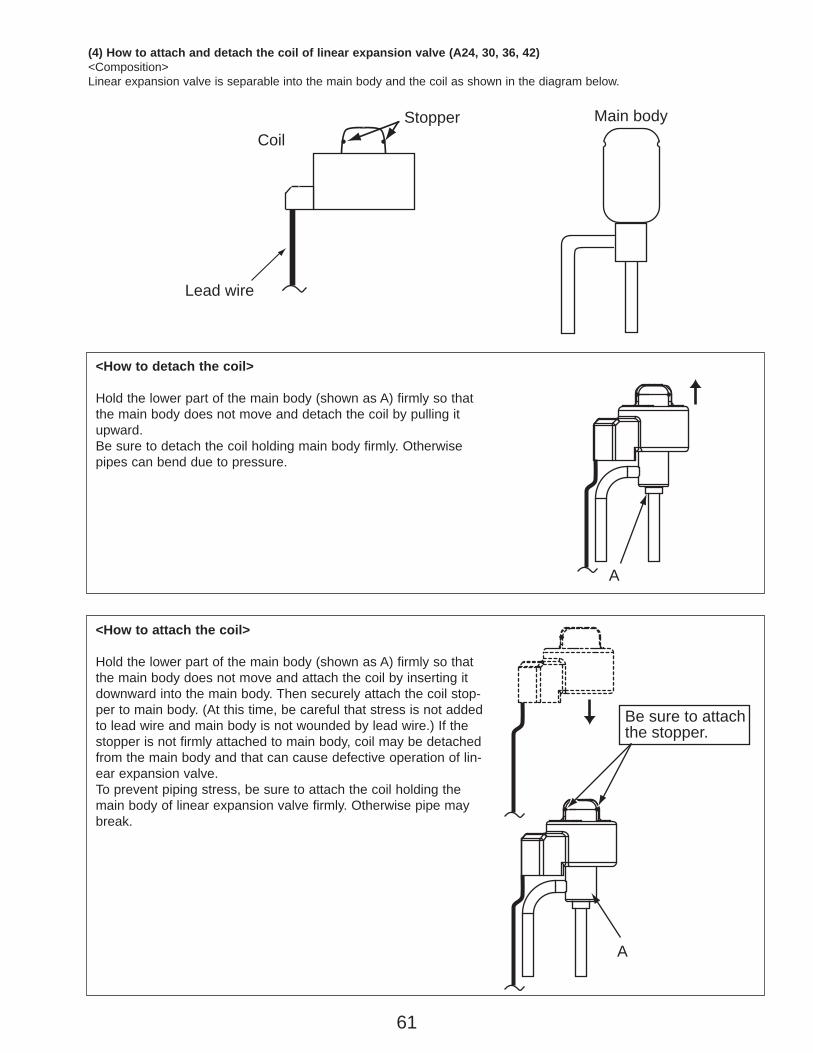
61
Main body
Lead wire
StopperCoil
A
Be sure to attach the stopper.
A
(4) How to attach and detach the coil of linear expansion valve (A24, 30, 36, 42)<Composition>Linear expansion valve is separable into the main body and the coil as shown in the diagram below.
<How to detach the coil>
Hold the lower part of the main body (shown as A) firmly so thatthe main body does not move and detach the coil by pulling itupward.Be sure to detach the coil holding main body firmly. Otherwisepipes can bend due to pressure.
<How to attach the coil>
Hold the lower part of the main body (shown as A) firmly so thatthe main body does not move and attach the coil by inserting itdownward into the main body. Then securely attach the coil stop-per to main body. (At this time, be careful that stress is not addedto lead wire and main body is not wounded by lead wire.) If thestopper is not firmly attached to main body, coil may be detachedfrom the main body and that can cause defective operation of lin-ear expansion valve.To prevent piping stress, be sure to attach the coil holding themain body of linear expansion valve firmly. Otherwise pipe maybreak.
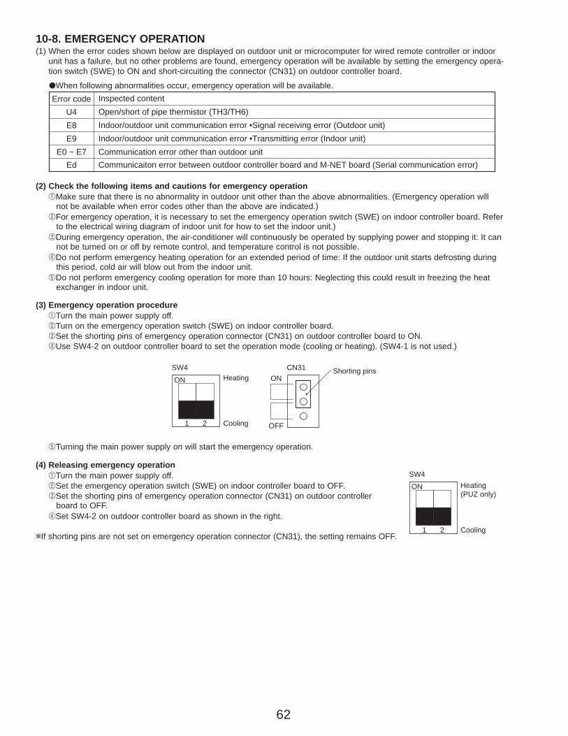
62
10-8. EMERGENCY OPERATION (1) When the error codes shown below are displayed on outdoor unit or microcomputer for wired remote controller or indoor
unit has a failure, but no other problems are found, emergency operation will be available by setting the emergency opera-tion switch (SWE) to ON and short-circuiting the connector (CN31) on outdoor controller board.
(4) Releasing emergency operation1Turn the main power supply off.2Set the emergency operation switch (SWE) on indoor controller board to OFF.3Set the shorting pins of emergency operation connector (CN31) on outdoor controller
board to OFF.4Set SW4-2 on outdoor controller board as shown in the right.
wIf shorting pins are not set on emergency operation connector (CN31), the setting remains OFF.
(2) Check the following items and cautions for emergency operation 1Make sure that there is no abnormality in outdoor unit other than the above abnormalities. (Emergency operation will
not be available when error codes other than the above are indicated.)2For emergency operation, it is necessary to set the emergency operation switch (SWE) on indoor controller board. Refer
to the electrical wiring diagram of indoor unit for how to set the indoor unit.)3During emergency operation, the air-conditioner will continuously be operated by supplying power and stopping it: It can
not be turned on or off by remote control, and temperature control is not possible.4Do not perform emergency heating operation for an extended period of time: If the outdoor unit starts defrosting during
this period, cold air will blow out from the indoor unit.5Do not perform emergency cooling operation for more than 10 hours: Neglecting this could result in freezing the heat
exchanger in indoor unit.
(3) Emergency operation procedure1Turn the main power supply off.2Turn on the emergency operation switch (SWE) on indoor controller board.3Set the shorting pins of emergency operation connector (CN31) on outdoor controller board to ON.4Use SW4-2 on outdoor controller board to set the operation mode (cooling or heating). (SW4-1 is not used.)
5Turning the main power supply on will start the emergency operation.
SW4
1 2 Cooling
HeatingON ON
OFF
CN31 Shorting pins
SW4
1 2 Cooling
Heating(PUZ only)
ON
Inspected contentOpen/short of pipe thermistor (TH3/TH6)Indoor/outdoor unit communication error •Signal receiving error (Outdoor unit)Indoor/outdoor unit communication error •Transmitting error (Indoor unit)Communication error other than outdoor unitCommunicaiton error between outdoor controller board and M-NET board (Serial communication error)
Error codeU4E8E9
E0 ~ E7Ed
●When following abnormalities occur, emergency operation will be available.
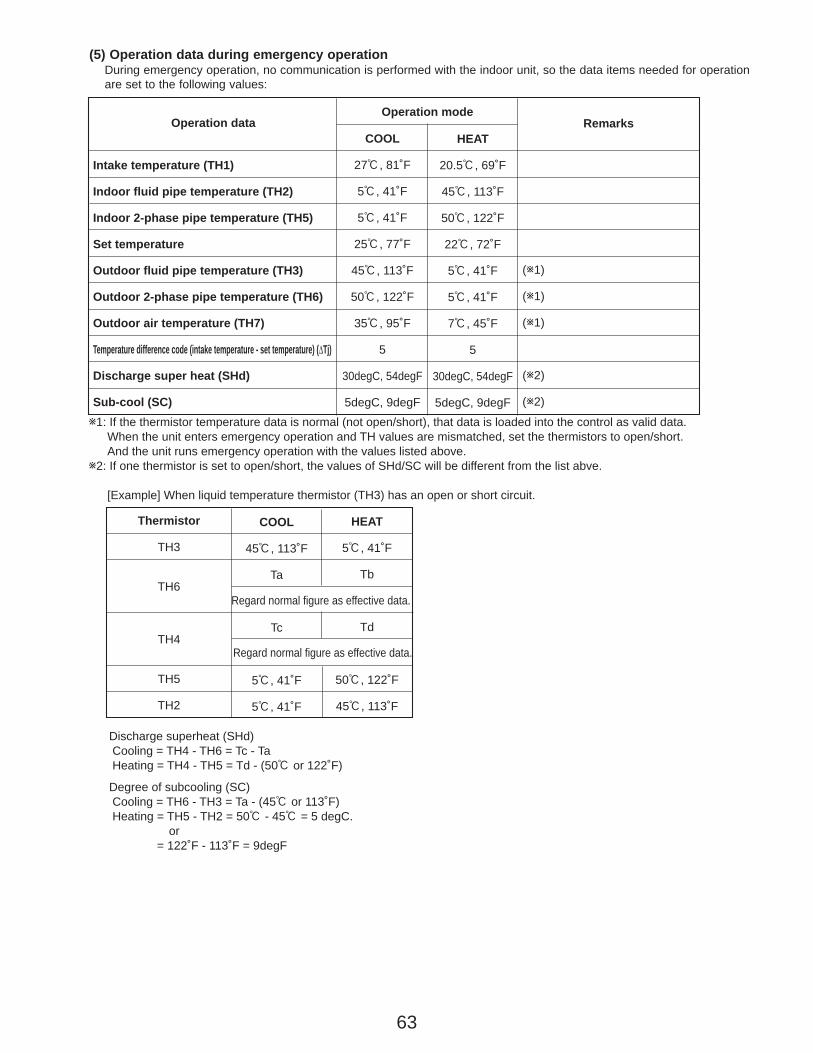
63
(5) Operation data during emergency operationDuring emergency operation, no communication is performed with the indoor unit, so the data items needed for operationare set to the following values:
Operation data
Intake temperature (TH1)
Indoor fluid pipe temperature (TH2)
Indoor 2-phase pipe temperature (TH5)
Set temperature
Outdoor fluid pipe temperature (TH3)
Outdoor 2-phase pipe temperature (TH6)
Outdoor air temperature (TH7)
Temperature difference code (intake temperature - set temperature) (ΔTj)
Discharge super heat (SHd)
Sub-cool (SC)
Operation mode
COOL
27:, 81˚F
5:, 41˚F
5:, 41˚F
25:, 77˚F
45:, 113˚F
50:, 122˚F
35:, 95˚F
5
30degC, 54degF
5degC, 9degF
HEAT
20.5:, 69˚F
45:, 113˚F
50:, 122˚F
22:, 72˚F
5:, 41˚F
5:, 41˚F
7:, 45˚F
5
30degC, 54degF
5degC, 9degF
(w1)
(w1)
(w1)
(w2)
(w2)
Remarks
w1: If the thermistor temperature data is normal (not open/short), that data is loaded into the control as valid data. When the unit enters emergency operation and TH values are mismatched, set the thermistors to open/short.And the unit runs emergency operation with the values listed above.
w2: If one thermistor is set to open/short, the values of SHd/SC will be different from the list abve.
[Example] When liquid temperature thermistor (TH3) has an open or short circuit.
COOL
45:, 113˚F
Ta
Tc
5:, 41˚F
5:, 41˚F
HEAT
5:, 41˚F
Tb
Td
50:, 122˚F
45:, 113˚F
Thermistor
TH3
TH6
TH4
TH5
TH2
Regard normal figure as effective data.
Regard normal figure as effective data.
Discharge superheat (SHd) Cooling = TH4 - TH6 = Tc - Ta Heating = TH4 - TH5 = Td - (50: or 122˚F)
Degree of subcooling (SC) Cooling = TH6 - TH3 = Ta - (45: or 113˚F) Heating = TH5 - TH2 = 50: - 45: = 5 degC.
or = 122˚F - 113˚F = 9degF
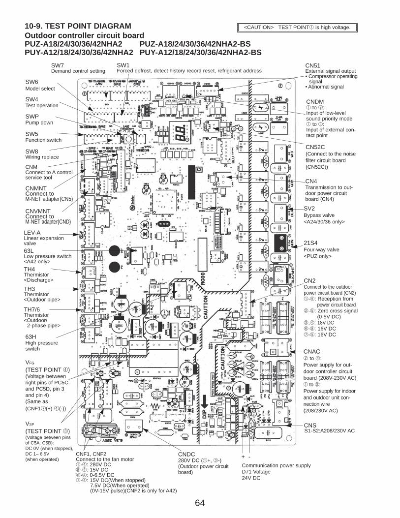
64
10-9. TEST POINT DIAGRAMOutdoor controller circuit boardPUZ-A18/24/30/36/42NHA2 PUZ-A18/24/30/36/42NHA2-BSPUY-A12/18/24/30/36/42NHA2 PUY-A12/18/24/30/36/42NHA2-BS
<CAUTION> TEST POINT1 is high voltage.
Communication power supply D71 Voltage 24V DC
CNSS1-S2:A208/230V AC
CNAC2 to 4:Power supply for out-door controller circuitboard (208V-230V AC)1 to 3:Power supply for indoorand outdoor unit con-nection wire (208/230V AC)
CNF1, CNF2 Connect to the fan motor1-4: 280V DC5-4: 15V DC6-4: 0-6.5V DC7-4: 15V DC(When stopped)
7.5V DC(When operated)(0V-15V pulse)(CNF2 is only for A42)
21S4Four-way valve<PUZ only>
63HHigh pressureswitch
SV2Bypass valve<A24/30/36 only>
CN4Transmission to out-door power circuitboard (CN4)
SW4Test operation
SW6Model select
SW5Function switch
SW1Forced defrost, detect history record reset, refrigerant address
CNDM1 to 2:Input of low-levelsound priority mode1 to 3:Input of external con-tact point
TH4Thermistor<Discharge>
TH3Thermistor<Outdoor pipe>
TH7/6Thermistor<Outdoor/
2-phase pipe>
CNDC280V DC (1+, 3-)(Outdoor power circuitboard)
+ -
VFG
(TEST POINT 4)(Voltage betweenright pins of PC5Cand PC5D, pin 3and pin 4)(Same as(CNF17(+)-4(-))
VSP
(TEST POINT 3)(Voltage between pinsof C5A, C5B):DC 0V (when stopped),DC 1– 6.5V (when operated)
SW7Demand control setting
CN51External signal output• Compressor operating
signal• Abnormal signal
LEV-ALinear expansionvalve
SWPPump down
SW8Wiring replace
CNMConnect to A controlservice tool
CNMNTConnect toM-NET adapter(CN5)
CNVMNTConnect toM-NET adapter(CND)
CN2Connect to the outdoorpower circuit board (CN2)1-5: Reception from
power circuit board2-5: Zero cross signal
(0-5V DC)3,4: 18V DC6-5: 16V DC7-5: 16V DC
CN52C(Connect to the noisefilter circuit board(CN52C))
63LLow pressure switch<A42 only>

65
Outdoor noise filter circuit boardPUZ-A18NHA2 PUZ-A18NHA2-BSPUY-A12/18NHA2 PUY-A12/18NHA2-BS
LO, NOVoltage of 208/230V AC is output.(Connect to the ACL)
CN52C52C relay signal(Connect to the outdoor controller circuit board(CN52C))
CN5Primary current(Connect to theoutdoor power circuit board(CN5))
CNAC1, CNAC2208/230V AC(Connect to theoutdoor controllercircuit board(CNAC))
EIConnect to the earth
LI, NIVoltage of 208/230V AC is input. (Connect to the terminal block(TB1))
E3Connect to the earth
E2Connect to the earth
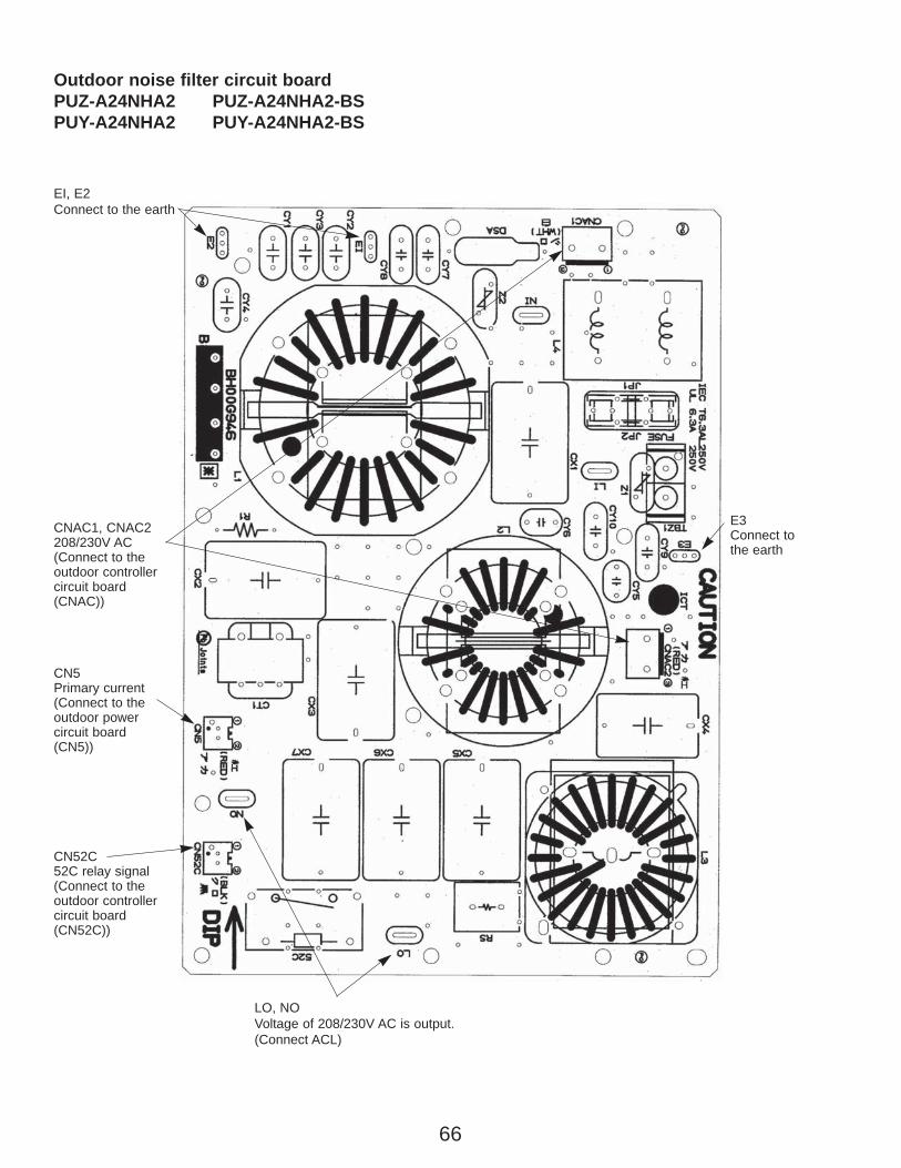
66
LO, NOVoltage of 208/230V AC is output.(Connect ACL)
CN52C52C relay signal(Connect to the outdoor controller circuit board(CN52C))
CN5Primary current(Connect to theoutdoor power circuit board(CN5))
CNAC1, CNAC2208/230V AC(Connect to theoutdoor controllercircuit board(CNAC))
EI, E2Connect to the earth
E3Connect to the earth
Outdoor noise filter circuit boardPUZ-A24NHA2 PUZ-A24NHA2-BSPUY-A24NHA2 PUY-A24NHA2-BS
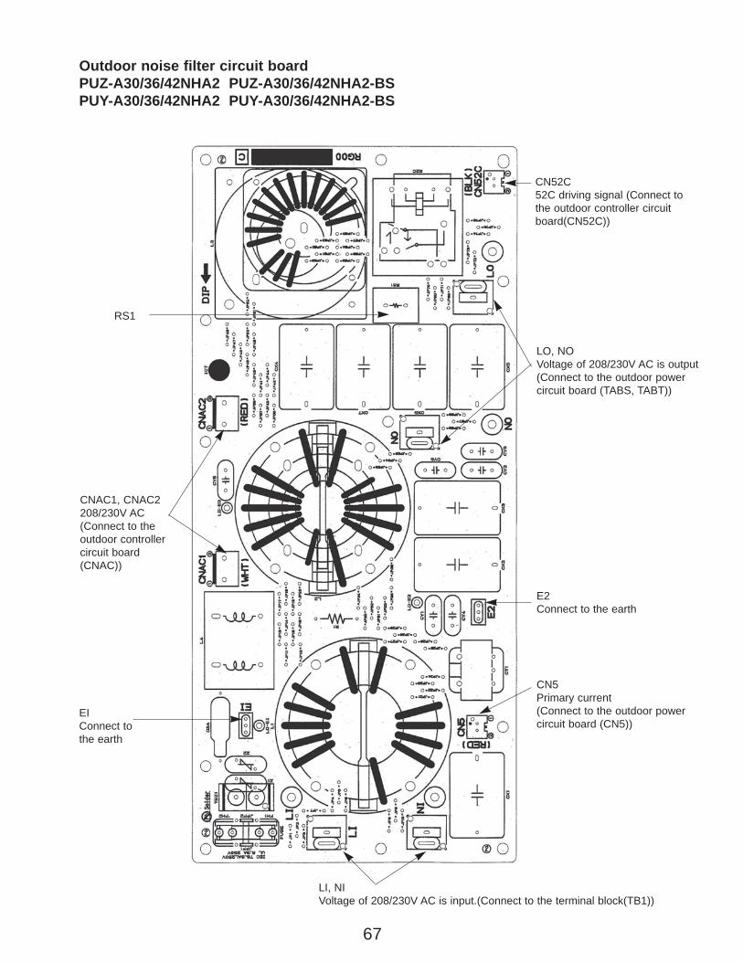
67
CNAC1, CNAC2208/230V AC(Connect to theoutdoor controllercircuit board(CNAC))
EIConnect to the earth
LI, NIVoltage of 208/230V AC is input.(Connect to the terminal block(TB1))
E2Connect to the earth
LO, NOVoltage of 208/230V AC is output(Connect to the outdoor powercircuit board (TABS, TABT))
RS1
CN52C52C driving signal (Connect tothe outdoor controller circuitboard(CN52C))
CN5Primary current(Connect to the outdoor powercircuit board (CN5))
Outdoor noise filter circuit boardPUZ-A30/36/42NHA2 PUZ-A30/36/42NHA2-BSPUY-A30/36/42NHA2 PUY-A30/36/42NHA2-BS

68
CN2Connect to the outdoor controller circuit board (CN2)1-5:Outdoor power circuit board ➔ Transmitting signalto the outdoor controller circuit board (0-5V DC)2-5: Zero cross signal (0-5V DC)3-4: Not used6-5: 16V DC7-5: 16V DC
Outdoor power circuit boardPUZ-A18NHA2PUZ-A18NHA2-BSPUY-A12/18NHA2PUY-A12/18NHA2-BS
1, 2, 6, 7 : +5 : – ][
LD1-LD2280-380V DCConnect to the outdoorcontrollercircuit board(CNDC)
R, SConnect to the ACL208/230V AC
U, V, WConnect to the compressor (MC)Voltage among phases: 5V to 180V AC
LD9Connect tothe earth Only A24
CN5Primary current detection(Connect to the outdoornoise filter circuit board(CN5))
CN4Connect from the outdoor controller circuit board(CN4)
CN3Thermistor<Heatsink>(TH8)
DIP-IPM
DIP-PFC
Brief check of DIP-IPM and DIP-PFCW Usually, they are in a state of being short-circuited if they are broken.Measure the resistance in the following points (connectors, etc.). If theyare short-circuited, it means that they are broken.1. Check of DIP-IPM
P-U, P-V, P-W, N-U, N-V, N-W2. Check of DIP-PFC
P-R, P-S, R-N, S-N
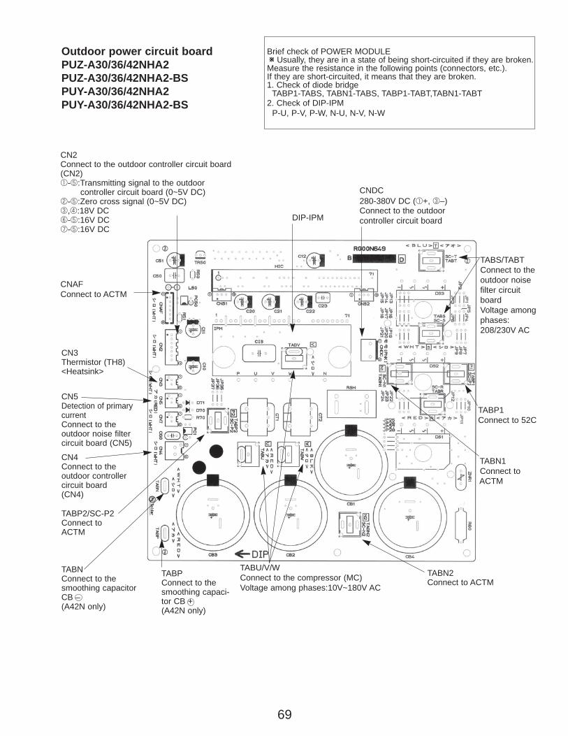
69
Outdoor power circuit boardPUZ-A30/36/42NHA2PUZ-A30/36/42NHA2-BSPUY-A30/36/42NHA2PUY-A30/36/42NHA2-BS
TABP1Connect to 52C
TABP2/SC-P2Connect toACTM
CN4Connect to theoutdoor controllercircuit board(CN4)
CN2Connect to the outdoor controller circuit board(CN2)1-5:Transmitting signal to the outdoor
controller circuit board (0~5V DC)2-5:Zero cross signal (0~5V DC)3,4:18V DC6-5:16V DC7-5:16V DC
CN3Thermistor (TH8)<Heatsink>
CN5Detection of primarycurrentConnect to the outdoor noise filter circuit board (CN5)
CNDC280-380V DC (1+, 3–)Connect to the outdoorcontroller circuit board
TABS/TABTConnect to theoutdoor noisefilter circuitboardVoltage among phases:208/230V AC
Brief check of POWER MODULEW Usually, they are in a state of being short-circuited if they are broken.Measure the resistance in the following points (connectors, etc.). If they are short-circuited, it means that they are broken.1. Check of diode bridge
TABP1-TABS, TABN1-TABS, TABP1-TABT,TABN1-TABT2. Check of DIP-IPM
P-U, P-V, P-W, N-U, N-V, N-W
TABN2Connect to ACTM
TABNConnect to thesmoothing capacitor CB –(A42N only)
TABU/V/WConnect to the compressor (MC) Voltage among phases:10V~180V AC
TABPConnect to thesmoothing capaci-tor CB +(A42N only)
TABN1Connect to ACTM
DIP-IPM
CNAFConnect to ACTM
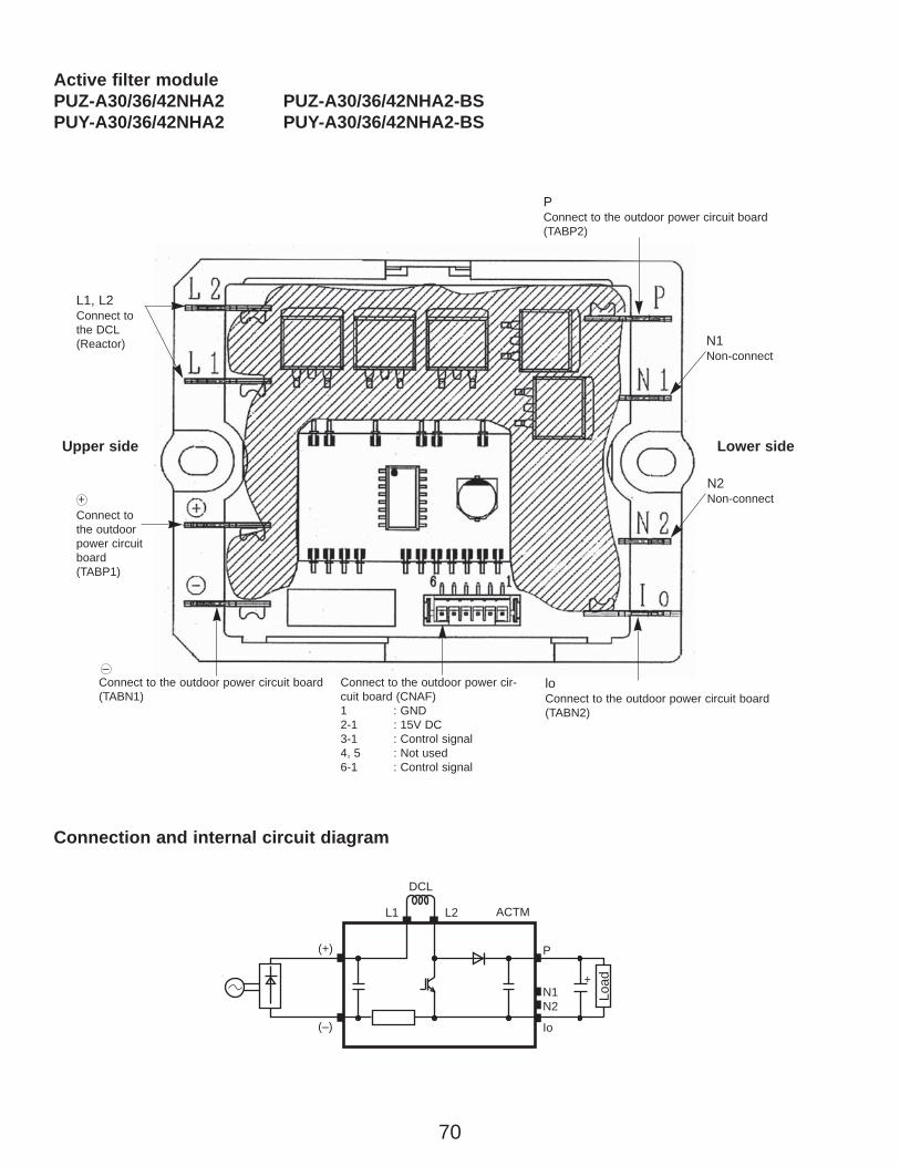
70
N1Non-connect
loConnect to the outdoor power circuit board(TABN2)
L1, L2Connect tothe DCL(Reactor)
PConnect to the outdoor power circuit board(TABP2)
+
DCL
L1 L2 ACTM
P
Io
N1N2
(+)
(–)
Load
Active filter modulePUZ-A30/36/42NHA2 PUZ-A30/36/42NHA2-BSPUY-A30/36/42NHA2 PUY-A30/36/42NHA2-BS
N2Non-connect
Connect to the outdoor power circuit board(TABN1)
Connect to the outdoor power cir-cuit board (CNAF)1 : GND2-1 : 15V DC3-1 : Control signal4, 5 : Not used6-1 : Control signal
Connect tothe outdoorpower circuitboard(TABP1)
Upper side Lower side
–
+
Connection and internal circuit diagram
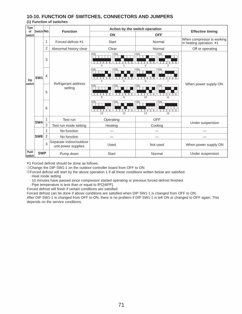
71
SwitchType
ofswitch
Dipswitch
Pushswitch
SW1
1
2
No. Function Effective timingAction by the switch operation
Forced defrost w1 Start NormalWhen compressor is working in heating operation. w1
Abnormal history clear
Refrigerant addresssetting
When power supply ON
Clear Normal Off or operating
SWP
6
5
4
3
Under suspensionPump down Start Normal
SW4
SW8
1212
3
Test run Operating OFFUnder suspension
Test run mode setting Heating CoolingNo function — —No function — —
Separate indoor/outdoorunit power supplies Used Not used
——
When power supply ON
ON OFF
1 2 30 1 2 3
4 5 6
ON
1 2 3 4 5 6
ON
1 2 3 4 5 6
ON
1 2 3 4 5 6
ON
1 2 34 5 6 7
4 5 6
ON
1 2 3 4 5 6
ON
1 2 3 4 5 6
ON
1 2 3 4 5 6
ON
1 2 38 9 10 11
4 5 6
ON
1 2 3 4 5 6
ON
1 2 3 4 5 6
ON
1 2 3 4 5 6
ON
1 2 312 13 14 15
4 5 6
ON
1 2 3 4 5 6
ON
1 2 3 4 5 6
ON
1 2 3 4 5 6
ON
w1 Forced defrost should be done as follows.1Change the DIP SW1-1 on the outdoor controller board from OFF to ON.2Forced defrost will start by the above operation 1 if all these conditions written below are satisfied.
· Heat mode setting· 10 minutes have passed since compressor started operating or previous forced defrost finished.· Pipe temperature is less than or equal to 8ºC[46ºF].
Forced defrost will finish if certain conditions are satisfied.Forced defrost can be done if above conditions are satisfied when DIP SW1-1 is changed from OFF to ON.After DIP SW1-1 is changed from OFF to ON, there is no problem if DIP SW1-1 is left ON or changed to OFF again. Thisdepends on the service conditions.
10-10. FUNCTION OF SWITCHES, CONNECTORS AND JUMPERS (1) Function of switches

72
1
2
3,4,56
345612
3,4123456786
ON OFFNo. Function Effective timingAction by the switch operation
No function
Power failureautomatic recovery w2
No functionModel select
Max. Hz setting(cooling)Max. Hz setting(heating)
No functionDefrost setting
No functionFunction switch
No function
Switch
SW5
SW7w4
Dipswitch
SW9
SW6
SW5
Type ofSwitch
—
Auto recovery
—
Max. Hz(cooling) o 0.8Max. Hz(heating) o 0.8
—For high humidity
—Valid
—
—
No auto recovery
—
NormalNormal
—Normal
—Normal
—
—
When power supply ON
—
Always
AlwaysAlways
—
Always—
Always—
Setting of demand controlw3
1
2
SW7-1 SW7-2OFF 0% (Operation stop)
75%50%
OFFON
OFFOFFON
Power consumption (Demand switch ON)
Model select
Following SW5-6 reference
1 2 3 4 5 6OFFON
PUZ-A42N
1 2 3 4 5 6OFFONPUY-A42N
7 8
7 8
1 2 3 4 5 6OFFON
1 2 3 4 5 6OFFON
1 2 3 4 5 6OFFON
PUZ-A18N
MODEL SW6 SW5-5.6
1 2 3 4 5 6OFFONPUY-A12N
PUY-A18N1 2 3 4 5 6
7 8
7 8
7 8OFFON
1 2 3 4 5 6OFFON
1 2 3 4 5 6OFFON
1 2 3 4 5 6OFFON
1 2 3 4 5 6OFFON
PUZ-A24N
1 2 3 4 5 6OFFONPUY-A24N
7 8
7 8
1 2 3 4 5 6OFFON
1 2 3 4 5 6OFFON
1 2 3 4 5 6OFFON
PUZ-A30N
PUZ-A36N
MODEL SW6 SW5-5.6
1 2 3 4 5 6OFFON
1 2 3 4 5 6OFFONPUY-A30N
PUY-A36N1 2 3 4 5 6
7 8
7 8
7 8
7 8OFFON
1 2 3 4 5 6OFFON
1 2 3 4 5 6OFFON
1 2 3 4 5 6OFFON
1 2 3 4 5 6OFFON
w2 Power failure automatic recovery can be set by either remote controller or this DIP SW. If one of them is set to ON, Autorecovery activates. Please set Auto recovery basically by remote controller because all units do not have DIP SW.Please refer to the indoor unit installation manual.
w3 SW7-1,2 are used for demand control. SW7-1,2 are effective only at the demand control.(Refer to next page : Special function (b))
w4 Please do not use SW7-3~6 usually. Trouble might be caused by the usage condition.
(2)Function of connector
CN31
Types Connector Function Effective timing
Connector Start
Short Open
Action by open/ short operation
Emergency operation When power supply ONNormal
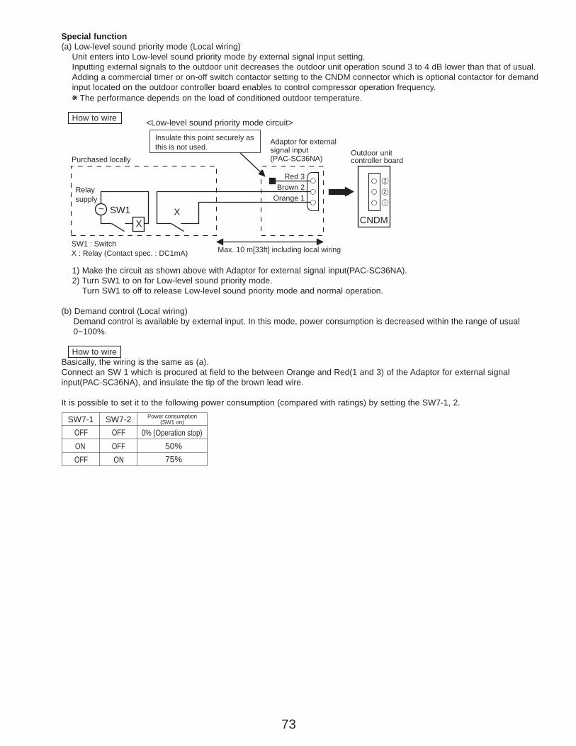
73
Special function(a) Low-level sound priority mode (Local wiring)
Unit enters into Low-level sound priority mode by external signal input setting.Inputting external signals to the outdoor unit decreases the outdoor unit operation sound 3 to 4 dB lower than that of usual. Adding a commercial timer or on-off switch contactor setting to the CNDM connector which is optional contactor for demandinput located on the outdoor controller board enables to control compressor operation frequency.W The performance depends on the load of conditioned outdoor temperature.
How to wire
1) Make the circuit as shown above with Adaptor for external signal input(PAC-SC36NA).2) Turn SW1 to on for Low-level sound priority mode.
Turn SW1 to off to release Low-level sound priority mode and normal operation.
(b) Demand control (Local wiring)Demand control is available by external input. In this mode, power consumption is decreased within the range of usual0~100%.
How to wireBasically, the wiring is the same as (a).Connect an SW 1 which is procured at field to the between Orange and Red(1 and 3) of the Adaptor for external signal input(PAC-SC36NA), and insulate the tip of the brown lead wire.
It is possible to set it to the following power consumption (compared with ratings) by setting the SW7-1, 2.
SW7-1 SW7-2OFF 0% (Operation stop)
75%50%
OFFON
OFFOFFON
Power consumption (SW1 on)
CNDMXSW1~
X
Max. 10 m[33ft] including local wiringSW1 : Switch X : Relay (Contact spec. : DC1mA)
Relaysupply
Red 3Brown 2
Orange 1
Purchased locally
Adaptor for external signal input(PAC-SC36NA)
Outdoor unit controller board
3
2
1
Insulate this point securely as this is not used.
<Low-level sound priority mode circuit>
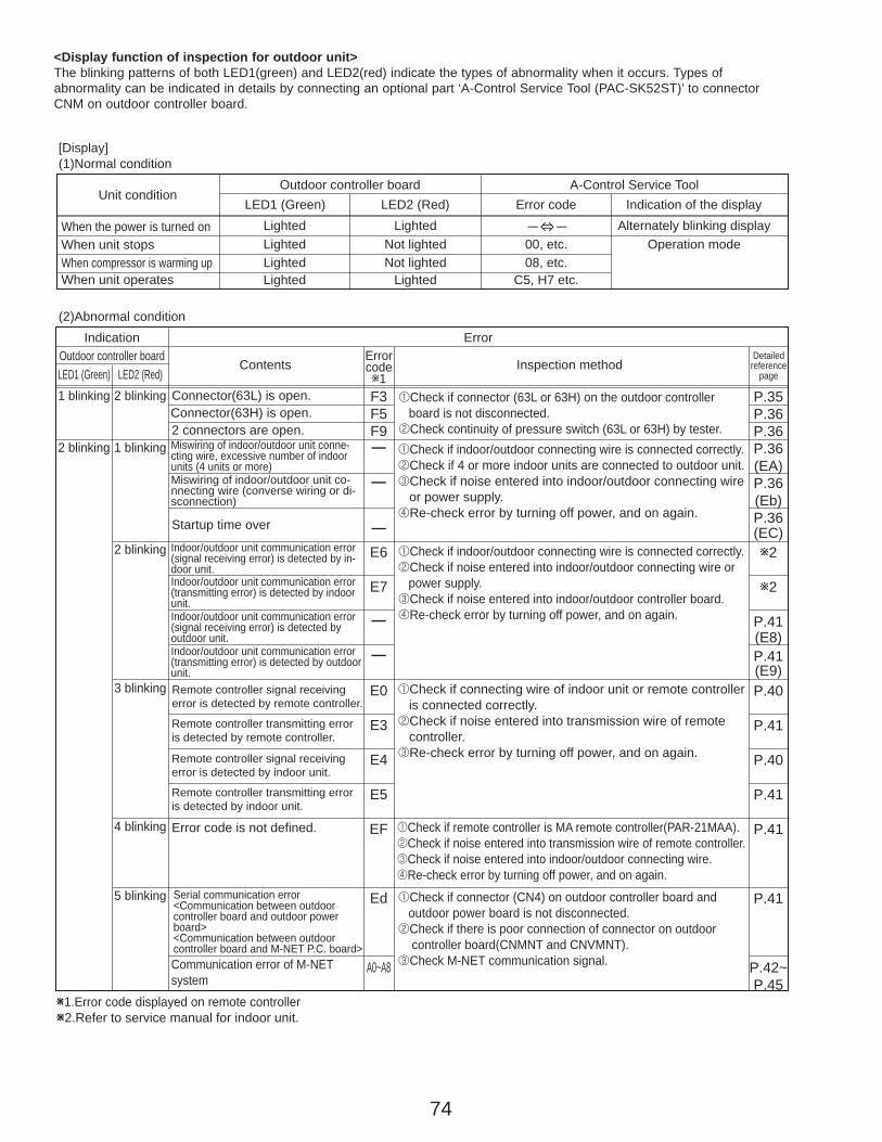
74
<Display function of inspection for outdoor unit>The blinking patterns of both LED1(green) and LED2(red) indicate the types of abnormality when it occurs. Types of abnormality can be indicated in details by connecting an optional part ‘A-Control Service Tool (PAC-SK52ST)’ to connectorCNM on outdoor controller board.
F3F5F9—
—
—E6
E7
—
—
E0
E3
E4
E5
EF
Ed
A0~A8
[Display](1)Normal condition
(2)Abnormal condition
Unit conditionOutdoor controller board A-Control Service Tool
LED1 (Green) LED2 (Red) Error code
When the power is turned onWhen unit stopsWhen compressor is warming upWhen unit operates
Lighted LightedLightedLightedLighted
Not lighted
Indication of the displayAlternately blinking display
Operation modeNot lighted
Lighted
00, etc.08, etc.
C5, H7 etc.
Indication ErrorErrorcodew1
Outdoor controller boardContents Inspection method
LED1 (Green) LED2 (Red)1 blinking 2 blinking
2 blinking 1 blinking
2 blinking
3 blinking
4 blinking
5 blinking
Connector(63L) is open.Connector(63H) is open.2 connectors are open.
Startup time over
Error code is not defined.
Miswiring of indoor/outdoor unit conne-cting wire, excessive number of indoor units (4 units or more)Miswiring of indoor/outdoor unit co-nnecting wire (converse wiring or di-sconnection)
Indoor/outdoor unit communication error(signal receiving error) is detected by in-door unit.Indoor/outdoor unit communication error(transmitting error) is detected by indoorunit.Indoor/outdoor unit communication error(signal receiving error) is detected by outdoor unit.Indoor/outdoor unit communication error (transmitting error) is detected by outdoorunit.Remote controller signal receiving error is detected by remote controller.
Remote controller transmitting error is detected by remote controller.
Remote controller signal receiving error is detected by indoor unit.
Remote controller transmitting error is detected by indoor unit.
Serial communication error<Communication between outdoor controller board and outdoor power board><Communication between outdoor controller board and M-NET P.C. board>Communication error of M-NETsystem
W1.Error code displayed on remote controllerW2.Refer to service manual for indoor unit.
1Check if indoor/outdoor connecting wire is connected correctly.2Check if 4 or more indoor units are connected to outdoor unit.3Check if noise entered into indoor/outdoor connecting wire or power supply.4Re-check error by turning off power, and on again.
1Check if connector (63L or 63H) on the outdoor controller board is not disconnected. 2Check continuity of pressure switch (63L or 63H) by tester.
1Check if connector (CN4) on outdoor controller board and outdoor power board is not disconnected.2Check if there is poor connection of connector on outdoor controller board(CNMNT and CNVMNT).3Check M-NET communication signal.
1Check if remote controller is MA remote controller(PAR-21MAA).2Check if noise entered into transmission wire of remote controller.3Check if noise entered into indoor/outdoor connecting wire.4Re-check error by turning off power, and on again.
1Check if connecting wire of indoor unit or remote controller is connected correctly.2Check if noise entered into transmission wire of remote controller.3Re-check error by turning off power, and on again.
1Check if indoor/outdoor connecting wire is connected correctly.2Check if noise entered into indoor/outdoor connecting wire or power supply.3Check if noise entered into indoor/outdoor controller board.4Re-check error by turning off power, and on again.
P.35P.36P.36P.36(EA)P.36(Eb)P.36(EC)w2
w2
P.41(E8)P.41(E9)P.40
P.41
P.40
P.41
P.41
P.41
P.42~P.45
Detailedreference
page
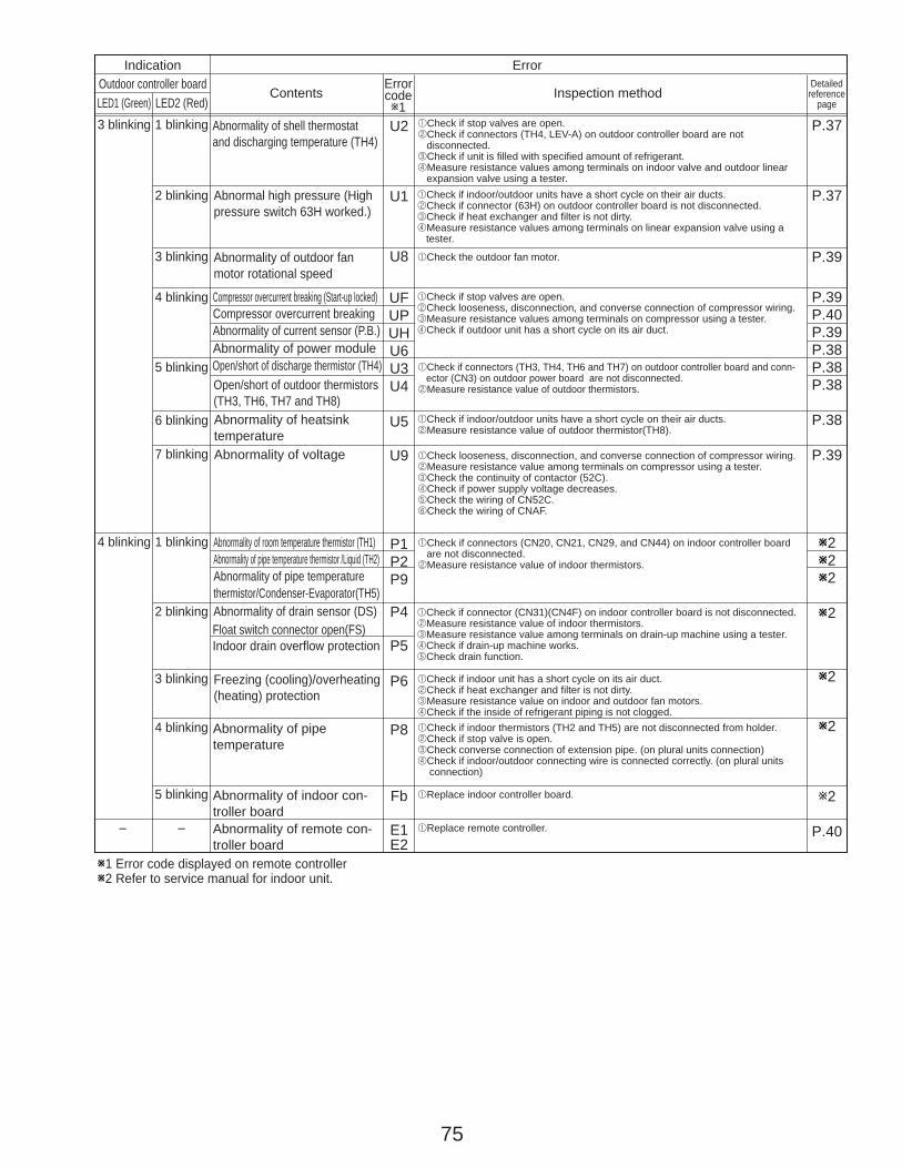
75
U2
U1
U8
UFUPUHU6U3U4
U5
U9
P1P2P9
P4
P5
P6
P8
Fb
E1E2
Indication ErrorErrorcodew1
Outdoor controller boardContents Inspection method
LED1 (Green) LED2 (Red)3 blinking 1 blinking
2 blinking
3 blinking
W1 Error code displayed on remote controllerW2 Refer to service manual for indoor unit.
4 blinking
5 blinking
6 blinking
7 blinking
1 blinking
2 blinking
3 blinking
4 blinking
5 blinking
––
4 blinking
Abnormality of shell thermostatand discharging temperature (TH4)
1Check if stop valves are open.2Check if connectors (TH4, LEV-A) on outdoor controller board are not disconnected.3Check if unit is filled with specified amount of refrigerant.4Measure resistance values among terminals on indoor valve and outdoor linear expansion valve using a tester.
Abnormal high pressure (High pressure switch 63H worked.)
Abnormality of outdoor fan motor rotational speed
1Check if indoor/outdoor units have a short cycle on their air ducts.2Check if connector (63H) on outdoor controller board is not disconnected.3Check if heat exchanger and filter is not dirty.4Measure resistance values among terminals on linear expansion valve using a tester.
1Check if stop valves are open.2Check looseness, disconnection, and converse connection of compressor wiring.3Measure resistance values among terminals on compressor using a tester.4Check if outdoor unit has a short cycle on its air duct.
Compressor overcurrent breaking (Start-up locked)Compressor overcurrent breakingAbnormality of current sensor (P.B.)Abnormality of power moduleOpen/short of discharge thermistor (TH4)Open/short of outdoor thermistors(TH3, TH6, TH7 and TH8)
1Check if connectors (TH3, TH4, TH6 and TH7) on outdoor controller board and conn- ector (CN3) on outdoor power board are not disconnected.2Measure resistance value of outdoor thermistors.
Abnormality of heatsinktemperature
1Check if indoor/outdoor units have a short cycle on their air ducts.2Measure resistance value of outdoor thermistor(TH8).
1Check the outdoor fan motor.
Abnormality of voltage 1Check looseness, disconnection, and converse connection of compressor wiring.2Measure resistance value among terminals on compressor using a tester.3Check the continuity of contactor (52C).4Check if power supply voltage decreases.5Check the wiring of CN52C.6Check the wiring of CNAF.
Abnormality of room temperature thermistor (TH1)Abnormality of pipe temperature thermistor /Liquid (TH2)Abnormality of pipe temperature thermistor/Condenser-Evaporator(TH5)
1Check if connectors (CN20, CN21, CN29, and CN44) on indoor controller board are not disconnected.2Measure resistance value of indoor thermistors.
Abnormality of drain sensor (DS)Float switch connector open(FS)Indoor drain overflow protection
1Check if connector (CN31)(CN4F) on indoor controller board is not disconnected.2Measure resistance value of indoor thermistors.3Measure resistance value among terminals on drain-up machine using a tester.4Check if drain-up machine works.5Check drain function.
Freezing (cooling)/overheating (heating) protection
1Check if indoor unit has a short cycle on its air duct.2Check if heat exchanger and filter is not dirty.3Measure resistance value on indoor and outdoor fan motors.4Check if the inside of refrigerant piping is not clogged.
Abnormality of pipe temperature
Abnormality of indoor con-troller boardAbnormality of remote con-troller board
1Check if indoor thermistors (TH2 and TH5) are not disconnected from holder.2Check if stop valve is open.3Check converse connection of extension pipe. (on plural units connection)4Check if indoor/outdoor connecting wire is connected correctly. (on plural units connection)
1Replace indoor controller board.
1Replace remote controller.
P.37
P.37
P.39
P.39P.40P.39P.38P.38P.38
P.38
P.39
W2W2W2
W2
W2
W2
w2
P.40
Detailedreference
page
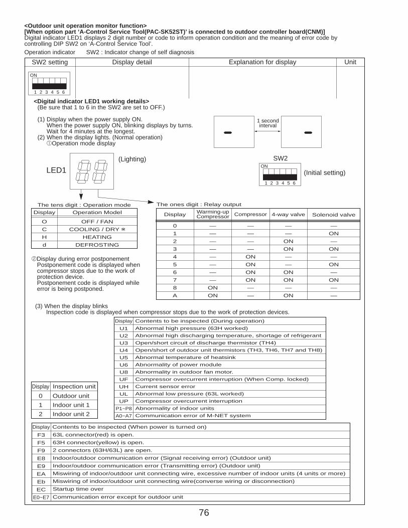
76
<Outdoor unit operation monitor function>[When option part ‘A-Control Service Tool(PAC-SK52ST)’ is connected to outdoor controller board(CNM)]Digital indicator LED1 displays 2 digit number or code to inform operation condition and the meaning of error code by controlling DIP SW2 on ‘A-Control Service Tool’.
SW2 setting
1
ON
2 3 4 5 6
Display detail Explanation for display UnitOperation indicator SW2 : Indicator change of self diagnosis
<Digital indicator LED1 working details>(Be sure that 1 to 6 in the SW2 are set to OFF.)
(1) Display when the power supply ON.When the power supply ON, blinking displays by turns.Wait for 4 minutes at the longest.
(2) When the display lights. (Normal operation)1Operation mode display
1
ON
2 3 4 5 6
(Initial setting)
SW2
1 secondinterval
LED1(Lighting)
Display Operation ModelThe tens digit : Operation mode The ones digit : Relay output
OCHd
Display
012345678A
CompressorWarming-upCompressor 4-way valve Solenoid valve
————ONONONON——
————————ONON
——ONON——ONON—ON
—ON—ON—ON—ON——
OFF / FANCOOLING / DRY w
HEATINGDEFROSTING
2Display during error postponementPostponement code is displayed when compressor stops due to the work of protection device.Postponement code is displayed while error is being postponed.
(3) When the display blinksInspection code is displayed when compressor stops due to the work of protection devices.
Display Contents to be inspected (When power is turned on)F3F5F9E8E9EAEbEC
E0~E7
63L connector(red) is open.63H connector(yellow) is open.2 connectors (63H/63L) are open.Indoor/outdoor communication error (Signal receiving error) (Outdoor unit)Indoor/outdoor communication error (Transmitting error) (Outdoor unit)Miswiring of indoor/outdoor unit connecting wire, excessive number of indoor units (4 units or more)Miswiring of indoor/outdoor unit connecting wire(converse wiring or disconnection)Startup time overCommunication error except for outdoor unit
Display Inspection unit012
Outdoor unitIndoor unit 1Indoor unit 2
Display Contents to be inspected (During operation)U1U2U3U4U5U6U8UFUHULUP
P1~P8A0~A7
Abnormal high pressure (63H worked)Abnormal high discharging temperature, shortage of refrigerantOpen/short circuit of discharge thermistor (TH4)Open/short of outdoor unit thermistors (TH3, TH6, TH7 and TH8)Abnormal temperature of heatsinkAbnormality of power moduleAbnormality in outdoor fan motor. Compressor overcurrent interruption (When Comp. locked)Current sensor errorAbnormal low pressure (63L worked)Compressor overcurrent interruptionAbnormality of indoor unitsCommunication error of M-NET system

77
SW2 setting
1
ON
2 3 4 5 6
Display detail Explanation for display UnitPipe temperature / Liquid(TH3)– 40~194
– 40~194 (– 40~90:)(When the coil thermistor detects 0˚F or below, “–” and temperature are displayed by turns.)
(Example) When -10˚F;0.5 secs. 0.5secs. 2 secs.
˚F
1
ON
2 3 4 5 6
1
ON
2 3 4 5 6
1
ON
2 3 4 5 6
1
ON
2 3 4 5 6
Discharge temperature (TH4)37~327
Output step of outdoor FAN0~10
The number of ON / OFF times ofcompressor0~9999
Compressor integrating operation times0~9999
37~327 (3~164:)(When the discharge thermistor detects 100˚F or more, hundreds digit, tens digit and ones digit are displayed by turns.)
(Example) When 105˚F; 0.5 secs. 0.5secs. 2 secs.
˚F
Step
100 times
10 hours
0~10
0~9999(When the number of times is 100 or more,hundreds digit, tens digit and ones digit are displayed by turns.)
(Example) When 42500 times (425 ✕100 times);0.5 secs. 0.5secs. 2 secs.
0~9999(When it is 100 hours or more, hundreds digit, tens digit and ones digit are displayed by turns.)
(Example) When 2450 hours (245 ✕10 hours);0.5 secs. 0.5secs. 2 secs.
1
ON
2 3 4 5 6
1
ON
2 3 4 5 6
1
ON
2 3 4 5 6
Compressor operating current0~50
LEV-A opening pulse0~480
0~50wOmit the figures after the decimal fractions.
0~480(When it is 100 pulse or more, hundreds digit, tens digit and ones digit are displayed by turns.
(Example) When 150 pulse;0.5 secs. 0.5secs. 2 secs.
A
Pulse
Error postponement code history (1)of outdoor unit
Postponement code displayBlinking: During postponementLighting: Cancellation of postponement“00” is displayed in case of no postponement.
Codedisplay
Codedisplay
Operation mode on error occurring Operation mode of when operation stops due toerror is displayed by setting SW2 like below.
1
ON
2 3 4 5 6
(SW2)
10
1
ON
2 3 4 5 6
Compressor operating frequency0~255
0~255(When it is 100Hz or more, hundreds digit, tens digit and ones digit are displayed by turns.
(Example) When 125Hz;0.5 secs. 0.5secs. 2 secs.
Hz
1 05
4 25
2 45
1 25
1 50
1
ON
2 3 4 5 6
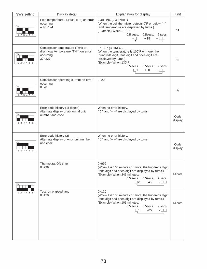
78
SW2 setting
1
ON
2 3 4 5 6
Display detail Explanation for display UnitPipe temperature / Liquid(TH3) on erroroccurring– 40~194
– 40~194 (– 40~90:)(When the coil thermistor detects 0˚F or below, “–” and temperature are displayed by turns.)
(Example) When –15˚F;0.5 secs. 0.5secs. 2 secs.
˚F
1
ON
2 3 4 5 6
1
ON
2 3 4 5 6
1
ON
2 3 4 5 6
1
ON
2 3 4 5 6
Compressor temperature (TH4) or discharge temperature (TH4) on erroroccurring37~327
Compressor operating current on erroroccurring0~20
Error code history (1) (latest)Alternate display of abnormal unitnumber and code
Error code history (2) Alternate display of error unit numberand code
37~327 (3~164:)(When the temperature is 100˚F or more, the hundreds digit, tens digit and ones digit are displayed by turns.)
(Example) When 130˚F;0.5 secs. 0.5secs. 2 secs.
˚F
A
Codedisplay
Codedisplay
0~20
When no error history, “ 0 ” and “– –” are displayed by turns.
When no error history, “ 0 ” and “– –” are displayed by turns.
1
ON
2 3 4 5 6
Thermostat ON time0~999
Test run elapsed time0~120
0~999(When it is 100 minutes or more, the hundreds digit,tens digit and ones digit are displayed by turns.)
(Example) When 245 minutes;0.5 secs. 0.5secs. 2 secs.
0~120(When it is 100 minutes or more, the hundreds digit,tens digit and ones digit are displayed by turns.)
(Example) When 105 minutes;0.5 secs. 0.5secs. 2 secs.
Minute
Minute
15
1 30
2 45
1 05
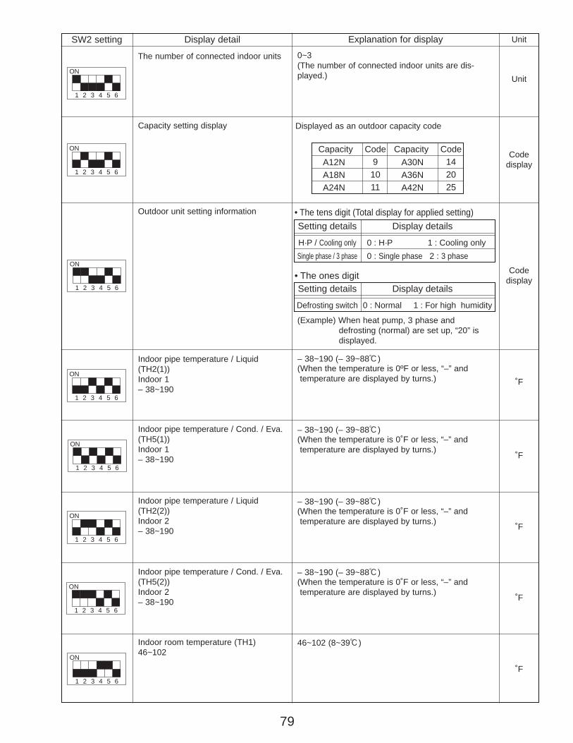
79
SW2 setting
1
ON
2 3 4 5 6
Display detail Explanation for display Unit
Capacity setting display Displayed as an outdoor capacity code
Codedisplay
1
ON
2 3 4 5 6
1
ON
2 3 4 5 6
Outdoor unit setting information
Indoor pipe temperature / Liquid(TH2(1))Indoor 1– 38~190
Codedisplay
˚F
– 38~190 (– 39~88:)(When the temperature is 0ºF or less, “–” andtemperature are displayed by turns.)
1
ON
2 3 4 5 6
1
ON
2 3 4 5 6
Indoor room temperature (TH1)46~102
CapacityA12NA18NA24N
A30NA36NA42N
Code91011
Capacity Code142025
Setting details• The tens digit (Total display for applied setting)
• The ones digit
H·P / Cooling onlySingle phase / 3 phase
Display details
0 : H·P 1 : Cooling only0 : Single phase 2 : 3 phase
Setting details
Defrosting switch
Display details
0 : Normal 1 : For high humidity
(Example) When heat pump, 3 phase and defrosting (normal) are set up, “20” is displayed.
1
ON
2 3 4 5 6
1
ON
2 3 4 5 6
Indoor pipe temperature / Cond. / Eva.(TH5(1))Indoor 1– 38~190
– 38~190 (– 39~88:)(When the temperature is 0˚F or less, “–” andtemperature are displayed by turns.)
˚F
– 38~190 (– 39~88:)(When the temperature is 0˚F or less, “–” andtemperature are displayed by turns.)
– 38~190 (– 39~88:)(When the temperature is 0˚F or less, “–” andtemperature are displayed by turns.)
˚F
˚F
˚F
46~102 (8~39:)
Indoor pipe temperature / Liquid(TH2(2))Indoor 2– 38~190
Indoor pipe temperature / Cond. / Eva.(TH5(2))Indoor 2– 38~190
1
ON
2 3 4 5 6
The number of connected indoor units
Unit
0~3(The number of connected indoor units are dis-played.)

80
1
ON
2 3 4 5 6
degF
Discharge superheat. SHd0~327
Cooling = TH4-TH6Heating = TH4-TH5
0~327 (0~182degC)(When the temperature is 100degF or more, hun-dreds digit, tens digit and ones digit are displayed by turns.)
degF
Sub cool. SC0~234
Cooling = TH6-TH3Heating = TH5-TH4
0~234 (0~130degC)(When the temperature is 100˚F or more, hundreds digit, tens digit and ones digit are displayed by turns.)
0.1 A
Input current of outdoor unit 0~500(When it is 100 or more, hundreds digit, tens digitand ones digit are displayed by turns.)
Hz
Targeted operation frequency0~255
0~255(When it is 100Hz or more, hundreds digit, tens digit and ones digit are displayed by turns.)
DC bus voltage180~370
180~370(When it is 100V or more, hundreds digit, tens digit and ones digit are displayed by turns.)
V
1
ON
2 3 4 5 6
1
ON
2 3 4 5 6
1
ON
2 3 4 5 6
1
ON
2 3 4 5 6
SW2 setting
1
ON
2 3 4 5 6
Display detail Explanation for display Unit
˚F
1
ON
2 3 4 5 6
1
ON
2 3 4 5 6
1
ON
2 3 4 5 6
Indoor setting temperature62~86
Outdoor pipe temperature / Cond./Eva. (TH6)-38~190
Outdoor heatsink temperature (TH8)-40~327
62~86 (17~30:)
˚F
˚F
˚F
-38~190 (-39~88:)(When the temperature is 0˚F or less, “–” and temperature are displayed by turns.)
-40~327 (-40~164:)(When the temperature is 0˚F or less, “–” and temperature are displayed by turns.)
(When the thermistor detects 100˚F or more, hundreds digit, tens digit and ones digit are displayed by turns.)
Outdoor outside temperature (TH7)-38~190
-38~190 (-39~88:)(When the temperature is 0˚F or less, “–” and temperature are displayed by turns.)
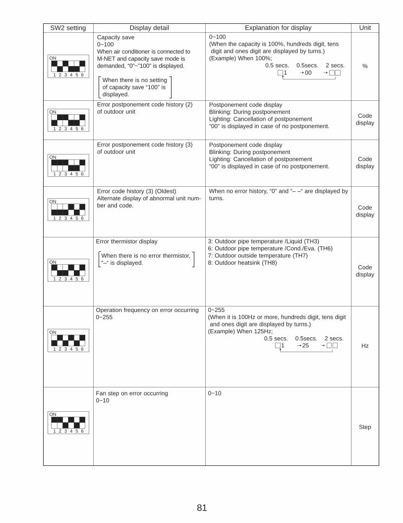
81
SW2 setting Display detail Explanation for display Unit
1
ON
2 3 4 5 6
%
Capacity save0~100When air conditioner is connected to M-NET and capacity save mode isdemanded, “0”~”100” is displayed.
When there is no setting of capacity save “100” is displayed.
0~100(When the capacity is 100%, hundreds digit, tens digit and ones digit are displayed by turns.)
(Example) When 100%;0.5 secs. 0.5secs. 2 secs.
Codedisplay
Error postponement code history (2)of outdoor unit
Postponement code displayBlinking: During postponementLighting: Cancellation of postponement“00” is displayed in case of no postponement.
Codedisplay
Error postponement code history (3)of outdoor unit
Postponement code displayBlinking: During postponementLighting: Cancellation of postponement“00” is displayed in case of no postponement.
Codedisplay
Error code history (3) (Oldest)Alternate display of abnormal unit num-ber and code.
When no error history, “0” and “– –“ are displayed byturns.
Error thermistor display
When there is no error thermistor, “–“ is displayed.
3: Outdoor pipe temperature /Liquid (TH3)6: Outdoor pipe temperature /Cond./Eva. (TH6)7: Outdoor outside temperature (TH7)8: Outdoor heatsink (TH8)
1
ON
2 3 4 5 6
1
ON
2 3 4 5 6
1
ON
2 3 4 5 6
1
ON
2 3 4 5 6
Codedisplay
Operation frequency on error occurring0~255
0~255(When it is 100Hz or more, hundreds digit, tens digit and ones digit are displayed by turns.)
(Example) When 125Hz;0.5 secs. 0.5secs. 2 secs.
1
ON
2 3 4 5 6 Hz
Fan step on error occurring0~10
0~10
1
ON
2 3 4 5 6Step
001
251
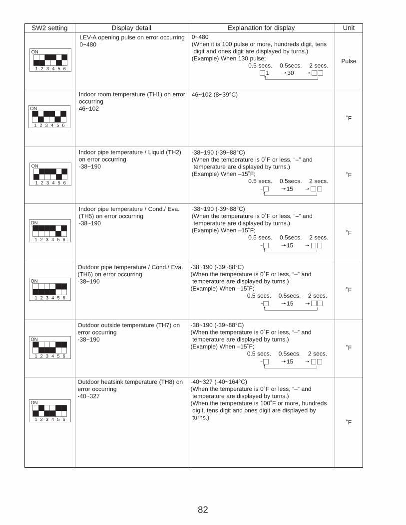
82
SW2 setting Display detail Explanation for display Unit
1
ON
2 3 4 5 6Pulse
LEV-A opening pulse on error occurring0~480
0~480(When it is 100 pulse or more, hundreds digit, tensdigit and ones digit are displayed by turns.)
(Example) When 130 pulse;0.5 secs. 0.5secs. 2 secs.
˚F
Indoor room temperature (TH1) on erroroccurring46~102
46~102 (8~39°C)
˚F
Indoor pipe temperature / Liquid (TH2)on error occurring-38~190
-38~190 (-39~88°C)(When the temperature is 0˚F or less, “–” and temperature are displayed by turns.)
(Example) When –15˚F;0.5 secs. 0.5secs. 2 secs.
Indoor pipe temperature / Cond./ Eva.(TH5) on error occurring-38~190
-38~190 (-39~88°C)(When the temperature is 0˚F or less, “–” and temperature are displayed by turns.)
(Example) When –15˚F;0.5 secs. 0.5secs. 2 secs.
Outdoor pipe temperature / Cond./ Eva.(TH6) on error occurring-38~190
-38~190 (-39~88°C)(When the temperature is 0˚F or less, “–” and temperature are displayed by turns.)
(Example) When –15˚F;0.5 secs. 0.5secs. 2 secs.
Outdoor outside temperature (TH7) onerror occurring-38~190
-38~190 (-39~88°C)(When the temperature is 0˚F or less, “–” and temperature are displayed by turns.)
(Example) When –15˚F;0.5 secs. 0.5secs. 2 secs.
Outdoor heatsink temperature (TH8) onerror occurring-40~327
-40~327 (-40~164°C)(When the temperature is 0˚F or less, “–” and temperature are displayed by turns.)
(When the temperature is 100˚F or more, hundredsdigit, tens digit and ones digit are displayed byturns.)
301
1
ON
2 3 4 5 6
1
ON
2 3 4 5 6
1
ON
2 3 4 5 6
1
ON
2 3 4 5 6
1
ON
2 3 4 5 6
1
ON
2 3 4 5 6
15
15
15
15
˚F
˚F
˚F
˚F

83
SW2 setting Display detail Explanation for display Unit
degF
0~327 (0~182degC)(When the temperature is 100degF or more, hundreds digit, tens digit and ones digit are displayed by turns.)
(Example) When 150degF;0.5 secs. 0.5secs. 2 secs.
Sub cool on error occurring. SC0~234
Cooling = TH6-TH3Heating = TH5-TH2
0~234 (0~130degC)(When the temperature is 100degF or more, hundreds digit, tens digit and ones digit are displayed by turns.)
(Example) When 115degF;0.5 secs. 0.5secs. 2 secs.
Thermostat-on time until error stops0~999
0~999(When it is 100 minutes or more, hundreds digit, tensdigit and ones digit are displayed by turns.)
(Example) When 415 minutes; 0.5 secs. 0.5secs. 2 secs.
5011
ON
2 3 4 5 6
Discharge superheat on error occurringSHd0~327
Cooling = TH4-TH6Heating = TH4-TH5
1
ON
2 3 4 5 6
1
ON
2 3 4 5 6
degF
Minute
151
154
1
ON
2 3 4 5 6
NormalOvervoltage errorUndervoltage errorInput current sensor error.L1 or L2-phase open error.Abnormal power synchronous signalPFC error (A12, 18, 24NHA) (Overvoltage / Undervoltage / Overcurrent)PFC/ ACTM errorUndervoltage
W Display examples for multiple errors:Overvoltage (01) + Undervoltage (02) = 03Undervoltage (02) + Power-sync signal error (08) = 0AL1 phase open error (04) + PFC error (10) = 14
Power circuit boardController circuit board
Controller circuit board
Power circuit board
Power circuit board
Check CNAF wiring.Defective ACTM/ P.B.
—Description Detection point Display
000102
04
08
10
20
U9 Error status during the Error postponement period
Codedisplay
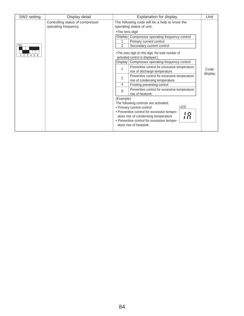
84
SW2 setting Display detail Explanation for display UnitControlling status of compressor operating frequency
1
ON
2 3 4 5 6
Codedisplay
The following code will be a help to know theoperating status of unit.
Display Compressor operating frequency control
Display Compressor operating frequency control
Primary current controlSecondary current control
12
1
4
8
2
•The tens digit
•The ones digit (In this digit, the total number of activated control is displayed.)
Preventive control for excessive temperaturerise of discharge temperaturePreventive control for excessive temperaturerise of condensing temperatureFrosting preventing controlPreventive control for excessive temperaturerise of heatsink
(Example)The following controls are activated.• Primary current control• Preventive control for excessive temper- ature rise of condensing temperature• Preventive control for excessive temper- ature rise of heatsink
1a
LED
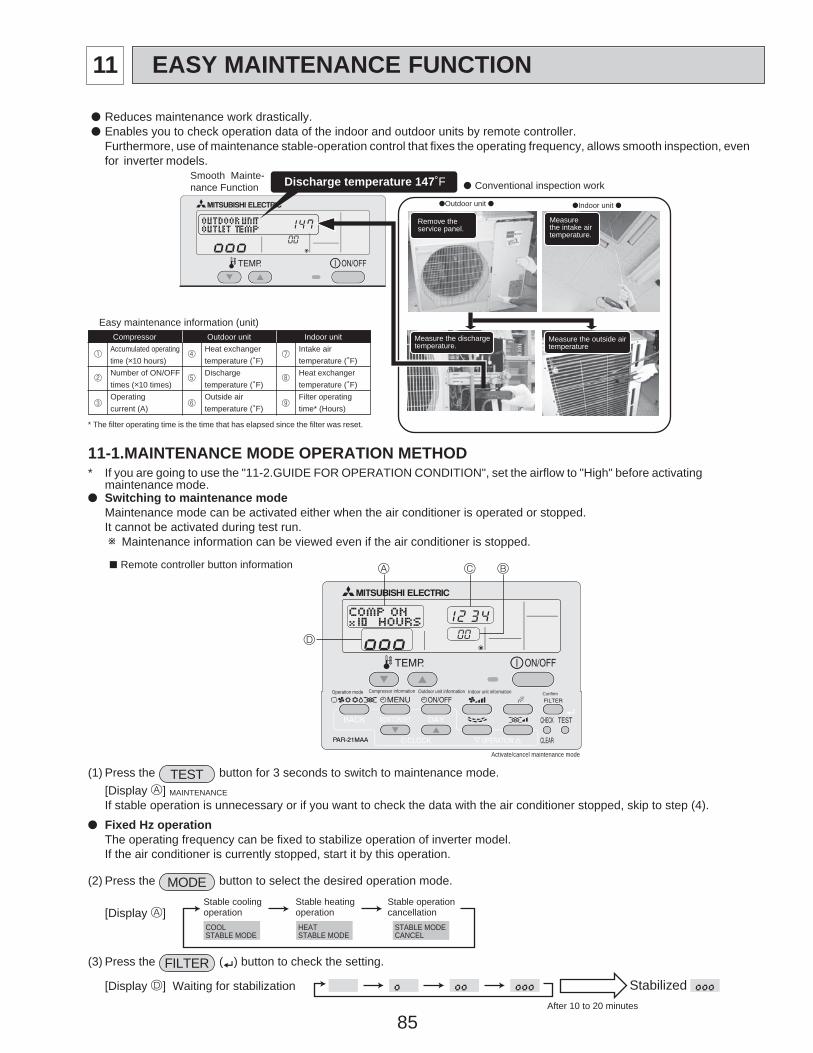
85
● Reduces maintenance work drastically.● Enables you to check operation data of the indoor and outdoor units by remote controller.
Furthermore, use of maintenance stable-operation control that fixes the operating frequency, allows smooth inspection, evenfor inverter models.
11-1.MAINTENANCE MODE OPERATION METHOD* If you are going to use the "11-2.GUIDE FOR OPERATION CONDITION", set the airflow to "High" before activating
maintenance mode.● Switching to maintenance mode
Maintenance mode can be activated either when the air conditioner is operated or stopped.It cannot be activated during test run. w Maintenance information can be viewed even if the air conditioner is stopped.
D
A C B
Operation mode Compressor information Outdoor unit information Indoor unit information Confirm
Activate/cancel maintenance mode
■ Remote controller button information
(1) Press the TEST button for 3 seconds to switch to maintenance mode.[Display A] MAINTENANCE
If stable operation is unnecessary or if you want to check the data with the air conditioner stopped, skip to step (4).● Fixed Hz operation
The operating frequency can be fixed to stabilize operation of inverter model.If the air conditioner is currently stopped, start it by this operation.
(2) Press the MODE button to select the desired operation mode.
[Display A]
(3) Press the FILTER ( ) button to check the setting.
[Display D] Waiting for stabilization
HEATSTABLE MODE
STABLE MODECANCEL
COOLSTABLE MODE
Stable coolingoperation
Stable heatingoperation
Stable operationcancellation
StabilizedAfter 10 to 20 minutes
Remove theservice panel.
Measurethe intake airtemperature.
Measure the dischargetemperature.
Measure the outside airtemperature
●Indoor unit ●●Outdoor unit ●
Smooth Mainte-nance Function ● Conventional inspection work
Easy maintenance information (unit)Compressor Outdoor unit Indoor unit
Accumulated operating Heat exchanger7
Intake airtime (o10 hours) temperature (˚F) temperature (˚F)Number of ON/OFF Discharge
8
4
5
1
2
963
Heat exchangertimes (o10 times) temperature (˚F) temperature (˚F)Operating Outside air Filter operatingcurrent (A) temperature (˚F) time* (Hours)
* The filter operating time is the time that has elapsed since the filter was reset.
Discharge temperature 147˚F
11 EASY MAINTENANCE FUNCTION
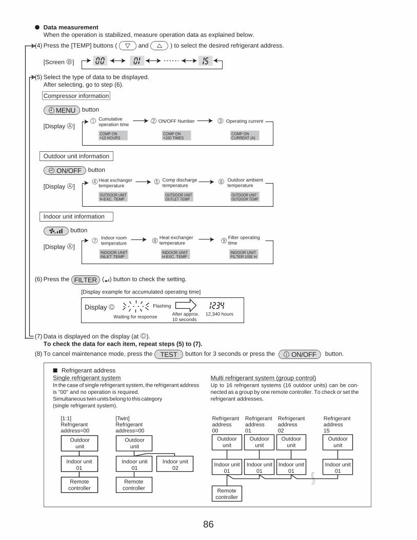
86
● Data measurementWhen the operation is stabilized, measure operation data as explained below.
(4) Press the [TEMP] buttons ( and ) to select the desired refrigerant address.
[Screen B]
(5) Select the type of data to be displayed.After selecting, go to step (6).
Compressor information
MENU button
[Display A]
Outdoor unit information
ON/OFF button
[Display A4 5 6
]
Indoor unit information
button
[Display A7 8 9
]
(6) Press the FILTER ( ) button to check the setting.
[Display example for accumulated operating time]
(7) Data is displayed on the display (at C).To check the data for each item, repeat steps (5) to (7).
(8) To cancel maintenance mode, press the TEST button for 3 seconds or press the ON/OFF button.
COMP ONo10 HOURS
COMP ONo100 TIMES
COMP ONCURRENT (A)
Cumulativeoperation time
ON/OFF Number Operating current1 2 3
OUTDOOR UNITH·EXC. TEMP
OUTDOOR UNITOUTLET TEMP
OUTDOOR UNITOUTDOOR TEMP
Heat exchangertemperature
Comp dischargetemperature
Outdoor ambienttemperature
INDOOR UNITINLET TEMP
INDOOR UNITH·EXC. TEMP
INDOOR UNITFILTER USE H
Indoor roomtemperature
Heat exchangertemperature
Filter operatingtime
12,340 hoursDisplay C
Waiting for response
Flashing
After approx.10 seconds
[1:1]Refrigerantaddress=00
[Twin]Refrigerantaddress=00
Outdoorunit
Indoor unit02
Indoor unit01
Outdoorunit
Remotecontroller
Remotecontroller
Indoor unit01
■ Refrigerant addressSingle refrigerant systemIn the case of single refrigerant system, the refrigerant addressis "00" and no operation is required.Simultaneous twin units belong to this category(single refrigerant system).
Multi refrigerant system (group control)Up to 16 refrigerant systems (16 outdoor units) can be con-nected as a group by one remote controller. To check or set therefrigerant addresses.
Refrigerantaddress00
Refrigerantaddress01
Refrigerantaddress02
Refrigerantaddress15
Outdoorunit
Indoor unit01
Outdoorunit
Indoor unit01
Outdoorunit
Indoor unit01
Outdoorunit
Indoor unit01
Remotecontroller
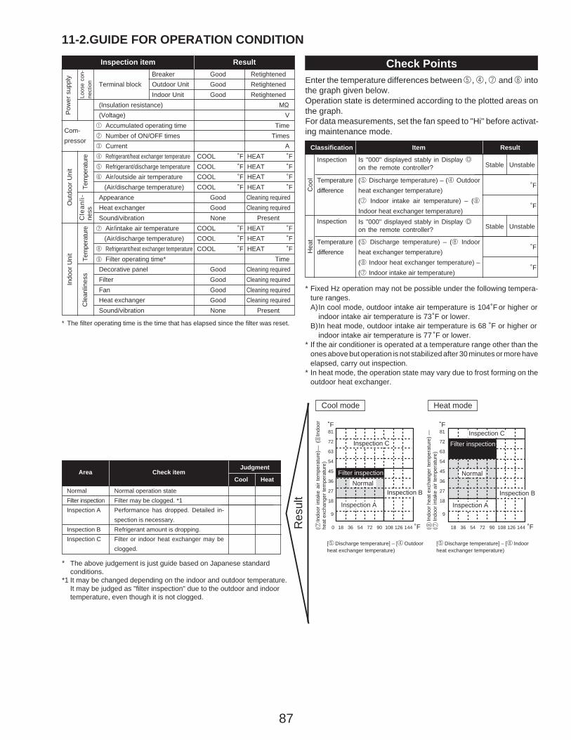
87
11-2.GUIDE FOR OPERATION CONDITIONInspection item Result
Pow
er s
uppl
y
Loos
e co
n-ne
ctio
n
Breaker Good RetightenedTerminal block Outdoor Unit Good Retightened
Indoor Unit Good Retightened(Insulation resistance) M"
(Voltage) V1 Accumulated operating time Time2 Number of ON/OFF times Times3 Current A4 Refrigerant/heat exchanger temperature COOL ˚F HEAT ˚F5 Refrigerant/discharge temperature COOL ˚F HEAT ˚F6 Air/outside air temperature COOL ˚F HEAT ˚F (Air/discharge temperature) COOL ˚F HEAT ˚FAppearance Good Cleaning requiredHeat exchanger Good Cleaning requiredSound/vibration None Present
Air/intake air temperature COOL ˚F HEAT ˚F (Air/discharge temperature) COOL ˚F HEAT ˚F8
7
9
Refrigerant/heat exchanger temperature COOL ˚F HEAT ˚FFilter operating time* Time
Decorative panel Good Cleaning requiredFilter Good Cleaning requiredFan Good Cleaning requiredHeat exchanger Good Cleaning requiredSound/vibration None Present
Com-pressor
Tem
pera
ture
Cle
anli-
ness
Out
door
Uni
t
Tem
pera
ture
Cle
anlin
ess
Indo
or U
nit
* The filter operating time is the time that has elapsed since the filter was reset.
Check PointsEnter the temperature differences between 5 , 4 ,7 and 8 intothe graph given below.Operation state is determined according to the plotted areas onthe graph.For data measurements, set the fan speed to "Hi" before activat-ing maintenance mode.
Is "000" displayed stably in Display Don the remote controller?
Is "000" displayed stably in Display Don the remote controller?
(5 Discharge temperature) – (4 Outdoorheat exchanger temperature)(7 Indoor intake air temperature) – (8Indoor heat exchanger temperature)
(5 Discharge temperature) – (8 Indoorheat exchanger temperature)(8 Indoor heat exchanger temperature) –(7 Indoor intake air temperature)
Coo
l
Classification Item Result
Inspection
Temperaturedifference
Hea
t
Inspection
Temperaturedifference
Stable Unstable
˚F
˚F
Stable Unstable
˚F
˚F
* Fixed Hz operation may not be possible under the following tempera-ture ranges.A)In cool mode, outdoor intake air temperature is 104 ̊F or higher or
indoor intake air temperature is 73 ̊F or lower.B)In heat mode, outdoor intake air temperature is 68 ˚F or higher or
indoor intake air temperature is 77 ̊ F or lower.* If the air conditioner is operated at a temperature range other than the
ones above but operation is not stabilized after 30 minutes or more haveelapsed, carry out inspection.
* In heat mode, the operation state may vary due to frost forming on theoutdoor heat exchanger.
˚F81
72
63
54
45
36
27
18
9
0 18 36 54 72 90 108 126 144
NormalFilter inspection
Inspection C
Inspection A
Inspection B
˚F81
72
63
54
45
36
27
18
9
˚F˚F
Normal
Filter inspectionInspection C
Inspection A
Inspection B
Cool mode Heat mode
( 7 In
door
inta
ke a
ir te
mpe
ratu
re)—
( 8In
door
heat
exc
hang
er te
mpe
ratu
re)
( 8 In
door
hea
t exc
hang
er te
mpe
ratu
re) —
( 7 In
door
inta
ke a
ir te
mpe
ratu
re)
[5 Discharge temperature] – [4 Outdoorheat exchanger temperature)
[5 Discharge temperature] – [8 Indoorheat exchanger temperature)
Res
ultNormal operation state
Filter may be clogged. *1Performance has dropped. Detailed in-spection is necessary.Refrigerant amount is dropping.Filter or indoor heat exchanger may beclogged.
Area Check itemJudgment
Cool Heat
NormalFilter inspectionInspection A
Inspection BInspection C
*
*1
18 36 54 72 90 108 126 144
The above judgement is just guide based on Japanese standard conditions.It may be changed depending on the indoor and outdoor temperature.It may be judged as "filter inspection" due to the outdoor and indoor temperature, even though it is not clogged.
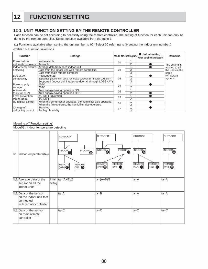
88
12 FUNCTION SETTING
Function Settings Mode No. Setting No. : Initial setting (when sent from the factory) Remarks
Power failure automatic recoveryIndoor temperature detecting
LOSSNAY connectivity
Power supply voltageAuto mode(only for PUZ)Frost prevention temperatureHumidifier control
Change of defrosting control
Not availableAvailableAverage data from each indoor unitData from the indoor unit with remote controllersData from main remote controllerNot supportedSupported (indoor unit dose not intake outdoor air through LOSSNAY)Supported (indoor unit intakes outdoor air through LOSSNAY)230V208VAuto energy-saving operation ONAuto energy-saving operation OFF2: [36˚F] (Normal)3: [37˚F]When the compressor operates, the humidifier also operates.When the fan operates, the humidifier also operates.StandardFor high humidity
121231231212121212
01
02
03
04
05
15
16
17
The setting is applied to all the units in the samerefrigerantsystem.
12-1. UNIT FUNCTION SETTING BY THE REMOTE CONTROLLEREach function can be set according to necessity using the remote controller. The setting of function for each unit can only be done by the remote controller. Select function available from the table 1.
(1) Functions available when setting the unit number to 00 (Select 00 referring to 4 setting the indoor unit number.)<Table 1> Function selections
Meaning of "Function setting"Mode02 : indoor temperature detecting
No. Indoor temperature(ta)=
No1. Average data of the sensor on all the indoor units
Initialsetting
ta=(A+B)/2 ta=(A+B)/2 ta=A ta=A
No2. Data of the sensoron the indoor unit thatconnectedwith remote controller
ta=A ta=B ta=A ta=A
No3. Data of the sensoron main remote controller
ta=C ta=C ta=C ta=C
OUTDOOR
INDOOR
REMOTE(MAIN)
REMOTE(SUB)
INDOOR
OUTDOOR
INDOOR
REMOTE(MAIN)
REMOTE(SUB)
OUTDOOR
INDOOR
REMOTE(MAIN)
OUTDOOR
INDOOR
REMOTE(MAIN)
REMOTE(SUB)
INDOOR
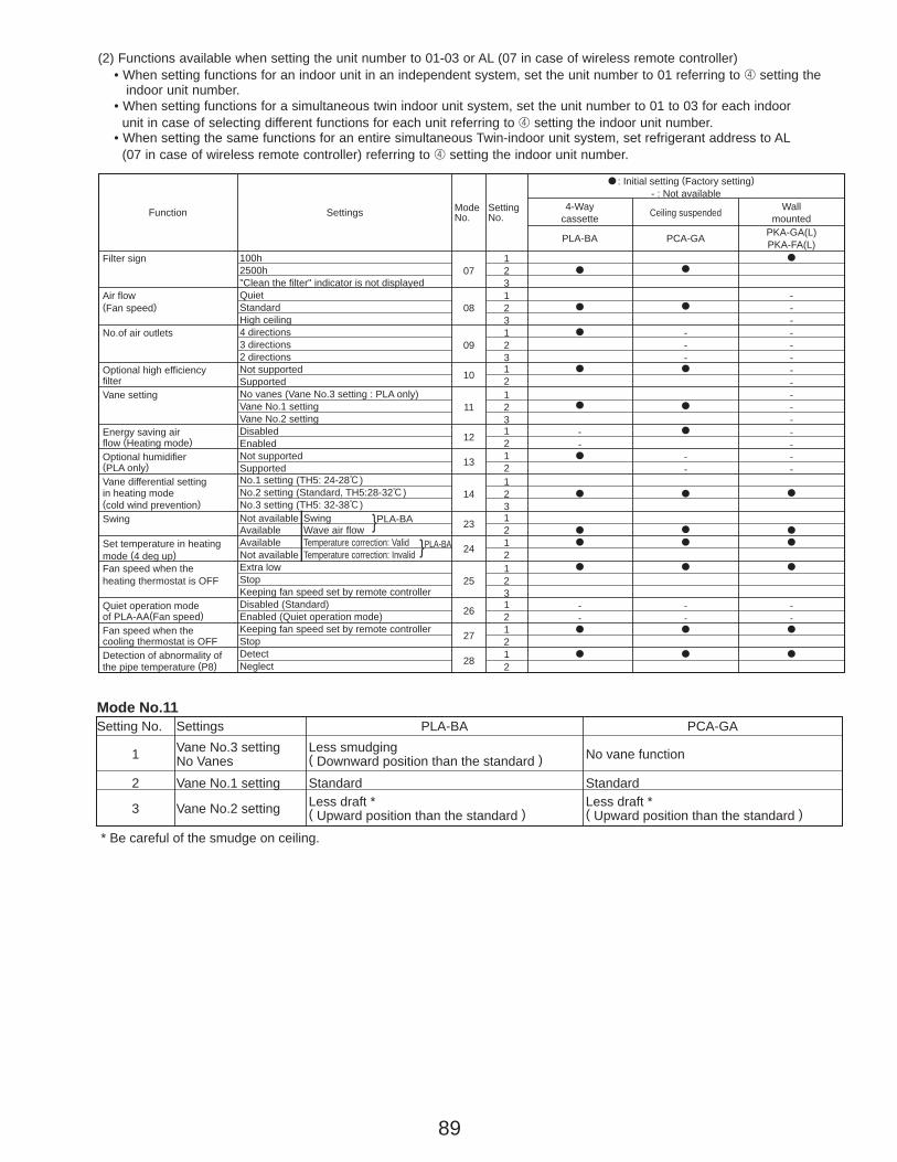
89
Function Settings No.Mode
No.Setting
: Initial setting (Factory setting)- : Not available
4-Waycassette Ceiling suspended Wall
mounted
PCA-GA PKA-GA(L)PKA-FA(L)
Filter sign 100h 12500h 07 2"Clean the filter" indicator is not displayed 3
Air flow Quiet 1 -(Fan speed) Standard 08 2 -
High ceiling 3 -No.of air outlets 4 directions 1 - -
3 directions 09 2 - -2 directions 3 -
--
-Optional high efficiency Not supported 10 1 -filter Supported 2 -Vane setting No vanes (Vane No.3 setting : PLA only) 1 -
Vane No.1 setting 11 2 -Vane No.2 setting 3 -
Energy saving air Disabled 12 1 -flow (Heating mode) Enabled 2 -Optional humidifier Not supported 13 1 - -(PLA only) Supported 2 - -Vane differential setting No.1 setting (TH5: 24-28:) 1in heating mode No.2 setting (Standard, TH5:28-32:) 14 2(cold wind prevention) No.3 setting (TH5: 32-38:) 3Swing 23 1
2Set temperature in heating 24 1mode (4 deg up) 2Fan speed when the Extra low 1heating thermostat is OFF Stop 25 2
Keeping fan speed set by remote controller 3Quiet operation mode Disabled (Standard) 26 1 - -of PLA-AA(Fan speed) Enabled (Quiet operation mode) 2 -
-- -
Fan speed when the Keeping fan speed set by remote controller 27 1cooling thermostat is OFF Stop 2Detection of abnormality of Detect
28 1the pipe temperature (P8) Neglect 2
PLA-BA
Not available SwingAvailable Wave air flowAvailable Temperature correction: ValidNot available Temperature correction: Invalid
}PLA-BA
}PLA-BA
(2) Functions available when setting the unit number to 01-03 or AL (07 in case of wireless remote controller)• When setting functions for an indoor unit in an independent system, set the unit number to 01 referring to 4 setting the
indoor unit number.• When setting functions for a simultaneous twin indoor unit system, set the unit number to 01 to 03 for each indoor
unit in case of selecting different functions for each unit referring to 4 setting the indoor unit number.• When setting the same functions for an entire simultaneous Twin-indoor unit system, set refrigerant address to AL
(07 in case of wireless remote controller) referring to 4 setting the indoor unit number.
Mode No.11Setting No. Settings PLA-BA PCA-GA
1 No VanesVane No.3 setting
( Downward position than the standard )Less smudging No vane function
2 Vane No.1 setting Standard Standard
3 Vane No.2 setting ( Upward position than the standard )Less draft *
( Upward position than the standard )Less draft *
* Be careful of the smudge on ceiling.
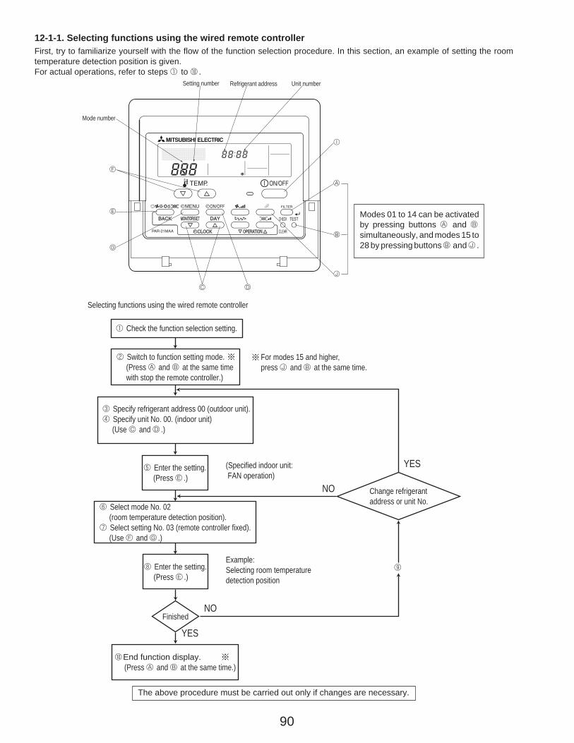
90
6 Select mode No. 02 (room temperature detection position).7 Select setting No. 03 (remote controller fixed). (Use F and G .)
8 Enter the setting. (Press E .)
Finished
0End function display. (Press A and B at the same time.)
Example:Selecting room temperaturedetection position
YES
YES
NO
NO
9
Selecting functions using the wired remote controller
1 Check the function selection setting.
For modes 15 and higher,press J and B at the same time.
3 Specify refrigerant address 00 (outdoor unit).4 Specify unit No. 00. (indoor unit) (Use C and D .)
5 Enter the setting. (Press E .)
(Specified indoor unit: FAN operation)
Change refrigerantaddress or unit No.
2 Switch to function setting mode. (Press A and B at the same time with stop the remote controller.)
12-1-1. Selecting functions using the wired remote controllerFirst, try to familiarize yourself with the flow of the function selection procedure. In this section, an example of setting the roomtemperature detection position is given.For actual operations, refer to steps 1 to 0 .
Setting number Refrigerant address Unit number
Mode number
F
E
G
C D
J
B
A
I
Modes 01 to 14 can be activatedby pressing buttons A and Bsimultaneously, and modes 15 to28 by pressing buttons B and J .
The above procedure must be carried out only if changes are necessary.
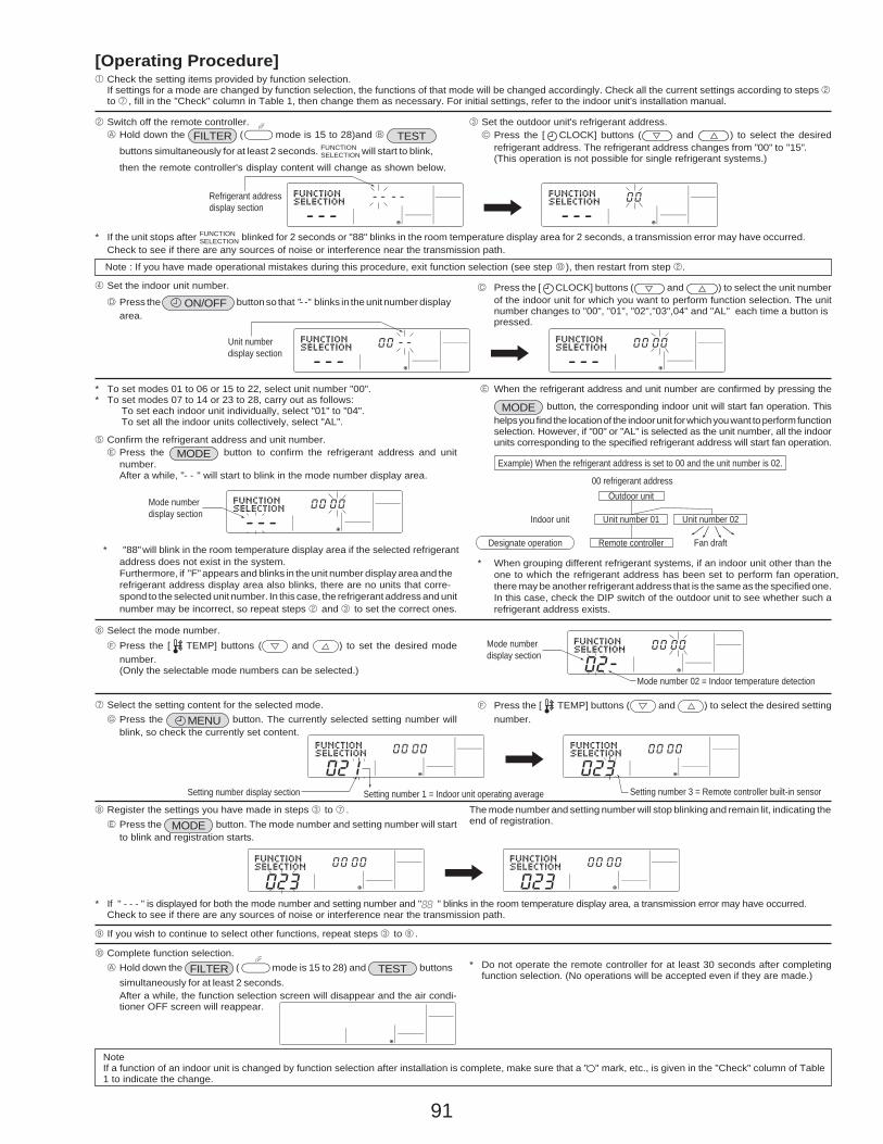
91
[Operating Procedure]1 Check the setting items provided by function selection.
If settings for a mode are changed by function selection, the functions of that mode will be changed accordingly. Check all the current settings according to steps 2to 7 , fill in the "Check" column in Table 1, then change them as necessary. For initial settings, refer to the indoor unit's installation manual.
2 Switch off the remote controller.A Hold down the ( mode is 15 to 28)and B
buttons simultaneously for at least 2 seconds. will start to blink,
then the remote controller's display content will change as shown below.
FILTER3 Set the outdoor unit's refrigerant address.
C Press the [ CLOCK] buttons ( and ) to select the desiredrefrigerant address. The refrigerant address changes from "00" to "15". (This operation is not possible for single refrigerant systems.)
* If the unit stops after FUNCTIONSELECTION blinked for 2 seconds or "88" blinks in the room temperature display area for 2 seconds, a transmission error may have occurred.
Check to see if there are any sources of noise or interference near the transmission path.
Note : If you have made operational mistakes during this procedure, exit function selection (see step 0 ), then restart from step 2.
4 Set the indoor unit number.
D Press the ON/OFF button so that "- -" blinks in the unit number displayarea.
C Press the [ CLOCK] buttons ( and ) to select the unit numberof the indoor unit for which you want to perform function selection. The unitnumber changes to "00", "01", "02","03",04" and "AL" each time a button ispressed.
* To set modes 01 to 06 or 15 to 22, select unit number "00".* To set modes 07 to 14 or 23 to 28, carry out as follows:
To set each indoor unit individually, select "01" to "04".To set all the indoor units collectively, select "AL".
5 Confirm the refrigerant address and unit number.E Press the MODE button to confirm the refrigerant address and unit
number.After a while, "- - " will start to blink in the mode number display area.
E When the refrigerant address and unit number are confirmed by pressing the
MODE button, the corresponding indoor unit will start fan operation. Thishelps you find the location of the indoor unit for which you want to perform functionselection. However, if "00" or "AL" is selected as the unit number, all the indoorunits corresponding to the specified refrigerant address will start fan operation.
* "88" will blink in the room temperature display area if the selected refrigerantaddress does not exist in the system.Furthermore, if "F" appears and blinks in the unit number display area and therefrigerant address display area also blinks, there are no units that corre-spond to the selected unit number. In this case, the refrigerant address and unitnumber may be incorrect, so repeat steps 2 and 3 to set the correct ones.
* When grouping different refrigerant systems, if an indoor unit other than theone to which the refrigerant address has been set to perform fan operation,there may be another refrigerant address that is the same as the specified one.In this case, check the DIP switch of the outdoor unit to see whether such arefrigerant address exists.
6 Select the mode number.F Press the [ TEMP] buttons ( and ) to set the desired mode
number.(Only the selectable mode numbers can be selected.)
7 Select the setting content for the selected mode.G Press the MENU button. The currently selected setting number will
blink, so check the currently set content.
F Press the [ TEMP] buttons ( and ) to select the desired settingnumber.
8 Register the settings you have made in steps 3 to 7 .E Press the MODE button. The mode number and setting number will start
to blink and registration starts.
The mode number and setting number will stop blinking and remain lit, indicating theend of registration.
* If " - - - " is displayed for both the mode number and setting number and " " blinks in the room temperature display area, a transmission error may have occurred.Check to see if there are any sources of noise or interference near the transmission path.
9 If you wish to continue to select other functions, repeat steps 3 to 8 .
0 Complete function selection.A Hold down the ( mode is 15 to 28) and buttons
simultaneously for at least 2 seconds. FILTER
After a while, the function selection screen will disappear and the air condi-tioner OFF screen will reappear.
* Do not operate the remote controller for at least 30 seconds after completingfunction selection. (No operations will be accepted even if they are made.)
NoteIf a function of an indoor unit is changed by function selection after installation is complete, make sure that a " " mark, etc., is given in the "Check" column of Table1 to indicate the change.
Refrigerant addressdisplay section
Unit numberdisplay section
Mode numberdisplay section
00 refrigerant address
Indoor unit
Fan draftRemote controller
Unit number 01 Unit number 02
Outdoor unit
Designate operation
Example) When the refrigerant address is set to 00 and the unit number is 02.
Mode numberdisplay section
Mode number 02 = Indoor temperature detection
Setting number display section Setting number 3 = Remote controller built-in sensorSetting number 1 = Indoor unit operating average
TESTFUNCTIONSELECTION
TEST
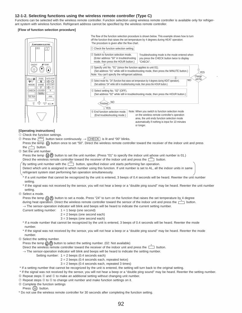
92
By setting unit number with the button, specified indoor unit starts performing fan operation. Detect which unit is assigned to which number using this function. If unit number is set to AL, all the indoor units in same refrigerant system start performing fan operation simultaneously.
[Operating instructions]1 Check the function settings.2 Press the button twice continuously. → CHECK is lit and “00” blinks.
Press the temp button once to set “50”. Direct the wireless remote controller toward the receiver of the indoor unit and pressthe button.
3 Set the unit number.Press the temp button to set the unit number. (Press “01” to specify the indoor unit whose unit number is 01.) Direct the wireless remote controller toward the receiver of the indoor unit and press the button.
* If a unit number that cannot be recognized by the unit is entered, 3 beeps of 0.4 seconds will be heard. Reenter the unit numbersetting.
* If the signal was not received by the sensor, you will not hear a beep or a “double ping sound” may be heard. Reenter the unit number setting.
4 Select a mode.Press the temp button to set a mode. Press “24” to turn on the function that raises the set temperature by 4 degree during heat operation. Direct the wireless remote controller toward the sensor of the indoor unit and press the button.→ The sensor-operation indicator will blink and beeps will be heard to indicate the current setting number.Current setting number: 1 = 1 beep (one second)
2 = 2 beeps (one second each)3 = 3 beeps (one second each)
* If a mode number that cannot be recognized by the unit is entered, 3 beeps of 0.4 seconds will be heard. Reenter the mode number.
* If the signal was not received by the sensor, you will not hear a beep or a “double ping sound” may be heard. Reenter the modenumber.
5 Select the setting number.Press the temp button to select the setting number. (02: Not available)Direct the wireless remote controller toward the receiver of the indoor unit and press the button.→ The sensor-operation indicator will blink and beeps will be heard to indicate the setting number.
Setting number: 1 = 2 beeps (0.4 seconds each)2 = 2 beeps (0.4 seconds each, repeated twice)3 = 2 beeps (0.4 seconds each, repeated 3 times)
* If a setting number that cannot be recognized by the unit is entered, the setting will turn back to the original setting.* If the signal was not received by the sensor, you will not hear a beep or a “double ping sound” may be heard. Reenter the setting number.6 Repeat steps 4 and 5 to make an additional setting without changing unit number.7 Repeat steps 3 to 5 to change unit number and make function settings on it.8 Complete the function settings
Press button.* Do not use the wireless remote controller for 30 seconds after completing the function setting.
ON/OFF TEMP
FAN
VANEMODE
CHECK LOUVER
TEST RUN
AUTO STOP
AUTO START
h
min
CHECK
RESETSET CLOCK
h
CHECK
min
h
The flow of the function selection procedure is shown below. This example shows how to turn off the function that raises the set temperature by 4 degrees during HEAT operation. The procedure is given after the flow chart.
1 Check the function selection setting.
2 Switch to function selection mode.(Enter address "50" in troubleshootingmode, then press the HOUR button.)
Troubleshooting mode is the mode entered whenyou press the CHECK button twice to display"CHECK".
3 Specify unit No. "01" (since the function applies to unit 01).(Set address "01" while still in troubleshooting mode, then press the MINUTE button.)
Note: You can't specify the refrigerant address.
4 Select mode No. "24" (function that raises set temperature by 4 degrees during HEAT operation).(Set address "24" while still in troubleshooting mode, then press the HOUR button.)
6
Finished
8 End function selection mode.(End troubleshooting mode.)
YES
NO
Note: When you switch to function selection modeon the wireless remote controller's operationarea, the unit ends function selection modeautomatically if nothing is input for 10 minutesor longer.
5 Select setting No. "02" (OFF).(Set address "02" while still in troubleshooting mode, then press the HOUR button.)
Change unit No.
YES
NO
7
[Flow of function selection procedure]
12-1-2. Selecting functions using the wireless remote controller (Type C)Functions can be selected with the wireless remote controller. Function selection using wireless remote controller is available only for refriger-ant system with wireless function. Refrigerant address cannot be specified by the wireless remote controller.
h
min
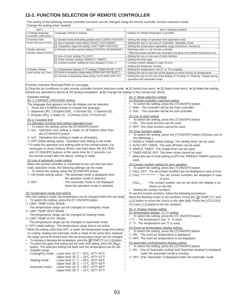
93
12-2. FUNCTION SELECTION OF REMOTE CONTROLLERThe setting of the following remote controller functions can be changed using the remote controller function selection mode.Change the setting when needed.
Item 11.Change language("CHANGE LANGUAGE")2.Function limit("FUNCTION SELECTION")
3.Mode selection("MODE SELECTION")
4.Display change("DISP MODE SETTING")
Item 3 (Setting content)• Display in multiple languages is possible.
• Setting the range of operation limit (operation lock)• Setting the use or non-use of "automatic" operation mode• Setting the temperature adjustable range (maximum, minimum)• Selecting main or sub remote controller
* When two remote controllers are connected to one group, one controller must be set to sub.• Setting the use or non-use of clock function• Setting the timer type• Contact number display in case of error• Setting the telephone number• Setting the temperature unit (: or °F) to display• Setting the use or non-use of the display of indoor (room) air temperature• Setting the use or non-use of the display of "Cooling" or "Heating" display during operation with automatic mode
Item 2Language setting to display
(1) Operation function limit setting (operation lock) ("LOCKING FUNCTION")(2) Use of automatic mode setting ("SELECT AUTO MODE")(3) Temperature range limit setting ("LIMIT TEMP FUNCTION")(1) Remote controller main/sub setting ("CONTROLLER MAIN/SUB")
(2) Use of clock setting ("CLOCK")(3) Timer function setting ("WEEKLY TIMER")(4) Contact number setting for error situation ("CALL.")
(1) Temperature display :/°F setting ("TEMP MODE :/°F")(2) Room air temperature display setting ("ROOM TEMP DISP SELECT")(3) Automatic cooling/heating display setting ("AUTO MODE DISP C/H")
[Function selection flowchart] Refer to next page.[1] Stop the air conditioner to start remote controller function selection mode. [2] Select from item1. [3] Select from item2. [4] Make the setting.(Details are specified in item3) [5] Setting completed. [6] Change the display to the normal one. (End)
➔➔➔
➔ ➔
[Detailed setting][4] -1. CHANGE LANGUAGE settingThe language that appears on the dot display can be selected.• Press the [ MENU] button to change the language.1 Japanese (JP), 2English (GB), 3German (D), 4Spanish (E),5 Russian (RU), 6 Italian (I), 7Chinese (CH), 8 French (F)[4] -2. Function limit(1) Operation function limit setting (operation lock)• To switch the setting, press the [ ON/OFF] button.1 no1 : Operation lock setting is made on all buttons other than
the [ ON/OFF] button.2 no2 : Operation lock setting is made on all buttons.3 OFF (Initial setting value) : Operation lock setting is not made* To make the operation lock setting valid on the normal screen, it is
necessary to press buttons (Press and hold down the [FILTER]and [ ON/OFF] buttons at the same time for 2 seconds.) onthe normal screen after the above setting is made..
(2) Use of automatic mode settingWhen the remote controller is connected to the unit that has auto-matic operation mode, the following settings can be made.• To switch the setting, press the [ ON/OFF] button.1 ON (Initial setting value) : The automatic mode is displayed when
the operation mode is selected.2 OFF : The automatic mode is not displayed
when the operation mode is selected.
[4] -3. Mode selection setting(1) Remote controller main/sub setting• To switch the setting, press the [ ON/OFF] button.1 Main : The controller will be the main controller.2 Sub : The controller will be the sub controller.
(2) Use of clock setting• To switch the setting, press the [ ON/OFF] button.1 ON : The clock function can be used.2 OFF: The clock function cannot be used.(3) Timer function setting• To switch the setting, press the [ ON/OFF] button (Choose one of
the followings.).1 WEEKLY TIMER (initial setting): The weekly timer can be used.2 AUTO OFF TIMER: The auto off timer can be used.
SIMPLE TIMER: The simple timer can be used.4
3
TIMER MODE OFF: The timer mode cannot be used.* When the use of clock setting is OFF, the "WEEKLY TIMER" cannot be
used.(4) Contact number setting for error situation• To switch the setting, press the [ ON/OFF] button.1 CALL OFF: The set contact numbers are not displayed in case of error.2 CALL **** *** **** : The set contact numbers are displayed in case
of error.
(3) Temperature range limit settingAfter this setting is made, the temperature can be changed within the set range.• To switch the setting, press the [ ON/OFF] button.1 LIMIT TEMP COOL MODE :
The temperature range can be changed on cooling/dry mode.2 LIMIT TEMP HEAT MODE :
The temperature range can be changed on heating mode.3 LIMIT TEMP AUTO MODE :
The temperature range can be changed on automatic mode.4 OFF (initial setting) : The temperature range limit is not active.* When the setting, other than OFF, is made, the temperature range limit setting
on cooling, heating and automatic mode is made at the same time. Howeverthe range cannot be limited when the set temperature range has not changed.
• To increase or decrease the temperature, press the [ TEMP ( ) or ( )] button.• To switch the upper limit setting and the lower limit setting, press the [ ]
button. The selected setting will flash and the temperature can be set.• Settable range
Cooling/Dry mode : Lower limit: 19 : ~ 30:, 67˚F~87˚FUpper limit: 30 : ~ 19:, 87˚F~67˚F
Heating mode : Lower limit: 17 : ~ 28:, 63˚F~83˚FUpper limit: 28 : ~ 17:, 83˚F~63˚F
Automatic mode : Lower limit: 19 : ~ 28:, 67˚F~83˚FUpper limit: 28 : ~ 19:, 83˚F~67˚F
CALL_ : The contact number can be set when the display is asshown on the left.
• Setting the contact numbersTo set the contact numbers, follow the following procedures.Move the flashing cursor to set numbers. Press the [ TEMP. ( ) and( )] button to move the cursor to the right (left). Press the [ CLOCK( ) and ( )] button to set the numbers.[4] -4. Display change setting(1) Temperature display :/ F setting• To switch the setting, press the [ ON/OFF] button.1: : The temperature unit : is used.2 F: The temperature unit
°
° °F is used.(2) Room air temperature display setting• To switch the setting, press the [ ON/OFF] button.1 ON : The room air temperature is displayed.2 OFF: The room air temperature is not displayed.(3) Automatic cooling/heating display setting• To switch the setting, press the [ ON/OFF] button.1 ON : One of "Automatic cooling" and "Automatic heating" is displayed
under the automatic mode is running.2 OFF: Only "Automatic" is displayed under the automatic mode.

94
OFF
no1
no2
OFF
ON
OFF
ON
OFF
OFF
CALL-
ON
OFF
ON
OFF
˚C
˚F
PAR-21MAA
ON/OFF
FILTER
CHECK
OPERATION CLEAR
TEST
TEMP.
MENU
BACK DAYMONITOR/SET
CLOCK
ON/OFF
English
Germany
Spanish
Russian
Italian
Chinese
French
Japanese
Item 3
Item 2Item 1
Hold down the E button and press the D button for 2 seconds.
Hold down the E button and press the D button for 2 seconds.
Remote controller function selection mode
E Press the operation mode button.G Press theTIMER MENU button.D Press theTIMER ON/OFF button.
Dot display
Normal display(Display when the air conditioner is not running)
[Function selection flowchart]Setting language (English)
Room air temperature is not displayed.
One of “Automatic cooling” and “Automatic heating” is displayed under the automatic mode is running. (Initial setting value)Only “Automatic” is displayed under the automatic mode.
ChangeLanguage
Functionselection
Modeselection
Displaymode setting
Operation lock setting is not used.(Initial setting value)
Operation lock setting is except On/Off button.
Operation lock setting is all buttons.
The automatic mode is displayed when the operation mode is selected. (Initial setting value)
The automatic mode is not displayed when the operation mode is selected.
The temperature range limit is not active. (Initial setting value)
The temperature range can be changed on cooling/dry mode.
The temperature range can be changed on heating mode.
The temperature range can be changed on automatic mode.
The remote controller will be the main controller. (Initial setting value)
The remote controller will be the sub controller.
The clock function can be used. (Initial setting value)
The clock function cannot be used.
Weekly timer can be used. (Initial setting value)
Auto off timer can be used.
Simple timer can be used.
Timer mode cannot be used.
The set contact numbers are not displayed in case of error. (Initial setting value)
The set contact numbers are displayed in case of error.
The temperature unit ˚F is used.(Initial setting value)
The temperature unit ˚C is used.
Room air temperature is displayed. (Initial setting value)
Fixed air flow direction modeNot necessary to set this mode. Refer to OPERATION MANUAL ofindoor unit for details on operation.
Automatic filter elevation panel up/down operation modeNot necessary to set this mode. Refer to OPERATION MANUAL of Optional Parts (Panel) for details on operation.
D
D
D
D
D
D
D
D
D
D
D
D
D
D
D
D
D
D
D
D
D
D
D
D
D
D
D
D
D
F
E
G
C D
H
B
A
I
D
D
G
G
G
G
G
G
G
G
G
G
G
G
G
G
G
G
G
G
E
E
E
E
*
*
*
*
One of thedescriptionmarked *on the rightwill bedisplayed.(current setting)

95
12-3. Function selection of wireless remote controllerTEMPERATURE DISPLAY :/-F SETTING (Change of temp mode from -F to :)
1 Press the set button with something sharp at the end. MODEL SELECT blinks.
2 Press the button. “F:” blinks.
3 Press the button. “C:” blinks.
4 Press the set button with something sharp at the end. MODEL SELECT is lighted for 3 seconds, then turned off.
AUTO START
ON/OFF TEMP
FAN
VANE
TEST RUN
AUTO STOP
AUTO START
h
min
LOUVER
MODE
CHECK
RESETSET CLOCK
MODELSELECT
NOT AVAILABLE
SWING
CHECK
FAN
TESTRUN F̊
C̊AMPMSTOP
START AMPM
COOLDRY
AUTOFAN
HEAT
1 4
1 42
2
3
3
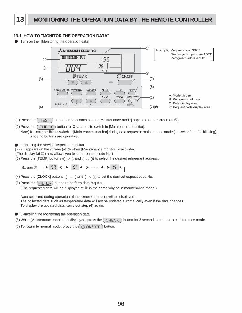
96
13-1. HOW TO "MONITOR THE OPERATION DATA"• Turn on the [Monitoring the operation data]
A
D
C
B
(1)
(2)
(3)
(4)
(5)
(6)
(7)
(1) Press the TEST button for 3 seconds so that [Maintenance mode] appears on the screen (at A).
(2) Press the CHECK button for 3 seconds to switch to [Maintenance monitor].Note) It is not possible to switch to [Maintenance monitor] during data request in maintenance mode (i.e., while "- - - -" is blinking),
since no buttons are operative.
Operating the service inspection monitor- - - ] appears on the screen (at D) when [Maintenance monitor] is activated.
(The display (at D ) now allows you to set a request code No.)(3) Press the [TEMP] buttons ( and ) to select the desired refrigerant address.
[Screen B ]
(4) Press the [CLOCK] buttons ( and ) to set the desired request code No.
(5) Press the FILTER button to perform data request.(The requested data will be displayed at C in the same way as in maintenance mode.)
Data collected during operation of the remote controller will be displayed.The collected data such as temperature data will not be updated automatically even if the data changes.To display the updated data, carry out step (4) again.
Canceling the Monitoring the operation data(6) While [Maintenance monitor] is displayed, press the CHECK button for 3 seconds to return to maintenance mode.
(7) To return to normal mode, press the ON/OFF button.
Example) Request code "004"Discharge temperature 156˚FRefrigerant address "00"
B: Refrigerant addressA: Mode display
C: Data display areaD: Request code display area
[
13 MONITORING THE OPERATION DATA BY THE REMOTE CONTROLLER

97
13-2. REQUEST CODE LIST* Certain indoor/outdoor combinations do not have the request code function; therefore, no request codes are displayed.
Req
uest
cod
e
Request contentDescription
(Display range)Unit Remarks
0123456789101112131415161718
19
20
2122232425262728293031
32
33
34
35
3637383940414243444546474849
Operation stateCompressor-Operating current (rms)Compressor-Accumulated operating timeCompressor-Number of operation timesDischarge temperature (TH4)Outdoor unit - Liquid pipe 1 temperature (TH3)Outdoor unit - Liquid pipe 2 temperatureOutdoor unit-2-phase pipe temperature (TH6)
Outdoor unit-Outside air temperature (TH7)Outdoor unit-Heatsink temperature (TH8)
Discharge super heat (SHd)Sub-cool (SC)
Compressor-Operating frequencyCompressor-Target operating frequencyOutdoor unit-Fan output stepOutdoor unit-Fan 1 speed(Only for air conditioners with DC fan motor)Outdoor unit-Fan 2 speed(Only for air conditioners with DC fan motor)
LEV (A) openingLEV (B) opening
Primary currentDC bus voltage
Number of connected indoor unitsIndoor unit-Setting temperatureIndoor unit-Intake air temperature <Measured by thermostat>Indoor unit-Intake air temperature (Unit No. 1)<Heat mode-4-deg correction>Indoor unit-Intake air temperature (Unit No. 2)<Heat mode-4-deg correction>Indoor unit-Intake air temperature (Unit No. 3)<Heat mode-4-deg correction>Indoor unit-Intake air temperature (Unit No. 4)<Heat mode-4-deg correction>
Indoor unit - Liquid pipe temperature (Unit No. 1)Indoor unit - Liquid pipe temperature (Unit No. 2)Indoor unit - Liquid pipe temperature (Unit No. 3)Indoor unit - Liquid pipe temperature (Unit No. 4)
Indoor unit-Cond./Eva. pipe temperature (Unit No. 1)Indoor unit-Cond./Eva. pipe temperature (Unit No. 2)Indoor unit-Cond./Eva. pipe temperature (Unit No. 3)Indoor unit-Cond./Eva. pipe temperature (Unit No. 4)
Thermostat ON operating timeTest run elapsed time
Refer to 13-2-1. Detail Contents in Request Code.0 – 500 – 99990 – 999937 ~ 327-40 ~ 194-40 ~ 194-38 ~ 190
-38 ~ 190-40 ~ 327
0 – 3270 – 234
0 – 2550 – 2550 – 10
0 – 9999
0 – 9999
0 – 5000 – 500
0 – 50180 – 370
0 – 462 ~ 8646 ~ 102
46 ~ 102
46 ~ 102
46 ~ 102
46 ~ 102
-38 ~ 190-38 ~ 190-38 ~ 190-38 ~ 190
-38 ~ 190-38 ~ 190-38 ~ 190-38 ~ 190
0 – 9990 – 120
–A
10 hours100 times
˚F˚F˚F˚F
˚F˚F
˚F˚F
HzHz
Step
rpm
rpm
PulsesPulses
AV
Units˚F˚F
˚F
˚F
˚F
˚F
˚F˚F˚F˚F
˚F˚F˚F˚F
MinutesMinutes
"0" is displayed if the air conditioner is a single-fantype.
"0" is displayed if the target unit is not present.
"0" is displayed if the target unit is not present.
"0" is displayed if the target unit is not present.
Not possible to activate maintenance mode during the test run.
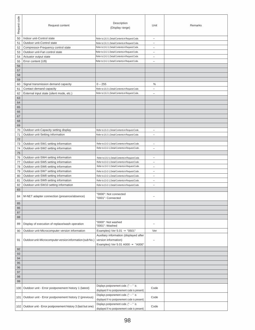
98
Req
uest
cod
e
Request contentDescription
(Display range)Unit Remarks
50515253545556575859606162636465666768697071727374757677787980818283
84
85868788
89
90
91
9293949596979899
100
101
102
Indoor unit-Control stateOutdoor unit-Control stateCompressor-Frequency control stateOutdoor unit-Fan control stateActuator output stateError content (U9)
Signal transmission demand capacityContact demand capacityExternal input state (silent mode, etc.)
Outdoor unit-Capacity setting displayOutdoor unit-Setting information
Outdoor unit-SW1 setting informationOutdoor unit-SW2 setting information
Outdoor unit-SW4 setting informationOutdoor unit-SW5 setting informationOutdoor unit-SW6 setting informationOutdoor unit-SW7 setting informationOutdoor unit-SW8 setting informationOutdoor unit-SW9 setting informationOutdoor unit-SW10 setting information
M-NET adapter connection (presence/absence)
Display of execution of replace/wash operation
Outdoor unit-Microcomputer version information
Outdoor unit-Microcomputer version information (sub No.)
Outdoor unit - Error postponement history 1 (latest)
Outdoor unit - Error postponement history 2 (previous)
Outdoor unit - Error postponement history 3 (last but one)
0 – 255
Refer to 13-2-1.Detail Contents in Request Code.
Refer to 13-2-1.Detail Contents in Request Code.
Refer to 13-2-1.Detail Contents in Request Code.
Refer to 13-2-1.Detail Contents in Request Code.
"0000": Not connected
Examples) Ver 5.01 ➝Auxiliary information (displayed afterversion information)Examples) Ver 5.01 A000 ➝
Displays postponement code. (" - - " isdisplayed if no postponement code is present)Displays postponement code. (" - - " isdisplayed if no postponement code is present)Displays postponement code. (" - - " isdisplayed if no postponement code is present)
––––––
%––
––
––
–––––––
–
–
Ver
–
Code
Code
Code
Refer to 13-2-1.Detail Contents in Request Code.
Refer to 13-2-1.Detail Contents in Request Code.Refer to 13-2-1.Detail Contents in Request Code.
Refer to 13-2-1.Detail Contents in Request Code.
Refer to 13-2-1.Detail Contents in Request Code.
Refer to 13-2-1.Detail Contents in Request Code.
Refer to 13-2-1.Detail Contents in Request Code.
Refer to 13-2-1.Detail Contents in Request Code.
Refer to 13-2-1.Detail Contents in Request Code.
Refer to 13-2-1.Detail Contents in Request Code.
Refer to 13-2-1.Detail Contents in Request Code.
Refer to 13-2-1.Detail Contents in Request Code.
Refer to 13-2-1.Detail Contents in Request Code.
Refer to 13-2-1.Detail Contents in Request Code.
Refer to 13-2-1.Detail Contents in Request Code.
"0001": Connected
"0000": Not washed"0001": Washed
"0501"
"A000"
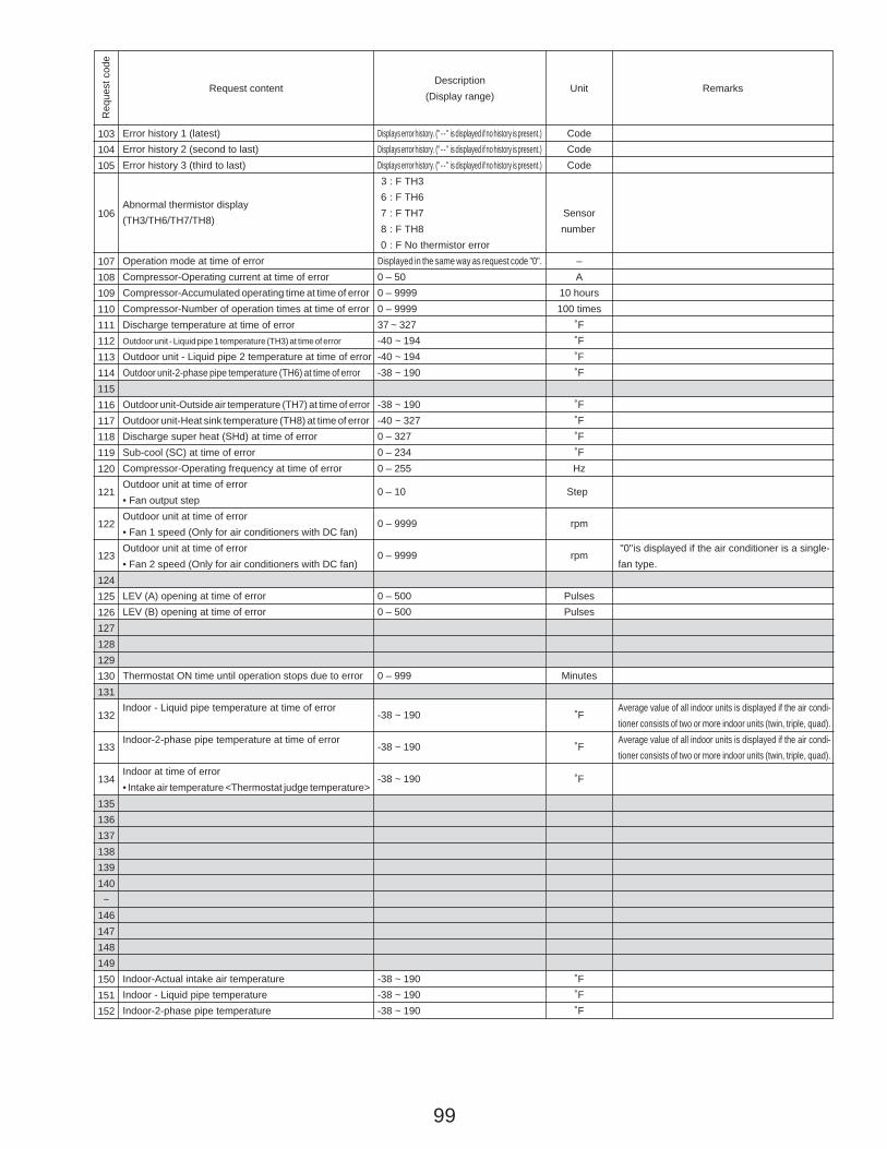
99
Req
uest
cod
e
Request contentDescription
(Display range)Unit Remarks
103104105
106
107108109110111112113114115116117118119120
121
122
123
124125126127128129130131
132
133
134
135136137138139140~
146147148149150151152
Displays error history. (" - - " is displayed if no history is present.)Displays error history. (" - - " is displayed if no history is present.)Displays error history. (" - - " is displayed if no history is present.)
: F TH36 : F TH67 : F TH78 : F TH80 : F No thermistor error
Displayed in the same way as request code "0".0 – 500 – 99990 – 999937 ~ 327-40 ~ 194-40 ~ 194-38 ~ 190
-38 ~ 190-40 ~ 3270 – 3270 – 2340 – 255
0 – 10
0 – 9999
0 – 9999
0 – 5000 – 500
0 – 999
-38 ~ 190
-38 ~ 190
-38 ~ 190
-38 ~ 190-38 ~ 190-38 ~ 190
CodeCodeCode
Sensornumber
–A
10 hours100 times
˚F˚F˚F˚F
˚F˚F˚F˚FHz
Step
rpm
rpm
PulsesPulses
Minutes
˚F
˚F
˚F
˚F˚F˚F
"0" is displayed if the air conditioner is a single-fan type.
Average value of all indoor units is displayed if the air condi-tioner consists of two or more indoor units (twin, triple, quad).Average value of all indoor units is displayed if the air condi-tioner consists of two or more indoor units (twin, triple, quad).
Error history 1 (latest)Error history 2 (second to last)Error history 3 (third to last)
Abnormal thermistor display(TH3/TH6/TH7/TH8)
Operation mode at time of errorCompressor-Operating current at time of errorCompressor-Accumulated operating time at time of errorCompressor-Number of operation times at time of errorDischarge temperature at time of errorOutdoor unit - Liquid pipe 1 temperature (TH3) at time of error
Outdoor unit - Liquid pipe 2 temperature at time of errorOutdoor unit-2-phase pipe temperature (TH6) at time of error
Outdoor unit-Outside air temperature (TH7) at time of errorOutdoor unit-Heat sink temperature (TH8) at time of errorDischarge super heat (SHd) at time of errorSub-cool (SC) at time of errorCompressor-Operating frequency at time of errorOutdoor unit at time of error• Fan output stepOutdoor unit at time of error• Fan 1 speed (Only for air conditioners with DC fan)Outdoor unit at time of error• Fan 2 speed (Only for air conditioners with DC fan)
LEV (A) opening at time of errorLEV (B) opening at time of error
Thermostat ON time until operation stops due to error
Indoor - Liquid pipe temperature at time of error
Indoor-2-phase pipe temperature at time of error
Indoor at time of error• Intake air temperature <Thermostat judge temperature>
Indoor-Actual intake air temperatureIndoor - Liquid pipe temperatureIndoor-2-phase pipe temperature
3
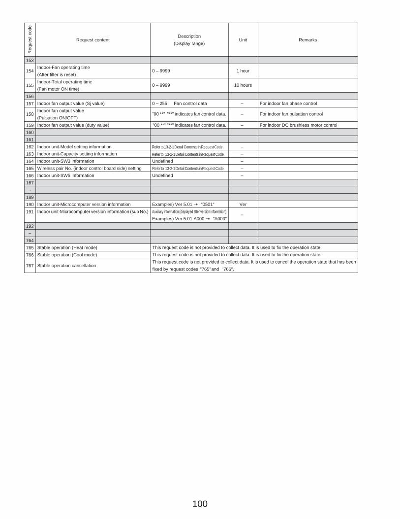
100
Req
uest
cod
e
Request contentDescription
(Display range)Unit Remarks
153
154
155
156157
158
159160161162163164165166167~
189190191
192~
764765766
767
0 – 9999
0 – 9999
0 – 255 Fan control data
00 **" "**" indicates fan control data.
"00 **" "**" indicates fan control data.
Refer to 13-2-1 Detail Contents in Request Code.UndefinedRefer to 13-2-1 Detail Contents in Request Code.
Undefined
Examples) Ver 5.01 ➝ "0501"Auxiliary information (displayed after version information)Examples) Ver 5.01 A000 ➝ "A000"
1 hour
10 hours
–
–
–
–––––
Ver
–
For indoor fan phase control
For indoor fan pulsation control
For indoor DC brushless motor control
Indoor-Fan operating time(After filter is reset)Indoor-Total operating time(Fan motor ON time)
Indoor fan output value (Sj value)Indoor fan output value(Pulsation ON/OFF)Indoor fan output value (duty value)
Indoor unit-Model setting informationIndoor unit-Capacity setting informationIndoor unit-SW3 informationWireless pair No. (indoor control board side) settingIndoor unit-SW5 information
Indoor unit-Microcomputer version informationIndoor unit-Microcomputer version information (sub No.)
Stable operation (Heat mode)Stable operation (Cool mode)
Stable operation cancellation
This request code is not provided to collect data. It is used to fix the operation state.This request code is not provided to collect data. It is used to fix the operation state.This request code is not provided to collect data. It is used to cancel the operation state that has beenfixed by request codes "765" and "766".
"
Refer to 13-2-1 Detail Contents in Request Code.
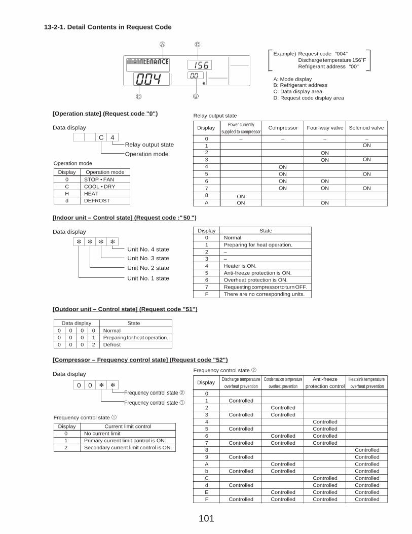
101
Frequency control state 2
Display Discharge temperature Condensation temperature Anti-freeze Heatsink temperatureoverheat prevention overheat prevention protection control overheat prevention
01 Controlled2 Controlled3 Controlled Controlled4 Controlled5 Controlled Controlled6 Controlled Controlled7 Controlled Controlled Controlled8 Controlled9 Controlled ControlledA Controlled Controlledb Controlled Controlled ControlledC Controlled Controlledd Controlled Controlled ControlledE Controlled Controlled ControlledF Controlled Controlled Controlled Controlled
13-2-1. Detail Contents in Request Code
[Operation state] (Request code ":0")
Data display
Example) Request code "004"Discharge temperature 156˚FRefrigerant address "00"
B: Refrigerant addressA: Mode display
C: Data display areaD: Request code display area
A
B
C
D
C 4Relay output stateOperation mode
[Indoor unit – Control state] (Request code :"50 ")
Data display
Operation mode
Display Operation mode0 STOP • FANC COOL • DRYH HEATd DEFROST
Relay output state
Display Power currently Compressor Four-way valve Solenoid valvesupplied to compressor
Unit No. 4 stateUnit No. 3 state
Unit No. 2 state
Unit No. 1 state
Display State0 Normal1 Preparing for heat operation.2 –3 –4 Heater is ON.5 Anti-freeze protection is ON.6 Overheat protection is ON.7 Requesting compressor to turn OFF.F There are no corresponding units.
[Outdoor unit – Control state] (Request code ":51")
Data display State0 0 0 0 Normal0 0 0 1 Preparing for heat operation.0 0 0 2 Defrost
[Compressor – Frequency control state] (Request code ":52")
Data display
0 0Frequency control state 2
Frequency control state 1
Frequency control state 1
Display Current limit control0 No current limit1 Primary current limit control is ON.2 Secondary current limit control is ON.
–
ONON
012345678A
–
ONONONON
–
ONON
ONON
ON
–ON
ON
ON
ON
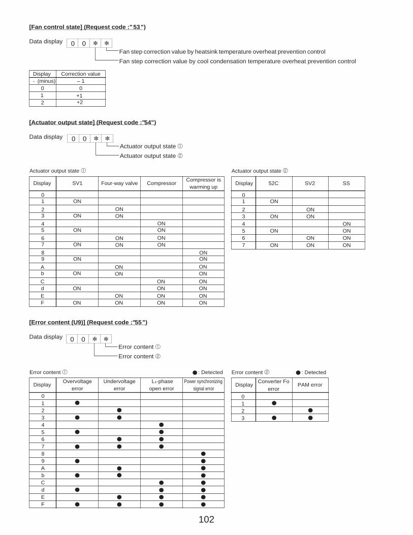
102
[Fan control state] (Request code :"53")
Data display
Fan step correction value by heatsink temperature overheat prevention controlFan step correction value by cool condensation temperature overheat prevention control
0 0
Display Correction value- (minus) – 1
0 0
2
[Actuator output state] (Request code :"54")
Data displayActuator output state 1Actuator output state 2
0 0
Actuator output state 1
Display SV1 Four-way valve Compressor
0123456789AbCdEF
ON
ON
ON
ON
ON
ON
ON
ON
ONON
ONON
ONON
ONON
ONONONON
ONONONON
ONONONONONONONON
Actuator output state 2
Display 52C SV2 SS
01234567
ON
ON
ON
ON
ONON
ONON
ONONONON
[Error content (U9)] (Request code :"55")
Data display
Error content 1Error content 2
0 0
Error content 1 : Detected
Display Overvoltage Undervoltage L1-phase Power synchronizingerror error open error signal error
0123456789AbCdEF
Error content 2 : Detected
Display Converter Fo PAM errorerror
0123
Compressor iswarming up
1 +1+2
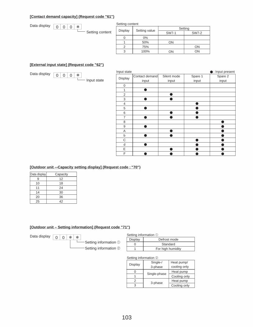
103
[Contact demand capacity] (Request code "61")
Data display 0 0 0Setting content
[External input state] (Request code "62")
Data display 0 0 0Input state
Input state : Input present
Display Contact demand Silent mode Spare 1 Spare 2input input input input
0123456789AbCdEF
[Outdoor unit -– Capacity setting display] (Request code : "70")
Data display Capacity
10 18 9 12
11 2414 3020 3625 42
[Outdoor unit – Setting information] (Request code "71")
Data displaySetting information 1Setting information 2
0 0Setting information 1
Display Defrost mode0 Standard1 For high humidity
Setting information 2
Display Single-/ Heat pump/3-phase cooling only
0 Single-phase Heat pump1 Cooling only2 3-phase Heat pump3 Cooling only
Setting content
Display Setting value SettingSW7-1 SW7-2
01 50% ON
ON2 75% ON
ON
0%
3 100%
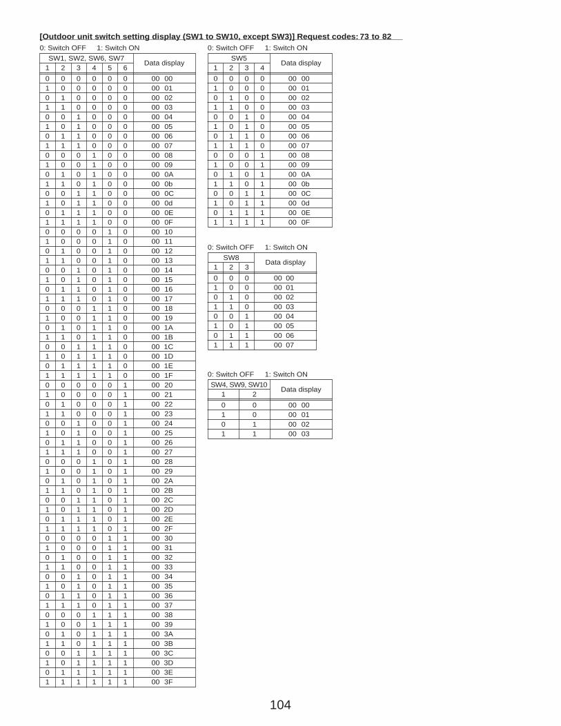
104
SW1, SW2, SW6, SW71 2 3 4 5 60 0 0 0 0 0 00 001 0 0 0 0 0 00 010 1 0 0 0 0 00 021 1 0 0 0 0 00 030 0 1 0 0 0 00 041 0 1 0 0 0 00 050 1 1 0 0 0 00 061 1 1 0 0 0 00 070 0 0 1 0 0 00 081 0 0 1 0 0 00 090 1 0 1 0 0 00 0A1 1 0 1 0 0 00 0b0 0 1 1 0 0 00 0C1 0 1 1 0 0 00 0d0 1 1 1 0 0 00 0E1 1 1 1 0 0 00 0F0 0 0 0 1 0 00 101 0 0 0 1 00 1 0 0 1 01 1 0 0 1 00 0 1 0 1 01 0 1 0 1 00 1 1 0 1 01 1 1 0 1 00 0 0 1 1 01 0 0 1 1 00 1 0 1 1 01 1 0 1 1 00 0 1 1 1 01 0 1 1 1 00 1 1 1 1 01 1 1 1 1 00 0 0 0 0 11 0 0 0 0 10 1 0 0 0 11 1 0 0 0 10 0 1 0 0 11 0 1 0 0 10 1 1 0 0 11 1 1 0 0 10 0 0 1 0 11 0 0 1 0 10 1 0 1 0 11 1 0 1 0 10 0 1 1 0 11 0 1 1 0 10 1 1 1 0 11 1 1 1 0 10 0 0 0 1 11 0 0 0 1 10 1 0 0 1 11 1 0 0 1 10 0 1 0 1 11 0 1 0 1 10 1 1 0 1 11 1 1 0 1 10 0 0 1 1 11 0 0 1 1 10 1 0 1 1 11 1 0 1 1 10 0 1 1 1 11 0 1 1 1 10 1 1 1 1 11 1 1 1 1 1
[Outdoor unit switch setting display (SW1 to SW10, except SW3)] Request codes: 73 to 820: Switch OFF 1: Switch ON
Data displaySW5
1 2 3 40 0 0 0 00 001 0 0 0 00 010 1 0 0 00 021 1 0 0 00 030 0 1 0 00 041 0 1 0 00 050 1 1 0 00 061 1 1 0 00 070 0 0 1 00 081 0 0 1 00 090 1 0 1 00 0A1 1 0 1 00 0b0 0 1 1 00 0C1 0 1 1 00 0d0 1 1 1 00 0E1 1 1 1 00 0F
0: Switch OFF 1: Switch ON
Data display
SW81 2 30 0 0 00 001 0 0 00 010 1 0 00 021 1 0 00 030 0 1 00 041 0 1 00 050 1 1 00 061 1 1 00 07
0: Switch OFF 1: Switch ON
Data display
SW4, SW9, SW101 20 0 00 001 0 00 010 1 00 021 1 00 03
0: Switch OFF 1: Switch ON
Data display
00 1100 1200 1300 1400 1500 1600 1700 1800 1900 1A00 1B00 1C00 1D00 1E00 1F00 2000 2100 2200 2300 2400 2500 2600 2700 2800 2900 2A00 2B00 2C00 2D00 2E00 2F00 3000 3100 3200 3300 3400 3500 3600 3700 3800 3900 3A00 3B00 3C00 3D00 3E00 3F

105
[Indoor unit – Model setting information] (Request code : 162)
Data display
0 0
See the table on the right.
Display Model setting state Display Model setting state
00 2001 2102 22
PKA-A·GA(L)PKA-A·FA(L)PCA-A·GA, PLA-A·BAPLA-A·AA
03 2304 2405 2506 2607 2708 2809 290A 2A0b 2b0C 2C0d 2d0E 2E0F 2F10 3011 3112 3213 3314 3415 3516 3617 3718 3819 391A 3A1b 3b1C 3C1d 3d1E 3E1F 3F
[Indoor unit – Capacity setting information] (Request code 163 )
Data display
0 0
See the table on the right.
Display Capacity setting state Display Capacity setting state
00 10 4201 1102 1203 1304 1405 1506 12 1607 1708 1809 18 190A 1A0b 24 1b0C 1C0d 30 1d0E 1E0F 36 1F
Display Pair No. setting state
00 No. 001 No. 1 J41 disconnected02 No. 2 J42 disconnected03 No. 3 J41, J42 disconnected
[Wireless pair No. (indoor control board side) setting] (Request code 165 )
Data display
0 0
See the table on the right.
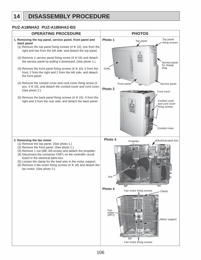
106
14 DISASSEMBLY PROCEDURE
OPERATING PROCEDURE PHOTOSPUZ-A18NHA2 PUZ-A18NHA2-BS
1. Removing the top panel, service panel, front panel and back panel(1) Remove the top panel fixing screws (4 ✕ 10), one from the
right and two from the left side, and detach the top panel.
(2) Remove 1 service panel fixing screw (4 ✕ 10) and detach the service panel by pulling it downward. (See photo 1.)
(3) Remove the front panel fixing screws (4 ✕ 10), 5 from the front, 2 from the right and 2 from the left side, and detach the front panel.
(4) Remove the conduit cover and cord cover fixing screw (2 pcs. 4 ✕ 10), and detach the conduit cover and cord cover.(See photo 2.)
(5) Remove the back panel fixing screws (4 ✕ 10), 4 from the right and 3 from the rear side, and detach the back panel.
2. Removing the fan motor(1) Remove the top panel. (See photo 1.)(2) Remove the front panel. (See photo 1.)(3) Remove 1 nut (M6, left-screw) and detach the propeller. (4) Disconnect the connector CNF1 on the controller circuit
board in the electrical parts box.(5) Loosen the clamp for the lead wire in the motor support. (6) Remove 4 fan motor fixing screws (4 ✕ 18) and detach the
fan motor. (See photo 3.)
Photo 1
Photo 2
Top panel Top panel fixing screws
Service panel
Service panel for charge plugGrille
Front panel
Photo 3 Propeller
Nut
Electrical parts box
Photo 4
Fanmotor(MF1)
Fan motor fixing screws
Fan motor fixing screws
Motor support
Clamp
Conduit coverand cord coverfixing screws
Cord cover
Conduit cover
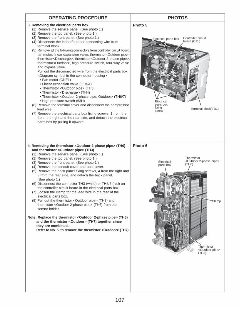
107
Electrical parts box Controller circuitboard (C.B.)
Electricalparts box fixingscrew Terminal block(TB1)
OPERATING PROCEDURE PHOTOS
4. Removing the thermistor <Outdoor 2-phase pipe> (TH6) and thermistor <Outdoor pipe> (TH3)(1) Remove the service panel. (See photo 1.)(2) Remove the top panel. (See photo 1.)(3) Remove the front panel. (See photo 1.)(4) Remove the conduit cover and cord cover.(5) Remove the back panel fixing screws, 4 from the right and
3 from the rear side, and detach the back panel. (See photo 1.)
(6) Disconnect the connector TH3 (white) or TH6/7 (red) on the controller circuit board in the electrical parts box.
(7) Loosen the clamp for the lead wire in the rear of the electrical parts box.
(8) Pull out the thermistor <Outdoor pipe> (TH3) and thermistor <Outdoor 2-phase pipe> (TH6) from the sensor holder.
Note: Replace the thermistor <Outdoor 2-phase pipe> (TH6)and the thermistor <Outdoor> (TH7) together since they are combined. Refer to No. 5. to remove the thermistor <Outdoor> (TH7).
3. Removing the electrical parts box(1) Remove the service panel. (See photo 1.)(2) Remove the top panel. (See photo 1.)(3) Remove the front panel. (See photo 1.)(4) Disconnect the indoor/outdoor connecting wire from
terminal block.(5) Remove all the following connectors from controller circuit board;
fan motor, linear expansion valve, thermistor<Outdoor pipe>,thermistor<Discharge>, thermistor<Outdoor 2-phase pipe>, thermistor<Outdoor>, high pressure switch, four-way valve and bypass valve. Pull out the disconnected wire from the electrical parts box.<Diagram symbol in the connector housing>
• Fan motor (CNF1) • Linear expansion valve (LEV-A) • Thermistor <Outdoor pipe> (TH3) • Thermistor <Discharge> (TH4) • Thermistor <Outdoor 2-phase pipe, Outdoor> (TH6/7) • High pressure switch (63H)
(6) Remove the terminal cover and disconnect the compressorlead wire.
(7) Remove the electrical parts box fixing screws, 1 from the front, the right and the rear side, and detach the electrical parts box by pulling it upward.
Photo 5
Photo 6
Thermistor<Outdoor 2-phase pipe>(TH6)
Clamp
Electricalparts box
Thermistor<Outdoor pipe>(TH3)
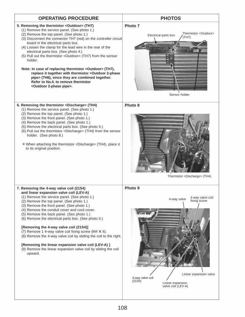
108
OPERATING PROCEDURE PHOTOS5. Removing the thermistor <Outdoor> (TH7)
(1) Remove the service panel. (See photo 1.)(2) Remove the top panel. (See photo 1.)(3) Disconnect the connector TH7 (red) on the controller circuit
board in the electrical parts box.(4) Loosen the clamp for the lead wire in the rear of the
electrical parts box. (See photo 4.)(5) Pull out the thermistor <Outdoor> (TH7) from the sensor
holder.
Note: In case of replacing thermistor <Outdoor> (TH7), replace it together with thermistor <Outdoor 2-phase pipe> (TH6), since they are combined together. Refer to No.4. to remove thermistor <Outdoor 2-phase pipe>.
Photo 7
Photo 9
6. Removing the thermistor <Discharge> (TH4)(1) Remove the service panel. (See photo 1.)(2) Remove the top panel. (See photo 1.)(3) Remove the front panel. (See photo 1.)(4) Remove the back panel. (See photo 1.)(5) Remove the electrical parts box. (See photo 5.)(6) Pull out the thermistor <Discharge> (TH4) from the sensor
holder. (See photo 8.)
w When attaching the thermistor <Discharge> (TH4), place it to its original position.
7. Removing the 4-way valve coil (21S4) and linear expansion valve coil (LEV-A)(1) Remove the service panel. (See photo 1.)(2) Remove the top panel. (See photo 1.)(3) Remove the front panel. (See photo 1.)(4) Remove the conduit cover and cord cover.(5) Remove the back panel. (See photo 1.)(6) Remove the electrical parts box. (See photo 5.)
[Removing the 4-way valve coil (21S4)](7) Remove 1 4-way valve coil fixing screw (M4 ✕ 6).(8) Remove the 4-way valve coil by sliding the coil to the right.
[Removing the linear expansion valve coil (LEV-A) ](9) Remove the linear expansion valve coil by sliding the coil
upward.
Thermistor <Outdoor>(TH7)
Sensor holder
Electrical parts box
Photo 8
Thermistor <Discharge> (TH4)
4-way valve
Linear expansion valve coil (LEV-A)
Linear expansion valve
4-way valve coilfixing screw
4-way valve coil(21S4)
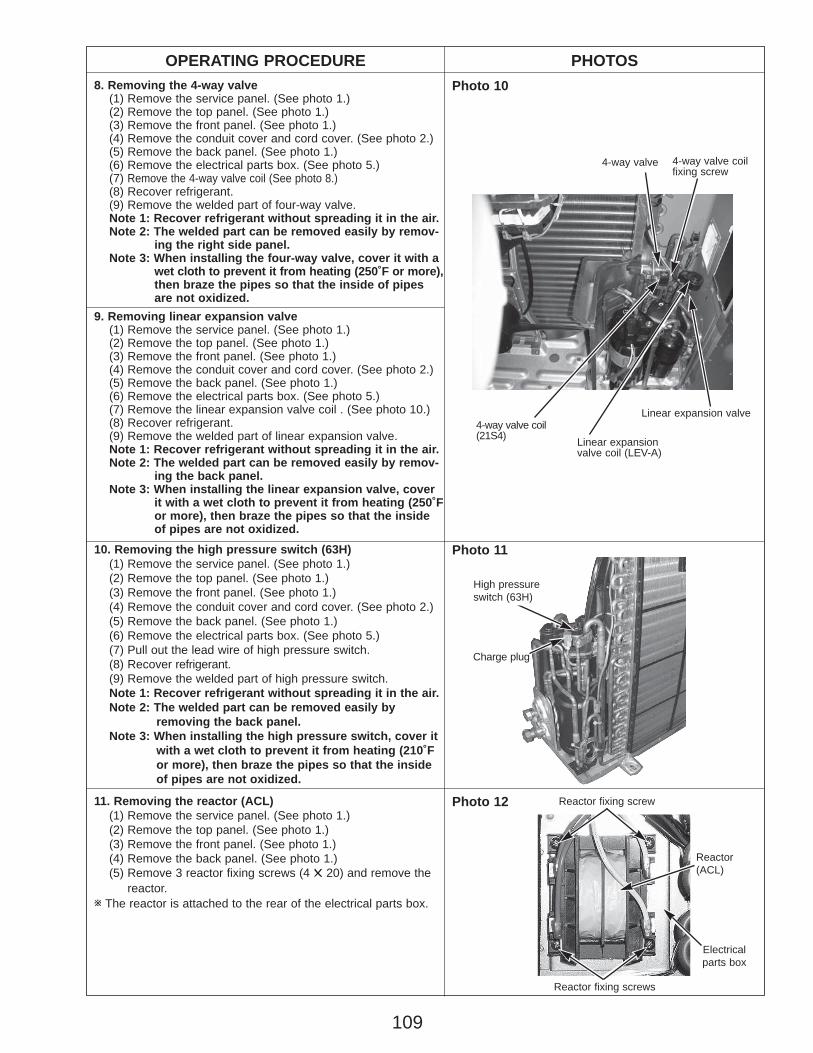
109
9. Removing linear expansion valve(1) Remove the service panel. (See photo 1.)(2) Remove the top panel. (See photo 1.)(3) Remove the front panel. (See photo 1.)(4) Remove the conduit cover and cord cover. (See photo 2.)(5) Remove the back panel. (See photo 1.)(6) Remove the electrical parts box. (See photo 5.)(7) Remove the linear expansion valve coil . (See photo 10.)(8) Recover refrigerant.(9) Remove the welded part of linear expansion valve.Note 1: Recover refrigerant without spreading it in the air.Note 2: The welded part can be removed easily by remov-
ing the back panel.Note 3: When installing the linear expansion valve, cover
it with a wet cloth to prevent it from heating (250˚For more), then braze the pipes so that the insideof pipes are not oxidized.
OPERATING PROCEDURE PHOTOS8. Removing the 4-way valve
(1) Remove the service panel. (See photo 1.)(2) Remove the top panel. (See photo 1.)(3) Remove the front panel. (See photo 1.)(4) Remove the conduit cover and cord cover. (See photo 2.)(5) Remove the back panel. (See photo 1.)(6) Remove the electrical parts box. (See photo 5.)(7) Remove the 4-way valve coil (See photo 8.)(8) Recover refrigerant.(9) Remove the welded part of four-way valve.Note 1: Recover refrigerant without spreading it in the air.Note 2: The welded part can be removed easily by remov-
ing the right side panel.Note 3: When installing the four-way valve, cover it with a
wet cloth to prevent it from heating (250˚F or more), then braze the pipes so that the inside of pipesare not oxidized.
Photo 10
Photo 1110. Removing the high pressure switch (63H)(1) Remove the service panel. (See photo 1.)(2) Remove the top panel. (See photo 1.)(3) Remove the front panel. (See photo 1.)(4) Remove the conduit cover and cord cover. (See photo 2.)(5) Remove the back panel. (See photo 1.)(6) Remove the electrical parts box. (See photo 5.)(7) Pull out the lead wire of high pressure switch.(8) Recover refrigerant.(9) Remove the welded part of high pressure switch.Note 1: Recover refrigerant without spreading it in the air.Note 2: The welded part can be removed easily by
removing the back panel.Note 3: When installing the high pressure switch, cover it
with a wet cloth to prevent it from heating (210˚F or more), then braze the pipes so that the inside of pipes are not oxidized.
Reactor fixing screw
High pressure switch (63H)
Reactor fixing screws
Reactor(ACL)
Electricalparts box
11. Removing the reactor (ACL)(1) Remove the service panel. (See photo 1.)(2) Remove the top panel. (See photo 1.)(3) Remove the front panel. (See photo 1.)(4) Remove the back panel. (See photo 1.)(5) Remove 3 reactor fixing screws (4 ✕ 20) and remove the
reactor.w The reactor is attached to the rear of the electrical parts box.
Photo 12
Charge plug
4-way valve
Linear expansion valve coil (LEV-A)
Linear expansion valve
4-way valve coilfixing screw
4-way valve coil(21S4)
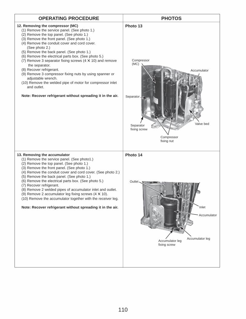
110
OPERATING PROCEDURE PHOTOSPhoto 13
Photo 14
Compressor(MC)
Valve bed
Separator
Separatorfixing screw
Compressorfixing nut
Accumulator
Accumulator
Outlet
Inlet
12. Removing the compressor (MC)(1) Remove the service panel. (See photo 1.)(2) Remove the top panel. (See photo 1.)(3) Remove the front panel. (See photo 1.)(4) Remove the conduit cover and cord cover.
(See photo 2.)(5) Remove the back panel. (See photo 1.)(6) Remove the electrical parts box. (See photo 5.)(7) Remove 3 separator fixing screws (4 ✕ 10) and remove
the separator.(8) Recover refrigerant.(9) Remove 3 compressor fixing nuts by using spanner or
adjustable wrench.(10) Remove the welded pipe of motor for compressor inlet
and outlet.
Note: Recover refrigerant without spreading it in the air.
Accumulator leg fixing screw
Accumulator leg
13. Removing the accumulator (1) Remove the service panel. (See photo1.)(2) Remove the top panel. (See photo 1.)(3) Remove the front panel. (See photo 1.)(4) Remove the conduit cover and cord cover. (See photo 2.)(5) Remove the back panel. (See photo 1.)(6) Remove the electrical parts box. (See photo 5.)(7) Recover refrigerant.(8) Remove 2 welded pipes of accumulator inlet and outlet.(9) Remove 2 accumulator leg fixing screws (4 ✕ 10).(10) Remove the accumulator together with the receiver leg.
Note: Recover refrigerant without spreading it in the air.
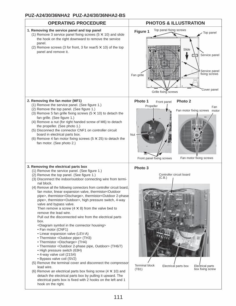
111
OPERATING PROCEDURE PHOTOS & ILLUSTRATIONPUZ-A24/30/36NHA2 PUZ-A24/30/36NHA2-BS
1. Removing the service panel and top panel(1) Remove 3 service panel fixing screws (5 ✕ 10) and slide
the hook on the right downward to remove the service panel.
(2) Remove screws (3 for front, 3 for rear/5 ✕ 10) of the top panel and remove it.
Figure 1 Top panel fixing screwsTop panel
Service panelfixing screws
Service panel
Grille fixing screws
Fan grille
2. Removing the fan motor (MF1)(1) Remove the service panel. (See figure 1.)(2) Remove the top panel. (See figure 1.)(3) Remove 5 fan grille fixing screws (5 ✕ 10) to detach the
fan grille. (See figure 1.)(4) Remove a nut (for right handed screw of M6) to detach
the propeller. (See photo 1.)(5) Disconnect the connector CNF1 on controller circuit
board in electrical parts box.(6) Remove 4 fan motor fixing screws (5 ✕ 25) to detach the
fan motor. (See photo 2.)
Photo 3
Photo 1Propeller
Front panel
Front panel fixing screws
Nut
Photo 2
Slide
3. Removing the electrical parts box(1) Remove the service panel. (See figure 1.)(2) Remove the top panel. (See figure 1.)(3) Disconnect the indoor/outdoor connecting wire from termi-
nal block.(4) Remove all the following connectors from controller circuit board,
fan motor, linear expansion valve, thermistor<Outdoorpipe>, thermistor<Discharge>, thermistor<Outdoor 2-phasepipe>, thermistor<Outdoor>, high pressure switch, 4-wayvalve and bypass valve.Then remove a screw (4 ✕ 8) from the valve bed toremove the lead wire.Pull out the disconnected wire from the electrical partsbox.<Diagram symbol in the connector housing>• Fan motor (CNF1) • Linear expansion valve (LEV-A) • Thermistor <Outdoor pipe> (TH3) • Thermistor <Discharge> (TH4) • Thermistor <Outdoor 2-phase pipe, Outdoor> (TH6/7) • High pressure switch (63H) • 4-way valve coil (21S4) • Bypass valve coil (SV2)
(5) Remove the terminal cover and disconnect the compressorlead wire.
(6) Remove an electrical parts box fixing screw (4 ✕ 10) anddetach the electrical parts box by pulling it upward. Theelectrical parts box is fixed with 2 hooks on the left and 1hook on the right.
Cover panel
Electrical parts box
Controller circuit board(C.B.)
Electrical partsbox fixing screw
Terminal block(TB1)
Fan motor fixing screwsFanmotor
Fan motor fixing screws
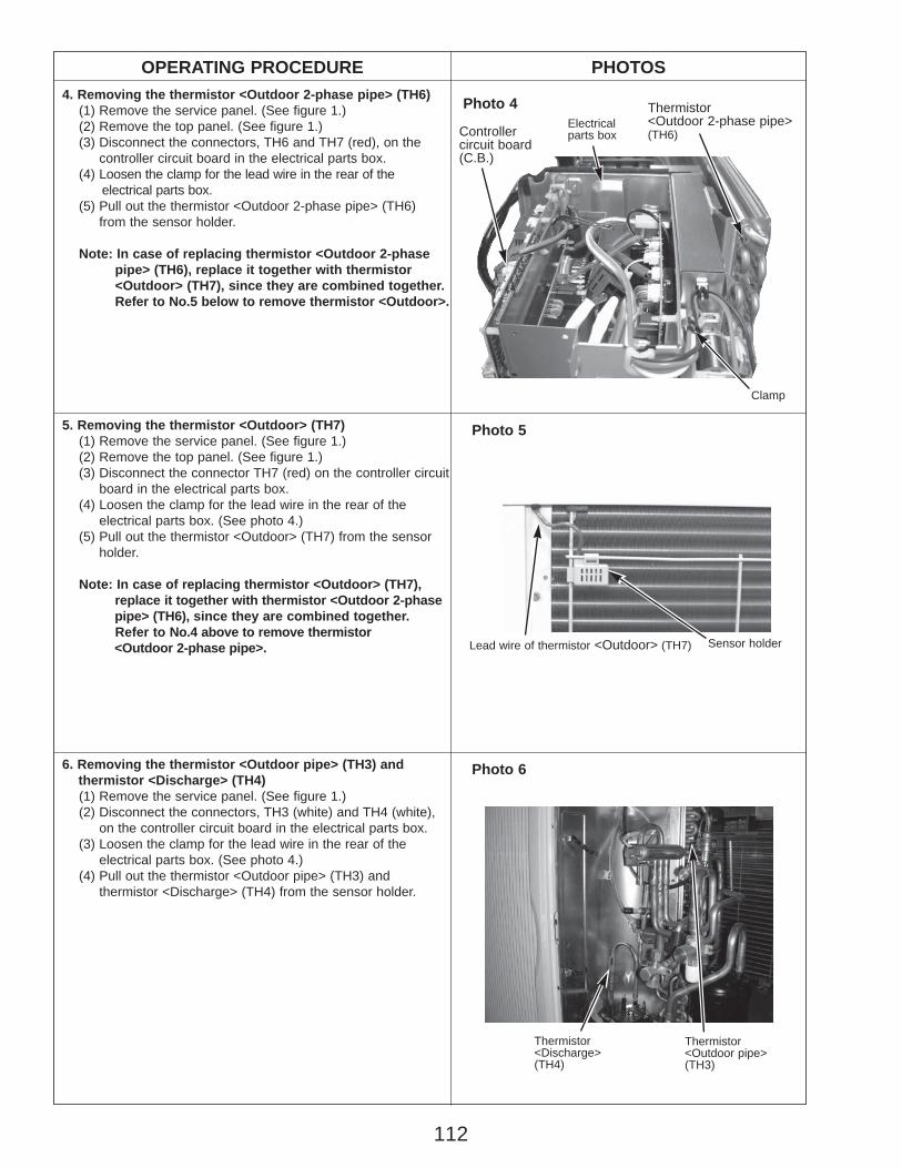
112
OPERATING PROCEDURE PHOTOS4. Removing the thermistor <Outdoor 2-phase pipe> (TH6)
(1) Remove the service panel. (See figure 1.)(2) Remove the top panel. (See figure 1.)(3) Disconnect the connectors, TH6 and TH7 (red), on the
controller circuit board in the electrical parts box.(4) Loosen the clamp for the lead wire in the rear of the
electrical parts box.(5) Pull out the thermistor <Outdoor 2-phase pipe> (TH6)
from the sensor holder.
Note: In case of replacing thermistor <Outdoor 2-phase pipe> (TH6), replace it together with thermistor <Outdoor> (TH7), since they are combined together. Refer to No.5 below to remove thermistor <Outdoor>.
5. Removing the thermistor <Outdoor> (TH7)(1) Remove the service panel. (See figure 1.)(2) Remove the top panel. (See figure 1.)(3) Disconnect the connector TH7 (red) on the controller circuit
board in the electrical parts box.(4) Loosen the clamp for the lead wire in the rear of the
electrical parts box. (See photo 4.)(5) Pull out the thermistor <Outdoor> (TH7) from the sensor
holder.
Note: In case of replacing thermistor <Outdoor> (TH7), replace it together with thermistor <Outdoor 2-phase pipe> (TH6), since they are combined together. Refer to No.4 above to remove thermistor <Outdoor 2-phase pipe>.
Photo 66. Removing the thermistor <Outdoor pipe> (TH3) and thermistor <Discharge> (TH4)(1) Remove the service panel. (See figure 1.)(2) Disconnect the connectors, TH3 (white) and TH4 (white),
on the controller circuit board in the electrical parts box.(3) Loosen the clamp for the lead wire in the rear of the
electrical parts box. (See photo 4.)(4) Pull out the thermistor <Outdoor pipe> (TH3) and
thermistor <Discharge> (TH4) from the sensor holder.
Photo 5
Thermistor<Discharge>(TH4)
Thermistor<Outdoor pipe> (TH3)
Photo 4
Clamp
Controllercircuit board(C.B.)
Thermistor<Outdoor 2-phase pipe>(TH6)
Electricalparts box
Lead wire of thermistor <Outdoor> (TH7) Sensor holder
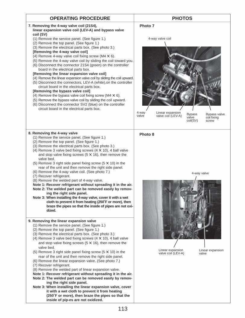
113
OPERATING PROCEDURE PHOTOS7. Removing the 4-way valve coil (21S4),
linear expansion valve coil (LEV-A) and bypass valve coil (SV)(1) Remove the service panel. (See figure 1.)(2) Remove the top panel. (See figure 1.)(3) Remove the electrical parts box. (See photo 3.)[Removing the 4-way valve coil](4) Remove 4-way valve coil fixing screw (M4 ✕ 6).(5) Remove the 4-way valve coil by sliding the coil toward you.(6) Disconnect the connector 21S4 (green) on the controller
board in the electrical parts box.[Removing the linear expansion valve coil](4) Remove the linear expansion valve coil by sliding the coil upward.(5) Disconnect the connectors, LEV-A (white),on the controller
circuit board in the electrical parts box.[Removing the bypass valve coil](4) Remove the bypass valve coil fixing screw (M4 ✕ 6).(5) Remove the bypass valve coil by sliding the coil upward.(6) Disconnect the connector SV2 (blue) on the controller
circuit board in the electrical parts box.
8. Removing the 4-way valve(1) Remove the service panel. (See figure 1.)(2) Remove the top panel. (See figure 1.)(3) Remove the electrical parts box. (See photo 3.)(4) Remove 3 valve bed fixing screws (4 ✕ 10), 4 ball valve
and stop valve fixing screws (5 ✕ 16), then remove the valve bed.
(5) Remove 3 right side panel fixing screw (5 ✕ 10) in the rear of the unit and then remove the right side panel.
(6) Remove the 4-way valve coil. (See photo 7.)(7) Recover refrigerant.(8) Remove the welded part of 4-way valve.Note 1: Recover refrigerant without spreading it in the air.Note 2: The welded part can be removed easily by remov-
ing the right side panel.Note 3: When installing the 4-way valve, cover it with a wet
cloth to prevent it from heating (250˚F or more), thenbraze the pipes so that the inside of pipes are not oxi-dized.
9. Removing the linear expansion valve(1) Remove the service panel. (See figure 1.)(2) Remove the top panel. (See figure 1.)(3) Remove the electrical parts box. (See photo 3.)(4) Remove 3 valve bed fixing screws (4 ✕ 10), 4 ball valve
and stop valve fixing screws (5 ✕ 16), then remove the valve bed.
(5) Remove 3 right side panel fixing screw (5 ✕ 10) in the rear of the unit and then remove the right side panel.
(6) Remove the linear expansion valve. (See photo 7.)(7) Recover refrigerant.(8) Remove the welded part of linear expansion valve.Note 1: Recover refrigerant without spreading it in the air.Note 2: The welded part can be removed easily by remov-
ing the right side panel.Note 3: When installing the linear expansion valve, cover
it with a wet cloth to prevent it from heating (250˚F or more), then braze the pipes so that theinside of pip-es are not oxidized.
Photo 7
Photo 8
Bypass valvecoil fixingscrew
4-wayvalve
4-way valve coil
Linear expansionvalve coil (LEV-A)
4-way valve
Bypassvalvecoil(SV)
Linear expansionvalve coil (LEV-A)
Linear expansionvalve
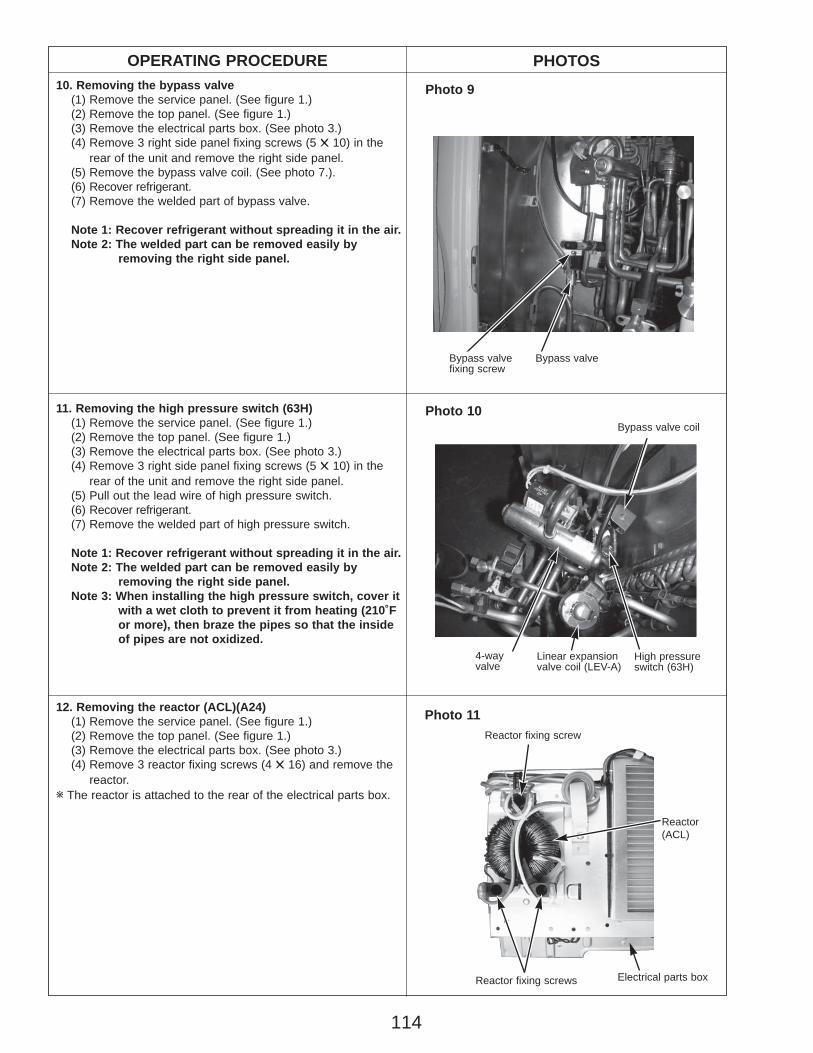
114
OPERATING PROCEDURE PHOTOS10. Removing the bypass valve
(1) Remove the service panel. (See figure 1.)(2) Remove the top panel. (See figure 1.)(3) Remove the electrical parts box. (See photo 3.)(4) Remove 3 right side panel fixing screws (5 ✕ 10) in the
rear of the unit and remove the right side panel.(5) Remove the bypass valve coil. (See photo 7.).(6) Recover refrigerant.(7) Remove the welded part of bypass valve.
Note 1: Recover refrigerant without spreading it in the air.Note 2: The welded part can be removed easily by
removing the right side panel.
12. Removing the reactor (ACL)(A24)(1) Remove the service panel. (See figure 1.)(2) Remove the top panel. (See figure 1.)(3) Remove the electrical parts box. (See photo 3.)(4) Remove 3 reactor fixing screws (4 ✕ 16) and remove the
reactor.w The reactor is attached to the rear of the electrical parts box.
Photo 9
Reactor fixing screw
11. Removing the high pressure switch (63H)(1) Remove the service panel. (See figure 1.)(2) Remove the top panel. (See figure 1.)(3) Remove the electrical parts box. (See photo 3.)(4) Remove 3 right side panel fixing screws (5 ✕ 10) in the
rear of the unit and remove the right side panel.(5) Pull out the lead wire of high pressure switch.(6) Recover refrigerant.(7) Remove the welded part of high pressure switch.
Note 1: Recover refrigerant without spreading it in the air.Note 2: The welded part can be removed easily by
removing the right side panel.Note 3: When installing the high pressure switch, cover it
with a wet cloth to prevent it from heating (210˚F or more), then braze the pipes so that the inside of pipes are not oxidized.
Bypass valve Bypass valvefixing screw
Reactor fixing screws
Reactor(ACL)
Photo 10
Photo 11
Electrical parts box
High pressure switch (63H)
Bypass valve coil
Linear expansion valve coil (LEV-A)
4-wayvalve
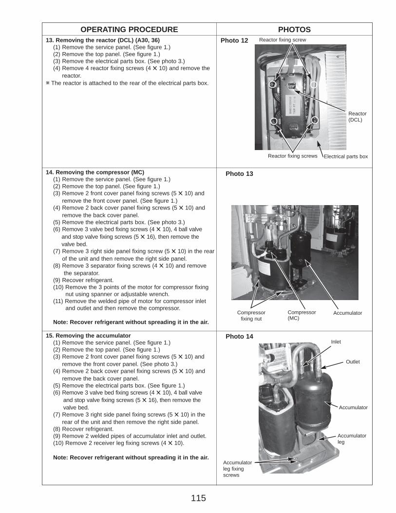
115
OPERATING PROCEDURE PHOTOS
14. Removing the compressor (MC)(1) Remove the service panel. (See figure 1.)(2) Remove the top panel. (See figure 1.)(3) Remove 2 front cover panel fixing screws (5 ✕ 10) and
remove the front cover panel. (See figure 1.)(4) Remove 2 back cover panel fixing screws (5 ✕ 10) and
remove the back cover panel.(5) Remove the electrical parts box. (See photo 3.)(6) Remove 3 valve bed fixing screws (4 ✕ 10), 4 ball valve
and stop valve fixing screws (5 ✕ 16), then remove the valve bed.
(7) Remove 3 right side panel fixing screw (5 ✕ 10) in the rearof the unit and then remove the right side panel.
(8) Remove 3 separator fixing screws (4 ✕ 10) and remove the separator.
(9) Recover refrigerant.(10) Remove the 3 points of the motor for compressor fixing
nut using spanner or adjustable wrench.(11) Remove the welded pipe of motor for compressor inlet
and outlet and then remove the compressor.
Note: Recover refrigerant without spreading it in the air.
15. Removing the accumulator (1) Remove the service panel. (See figure 1.)(2) Remove the top panel. (See figure 1.)(3) Remove 2 front cover panel fixing screws (5 ✕ 10) and
remove the front cover panel. (See photo 3.)(4) Remove 2 back cover panel fixing screws (5 ✕ 10) and
remove the back cover panel.(5) Remove the electrical parts box. (See figure 1.)(6) Remove 3 valve bed fixing screws (4 ✕ 10), 4 ball valve
and stop valve fixing screws (5 ✕ 16), then remove the valve bed.
(7) Remove 3 right side panel fixing screws (5 ✕ 10) in the rear of the unit and then remove the right side panel.
(8) Recover refrigerant.(9) Remove 2 welded pipes of accumulator inlet and outlet.(10) Remove 2 receiver leg fixing screws (4 ✕ 10).
Note: Recover refrigerant without spreading it in the air.
Photo 13
Accumulatorleg fixingscrews
Compressor(MC)
AccumulatorCompressorfixing nut
Accumulator
Accumulatorleg
Inlet
Outlet
Photo 14
13. Removing the reactor (DCL) (A30, 36)(1) Remove the service panel. (See figure 1.)(2) Remove the top panel. (See figure 1.)(3) Remove the electrical parts box. (See photo 3.)(4) Remove 4 reactor fixing screws (4 ✕ 10) and remove the
reactor.w The reactor is attached to the rear of the electrical parts box.
Reactor fixing screw
Reactor fixing screws
Reactor(DCL)
Photo 12
Electrical parts box
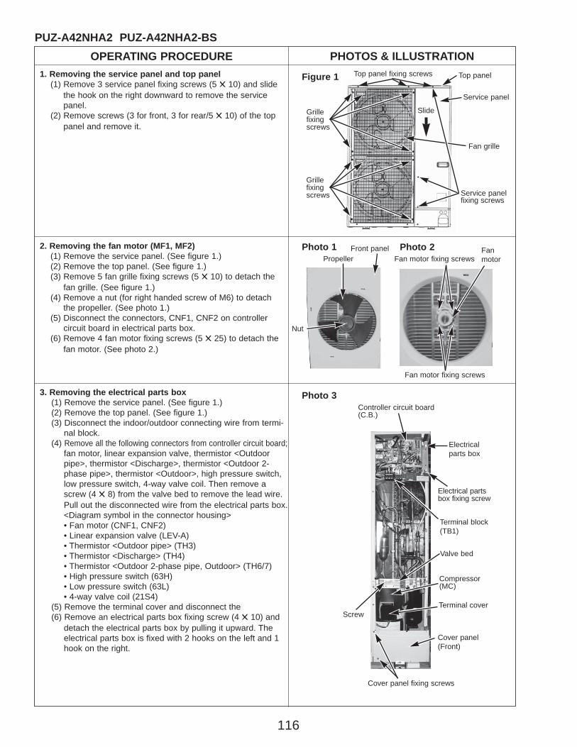
116
OPERATING PROCEDURE PHOTOS & ILLUSTRATIONPUZ-A42NHA2 PUZ-A42NHA2-BS
1. Removing the service panel and top panel(1) Remove 3 service panel fixing screws (5 ✕ 10) and slide
the hook on the right downward to remove the service panel.
(2) Remove screws (3 for front, 3 for rear/5 ✕ 10) of the top panel and remove it.
Figure 1 Top panel fixing screws Top panel
Service panelfixing screws
Service panel
Grillefixingscrews
Fan grille
2. Removing the fan motor (MF1, MF2)(1) Remove the service panel. (See figure 1.)(2) Remove the top panel. (See figure 1.)(3) Remove 5 fan grille fixing screws (5 ✕ 10) to detach the
fan grille. (See figure 1.)(4) Remove a nut (for right handed screw of M6) to detach
the propeller. (See photo 1.)(5) Disconnect the connectors, CNF1, CNF2 on controller
circuit board in electrical parts box.(6) Remove 4 fan motor fixing screws (5 ✕ 25) to detach the
fan motor. (See photo 2.)
Fan motor fixing screws
Photo 33. Removing the electrical parts box(1) Remove the service panel. (See figure 1.)(2) Remove the top panel. (See figure 1.)(3) Disconnect the indoor/outdoor connecting wire from termi-
nal block.(4) Remove all the following connectors from controller circuit board;
fan motor, linear expansion valve, thermistor <Outdoorpipe>, thermistor <Discharge>, thermistor <Outdoor 2-phase pipe>, thermistor <Outdoor>, high pressure switch,low pressure switch, 4-way valve coil. Then remove ascrew (4 ✕ 8) from the valve bed to remove the lead wire.Pull out the disconnected wire from the electrical parts box.<Diagram symbol in the connector housing>• Fan motor (CNF1, CNF2) • Linear expansion valve (LEV-A) • Thermistor <Outdoor pipe> (TH3) • Thermistor <Discharge> (TH4) • Thermistor <Outdoor 2-phase pipe, Outdoor> (TH6/7) • High pressure switch (63H) • Low pressure switch (63L) • 4-way valve coil (21S4)
(5) Remove the terminal cover and disconnect the (6) Remove an electrical parts box fixing screw (4 ✕ 10) and
detach the electrical parts box by pulling it upward. Theelectrical parts box is fixed with 2 hooks on the left and 1hook on the right.
Electricalparts box
Controller circuit board(C.B.)
Electrical partsbox fixing screw
Terminal cover
Cover panel (Front)
Cover panel fixing screws
Compressor(MC)
Photo 1 Fanmotor
Fan motor fixing screws
PropellerFront panel
Nut
Terminal block(TB1)
Photo 2
Valve bed
Screw
Grillefixingscrews
Slide
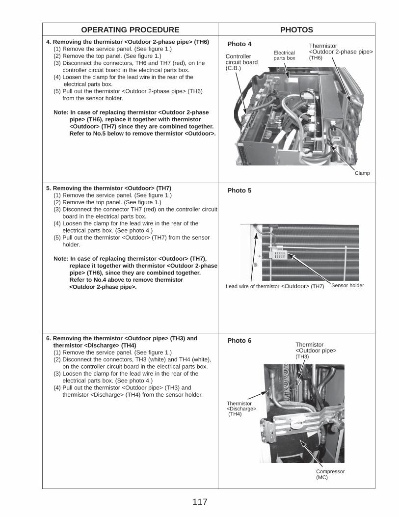
117
OPERATING PROCEDURE PHOTOS
Photo 44. Removing the thermistor <Outdoor 2-phase pipe> (TH6)(1) Remove the service panel. (See figure 1.)(2) Remove the top panel. (See figure 1.)(3) Disconnect the connectors, TH6 and TH7 (red), on the
controller circuit board in the electrical parts box.(4) Loosen the clamp for the lead wire in the rear of the
electrical parts box.(5) Pull out the thermistor <Outdoor 2-phase pipe> (TH6)
from the sensor holder.
Note: In case of replacing thermistor <Outdoor 2-phase pipe> (TH6), replace it together with thermistor <Outdoor> (TH7) since they are combined together. Refer to No.5 below to remove thermistor <Outdoor>.
5. Removing the thermistor <Outdoor> (TH7)(1) Remove the service panel. (See figure 1.)(2) Remove the top panel. (See figure 1.)(3) Disconnect the connector TH7 (red) on the controller circuit
board in the electrical parts box.(4) Loosen the clamp for the lead wire in the rear of the
electrical parts box. (See photo 4.)(5) Pull out the thermistor <Outdoor> (TH7) from the sensor
holder.
Note: In case of replacing thermistor <Outdoor> (TH7), replace it together with thermistor <Outdoor 2-phase pipe> (TH6), since they are combined together. Refer to No.4 above to remove thermistor <Outdoor 2-phase pipe>.
Photo 6
Clamp
Controllercircuit board(C.B.)
Thermistor<Outdoor 2-phase pipe>(TH6)
6. Removing the thermistor <Outdoor pipe> (TH3) and thermistor <Discharge> (TH4)(1) Remove the service panel. (See figure 1.)(2) Disconnect the connectors, TH3 (white) and TH4 (white),
on the controller circuit board in the electrical parts box.(3) Loosen the clamp for the lead wire in the rear of the
electrical parts box. (See photo 4.)(4) Pull out the thermistor <Outdoor pipe> (TH3) and
thermistor <Discharge> (TH4) from the sensor holder.
Electricalparts box
Photo 5
Thermistor<Discharge>(TH4)
Thermistor<Outdoor pipe>(TH3)
Compressor(MC)
Lead wire of thermistor <Outdoor> (TH7) Sensor holder
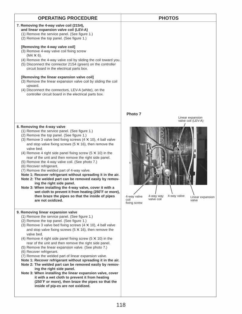
118
OPERATING PROCEDURE PHOTOS7. Removing the 4-way valve coil (21S4),
and linear expansion valve coil (LEV-A)(1) Remove the service panel. (See figure 1.)(2) Remove the top panel. (See figure 1.)
[Removing the 4-way valve coil](3) Remove 4-way valve coil fixing screw
(M4 ✕ 6).(4) Remove the 4-way valve coil by sliding the coil toward you.(5) Disconnect the connector 21S4 (green) on the controller
circuit board in the electrical parts box.
[Removing the linear expansion valve coil](3) Remove the linear expansion valve coil by sliding the coil
upward.(4) Disconnect the connectors, LEV-A (white), on the
controller circuit board in the electrical parts box.
8. Removing the 4-way valve(1) Remove the service panel. (See figure 1.)(2) Remove the top panel. (See figure 1.)(3) Remove 3 valve bed fixing screws (4 ✕ 10), 4 ball valve
and stop valve fixing screws (5 ✕ 16), then remove the valve bed.
(4) Remove 4 right side panel fixing screw (5 ✕ 10) in the rear of the unit and then remove the right side panel.
(5) Remove the 4-way valve coil. (See photo 7.)(6) Recover refrigerant.(7) Remove the welded part of 4-way valve.Note 1: Recover refrigerant without spreading it in the air.Note 2: The welded part can be removed easily by remov-
ing the right side panel.Note 3: When installing the 4-way valve, cover it with a
wet cloth to prevent it from heating (250˚F or more), then braze the pipes so that the inside of pipesare not oxidized.
9. Removing linear expansion valve(1) Remove the service panel. (See figure 1.)(2) Remove the top panel. (See figure 1.)(3) Remove 3 valve bed fixing screws (4 ✕ 10), 4 ball valve
and stop valve fixing screws (5 ✕ 16), then remove thevalve bed.
(4) Remove 4 right side panel fixing screw (5 ✕ 10) in the rear of the unit and then remove the right side panel.
(5) Remove the linear expansion valve. (See photo 7.)(6) Recover refrigerant.(7) Remove the welded part of linear expansion valve.Note 1: Recover refrigerant without spreading it in the air.Note 2: The welded part can be removed easily by remov-
ing the right side panel.Note 3: When installing the linear expansion valve, cover
it with a wet cloth to prevent it from heating (250˚F or more), then braze the pipes so that theinside of pip-es are not oxidized.
Photo 7
4-way valve
Linear expansion valve coil (LEV-A)
Linear expansion valve
4-way wayvalve coil
4-way valvecoilfixing screw
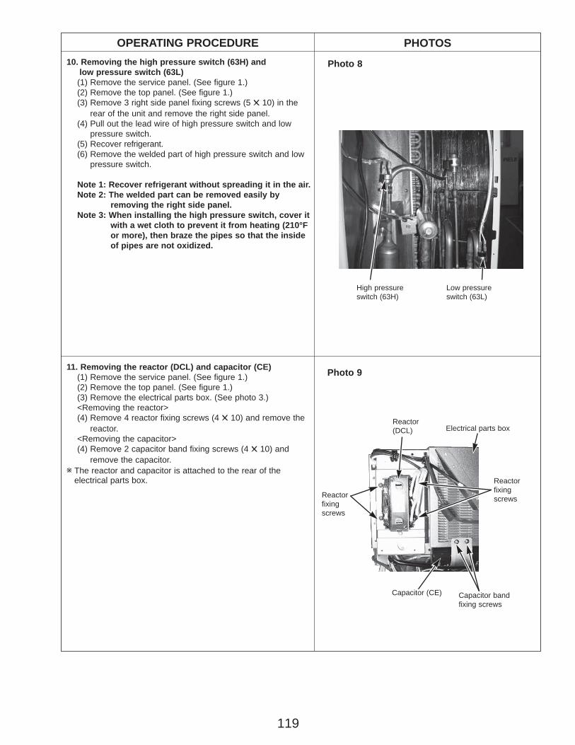
119
OPERATING PROCEDURE PHOTOS
11. Removing the reactor (DCL) and capacitor (CE)(1) Remove the service panel. (See figure 1.)(2) Remove the top panel. (See figure 1.)(3) Remove the electrical parts box. (See photo 3.)<Removing the reactor>(4) Remove 4 reactor fixing screws (4 ✕ 10) and remove the
reactor.<Removing the capacitor>(4) Remove 2 capacitor band fixing screws (4 ✕ 10) and
remove the capacitor.w The reactor and capacitor is attached to the rear of the
electrical parts box.
Capacitor band fixing screws
10. Removing the high pressure switch (63H) and low pressure switch (63L)(1) Remove the service panel. (See figure 1.)(2) Remove the top panel. (See figure 1.)(3) Remove 3 right side panel fixing screws (5 ✕ 10) in the
rear of the unit and remove the right side panel.(4) Pull out the lead wire of high pressure switch and low
pressure switch.(5) Recover refrigerant.(6) Remove the welded part of high pressure switch and low
pressure switch.
Note 1: Recover refrigerant without spreading it in the air.Note 2: The welded part can be removed easily by
removing the right side panel.Note 3: When installing the high pressure switch, cover it
with a wet cloth to prevent it from heating (210°F or more), then braze the pipes so that the inside of pipes are not oxidized.
Photo 8
Photo 9
Reactorfixingscrews
Reactorfixingscrews
Reactor(DCL) Electrical parts box
Capacitor (CE)
High pressure switch (63H)
Low pressure switch (63L)

OPERATING PROCEDURE PHOTOS12. Removing the compressor (MC)
(1) Remove the service panel. (See figure 1.)(2) Remove the top panel. (See figure 1.)(3) Remove 2 front cover panel fixing screws (5 ✕ 10) and
remove the front cover panel. (See photo 3.)(4) Remove 2 back cover panel fixing screws (5 ✕ 10) and
remove the back cover panel.(5) Remove the electrical parts box. (See photo 3.)(6) Remove 3 valve bed fixing screws (4 ✕ 10), 4 ball valve and
stop valve fixing screws (5 ✕ 16), then remove the valve bed.(7) Remove 3 right side panel fixing screw (5 ✕ 10) in the rear
of the unit and then remove the right side panel. (8) Remove 3 separator fixing screws (4 ✕ 10) and remove
the separator.(9) Recover refrigerant.(10) Remove the 3 points of the motor for compressor fixing
nut using spanner or adjustable wrench.(11) Remove the welded pipe of motor for compressor inlet
and outlet and then remove the compressor.
Note: Recover refrigerant without spreading it in the air.
13. Removing the accumulator(1) Remove the service panel. (See figure 1.)(2) Remove the top panel. (See figure 1.)(3) Remove 2 front cover panel fixing screws (5 ✕ 10) and
remove the front cover panel. (See photo 3.)(4) Remove 2 back cover panel fixing screws (5 ✕ 10) and
remove the back cover panel.(5) Remove the electrical parts box. (See photo 3.)(6) Remove 3 valve bed fixing screws (4 ✕ 10), 4 ball valve and
stop valve fixing screws (5 ✕ 16), then remove the valve bed.(7) Remove 3 right side panel fixing screw (5 ✕ 10) in the
rear of the unit and then remove the right side panel. (8) Recover refrigerant.(9) Remove 2 welded pipes of accumulator inlet and outlet.(10) Remove 2 accumulator leg fixing screws (4 ✕ 10).
Note: Recover refrigerant without spreading it in the air.
Photo 10
Compressor(MC)
Valve bed
Separator
Separatorfixing screw
Accumulator
Photo 11
Valve bedfixingscrews
Compressorfixing nut
Accumulator legfixing screws
Accumulator
Accumulatorleg
Inlet
Outlet
Compressor(MC)
HEAD OFFICE : TOKYO BLDG., 2-7-3, MARUNOUCHI, CHIYODA-KU, TOKYO 100-8310, JAPAN
CCopyright 2007 MITSUBISHI ELECTRIC ENGINEERING CO., LTD.Distributed in Nov. 2007 No.OCH429 PDF 9Made in Japan
New publication, effective Nov. 2007Specifications subject to change without notice