MINI-SPLIT SYSTEMS SERVICE MANUAL MHA Series Unit ...
52
1 MINI-SPLIT SYSTEMS SERVICE MANUAL MHA Series Unit Information CORP1913-L8 11/2020 Table of Contents 1. Indoor Units................................................ 3 1.1. Model Number Identification ..................................... 3 1.2. Indoor Unit Specifications ......................................... 3 1.3. Indoor Unit Dimensions ............................................ 4 1.4. Indoor Unit Clearances ............................................. 4 1.5. Indoor Unit Wall Mounts ........................................... 5 1.6. Indoor/Outdoor Matches ........................................... 5 2. Air Throw Data ........................................... 6 3. Power and Communication Wiring for Systems ..................................................... 7 3.1. Overview ................................................................... 7 3.2. Wire Gauge............................................................... 7 3.3. Terminal Connections ............................................... 8 4. Indoor Unit Diagrams ................................ 8 5. Wireless Remote ........................................ 9 5.1. Requirements ........................................................... 9 5.2. Remote Control Specifications ................................. 9 6. Connection to Centralized Controller .... 11 6.1. Set Indoor Unit Address for Centralized Control (Used with VRF Only)........................................................ 11 6.2. Indoor Unit Connection Points for Centralized Controller ................................................................ 12 6.3. Dry Mode Operation - Indoor Units......................... 12 6.3.1. Procedure................................................. 12 6.3.2. Dry Mode Operation Sequence................ 13 6.4. Test Run - Indoor Units ........................................... 13 6.4.1. Test Run Instructions................................ 13 6.4.2. Before Test Run........................................ 13 6.5. Double-Check Pipe Connections............................ 13 6.6. Ambient Temperature is Below 63°F (17°C) ........... 13 7. Single Zone Outdoor Units ..................... 15 7.1. Model Number Identification ................................... 15 7.2. Specifications.......................................................... 15 7.3. Cooling and Heating Capacities ............................. 16 7.3.1. Cooling - 009 (115V) ................................ 16 7.3.2. Heating - 009 (115V) ................................ 17 7.3.3. Cooling - 009 (208/230V) ......................... 17 7.3.4. Heating - 009 (208/230V) ......................... 18 7.3.5. Cooling - 012 (115V) ................................ 18 7.3.6. Heating - 012 (115V) ................................ 19 7.3.7. Cooling - 012 (208/230V) ......................... 19 7.3.8. Heating - 012 (208/230V) ......................... 20 7.3.9. Cooling - 018 (208/230V) ......................... 20 7.3.10. Heating - 018 (208/230V) ......................... 21 7.3.11. Cooling - 024 (208/230V) ......................... 21 7.3.12. Heating - 024 (208/230V) ......................... 22 MHA Single Zone Air Conditioning Outdoor Unit MWHA Wall Mount Single Zone Air Conditioning Indoor Unit Please refer to Corp1914-L8 for indoor and outdoor unit error codes and component diagnostics.
-
Upload
khangminh22 -
Category
Documents
-
view
1 -
download
0
Transcript of MINI-SPLIT SYSTEMS SERVICE MANUAL MHA Series Unit ...

1
MINI-SPLIT SYSTEMS SERVICE MANUALMHA Series Unit Information
CORP1913-L8 11/2020
Table of Contents1. Indoor Units ................................................3
1.1. ModelNumberIdentification .....................................31.2. IndoorUnitSpecifications .........................................31.3. IndoorUnitDimensions ............................................41.4. IndoorUnitClearances .............................................41.5. IndoorUnitWallMounts ...........................................51.6. Indoor/OutdoorMatches ...........................................5
2. Air Throw Data ...........................................6
3. Power and Communication Wiring for Systems .....................................................73.1. Overview ...................................................................73.2. WireGauge...............................................................73.3. TerminalConnections ...............................................8
4. Indoor Unit Diagrams ................................8
5. Wireless Remote ........................................95.1. Requirements ...........................................................95.2. RemoteControlSpecifications .................................9
6. Connection to Centralized Controller .... 116.1. SetIndoorUnitAddressforCentralizedControl(Used
withVRFOnly) ........................................................ 116.2. IndoorUnitConnectionPointsforCentralized
Controller ................................................................126.3. DryModeOperation-IndoorUnits .........................12
6.3.1. Procedure .................................................126.3.2. DryModeOperationSequence ................13
6.4. TestRun-IndoorUnits ...........................................136.4.1. TestRunInstructions ................................136.4.2. BeforeTestRun ........................................13
6.5. Double-CheckPipeConnections ............................136.6. AmbientTemperatureisBelow63°F(17°C) ...........13
7. Single Zone Outdoor Units .....................157.1. ModelNumberIdentification ...................................157.2. Specifications..........................................................157.3. CoolingandHeatingCapacities .............................16
7.3.1. Cooling-009(115V) ................................167.3.2. Heating-009(115V) ................................177.3.3. Cooling-009(208/230V) .........................177.3.4. Heating-009(208/230V) .........................187.3.5. Cooling-012(115V) ................................187.3.6. Heating-012(115V) ................................197.3.7. Cooling-012(208/230V) .........................197.3.8. Heating-012(208/230V) .........................207.3.9. Cooling-018(208/230V) .........................207.3.10. Heating-018(208/230V) .........................217.3.11. Cooling-024(208/230V) .........................217.3.12. Heating-024(208/230V) .........................22
MHA Single Zone Air Conditioning Outdoor Unit
MWHA Wall Mount Single ZoneAir Conditioning Indoor Unit
Please refer to Corp1914-L8 for indoor and outdoor unit error codes and component diagnostics.

2
7.4. UnitDimensions......................................................227.5. OutdoorUnitClearances ........................................23
7.5.1. SingleUnits ..............................................237.5.2. MultipleUnits ............................................24
8. Refrigeration Pipe Work ..........................258.1. Single-ZoneRefrigerantCycleDiagram .................258.2. Single-ZonePipingLimitations ...............................25
9. Outdoor Unit Connections and Line Set Usage .................................................269.1. PipeLength.............................................................269.2. TorqueRequirements .............................................26
10. Power and Communication Wiring for Systems ...................................................27
11. Outdoor Unit Diagrams ...........................28
12. Installation Requirements .......................2912.1. GasLeakCheckwithSoapWater: .........................3012.2. AirandMoisture......................................................3012.3. AirPurgingusingaVacuumPump .........................3012.4. AddingRefrigerantifPipeLengthExceeds
ChargeLessPipeLength .......................................3012.5. AddRefrigerantafterLong-TermSystem
Operation ................................................................3012.6. ServicingIndoorUnitRefrigerationCircuit..............31
12.6.1. CollectingRefrigerantintoOutdoorUnit...3112.6.2. AirPurgingwithVacuumPump ................31
12.7. EvacuationafterServicingtheOutdoorUnitRefrigerationCircuit ................................................3112.7.1. EvacuationoftheComplete
RefrigerationCircuit,Indoorand Outdoor Unit .............................................31
12.7.2. RefrigerantCharging ................................31
13. Electronic Function .................................3213.1. Abbreviation ............................................................3213.2. ElectricControlWorkingEnvironment. ...................32
14. Adding Refrigerant - Single-Zone Systems ....................................................32
15. Single-Zone Outdoor Unit LED Locations ..................................................32
16. SpecificationsandOperations ...............3316.1. CoolingChart ..........................................................3416.2. HeatingChart..........................................................3416.3. CapacityRequestCalculations ...............................3516.4. OutdoorFanControl ...............................................36
16.4.1. CoolingMode ...........................................36
17. Indoor and Outdoor Unit Disassembly ..3717.1. IndoorUnit(AllModels) ..........................................37
17.1.1. FrontPanel ...............................................3717.1.2. ElectricalParts .........................................3917.1.3. Evaporator ................................................4117.1.4. FanMotorandFan ...................................42
17.1.5. Step Motor ................................................4217.1.6. DrainHose ...............................................43
17.2. Outdoor Unit ...........................................................4317.2.1. PanelPlate(SomeModels)......................4317.2.2. PanelPlate(MWHA024S4) ......................4417.2.3. ElectronicComponents(MWHA009S4
andMWHA012S4) ...................................4517.2.4. ElectronicComponents(MWHA018S4) ...4617.2.5. ElectronicComponents(MWHA024S4) ...4617.2.6. FanDisassembly(MWHA009S4and
MWHA012S4) ..........................................4617.2.7. FanDisassembly(MWHA018S4) .............4717.2.8. FanDisassembly(MWHA024S4) .............4817.2.9. SoundBlanket ..........................................4917.2.10.Four-WayValve ........................................4917.2.11. Compressor ..............................................49

3
1. Indoor Units
1.1. ModelNumberIdentification
M WH A 009 S 4-1 P
Unit Type WH=Wall-MountedNon-DuctedUnit
Series Type M=Mini-Split
Voltage L=115V-1phase-60Hz P=208/230V-1phase-60Hz
WALL-MOUNTED INDOOR UNITS
CoolingEfficiency S=StandardEfficiency
Major Design Sequence A=FirstGeneration
Nominal Cooling Capacity 009=0.75ton
012=1ton 018=1.5tons 024=2tons
Refrigerant Type 4=HFC-410A
Minor Design Sequence 1=1stRevision
1.2. IndoorUnitSpecifications
Indoor Unit Model No. MWHA009S4 MWHA012S4
NominalSize-Tons 0.75 1
PowerSupply-60hz-1phase 115V 208/230V 115V 208/230V
Ratedloadamps 0.7 0.06 0.7 0.06
Output(W) 20 20 20 20
RoomTemperatureRange(°F) Cooling 62-90 62-90 62-90 62-90
Heating 32-86 32-86 32-86 32-86
AirVolume-cfm(High/Medium/Low) 247 / 182 / 129 309 / 285 / 187 294 / 212 / 171 324 / 282 / 212
SoundData(dBA)-Low/Medium/High 38 / 32 / 25 38 / 32 / 25 38 / 30 / 28 38 / 32 / 24
PipingConnections-Liquid/Gas-o.d.-flare-in. 1/4 / 3/8 1/4 / 3/8 1/4 / 1/2 1/4 / 1/2
Drainconnectiono.d.-in. 1 1 1 1
Net/Shippingweights-lbs. 18 / 23 18 / 23 19 / 25 19 / 25
Indoor Unit Model No. MWHA018S4 MWHA024S4
NominalSize-Tons 1.5 2
PowerSupply-60hz-1phase 208/230V 208/230V
Ratedloadamps 0.11 0.37
Output(W) 30 60
RoomTemperatureRange(°F) Cooling 62-90 62-90
Heating 32-86 32-86
AirVolume-cfm(High/Medium/Low) 449 / 393 / 262 706 / 588 / 450
SoundData(dBA)-Low/Medium/High 43 /35 / 30.5 48 / 42.5 / 34
PipingConnections-Liquid/Gas-o.d.-flare-in. 1/4 / 1/2 3/8 / 5/8
Drainconnectiono.d.-in. 1 1
Net/Shippingweights-lbs. 25 / 33 31 / 40

4
1.3. Indoor Unit Dimensions
A
B
C
TOP VIEW
FRONT VIEW
BOTTOM VIEW
SIDE VIEWSIDE VIEW
Figure 1. Indoor Unit Dimensions - Inches (mm)
SizeA B C
in. mm in. mm in. mm
9K 29-5/8 752 11-3/8 289 8-5/8 219
12K 32-3/4 832 11-3/4 298 8-3/4 222
18K 39-1/8 994 12-1/2 318 9-7/8 251
24K 44 1118 13-1/4 337 10-1/4 260
1.4. Indoor Unit Clearances
FRONT VIEW
Wall
Vertical Clearance - Clearance to Floor - 72 inches (1829 mm) Minimum
96 inches (2438 mm) Recommended
5”
(127 mm)
Minimum
6” (152 mm)
Minimum Clearance
Ceiling
Wall
Floor
5”
(127 mm)
Minimum
59”
(1499 mm)
Minimum
SIDE VIEW
Any Object

5
1.5. Indoor Unit Wall Mounts
MWCA009S4
Right Rear Hole
2-1/2 in. (64 mm)
diameter
Left Rear Hole
2-1/2 in. (64 mm)
diameter
Wall-Mount
Unit Outline
1-1/2 (38)
2 (51)
13-3/4 (349)
7 (178)
5-3/8
(136)
28-1/2 (724)
4
(102)
11
-3/8
(2
89
)
1-7/8
(48)
Figure 2. 9K Indoor Unit Wall Plate Dimensions - Inches (mm)
MWCA012S4
Right Rear Hole
2-1/2 in. (64 mm)
diameter
Left Rear Hole
2-1/2 in. (64 mm)
diameter
Wall-Mount
Unit Outline
1-3/4 (44)
1-3/4 (44)
16-3/4 (425)
9-1/8 (232)
5
(127)
31-5/8 (803)
7-1/2
(191)
11-3
/4 (
298)
1-3/4
(44)
Figure 3. 12K Indoor Unit Wall Plate Dimensions - Inches (mm)
MWCA018S4
Left Rear Hole
2-1/2 in. (64 mm)
diameter
Right Rear Hole
2-1/2 in. (64 mm)
diameter
20-3/8 (518)
5-5/8
(143)
Wall-Mount
Unit Outline
2-1/4 (57)
38 (965)
12-1
/2 (
318)
2-1/4
(57)
5-3/8 (137)
6-3/4 (171)
2-3/8 (60)
Figure 4. 18K Indoor Unit Wall Plate Dimensions - Inches (mm)
MWCA024S4
Left Rear Hole
2-1/2 in. (64 mm)
diameter
Right Rear Hole
2-1/2 in. (64 mm)
diameter
21-3/4 (553)
11-7/8
(301)
Wall-Mount
Unit Outline
2-1/8 (54)
42-1/2 (1080)
13-1
/4 (
337)
1-7/8
(48)
6-7/8 (175)
8-5/8 (219)
1-7/8 (48)
Figure 5. 24K Indoor Unit Wall Plate Dimensions - Inches (mm)
1.6. Indoor/Outdoor Matches
Indoor Unit Type Outdoor Unit Indoor Unit Cooling Capacity SEER EER
Heat Capacity HSPF (IV)
AHRI ReferenceHigh Low
Wall-MountedNon-Ducted
MHA009S4S-1L MWHA009S4-1L 9000 19 11.5 10,000 6000 10 204014488
MHA009S4S-1P MWHA009S4-1P 9000 18 11 9000 6000 9.5 204014490
MHA012S4S-1L MWHA012S4-1L 12,000 19 10.5 12,000 7500 9.5 204014489
MHA012S4S-1P MWHA012S4-1P 12,000 19 11 12,000 6800 9.5 204014491
MHA018S4S-1P MWHA018S4-1P 18,000 19 11 18,000 11,000 10 204014492
MHA024S4S-1P MWHA024S4-1P 24,000 17 9.5 24,000 14,400 9.5 204014493
• RatingsareAHRIcertifiedtoAHRIStandard210/240;• CoolingRatings-80°Fdrybulb/67°Fwetbulbenteringindoorcoilairand95°Fwetbulb/75°Fdrybulboutdoorairtemperature.• HighTemperatureHeatingRatings-70°Fdrybulb/60°Fwetbulbenteringindoorcoilairand47°Fdrybulb/43°Fwetbulboutdoorairtemperature.• LowTemperatureHeatingRatings-70°Fdrybulb/60°Fwetbulbenteringindoorcoilairand17°Fdrybulb/15°Fwetbulboutdoorairtemperature.• ToconvertHSPFfromRegionIVtoRegionV-Divideby1.15.

6
2. Air Throw Data
8 ft. 9 in.
6 ft. 6 in.
3 ft. 3 in.
0 ft. 0 in.0 ft. 0 in. 3 ft. 3 in. 6 ft. 6 in. 9 ft. 8 in. 13 ft. 1 in. 19 ft. 7 in.
MWHA009S4 - COOLING
16 ft. 4 in.
1.6 ft./sec.
3.2 ft./sec.
4.9 ft./sec.
1.6 ft./sec.
1.6 ft./sec.1.6 ft./sec.
1.6 ft./sec.
1.6 ft./sec.
3.2 ft./sec.
6.6 ft./sec.
8.2 ft./sec.
11.5 ft./sec.
8 ft. 9 in.
6 ft. 6 in.
3 ft. 3 in.
0 ft. 0 in.0 ft. 0 in. 3 ft. 3 in. 6 ft. 6 in. 9 ft. 8 in. 13 ft. 1 in. 19 ft. 7 in.
MWHA009S4 - HEATING
16 ft. 4 in.
3.0 ft./sec.
4.9 ft./sec.
1.3 ft./sec.
0.3 ft./sec.
6.6 ft./sec.
8.2 ft./sec.
11.5 ft./sec.
4.9 ft./sec.
1.3 ft./sec.
3.0 ft./sec.
3.0 ft./sec.
1.3 ft./sec.
0.3 ft./sec.
8 ft. 9 in.
6 ft. 6 in.
3 ft. 3 in.
0 ft. 0 in.0 ft. 0 in. 3 ft. 3 in. 6 ft. 6 in. 9 ft. 8 in. 13 ft. 1 in. 19 ft. 7 in.
MWHA012S4 - COOLING
16 ft. 4 in.
1.6 ft./sec.
3.2 ft./sec.
4.9 ft./sec.
1.6 ft./sec.
1.6 ft./sec.
1.6 ft./sec.1.6 ft./sec.
3.2 ft./sec.
6.6 ft./sec.
8.2 ft./sec.
11.5 ft./sec.
1.6 ft./sec.
8 ft. 9 in.
6 ft. 6 in.
3 ft. 3 in.
0 ft. 0 in.0 ft. 0 in. 3 ft. 3 in. 6 ft. 6 in. 9 ft. 8 in. 13 ft. 1 in. 19 ft. 7 in.
MWHA012S4 - HEATING
16 ft. 4 in.
3.0 ft./sec.
4.9 ft./sec.
1.3 ft./sec.
0.6 ft./sec.
6.6 ft./sec.
8.2 ft./sec.
11.5 ft./sec.
4.9 ft./sec.
3.0 ft./sec.
3.0 ft./sec.
0.6 ft./sec.
0.6 ft./sec.0.6 ft./sec.
9.8 ft./sec.
8 ft. 9 in.
6 ft. 6 in.
3 ft. 3 in.
0 ft. 0 in.0 ft. 0 in. 3 ft. 3 in. 6 ft. 6 in. 9 ft. 8 in. 13 ft. 1 in. 19 ft. 7 in.
MWHA018S4 - COOLING
16 ft. 4 in. 23 ft. 0 in.
13.4 ft./sec.
7.5 ft./sec.
9.2 ft./sec.
1.6 ft./sec.
3.0 ft./sec.
1.6 ft./sec.
4.9 ft./sec.
3.0 ft./sec.
3.0 ft./sec.
1.6 ft./sec.
3.0 ft./sec.
1.6 ft./sec.
1.6 ft./sec.
8 ft. 9 in.
6 ft. 6 in.
3 ft. 3 in.
0 ft. 0 in.0 ft. 0 in. 3 ft. 3 in. 6 ft. 6 in. 9 ft. 8 in. 13 ft. 1 in. 19 ft. 7 in.
MWHA018S4 - HEATING
16 ft. 4 in. 23 ft. 0 in.
3.2 ft./sec.
11.4 ft./sec.
9.8 ft./sec. 1.6 ft./sec.
0.3 ft./sec.4.9 ft./sec.
1.6 ft./sec.
1.6 ft./sec.
6.6 ft./sec.
3.2 ft./sec.
3.2 ft./sec.
8.2 ft./sec.
8 ft. 9 in.
6 ft. 6 in.
3 ft. 3 in.
0 ft. 0 in.0 ft. 0 in. 3 ft. 3 in. 6 ft. 6 in. 9 ft. 8 in. 13 ft. 1 in. 19 ft. 7 in.
MWHA024S4 - COOLING
16 ft. 4 in. 23 ft. 0 in. 26 ft. 2 in.
14.8 ft./sec.
8.2 ft./sec.
9.8 ft./sec.
6.6 ft./sec.
4.3 ft./sec.
4.3 ft./sec.4.3 ft./sec.
2.3 ft./sec.11.5 ft./sec.
2.3 ft./sec.
4.3 ft./sec.
4.3 ft./sec.
MWHA024S4 - HEATING8 ft. 9 in.
6 ft. 6 in.
3 ft. 3 in.
0 ft. 0 in.0 ft. 0 in. 3 ft. 3 in. 6 ft. 6 in. 9 ft. 8 in. 13 ft. 1 in. 19 ft. 7 in.16 ft. 4 in. 23 ft. 0 in. 26 ft. 2 in.
14.8 ft./sec.
8.2 ft./sec.
9.8 ft./sec. 1.0 ft./sec.
11.5 ft./sec.
2.6 ft./sec.
4.3 ft./sec.
2.6 ft./sec.
4.3 ft./sec.
1.0 ft./sec.

7
3. Power and Communication Wiring for Systems
CAUTIONThisunitmustbeproperlygroundedandprotectedbyacircuitbreaker.Thegroundwire for theunitmustnotbeconnectedtoagasorwaterpipe,alightningconductororatelephonegroundwire.Do not connect power wires to the outdoor unit un-til all other wiring and piping connections have been completed.Install all wiring at least 3 feet (1 m) away from televi-sions, radios or other electronic devices in order to avoid the possibility of interference with the unit op-eration.Do not install the unit near a lighting appliance that in-cludes a ballast. The ballast may affect remote control operation.
WARNINGIsolate the power supply before accessing unit electri-cal terminals.Install unit so that unit disconnect is accessible.Follow all local and national codes, as well as this installation instruction, during installation. Do NOT overload electrical circuit, as this may lead to failure andpossiblefire.Usespecifiedwiringandcabletomakeelectricalcon-nections. Clamp cables securely and make sure that connections are tight to avoid strain on wiring. Inse-cure wiring connections may result in equipment fail-ureandriskoffire.Wiringmustbeinstalledsothatallcover plates can be securely closed.
IntheU.S.A.,wiringmustconformwithcurrentlocalcodesand thecurrentNationalElectricCode (NEC). InCanada,wiringmustconformwithcurrentlocalcodesandthecurrentCanadianElectricalCode(CEC).
3.1. Overview
Refer to unit nameplate forminimumcircuit ampacity andmaximumover-currentprotectionsize.• Allindoorunitsarepoweredbytheoutdoorunit.• Makeallelectricalpowerwiringconnectionsatthe
outdoor unit. • Sizeoutdoorunitpowerperlocalcodeandpower
requirements.• Connectwiringbetweenindoorandoutdoorterminals.• Refertounitnameplateforratedvoltage.• Besuretoreattachallelectricalboxcoversafter
connectionsarecomplete.• FollowNEC/CECstandardsandalllocalandstate
codesduringwiringinstallation.
See“Table1.SingleZoneInstallationWiringRequirements”and “Table 2. Specifications” on page 9 for wiringrequirements.
3.2. Wire Gauge
Table 1. Single Zone Installation Wiring Requirements
Syst
ems
and
Term
inal
D
esig
natio
ns
Syst
em C
apac
ity
Syst
em V
olta
ge
Num
ber o
f C
ondu
ctor
s
Wire
Typ
e
Wire
Gau
ge /
MC
A
Indoor to OutdoorWiring(Communication/
Power)1,2,3andGND
9 & 12K 115VAC 4
Strandedandshieldedorunshielded
16AWG
OutdoortoMainPower
L,NandGND9 & 12K 115VAC 3 14AWG /
15A
Indoor to Outdoor Wiring
(Communication/Power)
1,2,3andGND
09K 208/230VAC 4 16AWG / 10A
Indoor to Outdoor Wiring
(Communication/Power)
1,2,3andGND
12K 208/230VAC 4 16AWG / 11A
OutdoortoMainPower
L1,L2andGND
09Kand12K 208/230VAC 3 16AWG
/ 9A
Indoor to Outdoor Wiring
(Communication/Power)
1,2,3andGND
18Kand24K 208/230VAC 4 16AWG
OutdoortoMainPower
L1,L2andGND
18Kand24K 208/230VAC 3 14AWG /
18A
MCA=MinimumCircuitAmps

8
3.3. Terminal Connections
208/230V Outdoor Unit
Terminal Block
From Power
Supply
Terminal Block
208/230V Indoor Unit
Outdoor Unit Indoor Unit
32 L1 L21
Y/G
1 3
Y/G
Y/G115VAC Outdoor Unit
Terminal Block
From Power
Supply
Terminal Block
115VAC Indoor Unit
Outdoor Unit Indoor Unit
32 L N1
Y/G
1 3
Y/G
Y/G
*
*18 and 24K
unit has
five terminal
sets.
Figure 6. Single Zone Wiring
4. Indoor Unit Diagrams
WIRING DIAGRAM (INDOOR UNIT)
SW
ING
MO
TO
R1
M
YE
LL
OW
RE
D
M
5
1 2 3
BL
AC
K
CN10A
DISPLAY BOARD8
Wired Controller
OPTIONAL
ADAPTER BOARD
CN3(CN301)
00
88
44
11 22
3355
66
77
CC
99AA
BBDD
EEFF
11 22
ONON 00
88
44
11 22
3355
66
77
CC
99AA
BBDD
EEFF
11 22
ONON00
88
44
11 22
3355
66
77
CC
99AA
BBDD
EEFF
11 22
ONON 00
88
44
11 22
3355
66
77
CC
99AA
BBDD
EEFF
11 22
ONON
ENC2+S1ENC2+S1
0~F 0~F 0~F 0~F 0~F 0~F 0~F 0~F
NETADDRESSNETADDRESS
CODECODE
0~150~15 16~3116~31 32~4732~47 48~6348~63
FOR SETTING NETADDRESSFOR SETTING NETADDRESS
CN501
CN403
X Y E
To LVM
Comm.Bus
YELL
OW
BR
OW
N
RED
5
5
Programmable
Wired Controller
OPTIONAL
4
Note: The programmable wired
controller and LVM use the same
port CN403.
CN2(CN201)
NOTE: COMPONENT IN
DASH LINE IS OPTIONAL
OR FIELD WIRING
CN402
S5
FOR REMOTE ON/OF
FACTORY SETTING
MODE REMOTE ON/OFF OFFREMOTE ON/OFF ON
Figure 7. 09K, 12K, 18K and 24K Indoor Unit Wiring Diagram (115 and 208/230VAC)

9
5. Wireless Remote
IMPORTANT!Frequentchangestooperatingmodemaycausesystemmalfunction. Allow at least one minute between modechangesforthesystemtostabilize.
5.1. Requirements
Usingtheremotecontroller• Pointtheremotecontrollerdirectlyattheindoorunit.• Standwithin26feet(8meters)oftheindoorunit.• Donotblockthesignalbetweentheremotecontroller
andindoorunit.NOTE: The remote controller will not function without a
clear line of sight to the indoor unit.• Donotsubmergetheremotecontrollerinliquid.• Donotexposetodirectsunlight.• Donotdroporsteponremotecontroller.• RemotecontrolholderUsefield-providedfastenerstoattachtheremotecontrollerholdertoanysuitableverticalsurfacesuchasawall.
5.2. RemoteControlSpecifications
Table 2. SpecificationsFunction SpecificationsRatedvoltage 3.0VDC(2AAAbatteries)
MinvoltageforsendingsignaltoCPU 2.4VDC
Effectivetransmittingdistance 26feet(8meters)
Operationconditions 23°Fto140°F(-5to60°C)
Function Buttons
MODE
FAN
TEMP
SLEEP SWING DIRECT
LED FOLLOWME
TURBO SELFCLEAN
ON/OFF SILENCEFP
TIMERON
TIMEROFF
Figure 8. Remote Control Buttons• Up arrow button.Presstoincreasethetemperature
setpointortoscrollthroughsettingsoptions.• On/Off button.Presstoturnthesystemonoroff.
• Mode button.Presstoscrollthroughtheoperationmodes: Auto→Cool→Dry→Heat→Fan.
• Fan speed.Presstoscrollthroughthefanspeeds:Auto→Low→Med→High.
• Sleep button.Presstoactivate“night-mode”.Thiswillautomaticallyincrease(cooling)ordecrease(heating)thesetpoint2°F(1°C)incrementperhourforthefirsttwohours.Themodifiedsetpointwillbesetforfivehours.Afterseventotalhourstheindoorunitwillturnoff.
NOTE: SLEEP mode is only available when the unit is in COOL, HEAT or AUTO mode.
• Turbo button.Presstoactiveturbomode.Inbothheatingandcoolingmodesonly,theindoorfanwillrampuptoreachthesetpointmorequickly.Afterreachingthesetpointorafter30minutes,theindoorunitwillresumethepreviousoperatingconditions.
• Self Clean button.Presstoactivateselfcleaningmode.Incoolingordrymodeonly,theindoorunitwilltemporarilychangeoperationtoallowcondensateontheindoorunitcoiltoevaporate,andthenwillreturntothepreviousoperatingconditions.
Figure 9. Self Clean Function• Down arrow button.Presstodecreasethe
temperaturesetpointorscrollthroughsettingsoptions.• Silence button. Pressandreleasetoactivatequiet
modeoperation.Theindoorunitwillchangeoperationtoprovidethequietestsoundpossible.
NOTE: Quiet mode operation may result in insufficient cooling or heating capacity. Press and release the Silence button again to stop quiet mode operation.
Frost Prevention Mode• FP button.Pressandholdfortwosecondsto
activatefrostpreventionmode.Inheatingmodeonly,theindoorunitwilloperateata46°Fsetpointandtheindoorunitdisplaywillshow“FP”.Tocancel,pushthe“ON/OFF”,“SLEEP”,“FP”,“MODE”,“FANSPEED”or“UP/DOWN”buttons.

10
• Timer ON button.Presstosetthenumberofhoursofdelaybeforetheindoorunitbeginsoperation.
• Timer OFF button.Presstosetthenumberofhoursofdelaybeforetheindoorunitstopsoperation.
• Swing button.Pressoncetoinitiatelouverupanddownoscillation.Pressagaintostoplouveroscillation.Louversremaininplacewherestopped.Notavailableinallindoorunitmodels.
• Direct (Direction)button.Presstomovelouversupanddownin6degreeincrements.Louversremaininplacewherestopped.
• LED button.PresstheLEDbuttontoturnontheindoorunitdisplay.Pressthebuttonagaintoturnoffthedisplay.
Follow Me• Follow Me button.Presstoactivatethewireless
remoteairtemperaturesensor.Thiswillalsotransferthetemperaturesensingfunctionfromtheindoorunittotheremote.Theindoorunit’sairtemperaturesensorwillbedisabled.Theindoorunitwillregulatetheroomtemperaturebasedonthetemperaturesensorintheremotecontroller,ratherthanthesensorintheindoorunit.
• Theremotecontrollerwillsendtheindoorunitasignaleverythreeminutes.Iftheindoorunitdoesn’treceivethesignalforsevenminutes,orifthebuttonispressedagain,theFollowMefunctionwillterminate.
• Theremotecontrollermustremainpointedtowardtheindoorunitandmustbewithin26feet(8meters)oftheunit.DonotremovethecontrollerfromtheroomorobstructthesignaloftheremotecontrollerduringFollowMeoperation.
Display
Transmitting Signal Display
Remote Controller ON
Timer ONTimer OFF
Not Used
Battery Charge Status
Night Mode
Follow Me
Not Used
Fan SpeedNot UsedSet Point or Room Temperature
Operation Modes
Figure 10. Remote Display
• Remote controller On. Icondisplaystoindicatethattheremotecontrollerison.
• Transmitting display.Iconblinksoncewhenasignalissentfromthewirelessremotecontroller.
• Operation mode.Theseiconsshowthecurrentmodeofoperation.Pressthemodebuttontoscrollthrough
theoperationmodes: Auto→Cool→Dry→Heat→Fan.
• Setpoint or Room Temperature.Displaysthesetpointtemperatureduringnormaloperation.DisplaystheroomtemperaturewheninFollowmemode.Adjustthesetpointwithup&downarrowbuttons.NodisplaywhenunitisinFanmode.
• Remote controller On.Icondisplaystoindicatethattheremotecontrollerison.
• Transmitting display.Iconblinksoncewhenasignalissentfromthewirelessremotecontroller.
• Operation mode.Theseiconsshowthecurrentmodeofoperation.Pressthemodebuttontoscrollthroughtheoperationmodes: Auto→Cool→Dry→Heat→Fan.
• Setpoint or Room Temperature.Displaysthesetpointtemperatureduringnormaloperation.Whileinfollowmemodethewirelessremotewilldisplaytheroomtemperatureandthewallunitwilldisplaythetargetsetpointtemperaturetobereached.Adjustthesetpointwithupanddownarrowbuttons.NodisplaywhenunitisinFanmode.
• Timer ON/OFF.Theseiconslightuptoindicatethattheindoorunithasatimedauto-startorauto-stopsetup. Battery charge status.Icondisplayschargestatusofwirelessremotecontrollerbatteries.
• Sleep mode.Icondisplaystoindicatethatsleepmodeoperationison.
• Follow me.Thisicondisplayswhentheairtemperaturesensorinthewirelessremotecontrolleristhesensorbeingusedbytheindoorunit.Whenthisfunctionisoff,theindoorunitusesabuilt-insensor.
• Fan speed.Displaysthecurrentfanspeed.
Operating Instruction
Batteries1. Removebatterycoverfrombackofremote.2. Insertbatteriesintobatterycompartment.3. Replacecoveroncontroller.NOTE: ON/OFF Timer, setpoint, fan speed and all
other functions will have to be reset whenever the batteries are completely discharged or are replaced.

11
WARNINGDonotmixoldandnewbatteriesorbatteriesofdifferenttypes.Donotleavethebatteriesintheremotecontrollerifthecontrollerwillnotbeusedforanextendedamountoftime.Disposeofusedbatteriesfollowinglocalandstatewastemanagementstandards.
Select Fahrenheit or Celsius
PressandholdtheUpandDownbuttonsatthesametimeforthreesecondstotogglebetweenFahrenheitandCelsius.NOTE: To Set the Operation Mode PresstheModebuttontoscrollthroughthemodeselections.• Auto–Systemoperatesincoolingorheatingmodeas
determinedbythesetpointandtheroomtemperature.• Cool–Systemoperatesincoolingmode.• Dry–Systemremoveshumidityaccordingtopreset
conditions(fanspeedandsetpointtemperature,notahumidistatsensor).Cannotadjustfanspeed.
• Heat–Systemoperatesinheatingmode.• Fan–ThisisforFanonly,noheatingorcooling.To set (or change) the room temperature setting (setpoint) Presstheupanddownarrowbuttonstoadjustthesetpoint.
Auto Mode 1. PressthePowerbutton,anLEDlightontheindoorunit
displays.2. PresstheModebuttonuntilthedisplayshowsAUTO.3. Adjust temperature setpoint using up and down arrow
buttons(range62°F–86°F).NOTE: Fan speed is auto and is not adjustable. Cool/Heat/Fan mode1. PresstheModebuttontoselectCool,Heat,orFan.2. Adjustthetemperaturesetpointusingupanddownarrow
buttons(range62°F–86°F).3. PresstheFan SpeedbuttontoselectAuto,Low,Med,
or Highfanspeed.NOTE: Temperature set point is not displayed in Fan
mode.
Dry Mode1. PressthePowerbutton.AnLEDlightontheindoorunit
displays.2. PresstheModebuttontoselectDry.3. Adjust the temperature set point using up and down
arrowbuttons.NOTE: Fan speed is not adjustable in dry mode. Using
dry mode will over shoot the set point by 6 - 8 degrees. There is no humidity sensor.
Timer Operation
TimerONandTimerOFFareusedtoturnonandturnoffthe
indoorunitatselectedintervals.Timer ON Operation1. PresstheTimer ONbutton.TheTimerONicon,thelast
auto-ontime,and“h”willdisplay.2. Press theTimer ON buttonagain toset theamountof
timebeforetheindoorunitbeginsoperation.Eachpresswill increase the time in half hour increments until 10hours,thentheincrementbecomes1hour.
Timer OFF Operation1. Press theTimer OFF button.TheTimerOFF icon, the
lastauto-offtime,and“h”willdisplay.2. PresstheTimer OFFbuttonagaintosettheamountof
timebeforethe indoorunitstopsoperation.Eachpresswill increase the time in half hour increments until 10hours,thentheincrementbecomes1hour.
Modify Timer ON/OFF settings1. PresseithertheTimerONbuttonortheTimerOFFbutton
tomodifythatsetting.2. Usetheuparrowanddownarrowbuttonstochangethe
timedoperationintervals.3. Setthetimerto0.0toturnofftimedoperation.
6. Connection to Centralized Controller
6.1. Set Indoor Unit Address for Centralized Control (Used with VRF Only)
All indoorunits connected toa centralizedcontrollermusthaveauniqueaddress.UsetheS1dipswitchandtheS2dialswitchtosettheaddressforeachindoorunit.Thetablebelowshowshowtosettheuniqueaddresses.Allindoorunitsarefactorysetto“0”.Tochangetheaddressto“1”,movethedialswitchtothe1position,donotadjustthedipswitches.Tochangetheaddressto“35”,movedipswitch1totheUPpositionandmovethedialswitchtothe3position.

12
0
8
4
1 23567
C
9ABDE
F
1 2
ON 0
8
4
1 23567
C
9ABDE
F
1 2
ON0
8
4
1 23567
C
9ABDE
F
1 2
ON 0
8
4
1 23567
C
9ABDE
F
1 2
ON
S1+S2
FOR SETTING ADDRESS
RANGE
ADDRESS
FACTORY SETTING
0 ~ F 0 ~ F 0 ~ F 0 ~ F
0 ~ 15 16 ~ 31 32 ~ 47 48 ~ 63
DIP SWITCH HANDLES
LEFT - DOWNRIGHT - DOWN
LEFT - DOWNRIGHT - UP
LEFT - UPRIGHT - DOWN
LEFT - UPRIGHT - UP
Figure 11. Dip Switches
IndoorUnitAddressis0BothdipswitchhandlesareDOWN,dialpointsto0.
IndoorUnitAddressis32Dipswitch1isUPanddipswitch2isDOWN,dialpointsto0.
Switchlocationandcolorvariesforeachindoorunit.Twoexamplesareshownabove.Figure 12. Dip Switch Settings
6.2. Indoor Unit Connection Points for Centralized Controller
Mini-split indoor units can be connected to a centralizedcontroller(e.g.LennoxVRFManager-LVMorTraneTracer)oraBACnetorLonWorksgatewayusingtheXYEterminalsontheindoorunitmainboard.
To CCMComm.Bus
X Y (E)
Y/G
Figure 13. Indoor Unit Connection Points (Typical Wiring Diagram)
Figure 14. Typical Indoor Unit Connection Points
6.3. Dry Mode Operation - Indoor Units
6.3.1. Procedure1. PresstheMODEbuttontoselectDRY mode.2. Press the UP/ DOWN button to select the desired
temperature.Thetemperaturesettingrangeisfrom62°Fto86°Finonedegreeincrements.
NOTE: The blower is preset at a low speed and cannot be changed therefore it will get cold and most likely will over shoot the temperature setting by 6-10 degrees depending on the room size or other various factors. Also the Follow Me mode does

13
not operate in this mode. The Follow Me mode is only available when a return air sensor is utilized. Typically in most cases the Follow Me mode will not be sufficient to remove excessive humidity.
NOTE: In addition, the outdoor units do not have a humidistat installed therefore they are unable to determine humidity levels. This product is not recommend as a main source for dehumidification. Note, this well over shoot the temperature by 6-8 degrees below what was set for dry mode.
NOTE: Using this mode will over shoot the temp by 6-8 degrees below what was set for dry mode.
6.3.2. Dry Mode Operation SequenceWhen indrymodeoperation theunit isactually incoolingmodewitha lowspeedbloweroperation.ThecompressorwillstopwhentheroomtemperatureistwodegreesCelsiuslowerthanthetemperaturesetting.However there is a temperature compensation for coolingmodethatistwodegreesCelsius.SotheunitwillstopwhenthetemperatureisfourdegreesCelsiuslowerthantheroomtemperaturesettings.NOTE: Four degrees Celsius is equivalent to 8°F
difference.
6.4. Test Run - Indoor Units
Onlyperformtestrunafteryouhavecompletedthefollowingsteps:• ElectricalSafetyChecks–Confirmthattheunit’s
electricalsystemissafeandoperatingproperly• GasLeakChecks–Checkallflarenutconnectionsand
confirmthatthesystemisnotleaking• Confirmthatgasandliquid(highandlowpressure)
valvesarefullyopen.
6.4.1. Test Run InstructionsYoushouldperformtheTestRunforatleast30minutes.1. Connectpowertotheunit.2. PresstheON/OFFbuttonontheremotecontrollertoturn
it on.3. Press themode button to scroll through the functions,
oneatatime:4. Leteach function run forfiveminutes,andperform the
followingchecks:
6.4.2. Before Test Run
Table 3. Test Run ChecklistChecks Pass FailNoelectricalleakage
Unitisproperlygrounded
Allelectricalterminalsproperlycovered
Indoorandoutdoorunitsaresolidlyinstalled
Allpipeconnectionpointsdonotleak
Waterdrainsproperlyfromdrainhose
Allpipingisproperlyinsulated
UnitperformsCOOLfunctionproperly
Indoorunitlouversrotateproperly
Indoorunitrespondstoremotecontroller
6.5. Double-Check Pipe Connections
Duringoperation,thepressureoftherefrigerantcircuitwillincrease.Thismayrevealleaksthatwerenotpresentduringyour initial leak check. Take time during the Test Run todouble-check thatall refrigerantpipeconnectionpointsdonothaveleaks.• Usingremotecontrol,returnunittothenormal
operatingtemperature.• Usinginsulationtape,wraptheindoorrefrigerantpipe
connectionsthatyouleftuncoveredduringtheindoorunitinstallationprocess.
6.6. Ambient Temperature is Below 63°F (17°C)
You can’t use the remote controller to turn on the COOLfunctionwhen the ambient temperature is below 17°C. Inthisinstance,youcanusetheMANUALCONTROLbuttontotesttheCOOLfunction.
• Liftthefrontpaneloftheindoorunit,andraiseituntilitclicksinplace.
• TheMANUALCONTROLbuttonislocatedontheright-handsideoftheunit.PressitonetimetoselecttheCOOLfunction.FirstpushisFCforcecooling,whichwilldisplayonthewallunitasFCwhichisusedforhighspeedcharging30minutetime.
• PerformTestRunasnormal.• PushthebuttononetimeisforFCforcecooling,which
willdisplayedonwallunitasFC.Thisisusedforhighspeedcharging30minutetime.
• Pushthebuttontwotimesforcoolingset75ºFandunitisinautomode.Temperatureissetat75°Fwithnochangingofsettemperature..

14
Manual control button
Figure 15. Manual Button Location

15
7. Single Zone Outdoor UnitsNOTE: Outdoor units can only be installed in an unenclosed outdoor environment.
7.1. ModelNumberIdentification
M H A 009 S 4 S-1 P
Series Type M=Mini-Split
CoolingEfficiency S=StandardEfficiency
Major Design Sequence A=FirstGeneration
Nominal Cooling Capacity 009=0.75ton
012=1ton 018=1.5tons 024=2tons
Refrigerant Type 4=HFC-410A
Refrigerant Circuits S=SingleCircuit
Minor Design Sequence 1=1stRevision
Voltage L=115V-1phase-60Hz P=208/230V-1phase-60Hz
Unit Type H=HeatPumpr
7.2. Specifications
Outdoor Unit Model No. MHA009S4S MHA012S4S MHA018S4S MHA024S4S
Nominal Size - Tons 0.75 1 1.5 2
Ambient Temperature Operating Range - °F
Cooling 5-122 5-122 5-122 5-122
Heating 5-86 5-86 5-86 5-86
Sound Data (dBA) 52 55 57.5 58
Refrigerant (R-410A) Chargefurnished 1lb.14oz. 1lb.14oz. 2lbs.12oz. 3lbs.15oz.
Maximumlinelengthwithfurnishedcharge-ft. 25 25 25 25
Additionalchargerequiredperft.-oz. 0.16 0.16 0.16 0.32
Compressor No.andType (1)Rotary (1)Rotary (1)Rotary (1)Rotary
Refrigerantoiltype EsterOil VG74
EsterOil VG74
EsterOil VG74
EsterOil VG74
Refrigerantoilcharge-oz. 10.5 10.5 14.9 22.7
Connections - in. Liquid/Gaspipe(flare) 1/4-3/8 1/4-1/2 1/4-1/2 3/8-5/8
Maximumrefrigerantpipelength-ft. 82 82 98 98
Max.differenceinlevelofindoorunit-ft. 33 33 66 66
Outdoor Fan
(No.)Diameter-in. (1)16-3/4 (1)16-7/8 (1)16-7/8 (1)19-1/4
Totalairvolume-cfm 1175 1175 1175 1825
rpm 850 / 650 800/650(115V) 800 / 750 / 650 (208/230V)
800 / 750 / 650 800 / 750 / 650
Outdoor Coil Numberofrows 1 1 2 2
Finsperinch 21 21 21 21
Fintype Hydrophilicaluminium
Tubeoutsidediameter-in. 1/4 1/4 1/4 1/4
Tubetype Rifledcoppertubing
Netfacearea-ft.² 4.04 4.72 4.67 5.12
Applicationarea-ft.² 129-189 172-252 251-368 330-484

16
Design Pressure PSIG 550 / 340 550 / 340 550 / 340 550 / 340
Shipping Data
Net/Shippingweight(lbs.)(115V) 67 / 72 71 / 77 --- ---
(208/230V) 67 / 72 67 / 73 80 / 86 106 / 113
ELECTRICAL DATA
Electrical Characteristics - 60 Hz - 1 Phase 115V 208/230V 115V 208/230V 208/230V 208/230V1MaximumOvercurrentProtection(amps) 20 15 20 15 20 25
2Minimumcircuitampacity 16 10 15 15 15 20
CompressorRatedloadamps 11.5 6.4 10.1 6.8 10.0 15.0
Outdoor Fan Motor Ratedloadamps 0.6 0.5 0.55 0.45 0.5 0.6
Output-W 34 34 34 34 34 115
NOTE-Extremesofoperatingrangeareplusandminus10%oflinevoltage.1HACRtypecircuitbreakerorfuse.2RefertoNationalorCanadianElectricalCodemanualtodeterminewire,fuseanddisconnectsizerequirements.
7.3. Cooling and Heating Capacities
7.3.1. Cooling - 009 (115V)
Outdoor Temperature - °F
(Dry Bulb)
Indoor Temperature - °F (Dry Bulb / Wet Bulb)65°F / 54°F 70°F / 59°F 75°F / 63°F 80°F / 67°F
Total mBtuh
Sensible mBtuh
Total mBtuh
Sensible mBtuh
Total mBtuh
Sensible mBtuh
Total mBtuh
Sensible mBtuh
–13 7.47 5.29 7.90 5.59 8.29 5.97 8.64 6.22
–5 7.99 5.63 8.45 5.96 8.96 6.53 9.29 6.61
–4 8.25 5.69 8.72 6.01 9.05 6.25 9.48 6.45
0 8.73 5.94 9.13 6.21 9.63 6.55 9.98 6.73
5 8.99 6.21 9.56 6.61 9.93 6.82 10.39 7.17
15 9.03 6.39 9.61 6.80 10.08 7.19 10.50 7.42
25 9.22 6.54 9.65 6.84 10.23 7.28 10.60 7.60
35 9.37 6.57 9.74 6.84 10.23 7.26 10.71 7.56
45 9.30 6.85 9.95 7.33 10.43 7.80 10.81 7.94
55 9.50 7.33 9.99 7.71 10.43 7.90 10.92 8.27
65 9.65 6.82 10.14 7.17 10.64 7.52 11.02 7.79
75 9.57 6.88 10.18 7.32 10.63 7.64 11.13 8.00
85 9.77 7.12 10.22 7.44 10.78 7.85 11.23 8.18
95 9.89 6.94 10.35 7.25 10.91 7.65 11.31 7.93
105 9.29 6.74 9.78 7.09 10.26 7.44 10.74 7.79
110 8.59 6.70 9.09 7.09 9.64 7.52 9.99 7.79
115 8.08 6.87 8.55 7.27 8.87 7.54 9.29 7.90
122 7.48 6.66 7.78 6.92 8.16 7.26 8.55 7.61

17
7.3.2. Heating - 009 (115V)
Outdoor Temperature - °F
(Dry Bulb)
Indoor Temperature - °F (Dry Bulb)60°F 65°F 70°F 75°FTotal
mBtuhTotal
mBtuhTotal
mBtuhTotal
mBtuh–13 4.49 4.34 4.11 3.94
–5 5.45 5.30 5.01 4.83
0 6.20 6.01 5.69 5.46
5 6.90 6.70 6.32 6.07
17 8.23 7.95 7.53 7.26
19.4 8.57 8.23 7.83 7.55
24.8 8.97 8.62 8.19 7.86
32 9.33 9.01 8.54 8.20
35 9.68 9.35 8.84 8.53
39.2 10.50 10.21 9.64 9.16
44.6 11.71 11.39 10.74 10.21
47 12.79 12.33 11.68 11.03
53.6 13.77 13.28 12.56 12.00
57 14.21 13.76 13.00 12.48
7.3.3. Cooling - 009 (208/230V)
Outdoor Temperature - °F
(Dry Bulb)
Indoor Temperature - °F (Dry Bulb / Wet Bulb)65°F / 54°F 70°F / 59°F 75°F / 63°F 80°F / 67°F
Total mBtuh
Sensible mBtuh
Total mBtuh
Sensible mBtuh
Total mBtuh
Sensible mBtuh
Total mBtuh
Sensible mBtuh
–13 7.13 5.07 7.38 5.22 7.97 5.67 8.43 5.94
–5 7.62 5.45 7.98 5.74 8.62 6.16 9.07 6.47
–4 7.73 5.65 8.19 5.96 8.79 6.43 9.25 6.71
0 8.13 5.71 8.52 5.98 9.35 6.57 9.74 6.82
5 8.42 6.03 8.93 6.47 9.64 6.91 10.15 7.26
15 8.50 6.22 9.12 6.74 9.89 7.24 10.30 7.54
25 8.73 5.94 9.20 6.20 9.93 6.76 10.46 7.04
35 8.97 6.18 9.39 6.44 10.08 6.95 10.61 7.33
45 9.04 6.17 9.42 6.45 10.23 6.98 10.77 7.31
55 9.12 6.63 9.61 6.99 10.49 7.62 10.92 7.90
65 9.25 6.74 9.75 7.10 10.52 7.66 11.08 8.07
75 9.50 6.66 9.95 6.97 10.62 7.45 11.24 7.88
85 9.58 6.81 10.04 7.09 10.84 7.71 11.41 8.04
95 9.71 7.15 10.29 7.58 10.99 8.09 11.62 8.69
105 9.12 7.12 9.62 7.50 10.38 8.10 10.93 8.52
110 8.58 7.29 9.09 7.73 9.71 8.25 10.27 8.73
115 8.01 7.13 8.50 7.56 9.17 8.16 9.66 8.59
122 7.43 6.83 7.87 7.24 8.54 7.85 8.89 8.18

18
7.3.4. Heating - 009 (208/230V)
Outdoor Temperature - °F
(Dry Bulb)
Indoor Temperature - °F (Dry Bulb)60°F 65°F 70°F 75°FTotal
mBtuhTotal
mBtuhTotal
mBtuhTotal
mBtuh–13 5.86 5.67 5.37 5.12
–5 6.98 6.75 6.39 6.10
0 8.10 7.84 7.41 7.11
5 8.96 8.69 8.23 7.94
17 10.80 10.48 9.91 9.52
19.4 10.86 10.53 9.96 9.56
24.8 10.94 10.61 10.02 9.67
32 10.98 10.67 10.07 9.56
35 11.10 10.73 10.16 9.60
39.2 11.61 11.23 10.62 10.14
44.6 12.56 12.14 11.47 11.01
47 13.11 12.58 11.96 11.54
53.6 13.55 13.00 12.35 11.86
57 13.82 13.34 12.66 12.03
7.3.5. Cooling - 012 (115V)
Outdoor Temperature - °F
(Dry Bulb)
Indoor Temperature - °F (Dry Bulb / Wet Bulb)65°F / 54°F 70°F / 59°F 75°F / 63°F 80°F / 67°F
Total mBtuh
Sensible mBtuh
Total mBtuh
Sensible mBtuh
Total mBtuh
Sensible mBtuh
Total mBtuh
Sensible mBtuh
–13 9.07 6.41 9.59 6.78 10.06 7.25 10.48 7.55
–5 9.69 6.84 10.26 7.23 10.88 7.92 11.27 8.02
–4 10.01 6.90 10.58 7.29 10.98 7.58 11.50 7.82
0 10.59 7.21 11.08 7.54 11.68 7.95 12.11 8.16
5 10.91 7.54 11.60 8.02 12.04 8.28 12.61 8.70
15 10.99 7.78 11.69 8.28 12.26 8.75 12.77 9.03
25 11.24 7.97 11.76 8.34 12.47 8.88 12.92 9.25
35 11.46 8.04 11.92 8.36 12.51 8.88 13.10 9.25
45 11.36 8.37 12.15 8.95 12.75 9.53 13.21 9.70
55 11.55 8.91 12.14 9.37 12.68 9.60 13.27 10.05
65 11.52 8.14 12.12 8.56 12.71 8.98 13.17 9.31
75 11.53 8.29 12.26 8.82 12.80 9.20 13.40 9.64
85 11.28 8.22 11.80 8.59 12.45 9.07 12.97 9.44
95 10.96 7.69 11.46 8.04 12.09 8.48 12.53 8.78
105 10.08 7.31 10.60 7.69 11.13 8.07 11.65 8.45
110 9.27 7.23 9.81 7.65 10.40 8.11 10.78 8.41
115 8.72 7.41 9.22 7.84 9.57 8.14 10.02 8.52
122 7.98 7.10 8.30 7.39 8.71 7.75 9.12 8.12

19
7.3.6. Heating - 012 (115V)
Outdoor Temperature - °F
(Dry Bulb)
Indoor Temperature - °F (Dry Bulb)60°F 65°F 70°F 75°FTotal
mBtuhTotal
mBtuhTotal
mBtuhTotal
mBtuh–13 4.66 4.51 4.24 4.07
–5 5.56 5.38 5.05 4.87
0 6.41 6.21 5.82 5.59
5 7.13 6.89 6.47 6.21
17 8.50 8.21 7.70 7.39
19.4 8.96 8.70 8.15 7.86
24.8 9.70 9.42 8.81 8.37
32 10.42 10.05 9.46 8.94
35 11.21 10.81 10.16 9.71
39.2 11.75 11.36 10.66 10.18
44.6 12.65 12.22 11.46 11.01
47 13.37 12.90 12.11 11.69
53.6 13.94 13.51 12.67 12.23
57 14.37 13.92 13.05 12.53
7.3.7. Cooling - 012 (208/230V)
Outdoor Temperature - °F
(Dry Bulb)
Indoor Temperature - °F (Dry Bulb / Wet Bulb)65°F / 54°F 70°F / 59°F 75°F / 63°F 80°F / 67°F
Total mBtuh
Sensible mBtuh
Total mBtuh
Sensible mBtuh
Total mBtuh
Sensible mBtuh
Total mBtuh
Sensible mBtuh
–13 8.64 5.88 9.05 6.16 9.68 6.59 10.35 7.04
–5 9.24 6.38 9.68 6.69 10.46 7.23 11.13 7.69
–4 9.37 6.63 9.82 6.96 10.73 7.60 11.35 8.04
0 9.98 7.08 10.28 7.29 11.23 7.97 11.95 8.47
5 10.33 7.43 10.89 7.83 11.77 8.46 12.45 8.95
15 10.35 7.54 10.92 7.95 11.73 8.55 12.55 9.14
25 10.44 7.32 10.95 7.67 11.90 8.34 12.66 8.87
35 10.68 7.74 11.13 8.07 12.08 8.76 12.79 9.27
45 10.64 7.86 11.09 8.20 12.05 8.91 12.82 9.48
55 10.78 7.84 11.24 8.17 12.35 8.98 13.07 9.50
65 11.06 8.05 11.66 8.49 12.59 9.17 13.32 9.70
75 11.20 7.85 11.81 8.28 12.69 8.90 13.57 9.51
85 11.40 8.06 11.96 8.45 12.99 9.18 13.82 9.77
95 11.60 9.05 12.16 9.49 13.29 10.36 14.06 10.97
105 10.84 9.00 11.29 9.37 12.20 10.13 12.98 10.77
110 9.25 7.87 9.65 8.20 10.54 8.96 11.15 9.48
115 8.56 7.61 8.92 7.94 9.75 8.68 10.37 9.23
122 7.92 7.21 8.25 7.51 9.02 8.20 9.54 8.68

20
7.3.8. Heating - 012 (208/230V)
Outdoor Temperature - °F
(Dry Bulb)
Indoor Temperature - °F (Dry Bulb)60°F 65°F 70°F 75°FTotal
mBtuhTotal
mBtuhTotal
mBtuhTotal
mBtuh–13 5.93 5.69 5.45 5.24
–5 7.06 6.78 6.49 6.27
0 7.86 7.54 7.21 6.89
5 8.74 8.38 8.02 7.70
17 10.26 9.86 9.43 8.96
19.4 10.98 10.54 10.08 9.68
24.8 11.93 11.45 10.94 10.56
32 12.86 12.36 11.79 11.26
35 13.65 13.09 12.50 12.00
39.2 14.09 13.58 12.96 12.50
44.6 15.08 14.54 13.86 13.30
47 15.79 15.17 14.50 13.78
53.6 16.37 15.73 15.02 14.20
57 16.88 16.22 15.47 14.70
7.3.9. Cooling - 018 (208/230V)
Outdoor Temperature - °F
(Dry Bulb)
Indoor Temperature - °F (Dry Bulb / Wet Bulb)65°F / 54°F 70°F / 59°F 75°F / 63°F 80°F / 67°F
Total mBtuh
Sensible mBtuh
Total mBtuh
Sensible mBtuh
Total mBtuh
Sensible mBtuh
Total mBtuh
Sensible mBtuh
–13 14.50 10.01 15.34 10.60 15.84 10.95 16.86 11.65
–5 15.50 10.98 16.40 11.62 17.13 12.13 18.12 12.84
–4 15.72 10.64 16.64 11.27 17.57 11.89 18.49 12.52
0 16.28 11.85 17.24 12.55 18.20 13.25 19.26 14.02
5 16.98 12.31 17.97 13.03 18.87 13.67 19.86 14.39
15 17.00 12.75 18.00 13.50 18.90 14.18 20.00 15.00
25 16.68 11.92 17.96 12.83 18.75 13.40 19.74 14.10
35 16.75 11.75 17.63 12.36 18.40 12.91 19.48 13.66
45 16.54 12.04 17.41 12.67 18.38 13.37 19.35 14.08
55 16.33 11.84 17.20 12.46 18.06 13.09 19.22 13.93
65 16.13 11.60 17.27 12.42 18.04 12.97 19.09 13.72
75 16.21 11.80 17.06 12.43 18.01 13.12 18.96 13.81
85 16.00 11.82 16.85 12.45 17.79 13.15 18.83 13.91
95 15.81 12.49 16.93 13.38 17.78 14.04 18.71 14.78
105 15.36 12.44 16.17 13.09 16.97 13.75 17.96 14.55
110 14.35 11.91 15.28 12.68 16.04 13.31 16.89 14.01
115 13.34 12.01 14.21 12.79 14.84 13.36 15.79 14.21
122 12.42 11.55 13.00 12.09 13.73 12.76 14.52 13.51
21
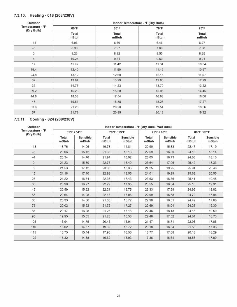
7.3.10. Heating - 018 (208/230V)
Outdoor Temperature - °F
(Dry Bulb)
Indoor Temperature - °F (Dry Bulb)60°F 65°F 70°F 75°FTotal
mBtuhTotal
mBtuhTotal
mBtuhTotal
mBtuh–13 6.96 6.69 6.46 6.27
–5 8.30 7.97 7.69 7.38
0 9.23 8.82 8.55 8.25
5 10.25 9.81 9.50 9.21
17 11.92 11.42 11.04 10.54
19.4 12.40 11.90 11.49 10.97
24.8 13.12 12.60 12.15 11.67
32 13.84 13.29 12.80 12.29
35 14.77 14.23 13.70 13.22
39.2 16.28 15.58 15.05 14.45
44.6 18.33 17.54 16.93 16.08
47 19.81 18.88 18.28 17.27
53.6 21.20 20.20 19.54 18.56
57 21.79 20.85 20.12 19.32
7.3.11. Cooling - 024 (208/230V)
Outdoor Temperature - °F
(Dry Bulb)
Indoor Temperature - °F (Dry Bulb / Wet Bulb)65°F / 54°F 70°F / 59°F 75°F / 63°F 80°F / 67°F
Total mBtuh
Sensible mBtuh
Total mBtuh
Sensible mBtuh
Total mBtuh
Sensible mBtuh
Total mBtuh
Sensible mBtuh
–13 18.76 14.06 19.78 14.81 20.90 15.83 22.47 17.19
–5 20.06 15.12 21.38 16.13 22.59 16.80 24.16 18.14
–4 20.34 14.76 21.94 15.92 23.05 16.73 24.66 18.10
0 21.23 15.30 22.75 16.40 23.64 17.06 25.42 18.33
5 21.53 17.12 23.08 18.36 24.25 19.25 25.94 20.46
15 21.18 17.10 22.98 18.55 24.01 19.29 25.68 20.55
25 21.22 16.54 22.36 17.43 23.63 18.36 25.41 19.45
35 20.90 16.27 22.29 17.35 23.55 18.34 25.18 19.31
45 20.59 15.52 22.21 16.75 23.33 17.59 24.95 18.82
55 20.64 14.98 22.13 16.06 22.99 16.68 24.72 17.94
65 20.33 14.66 21.80 15.72 22.90 16.51 24.49 17.66
75 20.02 15.92 21.72 17.27 22.69 18.04 24.26 19.30
85 20.17 16.28 21.25 17.16 22.46 18.13 24.15 19.50
95 19.95 15.55 21.28 16.58 22.48 17.52 24.04 18.73
105 18.94 14.75 20.43 15.91 21.47 16.71 22.96 17.88
110 18.02 14.67 19.32 15.72 20.18 16.34 21.58 17.33
115 16.75 15.44 17.96 16.56 18.77 17.08 20.18 18.29
122 15.32 14.68 16.62 15.93 17.36 16.64 18.56 17.80

22
7.3.12. Heating - 024 (208/230V)
Outdoor Temperature - °F
(Dry Bulb)
Indoor Temperature - °F (Dry Bulb)60°F 65°F 70°F 75°FTotal
mBtuhTotal
mBtuhTotal
mBtuhTotal
mBtuh–13 12.34 11.86 11.47 11.07
–5 14.70 14.13 13.65 13.04
0 16.35 15.71 15.17 14.48
5 17.95 17.20 16.67 16.00
17 21.14 20.26 19.61 18.53
19.4 21.54 20.60 19.96 18.96
24.8 22.07 21.09 20.44 19.52
32 22.55 21.59 20.90 20.06
35 23.23 22.24 21.51 20.75
39.2 25.25 24.15 23.36 22.42
44.6 28.28 27.15 26.24 25.32
47 29.63 28.33 27.46 26.36
53.6 30.72 29.39 28.45 27.02
57 31.83 30.44 29.44 27.82
7.4. Unit Dimensions
19-1/8 (486)
2-3/4
(70)
11-7/8 (302)
21-7/8
(556)
30-3/8 (772)
30-5/8 (778)
2-1/2
(64)
1/2 (13)
1/2
(13)
MCA009S4S, MCA012S4S, MCA081S4S
BOTTOM VIEW
FRONT VIEWSIDE VIEW
SIDE VIEW
12-5/8
(322)
11-1/4
(286)
2-3/8 (60)
3-5/8 (92)
DRAIN HOLE (bottom of unit)
11-3/4
(298)
Figure 16. 09, 12K and 18K Outdoor Unit Dimensions - Inches (mm)

23
MCA024S4S
27-5/8
(702)
BOTTOM VIEW
FRONT VIEWSIDE VIEW
SIDE VIEW
1/2
(13)14-1/4 (362)
2-3/4
(70)
33-5/8 (854)
21-1/4 (540)
33-1/4 (845)
7-7/8
(200)
1-3/8 (35)
15
(381)
13-1/8
(333)
2-3/8 (60)
3-5/8 (92)
13-3/4
(349)
Figure 17. 24K Outdoor Unit Dimensions - Inches (mm)
7.5. Outdoor Unit Clearances
7.5.1. Single Units
24 (610)
Air Outlet
Air Inlet
24
(610)
12
(305)79
(2007)
1 12
(305)
1 Minimum rear clearance can be 6 inches (152 mm) when mounted on brackets and with no obstructions on the other three sides.
Figure 18. Single Outdoor Unit Clearances - Inches (mm)

24
7.5.2. Multiple Units
Height of
Wall (C)
Unit
Height (A)
118 (2997)
(Min
imum
)
Unit
to
Wall
(B)
24 (610)
(Min
imum
)
60 (1500)
(Min
imum
)
10 (254)
(Minim
um)
10 (254)
(Minim
um)
AIRF
LO
W
AIRF
LO
W
CLEARANCE NOTES FOR MULTIPLE UNITS:
If the height of the wall (C) is less than or equal to the height of the smallest unit (A), the distance from the unit to the wall (B) must be a minimum of 10 inches
(254 mm).
If 1/2 the height of the unit (A) is less than the height of the wall (C), the distance from the unit to the wall (B) must be a minimum of 12 inches (305 mm).
If the height of the wall (C) is greater than the height of the unit (A), the distance from the unit to the wall (B) must be a minimum of 20 inches (508 mm).
NOTE: It is recommended that the single clearancebe followed in a multi-unit applications. If not then these are the maximum and minimum clearancesyou are allowed.
Figure 19. Multiple Outdoor Unit Clearances - Inches (mm)

25
8. Refrigeration Pipe Work
8.1. Single-Zone Refrigerant Cycle Diagram
LIQUID SIDE
GAS SIDE
HEATEXCHANGE(EVAPORATOR)
HEATEXCHANGE(CONDENSER)
COMPRESSOR
2-WAY VALVE
3-WAY VALVE
4-WAY VALVE
COOLING
HEATING
T2 Evaporatortemp. sensor
T1 Room temp.sensor
ACCUMULATOR
ROODTUOROODNI
CHECK VALVE(Heating Model only)
CAPILIARY TUBE
8.2. Single-Zone Piping Limitations
OUTDOOR UNIT
OUTDOOR UNIT
INDOOR UNIT
INDOOR UNIT
Maximum Line SetLength Maximum Line Set
Length
Maximum Elevation - Outdooor
Unit BELOW Indoor Unit
Maximum Elevation - Outdooor
Unit ABOVE Indoor Unit
Minimum Line Set Length - 10 ft. (3m)
Minimum Line Set Length - 10 ft. (3m)
Outside Unit BELOW Indoor Unit Outside Unit ABOVE Indoor Unit
Do not allow for excess length of line sets to be left rolled up as part of therequired distance, or in general. This will also cause additional performance issues.
IMPORTANT

26
Table 4. Line Set GuideEachsystemsizehasalinesetlengthandverticalelevationparameters.
System Size (KBtu)
Line Set Diameters (in.) Maximum Elevation Outdoor Unit BELOW
Indoor Unit - Feet (Meter)
Maximum Elevation
Outdoor Unit ABOVE Indoor
Unit - Feet (Meter)
Maximum Line Set Length - Feet (Meters)
Additional Refrigerant for greater than 25 Foot Line Set Lenght
Liquid Gas
009 1/4 3/8 33(10) 33(10) 82(25)Fortheadditionalcharging,werecommend0.161oz.for1/4”liquidlineand0.322oz.for3/8”liquidlineperfoot.
012 1/4 1/2 33(10) 33(10) 82(25)
018 1/4 1/2 66(20) 66(20) 98(30)
024 3/8 5/8 66(20) 66(20) 98(30)
9. Outdoor Unit Connections and Line Set Usage
Description Catalog No.
Size09 12 18 24
OUTDOOR UNITLineSets 1/4in.x3/8in.x25ft. 90X53 • N/A
1/4in.x3/8in.x50ft. X0258 • N/A
1/4in.x1/2in.x25ft. 90X52 N/A • • N/A
1/4in.x1/2in.x50ft. X0259 N/A • • N/A
3/8in.x5/8in.x25ft. X8406 N/A •3/8in.x5/8in.x50ft. X8407 N/A •
9.1. Pipe Length
Maximumpipinglengthandheightdifference.
Table 5. Pipe Diameter - MM (Inches)Indoor Unit
Extension Pipe Diameter (mm/inches)Model Pipe Diameter (mm/inches)
9KLiquid 6.35(1/4) Liquid 6.35(1/4)
Gas 9.52(3/8) Gas 9.52(3/8)
12Kand18KLiquid 6.35(1/4) Liquid 6.35(1/4)
Gas 12.7(1/2) Gas 12.7(1/2)
24KLiquid 9.52(3/8) Liquid 9.52(3/8)
Gas 15.9(5/8) Gas 15.9(5/8)
9.2. Torque Requirements
CAUTIONRefrigerantpipediameterisdifferentaccordingtoindoorunittobeconnected.Whenusingtheextensionpipe,refertothetablesbelow.Whenrefrigerantpipediameterisdifferentfromthatoftheoutdoorunitconnector(18Kindoorunit)anadditionaladapterisrequired.
Table 6. TorqueOutside Diameter Torque Additional Tightening
MM Inches v.cm N.cmФ6.35 1/4 1500(153kgf.cm) 1600(163kgf.cm)
Ф9.52 3/8 2500(255kgf.cm 2600(265kgf.cm)
Ф12.7 1/2 3500(357kgf.cm) 3600(367kgf.cm)

27
10. Power and Communication Wiring for Systems
CAUTIONThisunitmustbeproperlygroundedandprotectedbyacircuitbreaker.Thegroundwire for theunitmustnotbeconnectedtoagasorwaterpipe,alightningconductororatelephonegroundwire.Do not connect power wires to the outdoor unit un-til all other wiring and piping connections have been completed.Install all wiring at least 3 feet (1 m) away from televi-sions, radios or other electronic devices in order to avoid the possibility of interference with the unit op-eration.Do not install the unit near a lighting appliance that in-cludes a ballast. The ballast may affect remote control operation.
WARNINGIsolate the power supply before accessing unit electri-cal terminals.Install unit so that unit disconnect is accessible.Follow all local and national codes, as well as this installation instruction, during installation. Do NOT overload electrical circuit, as this may lead to failure andpossiblefire.Usespecifiedwiringandcabletomakeelectricalcon-nections. Clamp cables securely and make sure that connections are tight to avoid strain on wiring. Inse-cure wiring connections may result in equipment fail-ureandriskoffire.Wiringmustbeinstalledsothatallcover plates can be securely closed.
IntheU.S.A.,wiringmustconformwithcurrentlocalcodesand thecurrentNationalElectricCode (NEC). InCanada,wiringmustconformwithcurrentlocalcodesandthecurrentCanadianElectricalCode(CEC).Refer to unit nameplate forminimumcircuit ampacity andmaximumover-currentprotectionsize.• Allindoorunitsarepoweredbytheoutdoorunit.• Makeallelectricalpowerwiringconnectionsatthe
outdoor unit. • Sizeoutdoorunitpowerperlocalcodeandpower
requirements.• Connectwiringbetweenindoorandoutdoorterminals.• Refertounitnameplateforratedvoltage.• Besuretoreattachallelectricalboxcoversafter
connectionsarecomplete.• FollowNEC/CECstandardsandalllocalandstate
codesduringwiringinstallation.

28
11. Outdoor Unit Diagrams
COMPRESSOR
4-WAY
DC-FAN
CN 7
3
PAN
HEATER
CN
15
CN
60
CRANKCASE
HEATER
CN
17
BLU
E
BR
OW
N
BLACK
32 L N
RE
D
BLU
E
Y/G1
Y/G
AM
BIE
NT T
EM
P. S
EN
SO
R
DIS
CH
AR
GE
TE
MP. S
EN
SO
R
CN 21
.
Y/GY/G
CN
4_1
CN
4_2
CN
4_3
CN
4_4
REACTOR
CAPAC
ITO
R
BR
OW
N
BR
OW
N
BLAC
K
BLAC
K
Y/G
22
BLACK
WV
RED
BLUE
U
CN 1A
CN 3CN 1CN 2CN 16
CN 50
CN 30
CN 29
CN 28
OUTDOOR CONTROL
T5/TP
T3 T4
Figure 20. 9K - 115VAC Outdoor Unit Wiring Diagram
COMPRESSOR
Y/G
4-WAY
DC-FAN
CN 7
3
PAN
HEATER
CN
15
CN
60
CRANKCASE
HEATER
CN
17
BLU
E
BR
OW
N
YELLOW OR BLACK
32 L N
RE
D
BLU
E
Y/G1
Y/G
AM
BIE
NT T
EM
P. S
EN
SO
R
DIS
CH
AR
GE
TE
MP. S
EN
SO
R
CN 21
.
Y/GY/G
Y/G
CN
4_1
CN
4_2
CN
4_3
CN
4_4
REACTOR
CAPAC
ITO
R
BR
OW
N
BR
OW
N
BLAC
K
BLAC
K
22
BLACK
WV
RED
BLUE
U
CN 1A
CN 3 CN 1 CN 2 CN 16
CN
50
CN 30
CN 29
CN 28
OUTDOOR CONTROL
TP/T5
T3 T4
Figure 21. 12K - 115VAC Outdoor Unit Wiring Diagram

29
4-WAY VALVE
OU TDOOR
FAN
CN 7
3
PAN
HEATER
CN
15
CN
60
CRANKCASE
HEATER
CN
17
BLUE
BROWN
BLACK
32 L2
RED
BLUE
Y/G1
Y/G
CN 21
Y/G
CN 1A
Y/G
Y/G
COMPRESSOR
Y/G
CN
50
3
U V W
BLUE
RED
BLACK
OU
TD
OO
R
TE
MP. S
EN
SO
R
CO
MP
RE
SS
OR
DIS
CH
AR
GE
TE
MP. S
EN
SO
R
OU
TD
OO
R C
OIL
TE
MP. S
EN
SO
R
RED
BLAC
K
WH
TIE
OUTDOOR CONTROL
T5 T3 T4
Figure 22. 09K, 12K and 18K - 208/230VAC Outdoor Unit Wiring Diagram
4-WAY
DC- FAN
CN 414
3
PAN
HEATER
CN
19
CN
60
CRANKCASE
HEATER
CN
16
AM
BIE
NT T
EM
P. S
EN
SO
R
DIS
CH
AR
GE
TEM
P. SE
NS
OR
CN 17
.
Y/G
BLUE
BROWN 1
BLACK 3
32 L1L2
RED
BLUE L2
1Y/G
Y/G
CN 3
Y/G
Y/G
COMPRESSOR
Y/G
U V W
BLUE
RED
BLACK
L1 L2
S
White
Red
Blue
CN 6 CN 7 CN 8 CN 2
CN
21
W
V
U
OUTDOOR CONTROL
TP/T5
Figure 23. 24K - 208/230VAC Outdoor Unit Wiring Diagram
12. Installation Requirements

30
12.1. Gas Leak Check with Soap Water:
Apply soap water or a liquid neutral detergent on theconnectionswithasoftbrushtocheckforleakageinthepipeconnectingpoints.Ifbubblesemerge,thepipesareleaking.
12.2. Air and Moisture
Airandmoistureintherefrigerantsystemcausethefollowingproblems:• Increasesinsystempressure• Increasesinoperatingcurrent• Decreasesincoolingandheatingefficiency• Blocksincapillarytubingcausedbymoistureinthe
refrigerantcircuitfreezing• Corrosionofpartsintherefrigerantsystemcausedby
waterTheindoorunitsandthepipesbetweenindoorandoutdoorunitsmustbetestedforleakagesandevacuatedtoremovegasandmoisturefromthesystem.
12.3. Air Purging using a Vacuum Pump
• Completelytightentheflarenutsontheindoorandoutdoorunits.Confirmthatboththetwo-wayandthree-wayvalvesaresettotheclosedposition.
• ConnectthechargehosewiththepushpinoftheHandleLotothethree-wayvalvegasserviceport.
• ConnectthechargehoseoftheHandleHitothevacuumpump.
• FullyopentheHandleLoofthemanifoldvalve.• Turnonthevacuumpumptobeginevacuation.• Conducta30-minuteevacuation.Checkwhether
thecompoundmeterindicates-0.1Mpa(14.5Psi).Ifthemeterdoesnotindicate-0.1Mpa(14.5Psi)after30minuteshaselapsed,continueevacuationfor20moreminutes.Ifthepressuredoesnotreach-0.1Mpa(14.5Psi)after50minuteshaselapsed,checkifthereareanyleaks.
• FullyclosetheHandleLovalveofthemanifoldvalveandturnoffthevacuumpump.Afterfiveminutes,confirmthatthegaugeneedleisnotmoving.
• Turntheflarenutonthethree-wayvalve45°counter-clockwisefor6-7seconds.Oncegasbeginstocomeout,tightentheflarenut.Makesurethepressuredisplayonthepressureindicatorishigherthanatmosphericpressure.Thenremovethechargehosefromthethree-wayvalve.
• Fullyopenthetwo-wayandthree-wayvalvesandsecurelytightenthecaponthethree-wayvalve.
12.4. Adding Refrigerant if Pipe Length Exceeds Charge Less Pipe Length
Connectthechargehosetothechargingcylinderandopenthe two-way and three-way valves.With the charge hoseyoudisconnectedfromthevacuumpump,connectittothevalveatthebottomofthecylinder.IftherefrigerantisR-410A,placethecylinderbottom-uptoensureliquidchargingispossible.• Purgetheairfromthechargehose.• Openthevalveatthebottomofthecylinderandpress
thecheckvalveonthechargeset(becarefuloftheliquidrefrigerant).
• Placethechargingcylinderontotheelectronicscaleandrecordtheweight.
• Turnontheairconditionerincoolingmode.• Openthevalves(Lowside)onthechargeset.Charge
thesystemwithliquidrefrigerant.• Whentheelectronicscaledisplaystheproperweight
(refertothetable),disconnectthechargehosefromthethree-wayvalve’sserviceportimmediatelyandturnofftheairconditionerbeforedisconnectingthehose.
• MountthevalvestemcapsandtheserviceportUseatorquewrenchtotightentheserviceportcaptoatorqueof18N.m(13.27ft·lbs).
• Besuretocheckforgasleaks.
12.5. Add Refrigerant after Long-Term System Operation
• Connectthechargehosetothethree-wayserviceportandopenthetwo-wayandthree-wayvalve.
• Connectthechargehosetothevalveatthebottomofthecylinder.IftherefrigerantisR-410A,placethecylinderbottom-uptoensureliquidcharge.
• Purgetheairfromthechargehose.• Openthevalveatthebottomofthecylinderandpress
thecheckvalveonthechargesettopurgetheair(becarefuloftheliquidrefrigerant).
• Placethechargingcylinderontotheelectronicscaleandrecordtheweight.
• Turnontheairconditionerincoolingmode.• Openthevalves(Lowside)onthechargesetand
chargethesystemwithliquidrefrigerant.• Whentheelectronicscaledisplaystheproperweight
(refertothegaugeandthepressureofthelowside),disconnectthechargehosefromthethree-wayvalve’sserviceportimmediatelyandturnofftheairconditionerbeforedisconnectingthehose.
• Mountthevalvestemcapsandtheserviceport.Usetorquewrenchtotightentheserviceportcaptoatorqueof18N.m(13.27ft·lbs).

31
• Besuretocheckforgasleaks.
12.6. Servicing Indoor Unit Refrigeration Circuit
12.6.1. Collecting Refrigerant into Outdoor Unit
• Confirmthatboththetwo-wayandthree-wayvalvesaresettotheopenedposition
• Removethevalvestemcapsandconfirmthatthevalvestemsareintheopenedposition.
• Besuretouseahexagonalwrenchtooperatethevalvestems.
• Connectthechargehosewiththepushpinofhandlelotothethree-wayvalvesgasserviceport.
• Airpurgingofthechargehose-OpenthehandleLovalveofthemanifoldvalveslightlytopurgeairfromthechargehoseforfivesecondsandthencloseitquickly.
• Setthetwo-wayvalvetothecloseposition.• Operatetheairconditioneratthecoolingcycleand
stopitwhenthegaugeindicates0.1MPa(14psi).• Setthethree-wayvalvetotheclosedposition
immediately• Dothisquicklysothatthegaugeendsupindicating0.3
to0.5Mpa(43-72psi).• Disconnectthechargeset,andtightenthetwo-way
andthree-wayvalve’sstemnuts.• Useatorquewrenchtotightenthethree-wayvalves
serviceportcaptoatorqueof18N.m.• Besuretocheckforgasleakage.
12.6.2. Air Purging with Vacuum Pump
• Completelytightentheflarenutsoftheindoorandoutdoorunits,confirmthatboththetwo-wayandthree-wayvalvesaresettotheclosedposition.
• Connectthechargehosewiththepushpinofhandlelotothethree-wayvalvesgasserviceport.
• Connectthechargehoseofhandlehiconnectiontothevacuumpump.
• FullyopenthehandleLoofthemanifoldvalve.• Operatethevacuumpumptoevacuate.• Makeevacuationfor30minutesandcheckwhetherthe
compoundmeterindicates-0.1Mpa(500microns).Ifthemeterdoesnotindicate-0.1Mpa(500microbars)afterpumping30minutes,itshouldbepumped20minutesmore.Ifthepressurecan’tachieve-0.1Mpa(500microbars)afterpumping50minutes,pleasecheckiftherearesomeleakagepoints.
• FullyclosethehandleLovalveofthemanifoldvalveandstoptheoperationofthevacuumpump.Confirmthatthegaugeneedledoesnotmove(approximatelyfiveminutesafterturningoffthevacuumpump).
• Turntheflarenutofthethree-wayvalvesabout45°counterclockwiseforsixorsevensecondsafterthegascomingout,thentightentheflarenutagain.Makesurethepressuredisplayinthepressureindicatorisalittlehigherthantheatmospherepressure.Thenremovethechargehosefromthethree-wayvalve.
• Fullyopenthetwo-wayvalveandthree-wayvalveandsecurelytightenthecapofthethree-way
12.7. Evacuation after Servicing the Outdoor Unit Refrigeration Circuit
12.7.1. Evacuation of the Complete Refrigeration Circuit, Indoor and Outdoor Unit
• Confirmthatboththetwo-wayandthree-wayvalvesaresettotheopenedposition.
• Connectthevacuumpumptothree-wayvalve’sserviceport.
• Evacuationforapproximatelyonehour.Confirmthatthecompoundmeterindicates-0.1Mpa(500Microns/29.9in.hg).
• Closethevalve(Lowside)onthechargeset,turnoffthevacuumpump,andconfirmthatthegaugeneedledoesnotmove(approximately5minutesafterturningoffthevacuumpump).
• Disconnectthechargehosefromthevacuumpump.
12.7.2. Refrigerant Charging
• Connectthechargehosetothechargingcylinder,openthetwo-wayvalveandthethree-wayvalve.
• Connectthechargehosewhichyoudisconnectedfromthevacuumpumptothevalveatthebottomofthecylinder.IftherefrigerantisR-410A,makethecylinderbottomuptoensureliquidcharge.
• Purgetheairfromthechargehose• Openthevalveatthebottomofthecylinderandpress
thecheckvalveonthechargesettopurgetheair(becarefuloftheliquidrefrigerant).
• Putthechargingcylinderontotheelectronicscaleandrecordtheweight.
• Openthevalves(Lowside)onthechargesetandchargethesystemwithliquidrefrigerant.Ifthesystemcannotbechargewiththespecifiedamountofrefrigerant,orcanbechargedwithalittleatatime(approximately150geachtime),operatingtheairconditionerinthecoolingcycle;however,onetimeisnotsufficient,waitapproximately1minuteandthenrepeattheprocedure.
• Whentheelectronicscaledisplaystheproperweight,disconnectthechargehosefromthe3-wayvalve’sserviceportimmediately
• Ifthesystemhasbeenchargedwithliquidrefrigerant

32
whileoperatingtheairconditioner,turnofftheairconditionerbeforedisconnectingthehose.
• Mountedthevalvestemcapsandtheserviceport.Usetorquewrenchtotightentheserviceportcaptoatorqueof18N·m(13.27ft·lbs).
• Alwaysleakcheckafterservicingtherefrigerantsystem.
Thereareonelow-pressurecentralizedvalveandonehigh-pressurecentralizedvalve,itwillbemoretimesavingwhenvacuum and recycle refrigerant. But refer to the previousinstructionwhenvacuumandrecyclerefrigerant.
13. Electronic Function
13.1. Abbreviation
• T1:Indoorambienttemperature• T2:Middleindoorheatexchangercoiltemperature• T3:Outdoorheatexchangerpipetemperature• T4:Outdoorambienttemperature• T5:Compressordischargetemperature
13.2. Electric Control Working Environment.
• Inputvoltage:230V.• Inputpowerfrequency:60Hz.• Indoorfanstandardworkingamp.:<1A• Outdoorfanstandardworkingamp.:<1.5A.• Four-wayvalvestandardamp.:<1A
14. Adding Refrigerant - Single-Zone SystemsTheoutdoorunitisfactory-chargedwithrefrigerant.Calculatetheadditionalrefrigerantrequiredaccordingtothediameterand the lengthof the liquidpipebetween theoutdoorunitandindoorunitconnections.Besuretoaddtheproperamountofadditionalrefrigerant.Failuretodosomayresultinreducedperformance.See “Table 4. LineSetGuide” on page 26 for howmuchrefrigerantneedstobeaddedbasedonpipelength.NOTE: Interconnecting pipe work between outdoor and
indoor units must be 10 ft. or longer.NOTE: Do not remove refrigerant for line lengths less
than 25 ft. R-410A is a blended refrigerant. If you must remove charge, it is necessary to remove the entire charge and weigh in the new charge.
15. Single-Zone Outdoor Unit LED LocationsSingle-zoneoutdoorunitsdisplayflashcodeson themainboard.Themainboard isaccessedthroughthe topof theunit.Indoorunitswilldisplaymoredetailederrorcodes.TheseoutdoorunitsdonothaveaSW1spot checkpushbuttonswitch.Diagnostic isperformed throughaseriesofblue,redandgreenLEDs.NOTE: The control on all single-zone outdoor units is
mounted with all LEDs down and cannot be seen unless the control is removed.
Figure 24. Typical Location of Outdoor Unit LEDs

33
16. SpecificationsandOperationsTable 7. Electronic Functions Abbreviations
CN8 Indoorambienttemperature
CN9 Coiltemperatureofindoorheatexchanger
T3 Pipetemperatureofoutdoorheatexchanger
T4 Outdoorambienttemperature
T5 Compressordischargetemperature
Table 8. Electronic Control Working EnvironmentInputvoltage:230V
Inputpowerfrequency:60Hz
Indoorfannormalworkingamp.islessthan1A
Outdoorfannormalworkingampislessthan1.5A
Four-wayvalvenormalworkingampislessthan1A
Table 9. Main ProtectionThreeminutesdelayatrestartforcompressor
Oneminutedelayforthefirsttimestart-upandthreeminutesdelayforothers
Temperatureprotectionofcompressordischarge
Whenthecompressordischargeisgettinghigher,therunningfrequencywillbelimitedasbelowrules:
If215.6°F(102°C)<T5<244.4°F(115°C),decreasethefrequencytothelowerleveleverytwominutesuntiltoF1.
IfT5<244.4°F(115°C)fortenseconds,thecompressorwillstopandrestarttillT5<194°F(90°C)
Table 10. Indoor/Outdoor Units Communication ProtectionIftheindoorunitscannotreceivethefeedbacksignalfromtheoutdoorunitsfortwominutes,theunitwillstopanddisplayfailure.
HighCondenserColTempProtection
WhenT3>149°F(65°C)forthreeseconds,thecompressorwillstopwhiletheindoorfanandoutdoorfanwillcontinue.
WhenT3<125.6°F(52°C),theprotectionwillreleaseandthecompressorwillrestartafterthreeminutes.
RunningRules IfthecompressorfrequencykeepslowerthanRET_OIL_FREQ1_ADDforRET_OIL_TIME1_ADD,theACwillrisethefrequencytoRET_OIL_FREQ2_ADDforRET_OIL_TIME2_

34
16.1. Cooling Chart
Table 11. Cooling - Fahrenheit (Celsius)
°F(°C) ODU(DB) IDU(DB/WB)
0 (-17)
5 (-15)
15 (9.44)
45 (7.22)
75 (23.89)
85 (29.44)
95 (35)
105 (40.56)
115 (46.11)
120 (48.89)
PSI
70/59(21.11/15) 93 94 106 116 119 113 117 125 147 154
75/63 (23.89/17.22)
97 99 115 125 124 120 126 132 155 162
80/67 (26.67/19.44)
103 104 123 138 135 129 132 140 162 173
90/73 (32.22/22.78)
112 113 139 152 149 138 145 154 180 189
16.2. Heating Chart
Table 12. Heating - Fahrenheit (Celsius)
°F(°C) ODT / IDT 57/53(13.89/11.67)
47/43(8.33/6.11)
37/33(2.78/0.56)
27/23(-2.78/-5)
17/13 (-8.33/-10.56)
0/-2(-17/-19)
-17/-18(-27/-28)
PSI
55 439 413 367 330 302 268 239
65 471 435 386 368 339 297 276
75 489 457 381 381 362 312 290
0
0.5
1
1.5
2
2.5
3
3.5
4
55
65
75

35
16.3. Capacity Request Calculations
TotalcapacityRequest=Σ(Normcode×HP)/10×modifyrate+correction.
T1 Ts
3
1
1e
c
a 4
2
0
2
3
01
f
d
b
Figure 25. Cooling Mode
CapacityArea a b c d e f
NormCode(N) 3 2 1.5 1 .5 0
NOTE: The final result is integer.Plusalltheindoorcapacityrequesttogether,thenmodifyitbyT4.Whenthereisonlyoneindoorunit:
OutdoorTemperature(T4)
Cooling>29°C 18°Cto29°C <17°C
>84.2°F 64.4°Fto84.2°F <62.6°F
ModifyRate 100% 60% 40%
Whenthereismorethanoneindoorunit:OutdoorTemperature(T4)
Cooling>25°C 17°C-25°C <17°C
>77°F 62.6°F-77°F <62.6°F
ModifyRate 100% 80% 40%
NOTE: The final result is integer.Inlowambientcoolingmode,modifyrateisfixedas40%.Accordingtothefinalcapacityrequesttoconfirmheoperatingfrequency,asfollowingtable.
Frequency(Hz) 0 COOL_ F1
COOL_ F2
...
...COOL_
15COOL_
16
Amendatorycapacity demand 0 1 2
...
...15 16
Meanwhilethemaximumrunningfrequencywillbeadjustedaccordingtotheoutdoorambienttemp.

36
16.4. Outdoor Fan Control
16.4.1. Cooling ModeNormallythesystemwillchoosetherunningfanspeedaccordingtoambienttemperature:
T4
A DC_FAN_HI_SPD_ADD
B DC_FAN_MID_SPD_ADD
C DC_FAN_MIN_SPD_ADD
D DC_FAN_SLOW_SPD_ADD
E DC_FAN_SSLOW_SPD_ADD
23℃
22℃
20℃
28℃
19℃
17℃
26℃
25℃
Whenlowambientcoolingisvalid:
27High
Low
25
20
15
low ambient cooling
Outdoorfanspeedcontrollogical(lowambientcooling).WhenT4<15°C(59°F)andT3<30°C(86°F),theunitwillenterintolowambientcoolingmode.TheoutdoorfanwillchoosespeedaccordingtoT3.WhenT3≥38°C(100.4°F)orwhenT4≥20°C(68°F),theoutdoorfanwillchoosethespeedaccordingtoT4again.
38
Exit low ambient coolingmode, run with high fanfor 1 minute
Low
3027
23off

37
17. Indoor and Outdoor Unit DisassemblyNOTE: This section is for reference only. Actual unit
appearance may vary.
17.1. Indoor Unit (All Models)
17.1.1. Front Panel
Step 1. Holdthefrontpanelbythetabsonthebothsidesandliftit.
TAB
Step 2. Pushupthebottomofanairfilter(step1),andthenpullitoutdownwards(step2).
FILTER
Step 3. Openthehorizontallouverandpushthehooktowardslefttoopenit.
Horizontal Louver
Hook
Step 4. Bendthehorizontallouverlightlybybothhandstoloosenthehooks,thenremovethehorizontallouver.
Hook
Step 5. Prytheelectricalcoverbyascrewdriver,androtateittowardsleft,thenremoveit.

38
Step 6. Disconnecttheconnectorfordisplayboard.
Step 7. Slidethefrontpanelsidetosidetoreleaseeachaxis.
Step 8. Openthescrewcapandthenremovethethreescrews.
Step 9. Releasethehookswithhands.

39
Step 10. Releasethefivehooksintheback.
Hooks
Step 11. Pulloutthepanelframewhilepushingthehookthroughaclearancebetweenthepanelframeandtheheatexchanger.
Step 12. Releasethe5hooksoftheverticalblades,thenpulltheverticalbladesrightwardandremoveit.
Step 13. Remove1screwofthedisplayboard.Step 14. Rotatethedisplayboardinthedirectionshownin
therightpicture.
17.1.2. Electrical PartsNOTE: When handling electrical parts use anti-static
gloves.NOTE: Remove the front panel (see Step 1 on page 37)
before disassembling electrical parts.
Step 1. Cuttheribbonbyashear,thenpulloutthecoiltemperaturesensor(T2).
Step 2. Removeonefixingscrewoftheelectroniccontrolboxandtwoscrewsusedforthegroundconnection.
Ribbons T2 Sensor
Step 3. Anupwardforceismaintaineduntilthecoverofelectroniccontrolboxisremoved.

40
Step 4. Removethefixeddevicesoftheconnectors.
Step 5. Disconnecttheconnectorsoffanmotor,thestepmotorandtheT2sensor.
Step 6. Opentheleftsideplateofelectroniccontrolbox.
Step 7. Openthetwoclipsonthefrontoftheelectricbox.
Step 8. Opentheuppercoverplateofelectroniccontrolbox.
Step 9. Remove1screwandopenthe2clipsalongthedirectionindicatedinimagebelow.

41
Step 10. Pullouttheelectricalmainboardalongthedirectionindicatedinrightimagetoremoveit.
Display
Board
Terminal S
Terminal 1L
Terminal W
Pipe Temp Sensor
RoomTemp Sensor
17.1.3. EvaporatorNOTE: Remove the front panel and electrical parts (see
both “Front Panel” on page 37 and “Electrical Parts” on page 39 Electrical parts) before disassembling evaporator.
Step 1. Disassemblythepipholderlocatedattherearoftheunit.
Pipe Header
Step 2. Removetheonescrewontheevaporatorlocatedatthefixedplate.
Screw

42
Step 3. Releasethehookontheevaporator.
Step 4. Removetheonescrewontheevaporatorlocatedoatthefixedplate.
Step 5. Pullouttheevaporator.
17.1.4. Fan Motor and FanNOTE: Remove the front panel and electrical parts (see
“Front Panel” on page 37, “Electrical Parts”
on page 39 Electrical parts and “17.1.3. Evaporator” on page 41) before disassembling fan motor and fan.
Step 1. Removethetwoscrewsandremovethefixingboardofthefanmotor.
Screws
Step 2. Removethebearingsleeve.
Step 3. Removethefixingscrew.Step 4. Pulloutthefanmotorandfanassemblyfromthe
side.
Fixing Screw
17.1.5. Step MotorNOTE: Remove the front panel and electrical parts (see
both “Front Panel” on page 37 and “Electrical

43
Parts” on page 39 Electrical parts) before disassembling step motor.
Step 1. Removethetwoscrews,thenremovethesteppingmotor.
Stepping Motor
17.1.6. Drain Hose
Step 1. Rotatethefixedwireclockwiseindicatedinimaginebelow.
Step 2. Pullupthedrainhosetoremoveit.
17.2. Outdoor Unit
17.2.1. Panel Plate (Some Models)
Step 1. Turnofftheairconditionerandthepowerbreaker.
Step 2. Removethescrewofthebighandleandthenremovethehandle.
Step 3. Removethescrewsofthetopcoverandthenremovetopcover.Oneofthescrewsislocatedunderneaththebighandle.
Top Cover

44
Step 4. Removethescrewsofthefrontpanelandthenremovethefrontpanel.
Front Panel
Step 5. Removethescrewfromthewatercollectorcover.
Water Collection Cover
Step 6. Removethescrewsontherearcoilguardandthenremovethecoilguard.
Front Cover
Step 7. Removethescrewsfromtherightpanelandthenremovepanel.
Right Panel
17.2.2. Panel Plate (MWHA024S4)
Step 1. Turnofftheairconditionerandthepowerbreaker.
Step 2. Removethescrewsthatsecurethehandleandthenremovethehandle.
Step 3. Removethescrewsfromthetopcoverandthenremove.Oneofthescrewsislocatedunderneaththehandle.
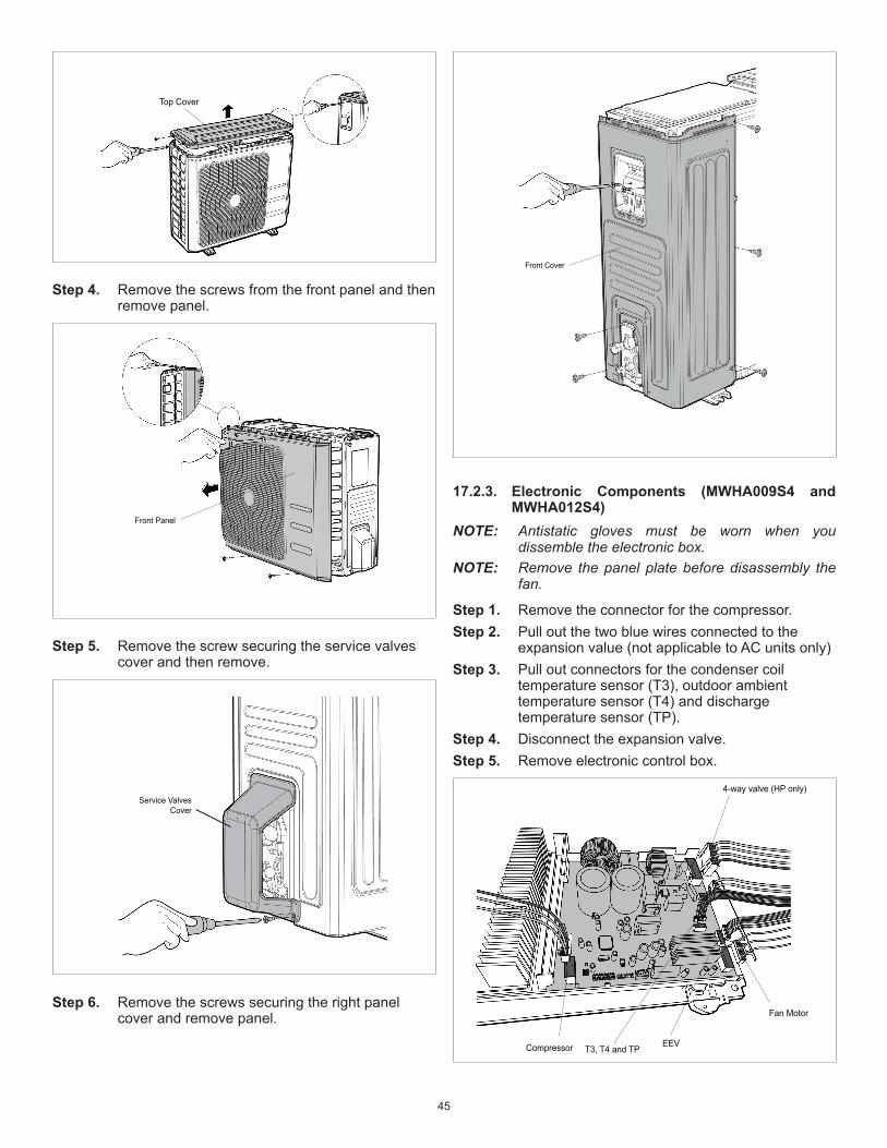
45
Top Cover
Step 4. Removethescrewsfromthefrontpanelandthenremovepanel.
Front Panel
Step 5. Removethescrewsecuringtheservicevalvescoverandthenremove.
Service Valves
Cover
Step 6. Removethescrewssecuringtherightpanelcoverandremovepanel.
Front Cover
17.2.3. Electronic Components (MWHA009S4 and MWHA012S4)
NOTE: Antistatic gloves must be worn when you dissemble the electronic box.
NOTE: Remove the panel plate before disassembly the fan.
Step 1. Removetheconnectorforthecompressor.Step 2. Pulloutthetwobluewiresconnectedtothe
expansionvalue(notapplicabletoACunitsonly)Step 3. Pulloutconnectorsforthecondensercoil
temperaturesensor(T3),outdoorambienttemperaturesensor(T4)anddischargetemperaturesensor(TP).
Step 4. Disconnecttheexpansionvalve.Step 5. Removeelectroniccontrolbox.
Compressor T3, T4 and TPEEV
Fan Motor
4-way valve (HP only)

46
17.2.4. Electronic Components (MWHA018S4)
Step 1. Removetheconnectorforthecompressor.Step 2. Pulloutconnectorsforthecondensercoil
temperaturesensor(T3),outdoorambienttemperaturesensor(T4)anddischargetemperaturesensor(TP).
Step 3. Disconnectthefour-wayvalvewire.Step 4. Disconnectthegroundwire.Step 5. Removetheconnectorfortheindoorunit.Step 6. Removeelectroniccontrolbox.
17.2.5. Electronic Components (MWHA024S4)NOTE: Antistatic gloves must be worn when you
dissemble the electronic box.NOTE: Remove the panel plate before disassembly the
fan.
Step 1. Removetheconnectorforthecompressor.Step 2. Pulloutthetwobluewiresconnectedtothe
expansionvalue(notapplicabletoACunitsonly)Step 3. Pulloutconnectorsforthecondensercoil
temperaturesensor(T3),outdoorambienttemperaturesensor(T4)anddischargetemperaturesensor(TP).
Step 4. Disconnecttheexpansionvalve.Step 5. Removeelectroniccontrolbox.
Compressor
Reactor
4-way valve
Fan Motor
EEV
T3, T4 and TP
17.2.6. Fan Disassembly (MWHA009S4 and MWHA012S4)
NOTE: Antistatic gloves must be worn when you dissemble the electronic box.
NOTE: Remove the panel plate before disassembly the fan.
Step 1. Removenutsecuringthefanwithaspanner.
Step 2. Removethescrewssecuringthetopcover.

47
Step 3. Releasethehooksandthenopentheelectroniccontrolboxcover.
Hook
Step 4. Disconnecttheconnectorfromthefanmotorfromtheelectroniccontrolboard.
Fan Motor Connector
Step 5. Removethescrewssecuringthefanmotorandthenremovefanassembly.
Fan Motor
17.2.7. Fan Disassembly (MWHA018S4)
Step 1. Removethenutsecuritythefantothefanmotor.
Step 2. Removethescrewssecuringthecoveroftheelectroniccontrolboxcover.
Step 3. Disconnectconnectorfromelectroniccontrolboardplug.

48
Step 4. Removethescrewssecuringthefanmotortobody.Thenremovefanmotor.
17.2.8. Fan Disassembly (MWHA024S4)
Step 1. Removethenutsecuritythefanwithaspanner.Thenremovethefan.
D Cut
Step 2. Releasethehooksandthenopentheelectroniccontrolboxcover.
Hook
Step 3. Disconnecttheconnectorforthefanmotorfromtheelectroniccontrolboard.
Fan Motor Connector
Step 4. Removethescrewssecuringthefanmotorfrombody.Removethefan.
Fan Motor

49
17.2.9. Sound BlanketNOTE: Recover refrigerant before removing the
compressor.
Sound Blanket
Sound Blanket (side)
17.2.10. Four-Way ValveWARNING:Recover refrigerant from the refrigerant circuitbeforeremovethefour-wayvalve.NOTE: Remove the panel plate, electrical parts, and fan
assembly before disassembling four-way valve.
Step 1. Heatupthebrazedpartsandthendetachthethefour-wayvalveandthepipe
Step 2. Removethefour-wayvalveassemblywithpliers.
17.2.11. CompressorNOTE: Recover refrigerant before removing the
compressor.
Step 1. Removetheflangenutoftheterminalcoverandremovethecover.
Terminal Cover
Step 2. Disconnectallconnectors.
Step 3. Removethehexnutsandwasherswhicharelocatedonthebottomoftheplatewhicharesecuringthecompressor.

50
Step 4. Heatupthebrazedpartsandthenremovethedischargeandsuctionspipes.
Step 5. Liftthecompressorfromthebasepanassemblywithpliers.

51

52