Dedicated Freight Corridor Corporation of India Ltd. - DFCCIL
Upload
khangminh22Category
view
16download
0
Addm 1 : Attachment 4 (94 Sheets)/ Vol. III
Sheet 1 of 94
Part -XI
Specification for 60/84/100 MVA, 220/132 kV/54 kV SCOTT-CONNECTED TRACTION POWER TRANSFORMER FOR 2x25 kV AT FEEDING SYSTEM
1. Scope 1.1 This document applies to 60/84/100 MVA, ONAN/ONAF/OFAF, 220/132/54kV
Scott-connected traction power transformers for Auto Transformer (AT) feeding system for installation in DFCC, an infrastructure providing company of Indian Railways.
1.2 The transformer shall be complete with all parts, fittings and accessories whether specifically mentioned herein or not, necessary for its efficient operation in an unattended traction substation and it shall be supplied with appropriate fire fighting system as per IS-3034:1993 or with Nitrogen Injection Fire Protection system as per safety guidelines 2010 issued by CEA.
2. Governing specification 2.1 In the preparation of this document, assistance has been taken from the
following National and International standards, wherever applicable.
Table No. 2.1-1
Standard Description
Equivalents IS
IEC 60076 (all parts)
IS:2026 (all parts)
Power transformers.
IEC 60044-1 IS:2705 Instrument transformer – Part 1: Current transformer.
IEC 60137 IS:2099 Bushing for alternating voltages above 1000V
IEC 60214 IS:8468 Tap changers.
IEC 60296 IS:335 Fluids for electrotechnical applications - Unused mineral insulating oils for transformers and switchgear/ New insulating oils.
IS:5 Colours for ready mix paints and Enamels.
IEC 60502-1 IS:1554 (Part 1)
PVC insulated (heavy duty) Electric cables: Part 1 For working voltages up to and including 1100V
IS:1570 Schedules for Wrought Steels - Part 5: Stainless and heat resisting steels.
IS:1576 Solid pressboard for electrical purposes
IEC 60422 IS:1866 Code of practice for electrical maintenance and supervision of mineral insulating oil in equipment
IS:2927 Brazing alloy
JIS C 2553 IS:3024 Grain oriented electrical steel sheets and strips

Addm 1 : Attachment 4 (94 Sheets)/ Vol. III
Sheet 2 of 94
IS: 3637 Gas operated relays
IS:3639 Fittings and accessories for power transformers
IS:4253 Cork composition sheets : Part 2 Cork and Rubber
IS:5561 Electrical power connectors
IEC 60909 IS:13234 Guide for short circuit calculations in 3Phase a.c. systems.
IEC 60270 IS: 6209 High-voltage test techniques - Partial discharge measurements.
IS:6600 Guide for loading of oil-immersed transformers
IS:10028 (all parts)
Code of practice for selection, installation and maintenance of transformers
IS:10593 Mineral Oil-impregnated electrical equipment in services - Guide to the interpretation of dissolved and free gases analysis
IEC 60137 IS: 12676 Oil impregnated paper insulated condensers bushings – dimensions and requirements
DIN 7733 Laminated products, pressboard for electrical engineering, types.
Central Electricity Authority (Measures relating to Safety and Electricity Supply) Regulations, 2010, part-III, Sec.4, 2010 Rule no. 44 (2) (ix).
2.2 In case of any conflict between the contents of the above standards and this document, the latter shall prevail.
2.3 Any deviation, proposed by the bidder, calculated to improve the performance, utility and efficiency of the equipment, will be given due consideration; provided full particulars of the deviation with justification are furnished. In such a case, the bidder shall quote according to this document and the deviations, if any, proposed by him shall be quoted as alternative/alternatives.
3. Climatic and Atmospheric Conditions 3.1 The transformer shall be suitable for outdoor use in moist tropical climate and
in areas the limiting weather conditions which the equipment has to withstand in service are given in Part-II of the Particular Specification.
3.2 The transformer would also be subjected to vibrations on account of trains running on nearby railway tracks.
3.3 The amplitude of these vibrations which occur with rapidly varying time periods in the range of 15 to 70 ms lies in the range of 30 to 150 microns at present, with instantaneous peaks going up to 350 microns. These vibrations may become more severe as the speeds and loads of trains increase in future.
4. Traction Power Supply Systems 2x25kV AT Feeding System
4.1 General Scheme
4.1.1 The electric power for railway traction is supplied in ac 50 Hz, single-phase through 2x25 kV AT feeding system, which has a feeding voltage (2x25 kV)

Addm 1 : Attachment 4 (94 Sheets)/ Vol. III
Sheet 3 of 94
from the traction substation (TSS) two times as high as the catenary voltage, which is 25 kV with respect to earth/rail. The power fed from the TSS through catenary and feeder wire is stepped down to the catenary voltage by means of autotransformers (ATs) installed about every 13 to 17 km along the track, and then fed to the locomotives. In other words, both the catenary and feeder voltage are, 25 kV with respect to the earth/rail, although the substation feeding voltage between catenary and feeder wires is 50 kV. The catenary voltage is therefore, the same as that in the conventional 25 kV system.
4.1.2 The power supply shall be obtained from the 220 kV/132 kV, three-phase, effectively earthed transmission network of the State Power Utilities to the Scott-connected transformer installed at the TSS, whose primary winding is connected to the three phases of the transmission network. The spacing between adjacent substations is normally 60 km.
4.1.3 One outer terminal of the secondary windings of the traction transformer is connected to the catenary and the other outer terminal is connected to the feeder.
4.1.4 ATs connect the 25 kV catenary to 25 kV return feeder, with mid-point connected to rail and earth (25 kV return OHE and earth). Two adjacent AT’s share power to feed trains at 25 kV/2x25 kV system feeds 50 kV supply from traction transformer terminal to the ATs. The load current (current drawn by electric locomotives) from the TSS flows through the catenary and returns to the TSS through the feeder. For a train in an AT-cell (distance between two consecutive ATs), most of the current is fed to the electric locomotive by the ATs of that AT-cell; the, current returns in the rails/earth and is boosted up to the feeder through the neutral terminals of the autotransformers. The current in OHE, therefore, is an algebraic sum of 25 kV current feed to locomotives from AT and the 50 kV supply to ATs from the TSS.
4.1.5 Approximately midway between adjacent TSSs, a sectioning and paralleling post (SP) is provided. In order to prevent wrong phase coupling of power supply, a dead zone known as ‘Neutral Section’ is provided in the OHE opposite the TSS as well as SP. At the TSS, there are two-feeder circuit breakers for either side of the TSS for controlling the power fed to the OHE, in a double track section. Out of the two feeder circuit breakers for one side, one feeds the OHE of that side while the other remains (open) as standby. There is also a paralleling interrupter, which is normally closed, for either side of the TSS for paralleling the OHE of the UP and DOWN tracks. In case of fault in the OHE, the feeder circuit breaker of the TSS trips to isolate it. The Bridging Interrupter is used to feed one TSS up to the next TSS, in case the adjacent TSS is temporarily out of order.
4.1.6 For maintenance work and keeping the voltage drop within limit, one or more sub-sectioning and paralleling post (SSP) are provided between the TSS and SP. The supply control Posts are on an average located every 13-17 km interval. An SSP has four sectioning interrupters and one paralleling interrupter, whereas an SP has two bridging circuit breakers (which remain open under normal feeding condition) and two paralleling interrupters.

Addm 1 : Attachment 4 (94 Sheets)/ Vol. III
Sheet 4 of 94
4.2 Protection System 4.2.1 The protection system of the traction transformer comprises the following:
1 Differential protection 2 Instantaneous and IDMT over-current, and earth fault protection
on the primary side
3 Protection against phase-failure on the secondary side (i.e. to detect malfunction of feeder/transformer circuit breaker)
4 Buchholz Relay 7 Thermistor/Optical hot spot sensor. The Transformer should have
built-in hottest spot temperature device to indicate and record the hot test spot temperature as per IEC-60076-2 (Ed. 3.0).
4.2.2 The protection systems for the OHE comprise the following:
1 Distance protection 2 Delta I type fault selective protection 3 Instantaneous over current protection 4 Under-voltage protection to avoid wrong phase coupling 5 Fault locating expert system based on AT voltage neutral current.
4.3 OHE General data
4.3.1 The OHE shall consists of (i) Contact wire of minimum 150 mm2 cross section suspended directly from catenary of wire of minimum 125 mm2 cross section by a number of vertical dropper wires, usually at regular intervals and (ii) a feeder wire of stranded all aluminium conductor.
4.4 Traction Transformer General Data
4.4.1 The transformer shall have 60/84/100 MVA power rating based on ONAN/ ONAF/OFAF cooling. The transformer shall be supplied with ONAN rating only.
4.4.2 However, provision shall be made by the contractor for installing cooling fans for operation in ONAF mode (84 MVA), as & when required by the employer.
4.4.3 Further, provision shall also be made by the contractor for installation of oil pump for operation in OFAF mode (100 MVA), as & when required by the employer.
4.5 Nature of traction loads and faults on the OHE system
4.5.1 The traction load is a frequently and rapidly varying one; between no load and overload. The TSS equipment is subject to frequent earth faults/short circuits caused by failure of insulation, snapping of OHE touching earth, wire dropped by bird connecting the OHE to earth/ over line structure, and miscreant activity. On an average, the number of faults/ short circuits per month could be as high as 40. The magnitude of the fault current may vary between 40% and 100% of the dead short circuit value. These faults are cleared by the feeder circuit breaker on operation of the distance, delta I and instantaneous over-current relays associated with the concerned feeder circuit breaker. In 2x25 kV system

Addm 1 : Attachment 4 (94 Sheets)/ Vol. III
Sheet 5 of 94
faults can occur with: feeder-earth; feeder-OHE and OHE-earth faults or a combination of them.
4.5.2 The existing Indian Railways ac electric locomotives are silicon rectifiers or with dc motors or GTO/IGBT based power converter fed 3-phase Induction Motors and the average power factor generally varies between 0.7 and 0.85 lagging, without reactive power compensation, which introduces harmonic currents in the 25kV power supply system.
4.5.3 On DFCC (Western) Locomotives are proposed to have VVVF drives and improved power factor closer to 0.98 and negligible harmonics. The traction supply may therefore be at higher power factor than those on IR.
4.6 Short-Circuit Apparent Power of the system 4.6.1 The short-circuit apparent power at the transformer location for various system
voltages is as under:
Highest system voltage (kV) Short circuit apparent power (MVA) 72.5 3,500 123 6,000
145 10,000 245 20,000
4.7 Auxiliary power supplies at TSS 4.7.1 The following auxiliary power supplies are available
1 110V dc from a battery 2 240 V ac, 50 Hz, single-phase from a 25/0.24 kV auxiliary transformer
feed from Traction supply.
5. Rating and General Data 5.1 The rating and general data of the transformer shall be as follows:
S.No. Item Description 1 Type ONAN/ONAF/OFAF cooled, Scott-connected (3
phase/ 2 phase), step down power transformer, double limb wound, core/shell-type for outdoor installation.
2 Windings Primary windings shall be T-connected for three phase supply. Two secondary windings, one per phase, Main-phase (M-phase) and Teaser-phase (T-phase), with a phase difference of 90 degree. The primary and secondary windings shall be uniformly insulated.
3 Rated Frequency (Hz) 50 + 3% 4 Rated 3-phase primary
voltage between phases Un 220/132

Addm 1 : Attachment 4 (94 Sheets)/ Vol. III
Sheet 6 of 94
(kV) 5 Highest 3-phase system
voltage between phases Um (kV)
245/145
6 Rated 2-phase secondary voltage (at no load), (kV)
54 per phase
7 Rated power, (MVA) 60/84/100 MVA ONAN/ONAF/OFAF (Each secondary winding shall have a rated power of 30/42/50MVA)
8 Rated current at the principal tapping: i. Rated primary current (A) ii. Rated secondary current
(A)
157.6 / 220.7 556 / 840 (for each secondary winding)
9 Percentage of impedance voltages, main/primary winding and teaser/primary winding at 30 MVA based at principal tapping.
%Z = 11-13%
10 Non-cumulative overload capacity on ONAN rating.
1) 150% rated load for 15 minutes 2) 200% rated load for 5 minutes
11 Polarity Subtractive 12 Tapping (off - circuit) Separate tapped winding on primary winding to
give rated secondary voltage for variation in primary voltage of +10% to -15%, in steps of 5% each.
13 Temperature rise 1) Winding: 50K at rated load, and 60K for overloads as specified in Clause 5.1(10) (temperature measured by resistance method).
2) Top oil: 45K (temperature rise measured by thermometer).
3) Current carrying parts in air. 40K (temperature rise measured by thermometer).
14 Maximum permissible losses
1.No-load losses ,kW 50 kW
2. Total load losses at the principal tapping including core, windings, frame parts, tank and auxiliary requirements.
250 kW at 60 MVA ONAN
15 Ability to withstand short circuit:

Addm 1 : Attachment 4 (94 Sheets)/ Vol. III
Sheet 7 of 94
6. Salient design features 6.1 Overall dimensions 6.1.1 The overall dimensions of the transformer shall be kept as low as possible and
in any case shall not exceed the transportation limit in India. (Transportation dimension)
1 Length x Width (in mm) 14,000 x 6,500 2 Height of topmost point of primary bushing terminal 7,500 mm 3 Height of topmost point of secondary bushing
terminal 5,500mm
1.Thermal ability 2.Dynamic ability
2s 0.5s
16 Flux density at rated voltage and frequency at principal tapping.
Shall not exceed either 1.7 T.
17 Current density in the windings.
Shall not exceed 2.5A/mm2 at 60MVA for ONAN.
18 Acoustic sound level when energized at rated voltage and at no-load.
NEMA Standard TR-1-1993 (R2000) Table -2
19 Bushing Item Secondary Primary (220/132kV)
Type OIP condenser
OIP condenser
Highest voltage for equipment Um(kV)
54 245/145
Rated current(A) 1250 800 Minimum creepage distance in air (mm)
1300 6125/3625
20
Busing type current transformers for differential protection of transformer
Item Secondary Primary Highest voltage 52 245/145 CT Ratio 1000/5 300/5, 600/5 Frequency(Hz) 50 +/- 3% 50 +/- 3% Class of accuracy as per IEC60044-1.
PX PX
Minimum knee-point emf,(V)
150 125/175
Maximum excitation current at knee-point voltage (A)
0.25 0.75
Maximum resistance of the secondary winding, (Ω)
0.5 0.25

Addm 1 : Attachment 4 (94 Sheets)/ Vol. III
Sheet 8 of 94
6.1.2 The manufacture shall, where practical, design the transformer so that with the bushings & accessories removed, the transformer shall fit within Indian Railway loading gauge, in case it is transported through rail, MMD to be enclosed with the offer.
6.1.3 The transformer should be designed nitrogen or dry air filled, such that it can be transported without the insulation oil inside the tank. The transformer shall be designed such that it can be transported with tank under pressure with nitrogen and other protective measures that the Manufacturer recommends, so that no moisture can enters the housing.
6.2 Tank 6.2.1 The tank for the transformer shall be of the top cover jointed with bolted
connection. The bottom plate of main tank shall be firmly welded to the main body and the top cover is a plate reinforced with ribs. The winding and core shall fully exposed when the tank cover is lifted. A pressure gauge along with a hygrometer shall be provided so that the status of dryness of the winding can be assessed in the transformer prior to its heat run before commissioning.
6.2.2 The tank shall be constructed from mild steel of a quality that allows welding without any defect/flaw, with a single tier construction, shaped so as to reduce welding to the minimum. The welded joints shall be made using good engineering practices. The tank shall be adequately strengthened for general rigidity to permit hoisting of the transformer filled with oil by crane. The tank body shall be designed to withstand against the full vacuum degree.
6.2.3 The tank shall be fitted with four lifting pads at the lower end to enable lifting of the transformer filled with oil by means of lifting jacks.
6.2.4 The tank shall be fitted with an under carriage and mounted on bidirectional swiveling type flanged rollers for being rolled on 1676mm (5' 6") gauge track, on which it shall also rest in the final position. The rollers shall be provided with detachable type locking arrangement to enable their locking after installing the transformer in the final position, to hold the transformer fixed on foundation and to prevent any accidental movement of the transformer.
6.2.5 There shall be at least five inspection covers of suitable size on the tank to enable inspection of the lower portions of bushings, and the leads as well as the various connections of the motorised off-circuit tap-changer.
6.2.6 The gaskets with groove NBR (NITRILE BUTADIENE RUBBER) shall be provided for oil sealing points. The rubberized cork gasket may be used for other general portion.
6.2.7 All valves used in the transformer shall be capable to withstand full vacuum degree. The manufacturer shall ensure that suitable anti-theft measures like locked use of blanking plates are provided on these valves, so as to prevent pilferage/theft of oil during transit and service.
6.3 Marshalling box 6.3.1 A vermin proof, weatherproof and well ventilated, marshalling box with IP
class 55, made up of sheet steel of thickness not less than 2 mm, strengthened with adequate stiffeners, shall be provided on the left hand side of the transformer tank as viewed from the secondary terminals side.

Addm 1 : Attachment 4 (94 Sheets)/ Vol. III
Sheet 9 of 94
It shall have a hinged door, with provision for padlocking the door opening outward horizontally.
6.3.2 The marshalling box shall have a sloping roof. The top of the marshalling, box shall be at a height of about 2 m from the transformer rail level.
6.3.3 The marshalling box, shall house the winding and oil temperature indicators and terminal board. To prevent condensation of moisture in the marshalling box, metal clad space heater controlled by an associated thermostat and switch shall be provided. Cable glands shall be provided for the incoming and outgoing cables.
6.3.4 The temperature indicators shall be so mounted such that their dials are at a height of not more than 1.6 m from the rail level. Transparent windows of tough acrylic plastic or similar non-fragile transparent material shall be, provided on the marshalling box, so as to enable reading of the temperature indicators without opening the door of the marshalling box
6.3.5 All cables from the bushing current transformers, Buchholz relay, magnetic oil level gauge, pressure relief device and, temperature indicators shall be run up to the marshalling box. The cables shall be of 1100 V grade, XLPE insulated, XLPE sheathed, steel wire armored, stranded copper conductor conforming to IEC 60502-1. The cables shall, be adequately insulated for heat from the tank surface and the sun.
6.3.6 All wiring in the marshalling box shall be clearly identified by lettered/figured ferrules of the interlock type, preferably of yellow colour with-black letters/figures. The ac and dc circuits shall be clearly distinguished and well separated from each other.
6.3.7 Suitable legend and schematic diagram plates made of anodised aluminium with black lettering and lines shall be fixed on the inside surface of the marshalling box door.
6.4 Core
6.4.1 The core shall be built-up of high permeability cold rolled grain oriented silicon steel laminations conforming to JIS C2553 or equivalent IS as indicated in Table No. 2.1-1. The flux density in any part of the core and yokes at the principal tapping with primary winding excited at the rated primary voltage and frequency shall not exceed 1.7 T. The successful bidder / manufacturer shall furnish calculations to prove that this value shall not be exceeded.
6.4.2 The lamination for the core shall be free from waves, deformations and signs of rust. Both sides of the laminations shall be coated with suitable insulation capable of withstanding stress relief annealing. In assembling the core, air gaps shall be avoided. Necessary cooling ducts shall be provided in the core and yoke for heat dissipation. The core clamping frame shall be provided with lifting eyes for the purpose of tanking and un-tanking the core and winding of the transformer.
6.4.3 The core shall be electrically solidly connected to the tank.
6.4.4 Design of the Core shall be boltless and it shall be tightened by binding the laminations using resin glass tape. Core laminations shall be tested after completion of the core assembly to ensure that they withstand a voltage of 2 kV r.m.s with respect to core for duration of 60 seconds.

Addm 1 : Attachment 4 (94 Sheets)/ Vol. III
Sheet 10 of 94
6.4.5 The transformer is required to be continuously in service, preferably without requiring any attention from the date of its energization, up to the periodical overhaul (POH), which is generally done after 10-12 years of service. The successful bidder/ manufacturer of the transformer shall, take this aspect into account during core assembly/manufacture and indicate measures taken by them to ensure suitable clamping to permit the above frequency and cover this in their instruction manual.
6.5 Windings 6.5.1 The winding shall be of disc/interleaved/inter-shield/rectangular pancake type
for the primary and of disc/helical/cylindrical/rectangular pancake type for the secondary windings. The primary and secondary windings shall be uniformly insulated. The four terminals of both secondary windings of 'M' and 'T' phases shall be brought out separately through 54 kV OIP condenser bushings, for cascade connection externally. The QAP of the manufacturing process is to be submitted along with the bid.
6.5.2 The workmanship shall be of high quality in keeping with Good Engineering Practices and as for insulation, insulating materials of class A or higher should only be used.
6.5.3 No joint shall be used in the winding conductor, in principle, except for inter-leave joint.
6.5.4 Separate tapped coil shall be provided for each primary winding for connection of the motorized off-circuit tap-changer. The tapped coils shall be distributed in multi-sections in order to reduce the imbalance in ampere turns to the minimum at any tap position.
6.5.5 Separate tapped winding shall be provided for each primary winding. The transformer windings shall be designed for the following rated withstand voltages:
Item Secondary Primary (220/132kV)
1 Highest voltage for equipment Um(kV) 52 245/145 2 Rated short duration power frequency
withstand voltage (kV) 95 395/275
3 Rated lightning impulse withstand voltage (kV peak)
250 950/650
6.5.6 The windings shall be so designed that the transfer of lightning and switching surges from primary to secondary windings and vice-versa is kept to the minimum level.
6.5.7 The axial pre-compression on the windings shall not be less than the double the calculated axial thrust that may be set up under dead short-circuit condition so; as to ensure that the windings do not become loose due to frequent short circuits in service.
6.5.8 During short circuits, the stresses set up in conductors, spacers, end blocks, clamping, rings and such other parts of the transformer; shall not exceed one third of the maximum permissible values.

Addm 1 : Attachment 4 (94 Sheets)/ Vol. III
Sheet 11 of 94
6.5.9 Pre-compressed spacers shall be used between disc shaped coils of the windings to transmit the axial forces generated due to the short circuits.
6.5.10 A uniform shrinkage shall be ensured during the drying of the individual coils or assembly of coils by providing a uniform clamping force with the help of hydraulic jacks or similar devices.
6.5.11 In order to keep unbalanced axial force due to non-uniform shrinkage/unequal height of the coils to the minimum, wedges of pre-compressed wood or similar such material shall be used.
6.5.12 The successful bidder/ manufacturer shall ensure that there is no further shrinkage of the coil assembly in any additional cycle after the final curing.
6.5.13 The separate winding compression structure suitable shall be provided apart from the core clamping structure in order to not causing any loose. The equal axial force compression system shall be applied on to each assembled windings throughout the drying process and fixing with the high tension self tightening structure to eliminate any loose unbalanced face due to non uniform shrinkage of windings. To prevent displacement of the radial spacers used in the windings, closed slots shall be provided.
6.5.14 The vertical locking strips and slots of the radial spacers shall be so designed as to withstand the-forces generated due to short circuits.
6.5.15 The vertical locking strips and radial spacers shall be made of pre-compressed pressboard conforming to grade PSP: 3052 of DIN 7733.
6.5.16 To prevent end blocks from shifting, pre-compressed pressboard ring shall be provided in between the two adjacent blocks. Coil clamping rings made of densified wood or mild steel shall be located in position with pressure screws.
6.5.17 Leads from the windings to the terminals, from the tap switch to the tappings of the primary windings and other interconnections shall be properly supported and secured.
6.5.18 The following particulars/ documents in respect of the radial spacer blocks (winding blocks), vertical locking strips (axial ribs), end blocks, insulating cylinder, angle rings, paper insulation of the conductor and coil clamping plates used in the manufacture of the windings shall be furbished. 1. Reference to specification-and grade of material. 2. Source(s) of supply, 3. Test certificates.
7. INSULATING OIL 7.1 The transformer shall be supplied with new insulating oil conforming to
IEC60296. In addition, 10% extra oil by volume, shall be supplied in non-returnable steel drums. The characteristics of the insulating oil before energisation of service shall conform to IEC 60296.
8. BUSHINGS AND TERMINAL CONNECTORS
8.1 Both the primary and secondary side bushings shall conform to IEC 60137. On the primary, side, sealed draw lead type Oil Impregnated Paper (OIP)

Addm 1 : Attachment 4 (94 Sheets)/ Vol. III
Sheet 12 of 94
condenser bushings shall be used. On the secondary side, sealed solid stem type OIP condenser bushings shall be used.
8.2 The bushings shall have a non-breathing oil expansion chamber. The expansion chamber shall be provided with an oil level indicator, which shall be so designed and dimensioned that oil level is clearly visible from ground level.
8.3 A test tap shall be provided for dielectric or power factor measurement.
8.4 The bushings shall be designed for the following insulation level:
1 Highest voltage for equipment Um (kV) 52 245/145 2 Rated short duration wet power frequency
withstand voltage (kV) 95 460/275
3 Rated lightning impulse withstand voltage (kV peak)
250 1050/650
8.5 Adjustable arcing horns shall be provided on both the primary and secondary bushings. The horn gap setting shall be variable as indicated below:
1. Highest voltage for equipment Um, kV 52 245/145 2. Horn gap setting variable between,
mm 150 and 300 1200 and 1500,
500 and 900
8.6 The design and construction of the bushing shall be such that stresses due to expansion and contraction in any part of the bushings shall not lead to its deterioration breakage. The bushings shall be free from corona and shall not cause radio interference.
8.7 The bushing terminals shall be provided with terminal connectors of bimetallic type and shall be such that there is no hot spot formation even during the extreme over load condition of ONAN rating with 200% over loading.
8.8 The terminal connectors shall conform to IS: 5561. The design shall be such as to be connected to the equipment terminal stud with a minimum of four 12 mm diameter bolts, nuts, spring and flat washers.
9. BUSHING TYPE CURRENT TRANSFORMERS
9.1 The 52 kV and 245/145 kV bushings shall be so arranged as to accommodate bushing type current transformers (BCTs) for the biased differential protection of the transformer. The BCTs shall conform to IEC 60044-1 and meet with the stipulations in Clause 5.1(20) of this document.
9.2 The BCTs shall be so designed as to withstand thermal and mechanical stresses resulting from frequent short circuits experienced by the transformer on which these are fitted.
9.3 Apart from the BCTs required for the biased differential protection, BCT of accuracy class 5 and conforming to IEC 60044-1, with suitable tappings, shall be mounted inside one bushing of the left-hand side (as viewed, from the. secondary; terminals, side) of each secondary winding 'M' and 'T' phases for use with the-winding temperature indicators.
9.4 The BCTs and the bushings shall be so mounted so that removal of a bushing can be achieved without disturbing the current transformers, terminals and

Addm 1 : Attachment 4 (94 Sheets)/ Vol. III
Sheet 13 of 94
connections or pipe work is easy and convenient.
9.5 The leads from the BCTs shall be terminated in terminal boxes provided on the bushing turrets. Suitable links shall be provided in the terminal boxes for shorting the secondary terminals of the BCTs, when not connected to the external measuring circuits.
9.6 The leads from the secondary winding of the BCT terminated in the terminal box on the bushing turret up to the marshalling box shall be of 1100 V grade, XLPE insulated, XLPE sheathed, steel wire armoured, stranded copper cable of cross section not less than 4 mm2 to IEC 60502-1.
9.7 Cable glands of proper size shall be provided in the terminal boxes to lead in/lead out the cables.
10. CLEARANCES 10.1 The relative orientation in space of the bushings fitted with terminal connectors
the main tank, radiators, conservator, pressure relief device, oil piping and other parts when mounted on the transformer shall be such that the various clearances in air from bushing live parts shall not be less than the appropriate values given here under:
1 Highest voltage for equipment Um(kV) 52 245/145
2 Minimum clearance (mm) 500 1900/1200
The same distance shall apply for clearances phase-to-earth (including oil piping work, conservator, pressure relief device and such other parts), phase-to-phase and towards terminals of a lower voltage winding.
11. MOTORISED OFF-LOAD TAP-CHANGER 11.1 The transformer shall be fitted with a motor operated off-circuit rotary type tap-
changer, to cater for the voltage, range specified in Clause 5.1(12) of this document. Visibility of the tap position should be such that display is legible. The motor drive unit shall be installed in a weather and corrosion proof adequately ventilated cubicle made of sheet steel not less than 2 mm thick with adequate stiffeners to prevent deformation during transit and handling. The cubicle shall have a sloping roof. The top of the cubicle shall be at a height of about 1.5 m from the rail level. The cubicle shall be so positioned that the hinge of the operating handle for manual operation is at a height of about 1.1 m from the rail level.
11.2 To prevent condensation of moisture in the cubicle, metal clad space heater, controlled by an associated thermostat and switch, shall be provided.
11.3 All wiring in the cubicle shall be clearly identified by lettered/figured ferruls of the interlock type, preferable of yellow colour with black letters/figures. The ac and dc circuits shall be clearly distinguished and well separated from each other.
11.4 Suitable legend and schematic diagram plates made of anodised aluminium with black lettering and lines shall be fixed on the inside surface of the cubicle door.
11.5 A tap position indicator shall be provided to indicate the tap position which shall

Addm 1 : Attachment 4 (94 Sheets)/ Vol. III
Sheet 14 of 94
be clearly visible to an operator standing on the ground. 11.6 The tap-changer motor shall be suitable for operation off 110 V from a battery.
The voltage at the battery terminals may vary between 110% and 85% of the normal value. The voltage at the tap-changer motor terminals is likely to be less than 85% of the normal value of 110 V due to voltage drop in control cable.
11.7 Once the tap changing operation has been initiated, it must be completed automatically (snap action) even if there is a failure of 110 V dc supply. In case off-circuit tap-changer with snap action is not readily available, onload tap-changer (without the diverter and other such parts necessary for the on-load tap changing), shall be provided so as to have the snap action.
11.8 The tap-changer shall be provided with suitable interlocking arrangement to prevent its operation (including manual tap changing) when either one or both circuit breakers on the primary as well as on the secondary sides of the transformer is/are in closed condition.
11.9 The tap-changer and its control circuit shall be designed for operation from the Remote Control Centre (RCC) by the Traction Power Controller (TPC) as well as from the tap-changer cubicle. A local/remote switch as well as necessary terminations for telesignals and telecommands from and to the tap-changer-for-operation from the RCC-shall therefore be provided in the tap-changer cubicle.
12. Cooling Equipment 12.1 The transformer shall be designed to be ONAN/ONAF/OFAF Cooled. The
transformer shall be designed such that in case of emergency feed extension, it shall be capable of delivering 40% more of the ONAN rating following the installation and commissioning of forced cooling and 100 MVA when oil pumps are installed in future.
12.2 The fans shall be designed with 50% redundancy. 12.3 The fans shall be fitted with fan failure alarms. These alarms shall be routed
back to the marshalling box, for connection to the SCADA system. There shall be visual indication in the marshalling box as to which fan group has failed.
12.4 The radiators shall consist of a pressed steel plate assembly formed into elliptical oil channels as per IEEMA Standard. The radiators shall be designed in such a manner that the temperature-rise limits specified under Clause 5.1 (13) of this document are not exceeded.
12.5 The radiators shall be removable (after isolating the same from the main tank) to facilitate transportation of the transformer. A drain plug of size 19 mm and an air-release plug of size 19 mm shall be provided at the bottom and at the top of each radiator bank for draining and filling of oil respectively. Each radiator bank shall also be provided with shut-off valves. If radiators are supplied as a separate unit, then body bellows type flexible joints shall be provided on the oil headers.
12.6 The radiators shall preferable be supported directly on the transformer tank. Each radiator bank shall be fitted with lifting lugs.
13. Parts, Fittings and Accessories 13.1 Apart from the parts, fittings and accessories specifically detailed in the
foregoing Clauses, the parts, fittings and accessories detailed hereunder shall be supplied with each transformer.

Addm 1 : Attachment 4 (94 Sheets)/ Vol. III
Sheet 15 of 94
13.1.1 Conservator Tank: It shall be of adequate capacity and complete with supporting bracket or structure, oil filling cap and drain valve of size 25 mm. The cylindrical portion of the conservator tank shall be of single piece construction without any gasket joint.
13.1.2 Oil Level Gauge: It shall be of magnetic type having a dial diameter of 200 to 250 mm. The gauge shall have markings corresponding to minimum oil level, maximum oil level and oil level corresponding to oil temperature of 30oC, 45oC and 85oC. The oil level indicator shall be so designed and mounted that the oil level is clearly visible to an operator standing on the ground. The oil level gauge shall be fitted with two SCADA readable contacts. The first contact shall provide a warning that the oil level is at 25% above the minimum level. The second contact shall indicate when the minimum oil level has been reached.
13.1.3 Silica Gel Breather: It shall be complete with oil seal and connecting pipes. The connecting pipes shall be secured properly. The container of the silica gel breather shall be of transparent flexi glass or similar material suitable for outdoor application.
13.1.3.1. Orange silica gel (round balls 2 to 5 mm) with quantity of two DT-8 silica gel connecting with flanged mounting two pipes control through different valves as per DIN: 42567 & IS: 6401 to be provided.
13.1.4 Pressure Relief Device: It shall operate to release internal pressure at pre-set value without endangering the equipment or operator and shall be of instantaneous reset type. There shall be two pressure sensor installed with the pressure relief valve. The first sensor shall provide indication that pressure within the transformer has increased to a point 25% below where the pressure relief device will operate. The second sensor shall indicate when the pressure within the transformers has become unacceptable. Both sensors shall have two contacts that can be read by the SCADA system.
13.1.4.1. Shroud Pressure Relief Device will be used and have provision of discharge of oil from PRD to safe place by closed pipeline. This avoidahazards of fire and it is safe to persons working near Transformer & it is environment friendly.
13.1.5 Filter Valves: The bottom and upper filter valves shall be of 50 mm size and suitably baffled to reduce aeration of oil. The valves shall be flanged to seat 40 mm adopter threaded to thread size P 1-1/2 for connection to oil filtration plant.
13.1.6 Drain Valve: It shall be of size 80 mm fitted with an oil sampling device of size 15mm.
13.1.7 Earthing Terminals: Two earthing terminals of adequate size shall be provided on the tank for its earthing with the help of 3 mild steel flats, each of size 75 mm x 8 mm. The terminals shall be clearly marked for earthing.
13.1.8 Buchholz Relay: It shall be of double float type, with two shut-off valves of 80 mm size, one between the conservator tank and the Buchholz relay and the other/between the transformer tank and the Buchholz relay. The relay shall have one alarm contact and one trip contact, none of the contacts being earthed. The contacts shall be of mercury/micro switch type, electrically

Addm 1 : Attachment 4 (94 Sheets)/ Vol. III
Sheet 16 of 94
independent and wired up to the marshalling box. A testing petcock shall be brought down through a pipe for the purpose of sampling the gas, if any, collected in the Buchholz relay.
13.1.9 Oil temperature indicator (OTI): It shall have one alarm contact, one trip contact and two normally open spare contacts none of the contacts being earthed. The contacts shall be electrically independent.
13.1.10 Winding temperature indicator (WTI): Two WTIs shall be provided, one for the M-phase and the other for the T-phase. Each WTI shall have one alarm contact, one trip contact and two normally open spare contacts, none of the contacts being earthed. The contacts shall be electrically independent. The windings shall also be fitted with analogue temperature sensors/thermistors/optical sensors that are suitable for being remote read via the SCADA system.
13.1.11 Thermometer Pockets: A separate thermometer pocket with cap shall .be provided on the tank for measuring the top oil temperature in the tank. The thermometer shall indicate hot spot temperature.
13.1.12 Rating Plate: The rating plate shall indicate the following:
• The ratings of the transformer
• The connection diagram of the windings
• The particulars of the bushing current transformers
• Weight without oil
• Weight with oil
• Kind of transformer (I.e. Scott Connected traction transformer)
• Manufacturer
• Date of manufacture
• Serial number
• Rated Voltages in (kV) and tapping range
• Rated primary and secondary currents
• Short circuit impedance
• Type of cooling
• Other details as per IEC 60076-1.
The rating plate shall be both in English and Hindi version. 13.2 All valves shall be of the double flange type and fitted with suitable blanking
plates on the outer face of the exposed flange. 13.3 The capillary tubes for temperature indicators shall be able to withstand normal
bending. They shall be supported properly without sharp or repeated bends or twists.
13.4 Fibre Optic Hot Winding Temperature Monitor:

Addm 1 : Attachment 4 (94 Sheets)/ Vol. III
Sheet 17 of 94
Fibre optical winding hot spot temperature monitor to be provided with the transformer windings, connected in addition to the winding temperature indicator in parallel to measure transformer winding hot spots in real time and activate control of the cooling system. The fibre to be given high strength casing through rugged jacketing and fibre to be securely routed till the tank wall plate. The application of fibre optic shall be governed by IEC-60076-2 (Ed. 3.0). Specification for Fibre Optic Temperature Measurement System
Fibre optic based temperature measurement of Oil and windings shall be done using Fibre Optic Sensors meetings following broad criteria:
13.4.1 System shall be of proven technology. The temperature sensing tip of the fiber optic shall be ruggedized. The probes shall be directly installed in each winding of power transformer to measure the winding hot spot and at the top oil temperature. There shall be at least 4 probes inside the transformer.
13.4.2 Out of the 4 probes one probe shall be used for top oil temperature measurement, one for HT winding and balance two for LV windings.
13.4.3 Probes shall be able to be completely immersed in hot transformer oil. They shall withstand exposure to hot vapour during the transformer insulation drying process, as part of Vacuum Phase Drying (VPD). The probes shall meet the requirement to eliminate the possibility of partial discharge in high electric stress areas in the transformer. Probes shall preferably have certified Weidman testing for electrical parameters as per ASTM D-3426 and ASTM D-149 that is current (no more than 1 year old). Test results and studies to be submitted by the transformer manufacturer along with the first unit of a certain type of traction power transformer.
13.4.4 Temperature range of the system should be up to +200°C without any need of recalibration. Probes must connect to the tank wall plate with threaded connectors containing a Viton O-ring to prevent against oil leakage.
13.4.5 Probes shall be of material inert to mineral and ester oils, multiple jacketed (Kevlar preferred), perforated out jacket to allow complete oil filling and mechanical strength.
13.4.6 System should include analog outputs for each measurement channel. Temperature resolution of the analog outputs shall be ±0.1°C and precision of ±0.5°C and the system shall offer user programmable temperature alarm outputs with 8 relays. The cooling system (Fans & Pumps) should be operated through these relays. The temperature settings for the relays shall be made as per the end-user request.
13.4.7 All inputs and outputs of the system shall meet the requirements of surge test of IEEE C37.90.1-2002 in which a 4000 V surge is applied to all the inputs and outputs without permanent damage to the instrument. The system should electronically store testing records of components and allow for on board diagnostics and instructions, including a signal strength reading to verify integrity of fiber optic connections. System should contain a battery for date/time stamp of data readings. The system should comply with IEC61850 protocol, along with DNP 3.0, Modbus, TCP/IP and ASCII.

Addm 1 : Attachment 4 (94 Sheets)/ Vol. III
Sheet 18 of 94
13.4.8 The transformer manufacturer should submit details showing that the probes are located in the hottest point of the winding, while submitting drawings for approval. The manufacturer are free to use more than 4 probes if design so required.
13.4.9 The controller shall be housed in cooler cubicle or in a separate enclosure having ingress protection IP 56.
13.4.10 Temperature Rise Test Measurements shall be made with the Fiber Optic Thermometers.
The equipment shall be operational during temperature tests and be demonstrated during these tests. During probe verification, the hottest probes for each phase shall be identified and temperature data for all probes recorded and reported in the test report.
13.5 The manufacturers of Part, Fittings & Accessories for the transformer shall be mentioned in the SOGP/BOM & got approved. During prototype test, the accessories will be tested & performance monitored by either at Customer Hold Point (CHP) or by Test Certificate (TC) Verification as categorised in Annexure 6. Henceforth, while ordering Traction Power Transformer, a copy of Employer approved SOGP should be called by the users. This document shall form basis for ordering accessories in the future. In case manufacturers desire to change a particular make of accessory, prior approval of Employer would be required and SOGP as well as Bill of Material (BOM) shall have to be got approved from Employer. In case of make of accessories approved under Customer Hold Point (CHP) for regular production, the Employer’s approval would be required separately on SOGP and BOM. The Traction Power Transformer manufacturer shall be responsible for availability of compatible accessories for the equipment approved.
14. Fasteners 14.1 All fasteners of 12 mm diameter and less exposed, to atmosphere shall be of
stainless steel and those above 12 mm diameter shall preferably be of stainless steel or of, mild steel hot dip galvanised to 610g/m of zinc. The material of the stainless steel fasteners shall conform to IS: 1570 (Part-V), Grade 04Cr17Ni12Mo2 or equivalents
15. PAINTING 15.1 Shot blasting/ sand blasting shall be done on the transformer tank to remove all
scales rust and other residue, before applying the paint inside the tank. All steel surfaces which are in contact with insulating oil shall be painted with heat resistant oil-insoluble insulating varnish. All steel surfaces exposed to weather shall be given, one primer coat of zinc chromate and two coats of anti corrosion grey paint. The touch-up of gray paint shall be applied at site by, the manufacturer.
16. TESTING OF TRANSFORMER
16.1 General 16.1.1 The designs and drawings of transformer together with detailed calculations &

Addm 1 : Attachment 4 (94 Sheets)/ Vol. III
Sheet 19 of 94
the Quality Assurance Plan (QAP) shall be furnished to the employer, within the period stipulated in the contract. Only after all the designs and drawings as well as the QAP have been-approved for prototype tests and a written advice given to that effect, shall the successful bidder/manufacturer take up manufacture of the prototype of the transformer. It is to be clearly understood that any change or modification required by the above authorities to be done in the prototype shall be done expeditiously, not withstanding approval having already been given for the, designs and drawings. Such change or modification shall be incorporated in the drawings.
16.1.2 Prior to giving a call to the Employer for inspection and testing of the prototype, the successful bidder/manufacturer shall submit a detailed test, schedule consisting of schematic circuit diagrams, for each of the tests and the number of days required to complete all the tests at one stretch. Once the schedule is approved, the tests shall invariably be done accordingly. In case any dispute or disagreement arises between the successful bidder/manufacturer and representative of the Employer during the process of testing as regards the procedure for type tests and/or the interpretation and acceptability of the results of type tests, it shall be brought to the notice of the Employer, as the case may be, whose decision shall be final and binding. Only after the prototype transformer is completed and ready in each and every respect, shall the successful bidder/manufacturer give the actual call for the inspection and testing.
16.1.3 The type tests shall be carried out on the prototype transformer at the works of the successful bidder/manufacturer or at reputed testing laboratory in the presence of the representative of the Employer, in accordance with the relevant specifications and as modified or amplified by this document.
16.2 Tests during manufacture 16.2.1 Though the tests described below shall form part of the type tests, the
manufacturer shall carry out these tests on each unit during the process of manufacture and submit the test reports to the Employer deputed for witnessing the routine tests:
• Oil leakage test.
• Vacuum test.
• Pressure test.
• Test for pressure relief device.
• Measurement of capacitance and tan-delta values.
16.2.1.1 Oil Leakage Test: The transformer with its radiators, conservator tank and other parts, fittings and accessories completely, assembled shall be tested for oil leakage by being filled with oil conforming to IEC 60296 at the ambient temperature and subjected to a pressure corresponding to twice the normal static oil head or to the normal static oil head plus 35 kN/m2 (0.35 kgf/cm2) whichever is lower, the static oil head being measured at the base of the tank. This pressure shall be maintained for a period of not less than 12 hr, during which time no leakage shall occur.
16.2.1.2 Vacuum Test: The transformer tank only shall be tested at a vacuum of 3.33 kN/m2(0.0333 kgf/cm2) for 60 min. The permanent deflection of flat plates

Addm 1 : Attachment 4 (94 Sheets)/ Vol. III
Sheet 20 of 94
after release of vacuum shall not exceed the values specified below: Horizontal length of flat plate Permanent deflection (mm)
Up to and including 750mm 5.0
751mm to 1250mm 6.5 1251mm to 1750mm 8.0 1751mm to 2000mm 9.5 2001mm to 2250mm 11.0 2251mm to 2500mm 12.5 2501mm to 3000mm 16.0
Above 3000mm 19.0
16.2.1.3 Pressure Test: Every transformer tank, radiator and conservator tank shall be subjected to an air pressure corresponding to twice the normal static head of oil or to normal static oil head pressure plus 35 kN/m2(0.35 kgf/cm2) whichever is lower as measured at the base of the tank. The pressure shall remain constant for 1 hour to indicate that there is no leakage.
16.2.1.4 Test of Pressure Relief Device: Every pressure relief device shall be subjected to gradually increasing oil pressure. It shall operate before the pressure reaches the test .pressure specified in Clause 16.2.1.3 hereof and the value; at which it has operated shall be recorded.
16.2.1.5 Measurement of capacitance and Tan-Delta values: The measurement of capacitance and tan-delta (dielectric loss factor) of the transformer windings shall be made by Schering Bridge.
16.3 Type Tests
16.3.1 General The type tests shall be carried out on' the prototype transformer at the works of the successful bidder/manufacturer or at any reputed laboratory in the presence of the representative of the Employer and in accordance with the relevant specifications and as altered, amended or supplemented by this document. Amongst others, the following shall constitute the type tests:
1) Temperature-rise test
2) Lightning impulse test.
3) Test with lightning impulse stopped on the tail
4) Short circuit test.
5) Measurement of acoustic sound level.
6) Measurement of partial discharge quantity.
7) Measurement of harmonics of no-load current.
16.3.2 Temperature-rise test:
16.3.2.1. The temperature rise test shall be done with the tap changer on the lowest tap position (-15%). in accordance with IEC60076-2 except as modified hereunder.

Addm 1 : Attachment 4 (94 Sheets)/ Vol. III
Sheet 21 of 94
1 At rated load 2 At 150% rated load for 15min after continuous operation at rated load
for 1hr.
3 At 200% rated load for 5 minutes after continuous operation at rated load for one hour.
The tests shall be undertaken at transformerson ONAN,ONAF and OFAF ratings.The tests shall be done continuously without any power supply interruption. In case interruptions of power supply do take place for some reason, then the entire test shall: be repeated after steady state conditions are attained.
16.3.2.2. The points to be ensured during the temperature rise test shall be:
1 The ambient temperature shall be measured using calibrated thermometers only
2 The winding temperature shall be determined by the resistance method only.
3 The temperature of the top oil shall be measured calibrated thermometer placed in an oil-filled thermometer pocket.
4 The average oil temperature shall be calculated as the difference between the top oil temperature and half the temperature drop in the cooling equipment (radiators)
5 The temperature of the hot-spot in the winding shall be the sum of the temperature of the top oil and ‘H’ times the temperature rise of the winding above the average oil temperature, where ‘H’ is the hot spot factor as per IEC 600076-2 and 60076-7.
16.3.2.3. The test shall be carried out as described below:
16.3.2.3.1. 100% load
1 A quantum of power equal to the sum of the measured losses viz. no-load and load losses measured at minus 15% tap position,/corrected to 750C plus 10% of such sum shall be fed to the primary winding of the, transformer with the secondary windings short-circuited.
2 The power so fed to the transformer shall be continuously maintained till such time as the steady stats temperature is reached i.e. the top oil temperature rise does not vary by more than 10C during four consecutive hourly readings
3 On attaining the steady state temperature, the current in the primary winding of the transformer shall be brought to the rated current which shall-be maintained for one hour. At the end of the period the power supply to the transformer shall be switched of and the time of Switching off recorded
4 The measurement of resistance shall commence as soon as is possible after switching off. The first reading of the resistance shall be taken as soon as possible, before the expiry of 90 seconds from the instant of switching off and the first ten readings shall be taken at intervals of l5s apart. Thereafter, another ten readings shall be taken at intervals of 30s apart.

Addm 1 : Attachment 4 (94 Sheets)/ Vol. III
Sheet 22 of 94
5 The time at which each of the resistance values is read shall also be recorded.
6 The temperatures of the ambient, top oil, the top and bottom radiator header oils shall also be recorded at half-hourly intervals throughout the test starting from the instant power supply is; switched on to commence the if test till it is switched off.
7 The WTI and OTI readings shall also be recorded at half hourly intervals right from the instant the power supply is switched on to commence the test till it is switched off
8 After power supply is switched off the readings of OTI and WTI shall be recorded at intervals of 1 min apart for 30 min
16.3.2.3.2. 150% load
1 After completion, of the test at 100% load, the transformer shall be fed with power which shall be a value so as to cause circulation of the rated current in the primary, winding with secondary windings short circuited. This current shall be circulated for 1h.
2 The current shall thereafter be increased to 150% of the rated current and maintained-for a" period of 15min. At the end of the 15 min period the power supply shall be switched off and the time of switching off recorded.
3 Thereafter the readings as indicated in Clause 16.3.2.3.1(4) to (8) shall be recorded.
4 The temperatures of ambient, top oil, the top and bottom radiator header oil and the temperatures indicated by OTI and WTI shall also be recorded at the time of switching on 150% load as well as at the time of switching off the power supply.
16.3.2.3.3. 200% Load
1 After completion of the test at 150% load, the transformer shall be fed with power which shall be a value so as to cause circulation of rated current in the primary with the secondary windings short circuited. This current shall be circulated for 1hour.
2 The current shall thereafter be increased to 200% of the rated current and be maintained for 5minute period. At the end of the 5minute period the power supply shall be switched off and the time of switching off recorded.
3 Thereafter the readings as indicated in clause 16.3.2.3.1(4) to (8) shall be recorded.
4 The temperatures of ambient, top-oil, top and bottom radiator header oils and temperatures indicated by OTI and WTI shall also be recorded at the time of switching on the 200% load as well as the time of switching of the power supply.
16.3.2.4. Determination of thermal time constant of the windings: The thermal time constant of the primary and secondary windings under both rated load and overloads shall be verified during the temperature rise tests. This test shall be completed for ONAN, ONAF and OFAF rating.

Addm 1 : Attachment 4 (94 Sheets)/ Vol. III
Sheet 23 of 94
16.3.2.5. The temperature rise of the oil, windings and current carrying parts in air under both the overload conditions stipulated in clauses 16.3.2.3.2 and 16.3.2.3.3 above shall not exceed the values stipulated in clause 5.1(13) of this document. The windings hot-spot temperature under the overload conditions shall not exceed 1150C.
16.3.2.6. Testing and calibration of the temperature indicators: The functioning of the OTI and WTI shall be verified during the tests described above. Both the OTI and WTI shall be recalibrated, where necessary, to reflect the respective temperatures correctly. In particular, the reading of the WTI shall be the same as the calculated value of the hot-spot temperature of the winding.
16.3.2.7. Determination of the thermal time constant of the WTI: The thermal time constant of the WTI shall be determined for comparison with the thermal time constant of the windings of the transformer, with respect to the transformer oil. For this purpose, the indications of the WTI and the OTI shall be recorded every minute during the first 1 hour from the instant the transformer is loaded. From the slope of the curve plotted with time on the x-axis and the difference between the readings of the WTI and the OTI at particular time on the y-axis, the thermal time constant of the WTI shall be determined.
16.3.3 Lightning Impulse Test 16.3.3.1. This test shall be done in accordance with IEC 60076-3. Each of the
terminals of the primary and secondary windings shall be tested with the following:
1 Highest voltage for equipment Um (kV) 52 245/145 2 Lightning impulse withstand voltage (kV peak) 250 950/650
16.3.4 Test with lightening impulse, chopped on the tail 16.3.4.1 This test shall be done in accordance with IEC60076-3 with appropriate test
voltage as stipulated in Clause 16.3.3.1 above.
16.3.5 Short Circuit Test 16.3.5.1 The short circuit test shall be conducted in accordance with IEC 60076-5
with the following schedule: 1. Insulation resistance of the windings with respect to the earth and the
windings. 2. No load current 3. No load loss 4. Resistance of windings 5. Percentage impedance voltages. 6. Load loss 7. Voltage ratio 8. Di-electric test comprising:
• Separate source voltage withstand test
• Induced over voltage withstand test 9. Recording of Surge frequency Response Analysis (SFRA) at the highest
(+10%), lowest (15%) and principal tapping as per IEC 60076-18.

Addm 1 : Attachment 4 (94 Sheets)/ Vol. III
Sheet 24 of 94
16.3.5.2 The short circuit test shall be performed from the secondary side. However test protocol need to be finalized with prior approval of the Employer.
16.3.5.3 The transformer shall be subject to a total of seven shots in the following sequence:
1st Shot
Asymmetrical and symmetrical currents in M-phase and T-phase respectively at highest tap (+10%)
2nd Shot
Symmetrical and asymmetrical currents in the M-phase and T-phase respectively at the highest tap (+10%)
3rd Shot
Asymmetrical and symmetrical currents in M-phase and T-phase respectively at principle tap
4th Shot
Symmetrical and asymmetrical currents in the M-phase and T-phase respectively at the principle tap
5th Shot
Asymmetrical and symmetrical currents in M-phase and T-phase respectively at lowest tap (-15%)
6th Shot
Symmetrical and asymmetrical currents in the M-phase and T-phase respectively at the lowest tap (-15%)
7th Shot
Symmetrical currents in M-phase and T-phase at lowest tap (-15%)
16.3.5.4 The duration of each shot shall be 0.25s as per IEC 60076.
16.3.5.5 Measurements shall be done after each shot for the following: 1 Percentage impedance voltage
2 No-load current 3 No-load loss
16.3.5.6 Further testing and inspection of the transformer subjected to the short-circuit test shall be carried out as per IEC 60076-5 with the modification that:
1 The dielectric routine tests shall be at 100% of the original test value
2 The percentage impedance voltages measured after the short circuit test shall not vary by more than 2% from those measured before the sort circuit test.
16.3.5.7 On completion of the short circuit test the transformer shall be un-tanked for
inspection of the core and windings. In case the inspection of the core and windings do not reveal any apparent defects and the results of the short circuit test, the values of percentage impedance voltages as also the results of the route tests done after the short circuit test are in order the transformer will be deemed to have passed the short circuit. If any of the results of the tests are not in order or the inspection of the core and winding reveals any defects, then the transformer shall be dismantled for detailed inspection.
16.3.6 Measurement of acoustic sound level 16.3.61 Measurement of acoustic sound level of the transformer energized at rated
voltage and frequency shall be carried out either as per Indian Electrical Rules & IEC60076-10.

Addm 1 : Attachment 4 (94 Sheets)/ Vol. III
Sheet 25 of 94
16.3.7 Measurement of Partial discharge quantity 16.3.7.1 Partial discharge quantity of the windings shall be measured in accordance
with IEC 60076-3.
16.3.8 Measurement of harmonic of no-load current. 16.3.8.1 The magnitude of harmonics of no-load current, as expressed in percentage
of the fundamental, shall be measured by means of a harmonic analyser, in accordance with IEC 60076-1.
16.3.9 Test with lightening impulse, chopped on the tail: 16.3.9.1 This test shall be done in accordance with IEC 60076-3 with appropriate test
voltage as stipulated in Clause 16.3.3.1 above. 16.4 Type tests on parts, fittings and accessories 16.4.1 Tests for motorized off circuit tap changer
16.4.1.1 Though there are no Indian Standards Specifications at present for motorized off-circuit tap-changer, the following test shall be carried out thereon in accordance with IEC 60214.
16.4.1.2 Tests for temperature rise of contacts: The test shall be carried out at rated current. The temperature rise shall not exceed the limit specified in IEC 60214.
16.4.1.3 Mechanical endurance test: With the tap changer in oil, 1000 operations shall be done manually. An operation shall comprise moving the tap changer from one tap position to the next higher or low tap position. All the taps of the tap changer i.e. 10% position tap through to the 15% tap shall be covered during the test.
16.4.1.4 Milli Volt drop tests: The test shall be done both before and after the mechanical endurance test to access the condition of contacts. The variation in millivolt drop values shall not be more that 20%.
16.4.1.5 Short Circuit current test: The test shall be done in accordance with IEC60214 with short circuit currents of 4 kA r.m.s, each 5s duration.
16.4.1.6 Dielectric tests: The test shall be done in accordance with IEC 60214.
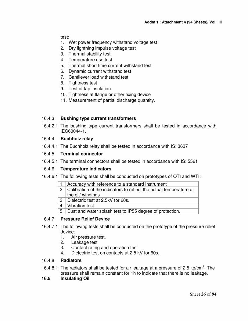
16.4.2 Condenser Bushings 16.4.2.1 The type tests shall be carried out in accordance with IEC 60137 on
porcelain housing of the condenser bushings. The following shall constitute the type test: 1. Visual inspection
2. Verification of dimensions
3. Electrical routine test
4. Porosity test
5. Temperature cycle test
6. Bending test 16.4.2.2 The type tests shall be carried out in accordance with IEC 60137 on
prototype of the condenser bushing. The following shall constitute the type
Addm 1 : Attachment 4 (94 Sheets)/ Vol. III
Sheet 26 of 94
test: 1. Wet power frequency withstand voltage test
2. Dry lightning impulse voltage test
3. Thermal stability test
4. Temperature rise test
5. Thermal short time current withstand test
6. Dynamic current withstand test
7. Cantilever load withstand test
8. Tightness test
9. Test of tap insulation
10. Tightness at flange or other fixing device
11. Measurement of partial discharge quantity.
16.4.3 Bushing type current transformers
16.4.2.1 The bushing type current transformers shall be tested in accordance with IEC60044-1.
16.4.4 Buchholz relay
16.4.4.1 The Buchholz relay shall be tested in accordance with IS: 3637
16.4.5 Terminal connector
16.4.5.1 The terminal connectors shall be tested in accordance with IS: 5561
16.4.6 Temperature indicators
16.4.6.1 The following tests shall be conducted on prototypes of OTI and WTI:
1 Accuracy with reference to a standard instrument 2 Calibration of the indicators to reflect the actual temperature of
the oil/ windings 3 Dielectric test at 2.5kV for 60s. 4 Vibration test. 5 Dust and water splash test to IP55 degree of protection.
16.4.7 Pressure Relief Device
16.4.7.1 The following tests shall be conducted on the prototype of the pressure relief device: 1. Air pressure test. 2. Leakage test 3. Contact rating and operation test 4. Dielectric test on contacts at 2.5 kV for 60s.
16.4.8 Radiators
16.4.8.1 The radiators shall be tested for air leakage at a pressure of 2.5 kg/cm2. The pressure shall remain constant for 1h to indicate that there is no leakage.
16.5 Insulating Oil

Addm 1 : Attachment 4 (94 Sheets)/ Vol. III
Sheet 27 of 94
16.5.1 The following tests shall be carried out in accordance with IEC60296 on the sample of new insulating oil for use in the prototype transformer: 1. Density at 27 0C 2. Kinetic viscosity at 27 0C 3. Interfacial tension at 27 0C 4. Flash point. 5. Neutralisation value (acidity) 6. Electric strength (with 2.5mm gap) 7. Dielectric dissipation factor (tan-delta) 8. Specific resistance at 27 0C and at 90 0C 9. Oxidation stability 10. Water content.
16.6 Routine tests
16.6.1 The following routine tests shall be undertaken on each transformer including the prototype unit in accordance with IEC 60076-1:
1. Visual examination
2. Insulation resistance measurement
3. Measurement of no load current
4. Measurement of no load loss
5. Measurement of resistance of the windings
6. Measurement of percentage impedance voltages
7. Measurement of load loss
8. Polarity test
9. Voltage ratio test.
10. Dielectric tests comprising:
• Separate-source voltage with stand test
• Induced over voltage with stand test.
11. Recording/ submission of SFRA as per IEC 60076.
12. Recurrent Surge Oscillogram (RSO) Test
13. Test for motorized off circuit tap changer 16.6.2 Visual examination: A general examination shall be made to check that the
transformer conforms to the approved drawings, various items are accessible for maintenance, the quality of workmanship and finish are of acceptable standards and all parts, fittings and accessories\are provided.
16.6.3 Insulation resistance test: The insulation resistance of the windings with respect to the earth and between the windings shall be measured using a 5 kV Megger.
16.6.4 Measurement of no-load current: Measurement, load current referred to the primary side shall be done at:

Addm 1 : Attachment 4 (94 Sheets)/ Vol. III
Sheet 28 of 94
1. 90%, 100% and 110% of the rated voltage at the principal tapping, and
2. The appropriate tap voltage at the +10% and -15% tap positions.
16.6.5 Measurement of no-load loss: Measurement of no-load loss referred to the primary, side shall be done at:
1. 90%, 100% and 110% of the rated voltage at the principal tapping, and
2. The appropriate tap voltage at the +10% and -15% tap positions.
16.6.6 Measurement of resistance of windings: The resistance of the windings shall be measured at all tappings and computed at 750C.
16.6.7 Measurement of percentage impedance voltages: The percentage impedance voltages at 'principal', +10% tap and -15% tap positions shall be measured at rated current and at ambient temperature and computed at 750C.
16.6.8 Measurement of load loss: Load losses at rated current shall be measured at principal, +10% and -15% tap positions at ambient temperature and computed at 750C.
16.6.9 Polarity test: The polarity (subtractive) and marking of the terminals for the polarity shall be verified.
16.6.10 Voltage ratio test: Voltage ratio shall be measured at all tap positions.
16.6.11 Dielectric tests:
16.6.11.1 Induced over voltage withstand test: The test shall be done by applying the test voltage across the entire secondary winding as per IEC 60076-3.
16.6.12 Separate source voltage withstand test: The test voltage to be applied as under:
1 Highest voltage for equipment Um (kV) 52 245 2 Rated short duration power frequency
withstand voltage (kV) 95 395
16.6.11.2 Recording of Surge Frequency Response Analysis (SFRA) as per IEC 60076-18.
16.6.13 Tests on off-load tap-changer: The tests shall be conducted in accordance with IEC 60214.
16.6.14 During the routine tests of any unit if it is found that the sum of the measured losses (i.e. no-load and load losses) measured at the principal tapping (corrected to 750C) exceeds the maximum guaranteed value defined in Clause 5.1 (14), the transformer shall be rejected.
16.7 If the prototype of a transformer conforming to this document and rating has already been approved in connection with previous supplies to Indian Railways, fresh type testing may be waived at the discretion of the Employer, provided that no changes whatsoever in the design or materials used or the process of manufacture have been made.

Addm 1 : Attachment 4 (94 Sheets)/ Vol. III
Sheet 29 of 94
However, the Employer reserves the right to conduct type tests, if he deems, it necessary to do so in the light of experience gained from previous supplies.
16.8 Only after approval of the original tracings of drawings incorporating changes, if any, as a result of the prototype tests and clear written approval of the results of. the tests on the prototype is communicated by the Employer, to the successful bidder/manufacturer, shall he take up bulk manufacture of the transformer which shall be strictly with the same materials and process of manufacture as adopted for the prototype. In no circumstances shall materials other than those approved in -the design/drawings and/or during the prototype testing be used for bulk manufacture-on the plea that they had been obtained prior to the approval of the prototype.
16.9 The bidder may quote his charges for short-circuit and temperature rise tests. No charges shall be payable, for any other type and routine tests.
16.10 Transformer before dispatch should be filled with Nitrogen/ dry air and provided with a gauge clearly visible for monitoring the pressure inside the tank.
17. TECHNICAL DATA The following shall be furnished by the Tenderer: 17.1 Calculations for:
1. Temperature rise of winding at rated current. 2. Hot-spot temperature of the winding at 150% and 200% rated loads for 15
min and 5 min respectively. 3. Thermal withstand capacity of the windings for a short circuit of 5 s
duration. 4. Mechanical forces in respect of the following as per IEEMA (Indian
Electrical & Electronic Manufacturer’s Association) formulae: a) Asymmetrical short-circuit current. b) Hoop stress in primary and secondary windings. c) Compressive pressure in the radial spacers. d) Internal axial compressive force. e) Axial imbalance force. f) Radial bursting force. g) Resistance to collapse. h) Bending stress on clamping ring and densified wood. i) Maximum allowable torque on pressure screws for coil clamping bolts at
the time of tightening, if any. 5. Flux density with the characteristic curve. 6. Maximum value of inrush current.
17.2 Drawings for:
1. Outline general arrangement drawing giving complete details of the transformer.
2. Arrangement of the core, windings and magnetic path. 3. Magnetizing characteristic of CRGO sheet steel.

Addm 1 : Attachment 4 (94 Sheets)/ Vol. III
Sheet 30 of 94
17.3 The successful bidder/ manufacturer shall submit to employer for approval the following detailed dimensioned drawings as per Indian Railways standard in sizes of 210 mm x 297 mm or any integral multiples thereof.
1. Outline general arrangement of the transformer indicating plan, front elevation, side elevation with all parts, fittings and accessories, electrical, clearances as well as salient guaranteed particulars.
2. Internal arrangement of the transformer indicating primary and secondary bushing lead connections, core to clamp to core-base bolting, and the locking arrangement of the core assembly with the tank.
3. Cross sectional view of the core and windings with material specifications and makes.
4. Detail of the pressure screws/oil dash-pot/coil clamping bolts or other devices and their location with materials specification.
5. Schematic view of the valves used on the transformer and the anti theft device so as to prevent theft of oil.
6. Transport outline dimensions. 7. General arrangements of the odd-circuit tap changer assembly with
salient technical parameters. 8. Tap changer cubical layout. 9. Schematic diagram for driving of motorisedoff circuit tap changer via
SCADA. 10. Name and rating plate of motorised off circuit tap changer. 11. General arrangement of marshalling box indicating protection and control
equipment. 12. Wiring diagram of the marshalling box. 13. Schematic diagram of protection and control circuits in marshalling box
with cable schedule. 14. Legend plate showing protection and control circuits for fitment into the
marshalling box. 15. OIP condenser bushing for primary side including cross-sectional view,
shed profile and salient electrical and mechanical characteristics. 16. OIP condenser bushing for secondary side including cross-sectional
view, shed profile and salient electrical and mechanical characteristics. 17. Dimensional drawing, V-I characteristic and rating plate for bushing type
current transformers. 18. Rigid terminal connectors for primary side bushing terminal 19. Rigid terminal connectors for secondary side bushing terminal 20. Rating plate with diagram of connections, both in English and Hindi
versions. 21. Details of radiators 22. Details of breather 23. External cable-run with cable schedule. 24. Any other drawings which the successful bidder considers necessary.
17.4 After approval, six copies of each of the approved drawings along with two sets of reproducible prints for each drawing shall be supplied to each consignee(s).
17.5 Two copies of the “Operations and Maintenance manual” for each transformer shall be supplied to the consignee(s) two copies of the manual shall be

Addm 1 : Attachment 4 (94 Sheets)/ Vol. III
Sheet 31 of 94
supplied to the employer.
18. Capitalisation of Transformer Losses 18.1 The traction transformers shall be low loss type. The value of losses shall be
guaranteed. The formula given in Clause 6.6 of the Particular Specification shall be used for the purpose of calculating the present worth of the transformer after taking into account capitalization of its losses, when comparing different bids capitalized cost of the losses in the transformer shall be added to the bid value for total quantity of transformers required for this Project in the lump sum form for evaluation purposes.
19. Spares 19.1 The bidder shall supply the following essential spares for every lot of up to 5
of 220kV transformers or part thereof. For 132 kV one set of bushings ,gasket ,terminal connectors only shall be supplied:
1. One primary bushing complete with parts, fitting and bushing type current transformer.
2. One secondary bushing complete with parts, fitting and bushing type current transformer.
3. One complete set of gaskets of all sizes required for use in the transformer.
4. One breather unit with silica gel. 5. One piece of radiator. 6. This clause left blank 7. One each of terminal connectors for primary and secondary side bushing
terminals 8. One set of valves 9. One pressure relief device. 10. One set of primary, secondary and tapping coil 11. One complete off circuit motorized tap changer
20. ERECTION, TESTING AND COMMISSIONING
20.1 The transformer shall be erected and commissioned by the successful bidder. The manufacturer shall invariably make available at site the services of an engineer of his to ensure, by his continued presence, that the process of erection, testing and commissioning of the transformer is in accordance with established and recommended practices. For this purpose, prior intimation regarding the dates/period and locations at which the transformers are to be erected and testing/commissioning done shall be given by the bidder to the manufacturer.
21. SCHEDULE OF GUARANTEED PERFORMANCE, TECHNICAL AND OTHER
PARTICULARS (GUARANTEED PARTICULARS ARE TO BE ESTABLISHED BY ACTUAL TESTS/ TEST REPORTS)

Addm 1 : Attachment 4 (94 Sheets)/ Vol. III
Sheet 32 of 94
SN DESCRIPTION UNIT OF MEASUREMENT
VALUE/ INFORMATION
1 2 3 4
A RATINGS/PARTICULARS
1. Name of the Manufacturer
2. Country of manufacture
3. Reference to specification based on which performance data is prescribed
4. Rated power MVA
5. Primary current at:
a) Rated load A
b) 150% rated load for 15 min A
c) 200% rated load for 5 min A
6. Secondary current at:
a) Rated load A
b) 150% rated load for 15 min A
c) 200% rated load for 5 min A
7. Rated voltage :
a) Primary kV
b) Secondary (at no-load) kV
8. Rated frequency Hz
9. Temperature rise above ambient temperature of 50 0C :
(i). Oil :
a) At rated load 0C
b) At 150% rated load for 15 min 0C
c) At 200% rated load for 5 min 0C
(ii) Winding :
a) At rated load 0C
b) At 150% rated load for 15 min. 0C
c) At 200% rated load for 5 min 0C
10 Hot-spot temperature of winding over ambient temperature of
0C
a) At rated load 0C

Addm 1 : Attachment 4 (94 Sheets)/ Vol. III
Sheet 33 of 94
b) At 150% rated load for 15 min. 0C
c) At 200% rated load for 5 min 0C
Interval of time between two successive overloads after continuous working at full load, at maximum ambient temperature of 50°C:
a) Between two consecutive over min. loads of 50% for 15 min
min.
b) Between two consecutive min overloads of which one is of 50% for 15 min and the other of 100% for 5 min.
min.
11 No-load current referred to primary side at rated frequency and at:
a) 90% rated voltage A
b) Rated voltage A
c) 110% rated voltage A
12 Power factor of no-load current at rated voltage and rated frequency
13 Value of the inrush current at rated voltage on primary side, the secondary side being open circuited
14 Losses:
(i) No-load loss at rated frequency and at:
a) 90% rated voltage at the principal tapping.
kW
b) rated voltage at the principal tapping.
kW
c) 110% rated voltage at the primary tapping.
kW
(ii) Load loss (at 75 0C) at rated current and frequency
kW
a) Principal tapping kW
b) -15% tapping kW
c) +10% tapping kW
(iii) Total losses at rated current and frequency
a) Principal tapping kW

Addm 1 : Attachment 4 (94 Sheets)/ Vol. III
Sheet 34 of 94
b) -15% tapping kW
c) +10% tapping kW
15 Resistance voltage (at 75 0C) at rated current
%
16 Reactance voltage (at 75 0C) at rated current and frequency
%
17 Impedance voltage (at 75 0C) at rated current and frequency
%
18 Resistance (at 75 0C) of primary winding
ohm
19 Resistance (at 75 0C) of secondary winding
ohm
20 Reactance of winding : H
a) Primary at
i) Principal tapping H
ii) +10% tapping H
iii) -15% tapping H
b) Secondary H
21 Regulation (at 75 0C) with rated current and at power factor of:
a) Unity %
b) 0.8 lagging %
22 Efficiencies:
(i). Efficiency (at 75 0C) at unity power factor at:
a). 100% load %
b). 75% load %
c). 50% load %
d). 25% load %
(ii). Efficiency (at 750C) at 0.8 power factor lagging at:
a). 100% load %
b). 75% load %
c). 50% load %
d). 25% load %
(iii) Percentage of rated load at which maximum efficiency occurs.
%

Addm 1 : Attachment 4 (94 Sheets)/ Vol. III
Sheet 35 of 94
23 Ability to withstand short-circuit:
a). Thermal s
b). Dynamic s
24 Thermal time constant (calculated):
(i) for winding with respect to oil at:
a). rated current min
b). 150% rated current min
c). 200% rated current min
(ii) Complete transformer at rated current min
25 Temperature gradient between oil and winding at:
a). Rated current 0C
b). 150% rated current for 15 min 0C
c). 200% rated current for 5 min.
0C
26 Temperature rise of oil:
(i). Calculated average temperature rise of oil at:
a). Rated current 0C
b). 150% rated current for 15 min 0C
c). 200% rated current for 5 min 0C
(ii) Estimated temperature rise of top oil at:
a). Rated current 0C
b). 150% rated current for 15 min 0C
c). 200% rated current for 5 min 0C
27 Details of core:
(i) Type of core
(ii) Flux density at rated voltage and frequency
tesla
(iii) Flux density at 110% rated voltage and frequency
tesla
(iv) Thickness of steel stampings mm
(v) Grade of core material and conforming specification

Addm 1 : Attachment 4 (94 Sheets)/ Vol. III
Sheet 36 of 94
(vi) Exciting VA/kg for core stampings at:
a) Flux density of 1.55 tesla VA/kg
b) Flux density at rated voltage VA/kg
c) Flux density at 110% rated voltage VA/kg
(vii) Exciting VA/kg for assembled core at:
a) Flux density of 1.55 tesla VA/kg
b) Flux density at rated voltage VA/kg
c) Flux density at 110% rated voltage Va/kg
(viii) Type of insulation between core laminations.
(ix) Type of joint between the core limbs and yoke.
kV
(x) Core bolt Insulation withstand voltage kV
(xi) Core bolt insulation flashover voltage kV
Details of windings:
28 (i) Type of winding
(a) Primary
(b) Secondary
(c) Number of turns of primary winding
(d) Number of turns of secondary winding
(e) Number of parallel paths in primary winding
(f) Number of parallel paths in secondary winding.
(g) Is interleaving/inter shielding of the winding adopted to ensure better impulse voltage distribution?
Yes/No
(i) Primary
(ii) Secondary
(h) Is the insulation of end turns of winding reinforced?
Yes/No
(i) Primary
(ii) Secondary
(i) Type of coil

Addm 1 : Attachment 4 (94 Sheets)/ Vol. III
Sheet 37 of 94
(ii) Mode of connection (i.e. in series or in parallel) of the portions of the windings on the two limbs of the core, if applicable.
(iii) Dimensions of the copper conductor used in the winding:
a) Primary mm x mm
b) Secondary mm x mm
c) Tapped winding.
mm x mm
(iv) Current density at rated current.
a) Primary A/mm2
b) Secondary A/mm2
(v) Insulation used over the conductor (details of material and specification there for)
(vi) Type of joints, if any, in the windings
(vii) Dielectric strength of windings:
a) Full wave lightning impulse withstand voltage:
i) Primary winding kV peak
ii) Secondary winding. kV peak
(b) Lightning Impulse chopped on the tail withstand voltage:
kV
(i) Primary winding
(ii) Secondary winding
(c) Separate source power frequency withstand voltage
kV
(i) Primary
(ii) Secondary
(d) Induced over voltage withstand value
(viii) Minimum flashover distance to earth in oil of :
a) Secondary winding to core
b) Primary winding to yoke
c) Primary winding to tank

Addm 1 : Attachment 4 (94 Sheets)/ Vol. III
Sheet 38 of 94
(ix) Material used for coil clamping rings and specification there for
(x) Magnitude of axial pre-compressive force on the winding
(a) Primary kV peak
(b) Secondary kV peak
(xi) Calculated maximum axial thrust in the winding due to dead short circuit at the terminals
(a) Primary
(b) Secondary
(xii) Calculated short circuit forces:
a) Hoop stress in primary winding kgf/cm2
b) Hoop stress in secondary winding kgf/cm2
c) Compressive pressure in the radial spacers
d) Internal axial compressive force kgf/cm
e) Axial imbalance force
f) Resistance to college kgf
g) Bending stress on clamping kgf/cm2
h) Radial bursting force
(xiii) Arrangement to maintain constant pressure on the windings
(xiv) Maximum permissible torque on pressure screws for coil clamping at the time of tightening, if any.
N.m
(xv) Can either end of each secondary winding (25 kV) be connected directly to earth?
Yes/No.
29 Motorised off-circuit tap changer:
a) Name of the manufacturer
b) Country of origin.
c) Type designation
d) Governing specification.
e) Is a separate taped winding provided on each secondary?

Addm 1 : Attachment 4 (94 Sheets)/ Vol. III
Sheet 39 of 94
f) Number of tappings:
i) Plus tappings
ii) Minus tappings
g) Percentage variation of voltage on different tapping.
h) Minimum contact pressure between moving and stationery contacts
kgf
i) Maximum rated through current A
j) Voltage class kV
k) Rated voltage of control circuit V(dc)
l) Tap changer motor particulars:
i) Make and type
ii) Rated voltage V(dc)
iii) Rated current A
iv) Rated power kW
v) Speed rpm.
vi) Class of insulation
30 Bushings:
(i). Primary side:
a) Name of the manufacturer
b) Country of origin
c) Governing specification
d) Type designation (specify as to whether it is OIP condenser bushing)
e) Voltage class kV
f) Rated current A
g) Visible power frequency discharge voltage
kV
h) Wet one minute power frequency withstand voltage
kV peak
i) Lightning impulse withstand voltage mm
j) Creepage distance
k) Weight of assembled bushing Kg
(ii) Secondary side

Addm 1 : Attachment 4 (94 Sheets)/ Vol. III
Sheet 40 of 94
a) Name of the manufacturer
b) Country of origin
c) Governing specification
d) Type designation
e) Voltage class kV
f) Rated current A
g) Visible power frequency discharge voltage
kV
h) Wet one minute power frequency withstand voltage
kV
i) Lightning impulse withstand voltage kV peak
j) Creepage distance mm
k) Weight of assembled bushing kgf
31 Bushing type current transformers:
(i). Primary side:
a) Name of the manufacturer
b) Governing specification
c) Transformation ratio
d) Accuracy class and rated accuracy limit factor
e) Rated current A
f) Rated output VA
g) Exciting current at the rated knee point emf
mA
h) Rated knee point emf V
i) Secondary winding resistance corrected to 750C
ohm
j) Short time thermal current and duration.
kA, s
(ii) Secondary side:
a) Name of the manufacturer
b) Governing specification
c) Transformation ration
d) Accuracy class

Addm 1 : Attachment 4 (94 Sheets)/ Vol. III
Sheet 41 of 94
e) Rated current A
f) Rated output VA
g) Exciting current at the rated knee point emf
mA
h) Rated knee point emf V
i) Secondary winding resistance corrected to 750C.
ohm
j) Short time thermal current and duration
kA, s
32 Insulating oil :
a) Governing specification
b) Grade of oil
c) Source of supply
d) Specific resistance at:
i) 27 0C ohm-cm
ii) 90 0C ohm-cm
e) Dielectric, dissipation factor (tan-delta) at 90 0C
f) Dielectric strength kV
g) Water content ppm
h) Interfacial tension N/m
i) Neutralisation value mg KOH/gm
j) Flash point °C
33 Type of transformer tank
34 Details of radiators:
a) Make and type
b) Type of mounting
c) Overall dimensions (LxWxH) mmx mm x mm
35 Details of Buchholz relay:
a) Make and type
b) Governing specification
c) Provision of shut-off valves on either side of the relay
Yes/No
d) Provision of alarm contact Yes/No

Addm 1 : Attachment 4 (94 Sheets)/ Vol. III
Sheet 42 of 94
e) Provision of trip contact Yes/No
f) Rated current of contacts A
36 Details of winding temperature
Indicator.
a) Make and type
b) Governing specification
c) Number of contacts provided
d) Rated current of contacts A
e) Dielectric withstand value of contacts
kV
37 Details of oil temperature indicator
a) make and type
b) Governing specification
c) Number of contacts provided
d) Rated current of contacts A
e) Dielectric withstand value of contacts
kV
38 Details of Magnetic oil level gauge:
a) Make and type
b) Governing specification
c) Diameter of dial mm
d) Number of contacts provided
e) Rated current of contact A
f) Dielectric withstand value of contacts kV
39 Details of pressure relief device:
a) Make and type
b) Governing specification
c) Does it reset itself Yes/No
40 Bimetallic terminal connectors:
(i) Primary side:
a) Source of supply
b) Governing specification
c) Type

Addm 1 : Attachment 4 (94 Sheets)/ Vol. III
Sheet 43 of 94
d) Rated current A
e) Temperature rise over an ambient temperature of 45°C while carrying rated current.
°C
f) Short time current and duration kA, s
(ii). Secondary side:
a) Source of supply
b) Governing specification
c) Type
d) Rated current A
e) Temperature rise over an ambient temperature of 450C while current rated current
°C
f) Short time current and duration kA, s
41 Acoustic sound level at a distance dB of 1 m, when energised at rated voltage and rated frequency without load.
dB
42 Partial discharge value at 1.5Um/ 3 kV r.m.s.
pC
43 Weights and dimensions:
(i) Net weight of core
(ii) Net weight of cooper:
a) Primary winding kg
b) Secondary winding kg
(iii) Net untanking weight of core frame and coils
kg
(iv) Net weight of insulating oil kg
(v) Volume of insulating oil l
(vi) Total weight of cooling equipment t
(vii) Total weight of transformer without oil t
(viii) Total shipping weight of complete transformer including all detachable parts, fittings and assemblies
t
(ix) Shipping weight of largest package t
(x) Crane lift (excluding slings) for un- mm

Addm 1 : Attachment 4 (94 Sheets)/ Vol. III
Sheet 44 of 94
tanking core and coils
(xi) Crane lift (excluding slings) for removal of primary side bushings.
mm
(xii) Dimensions of the complete transformer including all parts, fitting and accessories:
a) Overall length mm
b) Overall breadth mm
c) From rail level to the topmost point mm
(xiii) Minimum thickness of steel plate/ sheet used:
a) Bell tank mm
b) Tank bottom mm
c) Conservator mm
d) Radiator mm
e) Marshalling box. mm
(xiv) Overall shipping dimensions of the largest package (Length x width x height)
mm x mm x mm
(xv) Mode of transportation of transformer unit (filled with oil/nitrogen gas.)
Other particulars
44 Is the transformer tank fitted with lifting pads? If yes, what is the number of pads
Yes/ No
45 What is the number of inspection covers provided?
46 Are comfits/ trays provided for cable run?
Yes/ No
47 Is the core electrically connected with the tank?
Yes/No
48 Will the gaskets to be used in the transformer give trouble free service for at least 7 years? If not, indicate the life.
Yes/No
49 Is the core construction without core bolts?
Yes/No
50 Are the core bolts grounded, and if so, how?
Yes/ No
51 What is the number of radial spacers used in the winding?

Addm 1 : Attachment 4 (94 Sheets)/ Vol. III
Sheet 45 of 94
52 What is the number of joints provided in the winding?
53 Are the spacers/blocks/angle rings of pre-compressed press boards? If no, indicate the material with specification.
54 Are arrangements made for ensuring automatic constant pressure on the coils? If no. give the reasons.
Yes/ No
55 Are closed slots provided on outer most winding for locking the vertical strips? If no, give the reason.
Yes/ No
56 What is the periodicity for tightening of coil clamping arrangement?
Years
57 What are the designed values of short-circuit current for:
a) Symmetrical :
i) Primary winding A
ii) Secondary winding A
b) A symmetrical:
i) Primary winding A
ii) Secondary winding A
58 What is the over flux with stand capa-bility of the transformer (Maximum permissible limit of flux density) ?
Tesla
59 Are windings pre-shrunk? Yes/No
60 Have the details of drying cycles of the coils/coil assembly including final tightening values of pressure, temperature and degree of vacuum at various stages of drying been furnished?
Yes/ No
61 Are arcing horns provided for line and neutral bushings?
Yes/ No
62 Is a test tap provided in the line bush-ing?
Yes/ No
63 Is the porcelain housing of the bush-ings of single piece construction?
Yes/ No
64 Is the shed profile of porcelain housing of the bushing free from under-ribs but has a lip?
Yes/ No
65 Is the bushing type current transformer of low reactance type?
Yes/ No

Addm 1 : Attachment 4 (94 Sheets)/ Vol. III
Sheet 46 of 94
66 Is Clause by Clause "Statement of compliance" attached?
Yes/ No
67 Is "Statement of deviation", if any, attached?
Yes/ No
68 Does the tap changer have snap action? If not, give reason.
69 Is the Buchholz relay provided with two shut-off valves, one on either side?
Yes/ No
70 Is separate conservator tank & Buchholz relay provided for tap changing equipment?
Yes/ No
71 Are fasteners of 12 mm diameter and less exposed to atmosphere of stainless steel to Grade 04Cr17 Ni12Mo to IS 1570 Part-V?
Yes/ No
72 Are the fasteners of more than 12 mm diameter exposed to atmosphere of stainless steel or MS hot dip galvan-ised?
Yes/ No
73 Are test certificates for tests as per Clause 15.0 attached?
Yes/ No
74 Are all the calculations required as Yes/ No
75 Are all the drawings required as per clause 16.3.2 attached?
Yes/ No
76 (a) Are all the parts, fittings and accessories from Employer’s approved manufacturers?
Yes/ No
(b) If not, list the items which are to be type tested in the presence of Employer's representative.
Yes/No
77 Is adequate space provided in the marshalling box for housing the wiring and components?
Yes/ No
78 Is warranty as per clause 22.0? Yes/ No
79 Is the list of spares furnished or no?
***************

Addm 1 : Attachment 4 (94 Sheets)/ Vol. III
Sheet 47 of 94
Annexure - I
TECHNICAL SPECIFICATIONS FOR NITROGEN INJECTION FIRE PREVENTION AND EXTINGUISHING SYSTEM FOR OIL FILLED
TRANSFORMER 1.0 GENERAL DESCRIPTION:
Nitrogen injection fire protection system designed for oil filled transformers shall prevent tank explosion and the fire during internal faults resulting in an arc, where tank explosion will normally take few seconds after arc generation and also extinguish the external oil fires on transformer top cover due to tank explosion and/or external failures like busing fires, OLTC fires and fire from surrounding equipment’s.
The system shall drain a pre-determined quantity of oil from the tank top through outlet valve to reduce the tank pressure and inject nitrogen gas at high pressure from the lower side of the tank through inlet valves to create stirring action and deduce the temperature of top oil surface below flash point to extinguish the fire.
Conservator tank oil shall be isolated during busing bursting, tank explosion and oil fire to prevent aggravation of fire.
Transformer isolation shall be an essential pre-condition for activating the system. The system shall be designed to operate automatically. However, it shall be designed for manual operation, in case of failure of power supply.
The system shall consist of following equipment: 1. Fire extinguishing cubicle placed on a plinth at about 5-10 meter away
from the transformer. 2. Control box placed in the control room. 3. Necessary valves in the conservator pipe. 4. Suitable fire sensing components to be provided preferably in/on the tank
cover. 5. Signal box suitably placed.
2.0 SCOPE
The scope of this document covers design, engineering, supply testing at works before dispatch; erection, testing and commissioning and performance demonstration of “fire protection and extinguishing system by nitrogen injection method”.
The necessary civil work which will be required for construction of oil soak – pit for the storage of oil coming out from the transformer and plinth for extinguishing cubicle is outside the scope of this document. However, laying of oil pipe, nitrogen pipe, electrical cables, control boxes, extinguishing cubicle, nitrogen cylinder, necessary vales, fire detectors and other equipments& accessories required for erection, testing, commissioning and performance demonstration of the complete fire protection system is in the

Addm 1 : Attachment 4 (94 Sheets)/ Vol. III
Sheet 48 of 94
scope of the tenderer. It will be the responsibility of the tenderer, i.e. transformer manufacturer to coordinate with the supplier of the Fire Protection System for all the arrangements for the complete erection, testing, commissioning and performance tests. Notwithstanding the technical specifications and requirements mentioned herewith any modification can be incorporated for correct operation of nitrogen injection fire protection system without extra cost. The full details of the same are required to be submitted to Employer for approval, when first unit is implemented on a transformer of specific make & rating.
3.0 OPERATIONAL CONTROLS:
The system shall be provided with automatic control for fire prevention and fire extinction. Besides automatic control, remote electrical push button control on control box and local manual control in the fire-extinguishing cubicle shall be provided. The fire protection system will take signal from HV/LV circuit breaker.
4.0 SYSTEM ACTIVATING SIGNALS:
4.1 Transformer isolation shall be an essential pre-condition for activating the system. Provision shall be provided to isolate the Traction Power Transformer through Master trip relay or circuit breaker (HV and LV side in series) before Nitrogen injection and after oil depressurization.
4.2 There shall be two modes of operation of Fire Protection System i.e. Fire Prevention Mode & Fire Extinction Mode. In these mode the safety equipment to be involved are tabulated below. The logic of their operation shall be finalized during design approval.
Mode of Operation Safety Equipment to be used Fire Prevention
Mode • Differential relay/Over current/Restricted
earth fault relay.
• Pressure relief valve Fire Extinction
Mode • Fire sensing components
• Buchhloz relay 5.0 SYSTEM EQUIPMENT: 5.1 Fire Extinguishing Cubicle (FEC), placed on plinth at about minimum 5 meter
away from the transformer shall consist of:
5.1.1 Nitrogen gas cylinder with pressure reducer/regulator and falling pressure electrical contact manometer.
5.1.2 Oil drain pipe with mechanical quick drain valve; 5.1.3 Electro mechanical control equipment for oil drain and pre-determined
regulated nitrogen release. 5.1.4 Pressure monitoring switch for backup protection, pressure reducer with
solenoid valve in the cabinet for operation of nitrogen gas release, which will be IP-65, protected and leak proof for nitrogen release.
5.1.5 Limit switches for monitoring of the system. 5.1.6 Flanges on top panel for connecting oil drain and nitrogen injection pipes for
transformer.

Addm 1 : Attachment 4 (94 Sheets)/ Vol. III
Sheet 49 of 94
5.1.7 Panel lighting 5.1.8 Oil drainpipe extension of suitable sizes for connecting pipes to oil pit. 5.1.9 The Nitrogen gas cylinder should be of sufficient (not less than 50 liter) capacity
and should be filled at a pressure of not less than 150 bars with falling pressure electrical contact manometer, suitable design measures to prevent leakage of gas to be taken.
5.1.10 The nitrogen valve shall have IP-65 protection. The nitrogen shall be contained within the cylinder and released from the cylinder valve only upon activation of the fire protection system. Nitrogen purity shall 99.99%
5.1.11 Proper approvals and certificates should be provided with each cylinder. No used nitrogen bottle will be accepted.
5.2 Control box with activating, monitoring devices and line faults indicators to be placed in control room. It should have audiovisual alarm indication and push button switches for tests response.
5.3 Necessary valves to be fitted in the conservator pipeline between conservator and Buchholz relay operating mechanically on transformer oil flow rate with electrical signal for monitoring.
5.4 Suitable fire sensors to be fixed on transformer tank top cover and off circuit tap changer for sensing fire.
5.5 Signal box to be fixed on transformer side will for terminating cable connection from sensors and conservator shutter/signal box to be suitably placed.
5.6 All other consumables necessary for operation of complete system. 5.7 Control box should be microprocessor based and compatible to be interfaced
with existing RTU for Railway Traction SCADA system available at the control room. For communication, Control box shall have provision for interfacing with SCADA in this regards details Digital Input & Output required for operation monitoring through SCADA should be furnished.
6.0 OTHER REQUIREMENTS FOR SYSTEM INSTALLATION: 6.1 Oil drain and nitrogen injection openings with gate valves on transformer tank
at suitable locations. 6.2 Flanges with dummy piece in conservator pipe between Buchhloz relay and
conservator tank for fixing. 6.3 Brackets on transformer top cover for sensing equipment, valves to enable
operation of the system. 6.4 Spare potential free contacts for system activating signals i.e. differential relay,
Buchholz relay, pressure relief valve, transformer isolation (master trip relay). 6.5 Pipe connections between transformer to fire extinguishing cubicle and fire
extinguishing cubicle to oil pit. 6.6 Cabling on transformer top cover all sensors to be suitably connected for
reliable fire sensing and inter cabling between signal box to control box and control box to fire extinguishing cubicle.
6.7 Plinth for fire extinguishing cubicle. Oil pit with capacity as 10% of total oil quantity of transformer.
7.0 TECHNICAL DETAILS:
Fire extinction period:

Addm 1 : Attachment 4 (94 Sheets)/ Vol. III
Sheet 50 of 94
On commencement of Nitrogen injection : Maximum 30 seconds On system activation up to post cooling : Maximum 3 minutes Heat sensing area : 140± 2°C Seating for operation to isolate conservator : Min.60 Ltr. per minute
Power Source:
Control Box : 110 V DC Fire extinguishing cubicle for lighting : 240 V AC
8.0 CABLING: 8.1 Fire survival cables, able to withstand 750°C, 1.5 mm² with necessary no. of
conductors for connection of fire detectors in parallel shall be used. The test certificates for the cables shall be submitted.
8.2 Fire retardant low smoke (FRLS) cable 1.5 mm² with necessary no. of conductors for connection between transformer signal box/marshalling box to control box and control box to fire extinguishing cubicle shall be used.
8.3 Fire retardant low smoke (FRLS) cable 1.5 mm² with necessary no. of conductors for connection between control box to DC supply source and fire extinguishing cubicle to AC supply source, signal box/marshalling box to transformer shall be used.
9.0 PREVIOUS EXPERIENCE FOR QUALIFYING SUPPLIER: The supplier shall have a minimum experience of two years in the design, manufacturing, erection, testing and commissioning of Nitrogen Injection Fire Protection System on power transformers of similar or higher rating. At least 2 sets of the system shall be in successful operation for a minimum period of the 2 years. The supplier shall furnish the details of Nitrogen Injection Fire Protection System supplied by them so far, giving order reference, name and address of the customer, indicating the dates of commissioning as well as performance certificate of successful and satisfactory operation for minimum two years from the customers.
10.0 TESTS
10.1 Type Tests
Type test reports including that for detectors along with declared response time as per test approval certificate letter shall be submitted along with the tender.
The system shall be tested by international or a national testing body (NABL accredited recognized laboratory. Tariff Advisory Committee (TAC’s) approval, if any, shall be submitted with the tender.
10.2 Factory Test
Tests will be carried out on individual equipment of the system and the total system in the supplier’s workshop in presence of purchaser’s representative.
10.3 Performance Test

Addm 1 : Attachment 4 (94 Sheets)/ Vol. III
Sheet 51 of 94
Performance test of the complete system shall be carried out after complete erection at site by the supplier’s representative. These tests shall include simulation and verification of the response of the complete system without actual draining of the oil and injection of the nitrogen gas. In addition to above, additional tests as required necessary shall be conducted.
11.0 DRAWINGS AND MANUALS
Detailed layout drawing along with the equipment drawing to be given in the tender along with complete bill of materials. After awarding of contract, detailed dimensional drawing of the system complete bill of materials including location and size of plinth for cubicle and recommended capacity of oil soak-pit shall be submitted for purchaser’s approval. After approval 10 (ten) sets of all above drawings and 5 (five) sets of operation and Maintenance Instruction Manual (bound) shall be submitted for purchaser’s use.
12.0 SPARES:
One full set of spare nitrogen gas filled cylinder, one set of the installed no. of fire sensors shall be provided in addition to additional other recommended spares. The list of recommended spares is to be submitted along with the tender.
*******************

Addm 1 : Attachment 4 (94 Sheets)/ Vol. III
Sheet 52 of 94
Part -XII
Specification for8 MVA, 54 kV, 50Hz AUTO TRANSFORMER FOR 2 X 25 kV AT FEEDING SYSTEM
1 SCOPE 1.1 This document applies to 8 MVA, ONAN, 54 /27 kV Autotransformer for Auto
Transformer (AT) feeding system for Installation in DFCC, an infrastructure providing company of Indian Railway’s.
1.2 The transformer shall be complete with all parts, fittings and accessories
whether specifically mentioned herein or not, necessary for its efficient operation in an unattended traction substation.
2 GOVERNING SPECIFICATION 2.1 In the preparation of this document, assistance has been taken from the
following National and International Standards, wherever applicable.
Table No.: 2.1-1
Standards Description
Equivalents IS
IEC 60076 (all parts)
IS:2026 (all parts)
Power transformers.
IEC 60044-1 IS:2705 Instrument transformer – Part 1: Current transformer.
IEC 60137 IS:2099 Bushing for alternating voltages above 1000V
IEC 60214 IS:8468 Tap changers.
IEC 60296 IS:335 Fluids for electro technical applications - Unused mineral insulating oils for transformers and switchgear/ New insulating oils.
IS:5 Colours for ready mix paints and Enamels.
IEC 60502-1 IS:1554 (Part 1)
PVC insulated (heavy duty) Electric cables: Part 1 For working voltages up to and including 1100V
IS:1570 Schedules for Wrought Steels - Part 5: Stainless and heat resisting steels.
IS:1576 Solid pressboard for electrical purposes
IEC 60422 IS:1866 Code of practice for electrical maintenance and supervision of mineral insulating oil in equipment
IS:2927 Brazing alloy
JIS C 2553 IS:3024 Grain orient electrical steel sheets and strips IS:3637 Gas operated relays

Addm 1 : Attachment 4 (94 Sheets)/ Vol. III
Sheet 53 of 94
IS:3639 Fittings and accessories for power transformers
IS:4253 Cork composition sheets : Part 2 Cork and Rubber
IS:5561 Electrical power connectors
IS:5621 Hollow insulators for use in electrical equipment
IEC 60909 IS:13234 Guide for short circuit calculations in 3Phase a.c. systems.
IEC 60270 IS: 6209 High-voltage test techniques - Partial discharge measurements.
IEC 60076 IS:6600 Guide for loading of oil-immersed transformers
IS:10028 (all parts)
Code of practice for selection, installation and maintenance of transformers
IS:10593 Mineral Oil-impregnated electrical equipment in services - Guide to the interpretation of dissolved and free gases analysis
IEC 60137 IS: 12676 Oil impregnated paper insulated condensers bushings – dimensions and requirements
DIN:7733 Laminated products, pressboard for electrical engineering, types
Central Electricity Authority (Measures relating to Safety and Electricity Supply) Regulations, 2010, part-III, Sec.4, 2010 Rule no. 44 (2) (ix).
2.2 In case of any conflict between the contents of the above standards and this document the latter shall prevail.
2.3 Any deviation from this document, proposed by the bidder calculated to improve the performance, utility and efficiency of the equipment, will be given due consideration; provided full particulars of the deviation with justification therefore are furnished. In such a case, the bidder shall quote according to this document and the deviations. If any proposed by him shall be quoted as alternative/alternatives.
3 Climatic and Atmospheric Conditions
3.1 The transformer shall be suitable for outdoor use in moist tropical climate and in areas the limiting weather conditions which the equipment has to withstand in service are given in Part-II of the particular Specification.
3.2 The transformer would also be subjected to vibrations on account of trains running on nearby Railway tracks.
The amplitude of these vibrations which occur with rapidly varying time periods in the range of 15 to 70 ms lies in the range of 30 to 150 microns at present, with the instantaneous peaks going up to 350 microns. These

Addm 1 : Attachment 4 (94 Sheets)/ Vol. III
Sheet 54 of 94
vibrations may become more severe as the speeds and loads of trains increase in future.
4 TRACTION POWER SUPPLY SYSTEM (2x25 kV AT FEEDING SYSTEM)
4.1 General Scheme
4.1.1 The electric power for railway traction is supplied in ac 50 Hz, single-phase through 2x25 kV AT feeding system, which has a feeding voltage (2x25 kV) from the traction substation (TSS) two times as high as the catenary voltage, which is 25 kV with respect to earth/rail. The power fed from the TSS through catenary and feeder wire is stepped down to the catenary voltage by means of autotransformers (ATs) installed about every 13 to 17 km along the track, and then fed to the locomotives. In other words, both the catenary and feeder voltage are, 25 kV with respect to the earth/rail, although the substation feeding voltage between catenary and feeder wires is 50 kV. The catenary voltage is therefore, the same as that in the conventional 25 kV system.
4.1.2 The power supply shall be obtained from the 220/132 kV, three-phase, effectively earthed transmission network of the State Power to the Scott-connected transformer installed at the TSS, whose primary winding is connected to the three phases of the transmission network. The spacing between adjacent substations is normally 60 km.
4.1.3 One outer terminal of the secondary windings of the traction transformer is connected to the catenary and the other outer terminals are connected to the feeder.
4.1.4 ATs connect the 25 kV catenary to 25 kV return feeder, with mid-point connected to rail and earth (25 kV return OHE and earth). Two adjacent AT’s share power to feed trains at 25 kV/2x25 kV system feeds 50 kV supply from traction transformer terminal to the ATs. The load current (current drawn by electric locomotives) from the TSS flows through the catenary and returns to the TSS through the feeder. For a train in an AT-cell (distance between two consecutive ATs), most of the current is fed to the electric locomotive by the ATs of that AT-cell; the, current returns in the rails/earth and is boosted up to the feeder through the neutral terminals of the autotransformers. The current in OHE, therefore, is an algebraic sum of 25 kV current feed to locomotives from AT and the 50 kV supply to ATs from the TSS.
4.1.5 Approximately midway between adjacent TSSs, a sectioning and paralleling post (SP) is provided. In order to prevent wrong phase coupling of power supply, a dead zone known as ‘Neutral Section’ is provided in the OHE opposite the TSS as well as SP. At the TSS, there are two-feeder circuit breakers for either side of the TSS for controlling the power fed to the OHE, in a double track section. Out of the two feeder circuit breakers for one side, one feeds the OHE of that side while the other remains (open) as standby. There is also a paralleling interrupter, which is normally closed, for either side of the TSS for paralleling the OHE of the UP and DOWN tracks. In case of fault in the OHE, the feeder circuit breaker of the TSS trips to isolate it.
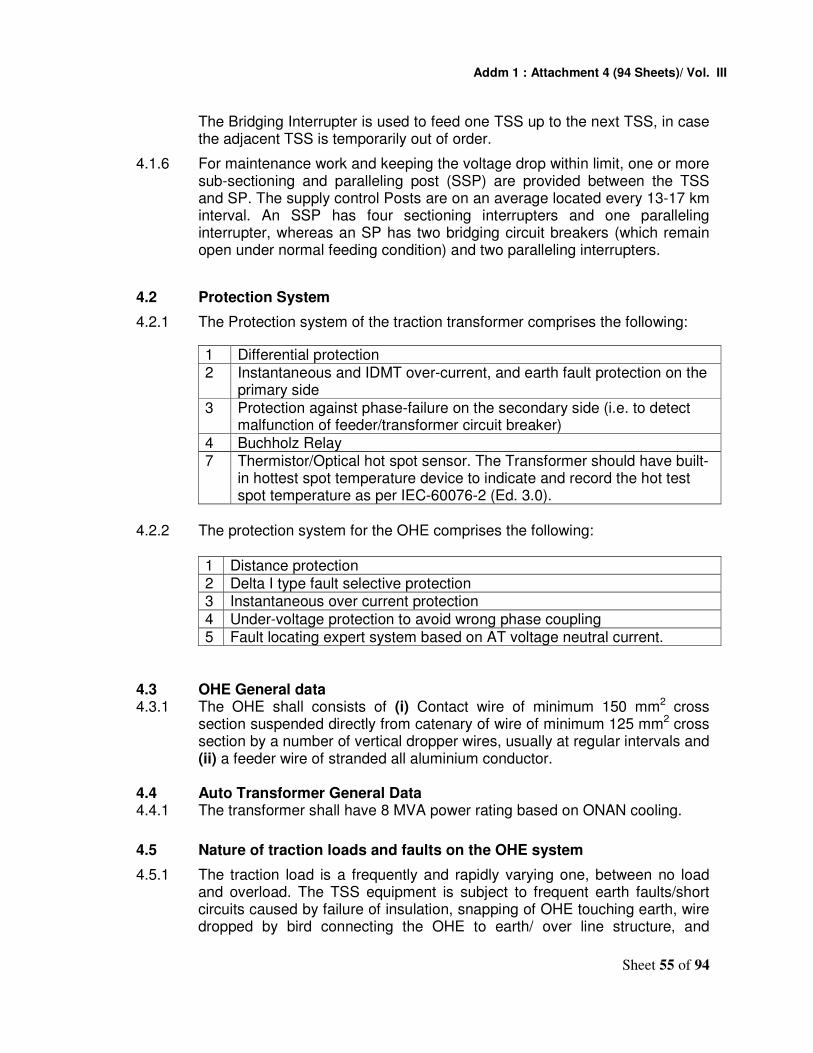
Addm 1 : Attachment 4 (94 Sheets)/ Vol. III
Sheet 55 of 94
The Bridging Interrupter is used to feed one TSS up to the next TSS, in case the adjacent TSS is temporarily out of order.
4.1.6 For maintenance work and keeping the voltage drop within limit, one or more sub-sectioning and paralleling post (SSP) are provided between the TSS and SP. The supply control Posts are on an average located every 13-17 km interval. An SSP has four sectioning interrupters and one paralleling interrupter, whereas an SP has two bridging circuit breakers (which remain open under normal feeding condition) and two paralleling interrupters.
4.2 Protection System
4.2.1 The Protection system of the traction transformer comprises the following:
1 Differential protection 2 Instantaneous and IDMT over-current, and earth fault protection on the
primary side
3 Protection against phase-failure on the secondary side (i.e. to detect malfunction of feeder/transformer circuit breaker)
4 Buchholz Relay 7 Thermistor/Optical hot spot sensor. The Transformer should have built-
in hottest spot temperature device to indicate and record the hot test spot temperature as per IEC-60076-2 (Ed. 3.0).
4.2.2 The protection system for the OHE comprises the following:
1 Distance protection 2 Delta I type fault selective protection 3 Instantaneous over current protection
4 Under-voltage protection to avoid wrong phase coupling 5 Fault locating expert system based on AT voltage neutral current.
4.3 OHE General data 4.3.1 The OHE shall consists of (i) Contact wire of minimum 150 mm2 cross
section suspended directly from catenary of wire of minimum 125 mm2 cross section by a number of vertical dropper wires, usually at regular intervals and (ii) a feeder wire of stranded all aluminium conductor.
4.4 Auto Transformer General Data 4.4.1 The transformer shall have 8 MVA power rating based on ONAN cooling.
4.5 Nature of traction loads and faults on the OHE system
4.5.1 The traction load is a frequently and rapidly varying one, between no load and overload. The TSS equipment is subject to frequent earth faults/short circuits caused by failure of insulation, snapping of OHE touching earth, wire dropped by bird connecting the OHE to earth/ over line structure, and

Addm 1 : Attachment 4 (94 Sheets)/ Vol. III
Sheet 56 of 94
miscreant activity. On an average, the number of faults/ short circuits per month could be as high as 40. The magnitude of the fault current may vary between 40% and 100% of the dead short circuit value. These faults are cleared by the feeder circuit breaker on operation of the distance, delta I and instantaneous over-current relays associated with the concerned feeder circuit breaker. In 2x25 kV system faults can occur with: feeder-earth; feeder-OHE and OHE-earth faults or a combination of them.
4.5.2 The existing Indian Railways ac electric locomotives are silicon rectifiers, with dc motors or GTO/IGBT based power converter fed 3-phase Induction Motor and the average power factor generally varies between 0.7 and 0.85 lagging, without reactive power compensation, which introduces harmonic currents in the 25 kV power supply system.
4.5.3 On DFCC (Western) Locomotives are proposed to have VVVF drives and improved power factor closer to 0.98 and negligible harmonics. The traction supply may therefore be at higher power factor than those on IR.
4.6 Short-circuit apparent power of the system 4.6.1 The short-circuit apparent power at the transformer location for various
system voltages is as under:
Highest system voltage (kV) Short circuit apparent power, (MVA)
72.5 3,500
123 6,000
145 10,000
245 20,000
4.7 Auxiliary power supplies at TSS 4.7.1 The following auxiliary power supplies are available
1 110V dc from a battery
2 240 V ac, 50 Hz, single-phase from a 25/0.24 kV auxiliary transformer feed from Traction supply.
5 RATING AND GENERAL DATA
5.1 The rating and general data of the auto transformer shall be as follows:
SN Item Description 1. Type ONAN cooled, single-phase autotransformer
with centre tapping (neutral terminal), double limb wound, core-type for outdoor installation

Addm 1 : Attachment 4 (94 Sheets)/ Vol. III
Sheet 57 of 94
2. Winding One winding with centre tapping, uniformly insulated, shall be provided.The outer (line) terminals of the winding shall be brought out through 54 kV class bushings, whereas the neutral terminal (centre tapping) through 12 kV class bushing.
3. Rated frequency, Hz 50 +3%
4. Rated primary voltage, kV 54 5. Maximum primary voltage, kV 60 6. Rated secondary voltage
(at no-load), kV 27
7. Rated power, MVA 8 MVA ONAN 8. Rated current
1) Rated primary current, A 148 2) Rated secondary current, A 296
9. Maximum leakage impedance as seen from secondary side
0.45 ohm
10. Non-cumulative overload capacity after the transformer has reached steady temperature on continuous operation at rated load (i.e.at rated power)
150% rated load for 15 min 200% rated load for 5 min
11. Temperature rise 1. Winding: 50K at rated load, and 60K for overloads as specified in Clause 5.1(10) (Temperature measured by resistance method).
2. Top oil: 45K (temperature rise measured by thermometer)
3. Current carrying parts in air: 40K (temperature rise measured by thermometer).
12. Maximum permissible losses 1. No-load loss, kW 6.5 kW 2. Load loss, kW 24 kW
13. Short circuit current (symmetrical)
25 (Twenty five) or 35 (Thirty five) times of the rated current.
14. Ability to withstand short circuit current of 25 (Twenty five) or 35 (Thirty five ) times of the rated current
1. Thermal ability 5s 2. Dynamic ability 0.5s
15. Flux density at rated voltage and frequency
Shall not exceed 1.55 Tesla.
16. Current density in the Shall not exceed 2.5 A/mm2

Addm 1 : Attachment 4 (94 Sheets)/ Vol. III
Sheet 58 of 94
windings at rated current 17. Acoustic sound level when
energized NEMA Standard TR-1 1993 (R2000) Table-2
18. Bushing Item Line terminals
Neutral terminals
Type OIP condenser
Solid or Liquid filled porcelain
Highest voltage for equipment Um(kV)
52 12
Rated current(kV) 800 800 Minimum
creepage distance in air(mm)
1300 300
19. Busing type current transformers on neutral transformer for fault locator:
1. Highest voltage for equipment Um, kV
12
2. CT ratio 500/5 3. Frequency, Hz 50 + 3% 4. Rated output, accuracy
class and accuracy limit factor as per IEC60044-1
30VA Class 5P15
5. Minimum knee-point emf, V 125 6. Maximum excitation
current at knee-point voltage, A.
0.25
7. Maximum resistance of the secondary winding When corrected to 75 , ohm
0.25
8. Rated short-time thermal current
25 kA for one second
9. Rated dynamic current 62.5 kA (peak) 6 SALIENT DESIGN FEATURES 6.1 Overall dimensions 6.1.1 The overall dimensions of the transformer shall be kept as low as possible
and in any case shall not exceed the transportation limit.
(Transportation dimension)
1 Length x Width (in mm) 14,000 x 6,500 2 Height of topmost point of primary bushing
terminal 7,500 mm
3 Height of topmost point of secondary bushing terminal
5,500mm
6.1.2 The manufacture shall, where practical, design the transformer so that with

Addm 1 : Attachment 4 (94 Sheets)/ Vol. III
Sheet 59 of 94
the bushings & accessories removed, the transformer shall fit within Indian Railway loading gauge, in case it is transported through rail, MMD to be enclosed with the offer.
6.1.3 The transformer should be designed nitrogen or dry air filled, such that it can be transported without the insulation oil inside the tank. The transformer shall be designed such that it can be transported with tank under pressure with nitrogen and other protective measures that the Manufacturer recommends, so that no moisture can enters the housing.
6.2 Tank
6.2.1 The tank for the transformer shall be of the top cover jointed with bolted connection. The bottom plate of main tank shall be firmly welded to the main body and the top cover is a plate reinforced with ribs. This is subject to quality and life of windings which does not require any retightening after energized in field. A pressure gauge along with a hygrometer shall be provided so that the status of dryness of the winding can be assessed in the transformer prior to its heat run before commissioning.
6.2.2 The tank shall be constructed from mild steel of a quality that- allows welding without any defect/flaw, with a single tier construction, so shaped as to reduce welding to the minimum. The welded joints shall be made using the latest welding techniques. The tank shall be adequately strengthened for general rigidity to permit hoisting of the transformer filled with oil by crane. The tank body shall be designed to withstand full vacuum degree.
6.2.3 The tank shall be fitted with four lifting pads at the lower end to enable lifting of the transformer filled with oil by means of lifting jacks.
6.2.4 The tank shall be fitted with an under carriage and mounted on bidirectional swiveling type flanged rollers for being rolled on 1676mm (5'6") gauge track on which it shall also rest in the final position..
The rollers shall be provided with detachable type locking arrangement to
enable their locking after installing the transformer in the final position, to hold the transformer fixed on foundation and to prevent any accidental movement of the transformer.
6.2.5 There shall be at least three inspection covers of suitable size on the tank to enable inspection of the lower portions of bushings, and the leads as well as the various connections inside the tank.
6.2.6 The gaskets with groove NBR (NITRILE BUTADIENE RUBBER) shall be provided for oil sealing points. The rubberized cork gasket may be used for other general portion.
6.2.7 All valves used in the transformer shall be capable to withstand full vacuum degree, conform to IS-3639. The manufacturer shall ensure that suitable anti-theft measures like locked use of blanking plates are provided on these valves, so as to prevent theft of oil during transit and service.
6.3 Marshalling box
6.3.1 A vermin proof, weatherproof and well ventilated, marshalling box with IP

Addm 1 : Attachment 4 (94 Sheets)/ Vol. III
Sheet 60 of 94
class 55, made up of sheet steel of thickness not less than 2 mm, strengthened with adequate stiffeners, shall be provided on the left hand side of the transformer tank as viewed from the secondary terminals side. It shall have a hinged door, with provision for padlocking the door opening outward horizontally.
6.3.2 The marshalling box shall have a sloping roof. The top of the marshalling, box shall be at a height of about 2m from the transformer rail level.
6.3.3 The marshalling box, shall house the winding and oil temperature indicators and terminal board. To prevent condensation of moisture in the marshalling box, metal clad space heater controlled by an associated thermostat and switch shall be provided. Cable glands shall be provided for the incoming and outgoing cables.
6.3.4 The temperature indicators shall be so mounted such that their dials are at a height of not more than 1.6 m from the rail level. Transparent windows of tough acrylic plastic or similar non- fragile transparent material shall be provided on the marshalling box, so as to enable reading of the temperature indicators without opening the door of the marshalling box.
6.3.5 All cables from the bushing current transformers, magnetic oil level gauge, pressure relief device and temperature indicators shall be run up to the marshalling box. The cables shall be of 1100 V grade, XLPE insulated, XLPE sheathed, steel wire armored, stranded copper conductor conforming to IEC 60502-1. The cables shall be adequately insulated for heat from the tank surface and the sun.
6.3.6 All wiring in the marshalling box shall be clearly identified by lettered/figured ferrules of the interlock type, preferably of yellow colour with-black letters/figures. The ac and dc circuits shall be clearly distinguished and well separated from each other.
6.3.7 Suitable legend and schematic diagram plates made of anodised aluminium with black lettering and lines shall be fixed on the inside surface of the marshalling box door.
6.4 Core 6.4.1 The core shall be built-up of high permeability cold rolled grain oriented
silicon steel laminations conforming to JISC 2553 or equivalent IS as indicated in Table No. 2.1-1. The flux density in any part of the core and yokes with primary winding excited at the rated primary voltage and frequency; shall not exceed 1.55T. The successful bidder / manufacturer shall furnish calculations to prove that this value shall not be exceeded.
6.4.2 The lamination for the core shall be free from waves, deformations and signs of rust. Both sides of the laminations shall be coated with suitable insulation capable of withstanding stress relief annealing. In assembling the core, air gaps shall be avoided. Necessary cooling ducts shall be provided in the core and yoke for heat dissipation The core clamping frame shall be provided with lifting eyes for the purpose of tanking and un-tanking the core and winding of the transformer.
6.4.3 The core shall be electrically solidly connected to the tank.

Addm 1 : Attachment 4 (94 Sheets)/ Vol. III
Sheet 61 of 94
6.4.4 Design of the Core shall be boltless and it shall be tightened by binding the laminations using resin glass type. Core laminations shall be tested after completion of the core assembly to ensure that they withstand a voltage of 2 kV r.m.s with respect to core for a duration of 60 seconds..
6.4.5 The transformer is required to be continuously in service, preferably without requiring any attention from the date of its energization, up to the periodical overhaul (POH), which is generally done after 10-12 years of service. The successful bidder/ manufacturer of the transformer shall take this aspect into account during core assembly/manufacture and indicate measures taken by them to ensure suitable clamping to permit the above frequency and cover this in their instruction manual.
6.5 Winding 6.5.1 The winding shall be of disc/concentric/interleave/multilayer type. The
winding shall be uniformly insulated. The two outer terminals of the winding shall be brought out through 54 kV OIP condenser bushings whereas the neutral terminal (Centre tapping) through a 12 kV oil-filled porcelain bushing. The QAP of the manufacturing process is to be submitted along with the bid.
6.5.2 The winding shall be made of continuous electrolytic copper conductor, paper insulated to class-A insulation. The conductor shall not have sharp edges which may damage the insulation.
6.5.3 The workmanship shall be of high quality in keeping with Good Engineering Practices.
6.5.4 No joint shall be used in the winding conductor, in principle, except for inter-leave joint.
6.5.5 The transformer winding shall be designed for the following rated withstand voltages:
1 Rated short duration power frequency withstands voltage kV 95
2 Rated lightning impulse withstand voltage kV peak 250
6.5.6 The axial pre-compression on the winding shall preferably be double the calculated axial thrust that may be set up under dead short-circuit condition, so as to ensure that the winding do not become loose due to frequent short circuits in service.
6.5.7 During short circuits the stresses set up in conductors, spacers and blocks, clamping rings and such other parts of the transformer, shall not exceed one third of the maximum permissible values.
6.5.8 Pre-compressed spacers shall be used between disc shaped coils of the winding to transmit the axial forces generated due to the short circuits.
6.5.9 Wood insulation, if used on the core and winding shall be seasoned, dried and well compressed and shall have adequate strength.
6.5.10 A uniform shrinkage shall be ensured during the drying of the individual coils or assembly of coils by providing a uniform clamping force with the help of hydraulic jacks or similar devices.

Addm 1 : Attachment 4 (94 Sheets)/ Vol. III
Sheet 62 of 94
6.5.11 The separate winding compression structure shall be provided apart from the core clamping structure in order not causing any loose. The equal-axial force and continuous compression system shall be applied onto each assembled windings throughout the drying process and fixed with the high-tension, self-tightening structure to eliminate any loose, unbalanced force due to non-uniform shrinkage of windings. No re-tightening of winding after the production is prohibited.
6.5.12 The successful bidder / manufacturer shall furnish details of various stages of drying of coils, coil assembly up to and including oil impregnation and final tightening of the coil assembly, values of pressure, duration, temperature and degree of vacuum maintained at various stages of drying shall also be indicated.
6.5.13 To prevent displacement of the radial spacers used in the winding, closed slots shall be provided and a vertical locking strip shall be passed through these slots.
6.5.14 The vertical locking strips and slots of the radial spacers shall be so designed as to withstand the forces generated due to short circuits.
6.5.15 The vertical locking strips and radial spacers shall be made of pre-compressed pressboard conforming to grade PSP:3052 of DIN 7733.
6.5.16 To prevent end blocks from shifting, pre-compressed pressboard ring shall be provided in between the two adjacent blocks. Coil clamping rings made of densified wood or mild steel shall be located in position with pressure screws.
6.5.17 Leads from the winding to the terminals and other interconnections shall be properly supported and secured.
6.5.18 The following particulars / documents in respect of the radial spacer blocks (winding blocks), vertical locking strips (axial ribs), end blocks, insulating cylinder, angle rings, paper insulation of the conductor and coil clamping plates used in the manufacture of winding shall be furnished:
a) Reference to specification and grade of material.
b) Source(s) of supply.
c) Test certificates.
7 INSULATING OIL 7.1 The transformer shall be supplied with new mineral insulating oil conforming
to IEC 60296/ IS: 335. In addition, 10% extra oil by volume, shall be supplied in non-returnable steel drums. The characteristics of the insulating oil before energization of the new transformer and during its maintenance and supervision in service shall confirm to IEC 60296.
8 BUSHINGS AND TERMINAL CONNECTORS
8.1 Both the line and neutral bushings shall confirm to IEC 60137. On the line

Addm 1 : Attachment 4 (94 Sheets)/ Vol. III
Sheet 63 of 94
side, 54 kV class, sealed solid stem type Oil Impregnated Paper (OIP) condenser bushings shall be used. On the neutral side, 12 kV class oil-filed porcelain bushing shall be used. The dimensions of the bushings shall confirm to IEC 60137.
8.2 The OIP condenser bushings shall have a non-breathing oil expansion chamber. The expansion chamber shall be provided with an oil-level indicator, which shall be so designed and dimensioned that oil level is clearly visible from ground level. A test tap shall be provided for dielectric or power factor measurement.
8.3 The bushings shall be designed for the following insulation level:
1 Highest voltage for equipment Um, kV 52 12
2 Rated short duration wet power frequency withstand voltage, kV
95 28
3 Rated lightning impulse withstand voltage, kV peak 250 75
8.4 The design and construction of the bushing shall be such that stresses due to expansion and construction in any part of the bushings shall not lead to its deterioration / breakage. The bushings shall be free from corona and shall not cause radio interference.
8.5 The bushing terminals shall be provided with rigid type terminal connectors of Bimetallic type and shall be such that there is no hot spot formation even during the extreme over load condition of ONAN rating with 200% over loading.
8.6 The terminal connectors shall confirm to IS: 5561. The design shall as to be connected to the equipment terminal stud with a minimum of four 12 mm diameter bolts, nuts, spring and flat washers.
9 BUSHING TYPE CURENT TRANSFORMERS
9.1 The neutral bushing shall be so arranged as to accommodate bushing type current transformer (BCT) for connection to the AT neutral current ratio type fault locator. The BCT shall conform to IEC 60044-1 and meet with the stipulations in Clause 5.1(19) of this document.
9.2 The BCT shall be so designed as to withstand thermal and technical stresses resulting from frequent short circuits experienced by the transformer on which these are fitted.
9.3 Apart from the BCTs required for the biased differential protection, BCT of accuracy class 5 and conforming to IEC 60044-1, with suitable tappings, shall be mounted inside a line bushing for use with the winding temperature indicator.
9.4 The BCTs and the bushings shall be so mounted that removal of a bushing can be achieved without disturbing the current transformers, terminals and connections or pipe work is easy and convenient.

Addm 1 : Attachment 4 (94 Sheets)/ Vol. III
Sheet 64 of 94
9.5 The leads from the BCTs shall be terminated in terminal boxes provided on the bushing turrets. Suitable links shall be provided in the terminal boxes for shorting the secondary terminals of the BCTs, when not connected to the external measuring circuits.
9.6 The leads from the secondary winding of the BCTs terminated in the terminal box on the bushing turret up to the marshalling box shall be of 1100V grade PVC insulated PVC sheathed, steel wire armoured, stranded copper cable of cross-section not less than 4 mm2 to IEC 60502-1.
9.7 Cable glands of proper size shall be provided in the terminal boxes to lead in / lead out the cables.
10 CLEARANCES 10.1 The relative orientation in space of the bushings fitted with terminal connectors,
the main tank radiators, conservator, pressure relief device, oil piping and other parts when mounted on the transformer, shall be such that the various clearances in air from live parts of bushing shall not be less than the appropriate values given hereunder:
1 Highest voltage for equipment Um, kV 52 12
2 Minimum clearance, mm 500 200
The same distance shall apply for clearance of phase-to-earth (including oil piping work, conservator, pressure relief device and such other parts), phase-to-phase and towards terminals of a lower voltage winding.
11 COOLING EQUIPMENT
11.1 The transformer shall be designed for ONAN type of cooling.
11.2 The radiators shall consist of a pressed steel plate assembly formed into elliptical oil channels or a series of separate elliptical tubes. The radiators shall be designed in such a manner that the temperature-rise limits specified under Clause 5.1(11) of this document are not exceeded.
11.3 The radiators shall be removable (after isolating the same from the main tank) to facilitate transportation of the transformer. A drain plug of size 19 mm and an air-release plug of size 19 mm shall be provided at the bottom and at the top of each radiator bank for draining and filling of oil respectively. Each radiator bank shall also be provided with shut-off valves. If radiators are supplied as a separate unit then body bellows type flexible joints shall be provided on the oil headers.
11.4 The radiators shall preferably be supported directly on the transformer tank. Each radiator bank shall be fitted with lifting lugs.
12 PARTS, FITTINGS AND ACESSORIES
12.1 Apart from the parts, fittings and accessories specifically detailed in the foregoing Clauses, the parts, fittings and accessories detailed hereunder shall be supplied with each transformer:

Addm 1 : Attachment 4 (94 Sheets)/ Vol. III
Sheet 65 of 94
12.1.1 Oil level gauge: It shall be of magnetic type having a dial diameter of 200 to 250 mm. The gauge shall have markings corresponding to minimum oil level, maximum oil level and oil level corresponding to oil temperature of 300C, 450C and 850C. The oil level indicator shall be so designed and mounted that the oil level is clearly visible to an operator standing on the ground. The oil level gauge shall be fitted with two SCADA readable contacts. The first contact shall provide a warning that the oil level is at 25% above the minimum level. The second contact shall indicate when the minimum oil level has been reached.
12.1.2 Silica Gel Breather:Auto-transformers shall be provided with Silica Gel Breather or N2 filled without Silica Gel Breather (in case of non-breathing design).If Silica Gel breather is provided, it shall be complete with oil seal and connecting pipes. The connecting pipes shall be secured properly. The container of the silica gel breather shall be of transparent flexi glass or similar material suitable for outdoor application.
12.1.2.1 Orange silica gel (round balls 2 to 5 mm) with quantity of two DT-8 silica gel connecting with flanged mounting two pipes control through different valves as per DIN: 42567 & IS: 6401 to be provided.
12.1.3 Pressure relief device: It shall operate to release internal pressure at a pre-set value without endangering the equipment or operator and shall be of instantaneous reset type. There shall be two pressure sensor installed with the pressure relief valve. The first sensor shall provide indication that pressure within the transformer has increased to a point 25% below where the pressure relief device will operate. The second sensor shall indicate when the pressure within the transformers has become unacceptable. Both sensors shall have two contacts that can be read by the SCADA system.
12.1.3.1 Shroud Pressure Relief Device will be used and have provision of discharge of oil from PRD to safe place by closed pipeline to avoid hazards of fire.
12.1.4 Filter valves: The bottom and upper filter valves shall be of 50 mm size and suitably baffled to reduce aeration of oil. The valves shall be flanged to seat 40 mm adopter threaded to thread size P 1½ for connection to oil filtration plant.
12.1.5 Drain valve: It shall be of size 80 mm fitted with an oil sampling device of size 15 mm.
12.1.6 Earthing terminals: Two earthing terminals of adequate size shall be provided on the tank for its earthing with the help of 3 mild steel flats, each of size 50 mm x 6 mm. The terminals shall be clearly marked for earthing.
12.1.7 Oil temperature indicator (OTI): It shall have one alarm contact, one trip contact and two normally open spare contacts none of the contacts being earthed. The contacts shall be electrically independent.
12.1.8 Winding temperature indicator (WTI): It shall have one alarm contact, one trip contact and two normally open spare contacts, none of the contacts being earthed. The contacts shall be electrically independent. The windings shall also be fitted with analogue temperature sensors/thermistors/optical

Addm 1 : Attachment 4 (94 Sheets)/ Vol. III
Sheet 66 of 94
sensors that are suitable for being remote read via the SCADA system.
12.1.9 Thermometer pockets: A separate thermometer pocket with cap shall be provided on the tank for measuring the top oil temperature in the tank. The thermometer shall indicate hot spot temperature.
12.1.10 Rating plate: The rating plate shall indicate the following:
• The ratings of the transformer
• The connection diagram of the windings
• The particulars of the bushing current transformers
• Weight without oil
• Weight with oil
• Kind of transformer (I.e. Scott Connected traction transformer)
• Manufacturer
• Date of manufacture
• Serial number
• Rated Voltages in (kV) and tapping range
• Rated primary and secondary currents
• Short circuit impedance
• Type of cooling Other details as per IEC 60076-1. The rating plate shall be both in English and Hindi version.
12.2 All valves shall be of the double flange type and fitted with suitable blanking plates on the outer face of the exposed flange.
12.3 The capillary tubes for temperature indicators shall be able to withstand normal bending. They shall be supported properly without sharp or repeated bends or twists.
13 FASTENERS
13.1 All fasteners of 12 mm diameter and less exposed to atmosphere shall be of stainless steel and those above 12 mm diameter shall preferably be of stainless steel or of mild steel hot dip galvanized to 610 g/m2 of zinc. The material of the stainless steel fasteners shall confirm to IS: 1570 (Part-V) Grade O4Cr17Ni12Mo22 or equivalents.
14 PAINTING
14.1 Shot blasting / sand blasting shall be done on the transformer tank to remove all scales, rust and other residue, before applying the paint inside the tank. All steel surfaces which are in contact with insulating varnish. All steel surfaces exposed to weather shall be given, one primer coat of zinc chromate and two coats of grey anti corrosion paint. The touch-up of gray paint shall be applied at site by, the manufacturer.
15 TESTING OF TRANSFORMER
15.1 General

Addm 1 : Attachment 4 (94 Sheets)/ Vol. III
Sheet 67 of 94
15.1.1 The designs and drawings together with the Quality Assurance Plan (QAP) shall be furnished to the employer, within the period stipulated in the contract.
Only after all the designs and drawings as well as the QAP have been approved for prototype tests and a written advice given to that effect shall the successful bidder / manufacturer take up manufacture of the prototype of the transformer. It is to be clearly understood that any change or modification required by the above authorities to be done in the prototype shall be done expeditiously, not withstanding approval having already been given for the designs and drawings.
15.1.2 Prior to giving a call to the Employer for inspection and testing of the prototype, the successful bidder/ manufacturer shall submit diagrams for each of the tests and the number of days required to complete all the tests at one stretch. Once the schedule is approved, the tests shall invariably be done accordingly. In case any dispute or disagreement arises between the successful bidder/manufacturer and representative of the Employer during the process of testing as regards the procedure for type tests and/or the interpretation and acceptability of the results of type tests, it shall be brought to the notice of the Employer, as the case may be, whose decision shall be final and binding. Only after the prototype transformer is completed and ready in each and every respect, shall the successful bidder/manufacturer give the actual call for inspection and testing.
15.1.3 The type tests shall be carried out on the prototype transformer at the works of the successful bidder/manufacturer or at a reputed testing laboratory in the presence of the representative of the employer in accordance with the relevant specifications and as modified or amplified by this document.
15.2 Tests during manufacture
15.2.1 Though the test described below shall form part of the type tests, the manufacturer shall carry out these tests on first and every unit during the process of manufacture and submit the test reports to the Employer’s Inspector deputed for witnessing the routine tests:
a) Oil leakage test.
b) Vacuum test.
c) Pressure test.
d) Test for pressure relief devise.
e) Measurement of capacitance and tan-delta values.
15.2.1.1 Oil leakage test: The transformer with its radiators, conservator tank and other parts, fittings and accessories completely assembled shall be tested for oil leakage by being filled with oil conforming to IEC 60296 at the ambient temperature and subjected to a pressure corresponding to twice the normal static oil head or to the normal static oil head plus 35 kN/m2(0.35 kgf/cm2), whichever is lower, the static oil head being measured at the base of the tank. This pressure shall be maintained for a period of not less than 12 h, during which time no leakage shall occur.

Addm 1 : Attachment 4 (94 Sheets)/ Vol. III
Sheet 68 of 94
15.2.1.2 Vacuum test: The transformer tank only shall be tested at a vacuum of 3.33 kN/m2(0.0333 kgf/cm2) for 60 min. The permanent deflection of flat plates after release of vacuum shall not exceed the values specified below:
Horizontal length of flat plate Permanent deflection. mm up to and including 750 mm 5.0
751 mm to 1250 mm 6.5 1251 mm to 1750 mm 8.0 1751 mm to 2000 mm 9.5 2001 mm to 2250 mm 11.0 2251 mm to 2500 mm 12.5 2501 mm to 3000 mm 16.0
above 3000 mm 19.0
15.2.1.3 Pressure test: Every transformer tank, radiator and conservator tank shall be subjected to an air pressure corresponding to twice the normal static head of oil or to the normal static oil head pressure plus 35 kN/m2 (0.35 kgf/cm2), whichever is lower, as measured at the base of the tank. The pressure shall remain constant do 1 hour to indicate that there is no leakage.
15.2.1.4 Test for pressure relief devise: Every pressure relief device shall be subjected to gradually increasing oil pressure. It shall operate before the pressure reaches the test pressure specified in Clause 15.2.1.3 hereof and the value at which it has operated shall be recorded.
15.2.1.5 Measurement of capacitance and tan-delta values: The
measurement of capacitance and tan-delta (dielectric loss factor) of the transformer windings shall be made by Schering Bridge.
15.3 Type Tests
15.3.1 The type tests shall be carried out on the prototype transformer at the works of the successful bidder/manufacturer or at any reputed laboratory in the presence of the representative of the Employer and in accordance with the relevant specifications and as altered, amended or supplemented by this document. Amongst others, following shall constitute the type tests:
1. Temperature-rise test.
2. Lightning impulse test.
3. Test with lightning impulse, chopped on the tail.
4. Short-circuit test.
5. Measurement of acoustic sound level.
6. Measurement of partial discharge quantity.
7. Measurement of harmonics of no-load current. 15.3.2 Temperature-rise test

Addm 1 : Attachment 4 (94 Sheets)/ Vol. III
Sheet 69 of 94
15.3.2.1 The temperature-rise test shall be done in accordance IEC 60076-2 except as modified hereunder.
1 At rated load 2 At 150% rated load for 15min after continuous operation at rated load
for 1hr.
3 At 200% rated load for 5min after continuous operation at rated load for 1hr.
The tests shall be done continuously without any power supply interruption. In case interruptions of power supply to take place for some reason, then the entire rest shall be repeated after steady state condition are attained.
15.3.2.2 The points to be ensured during the temperature-rise test shall be:
1 The ambient temperature shall be measured using calibrated thermometers only
2 The winding temperature shall be determined by the resistance method only.
3 The temperature of the top oil shall be measured calibrated thermometer placed in an oil-filled thermometer pocket.
4 The average oil temperature shall be calculated as the difference between the top oil temperature and half the temperature drop in the cooling equipment (radiators)
5 The temperature of the hot-spot in the winding shall be the sum of the temperature of the top oil and ‘H’ times the temperature rise of the winding above the average oil temperature, where ‘H’ is the hot spot factor as per IEC 600076-2 and 60076-7.
15.3.2.3 The test shall be carried out as described below:
15.3.2.3.1 100% load 1 A quantum of power equal to the sum of the measured losses viz. no-
load and load losses measured at minus 15% tap position/ corrected to 750C plus 10% of such sum shall be fed to primary winding of the transformer with the secondary winding short-circuited.
2 The power so fed to the transformer shall be continuously maintained till such time as the steady stats temperature is reached i.e. the top oil temperature rise does not vary by more than 10C during four consecutive hourly readings
3 On attaining the steady state temperature, the current in the primary winding of the transformer shall be brought to the rated current which shall be maintained for 1 hour. At the end of the period the power supply to the transformer shall be switched of and the time of Switching off recorded

Addm 1 : Attachment 4 (94 Sheets)/ Vol. III
Sheet 70 of 94
4 The measurement of hot resistance shall commence as soon as is possible after switching off. The first reading of the resistance shall be taken as soon as possible, before expiry of 90 seconds from the instant of switching off and the first ten readings shall be taken at intervals of l5s apart. Thereafter, another ten readings shall be taken at intervals of 30s apart.
5 The time at which each of the resistance values is read shall also be recorded.
6 The temperatures of the ambient, top oil, the top and bottom radiator header oils shall also be recorded at half-hourly intervals throughout the test starting from the instant power supply is; switched on to commence the if test till it is switched off.
7 The WTI and OTI readings shall also be recorded at half hourly intervals right from the instant the power supply is switched on to commence the test till it is switched off
8 After power supply is switched off the readings of OTI and WTI shall be recorded at intervals of 1 min apart for 30 min
15.3.2.3.2 150% load
1 After completion, of the test at 100% load, the transformer shall be fed with power which shall be a value so as to cause circulation of the rated current in the primary winding with secondary windings short circuited. This current shall be circulated for 1 hour.
2 The current shall thereafter be increased to 150% of the rated current and maintained-for a period of 15 min. At the end of the 15 min period, the power supply shall be switched off and the time of switching off recorded.
3 Thereafter, the readings as indicated in Clause 15.3.2.3.1(4) to (8) shall be recorded.
4 The temperatures of ambient, top oil, the top & bottom radiator header oil and the temperatures indicated by OTI and WTI shall also be recorded at the time of switching on 150% load as well as at the time of switching off the power supply.
15.3.2.3.3 200% load
1 After completion of the test at 150% load, the transformer shall be fed with power which shall be a value so as to cause circulation of rated current in the primary with the secondary windings short circuited. This current shall be circulated for 1 hour.
2 The current shall thereafter be increased to 200% of the rated current and be maintained for 5minute period. At the end of the 5 minute period the power supply shall be switched off and the time of switching off recorded.
3 Thereafter, the readings as indicated in clause 15.3.2.3.1(4) to (8) shall be recorded.
4 The temperatures of ambient, top-oil, top & bottom radiator header oils and

Addm 1 : Attachment 4 (94 Sheets)/ Vol. III
Sheet 71 of 94
temperatures indicated by OTI and WTI shall also be recorded at the time of switching on the 200% load as well as the time of switching of the power supply.
15.3.2.3 Determination of thermal time constant of the winding: The
thermal time constant of the winding under both rated load and overloads shall be verified during the temperature-rise tests.
15.3.2.4 The temperature rise of the oil, winding and current carrying parts in air
under both the overload conditions stipulated in Clauses 15.3.2.3.2 and 15.3.2.3.3 above shall not exceed the values stipulated in Clause 5.1(11), of this document. The winding hot-spot temperature under the overload conditions shall not exceed 1150C.
15.3.2.5 Testing and calibration of the temperature indicators: The
functioning of the OTI and WTI shall be verified during the tests described above. Both the OTI and WTI shall be recalibrated, if necessary, to reflect the respective temperatures correctly. In particular, the reading of the WTI shall be the same as the calculated value of the hot-spot temperature of the winding.
15.3.2.6 Determination of the thermal time constant of the WTI: The
thermal time constant of the WTI shall be determined for comparison with the thermal time constant of the winding of the transformer with respect to the transformer oil. For this purpose, the indications of the WTI and the OTI shall be recorded every 1 or 2 min during the first 1 h from the instant the transformer is loaded. From the slope of the curve plotted with the time on the X-axis and the difference between the readings of the WTI and OTI at the particular time on the Y-axis, the thermal time constant of the WTI shall be determined.
15.3.3 Lightning impulse test 15.3.3.1 This test shall be done in accordance with IEC 60076-3. The line
and neutral terminals of the winding shall be tested with the following:
1 Highest voltage for Equipment Um, kV 52 12
2 Lightning impulse withstand voltage kV peak 250 75
15.3.4 Test with lightning impulse, shopped on the tail 15.3.4.1 This test shall be done in accordance with IEC 60076-3 with the
appropriate test voltage as stipulated in Clause 15.3.3.1 above
15.3.5 Short-Circuit Test The short-circuit test shall be conducted in accordance with IEC60076-5
with the following schedule:

Addm 1 : Attachment 4 (94 Sheets)/ Vol. III
Sheet 72 of 94
15.3.5.1 Prior to commencement of the test, the following measurements/ tests shall be made:
a) Insulation resistance of the winding with respect to the earth.
b) No-load current.
c) No-load loss.
d) Resistance of windings.
e) Percentage impedance voltage.
f) Load loss.
g) Voltage ratio.
h) Di-electric tests comprising :
• Separate – source voltage withstand test, and
• Induced overvoltage withstand test.
i) Recording of Surge Frequency Response Analysis (SFRA) as per IEC 60076-18.
15.3.5.2 The test will be done with secondary side short-circuited and energizing the
primary side of the transformer at its rate voltage.
15.3.5.3 The transformer shall be subjected to a total of seven shots in the following sequence:
1st Shot Symmetrical current
2nd Shot Asymmetrical current
3rd Shot Asymmetrical current
4th Shot Symmetrical current
5th Shot Symmetrical current
6th Shot Asymmetrical current
7th Shot Symmetrical current
15.3.5.4 The duration of each shot shall be 0.25s as per IEC 60076. 15.3.5.5 Measurement shall be done after each shot for the following:
1 Percentage impedance voltage 2 No-load current 3 No-load loss
15.3.5.6 Further testing and inspection of the transformer subjected to the short-
circuit test shall be carried out as per IEC 60076-5 with the modification that:
1 The dielectric routine tests shall be at 100% of the original test value
2 The percentage impedance voltages measured after the short circuit

Addm 1 : Attachment 4 (94 Sheets)/ Vol. III
Sheet 73 of 94
test shall not vary by more than 2% from those measured before the sort circuit test.
15.3.5.7 On completion of the short-circuit test the transformer shall be un-tanked for
inspection of the core and windings. In case the inspection of the core and winding do not reveal any apparent defects and the results of the short-circuit test, the values of percentage impedance voltage as also the results of the routine tests done after the short-circuit test are in order, the transformer shall be deemed to have passed the short-circuit test.
If any of the results of the tests are not in order or the inspection of core and windings reveals any defect, then the transformer shall necessarily have to be dismantled completely for detailed inspection.
15.3.6 Measurement of acoustic sound level 15.3.6.1 Measurement of acoustic sound level of the transformer energized at rated
voltage and frequency shall be carried out either as per Indian Electrical Rules & IEC 60076-10.
15.3.7 Measurement of Partial discharge quantity 15.3.7.1 Partial discharge quantity of the windings shall be measured in accordance
with IEC 60076-3.
15.3.8 Measurement of harmonics of no-load current
15.3.8.1 The magnitude of harmonics of no-load current as expressed in percentage of the fundamental shall be measured by means of a harmonic analyzer, in accordance with IEC 60076-1.
15.4 Type tests on part, fittings and accessories
15.4.1 Bushings
15.4.1.1 The type tests shall be carried out in accordance with IEC 60137 on porcelain housing of the bushings. The following shall constitute the type tests:
a) Visual inspection.
b) Verification of dimensions
c) Electrical routine test.
d) Porosity test.
e) Temperature cycle test.
f) Bending test.
15.4.1.2 The type tests shall be carried out in accordance with IEC 60137 on the prototype of the bushings. The following shall constituted the type test:
a) Wet power frequency withstand voltage test.
b) Dry lightning impulse voltage withstand test.

Addm 1 : Attachment 4 (94 Sheets)/ Vol. III
Sheet 74 of 94
c) Thermal stability test.
d) Temperature-rise test.
e) Thermal short time current withstand test.
f) Dynamic current withstand test.
g) Cantilever load withstand test.
h) Tightness test.
i) Test of tap insulation.
j) Tightness test at flange or other fixing device.
k) Measurement of partial discharge quantity. 15.4.2 Bushing type current transformers 15.4.2.1 The bushing type current transformers shall be tested in accordance with
IEC60044-1.
15.4.3 Terminal connectors 15.4.3.1 The terminal connectors shall be tested in accordance with IS: 5561.
15.4.4 Bucholz Relay: The Buchholz relay shall be tested in accordance with IS:3637.
15.4.5 Temperature indicators
15.4.5.1 The following tests shall be conducted in prototypes of OTI and WTI:
1 Accuracy with reference to a standard instrument
2 Calibration of the indicators to reflect the actual temperature of the oil/ windings
3 Dielectric test at 2.5kV for 60s.
4 Vibration test.
5 Dust and water splash test to IP 55 degree of protection.
15.4.6 Pressure relief device
15.4.6.1 The following tests shall be conducted on the prototype of pressure relief device: a) Air pressure test. b) Leakage test. c) Contact rating and operation test. d) Dielectric test on contacts at 2.5kV for 60 s.
15.4.7 Radiators
15.4.7.1 The radiators shall be tested for air leakage at a pressure of 2.5 kg/m2. The pressure shall remain constant for 1 h to indicate that there is no leakage.
15.5 Insulating oil
15.5.1 The following tests shall be carried out in accordance with IEC 60296 on the sample of new insulating oil for use in the prototype transformer

Addm 1 : Attachment 4 (94 Sheets)/ Vol. III
Sheet 75 of 94
a) Density at 270C
b) Kinematic viscosity at 270C
c) Interfacial tension at 270C
d) Flash point.
e) Neutralisation value (acidity)
f) Electric strength (with 2.5 mm gap)
g) Dielectric dissipation factor (tan-delta)
h) Specific resistance at 270C and at 900C
i) Oxidation stability
j) Water content
15.6 Routine tests 15.6.1 The following routine tests shall be performed on each transformer including
the prototype unit in accordance with IEC 60076-1:
a) Visual examination
b) Insulation resistance test
c) Measurement of no-load current
d) Measurement of no-load loss
e) Measurement of resistance of the windings
f) Measurement of percentage impedance voltage
g) Measurement of load loss
h) Voltage ratio test
i) Dielectric tests comprising
• Separate-source voltage withstand test, and
• Induced overvoltage withstand test
j) Recording of SFRA as per IEC 60076.
15.6.2 Visual examination: A general examination shall be made to check that the transformer conforms to the approved drawings, various items are accessible for maintenance, the quality of workmanship and finish are of acceptable standards and all parts, fittings and accessories are provided.
15.6.3 Insulation resistance test: The insulation resistance of the winding with respect to the earth shall be measured using a 5 kV megger.
15.6.4 Measurement of no-load current: Measurement of no-load current referred to the primary side shall be done at 90%, 100%, and 110% of the rated voltage.
15.6.5 Measurement of no-load loss: Measurement of no-load loss shall be done at 90%, 100% and 110% of the rated voltage.
15.6.6 Measurement of resistance of windings: The resistance of the windings between the line and neutral terminals shall be measured and computed at 750C.

Addm 1 : Attachment 4 (94 Sheets)/ Vol. III
Sheet 76 of 94
15.6.7 Measurement of percentage impedance voltage: The percentage impedance voltage shall be measured at rated current and at ambient temperature and computed at 750C.
15.6.8 Measurement of load loss: Load loss at rated current shall be measured at ambient temperature and computed at 750C.
15.6.9 Voltage ratio test: The voltage ratio shall be measured.
15.6.10 Dielectric tests
15.6.10.1 Induced overvoltage withstand test: The test shall be done as per IEC 60076-3.
15.6.10.2 Separate source voltage withstand test: A test voltage of 28 kV shall be applied between the winding and tank.
15.6.11 Recording of Surge Frequency Response Analysis (SFRA) as per IEC 60076-18.
15.6.12 During the routine tests of any unit, if it is found that the sum of the measured losses (i.e. no-load and load losses) measured at the15% tap position (corrected to 750C) exceeds the value defined in Clause 16.3.2.3.1(1), or if the no-load loss/ load loss at the principal tapping exceeds the maximum guaranteed value defined in Clause 5.1 (12), the transformer shall be rejected.
15.7 If the prototype of a transformer conforming to this document and rating has already been approved in connection with previous supplies to Indian Railways, fresh type testing may be waived at the discretion of the Employer, provided that no changes whatsoever in the design or materials used or the process of manufacture have been made. However, the Employer reserves the right to conduct type tests if he deems it necessary to do so in the light of experience gained from previous supplies.
15.8 Only after approval of the original tracings of drawings incorporating changes, if any, as a result of the prototype tests and clear written approval of the results of. the tests on the prototype is communicated by the Employer, to the successful bidder/manufacturer, shall he take up bulk manufacture of the transformer which shall be strictly with the same materials and process of manufacture as adopted for the prototype. In no circumstances shall materials other than those approved in -the design/drawings and/or during the prototype testing be used for bulk manufacture-on the plea that they had been obtained prior to the approval of the prototype.
15.9 The bidder may quote separately his charges for short-circuit and temperature rise tests. No charges shall be payable for any other type and routine tests.
15.10 Transformer before dispatch should be filled with Nitrogen / dry air and provided with a gauge clearly visible for monitoring the pressure inside the tank.

Addm 1 : Attachment 4 (94 Sheets)/ Vol. III
Sheet 77 of 94
16 TECHNICAL DATA AND DRAWINGS 16.1 The bidder shall furnish along with his offer in the proforma, at Annexure-2,
the Schedule of Guaranteed Performance Technical and Other Particulars (SOGP) for the transformer. The particulars shall be complete in all respects. If there is any entry like shall be furnished later or a blank us left against any items, the offer is not likely to be considered as the evaluation of the offer is rendered difficult and cannot be compared with other offers, if any.
16.2 The bidder shall specifically indicate in a “Statement of Compliance” attached with the offer his compliance with each and every Clause of this document. In case the bidder wishes to deviate from any Clause(s) of this document, he may do so by giving reference to the Clause(s) with the reasons/justification for the deviation. This shall be in the form of a separate statement called the “Statement of Deviations”.
If there is no deviation at all a specific “NIL” “Statement of Deviations” shall be attached with the offer. If the “Statement of Compliance” and “Statement of Deviations” are not attached with the offer, it is not likely to be considered for the reason that it is an incomplete offer which cannot be properly evaluated and compared with other offers, if any.
16.3 The bidder shall furnish the following information along with his offer:
16.3.1 Calculations for: a) Temperature rise of winding at rated current. b) Hot-spot temperature of the winding at 150% and 200% rated loads for
15 min and 5 min respectively. c) Thermal withstand capacity of the windings for a short circuit of 5s
duration. d) Mechanical force in respect of the following as per IEEMA (Indian
Electrical & Electronic Manufacturer’s Association) formulas given in Annexure-3:
i) Hoop stress in primary and secondary windings.
ii) Compressive pressure in the radial spacers.
iii) Internal axial compressive force.
iv) Axial imbalance force.
v) Radial bursting force.
vi) Resistance to collapse.
vii) Bending stress on clamping ring and densified wood.
viii) Maximum allowable torque on pressure screws for coil clamping bolts at the time of tightening, if any
e) Flux density with the characteristic curve. f) Maximum value of inrush current.
16.3.2 Drawings for: a) Outline general arrangement drawing giving complete details of the
transformer

Addm 1 : Attachment 4 (94 Sheets)/ Vol. III
Sheet 78 of 94
b) Arrangement of the core, winding and magnetic path c) Magnetizing characteristic of CRGO sheet steel.
16.4 The successful bidder/manufacturer shall submit to the employer for approval the following detailed dimensioned drawings as per Indian Railways standard in sizes of 210 mm x 297 mm or any integral multiples thereof: a) Outline general arrangement of the transformer indicating plan, front
elevation, side elevation, with all parts, fittings and accessories, electrical clearances as well as salient guaranteed particulars.
b) Internal arrangement of the transformer indicating line and neutral bushing lead connections core to core-clamp earthing, core-clamp to tank earthing, core-clamp to Core-base bolting, and the locking arrangement of the core & coil assembly with the tank.
c) Cross sectional view of the core and winding with material specifications and makes.
d) Details of the pressure screws/ oil, dash-pot/ coil clamping bolts or other devices and their location with materials specification.
e) Schematic view of the valves used on the transformer and the antitheft device so as to prevent theft of oil.
f) Transport outline dimensional diagram.
g) General arrangement of marshalling box indicating protection and control equipment.
h) Wiring diagram of marshalling box.
i) Schematic diagram of protection and control circuits in marshalling box with cable schedule.
j) Legend plate showing protection and control circuits for fitment in the marshalling box.
k) OIP condenser bushing for line terminal including cross-sectional view, shed profile and salient electrical and mechanical characteristics.
l) Oil-filled porcelain bushing for neutral terminal including cross-sectional view shed profile and salient. Electrical and mechanical characteristics
m) Dimensional drawing, V-I characteristics and rating plate for bushing type current transformers.
n) Rigid type terminal connector for line bushing terminal.
o) Rigid type terminal connector for neutral bushing terminal.
p) Rating plate with diagram of connections both in English and Hindi versions.
q) Details of radiator
r) Details of breather.
s) External cable run with cable schedule.
t) Any other drawings considered necessary by the successful bidder/ manufacturer and / or Employer.

Addm 1 : Attachment 4 (94 Sheets)/ Vol. III
Sheet 79 of 94
16.4.1 The format of the title sheet to be adopted for preparation of the drawings is attached at Appendix-2.
16.4.2 After approval, six copies of each of the approved drawings along with two sets of reproducible prints for each drawing shall be supplied to each consignee(s).
16.4.3 Two copies of the “Operations and Maintenance manual” for each transformer shall be supplied to the consignee(s) two copies of the manual shall be supplied to the employer.
17 CAPTALISATION OF TRANSFORMER LOSSES 17.1 The capitalized value of transformer losses shall be as low as possible and
commensurate with optimum no-load and load losses. The formula given in Clause 6.6 of the Particular Specification shall be used for the purpose of calculating the present worth of the transformer after taking into account capitalization of its losses, when comparing different bids capitalized cost of the losses in the transformer shall be added to the bid value for total quantity of transformers required for this Project in the lump sum form for evaluation purposes.
18 SPARES
The bidder shall quote separately for the following essential spares for every lot of up to 5 transformers or part thereof: a) One line bushing complete with parts, fittings and bushing type current
transformer. b) One neutral bushing complete with parts, fittings and bushing type
current transformer. c) One complete set of gaskets of all sizes required for use in the
transformer. d) One piece of radiator. e) One terminal connector each for line and neutral side bushing terminals. f) One set valves. g) One pressure relief device.
19 ERRECTION TESTING AND COMMISSIONING
19.1 The transformer shall be erected and commissioned by the Contractor. The successful bidder/manufacturer shall invariably make available at site the services of an engineer of his to ensure, by his continued presence, that the process of erection, testing and commissioning of the transformer is in accordance with established recommended practices. For this purpose prior intimation regarding the dates/period and locations at which the transformers are to be erected and testing/commissioning done shall be given by the Employer to the successful bidder/manufacturer. No charges shall be payable by the employer to the successful bidder/manufacturer for the services of his engineer in this regard.

Addm 1 : Attachment 4 (94 Sheets)/ Vol. III
Sheet 80 of 94
20 SCHEDULE OF GUARANTEED PERFORMANCE, TECHNICAL AND OTHER PARTICULARS (GUARANTEED PARTICULARS ARE TO BE ESTABLISHED BY ACTUAL TESTS/ TEST REPORTS)
SN DESCRIPTION UNIT OF MEASUREMENT
VALUE/ INFORMATION
1 2 3 4
A RATINGS/PARTICULARS
1. Name of the Manufacturer
2. Country of manufacture
3. Reference to specification based on which performance data is prescribed
4. Rated power MVA
5. Primary current at:
a) Rated load A
b) 150% rated load for 15 min A
c) 200% rated load for 5 min A
6. Secondary current at:
a) Rated load A
b) 150% rated load for 15 min A
c) 200% rated load for 5 min A
7. Rated voltage :
a) Primary kV
b) Secondary (at no-load) kV
8. Rated frequency Hz
9. Temperature rise above ambient temperature of 50 0C :
(i). Oil :
a) At rated load 0C
b) At 150% rated load for 15 min 0C
c) At 200% rated load for 5 min 0C
(ii) Winding :
a) At rated load 0C
b) At 150% rated load for 15 min. 0C

Addm 1 : Attachment 4 (94 Sheets)/ Vol. III
Sheet 81 of 94
c) At 200% rated load for 5 min 0C
10 Hot-spot temperature of winding over ambient temperature of
0C
a) At rated load 0C
b) At 150% rated load for 15 min. 0C
c) At 200% rated load for 5 min 0C
Interval of time between two successive overloads after continuous working at full load, at maximum ambient temperature of 50°C:
a) Between two consecutive over min. loads of 50% for 15 min
min.
b) Between two consecutive min overloads of which one is of 50% for 15 min and the other of 100% for 5 min.
min.
11 No-load current referred to primary side at rated frequency and at:
a) 90% rated voltage A
b) Rated voltage A
c) 110% rated voltage A
12 Power factor of no-load current at rated voltage and rated frequency
13 Value of the inrush current at rated voltage on primary side, the secondary side being open circuited
14 Losses:
(i) No-load loss at rated frequency and at:
a) 90% rated voltage at the principal tapping.
kW
b) rated voltage at the principal tapping.
kW
c) 110% rated voltage at the primary tapping.
kW
d) Appropriate voltage at the 15% tapping. -
kW
e) Appropriate voltage at the +10% tapping/
kW
(ii) Load loss (at 75 0C) at rated current and frequency
kW
a) Principal tapping kW

Addm 1 : Attachment 4 (94 Sheets)/ Vol. III
Sheet 82 of 94
b) -15% tapping kW
c) +10% tapping kW
(iii) Total losses at rated current and frequency
a) Principal tapping kW
b) -15% tapping kW
c) +10% tapping kW
15 Resistance voltage (at 75 0C) at rated current
%
16 Reactance voltage (at 75 0C) at rated current and frequency
%
17 Impedance voltage (at 75 0C) at rated current and frequency
%
18 Resistance (at 75 0C) of primary winding
ohm
19 Resistance (at 75 0C) of secondary winding
ohm
20 Reactance of winding : H
i) Primary H
ii) Secondary at H
a). Principal tapping H
b). +10% tapping H
c). -15% tapping H
21 Regulation (at 75 0C) with rated current and at power factor of:
a) Unity %
b) 0.8 lagging %
22 Efficiencies:
(i). Efficiency (at 75 0C) at unity power factor at:
a). 100% load %
b). 75% load %
c). 50% load %
d). 25% load %
(ii). Efficiency (at 750C) at 0.8 power factor lagging at:

Addm 1 : Attachment 4 (94 Sheets)/ Vol. III
Sheet 83 of 94
a). 100% load %
b). 75% load %
c). 50% load %
d). 25% load %
(iii) Percentage of rated load at which maximum efficiency occurs.
%
23 Ability to withstand short-circuit:
a). Thermal s
b). Dynamic s
24 Thermal time constant (calculated):
(i) for winding with respect to oil at:
a). rated current min
b). 150% rated current min
c). 200% rated current min
(ii) Complete transformer at rated current min
25 Temperature gradient between oil and winding at:
a). Rated current 0C
b). 150% rated current for 15 min 0C
c). 200% rated current for 5 min. 0C
26 Temperature rise of oil:
(i). Calculated average temperature rise of oil at:
a). Rated current 0C
b). 150% rated current for 15 min 0C
c). 200% rated current for 5 min 0C
(ii) Estimated temperature rise of top oil at:
a). Rated current 0C
b). 150% rated current for 15 min 0C
c). 200% rated current for 5 min 0C
27 Details of core:
(i) Type of core
(ii) Flux density at rated voltage and tesla

Addm 1 : Attachment 4 (94 Sheets)/ Vol. III
Sheet 84 of 94
frequency
(iii) Flux density at 110% rated voltage and frequency
tesla
(iv) Thickness of steel stampings mm
(v) Grade of core material and conforming specification
(vi) Exciting VA/kg for core stampings at:
a) Flux density of 1.55 tesla VA/kg
b) Flux density at rated voltage VA/kg
c) Flux density at 110% rated voltage VA/kg
(vii) Exciting VA/kg for assembled core at:
a) Flux density of 1.55 tesla VA/kg
b) Flux density at rated voltage VA/kg
c) Flux density at 110% rated voltage Va/kg
(viii) Type of insulation between core laminations.
(ix) Type of joint between the core limbs and yoke.
kV
(x) Core bolt Insulation withstand voltage kV
(xi) Core bolt insulation flashover voltage kV
28 Details of windings:
(i) Type of winding
(a) Primary
(b) Secondary
(c) Number of turns of primary winding
(d) Number of turns of secondary winding
(e) Number of parallel paths in primary winding
(f) Number of parallel paths in secondary winding.
(g) Is interleaving/inter shielding of the winding adopted to ensure better impulse voltage distribution?
Yes/No
(i) Primary
(ii) Secondary

Addm 1 : Attachment 4 (94 Sheets)/ Vol. III
Sheet 85 of 94
(h) Is the insulation of end turns of winding reinforced?
Yes/No
(i) Primary
(ii) Secondary
(i) Type of coil
(ii) Mode of connection (i.e. in series or in parallel) of the portions of the windings on the two limbs of the core, if applicable.
(iii) Dimensions of the copper conductor used in the winding:
a) Primary mm x mm
b) Secondary mm x mm
c) Tapped winding. mm x mm
(iv) Current density at rated current.
a) Primary A/mm2
b) Secondary A/mm2
(v) Insulation used over the conductor (details of material and specification there for)
(vi) Type of joints, if any, in the windings
(vii) Dielectric strength of windings:
a) Full wave lightning impulse withstand voltage:
i) Primary winding kV peak
ii) Secondary winding. kV peak
(b) Lightning Impulse chopped on the tail withstand voltage:
kV
(i) Primary winding
(ii) Secondary winding
(c) Separate source power frequency withstand voltage
kV
(i) Primary
(ii) Secondary
(d) Induced over voltage withstand value

Addm 1 : Attachment 4 (94 Sheets)/ Vol. III
Sheet 86 of 94
(viii) Minimum flashover distance to earth in oil of :
a) Secondary winding to core
b) Primary winding to yoke
c) Primary winding to tank
(ix) Material used for coil clamping rings and specification there for
(x) Magnitude of axial pre-compressive force on the winding
(a) Primary kV peak
(b) Secondary kV peak
(xi) Calculated maximum axial thrust in the winding due to dead short circuit at the terminals
(a) Primary
(b) Secondary
(xii) Calculated short circuit forces:
a) Hoop stress in primary winding kgf/cm2
b) Hoop stress in secondary winding kgf/cm2
c) Compressive pressure in the radial spacers
d) Internal axial compressive force kgf/cm
e) Axial imbalance force
f) Resistance to college kgf
g) Bending stress on clamping kgf/cm2
h) Radial bursting force
(xiii) Arrangement to maintain constant pressure on the windings
(xiv) Maximum permissible torque on pressure screws for coil clamping at the time of tightening, if any.
N.m
(xv) Can either end of each secondary winding (25 kV) be connected directly to earth?
Yes/No.
29 Bushings:
(i). Primary side:

Addm 1 : Attachment 4 (94 Sheets)/ Vol. III
Sheet 87 of 94
a) Name of the manufacturer
b) Country of origin
c) Governing specification
d) Type designation (specify as to whether it is OIP condenser bushing)
e) Voltage class kV
f) Rated current A
g) Visible power frequency discharge voltage
kV
h) Wet one minute power frequency withstand voltage
kV peak
i) Lightning impulse withstand voltage mm
j) Creepage distance
k) Weight of assembled bushing Kg
(ii) Secondary side
a) Name of the manufacturer
b) Country of origin
c) Governing specification
d) Type designation
e) Voltage class kV
f) Rated current A
g) Visible power frequency discharge voltage
kV
h) Wet one minute power frequency withstand voltage
kV
i) Lightning impulse withstand voltage kV peak
j) Creepage distance mm
k) Weight of assembled bushing kgf
30 Bushing type current transformers:
(i). Primary side:
a) Name of the manufacturer
b) Governing specification
c) Transformation ratio
d) Accuracy class and rated accuracy

Addm 1 : Attachment 4 (94 Sheets)/ Vol. III
Sheet 88 of 94
limit factor
e) Rated current A
f) Rated output VA
g) Exciting current at the rated knee point emf
mA
h) Rated knee point emf V
i) Secondary winding resistance corrected to 750C
ohm
j) Short time thermal current and duration.
kA, s
(ii) Secondary side:
a) Name of the manufacturer
b) Governing specification
c) Transformation ration
d) Accuracy class
e) Rated current A
f) Rated output VA
g) Exciting current at the rated knee point emf
mA
h) Rated knee point emf V
i) Secondary winding resistance corrected to 750C.
ohm
j) Short time thermal current and duration
kA, s
31 Insulating oil :
a) Governing specification
b) Grade of oil
c) Source of supply
d) Specific resistance at:
i) 27 0C ohm-cm
ii) 90 0C ohm-cm
e) Dielectric, dissipation factor (tan-delta) at 90 0C-
f) Dielectric strength kV

Addm 1 : Attachment 4 (94 Sheets)/ Vol. III
Sheet 89 of 94
g) Water content ppm
h) Interfacial tension N/m
i) Neutralisation value mg KOH/gm
j) Flash point °C
32 Type of transformer tank
33 Details of radiators:
a) Make and type
b) Type of mounting
c) Overall dimensions (LxWxH) mmx mm x mm
34 Details of Buchholz relay:
a) Make and type
b) Governing specification
c) Provision of shut-off valves on either side of the relay
Yes/No
d) Provision of alarm contact Yes/No
e) Provision of trip contact Yes/No
f) Rated current of contacts A
35 Details of winding temperature
Indicator.
a) Make and type
b) Governing specification
c) Number of contacts provided
d) Rated current of contacts A
e) Dielectric withstand value of contacts
kV
36 Details of oil temperature indicator
a) make and type
b) Governing specification
c) Number of contacts provided
d) Rated current of contacts A
e) Dielectric withstand value of contacts
kV
37 Details of Magnetic oil level gauge:

Addm 1 : Attachment 4 (94 Sheets)/ Vol. III
Sheet 90 of 94
a) Make and type
b) Governing specification
c) Diameter of dial mm
d) Number of contacts provided
e) Rated current of contact A
f) Dielectric withstand value of contacts kV
38 Details of pressure relief device:
a) Make and type
b) Governing specification
c) Does it reset itself Yes/No
39 Bimetallic terminal connectors:
(i) Primary side:
a) Source of supply
b) Governing specification
c) Type
d) Rated current A
e) Temperature rise over an ambient temperature of 45°C while carrying rated current.
°C
f) Short time current and duration kA, s
(ii). Secondary side:
a) Source of supply
b) Governing specification
c) Type
d) Rated current A
e) Temperature rise over an ambient temperature of 450C while current rated current
°C
f) Short time current and duration kA, s
40 Acoustic sound level at a distance dB of 1 m, when energised at rated voltage and rated frequency without load.
41 Partial discharge value at 1.5Um/ 3 kV r.m.s.
pC
42 Weights and dimensions:

Addm 1 : Attachment 4 (94 Sheets)/ Vol. III
Sheet 91 of 94
(i) Net weight of core
(ii) Net weight of cooper:
a) Primary winding kg
b) Secondary winding kg
(iii) Net untanking weight of core frame and coils
kg
(iv) Net weight of insulating oil kg
(v) Volume of insulating oil l
(vi) Total weight of cooling equipment t
(vii) Total weight of transformer without oil t
(viii) Total shipping weight of complete transformer including all detachable parts, fittings and assemblies
t
(ix) Shipping weight of largest package t
(x) Crane lift (excluding slings) for un-tanking core and coils
mm
(xi) Crane lift (excluding slings) for removal of primary side bushings.
mm
(xii) Dimensions of the complete transformer including all parts, fitting and accessories:
a) Overall length mm
b) Overall breadth mm
c) From rail level to the topmost point mm
(xiii) Minimum thickness of steel plate/ sheet used:
a) Bell tank mm
b) Tank bottom mm
c) Conservator mm
d) Radiator mm
e) Marshalling box. mm
(xiv) Overall shipping dimensions of the largest package (Length x width x height)
mm x mm x mm
(xv) Mode of transportation of transformer unit (filled with oil/nitrogen gas.)

Addm 1 : Attachment 4 (94 Sheets)/ Vol. III
Sheet 92 of 94
Other particulars
43 Is the transformer tank fitted with lifting pads? If yes, what is the number of pads
Yes/ No
44 What is the number of inspection covers provided?
45 Are comfits/ trays provided for cable run?
Yes/ No
46 Is the core electrically connected with the tank?
Yes/No
47 Will the gaskets to be used in the transformer give trouble free service for at least 7 years? If not, indicate the life.
Yes/No
48 Is the core construction without core bolts?
Yes/No
49 Are the core bolts grounded, and if so, how?
Yes/ No
50 What is the number of radial spacers used in the winding?
51 What is the number of joints provided in the winding?
52 Are the spacers/blocks/angle rings of pre-compressed press boards? If no, indicate the material with specification.
53 Are arrangements made for ensuring automatic constant pressure on the coils? If no. give the reasons.
Yes/ No
54 Are closed slots provided on outer most winding for locking the vertical strips? If no, give the reason.
Yes/ No
55 What is the periodicity for tightening of coil clamping arrangement?
Years
56 What are the designed values of short-circuit current for:
a) Symmetrical :
i) Primary winding A
ii) Secondary winding A
b) A symmetrical:
i) Primary winding A
ii) Secondary winding A
57 What is the over flux withstand capability of the transformer (Maximum
Tesla

Addm 1 : Attachment 4 (94 Sheets)/ Vol. III
Sheet 93 of 94
permissible limit of flux density) ?
58 Are windings pre-shrunk? Yes/No
59 Have the details of drying cycles of the coils/coil assembly including final tightening values of pressure, temperature and degree of vacuum at various stages of drying been furnished?
Yes/ No
60 Are arcing horns provided for line and neutral bushings?
Yes/ No
61 Is a test tap provided in the line bushing?
Yes/ No
62 Is the porcelain housing of the bushings of single piece construction?
Yes/ No
63 Is the shed profile of porcelain housing of the bushing free from under-ribs but has a lip?
Yes/ No
64 Is the bushing type current transformer of low reactance type?
Yes/ No
65 Is Clause by Clause "Statement of compliance" attached?
Yes/ No
66 Is "Statement of deviation", if any, attached?
Yes/ No
67 Is the Buchholz relay provided with two shut-off valves, one on either side?
Yes/ No
68 Is separate conservator tank & Buchholz relay provided for tap changing equipment?
Yes/ No
69 Are fasteners of 12 mm diameter and less exposed to atmosphere of stainless steel to Grade 04Cr17 Ni12Mo to IS 1570 Part-V?
Yes/ No
70 Are the fasteners of more than 12 mm diameter exposed to atmosphere of stainless steel or MS hot dip galvanised?
Yes/ No
71 Are test certificates for tests as per Clause 15.0 attached?
Yes/ No
72 Are all the calculations required as Yes/ No

Addm 1 : Attachment 4 (94 Sheets)/ Vol. III
Sheet 94 of 94
73 Are all the drawings required as per clause 16.3.2 attached?
Yes/ No
74 (a) Are all the parts, fittings and accessories from Employer's approved manufacturers?
Yes/ No
(b) If not, list the items which are to be type tested in the presence of Employer's representative.
Yes/No
75 Is adequate space provided in the marshalling box for housing the wiring and components?
Yes/ No
76 Is warranty as per clause 22.0? Yes/ No
77 Is the list of spares furnished or no?
***************
Copyright © 2022 FDOKUMEN