traction winch 200 - Harken Industrial
34
TRACTION WINCH 200 INTW200 User manual Original Instruction UINTW200-00 23-11-2020
-
Upload
khangminh22 -
Category
Documents
-
view
1 -
download
0
Transcript of traction winch 200 - Harken Industrial

TRACTION WINCH 200INTW200
User manualOriginal Instruction
UINTW200-00 23-11-2020


3ENGLISH23-11-20
Index
Introduction �������������������������������������������������������������������������������������������������������������������������� 5Glossary and Symbols �����������������������������������������������������������������������������������������������������������������������5
General Information �������������������������������������������������������������������������������������������������������������� 6Identification Data and Plates on the Device �������������������������������������������������������������������������������������6
Safety Information ���������������������������������������������������������������������������������������������������������������� 7General Advice �����������������������������������������������������������������������������������������������������������������������������������7Intended Use ��������������������������������������������������������������������������������������������������������������������������������������7Improper Use �������������������������������������������������������������������������������������������������������������������������������������7
Safety Information ���������������������������������������������������������������������������������������������������������������� 8Personal Protective Equipment (PPE) ������������������������������������������������������������������������������������������������8Residual Risks �����������������������������������������������������������������������������������������������������������������������������������8System Description ����������������������������������������������������������������������������������������������������������������������������9
Parts Description �����������������������������������������������������������������������������������������������������������������������������������������9
Outline ���������������������������������������������������������������������������������������������������������������������������������������������10Max Working Load ��������������������������������������������������������������������������������������������������������������������������11Rope Requirements ��������������������������������������������������������������������������������������������������������������������������11Technical Data ���������������������������������������������������������������������������������������������������������������������������������11Winch Installation ����������������������������������������������������������������������������������������������������������������������������12
Mounting Surface ������������������������������������������������������������������������������������������������������������������������������������� 12
Winch Entry Angle of Pulling Rope ����������������������������������������������������������������������������������������������������������� 12
Winch Location ����������������������������������������������������������������������������������������������������������������������������������������� 12
Installation ������������������������������������������������������������������������������������������������������������������������������������������������ 13
Using The Device - Checking The Device Before Use ���������������������������������������������������������������������16Pulling Load �������������������������������������������������������������������������������������������������������������������������������������16Maintenance ������������������������������������������������������������������������������������������������������������������������������������19
Wash ��������������������������������������������������������������������������������������������������������������������������������������������������������� 19
Maintenance Schedule ����������������������������������������������������������������������������������������������������������������������������� 19
Disassembly procedure����������������������������������������������������������������������������������������������������������������������������� 19
Exploded view with maintenance products and parts list ����������������������������������������������������������������23Assembly �������������������������������������������������������������������������������������������������������������������������������������������������� 27
Handling ������������������������������������������������������������������������������������������������������������������������������������������28Storage���������������������������������������������������������������������������������������������������������������������������������������������28Maintenance Schedule ���������������������������������������������������������������������������������������������������������������������29
Worldwide Limited Warranty ���������������������������������������������������������������������������������������������� 34

4 ENGLISH 23-11-20

5ENGLISH23-11-20
GLOSSARY AND SYMBOLS
Intended Use - use of the device according to the information supplied in the instructions for use�
Improper Use - use of the device in a way different from that indicated in the instructions for use�
General User - a user that use the device to pulling loads
Text preceded by the following symbols contains very important information or instructions, especially in regards to safety�
Failure to observe these may lead to:
- danger for operators
- invalidity of the contract warranty
- refusal of the manufacturer to accept responsability
Introduction
WARNING!This denotes the existence of the potential danger, which could cause injury or damage if the information or instructions are not followed
NOTE!This denotes important information concerning the device

6 ENGLISH 23-11-20
General Information
IDENTIFICATION DATA AND PLATES ON THE DEVICE
Each device is identified by a plate on which the reference data of the device are inscribed indelibly� Always quote these references when contacting the manufacturer or service centres�
1� Name of manufacturer�
2� Name of product and Winch Model
3� Manufacturer's identification data�
4� Serial number in format:
last two numbers of the year of manufacture of the device (e�g� 20 = the year 2020)�
5� Safety information of Minimum turns and the diameter of the rope to use and pictogram showing the direction of rotation of the rope on the winch�
6� Pictogram instructing you to read the manual before using the device�
7� Indicator of the Max Working Load (MWL) of the device for pulling loads�
The plate is located under the device (see figure on right)
®
SM
R
Øi
Øe
Drawn
Note
Material
Description
Finish Scale
Date
Filename Rev.
Tolleranze per dimensioni lineari ed angolari prive di indicazione di tolleranza speci�che come da Tab. UNI EN 22768-1 -Classe di tolleranza Media.Tolerance for linear and angular dimensions without individual tolerance indications as for standard sheet UNI EN 22768-1 -Tolerance class m.
Tolleranze geometriche per elementi privi di indicazione di tolleranze speci�che come da Tab. UNI EN 22768-2 - Classe di tolleranza K.Geometrical tolerance for features without individual tolerance indications as for standard sheet UNI EN 22768-2 -Tolerance class K.
Revision / Modi�cation:
A - modi�cato nome prodotto e materiale di supporto (Orlandini - 13/05/2015)
Mass [g]
010
2030
4050
[mm
]
Code Mod.
Tolleranze generali per fori H13 UNI EN 20286.Holes general tolerance H13 UNI EN 20286.
Tolleranze generali per alberi h13 UNI EN 20286.Shafts general tolerance h13 UNI EN 20286.
Modelled Checked
Date Date
Surface [mm2]
ISO A4
La HARKEN SPA è proprietaria esclusiva di questo disegno e di tutte le informazioni in esso contenute. A norma di legge è vietata la riproduzione senza autorizzazione scritta rilasciata dalla HARKEN SPA.HARKEN SPA is the sole owner of this drawning and of all included information. According to law it is forbidden to reproduce this drawing whithout a written authorization issued by HARKEN SPA
Sheet format
1:1
Baselli CazzaroBaselli
16/10/2020 16/10/202016/10/2020
Smussi non quotati 0.2 x 45°.All unmarked chamfers 0.2 x 45°.
102030405060708090100 [mm]
F
E
C
D
A
B
E
D
C
B
A
1 2 3 4
Tutte le quote si riferiscono prima di eventuali trattamenti super�cialiAll dimensions refer to the moment previous to surface treatments
Riferimento a speci�che HarkenHarken standard dependence
Raggi non quotati 0.5All unmarked radii 0.5
Rompere spigoli viviRemove all sharpcorners
*1 MSP-00007 *4 OPS-00085
*5 OPS-00077
73459 S734590063 0
Realizzare secondo ISP 00010
Stampaggio - Inchiostri - Collanti come da speci�ca *4Loghi Harken come da speci�ca *5
PLASTICA GENERICA
Etichetta prodotto “Traction Winch 200”Product sticker “Traction Winch 200”
2587,2
98 mm
26.4 mm
1
34
6
2
5
7
®
SM
R
Øi
Øe
Drawn
Note
Material
Description
Finish Scale
Date
Filename Rev.
Tolleranze per dimensioni lineari ed angolari prive di indicazione di tolleranza speci�che come da Tab. UNI EN 22768-1 -Classe di tolleranza Media.Tolerance for linear and angular dimensions without individual tolerance indications as for standard sheet UNI EN 22768-1 -Tolerance class m.
Tolleranze geometriche per elementi privi di indicazione di tolleranze speci�che come da Tab. UNI EN 22768-2 - Classe di tolleranza K.Geometrical tolerance for features without individual tolerance indications as for standard sheet UNI EN 22768-2 -Tolerance class K.
Revision / Modi�cation:
A - modi�cato nome prodotto e materiale di supporto (Orlandini - 13/05/2015)
Mass [g]
010
2030
4050
[mm
]
Code Mod.
Tolleranze generali per fori H13 UNI EN 20286.Holes general tolerance H13 UNI EN 20286.
Tolleranze generali per alberi h13 UNI EN 20286.Shafts general tolerance h13 UNI EN 20286.
Modelled Checked
Date Date
Surface [mm2]
ISO A4
La HARKEN SPA è proprietaria esclusiva di questo disegno e di tutte le informazioni in esso contenute. A norma di legge è vietata la riproduzione senza autorizzazione scritta rilasciata dalla HARKEN SPA.HARKEN SPA is the sole owner of this drawning and of all included information. According to law it is forbidden to reproduce this drawing whithout a written authorization issued by HARKEN SPA
Sheet format
1:1
Baselli CazzaroBaselli
16/10/2020 16/10/202016/10/2020
Smussi non quotati 0.2 x 45°.All unmarked chamfers 0.2 x 45°.
102030405060708090100 [mm]
F
E
C
D
A
B
E
D
C
B
A
1 2 3 4
Tutte le quote si riferiscono prima di eventuali trattamenti super�cialiAll dimensions refer to the moment previous to surface treatments
Riferimento a speci�che HarkenHarken standard dependence
Raggi non quotati 0.5All unmarked radii 0.5
Rompere spigoli viviRemove all sharpcorners
*1 MSP-00007 *4 OPS-00085
*5 OPS-00077
73459 S734590063 0
Realizzare secondo ISP 00010
Stampaggio - Inchiostri - Collanti come da speci�ca *4Loghi Harken come da speci�ca *5
PLASTICA GENERICA
Etichetta prodotto “Traction Winch 200”Product sticker “Traction Winch 200”
2587,2
98 mm
26.4 mm
S XXXXXXXXXXXXXX

7ENGLISH23-11-20
Safety Information
GENERAL ADVICE
Use of the Traction Winch 200 for pulling loads is permitted to a general user in accordance with National Regulations & Working Guidelines/Practices�
Harken® is not responsible for damage caused by the Traction Winch 200 to people, animals or property in the case of:
- improper use of the Traction Winch 200
- lack of proper maintenance, as indicated in the Maintenance chapter of this Manual
- unauthorised modifications or changes
- use of spare parts that are not original or specific for the model
- total or partial failure to observe the instructions
- usage contrary to specific national regulations
INTENDED USE
This winch is designed to be used as a manually powered, rope-handling winch for pulling loads�
This product, as supplied by Harken, is considered to be applicable to general pulling operations� Should this product be incorporated into systems for lifting objects and/or persons, it must be CE Certified for its intended application adding the appropriate additional safety devices� Such systems are classified as “machinery for lifting objects and/or persons” and needs to be CE Certified
IMPROPER USE
The winch must not be used:
- for purposes different from those outlined in “Intended use” chapter, or for purposes not mentioned in this manual or different from those mentioned
- if unauthorised modifications or interventions have been carried out
- in an explosive atmosphere
- after it has fallen from a height of more than 1 meter onto a hard surface� In this case the device must be returned to the manufacturer or to a Harken® authorised repair centre
- with wire rope
- with loads in excess of the Maximum Working Load (MWL) of 200 kg for pulling loads
WARNING!Subjecting the winch to loads above the maximum working load can cause the winch to fail or pull off the mounting surface suddenly, possibly resulting in severe injury or death�

8 ENGLISH 23-11-20
PERSONAL PROTECTIVE EQUIPMENT (PPE)
It is necessary use gloves when operating the device�
RESIDUAL RISKS
You must pay attention to the following residual risks present when using Traction Winch 200:
WARNING! Rotating Parts Trapping RiskAlways wear clothing and protective gloves that are form fitting� Avoid loose gloves or clothing and always follow the instructions in the manual�
Safety Information

9ENGLISH23-11-20
Traction Winch 200
Pos. Description
1 Handle
2 Handle Lock
3 Socket Handle
4 Stripper Arm
5 Upper Jaw
6 Lower Jaw
7 Drum
8 Skirt
SYSTEM DESCRIPTION
Parts Description
Pos. Description
9 Peeler
10 Drive line
11 Plate
12 Guard plate
1
5
3
7
2
4
8
9
11
12
106

10 ENGLISH 23-11-20
Traction Winch 200
OUTLINE
Note: all dimensions are in mm�
®
SM
R
Øi
Øe
200
R284,50
30° 30° Max.deflection of rope
387
61
24
8°
30°
Max.deflection of rope
Drawn
Note
Material
Description
Finish Scale
Date
Filename Rev.
Tolleranze per dimensioni lineari ed angolari prive di indicazione di tolleranza specifiche come da Tab. UNI EN 22768-1 -Classe di tolleranza Media.Tolerance for linear and angular dimensions without individual tolerance indications as for standard sheet UNI EN 22768-1 -Tolerance class m.
Tolleranze geometriche per elementi privi di indicazione di tolleranze specifiche come da Tab. UNI EN 22768-2 - Classe di tolleranza K.Geometrical tolerance for features without individual tolerance indications as for standard sheet UNI EN 22768-2 -Tolerance class K.
Revision / Modification:
Mass [g]
010
2030
4050
[mm
]
A - Modificato nome Winch: era Winch 20 UMP;inseriti n°1xF83256700 e n°1xS418760063 (Marenghi 14/05/2015)
Code
C:\Users\davide.baselli\Desktop\LAVORI IN CORSO\Traction winch 200 manuale\
Mod.
Tolleranze generali per fori H13 UNI EN ISO 286-1 Holes general tolerance H13 UNI EN ISO 286-1
Tolleranze generali per alberi h13 UNI EN ISO 286-1Shafts general tolerance h13 UNI EN ISO 286-1
Modelled Checked
Date Date
Surface [mm2]
ISO A2
La HARKEN SPA è proprietaria esclusiva di questo disegno e di tutte le informazioni in esso contenute. A norma di legge è vietata la riproduzione senza autorizzazione scritta rilasciata dalla HARKEN SPA.HARKEN SPA is the sole owner of this drawning and of all included information. According to law it is forbidden to reproduce this drawing whithout a written authorization issued by HARKEN SPA
Sheet format
873460-outline
1:5
ToppiToppi
16/10/202016/10/2020
...
...
Traction Winch 200 INTW 200Traction Winch 200 INTW 200
0F87346000 A
Smussi non quotati 0.2 x 45°.All unmarked chamfers 0.2 x 45°.
102030405060708090100 [mm]
F
E
C
D
A
B
5 6 7 8
Tutte le quote si riferiscono prima di eventuali trattamenti superficialiAll dimensions refer to the moment previous to surface treatments
Riferimento a specifiche HarkenHarken standard dependence
Raggi non quotati 0.5All unmarked radii 0.5
Rompere spigoli viviRemove all sharpcorners
3 41 2 11109 12
G
H
B
E
C
F
G
A
D
Massimo
23/12/2014

11ENGLISH23-11-20
Traction Winch 200
TECHNICAL DATA
Rope 8mm-12mm (5/16" - 15/32") for pulling loads
Max Working Load (MWL) 200 kg (441 lb) for pulling loads
Power Ratio 19,2:1
Gear Ratio 2,76:1
Winch Weight 4�2 kg (9�26 lb)
Winch Handle lenght 254 mm (10")
Winch Dimensions 385 mm x 387 mm (15�16" x 15�23")
Recommended working temperature range -10°C +50°C
ROPE REQUIREMENTS
MAX WORKING LOAD
The Max Working Load (MWL) of the Traction Winch 200 is:
- 200 kg (441 lb) for pulling loads
WARNING!Do not apply a load greater than the Max Working Load (MWL) to the Winch�
WARNING!Use only ropes with a diameter listed in this manual for each model of Winch�
WARNING!Use only ropes in good condition�
WARNING!For correct maintenance of ropes consult the rope Usage Manual�
WARNING!Do not use with wire rope�

12 ENGLISH 23-11-20
Traction Winch 200
WARNING!Mount winch so that drive gear is positioned where rope enters winch drum� Incorrect positioning of drive gear can weaken winch leading to failure, possibly resulting in severe injury or death�
WARNING!Incorrect installation of winch may cause severe injury or death� Consult equipment supplier if in doubt about correct position of winch�
WARNING!Verify entry angle of rope� It must be 8° with tolerance of ±2°, to avoid rope overrides and damaging winch or making winch inoperable, leading to loss of control, possibly resulting in severe injury or death�
drive gear
ROPE
8°
WINCH INSTALLATION
Mounting Surface
Winch must be installed on a flat surface, reinforced if necessary, to withstand a load equal to 1000 kg�
Winch Entry Angle of Pulling Rope
Winch entry angle must be 8° with a tolerance of ±2° to avoid rope overrides�
Max deflection of rope after Drive Line is 30° in each direction (see OUTLINE chapter)�
Mount winch so drive gear is positioned where rope enters winch drum� Note: on winch skirt identifies location of drive gear�
Winch Location
Winch must be installed in a position to allow sufficient working space around unit, so not to impede operation of handles�
Winch must be installed in a position to ensure visibility of the load trajectory by operator at all times�
Harken® accepts no responsibility for defective installation or reassembly of its winches� If you have questions or concerns, Harken® Tech Service is at your disposal at techservice@harken�it�

13ENGLISH23-11-20
Traction Winch 200
InstallationThe Traction Winch 200 can be affixed in a number of ways dependant on the environment and industry; these include ratchet straps, fibre slings and strops and karabiners, making for a truly universal and adaptable pulling solution�
The Plate of Tractio Winch 200 has three openings which can be used to secure the winch in the in the desired position (see image)� Under the Plate is located two Guard plate to increase the grip with ground or tree�
30o
max� deflection
30o
max� deflection
WARNING!Leading the rope directly on to the Drum can cause overrides and damage winch or make winch inoperable, leading to loss of control, possibly resulting in severe injury or death� Always lead the rope through the Drive Line�
The Traction Winch 200 plate must be installed so that the line can be led through the Drive Line to the winch Drum, with no more than 30° of line deflection in any plane� The installation should use pulley deflectors if necessary to ensure a fair lead to the winch� The Drive Line should not take any significant angle load� (See following images)�
Fixing point Fixing point
Fixing point
Load direction
WARNING!Ensure the plate is securely attached to the mounting surface, so that it can operate under load without significant movement�

14 ENGLISH 23-11-20
The Traction Winch 200 must be installed in a position to allow sufficient working space around the unit, so not to impede operation of the handle�
The Traction Winch 200 must be installed in a position to ensure visibility of the lift trajectory by the operator at all times�
The stripper arm must be in a 4 o’clock position once the plate is mounted�
Direction of load
Direction of load
Direction of load
Direction of load
To change position of the stripper arm operate as following steps�
Tools required:
• medium flat-bladed screwdriver�

15ENGLISH23-11-20
Traction Winch 200
3. Unscrew the three screws (4Nm/35 in-lb)� 4. Remove the self-tailing arm by rotating and lifting it�
1. Unscrew the central screw ( 2 Nm/18 in-lb) 2. Slide off the hub n°20 and the cover n°19
5. Turn the Stripper arm in the required position and reassemble the winch acting in reverve way the step from 1 to 4�

16 ENGLISH 23-11-20
USING THE DEVICE - CHECKING THE DEVICE BEFORE USE
Check Plate for damage (excessive wear, cracks, deformation)�Check if Guard plate are correctly fixed to the Plate�Check if Drive line is tight and is pointing away from drum (see above images)Check if Winch base is securely fastened to plate (small amount of play between winch drum and base is normal)�Check if Stripper arm is positioned correctly depending on orientation of plate (see above images)�Check the correct operation of the Traction Winch 200 by rotating the drum by hand in clockwise direction and check the rotation lock in the opposite direction�Handle can be inserted in winch and lock-in mechanism prevents accidental removal�Handle can be rotated in both directions, resulting in the winch drum rotating on counter-clockwise handle rotation�
Traction Winch 200
PULLING LOAD
WARNING!Keep fingers, loose clothing, hair etc away from winch� Area around winch handle shouldd be kept clear of people and objects at all times�
To pull loads, proceed as follows:
1. Insert the rope inside Drive line then starting from the base, wind the rope on the drum of the Winch in a clockwise direction� Use at least four (4) complete turns, but no more than six (6), depending on rope diameter� Excess turns may cause rope to override or may cause excessive friction (See images)�
2. Ensure that the rope does not override (overlap) on the Winch (See images)�
Excessive turns at base of winch Rope override
WARNING!Before each use check the winch drum cannot be turned by hand counter-clockwise�
WARNING!Before each use inspect winch and jaws for degradation, cracks, or wear that may affect locking strength and operation� Check pulling rope to make sure that it is free from wear� If in doubt, replace with a suitably strong rope�
WARNING!Before each use, visually inspect the winch for signs of wear, damage or failure� If such signs are present, do not use the device� if the worn or defective parts are not immediately replaced, the manufacturer will assume no responsibility for resulting damage or accidents�

17ENGLISH23-11-20
Traction Winch 200
WARNING!Never allow rope to (override) overlap on winch drum� This can cause rope to jam and can prevent load from being pulled�
WARNING!Take at least four (4) turns of the rope around the winch drum, and if it slips under load increase the number of turns to a maximum of four, taking care not to overlap the rope�
NOTE!The number of turns needed round the winch drum depends on the load and the condition of the rope�
3. Pull rope through to take up any slack, then pass the rope on the stripper arm by winding rope clock-wise and pulling tight to engage�
4. Fit the rope into the jaws�
CORRECTINCORRECT
WARNING!Ensure correct placement of rope on the stripper arm and into the spring loaded jaws� Failure to secure the rope in the jaws may cause rope slippage�

18 ENGLISH 23-11-20
Traction Winch 200
5. Start by turning counter-clockwise the handle to pull the load� The gears automatically engage according to the direction of rotation�
• Rotating handle counter-clockwise, the Drum rotate clockwise;
• Rotating handle clockwise, the drum doesn't rotate and handle ratchet�
Rotating the handle through a series of complete revolutions is the most efficient way to operate� A back and forth action through a smaller arc can be used for confined spaces if required�
NOTE!The maximum input speed of the Traction Winch 200 is 60 rpm�
Gears engage Drum rotates
Gears disengage Handle ratchets

19ENGLISH23-11-20
Traction Winch 200
Wash
Wash the Winch frequently with fresh water�
Do not allow cleaning products or other caustic solutions to come into contact with Winch, especially anodized, chrome-plated, or plastic parts� Do not use solvents, polishes, or abrasive pastes on logos or winch stickers�
Maintenance Schedule
Traction Winch 200 must be completely overhauled, cleaned, and lubricated at least every 12 months� Maintenance of Winches must be carried out exclusively by trained personnel� Harsh environment and/or heavy use may require more frequent maintenance�
NOTE!A formal inspection of the winch must be performed at least annually by trained personell� The inspection should be recorded in an inspection and maintenance log (see Maintenance schedule at the end of this manual)�
MAINTENANCE
Disassembly procedure
Tool needed:
- One medium flat-bladed screwdriver
- A number five hex key
- Rags
To identify the various parts refer to the exploded view at the end of this Manual�
Torque to be applied in assembly phase
NOTE!Do not replace or modify Traction Winch 200 with a part that was not designed for it�
WARNING!Periodic maintenance must be carried out regularly� Lack of adequate maintenance shortens the life of the Winch, can cause serious injury and also invalidate the winch warranty�
NOTE!Maintenance of Traction Winch 200 must be carried out exclusively by trained personnel�
20 ENGLISH 23-11-20
7� Completely unscrew three screws
1� Unscrew the central screw (2Nm/18in-lb) 2� Slide off the hub and the cover 3� Unscrew the three screws (4Nm/35in-lb)
4� Remove the self-tailing arm by rotating and lifting it�
5� Lift off the drum
8� Remove the self-tailing arm support and slide out the bushing
9� Slide out the central shaft
6� Unscrew the five screw (8Nm/71in-lb) and remove the plate
Traction Winch 200

21ENGLISH23-11-20
10� Remove the pin 11� Slide off gear 12� Slide off gear
13� Unscrew the screw and remove the washer (4 Nm/35 in-lb)
Traction Winch 200
If it is necessary to replace winch jaws, proceed as follows:
2. Remove the jaws from drum1. Unscrew the 3 screws (4 Nm/35 in-lb)

22 ENGLISH 23-11-20
Once the winch is completely disassembled, clean the parts with a degreasing that does not leave residues, proper to clean metal components; rinse plastic parts in fresh water� Once you have done this, dry the parts with cloths that do not leave residue�
Inspect gears, bearings, pins and pawls for any signs of wear or corrosion�
Carefully check the teeth of gears and ring gears to make sure there are no traces of wear�
Replace worn or damaged components�
Carry out maintenance on components using the products listed below�
For more information on which products to use where, refer to the exploded diagram below�
Use a brush to lightly lubricate all gears, gear pins, teeth and all moving parts with grease�
Lightly lubricate the pawls and springs with oil� Do not use grease on the pawls!
Traction Winch 200
If it is necessary to replace Drive line, proceed as follows:
2. Install nut on the new Drive line�NOTE� Drive line should be installedwith no thread locker�
3. Wind Drive line into mounting hole (adjacent to "line in" arrow) as far as possible without it protruding through the plate and pointing the end of the Drive line away from center of Plate�
1. Unthighten the nut to unlock and unscrew the Drive line from the Plate�
1. Unthighten the four screw(8 Nm/71 in-lb)�
2. Remove the nuts and Guard Plates�
If it is necessary to replace Guard plate, proceed as follows:

23ENGLISH23-11-20
Traction Winch 200
14
13
15
16
12
17
18
19
20
®
SM
R
Øi
Øe
1
2
3
4
6
5
7
8
9
10
21
Drawn
Note
Material
Description
Finish Scale
Date
Filename Rev.
Tolleranze per dimensioni lineari ed angolari prive di indicazione di tolleranza specifiche come da Tab. UNI EN 22768-1 -Classe di tolleranza Media.Tolerance for linear and angular dimensions without individual tolerance indications as for standard sheet UNI EN 22768-1 -Tolerance class m.
Tolleranze geometriche per elementi privi di indicazione di tolleranze specifiche come da Tab. UNI EN 22768-2 - Classe di tolleranza K.Geometrical tolerance for features without individual tolerance indications as for standard sheet UNI EN 22768-2 -Tolerance class K.
Revision / Modification:
Mass [g]
010
2030
4050
[mm
]
A - Modificato nome Winch: era Winch 20 UMP;inseriti n°1xF83256700 e n°1xS418760063 (Marenghi 14/05/2015)
Code
C:\Users\davide.baselli\Desktop\LAVORI IN CORSO\Traction winch 200 manuale\
Mod.
Tolleranze generali per fori H13 UNI EN ISO 286-1 Holes general tolerance H13 UNI EN ISO 286-1
Tolleranze generali per alberi h13 UNI EN ISO 286-1Shafts general tolerance h13 UNI EN ISO 286-1
Modelled Checked
Date Date
Surface [mm2]
ISO A2
La HARKEN SPA è proprietaria esclusiva di questo disegno e di tutte le informazioni in esso contenute. A norma di legge è vietata la riproduzione senza autorizzazione scritta rilasciata dalla HARKEN SPA.HARKEN SPA is the sole owner of this drawning and of all included information. According to law it is forbidden to reproduce this drawing whithout a written authorization issued by HARKEN SPA
Sheet format
873460-outline
1:5
ToppiToppi
16/10/202016/10/2020
...
...
Traction Winch 200 INTW 200Traction Winch 200 INTW 200
0F87346000 A
Smussi non quotati 0.2 x 45°.All unmarked chamfers 0.2 x 45°.
102030405060708090100 [mm]
F
E
C
D
A
B
5 6 7 8
Tutte le quote si riferiscono prima di eventuali trattamenti superficialiAll dimensions refer to the moment previous to surface treatments
Riferimento a specifiche HarkenHarken standard dependence
Raggi non quotati 0.5All unmarked radii 0.5
Rompere spigoli viviRemove all sharpcorners
3 41 2 11109 12
G
H
B
E
C
F
G
A
D
Massimo
23/12/2014
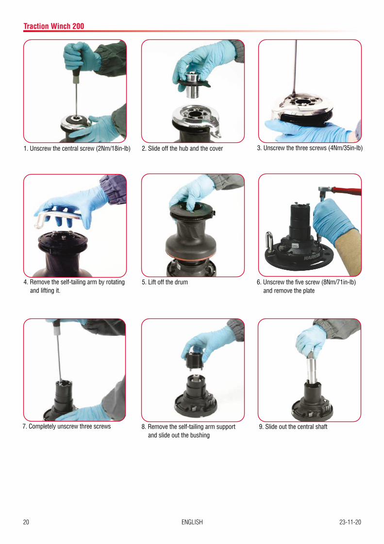
G
G 1
A
A
G 2
A Anti-Seize
G Harken® GreaseHarken® grease: 1� on assy socket screw 2� on drum gear
EXPLODED VIEW WITH MAINTENANCE PRODUCTS AND PARTS LIST
24 ENGLISH 23-11-20
Traction Winch 200
2
1
4
5
11
4
5
7
3
6
10
9
8
4
5 O
G
OO
OL
G
G
O
O
G
G
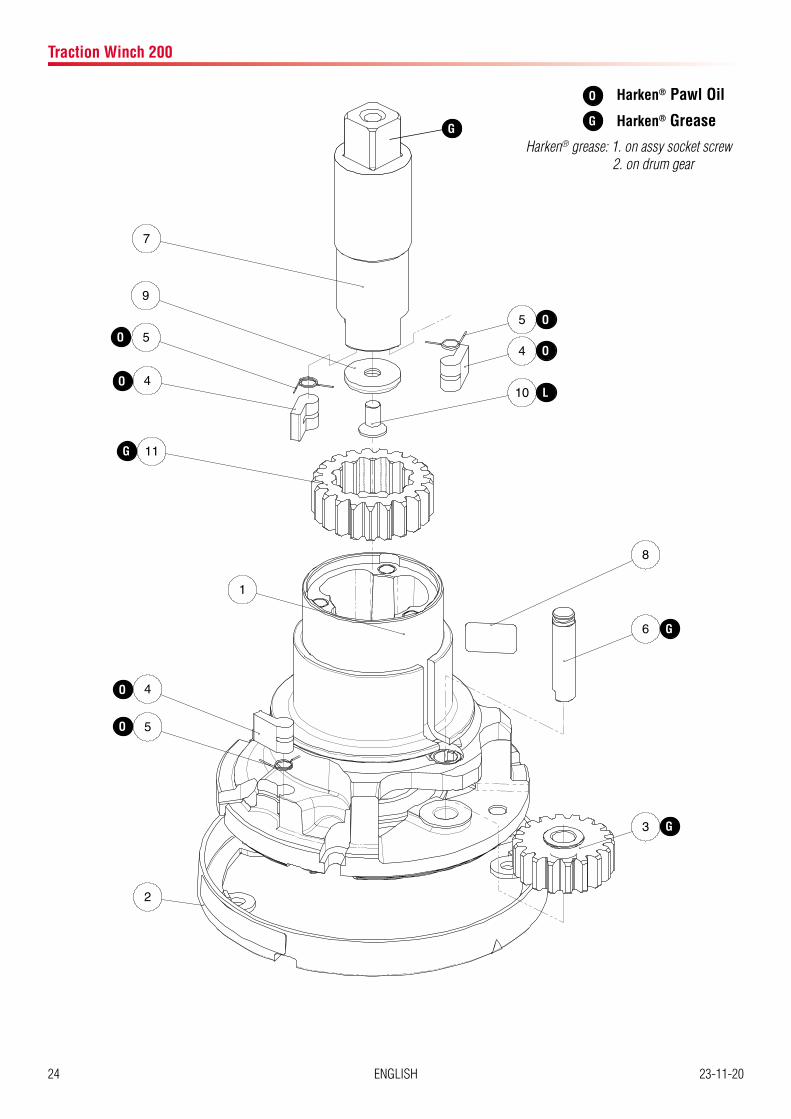
Harken® grease: 1� on assy socket screw 2� on drum gear
O Harken® Pawl Oil
Harken® Grease

25ENGLISH23-11-20
Traction Winch 200
Pos. Q.ty Code Description1 1 A 941369 00 Assy Housing Winch 20
Housing W20 Bushing Ø9xØ11x9* Bushing Ø9xØ11x12* Heli-coil M6x9 Bushing Ø55xØ62x34* Washer Ø33.5xØ58x5.5 Bushing Ø28xØ33x25*
2 1 A 941386 00 Assy Skirt Winch 20 Skirt W20
3 1 A 941367 00 Assy Gear Z18 Gear Z18 Bushing Ø9xØ11x7*
4 4 Pawl Ø8*5 4 Pawl Spring Ø8*6 1 S 41370 00 04 Pin7 1 S 41363 00 02 Shaft Winch 208 1 S 41876 00 63 Winch Serial Number Sticker9 1 S 268890080 Washer
10 1 M 06040 03 Screw M6x12 UNI 5933*11 1 S 41362 00 41 Gear Z2112 1 S 41294 00 A0 Stripper arm support13 1 S 41356 00 53 Drum W2014 1 S 28167 00 97 Red line*15 1 A 941365 00 Assy Jaws W20
Lower Jaw W20 Upper Jaw W20 Peeler W20 Spring
16 3 M 6009103 Screw UNI EN ISO 1207:1996 - M5x35 - A4*
17 1 S 41357 00 19 Stripper Arm W2018 3 M 6007103 Screw M6x50 UNI6107*19 1 S 41358 00 A5 Cover 1 Speed W2020 1 A94136400 Socket Assy W20
21 1 F83528400 Handle B10ASG
Socket Handle W20 Washer Ø7.7xØ25x5.8 Screw M8x20 UNI 6109*
(*) Available with service kit BK4512; see website www�harken�com
26 ENGLISH 23-11-20
®
SM
R
Øi
Øe
1
2
3
4
6
5
7
8
9
10
21
Drawn
Note
Material
Description
Finish Scale
Date
Filename Rev.
Tolleranze per dimensioni lineari ed angolari prive di indicazione di tolleranza specifiche come da Tab. UNI EN 22768-1 -Classe di tolleranza Media.Tolerance for linear and angular dimensions without individual tolerance indications as for standard sheet UNI EN 22768-1 -Tolerance class m.
Tolleranze geometriche per elementi privi di indicazione di tolleranze specifiche come da Tab. UNI EN 22768-2 - Classe di tolleranza K.Geometrical tolerance for features without individual tolerance indications as for standard sheet UNI EN 22768-2 -Tolerance class K.
Revision / Modification:
Mass [g]
010
2030
4050
[mm
]
A - Modificato nome Winch: era Winch 20 UMP;inseriti n°1xF83256700 e n°1xS418760063 (Marenghi 14/05/2015)
Code
C:\Users\davide.baselli\Desktop\LAVORI IN CORSO\Traction winch 200 manuale\
Mod.
Tolleranze generali per fori H13 UNI EN ISO 286-1 Holes general tolerance H13 UNI EN ISO 286-1
Tolleranze generali per alberi h13 UNI EN ISO 286-1Shafts general tolerance h13 UNI EN ISO 286-1
Modelled Checked
Date Date
Surface [mm2]
ISO A2
La HARKEN SPA è proprietaria esclusiva di questo disegno e di tutte le informazioni in esso contenute. A norma di legge è vietata la riproduzione senza autorizzazione scritta rilasciata dalla HARKEN SPA.HARKEN SPA is the sole owner of this drawning and of all included information. According to law it is forbidden to reproduce this drawing whithout a written authorization issued by HARKEN SPA
Sheet format
873460-outline
1:5
ToppiToppi
16/10/202016/10/2020
...
...
Traction Winch 200 INTW 200Traction Winch 200 INTW 200
0F87346000 A
Smussi non quotati 0.2 x 45°.All unmarked chamfers 0.2 x 45°.
102030405060708090100 [mm]
F
E
C
D
A
B
5 6 7 8
Tutte le quote si riferiscono prima di eventuali trattamenti superficialiAll dimensions refer to the moment previous to surface treatments
Riferimento a specifiche HarkenHarken standard dependence
Raggi non quotati 0.5All unmarked radii 0.5
Rompere spigoli viviRemove all sharpcorners
3 41 2 11109 12
G
H
B
E
C
F
G
A
D
Massimo
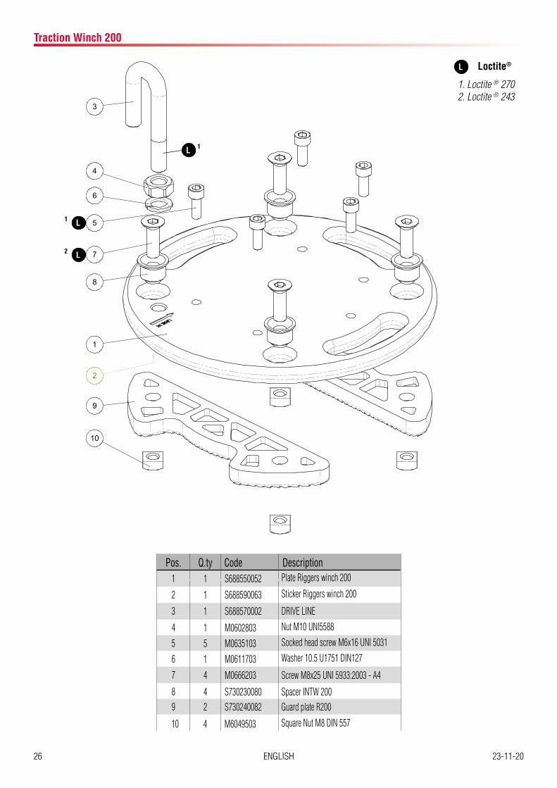
23/12/2014Pos. Q.ty Code Description
1 1 S688550052 Plate Riggers winch 200 2 1 S688590063 Sticker Riggers winch 200
3 1 S688570002 DRIVE LINE
4 1 M0602803 Nut M10 UNI5588
5 5 M0635103 Socked head screw M6x16 UNI 5031
6 1 M0611703 Washer 10.5 U1751 DIN127
7 4 M0666203 Screw M8x25 UNI 5933:2003 - A4
8 4 S730230080 Spacer INTW 2009 2 S730240082 Guard plate R200
10 4 M6049503 Square Nut M8 DIN 557
Traction Winch 200
L 1
L1
L2
L
1� Loctite ® 2702� Loctite ® 243
Loctite®

27ENGLISH23-11-20
NOTE!On every gear and every component that must be greased, apply Harken® grease with a brush in a proper quantity as shown below:
NOTE!Harken® grease to apply on all teeth: do not use excessive quantity of product to void wastes� If in contact with the pawls, an excess of grease can compromise the safety of the winch�
Assembly
Assemble the winch in the reverse order of the sequence in the section on disassembly�To tighten bolts, use the torque indicated in the disassembly procedure�
When positioning the stripper arm, align the peeler with it�
If the jaws have been disassembled, insert peeler between the two jaws, taking care that the letters TOP on the peeler are facing upwards�
OIL
To assemble the pawls:Correctly position the spring in its housing as shown at left�Hold the spring closed and slide the pawl into its housing�Once in position, check that the pawls can be easily opened and closed with a finger�In case of doubt concerning the assembly procedure contact Harken® Tech Service: techservice@harken�it
Traction Winch 200

28 ENGLISH 23-11-20
HANDLING
Protect against extreme temperatures: less then -10° C or more then +50° C
Extreme heat may distort composite parts�
Extreme cold can cause the material to become brittle and cause the lubrication to congeal�
STORAGE
Store in clean/dry place
Avoid impact which could damage jaws and skirt; ensure good packaging when shipping�
Traction Winch 200

29ENGLISH23-11-20
Traction Winch 200
MAINTENANCE SCHEDULE
Owner name
Product name and Model
Serial Number
Year of manufacture
Date of purchase
Date of first use
Maintenance interval Annual

30 ENGLISH 23-11-20
Traction Winch 200
Date of Service Description of ServiceName and Signature of Maintanance Operator
Date of Next Intervention

31ENGLISH23-11-20
Traction Winch 200
Date of Service Description of ServiceName and Signature of Maintanance Operator
Date of Next Intervention

32 ENGLISH 23-11-20
Traction Winch 200
Date of Service Description of ServiceName and Signature of Maintanance Operator
Date of Next Intervention


ManufacturerHarken Italy S.p.A.
Via Marco Biagi 14, 22070 Limido Comasco (CO), Italy Tel 031�3523511; Fax 031�3520031
Web: www�harken�it Email: info@harken�it
Worldwide Limited WarrantyRefer to the Harken World Limited Warranty on the website at:
http://www.harkenindustrial.com/
The product warranty is accepted only if it has been maintained as specified in this Manual by Harken authorized personnel and is accompanied by Maintenance Schedule properly compiled