Double reverse traction repositor versus traction table for the ...
Upload
khangminh22Category
view
2download
0
A Historical Perspective of Traction Drives and Related Technology
Stuart H. Loewenthal’
Traction or friction drives are perhaps the simplest of all rotary mechanisms and yet relatively little is known and even less has been written about them. In its simplest form a traction drive is just two smooth, unequal sized wheels in driving contact. Their simplicity suggests that their existence predates that of the gear drive. As speed regulators, oil-lubricated traction drives have been in industrial service for more than 50 years; yet the concept of transmitting power via traction remains unfamiliar and even alien to many. Indeed, traction drives are commonplace in our daily existence. Our car tires engaged against the road surface or a locomotive’s driving wheels against the rail are but two common examples.
Many applications may be found in equipment where simple and economical solutions to speed regulations are required, such as phonograph drives, self-propelled lawnmowers, and even the amusement park ride driven by a rubber tire. Of course, in these examples, simple dry contact is involved. However, this same principle can be harnessed in the construction of an oil-lubricated transmission containing all steel components.
Traction drives can be constructed to give a single, fixed-speed ratio, like a gearbox or, unlike a gearbox, a speed ratio that can be continuously varied. This latter arrangement is of extreme interest to drive-train configurators since it provides them with an essentially “infinite” number of shift points to optimize the performance of their drive system.
Because power transfer occurs between smooth rolling-bodies, generally across a thin, tenacious lubricant film, traction drives possess certain performance characteristics not found in other power transmissions. Traction drives can be designed to smoothly and continuously vary the speed ratio with efficiencies approaching those of the best gear drives. Unlike transmissions with gear teeth, which, even when perfectly machined, generate torsional oscillations as the load transfers between teeth, power transfer through traction is inherently smooth and quiet without any “backlash.” Film trapped between the rollers tends to protect against wear and to dampen torsional vibrations. The operating speed of some traction drives is limited only by the burst strength of the roller material and the available traction in the contact. In many cases traction drives can be designed to be as small as or smaller than their nontraction-drive counterparts. When manufactured in sufficient quantity, costs can also be quite competitive because of the similarities in manufacturing traction-drive components and ordinary mass-produced ball and roller bearings.
Although traction drives have been available for some time (refs. 1 to 7), it is perhaps within the past 15 years or so that they have been considered serious competitors of conventional mechanical power transmissions in some of the more demanding applications. The earlier drives, particularly those targeted for automotive applications, had their share of durability problems above nominal power levels and, as a consequence, relatively few succeeded in the market place. The underlying reason for this was that certain critical pieces of technology were generally lacking. Designs were based on mostly trial and error. No uniform failure theories were available to establish service life or reliability ratings. The drive materials of the day were crude by today’s standards. In short, traction drives were in their technical infancy.
Prompted by the search for more efficient automotive transmissions and bolstered by advance- ments made in rolling-element bearing technology, interest in traction drives has been renewed. Today’s analytical tools, materials, and traction fluids are far superior to those available only 10 years ago. This has led to the re-emergence of traction drives and the technology related to their design.
It is the intent of this review to trace the evolution of traction-drive technology, in a limited sense, from its early development to the efforts underway today. The reader will appreciate that no attempt has been made to comprehensively document the history of traction drives but rather to
‘NASA Lewis Research Center.
79
assemble, in a single place, a collection of source material on this broad subject for the benefit of those unfamiliar with these interesting devices.
Early History Since the development of machines there has been a need for transmissions to effectively match
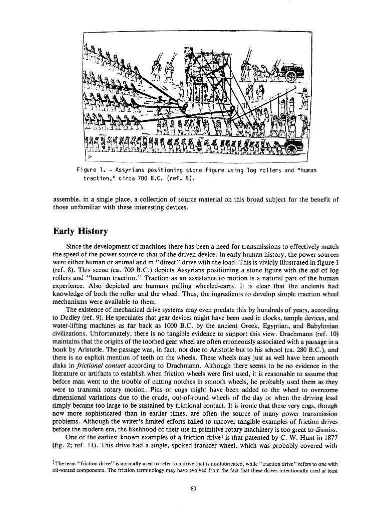
the speed of the power source to that of the driven device. In early human history, the power sources were either human or animal and in “direct” drive with the load. This is vividly illustrated in figure 1 (ref. 8). This scene (ca. 700 B.C.) depicts Assyrians positioning a stone figure with the aid of log rollers and “human traction.” Traction as an assistance to motion is a natural part of the human experience. Also depicted are humans pulling wheeledcarts. It is clear that the ancients had knowledge of both the roller and the wheel. Thus, the ingredients to develop simple traction wheel mechanisms were available to them.
The existence of mechanical drive systems may even predate this by hundreds of years, according to Dudley (ref. 9). He speculates that gear devices might have been used in clocks, temple devices, and water-lifting machines as far back as loo0 B.C. by the ancient Greek, Egyptian, and Babylonian civilizations. Unfortunately, there is no tangible evidence to support this view. Drachmann (ref. 10) maintains that the origins of the toothed gear wheel are often erroneously associated with a passage in a book by Aristotle. The passage was, in fact, not due to Aristotle but to his school (ca. 280 B.C.), and there is no explicit mention of teeth on the wheels. These wheels may just as well have been smooth disks in frictional contact according to Drachmann. Although there seems to be no evidence in the literature or artifacts to establish when friction wheels were first used, it is reasonable to assume that before man went to the trouble of cutting notches in smooth wheels, he probably used them as they were to transmit rotary motion. Pins or cogs might have been added to the wheel to overcome dimensional variations due to the crude, out-of-round wheels of the day or when the driving load simply became too large to be sustained by frictional contact. It is ironic that these very cogs, though now more sophisticated than in earlier times, are often the source of many power transmission problems. Although the writer’s limited efforts failed to uncover tangible examples of friction drives before the modern era, the likelihood of their use in primitive rotary machinery is too great to dismiss.
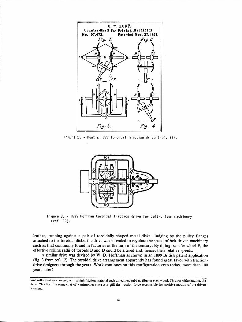
One of the earliest known examples of a friction drivel is that patented by C. W. Hunt in 1877 (fig. 2; ref. 11). This drive had a single, spoked transfer wheel, which was probably covered with
1The term “friction drive” is normally used to refer to a drive that is nonlubricated, while “traction drive” refers to one with oil-wetted components. The friction terminology may have evolved from the fact that these drives intentionally used at least
80
C. W. HUNT. Counter-Shaft for Driving Maohinmy.
No. 197,472. Patented Nov. 27, 1877. Fiy. 1. -
P
F i g u r e 2. - Hunt 's 1877 t o r o i d a l f r i c t i o n d r i v e ( r e f . 111.
F i g u r e 3. - 1899 Hoffman t o r o i d a l f r i c t i o n d r i v e f o r b e l t - d r i v e n machinery ( r e f . 12).
leather, running against a pair of toroidally shaped metal disks. Judging by the pulley flanges attached to the toroidal disks, the drive was intended to regulate the speed of belt-driven machinery such as that commonly found in factories at the turn of the century. By tilting transfer wheel E, the effective rolling radii of toroids B and D could be altered and, hence, their relative speeds.
A similar drive was devised by W. D. Hoffman as shown in an 1899 British patent application (fig. 3 from ref. 12). The toroidal drive arrangement apparently has found great favor with traction- drive designers through the years. Work continues on this configuration even today, more than 100 years later!
one roller that was covered with a high friction material such as leather, rubber;fiber or even wood. This not withstanding, the term "friction" is somewhat of a misnomer since it is still the traction force responsible for positive motion of the driven element.
81
I906 Y O Y 3. ,om T H E AUTOMOBILE.
Cars.
Either Shaft or
T W O For Sisa For
oughly Tetted During the Put
I 1 We Furnish the 1 Transmiss ion
As Shorn Here- 1 with to indude l Fly-whee l and
Direct C l u t c h . The Fnme is of Steel. Barings,
I Bdls mnd Rollen. M a t e r i a l and Workmanship of Highest Grade.
a & &
Fnnion Surhas
only in use on I n t e r m e d i a t e Speeds Forward and Revme.
Side F r i c t i o n Wheels Do M o l Rolnteon Drive. Centnl Friction Wheel is Driven on Inter- mediate Speeds b y Bolh S i d e W h e e l . F ~ o m Flywheel. Note Ikm?cctclulcl, in H u b of the Flywheel.
& e &
Puts Less Smin on the Running Gear of a Car Than Any Other Tnnsmiuion.
GEARLES TRANSMISSION CO., I)ochesttr, N. Y.
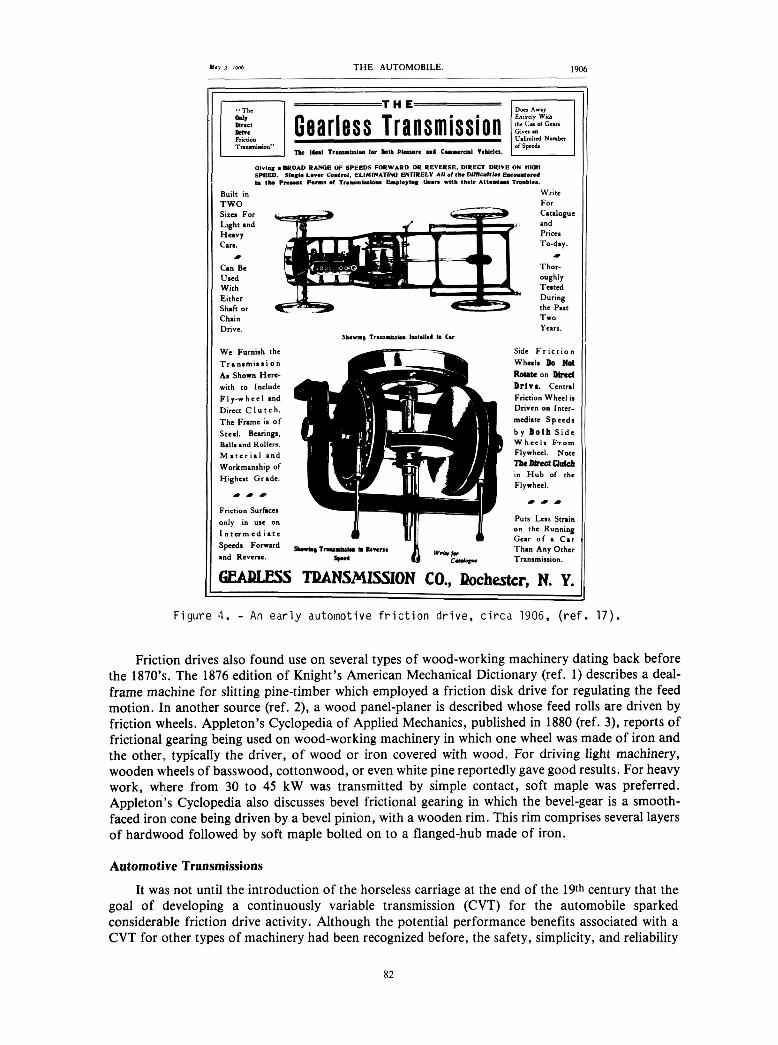
Figure 4. - An early automotive friction drive, circa 1906, (ref. 17).
Friction drives also found use on several types of wood-working machinery dating back before the 1870’s. The 1876 edition of Knight’s American Mechanical Dictionary (ref. 1) describes a deal- frame machine for slitting pine-timber which employed a friction disk drive for regulating the feed motion. In another source (ref. 2), a wood panel-planer is described whose feed rolls are driven by friction wheels. Appleton’s Cyclopedia of Applied Mechanics, published in 1880 (ref. 3), reports of frictional gearing being used on wood-working machinery in which one wheel was made of iron and the other, typically the driver, of wood or iron covered with wood. For driving light machinery, wooden wheels of basswood, cottonwood, or even white pine reportedly gave good results. For heavy work, where from 30 to 45 kW was transmitted by simple contact, soft maple was preferred. Appleton’s Cyclopedia also discusses bevel frictional gearing in which the bevel-gear is a smooth- faced iron cone being driven by a bevel pinion, with a wooden rim. This rim comprises several layers of hardwood followed by soft maple bolted on to a flanged-hub made of iron.
Automotive Transmissions
It was not until the introduction of the horseless carriage at the end of the 19th century that the goal of developing a continuously variable transmission (CVT) for the automobile sparked considerable friction drive activity. Although the potential performance benefits associated with a CVT for other types of machinery had been recognized before, the safety, simplicity, and reliability
82
I of the gearset offered greater appeal. It was good enough to select roughly the right speed ratio and to up-size the powerplant slightly, if needed, to drive the load. It quickly became apparent to the designers of early automobiles that a highly flexible transmission was badly needed to compensate for the lack of flexibility of the early gasoline engines. These engines had a tendency to run well only at one speed. As noted by P. M. Heldt in an unusually comprehensive review of the development of the automatic transmission (ref. 13), the chief objection to early sliding-gear transmission, apart from their lack of flexibility, was the difficulty in gear shifting. The gearboxes used on many of the early vintage cars, such as 1890 Panhard, were adopted from the clash gears used in factory equipment (ref. 14). Gear changing was not merely difficult but potentially damaging to the gear teeth. According to Hodges and Wise (ref. 15), “the best technique with those early cars was to slip the clutch gently and bang the gears home as quickly as possible, in the hope that you might catch the cogs unawares.” (Although Prentice and Shiels patented the synchromesh principle back in 1904, it wasn’t until the late 1920’s that General Motors developed the syncromesh gearshift for production. Syncromesh allowed almost any driver to shift from one speed to the next without clashing the gears (ref. 16).) In view of the limitations and inconveniences associated with gear changing, it is not surprising that the inventors of the day looked for a simple means of continuously and, hopefully, automatically varying the speed ratio between the engine and the wheels.
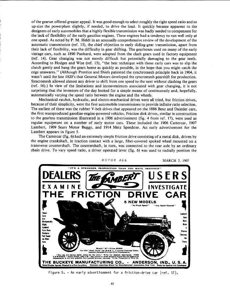
Mechanical ratchet, hydraulic, and electro-mechanical drives were all tried, but friction drives, because of their simplicity, were the first automobile transmissions to provide infinite ratio selection. The earliest of these was the rubber V-belt drives that appeared on the 1886 Benz and Daimler cars, the first massproduced gasoline-engine-powered vehicles. Friction disk drives, similar in construction to the gearless transmission illustrated in a 1906 advertisement (fig. 4 from ref. 17), were used as regular equipment on a number of early motor cars. These included the 1906 Cartercar, 1907 Lambert, 1909 Sears Motor Buggy, and 1914 Metz Speedster. An early advertisement for the Lambert appears in figure 5 .
The Cartercar (fig. 6) had an extremely simple friction drive consisting of a metal disk, driven by the engine crankshaft, in traction contact with a large, fibercovered spoked wheel mounted on a transverse countershaft. The countershaft, in turn, was connected to the rear axle by an ordinary chain drive. To vary speed ratio, a driver operated lever (fig. 6) was used to radially position the
’ MARCH 7, 1907 M O T O R A G b
“IT’S A STRONGER ?RO?OSlTION T H A N YOU H A V E lWAGINLD”
THE FRICTION DRIVE CAR
Figure 5. - An early advertisement for a friction-drive car ( r e f . 17).
83
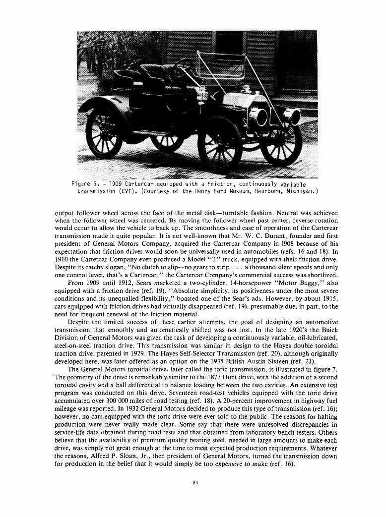
F i g u r e 6 . - 1909 C a r t e r c a r equipped w i t h a f r i c t i o n , c o n t i n u o u s l y v a r i a b l e t r a n s m i s s i b n ( C V T ) . ( C o u r t e s y o f the Henry Ford Museum, Dearborn, Michigan.)
output follower wheel across the face of the metal disk-turntable fashion. Neutral was achieved when the follower wheel was centered. By moving the follower wheel past center, reverse rotation would occur to allow the vehicle to back up. The smoothness and ease of operation of the Cartercar transmission made it quite popular. It is not well-known that Mr. W. C. Durant, founder and first president of General Motors Company, acquired the Cartercar Company in 1908 because of his expectation that friction drives would soon be universally used in automobiles (refs. 16 and 18). In 1910 the Cartercar Company even produced a Model “T” truck, equipped with their friction drive. Despite its catchy slogan, “NO clutch to slip-no gears to strip . . . a thousand silent speeds and only one control lever, that’s a Cartercar,” the Cartercar Company’s commercial success was shortlived.
From 1909 until 1912, Sears marketed a two-cylinder, 14-horsepower “Motor Buggy,” also equipped with a friction drive (ref. 19). “Absolute simplicity, its positiveness under the most severe conditions and its unequalled flexibility,” boasted one of the Sear’s ads. However, by about 1915, cars equipped with friction drives had virtually disappeared (ref. 19), presumably due, in part, to the need for frequent renewal of the friction material.
Despite the limited success of these earlier attempts, the goal of designing an automotive transmission that smoothly and automatically shifted was not lost. In the late 1920’s the Buick Division of General Motors was given the task of developing a continuously variable, oil-lubricated, steel-on-steel traction drive. This transmission was similar in design to the Hayes double toroidal traction drive, patented in 1929. The Hayes Self-selector Transmission (ref. 20), although originally developed here, was later offered as an option on the 1935 British Austin Sixteen (ref. 21).
The General Motors toroidal drive, later called the toric transmission, is illustrated in figure 7. The geometry of the drive is remarkably similar to the 1877 Hunt drive, with the addition of a second toroidal cavity and a ball differential to balance loading between the two cavities. An extensive test program was conducted on this drive. Seventeen road-test vehicles equipped with the toric drive accumulated over 300 OOO miles of road testing (ref. 18). A 20-percent improvement in highway fuel mileage was reported. In 1932 General Motors decided to produce this type of transmission (ref. 16); however, no cars equipped with the toric drive were ever sold to the public. The reasons for halting production were never really made clear. Some say that there were unresolved discrepancies in service-life data obtained during road tests and that obtained from laboratory bench testers. Others believe that the availability of premium quality bearing steel, needed in large amounts to make each drive, was simply not great enough at the time to meet expected production requirements, Whatever the reasons, Alfred P. Sloan, Jr., then president of General Motors, turned the transmission down for production in the belief that it would simply be too expensive to make (ref. 16).
84
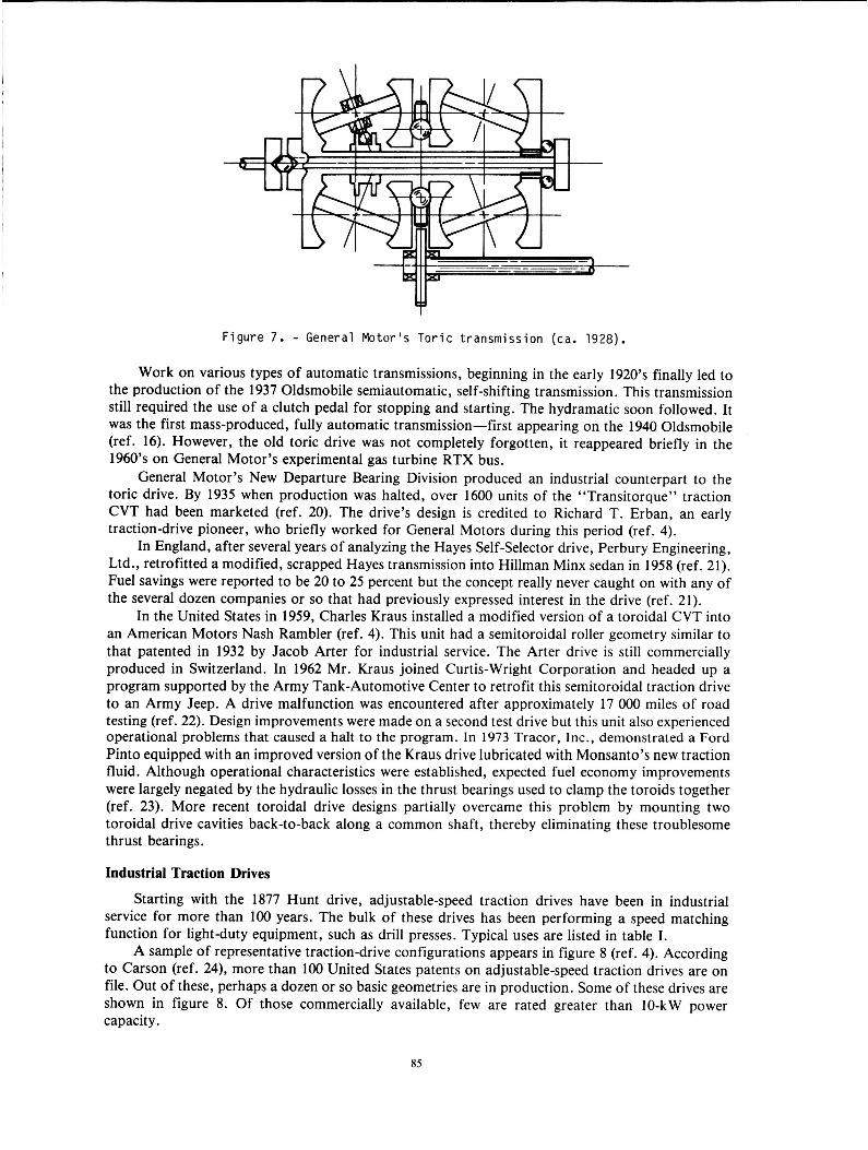
Figure 7. - General Hotor’s Toric transmission (ca. 1928).
Work on various types of automatic transmissions, beginning in the early 1920’s finally led to the production of the 1937 Oldsmobile semiautomatic, self-shifting transmission. This transmission still required the use of a clutch pedal for stopping and starting. The hydramatic soon followed. It was the first mass-produced, fully automatic transmission-first appearing on the 1940 Oldsmobile (ref. 16). However, the old toric drive was not completely forgotten, it reappeared briefly in the 1960’s on General Motor’s experimental gas turbine RTX bus.
General Motor’s New Departure Bearing Division produced an industrial counterpart to the toric drive. By 1935 when production was halted, over 1600 units of the “Transitorque” traction CVT had been marketed (ref. 20). The drive’s design is credited to Richard T. Erban, an early traction-drive pioneer, who briefly worked for General Motors during this period (ref. 4).
In England, after several years of analyzing the Hayes Self-selector drive, Perbury Engineering, Ltd., retrofitted a modified, scrapped Hayes transmission into Hillman Minx sedan in 1958 (ref. 21). Fuel savings were reported to be 20 to 25 percent but the concept really never caught on with any of the several dozen companies or so that had previously expressed interest in the drive (ref. 21).
In the United States in 1959, Charles Kraus installed a modified version of a toroidal CVT into an American Motors Nash Rambler (ref. 4). This unit had a semitoroidal roller geometry similar to that patented in 1932 by Jacob Arter for industrial service. The Arter drive is still commercially produced in Switzerland. In 1962 Mr. Kraus joined Curtis-Wright Corporation and headed up a program supported by the Army Tank-Automotive Center to retrofit this semitoroidal traction drive to an Army Jeep. A drive malfunction was encountered after approximately 17 OOO miles of road testing (ref. 22). Design improvements were made on a second test drive but this unit also experienced operational problems that caused a halt to the program. In 1973 Tracor, Inc., demonstrated a Ford Pinto equipped with an improved version of the Kraus drive lubricated with Monsanto’s new traction fluid. Although operational characteristics were established, expected fuel economy improvements were largely negated by the hydraulic losses in the thrust bearings used to clamp the toroids together (ref. 23). More recent toroidal drive designs partially overcame this problem by mounting two toroidal drive cavities back-to-back along a common shaft, thereby eliminating these troublesome thrust bearings.
Industrial Traction Drives
Starting with the 1877 Hunt drive, adjustable-speed traction drives have been in industrial service for more than 100 years. The bulk of these drives has been performing a speed matching function for light-duty equipment, such as drill presses. Typical uses are listed in table I.
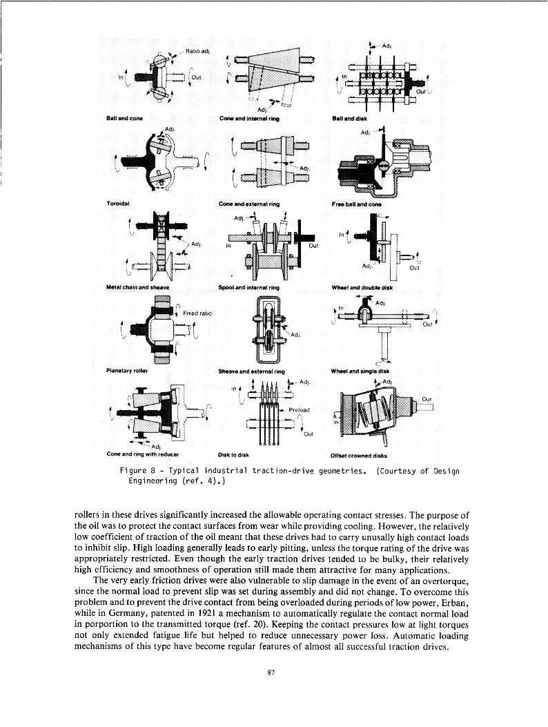
A sample of representative traction-drive configurations appears in figure 8 (ref. 4). According to Carson (ref. 24), more than 100 United States patents on adjustable-speed traction drives are on file. Out of these, perhaps a dozen or so basic geometries are in production. Some of these drives are shown in figure 8. Of those commercially available, few are rated greater than 10-kW power capacity.
85
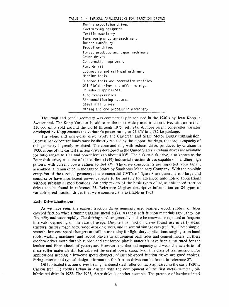
TABLE I . - TYPICAL APPLICATIONS FOR TRACTION DRIVES Marine propulsion drives Earthmoving equipment Textile machinery Farm equipment, agramachinery Rubber machinery Propeller drives Forest products and paper machinery Crane drives Construction equipment Pump drives Locomotive and railroad machinery Machine tools Outdoor tools and recreation vehicles Oil f ie ld drives and offshore rigs Household appliances Auto t r an smi ss i on s Air conditioning systems Steel mill drives Mining and ore processing machinery
The “ball and cone” geometry was commercially introduced in the 1940’s by Jean Kopp in Switzerland. The Kopp Variator is said to be the most widely used traction drive, with more than 250 000 units sold around the world through 1975 (ref. 24). A more recent cone-roller variator developed by Kopp extends the variator’s power rating to 75 kW in a 582-kg package.
The wheel and single-disk drive typify the Cartercar and Sears Motor Buggy transmission. Because heavy contact loads must be directly reacted by the support bearings, the torque capacity of this geometry is greatly restricted. The cone and ring with reducer drive, produced by Graham in 1935, is one of the earliest traction drives developed in the United States; Graham drives are available for ratio ranges to 1O:l and power levels to about 4 kW. The disk-to-disk drive, also known as the Beier disk drive, was one of the earliest (1949) industrial traction drives capable of handling high powers, with current power ratings to 164 kW. The drive components are imported from Japan, assembled, and marketed in the United States by Sumitomo Machinery Company. With the possible exception of the toroidal geometry, the commercial CVT’s of figure 8 are generally too large and complex or have insufficient power capacity to be suitable for advanced automotive applications without substantial modifications. An early review of the basic types of adjustable-speed traction drives can be found in reference 25. Reference 26 gives descriptive information on 24 types of variable speed traction drives that were commercially available in 1963.
Early Drive Limitations
As we have seen, the earliest traction drives generally used leather, wood, rubber, or fiber covered friction wheels running against metal disks. As these soft friction materials aged, they lost flexibility and wore rapidly. The driving surfaces generally had to be renewed or replaced at frequent intervals, depending on the rate of usage. Despite this, friction drives found use in early steam tractors, factory machinery, wood-working tools, and in several vintage cars (ref. 20). These simple, smooth, low-cost speed changers are still in use today for light-duty applications ranging from hand tools, washing machines, and record players to amusement park rides and cement mixers. In these modern drives more durable rubber and reinforced plastic materials have been substituted for the leather and fiber wheels of yesteryear. However, the thermal capacity and wear characteristics of these softer materials still basically set the useful power capacity of this class of transmission. For applications needing a low-cost speed changer, adjustable-speed friction drives are good choices. Sizing criteria and typical design information for friction drives can be found in reference 27.
Oil-lubricated traction drives having hardened steel roller contacts appeared in the early 1920’s. Carson (ref. 11) credits Erban in Austria with the development of the first metal-to-metal, oil- lubricated drive in 1922. The 1923, Arter drive is another example. The presence of hardened steel
86
Toroidal Caw and external ring Free bell and CWIB
Metat chain and dwMva Spool and hternei ring Wheal and dwbk disk
1
'J I
ratio
M c- Sheave and external ring Wheel 8nd ringk dbk
Cana and rtng wvtfh reducw Disk lo dhk Offset cioywHLd disks
Figure 8 - Typical industrial traction-drive geometries. (Courtesy of Design Engineering (ref. 4).)
rollers in these drives significantly increased the allowable operating contact stresses. The purpose of the oil was to protect the contact surfaces from wear while providing cooling. However, the relatively low coefficient of traction of the oil meant that these drives had to carry unusally high contact loads to inhibit slip. High loading generally leads to early pitting, unless the torque rating of the drive was appropriately restricted. Even though the early traction drives tended to be bulky, their relatively high efficiency and smoothness of operation still made them attractive for many applications.
The very early friction drives were also vulnerable to slip damage in the event of an overtorque, since the normal load to prevent slip was set during assembly and did not change. To overcome this problem and to prevent the drive contact from being overloaded during periods of low power, Erban, while in Germany, patented in 1921 a mechanism to automatically regulate the contact normal load in porportion to the transmitted torque (ref. 20). Keeping the contact pressures low at light torques not only extended fatigue life but helped to reduce unnecessary power loss. Automatic loading mechanisms of this type have become regular features of almost all successful traction drives.
87
Advancements in Technology Traction drive technology made relatively little progress for the first half of this century except
for the occasional introduction of a new geometric variation. Designs were largely predicated on laboratory or field experience and very little of this information was reported in the open technical literature.
Because of the great similarity in the contact operating condition, traction-drive technology benefited greatly from the wave of technical advancements made for rolling-element bearings. Major advancements in bearing design occurred in the late 1940’s with Grubin’s work in elastohydrodynamic lubrication (ref. 28) and Lundberg-Palmgren’s analysis of rolling-element fatigue life (ref. 29). In fact, the lubrication principles, operating conditions, and failure mechanisms of traction-drive contacts and bearing contacts are so similar that the design fundamentals are virtually interchangeable. The same may be said for gear contact design criteria as well.
In view of the durability shortcomings of earlier traction drives, much of the recent research has centered on improving the power capacity and reliability of these devices without sacrificing their inherent simplicity or high mechanical efficiency. Although work has been performed on many fronts, research efforts to date can be loosely categorized under one of several areas: (1) modeling the tractive behavior of the lubricant within the contact and its attendant power losses; (2) predicting the useful torque that can be passed between rollers without surface distress or that amount corresponding to a given fatigue life; (3) determining and improving the durability characteristics of traction-drive materials, primarily bearing-grade steels; (4) developing lubricants that produce higher traction forces in the contact without sacrificing conventional lubricant qualities; and (5) developing drive arrangements that maximize durability, torque capacity, and ratio capability and minimize size, weight, power loss, and complexity.
Traction Phenomena
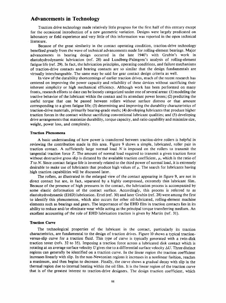
A basic understanding of how power is transferred between traction-drive rollers is helpful in reviewing the contribution made^ in this area. Figure 9 shows a simple, lubricated, roller pair in traction contact. A sufficiently large normal load N is imposed on the rollers to transmit the tangential traction force T. The amount of normal load required to transmit a given traction force without destructive gross slip is dictated by the available traction coefficient, p, which is the ratio of Tto N. Since contact fatigue life is inversely related to the third power of normal load, it is extremely desirable to make use of lubricants that produce high values of p. The search for lubricants having high traction capabilities will be discussed later.
The rollers, as illustrated in the enlarged view of the contact appearing in figure 9, are not in direct contact but are, in fact, separated by a highly compressed, extremely thin lubricant film. Because of the presence of high pressures in the contact, the lubrication process is accompanied by some elastic deformation of the contact surface. Accordingly, this process is referred to as elastohydrodynamic (EHD) lubrication. Ertel (ref. 30) and later Grubin (ref. 28) were among the first to identify this phenomenon, which also occurs for other oil-lubricated, rolling-element machine elements such as bearings and gears. The importance of the EHD film in traction contacts lies in its ability to reduce and/or eliminate wear while acting as the principal torque transferring medium. An excellent accounting of-the role of EHD lubrication traction is given by Martin (ref. 31).
Traction Curve
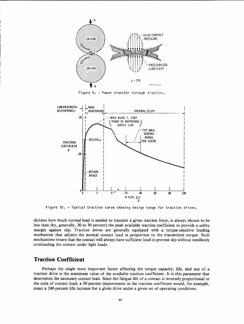
The technological properties of the lubricant in the contact, particularly its traction characteristics, are fundamental to the design of traction drives. Figure 10 shows a typical traction- versus-slip curve for a traction fluid. This type of curve is typically generated with a twin-disk traction tester (refs. 32 to 35). Imposing a traction force across a lubricated disk contact which is rotating at an average surface velocity Ugives rise to a differential surface velocity AU. Three distinct regions can generally be identified on a traction curve. In the linear region the traction coefficient increases linearly with slip. In the non-Newtonian regions it increases in a nonlinear fashion, reaches a maximum, and then begins to decrease. Finally, the curve shows a gradual decay with slip in the thermal region due to internal heating within the oil film. It is the linear region of the traction curve that is of the greatest interest to traction-drive designers. The design traction coefficient, which
88
7 HI CH CONTACT
PRESSURIZED
- TIN cs-so-1c15
I f N
F i g u r e 9. - Power t r a n s f e r through t r a c t i o n .
F i g u r e 10. - T y p i c a l t r a c t i o n curve showing des ign range f o r t r a c t i o n dr ives .
dictates how much normal load is needed to transmit a given traction force, is always chosen to be less than (by, generally, 20 to 30 percent) the peak available traction coefficient to provide a safety margin against slip. Traction drives are generally equipped with a torque-sensitive loading mechanism that adjusts the normal contact load in proportion to the transmitted torque. Such mechanisms insure that the contact will always have sufficient load to prevent slip without needlessly overloading the contact under light loads.
Traction Coefficient Perhaps the single most important factor affecting the torque capacity, life, and size of a
traction drive is the maximum value of the available traction coefficient. It is this parameter that determines the necessary contact load. Since the fatigue life of a contact is inversely proportional to the cube of contact load, a 50-percent improvement in the traction coefficient would, for example, mean a 240-percent life increase for a given drive under a given set of operating conditions.
89
Solidification Behavior
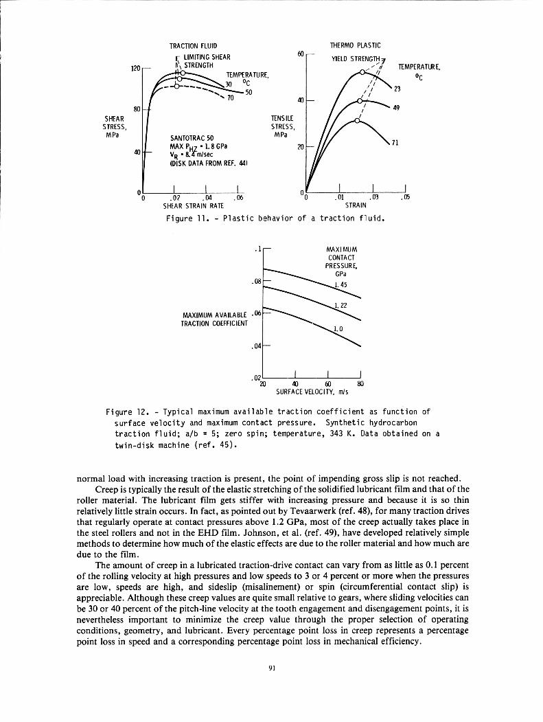
In a typical traction-drive contact, severe transient operating conditions are imposed on the lubricant. The lubricant is swept into the contact, exposed to contact pressures, which are 10 O00 times atmospheric or greater, and returned to ambient conditions, all in a few milliseconds. Clark, et al. (ref. 32), in 1951 were the first to experimentally observe that, under these high pressures and shear rates, the lubricant exhibits shearing properties of a plastic solid and will, in fact, yield at some critical shear stress. Although it had been known from static high-pressure viscometry experiments that an oil’s viscosity would increase dramatically with increasing pressure and eventually solidify under high enough pressure, this was really the first time that this effect was observed to occur under the highly transient conditions of a traction contact. This solidification phenomenon was later also observed by experimentors Smith (ref. 33), Plint (ref. 34), and Johnson and Cameron (ref. 35), among others. Indeed, one can see a striking similarity in the shear-stress-shear-strain rate curves of a traction fluid and the tensile-stress-strain curves of a typical thermoplastic (fig. 11). It is also clear from figure 1 1 that temperature has a similar adverse effect on the limiting shear strength (maximum traction coefficient) of the traction fluid and the yield strength of the thermoplastic. Furthermore, both materials exhibit either viscous or elastic behavior depending on the rate of straining. Plastics will flow like a liquid if stretched slowly enough but will show elastic resiliancy if pulled suddenly. An EHD film in the traction contact shows similar visco-elastic behavior.
Effects of Operating Conditions
Whether the lubricant exhibits viscous behavior or acts as an elastic solid depends on a number of factors. Contact pressure, temperature, shear rates, and lubricant composition all play important roles. Knowledge of the rheological characteristics of the lubricant as it passes through the contact is essential to predicting the performance of the contact, particularly in the absence of specific experimental data.
Visco-elastic lubricant behavior has been a subject pursued by a large number of investigators. Among them were Crook (ref. 36) and Dyson (ref. 37), who were among the first to call attention to such behavior, Johnson and Roberts (ref. 38), who experimentally demonstrated the transition from predominantly viscous to predominantly elastic response, and Trachman and Cheng (ref. 39), who used a compressional visco-elasticity model to numerically solve for the traction curve.
Based on the work of these investigators and on the comprehensive traction model advanced by Johnson and Tevaarwerk (ref. 40), one can assume that for most traction-drive contacts the maximum available traction coefficient is directly related to the shear yield strength of the solidified lubricant film.
From a large body of traction data generated on a twin-disk tester (refs. 41 to 44), it was found that an increase in contact pressure is beneficial to the available traction coefficient but that an increase in surface velocity, temperature, contact ellipticity ratio, misalinement, or spin (circumferential slip) has a negative effect. Figure 12 shows the typical effects that pressure and speed have on the traction coefficient of a traction fluid from test data generated in reference 45.
Creep
In the linear region of the traction curve, the transfer of torque will cause a small difference in velocity to be developed between the surfaces of the driver and driven rollers. This small velocity difference, generally less than 1 percent of the rolling velocity, is often referred to as creep rather than slip. This is because in creep only part of the contact is experiencing sliding while in slip there is total relative motion.
Creep is always present to some extent between rolling bodies that are transmitting torque, whether lubricated or not. Carter in 1926 was one of the first to identify the creep occurring between a locomotive’s driving wheel and the rail (ref. 46). Typically, a region of microslip will occur between the surfaces in the trailing region of the contact while the surfaces in the leading region will be locked together without relative motion (ref. 47). As the tangential traction force is increased, the microslip region will encompass more and more of the contact until, at some point, the whole contact is in total slip. This is the point of impending gross slip. It occurs when the ratio of traction force to normal load is equal to the maximum available traction coefficient. When a mechanism to increase the
TRACTION FLUID r LIMITING SHEAR
SHEAR STRESS, M Pa
(DISK DATA FROM REF. 44)
0' .06 0 .02 .04
THERM0 PLASTIC _- !7 n TEMPERATLRE.
\ n
TENSILE STRESS, M Pa
. 01 .u3 .05 SHtAR STRAIN RATE STRAIN
F i g u r e 11. - P l a s t i c behavior o f a t r a c t i o n f l u i d .
MAXIMUM CONTACT
MAXIMUM AVAILABLE TRACTION COEFFICIENT
.04-
SURFACE VELOCITY, m/s
F i g u r e 12. - T y p i c a l maximum a v a i l a b l e t r a c t i o n c o e f f i c i e n t as f u n c t i o n o f s u r f a c e v e l o c i t y and maximum con tac t pressure. t r a c t i o n f l u i d ; a/b = 5; zero spin; temperature, 343 K. Data ob ta ined on a t w i n - d i s k machine ( re f . 45).
Syn the t i c hydrocarbon
normal load with increasing traction is present, the point of impending gross slip is not reached. Creep is typically the result of the elastic stretching of the solidified lubricant film and that of the
roller material. The lubricant film gets stiffer with increasing pressure and because it is so thin relatively little strain occurs. In fact, as pointed out by Tevaarwerk (ref. 48), for many traction drives that regularly operate at contact pressures above 1.2 GPa, most of the creep actually takes place in the steel rollers and not in the EHD film. Johnson, et al. (ref. 49), have developed relatively simple methods to determine how much of the elastic effects are due to the roller material and how much are due to the film.
The amount of creep in a lubricated traction-drive contact can vary from as little as 0.1 percent of the rolling velocity at high pressures and low speeds to 3 or 4 percent or more when the pressures are low, speeds are high, and sideslip (misalinement) or spin (circumferential contact slip) is appreciable. Although these creep values are quite small relative to gears, where sliding velocities can be 30 or 40 percent of the pitch-line velocity at the tooth engagement and disengagement points, it is nevertheless important to minimize the creep value through the proper selection of operating conditions, geometry, and lubricant. Every percentage point loss in creep represents a percentage point loss in speed and a corresponding percentage point loss in mechanical efficiency.
91
Traction Fluids Because of the importance that the coefficient of traction has on the life, size, and performance
of a traction drive, considerable attention has been given to identifying fluids with high traction properties, starting in the late 50’s with Lane’s experiments (ref. 50). Using a modified two-ball tester, Lane found an apparent inverse relationship between the traction coefficient and temperature- viscosity index for naphthenic and paraffinic mineral oils.
In a comprehensive investigation into traction phenomena, Hewko (ref. 42) obtained traction performance data for both compounded and uncompounded mineral oils as well as for a group of synthetic fluids. He also investigated the effect of oil additives on traction as well as the effects of operating conditions, roller geometry, and surface topography. His results indicated that the lubricant composition and surface topography had the greatest overall effects on traction and that naphthenic-based mineral oils gave better performance than paraffinic oils. He also observed that many common types of additives can markedly reduce traction (ref. 42).
The research of reference 51 describes the development of a formulated traction fluid, designated as Sunoco Traction Drive Fluid-86. This fluid was subsequently field tested in the General Motors turbine bus toric drive and in an automatic transmission for the Oldsmobile Toronado with reportedly good results.
Hammann, et al. (ref. 52), examined some 26 test fluids and, unlike Lane (ref. 50), could not find any obvious relationship between the coefficient of traction and the viscosity index. However, his tests did identify several synthetic fluids that had up to 50 percent higher coefficients of traction, depending on test conditions, than those reported for the best naphthenic base oils (ref. 52). This research laid the groundwork for the development of Monsanto’s family of commercial traction fluids, Santotrac 30, 40, 50, and 70. These fluids are the most widely used traction oils today. The results of accelerated five-ball fatigue tests (ref. 53) indicated that these synthetic cycloaliphatic traction fluids have good fatigue-life performance, comparable with the reference tetraester oil used in this experiment.
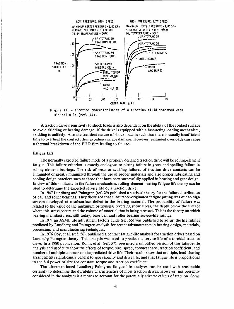
In an unusually complete doctoral investigation into the nature of traction power transfer, Gaggermeier (ref. 441, in one part of his work, measured the coefficient of traction of 17 lubricants on a twin-disk traction tester at both high and low contact pressures and surface speeds. The traction fluids in his tests showed substantially higher coefficients of traction than all of the commercial naphthenic mineral oils tested. The greatest differences occur at relatively low pressures and high surface speeds (fig. 13). At relatively high pressures and low speeds the traction fluids show less of an advantage. Under such conditions a good quality naphthenic mineral oil would serve almost as well. However, for most traction-drive applications there is considerable incentive to using a traction fluid, with expected traction improvements falling somewhere between the two examples of figure 13.
What is noteworthy about the traction curves in figure 13 is the way they illustrate the common and important tendency of traction fluids to solidify into a plastic material at far lower pressures and high speeds than conventional oils (e.g., see the work of Blair and Winer, ref. 54). This is the basic reason why the traction coefficient for the two traction fluids is already at high levels in fig- ure 13(a), while that for the mineral oils needs substantially higher pressure to attain high levels as indicated in figure 13(b). The tendency for early solidification has a lot to do with what makes a traction fluid a traction fluid.
Capacity and Durability Failure Criteria
Traction drives, like rolling-element bearings are generally sized on the basis of rolling-element fatigue life. This is because, for most applications, other than those that are particularly short-lived, the stress levels required for acceptable fatigue life are generally well below those for static yield failure. Because of these relatively low maximum operating stress levels, traction drives can generally tolerate shock loads several times the maximum design value without plastic deformation or other ill effects. This is contrary to the misbelief that traction drives are particularly vulnerable to sudden overloads. Furthermore, if these transient overloads are brief and do not occur too frequently, only a relatively small penalty to the drive’s total fatigue life will result.
92
LOW PRESSURE, HIGH SPEED HIGH PRESSURE, LOW SPEED
TRACTION COEFFICIENT,
CI
MAXIMUM HERTZ PRESSURE - 1.09 GPa
OIL IN TEMPERATURE H)oC SURFACE VELOCITY - 8.3 m h c
I r SANTOTRAC 70
SHELL CLAVUS
.02 .M .[)6
CREEP RA
MAXIMUM HERTZ PRESSURE = 1.86 GPa SURFACE VELOCITY 0.83 mlsec OIL TEMPERATURE W C
rSANTOTRAC 70
VAC HLP ZS
0 .02 .M .06 TE, AWU
Figure 13. - Tract ion c h a r a c t e r i s t i c s o f a t r a c t i o n f l u i d compared wi th mineral o i l s ( r e f . 44).
A traction drive’s sensitivity to shock loads is also dependent on the ability of the contact surface to avoid skidding or heating damage. If the drive is equipped with a fast-acting loading mechanism, skidding is unlikely. Also the transient nature of shock loads is such that there is usually insufficient time to overheat the contact, thus avoiding surface damage. However, sustained overloads can cause a thermal breakdown of the EHD film leading to failure.
Fatigue Life
The normally expected failure mode of a properly designed traction drive will be rollingelement fatigue. This failure criterion is exactly analogous to pitting failure in gears and spalling failure in rollingelement bearings. The risk of wear or scuffing failures of traction drive contacts can be eliminated or greatly minimized through the use of proper materials and also proper lubricating and cooling design practices such as those that have been successfully applied in bearing and gear design. In view of this similarity in the failure mechanism, rolling-element bearing fatigue-life theory can be used to determine the expected service life of a traction drive.
In 1947 Lundberg and Palmgren (ref. 29) published a statiscal theory for the failure distribution of ball and roller bearings. They theorized that subsurface-originated fatigue pitting was due to high stresses developed at a subsurface defect in the bearing material. The probability of failure was related to the value of the maximum orthogonal reversing shear stress, the depth below the surface where this stress occurs and the volume of material that is being stressed. This is the theory on which bearing manufacturers, still today, base ball and roller bearing service-life ratings.
In 1971 an ASME life adjustment factors guide (ref. 5 5 ) was published to adjust the life ratings predicted by Lundberg and Palmgren analysis for recent advancements in bearing design, materials, processing, and manufacturing techniques.
In 1976 Coy, et al. (ref. 56), published a contact fatigue-life analysis for traction drives based on Lundberg-Palmgren theory. This analysis was used to predict the service life of a toroidal traction drive. In a 1980 publication, Rohn, et al. (ref. 57), presented a simplified version of this fatigue-life analysis and used it to show the effects of torque, size, speed, contact shape, traction coefficient, and number of multiple contacts on the predicted drive life. Their results show that multiple, load-sharing arrangements significantly benefit torque capacity and drive life, and that fatigue life is proportional to the 8.4 power of size for constant torque and traction coefficient.
The aforementioned Lundberg-Palmgren fatigue life analyses can be used with reasonable certainty to determine the durability characteristics of most traction drives. However, not presently considered in the analyses is a means to account for the potentially adverse effects of traction. Some
93
investigators (ref. 5 8 ) have found up to a several-fold decrease in rolling-element fatigue life when relative sliding and traction have been introduced; while others (ref. 59) have observed no change or even an improvement in fatigue life, depending on the direction of the applied traction force. A new analytical fatigue-life model, proposed by Tallian, et al. (ref. 60), considers the effects of surface traction on surface- and subsurface-originated spalling. This work is significant because it addresses surface spalling, the more likely fatigue failure mode of gear and traction drive contacts. However, in its present form, the model requires many metallurgical and surface microgeometry parameters, which are not readily available. Thus, the utility of the analysis is, at present, limited. Also, there are currently insufficient test data to properly substantiate this model or to develop universal fatigue-life adjustment factors for the possible negative effects of surface traction. An element of conservatism is in order when establishing service life ratings based on current prediction methods.
Materials
Earlier traction drives were not exploited to their full potential because of uncertainties regarding their longterm reliability. The limited durability characteristics of the materials used in these drives were a major contributing factor. The substitution of oil-lubricated, hardened steel roller components in place of rubber or reinforced plastic running dry against cast-iron parts raises their load capacity by at least an order of magnitude (ref. 27).
Because of the similarity in operating conditions, hardened bearing steels are logical choices for traction-drive rollers. Today’s bearing steels are of significantly higher quality than the traditional air-melted, AISI 52100 steels used in rolling-element bearings since the 1920’s. The introduction of vacuum remelting processes in the late 1950’s has resulted in more homogeneous steels with fewer impurities and has extended rolling-element bearing life several-fold (ref. 61). Life improvements of eight times or more are not uncommon according to reference 5 5 . This reference recommends that a life-improvement factor of six be applied to Lundberg-Palmgren bearing life calculations when using modern vacuum-melted AISI 52100 steel. A similar life-improvement factor is applicable to traction- drive life calculations. This improvement in steel quality in combination with improvements in lubricant traction performance has increased the torque capacity of traction drives several-fold.
Performance Predictions Contact Traction
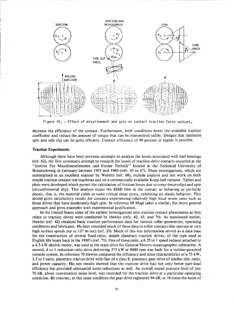
The distribution of local traction forces in the contact of an actual traction drive can be rather complicated as illustrated in figure 14. This figure shows the distribution of local traction vectors in the contact when longitudinal traction, misalinement, and spin are present. These traction forces will aline themselves with the local slip velocities. In traction-drive contacts some combination of traction, misalinement, and spin is always present. To determine the performance of a traction-drive contact, the elemental traction forces must be integrated over the contact area.
Because of the parabolic pressure distribution, the elemental traction forces are largest near the center of the contact and diminish in magnitude near the contact perimeter. As expected, in the case of longitudinal traction (fig. 14(a)), the forces aline themselves in the rolling direction. With the addition of misalinement (fig. 14(b)), a sideslip velocity is introduced causing the vectors to cock in line with the sideslip angle. Using conical rollers generally results in a circumferential slip pattern referred to as spin (fig. 14(c)). This rotary motion is due to the fact that the contact is in pure rolling only at its center. At the right hand edge of the contact the upper roller is sliding over the lower roller because of the mismatch in contact radii. At the left-hand edge the situation is reversed and so is the direction of slip. Because of solid-body rotation, a complete pattern of spin exists over all of the contact.
The power throughout the contact is determined from a summation of the traction force components alined in the rolling direction times their respective rolling velocities. It is clear that in misalinement only a portion of the traction force is generating useful traction and that the remainder is generating useless side force. For pure spin no useful traction is developed, since the elemental traction forces cancel one another. Since the contact power loss is proportional to the product of the elemental traction forces and slip velocities, the presence of spin and misalinement can significantly
94
TRACTION 8 ROLLING t DIRECTION
TRACTION AND MISALIGNMENT
SIDE SLIP ANGLE \ I
t
Figure 14. - Effect o f misalinement and sp in on contact traction force vectors.
decrease the efficiency of the contact. Furthermore, both conditions lower the available traction coefficient and reduce the amount of torque that can be transmitted safely. Designs that minimize spin and side slip can be quite efficient. Contact efficiency of 99 percent or higher is possible.
Traction Experiments
Although there have been previous attempts to analyze the losses associated with ball bearings (ref. 62), the first systematic attempt to research the losses of traction-drive contacts occurred at the “Institut Fur Maschinenelemente und Forder Technik” located at the Technical University of Braunschweig in Germany between 1955 and 1960 (refs. 63 to 67). These investigations, which are summarized in an excellent manner by Wernitz (ref. 68), include analysis and test work on both simple traction contact test machines and on a commercially available Kopp ball variator. Tables and plots were developed which permit the calculation of friction losses due to creep (microslip) and spin (circumferential slip). This analysis treats the EHD film in the contact as behaving as perfectly plastic, that is, the material yields at some critical shear stress, exhibiting no elastic behavior. This model gives satisfactory results for contacts experiencing relatively high local strain rates such as those drives that have moderately high spin. In reference 69 Magi takes a similar, but more general approach and gives examples with experimental justification.
In the United States some of the earliest investigations into traction contact phenomena as they relate to traction drives were conducted by Hewko (refs. 42, 43, and 70). As mentioned earlier, Hewko (ref. 42) obtained basic traction performance data for various roller geometries, operating conditions and lubricants. He later extended much of these data to roller contacts that operate at very high surface speeds (up to 127 m/sec) (ref. 23). Much of this test information served as a data base for the construction of several fixed-ratio, simple planetary traction drives, of the type used in English life boats back in the 1930’s (ref. 71). One of these units, a 6.25 to 1 speed reducer attached to a 4.5-kW electric motor, was used as the main drive for General Motors oceanographic submarine. A second, 6 to 1 reduction ratio drive delivering 373 kW at 8000 rpm was built for a turbine-powered torpedo system. In reference 70 Hewko compared the efficiency and noise characteristics of a 75-kW, 3.5 to 1 ratio, planetary tracton drive with that of a class 8, planetary gear drive of similar size, ratio, and power capacity. His test results showed that the traction drive had not only better part-load efficiency but provided substantial noise reductions as well. An overall sound pressure level of just 70 dB, about conversation noise level, was recorded for the traction drive at a particular operating condition. By contrast, at this same condition the gear drive registered 94 dB, or 16 times the noise of
95
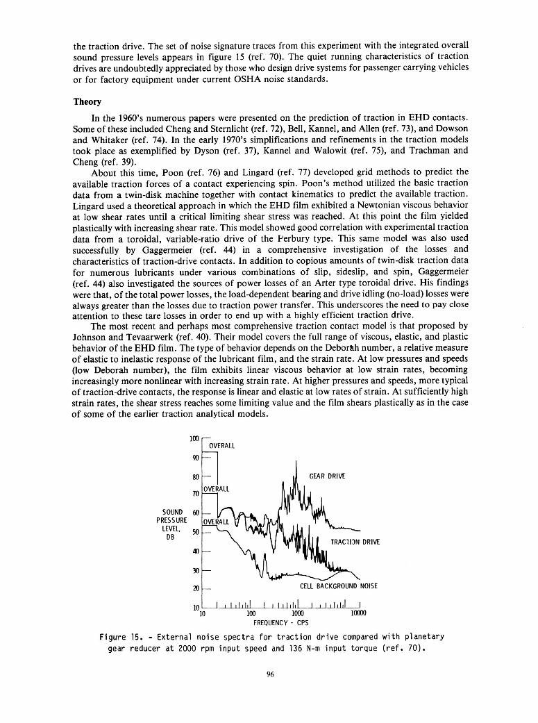
the traction drive. The set of noise signature traces from this experiment with the integrated overall sound pressure levels appears in figure 15 (ref. 70). The quiet running characteristics of traction drives are undoubtedly appreciated by those who design drive systems for passenger carrying vehicles or for factory equipment under current OSHA noise standards.
Theory
In the 1960's numerous papers were presented on the prediction of traction in EHD contacts. Some of these included Cheng and Sternlicht (ref. 72), Bell, Kannel, and Allen (ref. 73), and Dowson and Whitaker (ref. 74). In the early 1970's simplifications and refinements in the traction models took place as exemplified by Dyson (ref. 37), Kannel and Walowit (ref. 7 9 , and Trachman and Cheng (ref. 39).
About this time, Poon (ref. 76) and Lingard (ref. 77) developed grid methods to predict the available traction forces of a contact experiencing spin. Poon's method utilized the basic traction data from a twin-disk machine together with contact kinematics to predict the available traction. Lingard used a theoretical approach in which the EHD film exhibited a Newtonian viscous behavior at low shear rates until a critical limiting shear stress was reached. At this point the film yielded plastically with increasing shear rate. This model showed good correlation with experimental traction data from a toroidal, variable-ratio drive of the Perbury type. This same model was also used successfully by Gaggermeier (ref. 44) in a comprehensive investigation of the losses and characteristics of traction-drive contacts. In addition to copious amounts of twin-disk traction data for numerous lubricants under various combinations of slip, sideslip, and spin, Gaggermeier (ref. 44) also investigated the sources of power losses of an Arter type toroidal drive. His findings were that, of the total power losses, the load-dependent bearing and drive idling (no-load) losses were always greater than the losses due to traction power transfer. This underscores the need to pay close attention to these tare losses in order to end up with a highly efficient traction drive.
The most recent and perhaps most comprehensive traction contact model is that proposed by Johnson and Tevaarwerk (ref. 40). Their model covers the full range of viscous, elastic, and plastic behavior of the EHD film. The type of behavior depends on the Deborah number, a relative measure of elastic to inelastic response of the lubricant film, and the strain rate. At low pressures and speeds (low Deborah number), the film exhibits linear viscous behavior at low strain rates, becoming increasingly more nonlinear with increasing strain rate. At higher pressures and speeds, more typical of tractim-drive contacts, the response is linear and elastic at low rates of strain. At sufficiently high strain rates, the shear stress reaches some limiting value and the film shears plastically as in the case of some of the earlier traction analytical models.
FOVERALL
SOUND PRESSURE
LEVEL, DB
I
D R l M
CELL BACKGROUND NOISE
! ,LW,lILLLJllLLLL 100 loo0 loo00
10 10
FREQUENCY - CPS
"t, I l l l d
Figure 15. - External noise spectra for traction drive compared with planetary gear reducer a t 2000 rpm input speed and 136 N-m input torque (ref. 70).
96
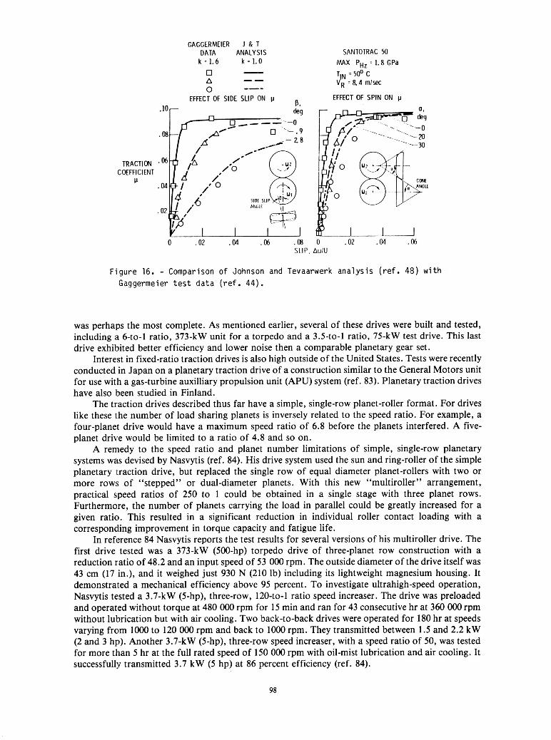
In reference 48 Tevaarwerk presents graphical solutions developed from the Johnson and Tevaarwerk elastic-plastic traction model. These solutions are of practical value in the design and optimization of traction-drive contacts. By knowing the initial slope (shear modulus) and the maximum traction coefficient (limiting shear stress) from a zero-spin/zero-sideslip traction curve, the traction, creep, spin torque, and contact power loss can be found over a wide range of spin values and contact geometries.
Figure 16 shows that this analysis compares favorably with test data, taken from experiments of Gaggermeier (ref. 44). The observed, pronounced reduction in the available traction coefficient with just a few degrees of misalinement, underscores the need to maintain accurate alinement of roller components in traction drives.
The Johnson and Tevaarwerk model, like many of the previous theories, provides an isothermal solution to the ascending portion of the traction curve. Under most circumstances the results from this isothermal analysis are quite satisfactory from a design standpoint. However, at higher surface speeds and for substantial spin, thermal effects start to become important. In reference 78 Daniels introduces a temperature-dependent elastic shear modulus term into the model, but this seems to have a rather weak effect on the results. Using an elaborate heat balance computer analysis, Tevaarwerk (ref. 79) in 1979 was able to correctly predict the heating effects occurring in a traction contact; but his solution is a bit too formidable for general design purposes. In reference 80 Tevaarwerk presents a simple, empirical technique to predict the thermally influenced, large-spin, traction curve from the large slip portion of a no-spin traction curve, but this requires knowledge of the full curve, which is not always available. Simpler analytical techniques are now being investigated (refs. 81 and 82) to better predict how heat generation within the contact affects the available traction coefficient.
Fluid Traction Data
To be able to apply the aforementioned traction drive, certain fundamental fluid properties, namely, the lubricant’s shear modulus and limiting yield shear stress, must first be known under the required operating speeds, pressures, and temperatures. Because of the difficulty of simulating the highly transient nature of an actual traction contact, the most reliable basic fluid property data are deduced, using methods described in reference 44, from the initial slope and maximum traction coefficient of an experimental traction curve. Unfortunately, there has been a general scarcity of these types of data over sufficiently broad enough operating conditions for design purposes. Recently, experimental traction data were obtained under a NASA program for both the Monsanto and Sun Oil traction fluids over a range of speeds, pressures, temperatures, spin, and sideslip values that might be encountered in traction drives (ref. 45). A regression analysis applied to the data resulted in a correlation equation that can be used to predict the initial slope and maximum traction coefficient at any intermediate operating condition (ref. 45).
Recent Developments During the past 5 years, several traction drives, which incorporate much of the latest technology,
have reached the prototype stage. Laboratory tests and design analysis of these drives show them to have relatively high-power densities and, in some cases, to be ready for commercialization.
Nasvytrac Drive
Although light-duty variable-ratio traction drives have been reasonably successful from a commercial standpoint, very few, if any, fixed-ratio types have progressed past the prototype stage. This is somewhat surprising in view of the outstanding ability of traction drives to provide smooth, quiet power transfer at extremely high or low speeds with good efficiency. They seem particularly well suited for high-speed machine tools, pump drives, and other turbomachinery. In other industrial applications they offer potential cost advantages because traction rollers should not be much more expensive to manufacture in quantity than ordinary rollers in roller bearings.
In terms of earlier work on fixed-ratio traction drives, the developmental effort at General Motors Research Laboratories on their planetary traction drive (as described by Hewko (ref. 70)),
97
TRACTION COEFFICIENT
IJ
GAGGERMEIER 1 & T DATA ANALYSIS
k = 1.6 0 A 0
k = 1.0 - -- --- EFFECT OF SIDE SLIP ON
. l o r
SANTOTRAC 50 MAX PHz = 1.8 GPa
JR =a. 4 m/sec T N ’ ~ @ C
EFFECT OF SPIN ON p
0 .02 .04 .06 SLIP, AulU
F i g u r e 16. - Comparison o f Johnson and Tevaarwerk a n a l y s i s ( r e f . 48) w i t h Gaggermeier t e s t d a t a ( r e f . 44).
was perhaps the most complete. As mentioned earlier, several of these drives were built and tested, including a 6-to-1 ratio, 373-kW unit for a torpedo and a 3.5-to-1 ratio, 75-kW test drive. This last drive exhibited better efficiency and lower noise then a comparable planetary gear set.
Interest in fixed-ratio traction drives is also high outside of the United States. Tests were recently conducted in Japan on a planetary traction drive of a construction similar to the General Motors unit for use with a gas-turbine auxilliary propulsion unit (APU) system (ref. 83). Planetary traction drives have also been studied in Finland.
The traction drives described thus far have a simple, single-row planet-roller format. For drives like these the number of load sharing planets is inversely related to the speed ratio. For example, a four-planet drive would have a maximum speed ratio of 6.8 before the planets interfered. A five- planet drive would be limited to a ratio of 4.8 and so on.
A remedy to the speed ratio and planet number limitations of simple, single-row planetary systems was devised by Nasvytis (ref. 84). His drive system used the sun and ring-roller of the simple planetary traction drive, but replaced the single row of equal diameter planet-rollers with two or more rows of “stepped” or dual-diameter planets. With this new “multiroller” arrangement, practical speed ratios of 250 to 1 could be obtained in a single stage with three planet rows. Furthermore, the number of planets carrying the load in parallel could be greatly increased for a given ratio. This resulted in a significant reduction in individual roller contact loading with a corresponding improvement in torque capacity and fatigue life.
In reference 84 Nasvytis reports the test results for several versions of his multiroller drive. The first drive tested was a 373-kW (500-hp) torpedo drive of three-planet row construction with a reduction ratio of 48.2 and an input speed of 53 000 rpm. The outside diameter of the drive itself was 43 cm (17 in.), and it weighed just 930 N (210 lb) including its lightweight magnesium housing. It demonstrated a mechanical efficiency above 95 percent. To investigate ultrahigh-speed operation, Nasvytis tested a 3.7-kW (5-hp), three-row, 120-to-1 ratio speed increaser. The drive was preloaded and operated without torque at 480 OOO rpm for 15 min and ran for 43 consecutive hr at 360 OOO rpm without lubrication but with air cooling. Two back-to-back drives were operated for 180 hr at speeds varying from 1OOO to 120 OOO rpm and back to 1OOO rpm. They transmitted between 1.5 and 2.2 kW (2 and 3 hp). Another 3.7-kW (5-hp), three-row speed increaser, with a speed ratio of 50, was tested for more than 5 hr at the full rated speed of 150 000 rpm with oil-mist lubrication and air cooling. It successfully transmitted 3.7 kW (5 hp) at 86 percent efficiency (ref. 84).
98
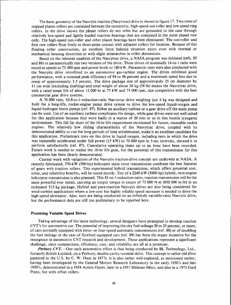
The basic geometry of the Nasvytis traction (Nasyvtrac) drive is shown in figure 17. Two rows of stepped planet-rollers are contained between the concentric, high-speed sun roller and low-speed ring rollers. In the drive shown the planet rollers do not orbit but are grounded to the case through relatively low-speed and lightly loaded reaction bearings that are contained in the outer planet row only. The high-speed sun-roller and other planet bearings have been eliminated. The sun-roller and first row rollers float freely in three-point contact with adjacent rollers for location. Because of this floating roller construction, an excellent force balance situation exists even with thermal or mechanical housing distortion or with slight mismatches in roller dimensions.
Based on the inherent qualities of the Nasvytrac drive, a NASA program was initiated (refs. 85 and 86) to parametrically test two versions of the drive. These drives of nominally 14-to-1 ratio were tested at speeds to 73 000 rpm and power levels to 180 kW. Parametric tests were also conducted with the Nasvytis drive retrofitted to an automotive gas-turbine engine. The drives exhibited good performance, with a nominal peak efficiency of 94 to 96 percent and a maximum speed loss due to creep of approximately 3.5 percent. The drive package size of approximately 25 cm diameter by 11 cm wide (excluding shafting) and total weight of about 26 kg (58 lb) makes the Nasvytrac drive, with a rated mean life of about 12 OOO hr at 75 kW and 75 OOO rpm, size competitive with the best commercial gear drive systems.
A 70 000 rpm, 10.8-to-I-reduction-ratio Nasvytrac drive weighing just 4 kg was designed and built for a long-life, rocket-engine pump drive system to drive the low-speed liquid-oxygen and liquid-hydrogen boost pumps (ref. 87). Either an auxiliary turbine or a gear drive off the main pump can be used. Use of an auxiliary turbine complicates the design, while gear drives were not well suited for this application because they wore badly in a matter of 20 min or so in this hostile cryogenic environment. This fell far short of the IO-hr life requirement envisioned for future, reuseable rocket engines. The relatively low sliding characteristics of the Nasvytrac drive, coupled with its demonstrated ability to run for long periods of time unlubricated, make it an excellent candidate for this application. Preliminary tests on this drive in liquid oxygen, including tests in which the drive was repeatedly accelerated under full power (15 kW) to 70 000 rpm in 5-sec intervals, showed it to perform satisfactorily (ref. 87). Cumulative operating times up to an hour have been recorded. Future work is needed to realize the 10-hr life goal, but the potential of this transmission for this application has been clearly demonstrated.
Current work with variations of the Nasvytis traction-drive concept are underway at NASA. A recently fabricated, 370-kW (500-hp) helicopter main rotor transmission combines the best features of gears with traction rollers. This experimental hybrid transmission, which offers potential cost, noise, and reliability benefits, will be tested shortly. Test of a 2240-kW (3000-hp) hybrid, twin-engine helicopter transmission is also planned. This 81 -to-1 -reduction-ratio, traction transmission will be the most powerful ever tested, carrying an output torque in excess of 73 OOO N-m (650 000 inslb) in an estimated 515-kg package. Hybrid and pure-traction Nasvytis drives are also being considered for wind-turbine applications where a low-cost but highly reliable speed increaser is needed to drive the high-speed alternator. Also, tests are being conducted on an infinitely variable-ratio Nasvytis drive, but the performance data are still too preliminary to be repofted here.
Promising Variable Speed Drives
Taking advantage of the latest technology, several designers have attempted to develop traction CVT’s for automotive use. The potential of improving the city fuel mileage 20 to 25 percent, or more, of cars normally equipped with three- or four-speed automatic transmissions (ref. 88) or of doubling the fuel mileage in the case of flywheel equipped cars (ref. 89) has been the major incentive for the resurgence in automotive CVT research and development. These applications represent a significant challenge, since compactness, efficiency, cost, and reliability are all at a premium.
Perbury CVT. -One such automotive effort is that being conducted by BL Technology, Ltd., formerly British Leyland, on a Perbury, double-cavity toroidal drive. This concept is rather old (first patented in the U.S. by C. W. Hunt in 1877). It is also rather well-explored, as mentioned earlier, having been investigated by the General Motors Research Laboratory in the early 1930’s and late 1950’s, demonstrated in a 1934 Austin-Hayes, later in a 1957 Hillman-Minx, and also in a 1973 Ford Pinto, but with offset rollers.
99
~ ~ I ~ C ~ A ~ 4 ~ ~ ~ ’ BEAR IN CS
F i g u r e 17. - Geometry o f t h e Nasvy t i s t r a c t i o n (Nasvytrac) t e s t d r i v e (ref. 85).
In 1977 Lucas Aerospace in England adapted the Perbury drive for maintaining constant frequency of the AC generators on the Sidley Hawker Harrier, a VSTOL jet fighter. This single cavity, toroidal drive is suitable for driving aircraft generators having output ratings up to 30 kV A. More than 20 years before this, Avco Lycoming, in the U.S., also offered a line of mechanical constant-speed drives based on the toroidal traction-drive principle. They were used on several aircraft in the ~ O ’ S , including the Douglas A-4E fighter, but have long since been discontinued.
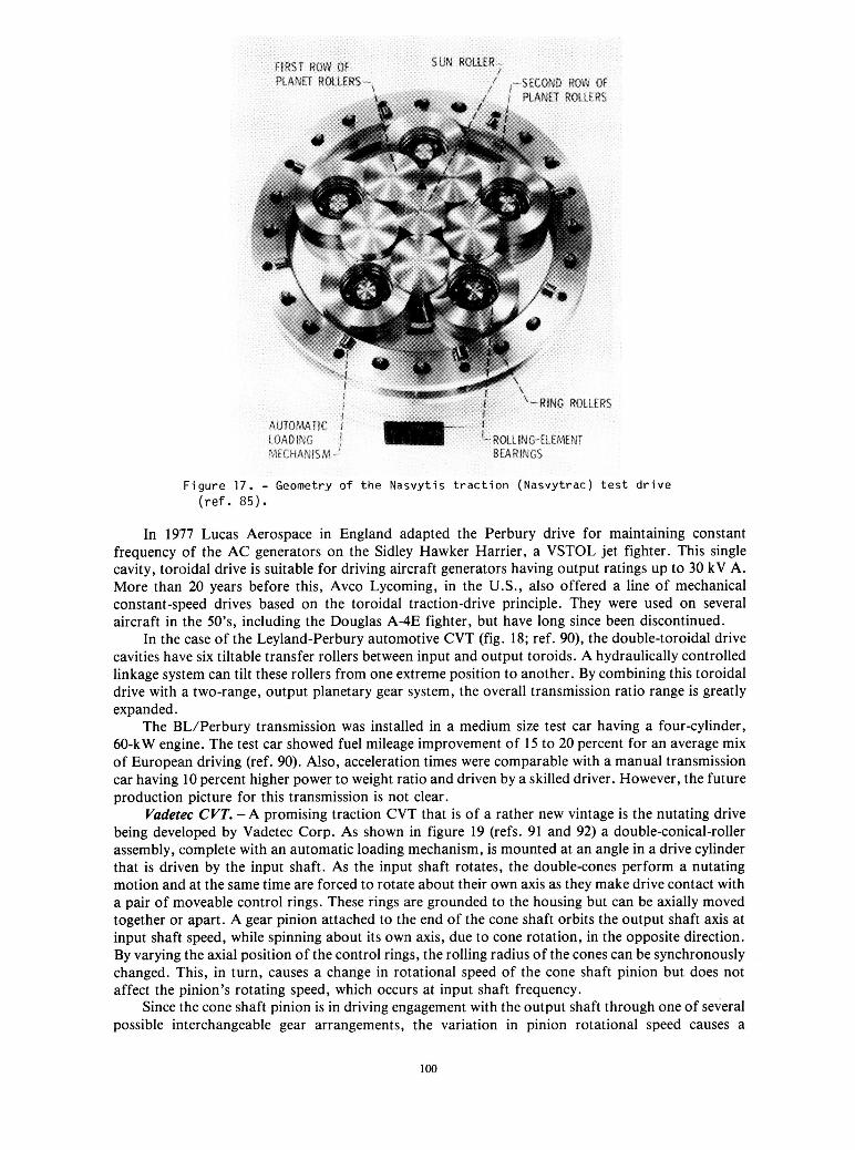
In the case of the Leyland-Perbury automotive CVT (fig. 18; ref. 90), the double-toroidal drive cavities have six tiltable transfer rollers between input and output toroids. A hydraulically controlled linkage system can tilt these rollers from one extreme position to another. By combining this toroidal drive with a two-range, output planetary gear system, the overall transmission ratio range is greatly expanded.
The BL/Perbury transmission was installed in a medium size test car having a four-cylinder, 60-kW engine. The test car showed fuel mileage improvement of 15 to 20 percent for an average mix of European driving (ref. 90). Also, acceleration times were comparable with a manual transmission car having 10 percent higher power to weight ratio and driven by a skilled driver. However, the future production picture for this transmission is not clear.
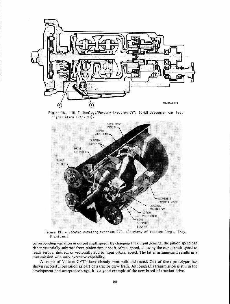
Vudetec CVT. -A promising traction CVT that is of a rather new vintage is the nutating drive being developed by Vadetec Corp. As shown in figure 19 (refs. 91 and 92) a double-conical-roller assembly, complete with an automatic loading mechanism, is mounted at an angle in a drive cylinder that is driven by the input shaft. As the input shaft rotates, the double-cones perform a nutating motion and at the same time are forced to rotate about their own axis as they make drive contact with a pair of moveable control rings. These rings are grounded to the housing but can be axially moved together or apart. A gear pinion attached to the end of the cone shaft orbits the output shaft axis at input shaft speed, while spinning about its own axis, due to cone rotation, in the opposite direction. By varying the axial position of the control rings, the rolling radius of the cones can be synchronously changed. This, in turn, causes a change in rotational speed of the cone shaft pinion but does not affect the pinion’s rotating speed, which occurs at input shaft frequency.
Since the cone shaft pinion is in driving engagement with the output shaft through one of several possible interchangeable gear arrangements, the variation in pinion rotational speed causes a
100
cs-ao-4an d b Figure 18. - BL TechnologylPerbury traction CVT, 60-kW passenger car test
installation (ref. 90).
Figure 19. - Vadetec nutating traction CVT. (Courtesy of Vadetec Corp., Troy, Michigan.)
corresponding variation in output shaft speed. By changing the output gearing, the pinion speed can either vectorially subtract from pinion/input shaft orbital speed, allowing the ouput shaft speed to reach zero, if desired, or vectorially add to input orbital speed. The latter arrangement results in a transmission with only overdrive capability.
A couple of Vadetec CVT’s have already been built and tested. One of these prototypes has shown successful operation as part of a tractor drive train. Although this transmission is still in the development and acceptance stage, it is a good example of the new breed of traction drive.
101
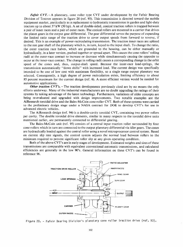
Fafnir CVT. -A planetary, cone roller type CVT under development by the Fafnir Bearing Division of Textron appears in figure 20 (ref. 93). This transmission is directed toward the mobile equipment market, particularly as a replacement to hydrostatic transmission in garden and light-duty tractors up to about 37 kW (50 hp). A set of double-sided, conical traction rollers is trapped between a pair of inner races and a pair of outer races. The conical rollers are mounted in a carrier that drives the planet gears in the output gear differential. The gear differential serves the purpose of expanding the limited ratio range of the traction drive to cover output speeds from forward to reverse, if desired. This is an example of power-recirculating transmission. The traction inner races are splined to the sun gear shaft of the planetary which is, in turn, keyed to the input shaft. To change the ratio, the outer traction race halves, which are grounded to the housing, can be either manually or hydraulically, in a later version, pushed together or spread apart. This causes the cone rollers’ rolling radii at the outer-race contact to increase or decrease while simultaneously causing the opposite to occur at the inner-race contact. The change in rolling radii causes a corresponding change in the orbit speed of the cones and, thus, output-shaft speed. Because the inner-race load-springs, the transmission automatically “down shifts” with increased load. The current design was specifically intended to be one of low cost with maximum flexibility, so a single range output planetary was selected. Consequently, a high degree of power recirculation exists, limiting efficiency to about 85 percent maximum for the current design (ref. 6) . A more efficient version would be needed for automotive applications.
Other traction CVT’s. -The traction developments previously cited are by no means the only efforts underway. Many of the industrial manufacturers are no doubt upgrading the ratings of their systems by taking advantage of the latest technology. Furthermore, variations of older concepts are being re-evaluated and upgraded with design improvements. Two notable examples are the AiResearch toroidal drive and the Bales-McCoin cone-roller CVT. Both of these systems were carried to the preliminary design stage under a NASA contract for DOE to develop CVT’s for use in advanced electric vehicles.
The AiResearch design (ref. 94) is a double-cavity toroidal CVT, containing two power rollers per cavity. The double toroidal drive elements, similar in many respects to the toroidal drive units mentioned earlier, are permanently connected to differential gearing.
The Bales-McCoin unit (ref. 95) consists of a central input traction roller surrounded by four cone-rollers which in turn are connected to the output planetary differential via idler gears. The cones are hydraulically loaded against the central roller using a novel microprocessor control system. Based on current slip rate signals, the control system adjusts the normal load between rollers to the minimum required to prevent significant roller slip at any given operating condition.
Both of the above CVT’s are in early stages of development. Estimated weights and sizes of these transmissions are comparable with equivalent conventional automatic transmissions, and calculated efficiencies are generally in the low 90’s. General information on these CVT’s can be found in reference 96.
RATIO ADJUSTER
TRACTION DRIVE ROLLER INNER RACES
RING GEAR
LOAD SPRINGS
PLANET GEAR
OUTER RACES
Figure 20. - Fafnir Bearing Division’s planetary cone roller traction drive (ref. 9 3 ) .
102
Future Technology Requirements
Although there has been significant progress within the last decade in the development of technology for traction drives, future refinements in certain areas are still needed.
Traction Fluids
Today’s traction fluids are far superior to the earlier lubricants used in traction drives. However, modern traction fluids generally have poor viscosity index characteristics. At temperatures well below freezing, traction fluids can be too viscous to pour properly. Pour-point suppressants such as those incorporated in conventional oils for Arctic service might help.
Traction fluids and the additives that they contain have a tendency to capture and retain air at temperatures below about 70” C. Aeration of the oil is undesirable from both a cooling and hydraulic control system standpoint. This problem is minimized when the oil is subjected to some nominal pressure which tends to significantly condense trapped air bubbles, as occurs in the contact between rollers.
The key to faster and more powerful traction drives is the development of traction fluids whose coefficient of traction shows less degradation with higher surface speeds, operating temperatures, and contact spin. Higher traction at lower contact pressures is also desirable far drives that have extra long life requirements. Today’s synthetic traction fluids appear to be reasonably stable but further work may be needed for “sealed-for-life” drive systems.
Materials
Although today’s bearing steels are well suited for traction drives, durability improvements and lower material costs are always welcome. Studies are required to determine if special coatings or nonmetallic materials might be useful in certain applications.
Sizing and Design Criteria
Fatigue-life prediction methods based on Lundberg-Palmgren theory are available to size traction drives. These methods are well established for determining life ratings of rolling-element bearings. However, they tend to underestimate the fatigue life obtained with today’s bearings. As a result, life-adjustment factors have been identified (ref. 55) to more accurately reflect the longer lives attendant with improved bearing materials, design, and manufacturing techniques. It is anticipated that many of these same life factors are also applicable to traction drives, but endurance test data are needed to corroborate this and to identify what life adjustment factors, if any, are needed.
The upper limit of power transfer for traction drives is relatively unexplored. Drives having power capacities of thousands of kilowatts can theoretically be constructed. Not enough is known about the practical thermal limits of traction contacts or their ability to tolerate transient slips under unusual circumstances. The fact that gear teeth regularly experience momentary slips of 30 or 40 percent on entering or leaving mesh suggest that transient slip values can be remarkably high.
Another important task is the establishment of a consistent, universally accepted design standard for traction drives, similar to those that currently exist for gear drives, bearings, and other mechanical components. The design guides of Wernitz (ref. 27) and Kraus (ref. 97), published about 20 years ago, were most welcome contributions to the field, but our basic understanding of traction phenomena has greatly improved during the interim. A clear, practical, and comprehensive guide for the design and assessment of traction transmissions would benefit the designer and user alike. The bulk of such a guide can probably be assembled from the wide spectrum of information that currently exists.
Manufacturing
In principle, traction drives should be relatively inexpensive to make in large quantities. Manufacturing techniques are essentially the same as those used in the production of rolling-element bearings. To date, traction drives have been produced in relatively limited quantities or on special order and as a result have not yet realized their low cost potential.
103
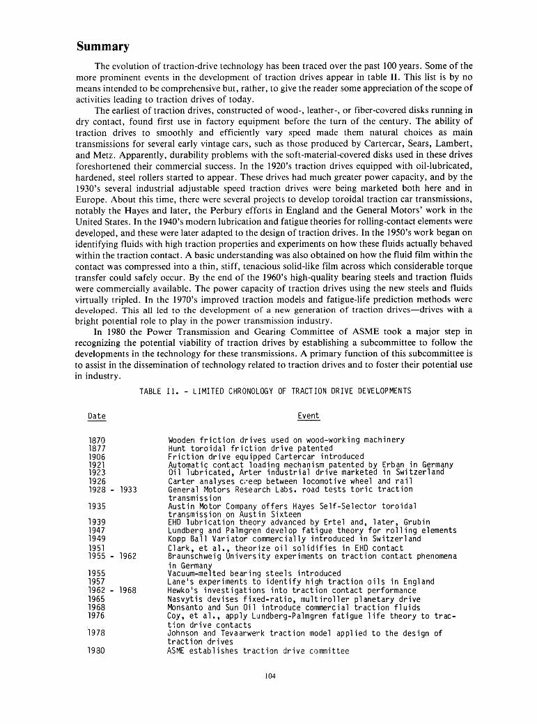
Summary The evolution of traction-drive technology has been traced over the past 100 years. Some of the
more prominent events in the development of traction drives appear in table 11. This list is by no means intended to be comprehensive but, rather, to give the reader some appreciation of the scope of activities leading to traction drives of today.
The earliest of traction drives, constructed of wood-, leather-, or fiber-covered disks running in dry contact, found first use in factory equipment before the turn of the century. The ability of traction drives to smoothly and efficiently vary speed made them natural choices as main transmissions for several early vintage cars, such as those produced by Cartercar, Sears, Lambert, and Metz. Apparently, durability problems with the soft-material-covered disks used in these drives foreshortened their commercial success. In the 1920’s traction drives equipped with oil-lubricated, hardened, steel rollers started to appear. These drives had much greater power capacity, and by the 1930’s several industrial adjustable speed traction drives were being marketed both here and in Europe. About this time, there were several projects to develop toroidal traction car transmissions, notably the Hayes and later, the Perbury efforts in England and the General Motors’ work in the United States. In the 1940’s modern lubrication and fatigue theories for rolling-contact elements were developed, and these were later adapted to the design of traction drives. In the 1950’s work began on identifying fluids with high traction properties and experiments on how these fluids actually behaved within the traction contact. A basic understanding was also obtained on how the fluid film within the contact was compressed into a thin, stiff, tenacious solid-like film across which considerable torque transfer could safely occur. By the end of the 1960’s high-quality bearing steels and traction fluids were commercially available. The power capacity of traction drives using the new steels and fluids virtually tripled. In the 1970’s improved traction models and fatigue-life prediction methods were developed. This all led to the development of a new generation of traction drives-drives with a bright potential role to play in the power transmission industry.
In 1980 the Power Transmission and Gearing Committee of ASME took a major step in recognizing the potential viability of traction drives by establishing a subcommittee to follow the developments in the technology for these transmissions. A primary function of this subcommittee is to assist in the dissemination of technology related to traction drives and to foster their potential use in industry.
TABLE 11. - LIMITED CHRONOLOGY OF TRACTION DRIVE DEVELOPMENTS
Date Event -
1870 Wooden friction drives used on wood-working machinery 1877 H u n t toroidal friction drive patented 1906 Friction drive equipped Cartercar introduced 1921 Automatic contact loadin mechanism patented by Erban in Germany 1923 Oil lubricated, Arter injustr ia l drive marketed in Switzerland 1926 Carter analyses ci-eep between locomotive wheel and r a i l 1928 - 1933 General Motors Research Labs. road tes t s to r ic traction
tr ansmi ss i on 1935 Austin Motor Company offers Hayes Self-selector toroidal
transmission on Austin Sixteen 1939 EHD lubrication theory advanced by Ertel and, la te r , Grubin 1947 Lundberg and Palmgren develop fatigue theory for rolling elements 1949 Kopp Ball Variator commercially introduced in Switzerland 1951 Clark, e t al., theorize o i l solidifies in E H D contact 1955 - 1962 Braunschweig University experiments on traction contact phenomena
i n German Vacuum-mefted bear ina steels introduced 1955
1957 Lane’s experiments t i identify high traction o i l s in England 1962 - 1968 Hewkols investigations into traction contact performance 1965 Nasvytis devises fixed-ratio, multiroller planetary drive 1968 Monsanto and Sun Oil introduce commercial traction fluids 1976 Coy, e t al., apply Lundberg-Palmgren fatigue l i f e theory to trac-
tion drive contacts 1978 Johnson and Tevaarwerk traction model applied to the design of
traction drives 1980 ASME establishes traction drive committee
104
Field experience has been gathered by industrial traction-drive manufacturers, some of whom have been making traction drives for more than 40 years. However, traction-drive technology is relatively young. The latest generation of traction drives has reached a high level of technical readiness. As these drives find their way into industrial service and as work continues in the laboratories, further improvements and increased usage of these drives can be expected.
Concluding Remarks In reviewing traction-drive developments through the years, it becomes evident that relatively
few developments resulted from basic research. Technical advancements were largely due to individual organizations striving to perfect their own specific systems. As a consequence, meager fundamental information was left behind for those who followed. Of course, as this review has attempted to point out, there have been notable exceptions to this, but, by and large, relatively little is known about the reasons for the many commercial diasappointments that occurred along the way.
It is encouraging, at least to this writer, that there currently seems to be greater communication among people working in the field. Admittedly, their numbers are miniscule compared with those working in the bearing and gear disciplines. Nonetheless, traction-drive technology of late seems to be making good progress. This is due, in no small measure, to much of the fine work that has been performed on tribological fundamentals, common to all rolling-element components. It is likely, in the years to come, that traction drives will find an increasingly larger role to play in the power transmission industry.
References 1 . Knights, Edward H.: Knight’s American Mechanical Dictionary. Vol. I. Hurd and Houghton, 1876, p. 680. 2. Trobridge: Census Office Report on Power and Machinery used by Manufacturer. Washington, 1888, p. 220. 3. Appleton’s Cyclopedia of Applied Mechanics. Vol. 11. D. Appleton and Co., 1880, pp. 36-37. 4. Yeaple, F.: Metal-To-Metal Traction Drives now have a New Lease on Life. Product Eng., vol. 42, no. 15, Oct. 1971,
5. Carson, R. W.: New and Better Traction Drives are Here. Mach. Des., vol. 46, no. 10, Apr. 18, 1974, pp. 148-155. 6. McCormick, D.: Traction Drives Move to Higher Powers. Des. Eng., Dec. 1980, pp. 35-39. 7. Hewko, L. 0.: Traction Drives and Their Potential Role in Energy Conservation. Presented at the Joint ASLE Energy-
8. Hamrock, B.; and Dowson, D.: Ball Bearing Lubrication. John Wiley & Sons, 1981. 9. Dudley, D. W.: The Evolution of the Gear Art. American Gear Manufacturers Association, 1969.
pp. 33-37.
Sources Technology Conference, New Orleans, LA, Feb. 1980.
10. Drachmann, A. G.: The Mechanical Technology of Greek and Roman Antiquity. Lubrecht and Cramer, 1963,
1 1 . Carson, R. W.: 100 Years in Review: Industrial Traction Drives. Power Transm. Des., vol. 19, no. 10, Oct. 1977,
12. Fellows, T. G.; et al.: Perbury Continuously Variable Ratio Transmission. Advances in Automobile Engineering, Pt. 11,
13. Heldt, P. M.: Automatic Transmissions. SAE J., vol. 40, no. 5, May 1937, pp. 206-220. 14. DeBono, E.: Eureca: An Illustrated History of Inventions from the Wheel to the Computer. Holt, Rinehart, and Winston,
15. Hodges, D.; and Wise, D. B.: The Story of the Car. Hamlyn Publication Group, Ltd. (London), 1974, p. 18. 16. Sloan, Alfred P.: My Years with General Motors. Doubleday and Co., Inc., 1964. 17. Clymer, F., Historical Motor Scrapbook. Vols. 1 and 2. Clymer Motor Publications, 1944. 18. Caris, D. F.; and Richardson, R. A.: Engine-Transmission Relationships for High Efficiency. SAE Trans., vol. 61, 1953,
19. Improved Technology is Givingan Old Principle a New Drive. Monsanto Magazine, Summer 1974, pp. 14-16. 20. Carson, R. W.: Focus on Traction Drives: 100 Years of Traction Drives. Power Transm. Des., vol. 17, no. 5 , May 1975,
21. Perry, F. G.: The Perbury Transmission. ASME Paper No. 80-GT-22, Mar. 1980. 22. Final Report on the Follow-On Phase of the Evaluation of the Wright Aeronautical Division Toroidal Drive Using a 1/4
Ton Military Truck as a Test Bed Vehicle. WAD R273-F, Curtis-Wright Corporation, Feb. 1966. 23. Carson, R. W.: Focus on Traction Drives. Power Transm. Des., vol. 17, no. 3, Mar. 1975, pp. 48-49. 24. Carson, R. W.: Today’s Traction Drives. Power Transm. Des., vol. 17, no. 1 1 , Nov. 1975, pp. 41-49. 25. Cahn-Speyer, P.: Mechanical Infinitely Variable Speed Drives. Eng. Dig. (London), vol. 18, no. 2, Feb. 1957, pp. 41-43. 26. Dvorak, D. Z.: Your Guide to Variable-Speed Mechanical Drives. Prod. Eng., vol. 34, Dec. 1963, pp. 63-74.
pp. 200-203.
pp. 99-100.
Pergamon Press (Oxford), 1964, pp. 123-142.
1974, p. 33.
pp. 81-96.
pp. 84 and 88.
105
27. Wernitz, W.: Friction Drives. Mechanical Design and Systems Handbook, H. A. Rothbart, ed., McGraw Hill Book Co., Inc., 1964, pp. 14-1 to 14-22.
28. Grubin, A. N.: Fundamentals of the Hydrodynamic Theory of Lubrication of Heavily Loaded Cylindrical Surfaces. Investigation of the Contact of Machine Components, Kh. F. Ketova, ed., Translation of Russian Book No. 30, Central Scientific Institute for Technology and Mechanical Engineering, Moscow, 1949, Chapter 2. (Available from Department of Scientific and Industrial Research, Great Britain, Transl. CTS-235 and Special Libraries Association, Transl.
29. Lundberg, G . and Palmgren, A., “Dynamic Capacity of Rolling Bearings,” Ingenioersvetenskapsakademian,
30. Ertel, A. M.: Hydrodynamic Lubrications Based on new Principles. Prikl. Mat. Mekh., vol. 3, no. 2, 1939 (in Russian). 31. Martin, K. F.: A Review of Frictional Predictions in Gear Teeth. Wear, vol. 49, 1978, pp. 201-238. 32. Clark, 0. H.; Woods, W. W.; and White, J. R.: Lubrication at Extreme Pressure with Mineral Oil Films. J. of Appl.
33. Smith, F. W.: The Effect of Temperature in Concentrated Contact Lubrication. ASLE Trans., vol. 5 , no. 1, Apr. 1962,
34. Plint, M. A.: Traction in Elastohydrodynamic Contacts. Proc. Inst. Mech. Eng. (London), vol. 182, no. 1, 1967,
35. Johnson, K. L.; and Cameron, R.: Shear Behavior of Elastohydrodynamic Oil Films at High Rolling Contact Pressures.
36. Crook, A. W.: Lubrication of Rollers. Pt. IV. Measurements of Friction and Effective Viscosity. Phil. Trans. Roy. SOC.,
37. Dyson, A.: Frictional Traction and Lubricant Rheology in Elastohydrodynamic Lubrication, Phil. Trans. Roy. SOC.,
38. Johnson, K. L.; and Roberts, A. D.: Observation of Visco Elastic Behavior of an Elastohydrodynamic Lubricant Film.
39. Trachman, E. G.; and Cheng, H. S.: Thermal and Non-Newtonian Effects on Traction in Elastohydrodynamic Contacts.
40. Johnson, K. L.; and Tevaarwerk, J. L.: Shear Behavior of Elastohydrodynamic Oil Films. Proc. R. SOC. (London), Ser.
41. Walowit, J. A.; and Smith, R. 0.: Traction Characteristics of a MIL-L-7808 Oil. ASME Paper No. 76-Lubs-19, 1976. 42. Hewko, L. 0.; Rounds, F. G. , Jr.; and Scott, R. L.: Tractive Capacity and Efficiency of Rolling Contacts. Rolling
Contact Phenomena, J. B. Bidwell, ed., Elsevier Publishing Co. (Amsterdam), 1962, pp. 157-185. 43. Hewko, L. 0.: Contact Traction and Creep of Lubricated Cylindrical Rolling Elements at Very High Surface Speeds.
ASLE Trans., vol. 12, no. 2, Apr. 1969, pp. 151-161. 44. Gaggermeier, Helmut: Investigations of Tractive Force Transmission in Variable Traction Drives in the area of
Elastohydrodynamic Lubrication. Ph.D. Dissertation, Technical University of Munich, July 1977. 45. Tevaarwerk, J. L.: Traction Contact Performance Evaluation at High Speeds. NASA CR-165226, 1981. 46. Carter, F. W.: On the Action of a Locomotive Driving Wheel. Proc. R. SOC. (London), Ser. A., vol. 112, 1926,
R-3554.)
Handlinger, No. 196, 1947.
Phys., vol. 22, no. 4, Apr. 1951, pp. 474-483.
pp. 142-148.
pp. 300-306.
Proc. Inst. Mech. Eng. (London), vol. 182, no. 1, 1967, pp. 307-318.
London, Ser. A., vol. 255, no. 1056, Jan. 1963, pp. 281-312.
London, Ser. A., vol. 266, no. 1170, Feb. 1970, pp. 1-33.
Proc. R. SOC. (London), Ser. A., vol. 337, 1974, pp. 217-242.
Symposium on Elastohydrodynamic Lubrication, Inst. of Mech. Eng. (London), 1972, pp. 142-148.
A., vol. 356, no. 1685, Aug. 1977, pp. 215-236.
pp. 151-157. 47. Johnson, K. L.: Tangential Tractions and Micro-Slip in Rolling Contact. Rolling Contact Phenomena, J. B. Bidwell, ed.,
Elsevier Publishing Co. (Amsterdam), 1962, pp. 6-28. 48. Tevaarwerk, J. L.: Traction Drive Performance Prediction for the Johnson and Tevaarwerk Traction Model. NASA
49. Johnson, K. L.; Nayak, L.; and Moore, A. J.: Determination of Elastic Shear Modulus of Lubricants from Disc Machine Tests. Elastohydrodynamics and Related Topics: Proc. 5th Leeds-Lyon Symposium on Tribology, Mech. Eng. Publ.
TP-1530, 1979.
Ltd., 1979, pp. 204-213. 50. Lane, T. B.: The Lubrication of Friction Drives. Lubr. Eng., vol. 13, Feb. 1957, pp. 85-88. 51. Haseltine, M. W.; et al.: Design and Development of Fluids for Traction and Friction Type Transmissions. SAE Paper
52. Hamman, W. C.; et al.: Synthetic Fluids for High Capacity Traction Drives. ASLE Trans., vol. 13, 1970, pp. 105-1 16. 53. Loewenthal, S. H.; and Parker, R. J.: Rolling-Element Fatigue Life with Two Synthetic Cycloaliphatic Traction Fluids.
54. Blair, Scott; and Winer, W. 0.: Shear Strength Measurements of Lubricants at High Pressures. J. Lubr. Tech., vol. 101,
5 5 . Bamberger, E. N., et al.: Life Adjustment Factors for Ball and Roller Bearings-An Engineering Guide. Am. SOC. of
56. Coy, J. J.; Loewenthal, S. H.; and Zaretsky, E. V.: Fatigue Life Analysis for Traction Drives with Application to a
57. Rohn, D. A.; Loewenthal, S. H.; and Coy, J . J.: Simplified Fatigue Life Analysis for Traction Drive Contacts. J . Mech.
58. MacPherson, P. B.: The Pitting Performance of Hardened Steels. ASME Paper No. 77-DET-39, Sept. 1977. 59. Soda, N.; and Yamamoto, T.: Effect of Tangential Traction and Roughness on Crack Initiation/Propagation During
60. Tallian, T. E.; Chiu, Y. P.; and Van Amerongen, E.: Predictions of Traction and Microgeometry Effects on Rolling
61. Bamberger, E. N.: Materials for Rolling Element Bearings. Bearing Design-Historical Aspects, Present Technology, and
710837, Oct. 1971.
NASA TN D-8124, 1976.
no. 3, July 1979, pp. 251-257.
Mech. Eng., 1971.
Toroidal Type Geometry. NASA TN D-8362, 1976.
Des., vol. 103, no. 2, Apr. 1981, pp. 430-439.
Rolling Contact. NASA TM-81608, 1981.
Contact Fatigue Life. J. Lubr. Tech., vol. 100, no. 2, Apr. 1978, pp. 156-166.
Future Problems, Am. SOC. Mech. Eng., 1980, pp. 1-46.
I06
62. Poritsky, H.; Hewlett, C. W., Jr.; and Coleman, R. E., Jr.: Sliding Friction of Ball Bearings of the Pivot Type. J. Appl.
63. Lutz, 0.: Grundsatzliches uber stufenlos verstellbare Walzgetriebe. Z. Konstruktion, vol. 7, 1955, p. 330; vol. 9, 1957,
64. Wernitz, W.: Walz-Bohrreibung-Bestimmung der Bohrmomente und Umfangskrafte bei Hertzscher Pressung mit
65. Maass, H.: Untersuchung uber die in elliptischen Hertzscher Flachen ubertragbaren Umfangskrafte, Dissertation,
66. Kutter, F.: Theoretische Untersuchung eines Reibgetriebes, Thesis, Technical University of Dresden, 1944. 67. Thomas, W.: Reibscheiben-Regelgetriebe (Linienberuhrung), Vol. 4 of the Schriftenreihe Antriebstechnik, Fr. Vieweg
68. Wernitz, W.: Friction at Hertzian Contact with Combined Roll and Twist. Rolling Contact Phenomena, J . B. Biddwell,
69. Magi, M.: On Efficiencies of Mechanical Coplanar Shaft Power Transmissions. Chalmers University, Gothenburg,
70. Hewko, L. 0.: Roller Traction Drive Unit for Extremely Quiet Power Transmission. J. Hydronautics, vol. 2, no. 3, July
71. New Departures in Automotive Ideas. New Departure Press, 1937, pp. 5-6. 72. Cheng, H. S.; and Sternlicht, B.: A Numerical Solution for the Pressure, Temperature, and Film Thickness Between Two
Infinitely Long Lubricated Rolling and Sliding Cylinders under Heavy Loads. J . Basic Eng., vol. 87, no. 3, Sept. 1965,
73. Bell, J . C.; Kannel, J . W.; and Allen, C. M.: The Rheological Behavior of the Lubricant in the Contact Zoneof a Rolling Contact System. J. Basic Eng., vol. 83, no. 3, Sept. 1964, pp. 423-425.
74. Dowson, D.; and Whitaker, B. A.: A Numerical Procedure for the Solution of the Elastohydrodynamic Problem of Rolling and Sliding Contacts Lubricated by a Newtonian Fluid. Proc. Inst. of Mech. Eng. (London), vol. 180, pt. 3B,
75. Kannel, J. W.; and Walowit, J. A.: Simplified Analysis for Tractions Between Rolling-Sliding Elastohydrodynamic
76. Poon, S. Y.: Some Calculations to Assess the Effect of Spin on the Tractive Capacity of Rolling Contact Drives. Proc.
77. Lingard, S.: Tractions at the Spinning Point Contacts of a Variable Ratio Friction Drive. Tribol. Int., vol. 7, Oct. 1974,
78. Daniels, B. K.: Traction Contact Optimization. ASLE Preprint No. 79-LC-1A-1, 1979. 79. Tevaarwerk, J. L.: Traction Calculations Using the Shear Plane Hypothesis. Thermal Effects in Tribology: Proc. 6th
80. Tevaarwerk, J. L.: A Simple Thermal Correction for Large Spin Traction Curves. J. Mech. Des., vol. 103, no. 2, Apr.
81. Johnson, K. L.; and Greenwood, J. A.: Thermal Analysis of an Eyring Fluid in Elastohydrodynamic Traction. Wear, vol.
82. Tevaarwerk, J. L.: Thermal Influence on the Traction Behavior of an Elastic/Plastic Model. Presented at the Leeds/Lyon
83. Nakamura, L.; et al.: A development of a Traction Roller System for a Gas Turbine Driven APU. SAE Paper No. 790106,
84. Nasvytis, A. L.: Multiroller Planetary Friction Drives. SAE Paper No. 660763, Oct. 1966. 85. Loewenthal, S. H.; Anderson, N. E.; and Nasvytis, A. L.: Performance of a Nasvytis Multiroller Traction Drive. NASA
86. Loewenthal, S. H.; Anderson, N. E.; and Rohn, D. A.: Evaluation of a High Performance Fixed-Ratio Traction Drive. J.
87. Meyer, S.; and Connelly, R. E.: Traction Drive for Cryogenic Boost Pump. NASA TM-81704, 1981. 88. Radtke, R. R.; Unnewehr, L. E.; and Freedman, R. J.: Optimization of a Continuously Variable Transmission with
89. Strauch, S.: Flywheel Systems for Vehicles. Proc. Electric and Hybrid Vehicle Advanced Technology Seminar, Dec. 8-9,
90. Stubbs, P. W. R.: The Development of a Perbury Traction Transmission for Motor Car Applciations. J . Mech. Des., vol.
91. Kemper, Y.: A High Power Density Traction Drive. SAE Paper No. 790849, 1979. 92. Elu, P.; and Kemper, Y.: Performance of a Nutating Traction Drive. ASME Paper No. 8O-C2/DET-63, Aug. 1980. 93. Dickinson, T. W.: Development of a Variable Speed Transmission for Light Ractors. SAE Paper No. 770749, Sept. 1977. 94. Raynard, A. E.; Kraus, J. H.; and Bell, D. D.: Design Study of Toroidal Traction CVT for Electric Vehicles.
(Rept-80-16762, AiResearch Manufacturing Company; NASA Contract DEN3-I 17.) DOE/NASA/Ol17-80/1, NASA
95. Walker, R. D.; and McCoin, D. K.: Design Study of a Continuously Variable Cone/Roller Traction Transmission for
96. Parker, R. J.; Loewenthal, S. H.; and Fischer, G. K.: Design Studies of Continuously Variable Transmissions for Electric
97. Kraus, C. E.: An Up-To-Date Guide for Designing Traction Drives. Pt. I. Mach. Des., July 2, 1964, pp. 106-112; and Pt.
Mech., vol. 24, no. 4, Dec. 1947, pp. A-261 to A-268.
p. 169; vol. 10, 1958, p. 425.
Punktberuhrung. Vol. 19 of Schriftenreihe Antriebstechnik, Fr. Vieweg und Sohn, Braunschweig, 1958.
Technical University of Braunschweig, 1959.
und Sohn, Braunschweig, 1954.
ed., Elsevier Publishing Co. (Amsterdam), 1962, pp. 132-156.
Sweden, 1974.
1968, pp. 160-167.
pp. 695-707.
1965, pp. 57-71.
Contacts. J. Lubr. Tech., vol. 93, Jan. 1971, pp. 39-46.
Inst. Mech. Eng. (London), vol. 185, no. 76/71, 1970, pp. 1015-1022.
pp. 228-234.
(1979) Leeds/Lyon Conf. on Tribology, Mech. Eng. Publ., Ltd., 1980, pp. 201-213.
1981, pp. 440-446.
61, 1980 pp. 353-374.
Conference on Tribology, (Leeds, England), Aug. 1981.
Feb. 1979.
TP-1378, 1978.
Mech. Des., vol. 103, no. 2, Apr. 1981, pp. 410-422.
Emission Constraints. SAE Paper No. 810107, Feb. 1981.
1980, California Institute of Technology, Pasadena, pp. 219-236.
103, no. 4, Jan. 1981, pp. 29-40.
CR-159803, 1980.
Electric Vehicles. DOE/NASA/0115-80/1, NASA CR-159841, Sept. 1980.
Vehicles. DOE/NASA/10444-12, NASA TM-81642, 1981.
11. Mach. Des., July 16, 1964, pp. 147-152.
107
Copyright © 2022 FDOKUMEN