TSGENCO VOLUME -IIB TECHNICAL SPECIFICATION FOR ...
466
TSGENCO 1X800 MW KOTHAGUDEM TPS, UNIT-12 AT KOTHAGUDEM, TELANGANA, INDIA VOLUME -IIB TECHNICAL SPECIFICATION FOR COOLING TOWER Specification No. : PE-TS-410-165-N001 (REV. 0) BHARAT HEAVY ELECTRICALS LIMITED POWER SECTOR PROJECT ENGINEERING MANAGEMENT NOIDA - 201301
-
Upload
khangminh22 -
Category
Documents
-
view
0 -
download
0
Transcript of TSGENCO VOLUME -IIB TECHNICAL SPECIFICATION FOR ...
TSGENCO
1X800 MW KOTHAGUDEM TPS, UNIT-12 AT KOTHAGUDEM, TELANGANA, INDIA
VOLUME -IIB
TECHNICAL SPECIFICATION FOR
COOLING TOWER
Specification No. : PE-TS-410-165-N001 (REV. 0)
BHARAT HEAVY ELECTRICALS LIMITED POWER SECTOR
PROJECT ENGINEERING MANAGEMENT NOIDA - 201301
TITLE: TECHNICAL SPECIFICATION
COOLING TOWER
PREAMBLE
SPEC. NO.: PE-TS-410-165-N001 VOLUME: IIB SECTION: REV. NO. 0 DATE: 23.01.15 SHEET 1 OF 1
1.0 The tender document contains three (3) volumes. The bidder shall meet the requirements of
all the three volumes. 1.1 Volume -I CONDITIONS OF CONTRACT This consists of four parts as below :
Volume - I A : This part contains instructions to bidders for making bids to BHEL.
Volume - I B : This part contains general commercial conditions of the tender and include provision that vendor shall be responsible for the quality of item supplied by their sub-vendors.
Volume - I C : This part contains special conditions of contract. Volume - I D : This part contains commercial conditions for erection and
commissioning site work, as applicable.
1.2 Volume - TECHNICAL SPECIFICATIONS Technical requirements are stipulated in Volume II which comprises of:
Volume - II A : General Technical Conditions Volume - II B : Technical specification including drawings, if any
1.2.1 Volume - II B: This volume is sub-divided into following sections:
Section - A : This section outlines the scope of enquiry. Section - B : This section provides “Project Information” Section - C : This section indicates technical requirements specific to the
contract, not covered in Section-D. Section - D
:
This section comprises of technical specifications of equipments complete with data sheet A, B & C. Data sheet-A specifies data and other requirements pertaining to the equipment. Data sheet - B specifies data to be filled by the bidder (Data Sheet B is contained in Volume - III) Data sheet - C indicates data documents to be furnished after the award of contract as per agreed schedule by the vendor (as applicable).
1.2.2 Volume – III - TECHNICAL SCHEDULES This volume contains technical schedules and Data Sheets – B (to be submitted at contract
stage), which are to be duly filled by the bidder and the same shall be furnished with the technical bid.
2.0 The requirements mentioned in Section C/Data Sheets-A of Section-D shall prevail and
govern in case of conflict between the same and the corresponding requirements mentioned in the descriptive portion in Section -D.
TITLE: TECHNICAL SPECIFICATION
COOLING TOWER
CONTENTS
SPEC. NO.: PE-TS-410-165-N001 VOLUME: IIB SECTION: REV. NO. 0 DATE 23.01.2015 SHEET 1 OF 1
CONTENTS SECTION TITLE A Scope of Inquiry B Project Information C Specific Technical Requirements C1 Specific Technical Requirements (Mechanical) C2 Specific Technical Requirements (Electrical) C3 Specific Technical Requirements (Civil) C4 Specific Technical Requirements (C&I) D Standard Technical Specifications D1 Standard Technical Specifications (Mechanical) D2 Standard Technical Specifications (Electrical)
TITLE: TECHNICAL SPECIFICATION
COOLING TOWERS
SCOPE OF ENQUIRY
SPEC. NO.: PE-TS-410-165-N001 VOLUME: IIB SECTION: A REV. NO. 00 DATE: 23.01.2015 SHEET 1 of 2
SECTION - A
SCOPE OF ENQUIRY
TITLE: TECHNICAL SPECIFICATION
COOLING TOWERS
SCOPE OF ENQUIRY
SPEC. NO.: PE-TS-410-165-N001 VOLUME: IIB SECTION: A REV. NO. 00 DATE: 23.01.2015 SHEET 2 of 2
1.00.00 SCOPE
1.01.01 This enquiry covers the complete cooling towers including design, manufacture, assembly, inspection
and testing at manufacturer’s and/or his sub-contractors works, proper packing, delivery at site, transportation, unloading/handling at site, storage at site, site fabrication, erection, site painting, commissioning, performance testing of Natural draft cooling tower (NDCT) including electrical, C&I, civil & structural works, as specified & as necessary for completeness in all respects and for efficient & trouble free operation for 1x800 MW Kothagudem TPS Unit-12.
The Cement for Cooling Tower is included in the bidder’s scope. The Structural and reinforced Steels for Cooling Tower are excluded from Bidder’s scope, they shall be free issue by BHEL. Terms and conditions for free issue items being given along with NIT.
However for Bid evaluation of the Cooling Tower, Bidder’s total price shall be determined after adding cost of Steel as per rates specified elsewhere, in Bidder’s total quoted price for the Cooling Tower.
2.00.00 GENERAL TECHNICAL INSTRUCTIONS
2.01.00 It is not the intent to specify herein all the details of design and manufacture. However, the equipment shall conform in all respects to high standards of design, engineering and workmanship, and shall be capable of performing the required duties in a manner acceptable to Engineer/Owner, who will interpret the meaning of drawing and specifications and shall be entitled to reject any component, work or material, which in his opinion is not in conformity with the duty requirements.
2.02.00 The omission of specific reference to any component/ accessory necessary for the proper performance of the equipment shall not relieve the bidder of the responsibility of providing such facilities to complete the supply/ erection / commissioning etc. of cooling tower and its drives at quoted prices.
2.03.00 BHEL’s/ owner’s representative shall be given access to the shop in which the equipment are being manufactured or tested and all test records shall be made available to him.
2.04.00 The equipment covered under this specification shall not be dispatched unless the same have been finally inspected, accepted and shipping release issued by BHEL.
2.05.00 In case of any deviation from this technical specification (Vol. IIB) and General Technical Conditions (Vol. IIC), the same shall be indicated in the schedule of deviations. In the absence of duly filled schedules it will be assumed that the bid strictly conforms to the specification.
2.06.00 Un priced copy of the price bid shall be furnished along with the technical bid.
2.07.00 The bidder shall assume full responsibility for the design of the cooling tower and its equipment, whether or not the design work was undertaken specifically in relation to the Contract and whether or not the bidder was directly involved in the design work.
2.08.00 In selecting materials of construction of equipment, the bidder shall pay particular attention to the atmospheric conditions existing at the Site and the nature of material/fluid handled.
2.09.00 The spares provided shall be suitably protected, coated, covered or boxed and crated to prevent damage or deterioration during handling/storage at site till the time of erection/usage.
2.10.00 For review/approval of drawings, bidder shall depute its concerned personnel for across the table finalization of drgs/docs at Engineer/owner’s office, as and when required. No price shall be admissible to bidder for same and bidder’s offer shall be considered inclusive of the same.
2.11.00 The Bidder shall indicate and include in his scope of supply all the necessary start-up, commissioning and recommended spares in addition to mandatory spares.
TITLE: TECHNICAL SPECIFICATION
COOLING TOWERS
PROJECT INFORMATION
SPEC. NO.: PE-TS-410-165-N001 VOLUME: IIB SECTION: B REV. NO. 00 DATE 23.01.2015 SHEET 1 OF 1
SECTION – B
PROJECT INFORMATION
Telangana State Power Generation Corporation Ltd. EPC Bid Document 1x800 MW Kothagudem TPS e-PCT/TS/K/02/2014-15
DEVELOPMENT CONSULTANTS (e-PCT-TS-K-02-2014-15-Vol. IIA-1&2.docx)
VOLUME : IIA
SECTION-II
PROJECT SYNOPSIS AND GENERAL INFORMATION
6042023
Text Box
Telangana State Power Generation Corporation Ltd. EPC Bid Document 1x800 MW Kothagudem TPS e-PCT/TS/K/02/2014-15
DEVELOPMENT CONSULTANTS (e-PCT-TS-K-02-2014-15-Vol. IIA-1&2.docx)
CONTENT
CLAUSE NO. DESCRIPTION 1.00.00 INTRODUCTION 2.00.00 APPROACH TO SITE 3.00.00 LAND 4.00.00 SOURCE OF COAL 5.00.00 SOURCE OF WATER 6.00.00 ASH DISPOSAL AREA 7.00.00 SALIENT DESIGN DATA

Telangana State Power Generation Corporation Ltd. EPC Bid Document 1x800 MW Kothagudem TPS e-PCT/TS/K/02/2014-15
DEVELOPMENT CONSULTANTS V.IIA/S-2 : 1 (e-PCT-TS-K-02-2014-15-Vol. IIA-1&2.docx)
VOLUME : IIA
SECTION-II
PROJECT SYNOPSIS AND GENERAL INFORMATION
1.00.00 INTRODUCTION The proposed 1x800 MW Kothagudem Thermal Power Station (KTPS),
Stage-VII, Unit-12 would be set up by Telangana State Power Corporation Ltd. (TSGENCO) at Kothagudem, Telangana. The proposed Power Plant will be installed adjacent to the existing D colony of Kothagudem Thermal Power Station, at Kothagudem.
The Bidder shall acquaint himself by a visit to the site, if felt necessary, with
the conditions prevailing at site before submission of the bid. The information given here in under is for general guidance and shall not be contractually binding on the Owner. All relevant site data /information as may be necessary shall have to be obtained /collected by the Bidder.
2.00.00 APPROACH TO SITE
Site is located in the existing D Colony of Kothagudem Thermal Power Station, which is at a distance 30 km from temple town of Bhadrachalam and 300 km from Hyderabad by road. The Nearest railway station is Bhadrachalam Road (Known as Kothagudem) at a distance of 12 km. Kothagudem- Bhadrachalam National Highway branches off to the power station site near village Paloncha.
3.00.00 LAND Land is primarily required for the main plant & auxiliaries (BTG) and balance of
plant (BOP) like ash handling, coal storage, cooling tower, switchyard etc., which is available within the existing plant boundary.
The existing colony is to be dismantled, and the land of about 137 acres will be
used for the main plant building, water facilities, switchyard, coal handling etc. The raw water reservoir will be located adjacent to the existing raw water reservoirs.
230 acres of land required for Ash Dyke will be procured. Land is available for
staff colony, which is to be constructed by the EPC contractor. 4.00.00 SOURCE OF COAL
100% Imported and Blended coal (50% imported + 50% indigenous) will be used. Indigenous coal shall be sourced from Suliyari coal mines, Madhya Pradesh.
Telangana State Power Generation Corporation Ltd. EPC Bid Document 1x800 MW Kothagudem TPS e-PCT/TS/K/02/2014-15
DEVELOPMENT CONSULTANTS V.IIA/S-2 : 2 (e-PCT-TS-K-02-2014-15-Vol. IIA-1&2.docx)
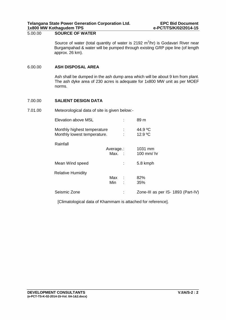
5.00.00 SOURCE OF WATER
Source of water (total quantity of water is 2192 m3/hr) is Godavari River near Burgampahad & water will be pumped through existing GRP pipe line (of length approx. 26 km).
6.00.00 ASH DISPOSAL AREA Ash shall be dumped in the ash dump area which will be about 9 km from plant.
The ash dyke area of 230 acres is adequate for 1x800 MW unit as per MOEF norms.
7.00.00 SALIENT DESIGN DATA 7.01.00 Meteorological data of site is given below:- Elevation above MSL : 89 m Monthly highest temperature : 44.9 ºC Monthly lowest temperature. : 12.9 ºC Rainfall Average. : 1031 mm Max. : 100 mm/ hr Mean Wind speed : 5.8 kmph Relative Humidity Max : 82% Min : 35%
Seismic Zone : Zone-III as per IS- 1893 (Part-IV)
[Climatological data of Khammam is attached for reference].
TITLE: TECHNICAL SPECIFICATION
COOLING TOWERS
SPECIFIC TECHNICAL REQUIREMENTS
SPEC. NO.: PE-TS-410-165-N001 VOLUME: IIB SECTION: C REV. NO. 00 DATE 23.01.2015 SHEET 1 OF 1
SECTION - C
SPECIFIC TECHNICAL REQUIREMENTS
SECTION C1 - Specific Technical Requirements (Mechanical) SECTION C2 - Specific Technical Requirements (Electrical) SECTION C3 - Specific Technical Requirements (Civil) SECTION C4 – Specific Technical Requirements (C&I)

TITLE: TECHNICAL SPECIFICATION
COOLING TOWERS
SPECIFIC TECHNICAL REQUIREMENTS
SPEC. NO.: PE-TS-410-165-N001 VOLUME: IIB SECTION: C REV. NO. 00 DATE 23.01.2015 SHEET 1 OF 1
SECTION – C1
SPECIFIC TECHNICAL REQUIREMENTS (MECHANICAL)
TITLE: TECHNICAL SPECIFICATION
COOLING TOWERS SPECIFIC TECHNICAL REQUIREMENTS
MECHANICAL
SPEC. NO.: PE-TS-410-165-N001 VOLUME: IIB SECTION: C REV. NO. 00 DATE 23.01.2015 SHEET 1 OF 10
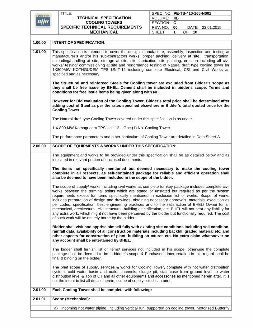
1.00.00 INTENT OF SPECIFICATION:
1.01.00 This specification is intended to cover the design, manufacture, assembly, inspection and testing at manufacturer’s and/or his sub-contractors works, proper packing, delivery at site, transportation, unloading/handling at site, storage at site, site fabrication, site painting, erection including all civil works/ testing/ commissioning at site and performance testing of Natural draft type cooling tower for 1X800MW KOTHGUDEM TPS UNIT-12 including complete Electrical, C&I and Civil Works as specified and as necessary. The Structural and reinforced Steels for Cooling tower are excluded from Bidder’s scope as they shall be free issue by BHEL. Cement shall be included in bidder’s scope. Terms and conditions for free issue items being given along with NIT. However for Bid evaluation of the Cooling Tower, Bidder’s total price shall be determined after adding cost of Steel as per the rates specified elsewhere in Bidder’s total quoted price for the Cooling Tower. The Natural draft type Cooling Tower covered under this specification is as under. 1 X 800 MW Kothagudem TPS Unit-12 – One (1) No. Cooling Tower The performance parameters and other particulars of Cooling Tower are detailed in Data Sheet-A.
2.00.00 SCOPE OF EQUIPMENTS & WORKS UNDER THIS SPECIFICATION:
The equipment and works to be provided under this specification shall be as detailed below and as indicated in relevant portion of enclosed documents. The items not specifically mentioned but deemed necessary to make the cooling tower complete in all respects, as self-contained package for reliable and efficient operation shall also be deemed to have been included in the scope of the bidder. The scope of supply/ works including civil works as complete turnkey package includes complete civil works between the terminal points which are stated or unstated but required as per the system requirements except for items specifically mentioned in exclusion list of works. Scope of works includes preparation of design and drawings, obtaining necessary approvals, materials, execution as per codes, specification, best engineering practices and to the satisfaction of BHEL/ Owner for all mechanical, architectural, civil structural, building electrification, etc. BHEL will not bear any liability for any extra work, which might not have been perceived by the bidder but functionally required. The cost of such work will be entirely borne by the bidder. Bidder shall visit and apprise himself fully with existing site conditions including soil condition, rainfall data, availability of all construction materials including backfill, graded material etc. and other aspects for construction of plant, building structures etc. No extra claim whatsoever on any account shall be entertained by BHEL. The bidder shall furnish list of items/ services not included in his scope, otherwise the complete package shall be deemed to be in bidder’s scope & Purchaser’s interpretation in this regard shall be final & binding on the bidder. The brief scope of supply, services & works for Cooling Tower, complete with hot water distribution system, cold water basin and outlet channels, sludge pit, stair case from ground level to water distribution level & Top of CT and all other equipments and accessories as mentioned herein after. It is not the intent to list all details herein; scope of supply listed is in brief.
2.01.00 Each Cooling Tower shall be complete with following:
2.01.01 Scope (Mechanical):
a) Incoming hot water piping, including vertical run, supported on cooling tower, Motorized Butterfly
TITLE: TECHNICAL SPECIFICATION
COOLING TOWERS SPECIFIC TECHNICAL REQUIREMENTS
MECHANICAL
SPEC. NO.: PE-TS-410-165-N001 VOLUME: IIB SECTION: C REV. NO. 00 DATE 23.01.2015 SHEET 2 OF 10
valves on hot water risers. Terminal point for hot water pipe shall be as marked in the tender drawing enclosed at Annexure 1 & 2 to Data Sheet - A. Welding at terminal point shall be in bidder’s scope. Bidder shall also supply a Pressure Gauge & Temperature Gauge at the terminal point. Any reducer/ expander required at the terminal point shall also be in the bidder’s scope.
b) Inlet louvers, tower fills & fill supports, drifts eliminators, including all supporting structures,
fastening arrangements & accessories.
c) Screens, along with guides embedded in concrete shall be provided at the outlet of cold water channel.
d) Sluice gate with mechanical jack arrangement and guides in each of the cold water outlet channel
connection from the cold water basin.
e) Manually operated chain pulley blocks, together with the monorails and supporting frames for the handling of screen and gates.
f) Knife-edge gate valve/sluice valve in each de-sludge connection and also De-sludge piping up to
the disposal point at local storm water drain channels.
g) Pipe spools to be embedded in sludge pit walls and terminated with flanged end at suitable distance from outer face of respective wall.
h) Water Distribution system consisting of troughs/ Pipes. Hangers & pipe supports & anchoring
arrangement for all piping coming under the scope of supply.
i) Two (2) Nos. (1+1) sludge pumps (submersible type) complete with electric motors, non-return valve, isolation valve, piping supports, hangers etc. for cold-water basin drainage. The bidder shall terminate pump discharge pipe work at a distance of 100 M from sludge pit.
j) Counter flanges, bolts, nuts & gaskets for all piping connections in the scope of bidders and also
at terminals.
2.01.02 Scope (Electrical):
a) Complete electrical equipment as per specification/ details indicated in Section C2 & D2 shall be in bidders’ scope.
b) The scope of power & control cables & special cables shall be as per Annexure-1 of section C-2 (electrical).
c) Base plate, foundation plates, anchor bolts, sleeves, inserts in concrete work for electrical and mechanical equipment & accessories.
2.01.03 Scope (C & I ):
a) Removable type Pitot Tube at each hot water inlet- piping header to measure the flow (during
performance Guarantee test only). The Pitot Tube shall be left with customer after the completion of the test .
b) One no. Pressure Gauge and One no. Temp Gauge at Hot Water pipe header at T.P.
c) One no. of Anemometer for measurement of wind velocity.
d) One no. of Psychrometer.
e) Local Control Panel for Sump/Sludge Pumps (Submersible type).
f) Level switches for sump/tank level high/normal/low/very low interlocks.
TITLE: TECHNICAL SPECIFICATION
COOLING TOWERS SPECIFIC TECHNICAL REQUIREMENTS
MECHANICAL
SPEC. NO.: PE-TS-410-165-N001 VOLUME: IIB SECTION: C REV. NO. 00 DATE 23.01.2015 SHEET 3 OF 10
g) Actuator for Motorised BFV at inlet of hot water pipes.
Refer section-C4.
2.01.04 Scope (Civil):
a) Complete civil works as detailed in Section – C3 including excavation, shoring, dewatering, backfilling, concrete work including shuttering, sand filling, disposal of surplus soil outside plant boundary, formwork including automatic climb form, laser beam survey instruments, fabrication, galvanizing and erection of steel structures and inserts, finishing anchor bolts, RCC sump/duct, laying and testing of hot water pipe line, water proofing, providing PVC water stops and joint fillers, drainage and other ancillary items connected with cooling towers. All faces of concrete structures and steel structures coming directly in contact with water shall be coated with corrosion resistant coating system as approved. The surfaces that would include are inner face of hyperbolic shell, raker column faces, inner faces of cold water basin, fill support structures, hot water distribution ducts & channels, cold water channel etc. The scope of this work shall consist of , but not limited to, the design and construction of reinforced concrete double curvature hyperbolic shell, ring beams, foundations (including Piling, if required), cold water basins with partition walls, hot water ducts, drain sumps, external drain chamber with associated pipe work, cold water channels with sluice gate up to the terminal point as specified elsewhere, hoists and monorails, primary and secondary hot water distribution troughs, fill support system including columns and beams, drift eliminators, testing of cold water basin for water tightness, external stairs, sludge pit for each basin section, all other staircases/ladders as required, doors and their frames, walkways, platforms, steel fitting, fixture, inserts, including fabrication, hand railing, providing protective measures in concrete and steel materials against effect of water and other chemicals on the completed structure etc.
b) Supply & application of painting at site.
2.01.05 The following are also included in bidder’s scope: a) One set of special tools & tackles required for maintenance of equipment & accessories in the
cooling towers.
b) Various drawings, datasheets, calculations, test reports/ certificates, operation & maintenance manuals including “As built drawings” etc. as specified & as necessary.
c) Supply of first fill of lubricants for all equipments under this package including second fill/ replenishments as necessary during & after commissioning till handing over of the plant.
d) Supply of commissioning spares on as required basis.
e) Scope of services shall include but not limited to erection/ testing/ commissioning/ trial run/ performance testing & handing over of cooling towers. Transportation of equipments, material to site, local clearance, storage at site etc. & supply of all labor including supervision personnel, materials, erection tools & tackles etc. as necessary for expeditious execution of works etc. are also included in bidder’s scope. It shall be the responsibility of the bidder to arrange all T & P required for the execution of complete job including erection & civil works.
3.00.00 Equipment & Services to be provided by Purchaser:
a. Supply and erection of incoming hot water piping up to bidder’s terminal point.
b. Supply & erection of sludge discharge piping beyond the bidder’s terminal point, if applicable.
c. Cold-water outlet channels for cooling tower beyond the bidder’s terminal point. d. For Electrical, Civil and C&I works refer Sections C2/ D2, C3 & C4 respectively enclosed herein.
TITLE: TECHNICAL SPECIFICATION
COOLING TOWERS SPECIFIC TECHNICAL REQUIREMENTS
MECHANICAL
SPEC. NO.: PE-TS-410-165-N001 VOLUME: IIB SECTION: C REV. NO. 00 DATE 23.01.2015 SHEET 4 OF 10
4.00.00 The cooling tower shall comply with standard technical specifications of cooling towers enclosed in section -’D’ & data sheet- A. In the event of any conflict between Section -’D’ / data sheet-A’ & section ‘C’, the latter shall prevail. Customer specification for cooling tower is enclosed at Section-C and it shall prevail in the event of conflict.
5.00.00 Thermal Design of Cooling Towers: The thermal design of cooling towers shall fulfill following design criteria.
5.01.00 Sensible heat of evaporated water shall be taken into account for calculating the air flow requirement, as per the following equation.
G*H = L (T1-T2)+(E*V*T2) Where L = Water flow rate in Kg/hr. T1 = Water inlet temperature to the tower in Deg.C T2 = Water outlet temperature to the tower in Deg.C EV = Evaporation loss in Kg/hr. at RH (as specified in Data Sheet-A) G = Air flow rate in Kg/hr. H = Change in enthalpy of air in Kcal/kg.
5.02.00 For the specified design conditions of water rate, range, approach, wet bulb and dry bulb temperatures
Bidder shall calculate and furnish the duty coefficient “D”. A nomogram indicating the ratio of water rate and duty coefficient, recooled water temperature and other thermal conditions specified shall be furnished with the bid. The nomogram shall cover the entire operating range and shall extend up to a wet bulb temperature of as specified in Data Sheet-A.
Along with the thermal design calculations as specified above, bidder has to submit the calculations for:
Total height of Natural Draft Cooling Tower Basin sizing Height of the hot water distribution header Drift Eliminator sizing Inlet Louver Sizing Sludge pit sizing
5.03.00 Based on the duty co-efficient and performance characteristics of the fill the bidder shall furnish an
equation expressing the relationship between the plan area of packing and the square root of tower height.
5.04.00 Bidder shall furnish performance characteristic curves for following variations in design parameters.15%, 25%, 60%, 70%, 80%, 90%, 100%. Bidder shall also clearly identify various “Guaranteed Zones” as per the requirement of code.
5.05.00 Bidder may note the calculations specified above must be enclosed with the offer without which bids run the risk of rejection. In case these calculations are based on the collaborator’s design then these calculations should be duly vetted by his collaborator. The bidder shall show, explain and prove the validity of the basis, procedures and methods used in these calculations.
5.06.00 The tower configuration shall be such that it shall offer minimum restriction to air flow.
5.07.00 The Cooling Tower Thermal design calculations shall be got vetted and approved by bidder from any of the IIT’s (Indian Institutes of Technology) in the event of order along with the related CT drawings for fill arrangements etc. and charges for same shall be included in the bidder’s base price itself.

TITLE: TECHNICAL SPECIFICATION
COOLING TOWERS SPECIFIC TECHNICAL REQUIREMENTS
MECHANICAL
SPEC. NO.: PE-TS-410-165-N001 VOLUME: IIB SECTION: C REV. NO. 00 DATE 23.01.2015 SHEET 5 OF 10
The Purchaser/ Customer however also reserve the rights to check the detailed calculations in the event of order and their interpretation shall be final in the event of any conflict.
5.08.00 The total CW Pumping head (MWC) within bidder’s terminal points shall not exceed the respective maximum limits specified in Data Sheets A. The CW pumping head specified limit is inclusive of static head plus frictional losses including 10% margin on frictional losses. No technical advantage shall be given to any bidder for total CW pumping head (MWC) offered less than above maximum limits. In the event of total CW pump head (MWC) offered being more than above maximum limits, the bids will be summarily rejected. The bidder’s Cooling Tower thermal design shall take care of above aspects including maximum permissible plan dimensions indicated in Data Sheet A.
6.00.00 Specific Requirements:
In addition to the salient technical requirements stipulated in Section “D”, the bidder may note specific requirements detailed herein for design of the cooling towers.
6.01.00 No wood/ timberwork shall be used in any component of the cooling tower.
6.02.00 The quality of water in CW sump shall be clarified water with analysis as given in data sheet-A of Section. D. a) The COC in CW System shall be ‘5’. b) Control of biological / algae is envisaged in purchaser’s scope.
6.03.00 The location, orientation, wind rose, scope demarcation, water levels etc. for the cooling tower shall be
as per the sketch enclosed at Annexure – 1 & 2.
6.04.00 Fills shall be PVC Splash V bars Type of approved make in easily removable sections.
6.05.00 PVC Drift eliminator blades shall be of three-pass full wave type supported on concrete framework & shall limit the drift losses to a value not greater than 0.002 % of the design water circulation rate.
6.06.00 All parts subjected to periodical maintenance & inspection such as Inlet louvers, fills, drift eliminators etc. shall be readily accessible.
6.07.00 Access doors shall be provided for entry into cooling water distribution level. The doors shall have easily operable shutter of leak proof design & shall be of MS construction with 2 coats of red oxide zinc chromate primer and anti-corrosive coating.
6.08.00 Two R.C.C. staircase for approach to hot water distribution level & aviation warning lamp etc.
6.09.00 Min. Four (4) external cage ladders for approach to top of cooling tower from ground level.
6.10.00 Access platforms and walkways with handrails for inspection and maintenance of hot water distribution system and Aviation Warning Lamp etc.
6.11.00 All steel parts in direct contact with water or humid air shall be of SS 316. All other steel parts not in direct contact with water/ humid air shall be galvanized steel. No hardware shall be of Cu or Cu based alloys. Material of construction shall be as indicated in Datasheet “A”. Wherever the material of construction for any component is not given, same shall be suitable for the intended service & shall be subject to purchaser’s approval during detailed engineering stage in the event of order.
TITLE: TECHNICAL SPECIFICATION
COOLING TOWERS SPECIFIC TECHNICAL REQUIREMENTS
MECHANICAL
SPEC. NO.: PE-TS-410-165-N001 VOLUME: IIB SECTION: C REV. NO. 00 DATE 23.01.2015 SHEET 6 OF 10
6.12.00 The sizing of the hot water distribution system shall be done by limiting the velocity through the pipes to a maximum of 2.0 m/sec.
6.13.00 a) Piping for sizes above 150 Nb Carbon steel plates to IS 2062, rolled and welded as per IS 3589. b) Piping up to and including 150 Nb shall be IS 1239 (Heavy Grade).
Required wall thickness for Hot Water riser and Distribution piping shall be as follows:
NB OD THK 1400 1422.00 14.0 1800 1829.00 16.0 1900 1936.00 18.0 2500 2540.00 20.0 2700 2740.00 20.0 3800 3840.00 20.0
6.14.00 The buried piping in bidder’s scope shall be steel pipe. Welding of pipe header with Purchaser’s pipe at terminal point shall be in bidder’s scope. The thrust block etc. shall also be in bidder’s scope.
Provision of at least 2 nos. welding sockets at water distribution level shall also be in bidder’s scope.
6.15.00 Motor Operated B.F. valves shall be provided in hot water distribution riser.
6.16.00 The cold-water basin of cooling tower shall be provided with a partition wall to facilitate isolation of each half of CW basin whenever required through isolating gates viz. minimum two nos. gates shall be provided for each cooling tower. CT basin shall be provided with adequate slope (Min slope of 1:120) towards the sludge sump for drainage purpose.
6.17.00 Under each valve, flange joint & such other items prone to gland/ joint leakage, suitable trays/ channels shall be provided so that any leakage water does not spread on the surroundings. This is also applicable for any air release valve that has to be mounted on hot water riser top. Erection of such air release valves has also to be done by the bidder.
6.18.00 Bidder to note that all sub vendors shall be subject to BHEL/ Customer approval in the event of order.
7.00.00 Deleted
8.00.00 PERFORMANCE TESTING AT SITE
8.01.00 Scope:
To ascertain the fulfillment of guarantees after completion of erection and commissioning of the cooling tower, contractor shall carry out performance test at site of one no. CT in presence of employer / purchaser through CTI approved/licensed testing agency. Under no circumstances, the bidder himself will conduct the test even if approved by CTI. The testing agency shall be independent from the bidder.
8.02.00 Codes:
The following codes and standards shall be applicable for conducting test unless otherwise modified or supplemented by the enclosed procedure and mutually agreed to between Owner, BHEL and bidder.
a) Code ATC-105: Acceptance test code for water cooling towers. (latest Version). b) BS-4485: Specification for Water Cooling Tower. c) BS-1042: Methods for the measurement of fluid flow in pipes. d) BS-3435: Measurement of electrical power and energy in acceptance testing.
TITLE: TECHNICAL SPECIFICATION
COOLING TOWERS SPECIFIC TECHNICAL REQUIREMENTS
MECHANICAL
SPEC. NO.: PE-TS-410-165-N001 VOLUME: IIB SECTION: C REV. NO. 00 DATE 23.01.2015 SHEET 7 OF 10
e) ASME 19.5: Supplements on instruments and apparatus.
8.03.00 Conductance of tests:
Performance testing of cooling tower shall be done to demonstrate the guaranteed cooling water temperature at rated duty point. The cold-water temperature as specified in the specification shall be guaranteed by the bidder for the design conditions of CW flow, range, ambient WBT as specified
8.03.01 The bidder shall submit cooling tower performance test procedure as per ATC 105 in consultation with CTI approved testing agency for approval & conduct the test as per the approved procedure, in the event of order.
8.03.02 The bidder shall be given permission to inspect the Cooling Tower in advance and ready it for the test.
8.03.03 One Cooling Tower performance shall be tested jointly by CTI approved testing agency in presence of the bidder, BHEL and Owner. All the representatives shall jointly record data of test. a) The responsibility for conducting the test will be with the bidder.
b) All test instruments required for the PG test will be provided by CTI approved testing
agency / or the instruments provided by contractor if the same meets the stipulations of the CTI testing agency and acceptable to testing agency.
c) Calibration of instruments to be used in the test shall be carried out by an approved independent
agency. Calibration of instruments should be carried out previous to, but not more than six months before the test. The calibration certificate of the instruments should be valid for the period of test.
d) List of instruments to be arranged by the bidder along with the calibration certificates of the
instruments to be used and psychometric charts and tables should be submitted to CTI/ owner for approval.
8.03.04 PG test shall be carried out by the bidder after completion of trial operation of the cooling tower and at
a time when the atmospheric conditions are within limits of deviation from the design conditions as specified in this section preferably in the period from May to September.
8.03.05 Performance test shall be carried out based on ambient WBT. The performance curves of the towers showing variation in performance with change in ambient wet bulb temperature, cooling range, relative humidity water loading of the tower etc, required to ascertain the performance of the tower shall be furnished along with the bid. Performance curves applicable to 90%, 100% and 110% of the design water flow rate shall be furnished. Each set shall consist of three or more cooling range curves and at least four relative humidity curves, arranged to show the effects of wet bulb temperature, relative humidity and cooling range on outlet water temperature. The range curves shall be presented in uniform increments of 0.5 deg. C, with sufficient scope to cover approximately + 20% of design range. The relative humidity curves shall be presented for spaced increments to cover the extent of expected conditions such as 5%, 20%, 40%, 60% and 100% relative humidity. The design conditions shall be indicated on the set applicable to design water flow rate. The dry bulb temperature associated with the wet bulb on each fixed relative humidity graph shall be included. The curves shall fully cover (but not necessarily be limited to) the range of variations specified. All performance curves shall be based on ambient wet bulb temperature.
8.03.06 The guaranteed performance of the equipments shall be demonstrated by the bidder after evaluating the P.G. test should the result of the test deviate from the guaranteed values the bidder shall be given an opportunity to modify the equipment as required to enable it to meet the guarantees. In such cases the PG test shall be repeated within one month from the date on which the equipment is ready for retest and cost of modification, including labour, materials and cost of additional testing shall be borne by the Bidder. The chance for repeat testing will be given only once during the contract period. All the modifications carried out by the bidder in the Cooling Tower to meet the contractual requirements shall be carried out free of cost to the Owner in other towers (if applicable for the package).
TITLE: TECHNICAL SPECIFICATION
COOLING TOWERS SPECIFIC TECHNICAL REQUIREMENTS
MECHANICAL
SPEC. NO.: PE-TS-410-165-N001 VOLUME: IIB SECTION: C REV. NO. 00 DATE 23.01.2015 SHEET 8 OF 10
8.03.07 In case the test cold water temperature as determined from the PG test is higher than the predicated value (based on the performance curves). Owner reserves the right to reject/ accept the tower after assessing the liquidated damages as specified.
9.00.00 The makes of all the equipments under this specification shall be subject to purchaser’s approval in the event of order.
10.00.00 It is mandatory for the bidder’s to furnish along with the bid the deviations if any, whether major or minor in the ‘Schedule of Deviations’ only. In the absence of the deviations listed in the ‘Schedule of Deviations’, the offer shall be deemed to be in full conformity with the specification not withstanding anything else stated elsewhere in the offer, data sheets etc. The hidden deviations or stated/ implied deviations in the offer shall not be acceptable and binding on the purchaser.
11.00.00 PERFORMANCE GUARANTEES AND LIQUIDATED DAMAGES
a) Performance testing of cooling tower shall be done to demonstrate the guaranteed cooling water temperature at rated duty point. The cold-water temperature as specified in the specification shall be guaranteed by bidder for the design conditions of CW flow, range, ambient WBT as specified.
In case the test cold-water temperature as determined from the PG test is higher than the predicted value (based on the performance curves). Owner reserves the right to reject the tower. In the event of its acceptance by purchaser liquidated damages as follows shall be applicable.
0.1oC over the guaranteed value = 405 lacs 0.2oC over the guaranteed value = 810 lacs 0.3oC over the guaranteed value = 1215 lacs 0.4oC over the guaranteed value = 1620 lacs 0.5oC over the guaranteed value = 2025 lacs 0.6oC over the guaranteed value = 2430 lacs 0.7oC over the guaranteed value = 2835 lacs 0.8oC over the guaranteed value = 3240 lacs 0.9oC over the guaranteed value = 3645 lacs 1.0oC over the guaranteed value = 4050 lacs
Bidder to note that the liquidated damages (as specified) for shortfall in performance shall be worked out independently for each cooling tower. To ascertain the fulfillment of guarantees of the cooling towers, the test results of the tower tested through CTI approved/licensed testing agency shall be considered for PG test evaluation and based on the test result, the liquidated damage if applicable shall be levied.
b) The bidder shall guarantee the following, apart from other performance guarantees of the complete package.
Total CW pumping head within the bidder’s terminal points viz. static head & frictional
losses for cooling tower.
c) The static head for calculating CW pumping head shall be considered up to top of the top most pipe without any siphon recovery. Frictional losses for pipes shall be as per William & Hazen formula with C = 120. Frictional losses for various valves & fittings e.g. Miter bends, valves, tees, reducers etc. shall be as per crane handbook. Ft Value for fitting friction drop calculation to be considered as 0.012 for all sizes greater than 600NB. The frictional losses shall be computed considering 10% margin on same.
TITLE: TECHNICAL SPECIFICATION
COOLING TOWERS SPECIFIC TECHNICAL REQUIREMENTS
MECHANICAL
SPEC. NO.: PE-TS-410-165-N001 VOLUME: IIB SECTION: C REV. NO. 00 DATE 23.01.2015 SHEET 9 OF 10
William & Hazen formula: V = 0.85 X C X (i) 0.54 X (d/4) 0.63.
The bidder shall substantiate the CW pumping head with calculations in the event of order and same shall be subject to approval.
d) The successful bidder shall demonstrate the above guarantees during performance testing at
site.
The purchaser is, however, not bound to accept the equipment and reserves the right to out rightly reject it if the actual values exceed beyond the plant design limits.
12.00.00 INSPECTION AND TESTING:
Purchaser/ Customer or their authorized representatives shall have the right to inspect at any stage of manufacture & construction, all materials, components & workmanship & testing of material. The bidder shall provide all facilities for inspection & testing without any extra cost to the purchaser/ Consultant.
12.01.00 The contractor/ manufacturer shall conduct the following minimum specific tests to ensure that the equipment shall conform to the requirements of this section and in full compliance with the requirements spelt out in applicable codes and standards.
12.02.00 Material identification and testing of regulating valve assemblies, screen assemblies, all supporting structural assemblies, fills, all nuts and bolts, sluice valves, nozzles and all other applicable components constituting each cooling tower.
12.03.00 Hydrostatic testing of hot water distribution piping regulating valves and all other pressure parts at a pressure and duration as spelt out in this specification.
12.04.00 Visual, dimensional checking of all components of each cooling tower.
12.05.00 Material testing of all components, hydrostatic testing of all pressure parts at a pressure and duration in compliance with this specification, static and dynamic balancing tests of all rotating components such as pump shaft, line shaft, impeller etc. and complete performance testing as minimum for each sludge pump in each cooling tower.
12.06.00 Tests for hoists, chain pulley blocks and all other lifting tackle shall be carried out as per relevant Indian/ equivalent international standards.
12.07.00 Any other tests deemed necessary for safe, reliable and satisfactory operation of the equipment.
13.00.00 QUALITY PLAN:
13.01.00 The inspection & testing of the cooling towers & its various components shall be as per quality plans approved by the purchaser/ Customer. Bidder shall submit the quality plans based on the guidelines given in specification & quality plans enclosed herein. The customer hold points of BHEL/ Customer/Customer nominated agency shall be marked in the QP at the contract stage, in the event of order & inspection/ testing shall be carried out as per same apart from various test certificates/ inspection records etc. Following standard QP are enclosed for bidder’s guidance:
Cooling tower Pipes, fittings & pipe work BF Valves Chain Pulley Blocks Gate/ Globe Valves Submersible Pumps
TITLE: TECHNICAL SPECIFICATION
COOLING TOWERS SPECIFIC TECHNICAL REQUIREMENTS
MECHANICAL
SPEC. NO.: PE-TS-410-165-N001 VOLUME: IIB SECTION: C REV. NO. 00 DATE 23.01.2015 SHEET 10 OF 10
13.02.00 The quality plans for various electrical, C&I and Civil works are enclosed in respective sections for bidder’s compliance.
13.03.00 For equipments not covered above, bidder shall submit QP’s for same on the basis of similar guidelines & submit for approval in the event of order.
14.00.00 Tests at Site:
14.01.00 After completion of erection and commissioning of the cooling tower, supplier in accordance with cooling tower Institute Bulletin No ATC-105 “Acceptance Test Procedure for Industrial Cooling Tower” shall carry out performance tests of each cooling tower.
14.02.00 Necessary correction curves shall be furnished by the supplier for approval along with the proposed test procedure for correcting the test results for any difference between test and guarantee design conditions.
14.03.00 All mounting and calibrating instruments required for site performance tests shall be arranged by the cooling tower supplier without any extra cost.
15.00.00 DRAWINGS, CURVES AND INFORMATION REQUIRED:
15.01.00 The following documents only shall be furnished by the bidder with his offer:
a) Compliance certificate duly signed and stamped (enclosed herein). b) General arrangement drawing for cooling tower, incorporating all relevant dimensions, Fill
layout, water distribution layout, cold water channels / sludge chamber/ screens/ gates in the cold water channel, staircase etc.
c) Pumping head calculations. d) Thermal design calculations (NDCT diameter & height calculation).
Note: The GA drawing/ calculations shall be only for reference purpose, same shall not be
reviewed/commented by purchaser at this stage and shall be subject to approval only during contract). However diameter and height of CT during contract stage shall not be less than the proposed dimensions as offered in the bid.
e) Tower performance curves. f) Guarantee Schedule duly signed and stamped (enclosed herein) g) Technical deviation schedule (if reqd.) (enclosed herein)
Apart from above no other drgs./docs./data sheets etc. are required to be submitted at bid stage and even if furnished shall not be taken cognizance of.
16.00.00 Successful bidder in the event of award of contract shall furnish the drawings/ documents as listed in Data Sheet-C. Distribution of various documents shall be as per the Annexure to Data Sheet-C:
Telangana State Power Generation Corporation Ltd. EPC Bid Document 1x800 MW Kothagudem TPS e-PCT/TS/K/02/2014-15
DEVELOPMENT CONSULTANTS (e-PCT-TS-K-02-2014-15-Vol. IIA-8.docx)
VOLUME : IIA
SECTION-VIII
REQUIREMENTS OF SPARES, TOOLS & TACKLE, LUBRICANTS/OIL/CONSUMABLES
6042023
Text Box
Telangana State Power Generation Corporation Ltd. EPC Bid Document 1x800 MW Kothagudem TPS e-PCT/TS/K/02/2014-15
DEVELOPMENT CONSULTANTS (e-PCT-TS-K-02-2014-15-Vol. IIA-8.docx)
CONTENT CLAUSE NO. DESCRIPTION 1.00.00 TOOLS AND TACKLE 2.00.00 SPARES ATTACHMENT ANNEXURE-I MANDATORY SPARE LIST
Telangana State Power Generation Corporation Ltd. EPC Bid Document 1x800 MW Kothagudem TPS e-PCT/TS/K/02/2014-15
DEVELOPMENT CONSULTANTS V.IIA/S-8 : 1 (e-PCT-TS-K-02-2014-15-Vol. IIA-8.docx)
VOLUME : IIA
SECTION-VIII
REQUIREMENTS OF SPARES, TOOLS & TACKLE, LUBRICANTS/OIL/CONSUMABLES
1.00.00 TOOLS & TACKLE The Contractor shall supply with the equipment one complete set of special
tools and tackle as required for the erection, assembly, dismantling & maintenance of the equipment. These special tools will also include special material handling equipment, jigs & fixtures for maintenance and calibration/ readjustment, checking & measurement aids etc. A list of such tools & tackle shall be submitted by the Bidder along with the offer. Detailed description of each tools/tackle, its function along with the equipment/part for which it is meant for and the price of each tools/tackle shall also be indicated in the offer. These tools & tackle shall be separately packed and sent to site before the first unit commissioning. The Bidder shall also ensure that these tools are not used for erection purpose.
2.00.00 SPARES 2.01.00 General The Bidder shall indicate and include in his scope of supply all the necessary
start-up, commissioning and recommended spares in addition to mandatory spares as specified elsewhere in the specification. The Owner reserves the right to buy any or all mandatory and recommended spares. The Contractor shall also state for each item of spares both mandatory and recommended, the normal expected service life.
2.01.01 All spares supplied under this contract shall be strictly interchangeable with the
parts for which they are intended to replace. The spares shall be treated and packed for long storage under the climatic conditions prevailing at the site, e.g. small items shall be packed in sealed transparent plastic bags with dessicator packs as necessary.
2.01.02 Each spare part shall be clearly marked or labelled on the outside of the
packing with the description. When more than one spare part is packed in a single case, a general description of the contents shall be shown on the outside and a detailed list enclosed. All cases, containers and other packages must be suitably marked and numbered for the purposes of identification.
2.01.03 All cases, containers or other packages are liable to be opened for examination
as may be considered necessary by the Engineer. 2.01.04 All mandatory spares shall be delivered to site within one to three months prior
to the scheduled date of the trial operation of the plant. However, they shall not be despatched before the despatch of the associated main equipment.
Telangana State Power Generation Corporation Ltd. EPC Bid Document 1x800 MW Kothagudem TPS e-PCT/TS/K/02/2014-15
DEVELOPMENT CONSULTANTS V.IIA/S-8 : 2 (e-PCT-TS-K-02-2014-15-Vol. IIA-8.docx)
2.01.05 The Bidder shall also guarantee supply of spare parts, which will be made,
based on manufacturer's drawings on special order from the Purchaser for 30 years after commissioning of the plant.
2.01.06 Warranty period for all kinds of spares shall be six thousand (6000) hours of
operation, except normal wear or eighteen (18) months from the date of receipt at site, whichever is earlier. In case of failure or non-conformance to specifications, the Contractor shall replace them free of cost.
2.02.00 Recommended Spares 2.02.01 The Contractor shall provide a list of recommended spares giving unit prices
and total prices for 2 years of normal operation of the plant for spares of indigenous origin, and for 5 years of normal operation for spares of non-indigenous origin. This list shall take into consideration the mandatory spares specified elsewhere in the specification and should be a separate list.
2.02.02 The price of recommended spares will not be used for the evaluation of bids.
The price of these spares shall remain valid for a period as specified elsewhere in the specification from the date of Award of the Contract. Where the recommended spares are the same as mandatory spares, the prices shall be the same. The prices of any recommended spares, which are not common with mandatory spares, shall be subject to review by the Owner, and shall be finalised after mutual discussion.
2.03.00 Start-up Commissioning Spares 2.03.01 Start-up commissioning spares are those spares which may be required during
the start-up and commissioning of the equipment/system. All spares used until the plant is handed over to the Owner shall come under this category. Said spares, properly marked, shall be supplied together with the main equipment and shall be used by the Contractor, if needed, during erection & commissioning stage. All such spares which remain unused till issuance of Taking Over Certificate by the Owner, along with an equipment-wise quantitative consumption report shall be returned to the Owner during time of handover. The list of commissioning spares to be brought by the Contractor to ensure smooth commissioning of the plant shall be subject to the Engineer's approval.
2.03.02 The Contractor shall submit a complete BBU list inclusive of recommended,
mandatory, initial start-up and commissioning spares. Costs of the above spares, which are consumed before the handing-over of the plant, shall be deemed to have been included in the lump sum proposal price of the package, and the Contractor shall have no claim on this account to the Owner.
2.04.00 Mandatory Spare Parts 2.04.01 The Owner considers some of the spares are essential for running the
equipment irrespective of whether they are included in the list of recommended spares by the Bidder as mentioned above.
Since the components involved can not be foreseen at the bidding stage, only

Telangana State Power Generation Corporation Ltd. EPC Bid Document 1x800 MW Kothagudem TPS e-PCT/TS/K/02/2014-15
DEVELOPMENT CONSULTANTS V.IIA/S-8 : 3 (e-PCT-TS-K-02-2014-15-Vol. IIA-8.docx)
broad requirements of the Owner in this respect are outlined hereinafter. The bidder shall include his proposal, on the basis of this guideline, an item-wise list of all components and the quantity, unit prices & total price thereof, offered as mandatory spares for each and every equipment. This list shall be separate from the list of recommended spares and shall be used for bid evaluation purposes. Any clarification in this respect may be obtained by the Bidder at the pre-bidding stage.
2.04.02 The mandatory spares should be supplied to the Owner at least one month
before the trial run. The despatch programme is subject to approval of the Owner/Consultant after award of contract.
2.04.03.1 Criteria for selection of Quantity of Mandatory Spares :
For Mandatory Spares refer Annexure-I. 2.04.04 Purchaser will have the option to procure any or all of the mandatory spares at
his discretion.
6042023
Text Box
DATASHEET-A OF SECTION-D.
TITLE: TECHNICAL SPECIFICATION
COOLING TOWERS SPECIFIC TECHNICAL REQUIREMENTS
SPEC. NO.: PE-TS-410-165-N001 VOLUME: IIB SECTION: C REV. NO. 00 DATE 23.01.2015 SHEET 1 OF 1
SECTION – C2
SPECIFIC TECHNICAL REQUIREMENTS (ELECTRICAL)
TITLE: ELECTRICAL EQUIPMENT SPECIFICATION
FOR NATURAL DRAFT COOLING TOWER
1 X 800 MW KOTHAGUDEM TPS
SPECIFICATION NO.
VOLUME NO. : II-B SECTION: C REV NO. : 00 DATE: 6.01.2015 SHEET: 1 OF 1
TECHNICAL SPECIFICATION
FOR
NATURAL DRAFT COOLING TOWER
(ELECTRICAL PORTION)
TITLE: ELECTRICAL EQUIPMENT SPECIFICATION
FOR NATURAL DRAFT COOLING TOWER
1 X 800 MW KOTHAGUDEM TPS
SPECIFICATION NO.
VOLUME NO. : II-B SECTION: C REV NO. : 00 DATE: 6.01.2015 SHEET: 1 OF 1
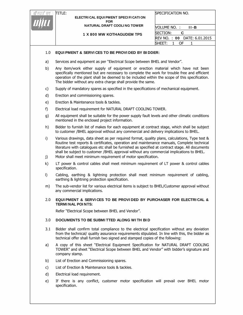
1.0 EQUIPMENT & SERVICES TO BE PROVIDED BY BIDDER: a) Services and equipment as per “Electrical Scope between BHEL and Vendor”.
b) Any item/work either supply of equipment or erection material which have not been specifically mentioned but are necessary to complete the work for trouble free and efficient operation of the plant shall be deemed to be included within the scope of this specification. The bidder without any extra charge shall provide the same.
c) Supply of mandatory spares as specified in the specifications of mechanical equipment.
d) Erection and commissioning spares.
e) Erection & Maintenance tools & tackles.
f) Electrical load requirement for NATURAL DRAFT COOLING TOWER.
g) All equipment shall be suitable for the power supply fault levels and other climatic conditions mentioned in the enclosed project information.
h) Bidder to furnish list of makes for each equipment at contract stage, which shall be subject to customer /BHEL approval without any commercial and delivery implications to BHEL.
i) Various drawings, data sheet as per required format, quality plans, calculations, Type test & Routine test reports & certificates, operation and maintenance manuals, Complete technical literature with catalogues etc shall be furnished as specified at contract stage. All documents shall be subject to customer /BHEL approval without any commercial implications to BHEL.
j) Motor shall meet minimum requirement of motor specification.
k) LT power & control cables shall meet minimum requirement of LT power & control cables specification.
l) Cabling, earthing & lightning protection shall meet minimum requirement of cabling, earthing & lightning protection specification.
m) The sub-vendor list for various electrical items is subject to BHEL/Customer approval without any commercial implications.
2.0 EQUIPMENT & SERVICES TO BE PROVIDED BY PURCHASER FOR ELECTRICAL &
TERMINAL POINTS:
Refer “Electrical Scope between BHEL and Vendor”. 3.0 DOCUMENTS TO BE SUBMITTED ALONG WITH BID
3.1 Bidder shall confirm total compliance to the electrical specification without any deviation
from the technical/ quality assurance requirements stipulated. In line with this, the bidder as technical offer shall furnish two signed and stamped copies of the following:
a) A copy of this sheet “Electrical Equipment Specification for NATURAL DRAFT COOLING TOWER" and sheet “Electrical Scope between BHEL and Vendor” with bidder’s signature and company stamp.
b) List of Erection and Commissioning spares.
c) List of Erection & Maintenance tools & tackles.
d) Electrical load requirement.
e) If there is any conflict, customer motor specification will prevail over BHEL motor specification.
TITLE: ELECTRICAL EQUIPMENT SPECIFICATION
FOR NATURAL DRAFT COOLING TOWER
1 X 800 MW KOTHAGUDEM TPS
SPECIFICATION NO.
VOLUME NO. : II-B SECTION: C REV NO. : 00 DATE: 6.01.2015 SHEET: 1 OF 1
3.2 No technical submittal such as copies of data sheets, drawings, write-up, quality plans, type test certificates, technical literature, etc. is required during tender stage. Any such submission even if made, shall not be considered as part of offer.
4.0 LIST OF ENCLOSURES
4.1 Electrical scope sheet between BHEL & Vendor. 4.2 Customer Spec. for LV Motors. 4.3 General requirement of LV Motors. 4.4 Data Sheet - A for LV Motors. 4.5 Electrical Load Data Format. 4.6 Datasheet-C (to be filled by Vendor) 4.7 QP for LV motors 4.8 Customer Spec for Cooling Tower 4.9 Customer Specification for Cables 4.10 Customer Specification for Erection Cabling, Grounding And Lightning Protection 4.11 Customer Specification for Illumination 4.12 Customer Specification for LT Switchgear 4.13 QAP for Earthing and lightning protection materials 4.14 QAP for Illumination 4.15 QAP for Cable tray support-welded 4.16 QAP for Cable tray
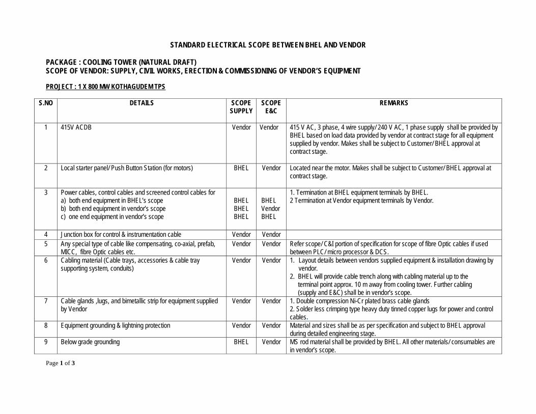
STANDARD ELECTRICAL SCOPE BETWEEN BHEL AND VENDOR PACKAGE : COOLING TOWER (NATURAL DRAFT) SCOPE OF VENDOR: SUPPLY, CIVIL WORKS, ERECTION & COMMISSIONING OF VENDOR’S EQUIPMENT
Page 1 of 3
PROJECT : 1 X 800 MW KOTHAGUDEM TPS
S.NO DETAILS SCOPE SUPPLY
SCOPE E&C
REMARKS
1 415V ACDB
Vendor
Vendor 415 V AC, 3 phase, 4 wire supply/ 240 V AC, 1 phase supply shall be provided by BHEL based on load data provided by vendor at contract stage for all equipment supplied by vendor. Makes shall be subject to Customer/ BHEL approval at contract stage.
2 Local starter panel/ Push Button Station (for motors) BHEL Vendor Located near the motor. Makes shall be subject to Customer/ BHEL approval at contract stage.
3 Power cables, control cables and screened control cables for a) both end equipment in BHEL’s scope b) both end equipment in vendor’s scope c) one end equipment in vendor’s scope
BHEL BHEL BHEL
BHEL Vendor BHEL
1. Termination at BHEL equipment terminals by BHEL. 2 Termination at Vendor equipment terminals by Vendor.
4 Junction box for control & instrumentation cable Vendor Vendor 5 Any special type of cable like compensating, co-axial, prefab,
MICC, fibre Optic cables etc. Vendor Vendor Refer scope/ C&I portion of specification for scope of fibre Optic cables if used
between PLC/ micro processor & DCS. 6 Cabling material (Cable trays, accessories & cable tray
supporting system, conduits) Vendor Vendor 1. Layout details between vendors supplied equipment & installation drawing by
vendor. 2. BHEL will provide cable trench along with cabling material up to the terminal point approx. 10 m away from cooling tower. Further cabling (supply and E&C) shall be in vendor’s scope.
7 Cable glands ,lugs, and bimetallic strip for equipment supplied by Vendor
Vendor Vendor 1. Double compression Ni-Cr plated brass cable glands 2. Solder less crimping type heavy duty tinned copper lugs for power and control cables.
8 Equipment grounding & lightning protection Vendor Vendor Material and sizes shall be as per specification and subject to BHEL approval during detailed engineering stage.
9
Below grade grounding BHEL Vendor MS rod material shall be provided by BHEL. All other materials/ consumables are in vendor’s scope.

STANDARD ELECTRICAL SCOPE BETWEEN BHEL AND VENDOR PACKAGE : COOLING TOWER (NATURAL DRAFT) SCOPE OF VENDOR: SUPPLY, CIVIL WORKS, ERECTION & COMMISSIONING OF VENDOR’S EQUIPMENT
Page 2 of 3
S.NO DETAILS SCOPE SUPPLY
SCOPE E&C
REMARKS
10 LV Motors with base plate and foundation hardware (in case applicable for NDCT)
Vendor Vendor Makes shall be subject to customer/ BHEL approval at contract stage.
11 Lighting System Vendor Vendor In addition to other lighting system items, vendor shall consider aviation lights & their control as per statutory requirement and Lighting panels (LP) & timer control as per requirement. Further wires, any other material required for lighting system shall also be considered by vendor in their scope. BHEL will provide the power supply for LP from LDB at one location near Cooling Tower. Further distribution from LP including material is in vendor’s scope.
12 Aviation Lighting Vendor Vendor Make shall be subject to customer/BHEL approval at contract stage 13 Receptacles/Industrial switch-sockets Vendor Vendor Make shall be subject to customer/BHEL approval at contract stage 14 Any other equipment/ material/ service required for
completeness of system based on system offered by the vendor (to ensure trouble free and efficient operation of the system).
Vendor Vendor
15 Engineering activities during detailed engineering stage, including those listed below: a. Electrical load data submission in PEM format b. Electrical equipment GA drawings and layout drawings c. Cable trench/ tray layout drawings d. Control cable schedules showing routing details [including
cables supplied by PEM for CT equipment]. e. Grounding and lightning protection system layouts f. Cable termination/ interconnection details (diagram)/ Cable
block diagram
Vendor -- 1. Documentation shall be submitted as per project schedule for BHEL/ customer approval.
2. Vendor shall be responsible for necessary coordination with BHEL for required engineering interfacing during contract stage.
3. Any approval required from electrical inspection authority for electrical equipment shall be arranged by vendor.
NOTES:

STANDARD ELECTRICAL SCOPE BETWEEN BHEL AND VENDOR PACKAGE : COOLING TOWER (NATURAL DRAFT) SCOPE OF VENDOR: SUPPLY, CIVIL WORKS, ERECTION & COMMISSIONING OF VENDOR’S EQUIPMENT
Page 3 of 3
1. Make of all electrical equipment/ items supplied shall be reputed make & shall be subject to approval of BHEL/Customer after award of contract without any commercial implication.
2. All QPs shall be subject to approval of BHEL/Customer after award of contract without any commercial implication.
3. In case the requirement of Junction Box arises on account of Power Cable size mismatch due to vendor’s engineering at later stage, vendor shall supply the Junction Box for suitable termination.
4. Wherever BHEL is indicated above, if the scope of supply and E&C of any of the above listed items is in BHEL’s Customer scope, then the respective items shall be supplied, erected and commissioned by BHEL’s Customer. For such items, BHEL as indicated in SUPPLY and E&C column above shall be read as “BHEL’s CUSTOMER”.
Telangana State Power Generation Corporation Ltd EPC Bid Document 1x800 MW Kothagudem TPS e-PCT/TS/K/02/2014-15
DEVELOPMENT CONSULTANTS (e-PCT/TS/K/02/2014-15/V-B/SEC-XV)
VOLUME : V-B
SECTION-XV
TECHNICAL SPECIFICATION FOR
CHIMNEY & NATURAL DRAFT COOLING TOWER - ELECTRICAL WORKS

Telangana State Power Generation Corporation Ltd EPC Bid Document 1x800 MW Kothagudem TPS e-PCT/TS/K/02/2014-15
DEVELOPMENT CONSULTANTS (e-PCT/TS/K/02/2014-15/V-B/SEC-XV)
CONTENTS
CLAUSE NO. DESCRIPTION
1.00.00 SCOPE OF WORK
2.00.00 DISTRIBUTION BOARDS
3.00.00 DAY MARKING AND AVIATION WARNING LIGHTS
4.00.00 INTERIOR AND EXTERIOR LIGHTS
5.00.00 CABLES AND CONDUITS
6.00.00 GROUNDING
7.00.00 CHIMNEY LIGHTNING PROTECTION
8.00.00 COOLING TOWER LIGHTNING PROTECTION
9.00.00 TESTS
10.00.00 DRAWINGS, DATA AND MANUALS
Telangana State Power Generation Corporation Ltd EPC Bid Document 1x800 MW Kothagudem TPS e-PCT/TS/K/02/2014-15
DEVELOPMENT CONSULTANTS V.V-B/S-XV/1 (e-PCT/TS/K/02/2014-15/V-B/SEC-XV)
SECTION : XV
TECHNICAL SPECIFICATIONFOR
CHIMNEY & NATURAL DRAFT COOLING TOWER - ELECTRICAL WORKS
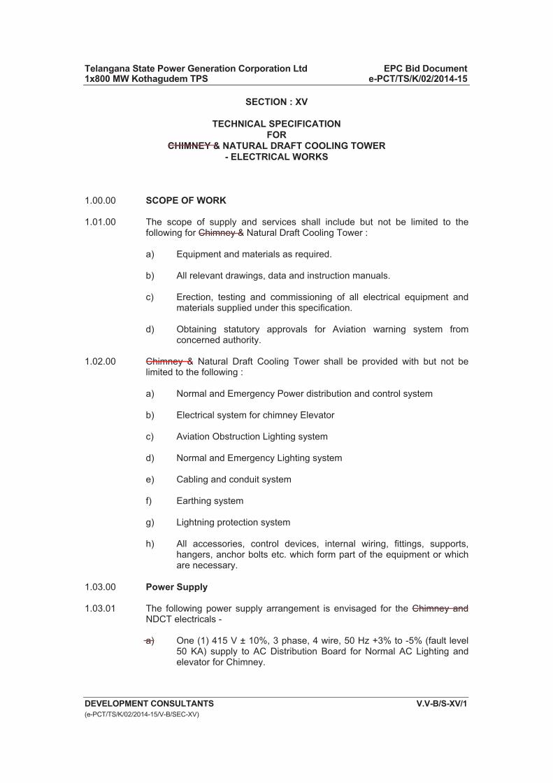
1.00.00 SCOPE OF WORK
1.01.00 The scope of supply and services shall include but not be limited to the following for Chimney & Natural Draft Cooling Tower :
a) Equipment and materials as required.
b) All relevant drawings, data and instruction manuals.
c) Erection, testing and commissioning of all electrical equipment and materials supplied under this specification.
d) Obtaining statutory approvals for Aviation warning system from concerned authority.
1.02.00 Chimney & Natural Draft Cooling Tower shall be provided with but not be limited to the following :
a) Normal and Emergency Power distribution and control system
b) Electrical system for chimney Elevator
c) Aviation Obstruction Lighting system
d) Normal and Emergency Lighting system
e) Cabling and conduit system
f) Earthing system
g) Lightning protection system
h) All accessories, control devices, internal wiring, fittings, supports, hangers, anchor bolts etc. which form part of the equipment or which are necessary.
1.03.00 Power Supply
1.03.01 The following power supply arrangement is envisaged for the Chimney and NDCT electricals -
a) One (1) 415 V ± 10%, 3 phase, 4 wire, 50 Hz +3% to -5% (fault level 50 KA) supply to AC Distribution Board for Normal AC Lighting and elevator for Chimney.
Telangana State Power Generation Corporation Ltd EPC Bid Document 1x800 MW Kothagudem TPS e-PCT/TS/K/02/2014-15
DEVELOPMENT CONSULTANTS V.V-B/S-XV/2 (e-PCT/TS/K/02/2014-15/V-B/SEC-XV)
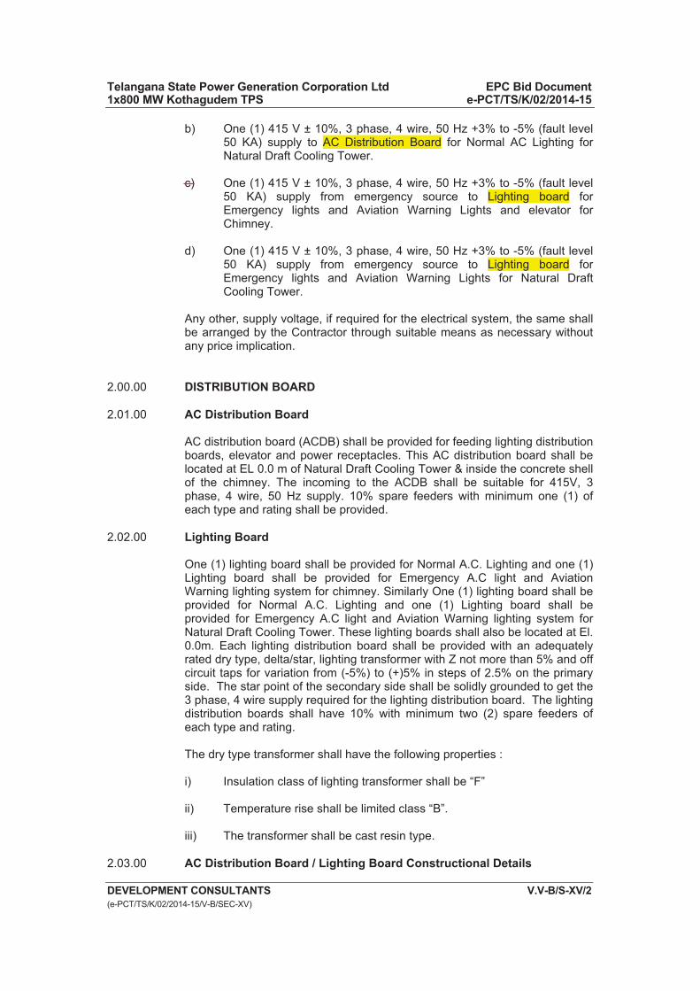
b) One (1) 415 V ± 10%, 3 phase, 4 wire, 50 Hz +3% to -5% (fault level 50 KA) supply to AC Distribution Board for Normal AC Lighting for Natural Draft Cooling Tower.
c) One (1) 415 V ± 10%, 3 phase, 4 wire, 50 Hz +3% to -5% (fault level 50 KA) supply from emergency source to Lighting board for Emergency lights and Aviation Warning Lights and elevator for Chimney.
d) One (1) 415 V ± 10%, 3 phase, 4 wire, 50 Hz +3% to -5% (fault level 50 KA) supply from emergency source to Lighting board for Emergency lights and Aviation Warning Lights for Natural Draft Cooling Tower.
Any other, supply voltage, if required for the electrical system, the same shall be arranged by the Contractor through suitable means as necessary without any price implication.
2.00.00 DISTRIBUTION BOARD
2.01.00 AC Distribution Board
AC distribution board (ACDB) shall be provided for feeding lighting distribution boards, elevator and power receptacles. This AC distribution board shall be located at EL 0.0 m of Natural Draft Cooling Tower & inside the concrete shell of the chimney. The incoming to the ACDB shall be suitable for 415V, 3 phase, 4 wire, 50 Hz supply. 10% spare feeders with minimum one (1) of each type and rating shall be provided.
2.02.00 Lighting Board
One (1) lighting board shall be provided for Normal A.C. Lighting and one (1) Lighting board shall be provided for Emergency A.C light and Aviation Warning lighting system for chimney. Similarly One (1) lighting board shall be provided for Normal A.C. Lighting and one (1) Lighting board shall be provided for Emergency A.C light and Aviation Warning lighting system for Natural Draft Cooling Tower. These lighting boards shall also be located at El. 0.0m. Each lighting distribution board shall be provided with an adequately rated dry type, delta/star, lighting transformer with Z not more than 5% and off circuit taps for variation from (-5%) to (+)5% in steps of 2.5% on the primary side. The star point of the secondary side shall be solidly grounded to get the 3 phase, 4 wire supply required for the lighting distribution board. The lighting distribution boards shall have 10% with minimum two (2) spare feeders of each type and rating.
The dry type transformer shall have the following properties :
i) Insulation class of lighting transformer shall be “F”
ii) Temperature rise shall be limited class “B”.
iii) The transformer shall be cast resin type.
2.03.00 AC Distribution Board / Lighting Board Constructional Details
Telangana State Power Generation Corporation Ltd EPC Bid Document 1x800 MW Kothagudem TPS e-PCT/TS/K/02/2014-15
DEVELOPMENT CONSULTANTS V.V-B/S-XV/3 (e-PCT/TS/K/02/2014-15/V-B/SEC-XV)
2.03.01 AC Distribution Board (ACDB) and Lighting Boards shall be metal enclosed, fabricated from CRCA sheet steel minimum 2 mm thick. AC Distribution Board shall be modular construction, fixed type module, floor-mounted and free-standing type. Each module of ACDB shall be provided with hinged door. Lighting Boards shall be suitable for either wall/column mounting on brackets or floor mounting on channel sills with hinged door on the front.
2.03.02 AC Distribution Board and Lighting Boards shall be dust and vermin-proof, IP-54 or better.
2..03.03 AC Distribution Board and Lighting Boards shall be so constructed as to permit free access to the terminal connections and easy replacement of parts. Front access doors shall have padlocking arrangements.
2.03.04 AC Distribution Board and Lighting Boards shall have provision of cable entry from bottom as required, with removable gland plates. Necessary double compression type brass cable glands, heavy duty tinned copper cable lugs (for aluminium and copper conductor) shall be furnished by the Contractor.
2.03.05 Two ground pads with M10 G.I. bolts and nuts shall be provided on AC Distribution Board and Lighting Boards for connection to 75mmx10mm G.I. flat.
2.03.06 AC Distribution Board shall be complete with designation and caution notice plates fixed at front and back side and feeder name plate fixed on the front cover. Each Lighting Board shall be complete with designation and caution notice plates fixed on front cover and a circuit directory plate fixed on inside of the front cover. Circuit directory plate shall contain details of the points to be controlled by each circuit including the location of the point controlled, rating of the protective units and loading of the circuit.
The plates shall be of anodized aluminium with inscriptions indelibly etched on it.
2.03.07 Bus bar shall be electrolytic grade hard drawn aluminium, colour coded for easy identification and designed for a maximum temperature of 85 Deg.C.
2.03.08 Incoming and outgoing circuits shall be terminated in suitable terminal blocks.
2.03.09 AC Distribution Board shall consist suitable rated MCCB for over load and short circuit protection for incomer, voltmeter with selector switch and suitable PT, C.T. operated ammeter. Outgoing feeder from the AC Distribution Board shall also have MCCB with a over load and short circuit release. It is the Contractor’s responsibility to ensure proper discrimination between outgoing MCCB of AC Distribution Board and downstream MCCB of Lighting Boards.
2.03.10 Each Lighting Board shall have an incoming triple pole MCCB with neutral link with over load and short circuit release., Lighting transformer and a number of outgoing miniature circuit breakers (MCB), 9 KA rating. The lighting transformer shall be dry type housed in the cubicle.
2.03.11 Access door of AC Distribution Board and Lighting Board shall be interlocked with incoming MCCB such that the door can be opened only when the MCCB is in OFF position. Means shall be provided to defeat this interlock.
Telangana State Power Generation Corporation Ltd EPC Bid Document 1x800 MW Kothagudem TPS e-PCT/TS/K/02/2014-15
DEVELOPMENT CONSULTANTS V.V-B/S-XV/4 (e-PCT/TS/K/02/2014-15/V-B/SEC-XV)
2.03.12 MCBs (9 KA rating) in Lighting boards shall be suitable for manual closing and opening and also automatic trip on overload and short circuit.
2.03.13 AC distribution board and lighting boards, after application of primer, shall be finished with electrostatic or powder painting process (thickness not less than 50 microns). For exterior shade refer to clause no.1.16.00 of section E0, Volume V-A.
3.00.00 AVIATION OBSTRUCTION LIGHTING FOR CHIMNEY AND COOLING TOWER
3.01.00 Illumination System for Chimney
3.01.01 Aviation Obstruction Lighting System
Aviation obstruction lighting system will conform to requirements of the latest Indian Standard, the International Civil Aviation Organization (ICAO), the instruction issued by the Director General of Civil Aviation – India and the Directorate of Air Routes & Aerodromes’ (DARA) Circular.
In confirmation to tender specifications and clause no. 6.3.8 of Annex-14 of ICAO, high intensity Type ’A’ white flashing XENON lights will be provided. AWLs will be provided at 2 levels at E.L.271.0m (considering the Chimney height to be 275m ) and 185.0m & Medium intensity type ‘B’ Red Flashing LED at 105.0m in conformation to the clause no. 6.3.19 of Annex-14 of ICAO, which says vertical intervals shall not exceed 105.0m. Three (3) nos. of lights will be provided at each level spaced 120o apart, confirming cl.no.6.3.11 & 6.3.22 of Annex-14 of ICAO. AWLs will be installed with the setting angles as specified in 6.3.21 of Annex-14 of ICAO i.e.2o at EL105.0m & 0o at other levels. A common flasher with flash frequency of 40 flashes per minute will be provided in aviation control panel, such that all AWLs flashes simultaneously as per cl. 6.3.35 of Annex-14 of ICAO.
AWLs at EL 271.0 are provided with 1.0m vertical projections and hence the light beam level is below the steel flue top by 3.0m in confirmation with cl.6.3.12 of Annex-14 of ICAO. Aviation painting is omitted as per cl.no.6.1.4c of Annex-14 of ICAO.
All AWLs are distributed over 3 phases such that failure of any one phase would not blank any face of chimney i.e R-Y-B, Y-B-R & B-R-Y arrangement.
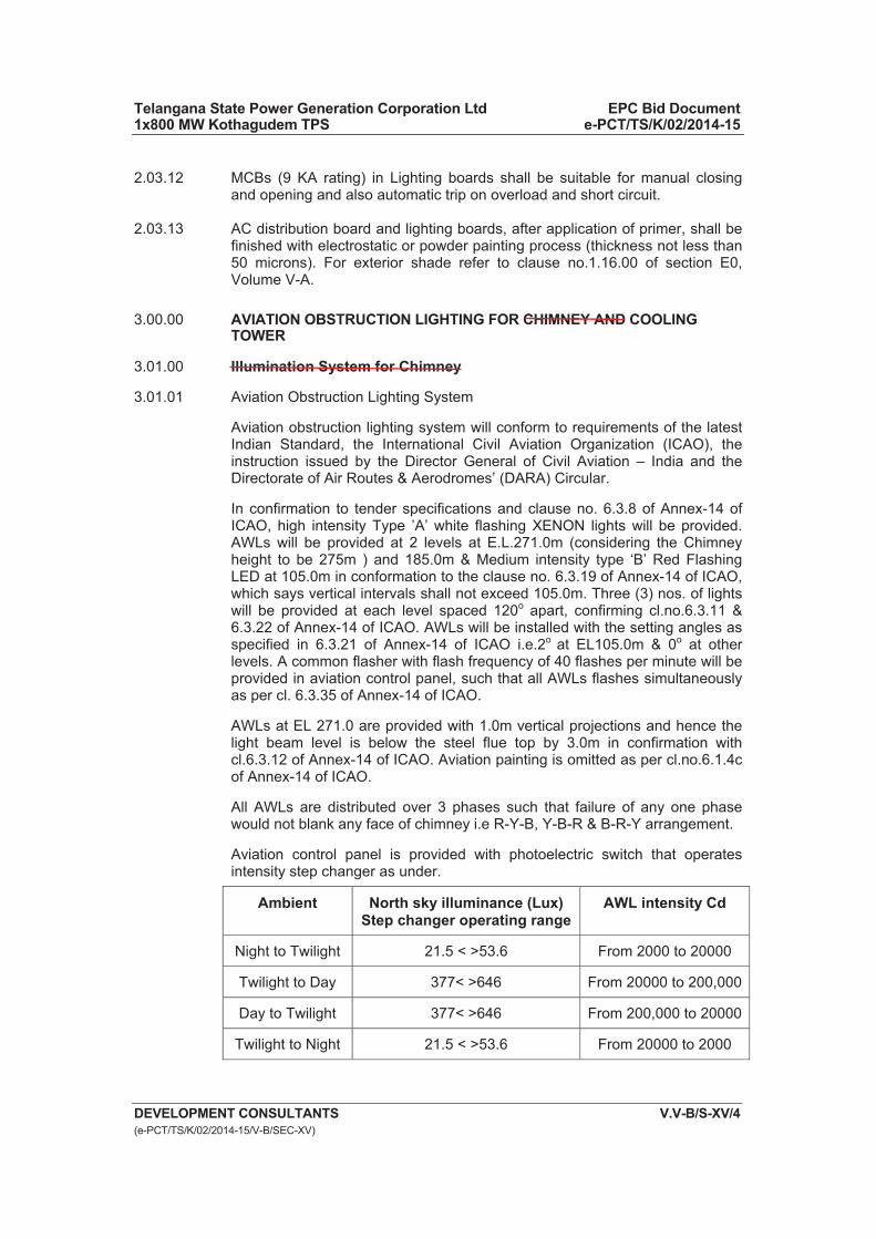
Aviation control panel is provided with photoelectric switch that operates intensity step changer as under.
Ambient North sky illuminance (Lux) Step changer operating range
AWL intensity Cd
Night to Twilight 21.5 < >53.6 From 2000 to 20000
Twilight to Day 377< >646 From 20000 to 200,000
Day to Twilight 377< >646 From 200,000 to 20000
Twilight to Night 21.5 < >53.6 From 20000 to 2000
Telangana State Power Generation Corporation Ltd EPC Bid Document 1x800 MW Kothagudem TPS e-PCT/TS/K/02/2014-15
DEVELOPMENT CONSULTANTS V.V-B/S-XV/5 (e-PCT/TS/K/02/2014-15/V-B/SEC-XV)
Temporary obstruction lighting will be provided during construction. Obstruction lights will be provided at the uppermost part of the stack or the surrounding scaffolding as construction proceeds upwards. As such level specified to have permanent obstruction lights is passed, that level will be provided with temporary lighting.
3.01.02 Temporary Obstruction Lights
The EPC Contractor shall provide at two (2) lights located at diametrically opposite points at the top of the chimney during the period of construction till the permanent obstruction lights are installed and energized, to serve as temporary obstruction lighting.
3.02.00 Illumination system for Cooling Tower
3.02.01 Aviation Obstruction Lighting System
Aviation obstruction lighting system conforms to the requirements of the latest Indian Standard, the International Civil Aviation Organization (ICAO), the instruction issued by the Director General of Civil Aviation – India and the Directorate of Air Routes & Aerodromes’ (DARA) Circular No. 3 of 1987.
White flashing high intensity LED lights of Type ’A’ of table 6.3, Annex-14 of ICAO guide lines shall be provided on top of cooling tower. Six numbers of AOLs shall be provided. All AOLs are distributed over 3 phases.
Aviation control panel is provided with photoelectric switch that de-activates and activates the circuit depending on north sky luminance.
Temporary obstruction lighting will be provided during construction. Obstruction lights will be provided at the uppermost part of the tower or the surrounding scaffolding as construction proceeds upwards. As such level specified to have permanent obstruction lights is passed, that level will be provided with temporary lighting.
The aviation obstruction lights shall meet the recommendations of ICAO and all the requirement of Director General of Civil Aviation, India. Aviation lights shall be fixed only on top of cooling tower. Type of fixtures shall be as listed below.
3.03.00 The illumination system of chimney and cooling tower is governed by DCGA guidelines. In case of any changes in the guidelines in future, the same shall be adhered to.
3.04.00 Aviation Obstruction Light Fixtures (AOL Fixtures)
3.04.01 Each AOL fixture shall have 100% standby light i.e. twin type. Incase of failure of one light, the standby should be activated automatically with auto changeover facility giving hooter feed back. AOL shall be L.E.D type for low and medium intensity and Xenon type for high intensity lights. The degree of protection shall conform to minimum IP 55 grade protection class. High intensity lights shall have intensity step changers.
The control panel for the AOLs shall be mounted near the main distribution board at ground level.
Telangana State Power Generation Corporation Ltd EPC Bid Document 1x800 MW Kothagudem TPS e-PCT/TS/K/02/2014-15
DEVELOPMENT CONSULTANTS V.V-B/S-XV/6 (e-PCT/TS/K/02/2014-15/V-B/SEC-XV)
3.04.02 Photoelectric light detectors shall be furnished and installed for cooling tower to monitor the north sky. The detector shall cause the control unit to energize the aviation lighting system when the north sky luminance. The lighting system may be energized during short periods of decreasing illumination due to abrupt periods of shadow during daylight hours, but shall not be de-energized as the result of short periods of increasing illumination levels due to lighting flashes or stray light sources when overall illumination level is such that the system is operating.
4.00.00 INTERIOR AND EXTERIOR LIGHTS
4.01.00 Interior platforms and staircase shall be illuminated by PHILIPS type NDC 21 or equivalent industrial well glass luminaries with 150 W HPSV lamp and separate control gear box. The number of fixtures shall be selected based on an illumination level of 70 lux for the staircase and platform. Fixture and control gear shall conform to degree of protection IP55 (min.).
At least two (2) fixtures on each platform level shall be fed from aviation warning lighting board (emergency source). All staircase lights shall also be fed from emergency system.
4.02.00 Necessary junction boxes with MCBs shall be provided on each platform to control the platform and staircase lights.
4.03.00 One (1) 15A, 240V, single phase industrial, weatherproof type, suitable for wall/ column mounting, 3-pin receptacle with suitable interlock shall be provided on each internal and external platforms. At least two 63A, 415V, three phase industrial, weatherproof type, 5-pin receptacles shall be provided at the internal platforms.
4.04.00 Chimney Elevator Machine Room
Industrial fluorescent luminaries with 2X28W fluorescent lamps with reflector shall be provided for Elevator machine room. The lux level shall be 100 lux. Four (4) numbers of bulk head luminaries with 100 W GLS lamp and wire guard shall be provided in the elevator pit.
4.05.00 Other Areas
Distribution & Lighting Boards area
Industrial well glass luminaries with 150 W HPSV lamp and integral control gear shall be provided in the Distribution & Lighting boards area. The lux level shall be 150 lux.
5.00.00 CABLES AND CONDUITS
5.01.00 Power cables shall have stranded aluminium conductor, 1100 V grade XLPE insulated, extruded PVC inner sheath galvanized steel wire armoured, overall extruded PVC sheath.
Telangana State Power Generation Corporation Ltd EPC Bid Document 1x800 MW Kothagudem TPS e-PCT/TS/K/02/2014-15
DEVELOPMENT CONSULTANTS V.V-B/S-XV/7 (e-PCT/TS/K/02/2014-15/V-B/SEC-XV)
Control cables shall have stranded annealed tinned copper conductor, 1100V grade PVC insulation, extruded PVC inner sheath, galvanized steel wire armoured, overall extruded PVC sheath. Minimum size of control cable shall be 2.5 sq. mm copper. The minimum sizes of LT cable to be chosen are as below:
AL - 16 sq.mm
CU - 2.5 sq.mm
Flexible trailing cable shall have annealed tinned copper conductor, EPR insulated, reinforced with nylon cord, cores laid up, HDCSP inner sheathed, cotton taped and HDCSP overall sheathed conforming to IS:9968.
Power, control and trailing cables shall be FRLS type.
Lighting wires shall have stranded copper conductor PVC insulated, 1100 V grade, laid in galvanized GI conduits and shall be of following minimum sizes:
� From Lighting panels to junction boxes : IC, 6 SQ.mm
� From junction boxes to lighting fixtures : IC, 2.5 SQ.mm (Number of wires per lead as required)
� From Lighting panels to receptacles (15A) : IC, 6 SQ.mm (A1)
5.02.00 Required number of GI pipe conduit of size not less than 32 mm dia shall be provided. Each conduit riser shall run from the lowest embedded pull box to the highest junction box. The lowest pull box shall be located 450mm above grade in the chimney / Cooling Tower. Pull boxes shall be installed at every 10m intervals vertically. The conduit risers shall run adjacent to the stairs such that the pull boxes become easily accessible from the stairs.
5.03.00 Each conduit riser shall have one circumferential conduit at each platform level. The circumferential conduit at each level shall be provided with three (3) more junction boxes equally spaced at the locations of the aviation warning lights. Suitable conduits shall also be provided from the junction box to the respective light point. The GI pull boxes and junction boxes shall be of size atleast 150mm x 150mm x 100mm, 3mm thk, preferably embedded in the concrete shell.
5.04.00 The conduits shall be electrically connected to all circumferential reinforcing rods which are in turn connected to the down conductors.
5.05.00 Conduit joints and connections shall be made thoroughly watertight and rust proof by application of white lead for embedded portion or red lead for exposed portion.
5.06.00 Conduits shall be hot dip galvanised conforming to relevant IS.
5.07.00 Conduit system shall be electrically bonded to the grounding system.
6.00.00 GROUNDING
Telangana State Power Generation Corporation Ltd EPC Bid Document 1x800 MW Kothagudem TPS e-PCT/TS/K/02/2014-15
DEVELOPMENT CONSULTANTS V.V-B/S-XV/8 (e-PCT/TS/K/02/2014-15/V-B/SEC-XV)
6.01.00 The Contractor shall provide a complete grounding system including underground matas needed for the RCC chimney & Cooling Tower.
6.02.00 The grounding installation work shall conform to the requirements of the Indian Electricity Rules and Code of Practice for Earthing (IS: 3043) as amended up-to-date and grounding notes & details. DWG No. 13A06- DWG-E-0600 attached with the specification. Each piece of electrical equipment/ structure shall be bonded to the grounding system at two (2) points min.
6.03.00 The main ground mat shall be of bare MS round bar of diameter identical to power house ground mat conductor, buried in earth at a min. depth of 1000 mm below finished grade level. Earth electrode of size 40 MM dia x 3 M length driven into the ground and connected to the ground grid conductor shall be provided, as required, to bring down the ground resistance.
6.04.00 Riser from the ground grid shall project 300 mm above grade / concrete floor level. All ground connections below grade shall be made by electric arc welding with low hydrogen content electrode. Above grade 75mmx10 mm galvanised mild steel (450 g/m2 zinc coating min) flats shall be run as main ground conductors securely fixed at intervals not exceeding 1500 mm.
One end of the galvanized mild steel flat shall be connected to the MS round bar riser by electric arc welding and the other end to the equipment by welding / bolting, as necessary. All welded portion shall be painted with bituminous paints against possible corrosion.
6.05.00 The chimney / Cooling Tower ground mat shall be connected to the nearest main plant ground mat by MS round bar at least at two distinct locations.
6.06.00 Ground grid resistance of the grounding system shall not be more than 0.5 ohm.
6.07.00 The ground conductor sizes for grounding of electrical equipment, lighting fixtures, junction boxes etc. shall be as follows :
i) Distribution Boards, Lighting : 50 mm x 6 mm GI Flat Panels and motors above 90 KW
ii) Motors above 30 KW upto 90 KW : 35 mm x 6 mm GI Flat
iii) Motors above 5 KW upto 30 KW : 25 mm x 3 mm GI Flat
iv) Motors upto 5 KW : 8 SWG GI wire
v) Lighting Fixtures, junction boxes, : 16 SWG G.I. wire conduits, etc.
7.00.00 CHIMNEY LIGHTNING PROTECTION
Lightning protection system shall confirm to the requirements of IS: 2309 amended up-to-date And Lightning protection notes and details. DWG. No. 13Axx-DWG-E-1000 attached with the specification.
7.01.00 Air Termination Rod

Telangana State Power Generation Corporation Ltd EPC Bid Document 1x800 MW Kothagudem TPS e-PCT/TS/K/02/2014-15
DEVELOPMENT CONSULTANTS V.V-B/S-XV/9 (e-PCT/TS/K/02/2014-15/V-B/SEC-XV)
The vertical air terminal rods shall be installed at the top of chimney to protect from lightning strokes.
Installation of air terminal at top the chimney for lightning protection shall be 20mm dia lead coated solid copper rod. The projected length of the rod shall be as required to protect the object from lightning stroke.
All the vertical air terminal rods shall be electrically connected together by means of horizontal conductors of size 75 x 10 mm galvanised steel flats.
The air terminal rod shall be properly fixed on the top of the chimney to withstand very high wind pressure.
7.02.00 Circumferential Band
The circumferential band shall be 75 x 10 mm galvanised steel flat fixed to the circumference of top of chimney at interval not more than 1.0 m. This shall be mounted with suitable anchors at such a height as to be accessible from the top of platform for maintenance. The anchors shall be embedded in concrete wall of the stack.
7.03.00 Down Conductors
Minimum four number of 75mm x 10mm GS flat down conductors shall be provided. These shall be not more than 15m apart on the periphery of the stack at the ground level. The down conductor shall be connected to circumferential band at the top portion of the stack and other end connected to the nearest mild steel rod riser from ground electrode. These conductors shall be continuous as far as practicable. Intermediate breaks shall be electrically bonded to form continuous circuit from top to bottom. Lapping of down conductor by bolting is not acceptable.
The down conductor shall be clamped along the surface at intervals of 1500mm by GS clamps. The connection between GS flat & GS clamps shall be done by arc welding.
At each chimney platform level, a circular band shall be provided which will be made of 75 x 10 mm GS flat and electrically connected to each down conductor.
7.04.00 Testing Points
Test joint shall be provided for each down conductor before termination on earth electrode at a height 1.5m from graded level. Test point shall be covered in 150 x 150 x 150 mm GS box. No sharp bends shall be formed in the down conductors and shall be kept as straight as possible.
7.05.00 Clamps, Anchors Etc.
All connections, clamps, anchors etc. of the lightning protection system shall be made of GS fittings. All joints or any other form of electrical connections, unless otherwise specified, shall be clamped or bolted by high pressure contact to form a connection of adequate current carrying capacity and mechanical strength. Soldered connections will not be permitted.
Telangana State Power Generation Corporation Ltd EPC Bid Document 1x800 MW Kothagudem TPS e-PCT/TS/K/02/2014-15
DEVELOPMENT CONSULTANTS V.V-B/S-XV/10 (e-PCT/TS/K/02/2014-15/V-B/SEC-XV)
7.06.00 Vertical and Horizontal Reinforcing Bars
All reinforcing bars shall be properly bonded and connected to earthing system which shall be separate than lightning protection.
The testing point of the down conductors shall be convenient for testing. Testing point shall be phosphor-bronze gunmetal or copper or other suitable.
7.07.00 Temporary Lightning Protection
During construction of chimney, temporary lightning protection shall be maintained by connecting the reinforcement bars to two earth electrodes by means of two 75x10mm GS conductors. These temporary protections shall be provided even after the completion of the chimney till such time the permanent protections are installed.
To avoid maleffect of highly corrosive atmosphere around the chimney due to flue gas and weather, the exposed conductors, connections, clamps, base plate etc. shall be protected by hot dip galvanizing. All site-welded joints conductors shall be coated with anti corrosive paints over a coat of primer.
8.00.00 COOLING TOWER LIGHTNING PROTECTION
Lightning protection system shall confirm to the requirements of IS: 2309 amended up-to-date and Lightning protection notes and details. DWG. No. 13A06-DWG-E-1000 attached with the specification.
8.01.00 Air Terminations
The vertical air terminal rods shall be installed at the top of cooling towers to protect these objects from lightning strokes.
The vertical air terminal except for chimney shall be made of 20 mm dia galvanised steel rod. The projected length of the rod shall be as required to protect the object from lightning stroke.
The air terminal rod shall be properly fixed on the top of the structure to withstand very high wind pressure.
All the vertical air terminal rods shall be electrically connected together by means of horizontal conductors of size 75 x 10 mm galvanised steel flats.
8.02.00 Down Conductors
The down conductors shall be 75 x 10 mm galvanised steel flats. One end of this shall be connected with air terminal rod/horizontal conductor at the top of structure and other end connected to the nearest mild steel rod riser from ground electrode.
Telangana State Power Generation Corporation Ltd EPC Bid Document 1x800 MW Kothagudem TPS e-PCT/TS/K/02/2014-15
DEVELOPMENT CONSULTANTS V.V-B/S-XV/11 (e-PCT/TS/K/02/2014-15/V-B/SEC-XV)
Each down conductor shall have an independent earth termination. In no case conductors of the lightning protection system shall be connected with the conductor of grounding system above ground level.
The connection between each down conductor and rod shall be made via test link located at approximately 1500 mm above ground level.
The down conductor shall be laid straight and sharp bends shall be avoided as far as practicable. The down conductor shall be clamped along the surface at intervals of 1500mm by GS clamps.
The down conductors shall be protected at the ground level against mechanical injury by means of non-metallic pipes, viz. PVC pipes filled with bituminous compound.
8.03.00 Testing Points
Test joint shall be provided for each down conductor before termination on earth electrode at a height 1.5m from graded level. Test point shall be covered in 150 x 150 x 150 mm GS box. No sharp bends shall be formed in the down conductors and shall be kept as straight as possible.
8.04.00 Clamps, Anchors Etc.
All connections, clamps, anchors etc. of the lightning protection system shall be made of GS fittings. All joints or any other form of electrical connections, unless otherwise specified, shall be clamped or bolted by high pressure contact to form a connection of adequate current carrying capacity and mechanical strength. Soldered connections will not be permitted.
8.05.00 Temporary Lightning Protection
During construction of cooling tower, temporary lightning protection shall be maintained by connecting the reinforcement bars to two earth electrodes by means of two 75x10mm GS conductors. These temporary protections shall be provided even after the completion of the chimney till such time the permanent protections are installed.
9.00.00 TESTS
9.01.00 Type Tests
The type tests for fire proof / penetration seal for floor and wall opening/ fire stop system for bottom of electrical switchgear/ panel base are as under:
i) Fire rating test.
ii) Hose Stream test
iii) Accelerated aging test.
iv) Fire rating test on the penetration seal system built out of accelerated aged components followed by hose stream test.
v) Temp. rise test for cable in the fire stop.
Telangana State Power Generation Corporation Ltd EPC Bid Document 1x800 MW Kothagudem TPS e-PCT/TS/K/02/2014-15
DEVELOPMENT CONSULTANTS V.V-B/S-XV/12 (e-PCT/TS/K/02/2014-15/V-B/SEC-XV)
vi) Water absorption test followed by fire rating test.
vii) Flame Resistance test for fire retardant coating material.
viii) Anti-rodent test.
Illumination in different areas are as per designed lux level should be established.
9.02.00 Test Certificates
Certified copies of all tests carried out at works and at site shall be furnished in requisite number of copies.
Test reports shall be complete with all details and shall also contain limit valves specified in the relevant standards, wherever applicable, to facilitate review of Test Report/ Certificates.
The fire proof sealing system shall be installed only after receipt of approval of the test reports.
10.00.00 DRAWINGS, DATA AND MANUALS
10.01.00 To be submitted with the Bid
10.01.01 Typical general arrangement drawing of Chimney / Cooling Tower showing location of lighting fixtures, lightning protection system, grounding system etc.
10.01.02 Typical general arrangement drawing of A.C. distribution board, lightning board.
10.01.03 Catalogue cuts of various types of lightning fixtures, major components, cables, conduits etc
10.01.04 Type Test Certificate of various equipment
10.02.00 To be submitted for Approval (A) / Reference (R) and subsequent Distribution
10.02.01 Dimensional general arrangement drawing of chimney / Cooling Tower showing disposition of aviation warning lights, interior lights on platforms and stairs, receptacles, A.C. distribution boards, lighting boards including their fixing arrangements (A).
10.02.02 Arrangement drawings for lightning protection and grounding system (A)
10.02.03 Single line drawing of A.C. distribution boards and lighting boards (A)
10.02.04 Cable and Conduit layout (A)
10.02.05 Technical data sheet of all equipment / components (A).
10.02.06 Instruction Manuals and Catalogue cuts of all equipment (R)
Telangana State Power Generation Corporation Ltd EPC Bid Document 1x800 MW Kothagudem TPS e-PCT/TS/K/02/2014-15
DEVELOPMENT CONSULTANTS V.V-B/S-XV/13 (e-PCT/TS/K/02/2014-15/V-B/SEC-XV)
The manuals shall clearly indicate the method of installation, check-up and tests to be carried out before commissioning of the equipment.
10.02.07 Any other relevant drawing or data necessary for satisfactory installation, operation and maintenance.
10.03.00 The Contractor may note that the drawings, data and manuals listed are minimum requirement only. The Contractor shall ensure that all other necessary information required to fully describe the equipment / system offered are submitted with his Bid.
Telangana State Power Generation Corporation Ltd. EPC Bid Document 1x800 MW Kothagudem TPS e-PCT/TS/K/02/2014-15
DEVELOPMENT CONSULTANTS (e-PCT/TS/K/02/2014-15/V-B/SEC-IV)
VOLUME : V-B
SECTION-IV
TECHNICAL SPECIFICATION FOR
CABLES
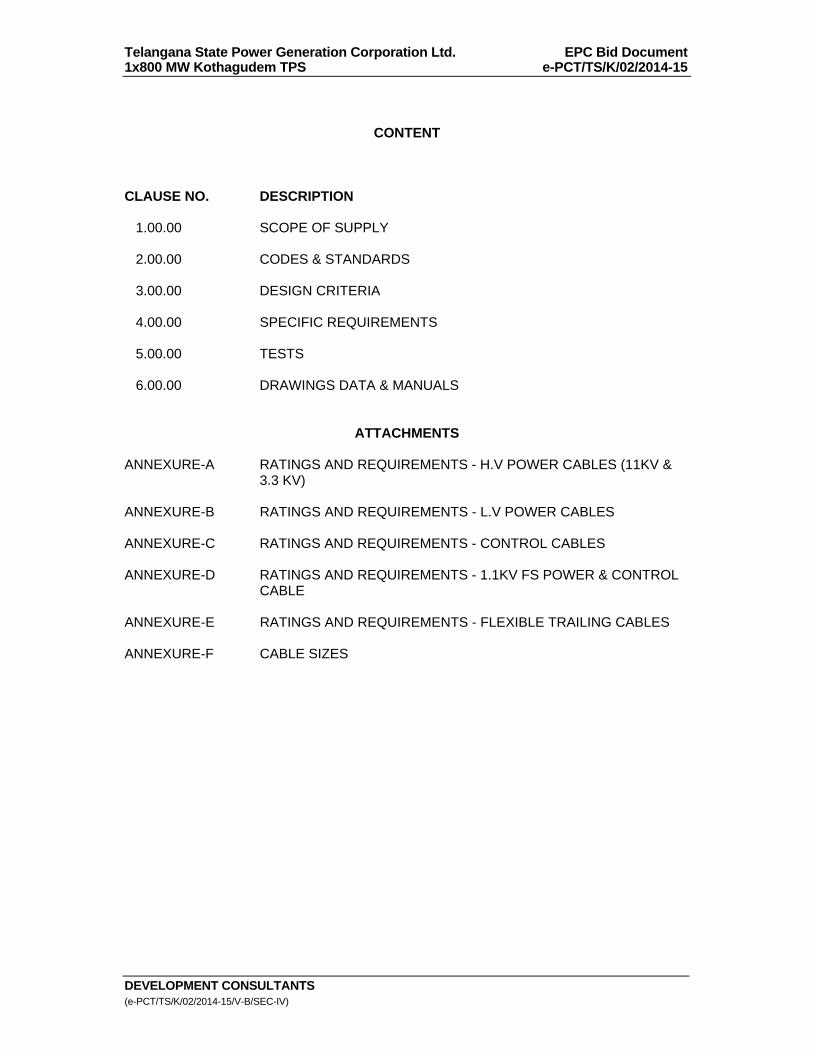
Telangana State Power Generation Corporation Ltd. EPC Bid Document 1x800 MW Kothagudem TPS e-PCT/TS/K/02/2014-15
DEVELOPMENT CONSULTANTS (e-PCT/TS/K/02/2014-15/V-B/SEC-IV)
CONTENT CLAUSE NO. DESCRIPTION 1.00.00 SCOPE OF SUPPLY 2.00.00 CODES & STANDARDS 3.00.00 DESIGN CRITERIA 4.00.00 SPECIFIC REQUIREMENTS 5.00.00 TESTS 6.00.00 DRAWINGS DATA & MANUALS
ATTACHMENTS ANNEXURE-A RATINGS AND REQUIREMENTS - H.V POWER CABLES (11KV &
3.3 KV) ANNEXURE-B RATINGS AND REQUIREMENTS - L.V POWER CABLES ANNEXURE-C RATINGS AND REQUIREMENTS - CONTROL CABLES ANNEXURE-D RATINGS AND REQUIREMENTS - 1.1KV FS POWER & CONTROL
CABLE ANNEXURE-E RATINGS AND REQUIREMENTS - FLEXIBLE TRAILING CABLES ANNEXURE-F CABLE SIZES
Telangana State Power Generation Corporation Ltd. EPC Bid Document 1x800 MW Kothagudem TPS e-PCT/TS/K/02/2014-15
DEVELOPMENT CONSULTANTS V.V-B/S-IV/1 (e-PCT/TS/K/02/2014-15/V-B/SEC-IV)
SECTION-IV
TECHNICAL SPECIFICATION FOR
CABLES 1.00.00 SCOPE OF SUPPLY 1.01.00 Power and Control Cables shall cover the requirement of entire Plant
including the switchyard. Other cables including special cables, if any, which may be necessary as per
proven engineering practice for satisfactory and trouble free operation of the entire cable system of the plant shall also be within the scope of supply. These shall include all such cables for electrical integral with mechanical equipment systems and subsystems.
1.02.00 Cable shall be furnished in accordance with this specification and the
following annexures : a) 11kV & 3.3 kV Power cables : Annexure - A b) 1100V Power Cables : Annexure – B c) Control Cables : Annexure – C
d) Fire Survival Cables : Annexure – D e) Flexible Trailing cable : Annexure – E
1.03.00 All relevant drawings, data and instruction manuals 2.00.00 CODES & STANDARDS 2.01.00 All cable and materials shall be designed, manufactured and tested in
accordance with the latest applicable Indian Standards (IS) and IEC except where modified and/or supplemented by this specification.
2.02.00 Cable and material conforming to any other standard which ensures equal or
better quality, may be accepted. In such case, copies of the English version of the standard adopted shall be submitted along with the bid.
2.03.00 The electrical installation shall meet the requirements of Indian Electricity
Rules as amended upto date and relevant IS Code of Practice. In addition, other rules and regulations applicable to the work shall be followed.
3.00.00 DESIGN CRITERIA 3.01.00 Cables will be generally laid on ladder type trays or drawn through rigid PVC/GI
/HDPE pipe/conduits. Cable tunnels shall be avoided as far as possible, except at locations where overhead trays are not possible, with prior approval of the Owner.
Telangana State Power Generation Corporation Ltd. EPC Bid Document 1x800 MW Kothagudem TPS e-PCT/TS/K/02/2014-15
DEVELOPMENT CONSULTANTS V.V-B/S-IV/2 (e-PCT/TS/K/02/2014-15/V-B/SEC-IV)
3.02.00 For continuous operation at specified rating, maximum conductor temperature shall be limited to the permissible value as per relevant standard and/or this specification which one is more stringent.
3.03.00 The insulation and sheath materials shall be resistant to oil, acid and alkali
and shall be tough enough to withstand mechanical stresses during handling. 3.04.00 Armouring shall be single round wire of galvanized steel for multicore cables
and aluminum for single core cable for power and control cables. For fire survival control cable, the armouring over inner sheath shall consist of single layer of wire / round galvanised steel wire as per IS 3975 amended upto date. For Fire survival power cable, Single core cables to be used in A.C. system, the armouring over inner sheath shall consist of single layer of round copper wire, for multi-core cables to be used in A.C. system and single core cables in D.C. System, the armouring over inner sheath shall consist of single layer of round galvanised steel wire.
3.05.00 The outer sheath shall have flame retardant low smoke halogen evolution
(FRLSH) characteristics or fire survival characteristics as applicable and shall meet the requirements of additional tests specified for the purpose.
3.06.00 Core identification for multicore cable shall be provided by colour coding. 3.07.00 HT cables shall be manufactured by triple extrusion dry cured (CCV) process
using pressurized nitrogen. 4.00.00 SPECIFIC REQUIREMENTS 4.01.00 General Description All Cables shall be furnished in strict compliance with ratings and
requirements and sizes as given in Annexures to this Specification. 4.02.00 Drum Length and Tolerance The cables shall be supplied in non-returnable packing steel drum for 11 kV &
3.3 kV power cables, wooden drums for 1100V power and control cables, each containing minimum 500 meters length of larger sizes of cable unless specifically asked for. For smaller sizes of cables, each drum shall contain 1000 meters length of cable. Allowable tolerance on individual drum length is +5%.
4.03.00 Non-Standard Length Non-standard lengths upto 5% of the total ordered quantity may be accepted.
However the Contractor will be required to obtain approval before packing the Cables on drums. Non-standard lengths shall not be less than 100 metres in any case.
4.04.00 Cable identification
Telangana State Power Generation Corporation Ltd. EPC Bid Document 1x800 MW Kothagudem TPS e-PCT/TS/K/02/2014-15
DEVELOPMENT CONSULTANTS V.V-B/S-IV/3 (e-PCT/TS/K/02/2014-15/V-B/SEC-IV)
Cable identification shall be provided by embossing on every meter on the outer sheath the following :
a) TSGENCO b) Manufacturer’s name or trade mark c) Voltage grade d) Year of manufacture e) Type of insulation, e.g. XLPE/PVC/HR85/IE2 etc. f) No. of core and size of cables. g) Type of improved fire performance, e.g. FR/FRLSH/FS h) IS number 4.05.00 Packing 4.05.01 Cables shall be supplied in non returnable drums. The drums shall be of
heavy construction. All wooden parts shall be manufactured from seasoned wood. All ferrous parts used shall be treated with suitable rust preventive finish or coating to avoid rusting during transit or storage. Wooden cable drum shall be treated by immersing in copper-nitrate solution.
4.05.02 Cable shall be wound and packed on drums in such a manner that it will be
properly sealed and firmly secured to the drum. The ends of each length shall be sealed before shipment.
4.05.03 The cable drums should carry the following details in printed form: a) TSGENCO
b) Manufacturer’s name or trade make
c) Type of cable & voltage grade d) Year of manufacture e) Type of insulation e.g. XLPE/HRPVC/IE2 f) No. of core and size of cables g) Cable code e.g. FRLSH/FS h) Length of cable on drum i) No. of length on drum, if more than one j) Direction of rotation, by arrow
k) Approx. gross mass.
Telangana State Power Generation Corporation Ltd. EPC Bid Document 1x800 MW Kothagudem TPS e-PCT/TS/K/02/2014-15
DEVELOPMENT CONSULTANTS V.V-B/S-IV/4 (e-PCT/TS/K/02/2014-15/V-B/SEC-IV)
l) IS/IEC number and ISI mark 4.06.00 Joints and Terminations Materials of construction for a joint/termination shall perfectly match with the
dielectric chemical and physical characteristics of the associated cables. The material and design concepts shall incorporate a high degree of operating compatibility between the cable and joints. The protective outer covering (jacket) used on the joints/terminations shall have the same qualities as that of the cable outer sheath in terms of ambient/operating temperature withstand capability and resistance to hazardous environments and corrosive elements. Straight through joints and terminations for HT cables shall be heat shrinkable type.
4.07.00 Selection Criteria 4.07.01 a) HT and LT power cables shall be selected on the basis of current
carrying capacity, short circuit rating and permissible voltage drop. b) While sizing power cables, following aspects shall be reckoned:
i) Ground/Ambient Air temperature
ii) Depth of Laying.
iii) Power Cables touching each other. c) Cables, for circuit breaker controlled feeders, shall withstand the short
circuit current for the fault clearing time 0.16 Sec. for outgoing feeder, 0.5 Sec. for Tie feeder and 1.0 Sec. for Incomer.
d) HT cables shall be sized based on the following considerations:
Rated current of the equipment and ground/ambient temperature. Touching/spacing of cable. Laying on multi-tier racks, trench Depth of laying.
The voltage drop of the cable , during motor starting condition , shall be limited to 15% and during full load running condition shall be limited to 3 % rated voltage. For BFP motor, the voltage drop during motor starting condition shall be limited to 20% and for Mill motor shall be limited to 10%. Other outgoing feeder / transformer feeder shall be limited to 3% rated voltage.
Short circuits withstand capability e) For fuse/MCCB/Breaker protected circuits the conductor size shall
depend upon full load current subject to voltage drop limited to 3% during running of all feeders and 15% during starting for motor feeders. In addition, transformer regulation shall also be considered for loads fed from 415V PMCC. Incase of other out going line feeder voltage drop shall be limited to 3%.
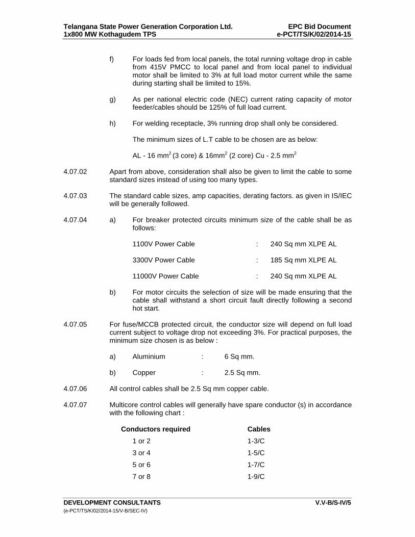
Telangana State Power Generation Corporation Ltd. EPC Bid Document 1x800 MW Kothagudem TPS e-PCT/TS/K/02/2014-15
DEVELOPMENT CONSULTANTS V.V-B/S-IV/5 (e-PCT/TS/K/02/2014-15/V-B/SEC-IV)
f) For loads fed from local panels, the total running voltage drop in cable
from 415V PMCC to local panel and from local panel to individual motor shall be limited to 3% at full load motor current while the same during starting shall be limited to 15%.
g) As per national electric code (NEC) current rating capacity of motor
feeder/cables should be 125% of full load current. h) For welding receptacle, 3% running drop shall only be considered. The minimum sizes of L.T cable to be chosen are as below: AL - 16 mm2 (3 core) & 16mm2 (2 core) Cu - 2.5 mm2
4.07.02 Apart from above, consideration shall also be given to limit the cable to some
standard sizes instead of using too many types. 4.07.03 The standard cable sizes, amp capacities, derating factors. as given in IS/IEC
will be generally followed. 4.07.04 a) For breaker protected circuits minimum size of the cable shall be as
follows: 1100V Power Cable : 240 Sq mm XLPE AL 3300V Power Cable : 185 Sq mm XLPE AL 11000V Power Cable : 240 Sq mm XLPE AL b) For motor circuits the selection of size will be made ensuring that the
cable shall withstand a short circuit fault directly following a second hot start.
4.07.05 For fuse/MCCB protected circuit, the conductor size will depend on full load
current subject to voltage drop not exceeding 3%. For practical purposes, the minimum size chosen is as below :
a) Aluminium : 6 Sq mm. b) Copper : 2.5 Sq mm. 4.07.06 All control cables shall be 2.5 Sq mm copper cable. 4.07.07 Multicore control cables will generally have spare conductor (s) in accordance
with the following chart : Conductors required Cables
1 or 2 1-3/C
3 or 4 1-5/C
5 or 6 1-7/C
7 or 8 1-9/C

Telangana State Power Generation Corporation Ltd. EPC Bid Document 1x800 MW Kothagudem TPS e-PCT/TS/K/02/2014-15
DEVELOPMENT CONSULTANTS V.V-B/S-IV/6 (e-PCT/TS/K/02/2014-15/V-B/SEC-IV)
9 or 10 1-12/C
Above 10 Two or more of above cables 4.07.08 Separate cables for each type of following services/functions as applicable
shall be used for each feeder. Same multicore cable using different services shall not be acceptable.
a) Power. b) Control, interlock and indication. c) Metering and measuring. d) Alarm and annunciation.
e) C.T. Cables.
f) V.T. Cables. 4.08.00 Cable Identification Cable identification shall be provided by embossing on the outer sheath the
following : a) Manufacturer's name or trade mark b) Manufacturer's name or trade mark c) Voltage grade
d) Year of manufacture e) Type of insulation, e.g. XLPE, HRPVC & IE2 etc.
f) No. of core & size of cables
g) Type of outer sheath e.g. FRLSH, FS etc. 4.09.00 Selected sizes of power and control cables are given in Annexure-G. 4.10.00 Fire Survival Cables shall be used for important auxiliaries / area as
recommended in Standard Technical Specification by CEA for the following services. The fire survival time of these cables shall not be less than 3 hours at 750 deg. C.
i. DC emergency lube oil pump ii. DC hydrogen seal pump iii. Turbine lube oil pump/barring gear
iv. DC emergency lighting for main building and service building
v. DC cables for battery to charger & DC distribution boards
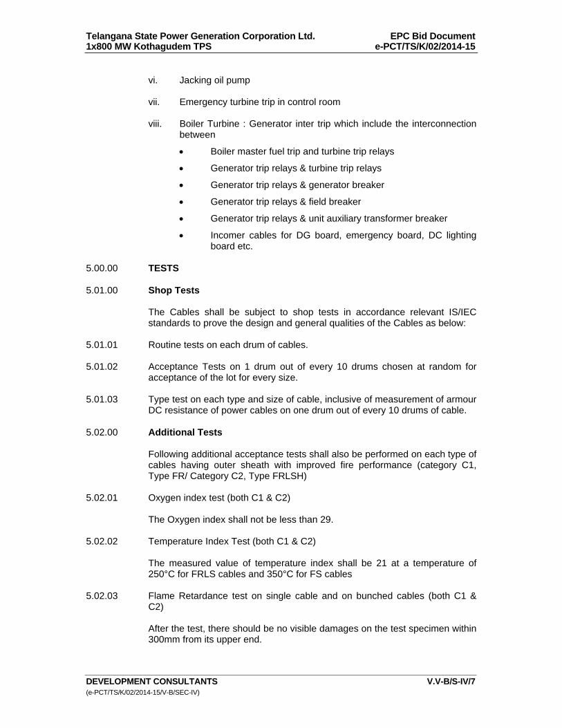
Telangana State Power Generation Corporation Ltd. EPC Bid Document 1x800 MW Kothagudem TPS e-PCT/TS/K/02/2014-15
DEVELOPMENT CONSULTANTS V.V-B/S-IV/7 (e-PCT/TS/K/02/2014-15/V-B/SEC-IV)
vi. Jacking oil pump
vii. Emergency turbine trip in control room
viii. Boiler Turbine : Generator inter trip which include the interconnection
between
Boiler master fuel trip and turbine trip relays
Generator trip relays & turbine trip relays
Generator trip relays & generator breaker
Generator trip relays & field breaker
Generator trip relays & unit auxiliary transformer breaker
Incomer cables for DG board, emergency board, DC lighting board etc.
5.00.00 TESTS 5.01.00 Shop Tests
The Cables shall be subject to shop tests in accordance relevant IS/IEC standards to prove the design and general qualities of the Cables as below:
5.01.01 Routine tests on each drum of cables. 5.01.02 Acceptance Tests on 1 drum out of every 10 drums chosen at random for
acceptance of the lot for every size. 5.01.03 Type test on each type and size of cable, inclusive of measurement of armour
DC resistance of power cables on one drum out of every 10 drums of cable. 5.02.00 Additional Tests Following additional acceptance tests shall also be performed on each type of
cables having outer sheath with improved fire performance (category C1, Type FR/ Category C2, Type FRLSH)
5.02.01 Oxygen index test (both C1 & C2) The Oxygen index shall not be less than 29. 5.02.02 Temperature Index Test (both C1 & C2) The measured value of temperature index shall be 21 at a temperature of
250°C for FRLS cables and 350°C for FS cables 5.02.03 Flame Retardance test on single cable and on bunched cables (both C1 &
C2) After the test, there should be no visible damages on the test specimen within
300mm from its upper end.
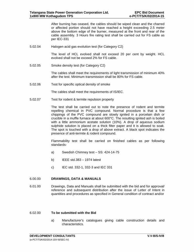
Telangana State Power Generation Corporation Ltd. EPC Bid Document 1x800 MW Kothagudem TPS e-PCT/TS/K/02/2014-15
DEVELOPMENT CONSULTANTS V.V-B/S-IV/8 (e-PCT/TS/K/02/2014-15/V-B/SEC-IV)
After burning has ceased, the cables should be wiped clean and the charred or affected portion should not have reached a height exceeding 2.5 meter above the bottom edge of the burner, measured at the front and rear of the cable assembly. 3 Hours fire rating test shall be carried out for FS cable as per IEC-331
5.02.04 Halogen acid gas evolution test (for Category C2) The level of HCL evolved shall not exceed 20 per cent by weight. HCL
evolved shall not be exceed 2% for FS cable. 5.02.05 Smoke density test (for Category C2) The cables shall meet the requirements of light transmission of minimum 40%
after the test. Minimum transmission shall be 80% for FS cable. 5.02.06 Test for specific optical density of smoke The cables shall meet the requirements of IS/IEC. 5.02.07 Test for rodent & termite repulsion property The test shall be carried out to note the presence of rodent and termite
repelling chemical in PVC compound. Normal procedure is that a few chippings of the PVC compound are slowly ignited in a porcelain dish or crucible in a muffle furnace at about 600°C. The resulting ignited ash is boiled with a little ammonium acetate solution (10%). A drop of aqueous sodium sulphide solution is placed on a thick filter paper and it is allowed to soak. The spot is touched with a drop of above extract. A black spot indicates the presence of anti-termite & rodent compound.
Flammability test shall be carried on finished cables as per following standards- a) Swedish Chimney test – SS: 424-14-75 b) IEEE std.383 – 1974 latest c) IEC std. 332-1, 332-3 and IEC 331
6.00.00 DRAWINGS, DATA & MANUALS 6.01.00 Drawings, Data and Manuals shall be submitted with the bid and for approval/
reference and subsequent distribution after the issue of Letter of Intent in quantities and procedures as specified in General condition of contract and/or
6.02.00 To be submitted with the Bid
a) Manufacturer's catalogues giving cable construction details and
characteristics.
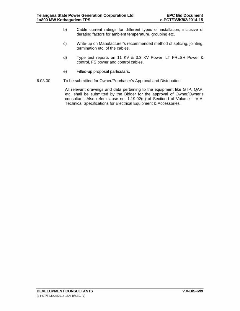
Telangana State Power Generation Corporation Ltd. EPC Bid Document 1x800 MW Kothagudem TPS e-PCT/TS/K/02/2014-15
DEVELOPMENT CONSULTANTS V.V-B/S-IV/9 (e-PCT/TS/K/02/2014-15/V-B/SEC-IV)
b) Cable current ratings for different types of installation, inclusive of derating factors for ambient temperature, grouping etc.
c) Write-up on Manufacturer’s recommended method of splicing, jointing,
termination etc. of the cables. d) Type test reports on 11 KV & 3.3 KV Power, LT FRLSH Power &
control, FS power and control cables. e) Filled-up proposal particulars.
6.03.00 To be submitted for Owner/Purchaser’s Approval and Distribution All relevant drawings and data pertaining to the equipment like GTP, QAP,
etc. shall be submitted by the Bidder for the approval of Owner/Owner’s consultant. Also refer clause no. 1.19.02(u) of Section-I of Volume – V-A: Technical Specifications for Electrical Equipment & Accessories.
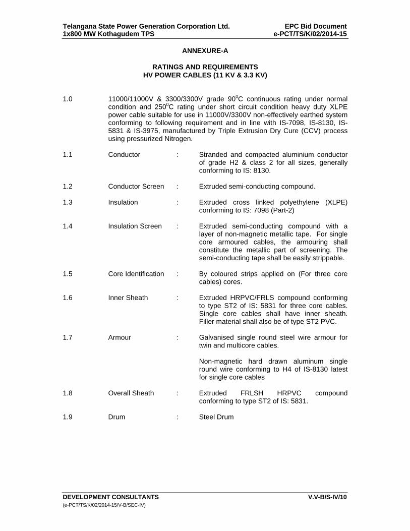
Telangana State Power Generation Corporation Ltd. EPC Bid Document 1x800 MW Kothagudem TPS e-PCT/TS/K/02/2014-15
DEVELOPMENT CONSULTANTS V.V-B/S-IV/10 (e-PCT/TS/K/02/2014-15/V-B/SEC-IV)
ANNEXURE-A
RATINGS AND REQUIREMENTS HV POWER CABLES (11 KV & 3.3 KV)
1.0 11000/11000V & 3300/3300V grade 900C continuous rating under normal
condition and 2500C rating under short circuit condition heavy duty XLPE power cable suitable for use in 11000V/3300V non-effectively earthed system conforming to following requirement and in line with IS-7098, IS-8130, IS-5831 & IS-3975, manufactured by Triple Extrusion Dry Cure (CCV) process using pressurized Nitrogen.
1.1 Conductor : Stranded and compacted aluminium conductor
of grade H2 & class 2 for all sizes, generally conforming to IS: 8130.
1.2 Conductor Screen : Extruded semi-conducting compound. 1.3 Insulation : Extruded cross linked polyethylene (XLPE)
conforming to IS: 7098 (Part-2) 1.4 Insulation Screen : Extruded semi-conducting compound with a
layer of non-magnetic metallic tape. For single core armoured cables, the armouring shall constitute the metallic part of screening. The semi-conducting tape shall be easily strippable.
1.5 Core Identification : By coloured strips applied on (For three core
cables) cores. 1.6 Inner Sheath : Extruded HRPVC/FRLS compound conforming
to type ST2 of IS: 5831 for three core cables. Single core cables shall have inner sheath. Filler material shall also be of type ST2 PVC.
1.7 Armour : Galvanised single round steel wire armour for
twin and multicore cables. Non-magnetic hard drawn aluminum single
round wire conforming to H4 of IS-8130 latest for single core cables
1.8 Overall Sheath : Extruded FRLSH HRPVC compound
conforming to type ST2 of IS: 5831. 1.9 Drum : Steel Drum
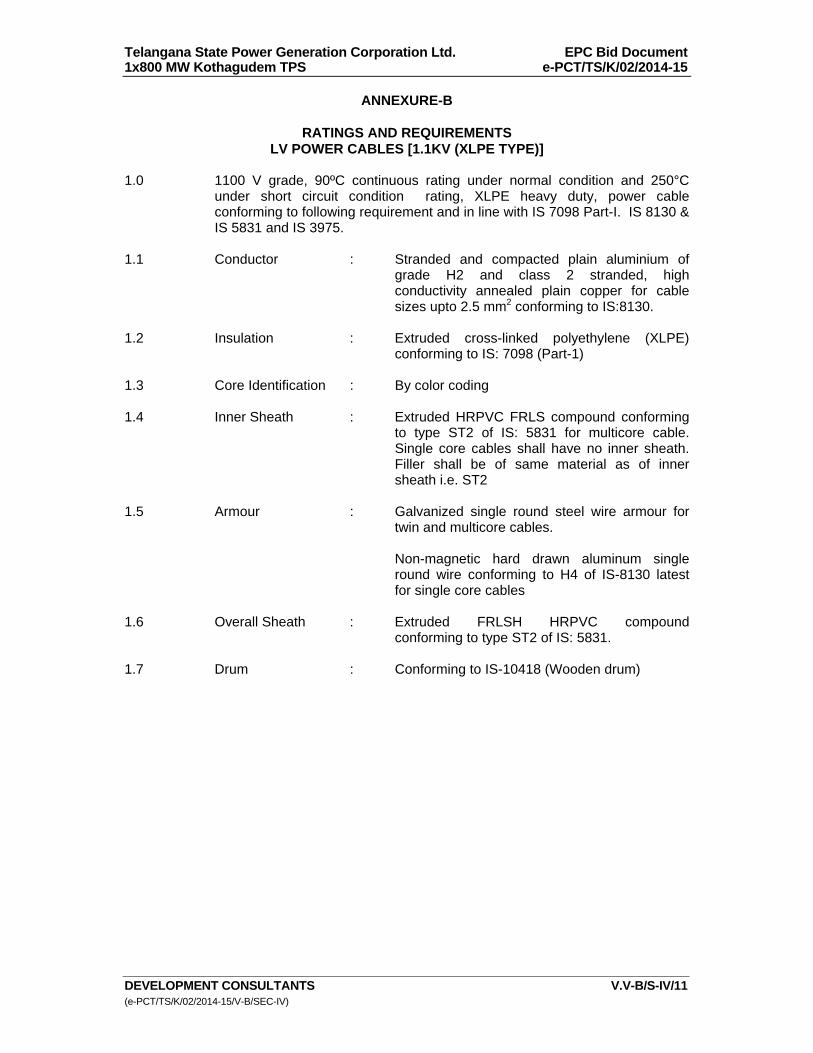
Telangana State Power Generation Corporation Ltd. EPC Bid Document 1x800 MW Kothagudem TPS e-PCT/TS/K/02/2014-15
DEVELOPMENT CONSULTANTS V.V-B/S-IV/11 (e-PCT/TS/K/02/2014-15/V-B/SEC-IV)
ANNEXURE-B
RATINGS AND REQUIREMENTS LV POWER CABLES [1.1KV (XLPE TYPE)]
1.0 1100 V grade, 90ºC continuous rating under normal condition and 250°C
under short circuit condition rating, XLPE heavy duty, power cable conforming to following requirement and in line with IS 7098 Part-I. IS 8130 & IS 5831 and IS 3975.
1.1 Conductor : Stranded and compacted plain aluminium of
grade H2 and class 2 stranded, high conductivity annealed plain copper for cable sizes upto 2.5 mm2 conforming to IS:8130.
1.2 Insulation : Extruded cross-linked polyethylene (XLPE)
conforming to IS: 7098 (Part-1)
1.3 Core Identification : By color coding 1.4 Inner Sheath : Extruded HRPVC FRLS compound conforming
to type ST2 of IS: 5831 for multicore cable. Single core cables shall have no inner sheath. Filler shall be of same material as of inner sheath i.e. ST2
1.5 Armour : Galvanized single round steel wire armour for
twin and multicore cables. Non-magnetic hard drawn aluminum single
round wire conforming to H4 of IS-8130 latest for single core cables
1.6 Overall Sheath : Extruded FRLSH HRPVC compound
conforming to type ST2 of IS: 5831. 1.7 Drum : Conforming to IS-10418 (Wooden drum)
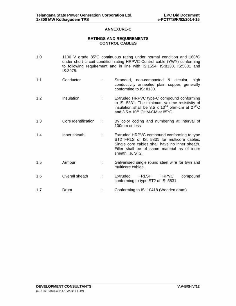
Telangana State Power Generation Corporation Ltd. EPC Bid Document 1x800 MW Kothagudem TPS e-PCT/TS/K/02/2014-15
DEVELOPMENT CONSULTANTS V.V-B/S-IV/12 (e-PCT/TS/K/02/2014-15/V-B/SEC-IV)
ANNEXURE-C
RATINGS AND REQUIREMENTS CONTROL CABLES
1.0 1100 V grade 85ºC continuous rating under normal condition and 160°C
under short circuit condition rating HRPVC Control cable (YWY) conforming to following requirement and in line with IS:1554, IS:8130, IS:5831 and IS:3975.
1.1 Conductor : Stranded, non-compacted & circular, high
conductivity annealed plain copper, generally conforming to IS: 8130.
1.2 Insulation : Extruded HRPVC type-C compound conforming
to IS: 5831. The minimum volume resistivity of insulation shall be 3.5 x 10¹⁴ ohm-cm at 27OC and 3.5 x 10¹¹ OHM-CM at 85OC.
1.3 Core Identification : By color coding and numbering at interval of
100mm or less 1.4 Inner sheath : Extruded HRPVC compound conforming to type
ST2 FRLS of IS: 5831 for multicore cables. Single core cables shall have no inner sheath. Filler shall be of same material as of inner sheath i.e. ST2.
1.5 Armour : Galvanised single round steel wire for twin and
multicore cables. 1.6 Overall sheath : Extruded FRLSH HRPVC compound
conforming to type ST2 of IS: 5831. 1.7 Drum : Conforming to IS: 10418 (Wooden drum)
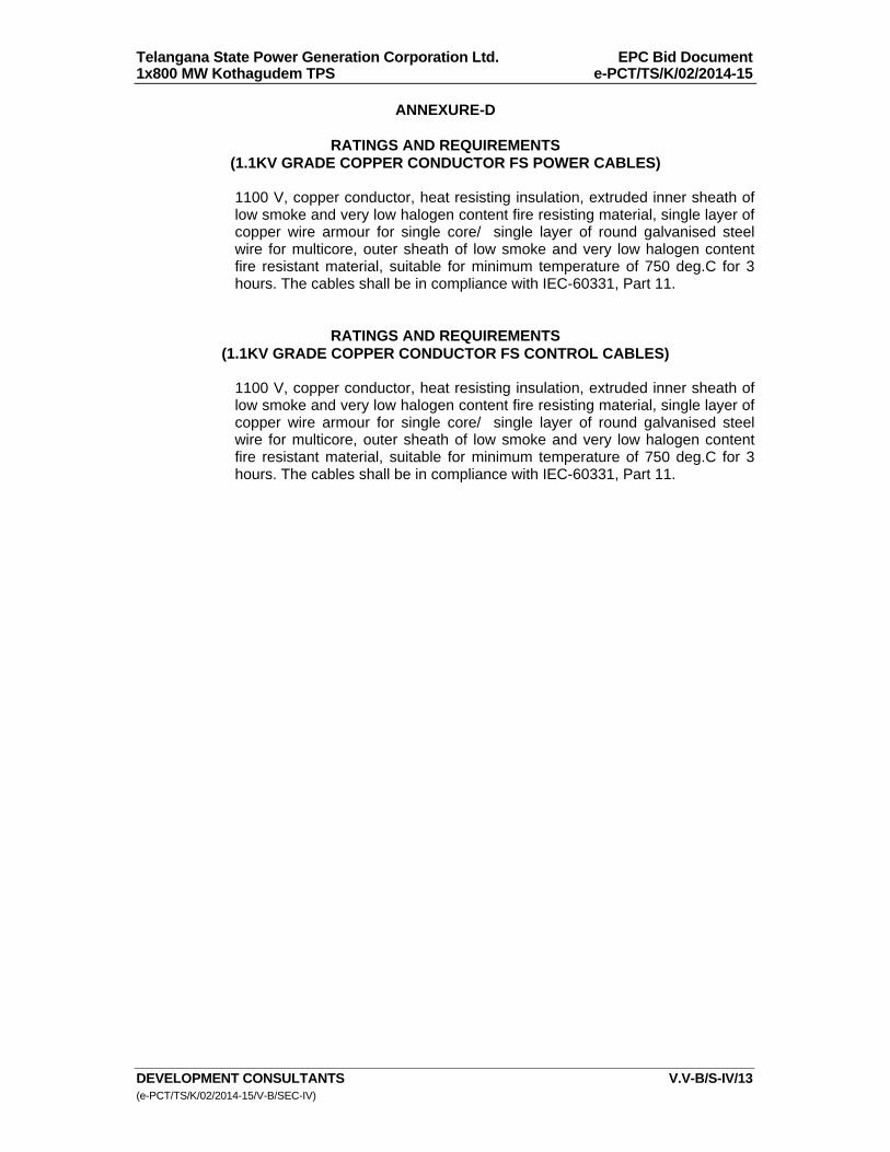
Telangana State Power Generation Corporation Ltd. EPC Bid Document 1x800 MW Kothagudem TPS e-PCT/TS/K/02/2014-15
DEVELOPMENT CONSULTANTS V.V-B/S-IV/13 (e-PCT/TS/K/02/2014-15/V-B/SEC-IV)
ANNEXURE-D
RATINGS AND REQUIREMENTS (1.1KV GRADE COPPER CONDUCTOR FS POWER CABLES)
1100 V, copper conductor, heat resisting insulation, extruded inner sheath of low smoke and very low halogen content fire resisting material, single layer of copper wire armour for single core/ single layer of round galvanised steel wire for multicore, outer sheath of low smoke and very low halogen content fire resistant material, suitable for minimum temperature of 750 deg.C for 3 hours. The cables shall be in compliance with IEC-60331, Part 11.
RATINGS AND REQUIREMENTS (1.1KV GRADE COPPER CONDUCTOR FS CONTROL CABLES)
1100 V, copper conductor, heat resisting insulation, extruded inner sheath of low smoke and very low halogen content fire resisting material, single layer of copper wire armour for single core/ single layer of round galvanised steel wire for multicore, outer sheath of low smoke and very low halogen content fire resistant material, suitable for minimum temperature of 750 deg.C for 3 hours. The cables shall be in compliance with IEC-60331, Part 11.
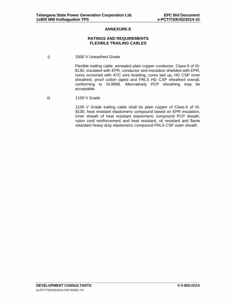
Telangana State Power Generation Corporation Ltd. EPC Bid Document 1x800 MW Kothagudem TPS e-PCT/TS/K/02/2014-15
DEVELOPMENT CONSULTANTS V.V-B/S-IV/14 (e-PCT/TS/K/02/2014-15/V-B/SEC-IV)
ANNEXURE-E
RATINGS AND REQUIREMENTS FLEXIBLE TRAILING CABLES
i) 3300 V Unearthed Grade
Flexible trailing cable, annealed plain copper conductor, Class-5 of IS-8130, insulated with EPR, conductor and insulation shielded with EPR, cores screened with ATC wire braiding, cores laid up, HD CSP inner sheathed, proof cotton taped and FRLS HD CSP sheathed overall, conforming to IS:9968. Alternatively PCP sheathing may be acceptable.
ii) 1100 V Grade
1100 V Grade trailing cable shall be plain copper of Class-5 of IS-
8130, heat resistant elastomeric compound based on EPR insulation, inner sheath of heat resistant elastomeric compound PCP sheath, nylon cord reinforcement and heat resistant, oil resistant and flame retardant heavy duty elastomeric compound FRLS CSP outer sheath.
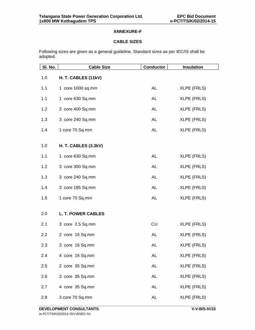
Telangana State Power Generation Corporation Ltd. EPC Bid Document 1x800 MW Kothagudem TPS e-PCT/TS/K/02/2014-15
DEVELOPMENT CONSULTANTS V.V-B/S-IV/15 (e-PCT/TS/K/02/2014-15/V-B/SEC-IV)
ANNEXURE-F
CABLE SIZES Following sizes are given as a general guideline. Standard sizes as per IEC/IS shall be adopted.
Sl. No. Cable Size Conductor Insulation 1.0 H. T. CABLES (11kV) 1.1 1 core 1000 sq.mm AL XLPE (FRLS) 1.1 1 core 630 Sq.mm AL XLPE (FRLS) 1.2 3 core 400 Sq.mm AL XLPE (FRLS) 1.3 3 core 240 Sq.mm AL XLPE (FRLS) 1.4 1 core 70 Sq.mm AL XLPE (FRLS) 1.0 H. T. CABLES (3.3kV) 1.1 1 core 630 Sq.mm AL XLPE (FRLS) 1.2 3 core 300 Sq.mm AL XLPE (FRLS) 1.3 3 core 240 Sq.mm AL XLPE (FRLS) 1.4 3 core 185 Sq.mm AL XLPE (FRLS) 1.5 1 core 70 Sq.mm AL XLPE (FRLS) 2.0 L. T. POWER CABLES 2.1 3 core 2.5 Sq.mm CU XLPE (FRLS) 2.2 2 core 16 Sq.mm AL XLPE (FRLS) 2.3 3 core 16 Sq.mm AL XLPE (FRLS) 2.4 4 core 16 Sq.mm AL XLPE (FRLS) 2.5 2 core 35 Sq.mm AL XLPE (FRLS) 2.6 3 core 35 Sq.mm AL XLPE (FRLS) 2.7 4 core 35 Sq.mm AL XLPE (FRLS) 2.8 3 core 70 Sq.mm AL XLPE (FRLS)
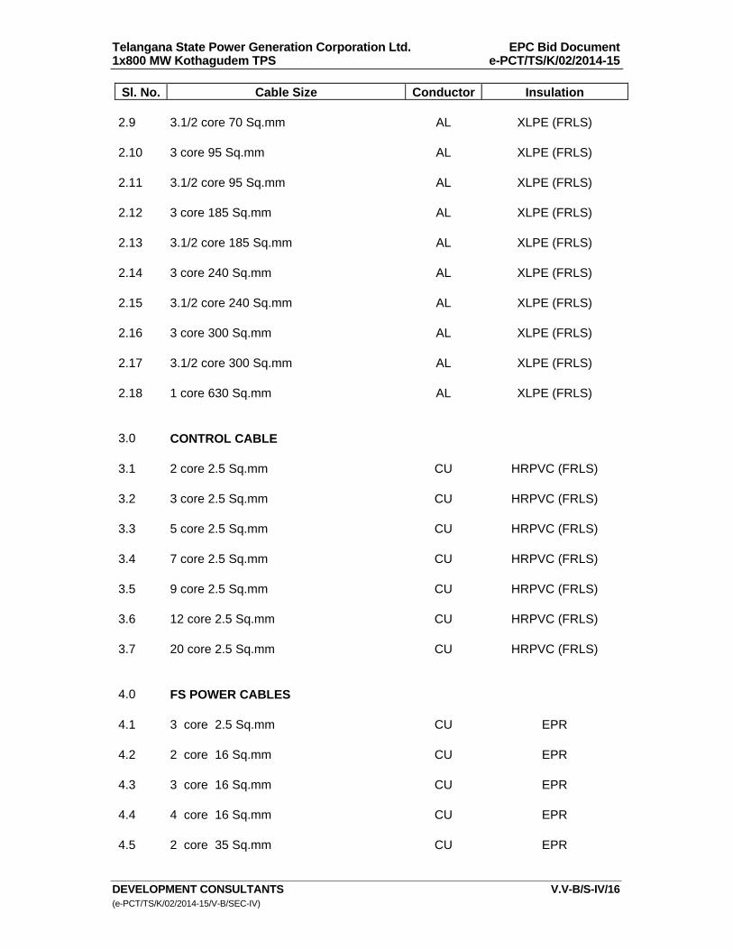
Telangana State Power Generation Corporation Ltd. EPC Bid Document 1x800 MW Kothagudem TPS e-PCT/TS/K/02/2014-15
DEVELOPMENT CONSULTANTS V.V-B/S-IV/16 (e-PCT/TS/K/02/2014-15/V-B/SEC-IV)
Sl. No. Cable Size Conductor Insulation 2.9 3.1/2 core 70 Sq.mm AL XLPE (FRLS) 2.10 3 core 95 Sq.mm AL XLPE (FRLS) 2.11 3.1/2 core 95 Sq.mm AL XLPE (FRLS) 2.12 3 core 185 Sq.mm AL XLPE (FRLS) 2.13 3.1/2 core 185 Sq.mm AL XLPE (FRLS) 2.14 3 core 240 Sq.mm AL XLPE (FRLS) 2.15 3.1/2 core 240 Sq.mm AL XLPE (FRLS) 2.16 3 core 300 Sq.mm AL XLPE (FRLS) 2.17 3.1/2 core 300 Sq.mm AL XLPE (FRLS) 2.18 1 core 630 Sq.mm AL XLPE (FRLS) 3.0 CONTROL CABLE 3.1 2 core 2.5 Sq.mm CU HRPVC (FRLS) 3.2 3 core 2.5 Sq.mm CU HRPVC (FRLS) 3.3 5 core 2.5 Sq.mm CU HRPVC (FRLS) 3.4 7 core 2.5 Sq.mm CU HRPVC (FRLS) 3.5 9 core 2.5 Sq.mm CU HRPVC (FRLS) 3.6 12 core 2.5 Sq.mm CU HRPVC (FRLS) 3.7 20 core 2.5 Sq.mm CU HRPVC (FRLS) 4.0 FS POWER CABLES 4.1 3 core 2.5 Sq.mm CU EPR 4.2 2 core 16 Sq.mm CU EPR 4.3 3 core 16 Sq.mm CU EPR 4.4 4 core 16 Sq.mm CU EPR 4.5 2 core 35 Sq.mm CU EPR

Telangana State Power Generation Corporation Ltd. EPC Bid Document 1x800 MW Kothagudem TPS e-PCT/TS/K/02/2014-15
DEVELOPMENT CONSULTANTS V.V-B/S-IV/17 (e-PCT/TS/K/02/2014-15/V-B/SEC-IV)
Sl. No. Cable Size Conductor Insulation 4.6 3 core 35 Sq.mm CU EPR 4.7 4 core 35 Sq.mm CU EPR 4.8 3 core 95 Sq.mm CU EPR 4.9 3.1/2 core 95 Sq.mm CU EPR 5.0 FS CONTROL CABLE 5.1 2 core 2.5 Sq.mm CU EPR 5.2 3 core 2.5 Sq.mm CU EPR 5.3 5 core 2.5 Sq.mm CU EPR 5.4 7 core 2.5 Sq.mm CU EPR 5.5 9 core 2.5 Sq.mm CU EPR 5.6 12 core 2.5 Sq.mm CU EPR

Telangana State Power Generation Corporation Ltd EPC Bid Document 1x800 MW Kothagudem TPS e-PCT/TS/K/02/2014-15
DEVELOPMENT CONSULTANTS (e-PCT/TS/K/02/2014-15/V-B/SEC-IX)
VOLUME : V-B
SECTION-IX
TECHNICAL SPECIFICATION FOR
ERECTION - CABLING, GROUNDING AND LIGHTNING PROTECTION SYSTEM
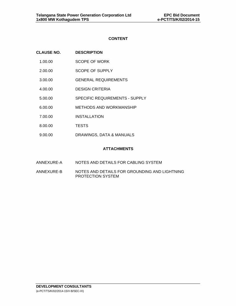
Telangana State Power Generation Corporation Ltd EPC Bid Document 1x800 MW Kothagudem TPS e-PCT/TS/K/02/2014-15
DEVELOPMENT CONSULTANTS (e-PCT/TS/K/02/2014-15/V-B/SEC-IX)
CONTENT CLAUSE NO. DESCRIPTION 1.00.00 SCOPE OF WORK 2.00.00 SCOPE OF SUPPLY 3.00.00 GENERAL REQUIREMENTS 4.00.00 DESIGN CRITERIA 5.00.00 SPECIFIC REQUIREMENTS - SUPPLY 6.00.00 METHODS AND WORKMANSHIP 7.00.00 INSTALLATION 8.00.00 TESTS 9.00.00 DRAWINGS, DATA & MANUALS
ATTACHMENTS ANNEXURE-A NOTES AND DETAILS FOR CABLING SYSTEM ANNEXURE-B NOTES AND DETAILS FOR GROUNDING AND LIGHTNING
PROTECTION SYSTEM

Telangana State Power Generation Corporation Ltd EPC Bid Document 1x800 MW Kothagudem TPS e-PCT/TS/K/02/2014-15
DEVELOPMENT CONSULTANTS V.V-B/S-IX/1 (e-PCT/TS/K/02/2014-15/V-B/SEC-IX)
SECTION-IX
TECHNICAL SPECIFICATION FOR
ERECTION - CABLING, GROUNDING AND LIGHTNING PROTECTION SYSTEM
1.00.00 SCOPE OF WORK 1.01.00 The scope of work covers complete and efficient design, supply, erection,
testing and commissioning of Plant lightning protection system, all cabling and electrical grounding works. The scope shall broadly cover, but not be limited to :
1. Main Power House Building 2. Boiler area, ESP stack 3. Transformer yard 4. All auxiliary buildings (including electrical rooms of respective
buildings) and structures as detailed in the Lead Specification. 5. Overhead interplant cable trestle and pipe cum cable trestle. 6. All electrical equipment as described in Volumes V-A & V-B. 7. 400kV Switchyard. 1.02.00 The scope of work shall also include all civil and structural works necessary
for successful installation and commercial operation of all electrical equipment to be erected under this specification.
2.00.00 SCOPE OF SUPPLY 2.01.00 The scope of supply shall include but not be limited to the followings 2.01.01 Timely procurement and transportation to site in properly packed condition of
all materials and miscellaneous items required to complete the erection work under this specification.
These materials and miscellaneous items shall include but not be limited to
the following : a) Galvanised steel pre-fabricated cable trays, coupler plates, nuts, bolts
& washers, reducers, covers, wall brackets, hanger clamps, straight run, elbows, bends, etc.
b) Galvanised steel rigid/flexible conduits and accessories, ferrules, lugs,
glands, terminal blocks, galvanised sheet steel junction boxes, cable fixing clamps, nuts & bolts, etc. as required.
c) Cable termination and jointing kits as necessary.
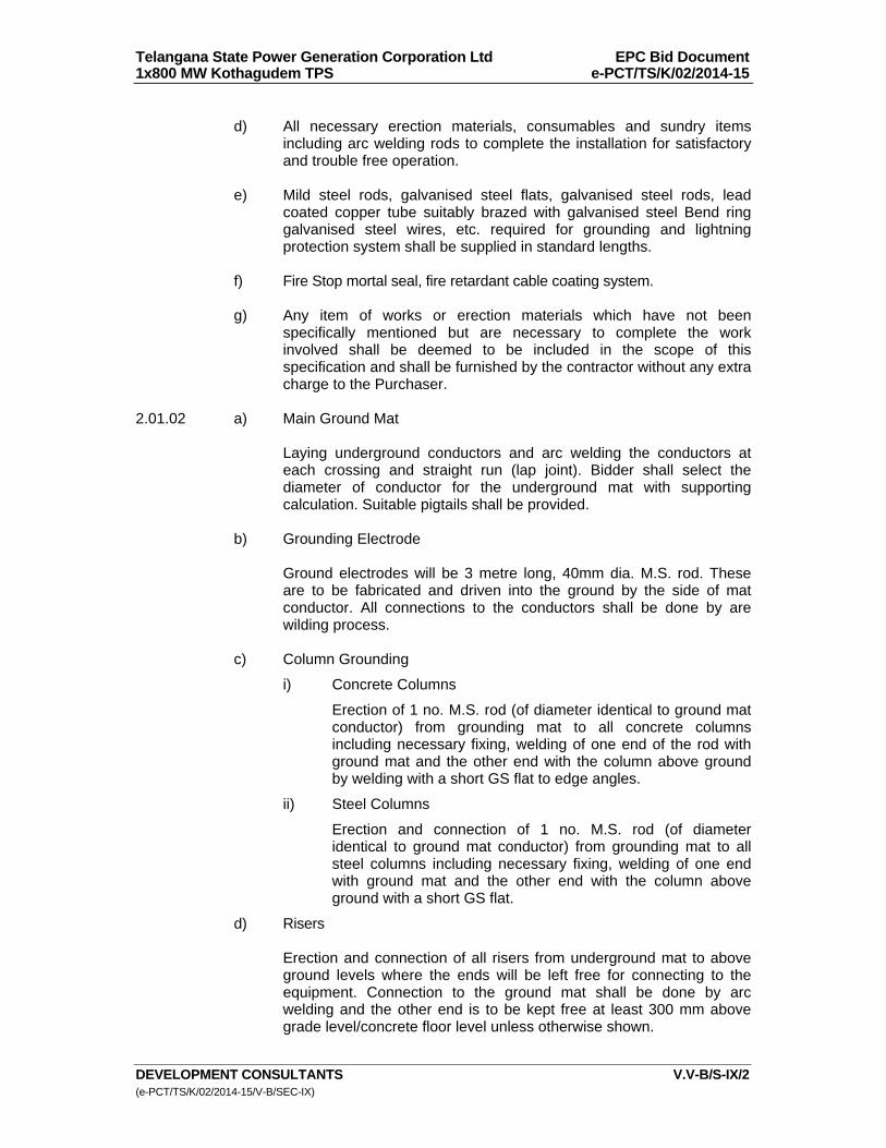
Telangana State Power Generation Corporation Ltd EPC Bid Document 1x800 MW Kothagudem TPS e-PCT/TS/K/02/2014-15
DEVELOPMENT CONSULTANTS V.V-B/S-IX/2 (e-PCT/TS/K/02/2014-15/V-B/SEC-IX)
d) All necessary erection materials, consumables and sundry items
including arc welding rods to complete the installation for satisfactory and trouble free operation.
e) Mild steel rods, galvanised steel flats, galvanised steel rods, lead
coated copper tube suitably brazed with galvanised steel Bend ring galvanised steel wires, etc. required for grounding and lightning protection system shall be supplied in standard lengths.
f) Fire Stop mortal seal, fire retardant cable coating system. g) Any item of works or erection materials which have not been
specifically mentioned but are necessary to complete the work involved shall be deemed to be included in the scope of this specification and shall be furnished by the contractor without any extra charge to the Purchaser.
2.01.02 a) Main Ground Mat Laying underground conductors and arc welding the conductors at
each crossing and straight run (lap joint). Bidder shall select the diameter of conductor for the underground mat with supporting calculation. Suitable pigtails shall be provided.
b) Grounding Electrode Ground electrodes will be 3 metre long, 40mm dia. M.S. rod. These
are to be fabricated and driven into the ground by the side of mat conductor. All connections to the conductors shall be done by are wilding process.
c) Column Grounding
i) Concrete Columns
Erection of 1 no. M.S. rod (of diameter identical to ground mat conductor) from grounding mat to all concrete columns including necessary fixing, welding of one end of the rod with ground mat and the other end with the column above ground by welding with a short GS flat to edge angles.
ii) Steel Columns
Erection and connection of 1 no. M.S. rod (of diameter identical to ground mat conductor) from grounding mat to all steel columns including necessary fixing, welding of one end with ground mat and the other end with the column above ground with a short GS flat.
d) Risers Erection and connection of all risers from underground mat to above
ground levels where the ends will be left free for connecting to the equipment. Connection to the ground mat shall be done by arc welding and the other end is to be kept free at least 300 mm above grade level/concrete floor level unless otherwise shown.
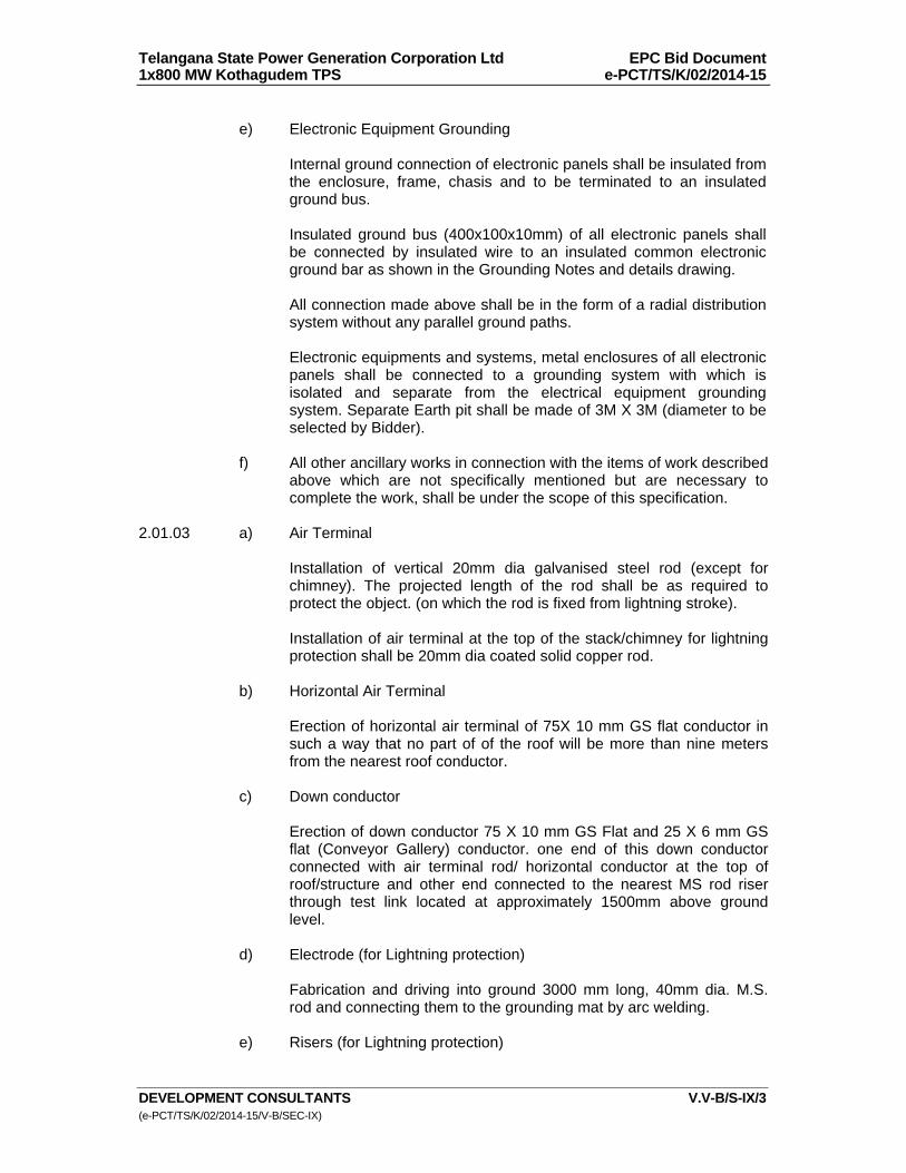
Telangana State Power Generation Corporation Ltd EPC Bid Document 1x800 MW Kothagudem TPS e-PCT/TS/K/02/2014-15
DEVELOPMENT CONSULTANTS V.V-B/S-IX/3 (e-PCT/TS/K/02/2014-15/V-B/SEC-IX)
e) Electronic Equipment Grounding
Internal ground connection of electronic panels shall be insulated from the enclosure, frame, chasis and to be terminated to an insulated ground bus.
Insulated ground bus (400x100x10mm) of all electronic panels shall
be connected by insulated wire to an insulated common electronic ground bar as shown in the Grounding Notes and details drawing.
All connection made above shall be in the form of a radial distribution
system without any parallel ground paths.
Electronic equipments and systems, metal enclosures of all electronic panels shall be connected to a grounding system with which is isolated and separate from the electrical equipment grounding system. Separate Earth pit shall be made of 3M X 3M (diameter to be selected by Bidder).
f) All other ancillary works in connection with the items of work described
above which are not specifically mentioned but are necessary to complete the work, shall be under the scope of this specification.
2.01.03 a) Air Terminal
Installation of vertical 20mm dia galvanised steel rod (except for chimney). The projected length of the rod shall be as required to protect the object. (on which the rod is fixed from lightning stroke).
Installation of air terminal at the top of the stack/chimney for lightning protection shall be 20mm dia coated solid copper rod.
b) Horizontal Air Terminal
Erection of horizontal air terminal of 75X 10 mm GS flat conductor in such a way that no part of of the roof will be more than nine meters from the nearest roof conductor.
c) Down conductor
Erection of down conductor 75 X 10 mm GS Flat and 25 X 6 mm GS flat (Conveyor Gallery) conductor. one end of this down conductor connected with air terminal rod/ horizontal conductor at the top of roof/structure and other end connected to the nearest MS rod riser through test link located at approximately 1500mm above ground level.
d) Electrode (for Lightning protection) Fabrication and driving into ground 3000 mm long, 40mm dia. M.S.
rod and connecting them to the grounding mat by arc welding.
e) Risers (for Lightning protection)
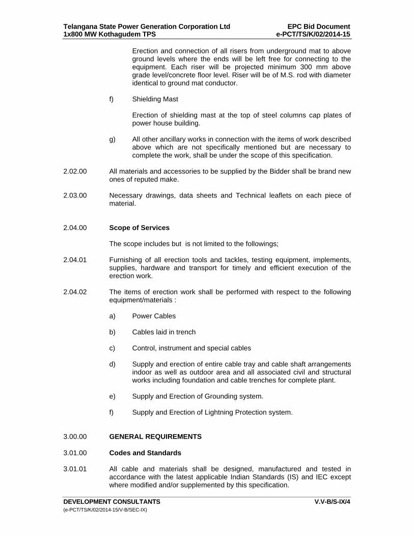
Telangana State Power Generation Corporation Ltd EPC Bid Document 1x800 MW Kothagudem TPS e-PCT/TS/K/02/2014-15
DEVELOPMENT CONSULTANTS V.V-B/S-IX/4 (e-PCT/TS/K/02/2014-15/V-B/SEC-IX)
Erection and connection of all risers from underground mat to above ground levels where the ends will be left free for connecting to the equipment. Each riser will be projected minimum 300 mm above grade level/concrete floor level. Riser will be of M.S. rod with diameter identical to ground mat conductor.
f) Shielding Mast Erection of shielding mast at the top of steel columns cap plates of
power house building. g) All other ancillary works in connection with the items of work described
above which are not specifically mentioned but are necessary to complete the work, shall be under the scope of this specification.
2.02.00 All materials and accessories to be supplied by the Bidder shall be brand new
ones of reputed make. 2.03.00 Necessary drawings, data sheets and Technical leaflets on each piece of
material. 2.04.00 Scope of Services The scope includes but is not limited to the followings; 2.04.01 Furnishing of all erection tools and tackles, testing equipment, implements,
supplies, hardware and transport for timely and efficient execution of the erection work.
2.04.02 The items of erection work shall be performed with respect to the following
equipment/materials : a) Power Cables b) Cables laid in trench c) Control, instrument and special cables d) Supply and erection of entire cable tray and cable shaft arrangements
indoor as well as outdoor area and all associated civil and structural works including foundation and cable trenches for complete plant.
e) Supply and Erection of Grounding system. f) Supply and Erection of Lightning Protection system. 3.00.00 GENERAL REQUIREMENTS 3.01.00 Codes and Standards 3.01.01 All cable and materials shall be designed, manufactured and tested in
accordance with the latest applicable Indian Standards (IS) and IEC except where modified and/or supplemented by this specification.

Telangana State Power Generation Corporation Ltd EPC Bid Document 1x800 MW Kothagudem TPS e-PCT/TS/K/02/2014-15
DEVELOPMENT CONSULTANTS V.V-B/S-IX/5 (e-PCT/TS/K/02/2014-15/V-B/SEC-IX)
3.01.02 Cable and material conforming to any other standard, which ensures equal or
better quality, may be accepted. In such case, copies of the English version of the standard adopted shall be submitted along with the bid.
3.01.03 The electrical installation shall meet the requirements of Indian Electricity
Rules as amended up to date and relevant IS Code of Practice. In addition, other rules and regulations applicable to the work shall be followed.
3.02.00 Erection Schedule 3.02.01 The entire erection work shall be carried out in a phased manner. A schedule
of the work showing the sequence of erection shall be submitted by the tenderer for this purpose.
3.02.02 The erection schedule, as approved by the Owner's Engineer shall be strictly
followed by the contractor. If, for any reason beyond the control of the Contractor, the work is held-up then the Contractor shall bring it to the notice of the Owner's Engineer without any delay.
4.00.00 DESIGN CRITERIA 4.01.00 Grounding System 4.01.01 Grounding shall follow the relevant standards/codes amended till date as below:
a) Indian Electricity rules
b) National Electrical Code c) Code of Practice of Earthing IS 3043 d) Protection of building and allied structures against lightning IS 2309 e) IS- 732, IS 226, IS 2629, IS 2633 & IS 4759
f) IEEE -80-2000, IEEE-665
The station grounding system shall be an interconnected network of MS conductor and MS ground rods. The system shall be provided to protect plant personnel and equipment from the hazards, which can occur during power system faults and lightning strikes
4.01.02 The main objectives of grounding system are to : a) Provide safety to personnel from contact of dangerous potential
caused by ground fault. b) Ensure sufficient grounding current for effective relaying. c) Stabilize circuit potential with respect to ground.
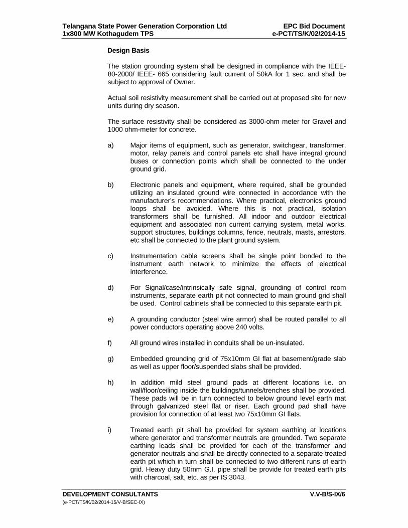
Telangana State Power Generation Corporation Ltd EPC Bid Document 1x800 MW Kothagudem TPS e-PCT/TS/K/02/2014-15
DEVELOPMENT CONSULTANTS V.V-B/S-IX/6 (e-PCT/TS/K/02/2014-15/V-B/SEC-IX)
Design Basis
The station grounding system shall be designed in compliance with the IEEE- 80-2000/ IEEE- 665 considering fault current of 50kA for 1 sec. and shall be subject to approval of Owner.
Actual soil resistivity measurement shall be carried out at proposed site for new units during dry season. The surface resistivity shall be considered as 3000-ohm meter for Gravel and 1000 ohm-meter for concrete.
a) Major items of equipment, such as generator, switchgear, transformer,
motor, relay panels and control panels etc shall have integral ground buses or connection points which shall be connected to the under ground grid.
b) Electronic panels and equipment, where required, shall be grounded
utilizing an insulated ground wire connected in accordance with the manufacturer's recommendations. Where practical, electronics ground loops shall be avoided. Where this is not practical, isolation transformers shall be furnished. All indoor and outdoor electrical equipment and associated non current carrying system, metal works, support structures, buildings columns, fence, neutrals, masts, arrestors, etc shall be connected to the plant ground system.
c) Instrumentation cable screens shall be single point bonded to the
instrument earth network to minimize the effects of electrical interference.
d) For Signal/case/intrinsically safe signal, grounding of control room
instruments, separate earth pit not connected to main ground grid shall be used. Control cabinets shall be connected to this separate earth pit.
e) A grounding conductor (steel wire armor) shall be routed parallel to all
power conductors operating above 240 volts. f) All ground wires installed in conduits shall be un-insulated. g) Embedded grounding grid of 75x10mm GI flat at basement/grade slab
as well as upper floor/suspended slabs shall be provided. h) In addition mild steel ground pads at different locations i.e. on
wall/floor/ceiling inside the buildings/tunnels/trenches shall be provided. These pads will be in turn connected to below ground level earth mat through galvanized steel flat or riser. Each ground pad shall have provision for connection of at least two 75x10mm GI flats.
i) Treated earth pit shall be provided for system earthing at locations
where generator and transformer neutrals are grounded. Two separate earthing leads shall be provided for each of the transformer and generator neutrals and shall be directly connected to a separate treated earth pit which in turn shall be connected to two different runs of earth grid. Heavy duty 50mm G.I. pipe shall be provide for treated earth pits with charcoal, salt, etc. as per IS:3043.
Telangana State Power Generation Corporation Ltd EPC Bid Document 1x800 MW Kothagudem TPS e-PCT/TS/K/02/2014-15
DEVELOPMENT CONSULTANTS V.V-B/S-IX/7 (e-PCT/TS/K/02/2014-15/V-B/SEC-IX)
j) Dedicated treated earth pit shall be provided for lightning protection
system. k) Clean earthing for instrumentation shall be provided with dedicated
earthing system and separate treated earth pits below the main control room, feed water pump house in turbine house etc.
l) Connection between the equipment earth lead and the grid conductor
shall be welded. For rust protection, the welds shall be treated with zinc chromate primer and coated with zinc rich paint.
4.01.03 In order to meet the above objectives, ground grid mesh will be provided for
the main plant complex, viz., switchyard, transformer yard adjacent to power house building, power house building and boiler area up to stack, auxiliary buildings, etc. The earth mats of main plant and BOP area will be interconnected by two or more connections.
All electrical equipment, non current carrying metal parts, structures, building
steel, lightning protection system, generator/transformer neutrals will be connected to this station ground grid.
The major aspects to be considered for grounding system design are given
below : 4.01.04 Ground Grid Conductor a) Ground grid conductor of mild steel rod shall be used. b) The minimum conductor section is determined on the basis of ground
fault current. This section is then increased by an allowance to account for the soil corrosion loss of 0.3 mm per year over the design life of 30 years.
4.01.05 Underground Grid a) The ground grid mesh is designed to keep the touch and step voltages
within safe limits as per recommendation of IEEE 80 & IEEE 665. b) The ground grid conductors will be buried in earth at a minimum depth
of 1000 mm. The length of ground conductors below earth will be sufficient to ensure a ground resistance less than 0.5 ohm.
c) The ground grid conductor will be so laid as to provide short and direct
connection to building steel and major electrical equipment. d) Ground rods shall be provided at the points where system
neutrals/lightning protections are connected to the ground grid.
e) All ground grid conductor connections will be welded type.
f) Main Plant ground grid shall be connected with the switchyard and other auxiliary building /area ground grid at least at two (2) points.
Telangana State Power Generation Corporation Ltd EPC Bid Document 1x800 MW Kothagudem TPS e-PCT/TS/K/02/2014-15
DEVELOPMENT CONSULTANTS V.V-B/S-IX/8 (e-PCT/TS/K/02/2014-15/V-B/SEC-IX)
g) For test pits, the Electrode will be 100 mm dia. Heavy duty C.I. pipe with perforations. Electrodes installed in test pits will have disconnecting facilities
4.01.06 Above Ground Connections a) Galvanised steel flats shall be used for all connections above earth. b) Inside building, ground conductors will be run for each floor supported
on building steel and/or cable trays. These ground conductors in turn will be connected to the station ground grid through riser (at least two) coming up along building columns/cable shafts.
c) Two separate and distinct ground connections will be provided for
each electrical equipment in compliance with I.E. Rules. d) All connections above ground will be welded type except connection
to equipment/structures which shall be bolted type. 4.01.07 Equipment Ground Lead Equipment ground connections will be sized to carry the available ground
fault current. Considerations shall also be given to mechanical ruggedness of the connections and to limit the number of sizes.
4.01.08 The minimum ground conductor sizes for various equipment and structures
are given in Annexure-B. 4.01.09 Entire erection of grounding work shall be carried out in such a way as to be
capable of withstanding the intended services of carrying full short circuit level currents to ground mat without any damage/deformation.
4.02.00 Lightning Protection System Lighting protection system design shall be as per IS:2309 4.02.01 The main purposes of lightning protection system are to : a) Provide protection to structures from lightning strokes. b) Provide a low resistance-conducting path to lightning discharge. 4.02.02 Lightning protection shall be provided for Power House building, auxiliary
building , chimney, cooling tower and other structures. 4.02.03 Lightning protection will also be provided for building/ structures where the
overall rise factor exceeds 10-6 as per IS:2309. 4.02.04 For metal structures which are electrically continuous down to the ground
level, no lightning protection is required except adequate grounding connections.
4.02.05 System Design
Telangana State Power Generation Corporation Ltd EPC Bid Document 1x800 MW Kothagudem TPS e-PCT/TS/K/02/2014-15
DEVELOPMENT CONSULTANTS V.V-B/S-IX/9 (e-PCT/TS/K/02/2014-15/V-B/SEC-IX)
a) Air termination network with down conductors and earthing electrodes will be provided on the basis of IS Code of Practice.
b) Horizontal air termination shall be so laid out that no part of the roof
will be more than 9 meters from the nearest conductor. c) Shielding angle for one vertical air termination shall be 45 degrees.
For more than one rod, shielding angle between the rods shall be taken as 60 Degrees.
d) Down conductors will run along the outer surfaces of the building and
shall have a test joint about 1500 mm above ground. e) An earth electrode will be provided at the connection point of the down
conductor with the station ground. f) Galvanised steel rods and flats will be generally used for air
termination and connections. All connections will be welded type. g) For air terminals of chimney, lead coated copper tube suitably brazed
with G.S. Band ring shall be provided. 4.03.00 Cabling System 4.03.01 Erection of cabling work shall be carried out in such a way as to provide a
reliable and assured electric power supply system to all station auxiliaries. 4.03.02 Cable routing will be done on unit basis as far as possible. 4.03.03 Erection of cabling work shall be executed keeping in view all necessities and
requirements of fire fighting codes for Generating Stations having an adverse industrial environment.
4.03.04 Suitable embedded steel inserts shall be provided on wall/floor/ ceiling
surfaces for welding of cable tray bracket in order to make the cable tray system withstand horizontal/vertical accelerations due to seismic forces for indoor trays and also wind load for outdoor trays such as on Boiler platforms in addition to normal tray cable loadings.
4.04.00 All erection work to be carried out under this specification shall conform to the
notes and details given in Annexure-A and drawings attached to this specification.
5.00.00 SPECIFIC REQUIREMENTS - SUPPLY 5.01.00 Equipment and Material 5.01.01 Equipment and material shall comply with description, rating, type and size as
detailed in this specification, drawings and annexures. 5.01.02 Equipment and materials furnished shall be complete and operative in all
details.
Telangana State Power Generation Corporation Ltd EPC Bid Document 1x800 MW Kothagudem TPS e-PCT/TS/K/02/2014-15
DEVELOPMENT CONSULTANTS V.V-B/S-IX/10 (e-PCT/TS/K/02/2014-15/V-B/SEC-IX)
5.01.03 All accessories, fittings, supports, hangers, anchor bolts etc. which form part of the equipment or which are necessary for safe and satisfactory installation and operation of the equipment shall be furnished.
5.01.04 All parts shall be made accurately to standard gauges so as to facilitate
replacement and repair. All corresponding parts of similar equipment shall be interchangeable.
5.02.00 Pre-fabricated Cable Trays 5.02.01 Cable trays shall be pre-fabricated ladder type sheet steel with hot dip
galvanising furnished in standard length of 2.5 metres. 5.02.02 Cable trays shall be of standard width specified in Annexure-A and drawings. 5.02.03 Cable trays shall be complete with all necessary hot dip galvanised sheet
steel accessories such as coupler plates, ground continuity connections and associated nuts, bolts, washers, hangers, clamps, etc. Also horizontal / vertical bends, horizontal / vertical Tee, Reducers, Horizontal cross-pieces, protective covers shall be supplied along with straight runs in order to take care of cable tray alignments in different routes.
5.02.04 All fittings like horizontal/ vertical elbow, horizontal crosspiece, reducer,
horizontal tee, etc. should be pre-fabricated. Each fitting shall be provided with two nos. hot dip galvanised side coupler plates & associated bolts, nuts and washers on each side.
5.02.05 Cable trays, fittings & accessories as well as elbows, reducers, tees, crosses,
etc. shall be fabricated out of 14 gauge (2 mm thick) hot rolled mild steel sheets.
5.02.06 Contractor shall supply 14 gauge (2 mm thick) perforated type hot rolled mild
steel sheet covers for vertical cable shafts up to a height of 2.5 metres from floor level. The perforated covers used for the vertical raceways may be of one or more pieces along the width of the raceway, depending on the width of the raceway and shall be bolted to the structural framework of the raceway.
5.02.07 The cable trays, fittings and accessories including all bolts, nuts, screws,
washers, etc. shall be hot dip galvanised after fabrication as per IS:2629. Galvanising shall be uniform, clear, smooth and free from acid spots. Should the galvanising of the samples be found defective, the entire batch of steel will have to be re-galvanised at Contractor's cost.
The amount of zinc deposited shall not be less than 610 gms per square
metre of surface area and in addition the thickness of the zinc deposit at any spot whatsoever, shall not be less than 75 microns. The Owner reserves the right to measure the thickness of zinc deposit by Elcometer or any other instrument and reject any component, which shows thickness of zinc at any location to be less than 75 microns.
5.02.08 The Contractor shall perform all tests necessary to ensure that the material
and workmanship conform to the relevant standards and that such tests are adequate to demonstrate that the equipment will comply with the requirement of this specification.

Telangana State Power Generation Corporation Ltd EPC Bid Document 1x800 MW Kothagudem TPS e-PCT/TS/K/02/2014-15
DEVELOPMENT CONSULTANTS V.V-B/S-IX/11 (e-PCT/TS/K/02/2014-15/V-B/SEC-IX)
The tolerance on dimensions shall be in accordance with appropriate Indian Standards. The extent of the tests to be performed by the contractor shall include but not be limited to the following:
Deflection Test A 2.5 metre straight section of each type of cable trays shall be simply
supported at the two ends. A uniformly distributed load of 100 Kg per metre will be applied along the length of the tray. The maximum deflection at mid span shall not exceed 7 mm.
5.02.09 For other details refer CABLING NOTES AND DETAILS annexed to this
specification. 5.03.00 Conduits and Accessories 5.03.01 Conduits shall be of rigid steel, hot-dip galvanised, furnished in standard
length of 5 metres, threaded at both ends. 5.03.02 Conduits diameter upto and including 25mm size shall be of 16 SWG and
conduits above 25 mm diameter shall be of 14 SWG. Minimum diameter of conduits shall be 20 mm.
5.03.03 Each piece of conduit shall be straight, free from blister and other defects,
internal surface shall be of smooth finish and covered with capped bushings at both ends.
5.03.04 The contractor shall provide and install all rigid steel conduits, mild steel
pipes, flexible conduits rigid PVC pipes, etc. complete with accessories such as tees, bends, adopters, locknuts, pull boxes, conduit plugs, caps, etc as required for the cabling work.
5.03.05 Steel conduits with interior coating of silicon epoxy ester for ease of
wire/cable pulling shall be seamed by welding and flo-coat metal conduit/hot-dip galvanised. These shall be supplied in standard length of 5M with minimum wall thickness as specified in IS:9537. In chemical handling areas, Battery Room, etc., the exterior surface shall be further coated with chromate and polymer for better resistance to corrosion. Conduits, fittings & accessories shall have ISI mark.
5.03.06 For sizes above 63 mm mild steel pipes with necessary fittings & accessories
shall be provided and installed by the contractor. Pipes shall be manufactured by electric welding process. These pipes shall be of heavy duty class as per IS:1239 and shall have ISI mark. Pipes shall be supplied in lengths of approximately 5 metres. Pipes, fittings & accessories shall be hot dip galvanised both on inside and outside.
5.03.07 Flexible conduits shall comply with IS:3480. They shall be made with bright,
cold-rolled, annealed and electro-galvanised mild steel strips. Flexible conduits shall be used between embedded conduits/pipes and the motor terminals. Flexible conduits shall also be used between fixed conduit and any equipment terminal boxes where vibration is anticipated or equipment that require regular removal.
Telangana State Power Generation Corporation Ltd EPC Bid Document 1x800 MW Kothagudem TPS e-PCT/TS/K/02/2014-15
DEVELOPMENT CONSULTANTS V.V-B/S-IX/12 (e-PCT/TS/K/02/2014-15/V-B/SEC-IX)
5.03.08 Rigid PVC conduits conforming to IS:4985 shall generally be used for control & instrumentation cables in some areas where cable trays do not exist and where the runs are straight ones generally the PVC pipes with special Bell Mouthing shall be of 110 mm,160 mm & 200 mm outside diameter and shall be suitable for working pressure of 6 kg/sq. cm. The length of each pipe shall be 5 to 6 metres. Necessary fittings & accessories as may be required for the installation shall also be provided.
5.04.00 Junction Boxes 5.04.01 Glass Fibre Reinforced Junction Boxes a) No. of Ways:12 / 24 / 36 / 48 with 20% spare terminals. b) Design Junction boxes shall be Glass Fibre Reinforced with saturated
polyester informing to standards like DIN 16911 type 803 / 16913 type 834, 5 self extinguishing in accordance with ASTM D 635 / UL 94 VO.
c) Enclosure Junction boxes for use in outdoor or damp locations shall be sturdy
construction. Temperature resistance between – 10 to 100 deg C. Impact resistance shall be greater than 7 Nm, (EN 50 014). Protective insulation shall be in line with VDE 0100, dielectric strength shall be greater than 10 KV/ mm, halogen free toxicity, the enclosure and door cover shall be painted and electro-statically powder coated (preferably in RAL 7032). Earth connection (studs size shall be M6) shall be provided on the cover as well as door.
d) Doors With integrated viewing window of 3 mm resistant plexi – glass or
equivalent. The doors shall have industrial heavy – duty hinges. The doors shall be easily but firmly lockable with quick release fastener.
e) Protection Class : Protection Category shall be IP 66 to EN60 529. There shall be
guaranteed perfect seal to meet Protection class IP 66 providing sealing arrangement like highly elastic foamed in special type seal like polyurethane / chloroprene. The sealing rubber shall not have aging effect and shall retain its sealing characteristics for more than 20 yrs. Bidder shall indicate this in data sheet. The rubber seal should be pasted at its place with pasting technology for like more than 20 yrs ( double sealing arrangement is preferred).
f) Mounting clamps and accessories : Suitable for mounting on walls, columns and structure. Brackets, bolts,
nuts, screws, glands and lugs required for erection shall be of brass. The accessories like mounting plants etc. of steel shall be powdered coated. The support rails for terminal box shall be zinc coated.
Telangana State Power Generation Corporation Ltd EPC Bid Document 1x800 MW Kothagudem TPS e-PCT/TS/K/02/2014-15
DEVELOPMENT CONSULTANTS V.V-B/S-IX/13 (e-PCT/TS/K/02/2014-15/V-B/SEC-IX)
g) General : i) JBs shall have small canopy at the top. ii) There shall be rainwater collection arrangement from top and
side of the outer ages to ensure that any leakage in to the junction box shall be avoided and it shall fall outside.
iii) Cable entry shall be from bottom side only. iv) Ensure gland plate sealing perfect. It shall be of the same
quality and arrangement as that of door to cover arrangement. 5.04.02 Steel Junction Boxes :
a) No. of Ways:12 / 24 / 36 / 48 with 20% spare terminals. b) Design : Junction boxes shall be designed in accordance with NEC, article 370,
paragraph 18, 20 or equivalent standards. c) Enclosure : Junction boxes for use in outdoor or damp locations shall be sturdy
steel construction. The enclosure and door cover shall be surface finished clean, degreased, phosphated, deep coated primed (preferably in RAL 7044) and electro-statically powder coated (preferably in RAL 7032). Earth connection (studs size shall be M 6) shall be provided on the cover as well as door. The sheath steel thickness shall be minimum 2 mm.
d) Doors : The doors shall be hinged and lockable. The doors shall have
industrial heavy – duty hinges. The doors shall be easily but firmly lockable with quick release fastener.
e) Protection Class : Protection Category shall be IP 66 to EN60 529 / 10.91 complies with
NEMA 4. There shall be guaranteed perfect seal to meet Protection class IP 66 providing sealing arrangement like highly elastic foamed in special type seal like polyurethane. There shall be an arrangement like multifold protection channel for additional stability and prevention of ingress of dust and water when the enclosure is open.
The sealing rubber shall not have aging effect and shall retain its
sealing characteristics for more than 20 yrs. Bidder shall indicate this in data sheet. The rubber seal should be pasted at its place with pasting technology for like more than 20 yrs (double sealing arrangement is preferred).
Telangana State Power Generation Corporation Ltd EPC Bid Document 1x800 MW Kothagudem TPS e-PCT/TS/K/02/2014-15
DEVELOPMENT CONSULTANTS V.V-B/S-IX/14 (e-PCT/TS/K/02/2014-15/V-B/SEC-IX)
f) Mounting clamps and accessories: Suitable for mounting on walls, columns and structure. Brackets, bolts,
nuts, screws, glands and lugs required 5.04.03 The junction boxes shall have the following indelible marking
Circuit nos. on top by white-stenciled paint at site.
Circuit nos. with ferrules (inside) as per approved drawing.
Danger sign in case of 415V circuit. 5.05.00 Terminals 5.05.01 Multiway terminal blocks of approved type, complete with screws, nuts;
washers and marking strips shall be furnished for connection of incoming/outgoing wires.
5.05.02 Each control cable terminal shall be suitable for connection of 2 nos. 2.5
sq.mm. stranded copper conductors without any damage to the conductor or looseness of conductors.
5.06.00 Cable Termination & Jointing Kits 5.06.01 The Bidder shall supply cable termination and jointing kits in requisite quantity
for H.T. Power Cables, L.T. Power, Control Cables, Instrumentation Cables, etc. along with all accessories & consumables required for making termination and joints complete. All the materials and components of the termination/joints shall be suitable and compatible with the type of cables for which the terminals/ joints are intended.
5.06.02 The straight through joints of H.T. and L.T. cables shall be of Tapex/
Paracast/Parawrap type/approved make.. The end termination kits for H.T. cables shall be of Raychem/3M/Elastimold type/approved make. Cable joint or end terminations on Electrical equipment shall be suitable for Indoor & Outdoor use, as the case may be.
5.06.03 Glands and lugs required for termination of H.T., L.T. and instrumentation
cables shall be supplied by the Contractor in required quantity. 5.07.00 Cable Glands Cable glands shall be tinned brass gland, double compression type complete
with necessary armour clamp and tapered washer, etc. Cable glands shall match with the sizes of different HT/LT/Control cables.
5.08.00 Cable Lugs Cable lugs shall be suitable for termination of different cross-sections of
H.T./L.T./Control/Instrumentation cables and shall be of following types : i) Aluminium tubular terminal end for solderless crimping to aluminium
conductors.
Telangana State Power Generation Corporation Ltd EPC Bid Document 1x800 MW Kothagudem TPS e-PCT/TS/K/02/2014-15
DEVELOPMENT CONSULTANTS V.V-B/S-IX/15 (e-PCT/TS/K/02/2014-15/V-B/SEC-IX)
ii) Copper tubular terminal end for solderless crimping to copper conductors.
Solderless crimping of terminals shall be done by using corrosion
inhibiting compound. The cable lugs shall suit the type of terminals provided on the equipment. Lugs for control/instrumentation cables shall be PVC insulated/sleeved type.
iii) Cable lugs for control cable termination shall be insulated. These lugs
shall be pin type/flat type/ring type/U type to suit the terminals provided in the panels.
5.09.00 Consumables and Hardware 5.09.01 The Contractor shall furnish all erection materials, hardware and
consumables required to complete the installation. 5.09.02 The materials shall include but not be limited to the following : Consumables : Welding rods & gas, oil and grease, cleaning fluids,
paints, electrical tape, soldering materials, etc. Hardware : Bolts, nuts, washers, screws, brackets, supports,
clamps, hangers, saddles, cleats, sills, shims, etc. 5.09.03 Supply of cement, sand, stone, etc. required for the execution of the contract shall be the responsibility of the Contractor.
5.10.00 Testing Equipment 5.10.01 The major testing equipment that are required to be provided by the
Contractor are listed below : a) Insulation Tests
i) Power operated Meggar - 1 KV and 10 KV grade
b) Hand driven earth Resistance Meggar, range 0-1/3/30 ohms. c) High potential testing set - roller mounted type d) Tong testers of suitable ranges. e) Contact resistance measuring set for micro-ohms. f) Torque wrench of various sizes. g) Multimeters, test lamp, field telephone with buzzer set, different
gauges, etc. 5.10.02 The list of equipment is indicative only. Any other test equipments required
will be arranged by the Contractor. 6.00.00 METHODS AND WORKMANSHIP

Telangana State Power Generation Corporation Ltd EPC Bid Document 1x800 MW Kothagudem TPS e-PCT/TS/K/02/2014-15
DEVELOPMENT CONSULTANTS V.V-B/S-IX/16 (e-PCT/TS/K/02/2014-15/V-B/SEC-IX)
6.01.00 All work shall be installed in a first class, neat workmanlike manner by
mechanics/ electricians skilled in the trade involved. 6.02.00 The erection work shall be supervised by competent supervisors holding
relevant supervisory license from the Government. 6.03.00 All details on installation shall be electrically and mechanically correct. 6.04.00 The installation shall be carried out in such a manner as to preserve access
to other equipment installed. 7.00.00 INSTALLATION 7.01.01 Installation work shall be carried out in accordance with good engineering
practices and also as per manufacturer's instructions/ recommendations where the same are available.
7.01.02 Equipment shall be installed in a neat workmanlike manner so that it is level,
plumb, square and properly aligned and oriented. 7.01.03 Cable installation work shall mean erection of cable trays/racks, supports,
hangers, junction boxes, conduits, laying of cables either in ground or on trays inside trenches tunnels/overhead trays in conduits, etc. dressing and clamping, jointing and termination inclusive of supply of necessary jointing/ termination kits, lugs, glands, ferrules, tapes, etc. and other accessories, grounding of cable armour. In case of direct laying in ground, all excavation work, necessary back-filling, supply of bricks and protective concrete slabs, removal of excess earth shall be part of the installation work.
7.01.04 Grounding installation work shall mean erection, jointing/ brazing/ welding,
connection and painting, testing of ground conductors including supply of necessary steel/copper.
7.01.05 Lightning protection system installation work shall mean erection, jointing,
welding, connection and painting, testing of air termination network, down conductors, shielding masts, connection to ground grid, electrodes, risers, horizontal conductors, etc. of lightning protection system.
7.02.00 Cable Trays 7.02.01 Pre-fabricated cable trays and accessories shall be assembled & erected at
site. Adequate spaces will be provided to facilitate installation of cable system and to allow routine inspection and modification after installation.
7.02.02 Cable trays either inside concrete trenches or inside buildings and racks
inside cable shafts shall be aligned and leveled properly. All tray runs shall be installed parallel to the trench/building walls and floors except otherwise noted in the approved drawings.
7.02.03 As far as practicable, cable trays shall be supported from one side only in
order to facilitate installation and maintenance of cables from the other side.

Telangana State Power Generation Corporation Ltd EPC Bid Document 1x800 MW Kothagudem TPS e-PCT/TS/K/02/2014-15
DEVELOPMENT CONSULTANTS V.V-B/S-IX/17 (e-PCT/TS/K/02/2014-15/V-B/SEC-IX)
7.02.04 The cable trays shall be supported in general at a span of exceeding 1.25 metres horizontally and 1.0 metre vertically.
7.02.05 Sufficient spacing not less than 250 mm shall be provided between trays and
maintained to permit adequate access, for installing & maintaining the cables. 7.02.06 Complete cable tray support structure after installation shall be inspected/
tested for welding strength, straightness, accuracy, use of proper sizes and compliance to drawings.
7.02.07 Complete cable tray and accessory installation work shall be inspected/tested
for proper alignment, leveling, use of proper accessories, high quality workmanship, etc.
7.02.08 The Contractor shall remove the RCC/steel trench covers whenever required
and shall again place the same in their positions after the erection work in the particular area is completed or when further work is not likely to be taken up for some time.
7.02.09 Whenever any pipe/conduit/cable tray emerges out or enters into a building
care should be taken to ensure that no water enters into the building. 7.02.10 Cable trays in areas subject to excessive coal dust, oil spillage, mechanical
damage or accessible to personal contact shall be provided with raised sheet metal tray covers, installed on upper tray in horizontal run and front in vertical run.
7.02.11 Cable trays/racks shall be so arranged that they do not obstruct or impair
clearances of passage way. 7.02.12 Cable tray/conduit system will be so designed as to accommodate maximum
pulling tension and minimum bending radius of cable. 7.02.13 Cable tray/conduit system will be constructed to prevent drainage of water
into equipment or building. 7.02.14 Cable tray/conduit system shall be electrically continuous and grounded. 7.02.15 Different voltage grade cables will be laid in separate trays when trays are run
in tier formation. Power cables will normally be on top trays and control/instrumentation cable on bottom trays.
7.03.00 Cable and Conduits 7.03.01 The Contractor shall install, terminate and connect up all cable and conduits
as per drawings and cable schedules. 7.03.02 The drawings shall be strictly followed except where obvious interference
occurs. In such cases, the routing shall be changed as directed and/or approved by the Engineer.
7.03.03 Approximate lengths of cable and conduit runs will be shown by the
contractor in the cable schedule for guidance only. Before commencement of work the Contractor shall take actual measurements and prepare his own cable-cutting schedule to reduce wastage to a minimum.
Telangana State Power Generation Corporation Ltd EPC Bid Document 1x800 MW Kothagudem TPS e-PCT/TS/K/02/2014-15
DEVELOPMENT CONSULTANTS V.V-B/S-IX/18 (e-PCT/TS/K/02/2014-15/V-B/SEC-IX)
7.03.04 The Contractor shall also maintain and submit when requested, a record of
cable insulation value when drawn from store, after laying, before and after termination/jointing.
7.03.05 Where direct heat radiation exists, heat isolating barriers, shall be adopted for
cabling system. 7.03.06 Cabling/wiring in offices, laboratories, control rooms etc. shall be taken
through concealed G.I. or rigid PVC pipes as directed by the owner's Engineer.
7.03.07 At certain places where hazardous fumes/gasses may cause fire to the
cables, cable trenches after installation of cables shall be sand filled. 7.04.00 Conduit and Accessories 7.04.01 Conduit/pipes shall be used only in short lengths in certain areas where
required and/or as directed by the Engineer. 7.04.02 The Contractor shall furnish all conduits complete with accessories as
required. 7.04.03 Conduits shall be flexible type in general. However, rigid type steel conduit if
required shall also be supplied by the Contractor. 7.04.04 Except for inside an enclosure wherever the cable enters or leaves the
conduit, the conduit end shall be sealed by suitable sealing compound, having fire withstand capability.
7.04.05 The entire metallic conduit system, when embedded or exposed shall be
electrically continuous and grounded. 7.04.06 Where it is possible for water or other liquids to enter conduits, sloping of
conduit runs and drainage of flow points shall be considered. 7.04.07 Pull boxes will be installed between termination points where required to
facilitate cable pulling, but at a maximum interval of 30 meters. 7.04.08 Conduits shall be firmly fastened within 900 mm of each junction box/pull
box/cabinet/fitting, etc. Conduits shall be supported at least every 2000 mm. 7.05.00 Cables : Storage and Handling 7.05.01 Cable drums shall be stored on hard and well-drained surface so that they
may not sink. In no case shall the drum be stored on the flat, i.e., with flange horizontal.
7.05.02 Rolling of drums shall be avoided as far as practicable, for short distance, the
drums may be rolled provided they are rolled slowly and in proper direction as marked on the drum.
7.05.03 In absence of any indication, the drums may be rolled in the same direction
as it was rolled during taking up the cable.
Telangana State Power Generation Corporation Ltd EPC Bid Document 1x800 MW Kothagudem TPS e-PCT/TS/K/02/2014-15
DEVELOPMENT CONSULTANTS V.V-B/S-IX/19 (e-PCT/TS/K/02/2014-15/V-B/SEC-IX)
7.05.04 For unreeling the cable, the drum shall be mounted on jacks or on cable wheel. The spindle shall be strong enough to carry the weight without bending.
7.05.05 The drum shall be rolled on the spindle slowly so that the cable should come
out over the drum and not below the drum. 7.05.06 While laying cable, cable rollers shall be used at an interval of 2000 mm. The
cables shall be pushed over the roller by a gang of people positioned in between rollers over a suitable distance. Care shall be taken so that kinks and twists or any mechanical damage does not occur in cables. Only approved cable pulling grips or other devices shall be used. Cables shall not be dragged on ground or along structure while laying out from cable drums.
7.05.07 Cable shall not be pulled from the end without having intermediate pushing
arrangement. Bending radius of the cable during installation shall not be less than what is specified by the manufacturer.
7.05.08 Empty cable drums shall be returned to the Owner. 7.06.00 Cable Laying 7.06.01 Cables will generally be laid on ladder type prefabricated cable trays, cable
rack, overhead supported from building steel/structures or cable bridge/cable trestle as per approved drawing. For outdoor area cable rack shall be used in Pipe Bridge for outdoor area cable interconnection. Cables shall be run in concrete trenches in transformer yard and switchyard only and in those electrical rooms at ground level, which are without any spreader room below. Cables buried directly in ground are not acceptable except for street lighting cable.
In indoor pumps, mechanical equipment areas overhead cable trays shall
generally be used. A.C. and D.C. circuit will not be run in same cable. Further, separately fused
circuit will run in separate cables. Cables for redundant equipment system shall be run in separate trays, as far as possible.
7.06.02 Cables laid on trays and risers shall be neatly dressed and clamped with
self-locking type fire resistant nylon ties at an interval of 750 mm. for horizontal and vertical runs, in case of both power, control and instrumentation cables.
7.06.03 All single core power cables for 3 Ph. AC circuits shall be laid in trefoil
formation and suitably clamped with self-locking type fire resistant nylon ties at an interval of 750 mm.
7.06.04 All H.T. multicore power cables and L.T. multicore power cables with
cross-sectional area including & above 95 sq.mm shall be clamped individually by self-locking type fire resistant nylon ties.
7.06.05 L.T. power cables of cross sectional area less than 95 sq. mm. and all control
and Instrumentation cables shall be clamped in bunches with self-locking type fire resistant nylon ties. The number of cable in one bunch shall not exceed eight (8).
Telangana State Power Generation Corporation Ltd EPC Bid Document 1x800 MW Kothagudem TPS e-PCT/TS/K/02/2014-15
DEVELOPMENT CONSULTANTS V.V-B/S-IX/20 (e-PCT/TS/K/02/2014-15/V-B/SEC-IX)
7.06.06 Prior to laying of cables inside the indoor and outdoor trenches, the contractor
shall properly clean the trenches. 7.06.07 For underground crossing of railways, road, etc. additional protection shall be
provided in form of hume pipe or concrete encased rigid steel conduits (duct bank.
7.06.08 After completion of installation and prior to connection, all power cables shall
be subjected to a high potential test. 7.07.00 Cable Tags & Markers 7.07.01 Each cable and conduit run shall be tagged with numbers that appear in the
cable and conduit schedules. Cables and conduits shall be tagged at their entrance, bends, every 30.0M and exit from any equipment, junction box. When a cable/conduit passes through a wall, tags shall be fitted on both sides of the wall.
7.07.02 The tags shall be of aluminium with the number punched on it and securely
attached to the cable by not less than two turns of 16 SWG G.I. wire. For single core cable the wire shall be of non-magnetic material.
7.07.03 The location of cable joints, if any, shall be clearly indicated with cable marker
with an additional inscription 'cable-joint'. 7.07.04 The Contractor shall furnish and install all tags and markers stated above. 7.08.00 Cable Termination and Connection 7.08.01 The termination and connection of cables shall be done strictly in accordance
with manufacturer's instruction, drawings and/or as directed by the Engineer. 7.08.02 The work shall include all clamping, fitting, fixing, soldering, tapping,
compound filling, cable jointing, crimping, shorting and grounding as required for the complete job. All equipment required for all such operations shall be of Contractor's procurement.
7.08.03 Furnishing of all consumable materials such as soldering material, electrical
tape, sealing material as well as cable jointing kits shall be included in the offer.
7.08.04 Cable joint kits for all cables shall be supplied by Contractor under this
specification. Responsibility for proper termination shall lie on the contractor. Guarantee for termination shall also have to be given by Contractor.
7.08.05 The equipment will be generally provided with blank bottom plates for
cable/conduit entry and cable end box for power cables. 7.08.06 The Contractor shall perform all drilling, cutting on the blank plate and any
minor modification work required to complete the job.

Telangana State Power Generation Corporation Ltd EPC Bid Document 1x800 MW Kothagudem TPS e-PCT/TS/K/02/2014-15
DEVELOPMENT CONSULTANTS V.V-B/S-IX/21 (e-PCT/TS/K/02/2014-15/V-B/SEC-IX)
7.08.07 If the cable end box or terminal enclosure provided on the equipment is found unsuitable and requires major modification, the same shall be carried out by the contractor.
7.08.08 Control/instrumentation cable cores entering control panel/ switchgear/ MCC,
etc. shall be neatly bunched and served with PVC perforated tape to keep it in position at the terminal block.
7.08.09 The Contractor shall put ferrules on all control cable cores in all junction
boxes and at all terminations. The ferrules shall carry terminal numbers as per drawings. All ferrules shall be coloured, plastic & interlocked type.
7.08.10 Spare cores shall be similarly ferruled, crimped with lug and taped on the
ends. Spare cores shall be ferruled with individual cable number. 7.08.11 Termination and connection shall be carried out in such a manner as to avoid
strain on the terminals. 7.08.12 All cable entry Points shall be properly sealed and made vermin and dust
proof. Unusual opening, if any, shall be effectively closed. Sealing work shall be carried out with approved sealing compound having fire withstand capability for at least three hours.
7.09.00 Termi-point Connection a) The conductor (solid or stranded) is forced against the contact area of
the 2.4 x 0.8 mm or 1.6 x 0.8 mm connection pin by means of a tin-coated bronze clip, which maintains a constant pressure. In the Maxitermi-point method, 2.4 x 0.8 mm pins is used without exception.
b) The conductor is "shot" onto the pin together with the clip. The
resulting friction causes both the wire and the contact area of the pin to be cleaned and any oxide layers to be penetrated.
c) Apart from this the wire and the clip are deformed in such a way that a
gas-tight connection with very good electrical and mechanical properties is established.
d) A special manually or pneumatically driven gun is required. Up to 3
adjacent connections can be "shot" onto one pin. In most cases only one clip at the base of the pin is attached. The sections above usually remain vacant. Any part of a connection pin may be reused several times after removal of the existing clip connection. Contact areas below existing connections that have become vacant can be reused by pushing the connections above the vacant space downwards, so that the new connection can be "shot" on above the top connection. The single jumper wires need not be specially prepared as the end insulation is stripped within the tool.
e) This connection method requires special insulation of the wires. The
diameter of solid conductors is 0.8 mm the cross-section of stranded conductors 0.5 Sq.mm.
f) The conductor is deformed greatly when attached and is to be
shortened by 3 mm when disconnected and reused.

Telangana State Power Generation Corporation Ltd EPC Bid Document 1x800 MW Kothagudem TPS e-PCT/TS/K/02/2014-15
DEVELOPMENT CONSULTANTS V.V-B/S-IX/22 (e-PCT/TS/K/02/2014-15/V-B/SEC-IX)
g) Strips and special tools for termi-point connection shall be supplied by
the Contractor. 7.10.00 Cable Joints 7.10.01 Cable shall be installed without joints as far as practicable. 7.10.02 If however jointing becomes necessary, it shall be made only by qualified
cable jointer and strictly in accordance with manufacturer's recommendation. 7.11.00 Grounding 7.11.01 The Contractor shall carryout the interconnection among various peripheral
earthing grids/mats, steel structures, lightning protection system as well as grounding of all electrical equipment, etc. The grounding work shall be carried out as per provisions of I.E. rules Indian standards and enclosed grounding and lightning protection notes and details.
7.11.02 The grounding shall be done by conductors of adequate sizes (size shall be
selected by the bidder with supporting calculation) and the same shall be connected to the risers of main ground mat.
7.11.03 For fabricated cable trays, a separate ground conductor (50x6 mm G.S. flat)
shall run along the entire length of each route of cable tray being suitably clamped on the cable tray. Individual cable trays of each section shall be connected to above ground conductor through 50x6 mm G.S. flat to maintain continuity of ground path.
7.11.04 All ground conductor connections shall be made by electric arc welding/
brazing unless otherwise specified. Ground connections shall be made from nearest available station ground grid risers. The rods/connection shall be coated with cold galvanizing /weather resistance anti corrosive paints.
7.11.05 All ground conductors shall be painted black for easy identification. 7.11.06 Equipment ground connections, after being checked and tested by the
Engineer, shall be coated with anti-corrosive paint. 7.11.07 Whether specifically shown or not, all conduits, trays, cable armour and cable
end box, electrical equipment such as motors, switchboards, panels, cabinets, junction boxes, lockout switches, fittings, fixtures, etc. shall be effectively grounded.
7.11.08 If there is no provision to ground the L.T. transformer neutral at transformer
end, to make an effectively earthed 415V system the neutral bus of all 415V distribution boards shall be connected to ground grid at two different and distinct points.
7.11.09 The underground mat will be made of mild steel rods laid underground in
length and breadth of the area at a depth of minimum 1 metre below grade level. All crossings and straight run shall be arc welded for good electrical continuity. Ground conductors, when crossing underground trenches, directly laid underground pipe and equipment foundation, if any, shall be at least 300
Telangana State Power Generation Corporation Ltd EPC Bid Document 1x800 MW Kothagudem TPS e-PCT/TS/K/02/2014-15
DEVELOPMENT CONSULTANTS V.V-B/S-IX/23 (e-PCT/TS/K/02/2014-15/V-B/SEC-IX)
mm below the bottom elevation of such trenches/pipes as shown in the relevant drawing.
The Contractor will plan and organise works to lay the grounding mat in the
same sequence in which the building and equipment foundation is being done.
7.12.00 Painting 7.12.01 The Contractor shall paint steel fabrications at site with two (2) coats of red
oxide primer. Finish paint shall be as per TSGENCO standard practice which will be informed to Bidder during detail engineering. Also refer to clause no. 1.16.00 of Section-I, Volume V-A.
7.13.00 Galvanising 7.13.01 The galvanising shall be uniform, clean, smooth, continuous and free from
acid spots. Should the galvanising of the samples be found defective, the entire batch of steel has to be regalvanised, at Contractor's cost. The amount of zinc deposit shall not be less than 610 grams per square metre of surface area and in addition, the thickness of the zinc deposit at any spot whatsoever shall not be less than 75 microns. The Owner reserves the right to measure the thickness of zinc deposit by Elkometer or any other instrument and reject any component which shows thickness of zinc at any location less than 75 microns.
7.14.00 Excavation and Back Filling 7.14.01 The Contractor shall perform all excavation and backfilling as required for
buried cable and ground connections. 7.14.02 Excavation shall be performed up to the required depth. Such sheeting and
shoring shall be done as may be necessary for protection of the work. 7.14.03 The Contractor shall make use of his own arrangements for pumping out any
water that may be accumulated in the excavation. 7.14.04 All excavation shall be backfilled to the original level with good consolidation. 7.15.00 Steel Fabrication 7.15.01 All racks, trays, supports, hangers & brackets wherever necessary shall be
fabricated by the Contractor. 7.15.02 Steel for fabrication shall be straightened and cleaned of rust and grease. All
fabrication shall be free of sharp edge and burns so as not to cause any damage to personnel or cables.
7.16.00 Cleaning up of Work Site 7.16.01 The Contractor shall, from time to time, remove all rubbish resulting from
execution of his work. No materials shall be stored or placed on passage or drive ways.
Telangana State Power Generation Corporation Ltd EPC Bid Document 1x800 MW Kothagudem TPS e-PCT/TS/K/02/2014-15
DEVELOPMENT CONSULTANTS V.V-B/S-IX/24 (e-PCT/TS/K/02/2014-15/V-B/SEC-IX)
7.16.02 Upon completion of work, the Contractor shall remove all rubbish, tools, scaffoldings, temporary structures and surplus materials etc. to leave the premises clean and fit for use.
8.00.00 TESTS 8.01.00 Shop Tests 8.01.01 All equipment shall be completely assembled, wired, adjusted and routine
tested as per relevant Indian Standards at manufacturer's works. 8.01.02 Tests on panels/junction boxes shall include :
a) Wiring continuity tests.
b) High voltage and insulation tests.
c) Operational tests. 8.02.00 Site Tests 8.02.01 Contractor shall thoroughly test and meggar all cables, wires and equipment
to prove the same are free from ground and short circuit. 8.02.02 If any ground or short circuit is found, the fault shall be rectified or the cable
and/or equipment replaced. 8.02.03 All power cables after installation and prior to connections shall be subjected
to High Potential tests. Also the insulation resistance values shall be measured both before and after Hipot test for comparison. The leakage current shall also be measured during the Hipot test at site.
Cable cores shall be tested for :
a) Physical damage
b) Continuity
c) Correctness of connections as per relevant wiring diagram
d) Insulation resistance to earth
e) Insulation resistance between conductors
f) Proper earth connections of cable glands, cable boxes, cable armour, screens etc.
8.02.04 All equipment shall be demonstrated to operate in accordance with the
requirements of this specification. 8.03.00 Test Certificates 8.03.01 Type test certificate on any equipment, if so desired by the Owner, shall be
furnished. Otherwise the equipment shall have to be type tested, free of charge, to prove the design.
9.00.00 DRAWINGS, DATA & MANUALS

Telangana State Power Generation Corporation Ltd EPC Bid Document 1x800 MW Kothagudem TPS e-PCT/TS/K/02/2014-15
DEVELOPMENT CONSULTANTS V.V-B/S-IX/25 (e-PCT/TS/K/02/2014-15/V-B/SEC-IX)
9.01.00 To be submitted with the Bid 9.01.01 Make, type and catalogue number of different electrical items and
accessories along with technical leaflets, data sheets etc. 9.01.02 Typical General arrangement drawings showing constructional features, fixing
arrangement of pre-fabricated cable trays. 9.01.03 Bill of Materials for cable trays and accessories, conduits & accessories. 9.01.04 Layout of Grounding system & lightning protection system showing
connection and other details along with backup design calculations and detailed write up.
9.01.05 Bill of materials for grounding and lightning protection system. 9.01.06 Drawing showing details of equipment grounding. 9.02.00 To be submitted after Award of Contract 9.02.01 Make, type & catalogue number of cable termination kits, joints &
accessories. 9.02.02 Detail dimensional drawings showing constructional features, grounding,
fixing arrangement etc. 9.02.03 Bill of Materials for Pre-fabricated cable tray and accessories, Conduits &
accessories. 9.02.04 Dimensional G.A. drawings and data sheets for different equipment and items
supplied under this specification. 9.02.05 Layout drawing of Grounding system and Lightning protection system
showing connection details along with backup design calculation and detailed write up.
9.02.06 Bill of material for grounding system and lightning protection system. 9.02.07 Drawing showing details of equipment grounding system. 9.02.08 Cable schedule and inter-connection charts for the entire power plant.
Telangana State Power Generation Corporation Ltd EPC Bid Document 1x800 MW Kothagudem TPS e-PCT/TS/K/02/2014-15
DEVELOPMENT CONSULTANTS V.V-B/S-IX/26 (e-PCT/TS/K/02/2014-15/V-B/SEC-IX)
ANNEXURE-A
NOTES AND DETAILS FOR
CABLING SYSTEM 1.00.00 GENERAL 1.01.00 These notes and details shall be read and construed in conjunction with
Specification and the drawings meant for cable tray details and supporting arrangements in Trench, Racks etc., enclosed elsewhere. In case of conflict between these notes and drawings, the latter shall prevail.
1.02.00 The Cabling System installation work shall conform to the requirements of the
latest revisions of the following standards/codes a) Indian Electricity Rules, 1956, with up to date amendment. b) I.S. Code of Practice. 2.00.00 CABLE ROUTING/LAYING 2.01.01 Cables shall generally be laid on ladder type cable trays either in trenches or
overhead supported from building steel/structures except in some cases cables may have to be laid underground and for short runs in conduits for protection or crossing.
2.01.02 For interplant connections, the cables may be directly buried or routed
through an overhead cable bridge or cable trenches/tunnels selection being dependent on site constraints.
2.01.03 For underground crossing of railways, roads etc. hume pipes shall be used
and shall be laid at a depth of minimum 1000 mm such that cables shall not be damaged.
2.01.04 In boiler area, trench will be avoided as far as practicable. The cable racks
shall be supported from Boiler structure in vertical configuration with suitable cover to avoid deposition of coal dust as far as practicable.
2.01.05 Different voltage grade cables shall be laid in separate trays when trays are
arranged in tiers. Power cables shall be on top trays and Control/Instrumentation cables on bottom trays, and it is recommended that trays for cables of different voltage levels be stacked in descending order with higher voltage level above.
2.01.06 Cables for redundant equipment/system shall be run in separate trays in
separate route. 2.01.07 Cables from two different services viz. supply from station board and supply
from unit board shall be fully segregated to prevent simultaneous damage due to fire in one of the services.

Telangana State Power Generation Corporation Ltd EPC Bid Document 1x800 MW Kothagudem TPS e-PCT/TS/K/02/2014-15
DEVELOPMENT CONSULTANTS V.V-B/S-IX/27 (e-PCT/TS/K/02/2014-15/V-B/SEC-IX)
2.01.08 Low level signal cables and other special Instrumentation and Control cables shall run in separate trays. In general, a minimum of 1500 mm clearance shall be maintained between these cables and noise generating equipment (large motors, generators, transformers etc.).
2.01.09 The cable spreaders of each unit shall be compartmentalized by provision of
fire proof partition wall. 2.01.10 The floor of the cable spreader rooms will have to be made water proof so
that water does not percolate to lower levels in the event of fire fighting operations. Adequate arrangement for efficient drainage of water shall be provided. The cable raceways should also be suitably curved to avoid water entry through this place.
2.01.11 Cabling System for CHP
a) Cable in CHP area shall be generally routed through the conveyor gallery / tunnel, TP / Buildings by separate supporting structures, Pipe cum cable bridge. The cables shall be laid in vertical trays.
b) In substation & switchgear room cable shall be laid in horizontal cable
trays installed in cable vault room.
c) Cables may also be routed through hume pipes to enter into various buildings from the nearest overhead cable trestle/substation building.
d) Overhead cable trestle/cable bridge shall be provided for routing of
cables between the following Sub-Stations/buildings:
i) Main CHP Substation Building and Crusher House.
ii) Main CHP Substation Building and Pump House (if required).
iii) Wagon Tippler Substation Building and TP.
The bottom of the steel supporting structure shall be generally at 2.5m above the grade level except for road crossing and rail crossing where the same shall be 6.5 m and 9.0m respectively above grade level.
e) Cable trays shall be laid out horizontally in sub-station buildings and
pump-house whereas the same shall be installed vertically inside transfer points, crusher house, conveyor gallery/tunnel etc. The cable trestle shall have a minimum 600mm clear walk way all along its routes and shall have maintenance platforms as required.
f) Separate trays shall be provided for H.T., L.T., control and
instrumentation cables. LT mutlicore Power cables shall be laid in single layer & touching formation and single core cable in trefoil formation shall be laid with a distance of four times the diameter of cable between trefoil centre lines and clamped at every two meter while control and instrumentation cables shall be laid in maximum of two layers formation. Single core HT power cables shall be laid on trefoil formation with a distance of four times the diameter of cable between trefoil centre lines and clamped at every two meter and Multi core power cables shall be laid in single layer & touching formation. Normally cable trays shall be designed with 70% fill-in criteria and
Telangana State Power Generation Corporation Ltd EPC Bid Document 1x800 MW Kothagudem TPS e-PCT/TS/K/02/2014-15
DEVELOPMENT CONSULTANTS V.V-B/S-IX/28 (e-PCT/TS/K/02/2014-15/V-B/SEC-IX)
conduit 40% fill-in criteria. Same cable laying philosophy shall be considered in other areas of the plant, if not specifically mentioned.
2.02.00 Cable Trays/Supports 2.02.01 Cable trays and covers shall be pre-fabricated type, constructed from
minimum 14 SWG sheet steel for trays and 16 SWG for covers and hot-dip galvanized after fabrication.
2.02.02 Cable tray supports shall be cantilever type for each installation. All supports
and hardware shall be hot-dip galvanised. 2.02.03 Standard cable tray width shall be 600 mm. However, trays with 450, and
300, 150 mm width may be used in some places considering the requirement and space restrictions. For instrumentation and control purpose, some perforated type cable trays of width 150 and/or 100mm may be used particularly in Boiler Platform area, and 600, 450, 300 mm perforated trays may be used depending on site requirement.
2.02.04 Cable trays shall be ladder type with 250 mm rung spacing, 100 mm depth
and rung width not less than 50 mm. Ladder type trays for power & control cables and perforated type for instrumentation cables shall be provided.
2.02.05 All weld for cable tray supports shall have a min. throat thickness of 6 mm. 2.02.06 Cable trays in areas subjected to excessive coal dust, or mechanical damage
will have hot-dip galvanised sheet metal tray cover installed on front tray in vertical run and inverted `V' type on upper tray in horizontal run.
Where covers are used on trays containing power cables, consideration
should be given to ventilation requirements. Areas where corrosive chemicals are likely to be handled, cable tray and covers shall be epoxy painted.
2.03.00 Conduits 2.03.01 Conduits shall be rigid steel coated type; minimum size of conduit shall be
limited to 19mm. 2.03.02 Steel conduits with interior coating of silicon epoxy ester for ease of wire
pulling shall be seamed by welding and flo-coat metal conduit/hot-dip galvanised. These shall be supplied in standard length of 5M with minimum wall thickness as specified in IS:9537 Part-II. In chemical handling areas, Battery room etc., the exterior surface shall be further coated with chromate and polymer for better resistance to corrosion.
2.03.03 Conduit runs shall be supported at an interval of 750 mm for vertical run and
1000 mm for horizontal run. 2.03.04 Conduits shall be sized so that conduit fill (ratio of total cable area to conduit
area) shall not exceed the following :
One Cable : 53%
Two Cable : 31%
Three Cables & Up : 40%
Telangana State Power Generation Corporation Ltd EPC Bid Document 1x800 MW Kothagudem TPS e-PCT/TS/K/02/2014-15
DEVELOPMENT CONSULTANTS V.V-B/S-IX/29 (e-PCT/TS/K/02/2014-15/V-B/SEC-IX)
2.03.05 Conduit runs shall be provided with necessary bends as required. 2.04.00 Installation 2.04.01 The Contractor shall install terminate and connect up all cables and conduits
with supporting arrangements as per drawings, cable schedules and interconnection chart/drawings.
2.04.02 The HV power cables of 11 KV/3.3 KV shall be laid in trays or racks as
follows :
a) In single layer only.
b) Multi core cables to be laid in touching with each other.
c) Single core cables to be laid in trefoil formation shall be laid with a distance of four times the diameter of cable between trefoil centerlines and clamp every two meter.
2.04.03 1100V grade power cables shall be laid in single layer in trays. 2.04.04 1100V grade mutlicore power cable shall be laid in touching formation to each
other. 2.04.05 1100V grade Single core cables to be laid in trefoil formation shall be laid with
a distance of four times the diameter of cable between trefoil centerlines and clamp every two meter.
2.04.05 Control and Instrumentation cables can be laid up to a maximum of two layers
in each tray. 2.04.06 Normally cable trays shall be designed with 70% fill-in criteria and conduit
40% fill-in criteria. Same cable laying philosophy shall be considered in other areas of the plant, if not specifically mentioned.
2.04.07 The trays shall be run with a vertical spacing of 300 mm for overhead cable
trays as well as inside cable trenches. A minimum of 225 mm clearance shall be provided between the top of tray and beams, cold piping, 500 mm clearance for hot piping/object to facilitate installation of cables in tray.
2.04.08 Adequate pull boxes shall be provided in conduit run to facilitate cable pulling
in long runs and also to ensure that there will be no more than 270 Deg. bends between pull points.
2.04.09 Cable tray/conduit system shall be installed to accommodate cable
manufacturer's recommended maximum pulling tension and minimum bending radius.
2.04.10 All openings in the floor and wall for cable access shall be sealed after
installation of the cable system with non-inflammable materials, as follows :
i) Fire stop/Penetration seal shall be installed in the cable spreaders and cable raceways.
ii) Similarly in the trenches fire stop/penetration seals shall be provided at suitable interval to avoid spread of fire.
Telangana State Power Generation Corporation Ltd EPC Bid Document 1x800 MW Kothagudem TPS e-PCT/TS/K/02/2014-15
DEVELOPMENT CONSULTANTS V.V-B/S-IX/30 (e-PCT/TS/K/02/2014-15/V-B/SEC-IX)
iii) For all H.T., L.T., Relay and Control panels, Control desk, instrumentation panels, battery charger, D.C. Dist. boards and other miscellaneous panels, fire-stops should be provided below base plate.
2.04.11 All floor/wall openings for cable entry to the electrical equipment and
accessories shall be sealed with non-inflammable materials, after completion of cable installation. Thickness of such materials shall be equal to the thickness of floor/wall unless specified otherwise.
2.04.12 The portion of galvanised steel, which, if required, undergoes any welding at
site shall be coated with two (2) coats of cold galvanising anti-corrosive paint after welding.
2.04.13 Refer Clause No. 3.00.00 below for details of fire-proof sealing and fire
protection coating. 2.05.00 Identification 2.05.01 The complete cabling system shall be properly identified. Methods for
identification of cabling system shall be furnished to the successful EPC Contractor shall strictly adhere to the said methods.
2.05.02 Each cable and conduit run shall be tagged with numbers that appear in the
cable and conduit schedule. 2.05.03 Location of cables laid directly underground shall be clearly indicated with
cable marker made of galvanised iron plate, projected above ground level. 2.05.04 Cable tags shall be provided on all cables at each end (just before entering
the equipment enclosure), on both sides of a wall or floor crossing, on each duct/conduit entry, at each bend and at every thirty (30) metres in cable tray/trench runs. Cable tags shall also be provided inside the switchgear, MCC, control & relay panels etc. wherever required for cable identification, such as where a number of cables enter together through a gland plate.
3.00.00 FIRE-PROOF SEALING / FIRE PROTECTION COATING SYSTEM 3.01.00 The Fire proof sealing / fire stop system / fire protection coating system is
required to prevent spreading of fire from one placed to other place (or one zone to other zone) through the openings in wall / floor, cables laid in trays / racks and openings below Electrical Switchgear / MCC / Distribution boards / Cabinets / Panels, etc. The fire proof sealing system shall conform to the latest edition including amendments of BS-476.
3.02.00 Scope of Work 3.02.01 The scope of work includes but is not limited to the following supply and
services: i) Fire Stops in wall / floors. ii) Fire stops below switchgear / MCC / Switchboards, junction boxes /
panels / cabinets, etc. which are floor mounted type. iii) Fire retardant coating to be applied for installed cables.

Telangana State Power Generation Corporation Ltd EPC Bid Document 1x800 MW Kothagudem TPS e-PCT/TS/K/02/2014-15
DEVELOPMENT CONSULTANTS V.V-B/S-IX/31 (e-PCT/TS/K/02/2014-15/V-B/SEC-IX)
iv) Minor civil / structural works for installation of the entire work. v) All necessary erection materials, consumables and sundry items to
complete the entire work for satisfactory and trouble free operation. vi) Any special tools & tackles. vii) Conducting the type test of fire proof sealing system in presence of
Owner's engineers. viii) All relevant Drawings, Data sheets and instruction manuals.
ix) Fire proof barrier walls. x) Fire proof doors.
3.03.00 Design Criteria 3.03.01 Fire Proof Sealing System The material / components used for fire-proof sealing system shall be
provided to meet the following requirements: i) Life expectancy should not be less than 30 years from the date of
installation. ii) Free from shrinkage or cracking or asbestos in composition and
should achieve smoke and gas tightness during fire and should be modifiable.
iii) Not to generate toxic gas and harms to the personnel handling the
system. iv) Prohibition of production of acid or alkali during gas generation. v) Will not produce suffocating / corrosive gas. vi) Repellant to paste / rodent / termite. vii) Expansion co-efficient - very low which is to be comparable with
masonry concrete. viii) Not soluble / reactive to acid, water, alkali. ix) Thermal conductivity - low. x) The material in contact with the cables in the fire-proof sealing system
shall be compatible with the material used for outer sheath of cables. xi) It should not have any adverse effect on the cables and should not
alter the current carrying capacity of the cables.

Telangana State Power Generation Corporation Ltd EPC Bid Document 1x800 MW Kothagudem TPS e-PCT/TS/K/02/2014-15
DEVELOPMENT CONSULTANTS V.V-B/S-IX/32 (e-PCT/TS/K/02/2014-15/V-B/SEC-IX)
xii) Retrofit in design to accommodate not less than 15% more addition of cables depending upon the size of cables, physically and chemically stable.
xiii) Capable of withstanding vibrations, drop-loads, foot traffics,
mechanical loads, etc. xiv) The F.P.S. system shall maintain its integrity and perform satisfactory
even after a. Remaining in water for a long time. b. Accelerated thermal aging. c. Sustaining vibrations. xv) The design and construction of F.P.S. system shall specifically take
into account the fact that under seismic disturbances, normal load, short circuit and fire conditions, the cable / cable trays will be subject to movement, expansion and oscillation and this shall not result in any damage or cause dislocation of the F.P.S. system or the material constituting the FPS System.
xvi) Non-hygroscopic, non-inflammable and shall not get affected over a
period of time due to humidity, moisture and ozone etc. and should not contain volatile solvents which may cause a fire hazard during application.
xvii) The fire rating shall not be less than one (1) hour and the system shall
be stable after applicable of water jet in the exposed side in order to extinguish fire.
3.03.02 Fire Protection coating to be applied on installed Cables: The cables shall be coated with fire protection material of 2 mm dry thickness
at the strategic locations as follows so as to limit the spread of fire: i) At fire stops in walls and floors on either side upto 500 mm length. ii) At fire stop below Electrical Switchgears/ MCCs/ Panels/ Cabins, etc.
on one side coating of 500 mm length, i.e., on the cable vault side / cable trench side.
iii) Length of 500 mm on all sides of the junction/crossing of cabling work
in open cable routes/ cable trench. iv) In fire risk areas and where specified at suitable intervals as decided
upon side conditions in open cable routes. v) Where necessary and specified at site intervals along cable routes in
cable trenches. vi) The coating shall be applied evenly on the cables only.
3.03.03 The fire protection coating shall have the following properties/composition:
Telangana State Power Generation Corporation Ltd EPC Bid Document 1x800 MW Kothagudem TPS e-PCT/TS/K/02/2014-15
DEVELOPMENT CONSULTANTS V.V-B/S-IX/33 (e-PCT/TS/K/02/2014-15/V-B/SEC-IX)
i) Asbestos free, non-volatile, not eatable by vermin, harmless and non-
irritant to skin of human. ii) Not affecting the current carrying capacity of the cables and the
properties of the installed cables. iii) It shall delay fire damage to cables and prevent flame spreading
meeting the requirement of IEEE - 383. iv) Coating material shall show no signs of cracking and peeling when the
coated cable is bent to the radius of minimum 12 times the diameter of the maximum size cable at 180°C.
v) The limiting oxygen index of the material shall not be less than 60% as
per ASTMD - 2863. vi) Life expectancy equivalent to the cable installations.
3.03.04 The various openings in the cable vault, vertical/ horizontal raceways of
cables penetrating walls/ floors and the bottom of Electrical switchgears/ MCCs/ distribution boards/ Cabinets/ Panels shall be provided with fire stop systems. Cables passing through the openings at various locations are laid on various tiers of the cable trays/ racks in the bunch formation. Bidder shall visit the site to assess and get acquainted with the type of cable installation where fire stops and fire protection coating are to be provided. In case steel frames are required to be fabricated and fixed in the openings, the fabrication of frame & fixing of the same shall have to be done by the Contractor without any extra cost. The necessary steel section for fabrication of frames shall be supplied by the Contractor without any extra cost. Any civil works required to be done in the openings shall be carried out by the Bidder. Bidder shall also include one set of tools & accessories required for addition or removal of cables after the seal is made.
3.04.00 The bidder shall quote the unit rates for provision of supply, installation,
testing & commissioning of the fire proof seals as given in the specification. Bidder is requested to quote the unit rates per square metre (i.e., area) basis of the area of the fire sealing material.
3.05.00 Type Test On Penetration Seals 3.05.01 The type tests for fire proof/ penetration seal for floor and wall opening/ fire
stop system for bottom of electrical switchgear/ MCC/ panel base are as under: i) Fire rating test. ii) Hose Stream test. iii) Accelerated aging test. iv) Fire rating test on the penetration seal system built out of accelerated
aged components followed by hose stream test. v) Temp. rise test for cable in the fire stop.
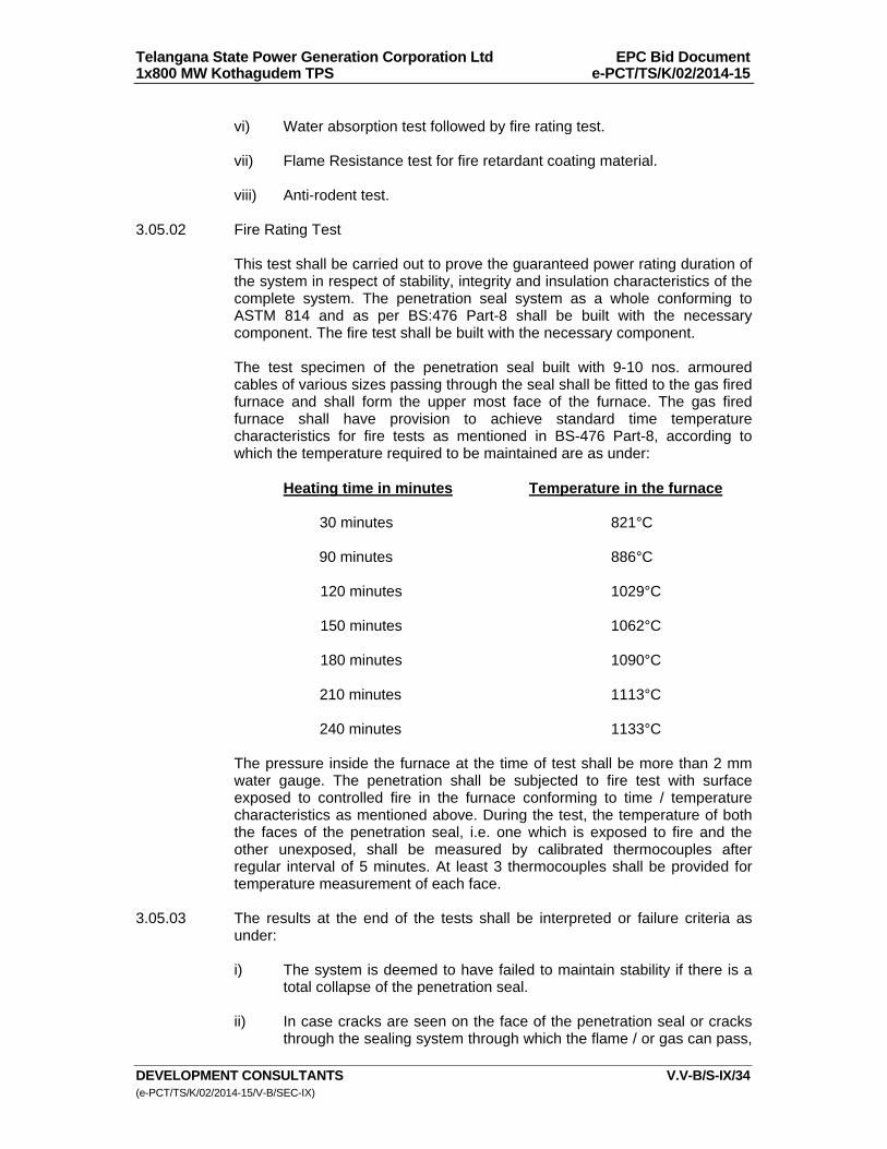
Telangana State Power Generation Corporation Ltd EPC Bid Document 1x800 MW Kothagudem TPS e-PCT/TS/K/02/2014-15
DEVELOPMENT CONSULTANTS V.V-B/S-IX/34 (e-PCT/TS/K/02/2014-15/V-B/SEC-IX)
vi) Water absorption test followed by fire rating test. vii) Flame Resistance test for fire retardant coating material. viii) Anti-rodent test.
3.05.02 Fire Rating Test This test shall be carried out to prove the guaranteed power rating duration of
the system in respect of stability, integrity and insulation characteristics of the complete system. The penetration seal system as a whole conforming to ASTM 814 and as per BS:476 Part-8 shall be built with the necessary component. The fire test shall be built with the necessary component.
The test specimen of the penetration seal built with 9-10 nos. armoured
cables of various sizes passing through the seal shall be fitted to the gas fired furnace and shall form the upper most face of the furnace. The gas fired furnace shall have provision to achieve standard time temperature characteristics for fire tests as mentioned in BS-476 Part-8, according to which the temperature required to be maintained are as under:
Heating time in minutes Temperature in the furnace
30 minutes 821°C 90 minutes 886°C 120 minutes 1029°C 150 minutes 1062°C 180 minutes 1090°C 210 minutes 1113°C 240 minutes 1133°C
The pressure inside the furnace at the time of test shall be more than 2 mm
water gauge. The penetration shall be subjected to fire test with surface exposed to controlled fire in the furnace conforming to time / temperature characteristics as mentioned above. During the test, the temperature of both the faces of the penetration seal, i.e. one which is exposed to fire and the other unexposed, shall be measured by calibrated thermocouples after regular interval of 5 minutes. At least 3 thermocouples shall be provided for temperature measurement of each face.
3.05.03 The results at the end of the tests shall be interpreted or failure criteria as
under:
i) The system is deemed to have failed to maintain stability if there is a total collapse of the penetration seal.
ii) In case cracks are seen on the face of the penetration seal or cracks
through the sealing system through which the flame / or gas can pass,
Telangana State Power Generation Corporation Ltd EPC Bid Document 1x800 MW Kothagudem TPS e-PCT/TS/K/02/2014-15
DEVELOPMENT CONSULTANTS V.V-B/S-IX/35 (e-PCT/TS/K/02/2014-15/V-B/SEC-IX)
the system is deemed to have failed to maintain integrity. The development of crack is characterized by ignition cotton wool held near the seal on the unexposed surface at a distance of about 30 mm from the aperture.
iii) In case the mean temperature rise of unexposed surface of seal
exceeds 140°C above the initial temperature or temperature of unexposed surface exceeds 180°C, the system shall deemed to have failed in respect of insulation characteristics.
iv) Temperature measurement on the unexposed side of the penetration
seal specimen shall be measured by the thermocouple on the surface of penetrating items and on fire stop material in accordance with ATME-814/UL 1479 at a distance of 25 mm from fire stop material and penetration items respectively.
3.05.04 Hose Stream Test: The intention of the hose stream test is to ascertain whether the penetration
seal assembly maintains its stability on application of water jet after withstanding the fire for 1 hour i.e. the guaranteed fire rating duration.
The test apparatus for this test shall be similar to the one used for carrying
out the fire rating test. The penetration seal system shall be subjected to the action of hose stream at the nozzle pressure of 30 psi supplied for a duration of 1.5 sec./ sq.ft. of exposed area. The hose stream shall be applied with 1.1/ 8" dia. nozzle at a perpendicular distance of approximately 17 ft. from the centre of the assembly on a line approximately 270 deg. from the line normal to the centre for the test assembly. The water stream shall be applied within 4 minutes and 30 seconds after completion of fire rating test.
However, this period shall not exceed more than 10 minutes in case of
practical difficulties experienced by testing stations. The application of water stream shall be maintained through out the test duration and shall traverse the complete fire stop system.
The fire stop assembly is deemed to have passed the hose stream test
successfully if no through projection of water is noticed on the unexposed surface of the seal. Further on completion of hose stream test, the appearance of the penetration seal system shall not alter substantially indicating thereby that the stability of the system ahs been maintained.'
3.05.05 Accelerated aging test The intention of accelerated aging test is to ascertain whether the artificial
aging of the systems and components thereof results into change in the mechanical properties or in the form. In order to simulate aging, artificial aging shall be resorted to.
For the purpose of subjecting the penetrations seal system components to
accelerated aging, the system / components shall be stored for 336 hours in air furnace where the temperature of the inside air, shall be maintained at 100 degree centigrade. However, for system components in pliable form, system component shall be stored for 448 hours in air furnace where temp. of air inside the furnace shall be maintained at 75°C. It is assumed that the
Telangana State Power Generation Corporation Ltd EPC Bid Document 1x800 MW Kothagudem TPS e-PCT/TS/K/02/2014-15
DEVELOPMENT CONSULTANTS V.V-B/S-IX/36 (e-PCT/TS/K/02/2014-15/V-B/SEC-IX)
changes occurring during test period would roughly correspond to the effect on aging over a period of about 40 years.
After completion of 336 hours / 448 hours, the mechanical properties such as
tensile strength element, elongation and hardness of the material (as may be applicable) shall be tested. These results shall be compared with corresponding values before subjecting to accelerated aging test.
The change in the form of system / components shall also be compared with
the form before the tests to ascertain whether the system / components thereof have undergone any permanent change.
In case the mechanical properties before and after the accelerated aging do
not indicate substantial change, the system shall be deemed to have passed the accelerated aging test. Similarly the variation in the form of the system components at the end of the test shall not indicate permanent deformation which is likely to affect the ceiling properties of the system.
3.05.06 Fire Rating test After Accelerated Aging: Intention to this test is to ascertain whether the penetration seal built out of
components already subjected to accelerated aging still passes the fire rating test for guaranteed fire rating duration.
The test apparatus for this test shall be similar to the one used for fire rating
test mentioned above. The assembly or the penetration seal shall be carried out with the components which were subjected to accelerated aging test based on the test procedure mentioned above. In case there is a problem of co-ordination with the test station, the prototype assembly may be subjected to aging in manufacturer's works under the conditions mentioned above and live fire test should be carried out at manufacturer's works in presence of Owner's representative.
In live fire test, the temperature of fire shall be of the order of 1000 deg.C at
the end of 3 hours. The test shall be carried out at atmospheric pressure. The interpretation of test results for failure shall be similar to those mentioned
under fire rating test/live fire test at (1) - (c) above. 3.05.07 Temperature rise test for cable in the fire stop: This test shall be carried out to ascertain whether due to inadequate
dissipation of heat at the location of fire stop, the temperature of cable conductor or outer sheath in contact with the fire stop, rises beyond the acceptable limits due to which whether any derating is required for cables.
Fire stop systems hall be erected with, at least 8-10 armoured cables,
specially power cables. While laying the cable through penetration seal, thermocouple shall be placed on the outer surface of cable in contact with the fire stop system. The location shall be selected where there exists possibility of inadequate dissipation of heat from cables to the atmosphere due to fire stop components. Two thermocouples shall also be located on the two surfaces of the fire penetration seal system. Similarly thermocouples shall also be placed on the other surface of cables where there exists contact of free air without any obstruction so as to enable adequate nature cooling.
Telangana State Power Generation Corporation Ltd EPC Bid Document 1x800 MW Kothagudem TPS e-PCT/TS/K/02/2014-15
DEVELOPMENT CONSULTANTS V.V-B/S-IX/37 (e-PCT/TS/K/02/2014-15/V-B/SEC-IX)
In case the temperature of outer surface of the cable in contact or inside the
fire stop system does not exceed 75 degree centigrade, it is inferred that no derating of cable is required for cable when used in conjunction with the particular fire stop system.
Test shall be repeated with reduced current till the temperature of cable outer
surface in contact with fire stop system is limited to 75°C. The rate of the current so guaranteed by the cable manufacturer as free air rating shall be the derating factor.
3.05.08 Water Absorption Test: The test specimen shall be immersed in fresh clean water at a temp. of 20°C.
The test specimen must be separated from the bottom and sides of the soak tank by at least 10 mm and it shall be covered by approximately 25 mm of water. At the end of the 24 hours soak period, the specimen shall be removed from the water and moped up with a damp cloth.
Fire rating test after water absorption is to ascertain whether the penetration
seal subjected to water absorption still passes the fire rating test for guaranteed fire rating duration.
The test apparatus for this test shall be similar to the one used for fire rating
test at Sr. No.1. In case there is problem of coordination with test stations, the prototype assembly may be subject to water absorption test at manufacturer's works followed by live fire test which should be carried out at manufacturer's works in presence of Owner's representative. In line fire test, the temp. of furnace shall be of the order of 1000°C at the end of 3 hours. The test shall be carried out at atmospheric pressure.
3.05.09 Flame Resistance Test for fire Retardant Coating Material: Sample strips shall be of ½ " wide, 12" long and approximately 70 mills in
thick (without any reinforcement). Each strip shall be held vertically (clamped at the top) in a natural gas burner flame, (blue cone of flame touching bottom edge of sample) for 10 minutes. The flame shall then be removed and observation shall be recorded. In case, any flaming of the samples should cease after the removal of gas burner. White charred length of the sample should not exceed 1 & ½”.
3.05.10 Anti-Rodent Test: Physical tests:
a) This test shall be carried out to ascertain the anti-rodent properties of the components of the Fire proof sealing system.
b) This test shall be carried out at approved test station performing
sealing system tests on pharmaceutical products. The complete Fire Proof sealing system shall be subjected to attack of inspect / vermin such as rate for about 20 days.
c) At the end of the test condition of the surface of Fire Proof sealing
system the test material shall be compared with the surface condition
Telangana State Power Generation Corporation Ltd EPC Bid Document 1x800 MW Kothagudem TPS e-PCT/TS/K/02/2014-15
DEVELOPMENT CONSULTANTS V.V-B/S-IX/38 (e-PCT/TS/K/02/2014-15/V-B/SEC-IX)
before commencement of the test. The fire stop shall be deemed to have passed this test in case no marks of growth are seen on the surface.
3.05.11 Test Certificates Certified copies of all tests carried out at works and at site shall be furnished
in requisite number of copies. Test reports shall be complete with all details and shall also contain limit
valves specified in the relevant standards, wherever applicable, to facilitate review of Test Report/ Certificates.
The fire proof sealing system shall be installed only after receipt of approval
of the test reports. 3.05.12 Testing Charges The bidder has to indicate that unit rates for conducting the type test
successfully alongwith the offer, which will be considered for evaluation of tender.
Telangana State Power Generation Corporation Ltd EPC Bid Document 1x800 MW Kothagudem TPS e-PCT/TS/K/02/2014-15
DEVELOPMENT CONSULTANTS V.V-B/S-IX/39 (e-PCT/TS/K/02/2014-15/V-B/SEC-IX)
ANNEXURE-B
NOTES & DETAILS FOR
GROUNDING & LIGHTNING PROTECTION SYSTEM 1.00.00 GENERAL 1.01.00 These notes and details shall be read and construed in conjunction with
grounding and lightning protection drawings and specification. In case of conflict between these notes and drawings, the latter shall prevail.
1.02.00 The grounding and lightning protection system installation work shall conform
to the requirements of the latest editions of the following standards/codes : a) Indian Electricity Rules, 1956. b) National Electrical Code, 1985. c) Code of Practice for Earthing (IS: 3043) d) Protection of Buildings and Allied Structures Against Lightning (IS:
2309) e) IEEE 80 2.00.00 GROUNDING SYSTEM 2.01.00 Main Grounding Mat/Grid 2.01.01 The main ground grid shall be buried in earth at a minimum depth of 1000
mm below finished grade level unless stated otherwise. The diameter of ground grid conductor shall be selected by EPC contractor with supporting calculation.
2.01.02 A minimum earth coverage of 300 mm shall be provided between the ground
grid conductor and the bottom of trenches, tunnels, underground pipes, foundations, railway tracks etc. The ground grid conductor shall be re-routed in case it fouls with equipment foundations.
2.01.03 In some cases, it may happen that the construction work of cable trench,
foundation and laying of underground pipes are being taken up after the grounding mat has been laid. It may be required to cut a portion of grounding conductor to avoid fouling with cable trench, equipment foundations, underground pipes etc. In this case, the ground conductor shall be properly rerouted and rejoined/reconnected with the main grounding mat during the construction/laying of above underground objects and good electrical continuity of grounding conductor shall be ensured.
2.01.04 Grounding conductors crossing the road may have to be laid at greater depth
to suit the site conditions.
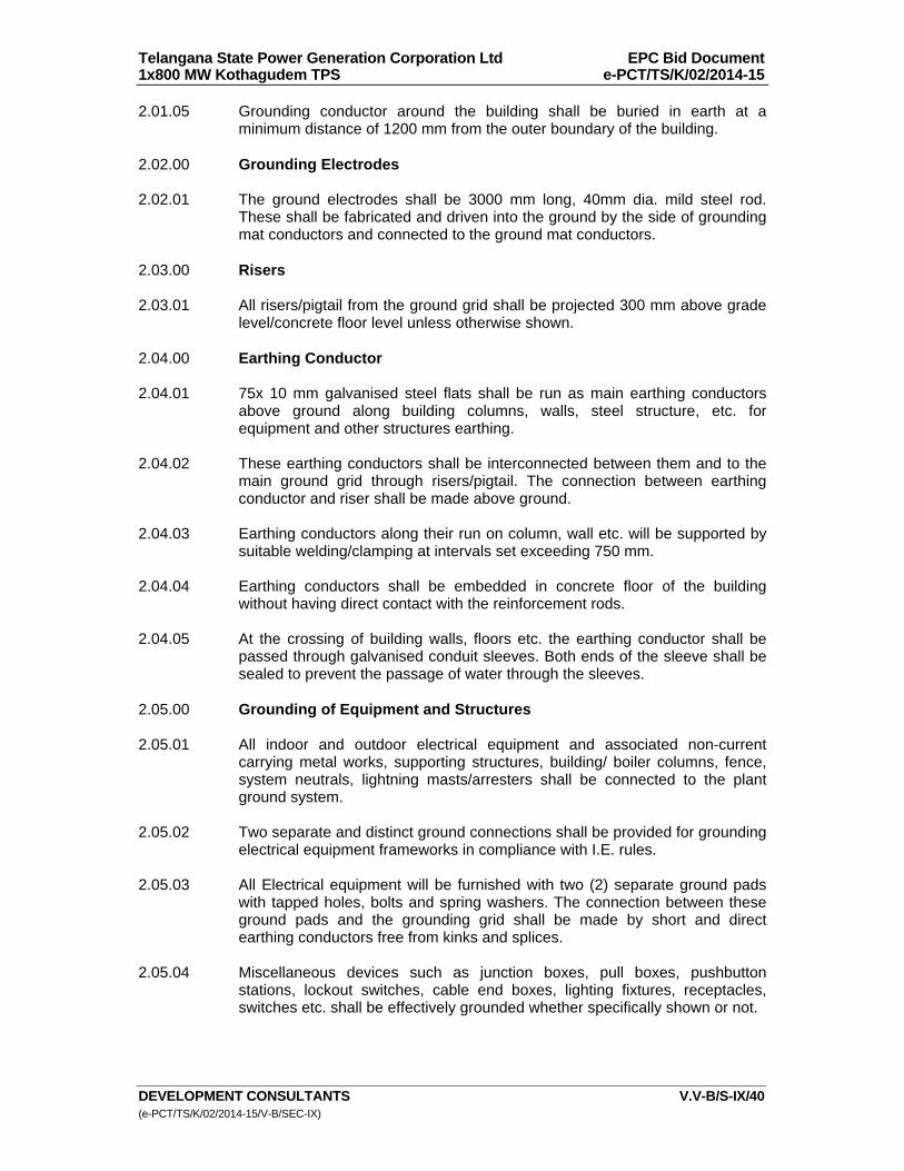
Telangana State Power Generation Corporation Ltd EPC Bid Document 1x800 MW Kothagudem TPS e-PCT/TS/K/02/2014-15
DEVELOPMENT CONSULTANTS V.V-B/S-IX/40 (e-PCT/TS/K/02/2014-15/V-B/SEC-IX)
2.01.05 Grounding conductor around the building shall be buried in earth at a minimum distance of 1200 mm from the outer boundary of the building.
2.02.00 Grounding Electrodes 2.02.01 The ground electrodes shall be 3000 mm long, 40mm dia. mild steel rod.
These shall be fabricated and driven into the ground by the side of grounding mat conductors and connected to the ground mat conductors.
2.03.00 Risers 2.03.01 All risers/pigtail from the ground grid shall be projected 300 mm above grade
level/concrete floor level unless otherwise shown. 2.04.00 Earthing Conductor 2.04.01 75x 10 mm galvanised steel flats shall be run as main earthing conductors
above ground along building columns, walls, steel structure, etc. for equipment and other structures earthing.
2.04.02 These earthing conductors shall be interconnected between them and to the
main ground grid through risers/pigtail. The connection between earthing conductor and riser shall be made above ground.
2.04.03 Earthing conductors along their run on column, wall etc. will be supported by
suitable welding/clamping at intervals set exceeding 750 mm. 2.04.04 Earthing conductors shall be embedded in concrete floor of the building
without having direct contact with the reinforcement rods. 2.04.05 At the crossing of building walls, floors etc. the earthing conductor shall be
passed through galvanised conduit sleeves. Both ends of the sleeve shall be sealed to prevent the passage of water through the sleeves.
2.05.00 Grounding of Equipment and Structures 2.05.01 All indoor and outdoor electrical equipment and associated non-current
carrying metal works, supporting structures, building/ boiler columns, fence, system neutrals, lightning masts/arresters shall be connected to the plant ground system.
2.05.02 Two separate and distinct ground connections shall be provided for grounding
electrical equipment frameworks in compliance with I.E. rules. 2.05.03 All Electrical equipment will be furnished with two (2) separate ground pads
with tapped holes, bolts and spring washers. The connection between these ground pads and the grounding grid shall be made by short and direct earthing conductors free from kinks and splices.
2.05.04 Miscellaneous devices such as junction boxes, pull boxes, pushbutton
stations, lockout switches, cable end boxes, lighting fixtures, receptacles, switches etc. shall be effectively grounded whether specifically shown or not.
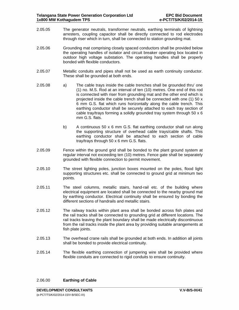
Telangana State Power Generation Corporation Ltd EPC Bid Document 1x800 MW Kothagudem TPS e-PCT/TS/K/02/2014-15
DEVELOPMENT CONSULTANTS V.V-B/S-IX/41 (e-PCT/TS/K/02/2014-15/V-B/SEC-IX)
2.05.05 The generator neutrals, transformer neutrals, earthing terminals of lightning arresters, coupling capacitor shall be directly connected to rod electrodes through riser which in turn, shall be connected to station grounding mat.
2.05.06 Grounding mat comprising closely spaced conductors shall be provided below
the operating handles of isolator and circuit breaker operating box located in outdoor high voltage substation. The operating handles shall be properly bonded with flexible conductors.
2.05.07 Metallic conduits and pipes shall not be used as earth continuity conductor.
These shall be grounded at both ends. 2.05.08 a) The cable trays inside the cable trenches shall be grounded thru' one
(1) no. M.S. Rod at an interval of ten (10) metres. One end of this rod is connected with riser from grounding mat and the other end which is projected inside the cable trench shall be connected with one (1) 50 x 6 mm G.S. flat which runs horizontally along the cable trench. This earthing conductor shall be securely attached to each tray section of cable tray/trays forming a solidly grounded tray system through 50 x 6 mm G.S. flats.
b) A continuous 50 x 6 mm G.S. flat earthing conductor shall run along
the supporting structure of overhead cable trays/cable shafts. This earthing conductor shall be attached to each section of cable tray/trays through 50 x 6 mm G.S. flats.
2.05.09 Fence within the ground grid shall be bonded to the plant ground system at
regular interval not exceeding ten (10) metres. Fence gate shall be separately grounded with flexible connection to permit movement.
2.05.10 The street lighting poles, junction boxes mounted on the poles, flood light
supporting structures etc. shall be connected to ground grid at minimum two points.
2.05.11 The steel columns, metallic stairs, hand-rail etc. of the building where
electrical equipment are located shall be connected to the nearby ground mat by earthing conductor. Electrical continuity shall be ensured by bonding the different sections of handrails and metallic stairs.
2.05.12 The railway tracks within plant area shall be bonded across fish plates and
the rail tracks shall be connected to grounding grid at different locations. The rail tracks leaving the plant boundary shall be made electrically discontinuous from the rail tracks inside the plant area by providing suitable arrangements at fish plate joints.
2.05.13 The overhead crane rails shall be grounded at both ends. In addition all joints
shall be bonded to provide electrical continuity. 2.05.14 The flexible earthing connection of jumpering wire shall be provided where
flexible conduits are connected to rigid conduits to ensure continuity. 2.06.00 Earthing of Cable

Telangana State Power Generation Corporation Ltd EPC Bid Document 1x800 MW Kothagudem TPS e-PCT/TS/K/02/2014-15
DEVELOPMENT CONSULTANTS V.V-B/S-IX/42 (e-PCT/TS/K/02/2014-15/V-B/SEC-IX)
2.06.01 The metallic sheaths, screens and armour of cables shall be earthed at both
switchgear/MCC/DB and equipment ends. 2.07.00 Jointing and Connection 2.07.01 All ground conductor connections below ground level shall be done by electric
arc welding with low hydrogen content electrode. The contact surfaces shall be thoroughly cleaned to provide good electrical continuity.
2.07.02 The bending of the large diameter ground conductor where necessary shall
be done by gas heating. 2.07.03 The projected portion of riser/pigtail above ground shall be coated with two
coats of bitumen paints (anti-corrosive paints) with a minimum thickness of 1 mm after connection.
2.07.04 The connections between the riser/pigtail and earthing conductors
(galvanised steel flats) and between the earthing conductors above ground level shall be made by electric arc welding.
2.07.05 The portion of galvanised steel flats, which undergoes welding at site, shall
be coated with two (2) coats of cold galvanising anti-corrosive paint after welding.
2.07.06 The earthing connections to equipment grounding pads/terminals and some
removable structures shall be bolted type with GI bolts and nuts. The contact surfaces shall be thoroughly cleaned (to free from scale, paint, enamel, grease, rust) before connection to ensure good electrical contact.
2.07.07 Equipment/structures ground connections after properly checked and tested
shall be coated with weather resistant paints/cold galvanising paints. 2.08.00 The sizes and materials of ground conductors used in grounding system are
listed below : Description Size Material a) Main Grounding Grid 36mm dia. min. Mild Steel Conductor higher size if required by calculation. b) Riser/Pigtail From to be decided Mild Steel Grounding Grid/Mat By Bidder c) Electrode 40mm dia. Mild Steel 3000 mm long.
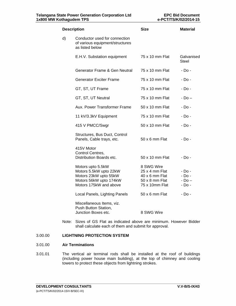
Telangana State Power Generation Corporation Ltd EPC Bid Document 1x800 MW Kothagudem TPS e-PCT/TS/K/02/2014-15
DEVELOPMENT CONSULTANTS V.V-B/S-IX/43 (e-PCT/TS/K/02/2014-15/V-B/SEC-IX)
Description Size Material d) Conductor used for connection of various equipment/structures as listed below E.H.V. Substation equipment 75 x 10 mm Flat Galvanised Steel Generator Frame & Gen Neutral 75 x 10 mm Flat - Do - Generator Exciter Frame 75 x 10 mm Flat - Do - GT, ST, UT Frame 75 x 10 mm Flat - Do - GT, ST, UT Neutral 75 x 10 mm Flat - Do – Aux. Power Transformer Frame 50 x 10 mm Flat - Do - 11 kV/3.3kV Equipment 75 x 10 mm Flat - Do - 415 V PMCC/Swgr 50 x 10 mm Flat - Do - Structures, Bus Duct, Control Panels, Cable trays, etc. 50 x 6 mm Flat - Do - 415V Motor Control Centres, Distribution Boards etc. 50 x 10 mm Flat - Do - Motors upto 5.5kW 8 SWG Wire Motors 5.5kW upto 22kW 25 x 4 mm Flat - Do - Motors 23kW upto 55kW 40 x 6 mm Flat - Do - Motors 56kW upto 174kW 50 x 8 mm Flat - Do – Motors 175kW and above 75 x 10mm Flat - Do - Local Panels, Lighting Panels 50 x 6 mm Flat - Do - Miscellaneous Items, viz. Push Button Station, Junction Boxes etc. 8 SWG Wire Note: Sizes of GS Flat as indicated above are minimum. However Bidder
shall calculate each of them and submit for approval. 3.00.00 LIGHTNING PROTECTION SYSTEM 3.01.00 Air Terminations 3.01.01 The vertical air terminal rods shall be installed at the roof of buildings
(including power house main building), at the top of chimney and cooling towers to protect these objects from lightning strokes.
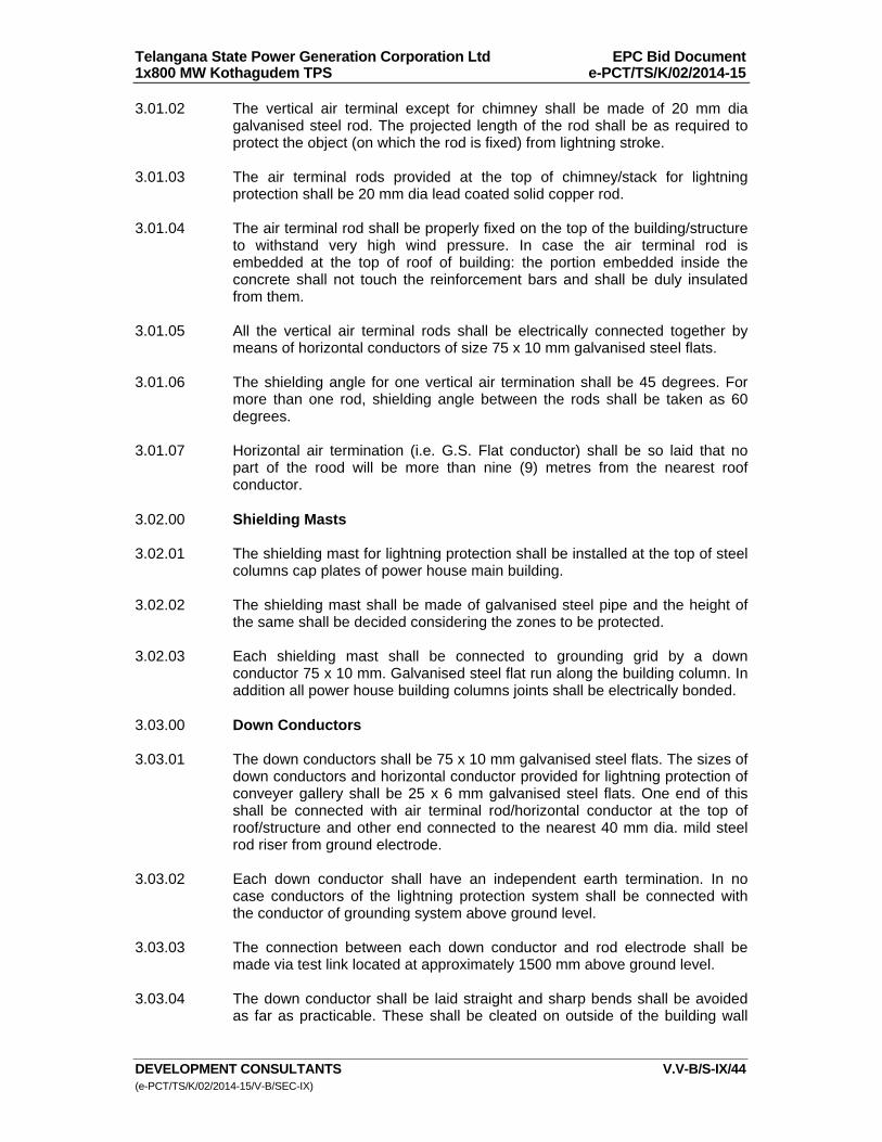
Telangana State Power Generation Corporation Ltd EPC Bid Document 1x800 MW Kothagudem TPS e-PCT/TS/K/02/2014-15
DEVELOPMENT CONSULTANTS V.V-B/S-IX/44 (e-PCT/TS/K/02/2014-15/V-B/SEC-IX)
3.01.02 The vertical air terminal except for chimney shall be made of 20 mm dia galvanised steel rod. The projected length of the rod shall be as required to protect the object (on which the rod is fixed) from lightning stroke.
3.01.03 The air terminal rods provided at the top of chimney/stack for lightning
protection shall be 20 mm dia lead coated solid copper rod. 3.01.04 The air terminal rod shall be properly fixed on the top of the building/structure
to withstand very high wind pressure. In case the air terminal rod is embedded at the top of roof of building: the portion embedded inside the concrete shall not touch the reinforcement bars and shall be duly insulated from them.
3.01.05 All the vertical air terminal rods shall be electrically connected together by
means of horizontal conductors of size 75 x 10 mm galvanised steel flats. 3.01.06 The shielding angle for one vertical air termination shall be 45 degrees. For
more than one rod, shielding angle between the rods shall be taken as 60 degrees.
3.01.07 Horizontal air termination (i.e. G.S. Flat conductor) shall be so laid that no
part of the rood will be more than nine (9) metres from the nearest roof conductor.
3.02.00 Shielding Masts 3.02.01 The shielding mast for lightning protection shall be installed at the top of steel
columns cap plates of power house main building. 3.02.02 The shielding mast shall be made of galvanised steel pipe and the height of
the same shall be decided considering the zones to be protected. 3.02.03 Each shielding mast shall be connected to grounding grid by a down
conductor 75 x 10 mm. Galvanised steel flat run along the building column. In addition all power house building columns joints shall be electrically bonded.
3.03.00 Down Conductors 3.03.01 The down conductors shall be 75 x 10 mm galvanised steel flats. The sizes of
down conductors and horizontal conductor provided for lightning protection of conveyer gallery shall be 25 x 6 mm galvanised steel flats. One end of this shall be connected with air terminal rod/horizontal conductor at the top of roof/structure and other end connected to the nearest 40 mm dia. mild steel rod riser from ground electrode.
3.03.02 Each down conductor shall have an independent earth termination. In no
case conductors of the lightning protection system shall be connected with the conductor of grounding system above ground level.
3.03.03 The connection between each down conductor and rod electrode shall be
made via test link located at approximately 1500 mm above ground level. 3.03.04 The down conductor shall be laid straight and sharp bends shall be avoided
as far as practicable. These shall be cleated on outside of the building wall

Telangana State Power Generation Corporation Ltd EPC Bid Document 1x800 MW Kothagudem TPS e-PCT/TS/K/02/2014-15
DEVELOPMENT CONSULTANTS V.V-B/S-IX/45 (e-PCT/TS/K/02/2014-15/V-B/SEC-IX)
and column/structure at about 750 mm intervals unless stated otherwise in the drawing.
3.03.05 At all supports for down conductor along the column/wall of the buildings;
chimney etc. the portion embedded inside the building concrete should not touch the reinforcement bars.
3.03.06 All exposed metallic parts of the buildings shall be bonded to the down
conductors. Such parts shall include ladders, balconies, conduits etc. 3.03.07 The down conductors shall be protected at the ground level against
mechanical injury by means of non-metallic pipes, viz. PVC pipes filled with bituminous compound.
3.04.00 Electrodes (for Lightning Protection) 3.04.01 The electrodes shall be 3000 mm long, 40mm dia. mild steel rod. These shall
be driven into the ground. 3.04.02 All the electrodes shall be interconnected by means of one mild steel rod
which will be laid under ground at a minimum depth of 1000 mm below finished grade level unless stated otherwise. This ground mat/electrode in turn shall be connected to main grounding grid.
3.05.00 Riser (for Lightning Protection) 3.05.01 All risers connected to grounding mat shall be projected 300 mm above grade
level unless stated otherwise. 3.06.00 Jointing & Connection 3.06.01 All ground conductor connections below ground level shall be done by electric
arc welding with low hydrogen content electrode. 3.06.02 The projected portion of riser above ground shall be coated with two (2) coats
of bitumen paints (anti-corrosive paints) with a minimum thickness of 1 mm after connection.
3.06.03 The joints in the lightning conductors shall be kept to a minimum and there
shall be no joint in the underground portions of conductors. 3.06.04 All the joints shall be done by arc welding process overlapping of the
conductors at straight joints shall not be less than 150 mm. The contact surfaces shall be cleaned properly before jointing.
3.06.05 The portion of galvanised steel flats, which undergoes welding at site, shall
be coated with two (2) coats of cold galvanising anti-corrosive paint after welding.
3.06.06 The bolted joint of the test link shall be covered with thick coating of bitumen
paint after successful testing. 3.06.07 The air terminal rods and shielding mast shall be coated with weather
resistant anti-corrosive paint (zinc chromate followed by two coats of aluminium paint).

Telangana State Power Generation Corporation Ltd EPC Bid Document 1x800 MW Kothagudem TPS e-PCT/TS/K/02/2014-15
DEVELOPMENT CONSULTANTS V.V-B/S-IX/46 (e-PCT/TS/K/02/2014-15/V-B/SEC-IX)
3.06.08 The steel to copper connection shall be brazed type. 3.07.00 Lightning Protection of 400kV Switchyard & Other areas 3.07.01 The lightning protection of outdoor switchyards/substation shall be done by
lightning masts on the top of steel towers. In addition, shield wires shall be used where required. The shield wire shall be strung across the top of the steel tower and/or powerhouse structure.
3.07.02 The shield wire which shall be brought down up to bottom of steel tower shall
be connected to the earthing conductor (50 x 6 mm galvanised steel flat) which in turn connected to the riser (from the main grounding mat/grid).
3.07.03 The lightning protection of inflammable liquid storage tanks wherever
required, shall be provided with horizontal conductors strung between tall poles covering the entire zones or with air terminal rods mounted on top of poles/structure. These horizontal conductors/vertical air terminal rods shall be connected to rod electrodes, which in turn shall be connected to station ground mat.
3.07.04 The lightning protection of conveyor gallery shall be provided with horizontal
conductors (25 x 6 mm G.S. Flat) run along the length of the conveyor gallery at the top of gallery roof. This conductor shall be connected to riser and grounding electrode at an approximate interval of 30 mm through two down conductions (each 25 x 6 mm G.S. Flats).
3.08.00 The sizes and materials of earthing conductors to be used in lightning
protection system are listed below : Description Size Material
a) Vertical Air Termination 20 mm dia Rod Lead Coated (Chimney) Copper rod.
b) Vertical Air Termination 20 mm dia Rod Galvanised (Except Chimney) steel c) Horizontal Conductor i) 75 x 10 mm Flat - Do - ii) 25 x 3 mm Flat - Do - d) Down Conductors i) 75 x 10 mm Flat - Do - ii) 25 x 3 mm Flat - Do - e) Riser From Electrode/ to be decided Mild Steel Grounding Mat by Bidder f) Electrode for Lightning 3000 mm long , Mild Steel Protection 40mm dia. Note :

Telangana State Power Generation Corporation Ltd EPC Bid Document 1x800 MW Kothagudem TPS e-PCT/TS/K/02/2014-15
DEVELOPMENT CONSULTANTS V.V-B/S-IX/47 (e-PCT/TS/K/02/2014-15/V-B/SEC-IX)
In addition to above, all materials as required such as G.I. pipes of appropriate length, diameter and thickness will be provided for lightning masts of Power House building and Switchyard.
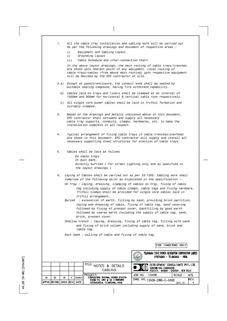
All single core power cables shall be laid in trifoil formation and
Cables laid on trays and risers shall be clamped at an interval of 1500mm and 900mm for horizontal & vertical cable runs respectively.
Typical arrangement of fixing cable trays in cable trenches/overheadare shown in this document. EPC contractor will supply and install allnecessary supporting steel structures for erection of cable trays.
installation complete in all respect.
EPC contractor shall estimate and supply all necessaryBased on the drawings and details indicated above in this document,
cable tray supports, conduits, clamps, hardwares, etc. to make the
Except at panels/enclosure, the conduit ends shall be sealed by suitable sealing compound, having fire withstand capability.
will be decided by the EPC contractor at site.cable trays/cables (from above main routing) upto respective equipment
In the above layout drawings, the main routing of cable trays/trenchesare shown upto nearest point of any equipment. Local routing of
Cable Schedule and inter-connection Chart.
Equipment and Cabling Layout.
as per the following drawings and document of respective areas :All the cable tray installation and cabling work will be carried out
comprise of the following as/or as stipulated in the specification :-
On Tray : laying, dressing, clamping of cables on tray, fixing of cable
Directly burried ( for street lighting only and as specified in
Laying of Cables shall be carried out as per IS:1255. Cabling work shall 6.
5.
tag including supply of cable clamps, cable tags and fixing hardware.
In duct bank. On cable trays
Cables shall be laid as follows
c)
b)
4.
3.
2.a)
1.
suitably clamped.
ii)
i)
the layout drawings )
Grounding Layout.i)
Trifoil clamps shall be provided for single core cables laid in
trifoil arrangement. Buried : excavation of earth, filling by sand, providing brick partition,
laying and dressing of cable, fixing of cable tag, sand covering followed by fixing of precast cover, backfilling by good earth followed by coarse earth including the supply of cable tag, sand, brick, precast cover.
Shallow trench : laying, dressing, fixing of cable tag, filling with sand
and fixing of brick column including supply of sand, brick and cable tag.
Duct bank : pulling of cable and fixing of cable tag.
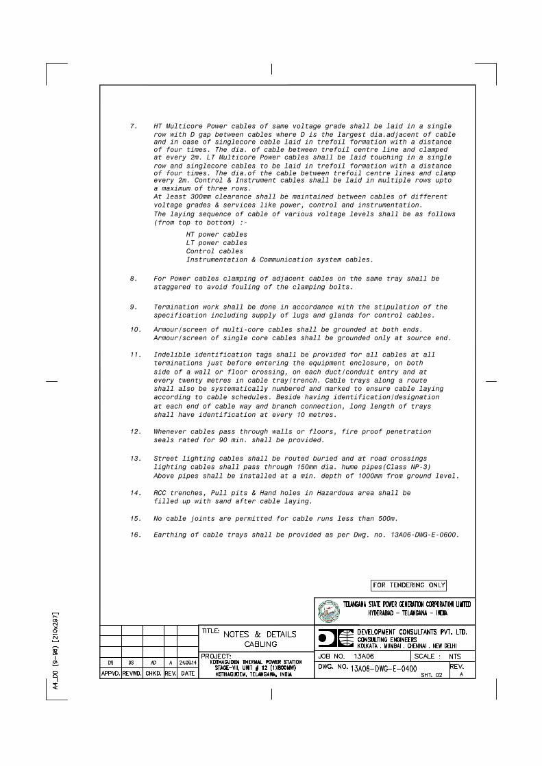
The laying sequence of cable of various voltage levels shall be as follows(from top to bottom) :-
voltage grades & services like power, control and instrumentation.At least 300mm clearance shall be maintained between cables of different
row with D gap between cables where D is the largest dia.adjacent of cable HT Multicore Power cables of same voltage grade shall be laid in a single 7.
Instrumentation & Communication system cables.Control cablesLT power cablesHT power cables
Earthing of cable trays shall be provided as per Dwg. no. 13A06-DWG-E-0600.
No cable joints are permitted for cable runs less than 500m.
RCC trenches, Pull pits & Hand holes in Hazardous area shall befilled up with sand after cable laying.
Street lighting cables shall be routed buried and at road crossings lighting cables shall pass through 150mm dia. hume pipes(Class NP-3)Above pipes shall be installed at a min. depth of 1000mm from ground level.
at each end of cable way and branch connection, long length of traysshall have identification at every 10 metres.
seals rated for 90 min. shall be provided.Whenever cables pass through walls or floors, fire proof penetration
according to cable schedules. Beside having identification/designation shall also be systematically numbered and marked to ensure cable laying
side of a wall or floor crossing, on each duct/conduit entry and atevery twenty metres in cable tray/trench. Cable trays along a route
terminations just before entering the equipment enclosure, on both Indelible identification tags shall be provided for all cables at all
16.
15.
14.
13.
12.
11.
staggered to avoid fouling of the clamping bolts.For Power cables clamping of adjacent cables on the same tray shall be 8.
specification including supply of lugs and glands for control cables.Termination work shall be done in accordance with the stipulation of the 9.
Armour/screen of single core cables shall be grounded only at source end.Armour/screen of multi-core cables shall be grounded at both ends.10.
and in case of singlecore cable laid in trefoil formation with a distance of four times. The dia. of cable between trefoil centre line and clamped at every 2m. LT Multicore Power cables shall be laid touching in a single row and singlecore cables to be laid in trefoil formation with a distance of four times. The dia.of the cable between trefoil centre lines and clamp every 2m. Control & Instrument cables shall be laid in multiple rows upto a maximum of three rows.
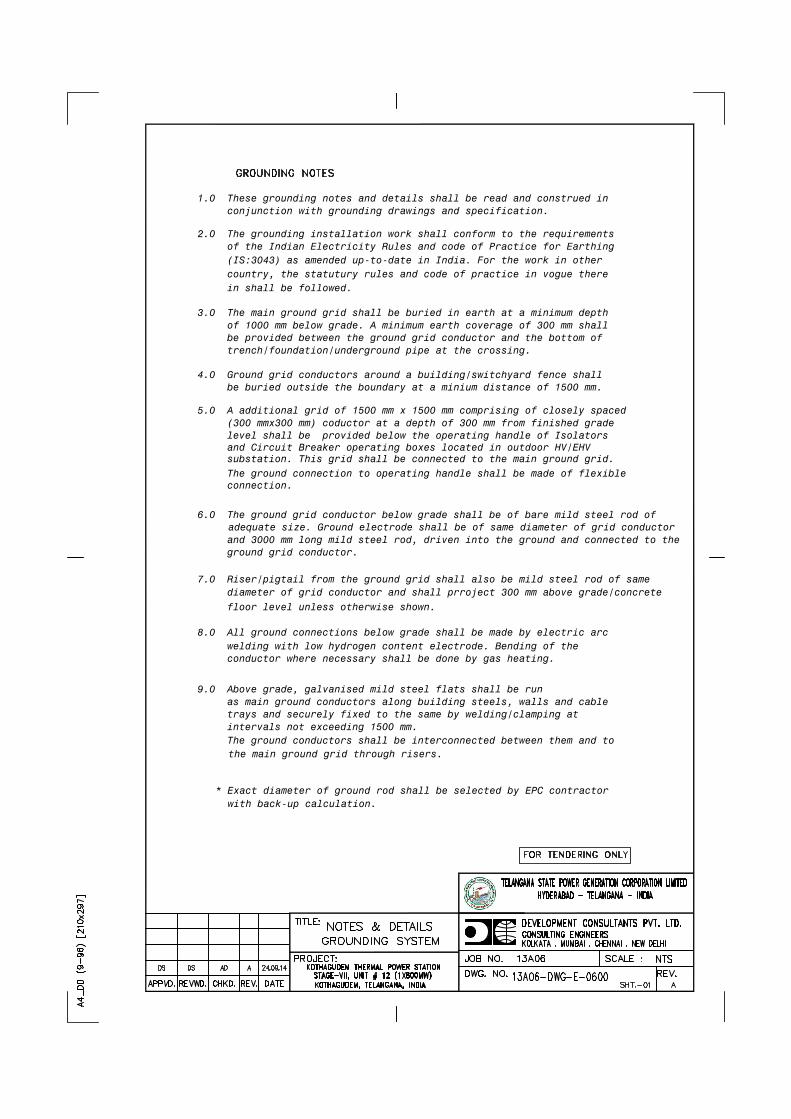
1.0 These grounding notes and details shall be read and construed in conjunction with grounding drawings and specification.
2.0 The grounding installation work shall conform to the requirements of the Indian Electricity Rules and code of Practice for Earthing
3.0 The main ground grid shall be buried in earth at a minimum depth of 1000 mm below grade. A minimum earth coverage of 300 mm shall be provided between the ground grid conductor and the bottom of trench/foundation/underground pipe at the crossing.
4.0 Ground grid conductors around a building/switchyard fence shall be buried outside the boundary at a minium distance of 1500 mm.
5.0 A additional grid of 1500 mm x 1500 mm comprising of closely spaced (300 mmx300 mm) coductor at a depth of 300 mm from finished grade
6.0 The ground grid conductor below grade shall be of bare mild steel rod ofadequate size. Ground electrode shall be of same diameter of grid conductor
and 3000 mm long mild steel rod, driven into the ground and connected to the
7.0 Riser/pigtail from the ground grid shall also be mild steel rod of same
floor level unless otherwise shown.
8.0 All ground connections below grade shall be made by electric arc
9.0 Above grade, galvanised mild steel flats shall be run as main ground conductors along building steels, walls and cable trays and securely fixed to the same by welding/clamping at intervals not exceeding 1500 mm.
(IS:3043) as amended up-to-date in India. For the work in other
level shall be provided below the operating handle of Isolators
welding with low hydrogen content electrode. Bending of the
and Circuit Breaker operating boxes located in outdoor HV/EHV
ground grid conductor.
diameter of grid conductor and shall prroject 300 mm above grade/concrete
conductor where necessary shall be done by gas heating.
The ground conductors shall be interconnected between them and to the main ground grid through risers.
The ground connection to operating handle shall be made of flexible connection.
country, the statutury rules and code of practice in vogue there in shall be followed.
substation. This grid shall be connected to the main ground grid.
* Exact diameter of ground rod shall be selected by EPC contractor with back-up calculation.
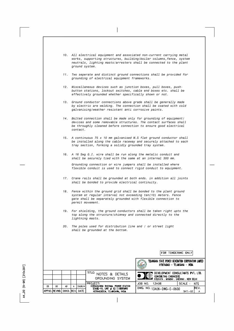
galvanising/weather resistant anti corrosive paints.
neutrals, lighting masts/arresters shall be connected to the plant
flexible conduit is used to connect rigid conduit to equipment.
shall be securely tied with the same at an internal 300 mm.
shall be bonded to provide electrical continuity.
be throughly cleaned before connection to ensure good electrical
gate shall be separately grounded with flexible connection to system at regular interval not exceeding ten(10) meters. Fence 18. Fence within the ground grid shall be bonded to the plant ground
17. Crane rails shall be grounded at both ends. in addition all joints
Grounding connection or wire jumpers shall be installed where
16. A 16 Swg G.I. wire shall be run along the metalic conduit and
tray section, forming a solidly grounded tray system. be installed along the cable raceway and securely attached to each 15. A continuous 75 x 10 mm galvanised M.S flat ground conductor shall
devices and some removable structures. The contact surfaces shall 14. Bolted connection shall be made only for grounding of equipment/
by electric are welding. The connection shall be coated with cold 13. Ground conductor connections above grade shall be generally made
effectively grounded whether specifically shown or not. button stations, lockout switches, cable end boxes etc. shall be 12. Miscellaneous devices such as junction boxes, pull boxes, push-
grounding of electrical equipment frameworks. 11. Two seperate and distinct ground connections shall be provided for
works, supporting structures, building/boiler columns,fence, system 10. All electrical equipment and associated non-current carrying metal
permit movement.
ground system.
contact.
shall be grounded at the bottom. 20. The poles used for distribution line and / or street light
lightning masts. top along the structure/chimney and connected directly to the 19. For shielding, the ground conductors shall be taken right upto the
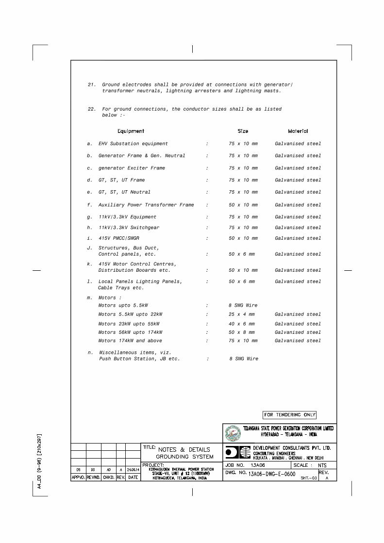
b. Generator Frame & Gen. Neutral : 75 x 10 mm Galvanised steel
a. EHV Substation equipment : 75 x 10 mm Galvanised steel
22. For ground connections, the conductor sizes shall be as listed
transformer neutrals, lightning arresters and lightning masts. 21. Ground electrodes shall be provided at connections with generator/
below :-
c. generator Exciter Frame : 75 x 10 mm Galvanised steel
d. GT, ST, UT Frame : 75 x 10 mm Galvanised steel
f. Auxiliary Power Transformer Frame : 50 x 10 mm Galvanised steel
g. 11kV/3.3kV Equipment : 75 x 10 mm Galvanised steel
e. GT, ST, UT Neutral : 75 x 10 mm Galvanised steel
h. 11kV/3.3kV Switchgear : 75 x 10 mm Galvanised steel
i. 415V PMCC/SWGR : 50 x 10 mm Galvanised steel
J. Structures, Bus Duct,Control panels, etc. : 50 x 6 mm Galvanised steel
k. 415V Motor Control Centres,Distribution Booards etc. : 50 x 10 mm Galvanised steel
l. Local Panels Lighting Panels, : 50 x 6 mm Galvanised steel
m. Motors :
Motors upto 5.5kW : 8 SWG Wire
Motors 5.5kW upto 22kW : 25 x 4 mm Galvanised steel
Motors 23kW upto 55kW : 40 x 6 mm Galvanised steel
Motors 56kW upto 174kW : 50 x 8 mm Galvanised steel
n. Miscellaneous items, viz.Push Button Station, JB etc. : 8 SWG Wire
Cable Trays etc.
Motors 174kW and above : 75 x 10 mm Galvanised steel

of chimney/ stack for lightning protection shall be 20 mm dia lead objects, from lightning stroke. Air terminal rods provided on top
connected with the conductors of the grounding system above ground In no case conductors of the lightning protection system shall be 3.2 Each down conductor shall have an independent earth termination.
horizontal conductors on top of roof/structure and the other end to One end of these flats shall be connected to the air terminal rods/
However, The down conductor of conveyor gallery may be 25 x 3mm 3.1 The down conductors shall be 75 x 10 mm galvanished MS flats.
joints shall be electrically bonded. the building column. In addition, all power house building column station by a 75 x 10 mm. galvanised MS down conductor running along 2.3 Each shielding mast shall be connected to grounding grid of the
heights of the same shall be decided considering the zones to be 2.2 The shielding masts shall be made of galvanished steel pipe and the
top of the steel column cap plates of power house main building. 2.1 The shielding mast for lightning protection shall be installed on
the nearest Horizonal air terminals. out that no part of the roof is more than nine (9) metres away from 1.6 Horizontal air terminations (galvanised MS flats) shall be so laid
degrees. For more than one rod, shielding angle between the rods 1.5 The shielding angle for one vertical air termination shall be 45
means of horizontal conductors (galvanised MS flats) of size 1.4 All vertical air terminal rods shall be electrically connected by
in the contrete shall not touch the reinforcement bars and shall rods are embedded in the building roof, the portion embedded structures to withstand wind pressure.In case the air terminal 1.3 Air terminal rods shall be properly fixed on top of buildings/
mounting structure, if any, shall be as required to protect the galvanised steel rods. The projected length of the rods including 1.2 Vertical air terminal except those for chimney shall be 20 mm dia
structured/buildings to be protected from lightning strokes. 1.1 Vertical air terminal rods shall be installed on the top of all
protected.
the nearest earth terminals.
galvanised MS flats.
coated solid copper rods.
shall be taken as 60 degrees.
75 x 10 mm.
be duely insulated from them.

5.6 Steel to copper connection shall be brazed type.
protection shall be provided as Earth Terminal.
3.3 The connetion between each down conductor and earth terminal shall be made via test link located at approximately 1500 mm above ground
3.4 The down conductors shall be laid straight and sharp bends shall be avoided as far as practicable. These shall be cleated on the outside of the building wall and or columns/structures at intervals of about 750 mm., unless indicated otherwise in the drawings.
3.5 Down conductors along the chimney shell shall be electrically connected with the reinforcement rods by suitable lugs welded (6 mm fillet) to both down conductor and reinforcement at the interval
3.6 All exposed metallic parts of a building shall be bonded to the down conductors. Such parts shall include ladders, balconies,
4.1 Where ground mat is available, the risers specifically ear-marked for lightning protection shall be considered as Earth Terminal.
4.2 Where ground mat is not available sparate earth pit as per IS-3043 or approved international standard specifically for lightning
5.1 Number of joints in the lightning conductors shall be kept to a
5.2 All the joints shall be done by arc welding process. Overlapping of conductors at straight joints shall not be less than 150 mm. The contact surfaces shall be properly cleaned before jointing.
In such case, one electrode shall be provide close to the each
5.3 Those portions of galvanished steel flats, which have been welded at site, shall be coated with two (2) coats of cold galvanising anti-
5.4 After successful testing the bolted joints of test links shall be wrapped by bitumenons hessian tape followed by 3 mm thick coating
5.5 Air terminal rods and shielding masts shall be coated with weather resistant anti-corrosive paint (zinc chromate followed by two coats
of bitumen compound.
minimum.
corrosive paint after welding.
of aluminium paint).
of 30 mm.
level.
conduits etc.
Earth Terminals.
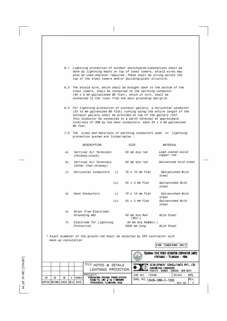
steel
steel
steel
steel
DESCRIPTION SIZE MATERIAL
ii) 25 x 3 mm Flat Galvanished Mild
ii) 25 x 3 mm Flat Galvanished Mild
conveyor gallery shall be provided on top of the gallery roof. This conductor be connected to a earth terminal at approximate intervals of 30M by two down conductors, each 25 x 3 mm galvanised
7.0 The sizes and materials of earthing conductors used in lightning
a) Vertical Air Terminals 20 mm dia rod
c) Horizontal conductors i) 75 x 10 mm Flat Galvanished Mild
d) Down Conductors i) 75 x 10 mm Flat Galvanished Mild
Grounding Mat 40 mm dia Rod Mild Steel
f) Electrode for Lightning 40 mm dia Rod Protection 3000 mm long Mild Steel
protection system are listed below :
6.1 Lightning protection of outdoor switchyards/substations shall be done by lightning masts on top of steel towers. shield wires may
6.2 The shield wire, which shall be brought down to the bottom of the steel towers, shall be connected to the earthing conductor (50 x 6 mm galvanished MS flat), which in turn, shall be
6.3 For lightning protection of conveyor gallery, a horizontal conductor (25 x3 mm galvanised MS flat) running along the entire length of the
connected to the riser from the main grounding mat/grid.
also be used wherever required. These shall be strung across the top of the steel towers and/or building/plant structure.
e) Riser From Electrode/
MS flat.
(Chimney/stack)Lead coated solid copper rod.
b) Vertical Air Terminals 20 mm dia rod (Other than chimney)
Galvanised mild steel
(Min.)
(Min.)
* Exact diameter of the ground rod shall be selected by EPC contractor with back-up calculation

Telangana State Power Generation Corporation Ltd EPC Bid Document 1x800 MW Kothagudem TPS e-PCT/TS/K/02/2014-15
DEVELOPMENT CONSULTANTS (e-PCT/TS/K/02/2014-15/V-B/SEC-VII)
VOLUME : V-B
SECTION-VII
TECHNICAL SPECIFICATION FOR
ILLUMINATION SYSTEM
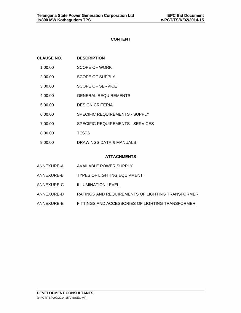
Telangana State Power Generation Corporation Ltd EPC Bid Document 1x800 MW Kothagudem TPS e-PCT/TS/K/02/2014-15
DEVELOPMENT CONSULTANTS (e-PCT/TS/K/02/2014-15/V-B/SEC-VII)
CONTENT CLAUSE NO. DESCRIPTION 1.00.00 SCOPE OF WORK 2.00.00 SCOPE OF SUPPLY 3.00.00 SCOPE OF SERVICE 4.00.00 GENERAL REQUIREMENTS 5.00.00 DESIGN CRITERIA 6.00.00 SPECIFIC REQUIREMENTS - SUPPLY 7.00.00 SPECIFIC REQUIREMENTS - SERVICES 8.00.00 TESTS 9.00.00 DRAWINGS DATA & MANUALS
ATTACHMENTS ANNEXURE-A AVAILABLE POWER SUPPLY ANNEXURE-B TYPES OF LIGHTING EQUIPMENT ANNEXURE-C ILLUMINATION LEVEL ANNEXURE-D RATINGS AND REQUIREMENTS OF LIGHTING TRANSFORMER ANNEXURE-E FITTINGS AND ACCESSORIES OF LIGHTING TRANSFORMER
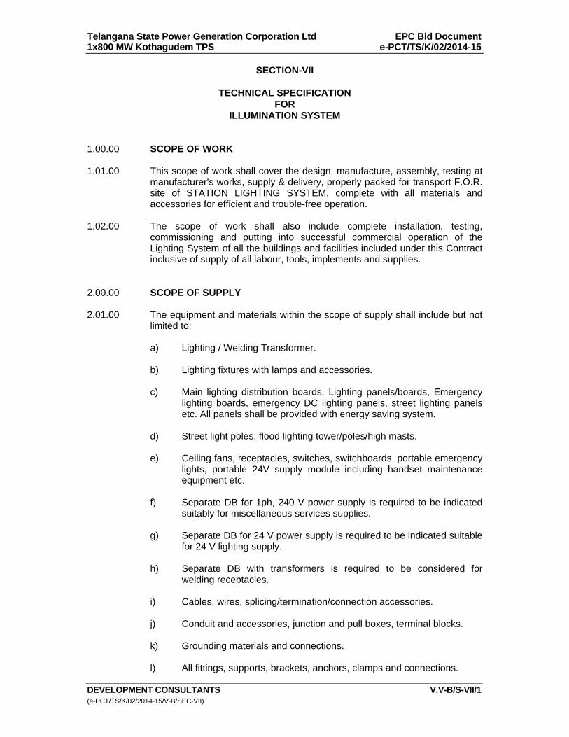
Telangana State Power Generation Corporation Ltd EPC Bid Document 1x800 MW Kothagudem TPS e-PCT/TS/K/02/2014-15
DEVELOPMENT CONSULTANTS V.V-B/S-VII/1 (e-PCT/TS/K/02/2014-15/V-B/SEC-VII)
SECTION-VII
TECHNICAL SPECIFICATION FOR
ILLUMINATION SYSTEM 1.00.00 SCOPE OF WORK 1.01.00 This scope of work shall cover the design, manufacture, assembly, testing at
manufacturer's works, supply & delivery, properly packed for transport F.O.R. site of STATION LIGHTING SYSTEM, complete with all materials and accessories for efficient and trouble-free operation.
1.02.00 The scope of work shall also include complete installation, testing,
commissioning and putting into successful commercial operation of the Lighting System of all the buildings and facilities included under this Contract inclusive of supply of all labour, tools, implements and supplies.
2.00.00 SCOPE OF SUPPLY 2.01.00 The equipment and materials within the scope of supply shall include but not
limited to: a) Lighting / Welding Transformer. b) Lighting fixtures with lamps and accessories. c) Main lighting distribution boards, Lighting panels/boards, Emergency
lighting boards, emergency DC lighting panels, street lighting panels etc. All panels shall be provided with energy saving system.
d) Street light poles, flood lighting tower/poles/high masts. e) Ceiling fans, receptacles, switches, switchboards, portable emergency
lights, portable 24V supply module including handset maintenance equipment etc.
f) Separate DB for 1ph, 240 V power supply is required to be indicated
suitably for miscellaneous services supplies. g) Separate DB for 24 V power supply is required to be indicated suitable
for 24 V lighting supply. h) Separate DB with transformers is required to be considered for
welding receptacles. i) Cables, wires, splicing/termination/connection accessories. j) Conduit and accessories, junction and pull boxes, terminal blocks. k) Grounding materials and connections. l) All fittings, supports, brackets, anchors, clamps and connections.
Telangana State Power Generation Corporation Ltd EPC Bid Document 1x800 MW Kothagudem TPS e-PCT/TS/K/02/2014-15
DEVELOPMENT CONSULTANTS V.V-B/S-VII/2 (e-PCT/TS/K/02/2014-15/V-B/SEC-VII)
m) Steel for field fabrication of supports and brackets. 2.01.01 Data sheets and technical leaflets on each piece of equipments / devices 3.00.00 SCOPE OF SERVICE 3.01.00 Carrying out of detail engineering including detail design calculations,
preparation of lighting layouts showing location of fixtures, cable wires and conduit routing, preparation of cable schedule, and other related drawings as detailed in subsequent clauses and also consider the energy saving system.
3.01.01 Furnishing of all labour, skilled and unskilled, supervisory personnel, erection
tools and tackles, testing equipment, implements, supplies, consumables & hardware, and transport for timely and efficient execution of the contract work.
3.01.02 Preparation of AS-BUILT drawings showing field modifications, if any. 4.00.00 GENERAL REQUIREMENTS 4.01.00 Codes and Standards Major standards, which shall be followed, are listed below. Other applicable
Indian standards even if not covered in the listed standard shall be followed. a) IS-1913 b) IS-1977 c) IS-10322 d) IS-8623 e) IS-6064 f) IS-8828 g) IEC-598 h) IS-13703 i) IS-13947 j) IS-1248 k) IS-2705 l) IS-4160 m) IS-2713 n) IS-800

Telangana State Power Generation Corporation Ltd EPC Bid Document 1x800 MW Kothagudem TPS e-PCT/TS/K/02/2014-15
DEVELOPMENT CONSULTANTS V.V-B/S-VII/3 (e-PCT/TS/K/02/2014-15/V-B/SEC-VII)
o) IS-2026 p) IS-2099 q) IS-694 r) IS-1554 s) IS-9537
t) IS-14772
u) IS-5133 5.00.00 DESIGN CRITERIA 5.01.00 Design Basis 5.01.01 The system provides lighting and electric power supply to Main plant & BOP
areas, extension part of 400kV switchyard, peripheral roads inside boundary wall, non service areas, etc. under the scope of this contract. In addition, it also provides lighting to selected areas during plant emergency conditions.
5.01.02 The system will be installed in an adverse industrial environment. Equipment
in some areas will be subject to vibration, coal-dust, fly-ash, oil/water vapours as prevalent in a thermal generating plant.
5.01.03 The design shall be such as to provide minimum lighting levels as specified
for different areas. The Bidder shall carefully consider these lighting levels and layouts in making the offer and shall clearly indicate if any change is required to achieve the design lighting levels with the equipment offered.
5.01.04 The systems shall be suitable for operation on available power supply having
characteristics as given in the annexure. 5.01.05 All fittings of control room / office shall be energy efficient type. 5.01.06 The main plant/auxiliary building/other BOP area shall generally be provided
with :
Main lighting system for full illumination under normal power supply conditions and shall operate from 415V/240V AC power supply tapped from respective MLDB/lighting panels.
Emergency lighting system for reduced illumination operated by DG
supply feeders during failure of main power supply. It shall cover 20% of fixtures in the building and associated area.
Minimum emergency lighting system for reduced illumination during failure of main power supply with the help of 220V DC batteries/supply feeders. This is applicable for Coal Handling Plant also. Regarding lux level of emergency lighting in CHP area, refer to Annexure-B.
Telangana State Power Generation Corporation Ltd EPC Bid Document 1x800 MW Kothagudem TPS e-PCT/TS/K/02/2014-15
DEVELOPMENT CONSULTANTS V.V-B/S-VII/4 (e-PCT/TS/K/02/2014-15/V-B/SEC-VII)
5.01.07 Various lighting panel shall be fed directly from nearest Main Lighting Distribution Board and these MLDB s shall be subsequently fed from respective 415V switchgear/PMCC through 1:1 transformers to reduce fault level. If the fault level can be contained within 9 kA by virtue of cable impedances, use of 1:1 transformer can be dispensed with.
5.02.00 System Concept The lighting system shall comprise following sub-systems: 5.02.01 Normal A.C. Lighting This will be provided by A.C. lighting fixtures distributed throughout the plant
area. These lights will be ON as long as the station A.C. supply is available.
A.C. lighting fixtures will be fed from respective area lighting panels, which in turn will be connected to main lighting distribution board. The main lighting distribution boards (MLDB) shall have 2x100% incomers and bus-coupler and be fed through 2x100% lighting transformers, which forms a part of the MLDB. Normal A.C. supply thus made available by the MLDB is 415V-3ph-4W-50HZ effectively grounded. Both the MLDB & the lighting panels shall be provided with at least 20% spare outlets.
Arrangement shall be made for automatic light control in switchyard, boiler
gallery, ESP area, turbine floor (high bay) area as required during day time. 5.02.02 Normal cum Emergency A.C. Lighting a) On failure of normal A.C. Supply, emergency A.C. lighting will be
provided in selected areas of the powerhouse, boiler area, boiler galleries etc for general visibility, safe movements and operation of important auxiliaries.
b) The emergency MLDBs (EMLDB) are similar to the MLDB except that
lighting transformers in this case are fed from station A.C. Emergency bus having D.G. System backup. Thus power for A.C. emergency lighting is 415V-3ph-4W, 50HZ, effectively grounded.
These lights will be kept "ON" from normal power supply source and upon its failure will be fed from DG.
c) A.C. emergency lighting fixture will account for 20% of the total lighting fixtures provided in the above mentioned area. In main control room 30% emergency lighting shall be provided.
5.02.03 Emergency D.C. Lighting a) This will be provided by emergency D.C. lighting fixtures located
strategically in critical operating areas and emergency exits to enable safe movement of operating personnel access to important control points when both the normal AC and Emergency lighting system fails. These lighting fixtures will be fed from DC lighting panels which in turn will be fed from 220V DC LDB. The supply to DC lighting panels will be automatically switched ON in case of loss of plant normal &
Telangana State Power Generation Corporation Ltd EPC Bid Document 1x800 MW Kothagudem TPS e-PCT/TS/K/02/2014-15
DEVELOPMENT CONSULTANTS V.V-B/S-VII/5 (e-PCT/TS/K/02/2014-15/V-B/SEC-VII)
emergency AC supply. The DC lights will be switched OFF after about 3 minutes following restoration of normal AC or emergency AC supply.
b) Emergency DC Lighting (CHP Area) 100W, 220V DC lighting fixture shall be provided in underground
portion of conveyor, each switchgear room, control room, office room, pump house, each drive floor of TPs, staircase of TPs, buildings and local control area. DC lighting fixtures will be fed from 220V DC LDB, which in turn will be fed from CHP DC system.
5.02.04 24V, 1 ph AC maintenance lighting system
Separate DB for 24V power supply shall be provided for 24V maintenance lighting.
5.02.05 Street/Area Lighting Time switch and photocell will be used for controlling area lights with
provision for manual override and also have the provision of latest Energy Saving Systems.
. Same arrangement will also be used for controlling, boiler gallery, ESP area,
turbine floor (high bay) area illumination. 5.02.06 Remote Emergency Lighting This will be provided in auxiliary/off-site buildings except CHP where D.C.
supply is not available by self-contained battery / automatic charger/inverter/flood light units. These portable emergency light units will be energized automatically on loss of normal A.C. supply.
5.03.00 Ratings & Requirements 5.03.01 All equipment and accessories shall be designed for continuous operation
under site conditions without exceeding permissible temperature rise as stipulated in relevant standards.
5.03.02 Switch, fuses, MCCB, miniature circuit breakers (MCB), busbar shall be fully
rated for short circuit level at the point of application. MCB shall have back-up HRC fuse if its rating is less than the available short circuit current.
5.03.03 All equipment and accessories shall have proper enclosure to suit the site
conditions. Hazardous areas shall have flame-proof enclosure. 5.03.04 All wiring from lighting panels to fixtures and receptacles shall be carried out
by PVC wires in G.I. Conduits. 5.03.05 Heavy duty XLPE FRLS cables as pre cable specification will be used for
connections : a) From main lighting board to area lighting panels b) From street/area lighting panel to street light poles.
Telangana State Power Generation Corporation Ltd EPC Bid Document 1x800 MW Kothagudem TPS e-PCT/TS/K/02/2014-15
DEVELOPMENT CONSULTANTS V.V-B/S-VII/6 (e-PCT/TS/K/02/2014-15/V-B/SEC-VII)
c) From Welding DBs to receptacles of 63A and above 5.03.06 The lighting system will be supplied from 415V/415V ± 5%, indoor, dry type
lighting transformers. However it shall be so chosen to limit the fault level within 9kA.
5.03.07 Suitable number of Flood Lighting Towers / Lighting Masts with adequate
HPSV Flood Light will be provided for necessary outdoor areas as required. 5.03.08 Lighting of all main streets, approach roads to various buildings shall be
included. 5.03.09 Each lighting panel shall be provided with adequate number of outgoing
miniature circuit breaker for controlling fixtures. 5A, 5 Pin sockets shall be fed from the lighting panel through separate circuits.
5.03.10 All A.C. Normal and Emergency A.C. lighting shall be provided with Energy
Saving System. 5.04.00 Method of Calculation 5.04.01 Standard Lumen method shall be adopted for interior & exterior lighting in
order to determine the number of lighting fixtures for obtaining the desired average level of illumination.
5.04.02 The coefficient of utilization shall be considered to take care of Lumen loss
due to : a) effect of room dimensions. b) absorption of light in luminaires.
c) absorption of light at various room surfaces, i.e ceiling wall etc. d) floor cavity, ceiling cavity.
e) mounting height. 5.04.03 Moreover a maintenance factor shall also be considered to account for the fall
of illumination due to aging, pollution like dust deposit etc. Maintenance factors to be considered for various areas shall be as follows :
Area Maintenance factor Control Room 0.75 Switchgear/MCC Room 0.65 General indoor area 0.60
Dusty Area 0.55
Light loss Factor
Telangana State Power Generation Corporation Ltd EPC Bid Document 1x800 MW Kothagudem TPS e-PCT/TS/K/02/2014-15
DEVELOPMENT CONSULTANTS V.V-B/S-VII/7 (e-PCT/TS/K/02/2014-15/V-B/SEC-VII)
It is recommended that in interiors with fairly clean atmosphere, for example, offices, air conditioned control rooms etc, a light loss factor of 0.8, in interiors which are prone to accumulate dust faster, for example, most in industrial interior an LLF of 0.7 and in high dirt prone interiors an LLF of 0.6 may be adopted for calculating the no. of luminaires to be installed for a particular service illuminance.
5.04.04 To achieve the recommended luminance relationship, it is necessary to select
the reflectance of all finishes of the room surfaces. The recommended reflectance values for industrial interiors and equipment are given below for bidder’s guide lines:
(For station / other BOP area except CHP) Surface Reflectance Percentage Ceiling 80-90 Wall 40-60 Desk and Bench tops, machines 25-45 And equipment Floor not less than 20 CHP Requirement:-
For Dusty area such as conveyor galleries, TPs, crusher house etc.: Surface Reflectance Percentage Ceiling 50 Wall 30 Floor 10 5.04.05 Lux level to be considered for various areas are given in Annexure-C. 5.04.06 Voltage drop at the fixture from the MLDB bus shall not exceed 3%. 5.04.07 Circuit loading of each lighting Panel shall be done in such a way that almost
balanced loading in all the phases i.e. R, Y & B is achieved. 5.04.08 At least two sub circuits shall be used for illumination of a particular area. 5.04.09 Sub circuit loading of each lighting panel shall be restricted to 2000 Watts. 6.00.00 SPECIFIC REQUIREMENTS - SUPPLY 6.01.00 Equipment and Material 6.01.01 Equipment and material shall comply with description, rating, type and size as
detailed in this specification, drawings and annexures.
Telangana State Power Generation Corporation Ltd EPC Bid Document 1x800 MW Kothagudem TPS e-PCT/TS/K/02/2014-15
DEVELOPMENT CONSULTANTS V.V-B/S-VII/8 (e-PCT/TS/K/02/2014-15/V-B/SEC-VII)
6.01.02 Equipment and materials furnished shall be complete and operative in all details.
6.01.03 All accessories, control devices, internal wiring, fittings, supports, hangers,
anchor bolts etc. which form part of the equipment or which are necessary for safe and satisfactory installation and operation of the equipment shall be furnished.
6.01.04 All parts shall be made accurately to standard gauges so as to facilitate
replacement and repair. All corresponding parts of similar equipment shall be interchangeable.
6.02.00 Lighting/Welding Transformers & Lighting Fixtures 6.02.01 Each AC Lighting Distribution Board (MLDB) / Welding DB shall be fed from a
transformer. The transformers shall be dry type, indoor type dusty vermin proof having 415V / 415V ± 2 x 2.5% with off load tap-changer on primary side. The vector-group shall be Dyn11. (The secondary side shall be solidly grounded through an additional neutral bushing exclusively used for grounding.)The casing of the transformer shall be grounded at least at two (2) points. The transformer may be located inside the lighting / welding DB itself or by the side of respective DB. Impedance of the transformer shall be so selected such that fault level of lighting/welding system is reduced to 3-5 kA.
6.02.02 If necessary, apart from the main lighting transformers, separate small
additional lighting transformers may be used at distance lighting points. 6.02.03 Lighting fixtures shall be designed for minimum glare. The surface finish shall
be smooth, unobtrusive and scratch resistant. 6.02.04 Reflector shall be of sheet steel or aluminium, minimum 20 SWG thick,
securely fixed by fastening device of captive type. 6.02.05 Fixture shall be suitable for 20 mm conduit entry and 16 SWG G.I. earth wire
connection. 6.02.06 High bay fixtures shall have provision for vibration damper to ensure rated
lamp life. Cost of each damper shall be separately indicated. 6.02.07 Fixture shall be furnished complete with lamps and integrally/non integrally or
separately mounted control gear & accessories as applicable for different types of fixtures. These shall include holders, ballast, capacitor, starter, ignitors, etc.
6.02.08 Fixtures shall be fully wired up to respective terminal blocks, suitable for loop
in and loop out connection of PVC wires of following sizes : a) Lighting fixture : 2.5 mm2 Copper b) Flood Light fixture : 2x2.5 mm2 Copper 6.03.00 Lamps 6.03.01 General lighting service (GLS) lamps shall be with clear glass and screwed
caps.
Telangana State Power Generation Corporation Ltd EPC Bid Document 1x800 MW Kothagudem TPS e-PCT/TS/K/02/2014-15
DEVELOPMENT CONSULTANTS V.V-B/S-VII/9 (e-PCT/TS/K/02/2014-15/V-B/SEC-VII)
6.03.02 All fluorescent lamp shall be bi-pin rotary type. Lamp holder shall be spring
loaded, low contact resistance type and shall have resistance to wear. CFL and T5 fluorescent tube with electronic ballast or tri-phosphorous tube
Fluorescent lamp will be used in indoor application having low height like 3 to
5 metres requiring good colour rendering. All control rooms, electrical panel room, auxiliary building, laboratories, office area, etc. will be provided with fluorescent lamp fixtures. The fluorescent lamp will be tubular, cool daylight type of 28W as per annexure.
6.03.03 Mercury/Sodium vapour lamp shall be colour corrected type with screwed
cap. HPSV lamp has the advantage of very high efficiency (lumens/watt) and
hence recommended for indoor application with elevation more than 4 meters such as TG Hall, Boiler & ESP platform, Pump House and all outdoor application such as area lighting, roads, boundary wall, etc. Flameproof fixtures will be used for hazardous areas with HPMV lamps. The HPSV/ HPMV lamps will be elliptical of rating 70W/150W/250W/400W as required depending on application. For all indoor application in CHP area such as conveyor galleries / tunnels and floor below 4m, 35W low pressure sodium vapour / 70W HPSV shall be considered.
6.03.04 Lamps shall be suitable for use in position and capable of withstanding small
vibrations. Restrictions and special features, if any, shall be clearly indicated in the bid.
6.04.00 Ballast/Electronic Ballast 6.04.01 Ballasts shall be heavy duty, low loss, polyester-filled type with copper
winding. Ballast shall be free from hum. 6.04.02 Ballast for Mercury/Sodium vapour lamp shall be provided with suitable
tapping to set the voltage within range specified. 6.04.03 In multi-lamp fixture, each lamp shall be provided with individual ballast. 6.04.04 Ballast windings shall have maximum operating temperature of 120oC without
rated temperature rise marking. 6.04.05 Electronic Ballast shall be suitable for 220 V DC and also 240 V AC. 6.04.06 Electronic Ballast shall be compact, lightweight, high frequency electronic
standard ballast for fluorescent lamps. 6.04.07 It shall be Flicker-free warm start, ideal for areas with high switching
frequency. 6.04.08 Electronic Ballast shall be of such design that minimum 25% reduction in
energy consumption at constant luminous flux compared with conventional gear.
6.04.09 Electronic Ballast shall not cause high harmonic distortion.

Telangana State Power Generation Corporation Ltd EPC Bid Document 1x800 MW Kothagudem TPS e-PCT/TS/K/02/2014-15
DEVELOPMENT CONSULTANTS V.V-B/S-VII/10 (e-PCT/TS/K/02/2014-15/V-B/SEC-VII)
6.04.11 Electronic Ballast shall provide constant light independent of mains voltage fluctuation.
6.05.00 Lighting Panel/Distribution Boards 6.05.01 Lighting Distribution Boards/panels shall be metal-enclosed, cabinet type,
fabricated from CRCA sheet steel minimum 2 mm thick, suitable for either wall/column mounting on brackets or floor mounting on channel sills.
6.05.02 Indoor Lighting Distribution Boards & Lighting Panels shall be dust and
vermin-proof, IP-52 or better; outdoor panels shall be weather-proof with canopy, IPW-55 or better. The cubicle-housing transformer shall be minimum IP-42.
6.05.03 Lighting Distribution Boards and Lighting Panels shall be so constructed as to
permit free access to the terminal connections and easy replacement of parts. Front access doors shall have padlocking arrangements.
6.05.04 Lighting Distribution Boards shall have provision of cable entry from bottom
and, panels shall have provision of cable entry from top and bottom, as required, with removable gland plates. Necessary double compression type brass cable glands, tinned copper/Aluminium cable lugs are to be furnished.
6.05.05 Two ground pads with M10 G.I. bolts and nuts shall be provided on each
Lighting Distribution Board and Lighting Panel for connection to ground conductor.
6.05.06 Each Lighting Distribution Board shall be complete with designation and
caution notice plates fixed on front cover and a directory plate fixed on inside of the front cover. This directory plate shall contain details of the Lighting Panels being fed from the Distribution Board including their designation, location, loading etc.
Each Lighting Panel shall be complete with designation and caution notice
plates fixed on front cover and a circuit directory plate fixed on inside of the front cover. Circuit directory plate shall contain details of the points to be controlled by each circuit including the location of the point controlled, rating of the protective units and loading of each circuit.
The plates shall be of anodized aluminium with inscriptions indelibly etched on
it. 6.05.07 Bus bar shall be electrolytic grade hard drawn aluminium, colour coded for
easy identification and designed for a maximum temperature of 85ºC. Minimum size shall be 25 x 6 mm.
6.05.08 Incoming and outgoing circuits shall be terminated in suitable terminal blocks. 6.06.00 Board/Panel Equipment 6.06.01 Each Distribution Board shall consist of one dry type transformer housed in
the cubicle, voltmeter with selector switch, C.T. operated ammeter and incoming triple pole MCCB. Outgoing feeder from the Lighting Distribution
Telangana State Power Generation Corporation Ltd EPC Bid Document 1x800 MW Kothagudem TPS e-PCT/TS/K/02/2014-15
DEVELOPMENT CONSULTANTS V.V-B/S-VII/11 (e-PCT/TS/K/02/2014-15/V-B/SEC-VII)
Board shall have MCCB. Proper discrimination between outgoing MCCB of Lighting Distribution Board and downstream MCCB of Lighting Panel should be ensured.
6.06.02 Each lighting panel shall have an incoming triple pole MCCB with neutral link
and ELCB and a number of outgoing miniature circuit breakers (MCB) as per annexure.
6.06.03 Board/Panel access door shall be interlocked with incoming MCCB such that
the door can be opened only when the MCCB is in OFF position. Means shall be provided to defeat this interlock.
6.06.04 All MCCB shall be single throw, air break, heavy duty type having quick-make
quick-break contacts. Fuses shall be HRC link type. Contactors shall be air break electromagnetic type. Push buttons shall be push to actuate type.
6.06.05 MCB shall be suitable for manual closing and opening and also automatic trip
on overload and short circuit. 6.06.06 Time switch in street lighting panels shall be clock switch type with ON-OFF
time setting facility, which shall ensure respective ON-OFF operation in every 24 Hours cycle. Voltmeter/Ammeter shall be of accuracy class 1.0 or better as per IS: 1248. Voltmeter/Ammeter selector switch shall be of reputed make.
6.07.00 Receptacles 6.07.01 Receptacles shall be heavy duty, complete with individual plug and switch as
detailed in the annexure. 6.07.02 The conduit box of the receptacle shall be provided with earthing screws with
washer and nuts welded on the surface for grounding with 16 SWG G.I. wire. Arrangement shall be provided inside the conduit box for grounding of third pin.
6.07.03 Shrouded type plug shall be provided with corresponding matching
arrangement at sockets to prevent accidental contact with finger during plug insertion.
6.08.00 Fans & Regulators 6.08.01 The fans shall have three well balanced blades, and shall be reasonably free
from noise. Pedestal fans shall also be provided as per requirement. 6.08.02 Fan motor shall be totally enclosed type with copper winding and class E
insulation. 6.08.03 Regulator shall have minimum five steps. Electronic regulator with smooth
control is to be provided. 6.09.00 Switch & Switch Board 6.09.01 All switch boards/boxes shall be of bent steel construction, fabricated of 14
SWG M.S. sheet with 6 mm thick bakelite cover with brass fixing screws. 6.09.02 Switch boards/boxes located in control room and office areas shall be flush
mounted type on brick wall with only the switch knob projecting outside.
Telangana State Power Generation Corporation Ltd EPC Bid Document 1x800 MW Kothagudem TPS e-PCT/TS/K/02/2014-15
DEVELOPMENT CONSULTANTS V.V-B/S-VII/12 (e-PCT/TS/K/02/2014-15/V-B/SEC-VII)
6.09.03 Switch boards/boxes shall have conduit knock outs on the sides. Adequate
provision shall be made for ventilation of these boxes. 6.09.04 Flush type receptacles where provided shall be so located that only the plug
projects outside. 6.09.05 Switches shall have quick-make and quick-break mechanism operated by a
suitable external handle complete with position indicator. 6.10.00 Lighting Poles & Flood Light Tower 6.10.01 Street Light Poles a) Street light poles shall be swaged and welded steel pole, complete
with fixing brackets, weather-proof junction box and all other accessories.
b) The pole shall be coated with bituminous preservative paint on inside
as well as embedded outside surface. Exposed surface shall be coated with two coats of metal primer (comprising of red oxide and zinc chromate in synthetic medium).
6.10.02 Flood Light Tower
a) Flood light tower shall be a lattice structure with maintenance platform
and approach ladder. All structural members and hardware shall be hot-dip galvanized.
b) Structures shall be designed for an additional load of 1500kg for
maintenance crew. Deflection under maximum wind pressure shall not exceed 1 in 360. Structural design shall be as per IS-800.
6.10.03 Lighting High Masts Applicable standards : The following shall be Reference Standards for loading of the High Mast:
a) IS-875 (Part-III) 1987 - Code and practice for design loads for Structures.
b) BSEN 10025/DIN 17100 - Grade of M.S. Plates.
c) BS-5135/AWS - Welding
d) BS.ISO 1461 - Galvanizing
e) TR. No. 7200 of ILE - UK Specification for Mast and
foundation. Structure : Lighting High Mast shall be of continuously tapered polygonal cross section,
at least 20 sided, hot dip galvanized and presenting a good and pleasuring appearance and shall be based on proven In-Tension design confirming to
Telangana State Power Generation Corporation Ltd EPC Bid Document 1x800 MW Kothagudem TPS e-PCT/TS/K/02/2014-15
DEVELOPMENT CONSULTANTS V.V-B/S-VII/13 (e-PCT/TS/K/02/2014-15/V-B/SEC-VII)
the standards referred to above, to give an assured performance, and reliable service. The structure shall be suitable for wind loading as per IS-875 Part-III, 1987. The masts dimensions shall be as per standards.
The Mast shall be of 30M height with lantern carriage to enable
raising/lowering for ease of maintenance, including the Head Frame, Double Drum Winch, continuous stainless steel wire rope, in built power tool, luminaries, suitable aviation warning light, lightning along with necessary power cables within the mast. The mast shall be delivered only in three sections & shall be joined together by slip stressed fit method at site. No site welding or bolted joints shall be done on the mast.
High mast shall be complete with feeder pillar panel for power distribution to
lighting fixtures and winch motor. Feeder pillar panel shall be outdoor type stand mounting with dust and vermin proof, IP 55 and constructed of 14 swg sheet steel.
6.11.00 Maintenance Equipment 6.11.01 The Contractor shall supply one (1) no. of wheel mounted adjustable
aluminium ladder for the maintenance of street lights. 6.11.02 For the maintenance of lighting fixtures within the power house, the contractor
shall also supply four (4) nos. free standing adjustable aluminium ladder, adjustable from 5m. to 10m.
6.11.03 For the maintenance of lighting fixtures within the CHP area, the Bidder shall
supply two (2) nos. free standing adjustable aluminium ladder, adjustable from 5m. to 10m.
6.12.00 Special Requirement 6.12.01 All outdoor illumination fixtures, unless it is fed from photo cell/time switch
controlled lighting panel, has to be provided with outdoor type local switches. 6.12.02 In all the air filtration units and air handling units, one marine type lamp (of
100 Watt approx.) shall be supplied and the wiring & fixing of the same has to 6.13.00 Lighting Cables & Wires 6.13.01 Lighting Cable shall be heavy duty, 1100 Volt grade, multi-core stranded
aluminium conductor, XLPE insulated, extruded PVC inner sheath, single round G.I. wire armoured and overall PVC sheathed with FRLS conforming to IS 1554.
6.13.02 Lighting wires shall be 1100 Volt grade, fire resistance PVC insulated,
stranded conductor, single core cable conforming to IS 694, colour coded as below :
RED for R-Phase BLACK for Neutral YELLOW for Y-Phase WHITE for +'Ve D.C.
Telangana State Power Generation Corporation Ltd EPC Bid Document 1x800 MW Kothagudem TPS e-PCT/TS/K/02/2014-15
DEVELOPMENT CONSULTANTS V.V-B/S-VII/14 (e-PCT/TS/K/02/2014-15/V-B/SEC-VII)
BLUE for B-Phase GREY for -'Ve D.C. 6.13.03 Wire size shall be as follows : For point wiring beyond lighting panel : 10 Sq.mm. Aluminium. i.e from lighting Panel to junction Stranded conductor box (main run) From Junction box to lighting fixture : 2.5 Sq.mm. Copper Stranded conductor 6.14.00 Conduits and Accessories 6.14.01 Conduits shall be rigid steel, hot-dip galvanised, furnished in standard length
of 3 metres, threaded at both ends. 6.14.02 Thickness of conduits up to and including 25 mm dia shall be of 16 SWG and
conduits above 25 mm shall be of 14 SWG. Minimum size of conduits shall be 20 mm.
6.14.03 Each piece of conduit shall be straight, free from blister and other defects and
covered with capped bushings at both ends. 6.14.04 Flexible conduits shall be made with bright, cold rolled annealed and
electro-galvanised mild steel strips and coated with PVC. 6.15.00 Junction Box 6.15.01 Junction boxes shall be of 16 SWG sheet steel hot-dip galvanised, dust and
damp proof, generally conforming to IP-55. 6.15.02 Junction boxes shall be complete with gasketed inspection cover, conduit
knock out/threaded hub and terminal blocks. 6.15.03 Junction boxes for outdoor use shall be weatherproof IPW-55 and those for
hazardous location shall be flame-proof type. 6.15.04 Junction boxes shall have following indelible markings: Circuit nos. on top Circuit nos. with ferrules (inside) as per drawing DANGER sign in case of 415V circuit 6.16.00 Terminals 6.16.01 Multi way terminal blocks of approved type, complete with screws, nuts,
washers and marking strips shall be furnished for connection of incoming/outgoing wires.
6.16.02 Each terminal shall be suitable for connection up to 2 nos. 10 Sq.mm
stranded aluminium conductors without any damage to the conductor or looseness of connectors.
Telangana State Power Generation Corporation Ltd EPC Bid Document 1x800 MW Kothagudem TPS e-PCT/TS/K/02/2014-15
DEVELOPMENT CONSULTANTS V.V-B/S-VII/15 (e-PCT/TS/K/02/2014-15/V-B/SEC-VII)
6.17.00 Portable Emergency Lighting Unit The portable emergency lighting unit shall be complete with 6 volt storage
battery (rechargeable), inverter, automatic charger, twin 6 watts fluorescents tube lamp and test switch. Contractor shall furnish make, type and catalogue.
6.18.00 24 V Supply Module 6.18.01 Each 24V A.C. supply module shall have one (1) no air cooled two winding,
500VA, 1-phase, 50Hz, 240/24V transformer with 6A (240V side) and 16A (24V side) HRC fuse and necessary 240V and 24V terminals for incoming and outgoing connections. The 240V terminals of 24V AC supply module shall be fed from respective lighting panels. A group of 6A, 24V AC receptacles located near Boiler access doors and condenser area shall be wired up from 24V side of each 24V A.C. supply module.
The 24V A.C. supply modules shall be sheet steel enclosed with louvers and
shall be suitable for outdoor use. The 24V A.C. supply modules shall be suitable for wall/steel structure/column mounting. Switches shall be mounted at the front on sheet steel enclosure.
6.18.01 Portable 24 V AC supply modules having sheet steel enclosure with louvers
as per above shall be supplied. 24V halogen automobiles lamps with reflector along with 1100 V, twin core PVC sheathed, 2.5 mm2 stranded copper wire of 20 m lengths as handset
Exact requirement will be finalized during detail engineering and accordingly
the bidder shall furnish the same. 6.19.00 Not used. 6.20.00 Moulded Case Circuit Breaker (MCCB) 6.20.01 MCCB shall be heavy duty, triple pole, load break-fault-make type conform to
the duty as required. MCCB shall be provided with a common trip bar, so as to ensure opening of all phases even when fault occurs in only one phase.
6.20.02 MCCB shall have positive indication in ON and OFF position with indication
on each Module. 6.20.03 The MCCB should be housed in a heat resistant moulded insulated housing Overload and Magnetic release of MCCB shall be suitable for setting at site.
The Short Circuit release shall be of minimum of 12x In.
6.20.04 For Fuel Oil / hazardous area, one (1) no. 63Amp MCB shall be provided within a Flame-proof enclosure. The enclosure shall be Flame-proof as per the stipulations of relevant standard. It shall have a degree of protection of IPW-55. The enclosure front access door shall be interlocked with the MCB. It shall have grounding facility on opposite sides complete with designation and caution notice plates fixed on the front cover. It shall meet the requirement of IS 5571 & IS – 5572.The MCB enclosure shall suitable for entry of 4/Cx16 sq.mm XLPE Copper cable. The total unit shall have a valid certification for using in the specified zone from statuory authority preferably of CMRI and/or CE Ex II 2 G EEx-D IIB T4/T5/T6; CE Ex II2 2(1) G EEx-d (ia) IIB T5/T6; CE Ex II2 (1) GD EEx-d (ia)IIB T5/T6 or similar.
Telangana State Power Generation Corporation Ltd EPC Bid Document 1x800 MW Kothagudem TPS e-PCT/TS/K/02/2014-15
DEVELOPMENT CONSULTANTS V.V-B/S-VII/16 (e-PCT/TS/K/02/2014-15/V-B/SEC-VII)
6.21.00 Nameplate Nameplates shall be furnished for identification of devices and circuits. All
switches, controls and indications shall be permanently and legibly marked in English as to clearly indicate their functions.
All lighting fixtures, receptacles, fans, junction boxes etc. shall be properly
marked up indelibly with corresponding circuit numbers. 6.22.00 Samples Owner reserves the right to call for samples if considered necessary and the
same shall be submitted by the Bidder free and without any obligation. 6.23.00 Street light powered by solar energy
Solar PV street lighting system is an innovative system that operates using the light energy available from the sun to provide lighting during nighttime. This system is based on the principle of conversion of solar energy into DC electricity. Solar PV street lighting is a reliable and an efficient stand alone system. It presents a package consists of a solar PV module, a lead acid battery, battery charger regulator & dusk to dawn regulator, electronics control unit complete with high frequency inverter and luminaire. The energy radiated by sun is converted to DC power by the adjustable solar PV module mounted on the top of the lighting pole. This power is stored in the battery housed in the battery box and powers the street light during the night. The system is automatically switched on at dusk and off at dawn. Basic system components as per MNES specification are
Solar PV module (12V, 75Wp) A hot deep galvanized epoxy coated light pole with module frame
structure Luminaries using CFL 11W lamp with high efficiency inverter and dusk
to dawn regulator circuit. Along with water proof cabinet. A low maintenance 12V, 75AH tubular stationary lead acid battery
specially designed for photovoltaic application with suitable battery box.
A complete set of cables and other installation material.
It shall be featured with bright light, 3/5 non-sun days autonomy, auto on/off and integrated design.
7.00.00 SPECIFIC REQUIREMENTS - SERVICES 7.01.00 Consumables and Hardware 7.01.01 The Contractor shall furnish all erection materials, hardware and
consumables required for the complete installation.
Telangana State Power Generation Corporation Ltd EPC Bid Document 1x800 MW Kothagudem TPS e-PCT/TS/K/02/2014-15
DEVELOPMENT CONSULTANTS V.V-B/S-VII/17 (e-PCT/TS/K/02/2014-15/V-B/SEC-VII)
7.01.02 The materials shall include but shall not be limited to the following : a) Consumables : Welding rods & gas, oil and grease, cleaning
fluids, paints, electrical tape, soldering materials etc.
b) Hardware : Bolts, nuts, washers, screws, brackets,
supports, clamps, hangers, saddles, cleats, sills, shims etc.
c) Materials : Junction boxes, terminal blocks, connectors,
ferrules, lugs, brass glands, rigid/flexible conduits, cables, ground wires etc.
7.01.03 Supply of cement, sand, stone etc. required for the execution of the contract
shall be the responsibility of the Contractor. 7.02.00 Testing Equipment 7.02.01 The Contractor will provide such checking and testing equipment as test
lamp, buzzer, 500-volt meggar, earth meggar, lux-meter etc. and also other testing equipment as required.
7.03.00 Installation - General 7.03.01 Installation work shall be carried out in accordance with good engineering
practices and also manufacturer's instructions/ recommendations where the same are available.
7.03.02 Equipment shall be installed in a neat workmanlike manner so that it is level,
plumb, square and properly aligned and oriented. 7.04.00 Lighting Fixtures 7.04.01 Continuous rows of fluorescent tubes shall be mounted on a continuous M.S.
angle for each row of lights. 7.04.02 In turbine hall, fixtures shall be mounted to maintain sufficient clearance from
the overhead traveling crane trolley. 7.04.03 In boiler galleries, mounting height of fixtures shall be about 2500 mm from
platforms except shown otherwise. Bracket for fixture mounting shall be fabricated at site from 40 mm conduits
with a reducing socket to suit the fixtures and clamped on to the handrails. The fixing shall be strong enough to withstand vibration and high wind velocity.
If a roof over platform is available, the fixture can be pendant mounted. 7.04.04 Floodlights shall be mounted on steel base facing the tentative direction
shown on drawings. Fixing holes shall be provided with slot to turn the fixture

Telangana State Power Generation Corporation Ltd EPC Bid Document 1x800 MW Kothagudem TPS e-PCT/TS/K/02/2014-15
DEVELOPMENT CONSULTANTS V.V-B/S-VII/18 (e-PCT/TS/K/02/2014-15/V-B/SEC-VII)
about 5 Deg on both sides. Bolts shall be finally tightened with spring washer.
The Contractor shall supply and install the steel base for fixing the flood light
on the flood light towers. Terminal connection to the floodlight shall be made through PVC coated
flexible metallic conduits. 7.04.05 Fixtures shall be mounted on sub-station structures with suitable clamps. No
cutting or drilling of sub-station structures is permitted. 7.04.06 The fixtures after erection shall be marked up indelibly with corresponding
circuit number for easy identification of lamp circuit. 7.05.00 Receptacles Receptacles shall be installed at locations shown in approved drawings. As a
minimum the following shall be provided – Atleast one 6/16A, 240V AC universal socket outlet with switch shall be
provided in office, cabins, etc. 63A, 3 phase, 4 wire, 5 pin Receptacle shall be provided at the following
locations as a minimum –
a) Two (2) nos. at each floor of TG building b) Three (3) nos. in each Boiler platform c) One (1) each in pump houses and switchgear rooms d) One (1) no. in each ESP, Transformer yard, Cooling Tower, Battery
room. e) Two (2) nos. in each floor of Junction Tower, Transfer Tower, Screen
house, Bunker floor, Hopper area, CHP switchgear room. Receptacles in these area will be flame proof type.
f) In conveyor gallery Receptacle shall be provided at interval of 50m, atleast one if length is less than 50m.
Each circuit of welding DB shall feed a maximum of two (2) nos. welding
receptacles. 7.06.00 MLDB, EMLDB DCELDB and Lighting Panel 7.06.01 MLDB, EMLDB DCELDB and Lighting panels shall be erected at the locations
indicated in approved drawings. 7.07.00 Street Lighting Poles Erection of Street Lighting poles together with all its accessories including
civil foundation work, installing lighting fixture, wiring and cabling work are included within scope of contractor.
7.08.00 Conduit System
Telangana State Power Generation Corporation Ltd EPC Bid Document 1x800 MW Kothagudem TPS e-PCT/TS/K/02/2014-15
DEVELOPMENT CONSULTANTS V.V-B/S-VII/19 (e-PCT/TS/K/02/2014-15/V-B/SEC-VII)
7.08.01 In case of unarmoured cable, all conduits shall originate from the respective
lighting panel and terminate in lighting fixtures, receptacles etc. 7.08.02 Exposed conduits shall be run in straight lines parallel to building columns,
beams and walls as far as practicable. Unnecessary bends and crossings shall be avoided to present a neat appearance.
7.08.03 Conduit supports shall be provided at an interval of 750 mm for horizontal
runs and 1000 mm for vertical runs. 7.08.04 Conduits shall be clamped on to approved type spacer plates or brackets by
saddles or U-bolts. The spacer plates or brackets in turn, shall be fixed to the building steel by welding and to concrete or brick work by grouting as shown on drawings.
Wooden plug inserted in the masonry or concrete for conduit support is not
acceptable. 7.08.05 Embedded conduits shall be securely fixed in position to preclude any
movement. In fixing embedded conduit, if welding or brazing is used, extreme care should be taken to avoid any injury to the inner surface of the conduit.
7.08.06 Spacing of embedded conduits shall be such as to permit flow of concrete
between them and in no case shall be less than 40 mm. 7.08.07 Where conduits are run on cable trays they shall be clamped to supporting
steel at an interval of 600 mm. 7.08.08 For directly embedding in soil, the conduits shall be coated with an asphalt -
base compound. Concrete pier or anchor shall be provided where necessary to support the conduit rigidly and to hold it in place.
7.08.09 Conduits shall be installed in such a way as to ensure against trouble from
trapped condensation. 7.08.10 Running threads shall be avoided as far as practicable. Where it is
unavoidable, check nuts shall be used. 7.08.11 Conduits shall be kept, wherever possible, at least 300 mm away from hot
pipes, heating device etc. when it is evident that such proximity may impair the service life of cables.
7.08.12 Slip joints shall be provided when conduits cross structural expansion joints
or where long run of exposed conduits are installed, so that temperature change will cause no distortion due to expansion or contraction of conduit run.
7.08.13 For long run, junction/pull boxes shall be provided at suitable intervals to
facilitate wiring. 7.08.14 Conduits shall be securely fastened to junction box or cabinets, each with a
locknut and insulated bushing inside the box and locknut outside.
Telangana State Power Generation Corporation Ltd EPC Bid Document 1x800 MW Kothagudem TPS e-PCT/TS/K/02/2014-15
DEVELOPMENT CONSULTANTS V.V-B/S-VII/20 (e-PCT/TS/K/02/2014-15/V-B/SEC-VII)
7.08.15 Conduit lengths shall be joined by screwed couplers. Couplers shall be clearly cut.
7.08.16 Conduit joints and connections shall be made thoroughly water-tight and
rust-proof by application of a thread compound which will not insulate the joints.
White lead is suitable for application on embedded conduit and red lead for
exposed conduit. 7.08.17 The Battery Room installation shall be made with acid fume proof conduits. 7.08.18 Field bends shall have a minimum radius of four (4) times the conduit
diameter. All bends shall be free of kinks, indentations or flattened surfaces. Heat shall not be applied in making any conduit bend.
7.08.19 The entire metallic conduit system, whether embedded or exposed, shall be
electrically continuous and thoroughly grounded. 7.08.20 Lighting fixture shall not be suspended directly from junction box in the main
conduit run. 7.08.21 Conduits and fittings shall be properly protected during construction period
against mechanical injury. Conduits ends shall be plugged or capped to prevent entry of foreign material.
7.08.22 After installation the conduits shall be thoroughly cleaned by compressed air
before pulling in the wire. 7.08.23 In control rooms and office areas provided with false ceiling conduct run shall
be concealed type, embedded in the walls. 7.09.00 Wiring 7.09.01 Wiring shall be generally carried out by PVC wires in conduits. All wires in a
conduit shall be drawn simultaneously. No subsequent drawing is permissible.
7.09.02 Wire shall not be pulled through more than two equivalent 90º bends in a
single conduit run. 7.09.03 Wiring shall be spliced only at junction boxes with approved type connections
or terminal strips. Maximum two wires can be connected to each way of the terminal block. Splicing of only one phase shall be done in a junction box.
7.09.04 For lighting fixtures, connection shall be teed off through suitable round
conduit or junction box, so that the connection can be attended without taking down the fixture.
7.09.05 For vertical run of wires in conduit, wires shall be suitably supported by
means of wooden/hard rubber plugs at each pull/ junction box.
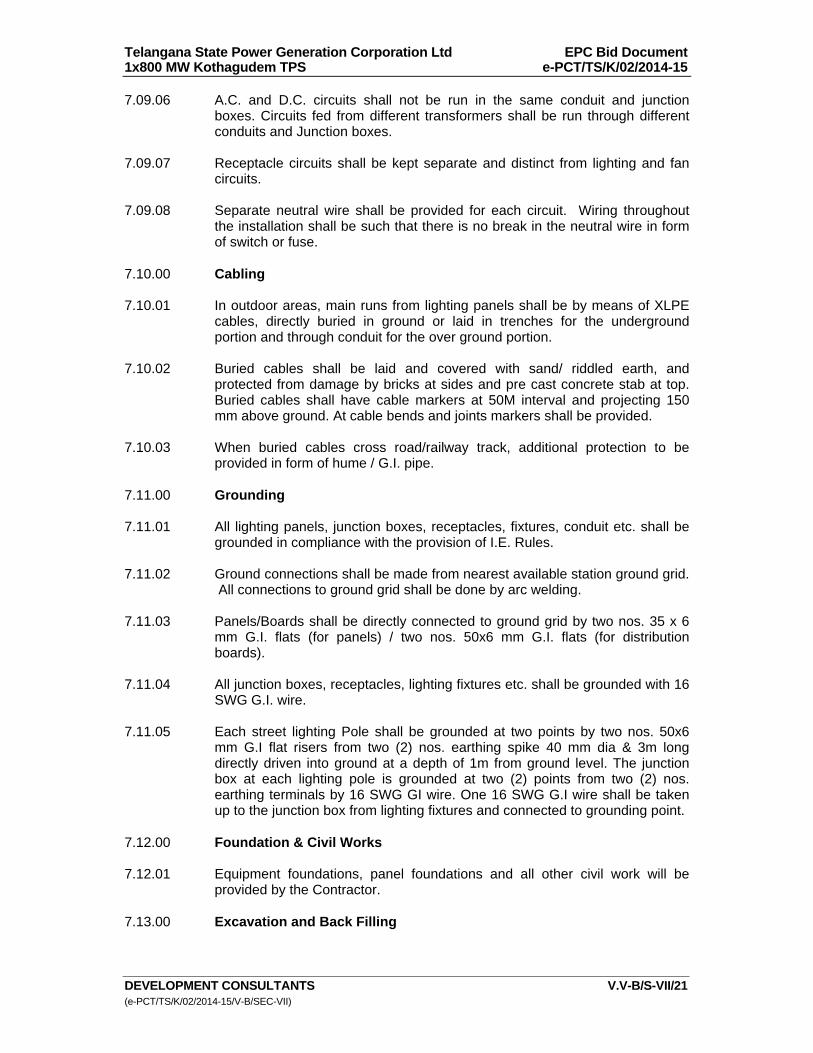
Telangana State Power Generation Corporation Ltd EPC Bid Document 1x800 MW Kothagudem TPS e-PCT/TS/K/02/2014-15
DEVELOPMENT CONSULTANTS V.V-B/S-VII/21 (e-PCT/TS/K/02/2014-15/V-B/SEC-VII)
7.09.06 A.C. and D.C. circuits shall not be run in the same conduit and junction boxes. Circuits fed from different transformers shall be run through different conduits and Junction boxes.
7.09.07 Receptacle circuits shall be kept separate and distinct from lighting and fan
circuits. 7.09.08 Separate neutral wire shall be provided for each circuit. Wiring throughout
the installation shall be such that there is no break in the neutral wire in form of switch or fuse.
7.10.00 Cabling 7.10.01 In outdoor areas, main runs from lighting panels shall be by means of XLPE
cables, directly buried in ground or laid in trenches for the underground portion and through conduit for the over ground portion.
7.10.02 Buried cables shall be laid and covered with sand/ riddled earth, and
protected from damage by bricks at sides and pre cast concrete stab at top. Buried cables shall have cable markers at 50M interval and projecting 150 mm above ground. At cable bends and joints markers shall be provided.
7.10.03 When buried cables cross road/railway track, additional protection to be
provided in form of hume / G.I. pipe. 7.11.00 Grounding 7.11.01 All lighting panels, junction boxes, receptacles, fixtures, conduit etc. shall be
grounded in compliance with the provision of I.E. Rules. 7.11.02 Ground connections shall be made from nearest available station ground grid.
All connections to ground grid shall be done by arc welding. 7.11.03 Panels/Boards shall be directly connected to ground grid by two nos. 35 x 6
mm G.I. flats (for panels) / two nos. 50x6 mm G.I. flats (for distribution boards).
7.11.04 All junction boxes, receptacles, lighting fixtures etc. shall be grounded with 16
SWG G.I. wire. 7.11.05 Each street lighting Pole shall be grounded at two points by two nos. 50x6
mm G.I flat risers from two (2) nos. earthing spike 40 mm dia & 3m long directly driven into ground at a depth of 1m from ground level. The junction box at each lighting pole is grounded at two (2) points from two (2) nos. earthing terminals by 16 SWG GI wire. One 16 SWG G.I wire shall be taken up to the junction box from lighting fixtures and connected to grounding point.
7.12.00 Foundation & Civil Works 7.12.01 Equipment foundations, panel foundations and all other civil work will be
provided by the Contractor. 7.13.00 Excavation and Back Filling
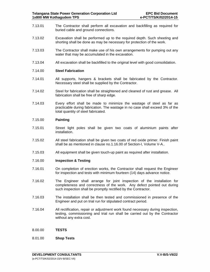
Telangana State Power Generation Corporation Ltd EPC Bid Document 1x800 MW Kothagudem TPS e-PCT/TS/K/02/2014-15
DEVELOPMENT CONSULTANTS V.V-B/S-VII/22 (e-PCT/TS/K/02/2014-15/V-B/SEC-VII)
7.13.01 The Contractor shall perform all excavation and backfilling as required for buried cable and ground connections.
7.13.02 Excavation shall be performed up to the required depth. Such sheeting and
shorting shall be done as may be necessary for protection of the work. 7.13.03 The Contractor shall make use of his own arrangements for pumping out any
water that may be accumulated in the excavation. 7.13.04 All excavation shall be backfilled to the original level with good consolidation. 7.14.00 Steel Fabrication 7.14.01 All supports, hangers & brackets shall be fabricated by the Contractor.
Necessary steel shall be supplied by the Contractor. 7.14.02 Steel for fabrication shall be straightened and cleaned of rust and grease. All
fabrication shall be free of sharp edge. 7.14.03 Every effort shall be made to minimize the wastage of steel as far as
practicable during fabrication. The wastage in no case shall exceed 3% of the total quantity of steel fabricated.
7.15.00 Painting
7.15.01 Street light poles shall be given two coats of aluminium paints after
installation. 7.15.02 All steel fabrication shall be given two coats of red oxide primer. Finish paint
shall be as mentioned in clause no.1.16.00 of Section-I, Volume V-A.. 7.15.03 All equipment shall be given touch-up paint as required after installation. 7.16.00 Inspection & Testing 7.16.01 On completion of erection works, the Contractor shall request the Engineer
for inspection and tests with minimum fourteen (14) days advance notice. 7.16.02 The Engineer shall arrange for joint inspection of the installation for
completeness and correctness of the work. Any defect pointed out during such inspection shall be promptly rectified by the Contractor.
7.16.03 The installation shall be then tested and commissioned in presence of the
Engineer and put on trial run for stipulated contract period. 7.16.04 All rectification, repair or adjustment work found necessary during inspection,
testing, commissioning and trial run shall be carried out by the Contractor without any extra cost.
8.00.00 TESTS 8.01.00 Shop Tests

Telangana State Power Generation Corporation Ltd EPC Bid Document 1x800 MW Kothagudem TPS e-PCT/TS/K/02/2014-15
DEVELOPMENT CONSULTANTS V.V-B/S-VII/23 (e-PCT/TS/K/02/2014-15/V-B/SEC-VII)
8.01.01 All equipment shall be completely assembled, wired, adjusted and routine tested as per relevant Indian Standards at manufacturer's works.
8.01.02 Tests on lighting Distribution Boards/Panels shall include : a) Wiring continuity tests. b) High voltage and insulation tests. c) Operational tests. 8.02.00 Site Tests 8.02.01 Contractor shall thoroughly test and megger all cables, wires and equipment
to prove that the same are free from ground and short circuit. 8.02.02 If any ground or short circuit is found, the fault shall be rectified or the cable
and/or equipment replaced. 8.02.03 All equipment shall be demonstrated to operate in accordance with the
requirements of this specification. 8.02.04 Illumination in different areas are as per designed lux level should be
established. 9.00.00 DRAWINGS, DATA & MANUALS 9.01.00 Drawings, data and manuals shall be submitted in triplicate with the bid and in
quantities and procedures as specified in the General Condition of Contract and/or elsewhere in this specification for approval and subsequent distribution after the issue of Letter of Intent.
9.02.00 To be submitted with the Bid 9.02.01 Make, type and catalogue number of lighting fixtures, lamps and accessories
along with technical leaflets, data sheets, polar curves etc. 9.02.02 Typical outline drawings, showing constructional features, cable/ conduit
entry, fixing arrangements etc of : a) Lighting Distribution Board & Panel/receptacles/junction boxes.
b) Street light pole.
9.02.03 Technical leaflets and data sheet on each piece of equipment / device such as MCB, switch fuse, MCCB, receptacle etc.
9.02.04 Type test certificates on lighting fixtures and lighting panels, transformer,
ballast, power cables. 9.03.00 To be submitted after Award of Contract 9.03.01 All relevant drawings and data pertaining to the lighting system like GTP, GA
drawing, BOM, lighting layout drawings showing disposition of fixtures,

Telangana State Power Generation Corporation Ltd EPC Bid Document 1x800 MW Kothagudem TPS e-PCT/TS/K/02/2014-15
DEVELOPMENT CONSULTANTS V.V-B/S-VII/24 (e-PCT/TS/K/02/2014-15/V-B/SEC-VII)
panels, conduit/wire routing, schematic drawing, QAP, etc. shall be submitted by the Bidder for the approval of Owner/Owner’s consultant. Also refer clause no. 1.19.02(u) of Section-I of Volume – V-A: Technical Specifications for Electrical Equipment & Accessories.
9.03.02 AS-BUILT lighting layout and erection drawings, properly incorporating the
changes/alterations/field modifications, if any, as carried out at field along with circuit distribution schemes of all lighting panels, conduit and cable routing and as acceptable to the Owner.
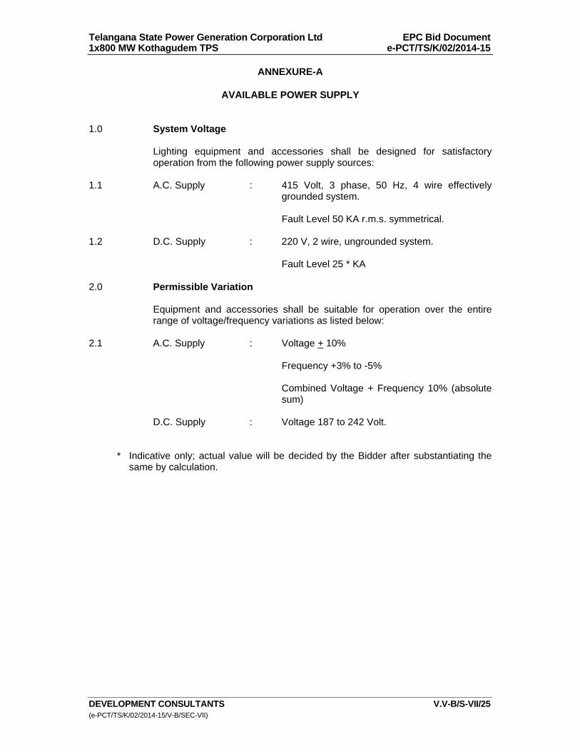
Telangana State Power Generation Corporation Ltd EPC Bid Document 1x800 MW Kothagudem TPS e-PCT/TS/K/02/2014-15
DEVELOPMENT CONSULTANTS V.V-B/S-VII/25 (e-PCT/TS/K/02/2014-15/V-B/SEC-VII)
ANNEXURE-A
AVAILABLE POWER SUPPLY 1.0 System Voltage Lighting equipment and accessories shall be designed for satisfactory
operation from the following power supply sources: 1.1 A.C. Supply : 415 Volt, 3 phase, 50 Hz, 4 wire effectively
grounded system. Fault Level 50 KA r.m.s. symmetrical. 1.2 D.C. Supply : 220 V, 2 wire, ungrounded system. Fault Level 25 * KA 2.0 Permissible Variation Equipment and accessories shall be suitable for operation over the entire
range of voltage/frequency variations as listed below: 2.1 A.C. Supply : Voltage +_ 10% Frequency +3% to -5% Combined Voltage + Frequency 10% (absolute
sum) D.C. Supply : Voltage 187 to 242 Volt. * Indicative only; actual value will be decided by the Bidder after substantiating the
same by calculation.

Telangana State Power Generation Corporation Ltd EPC Bid Document 1x800 MW Kothagudem TPS e-PCT/TS/K/02/2014-15
DEVELOPMENT CONSULTANTS V.V-B/S-VII/26 (e-PCT/TS/K/02/2014-15/V-B/SEC-VII)
ANNEXURE-B
TYPES OF LIGHTING EQUIPMENT 1.0 LIGHTING FIXTURES & LAMPS
Each lighting fixture shall be furnished complete with associated lamp, holder and control gear fully wired up. Control should include copper ballast, electronic choke, capacitor starter, electronic-igniter (separate type), fuse connector block etc.
Well glass fittings for HPSV lamps higher wattage (250/400 W) floodlight luminaire, the control gear will be separate/non-integral type whereas for high bay, streetlight and mini flood light fixture, the control gear shall be integral type.
SL. NO.
FIXTURE TYPE REFERENCE FIXTURE NO.
DESCRIPTION AREA OF USE
1.1 SA GE GET CI 1X28 C/S HF + Reflector 1X28 (ALM) / eqv.
Surface / pendant mounted with Al reflector commercial / decorative type luminaire suitable for 1 x 28W T5 FL
Swgr room / MCC room / Workshop / Maint. Shop / Office / Toilet / Corridor / Pantry / Stores
1.2 SB GE GET CI 1X28 C/S HF / eqv.
Surface / pendant mounted without reflector commercial / decorative type luminaire suitable for 1 x 28W T5 FL
Swgr room / MCC room / Workshop / Maint. Shop / Office / Toilet / Corridor / Stairs / Pantry / Stores
1.3 DA GE GET CI 2X28 C/S HF + Reflector 2X28 (ALM) / eqv.
Surface / pendant mounted with Al reflector commercial / decorative type luminaire suitable for 2 x 28W T5 FL
Swgr room / MCC room / Workshop / Maint. Shop / Office / Toilet / Corridor / Pantry / Stores
1.4 DB GE GET CI 2X28 C/S HF / eqv.
Surface / pendant mounted without reflector commercial / decorative type luminaire suitable for 2 x 28W T5 FL
Swgr room / MCC room / Workshop / Maint. Shop / Office / Toilet / Corridor / Stairs / Pantry / Stores
1.5 DC Philips TCS 150 2XTL5-28W MIEBT 228 / eqv.
Decorative, surface / pendant mounted mirror optics luminaire housing made up of CRCA sheet steel, powder coated white, accommodating all electrical accessories pre-wired up to a terminal block suitable for 2 x 28W TL5.
Office rooms / Corridor / Conference Room / Engineer's Room
1.6 DD Philips TMS 669 M 2XTL5-28W HF D6 / eqv.
Decorative, recess mounted mirror optics luminaire, housing made up of CRCA sheet steel, powder coated white,
False Ceiling areas (Control Room / Electronic Eqpt. Room / Office / Conference room /
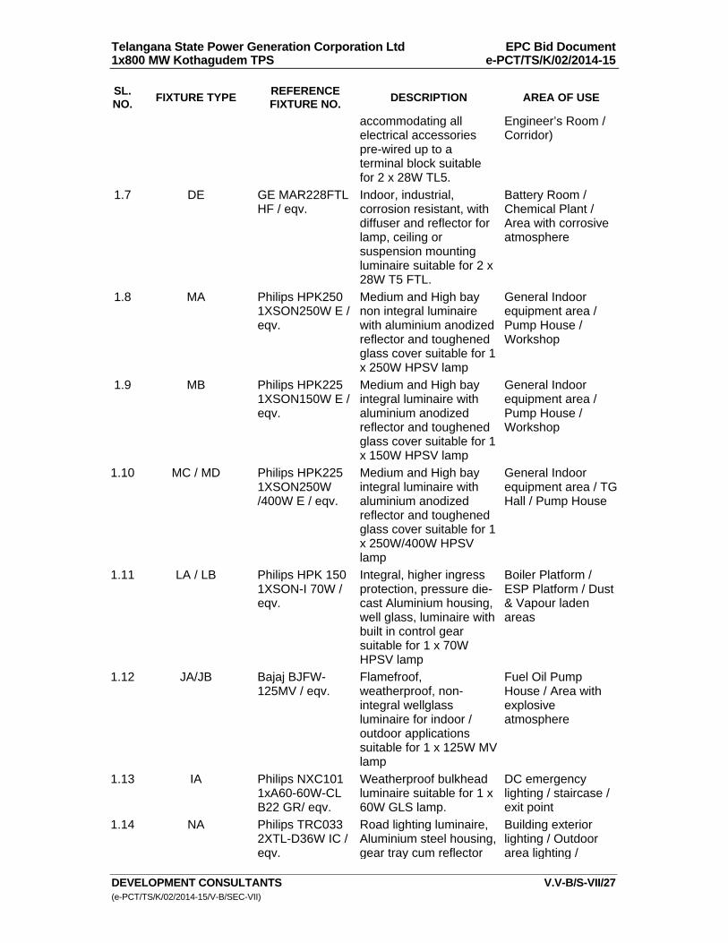
Telangana State Power Generation Corporation Ltd EPC Bid Document 1x800 MW Kothagudem TPS e-PCT/TS/K/02/2014-15
DEVELOPMENT CONSULTANTS V.V-B/S-VII/27 (e-PCT/TS/K/02/2014-15/V-B/SEC-VII)
SL. NO.
FIXTURE TYPE REFERENCE FIXTURE NO.
DESCRIPTION AREA OF USE
accommodating all electrical accessories pre-wired up to a terminal block suitable for 2 x 28W TL5.
Engineer’s Room / Corridor)
1.7 DE GE MAR228FTL HF / eqv.
Indoor, industrial, corrosion resistant, with diffuser and reflector for lamp, ceiling or suspension mounting luminaire suitable for 2 x 28W T5 FTL.
Battery Room / Chemical Plant / Area with corrosive atmosphere
1.8 MA Philips HPK250 1XSON250W E / eqv.
Medium and High bay non integral luminaire with aluminium anodized reflector and toughened glass cover suitable for 1 x 250W HPSV lamp
General Indoor equipment area / Pump House / Workshop
1.9 MB Philips HPK225 1XSON150W E / eqv.
Medium and High bay integral luminaire with aluminium anodized reflector and toughened glass cover suitable for 1 x 150W HPSV lamp
General Indoor equipment area / Pump House / Workshop
1.10 MC / MD Philips HPK225 1XSON250W /400W E / eqv.
Medium and High bay integral luminaire with aluminium anodized reflector and toughened glass cover suitable for 1 x 250W/400W HPSV lamp
General Indoor equipment area / TG Hall / Pump House
1.11 LA / LB Philips HPK 150 1XSON-I 70W / eqv.
Integral, higher ingress protection, pressure die-cast Aluminium housing, well glass, luminaire with built in control gear suitable for 1 x 70W HPSV lamp
Boiler Platform / ESP Platform / Dust & Vapour laden areas
1.12 JA/JB Bajaj BJFW-125MV / eqv.
Flamefroof, weatherproof, non-integral wellglass luminaire for indoor / outdoor applications suitable for 1 x 125W MV lamp
Fuel Oil Pump House / Area with explosive atmosphere
1.13 IA Philips NXC101 1xA60-60W-CL B22 GR/ eqv.
Weatherproof bulkhead luminaire suitable for 1 x 60W GLS lamp.
DC emergency lighting / staircase / exit point
1.14 NA Philips TRC033 2XTL-D36W IC / eqv.
Road lighting luminaire, Aluminium steel housing, gear tray cum reflector
Building exterior lighting / Outdoor area lighting /

Telangana State Power Generation Corporation Ltd EPC Bid Document 1x800 MW Kothagudem TPS e-PCT/TS/K/02/2014-15
DEVELOPMENT CONSULTANTS V.V-B/S-VII/28 (e-PCT/TS/K/02/2014-15/V-B/SEC-VII)
SL. NO.
FIXTURE TYPE REFERENCE FIXTURE NO.
DESCRIPTION AREA OF USE
made of CRCA sheet, with acrylic cover suitable for 2X36W TL-D.
Outdoor eqpt. Area
1.15 TA Philips SGP 325 1XSON-T 150W FG / eqv.
Street light luminaire with pressure die cast aluminium housing, POT optics reflector and heat resistant toughened flat glass cover (IP 65) with 1 x 150W HPSV lamp - pole mounted
Street lighting / boundary lighting
1.16 TB Philips SGP 325 1XSON-T 250W FG / eqv.
Street light luminaire with pressure die cast aluminium housing, POT optics reflector and heat resistant toughened flat glass cover (IP 65) with 1 x 250W HPSV lamp - pole mounted
Street lighting / boundary lighting
1.17 CA Bajaj BJC-111 / eqv.
Surface mounting decorative luminaire with 1 x 11W CFL
Toilet / Wash basin / staircase
1.18 CB Philips FCS 100 1XPL-C/2P 18W I 240V / eqv.
Surface mounting decorative downlight luminaire, electrochemical brightened reflector with 1 x 18W PL-C
Lobby / Staircase
1.19 CC Philips FBH 145 M 1XPL-C/2P 18W / 220V / eqv.
Recess, decorative vertical mounting downlighter, high efficiency optics and option of multiple attachment suitable for 1X 13W/18W PL-C
Control Room / Electronic Eqpt. Room for DC emergency light
1.20 CD Philips FBH 145 M 2XPL-C/4P 18W HF 240V LH / eqv.
Recess, decorative vertical mounting downlighter, high efficiency optics and option of multiple attachment suitable for 2X 18W PL-C
Control Room / Electronic Eqpt. Room / Conference room / Office / Engineer's Room as UPS emergency light
1.21 PA Philips SWF231 1XSON-T 150W A / eqv.
Compact, sturdy, general purpose with integral gear floodlight luminaire suitable for with 1 x 150W HPSV lamp
Area lighting / Yard lighting / Floodlighting purpose
1.22 PB Philips SWF331 1XSON-T 250W
Compact, sturdy, general purpose with integral
Area lighting / Yard lighting /
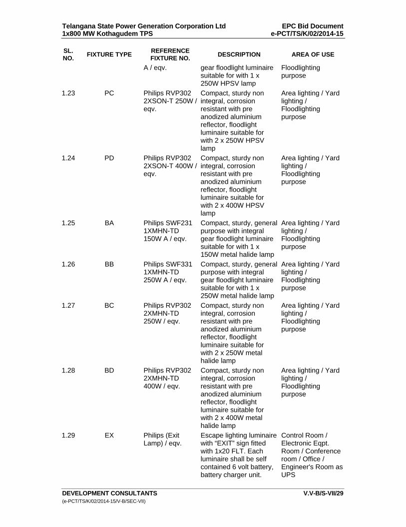
Telangana State Power Generation Corporation Ltd EPC Bid Document 1x800 MW Kothagudem TPS e-PCT/TS/K/02/2014-15
DEVELOPMENT CONSULTANTS V.V-B/S-VII/29 (e-PCT/TS/K/02/2014-15/V-B/SEC-VII)
SL. NO.
FIXTURE TYPE REFERENCE FIXTURE NO.
DESCRIPTION AREA OF USE
A / eqv. gear floodlight luminaire suitable for with 1 x 250W HPSV lamp
Floodlighting purpose
1.23 PC Philips RVP302 2XSON-T 250W /eqv.
Compact, sturdy non integral, corrosion resistant with pre anodized aluminium reflector, floodlight luminaire suitable for with 2 x 250W HPSV lamp
Area lighting / Yard lighting / Floodlighting purpose
1.24 PD Philips RVP302 2XSON-T 400W /eqv.
Compact, sturdy non integral, corrosion resistant with pre anodized aluminium reflector, floodlight luminaire suitable for with 2 x 400W HPSV lamp
Area lighting / Yard lighting / Floodlighting purpose
1.25 BA Philips SWF231 1XMHN-TD 150W A / eqv.
Compact, sturdy, general purpose with integral gear floodlight luminaire suitable for with 1 x 150W metal halide lamp
Area lighting / Yard lighting / Floodlighting purpose
1.26 BB Philips SWF331 1XMHN-TD 250W A / eqv.
Compact, sturdy, general purpose with integral gear floodlight luminaire suitable for with 1 x 250W metal halide lamp
Area lighting / Yard lighting / Floodlighting purpose
1.27 BC Philips RVP302 2XMHN-TD 250W / eqv.
Compact, sturdy non integral, corrosion resistant with pre anodized aluminium reflector, floodlight luminaire suitable for with 2 x 250W metal halide lamp
Area lighting / Yard lighting / Floodlighting purpose
1.28 BD Philips RVP302 2XMHN-TD 400W / eqv.
Compact, sturdy non integral, corrosion resistant with pre anodized aluminium reflector, floodlight luminaire suitable for with 2 x 400W metal halide lamp
Area lighting / Yard lighting / Floodlighting purpose
1.29 EX Philips (Exit Lamp) / eqv.
Escape lighting luminaire with “EXIT” sign fitted with 1x20 FLT. Each luminaire shall be self contained 6 volt battery, battery charger unit.
Control Room / Electronic Eqpt. Room / Conference room / Office / Engineer's Room as UPS
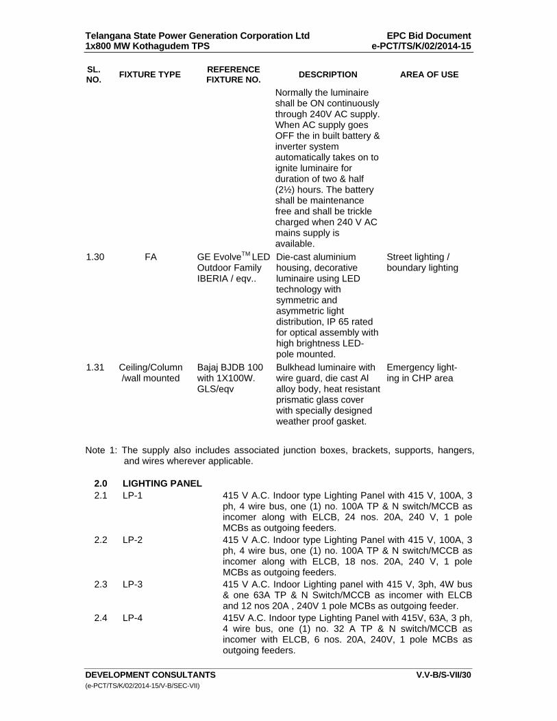
Telangana State Power Generation Corporation Ltd EPC Bid Document 1x800 MW Kothagudem TPS e-PCT/TS/K/02/2014-15
DEVELOPMENT CONSULTANTS V.V-B/S-VII/30 (e-PCT/TS/K/02/2014-15/V-B/SEC-VII)
SL. NO.
FIXTURE TYPE REFERENCE FIXTURE NO.
DESCRIPTION AREA OF USE
Normally the luminaire shall be ON continuously through 240V AC supply. When AC supply goes OFF the in built battery & inverter system automatically takes on to ignite luminaire for duration of two & half (2½) hours. The battery shall be maintenance free and shall be trickle charged when 240 V AC mains supply is available.
1.30 FA GE EvolveTM LED Outdoor Family IBERIA / eqv..
Die-cast aluminium housing, decorative luminaire using LED technology with symmetric and asymmetric light distribution, IP 65 rated for optical assembly with high brightness LED- pole mounted.
Street lighting / boundary lighting
1.31 Ceiling/Column /wall mounted
Bajaj BJDB 100 with 1X100W. GLS/eqv
Bulkhead luminaire with wire guard, die cast Al alloy body, heat resistant prismatic glass cover with specially designed weather proof gasket.
Emergency light- ing in CHP area
Note 1: The supply also includes associated junction boxes, brackets, supports, hangers,
and wires wherever applicable.
2.0 LIGHTING PANEL 2.1 LP-1 415 V A.C. Indoor type Lighting Panel with 415 V, 100A, 3
ph, 4 wire bus, one (1) no. 100A TP & N switch/MCCB as incomer along with ELCB, 24 nos. 20A, 240 V, 1 pole MCBs as outgoing feeders.
2.2 LP-2 415 V A.C. Indoor type Lighting Panel with 415 V, 100A, 3 ph, 4 wire bus, one (1) no. 100A TP & N switch/MCCB as incomer along with ELCB, 18 nos. 20A, 240 V, 1 pole MCBs as outgoing feeders.
2.3 LP-3 415 V A.C. Indoor Lighting panel with 415 V, 3ph, 4W bus & one 63A TP & N Switch/MCCB as incomer with ELCBand 12 nos 20A , 240V 1 pole MCBs as outgoing feeder.
2.4 LP-4 415V A.C. Indoor type Lighting Panel with 415V, 63A, 3 ph, 4 wire bus, one (1) no. 32 A TP & N switch/MCCB as incomer with ELCB, 6 nos. 20A, 240V, 1 pole MCBs as outgoing feeders.
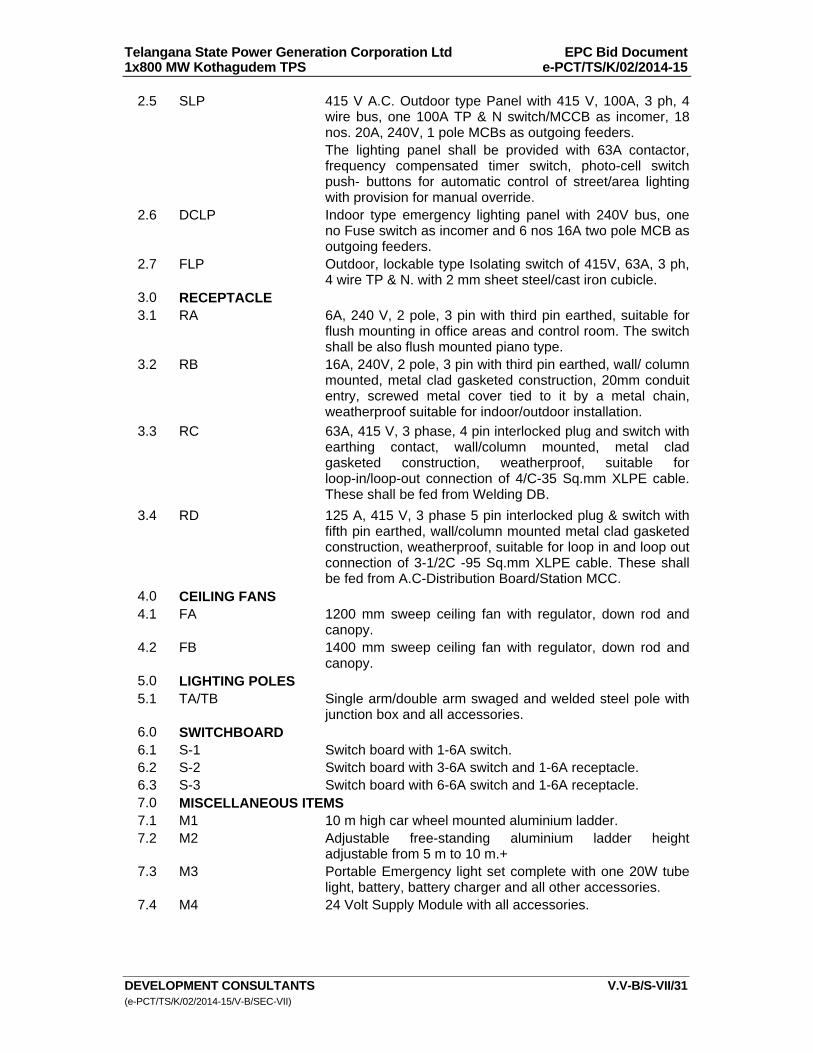
Telangana State Power Generation Corporation Ltd EPC Bid Document 1x800 MW Kothagudem TPS e-PCT/TS/K/02/2014-15
DEVELOPMENT CONSULTANTS V.V-B/S-VII/31 (e-PCT/TS/K/02/2014-15/V-B/SEC-VII)
2.5 SLP 415 V A.C. Outdoor type Panel with 415 V, 100A, 3 ph, 4 wire bus, one 100A TP & N switch/MCCB as incomer, 18 nos. 20A, 240V, 1 pole MCBs as outgoing feeders.
The lighting panel shall be provided with 63A contactor, frequency compensated timer switch, photo-cell switch push- buttons for automatic control of street/area lighting with provision for manual override.
2.6 DCLP Indoor type emergency lighting panel with 240V bus, one no Fuse switch as incomer and 6 nos 16A two pole MCB as outgoing feeders.
2.7 FLP Outdoor, lockable type Isolating switch of 415V, 63A, 3 ph, 4 wire TP & N. with 2 mm sheet steel/cast iron cubicle.
3.0 RECEPTACLE 3.1 RA 6A, 240 V, 2 pole, 3 pin with third pin earthed, suitable for
flush mounting in office areas and control room. The switch shall be also flush mounted piano type.
3.2 RB 16A, 240V, 2 pole, 3 pin with third pin earthed, wall/ column mounted, metal clad gasketed construction, 20mm conduit entry, screwed metal cover tied to it by a metal chain, weatherproof suitable for indoor/outdoor installation.
3.3 RC 63A, 415 V, 3 phase, 4 pin interlocked plug and switch with earthing contact, wall/column mounted, metal clad gasketed construction, weatherproof, suitable for loop-in/loop-out connection of 4/C-35 Sq.mm XLPE cable. These shall be fed from Welding DB.
3.4 RD 125 A, 415 V, 3 phase 5 pin interlocked plug & switch with fifth pin earthed, wall/column mounted metal clad gasketed construction, weatherproof, suitable for loop in and loop out connection of 3-1/2C -95 Sq.mm XLPE cable. These shall be fed from A.C-Distribution Board/Station MCC.
4.0 CEILING FANS 4.1 FA 1200 mm sweep ceiling fan with regulator, down rod and
canopy. 4.2 FB 1400 mm sweep ceiling fan with regulator, down rod and
canopy. 5.0 LIGHTING POLES 5.1 TA/TB Single arm/double arm swaged and welded steel pole with
junction box and all accessories. 6.0 SWITCHBOARD 6.1 S-1 Switch board with 1-6A switch. 6.2 S-2 Switch board with 3-6A switch and 1-6A receptacle. 6.3 S-3 Switch board with 6-6A switch and 1-6A receptacle. 7.0 MISCELLANEOUS ITEMS 7.1 M1 10 m high car wheel mounted aluminium ladder. 7.2 M2 Adjustable free-standing aluminium ladder height
adjustable from 5 m to 10 m.+ 7.3 M3 Portable Emergency light set complete with one 20W tube
light, battery, battery charger and all other accessories. 7.4 M4 24 Volt Supply Module with all accessories.
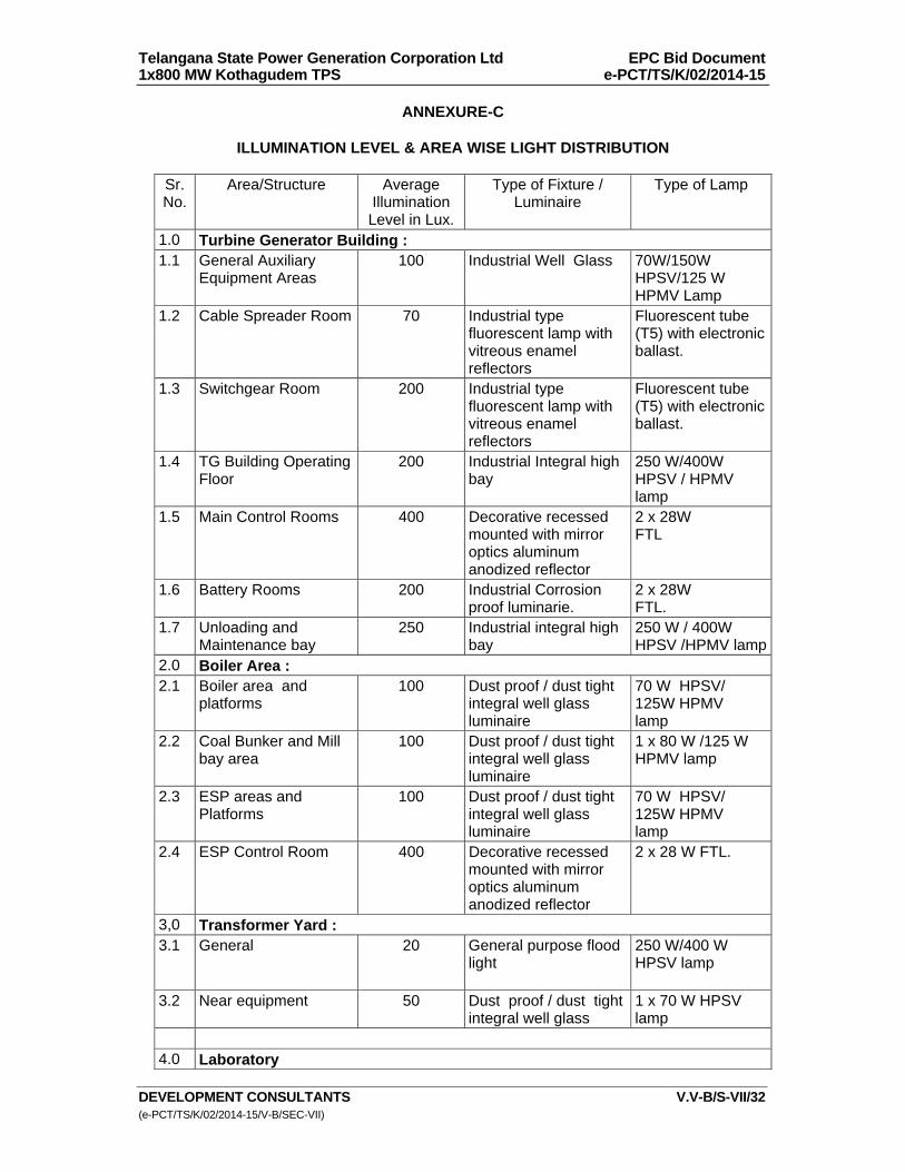
Telangana State Power Generation Corporation Ltd EPC Bid Document 1x800 MW Kothagudem TPS e-PCT/TS/K/02/2014-15
DEVELOPMENT CONSULTANTS V.V-B/S-VII/32 (e-PCT/TS/K/02/2014-15/V-B/SEC-VII)
ANNEXURE-C
ILLUMINATION LEVEL & AREA WISE LIGHT DISTRIBUTION
Sr. No.
Area/Structure Average Illumination Level in Lux.
Type of Fixture / Luminaire
Type of Lamp
1.0 Turbine Generator Building : 1.1 General Auxiliary
Equipment Areas 100 Industrial Well Glass 70W/150W
HPSV/125 W HPMV Lamp
1.2 Cable Spreader Room 70 Industrial type fluorescent lamp with vitreous enamel reflectors
Fluorescent tube (T5) with electronic ballast.
1.3 Switchgear Room 200 Industrial type fluorescent lamp with vitreous enamel reflectors
Fluorescent tube (T5) with electronic ballast.
1.4 TG Building Operating Floor
200 Industrial Integral high bay
250 W/400W HPSV / HPMV lamp
1.5 Main Control Rooms 400 Decorative recessed mounted with mirror optics aluminum anodized reflector
2 x 28W FTL
1.6 Battery Rooms 200 Industrial Corrosion proof luminarie.
2 x 28W FTL.
1.7 Unloading and Maintenance bay
250 Industrial integral high bay
250 W / 400W HPSV /HPMV lamp
2.0 Boiler Area : 2.1 Boiler area and
platforms 100 Dust proof / dust tight
integral well glass luminaire
70 W HPSV/ 125W HPMV lamp
2.2 Coal Bunker and Mill bay area
100 Dust proof / dust tight integral well glass luminaire
1 x 80 W /125 W HPMV lamp
2.3 ESP areas and Platforms
100 Dust proof / dust tight integral well glass luminaire
70 W HPSV/ 125W HPMV lamp
2.4 ESP Control Room 400 Decorative recessed mounted with mirror optics aluminum anodized reflector
2 x 28 W FTL.
3,0 Transformer Yard : 3.1 General 20 General purpose flood
light 250 W/400 W HPSV lamp
3.2 Near equipment 50 Dust proof / dust tight integral well glass
1 x 70 W HPSV lamp
4.0 Laboratory
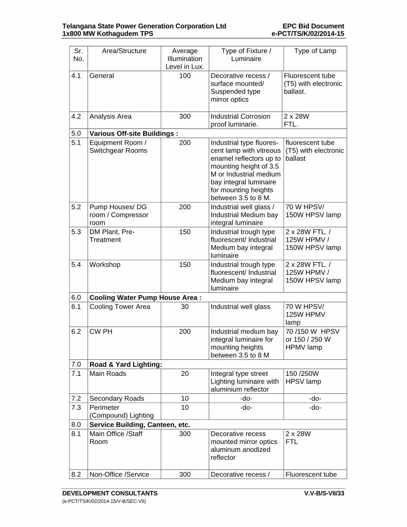
Telangana State Power Generation Corporation Ltd EPC Bid Document 1x800 MW Kothagudem TPS e-PCT/TS/K/02/2014-15
DEVELOPMENT CONSULTANTS V.V-B/S-VII/33 (e-PCT/TS/K/02/2014-15/V-B/SEC-VII)
Sr. No.
Area/Structure Average Illumination Level in Lux.
Type of Fixture / Luminaire
Type of Lamp
4.1 General 100 Decorative recess / surface mounted/ Suspended type mirror optics
Fluorescent tube (T5) with electronic ballast.
4.2 Analysis Area 300 Industrial Corrosion proof luminarie.
2 x 28W FTL.
5.0 Various Off-site Buildings : 5.1 Equipment Room /
Switchgear Rooms 200 Industrial type fluores-
cent lamp with vitreous enamel reflectors up to mounting height of 3.5 M or Industrial medium bay integral luminaire for mounting heights between 3.5 to 8 M.
fluorescent tube (T5) with electronic ballast
5.2 Pump Houses/ DG room / Compressor room
200 Industrial well glass / Industrial Medium bay integral luminaire
70 W HPSV/ 150W HPSV lamp
5.3 DM Plant, Pre- Treatment
150 Industrial trough type fluorescent/ Industrial Medium bay integral luminaire
2 x 28W FTL. / 125W HPMV / 150W HPSV lamp
5.4 Workshop 150 Industrial trough type fluorescent/ Industrial Medium bay integral luminaire
2 x 28W FTL. / 125W HPMV / 150W HPSV lamp
6.0 Cooling Water Pump House Area :6.1 Cooling Tower Area 30 Industrial well glass 70 W HPSV/
125W HPMV lamp
6.2 CW PH 200 Industrial medium bay integral luminaire for mounting heights between 3.5 to 8 M
70 /150 W HPSV or 150 / 250 W HPMV lamp
7.0 Road & Yard Lighting: 7.1 Main Roads 20 Integral type street
Lighting luminaire with aluminium reflector
150 /250W HPSV lamp
7.2 Secondary Roads 10 -do- -do- 7.3 Perimeter
(Compound) Lighting 10 -do- -do-
8.0 Service Building, Canteen, etc. 8.1 Main Office /Staff
Room 300 Decorative recess
mounted mirror optics aluminum anodized reflector
2 x 28W FTL
8.2 Non-Office /Service 300 Decorative recess / Fluorescent tube
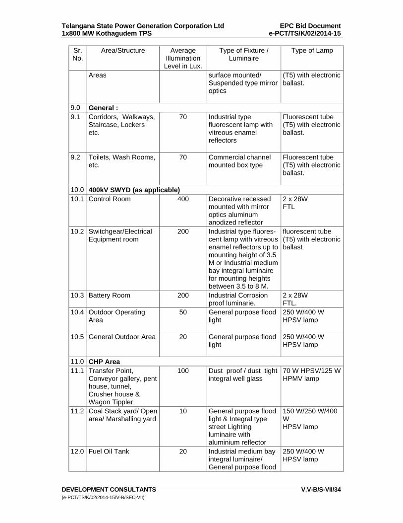
Telangana State Power Generation Corporation Ltd EPC Bid Document 1x800 MW Kothagudem TPS e-PCT/TS/K/02/2014-15
DEVELOPMENT CONSULTANTS V.V-B/S-VII/34 (e-PCT/TS/K/02/2014-15/V-B/SEC-VII)
Sr. No.
Area/Structure Average Illumination Level in Lux.
Type of Fixture / Luminaire
Type of Lamp
Areas surface mounted/ Suspended type mirror optics
(T5) with electronic ballast.
9.0 General : 9.1 Corridors, Walkways,
Staircase, Lockers etc.
70 Industrial type fluorescent lamp with vitreous enamel reflectors
Fluorescent tube (T5) with electronic ballast.
9.2 Toilets, Wash Rooms, etc.
70 Commercial channel mounted box type
Fluorescent tube (T5) with electronic ballast.
10.0 400kV SWYD (as applicable)10.1 Control Room 400 Decorative recessed
mounted with mirror optics aluminum anodized reflector
2 x 28W FTL
10.2 Switchgear/Electrical Equipment room
200 Industrial type fluores-cent lamp with vitreous enamel reflectors up to mounting height of 3.5 M or Industrial medium bay integral luminaire for mounting heights between 3.5 to 8 M.
fluorescent tube (T5) with electronic ballast
10.3 Battery Room 200 Industrial Corrosion proof luminarie.
2 x 28W FTL.
10.4 Outdoor Operating Area
50 General purpose flood light
250 W/400 W HPSV lamp
10.5 General Outdoor Area 20 General purpose flood light
250 W/400 W HPSV lamp
11.0 CHP Area 11.1 Transfer Point,
Conveyor gallery, pent house, tunnel, Crusher house & Wagon Tippler
100 Dust proof / dust tight integral well glass
70 W HPSV/125 W HPMV lamp
11.2 Coal Stack yard/ Open area/ Marshalling yard
10 General purpose flood light & Integral type street Lighting luminaire with aluminium reflector
150 W/250 W/400 W HPSV lamp
12.0 Fuel Oil Tank 20 Industrial medium bay integral luminaire/ General purpose flood
250 W/400 W HPSV lamp
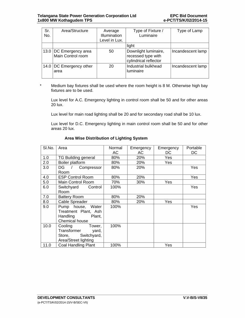
Telangana State Power Generation Corporation Ltd EPC Bid Document 1x800 MW Kothagudem TPS e-PCT/TS/K/02/2014-15
DEVELOPMENT CONSULTANTS V.V-B/S-VII/35 (e-PCT/TS/K/02/2014-15/V-B/SEC-VII)
Sr. No.
Area/Structure Average Illumination Level in Lux.
Type of Fixture / Luminaire
Type of Lamp
light 13.0 DC Emergency area
Main Control room 50 Downlight luminaire,
recessed type with cylindrical reflector
Incandescent lamp
14.0 DC Emergency other area
20 Industrial bulkhead luminaire
Incandescent lamp
* Medium bay fixtures shall be used where the room height is 8 M. Otherwise high bay
fixtures are to be used. Lux level for A.C. Emergency lighting in control room shall be 50 and for other areas
20 lux. Lux level for main road lighting shall be 20 and for secondary road shall be 10 lux. Lux level for D.C. Emergency lighting in main control room shall be 50 and for other
areas 20 lux. Area Wise Distribution of Lighting System
Sl.No. Area Normal AC
Emergency AC
Emergency DC
Portable DC
1.0 TG Building general 80% 20% Yes 2.0 Boiler platform 80% 20% Yes 3.0 DG / Compressor
Room 80% 20% Yes
4.0 ESP Control Room 80% 20% Yes 5.0 Main Control Room 70% 30% Yes 6.0 Switchyard Control
Room 100% Yes
7.0 Battery Room 80% 20% 8.0 Cable Spreader 80% 20% Yes 9.0 Pump house, Water
Treatment Plant, Ash Handling Plant, Chemical house
100% Yes
10.0 Cooling Tower, Transformer yard, Store, Switchyard, Area/Street lighting
100%
11.0 Coal Handling Plant 100% Yes

Telangana State Power Generation Corporation Ltd EPC Bid Document 1x800 MW Kothagudem TPS e-PCT/TS/K/02/2014-15
DEVELOPMENT CONSULTANTS V.V-B/S-VII/36 (e-PCT/TS/K/02/2014-15/V-B/SEC-VII)
ANNEXURE-D
RATINGS AND REQUIREMENTS OF
LIGHTING / WELDINGTRANSFORMER Type : Cast Resin Dry Type KVA rating : to be finalized during detail engineering Voltage rating : 415 V/415 V Cooling : AN P.U. Impedance : 0.045 +_ 10% Voltage control : Off load tap switch/link with change of +_ 5% in
step of 2.5% tapping full capacity. Vector Group : Dyn11 Class of Insulation : F (155C) Maximum Temperature rise over 50C. ambient in winding by resistance : 90C Neutral : Solidly grounded. The secondary neutral of the transformer shall be brought out for getting a grounded 4wire supply. Each transformer shall be routine tested and one transformer shall be type tested in accordance with relevant standard. The transformer shall be liable for rejection if the tolerance on the quoted values of losses, impedance, temperature rise, etc. exceeds the specified values of relevant standard. The transformer shall be mounted inside sheet steel enclosure, which shall be an integral part of Lighting Distribution Board.

Telangana State Power Generation Corporation Ltd EPC Bid Document 1x800 MW Kothagudem TPS e-PCT/TS/K/02/2014-15
DEVELOPMENT CONSULTANTS V.V-B/S-VII/37 (e-PCT/TS/K/02/2014-15/V-B/SEC-VII)
ANNEXURE-E
FITTINGS AND ACCESSORIES OF
LIGHTING / WELDING TRANSFORMER Each transformer shall be equipped with fittings and accessories as listed below : 1. 150 mm dia. winding temperature indicator with maximum reading pointer and
electrically separate sets of contacts for trip and alarm 2. Handling and lifting lugs both for enclosure and core-coil assembly. 3. Jacking pad for core-coil assembly. 4. Inspection cover for cable and box. 5. Door handle operated safety limit switch with 1NO + 1NC contact. 6. Ground bus. 7. IP-55 junction box. 8. Rating and terminal marking plates. Note All indication, alarm, trip contacts provided shall be rated for 2.0A at 220 V D.C. and 5A at 240 V A.C.
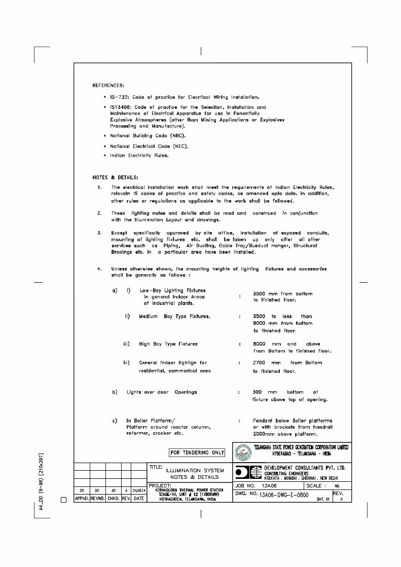
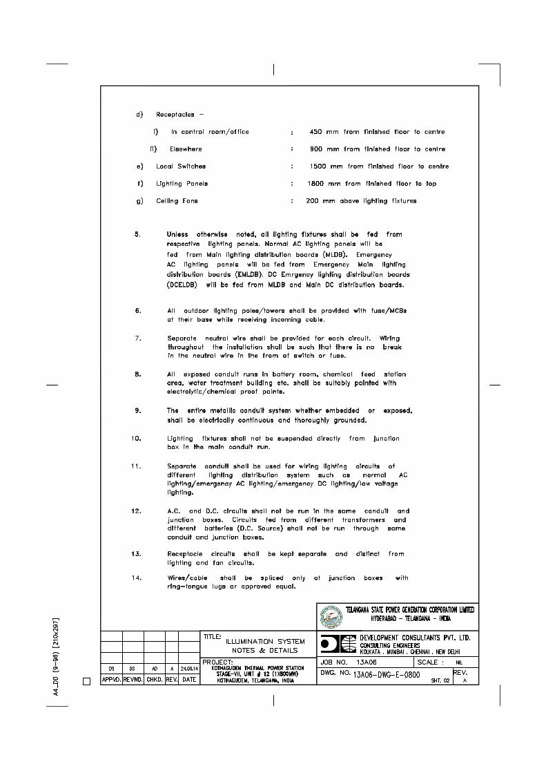
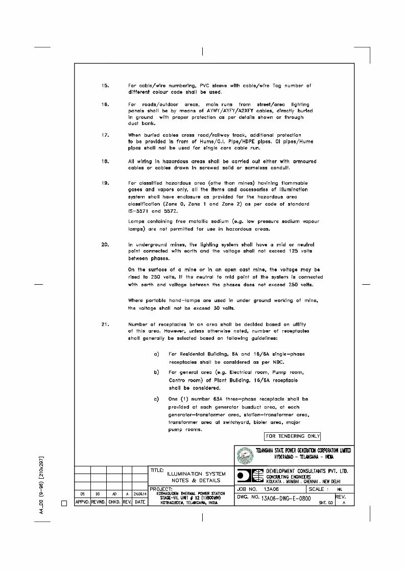
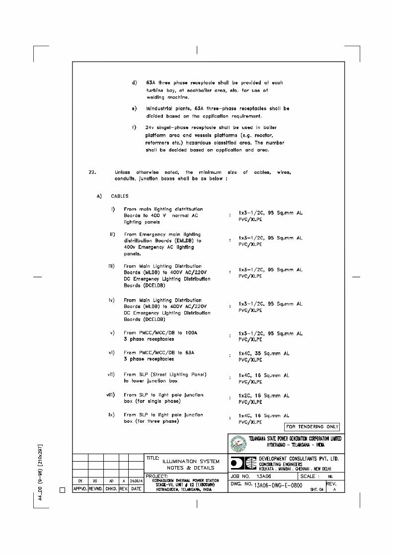
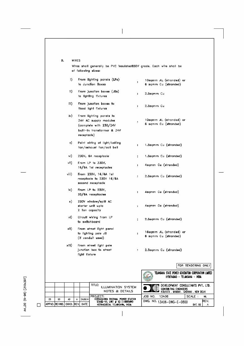
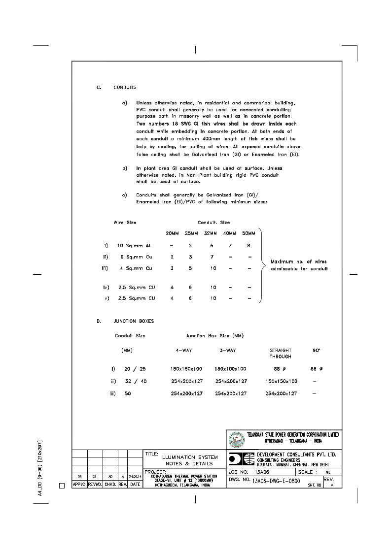
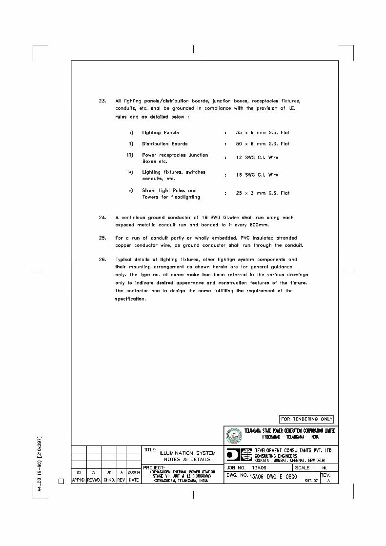

Telangana State Power Generation Corporation Ltd. EPC Bid Document 1x800 MW Kothagudem TPS e-PCT/TS/K/02/2014-15
DEVELOPMENT CONSULTANTS (e-PCT/TS/K/02/2014-15/V-A/SEC-VII)
VOLUME: V-A
SECTION-VII
TECHNICAL SPECIFICATION FOR
415V PMCC/MCC, 415V ACDB AND 220V DCDB
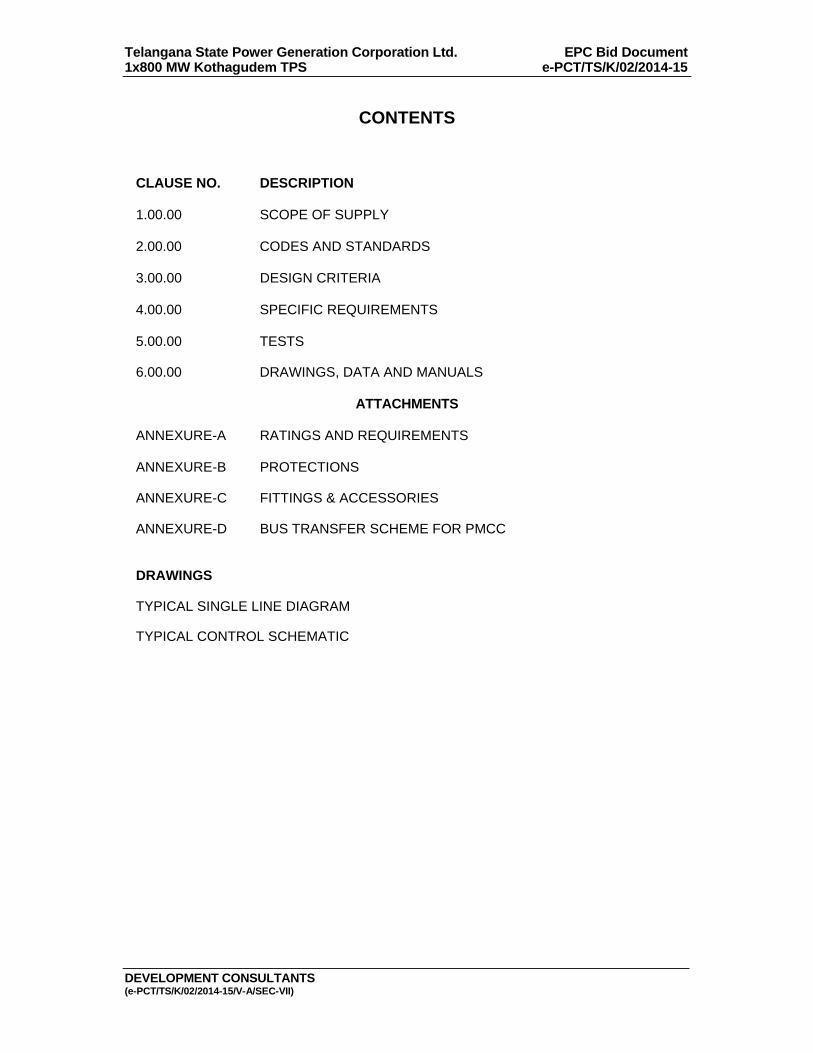
Telangana State Power Generation Corporation Ltd. EPC Bid Document 1x800 MW Kothagudem TPS e-PCT/TS/K/02/2014-15
DEVELOPMENT CONSULTANTS (e-PCT/TS/K/02/2014-15/V-A/SEC-VII)
CONTENTS
CLAUSE NO. DESCRIPTION 1.00.00 SCOPE OF SUPPLY 2.00.00 CODES AND STANDARDS 3.00.00 DESIGN CRITERIA 4.00.00 SPECIFIC REQUIREMENTS 5.00.00 TESTS 6.00.00 DRAWINGS, DATA AND MANUALS
ATTACHMENTS
ANNEXURE-A RATINGS AND REQUIREMENTS
ANNEXURE-B PROTECTIONS ANNEXURE-C FITTINGS & ACCESSORIES ANNEXURE-D BUS TRANSFER SCHEME FOR PMCC
DRAWINGS
TYPICAL SINGLE LINE DIAGRAM TYPICAL CONTROL SCHEMATIC
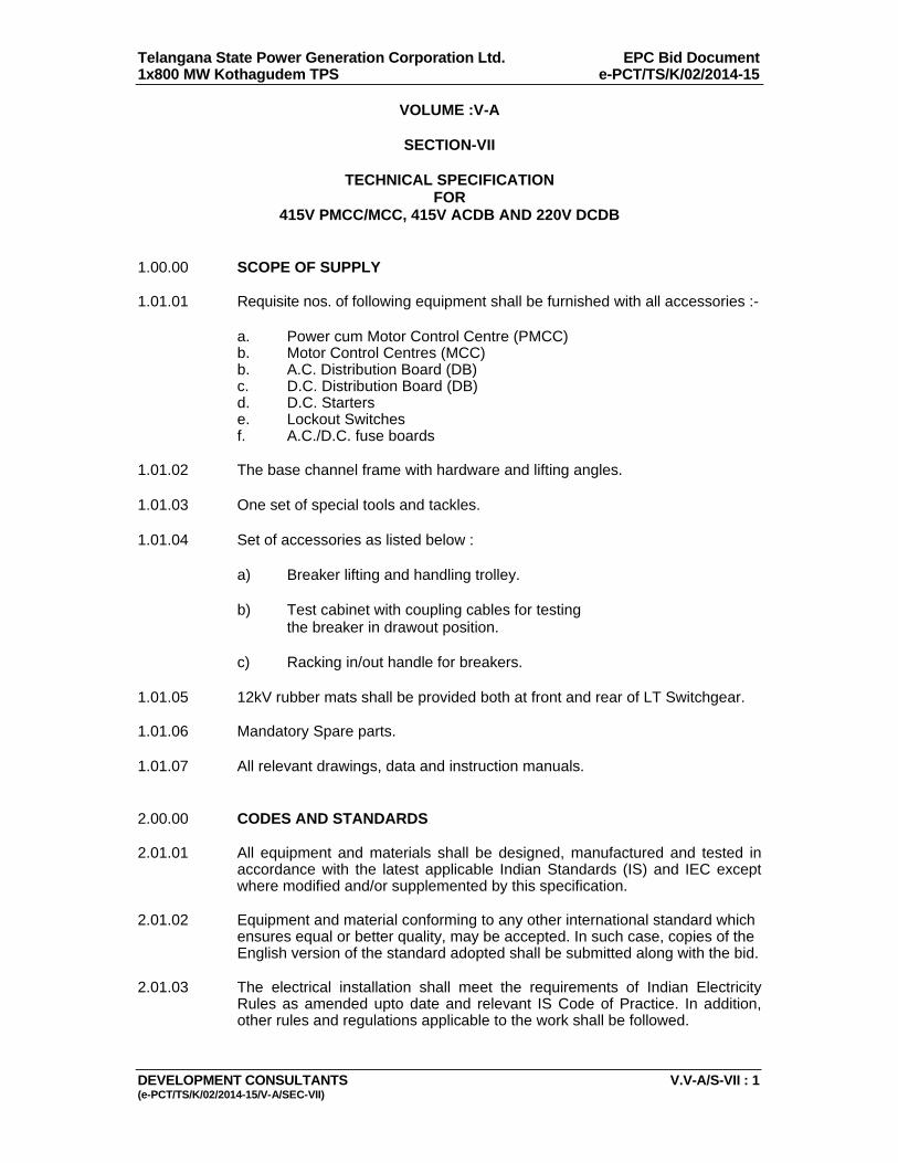
Telangana State Power Generation Corporation Ltd. EPC Bid Document 1x800 MW Kothagudem TPS e-PCT/TS/K/02/2014-15
DEVELOPMENT CONSULTANTS V.V-A/S-VII : 1 (e-PCT/TS/K/02/2014-15/V-A/SEC-VII)
VOLUME :V-A
SECTION-VII
TECHNICAL SPECIFICATION FOR
415V PMCC/MCC, 415V ACDB AND 220V DCDB 1.00.00 SCOPE OF SUPPLY 1.01.01 Requisite nos. of following equipment shall be furnished with all accessories :- a. Power cum Motor Control Centre (PMCC) b. Motor Control Centres (MCC) b. A.C. Distribution Board (DB) c. D.C. Distribution Board (DB) d. D.C. Starters e. Lockout Switches f. A.C./D.C. fuse boards 1.01.02 The base channel frame with hardware and lifting angles. 1.01.03 One set of special tools and tackles. 1.01.04 Set of accessories as listed below : a) Breaker lifting and handling trolley. b) Test cabinet with coupling cables for testing the breaker in drawout position. c) Racking in/out handle for breakers. 1.01.05 12kV rubber mats shall be provided both at front and rear of LT Switchgear. 1.01.06 Mandatory Spare parts. 1.01.07 All relevant drawings, data and instruction manuals. 2.00.00 CODES AND STANDARDS 2.01.01 All equipment and materials shall be designed, manufactured and tested in
accordance with the latest applicable Indian Standards (IS) and IEC except where modified and/or supplemented by this specification.
2.01.02 Equipment and material conforming to any other international standard which
ensures equal or better quality, may be accepted. In such case, copies of the English version of the standard adopted shall be submitted along with the bid.
2.01.03 The electrical installation shall meet the requirements of Indian Electricity
Rules as amended upto date and relevant IS Code of Practice. In addition, other rules and regulations applicable to the work shall be followed.
Telangana State Power Generation Corporation Ltd. EPC Bid Document 1x800 MW Kothagudem TPS e-PCT/TS/K/02/2014-15
DEVELOPMENT CONSULTANTS V.V-A/S-VII : 2 (e-PCT/TS/K/02/2014-15/V-A/SEC-VII)
3.00.00 DESIGN CRITERIA 3.01.00 The PMCCs/MCCs/DBs will be used to provide power, control and protection
for 415/240V A.C. and 220V D.C. auxiliary services (Motors & Feeders) of generating units.
3.02.00 Duty involves direct-on-line starting of large squirrel cage motors below
175kW. The starting current varies from 6 to 8 times rated current at very low power factor.
3.03.00 The equipment will be located in a hot, humid and tropical atmosphere, highly
polluted at places with coal dust and/or fly ash. 3.04.00 For continuous operation at specified ratings, the temperature rise of various
equipment/components shall be limited to the permissible values stipulated in relevant standards and/or this specification.
3.05.00 Equipment ratings and quantities are detailed in the enclosed drawings and
annexure. Equipment shall be furnished in strict compliance with the same. 3.06.00 All equipment and components thereof shall be capable of withstanding the
mechanical forces and thermal stresses of the short-circuit currents without any damage or deterioration of the materials.
3.07.00 The PMCCs/ MCCs / DBs shall have two incomers and one bus-coupler. In
addition to electrical interlocks, mechanical castle key interlock shall be provided between the two incomers and the bus-coupler so that any two of the three may be closed at a time.
3.08.00 Busbars of PMCCs shall be sized to carry continuously the associated
transformer secondary current plus a 20% margin. Busbars of MCC/DBs shall be sized to carry continuously the total running
load of MCC/DB plus a 20% margin. 3.09.00 In cubicle of incomers & bus section breakers/MCCBs shall be identical to the
associated busbar rating. 3.10.00 For continuous operation at specified ratings, the temperature rise of various
equipment/components shall be limited to the permissible values specified in relevant standards and/or this specification.
3.11.00 Circuit breakers shall not produce any harmful over voltage during switching
off of induction motors. If required, surge protective devices shall be included in the scope of supply to limit over voltages.
3.12.00 Incomers, Bus-couplers & outgoing feeders rated upto & including 630A shall
be MCCB controlled. Above 630A all incomers, Bus-couplers & outgoing Feeders shall be ACB controlled. For critical loads ACB controlled feeders shall be provided which will be decided during detail engineering.
3.13.00 All motor rated 110kW & above, below 175kW shall be ACB controlled. Motor
rated upto 110kW shall be contactor operated.
Telangana State Power Generation Corporation Ltd. EPC Bid Document 1x800 MW Kothagudem TPS e-PCT/TS/K/02/2014-15
DEVELOPMENT CONSULTANTS V.V-A/S-VII : 3 (e-PCT/TS/K/02/2014-15/V-A/SEC-VII)
3.14.00 MCC & PMCC shall have sufficient number of spare modules (at least 20% of
various sizes used with a minimum of 1 no. for each rating and type). 3.15.00 Outgoing feeders of PMCC shall be limited to minimum number of different
sizes so that max. standardization is achieved from MCCB & contactor size point of view.
3.16.00 Incomers & bus section breakers of PMCCs/MCCs shall have provisions for
remote operation from control room. 3.17.00 All breaker operated motor feeder shall be supplied from PMCC. 3.18.00 One no. Normal/Emergency switchgear to cater power supply to important
emergency load / motors for safe shut-down of unit including 220V battery chargers shall be provided for each unit. The main incoming supply shall be from 415V unit service switchgear. When main incoming supply fails, reserve incoming supply shall be switched ON automatically from 415V station service switchgear. In case of total failure of AC supply of the power station, the supply from DG shall be switched ON automatically.
3.19.00 Each switchgear shall be provided with two bus sections, two incomer and a
bus coupler rated for 100% of the loads connected to the switchgear. 3.20.00 For each auxiliary or load, one feeder shall be provided except for the
following cases: One feeder for a maximum 2 nos. isolator motor operating mechanism. 3.21.00 The switchgears shall be provided with suitable number and type of outgoing
feeders for the respective auxiliary loads of the system/area, power supply feeders to various panels, lighting transformer, space heating panels, control cabinets and all other loads encountered in the plant. In addition, following feeders shall be provided in each bus section of each switchgear.
a) Bus VT module: One (1) no.
b) Switchgear test supply module: One (1) no.
c) 240V, 1 phase essential supply module with five nos. 1 phase outlets:
One (1) no. Necessary 415V/240V dry type transformer shall be provided.
d) Alarm module for common alarm for outgoing feeder fault: One (1) no. e) DC supply alarm module for incomer, bus coupler fault: One (1) no.
3.22.00 Each feeder shall be provided with two nos. interposing relays for start & stop.
These interposing relays shall be located in separate IPR panel described under C&I specification.
Telangana State Power Generation Corporation Ltd. EPC Bid Document 1x800 MW Kothagudem TPS e-PCT/TS/K/02/2014-15
DEVELOPMENT CONSULTANTS V.V-A/S-VII : 4 (e-PCT/TS/K/02/2014-15/V-A/SEC-VII)
4.00.00 SPECIFIC REQUIREMENTS 4.01.00 Construction 4.01.01 PMCC / MCC / DB shall be indoor, metal-clad, air insulated and floor
mounting type. All MCCs shall be fully draw out type and DBs shall be fixed type. ACB modules of PMCCs/MCCs shall be fully drawout type. MCCB / Switch Fuse modules shall also be fully drawout type. The design and construction shall be such as to allow extension at either end.
4.01.02 All PMCC/MCC shall be of double front construction. 4.01.03 PMCC /MCC/DB enclosure shall be dust and splash proof, conforming to a
degree of protection IP-54. All switchboard frames and load bearing members shall be fabricated using suitable mild steel structural sections or pressed and shaped cold rolled sheet steel of thickness 2.0mm. Frames shall be enclosed in cold rolled sheet steel of thickness 1.6 mm. Doors and covers shall also be of cold rolled sheet steel thickness 1.6 mm. Stiffeners shall be provided wherever necessary. The gland plate thickness shall be 3.0 mm for hot/cold rolled sheet steel and 4.0 mm for non-magnetic material.
4.01.04 PMCC / MCC / DB assembly shall comprise a continuous line up of dead
front, free-standing vertical sections, housing the control modules in multi tier formation.
4.01.05 The design shall be fully compartmentalized with metal/insulating partitions
between compartments. The working height shall be limited within 750 mm to 1800 mm from floor level.
4.01.06 Each control module shall be housed in a separate compartment, complete
with an individual front access door having sufficient opening with concealed type hinges. Each vertical section shall have a removal back cover. All doors and covers shall be gasketed.
4.01.07 All push buttons, lamps, indicating instruments shall be flush / semi-flush
mounted on respective module compartment. 4.01.08 A full height vertical cable chamber with cable supports shall be provided in
each section to facilitate unit wiring. The chamber shall be liberally sized to accommodate all cables and shall have removable cover at the front for access.
4.01.09 A horizontal wireway, extending the entire length, shall be provided at the top
of each PMCC / MCC / DB for inter panel wiring. 4.01.10 The width of the cable alley shall not be less than 250 mm. 4.02.00 Bus and Bus Taps 4.02.01 All PMCCs/MCCs/DBs shall be provided with three phase & neutral bus bars .
All DCDBs shall be provided with two busbars. All busbar compartments shall be completely enclosed.

Telangana State Power Generation Corporation Ltd. EPC Bid Document 1x800 MW Kothagudem TPS e-PCT/TS/K/02/2014-15
DEVELOPMENT CONSULTANTS V.V-A/S-VII : 5 (e-PCT/TS/K/02/2014-15/V-A/SEC-VII)
4.02.02 The main buses and connections shall be of high conductivity Aluminium / Aluminium alloy, sized for specified current ratings with maximum temperature limited to 85oc (i.e., 35oC rise over 50oC ambient).
4.02.03 Vertical busbars shall be designed for minimum current rating of 200A.
Separate vertical busbars shall be provided for each vertical panel. 4.02.04 All bus connections shall be silver plated. Adequate contact pressure shall be
ensured by means of two-bolt connection with plain and spring washers and locknuts.
Bimetallic connector shall be furnished for connection between dissimilar
metals. 4.02.05 Busbars and connections shall be fully insulated for working voltage with
adequate phase/ground clearances. Insulating sleeves for busbars and shrouds for joints and tap-off points shall be provided.
Bus insulators shall be flame retardant, non-hygroscopic track-resistant type
with high creepage surface. 4.02.06 Busbars shall be supported and braced to withstand the stresses due to
maximum short circuit current and also to take care of any thermal expansion. 4.02.07 Busbars shall be colour coded for easy identification and so located that the
sequence R-Y-B shall be from left to right, top to bottom or front to rear when viewed from the front of the assembly.
4.03.00 Control Modules 4.03.01 Draw-out type control module shall have self-aligning power/control
disconnects. All disconnects shall be silver plated to ensure good contacts. 4.03.02 The design shall be such as to permit easy withdrawal/reinsertion of the unit
with guide rails to ensure correct alignment. 4.03.03 Control Module shall house the control components for a circuit such as
switch fuse / MCCB, contactors, relays, push buttons, lamps etc. as per requirement of the control circuit.
4.03.04 The equipment layout shall provide sufficient working space in between the
components and subject to Owner's approval. 4.03.05 Various module/compartment sizes shall be multiple of one basic unit to
facilitate modifications at site. Suitable provision for this purpose should also be incorporated in the vertical bus bars.
4.03.06 Draw-out type control modules of same size and type shall be electrically and
physically interchangeable. 4.04.00 Air Circuit Breaker 4.04.01 Circuit breaker shall be provided on the incomer having minimum interrupting
capacity equal to the 50kA(r.m.s) fault level.
Telangana State Power Generation Corporation Ltd. EPC Bid Document 1x800 MW Kothagudem TPS e-PCT/TS/K/02/2014-15
DEVELOPMENT CONSULTANTS V.V-A/S-VII : 6 (e-PCT/TS/K/02/2014-15/V-A/SEC-VII)
4.04.02 Circuit breaker shall be three pole, single throw, air-break type with independent manual spring closing, trip-free mechanism and shunt trip. However Incomer breaker shall be four pole type.
4.04.03 Circuit breaker shall be draw-out type, having service, test & isolated position
with positive indication for each position. 4.04.04 Circuit breakers of identical rating shall be physically and electrically
interchangeable. 4.04.05 Each breaker shall be provided with microprocessor based protection unit
having three overload protection with adjustable current and time, three short circuit protection with adjustable current and time and three instantaneous short circuit protection. The operating characteristic shall be suitable for co-ordination with down-stream fuses.
4.04.06 Circuit breakers shall be provided with motor wound spring charging
mechanism. Spring charging shall take place automatically after each breaker closing operation. One open-close-open operation of the circuit breaker shall be possible after failure of power supply to the motor. In addition, facility for manual charging of spring shall be provided.
4.04.07 Mechanical safety interlock shall be provided to prevent the circuit breaker
from being racked in or out of the service position when the breaker is closed. It shall not be possible to open the circuit breaker door cubicle unless the breaker is in ‘OFF’ position.
4.04.08 Automatic safety shutters shall be provided to cover up the stationary
disconnects when the breaker is withdrawn. 4.04.09 Each breaker shall be provided with an emergency manual trip, mechanical
ON-OFF indicator, an operation counter and spring mechanism charge/discharge indicator, and electrical anti-pumping feature.
4.04.10 In addition to the auxiliary contacts required for normal breaker operation and
indication, each breaker shall be provided with the following for interlocking purpose :-
a. Position/Cell switch with 4 NO + 4 NC contacts. b. Auxiliary switch, with minimum 6NO + 6NC contacts, 4.04.11 Spring charge limit switch shall be provided for breakers with motor wound
spring charging mechanism. These limit switches shall be provided with minimum 2NO + 2NC contact.
4.04.12 Limit/auxiliary switches shall be convertible type, that is, suitable for changing
N.O. contact to N.C. and vice-versa. 4.04.13 Each breakers operated feeder shall be provided with protective devices as
specified in Annexure–B.
Telangana State Power Generation Corporation Ltd. EPC Bid Document 1x800 MW Kothagudem TPS e-PCT/TS/K/02/2014-15
DEVELOPMENT CONSULTANTS V.V-A/S-VII : 7 (e-PCT/TS/K/02/2014-15/V-A/SEC-VII)
4.05.00 Switches 4.05.01 Switches shall be triple pole, air break, AC23 motor duty for motor feeders
and AC22 heavy duty for other feeders. Motors duty switches shall be capable of safely making and breaking the
locked rotor current of the associated motor circuit. 4.05.02 The switch shall have a quick-make, quick-break mechanism operated by a
suitable external handle, complete with position indicator. This handle shall have provision for padlocking in ON and OFF position.
4.05.03 The compartment door shall be interlocked mechanically with the switch such
that the door cannot be opened unless the switch is in OFF position. Means shall be provided for releasing this interlock at any time.
4.05.04 Switches shall be capable of withstanding the let-through fault current of
back-up fuses or circuit breakers. 4.05.05 Wherever two incoming switches and one bus-section switch are provided for
an assembly, these shall be mechanically/key interlocked to ensure that only two out of the three can be closed at time.
Wherever two incoming switches are provided for an assembly, these shall be mechanically/key interlocked to ensure that one of the two can be closed at time.
4.05.06 All incoming and outgoing feeders shall be provided with bolted disconnect
link for isolation of neutral if necessary. 4.06.00 Fuses 4.06.01 Fuses shall be HRC, preferably link type, with a minimum interrupting
capacity equal to the short circuit current of the LT system. Fuses shall be mounted on insulated fuse carriers, which are mounted on fuse bases. Wherever it is not possible to mount fuses on carriers, fuses shall be directly mounted on plug-in type of base. In such cases, one set of insulated fuse pulling handles shall be supplied with each board.
4.06.02 Fuses shall be furnished complete with fuse bases and fittings of such design
as to permit easy and safe replacement of fuse element. Visible indication shall be provided on blowing of the fuse. 4.06.03 Motor fuse characteristics and ratings shall be chosen to ride over starting
period without blowing. The fuse on incoming feeder wherever provided, shall be chosen to provide discrimination with motor/feeder fuses.
4.07.00 Moulded Case Circuit Breaker (MCCB) 4.07.01 The MCCBs shall be of drawout type with trip-free operating mechanism of
quick make & quick break type. Each MCCB shall be equipped with thermal release for thermal overload and magnetic release for short circuit protection on each pole.
Telangana State Power Generation Corporation Ltd. EPC Bid Document 1x800 MW Kothagudem TPS e-PCT/TS/K/02/2014-15
DEVELOPMENT CONSULTANTS V.V-A/S-VII : 8 (e-PCT/TS/K/02/2014-15/V-A/SEC-VII)
4.07.02 MCCBs / MPCBs shall be suitable for manual closing and opening and also automatic trip on overload and short circuit. MCCB shall have intermediate position to indicate trip condition.
4.07.03 The MCCBs shall be provided with mechanical ON-OFF indicator at the front
panel. The MCCB handles, after the breaker tripped due to faults, shall occupy a mean position indicating trip condition.
4.07.04 The compartment door shall be interlocked mechanically with the MCCB such
that the door cannot be opened unless the MCCB is in OFF position. Means shall be provided for releasing this interlock at any time.
4.07.05 All feeders of PMCC / MCC rated up to & including 630 Amp shall be provided
with MCCB. Air circuit breaker shall be provided for feeders rated above 630 Amp. For critical loads ACB controlled feeders shall be provided which will be decided during detailed engineering.
4.07.06 Motors rating above 110 KW will be operated by Air circuit breaker and
protected by consolidated numerical motor protection relay. 4.08.00 A.C. Starter 4.08.01 Contactors a. The contactors shall be three pole, air break type designed for duty
class III - Category AC3 (for unidirectional motor) with non-bouncing silver/ silver alloy contacts. Contacts for reversible motors will be of AC4 duty.
b. Each contactor shall be provided with minimum two (2) normally open
and two (2) normally closed auxiliary contacts rated 10 A at 240V A.C. c. Reversing contacts shall be electrically and mechanically interlocked. d. Contactors with delayed dropout feature shall be provided for some
essential auxiliaries. These contactors shall not dropout on power failure if the voltage is restored within 3 seconds.
4.08.02 Protection a. Thermal overload relays shall be three element, positive acting,
ambient temperature compensated with adjustable settings. b. Single phase preventor relay shall be provided, preferably as an inbuilt
feature of thermal overload relay. c. Relays shall be manual reset type with two changeover potential-free
contacts. Resetting of relays shall be possible with compartment door closed. Colour of the resetting button shall be BLACK.
d. Relays may be direct acting or C.T. operated, depending on current
rating. C.T.s shall be included in the scope of supply. e. Motor starters shall have type '2' co-ordination according to IEC 947-4.

Telangana State Power Generation Corporation Ltd. EPC Bid Document 1x800 MW Kothagudem TPS e-PCT/TS/K/02/2014-15
DEVELOPMENT CONSULTANTS V.V-A/S-VII : 9 (e-PCT/TS/K/02/2014-15/V-A/SEC-VII)
f. Earth fault relays with adjustable settings and time delays fed from core balance CT shall be provided.
g. Numerical / Digital Motor protection relay with short circuit, over load,
earth fault, locked rotor and unbalance (NPS) load protection functions shall be provided for motor rated above 90 kW.
4.09.00 Control Transformer 4.09.01 LT Switchboard control supply The Bidder shall provide one (1) no. adequately rated 415V/110V Control
Transformer in each bus section with necessary taps and auto changeover facility for providing control power supply to various modules of the board, except motor feeders. Each motor feeder shall be provided with 415/110V control transformer of adequate capacity (min. 75VA) for control supply to such module. The sizing of control transformer shall be carried out by the Bidder considering the actual load of power contactors, auxiliary contactors, indicating lamps and other equipment in the module circuit. An additional load of 15watts shall be considered for each module for remote auxiliary relays and lamps to be connected in the control circuit of modules. Bidder shall also ensure that control transformer are adequately designed for meeting the momentary loading requirements and the voltage drop during this condition shall not be more than 5%. Each transformer shall be sized for catering to control supply of both bus sections.
4.09.02 LT Switchboard space heater supply The Bidder shall provide one (1) no. adequately rated 415V/240V Control
Transformer in each bus section with necessary taps and auto changeover facility for providing power supply to panel space heater, Motor space heater of motor rated 30 KW & above, Panel Illumination & Socket. The supply of these two (2) nos. control transformer are tapped from incoming supply of 415V PMCC/MCC before the incoming breaker. Incoming circuit to the space heater auxiliary bus shall be through isolating switch HRC fuse and neutral link of suitable rating. The supply of different modules shall be tapped individually from the auxiliary bus bars. Control supply healthy indication shall be provided. Each transformer shall be sized for catering to space heater supply of both bus sections.
4.10.00 D.C. Starters 4.10.01 D.C. Starter for emergency oil pump shall be fixed resistance type, designed
to provide fast acceleration during starting. 4.10.02 DC starters shall be complete with switch-fuse units, contactors, resistors,
relays, meters, push-buttons, lamps, etc. 4.10.03 Starters shall be furnished in totally enclosed floor-mounting, sheet steel
cubicles complete with a hinged front access door. Minimum thickness of sheet steel shall be 2mm.
4.10.04 The cubicle enclosure shall provide dust and humidity protection, the degree
of protection being not less than IP-54.
Telangana State Power Generation Corporation Ltd. EPC Bid Document 1x800 MW Kothagudem TPS e-PCT/TS/K/02/2014-15
DEVELOPMENT CONSULTANTS V.V-A/S-VII : 10 (e-PCT/TS/K/02/2014-15/V-A/SEC-VII)
The resistor enclosure shall be provided with ventilating louvers and wire mesh guard and shall have a degree of protection IP-23.
4.10.05 Cubicle space heater shall be provided to maintain internal temperature
above dew point. Heater shall be furnished with switch-fuse unit and thermostat control.
4.11.00 Relays 4.11.01 All incoming and bus-coupler circuits and circuit breaker operated outgoing
feeders shall be provided with numerical relays. Breaker operated motor feeders shall be provided with numerical motor protection relay.
4.11.02 The numerical relays shall have provisions for interfacing with Plant DDCMIS
/ PLC. 4.11.03 Relays shall be of drawout design with built-in testing facilities. Small auxiliary
relays may be in non-drawout execution. 4.11.04 All protective relays, auxiliary relays, and timers shall be provided with hand
reset operation indicator (flag). 4.11.05 Relays shall be rated for operation on 110V secondary voltage and 5 A or 1
A. Number and rating of relay contacts shall suit the job requirements. 4.12.00 Control and Indication 4.12.01 Circuit breakers shall be wired up for local and remote operation. Each
breaker cubicle shall be equipped with the following : i) One (1) TEST-NORMAL-TRIAL selector switch with pistol grip handle
and key interlock for breakers with motor wound spring charging mechanism.
ii) On-Off control switches shall have three positions (T-N-C) and shall
be spring return to 'Neutral' from close and trip positions. They shall have two contacts closing in close position and two contacts closing in trip positions, and shall have Pistol Grip handles. Lost motion feature shall be provided wherever required.
iii) Following indicating lamps on the front of the compartment: Breaker open - GREEN Breaker closed - RED Breaker tripped - AMBER Spring charged - WHITE Trip Ckt. Healthy - BLUE Motor Space heater ‘ON’ for motor circuit - YELLOW
Telangana State Power Generation Corporation Ltd. EPC Bid Document 1x800 MW Kothagudem TPS e-PCT/TS/K/02/2014-15
DEVELOPMENT CONSULTANTS V.V-A/S-VII : 11 (e-PCT/TS/K/02/2014-15/V-A/SEC-VII)
4.12.02 Push button shall be heavy duty, oil tight, push to actuate type with integral escutcheon plate marked with its function.
4.12.03 Each push button shall have minimum two (2) nos. normally open and two (2)
nos. normally closed contacts rated 10 A at 240 V. 4.12.04 One (1) NORMAL-TRIAL selector switch shall be provided for all motor
feeders. 4.12.05 Selectors switches shall be stay-put, rotary type with escutcheon plates
marked to indicate the function and positions, and shall be lockable in each position. Selector switch contacts shall be rated for 10A at 240 V A.C.
4.12.06 Selector switches shall be provided with minimum three (3) contact blocks of
1 NO + 1 NC each. The exact requirements of contacts shall be decided by the Tenderers taking
into account the scheme requirement and spares. 4.12.07 Lamps shall be clustered LED type with series resistor and coloured lens.
Lens and lamps shall be replaceable from the front. Lamps shall be located just above the associated push button/control switch
4.12.08 The general scheme of connections for control, interlock and protection is
shown in the enclosed drawings. Detailed requirements of individual circuits will be intimated later to the successful bidder, who shall develop and furnish the schemes accordingly.
4.13.00 Meters 4.13.01 All indicating instruments (96 x 96 mm) shall be switchboard type, with 250`
scale, anti-glare glass and accuracy class of ± 2% full scale. Each meter shall have zero adjuster on the front.
4.13.02 Motor ammeter shall be suitable to indicate starting current (6 to 8 times full
load current) for DOL starting of motor. Motor ammeter shall be provided for motor rated 30 kW and above and for
critical drives, to be finalized during detail engineering. 4.13.03 All incomers, tie feeders, circuit breaker operated motor feeders shall be
provided with 3-phase multifunction meter with pulse output and communication port for interfacing with Plant DDCMIS / PLC.
4.13.04 Meter selector switches shall be maintained contact, stay-put type, with knob
handle. Ammeter and voltmeter selector switches shall be four position type. Ammeter selector switches shall have made before break contacts, to prevent open circuiting of CT secondary.
4.14.00 Current Transformer 4.14.01 Current Transformer, shall be cast resin type rated 10 VA. All secondary
connections shall be bought out to terminal blocks where wye or delta connection will be made.

Telangana State Power Generation Corporation Ltd. EPC Bid Document 1x800 MW Kothagudem TPS e-PCT/TS/K/02/2014-15
DEVELOPMENT CONSULTANTS V.V-A/S-VII : 12 (e-PCT/TS/K/02/2014-15/V-A/SEC-VII)
4.14.02 Accuracy class of the current transformers shall be: a) Class PS for REF b) Class 5P20 for other relaying.
c) Class 1.0 ISF < 5 for metering. d) Class 0.5 ISF < 5 for metering (Incomer & Bus coupler of PMCC) Other CT particulars like ratio, burden, knee point, excitation current &
secondary resistance shall be decided by the bidder. 4.14.03 CT secondary shall be rated for 1A for metering & either 5A or 1A for
protection. 4.15.00 Voltage Transformer 4.15.01 Voltage transformers shall be cast-resin, drawout type and shall have an
accuracy class of 1.0. Voltage transformer mounted on breaker carriage is not acceptable. For Incomer and bus coupler of PMCC accuracy class of voltage transformer shall be 0.5.
4.15.02 High voltage windings of voltage transformer shall be protected by current
limiting fuses. The voltage transformer and fuses shall be completely disconnected and visibly grounded in fully draw out position.
4.15.03 Secondary winding MCBs, sized to prevent overload shall be installed in all
ungrounded secondary leads. MCBs shall be suitably located to permit easy replacement while the switchgear/PMCC is energized.
4.15.04 Both primary side & secondary side fuse failure / voltage loss monitoring
system of VT shall be provided. 4.16.00 Transducers 4.16.01 Transducer for conversion of AC electrical quantities such as voltage, current,
KW etc. shall be supplied as required for remote connection to Plant DDCMIS / PLC. All transducers shall be dual output type.
4.16.02 The transducers for indicating type instruments shall be of very low burden
type having 4-20 mA DC linear, galvanically isolated output, compatible with secondary instruments and Plant DDCMIS system.
4.17.00 Secondary Wiring 4.17.01 The PMCC/MCC/DB shall be fully wired at the factory to ensure proper
functioning of control, protection and interlocking schemes. 4.17.02 Fuse and links shall be provided to permit individual circuit isolation from bus
wires without disturbing other circuits. All spare contacts of relays, push buttons and other devices shall be wired upto terminal blocks.
Telangana State Power Generation Corporation Ltd. EPC Bid Document 1x800 MW Kothagudem TPS e-PCT/TS/K/02/2014-15
DEVELOPMENT CONSULTANTS V.V-A/S-VII : 13 (e-PCT/TS/K/02/2014-15/V-A/SEC-VII)
4.17.03 Wiring shall be done with flexible, 1100V grade, fire resistance PVC insulated switchboard wires with stranded Copper conductors of 2.5 mm2 for control & current circuits and 1.5 mm2 for voltage circuits.
4.17.04 Each wire shall be identified, at both ends, with permanent markers bearing
wire numbers as per Contractor's wiring diagrams. 4.17.05 Wire terminations shall be made with crimping type connector with insulating
sleeves. Wires shall not be spliced between terminals. Separate colour code shall be used for AC & DC circuit wiring for easy identification.
4.18.00 Terminal Blocks 4.18.01 Terminal blocks shall be 1100V grade box-clamp type with marking strips
similar to ELMEX 10 mm2 or equal. Terminals for C.T. secondary leads shall have provision for shorting.
4.18.02 Terminal blocks used for interface with DDCMIS / PLC via termination cabinet
shall be suitably sized to facilitate proper termination of interconnecting cables.
4.18.03 Not more than two wires shall be connected to any terminal. Spare terminals
equal in number to 20% active terminals shall be furnished. 4.18.04 Terminal blocks shall be located to allow easy access. Wiring shall be so
arranged that individual wires of an external cable can be connected to consecutive terminals.
4.19.00 Cable Terminations 4.19.01 PMCC shall be designed for cable entry from bottom. MCC/DB shall be
designed for cable entry both from top and bottom. Actual configuration shall be intimated later sufficient space shall be provided for ease of termination and connection.
4.19.02 Power cables shall be 1100V, Copper/Aluminum conductor, XLPE insulated,
armoured, FRLSH PVC overall sheathed. Control cables shall be 1100V, PVC insulated, armoured, PVC overall
sheathed with 2.5 mm2 stranded Copper conductor. 4.19.03 All provisions and accessories shall be furnished for termination and
connection of cables, including removable gland plates, cable supports, crimp type tinned Copper/Aluminium lugs, brass compression glands with tapered washer (Power Cables only) and Terminal blocks.
4.19.04 Sufficient space shall be provided between the lower most power cable
termination and gland plate for easy cable connection. 4.20.00 Bus Duct Connection 4.20.01 Bus duct connections shall be furnished along with transition panel, if
required. Unless mentioned otherwise bus duct connections shall generally be from the top.

Telangana State Power Generation Corporation Ltd. EPC Bid Document 1x800 MW Kothagudem TPS e-PCT/TS/K/02/2014-15
DEVELOPMENT CONSULTANTS V.V-A/S-VII : 14 (e-PCT/TS/K/02/2014-15/V-A/SEC-VII)
4.20.02 All connecting bus work shall have the same continuous current rating as associated PMCC bus and shall be fully braced for the LT system short circuit current.
4.20.03 All provisions such as matching flange and other accessories shall be
furnished for connection to bus duct. 4.21.00 Ground Bus 4.21.01 A Cu / Al ground bus rated to carry the maximum fault current, shall extend
full length of the MCC/DB. 4.21.02 The ground bus shall be provided with two-bolt drilling with G.I. bolts & nuts at
each end to receive 50 x 6 mm G.I. flats. 4.21.03 All stationary structures shall be directly connected to the ground bus for
effective grounding. 4.21.04 The frame of draw out module shall be grounded at all times except when the
power disconnects are separated by a safe distance. 4.21.05 All hinged doors shall be earthed through flexible copper braid wire. 4.22.00 Nameplate 4.22.01 Nameplate of approved design shall be provided for each control
compartment and also at the top of each PMCC / MCC / DB. 4.22.02 The material of the name plate shall be anodized aluminium / lamicoid or
approved equal, 3 mm thick, with white letter on black background. Name plates shall be minimum 20 x 75 mm for instrument / devices and 40 x 150 mm for panels.
4.22.03 Caution notice on suitable metal plate shall be affixed at the back of each
vertical panel. 4.23.00 Space Heater 4.23.01 Panel and motor space heater shall be fed from separate AC auxiliary
busbars running throughout the switchboard. The space heater bus shall be fed from control transformer described earlier. Suitable terminals shall also be provided to facilitate energisation of the control transformer from outside during long shutdown of the board.
4.23.02 Each vertical section of the PMCC / MCC / DB shall be furnished with
thermostat controlled space heater and 5A, 5 pin plug socket. 4.23.03 In addition, motor feeders 30 KW and above shall be wired up for feeding
motor space heater through starter auxiliary ‘OFF’ contacts. 4.23.04 Cubicle heater, Motor heater and plug socket circuit shall be provided with
individual MCB/switch fuse units.
Telangana State Power Generation Corporation Ltd. EPC Bid Document 1x800 MW Kothagudem TPS e-PCT/TS/K/02/2014-15
DEVELOPMENT CONSULTANTS V.V-A/S-VII : 15 (e-PCT/TS/K/02/2014-15/V-A/SEC-VII)
4.24.00 A.C./D.C. Power Supplies 4.24.01 Necessary 415V AC and 220V DC power supplies as required for control and
service shall be arranged by the contractor. Single feeder shall be arranged for A.C. supply and duplicate feeder shall be arranged for D.C. supply.
4.24.02 Isolating switch fuse units shall be provided at each switchgear for the
incoming supplies, 4-pole, single throw for A.C. and 2-pole, double throw for D.C. Molded case circuit breaker (MCCB) shall also be accepted as an alternative.
4.24.03 Bus-wires of adequate capacity shall be provided to distribute the incoming
supplies to different cubicles. Isolating switch fuse units / MCCB shall be provided at each cubicle for A.C/D.C. supplies.
4.24.04 A.C. load shall be so distributed as to present a balanced loading on
three-phase supply system. 4.25.00 Tropical Protection All equipment, accessories and wiring shall have fungus protection, involving
special treatment of insulation and metal against fungus, insects & corrosion. Screens of corrosion resistant material shall be furnished on all ventilating
louvers to prevent the entrance of insects. 4.26.00 Painting 4.26.01 All steel surfaces shall be sand blasted, grounded and pickled as required to
produce a smooth, clean surface free of scale, grease & rust. 4.26.02 After cleaning, the surfaces shall be given a phosphate coating followed by
two coats of high quality primer and stoved after each coat. 4.26.03 For paint shade of finish coat, refer clause no.1.16.00 of Section E1, Volume
V-A. 4.26.04 Sufficient quantity of touch-up paint shall be furnished for application at site. 4.26.05 Caution notice plate shall be affixed at the back of each vertical panel. 5.00.00 TESTS 5.01.00 All equipment shall be completely assembled, wired, adjusted and tested at
the factory as per the relevant standards. 5.02.00 Routine Test The tests shall include but not necessarily be limited to the following :- a. Operation under simulated service condition to ensure accuracy of
wiring, correctness of control scheme and proper functioning of the equipment.
Telangana State Power Generation Corporation Ltd. EPC Bid Document 1x800 MW Kothagudem TPS e-PCT/TS/K/02/2014-15
DEVELOPMENT CONSULTANTS V.V-A/S-VII : 16 (e-PCT/TS/K/02/2014-15/V-A/SEC-VII)
b. All wiring and current carrying part shall be given appropriate High
Voltage Test. c. Primary current & voltages shall be applied to all instrument
transformers. d. Routine test shall be carried out on all equipment such as circuit
breakers, switch - fuse, contactors, relays, meters etc. 5.03.00 Type Tests The type test certificates for the following tests carried out on an identical &
similar type of switchgear shall be furnished. The date of tests shall be within the last five years.
a. Temperature rise Test b. Short time current test on main circuit and earth circuit. c. Verification of making and breaking capacity. Type test certificates of any equipment shall be furnished if so designed by
the purchaser/ owner. Otherwise the equipment shall have to be type tested free of charge, to prove the design. Type test performed before five (5) years are not acceptable.
6.00.00 DRAWINGS, DATA & MANUALS 6.01.00 Drawings, Data & Manuals shall be submitted in triplicate with the bid and in
quantities and procedures as specified in General Conditions of Contract and/or elsewhere in the specification for approval and subsequent distribution after the issue of 'Letter of Intent'.
6.02.00 To be submitted with the bid :- a. General arrangement drawing showing constructional features, space
required in front for withdrawals, power & control cable entry points etc.
b. Typical foundation plan c. Typical control schematic d. Bill of materials e. Type test reports on circuit breaker f. Technical leaflets on :- i) Circuit breaker ii) Switch-fuse units iii) Contactors iv) Relays, meters, push buttons, selector switches etc. v) Glands/terminals blocks
Telangana State Power Generation Corporation Ltd. EPC Bid Document 1x800 MW Kothagudem TPS e-PCT/TS/K/02/2014-15
DEVELOPMENT CONSULTANTS V.V-A/S-VII : 17 (e-PCT/TS/K/02/2014-15/V-A/SEC-VII)
6.03.00 To be submitted for Owner / Purchaser’s Approval and Distribution All relevant drawings and data pertaining to the equipment like GTP, GA
drawing, foundation plan, BOM, control & schematics, QAP, etc. shall be submitted by the Bidder for approval of Owner/Owner’s consultant. Also refer clause no. 1.19.02(u) of Section-I of Volume – V-A: Technical Specifications for Electrical Equipment & Accessories.
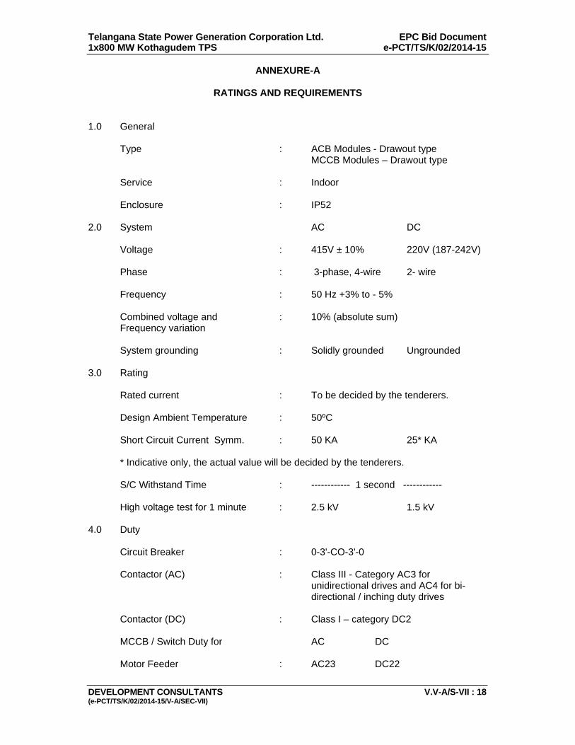
Telangana State Power Generation Corporation Ltd. EPC Bid Document 1x800 MW Kothagudem TPS e-PCT/TS/K/02/2014-15
DEVELOPMENT CONSULTANTS V.V-A/S-VII : 18 (e-PCT/TS/K/02/2014-15/V-A/SEC-VII)
ANNEXURE-A
RATINGS AND REQUIREMENTS 1.0 General Type : ACB Modules - Drawout type MCCB Modules – Drawout type Service : Indoor Enclosure : IP52 2.0 System AC DC Voltage : 415V ± 10% 220V (187-242V) Phase : 3-phase, 4-wire 2- wire Frequency : 50 Hz +3% to - 5% Combined voltage and : 10% (absolute sum) Frequency variation System grounding : Solidly grounded Ungrounded 3.0 Rating Rated current : To be decided by the tenderers. Design Ambient Temperature : 50ºC Short Circuit Current Symm. : 50 KA 25* KA * Indicative only, the actual value will be decided by the tenderers. S/C Withstand Time : ------------ 1 second ------------ High voltage test for 1 minute : 2.5 kV 1.5 kV 4.0 Duty Circuit Breaker : 0-3'-CO-3'-0
Contactor (AC) : Class III - Category AC3 for unidirectional drives and AC4 for bi-directional / inching duty drives
Contactor (DC) : Class I – category DC2 MCCB / Switch Duty for AC DC Motor Feeder : AC23 DC22
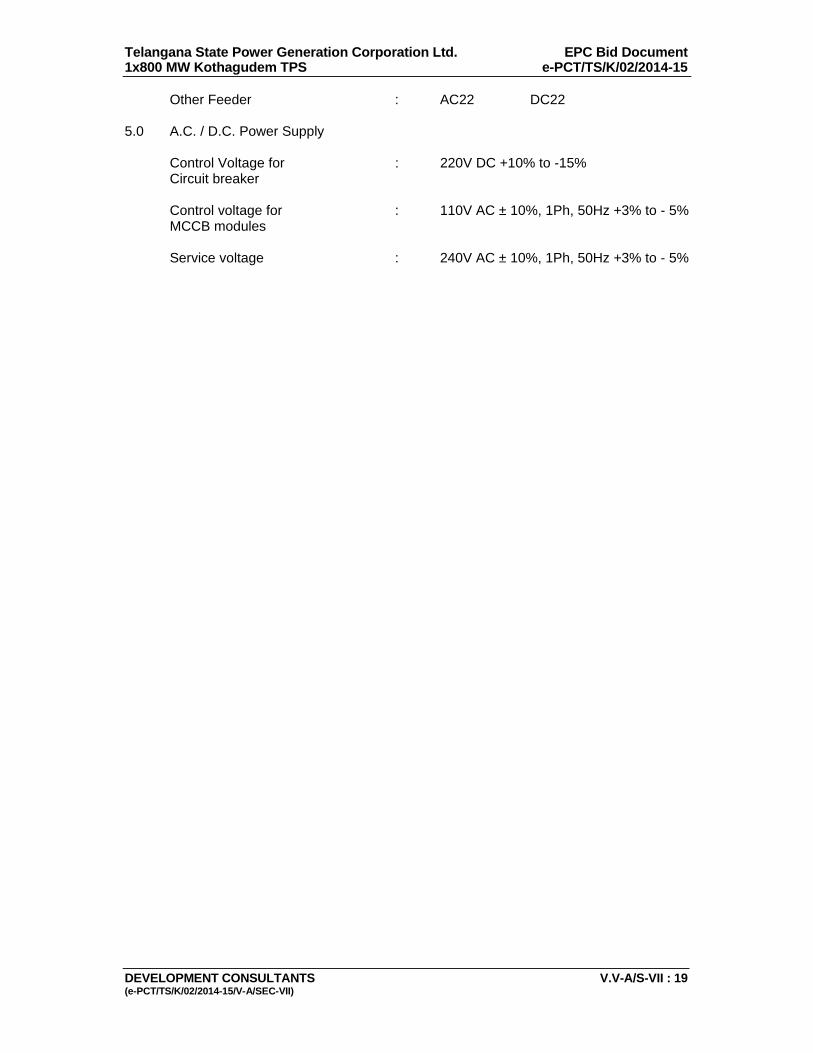
Telangana State Power Generation Corporation Ltd. EPC Bid Document 1x800 MW Kothagudem TPS e-PCT/TS/K/02/2014-15
DEVELOPMENT CONSULTANTS V.V-A/S-VII : 19 (e-PCT/TS/K/02/2014-15/V-A/SEC-VII)
Other Feeder : AC22 DC22 5.0 A.C. / D.C. Power Supply Control Voltage for : 220V DC +10% to -15% Circuit breaker Control voltage for : 110V AC ± 10%, 1Ph, 50Hz +3% to - 5% MCCB modules Service voltage : 240V AC ± 10%, 1Ph, 50Hz +3% to - 5%
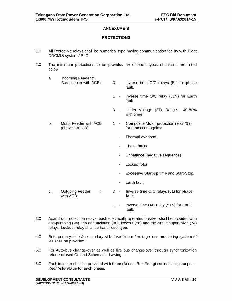
Telangana State Power Generation Corporation Ltd. EPC Bid Document 1x800 MW Kothagudem TPS e-PCT/TS/K/02/2014-15
DEVELOPMENT CONSULTANTS V.V-A/S-VII : 20 (e-PCT/TS/K/02/2014-15/V-A/SEC-VII)
ANNEXURE-B
PROTECTIONS 1.0 All Protective relays shall be numerical type having communication facility with Plant
DDCMIS system / PLC. 2.0 The minimum protections to be provided for different types of circuits are listed
below: a. Incoming Feeder & Bus-coupler with ACB : 3 - inverse time O/C relays (51) for phase
fault. 1 - Inverse time O/C relay (51N) for Earth
fault. 3 - Under Voltage (27), Range : 40-80%
with timer b. Motor Feeder with ACB: 1 - Composite Motor protection relay (99) (above 110 kW) for protection against - Thermal overload - Phase faults - Unbalance (negative sequence) - Locked rotor - Excessive Start-up time and Start-Stop. - Earth fault c. Outgoing Feeder : 3 - Inverse time O/C relays (51) for phase with ACB fault. 1 - Inverse time O/C relay (51N) for Earth
fault. 3.0 Apart from protection relays, each electrically operated breaker shall be provided with
anti-pumping (94), trip annunciation (30), lockout (86) and trip circuit supervision (74) relays. Lockout relay shall be hand reset type.
4.0 Both primary side & secondary side fuse failure / voltage loss monitoring system of
VT shall be provided.. 5.0 For Auto-bus change-over as well as live bus change-over through synchronization
refer enclosed Control Schematic drawings. 6.0 Each incomer shall be provided with three (3) nos. Bus Energised indicating lamps –
Red/Yellow/Blue for each phase.
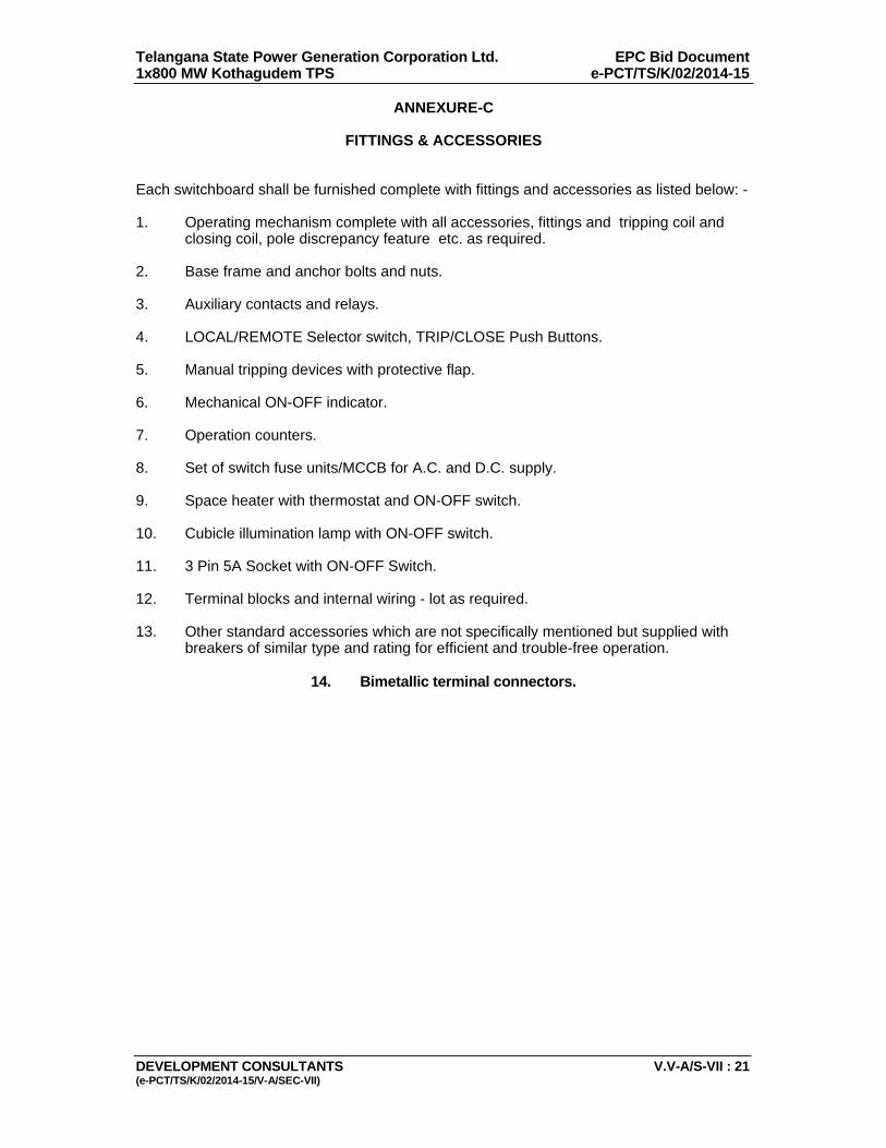
Telangana State Power Generation Corporation Ltd. EPC Bid Document 1x800 MW Kothagudem TPS e-PCT/TS/K/02/2014-15
DEVELOPMENT CONSULTANTS V.V-A/S-VII : 21 (e-PCT/TS/K/02/2014-15/V-A/SEC-VII)
ANNEXURE-C
FITTINGS & ACCESSORIES Each switchboard shall be furnished complete with fittings and accessories as listed below: - 1. Operating mechanism complete with all accessories, fittings and tripping coil and
closing coil, pole discrepancy feature etc. as required. 2. Base frame and anchor bolts and nuts. 3. Auxiliary contacts and relays. 4. LOCAL/REMOTE Selector switch, TRIP/CLOSE Push Buttons. 5. Manual tripping devices with protective flap. 6. Mechanical ON-OFF indicator. 7. Operation counters. 8. Set of switch fuse units/MCCB for A.C. and D.C. supply. 9. Space heater with thermostat and ON-OFF switch. 10. Cubicle illumination lamp with ON-OFF switch. 11. 3 Pin 5A Socket with ON-OFF Switch. 12. Terminal blocks and internal wiring - lot as required. 13. Other standard accessories which are not specifically mentioned but supplied with
breakers of similar type and rating for efficient and trouble-free operation.
14. Bimetallic terminal connectors.
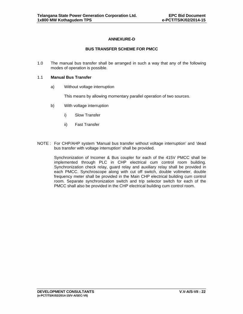
Telangana State Power Generation Corporation Ltd. EPC Bid Document 1x800 MW Kothagudem TPS e-PCT/TS/K/02/2014-15
DEVELOPMENT CONSULTANTS V.V-A/S-VII : 22 (e-PCT/TS/K/02/2014-15/V-A/SEC-VII)
ANNEXURE-D
BUS TRANSFER SCHEME FOR PMCC
1.0 The manual bus transfer shall be arranged in such a way that any of the following
modes of operation is possible. 1.1 Manual Bus Transfer a) Without voltage interruption This means by allowing momentary parallel operation of two sources. b) With voltage interruption i) Slow Transfer ii) Fast Transfer NOTE : For CHP/AHP system ‘Manual bus transfer without voltage interruption’ and ‘dead
bus transfer with voltage interruption’ shall be provided.
Synchronization of Incomer & Bus coupler for each of the 415V PMCC shall be implemented through PLC in CHP electrical cum control room building. Synchronization check relay, guard relay and auxiliary relay shall be provided in each PMCC. Synchroscope along with cut off switch, double voltmeter, double frequency meter shall be provided in the Main CHP electrical building cum control room. Separate synchronization switch and trip selector switch for each of the PMCC shall also be provided in the CHP electrical building cum control room.
Telangana State Power Generation Corporation Ltd EPC Bid Document 1x800 MW Kothagudem TPS e-PCT/TS/K/02/2014-15
DEVELOPMENT CONSULTANTS (e-PCT/TS/K/02/2014-15/V-A/SEC-VIII)
VOLUME: V-A
SECTION-VIII
TECHNICAL SPECIFICATION FOR
LOCAL CONTROL BOARDS/PANELS, LOCAL ISOLATING SWITCH UNITS
AND LOCAL PUSH BUTTON STATIONS
Telangana State Power Generation Corporation Ltd EPC Bid Document 1x800 MW Kothagudem TPS e-PCT/TS/K/02/2014-15
DEVELOPMENT CONSULTANTS (e-PCT/TS/K/02/2014-15/V-A/SEC-VIII)
CONTENT CLAUSE NO. DESCRIPTION 1.00.00 SCOPE OF SUPPLY 2.00.00 CODES AND STANDARDS 3.00.00 DESIGN CRITERIA 4.00.00 SPECIFIC REQUIREMENTS 5.00.00 TESTS 6.00.00 DRAWINGS, DATA AND MANUALS ATTACHMENTS ANNEXURE-A RATINGS AND REQUIREMENTS ANNEXURE-B A.C/D.C POWER SUPPLY ANNEXURE-C FUNCTIONAL REQUIREMENTS OF ANNUNCIATOR ANNEXURE-D AREA WISE INDICATIVE LIST OF LOCAL CONTROL BOARDS/PANELS ANNEXURE-E LOCAL CONTROL PANEL / LOCAL STARTER PANEL FOR COAL HANDLING PLANT

Telangana State Power Generation Corporation Ltd EPC Bid Document 1x800 MW Kothagudem TPS e-PCT/TS/K/02/2014-15
DEVELOPMENT CONSULTANTS V.V-A/S-VIII : 1 (e-PCT/TS/K/02/2014-15/V-A/SEC-VIII)
VOLUME: V-A
SECTION-VIII
TECHNICAL SPECIFICATION FOR
LOCAL CONTROL BOARDS/PANELS, LOCAL ISOLATING SWITCH UNITS AND LOCAL PUSH BUTTON STATIONS
1.00.00 SCOPE OF SUPPLY 1.01.00 The following equipment shall be furnished with all accessories: a) Complete set of Local Control Boards/Panels, an indicative list of
which is given in Annexure-C b) Local Push Button Stations: As required c) Local Isolating Switch Units: As required 1.02.00 Furnishing, Mounting, and wiring of all equipments, devices and accessories 1.03.00 Floor Channel sill, vibration damping pad, and kick plates for all floor-mounted
control boards/panels, complete with holding down bolts and nuts. 1.04.00 Mounting hardware for all control boards/panels, Local Push Button Stations,
and Local Isolating Switch Units. 2.00.00 CODES AND STANDARDS 2.01.00 All equipment and materials shall be designed, manufactured and tested in
accordance with the latest applicable Indian Standards (IS) and IEC except where modified and/or supplemented by this specification.
2.02.00 Equipment and material conforming to any other international standards,
which ensure equal or better quality, may be accepted. In such case, copies of the English version of the standard adopted shall be submitted along with the bid.
2.03.00 The electrical installation shall meet the requirements of Indian Electricity
Rules as amended up to date and relevant IS Code of Practice. In addition, other rules and regulations applicable to the work shall be followed.
3.00.00 DESIGN CRITERIA 3.01.00 The Local Control Boards/Panels will be used for controlling incomers/
bus-section/electrically operated radial breaker feeders of the associated PMCC/MCC. Necessary indications, meters, annunciations and mimic representation shall also be provided on these control boards/panels.
Local control of all drives shall be done from Process Control Boards/Panels,
as described in respective sections of mechanical specification.
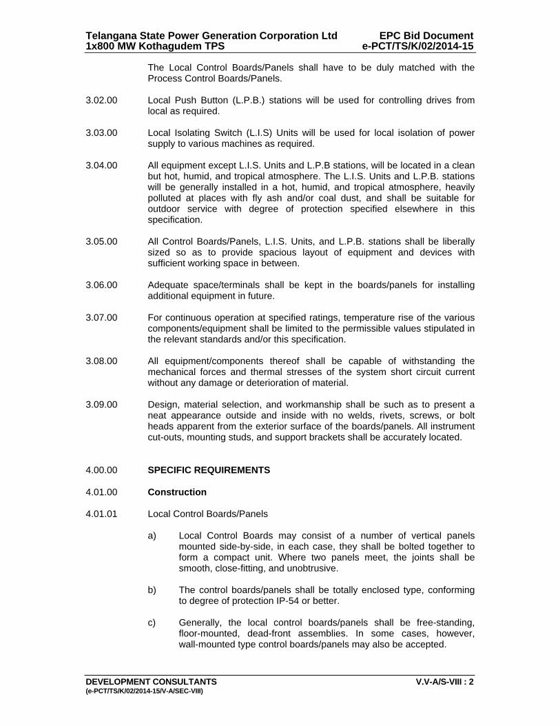
Telangana State Power Generation Corporation Ltd EPC Bid Document 1x800 MW Kothagudem TPS e-PCT/TS/K/02/2014-15
DEVELOPMENT CONSULTANTS V.V-A/S-VIII : 2 (e-PCT/TS/K/02/2014-15/V-A/SEC-VIII)
The Local Control Boards/Panels shall have to be duly matched with the Process Control Boards/Panels.
3.02.00 Local Push Button (L.P.B.) stations will be used for controlling drives from
local as required. 3.03.00 Local Isolating Switch (L.I.S) Units will be used for local isolation of power
supply to various machines as required. 3.04.00 All equipment except L.I.S. Units and L.P.B stations, will be located in a clean
but hot, humid, and tropical atmosphere. The L.I.S. Units and L.P.B. stations will be generally installed in a hot, humid, and tropical atmosphere, heavily polluted at places with fly ash and/or coal dust, and shall be suitable for outdoor service with degree of protection specified elsewhere in this specification.
3.05.00 All Control Boards/Panels, L.I.S. Units, and L.P.B. stations shall be liberally
sized so as to provide spacious layout of equipment and devices with sufficient working space in between.
3.06.00 Adequate space/terminals shall be kept in the boards/panels for installing
additional equipment in future. 3.07.00 For continuous operation at specified ratings, temperature rise of the various
components/equipment shall be limited to the permissible values stipulated in the relevant standards and/or this specification.
3.08.00 All equipment/components thereof shall be capable of withstanding the
mechanical forces and thermal stresses of the system short circuit current without any damage or deterioration of material.
3.09.00 Design, material selection, and workmanship shall be such as to present a
neat appearance outside and inside with no welds, rivets, screws, or bolt heads apparent from the exterior surface of the boards/panels. All instrument cut-outs, mounting studs, and support brackets shall be accurately located.
4.00.00 SPECIFIC REQUIREMENTS 4.01.00 Construction 4.01.01 Local Control Boards/Panels a) Local Control Boards may consist of a number of vertical panels
mounted side-by-side, in each case, they shall be bolted together to form a compact unit. Where two panels meet, the joints shall be smooth, close-fitting, and unobtrusive.
b) The control boards/panels shall be totally enclosed type, conforming
to degree of protection IP-54 or better. c) Generally, the local control boards/panels shall be free-standing,
floor-mounted, dead-front assemblies. In some cases, however, wall-mounted type control boards/panels may also be accepted.
Telangana State Power Generation Corporation Ltd EPC Bid Document 1x800 MW Kothagudem TPS e-PCT/TS/K/02/2014-15
DEVELOPMENT CONSULTANTS V.V-A/S-VIII : 3 (e-PCT/TS/K/02/2014-15/V-A/SEC-VIII)
d) Floor-mounted control boards/panels shall be assembled on channel/ angle base plates with anti-vibration mountings and stainless steel kick-plates.
e) All switchboard/panels frames and load bearing members shall be
fabricated using suitable mild steel structural sections or pressed and shaped cold rolled sheet steel of thickness 2.0mm. Frames shall be enclosed in cold rolled sheet steel of thickness 1.6 mm. Doors and covers shall also be of cold rolled sheet steel thickness 1.6 mm. Stiffeners shall be provided wherever necessary. The gland plate thickness shall be 3.0 mm for hot/cold rolled sheet steel and 4.0 mm for non-magnetic material.
The boards/panels shall have sufficient structural reinforcement to
ensure a plane surface, to limit vibration, and to provide rigidity during shipment and installation.
f) All floor-mounted panels shall have rear door. g) Doors shall have concealed type hinges and padlocking arrangement.
Doors shall be grounded by flexible copper braid. h) All doors and removable covers shall be provided with neoprene
rubber gaskets all round and latches sufficiently strong to hold them in alignment when closed.
i) Working height of the panels shall be limited between 550 mm and
1800 mm above floor level. 4.01.02 Local Push Button Stations a) L.P.B. Stations shall be furnished in sheet steel enclosure of dust and
vermin-proof, weather-proof, gasketted construction, suitable for outdoor use without canopy, and conforming to degree of protection IP-55 or better for indoor and IP-65 for outdoor.
b) L.P.B. Stations shall be suitable for column/structure/wall mounting
and shall be complete with push-buttons, terminal blocks, anodised aluminum inscription plate, two (2) nos. earthing terminals, removable gland plate along with crimp type tinned copper lugs and compression type glands for cable/conduit entry from top and bottom. The earthing terminals shall be suitable for connection to one (1) no. 8 SWG G.I. wire.
c) L.P.B. Stations shall be of the following basic type and equipped with: Type-A : One (1) START push-button and one (1)
STOP push-button. Type-B : One (1) OPEN push-button, one(1)
CLOSE push-button, and one(1) STOP push-button.

Telangana State Power Generation Corporation Ltd EPC Bid Document 1x800 MW Kothagudem TPS e-PCT/TS/K/02/2014-15
DEVELOPMENT CONSULTANTS V.V-A/S-VIII : 4 (e-PCT/TS/K/02/2014-15/V-A/SEC-VIII)
Type-C : Flame proof type as per IS-2148. one (1) START push-button and one(1) STOP push-button.
Type-D : One (1) STOP Lock-out switch. Type-E : One (1) STOP Emergency PB. Belt sway bridging Push Button shall be provided in the Local Push
Button Station for all conveyor Drives. Emergency Stop push button shall be provided in the Local Push
Button Station for all HT motors. Any other type of L.P.B. Station, if required, shall be subject to
approval of the Purchaser. d) OPEN, CLOSE, and START push-buttons shall be spring return to
normal type. STOP push-buttons shall have mushroom head actuator with press-to-latch and key-to-release feature.
e) OPEN/START push buttons shall be GREEN, STOP push buttons
shall be RED, and CLOSE buttons may be YELLOW. f) All push-buttons shall have a minimum of two (2) Normally-Open and
two (2) Normally-Closed electrically separate contacts, rated minimum 10 A at operating voltage.
g) Wiring shall be done with 1100V grade fire resistance PVC insulated
stranded copper conductor of not less than 2.5 Sq.mm cross section. Each wire shall be identified at both ends by ferrules with wire designation.
h) Terminals shall have provision for connecting at least two (2) nos. 2.5
sq.mm. Copper cable and shall be rated for carrying continuously minimum 10 A at 240V A.C. and 2 A at 220V D.C.
4.01.03 Local Isolating Switch Units a) L.I.S. Units shall be furnished in sheet steel enclosure of dust and
vermin-proof, weather-proof, gasketted construction, suitable for outdoor use without canopy, and conforming to degree of protection IP-55 or better.
b) L.I.S. Units shall be suitable for column/structure/wall mounting and
shall be complete with load-break switch, terminal blocks, anodised aluminum inscription plate, two (2) nos. earthing pads, removable gland plate along with crimp type tinned copper lugs and compression type glands for cable/conduit entry from top and bottom. The earthing pads shall be suitable for connection to 25 x 3 mm G.S. flat
c) Load-break switches shall be four-pole, air break, heavy-duty type.
Duty class of load-break switches shall be AC-23 for motor feeders. Motor feeder switches shall be capable of safely breaking the locked rotor current of the associated motor circuit.
Telangana State Power Generation Corporation Ltd EPC Bid Document 1x800 MW Kothagudem TPS e-PCT/TS/K/02/2014-15
DEVELOPMENT CONSULTANTS V.V-A/S-VIII : 5 (e-PCT/TS/K/02/2014-15/V-A/SEC-VIII)
d) Terminals shall be clip-on type, 10 sq.mm. minimum. 4.02.00 Equipment Mounting 4.02.01 All equipment shall be so mounted that removal and replacement may be
accomplished individually without interruption of services to others. No equipment shall be mounted on panel door.
4.02.02 All equipment mounted inside the panels shall be so located that their
terminals and adjustments are readily accessible for inspection or maintenance.
4.02.03 For Local Control Boards/Panels control components such as push buttons,
indicating lamps, selector switches, indicating meters etc. shall be flush mounted on the front face of the board/panel while switch fuses, supervision relays (AC/DC) etc. shall be mounted inside.
4.03.00 Name Plate 4.03.01 Nameplates shall be furnished for each panel and for each instrument or
device mounted on the panel. Each LPB Station shall also be provided with a nameplate.
4.03.02 The material of the nameplate shall be lamicoid or approved equal, 3 mm
thick, with white letters on black background. 4.03.03 The nameplates shall be held by self tapping screws. The size of nameplate
shall be approx. 20 mm x 75 mm for equipment and 40 mm x 150 mm for the panels. The size of the nameplate shall suit the overall dimensions of LPB station/L.I.S Unit.
4.03.04 Nameplates for panels shall be provided both on the front and on the rear and
shall be according to final device/designation list. 4.03.05 Control and meter selection switches shall have integral nameplates.
Nameplates for all other devices shall be located below the respective devices.
4.03.06 Instruments and devices mounted on the face of the panels shall also be
identified on the rear with the instrument or device number. The number may be painted on or adjacent to the instrument or device case.
4.04.00 Mimic Diagram 4.04.01 Mimic diagram of electrical connections shall be furnished on the front face of
all electrical control panels. 4.04.02 Mimic buses shall be at least 3 mm thick and 10 mm in width, made of
suitably treated metal strips or approved equivalent and colour coded to denote different voltages.
4.04.03 The mimic representation, colour and size of diagram are subject to the
approval of the Purchaser.

Telangana State Power Generation Corporation Ltd EPC Bid Document 1x800 MW Kothagudem TPS e-PCT/TS/K/02/2014-15
DEVELOPMENT CONSULTANTS V.V-A/S-VIII : 6 (e-PCT/TS/K/02/2014-15/V-A/SEC-VIII)
4.05.00 Illumination, Space Heating and Receptacles 4.05.01 Each panel shall be provided with interior fluorescent tube with door switch,
space heater with thermostat and 5A, 5-pin receptacle with plug. Fifth pin of the socket shall be effectively grounded through the metallic structure.
4.05.02 Tube, heater and receptacle circuits shall be suitable for available A.C. supply
and furnished with individual ON-OFF switch. 4.05.03 The lamp shall be located at the ceiling and guarded with protective cage.
Space heater shall be located near the floor so as not to pose any hazard to service personnel.
4.06.00 AC/DC Power Supply 4.06.01 Necessary A.C. and D.C. supplies as required for control and service shall be
arranged by the contractor. Single feeder shall be arranged for A.C supply and duplicate feeders shall be arranged for D.C supply.
4.06.02 Isolating switch fuse units shall be provided for the incoming AC/DC power
supplies and bus wires shall be run for power distribution to different panels. D.C. supply isolating switches shall be double pole, double throw with off and A.C. supply isolating switches shall be 4-pole, double throw type.
4.06.03 Fuse and link shall be provided for individual circuits for protection and also
for isolation from bus wire without disturbing other circuits. 4.06.04 The fuse requirements in each panel shall be grouped in easily accessible
fuse blocks or distribution panel. The grouping shall be done in a neat and orderly fashion.
4.06.05 Alarm relays with reverse flag shall be provided to annunciate failure of main
incoming A.C. and D.C. power supplies and annunciation D.C. supply in each panel. Lamp indications shall be provided individually for main D.C. supply-1 fail, main D.C. supply-2 fail, and panel annunciation D.C. supply fail. A common A.C. electric bell shall be provided to give an audible alarm in case of failure of D.C. supply-1/D.C. supply-2/annunciation D.C. supply in any panel. A common push-button shall also be provided for cancellation of lamp indications and audible alarm.
4.06.06 Separate circuits shall be provided for (a) indication and alarm (b) tripping,
and (c) control. 4.06.07 For lighting, auxiliary supply and space heating A.C. supply shall be used.
D.C. supply shall be used for providing control supply to annunciator. 4.06.08 Bus wires of adequate capacity shall be provided to distribute the incoming
supplies to different cubicles of a VDB. Isolating switch fuse units shall be provided at each cubicle for A.C/D.C supplies.
4.07.00 Wiring
Telangana State Power Generation Corporation Ltd EPC Bid Document 1x800 MW Kothagudem TPS e-PCT/TS/K/02/2014-15
DEVELOPMENT CONSULTANTS V.V-A/S-VIII : 7 (e-PCT/TS/K/02/2014-15/V-A/SEC-VIII)
4.07.01 The panels shall be fully wired up at the factory to ensure proper functioning of control, protection and metering schemes.
4.07.02 All spare contacts of relays and switches shall be wired up to terminal blocks. 4.07.03 Wiring shall be done with 1100V grade fire resistance PVC insulated stranded
copper conductor of not less than 2.5 Sq.mm cross section for current control circuits and voltage circuits.
4.07.04 Each wire shall be ferruled by plastic tube with indelliable ink print at both end
having terminal Block No., terminal numbers, destination number as per approved wiring drawing.
4.07.05 All wire termination shall be made with insulated sleeve solderless crimping
type tinned copper lugs. Wires shall not be tapped or spliced between terminals.
4.07.06 Wiring shall be neatly bunched in groups by non-metallic cleats or bands.
Each group shall be adequately supported along its run to prevent sagging or strain on the termination.
4.07.07 Colour codes shall be used for wiring as per latest revision of IS: 375. 4.08.00 Terminal Block 4.08.01 Multi-way terminal blocks complete with necessary binding screws and
washers for wire connections and marking strip for circuit identification shall be furnished for terminating the panel wiring and outgoing cables. Terminals shall be box-clamp type, 10 sq.mm. minimum. Terminals for C.T. secondary leads shall have provision of shorting and grounding.
4.08.02 Not more than two wires shall be connected to one terminal. If necessary, a
number of terminals shall be jumpered together to provide wiring points. 4.08.03 Each terminal shall be identified with designation as per approved schematic.
At least 20% of the total number of active terminals shall be furnished as spare in each panel.
4.08.04 The wiring and terminals shall be so arranged that individual wires of an
external cable can be connected to consecutive terminals. 4.08.05 The terminal blocks shall be located to allow easy access and also to suit
floor openings for cable entry. 4.08.06 The terminal blocks within the panels shall be mounted on vertical support
brackets. The support brackets shall be tack welded to the interior sheet steel mounting plates of the cabinet. Support brackets shall not be welded directly to the walls of the enclosure. The terminal blocks shall be attached to the support brackets with round head machine screws.
4.08.07 Terminal blocks shall generally be mounted vertically with adequate spacing
(not less than 100 mm) between adjacent rows. 4.08.08 The bottom of the terminal block shall be at least 200 mm above the incoming
cable gland plate.
Telangana State Power Generation Corporation Ltd EPC Bid Document 1x800 MW Kothagudem TPS e-PCT/TS/K/02/2014-15
DEVELOPMENT CONSULTANTS V.V-A/S-VIII : 8 (e-PCT/TS/K/02/2014-15/V-A/SEC-VIII)
4.09.00 Cable Entry 4.09.01 The Control Boards/Panels shall have provisions of cable entry from the
bottom. Bottom plate shall be provided to make entry dust-tight. L.P.B. stations and Local Isolating Switch Units shall have provision for cable/ conduit entry from both top and bottom. Suitable cable gland-plates shall be provided.
4.10.00 Grounding 4.10.01 50 x 6 mm GI ground bus shall be provided in each control panel extending
along the entire length of the assembly. 4.10.02 The ground bus shall have two-bolt drilling with GI bolts and nuts at each end
and shall be suitable for connection to 50 x 6 mm G.S. flat. 4.10.03 The ground bus shall be bolted to the panel structures and shall effectively
ground the entire assembly. The cases of meters, relays and switching devices shall be grounded through the steel structure.
4.10.04 Whenever a circuit is grounded, a single wire from the circuit shall be run
independently to the ground bus and connected to it. 4.11.00 Painting 4.11.01 For paint shade finish, refer Section-X of Volume: II-A : Lead Specification. 4.11.02 Caution Notice plate shall be affixed at the back of each vertical panel. 4.12.00 Switches 4.12.01 Switches shall be dust protected, heavy duty, switchboard type, complete with
escutcheon plate. Contacts shall be silver surfaced and rated minimum 10A at operating voltage.
4.12.02 415V Breaker control switches shall be 3-position (TRIP/NORMAL/-CLOSE),
120o, spring return to neutral with lost motion device, non-lockable, sequence device, pistol grip handle. RED/AMBER/GREEN (circuit breaker CLOSED/ TRIPPED-OR-TRIP CIRCUIT UNHEALTHY/OPEN) indicating lamps shall be provided with each breaker control switch.
4.12.03 Contact details and type of handle required for other types of switches are
given below : Sl. No. Application Switch description a) Synchronizing Selector switch 180o, 4-position (INCOMER-1/
BUS-SECTION / INCOMER-2/OFF), stay put type, pistol grip handle.
OR
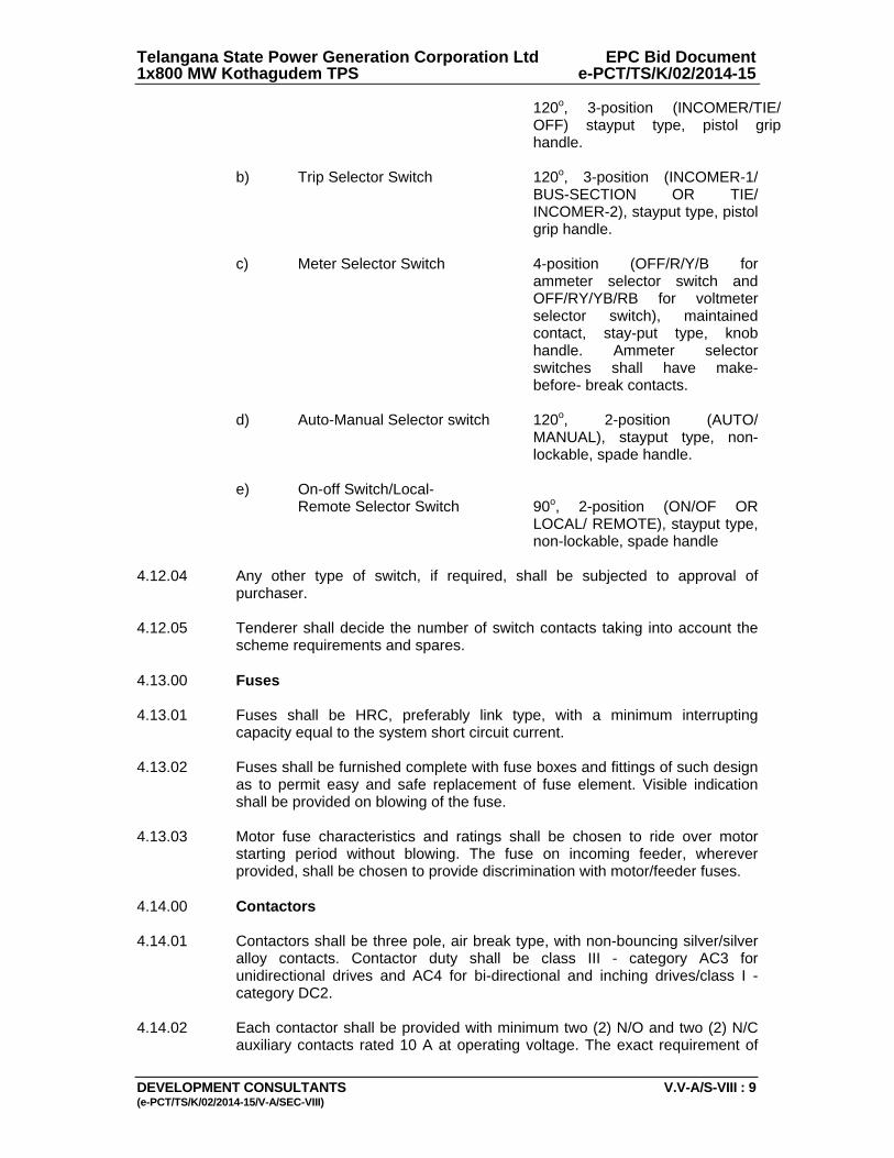
Telangana State Power Generation Corporation Ltd EPC Bid Document 1x800 MW Kothagudem TPS e-PCT/TS/K/02/2014-15
DEVELOPMENT CONSULTANTS V.V-A/S-VIII : 9 (e-PCT/TS/K/02/2014-15/V-A/SEC-VIII)
120o, 3-position (INCOMER/TIE/ OFF) stayput type, pistol grip handle.
b) Trip Selector Switch 120o, 3-position (INCOMER-1/
BUS-SECTION OR TIE/ INCOMER-2), stayput type, pistol grip handle.
c) Meter Selector Switch 4-position (OFF/R/Y/B for
ammeter selector switch and OFF/RY/YB/RB for voltmeter selector switch), maintained contact, stay-put type, knob handle. Ammeter selector switches shall have make- before- break contacts.
d) Auto-Manual Selector switch 120o, 2-position (AUTO/
MANUAL), stayput type, non- lockable, spade handle.
e) On-off Switch/Local- Remote Selector Switch 90o, 2-position (ON/OF OR
LOCAL/ REMOTE), stayput type, non-lockable, spade handle
4.12.04 Any other type of switch, if required, shall be subjected to approval of
purchaser. 4.12.05 Tenderer shall decide the number of switch contacts taking into account the
scheme requirements and spares. 4.13.00 Fuses 4.13.01 Fuses shall be HRC, preferably link type, with a minimum interrupting
capacity equal to the system short circuit current. 4.13.02 Fuses shall be furnished complete with fuse boxes and fittings of such design
as to permit easy and safe replacement of fuse element. Visible indication shall be provided on blowing of the fuse.
4.13.03 Motor fuse characteristics and ratings shall be chosen to ride over motor
starting period without blowing. The fuse on incoming feeder, wherever provided, shall be chosen to provide discrimination with motor/feeder fuses.
4.14.00 Contactors 4.14.01 Contactors shall be three pole, air break type, with non-bouncing silver/silver
alloy contacts. Contactor duty shall be class III - category AC3 for unidirectional drives and AC4 for bi-directional and inching drives/class I - category DC2.
4.14.02 Each contactor shall be provided with minimum two (2) N/O and two (2) N/C
auxiliary contacts rated 10 A at operating voltage. The exact requirement of
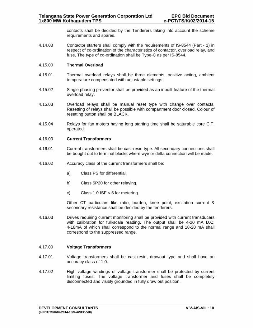
Telangana State Power Generation Corporation Ltd EPC Bid Document 1x800 MW Kothagudem TPS e-PCT/TS/K/02/2014-15
DEVELOPMENT CONSULTANTS V.V-A/S-VIII : 10 (e-PCT/TS/K/02/2014-15/V-A/SEC-VIII)
contacts shall be decided by the Tenderers taking into account the scheme requirements and spares.
4.14.03 Contactor starters shall comply with the requirements of IS-8544 (Part - 1) in
respect of co-ordination of the characteristics of contactor, overload relay, and fuse. The type of co-ordination shall be Type-C as per IS-8544.
4.15.00 Thermal Overload 4.15.01 Thermal overload relays shall be three elements, positive acting, ambient
temperature compensated with adjustable settings. 4.15.02 Single phasing preventor shall be provided as an inbuilt feature of the thermal
overload relay. 4.15.03 Overload relays shall be manual reset type with change over contacts.
Resetting of relays shall be possible with compartment door closed. Colour of resetting button shall be BLACK.
4.15.04 Relays for fan motors having long starting time shall be saturable core C.T.
operated. 4.16.00 Current Transformers 4.16.01 Current transformers shall be cast-resin type. All secondary connections shall
be bought out to terminal blocks where wye or delta connection will be made. 4.16.02 Accuracy class of the current transformers shall be: a) Class PS for differential. b) Class 5P20 for other relaying. c) Class 1.0 ISF < 5 for metering. Other CT particulars like ratio, burden, knee point, excitation current &
secondary resistance shall be decided by the tenderers. 4.16.03 Drives requiring current monitoring shall be provided with current transducers
with calibration for full-scale reading. The output shall be 4-20 mA D.C; 4-18mA of which shall correspond to the normal range and 18-20 mA shall correspond to the suppressed range.
4.17.00 Voltage Transformers 4.17.01 Voltage transformers shall be cast-resin, drawout type and shall have an
accuracy class of 1.0. 4.17.02 High voltage windings of voltage transformer shall be protected by current
limiting fuses. The voltage transformer and fuses shall be completely disconnected and visibly grounded in fully draw out position.
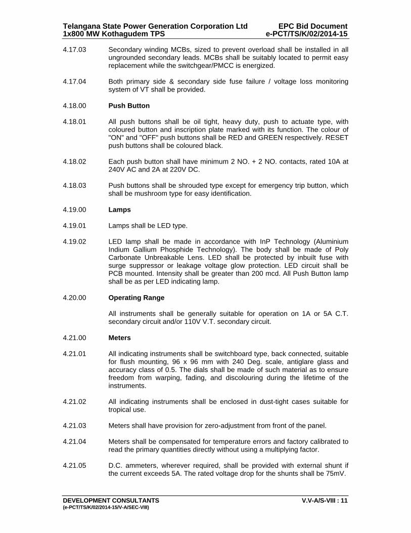
Telangana State Power Generation Corporation Ltd EPC Bid Document 1x800 MW Kothagudem TPS e-PCT/TS/K/02/2014-15
DEVELOPMENT CONSULTANTS V.V-A/S-VIII : 11 (e-PCT/TS/K/02/2014-15/V-A/SEC-VIII)
4.17.03 Secondary winding MCBs, sized to prevent overload shall be installed in all ungrounded secondary leads. MCBs shall be suitably located to permit easy replacement while the switchgear/PMCC is energized.
4.17.04 Both primary side & secondary side fuse failure / voltage loss monitoring
system of VT shall be provided. 4.18.00 Push Button 4.18.01 All push buttons shall be oil tight, heavy duty, push to actuate type, with
coloured button and inscription plate marked with its function. The colour of "ON" and "OFF" push buttons shall be RED and GREEN respectively. RESET push buttons shall be coloured black.
4.18.02 Each push button shall have minimum 2 NO. + 2 NO. contacts, rated 10A at
240V AC and 2A at 220V DC. 4.18.03 Push buttons shall be shrouded type except for emergency trip button, which
shall be mushroom type for easy identification. 4.19.00 Lamps 4.19.01 Lamps shall be LED type. 4.19.02 LED lamp shall be made in accordance with InP Technology (Aluminium
Indium Gallium Phosphide Technology). The body shall be made of Poly Carbonate Unbreakable Lens. LED shall be protected by inbuilt fuse with surge suppressor or leakage voltage glow protection. LED circuit shall be PCB mounted. Intensity shall be greater than 200 mcd. All Push Button lamp shall be as per LED indicating lamp.
4.20.00 Operating Range All instruments shall be generally suitable for operation on 1A or 5A C.T.
secondary circuit and/or 110V V.T. secondary circuit. 4.21.00 Meters 4.21.01 All indicating instruments shall be switchboard type, back connected, suitable
for flush mounting, 96 x 96 mm with 240 Deg. scale, antiglare glass and accuracy class of 0.5. The dials shall be made of such material as to ensure freedom from warping, fading, and discolouring during the lifetime of the instruments.
4.21.02 All indicating instruments shall be enclosed in dust-tight cases suitable for
tropical use. 4.21.03 Meters shall have provision for zero-adjustment from front of the panel. 4.21.04 Meters shall be compensated for temperature errors and factory calibrated to
read the primary quantities directly without using a multiplying factor. 4.21.05 D.C. ammeters, wherever required, shall be provided with external shunt if
the current exceeds 5A. The rated voltage drop for the shunts shall be 75mV.

Telangana State Power Generation Corporation Ltd EPC Bid Document 1x800 MW Kothagudem TPS e-PCT/TS/K/02/2014-15
DEVELOPMENT CONSULTANTS V.V-A/S-VIII : 12 (e-PCT/TS/K/02/2014-15/V-A/SEC-VIII)
4.22.00 Annunciator System 4.22.01 Each control panel shall be provided with an annunciator window board. The
annunciator boards shall be back-connected and suitable for semi-flush mounting.
4.22.02 The annunciator system shall be solid state type with optical isolation for input
signals. The functional requirements shall be as per Annexure-C. 4.22.03 Each annunciator group shall be independent, complete with its own power
supply, acknowledge-reset-test buttons and other necessary accessories. Hooter for audible alarm shall be common for each control panel assembly.
4.22.04 Each annunciator group shall be provided with a common alarm relay for
group alarm annunciation in remote control room. The common alarm relay will operate on actuation of any alarm point of the group.
4.22.05 The annunciator shall be non-integral type with hardware box mounted
separately for easy access and maintenance. 4.22.06 Audible alarms with different tones shall be used for trip, non-trip and ring
back functions. 4.22.07 The window size shall be such as to accommodate minimum three (3) lines of
twelve (12) characters each. Each character shall be minimum 4.75 mm high. 4.22.08 The annunciator system shall be suitable for operation from both NO and NC
type initiating contacts. 4.22.09 At least 10% spare channels and window facia shall be provided in each
annunciator group. 4.23.00 Relays 4.23.01 Auxiliary relays shall be furnished in fixed, dust-tight, casings and mounted
inside the panel. 4.23.02 The relays shall have adequate numbers of contacts to suit scheme
requirements. Besides, each relay shall have spare contacts for future use. 4.23.03 Contacts shall be silver-surfaced, bounce-free, and capable of repeated
operation without deterioration. 4.24.00 Auxiliary Devices 4.24.01 The Contractor shall furnish, install, and wire-up all auxiliary devices such as
timing / switching / lockout / auxiliary relays/auxiliary contactors, etc. as required for the proper functioning of the approved schemes.
4.24.02 The Contractor shall number the various types of relays and contactors as per
the numbers appearing in the approved Schematic/Wiring appearing in the approved Schematic/Wiring diagrams.
5.00.00 TESTS

Telangana State Power Generation Corporation Ltd EPC Bid Document 1x800 MW Kothagudem TPS e-PCT/TS/K/02/2014-15
DEVELOPMENT CONSULTANTS V.V-A/S-VIII : 13 (e-PCT/TS/K/02/2014-15/V-A/SEC-VIII)
5.01.00 All Control Boards/Panels, L.I.S. Units and L.P.B. Stations shall be completely
assembled, wired, adjusted and tested at the factory prior to shipment to ensure accuracy of wiring, correctness of control scheme and proper functioning of all components.
5.02.00 Routine Tests 5.02.01 The tests shall include wiring continuity tests, high voltage tests, interlock &
sequential operation test, insulation measurement test both before and after high voltage test, and functional tests to ensure accuracy of wiring operation of the control/ protection/metering schemes and individual equipment. Detailed test report including procedure and drawing shall be furnished.
5.02.02 All switches, meters, relays and other devices shall be tested and calibrated
in accordance with relevant IS standards. 5.03.00 Type test certificate on any equipment, if so desired shall be furnished.
Otherwise the equipment shall have to be type tested, free of charge, to prove the design.
6.00.00 DRAWINGS, DATA & MANUALS 6.01.00 Drawings, Data & Manuals shall be submitted in triplicate with the bid and in
quantities and procedures as specified in General Conditions of Contract and/or elsewhere in the specification for approval and subsequent distribution after the issue of 'Letter of Intent'.
6.02.00 To be submitted with the Bid 6.02.01 General Arrangement drawings and cross-section of each equipment showing
constructional features, cable entry points etc. 6.02.02 Typical foundation plan. 6.02.03 Bill of Materials. 6.02.04 Technical leaflet and Catalogues of: a) Local Control Boards and Local Starter-cum-Control panels b) Local Isolating switch units c) Local Push Button Stations d) Switches and Lamps e) Meters, relays, push buttons f) Switch fuse units g) Annunciator System h) Auxiliary Devices
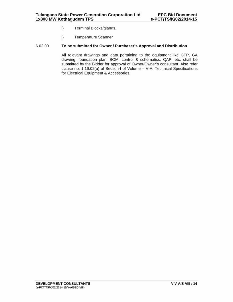
Telangana State Power Generation Corporation Ltd EPC Bid Document 1x800 MW Kothagudem TPS e-PCT/TS/K/02/2014-15
DEVELOPMENT CONSULTANTS V.V-A/S-VIII : 14 (e-PCT/TS/K/02/2014-15/V-A/SEC-VIII)
i) Terminal Blocks/glands. j) Temperature Scanner 6.02.00 To be submitted for Owner / Purchaser’s Approval and Distribution
All relevant drawings and data pertaining to the equipment like GTP, GA drawing, foundation plan, BOM, control & schematics, QAP, etc. shall be submitted by the Bidder for approval of Owner/Owner’s consultant. Also refer clause no. 1.19.02(u) of Section-I of Volume – V-A: Technical Specifications for Electrical Equipment & Accessories.

Telangana State Power Generation Corporation Ltd EPC Bid Document 1x800 MW Kothagudem TPS e-PCT/TS/K/02/2014-15
DEVELOPMENT CONSULTANTS V.V-A/S-VIII : 15 (e-PCT/TS/K/02/2014-15/V-A/SEC-VIII)
ANNEXURE-A
RATINGS & REQUIREMENTS 1.0 Local Control Board 1.1 General Type : Fixed type Service : Indoor Enclosure : IP-54 1.2 System Voltage : 415 Volt ± 10% Phase : 3 Frequency : 50 Hz +3% to -5% System : Solidly grounded 1.3 Rated Current at 50C Bus bar : To be decided by the Tenderers Switches : To be decided by the Tenderers 1.4 Short Circuit Rating Interrupting : 50 kA Short time for 1 Second : 50 kA 1.5 Insulation Level : 2.5 kV for 1 min.
ANNEXURE-B
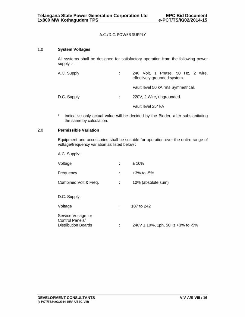
Telangana State Power Generation Corporation Ltd EPC Bid Document 1x800 MW Kothagudem TPS e-PCT/TS/K/02/2014-15
DEVELOPMENT CONSULTANTS V.V-A/S-VIII : 16 (e-PCT/TS/K/02/2014-15/V-A/SEC-VIII)
A.C./D.C. POWER SUPPLY
1.0 System Voltages All systems shall be designed for satisfactory operation from the following power
supply :- A.C. Supply : 240 Volt, 1 Phase, 50 Hz, 2 wire,
effectively grounded system. Fault level 50 kA rms Symmetrical. D.C. Supply : 220V, 2 Wire, ungrounded. Fault level 25* kA * Indicative only actual value will be decided by the Bidder, after substantiating
the same by calculation. 2.0 Permissible Variation Equipment and accessories shall be suitable for operation over the entire range of
voltage/frequency variation as listed below : A.C. Supply: Voltage : ± 10% Frequency : +3% to -5% Combined Volt & Freq. : 10% (absolute sum) D.C. Supply: Voltage : 187 to 242 Service Voltage for Control Panels/ Distribution Boards : 240V ± 10%, 1ph, 50Hz +3% to -5%
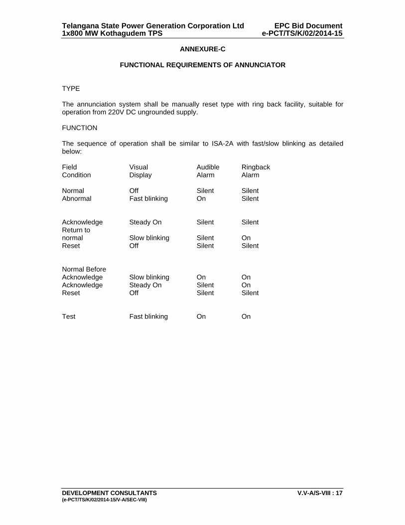
Telangana State Power Generation Corporation Ltd EPC Bid Document 1x800 MW Kothagudem TPS e-PCT/TS/K/02/2014-15
DEVELOPMENT CONSULTANTS V.V-A/S-VIII : 17 (e-PCT/TS/K/02/2014-15/V-A/SEC-VIII)
ANNEXURE-C
FUNCTIONAL REQUIREMENTS OF ANNUNCIATOR TYPE The annunciation system shall be manually reset type with ring back facility, suitable for operation from 220V DC ungrounded supply. FUNCTION The sequence of operation shall be similar to ISA-2A with fast/slow blinking as detailed below: Field Visual Audible Ringback Condition Display Alarm Alarm Normal Off Silent Silent Abnormal Fast blinking On Silent Acknowledge Steady On Silent Silent Return to normal Slow blinking Silent On Reset Off Silent Silent Normal Before Acknowledge Slow blinking On On Acknowledge Steady On Silent On Reset Off Silent Silent Test Fast blinking On On
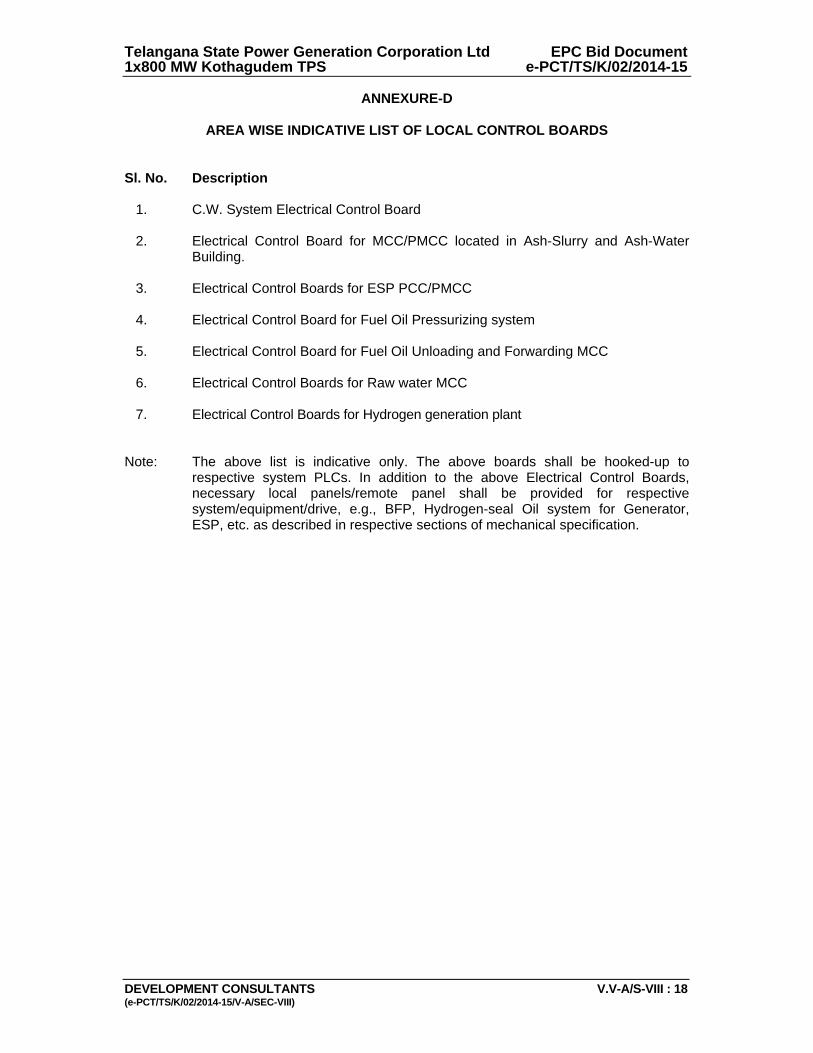
Telangana State Power Generation Corporation Ltd EPC Bid Document 1x800 MW Kothagudem TPS e-PCT/TS/K/02/2014-15
DEVELOPMENT CONSULTANTS V.V-A/S-VIII : 18 (e-PCT/TS/K/02/2014-15/V-A/SEC-VIII)
ANNEXURE-D
AREA WISE INDICATIVE LIST OF LOCAL CONTROL BOARDS Sl. No. Description 1. C.W. System Electrical Control Board 2. Electrical Control Board for MCC/PMCC located in Ash-Slurry and Ash-Water
Building. 3. Electrical Control Boards for ESP PCC/PMCC 4. Electrical Control Board for Fuel Oil Pressurizing system
5. Electrical Control Board for Fuel Oil Unloading and Forwarding MCC 6. Electrical Control Boards for Raw water MCC
7. Electrical Control Boards for Hydrogen generation plant Note: The above list is indicative only. The above boards shall be hooked-up to
respective system PLCs. In addition to the above Electrical Control Boards, necessary local panels/remote panel shall be provided for respective system/equipment/drive, e.g., BFP, Hydrogen-seal Oil system for Generator, ESP, etc. as described in respective sections of mechanical specification.
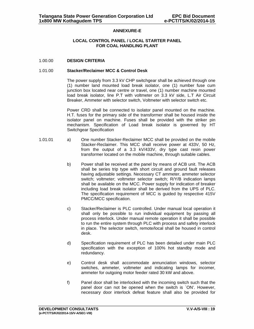
Telangana State Power Generation Corporation Ltd EPC Bid Document 1x800 MW Kothagudem TPS e-PCT/TS/K/02/2014-15
DEVELOPMENT CONSULTANTS V.V-A/S-VIII : 19 (e-PCT/TS/K/02/2014-15/V-A/SEC-VIII)
ANNEXURE-E
LOCAL CONTROL PANEL / LOCAL STARTER PANEL FOR COAL HANDLING PLANT
1.00.00 DESIGN CRITERIA 1.01.00 Stacker/Reclaimer MCC & Control Desk The power supply from 3.3 kV CHP switchgear shall be achieved through one
(1) number land mounted load break isolator, one (1) number fuse cum junction box located near centre or travel, one (1) number machine mounted load break isolator, line P.T with voltmeter on 3.3 kV side, L.T Air Circuit Breaker, Ammeter with selector switch, Voltmeter with selector switch etc.
Power CRD shall be connected to isolator panel mounted on the machine.
H.T. fuses for the primary side of the transformer shall be housed inside the isolator panel on machine. Fuses shall be provided with the striker pin mechanism. Specification of Load break isolator is governed by HT Switchgear Specification
1.01.01 a) One number Stacker-Reclaimer MCC shall be provided on the mobile
Stacker-Reclaimer. This MCC shall receive power at 433V, 50 Hz, from the output of a 3.3 kV/433V, dry type cast resin power transformer located on the mobile machine, through suitable cables.
b) Power shall be received at the panel by means of ACB unit. The ACB
shall be series trip type with short circuit and ground fault releases having adjustable settings. Necessary CT ammeter, ammeter selector switch; voltmeter; voltmeter selector switch; R/Y/B indication lamps shall be available on the MCC. Power supply for indication of breaker including load break isolator shall be derived from the UPS of PLC. The specification requirement of MCC is guided by respective 415V PMCC/MCC specification.
c) Stacker/Reclaimer is PLC controlled. Under manual local operation it
shall only be possible to run individual equipment by passing all process interlock. Under manual remote operation it shall be possible to run the entire system through PLC with process and safety interlock in place. The selector switch, remote/local shall be housed in control desk.
d) Specification requirement of PLC has been detailed under main PLC
specification with the exception of 100% hot standby mode and redundancy.
e) Control desk shall accommodate annunciation windows, selector
switches, ammeter, voltmeter and indicating lamps for incomer, ammeter for outgoing motor feeder rated 30 kW and above.
f) Panel door shall be interlocked with the incoming switch such that the
panel door can not be opened when the switch is `ON’. However, necessary door interlock defeat feature shall also be provided for

Telangana State Power Generation Corporation Ltd EPC Bid Document 1x800 MW Kothagudem TPS e-PCT/TS/K/02/2014-15
DEVELOPMENT CONSULTANTS V.V-A/S-VIII : 20 (e-PCT/TS/K/02/2014-15/V-A/SEC-VIII)
testing purpose. Rating of components shall conform to the rating indicated in the enclosed component selection chart.
g) Audio visual annunciation system shall have at least but not limited to
the following annunciation points complete with Accept/Test Preset P.B.:
i) Transformer winding temperature high.
ii) 415 V Incomer breaker tripped
iii) Boom Conveyor zero speed switch operated
iv) Boom Conveyor belt sway operated
v) Boom Conveyor pull cord switch operated
vi) Boom Conveyor brake not released.
vii) Boom Conveyor Motor overload/SPPR fault
viii) Back up limit switch operated.
ix) Wind velocity high.
x) Wind velocity very high.
xi) Slew limit switch operated.
xii) Slew drive fault.
xiii) Slew motor overload.
xiv) Slew drive lubrication system fault.
xv) Hydraulic oil temperature high.
xvi) Oil level low in hydraulic tank.
xvii) Hydraulic system filter clogged.
xviii) Bucket wheel brake not released.
xix) Bucket wheel zero speed switch fault.
xx) Bucket wheel motor overload/SPPR fault.
xxi) Power CRD motor overload.
xxii) Power CRD over tension switch operated.
xxiii) Control CRD motor overload.
xxiv) Control CRD over tension switch operated.
xxv) Travel drive brake not released.
xxvi) Travel drive motor overload/SPPR fault.
xxvii) Travel limit switch operated.
xxviii) Rail clamp not released.
xxix) DS motor overload/SPPR fault (to be provided for each
motor).
xxx) HT load brake switch operated.
Telangana State Power Generation Corporation Ltd EPC Bid Document 1x800 MW Kothagudem TPS e-PCT/TS/K/02/2014-15
DEVELOPMENT CONSULTANTS V.V-A/S-VIII : 21 (e-PCT/TS/K/02/2014-15/V-A/SEC-VIII)
Annunciation system shall be similar to that of main Control Panel with 20% spare windows.
h) Separate cable reeling drum shall be provided for power & control
cable. Combined trailing cable shall have 24C X 2.5 mm2 (cu) control cable and 8 pair 1.5 mm2 (cu) screened cable for signal and communication.
1.02.00 ON/OFF operation of Wagon tipplers shall be achieved from the respective
Wagon tippler Control desk through PLC based logic. Control desk shall be provided in each Wagon tippler Control room for Control, Operation, Indication & Annunciation of Wagon Tippler equipment. Control desk shall interface with PLC for the entire operation and shall accommodate annunciation windows, ammeter, voltmeter, selector switches and indicating lamps for incomer, ammeter for outgoing motor feeder rated 30 kW and above. Other features as described above for the control desk of Stacker Reclaimer shall also be considered for Wagon Tippler.
1.03.00 MCC/DB/Local Starter Panel for Dust Suppression, Dust Extraction, Sump
Pump, Coal Sampler, Bunker Level and other Panels 1.03.01 The Local Starter Panel shall be fixed type with compartmentalized execution.
One (1) number 415 V ± 10% 3 phase 4 wire 50 Hz +3% to -5% power supply feeder shall be provided for each panel. Power shall be received through an incoming SFU having R/Y/B indication lamps, voltmeter with selector switch, ammeter with selector switch. Individual motor feeder shall have their switch fuse, power contactor, overload relay-cum-single phasing preventor (hand reset type), stop/ start push button, auto/manual selector switch, Red/Green/ Trip indication lamp, auxiliary relays, timers, etc. The stop push button shall be lockable type. Necessary interlock, annunciation, 415/240 V Transformers for control supply, space heating as applicable to meet system requirement shall also be provided and in no case derive any power supply from its main feeder. Separate feeders shall also be provided for brakes and rail clamp as applicable. Facility shall be provided for resetting the motor overload relay from outside without opening the panel door. Panel door shall be interlocked with the incoming Switch such that the door can not be opened when Switch is ON.
Specification requirement of the above including module selection chart will
be governed by 415 V MCC/PMCC Specification. 1.03.02 Interlock, control, indication, annunciation etc. shall be achieved by relay logic 1.03.03 Isolation of individual circuit in the MCC/DB/Local Starter Panel shall be
provided through individual Fuse. 1.03.04 Control features as described under relevant mechanical section shall be
considered for interlocking and preparation of control schematic. 1.03.05 Thermostatically control space heater shall be provided. 1.03.06 Necessary door interlock defeat feature shall also be provided for testing
purpose. Wherever necessary, the panels shall be designed for outdoor and of weather proof/rain protection type. Ratings of components shall be as per module selection chart indicated under 415 V PCC/PMCC/MCC Specification.
Telangana State Power Generation Corporation Ltd EPC Bid Document 1x800 MW Kothagudem TPS e-PCT/TS/K/02/2014-15
DEVELOPMENT CONSULTANTS V.V-A/S-VIII : 22 (e-PCT/TS/K/02/2014-15/V-A/SEC-VIII)
1.03.07 Travelling Tripper DB cum Control Panel In addition to indication to be provided for drives, following indications shall
also be provided in local panel:
i) Brakes applied ii) Rail clamps applied iii) Flap Gate position iv) Travel driver over speed v) Travelling tripper – Forward/Reverse vi) Cable Reeling Drum on
Travelling tripper position on bunker shall be provided in the PLC. Control features as described under relevant mechanical portion shall be
considered for interlocking and preparation of control schematic. Cable reeling drum shall be provided for power & control cable. Apart from
meeting the requirements in respect of control , indication & annunciation and telecommunication following spare cores shall be provided:
i) 4 pair core ( Sheilded) for communication. ii) 4 Core for control.
1.03.08 Sump Pump Control Panel Sump Pump Control Panel shall be provided with level controller, necessary
contacts to start pumps in auto mode when level reaches high. Further, very high level shall cause hooter to blare and the same shall stop after sometime delay. In manual mode it shall be possible to start individual pump. However, in manual mode and auto mode of operation, pump shall be tripped when level in the sump pit reaches low. Sump pumps shall be able to operate from PLC, the level switches shall be wired to PLC.
In addition to other indicating lamps level high indication lamp shall also be
provided in local panel. 1.03.09 Miscellaneous Control Panels Miscellaneous control panel i.e. dust suppression panel, ventilation panel,
etc. shall have individual starter feeder for individual drive. Other features as specified above shall also be provided. Equipment such as Vibrating Grizzle feeders, Magnetic separators, Metal detectors, Dust suppression, Ventilation, Dust extraction, Coal Sampler, Bunker Level, Hoists etc. shall have individual starter-cum-control panels to suit individual requirements. The panels shall include all necessary feeders, start stop PB, indicating lamp, annunciation system, 415/240V control transformers for control supply and space heating as applicable to meet system requirement. For Magnetic Separators, separate panels shall be provided. One panel shall accommodate transformer & rectifier and the other panel shall accommodate incomer and other controlling items.
Telangana State Power Generation Corporation Ltd EPC Bid Document 1x800 MW Kothagudem TPS e-PCT/TS/K/02/2014-15
DEVELOPMENT CONSULTANTS V.V-A/S-VIII : 23 (e-PCT/TS/K/02/2014-15/V-A/SEC-VIII)
The requirement of 4-20 mA signals for Belt Weigher and bunker level indicator have been spell out in Mechanical Specification and accordingly the same shall be provided.
2.00.00 SPECIFIC DESIGN REQUIREMENT 2.01.00 Construction a) Stacker/Reclaimer/ Wagon Tippler Control Desk
Ammeters and annunciation facia shall be mounted on the vertical portion of the panel and all push button; selector switches; indication lamps etc. shall be mounted on the desk portion. The front desk shall be with top inclined downward towards front. A removable type front door shall be provided on the desk portion along with a lockable and lift-off rear door for the panel portion of the desk-cum-panel.
Travelling Tripper/Magnetic Separator/Metal Detector/Dust Extraction/
Dust Suppression/Ventilation/Coal Sampler/Bunker Level indication, Hoist/MCC/DB/Starter-Cum-Control Panel, Misc. Control Stations, Push Button Stations & Local Information Boards.
These panels/stations shall be furnished in sheet steel enclosures
suitable for wall/column/floor mounting. 2.02.00 General
a) Design, material selection and workmanship shall be such as to present a neat appearance outside and inside with no marks of welds, rivets, screws or bolt heads apparent from the exterior surface of the frames.
b) Panels shall be of folded sheet steel construction, assembled on
channel/angle base plates. Anti-vibration mountings shall be provided for moving equipment.
c) All switchboard/panel frames and load bearing members shall be
fabricated using suitable mild steel structural sections or pressed and shaped cold rolled sheet steel of thickness 2.0mm. Frames shall be enclosed in cold rolled sheet steel of thickness 1.6 mm. Doors and covers shall also be of cold rolled sheet steel thickness 1.6 mm. Stiffeners shall be provided wherever necessary. The gland plate thickness shall be 3.0 mm for hot/cold rolled sheet steel and 4.0 mm for non-magnetic material. The panels shall have sufficient structural reinforcement to ensure a plain surface, limit vibration and provide rigidity during despatch and installation. Vertical panels shall be freestanding type.
d) Sufficient inter-component spacing shall be available for easy
maintenance, replacement, ventilation etc. of the components. A minimum spacing of 50mm is recommended for the same.
e) All doors, covers etc. shall be properly gasketted to make the panel
effectively vermin and dust proof. Door hinges shall be concealed
Telangana State Power Generation Corporation Ltd EPC Bid Document 1x800 MW Kothagudem TPS e-PCT/TS/K/02/2014-15
DEVELOPMENT CONSULTANTS V.V-A/S-VIII : 24 (e-PCT/TS/K/02/2014-15/V-A/SEC-VIII)
type. Special dust protection measures shall be taken for panels located in dusty area.
f) All hardware for the complete installation of the equipment including
foundation and fixing bolts, nuts, washers etc. shall be supplied to suit the requirement. All bolts, nuts etc. exposed to external atmosphere shall be cadmium plated or zinc passivated.
g) The panels shall be liberally sized so as to provide spacious layout of
equipment and devices with sufficient working space in between.
h) Shock absorbers shall be provided for panels mounted on mobile machines.
i) Maximum and minimum height of the operating devices on all panels
except Local Control Stations shall be restricted to 1800 mm and 750 mm respectively from the floor level.
Telangana State Power Generation Corporation Ltd EPC Bid Document 1x800 MW Kothagudem TPS e-PCT/TS/K/02/2014-15
DEVELOPMENT CONSULTANTS (e-PCT/TS/K/02/2014-15/V-A/SEC-II)
VOLUME: V-A
SECTION-II
TECHNICAL SPECIFICATION FOR
A.C. & D.C. MOTORS
Telangana State Power Generation Corporation Ltd EPC Bid Document 1x800 MW Kothagudem TPS e-PCT/TS/K/02/2014-15
DEVELOPMENT CONSULTANTS (e-PCT/TS/K/02/2014-15/V-A/SEC-II)
CONTENT CLAUSE NO. DESCRIPTION 1.00.00 SCOPE 2.00.00 CODES & STANDARDS 3.00.00 SERVICE CONDITIONS 4.00.00 TYPE AND RATING 5.00.00 PERFORMANCE 6.00.00 SPECIFIC REQUIREMENTS 7.00.00 ACCESSORIES 8.00.00 TESTS 9.00.00 DRAWINGS, DATA & MANUALS ATTACHMENT ANNEXURE-A DESIGN DATA
Telangana State Power Generation Corporation Ltd EPC Bid Document 1x800 MW Kothagudem TPS e-PCT/TS/K/02/2014-15
DEVELOPMENT CONSULTANTS V.V-A/S-II: 1 (e-PCT/TS/K/02/2014-15/V-A/SEC-II)
VOLUME: V-A
SECTION-II
TECHNICAL SPECIFICATION FOR
A.C. & D.C. MOTORS 1.00.00 SCOPE 1.01.00 This section covers the general requirements of the drive motors for power
station auxiliary equipment. 1.02.00 Motors shall be furnished in accordance with both this general specification
and the accompanying driven equipment specification. 1.03.00 In case of any discrepancy, the driven equipment specification shall govern. 2.00.00 CODES & STANDARDS 2.01.00 All motors shall conform to the latest applicable IS, IEC and CBIP Standards/
Publications except when otherwise stated herein or in the driven equipment specification.
2.02.00 Major standards, which shall be followed, are listed below other applicable
Indian Standards for any component part even if not covered in the listed standards shall also be followed:
i) IS-325 ii) IS-12615 iii) IEC-60034 3.00.00 SERVICE CONDITIONS 3.01.00 The motors will be installed in hot, humid and tropical atmosphere highly
polluted at places with coal dust and/or fly ash. 3.02.00 Unless otherwise noted, electrical equipment/system design shall be based
on the service conditions and auxiliary power supply given in the annexure to this specification.
3.03.00 For motor installed outdoor and exposed to direct sunrays, the effect of solar
heat shall be considered in the determination of the design ambient temperature.
4.00.00 TYPE AND RATING 4.01.00 A.C. Motors 4.01.01 Motors shall be general purpose, constant speed, squirrel cage, three/single
phase, induction type.
Telangana State Power Generation Corporation Ltd EPC Bid Document 1x800 MW Kothagudem TPS e-PCT/TS/K/02/2014-15
DEVELOPMENT CONSULTANTS V.V-A/S-II: 2 (e-PCT/TS/K/02/2014-15/V-A/SEC-II)
4.01.02 All motors shall be rated for continuous duty. They shall also be suitable for long period of inactivity.
4.01.03 LT motor & HT motor name-plate rating at 50C shall have at least 15%
margin and 10% margin respectively over the input power requirement of the driven equipment at rated duty point unless stated otherwise in driven equipment specification.
4.01.04 The motor characteristics shall match the requirements of the driven
equipment so that adequate starting, accelerating, pull up, break down and full load torques are available for the intended service.
4.01.05 Motors efficiency class shall be IE1, IE2 as per latest version of IEC-60034. 4.02.00 D.C. Motors 4.02.01 D.C. motor provided for emergency service shall be shunt/compound wound
type. 4.02.02 Motor shall be sized for operation with fixed resistance starter for maximum
reliability. Starter panel complete with all accessories shall be included in the scope of
supply. 5.00.00 PERFORMANCE 5.01.00 Running Requirements 5.01.01 Motor shall run continuously at rated output over the entire range of voltage
and frequency variations as given in the annexure. 5.01.02 The motor shall be capable of operating satisfactorily at full load for 5 minutes
without injurious heating with 75% rated voltage at motor terminals. 5.01.03 The motor shall be designed to withstand momentary overload of 60% of full
load torque for 15 second without any damage. 5.02.00 Starting Requirements Motor shall be designed for direct online starting at full voltage. Breakaway
starting current as percentage of full load current for various motor rating shall not exceed the given below-
Motors up to 1500kW - 600% subject to IS tolerance of plus
20%.
Motors above 1500kW - 450% not subject to any positive tolerance.
5.02.01 The motor shall be capable of withstanding the stresses imposed if started at
110% rated voltage.

Telangana State Power Generation Corporation Ltd EPC Bid Document 1x800 MW Kothagudem TPS e-PCT/TS/K/02/2014-15
DEVELOPMENT CONSULTANTS V.V-A/S-II: 3 (e-PCT/TS/K/02/2014-15/V-A/SEC-II)
5.02.02 Motor shall start with rated load and accelerate to full speed with 80% rated voltage at motor terminals except mill motor. Mill motor shall start with rated load and accelerate to full speed at 85% of the rated voltage at the motor terminals.
5.02.03 a) Two hot starts in succession with motor initially at normal running
temperature. b) Pump motor subject to reverse rotation shall be designed to withstand
the stresses encountered when starting with shaft rotating at 125% rated speed in reverse direction.
5.02.04 The motors shall be designed to withstand 120% of rated speed for 2 minutes
without any mechanical damage. 5.03.00 Stress During Bus Transfer 5.03.01 The motor may be subjected to sudden application of 150% rated voltage
during bus transfer, due to the phase difference between the incoming voltage and motor residual voltage.
5.03.02 The motor shall be designed to withstand any torsional and/or high current
stresses, which may result, without experiencing any deterioration in the normal life and performance characteristics.
5.04.00 Locked Rotor Withstand Time 5.04.01 The locked rotor withstand time under hot condition at 110% rated voltage
shall be more than motor starting time by at least 3 seconds for motors up to 20 seconds starting time and by 5 seconds for motor with more than 20 seconds starting time.
5.04.02 Starting time mentioned above is at minimum permissible voltage of 80%
rated voltage. 5.04.03 Hot thermal withstand curve shall have a margin of at least 10% over the full
load current of the motor to permit relay setting utilising motor rated capacity. 6.00.00 SPECIFIC REQUIREMENTS 6.01.00 Enclosure 6.01.01 All motor enclosures for outdoor, semi-outdoor & indoor application shall
conform to the degree of protection IP-55 unless otherwise specified. Motor for outdoor or semi-outdoor service shall be of weather-proof construction with canopy.
6.01.02 For hazardous area approved type of increased safety enclosure shall be furnished.
6.02.00 Cooling 6.02.01 The motor shall be self ventilated type, either totally enclosed fan cooled IC
411(TEFC), totally enclosed tube ventilated IC 511(TETV) or closed air circuit air- cooled IC 611(CACA).
Telangana State Power Generation Corporation Ltd EPC Bid Document 1x800 MW Kothagudem TPS e-PCT/TS/K/02/2014-15
DEVELOPMENT CONSULTANTS V.V-A/S-II: 4 (e-PCT/TS/K/02/2014-15/V-A/SEC-II)
6.02.02 For large capacity motors not available with above type of cooling may be accepted with IC 81W or IC 91W, closed air circuit water cooled (CACW) subject to the approval of the owner.
6.03.00 Winding and Insulation 6.03.01 All insulated winding shall be of copper. 6.03.02 All motors shall have class F insulation but limited to class B temperature rise. 6.03.03 Windings shall be impregnated to make them non-hygroscopic and oil
resistant. 6.04.00 Tropical Protection 6.04.01 All motors shall have fungus protection involving special treatment of
insulation and metal against fungus, insects and corrosion. 6.04.02 All fittings and hardwares shall be corrosion resistant. 6.05.00 Bearings 6.05.01 Motor shall be provided with antifriction bearings, unless sleeve bearings are
required by the motor application. Bearings shall be rated for minimum service life of 40,000Hrs.
6.05.02 Vertical shaft motors shall be provided with thrust and guide bearings. Thrust
bearing of tilting pad type is preferred. 6.05.03 Bearings shall be provided with seals to prevent leakage of lubricant or
entrance of foreign matters like dirt, water etc. into the bearing area. 6.05.04 Sleeve bearings shall be split type, ring oiled, with permanently aligned, close
running shaft sleeves. 6.05.05 Grease lubricated bearings shall be pre-lubricated and shall have provisions
for in-service positive lubrication with drains to guard against over lubrication. LT motors 15kW and above shall be provided with external greasing arrangement.
6.05.06 Oiled bearing shall have an integral self cooled oil reservoir with oil ring
inspection ports, oil sight glass with oil level marked for standstill and running conditions and oil fill and drain plugs.
6.05.07 Forced lubricated or water cooled bearing shall not be used without prior
approval of Owner. 6.05.08 Lubricant shall not deteriorate under all service conditions. The lubricant shall
be limited to normally available types with IOC equivalent. 6.05.09 Bearings shall be insulated as required to prevent shaft current and resultant
bearing damage. 6.06.00 Noise & Vibration
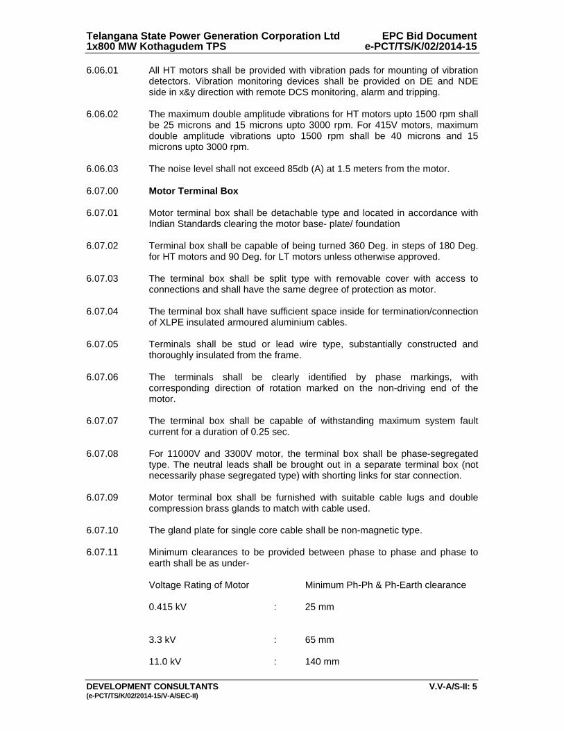
Telangana State Power Generation Corporation Ltd EPC Bid Document 1x800 MW Kothagudem TPS e-PCT/TS/K/02/2014-15
DEVELOPMENT CONSULTANTS V.V-A/S-II: 5 (e-PCT/TS/K/02/2014-15/V-A/SEC-II)
6.06.01 All HT motors shall be provided with vibration pads for mounting of vibration detectors. Vibration monitoring devices shall be provided on DE and NDE side in x&y direction with remote DCS monitoring, alarm and tripping.
6.06.02 The maximum double amplitude vibrations for HT motors upto 1500 rpm shall
be 25 microns and 15 microns upto 3000 rpm. For 415V motors, maximum double amplitude vibrations upto 1500 rpm shall be 40 microns and 15 microns upto 3000 rpm.
6.06.03 The noise level shall not exceed 85db (A) at 1.5 meters from the motor. 6.07.00 Motor Terminal Box 6.07.01 Motor terminal box shall be detachable type and located in accordance with
Indian Standards clearing the motor base- plate/ foundation 6.07.02 Terminal box shall be capable of being turned 360 Deg. in steps of 180 Deg.
for HT motors and 90 Deg. for LT motors unless otherwise approved. 6.07.03 The terminal box shall be split type with removable cover with access to
connections and shall have the same degree of protection as motor. 6.07.04 The terminal box shall have sufficient space inside for termination/connection
of XLPE insulated armoured aluminium cables. 6.07.05 Terminals shall be stud or lead wire type, substantially constructed and
thoroughly insulated from the frame. 6.07.06 The terminals shall be clearly identified by phase markings, with
corresponding direction of rotation marked on the non-driving end of the motor.
6.07.07 The terminal box shall be capable of withstanding maximum system fault
current for a duration of 0.25 sec. 6.07.08 For 11000V and 3300V motor, the terminal box shall be phase-segregated
type. The neutral leads shall be brought out in a separate terminal box (not necessarily phase segregated type) with shorting links for star connection.
6.07.09 Motor terminal box shall be furnished with suitable cable lugs and double
compression brass glands to match with cable used. 6.07.10 The gland plate for single core cable shall be non-magnetic type. 6.07.11 Minimum clearances to be provided between phase to phase and phase to
earth shall be as under- Voltage Rating of Motor Minimum Ph-Ph & Ph-Earth clearance 0.415 kV : 25 mm 3.3 kV : 65 mm 11.0 kV : 140 mm
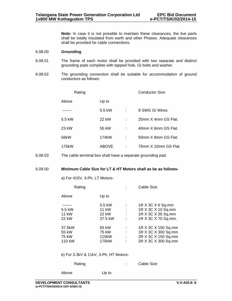
Telangana State Power Generation Corporation Ltd EPC Bid Document 1x800 MW Kothagudem TPS e-PCT/TS/K/02/2014-15
DEVELOPMENT CONSULTANTS V.V-A/S-II: 6 (e-PCT/TS/K/02/2014-15/V-A/SEC-II)
Note: In case it is not possible to maintain these clearances, the live parts
shall be totally insulated from earth and other Phases. Adequate clearances shall be provided for cable connections.
6.08.00 Grounding 6.08.01 The frame of each motor shall be provided with two separate and distinct
grounding pads complete with tapped hole, GI bolts and washer. 6.08.02 The grounding connection shall be suitable for accommodation of ground
conductors as follows: Rating Conductor Size
Above Up to ------- 5.5 kW : 8 SWG GI Wires. 5.5 kW 22 kW : 25mm X 4mm GS Flat. 23 kW 55 kW : 40mm X 6mm GS Flat. 56kW 174kW : 50mm X 8mm GS Flat. 175kW ABOVE : 75mm X 10mm GS Flat. 6.08.03 The cable terminal box shall have a separate grounding pad. 6.09.00 Minimum Cable Size for LT & HT Motors shall as be as follows- a) For 415V, 3-Ph, LT Motors- Rating : Cable Size
Above Up to ------- 5.5 kW : 1R X 3C X 6 Sq.mm 5.5 kW 11 kW : 1R X 3C X 10 Sq.mm 11 kW 22 kW : 1R X 3C X 35 Sq.mm 22 kW 37.5 kW : 1R X 3C X 70 Sq.mm. 37.5kW 55 kW : 1R X 3C X 150 Sq.mm 55 kW 75 kW : 1R X 3C X 300 Sq.mm 75 kW 110kW : 2R X 3C X 150 Sq.mm 110 kW 175kW : 2R X 3C X 300 Sq.mm b) For 3.3kV & 11kV, 3-Ph, HT Motors- Rating : Cable Size
Above Up to
Telangana State Power Generation Corporation Ltd EPC Bid Document 1x800 MW Kothagudem TPS e-PCT/TS/K/02/2014-15
DEVELOPMENT CONSULTANTS V.V-A/S-II: 7 (e-PCT/TS/K/02/2014-15/V-A/SEC-II)
175 kW 1000 kW : 1R X 3C X 240 Sq.mm 1000 kW 2000 kW : 2R X 3C X 240 Sq.mm 2000 kW 4500 kW : 2R X 3C X 300 Sq.mm 4501 kW 10,000 kW : 9R X 1C X 1000 Sq.mm.
Note: During detail engineering if higher cable size is required same shall be provided.
6.10.00 Rating Plate In addition to the minimum information required by IS, the following
information shall be shown on motor rating plate : a) Temperature rise in Deg.C under rated condition and method of
measurement. b) Degree of protection. c) Bearing identification no. and recommended lubricant. d) Location of insulated bearings. 7.00.00 ACCESSORIES 7.01.00 General Accessories shall be furnished, as listed below, or if otherwise required by
driven equipment specification or application. 7.02.00 Space Heater 7.02.01 Motor of rating 30 kW and above shall be provided with space heaters,
suitably located for easy removal or replacement. 7.02.02 The space heater shall be rated 240 V, 1 Phase, 50Hz and sized to maintain
the motor internal temperature above dew point when the motor is idle. 7.02.03 Minimum Cable Size for space heater shall be as listed-
i) For LT motors: 2.5 sq.mm, 2-Core copper cable complying with IS-
1554(Part-1). ii) For HT motors: 6 sq.mm, 2 Core aluminium cable complying with IS-
1554(Part-1).
7.03.00 Temperature Detectors 7.03.01 All 11000V and 3300V motors shall be provided with twelve (12) nos. simplex
type winding temperature detectors, four (4) nos. per phase.
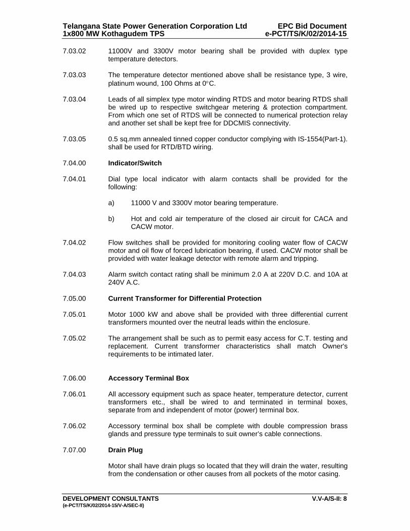
Telangana State Power Generation Corporation Ltd EPC Bid Document 1x800 MW Kothagudem TPS e-PCT/TS/K/02/2014-15
DEVELOPMENT CONSULTANTS V.V-A/S-II: 8 (e-PCT/TS/K/02/2014-15/V-A/SEC-II)
7.03.02 11000V and 3300V motor bearing shall be provided with duplex type temperature detectors.
7.03.03 The temperature detector mentioned above shall be resistance type, 3 wire,
platinum wound, 100 Ohms at 0C. 7.03.04 Leads of all simplex type motor winding RTDS and motor bearing RTDS shall
be wired up to respective switchgear metering & protection compartment. From which one set of RTDS will be connected to numerical protection relay and another set shall be kept free for DDCMIS connectivity.
7.03.05 0.5 sq.mm annealed tinned copper conductor complying with IS-1554(Part-1).
shall be used for RTD/BTD wiring. 7.04.00 Indicator/Switch 7.04.01 Dial type local indicator with alarm contacts shall be provided for the
following: a) 11000 V and 3300V motor bearing temperature. b) Hot and cold air temperature of the closed air circuit for CACA and
CACW motor. 7.04.02 Flow switches shall be provided for monitoring cooling water flow of CACW
motor and oil flow of forced lubrication bearing, if used. CACW motor shall be provided with water leakage detector with remote alarm and tripping.
7.04.03 Alarm switch contact rating shall be minimum 2.0 A at 220V D.C. and 10A at
240V A.C. 7.05.00 Current Transformer for Differential Protection 7.05.01 Motor 1000 kW and above shall be provided with three differential current
transformers mounted over the neutral leads within the enclosure. 7.05.02 The arrangement shall be such as to permit easy access for C.T. testing and
replacement. Current transformer characteristics shall match Owner's requirements to be intimated later.
7.06.00 Accessory Terminal Box 7.06.01 All accessory equipment such as space heater, temperature detector, current
transformers etc., shall be wired to and terminated in terminal boxes, separate from and independent of motor (power) terminal box.
7.06.02 Accessory terminal box shall be complete with double compression brass
glands and pressure type terminals to suit owner’s cable connections. 7.07.00 Drain Plug Motor shall have drain plugs so located that they will drain the water, resulting
from the condensation or other causes from all pockets of the motor casing.
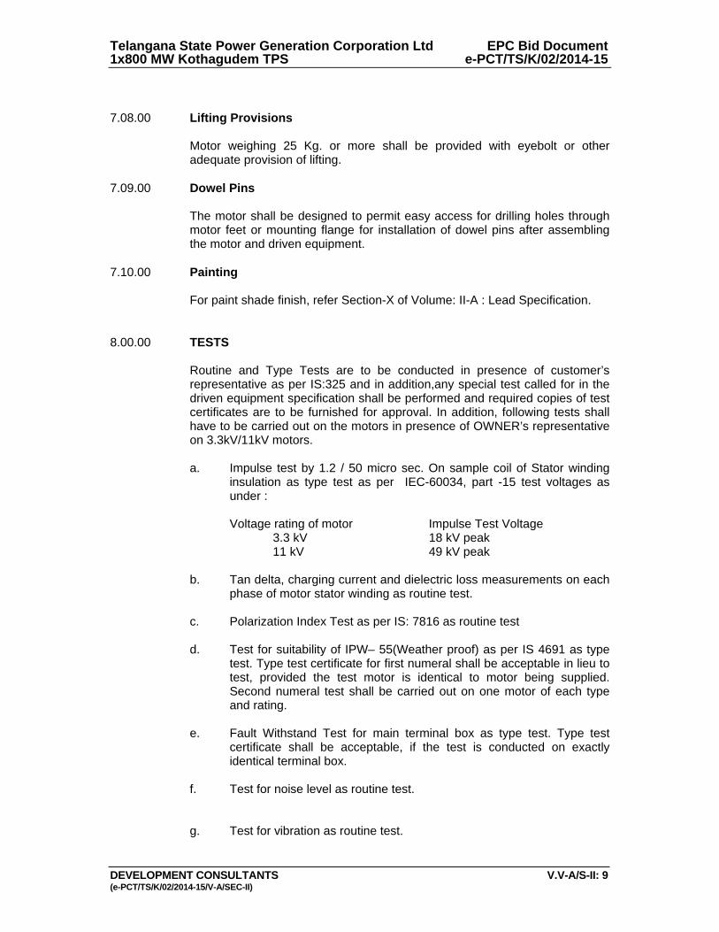
Telangana State Power Generation Corporation Ltd EPC Bid Document 1x800 MW Kothagudem TPS e-PCT/TS/K/02/2014-15
DEVELOPMENT CONSULTANTS V.V-A/S-II: 9 (e-PCT/TS/K/02/2014-15/V-A/SEC-II)
7.08.00 Lifting Provisions Motor weighing 25 Kg. or more shall be provided with eyebolt or other
adequate provision of lifting. 7.09.00 Dowel Pins The motor shall be designed to permit easy access for drilling holes through
motor feet or mounting flange for installation of dowel pins after assembling the motor and driven equipment.
7.10.00 Painting For paint shade finish, refer Section-X of Volume: II-A : Lead Specification. 8.00.00 TESTS
Routine and Type Tests are to be conducted in presence of customer’s representative as per IS:325 and in addition,any special test called for in the driven equipment specification shall be performed and required copies of test certificates are to be furnished for approval. In addition, following tests shall have to be carried out on the motors in presence of OWNER’s representative on 3.3kV/11kV motors. a. Impulse test by 1.2 / 50 micro sec. On sample coil of Stator winding
insulation as type test as per IEC-60034, part -15 test voltages as under :
Voltage rating of motor Impulse Test Voltage 3.3 kV 18 kV peak 11 kV 49 kV peak b. Tan delta, charging current and dielectric loss measurements on each
phase of motor stator winding as routine test. c. Polarization Index Test as per IS: 7816 as routine test d. Test for suitability of IPW– 55(Weather proof) as per IS 4691 as type
test. Type test certificate for first numeral shall be acceptable in lieu to test, provided the test motor is identical to motor being supplied. Second numeral test shall be carried out on one motor of each type and rating.
e. Fault Withstand Test for main terminal box as type test. Type test
certificate shall be acceptable, if the test is conducted on exactly identical terminal box.
f. Test for noise level as routine test. g. Test for vibration as routine test.
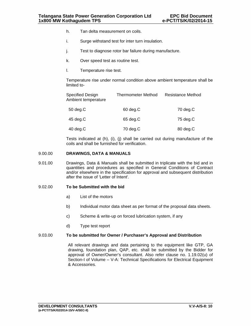
Telangana State Power Generation Corporation Ltd EPC Bid Document 1x800 MW Kothagudem TPS e-PCT/TS/K/02/2014-15
DEVELOPMENT CONSULTANTS V.V-A/S-II: 10 (e-PCT/TS/K/02/2014-15/V-A/SEC-II)
h. Tan delta measurement on coils. i. Surge withstand test for inter turn insulation. j. Test to diagnose rotor bar failure during manufacture.
k. Over speed test as routine test. l. Temperature rise test. Temperature rise under normal condition above ambient temperature shall be limited to- Specified Design Thermometer Method Resistance Method Ambient temperature 50 deg.C 60 deg.C 70 deg.C 45 deg.C 65 deg.C 75 deg.C 40 deg.C 70 deg.C 80 deg.C Tests indicated at (h), (i), (j) shall be carried out during manufacture of the coils and shall be furnished for verification.
9.00.00 DRAWINGS, DATA & MANUALS 9.01.00 Drawings, Data & Manuals shall be submitted in triplicate with the bid and in
quantities and procedures as specified in General Conditions of Contract and/or elsewhere in the specification for approval and subsequent distribution after the issue of 'Letter of Intent'.
9.02.00 To be Submitted with the bid a) List of the motors b) Individual motor data sheet as per format of the proposal data sheets. c) Scheme & write-up on forced lubrication system, if any d) Type test report 9.03.00 To be submitted for Owner / Purchaser’s Approval and Distribution All relevant drawings and data pertaining to the equipment like GTP, GA
drawing, foundation plan, QAP, etc. shall be submitted by the Bidder for approval of Owner/Owner’s consultant. Also refer clause no. 1.19.02(u) of Section-I of Volume – V-A: Technical Specifications for Electrical Equipment & Accessories.
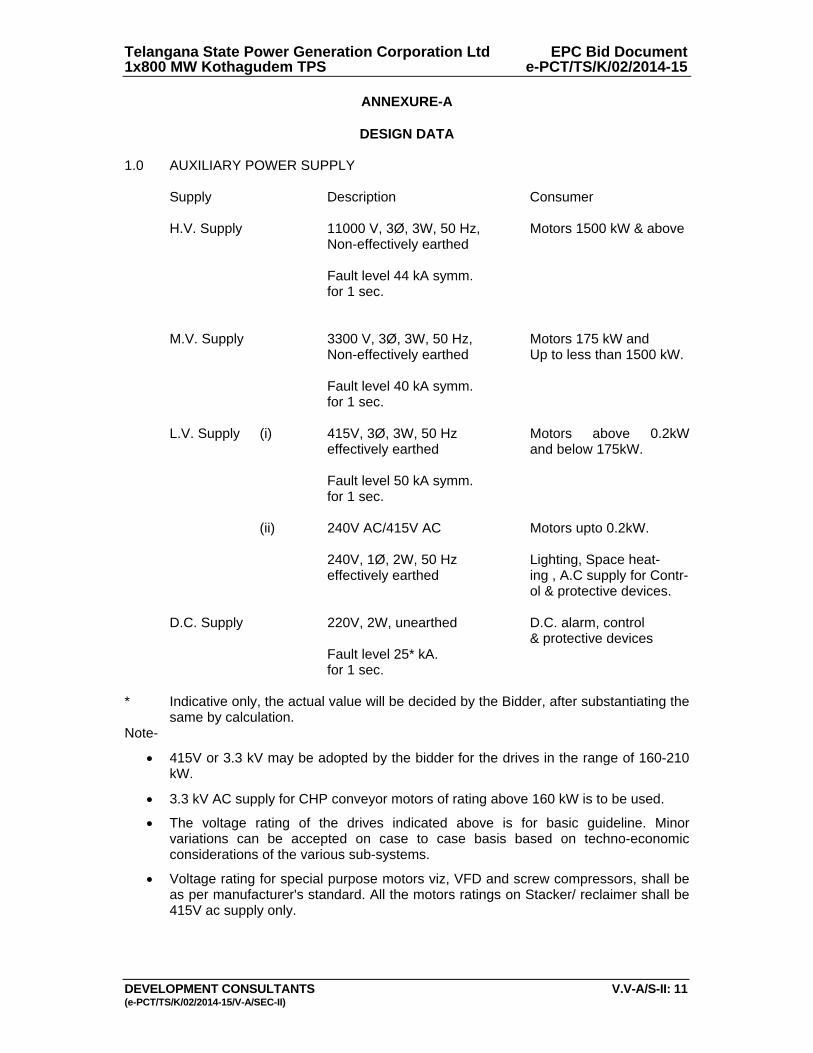
Telangana State Power Generation Corporation Ltd EPC Bid Document 1x800 MW Kothagudem TPS e-PCT/TS/K/02/2014-15
DEVELOPMENT CONSULTANTS V.V-A/S-II: 11 (e-PCT/TS/K/02/2014-15/V-A/SEC-II)
ANNEXURE-A
DESIGN DATA 1.0 AUXILIARY POWER SUPPLY Supply Description Consumer H.V. Supply 11000 V, 3Ø, 3W, 50 Hz, Motors 1500 kW & above Non-effectively earthed Fault level 44 kA symm. for 1 sec. M.V. Supply 3300 V, 3Ø, 3W, 50 Hz, Motors 175 kW and Non-effectively earthed Up to less than 1500 kW. Fault level 40 kA symm. for 1 sec.
L.V. Supply (i) 415V, 3Ø, 3W, 50 Hz Motors above 0.2kW effectively earthed and below 175kW.
Fault level 50 kA symm. for 1 sec. (ii) 240V AC/415V AC Motors upto 0.2kW. 240V, 1Ø, 2W, 50 Hz Lighting, Space heat- effectively earthed ing , A.C supply for Contr- ol & protective devices. D.C. Supply 220V, 2W, unearthed D.C. alarm, control & protective devices Fault level 25* kA. for 1 sec. * Indicative only, the actual value will be decided by the Bidder, after substantiating the
same by calculation. Note-
415V or 3.3 kV may be adopted by the bidder for the drives in the range of 160-210 kW.
3.3 kV AC supply for CHP conveyor motors of rating above 160 kW is to be used.
The voltage rating of the drives indicated above is for basic guideline. Minor variations can be accepted on case to case basis based on techno-economic considerations of the various sub-systems.
Voltage rating for special purpose motors viz, VFD and screw compressors, shall be as per manufacturer's standard. All the motors ratings on Stacker/ reclaimer shall be 415V ac supply only.

Telangana State Power Generation Corporation Ltd EPC Bid Document 1x800 MW Kothagudem TPS e-PCT/TS/K/02/2014-15
DEVELOPMENT CONSULTANTS V.V-A/S-II: 12 (e-PCT/TS/K/02/2014-15/V-A/SEC-II)
2.0 RANGE OF VARIATION A.C. Supply : Voltage : ± 10% Frequency : +3% to -5% Combined Volt + frequency : 10% (absolute sum) During starting of large motor, the voltage may drop to 80% of the rated voltage for a
period of 60 seconds. All electrical equipment while running shall successfully ride over such period without affecting system performance.
D.C. Supply : Voltage : 187 to 242 Volt
Telangana State Power Generation Corporation Ltd EPC Bid Document 1x800 MW Kothagudem TPS e-PCT/TS/K/02/2014-15
DEVELOPMENT CONSULTANTS (e-PCT/TS/K/02/2014-15/V-A/SEC-IIII)
VOLUME: V-A
SECTION-III
TECHNICAL SPECIFICATION FOR
ELECTRIC MOTOR ACTUATORS
Telangana State Power Generation Corporation Ltd EPC Bid Document 1x800 MW Kothagudem TPS e-PCT/TS/K/02/2014-15
DEVELOPMENT CONSULTANTS (e-PCT/TS/K/02/2014-15/V-A/SEC-IIII)
CONTENT CLAUSE NO. DESCRIPTION 1.00.00 SCOPE 2.00.00 STANDARDS 3.00.00 SERVICE CONDITIONS 4.00.00 RATING 5.00.00 PERFORMANCE 6.00.00 SPECIFIC REQUIREMENT 7.00.00 ACCESSORIES 8.00.00 TEST 9.00.00 DRAWINGS, DATA & MANUALS ATTACHMENT ANNEXURE-A DESIGN DATA
Telangana State Power Generation Corporation Ltd EPC Bid Document 1x800 MW Kothagudem TPS e-PCT/TS/K/02/2014-15
DEVELOPMENT CONSULTANTS V.V-A/S-III: 1 (e-PCT/TS/K/02/2014-15/V-A/SEC-XIII)
VOLUME: V-A
SECTION-III
TECHNICAL SPECIFICATION FOR
ELECTRIC MOTOR ACTUATORS 1.00.00 SCOPE 1.01.00 This Section covers the general requirements of Electric Motor Actuators for
valves/dampers. 1.02.00 All electric motor actuators shall be furnished in accordance with this general
specification and the accompanying driven equipment specification. All the electrical actuators shall be INTEGRAL type only.
2.00.00 STANDARDS 2.01.00 All electrical equipment shall conform to the latest applicable IS, ANSI and
NEMA Standards, except when stated otherwise herein or in driven equipment specification.
2.02.00 Major standards, which shall be followed, are listed below. Other applicable
Indian Standards for any component part even if not covered in the listed standards shall also be followed
i) IS-9334
ii) IS-325 3.00.00 SERVICE CONDITIONS 3.01.00 The actuator shall be suitable for operation in hot, humid and tropical
atmosphere, highly polluted at places with coal dust and/or fly ash. 3.02.00 Unless otherwise noted, electrical equipment/system design shall be based
on the service conditions and auxiliary power supply given in the general specification.
3.03.00 For actuator motor installed outdoor and exposed to direct sun rays, the effect
of solar heat shall be considered in the determination of the design ambient temperature.
4.00.00 RATING 4.01.00 For isolating service, the actuator shall be rated for three successive
open-close operation of the valve/damper or 15 minutes, whichever is longer. 4.02.00 For regulating service, the actuator shall be suitably time-rated for the duty
cycle involved with necessary number of starts per hour, but in no case less than 150 starts per hour.

Telangana State Power Generation Corporation Ltd EPC Bid Document 1x800 MW Kothagudem TPS e-PCT/TS/K/02/2014-15
DEVELOPMENT CONSULTANTS V.V-A/S-III: 2 (e-PCT/TS/K/02/2014-15/V-A/SEC-XIII)
5.00.00 PERFORMANCE The actuator shall meet the following performance requirements: 5.01.00 Open and close the valve completely and make leak-tight valve closure
without jamming. 5.02.00 Attain full speed operation before valve load is encountered and imparts an
unseating blow to start the valve in motion (hammer blow effect). 5.03.00 Operate the valve stem at standard stem speed and shall function against
design differential pressure across the valve seat. 5.04.00 The motor reduction gearing shall be sufficient to lock the shaft when the
motor is de-energised and prevent drift from torque switch spring pressure. 5.05.00 The entire mechanism shall withstand shock resulting from closing with
improper setting of limit switches or from lodging of foreign matter under the valve seat.
6.00.00 SPECIFIC REQUIREMENT 6.01.00 Construction 6.01.01 The actuator shall essentially comprise the drive motor, torque/ limit switches,
gear train, clutch, hand wheel, position indicator/ transmitter, in-built thermostat for over load protection, space heater and internal wiring.
6.01.02 The actuator enclosure shall be totally enclosed, dust tight, weather-proof
suitable for outdoor use without necessity of any canopy. Degree of protection of enclosure for motor actuator shall be IP-65.
6.01.03 All electrical equipment, accessories and wiring shall be provided with tropical
finish to prevent fungus growth. 6.01.04 The actuator shall be designed for mounting in any position without any
lubricant leakage or operating difficulty. 6.02.00 Motor 6.02.01 The drive motor shall be three phase, squirrel cage, induction machine with
minimum class B insulation and IPW-55 enclosure, designed for high torque and reversing service. Canopy shall be provided for outdoor service.
6.02.02 The motor shall be designed for full voltage direct on-line start, with starting
current limited to 6 times full-load current. 6.02.03 The motor shall be capable of starting at 85 percent of rated voltage and
running at 80 percent of rated voltage at rated torque and 85 percent rated voltage at 33 percent excess rated torque for a period of 5 minutes each.
6.02.04 Motor leads shall be terminated in the limit switch compartment. 6.02.05 Motor actuators for valves/dampers shall be with integral starter with
3phase/3wire, 415V AC and operable from remote.

Telangana State Power Generation Corporation Ltd EPC Bid Document 1x800 MW Kothagudem TPS e-PCT/TS/K/02/2014-15
DEVELOPMENT CONSULTANTS V.V-A/S-III: 3 (e-PCT/TS/K/02/2014-15/V-A/SEC-XIII)
6.02.06 Earthing terminals shall be provided on either side of the motor. 6.03.00 Limit Switches Each actuator shall be provided with following limit switches: - 6.03.01 2 torque limit switches, one for each direction of travel, self-locking,
adjustable torque type. 6.03.02 4 end-of-travel limit switches, two for each direction of travel. 6.03.03 2 position limit switches, one for each direction of travel, each adjustable at
any position from fully open to fully closed positions of the valve/damper. 6.03.04 Each limit switch shall have 2 NO + 2 NC potential free contacts. Contact
rating shall be 5A at 240V A.C. or 0.5A at 220V D.C. 6.04.00 Hand Wheel Each actuator shall be provided with a hand wheel for emergency manual
operation. The hand wheel shall declutch automatically when the motor is energized.
6.05.00 Position Indicator/Transmitter The actuator shall have: 6.05.01 One (1) built-in local position indicator for 0-100% travel. 6.05.02 One (1) position transmitter, 4-20 mA current signal as position feedback, for
remote indicator. 6.06.00 Space Heater A space heater shall be included in the limit switch compartment suitable for
240V, 1 phase, 50 Hz supply. 6.07.00 Wiring All electrical devices shall be wired up to and terminated in a terminal box. All
wiring shall be done with 1100V grade fire resistance PVC insulated stranded copper conductor of not less than 2.5 Sq.mm cross section. All wiring shall be identified at both ends with ferrules. All the electrical actuators shall have uniform wiring.
6.08.00 Terminal Box The terminal box shall be weather proof, with removable front cover and cable
glands for cable connection. The terminal shall be suitable for connection of 2.5 Sq.mm copper conductor.
7.00.00 ACCESSORIES

Telangana State Power Generation Corporation Ltd EPC Bid Document 1x800 MW Kothagudem TPS e-PCT/TS/K/02/2014-15
DEVELOPMENT CONSULTANTS V.V-A/S-III: 4 (e-PCT/TS/K/02/2014-15/V-A/SEC-XIII)
As required for the driven equipment, the actuator shall be furnished with
starting equipment mounted on the actuator. This shall include: 7.01.00 One (1) triple pole MCCB 7.02.00 One (1) reversing starter with mechanically interlocked contactors, 3 thermal
overload relays, 2 NO + 2 NC auxiliary contacts for each contactor. 7.03.00 One (1) remote-local selector switch. 7.04.00 CLOSE-STOP-OPEN oil tight push buttons with indication lights. 7.05.00 415/240 V control transformer with primary & secondary fuses. 8.00.00 TEST The actuator and all components thereof shall be subject to tests as per
relevant Standards. In addition, if any special test is called for in equipment specification, the same shall be performed.
9.00.00 DRAWINGS, DATA & MANUALS 9.01.00 Drawings, Data & Manuals shall be submitted in triplicate with the bid and in
quantities and procedures as specified in General Conditions of Contract and/or elsewhere in the specification for approval and subsequent distribution after the issue of 'Letter of Intent'.
9.02.00 To be submitted with Bid
Data sheet for each type of actuator shall be furnished along with internal wiring diagram, suggested control schematic and torque limit switch contact development and manufacturer's catalogues. Drawings, Data & Manuals shall be submitted in triplicate with the bid and in quantities and procedures as specified in General Conditions of Contract and/or elsewhere in the specification for approval and subsequent distribution after the issue of 'Letter of Intent'.
9.03.00 To be submitted for Owner / Purchaser’s Approval and Distribution
All relevant drawings and data pertaining to the equipment like GTP, GA drawing, foundation plan, BOM, control & schematics, QAP, etc. shall be submitted by the Bidder for approval of Owner/Owner’s consultant. Also refer clause no. 1.19.02(u) of Section-I of Volume – V-A: Technical Specifications for Electrical Equipment & Accessories.

Telangana State Power Generation Corporation Ltd EPC Bid Document 1x800 MW Kothagudem TPS e-PCT/TS/K/02/2014-15
DEVELOPMENT CONSULTANTS V.V-A/S-III: 5 (e-PCT/TS/K/02/2014-15/V-A/SEC-XIII)
ANNEXURE-A
DESIGN DATA
1.0 AUXILIARY POWER SUPPLY Supply Description Consumer L.V. Supply (i) 415V, 3Ø, 3W, 50 Hz Motors above 0.2kW Effectively earthed upto less than 175kW. Fault level 50 kA symm. for 1 sec. (ii) 240V AC/415V AC Motors upto 0.2kW. 240V, 1Ø, 2W, 50 Hz Lighting, Space heat- effectively earthed ing , A.C supply for Contr- ol & protective devices. D.C. Supply 220V, 2W, unearthed D.C. alarm, control & protective devices Fault level 25* kA. for 1 sec. * Indicative only, the actual value will be decided by the Bidder, after substantiating the same by calculation. 2.0 RANGE OF VARIATION A.C. Supply : Voltage : ± 10% Frequency : +3% to -5%. Combined Volt + frequency : 10% (absolute sum) During starting of large motor, the voltage may drop to 80% of the rated voltage for a
period of 60 seconds. All electrical equipment while running shall successfully ride over such period without affecting system performance.
D.C. Supply : Voltage : 187 to 242

TITLE: TECHNICAL SPECIFICATION
COOLING TOWERS SPECIFIC TECHNICAL REQUIREMENTS
SPEC. NO.: PE-TS-410-165-N001 VOLUME: IIB SECTION: C REV. NO. 00 DATE 23.01.2015 SHEET 1 OF 1
SECTION – C3
SPECIFIC TECHNICAL REQUIREMENTS (CIVIL)
GEO-TECHNICAL INVESTIGATION & FOUNDATION SYSTEM FOR NDCT
1x800 MW KOTHAGUDEM – SPECIFIC
TECHNICAL REQUIREMENTS
SPECIFICATION NO.
VOLUME – II B
SECTION - C SUB-SECTION -
REV.0 DATE 07.02.2015
SHEET 1 OF 4
3.00.00 GEO-TECHNICAL INVESTIGATION & FOUNDATION SYSTEM
3.01.01
BHEL is carrying out detailed geo-technical investigation in the proposed cool-ing tower site. The sub-strata details encountered at bore holes BH-19, 25, & 26 are enclosed as Annexure-1. The geotechnical data attached shall be solely for the purpose of guidance to the bidder. BHEL/owner does not take any re-sponsibility about the accuracy and applicability of the geo-technical data fur-nished herewith. The onus of correct assessment/interpretation and under-standing of the existing sub-strata conditions is on the bidder. Any variation in the data between the one furnished and to that found during execution of the work at site shall not constitute a valid reason in affecting the terms & condi-tions of this bid and the bidder shall note that nothing extra will be payable on this account. The bidder shall fully satisfy himself about the nature of sub-strata expected to be encountered including the type of foundation, ground wa-ter table and construction methodology to be adopted etc. prior to the submis-sion of the bid.
3.01.02
Detailed geo-technical Investigation report shall be made available to the suc-cessful bidder during contract engineering stage. If the bidder desires to carry out additional geo-technical investigation he/she may do so with prior infor-mation/permission of BHEL/owner at no extra cost to BHEL/owner. No exten-sion in time schedule shall be permitted on this account. The bidder shall ob-tain approval on the agency for conducting geo-technical investigation work, field and laboratory testing schedule proposed by the bidder etc from BHEL/owner before undertaking the geo-technical investigation work. Howev-er, the net safe bearing capacity (SBC) of shallow foundation to be adopted for the design of foundations during detailed engineering shall be limited to the values mentioned elsewhere in the specification and any value of net SBC higher than the one indicated shall not be accepted. However, bidder shall note that the net safe bearing capacity and foundation depth/ safe load carry-ing capacity of pile to be adopted for design during detailed engineering stage shall be got approved by BHEL/owner.
3.02.00 Foundation System
3.02.01 General Requirements a. All equipments/structures shall be supported on suitable open
foundation along with any special requirements/remedial measures/treatment called for subsoil/foundations as approved by BHEL/owner.
1x800 MW KOTHAGUDEM – SPECIFIC
TECHNICAL REQUIREMENTS
SPECIFICATION NO.
VOLUME – II B
SECTION - C SUB-SECTION -
REV.0 DATE 07.02.2015
SHEET 2 OF 4
b. All foundations shall be designed in accordance with the provisions of relevant part of latest revision of Indian Standards or as per the tech-nical specification whichever is stringent.
c. No foundation shall rest on filled up soil./Loose soil
d. A combination of open and pile foundations shall not be permitted under
the same structure.
e. Foundations shall be designed to resist loading derived from environ-mental loads including loads due to wave, current, wind or seismic, gravity loads, construction loads, static and moving loads and any other loads as applicable and as specified elsewhere in the specification.
f. Foundation shall be designed for worst combination of loads as de-scribed elsewhere in the specification.
g. Ground water table shall be considered at finished ground level for de-sign purposes unless specified elsewhere in the specification.
h. Ordinary Portland cement Grade 53 complying with IS: 12269 shall be used in concrete works for all structures and foundations. For PCC, pav-ing and plinth protection works, OPC Grade 43 shall be used.
i. Minimum grade of concrete shall be M30
3.02.02 Open foundations
In case shallow/open foundations are adopted then the following shall be strictly adhered to.
i. Minimum width of foundation shall be 1m.
ii. Minimum founding level shall be as mentioned in Table-1.
iii. The net safe bearing capacity (SBC) of shallow/open
foundations at different founding level shall be limited to the values as mentioned in the following Table-1 and any
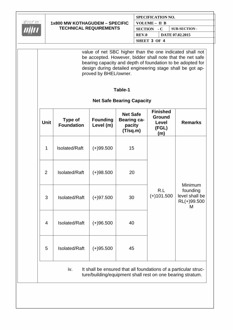
1x800 MW KOTHAGUDEM – SPECIFIC
TECHNICAL REQUIREMENTS
SPECIFICATION NO.
VOLUME – II B
SECTION - C SUB-SECTION -
REV.0 DATE 07.02.2015
SHEET 3 OF 4
value of net SBC higher than the one indicated shall not be accepted. However, bidder shall note that the net safe bearing capacity and depth of foundation to be adopted for design during detailed engineering stage shall be got ap-proved by BHEL/owner.
Table-1
Net Safe Bearing Capacity
Unit Type of
Foundation Founding Level (m)
Net Safe Bearing ca-
pacity (T/sq.m)
Finished Ground Level (FGL)
(m)
Remarks
1 Isolated/Raft (+)99.500
15
R.L (+)101.500
Minimum founding
level shall be RL(+)99.500
M
2 Isolated/Raft (+)98.500 20
3 Isolated/Raft (+)97.500
30
4 Isolated/Raft (+)96.500
40
5 Isolated/Raft (+)95.500
45
iv. It shall be ensured that all foundations of a particular struc-
ture/building/equipment shall rest on one bearing stratum.
1x800 MW KOTHAGUDEM – SPECIFIC
TECHNICAL REQUIREMENTS
SPECIFICATION NO.
VOLUME – II B
SECTION - C SUB-SECTION -
REV.0 DATE 07.02.2015
SHEET 4 OF 4
v. The permissible settlement as mentioned under para “permissible settlement of foundations” or permissible set-tlement from functional requirement whichever is more stringent shall be adopted for the design.
vi. The permissible total settlement and differential settlement of foundation resting on soil mass shall be governed by IS: 1904 and from functional requirements whichever is more stringent. Unless otherwise mentioned, the total settlement of cooling tower foundation resting on soil shall be restrict-ed to 25mm.
vii. Analysis and proportioning of footings to minimize differen-tial settlements shall be carried out for all major founda-tions and the same shall be submitted for BHEL/owner’s approval.
viii. In case any soft soil/loose stratum is met with at the found-
ing level or below during execution, the same shall be completely removed and filled back with PCC 1(cement):3(sand):6(stone aggregates) up to desired foundation level.
ix. Expansive soil shall not be used for filling/back filling
around foundation.
x. No foundation shall be resting on expansive soil.
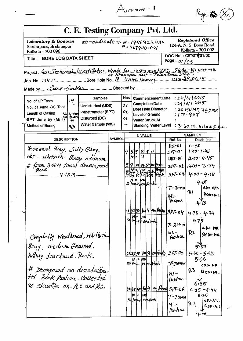
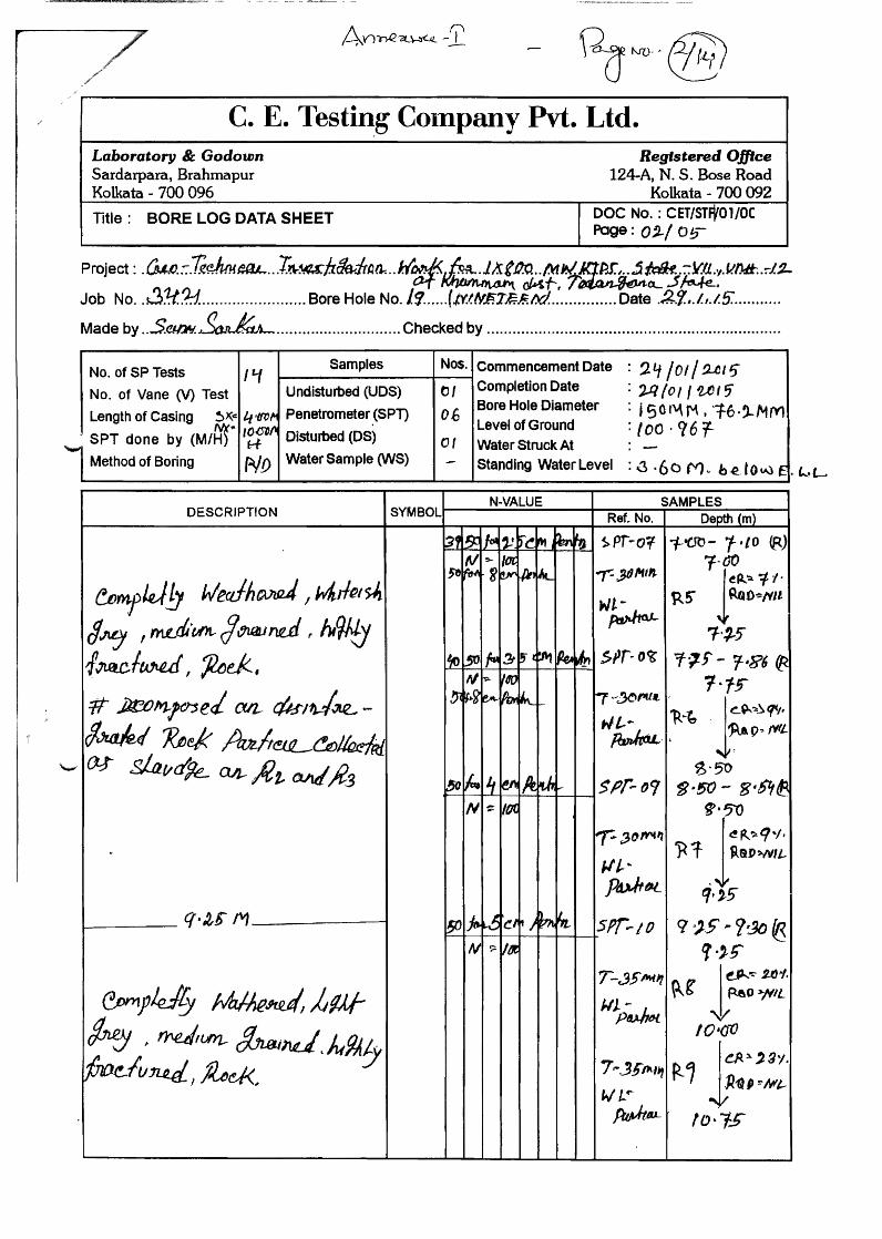
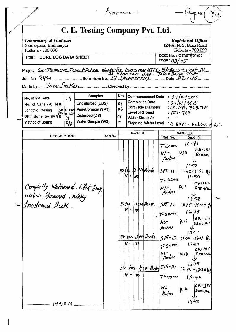

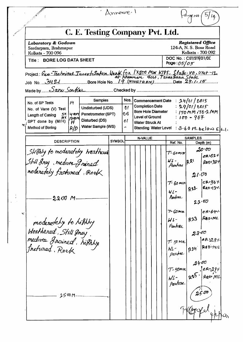

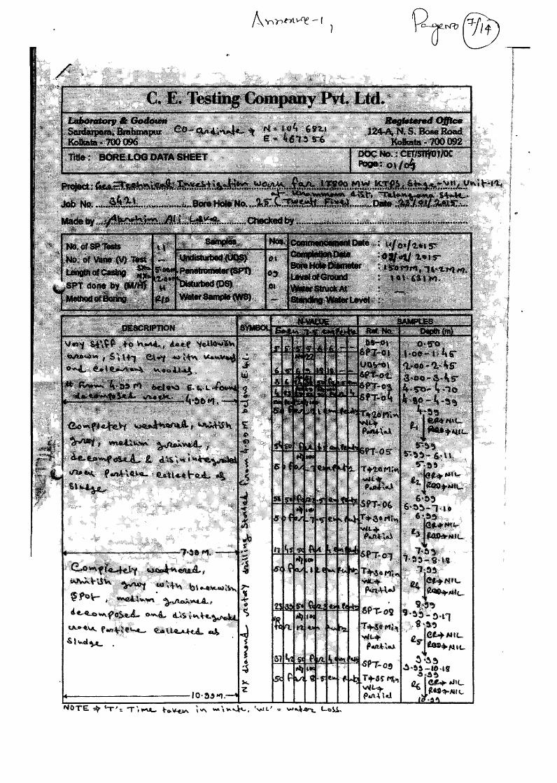
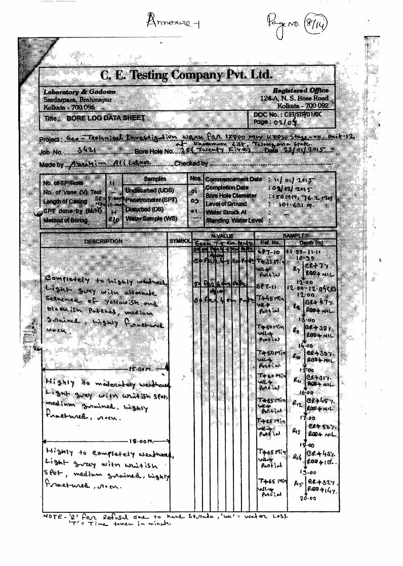

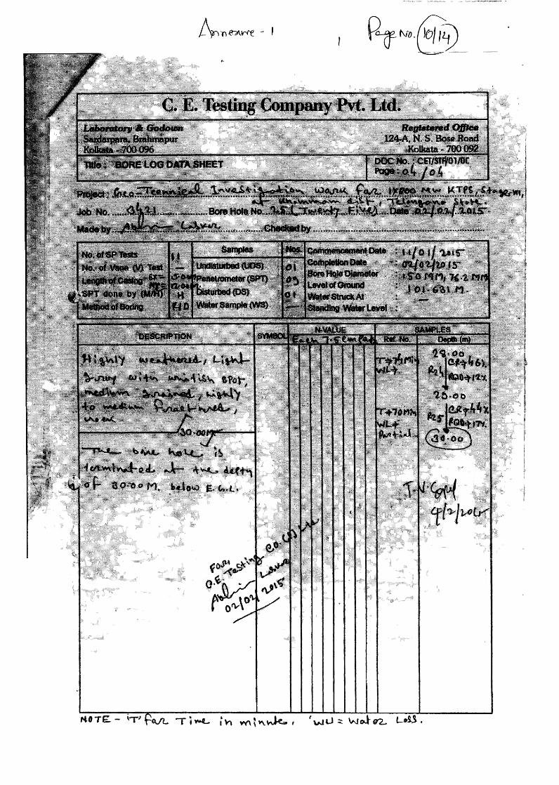
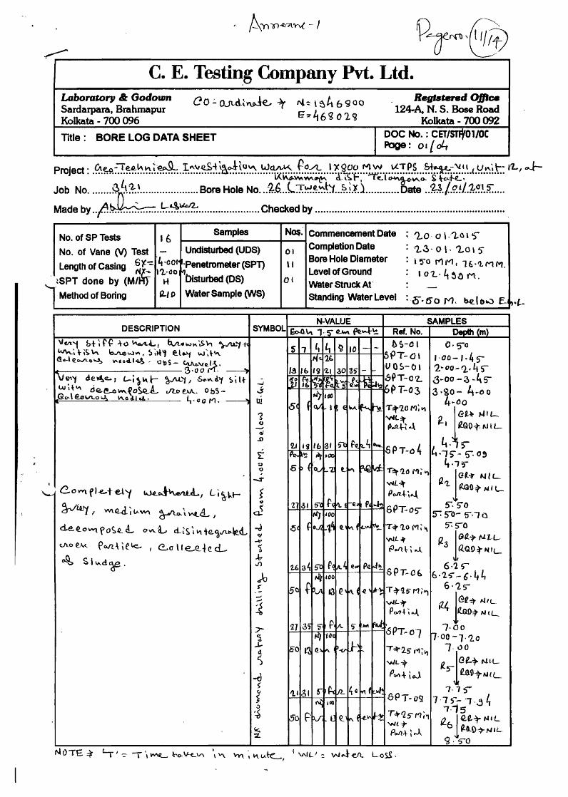
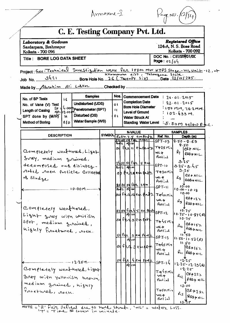

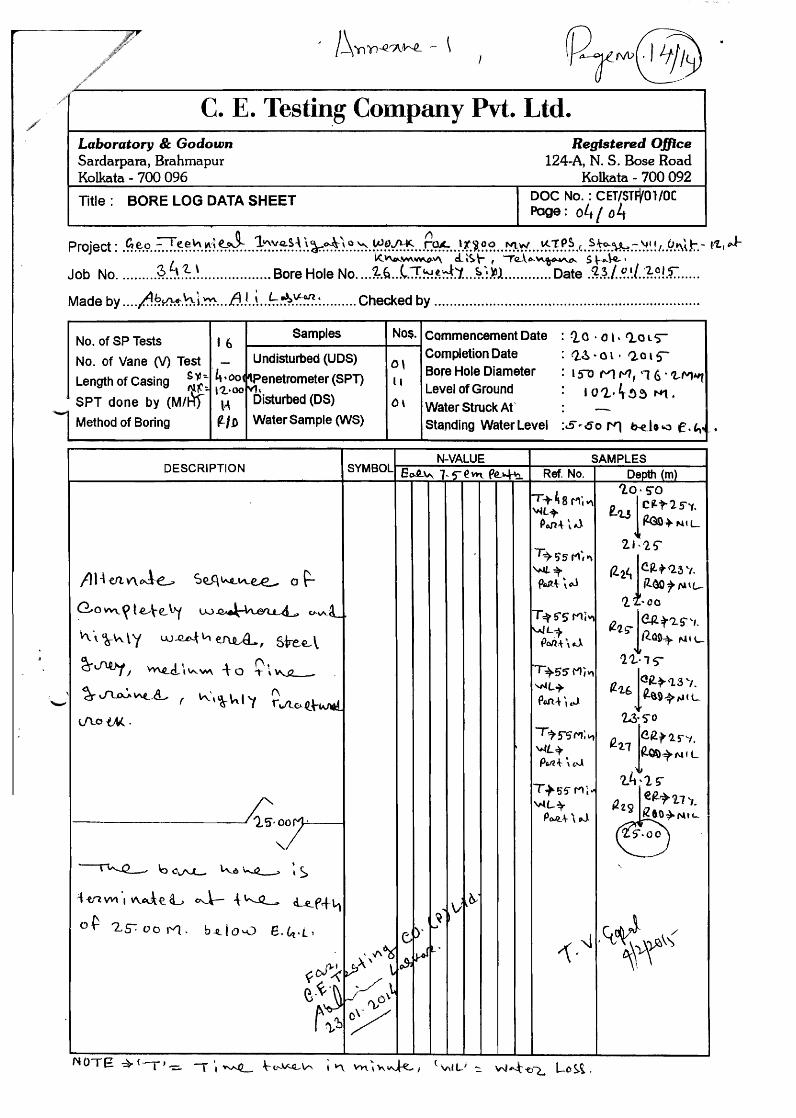

Telangana State Power Generation Corporation Ltd EPC Bid Document 1x800 MW Kothagudem TPS e-PCT/TS/K/02/2014-15
DEVELOPMENT CONSULTANTS (PCA.CD-005.e-PCT-TS-K-02-2014-15-VII-D_KTPS.DOC)
VOLUME : VII-D
TECHNICAL SPECIFICATION FOR
NATURAL DRAFT COOLING TOWER (NDCT)
6042023
Text Box
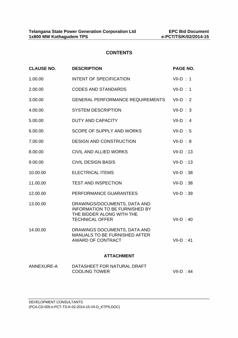
Telangana State Power Generation Corporation Ltd EPC Bid Document 1x800 MW Kothagudem TPS e-PCT/TS/K/02/2014-15
DEVELOPMENT CONSULTANTS (PCA.CD-005.e-PCT-TS-K-02-2014-15-VII-D_KTPS.DOC)
CONTENTS
CLAUSE NO. DESCRIPTION PAGE NO. 1.00.00 INTENT OF SPECIFICATION VII-D : 1 2.00.00 CODES AND STANDARDS VII-D : 1 3.00.00 GENERAL PERFORMANCE REQUIREMENTS VII-D : 2 4.00.00 SYSTEM DESCRIPTION VII-D : 3 5.00.00 DUTY AND CAPACITY VII-D : 4 6.00.00 SCOPE OF SUPPLY AND WORKS VII-D : 5 7.00.00 DESIGN AND CONSTRUCTION VII-D : 8 8.00.00 CIVIL AND ALLIED WORKS VII-D : 13 9.00.00 CIVIL DESIGN BASIS VII-D : 13 10.00.00 ELECTRICAL ITEMS VII-D : 38 11.00.00 TEST AND INSPECTION VII-D : 38 12.00.00 PERFORMANCE GUARANTEES VII-D : 39 13.00.00 DRAWINGS/DOCUMENTS, DATA AND INFORMATION TO BE FURNISHED BY THE BIDDER ALONG WITH THE TECHNICAL OFFER VII-D : 40 14.00.00 DRAWINGS DOCUMENTS, DATA AND MANUALS TO BE FURNISHED AFTER AWARD OF CONTRACT VII-D : 41
ATTACHMENT
ANNEXURE-A DATASHEET FOR NATURAL DRAFT COOLING TOWER VII-D : 44
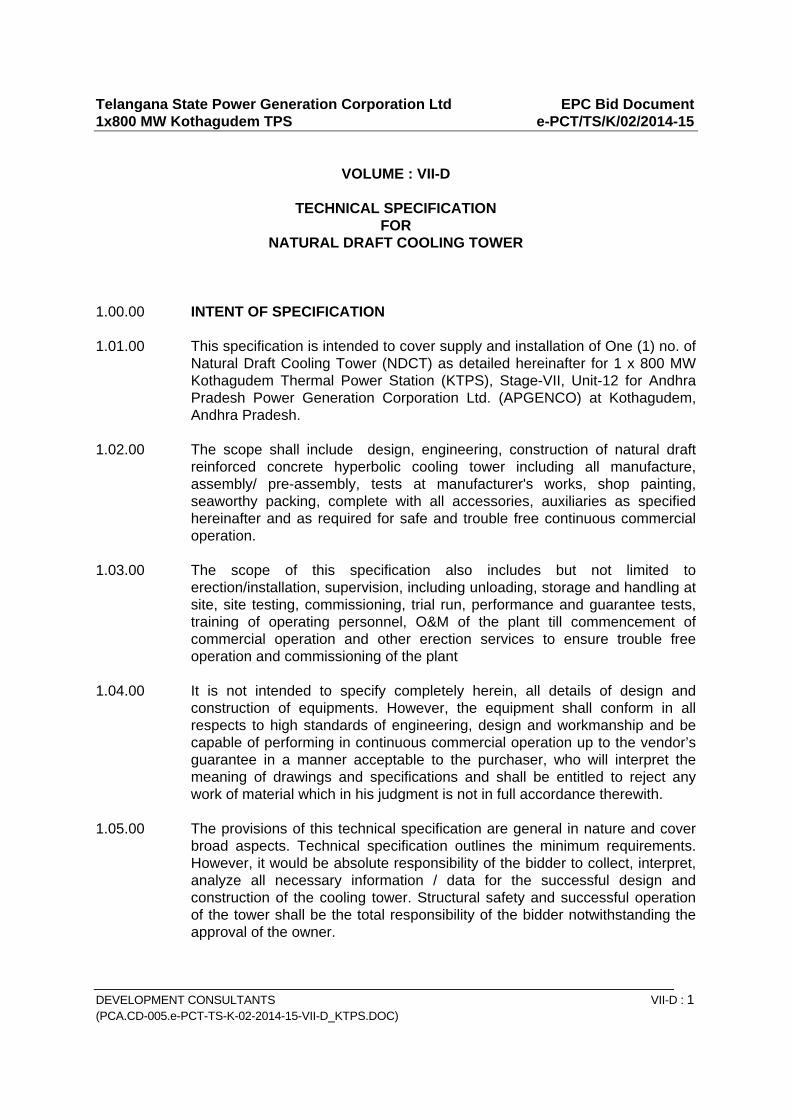
Telangana State Power Generation Corporation Ltd EPC Bid Document 1x800 MW Kothagudem TPS e-PCT/TS/K/02/2014-15
DEVELOPMENT CONSULTANTS VII-D : 1 (PCA.CD-005.e-PCT-TS-K-02-2014-15-VII-D_KTPS.DOC)
VOLUME : VII-D
TECHNICAL SPECIFICATION
FOR NATURAL DRAFT COOLING TOWER
1.00.00 INTENT OF SPECIFICATION 1.01.00 This specification is intended to cover supply and installation of One (1) no. of
Natural Draft Cooling Tower (NDCT) as detailed hereinafter for 1 x 800 MW Kothagudem Thermal Power Station (KTPS), Stage-VII, Unit-12 for Andhra Pradesh Power Generation Corporation Ltd. (APGENCO) at Kothagudem, Andhra Pradesh.
1.02.00 The scope shall include design, engineering, construction of natural draft
reinforced concrete hyperbolic cooling tower including all manufacture, assembly/ pre-assembly, tests at manufacturer's works, shop painting, seaworthy packing, complete with all accessories, auxiliaries as specified hereinafter and as required for safe and trouble free continuous commercial operation.
1.03.00 The scope of this specification also includes but not limited to
erection/installation, supervision, including unloading, storage and handling at site, site testing, commissioning, trial run, performance and guarantee tests, training of operating personnel, O&M of the plant till commencement of commercial operation and other erection services to ensure trouble free operation and commissioning of the plant
1.04.00 It is not intended to specify completely herein, all details of design and
construction of equipments. However, the equipment shall conform in all respects to high standards of engineering, design and workmanship and be capable of performing in continuous commercial operation up to the vendor’s guarantee in a manner acceptable to the purchaser, who will interpret the meaning of drawings and specifications and shall be entitled to reject any work of material which in his judgment is not in full accordance therewith.
1.05.00 The provisions of this technical specification are general in nature and cover
broad aspects. Technical specification outlines the minimum requirements. However, it would be absolute responsibility of the bidder to collect, interpret, analyze all necessary information / data for the successful design and construction of the cooling tower. Structural safety and successful operation of the tower shall be the total responsibility of the bidder notwithstanding the approval of the owner.
Telangana State Power Generation Corporation Ltd EPC Bid Document 1x800 MW Kothagudem TPS e-PCT/TS/K/02/2014-15
DEVELOPMENT CONSULTANTS VII-D : 2 (PCA.CD-005.e-PCT-TS-K-02-2014-15-VII-D_KTPS.DOC)
2.00.00 CODES AND STANDARDS 2.01.00 The design, construction, manufacture, performance, testing and
commissioning of the cooling tower as specified hereinafter shall comply with the requirements of all applicable latest Indian/British/American Standards and Codes of Practice. The latest editions of the following standards and publications shall be followed in particular:
2.01.01 BS 4485 Water Cooling Tower (Part 1 thru’ 4) 2.01.02 Cooling Tower Institute of USA, Bulletin ATC-105: "Acceptance Test
Procedure for Water Cooling Tower." 2.01.03 PTC-23: ASME Performance Test Code for Atmospheric Water Cooling
Equipment. 2.01.04 IS: 11504: Criteria for Structural Design of Reinforced Concrete Natural
Draught Cooling Towers. 2.01.05 American Society of Testing Materials 2.02.00 The materials of various components such as PVC, plain and reinforced
concrete, bars and steel wires for concrete reinforcement etc. shall be in accordance with relevant Indian Standards or else to applicable American Standards.
2.03.00 In case of any contradiction between the aforesaid Standards and stipulations
as per this technical specification as specified hereinafter, the stipulations of this technical specification shall prevail.
Also, in case of any contradiction between this technical specification and
stipulations of the enclosed "Data Specification Sheets", the stipulations of the Data Specification Sheets will prevail.
3.00.00 GENERAL PERFORMANCE REQUIREMENTS 3.01.00 The cooling tower shall be designed for continuous operation to cool not less
than the design flow of water from specified inlet temperature to outlet temperature at a design ambient wet bulb temperature and other design parameters as enumerated in the enclosed Natural Draught Cooling Tower Data Specification Sheets.
3.02.00 The cooling tower shall be designed for continuous operation throughout the
year, unless specially stated otherwise in Data Specification Sheet. The guaranteed performance (cold water temperature) shall be achieved at all wind velocities as specified.
Telangana State Power Generation Corporation Ltd EPC Bid Document 1x800 MW Kothagudem TPS e-PCT/TS/K/02/2014-15
DEVELOPMENT CONSULTANTS VII-D : 3 (PCA.CD-005.e-PCT-TS-K-02-2014-15-VII-D_KTPS.DOC)
3.03.00 The cooling tower shall also give satisfactory performance while handling the
specified water during monsoon months, with the range as indicated in Data Specification Sheet.
3.04.00 For arriving at the air properties such as enthalpy, density etc., no correction
for altitude shall be considered. All properties shall be taken from the data provided on CTI or BS code corresponding to sea level.
3.05.00 Bidder shall also furnish the following in support of tower design and
performance, along with the bid without which the offer is liable for rejection. 3.05.01 Heat balance calculations. 3.05.02 Justification for the outlet air temperature. This could be in the form of
operating experience on existing towers or laboratory test on actual fill shape, material and configuration as offered. In the case of laboratory test, Bidder shall indicate correction / scaling factor applied to predict performance of full size tower under field conditions.
3.05.03 Calculations to show the adequacy of tower height to provide the required
Draught. 3.05.04 Calculations for tower duty coefficient and performance coefficient. 3.05.05 Sketch showing fill arrangement which should clearly indicate the total depth,
horizontal and vertical spacing. 3.06.00 Drift loss of the cooling tower expressed in % of rated capacity shall be limited
to as close to zero as possible. 3.07.00 The Bidder shall assume full responsibility in proper design and operating of
each and every component of the complete cooling tower as well as the cooling tower as a whole.
4.00.00 SYSTEM DESCRIPTION 4.01.00 The natural draught cooling tower will be located inside the plant boundary
and will be used for cooling the hot circulating water returning from the condenser and various other heat exchangers. The circulation of water will be maintained by Circulating Water (CW) Pumps and Auxiliary Cooling Water (ACW) pumps located inside C.W. pump house.
4.02.00 The hot circulating water reaching the cooling tower will be raised to the top of
the hot water distribution system of the tower. The hot water distribution pipes inside the Tower shall be fitted with spray nozzles to distribute the hot water evenly over the PVC fill located immediately below. The hot water cools by evaporation as it drains through the PVC fill into the cooling tower basin.

Telangana State Power Generation Corporation Ltd EPC Bid Document 1x800 MW Kothagudem TPS e-PCT/TS/K/02/2014-15
DEVELOPMENT CONSULTANTS VII-D : 4 (PCA.CD-005.e-PCT-TS-K-02-2014-15-VII-D_KTPS.DOC)
4.03.00 The cooled water will be collected in a circular basin located under the cooling
tower. The basin shall have a central partition, such that any half of the basin can be cleaned/ repaired while the other half is in use.
4.04.00 Water from the cold water basins will flow through RCC channel to the sump
of the C.W. pump house. 4.05.00 The supplier should preferably be in a position to take up maintenance/
overhauling work as and when desired by the Owner during whole life of operation of the plant, on service contract and/or piecemeal basis.
5.00.00 DUTY AND CAPACITY 5.01.00 Cooling tower shall be capable of cooling the total quantity of hot condensate
circulating water and auxiliary cooling water, through the specified 'Range' at the design wet bulb temperature and other parameters as per Data sheet. This cooling shall be possible even with the maximum or calm wind conditions. The Cooling tower shall be designed for continuous operation throughout the year.
5.02.00 The basin wall curb level shall be minimum 500 mm above the finished grade
floor. The grade level surrounding the cooling tower shall provide for effective storm water drainage away from the tower. Depth of basin from well top shall be suitable for 6 minute storage of rated capacity excluding free board of 300 mm and not less than minimum one (1) metre. Basin slope towards cooling sump shall be 1 in 120.
5.03.00 The bidder shall review the analysis of water in circulation. All materials and
components furnished under this specification shall be suitable for continuous and reliable operation of the tower with the water in circulation. Special care must be taken to select and use materials and components, which will not corrode, leach or be subject to organic and inorganic deposits or destructive action leading to subsequent failure or erosion by water droplets or be source of electrolytic corrosion being set-up between components. Any materials or components, found inadequate for the service during the first 12 months, after commissioning will have to be replaced at site with suitable material of construction in all towers without any additional cost to the Owner at a time when unit is under shut down.
5.04.00 Re-cooled water from tower basin will be conveyed through a concrete
channel to the circulating water sump for recirculation. Hot water will be delivered to the tower through distributing headers. Re-cooled water from tower shall be thoroughly mixed to ensure temperature equalization prior to entering the channel leading to the pumps.
Telangana State Power Generation Corporation Ltd EPC Bid Document 1x800 MW Kothagudem TPS e-PCT/TS/K/02/2014-15
DEVELOPMENT CONSULTANTS VII-D : 5 (PCA.CD-005.e-PCT-TS-K-02-2014-15-VII-D_KTPS.DOC)
6.00.00 SCOPE OF SUPPLY AND WORKS The following Equipment shall be supplied under this specification. 6.01.00 General
Thermal, mechanical and structural design of cooling tower including all appurtenant civil works.
Drift eliminators Supply at site of all materials and equipment required for construction. Construction of cooling tower including all work and services
connected herewith. Construction of cold water basin, cold water outlet channel/ duct and
basin de-sludge arrangement. Hot water distribution piping/ducting along with spray nozzle system. Supply, shop testing of components and erection of all mechanical
equipment, PVC fill, Spray nozzles, etc. Complete lightning protection system, aviation obstruction lighting
system, earthing including the necessary power distribution arrangement as per technical specification for “Electrical Equipment and Accessories, Vol.V-A & Vol.V-B”.
6.02.00 Detailed Scope of Civil Works
Excavation and backfilling for columns foundation and substructure below cold water basin level.
R.C. foundation raft & Cold water Basin, R.C. Shell, R.C. support
framework for fill support. Hot water distribution duct.
Painting of concrete surfaces shall be as per Cl. 9.09.00 of volume - VII D.
Providing and installation of access doors in the shell of cooling tower including the necessary fittings and appliances on Tower Shell. The access doors shall be of heavy duty MS doors duly painted with 3 coats of epoxy paints.

Telangana State Power Generation Corporation Ltd EPC Bid Document 1x800 MW Kothagudem TPS e-PCT/TS/K/02/2014-15
DEVELOPMENT CONSULTANTS VII-D : 6 (PCA.CD-005.e-PCT-TS-K-02-2014-15-VII-D_KTPS.DOC)
Main access RC staircase outside the tower up to Hot water Duct top, internal RC walkways and platforms all with necessary galvanized MS pipe handrails.
Cold water channel outlet into gravity tunnel. De-sludging arrangement for each compartment of cold water basin. Provision of permanent access ladder up to top of tower
manufactured in galvanized mild steel with adequate back-guards and landing platforms. The ladder shall comply with all applicable regulations.
Provision of peripheral drainage around cooling tower as per Cl.
9.11.00 of volume - VII D Necessary site clearing and grading all round the tower in accordance
with specifications and drawings. Water fill test of cold water basin, cold water outlet channel and
tunnel. Hydro test of Hot water Duct. Supply and erection of all base plates, foundation plates, anchor
bolts, sleeves, nuts, fasteners, embedded parts and any other likewise material required for all electrical and mechanical equipment and accessories to complete the work.
Rock anchors will not be considered for foundations in any case.
Preparation and supply of all working drawings required for the work:
Piling, excavation, dewatering, shoring and shuttering, backfilling
around under ground structures and disposal of surplus soil outside the plant boundary / to the designated dump yard.
Any other works not mentioned herein, but sufficiently implied and are necessary for completion and proper functioning of the cooling tower.
6.03.00 Detailed scope of Mechanical works
Hot water distributions spray system of reliable & efficient design, along with its supporting arrangement.
Hot water duct/pipe work along with supports and anchors.
Telangana State Power Generation Corporation Ltd EPC Bid Document 1x800 MW Kothagudem TPS e-PCT/TS/K/02/2014-15
DEVELOPMENT CONSULTANTS VII-D : 7 (PCA.CD-005.e-PCT-TS-K-02-2014-15-VII-D_KTPS.DOC)
Gear operated with chain pulley arrangement isolation valves on hot water inlet piping before hot water distribution system to achieve basin maintenance.
Painting both inside and outside surfaces of steel pipes with three
coats of rust and corrosion resisting paint including thorough cleaning of the surfaces.
Tower PVC fill, drift eliminators including all required supporting
structure and accessories, etc. as necessary. Screens along with guides embedded in concrete at each of the cold
water outlet channels from the cold water basin. Sluice gate with mechanical jack arrangement and guides in each of
the cold water outlet channel connection from the cold water basin. Manually operated chain pulley blocks, together with the monorails
and supporting frames for the handling of screen and gates. Cold water outlet duct/tunnel. Knife-edge gate valve/sluice valve in each de-sludge connection and
also De-sludge piping up to the disposal point at local storm water drain channels.
Tower Fill Hot water By-Pass Nozzle connections on Hot water duct/
piping for system lines flushing during commissioning. Instrument tapping provisions on hot water duct/piping and cold water
duct/piping for carrying out flow and temperature measurement during PG test.
6.04.00 Detailed Scope of Electrical Works Refer Volume V-B, Section-XV, Technical Specification for Chimney and
Natural Draft Cooling Tower- Electrical works. 6.05.00 Any additional equipment, material, services which are not specifically
mentioned here, but are required to make the plant/systems in the scope of the Bidder complete in every respect in accordance with the technical specification and for safe operation and guaranteed performance, shall be deemed to be covered under the scope of this specification.
6.06.00 All accessories and hardwares. 6.07.00 One set of special tools and tackles.

Telangana State Power Generation Corporation Ltd EPC Bid Document 1x800 MW Kothagudem TPS e-PCT/TS/K/02/2014-15
DEVELOPMENT CONSULTANTS VII-D : 8 (PCA.CD-005.e-PCT-TS-K-02-2014-15-VII-D_KTPS.DOC)
6.08.00 All relevant drawings, data and O&M manuals. 6.09.00 The scope of this specification also includes erection, installation, site testing,
commissioning, trial run, performance and guarantee tests, training of operating personnel, O&M of the plant till commencement of commercial operation and other erection services to ensure trouble free operation and commissioning of the Equipment/System.
7.00.00 DESIGN AND CONSTRUCTION 7.01.00 Hot Water Distribution System 7.01.01 The distribution system shall be designed for flexible and satisfactory
operation at all reasonable loads. 7.01.02 The hot water distribution shall be suitable for handling an additional 20% flow
over the design circulating water flow. The hot water distribution shall be done by two headers, each covering half of cooling tower area so that it can be operated at 50% capacity.
7.01.03 The hot water distribution piping and valves shall be designed for a working
pressure as calculated by the Bidder. 7.01.04 The spray system can be either upward or downward maintaining water spray
even with shutdown flows. 7.01.05 The sprayers shall be arranged in a uniform pattern with proper distance to
produce 10% to 20% overlapping of the individual sprays. This arrangement shall provide extremely even water distribution with uniformly sized droplets entering the fill. The spray overlapping required avoiding dry pockets in the fill due to variations expected in water head availability in main hot water duct.
7.01.06 The spray nozzle shall be reliable and effective in breaking the hot water jet
into a spray pattern of uniformly sized droplets. It should be proven and tested design to provide maintenance free service for minimum 3 years.
7.01.07 The fixing arrangement of spray nozzles to hot water distribution header shall
be of flanged joint type. Screwed joint shall be avoided as they are likely to get loosened due to flow induced vibrations.
7.01.08 The distribution of water shall be in Ducts / troughs of approved material.
The entire water distribution system shall be self-draining and non-clogging type.
7.01.09 The distribution troughs/pipes shall be independently supported from the
structures and shall be easily removable. Provision shall also be made for easy flushing or cleaning of all troughs / pipes.
Telangana State Power Generation Corporation Ltd EPC Bid Document 1x800 MW Kothagudem TPS e-PCT/TS/K/02/2014-15
DEVELOPMENT CONSULTANTS VII-D : 9 (PCA.CD-005.e-PCT-TS-K-02-2014-15-VII-D_KTPS.DOC)
7.01.10 The structural design of the water distribution system shall also consider the
following loadings, combined as appropriate.
a) Self weight. b) Hydraulic pressure during normal operations, including pressure
surges. c) Hydraulic pressures due to mal-operation of tower or supply pumps.
7.01.11 Seismic loading on the water distribution system shall also be considered. 7.01.12 The water distribution system shall be provided with adequate pressure surge
relief facilities to prevent pressure loadings in excess of values used in the design. If such facilities are not provided, a further increase in loading shall be considered in the design. The pressure level to be considered shall not be less than 1.5 times the design pressure.
7.01.13 The design of water distribution system and its supports shall be capable of
accommodating all thermal stresses and movements due to changes in inlet water temperature, outlet water temperature and ambient temperature.
7.01.14 If open basin system of distribution is provided, the basin shall be provided
with removable type covers made of pre-cast concrete. 7.01.15 Splash boxes in cross flow tower shall be provided at the discharge of each
distribution valve to minimize splashing and to facilitate even distribution of water.
7.01.16 The nozzles shall be spaced to give even distribution of water over the entire
space occupied by top row of fills. 7.01.17 The nozzles and splash plates shall be made of High Density Polyethylene or
approved equal. 7.01.18 The pipes & valves etc. used shall be designed and arranged to take care of
the possible thermal stress due to temperature variation. The pipes & fittings shall have extra heavy thickness.
7.01.19 Ready accessibility to the different parts like isolation valves etc. shall be
provided and as required necessary platform/walkway and ladder shall be provided for this purpose.
Telangana State Power Generation Corporation Ltd EPC Bid Document 1x800 MW Kothagudem TPS e-PCT/TS/K/02/2014-15
DEVELOPMENT CONSULTANTS VII-D : 10 (PCA.CD-005.e-PCT-TS-K-02-2014-15-VII-D_KTPS.DOC)
7.02.00 Louver and Casing 7.02.01 Louvers shall be designed for air entry to the tower with low velocity for
minimum pressure drop and less chance of recirculation of moist air. To eliminate splash out, louvers shall slope to shed water inwards.
7.02.02 The louvers and casing may be made of concrete. Concrete casing wall shall
be supported from the basin through reinforced concrete. Hinged access door with platforms shall be provided for entry into the tower at suitable locations.
7.03.00 Fill 7.03.01 Cooling tower fill shall be made PVC, V-bar type of approved make. 7.03.02 Minimum weight of fill should be 100 Kg/sqm. 7.03.03 The Bidder shall enclose with his proposal a write-up on the method of
replacement of damaged/deteriorated fills during the life of cooling tower. Also Bidder's experience with pre-stressed concrete fills shall be clearly furnished in proposal. Bidder shall also indicate whether these are to be manufactured at shop or at site.
7.03.04 The PVC fill if offered shall be durable and fire retardant quality. The Bidder
shall furnish details of PVC fill along with his offer indicating fire retardant properties, ageing effect, vibration caused by water and wind effects. Frequency of replacement of PVC fills and the method of such replacement shall also be mentioned with above details. The PVC fills shall be of proven quality and the make and its properties shall be subject to Purchaser's approval. The Bidder shall furnish with his proposal, a sample of the fill material to be used for the specified cooling tower.
7.03.05 Design and facing of the fills shall be such as to expose high air/water surface
with minimum air pressure drop. Air velocity through the fills shall be uniform. 7.04.00 Fill Supports 7.04.01 Splash bar type fills shall be supported on the grids at frequent intervals,
preferably not exceeding 450 mm, to minimize sag, possibility of dislodgement, and damage to fill materials as a consequence of induced vibration in the fill.
7.04.02 For film type filling, the sheet like fills consisting of multiple vertical surfaces
shall be tied with filling support bars by stainless steel or nylon wires. Suitable spacers shall be used to maintain verticality of the sheets.
7.04.03 The fill and the support system shall be sufficiently strong to withstand the
Telangana State Power Generation Corporation Ltd EPC Bid Document 1x800 MW Kothagudem TPS e-PCT/TS/K/02/2014-15
DEVELOPMENT CONSULTANTS VII-D : 11 (PCA.CD-005.e-PCT-TS-K-02-2014-15-VII-D_KTPS.DOC)
water loading when the flow path is 30% chocked. 7.05.00 Drift Eliminators 7.05.01 Zig-Zag path type Multi pass Drift eliminators (minimum two pass) shall be
provided so as to limit the drift loss to that specified earlier or as in the Data Specification Sheet.
7.05.02 In case the tower is provided with pre-stressed concrete or PVC fill, drift
eliminators may be made up of PVC. 7.05.03 The eliminator frame shall be of rugged construction and shall be firmly
secured to arrest vibration. 7.06.00 Access 7.06.01 Staircases shall be provided external to the cooling tower along with
stairways, landings, walkways, handrails and access doors. Minimum 2 Nos. staircase 1000 mm wide and minimum landing width of 1000 mm at locations as necessary to give safe and convenient access to the top and the interior parts of the tower.
7.06.02 Suitable arrangement for supporting walkways inside the cooling tower shall
be made and such arrangement shall be independent of the fill material. 7.06.03 Whether specifically mentioned in the Data Specification Sheet or not, steel
components and fittings used in walkways, handrails shall be hot dip galvanized after fabrication.
7.07.00 Cooling Tower Basin & Outlet Sumps 7.07.01 The hot water distribution basin and cold water outlet channel of the cooling
towers shall be designed by considering a minimum of 10% margin over the design cooling tower flow.
7.07.02 Cooling tower basin, shall be supplied/constructed along with all civil parts,
base plates, anchor bolts, nuts, and other accessories, pipe sleeves, inserts, etc. and as required to complete the work in all respects.
7.07.03 The work shall include excavation/back-filling as necessary, all concrete/steel
work, cold water outlet sump & sludge pit for each basin, water-proofing and all other works.
7.07.04 The basin shall be partitioned into two individual chambers such that one
section can be taken out for maintenance /de-sludging while the other section is in operation.
7.07.05 Sludge pit with isolating valves, and spool pipe shall be provided for individual
Telangana State Power Generation Corporation Ltd EPC Bid Document 1x800 MW Kothagudem TPS e-PCT/TS/K/02/2014-15
DEVELOPMENT CONSULTANTS VII-D : 12 (PCA.CD-005.e-PCT-TS-K-02-2014-15-VII-D_KTPS.DOC)
basin chambers for connection to drainage pipe. 7.07.06 For each basin chamber, there shall be a cold water outlet sump. In the
connection between basin chamber and cold water sump there shall be screen and sluice gate/Butterfly valve.
7.07.07 Each basin chamber shall have overflow arrangement at sludge pit end. 7.07.08 Basin slope towards cooling sump shall be 1 in 120. 7.08.00 Screens & Isolating Devices in Cold Water Outlet Sumps, Valves and
Pipes in Sludge Pits and Accessories 7.08.01 Screens shall be out of 8 gauge 25 mm clear opening SS wire netting welded
to frame of structural steel section/flats. Framework shall be hot dip galvanized and provided with primer and bituminous painting. Two numbers of screens shall be supplied per tower. Lifting lugs or eye bolts shall be provided on top of the screen frame for ease of handling.
7.08.02 For handling screens, one set of monorail with supporting structure and chain
pulley hoist complete with lifting chain and push type trolley for mounting the hoist shall be furnished, if asked for in the Data Specification Sheets. The chain pulley hoist shall be manually operated and shall conform to IS: 3832, Class-2.
7.08.03 Sluice gates or Butterfly valves in cold water outlet sumps shall be provided
as mentioned in Data Specification Sheet. Sluice gates shall be as per appropriate class of IS: 3042. Butterfly valves shall conform to AWWA C-504 (latest revision).
All mild steel parts shall be galvanized or painted with epoxy enamel primer &
paint. The sluice gate may be rectangular or circular as per preference of the Bidder.
The sluice gates/Butterfly valves shall be complete with head-stock for
manual operation. The head-stock shall have pillar, base plate and hand wheel made up of cast iron. The head-stock shall have rising/non-rising spindle with position indicator.
7.08.04 The flow area through each gate/valve and screen shall be such as to
maintain a flow velocity through them within 1.2 M/sec during the rated flow from cooling tower, with the minimum water level in the cold water basin.
7.08.05 The isolating valves in sludge pits shall conform to appropriate class of IS:
780. Each valve shall be complete with pedestal type manual operator, with rising/non-rising spindle and valve position indicator.
7.08.06 The pipe spools, to be embedded in sludge pit for piping connection, shall be
Telangana State Power Generation Corporation Ltd EPC Bid Document 1x800 MW Kothagudem TPS e-PCT/TS/K/02/2014-15
DEVELOPMENT CONSULTANTS VII-D : 13 (PCA.CD-005.e-PCT-TS-K-02-2014-15-VII-D_KTPS.DOC)
C.I. pipe as per IS: 1536, Class-LA, unless otherwise mentioned elsewhere. 7.09.00 Hardware All nails and fastening bolts, nuts & washers used in the cooling tower
stainless steel, if not specified in the Data Specification Sheet. 8.00.00 CIVIL AND ALLIED WORKS 8.01.00 The civil design and construction of the cooling tower shall be in accordance
with the following technical specifications and the Data Specification Sheets enclosed with this specification –
a) Earthwork in Excavation and Backfilling. b) Cement Concrete (Plain and Reinforced). c) Masonry and Allied work. d) Finish to Masonry and Concrete. e) Metal doors, windows, ventilators, louvers etc. f) Roof water proofing, insulation and allied work. g) Painting, white washing, polishing etc. h) Sheet work in roof and siding.
8.02.00 The technical specifications are of general nature. Only those portions of the
specifications which relate to the various works required to be done as per the technical requirements as specified in the tender document need to be considered.
8.03.00 The Cooling Tower shell, ring beams, diagonal columns at base supporting
the ring beam below shell, cold water basin, fill support frame work, hot water distribution duct, cold water channel, louver etc. shall be cast-in-situ RCC construction.
9.00.00 CIVIL DESIGN BASIS 9.01.00 Loading The following loads shall be considered for the design of cooling towers:
a) Dead loads

Telangana State Power Generation Corporation Ltd EPC Bid Document 1x800 MW Kothagudem TPS e-PCT/TS/K/02/2014-15
DEVELOPMENT CONSULTANTS VII-D : 14 (PCA.CD-005.e-PCT-TS-K-02-2014-15-VII-D_KTPS.DOC)
b) Wind loads c) Earthquake forces d) Loads due to temperature and shrinkage effects. Temperature effects
due to solar radiation shall also be considered. e) Construction load f) Foundation settlement etc. g) Any other load likely to come on cooling tower.
9.01.01 Dead Load For assessing the self weight of the structure, the specific weight of the
concrete shall be taken as 2500 kg/m3. All other dead loads shall be assessed in accordance with relevant codal provision. Dead load shall include the self weight of structure, weight of fill material, weight due to plugging/chocking of fills, weight of falling water, weight of hot water pipe, weight of water in hot water channel and distribution system including the self weight of channel and distribution system, weight of drift eliminators etc.
Secondary stresses, if any, due to permanent fixtures on the shell shall also
be considered. In addition, live load on the supporting structure due to maintenance activities related to fills /ducts/distribution system shall be considered.
9.01.02 Wind Load The wind pressure on the tower shall be assessed on theoretical basis as well
as with the help of Model tests in a wind tunnel of turbulent boundary layer. All the theoretical methods outlined hereunder for estimating wind load on
cooling tower shell shall be valid only if the towers spaced at clear distance of greater than 0.5 times the base diameter at the finished graded ground level. The theoretical method outlined herein forms the basis only for assessing lowest limit of wind forces and shell structure interaction.
For conducting model tests, bidders should survey the whole terrain and
make their own assessment of likely critical wind forces & wind structure interaction. It would be the responsibility of the contractor to collect necessary meteorological data duly vetted from the recognized govt. agencies/institutions. After collection of necessary meteorological data, most critical wind speed, wind pressure distribution and other necessary parameter shall be determined by the bidder and get the same vetted by the above agency/appropriate agency(s). Then with the help of physical model tests in a

Telangana State Power Generation Corporation Ltd EPC Bid Document 1x800 MW Kothagudem TPS e-PCT/TS/K/02/2014-15
DEVELOPMENT CONSULTANTS VII-D : 15 (PCA.CD-005.e-PCT-TS-K-02-2014-15-VII-D_KTPS.DOC)
wind tunnel, offering appropriate aerodynamic similitude, the contractor shall obtain the most critical forces, stresses etc. with cooling tower at various levels and locations. Such model test shall also include all adjacent topographical features, buildings, and other structures which are likely to influence the wind load pattern on the tower significantly. The model test shall be carried out in a well reputed institute/testing laboratory after obtaining prior approval from the Owner. The testing agency selected by the contractor shall have requisite experience and should have successfully carried out tests in the past for at least one cooling tower of similar capacity. The model tests shall be duly witnessed and approved by the Owner/consultant. The model test results shall be made available before final approval of the design.
The complete cooling tower shall be designed for all possible wind directions
and on the basis of worst load conditions as obtained from Model test and theoretical methods. Under the theoretical method, the circumferential net wind pressure distribution and wind pressure coefficient (p1) for the tower shell (without meridional ribs) shall be obtained from the “Criteria for structural design of Reinforced concrete Nature Draft Cooling Towers IS: 11504-1985.
The above circumferential wind pressure coefficient (p1) shall be increased
by multiplying it by 1.43 to account for turbulence in the incident wind and load intensification due to turbulence induced by the adjacent cooling tower or the other structures of significant dimensions. Therefore, the actual design circumferential net wind pressure coefficient (p) shall be computed as p=1.43(p1), where (p1) is the wind pressure coefficient as per IS: 11504-1985.Enhancement factor 1.43 is considered to take the interference effect of adjacent structures of significant dimensions into account.10% increment shall be considered for imperfection in construction as per IS:11504.This factor shall be increased further by 10% during foundation design in absence of model test results. If the model is for C/L of shell, wind load shall be appropriately augmented to cater to the increase in diameter of the shell(O.D).
This design net pressure coefficient (p) and the distribution along the
circumference of tower shall be used at all heights of the tower. The above design net pressure coefficient (p) shall include the effect of internal suction.
In order to compute the quasi-static design wind pressure at a given height
along the circumference of the tower, the net design pressure coefficient (p) shall be multiplied by the wind pressure acting at that height [P(z)]. For details, reference shall be made to “Criteria for Wind Resistant Design of Structures and Equipments” and as given below.
The wind pressure at a given height [P(z)] shall be computed as per the
stipulations of IS: 875 (Part 3)-1987. For computing the design wind pressure at a given height the basic wind speed (Vb) shall be taken as Vb=50m/sec at 10.0 meters height above mean ground level. For computing design wind
6042023
Text Box
44 m/sec
Telangana State Power Generation Corporation Ltd EPC Bid Document 1x800 MW Kothagudem TPS e-PCT/TS/K/02/2014-15
DEVELOPMENT CONSULTANTS VII-D : 16 (PCA.CD-005.e-PCT-TS-K-02-2014-15-VII-D_KTPS.DOC)
speed (Vz) at a height z, the risk co-efficient K1=1.08 shall be considered. For coefficient K2, Terrain category 4 and class ‘C’ as per table 2 of IS: 875 (Part-3) – 1987 (Latest) shall be considered. Coefficient K3 shall be determined by taking into account nearby plant site and other features of the station & topography. The wind direction for design purposes shall be the one which would induce the worst load conditions. However, coefficient K3 shall not be less than one under any circumstances. The wind pressure at a given height shall be computed theoretically in accordance to the IS Codal position given as under:
Pz = 0.6 Vz2 N/m2 The bidder shall also compute the wind pressure (pz) along the wind direction
by Gust Factor (GF) or Gust effective factor method (GEF). Method for estimating the wind load on the tower and other elements, shall be based on IS: 875 (Part-3)-1987. While calculating the gust factor, the term ‘b’ shall be taken as the diameter of the throat in Fig. 10 of IS: 875 (Part-3)-1987.
Design of the tower shall satisfy quasi-static method & GEF method. Dynamic
effects on the tower due to wind action shall also be investigated to ascertain the wind induced oscillation such as ovalling and excitation along and across the wind direction. Bidder shall carry out detailed analysis for the tower and consider the worst combination of static & dynamic effects.
In case the bidder proposes to adopt aerodynamic rough surface such as
provision of meridional ribs in the cooling tower shell, the pressure coefficients as given in the VGB-BTR KUHLTUMRE GERMAN SPECIFICATIONS (latest) (structural design of cooling towers) shall be permitted. The provisions of BTR may be adopted for choosing the value of circumferential wind pressure coefficient (p1) only. The wind pressure coefficient (p1), as obtained from BTR after accounting for internal suction shall be multiplied by a factor of 1.43 to arrive at the net design pressure coefficient (p). The bidder shall furnish authorized English Translation of VGB-BTR KUHLTURME GERMAN SPECIFICATIONS (latest) for the review of the Owner. All other stipulations as specified in these specifications shall be met with.
Entire analysis and designs adopted shall be fully supported with
authenticated literatures/documents along with relevant references where the same has been successfully implemented.
Telangana State Power Generation Corporation Ltd EPC Bid Document 1x800 MW Kothagudem TPS e-PCT/TS/K/02/2014-15
DEVELOPMENT CONSULTANTS VII-D : 17 (PCA.CD-005.e-PCT-TS-K-02-2014-15-VII-D_KTPS.DOC)
9.01.03 Earthquake Forces The seismic analysis shall be carried out in accordance with IS:1893 (all
latest parts) by modal analysis for the hyperbolic cooling towers or any other method as approved by the Owner. The earthquake analysis of the shell and its support columns including the foundations shall be carried out by response spectrum method. For the fill supporting structures (RCC frames) response spectrum method is permitted. The modulus of elasticity for concrete shall be obtained from IS: 456-2000 Clause 6.2.3.1 with an Age Factor of 1.0. All the analysis shall be carried out as per the theory of elasticity.
Entire analysis and designs adopted shall be fully supported with
authenticated literatures/documents along with relevant reference where the same has been successfully implemented.
9.01.04 Loads due to temperature effects Stresses due to temperature effects : The cooling tower shell shall be designed for stress due to axi-symmetric
temperature distribution corresponding to external ambient temperature variation from 12.0oC to 50oC. However, the detailed analysis of actual thermal gradient by considering temperatures inside the tower and external ambient temperatures shall be carried out furnishing detailed references and justification for the same.
The shell shall also be checked for thermal stresses arising due to partial
operation of the tower in case the operational philosophy so demands. The analysis for the stresses resulting from non-axi-symmetric temperature loading shall be carried out. In such non-symmetric temperature loading, the calculation shall be based upon the operating specification. Besides, the shell shall also be designed for one sided solar radiation effect. Nevertheless an effective temperature difference of at least 250 C across the shell thickness constant over the height and follow a sine functions along half the circumference shall be considered.
Entire analysis and designs adopted shall be fully supported with
authenticated literatures / documents along with relevant references where the same has been successfully implemented.
9.01.05 Construction Loadings The method of construction and the type of formwork to be used shall be
decided by the bidder in advance and should be enclosed in the bids submitted. Construction loadings that may occur during execution of work shall be considered in the design of the cooling tower structure. Factors
Telangana State Power Generation Corporation Ltd EPC Bid Document 1x800 MW Kothagudem TPS e-PCT/TS/K/02/2014-15
DEVELOPMENT CONSULTANTS VII-D : 18 (PCA.CD-005.e-PCT-TS-K-02-2014-15-VII-D_KTPS.DOC)
causing temporary loading may include the following depending upon the method of construction.
a) Barrowing of concrete b) Scaffolding and formwork c) Loads produced by anchoring devices of climbing scaffolds. d) Hoist fixings e) Storage of materials on scaffolding f) Temporary access g) Tower crane fixings h) Works temporarily omitted for access purposes. Any other load such as foundation settlement, etc. All loads likely to act on cooling tower but not specified herein shall also be
considered for the design of cooling tower structures. In case different degrees of subsoil stiffness exist, effect of the same shall be
taken into account. In such a case, for computing settlements, load distributing capacity of the shell may be considered. Differential settlement between adjacent sections of foundation shall be considered under most unfavourable load combination.
9.01.06 Load Combinations Following minimum load combinations shall be considered for the design of
cooling towers structures.
a) DL + WL + SL b) DL + Se L c) DL + TL d) DL + WL + TL + SL e) DL + Se L + TL + SL f) 1.0 DL + 1.5 WL g) 0.9 DL +1.5 WL
Telangana State Power Generation Corporation Ltd EPC Bid Document 1x800 MW Kothagudem TPS e-PCT/TS/K/02/2014-15
DEVELOPMENT CONSULTANTS VII-D : 19 (PCA.CD-005.e-PCT-TS-K-02-2014-15-VII-D_KTPS.DOC)
h) 0.9 DL-1.5WL Where, DL = Dead Load WL = Wind Load SL = Settlement Load Se L = Seismic Load TL = Thermal Load
In addition to above, construction loads shall be duly accounted for. Under TL
various types of thermal loads, as described above, shall be considered separately. Besides above load combination, other load combinations as per relevant IS codes shall also be followed.
9.01.07 Permissible Stresses For load combination (a) to (e) working stress method shall be done without
considering 33% increase in permissible stresses in concrete and reinforcement.
For the load case (f) to (h) the shell of cooling towers shall be checked by limit
state method as per IS: 456. The stress in the reinforcement steel shall not exceed 87% of the specific characteristic strength of reinforcement steel and the compressive stress in the concrete shall not exceed 45% of the specified 28 days cube strength of the concrete as per IS: 456.
In the design of the cooling tower shell, column, pile caps, pedestals, ring
beams etc. no increase in the strength with the age of the concrete shall be permitted.
Permissible stress for steel structures shall be as per IS: 800 based on
working stresses. 9.02.00 Tower Design Consideration 9.02.01 General
The complete cooling tower, including the shell, columns, ring beam and foundation, shall be structurally analyzed using a proven finite element modeling technique or an approved alternative method including validation of software used for analysis. For elastic analysis, concrete may be assumed to be un-cracked, homogenous and isotropic. The design geometric profile, thickness variation and support conditions of shell shall be considered in the structural analysis.
Telangana State Power Generation Corporation Ltd EPC Bid Document 1x800 MW Kothagudem TPS e-PCT/TS/K/02/2014-15
DEVELOPMENT CONSULTANTS VII-D : 20 (PCA.CD-005.e-PCT-TS-K-02-2014-15-VII-D_KTPS.DOC)
Analysis based on a recognized bending theory of the elastic shells
shall be adopted for the design of the tower and supporting structures.
Regardless of analysis method adopted, the equilibrium checks of
internal forces and external loads shall be performed. Geometric imperfections, if exceed the permissible limit, then the
analysis of shell shall take into account of such imperfections and resubmitted for Owner’s approval.
Boundary conditions shall be realistic and based on actual
configuration. The magnitude of the calculated displacements should be within limits of the applied theory.
A detailed dynamic analysis shall be carried out for complete tower for
seismic forces by response spectrum method. Cooling tower shall also be designed for cross wind oscillations (wind induced vibration) if the fundamental natural frequency of the tower is less than or equal to 1 Hz. Frequency calculation for free vibration analysis shall also be furnished by bidder during detailed engineering.
9.02.02 Size and Shape
The base diameter, air intake opening height, tower height and throat
diameter shall be determined by thermal design consideration by the contractor and submitted to Owner for approval.
As the range of possible hyperbolic shell shapes is infinite, the same
shall generally conform to the following major proportions, which have been extensively adopted in cooling tower constructions.
H/D = 1.2 to 1.55 Where H is the total tower height above basin sill level Hb/H = 0.75 to 0.85 Hb is the vertical distance from the throat to basin sill level and ‘D’ is
the base diameter at basin sill level.
However, other proven profiles may be permitted subject to approval from the Owner. Bidders shall submit along with the offer complete details of the profile, in case the profile is not within the limits stated above, and the names of the sites where such shell profiles have been successfully constructed. Notwithstanding what is stated above, the Owner reserves the right to accept / reject the shell profile.
Telangana State Power Generation Corporation Ltd EPC Bid Document 1x800 MW Kothagudem TPS e-PCT/TS/K/02/2014-15
DEVELOPMENT CONSULTANTS VII-D : 21 (PCA.CD-005.e-PCT-TS-K-02-2014-15-VII-D_KTPS.DOC)
9.02.03 Tower Shell Boundary Conditions A. Shell Analysis and Design
The following boundary conditions shall be assumed for the design of cooling tower shell :
a) At Upper Edge
The top edge of the shell shall be gradually thickened to form a ring beam to guard against possible instability of the top of the shell due to high velocity wind gusts. Top edge shall be considered as a free edge in the analysis.
b) At Lower Edge
The lower edge of the shell shall be thickened to form a lower ring beam. The thickness transition from shell to lower ring beam shall be smooth and shall be considered as an integral part of the shell. The lower boundary of the shell shall be considered as elastically supported by discrete columns.
The influence of both support structure flexibility and foundation settlement shall be considered in the analysis and design of cooling tower shell. The shell analysis should include following information at 10o plan angle and of not more than 0.05 of the shell height.
i) Meridional and circumferential direct stress resultants and the
tangential shear stress resultants. ii) Meridional and circumferential bending moments. iii) Displacements normal to the shell mid-surface. B. Buckling of Tower Shells
Critical dynamic pressure (wind pressure) at buckling shall be calculated from BS: 4485 Part-4:1996.
Buckling of Cooling Tower shell be checked as per Finite Element
Analysis using software such as NISA 2, Ansys etc. The factor of safety for snap through buckling shall be more than 5. This requires non linear analysis including simulation of opening in the model. Alternatively, bifurcation buckling factor can be calculated using linear eigen value analysis with modulus of elasticity E=0.8Ec, to account for cracked section, with factor of safety more than 7.
Telangana State Power Generation Corporation Ltd EPC Bid Document 1x800 MW Kothagudem TPS e-PCT/TS/K/02/2014-15
DEVELOPMENT CONSULTANTS VII-D : 22 (PCA.CD-005.e-PCT-TS-K-02-2014-15-VII-D_KTPS.DOC)
Besides above, a buckling analysis with wind forces should be made using the theoretical tower geometry and boundary conditions, including the influence of dead weight, by the method of buckling stress state (BSS) approach in accordance with the provisions of VGB/BS 4485.
The buckling safety factor shall be at least 5.0 for load combinations
of dead load + wind load. When imperfections in the shell geometry are larger than specified
tolerances, the analysis should be rechecked to account for such imperfections and ensure that the desired buckling capacity remains.
C. Opening in Shells
Opening through the shells should be avoided as far as possible.
They should be of smallest required dimensions and shall be shaped such that stress concentration is minimized at the boundary of the opening. Should thickening of the edges be necessary, it shall be smoothly tempered back to the shell thickness.
Openings shall be provided with additional edge reinforcement of a
minimum cross sectional area at each edge equal to 75% of the reinforcement intercepted by the openings in the direction parallel to the edges. In addition diagonal reinforcement shall be provided at each corner as close as possible. The total cross-sectional area in cm2 of this reinforcement shall be 0.5d, at each corner where‘d’ is the shell thickness in cm.
No horizontal thrust due to the inlet piping shall be transmitted to the
shell.
D. Minimum Thickness of Shell The thickness of the shell shall not be minimum 300 mm or more as per design.
E. Minimum Reinforcement in Shell Spacing and Placement The reinforcement used shall be cold worked steel high strength
deformed bars of grade Fe 415/500 conforming to IS: 1786 – latest. All reinforcement steel shall be corrosion resistant steel/HCRM. The minimum reinforcement to be provided shall be as follows:
Top one third portion of shell: 0.4% of concrete cross-sectional area
along circumferential direction and 0.35% of concrete cross sectional area along meridional direction.
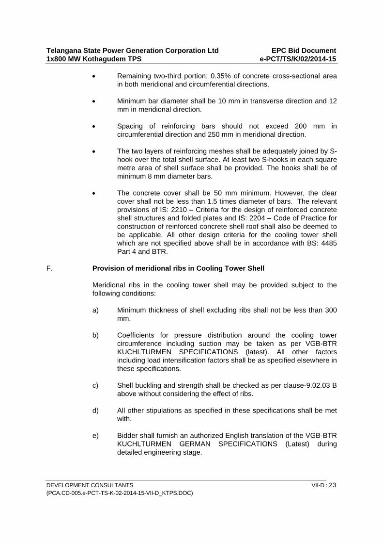
Telangana State Power Generation Corporation Ltd EPC Bid Document 1x800 MW Kothagudem TPS e-PCT/TS/K/02/2014-15
DEVELOPMENT CONSULTANTS VII-D : 23 (PCA.CD-005.e-PCT-TS-K-02-2014-15-VII-D_KTPS.DOC)
Remaining two-third portion: 0.35% of concrete cross-sectional area in both meridional and circumferential directions.
Minimum bar diameter shall be 10 mm in transverse direction and 12
mm in meridional direction. Spacing of reinforcing bars should not exceed 200 mm in
circumferential direction and 250 mm in meridional direction. The two layers of reinforcing meshes shall be adequately joined by S-
hook over the total shell surface. At least two S-hooks in each square metre area of shell surface shall be provided. The hooks shall be of minimum 8 mm diameter bars.
The concrete cover shall be 50 mm minimum. However, the clear
cover shall not be less than 1.5 times diameter of bars. The relevant provisions of IS: 2210 – Criteria for the design of reinforced concrete shell structures and folded plates and IS: 2204 – Code of Practice for construction of reinforced concrete shell roof shall also be deemed to be applicable. All other design criteria for the cooling tower shell which are not specified above shall be in accordance with BS: 4485 Part 4 and BTR.
F. Provision of meridional ribs in Cooling Tower Shell
Meridional ribs in the cooling tower shell may be provided subject to the following conditions:
a) Minimum thickness of shell excluding ribs shall not be less than 300
mm. b) Coefficients for pressure distribution around the cooling tower
circumference including suction may be taken as per VGB-BTR KUCHLTURMEN SPECIFICATIONS (latest). All other factors including load intensification factors shall be as specified elsewhere in these specifications.
c) Shell buckling and strength shall be checked as per clause-9.02.03 B
above without considering the effect of ribs. d) All other stipulations as specified in these specifications shall be met
with. e) Bidder shall furnish an authorized English translation of the VGB-BTR
KUCHLTURMEN GERMAN SPECIFICATIONS (Latest) during detailed engineering stage.
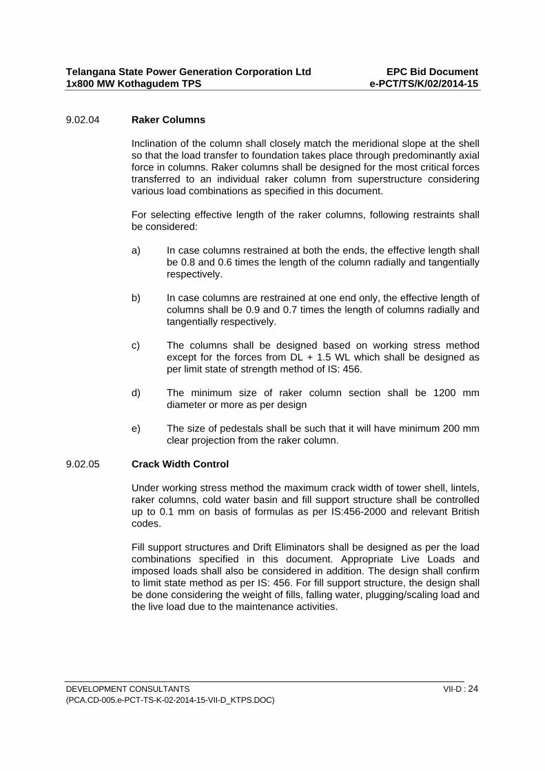
Telangana State Power Generation Corporation Ltd EPC Bid Document 1x800 MW Kothagudem TPS e-PCT/TS/K/02/2014-15
DEVELOPMENT CONSULTANTS VII-D : 24 (PCA.CD-005.e-PCT-TS-K-02-2014-15-VII-D_KTPS.DOC)
9.02.04 Raker Columns
Inclination of the column shall closely match the meridional slope at the shell so that the load transfer to foundation takes place through predominantly axial force in columns. Raker columns shall be designed for the most critical forces transferred to an individual raker column from superstructure considering various load combinations as specified in this document. For selecting effective length of the raker columns, following restraints shall be considered:
a) In case columns restrained at both the ends, the effective length shall
be 0.8 and 0.6 times the length of the column radially and tangentially respectively.
b) In case columns are restrained at one end only, the effective length of
columns shall be 0.9 and 0.7 times the length of columns radially and tangentially respectively.
c) The columns shall be designed based on working stress method
except for the forces from DL + 1.5 WL which shall be designed as per limit state of strength method of IS: 456.
d) The minimum size of raker column section shall be 1200 mm
diameter or more as per design e) The size of pedestals shall be such that it will have minimum 200 mm
clear projection from the raker column. 9.02.05 Crack Width Control Under working stress method the maximum crack width of tower shell, lintels,
raker columns, cold water basin and fill support structure shall be controlled up to 0.1 mm on basis of formulas as per IS:456-2000 and relevant British codes.
Fill support structures and Drift Eliminators shall be designed as per the load
combinations specified in this document. Appropriate Live Loads and imposed loads shall also be considered in addition. The design shall confirm to limit state method as per IS: 456. For fill support structure, the design shall be done considering the weight of fills, falling water, plugging/scaling load and the live load due to the maintenance activities.
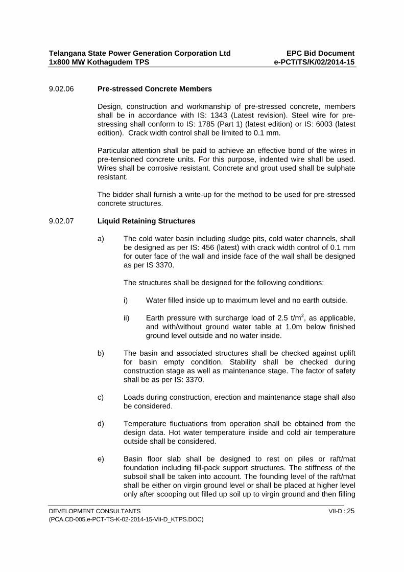
Telangana State Power Generation Corporation Ltd EPC Bid Document 1x800 MW Kothagudem TPS e-PCT/TS/K/02/2014-15
DEVELOPMENT CONSULTANTS VII-D : 25 (PCA.CD-005.e-PCT-TS-K-02-2014-15-VII-D_KTPS.DOC)
9.02.06 Pre-stressed Concrete Members Design, construction and workmanship of pre-stressed concrete, members
shall be in accordance with IS: 1343 (Latest revision). Steel wire for pre-stressing shall conform to IS: 1785 (Part 1) (latest edition) or IS: 6003 (latest edition). Crack width control shall be limited to 0.1 mm.
Particular attention shall be paid to achieve an effective bond of the wires in
pre-tensioned concrete units. For this purpose, indented wire shall be used. Wires shall be corrosive resistant. Concrete and grout used shall be sulphate resistant.
The bidder shall furnish a write-up for the method to be used for pre-stressed
concrete structures. 9.02.07 Liquid Retaining Structures a) The cold water basin including sludge pits, cold water channels, shall
be designed as per IS: 456 (latest) with crack width control of 0.1 mm for outer face of the wall and inside face of the wall shall be designed as per IS 3370.
The structures shall be designed for the following conditions:
i) Water filled inside up to maximum level and no earth outside. ii) Earth pressure with surcharge load of 2.5 t/m2, as applicable,
and with/without ground water table at 1.0m below finished ground level outside and no water inside.
b) The basin and associated structures shall be checked against uplift
for basin empty condition. Stability shall be checked during construction stage as well as maintenance stage. The factor of safety shall be as per IS: 3370.
c) Loads during construction, erection and maintenance stage shall also
be considered. d) Temperature fluctuations from operation shall be obtained from the
design data. Hot water temperature inside and cold air temperature outside shall be considered.
e) Basin floor slab shall be designed to rest on piles or raft/mat
foundation including fill-pack support structures. The stiffness of the subsoil shall be taken into account. The founding level of the raft/mat shall be either on virgin ground level or shall be placed at higher level only after scooping out filled up soil up to virgin ground and then filling
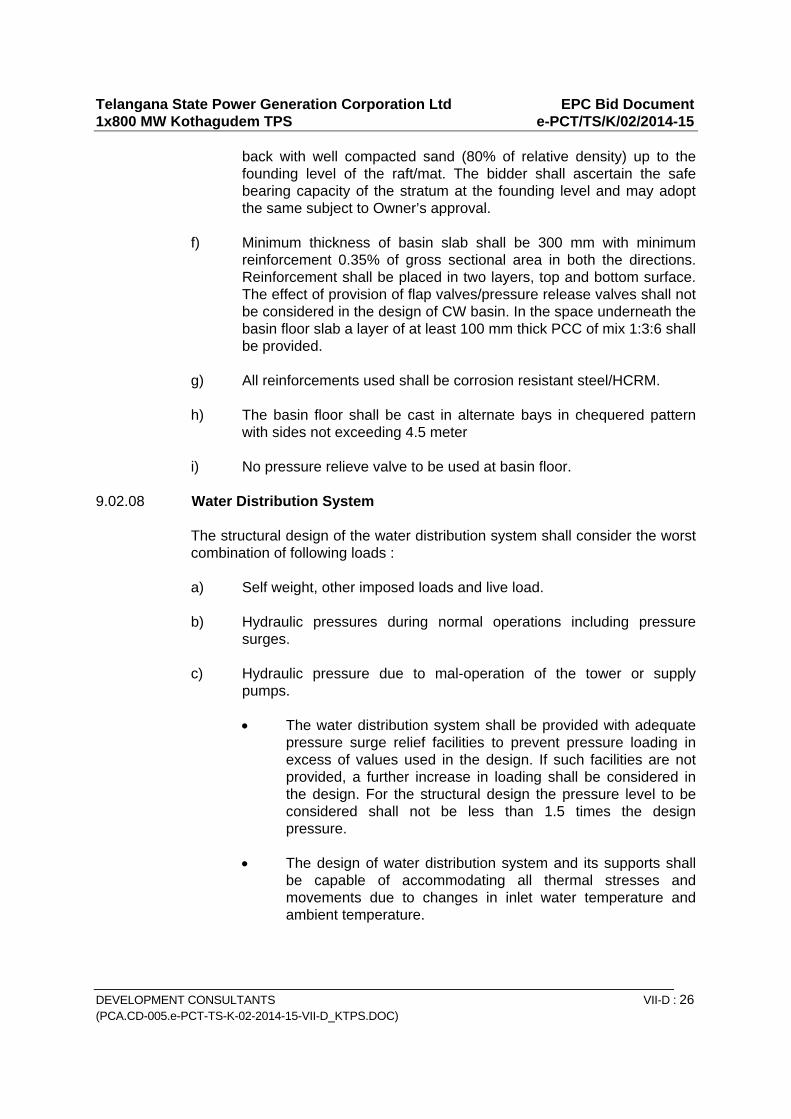
Telangana State Power Generation Corporation Ltd EPC Bid Document 1x800 MW Kothagudem TPS e-PCT/TS/K/02/2014-15
DEVELOPMENT CONSULTANTS VII-D : 26 (PCA.CD-005.e-PCT-TS-K-02-2014-15-VII-D_KTPS.DOC)
back with well compacted sand (80% of relative density) up to the founding level of the raft/mat. The bidder shall ascertain the safe bearing capacity of the stratum at the founding level and may adopt the same subject to Owner’s approval.
f) Minimum thickness of basin slab shall be 300 mm with minimum
reinforcement 0.35% of gross sectional area in both the directions. Reinforcement shall be placed in two layers, top and bottom surface. The effect of provision of flap valves/pressure release valves shall not be considered in the design of CW basin. In the space underneath the basin floor slab a layer of at least 100 mm thick PCC of mix 1:3:6 shall be provided.
g) All reinforcements used shall be corrosion resistant steel/HCRM. h) The basin floor shall be cast in alternate bays in chequered pattern
with sides not exceeding 4.5 meter i) No pressure relieve valve to be used at basin floor. 9.02.08 Water Distribution System
The structural design of the water distribution system shall consider the worst combination of following loads :
a) Self weight, other imposed loads and live load. b) Hydraulic pressures during normal operations including pressure
surges. c) Hydraulic pressure due to mal-operation of the tower or supply
pumps.
The water distribution system shall be provided with adequate pressure surge relief facilities to prevent pressure loading in excess of values used in the design. If such facilities are not provided, a further increase in loading shall be considered in the design. For the structural design the pressure level to be considered shall not be less than 1.5 times the design pressure.
The design of water distribution system and its supports shall
be capable of accommodating all thermal stresses and movements due to changes in inlet water temperature and ambient temperature.
Telangana State Power Generation Corporation Ltd EPC Bid Document 1x800 MW Kothagudem TPS e-PCT/TS/K/02/2014-15
DEVELOPMENT CONSULTANTS VII-D : 27 (PCA.CD-005.e-PCT-TS-K-02-2014-15-VII-D_KTPS.DOC)
The possibility of vibrations being imposed on the distribution
system shall be investigated in the design. Seismic loading on the water distribution system shall also be taken into account.
The design shall be carried out based on uncracked section as
per IS: 3370 under normal operating conditions. Strength check for worst loading including malfunctioning shall be carried out with stress limitations as per IS: 3370. The construction shall be completely water tight without the use of fillets, sealing compounds etc. The method of construction shall be such so as to avoid excessive rise in temperature of concrete due to release of heat of hydration.
Hot water distribution basin/trough/channel at top shall be
covered by removable precast concrete slab to prevent direct exposure from sunlight. Corners of pre-cast concrete slabs shall be protected by angles. Lifting lugs shall also be provided for handling of concrete slabs.
Basin channel wall shall be designed for a minimum surcharge
load of 25 KN/Sqm. Paving shall be provided all round cold water basin.
9.02.09 Platforms, Walkways, Stairways, Staircases, Internal Grillage etc. These shall be designed as per working stress method IS: 456-2000 and IS:
800. The crack width in all RCC structures shall be limited to 0.1 mm. A minimum live load of 500 kq/sqm shall be considered for the design of all platforms, walkways, staircases etc. in addition to their own weight.
Platforms shall be minimum 1.2 M wide and walkways shall have 1.5 M wide. 9.02.10 Steel Structures All structural steel members shall conform to IS: 2062 (GR-A). These
structures shall be designed, fabricated and erected as per IS: 800 and other relevant Indian Standard codes for structural steel work. All steel structures shall be coated with anticorrosive system.
9.02.11 Slide Gates and Screens Slide Gates and Screens, as per IS: 5620 conforming to IS: 2062 Gr. A, shall
be designed for worst combination of operating and maintenance condition. All steel components shall be coated with anti-corrosive paint system. However, all guides of slide gates and screens shall be of stainless steel of Grade AISI 316L.

Telangana State Power Generation Corporation Ltd EPC Bid Document 1x800 MW Kothagudem TPS e-PCT/TS/K/02/2014-15
DEVELOPMENT CONSULTANTS VII-D : 28 (PCA.CD-005.e-PCT-TS-K-02-2014-15-VII-D_KTPS.DOC)
9.03.00 Foundations Data specification sheet and Soil Report (By EPC Contractor) shall be
referred to for selecting allowable bearing pressure to be considered in designing the foundation and in selecting depth of foundation. Cooling tower foundation is to be designed as strip foundation considering appropriate modulus of subgrade reaction. However, the bidder has to select suitable type of foundation compatible with the soil strata and calculated settlement of structure and foundation system. The bidder shall have to furnish conceptual design indicating type of foundation, general arrangement drawing for super structure, basin, pipe supports, pits, founding level etc. including settlement criteria complete with a design basis report with the offer.
The design of the cooling tower foundation structures shall be based on IS:
456 as per working stress method for worst load combination as per clause 9.01.06 In case of load combination DL + 1.5 WL, the limit state method as per IS: 456 shall be adopted.
Foundation shall be checked for safety against overturning, sliding and uplift.
The minimum factors of safety for overturning, sliding and hydrostatic uplift shall be 1.5, 1.5 and 1.25 respectively.
While checking stability of the structures, neglect favourably acting loads from
water fill, soil cover beyond the edge of the foundation. Ground water table shall be considered at 1.0m below Plant Finished Grade Level for design of foundations and all underground structures.
Minimum grade of concrete shall be M25 for foundation resting over 100mm thick PCC (1:3:6 ) layer. Clear cover shall not be less than 50mm.
Pile foundation if adopted shall be designed in accordance with IS: 2911(Part-
I / Sec-I, II and III). Generally net tension should be avoided in the foundations/piles for the shell
support foundation unless specifically permitted by the Owner. While accounting for over burden of the soil for checking the foundation
against up-lift, dead weight of the soil directly above the pile cap or ring raft, as the case may be, shall only be considered, neglecting the weight of soil in the cone of up-lift above the foundation.
The foundation structures will be subjected to following loading and extreme
load combination case shall be considered for design.
1. Most critical forces transferred from superstructure for the various load combinations.
2. Uplift forces
Telangana State Power Generation Corporation Ltd EPC Bid Document 1x800 MW Kothagudem TPS e-PCT/TS/K/02/2014-15
DEVELOPMENT CONSULTANTS VII-D : 29 (PCA.CD-005.e-PCT-TS-K-02-2014-15-VII-D_KTPS.DOC)
3. Loading due to foundation settlement 4. Concentrated local loading from column nodes 5. Thermally induced local loading where supply culverts pass through
the foundation structures without structural isolation. 6. Surcharge of 2.5 t/sq.m. CW basin surcharge load shall also be considered in addition to the other relevant loads for the design.
9.04.00 Fill Support Structures and Other Structures The self weight of the pack support structures shall be based on the weight of
the packing including weight of standing, running and dripping water, other operation and plugging/chocking (debris/scaling) loads, etc. in accordance with manufacturer’s data. In addition, a live load of 100 kg/m2 shall also be considered for the design of supporting structures.
For other structures like walkways, platforms, etc. a live load of 500 kg/sq.m
shall be considered. Hand railings shall be designed for horizontal load of 60 kg/m2.
Wind deflector walls and any other structural elements shall be designed for a
horizontal wind load of 80 kq/sqm or as per manufacturer’s recommendations, whichever is higher. Thermal loading shall be as per manufacturer’s recommendations. Earthquake loading shall be considered based on criteria given for cooling tower. Response spectrum analysis shall be considered.
Design of RCC members shall be based on IS: 456:2000 with limiting crack
width of 0.1 mm. The cold water basin slab/raft shall form the common foundation for the pack
support structures. The foundation shall be designed for the most critical forces transferred from CW basin & fill supporting structures including loads introduced by constructional equipments and crane deployed for fill supporting structure or shell erection.
9.05.00 Requirements for Concrete and Reinforcement All concrete work for the cooling tower shall comply with the requirements
given in technical specification for Cement Concrete (Plain & reinforced)

Telangana State Power Generation Corporation Ltd EPC Bid Document 1x800 MW Kothagudem TPS e-PCT/TS/K/02/2014-15
DEVELOPMENT CONSULTANTS VII-D : 30 (PCA.CD-005.e-PCT-TS-K-02-2014-15-VII-D_KTPS.DOC)
Ordinary Portland cement Grade 53 complying with IS:12269 shall be used in
concrete works for all structures and foundations. For PCC, paving and plinth protection works, OPC Grade 43 shall be used.
Fine and coarse aggregate to be used in cement shall comply with IS-383. Structural concrete shall be of design mix complying with the relevant
provisions of IS codes or any International Code of Practice as approved by the Owner.
Durability of the concrete shall conform to severe exposure category as per
Table 3 of IS: 456 except noted specifically otherwise. Plain mild steel reinforcing bar shall conform to IS: 432 grade I quality and
high yield strength deform bars (TMT) shall conform to IS: 1786 (Fe-500). All reinforcements used in RCC structure shall be corrosion resistant. Column
reinforcing bars shall be carefully anchored in the shell and foundation. The anchoring length shall not be less than 80 times the diameter of the bars.
All foundations structures shall be provided on all sides with a minimum
reinforcement of 0.12% of gross cross-sectional area distributed over top and bottom faces.
The minimum grade of concrete of structural components of cooling towers
shall be as follows in accordance with IS: 456. a) Shell and Raker Columns : M-30 grade b) Pre-cast pre-stressed elements : M-30 grade c) All other RCC concrete : M-30 grade d) PCC encasement concrete except piles : M-25 grade e) Piles (with OPC/PPC/PFC) : M-30 grade f) Tower foundation : M-30 grade g) Mud mat/lean concrete PCC : M-10 grade Coarse and fine aggregates shall be specially selected to ensure that they are
not susceptible to alkali/chloride attack or prone to disintegration at high temperatures. In particular limestone aggregates shall never be used. The maximum size of coarse aggregate shall not be larger than 1/8th narrowest dimension between reinforcement bars not more than 20 mm.
Telangana State Power Generation Corporation Ltd EPC Bid Document 1x800 MW Kothagudem TPS e-PCT/TS/K/02/2014-15
DEVELOPMENT CONSULTANTS VII-D : 31 (PCA.CD-005.e-PCT-TS-K-02-2014-15-VII-D_KTPS.DOC)
Washing and screening of coarse and fine aggregates to remove fines, dirt or other deleterious materials shall be carried out by approved means as directed by the Engineer-in-charge.
The water cement ratio by weight shall be 0.45 maximum including free
moisture in the aggregates, and slump should be suitably decided to provide good quality concrete work.
9.06.00 Admixtures Admixtures may be permitted to be used in accordance with relevant IS codes
to modify the rate of hardening or setting, to improve workability or as an aid to control concrete quality and protection to reinforcement bars against corrosion. The Owner reserves the right to direct the contractor to conduct laboratory tests or use test data, or other satisfactory reference before granting approval. The cost of all tests conducted shall be borne by the contractor. The admixture shall be used in strict accordance with the manufacturer’s directions and/or as directed by the Owner. No extra payment will be made to the contractor on account of using admixtures.
Particular attention must be given to concrete placement because of the thin
wall section and the presence of reinforcing steel. Consolidation of concrete shall be by vibration. Removal of air and water at the form surface shall be by vibration and rodding. Particular attention shall be paid to accurately shape the corners at all openings.
Point of discharge of the concrete in to the forms be 1500 mm max. above the
concrete surface. Concrete shall be deposited in approximately level layers not greater than 400 mm deep unless permitted otherwise.
Concrete in the cooling tower shell in each lift shall be so laid that the no. of
vertical or inclined construction joints are minimized to the extent possible. Horizontal construction joints shall be maintained at uniform spacing throughout the height of the cooling tower as per the directions of the Owner.
Special attention shall be paid to proper curing of vertical faces of the cooling
tower shell so that these do not remain dry. All thin walled structural members shall be protected by means of curing agents. It is recommended to use a curing agent for the cooling tower shell providing additional protection like a single transparent cooling with a material based on vinyl mixed polymer. Inside face of the shell should be protected by a second pigmented coating of the same base material. Any other method of curing, if permitted by the Owner may be used.
Sampling and testing of concrete shall be carried out as stated in Technical
Specification elsewhere and as per relevant Indian Standard Codes. However, following minimum tests shall be carried out, irrespective of whatever stated otherwise:
Telangana State Power Generation Corporation Ltd EPC Bid Document 1x800 MW Kothagudem TPS e-PCT/TS/K/02/2014-15
DEVELOPMENT CONSULTANTS VII-D : 32 (PCA.CD-005.e-PCT-TS-K-02-2014-15-VII-D_KTPS.DOC)
Test of compressive strength Columns – 1 Set of 3 cubes per column Shell-2 sets of 3 cubes per climbing section 9.07.00 Cover to Reinforcement Unless indicated otherwise the clear concrete cover for reinforcement shall be
as per IS Codes. The correct cover shall be maintained by cement mortar spacers/cubes or
other approved means, reinforcement for footing/pile caps, grade beam, and slabs on sub-grade shall be supported on pre-cast concrete cover block as approved by Engineer-in-charge. The use of pebbles or stones as cover blocks shall not be permitted.
The 28 days crushing strength of cement mortar cubes/pre-cast concrete
cover blocks shall be at least equal to the specified strength of concrete in which the cubes / blocks are embedded.
The minimum clear distance between reinforcing bars shall be in accordance
with IS:456 (latest edition) or as specified elsewhere in this specification. All lapping of reinforcement bars in the cooling tower shell shall be by lapping
as per relevant codal provisions. Prior approval of the Owner shall be taken for deciding the method of lapping the reinforcement bars in the shell.
9.08.00 Checking of shell geometry The form work for shell shall be capable of adjusting to shell profile and
thickness accurately, and rigidly braced to prevent deflection or movement during concreting.
The form work shall be rigid, shape preserving , tight fitting and easy to
construct so as to ensure smooth concrete surfaces, no geometrical discontinuities and achieve a high degree of dimensional accuracy.
Check for absolute positions may be carried out from ground stations
arranged at not more than 10 degree plan angle apart. Readings of horizontal radius shall be taken at every lift.
The shell shall be constructed within the dimensional tolerances as stipulated
in clause 7.3 of IS: 11504. If the permissible dimensional tolerance are exceeded, the Owner will instruct the contractor, in writing, to stop construction of the shell. The Contractor shall then examine the situation and
Telangana State Power Generation Corporation Ltd EPC Bid Document 1x800 MW Kothagudem TPS e-PCT/TS/K/02/2014-15
DEVELOPMENT CONSULTANTS VII-D : 33 (PCA.CD-005.e-PCT-TS-K-02-2014-15-VII-D_KTPS.DOC)
submit a report to the Owner who may require the contractor to demonstrate by calculations that the structural integrity of the shell will not be impaired as a result of the imperfections. The calculations shall be submitted to the Owner, for approval, before construction will be permitted to proceed.
If in the opinion of the Owner the calculations show that the integrity of the
shell could be threatened, the Contractor will be required to submit to the Owner detailed arrangement and supporting calculations to set right the shell geometry for approval, before construction will be permitted to proceed.
The cost of carrying out the calculation, any remedial work required and idle
time or any delays to the construction programme as a result of dimensional tolerances being exceeded will be borne by the contractor.
Adjustment to the tower shell line on the basis of the survey results shall be
made gradually; limiting the maximum change of direction from the existing vertical shell profile to be not more than an angular change of 10 mm measured over 1m of height. Any such adjustment shall be made with full knowledge and consent of the Owner.
The contractor shall carry out an as-built-survey of each lift of the shell. The
results of these checks will be recorded on a suitably developed drawing of the shell from which it will be possible to locate the survey check point. A copy of these results will be presented to the Owner prior to commencing the next shell pour.
The contractor’s shell construction procedures shall include for providing the
Owner with the facilities and a reasonable time period as may be required to carry out an independent check of the completed works.
Suitable communication system such as telephone, wireless equipments, etc.
shall be provided by the contractor so that the communications are possible at different elevations of the tower from the ground during construction.
All piling work shall be carried out by specialist subcontractor approved by the
Owner. Initial pile load test shall be carried out for at least 3 sets of piles for direct compression and lateral load.
Since the effective action of the piles will depend on the adopted method of
construction, the contractor shall guarantee that the piles, as constructed by the sub-contractor, shall effectively transmit the maximum loads which can be imposed on the foundation soil and corresponding maximum deflections.
9.09.00 General Requirements
a) The basin slab shall be divided into two equal parts by a partition wall designed to withstand full hydrostatic pressure, with one side empty. The basin construction joints shall be made watertight by injection of

Telangana State Power Generation Corporation Ltd EPC Bid Document 1x800 MW Kothagudem TPS e-PCT/TS/K/02/2014-15
DEVELOPMENT CONSULTANTS VII-D : 34 (PCA.CD-005.e-PCT-TS-K-02-2014-15-VII-D_KTPS.DOC)
chemical grout through nipples. The basin construction shall be tested for water tightness, in accordance with IS: 3370 (Part I) (Latest edition). The cost of the test and any rectification and re-test if required is deemed to be included in the contractor’s quoted price. Any cost of filling and emptying of the basin and to rectify defects shall also be borne by the contractor.
b) PVC water stops shall be provided at all construction/ expansion
joints of water retaining structures. 230 mm (min) wide and 10 mm (min) thick approved quality PVC water stop with central bulb shall be used where expansion joints are envisaged.
c) The basin floor of each compartment shall be provided with a slope of
not less than 1 in 120 towards sump for dewatering. From sump, the water will be drained by C.I. drain pipe, embedded below the basin floor, into a drain chamber outside the tower basin or as per the arrangements described elsewhere in the tender document. Suitable sluice gates (rising spindle type) conforming to IS: 3042 or sluice valves shall be provided in the drain chamber or any other arrangement specified elsewhere in the tender document. Suitable operating platform with access ladders for operating the gates or valves and pipes, shall be provided in the drain box.
d) A 250 mm high sill shall separate the pond floor from the tower outlet. e) Uniform surface on the top of basin floor shall be provided. In case
undulated surface is observed, a top of layer of minimum 25 mm thick 1.3 mix mortar to be provided to achieve uniform surface.
f) Fill will be of film type supported on RCC beam. Film fill should be
characterized by reduced air pressure losses, and shall not susceptible to clogging. Design and facing of the film fill shall be such as to expose high air/water surface with minimum air pressure drop.
g) The sluice gates shall be structural steel with anti-corrosive coating
specified elsewhere. Number of sluice gates and removable screen shall be two (2) per tower. Proper rubber seal shall be provided so as to avoid any leakage of water. The rubber seal provided for the sluice gates be tested in accordance with the relevant Indian Standard Code. Sluice gates shall be checked for water tightness and smooth operation in dry and wet conditions. Suitable facilities, as approved by the Owner, shall be provided for handling of sluice gates and screens.
h) Lean concrete below foundations, cold water basin, other liquid
retaining structures and all underground structures, unless noted otherwise shall be at least 100 mm thick.
i) The R.C.C. structure of the Cooling Tower shall be painted on the
Telangana State Power Generation Corporation Ltd EPC Bid Document 1x800 MW Kothagudem TPS e-PCT/TS/K/02/2014-15
DEVELOPMENT CONSULTANTS VII-D : 35 (PCA.CD-005.e-PCT-TS-K-02-2014-15-VII-D_KTPS.DOC)
exterior surface with two (2) coats of water proof cement paint of approved make and colour .
The interior surface of the Cooling Tower structure and the interior
face of the Cooling Tower Basin, fill supporting beams, columns and bracings, raker columns etc. which are in contact with water / moisture shall be painted with one coat of primer and two coats water proof bituminous paint conforming to IS:3384 and IS:9862 respectively.
j) Unless noted otherwise all concrete surface which are in contact with
the earth shall be applied with anticorrosive coat system. k) Water proofing and plasticizer admixtures conforming to relevant IS
codes may be added as per manufacturer’s instruction to the concrete subject to approval of the Owner.
l) The tower shall be provided with two numbers external RC staircase,
leading to a heavy duty door giving access to the distribution system. Staircase shall be minimum 1000 mm wide (clear), with landings of minimum width of 1000 mm at not more than 2500 mm height intervals unless approved otherwise. The stair shall have risers not exceeding 125 mm and treads 250 mm minimum. Anti-skid nosing at each step shall be provided.
m) Minimum size of all doors shall be 2100 mm high (clear) and 1200
mm wide (clear). The door shall be of steel with anti-corrosive coating of polyurethane as specified elsewhere. However, FRP material or equivalent may also be used subject to approval of the Owner. The door shall be air tight when closed.
n) The hand railing on both sides of the staircase shall be galvanized
with three rails of 32 mm NB pipes conforming to medium class as per IS:1239, and posts conforming to medium class as per IS:1239 of 32 mm dia galvanized pipes spaced not more than 1.2 m centers. The top hand rail shall be at 1000 mm above the steps with an intermediate member at 550 mm height. The posts and runners shall be welded construction with round corners. Complete hand rail shall be applied with anticorrosive coating system as specified elsewhere. All galvanization works shall have 610 gm/sqm of deposit.
o) Approved walkways and platforms shall be provided inside the tower
at distribution pipe level. These walkways and platforms shall provide safe and clear access to all sprayers and all distribution pipes. The clear width of walkway shall be 1.5m and clear head room shall not be less than 2 m. Radial gaps of 12 mm wide shall be provided at intervals in the walkways for discontinuity.
Telangana State Power Generation Corporation Ltd EPC Bid Document 1x800 MW Kothagudem TPS e-PCT/TS/K/02/2014-15
DEVELOPMENT CONSULTANTS VII-D : 36 (PCA.CD-005.e-PCT-TS-K-02-2014-15-VII-D_KTPS.DOC)
A reinforced concrete platform of 1500 mm clear width shall be provided around the tower valves. Other walkways shall be at least 600 mm wide with 50 mm (minimum) safety kerbs along each edge. Access ways shall be clear of all obstructions such as distribution pipe support beams, drift eliminator support beams etc. The walkways shall be provided with transverse slots or other opening which will permit the free passage of air and water.
p) Hot double dip galvanized handrails as described above shall be
provided on all sides where there is a risk of falling through the fill. q) Reinforced concrete platforms 1.2 m clear width all around the tower
circumference shall be provided on the tower for fixing of aviation warning light at levels specified elsewhere. 12 mm wide radial gaps shall be provided in the platform at suitable intervals for discontinuity. Adequate MS embedment shall be provided in each side of platform to facilitate maintenance of tower shell.
Two (2) diametrically opposite galvanized MS caged ladders, 600 mm
wide, made out of 6 mm, x 10 mm flats for full height of the tower shall be provided as per IS: 3696.
r) MS rung ladders shall be hot dip galvanized ladder shall be 600 mm
wide fabricated out of 60 mm x 10 mm flats with 20 mm dia. rungs at 300 mm centers. Stays shall be provided at every 2.25 m intervals connecting the ladder with the concrete shell. Upto throat level these ladders shall be on the exterior surface of the cooling tower and shall be continued along the inside surface of the tower up to the top of the tower.
Galvanised MS Safety cage shall be provided for all ladders and shall
be fabricated out of 5 nos. verticals of 50 mm x 6 mm flats with 50 mm x 6 mm flat straps at 800mm centers.
A RCC landing of size not less than 750 mm x 1500 mm, with
galvanized handrails and galvanized steel door to be provided at the throat for interchange. Intermediate landings of reinforced concrete of size not less than 750 mm x 1500 mm shall be provided at every 8 to 10 m height of the ladder.
Some of these landing levels shall be suitably adjusted to give access
to aviation warning beacons for maintenance. Handrails as described above shall be provided on all platforms. The ladder leading to the top platform shall have approach from ground via the RCC staircase.
Telangana State Power Generation Corporation Ltd EPC Bid Document 1x800 MW Kothagudem TPS e-PCT/TS/K/02/2014-15
DEVELOPMENT CONSULTANTS VII-D : 37 (PCA.CD-005.e-PCT-TS-K-02-2014-15-VII-D_KTPS.DOC)
s) In order to provide approach for maintenance of shell (inside & outside
faces), all platforms shall have 20 mm wide radial openings in the platform floor at locations approved by Owner. Adequate numbers of 75 mm internal diameter puddle flanged C.I. pipes shall be embedded in this platform for passing ropes during maintenance of tower shell.
t) All exposed structural steel work used in cooling towers shall be hot
double dip galvanized unless it is coated with a separate anti-corrosive coating system. The minimum coating shall be 610 gm/sq.m and shall comply with relevant IS codes. Galvanizing shall be checked and tested in accordance with IS: 2629.Galvanization shall be followed by the application of an etching primer and anticorrosive hibuild epoxy coating system of DFT 260 microns. All welding shall be done before galvanizing. Any site joints required to be carried out after galvanizing shall be either flanged or screwed joints. Nails, nuts, bolts and all components coming in direct contact with water shall be of stainless steel of AISI 304 or equivalent.
u) Mix proportion in Cement-sand mortar for brick masonry work shall be
1:6 for 250 mm thick brickwork and cement-sand mortar (1:6) shall be used for 125 mm and 75 mm thick brickwork.Thickness of 1:6 cement-sand plaster on brick masonry shall be 18 mm for outside, 12 mm for inside and thickness of 1:4 cement-sand plaster shall be 6 mm for ceiling.
v) Materials for precast concrete components including joint fixing, lifting
hooks and other exposed steel components shall conform to technical specification and other points mention in the document.
9.10.00 Grating Steel gratings, where required, shall be fabricated out of steel flats with
minimum thickness of 6 mm. Thickness of fabricated grating shall be 32 mm with flats so arranged as to have a maximum opening of 25 mm or less. Treads for staircases, where needed, shall be of similar grating construction but provided with toe flats of 6 mm thick, and non-skid nosing in an approved manner extending up to 100 mm above the walkway surface. All steel gratings shall be galvanized and applied with anticorrosive coating specified elsewhere.
9.11.00 Paving The finished ground level shall be paved for 3.0m width all round the outer
edge of the cold water basin. The paving shall consist of 150 thick RCC slab of M-20 grade over soling. The minimum reinforcement shall be 10 mm dia spaced 150 mm center to center both ways top and bottom. The RCC slab shall be overlaid 100 mm thick M-10 PCC mat and 300 mm well compacted
Telangana State Power Generation Corporation Ltd EPC Bid Document 1x800 MW Kothagudem TPS e-PCT/TS/K/02/2014-15
DEVELOPMENT CONSULTANTS VII-D : 38 (PCA.CD-005.e-PCT-TS-K-02-2014-15-VII-D_KTPS.DOC)
sand layer. All around peripheral RCC drain leading to drain chamber shall be suitably provided.
9.12.00 Fittings and fixtures
a) Complete system of Lightning protection, Aviation warning lights and Access ladder to be provided as per Clause 7.5 of IS 11504 (latest).
10.00.00 ELECTRICAL ITEMS Refer Volume- V-B, Section-XV. 11.00.00 TESTING AND INSPECTION 11.01.00 Test at Manufacture’s work 11.01.01 The manufacturer shall conduct all tests required to ensure that the
equipment furnished shall conform to the requirements of this specification and shall be in compliance with requirements of applicable codes and standards.
11.01.02 The particulars of the proposed tests and the procedures for the tests shall be
submitted to the Purchaser/Consultant for approval before conducting the tests.
11.01.03 Inspection shall be conducted by the manufacturer to establish and maintain
quality of workmanship, to ensure mechanical accuracy of components, compliance with drawings, identity & acceptability of all material, part and equipment. Where specified, all such inspections shall be conducted in presence of Purchaser's representatives.
11.01.04 The Bidder shall submit to the Purchaser/Consultant at the initiation of the
contract, the detailed bar chart showing the manufacturing program and indicating the period when Purchaser or his authorized inspecting agency are required at the shop for inspection and/or testing. Also, the manufacturer shall intimate the Purchaser 3 to 4 weeks in advance of such tests. The Purchaser/Consultant shall be given full access to all tests and inspection.
11.01.05 All materials used for cooling tower construction shall be of tested quality.
Materials shall be tested as per the relevant standards or codes and test certificates shall be made available to the Purchaser/Consultant.
11.01.06 Where stage inspection is specified, all material test certificates shall be
correlated and verified with the actual material used for construction before starting fabrication by Purchaser's inspector who shall stamp the material. In case mill test certificates for the material are not available, the supplier shall
Telangana State Power Generation Corporation Ltd EPC Bid Document 1x800 MW Kothagudem TPS e-PCT/TS/K/02/2014-15
DEVELOPMENT CONSULTANTS VII-D : 39 (PCA.CD-005.e-PCT-TS-K-02-2014-15-VII-D_KTPS.DOC)
carry out physical and chemical tests at his own cost from a testing agency, approved by the Purchaser, as per the requirements of specified material standard. The samples for physical and chemical testing shall be drawn up in presence of Purchaser's inspector who shall also witness the testing.
11.01.07 Hydrostatic testing for hot water distribution piping shall be at a pressure of
200% of design pressure after fabrication at shop. 11.01.08 Butterfly valves shall be tested as per the stipulations of AWWA C- 504, latest
edition. 11.02.00 Tests at Site 11.02.01 After completion of construction, erection and commissioning of the cooling
tower, performance test of the cooling tower shall be carried out as specified in Data Specification Sheet in accordance with Cooling Tower Institute Bulletin No. ATC-105 "Acceptance Test Procedure for Water Cooling Tower" or ASME (USA) performance test code PTC: 23 or other equivalent mutually agreed method. The details of the proposed test procedure shall be submitted by the supplier sufficiently in advance of the commencement of test for the review and approval of the Purchaser.
11.02.02 Necessary correction curves required for correcting the test results for any
difference between test and guaranteed design conditions shall be furnished by the supplier for approval along with the proposed test procedure.
11.02.03 All testing and calibrating instruments required for site performance tests shall
be arranged by the cooling tower supplier without any extra cost. 12.00.00 PERFORMANCE GUARANTEES 12.01.00 Each equipment shall be guaranteed to meet the performance requirements
as specified. If during the performance testing of the tower, the actual cooling water temperature obtained is higher than the guaranteed cooling water temperature (obtained from the performance curve) corresponding to the flow, wet bulb temperature, relative humidity and cooling range prevailing during the test, the contractor shall satisfactorily rectify all defects within scheduled time period.
12.02.00 After the tests conducted at the Manufacturer's works in accordance with this
specification, rectification of any defect observed shall be satisfactorily done without charging any extra cost to the Owner.
12.03.00 The performance test shall be carried out at site as specified and all defects
shall be satisfactorily rectified within scheduled time period. No extra cost shall be charged to the Owner for such rectification. After rectification, retesting will be done by Bidder without any extra cost to Owner till
Telangana State Power Generation Corporation Ltd EPC Bid Document 1x800 MW Kothagudem TPS e-PCT/TS/K/02/2014-15
DEVELOPMENT CONSULTANTS VII-D : 40 (PCA.CD-005.e-PCT-TS-K-02-2014-15-VII-D_KTPS.DOC)
satisfactory performance is achieved. 12.04.00 The bidder shall guarantee that the cooling towers offered shall meet the
ratings and performance requirements stipulated in this specification. The bidder shall also furnish a declaration for certain guaranteed parameters like “Fulfillment of cold water temperature” which shall attract levees of liquidated damages for shortfall in performance. In case the contractor does not fulfill the guaranteed parameters, purchaser may undertake to rectify the system/equipment and expenditure incurred along with any other incidentals shall be recovered from the contractor.
13.00.00 DRAWINGS/DOCUMENTS, DATA & INFORMATION TO BE FURNISHED
BY THE BIDDER ALONG WITH THE TECHNICAL OFFER 13.01.00 The Bidder shall furnish along with his proposal following specific
drawings/documents/data as asked for in this section. 13.01.01 General arrangement drawing for cooling tower, incorporating all relevant
dimensions, material of construction of different parts, limits of scope of supply of piping, limits of civil works included, basin details indicating overflow and de-sludging arrangement, arrangement of staircase, ladders, platforms, lightning protection system, Aviation obstruction lightning system of cooling tower etc.
13.01.02 Predicted performance curves, showing wet bulb Vs. cold water temperatures
for design cooling range, 85% cooling range and 115% cooling range. Such curves shall be furnished for 85%, 100%, 115% flow. In case more than one operating point is specified, all above details/curves are to be furnished corresponding to all additional operating points also.
13.01.03 Cooling Tower Manufacturer's detailed literature including drawing and
diagram for :
a) Tower fills with supporting arrangement. b) Drift eliminator. c) Complete distribution system including regulating type water
distribution valves, distribution basin/pipes, orifices/ nozzles, etc. 13.01.04 Electrical power distribution scheme. 13.01.05 A detailed experience list about supply of similar plant by the Bidder/
Manufacturer and his collaborator. 13.01.06 A comprehensive write-up or Brochure on the details of manufacturing and
testing facilities in the shop of Manufacturer. 13.01.07 All other relevant data and drawings as asked for in the specification and as
Telangana State Power Generation Corporation Ltd EPC Bid Document 1x800 MW Kothagudem TPS e-PCT/TS/K/02/2014-15
DEVELOPMENT CONSULTANTS VII-D : 41 (PCA.CD-005.e-PCT-TS-K-02-2014-15-VII-D_KTPS.DOC)
required. 13.01.08 A sample of the fill material to be used for the specified cooling tower. 13.01.09 Bidder's proposal covering chemical treatment of cooling water to minimize
biological fouling, scaling and corrosion as well as for containing concentration factor.
14.00.00 DRAWINGS/DOCUMENT, DATA, AND MANUAL TO BE FURNISHED
AFTER AWARD OF CONTRACT 14.01.00 Final version of all drawings/data/informations asked for in clause 13.00.00
above. 14.02.00 The following drawings shall be submitted within a reasonable time after
placement of order : 14.02.01 General arrangement of the cooling tower, indicating all principal dimensions,
extent of platforms, walkways, handrails, stairs, doors, illumination, arrangement of cooling tower structure and limits of supply and erection of piping, electrical and civil works.
14.02.02 Arrangement drawing of the cold water sumps and sludge pits for the cooling
tower, incorporating also arrangements of screens, sluice gates, butterfly valves, gate valves, piping, and monorail chain pulley block installation, etc.
14.02.03 Performance curves as described in Clause 12.01.02. 14.02.04 Following drawings on mechanical equipment, their drives and accessories:
i) Fabrication and piping erection drawing. ii) Outline and sectional drawings of valves of each category indicating
also material of construction. iii) Drawing on fill, drift eliminator and its support systems and fastening
arrangement complete with data on material of construction. iv) Drawing on splash boxes, nozzles in hot water basin, with data on
material of construction. v) Drawings on screens & gates with material of construction.
14.02.05 Electrical Drawings and Data as specified in Volume- V-B, Section-XV. 14.02.06 Detail technical particulars of equipment and materials under the scope of this
specification.
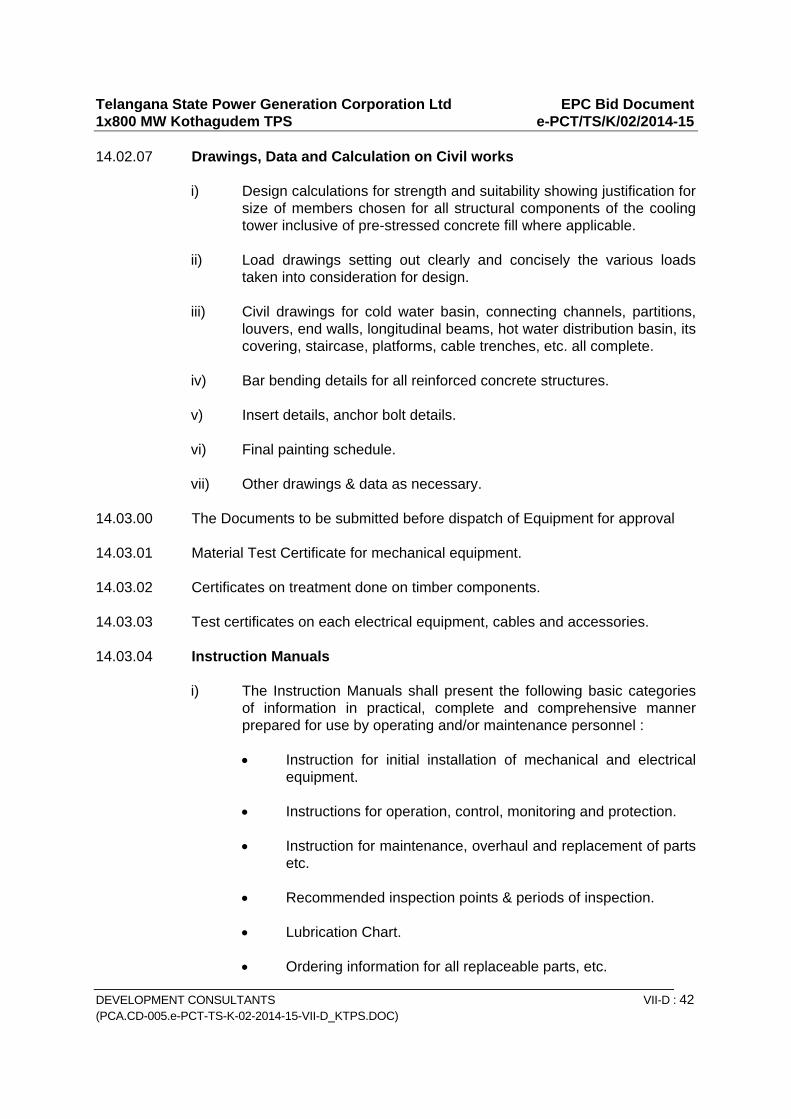
Telangana State Power Generation Corporation Ltd EPC Bid Document 1x800 MW Kothagudem TPS e-PCT/TS/K/02/2014-15
DEVELOPMENT CONSULTANTS VII-D : 42 (PCA.CD-005.e-PCT-TS-K-02-2014-15-VII-D_KTPS.DOC)
14.02.07 Drawings, Data and Calculation on Civil works
i) Design calculations for strength and suitability showing justification for size of members chosen for all structural components of the cooling tower inclusive of pre-stressed concrete fill where applicable.
ii) Load drawings setting out clearly and concisely the various loads
taken into consideration for design. iii) Civil drawings for cold water basin, connecting channels, partitions,
louvers, end walls, longitudinal beams, hot water distribution basin, its covering, staircase, platforms, cable trenches, etc. all complete.
iv) Bar bending details for all reinforced concrete structures. v) Insert details, anchor bolt details. vi) Final painting schedule. vii) Other drawings & data as necessary.
14.03.00 The Documents to be submitted before dispatch of Equipment for approval 14.03.01 Material Test Certificate for mechanical equipment. 14.03.02 Certificates on treatment done on timber components. 14.03.03 Test certificates on each electrical equipment, cables and accessories. 14.03.04 Instruction Manuals
i) The Instruction Manuals shall present the following basic categories of information in practical, complete and comprehensive manner prepared for use by operating and/or maintenance personnel :
Instruction for initial installation of mechanical and electrical
equipment. Instructions for operation, control, monitoring and protection. Instruction for maintenance, overhaul and replacement of parts
etc. Recommended inspection points & periods of inspection. Lubrication Chart. Ordering information for all replaceable parts, etc.
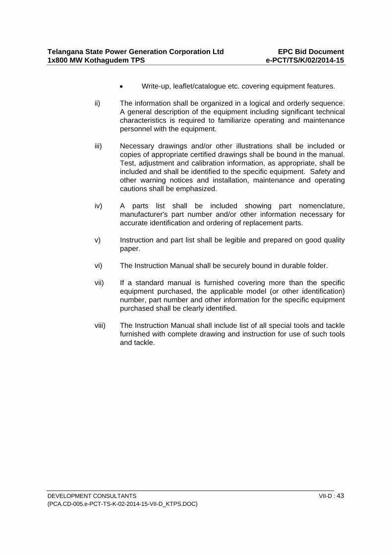
Telangana State Power Generation Corporation Ltd EPC Bid Document 1x800 MW Kothagudem TPS e-PCT/TS/K/02/2014-15
DEVELOPMENT CONSULTANTS VII-D : 43 (PCA.CD-005.e-PCT-TS-K-02-2014-15-VII-D_KTPS.DOC)
Write-up, leaflet/catalogue etc. covering equipment features.
ii) The information shall be organized in a logical and orderly sequence.
A general description of the equipment including significant technical characteristics is required to familiarize operating and maintenance personnel with the equipment.
iii) Necessary drawings and/or other illustrations shall be included or
copies of appropriate certified drawings shall be bound in the manual. Test, adjustment and calibration information, as appropriate, shall be included and shall be identified to the specific equipment. Safety and other warning notices and installation, maintenance and operating cautions shall be emphasized.
iv) A parts list shall be included showing part nomenclature,
manufacturer's part number and/or other information necessary for accurate identification and ordering of replacement parts.
v) Instruction and part list shall be legible and prepared on good quality
paper. vi) The Instruction Manual shall be securely bound in durable folder. vii) If a standard manual is furnished covering more than the specific
equipment purchased, the applicable model (or other identification) number, part number and other information for the specific equipment purchased shall be clearly identified.
viii) The Instruction Manual shall include list of all special tools and tackle
furnished with complete drawing and instruction for use of such tools and tackle.

Telangana State Power Generation Corporation Ltd EPC Bid Document 1x800 MW Kothagudem TPS e-PCT/TS/K/02/2014-15
DEVELOPMENT CONSULTANTS VII-D : 44 (PCA.CD-005.e-PCT-TS-K-02-2014-15-VII-D_KTPS.DOC)
ANNEXURE-A
DATASHEET FOR NATURAL DRAFT COOLING TOWER 1.0 General Information Type of Cooling Tower : Natural Draft, Hyperbolic No. of Cooling Towers Required : One Location : Outdoor Duty : Continuous 2.0 Design Working Conditions Hot water inlet temperature : 42.0oC Design Ambient wet bulb temperature (WBT) : 28oC Design Ambient temp. for electrical equipment : 50oC Design Ambient Relative Humidity (RH) : 44.96% Whether inlet air wet bulb temperature to be corrected considering re-circulation as per CTI bulletin PFM-116 : Yes Design CT inlet wet bulb temperature : By Bidder Basin Holding Capacity : 6 mins of design CT capacity Design Wind speed : As per site data 3.0 Performance Requirement Rated Cooling Water flow : By Bidder Cooling range : 10.5°C Approach to ambient wet bulb temperature : 5.0°C Maximum permissible drift loss : 0.002%
6042023
Text Box
42.5
6042023
Text Box
9.5
6042023
Text Box
90000 cub.m/hr.
6042023
Text Box
28 degC
6042023
Text Box
Refer spec.
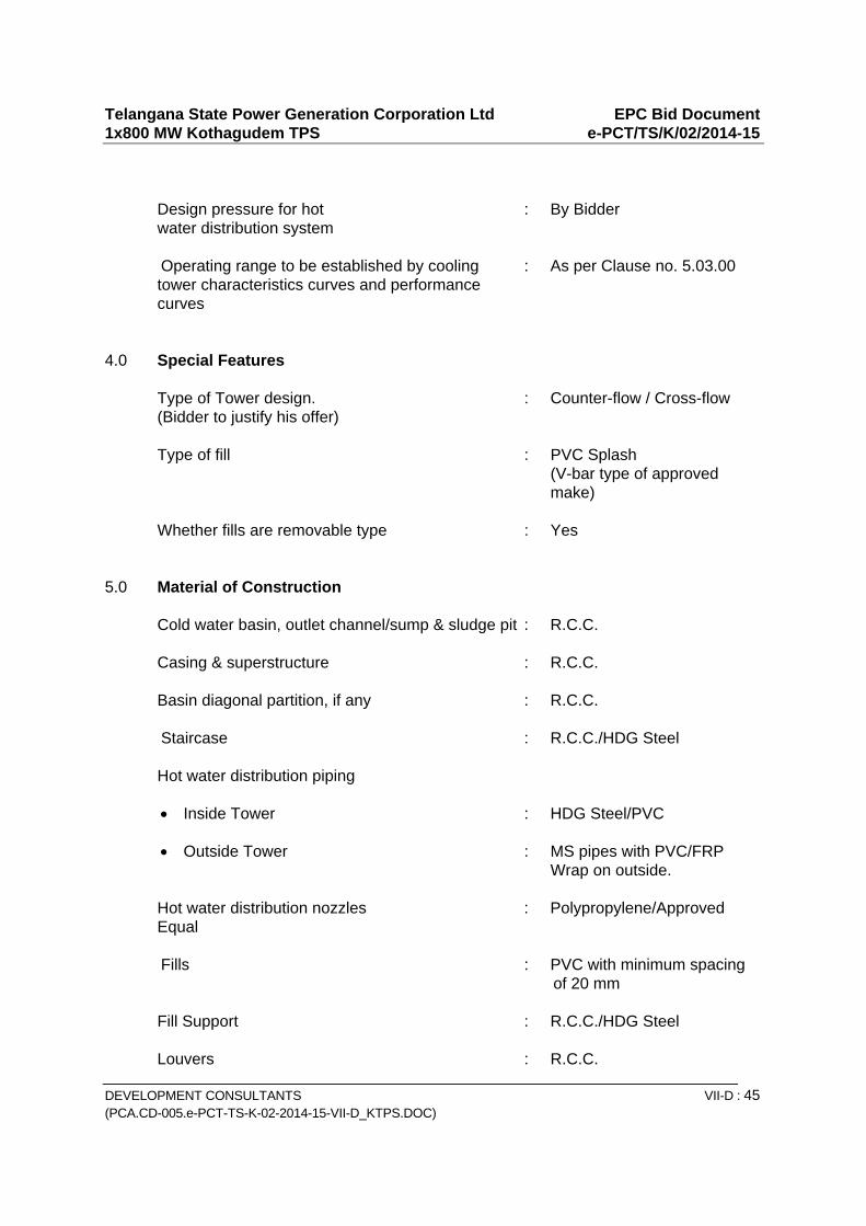
Telangana State Power Generation Corporation Ltd EPC Bid Document 1x800 MW Kothagudem TPS e-PCT/TS/K/02/2014-15
DEVELOPMENT CONSULTANTS VII-D : 45 (PCA.CD-005.e-PCT-TS-K-02-2014-15-VII-D_KTPS.DOC)
Design pressure for hot : By Bidder water distribution system Operating range to be established by cooling : As per Clause no. 5.03.00 tower characteristics curves and performance curves 4.0 Special Features Type of Tower design. : Counter-flow / Cross-flow (Bidder to justify his offer) Type of fill : PVC Splash (V-bar type of approved make) Whether fills are removable type : Yes 5.0 Material of Construction Cold water basin, outlet channel/sump & sludge pit : R.C.C. Casing & superstructure : R.C.C. Basin diagonal partition, if any : R.C.C. Staircase : R.C.C./HDG Steel Hot water distribution piping
Inside Tower : HDG Steel/PVC Outside Tower : MS pipes with PVC/FRP
Wrap on outside. Hot water distribution nozzles : Polypropylene/Approved Equal Fills : PVC with minimum spacing
of 20 mm Fill Support : R.C.C./HDG Steel Louvers : R.C.C.
6042023
Text Box
6.2 kg/sq.cm
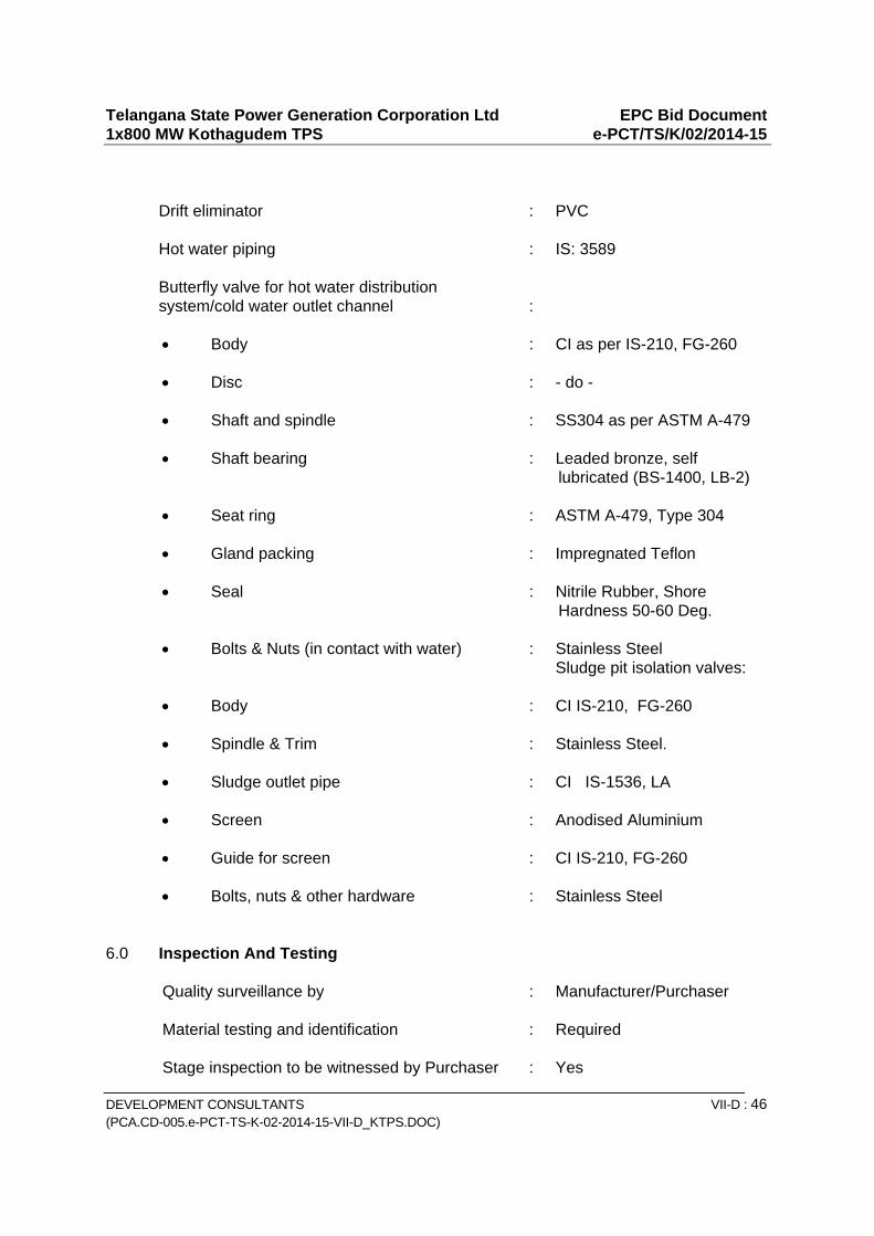
Telangana State Power Generation Corporation Ltd EPC Bid Document 1x800 MW Kothagudem TPS e-PCT/TS/K/02/2014-15
DEVELOPMENT CONSULTANTS VII-D : 46 (PCA.CD-005.e-PCT-TS-K-02-2014-15-VII-D_KTPS.DOC)
Drift eliminator : PVC Hot water piping : IS: 3589 Butterfly valve for hot water distribution system/cold water outlet channel :
Body : CI as per IS-210, FG-260 Disc : - do - Shaft and spindle : SS304 as per ASTM A-479 Shaft bearing : Leaded bronze, self
lubricated (BS-1400, LB-2) Seat ring : ASTM A-479, Type 304 Gland packing : Impregnated Teflon Seal : Nitrile Rubber, Shore
Hardness 50-60 Deg. Bolts & Nuts (in contact with water) : Stainless Steel Sludge pit isolation valves: Body : CI IS-210, FG-260 Spindle & Trim : Stainless Steel. Sludge outlet pipe : CI IS-1536, LA Screen : Anodised Aluminium Guide for screen : CI IS-210, FG-260 Bolts, nuts & other hardware : Stainless Steel
6.0 Inspection And Testing Quality surveillance by : Manufacturer/Purchaser Material testing and identification : Required Stage inspection to be witnessed by Purchaser : Yes
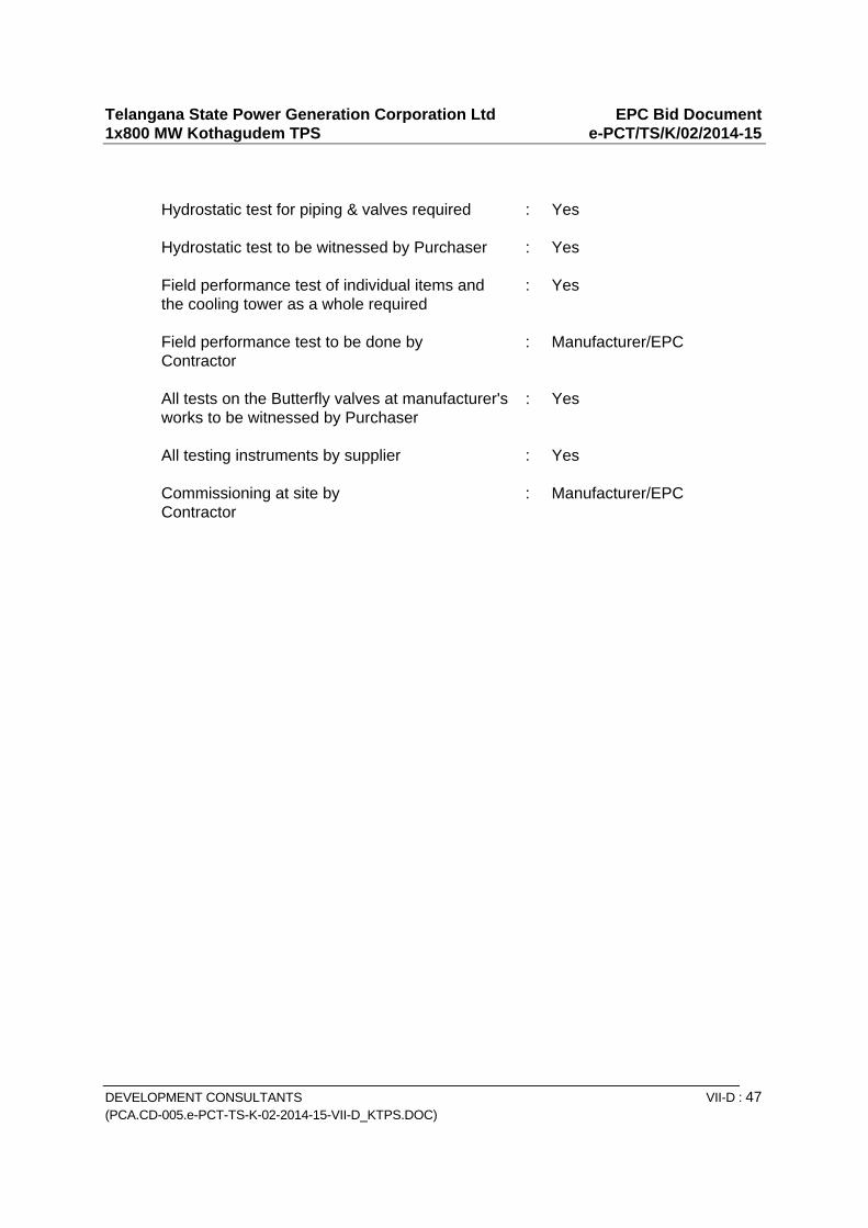
Telangana State Power Generation Corporation Ltd EPC Bid Document 1x800 MW Kothagudem TPS e-PCT/TS/K/02/2014-15
DEVELOPMENT CONSULTANTS VII-D : 47 (PCA.CD-005.e-PCT-TS-K-02-2014-15-VII-D_KTPS.DOC)
Hydrostatic test for piping & valves required : Yes Hydrostatic test to be witnessed by Purchaser : Yes Field performance test of individual items and : Yes the cooling tower as a whole required Field performance test to be done by : Manufacturer/EPC Contractor All tests on the Butterfly valves at manufacturer's : Yes works to be witnessed by Purchaser All testing instruments by supplier : Yes Commissioning at site by : Manufacturer/EPC Contractor
TITLE: TECHNICAL SPECIFICATION
COOLING TOWERS SPECIFIC TECHNICAL REQUIREMENTS
SPEC. NO.: PE-TS-410-165-N001 VOLUME: IIB SECTION: C REV. NO. 00 DATE 23.01.2015 SHEET 1 OF 1
SECTION – C4
SPECIFIC TECHNICAL REQUIREMENTS (C&I)
1X800 MW KOTHAGUDAM TPS
SPECIFIC TECHNICAL REQUIREMENTS (C&I)
NATURAL DRAUGHT COOLING TOWER
OF 4
`
0
CONTROL AND INSTRUMENTATION
FOR
NATURAL DRAUGHT COOLING TOWER
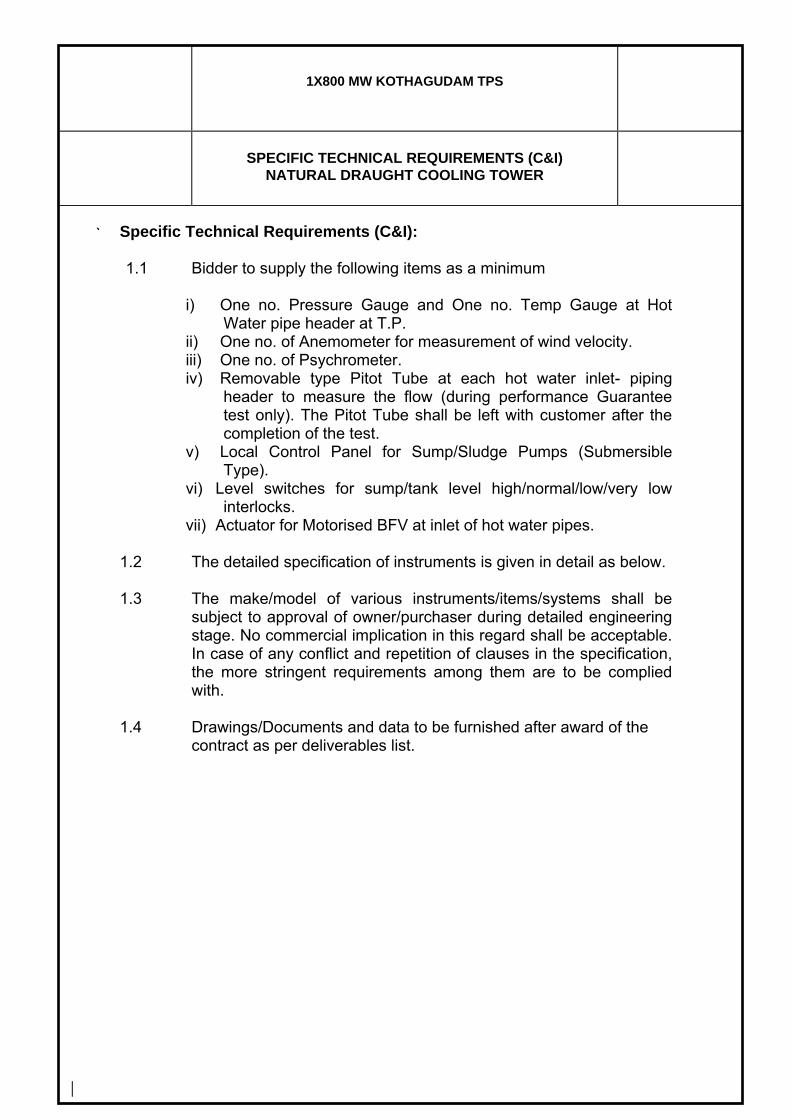
1X800 MW KOTHAGUDAM TPS
SPECIFIC TECHNICAL REQUIREMENTS (C&I)
NATURAL DRAUGHT COOLING TOWER
OF 4
`
0
Specific Technical Requirements (C&I): 1.1 Bidder to supply the following items as a minimum
i) One no. Pressure Gauge and One no. Temp Gauge at Hot
Water pipe header at T.P. ii) One no. of Anemometer for measurement of wind velocity. iii) One no. of Psychrometer. iv) Removable type Pitot Tube at each hot water inlet- piping
header to measure the flow (during performance Guarantee test only). The Pitot Tube shall be left with customer after the completion of the test.
v) Local Control Panel for Sump/Sludge Pumps (Submersible Type).
vi) Level switches for sump/tank level high/normal/low/very low interlocks.
vii) Actuator for Motorised BFV at inlet of hot water pipes.
1.2 The detailed specification of instruments is given in detail as below.
1.3 The make/model of various instruments/items/systems shall be subject to approval of owner/purchaser during detailed engineering stage. No commercial implication in this regard shall be acceptable. In case of any conflict and repetition of clauses in the specification, the more stringent requirements among them are to be complied with.
1.4 Drawings/Documents and data to be furnished after award of the
contract as per deliverables list.
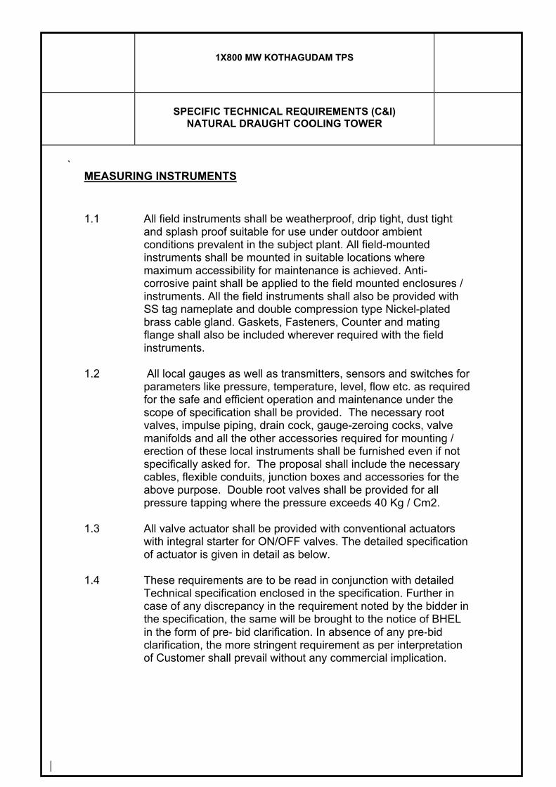
1X800 MW KOTHAGUDAM TPS
SPECIFIC TECHNICAL REQUIREMENTS (C&I)
NATURAL DRAUGHT COOLING TOWER
`
MEASURING INSTRUMENTS
1.1 All field instruments shall be weatherproof, drip tight, dust tight and splash proof suitable for use under outdoor ambient conditions prevalent in the subject plant. All field-mounted instruments shall be mounted in suitable locations where maximum accessibility for maintenance is achieved. Anti-corrosive paint shall be applied to the field mounted enclosures / instruments. All the field instruments shall also be provided with SS tag nameplate and double compression type Nickel-plated brass cable gland. Gaskets, Fasteners, Counter and mating flange shall also be included wherever required with the field instruments.
1.2 All local gauges as well as transmitters, sensors and switches for
parameters like pressure, temperature, level, flow etc. as required for the safe and efficient operation and maintenance under the scope of specification shall be provided. The necessary root valves, impulse piping, drain cock, gauge-zeroing cocks, valve manifolds and all the other accessories required for mounting / erection of these local instruments shall be furnished even if not specifically asked for. The proposal shall include the necessary cables, flexible conduits, junction boxes and accessories for the above purpose. Double root valves shall be provided for all pressure tapping where the pressure exceeds 40 Kg / Cm2.
1.3 All valve actuator shall be provided with conventional actuators with integral starter for ON/OFF valves. The detailed specification of actuator is given in detail as below.
1.4 These requirements are to be read in conjunction with detailed
Technical specification enclosed in the specification. Further in case of any discrepancy in the requirement noted by the bidder in the specification, the same will be brought to the notice of BHEL in the form of pre‐ bid clarification. In absence of any pre‐bid clarification, the more stringent requirement as per interpretation of Customer shall prevail without any commercial implication.
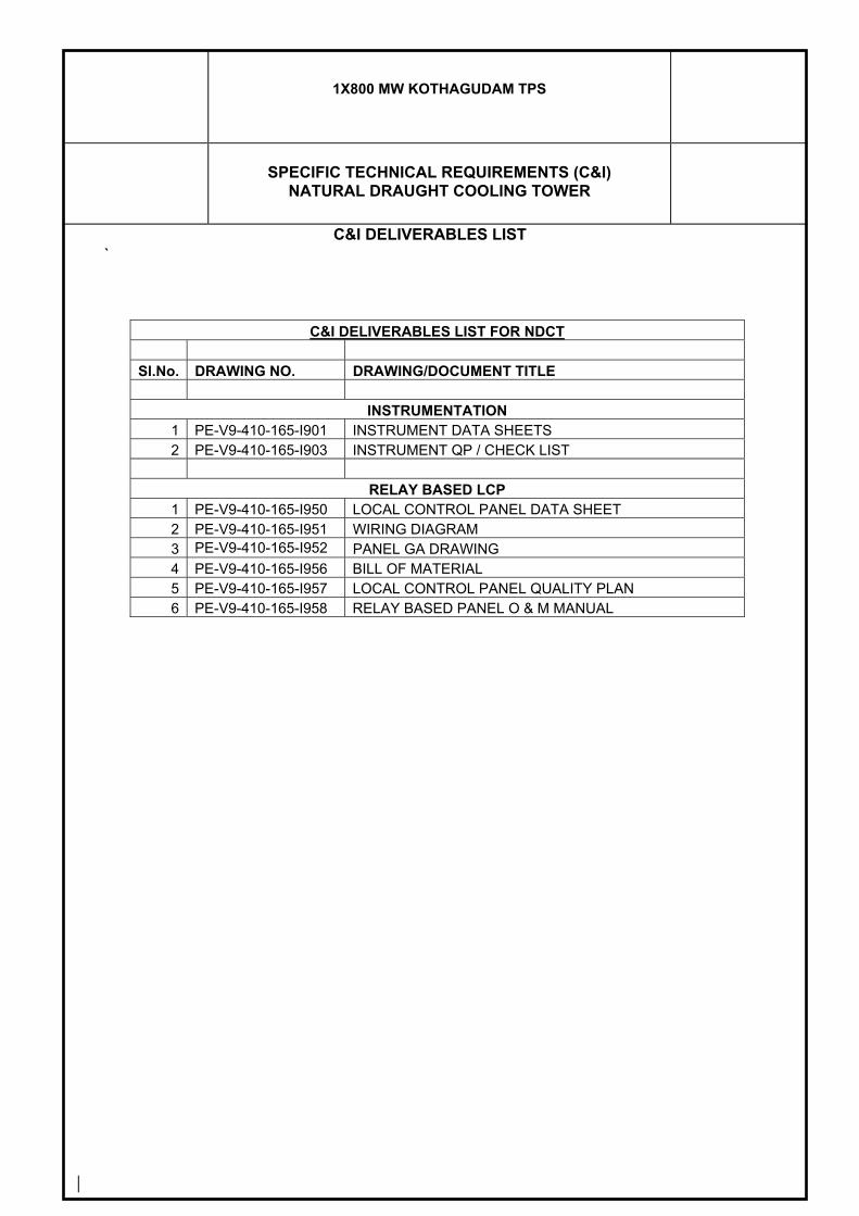
1X800 MW KOTHAGUDAM TPS
SPECIFIC TECHNICAL REQUIREMENTS (C&I)
NATURAL DRAUGHT COOLING TOWER
`
C&I DELIVERABLES LIST
C&I DELIVERABLES LIST FOR NDCT
Sl.No. DRAWING NO. DRAWING/DOCUMENT TITLE
INSTRUMENTATION 1 PE-V9-410-165-I901 INSTRUMENT DATA SHEETS 2 PE-V9-410-165-I903 INSTRUMENT QP / CHECK LIST
RELAY BASED LCP
1 PE-V9-410-165-I950 LOCAL CONTROL PANEL DATA SHEET 2 PE-V9-410-165-I951 WIRING DIAGRAM 3 PE-V9-410-165-I952 PANEL GA DRAWING 4 PE-V9-410-165-I956 BILL OF MATERIAL 5 PE-V9-410-165-I957 LOCAL CONTROL PANEL QUALITY PLAN 6 PE-V9-410-165-I958 RELAY BASED PANEL O & M MANUAL
1X800 MW KOTHAGUDAM TPS
SPECIFIC TECHNICAL REQUIREMENTS (C&I)
NATURAL DRAUGHT COOLING TOWER
OF 4
`
0
MANDATORY SPARES

Andhra Pradesh Power Generation Corporation Ltd.1x800 MW Kothagudem TPS
EPC Bid Documente-PCT/TS/K/02/2014-15
ANNEXURE-I
DEVELOPMENT CONSULTANTS(e-PCT-TS-K-02-2014-15-Vol. IIA-8-Annx-1.xls) V.IIA/S-VIII : 58
Sl. No. Description Quantity for each type of equipment / instrumentA. Field Instruments1 Transmitters/ Gauges/Switches etc. along with relevant
accessories10% of total or at least two (whichever is higher) for each type along with accessories.
2 Temperature Element (RTD/Thermo-couple) with thermowell
10% of each type , range and immersion length . Minimum 5 nos.
3 Furnace Temperature Probe Thermocouple 1 no.4 HFO/LFO Oil meter5 Sensor 1 no. each for each type, model & range6 O Rings 2 nos. of each size7 Gaskets 3 nos. of each size
B. Analysers1 Field sensor 2 nos.2 Field transmitter/ complete electronic unit 1 no.3 Power supply card 1 no.4 Instrumentation hardware 1 no. each item
C. Control Valves and Dampers I) Pneumatic Control Valves & Block Valves1 Plot Relay 1 set for each valve2 Actuator Diaphragm 1 no.for each valve3 Feedback Linkage 1 no.for each valve4 Smart Positioners 10% of total quantity of each model/type5 I/P Converters (If any) 10% of total quantity or minimum 15 nos.6 Complete Consumables for Valve Viz. O-ring, Gland
Packing, Packing Ring, Bonnet Seal etc2 Sets each size, rating, type
7 Valve Disc 2 Sets each size, rating, type8 Valve Spindle 2 Sets each size, rating, type9 Valve Seat 2 Sets each size, rating, type10 Bush 2 Sets each size, rating, type11 Guide 2 Sets each size, rating, type12 Guide Bush 2 Sets each size, rating, type13 Coupling Nut 2 Sets each size, rating, type14 Actuator Piston with Rod & Seal 2 Sets each size, rating, type15 Control valve stem packing and spare operator moulded
rubber diaphragms1 set for each size, rating, type
16 Valve trim (including cage, plug, stem, seat rings, guide bushings etc.) for each of the control valves as offered.
1 set for each size, rating, type
17 Solenoid valves, position transmitters, limit switches, I/P convertors, positioners etc of each type
10% of total quantity spare with minimum 1 no. for each size, rating, type
II) Dampers1 Actuator Diaphragm 1 set for each damper2 O-Ring set 2 nos. of each size for positioner3 Feedback Linkage 1 no.for each type4 Packing & gasket 1 no.for each type
III) Solenoid Valves1 Solenoid Valve Coil 2 nos. of each rating & insulation2 Plunger 1 no. of each type3 Seat 2 no. of each type & size4 Gaskets 2 sets of each type & size5 O-Ring set 5 sets of each type & size
D. Flow Elements1 Root valves 2 nos. for each flow element2 Gland packing for root valves 2 nos. for each flow element3 Gaskets 2 nos. for each flow element
E. Process Connection Piping (Impulse piping/tubing, sampling piping / tubing & air supply piping as applicable)
1 Valves of all types 10% of each type, class, size & model2 Valve Manifolds (2 way/3 way/5 way) 10% of each type, class, size & model3 Fittings 10% of each type, class, size & model4 Filter Regulators 20% of each model
F. Cables (Control & Instrumentation) 10% of each type, pair and size of actual installed quantity
G. DDCMIS
MANDATORY SPARE LIST (CONTROL & INSTRUMENTATION)
The Bidder shall offer mandatory spares of the same make, model and type for items which are offered in the main offer. Further, offered spare parts shall be of the same grade and shall have same performance as the instruments which they are to replace.
3833321
Line
3833321
Rectangle
3833321
Rectangle
3833321
Line

Andhra Pradesh Power Generation Corporation Ltd.1x800 MW Kothagudem TPS
EPC Bid Documente-PCT/TS/K/02/2014-15
ANNEXURE-I
DEVELOPMENT CONSULTANTS(e-PCT-TS-K-02-2014-15-Vol. IIA-8-Annx-1.xls) V.IIA/S-VIII : 59
1 Electronic Modules (IO cards, Remote IO cards, communication interface cards, controller cards, CPU module, logic cards, network switches etc.)
10% of total quantityor minimum 4 nos. whichever is higher
2 Relays 10% of total quantity or minimum 10 nos. whichever is higher
3 Power Supply Modules & Power Packs for control system 10% or minimum 4 nos. whichever is higher for each type and rating.
4 Industrial grade ethernet switches 4 nos. for each type minimum.5 Any other system specific Module/Cards used in the
system but not mentioned in this list10% of total nos. used in the system or minimum 1(one) no. whichever is more for each type and model.
6 Network Items (Network switch/ LIU unit/ Transceiver/ FO patch cord etc.)
10% of total nos. used for each type and model in the system or minimum 2(two) no. whichever is more.
7 MCB (Miniature case circuit breaker) 10% of total quantity or minimum 10 nos. whichever is higher for each type and rating.
8 Fuses 200% or minimum 50 no's for each type and rating9 Racks for housing I/O & Processor Modules 1(One) no. each type used in the system10 Prefab interconnecting cables with connectors 10% of total nos. used in the system or minimum 4(four)
nos. whichever is more for each type.11 Network communication cable with end connectors 10% of total nos. used in the system or minimum 4(four)
nos. whichever is more for each type.12 I/O bus cables with connectors for remote I/O units 1 no. of each type & length13 Cooling Fans 2 nos. for each cabinet14 Loose Connectors 5 nos. of each type15 Printers 2nos. Complete set16 Key Board & Cursor control device 2nos.17 Complete Set of Operators Work Station 2nos. complete set18 Colour TFT Monitor 2nos. complete set19 Hard Disk Drive for the work Station 2nos complete set20 Toner for colour Laserjet Printer 10 (ten) nos. each colour other than black & 20nos. black
21 Memory Module/ EEPROM Chip 10% of total nos. used in the system or minimum 4(four) nos. whichever is more.
22 Battery for RAM Backup 2 (two) nos.23 Terminal Block 10% of total nos. used in the system for each type and
rating.24 Read-Write CD/DVD 2 (two) no. complete set25 Blank CD/DVD 50 (fifty) nos.H. Large Video Screen1 LED Light Source 2 nos. for each LVS2 Dust Filter 10% of the total quantity or minimum 8 nos. whichever is
higher3 Graphic Output Card 10% of the total quantityor minimum 1 no. whichever is
higher4 LAN Card for Controller 10% of the total quantity or minimum 1 no. whichever is
higher5 Video Input Card CCTV 10% of the total quantity or minimum 1 no. whichever is
higher6 Controller unit 10% of the total quantityor minimum 1 no. whichever is
higher7 DVI Cable (10 Mtr.) 2 nos.
I. Master Clock System 10% of the total quantity offered for each type of electronic modules or 1 number whichever is higher
J. HART Management system1 Multiplexer (Master) 10% of the total quantity or minimum 1 no. whichever is
higher2 Multiplexer (Slave) 10% of the total quantity or minimum 7 nos. whichever is
higher3 Patch Board 10% of the total quantity or minimum 8 nos. whichever is
higher4 Power Supply Module 10% of the total quantity or minimum 1 no. whichever is
higher5 RS485/RS232 converter 10% of the total quantity or minimum 1 no. whichever is
higher6 Fuse 100%7 Communication Module & Interface Module 10% of the total quantity or minimum 1 no. whichever is
higher8 Industrial grade ethernet switches 4 nos. for each type minimum.
K. PA System1 Power Supply Module 25% of supplied quantity or one whichever is more2 Controller modules 20% of supplied quantity or minimum one each type
whichever is higher3 Communication module 20% of supplied quantity or minimum one each type
whichever is higher
3833321
Line
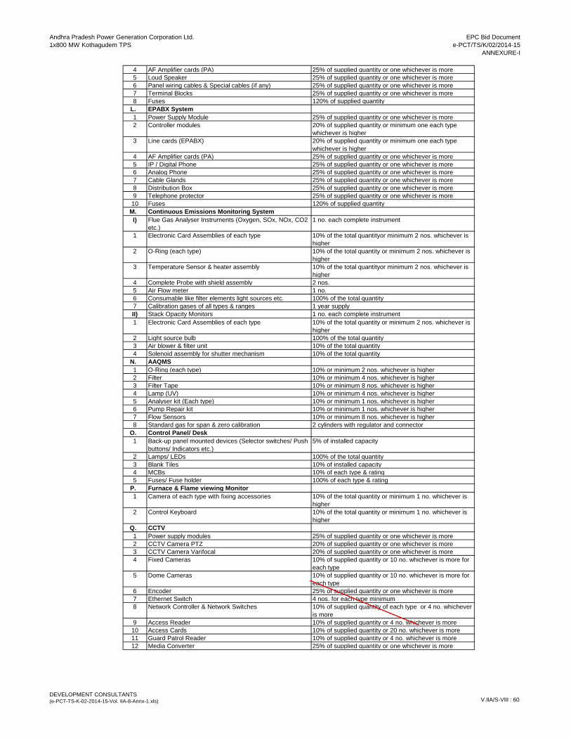
Andhra Pradesh Power Generation Corporation Ltd.1x800 MW Kothagudem TPS
EPC Bid Documente-PCT/TS/K/02/2014-15
ANNEXURE-I
DEVELOPMENT CONSULTANTS(e-PCT-TS-K-02-2014-15-Vol. IIA-8-Annx-1.xls) V.IIA/S-VIII : 60
4 AF Amplifier cards (PA) 25% of supplied quantity or one whichever is more5 Loud Speaker 25% of supplied quantity or one whichever is more6 Panel wiring cables & Special cables (if any) 25% of supplied quantity or one whichever is more7 Terminal Blocks 25% of supplied quantity or one whichever is more8 Fuses 120% of supplied quantity
L. EPABX System1 Power Supply Module 25% of supplied quantity or one whichever is more2 Controller modules 20% of supplied quantity or minimum one each type
whichever is higher3 Line cards (EPABX) 20% of supplied quantity or minimum one each type
whichever is higher4 AF Amplifier cards (PA) 25% of supplied quantity or one whichever is more5 IP / Digital Phone 25% of supplied quantity or one whichever is more6 Analog Phone 25% of supplied quantity or one whichever is more7 Cable Glands 25% of supplied quantity or one whichever is more8 Distribution Box 25% of supplied quantity or one whichever is more9 Telephone protector 25% of supplied quantity or one whichever is more10 Fuses 120% of supplied quantity
M. Continuous Emissions Monitoring SystemI) Flue Gas Analyser Instruments (Oxygen, SOx, NOx, CO2
etc.)1 no. each complete instrument
1 Electronic Card Assemblies of each type 10% of the total quantityor minimum 2 nos. whichever is higher
2 O-Ring (each type) 10% of the total quantity or minimum 2 nos. whichever is higher
3 Temperature Sensor & heater assembly 10% of the total quantityor minimum 2 nos. whichever is higher
4 Complete Probe with shield assembly 2 nos.5 Air Flow meter 1 no.6 Consumable like filter elements light sources etc. 100% of the total quantity7 Calibration gases of all types & ranges 1 year supplyII) Stack Opacity Monitors 1 no. each complete instrument1 Electronic Card Assemblies of each type 10% of the total quantity or minimum 2 nos. whichever is
higher2 Light source bulb 100% of the total quantity3 Air blower & filter unit 10% of the total quantity4 Solenoid assembly for shutter mechanism 10% of the total quantity
N. AAQMS1 O-Ring (each type) 10% or minimum 2 nos. whichever is higher2 Filter 10% or minimum 4 nos. whichever is higher3 Filter Tape 10% or minimum 8 nos. whichever is higher4 Lamp (UV) 10% or minimum 4 nos. whichever is higher5 Analyser kit (Each type) 10% or minimum 1 nos. whichever is higher6 Pump Repair kit 10% or minimum 1 nos. whichever is higher7 Flow Sensors 10% or minimum 8 nos. whichever is higher8 Standard gas for span & zero calibration 2 cylinders with regulator and connector
O. Control Panel/ Desk1 Back-up panel mounted devices (Selector switches/ Push
buttons/ Indicators etc.)5% of installed capacity
2 Lamps/ LEDs 100% of the total quantity3 Blank Tiles 10% of installed capacity4 MCBs 10% of each type & rating5 Fuses/ Fuse holder 100% of each type & rating
P. Furnace & Flame viewing Monitor1 Camera of each type with fixing accessories 10% of the total quantity or minimum 1 no. whichever is
higher2 Control Keyboard 10% of the total quantity or minimum 1 no. whichever is
higherQ. CCTV 1 Power supply modules 25% of supplied quantity or one whichever is more2 CCTV Camera PTZ 20% of supplied quantity or one whichever is more3 CCTV Camera Varifocal 20% of supplied quantity or one whichever is more4 Fixed Cameras 10% of supplied quantity or 10 no. whichever is more for
each type 5 Dome Cameras 10% of supplied quantity or 10 no. whichever is more for
each type 6 Encoder 25% of supplied quantity or one whichever is more7 Ethernet Switch 4 nos. for each type minimum8 Network Controller & Network Switches 10% of supplied quantity of each type or 4 no. whichever
is more9 Access Reader 10% of supplied quantity or 4 no. whichever is more10 Access Cards 10% of supplied quantity or 20 no. whichever is more11 Guard Patrol Reader 10% of supplied quantity or 4 no. whichever is more12 Media Converter 25% of supplied quantity or one whichever is more
3833321
Line
3833321
Rectangle
3833321
Line
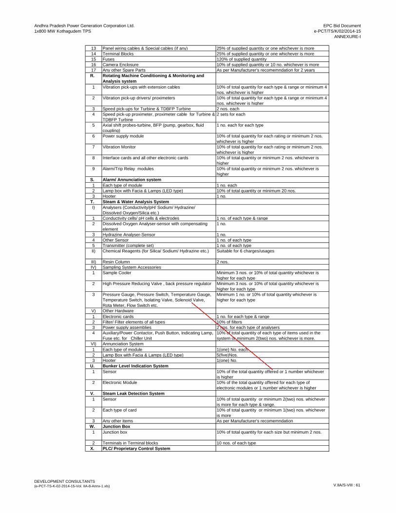
Andhra Pradesh Power Generation Corporation Ltd.1x800 MW Kothagudem TPS
EPC Bid Documente-PCT/TS/K/02/2014-15
ANNEXURE-I
DEVELOPMENT CONSULTANTS(e-PCT-TS-K-02-2014-15-Vol. IIA-8-Annx-1.xls) V.IIA/S-VIII : 61
13 Panel wiring cables & Special cables (if any) 25% of supplied quantity or one whichever is more14 Terminal Blocks 25% of supplied quantity or one whichever is more15 Fuses 120% of supplied quantity 16 Camera Enclosure 10% of supplied quantity or 10 no. whichever is more17 Any other Spare Parts As per Manufacturer's recomemndation for 2 yearsR. Rotating Machine Conditioning & Monitoring and
Analysis system1 Vibration pick-ups with extension cables 10% of total quantity for each type & range or minimum 4
nos. whichever is higher2 Vibration pick-up drivers/ proximeters 10% of total quantity for each type & range or minimum 4
nos. whichever is higher3 Speed pick-ups for Turbine & TDBFP Turbine 2 nos. each4 Speed pick-up proximeter, proximeter cable for Turbine &
TDBFP Turbine2 sets for each
5 Axial shift probes-turbine, BFP (pump, gearbox, fluid coupling)
1 no. each for each type
6 Power supply module 10% of total quantity for each rating or minimum 2 nos. whichever is higher
7 Vibration Monitor 10% of total quantity for each rating or minimum 2 nos. whichever is higher
8 Interface cards and all other electronic cards 10% of total quantity or minimum 2 nos. whichever is higher
9 Alarm/Trip Relay modules 10% of total quantity or minimum 2 nos. whichever is higher
S. Alarm/ Annunciation system1 Each type of module 1 no. each2 Lamp box with Facia & Lamps (LED type) 10% of total quantity or minimum 20 nos.3 Hooter 1 no.
T. Steam & Water Analysis SystemI) Analysers (Conductivity/pH/ Sodium/ Hydrazine/
Dissolved Oxygen/Silica etc.)1 Conductivity cells/ pH cells & electrodes 1 no. of each type & range2 Dissolved Oxygen Analyser-sensor with compensating
element1 no.
3 Hydrazine Analyser-Sensor 1 no.4 Other Sensor 1 no. of each type5 Transmitter (complete set) 1 no. of each typeII) Chemical Reagents (for Silica/ Sodium/ Hydrazine etc.) Suitable for 6 charges/usages
III) Resin Column 2 nos.IV) Sampling System Accessories1 Sample Cooler Minimum 3 nos. or 10% of total quantity whichever is
higher for each type2 High Pressure Reducing Valve , back pressure regulator Minimum 3 nos. or 10% of total quantity whichever is
higher for each type3 Pressure Gauge, Pressure Switch, Temperature Gauge,
Temperature Switch, Isolating Valve, Solenoid Valve, Rota Meter, Flow Switch etc.
Minimum 1 no. or 10% of total quantity whichever is higher for each type
V) Other Hardware1 Electronic cards 1 no. for each type & range2 Filter/ Filter elements of all types 10% of filters3 Power supply assemblies 2 nos. for each type of analysers4 Auxiliary/Power Contactor, Push Button, Indicating Lamp,
Fuse etc. for Chiller Unit10% of total quantity of each type of items used in the system or minimum 2(two) nos. whichever is more.
VI) Annunciation System1 Each type of module 1(one) No. each2 Lamp Box with Facia & Lamps (LED type) 5(five)Nos.3 Hooter 1(one) No.
U. Bunker Level Indication System1 Sensor 10% of the total quantity offered or 1 number whichever
is higher2 Electronic Module 10% of the total quantity offered for each type of
electronic modules or 1 number whichever is higherV. Steam Leak Detection System1 Sensor 10% of total quantity or minimum 2(two) nos. whichever
is more for each type & range.2 Each type of card 10% of total quantity or minimum 1(two) nos. whichever
is more3 Any other items As per Manufacturer's recomemndation
W. Junction Box1 Junction box 10% of total quantity for each size but minimum 2 nos.
2 Terminals in Terminal blocks 10 nos. of each typeX. PLC/ Proprietary Control System
3833321
Line
3833321
Rectangle
3833321
Rectangle
3833321
Line
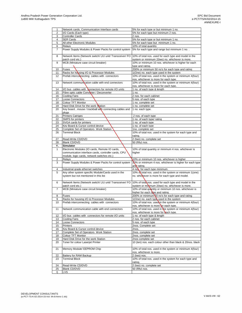
Andhra Pradesh Power Generation Corporation Ltd.1x800 MW Kothagudem TPS
EPC Bid Documente-PCT/TS/K/02/2014-15
ANNEXURE-I
DEVELOPMENT CONSULTANTS(e-PCT-TS-K-02-2014-15-Vol. IIA-8-Annx-1.xls) V.IIA/S-VIII : 62
1 Network cards, Communication Interface cards 5% for each type or but minimum 1 no. 2 I/O Cards (Each type) 5% for each type but minimum 2 nos. 3 Controller Cards 2 nos.4 SER Cards 5% for each type or but minimum 1 no. 5 All other Electronic Modules 5% for each type but minimum 1 no. 6 Relays 10% of total quantity7 Power Supply Modules & Power Packs for control system 5% for each type and range but minimum 1 no. .
8 Network Items (Network switch/ LIU unit/ Transceiver/ FO patch cord etc.)
10% of total nos. used for each type and model in the system or minimum 2(two) no. whichever is more.
9 MCB (Miniature case circuit breaker) 10% or minimum 10 nos. whichever is higher for each type and rating.
10 Fuses 200% or minimum 50 no's for each type and rating11 Racks for housing I/O & Processor Modules 1(One) no. each type used in the system12 Prefab interconnecting cables with connectors 10% of total nos. used in the system or minimum 4(four)
nos. whichever is more for each type.13 Network communication cable with end connectors 10% of total nos. used in the system or minimum 4(four)
nos. whichever is more for each type.14 I/O bus cables with connectors for remote I/O units 1 no. of each type & length15 Fibre optic cable Converter / Deconverter 1 no.16 Cooling Fans 2 nos. for each cabinet17 Loose Connectors 5 nos. of each type18 Colour TFT Monitor 1 no. complete set19 Hard Disk Drive for the work Station 1 no. complete set20 Key board , mouse / trackball with connecting cables and
plugs 1 no. each type.
21 Printers Catriges 2 nos. of each type22 SMPS for printers 1 no. of each type/ rating23 SVGA cards for printers 1 no. of each type24 Key Board & Cursor control device 1 no. of each type25 Complete Set of Operators Work Station 1no. complete set26 Terminal Block 10% of total nos. used in the system for each type and
rating.27 Read-Write CD/DVD 2 (two) no. complete set28 Blank CD/DVD 50 (fifty) nos.Y. Simulator1 Electronic Modules (IO cards, Remote IO cards,
communication interface cards, controller cards, CPU module, logic cards, network switches etc.)
10% of total quantity or minimum 4 nos. whichever is higher
2 Relays 10% or minimum 10 nos. whichever is higher3 Power Supply Modules & Power Packs for control system 10% or minimum 4 nos. whichever is higher for each type
and rating.4 Industrial grade ethernet switches 4 nos. for each type minimum.5 Any other system specific Module/Cards used in the
system but not mentioned in this list10% of total nos. used in the system or minimum 1(one) no. whichever is more for each type and model.
6 Network Items (Network switch/ LIU unit/ Transceiver/ FO patch cord etc.)
10% of total nos. used for each type and model in the system or minimum 2(two) no. whichever is more.
7 MCB (Miniature case circuit breaker) 10% of total quantity or minimum 10 nos. whichever is higher for each type and rating.
8 Fuses 200% or minimum 50 no's for each type and rating9 Racks for housing I/O & Processor Modules 1(One) no. each type used in the system10 Prefab interconnecting cables with connectors 10% of total nos. used in the system or minimum 4(four)
nos. whichever is more for each type.11 Network communication cable with end connectors 10% of total nos. used in the system or minimum 4(four)
nos. whichever is more for each type.12 I/O bus cables with connectors for remote I/O units 1 no. of each type & length13 Cooling Fans 2 nos. for each cabinet14 Loose Connectors 5 nos. of each type15 Printers 2nos. Complete set16 Key Board & Cursor control device 2nos.17 Complete Set of Operators Work Station 2nos. complete set18 Colour TFT Monitor 2nos. complete set19 Hard Disk Drive for the work Station 2nos complete set20 Toner for colour Laserjet Printer 10 (ten) nos. each colour other than black & 20nos. black
21 Memory Module/ EEPROM Chip 10% of total nos. used in the system or minimum 4(four) nos. whichever is more.
22 Battery for RAM Backup 2 (two) nos.23 Terminal Block 10% of total nos. used in the system for each type and
rating.24 Read-Write CD/DVD 2 (two) no. complete set25 Blank CD/DVD 50 (fifty) nos.I) LVS
3833321
Line
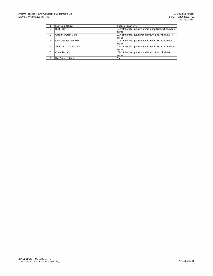
Andhra Pradesh Power Generation Corporation Ltd.1x800 MW Kothagudem TPS
EPC Bid Documente-PCT/TS/K/02/2014-15
ANNEXURE-I
DEVELOPMENT CONSULTANTS(e-PCT-TS-K-02-2014-15-Vol. IIA-8-Annx-1.xls) V.IIA/S-VIII : 63
1 LED Light Source 2 nos. for each LVS2 Dust Filter 10% of the total quantity or minimum 8 nos. whichever is
higher3 Graphic Output Card 10% of the total quantityor minimum 1 no. whichever is
higher4 LAN Card for Controller 10% of the total quantity or minimum 1 no. whichever is
higher5 Video Input Card CCTV 10% of the total quantity or minimum 1 no. whichever is
higher6 Controller unit 10% of the total quantityor minimum 1 no. whichever is
higher7 DVI Cable (10 Mtr.) 2 nos.
3833321
Line
1X800 MW KOTHAGUDAM TPS
SPECIFIC TECHNICAL REQUIREMENTS (C&I)
NATURAL DRAUGHT COOLING TOWER
OF 4
`
0
FIELD & MEASURING INSTRUMENTS
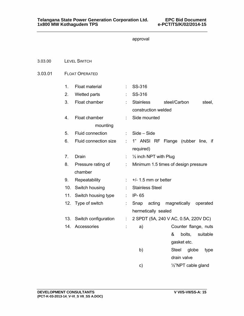
Telangana State Power Generation Corporation Ltd. EPC Bid Document 1x800 MW Kothagudem TPS e-PCT/TS/K/02/2014-15
DEVELOPMENT CONSULTANTS V VI/S-VII/SS-A: 15 (PCT-K-03-2013-14_V-VI_S VII_SS A.DOC)
approval
3.03.00 LEVEL SWITCH
3.03.01 FLOAT OPERATED
1. Float material : SS-316
2. Wetted parts : SS-316
3. Float chamber : Stainless steel/Carbon steel,
construction welded
4. Float chamber
mounting
: Side mounted
5. Fluid connection : Side – Side
6. Fluid connection size : 1” ANSI RF Flange (rubber line, if
required)
7. Drain : ½ inch NPT with Plug
8. Pressure rating of
chamber
: Minimum 1.5 times of design pressure
9. Repeatability : +/- 1.5 mm or better
10. Switch housing : Stainless Steel
11. Switch housing type : IP- 65
12. Type of switch : Snap acting magnetically operated
hermetically sealed
13. Switch configuration : 2 SPDT (5A, 240 V AC, 0.5A, 220V DC)
14. Accessories : a) Counter flange, nuts
& bolts, suitable
gasket etc.
b) Steel globe type
drain valve
c) ½”NPT cable gland
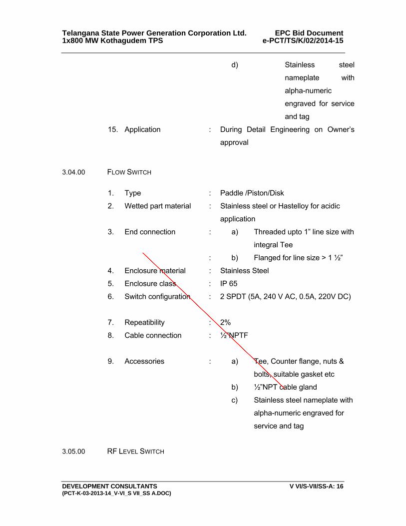
Telangana State Power Generation Corporation Ltd. EPC Bid Document 1x800 MW Kothagudem TPS e-PCT/TS/K/02/2014-15
DEVELOPMENT CONSULTANTS V VI/S-VII/SS-A: 16 (PCT-K-03-2013-14_V-VI_S VII_SS A.DOC)
d) Stainless steel
nameplate with
alpha-numeric
engraved for service
and tag
15. Application : During Detail Engineering on Owner’s
approval
3.04.00 FLOW SWITCH
1. Type : Paddle /Piston/Disk
2. Wetted part material : Stainless steel or Hastelloy for acidic
application
3. End connection : a) Threaded upto 1” line size with
integral Tee
: b) Flanged for line size > 1 ½”
4. Enclosure material : Stainless Steel
5. Enclosure class : IP 65
6. Switch configuration : 2 SPDT (5A, 240 V AC, 0.5A, 220V DC)
7. Repeatibility : 2%
8. Cable connection : ½”NPTF
9. Accessories : a) Tee, Counter flange, nuts &
bolts, suitable gasket etc
b) ½”NPT cable gland
c) Stainless steel nameplate with
alpha-numeric engraved for
service and tag
3.05.00 RF LEVEL SWITCH
3833321
Line
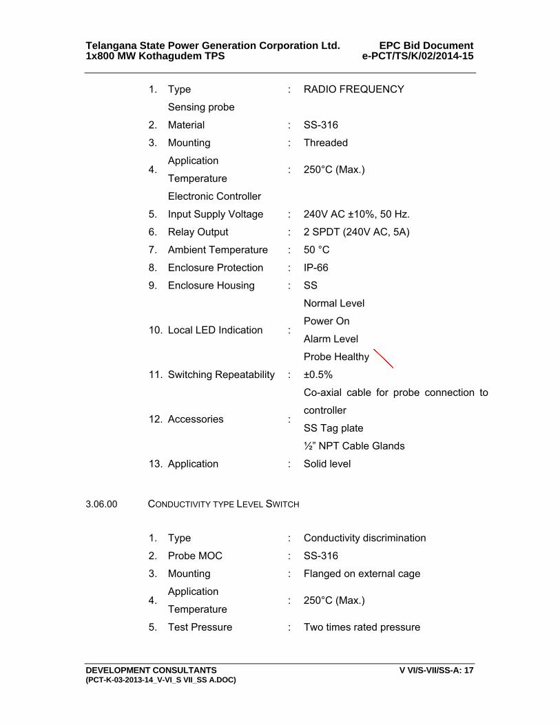
Telangana State Power Generation Corporation Ltd. EPC Bid Document 1x800 MW Kothagudem TPS e-PCT/TS/K/02/2014-15
DEVELOPMENT CONSULTANTS V VI/S-VII/SS-A: 17 (PCT-K-03-2013-14_V-VI_S VII_SS A.DOC)
1. Type : RADIO FREQUENCY
Sensing probe
2. Material : SS-316
3. Mounting : Threaded
4. Application
Temperature : 250°C (Max.)
Electronic Controller
5. Input Supply Voltage : 240V AC ±10%, 50 Hz.
6. Relay Output : 2 SPDT (240V AC, 5A)
7. Ambient Temperature : 50 °C
8. Enclosure Protection : IP-66
9. Enclosure Housing : SS
10. Local LED Indication :
Normal Level
Power On
Alarm Level
Probe Healthy
11. Switching Repeatability : ±0.5%
12. Accessories :
Co-axial cable for probe connection to
controller
SS Tag plate
½” NPT Cable Glands
13. Application : Solid level
3.06.00 CONDUCTIVITY TYPE LEVEL SWITCH
1. Type : Conductivity discrimination
2. Probe MOC : SS-316
3. Mounting : Flanged on external cage
4. Application
Temperature : 250°C (Max.)
5. Test Pressure : Two times rated pressure
3833321
Line
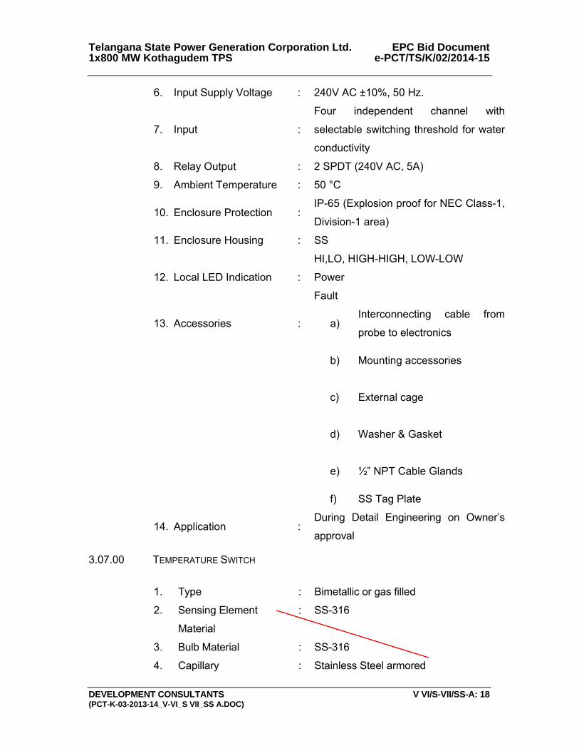
Telangana State Power Generation Corporation Ltd. EPC Bid Document 1x800 MW Kothagudem TPS e-PCT/TS/K/02/2014-15
DEVELOPMENT CONSULTANTS V VI/S-VII/SS-A: 18 (PCT-K-03-2013-14_V-VI_S VII_SS A.DOC)
6. Input Supply Voltage : 240V AC ±10%, 50 Hz.
7. Input :
Four independent channel with
selectable switching threshold for water
conductivity
8. Relay Output : 2 SPDT (240V AC, 5A)
9. Ambient Temperature : 50 °C
10. Enclosure Protection : IP-65 (Explosion proof for NEC Class-1,
Division-1 area)
11. Enclosure Housing : SS
12. Local LED Indication :
HI,LO, HIGH-HIGH, LOW-LOW
Power
Fault
13. Accessories : a)Interconnecting cable from
probe to electronics
b) Mounting accessories
c) External cage
d) Washer & Gasket
e) ½” NPT Cable Glands
f) SS Tag Plate
14. Application : During Detail Engineering on Owner’s
approval
3.07.00 TEMPERATURE SWITCH
1. Type : Bimetallic or gas filled
2. Sensing Element
Material
: SS-316
3. Bulb Material : SS-316
4. Capillary : Stainless Steel armored
3833321
Line
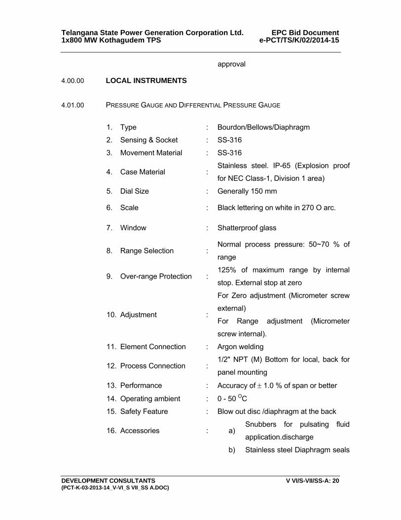
Telangana State Power Generation Corporation Ltd. EPC Bid Document 1x800 MW Kothagudem TPS e-PCT/TS/K/02/2014-15
DEVELOPMENT CONSULTANTS V VI/S-VII/SS-A: 20 (PCT-K-03-2013-14_V-VI_S VII_SS A.DOC)
approval
4.00.00 LOCAL INSTRUMENTS
4.01.00 PRESSURE GAUGE AND DIFFERENTIAL PRESSURE GAUGE
1. Type : Bourdon/Bellows/Diaphragm
2. Sensing & Socket : SS-316
3. Movement Material : SS-316
4. Case Material : Stainless steel. IP-65 (Explosion proof
for NEC Class-1, Division 1 area)
5. Dial Size : Generally 150 mm
6. Scale : Black lettering on white in 270 O arc.
7. Window : Shatterproof glass
8. Range Selection : Normal process pressure: 50~70 % of
range
9. Over-range Protection : 125% of maximum range by internal
stop. External stop at zero
10. Adjustment :
For Zero adjustment (Micrometer screw
external)
For Range adjustment (Micrometer
screw internal).
11. Element Connection : Argon welding
12. Process Connection : 1/2" NPT (M) Bottom for local, back for
panel mounting
13. Performance : Accuracy of ± 1.0 % of span or better
14. Operating ambient : 0 - 50 OC
15. Safety Feature : Blow out disc /diaphragm at the back
16. Accessories : a)Snubbers for pulsating fluid
application.discharge
b) Stainless steel Diaphragm seals

Telangana State Power Generation Corporation Ltd. EPC Bid Document 1x800 MW Kothagudem TPS e-PCT/TS/K/02/2014-15
DEVELOPMENT CONSULTANTS V VI/S-VII/SS-A: 21 (PCT-K-03-2013-14_V-VI_S VII_SS A.DOC)
for corrosive/ viscous/ solid
bearing or slurry type fluid
applications
c)3-Way SS316 Gauge cock for
pressure gauges
d)
5-valve SS316 manifold from
barstock for differential pressure
gauge
e)Siphons for steam and hot
water services
17. Nameplate : Tag number, service engraved in
stainless steel tag plate
4.02.00 LEVEL INDICATOR (FLOAT & BOARD TYPE)
1. Type : Float and Board
2. Float Material : SS-316
3. Float Cable : SS-316
4. Indicator Assembly : Epoxy painted Aluminium
5. Guide wire spring
assembly :
SS-316 (2 Nos.)
6. Guide Wire Anchor : SS-316
7. Scale Board :
Anodized Aluminium with engraved
marking ( Minimum graduation 10mm),
mounting brackets and suitable
hardware required as per tank height
8. Elbow Assembly : Anodized Aluminium
9. Flanges : RF , ANSI 150 , SS (3 Nos.)
10. Accuracy : + 10 mm or better
11. Accessories : All mounting accessories including
counter flange, nuts & bolts, suitable
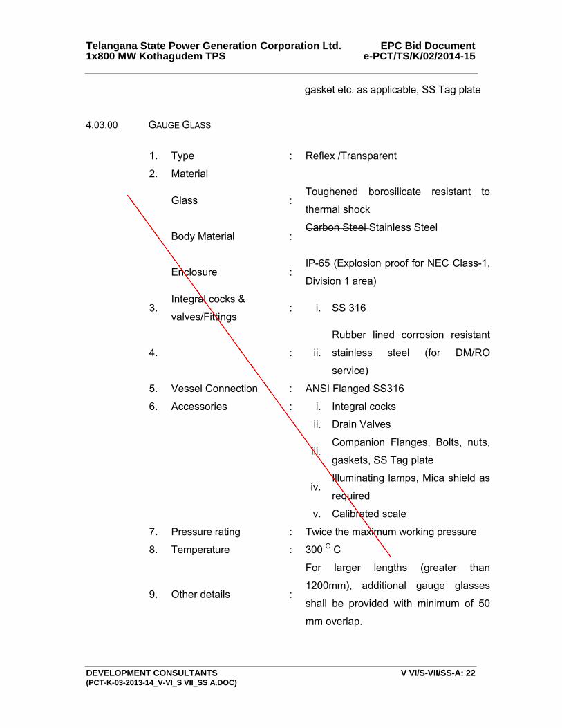
Telangana State Power Generation Corporation Ltd. EPC Bid Document 1x800 MW Kothagudem TPS e-PCT/TS/K/02/2014-15
DEVELOPMENT CONSULTANTS V VI/S-VII/SS-A: 22 (PCT-K-03-2013-14_V-VI_S VII_SS A.DOC)
gasket etc. as applicable, SS Tag plate
4.03.00 GAUGE GLASS
1. Type : Reflex /Transparent
2. Material
Glass : Toughened borosilicate resistant to
thermal shock
Body Material : Carbon Steel Stainless Steel
Enclosure : IP-65 (Explosion proof for NEC Class-1,
Division 1 area)
3. Integral cocks &
valves/Fittings : i. SS 316
4. : ii.
Rubber lined corrosion resistant
stainless steel (for DM/RO
service)
5. Vessel Connection : ANSI Flanged SS316
6. Accessories : i. Integral cocks
ii. Drain Valves
iii.Companion Flanges, Bolts, nuts,
gaskets, SS Tag plate
iv.Illuminating lamps, Mica shield as
required
v. Calibrated scale
7. Pressure rating : Twice the maximum working pressure
8. Temperature : 300 O C
9. Other details :
For larger lengths (greater than
1200mm), additional gauge glasses
shall be provided with minimum of 50
mm overlap.
3833321
Line
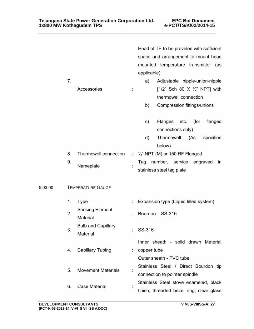
Telangana State Power Generation Corporation Ltd. EPC Bid Document 1x800 MW Kothagudem TPS e-PCT/TS/K/02/2014-15
DEVELOPMENT CONSULTANTS V VI/S-VII/SS-A: 27 (PCT-K-03-2013-14_V-VI_S VII_SS A.DOC)
Head of TE to be provided with sufficient
space and arrangement to mount head
mounted temperature transmitter (as
applicable).
7.
Accessories :
a) Adjustable nipple-union-nipple
[1/2” Sch 80 X ½” NPT] with
thermowell connection
b) Compression fittings/unions
c) Flanges etc. (for flanged
connections only)
d) Thermowell (As specified
below)
8. Thermowell connection : ½” NPT (M) or 150 RF Flanged
9. Nameplate :
Tag number, service engraved in
stainless steel tag plate
5.03.00 TEMPERATURE GAUGE
1. Type : Expansion type (Liquid filled system)
2. Sensing Element
Material : Bourdon – SS-316
3. Bulb and Capillary
Material : SS-316
4. Capillary Tubing :
Inner sheath - solid drawn Material
copper tube
Outer sheath - PVC tube
5. Movement Materials : Stainless Steel / Direct Bourdon tip
connection to pointer spindle
6. Case Material : Stainless Steel stove enameled, black
finish, threaded bezel ring, clear glass
3833321
Line
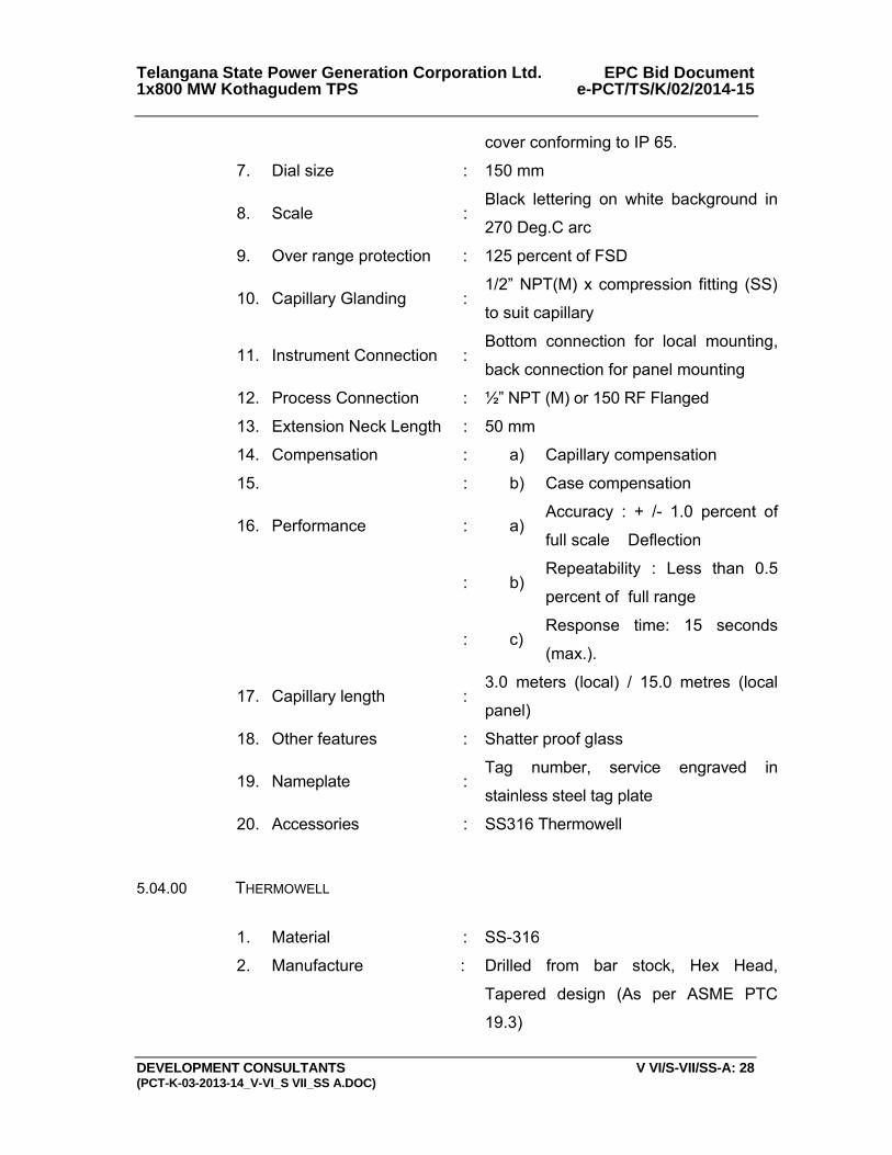
Telangana State Power Generation Corporation Ltd. EPC Bid Document 1x800 MW Kothagudem TPS e-PCT/TS/K/02/2014-15
DEVELOPMENT CONSULTANTS V VI/S-VII/SS-A: 28 (PCT-K-03-2013-14_V-VI_S VII_SS A.DOC)
cover conforming to IP 65.
7. Dial size : 150 mm
8. Scale : Black lettering on white background in
270 Deg.C arc
9. Over range protection : 125 percent of FSD
10. Capillary Glanding : 1/2” NPT(M) x compression fitting (SS)
to suit capillary
11. Instrument Connection : Bottom connection for local mounting,
back connection for panel mounting
12. Process Connection : ½” NPT (M) or 150 RF Flanged
13. Extension Neck Length : 50 mm
14. Compensation : a) Capillary compensation
15. : b) Case compensation
16. Performance : a)Accuracy : + /- 1.0 percent of
full scale Deflection
: b)Repeatability : Less than 0.5
percent of full range
: c)Response time: 15 seconds
(max.).
17. Capillary length : 3.0 meters (local) / 15.0 metres (local
panel)
18. Other features : Shatter proof glass
19. Nameplate : Tag number, service engraved in
stainless steel tag plate
20. Accessories : SS316 Thermowell
5.04.00 THERMOWELL
1. Material : SS-316
2. Manufacture : Drilled from bar stock, Hex Head,
Tapered design (As per ASME PTC
19.3)
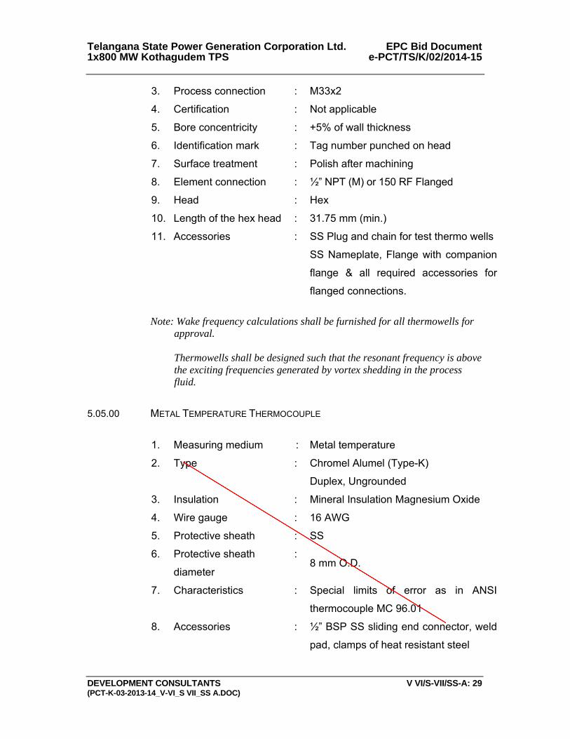
Telangana State Power Generation Corporation Ltd. EPC Bid Document 1x800 MW Kothagudem TPS e-PCT/TS/K/02/2014-15
DEVELOPMENT CONSULTANTS V VI/S-VII/SS-A: 29 (PCT-K-03-2013-14_V-VI_S VII_SS A.DOC)
3. Process connection : M33x2
4. Certification : Not applicable
5. Bore concentricity : +5% of wall thickness
6. Identification mark : Tag number punched on head
7. Surface treatment : Polish after machining
8. Element connection : ½” NPT (M) or 150 RF Flanged
9. Head : Hex
10. Length of the hex head : 31.75 mm (min.)
11. Accessories : SS Plug and chain for test thermo wells
SS Nameplate, Flange with companion
flange & all required accessories for
flanged connections.
Note: Wake frequency calculations shall be furnished for all thermowells for
approval.
Thermowells shall be designed such that the resonant frequency is above the exciting frequencies generated by vortex shedding in the process fluid.
5.05.00 METAL TEMPERATURE THERMOCOUPLE
1. Measuring medium : Metal temperature
2. Type : Chromel Alumel (Type-K)
Duplex, Ungrounded
3. Insulation : Mineral Insulation Magnesium Oxide
4. Wire gauge : 16 AWG
5. Protective sheath : SS
6. Protective sheath
diameter
:8 mm O.D.
7. Characteristics : Special limits of error as in ANSI
thermocouple MC 96.01
8. Accessories : ½” BSP SS sliding end connector, weld
pad, clamps of heat resistant steel
3833321
Line
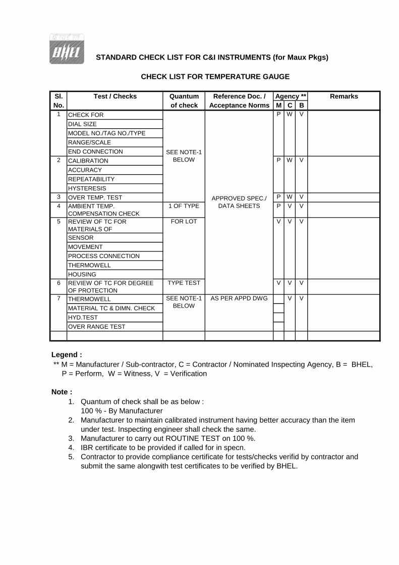
STANDARD CHECK LIST FOR C&I INSTRUMENTS (for Maux Pkgs)
Sl. Test / Checks Quantum Reference Doc. / RemarksNo. of check Acceptance Norms M C B
CHECK FOR
DIAL SIZE
MODEL NO./TAG NO./TYPE
RANGE/SCALE
END CONNECTION
CALIBRATION
ACCURACY
REPEATABILITY
HYSTERESIS3 OVER TEMP. TEST P W V
4 AMBIENT TEMP. COMPENSATION CHECK
1 OF TYPE P V V
REVIEW OF TC FOR MATERIALS OF
SENSOR
MOVEMENT
PROCESS CONNECTION
THERMOWELL
HOUSING6 REVIEW OF TC FOR DEGREE
OF PROTECTIONTYPE TEST V V V
THERMOWELL
MATERIAL TC & DIMN. CHECK
HYD.TEST
OVER RANGE TEST
Legend : ** M = Manufacturer / Sub-contractor, C = Contractor / Nominated Inspecting Agency, B = BHEL, P = Perform, W = Witness, V = Verification
Note :1. Quantum of check shall be as below : 100 % - By Manufacturer2. Manufacturer to maintain calibrated instrument having better accuracy than the item under test. Inspecting engineer shall check the same. 3. Manufacturer to carry out ROUTINE TEST on 100 %.4. IBR certificate to be provided if called for in specn.5. Contractor to provide compliance certificate for tests/checks verifid by contractor and submit the same alongwith test certificates to be verified by BHEL.
Agency **
W V
P
SEE NOTE-1 BELOW
AS PER APPD DWG V V7
2
FOR LOT V V
P
5
1
SEE NOTE-1 BELOW
W V
V
CHECK LIST FOR TEMPERATURE GAUGE
APPROVED SPEC./ DATA SHEETS
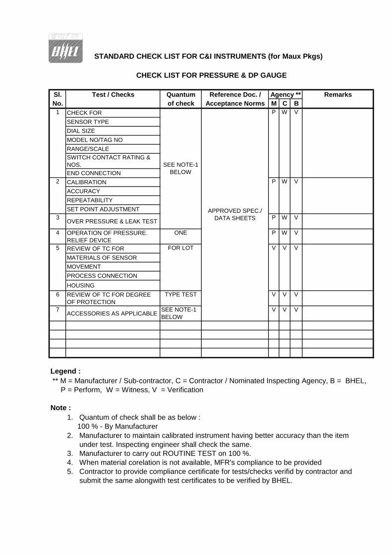
STANDARD CHECK LIST FOR C&I INSTRUMENTS (for Maux Pkgs)
Sl. Test / Checks Quantum Reference Doc. / RemarksNo. of check Acceptance Norms M C B
CHECK FOR
SENSOR TYPE
DIAL SIZE
MODEL NO/TAG NO
RANGE/SCALE
SWITCH CONTACT RATING & NOS.
END CONNECTION
CALIBRATION
ACCURACY
REPEATABILITY
SET POINT ADJUSTMENT3
OVER PRESSURE & LEAK TESTP W V
4 OPERATION OF PRESSURE. RELIEF DEVICE
ONE P W V
REVIEW OF TC FOR
MATERIALS OF SENSOR
MOVEMENT
PROCESS CONNECTION
HOUSING
6 REVIEW OF TC FOR DEGREE OF PROTECTION
TYPE TEST V V V
7ACCESSORIES AS APPLICABLE
SEE NOTE-1 BELOW
V V V
Legend : ** M = Manufacturer / Sub-contractor, C = Contractor / Nominated Inspecting Agency, B = BHEL, P = Perform, W = Witness, V = Verification
Note :1. Quantum of check shall be as below : 100 % - By Manufacturer2. Manufacturer to maintain calibrated instrument having better accuracy than the item under test. Inspecting engineer shall check the same. 3. Manufacturer to carry out ROUTINE TEST on 100 %.4. When material corelation is not available, MFR's compliance to be provided5. Contractor to provide compliance certificate for tests/checks verifid by contractor and submit the same alongwith test certificates to be verified by BHEL.
Agency **
5 FOR LOT V V V
2 P W V
1 P W V
APPROVED SPEC./ DATA SHEETS
SEE NOTE-1 BELOW
CHECK LIST FOR PRESSURE & DP GAUGE
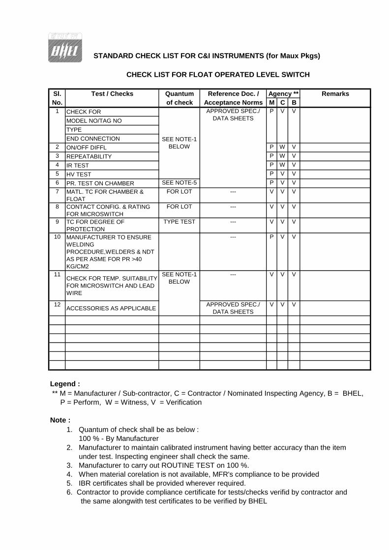
STANDARD CHECK LIST FOR C&I INSTRUMENTS (for Maux Pkgs)
Sl. Test / Checks Quantum Reference Doc. / RemarksNo. of check Acceptance Norms M C B
CHECK FOR
MODEL NO/TAG NO
TYPE
END CONNECTION2 ON/OFF DIFFL P W V
3 REPEATABILITY P W V
4 IR TEST P W V
5 HV TEST P V V
6 PR. TEST ON CHAMBER SEE NOTE-5 P V V
7 MATL. TC FOR CHAMBER & FLOAT
FOR LOT --- V V V
8 CONTACT CONFIG. & RATING FOR MICROSWITCH
FOR LOT --- V V V
9 TC FOR DEGREE OF PROTECTION
TYPE TEST --- V V V
10 MANUFACTURER TO ENSURE WELDING PROCEDURE,WELDERS & NDT AS PER ASME FOR PR >40 KG/CM2
--- P V V
11CHECK FOR TEMP. SUITABILITY FOR MICROSWITCH AND LEAD WIRE
--- V V V
12ACCESSORIES AS APPLICABLE
APPROVED SPEC./ DATA SHEETS
V V V
Legend : ** M = Manufacturer / Sub-contractor, C = Contractor / Nominated Inspecting Agency, B = BHEL, P = Perform, W = Witness, V = Verification
Note :1. Quantum of check shall be as below : 100 % - By Manufacturer2. Manufacturer to maintain calibrated instrument having better accuracy than the item under test. Inspecting engineer shall check the same. 3. Manufacturer to carry out ROUTINE TEST on 100 %.4. When material corelation is not available, MFR's compliance to be provided5. IBR certificates shall be provided wherever required.
APPROVED SPEC./ DATA SHEETS
SEE NOTE-1 BELOW
SEE NOTE-1 BELOW
V
Agency **
6. Contractor to provide compliance certificate for tests/checks verifid by contractor and
P V
CHECK LIST FOR FLOAT OPERATED LEVEL SWITCH
the same alongwith test certificates to be verified by BHEL
1
1X800 MW KOTHAGUDAM TPS
SPECIFIC TECHNICAL REQUIREMENTS (C&I)
NATURAL DRAUGHT COOLING TOWER
OF 4
`
0
ACTUATORS

Telangana State Power Generation Corporation Ltd EPC Bid Document 1x800 MW Kothagudem TPS e-PCT/TS/K/02/2014-15
DEVELOPMENT CONSULTANTS V.V-A/S-III: 1 (e-PCT/TS/K/02/2014-15/V-A/SEC-XIII)
VOLUME: V-A
SECTION-III
TECHNICAL SPECIFICATION FOR
ELECTRIC MOTOR ACTUATORS 1.00.00 SCOPE 1.01.00 This Section covers the general requirements of Electric Motor Actuators for
valves/dampers. 1.02.00 All electric motor actuators shall be furnished in accordance with this general
specification and the accompanying driven equipment specification. All the electrical actuators shall be INTEGRAL type only.
2.00.00 STANDARDS 2.01.00 All electrical equipment shall conform to the latest applicable IS, ANSI and
NEMA Standards, except when stated otherwise herein or in driven equipment specification.
2.02.00 Major standards, which shall be followed, are listed below. Other applicable
Indian Standards for any component part even if not covered in the listed standards shall also be followed
i) IS-9334
ii) IS-325 3.00.00 SERVICE CONDITIONS 3.01.00 The actuator shall be suitable for operation in hot, humid and tropical
atmosphere, highly polluted at places with coal dust and/or fly ash. 3.02.00 Unless otherwise noted, electrical equipment/system design shall be based
on the service conditions and auxiliary power supply given in the general specification.
3.03.00 For actuator motor installed outdoor and exposed to direct sun rays, the effect
of solar heat shall be considered in the determination of the design ambient temperature.
4.00.00 RATING 4.01.00 For isolating service, the actuator shall be rated for three successive
open-close operation of the valve/damper or 15 minutes, whichever is longer. 4.02.00 For regulating service, the actuator shall be suitably time-rated for the duty
cycle involved with necessary number of starts per hour, but in no case less than 150 starts per hour.
Telangana State Power Generation Corporation Ltd EPC Bid Document 1x800 MW Kothagudem TPS e-PCT/TS/K/02/2014-15
DEVELOPMENT CONSULTANTS V.V-A/S-III: 2 (e-PCT/TS/K/02/2014-15/V-A/SEC-XIII)
5.00.00 PERFORMANCE The actuator shall meet the following performance requirements: 5.01.00 Open and close the valve completely and make leak-tight valve closure
without jamming. 5.02.00 Attain full speed operation before valve load is encountered and imparts an
unseating blow to start the valve in motion (hammer blow effect). 5.03.00 Operate the valve stem at standard stem speed and shall function against
design differential pressure across the valve seat. 5.04.00 The motor reduction gearing shall be sufficient to lock the shaft when the
motor is de-energised and prevent drift from torque switch spring pressure. 5.05.00 The entire mechanism shall withstand shock resulting from closing with
improper setting of limit switches or from lodging of foreign matter under the valve seat.
6.00.00 SPECIFIC REQUIREMENT 6.01.00 Construction 6.01.01 The actuator shall essentially comprise the drive motor, torque/ limit switches,
gear train, clutch, hand wheel, position indicator/ transmitter, in-built thermostat for over load protection, space heater and internal wiring.
6.01.02 The actuator enclosure shall be totally enclosed, dust tight, weather-proof
suitable for outdoor use without necessity of any canopy. Degree of protection of enclosure for motor actuator shall be IP-65.
6.01.03 All electrical equipment, accessories and wiring shall be provided with tropical
finish to prevent fungus growth. 6.01.04 The actuator shall be designed for mounting in any position without any
lubricant leakage or operating difficulty. 6.02.00 Motor 6.02.01 The drive motor shall be three phase, squirrel cage, induction machine with
minimum class B insulation and IPW-55 enclosure, designed for high torque and reversing service. Canopy shall be provided for outdoor service.
6.02.02 The motor shall be designed for full voltage direct on-line start, with starting
current limited to 6 times full-load current. 6.02.03 The motor shall be capable of starting at 85 percent of rated voltage and
running at 80 percent of rated voltage at rated torque and 85 percent rated voltage at 33 percent excess rated torque for a period of 5 minutes each.
6.02.04 Motor leads shall be terminated in the limit switch compartment. 6.02.05 Motor actuators for valves/dampers shall be with integral starter with
3phase/3wire, 415V AC and operable from remote.
Telangana State Power Generation Corporation Ltd EPC Bid Document 1x800 MW Kothagudem TPS e-PCT/TS/K/02/2014-15
DEVELOPMENT CONSULTANTS V.V-A/S-III: 3 (e-PCT/TS/K/02/2014-15/V-A/SEC-XIII)
6.02.06 Earthing terminals shall be provided on either side of the motor. 6.03.00 Limit Switches Each actuator shall be provided with following limit switches: - 6.03.01 2 torque limit switches, one for each direction of travel, self-locking,
adjustable torque type. 6.03.02 4 end-of-travel limit switches, two for each direction of travel. 6.03.03 2 position limit switches, one for each direction of travel, each adjustable at
any position from fully open to fully closed positions of the valve/damper. 6.03.04 Each limit switch shall have 2 NO + 2 NC potential free contacts. Contact
rating shall be 5A at 240V A.C. or 0.5A at 220V D.C. 6.04.00 Hand Wheel Each actuator shall be provided with a hand wheel for emergency manual
operation. The hand wheel shall declutch automatically when the motor is energized.
6.05.00 Position Indicator/Transmitter The actuator shall have: 6.05.01 One (1) built-in local position indicator for 0-100% travel. 6.05.02 One (1) position transmitter, 4-20 mA current signal as position feedback, for
remote indicator. 6.06.00 Space Heater A space heater shall be included in the limit switch compartment suitable for
240V, 1 phase, 50 Hz supply. 6.07.00 Wiring All electrical devices shall be wired up to and terminated in a terminal box. All
wiring shall be done with 1100V grade fire resistance PVC insulated stranded copper conductor of not less than 2.5 Sq.mm cross section. All wiring shall be identified at both ends with ferrules. All the electrical actuators shall have uniform wiring.
6.08.00 Terminal Box The terminal box shall be weather proof, with removable front cover and cable
glands for cable connection. The terminal shall be suitable for connection of 2.5 Sq.mm copper conductor.
7.00.00 ACCESSORIES
Telangana State Power Generation Corporation Ltd EPC Bid Document 1x800 MW Kothagudem TPS e-PCT/TS/K/02/2014-15
DEVELOPMENT CONSULTANTS V.V-A/S-III: 4 (e-PCT/TS/K/02/2014-15/V-A/SEC-XIII)
As required for the driven equipment, the actuator shall be furnished with
starting equipment mounted on the actuator. This shall include: 7.01.00 One (1) triple pole MCCB 7.02.00 One (1) reversing starter with mechanically interlocked contactors, 3 thermal
overload relays, 2 NO + 2 NC auxiliary contacts for each contactor. 7.03.00 One (1) remote-local selector switch. 7.04.00 CLOSE-STOP-OPEN oil tight push buttons with indication lights. 7.05.00 415/240 V control transformer with primary & secondary fuses. 8.00.00 TEST The actuator and all components thereof shall be subject to tests as per
relevant Standards. In addition, if any special test is called for in equipment specification, the same shall be performed.
9.00.00 DRAWINGS, DATA & MANUALS 9.01.00 Drawings, Data & Manuals shall be submitted in triplicate with the bid and in
quantities and procedures as specified in General Conditions of Contract and/or elsewhere in the specification for approval and subsequent distribution after the issue of 'Letter of Intent'.
9.02.00 To be submitted with Bid
Data sheet for each type of actuator shall be furnished along with internal wiring diagram, suggested control schematic and torque limit switch contact development and manufacturer's catalogues. Drawings, Data & Manuals shall be submitted in triplicate with the bid and in quantities and procedures as specified in General Conditions of Contract and/or elsewhere in the specification for approval and subsequent distribution after the issue of 'Letter of Intent'.
9.03.00 To be submitted for Owner / Purchaser’s Approval and Distribution
All relevant drawings and data pertaining to the equipment like GTP, GA drawing, foundation plan, BOM, control & schematics, QAP, etc. shall be submitted by the Bidder for approval of Owner/Owner’s consultant. Also refer clause no. 1.19.02(u) of Section-I of Volume – V-A: Technical Specifications for Electrical Equipment & Accessories.
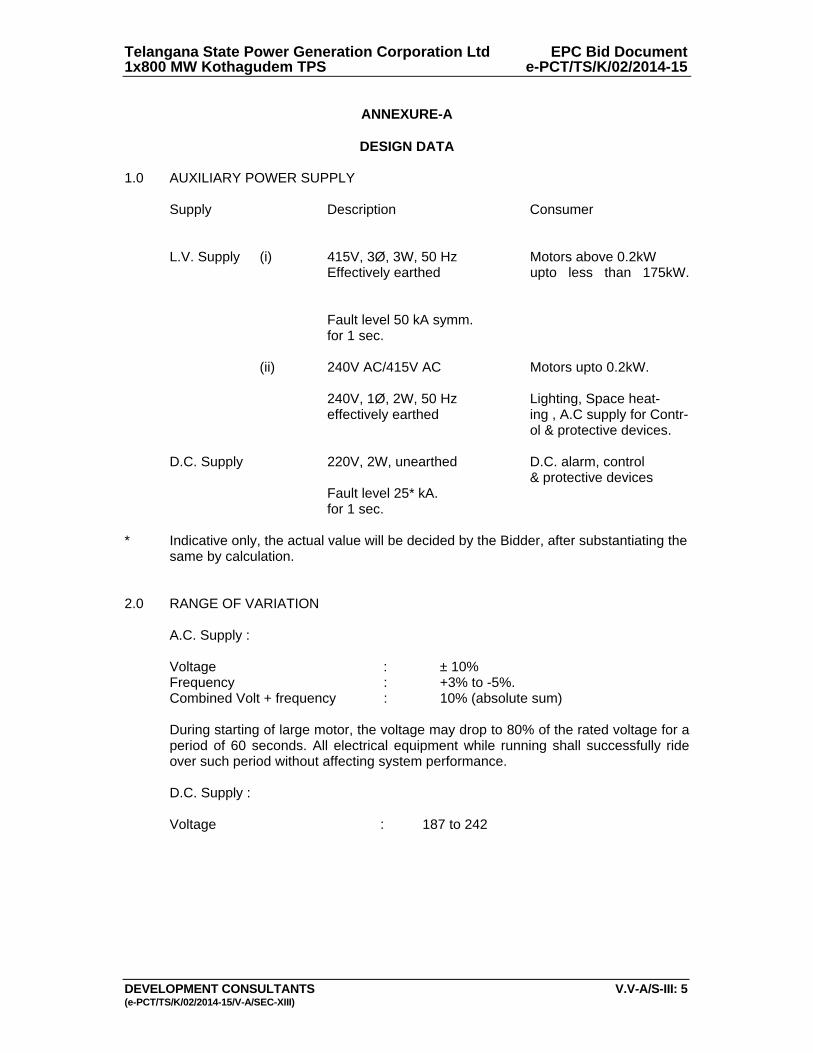
Telangana State Power Generation Corporation Ltd EPC Bid Document 1x800 MW Kothagudem TPS e-PCT/TS/K/02/2014-15
DEVELOPMENT CONSULTANTS V.V-A/S-III: 5 (e-PCT/TS/K/02/2014-15/V-A/SEC-XIII)
ANNEXURE-A
DESIGN DATA
1.0 AUXILIARY POWER SUPPLY Supply Description Consumer L.V. Supply (i) 415V, 3Ø, 3W, 50 Hz Motors above 0.2kW Effectively earthed upto less than 175kW. Fault level 50 kA symm. for 1 sec. (ii) 240V AC/415V AC Motors upto 0.2kW. 240V, 1Ø, 2W, 50 Hz Lighting, Space heat- effectively earthed ing , A.C supply for Contr- ol & protective devices. D.C. Supply 220V, 2W, unearthed D.C. alarm, control & protective devices Fault level 25* kA. for 1 sec. * Indicative only, the actual value will be decided by the Bidder, after substantiating the same by calculation. 2.0 RANGE OF VARIATION A.C. Supply : Voltage : ± 10% Frequency : +3% to -5%. Combined Volt + frequency : 10% (absolute sum) During starting of large motor, the voltage may drop to 80% of the rated voltage for a
period of 60 seconds. All electrical equipment while running shall successfully ride over such period without affecting system performance.
D.C. Supply : Voltage : 187 to 242

SPECIFICATION FOR
MOTORISED VALVE ACTUATOR
SPECIFICATION NO.:
VOLUME
SECTION
REV. NO. 00 DATE: 06.01.2015
SHEET 1 OF 3
Data Sheet A & B
DATA SHEET-A (TO BE FILLED BY PURCHASER)
DATA SHEET-B
(TO BE FILLED-UP BY BIDDER)
FO
RM
NO
. P
EM
-666
6-0
GENERAL*
* PROJECT 1 X 800 MW KOTHAGUDAM TPS
OFFER REFERENCE
* TAG NO. SERVICE
* DUTY ON / OFF INCHING
* LINE SIZE (inlet/outlet): MATERIAL
* VALVE TYPE GLOBE GATE REG. GLOBE BUTTERFLY
* OPENING / CLOSING TIME
* WORKING PRESSURE
AMBIENT CONDITION SHALL BE SUITABLE FOR CONTINUOUS OPERATION UNDER AN AMBIENT TEMP. OF 0-55 DEG C AND RELATIVE HUMIDITY OF 0-95%
VALVE SEAT TEST PRESS BIDDER TO SPECIFY
REQUIRED VALVE TORQUE BIDDER TO SPECIFY
ACTUATOR RATED TORQUE BIDDER TO SPECIFY
CONSTRUCTION AND SIZING
CONSTRUCTION TOTALLY ENCLOSED, DUST TIGHT, WEATHER PROOF,SUITABLE FOR OUTDOOR USE WITHOUT CANOPY, IP:65
MECHANICAL POSITION INDICATOR TO BE PROVIDED FOR 0-100% TRAVEL
BEARINGS DOUBLE SHIELDED, GREASE LUBRICATED ANTI-FRICTION.
GEAR TRAIN FOR LIMIT SWITCH/TORQUE SWITCH OPERATION
METAL (NOT FIBRE GEARS). SELF-LOCKING TO PREVENT DRIFT UNDER TORQUE SWITCH SPRING PRESSURE WHEN MOTOR IS DE-ENERGIZED.
SIZING
OPEN/CLOSE AT RATED SPEED AGAINST DESIGNED DIFFERENTIAL PRESSURE AT 90% OF RATED VOLTAGE. FOR ISOLATING SERVICE THREE SUCCESSIVE OPEN-CLOSE OPERATIONS OR 15 MINS. WHICHEVER IS HIGHER. FOR REGULATING SERVICE - 150 STARTS/HR MINIMUM
HANDWHEEL
* REQUIRED YES NO
* ORIENTATION TOP MOUNTED SIDE MOUNTED
*TO DISENGAGE AUTOMATICALLY DURING MOTOR OPERATION.
ELECTRIC ACTUATOR
ACTUATOR MAKE/MODEL BIDDER TO SPECIFY
MOTOR MAKE / MODEL / TYPE / RATING (KW)
BIDDER TO SPECIFY
@ MOTOR TYPE SQUIRREL CAGE INDUCTION MOTOR, STARTING CURRENT LIMITED TO SIX TIMES THE FULL LOAD CURRENT-INCLUSIVE OF I.S. TOLERANCE
ACTUATOR APPLICABLE WIRING DIAGRAM
ENCLOSED DRG. NO. 3-V-MISC-24227 R00 (INDICATIVE)
COLOUR SHADE BLUE (RAL 5012), To be decided during detail engg.
PAINT TYPE (## Refer Notes) ENAMEL EPOXY …….
SHAFT RPM BIDDER TO SPECIFY
OLR SET VALUE BIDDER TO SPECIFY
@ STARTING / FULL LOAD CURRENT BIDDER TO SPECIFY
NO. OF REV FOR FULL TRAVEL BIDDER TO SPECIFY
@ PWR SUPP TO MTR / STARTER 415V, 3PH, AC
@ CONTROL VOLTAGE REQUIREMENT
TO BE DERIVED FROM THE POWER SUPPLY TO THE STARTER 230 V 110 V (BIDDER TO SPECIFY SINCE INTEGRAL STARTER IS ENVISAGED)

SPECIFICATION FOR
MOTORISED VALVE ACTUATOR
SPECIFICATION NO.:
VOLUME
SECTION
REV. NO. 00 DATE: 06.01.2015
SHEET 2 OF 3
Data Sheet A & B
DATA SHEET-A (TO BE FILLED BY PURCHASER)
DATA SHEET-B
(TO BE FILLED-UP BY BIDDER)
FO
RM
NO
. P
EM
-666
6-0
@ ENCLOSURE CLASS OF MOTOR IP 65 FLAME PROOF
@ INSULATION CLASS CLASS-F TEMP. RISE LIMITED TO CLASS-B
@ WINDING TEMP PROTECTION THERMOSTAT (3 Nos.,1 IN EACH PHASE) ---------------------------------------------------------
SINGLE PHASE / WRONG PHASE SEQUENCE PROTECTION
REQUIRED
INTEGRAL STARTER
INTEGRAL STARTER REQUIRED NOT REQUIRED
TYPE OF SWITCHING DEVICE CONTACTORS THYRISTORS
TYPE CONVENTIONAL SMART (NON-INTRUSIVE)
IF SMART
NOT APPLICABLE
a) SERIAL LINK INTERFACE INTEGRAL FIELD MOUNTED
b) SERIAL LINK PROTOCOL FOUNDATION FIELD-BUS PROFI-BUS DEVICE NET …………
c) SERIAL LINK MEDIA TWISTED PAIR Cu-CBL CO-AXIAL Cu-CBL OFC
d) HAND HELD PROGRAMMER REQUIRED NOT REQUIRED
e) TYPE OF HAND HELD PROGRAMMER
BLUETOOTH INFRARED ..............
f) MASTER STATION REQUIRED NOT REQUIRED
g) MASTER STN INTRFACE WITH DCS MODBUS TCP/IP
h) DETAILS OF SPECIAL CABLE ENCLOSED NOT REQUIRED
STEP DOWN CONT. TRANSFORMER REQUIRED
OPEN / CLOSE PB REQUIRED NOT REQUIRED
STOP PB REQUIRED NOT REQUIRED
INDICATING LAMPS REQUIRED NOT REQUIRED
LOCAL REMOTE S/S REQUIRED NOT REQUIRED
STATUS CONTACTS FOR MONITORING REQUIRED NOT REQUIRED
INTEGRAL STARTER DISTURBED SIGNAL
REQUIRED (O/L RELAY OPERATED, CONT. /POWER SUPPLY FAILED, S/S IN LOCAL, TORQUE SWITCH OPTD. MID WAY)
INTERPOSING RELAY/OPTO COUPLER (Applicable for integral Starter)
TYPE OF ISOLATING DEVICE INTERPOSING RELAY OPTO COUPLER EITHER
QUANTITY 2 NOs. 3 NOs.
DRIVING VOLTAGE 20.5 – 24V DC _____________V DC
DRIVING CURRENT 125mA MAX _____________mA MAX
LOAD RESISTANCE > 192 ohms - <25 k ohms > _______ohms - < __________ohms
TORQUE SWITCH (Not Applicable for Smart Actuator) ($$ Refer Notes)
MFR & MODEL NO. BIDDER TO SPECIFY
OPEN / CLOSE 1 No. 2Nos. / 1 No. 2Nos
CONTACT TYPE 2 NO + 2 NC
RATING 5A 240V AC AND 0.5A 220V DC
CALIBRATED KNOBS(OPEN&CLOSE TS) REQUIRED FOR SETTING DESIRED TORQUE
ACCURACY +3% OF SET VALUE
LIMIT SWITCH (Not Applicable for Smart Actuator) ($$ Refer Notes)
MFR & MODEL NO. BIDDER TO SPECIFY
OPEN : INT : CLOSE 1 No 2 Nos.
2 Nos. (ADJ.) 1 No. 2Nos.
CONTACT TYPE 2 NO + 2 NC
RATING (AC / DC) 5A 240V AC AND 0.5A 220V DC

SPECIFICATION FOR
MOTORISED VALVE ACTUATOR
SPECIFICATION NO.:
VOLUME
SECTION
REV. NO. 00 DATE: 06.01.2015
SHEET 3 OF 3
Data Sheet A & B
DATA SHEET-A (TO BE FILLED BY PURCHASER)
DATA SHEET-B
(TO BE FILLED-UP BY BIDDER)
FO
RM
NO
. P
EM
-666
6-0
POSITION TRANSMITTER
POSITION TRANSMITTER REQUIRED NOT REQUIRED
MFR & MODEL NO. BIDDER TO SPECIFY
TYPE ELECTRONIC (2 WIRE) R/I CONVERTER ELECTRONIC (2 WIRE) CONTACTLESS
SUPPLY 24V DC ………
OUTPUT 4-20mA
ACCURACY + 1% FS
SPACE HEATER
@SPACE HEATER REQUIRED
@ POWER SUPPLY (NON INTEGRAL) 240V AC,1 PH.,50 Hz
@ POWER SUPPLY (INTEGRAL) BIDDER TO SPECIFY
@ RATING BIDDER TO SPECIFY
TERMINAL BOX
ACTUATOR/MOTOR TERMINAL BOX REQUIRED
ENCL CLASS ACTUATOR/MOTOR T.B. @ IP 68 @………
@ EARTHING TERMINAL REQUIRED
PLUG & SOCKET(9 PIN) (FOR COMMD, LS/TS FEED BACK, PoT)
REQUIRED NOT REQUIRED 2 NOS. ----------------
CABLE GLANDS
@ POWER CABLE GLAND SIZE: DURING DETAILED ENGINEERING
@ SPACE HEATER CABLE GLAND SIZE: NOT REQUIRED
OTHER CONTROL CABLE GLANDS-1 1No. for BFV of CW PUMP(Cable size 2Px1.5mm2)
OTHER CONTROL CABLE GLANDS-2 QUANTITY & SIZE: 1no., 2.5 sq. mm
WEIGHT TOTAL WEIGHT (ACTUATOR + ACCESSORIES)
BIDDER TO SPECIFY _________________ Kg.
NOTES:
1. SCOPE: DESIGN, MANUFACTURE, INSPECTION, TESTING AND DELIVERY TO SITE OF ELECTRIC ACTUATOR FOR INCHING OR OPEN / CLOSE DUTY. 2. CODES & STANDARDS: DESIGN AND MATERIALS USED SHALL COMPLY WITH THE RELEVANT LATEST NATIONAL AND INTERNATION STANDARD. AS A MINIMUM,
THE FOLLOWING STANDARDS SHALL BE COMPLIED WITH: IS-9334, IS-2147, IS-2148, IS-325, IS-2959, IS-4691 AND IS-4722
3. TEMPERATURE RISE SHALL BE RESTRICTED TO 70 DEG. C FOR AMBIENT TEMPERATURE OF 50 DEG C. 4. CABLE GLANDS OF DOUBLE COMPRESSION TYPE, BRASS MATERIAL, WITH NICKEL COATING SHALL BE PROVIDED. 5. THE TORQUE SWITCHES SHALL BE PROVIDED WITH MECHANICAL LATCHING DEVICE TO PREVENT OPERATION WHEN UNSEATING FROM THE END POSITIONS.
THE LATCHING DEVICE SHALL UNLATCH AS SOON AS THE VALVE LEAVES THE END POSITION. IF SUCH PROVISION IS NOT POSSIBLE, THE TORQUE SWITCHES SHALL BE BYPASSED BY END-POSITION LIMIT SWITCHES WHICH OPENS ON VALVE LEAVING END POSITION.THESE LIMIT SWITCHES ARE ADDITIONAL TO THE NUMBER OF LIMIT SWITCHES SPECIFIED ELSEWHERE.
6. THE MOTOR SHALL OPERATE SATISFACTORILY UNDER THE +/- 10% SUPPLY VOLTAGE VARIATION AT RATED FREQUENCY, -5% TO +3% VARIATION IN
FREQUENCY AT RATED SUPPLY VOLTAGE, SIMULTANEOUS VARIATION IN VOLTAGE & FREQUENCY THE SUM OF ABSOLUTE PERCENTAGE NOT EXCEEDING 10%. 7. THE MOTOR SHALL BE SUITABLE FOR DIRECT ON LINE STARTING.
$$ TORQUE SWITCH & LIMIT SWITCH SHALL ACT INDEPENDENT OF EACH OTHER. TANDEM OPERATION IS NOT ACCEPTABLE. ## EPOXY PAINT IS RECOMMENDED FOR COASTAL AREAS.
PREPARED BY CHECKED BY APPROVED BY VENDOR COMPANY SEAL
NAME RAHUL VARSHNEY SURESH CHAND SHARMA
SURESH CHAND SHARMA NAME
SIGNATURE SIGNATURE
DATE 06.01.2015 06.01.2015 06.01.2015 DATE
NOTES* = TO BE FILLED BY MPL (LEAD AGENCY). @= TO BE FILLED BY ES
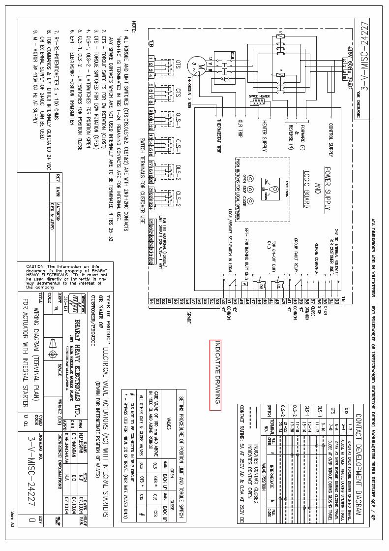
IND
ICA
TIVE
DR
AW
ING

1X800 MW KOTHAGUDAM TPS
SPECIFIC TECHNICAL REQUIREMENTS (C&I)
NATURAL DRAUGHT COOLING TOWER
OF 4
`
0
SUMP PUMP
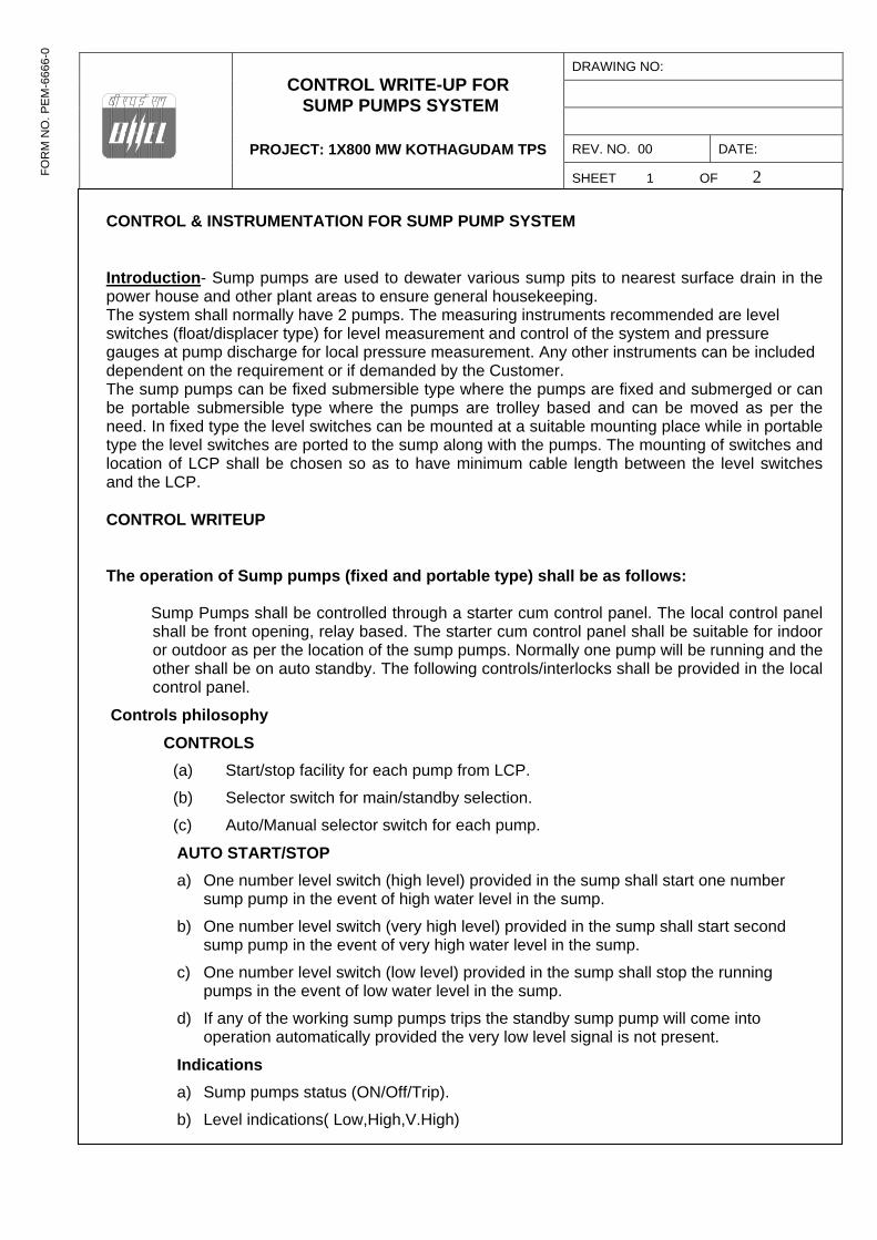
CONTROL WRITE-UP FOR SUMP PUMPS SYSTEM
PROJECT: 1X800 MW KOTHAGUDAM TPS
DRAWING NO:
REV. NO. 00 DATE:
SHEET 1 OF 2
FO
RM
NO
. P
EM
-666
6-0
FO
RM
NO
. PE
M-6
666-
0
CONTROL & INSTRUMENTATION FOR SUMP PUMP SYSTEM
Introduction- Sump pumps are used to dewater various sump pits to nearest surface drain in the power house and other plant areas to ensure general housekeeping. The system shall normally have 2 pumps. The measuring instruments recommended are level switches (float/displacer type) for level measurement and control of the system and pressure gauges at pump discharge for local pressure measurement. Any other instruments can be included dependent on the requirement or if demanded by the Customer. The sump pumps can be fixed submersible type where the pumps are fixed and submerged or can be portable submersible type where the pumps are trolley based and can be moved as per the need. In fixed type the level switches can be mounted at a suitable mounting place while in portable type the level switches are ported to the sump along with the pumps. The mounting of switches and location of LCP shall be chosen so as to have minimum cable length between the level switches and the LCP. CONTROL WRITEUP
The operation of Sump pumps (fixed and portable type) shall be as follows:
Sump Pumps shall be controlled through a starter cum control panel. The local control panel shall be front opening, relay based. The starter cum control panel shall be suitable for indoor or outdoor as per the location of the sump pumps. Normally one pump will be running and the other shall be on auto standby. The following controls/interlocks shall be provided in the local control panel.
Controls philosophy
CONTROLS
(a) Start/stop facility for each pump from LCP.
(b) Selector switch for main/standby selection.
(c) Auto/Manual selector switch for each pump.
AUTO START/STOP
a) One number level switch (high level) provided in the sump shall start one number sump pump in the event of high water level in the sump.
b) One number level switch (very high level) provided in the sump shall start second sump pump in the event of very high water level in the sump.
c) One number level switch (low level) provided in the sump shall stop the running pumps in the event of low water level in the sump.
d) If any of the working sump pumps trips the standby sump pump will come into operation automatically provided the very low level signal is not present.
Indications
a) Sump pumps status (ON/Off/Trip).
b) Level indications( Low,High,V.High)
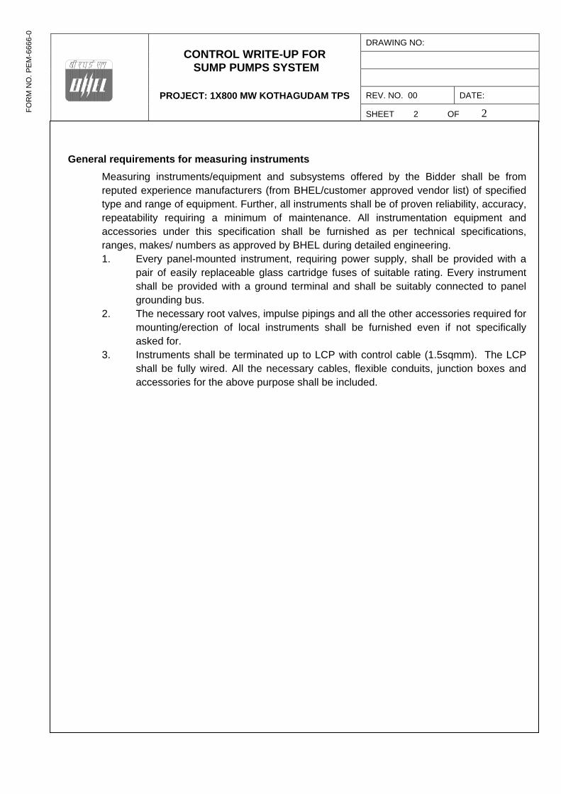
CONTROL WRITE-UP FOR SUMP PUMPS SYSTEM
PROJECT: 1X800 MW KOTHAGUDAM TPS
DRAWING NO:
REV. NO. 00 DATE:
SHEET 2 OF 2
FO
RM
NO
. P
EM
-666
6-0
FO
RM
NO
. PE
M-6
666-
0
General requirements for measuring instruments
Measuring instruments/equipment and subsystems offered by the Bidder shall be from reputed experience manufacturers (from BHEL/customer approved vendor list) of specified type and range of equipment. Further, all instruments shall be of proven reliability, accuracy, repeatability requiring a minimum of maintenance. All instrumentation equipment and accessories under this specification shall be furnished as per technical specifications, ranges, makes/ numbers as approved by BHEL during detailed engineering. 1. Every panel-mounted instrument, requiring power supply, shall be provided with a
pair of easily replaceable glass cartridge fuses of suitable rating. Every instrument shall be provided with a ground terminal and shall be suitably connected to panel grounding bus.
2. The necessary root valves, impulse pipings and all the other accessories required for mounting/erection of local instruments shall be furnished even if not specifically asked for.
3. Instruments shall be terminated up to LCP with control cable (1.5sqmm). The LCP shall be fully wired. All the necessary cables, flexible conduits, junction boxes and accessories for the above purpose shall be included.
Telangana State Power Generation Corporation Ltd. EPC Bid Document 1x800 MW Kothagudem TPS e-PCT/TS/K/02/2014-15
DEVELOPMENT CONSULTANTS V VI/S-VII/SS-D: 1 (PCT-K-03-2013-14_V-VI_S VII_SS D.DOC)
1.00.00 GENERAL REQUIREMENT
1.01.00 ENCLOSURES FOR INSTRUMENTS AND OTHER EQUIPMENT
1.01.01 All panels, cabinets, distribution boxes, junction boxes, terminal boxes and all
other field mounted equipment / enclosures shall have suitable environmental protection as detailed in Section-I of this volume of the specification.
1.02.00 SURFACE PREPARATION & PAINTING
1.02.01 All sheet metal panel/ desk exterior steel surfaces shall be sand blasted,
ground smooth and painted as specified below. 1.02.02 Suitable filler shall be applied to all pits, blemishes and voids in the surface.
The filler shall be sanded so that surfaces are level and flat; corners are smooth and even. Exposed raw metal edges shall be ground burr-free. The entire surface shall be blast clean to remove rust and scale and all other residue due to the fabrication operation. Oil, grease and salts etc. shall be removed from the panels by one or more solvent cleaning methods prior to blasting.
1.02.03 Two spray coats of inhibitive epoxy primer surfacer shall be applied to all exterior and interior surfaces, each coat of primer surfacer shall be of dry film thickness of 1.5 mil. A minimum of two spray coats of final finish color (Catalyzed epoxy or polyurethane) shall be applied to all surface of dry film thickness 2.0 Mil. The finish colors for exterior and interior surfaces shall conform to the following shades:
• Exterior – Opaline green shade 275 of IS: 5 or equivalent international code..
• Interior - Brilliant White. 1.02.04 Paint films, which show sags, cheeks, blisters, teardrops, fat edges or other
painting imperfections, shall not be acceptable.
1.03.00 WIRING
1.03.01 All spare contacts of relays, switches and push buttons shall be wired up to
the terminal blocks. All intercommunications between sections of panels/desks shall be furnished.
1.03.02 Each wire shall be identified at both ends with wire designation as per approved wiring diagram. Heat shrinkable type ferrules with indelible computerized ink print shall be used with cross- identification.
1.03.03 All wire termination shall be made with insulated sleeve and crimping type lugs. Wire shall not be spliced or tapped between terminals. Open-ended terminal lugs will not be accepted. Wires shall not be looped around the terminal screws or studs.
3061515
Line
3061515
Line
3061515
Line
3061515
Line
Telangana State Power Generation Corporation Ltd. EPC Bid Document 1x800 MW Kothagudem TPS e-PCT/TS/K/02/2014-15
DEVELOPMENT CONSULTANTS V VI/S-VII/SS-D: 2 (PCT-K-03-2013-14_V-VI_S VII_SS D.DOC)
1.03.04 Internal wiring should be terminated uniformly on one side of the terminal
block leaving the other side available for termination of outgoing cables. Internal wiring shall be grouped so that all outgoing wiring to each particular remote location is terminated on adjacent terminal blocks. Interior wiring and jumperings shall be arranged so that external connections can be made from internal side of terminal blocks. Common connections shall be limited to two (2) wires per terminal.
1.03.05 Wiring shall be arranged to ensure free access to all instrument or devices for maintenance. No wire shall be routed across the face or rear of any device in a manner, which will impede the opening of covers or obstruct access to leads, terminals or devices
1.03.06 Wires shall be dressed and run in trays or troughs with clamp-on type covers. Wirings may be neatly bunched in groups by non-metallic cleats or bands. Each group shall be adequately supported along its run to prevent sagging or strain on termination.
1.03.07 Shield wires shall be terminated on separate terminal blocks. Common connections shall be limited to two wires per terminal. Signal circuit shields shall be grounded at the power supply end only or as recommended by manufacturer.
1.03.08 All low level signal cables shall be separately bundled to from control cable and maintained at 300 mm minimum spacing from control bundles.
1.03.09 Panel internal wiring shall follow distinct color-coding to segregate different voltage levels viz. 24V DC, 48V, 110V AC, 240V AC, 220V DC etc.
1.03.10 Thermocouple lead wires, analyzer measuring lead wires, or any other lead
wires carrying measuring signal of the order of low milli volt or micro volt shall be electrically and physically isolated from other AC and DC wiring. Shielded wires used in such cases for panel internal wiring shall be continuous and ungrounded with the shield terminated individually and separately in panel terminal block.
1.03.11 Wiring to door mounted devices shall be provided with multi-strand wires of (49 strands minimum) adequate loop lengths of hinge-wire so that multiple door openings will not cause fatigue failure of the conductor.
1.03.12 Internal wiring in factory pre-wired electronic systems cabinets may be installed according to the Contractor's standard wire size, insulation, and method of termination on internal equipment. Insulation for all wiring, including circuit board wiring, back panel wiring, power supply wiring and interconnecting cables between devices shall pass the vertical flame test per IPCEAS-1981. Identification of conductors may be done by insulation color-coding identified on drawings or by printed wiring lists.
Telangana State Power Generation Corporation Ltd. EPC Bid Document 1x800 MW Kothagudem TPS e-PCT/TS/K/02/2014-15
DEVELOPMENT CONSULTANTS V VI/S-VII/SS-D: 3 (PCT-K-03-2013-14_V-VI_S VII_SS D.DOC)
1.04.00 TERMINAL BLOCKS
1.04.01 All terminal blocks shall be rail mounted/ post mounted type, cage clamp type
with high quality non-flammable insulating material of melamine suitable for working temperature of 105 Deg C. The terminal blocks in field mounted junction boxes, instrument enclosures racks etc. shall be suitable for cage clamp connections. The terminal blocks in Control Equipment Room termination/ marshalling cubicles shall be suitable for post mounted cage clamp connection at the field input end. The exact type of terminal blocks to be provided by Bidder shall be subject to Owner.
1.04.02 All terminal blocks shall be provided complete with all required accessories including assembly rail, locking pin and section, end brackets, small partitions, transparent covers, support brackets, distance sleeves, warning level, marking etc. For RTDs ring - tong type lugs shall be used at Junction Boxes.
1.04.03 The characteristics of the terminal blocks shall be as follows.
i) High contact force, independent of conductor cross-section and large contact surface area.
ii) Integrated self-loosening protection to avoid shifting of contact surface that may allow contamination of connection point.
iii) Inspection and maintenance free (resistant to thermal aging and vibration)
iv) Low and constant voltage drop 1.04.04 The insulation of the terminal blocks shall be of suitable thermoplastic
material.
1.04.05 The spacing between Terminal blocks channels in panels and cubicles shall be adequate for routing the cable troughs and to allow adequate free workspace for termination and removal of wires. The terminal blocks shall be arranged with atleast 100 mm clearance between two sets of terminal blocks and junction box walls.
1.04.06 Signals of different voltage levels shall be clearly segregated by providing
separate rows to each type of signal and by using terminal blocks of different color for each type of signal and by providing barrier strips between them.
1.04.07 Terminal blocks shall be provided with white marking strips / self-adhesive
marker cards and where permitted by the safety codes and standards, shall be without covers. Power terminals and high voltage (above 48 volts) terminals shall have protection covers. All terminals shall be provided with permanent terminal identification numbers on both sides.
1.04.08 At least 20% spare unused terminals shall be provided on each terminal block
for circuit modifications and for termination of all conductors in a multi-conductor control cable.
Telangana State Power Generation Corporation Ltd. EPC Bid Document 1x800 MW Kothagudem TPS e-PCT/TS/K/02/2014-15
DEVELOPMENT CONSULTANTS V VI/S-VII/SS-D: 4 (PCT-K-03-2013-14_V-VI_S VII_SS D.DOC)
1.04.09 The bottom of the terminal block shall be at least 200 mm above the cable
gland for bottom entry type panels.
1.04.10 For extending 24 V DC supply to panels, the size of the terminals shall be decided based on voltage drop and not based on current.
1.04.11 Other requirements of the terminal blocks are as follows:
i) The last terminal in a rail-mounted assembly shall be closed with an end plate and end bracket.
ii) For visual and electrical separation of terminal groups, partition plates shall be provided, which can be push fitted after forming an assembly.
iii) Design shall permit testing of incoming and outgoing signals by using suitable test plug and socket without disconnecting the cable connections.
iv) It shall be possible to use jumper plugs through the above test plug socket to connect adjacent terminals. Adequate number of short circuit jumper plugs shall be provided for the purpose.
v) Where more than one connection to a terminal block is required, two tier terminals shall be used.
1.05.00 GROUNDING
1.05.01 Separate Protective and Electronic system ground as required shall be provided.
1.05.02 All panels, desks, cabinets shall be provided with a continuous bare copper
ground bus (Frame ground), bolted to the panel structure at bottom on both sides and effectively ground the entire structure. The bolts shall face inside of panels.
1.05.03 For electronic system cabinets the electronic system ground bus (Electronic
ground) shall be similar but insulated from the cabinet and shall be separately connected to the system ground .The same ground may be used to earth the shield of shielded signal cables, otherwise a separate ground bus shall be provided for connecting the signal cable shields. Cable shields shall be grounded at the panel end only and shall never be left open .The electronic ground between panels of a shipping section shall be firmly looped.
2.00.00 CONTROL DESKS & PANELS
2.01.00 GENERAL
2.01.01 All control desk, panels etc. shall be furnished fully wired with necessary
provision for convenience outlets, internal lighting, utility receptacles, grounding, ventilation, space heating, anti-vibration pads, internal piping &
Telangana State Power Generation Corporation Ltd. EPC Bid Document 1x800 MW Kothagudem TPS e-PCT/TS/K/02/2014-15
DEVELOPMENT CONSULTANTS V VI/S-VII/SS-D: 5 (PCT-K-03-2013-14_V-VI_S VII_SS D.DOC)
accessories as required for completeness of the system. 2.01.02 The design shall conform to the EN ISO 11064 (Ergonomical design of
Control Room), Part 1, 2 and 3.
2.01.03 The exact dimensions, material, construction details, grounding, general arrangement etc. shall be as per actual requirement and shall be finalized during detail engineering and subjected to Owner’s approval.
2.01.04 Incoming power supply feeders shall be duplicated. Alarm shall be provided for failure of a power supply feed.
2.01.05 For Control desk/ panel mounted instruments/ devices etc. which are to be powered from UPS, all required conversion of interface equipments/ accessories to make such devices compatible with UPS supply shall be provided. All necessary hardware like input switches/ fuse unit for each feeder as well as switch fuse unit for each instrument/ device on the power supply line shall be provided. From UPS redundant feeders shall be provided wih suitably rated MCB and provision of fast auto changeover of UPS feeders.
2.01.06 Crating of the panels and desks shall be suitable for protection against shock, vibration, inappropriate handling and inclement weather conditions during transportation and warehousing. Mounted equipment shall have adequate protection against damage during handling, transit and storage. Suitable desiccant shall be used inside the packing case.
2.01.07 Nameplate
a) Nameplate shall be provided for instrument or device mounted on the panel.
b) Nameplates for panels shall be provided both in front and rear.
2.02.00 CONTROL DESK
2.02.01 Control desk shall be free standing, floor mounting, table top type with doors at back and shall be constructed of 3 mm thick (minimum) CRCA steel or Aluminium extrusion. Aluminium structure shall be anodized or powder coated paint finish. The top surface of control desk shall be 30 mm (minimum) thick with the top 12 mm (minimum) of acrylic solid surface and the remaining 18 mm of laminated medium density fibre (MDF) board.
2.02.02 Monitors with retractable keyboard shall be provided on the desk. Desk shall be arranged in arc-like shape without any sharp edges. Edges shall be extruded PVC or rounded post-formed laminate.
2.02.03 Desks shall be of modular, scalable and industrially ruggedized design and
shall have connections for PA system handsets & telephone sets.
2.02.04 Desks shall have concealed cable trays for wire dressing. Both Horizontal & Side Managers (2 separate horizontal cable routing wire baskets for power & data cables) shall be provided.
Telangana State Power Generation Corporation Ltd. EPC Bid Document 1x800 MW Kothagudem TPS e-PCT/TS/K/02/2014-15
DEVELOPMENT CONSULTANTS V VI/S-VII/SS-D: 6 (PCT-K-03-2013-14_V-VI_S VII_SS D.DOC)
Each User station will be provided with 2 separate power distribution units (1 for Main line & 1 for UPS line). Each power distribution unit will have 6 points of 5/13 Amp sockets, Mains MCB On/Off Switch & Indicator. Adequate heat management provision for Exhaust of heat from within the Console Desk Assembly shall be provided. There will be multiple fans provided in the Main Control Desk. Each Fan will be of 230 VAC 250 CFM Ball Bearing based. Ventilation louvers will be provided on both Front & Rear Modesty with special Air Filters. Adequate space for CPU & Other equipments placed with in the desk.
2.02.05 Design shall include Earthing bolts.
2.02.06 Back installed items shall be suitably concealed from front view.
2.02.07 All operator workstations for SG, TG, Auxiliaries & Off-site Plants shall be mounted on this Control Desk. The cabling / wiring between OWS & CPUs, power supply cables etc. shall be aesthetically routed and concealed from view.
2.02.08 HARDWIRED DEVICES ON CONTROL DESK (DRAW OUT SECTION) Release and Lamp Test push buttons shall be provided for a set of push buttons (decided during detail engineering stage). Depending on the type of control/ function, required number of push buttons/ indicating LEDs & their color, push button stations shall be selected. The size of push button stations shall be 24 x 48 mm or 25 x 50 mm and shall have service inscription details at the front. Emergency push buttons (with cover) shall be mounted on top of Control Desk.
2.03.00 BACK UP PANEL
2.03.01 Construction shall be from CRCA steel of thickness not less than 3mm.
2.03.02 Upright back-up panel shall be provided where hardwired devices shall be
mounted on a mosaic grid type console. The mosaic grid tiles shall be of 24 mm x 48 mm (or 25 mm x 50 mm) size, made of heat & flame retardant, self extinguishing and non-hygroscopic material with flat matt finish without glare and non reflecting type.
2.03.03 DDCMIS Back-up Panel (referred as Unit Control Panel-UCP) shall also mount annunciation fascia (minimum 500 nos.) and the flame monitoring cameras along with other hardwired devices as decided during detail engineering stage by Owner. Color coding shall also subject to Owner’s approval.
2.03.04 Colored Mimic for different Off-site plant control systems (as enumerated elsewhere in this specification) and hardwired annunciation system shall also
Telangana State Power Generation Corporation Ltd. EPC Bid Document 1x800 MW Kothagudem TPS e-PCT/TS/K/02/2014-15
DEVELOPMENT CONSULTANTS V VI/S-VII/SS-D: 7 (PCT-K-03-2013-14_V-VI_S VII_SS D.DOC)
be mounted on the back up panels.
2.04.00 PANELS/CABINETS
2.04.01 All DDCMIS system modules, power supply components and other Local Control panels (PLC/Relay based) shall be housed in cabinets as specified below.
2.04.02 The cabinet mounted equipments shall be fully assembled, installed in mounting racks, wired and fully tested as per specification requirements and Owner approved drawings prior to shipment to the project site.
2.04.03 The Bidder shall ensure that the cabinets are complete & ready for installation before dispatch from manufacturing works. The installation work at project site for these cabinets shall only involve connections through multi-pair cables from marshalling cabinets (wherever provided) to system cabinets and inter-cabinet/cabinet to Control Desk/ Back up Panel.
2.04.04 All electronic cards, network components, power supply modules etc. located shall be suitably housed in cabinets and shall be neatly arranged in sub-racks. Network components shall be visible in door closed condition (e.g. Glass doors etc.) as approved by Owner.
2.04.05 Bidder shall design the cabinet internal arrangement, floor cutout and cable gland plate such that all the cables entering or leaving the cabinet can be properly glanded in the gland plate.
2.04.06 The packaging density of panels shall be such that the temperature rise within the panels shall never exceed 10°C above ambient even under worst operating conditions. Cooling Fans shall be provided wherever required and this shall be of industrial grade.
2.04.07 TECHNICAL PARTICULARS
1. Material of Construction
: Cold Rolled Coal Annealed (CRCA) steel sheet
2. Thickness of Sheet : a)2.0 mm for faces supporting instruments / terminals
: b) 1.6 mm for other sides and top
3. Construction : Welded throughout as per approved National Standards
4. Post welding operation : a)Grounding of all welds to smoothness
: b) Rounding of corners
Telangana State Power Generation Corporation Ltd. EPC Bid Document 1x800 MW Kothagudem TPS e-PCT/TS/K/02/2014-15
DEVELOPMENT CONSULTANTS V VI/S-VII/SS-D: 8 (PCT-K-03-2013-14_V-VI_S VII_SS D.DOC)
: c) Cleaning of weld spatters
5. Panel height : 2300 mm (approx)
6. Corners : 7 mm inner radius
7. Dimensional Tolerances
: a) In height & length - 3 mm
b)In height between adjacent sections - 2 mm
c) Total for a group - 6 mm
8. Doors : Double, recessed, turned back edges, full height front & rear
i) Thickness of Sheet
: 2 mm
ii) Hinges : Stainless steel
iii) Door latches : Three point type
iv) Door gaskets : Neoprene rubber on fixed frame to result dust proof/weatherproof enclosure
v) Opening of the doors
: Outward
vi) Louvers : With removable wire mesh to ensure dust and vermin proof
9. Gland plates : Removable in sections
4 mm thick (bottom)
10. Cable entry : Bottom
11. Hardware : a) Anti vibration pad- 15 mm
b)Predrilled base channel ISMC – 100 or equivalent for all sides
c)Stainless steel buff- finished 2 mm thick kick plate for all sides
d)Stainless steel scratch strips along desk edges fixed with pan-head recessed screws
e) Rubber strips to ensure air

Telangana State Power Generation Corporation Ltd. EPC Bid Document 1x800 MW Kothagudem TPS e-PCT/TS/K/02/2014-15
DEVELOPMENT CONSULTANTS V VI/S-VII/SS-D: 9 (PCT-K-03-2013-14_V-VI_S VII_SS D.DOC)
tightness between kick plate and finished floor
f) Lifting hook / Eye bolt
g) Drawing pocket
h)Door switch, lamps, thermostat, heaters and industrial grade cooling fans,, illumination fixures
12. Name Plate : Both at front and back surface of the panel
13. Fixing of name plate : Stainless steel pan head screws
14. Name plate material : Laminated phenolic (3 layers)
15. Lettering : Black with white engraved
16. Mounting of terminal blocks
: Vertical angle support bracket tack welded on sheet steel plate, screwed on internal wall of enclosure
2.05.00 FURNITURE
All the furnitures in the Central / Local control Room (s), Engineers’ rooms, Instrument laboratory , SWAS Room & any other rooms with C&I equipments located in different plant buildings under Bidder’s scope shall be included in Bidder’s scope of supply. Bidder shall provide following industrial grade furniture items as a minimum from reputed manufacturers/suppliers meeting International Standards. The furniture shall be modular and latest with ease of operational features. The furniture shall be modern, aesthetically designed, modular, flexible, space saving and future safe.
2.05.01 WORK STATION FURNITURE
Modular work station furniture, suitable for mounting servers & historians, programmer stations, PC based systems, printers (A4/A3 color laserjet) etc. shall be provided.
2.05.02 PC RACK
PC Racks shall be provided to mount CPUs of workstations/PCs of OWS/LVS etc. in control room. For each PC / workstation / monitor at least one chair shall be included.
2.05.03 CHAIRS
3833321
Line
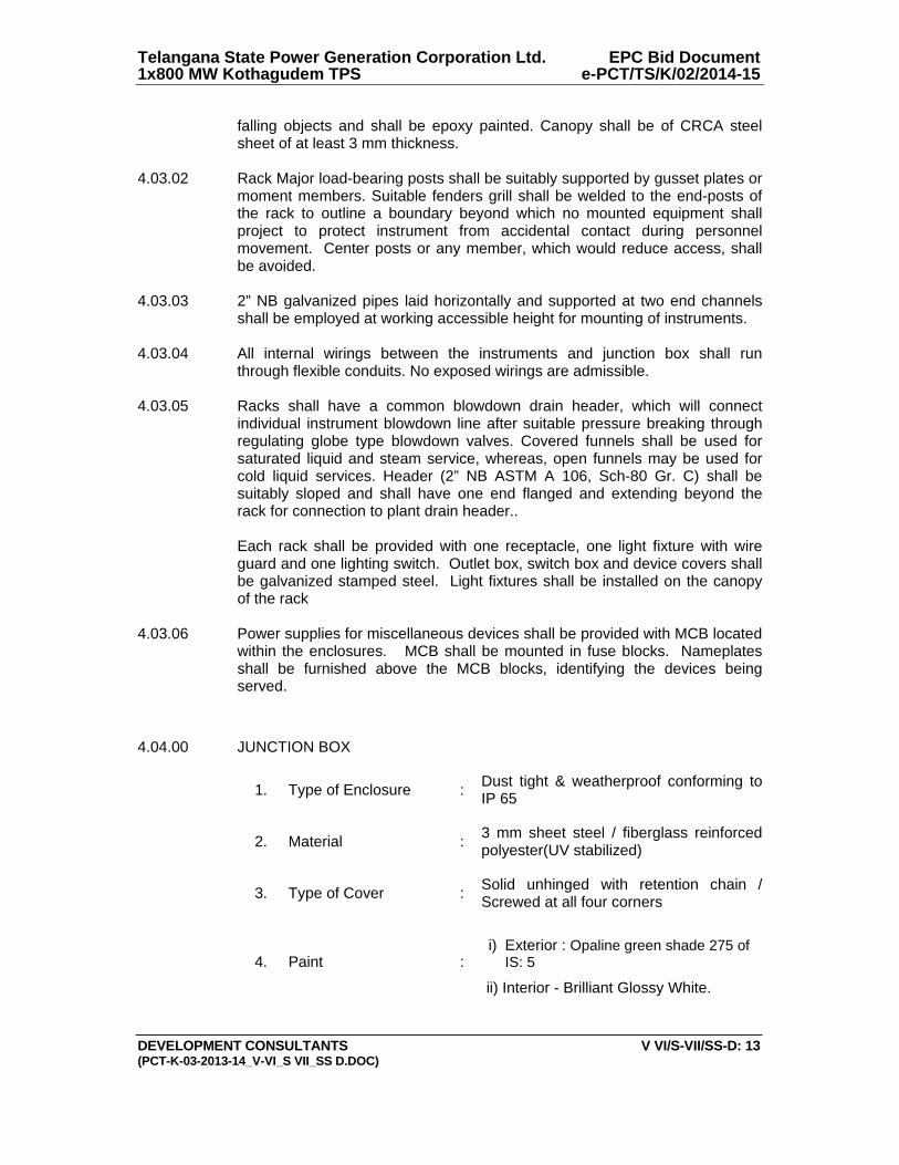
Telangana State Power Generation Corporation Ltd. EPC Bid Document 1x800 MW Kothagudem TPS e-PCT/TS/K/02/2014-15
DEVELOPMENT CONSULTANTS V VI/S-VII/SS-D: 13 (PCT-K-03-2013-14_V-VI_S VII_SS D.DOC)
falling objects and shall be epoxy painted. Canopy shall be of CRCA steel sheet of at least 3 mm thickness.
4.03.02 Rack Major load-bearing posts shall be suitably supported by gusset plates or moment members. Suitable fenders grill shall be welded to the end-posts of the rack to outline a boundary beyond which no mounted equipment shall project to protect instrument from accidental contact during personnel movement. Center posts or any member, which would reduce access, shall be avoided.
4.03.03 2” NB galvanized pipes laid horizontally and supported at two end channels shall be employed at working accessible height for mounting of instruments.
4.03.04 All internal wirings between the instruments and junction box shall run through flexible conduits. No exposed wirings are admissible.
4.03.05 Racks shall have a common blowdown drain header, which will connect individual instrument blowdown line after suitable pressure breaking through regulating globe type blowdown valves. Covered funnels shall be used for saturated liquid and steam service, whereas, open funnels may be used for cold liquid services. Header (2” NB ASTM A 106, Sch-80 Gr. C) shall be suitably sloped and shall have one end flanged and extending beyond the rack for connection to plant drain header.. Each rack shall be provided with one receptacle, one light fixture with wire guard and one lighting switch. Outlet box, switch box and device covers shall be galvanized stamped steel. Light fixtures shall be installed on the canopy of the rack
4.03.06 Power supplies for miscellaneous devices shall be provided with MCB located within the enclosures. MCB shall be mounted in fuse blocks. Nameplates shall be furnished above the MCB blocks, identifying the devices being served.
4.04.00 JUNCTION BOX
1. Type of Enclosure : Dust tight & weatherproof conforming to IP 65
2. Material : 3 mm sheet steel / fiberglass reinforced polyester(UV stabilized)
3. Type of Cover : Solid unhinged with retention chain / Screwed at all four corners
4. Paint :
i) Exterior : Opaline green shade 275 of
IS: 5
ii) Interior - Brilliant Glossy White.
3833321
Line
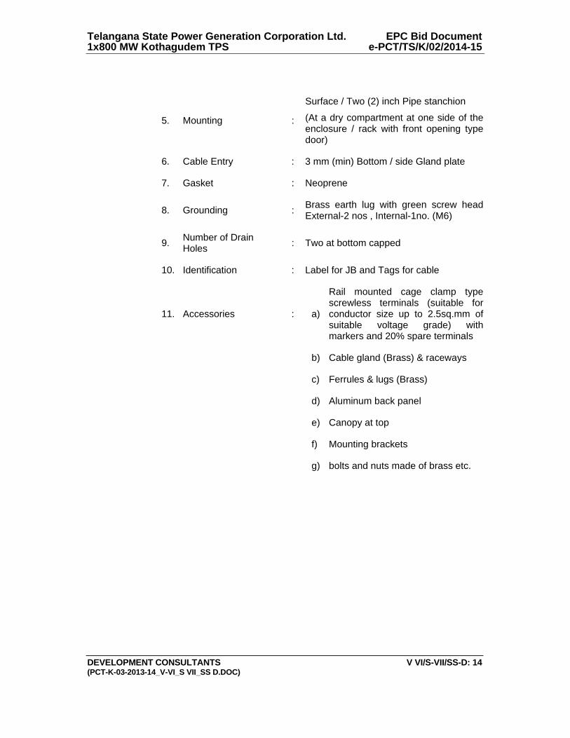
Telangana State Power Generation Corporation Ltd. EPC Bid Document 1x800 MW Kothagudem TPS e-PCT/TS/K/02/2014-15
DEVELOPMENT CONSULTANTS V VI/S-VII/SS-D: 14 (PCT-K-03-2013-14_V-VI_S VII_SS D.DOC)
5. Mounting :
Surface / Two (2) inch Pipe stanchion
(At a dry compartment at one side of the enclosure / rack with front opening type door)
6. Cable Entry : 3 mm (min) Bottom / side Gland plate
7. Gasket : Neoprene
8. Grounding : Brass earth lug with green screw head External-2 nos , Internal-1no. (M6)
9. Number of Drain Holes
: Two at bottom capped
10. Identification : Label for JB and Tags for cable
11. Accessories : a)
Rail mounted cage clamp type screwless terminals (suitable for conductor size up to 2.5sq.mm of suitable voltage grade) with markers and 20% spare terminals
b) Cable gland (Brass) & raceways
c) Ferrules & lugs (Brass)
d) Aluminum back panel
e) Canopy at top
f) Mounting brackets
g) bolts and nuts made of brass etc.
1X800 MW KOTHAGUDAM TPS
SPECIFIC TECHNICAL REQUIREMENTS (C&I)
NATURAL DRAUGHT COOLING TOWER
OF 4
`
0
LOCAL PANEL
SPECIFICATION FOR LOCAL PANELS
SPECIFICATION NO.:
VOLUME
SECTION
REV. NO. 00 DATE :
SHEET 1 OF 5
FO
RM
NO
. PE
M-6
666-
0
1.0 SCOPE
This specification covers the Design, Manufacture, Inspection and Testing at the manufacturer’s works, proper packing for transportation and delivery to site, supervision, erection, and commissioning at site of Local Panels required for control and monitoring of the Auxiliary Plant & Equipment.
2.0 CODES AND STANDARDS
2.1 All the equipments specified herein shall comply with the requirements of the latest issue of the relevant National and International standards.
2.2 As a minimum requirement, the following standards shall be complied with:
a) IS-6005 : 1998 : Code of practice for phosphating of iron and steel. b) IS-5 : 2007 : Colors for ready mixed paints and enamels. c) IS-1248:2003 : Direct Acting Indicating Analog Elec Measuring Instruments. d) IS/IEC 60947:Part 1:2004 : Low Voltage switchgear & control gear: Part-I (General Rules) e) IS-8828:1996 : Circuit breaker for household and similar installations. f) IS-13947 (Part-I):1993 : Low Voltage switchgear & control gear : Part-I (General Rules) g) ISA-18.1:1979 : Annunciator Sequences and Specification h) NFPA-496:2003 : Purged & Pressurised Enclosure for Electrical Equipment in
Hazardous Locations.
3.0 TECHNICAL REQUIREMENTS
3.1 Panel Construction
3.1.1 The local panels shall house the secondary instruments, annunciation system, Single loop controller, Control switches / push buttons, indicating lamps/LED cluster, relays, timers and other devices required for operation and monitoring of the equipment locally.
3.1.2 The panels shall be of free standing type either welded construction on angle iron (minimum section of 50 x 50 x 4 mm) structure or folded construction by sheet metal formation depending upon the equipments to be mounted on it. The panels shall be robustly built and stiffeners as necessary shall be provided.
3.1.3 The panel shall be suitably reinforced to ensure adequate support for all instruments mounted thereon. All welds on exposed panel surfaces shall be ground smooth.
3.1.4 The salient features of construction shall be:
Sheet material: Cold rolled sheet steel Frame thickness: Not less than 3.0mm Enclosure thickness: Not less than 2.5 mm for load bearing sections (Mounted with instruments) 1.6 mm for doors and Not less than 2.0 mm for others Gland plate thickness: 3.0mm Base channel: ISMC 100 with anti-vibration mounting & foundation bolts.
3.1.5 The panel shall be provided with doors with integral lockable handle. The door when locked shall be
held at minimum three places. The door width shall not be more than 550mm.The doors shall be provided with suitable stiffeners to prevent buckling. The handle shall be on the right side of the door. The door shall be removable type with concealed hinges to facilitate maintenance work. Suitable pocket inside the door shall be provided for keeping the drawings / documents.
[[[[[[[[[[[[[[[[[[[[[[[[[[[ 3.1.6 Suitable neoprene gasket shall be provided on all doors and removable covers. Suitable ventilation
system along with louvers shall be provided at bottom and top of the doors covered with removable wire mesh.
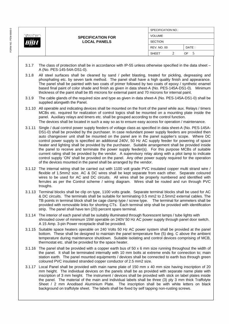
SPECIFICATION FOR LOCAL PANELS
SPECIFICATION NO.:
VOLUME
SECTION
REV. NO. 00 DATE :
SHEET 2 OF 5
FO
RM
NO
. PE
M-6
666-
0
3.1.7 The class of protection shall be in accordance with IP-55 unless otherwise specified in the data sheet – A (No. PES-145-54A-DS1-0).
3.1.8 All steel surfaces shall be cleaned by sand / pellet blasting, treated for pickling, degreasing and phosphating etc. by seven tank method. The panel shall have a high quality finish and appearance. The panel shall be painted with two coats of primer followed by two coats of epoxy / synthetic enamel based final paint of color shade and finish as given in data sheet-A (No. PES-145A-DS1-0). Minimum thickness of the paint shall be 85 microns for external paint and 70 microns for internal paint.
3.1.9 The cable glands of the required size and type as given in data sheet-A (No. PES-145A-DS1-0) shall be supplied alongwith the Panel.
3.1.10 All operable and indicating devices shall be mounted on the front of the panel while aux. Relays / timers MCBs etc. required for realization of control logics shall be mounted on a mounting plate inside the panel. Auxiliary relays and timers etc. shall be grouped according to the control function.
The devices shall be located in such a way so as to ensure easy access for operation / maintenance.
3.1.11 Single / dual control power supply feeders of voltage class as specified in data sheet-A (No. PES-145A-DS1-0) shall be provided by the purchaser. In case redundant power supply feeders are provided then auto changeover unit shall be mounted on the panel are in the panel supplier’s scope. Where DC control power supply is specified an additional 240V, 50 Hz AC supply feeder for powering of space heater and lighting shall be provided by the purchaser. Suitable arrangement shall be provided inside the panel to receive and terminate the power supply feeder(s). For this purpose MCBs of suitable current rating shall be provided by the vendor. A supervisory relay along with a pilot lamp to indicate control supply ‘ON’ shall be provided on the panel. Any other power supply required for the operation of the devices mounted in the panel shall be arranged by the vendor.
3.1.12 The internal wiring shall be carried out with 1100 volt grade PVC insulated copper multi strand wire / flexible of 1.5mm2 size. AC & DC wires shall be kept separate from each other. Separate coloured wires to be used for AC and DC circuits. All wires shall be properly numbered and identified with ferrules as per the Control scheme / wiring diagram. Wires shall be routed and run through PVC troughs.
3.1.13 Terminal blocks shall be clip on type, 1100 volts grade. Separate terminal blocks shall be used for AC & DC circuits. The terminals shall be suitable for terminating 0.5 mm2 to 2.5mm2 external cables. The TB points in terminal block shall be cage clamp type / screw type. The terminal for ammeters shall be provided with removable links for shorting CTs. Each terminal strip shall be provided with identification strip. The panel shall have ten (20) percent spare terminal.
3.1.14 The interior of each panel shall be suitably illuminated through fluorescent lamps / tube lights with shrouded cover of minimum 15W operable on 240V 50 Hz AC power supply through panel door switch. A 15 Amp. 3-pin Power receptacle shall be provided.
3.1.15 Suitable space heaters operable on 240 Volts 50 Hz AC power system shall be provided at the panel bottom. These shall be designed to maintain the panel temperature five (5) deg. C above the ambient temperature during maintenance shutdown. Suitable isolating and control devices comprising of MCB, thermostat etc. shall be provided for the space heater.
3.1.16 The panel shall be provided with a copper earth bus of 50 x 6 mm size running throughout the width of the panel. It shall be terminated internally with 10 mm bolts at extreme ends for connection to; main station earth. The panel mounted equipments / devices shall be connected to earth bus through green coloured PVC insulated stranded copper conductor of 2.5 mm2 size.
3.1.17 Local Panel shall be provided with main name plate of 150 mm x 40 mm size having inscription of 20 mm height. The individual devices on the panels shall be as provided with separate name plate with inscription of 3 mm height. The instrument / devices shall be provided with stick on label plates inside the panel. The material of the main and individual labels shall be three (3) ply 3 mm thick Traffolyte Sheet / 2 mm Anodised Aluminium Plate. The inscription shall be with white letters on black background on traffolyte sheet. The labels shall be fixed by self tapping non-rusting screws.

SPECIFICATION FOR LOCAL PANELS
SPECIFICATION NO.:
VOLUME
SECTION
REV. NO. 00 DATE :
SHEET 3 OF 5
FO
RM
NO
. PE
M-6
666-
0
3.1.18 Vendor shall furnish electric load and heat load list ( in case panel is to be placed in ac environment ) of each panel.
3.2 Hazardous Area Panel Requirement
3.2.1 The Local Panel located in hazardous area shall be pressurized as per NFPA-496 requirements to
render it non-hazardous. Alarms shall be provided for local and remote annunciation when pressurisation falls below 2.5 mm of water column. Protection shall be of type Z of NFPA-496. It shall not be possible to switch ON the power of purged section unless it is purged as per the recommendation of NFPA-496. Vendor must provide a protective device on the panel to protect the panel from over pressurisation.
3.2.2 Vendor shall supply pressurisation kit consisting of valves, restriction orifices, dual filter regulation, pressure gauges, pressure switches, rotameter etc. Pressurisation kit shall be surface mounting on a metal board and located outside the local panel. Pressurisation kit shall further consist of solenoid valve flow switch, timer blow off safety device etc., so as to make purging fully automatic. However final start shall be manual. Panel protection against over pressure to be provided as per NFPA-496.
3.2.3 Pressurised local control panel pressurization kit assembly design shall provide minimum leakage flow through the Local Control Panel. Panel venting shall be as per NFPA-496.
3.2.4 All components in the local panel like indicating instruments, push buttons switches, lamps etc., which are required to be energized without panel pressurization or before completion of purge cycle shall be explosion proof as per NEMA-7 & suitable for area classification.
3.2.5 All push buttons etc. requiring frequent operation during machine running shall have good positive sealing. Weatherproof housing or cover to be provided wherever necessary. Vendor shall provide pressurisation bypass switch outside explosion proof enclosure of pressurized panel with lamp indication. This shall be used only during maintenance. All hinges, screws, other non-painted metallic parts shall be of stainless steel material.
3.2.6 Provision to switch off manually all types of power shall be provided in the panel. In addition, it shall also be possible to switch off power circuits / components which are powered from motor control centre or control room manually in case of pressurization failure. All such cables from MCC and main control room shall be terminated in explosion proof boxes (NEMA-7).
3.3 Control & Monitoring devices
3.3.1 Instruments like Indicators, recorders, single loop controllers etc. as applicable and specified elsewhere for the plant / equipment shall be supplied and mounted on the panel.
3.3.2 Alarm Annunciator System
It shall be solid state discrete facia type having a sequence of ISA-S18.1A or as specified, opaque facia windows of 70 mm x 50 mm size, having two (2) lamps per window, and hooter of 10W, and provision for repeat group alarm at remote. The annunciator shall be provided with ten (10) percent spare windows or minimum two (2) windows along with electronics.
3.3.3 Relays
The relays shall be electromagnetic type suitable for specified control supply. Its contact configuration and rating shall be suitable for the specified control function. However minimum contact rating shall be 5 Amp AC & 2 Amp DC as applicable. There shall be ten (10) percent spare contacts.
3.3.4 Timers
The timers shall be electronic type suitable for specified control supply. Its contact configuration and rating shall be suitable for the specified control function. However, minimum contact rating shall be 5 Amp AC & 2 Amp DC as applicable.
3.3.5 Control / Selector Switches
Switches shall be Rotary Cam type with minimum of 5 Amps AC & 2 Amp DC continuous current rating. Selector switches shall be stay put type while control switches shall be spring-return-to-neutral type.
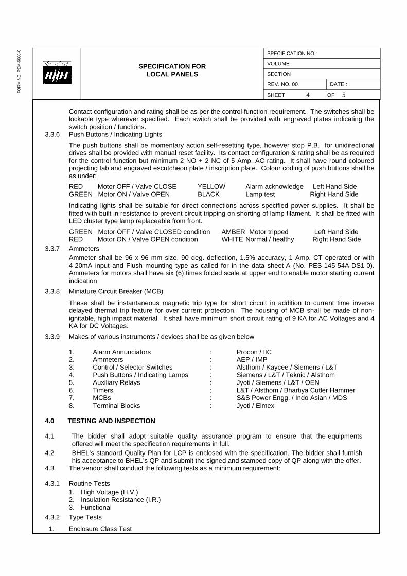
SPECIFICATION FOR LOCAL PANELS
SPECIFICATION NO.:
VOLUME
SECTION
REV. NO. 00 DATE :
SHEET 4 OF 5
FO
RM
NO
. PE
M-6
666-
0
Contact configuration and rating shall be as per the control function requirement. The switches shall be lockable type wherever specified. Each switch shall be provided with engraved plates indicating the switch position / functions.
3.3.6 Push Buttons / Indicating Lights
The push buttons shall be momentary action self-resetting type, however stop P.B. for unidirectional drives shall be provided with manual reset facility. Its contact configuration & rating shall be as required for the control function but minimum 2 NO + 2 NC of 5 Amp. AC rating. It shall have round coloured projecting tab and engraved escutcheon plate / inscription plate. Colour coding of push buttons shall be as under:
RED Motor OFF / Valve CLOSE YELLOW Alarm acknowledge Left Hand Side GREEN Motor ON / Valve OPEN BLACK Lamp test Right Hand Side
Indicating lights shall be suitable for direct connections across specified power supplies. It shall be fitted with built in resistance to prevent circuit tripping on shorting of lamp filament. It shall be fitted with LED cluster type lamp replaceable from front.
GREEN Motor OFF / Valve CLOSED condition AMBER Motor tripped Left Hand Side RED Motor ON / Valve OPEN condition WHITE Normal / healthy Right Hand Side
3.3.7 Ammeters
Ammeter shall be 96 x 96 mm size, 90 deg. deflection, 1.5% accuracy, 1 Amp. CT operated or with 4-20mA input and Flush mounting type as called for in the data sheet-A (No. PES-145-54A-DS1-0). Ammeters for motors shall have six (6) times folded scale at upper end to enable motor starting current indication
3.3.8 Miniature Circuit Breaker (MCB)
These shall be instantaneous magnetic trip type for short circuit in addition to current time inverse delayed thermal trip feature for over current protection. The housing of MCB shall be made of non-ignitable, high impact material. It shall have minimum short circuit rating of 9 KA for AC Voltages and 4 KA for DC Voltages.
3.3.9 Makes of various instruments / devices shall be as given below 1. Alarm Annunciators : Procon / IIC 2. Ammeters : AEP / IMP 3. Control / Selector Switches : Alsthom / Kaycee / Siemens / L&T 4. Push Buttons / Indicating Lamps : Siemens / L&T / Teknic / Alsthom 5. Auxiliary Relays : Jyoti / Siemens / L&T / OEN 6. Timers : L&T / Alsthom / Bhartiya Cutler Hammer 7. MCBs : S&S Power Engg. / Indo Asian / MDS 8. Terminal Blocks : Jyoti / Elmex
4.0 TESTING AND INSPECTION
4.1 The bidder shall adopt suitable quality assurance program to ensure that the equipments
offered will meet the specification requirements in full.
4.2 BHEL’s standard Quality Plan for LCP is enclosed with the specification. The bidder shall furnish his acceptance to BHEL’s QP and submit the signed and stamped copy of QP along with the offer.
4.3 The vendor shall conduct the following tests as a minimum requirement: 4.3.1 Routine Tests
1. High Voltage (H.V.) 2. Insulation Resistance (I.R.) 3. Functional
4.3.2 Type Tests
1. Enclosure Class Test

SPECIFICATION FOR LOCAL PANELS
SPECIFICATION NO.:
VOLUME
SECTION
REV. NO. 00 DATE :
SHEET 5 OF 5
FO
RM
NO
. PE
M-6
666-
0
5.0 SPARES AND CONSUMABLES
5.1 Commissioning Spares and consumables
The bidder shall supply all commissioning spares and consumables ‘as required’ during Start-up, as part of the main equipment supply.
5.2. Mandatory Spares
The bidder shall offer alongwith main offer, the Mandatory Spares as specified elsewhere in the specification. The Mandatory Spares offered shall be of the same make and type as the main equipment.
5.3. Recommended Spares
The bidder shall furnish a list of Recommended Spares indicating the normal service expectancy period and frequency of replacement; quantities recommended for 3 years operation alongwith unit rate against each item to enable BHEL/BHEL’s Customer to place a separate order later, if required.
6.0 DRAWINGS AND DOCUMENTS
6.1 The bidder shall furnish the following documents in required number of copies along with the bid :
1. Data Sheet no. PES-145A-DS1-0 2. General Arrangement Drawing. 3. Catalogue and technical information for instruments and devices. 4. Quality Plan.
6.2 The vendor shall furnish the following documents in required number as agreed after the award of
contract:
1. Data Shee No. PES-145A-DS2-0 2. GA Drawing indicating layout of instruments, construction details, foundation details, cable gland
plate alongwith cable glands and all details mentioned in this specification. 3. Control Schematic Diagram along with grouping of different terminals for various functions. 4. Catalogue and technical information for instruments and devices with selected options clearly
marked. 5. O&M Manuals. 6. “As Built” Drawing. 7. CDs.
7.0 MARKING AND PACKING
7.1 Panel with all instruments / devices mounted on it shall be suitably packed & protected for the entire period of despatch, storage and erection against impact, abrasion, corrossion, incidental damage due to vermin, sunlight, high temperature, rain moisture, humidity, dust, sea-water spray (where applicable) as well as rough handling and delays in Transit and storage in open.
8.0 APPLICABLE DATA SHEET FORMS
This document shall be read with one or more of the following data sheet forms :
- Data sheet A&B for Local Panels : Data sheet no. PES-145A-DS1-0 - Data sheet C for Local Panels : Data sheet no. PES-145A-DS2-0

DATA SHEET FOR LOCAL PANELS
SPECIFICATION NO.:
VOLUME
SECTION
REV. NO. DATE:
SHEET 1 OF 1TAG No. …………. Qty................. Data Sheet No.: PES-145A-DS1-0
Data Sheet A & B
DATA SHEET-A FOR LOCAL PANEL (TO BE FILLED BY PURCHASER)
DATA SHEET-B
(TO BE FILLED-UP BY BIDDER)
FO
RM
NO
. PE
M-6
666-
0
GENERAL MANUFACTURER
CONSTRUCTION FOLDED WELDED (CRCA)
(As per requirement)
ENCLOSURE SHEET THICKNESS
FRONT ▐ 2.0 mm
OTHER ▐ 2.0 mm
DOOR ▐ 2.0 mm
TECHNICAL INPUT POWER SUPPLY 240V 50 Hz AC 220V DC
█ 415V 3 PHASE
NO. OF FEEDERS ONE ▐ TWO
CONTROL SUPPLY
110V AC 220V AC
220V DC █ During detailed engg.
(As per requirement)
ALARM ANNUNCIATOR WINDOW
(EXCLUDING SPARES) AS REQUIRED
PAINT TYPE EPOXY ENAMEL
█ EPOXY POWDER COATED
PANEL COLOUR (EXTERNAL)
█ Exterior- Opaline green shade 275 of IS: 5 or equivalent international code █ Interior- Brilliant White (To be finalized during detailed engineering.)
FINISH ▐ MATT
GLOSSY SEMI GLOSSY
PANEL COLOUR (INTERNAL) █ BRILLIANT WHITE CREAM
OFF WHITE
FINISH MATT
GLOSSY █ SEMI GLOSSY
CLASS OF PROTECTION IP-42
█ IP-65
CONTROL HARDWARE █ RELAY BASED
FOUNDATION ARRANGEMENT ▐ FOUNDATION BOLTS ANCHOR FASTENERS
WEIGHT OF PANEL (Kg.) BIDDER TO SPECIFY
PANEL TYPE PRESSURISED █ UNPRESSURISED
As per Requirement
CABLE GLAND SINGLE COMPRESSION
█ DOUBLE COMPRESSION
AMMETER (TYPE OF INPUT) 1 Amp CT 4-20 mA
As per Requirement
PREPARED BY CHECKED BY APPROVED BY COMPANY SEAL
NAME NAME
SIGNATURE SIGNATURE
DATE DATE
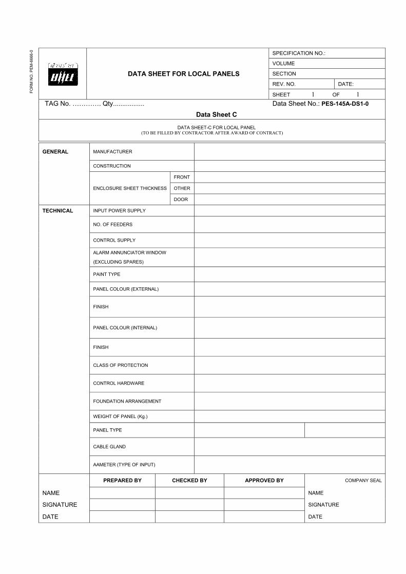
DATA SHEET FOR LOCAL PANELS
SPECIFICATION NO.:
VOLUME
SECTION
REV. NO. DATE:
SHEET 1 OF 1TAG No. …………. Qty................. Data Sheet No.: PES-145A-DS1-0
Data Sheet C
DATA SHEET-C FOR LOCAL PANEL (TO BE FILLED BY CONTRACTOR AFTER AWARD OF CONTRACT)
FO
RM
NO
. PE
M-6
666-
0
GENERAL MANUFACTURER
CONSTRUCTION
ENCLOSURE SHEET THICKNESS
FRONT
OTHER
DOOR
TECHNICAL INPUT POWER SUPPLY
NO. OF FEEDERS
CONTROL SUPPLY
ALARM ANNUNCIATOR WINDOW
(EXCLUDING SPARES)
PAINT TYPE
PANEL COLOUR (EXTERNAL)
FINISH
PANEL COLOUR (INTERNAL)
FINISH
CLASS OF PROTECTION
CONTROL HARDWARE
FOUNDATION ARRANGEMENT
WEIGHT OF PANEL (Kg.)
PANEL TYPE
CABLE GLAND
AAMETER (TYPE OF INPUT)
PREPARED BY CHECKED BY APPROVED BY COMPANY SEAL
NAME NAME
SIGNATURE SIGNATURE
DATE DATE
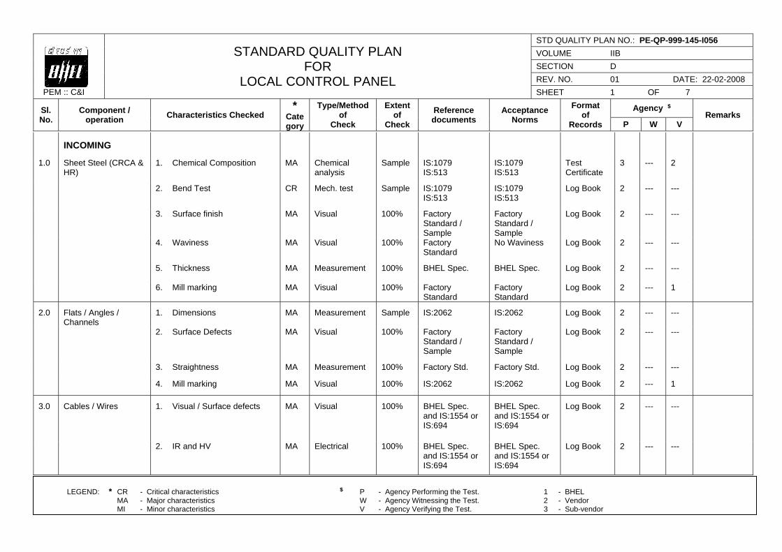
PEM :: C&I
STANDARD QUALITY PLAN FOR
LOCAL CONTROL PANEL
STD QUALITY PLAN NO.: PE-QP-999-145-I056
VOLUME IIB
SECTION D
REV. NO. 01 DATE: 22-02-2008
SHEET 1 OF 7
Sl. No.
Component / operation
Characteristics Checked *
Category
Type/Method of
Check
Extent of
Check
Reference documents
Acceptance Norms
Format of
Records
Agency $ Remarks
P W V
LEGEND: * CR - Critical characteristics $ P - Agency Performing the Test. 1 - BHEL MA - Major characteristics W - Agency Witnessing the Test. 2 - Vendor MI - Minor characteristics V - Agency Verifying the Test. 3 - Sub-vendor
INCOMING
1.0 Sheet Steel (CRCA & HR)
1. Chemical Composition MA Chemical analysis
Sample IS:1079 IS:513
IS:1079 IS:513
Test Certificate
3 --- 2
2. Bend Test CR Mech. test Sample IS:1079 IS:513
IS:1079 IS:513
Log Book 2 --- ---
3. Surface finish MA Visual 100% Factory Standard / Sample
Factory Standard / Sample
Log Book 2 --- ---
4. Waviness MA Visual 100% Factory Standard
No Waviness Log Book 2 --- ---
5. Thickness MA Measurement 100% BHEL Spec. BHEL Spec. Log Book 2 --- ---
6. Mill marking MA Visual 100% Factory Standard
Factory Standard
Log Book 2 --- 1
2.0 Flats / Angles / Channels
1. Dimensions MA Measurement Sample IS:2062 IS:2062 Log Book 2 --- ---
2. Surface Defects MA Visual 100% Factory Standard / Sample
Factory Standard / Sample
Log Book 2 --- ---
3. Straightness MA Measurement 100% Factory Std. Factory Std. Log Book 2 --- ---
4. Mill marking MA Visual 100% IS:2062 IS:2062 Log Book 2 --- 1
3.0 Cables / Wires 1. Visual / Surface defects MA Visual 100% BHEL Spec. and IS:1554 or IS:694
BHEL Spec. and IS:1554 or IS:694
Log Book 2 --- ---
2. IR and HV MA Electrical 100% BHEL Spec. and IS:1554 or IS:694
BHEL Spec. and IS:1554 or IS:694
Log Book 2 --- ---
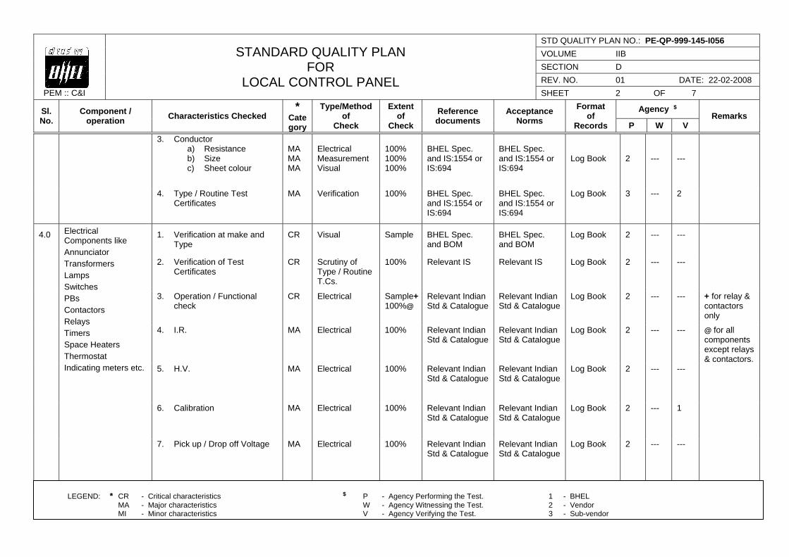
PEM :: C&I
STANDARD QUALITY PLAN FOR
LOCAL CONTROL PANEL
STD QUALITY PLAN NO.: PE-QP-999-145-I056
VOLUME IIB
SECTION D
REV. NO. 01 DATE: 22-02-2008
SHEET 2 OF 7
Sl. No.
Component / operation
Characteristics Checked *
Category
Type/Method of
Check
Extent of
Check
Reference documents
Acceptance Norms
Format of
Records
Agency $ Remarks
P W V
LEGEND: * CR - Critical characteristics $ P - Agency Performing the Test. 1 - BHEL MA - Major characteristics W - Agency Witnessing the Test. 2 - Vendor MI - Minor characteristics V - Agency Verifying the Test. 3 - Sub-vendor
3. Conductor a) Resistance b) Size c) Sheet colour
MA MA MA
Electrical Measurement Visual
100% 100% 100%
BHEL Spec. and IS:1554 or IS:694
BHEL Spec. and IS:1554 or IS:694
Log Book
2
---
---
4. Type / Routine Test Certificates
MA Verification 100% BHEL Spec. and IS:1554 or IS:694
BHEL Spec. and IS:1554 or IS:694
Log Book 3 --- 2
4.0 Electrical Components like Annunciator Transformers Lamps Switches PBs Contactors Relays Timers Space Heaters Thermostat Indicating meters etc.
1. Verification at make and Type
CR Visual Sample BHEL Spec. and BOM
BHEL Spec. and BOM
Log Book 2 --- ---
2. Verification of Test Certificates
CR Scrutiny of Type / Routine T.Cs.
100% Relevant IS Relevant IS Log Book 2 --- ---
3. Operation / Functional check
CR Electrical Sample+100%@
Relevant Indian Std & Catalogue
Relevant Indian Std & Catalogue
Log Book 2 --- --- + for relay & contactors only
4. I.R. MA Electrical 100% Relevant Indian Std & Catalogue
Relevant Indian Std & Catalogue
Log Book 2 --- --- @ for all components except relays & contactors.
5. H.V. MA Electrical 100% Relevant Indian Std & Catalogue
Relevant Indian Std & Catalogue
Log Book 2 --- ---
6. Calibration MA Electrical 100% Relevant Indian Std & Catalogue
Relevant Indian Std & Catalogue
Log Book 2 --- 1
7. Pick up / Drop off Voltage MA Electrical 100% Relevant Indian Std & Catalogue
Relevant Indian Std & Catalogue
Log Book 2 --- ---
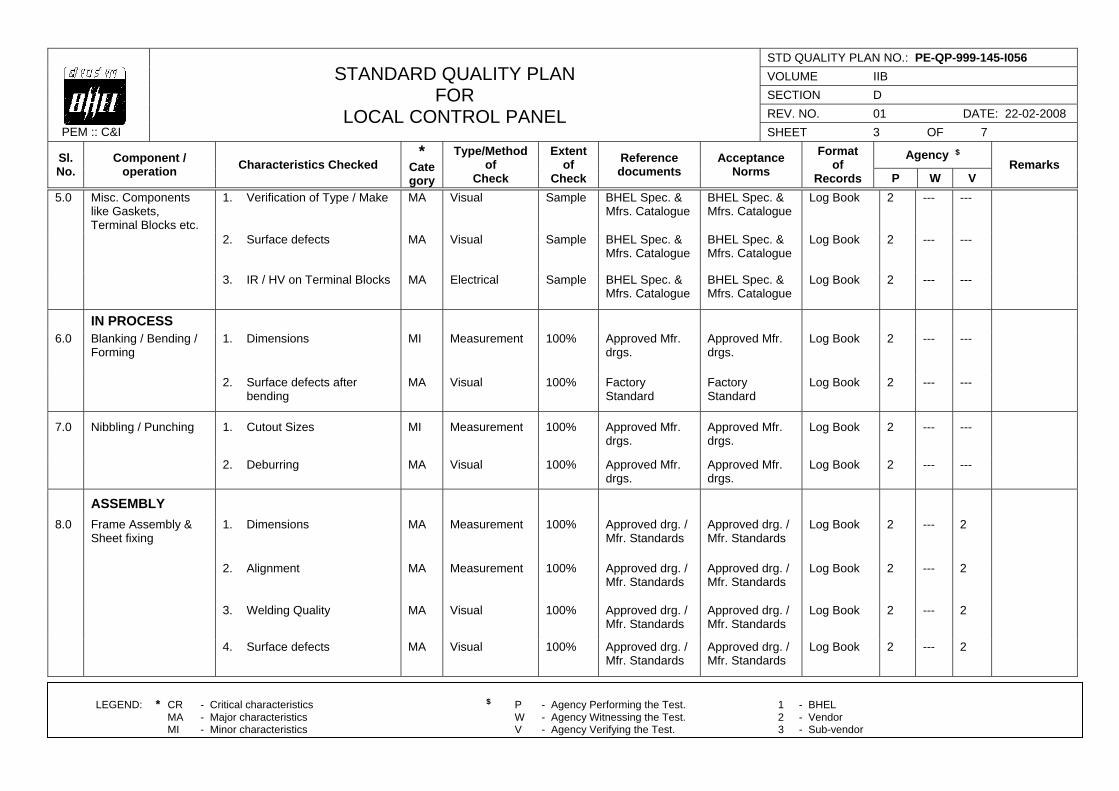
PEM :: C&I
STANDARD QUALITY PLAN FOR
LOCAL CONTROL PANEL
STD QUALITY PLAN NO.: PE-QP-999-145-I056
VOLUME IIB
SECTION D
REV. NO. 01 DATE: 22-02-2008
SHEET 3 OF 7
Sl. No.
Component / operation
Characteristics Checked *
Category
Type/Method of
Check
Extent of
Check
Reference documents
Acceptance Norms
Format of
Records
Agency $ Remarks
P W V
LEGEND: * CR - Critical characteristics $ P - Agency Performing the Test. 1 - BHEL MA - Major characteristics W - Agency Witnessing the Test. 2 - Vendor MI - Minor characteristics V - Agency Verifying the Test. 3 - Sub-vendor
5.0 Misc. Components like Gaskets, Terminal Blocks etc.
1. Verification of Type / Make MA Visual Sample BHEL Spec. & Mfrs. Catalogue
BHEL Spec. & Mfrs. Catalogue
Log Book 2 --- ---
2. Surface defects MA Visual Sample BHEL Spec. & Mfrs. Catalogue
BHEL Spec. & Mfrs. Catalogue
Log Book 2 --- ---
3. IR / HV on Terminal Blocks MA Electrical Sample BHEL Spec. & Mfrs. Catalogue
BHEL Spec. & Mfrs. Catalogue
Log Book 2 --- ---
IN PROCESS
6.0 Blanking / Bending / Forming
1. Dimensions MI Measurement 100% Approved Mfr. drgs.
Approved Mfr. drgs.
Log Book 2 --- ---
2. Surface defects after bending
MA Visual 100% Factory Standard
Factory Standard
Log Book 2 --- ---
7.0 Nibbling / Punching 1. Cutout Sizes MI Measurement 100% Approved Mfr. drgs.
Approved Mfr. drgs.
Log Book 2 --- ---
2. Deburring MA Visual 100% Approved Mfr. drgs.
Approved Mfr. drgs.
Log Book 2 --- ---
ASSEMBLY
8.0 Frame Assembly & Sheet fixing
1. Dimensions MA Measurement 100% Approved drg. / Mfr. Standards
Approved drg. / Mfr. Standards
Log Book 2 --- 2
2. Alignment MA Measurement 100% Approved drg. / Mfr. Standards
Approved drg. / Mfr. Standards
Log Book 2 --- 2
3. Welding Quality MA Visual 100% Approved drg. / Mfr. Standards
Approved drg. / Mfr. Standards
Log Book 2 --- 2
4. Surface defects MA Visual 100% Approved drg. / Mfr. Standards
Approved drg. / Mfr. Standards
Log Book 2 --- 2

PEM :: C&I
STANDARD QUALITY PLAN FOR
LOCAL CONTROL PANEL
STD QUALITY PLAN NO.: PE-QP-999-145-I056
VOLUME IIB
SECTION D
REV. NO. 01 DATE: 22-02-2008
SHEET 4 OF 7
Sl. No.
Component / operation
Characteristics Checked *
Category
Type/Method of
Check
Extent of
Check
Reference documents
Acceptance Norms
Format of
Records
Agency $ Remarks
P W V
LEGEND: * CR - Critical characteristics $ P - Agency Performing the Test. 1 - BHEL MA - Major characteristics W - Agency Witnessing the Test. 2 - Vendor MI - Minor characteristics V - Agency Verifying the Test. 3 - Sub-vendor
9.0 Pre-treatment and Painting
1. Pretreatment Process MA Visual 100% Factory Standard & IS: 6005
Factory Standard & IS: 6005
Log Book 2 --- 1
2. Process parameters like bath temp. concentration etc.
MA Measurement Periodic Factory Standard & IS: 6005
Factory Standard & IS: 6005
Log Book 2 --- 1
3. Dipping / Removal Time MA Measurement 100% Factory Standard & IS: 6005
Factory Standard & IS: 6005
Log Book 2 --- 1
4. Surface quality after every dip
MA Visual 100% Factory Standard & IS: 6005
Factory Standard & IS: 6005
Log Book 2 --- 1
5. Primer after phosphating MA Visual, Thickness
100% Factory Standard & IS: 6005
Factory Standard & IS: 6005
Log Book 2 --- 1
6. Putty Application & Rubbing after primer
MA Visual 100% Factory Standard & IS: 6005
Factory Standard & IS: 6005
Log Book 2 --- 1
7. Paint first coat MA Visual, Thickness
100% Factory Standard & IS: 6005
Factory Standard & IS: 6005
Log Book 2 --- 1
8. Putty Application and Rubbing after first coat of paint
MA Visual 100% Factory Standard & IS: 6005
Factory Standard & IS: 6005
Log Book 2 --- 1
9. Paint second coat MA Visual, Thickness, Scratch test Colour adhesion
100%
Factory Standard & IS: 6005
Factory Standard & IS: 6005
Log Book 2 --- 1
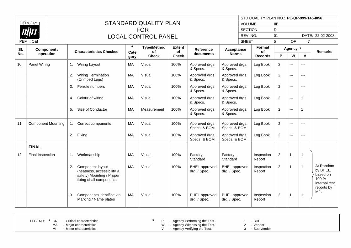
PEM :: C&I
STANDARD QUALITY PLAN FOR
LOCAL CONTROL PANEL
STD QUALITY PLAN NO.: PE-QP-999-145-I056
VOLUME IIB
SECTION D
REV. NO. 01 DATE: 22-02-2008
SHEET 5 OF 7
Sl. No.
Component / operation
Characteristics Checked *
Category
Type/Method of
Check
Extent of
Check
Reference documents
Acceptance Norms
Format of
Records
Agency $ Remarks
P W V
LEGEND: * CR - Critical characteristics $ P - Agency Performing the Test. 1 - BHEL MA - Major characteristics W - Agency Witnessing the Test. 2 - Vendor MI - Minor characteristics V - Agency Verifying the Test. 3 - Sub-vendor
10. Panel Wiring 1. Wiring Layout MA Visual 100% Approved drgs. & Specs.
Approved drgs. & Specs.
Log Book 2 --- ---
2. Wiring Termination (Crimped Lugs)
MA Visual 100% Approved drgs. & Specs.
Approved drgs. & Specs.
Log Book 2 --- ---
3. Ferrule numbers MA Visual 100%
Approved drgs. & Specs.
Approved drgs. & Specs.
Log Book 2 --- ---
4. Colour of wiring MA Visual 100% Approved drgs. & Specs.
Approved drgs. & Specs.
Log Book 2 --- 1
5. Size of Conductor MA Measurement 100%
Approved drgs. & Specs.
Approved drgs. & Specs.
Log Book 2 --- 1
11. Component Mounting 1. Correct components MA Visual 100% Approved drgs., Specs. & BOM
Approved drgs., Specs. & BOM
Log Book 2 --- ---
2. Fixing MA Visual 100% Approved drgs.,
Specs. & BOM Approved drgs., Specs. & BOM
Log Book 2 --- ---
FINAL
12. Final Inspection 1. Workmanship MA Visual 100% Factory Standard
Factory Standard
Inspection Report
2 1 1
At Random by BHEL, based on 100 % internal test reports by Mfr.
2. Component layout (neatness, accessibility & safety) Mounting / Proper fixing of all components
MA Visual 100%
BHEL approved drg. / Spec.
BHEL approved drg. / Spec.
Inspection Report
2 1 1
3. Components identification Marking / Name plates
MA Visual 100% BHEL approved drg. / Spec.
BHEL approved drg. / Spec.
Inspection Report
2 1 1
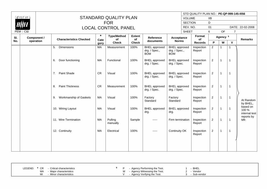
PEM :: C&I
STANDARD QUALITY PLAN FOR
LOCAL CONTROL PANEL
STD QUALITY PLAN NO.: PE-QP-999-145-I056
VOLUME IIB
SECTION D
REV. NO. 01 DATE: 22-02-2008
SHEET 6 OF 7
Sl. No.
Component / operation
Characteristics Checked *
Category
Type/Method of
Check
Extent of
Check
Reference documents
Acceptance Norms
Format of
Records
Agency $ Remarks
P W V
LEGEND: * CR - Critical characteristics $ P - Agency Performing the Test. 1 - BHEL MA - Major characteristics W - Agency Witnessing the Test. 2 - Vendor MI - Minor characteristics V - Agency Verifying the Test. 3 - Sub-vendor
5. Dimensions MA Measurement 100%
BHEL approved drg. / Spec., BOM
BHEL approved drg. / Spec., BOM
Inspection Report
2 1 1
At Random by BHEL, based on 100 % internal test reports by Mfr.
6. Door functioning MA Functional 100%
BHEL approved drg. / Spec.
BHEL approved drg. / Spec.
Inspection Report
2 1 1
7. Paint Shade CR Visual 100%
BHEL approved drg. / Spec.
BHEL approved drg. / Spec.
Inspection Report
2 1 1
8. Paint Thickness CR Measurement 100%
BHEL approved drg. / Spec.
BHEL approved drg. / Spec.
Inspection Report
2 1 1
9. Workmanship of Gaskets MA Visual 100%
Factory Standard
Factory Standard
Inspection Report
2 1 1
10. Wiring Layout MA Visual 100%
BHEL approved drg.
BHEL approved drg.
Inspection Report
2 1 1
11. Wire Termination MA Pulling manually
Sample ----- Firm termination Inspection Report
2 1 1
12. Continuity MA Electrical 100%
----- Continuity OK Inspection Report
2 1 1
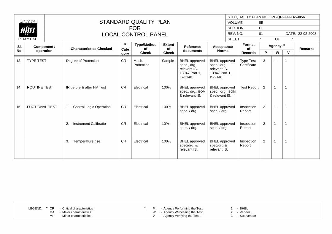
PEM :: C&I
STANDARD QUALITY PLAN FOR
LOCAL CONTROL PANEL
STD QUALITY PLAN NO.: PE-QP-999-145-I056
VOLUME IIB
SECTION D
REV. NO. 01 DATE: 22-02-2008
SHEET 7 OF 7
Sl. No.
Component / operation
Characteristics Checked *
Category
Type/Method of
Check
Extent of
Check
Reference documents
Acceptance Norms
Format of
Records
Agency $ Remarks
P W V
LEGEND: * CR - Critical characteristics $ P - Agency Performing the Test. 1 - BHEL MA - Major characteristics W - Agency Witnessing the Test. 2 - Vendor MI - Minor characteristics V - Agency Verifying the Test. 3 - Sub-vendor
13. TYPE TEST Degree of Protection CR Mech. Protection
Sample
BHEL approved spec., drg relevant IS-13947 Part-1, IS-2148.
BHEL approved spec., drg relevant IS-13947 Part-1, IS-2148.
Type Test Certificate
3 --- 1
14 ROUTINE TEST IR before & after HV Test CR Electrical 100%
BHEL approved spec., drg., BOM & relevant IS.
BHEL approved spec., drg., BOM & relevant IS.
Test Report 2 1 1
15 FUCTIONAL TEST 1. Control Logic Operation CR Electrical 100%
BHEL approved spec. / drg.
BHEL approved spec. / drg.
Inspection Report
2 1 1
2. Instrument Calibratio CR Electrical 10%
BHEL approved spec. / drg.
BHEL approved spec. / drg.
Inspection Report
2 1 1
3. Temperature rise CR Electrical 100%
BHEL approved spec/drg. & relevant IS.
BHEL approved spec/drg & relevant IS.
Inspection Report
2 1 1
TITLE: TECHNICAL SPECIFICATION
COOLING TOWERS STANDARD TECHNICAL SPECIFICATION
SPEC. NO.: PE-TS-410-165-N001 VOLUME: IIB SECTION: DREV. NO. 00 DATE 23.01.2015 SHEET 1 OF 1
SECTION - D
STANDARD TECHNICAL SPECIFICATION
SECTION D1 - Standard Technical Specification (Mechanical) SECTION D2 – Standard Technical Specification (Electrical)
TITLE: TECHNICAL SPECIFICATION
COOLING TOWERS STANDARD TECHNICAL SPECIFICATION
MECHANICAL
SPEC. NO.: PE-TS-410-165-N001 VOLUME: IIB SECTION: DREV. NO. 00 DATE 23.01.2015 SHEET 1 OF 1
SECTION D1
STANDARD TECHNICAL SPECIFICATION (MECHANICAL)
STANDARD TECHNICAL SPECIFICATION FOR NDCT
DATASHEET A
DOCUMENT DISTRIBUTION SCHEDULE
STANDARD QUALITY PLANS
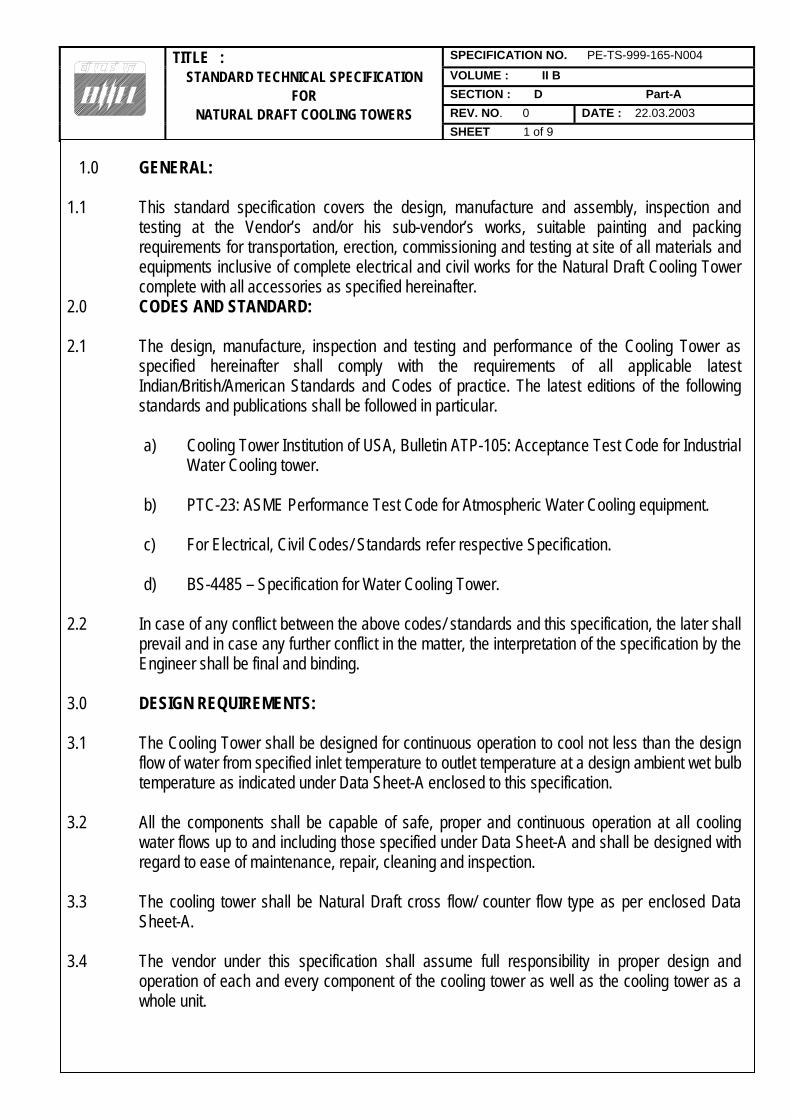
TITLE : SPECIFICATION NO. PE-TS-999-165-N004
STANDARD TECHNICAL SPECIFICATION VOLUME : II B
FOR SECTION : D Part-A
NATURAL DRAFT COOLING TOWERS REV. NO. 0 DATE : 22.03.2003
SHEET 1 of 9
1.0 GENERAL:
1.1 This standard specification covers the design, manufacture and assembly, inspection and
testing at the Vendor’s and/or his sub-vendor’s works, suitable painting and packing requirements for transportation, erection, commissioning and testing at site of all materials and equipments inclusive of complete electrical and civil works for the Natural Draft Cooling Tower complete with all accessories as specified hereinafter.
2.0 CODES AND STANDARD:
2.1 The design, manufacture, inspection and testing and performance of the Cooling Tower as specified hereinafter shall comply with the requirements of all applicable latest Indian/British/American Standards and Codes of practice. The latest editions of the following standards and publications shall be followed in particular.
a) Cooling Tower Institution of USA, Bulletin ATP-105: Acceptance Test Code for Industrial Water Cooling tower.
b) PTC-23: ASME Performance Test Code for Atmospheric Water Cooling equipment.
c) For Electrical, Civil Codes/ Standards refer respective Specification.
d) BS-4485 – Specification for Water Cooling Tower.
2.2 In case of any conflict between the above codes/ standards and this specification, the later shall prevail and in case any further conflict in the matter, the interpretation of the specification by the Engineer shall be final and binding.
3.0 DESIGN REQUIREMENTS:
3.1 The Cooling Tower shall be designed for continuous operation to cool not less than the design flow of water from specified inlet temperature to outlet temperature at a design ambient wet bulb temperature as indicated under Data Sheet-A enclosed to this specification.
3.2 All the components shall be capable of safe, proper and continuous operation at all cooling water flows up to and including those specified under Data Sheet-A and shall be designed with regard to ease of maintenance, repair, cleaning and inspection.
3.3 The cooling tower shall be Natural Draft cross flow/ counter flow type as per enclosed Data Sheet-A.
3.4 The vendor under this specification shall assume full responsibility in proper design and operation of each and every component of the cooling tower as well as the cooling tower as a whole unit.
TITLE : SPECIFICATION NO. PE-TS-999-165-N004
STANDARD TECHNICAL SPECIFICATION VOLUME : II B
FOR SECTION : D Part-A
NATURAL DRAFT COOLING TOWERS REV. NO. 0 DATE : 22.03.2003
SHEET 2 of 9
3.5 The Cooling tower shall be suitable for handling the fluid as per Data Sheet-A and also for
achieving the specified parameters in Data Sheet-A.
3.6 The Cooling tower shall be designed such that the drift losses and the evaporation losses are limited to the values as specified in Data Sheet-A.
3.7 The Cooling Tower structure shall be of adequate strength to withstand the wind load and the effect of earthquake on the structure. Design wind pressure and horizontal/vertical seismic coefficient shall be taken as mentioned in the specification for civil works enclosed to this specification.
4.0 CONSTRUCTIONAL FEATURES:
4.1 Casing and Louver (If required):
4.1.1 The Louvers shall be designed for air entry to the tower with low velocity for minimum pressure drop and less chance of recirculation of moist air. To eliminate splash out, louvers shall slope to shed water inwards.
4.1.2 The louvers and casing shall be made of material as specified in the Data Sheet-A.
4.2 Partitions:
4.2.1 Partitions shall be provided so that one section can be taken out of service without affecting the operation of capacity of other section.
4.3 Fill:
4.3.1 Cooling tower fills type and material shall be as specified in Data Sheet-A.
4.3.2 Design and arrangement of the fills shall be so as to expose high air/ water surface with minimum air pressure drop.
4.4 Fill Supports:
4.4.1 Fills shall be supported at frequent intervals, which shall minimise sag. Possibility of dislodgement and damage to fill materials as a consequence of induced vibration in the fill.
4.5 Drift Eliminations:
4.5.1 Multipass drift eliminators with minimum two-pass zig zag path type shall be provided so as to limit the drift loss to that specified in Data Sheet-A.
4.5.2 The eliminator frame shall be of rugged construction and shall be firmly secured to the structural

TITLE : SPECIFICATION NO. PE-TS-999-165-N004
STANDARD TECHNICAL SPECIFICATION VOLUME : II B
FOR SECTION : D Part-A
NATURAL DRAFT COOLING TOWERS REV. NO. 0 DATE : 22.03.2003
SHEET 3 of 9
frame to arrest vibration. Suitable access to the eliminator frame work from the basin should be provided for any maintenance or physical replacement of eliminator blades etc., when the particular cell is taken out for maintenance.
4.6 Hot Water Distribution System:
4.6.1 Motorised/Manual valves (as indicated in Data sheet A) shall be provided in the hot water distribution piping such that each section can be isolated without affecting the operation of other section.
4.6.2 The pipes and valves in hot water distribution system shall be designed to take care of the possible thermal stresses due to temperature variation. This could be achieved by providing sliding supports for supporting all the pipes fabricated from carbon steel.
4.6.3 The hot water distribution piping and valves shall be designed for the design pressure as indicated in the Data Sheet-A.
4.7 Cold Water Basin:
4.7.1 The cooling tower basin shall be constructed in RCC (unless otherwise specified in Data Sheet-A). The capacity of the cooling tower basin shall be as indicated in Data Sheet-A.
4.7.2 The cold water basin shall be partitioned into two chambers or as specified in Data Sheet-A. The two sections of the Cooling Tower basin should be separate water tight compartments, which can be isolated one at a time for cleaning/maintenance purposes.
4.7.3 Sludge pits with isolating valves and spool pipe having flanged ends shall be provided for individual basin chamber for connection to drainage pipe.
4.7.4 For each basin chamber, there shall be a cold-water outlet channel. In the connection between basin chamber and cold water outlet channel there shall be a stationary coarse bar screen and gate in the absence of any specific preference under Data Sheet-A.
4.7.5 Each basin chamber shall have an overflow arrangement and scouring arrangement.
4.8 Submersible sludge Pumps:
4.8.1 The submersible type sludge pumps complete with electric motors, discharge side valves, piping, supports, hangers and clamps etc. shall be supplied at the option of the purchaser for each cooling tower for basin draining/ desludging. The quantity, design parameters and the materials of construction of the vertical sludge pumps shall be as per Data Sheet-A. Each pump shall be non-clog type, self water lubricated. The vertical sludge pumps shall be treated as an optional item and are to be offered if asked for in the Data Sheet-A enclosed to this specification.
TITLE : SPECIFICATION NO. PE-TS-999-165-N004
STANDARD TECHNICAL SPECIFICATION VOLUME : II B
FOR SECTION : D Part-A
NATURAL DRAFT COOLING TOWERS REV. NO. 0 DATE : 22.03.2003
SHEET 4 of 9
4.9.0 Screens & Gates in Cold Water outlet Chamber:
4.9.1 The screens shall be vertical stationary type; the opening size and the mesh aperture shall be as per Data Sheet-A. The guides for the screens to be embedded in the concrete shall be of material as per Data Sheet-A.
Lifting lugs or eye bolts shall be provided on top of the screen frame for ease of handling.
4.9.2 For handling screens, one set of monorail with supporting structure and chain pulley hoist complete with lifting chain and trolley for mounting the hoist shall be furnished. The chain pulley hoist shall be manually operated and shall conform to IS-3832 class-II.
4.9.3 The gates fixed in vertical sections in cold water outlet chamber shall be as per standard practice and quality, material and type shall be as given in Data Sheet-A.
4.9.4 The isolating valves on the scour lines within the sludge pits shall conform to class I of IS-780 and shall be of reputed make.
4.10 Hardware:
4.10.1 All nails and fastening bolts, nuts and washers etc used in the cooling tower which are coming in direct contact with water or humid air shall be made of stainless steel 304, all others nuts & bolts etc. shall be made of HDG steel.
4.11.0 Access:
4.11.1 Two R.C.C. staircases for approach to the hot water distribution level
4.11.2 Doors for entrance into Cooling Tower Distribution level shall be provided as specified in Data Sheet -A.
4.11.3 Two external ladders for approach to top of cooling tower from water distribution level.
4.11.4 Access/platforms for inspection and maintenance of hot water distribution system along with spray nozzles.
4.11.5 Suitable arrangement for supporting walkways inside the cooling tower shall be made and loading of such arrangement shall be independent of the fill material.
4.11.6 Whether specifically mentioned in the data sheet or not, steel components and fittings used in walkways, handrails and access doors shall be hot dip galvanised after fabrication.
5.0 INSPECTION AND TESTING:

TITLE : SPECIFICATION NO. PE-TS-999-165-N004
STANDARD TECHNICAL SPECIFICATION VOLUME : II B
FOR SECTION : D Part-A
NATURAL DRAFT COOLING TOWERS REV. NO. 0 DATE : 22.03.2003
SHEET 5 of 9
5.1 The inspection/ testing of cooling tower and its various components shall be as per the
approved Quality Plans.
5.2 Hydrostatic test for the hot water distribution piping shall be conducted at site after complete erection. The test pressure and duration shall be as per Data Sheet-A.
6.0 TEST AT SITE:
6.1 The Cooling Tower as a whole shall be tested at site to check and ascertain that the performance meets the requirements of the specification. It is the responsibility of the vendor to conduct the performance test of the cooling tower and prove the specified parameters to the satisfaction of the purchaser. The test shall be witnessed by the purchaser/ customer’s representative or both, for which 15 days clear notice will be given to purchaser by the vendor.
6.2 The performance test of the cooling tower shall be carried out in accordance with cooling tower Institute Bulletin No. ATP 105 Acceptance test for Industrial Cooling Tower.
The details of the proposed test procedure shall be submitted by the vendor sufficiently in advance of the commencement of test for the review and approval of the purchaser.
6.3 Necessary correction curves required for correcting the test results for any difference in test and guaranteed design condition shall be furnished by the supplier for approval along with the proposed test procedure.
6.4 All testing and calibrating instruments required for the site performance test shall be arranged by the cooling tower supplier without any extra cost. All instruments used by the supplier shall be duly calibrated from a recognised Institution and the same is to be arranged by the supplier.
7.0 PERFORMACNE GUARANGTEE, TOLERANCE & PENALTIES:
7.1 Each equipment shall be guaranteed to meet the performance requirement as specified.
7.2 The tests shall be conducted at the manufacturer’s works/ site in accordance with this specification and rectification of all defects shall be satisfactory done without charging any extra amount to purchaser.
7.3 The performance test shall be carried out at site as specified and all defects shall be satisfactorily rectified within a time period decided by purchaser. No extra amount shall be charged to purchaser for such rectification. After rectification, retesting will be done by purchaser/ customer’s representative without any extra cost to purchaser till satisfactory performance is achieved.
7.4 The vendor shall submit performance curves for the cooling tower showing variation in performance from the design duty point with change in approach to wet bulb temperature,
TITLE : SPECIFICATION NO. PE-TS-999-165-N004
STANDARD TECHNICAL SPECIFICATION VOLUME : II B
FOR SECTION : D Part-A
NATURAL DRAFT COOLING TOWERS REV. NO. 0 DATE : 22.03.2003
SHEET 6 of 9
cooling range, water loading of the tower.
7.5 The vendor shall guarantee the performance of the whole cooling tower plant to meet the specifications when tested in accordance with cooling tower institute acceptance test code ATP-105, performance curves as per ATP-105 shall be furnished by the vendor.
7.6 If any defects are observed, the bidder shall rectify the same without extra cost to the purchaser. Even after rectification if the guaranteed performance is not achieved, then for every increase of 0.5 degree C or part thereof in the cold water temperature over design conditions, a sum as specified in data Sheet-A shall be paid by vendor to the purchaser for shortfall of guarantee, for the cooling tower.
7.6.1 In case the cold water temperature exceeds the acceptable limits of purchaser, the whole plant will be rejected and the vendor shall refund the entire money paid to him together with any penalty levied otherwise.
8.0 SPECIAL CLEANING PROTECTION & PAINTING:
8.1 All equipment shall be neatly finished. All exposed metal/ concrete/ wooden surface shall be smooth and free from burrs/ projections.
The metal surfaces to be painted should be accessible, suitable for priming and affording maximum protection throughout the life of the plant. The surface preparation shall be done either mechanically or chemically by one or more of the methods as given in IS-1477 (Part-I) and shall include the following:
a) Removal of oil, grease, dirt and swarf etc., as per Section 6.1 of IS-1477 (Part-I). b) Removal of rust and scale etc., as per Section 6.2 of IS-1477 (Part-I). c) Sand blasting/ shot blasting as per Section 6.2.4 of IS-1477 (Part-I) or wire brushing and
picking as specified in Data Sheet-A.
8.2 INSIDE SURFACE OF PIPING & VALVES IN HOT WATER RISERS:
8.2.1 The inside surfaces of the piping and the valves which are in contact with water and which are not made of stainless steel or other corrosion resistant materials shall be painted with coal tar based epoxy paint of approved make and quality over a coat of Zinc Chromate Primer. The thickness of cured coating shall be as specified in Data Sheet-A.
8.3 Outside Surface of Piping (Buried):
8.3.1 Surface treatment as specified in Data Sheet-A.
TITLE : SPECIFICATION NO. PE-TS-999-165-N004
STANDARD TECHNICAL SPECIFICATION VOLUME : II B
FOR SECTION : D Part-A
NATURAL DRAFT COOLING TOWERS REV. NO. 0 DATE : 22.03.2003
SHEET 7 of 9
8.3.2 Coating/ wrapping/ concrete lining as specified in Data Sheet-A.
8.4 Outside Surface or Piping (Exposed):
8.4.1 Surface treatment as specified in Data Sheet-A.
8.4.2 One coat of red oxide primer.
8.4.3 Synthetic enamel paint of approved shade, make and quality. The thickness of cured coating
shall be as specified in Data Sheet-A.
8.5 All steel parts used for cooling tower construction shall be hot dip galvanised as per IS-4736 after shop fabrication. The external surfaces of the flow regulating valves access platform, access door and also the hoisting derrick subjected to hot water fumes shall also be thoroughly cleaned and treated and shall be coated with rust preventing paints.
8.6 All parts shall be properly boxed, crated or otherwise protected for transportation. Exposed metal finished surfaces shall be thoroughly greased before transportation.
8.7 The external and internal surfaces of the tower shall also be painted.
9.0 DRAWING AND DATA AFTER AWARD OF CONTRACT:
The vendor shall furnish drawings and other technical documents as given in Data Sheet-C, enclosed with the specification.
10.0 SPECIAL TOOLS & TACKLES:
Special tools & tackles, if any, shall be included in scope of supply by the vendor. A list giving description of such tools & tackles shall be furnished by vendor.
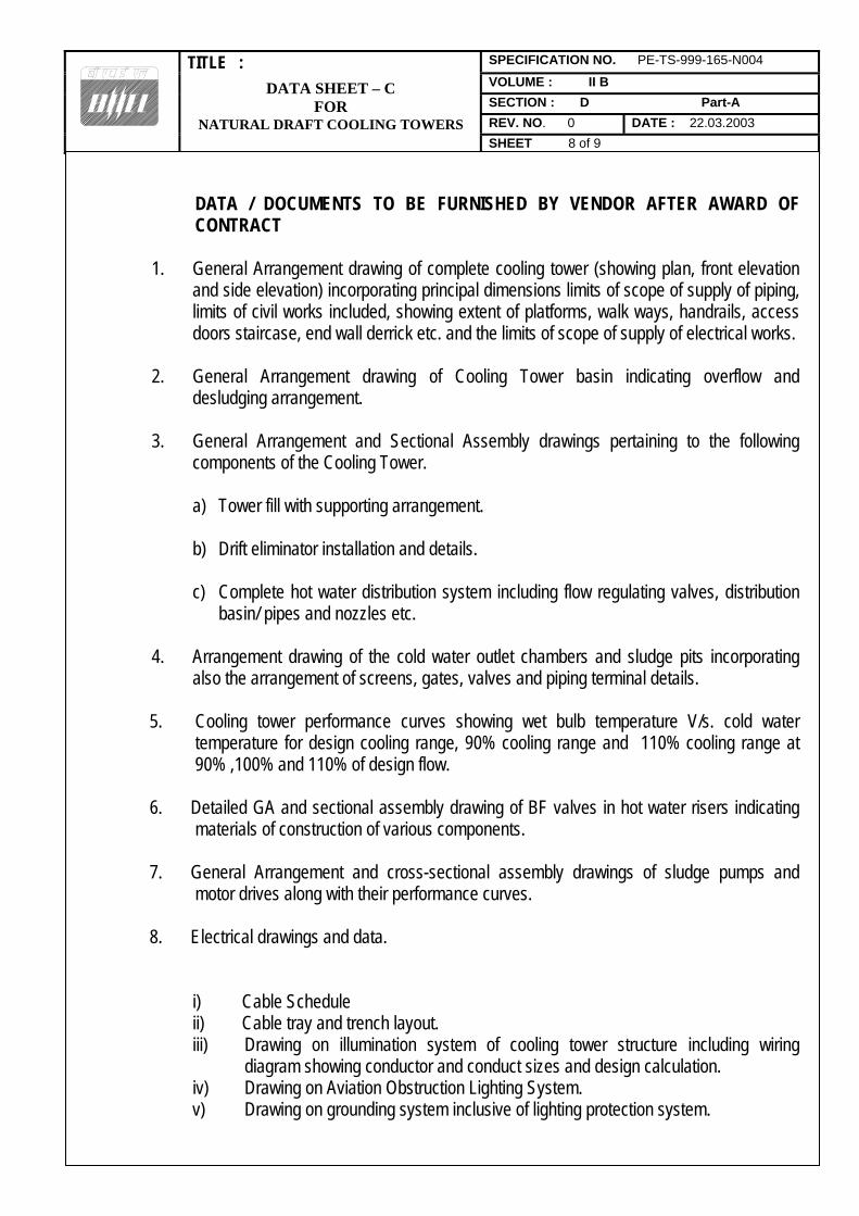
TITLE : SPECIFICATION NO. PE-TS-999-165-N004
STANDARD TECHNICAL SPECIFICATION VOLUME : II B
FOR SECTION : D Part-A
NATURAL DRAFT COOLING TOWERS REV. NO. 0 DATE : 22.03.2003
SHEET 8 of 9
DATA / DOCUMENTS TO BE FURNISHED BY VENDOR AFTER AWARD OF CONTRACT
1. General Arrangement drawing of complete cooling tower (showing plan, front elevation
and side elevation) incorporating principal dimensions limits of scope of supply of piping, limits of civil works included, showing extent of platforms, walk ways, handrails, access doors staircase, end wall derrick etc. and the limits of scope of supply of electrical works.
2. General Arrangement drawing of Cooling Tower basin indicating overflow and
desludging arrangement. 3. General Arrangement and Sectional Assembly drawings pertaining to the following
components of the Cooling Tower.
a) Tower fill with supporting arrangement.
b) Drift eliminator installation and details.
c) Complete hot water distribution system including flow regulating valves, distribution basin/ pipes and nozzles etc.
4. Arrangement drawing of the cold water outlet chambers and sludge pits incorporating
also the arrangement of screens, gates, valves and piping terminal details. 5. Cooling tower performance curves showing wet bulb temperature V/s. cold water
temperature for design cooling range, 90% cooling range and 110% cooling range at 90% ,100% and 110% of design flow.
6. Detailed GA and sectional assembly drawing of BF valves in hot water risers indicating materials of construction of various components.
7. General Arrangement and cross-sectional assembly drawings of sludge pumps and
motor drives along with their performance curves. 8. Electrical drawings and data.
i) Cable Schedule ii) Cable tray and trench layout. iii) Drawing on illumination system of cooling tower structure including wiring
diagram showing conductor and conduct sizes and design calculation. iv) Drawing on Aviation Obstruction Lighting System. v) Drawing on grounding system inclusive of lighting protection system.
DATA SHEET – C FOR
NATURAL DRAFT COOLING TOWERS
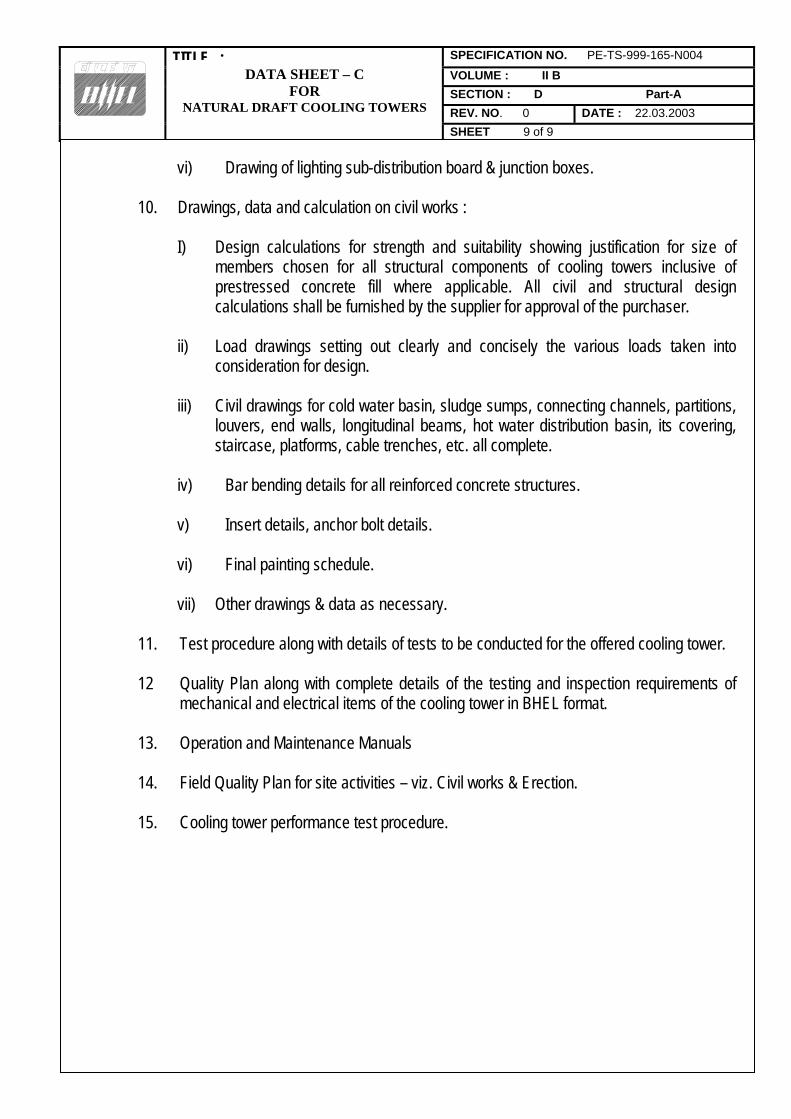
TITLE : SPECIFICATION NO. PE-TS-999-165-N004
STANDARD TECHNICAL SPECIFICATION VOLUME : II B
FOR SECTION : D Part-A
NATURAL DRAFT COOLING TOWERS REV. NO. 0 DATE : 22.03.2003
SHEET 9 of 9
vi) Drawing of lighting sub-distribution board & junction boxes.
10. Drawings, data and calculation on civil works :
I) Design calculations for strength and suitability showing justification for size of members chosen for all structural components of cooling towers inclusive of prestressed concrete fill where applicable. All civil and structural design calculations shall be furnished by the supplier for approval of the purchaser.
ii) Load drawings setting out clearly and concisely the various loads taken into
consideration for design. iii) Civil drawings for cold water basin, sludge sumps, connecting channels, partitions,
louvers, end walls, longitudinal beams, hot water distribution basin, its covering, staircase, platforms, cable trenches, etc. all complete.
iv) Bar bending details for all reinforced concrete structures. v) Insert details, anchor bolt details.
vi) Final painting schedule.
vii) Other drawings & data as necessary.
11. Test procedure along with details of tests to be conducted for the offered cooling tower. 12 Quality Plan along with complete details of the testing and inspection requirements of
mechanical and electrical items of the cooling tower in BHEL format. 13. Operation and Maintenance Manuals 14. Field Quality Plan for site activities – viz. Civil works & Erection. 15. Cooling tower performance test procedure.
DATA SHEET – C FOR
NATURAL DRAFT COOLING TOWERS

TITLE: TECHNICAL SPECIFICATION
COOLING TOWER 1X800MW KOTHAGUDEM TPS U#12
DATASHEET - A
SPEC. NO.: PE-TS-410-165-N001 VOLUME: II B SECTION: D1 REV. NO. 0 DATE 16.01.15 SHEET 1 of 7
1.0 GENERAL INFORMATION
No. of Cooling Towers required : One (01) no.
Location Out door
Duty Continuous
Type
Natural draught Counter flow with PVC Splash Bar type
Finished ground level EL (+) 2.0 M (RL+101.5M)
Basin Kerb level (Basin Sill Top level)
EL (+) 2.5 M (RL+102.0M)
2.0 DESIGN PERFORMANCE FOR EACH COOLING TOWER
2.1 Design Cooling water flow : 90000 M3/hr.
2.2 Design ambient wet bulb temp. : 28.0 oC
2.3 Design inlet air wet bulb temperature.
: 28.0 oC
2.4 Approach w.r.t. design inlet air wet bulb temperature (viz. 28.0oC)
: 5.0 oC
2.5 Cold water temperature
: 33 oC
2.6 Hot water inlet temperature
: 42.5 oC
2.7 Cooling Range : 9.5 oC
2.8
Design ambient Relative Humidity
: 45%
2.9 Liquid Handled
: Clarified Water (refer details of cooling water analysis at Annexure-3)
a) Total CW Pumping head
permissible viz. static head plus frictional losses as below:
Static head w.r.t.
FGL Frictional losses
within bidders T.P. with 10% margin
Velocity head
:
Not to exceed 16.5 MWC
2.10 Maximum permissible drift loss
: Max. 0.002 %
2.11
Design pressure for hot water distribution
:
6.2 kg/cm2(g)

TITLE: TECHNICAL SPECIFICATION
COOLING TOWER 1X800MW KOTHAGUDEM TPS U#12
DATASHEET - A
SPEC. NO.: PE-TS-410-165-N001 VOLUME: II B SECTION: D1 REV. NO. 0 DATE 16.01.15 SHEET 2 of 7
2.12
system Maximum foundation Diameter (outermost edge of foundation)
:
150 M
2.13 Minimum Basin Diameter
: 140 M
2.14
Maximum Cooling tower flow capacity to be considered for design of hot water distribution and cold water channel
:
Min 120% of design CW flow.
3.0 SPECIAL FEATURES
3.1 Basin type
Sectionalized (two compartment) by partition wall. Each basin chamber shall have overflow
arrangement and sludge pit end with necessary dewatering arrangement.
3.2 Whether fills are removable
: Yes
3.3 Fills supporting by nailing acceptable
: NO
4.0 Cold Water Basin Details
4.1 Finished ground level
: EL (+) 2.0 M (RL+101.5M)
4.2 Maximum water level
: EL (+) 2.2 M (RL+101.7M)
4.3 Min. Water level
: EL (+) 1.6 M (RL+101.1M)
4.4 Storage capacity between Normal and minimum water levels.
: 6 minutes (Between Max. & Min. Water Level) of Cooling tower design Flow.
4.5 Invert level of CT Basin : EL (+) 1.1 M (RL+100.6M) ---at basin centre EL (+) 0.45 M (RL+99.95M) ---at basin periphery
4.6 Invert level of CW Channel near CT level
: EL (-) 2.4 M (RL+97.1M)
4.7 a) Depth of Sludge pit b) Submersible type sludge pumps
: :
Suitable for complete dewatering. To include sludgepump submergence & clearance depth below basin/channel invert level
1 working + 1 standby
(Min capacity of 200 cub M / hr )
4.8 Number of sludge pits : Sludge pit with isolating valves, and spool pipe shall be provided for individual basin chambers for connection to drainage pipe.
4.9 Number of cold water outlet channels
: One for each compartment of CW basin. Cold water outlet shall be designed for flow velocity through them within 1.2 M/sec during the rated flow from cooling tower, with the minimum water level in the cold water basin. At T.P Bidder to match same as per T.P. Drawing.
4.10 Depth of CW channel 4.4 M from FGL (Ref Annexure-1)
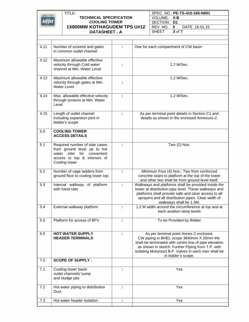
TITLE: TECHNICAL SPECIFICATION
COOLING TOWER 1X800MW KOTHAGUDEM TPS U#12
DATASHEET - A
SPEC. NO.: PE-TS-410-165-N001 VOLUME: II B SECTION: D1 REV. NO. 0 DATE 16.01.15 SHEET 3 of 7
4.11 Number of screens and gates in common outlet channel
: One for each compartment of CW basin
4.12 Maximum allowable effective velocity through Cold water channel at Min. Water Level
:
1.2 M/Sec.
4.13
Maximum allowable effective velocity through gates at Min. Water Level
: 1.2 M/Sec.
4.14
Max. allowable effective velocity through screens at Min. Water Level
: 1.2 M/Sec.
4.15
Length of outlet channel including expansion joint in bidder’s scope
: As per terminal point details in Section C1 and details as shown in the enclosed Annexure-2.
5.0 COOLING TOWER ACCESS DETAILS
5.1 Required number of stair cases from ground level up to hot water inlet for convenient access to top & interiors of Cooling tower
: Two (2) Nos.
5.2 Number of cage ladders from ground floor to cooling tower top.
: Minimum Four (4) Nos.: Two from reinforced concrete stairs to platform at the top of the tower and other two shall be from ground level itself.
5.3 Internal walkway of platform with hand rails
: Walkways and platforms shall be provided inside the tower at distribution pipe level. These walkways and platforms shall provide safe and clear access to all sprayers and all distribution pipes. Clear width of
walkways shall be 1.5M. 5.4 External walkway platform : 1.2 M width around the circumference at top and at
each aviation lamp levels
5.5 Platform for access of BFV : To be Provided by Bidder
6.0
HOT WATER SUPPLY HEADER TERMINALS
: As per terminal point Annex-2 enclosed. CW piping in BHEL scope 3840mm X 20mm thk.
shall be terminated with centre line of pipe elevation as shown in sketch. Further Piping from T.P. with
isolating Motorized B.F. Valves in each riser shall be in bidder’s scope.
7.0 SCOPE OF SUPPLY :
7.1 Cooling tower basin outlet channels/ sump and sludge pits
: Yes
7.2 Hot water piping to distribution Duct
: Yes
7.3 Hot water header isolation : Yes
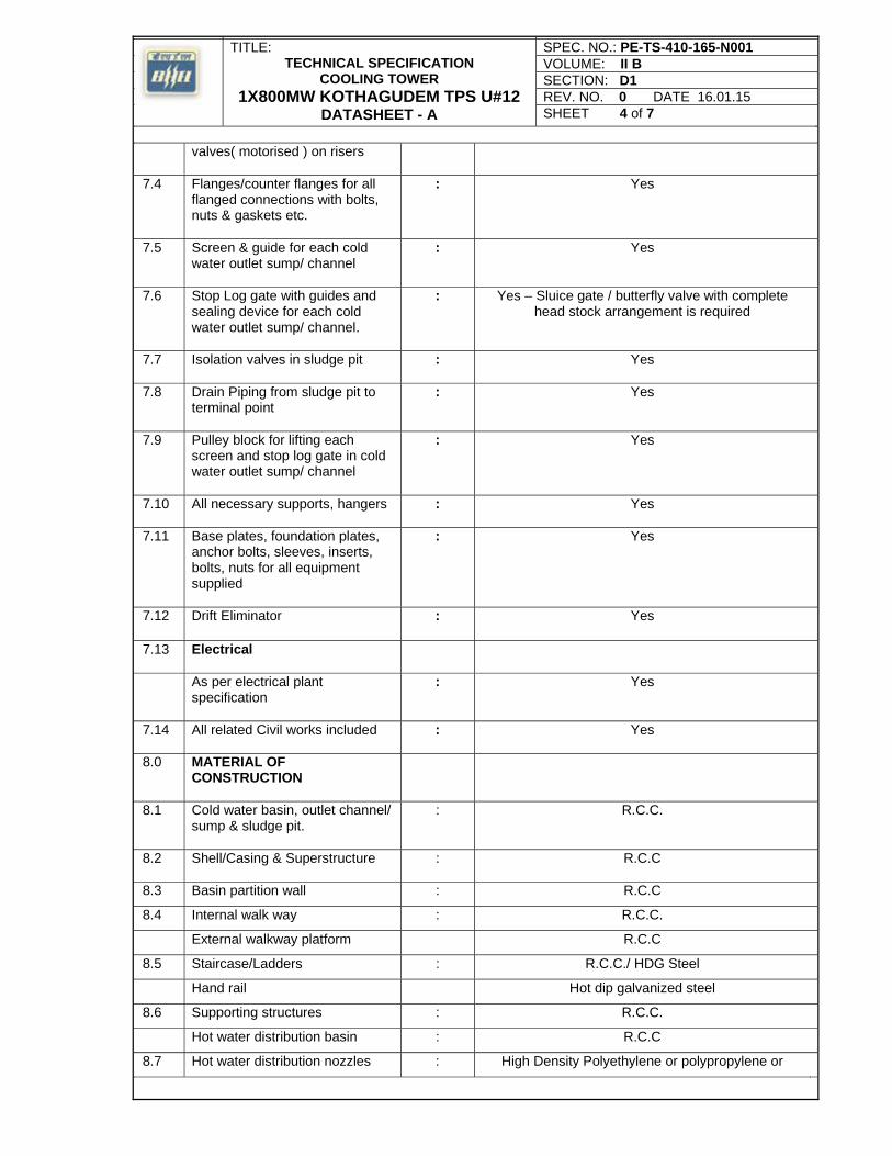
TITLE: TECHNICAL SPECIFICATION
COOLING TOWER 1X800MW KOTHAGUDEM TPS U#12
DATASHEET - A
SPEC. NO.: PE-TS-410-165-N001 VOLUME: II B SECTION: D1 REV. NO. 0 DATE 16.01.15 SHEET 4 of 7
valves( motorised ) on risers
7.4 Flanges/counter flanges for all flanged connections with bolts, nuts & gaskets etc.
: Yes
7.5 Screen & guide for each cold water outlet sump/ channel
: Yes
7.6 Stop Log gate with guides and sealing device for each cold water outlet sump/ channel.
: Yes – Sluice gate / butterfly valve with complete head stock arrangement is required
7.7 Isolation valves in sludge pit
: Yes
7.8 Drain Piping from sludge pit to terminal point
: Yes
7.9 Pulley block for lifting each screen and stop log gate in cold water outlet sump/ channel
: Yes
7.10 All necessary supports, hangers
: Yes
7.11 Base plates, foundation plates, anchor bolts, sleeves, inserts, bolts, nuts for all equipment supplied
: Yes
7.12 Drift Eliminator : Yes
7.13 Electrical
As per electrical plant specification
: Yes
7.14 All related Civil works included
: Yes
8.0 MATERIAL OF CONSTRUCTION
8.1 Cold water basin, outlet channel/ sump & sludge pit.
: R.C.C.
8.2 Shell/Casing & Superstructure
: R.C.C
8.3 Basin partition wall : R.C.C
8.4 Internal walk way : R.C.C.
External walkway platform R.C.C
8.5 Staircase/Ladders : R.C.C./ HDG Steel
Hand rail Hot dip galvanized steel
8.6 Supporting structures : R.C.C.
Hot water distribution basin : R.C.C
8.7 Hot water distribution nozzles : High Density Polyethylene or polypropylene or
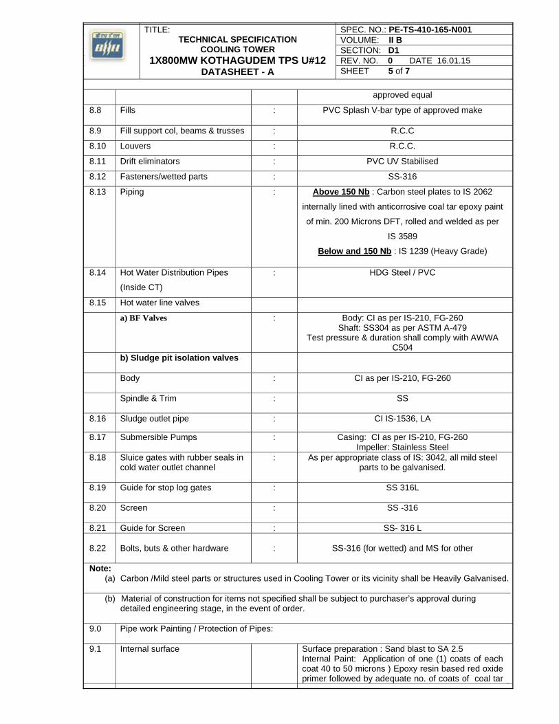
TITLE: TECHNICAL SPECIFICATION
COOLING TOWER 1X800MW KOTHAGUDEM TPS U#12
DATASHEET - A
SPEC. NO.: PE-TS-410-165-N001 VOLUME: II B SECTION: D1 REV. NO. 0 DATE 16.01.15 SHEET 5 of 7
approved equal
8.8 Fills : PVC Splash V-bar type of approved make
8.9 Fill support col, beams & trusses : R.C.C
8.10 Louvers : R.C.C.
8.11 Drift eliminators : PVC UV Stabilised
8.12 Fasteners/wetted parts : SS-316
8.13 Piping : Above 150 Nb : Carbon steel plates to IS 2062
internally lined with anticorrosive coal tar epoxy paint
of min. 200 Microns DFT, rolled and welded as per
IS 3589
Below and 150 Nb : IS 1239 (Heavy Grade)
8.14 Hot Water Distribution Pipes
(Inside CT)
: HDG Steel / PVC
8.15 Hot water line valves
a) BF Valves : Body: CI as per IS-210, FG-260 Shaft: SS304 as per ASTM A-479
Test pressure & duration shall comply with AWWA C504
b) Sludge pit isolation valves
Body
: CI as per IS-210, FG-260
Spindle & Trim : SS
8.16 Sludge outlet pipe : CI IS-1536, LA
8.17 Submersible Pumps : Casing: CI as per IS-210, FG-260 Impeller: Stainless Steel
8.18 Sluice gates with rubber seals in cold water outlet channel
: As per appropriate class of IS: 3042, all mild steel parts to be galvanised.
8.19 Guide for stop log gates
: SS 316L
8.20 Screen : SS -316
8.21 Guide for Screen : SS- 316 L 8.22
Bolts, buts & other hardware
:
SS-316 (for wetted) and MS for other
Note:
(a) Carbon /Mild steel parts or structures used in Cooling Tower or its vicinity shall be Heavily Galvanised.
(b) Material of construction for items not specified shall be subject to purchaser’s approval during detailed engineering stage, in the event of order.
9.0 Pipe work Painting / Protection of Pipes:
9.1 Internal surface
Surface preparation : Sand blast to SA 2.5 Internal Paint: Application of one (1) coats of each coat 40 to 50 microns ) Epoxy resin based red oxide primer followed by adequate no. of coats of coal tar
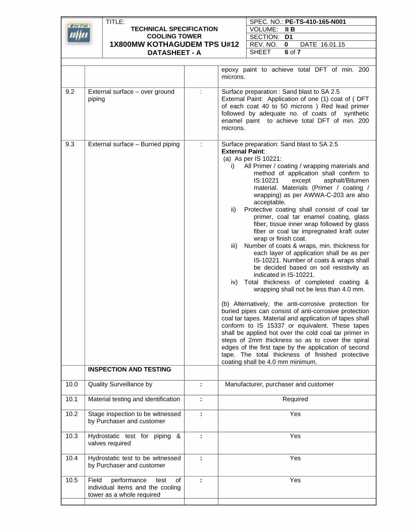
TITLE: TECHNICAL SPECIFICATION
COOLING TOWER 1X800MW KOTHAGUDEM TPS U#12
DATASHEET - A
SPEC. NO.: PE-TS-410-165-N001 VOLUME: II B SECTION: D1 REV. NO. 0 DATE 16.01.15 SHEET 6 of 7
epoxy paint to achieve total DFT of min. 200 microns.
9.2 External surface – over ground piping
: Surface preparation : Sand blast to SA 2.5 External Paint: Application of one (1) coat of ( DFT of each coat 40 to 50 microns ) Red lead primer followed by adequate no. of coats of synthetic enamel paint to achieve total DFT of min. 200 microns.
9.3 External surface – Burried piping : Surface preparation: Sand blast to SA 2.5 External Paint: (a) As per IS 10221:
i) All Primer / coating / wrapping materials and method of application shall confirm to IS:10221 except asphalt/Bitumen material. Materials (Primer / coating / wrapping) as per AWWA-C-203 are also acceptable.
ii) Protective coating shall consist of coal tar primer, coal tar enamel coating, glass fiber, tissue inner wrap followed by glass fiber or coal tar impregnated kraft outer wrap or finish coat.
iii) Number of coats & wraps, min. thickness for each layer of application shall be as per IS-10221. Number of coats & wraps shall be decided based on soil resistivity as indicated in IS-10221.
iv) Total thickness of completed coating & wrapping shall not be less than 4.0 mm.
(b) Alternatively, the anti-corrosive protection for buried pipes can consist of anti-corrosive protection coal tar tapes. Material and application of tapes shall conform to IS 15337 or equivalent. These tapes shall be applied hot over the cold coal tar primer in steps of 2mm thickness so as to cover the spiral edges of the first tape by the application of second tape. The total thickness of finished protective coating shall be 4.0 mm minimum.
INSPECTION AND TESTING
10.0
Quality Surveillance by : Manufacturer, purchaser and customer
10.1 Material testing and identification
: Required
10.2 Stage inspection to be witnessed by Purchaser and customer
: Yes
10.3 Hydrostatic test for piping & valves required
: Yes
10.4 Hydrostatic test to be witnessed by Purchaser and customer
: Yes
10.5 Field performance test of individual items and the cooling tower as a whole required
: Yes
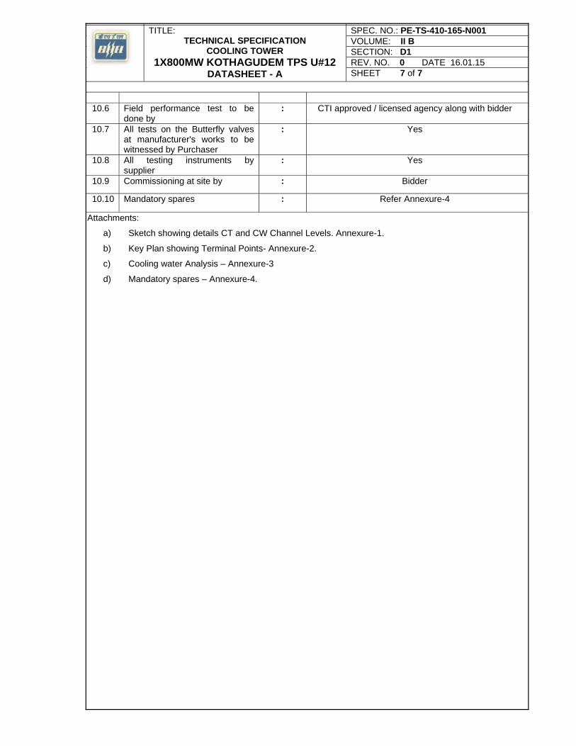
TITLE: TECHNICAL SPECIFICATION
COOLING TOWER 1X800MW KOTHAGUDEM TPS U#12
DATASHEET - A
SPEC. NO.: PE-TS-410-165-N001 VOLUME: II B SECTION: D1 REV. NO. 0 DATE 16.01.15 SHEET 7 of 7
10.6 Field performance test to be done by
: CTI approved / licensed agency along with bidder
10.7 All tests on the Butterfly valves at manufacturer's works to be witnessed by Purchaser
: Yes
10.8 All testing instruments by supplier
: Yes
10.9 Commissioning at site by : Bidder
10.10 Mandatory spares : Refer Annexure-4
Attachments:
a) Sketch showing details CT and CW Channel Levels. Annexure-1.
b) Key Plan showing Terminal Points- Annexure-2.
c) Cooling water Analysis – Annexure-3
d) Mandatory spares – Annexure-4.

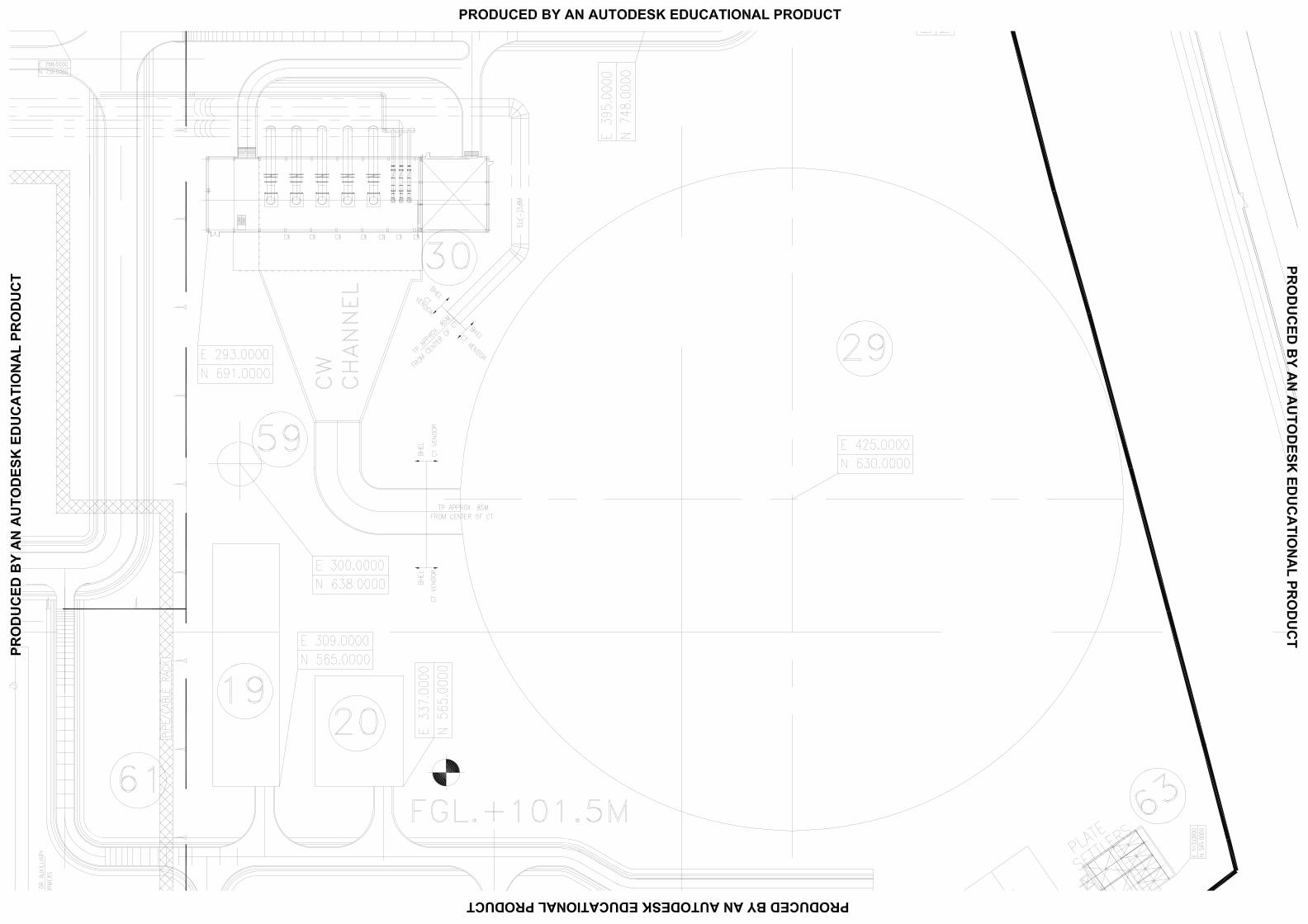
6042023
Text Box
ANNEXURE-2
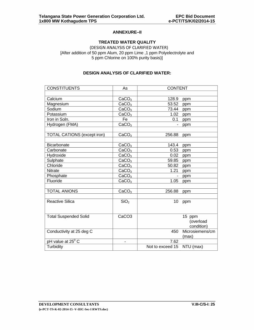
Telangana State Power Generation Corporation Ltd. EPC Bid Document 1x800 MW Kothagudem TPS e-PCT/TS/K/02/2014-15
DEVELOPMENT CONSULTANTS V.III-C/S-I: 25 (e-PCT-TS-K-02-2014-15 -V-IIIC-Sec-I RWTS.doc)
ANNEXURE–II
TREATED WATER QUALITY (DESIGN ANALYSIS OF CLARIFIED WATER)
[After addition of 50 ppm Alum, 20 ppm Lime ,1 ppm Polyelectrolyte and 5 ppm Chlorine on 100% purity basis)]
DESIGN ANALYSIS OF CLARIFIED WATER:
CONSTITUENTS As CONTENT Calcium CaCO3 128.9 ppm Magnesium CaCO3 53.52 ppm Sodium CaCO3 73.44 ppm Potassium CaCO3 1.02 ppm Iron in Soln. Fe 0.1 ppm Hydrogen (FMA) CaCO3 - ppm TOTAL CATIONS (except iron) CaCO3 256.88 ppm Bicarbonate CaCO3 143.4 ppm Carbonate CaCO3 0.53 ppm Hydroxide CaCO3 0.02 ppm Sulphate CaCO3 59.85 ppm Chloride CaCO3 50.82 ppm Nitrate CaCO3 1.21 ppm Phosphate CaCO3 - ppm Fluoride CaCO3 1.05 ppm TOTAL ANIONS CaCO3 256.88 ppm Reactive Silica
SiO2
10 ppm
Total Suspended Solid CaCO3 15 ppm (overload condition)
Conductivity at 25 deg C 450 Microsiemens/cm (max)
pH value at 250 C - 7.62 Turbidity Not to exceed 15 NTU (max)
6045324
Text Box
10 ppm for normal condition
6045324
Text Box
10 NTU for normal condition
6042023
Text Box
ANNEXURE-3
6042023
Text Box
COC for CW system shall be 5. The water analysis may be suitably corrected for COC 5 by the bidder.
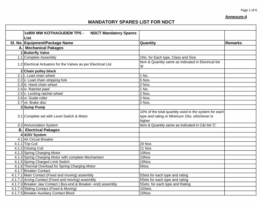
Page 1 of 6
Annexure-4
1x800 MW KOTHAGUDEM TPS - NDCT Mandatory Spares List
Sl. No. Equipment/Package Name Quantity RemarksA. Mechanical Pakages1 Butterfly Valve
1.1 Complete Assembly 1No. for Each type, Class and Size
1.2 Electrical Actuators for the Valves as per Electrical List Item & Quantity same as indicated in Electrical list 'B'
2 Chain pulley block 2.1 i. Load chain wheel 1 No.2.2 ii. Load chain stripping fork 5 Nos.2.3 iii. Hand chain wheel 2 Nos.2.4 iv. Ratchet pawl 1 No.2.5 v. Locking ratchet wheel 2 Nos.2.6 vi. Guide roller 2 Nos.2.7 vii. Brake disc 2 Nos.
3 Sump Pump
3.1 Complete set with Level Switch & Motor10% of the total quantity used in the system for each type and rating or Minimum 1No. whichever is higher
3.2 Annunciation System Item & Quantity same as indicated in C&I list 'C'B. Electrical Pakages4 415V System
4.1 Air Circuit Breaker 4.1.1 Trip Coil 20 Nos4.1.2 Closing Coil 21 Nos4.1.3 Spring Charging Motor 10Nos4.1.4 Spring Charging Motor with complete Mechanisim 10Nos4.1.5 Spring Charged Limit Switch 10Nos.4.1.6 Thermal Overload for Spring Charging Motor 5Nos.4.1.7 Breaker Contact
4.1.7.1 Main Contact (Fixed and moving) assembly 5Sets for each type and rating4.1.7.2 Arcing Contact (Fixed and moving) assembly 5Sets for each type and rating4.1.7.3 Breaker Jaw Contact ( Bus-end & Breaker- end) assembly 5Sets. for each type and Rating4.1.7.4 Sliding Contact (Fixed & Moving) 15Sets.4.1.7.5 Breaker Auxiliary Contact Block 15Nos.
MANDATORY SPARES LIST FOR NDCT
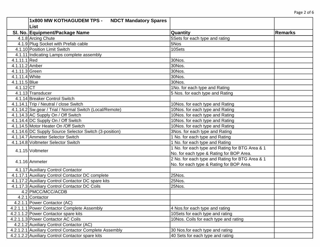
Page 2 of 6
1x800 MW KOTHAGUDEM TPS - NDCT Mandatory Spares List
Sl. No. Equipment/Package Name Quantity Remarks4.1.8 Arcing Chute 5Sets for each type and rating4.1.9 Plug Socket with Prefab cable 5Nos
4.1.10 Position Limit Switch 10Sets4.1.11 Indicating Lamps complete assembly
4.1.11.1 Red 30Nos.4.1.11.2 Amber 30Nos.4.1.11.3 Green 30Nos.4.1.11.4 White 30Nos.4.1.11.5 Blue 30Nos.
4.1.12 CT 1No. for each type and Rating 4.1.13 Transducer 5 Nos. for each type and Rating4.1.14 Breaker Control Switch
4.1.14.1 Trip / Neutral / close Switch 10Nos. for each type and Rating4.1.14.2 Sw.gear / Trial / Normal Switch (Local/Remote) 10Nos. for each type and Rating4.1.14.3 AC Supply On / Off Switch 10Nos. for each type and Rating4.1.14.4 DC Supply On / Off Switch 10Nos. for each type and Rating4.1.14.5 Motor Heater On /Off Switch 10Nos. for each type and Rating4.1.14.6 DC Supply Source Selector Switch (3-position) 3Nos. for each type and Rating4.1.14.7 Ammeter Selector Switch 1 No. for each type and Rating4.1.14.8 Voltmeter Selector Switch 1 No. for each type and Rating
4.1.15 Voltmeter1 No. for each type and Rating for BTG Area & 1 No. for each type & Rating for BOP Area.
4.1.16 Ammeter2 No. for each type and Rating for BTG Area & 1 No. for each type & Rating for BOP Area.
4.1.17 Auxiliary Control Contactor 4.1.17.1 Auxiliary Control Contactor DC complete 25Nos.4.1.17.2 Auxiliary Control Contactor DC spare kits 25Nos.4.1.17.3 Auxiliary Control Contactor DC Coils 25Nos.
4.2 PMCC/MCC/ACDB 4.2.1 Contactor
4.2.1.1 Power Contactor (AC) 4.2.1.1.1 Power Contactor Complete Assembly 4 Nos.for each type and rating4.2.1.1.2 Power Contactor spare kits 10Sets for each type and rating4.2.1.1.3 Power Contactor AC Coils 10Nos. Coils for each type and rating
4.2.1.2 Auxiliary Control Contactor (AC) 4.2.1.2.1 Auxiliary Control Contactor Complete Assembly 30 Nos.for each type and rating4.2.1.2.2 Auxiliary Control Contactor spare kits 40 Sets for each type and rating
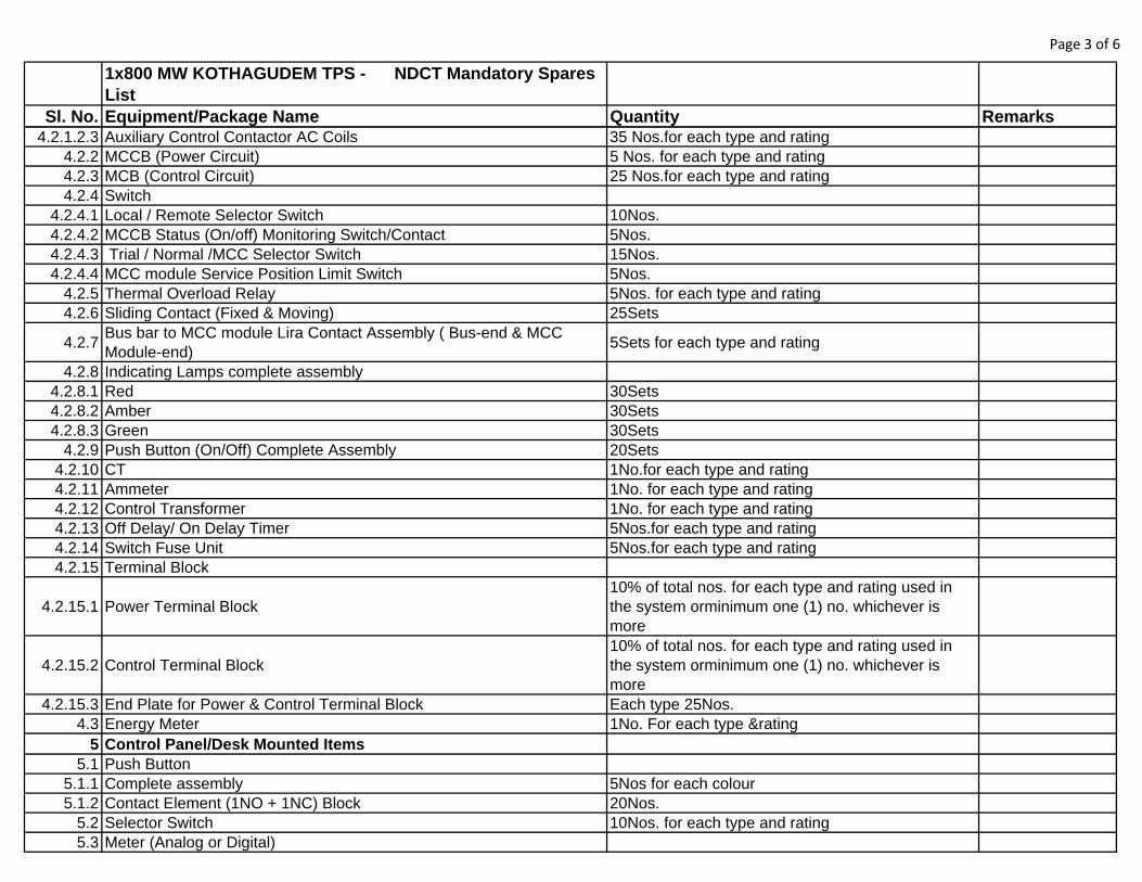
Page 3 of 6
1x800 MW KOTHAGUDEM TPS - NDCT Mandatory Spares List
Sl. No. Equipment/Package Name Quantity Remarks4.2.1.2.3 Auxiliary Control Contactor AC Coils 35 Nos.for each type and rating
4.2.2 MCCB (Power Circuit) 5 Nos. for each type and rating4.2.3 MCB (Control Circuit) 25 Nos.for each type and rating4.2.4 Switch
4.2.4.1 Local / Remote Selector Switch 10Nos.4.2.4.2 MCCB Status (On/off) Monitoring Switch/Contact 5Nos.4.2.4.3 Trial / Normal /MCC Selector Switch 15Nos.4.2.4.4 MCC module Service Position Limit Switch 5Nos.
4.2.5 Thermal Overload Relay 5Nos. for each type and rating4.2.6 Sliding Contact (Fixed & Moving) 25Sets
4.2.7Bus bar to MCC module Lira Contact Assembly ( Bus-end & MCC Module-end)
5Sets for each type and rating
4.2.8 Indicating Lamps complete assembly 4.2.8.1 Red 30Sets4.2.8.2 Amber 30Sets4.2.8.3 Green 30Sets
4.2.9 Push Button (On/Off) Complete Assembly 20Sets4.2.10 CT 1No.for each type and rating4.2.11 Ammeter 1No. for each type and rating4.2.12 Control Transformer 1No. for each type and rating4.2.13 Off Delay/ On Delay Timer 5Nos.for each type and rating4.2.14 Switch Fuse Unit 5Nos.for each type and rating4.2.15 Terminal Block
4.2.15.1 Power Terminal Block10% of total nos. for each type and rating used in the system orminimum one (1) no. whichever is more
4.2.15.2 Control Terminal Block10% of total nos. for each type and rating used in the system orminimum one (1) no. whichever is more
4.2.15.3 End Plate for Power & Control Terminal Block Each type 25Nos.4.3 Energy Meter 1No. For each type &rating
5 Control Panel/Desk Mounted Items 5.1 Push Button
5.1.1 Complete assembly 5Nos for each colour5.1.2 Contact Element (1NO + 1NC) Block 20Nos.
5.2 Selector Switch 10Nos. for each type and rating5.3 Meter (Analog or Digital)
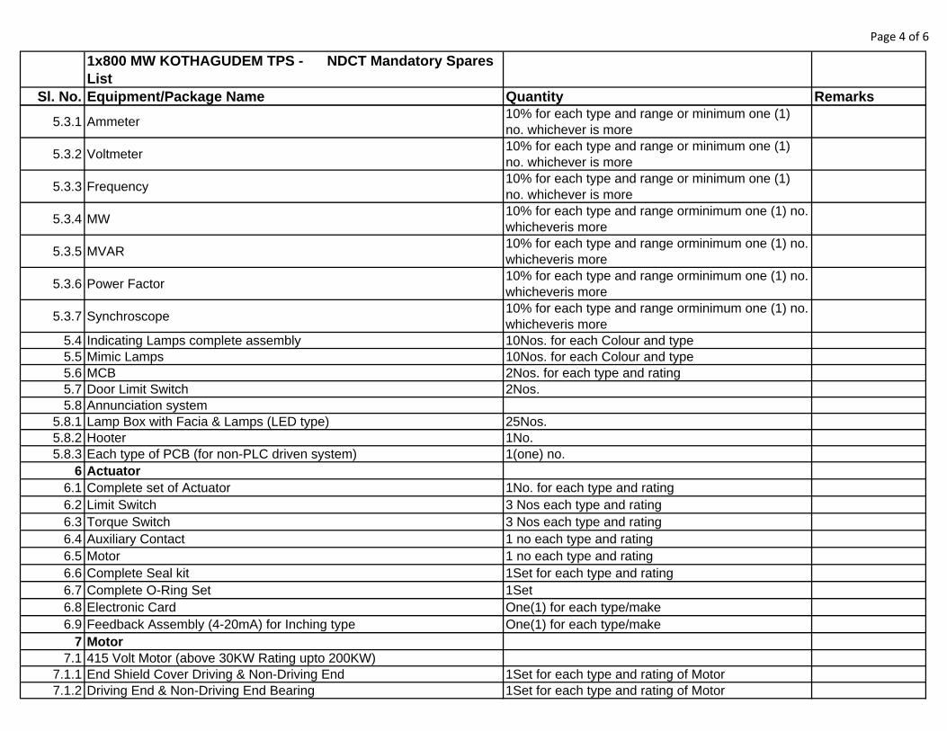
Page 4 of 6
1x800 MW KOTHAGUDEM TPS - NDCT Mandatory Spares List
Sl. No. Equipment/Package Name Quantity Remarks
5.3.1 Ammeter10% for each type and range or minimum one (1) no. whichever is more
5.3.2 Voltmeter10% for each type and range or minimum one (1) no. whichever is more
5.3.3 Frequency 10% for each type and range or minimum one (1) no. whichever is more
5.3.4 MW10% for each type and range orminimum one (1) no. whicheveris more
5.3.5 MVAR10% for each type and range orminimum one (1) no. whicheveris more
5.3.6 Power Factor10% for each type and range orminimum one (1) no. whicheveris more
5.3.7 Synchroscope10% for each type and range orminimum one (1) no. whicheveris more
5.4 Indicating Lamps complete assembly 10Nos. for each Colour and type5.5 Mimic Lamps 10Nos. for each Colour and type5.6 MCB 2Nos. for each type and rating5.7 Door Limit Switch 2Nos.5.8 Annunciation system
5.8.1 Lamp Box with Facia & Lamps (LED type) 25Nos.5.8.2 Hooter 1No.5.8.3 Each type of PCB (for non-PLC driven system) 1(one) no.
6 Actuator 6.1 Complete set of Actuator 1No. for each type and rating6.2 Limit Switch 3 Nos each type and rating6.3 Torque Switch 3 Nos each type and rating6.4 Auxiliary Contact 1 no each type and rating6.5 Motor 1 no each type and rating6.6 Complete Seal kit 1Set for each type and rating6.7 Complete O-Ring Set 1Set6.8 Electronic Card One(1) for each type/make6.9 Feedback Assembly (4-20mA) for Inching type One(1) for each type/make
7 Motor 7.1 415 Volt Motor (above 30KW Rating upto 200KW)
7.1.1 End Shield Cover Driving & Non-Driving End 1Set for each type and rating of Motor7.1.2 Driving End & Non-Driving End Bearing 1Set for each type and rating of Motor
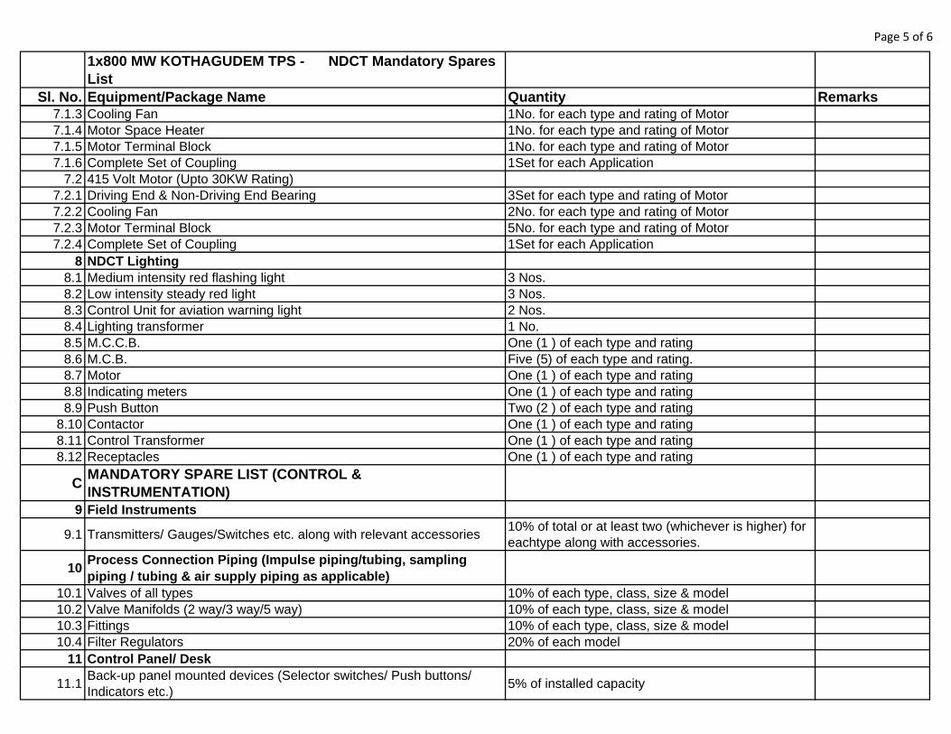
Page 5 of 6
1x800 MW KOTHAGUDEM TPS - NDCT Mandatory Spares List
Sl. No. Equipment/Package Name Quantity Remarks7.1.3 Cooling Fan 1No. for each type and rating of Motor7.1.4 Motor Space Heater 1No. for each type and rating of Motor7.1.5 Motor Terminal Block 1No. for each type and rating of Motor7.1.6 Complete Set of Coupling 1Set for each Application
7.2 415 Volt Motor (Upto 30KW Rating) 7.2.1 Driving End & Non-Driving End Bearing 3Set for each type and rating of Motor7.2.2 Cooling Fan 2No. for each type and rating of Motor7.2.3 Motor Terminal Block 5No. for each type and rating of Motor7.2.4 Complete Set of Coupling 1Set for each Application
8 NDCT Lighting 8.1 Medium intensity red flashing light 3 Nos.8.2 Low intensity steady red light 3 Nos.8.3 Control Unit for aviation warning light 2 Nos.8.4 Lighting transformer 1 No.8.5 M.C.C.B. One (1 ) of each type and rating8.6 M.C.B. Five (5) of each type and rating.8.7 Motor One (1 ) of each type and rating8.8 Indicating meters One (1 ) of each type and rating8.9 Push Button Two (2 ) of each type and rating
8.10 Contactor One (1 ) of each type and rating8.11 Control Transformer One (1 ) of each type and rating8.12 Receptacles One (1 ) of each type and rating
CMANDATORY SPARE LIST (CONTROL & INSTRUMENTATION)
9 Field Instruments
9.1 Transmitters/ Gauges/Switches etc. along with relevant accessories10% of total or at least two (whichever is higher) for eachtype along with accessories.
10Process Connection Piping (Impulse piping/tubing, sampling piping / tubing & air supply piping as applicable)
10.1 Valves of all types 10% of each type, class, size & model10.2 Valve Manifolds (2 way/3 way/5 way) 10% of each type, class, size & model10.3 Fittings 10% of each type, class, size & model10.4 Filter Regulators 20% of each model
11 Control Panel/ Desk
11.1Back-up panel mounted devices (Selector switches/ Push buttons/ Indicators etc.)
5% of installed capacity

Page 6 of 6
1x800 MW KOTHAGUDEM TPS - NDCT Mandatory Spares List
Sl. No. Equipment/Package Name Quantity Remarks11.2 Lamps/ LEDs 100% of the total quantity11.3 Blank Tiles 10% of installed capacity11.4 MCBs 10% of each type & rating11.5 Fuses/ Fuse holder 100% of each type & rating
12 Alarm/ Annunciation system 12.1 Each type of module 1 no. each12.2 Lamp box with Facia & Lamps (LED type) 10% of total quantity or minimum 20 nos.12.3 Hooter 1 no.
13 Junction Box
13.1 Junction box10% of total quantity for each size but minimum 2 nos.
13.2 Terminals in Terminal blocks 10 nos. of each type
NOTES:
1
2
3
ANY ITEM ABOVE WHICH IS NOT REQUIRED, MAY BE INDICATED AS 'NOT APPLICABLE'. HOWEVER DURING DETAILED ENGINEERING IF THAT ITEM FOUND TO BE APPLICABLE, SAME SHALL BE SUPPLIED BY THE BIDDER WITHOUT ANY EXTRA COST TO BHEL/CUSTOMER.
WHEREEVER THE QTY. IS MENTIONED IN PERCENTAGE / SETS, BIDDER TO INDICATE THE QUANTITY IN THE REMARKS COLUMN. THE QUANTITY SHALL BE VERIFIED DURING DETAILED ENGINEERING AND ANY CHANGE IN QUANTITY SHALL BE ACCOMODATED BY THE BIDDER WITHOUT ANY PRICE IMPLICATION.
The Bidder shall offer mandatory spares of the same make, model and type for items which are offered in the main offer. Further, offered spare parts shall be of the same grade and shall have same performance as the instruments which they are to replace.
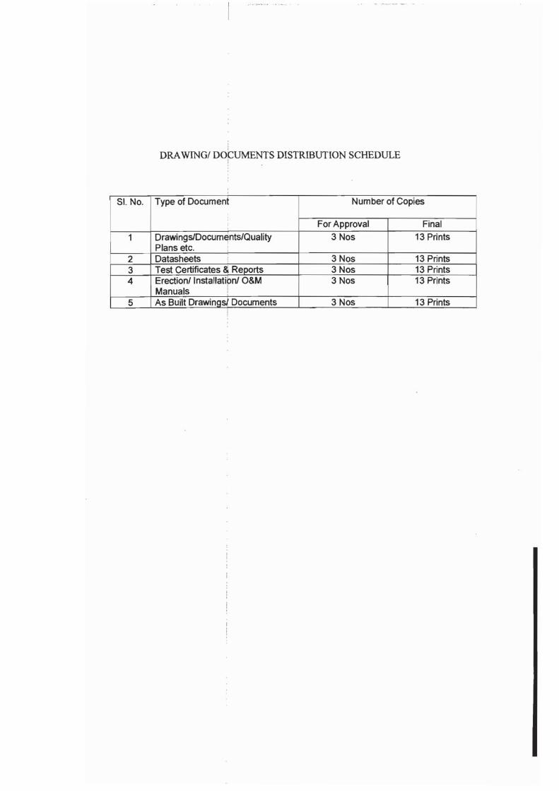
6042023
Text Box
STANDARD QUALITY PLAN
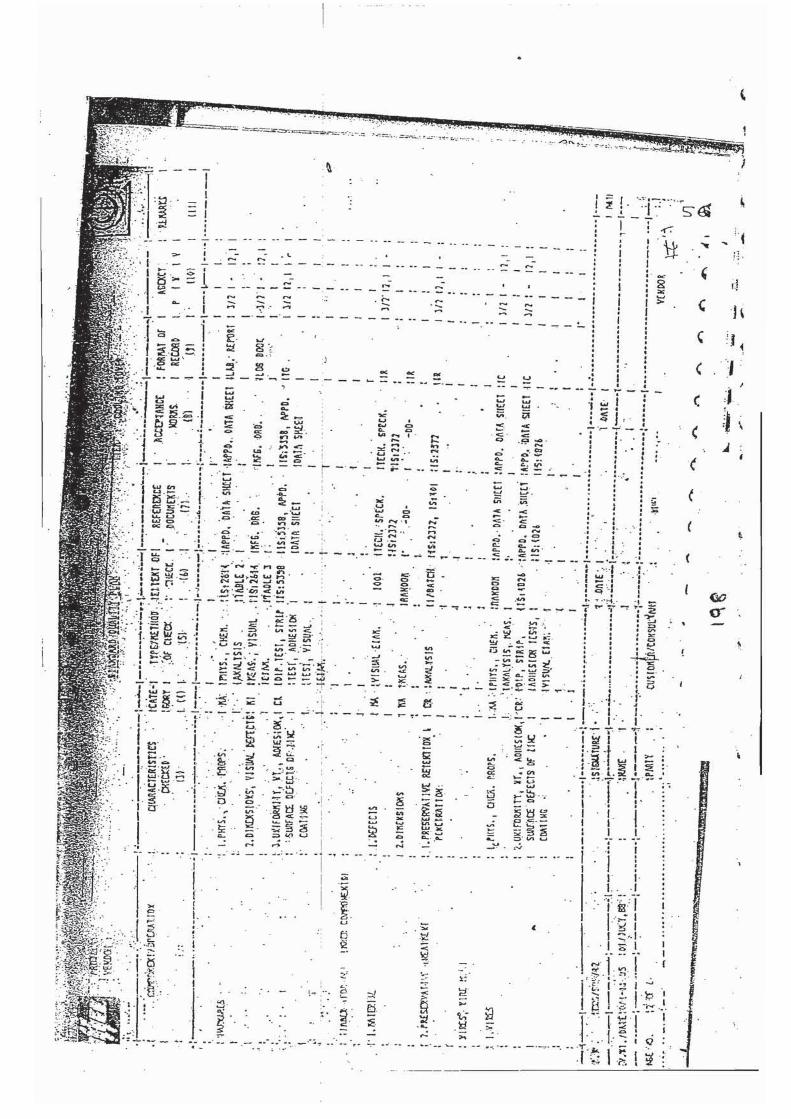


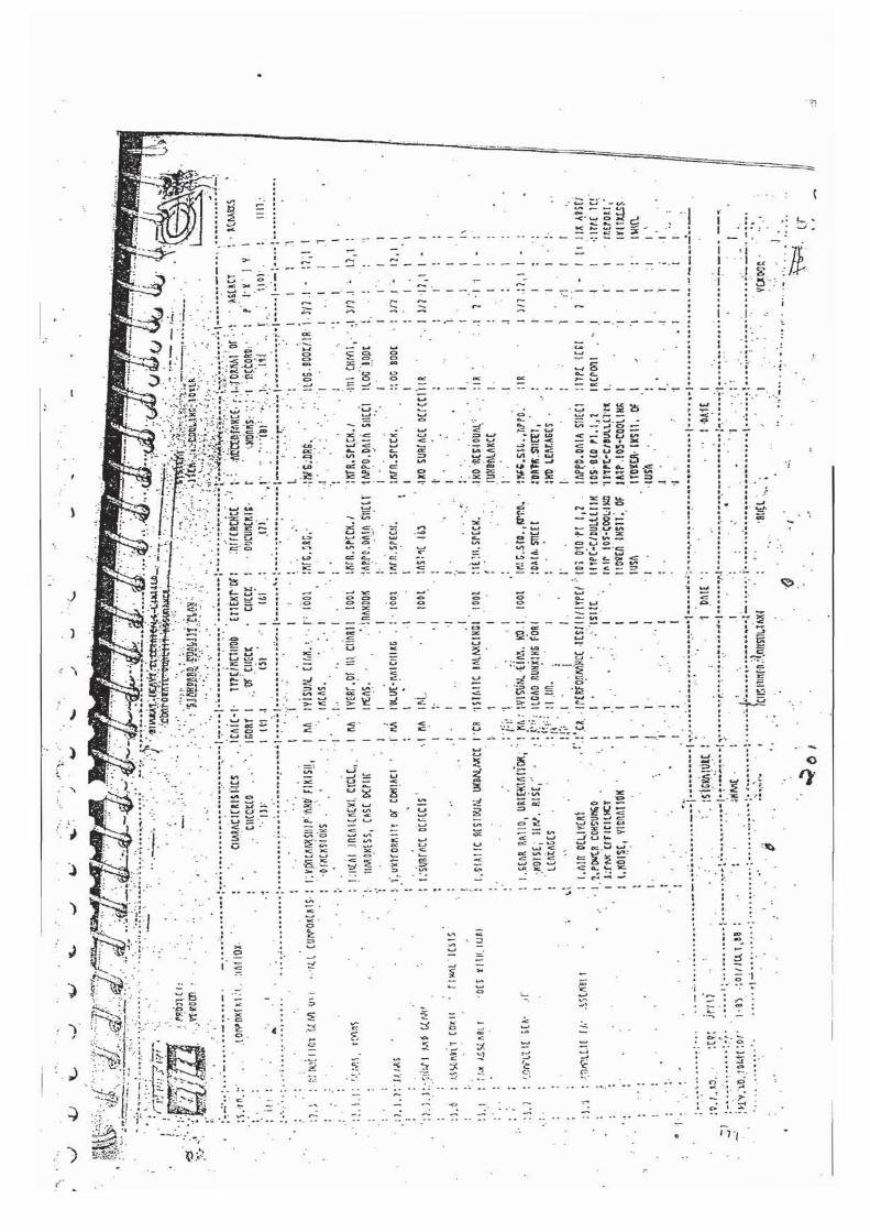

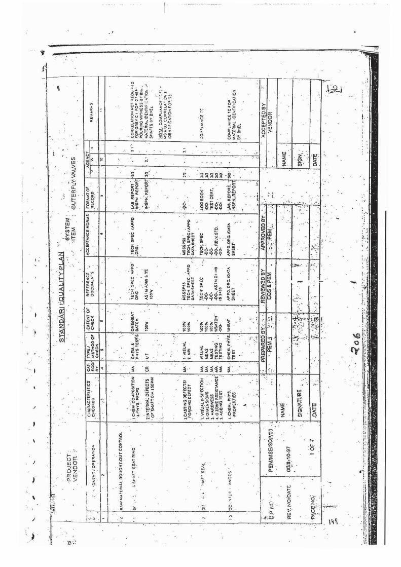

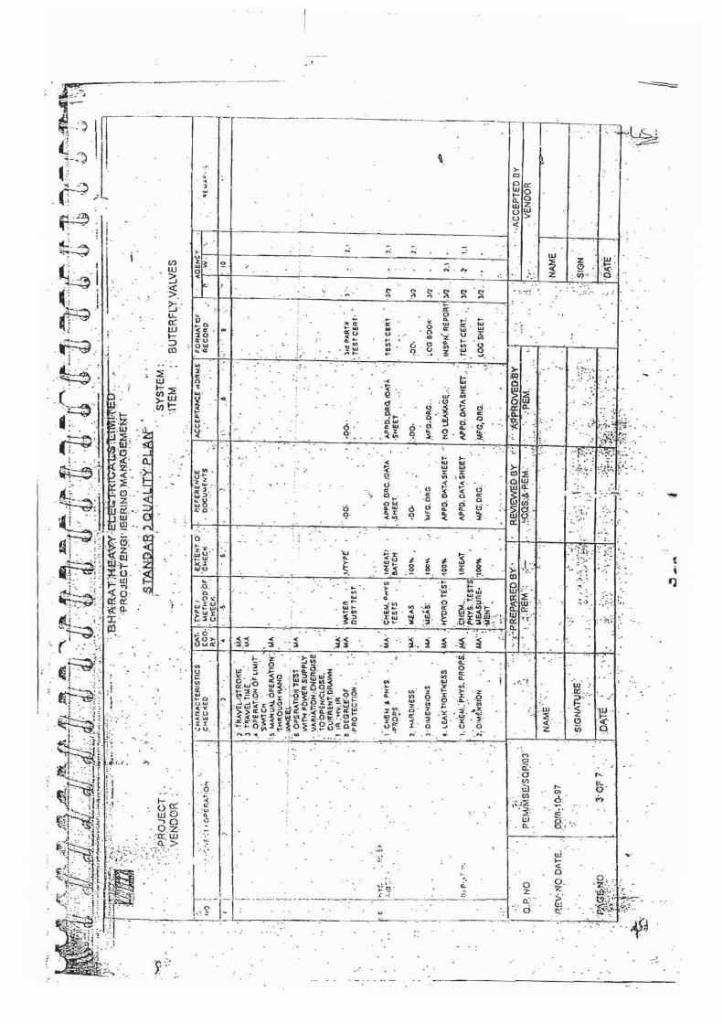
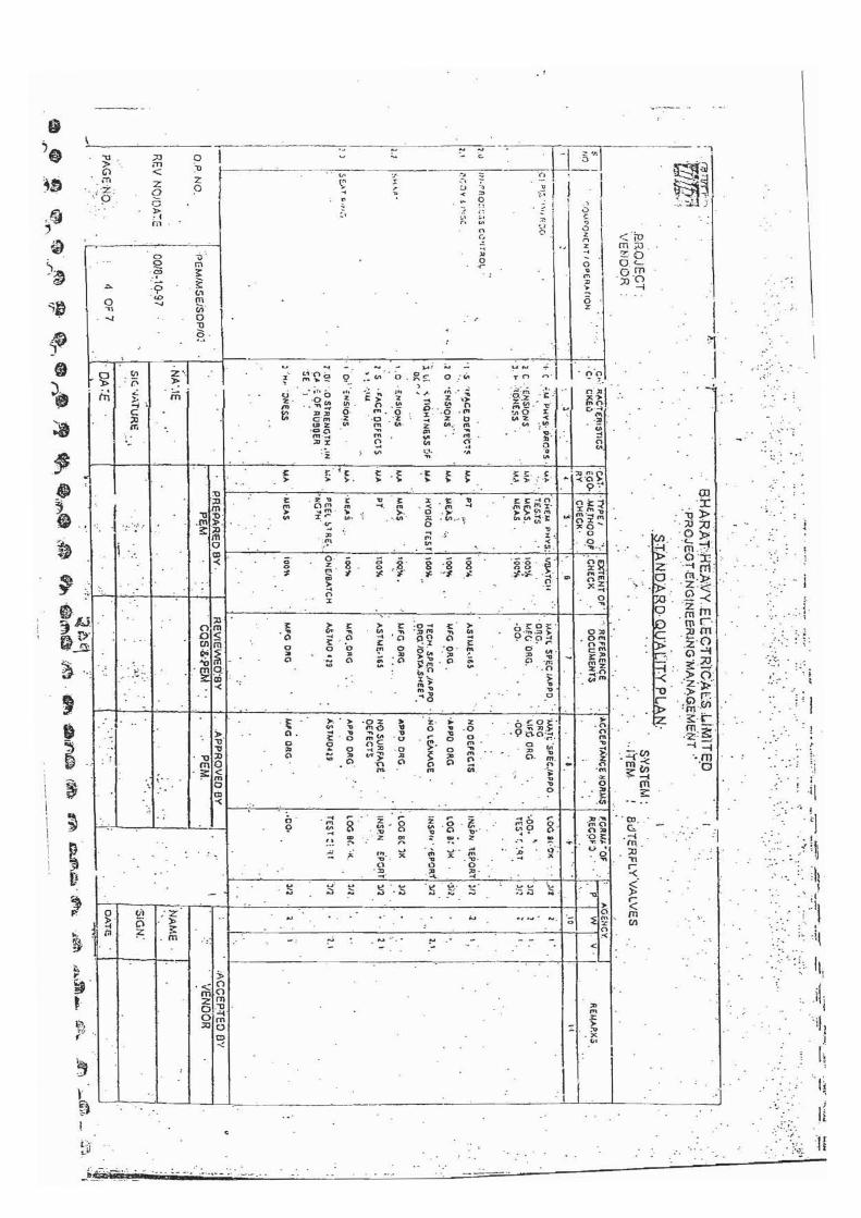
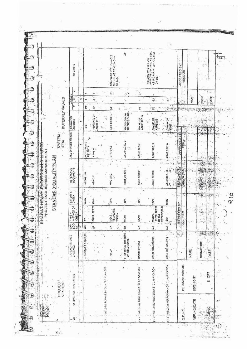

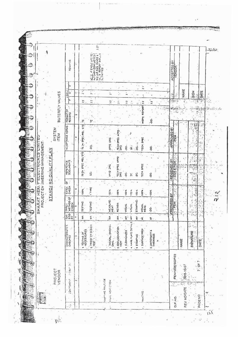
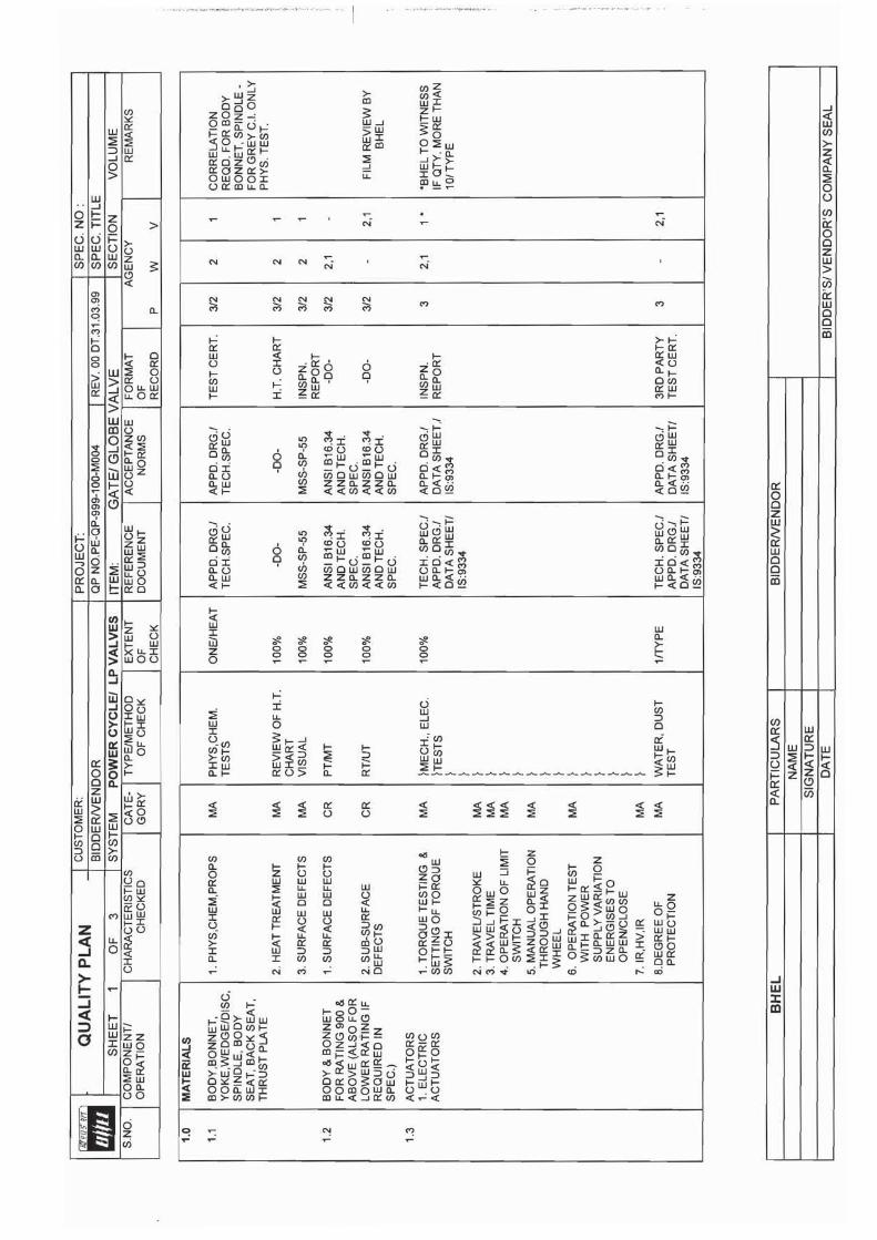
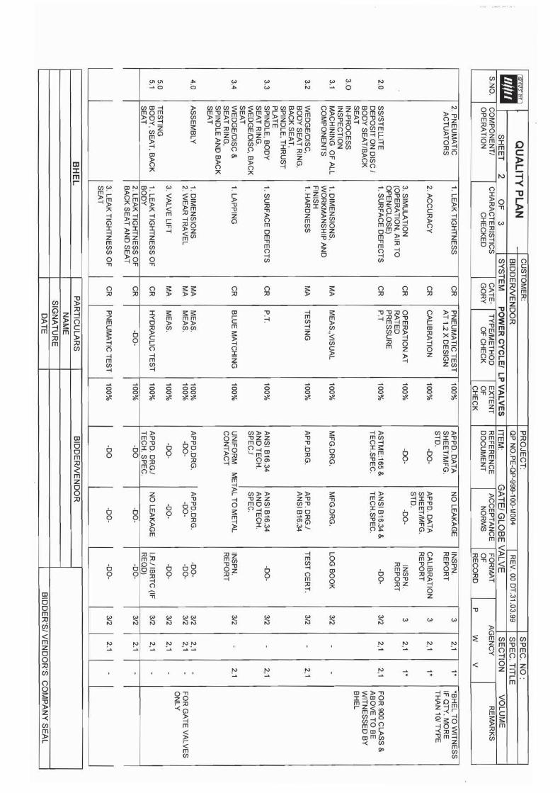
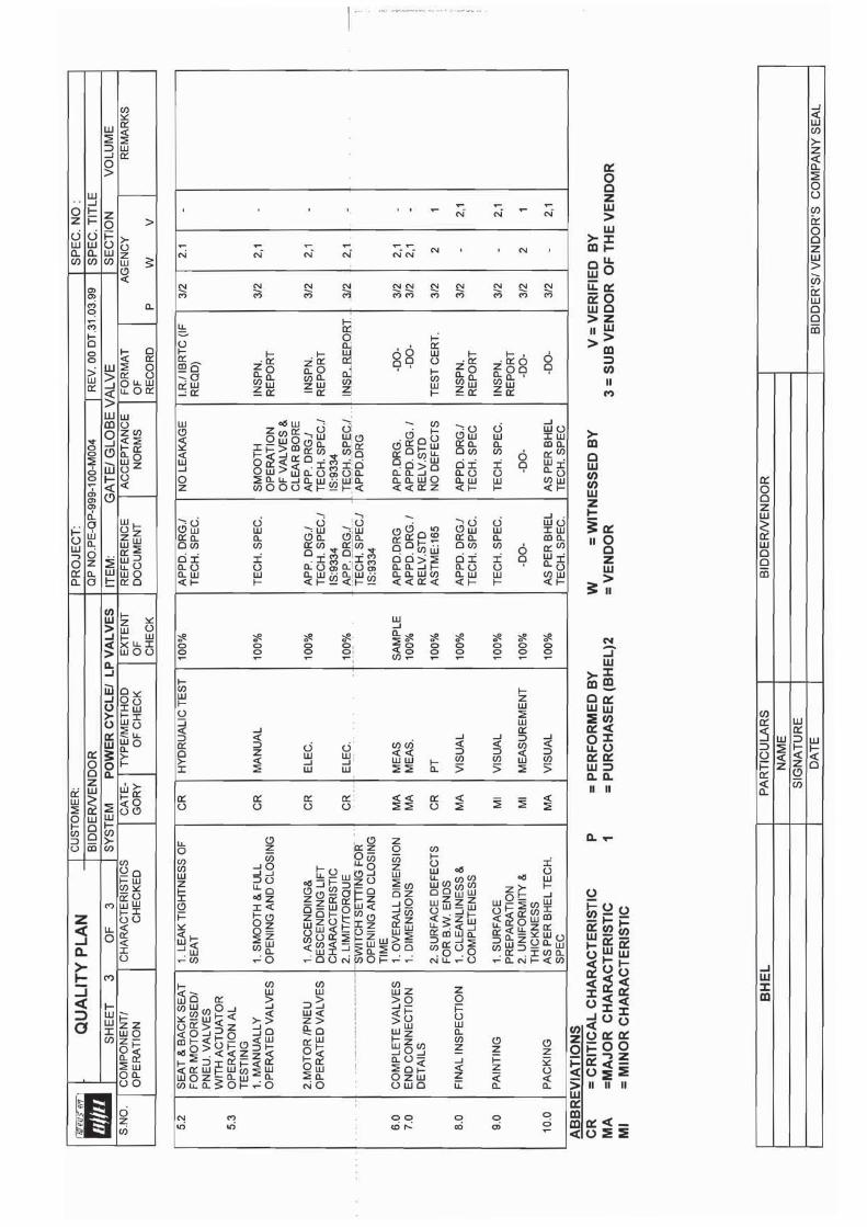
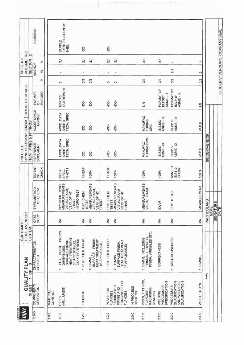
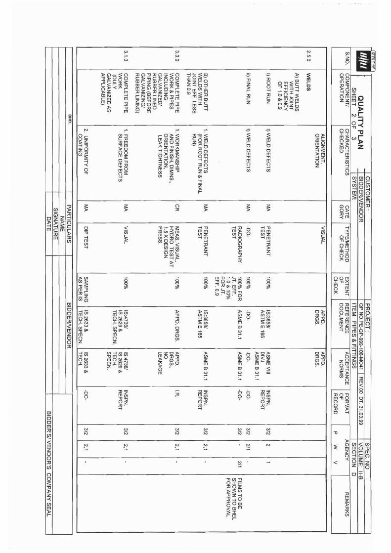


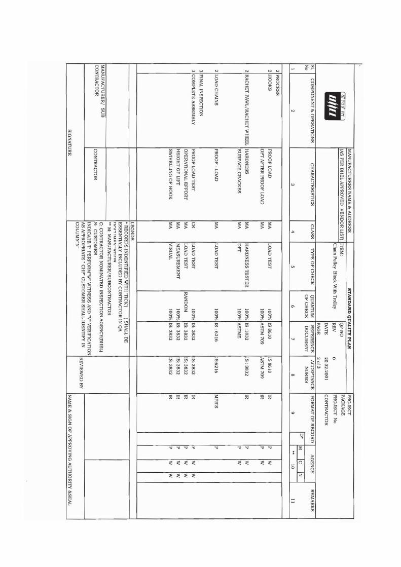

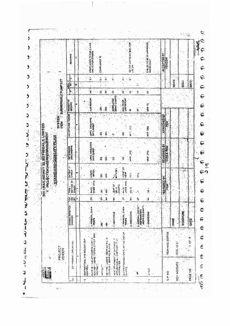
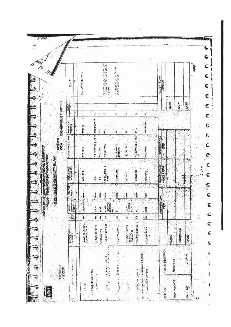
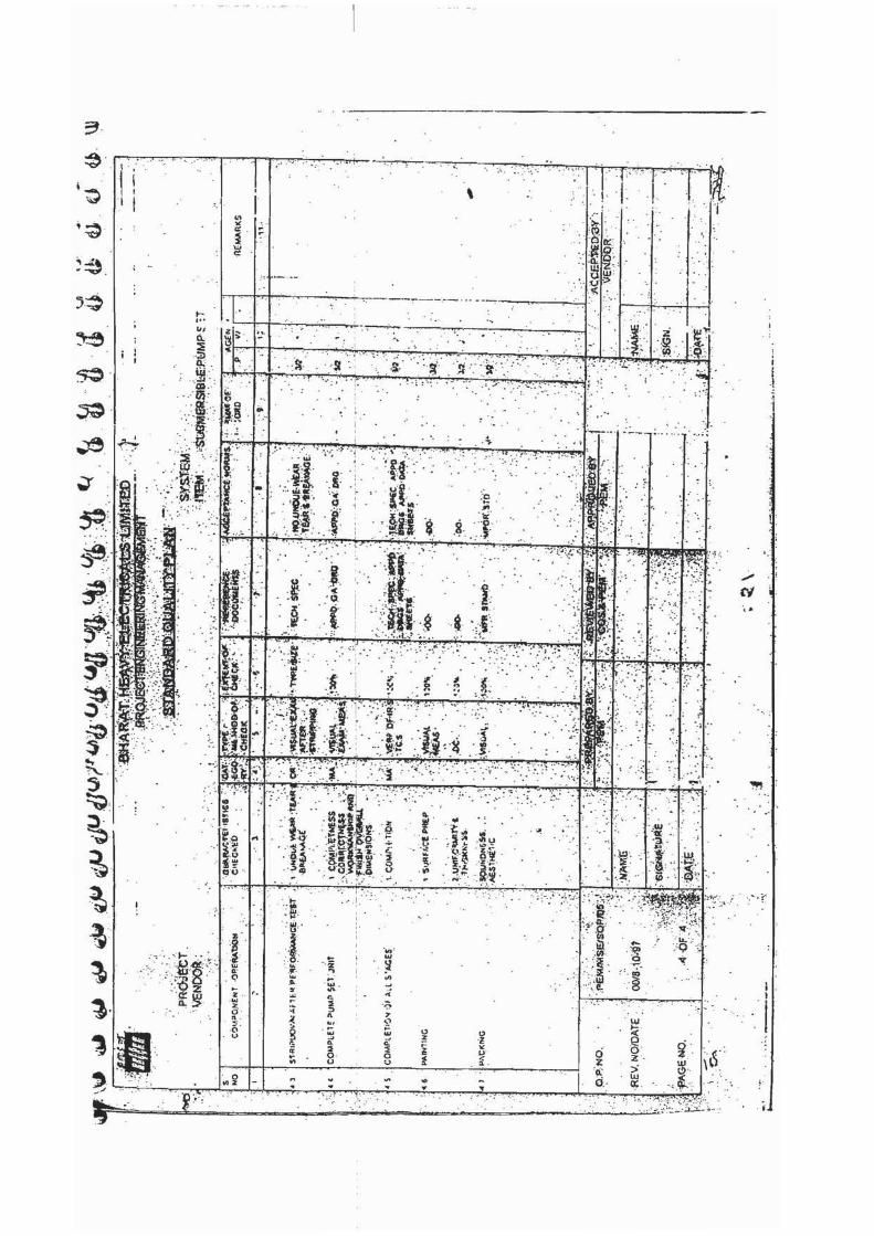
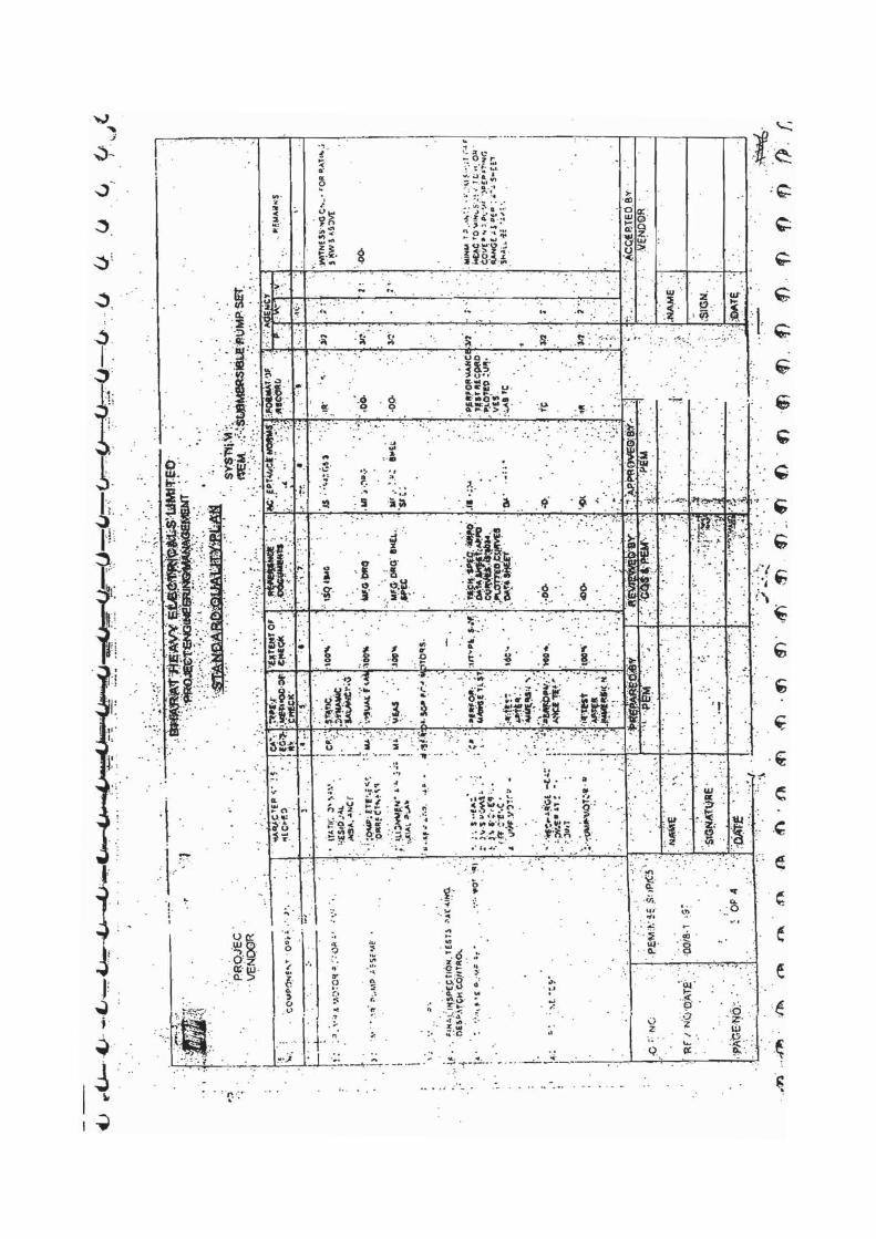

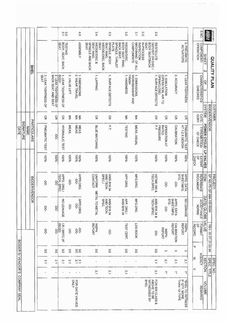
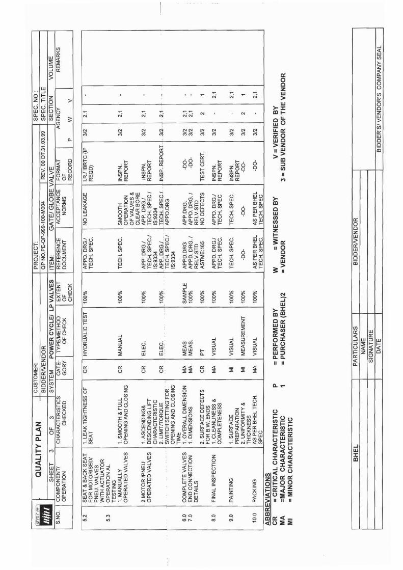
TITLE: TECHNICAL SPECIFICATION
COOLING TOWERS STANDARD TECHNICAL SPECIFICATION
ELECTRICAL
SPEC. NO.: PE-TS-410-165-N001 VOLUME: IIB SECTION: DREV. NO. 00 DATE 23.01.2015 SHEET 1 OF 1
SECTION D2
STANDARD TECHNICAL SPECIFICATION (ELECTRICAL)
GENERAL TECHNICAL REQUIRMENTS FOR LV MOTORS
DATASHEET A
STANDARD QUALITY PLANS
DATASHEET C
SECTION : D
TITLE : GENERAL TECHNICAL REQUIREMENTs
FOR
LV MOTORS
SPECIFICATION NO. PE-SS-999-506-E101 VOLUME NO. : II-B
REV NO. : 00 DATE : 29/08/2005SHEET : 1 OF 1
GENERAL TECHNICAL REQUIREMENTS
FOR
LV MOTORS
SPECIFICATION NO.: PE-SS-999-506-E101 Rev 00
TITLE : GENERAL TECHNICAL REQUIREMENTs
FOR
LV MOTORS
SPECIFICATION NO. PE-SS-999-506-E101 VOLUME NO. : II-B
SECTION : D REV NO. : 00 DATE : 29/08/2005SHEET : 1 OF 4
1.0 INTENT OF SPECIFIATION
The specification covers the design, materials, constructional features, manufacture, inspection and testing at manufacturer’s work, and packing of Low voltage (LV) squirrel cage induction motors along with all accessories for driving auxiliaries in thermal power station.
Motors having a voltage rating of below 1000V are referred to as low voltage (LV) motors. 2.0 CODES AND STANDARDS Motors shall fully comply with latest edition, including all amendments and revision, of following
codes and standards: IS:325 Three phase Induction motors IS : 900 Code of practice for installation and maintenance of induction motors IS: 996 Single phase small AC and universal motors IS: 4722 Rotating Electrical machines IS: 4691 Degree of Protection provided by enclosures for rotating electrical machines IS: 4728 Terminal marking and direction of rotation rotating electrical machines IS: 1231 Dimensions of three phase foot mounted induction motors IS: 8789 Values of performance characteristics for three phase induction motors IS: 13555 Guide for selection and application of 3-phase A.C. induction motors for
different types of driven equipment IS: 2148 Flame proof enclosures for electrical appliance IS: 5571 Guide for selection of electrical equipment for hazardous areas IS: 12824 Type of duty and classes of rating assigned IS: 12802 Temperature rise measurement for rotating electrical machnines IS: 12065 Permissible limits of noise level for rotating electrical machines IS: 12075 Mechanical vibration of rotating electrical machines In case of imported motors, motors as per IEC-34 shall also be acceptable.
3.0 DESIGN REQUIREMENTS 3.1 Motors and accessories shall be designed to operate satisfactorily under conditions specified in data
sheet-A and Project Information, including voltage & frequency variation of supply system as defined in Data sheet-A
3.2 Motors shall be continuously rated at the design ambient temperature specified in Data Sheet-A and
other site conditions specified under Project Information Motor ratings shall have at least a 15% margin over the continuous maximum demand of the driven equipment, under entire operating range including voltage & frequency variation specified above.
3.3 Starting Requirements 3.3.1 Motor characteristics such as speed, starting torque, break away torque and starting time shall be
properly co-ordinated with the requirements of driven equipment. The accelerating torque at any speed with the minimum starting voltage shall be at least 10% higher than that of the driven equipment.
3.3.2 Motors shall be capable of starting and accelerating the load with direct on line starting without
exceeding acceptable winding temperature.

TITLE : GENERAL TECHNICAL REQUIREMENTs
FOR
LV MOTORS
SPECIFICATION NO. PE-SS-999-506-E101 VOLUME NO. : II-B
SECTION : D REV NO. : 00 DATE : 29/08/2005SHEET : 2 OF 4
The limiting value of voltage at rated frequency under which a motor will successfully start and
accelerate to rated speed with load shall be taken to be a constant value as per Data Sheet - A during the starting period of motors.
3.3.3 The following frequency of starts shall apply
i) Two starts in succession with the motor being initially at a temperature not exceeding the rated load temperature.
ii) Three equally spread starts in an hour the motor being initially at a temperature not exceeding
the rated load operating temperature. (not to be repeated in the second successive hour)
iii) Motors for coal conveyor and coal crusher application shall be suitable for three consecutive hot starts followed by one hour interval with maximum twenty starts per day and shall be suitable for mimimum 20,000 starts during the life time of the motor
3.4 Running Requirements 3.4.1 Motors shall run satisfactorily at a supply voltage of 75% of rated voltage for 5 minutes with full load
without injurious heating to the motor. 3.4.2 Motor shall not stall due to voltage dip in the system causing momentary drop in voltage upto 70% of
the rated voltage for duration of 2 secs. 3.5 Stress During bus Transfer 3.5.1 Motors shall withstand the voltage, heavy inrush transient current, mechanical and torque stress
developed due to the application of 150% of the rated voltage for at least 1 sec. caused due to vector difference between the motor residual voltage and the incoming supply voltage during occasional auto bus transfer.
3.5.2 Motor and driven equipment shafts shall be adequately sized to satisfactorily withstand transient
torque under above condition. 3.6 Maximum noise level measured at distance of 1.0 metres from the outline of motor shall not exceed
the values specified in IS 12065. 3.7 The max. vibration velocity or double amplitude of motors vibration as measured at motor bearings
shall be within the limits specified in IS: 12075. 4.0 CONSTRUCTIONAL FEATURES 4.1 Indoor motors shall conform to degree of protection IP: 54 as per IS: 4691. Outdoor or semi-indoor
motors shall conform to degree of protection IP: 55 as per IS: 4691and shall be of weather-proof construction. Outdoor motors shall be installed under a suitable canopy
4.2 Motors upto 160KW shall have Totally Enclosed Fan Cooled (TEFC) enclosures, the method of
cooling conforming to IC-0141 or IC-0151 of IS: 6362.
Motors rated above 160 KW shall be Closed Air Circuit Air (CACA) cooled 4.3 Motors shall be designed with cooling fans suitable for both directions of rotation.
TITLE : GENERAL TECHNICAL REQUIREMENTs
FOR
LV MOTORS
SPECIFICATION NO. PE-SS-999-506-E101 VOLUME NO. : II-B
SECTION : D REV NO. : 00 DATE : 29/08/2005SHEET : 3 OF 4
4.4. Motors shall not be provided with any electric or pneumatic operated external fan for cooling the
motors. 4.5 Frames shall be designed to avoid collection of moisture and all enclosures shall be provided with
facility for drainage at the lowest point. 4.6 In case Class ‘F’ insulation is provided for LV motors, temperature rise shall be limited to the limits
applicable to Class ‘B’ insulation. In case of continuous operation at extreme voltage limits the temperature limits specified in table-1 of IS:325 shall not exceed by more than 10°C.
4.7 Terminals and Terminal Boxes 4.7.1 Terminals, terminal leads, terminal boxes, windings tails and associated equipment shall be suitable
for connection to a supply system having a short circuit level, specified in the Data Sheet-A. Unless otherwise stated in Data Sheet-A, motors of rating 110 kW and above will be controlled by
circuit breaker and below 110 kW by switch fuse-contactor. The terminal box of motors shall be designed for the fault current mentioned in data sheet “A”.
4.7.2 unless otherwise specified or approved, phase terminal boxes of horizontal motors shall be positioned
on the left hand side of the motor when viewed from the non-driving end. 4.7.3 Connections shall be such that when the supply leads R, Y & B are connected to motor terminals A B
& C or U, V & W respectively, motor shall rotate in an anticlockwise direction when viewed from the non-driving end. Where such motors require clockwise rotation, the supply leads R, Y, B will be connected to motor terminals A, C, B or U W & V respectively.
4.7.4 Permanently attached diagram and instruction plate made preferably of stainless steel shall be
mounted inside terminal box cover giving the connection diagram for the desired direction of rotation and reverse rotation.
4.7.5 Motor terminals and terminal leads shall be fully insulated with no bar live parts. Adequate space
shall be available inside the terminal box so that no difficulty is encountered for terminating the cable specified in Data Sheet-A.
4.7.6 Degree of protection for terminal boxes shall be IP 55 as per IS 4691. 4.7.7 Separate terminal boxes shall be provided for space heaters.. If this is not possible in case of LV
motors, the space heater terminals shall be adequately segregated from the main terminals in the main terminal box. Detachable gland plates with double compression brass glands shall be provided in terminal boxes.
4.7.8. Phase terminal boxes shall be suitable for 360 degree of rotation in steps of 90 degree for LV motors. 4.7.9 Cable glands and cable lugs as per cable sizes specified in Data Sheet-A shall be included. Cable lugs
shall be of tinned Copper, crimping type. 4.8 Two separate earthing terminals suitable for connecting G.I. or MS strip grounding conductor of size
given in Data Sheet-A shall be provided on opposite sides of motor frame. Each terminal box shall have a grounding terminal.
4.9 General
TITLE : GENERAL TECHNICAL REQUIREMENTs
FOR
LV MOTORS
SPECIFICATION NO. PE-SS-999-506-E101 VOLUME NO. : II-B
SECTION : D REV NO. : 00 DATE : 29/08/2005SHEET : 4 OF 4
4.9.1 Motors provided for similar drives shall be interchangeable. 4.9.2 Suitable foundation bolts are to be supplied alongwith the motors. 4.9.3 Motors shall be provided with eye bolts, or other means to facilitate safe lifting if the weight is 20Kgs.
and above. 4.9.4 Necessary fitments and accessories shall be provided on motors in accordance with the latest Indian
Electricity rules 1956. 4.9.5 All motors rated above 30 kW shall be provided with space heaters to maintain the motor internal air
temperature above the dew point. Unless otherwise specified, space heaters shall be suitable for a supply of 240V AC, single phase, 50 Hz.
4.9.6 Name plate with all particulars as per IS: 325 shall be provided 4.9.7 Unless otherwise specified, the colour of finish shall be grey to Shade No. 631 and 632 as per IS:5 for
motors installed indoor and outdoor respectively. The paint shall be epoxy based and shall be suitable for withstanding specified site conditions.
5.0 INSPECTION AND TESTING 5.1 All materials, components and equipments covered under this specification shall be procured,
manufactured, as per the BHEL standard quality plan No. PED-506-00-Q-006/0 and PED-506-00-Q-007/2 enclosed with this specification and which shall be complied.
5.2 LV motors of type-tested design shall be provided. Valid type test reports not more than 5 year shall
be furnished. In the absence of these, type tests shall have to be conducted by manufacturer without any commercial implication to purchaser.
5.3 All motors shall be subjected to routine tests as per IS: 325 and as per BHEL standard quality plan. 5.4 Motors shall also be subjected to additional tests, if any, as mentioned in Data Sheet A. 6.0 DRAWINGS TO BE SUBMITTED AFTER AWARD OF CONTRACT a) OGA drawing showing the position of terminal boxes, earthing connections etc. b) Arrangement drawing of terminal boxes. c) Characteristic curves: (To be given for motor above 55 kW unless otherwise specified in Data Sheet). i) Current vs. time at rated voltage and minimum starting voltage. ii) Speed vs. time at rated voltage and minimum starting voltage.
iii) Torque vs. speed at rated voltage and minimum voltage. For the motors with solid coupling the above curves i), ii), iii) to be furnished for the motors coupled with driven equipment. In case motor is coupled with mechanical equipment by fluid coupling, the above curves shall be furnished with and without coupling.
iv) Thermal withstand curve under hot and cold conditions at rated voltage and max. permissible voltage.
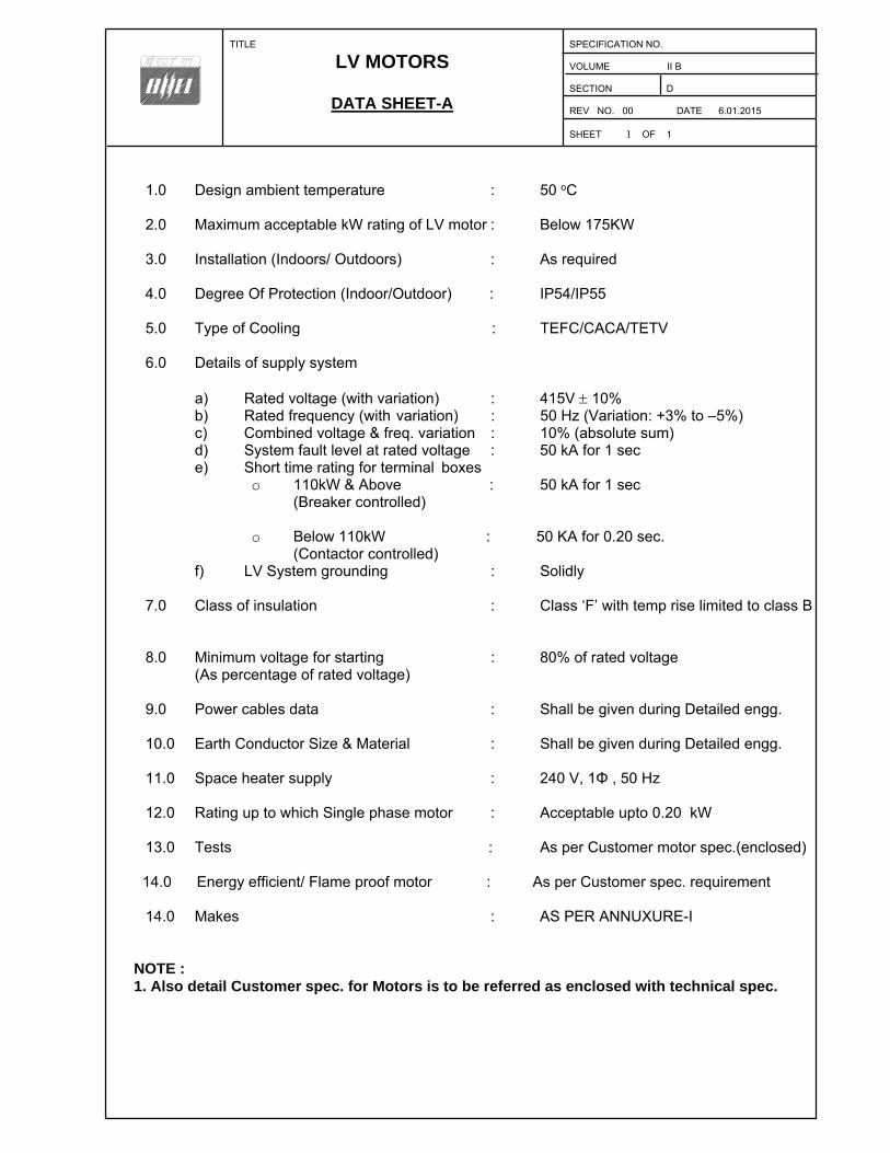
TITLE
LV MOTORS
DATA SHEET-A
SPECIFICATION NO. VOLUME II B SECTION D REV NO. 00 DATE 6.01.2015 SHEET 1 OF 1
1.0 Design ambient temperature : 50 oC 2.0 Maximum acceptable kW rating of LV motor : Below 175KW 3.0 Installation (Indoors/ Outdoors) : As required 4.0 Degree Of Protection (Indoor/Outdoor) : IP54/IP55 5.0 Type of Cooling : TEFC/CACA/TETV 6.0 Details of supply system a) Rated voltage (with variation) : 415V 10% b) Rated frequency (with variation) : 50 Hz (Variation: +3% to –5%) c) Combined voltage & freq. variation : 10% (absolute sum) d) System fault level at rated voltage : 50 kA for 1 sec
e) Short time rating for terminal boxes o 110kW & Above : 50 kA for 1 sec
(Breaker controlled)
o Below 110kW : 50 KA for 0.20 sec. (Contactor controlled)
f) LV System grounding : Solidly 7.0 Class of insulation : Class ‘F’ with temp rise limited to class B 8.0 Minimum voltage for starting : 80% of rated voltage
(As percentage of rated voltage) 9.0 Power cables data : Shall be given during Detailed engg. 10.0 Earth Conductor Size & Material : Shall be given during Detailed engg. 11.0 Space heater supply : 240 V, 1Φ , 50 Hz 12.0 Rating up to which Single phase motor : Acceptable upto 0.20 kW 13.0 Tests : As per Customer motor spec.(enclosed)
14.0 Energy efficient/ Flame proof motor : As per Customer spec. requirement
14.0 Makes : AS PER ANNUXURE-I
NOTE : 1. Also detail Customer spec. for Motors is to be referred as enclosed with technical spec.
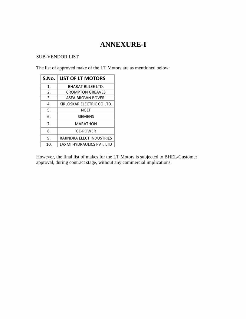
ANNEXURE-I SUB-VENDOR LIST The list of approved make of the LT Motors are as mentioned below:
However, the final list of makes for the LT Motors is subjected to BHEL/Customer approval, during contract stage, without any commercial implications.
S.No. LIST OF LT MOTORS 1. BHARAT BIJLEE LTD. 2. CROMPTON GREAVES 3. ASEA BROWN BOVERI 4. KIRLOSKAR ELECTRIC CO LTD. 5. NGEF
6. SIEMENS
7. MARATHON
8. GE-POWER
9. RAJINDRA ELECT INDUSTRIES 10. LAXMI HYDRAULICS PVT. LTD
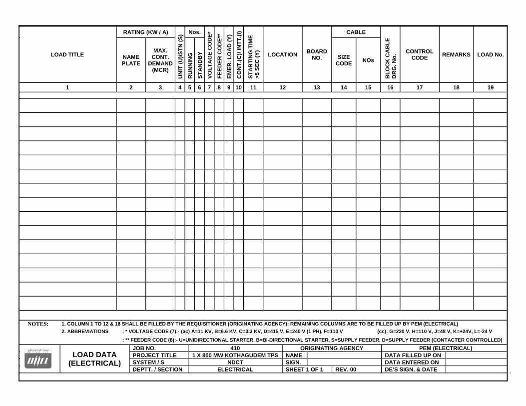
LOAD TITLE
RATING (KW / A)
UN
IT (
U)/
ST
N (
S) Nos.
VO
LT
AG
E C
OD
E*
FE
ED
ER
CO
DE
**
EM
ER
. L
OA
D (
Y)
CO
NT
.(C
)/ IN
TT
.(I)
ST
AR
TIN
G T
IME
>
5 S
EC
(Y
)
LOCATION BOARD
NO.
CABLE
BL
OC
K C
AB
LE
D
RG
. No
. CONTROL CODE
REMARKS LOAD No. NAME PLATE
MAX. CONT.
DEMAND (MCR)
RU
NN
ING
ST
AN
DB
Y
SIZE CODE
NOs
1 2 3 4 5 6 7 8 9 10 11 12 13 14 15 16 17 18 19
NOTES: 1. COLUMN 1 TO 12 & 18 SHALL BE FILLED BY THE REQUISITIONER (ORIGINATING AGENCY); REMAINING COLUMNS ARE TO BE FILLED UP BY PEM (ELECTRICAL)
2. ABBREVIATIONS : * VOLTAGE CODE (7):- (ac) A=11 KV, B=6.6 KV, C=3.3 KV, D=415 V, E=240 V (1 PH), F=110 V (cc): G=220 V, H=110 V, J=48 V, K=+24V, L=-24 V
: ** FEEDER CODE (8):- U=UNIDIRECTIONAL STARTER, B=BI-DIRECTIONAL STARTER, S=SUPPLY FEEDER, D=SUPPLY FEEDER (CONTACTER CONTROLLED)
LOAD DATA (ELECTRICAL)
JOB NO. 410 ORIGINATING AGENCY PEM (ELECTRICAL) PROJECT TITLE 1 X 800 MW KOTHAGUDEM TPS NAME DATA FILLED UP ON SYSTEM / S NDCT SIGN. DATA ENTERED ON DEPTT. / SECTION ELECTRICAL SHEET 1 OF 1 REV. 00 DE’S SIGN. & DATE
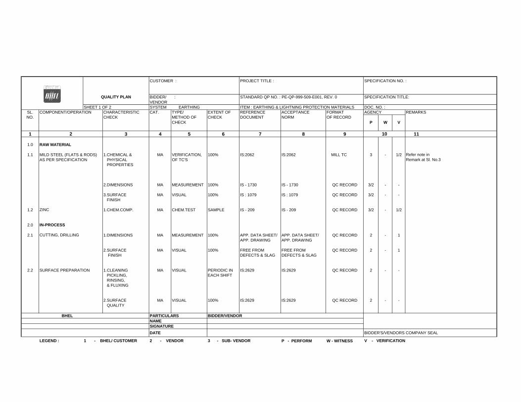
CUSTOMER : PROJECT TITLE : SPECIFICATION NO. :
BIDDER/ : STANDARD QP NO. : PE-QP-999-509-E001, REV. 0 SPECIFICATION TITLE: VENDOR
SHEET 1 OF 2 SYSTEM EARTHING ITEM : EARTHING & LIGHTNING PROTECTION MATERIALS DOC. NO. :SL. COMPONENT/OPERATION CHARACTERISTIC CAT. TYPE/ EXTENT OF REFERENCE ACCEPTANCE FORMAT AGENCY REMARKSNO. CHECK METHOD OF CHECK DOCUMENT NORM OF RECORD
CHECK P W V
1 3 4 5 6 7 8 9 11
1.0 RAW MATERIAL
1.1 MILD STEEL (FLATS & RODS) 1.CHEMICAL & MA VERIFICATION, 100% IS:2062 IS:2062 MILL TC 3 - 1/2AS PER SPECIFICATION PHYSICAL OF TC'S
PROPERTIES
2.DIMENSIONS MA MEASUREMENT 100% IS - 1730 IS - 1730 QC RECORD 3/2 - -
3.SURFACE MA VISUAL 100% IS : 1079 IS : 1079 QC RECORD 3/2 - - FINISH
1.2 1.CHEM.COMP. MA CHEM.TEST SAMPLE IS - 209 IS - 209 QC RECORD 3/2 - 1/2
2.0
2.1 1.DIMENSIONS MA MEASUREMENT 100% APP. DATA SHEET/ APP. DATA SHEET/ QC RECORD 2 - 1APP. DRAWING APP. DRAWING
2.SURFACE MA VISUAL 100% FREE FROM FREE FROM QC RECORD 2 - 1 FINISH DEFECTS & SLAG DEFECTS & SLAG
2.2 SURFACE PREPARATION 1.CLEANING MA VISUAL PERIODIC IN IS:2629 IS:2629 QC RECORD 2 - - PICKLING, EACH SHIFT RINSING, & FLUXING
2.SURFACE MA VISUAL 100% IS:2629 IS:2629 QC RECORD 2 - - QUALITY
BHEL PARTICULARS BIDDER/VENDORNAMESIGNATURE
DATE BIDDER'S/VENDORS COMPANY SEAL
P - PERFORM W - WITNESS
CUTTING, DRILLING
IN-PROCESS
LEGEND : 1 - BHEL/ CUSTOMER 2 - VENDOR 3 - SUB- VENDOR V - VERIFICATION
QUALITY PLAN
ZINC
2
Refer note in Remark at Sl. No.3
10
6042023
Text Box
STANDARD QUALITY PLAN - EARTHING & LIGHTNING PROTECTION MATERIALS

CUSTOMER : PROJECT TITLE : SPECIFICATION NO. :
QUALITY PLAN BIDDER/ : STANDARD QP NO. : PE-QP-999-509-E001 REV. 0 SPECIFICATION TITLE: VENDOR
SHEET 2 OF 2 SYSTEM EARTHING ITEM : EARTHING & LIGHTNING PROTECTION MATERIALS DOC. NO. :SL. COMPONENT/OPERATION CHARACTERISTIC CAT. TYPE/ EXTENT OF REFERENCE ACCEPTANCE FORMAT AGENCY REMARKSNO. CHECK METHOD OF CHECK DOCUMENT NORM OF RECORD
CHECK P W V
1 3 4 5 6 7 8 9 11
2.3 1.TEMPERATURE MA TEMPERATURE CONTINUOUS IS - 2629 IS - 2629 QC RECORD 3/2 - - OF BATH INDICATOR
2. DROSS MA VISUAL PERIODIC IS - 2629 IS - 2629 QC RECORD 3/2 - -
3. RATE OF MA VISUAL/ 100% IS - 2629/ IS - 2629/ QC RECORD 3/2 - 2 IMMERSION MEASUREMENT MFRS PRACTICE MFRS PRACTICE
4.SURFACE MA VISUAL 100% IS - 2629 FREE FROM BURRS, QC RECORD 3/2 - - QUALITY ROUGHNESS,
SLAG, FLUX, STAINETC.
3.0 FINISHED ITEMS 1. CHEMICAL MA CHEMICAL 1 No./LOT/SIZE IS-2062 IS-2062 LAB TC 2 - 1 Note : Sample shall be selected by BHEL & testing
2.DIMENSIONS MA MEASUREMENT IS 2500 (PART 1)APP. DATA SHEET/ APP. DATA SHEET/ INSP. REPORT 2 1 - shall be done at NABL/ govt.LEVEL S-4 APP. DRAWING APP. DRAWING approved lab
3.SURFACE FINISH MA VISUAL IS 2500 (PART 1)FREE FROM FREE FROM INSP. REPORT 2 1 -LEVEL S-4 BURRS, SLAG, BURRS, SLAG,
ROUGHNESS, ROUGHNESS,FLUX, STAIN, FLUX, STAIN,ETC. ETC.
4.MASS OF MA CHEM. TEST IS - 4759 IS-6745 / APP. DATA SHEET INSP. REPORT 2 1 - ZINC COATING APP. DATA SHEET
5.UNIFORMITY MA CHEM. TEST IS - 4759 IS-2633 IS-2633 INSP. REPORT 2 1 - OF ZINC COATING
6.THICKNESS MA ELCOMETER IS - 4759 APP. DATA SHEET APP. DATA SHEET INSP. REPORT 2 1 - OF ZINC COATING
6.ADHESION MA MECH.TEST IS-4759 IS-2629 IS-2629 INSP. REPORT 2 1 -
BHEL PARTICULARS BIDDER/VENDORNAMESIGNATUREDATE BIDDER'S/VENDORS COMPANY SEAL
P - PERFORM W - WITNESSLEGEND : 1 - BHEL/ CUSTOMER 2 - VENDOR 3 - SUB- VENDOR V - VERIFICATION
GALVANISING
2 10
If vendor doesn't have his own galvanizing plant duly approved by BHEL PEM; then galvanizing shall be carried out at BHEL-PEM approved other galvanizing plants as per Annexure-2.
6042023
Text Box
STANDARD QUALITY PLAN - EARTHING & LIGHTNING PROTECTION MATERIALS

CUSTOMER : PROJECT TITLE : SPECIFICATION NO. :
BIDDER/ : SPECIFICATION TITLE : VENDOR
SHEET 1 OF 5 SYSTEM ITEM :ILLUMINATION DOC. NO. :
SL. COMPONENT/OPERATION CHARACTERISTIC CAT. TYPE/ EXTENT OF REFERENCE ACCEPTANCE FORMAT AGENCY REMARKSNO. CHECK METHOD OF CHECK DOCUMENT NORM OF RECORD
CHECK P W V
1 3 4 5 6 7 8 9
1.0 LUMINAIRES & LAMPS 1. ACCEPTANCE TEST
a) VISUAL MA VISUAL IS 10322IS 10322 /APPD DRG./DATASHEET
IS 10322 /APPD DRG./DATASHEET
TEST CERT 3/2 1 -
(PART5 SEC1)
b) IR (Dry) CR ELECTRICAL IS 10322 -DO- -DO- -DO- 3/2 1 -
c) HIGH VOLTAGE CR ELECTRICAL -DO- -DO- -DO- -DO- 3/2 1 -
d) DUST PROOF CR ELECTRICAL -DO- -DO- -DO- -DO- 3/2 1 -
e) PHOTOMETRIC CR ELECTRICAL -DO- -DO- -DO- -DO- 3/2 1* -
2. ROUTINE TEST
a) VISUAL MA VISUAL 100%IS 10322 /APPD DRG./DATASHEET
IS 10322 /APPD DRG./DATASHEET
TEST CERT 3/2 - 1
b) IR (Dry) CR ELECTRICAL -DO- -DO- -DO- -DO- 3/2 - 1
c) HIGH VOLTAGE CR ELECTRICAL -DO- -DO- -DO- -DO- 3/2 - 1
3. TYPE TEST MA ELECTRICALONE OF EACH TYPE
IS 10322. IEC-62384/ 61347
FOR LED
IS 10322. IEC-62384/ 61347
FOR LEDTEST REPORT 3/2 - 1**
2.0 LIGHTING PANELS AND 1.DIMENSIONS MA MEASUREMENT 10% APPD DRG. APPD DRG. INSPT. REPORT 3 2,1 - COMPONENTS TO BE OFLIGHTING DISTRIBUTION APPROVED MAKE
BOARDS/ FEEDER PILLAR 2.PAINT SHADE/ MA VISUAL/ -DO-APPD DRG./DATA SHEET
APPD DRG./DATA SHEET
INSPT. REPORT 3 2,1 -
THICKNESS MEASUREMENT
3.DEGREE OF MA TESTS1/ SIZE & RATING
APPD DRG./DATA SHEET
APPD DRG./DATA SHEET
TEST CERT - - 2,1
PROTECTION RELEVANT IS RELEVANT IS(INCLUDINGEXPLOSIONPROOF IF ANY)
4.FUNCTIONAL TEST MA ELECT. 100%APPD DRG./DATA SHEET
APPD DRG./DATA SHEET
INSPT. REPORT 3 2,1 -
5.HV/IR/HV MA ELECT 100% 2.5KV AC FOR 2.5KV AC FOR INSPT. REPORT 3 2,1 -1 MINUTE 1 MINUTE
BHEL PARTICULARS BIDDER/VENDORNAMESIGNATUREDATE BIDDER'S/VENDORS COMPANY SEAL
STANDARD QP NO. : PE-QP-999-558-E001, REV.0QUALITY PLAN
** Refer note 3 & 4
*: ONE NO. LUMINAIRE OF EACH TYPE TO BE WITNESSED BY BHEL. MAIN VENDOR TO WITNESS AS PER IS-10322.
AFTER SUCCESSFUL COMPLETION OF 1a, 1b & 1c FURTHER TESTING OF 1d) TO BE DONE BY PAPER INSERTION METHOD.
LEGEND : 1 - BHEL/ CUSTOMER 2 - VENDOR 3 - SUB- VENDOR P - PERFORM W - WITNESS V - VERIFICATION
112 10
6042023
Text Box
STANDARD QUALITY PLAN - ILLUMINATION
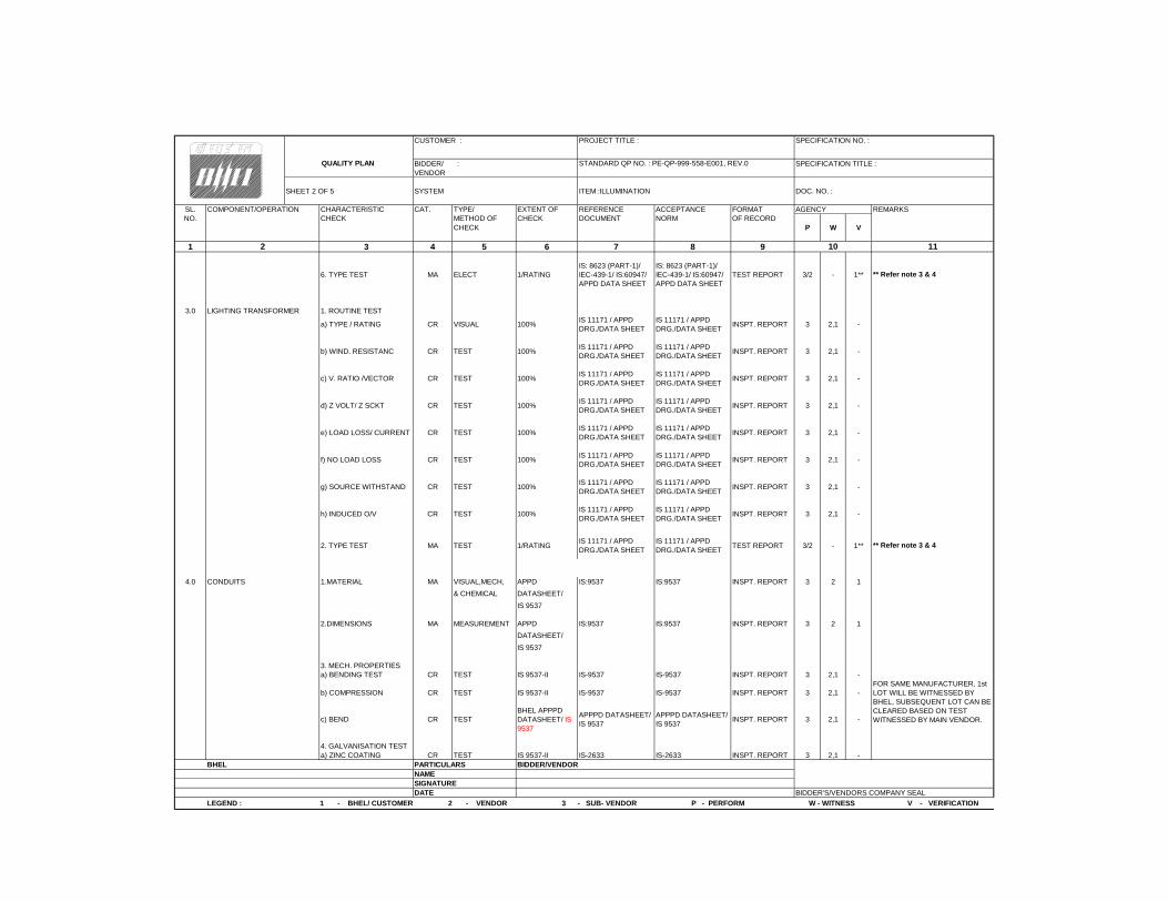
CUSTOMER : PROJECT TITLE : SPECIFICATION NO. :
BIDDER/ : SPECIFICATION TITLE : VENDOR
SHEET 2 OF 5 SYSTEM ITEM :ILLUMINATION DOC. NO. :
SL. COMPONENT/OPERATION CHARACTERISTIC CAT. TYPE/ EXTENT OF REFERENCE ACCEPTANCE FORMAT AGENCY REMARKSNO. CHECK METHOD OF CHECK DOCUMENT NORM OF RECORD
CHECK P W V
1 3 4 5 6 7 8 9
6. TYPE TEST MA ELECT 1/RATINGIS: 8623 (PART-1)/ IEC-439-1/ IS:60947/ APPD DATA SHEET
IS: 8623 (PART-1)/ IEC-439-1/ IS:60947/ APPD DATA SHEET
TEST REPORT 3/2 - 1**
3.0 LIGHTING TRANSFORMER 1. ROUTINE TEST
a) TYPE / RATING CR VISUAL 100%IS 11171 / APPD DRG./DATA SHEET
IS 11171 / APPD DRG./DATA SHEET
INSPT. REPORT 3 2,1 -
b) WIND. RESISTANC CR TEST 100%IS 11171 / APPD DRG./DATA SHEET
IS 11171 / APPD DRG./DATA SHEET
INSPT. REPORT 3 2,1 -
c) V. RATIO /VECTOR CR TEST 100%IS 11171 / APPD DRG./DATA SHEET
IS 11171 / APPD DRG./DATA SHEET
INSPT. REPORT 3 2,1 -
d) Z VOLT/ Z SCKT CR TEST 100%IS 11171 / APPD DRG./DATA SHEET
IS 11171 / APPD DRG./DATA SHEET
INSPT. REPORT 3 2,1 -
e) LOAD LOSS/ CURRENT CR TEST 100%IS 11171 / APPD DRG./DATA SHEET
IS 11171 / APPD DRG./DATA SHEET
INSPT. REPORT 3 2,1 -
f) NO LOAD LOSS CR TEST 100%IS 11171 / APPD DRG./DATA SHEET
IS 11171 / APPD DRG./DATA SHEET
INSPT. REPORT 3 2,1 -
g) SOURCE WITHSTAND CR TEST 100%IS 11171 / APPD DRG./DATA SHEET
IS 11171 / APPD DRG./DATA SHEET
INSPT. REPORT 3 2,1 -
h) INDUCED O/V CR TEST 100%IS 11171 / APPD DRG./DATA SHEET
IS 11171 / APPD DRG./DATA SHEET
INSPT. REPORT 3 2,1 -
2. TYPE TEST MA TEST 1/RATINGIS 11171 / APPD DRG./DATA SHEET
IS 11171 / APPD DRG./DATA SHEET
TEST REPORT 3/2 - 1**
4.0 CONDUITS 1.MATERIAL MA VISUAL,MECH, APPD IS:9537 IS:9537 INSPT. REPORT 3 2 1
& CHEMICAL DATASHEET/
IS 9537
2.DIMENSIONS MA MEASUREMENT APPD IS:9537 IS:9537 INSPT. REPORT 3 2 1
DATASHEET/
IS 9537
3. MECH. PROPERTIESa) BENDING TEST CR TEST IS 9537-II IS-9537 IS-9537 INSPT. REPORT 3 2,1 -
b) COMPRESSION CR TEST IS 9537-II IS-9537 IS-9537 INSPT. REPORT 3 2,1 -
c) BEND CR TESTBHEL APPPD DATASHEET/ IS 9537
APPPD DATASHEET/ IS 9537
APPPD DATASHEET/ IS 9537
INSPT. REPORT 3 2,1 -
4. GALVANISATION TESTa) ZINC COATING CR TEST IS 9537-II IS-2633 IS-2633 INSPT. REPORT 3 2,1 -
BHEL PARTICULARS BIDDER/VENDORNAMESIGNATUREDATE BIDDER'S/VENDORS COMPANY SEAL
QUALITY PLAN STANDARD QP NO. : PE-QP-999-558-E001, REV.0
FOR SAME MANUFACTURER, 1st LOT WILL BE WITNESSED BY BHEL, SUBSEQUENT LOT CAN BE CLEARED BASED ON TEST WITNESSED BY MAIN VENDOR.
LEGEND : 1 - BHEL/ CUSTOMER 2 - VENDOR 3 - SUB- VENDOR P - PERFORM W - WITNESS V - VERIFICATION
** Refer note 3 & 4
** Refer note 3 & 4
2 1110
6042023
Text Box
STANDARD QUALITY PLAN - ILLUMINATION
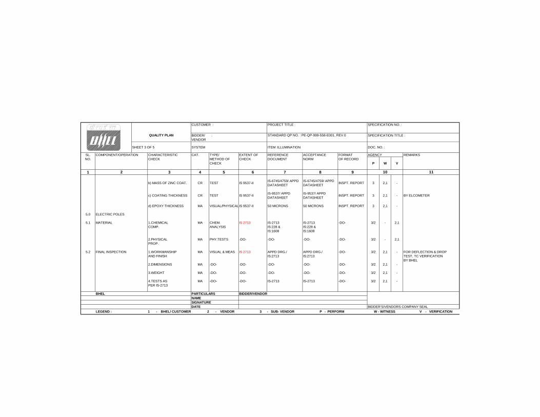
CUSTOMER : PROJECT TITLE : SPECIFICATION NO. :
BIDDER/ : SPECIFICATION TITLE : VENDOR
SHEET 3 OF 5 SYSTEM ITEM :ILLUMINATION DOC. NO. :
SL. COMPONENT/OPERATION CHARACTERISTIC CAT. TYPE/ EXTENT OF REFERENCE ACCEPTANCE FORMAT AGENCY REMARKSNO. CHECK METHOD OF CHECK DOCUMENT NORM OF RECORD
CHECK P W V
1 3 4 5 6 7 8 9
b) MASS OF ZINC COAT. CR TEST IS 9537-IIIS-6745/4759/ APPD DATASHEET
IS-6745/4759/ APPD DATASHEET
INSPT. REPORT 3 2,1 -
c) COATING THICKNESS CR TEST IS 9537-IIIS-9537/ APPD DATASHEET
IS-9537/ APPD DATASHEET
INSPT. REPORT 3 2,1 - BY ELCOMETER
d) EPOXY THICKNESS MA VISUAL/PHYSICALIS 9537-II 50 MICRONS 50 MICRONS INSPT. REPORT 3 2,1 -
5.0 ELECTRIC POLES
5.1 MATERIAL 1.CHEMICAL MA CHEM. IS 2713 IS-2713 IS-2713 -DO- 3/2 - 2,1COMP. ANALYSIS IS:228 & IS:228 &
IS:1608 IS:1608
2.PHYSICAL MA PHY.TESTS -DO- -DO- -DO- -DO- 3/2 - 2,1PROP.
5.2 FINAL INSPECTION 1.WORKMANSHIP MA VISUAL & MEAS IS 2713 APPD DRG./ APPD DRG./ -DO- 3/2 2,1 - FOR DEFLECTION & DROPAND FINISH IS:2713 IS:2713 TEST, TC VERIFICATION
BY BHEL2.DIMENSIONS MA -DO- -DO- -DO- -DO- -DO- 3/2 2,1 -
3.WEIGHT MA -DO- -DO- -DO- -DO- -DO- 3/2 2,1 -
4.TESTS AS MA -DO- -DO- IS-2713 IS-2713 -DO- 3/2 2,1 -PER IS-2713
BHEL PARTICULARS BIDDER/VENDORNAMESIGNATUREDATE BIDDER'S/VENDORS COMPANY SEAL
QUALITY PLAN STANDARD QP NO. : PE-QP-999-558-E001, REV.0
LEGEND : 1 - BHEL/ CUSTOMER 2 - VENDOR 3 - SUB- VENDOR P - PERFORM W - WITNESS V - VERIFICATION
2 10 11
6042023
Text Box
STANDARD QUALITY PLAN - ILLUMINATION
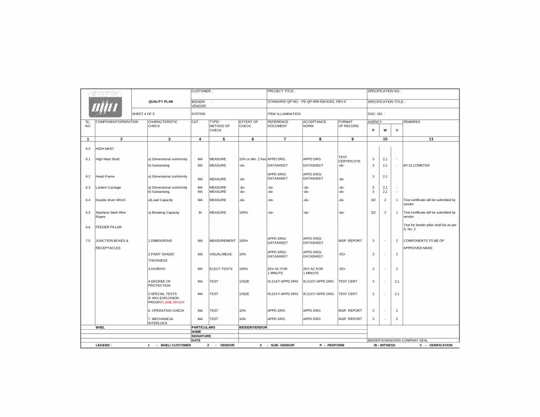
CUSTOMER : PROJECT TITLE : SPECIFICATION NO. :
BIDDER/ : SPECIFICATION TITLE : VENDOR
SHEET 4 OF 5 SYSTEM ITEM :ILLUMINATION DOC. NO. :
SL. COMPONENT/OPERATION CHARACTERISTIC CAT. TYPE/ EXTENT OF REFERENCE ACCEPTANCE FORMAT AGENCY REMARKSNO. CHECK METHOD OF CHECK DOCUMENT NORM OF RECORD
CHECK P W V
1 3 4 5 6 7 8 9
6.0 HIGH MAST
6.1 High Mast Shaft a) Dimensional conformity MA MEASURE 10% or Min. 2 Nos.APPD DRG. APPD DRG.TEST CERTIFICATE
3 2,1 -
b) Galvanising MA MEASURE -do- DATASHEET DATASHEET -do- 3 2,1 - BY ELCOMETER
6.2 Head Frame a) Dimensional conformityMA MEASURE -do-
APPD DRG/ DATASHEET
APPD DRG/ DATASHEET -do-
3 2,1
6.3 Lantern Carriage a) Dimensional conformity MA MEASURE -do- -do- -do- -do- 3 2,1 -b) Galvanising MA MEASURE -do- -do- -do- -do- 3 2,1 -
6.4 Double drum Winch a)Load Capacity MA MEASURE -do- -do- -do- -do- 3/2 2 1
6.5 Stainless Steel Wire a) Breaking Capacity M MEASURE 100% -do- -do- -do- 3/2 2 1Ropes
6.6 FEEDER PILLAR
7.0 JUNCTION BOXES & 1.DIMENSIONS MA MEASUREMENT 100%APPD DRG/ DATASHEET
APPD DRG/ DATASHEET
INSP. REPORT 3 - 2 COMPONENTS TO BE OF
RECEPTACLES APPROVED MAKE
2.PAINT SHADE/ MA VISUAL/MEAS. 10%APPD DRG/ DATASHEET
APPD DRG/ DATASHEET
-DO- 3 - 2
THICKNESS
3.HV/IR/HV MA ELECT.TESTS 100% 2KV AC FOR 2KV AC FOR -DO- 3 - 21 MINUTE 1 MINUTE
4.DEGREE OF MA TEST 1/SIZE IS:2147/ APPD DRG IS:2147/ APPD DRG TEST CERT. 3 - 2,1PROTECTION
5.SPECIAL TESTS MA TEST 1/SIZE IS:2147/ APPD DRG IS:2147/ APPD DRG TEST CERT. 3 - 2,1IF ANY,EXPLOSIONPROOF/FLAME PROOF
6. OPERATION CHECK MA TEST 10% APPD DRG APPD DRG INSP. REPORT 3 - 2
7. MECHANICAL MA TEST 10% APPD DRG APPD DRG INSP. REPORT 3 - 2INTERLOCK
BHEL PARTICULARS BIDDER/VENDORNAMESIGNATUREDATE BIDDER'S/VENDORS COMPANY SEAL
QUALITY PLAN STANDARD QP NO. : PE-QP-999-558-E001, REV.0
11
Test certificate will be submitted by vendor
LEGEND : 1 - BHEL/ CUSTOMER 2 - VENDOR 3 - SUB- VENDOR P - PERFORM W - WITNESS V - VERIFICATION
102
Test certificate will be submitted by vendor
Test for feeder pillar shall be as per S. No. 2
6042023
Text Box
STANDARD QUALITY PLAN - ILLUMINATION
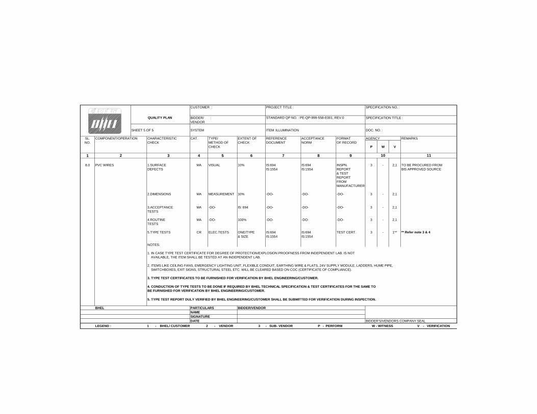
CUSTOMER : PROJECT TITLE : SPECIFICATION NO. :
BIDDER/ : SPECIFICATION TITLE : VENDOR
SHEET 5 OF 5 SYSTEM ITEM :ILLUMINATION DOC. NO. :
SL. COMPONENT/OPERATION CHARACTERISTIC CAT. TYPE/ EXTENT OF REFERENCE ACCEPTANCE FORMAT AGENCY REMARKSNO. CHECK METHOD OF CHECK DOCUMENT NORM OF RECORD
CHECK P W V
1 3 4 5 6 7 8 9
8.0 PVC WIRES 1.SURFACE MA VISUAL 10% IS:694 IS:694 INSPN. 3 - 2,1 TO BE PROCURED FROMDEFECTS IS:1554 IS:1554 REPORT BIS APPROVED SOURCE
& TEST REPORTFROM MANUFACTURER
2.DIMENSIONS MA MEASUREMENT 10% -DO- -DO- -DO- 3 - 2,1
3.ACCEPTANCE MA -DO- IS: 694 -DO- -DO- -DO- 3 - 2,1TESTS
4.ROUTINE MA -DO- 100% -DO- -DO- -DO- 3 - 2,1TESTS
5.TYPE TESTS CR ELEC.TESTS ONE/TYPE IS:694 IS:694 TEST CERT. 3 - 1**& SIZE IS:1554 IS:1554
NOTES:
1. IN CASE TYPE TEST CERTIFICATE FOR DEGREE OF PROTECTION/EXPLOSION PROOFNESS FROM INDEPENDENT LAB. IS NOT AVAILABLE, THE ITEM SHALL BE TESTED AT AN INDEPENDENT LAB.
2. ITEMS LIKE CEILING FANS, EMERGENCY LIGHTING UNIT, FLEXIBLE CONDUIT, EARTHING WIRE & FLATS, 24V SUPPLY MODULE, LADDERS, HUME PIPE, SWITCHBOXES, EXIT SIGNS, STRUCTURAL STEEL ETC. WILL BE CLEARED BASED ON COC (CERTIFICATE OF COMPLIANCE).
3. TYPE TEST CERTIFICATES TO BE FURNISHED FOR VERIFICATION BY BHEL ENGINEERING/CUSTOMER.
5. TYPE TEST REPORT DULY VERIFIED BY BHEL ENGINEERING/CUSTOMER SHALL BE SUBMITTED FOR VERIFICATION DURING INSPECTION.
BHEL PARTICULARS BIDDER/VENDORNAMESIGNATUREDATE BIDDER'S/VENDORS COMPANY SEAL
4. CONDUCTION OF TYPE TESTS TO BE DONE IF REQUIRED BY BHEL TECHNICAL SPECIFICATION & TEST CERTIFICATES FOR THE SAME TO BE FURNISHED FOR VERIFICATION BY BHEL ENGINEERING/CUSTOMER.
LEGEND : 1 - BHEL/ CUSTOMER 2 - VENDOR 3 - SUB- VENDOR P - PERFORM W - WITNESS V - VERIFICATION
QUALITY PLAN STANDARD QP NO. : PE-QP-999-558-E001, REV.0
10 112
** Refer note 3 & 4
6042023
Text Box
STANDARD QUALITY PLAN - ILLUMINATION
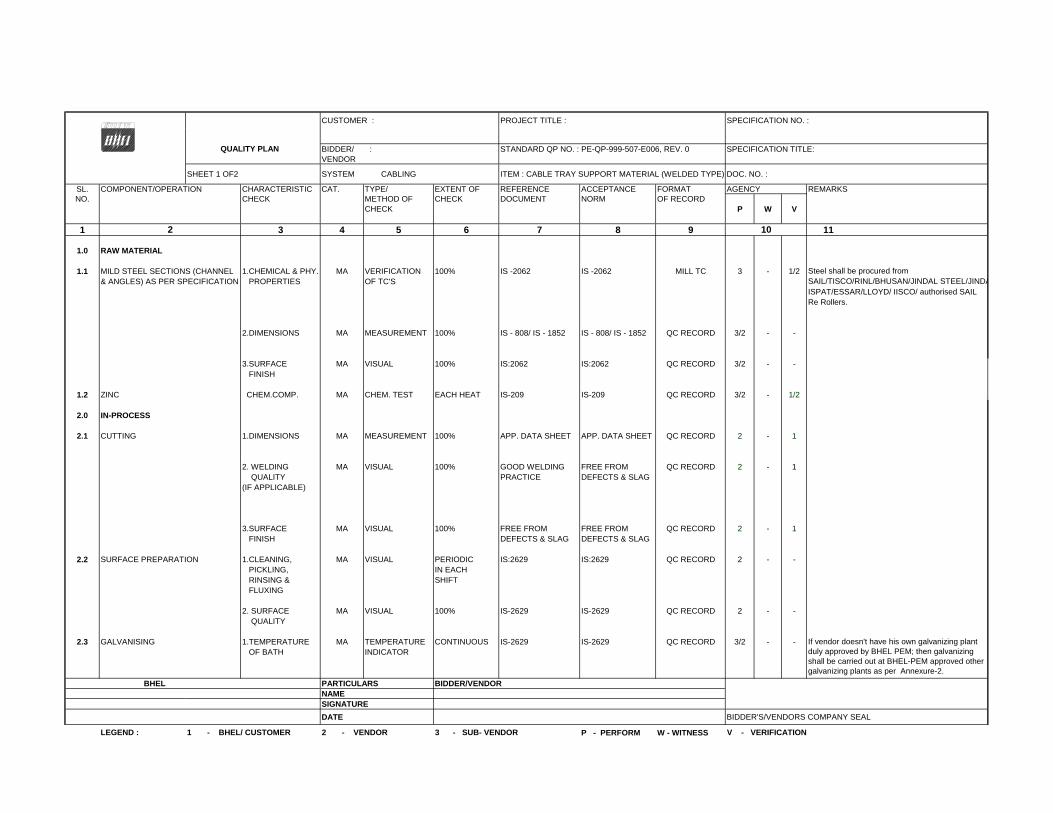
CUSTOMER : PROJECT TITLE : SPECIFICATION NO. :
BIDDER/ : STANDARD QP NO. : PE-QP-999-507-E006, REV. 0 SPECIFICATION TITLE: VENDOR
SHEET 1 OF2 SYSTEM CABLING ITEM : CABLE TRAY SUPPORT MATERIAL (WELDED TYPE) DOC. NO. :
SL. COMPONENT/OPERATION CHARACTERISTIC CAT. TYPE/ EXTENT OF REFERENCE ACCEPTANCE FORMAT AGENCY REMARKSNO. CHECK METHOD OF CHECK DOCUMENT NORM OF RECORD
CHECK P W V
1 3 4 5 6 7 8 9 11
1.0 RAW MATERIAL
1.1 MILD STEEL SECTIONS (CHANNEL 1.CHEMICAL & PHY. MA VERIFICATION 100% IS -2062 IS -2062 MILL TC 3 - 1/2& ANGLES) AS PER SPECIFICATION PROPERTIES OF TC'S
ISPAT/ESSAR/LLOYD/ IISCO/ authorised SAIL Re Rollers.
2.DIMENSIONS MA MEASUREMENT 100% IS - 808/ IS - 1852 IS - 808/ IS - 1852 QC RECORD 3/2 - -
3.SURFACE MA VISUAL 100% IS:2062 IS:2062 QC RECORD 3/2 - - FINISH
1.2 ZINC CHEM.COMP. MA CHEM. TEST EACH HEAT IS-209 IS-209 QC RECORD 3/2 - 1/2
2.0 IN-PROCESS
2.1 CUTTING 1.DIMENSIONS MA MEASUREMENT 100% APP. DATA SHEET APP. DATA SHEET QC RECORD 2 - 1
2. WELDING MA VISUAL 100% GOOD WELDING FREE FROM QC RECORD 2 - 1 QUALITY PRACTICE DEFECTS & SLAG(IF APPLICABLE)
3.SURFACE MA VISUAL 100% FREE FROM FREE FROM QC RECORD 2 - 1 FINISH DEFECTS & SLAG DEFECTS & SLAG
2.2 SURFACE PREPARATION 1.CLEANING, MA VISUAL PERIODIC IS:2629 IS:2629 QC RECORD 2 - - PICKLING, IN EACH RINSING & SHIFT FLUXING
2. SURFACE MA VISUAL 100% IS-2629 IS-2629 QC RECORD 2 - - QUALITY
2.3 GALVANISING 1.TEMPERATURE MA TEMPERATURE CONTINUOUS IS-2629 IS-2629 QC RECORD 3/2 - - OF BATH INDICATOR
BHEL PARTICULARS BIDDER/VENDORNAMESIGNATURE
DATE BIDDER'S/VENDORS COMPANY SEAL
P - PERFORM W - WITNESS
If vendor doesn't have his own galvanizing plant duly approved by BHEL PEM; then galvanizing shall be carried out at BHEL-PEM approved other galvanizing plants as per Annexure-2.
SAIL/TISCO/RINL/BHUSAN/JINDAL STEEL/JINDA
QUALITY PLAN
102
Steel shall be procured from
LEGEND : 1 - BHEL/ CUSTOMER 2 - VENDOR 3 - SUB- VENDOR V - VERIFICATION
6042023
Text Box
STANDARD QUALITY PLAN - CABLE TRAY SUPPORT MATERIAL (WELDED TYPE)
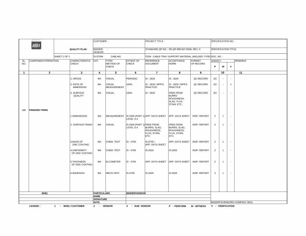
CUSTOMER : PROJECT TITLE : SPECIFICATION NO. :
QUALITY PLAN BIDDER/ : STANDARD QP NO. : PE-QP-999-507-E006, REV. 0 SPECIFICATION TITLE: VENDOR
SHEET 2 OF 2 SYSTEM CABLING ITEM : CABLE TRAY SUPPORT MATERIAL (WELDED TYPE) DOC. NO. :
SL. COMPONENT/OPERATION CHARACTERISTIC CAT. TYPE/ EXTENT OF REFERENCE ACCEPTANCE FORMAT AGENCY REMARKSNO. CHECK METHOD OF CHECK DOCUMENT NORM OF RECORD
CHECK P W V
1 3 4 5 6 7 8 9 11
2. DROSS MA VISUAL PERIODIC IS - 2629 IS - 2629 QC RECORD 3/2 - -
3. RATE OF MA VISUAL 100% IS - 2629 / MFR'S IS - 2629 / MFR'S QC RECORD 3/2 - 2 IMMERSION MEASUREMENT PRACTICE PRACTICE
4. SURFACE MA VISUAL 100% IS - 2629 FREE FROM QC RECORD 3/2 - - QUALITY BURRS
ROUGHNESS,SLAG, FLUX,STAIN, ETC.
3.0 FINISHED ITEMS
1.DIMENSIONS MA MEASUREMENT IS 2500 (PART 1) APP. DATA SHEET APP. DATA SHEET INSP. REPORT 2 1 -LEVEL S-4
2. SURFACE FINISH MA VISUAL IS 2500 (PART 1) FREE FROM FREE FROM INSP. REPORT 2 1 -LEVEL S-4 BURRS, SLAG, BURRS, SLAG,
ROUGHNESS, ROUGHNESS,FLUX, STAIN, FLUX, STAIN,ETC. ETC.
3.MASS OF MA CHEM. TEST IS - 4759 IS-6745 / APP. DATA SHEET INSP. REPORT 2 1 - ZINC COATING APP. DATA SHEET
4.UNIFORMITY MA CHEM. TEST IS - 4759 IS-2633 IS-2633 INSP. REPORT 2 1 - OF ZINC COATING
5.THICKNESS MA ELCOMETER IS - 4759 APP. DATA SHEET APP. DATA SHEET INSP. REPORT 2 1 - OF ZINC COATING
6.ADHESION MA MECH.TEST IS-4759 IS-2629 IS-2629 INSP. REPORT 2 1 -
BHEL PARTICULARS BIDDER/VENDORNAMESIGNATUREDATE BIDDER'S/VENDORS COMPANY SEAL
P - PERFORM W - WITNESSLEGEND : 1 - BHEL/ CUSTOMER 2 - VENDOR 3 - SUB- VENDOR V - VERIFICATION
102
6042023
Text Box
STANDARD QUALITY PLAN - CABLE TRAY SUPPORT MATERIAL (WELDED TYPE)
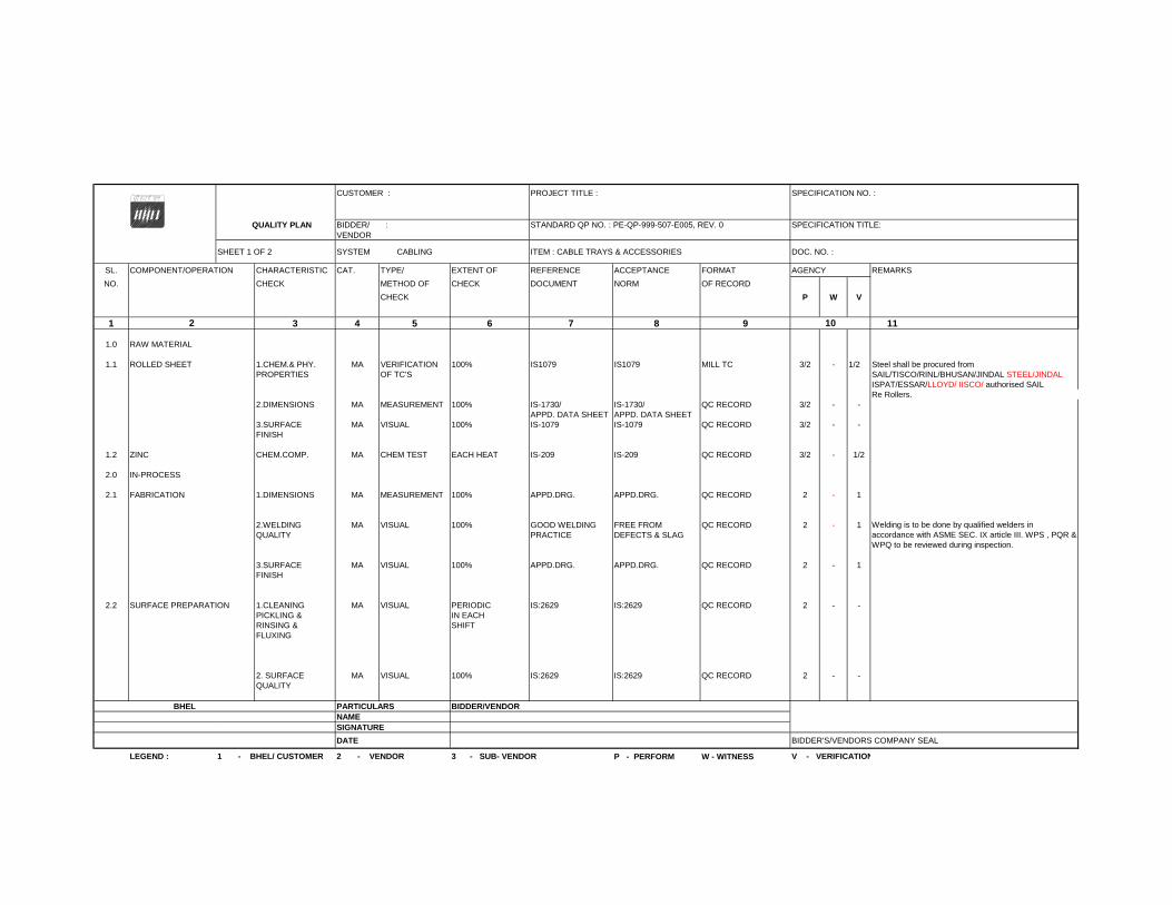
CUSTOMER : PROJECT TITLE : SPECIFICATION NO. :
QUALITY PLAN BIDDER/ : STANDARD QP NO. : PE-QP-999-507-E005, REV. 0 SPECIFICATION TITLE: VENDOR
SHEET 1 OF 2 SYSTEM CABLING ITEM : CABLE TRAYS & ACCESSORIES DOC. NO. :
SL. COMPONENT/OPERATION CHARACTERISTIC CAT. TYPE/ EXTENT OF REFERENCE ACCEPTANCE FORMAT AGENCY REMARKS
NO. CHECK METHOD OF CHECK DOCUMENT NORM OF RECORD
CHECK P W V
1 3 4 5 6 7 8 9 11
1.0 RAW MATERIAL
1.1 ROLLED SHEET 1.CHEM.& PHY. MA VERIFICATION 100% IS1079 IS1079 MILL TC 3/2 - 1/2 Steel shall be procured from PROPERTIES OF TC'S SAIL/TISCO/RINL/BHUSAN/JINDAL STEEL/JINDAL
ISPAT/ESSAR/LLOYD/ IISCO/ authorised SAIL Re Rollers.
2.DIMENSIONS MA MEASUREMENT 100% IS-1730/ IS-1730/ QC RECORD 3/2 - -APPD. DATA SHEET APPD. DATA SHEET
3.SURFACE MA VISUAL 100% IS-1079 IS-1079 QC RECORD 3/2 - -FINISH
1.2 ZINC CHEM.COMP. MA CHEM TEST EACH HEAT IS-209 IS-209 QC RECORD 3/2 - 1/2
2.0 IN-PROCESS
2.1 FABRICATION 1.DIMENSIONS MA MEASUREMENT 100% APPD.DRG. APPD.DRG. QC RECORD 2 - 1
2.WELDING MA VISUAL 100% GOOD WELDING FREE FROM QC RECORD 2 - 1QUALITY PRACTICE DEFECTS & SLAG
3.SURFACE MA VISUAL 100% APPD.DRG. APPD.DRG. QC RECORD 2 - 1FINISH
2.2 SURFACE PREPARATION 1.CLEANING MA VISUAL PERIODIC IS:2629 IS:2629 QC RECORD 2 - -PICKLING & IN EACHRINSING & SHIFTFLUXING
2. SURFACE MA VISUAL 100% IS:2629 IS:2629 QC RECORD 2 - -QUALITY
BHEL PARTICULARS BIDDER/VENDORNAMESIGNATURE
DATE BIDDER'S/VENDORS COMPANY SEAL
P - PERFORM W - WITNESS
2 10
LEGEND : 1 - BHEL/ CUSTOMER 2 - VENDOR 3 - SUB- VENDOR V - VERIFICATION
Welding is to be done by qualified welders in accordance with ASME SEC. IX article III. WPS , PQR & WPQ to be reviewed during inspection.
6042023
Text Box
STANDARD QUALITY PLAN - CABLE TRAYS & ACCESSORIES
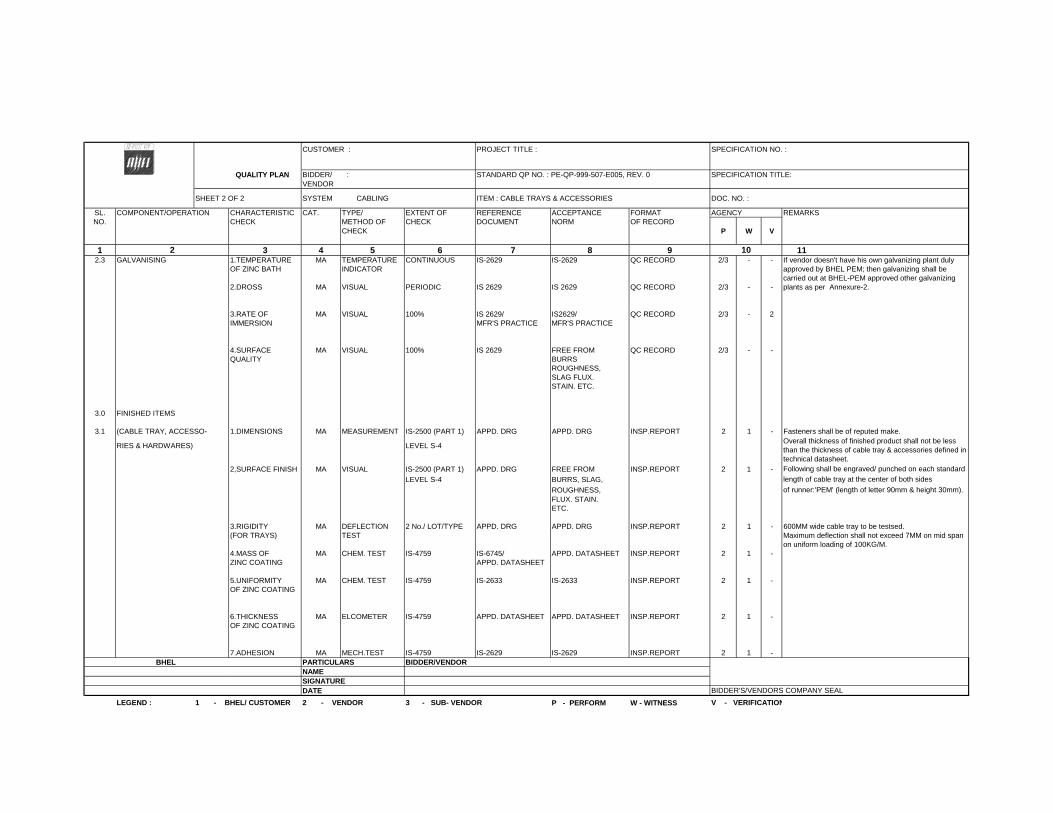
CUSTOMER : PROJECT TITLE : SPECIFICATION NO. :
QUALITY PLAN BIDDER/ : STANDARD QP NO. : PE-QP-999-507-E005, REV. 0 SPECIFICATION TITLE: VENDOR
SHEET 2 OF 2 SYSTEM CABLING ITEM : CABLE TRAYS & ACCESSORIES DOC. NO. :
SL. COMPONENT/OPERATION CHARACTERISTIC CAT. TYPE/ EXTENT OF REFERENCE ACCEPTANCE FORMAT AGENCY REMARKSNO. CHECK METHOD OF CHECK DOCUMENT NORM OF RECORD
CHECK P W V
1 3 4 5 6 7 8 9 112.3 GALVANISING 1.TEMPERATURE MA TEMPERATURE CONTINUOUS IS-2629 IS-2629 QC RECORD 2/3 - -
OF ZINC BATH INDICATOR
2.DROSS MA VISUAL PERIODIC IS 2629 IS 2629 QC RECORD 2/3 - -
3.RATE OF MA VISUAL 100% IS 2629/ IS2629/ QC RECORD 2/3 - 2IMMERSION MFR'S PRACTICE MFR'S PRACTICE
4.SURFACE MA VISUAL 100% IS 2629 FREE FROM QC RECORD 2/3 - -QUALITY BURRS
ROUGHNESS,SLAG FLUX. STAIN. ETC.
3.0 FINISHED ITEMS
3.1 (CABLE TRAY, ACCESSO- 1.DIMENSIONS MA MEASUREMENT IS-2500 (PART 1) APPD. DRG APPD. DRG INSP.REPORT 2 1 - Fasteners shall be of reputed make.
RIES & HARDWARES) LEVEL S-4
2,SURFACE FINISH MA VISUAL IS-2500 (PART 1) APPD. DRG FREE FROM INSP.REPORT 2 1 -
LEVEL S-4 BURRS, SLAG,
ROUGHNESS,FLUX. STAIN.ETC.
3.RIGIDITY MA DEFLECTION 2 No./ LOT/TYPE APPD. DRG APPD. DRG INSP.REPORT 2 1 - 600MM wide cable tray to be testsed.(FOR TRAYS) TEST Maximum deflection shall not exceed 7MM on mid span
on uniform loading of 100KG/M.4.MASS OF MA CHEM. TEST IS-4759 IS-6745/ APPD. DATASHEET INSP.REPORT 2 1 -ZINC COATING APPD. DATASHEET
5.UNIFORMITY MA CHEM. TEST IS-4759 IS-2633 IS-2633 INSP.REPORT 2 1 -OF ZINC COATING
6.THICKNESS MA ELCOMETER IS-4759 APPD. DATASHEET APPD. DATASHEET INSP.REPORT 2 1 -OF ZINC COATING
7.ADHESION MA MECH.TEST IS-4759 IS-2629 IS-2629 INSP.REPORT 2 1 -BHEL PARTICULARS BIDDER/VENDOR
NAMESIGNATUREDATE
P - PERFORM W - WITNESS
2
of runner:'PEM' (length of letter 90mm & height 30mm).
10
length of cable tray at the center of both sides
If vendor doesn't have his own galvanizing plant duly approved by BHEL PEM; then galvanizing shall be carried out at BHEL-PEM approved other galvanizing plants as per Annexure-2.
Following shall be engraved/ punched on each standard
Overall thickness of finished product shall not be less than the thickness of cable tray & accessories defined in technical datasheet.
LEGEND : 1 - BHEL/ CUSTOMER 2 - VENDOR 3 - SUB- VENDOR V - VERIFICATION
BIDDER'S/VENDORS COMPANY SEAL
6042023
Text Box
STANDARD QUALITY PLAN - CABLE TRAYS & ACCESSORIES

CUSTOMER TSPGCL PROJECT 1 X 800 MW KOTHAGUDEM TPS SPECIFICATION :
TITLE NUMBER :
QUALITY PLAN BIDDER/ : QUALITY PLAN SPECIFICATION : VENDOR NUMBER PED-506-00-Q-007, REV-03 TITLE
SHEET 1 OF 9 SYSTEM ITEM: AC ELECT. MOTORS 55 KW & ABOVE (LV & MV) SECTION VOLUME IIISL. COMPONENT/OPERATION CHARACTERISTIC CAT. TYPE/ EXTENT OF REFERENCE ACCEPTANCE FORMAT AGENCY REMARKSNO. CHECK METHOD OF CHECK DOCUMENT NORM OF RECORD
CHECK P W V
1 3 4 5 6 7 8 9 111.0 RAW MATERIAL & BOUGHT OUT
CONTROL
1.1 SHEET STEEL, PLATES, 1.SURFACE MA VISUAL 100% - FREE FROM LOG BOOK 3 - -SECTION, EYEBOLTS CONDITION BLINKS,
CRACKS,WAVINESSETC
2.DIMENSIONS MA MEASUREMENT SAMPLE MANFR'S MANFR'S -DO- 3 - -DRG./SPEC DRG./SPEC
3.PROOF LOAD MA MECH. TEST -DO- -DO- -DO- INSPEC. 3 - 2TEST (EYE REPORTBOLT)
1.2 HARDWARES 1.SURFACE MA VISUAL 100% FREE FROM -DO- 3 - -CONDITION CRACKS, UN-
EVENNESS ETC.
2.PROPERTY MA VISUAL SAMPLES MANFR'S RELEVENT SUPPLIERS 3 - 2 PROPERTY CLASS CLASS DRG./SPEC IS/SPEC. TC & LOG MARKING SHALL BE
BOOK CHECKED BY THEVENDOR
1.3 CASTING 1.SURFACE MA VISUAL 100% FREE FROM LOG BOOK 3 - 2CONDITION CRACKS,
BLOW HOLESETC.
2.CHEM. & MA CHEM & MECH 1/HEAT NO. MANFR'S RELEVENT SUPPLIER'S 3 - 2 HEAT NO. SHALL BEPHY. PROP. TEST DRG./SPEC IS/ TC VERIFIED
3.DIMENSIONS MA MEASUREMENT 100% MANUFR'S MANUFR'S LOG BOOK 3 - 2DRG. DRG.
1.4 PAINT & VARNISH 1.MAKE, SHADE, MA VISUAL 100% MANFR'S MANFR'S LOG BOOK 3 - 2SHELF LIFE & CONTINUOUS DRG./SPEC DRG./SPECTYPE
BHEL PARTICULARS BIDDER/VENDORNAMESIGNATUREDATE BIDDER'S/VENDORS COMPANY SEAL
2 10
6042023
Text Box
STANDARD QUALITY PLAN - AC ELECT. MOTORS 55 KW & ABOVE (LV & MV)
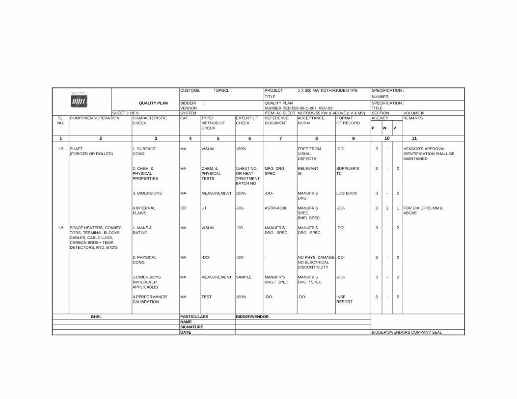
CUSTOMER TSPGCL PROJECT 1 X 800 MW KOTHAGUDEM TPS SPECIFICATION :
TITLE NUMBER :
QUALITY PLAN BIDDER/ : QUALITY PLAN SPECIFICATION : VENDOR NUMBER PED-506-00-Q-007, REV-03 TITLE
SHEET 2 OF 9 SYSTEM ITEM: AC ELECT. MOTORS 55 KW & ABOVE (LV & MV) SECTION VOLUME IIISL. COMPONENT/OPERATION CHARACTERISTIC CAT. TYPE/ EXTENT OF REFERENCE ACCEPTANCE FORMAT AGENCY REMARKSNO. CHECK METHOD OF CHECK DOCUMENT NORM OF RECORD
CHECK P W V
1 3 4 5 6 7 8 9 11
1.5 SHAFT 1. SURFACE MA VISUAL 100% - FREE FROM -DO- 3 - - VENDOR'S APPROVAL(FORGED OR ROLLED) COND. VISUAL IDENTIFICATION SHALL BE
DEFECTS MAINTAINED
2. CHEM. & MA CHEM. & 1/HEAT NO. MFG. DRG. RELEVANT SUPPLIER'S 3 - 2PHYSICAL PHYSICAL OR HEAT SPEC. IS TCPROPERTIES TESTS TREATMENT
BATCH NO
3. DIMENSIONS MA MEASUREMENT 100% -DO- MANUFR'S LOG BOOK 3 - 2DRG.
4.INTERNAL CR UT -DO- ASTM-A388 MANUFR'S -DO- 3 2 1 FOR DIA OF 55 MM & FLAWS SPEC. ABOVE
BHEL SPEC.
1.6 SPACE HEATERS, CONNEC- 1. MAKE & MA VISUAL -DO- MANUFR'S MANUFR'S -DO- 3 - 2TORS, TERMINAL BLOCKS, RATING DRG. SPEC. DRG. SPEC.CABLES, CABLE LUGS,CARBON BRUSH TEMP.DETECTORS, RTD, BTD'S
2. PHYSICAL MA -DO- -DO- - NO PHYS. DAMAGE, -DO- 3 - 2COND. NO ELECTRICAL
DISCONTINUITY
3.DIMENSIONS MA MEASUREMENT SAMPLE MANUFR'S MANUFR'S -DO- 3 - 2(WHEREVER DRG./ SPEC. DRG. / SPEC.APPLICABLE)
4.PERFORMANCE/ MA TEST 100% -DO- -DO- INSP. 3 - 2CALIBRATION REPORT
BHEL PARTICULARS BIDDER/VENDORNAMESIGNATUREDATE BIDDER'S/VENDORS COMPANY SEAL
102
6042023
Text Box
STANDARD QUALITY PLAN - AC ELECT. MOTORS 55 KW & ABOVE (LV & MV)
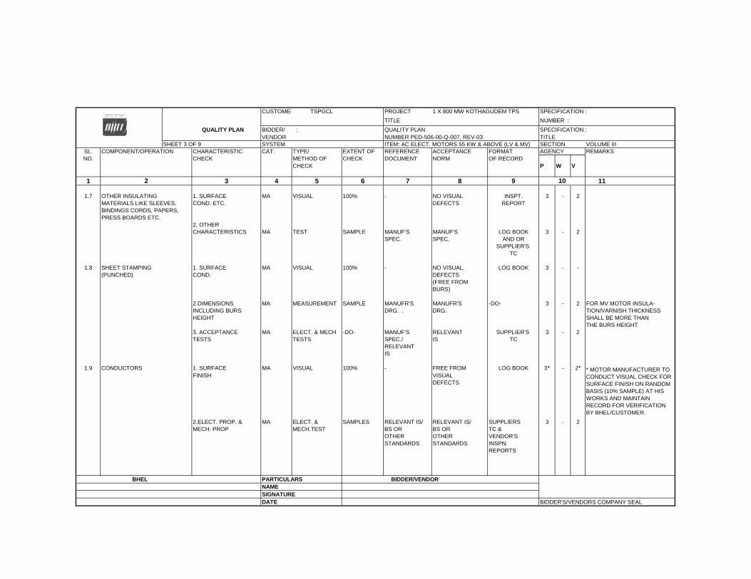
CUSTOMER TSPGCL PROJECT 1 X 800 MW KOTHAGUDEM TPS SPECIFICATION :
TITLE NUMBER :
QUALITY PLAN BIDDER/ : QUALITY PLAN SPECIFICATION : VENDOR NUMBER PED-506-00-Q-007, REV-03 TITLE
SHEET 3 OF 9 SYSTEM ITEM: AC ELECT. MOTORS 55 KW & ABOVE (LV & MV) SECTION VOLUME IIISL. COMPONENT/OPERATION CHARACTERISTIC CAT. TYPE/ EXTENT OF REFERENCE ACCEPTANCE FORMAT AGENCY REMARKSNO. CHECK METHOD OF CHECK DOCUMENT NORM OF RECORD
CHECK P W V
1 3 4 5 6 7 8 9 11
1.7 OTHER INSULATING 1. SURFACE MA VISUAL 100% - NO VISUAL INSPT. 3 - 2MATERIALS LIKE SLEEVES, COND. ETC. DEFECTS REPORTBINDINGS CORDS, PAPERS,PRESS BOARDS ETC.
2. OTHERCHARACTERISTICS MA TEST SAMPLE MANUF'S MANUF'S LOG BOOK 3 - 2
SPEC. SPEC. AND ORSUPPLIER'S
TC
1.8 SHEET STAMPING 1. SURFACE MA VISUAL 100% - NO VISUAL LOG BOOK 3 - -(PUNCHED) COND. DEFECTS
(FREE FROM BURS)
2.DIMENSIONS MA MEASUREMENT SAMPLE MANUFR'S MANUFR'S -DO- 3 - 2 FOR MV MOTOR INSULA-INCLUDING BURS DRG. . DRG. TION/VARNISH THICKNESSHEIGHT SHALL BE MORE THAN
THE BURS HEIGHT3. ACCEPTANCE MA ELECT. & MECH -DO- MANUF'S RELEVANT SUPPLIER'S 3 - 2TESTS TESTS SPEC./ IS TC
RELEVANTIS
1.9 CONDUCTORS 1. SURFACE MA VISUAL 100% - FREE FROM LOG BOOK 3* - 2*FINISH VISUAL
DEFECTS
2.ELECT. PROP, & MA ELECT. & SAMPLES RELEVANT IS/ RELEVANT IS/ SUPPLIERS 3 - 2MECH. PROP MECH.TEST BS OR BS OR TC &
OTHER OTHER VENDOR'SSTANDARDS STANDARDS INSPN.
REPORTS
BHEL PARTICULARS BIDDER/VENDORNAMESIGNATUREDATE BIDDER'S/VENDORS COMPANY SEAL
102
* MOTOR MANUFACTURER TO CONDUCT VISUAL CHECK FOR SURFACE FINISH ON RANDOM BASIS (10% SAMPLE) AT HIS WORKS AND MAINTAIN RECORD FOR VERIFICATION BY BHEL/CUSTOMER.
6042023
Text Box
STANDARD QUALITY PLAN - AC ELECT. MOTORS 55 KW & ABOVE (LV & MV)
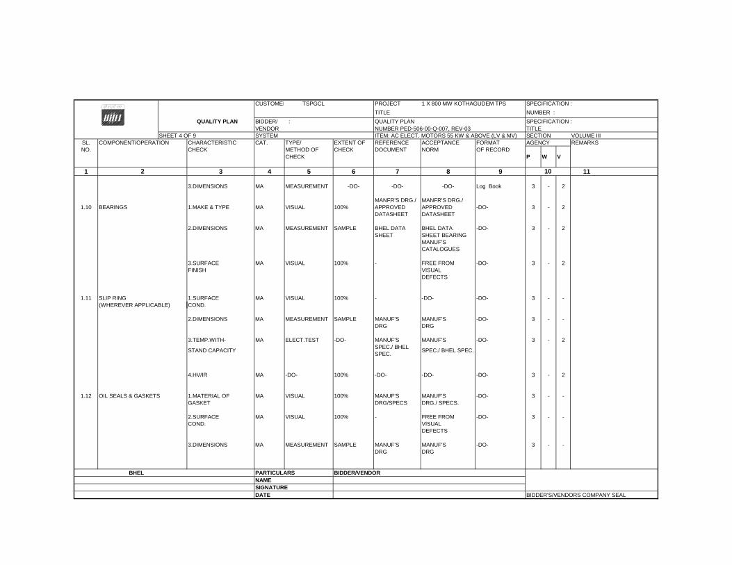
CUSTOMER TSPGCL PROJECT 1 X 800 MW KOTHAGUDEM TPS SPECIFICATION :
TITLE NUMBER :
QUALITY PLAN BIDDER/ : QUALITY PLAN SPECIFICATION : VENDOR NUMBER PED-506-00-Q-007, REV-03 TITLE
SHEET 4 OF 9 SYSTEM ITEM: AC ELECT. MOTORS 55 KW & ABOVE (LV & MV) SECTION VOLUME IIISL. COMPONENT/OPERATION CHARACTERISTIC CAT. TYPE/ EXTENT OF REFERENCE ACCEPTANCE FORMAT AGENCY REMARKSNO. CHECK METHOD OF CHECK DOCUMENT NORM OF RECORD
CHECK P W V
1 3 4 5 6 7 8 9 11
3.DIMENSIONS MA MEASUREMENT -DO- -DO- -DO- Log Book 3 - 2
1.10 BEARINGS 1.MAKE & TYPE MA VISUAL 100%MANFR'S DRG./ APPROVED DATASHEET
MANFR'S DRG./ APPROVED DATASHEET
-DO- 3 - 2
2.DIMENSIONS MA MEASUREMENT SAMPLE BHEL DATA BHEL DATA -DO- 3 - 2SHEET SHEET BEARING
MANUF'SCATALOGUES
3.SURFACE MA VISUAL 100% - FREE FROM -DO- 3 - 2FINISH VISUAL
DEFECTS
1.11 SLIP RING 1.SURFACE MA VISUAL 100% - -DO- -DO- 3 - -(WHEREVER APPLICABLE) COND.
2.DIMENSIONS MA MEASUREMENT SAMPLE MANUF'S MANUF'S -DO- 3 - -DRG DRG
3.TEMP.WITH- MA ELECT.TEST -DO- MANUF'S MANUF'S -DO- 3 - 2
STAND CAPACITYSPEC./ BHEL SPEC.
SPEC./ BHEL SPEC.
4.HV/IR MA -DO- 100% -DO- -DO- -DO- 3 - 2
1.12 OIL SEALS & GASKETS 1.MATERIAL OF MA VISUAL 100% MANUF'S MANUF'S -DO- 3 - -GASKET DRG/SPECS DRG./ SPECS.
2.SURFACE MA VISUAL 100% - FREE FROM -DO- 3 - -COND. VISUAL
DEFECTS
3.DIMENSIONS MA MEASUREMENT SAMPLE MANUF'S MANUF'S -DO- 3 - -DRG DRG
BHEL PARTICULARS BIDDER/VENDORNAMESIGNATUREDATE BIDDER'S/VENDORS COMPANY SEAL
102
6042023
Text Box
STANDARD QUALITY PLAN - AC ELECT. MOTORS 55 KW & ABOVE (LV & MV)

CUSTOMER TSPGCL PROJECT 1 X 800 MW KOTHAGUDEM TPS SPECIFICATION :
TITLE NUMBER :
QUALITY PLAN BIDDER/ : QUALITY PLAN SPECIFICATION : VENDOR NUMBER PED-506-00-Q-007, REV-03 TITLE
SHEET 5 OF 9 SYSTEM ITEM: AC ELECT. MOTORS 55 KW & ABOVE (LV & MV) SECTION VOLUME IIISL. COMPONENT/OPERATION CHARACTERISTIC CAT. TYPE/ EXTENT OF REFERENCE ACCEPTANCE FORMAT AGENCY REMARKSNO. CHECK METHOD OF CHECK DOCUMENT NORM OF RECORD
CHECK P W V
1 3 4 5 6 7 8 9 11
2.0 IN PROCESS
2.1 STATOR FRAME WELDING 1.WORKMANSHIP MA VISUAL 100% -DO- GOOD FINISH LOG BOOK 3/2 2 -(IN CASE OF FABRICATED & CLEANNESSSTATOR )
2.DIMENSIONS MA MEASUREMENT -DO- MANUF'S MANUF'S -DO- 2 - -DRG DRG
2.2 MACHINING 1.FINISH MA VISUAL 100% -DO- GOOD FINISH LOG BOOK 2 - -
2.DIMENSIONS MA MEASUREMENT -DO- MANUF'S MANUF'S -DO- 2 - -DRG DRG
3.SHAFT SURFACE MA PT -DO- RELEVENT MANUFR'S -DO- 2 - 1FLOWS SPEC./ SPEC./
ASTM-E165 BHEL SPEC./
2.3 PAINTING 1.SURFACE MA VISUAL 100% MANFR'S BHEL LOG BOOK 2 - -PREPARATION SPEC/BHEL SPEC.
SPEC./ SAME ASRELEVANT COL.7STAND
2.PAINT THICKNESS MA MEASUREMENT SAMPLE -DO- -DO- -DO- 2 - -(BOTH PRIMER & BY ELCOMETERFINISH COAT)
3.SHADE MA VISUAL -DO- -DO- -DO- Log Book 2 - -
4.ADHESION MA CROSS -DO- -DO- -DO- Log Book 2 - -CUTTING &TAPE TEST
BHEL PARTICULARS BIDDER/VENDORNAMESIGNATUREDATE BIDDER'S/VENDORS COMPANY SEAL
102
6042023
Text Box
STANDARD QUALITY PLAN - AC ELECT. MOTORS 55 KW & ABOVE (LV & MV)
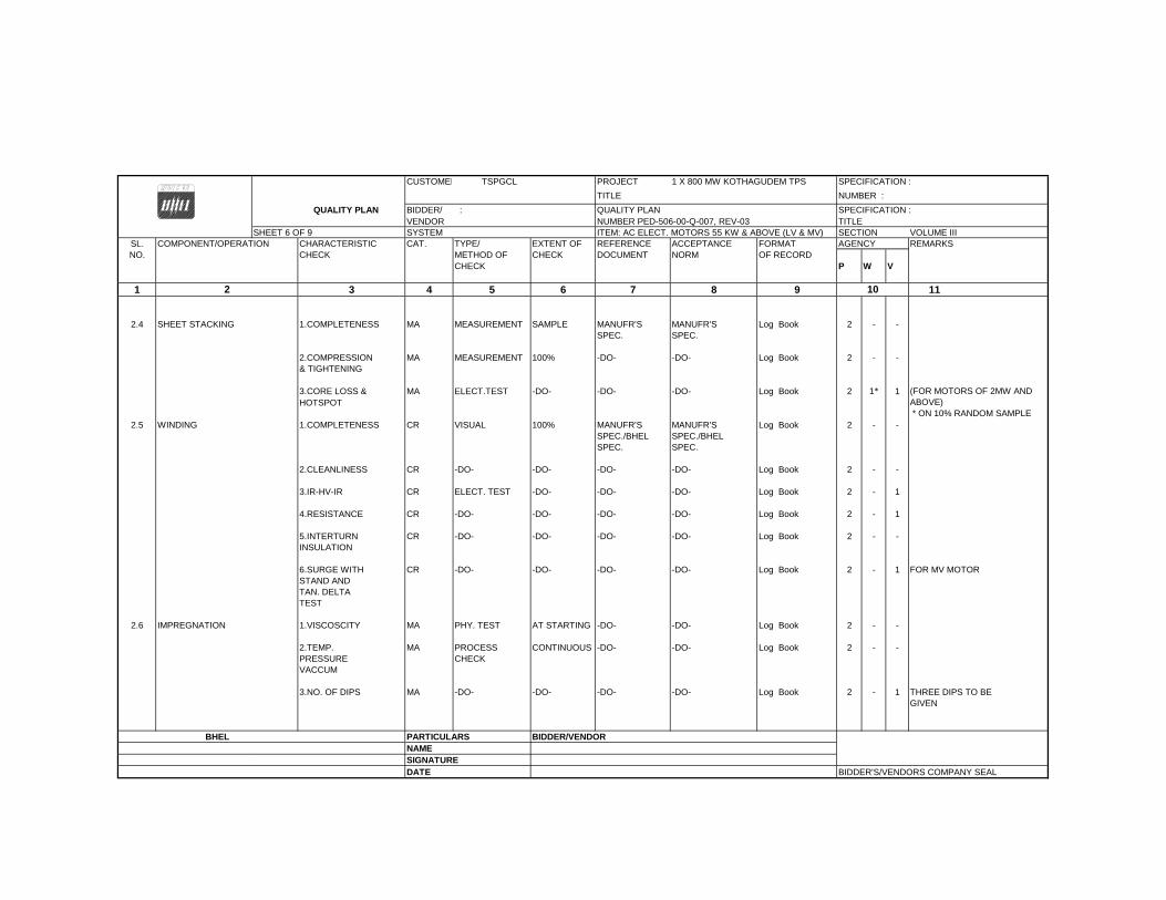
CUSTOMER TSPGCL PROJECT 1 X 800 MW KOTHAGUDEM TPS SPECIFICATION :
TITLE NUMBER :
QUALITY PLAN BIDDER/ : QUALITY PLAN SPECIFICATION : VENDOR NUMBER PED-506-00-Q-007, REV-03 TITLE
SHEET 6 OF 9 SYSTEM ITEM: AC ELECT. MOTORS 55 KW & ABOVE (LV & MV) SECTION VOLUME IIISL. COMPONENT/OPERATION CHARACTERISTIC CAT. TYPE/ EXTENT OF REFERENCE ACCEPTANCE FORMAT AGENCY REMARKSNO. CHECK METHOD OF CHECK DOCUMENT NORM OF RECORD
CHECK P W V
1 3 4 5 6 7 8 9 11
2.4 SHEET STACKING 1.COMPLETENESS MA MEASUREMENT SAMPLE MANUFR'S MANUFR'S Log Book 2 - -SPEC. SPEC.
2.COMPRESSION MA MEASUREMENT 100% -DO- -DO- Log Book 2 - -& TIGHTENING
3.CORE LOSS & MA ELECT.TEST -DO- -DO- -DO- Log Book 2 1* 1HOTSPOT
2.5 WINDING 1.COMPLETENESS CR VISUAL 100% MANUFR'S MANUFR'S Log Book 2 - -SPEC./BHEL SPEC./BHEL SPEC. SPEC.
2.CLEANLINESS CR -DO- -DO- -DO- -DO- Log Book 2 - -
3.IR-HV-IR CR ELECT. TEST -DO- -DO- -DO- Log Book 2 - 1
4.RESISTANCE CR -DO- -DO- -DO- -DO- Log Book 2 - 1
5.INTERTURN CR -DO- -DO- -DO- -DO- Log Book 2 - -INSULATION
6.SURGE WITH CR -DO- -DO- -DO- -DO- Log Book 2 - 1 FOR MV MOTORSTAND ANDTAN. DELTATEST
2.6 IMPREGNATION 1.VISCOSCITY MA PHY. TEST AT STARTING -DO- -DO- Log Book 2 - -
2.TEMP. MA PROCESS CONTINUOUS -DO- -DO- Log Book 2 - -PRESSURE CHECKVACCUM
3.NO. OF DIPS MA -DO- -DO- -DO- -DO- Log Book 2 - 1 THREE DIPS TO BE GIVEN
BHEL PARTICULARS BIDDER/VENDORNAMESIGNATUREDATE BIDDER'S/VENDORS COMPANY SEAL
102
(FOR MOTORS OF 2MW AND ABOVE) * ON 10% RANDOM SAMPLE
6042023
Text Box
STANDARD QUALITY PLAN - AC ELECT. MOTORS 55 KW & ABOVE (LV & MV)
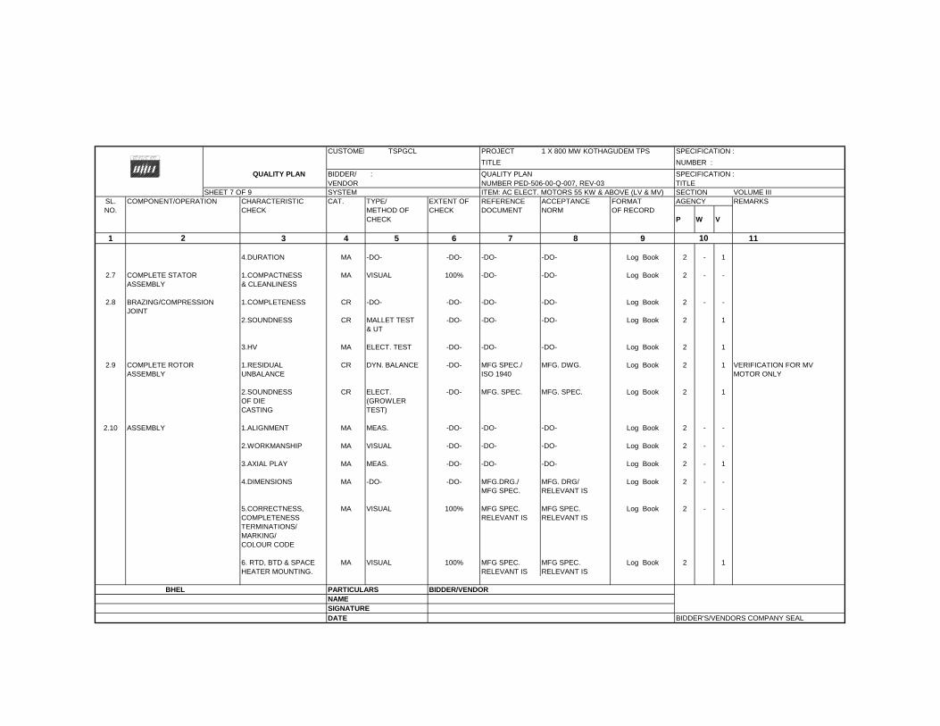
CUSTOMER TSPGCL PROJECT 1 X 800 MW KOTHAGUDEM TPS SPECIFICATION :
TITLE NUMBER :
QUALITY PLAN BIDDER/ : QUALITY PLAN SPECIFICATION : VENDOR NUMBER PED-506-00-Q-007, REV-03 TITLE
SHEET 7 OF 9 SYSTEM ITEM: AC ELECT. MOTORS 55 KW & ABOVE (LV & MV) SECTION VOLUME IIISL. COMPONENT/OPERATION CHARACTERISTIC CAT. TYPE/ EXTENT OF REFERENCE ACCEPTANCE FORMAT AGENCY REMARKSNO. CHECK METHOD OF CHECK DOCUMENT NORM OF RECORD
CHECK P W V
1 3 4 5 6 7 8 9 11
4.DURATION MA -DO- -DO- -DO- -DO- Log Book 2 - 1
2.7 COMPLETE STATOR 1.COMPACTNESS MA VISUAL 100% -DO- -DO- Log Book 2 - -ASSEMBLY & CLEANLINESS
2.8 BRAZING/COMPRESSION 1.COMPLETENESS CR -DO- -DO- -DO- -DO- Log Book 2 - -JOINT
2.SOUNDNESS CR MALLET TEST -DO- -DO- -DO- Log Book 2 1& UT
3.HV MA ELECT. TEST -DO- -DO- -DO- Log Book 2 1
2.9 COMPLETE ROTOR 1.RESIDUAL CR DYN. BALANCE -DO- MFG SPEC./ MFG. DWG. Log Book 2 1 VERIFICATION FOR MVASSEMBLY UNBALANCE ISO 1940 MOTOR ONLY
2.SOUNDNESS CR ELECT. -DO- MFG. SPEC. MFG. SPEC. Log Book 2 1OF DIE (GROWLERCASTING TEST)
2.10 ASSEMBLY 1.ALIGNMENT MA MEAS. -DO- -DO- -DO- Log Book 2 - -
2.WORKMANSHIP MA VISUAL -DO- -DO- -DO- Log Book 2 - -
3.AXIAL PLAY MA MEAS. -DO- -DO- -DO- Log Book 2 - 1
4.DIMENSIONS MA -DO- -DO- MFG.DRG./ MFG. DRG/ Log Book 2 - -MFG SPEC. RELEVANT IS
5.CORRECTNESS, MA VISUAL 100% MFG SPEC. MFG SPEC. Log Book 2 - -COMPLETENESS RELEVANT IS RELEVANT ISTERMINATIONS/MARKING/COLOUR CODE
6. RTD, BTD & SPACE MA VISUAL 100% MFG SPEC. MFG SPEC. Log Book 2 1HEATER MOUNTING. RELEVANT IS RELEVANT IS
BHEL PARTICULARS BIDDER/VENDORNAMESIGNATUREDATE BIDDER'S/VENDORS COMPANY SEAL
102
6042023
Text Box
STANDARD QUALITY PLAN - AC ELECT. MOTORS 55 KW & ABOVE (LV & MV)
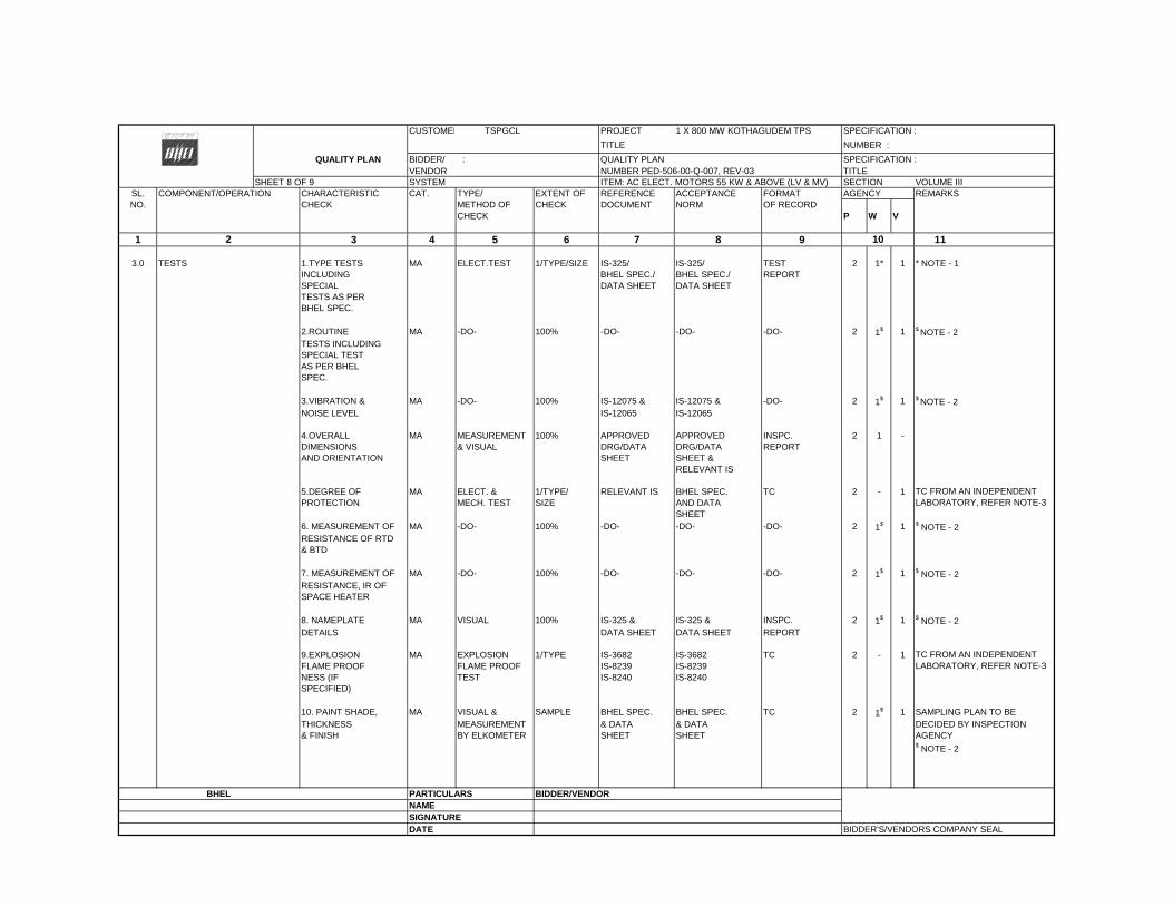
CUSTOMER TSPGCL PROJECT 1 X 800 MW KOTHAGUDEM TPS SPECIFICATION :
TITLE NUMBER :
QUALITY PLAN BIDDER/ : QUALITY PLAN SPECIFICATION : VENDOR NUMBER PED-506-00-Q-007, REV-03 TITLE
SHEET 8 OF 9 SYSTEM ITEM: AC ELECT. MOTORS 55 KW & ABOVE (LV & MV) SECTION VOLUME IIISL. COMPONENT/OPERATION CHARACTERISTIC CAT. TYPE/ EXTENT OF REFERENCE ACCEPTANCE FORMAT AGENCY REMARKSNO. CHECK METHOD OF CHECK DOCUMENT NORM OF RECORD
CHECK P W V
1 3 4 5 6 7 8 9 11
3.0 TESTS 1.TYPE TESTS MA ELECT.TEST 1/TYPE/SIZE IS-325/ IS-325/ TEST 2 1* 1 * NOTE - 1INCLUDING BHEL SPEC./ BHEL SPEC./ REPORTSPECIAL DATA SHEET DATA SHEETTESTS AS PERBHEL SPEC.
2.ROUTINE MA -DO- 100% -DO- -DO- -DO- 2 1$ 1 $ NOTE - 2TESTS INCLUDINGSPECIAL TESTAS PER BHELSPEC.
3.VIBRATION & MA -DO- 100% IS-12075 & IS-12075 & -DO- 2 1$ 1 $ NOTE - 2NOISE LEVEL IS-12065 IS-12065
4.OVERALL MA MEASUREMENT 100% APPROVED APPROVED INSPC. 2 1 -DIMENSIONS & VISUAL DRG/DATA DRG/DATA REPORTAND ORIENTATION SHEET SHEET &
RELEVANT IS
5.DEGREE OF MA ELECT. & 1/TYPE/ RELEVANT IS BHEL SPEC. TC 2 - 1PROTECTION MECH. TEST SIZE AND DATA
SHEET6. MEASUREMENT OF MA -DO- 100% -DO- -DO- -DO- 2 1$ 1 $ NOTE - 2RESISTANCE OF RTD & BTD
7. MEASUREMENT OF MA -DO- 100% -DO- -DO- -DO- 2 1$ 1 $ NOTE - 2RESISTANCE, IR OF SPACE HEATER
8. NAMEPLATE MA VISUAL 100% IS-325 & IS-325 & INSPC. 2 1$ 1 $ NOTE - 2DETAILS DATA SHEET DATA SHEET REPORT
9.EXPLOSION MA EXPLOSION 1/TYPE IS-3682 IS-3682 TC 2 - 1FLAME PROOF FLAME PROOF IS-8239 IS-8239NESS (IF TEST IS-8240 IS-8240SPECIFIED)
10. PAINT SHADE, MA VISUAL & SAMPLE BHEL SPEC. BHEL SPEC. TC 2 1$ 1 SAMPLING PLAN TO BETHICKNESS MEASUREMENT & DATA & DATA DECIDED BY INSPECTION& FINISH BY ELKOMETER SHEET SHEET AGENCY
$ NOTE - 2
BHEL PARTICULARS BIDDER/VENDORNAMESIGNATUREDATE BIDDER'S/VENDORS COMPANY SEAL
102
TC FROM AN INDEPENDENT LABORATORY, REFER NOTE-3
TC FROM AN INDEPENDENT LABORATORY, REFER NOTE-3
6042023
Text Box
STANDARD QUALITY PLAN - AC ELECT. MOTORS 55 KW & ABOVE (LV & MV)
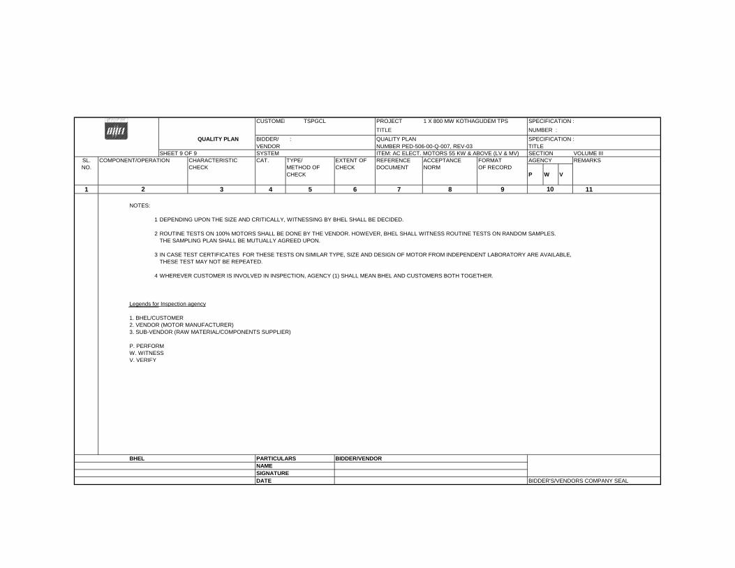
CUSTOMER TSPGCL PROJECT 1 X 800 MW KOTHAGUDEM TPS SPECIFICATION :
TITLE NUMBER :
QUALITY PLAN BIDDER/ : QUALITY PLAN SPECIFICATION : VENDOR NUMBER PED-506-00-Q-007, REV-03 TITLE
SHEET 9 OF 9 SYSTEM ITEM: AC ELECT. MOTORS 55 KW & ABOVE (LV & MV) SECTION VOLUME IIISL. COMPONENT/OPERATION CHARACTERISTIC CAT. TYPE/ EXTENT OF REFERENCE ACCEPTANCE FORMAT AGENCY REMARKSNO. CHECK METHOD OF CHECK DOCUMENT NORM OF RECORD
CHECK P W V
1 3 4 5 6 7 8 9 11
NOTES:
1 DEPENDING UPON THE SIZE AND CRITICALLY, WITNESSING BY BHEL SHALL BE DECIDED.
2 ROUTINE TESTS ON 100% MOTORS SHALL BE DONE BY THE VENDOR. HOWEVER, BHEL SHALL WITNESS ROUTINE TESTS ON RANDOM SAMPLES.THE SAMPLING PLAN SHALL BE MUTUALLY AGREED UPON.
3 IN CASE TEST CERTIFICATES FOR THESE TESTS ON SIMILAR TYPE, SIZE AND DESIGN OF MOTOR FROM INDEPENDENT LABORATORY ARE AVAILABLE, THESE TEST MAY NOT BE REPEATED.
4 WHEREVER CUSTOMER IS INVOLVED IN INSPECTION, AGENCY (1) SHALL MEAN BHEL AND CUSTOMERS BOTH TOGETHER.
Legends for Inspection agency
1. BHEL/CUSTOMER2. VENDOR (MOTOR MANUFACTURER)3. SUB-VENDOR (RAW MATERIAL/COMPONENTS SUPPLIER)
P. PERFORMW. WITNESSV. VERIFY
BHEL PARTICULARS BIDDER/VENDORNAMESIGNATUREDATE BIDDER'S/VENDORS COMPANY SEAL
102
6042023
Text Box
STANDARD QUALITY PLAN - AC ELECT. MOTORS 55 KW & ABOVE (LV & MV)
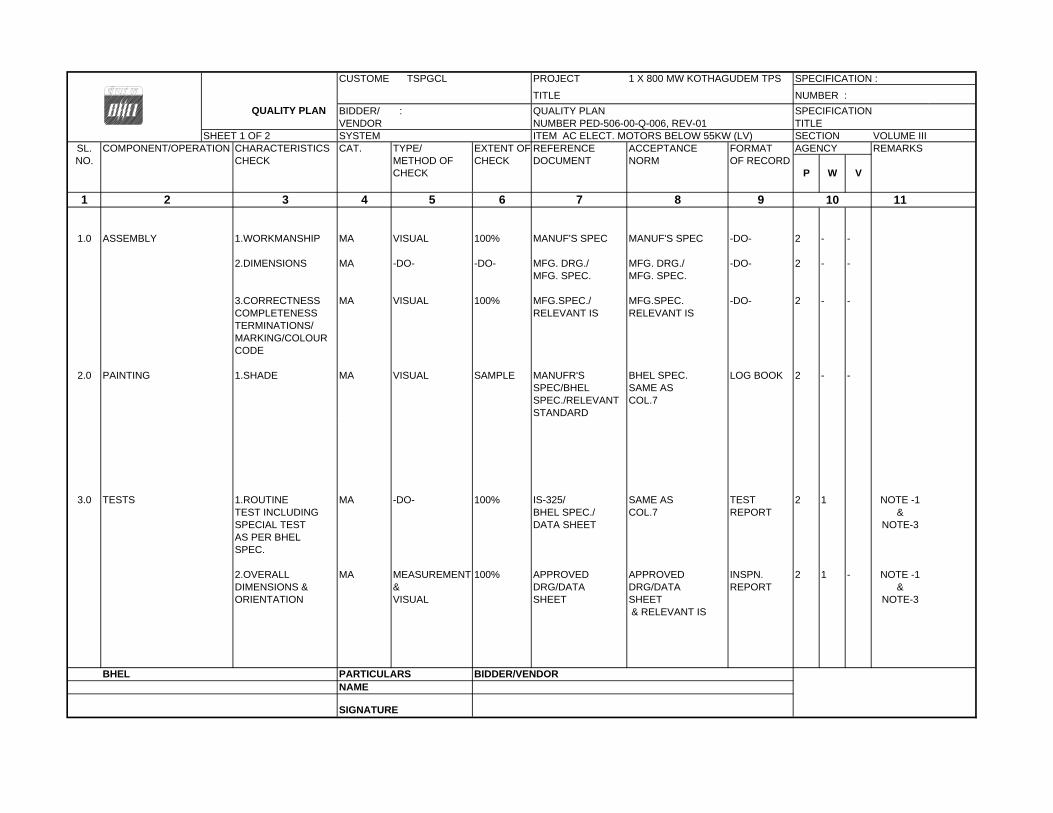
CUSTOMER TSPGCL PROJECT 1 X 800 MW KOTHAGUDEM TPS
TITLE NUMBER :
QUALITY PLAN BIDDER/ : QUALITY PLAN SPECIFICATION VENDOR NUMBER PED-506-00-Q-006, REV-01 TITLE
SHEET 1 OF 2 SYSTEM ITEM AC ELECT. MOTORS BELOW 55KW (LV) SECTION VOLUME IIISL. COMPONENT/OPERATION CHARACTERISTICS CAT. TYPE/ EXTENT OF REFERENCE ACCEPTANCE FORMAT AGENCY REMARKSNO. CHECK METHOD OF CHECK DOCUMENT NORM OF RECORD
CHECK P W V
1 3 4 5 6 7 8 9 10 11
1.0 ASSEMBLY 1.WORKMANSHIP MA VISUAL 100% MANUF'S SPEC MANUF'S SPEC -DO- 2 - -
2.DIMENSIONS MA -DO- -DO- MFG. DRG./ MFG. DRG./ -DO- 2 - -MFG. SPEC. MFG. SPEC.
3.CORRECTNESS MA VISUAL 100% MFG.SPEC./ MFG.SPEC. -DO- 2 - -COMPLETENESS RELEVANT IS RELEVANT ISTERMINATIONS/MARKING/COLOURCODE
2.0 PAINTING 1.SHADE MA VISUAL SAMPLE MANUFR'S BHEL SPEC. LOG BOOK 2 - -SPEC/BHEL SAME ASSPEC./RELEVANT COL.7STANDARD
3.0 TESTS 1.ROUTINE MA -DO- 100% IS-325/ SAME AS TEST 2 1 NOTE -1TEST INCLUDING BHEL SPEC./ COL.7 REPORT &SPECIAL TEST DATA SHEET NOTE-3AS PER BHEL SPEC.
2.OVERALL MA MEASUREMENT 100% APPROVED APPROVED INSPN. 2 1 - NOTE -1DIMENSIONS & & DRG/DATA DRG/DATA REPORT &ORIENTATION VISUAL SHEET SHEET NOTE-3
& RELEVANT IS
BHEL PARTICULARS BIDDER/VENDORNAME
SIGNATURE
SPECIFICATION :
2
6042023
Text Box
STANDARD QUALITY PLAN - AC ELECT. MOTORS BELOW 55 KW (LV)

CUSTOMER TSPGCL PROJECT 1 X 800 MW KOTHAGUDEM TPS
QUALITY PLAN TITLE NUMBER : BIDDER/ : QUALITY PLAN SPECIFICATION :
VENDOR NUMBER PED-506-00-Q-006, REV-01 TITLE :SHEET 2 OF 2 SYSTEM ITEM AC ELECT. MOTORS BELOW 55KW (LV) SECTION VOLUME III
SL. COMPONENT/OPERATION CHARACTERISTICS CAT. TYPE/ EXTENT OF REFERENCE ACCEPTANCE FORMAT AGENCY REMARKSNO. CHECK METHOD OF CHECK DOCUMENT NORM OF RECORD
CHECK P W V
1 3 4 5 6 7 8 9 10 11
3.NAMEPLATE MA VISUAL 100% IS-325 & IS-325 & INSPN. 2 1 -DETAILS DATA SHEET DATA SHEET REPORT
NOTES:
1 ROUTINE TESTS ON 100% MOTORS SHALL BE DONE BY THE VENDOR. HOWEVER, BHEL SHALL WITNESS ROUTINE TESTS ON RANDOM SAMPLES. THE SAMPLING PLAN SHALL BE MUTUALLY AGREED UPON
2 WHERE EVER CUSTOMER IS INVOLVED IN INSPECTION, (1) SHALL MEAN BHEL AND CUSTOMERS BOTH TOGETHER.3 FOR EXHAUST/VENTILATION FAN MOTORS OF RATING UPTO 1.5KW , ONLY ROUTINE TEST CERTIFICATES SHALL BE FURNISHED FOR SCRUTINY.
Legends for Inspection agency
1. BHEL/CUSTOMER2. VENDOR (MOTOR MANUFACTURER)3. SUB-VENDOR (RAW MATERIAL/COMPONENTS SUPPLIER)
P. PERFORMW. WITNESSV. VERIFY
BHEL PARTICULARS BIDDER/VENDORNAMESIGNATUREDATE BIDDER'S/VENDORS COMPANY SEAL
SPECIFICATION :
2
6042023
Text Box
STANDARD QUALITY PLAN - AC ELECT. MOTORS BELOW 55 KW (LV)
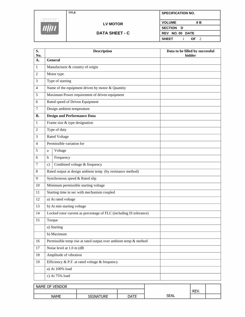
TITLE
LV MOTOR
DATA SHEET - C
SPECIFICATION NO.
VOLUME II B
SECTION D
REV NO. 00 DATE
SHEET 1 OF 2
NAME OF VENDOR SEAL
REV.
NAME SIGNATURE DATE
S. No.
Description Data to be filled by successful bidder
A. General
1 Manufacturer & country of origin
2 Motor type
3 Type of starting
4 Name of the equipment driven by motor & Quantity
5 Maximum Power requirement of driven equipment
6 Rated speed of Driven Equipment
7 Design ambient temperature
B. Design and Performance Data
1 Frame size & type designation
2 Type of duty
3 Rated Voltage
4 Permissible variation for
5 a Voltage
6 b Frequency
7 c) Combined voltage & frequency
8 Rated output at design ambient temp (by resistance method)
9 Synchronous speed & Rated slip
10 Minimum permissible starting voltage
11 Starting time in sec with mechanism coupled
12 a) At rated voltage
13 b) At min starting voltage
14 Locked rotor current as percentage of FLC (including IS tolerance)
15 Torque
a) Starting
b) Maximum
16 Permissible temp rise at rated output over ambient temp & method
17 Noise level at 1.0 m (dB
18 Amplitude of vibration
19 Efficiency & P.F. at rated voltage & frequency
a) At 100% load
c) At 75% load
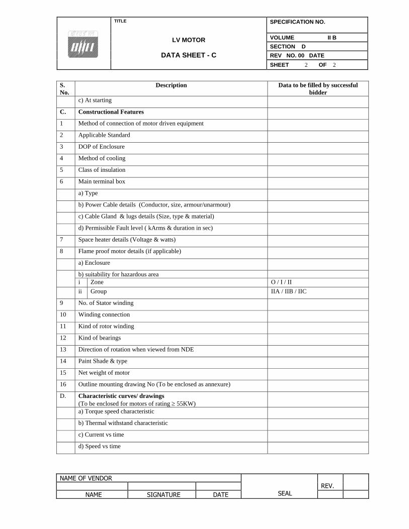
TITLE
LV MOTOR
DATA SHEET - C
SPECIFICATION NO.
VOLUME II B
SECTION D
REV NO. 00 DATE
SHEET 2 OF 2
NAME OF VENDOR SEAL
REV.
NAME SIGNATURE DATE
S. No.
Description Data to be filled by successful bidder
c) At starting
C. Constructional Features
1 Method of connection of motor driven equipment
2 Applicable Standard
3 DOP of Enclosure
4 Method of cooling
5 Class of insulation
6 Main terminal box
a) Type
b) Power Cable details (Conductor, size, armour/unarmour)
c) Cable Gland & lugs details (Size, type & material)
d) Permissible Fault level ( kArms & duration in sec)
7 Space heater details (Voltage & watts)
8 Flame proof motor details (if applicable)
a) Enclosure
b) suitability for hazardous area i Zone O / I / II
ii Group IIA / IIB / IIC
9 No. of Stator winding
10 Winding connection
11 Kind of rotor winding
12 Kind of bearings
13 Direction of rotation when viewed from NDE
14 Paint Shade & type
15 Net weight of motor
16 Outline mounting drawing No (To be enclosed as annexure)
D. Characteristic curves/ drawings (To be enclosed for motors of rating 55KW)
a) Torque speed characteristic
b) Thermal withstand characteristic
c) Current vs time
d) Speed vs time