Technical Specification 41-24 Issue 2017 Guidelines for ...
121
PRODUCED BY THE OPERATIONS DIRECTORATE OF ENERGY NETWORKS ASSOCIATION www.energynetworks.org 1 Technical Specification 41-24 Issue <1> 2017 Guidelines for the Design, Installation, Testing and Maintenance of Main Earthing Systems in Substations
-
Upload
khangminh22 -
Category
Documents
-
view
2 -
download
0
Transcript of Technical Specification 41-24 Issue 2017 Guidelines for ...

PRODUCED BY THE OPERATIONS DIRECTORATE OF ENERGY NETWORKS ASSOCIATION
www.energynetworks.org
1
Technical Specification 41-24
Issue <1> 2017
Guidelines for the Design, Installation, Testing and Maintenance of Main Earthing Systems in Substations

ENA Technical Specification 41-24 Issue <DRAFT-August> <2016>
Page 2
<Insert publication history here, e.g. “First published, December, 2011”>
Amendments since publication
Issue Date Amendment
Issue <1>
<April, 2016>
Draft updated in line with comments from previous meeting. References to S34 highlighted for discussion at April Meeting. Some comments included in body for guidance. Other changes accepted and tracked changes removed [RW].
June 2016 Minor changes for review at June meeting
August 2016 Edits following June meeting. All changes accepted. Yellow highlight for S34 references remaining.
TO DO: Case studies at end of document. Flow chart.
Dec 2016 / March 2017
Risk assessment section revised and flow chart updated. General tidy prior to issue.
© <year of publication> Energy Networks Association
All rights reserved. No part of this publication may be reproduced, stored in a retrieval system or transmitted in any form or by any means, electronic, mechanical, photocopying, recording or otherwise, without the prior written consent of Energy Networks Association. Specific enquiries concerning this document should be addressed to:
Operations Directorate Energy Networks Association 6th Floor, Dean Bradley House
52 Horseferry Rd London
SW1P 2AF
This document has been prepared for use by members of the Energy Networks Association to take account of the conditions which apply to them. Advice should be taken from an appropriately qualified engineer on the suitability of this document for any other purpose.

ENA Technical Specification 41-24 Issue <DRAFT-OCTOBER> <2106>
Page 3
Contents 1
Foreword .................................................................................................................................... 9 2
Scope ................................................................................................................................. 10 3
Normative references ........................................................................................................ 10 4
Definitions .......................................................................................................................... 11 5
Fundamental Requirements .............................................................................................. 15 6
4.1 Function of an earthing system ................................................................................ 15 7
4.2 Typical features of an earthing system .................................................................... 15 8
4.3 The effects of substation potential rise on persons ................................................. 16 9
4.3.1 Touch potential ............................................................................................ 17 10
4.3.2 Step potential ............................................................................................... 17 11
4.3.3 Transfer potential ......................................................................................... 17 12
4.3.4 General ........................................................................................................ 17 13
4.3.5 Limits for LV networks ................................................................................. 18 14
4.3.6 Limits for Other systems .............................................................................. 18 15
4.3.7 Limits for Telecommunications Equipment (HOT/COLD sites)................... 18 16
4.4 Safety criteria ........................................................................................................... 18 17
4.4.1 General ‘permissible’ design limits .............................................................. 18 18
4.4.2 Effect of electricity on animals ..................................................................... 22 19
4.4.3 Injury or shock to persons and animals outside the installation ................. 22 20
4.5 Electrical Requirements ........................................................................................... 22 21
4.5.1 Method of neutral earthing ........................................................................... 22 22
4.5.2 Fault Current ................................................................................................ 23 23
4.5.3 Thermal effects - general ............................................................................. 23 24
Design ................................................................................................................................ 24 25
5.1 Design Considerations ............................................................................................. 24 26
5.1.1 Limiting values for EPR ............................................................................... 24 27
5.1.2 Touch and Step voltages ............................................................................. 24 28
5.1.3 Factors to include in calculation of EPR and Safety Voltages .................... 24 29
5.1.4 Transfer Potential ......................................................................................... 24 30
5.2 Preliminary Arrangement and Layout ...................................................................... 25 31
5.3 Design Guidelines .................................................................................................... 25 32
5.3.1 Outdoor Substations .................................................................................... 25 33
5.3.2 Indoor Substations ....................................................................................... 26 34
5.3.3 Shared Sites................................................................................................. 27 35
5.3.4 Distribution (or ‘Secondary’) Substations .................................................... 27 36
5.3.5 Metallic Fences ............................................................................................ 27 37
5.3.6 Provision of Maintenance/Test facilities ...................................................... 27 38
5.4 Design data .............................................................................................................. 28 39
5.4.1 Soil Resistivity .............................................................................................. 28 40
5.4.2 Fault currents and durations - general ........................................................ 29 41
5.4.3 Fault current growth ..................................................................................... 30 42
5.4.4 Fault currents for EPR and safety voltage calculations .............................. 30 43

ENA Technical Specification 41-24 Issue <DRAFT-OCTOBER> <2106>
Page 4
5.4.5 Fault currents and clearance times for conductor size (thermal effects)44 ...................................................................................................................... 31 45
5.4.6 Fault currents and times for electrode size calculations (thermal 46 effects) ......................................................................................................... 32 47
5.5 Conductor and Electrode Ratings ............................................................................ 34 48
5.5.1 Earthing Conductors and Electrodes ........................................................... 34 49
5.5.2 Electrode Surface Current Density Ratings ................................................ 40 50
5.6 Design Assessment ................................................................................................. 42 51
5.6.1 Design flowchart .......................................................................................... 42 52
5.6.2 Assessment Procedure ................................................................................ 44 53
5.6.3 Methods to improve design (Mitigation measures) ..................................... 45 54
5.6.3.1 EPR reduction ............................................................................... 45 55
5.6.3.2 Touch Voltage reduction ............................................................... 46 56
5.7 Risk Assessment ...................................................................................................... 46 57
5.7.1 Methodology................................................................................................. 46 58
5.7.2 Typical applications...................................................................................... 47 59
Construction of Earthing Systems ..................................................................................... 48 60
6.1 General Design Philosophy ..................................................................................... 48 61
6.1.1 Materials ....................................................................................................... 48 62
6.1.2 Avoiding Theft .............................................................................................. 48 63
6.2 Jointing Conductors and Equipment Connections .................................................. 49 64
6.2.1 General ........................................................................................................ 49 65
6.2.2 Transition washers ....................................................................................... 49 66
6.2.3 Copper to Copper Connections ................................................................... 50 67
6.2.4 Copper to Earth Rods .................................................................................. 50 68
6.2.5 Electrode Test Points ................................................................................... 50 69
6.2.6 Copper to Equipment (Steel, or Galvanised Steel) Connections ................ 50 70
6.2.7 Aluminium to Equipment Connections ........................................................ 50 71
6.2.8 Aluminium to Aluminium Connections ......................................................... 51 72
6.2.9 Aluminium to Copper Connections .............................................................. 51 73
6.2.10 Earthing Connections to Aluminium Structures........................................... 52 74
6.2.11 Steel Structures ........................................................................................... 52 75
6.3 Above Ground Earthing Installations ....................................................................... 53 76
6.3.1 Fixing Above Ground Conductor to Supports ............................................. 53 77
6.3.2 Prevention of Corrosion of Above Ground Conductors .............................. 53 78
6.3.3 Metal Trench Covers ................................................................................... 53 79
6.3.4 Loops for Portable Earth Connections ........................................................ 53 80
6.4 Below Ground Earthing Installations ....................................................................... 54 81
6.4.1 Installation of Buried Electrode within a Substation .................................... 54 82
6.4.2 Positioning of Buried Electrode ................................................................... 54 83
6.4.3 Other Earth Electrodes ................................................................................ 55 84
6.4.3.1 Earth Rods .................................................................................... 55 85
6.4.3.2 Earth Plates .................................................................................. 55 86
6.5 Use of Structural Earths including Steel Piles and Rebar ....................................... 56 87

ENA Technical Specification 41-24 Issue <DRAFT-OCTOBER> <2106>
Page 5
6.5.1 Sheet Steel Piles .......................................................................................... 56 88
6.5.2 Horizontal Steel Reinforced Foundations .................................................... 56 89
6.5.3 Vertical Steel Reinforced Concrete Columns .............................................. 57 90
6.6 Metallic Fences ........................................................................................................ 57 91
6.6.1 Independently Earthed Fences .................................................................... 57 92
6.6.2 Segregation between independently earthed fence and earthing 93 system .......................................................................................................... 57 94
6.6.3 Fences Bonded to the Substation Earthing System ................................... 59 95
6.6.4 Third Party Metallic Fences ......................................................................... 60 96
6.6.5 Insulated Fence Sections. ........................................................................... 60 97
6.6.6 Chain Link Fencing (Galvanised or Plastic Coated) ................................... 61 98
6.6.7 Coated Fence Panels .................................................................................. 61 99
6.6.8 Electric Security Fences .............................................................................. 61 100
6.6.9 Anti-climbing Precautions ............................................................................ 61 101
6.7 Specific Items ........................................................................................................... 61 102
6.7.1 Water Services to Substations .................................................................... 61 103
6.7.2 Non-current carrying metalwork .................................................................. 62 104
6.7.3 Items normally bonded to the main earth grid: ............................................ 62 105
6.7.4 Items NOT normally bonded to the Earth Grid ............................................ 62 106
6.7.5 Non-standard bonding arrangements .......................................................... 63 107
6.8 Overhead Line Terminations.................................................................................... 63 108
6.8.1 Tower Terminations Adjacent to Substation ............................................... 63 109
6.8.2 Steel Tower Termination with Cable Sealing Ends ..................................... 63 110
6.8.3 Terminal Poles with Stays Adjacent to Substation Fence .......................... 63 111
6.8.4 Down drop Anchorage Arrangement with Arcing Horns ............................. 64 112
6.8.5 Loss of Aerial Earth Wires ........................................................................... 64 113
6.9 HV Cable Metallic Sheath / Armour Earthing .......................................................... 64 114
6.9.1 Insulated (Polymeric) Sheath Cables .......................................................... 64 115
6.9.2 Cables Entering Substations ....................................................................... 65 116
6.9.3 Cables Within Substations ........................................................................... 65 117
6.9.4 Outdoor Cable Sealing-Ends ....................................................................... 65 118
6.9.5 Use of Disconnected, Non-Insulated Sheath/Armour Cables as an 119 Electrode ...................................................................................................... 65 120
6.10 Light-current Equipment Associated with External Cabling .................................... 66 121
6.11 Metal Clad and Gas Insulated (GIS) Substations.................................................... 66 122
6.11.1 Metal Clad Substations ................................................................................ 66 123
6.11.2 Gas Insulated Switchgear (GIS) .................................................................. 66 124
6.12 Fault Throwing Switches, Earth Switches and Disconnectors ................................ 67 125
6.12.1 Background .................................................................................................. 67 126
6.12.2 Fault Throwing Switches (Phase - Earth) .................................................... 68 127
6.12.3 Earth Switches ............................................................................................. 68 128
6.12.4 Isolators ........................................................................................................ 68 129
6.13 Operating Handles, Mechanisms and Control Kiosks ............................................. 68 130
6.13.1 Background .................................................................................................. 68 131

ENA Technical Specification 41-24 Issue <DRAFT-OCTOBER> <2106>
Page 6
6.13.2 Earth Mats (Stance Earths) ......................................................................... 68 132
6.13.3 Connection of Handles to the Earth Grid and Stance Earths ..................... 69 133
6.14 Surge Arrestors and CVTs ....................................................................................... 69 134
Measurements ................................................................................................................... 71 135
7.1 General ..................................................................................................................... 71 136
7.2 Safety ....................................................................................................................... 71 137
7.3 Instrumentation and Equipment ............................................................................... 71 138
7.4 Soil Resistivity Measurements ................................................................................. 72 139
7.4.1 Objective ...................................................................................................... 72 140
7.4.2 Wenner Method ........................................................................................... 72 141
7.4.3 Interpretation of Results ............................................................................... 72 142
7.4.4 Sources of Error ........................................................................................... 72 143
7.4.5 Driven Rod Method ...................................................................................... 73 144
7.5 Earth Resistance/Impedance Measurements ......................................................... 73 145
7.5.1 Objective ...................................................................................................... 73 146
7.5.2 Method ......................................................................................................... 74 147
7.5.3 Interpretation of Results ............................................................................... 74 148
7.5.4 Sources of Error ........................................................................................... 75 149
7.6 Comparative Method of Measuring Earth Resistance ............................................. 76 150
7.6.1 Objective ...................................................................................................... 76 151
7.6.2 Method ......................................................................................................... 76 152
7.6.3 Interpretation of Results ............................................................................... 77 153
7.6.4 Sources of Error ........................................................................................... 77 154
7.7 Earth Connection Resistance Measurements (Equipment Bonding Tests) ............ 78 155
7.7.1 Objective ...................................................................................................... 78 156
7.7.2 Method ......................................................................................................... 78 157
7.7.3 Interpretation of Results ............................................................................... 78 158
7.8 Earth Conductor Joint Resistance Measurements .................................................. 79 159
7.8.1 Objective ...................................................................................................... 79 160
7.8.2 Method ......................................................................................................... 79 161
7.8.3 Interpretation of Results ............................................................................... 79 162
7.9 Earth Potential Measurements ................................................................................ 79 163
7.9.1 Objective ...................................................................................................... 79 164
7.9.2 Method ......................................................................................................... 80 165
7.9.3 Interpretation of Results ............................................................................... 80 166
7.10 Earth Electrode Separation Test .............................................................................. 80 167
7.10.1 Objective ...................................................................................................... 80 168
7.10.2 Method ......................................................................................................... 80 169
7.10.3 Interpretation of Results ............................................................................... 80 170
7.11 Buried Earth Electrode Location .............................................................................. 81 171
7.11.1 Objective ...................................................................................................... 81 172
7.11.2 Method ......................................................................................................... 81 173
MAINTENANCE ................................................................................................................. 82 174
8.1 Introduction ............................................................................................................... 82 175

ENA Technical Specification 41-24 Issue <DRAFT-OCTOBER> <2106>
Page 7
8.1.1 Inspection ..................................................................................................... 82 176
8.1.2 Maintenance and Repairs ............................................................................ 82 177
8.2 Types of Inspection .................................................................................................. 83 178
8.2.1 Introduction .................................................................................................. 83 179
8.2.2 Frequent Visual Inspection .......................................................................... 83 180
8.2.3 Infrequent Detailed Visual Inspection .......................................................... 83 181
8.2.4 Detailed Visual Inspection, Testing and Analysis ....................................... 84 182
8.2.4.1 Testing .......................................................................................... 84 183
8.2.4.2 Selected Excavation and Examination of Buried Earth 184 Electrode ....................................................................................... 85 185
8.2.4.3 Analysis and Recording of Test Results ...................................... 85 186
8.3 Maintenance and Repair of Earthing Systems ........................................................ 86 187
8.4 Procedure for the Remaking Defective Joints or Repairing Conductor Breaks188 .................................................................................................................................. 87 189
8.4.1 Introduction .................................................................................................. 87 190
8.4.2 Joint Repair Methods ................................................................................... 87 191
8.4.3 Flexible Braids ............................................................................................. 87 192
Ground Mounted Distribution Substation Earthing ........................................................... 88 193
9.1 Introduction ............................................................................................................... 88 194
9.2 Relocation of Pole Mounted Equipment to Ground Level ....................................... 88 195
9.3 General design requirements................................................................................... 88 196
9.3.1 Design Data Requirements.......................................................................... 89 197
9.3.2 Conductor and electrode sizing ................................................................... 89 198
9.3.3 Target resistance ......................................................................................... 89 199
9.3.4 EPR design limit ........................................................................................... 90 200
9.3.5 Calculation of EPR ....................................................................................... 90 201
9.3.5.1 Factors to consider: ...................................................................... 90 202
9.3.5.2 Transfer Potential from source ..................................................... 91 203
9.3.6 Step/Touch Potentials at the Substation ..................................................... 91 204
9.3.7 Simplified approach ..................................................................................... 91 205
9.4 Network and other contributions .............................................................................. 92 206
9.4.1 Additional Electrode ..................................................................................... 92 207
9.4.2 Parallel contributions from interconnected HV and LV networks ................ 92 208
9.4.3 Ascertaining Network Contribution .............................................................. 93 209
9.4.4 Global Earthing Systems ............................................................................. 93 210
9.5 Transfer Potential onto LV network ......................................................................... 94 211
9.5.1 General ........................................................................................................ 94 212
9.5.2 Touch voltage on LV system as a result of HV faults ................................. 94 213
9.5.3 Stress Voltage .............................................................................................. 94 214
9.6 Combined HV and LV earthing ................................................................................ 95 215
9.7 Segregated HV and LV earthing .............................................................................. 95 216
9.7.1 Separation Distance .................................................................................... 95 217
9.7.2 Transfer voltage to third parties ................................................................... 96 218
9.7.3 Further Considerations ................................................................................ 96 219

ENA Technical Specification 41-24 Issue <DRAFT-OCTOBER> <2106>
Page 8
9.7.4 Multiple LV electrodes on segregated systems........................................... 97 220
9.8 Situations where HV/LV systems cannot be segregated ........................................ 97 221
9.9 Practical Considerations .......................................................................................... 97 222
9.10 LV installations near High EPR sites ....................................................................... 98 223
9.11 Supplies to/from High EPR (HPR) sites .................................................................. 98 224
9.11.1 Special Arrangements ................................................................................. 99 225
Pole Mounted Substation and Equipment Earthing ........................................................ 100 226
10.1 General Comments & Assumptions....................................................................... 100 227
10.2 Pole Mounted Transformers .................................................................................. 100 228
10.3 Electrode Configuration for Pole Mounted Equipment .......................................... 101 229
10.4 HV Earth Electrode Value ...................................................................................... 102 230
10.5 Electrode Arrangement Selection Method ............................................................. 102 231
10.6 Earthed Operating Mechanisms Accessible From Ground Level ......................... 103 232
10.7 Air Break Switch Disconnector (ABSD) with an isolated operating mechanism233 ................................................................................................................................ 107 234
10.8 Surge Arresters ...................................................................................................... 109 235
10.9 Cable Terminations ................................................................................................ 109 236
10.10 Operations at Earthed Equipment Locations ......................................................... 110 237
10.11 Installation .............................................................................................................. 110 238
10.12 Inspection & Maintenance of Earth Installations ................................................... 111 239
10.12.1 Items to Inspect .......................................................................................... 111 240
10.12.2 Items to Examine ....................................................................................... 111 241
10.12.3 Items to Test .............................................................................................. 111 242
Case studies / examples ................................................................................................. 113 243
11.1 Risk assessment – house near substation ............................................................ 113 244
11.2 LV Supply into HOT (HPR) site ............................................................................. 115 245
246
247
248

ENA Technical Specification 41-24 Issue <DRAFT-OCTOBER> <2106>
Page 9
Foreword 249
This Technical Specification (TS) is published by the Energy Networks Association (ENA) and 250 comes into effect from June, 2017. It has been prepared under the authority of the ENA 251 Engineering Policy and Standards Manager and has been approved for publication by the ENA 252 Electricity Networks and Futures Group (ENFG). The approved abbreviated title of this 253 engineering document is “ENA TS 41-24”. 254
This Specification is to be used in conjunction with Engineering Recommendation S34 (2017). 255 In this document account has been taken of: 256
(i) UK Adoption of BS EN 50522:2010 (Earthing of Power Installations Exceeding 257 1kV a.c.), in particular with reference to acceptable touch/step voltage limits 258 derived from IEC/TS 60479-1:2005 (Effects of current on human beings and 259 livestock); 260
(ii) changes to earthing practice as outlined in ESQC (Electrical Safety, Quality, and 261 Continuity) Regulations, 2002, in particular with regard to smaller ‘distribution’ or 262 ‘secondary’ substations. These are described in Sections 9 and 10 of this 263 specification; 264
(iii) the requirements for Protective Multiple Earthing systems as outlined in 265 Engineering Recommendation G12. (The relevant items concerning substation 266 earthing in EREC G12/4 have now been transferred to this document); 267
(iv) the increasing use of plastic sheathed cables; 268
(v) the differing requirements of earthing systems at various voltages and for differing 269 types of substation installation. 270
271

ENA Technical Specification 41-24 Issue <DRAFT-OCTOBER> <2106>
Page 10
Scope 272
This Specification applies to fixed earthing systems for all electricity supply systems and 273 equipment earthing within EHV, HV and HV/LV substations. 274
It also applies to: 275
(i) terminal towers adjacent to substations and cable sealing end compounds; 276
(ii) pole mounted transformer or air-break switch disconnector installations; 277
(iii) pole mounted reclosers with ground level control. 278
It does not apply to earthing systems for quarries and railway supply substations. 279
Normative references 280
The following referenced documents, in whole or part, are indispensable for the application of 281 this document. For dated references, only the edition cited applies. For undated references, 282 the latest edition of the referenced document (including any amendments) applies. 283
BS 7430:2011+2015 (Code of Practice for Protective Earthing of Electrical Installations) 284
ESQC (Electrical Safety, Quality, and Continuity) Regulations, 2002 (As amended) 285
BS EN 50522:2010 (Earthing of Power Installations Exceeding 1kV a.c.) 286
IEC/TS 60479-1:2005 (Effects of current on human beings and livestock). (Part 1 – General 287 Aspects) 288
IEC/TR 60479- 3 – (Effects of currents passing through the body of livestock) 289
ITU-T: Directives concerning the protection of telecommunication lines against harmful effects 290 from electric power and electrified railway lines: Volume VI: Danger, damage and disturbance 291 (2008) 292
CIGRE Working Group 23.10 Paper 151 (044) (Dec. 1993): Earthing of GIS – An Application 293 Guide 294
Other references as included in this document: ER 134, S34, BS EN 62305, IEEE 80, IEEE 295 81, BS EN 62561-2 296
297
298

ENA Technical Specification 41-24 Issue <DRAFT-OCTOBER> <2106>
Page 11
Definitions 299
APPROVED EQUIPMENT Equipment Approved in operational policy document for use in the appropriate circumstances.
AUXILIARY ELECTRODE See SUPPLEMENTARY ELECTRODE
BACKUP PROTECTION Protection set to operate following failure or slow operation of primary protection – see NORMAL PROTECTION below. For design purposes the backup protection clearance time may be taken as a fixed (worst case) clearance time appropriate to the network operator’s custom and practice.
BONDING CONDUCTOR A protective conductor providing equipotential bonding.
CROSS COUNTRY FAULT Two or more phase-to-earth faults at separate locations and on different phases. Effectively this creates a phase-phase fault with current flowing through earth electrode and/or bonding conductors. The result can be an increased ‘EARTH FAULT CURRENT’ for design purposes at some locations. CROSS COUNTRY FAULTS are usually considered only if a first phase-earth fault does not automatically clear within a short period, or if significant phase voltage displacement (neutral voltage displacement) could occur. If an accurate figure is not available, a value of 85% of the double phase-to-earth fault current may be assumed.
EARTH The conductive mass of earth whose electric potential at any point is conventionally taken as zero.
EARTH ELECTRODE A conductor or group of conductors in intimate contact with, and providing an electrical connection to, earth.
EARTH ELECTRODE POTENTIAL
The difference in potential between the 'EARTH ELECTRODE' and a remote 'EARTH'.
EARTH ELECTRODE RESISTANCE
The resistance of an 'EARTH ELECTRODE' with respect to 'EARTH'.
EARTH ELECTRODE RESISTANCE AREA
That area of ground over which the resistance of an 'EARTH ELECTRODE' effectively exists. It is the same area of ground over which the 'EARTH ELECTRODE POTENTIAL' exists.
EARTH FAULT A fault causing current to flow in one or more earth-return paths. Typically a single phase to earth fault, but this term may also be used to describe two phase and three phase faults involving earth.
EARTH FAULT CURRENT The worst case steady state (symmetrical) RMS current to earth, i.e. that returning to the system neutral(s) resulting from a single phase to earth fault. This is normally calculated (initially) for the ‘zero ohm’ fault condition. Depending on the circumstances, the value can be modified by including ‘earth resistance’. Not to be confused with ‘GROUND RETURN’

ENA Technical Specification 41-24 Issue <DRAFT-OCTOBER> <2106>
Page 12
current which relates to the proportion of current returning via soil.
In some situations, particularly ‘CROSS COUNTRY FAULTS’, a different single phase to earth fault at two separate locations can result in ‘EARTH FAULT CURRENT’ (as seen at the fault-point) that does not return to the system neutrals yet should still be considered at the design stage.
EARTH POTENTIAL RISE (EPR) OR GROUND POTENTIAL
The difference in potential which may exist between a point on the ground and a remote 'EARTH'. Formerly known as RoEP (Rise of Earth Potential). The term ‘GPR’ (Ground Potential Rise) is an alternative form, not used in this standard.
EARTHING CONDUCTOR OR EARTHING CONNECTION
A protective conductor connecting a main earth terminal of an installation to an 'EARTH ELECTRODE' or to other means of earthing.
EARTH MAT Definition requested by WPD. Group to decide form of words, e.g.: A buried or surface laid mesh or other electrode, usually installed at the operator position close to switchgear or other plant, intended to control or limit hand-feet TOUCH POTENTIAL.
EARTHING SYSTEM
The complete interconnected assembly of 'EARTHING CONDUCTORS' and 'EARTH ELECTRODES' (including cables with uninsulated sheaths).
EHV Extra High Voltage, typically used in UK to describe a voltage of 33kV or higher.
ELECTRODE CURRENT The current entering the ground through the substation’s electrode system under earth fault conditions. This term is generally used in the context of electrode sizing calculations and is slightly different to Ground Return Current since the ground return current may flow through alternative paths such as auxiliary electrodes etc. For design purposes the electrode current may be taken as the worst case current flowing into a substation’s electrode system under foreseeable fault conditions including, where relevant, the loss of metallic return paths and/or cross country faults.
GLOBAL EARTHING SYSTEM
An earthing system of sufficiently dense interconnection such that all items are bonded together and rise in voltage together under fault conditions. No ‘true earth’ reference exists and therefore safety voltages are limited.
GROUND RETURN CURRENT
The proportion of EARTH FAULT CURRENT returning via soil (as opposed to metallic paths such as cable sheaths or overhead earth wires)
If there is a metallic return path for EARTH FAULT CURRENT (e.g. a cable screen or overhead earth wire), this will typically convey a large proportion of the earth fault current. The remainder will return through soil to the system neutral(s).

ENA Technical Specification 41-24 Issue <DRAFT-OCTOBER> <2106>
Page 13
Reduction factors for neutral current flows (multiple earthed systems) and sheath/earth wire return currents may be applied to calculate the GROUND RETURN CURRENT. The GROUND RETURN CURRENT is used in EPR calculations as it flows through the resistance formed by a substation’s overall earth electrode system (and that of the wider network) and thus contributes to voltage rise of that system. Annex I of BS EN 50522 describes some methods for calculating this component. Further guidance is given in ENA EREC S34.
GROUND VOLTAGE PROFILE
The radial ground surface potential around an 'EARTH ELECTRODE' referenced with respect to remote 'EARTH'.
HOT / COLD SITE A HOT site is defined as one which exceeds ITU limits for EPR, typically these thresholds are 650 V (for reliable fault clearance time <= 0.2 seconds), or 430 V otherwise. The requirements derive from telecommunication standards relating to voltage withstand on equipment.
Note: These thresholds have formerly been applied as design limits for EPR in some areas. The terms HOT and COLD were often applied as a convenience (on the basis that many COLD sites do achieve safe step/touch limits) but do not relate directly to safe design limits for touch and step voltages in substations. Refer to ‘HIGH EPR’ below.
HIGH EPR / HPR High Potential Rise resulting from an earth fault. An EPR greater than twice the permissible touch voltage limit (e.g. 466 V for 1 second faults on soil or outdoor concrete).
HV (High Voltage) A voltage greater than 1kV and less than 33kV. Typically used to describe 6.6kV, 11kV and 20kV systems in UK.
MES (Main Earthing System) The interconnected arrangement of earth electrode and bonds to main items of plant in a substation.
NORMAL PROTECTION OPERATION
Clearance of a fault under normal (usual) circumstances. The normal clearance time will include relay operating time and mechanical circuit breaker delays for all foreseeable faults, and may be calculated for design purposes. Alternatively a network operator may work to the ‘worst case’ protection clearance time applicable to the network in a given area. This time assumes that faults will be cleared by normal upstream protection and does not allow for e.g. stuck circuit breakers or other protection failures/delays. Certain parts of an earthing design should consider slower ‘BACKUP PROTECTION’ operation (see above) which allows for a failure of normal protection.
NETWORK OPERATOR
Owner or operator of assets. Includes DNO (Distribution Network Operator), IDNO (Independent or ‘Inset’ DNO) and Transmission Network Operator (TNO) as defined in the Distribution Code (DCode) or System Operator Transmission Code (STC) as appropriate.

ENA Technical Specification 41-24 Issue <DRAFT-OCTOBER> <2106>
Page 14
SUPPLEMENTARY ELECTRODE
Electrode that improves the performance of an earthing system, and may increase resilience, but is not critical to the safety of the ‘as designed’ system.
STEP POTENTIAL See Section 4.3.2 for definition.
STRESS VOLTAGE Voltage difference between two segregated earthing systems, which may appear across insulators/bushings etc. or cable insulation.
TOUCH POTENTIAL See Section 4.3.1 for definition.
TRANSFER POTENTIAL
WITHSTAND VOLTAGE
See Section 4.3.3 for definition.
The maximum STRESS VOLTAGE that can be safely permitted between items of plant or across insulation without risk of insulation breakdown or failure.
300

ENA Technical Specification 41-24 Issue <DRAFT-OCTOBER> <2106>
Page 15
Fundamental Requirements 301
4.1 Function of an earthing system 302
Every substation shall be provided with an earthing installation designed so that in both normal 303 and abnormal conditions there is no danger to persons arising from earth potential in any place 304 to which they have legitimate access. The installation shall be able to pass the maximum 305 current from any fault point back to the system neutral whilst maintaining step, touch, and 306 transfer potentials within permissible limits (defined in Section 4.3) based on normal* protection 307 relay and circuit breaker operating times. In exceptional circumstances where the above 308 parameters may not be economically or practically kept below permissible limits a probabilistic 309 risk assessment may be carried out. Where this shows the risk to be below accepted ALARP 310 levels the level of earth potential rise mitigation may be reduced (refer to Section 5.7). 311
The earthing system shall be designed to avoid damage to equipment due to excessive 312 potential rise, potential differences within the earthing system (stress voltages), and due to 313 excessive currents flowing in auxiliary paths not intended for carrying fault current. 314
The design shall be such that the passage of fault current does not result in any thermal or 315 mechanical damage [for backup protection clearance times] or damage to insulation of 316 connected apparatus. It shall be such that protective gear, including surge protection, is able 317 to operate correctly. 318
Any exposed normally un-energised metalwork within a substation, which may be made live 319 by consequence of a system insulation failure can present a safety hazard to personnel. It is 320 a function of the station earthing system to eliminate such hazards by solidly bonding together 321 all such metalwork and to bond this to the substation earth electrode system in contact with 322 the general mass of earth. Dangerous potential differences between points legitimately 323 accessible to personnel shall be eliminated by appropriate design. 324
The earthing system shall maintain its integrity for the expected installation lifetime with due 325 allowance for corrosion and mechanical constraints. 326
The earthing system performance shall contribute to ensuring electromagnetic compatibility 327 (EMC) among electrical and electronic apparatus of the high voltage system in accordance 328 with IEC/TS 61000-5-2. 329
4.2 Typical features of an earthing system 330
The earthing installation requirements are met principally by providing in each substation an 331 arrangement of electrodes and earthing conductors which act as an earthing busbar. This is 332 called the 'main earth grid' or ‘main earth system’ (MES) and the following are connected to it: 333
(i) all equipment housing or supporting high voltage conductors within the substation 334 such as transformer and circuit breaker tanks, arcing rings and horns and metal 335 bases of insulators; 336
(ii) neutral connection of windings of transformers required for high voltage system 337 earthing. For high voltage systems the connections may be via earthing resistors 338 or other current limiting devices, as described in Section 4.4. (The neutral earthing 339 of low-voltage systems is separately considered in Section 9); 340
* See ‘Definitions’ in Section 3

ENA Technical Specification 41-24 Issue <DRAFT-OCTOBER> <2106>
Page 16
(iii) earth electrodes, additional to the main earth grid which may itself function as an 341 earth electrode; 342
(iv) earth connections from overhead line terminal supports and the sheaths / screens 343 of underground cables; 344
(v) earth mats, provided as a safety measure, to reduce the potential difference 345 between points on the area of ground adjacent to manually operated plant and the 346 metalwork including handles of that plant (but see also 10.6); 347
(vi) ‘Grading Electrodes’ (intended to reduce touch voltages on equipment), which as a 348 minimum consist of a horizontal ring electrode around all items of earthed plant and 349 the equipment and bonded to it. This often must be supplemented by additional 350 grading electrodes inside the ring; 351
(vii) ‘High Frequency Electrodes’, conductors and electrodes specifically configured to 352 reduce the impedance to lightning, switching and other surges at applicable 353 locations, e.g. surge arresters, CVTs and GIS bus interfaces; 354
(viii) all other exposed and normally un-energised metalwork wholly inside the 355 substation perimeter fence, e.g. panels (excluding floating fence panels), kiosks, 356 lighting masts, oil tanks, etc. Conductive parts not liable to introduce a potential 357 need not be bonded (e.g. metal window frames in brick walls). Items such as 358 fences, cables and water pipes which are not wholly inside the substation are 359 separately considered in Sections 6.6 and 6.7. 360
(ix) Fences may be bonded to the main earth system in some situations – refer to 361 Section 6.6. 362
Substation surface materials, for example stone chippings which have a high value of 363 resistivity, are chosen to provide a measure of insulation against potential differences occurring 364 in the ground and between ground and adjacent plant. Although effective bonding significantly 365 reduces this problem the surface insulation provides added security under system fault 366 conditions. Permissible ‘touch/step’ voltages are higher where an insulated surface layer is 367 provided – refer to ‘Safety Criteria’ below. 368
4.3 The effects of substation potential rise on persons 369
During the passage of earth-fault current a substation earth electrode is subjected to a voltage 370 rise (Earth Potential Rise, or ‘EPR’, sometimes denoted as UE). Potential gradients develop in 371 the surrounding ground area. These gradients are highest adjacent to the substation earth 372 electrode and the ground potential reduces to zero (or ‘true earth potential’) at some distance 373 from the substation earth electrode. 374
A person will be at risk if he/she can simultaneously contact parts at different potential; thus in 375 a well designed system the voltage differences between metallic items will be kept to safe 376 levels regardless of the voltage rise (EPR) on the system. 377
Ground potential gradients around the electrode system, if great enough, can present a hazard 378 to persons and thus effective measures to limit them must be incorporated in the design. 379
The three main design parameters relate to ‘Touch’, ‘Step’ and ‘Transfer’ voltages as defined 380 below. These terms are shown as UvT, UvS and ‘A’ in Figure 1. 381
382

ENA Technical Specification 41-24 Issue <DRAFT-OCTOBER> <2106>
Page 17
Cable sheath earthed at substation
Earthing Electrode
Earthing Electrode
Potential grading earthing electrodes (eg ring earth electrodes), each connected to the earth electrode
S1S2
S3
Step Potential (UvS)
Touch Potential
(UvT)
Touch
Potential (UvT)
Earth
Potential
Rise, EPR
(UE)Voltage
gradient
across
site
Cable having a continuous metal sheath insulated throughout but exposed at both ends
EarthingElectrode
Transfer Potential (shown
equal to EPR for sheath
bonded at substation only)
Touch voltage on
sheath (or earthed
cores) when bonded to
local electrode as
shown.
Touch voltage will
approach EPR without
bond to local electrode
Fence
Touch
Potential
(separately earthedfence)Earth
fault
From source
A
383
Figure 1 – Showing Touch, Step, and Transfer Voltages resulting from an earth fault 384
385
4.3.1 Touch potential 386
This term describes the voltage appearing between a person’s hands and feet. It arises from 387 the fact that the ground surface potential at a person’s feet can be somewhat lower in value 388 than that present on the buried earth electrode (and any connected metalwork). If an earthed 389 metallic structure is accessible, a person standing on the ground 1 metre away and touching 390 the structure will be subject to the 'touch potential'. For a given substation the maximum value 391 of 'touch potential' can be up to two or three times greater than the maximum value of 'step 392 potential'. In addition, the permissible limits for step potential are usually much higher than for 393 touch potential. As a consequence, if a substation is safe against 'touch potentials', it will 394 normally be safe against 'step potentials'. 395
In some situations, the ‘hand-hand’ touch potential needs to be considered, for example if 396 ‘unbonded’ parts are within 2 metres. The permissible limits for this scenario can be calculated 397 as described in IEC/TS 60479-1, using the body impedance not exceeded by 5% of the 398 population. In general, such situations should be designed out, e.g. by increasing separation 399 or introducing barriers if the systems must be electrically separate, or by bonding items 400 together. The siting of fences needs consideration in this regard. 401
4.3.2 Step potential 402
As noted above, a potential gradient in the ground is greatest immediately adjacent to the 403 substation earth electrode area. Accordingly the maximum 'step potential' at a time of 404 substation potential rise will be experienced by a person who has one foot on the ground of 405 maximum potential rise and the other foot one step towards true earth. For purposes of 406 assessment the step distance is taken as one metre. This is shown as UvS in Figure 1. 407
4.3.3 Transfer potential 408
4.3.4 General 409
A metallic object having length - a fence, a pipe, a cable sheath or a cable core, for example, 410 may be located so as to bring in (‘import’) or carry out (‘export’) a potential to or from the site. 411
By such means a remote, or ‘true earth’ (zero) potential can be transferred into an area of high 412 potential rise (HPR) or vice-versa. For example a long wire fence tied to a (bonded) substation 413 fence could export the site EPR to the end of the wire fence, where it may pose an electric 414 shock hazard to somebody standing on soil at ‘true earth’ potential. Similarly, a metallic water 415 pipe (or telephone cable, or pilot cable, etc.) could ‘import’ a zero volt reference into a 416

ENA Technical Specification 41-24 Issue <DRAFT-OCTOBER> <2106>
Page 18
substation, where local voltage differences could be dangerous. Bonding the cable or pipe to 417 the substation system might reduce local risk but could create a problem elsewhere; isolation 418 units or insulated inserts (for pipework) are typical solutions that may need to be considered. 419
The limits for permissible transfer voltage relate to shock risk (Touch and Step Voltage), and 420 equipment damage / insulation breakdown (Stress Voltage). 421
4.3.5 Limits for LV networks 422
Safety criteria (as defined in Section 4.4.1) apply to the voltage that may be transferred to LV 423 networks. Further information is given in Section 9.5. 424
4.3.6 Limits for Other systems 425
Voltages carried to pipelines, fences, and other metallic structures during HV fault conditions 426 must not exceed permissible touch and step voltage limits as defined below (Section 4.4.1). 427 In some circumstances (for example pipelines connected to gas or oil pumping or storage 428 facilities), lower limits may apply as defined in relevant standards. 429
4.3.7 Limits for Telecommunications Equipment (HOT/COLD sites) 430
Care must be taken to ensure that telecommunications and other systems are not adversely 431 impacted by substation or structure EPR; in general these systems must be routed so that the 432 insulation withstand is not exceeded by passing through an area of high potential rise. Where 433 the EPR on substations (or structures) exceeds certain levels, the operators of these systems 434 must be notified. Refer to ENA ER S36 for more information. 435
ITU Directives† presently prescribe limits (for induced or impressed voltages derived from HV 436 supply networks) of 430 V rms or, in the case of high security lines, 650 V rms. (High security 437 lines are those with fast acting protection which, in the majority of cases, limits the fault duration 438 to less than 200 milliseconds.) Voltages above and below these limits are termed ‘HOT’ and 439 ‘COLD’ respectively, although it should be noted that these terms do not relate directly to 440 safety voltages. 441
For telecoms connections to ‘HOT’ sites, consultation with telecommunications provider may 442 be necessary to arrive at a solution, e.g. isolation transformers or optic fibre links to ensure the 443 telecoms system is segregated from the substation earth. 444
4.4 Safety criteria 445
4.4.1 General ‘permissible’ design limits 446
An effective earthing system is essential to ensure the safety of persons in, and close to 447 substations, and to minimise the risk of danger on connected systems beyond the substation 448 boundaries. The most significant hazard to humans is that sufficient current will flow through 449 the heart to cause ventricular fibrillation. 450
The basic criteria adopted in this specification for the safety of personnel are those laid down 451 in BS EN 50522, which in turn derive from IEC/TS 60479-1. In addition, ITU-T directives are 452 considered where relevant, and where their limits might be lower than BS EN 50522. 453
The relevant limits for touch and step voltages are given in Tables 1 and 2 below. 454
These use the body impedance values not exceeded by 5% of the population, and the ‘C2’ 455 current curve as described in National Annexe NA of BS EN 50522:2010. 456
† (ITU-T: Directives concerning the protection of telecommunication lines against harmful effects from electric
power and electrified railway lines: Volume VI: Danger, damage and disturbance (2008))

ENA Technical Specification 41-24 Issue <DRAFT-OCTOBER> <2106>
Page 19
In selecting the appropriate limits, the designer must consider the type of surface covering, 457 and if footwear will be worn. Within substations, it should be assumed that footwear will be 458 worn. IEC/TS 60479-1 states that these design limits are sufficiently conservative to apply to 459 all humans including children; however it is recommended that further reference be made to 460 that standard, and relevant (lower) limits adopted as necessary if a substation is in close 461 proximity to, or might otherwise impinge on high risk groups. 462
463

ENA Technical Specification 41-24 Issue <DRAFT-OCTOBER> <2106>
Page 20
Table 1 – Permissible touch voltages for typical fault clearance times: 464
Permissible touch voltages V(A)
Fault clearance time, seconds
0.1 .15 0.2 0.3 0.4 0.5 0.6 0.7 0.8 0.9 1 1.1 1.2 1.3 1.4 1.5 2 3 5 ≥10(B)
Bare feet (with contact resistance)
521 462 407 313 231 166 128 106 92 84 80 76 73 71 69 67 63 60 58 57
Shoes on soil or outdoor concrete
2070 1808 1570 1179 837 578 420 332 281 250 233 219 209 200 193 188 173 162 156 153
Shoes on 75mm chippings
2341 2043 1773 1331 944 650 471 371 314 279 259 244 232 223 215 209 192 180 173 170
Shoes on 150mm
chippings or dry(D)
concrete
2728 2379 2064 1548 1095 753 544 428 361 321 298 280 266 255 246 239 220 205 198 194
Shoes on 100mm Asphalt
13500 11800 10200 7600 5300 3600 2500 2000 1600 1400 1370 1300 1200 1100 1100 1080 990 922 885 866
NOTE: These values are based on fibrillation limits. Immobilisation or falls/muscular contractions could occur at lower voltages. Steady state or standing voltages may require additional consideration.
A) Additional resistances apply based on footwear resistance as well as contact patch, as defined in BS EN 50522, i.e. each shoe is 4kΩ and the contact patch offers 3xρ, where ρ is the resistivity of the substrate in Ω·m.
Thus for touch voltage, the series resistance offered by both feet is 2150 Ω for shoes on soil/wet concrete (effective ρ=100 Ω·m). For 75 mm chippings, each contact patch adds 1000 Ω to each foot, giving 2500 Ω
(effective ρ=333 Ω·m). For 150mm chippings (and a conservative estimate for dry concrete), the total resistance is 3000 Ω (effective ρ = 670 Ω·m). Concrete resistivity typically will vary between 2,000-10,000 Ω·m
(dry) and 30-100 Ω·m (saturated). For asphalt, an effective ρ =10,000 Ω·m gives 34kΩ per shoe.
B) The >= 10s column is an asymptotic value which may be applied to longer fault duration. This is a fibrillation limit only; it may be prudent to apply lower limits to longer duration faults or steady state voltages
sufficient to limit body current to ‘let-go’ threshold values.
C) This assumes no contact resistance but does apply the ‘dry’ body impedance values with large contact areas. For other scenarios (e.g. salt-water wet) refer to IEC/TS 60479-1.
D) Dry assumes indoors. Outdoor concrete, or that buried in normally ‘wet’ areas or deep (>0.6m) below ground level should be treated in the same way as soil.
465

ENA Technical Specification 41-24 Issue <DRAFT-OCTOBER> <2106>
Page 21
Table 2 – Permissible step voltages for typical fault clearance times: 466
Permissible step voltages V(B)
Fault clearance time, seconds
0.1 .15 0.2 0.3 0.4 0.5 0.6 0.7 0.8 0.9 1 1.1 1.2 1.3 1.4 1.5 2 3 5 ≥10(C)
Bare feet (with contact resistance)
22753 19763 17077 12715 8905 6044 4290 3320 2770 2434 2249 2098 1992 1897 1823 1771 1616 1503 1442 1412
Shoes on soil or outdoor concrete
A) A) A) A) A) A) A) A) 21608 19067 17571 16460 15575 14839 14267 13826 12629 11727 11250 11012
Shoes on 75mm chippings
A) A) A) A) A) A) A) A) 24906 21976 20253 18971 17951 17103 16445 15936 14557 13517 12967 12692
Shoes on 150mm chippings or dry concrete
A) A) A) A) A) A) A) A) A) A) 24083 22559 21347 20338 19555 18951 17311 16074 15420 15092
Shoes on 100mm Asphalt
A) A) A) A) A) A) A) A) A) A) A) A) A) A) A) A) A) A) A) A)
NOTES:
1) As for touch voltage, these limits are calculated according to fibrillation thresholds. Immobilisation or falls / involuntary movements could occur at lower voltages.
2) In general, compliance with touch voltage limits will achieve safe step voltages.
A) Limits could not be foreseeably exceeded, i.e. 25kV or greater.
B) Additional footwear / contact resistances appear in series (rather than parallel for the hand-feet case), and are therefore 4x those in equivalent touch potential case.
C) The >= 10s column is an asymptotic value which may be applied to longer fault duration. This is a fibrillation limit only; it may be prudent to apply lower limits to longer duration faults or steady state voltages
sufficient to limit body current to ‘let-go’ threshold values.
D) This assumes no contact resistance but does apply the ‘dry’ body impedance values. For wet or salt-water wet, scenarios refer to IEC/TS 60479-1.
467

ENA Technical Specification 41-24 Issue <DRAFT-OCTOBER> <2106>
Page 22
The figures above give acceptable touch and step potentials as a function of fault current 468 duration. Note that touch and step voltages are normally a fraction of the total EPR, and 469 therefore if the EPR (for all foreseeable fault conditions) is below the limits above then it follows 470 that the site will be compliant. (The full design assessment procedure is given in Section 5.) 471
Permissible limits are a function of normal protection clearance times. Figure B2 of BS EN 472 50522 shows curves showing intermediate values, if required. 473
Touch and Step Voltages are sometimes collectively referred to as ‘Safety Voltages’ since they 474 relate directly to the safety of persons or animals. 475
Substations shall be designed so that ‘Safety Voltages’ are below the limits defined in Table 1 476 and Table 2 above. It will be appreciated that there are particular locations in a substation 477 where a person can be subjected to the maximum 'step' or 'touch' potential. Steep potential 478 gradients in particular can exist around individual rod electrodes or at the corner of a meshed 479 grid. 480
The presence of a surface layer of very high resistivity material provides insulation from these 481 ground potentials and greatly reduces the associated risks. Thus substations surfaced with 482 stone chippings/concrete or asphalt are inherently safer than those with grass surfacing, and 483 permissible limits are higher. These relate to the ‘Additional Resistance’ rows in the tables 484 above. 485
4.4.2 Effect of electricity on animals 486
The main focus of this document is human safety. However, horses and cattle are known to 487 be particularly susceptible to potential gradients in soil. There are no safety limits prescribed 488 for animals but technical report (IEC/TR 60479-3) provides some limited experimental data. 489 Interpretation of this data suggests that voltage gradients (e.g. around remote electrodes or 490 structures placed in fields) not exceeding 25 V/m will generally not result in animal fatality. 491
4.4.3 Injury or shock to persons and animals outside the installation 492
Shock risk outside an installation can be introduced by metallic transfer (fence, pipe, cable) or 493 via the soil. Where a hazardous transferred potential can occur due to metallically conductive 494 means, that eventuality should be removed by the introduction of insulation or other protective 495 measures (examples include insulated sections introduced into external metal fences). Where 496 metal fences are bonded to the substation earthing system, the touch and step potentials 497 external to them must be controlled by the design, such that they are within the acceptable 498 limits. In other words, most risks should be managed by design such that touch and step 499 voltages are below safe ‘deterministic’ limits defined in Table 2 above. Where HV and LV 500 earthing systems are combined, the EPR is transferred from the installation into domestic, 501 commercial or industrial properties and must be at a level that complies with the requirements 502 of section 9.5. 503
In many situations, risk to individuals may be beyond the control of the network operator, for 504 example if a building is erected close to an existing substation. In such circumstances, a risk 505 assessment should be carried out to establish the level of risk, and the justifiable spend to 506 mitigate against that risk. Acceptable voltage thresholds will be influenced by activity (e.g. 507 wet/dry), location (e.g. beach-side) and the presence of animals. The risk assessment process 508 is described further in Section 5.7. 509
4.5 Electrical Requirements 510
4.5.1 Method of neutral earthing 511
The method of neutral (or ‘star point’) earthing strongly influences the fault current level. The 512 earthing system shall be designed appropriate to any normal or ‘alternative’ neutral earthing 513

ENA Technical Specification 41-24 Issue <DRAFT-OCTOBER> <2106>
Page 23
arrangements, in a similar way that it will be necessary to consider alternative running 514 arrangements that may affect fault levels or protection clearance times. 515
Note, if the system uses a tuned reactor (arc suppression coil (ASC) / Petersen coil) connected 516 between the transformer neutral and earth, the magnitude of the current in the earthing system 517 may be small due to the tuning of the ASC reactance against the capacitance to earth of the 518 unfaulted phases. However, other conditions can occur that require a higher current to be 519 considered. For instance, if the tuned reactor can be shorted out (bypassed), e.g. for 520 maintenance or protection purposes whilst the transformer is still on load, then it is necessary 521 to design for this (refer to sections 5.4.2 and 5.4.5). Furthermore, even if there is no alternative 522 method of system earthing it is still necessary to consider the possibility of a neutral bushing 523 fault on the tuned reactor effectively shorting out the tuned reactor. Such considerations also 524 apply to all impedance earthed systems if there is a foreseeable risk of the impedance ‘failing’ 525 and remaining out for any significant time. 526
The likelihood of phase-to-earth insulation failure is increased on ASC systems, particularly if 527 earth faults are not automatically disconnected. This is because a first earth fault will cause 528 phase displacement such that the two healthy phases will become at increased voltage relative 529 to earth (approaching line-line voltage). Consideration should be given to a ‘cross-country’ 530 fault where two phase-to-earth faults occur simultaneously on different phases. The current 531 can approach phase-to-phase levels if the earth resistance at each fault site is minimal or if 532 there is metallic interconnection between the sites. 533
4.5.2 Fault Current 534
The passage of fault current into an electrode system causes voltage rise (EPR, and 535 touch/step/transfer voltages) and heating. Both are related to the magnitude of fault current 536 flow. Section 5.4 describes the fault currents (and durations) applicable to earthing design. 537
4.5.3 Thermal effects - general 538
The earthing system shall be sized according to the maximum foreseeable current flow and 539 duration to prevent damage due to excessive temperature rise. For main items of plant in 540 substations (switchgear, transformers, VTs, CTs, surge arrestors, etc.), consideration needs 541 to be given to the possibility of simultaneous phase-earth faults on different items of plant, 542 which could result in phase-phase current flows through the MES. Refer also to Section 5.4.5. 543
Any current flowing into an electrode will give rise to heating at the electrode and surrounding 544 soil. If the current magnitude or duration is excessive, local soil can dry out leading to an 545 increase in the resistance of the electrode system. Section 5.5.2 defines a ‘surface current 546 density’ limit (in terms of Amps per m2 or cm2 of electrode area). In some situations, even if 547 target resistance and design EPR values are achieved, it may be necessary to increase the 548 electrode contact surface area to ensure compliance with this requirement (Section 5.4.6). 549
550

ENA Technical Specification 41-24 Issue <DRAFT-OCTOBER> <2106>
Page 24
Design 551
5.1 Design Considerations 552
This section describes general arrangements applicable to all substations. Further discussion 553 relating to those items specific to distribution substations is included in Section 9, and pole-554 mounted systems are further described in Section 10. 555
5.1.1 Limiting values for EPR 556
The design shall comply with the safety criteria (touch, step and transfer voltages) and with the 557 earthing conductor and earth electrode conductor current ratings, and will need to allow 558 sufficient current flow for reliable protection operation. 559
There is no design requirement which directly limits the overall EPR of a substation to a 560 particular value, however, the design will need to consider insulation withstand between 561 different systems, and voltage contours in surrounding soil. The need to comply with these 562 requirements, and safety limits, will naturally tend to restrict the acceptable EPR. In practice, 563 an upper EPR limit may be applied by different network operators based on equipment 564 specifications and/or proximity to third party systems. 565
5.1.2 Touch and Step voltages 566
Touch and Step voltages (collectively referred to as ‘Safety Voltages’) are the most important 567 design criteria. A substation that fails to achieve permissible touch voltage limits will not be 568 safe. Formulae for calculating touch and step voltages are presented in EREC S34. 569
5.1.3 Factors to include in calculation of EPR and Safety Voltages 570
For each operating voltage at a substation, two conditions of earth fault should be considered 571 to determine the maximum value of earth electrode current. In one, the earth fault is external 572 to the substation; here the current of concern is that returning to the neutral(s) of the 573 transformer(s) at the substation under consideration. The other is for an earth fault in the 574 substation; here the current of concern is now that value returning to the neutral(s) of the 575 transformer(s) external to the substation under consideration. These currents are components 576 of the system earth fault currents. If these return currents have available to them other 577 conducting paths directly connected to the earthing system of the substation, for example 578 overhead line earth-wires and cable sheaths, then the currents in these paths shall be 579 deducted from the appropriate return current to derive the value of current passing through the 580 earth electrode system of the substation. Evaluation of this ‘ground-return’ current component 581 is described in EREC S34. See also Section 5.4.2. 582
5.1.4 Transfer Potential 583
A further factor that needs to be considered is ‘transfer voltage’ that may arise from a fault at 584 the source substation(s), if there is a metallic connection (cable sheath or earth wire) between 585 the substation earthing systems. Methods for calculating the transferred potential are 586 described in ENA EREC S34. 587
A person at a remote location could theoretically receive the full (100%) EPR as a touch 588 potential since he/she will be in contact with ‘true earth’. This may be disregarded if the EPR 589 at the source substation is known to meet the safety criteria, i.e. is within acceptable touch 590 voltage limits. However, particular care is needed if there is a possibility of hand-hand contact 591 between a transfer potential source, and other earthed metalwork. The possibility should be 592 excluded by appropriate barriers (e.g. insulated glands, enclosures) or bonding. If this cannot 593 be ensured, then lower voltage limits apply to the hand-hand shock case (refer to IEC/TS 594 60479-1). 595

ENA Technical Specification 41-24 Issue <DRAFT-OCTOBER> <2106>
Page 25
5.2 Preliminary Arrangement and Layout 596
In order to determine fully the requirements for and adequacy of an earthing system it is 597 necessary to produce a preliminary design arrangement of that earthing system. From a site 598 layout drawing showing the location of the plant to be earthed, a preliminary design 599 arrangement of the earthing system for the substation should be prepared, incorporating the 600 relevant ‘functions’ of Section 4.1 and the relevant ‘features’ of Section 4.2. The particular 601 layout arrangement will be unique to each substation but all will have some dependence on, 602 inter alia, a combination of the factors described in Section 5.4.5, relating to fault level, fault 603 duration, electrode current and soil type. 604
5.3 Design Guidelines 605
This Section gives an outline of those features of earthing system arrangements which have 606 proved to be most satisfactory in practice. 607
5.3.1 Outdoor Substations 608
Except for pole mounted equipment, it is recommended that the earthing arrangement be 609 based on a bare ‘perimeter electrode’ (peripheral buried horizontal earthing electrode), 610 generally encompassing the plant items to be earthed such that the perimeter earth electrode 611 is at least 1m out from the plant items to provide touch voltage control at arm’s reach. Internal 612 connections shall connect from the perimeter electrode to the items of plant. These internal 613 connections function as earthing conductor if not in contact with soil, or electrode otherwise. 614 Where reasonably practicable, the amount run above the surface shall be minimized to deter 615 theft. In addition, discrete earth electrodes, e.g. rods or plates, may be connected to this 616 perimeter electrode. These may variously be employed to reduce the surface current and/or 617 the electrode resistance of the overall earth electrode system. The overall electrode system is 618 termed the Main Earthing System (MES). 619
The electrode system may be augmented with inter-connected, buried, bare cross-connections 620 to form a grid. Such cross-connections increase the quantity of earth electrode conductor and 621 mesh density of the grid, reduce touch voltages on plant within the grid, and provide local main 622 conductors to keep equipment connections short; in addition they increase security/resilience 623 of connections by introducing multiple paths for fault current, which is an important 624 consideration. 625
In all substations it is recommended that duplicate connections are made from the Main 626 Earthing System (MES) to main items of plant, in order to increase resilience (refer to Section 627 5.4.5 for conductor sizing). 628
Where regular contact of an operator with an earthed structure is anticipated, e.g. at a switch 629 handle, the earthing system shall be enhanced by providing an earth mat (or, if a mat poses 630 difficulties, appropriate grading electrode) at or just below the surface of the ground and 631 bonded to the metalwork, so arranged that the metalwork can only be touched while standing 632 above the mat (or enhanced area). 633
Pole-mounted equipment presents a particularly difficult ground potential gradient problem and 634 the special precautions noted in Section 10 shall be observed. It may be necessary to apply 635 these precautions in some ground-mounted substations. 636
Fault current flowing through an earth electrode system to ground uses the outer extremities 637 of the electrode system to a greater extent than the inner parts of the system. Thus, adding 638 more earth electrode, whether as vertical rods or as horizontal tape, to the inner area of a small 639 loop or well integrated grid electrode system, will have little impact in reducing earth resistance 640 or the current density in the outer electrode conductors of the system (however this can help 641 to control step/touch potentials around specific items of plant). 642

ENA Technical Specification 41-24 Issue <DRAFT-OCTOBER> <2106>
Page 26
Such reductions (in overall earth resistance) as may be desirable are best achieved by 643 extending the electrode system to cover a greater area of ground (e.g. by buried ‘radial’ 644 electrodes), or by driving rods around the periphery of the system or by a combination of both. 645
The vertical rod electrode is most effective for use in small area substations or when low soil 646 resistivity strata, into which the rod can penetrate, lies beneath a layer of high soil resistivity. 647 Rods are least effective where there is a high resistivity layer beneath one of lower resistivity, 648 e.g. where underlying bedrock is near to the surface. In these locations extended horizontal 649 electrodes in the low resistivity surface layer are more effective. 650
For large area substations employing a grid electrode system, the addition of vertical rods, 651 even when optimally installed around the periphery of the system, may make only a marginal 652 improvement. 653
5.3.2 Indoor Substations 654
The plant of indoor substations will normally be erected on a concrete raft, often containing a 655 steel reinforcing mesh (re-bar). To control touch and step potentials around plant, it is common 656 for re-bar to be bonded to the main earthing system, or for a dedicated ‘grading mesh’ (usually 657 consisting of prefabricated steel or copper mesh) to be buried in concrete screed in the 658 substation area. These measures are to control potential gradients and are not intended to 659 act as an ‘electrode’ (they may be employed for example above basement areas); dedicated 660 electrodes will also be required to provide a connection to the mass of earth and achieve the 661 functional requirements. For new substation buildings a buried peripheral horizontal electrode 662 may be conveniently installed around the building foundation and supplemented with vertical 663 rod electrodes as required. Coordination with the civil engineering design can result in a cost-664 effective installation. 665
Where reinforcing mesh in concrete is to function as supplementary earth electrode, it must be 666 designed to carry the current without cracking the concrete, be constructed with mesh panels 667 welded together and be welded to the peripheral buried earth electrode at suitable intervals 668 (e.g. 5 m). 669
The provision of a buried main earth bonding conductor within the confines of an existing 670 building is often impractical and thus a surface mounted main earthing conductor loop, is 671 normally installed with surface run (and duplicate) spur connections to the various items of 672 plant. The earth electrode system employed with this arrangement may differ depending on 673 the magnitude of earth fault current that the electrode system is required to carry. Marshalling 674 earth bars are sometimes used in addition to, or instead of, a surface laid loop, and (if properly 675 labelled) can facilitate measurement/maintenance. The convenience of such an arrangement 676 often brings with it a high reliance on bolted connections and so the ‘resilience’ aspect needs 677 to be balanced with convenience. 678
Substations in buildings may require a buried loop/ring electrode outside the building if any 679 extraneous metalwork (e.g. metal cladding, steel joists, handrails, communications antennae 680 etc.) is bonded to the substation earthing system and could otherwise present a touch potential 681 issue to those outside the building. The same considerations apply where a substation is 682 installed in an existing building (for example in the basement of a tower block), even if the 683 building is not recognisable as a ‘substation building’; in fact risks associated with members of 684 the public will often be higher in such installations and warrant additional consideration. 685
Electrode systems (rod nests, etc.) should not be sited close to main access/egress routes 686 without consideration of step and touch voltage in these areas. 687
Grading electrode (where required) should be positioned 1 m from metal-clad buildings, and 688 bonded to the building’s internal HV or EHV earthing system at two or more separate points. 689

ENA Technical Specification 41-24 Issue <DRAFT-OCTOBER> <2106>
Page 27
If the building is to be provided with a lightning protection system that will be bonded to the 690 main earthing system, the LPS electrodes may contribute to potential grading. Calculations 691 and/or computer modelling will normally be necessary to demonstrate whether such measures 692 can be used in place of dedicated grading electrodes. 693
Sparsely positioned rods (e.g. associated with a lightning protection system to BS EN / IEC 694 62305-1) may serve this function if compliance can be demonstrated at the design stage. 695
A lightning protection electrode system if purposely designed with regard to power system fault 696 currents and with closely spaced rods (or interconnecting electrode ring), could serve the dual 697 purpose of lightning protection and potential grading. Care is needed to ensure that such a 698 system cannot be disconnected from the building, e.g. by removal of test links. 699
Conversely, any earthing system designed for power system fault current may be used for 700 lightning protection system if compliant with BS EN / IEC 62305-1, particularly with regard to 701 high frequency components and down-conductor routing (free of tight bends etc.) 702
5.3.3 Shared Sites 703
Where the customer operates HV (and/or EHV) switchgear, there will be a natural boundary 704 between Network Operator’s ownership, and customer ownership. Ideally the Network 705 Operator should not rely on the customer’s earthing system to ensure electrical safety around 706 the Network Operator’s assets, unless maintenance agreements can be made. In practice, the 707 systems may need to be connected together, but each system should (where reasonably 708 practicable) be designed to be safe (touch voltages) in the absence of any (electrode) 709 contribution from the other system. 710
Neither party should rely on the other’s earthing system unless regular maintenance/testing of 711 both systems can be assured. 712
5.3.4 Distribution (or ‘Secondary’) Substations 713
Distribution (HV:LV) substation earthing is particularly important given that LV system 714 neutral/earth conductors may be connected to, or close to HV earthing systems and 715 consequently could export ‘transfer potential’ to customer installations. Specific examples for 716 ground mounted substations are given in Section 9, and pole mounted equipment is covered 717 in Section 10. 718
5.3.5 Metallic Fences 719
Substation fences are typically either a) Bonded to the MES, or b) Separately earthed. In 720 general, a bonded design will be required if 2m separation (or barriers/effective insulation) 721 cannot be established to prevent simultaneous contact (hand-hand) between the systems. A 722 separately earthed system is preferable otherwise to minimise the EPR (and resulting touch 723 voltage) that may be accessible externally. 724
In the case of bonded fences, consideration must be given to touch voltages that appear on 725 the fence under fault conditions; an external peripheral electrode may be required 1m around 726 the outside of the fence to achieve acceptable levels. Care must also be taken to ensure that 727 voltage rise is not ‘exported’ via third party fences etc. that may be in contact with the fence. 728
Refer to Section 6.6 for more details. 729
5.3.6 Provision of Maintenance/Test facilities 730
Facilities for Monitoring Earth System Efficiency (described in Section 6.2.5) should be 731 included at the design stage. Refer to Section 7.5 for information on earth resistance 732 measurements. 733

ENA Technical Specification 41-24 Issue <DRAFT-OCTOBER> <2106>
Page 28
Test points (e.g. for clamp meter testing) should be shown on earthing drawings. 734
5.4 Design data 735
The final design of the earthing system can only be undertaken when sufficient knowledge is 736 available of the proposed physical and electrical arrangements of the substation. 737
As a minimum, the designer must have knowledge of: 738
1) value of fault current and supply arrangements (overhead and/or underground cable) 739
2) fault duration (or protection settings) 740
3) soil resistivity 741
4) substation dimensions 742
Any special features about the site, such as subsoil of a corrosive nature and the suitability of 743 the site for driven earth rods or other forms of electrode, must be ascertained. Other relevant 744 features, such as existing earth electrodes, nearby earthed structures, buried pipes or piled 745 foundations are also required to be noted and taken into consideration. 746
In urban areas in particular the substation may be served by an underground cable network 747 which (particularly if incorporating non-insulated sheaths/armours) will make a ‘contribution’ 748 which may be taken into consideration. Refer to Section 9.4.3 for details on the contribution 749 from typical 11kV networks. 750
5.4.1 Soil Resistivity 751
The value of the specific resistivity of the soil may be ascertained by reference to published 752 data or by direct measurement. Table 3 (below) sets out typical values relating to types of soil 753 but these should be used for very preliminary assessments only. 754
[Nationally available soil survey data can also be used for this purpose, e.g. 755
http://mapapps.bgs.ac.uk/geologyofbritain/home.html ]. 756

ENA Technical Specification 41-24 Issue <DRAFT-OCTOBER> <2106>
Page 29
Table 3 - Typical soil resistivity values 757
Resistivity in Ω·m 758
SOIL RESISTIVITY (Ω·m)
Loams, garden soils, etc 5 – 50
Clays 10 – 100
Chalk 30 – 100
Clay, sand and gravel mixture 40 – 250
Marsh, peat 150 – 300
Sand 250 – 500
Slates and slatey shales 300 – 3,000
Rock 1,000 – 10,000
759
Multi-layer soil models and computer modelling may offer more effective / optimal designs than 760 typical or ‘homogeneous’ soil models. Except for some smaller substations, (where the 761 additional expense may not be warranted), direct measurement will normally be necessary 762 prior to detailed design. The recommended method, using the Wenner Array, is described in 763 Section 7.4. 764
It should be noted that the top layers of soil may be subject to significant seasonal variation 765 due to fluctuating moisture content. Designs should utilise deeper more ‘stable’ strata wherever 766 possible; the depth of this ‘stable’ layer is variable depending on soil type and weather/climate. 767
5.4.2 Fault currents and durations - general 768
The earthing system must remain intact, and safety voltages must be acceptable for all 769 foreseeable fault conditions. BS EN 50522 describes the need to consider single phase to 770 earth, two phase, and three phase to earth fault current flows, as well as ‘cross country’ faults 771 in some situations. 772
The relevant currents for earthing design are summarised in Table 4 below, and described in 773 detail in the following sections. 774
775
776

ENA Technical Specification 41-24 Issue <DRAFT-OCTOBER> <2106>
Page 30
Table 4 – Relevant currents for earthing design purposes 777
Type of System Earth Supplying Fault
Relevant for EPR and Safety Voltages
Relevant for thermal effects
Earth Electrode Earthing Conductor
Solid Earthing If known, and if earth-return paths are known to be reliable and rated for duty:
Ground return current should be used.
Otherwise:
Earth fault current should be used.
See Section 5.4.3
Maximum foreseeable electrode current.
This should be taken as the ground return current or value between ground return current and earth fault current, taking into account the loss of any metallic return paths (cable sheath or overhead earth wire) where relevant.
See sections 5.4.6 and 5.5.2
Earth fault currents for all voltage levels at the substation. Three phase (or phase-to-phase) faults should be considered if phase-to-phase fault current can flow through earthing conductors (e.g. separately earthed items of plant, particularly single phase equipment).
See section 5.4.5.
Impedance Earthing
Arc Suppression Coil (ASC or Petersen Coil)
ASCs are generally used in addition to solid or impedance earthing. It is therefore usually appropriate to design to the alternative solid or impedance arrangement (as above) which is termed the ‘bypass’ arrangement.
In addition, cross-country faults should be considered if they are likely to be more onerous in terms of magnitude and/or duration.
Steady state currents (i.e. the maximum current that can flow in the earthing system without protection operation) may impose additional requirements on the designer.
Refer to Section 5.4.3 See section 5.4.6. See Section 5.4.5
Notes:
Fault currents associated with all voltages levels in substations must be considered. The appropriate protection clearance times for each voltage level must be applied – refer to Section 5.4.2
778
Refer to Table 1 in BS EN 50522 for further details. 779
780
5.4.3 Fault current growth 781
Consideration should be given to future network alterations and alternative running 782 arrangements. A margin should be added to allow for future changes without detailed 783 assessment (e.g. typical 20% increase, unless more accurate information is available). 784
If fault levels are expected to approach the switchgear rating in the foreseeable future, the 785 switchgear rating should be used as the design figure. In any case the rating of the 786 earthing system should be reviewed if plant is to be upgraded such that higher fault levels may 787 be possible. 788
5.4.4 Fault currents for EPR and safety voltage calculations 789
The fault current applicable to EPR calculation (and therefore safety voltage calculations) is 790 the maximum (symmetrical RMS) current to earth (earth-fault current) that the installation will 791 see under fault conditions. 792
Normal operating time of protection relays and breakers should be used for safety voltage 793 calculations, rather than worst-case (back-up) protection clearance times. 794

ENA Technical Specification 41-24 Issue <DRAFT-OCTOBER> <2106>
Page 31
Cable sheath or earth wire return paths should be included if they are reliable and rated for 795 duty, in which case the resultant (smaller) Ground Return Current may be used for design 796 purposes, since it is this current (or a fraction of it) that flows into the local electrode system 797 and gives rise to EPR. Designs should consider touch voltage that may result under various 798 failure scenarios and for all voltage levels at a substation. 799
If specific protection settings are not available, the design should use ‘upper bound’ (slowest) 800 clearance times associated with normal protection operation, as specified by the network 801 operator. 802
These considerations apply whether the source substation (i.e. that supplying the fault) is 803 impedance or solidly earthed. EPR should be calculated for all voltage levels at any substation, 804 for faults at the substation and on circuits fed from it. LV faults can usually be shown to be 805 insignificant in this regard. 806
For substations with Arc Suppression Coils (ASCs), the design should be based on the most 807 onerous (in terms of magnitude and/or duration) earth-fault or cross-country fault. In addition, 808 the design should consider long duration EPR conditions which may give rise to near ‘steady 809 state’ voltages on equipment or fences etc. 810
Note: In many cases the ‘solid’ earth fault level is an appropriate design figure for safety voltage assessment on 811 ASC systems, since this is likely to represent a realistic upper-bound. The need to consider alternative fault 812 scenarios / currents is subject to operational experience / risk assessment. 813
814
5.4.5 Fault currents and clearance times for conductor size (thermal effects) 815
Conductor sizing calculations should be based on backup protection clearance time, i.e. the 816 design shall allow for failure of primary protection without damage to the earthing system. In 817 the absence of network specific data, the following operating times should be assumed: 818
Up to and including 132 kV: 3 seconds (excluding LV) 819
275 kV and higher voltages: 1 second 820
For earthing conductors and electrodes in substations it is recommended that the design fault-821 current should be the maximum symmetrical three-phase fault current value, or other worst 822 case foreseeable value if greater. 823
NOTE: The decision of whether to include the ‘missing return path’ scenario is largely dependent on operational 824 experience and risk assessment. For example, the likelihood of complete failure of the metallic return path will be 825 higher for a single overhead earth wire than it would be for a triplex (3 x bunched single cores) cable network 826 arranged in a ring. 827
The maximum fault current applies wherever this may be borne by one spur connection, in 828 which case that spur shall be sized accordingly. In grid (mesh) earthing designs there will 829 often be parallel paths to share the current; if the current is to flow in two or more paths (e.g. 830 around a ring) then each individual path shall be sized to no less than 60% of the fault current. 831
Installations connected to, or part of the one where the highest fault current occurs, may only 832 be required to carry a portion of that current and the earth conductors may be sized 833 accordingly. For example, in lower voltage areas peripheral to a higher voltage one, their earth 834 conductors must be sized to meet the lower voltage fault current and calculations may show 835 that they are also adequate for their proportion of the HV or EHV fault current. 836
Conductor ratings are given in Section 5.5.1. 837

ENA Technical Specification 41-24 Issue <DRAFT-OCTOBER> <2106>
Page 32
5.4.6 Fault currents and times for electrode size calculations (thermal effects) 838
The discrete earth electrode shall at all times retain its functional properties, i.e. both its current 839 carrying capability and its value of resistance to earth. For these reasons the temperature rise 840 of the electrode conductor and the density of current dissipation from electrode to soil, during 841 the passage of fault current through it, shall be limited. 842
Electrodes are thus subject to thermal requirements of the electrode material due to passage 843 of fault current, and current limits imposed by the electrode-to-soil interface as described 844 below: 845
a) ‘Conductor Thermal requirements’ are satisfied by appropriate choice of material and 846 cross sectional area for each electrode and its connection to the main earthing system 847 (Section 5.5.1). 848
b) ‘Surface Current Density’ requirements are satisfied by ensuring sufficient electrode 849 surface area. In some cases it will be necessary to install additional electrode(s) to 850 satisfy this requirement, particularly if the electrode resistance requirements can be 851 met with a relatively small electrode system. 852
Further detail – surface current density 853
The soil surrounding earth electrodes is of a much higher sensitivity than the electrode 854 conductor material and thus the passage of current through the soil will develop, relatively, a 855 much higher temperature rise. The effect of high temperature in the soil causes drying of the 856 surrounding soil, thus further increasing its resistivity, or even the production of steam which 857 can force a separation between the electrode conductor and its interfacing soil. 858
For this reason the current rating of an earth electrode is specified in terms of its surface current 859 density (A/mm2), and is dependent on soil resistivity. As a consequence the current rating of 860 buried electrodes in practical installations is very much less than equivalent sized above-861 ground earthing conductors (Section 5.5.2 gives typical ratings). 862
Where a multi-mesh buried main earth grid is installed, the density of fault current in the earth 863 electrode should rapidly reduce as the distance from the point of fault increases. Provided, 864 therefore, that a sufficient quantity of grid conductor is buried and is well distributed, the surface 865 current density will generally be satisfactory and high surface temperature restricted to a small 866 area close to the fault point and thus have negligible effect on the value of total earth electrode 867 resistance or on the efficacy of the earthing system as a whole. 868
Design fault currents and clearance times for electrode ratings 869
The surface area of the main electrode through which the fault current flows to ground shall, 870 as a minimum, be sufficient to disperse the maximum foreseeable electrode current (i.e. the 871 total current flowing into the electrode system). 872
The ground return current (or earth fault current) should be used in calculations if the 873 electrode current(s) are not known. Higher values may be appropriate for ASC systems, as 874 described below. 875
NOTE 1: The maximum current flow into individual electrode groups (where there is more than one) should be 876 assumed to be 60% of the ultimate overall figure used above. 877
NOTE 2: Reduction factors for neutral current flows (multiple earthed systems) and sheath/earth wire return 878 currents may be applied in the normal way to calculate ground return current or electrode current. 879
NOTE 3: Faults at all voltage levels in each substation shall be considered. 880
881

ENA Technical Specification 41-24 Issue <DRAFT-OCTOBER> <2106>
Page 33
The possibility of sheath failure or aerial earth wire failure can give rise to higher than normal 882 ground return current (and consequent electrode current) and should be considered where 883 necessary, as described in the previous section. 884
For ASC systems*, the electrode current calculation must consider cross-country faults 885 since these are more likely on ASC systems. The electrode current in such circumstances can 886 sometimes exceed the normal calculated ground return current. Solid earth-fault level or 887 phase-to-phase fault levels should be used if there is any doubt, even if the ‘bypass’ is via 888 resistor or reactor. The value to be used is subject to risk assessment and operational 889 experience. 890
* NOTE: This is particularly relevant where earth faults are not automatically disconnected within 3 seconds. 891
The relevant clearance times are for backup protection operation as described in the previous 892 section, since it is imperative that the earthing system remains intact if faults are slow to clear. 893
Long term (steady state) current flows can cause drying of soil, and must be considered in 894 addition to normal faults (see below). 895
Relatively rare faults (e.g. bushing failures or internal faults) which may cause an ASC or 896 impedance to be shorted out should be considered if necessary, based on operational 897 experience. 898
Long term current flows 899
If significant ground-return current can flow for prolonged duration (i.e. without protection 900 operation), the effect of this current should be considered separately; it can lead to drying at 901 the electrode-soil interface and impose a steady state (or ‘standing voltage’) on plant which 902 can require additional measures to ensure safety. This is relevant for ASC systems where 903 earth faults are not automatically disconnected, or where moderate current can return via earth 904 to the system neutral in normal circumstances due to un-balanced network capacitance or 905 leakage. The magnitude of this current should be taken as the ASC coil rating or earth-fault 906 protection relay current settings. 907
NOTE: A maximum surface current density of 40 A/m2 is appropriate for long term current flows. This is unlikely to 908 cause drying at the electrode-soil interface. 909
910
Surface area and current density requirements 911
In many cases the electrode surface area requirement is satisfied by normal design practice 912 based on achieving a satisfactorily low earth resistance value; care is needed for systems 913 where a small electrode system is otherwise thought to be sufficient. 914
The appropriate fault current, as described above, should be divided by the surface area of the 915 electrode system (as described in EREC S34 section XXX) to demonstrate that the current 916 density at the electrode-soil interface is within limits given in Section 5.5.2. 917
It is permitted to use the surface area of all connected electrodes (main and auxiliary) in this 918 calculation. However, it is good design practice, wherever possible, to ensure that sufficient 919 main electrode meets this requirement. 920
NOTE: In situations such as substations in urban areas where the overall Ground Return Current is significantly 921 increased by interconnection to a larger network or other auxiliary electrode system, dividing this overall ground 922 return current (returning via a wide area electrode system, shown as IE in EREC S34 Figure 3.2) into the local 923 electrode surface area will provide a safety margin. It is permissible, for design economy, to calculate the local 924 electrode current (i.e. by evaluation of the ground return current ‘split’ between the local electrode system and other 925 paths, shown as IES in S34 Fig 3.2), and dividing this resultant electrode current into the local electrode area. This 926 approach should be used with caution, or combined with the risk assessment approach outlined in Section 5.7 as 927

ENA Technical Specification 41-24 Issue <DRAFT-OCTOBER> <2106>
Page 34
failure of auxiliary electrode connections etc. could result in overheating/failure of the local electrode system under 928 fault conditions. 929
930
Limiting values of surface current rating, calculated for some typical electrodes are given in 931 Table 8 below (section 5.5.2). 932
5.5 Conductor and Electrode Ratings 933
The earthing system must remain intact following a protection failure as described in section 934 5.4.5. 935
5.5.1 Earthing Conductors and Electrodes 936
Earthing conductors should normally be selected from standard copper or aluminium sections; 937 this does not exclude the use of other materials if longevity and resilience (especially to 938 corrosion) can be demonstrated. For alkaline or acidic soils (i.e. those where the pH is greater 939 than 10 or less than 4), or in other situations where corrosion is likely, it may be necessary to 940 oversize electrodes, or to apply other measures to give a reasonable lifetime. Refer to BS 7430 941 for further details. 942
Based on maximum fault clearance times, the conductor temperature should not exceed 405°C 943 for copper and 325°C for aluminium based on an initial temperature of 30°C. A lower limit of 944 250°C (absolute) is relevant for bolted connections, since extreme thermal cycling can lead to 945 loosening over time. 946
Table 5 and Table 6 below give declared current ratings for a range of standard conductor 947 sizes for both 1 second and 3 second fault duration times. The short time rating of other 948 conductors can be calculated from formulae given in EREC S34. 949
950

ENA Technical Specification 41-24 Issue <DRAFT-OCTOBER> <2106>
Page 35
Table 5 - CONDUCTOR RATINGS (COPPER) 951
(a) 405°C maximum temperature (Copper) 952
These copper sizes are based on a temperature rise of 375°C occurring in 3 seconds and 1 second above an ambient temperature of 30°C (i.e. achieving a maximum temperature of 405°C) with the currents in columns
(a) and (b) respectively applied to the conductors. For each substation it will be necessary to specify whether column (a) or (b) should apply.
Fault Current (kA) Not Exceeding
Copper Strip (mm) Stranded Copper Conductor
(a) (b)
(3 secs) (1 sec) Single (spur)
Connections
Duplicate or Loop
Connections
Single (spur) Connections
Duplicate or Loop Connections
4 25 x 4 25 x 4 70mm2 70mm2
8 25 x 4 25 x 4 70mm2 70mm2
12 25 x 4 25 x 4 95mm2 70mm2
13.2 31.5 x 4 25 x 4 120mm2 70mm2
18.5 40 x 4 25 x 4 150mm2 95mm2
22 50 x 4 31.5 x 4 120mm2
26.8 40 x 6.3 40 x 4 150mm2
40 - 50 x 4
40 50 x 4 31.5 x 4
60 50 x 6.3 50 x 4
63
NOTE:
Equivalent sizes for stranded conductor include, but are not limited to the following, quoted as number of strands/strand diameter:
70mm2=19/2.14mm or 7/3.55mm(e.g. HDC); 95mm2= 37/1.78mm; 120mm2 =37/2.03mm; 150mm2
=37/2.25mm.
Consideration of corrosion risk may lead to the decision to specify minimum strand diameters (e.g. 1.7mm or larger as per BS EN 50164-2). A minimum strand diameter of 3mm is preferred by some DNOs for longevity of the electrode system particularly if corrosive soils exist.
953
954
955

ENA Technical Specification 41-24 Issue <DRAFT-OCTOBER> <2106>
Page 36
(b) 250°C maximum temperature (Copper) – bolted connections 956
These copper sizes are based on a temperature rise not exceeding 250°C, from an ambient temperature of
30°C with the currents in columns (a) and (b) respectively applied to the conductors. For each substation it will be necessary to specify whether column (a) or (b) should apply. These figures are generally applicable to bolted connections between tapes or lugs etc. which offer a relatively small thermal mass.
Fault Current (kA) Not Exceeding
Copper Strip (mm) Stranded Copper Conductor
(a) (b)
(3 secs) (1 sec) Single (spur)
Connections
Duplicate or Loop
Connections
Single (spur) Connections
Duplicate or Loop Connections
4 25 x 4 70mm2 70mm2
8 25 x 4 95mm2 70mm2
12 25 x 6 120mm2 95mm2
13.2 25 x 6 150mm2 95mm2
18.5 38 x 5 185mm2 120mm2
22 40 x 6 150mm2
26.8 50 x 6 185mm2
40 - 40 x 6
40 40 x 6 50 x 3
60 - 50 x 6
63 - 50 x 6
NOTE:
Equivalent sizes for stranded conductor include, but are not limited to the following, quoted as number of strands/strand diameter:
70mm2=19/2.14mm or 7/3.55mm(e.g. HDC); 95mm2= 37/1.78mm; 120mm2 =37/2.03mm; 150mm2
=37/2.25mm.
Consideration of corrosion risk may lead to the decision to specify minimum strand diameters (e.g. 1.7mm or larger as per BS EN 50164-2). A minimum strand diameter of 3mm is preferred by some DNOs for longevity of the electrode system particularly if corrosive soils exist.
957
958
959

ENA Technical Specification 41-24 Issue <DRAFT-OCTOBER> <2106>
Page 37
Table 6 - CONDUCTOR RATINGS (ALUMINIUM) 960
(a) 325°C maximum temperature (Aluminium) 961
These aluminium sizes are based on a temperature rise of 295°C occurring in 3 seconds and 1 second above an ambient temperature of 30°C with the currents in columns 1(a) and 1(b) respectively applied to the conductors. For each substation it will be necessary to specify whether column 1(a) and 1(b) should apply.
Fault Current (kA) Not
Exceeding Aluminium Strip (mm)
Stranded Aluminium Conductor (mm)
(a) (b)
(3 secs) (1 sec) Single (spur)
Connections
* Duplicate or Loop
Connections
Single (spur) Connections
Duplicate or Loop
Connections
4 20 x 4 20 x 2.5 70mm2 70mm2
7.5 25 x 4 20 x 4 120mm2 70mm2
12 40 x 4 25 x 4 120mm2
13.2 50 x 4 25 x 4 120mm2
18.5 40 x 6 40 x 4 150mm2
22 50 x 6 50 x 4
26.8 60 x 6 40 x 6
40 60 x 6 50 x 6
40 50 x 6 50 x 4
60 80 x 6 50 x 6
NOTE:
Equivalent sizes for stranded conductor include, but are not limited to the following, quoted as number of strands/strand diameter:
70mm2=19/2.14mm or 7/3.55mm; 95mm2= 37/1.78mm; 120mm2 =37/2.03mm; 150mm2 =37/2.25mm.
962
963
964
965

ENA Technical Specification 41-24 Issue <DRAFT-OCTOBER> <2106>
Page 38
966
(b) 250°C maximum temperature (Aluminium) – bolted connections 967
These aluminium sizes are based on a temperature rise not exceeding 250°C in 3 seconds and 1 second from an ambient (initial) temperature of 30°C with the currents in columns 1(a) and 1(b) respectively
applied to the conductors. For each substation it will be necessary to specify whether column 1(a) and 1(b) should apply. These figures are generally applicable to bolted connections between tapes or lugs etc. which offer a relatively small thermal mass.
Fault Current (kA) Not
Exceeding Aluminium Strip (mm)
Stranded Aluminium Conductor (mm)
(a) (b)
(3 secs) (1 sec) Single (spur)
Connections
* Duplicate or Loop
Connections
Single (spur) Connections
Duplicate or Loop
Connections
4 20 x 4 20 x 2.5 70mm2 70mm2
7.5 25 x 5 25 x 3 120mm2 70mm2
12 50 x 4 25 x 5 185mm2 120mm2
13.2 50 x 4 25 x 5 120mm2
18.5 50 x 6 50 x 4 185mm2
22 60 x 6 50 x 4
26.8 - 40 x 6
40 - 60 x 6
40 60 x 6 40 x 6
60 - 60 x 6
NOTE:
Equivalent sizes for stranded conductor include, but are not limited to the following, quoted as number of strands/strand diameter:
70mm2=19/2.14mm or 7/3.55mm; 95mm2= 37/1.78mm; 120mm2 =37/2.03mm; 150mm2 =37/2.25mm.
Duplicate or loop connections have been rated to carry 60 per cent of the full fault current.
968
969

ENA Technical Specification 41-24 Issue <DRAFT-OCTOBER> <2106>
Page 39
Table 7 - Cross sectional areas for steel structures carrying fault current 970
These sizes are based on the maximum temperature achieved after the passage
of fault current for 3 seconds and 1 second from an ambient (initial) temperature of 30°C. For each substation it will be necessary to specify whether column 1(a)
or 1(b) should apply.
Fault Current (kA) Not Exceeding
250°C (applicable to bolted structures)
400°C (applicable to
welded/continuous structures which are
galvanised)
(a) (b)
(3 secs) (1 sec) mm2 mm2
4 109 91
7.5 204 171
12 327 273
13.2 359 301
18.5 503 421
22 599 501
26.8 729 610
40 1087 910
40 628 525
60 942 789
971
972
973

ENA Technical Specification 41-24 Issue <DRAFT-OCTOBER> <2106>
Page 40
5.5.2 Electrode Surface Current Density Ratings 974
Table 8 below shows the current rating of typical electrodes. The limiting factor tends to be 975 heating at the electrode-soil interface, consequently the ratings are dependent on soil 976 resistivity. 977
978
Table 8 - MAXIMUM CURRENT RATING OF TYPICAL ROD, TAPE AND PLATE ELECTRODES 979
Soil Resistivity
Ω·m
3 – Second Current Rating 1 - Second Current Rating
Rod 16mm Dia. A (per metre
length)
Plate 915 x 915mm
A
Plate 1220 x 1220mm A
25 x 4 mm tape
Rod 16mm Dia. A (per
metre length)
Plate 915 x 915mm A
Plate 1220 x 1220mm A
25 x 4 mm tape
10 69.7 2322 3135 80.3 120.7 4022 6979 138.9
30 40.2 1340 2217 46.4 69.7 2322 4128 80.3
40 34.9 1161 1568 40.1 60.4 2011 3575 69.3
50 31.2 1038 1402 35.9 54 1799 3197 61.7
60 28.4 948 1280 32.7 49.3 1642 2919 56.8
70 26.3 878 1185 30.3 45.6 1520 2702 52.6
80 24.6 821 1108 28.3 42.7 1422 2528 49.2
100 22 734 991 25.4 38.2 1272 2261 44
150 18 600 810 20.7 31.2 1038 1846 35.9
200 15.6 519 701 17.9 27 899 1599 31.2
250 13.9 464 627 16 24.1 804 1430 27.8
300 12.7 424 572 14.6 22 734 1305 25.4
980
In most practical installations the actual values of surface current density will be considerably 981 less than the above limiting values, due to the quantity of bare buried conductor (electrode) 982 employed in the installation to provide effective bonding and in some installations where extra 983 electrodes have been added, to comply with the touch potential limits. Further detail is given 984 in EREC S34 – Equation to go in S34 and to be referenced from here; note that this current 985 density limit is independent on electrode material, and therefore the limits can be applied to 986 rebar/piling/other ‘fortuitous’ or auxiliary electrodes, providing that temperature rise in these 987 structures under fault conditions will not cause issues such as cracking/distortion etc. 988

ENA Technical Specification 41-24 Issue <DRAFT-OCTOBER> <2106>
Page 41
Where an electrode is encased in a material such as concrete, or material/agent other than 989 surrounding soil, the surface area calculation should be carried out at the electrode-material 990 interface, using the surface area of the metallic electrode itself and the properties of the ‘agent’. 991 In some cases it will also be necessary to carry out a similar calculation at the interface of the 992 ‘agent’ with surrounding soil, noting that the larger surface area offered by the agent will apply. 993
A well designed earthing system should provide sufficient surface area to satisfy this 994 requirement without reliance on rebar or other fortuitous / auxiliary electrodes. 995
ENA Technical Specification 41-24 Issue <DRAFT-OCTOBER> <2106>
Page 42
5.6 Design Assessment 996
The assessment procedure outlined in 5.6.1 begins with an approximation which, if furnishing 997 satisfactory results, avoids the need for a more detailed assessment. If the results of this 998 approximate assessment indicate that the safety criteria could be exceeded or the rise of earth 999 potential is considered to be excessive, then the more refined assessment should be 1000 employed. 1001
When an entirely theoretical approach is used for assessing the design of an earthing system, 1002 doubts on the reliability of the result may arise due to uncertainties as to the correct value of 1003 soil resistivity to be used or of the effects that other buried structures may have. In these 1004 circumstances recourse may have to be had to direct measurement to obtain a more reliable 1005 result. 1006
Recommended methods of measurement are given in Section 7.5. On the basis that the earth 1007 electrode system will not yet be installed, measurement may be made on representative test 1008 electrodes and the results extrapolated to the intended final design. Measurement may be 1009 delayed until a sufficiently representative part of the intended system is installed to obtain a 1010 better prediction of any improvements necessary. In any event a final check measurement of 1011 the completed installation is recommended prior to energisation. 1012
5.6.1 Design flowchart 1013
The general approach is summarised in the flowchart below: 1014

ENA Technical Specification 41-24 Issue <DRAFT-OCTOBER> <2106>
Page 43
Obtain basic data (Section 5.5) – including substation plans,
fault levels, protection settings and supply arrangements.
Existing
site or connected to
existing infrastructure?
Select earthing conductor and earth electrode sizes
according to fault level and duration – refer to Table 4
Use standard design or apply standard design
methodology (Sections 5.4. and 5.5) to meet
functional requirements outlined in Section 4
In Urban
Location?
Is EPR < 2x
Touch Voltage
Limit (UTP)
Touch,
transfer and
surrounding voltages
acceptable?
Modify design or apply additional
measures similar to 50522 Annexe
E or beyond, or measures to reduce
EPR (preferred – 5.7.2.1)
Practicable to
implement additional
measures?
Finalise / Approve detailed design for installation; check
consistent with good engineering practice
Calculate touch voltages and transfer voltages
(EREC S34 or computer modelling)
Carry out Risk
Assessment
(5.8, and BS
EN 50522)Y
Re-design feasibility
assessment (5.7.2)
Risk
Acceptable
?
Yes
Modify
design
(5.7.2)
No (exceeds ALARP threshold)
No
Calculate EPR - use appropriate fault current (5.5.3) and obtain ground
return components (EREC S34 section X). Evaluate EPR for all
voltages, including transfer voltage where relevant.
Yes
Yes
Assess and measure
existing earthing
(Section 7)
Carry out soil resistivity measurements and/or obtain soil data (7.4)
Produce soil model (7.4.3)
Design electrode system based on standard methodology
(5.4, 6.1, 6.4)
Use soil and electrode parameters to estimate resistance values with
parallel paths (EREC S34 sec XX)
Yes
No
Install standard
design or use
standard
methodology
(Section 5.4)
Cable
fed and
impedance
earthed
Yes
No
Yes
Use methods described in Section 6 to install system
Carry out commissioning measurements (Relevant
parts of sections 7.5 – 7.11)
Reasonable
agreement with
design?
Installation Complete
Review Design
Calculations
Differences
significant?N
N
Yes
No
Global
Earthing
system?
YesNo
No
Yes
Refer to Section 9.4 for
discussion of whether the
installation can be
considered part of a global
earthing system. Usually
applicable to small
substations only.
Assess transfer voltage to LV
network, where appropriate.
Also consider the radius of
any ‘HOT’ zone or High EPR
area if this may impact on
third parties.
Difficult / impractical /
uneconomical to
implement additional
measures
Measured figures better than or
equal to design figures, or
otherwise confirm adequacy to
meet design requirements
1015

ENA Technical Specification 41-24 Issue <DRAFT-OCTOBER> <2106>
Page 44
5.6.2 Assessment Procedure 1016
An approximate assessment considers both the internal and external earth fault conditions as 1017 explained above but disregards any contribution that external electrodes, e.g. overhead line 1018 earth-wires or cable sheaths, may have. An approximate assessment may be all that is 1019 required in many cases providing compliance with the safety criteria is demonstrated. 1020
By reference to the flowchart above (Section 5.6.1): 1021
1) Establish the soil resistivity (by measurement or enquiry) 1022
2) Estimate the resistance of the site electrode system (using computer modelling or 1023
calculations as detailed in EREC S34). 1024
3) Obtain the worst-case fault current flowing through the electrode system, disregarding 1025
the effect of ‘fortuitous’ electrode systems or cable sheath/earthwire return paths. 1026
4) Estimate the EPR, which is the product of resistance (point 2 above) and current 1027
(point 3). 1028
5) If the value derived in (4) above does not exceed 2x the permissible 'touch' potential 1029
then no further assessment needs to be done. The finalised design of the earthing 1030
system may be prepared taking into account the earthing and electrode conductor 1031
ratings. 1032
If the value derived under (4) above exceeds the appropriate safety voltages by a factor of 2 1033 or more, then a more refined assessment shall be made as detailed below. 1034
6) Determine the soil resistivity by measurement. 1035
7) Estimate the value of the substation earth electrode system resistance, including the 1036
contributions made by any overhead earthwires and/or earthed cable sheaths 1037
radiating from the site using the preliminary design assessment layout and the data 1038
provided in EREC S34. 1039
8) Obtain the appropriate total values of system earth fault current for both an internal 1040
and external earth fault and deduce the greater value of the two following quantities 1041
of earth fault current passing through the earth electrode system. Refer to EREC S34 1042
for guidance on this evaluation. 1043
9) For an internal fault, establish the total fault current less that returning to any local 1044
transformer neutrals and that returning as induced current in any earthwire or cable 1045
sheath/armour. 1046
10) For an external fault, that returning to local transformers less that returning as 1047
induced current in any earthwire or cable sheath/armour. 1048
11) Estimate the rise of earth potential (EPR) based on the product of items (7) and (9) or 1049
(10) above, whichever is the greater. 1050
12) If the EPR value derived under (11) above exceeds 2x the appropriate touch or step 1051
voltages, an assessment covering touch, step, and transfer potentials shall be made. 1052
The design should consider LV, telecoms, and remote systems where relevant (ref: 1053
EREC S34 Section XXX) 1054

ENA Technical Specification 41-24 Issue <DRAFT-OCTOBER> <2106>
Page 45
13) If the earthing system is safe against 'touch' potential it will almost always be safe 1055
against 'step' potential*, although special consideration may be needed in certain 1056
situations such as wet areas, livestock, etc. 1057
Reference should be made to EREC S34 for equations giving ground surface potential 1058 contours; the touch potential is the difference between EPR and ground surface potential up 1059 to 1m from plant / bonded items. Computer modelling may be necessary for complex systems. 1060
Depending on the results of the evaluation, further improvements in the design of the earth 1061 electrode system may be necessary until the appropriate safety criteria for touch, step and 1062 transfer potentials are met and any necessary isolation or additional insulation is provided to 1063 avoid contact with transferred potentials which exceed the appropriate safety limit. 1064
5.6.3 Methods to improve design (Mitigation measures) 1065
Following assessment, if the safety criteria are not met, the designer shall consider ways to 1066 either a) reduce overall EPR, or b) reduce the step/touch voltages. 1067
5.6.3.1 EPR reduction 1068
As described in 4.4.1, there is no specified limit to the rise of earth potential of the substation 1069 and the ultimate design limit is dependent on a number of factors. However, improvements 1070 may sometimes be justified to lower this value by reducing the value of the earth electrode 1071 resistance. If, for example, the surface potential outside the substation exceeds that which is 1072 acceptable to third parties in that area (e.g. telecoms or pipeline operators), then lowering the 1073 earth electrode resistance (and consequent EPR) may be considered. 1074
Reduction of earth resistance by extending electrode area may increase transfer potential onto 1075 third party metallic services and this must be considered in the design. Note that it may be 1076 cheaper and more practical instead to protect the other authorities’ plant by isolation or 1077 additional insulation. 1078
EPR (arising from local faults) can generally be reduced by one or more of: a) earth resistance 1079 reduction, b) fault level reduction, or c) reducing the ground return component. 1080
a) Is probably more practical to achieve by installation of additional electrode. 1081
b) Can be achieved by impedance earthing (section 4.5.1), or changes to running 1082 arrangements, or possibly more accurate calculation of earth fault level including earth 1083 resistance values (which may be of benefit in marginal situations). 1084
c) Can be achieved by lower impedance metallic return paths (e.g. enhanced cable 1085 sheaths or earth-wires, or undergrounding a section of overhead line to make a 1086 complete cable circuit). 1087
An excessive EPR arising from transfer voltage, e.g. carried along the cable sheath from the 1088 source substation, can be reduced by lowering earth resistance as a) above, or by introducing 1089 a sheath break into the cable (e.g. by using an insulated gland or un-earthed overhead line 1090 section); special care is required in such circumstances to ensure that an individual cannot 1091 contact two earthing systems simultaneously. There may be other considerations which make 1092 a sheath break unacceptable or ineffective in some circumstances. Alternatively, measures 1093
* As stated in BS EN 50522: As a general rule meeting the touch voltage requirements satisfies the step voltage requirements, because the tolerable step voltage limits are much higher than touch voltage limits due to the different current path through the body.

ENA Technical Specification 41-24 Issue <DRAFT-OCTOBER> <2106>
Page 46
could be employed to lower the EPR at the source substation. In any case, the design must 1094 be re-assessed to consider these revised arrangements. 1095
5.6.3.2 Touch Voltage reduction 1096
If reduction of EPR is not practicable or economic, touch voltage can be reduced by adopting 1097 measures to equalise potential between an operator’s hands and feet; generally these 1098 measures involve additional bonded grading electrode or mesh under the operator’s position, 1099 or insulated platforms. 1100
Equations are provided in EREC S34 which give simple touch voltage calculations. 1101
The touch and step voltages must be re-calculated or re-modelled following any changes to 1102 the electrode layout. The touch voltages appearing on external parts of a substation 1103 (fences/doors/substations) must also be considered as these could cause issues for members 1104 of public. 1105
In some circumstances, asphalt (tarmac) or similar ground coverings may be used to justify an 1106 increase in the permissible limits so that the touch voltages are acceptable (see Section 4.4.1). 1107 Protection enhancement (faster fault clearance) may be also explored in similar 1108 circumstances, since permissible limits for touch/step voltage are higher if faster fault 1109 clearance times can be achieved. These two measures should not be considered an 1110 alternative to a properly designed earthing system and should be used only as a last resort, or 1111 in conjunction with the risk assessment approach outlined below. 1112
5.7 Risk Assessment 1113
In some situations it may not be reasonable to achieve compliance with permissible safety 1114 voltages at all locations in and around a substation. Nevertheless, in some locations (e.g. 1115 unmanned sites with restricted access), it may be deemed to be an acceptably low risk. It is 1116 recognised in new standards that some risk must be accepted in order to provide electrical 1117 infrastructure to society. 1118
As set out in BS EN 50522, risk assessment is one of the acceptable tools for analysis of 1119 situations where the cost of removing an identified risk appears to be disproportionately high. 1120 A risk-based approach needs to consider the statistical probability of injury occurring, and to 1121 weigh this against the cost needed to mitigate against that risk. 1122
Risk Assessment should only be used in circumstances where strict compliance with 1123 permissible safety voltage limits cannot be achieved, and where there are valid and well 1124 documented reasons for this. It should be used only as a last resort, as described in the 1125 flowchart in Section 5.6.1. In practice it is most appropriate outside an installation as it should 1126 almost always be possible to achieve safe (deterministic) step and touch voltages within site 1127 boundaries. 1128
A worked example is provided in Section 11. 1129
5.7.1 Methodology 1130
The use of risk assessment needs to be justified, e.g. when achieving safe (deterministic) 1131 touch and step potentials is not practicable and economical. 1132
The individual risk of fatality per year (IR) for a hypothetical person* is calculated from the mean 1133 number of significant EPR events (𝑓𝑛) per annum, the probability of exposure (PE) and the 1134 probability of fibrillation (PFB). A simplified formula applicable to power system applications is: 1135
* A hypothetical person describes an individual who is in some fixed relation to the hazard, e.g. the person most
exposed to it, or a person living at some fixed point or with some assumed pattern of life [R2P2]. To ensure that

ENA Technical Specification 41-24 Issue <DRAFT-OCTOBER> <2106>
Page 47
𝐼𝑅 ≅ 𝑓𝑛 ∗ 𝑃𝐸 ∗ 𝑃𝐹𝐵 1136
1137
This simplified formula is in line with that presented in Annex NB of IEC 50522. 1138
𝑃𝐸 and 𝑃𝐹𝐵 are dimensionless quantities; 𝑃𝐸 relates to the proportion of time that an individual 1139
is in contact with the system. 𝑃𝐹𝐵 can be derived from body current calculations and fault 1140 clearance times, with reference to Figure 20 of IEC 60479-1 [xx]. The assessment should in 1141
the first instance use the higher 𝑃𝐹𝐵 for the band (e.g. 5% for the 0-5% band AC-4.1 between 1142 lines C1 and C2). An interpolated rather than upper-bound 𝑃𝐹𝐵 may be justifiable in some 1143 circumstances. 1144
It is recommended that the large area dry contact impedance model ‘not exceeded for 5% of 1145 the population’ is used (Table 1 of IEC 60479-1:2005) unless specific circumstances apply. 1146
The calculated individual risk is then compared to a broadly acceptable risk of death per person 1147 per year as defined in the HSE Document “Reducing Risk Protecting People” (R2P2) [ref xx]. 1148 If the risk is greater than 1 in 1 million (deaths per person per year), but less than 1 in 1000, 1149 this falls into the ALARP region (as low as reasonably practicable) and the cost of reducing 1150 risk should then be evaluated taking into account the expected lifetime of the installation and 1151 the HSE’s present value for the prevention of a fatality (VPF) to determine the justifiable spend 1152 for mitigation. 1153
Where the justifiable spend is significantly less than the cost of mitigation, risk assessment 1154 may justify the decision to take no mitigating action. Mitigation may include (and is not limited 1155 to) new or relocated barriers/fences, insulating paint, earthing redesign, substation relocation, 1156 restricted access / signage, protection enhancements, reliability improvements, EPR 1157 reduction, insulated ground coverings or fault level modification. 1158
5.7.2 Typical applications 1159
Typical applications for risk assessment may be those outside an installation, on the basis that 1160 it is almost always possible to control step and touch potentials within the confines of a 1161 substation by using appropriate buried electrode and/or ground coverings. Risk assessment is, 1162 in any case, not appropriate for situations where the presence of an individual increases the 1163 likelihood of an earth fault, e.g. switching operations or work in substations or HV installations. 1164
Case Study 1 in Section 11 describes a typical example of a house that has been built close to 1165 a substation with high EPR. Under substation fault conditions, touch voltages exceeding 1166 permissible design limits can appear in and around the house, due to voltage differences 1167 between the elevated soil potential and the remote LV system entering the house. The risk 1168 assessment approach allows the need for mitigation measures to be evaluated. 1169
1170
all significant risks for a particular hazard are adequately covered, there will usually have to be a number of hypothetical persons considered.

ENA Technical Specification 41-24 Issue <DRAFT-OCTOBER> <2106>
Page 48
Construction of Earthing Systems 1171
6.1 General Design Philosophy 1172
Above ground connections may use copper or aluminium conductors. Metal structures may 1173 be used to provide connections between equipment and the earth grid where appropriate. 1174
Below ground earth grids will normally be installed using copper conductor. 1175
When designing and installing both above and below ground earthing installations the risk of 1176 theft and corrosion must be considered and mitigation measures put in place where necessary. 1177
6.1.1 Materials 1178
• The use of copper earthing conductor is preferable due to its electrical and material 1179 properties. 1180
• Copper tape and (hard drawn) stranded copper conductor (min strand diameter 2mm) 1181 may be used as buried electrode. 1182
• Bare aluminium or copper rope (fine braided) conductors must not be used underground 1183 in any circumstances due to risk of accelerated corrosion. 1184
• Aluminium (which is less prone to theft) may be used at least 150mm above ground. 1185 • Galvanised steel may be used as supplementary electrode where it is already installed 1186
for other reasons. Consideration should be given to the risk of corrosion over the lifetime 1187 of the installation. [Galvanised steel has an electropotential different to that of copper 1188 and can erode quickly if connected to a system which has copper electrodes ] 1189
• In very hostile environments it may occasionally be necessary to use more resilient 1190 materials such as stainless steel. 1191 1192
6.1.2 Avoiding Theft 1193
At the design stage all exposed copper electrode should be reduced to a minimum. 1194 On new installations above ground exposed copper and aluminium sections should be fixed 1195 using anti-theft fixing techniques. See Section 6.3.1 for conductor fixing detail. 1196
At new and existing high risk sites the use of additional anti-theft precautions must be 1197 considered. 1198
Precautions above ground may include: 1199
• application of anti-climb paint on above ground sections and / or above ground copper 1200 may be painted to look like aluminium or galvanised steel; 1201
• fitting galvanised steel anti-theft capping over the conductor to a height of at least 3 m or 1202 the equipment position; 1203
• fitting steel banding around structures and pinning the fixings; 1204 • stamping copper tape electrode with the owner’s name; 1205 • earth connections to such items as metal cladding, metal structures, metal door frames 1206
or any other metallic panels should be made inside buildings; 1207 • additional site security precautions such as the application of alarms, electric perimeter 1208
fences, CCTV etc.; 1209 • use of forensic traceable liquids; 1210 • avoiding yellow/green insulated coverings (use e.g. grey instead). 1211
1212
Precautions below ground may include: 1213
• placing concrete or concrete anchor blocks over buried electrode; 1214 • attaching earth rods every few metres to prevent removal of electrode; 1215

ENA Technical Specification 41-24 Issue <DRAFT-OCTOBER> <2106>
Page 49
• pinning electrode at least every 300 mm where it is installed in concrete trench work or 1216 over concrete plinths; 1217
• laying electrode in conductive concrete or similar materials. 1218
Earthing conductors located in pre-formed concrete trenches (or similar) containing power 1219 and/or multicore cables should be fixed to the walls near the top (e.g. 100mm from the top). 1220 Where possible they should be concealed or otherwise protected against theft. 1221
6.2 Jointing Conductors and Equipment Connections 1222
6.2.1 General 1223
Exothermic welded, brazed and compression type joints are acceptable above and below 1224 ground. 1225
Bolted joints are only permissible above ground. For replacement work following theft this may 1226 not be initially practical but any temporary bolted underground joints must be replaced to make 1227 the repairs permanent. 1228
For connections made to equipment welded joints may be possible, but in the majority of cases, 1229 bolted joints will be necessary. The provision of bolted earth connections on equipment needs 1230 special consideration to achieve a low resistance arrangement which can withstand the 1231 maximum earth fault current without deterioration. Purpose designed connections should 1232 preferably be provided by the equipment manufacturer. 1233
Bolted connections should preferably be of the double bolt / double hole lug fixing type, 1234 however this generally requires drillings to be provided at the equipment procurement stage. 1235 Where single bolt / single hole lug fixings are provided the application of a washer and second 1236 (lock) nut provides extra security. 1237
With aluminium conductors in particular surface preparation is critical to achieving connections 1238 with ongoing low resistance. 1239
Nuts, bolts and washers are to be of high tensile stainless steel or galvanised steel, except for 1240 transition washers used for joining dissimilar metals. 1241
6.2.2 Transition washers 1242
A transition washer may be used to minimise corrosion when joining dissimilar metals with a 1243 bolted connection. Transition washers designed for copper-aluminium joints shall be surface 1244 penetrating, grease protected washers manufactured from corrosion resistant copper alloy to 1245 BS2874 (grade CZ121). They are designed to provide a stable corrosion resistant interface 1246 between aluminium and copper or tinned copper, and are usually provided as a pack including 1247 appropriate matched nuts, bolts and washers. 1248
Different transition washers may be required for connections from copper to galvanised metal. 1249
Transition washers tend not to be widely used for connections between aluminium and zinc 1250 coated (galvanised) steel, because zinc and aluminium are very close in the galvanic series. 1251 Such connections are likely to corrode however once the zinc coating has been lost, and 1252 therefore precautions should be taken to exclude moisture by use of an appropriate grease or 1253 paint applied after the joint is made. 1254
All bolted joints should be painted with two coats of bitumen paint, where practicable, as an 1255 aid to preventing corrosion. 1256

ENA Technical Specification 41-24 Issue <DRAFT-OCTOBER> <2106>
Page 50
6.2.3 Copper to Copper Connections 1257
Tape to tape connections must be brazed or exothermically welded. 1258
Stranded to stranded connections must be exothermically welded or joined using compression 1259 joints. 1260
Stranded to tape connections must be exothermically welded or a lug must be compressed 1261 onto the stranded conductor, which for underground use is bolted and then brazed or welded 1262 onto the copper tape. For above ground purposes, the lug may be bolted to the tape but should 1263 preferably have a double bolt fitting. 1264
Soft soldered joints (e.g. lead-tin or lead free solder) shall not be used. 1265
6.2.4 Copper to Earth Rods 1266
Connections must be brazed or exothermically welded. Bolting and U-bolts are not acceptable. 1267 [Except for smaller distribution substations where hot works may not be practicable]. 1268
6.2.5 Electrode Test Points 1269
Electrode test points may be required either at the rod top for long single rods or inline between 1270 a rod group and the main earthing system. To allow individual rod resistance values to be 1271 tested with a clip-on meter and facilitate electrode tracing all test points should be suitably 1272 constructed to allow the test clamp to fit and to avoid corrosion. 1273
Test links are not recommended, but where installed special procedures must be adopted to 1274 avoid inadvertent disconnection and to permit safe management/testing techniques. 1275
A test point associated with pile cap connections is useful but only if the design of the rebar is 1276 electrically separated from the rest of the site. At most sites the rebar will be connected 1277 together and while this provides an excellent earth, testing the individual pile cap earths is 1278 impossible. In these cases separate earth pins should have been provided in the design 1279 perhaps for high frequency and/or lightning protection which will allow testing between 1280 individual earth rods and the main earth grid. 1281
6.2.6 Copper to Equipment (Steel, or Galvanised Steel) Connections 1282
Connections should, wherever possible, be in the vertical plane. Remove paint from the metal 1283 at joint position on the equipment earth, sand metal smooth and apply neutral jointing 1284 compound. Drill the copper tape to accommodate the bolts (normal diameter is 10 mm) and 1285 then tin the complete contact area. The bolt holes must be less than one-third the width of the 1286 tape. Failing this a copper flag must be jointed to the copper tape and the holes drilled into 1287 this. A two bolt fixing is preferred, unless a suitably rated fixing is provided by the manufacturer. 1288 Copper joint surfaces, once drilled should be cleaned using aluminium oxide cloth (grade 80). 1289 Copper is tinned at all bolted connections; the tinning needs to be thin, and should not exceed 1290 an average of 0.5 mm, otherwise it will ‘flow’ from bolted sections under pressure. Neutral 1291 jointing compound is then to be applied to the joint faces. 1292
The same procedure should be used when joining to galvanised steel, in which case the zinc 1293 coating shall be removed from the joint faces. 1294
6.2.7 Aluminium to Equipment Connections 1295
Aluminium conductor connections to equipment should, where possible be in the vertical plane. 1296 In all cases joints must be made in accordance with Section 6.2.6 above. However, the 1297 aluminium tape should not be tinned, and appropriate transition washers should be used at the 1298 aluminium to steel interface. 1299

ENA Technical Specification 41-24 Issue <DRAFT-OCTOBER> <2106>
Page 51
6.2.8 Aluminium to Aluminium Connections 1300
The preferred method is either inert-gas tungsten-arc (TIG) or inert-gas metal arc (MIG) 1301 welding provided that the area of the welded material at least matches that of the tape cross 1302 section. Bolted joints are acceptable since aluminium is only used above ground. 1303
For bolted joints the following applies: 1304
All joints require a two bolt fixing. 1305
Bolts must be high tensile galvanised steel, fitted with large diameter galvanised steel 1306 washers, or (optionally), transition washers designed to penetrate the aluminium 1307 oxide coating. 1308
The surface aluminium must be cleaned using grade 80 aluminium oxide cloth or 1309 equivalent and coated with neutral compound grease. This may not be necessary if a 1310 transition washer is used, in which case manufacturer’s guidance should be followed. 1311
Bolts must be tightened using a torque wrench, to avoid over stressing in accordance 1312 with Table 9 below. It is important not to compress aluminium connectors by excessive 1313 tightening, as loss of ‘elasticity’ by plastic deformation can result in loosening of the 1314 connection when subject to thermal cycling. 1315
All excess grease must be wiped off the finished joint. 1316
The joint must be sealed with two coats of bitumastic paint or equivalent. 1317
1318
Table 9 – Bolt sizes and torques for use on aluminium 1319
Dimensions in millimetres 1320
Bar Width
Bar Overlap
Bolt Diameter
Hole Size
Recommended Torque (Nm)
Washer
Size
Washer
Thickness
40 80 10 12 35
OD 25
ID 11
2.5
60 100 12 14 50 OD 28
ID 12.5
3.0
1321
6.2.9 Aluminium to Copper Connections 1322
Connections are to be in the vertical plane, at least 150mm above the ground or concrete 1323 plinth. They must be located in positions where water cannot gather and the aluminium will be 1324 above the copper. Bimetallic joints must not be made on buried sections of electrode. 1325
All connections involving dissimilar metals must be cleaned with abrasive cloth and coated 1326 with neutral compound grease, before making a bolted connection. Copper must be pre-tinned. 1327 The finished joint should be sealed using bitumastic paint, compound, water proof tape or a 1328 heat shrink tube filled with neutral grease. A transition washer [section 6.2.2] may be used to 1329 minimise corrosion at bolted joints. 1330
Where joints have been made closer to ground level than 150 mm (usually following theft), a 1331 corrosion risk assessment is necessary. If the ground is well drained and there is little chance 1332 of water being retained around the joint then the above arrangement is acceptable. If not then 1333 the copper must be extended upwards to reduce risk of corrosion. 1334

ENA Technical Specification 41-24 Issue <DRAFT-OCTOBER> <2106>
Page 52
6.2.10 Earthing Connections to Aluminium Structures 1335
The following procedures are necessary to ensure that aluminium structures used to support 1336 substation equipment do not corrode: 1337
(i) The bottom surface of the structure base and the top surface where galvanised 1338 steel or other equipment is to be fitted, must be painted with two coats of bitumastic 1339 paint, prior to bolting into position on the concrete plinth. (Note - this reduces the 1340 possibility of bimetallic action which would corrode the aluminium). A conducting 1341 strap is required between any steel of the top level equipment support and the 1342 aluminium structure. 1343
(ii) Provision should be made for connecting below ground conductor to the structure 1344 via a suitable drilling and bi metallic connection (ref. 6.2.9). 1345
(iii) Except for fault throwers and high frequency earths (capacitor voltage transformers 1346 and surge arresters) the aluminium structure leg(s) may be used to provide earth 1347 continuity down to the connection to the main earth grid. The following is also 1348 necessary: 1349
Any bolted sections of the structure that may be subject to bimetallic corrosion, and/or may be 1350 of insufficient cross section, should be bridged using aluminium earth tape. The bridged joint 1351 must be made as any other aluminium to aluminium earth connection. Totally tinned copper 1352 straps can be used if necessary on connections to insulator supports from the aluminium. The 1353 copper and completed connection must be painted to prevent moisture ingress and corrosion. 1354
The aluminium structure must be connected to the main substation earth grid, using copper 1355 tape that is tinned at the joint position. 1356
Where the legs of the support structure are greater than two metres apart or the structure forms 1357 a bolted TT (or goalpost type) formation, an earth connection must be made on two legs of the 1358 structure. 1359
6.2.11 Steel Structures 1360
Steel structure legs should be used wherever practicable to provide the connection between 1361 the earth grid and equipment at the top, except for fault throwers and earth switches. For 1362 equipment requiring high frequency earths (e.g. capacitor voltage transformers and surge 1363 arresters), refer to section 6.14. 1364
Ideally the structure should be of the welded type or have one or more legs formed with a 1365 continuous section from ground to equipment level. 1366
If a steel structure is used to convey fault current, it must be reliable, and of sufficient current 1367 carrying capacity to avoid excessive temperature rise. If there is reliance on a single joint or 1368 leg, bolted shunts shall be considered. Where bolted shunts are used, the temperature rise of 1369 bolted connections shall be limited to 250 ºC. Refer to Section 0. 1370
Joints should be reliable. Galvanising (zinc coating) of the steel forms an oxide which 1371 increases in thickness with age and could create a high resistance at steel - steel joint surfaces. 1372
Where aluminium tape is connected to a galvanised steel structure a transition washer is not 1373 required, however adequate preparation of the joint surfaces, and protection from water 1374 ingress is required in accordance with normal best practice. Refer to Section 6.2 for more 1375 detail of jointing practices. 1376
1377

ENA Technical Specification 41-24 Issue <DRAFT-OCTOBER> <2106>
Page 53
6.3 Above Ground Earthing Installations 1378
6.3.1 Fixing Above Ground Conductor to Supports 1379
Previous standards required that above ground copper or aluminium tape was fixed to 1380 structures at 1m intervals using cleats. This is acceptable from a technical prospective; 1381 unfortunately the cleats used provide a convenient way for the above ground conductor to be 1382 stolen. 1383
To prevent theft, the following methods of fixing shall be used: 1384
Pinning at least every 300 mm for higher security using stainless steel pins. (The pins should 1385 have plastic spacers to separate the pin from the conductor and in the case of aluminium, 1386 plastic spacers to separate the aluminium from galvanised steelwork). 1387
Drilling and screwing with tamper proof screw heads. This method is more appropriate if the 1388 concrete support may be damaged by use of percussion driven pins. Again a plastic spacer is 1389 required to separate the screw from the metal. The screws should be stainless steel. 1390
It is important that the pins or screws are fitted such that water cannot gather and cause 1391 corrosion. Aluminium should preferably not be in direct contact with concrete, so if practicable, 1392 the back of the conductor should be coated with a high temperature aluminium grease or other 1393 heat-proof coating to prevent this. 1394
Consideration must be given to the reduction of conductor cross sectional area and current 1395 carrying capability due to drilling. Any holes introduced into the earth conductor should not 1396 exceed 10mm in diameter and one third of the width. 1397
Note that the design final temperature of a bolted connection is 250 ºC, compared to that of 1398 405ºC (copper) and 325ºC (aluminium). Consequently earthing conductors with bolted 1399 connections have a rating that is between 80% and 90% of their normal value. 1400
6.3.2 Prevention of Corrosion of Above Ground Conductors 1401
Copper strip conductor supported from or in contact with galvanised steel should either be 1402 tinned or coated in a high temperature grease to prevent electrolytic action. 1403
Unless it is protected, aluminium earthing conductor should not be laid within 150 mm of 1404 ground level. 1405
6.3.3 Metal Trench Covers 1406
Within substation buildings, trench covers need to be indirectly earthed. This is best achieved 1407 by installing a copper strip (25mm x 3mm) along one edge of the trench top edge. The covers 1408 will be in contact with this when in position. The copper strip should be bonded to the 1409 switchgear earth bar or internal earthing system. 1410
[Feedback awaited re: Computer flooring / suspended flooring] 1411
6.3.4 Loops for Portable Earth Connections 1412
Earth loops of aluminium or copper strip conductor connected to the structure earth 1413 connection, must be provided at appropriate locations where portable earth leads need to be 1414 applied. The loops, if not provided as part of the structure shall preferably be formed separately 1415 and jointed to the aluminium or copper tape. Recommended size should be not less than 230 1416 mm long and 75 mm high. 1417
Loops must not be installed in the run of high frequency earths associated with CVTs and 1418 surge arrestors since these will introduce a high impedance to high frequency/steep fronted 1419 surges. A loop for portable earths may be added in parallel to the straight earthing conductor 1420

ENA Technical Specification 41-24 Issue <DRAFT-OCTOBER> <2106>
Page 54
rather than as a loop formed in the earthing conductor itself. ‘D’ loops should only be installed 1421 on fully rated conductors. 1422
1423
6.4 Below Ground Earthing Installations 1424
6.4.1 Installation of Buried Electrode within a Substation 1425
The electrode must be installed at least 600 mm deep. This gives physical protection to the 1426 electrode and connections. It also tends to place the electrode in moist soil below the frost line 1427 so helping ensure its resistance is stable. The resistivity of ice is in the region 10,000 to 1428 100,000 Ohm.m (e.g. compared with 10-1000 Ohm.m for most soils), therefore an earthing 1429 system’s resistance will increase significantly if it is not clear of frost. 1430
Buried earth electrode should be surrounded by 150 mm of fine texture non-corrosive soil, 1431 firmly consolidated. The use of pulverised fuel ash (PFA) or coke breeze as backfill is not 1432 recommended as it may induce rapid corrosion of buried electrode and metallic cable sheaths.1433 Where there is a risk of corrosion, the electrode size may need to be increased. 1434
If the indigenous soil is hostile to copper, i.e. acidic with a pH value of less than 6 or alkaline 1435 with a pH value of more than 10, suitable surrounding soil should be imported. However, if 1436 groundwater is present (which may serve to remove the imported soil) then other methods may 1437 be necessary to protect the electrode. More regular testing or inspection may be required. 1438
When laying stranded conductor, care should be taken to avoid distorting and opening the 1439 individual strands, because this increases the probability of accelerated corrosion. 1440
1441
6.4.2 Positioning of Buried Electrode 1442
The laying of earth electrode close and parallel to hessian served power cables, multicore 1443 cables, or bare metal pipes, is to be avoided. This is to reduce the risk of them being punctured 1444 due to high currents or voltage transients on the electrode. 1445
Electrode must be at laid at least 300 mm away from hessian served power cables and bare 1446 metal pipes and 150 mm away from plastic sheathed cables. Where a crossing is necessary, 1447 PVC tape or a split plastic duct must be applied around the cable or pipe for 0.5 m either side 1448 of a position where the cable or pipe crosses an earth electrode, or for the distance over which 1449 the 0.3 m separation cannot be maintained. 1450
Where copper tape within the site is to be buried under proposed cable routes care must be 1451 taken to ensure it is buried deep enough or otherwise protected in a duct so that it is not 1452 damaged during cable installation. 1453
Where electrode connected to the earthing system is laid under metal fencing, and the fencing 1454 is independently earthed, the electrode should be insulated for at least 2 m each side of the 1455 fence. 1456
Earthing conductors laid near drainage pits or other civil works should maintain a separation 1457 of at least 500 mm to avoid mechanical damage during subsequent works. 1458
Where bare electrode has to cross permanent trench routes: 1459
short lengths of electrode may be laid under the trench for later connection to the 1460
grid; 1461
a short duct may be laid under the trench to accommodate the electrode. 1462
Subsidiary connections to equipment may be laid at shallower depth. Due to variation of soil 1463 resistivity near the surface, their contribution to the overall earth resistance should be ignored 1464

ENA Technical Specification 41-24 Issue <DRAFT-OCTOBER> <2106>
Page 55
in the design. Their contribution towards reducing touch and step potentials should be 1465 included. 1466
In cases where a concrete plinth covers the whole substation site, (e.g. 11 kV/LV unit type or 1467 urban 33kV substations) earth electrodes should be installed prior to construction of the plinth. 1468 Provision should be made to bring multiple connections out through the concrete. The extent 1469 of the electrode mesh required will be influenced by whether steel reinforcing is used and 1470 bonded, within the foundation. 1471
When routing bare electrode off site, either to reduce the overall earth resistance or to provide 1472 a connection to external equipment such as terminal poles, routes that may be frequented by 1473 people with bare feet or animals are to be avoided. 1474
If this is not possible, calculations or computer modelling should be used to confirm that the 1475 step potentials in these areas are acceptable (a design figure of 25 V/m may be used for 1476 livestock areas as described in Section 4.4.2). Where electrode crosses land that is ploughed 1477 it should be installed a minimum of 1m deep. 1478
When rebar is installed in building and equipment foundations duplicate connections may be 1479 made from the rebar to the grid for touch voltage control. (See section 6.5). 1480
Burying copper in concrete below ground level, and at a depth such that the moisture content 1481 remains reasonably stable, does not reduce the effectiveness of the earthing [except where 1482 damp-proof membranes are installed]. 1483
1484
6.4.3 Other Earth Electrodes 1485
6.4.3.1 Earth Rods 1486
These are generally convenient to install where the subsoil is free from boulders and rock. Rod 1487 electrodes and their connections should be in accordance with ENA TS 43-94. The earth 1488 resistance of a rod or group of rod electrodes may be calculated from formulae given in EREC 1489 S34. 1490
A number of rods may be connected in parallel but they should be installed with sufficient 1491 spacing apart such that each is essentially outside the resistance area of any other. For 1492 worthwhile results the mutual separation should be not less than the depth of the rod. 1493
The rods may be connected to the earth grid via a test chamber which is capable of accepting 1494 a clip on resistance meter. 1495
Deep earth electrodes should, as far as possible, be driven into the earth vertically. If rods are 1496 installed in drilled holes they may be backfilled with a proprietary low resistance backfill 1497 material. 1498
Rods may be particularly advantageous if the earth resistivity falls with depth. If several deep 1499 earth electrodes are necessary in order to achieve a required parallel resistance, then, where 1500 space is available, the mutual minimum separation could usefully be double that of the effective 1501 length of an individual earth electrode. 1502
Substations in large urban developments are often located below ground level in tanked 1503 structures. In such situations special facilities for installing earth electrodes are required. 1504
6.4.3.2 Earth Plates 1505
Earth plates tended to be used in older earthing system designs when they were often situated 1506 in groups or “nests” near the main transformers. Modern designs make little use of plates, 1507 except where the soil is such that it is difficult to drive in earth rods or at the corners of the 1508

ENA Technical Specification 41-24 Issue <DRAFT-OCTOBER> <2106>
Page 56
earth grid perimeter electrode. In this case a plate will be installed in the vertical plane and 1509 acts as a replacement for a rod. 1510
In older sites, should an earth plate require replacement, it is likely that the earthing system 1511 itself will require redesign and this may render the plate obsolete. Where there is any doubt, 1512 the plate can be replaced on a like for like basis, or by several 2.4m rods in parallel, close 1513 together. Plates are typically 1220 mm or 915 mm square in size, of ribbed cast iron and 1514 approximately 12 mm thick. 1515
6.5 Use of Structural Earths including Steel Piles and Rebar 1516
Structural metalwork (piles and foundations) can make a valuable contribution to an earthing 1517 system, specifically providing parallel paths for earth fault current, reducing overall earth 1518 resistance and increasing resilience. Such contributions should be viewed as additional, rather 1519 than instead of, a dedicated earthing system. 1520
Horizontal (meshed) rebar installed in concrete or in a screed below plant can provide good 1521 control of touch voltages. In this sense it should be viewed in terms of touch voltage control, 1522 rather than as an electrode system. 1523
6.5.1 Sheet Steel Piles 1524
Sheets that are more than 3m long and 2m wide are to be bonded to the earthing system, as 1525 specified by the Design Engineer. Stainless steel studs are to be exothermically welded to 1526 each second sheet at a suitable height (normally 600mm below finished ground level) and a 1527 strip of 40mm x 4mm copper tape will be bolted to these. The strip will in turn be connected to 1528 the main substation earthing system. If the piles form a separate electrode connected to the 1529 earthing system at one point, then the connection should be via a test chamber such that the 1530 contribution of the piles may be monitored. Bolted connections should be avoided where 1531 possible. 1532
6.5.2 Horizontal Steel Reinforced Foundations 1533
For transformer and switch rooms, the most significant benefit of shallow rebar mesh is in 1534 potential grading (touch voltage control). Where this is necessary to ensure operator safety 1535 (i.e. in situations where the EPR exceeds safe touch voltage limits), it is important to ensure 1536 the integrity of any connections. 1537
For touch voltage control, rebar will be installed normally at shallow depth (i.e. with the rebar 1538 strips bound with soft steel wire, or as a prefabricated mesh), but with two or more rebar 1539 connections left protruding from the concrete for approximately 150mm sufficient to allow 1540 connection to copper or aluminium conductors. Alternatively connections may be provided 1541 before concrete is poured using a rebar clamp with flexible earth conductor. In either case any 1542 inaccessible rebar extension used for the final connections must be welded to the main rebar 1543 assembly. 1544
Ideally the rebar should be arranged with welded connections along at least two orthogonal 1545 edges such that welded joints connect each bar. 1546
If the rebar in concrete is to function as an auxiliary earth electrode (e.g. it is installed at 1547 sufficient depth to make a contribution), then current rating considerations may mean that 1548 exothermic welding is necessary for connections to the rebar and between rebar meshes. 1549
NOTE: Protruding rebar may not be acceptable in some circumstances due to concerns with water ingress etc. 1550

ENA Technical Specification 41-24 Issue <DRAFT-OCTOBER> <2106>
Page 57
6.5.3 Vertical Steel Reinforced Concrete Columns 1551
Where these columns have steel reinforcing that extends further into the ground than it is 1552 possible to bury a conventional earthing system, then the design may require these to be 1553 bonded to the earthing system. The easiest method is to leave a section of bonded rebar 1554 150mm out of the concrete for a connection to be made later by the earth installers. This steel 1555 reinforcing bar must have its electrical continuity maintained at joint positions by welding the 1556 connection. Some designs require electrical connections between the piles made with rebar. 1557 In this case supervision of the civil works will be required before concrete is poured. 1558
NOTE: Protruding rebar may not be acceptable in some circumstances due to concerns with water ingress etc. 1559
6.6 Metallic Fences 1560
Two alternative earthing arrangements may be applied to metallic substation fences. These 1561 are: 1562
an independently earthed (or segregated) fence arrangement where the fence is kept 1563
electrically isolated from the substation main earth system (Figure 2) or: 1564
a bonded fence arrangement where the fence is bonded to the substation main earth 1565 system (Figure 3). 1566
Occasionally it may be appropriate to employ both methods on different fence sections at the 1567 same site. In this case insulated sections are used to physically link the fences with different 1568 earthing arrangements. 1569
Where the fence panels are supported by steel posts that are at least 1m deep in the ground, 1570 the posts can be considered as earth electrodes. 1571
Where it is important (mainly overhead lines crossing or in parallel with the fence or proximity 1572 to magnetic fields) to provide electrical continuity between adjacent panels, this can be 1573 provided by attention to the bolt/fixing connections or by providing a separate continuity 1574 conductor (buried or supported on the fence). 1575
6.6.1 Independently Earthed Fences 1576
Where the substation earthing system is effectively within the substation perimeter fence, the 1577 fence should be separately earthed with rods approximately 2.4 m long located at: 1578
all fence corners; 1579
one metre either side of each point where HV overhead conductors cross the 1580 fence; 1581
additional locations such that the interval between rods sites shall not exceed 50m. 1582
Gate posts should be bonded together with below ground connections to ensure that difference 1583 potentials do not arise when the two parts are bridged by a person opening the gates. Flexible 1584 copper bonds (minimum 16mm2 cu or equivalent) should also be used to bond the gates to the 1585 posts as an additional safety measure. 1586
6.6.2 Segregation between independently earthed fence and earthing system 1587
A segregation distance above ground of at least 2 metres should be maintained between the 1588 substation fence and the substation earthing system including all items connected to it. (This 1589 is based on personnel avoiding simultaneous contact with the independently earthed fence 1590 and equipment connected to the earthing system.) A similar distance shall be maintained 1591 below ground, where practicable, taking into account the location of substation perimeter 1592 electrodes etc. 1593

ENA Technical Specification 41-24 Issue <DRAFT-OCTOBER> <2106>
Page 58
The 2m segregation between the independently earthed fence and the earthing system shall 1594 be maintained on an ongoing basis. This must not be compromised by alterations such as the 1595 addition of lighting or security installations, where e.g. cable armours can compromise the 1596 segregation of the systems. 1597
Where the required segregation cannot be achieved then mitigation measures should be 1598 considered (e.g. insulating paint or barriers (that do not compromise security)). Alternatively, 1599 the risk assessment approach outlined in section 5.7 may be applied. 1600
Methods to calculate the transfer potential onto fences are described in EREC S34. 1601
1602
1603
1604

ENA Technical Specification 41-24 Issue <DRAFT-OCTOBER> <2106>
Page 59
Figure 2 – Arrangement of separately earthed fence 1605
Earth rods 1m either side of overhead line crossing
Maximum spacing between rods 50m
Corner rods
Buried main earthing system NOT connected to fence
Minimum 2m separation between earthing systems
Separately earthed metallic fence(e.g. palisade fence)
Bond between gateposts, insulated if within 2m of main
earthing system.Braid from gate to posts also shown.
Cables in insulated ducts at least 2m
either side of fence
= Fence electrode (rod)1606 1607
6.6.3 Fences Bonded to the Substation Earthing System 1608
This arrangement is used where substation plant and equipment is located with 2m of a 1609 metallic fence and where internal fences which are located within the area encompassed by 1610 the substation earthing system. The fences should be connected to the earth grid using 1611 discrete but visible connections located at: 1612
all fence corners; 1613
one metre either side of each point where HV overhead conductors cross the 1614 fence; 1615
additional locations such that the interval between connections does not exceed 1616 50m. 1617
Where the fence which is connected to the substation earthing system is the perimeter fence, 1618 and where the touch potential external to the fence could exceed the safety limits set out in 1619 Table 1, then the following requirements apply. 1620
A bare electrode conductor shall be buried in the ground external to the perimeter 1621 fence at approximately a distance of 1 metre away and at a depth of 0.5 metres. In 1622 agricultural locations risk of disturbance due to ploughing should be addressed; 1623
The conductor should be connected to the fence and to the earthing system at 1624 intervals of 50 metres or less such that it becomes an integral part of the substation 1625 earthing system. One method to achieve this is to ‘expand’ the substation grid such 1626 that the fence is located within the area of this grid. (Figure 3 below); 1627
Chippings or asphalt around the substation perimeter will provide additional 1628 protection to animals/persons outside the substation. 1629

ENA Technical Specification 41-24 Issue <DRAFT-OCTOBER> <2106>
Page 60
At locations where fencing connected to the substation earth grid abuts with independently 1630 earthed fencing and this presents a touch hazard, there should be electrical isolation between 1631 the two fence systems. See para. 6.6.5 for methods of achieving electrical isolation between 1632 fences using insulated fence sections. 1633
Figure 3 – Arrangement of bonded fence 1634
Bonds 1m either side of overhead line crossing
Maximum spacing between bonds 50m
Corner bonds
Buried main earthing system connected to fence at regular intervals not exceeding 50m
Outer electrode 1m from fence to provide touch voltage control
Metallic fence(e.g. palisade fence)Connected to main earthing system
Bond between gateposts
Braid from gate to posts also shown
Cables passing under fence – ducts not
required if sheaths bonded to main earthing system
= Fence connection
Fence connection shown inside fence line (preferred alternative where theft is a problem)
1635 1636
6.6.4 Third Party Metallic Fences 1637
Third parties shall not directly connect their metal fences to a metallic substation fence, as this 1638 may introduce a transfer potential risk. Where such third party fences are present or are likely 1639 to be present within 2 m of the substation, one of the options listed below should be 1640 implemented to maintain electrical isolation between the two fence systems. 1641
Note: Security considerations may preclude this if the third-party fence could act as a climbing aid. 1642
1643
6.6.5 Insulated Fence Sections. 1644
Insulated fence sections to segregate lengths of fencing which are bonded to the main earth 1645 grid from those which are independently earthed or connected to third party fences may be 1646 used. The insulated sections may be formed by: 1647
a) Installing a 2 m (or longer) insulated fence panel made wholly of insulating material. 1648
b) Installing a 2 m (or longer) metal fence panel mounted on insulated supports / standoff 1649 insulators. (The insulators need a voltage withstand capability in excess of the highest 1650 EPR at the perimeter of the site whilst at least maintaining the equivalent physical 1651 strength of the fence). 1652

ENA Technical Specification 41-24 Issue <DRAFT-OCTOBER> <2106>
Page 61
Coated fences (section 6.6.7) must not be treated as insulated sections unless specifically 1653 designed and tested for such purposes. 1654
6.6.6 Chain Link Fencing (Galvanised or Plastic Coated) 1655
Such fencing should be earthed by bonding the support posts, fence and straining wires and 1656 any anti-climbing devices to the independent or bonded fence earth electrode system as 1657 appropriate. This may conveniently be achieved by the addition of an electrode run with the 1658 fence to aid bonding/earthing. The fence shall be treated as if it were bare metal, i.e. no 1659 insulation withstand should normally be assumed. 1660
If a touch potential issue exists with a plastic coated chain link fence it should be addressed 1661 by installing a grading electrode rather than by relying on the integrity of the plastic fence 1662 coating which may not be comprehensive and is also likely to deteriorate. 1663
6.6.7 Coated Fence Panels 1664
These typically consist of galvanised steel support posts and galvanised steel mesh panels, 1665 all of which are coated. When used for enclosing electrical apparatus or a substation, they 1666 shall be earthed and precautions are necessary to cater against damage or erosion of the 1667 coating. The support posts shall be earthed via a bolted connection and ideally the metal of 1668 each panel should in turn be similarly connected to the post. Ideally these should be via 1669 manufacturer provided facilities. The overall fence is connected to earth in a similar manner to 1670 a separately earthed or bonded metal palisade fence. 1671
Such fences should not be treated as insulating, unless the covering is specifically designed 1672 for this purpose and its longevity can be assured. 1673
If a touch potential issue exists with a coated fence it should be addressed by installing a 1674 grading electrode. 1675
6.6.8 Electric Security Fences 1676
When electric security fencing is installed on independently earthed fence installations, the 1677 isolation of segregated fence sections from the main substation earthing system must be 1678 maintained. This may require independent electric fence zones and special consideration of 1679 electric fence earth connections. 1680
6.6.9 Anti-climbing Precautions 1681
Where barbed wire or other metal anti-climbing devices are erected along the top of brick walls 1682 or other non-metallic barriers they may be connected to earth using the same procedure as 1683 with fencing. Note that metallic parts not liable to introduce a potential need not be bonded 1684 (e.g. short lengths of barbed wire or spikes etc.). 1685
Care should be taken to ensure that anti climbing guards do not bridge fencing sections that 1686 are designed to be separately earthed or isolated. This includes e.g. the metal centre rods of 1687 plastic ‘vane’ guards etc. 1688
6.7 Specific Items 1689
6.7.1 Water Services to Substations 1690
Water supplies to substations shall be run in non-metallic pipes. This avoids the substation 1691 potential rise being transferred outside so endangering other users of the water supply system. 1692 This is now largely a legacy issue at older sites as insulated pipes are used for new 1693 construction. When such an existing site is being refurbished or upgraded at least a section of 1694 insulated plastic pipe should be inserted in the incoming metallic water service. 1695

ENA Technical Specification 41-24 Issue <DRAFT-OCTOBER> <2106>
Page 62
Any metallic pipe used within the substation site should be bonded to the substation earthing 1696 system and adequately segregated from separately earthed fence sections. 1697
6.7.2 Non-current carrying metalwork 1698
Most non-current carrying metalwork of all kinds within the perimeter fence shall be securely 1699 bonded to the main earthing system to ensure that all such items are held to the same potential 1700 and, if called upon to do so, will carry fault currents without damage. Exceptions apply to 1701 conductive parts not liable to introduce a potential, and these need not be bonded. 1702
The cross section of any bonding conductors shall be as described in Table 5 and Table 6. If 1703 there is no likelihood of current flow or corrosion/erosion, equipotential bonding conductors 1704 should be no smaller than 16mm2 copper or equivalent. 1705
NOTE: Small metallic items (extraneous metalwork) that are unlikely to introduce or carry a significant potential, 1706 need not be bonded to the main earthing system (ref: 4.2). Such items may include, but are not limited to, window 1707 frames, signposts, wall brackets, small access steps/handrails etc.; However if there is any foreseeable likelihood 1708 of them adopting a potential in service (sufficient to cause a touch voltage hazard), such items should be bonded 1709 to the main earthing system. 1710
Larger items, even if some distance from current carrying metalwork, may adopt a stray voltage due to induction or 1711 capacitive coupling and should always be bonded. 1712
6.7.3 Items normally bonded to the main earth grid: 1713
These include: 1714
overhead line termination structures including towers, gantries and earthed wood pole 1715 structures within or adjacent to the substation; 1716
power cable sheaths and armours (at one or more points); 1717
transformer and reactor tanks, coolers and radiators, tap changers, earthing resistors, 1718 earthing reactors, high voltage transformer neutral connections; 1719
metal clad switchgear assemblies and cases, isolators and earth switch bases; 1720
metal gantries and structures and metalwork mounted on wood structures; 1721
metallic building structures including steel frames (bonded at each corner), rebar and 1722 piles. Miscellaneous metalwork associated with oil and air tanks, screens, steel structures 1723 of all kinds; 1724
all panels, cubicles, kiosks, LV AC equipment, lighting and security masts. 1725
Critical items such as transformer tanks and terminal towers shall have duplicate connections 1726 to the main earth grid. 1727
6.7.4 Items NOT normally bonded to the Earth Grid 1728
The following list is not exhaustive, and includes some typical items that a designer may specify 1729 to remain un-bonded. 1730
The perimeter fence is only bonded to the main earth system if all or part if it cannot be 1731 kept at least 2 m clear of earthed structures and the main earthing system. (Section 6.6) 1732
Screens of telephone cables where they are taken into HOT sites. (Refer to 4.3.7); 1733
Extraneous non-current carrying metalwork as described in Section 6.7.2 1734
Parts intended to be isolated from earth (e.g. floating fence panels, some stay wires, etc.) 1735
Some protection equipment, or equipment connected to (e.g.) frame leakage protection, 1736 which must be connected to earth in a specific manner. 1737
LV neutrals/earths in some circumstances. 1738

ENA Technical Specification 41-24 Issue <DRAFT-OCTOBER> <2106>
Page 63
6.7.5 Non-standard bonding arrangements 1739
Sometimes it may be necessary to isolate cable sheaths and screens from the main substation 1740 earth grid to avoid transfer potential issues. Such arrangements must be the subject of a 1741 bespoke design and precautions taken at the earth isolation point to avoid touch potential 1742 issues. 1743
NOTE: There may be other considerations which make a sheath break unacceptable or ineffective in some 1744 circumstances. ENA EREC C55 provides further related information. 1745
6.8 Overhead Line Terminations 1746
6.8.1 Tower Terminations Adjacent to Substation 1747
Where the aerial earth wire of an incoming overhead line terminates on a steel tower / terminal 1748 support adjacent to a substation, continuity shall be provided for current in the earth wire to 1749 flow into the main earthing system. Continuity is to be provided by: 1750
bonding the aerial earth wire to the top of the line gantry, or; 1751
bonding the aerial earth wire to the top of the tower, and bonding the base of the tower to 1752 the main substation earthing system. 1753
The rating of the bonds must at least be equal to that of the aerial earth wire. 1754
If not bonded via aerial earth wire, the tower must be bonded to the main earth grid via two 1755 continuous conductors which run from different tower legs via separate routes and connect to 1756 two different points on the main earth grid. Each below ground conductor must be fully rated. 1757 The bonds should be buried and be installed so as to minimise risk of theft. If the bonds run 1758 under an independently earthed fence they must be insulated for a 2 metre distance on either 1759 side of the fence. 1760
If the tower legs are located within 2 m of an independently earthed metal fence then the 1761 section of fence adjacent to the tower should be bonded to the tower and electrically isolated 1762 from the rest of the fence. Alternatively the relevant metal fence panels may be replaced by 1763 insulated panels, or suitable insulating coating applied (ref: 4.4.3 and 6.6). If this is not 1764 practicable a risk assessment should be carried out (section 5.7). 1765
6.8.2 Steel Tower Termination with Cable Sealing Ends 1766
Where an aerial earth wire terminates on a tower with a sealing end platform or an associated 1767 cable sealing-end compound that is well outside the substation, continuity between the base 1768 of the tower and the main earthing system will be provided by either the sheaths of the power 1769 cables or by an earth continuity conductor laid and installed in accordance with ENA EREC 1770 C55. 1771
6.8.3 Terminal Poles with Stays Adjacent to Substation Fence 1772
Stay wires that are external to the site and more than 2 m from the fence or earthed metalwork 1773 may be left un-earthed, if this is in accordance with normal practice. They should be earthed 1774 within the substation compound where possible to minimise risk from current leakage across 1775 the stay insulator. 1776
Earthed stay wires can present a touch potential risk if the stay is in very close proximity to an 1777 independently earthed fence, and may form an inadvertent connection between the 1778 independently earthed fence and the main earth grid. To address this, in addition to installing 1779 the normal upper stay insulator a second stay insulator should be installed as close to ground 1780 level as possible leaving the centre section of the stay unearthed. 2 m segregation must be 1781 achieved between the lower earthed section of the stay including the rod and the fence. 1782

ENA Technical Specification 41-24 Issue <DRAFT-OCTOBER> <2106>
Page 64
Unless the earthed stay rod is inside the earth grid, a loop of buried electrode should be laid 1783 around the rod at a 1m radius, and bonded to the rod/main earthing system to control touch 1784 potential. 1785
6.8.4 Down drop Anchorage Arrangement with Arcing Horns 1786
Where it is necessary to have an assembly of ferrous fittings such as turn buckles, links, 1787 shackles etc. between the insulators and an earthed structure or ground anchor point, 1788 precautions may be required if the earth fault current is very large. 1789
The earthed end arc-ring (or horn) anchorage arrangement may be attached to the main earth 1790 connection by means of a flexible copper shunt, in order to limit earth fault current flowing 1791 through the discontinuous ferrous fittings. This prevents mechanical damage due to arcing. 1792
6.8.5 Loss of Aerial Earth Wires 1793
If alterations are carried out to overhead lines which break an otherwise continuous aerial earth 1794 wire between substation sites, consideration must be given to the increase in ground return 1795 current and consequent increase in EPR which arises. 1796
There may also be a further increase in EPR due to reduction of the chain impedance 1797 contribution. It may be necessary to consider the installation of an overhead or buried earth 1798 conductor to provide continuity of the aerial earth wire. 1799
6.9 HV Cable Metallic Sheath / Armour Earthing 1800
This section covers all HV power cables contained within or entering HV substations but 1801 excludes those HV cables which feed HV/LV transformers located in the substation where the 1802 LV supply is exclusively for use in the substation. The requirements for these latter cables are 1803 dealt with under Section 9. 1804
6.9.1 Insulated (Polymeric) Sheath Cables 1805
The metallic sheath/armour of cables can, due to their inductive coupling properties, provide a 1806 very low impedance return path for earth fault current flowing in the cable phase conductors. 1807 This can greatly reduce the current that returns to source though the ground and subject to the 1808 sheath being continuous significantly reduce the EPR at associated terminal substations. 1809
To achieve this, the sheath/armour must be earthed at least at both ends. This arrangement 1810 of earthing is generally satisfactory for three-core and TRIPLEX type high voltage cables 1811 forming part of general distribution system circuits. 1812
Simply bonding sheaths/armours at both ends of single-core cables or very heavily loaded 1813 circuits such as transformer interplant cables can cause de-rating as large steady-state 1814 currents may flow in the sheath/armours, causing additional heating and risking damage. 1815
Consequently two methods of installation have been developed for single-core cables where 1816 the length is sufficient to cause this problem. 1817
a) Single Point Bonding – where the sheaths are connected to earth at one point. A parallel 1818 Earth Continuity Conductor may be laid with the cables to provide continuity between items 1819 of plant. 1820
b) Cross bonding – where the sheaths are connected to earth at each end, and periodically 1821 transposed to cancel circulating currents flowing in the sheaths. 1822
Single-point bonding preserves the rating of the cables, but permits a voltage to develop 1823 between the sheaths/armours and earth at the unearthed ends of the cables which could, on 1824 long cable runs, require shrouding or other measures to ensure safety. 1825

ENA Technical Specification 41-24 Issue <DRAFT-OCTOBER> <2106>
Page 65
Cross-bonding provides a return path for earth fault current in the sheaths without permitting 1826 significant steady-state de-rating current to flow or exceeding the sheath voltage rise limit. Care 1827 is needed at link boxes/transposition points. 1828
Both methods, together with their merits and disadvantages are described in detail in ENA 1829 EREC C55 “Insulated Sheath Power Cable Systems”, together with solutions to the problems 1830 described above. A bespoke cable and earthing / bonding design is usually required for very 1831 heavily loaded circuits (e.g. interplant cables) or circuits operating above 33 kV. 1832
Methods for calculating the sheath return current and resulting ground return current (for 1833 systems with sheaths earthed at both ends) are given in ENA EREC S34. 1834
6.9.2 Cables Entering Substations 1835
The sheath/armour at the substation end of the cable should be earthed to the substation 1836 earthing system. 1837
TRIPLEX, three-core, and fully cross-bonded cables will, in addition, be earthed at their remote 1838 ends. This provides both a conductive and inductive path for fault current. With cross-bonded 1839 single-core cables, it is the usual practice to install further additional sheath earths along the 1840 route of the cable. The additional sheath earths will normally produce an insignificant benefit, 1841 and can be ignored in the assessment of the substation earth resistance. 1842
6.9.3 Cables Within Substations 1843
Three-core cables will have their sheath/armour earthed at both ends. 1844
Single-core cables will usually be short enough to allow single-point sheath/armour earthing, 1845 without causing serious sheath voltage rise problems. The single sheath/armour bond to earth 1846 should be located where personnel are most frequently present, for example at switchgear. 1847 Screens should be shrouded at the unearthed end. An earth continuity conductor may be 1848 required. Refer to ENA EREC C55 for further details. 1849
For the higher voltage systems, sheath voltage limiting devices (SVLs) may be installed 1850 between the sheath and earth at the unearthed end of the cable to protect the integrity of the 1851 sheath and its terminating point insulation against transient voltage surges on the sheath. 1852
6.9.4 Outdoor Cable Sealing-Ends 1853
Where cables terminate at outdoor sealing-ends, pedestal-type insulators are fitted to insulate 1854 the sealing-end base and gland from its support structure. If sheath earthing is made at this 1855 location special earthing bonds are required in accordance with ENA TS 09-15 or EREC C55 1856 as appropriate. 1857
When the standing sheath-voltage at a termination can exceed 10 volts to earth, the base 1858 metalwork of the sealing-end shall be screened against accidental contact by means of an 1859 insulating shroud of the type illustrated in EREC C55. 1860
Sealing-end support insulators should be used only for short single-core cable tails with an 1861 earth bond made at the trifurcating point of any three-core cable. 1862
6.9.5 Use of Disconnected, Non-Insulated Sheath/Armour Cables as an Electrode 1863
Metallic sheathed/armoured hessian served cables are often decommissioned or replaced with 1864 insulated sheath cables. Where these are laid direct in soil, they can provide a valuable 1865 electrode contribution. Where practicable (particularly if the buried length exceeds 200 m) 1866 these redundant cables should be retained as earth electrodes to maintain their contribution 1867 towards lowering overall substation earth resistance and EPR. 1868

ENA Technical Specification 41-24 Issue <DRAFT-OCTOBER> <2106>
Page 66
If such sections are retained, the phase conductors and sheaths/armours of these cables, once 1869 disconnected should be joined together to maintain their contribution to the electrode system. 1870 The start ends should ideally be connected to the earth grid via test chambers to permit 1871 continuity or resistance measurements. The remote ends should, if practicable, be connected 1872 to the electrode system at a joint or distribution substation. Cable and earthing records should 1873 be annotated to show such cables are being used as substation earth electrode. 1874
Constant-force springs (CFS) or plumbed joints may be appropriate for connecting stranded 1875 copper conductor to lead sheathed cables; other types of connection may loosen in service as 1876 the lead continues to flow or ‘creep’ under contact pressure. In any case moisture should be 1877 excluded from such joints using heat shrink boots or similar. Manufacturer’s guidance should 1878 be sought if connecting to sheaths of other cable types. 1879
6.10 Light-current Equipment Associated with External Cabling 1880
All exposed conductive parts of light current equipment shall be earthed to the main earthing 1881 system as required. Where pilot or communication cables operate between two remote points 1882 and the rise of earth potential at each end of the circuit does not exceed the appropriate ITU-1883 T limit, any required circuit earth may be made at either end. If the rise of earth potential at 1884 either end exceeds the appropriate ITU-T limit, then protective measures shall be applied to 1885 those circuits. Refer to ENA EREC S36, and sections 4.3.7 and 6.9.3. 1886
6.11 Metal Clad and Gas Insulated (GIS) Substations 1887
6.11.1 Metal Clad Substations 1888
Metal clad substations will normally be erected on a concrete raft. The provisions for an earth 1889 electrode system in these circumstances will be similar to those described under item 9.3.1. 1890 Where touch potential is an issue consideration should be given to using an enclosure made 1891 of insulating material and to using surface-laid earth mat/grating. 1892
6.11.2 Gas Insulated Switchgear (GIS) 1893
Gas Insulated Switchgear (GIS) employing single-phase busbar enclosures require additional 1894 earthing precautions incorporated into the design of the substation earthing system. 1895
Due to close coupling with individual phase conductors busbar enclosures can experience high 1896 levels of induction. Steelwork used to support the enclosures and adjoining items of plant may 1897 form closed paths in which induced inter-phase and earth currents flow under both steady-1898 state and fault conditions. These currents can be undesirably high and may approach the 1899 phase conductor current. The flow of circulating current renders secondary wiring more 1900 vulnerable to inductive interference. 1901
A further issue with GIS is the creation of surge voltages on the enclosures and associated 1902 steelwork during switching or other transient/high frequency system disturbances. 1903
To help minimise the above effects it is recommended that an earth grid, well integrated and 1904 with locally enhanced electrode (e.g. increased mesh density and vertical rods) in the regions 1905 close to the plant, be laid over the raft from which short spur connections can then be taken to 1906 the specific earthing points on the equipment. Typical arrangements are described in CIGRE 1907 Paper 044/151 - “Earthing of GIS – An Application Guide”, issued by Working Group 23.10 1908 (December 1993). 1909
To retain current in the busbar enclosures, short circuit bonds, together with a connection to 1910 the earthing system, should be made between the phase enclosures at all line, cable and 1911 transformer terminations, at busbar terminations and, for long busbar runs, at approximately 1912 20 metre intervals. Switchboards > 20 m long will require intermediate connections. Except 1913 where adjacent enclosures are insulated from each other the interface flanges of the 1914

ENA Technical Specification 41-24 Issue <DRAFT-OCTOBER> <2106>
Page 67
enclosures should have bonds across them and the integrity of bolted joints of all bonds should 1915 be checked. 1916
As a guide the resistance of the bonded flanges should not exceed 5 micro-ohm. At insulated 1917 flanges consideration should be given to the installation of non-linear resistive devices to 1918 prevent transient flash-over. 1919
6.12 Fault Throwing Switches, Earth Switches and Disconnectors 1920
6.12.1 Background 1921
Fault throwing switches, earth switches and disconnectors are normally mounted on steel, 1922 aluminium, steel reinforced concrete or wood pole structures. 1923
Metallic structures may be of electrically continuous all welded construction or assembled 1924 using several large pre welded sections or individual bolted members. In some cases though 1925 the structure is of bolted construction there may be a continuous metallic section from ground 1926 to equipment level. Where there is more than one metallic section in series in a fault current 1927 path continuity between sections needs to be considered. 1928
Where steel or aluminium support structures are used to support isolators and / or earth 1929 switches it is desirable to use the structure itself to carry earth fault current in order to reduce 1930 the need for above ground earth conductors with consequent risk of theft. This arrangement is 1931 only acceptable where the metallic structure can provide a reliable earth connection with 1932 adequate current carrying capacity. 1933
NOTE: Some Network Operators may not use support structures in lieu a dedicated earthing conductor. See also 1934 6.2.6 1935
When installing earth connections to earth switches and isolators the design will take into 1936 account the magnitude and duration of the prospective earth fault currents involved. Fault 1937 throwing switches shall have a dedicated earth connection, see 6.12.2. 1938
The main earth connection to these devices carries earth fault current under the following 1939 conditions: 1940
Table 10 – Conditions for the passage of earth fault current 1941
Device Condition For Passage of Earth Fault Current
Fault Throwing Switch By design when protection operates
Earth Switch When there is an equipment failure or switching error. May also carry lightning induced current when closed.
Isolator When the isolator or its connections fault, or when the isolator is used in a sacrificial mode if main protection fails.
1942
The main options for connecting earth switches and isolators are to use either: 1943
a fully rated earth conductor, fixed to the structure. This method is most applicable to higher 1944 fault current applications (e.g. systems operating at 90kV and above) or where the support 1945 structure cannot provide an adequate earth fault current path. See Table 5 and Table 6 for 1946 conductor ratings; 1947
alternatively a metallic structure may be used to conduct earth fault current from the top of 1948 the structure equipment to the grid. This is subject to the structure having sufficient current 1949

ENA Technical Specification 41-24 Issue <DRAFT-OCTOBER> <2106>
Page 68
carrying capability and being electrically continuous. The method is more applicable to 1950 lower fault current applications (e.g. 33 kV systems) which use welded or continuous 1951 metallic structures. 1952
The following earthing arrangements apply to fault throwing switches, earth switches and 1953 isolators located within secured substation sites fitted with earth grids. 1954
Different arrangements (e.g. insulated down-leads) may be required for equipment located 1955 outside substations in areas accessible to the public. 1956
6.12.2 Fault Throwing Switches (Phase - Earth) 1957
A direct earth connection shall be made from the switch earth contact to the main earth grid 1958 using a conductor fixed to the structure. 1959
6.12.3 Earth Switches 1960
Connections from earth switches to the main earth grid may be made by either: 1961
a) An earth conductor, fixed to the structure or: 1962
b) By using the metallic support structure as a conductor subject to the aluminium or steel 1963 structure having sufficient current carrying capability and being electrically continuous. 1964
6.12.4 Isolators 1965
Connections from isolator support metalwork to the main earth grid may be made by either: 1966
a) A fully rated earth conductor, fixed to the structure or: 1967
b) By using the metallic support structure as a conductor subject to the aluminium or steel 1968 structure having sufficient current carrying capability and being electrically continuous. 1969
6.13 Operating Handles, Mechanisms and Control Kiosks 1970
6.13.1 Background 1971
Earthing arrangements for operating handles of isolators, circuit breakers, earth and fault 1972 throwing switches must provide touch and step potential control for the operator. 1973
These are critical locations which require careful consideration and sound construction. 1974
A full earth grid may not always be present at some older sites and additional precautions may 1975 be required when operational work and/or minor alterations are being carried out to ensure 1976 safe touch and step potentials. Generally, with exceptions outlined below, stance earths shall 1977 be provided at all locations where operators may stand to operate high voltage equipment 1978 handles, mechanisms and control equipment. 1979
6.13.2 Earth Mats (Stance Earths) 1980
New installations will have touch and step potential control provided by a purpose designed 1981 earth grid. If it can be demonstrated that such measures are adequate to ensure operator 1982 safety, and if a network operator’s operational policy allows, an additional stance earth may 1983 not be required. In making this assessment, the likelihood of deterioration due to theft or 1984 corrosion should be considered. Portable or visible (surface laid) stance earths may be 1985 required in addition to any buried grading electrode as a risk reduction measure. 1986
NOTE: Surface-laid earth mats are preferred over buried earth mats; they give much better touch control and their 1987 presence can readily be checked. The size and position of the mat must match the operator stance position(s) for 1988 the given equipment. Galvanised steel grating earth mats can be readily extended to cover the operator path 1989 followed with horizontal operation handles. Buried earth mats may be a suitable alternative to surface-laid earth 1990 mats where the resulting touch voltage is sufficiently low. 1991

ENA Technical Specification 41-24 Issue <DRAFT-OCTOBER> <2106>
Page 69
6.13.3 Connection of Handles to the Earth Grid and Stance Earths 1992
The earth connection from the handle to the grid shall always be separate to that for the switch 1993 metalwork and be as short as possible. 1994
The earth connection shall use standard copper conductor connected direct to the main 1995 substation earth. 1996
In some cases an insulated insert may be fitted between the operating handle and the switch 1997 metalwork to help prevent any fault current flowing down the handle and mechanism into the 1998 earth grid. 1999
Refer also to Section 10.6 (Earthed Operating Mechanisms Accessible From Ground Level). 2000
6.14 Surge Arrestors and CVTs 2001
Plant including surge arresters and CVTs (Capacitor Voltage Transformers), which are 2002 connected between line and earth, present relatively low impedance to steep-fronted surges 2003 and permit high-frequency currents to flow through them to earth. 2004
Unless a low impedance earth connection is provided, the effectiveness of the arrester could 2005 be impaired and high transient potentials appear on the earthing connections local to the 2006 equipment. The following installation earthing arrangements are recommended: 2007
Two connections to earth are required for both surge arresters and capacitive voltage 2008 transformers (CVTs): 2009
The first connection (for power frequency earthing) will use the structure to the main 2010 substation earth grid. 2011
The second (high frequency) connection should be direct to an earth rod, installed 2012 vertically in the ground as near to the surge arrester base as possible, with a tee 2013 connection to the support structure if metal. High frequency earth rods shall be driven 2014 vertically into the ground to a depth of approximately 4.8m. Where this is not achievable, 2015 a high density earth mesh arrangement or four (or more) long horizontally buried 2016 conductors (nominally 10m in length, minimum depth 600mm) dispersed at 90° (or less, 2017 equally spaced across the full 360º) may be used in place of the rod. Calculations must 2018 be provided to demonstrate that any proposal is equivalent to the 4.8m long earth rods. 2019 The high frequency connection shall be made to the centre of the alternative HF earthing 2020 designs. Dedicated earth mats or similar may be considered in difficult circumstances. 2021
Refer to BS EN 62305 (Lightning Protection Standard) and BS EN 62561-2 (Lightning 2022 Protection System Components – requirements for conductors and earth electrodes), or ENA 2023 ER 134 for more information. 2024
The benefit of surge arresters over arc gaps is greatest when the resistance to earth is less 2025 than 20 Ohms. When a surge arrester is provided at a cable termination, the earth side of the 2026 arrester should be connected to the cable crucifix and thereby to the cable sheath. Surge 2027 arresters should be sited as close as practical to the terminals of the plant, (e.g. transformer 2028 bushings or cable sealing ends) which they are protecting. 2029
The support structure and plinth will be designed to allow the high frequency earth connection 2030 to either pass through its centre, or through an angled slot to ensure that the connection is as 2031 short and straight as possible. This will aid performance and deter theft. It is particularly 2032 important to avoid sharp bends. This connection must not be enclosed within a steel support 2033 tube or box. 2034

ENA Technical Specification 41-24 Issue <DRAFT-OCTOBER> <2106>
Page 70
Fully rated conductors must be used for both high frequency and power frequency 2035 connections. High frequency downleads should be insulated from the support structure 2036 (except where bonded to the structure at low level) to accommodate surge counters, and also 2037 to facilitate testing of the electrode with a clamp meter (Section 7.6.2(b)). 2038

ENA Technical Specification 41-24 Issue <DRAFT-OCTOBER> <2106>
Page 71
Measurements 2039
7.1 General 2040
This section describes some of the most common measurements which may be required 2041 during the design, commissioning or maintenance of an earthing system at an electrical 2042 installation. An overview of the important measurement and interpretation methods is provided 2043 together with some guidance on avoiding sources of error. More detailed guidance and method 2044 statements would be expected to be available in company manuals and operational 2045 documentation. 2046
7.2 Safety 2047
The earthing related measurements described in this section are potentially hazardous. They 2048 must be carried out by competent staff using safe procedures following a thorough assessment 2049 of the risks. The risk assessment should include, but not be limited to, consideration of the 2050 following aspects and the necessary control measures implemented, e.g. personal protective 2051 equipment, special procedures or other operational controls. 2052
a) Potential differences that may occur during earth fault conditions between the 2053 substation earthing system and test leads connected to remote test probes. 2054 The likelihood of an earth fault occurring should be part of this assessment, 2055 e.g. not allowing testing to proceed during lightning conditions or planned 2056 switching operations. 2057
b) Potential differences that may occur between different earthing systems or 2058 different parts of the same earthing system. In particular, approved safe 2059 methods must be used when disconnecting earth electrodes for testing and 2060 making or breaking any connections to earth conductors which have not been 2061 proven to be effectively connected to earth*. 2062
c) Potential differences occurring as a result of induced voltage across test leads 2063 which are in parallel with a high-voltage overhead line or underground cable. 2064
d) Environmental hazards of working in a live substation or a construction site as 2065 governed by the electricity company safety rules or the CDM regulations as 2066 applicable. 2067
e) Injury when running out test leads for large distances in surrounding land. 2068
2069
* NOTE: Disconnection from earth can cause voltage differences to arise in the case of the path from tower line-2070 earthing system due to induction; as it is related to current in the tower line, and therefore present continuously, it 2071 represents a particularly serious hazard. 2072
2073
7.3 Instrumentation and Equipment 2074
It is imperative that measurements are taken using the most suitable instrumentation for the 2075 required task which is in good working order and has a valid calibration certificate. The 2076 instrumentation will be used for field measurements in all weather conditions. It must therefore 2077 be robust, have a sufficient level of water resistance and be suitably protected from electrical 2078 transients (e.g. by fuses) and shielded for use in high-voltage installations. Further advice on 2079 this may be sought from a reputable instrument manufacturer. 2080
Instruments shall be calibrated regularly (e.g. annually) to a traceable national standard. 2081 Heavily used instruments should be checked more frequently, e.g. against other calibrated 2082 instruments or standard resistors, between formal calibration periods. Instruments must be 2083
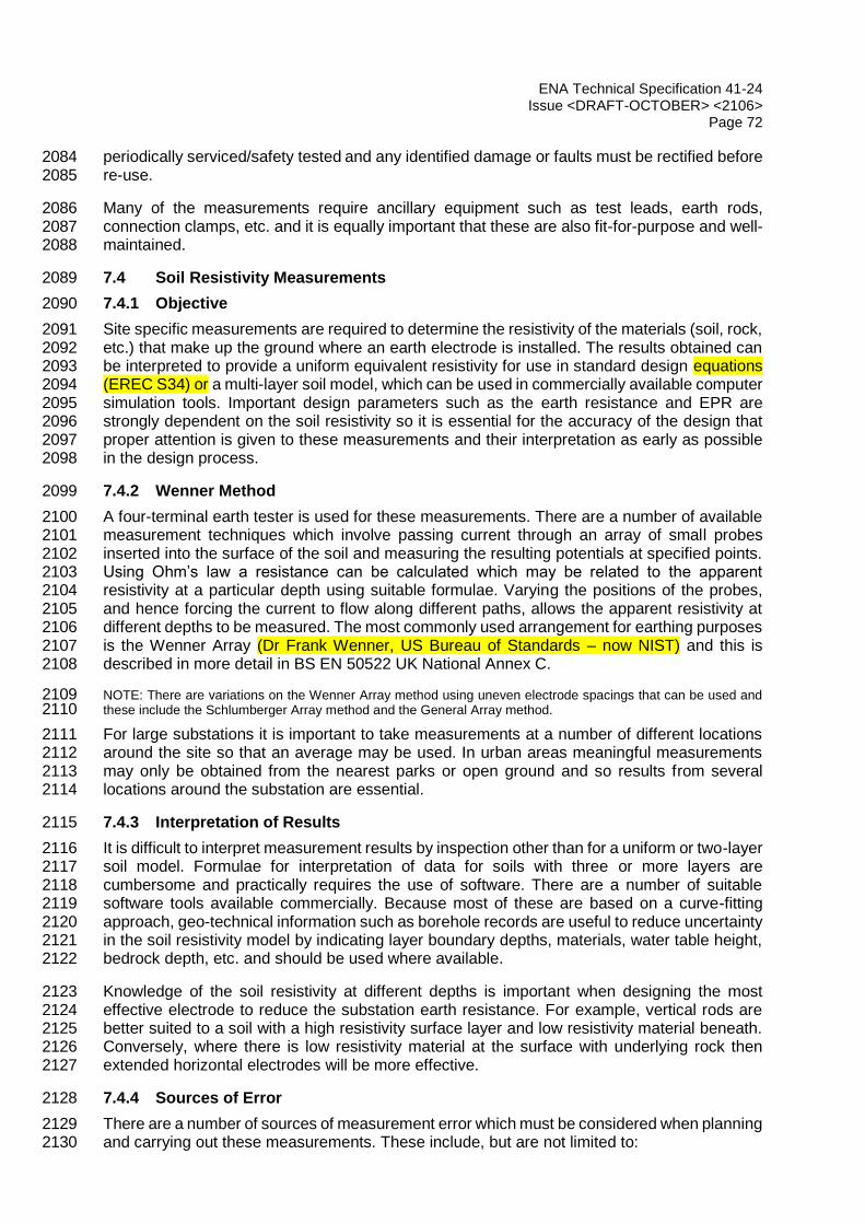
ENA Technical Specification 41-24 Issue <DRAFT-OCTOBER> <2106>
Page 72
periodically serviced/safety tested and any identified damage or faults must be rectified before 2084 re-use. 2085
Many of the measurements require ancillary equipment such as test leads, earth rods, 2086 connection clamps, etc. and it is equally important that these are also fit-for-purpose and well-2087 maintained. 2088
7.4 Soil Resistivity Measurements 2089
7.4.1 Objective 2090
Site specific measurements are required to determine the resistivity of the materials (soil, rock, 2091 etc.) that make up the ground where an earth electrode is installed. The results obtained can 2092 be interpreted to provide a uniform equivalent resistivity for use in standard design equations 2093 (EREC S34) or a multi-layer soil model, which can be used in commercially available computer 2094 simulation tools. Important design parameters such as the earth resistance and EPR are 2095 strongly dependent on the soil resistivity so it is essential for the accuracy of the design that 2096 proper attention is given to these measurements and their interpretation as early as possible 2097 in the design process. 2098
7.4.2 Wenner Method 2099
A four-terminal earth tester is used for these measurements. There are a number of available 2100 measurement techniques which involve passing current through an array of small probes 2101 inserted into the surface of the soil and measuring the resulting potentials at specified points. 2102 Using Ohm’s law a resistance can be calculated which may be related to the apparent 2103 resistivity at a particular depth using suitable formulae. Varying the positions of the probes, 2104 and hence forcing the current to flow along different paths, allows the apparent resistivity at 2105 different depths to be measured. The most commonly used arrangement for earthing purposes 2106 is the Wenner Array (Dr Frank Wenner, US Bureau of Standards – now NIST) and this is 2107 described in more detail in BS EN 50522 UK National Annex C. 2108
NOTE: There are variations on the Wenner Array method using uneven electrode spacings that can be used and 2109 these include the Schlumberger Array method and the General Array method. 2110
For large substations it is important to take measurements at a number of different locations 2111 around the site so that an average may be used. In urban areas meaningful measurements 2112 may only be obtained from the nearest parks or open ground and so results from several 2113 locations around the substation are essential. 2114
7.4.3 Interpretation of Results 2115
It is difficult to interpret measurement results by inspection other than for a uniform or two-layer 2116 soil model. Formulae for interpretation of data for soils with three or more layers are 2117 cumbersome and practically requires the use of software. There are a number of suitable 2118 software tools available commercially. Because most of these are based on a curve-fitting 2119 approach, geo-technical information such as borehole records are useful to reduce uncertainty 2120 in the soil resistivity model by indicating layer boundary depths, materials, water table height, 2121 bedrock depth, etc. and should be used where available. 2122
Knowledge of the soil resistivity at different depths is important when designing the most 2123 effective electrode to reduce the substation earth resistance. For example, vertical rods are 2124 better suited to a soil with a high resistivity surface layer and low resistivity material beneath. 2125 Conversely, where there is low resistivity material at the surface with underlying rock then 2126 extended horizontal electrodes will be more effective. 2127
7.4.4 Sources of Error 2128
There are a number of sources of measurement error which must be considered when planning 2129 and carrying out these measurements. These include, but are not limited to: 2130
ENA Technical Specification 41-24 Issue <DRAFT-OCTOBER> <2106>
Page 73
(a) influence of buried metallic structures such as bare cable armouring/sheaths, earth 2131 electrodes, pipes, etc. Measurements taken above or near buried metallic services will 2132 indicate lower resistivity values than actually exists. This can lead to under-designed 2133 earthing systems which may be costly to rectify at the commissioning stage. 2134 Measurement locations must be carefully planned to avoid interference from metallic 2135 structures by consulting service records and, where there remains uncertainty, the use 2136 of scanning methods on site. It is also important that measurements are taken at a 2137 number of different locations (minimum of two) around the site of interest so that any 2138 influenced results become apparent in comparison to unaffected results. Two 2139 orthogonal sets of measurements can also help to indicate an error; 2140
(b) interference from stray voltages in the soil or induction from nearby electrical systems 2141 may adversely affect measurement results, normally evident as an unstable reading on 2142 the instrument or unexpectedly high readings. This may be reduced by avoiding test 2143 leads running in parallel with high voltage power lines/cables or near other potential 2144 sources of interference, e.g. electric traction systems. 2145
(c) the wenner spacings used must be appropriate for the size of the earthing system and 2146 recommended spacings are provided in BS EN 50522 National Annex C. Spacings that 2147 are too short may not identify the lower layer resistivities which can introduce large 2148 positive or negative error into design calculations; 2149
(d) low resistivity soils, especially at long wenner spacings, require relatively small 2150 resistances to be measured at the surface. Instrumentation with an inadequate lower 2151 range may reach its limit and incorrectly indicate higher resistivity values than exist; 2152
(e) care must be taken in interpreting the measurement data. If using computer software 2153 tools, it should be remembered that the result is a ‘model’ of the soil conditions which 2154 is largely determined by automatic curve-fitting routines or user judgement. To increase 2155 confidence it is good practice to ‘test’ the model by comparing it to other geological 2156 data available for the site and the expected range of resistivity values for the materials 2157 known to be present. Measured resistances of vertical rods installed at the site can also 2158 be compared to calculated values obtained using the soil model to increase confidence. 2159 It should be recognised that the soil resistivity model may need to be refined throughout 2160 the project as more supporting information becomes available. 2161
7.4.5 Driven Rod Method 2162
The driven rod method is an alternative to the Wenner Method which is particularly useful in 2163 built-up urban areas where there is inadequate open land to run out test leads. This method 2164 should be used with caution and measures must be taken to avoid the possibility of damage 2165 to buried services, in particular HV cables. Where the absence of buried services cannot be 2166 established, rods must not be driven. An earth rod is driven vertically into the ground and its 2167 earth resistance measured as each section is installed using either of the methods from 2168 Sections 12.5 and 12.6. Using a simple equation (for uniform soil equivalence – refer to ENA 2169 EREC S34) or computer simulation (for multi-layer analysis) the soil resistivity may be deduced 2170 from the measured rod resistance and its length in contact with the soil. This method can be 2171 cost-effective as the rods can be used as part of the earthing installation. Where possible the 2172 results from driven rods at a number of locations around the site should be used together with 2173 any available Wenner Method data to improve confidence in the derived soil resistivity model. 2174
7.5 Earth Resistance/Impedance Measurements 2175
7.5.1 Objective 2176
The substation earth resistance or impedance is normally measured where practicable on 2177 commissioning of a new substation and subsequently at maintenance intervals. The 2178

ENA Technical Specification 41-24 Issue <DRAFT-OCTOBER> <2106>
Page 74
measurement will include all earthing components connected at the time of the test and the 2179 result represents the value which is normally multiplied by the ground return current to 2180 determine the EPR. This method may also be used to measure the earth resistance or 2181 impedance of individual electrodes, tower footings or tower line chain impedances. (Refer to 2182 ENA EREC S34 for details of chain impedance and relevant calculations). 2183
7.5.2 Method 2184
The most commonly used method of measuring substation earth resistance or impedance is 2185 the fall-of-potential method and this is described in BS EN 50522 UK National Annex C. It 2186 requires temporary electrodes to be installed in the ground some distance from the substation 2187 and connected back via trailing leads. A standard four-pole earth tester should be used (as 2188 opposed to a three-pole tester – refer to 7.5.4(e) to inject a small test current into the earth 2189 electrode and returned via a remote probe. A voltage gradient is set up around the electrode 2190 and a second probe is used to measure this with respect to the electrode voltage rise. The 2191 resistance is calculated and results are normally presented as a curve of resistance versus 2192 distance from the substation along a particular route. Voltage measurements may be taken 2193 along any route but traverses which are parallel or orthogonal to the current lead are most 2194 commonly used and are more readily interpreted using standard methods. 2195
Most commercially available earth testers use a switched DC square wave signal. Where it is 2196 possible to select a very low switching frequency (below 5 Hz) the measured values will 2197 approach the DC resistance which will be accurate for small earth electrode systems in 2198 medium to high soil resistivity. When higher switching frequencies are used (128 Hz is 2199 common) inductive effects may be evident in the results. Where an appreciable inductive 2200 component is expected and long parallel test leads are used it is advisable to use an AC 2201 waveform, so that mutual coupling between the test lead may be subtracted and a true AC 2202 impedance obtained. Because of the appreciable standing voltage commonly found on live 2203 substation earth electrodes, AC test signals are normally selected to avoid the fundamental 2204 and harmonic frequencies. For the most accurate results, measurements should be taken 2205 using frequencies either side of the power frequency to allow interpolation. Additional guidance 2206 may be found in IEEE 81 (add ref). 2207
It may not be possible to use the fall-of-potential method where no suitable routes exist for the 2208 test lead / probe set up, e.g. in urban or industrial areas. Alternative methods must be used in 2209 these locations as described in Section 7.6. 2210
The substation earth resistance or impedance can also be measured by injecting a current 2211 from a generator connected to a remote substation earthing system via a de-energised power 2212 line. The rise in electrode potential is then measured with respect to another remote earth 2213 electrode such as a telecommunication circuit earth. This method is more costly in terms of 2214 equipment resources and circuit outages; it is rarely used in the UK. Experience has shown 2215 that care must be taken to ensure that there are no unwanted metallic paths between the 2216 substation electrode and either of the reference electrodes as this will divert current and 2217 introduce errors, unless the diverted current can be measured and a correction applied. This 2218 is especially difficult to achieve in urban environments, otherwise this technique would be a 2219 good option where no suitable area for a fall-of-potential measurement exist. 2220
7.5.3 Interpretation of Results 2221
Earth resistance or impedance measurement results are normally in the form of a series of 2222 points on a curve which must be interpreted using a mathematical rule or procedure. Care 2223 must be taken in selecting a suitable method and their limitations must be understood. More 2224 detail on the methods available is given in BS EN 50522 UK National Annex C. 2225

ENA Technical Specification 41-24 Issue <DRAFT-OCTOBER> <2106>
Page 75
7.5.4 Sources of Error 2226
There are a number of sources of measurement error which must be considered when planning 2227 and carrying out these measurements. These include, but are not limited to: 2228
(a) influence of buried metallic structures such as bare cable armouring/sheaths, earth 2229 electrodes, pipes, etc. Measurements taken above or near buried metallic services will 2230 generally underestimate the substation resistance. Measurement locations must be 2231 carefully planned to avoid interference from metallic structures by consulting service 2232 records and, where there remains uncertainty, the use of scanning methods on site. 2233 Measurement results that have been influenced by a parallel buried metallic structure 2234 will typically be lower than expected and the resistance curve will be flat. A metallic 2235 structure crossing the measurement traverse at right-angles will result in a depression 2236 in the resistance curve. If interference is suspected the measurement should be 2237 repeated along a different route or an alternative method used; 2238
(b) the distance between the substation and the remote current probe is important to the 2239 accuracy of the measurement. The theoretical recommended distance is between five 2240 and ten times the maximum dimension of the earth electrode with the larger separations 2241 required where there is underlying rock. In practice, where there is insufficient land to 2242 achieve this, the current probe should be located as far away from the substation as 2243 possible. Measurements taken using relatively short distances between the substation 2244 and return electrode may not be accurately interpreted using standard methods and 2245 require analysis using more advanced methods. Typical distances used range from 2246 400 m for standard 33/11 kV Primary Substations up to 1000 m or greater for large 2247 transmission substations or for large combined systems; 2248
(c) interference caused by standing voltage (‘noise’) on a substation earthing system may 2249 result in standard earth testers failing to produce satisfactory results. This is normally 2250 evident as fluctuating readings, reduced resolution or via a warning/error message. 2251 Typical environments where this may be experienced include transmission substations 2252 (275 kV and 400 kV), railway supply substations or substations supplying large 2253 industrial processes such as arc furnaces or smelters; 2254
(d) results must be interpreted using an appropriate method and compared to calculations. 2255 Where there is significant difference further investigation is required. Interpretation 2256 using the 61.8% Rule or Slope Method may not be appropriate in all circumstances as 2257 they are based on simple assumptions; Detailed analysis using computer software may 2258 give greater accuracy where: 2259
the soil resistivity is non-uniform, i.e. multi layered soils; 2260
where the current return electrode is relatively near to the electrode under test, 2261 e.g. less than five times the size of the earth electrode being tested; 2262
for a large and irregular shaped electrode where the test is taken far away from 2263 the centre of the electrode 2264
where there are known nearby buried metallic objects that may have influenced 2265 the measurements. 2266
(e) use of a three-pole earth tester is acceptable where the resistance of the single lead 2267 connecting the instrument to the electrode is insignificant compared to the electrode 2268 resistance. These instruments are generally suitable only for measuring small electrode 2269 components such as rods or a small group of rods in medium to high resistivity soils. 2270 For larger substations or low resistance electrodes a four-pole instrument is essential 2271 to eliminate the connecting lead resistances which would otherwise introduce a 2272 significant error. 2273

ENA Technical Specification 41-24 Issue <DRAFT-OCTOBER> <2106>
Page 76
7.6 Comparative Method of Measuring Earth Resistance 2274
7.6.1 Objective 2275
To measure the earth resistance of small individual electrode components within a large 2276 interconnected earthing system. This method is most effective where a relatively high 2277 resistance electrode is measured in comparison to a ‘reference earthing system’ which has a 2278 much lower resistance. 2279
7.6.2 Method 2280
Two different approaches may be used as follows: 2281
(a) The first method, illustrated in Figure 12.1, requires that the electrode being tested is 2282 disconnected from the remainder of the substation earthing system, e.g. immediately after 2283 installation prior to the connection being made or via opening of a test link at existing sites. 2284 A standard four-pole earth tester may be used with terminals C1 and P1 connected to the 2285 electrode component being tested. Terminals C2 and P2 are connected to the ‘reference 2286 earth’. Current is circulated around the earth loop containing the electrode and the 2287 reference earth resistances and the voltage developed across them is measured. Using 2288 Ohm’s Law the series ‘loop resistance’ is calculated and if the reference earth resistance 2289 is sufficiently low relative to the electrode resistance the measured value will approach the 2290 electrode resistance. 2291
(b) The second method, illustrated in Figure 12.2 uses a similar principle but does not require 2292 disconnection of the electrode. A clamp type meter is placed around the connection to the 2293 electrode which generates and measures current and voltage in the electrode loop and 2294 displays the ‘loop resistance’. The advantage of this method is that the earth electrodes 2295 may be tested without disconnection hence avoiding the associated safety risks and the 2296 need to apply earth disconnection procedures. This is the preferred method for safety and 2297 facilities should be included in the design to allow access to rods for testing with a clamp 2298 meter. 2299
2300
2301
Figure 12.1 — Illustration of Earth Resistance Measurement using the Comparative Method and 2302 a Four-Pole Earth Tester (Test Electrode Disconnected). 2303
2304
C1 P1 P2 C2
FOUR-POLE
EARTH TESTER
ELECTRODE
UNDER TEST
PARALLEL NETWORK OF
EARTH ELETRODES
R1
R (Parallel)
If R(Parallel) << R1 the measured ‘earth loop’ resistance
[R(Parallel)+R1] approaches R1.

ENA Technical Specification 41-24 Issue <DRAFT-OCTOBER> <2106>
Page 77
2305
2306
2307
2308
2309
2310
Figure 12.2 Illustration of Earth Resistance Measurement using the Comparative Method 2311 and a Clamp Type Resistance Meter (Test Electrode Connected) 2312
2313
7.6.3 Interpretation of Results 2314
In order to accurately measure an electrode resistance via this method it is necessary to have 2315 a very low reference earthing system resistance compared to the electrode resistance (10% 2316 or lower is recommended). It is also necessary to have a reasonable physical separation 2317 between the electrode and reference earth to reduce mutual coupling through the soil. 2318
If the reference earth resistance is too high the measured result will be significantly higher than 2319 the Electrode resistance (if it is known it can be subtracted). If the electrode and reference 2320 earths are too close together then a value lower than the electrode resistance may be 2321 measured. These errors may be acceptable if the purpose of the measurement is a 2322 maintenance check where it is only necessary to compare periodic readings with historical 2323 results to identify unexpected increases, e.g. due to corrosion or theft. 2324
If several different electrodes can be tested with respect to the same reference earth more 2325 detailed interpretation methods may be developed to increase confidence in the individual 2326 electrode resistances and in some circumstances allow the reference earth resistance to be 2327 deduced. 2328
7.6.4 Sources of Error 2329
(a) If the reference earth resistance is too high relative to the electrode resistance the 2330 measured value may be significantly higher than the electrode resistance. An approximate 2331 assessment of this may be made by comparing the physical area covered by the respective 2332 earthing systems, e.g. a rod electrode measured with respect to a large substation earth 2333 grid would be expected to provide a reasonable accurate resistance for the rod electrode. 2334
(b) Where the test electrode and reference earth are in close proximity to each other there will 2335 be significant mutual coupling via the soil which may result in an apparently lower reading 2336 than the true electrode resistance. 2337
(c) The electrode under test may be inadvertently in contact with the reference electrode below 2338 ground level, or otherwise connected to it. The test current is then circulated around a loop 2339 and does not represent the intended earth electrode resistance. 2340
(d) This method cannot be directly used to measure the overall substation earth resistance 2341 which requires the use of the fall-of-potential method described in Section 12.6. 2342
2343
CLAMP TYPE
EARTH TESTER
ELECTRODE
UNDER TEST
PARALLEL NETWORK OF
EARTH ELETRODES
R1
R(Parallel)
If R(Parallel) << R1 the measured ‘earth loop’ resistance
[R(Parallel)+R1] approaches R1.

ENA Technical Specification 41-24 Issue <DRAFT-OCTOBER> <2106>
Page 78
7.7 Earth Connection Resistance Measurements (Equipment Bonding Tests) 2344
7.7.1 Objective 2345
To measure the resistance between a plant item and the main substation earth electrode to 2346 check bonding adequacy. This is essential during commissioning of a new substation to 2347 confirm that each item of plant is effectively connected to the earth electrode system. It is also 2348 useful as an on-going maintenance check and for operational procedures, e.g. post-theft 2349 surveys. 2350
7.7.2 Method 2351
The procedure is based upon the principle of measuring the resistance between a set point (or 2352 points) on the main electrode system and individual items of earthed equipment. A micro-2353 ohmmeter is used and the connection arrangement is illustrated in Figure 12.3. Measurements 2354 can be taken from one central point (such as the switchgear earth bar) or, to avoid the use of 2355 unduly long leads, once a point is confirmed as being adequately connected, it can be used 2356 as a reference point for the next test and so on. 2357
2358
Figure 12.3 Connections for Earth Bonding Conductor Resistance Measurements 2359
To establish that a satisfactory connection exists between the grid and any exposed metalwork 2360 it is necessary to measure in the micro-ohms or milli-ohms range. An injection current of at 2361 least 100 mA is recommended. 2362
The probable path of the injected current must be considered and where the substation uses 2363 a bus-zone protection scheme care must be taken to ensure that any test current does not 2364 produce enough current to operate protection systems. 2365
Special procedures must be adopted when checking bonding between a substation earthing 2366 electrode and a terminal transmission tower. If the bond is ineffective or missing a potential 2367 difference may exist which may pose a shock hazard or damage to a test instrument. Normally 2368 these methods will include checking current flow in the terminal tower legs prior to testing as 2369 a higher proportion of current will flow in a leg with an effective connection to the substation. 2370 This would be supplemented by voltage measurements using suitably insulated probes and 2371 meters and buried electrode location techniques. 2372
7.7.3 Interpretation of Results 2373
The measured resistance between the two connection points will depend on the length, cross-2374 sectional area, material and number of earth conductors between them. Based on a maximum 2375 distance of 50 m between connection points, a threshold value of 20 mΩ will provide a good 2376 indication of when further investigation is required. 2377
C1 P1 P2 C2 FOUR-POLE
EARTH TESTER
EARTH
CONNECTION 1
EARTH
CONNECTION 2

ENA Technical Specification 41-24 Issue <DRAFT-OCTOBER> <2106>
Page 79
7.8 Earth Conductor Joint Resistance Measurements 2378
7.8.1 Objective 2379
To measure the resistance across an earth conductor joint to check its electrical integrity. This 2380 is normally performed for every joint created at a new substation prior to backfilling. It is also 2381 carried out during periodic maintenance assessments. 2382
7.8.2 Method 2383
The method described uses a micro-ohmmeter to measure electrical resistance and is suitable 2384 for bolted, compression, brazed and welded joints. It does not check the mechanical integrity 2385 of welds or for voids inside a joint. 2386
Most micro-ohmmeters are supplied with standard leads with two sharp pins that can penetrate 2387 through paint or surface corrosion to reach the metal underneath. The first set of leads is 2388 connected to one side of the joint and the second set to the other as illustrated in Figure 12.4. 2389 Ideally, the connectors should be no more than 25 mm either side of the joint. A suitable scale 2390 must be selected on the instrument (normally a minimum current of 10 A is required to measure 2391 in the micro-Ohm range) and an average value recorded after the test polarity has been 2392 reversed. 2393
2394
Figure 12.4 Connections for Earth Conductor Joint Resistance Measurements 2395
Joints must also be mechanically robust and survive a firm tap with a steel hammer. 2396
7.8.3 Interpretation of Results 2397
The measured resistance should not significantly exceed that of an equivalent length of 2398 conductor without a joint. Joints which exceed this by more than 50% must be remade. Where 2399 different sized tapes are involved, the threshold value used should be that of the smaller tape. 2400
At new installations it is recommended that a few sample joints are made under controlled 2401 conditions (e.g. in a workshop), their resistance measured and the median of these values 2402 used as the benchmark for all other similar joints made at the installation. 2403
7.9 Earth Potential Measurements 2404
7.9.1 Objective 2405
To measure Touch, Step and Transfer Voltages (e.g. ‘Hot Zones’) for comparison with 2406 calculated values. These measurements may be required to confirm that the installed design 2407 complies with the main safety limits (see Section 4.4). Advanced techniques and equipment 2408 are required to perform these measurements at live substations and guidance on the different 2409 methods available can be found in IEEE 81 (add ref). 2410
FOUR-POLE
EARTH TESTER
EARTH
CONDUCTOR
JOINT
C1 P1 P2 C2

ENA Technical Specification 41-24 Issue <DRAFT-OCTOBER> <2106>
Page 80
7.9.2 Method 2411
Earth potential measurements may be measured by injecting a current into the substation 2412 electrode and returning through a remote electrode via a connecting conductor. The return 2413 electrode may be another substation electrode connected via a de-energised power line or a 2414 temporary test lead and set of probes. Providing the return electrode is located at a large 2415 distance from the substation (relative to the size of the substation electrode) a potential profile 2416 will be set up around the substation proportional to that which would exist during fault 2417 conditions. The voltage between the substation electrode and different points on the surface 2418 can then be measured and related to Touch Voltage. Step Voltage can also be determined 2419 from measurements of the potential difference between points on the surface which are 1 m 2420 apart. In both cases the actual touch voltage can be found by scaling in the ratio of the test 2421 current and fault current. 2422
In a similar way, the potential gradients may be measured around the substation, for example 2423 emanating out from each corner, and equipotential contours derived to provide Hot Zone 2424 information. Measurements may also be carried out to determine the voltage transferred from 2425 a substation electrode to a nearby metallic structure, e.g. a steel pipe or the earthing system 2426 associated with a different electrical system. 2427
7.9.3 Interpretation of Results 2428
The measurement results must be interpreted by competent engineers and compared to 2429 calculated values. It is recommended that a series of measurements are taken at a number of 2430 locations around the substation where high touch or step voltages are expected (normally at 2431 the corners or in areas where the electrode mesh is less dense). This will enable the trends in 2432 the voltage gradients to be assessed to identify spurious data points. Where the return 2433 electrode is not located sufficiently far away from the test electrode large errors may be 2434 introduced. These errors may be corrected using a detailed computer model or by averaging 2435 the measurements obtained using different current return electrode locations. 2436
7.10 Earth Electrode Separation Test 2437
7.10.1 Objective 2438
To assess the electrical separation of two electrodes in the soil by measurement, e.g. 2439 segregated HV and LV electrodes at an 11 kV distribution substation or a substation earth 2440 electrode and a separately earthed fence. 2441
7.10.2 Method 2442
This method requires that the earth resistances of the two electrodes (R1 and R2) have been 2443 measured separately using the fall-of-potential method described in Section 12.5. 2444
Similar connections are then made as the bonding integrity checks (figure 12.3) and the ‘earth 2445 loop’ resistance (R3) of the two electrodes via the ground is measured. 2446
7.10.3 Interpretation of Results 2447
If the two electrodes are separated by a large distance then the R3 will approach the series 2448 resistance of R1 + R2. Lower measured values of R3 indicate a degree of conductive coupling 2449 through the soil. Generally, for the purposes of checking satisfactory segregation of earth 2450 electrodes the following test is used: R3 > 0.9(R1 + R2). Values lower than 0.9 (R1 + R2) may 2451 indicate inadequate separation and further investigation is required (refer to Section 9.7.3). 2452

ENA Technical Specification 41-24 Issue <DRAFT-OCTOBER> <2106>
Page 81
7.11 Buried Earth Electrode Location 2453
7.11.1 Objective 2454
At older substation sites, whilst an earthing system is in place, a record of its design may not 2455 exist or may be out of date. An earthing record is desirable to ensure that the design is 2456 satisfactory and to assist in the planning of new construction work. The record should include 2457 the position of the electrode, its burial depth, material, size and installation method (e.g. above 2458 ground, in ducts, or buried directly). 2459
Where existing electrode needs to be located within live substations, surface detection 2460 methods are usually the lowest cost option. 2461
7.11.2 Method 2462
The most effective surface detection techniques, found by experience are documented below. 2463 This includes commercially available low to medium frequency systems and Ground 2464 Penetrating Radar (high frequency) systems. It should be noted that these methods are subject 2465 to interference from other buried services and often need to be supplemented by trial 2466 excavations. 2467
A low to medium frequency system comprises a transmitter and receiver, working at 2468 frequencies from 50 Hz (detection of live mains cables) to nearly 100 kHz. The transmitter 2469 injects a signal into the earthing system which is to be traced (the “target line”). As this signal 2470 passes through the earth electrodes, it radiates an electric and magnetic field, one or both of 2471 which can be detected and interpreted by coils in the receiver. Basic receivers simply emit an 2472 audio tone as they are passed over the target line. More advanced receivers give information, 2473 such as burial depth and test current magnitude. This feature can sometimes enable one to 2474 distinguish between the target line and others which have erroneously picked up the 2475 transmitter’s signal through coupling. 2476
A ground penetrating radar system, used in conjunction with appropriate analysis software, 2477 can also be used to produce a reasonable graphical image of structures below the surface. 2478 Radar systems detect the dielectric contrast between a target and its surroundings and so are 2479 well suited for detecting conductive, metallic electrodes against soil which is relatively resistive. 2480 They are well suited to drained, high soil resistivity locations. The radar system is usually 2481 guided over the trace area in a grid pattern, with detection results being stored for later analysis 2482 by the computer. 2483
Where neither of the above methods are conclusive, e.g. in areas with a high density of buried 2484 services, selected trial holes may be required. 2485
2486

ENA Technical Specification 41-24 Issue <DRAFT-OCTOBER> <2106>
Page 82
MAINTENANCE 2487
8.1 Introduction 2488
Earthing systems shall be inspected, maintained and repaired so as to ensure they will operate 2489 in the manner required on an ongoing basis. 2490
8.1.1 Inspection 2491
This falls into two main categories: 2492
(a) Visual Inspection 2493
(b) Detailed Physical Examination and Testing 2494
When setting inspection, testing and maintenance regimes for a substation consideration shall 2495 be given to identifying and where necessary rectifying issues arising from: 2496
physical deterioration and damage/theft; 2497
inappropriate installation alterations or third party actions which prejudice the principal of 2498 operation of the earthing system; 2499
inappropriate installation / design; 2500
changes to system operating regimes or construction which alter the magnitude, flow and 2501 / or duration of earth fault current to values outside the original earthing system design 2502 parameters; 2503
magnitude of EPR and how close touch and step potentials are to safety limits. 2504
The frequency of inspection and testing should be set according to EPR, risk of theft, damage, 2505 and deterioration. It may be revised from time to time if circumstances change. 2506
If an extraordinary event occurs (e.g. delayed fault clearance) then additional ad hoc inspection 2507 and testing may be required 2508
8.1.2 Maintenance and Repairs 2509
When undertaking repairs or minor alterations to damaged earth conductor and buried 2510 electrode the procedures adopted must take into account: 2511
Broken conductors may operate at elevated voltages even when the rest of the 2512 associated network is operating normally. 2513
The possibility of transient or sustained system earths fault occurring while repairs are 2514 being undertaken. 2515
Inspection, testing and maintenance work must be undertaken in accordance with company 2516 operational and safety procedures. Where required risk assessments and method statements 2517 will be prepared. Inspectors must wear company specified personal protective equipment and 2518 only approach plant and equipment when it is safe to do so. See Sections 8.3 and 8.4 for 2519 further issues. 2520
2521

ENA Technical Specification 41-24 Issue <DRAFT-OCTOBER> <2106>
Page 83
8.2 Types of Inspection 2522
8.2.1 Introduction 2523
The main types of inspection may be summarised as: 2524
a frequent basic visual inspection to check there is no visible damage, theft or obvious 2525 impairment of the earthing system; 2526
a less frequent and more detailed visual inspection to review the standard of construction 2527 and condition as well as checking for damage, theft and impairment; 2528
an infrequent more thorough visual inspection combined with testing, measurement and 2529 analysis. 2530
For an open busbar substation typical areas to be inspected include earth connections 2531 associated with: 2532
(i) aluminium, steel, concrete and wood structures; 2533
(ii) towers, earthed poles and above ground cable connections within or adjacent to 2534 the substation site. 2535
(iii) isolator mechanisms, fault-throwing switches, earth switches and control kiosks 2536 including associated surface and buried earth mats; 2537
(iv) transformers, reactors, VTs, CVTs, CTs, surge-arresters and arcing horns; 2538
(v) transformer neutral links and switches and associated connections to earth either 2539 direct or via earthing resistors, reactors or earthing transformers; 2540
(vi) metallic Fencing and gates; 2541
(vii) indoor switchgear (if present) including connections to plant, cables, structural steel 2542 work and earth bars. 2543
8.2.2 Frequent Visual Inspection 2544
This can form part of a normal routine substation inspection procedure or be a part of the 2545 procedures operation staff conduct when entering a substation. The objective is to frequently 2546 and quickly check for visible damage, theft or obvious impairment of the earthing system. 2547
During routine visual inspections accessible earth connections associated with key items of 2548 electrical plant in the substation should be checked. Procedures such as lifting trench covers 2549 will normally be avoided unless the initial inspection gives cause for concern. 2550
8.2.3 Infrequent Detailed Visual Inspection 2551
Before commencing a detailed examination, the substation earthing records should be 2552 checked to confirm they correspond to the actual layout. The inspector should be aware of the 2553 fence earthing arrangement and whether it is independently earthed or bonded to the earth 2554 grid or a mixture of both. 2555
The key items covered in the Frequent Inspection plus all other accessible connections to 2556 plant, circuits and civil infrastructure should be inspected thoroughly. As well as condition, the 2557 standard of construction should be reviewed against present practices and any inadequacies 2558 reported. Checks for damage, theft and impairment of the earthing system should also be 2559 carried out. Visual checks should be carried out on less accessible earthing conductors not 2560 covered in the Frequent Inspection such as those located under trench covers or located in 2561 basements. 2562

ENA Technical Specification 41-24 Issue <DRAFT-OCTOBER> <2106>
Page 84
The results of all inspections must be documented in accordance with company procedures. 2563
A pre-prepared check list for each site will assist consistent reporting and record keeping. 2564
8.2.4 Detailed Visual Inspection, Testing and Analysis 2565
This consists of four related parts: 2566
A thorough detailed visual inspection and review of the earth connections to all electrical 2567 plant, circuits and civil infrastructure as per 8.2.3 2568
Carrying out specific testing and measurement of the earthing installation as per 8.2.4.1 2569
Selecting portions of the buried electrode system for examination via trial holes as per 2570 8.2.4.2 2571
Analysis and recording of results including review of EPR related issues as per 8.2.4.3 2572
2573
8.2.4.1 Testing 2574
See Section 7 for specific measurement and analysis techniques. 2575
Testing may include: 2576
(i) Measurement of the overall substation earth resistance/impedance value; 2577
(ii) Measuring resistance of: 2578
Individual earth electrodes 2579
Rod and plate groups 2580
Fence earth rods 2581
Test electrodes (where fitted). 2582
Surge arrester, CVT and GIS high frequency earths; 2583
(iii) Measurement of soil resistivity; 2584
(iv) Resistance tests across a representative sample of important joints using a micro-2585 ohmmeter. The value should be recorded and compared with the values 2586 recommended by the manufacturer, or taken for similar joints elsewhere. Any joint 2587 where the resistance value is excessive will require to be broken down, cleaned 2588 and remade, or replaced; 2589
(v) Confirmation of continuity between key items such as transformers, switchgear, 2590 terminal tower(s) etc. and the main substation earth grid using a micro-ohmmeter. 2591 This is especially important for items where corrosion, theft or damage is 2592 considered to have prejudiced the integrity of the connection; 2593
(vi) Confirmation of continuity between adjacent site earthing systems; 2594
(vii) Confirmation of whether metallic fences are isolated from or bonded to the main 2595 substation earth grid by carrying out a separation test; 2596
(viii) For substations fitted with frame leakage earth fault protection checking the integrity 2597 of the segregation between earth zones by testing and/or visual inspection and also 2598 testing across cable terminations where island glands are fitted; 2599
(ix) Measurement of Soil pH value; 2600

ENA Technical Specification 41-24 Issue <DRAFT-OCTOBER> <2106>
Page 85
(x) Tracing of buried electrode if required to update the substation earthing drawing; 2601
(xi) Segregation tests and review of segregation between distribution substation HV 2602 and LV earths. (Refer to Sections 7.10 and 9.7); 2603
8.2.4.2 Selected Excavation and Examination of Buried Earth Electrode 2604
Since the earth electrode system is largely buried, it is impracticable to carry out a detailed 2605 examination of the whole installation. However, it cannot be assumed that the buried electrode 2606 system, once installed will remain in good condition. 2607
Particularly where a substation site is associated with former industrial use such as a coal 2608 power station or foundry which may have produced corrosive material used as landfill there is 2609 enhanced risk of corrosion of buried copper conductor. A similar risk may also arise if material 2610 from such sites is imported to construct a substation. It is recommended that representative 2611 locations be chosen to excavate and expose the buried electrode, in order to check its 2612 condition. 2613
These should include some below ground connections, e.g. an earth rod connection position, 2614 or other locations where the electrode is jointed. Several connections from above ground plant 2615 should be uncovered back to the connection to the buried earth tape/grid, to check their 2616 condition through the layers of chippings and soil. Conductor size should be compared with 2617 records. 2618
Whilst carrying out excavation, the soil pH value should be checked. This should lie between 2619 6.0 and 10.0. For pH values outside these limits, it is probable that corrosion of the copper 2620 conductors/connectors will be evident. In the past, power station ash has been used as 2621 bedding for earth electrodes. This is known to be acidic, and is likely to cause corrosion of the 2622 conductors. 2623
Where tests show the pH value of the soil to be outside the limits, if the copper electrode is 2624 corroded, then repairs or a new electrode system and either some imported soil or an inert 2625 backfill (such as bentonite) is required. If the electrode has limited corrosion, then a soil / 2626 corrosion investigation is necessary to assess the risk of future corrosion and any precautions 2627 necessary. Normally the corrosion rate will be uneven, with severe corrosion in some areas 2628 and none in others. Severely corroded electrodes will need to be replaced, whilst that 2629 elsewhere will need to be monitored and measures taken to limit corrosion in all important 2630 areas. 2631
Should examination of the exposed conductors or connections give cause for concern, then 2632 additional excavations elsewhere on site may be necessary to assess the extent of the 2633 problem. 2634
8.2.4.3 Analysis and Recording of Test Results 2635
Resistance values for the substation, individual electrode groups and for joints should be 2636 recorded and where previous values are available compared to indicate any trend. 2637
The earthing drawing should be updated if required with revised electrode sizes and positions. 2638
Once a new substation earth resistance is obtained it should be used to recalculate the 2639 substation EPR using up to date earth fault current data and earth fault current return paths 2640 (earth wires/cable sheaths etc). Safety voltages and conductor current ratings should be 2641 recalculated and any deficiencies identified. 2642
The presence (or otherwise), values and configuration of any resistances / impedances placed 2643 in high voltage transformer neutrals should be recorded and aligned with those contained in 2644 the company power system model. 2645

ENA Technical Specification 41-24 Issue <DRAFT-OCTOBER> <2106>
Page 86
Defects should be listed and prioritised for remedial action. 2646
8.3 Maintenance and Repair of Earthing Systems 2647
In some cases, earthing related maintenance and repair work will be reactive, following theft 2648 or damage revealed by an inspection. 2649
Before undertaking earthing system repair or measurement work, the responsible person in 2650 charge of the work must familiarise themselves with the site specific risks and consequences 2651 of: 2652
Working on or touching unsound earthing systems; 2653
Open circuiting (even for a short time) earth conductor circuits; 2654
Extending (even temporally) earthing systems from sites where touch and step potentials 2655 are controlled; 2656
Working on broken earthing conductors; 2657
An earth fault occurring on the system being worked on. For primary substations 2658 supplying extended high voltage rural overhead line networks this can be a relatively 2659 frequent occurrence (e.g. at least once a week). Supervisors should avoid work or testing 2660 being carried out in high risk periods such as during storms or fault switching. 2661
There is risk of serious or fatal electric shock when working on intact and depleted/damaged 2662 earthing systems. The responsible person in charge of any remedial work should be suitably 2663 qualified to undertake this area of work. Network Operators should develop their own 2664 policies/procedures for dealing with depleted earthing systems. 2665
Specialised equipment including insulated rods, shorting leads and conductor clamps are 2666 required to make repairs. PPE including insulated footwear and gloves must be available if 2667 required. 2668
High voltages can appear on earth system conductors even under normal running conditions. 2669 Items requiring particular caution include connections associated with CVTs, transformer 2670 neutrals, underground cable bonding arrangements and connections between main earth grids 2671 and overhead line towers. 2672
Examples of situations requiring remedial work include: 2673
broken or damaged below ground earthing conductors which have been exposed in the 2674 course of excavation work; 2675
broken or damaged bonding conductors on underground cable systems (such as cross-2676 bonding connections that can be expected to carry significant current under normal 2677 operating conditions); 2678
repairs to/replacement of high resistance earth connections (Para 8.4); 2679
minor alterations to/diversions of earthing systems for construction work; 2680
repairs after theft of earthing conductors (Remedial work on depleted earthing systems is 2681 normally the subject of a bespoke company instruction and is outside the scope of this 2682 document). 2683
2684

ENA Technical Specification 41-24 Issue <DRAFT-OCTOBER> <2106>
Page 87
8.4 Procedure for the Remaking Defective Joints or Repairing Conductor Breaks 2685
8.4.1 Introduction 2686
It may be necessary to remake a joint or repair a break on the earth electrode system at a 2687 substation for a number of reasons: 2688
(a) The joint is obviously damaged. 2689
(b) The joint has failed a micro-ohmmeter test. 2690
(c) An earth electrode has been severed. 2691
(d) A minor diversion of the electrode system or other repair work may be proposed. 2692
Should a fault occur during the period when a repair is being carried out, to prevent danger 2693 from a high voltage, which could appear across the joint, precautions must be taken. 2694
The design of the earth grid (if present) may or may not be adequate to eliminate danger to 2695 personnel when touching a bare broken conductor even after a temporary earth continuity 2696 conductor has been applied. 2697
Before carrying out any repairs, the joint or break to be repaired must be short-circuited by 2698 connecting a fully-rated conductor to positions either side of the break or defective joint. This 2699 short must be applied using an approved procedure involving insulated rods. 2700
If company policy so states or any doubt exists the operator shall wear insulating footwear and 2701 gloves designed for electrical application when handling earth conductor to make a permanent 2702 repair. 2703
Whilst carrying out work, the operator should stand within the boundaries of the earth grid, or 2704 immediately above a bare buried earth conductor. 2705
For example, if a terminal tower earth connection is broken, a significant potential difference 2706 may be present between the tower and earth grid. Arcing and current flow will occur when 2707 trying to remake the connection. Insulated rods and approved connectors are required to apply 2708 the initial short-circuit. The repairs, as detailed in the next paragraph, can then be carried out. 2709
Similarly high voltages may appear across open circuited cross bonding conductors on high 2710 voltage underground cable circuits. 2711
8.4.2 Joint Repair Methods 2712
(i) Compression Joint – Cannot be repaired, must be replaced. 2713
(ii) Mechanical Connector - Disconnect, clean all contact surfaces, apply a company 2714 approved contact lubricant, reconnect and re-tighten. 2715
(iii) Cold-weld/Exothermic weld Joint - If defective this type of joint must be replaced. 2716
On completion of repair of any joint, having first connected the instrument across the joint, the 2717 temporary earth continuity conductor* should be removed; a micro-ohmmeter resistance test 2718 must then be carried out across the joint. 2719
* Shorting strap 2720
8.4.3 Flexible Braids 2721
Flexible bonding braids or laminations should be inspected for signs of fracture and corrosion 2722 and changed as required. A protective compound may be applied to flexible braids where 2723 corrosive conditions exist. 2724

ENA Technical Specification 41-24 Issue <DRAFT-OCTOBER> <2106>
Page 88
Ground Mounted Distribution Substation Earthing 2725
9.1 Introduction 2726
Whilst the general principles of earthing can be applied to all voltage levels, small (distribution) 2727 substations providing supply to LV networks can present their own additional challenges. The 2728 key earthing related differences between distribution (or ‘secondary’) substations, and larger 2729 (‘primary’, or ‘grid’ substations) include: 2730
high voltage distribution apparatus is often located in densely populated areas in close 2731 proximity to the public; 2732
earth fault clearance times on distribution systems are usually longer; 2733
many older ‘legacy’ installations do not have the benefit of a comprehensive earth grid 2734 environment, as they rely on metallic sheath cable systems to control touch and step 2735 potentials; 2736
low-voltage earth connections may be combined with HV earthing systems, or in close 2737 proximity to them; 2738
connections from the low voltage distribution system are taken into almost every property; 2739
for new connections distribution network operators have a legal obligation to provide a 2740 low voltage earth terminal to their customers as long as it is safe to do so; 2741
the low voltage system must be earthed such that earth potential rise due to high voltage 2742 earth faults does not cause shock or injury (to installation users, public or staff) or 2743 damage to internal electrical installations, distribution equipment or telecommunication 2744 systems. 2745
The design issues, therefore, can be summarised as: a) achieving safety in and around the 2746 HV:LV substation, and b) ensuring that danger does not arise on the LV system as a 2747 consequence of HV faults. 2748
The design approach outlined in Section 5.6.1 applies equally to distribution substations, and 2749 special considerations are described below. 2750
9.2 Relocation of Pole Mounted Equipment to Ground Level 2751
Due to the high EPR that can appear on pole mounted equipment, metallic items must not be 2752 re-located at ground level (e.g. replacing a pole transformer with a small padmount substation) 2753 without appropriate modifications to the earthing system. 2754
Ground mounted substations will introduce a touch potential risk that is absent from pole 2755 mounted installations, and consequently require an electrode system that not only limits EPR, 2756 but controls touch and step voltages to safe limits. 2757
Similarly, care should be exercised if other earthed equipment on the pole (e.g. auto-reclose 2758 relay cabinet) is within reach of those on the ground. 2759
Section 10 describes pole mounted installations in detail. In either case, the decision to 2760 operate with combined HV and LV, or otherwise, must consider the voltage that will be 2761 impressed on the LV system under HV fault conditions (Section 9.5). 2762
9.3 General design requirements 2763
In common with any earthing system, the design of any new build substation must satisfy 2764 requirements for EPR, touch/step voltages, transfer voltages, and stress voltages. If major 2765

ENA Technical Specification 41-24 Issue <DRAFT-OCTOBER> <2106>
Page 89
changes are to be made to an existing substation, the effects of these proposed changes on 2766 the existing earthing system need to be considered. A significant consideration in all cases is 2767 the transfer potential that will be impressed on the LV network under HV fault conditions. See 2768 9.5 2769
9.3.1 Design Data Requirements 2770
The data required is similar to that described in Section 5.4, as necessary to determine the 2771 current flow into the electrode system, and the fault duration. These include: 2772
1) fault level at the new substation, or at the source (primary); 2773
2) resistance of the earthing system at the primary substation (Ra), and at the new 2774 distribution substation (Rb); 2775
3) circuit length and cable type(s); 2776
4) whether there is any overhead line in the circuit. 2777
For worst case studies, if there is any overhead line, the ground return current (Igr) can be 2778 assumed equal to the earth fault current at the distribution substation (i.e. Igr% = 100%). 2779
9.3.2 Conductor and electrode sizing 2780
Earth conductors at distribution substations will usually connect key items of plant such as 2781 transformer(s), ring main unit / switchgear, and low voltage cabinets. In many ‘unit substations’ 2782 these items may be supplied with bonding connections in place. These bonds must be sized 2783 as described in 5.5.1; in general they must be sized for the maximum foreseeable earth fault 2784 level. For ASC systems the limited ASC current must not be used (see Section 5.4.5). DNOs 2785 may wish to use the earth fault level at the primary substation, or higher value allowing for 2786 growth and uncertainty, up to the 3-phase fault current. 2787
Electrodes must have sufficient surface area to meet the requirements of Sections 5.4.6 and 2788 5.5.2. The worst case foreseeable ‘electrode current’ should be used for design purposes, this 2789 may be taken as the maximum earth-fault current at the substation or its source, or the larger 2790 of cross-country fault current or bypass fault current on ASC systems. 2791
Note: If detailed modelling of current distribution is carried out, it will be seen that the ‘ground return current’, if 2792 calculated using a contribution from a wide area network, will be significantly higher than the local ‘electrode current’. 2793 The electrode current or ground return currents may be used for electrode design purposes, providing that 2794 connection to the wider network contribution is reliable. If any doubt exists as to the prolonged integrity of sheath 2795 return paths and/or auxiliary electrode connections, the larger earth fault level (calculated for a zero ohm fault) 2796 should be used. 2797
9.3.3 Target resistance 2798
A HV electrode system must be established for the substation, that is of sufficiently low 2799 resistance to ensure reliable protection operation and to limit EPR (and touch/step voltages) 2800 to acceptable levels. The design process in this respect is no different to that outlined in 2801 Section 5.3. The resistance that must be achieved is termed the ‘target resistance’, and may 2802 be specified with and without contribution from parallel systems. Use of a target resistance for 2803 the substation’s earthing system, which ensures compliance with the safety criteria, is useful 2804 as it is a more readily understood parameter that can be achieved and tested by installers. 2805 ‘Network contribution’ is discussed in Section 9.4.3. 2806
For ground mounted substations, traditional custom and practice (permitted by previous 2807 versions of this standard) was to apply a target resistance (before connection to the network) 2808 of 1 ohm. If this could be achieved, it was permissible to combine the HV and LV earthing 2809 systems. No perimeter or grading electrodes were installed in such ‘legacy’ systems, and often 2810 only one vertical rod or horizontal electrode would be installed. This approach relied heavily 2811

ENA Technical Specification 41-24 Issue <DRAFT-OCTOBER> <2106>
Page 90
on contributions from lead sheathed cables radiating away from the substation, and often 2812 passing under the operator’s position. In this way, these cables provided a degree of potential 2813 grading (thus reducing touch potentials) as well as reducing the overall (combined) earth 2814 resistance of the substation. Experience has shown that this approach is no longer applicable, 2815 particularly given the now widespread use of polymeric (insulated sheath) cables. 2816
Network operators may find that different ‘target values’ for earth resistance are generally 2817 applicable in different geographical areas, and for overhead or underground networks, and 2818 thus may choose to adopt a ‘rule of thumb’ to assist designers and other connections providers. 2819 In any case, calculations or measurements sufficient to demonstrate that the installed system 2820 will be safe must be carried out at the design stage. Refer to 9.3.7. 2821
Target resistance values should consider all foreseeable running arrangements or network 2822 configurations, especially if the network is automated or remote controlled. Refer to Section 2823 9.9. 2824
9.3.4 EPR design limit 2825
A natural EPR design limit is imposed by a) consideration of transfer voltage onto the LV 2826 systems for combined HV/LV systems, and b) insulation withstand (stress voltage) between 2827 the HV and LV systems for segregated systems. See section 9.5 for more detail regarding 2828 separation distances. These considerations may for example, lead to typical design EPR limits 2829 of 3 kV (or higher, depending on equipment withstand voltage) for segregated systems, and 2830 466 V* for combined systems. 2831
9.3.5 Calculation of EPR 2832
The EPR for a distribution substation, for faults at that substation, is calculated in the 2833 conventional manner, i.e. by multiplying the ground return current by the overall (combined) 2834 substation earth resistance. 2835
9.3.5.1 Factors to consider: 2836
The ground return current value is influenced by the earth fault current ‘split’ between the soil 2837 return path and the cable sheath. The impedance of the cable sheath(s) is made up of a ‘self 2838 impedance’ (fixed), and a ‘mutual impedance’ that is dependent on a number of factors. 2839
The earth fault current is influenced by the resistance of the earthing system and the 2840 impedance of the cable sheath. The source impedance (primary substation), the resistance 2841 of the primary substation earthing system, and in particular the method of neutral earthing will 2842 have an effect. 2843
For most accuracy, some form of iterative calculation or computer model will be required to 2844 explore the relationship between fault current, EPR, and substation resistance. However, in 2845 any such design there are often other factors or unknowns / variables which may be of more 2846 significance. For this reason it may be sufficient for a design to err on the side of caution by 2847 using a ‘zero-ohm’ earth fault level (the maximum theoretical fault level at the distribution 2848 substation calculated using zero sequence impedances for the circuit). Fault impedance can 2849 then be introduced only if necessary to achieve an economic or practicable solution. 2850
ENA EREC S34 provides a detailed discussion of EPR calculations and includes worked 2851 examples to assist with the calculation of ground return current. 2852
* This value is 2x the 1 second touch voltage limit of 233 volts, and replaces the previous design figure of 430 Volts.

ENA Technical Specification 41-24 Issue <DRAFT-OCTOBER> <2106>
Page 91
9.3.5.2 Transfer Potential from source 2853
A second contribution to EPR comes from Transfer Potential ‘exported’ from the source 2854 substation, since any EPR at the source will be conveyed along the cable sheath and will 2855 appear (in part) at the new substation. 2856
Transfer potential need not been considered if there is any overhead line in the circuit, or if the 2857 new substation is not the first on the feeder and transfer potential is known to be of no 2858 significance at previous distribution substations. 2859
In determining the acceptable transfer potential from source, the relevant protection clearance 2860 time at the source should be used in touch/step calculations. 2861
9.3.6 Step/Touch Potentials at the Substation 2862
Many network operators or connection providers opt for a ‘standard’ design of distribution 2863 substation, and it is possible to establish, by modelling or calculation, the step and touch 2864 potentials as a % of EPR for each ‘standard’ layout. These values are influenced to a small 2865 degree by the depth of rods and the proximity of other earthed metalwork, but for design 2866 purposes can be taken as fixed for each layout. Typical values for touch potential within a 2867 3x3m ‘unit substation’ that has a perimeter ‘grading ring’ and corner electrodes are 20-40% of 2868 EPR. A substation built on a fine (and bonded) rebar mesh might present a touch voltage in 2869 the region of 10% or less of EPR. 2870
Substations that employ a single rod electrode, or similar ‘legacy’ design, are unlikely to limit 2871 touch potentials to less than 75% of EPR away from the electrode, and may have unacceptably 2872 high step potentials (gradients) in the vicinity of the electrode, depending on its depth of burial. 2873 Computer modelling using an appropriate package and soil model will normally be necessary 2874 to demonstrate safety unless the system is simple enough to permit ‘first principle’ calculations 2875 such as those presented in EREC S34 or other relevant standards. 2876
The appropriate design limits for touch and step potential are given in Table 2 and are 2877 dependent on normal (calculated or worst case) protection operation. 2878
9.3.7 Simplified approach 2879
In some cases, a safe system can be achieved without detailed design calculations; DNOs 2880 may wish to instead adopt simple rules in certain geographic areas, provided these rules can 2881 be shown to produce a site with acceptable touch, step and transfer voltages. For example, a 2882 ‘standard’ layout (perhaps consisting of a perimeter electrode and corner rods) might be 2883 appropriate if: 2884
a) 11 kV fault current is limited by reactor or resistor, and; 2885
b) there is a continuous cable connection to the primary substation, and; 2886
c) there is interconnection to the wider (HV and LV) network, and; 2887
d) the transfer potential from the Primary Substation is below the permissible touch 2888 voltage (taking into consideration clearance times at the primary); 2889
e) there is some ‘potential grading’ to limit step/touch to 50% or less of EPR (this assumes 2890 that site EPR will not exceed 2x permissible touch voltage limits). 2891
This approach is broadly consistent with that outlined in the design flowchart (Section 5.6.1). 2892
2893
Circumstances where the simplified approach is not appropriate: 2894

ENA Technical Specification 41-24 Issue <DRAFT-OCTOBER> <2106>
Page 92
More detailed assessments might be needed if one or more of the following apply: 2895
a) there is any overhead line in circuit, or other break in the earth-return path; 2896
b) the substation is not interconnected to the HV or LV network; 2897
c) the secondary winding of the main transformer at the primary substation is solidly 2898 earthed. 2899
d) dedicated earth fault protection is not installed; 2900
e) the primary substation is a site where the EPR is greater than twice the permissible 2901 touch voltage limit for the applicable fault clearance times and there is a cable 2902 connection giving a transfer voltage consideration. 2903
In difficult circumstances a ‘HPR*’ but ‘Safe (step/touch) voltage’ design is allowable by 2904 appropriate use of grading electrode/mesh to control step and touch voltages. Alternatively, 2905 the EPR may be reduced by appropriate means (refer to Section 5.6.3 - Methods to improve 2906 design). 2907
* High (earth) Potential Rise 2908
9.4 Network and other contributions 2909
Distribution substations are commonly connected to larger metallic systems which can serve 2910 as an electrode. The following sub-sections describe typical contributions which may be 2911 included in design calculations. 2912
9.4.1 Additional Electrode 2913
In many cases it will be possible to supplement the substation’s electrode system by laying 2914 bare copper, or a long ‘rod nest’ beneath incoming or outgoing cables (subject to 2915 separation/segregation where required), although when there are several parties involved in a 2916 project it may not be possible for the substation installer to do so without agreement with the 2917 cable installers (and landowners) at the design stage. Test facilities (e.g. an accessible loop) 2918 may be provided so that the integrity of buried horizontal electrode can be tested periodically. 2919
Electrode contribution such as this may be considered in calculations for EPR, touch/step 2920 voltages, and surface current density. It should not be included in design calculations if it is 2921 vulnerable to theft and/or damage. Suitable precautions should be taken to ensure the integrity 2922 of any such connections if they are safety critical. 2923
9.4.2 Parallel contributions from interconnected HV and LV networks 2924
If it is not practicable to achieve a ‘safe’ (compliant) design based on HV electrode (and 2925 additional electrode) contribution alone, then a reasonable ‘parallel’ contribution from the HV 2926 network may be included in the design (Section 9.4.3 below). However, this ‘network 2927 contribution’ must not be the sole means of earthing and it is recommended that the local 2928 (HV) electrode contribution does not exceed 40 Ohms or value sufficient to ensure reliable 2929 protection operation. In this way, there is some protection against failure of cable 2930 sheath/glands. 2931
The LV network contribution may also be used if it can be shown that it is safe to combine the 2932 HV and LV networks. Consideration should be given to the magnitude of fault current that will 2933 flow into other (parallel) systems, particularly in the case of solidly earthed HV systems, to 2934 ensure that the thermal ratings of any conductor or cable sheath are not exceeded. 2935
The thermal rating and surface current density requirements of sections 5.5.1 and 5.5.2 should 2936 ideally be satisfied where possible without reliance on network contribution, thus allowing the 2937

ENA Technical Specification 41-24 Issue <DRAFT-OCTOBER> <2106>
Page 93
earthing system to withstand fault current without damage should the cable sheath/gland 2938 connections fail. 2939
9.4.3 Ascertaining Network Contribution 2940
The HV network or LV network, (if applicable), can serve as an effective electrode system, and 2941 will provide a reduction in earth resistance when combined with the substation earth. 2942
The ‘Network Contribution’ element is difficult to establish accurately at the design stage, and 2943 measurements of the LV and HV network may be necessary to inform the design. However, 2944 due to the relatively routine nature of most 11 kV (or HV) connections, a conservative estimate 2945 is often made to expedite the design process. 2946
The contribution from the network is (for older networks) made up of horizontal electrodes (un-2947 insulated cable sheaths) and ‘point’ electrodes at distribution substations. 2948
The cable connected distribution substations (whether connected with polymeric HV cables or 2949 otherwise) can be modelled as a ‘ladder network’, with cable sheath impedances forming the 2950 series elements, and earth electrode resistances forming the parallel parts. This is termed the 2951 ‘chain impedance’, and is akin to the treatment of metal EHV towers in ENA EREC S34. The 2952 ‘chain impedance’ contribution from the HV network substations falls as distance increases 2953 from the new substation. In practice the substations within a 1-2 km radius are those which 2954 need to be considered. 2955
The ‘horizontal electrode’ contribution from any lead sheathed or hessian served HV cable 2956 sheaths can be treated in the same way as a buried horizontal conductor (EREC S34). In 2957 practice, each conductor will have an effective length, beyond which no additional contribution 2958 can be assumed. A practical HV network will radiate from a substation in more than one 2959 direction, and a contribution can be assumed from each ‘leg’ provided their areas of influence 2960 do not overlap. In cases of doubt, these systems should be modelled using appropriate 2961 computer software, or measurements carried out (taking care to use a method appropriate to 2962 the size of the network). 2963
Calculated values for network contribution are often pessimistic in dense urban areas, where 2964 numerous parallel contributions (such as water and gas pipes, building foundations, etc.) may 2965 exist. If this is so, the designer may commission a measurement of network contribution (if 2966 possible), or may use an estimated value for network contribution, or may be able to 2967 demonstrate that the area is a Global Earthing System (GES) – see next section. 2968
[Include reference to worked example here – S34?] 2969
9.4.4 Global Earthing Systems 2970
A ‘Global Earthing System’ (GES), is a system where all equipment is bonded together, and 2971 the ground is saturated with metallic ‘electrode contributions’ in the form of metallic cable 2972 sheaths or bare conductors laid direct in soil. In such a system, the voltage on the surface of 2973 the soil will rise in sympathy with that of bonded HV steelwork under fault conditions, and the 2974 voltage differences (leading to touch voltage risk) are minimal. The term is often used to 2975 describe dense urban networks where measurements or detailed calculation of network 2976 contribution is not practical. Refer to annex O (informative) in BS EN 50522 for more detail. 2977
Network operators may wish to designate certain geographic areas as ‘GES’, in which case 2978 they will need to carry out measurements or analysis to demonstrate that the designation is 2979 appropriate. In addition they should carry out calculations to assess the ‘target resistance’ 2980 required in these areas; this is most easily achieved by assuming a low value of network 2981 contribution and designing an electrode system that is sufficient to satisfy protection operation, 2982 current density and thermal ratings in the absence of this network contribution. A standard 2983

ENA Technical Specification 41-24 Issue <DRAFT-OCTOBER> <2106>
Page 94
design using perimeter electrode/rebar mesh etc. is usually still warranted for these reasons, 2984 using an appropriate resistance value to ensure safety. 2985
GES networks by definition operate with combined HV/LV earthing. It should be noted that 2986 touch potentials in GES networks can arise from transferred sources that may not be locally 2987 bonded, e.g. cable sheaths bonded to remote systems, metallic gas/water pipes with insulated 2988 covering, pilot/communications cables, and HV or LV insulated sheathed cables connected to 2989 metallic plant that is not bonded to the local ‘global’ earthing system. Such arrangements can 2990 cause ‘islands’ of higher potential inside a ‘GES’, and thus the benefits of a GES do not apply. 2991
9.5 Transfer Potential onto LV network 2992
9.5.1 General 2993
ESQC Regulations (2002) require that danger will not arise on the LV system as a 2994 consequence of HV faults. In practice, this means that the HV and LV earthing systems must 2995 be separated if the HV EPR cannot be limited to the applicable limit. 2996
NOTE: Previously, a design limit of 430 V has been applied, i.e. the HV and LV systems could be combined if the 2997 HV EPR was <=430 V; in practice, this EPR would be impressed on the LV neutral/earth (star point). The voltage 2998 ultimately transferred to a consumer’s LV earth terminal would be less than this, and the touch voltage appearing 2999 within an installation would be even lower. 3000
9.5.2 Touch voltage on LV system as a result of HV faults 3001
BS EN 50522 Section 6.1 Table 2 introduces the concept of ‘F’ factors. In order to combine 3002 HV and LV earthing systems, the HV EPR must not exceed F x UTp , where UTp is the 3003 acceptable touch voltage as a function of HV fault clearance time. 3004
The ‘F’ factor described above relates to the percentage of EPR that will appear as a touch 3005 voltage on the LV network; it relates to the potential grading that will occur within an installation, 3006 as well as the decay in exported potential along a multiple earthed neutral conductor. The 3007 resultant touch voltage within the consumer’s installation is necessarily subject to a number of 3008 factors beyond the control of any network operator. 3009
It is recommended that in the UK, a value of F = 2 is used unless: 3010
The LV neutral/earth conductor is earthed at only one point, and: 3011
The LV supplies only a small system that is isolated from the general mass of earth (e.g. 3012 a metal pillar on a concrete plinth without outgoing circuits). 3013
In such circumstances note (d) of BS EN 50522 Table 2 applies, which states: “If the PEN or 3014 neutral conductor of the low voltage system is connected to earth only at the HV earthing 3015 system, the value of F shall be 1.” 3016
In such circumstances a reduced EPR limit is applicable (e.g. 233 volts for a 1 second fault, 3017 see Table 1) because it must be assumed that the full EPR could appear as a touch voltage. 3018
In practice, for typical arrangements in the UK where F = 2, the HV EPR must not exceed 466 3019 volts if the systems are to be combined. This assumes a 1 second fault clearance time. Lower 3020 limits will apply for longer fault durations. 3021
9.5.3 Stress Voltage 3022
The Stress Voltage is the voltage across any two points in a substation or connected circuits. 3023 The Stress Voltage Limit relates to the insulation withstand requirement of cables and 3024 equipment. 3025
If HV and LV systems are combined then stress voltage limits are unlikely to be exceeded in 3026 the substation. 3027

ENA Technical Specification 41-24 Issue <DRAFT-OCTOBER> <2106>
Page 95
For segregated HV and LV systems, stress voltage includes the difference in potential between 3028 the HV and LV earths, and may be assumed equal to the EPR of the substation. Typically this 3029 needs to be considered in the insulation withstand of the LV neutral bushing, LV neutral busbar 3030 supports, and LV cable screen where these are in close proximity to HV steelwork (a value of 3031 3 kV or more is often quoted for modern equipment). 3032
Care is needed if bringing (remotely earthed) LV supplies into such sites, particularly if feeding 3033 into metal equipment cabinets that are earthed to HV steelwork. In such circumstances the 3034 insulation withstand within the equipment should be verified to ensure that that breakdown 3035 between LV phase/neutral/earth and HV steelwork cannot occur internally. Isolation 3036 transformers may be required to ensure that HV and LV systems do not flash across under HV 3037 fault conditions. 3038
Where these criteria are met, the requirements of BS EN 50522 (Table 2) will be achieved. 3039
9.6 Combined HV and LV earthing 3040
HV and LV earthing systems will generally be combined if the EPR on HV steelwork does not 3041 exceed LV transfer voltage limits described above (Section 9.5). 3042
In general: 3043
combine HV & LV earths if voltage rise due to an HV or EHV earth fault is safe to apply 3044 to the transformer LV earth; 3045
segregate HV & LV earths if voltage rise on LV transformer earth is unacceptable. 3046
A substation with EPR limited to 466V will usually be suitable for combined earthing if supplying 3047 a PME network*. This limit is subject to the caveats described in Section 9.5.2. 3048
9.7 Segregated HV and LV earthing 3049
For segregated earth systems, it is necessary to ensure that the LV electrode system is sited 3050 at sufficient distance from the HV electrode so that the voltage rise on the LV network is 3051 acceptable. 3052
9.7.1 Separation Distance 3053
Table 11 below provide an approximate minimum separation distance based on the EPR and 3054 acceptable LV transfer limits. The values are not significantly dependent on soil resistivity 3055 once the EPR is known, although a uniform soil model is assumed. 3056
The tables are calculated for 3x3m substations and 5x5m substations, assuming both have a 3057 perimeter electrode. These are calculated values as given by EREC S34 Equation P3. They 3058 have been compared with modelled results (for uniform soil) and the most conservative values 3059 are presented in these tables; this represents the voltage contour furthest from the substation, 3060 such that any LV electrode beyond this distance from the substation boundary will be at or 3061 below the stated Vx figure under HV fault conditions. 3062
3063
Table 11 - Separation distance (m) from 3x3m substation. 3064
* A factor of 2 can be assumed for PME networks compliant with ENA ER G12/4, i.e. the voltage appearing at the customer’s earth terminal is expected to be no more than 50% of the substation EPR. This paragraph also assumes that HV faults will clear within 1 second.

ENA Technical Specification 41-24 Issue <DRAFT-OCTOBER> <2106>
Page 96
EPR(V) 1000 2000 3000 5000
Vx (V)
233 3.0 7.6 12.2 21.5
324 1.8 5.0 8.3 15.0
376 1.4 4.2 7.0 12.7
466 0.8 3.0 5.3 9.9
3065
Table 12 – Separation distance (m) from 5x5m substation. 3066
EPR(V) 1000 2000 3000 5000
Vx (V)
233 5.0 12.7 20.4 35.8
324 3.0 8.4 13.9 25.0
376 2.3 6.9 11.7 21.2
466 1.4 5.1 8.9 16.6
3067
NOTE: The following voltage limits are tabulated. For other values refer to Table 1: 3068
233 V = 1 second touch voltage limit on soil (or EPR limit with F=1); 3069 324 V = 162 V x 2, EPR limit applicable to 3 second faults with F=2; 3070 376 V = 188 V x 2, EPR limit applicable to 1.5 second faults with F=2; 3071 466 V = 233 V x 2, EPR limit applicable to 1 second faults with F=1. 3072
3073
These figures relate to the distance of the voltage contour at its furthest point from the 3074 substation; in some cases (multiple earthed systems) the first LV neutral/earth electrode may 3075 be sited inside the appropriate contour, refer to Section 9.7.4 and to worked examples in ENA 3076 EREC S34. 3077
9.7.2 Transfer voltage to third parties 3078
For substations that are close to third parties, refer to Section 4.3.3. Consideration must be 3079 given to railways, pipelines, telecommunications, cable TV, etc. if such utilities pass through 3080 an area of high potential. The formulae in EREC S34 (ref xxx) may be used to provide an 3081 indication of the EPR that may be transferred to nearby objects. 3082
9.7.3 Further Considerations 3083
The precise separation distance to be maintained between the HV and LV earthing systems is 3084 dependent on the EPR, the soil layer structure, and the physical layout of the earth electrodes. 3085 If necessary, it should be calculated during the design phase using the methods contained in 3086

ENA Technical Specification 41-24 Issue <DRAFT-OCTOBER> <2106>
Page 97
EREC S34 or via detailed simulation and must include the effect of electrodes located away 3087 from the substation (See Section 9.7.4). 3088
For existing substations or during commissioning of a new installation the transfer potential 3089 should be determined by measurement where practicable to confirm the calculated value. A 3090 ‘Separation Factor’ of 0.9 or greater should be achieved (as described in Section 7.10). 3091
9.7.4 Multiple LV electrodes on segregated systems 3092
The separation distances above are those relating to the potential contour, such that the LV 3093 electrode(s) is/are sited beyond this. In practice, if these distances cannot be maintained, one 3094 or more electrodes on a multiple earthed neutral (e.g. PME system) may be sited within a 3095 higher voltage contour (but no closer than 3m) provided that the majority of the PME LV 3096 electrodes are sited beyond this. An above ground separation of 2m or more must be 3097 maintained to prevent simultaneous (hand-hand) contact between the systems. 3098
This assumes that the remainder of the LV system as a whole will have a resistance lower 3099 than that of the LV neutral electrode. The LV earthing system will have a ‘centre of gravity’ that 3100 lies outside the relevant contour, i.e. the transfer voltage will be the weighted average of that 3101 appearing at all LV electrodes. Any design based on these assumptions should be backed up 3102 by a measurement of separation factor for the installed arrangement. 3103
Refer also to EREC S34 for calculations / worked examples. 3104
This relaxation does not apply to SNE systems or PNB systems where the neutral/earth is 3105 earthed at only one point. 3106
Where calculations based on the local LV electrode (closest to the substation) indicate 3107 impractical separation distances or excessive transfer potentials, the design should be 3108 reviewed and further LV electrodes installed at the end of LV feeder cables, connected via the 3109 neutral earth conductor. To maximise this beneficial effect, they should be located as far away 3110 from the HV electrode as possible and have a lower resistance than the LV electrode at the 3111 substation. 3112
9.8 Situations where HV/LV systems cannot be segregated 3113
In some situations it is not possible to segregate HV and LV systems safely without additional 3114 measures. One example is where an LV system exists within a HV system, or there are other 3115 similar physical constraints meaning that systems cannot reasonably be kept apart. Refer to 3116 BS EN 50522. 3117
In such circumstances, consideration should be given to combining the HV and LV systems 3118 and augmenting the electrode system(s) such that EPR and HV-LV transfer voltage is 3119 acceptable. If this is not practical, insulated mats/barriers could be considered in relevant 3120 areas. 3121
If necessary, the building or area could operate with a combined HV/LV system, safely yet with 3122 a high EPR provided all sources of transfer potential into/out of the ‘high EPR area’ can be 3123 excluded, and touch voltages are managed in and around the building. Refer to guidance on 3124 stress voltage given in Section 9.5.3 above. 3125
9.9 Practical Considerations 3126
HV networks are usually capable of being manually, or automatically reconfigured. The 3127 change in ‘running arrangements’ will affect various parameters including fault level, protection 3128 clearance time, and sheath return current/percentage. 3129

ENA Technical Specification 41-24 Issue <DRAFT-OCTOBER> <2106>
Page 98
This complication means that a bespoke design for a distribution substation may not be valid 3130 if the running arrangement changes, and therefore the value of detailed design calculations on 3131 a ‘dynamic’ network is questionable. It is recommended that the design considers all 3132 foreseeable running arrangements, or (for simplicity) makes worst case assumptions regarding 3133 fault level, protection clearance time, and ground return current. 3134
A network operator may wish to adopt or provide a target resistance value (tailored to different 3135 geographic areas and different system earthing/protection scenarios), or other simplification of 3136 these design rules, for these reasons. 3137
9.10 LV installations near High EPR sites 3138
LV electrodes (segregated systems) as described above must be clear of the relevant voltage 3139 contour. The consideration also applies to any customer’s TT electrode. If necessary the 3140 electrode(s) should be relocated or the shape of the high EPR zone altered by careful 3141 positioning of HV electrodes. In addition, where possible, LV electrode locations should place 3142 them clear of any fallen HV or EHV conductors. 3143
The siting of LV earths must consider zones with elevated potential e.g. some properties close 3144 to high EPR substations or EHV towers may themselves be in an area of high EPR, in which 3145 case provision of an LV earth derived from outside that zone may introduce a touch voltage 3146 risk at the installation, due to the LV earth being a remote earth reference. The arrangement 3147 can also pose a risk to other customers on the LV network if it will permit dangerous voltages 3148 to be impressed on the LV neutral/earth. 3149
Detailed modelling of HV/LV networks may demonstrate that voltage differences are not 3150 significant, due to the influence of the network on the shape of the contours; however such 3151 modelling may not be practicable. If any doubt exists, customers should not be offered an earth 3152 terminal, and no LV network earths shall be located in the area of high EPR. Cables passing 3153 through the area should be ducted or otherwise insulated to limit stress voltage to permissible 3154 limits. Typically a customer will use their own TT earth electrode; however if properties are in 3155 an area where EPR exceeds 1200 V, it is possible that they will experience L-E or N-E 3156 insulation failures in HV or EHV fault conditions; isolation transformers (or careful siting of 3157 HV:LV transformers and electrode systems) may be required; refer to Section 9.11 below, and 3158 to risk assessment case studies given in Section 11. 3159
For PME electrode locations, reference should be made to ENA EREC G12. 3160
9.11 Supplies to/from High EPR (HPR) sites 3161
Network supplies into HPR sites invariably need care if the network earth is to remain 3162 segregated from the HPR site earth. In remaining separate, this can introduce touch voltage 3163 risk within the site. It is normally necessary to use a careful combination of bonding and 3164 segregation to ensure that danger does not arise within the site, or on the wider network. 3165 Sheath breaks (insulated glands) or unearthed overhead line sections are often convenient 3166 mechanisms to segregate the earthing systems. 3167
Similar considerations are required for LV supplies derived from HPR sites if these are to 3168 ‘export’ to a wider area. Typically the LV neutral will be earthed outside the contours of highest 3169 potential and will be kept separate from all HPR steelwork in accordance with normal best 3170 practice. It may be necessary to apply ducting or additional insulation to prevent insulation 3171 breakdown and resultant fault current diversion from the HPR site into the wider network. 3172
Refer to EREC S34 for specific examples, and to Section 11 (Case Studies). 3173

ENA Technical Specification 41-24 Issue <DRAFT-OCTOBER> <2106>
Page 99
9.11.1 Special Arrangements 3174
Where a standard substation earthing arrangement is not applicable, other options may 3175 include: 3176
combining HV & LV earths and managing touch and step potentials by installing an earth 3177 grid to enclose the installation supplied, i.e. effectively producing a large ‘equipotential’ safe 3178 zone, irrespective of EPR. (The design must take into account any metallic services such 3179 as Telecoms entering or leaving the installation, and is most useful in rural areas); 3180
using an isolation transformer with a separate earthing system where an LV supply has to 3181 be taken outside a HPR substation site with a bonded HV/LV earth system; 3182
use of isolation transformers to provide small capacity LV supplies to HPR ground 3183 mounted substations. E.g. LV supplies to tele-control equipment located within 3184 substations with segregated HV/LV earths (as described in 9.5.3). The (alternative) use 3185 of TT supplies (derived outside the High EPR zone) in such circumstance does not 3186 protect against insulation failure/flashover between the LV phase/neutral conductors and 3187 HV steelwork and could lead to the systems becoming inadvertently combined. 3188
For supplies to mobile phone base stations refer to ENA EREC G78. 3189
3190
See case study XXX 3191
3192
ENA Technical Specification 41-24 Issue <DRAFT-OCTOBER> <2106>
Page 100
Pole Mounted Substation and Equipment Earthing 3193
This section describes earthing associated with HV Distribution Overhead Line Networks 3194 (excluding Tower lines). 3195
10.1 General Comments & Assumptions 3196
Extreme care must be taken when replacing pole mounted equipment with ground mounted 3197 equipment, since any existing earthing system is unlikely to be adequate to limit touch voltages 3198 to safe levels on the new installation. 3199
10.2 Pole Mounted Transformers 3200
Pole mounted transformers (PMTs) typically operate with a segregated HV and LV earthing 3201 system* (see section 9.6), and (since the metalwork is out of reach), a high EPR can be 3202 tolerated on the HV steelwork, provided that the LV electrode system is suitably separated 3203 from the HV system. Figure 4 below shows a typical arrangement where the main LV electrode 3204 is at the first pole (i.e. one span away) from the HV pole. 3205
The limiting factor for EPR is usually insulation withstand (stress voltage) on the LV cables, 3206 insulators and bushings at the pole-top; often a design value of 2 kV to 5 kV is assumed, 3207 depending on equipment specifications. A high EPR (with a small electrode system) is often 3208 inevitable on systems supplied by unearthed overhead lines as these do not enjoy the ‘return 3209 path’ offered by a metallic cable sheath/armour. 3210
The HV electrode must be sited and designed so that it will not present a danger in terms of 3211 hazardous step potentials (voltage gradient) around it. In this respect it is no different to that 3212 of ground mounted systems described above, except that PMTs are often in fields, close to 3213 livestock/animals, and with high ground return currents. Refer to Section 10.3. 3214
3215
3216
* In some network areas, combined HV/LV systems were employed, so this cannot be assumed.
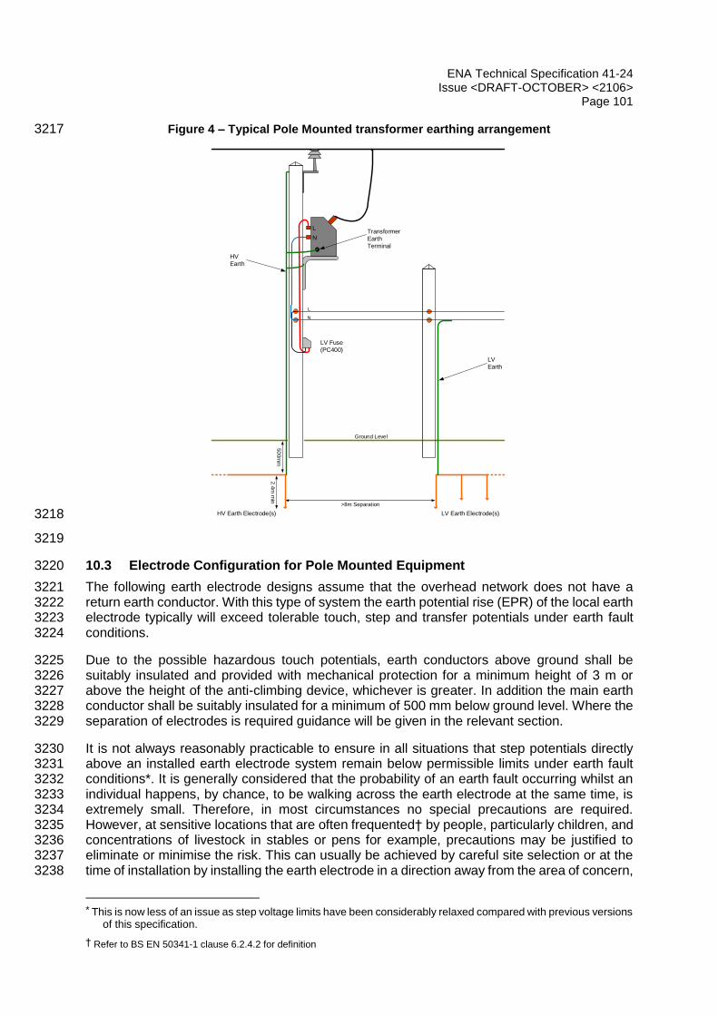
ENA Technical Specification 41-24 Issue <DRAFT-OCTOBER> <2106>
Page 101
Figure 4 – Typical Pole Mounted transformer earthing arrangement 3217
Ground Level
>8m Separation
50
0m
m2.4
m m
in
HV
Earth
Transformer
Earth
Terminal
LV Earth Electrode(s)HV Earth Electrode(s)
LV
Earth
L
N
N
L
LV Fuse
(PC400)
3218
3219
10.3 Electrode Configuration for Pole Mounted Equipment 3220
The following earth electrode designs assume that the overhead network does not have a 3221 return earth conductor. With this type of system the earth potential rise (EPR) of the local earth 3222 electrode typically will exceed tolerable touch, step and transfer potentials under earth fault 3223 conditions. 3224
Due to the possible hazardous touch potentials, earth conductors above ground shall be 3225 suitably insulated and provided with mechanical protection for a minimum height of 3 m or 3226 above the height of the anti-climbing device, whichever is greater. In addition the main earth 3227 conductor shall be suitably insulated for a minimum of 500 mm below ground level. Where the 3228 separation of electrodes is required guidance will be given in the relevant section. 3229
It is not always reasonably practicable to ensure in all situations that step potentials directly 3230 above an installed earth electrode system remain below permissible limits under earth fault 3231 conditions*. It is generally considered that the probability of an earth fault occurring whilst an 3232 individual happens, by chance, to be walking across the earth electrode at the same time, is 3233 extremely small. Therefore, in most circumstances no special precautions are required. 3234 However, at sensitive locations that are often frequented† by people, particularly children, and 3235 concentrations of livestock in stables or pens for example, precautions may be justified to 3236 eliminate or minimise the risk. This can usually be achieved by careful site selection or at the 3237 time of installation by installing the earth electrode in a direction away from the area of concern, 3238
* This is now less of an issue as step voltage limits have been considerably relaxed compared with previous versions
of this specification.
† Refer to BS EN 50341-1 clause 6.2.4.2 for definition

ENA Technical Specification 41-24 Issue <DRAFT-OCTOBER> <2106>
Page 102
burying the electrode as deep as practicable, and/or fencing the electrode off to prevent 3239 access. 3240
A similar situation also applies to personnel carrying out live operations such as HV drop-out 3241 fuse replacement, live-line tapping at earthed locations or ABSD switching using hook stick 3242 (hot-stick or insulated rods) techniques on earthed poles. 3243
10.4 HV Earth Electrode Value 3244
The HV electrode is (usually) the only return path for HV fault current (except relatively rare 3245 instances of cable fed PMTs, or cable terminations), and its resistance must generally be low 3246 enough to operate HV protection within design limits for the network (typically 1 to 1.5 seconds 3247 maximum); electrode resistance values between 10 Ohm and 40 Ohm are often quoted for 3248 design purposes, with lower values providing increased resilience to lightning strikes. (Lower 3249 resistance values will limit the voltage rise on HV steelwork, and can prevent ‘back flashover’ 3250 across LV bushings resulting from lightning surges, which would otherwise destroy the 3251 transformer winding). 3252
In general the lower the earth electrode resistance the more earth fault current will flow, 3253 resulting in more reliable operation of the circuit protection. Where surge arresters are used it 3254 is generally accepted that 10 Ohm is the preferred maximum value of earth electrode 3255 resistance for satisfactory operation of the arrester. This is in line with the preferred 10 Ohm 3256 value in BS EN 62305 for high frequency lightning earth electrodes. 3257
10.5 Electrode Arrangement Selection Method 3258
A common arrangement of rods used for earth electrodes associated with overhead line 3259 equipment is a run of parallel rods interconnected with a horizontal conductor. 3260
Resistance values may be calculated using formulae in EREC S34. The calculated values are 3261 considered to be conservative and are based on uniform soil resistivity. 3262
Calculated resistance values for the same rod and soil arrangements, using earthing design 3263 software are approximately 30% lower. Where the ground conditions are difficult, i.e. of high 3264 resistivity and/or rocky, the cost of obtaining the required earth electrode resistance value may 3265 warrant carrying out a site specific design. 3266
3267

ENA Technical Specification 41-24 Issue <DRAFT-OCTOBER> <2106>
Page 103
10.6 Earthed Operating Mechanisms Accessible From Ground Level 3268
This section deals with pole mounted auto-reclosers (PMARs), sectionalisers, and air break 3269 switch disconnectors, that are all capable of being manually operated via an earthed metallic 3270 control box or switch mechanism. It is important to note that where a low voltage supply is 3271 required for control circuits, the supply should be derived from a dedicated transformer whose 3272 LV neutral is earthed directly to the installation’s main HV earth conductor. 3273
There are several methods of minimising the risk from possibly hazardous touch and step 3274 potentials at such installations. In selecting the most appropriate method due account should 3275 be taken of the nature of the site, the accessibility of the equipment to third parties and the 3276 EPR level under fault conditions. 3277
(1) Use of wireless remote control for a unit mounted on the pole out of reach from ground 3278 level. With this method, an HV earth electrode system may be required where surge 3279 arresters are fitted or where the manufacturer of the equipment specifies. Where 3280 equipment is unearthed its mounting height shall comply with the relevant regulations. 3281
(2) Place the control box out of reach from ground level, access being via an insulated 3282 ladder. Again, with this method an HV earth electrode system may be required where 3283 surge arresters are fitted or where the manufacturer of the equipment specifies. 3284 Where equipment is unearthed its mounting height shall comply with the relevant 3285 regulations. 3286
Install an operator’s earth mat and grading conductors to help provide an equipotential 3287 zone for the operator. Figure 5 and Figure 7 show an example of how this may be 3288 achieved. Whilst this minimises the hazards for the operator it requires that the 3289 installation be carried out with great diligence. It is also important that the future 3290 integrity of the earth electrode is ensured. Misplacement of the earth electrode 3291 conductors can result in the operator being exposed to hazardous touch and step 3292 potentials. Consideration needs to be given to the selection of the site prior to 3293 installation to ensure that the required earth electrode configuration can be installed 3294 correctly, and maintained adequately into the future. Use of suitable personal 3295 protective equipment for switching operations may also be considered as an 3296 additional risk control measure; dielectric (insulated) footwear rated at >7 kV is now 3297 commonly used to protect operators against step potentials when stepping on/off the 3298 platform. 3299
(3) Where mechanical damage is likely, for example in farmland, protective measures 3300 need to be considered to ensure the integrity of the earth electrode and the earth mat. 3301 An example would be to install and fix the earth mat on or in a raft of concrete or fence 3302 off the area surrounding the earth mat. 3303
The use of grading conductors to minimise step potentials in the immediate vicinity of the 3304 operator’s earth mat may prove impractical in some circumstances, particularly where there is 3305 a danger of them being damaged by ploughing. Burying the grading conductors at a greater 3306 depth will significantly reduce their effectiveness. Keeping step potentials within tolerable limits 3307 can be extremely difficult and in some case impracticable. In such circumstances alternative 3308 mitigation should be considered. 3309
Factors such as, soil structure, operating voltage, type of HV system earthing (solid or 3310 resistance) and system impedance all have an effect on the value of step and touch potentials 3311 created around the earth electrode, whereas protection clearance times will have a bearing in 3312 determining the tolerable touch and step potential limits. At some sites it may be prudent to 3313 restrict access to the control box, for example by use of insulating barriers or fences, so that it 3314

ENA Technical Specification 41-24 Issue <DRAFT-OCTOBER> <2106>
Page 104
is not possible for third parties to touch the control box and where operators can only touch the 3315 control box when standing on the earth mat. 3316
It should be noted that burying the operator’s earth mat will increase the touch potential 3317 between the control box and the surface of the ground above the earth mat; the greater the 3318 depth of the mat, the greater the potential difference between the soil surface above the mat 3319 and the control box. The hazard this presents can be managed by covering the mat with a 3320 high resistivity material which will increase the impedance path between the hands and feet. 3321 Burying the mat will also have the effect of reducing the step potentials for an operator stepping 3322 off the mat. However, the prime concern is to minimise the touch potentials as these are 3323 considered to be more hazardous than step potentials. Where the mat is buried the touch 3324 potential and the hazard it presents will be site specific, being dependent upon the actual EPR 3325 and the protection clearance times for the given site, therefore a site specific design is 3326 recommended. The surface mat shown in Figure 5 results in negligible touch potentials for the 3327 operator standing on the mat, irrespective of the EPR. 3328
In all cases it is an option to use control measures to mitigate risk if a company deems this is 3329 the most appropriate solution in the circumstances. 3330
3331
3332

ENA Technical Specification 41-24 Issue <DRAFT-OCTOBER> <2106>
Page 105
NOTE: This arrangement does not exclude the use of a portable earth mat. 3333
Figure 5 — Earthing Arrangement for a PMAR with Ground Level Control Box. 3334
3335
Extended electrode ifrequired to obtain correct resistance value. Min. depth 500mm (1000mm in agricultural land)
1000mm x 1000mmearth mat
Potential gradingconductorsmax. 300mm deep
Operator's access route
Recommended pre-formed metallic mesh earth matMin. 1000mm x 1000mmMax. mesh size 100mm x 100mm
Optional concrete support raft/slab
Grading conductorsmax. 300mm deepSoil level
2000mmradius
Plan View

ENA Technical Specification 41-24 Issue <DRAFT-OCTOBER> <2106>
Page 106
3336
Figure 6 — Alternative Earthing Arrangement for a PMAR with Ground Level Control Box. 3337
3338
Recommended pre-formed metallic mesh earth matMin. 1000mm x 1000mmMax. mesh size 100mm x 100mm
Potential gradingconductorsmax. 300mm deep
Operator's access route
Optional concrete support raft/slab
Grading conductorsmax. 300mm deep
2000mmradius
Soil level
Extended electrode ifrequired to obtain correct resistance value. Min. depth 500mm (1000mm in agricultural land)
1000mm x 1000mmearth mat
Plan View
Obst
ruct
ion s
uch
as
hedge

ENA Technical Specification 41-24 Issue <DRAFT-OCTOBER> <2106>
Page 107
10.7 Air Break Switch Disconnector (ABSD) with an isolated operating mechanism 3339
There are several methods of controlling hazardous touch and step potentials, at pole mounted 3340 ABSDs. 3341
Install an insulated rod operated ABSD at high level that does not require an earth electrode. 3342 Where equipment is unearthed its mounting height shall comply with the relevant regulations. 3343 This option removes the risk of the operator being exposed to the hazard of touch and step 3344 potentials that could occur under certain earth fault conditions when adopting method 2 below. 3345
(1) Install an ABSD that is operated manually from ground level with a separate HV earth 3346 electrode and operator’s earth mat. This approach relies on effective separation of 3347 the HV earth electrode that connects the HV steelwork to earth, and the operator’s 3348 earth mat connected to the operating handle. This arrangement is typical of existing 3349 earthed ABSD equipment found on rural overhead line distribution networks. 3350
Separation is achieved by placing the HV earth electrode a minimum of 5m away from the 3351 base of the operator’s earth mat using insulated earth conductor from the electrode to the HV 3352 steel work, and by insulating the operating handle from the switch mechanism using an 3353 insulating insert in the operating rod. The top of the insert needs to be a minimum of 3m from 3354 ground level when in its lowest position. The operating handle needs to be connected to an 3355 earth mat positioned where the operator will stand to operate the handle. If the earth mat is 3356 installed such that it is visible the operator can verify its existence and its connection to the 3357 handle prior to operating the handle. The continuing effective segregation of the HV earth 3358 electrode and the operator’s earth mat is the most important aspect of the way in which this 3359 arrangement seeks to control the touch and step potentials around the operator’s earth mat 3360 position. To minimise the possibility of contact between the buried insulated earth conductor 3361 and the surrounding soil, should the earth conductor’s insulation fail, the conductor could be 3362 installed in plastic ducting. 3363
Where mechanical damage is possible, for example in farmland, protective measures may 3364 need to be considered to ensure the integrity of the earth electrode and the earth mat. An 3365 example would be to install and fix the earth mat on or in a raft of concrete or fence off the 3366 area surrounding the earth mat using non-conducting fencing. 3367
Under earth fault conditions the HV earth electrode will rise in potential with respect to remote 3368 earth. A potential gradient will be produced around the electrode; the potentials being highest 3369 immediately above the electrode and reducing rapidly with distance. The earth mat will be 3370 located within the potential gradient surrounding the HV earth electrode, but due to the 3371 separation distance of 5m the potential at that point with respect to remote earth will be 3372 relatively small. The surface level earth mat for the operating handle and the handle itself will 3373 rise in potential but there will be effectively no potential difference between the mat and handle. 3374
Under earth fault conditions, assuming the correct separation distance between the HV earth 3375 electrode and the operating handle earth mat, should the operator have one foot on the mat 3376 and one off the mat, touch and step potentials surrounding the earth mat should not exceed 3377 tolerable limits. However, there is a risk of hazardous touch and step potentials arising if the 3378 HV earth electrode short circuits to the operating handle earth mat. The risk of such a short 3379 circuit occurring is extremely small provided that the earth installation is correctly installed, 3380 inspected and maintained. 3381
The actual size and shape of the earth mat shall be such as to ensure that the operator will be 3382 standing towards its centre whilst operating the handle. Notwithstanding this requirement the 3383 minimum size of earth mat should be 1 m by 1 m. Due consideration needs to be taken of the 3384 type of handle, whether it is a two handed or single handed operation and whether the operator 3385 may be left or right handed. A purpose made mat is recommended in preference to a mat 3386

ENA Technical Specification 41-24 Issue <DRAFT-OCTOBER> <2106>
Page 108
formed on site out of bare conductor, as this eliminates problems of variation in shape and size 3387 that can occur with the latter. Where a buried earth mat is used, the maximum depth of the 3388 mat should be no greater than 300 mm. 3389
Under normal earth fault conditions the touch potential for both buried and surface 3390 mounted scenarios will be negligible. When deciding between the use of a buried 3391 earth mat and a surface mounted mat the following issues shall be considered: 3392
A surface mounted mat will allow the operator to visually confirm both the 3393 position of the earth mat relative to the handle and also the integrity of the 3394 connection between the earth mat and the handle. 3395
A surface mounted mat will minimise any touch potentials between the soil 3396 surface on the mat and the handle, both under normal earth fault conditions 3397 and under second fault conditions where the handle and the earth mat become 3398 energised although this scenario should be less likely because effective 3399 segregation can be visually confirmed before operation. 3400
Conversely a surface mounted mat will maximise the step potential around the 3401 mat although this will only be an issue if the mat and handle become energised 3402 under a second fault scenario. 3403
A buried earth mat will not allow the operator to visually confirm either its 3404 position relative to the handle, or the integrity of its physical connection to the 3405 handle before operation. 3406
Burying the earth mat will increase the value of any touch potential between 3407 the handle and the soil above the earth mat, this potential will increase with 3408 depth. 3409
To maintain the same effective soil surface area with a buried earth mat for 3410 the operator to stand on and minimise any resulting touch potentials requires 3411 a significantly larger mat than for a surface mounted mat. 3412
Where a second fault occurs that energises the operating handle and earth 3413 mat, with a buried earth mat the touch potential could exceed tolerable levels. 3414
Conversely burying the mat will have the effect of reducing the step potentials 3415 under such conditions for an operator stepping off the mat. 3416
The use of suitably rated PPE in these situations would assist in minimising the risk of exposure 3417 to possibly hazardous potentials. 3418
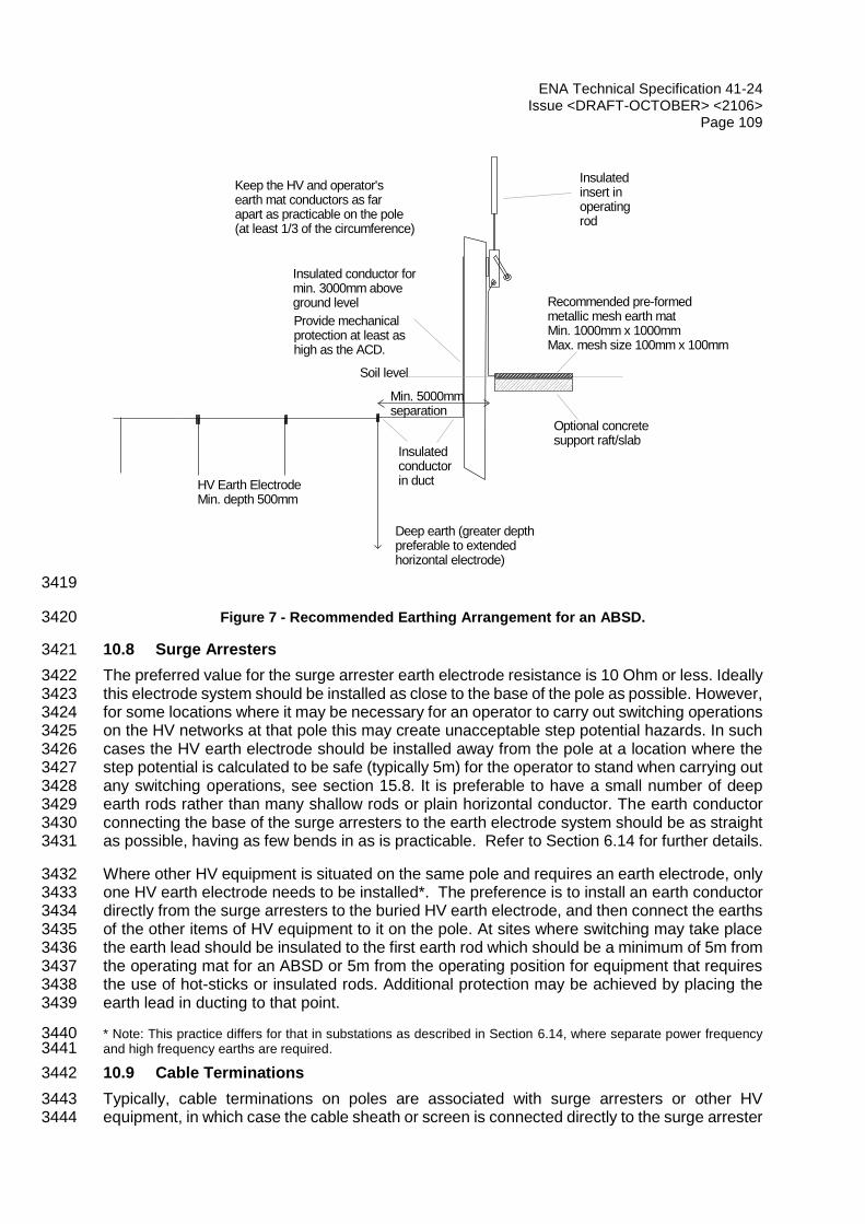
ENA Technical Specification 41-24 Issue <DRAFT-OCTOBER> <2106>
Page 109
3419
Figure 7 - Recommended Earthing Arrangement for an ABSD. 3420
10.8 Surge Arresters 3421
The preferred value for the surge arrester earth electrode resistance is 10 Ohm or less. Ideally 3422 this electrode system should be installed as close to the base of the pole as possible. However, 3423 for some locations where it may be necessary for an operator to carry out switching operations 3424 on the HV networks at that pole this may create unacceptable step potential hazards. In such 3425 cases the HV earth electrode should be installed away from the pole at a location where the 3426 step potential is calculated to be safe (typically 5m) for the operator to stand when carrying out 3427 any switching operations, see section 15.8. It is preferable to have a small number of deep 3428 earth rods rather than many shallow rods or plain horizontal conductor. The earth conductor 3429 connecting the base of the surge arresters to the earth electrode system should be as straight 3430 as possible, having as few bends in as is practicable. Refer to Section 6.14 for further details. 3431
Where other HV equipment is situated on the same pole and requires an earth electrode, only 3432 one HV earth electrode needs to be installed*. The preference is to install an earth conductor 3433 directly from the surge arresters to the buried HV earth electrode, and then connect the earths 3434 of the other items of HV equipment to it on the pole. At sites where switching may take place 3435 the earth lead should be insulated to the first earth rod which should be a minimum of 5m from 3436 the operating mat for an ABSD or 5m from the operating position for equipment that requires 3437 the use of hot-sticks or insulated rods. Additional protection may be achieved by placing the 3438 earth lead in ducting to that point. 3439
* Note: This practice differs for that in substations as described in Section 6.14, where separate power frequency 3440 and high frequency earths are required. 3441
10.9 Cable Terminations 3442
Typically, cable terminations on poles are associated with surge arresters or other HV 3443 equipment, in which case the cable sheath or screen is connected directly to the surge arrester 3444
Keep the HV and operator'searth mat conductors as farapart as practicable on the pole(at least 1/3 of the circumference)
Insulatedinsert in operating rod
Insulated conductor for min. 3000mm aboveground level
Soil level
Provide mechanical protection at least as high as the ACD.
HV Earth ElectrodeMin. depth 500mm
Deep earth (greater depth preferable to extended horizontal electrode)
Insulated conductor in duct
Min. 5000mmseparation
Optional concretesupport raft/slab
Recommended pre-formed metallic mesh earth matMin. 1000mm x 1000mmMax. mesh size 100mm x 100mm

ENA Technical Specification 41-24 Issue <DRAFT-OCTOBER> <2106>
Page 110
or HV equipment main earth conductor. In the absence of surge arresters or other earthed HV 3445 equipment the cable will require the installation of an earth electrode. 3446
10.10 Operations at Earthed Equipment Locations 3447
At earthed installations fed via overhead line systems, it is essential to have robust operational 3448 procedures to minimise the risk from the possible hazards associated with the high rise of earth 3449 potential under earth fault conditions. It should be noted that the risk increases during live fault 3450 switching operations. It is beyond the scope of this document to detail such procedures but 3451 consideration should be given to the following points. 3452
Earth systems are usually designed to minimise hazards under main protection operation. 3453 They are not designed, unless specifically required, to minimise hazards under secondary or 3454 backup protection conditions. This is an important point to note when developing fault switching 3455 operational procedures. Temporarily disabling parts of the protection system, reconfiguring the 3456 network, or raising protection settings to aid in fault location during fault switching can give rise 3457 to touch, step and transfer potentials of a duration that the associated earth systems have not 3458 been designed to take account of. 3459
Precautions shall be taken, by virtue of the equipment design and earthing arrangements to 3460 minimise any touch and step potential hazards. For example, where rod operated (insulated 3461 hot sticks) equipment is used, the simplest way of minimising hazards from touch and step 3462 potentials is by, where practicable, placing the earthing electrode, not serving as grading 3463 conductors, away from the position where the operator will be standing. Where several people 3464 are present during operations, any person not actively carrying out operations should stand 3465 well clear of the installed earth electrode. 3466
10.11 Installation 3467
The following points should be considered when installing an earth electrode system for 3468 overhead line equipment: 3469
(1) Materials and jointing methods shall comply with the requirements of BS 7430. 3470
(2) Installation teams should have a basic understanding of the functions of an earth system, 3471 and should carry out installations to a detailed specification. 3472
(3) Typically, installing a horizontal earth electrode system at a greater depth than 500mm 3473 will not have any significant effect on reducing the earth electrode's resistance value. 3474 However, it is recommended that the electrode is buried as deep as is practically possible 3475 to minimise surface potentials and the possibility of mechanical damage. Where 3476 ploughing is a concern the electrode should be buried at a minimum depth of 1m. 3477
(4) Ensure maximum separation is achieved on the pole between HV earth conductors and 3478 ABSD handle earth mat conductors. 3479
(5) It is recommended that a test point is made available for future connection of an earth 3480 tester above ground so that the earth electrode resistance can be measured. This test 3481 point should be installed and constructed so as to prevent unauthorised access, and on 3482 ABSD’s prevent possible flashover to the operator’s handle and associated earth mat. 3483
(6) Welded, brazed or compression connections are preferable to bolted connections for 3484 underground joints. 3485
(7) Corrosive materials and high resistivity materials such as sand should not be used as a 3486 backfill immediately around the electrode. 3487
(8) The earth resistance of the installed electrode should be measured and recorded. 3488

ENA Technical Specification 41-24 Issue <DRAFT-OCTOBER> <2106>
Page 111
(9) Where a buried operator’s earth mat has been installed, the mat should have two 3489 connections made to the operating handle. 3490
10.12 Inspection & Maintenance of Earth Installations 3491
10.12.1 Items to Inspect 3492
During routine line inspections it is recommended that the following items are visually 3493 inspected and their condition recorded, with any defects being rectified in a timely manner: 3494
(1) ABSD earth mat and connection to operating handle. 3495
(2) Separation of HV and operator’s handle earth on an ABSD. 3496
(3) Separation of HV and LV earth conductors on the pole. 3497
(4) Check that the anti-climbing device does not compromise the separation between the 3498 HV earth conductor and the operating handle. 3499
(5) Insulation of HV and LV earth conductors. 3500
(6) Mechanical protection of HV and LV earth conductors. 3501
(7) Bonding of plant and equipment. 3502
(8) State of connections, including any test point. 3503
(9) Signs of possible mechanical damage to earth electrode and buried earth mats. 3504
10.12.2 Items to Examine 3505
Periodically examine a random sample of buried earth electrodes and buried ABSD handle 3506 earth mats, and rectify any defects found. The examination should check for the following: 3507
(1) position of earth mat and electrode locations relative to ABSD handle and operator’s 3508 position; 3509
(2) insulating insert in the ABSD operating rod; 3510
(3) state of underground connections; 3511
(4) state of earth electrode components, particularly galvanised steel rods; 3512
(5) state of insulation on underground earth conductors where separation of electrodes is 3513 required. 3514
NOTE: When carrying out this work protective measures shall be taken to ensure the safety of personnel during 3515 fault conditions. 3516
The results of the examinations can then be used to assist in developing ongoing inspection 3517 and maintenance policy, and procedures. 3518
10.12.3 Items to Test 3519
(1) Periodically test the earth electrode resistance. For the relatively small earth systems 3520 typically associated with overhead line equipment, a small 3 terminal earth tester is 3521 adequate. The test should be carried out in accordance with the manufacturer’s 3522 instructions. 3523
(2) Regularly test the continuity between operating handle and the operator’s earth mat. 3524

ENA Technical Specification 41-24 Issue <DRAFT-OCTOBER> <2106>
Page 112
(3) Regularly test the continuity of buried earth mats. 3525
(4) Periodically test a random sample of insulating inserts used in ABSD operating 3526 mechanisms. 3527
Important: When carrying out these measurements the equipment should be made dead or 3528 where this is not practicable a risk assessment should be carried out and suitable test 3529 procedures should be adopted which safeguard the operator from any rise of earth potential. 3530 Such procedures may for example include the use of insulating gloves and boots, mats and / 3531 or fully insulated test equipment. 3532
3533
3534
3535

ENA Technical Specification 41-24 Issue <DRAFT-OCTOBER> <2106>
Page 113
3536
Case studies / examples 3537
11.1 Risk assessment – house near substation 3538
3539
This case study concerns a house that has been built close to a primary substation. The EPR 3540 at the substation in this case is 3kV, and historical data suggests that significant EPR events 3541 may occur up to 8 times per year on average (due to a combination of local and remote faults). 3542 Computer modelling / calculations show that the ground potential rise at the property is 1596 3543 volts. 3544
LV Network
Primary
VT
3545
The house LV earth is assumed to be derived from a remote source (e.g. segregated earthing 3546 at the distribution substation, located some distance from the primary substation). The worst 3547 case assumption is that the house earthing system is connected to a remote (zero volt) 3548 reference. 3549
Under HV/EHV fault conditions the voltage on the soil around the house will rise, leading to 3550 touch potential risk in and around the dwelling. Various scenarios should be considered; this 3551 case study looks at the risk outside the property when an occupant is using an outside tap 3552 (bonded to the LV earth). This is one of the most significant risks because the occupant may 3553 be standing on soil, and may be barefoot, meaning that the resistance of the ‘accidental circuit’ 3554 will be low. The maximum touch voltage that will occur is 1596 V and this will remain for the 3555 duration of each fault (1.5 seconds). 3556
For barefoot conditions, the maximum permissible touch voltage (1.5 seconds) is 68 volts. This 3557 ‘deterministic limit’ is based on the C2 curve from IEC 60479-1 and the body impedance model 3558 for 95% of the population, i.e. the same criteria used in the examples in BS EN 50522. 3559
If the faults clear in 0.5 seconds, the deterministic limit (UTP) would be 166 volts. 3560
In either case, the touch potential (tap-to-soil) is therefore above the C2 curve, and places the 3561 fibrillation risk between 50% and 100%. For initial analysis therefore, PFB may be assumed 3562 to be 1 (more detailed analysis shows the body current to be around 2745 mA, which is well 3563 into the AC-4 region of IEC 60479-1 Figure 20, i.e. “Probability of ventricular fibrillation above 3564 50%”. 3565
PF relates to the probability of fault. For the purposes of this analysis it may be taken as equal 3566 to F, where F is the number of significant earth faults in a year. 3567
The probability of exposure (PE) relates to the time that an individual may be exposed to risk. 3568 The most significant, and obvious risk relates to contact with the outside tap. It is assumed 3569

ENA Technical Specification 41-24 Issue <DRAFT-OCTOBER> <2106>
Page 114
that the tap is used twice per week, and that each use produces two contacts for 4 seconds 3570 as the tap is turned on and off. The exposure is calculated as: 3571
PE = 52 * 2 * 4 (seconds) / (365*24*60*60 seconds/year) 3572
PE = 1.32 × 10⁻⁵ y-1 3573
The individual risk (IR) is calculated using the formula: 3574
𝐼𝑅 = 𝑓𝑛 ∗ 𝑃𝐸 ∗ 𝑃𝐹𝐵 3575
where 3576
𝑓𝑛 = frequency of significant EPR events, on average per year 3577
𝑃𝐹𝐵 = probability of heart fibrillation 3578
𝑃𝐸 = probability of exposure 3579
Thus: 3580
Defect PF PFB PE Risk Remedial action
Close proximity to substation with High EPR
8 1 1.32x10⁻⁵ 1.06x10⁻⁴ per person per year
Required (IR > 1 in 1 million per person per year)
3581
The risk assessment process should consider all risk scenarios, and the overall risk is the sum 3582 of these. At this particular property it is possible to demonstrate that (due to a combination of 3583 equipotential bonding and dry floor coverings) a significant touch voltage will not appear in the 3584 property, so internal risk may be taken as 0. 3585
In conclusion, in this example the risk to an individual exceeds the broadly acceptable 3586 threshold of 1x10⁻⁶ pppy, and falls into the ALARP region. This simplified analysis would 3587 suggest therefore that mitigation is required. 3588
The justifiable spend is calculated according to the loss of life that could occur during the 3589 lifetime of the installation. The latest ‘value for the prevention of a fatality’ figure should be used 3590 based on HSE guidelines [R2P2], and is currently £1M: 3591
Expected lifetime of installation: 100 years 3592
Fatalities in 100 years: 1.06x10-4 x 100 = 0.0106 3593
Number of individuals (e.g. other properties) exposed to same risk: 10 3594
Justifiable spend = £1,000,000 x 0.0106 x 10 = £106,000 3595
Therefore if the cost of reducing risk to broadly acceptable levels is less than this, mitigation 3596 of the hazard should be carried out. If only 10 properties are affected, and if only the outside 3597 tap is an issue, mitigation could include installation of insulated inserts in pipework, installation 3598 of a local electrode/earthing system for the tap, or alterations to the LV supply arrangements. 3599 More conventional alterations to the substation earthing system, EPR, or fault rates should 3600 also be considered. Modifications to customer property must also consider the likelihood that 3601

ENA Technical Specification 41-24 Issue <DRAFT-OCTOBER> <2106>
Page 115
they may become altered or compromised as they are beyond the control of the network 3602 operator. 3603
Before calculating the justifiable spend, any ‘worst case’ assumptions should be revisited. 3604 Fault rates and EPRs will have a ‘distribution function’ typically a poisson distribution, but it is 3605 unlikely that sufficient data will be available to allow a full probabilistic assessment. Instead, it 3606 may be necessary to more accurately determine the number of significant EPR events, 3607 perhaps by measurements / logging over a prolonged period. 3608
Another significant assumption in the analysis above is that the full voltage (1596 V) appears 3609 as a touch voltage. In reality, the LV neutral/earth, and pipework may be in contact with soil 3610 close to the individual and may therefore rise in potential in sympathy with the substation 3611 earthing system. The result could be a much reduced voltage difference (touch voltage) 3612 between tap and soil. 3613
As an example, if measurements show that in fact the significant fault rate is 1 per year, and 3614 each produces a lower (measured) touch voltage at the property than modelled (such that 3615 maximum PFB = 0.5, say), the resultant individual risk would be: 3616
IR = 1 x 0.5 x 1.06x10-4 = 5.3 x 10⁻⁵. 3617
If there is robust data to justify it, a further reduction factor can be applied by looking at the 3618 relationship between exposure and fault. If for example, the tap is only used barefoot on dry 3619 sunny days, it may be that the fault rate is lower on those days. A ‘correlation factor’ may be 3620 applied to account for this. In the example above, if the fault rate on dry days is 1/10th that for 3621 the rest of the year, a factor of 0.1 may be applied to 𝑃𝐸 ∗ 𝑃𝐹𝐵, giving an overall risk of 5.3 x 3622 10-6. This is still not ‘acceptable’ but the justifiable spend comes down to £5,300. If the risk 3623 cannot be significantly reduced for this amount, the network operator may be able to justify the 3624 decision to do nothing. 3625
This case study considers only one aspect of overall risk. All similar scenarios should be 3626 considered (e.g. risk inside the property, if any) and an overall risk calculated by summing the 3627 individual risks from each scenario. In this case, studies inside the property (considering 3628 flooring resistance) show that there is no likelihood of fibrillation for typical domestic floor 3629 coverings (carpet, wood, dry tiles, etc.), but some risk may exist in bare concrete or wet areas. 3630
This study considers only fibrillation risk. Injuries from minor shocks (e.g. falls etc.) have not 3631 been considered. A tailored approach may be required for different circumstances, e.g. 3632 nurseries, nursing homes, hospitals, etc. 3633
[11] HSE, Reducing Risk Protecting People, 2001 3634
3635
11.2 LV Supply into HOT (HPR) site 3636
3637
This case study considers the provision of an LV supply into a transmission substation with 3638
an EPR which cannot safely be carried outside the substation boundary (i.e.the EPR 3639
exceeds 2 x safe step and touch voltage thresholds, and/or the substation is declared ‘HOT’). 3640
3641
The following parameters apply: 3642
3643
EPR 3 kV

ENA Technical Specification 41-24 Issue <DRAFT-OCTOBER> <2106>
Page 116
Protection clearance time 0.2 seconds
3644
The substation is in a suburban location with a local underground LV network and mixed 3645
overhead / underground 11kV cable system. The LV network supplies nearby properties and 3646
remains outside the ‘HOT’ zone (650V) which is calculated to extend 150m from the site. 3647
3648
A 100A (3 phase) LV supply has been requested by the substation operator, this is to serve 3649
as a backup to local site supply transformers. 3650
The EPR exceeds that which can safely be imposed on the LV network under fault conditions. 3651 Therefore, taking an ordinary LV supply into the site from the nearby network is not an option. 3652 (The LV neutral/earth would invariably become combined with the substation earthing). 3653
The options available to the DNO include those listed below. The merits/disadvantages of each 3654 approach are discussed: 3655
Option Merits / Disadvantages
11kV cable taken to local transformer /
RMU located on transmission site
The 11kV system can be assumed to be remotely
earthed and may therefore adopt a close-to-zero
voltage rise under transmission EPR events. If the
cable is taken onto the site, its sheath insulation
could puncture and a high EPR could be exported
to the 11kV system.
To avoid this, the cable must be ducted within the
highest voltage contours (dependent on its sheath
withstand voltage). Extending ducting to the 2kV
contour is a relatively common practice to avoid
this.
Any such cable connection into a ‘HOT’ site
requires extreme care with the earthing of the
RMU/Transformer or unit substation, as the
earthing systems for the 11kV cable must not be
combined with site earths. It is often most practical
to earth the transformer HV and LV earths to the
site earth, but to introduce an insulated gland
(sheath break) in the 11kV cable(s) where they
enter the plant. This can cause problems a) touch
voltages between cable sheath and local steelwork,
b) no metallic return for 11kV faults beyond the
break, requiring the substation earth to be able to
limit 11kV EPR and of sufficiently low resistance to
operate 11kV protection, and c) operational issues
if RMU earth is applied, since the 11kV cable cores
will become connected to the local site earth. This
could create a hazard for staff working on the cable
or elsewhere on the 11kV network unless specific
operational practices are adopted.

ENA Technical Specification 41-24 Issue <DRAFT-OCTOBER> <2106>
Page 117
Option Merits / Disadvantages
11kV overhead line supply to site, with
pole mounted or ground mounted
transformer
An 11kV supply to site, if via 3-wire (unearthed)
overhead construction is a simple and effective
solution to the issues described above. The OHL
can effectively be carried direct into the site, where
it can supply a ground mounted transformer or pole
mounted transformer. For both arrangements, the
transformer HV and LV earths can be combined
and connected to the site earth. A 3kV EPR on the
site earth is unlikely to initiate flashover between
the 11kV phases and steelwork, or between any
short 11kV cable sheath-to-cores, although this
possibility should be considered in extreme EPR
situations. (Similar insulation breakdown could
occur internal to the transformer if the casing is
elevated above phase voltages). Care should be
taken with operational earth positions and
procedures.
The disadvantage of this method is that the supply
may be more vulnerable than underground supplies
and consequently might be unacceptable where a
resilient supply is necessary.
LV supply from network The DNO considered making an LV supply
available direct from the network, but withholding
the earth terminal. (e.g. TT arrangement). It should
be borne in mind that the LV neutral / earth will
remain tied close-to-zero volts under transmission
EPR events, and therefore the possibility of
insulation breakdown / flashover to the LV system
is very real. Whilst it may be possible to duct the
LV cable, there will be little or no control of the LV
circuit routing arrangements etc, (e.g. some may
pass close to, or in contact with site steelwork) and
for this reason the unisolated LV supply should not
be used when EPR can exceed e.g. 440V, (or
nominal withstand voltage of LV cable or equipment
insulation). Isolation transformers are an option,
though care is required with the siting and
protection of the isolation unit itself.
Dedicated off-site transformer and LV
supply into site
Offers little or no benefit, and introduces the risk of
exporting transmission EPR to the transformer.
The LV arrangements could be PNB, i.e. the neutral
could be earthed at the transmission site (only),
whilst the HV could be earthed to the local network.
The LV neutral to HV steelwork insulation withstand
voltage must be sufficient to withstand the full EPR
as a stress-voltage, and the LV cable must be
ducted outside the transmission substation.

ENA Technical Specification 41-24 Issue <DRAFT-OCTOBER> <2106>
Page 118
Option Merits / Disadvantages
3656
In this case, the pole-mounted transformer and overhead 11kV line solution has been adopted. 3657 This is the minimum cost solution and (because it is a ‘back up’ supply) the reliability is 3658 acceptable to the transmission network operator. For operational reasons an ABSD is best 3659 located outside the site boundary and will serve as a point of isolation and earthing point for 3660 the 11kV network beyond that point. 3661
3662
High EPR zone (HPR)
Supply from nearby 11kV network
LV cable
on site
HV and LV
earth
connection
Ground mounted plant
clear of HOT contours
3663
Figure 8 – Overhead supply into High EPR site 3664

ENA Technical Specification 41-24 Issue <DRAFT-OCTOBER> <2106>
Page 119
3665
3666

ENA Technical Specification 41-24 Issue <DRAFT-OCTOBER> <2106>
Page 120
3667
3668
3669
3670
3671
3672
3673
3674
3675
3676
3677
3678
3679
3680
3681
3682
3683
3684
3685
3686
3687
3688
3689
3690
3691
3692

ENA Technical Specification 41-24 Issue <DRAFT-OCTOBER> <2106>
Page 121
3693
3694
3695
3696
This page deliberately left blank. 3697
3698
3699