technical-specification-of-acsr-conductor-for-transmission ...
Upload
khangminh22Category
view
1download
0
Technical Specification for
Supply & Delivery of 11KV Non extensible
3 -Way Ring Main Unit
(For both Bulk consumer & DTR Out Door installation)
1.0 SCOPE
This specification covers Design, Engineering, Manufacture, Assembly, testing,
Inspection, packing and delivery at site of Ring main Units. The RMU to be supplied
against this specification are required for vital installations where continuity of service is
very important as well as for Bulk consumer metering purpose. The design, materials
and manufacture of the equipment shall, therefore, be of the highest order to ensure
continuous and trouble-free service over the years.
The RMU offered shall be compact, maintenance free, easy to install, reliable, safe and
easy to operate and complete with all parts necessary for their effective and trouble-free
operation. Such parts will be deemed to be within the scope of the supply irrespective of
whether they are specifically indicated in the commercial order or not.
It is not the intent to specify herein complete details of design and construction. The offered
equipment shall conform to the relevant standards and be of high quality, sturdy, robust and
of good design and workmanship complete in all respects and capable to perform continuous
and satisfactory operations in the actual service conditions at site and shall have sufficiently
long life in service as per statutory requirements. In actual practice, not withstanding any
anomalies, discrepancies, omissions, in-completeness, etc. in these specifications, the design
and constructional aspects, including materials and dimensions, will be subject to good
engineering practice in conformity with the required quality of the product, and to such
tolerances, allowances and requirements for clearances etc. as are necessary by virtue of
various stipulations in that respect in the relevant Indian Standards, IEC standards, I.E.
Rules, I.E. Act and other statutory provisions.
The Bidder shall bind himself to abide by these considerations to the entire satisfaction
of WBSEDCL and will be required to adjust such details at no extra cost to WBSEDCL
over and above the tendered rates and prices.
2.0 Scope of Work
2.1 Tolerances: Tolerances on all the dimensions shall be in accordance with provisions
made in the relevant Indian/IEC standards amended up to date and in this specification.
Otherwise the same will be governed by good engineering practice in conformity with
required quality of the product.
2.2 Recommended spares: The bidder shall furnish in his offer a list of recommended spares
with unit rates for each set of equipment that may be necessary for satisfactory
operation and maintenance of circuit breaker and Isolators. The WBSEDCL reserves
right of selection of items and quantities of these spares to be ordered. The cost of such
spares shall not be considered for tender evaluation.
2.3 Erection and maintenance tools: Any special tools if required for Installation &
Commissioning of the RMU to be supplied with the each set of RMU free of cost.
3.0 Key RMU Components
Key RMU components are listed as follows:
Two (2) Isolators with earthing switches, connecting the RMU to incoming and
outgoing main loop, suitable for 11 KV XLPE cables of size 400 / 300 mm2 cross
section aluminium conductor.
One (1) circuit breaker (CB) with earthing switches, connecting the RMU to
distribution transformers / feeder loop or to indoor combined CT/PT unit for Bulk
metering arrangement, suitable for 11 kV, XLPE cables of size 185 mm2 cross section
aluminium conductor.
One numerical Series Trip & Self Power relay having non-directional O/C and E/F
protection for each outgoing feeder. In case of 630 KVA & above DTRs, auxiliary relay
for transformer supervision shall be provided. FPI needs to be provided in both LBS
with E/F & O/C indication having in built Push Button for Reset.
All necessary Current transformers for protection.
Capacitor voltage dividers serving live-line cable indicators.
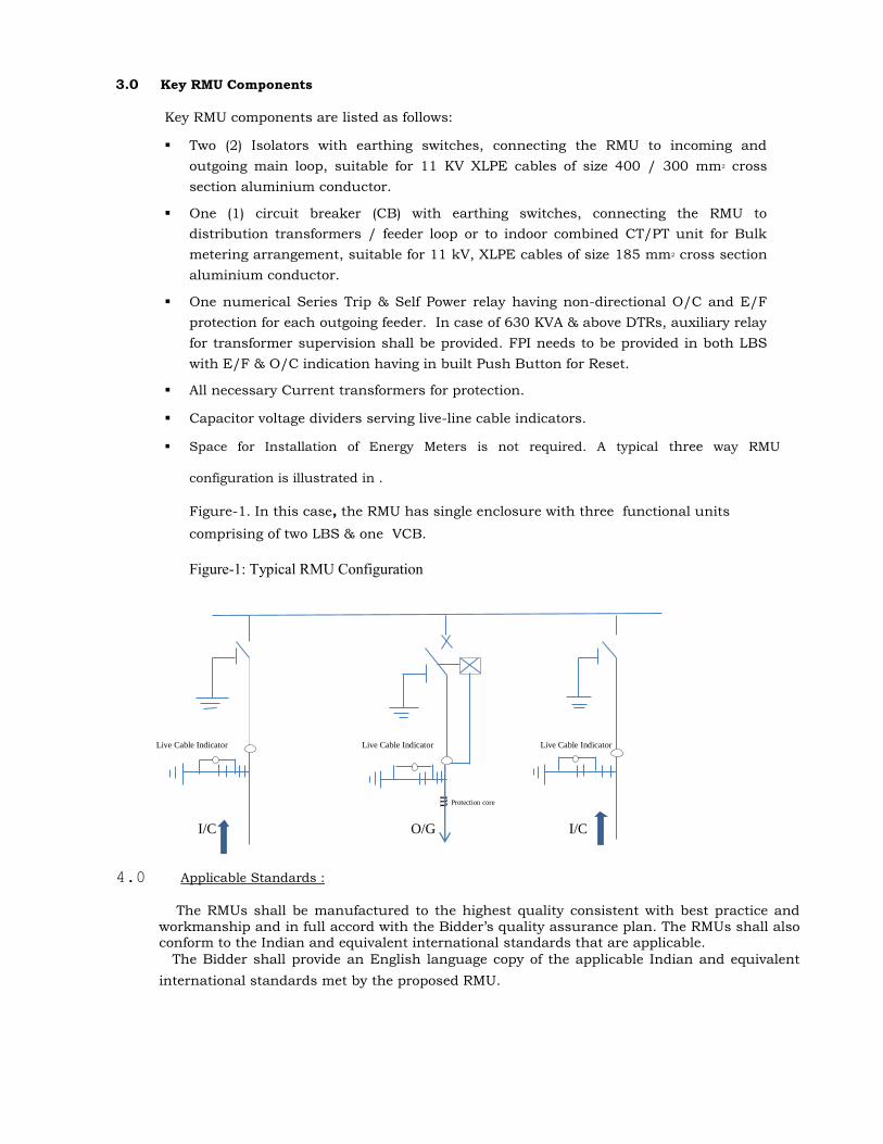
Space for Installation of Energy Meters is not required. A typical three way RMU
configuration is illustrated in .
Figure-1. In this case, the RMU has single enclosure with three functional units
comprising of two LBS & one VCB.
Figure-1: Typical RMU Configuration
Live Cable Indicator Live Cable Indicator Live Cable Indicator
ᴟ Protection core
I/C O/G I/C
4.0 Applicable Standards :
The RMUs shall be manufactured to the highest quality consistent with best practice and
workmanship and in full accord with the Bidder’s quality assurance plan. The RMUs shall also conform to the Indian and equivalent international standards that are applicable.
The Bidder shall provide an English language copy of the applicable Indian and equivalent
international standards met by the proposed RMU.
Rating, characteristics, tests and test procedures etc. for the RMU , protection Relays,
monitoring and control devices and accessories including current transformer shall
comply with the provisions and requirements of the standards of the IEC and IS
where specified.
The latest revision or edition in effect at the time of bid invitation shall apply. Where
references are given to numbers in the old numbering scheme from IEC it shall be taken
to be the equivalent number in the new five-digit number scheme. The bidder shall
specifically state the precise standard, complete with identification number, to which the
various equipments and materials are manufactured and tested. The bid document may
not contain a full list of standards to be used, as they only are referred to where useful
for clarification of the text.
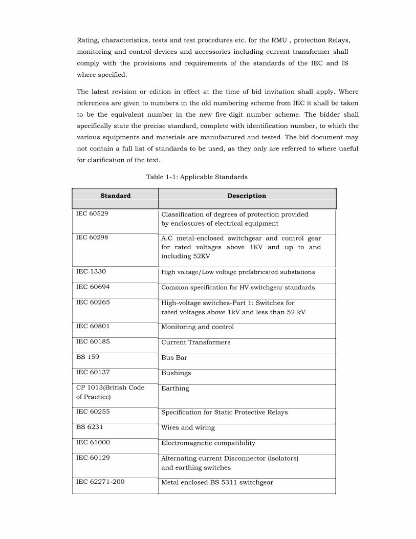
Table 1-1: Applicable Standards
Standard Description
IEC 60529
IEC 60298
Classification of degrees of protection provided
by enclosures of electrical equipment A.C metal-enclosed switchgear and control gear
for rated voltages above 1KV and up to and
including 52KV
IEC 1330
IEC 60694
IEC 60265
IEC 60801
IEC 60185
BS 159
IEC 60137
CP 1013(British Code
of Practice)
IEC 60255
BS 6231
IEC 61000
IEC 60129
IEC 62271-200
High voltage/Low voltage prefabricated substations Common specification for HV switchgear standards High-voltage switches-Part 1: Switches for
rated voltages above 1kV and less than 52 kV Monitoring and control Current Transformers Bus Bar Bushings Earthing
Specification for Static Protective Relays Wires and wiring Electromagnetic compatibility Alternating current Disconnector (isolators)
and earthing switches Metal enclosed BS 5311 switchgear
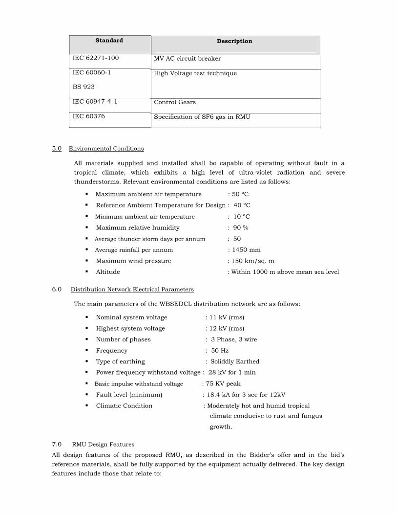
Standard
IEC 62271-100
IEC 60060-1
BS 923
IEC 60947-4-1
IEC 60376
Description
MV AC circuit breaker High Voltage test technique
Control Gears Specification of SF6 gas in RMU
5.0 Environmental Conditions
All materials supplied and installed shall be capable of operating without fault in a
tropical climate, which exhibits a high level of ultra-violet radiation and severe
thunderstorms. Relevant environmental conditions are listed as follows:
Maximum ambient air temperature : 50 ºC
Reference Ambient Temperature for Design : 40 ºC
Minimum ambient air temperature : 10 ºC
Maximum relative humidity : 90 %
Average thunder storm days per annum : 50
Average rainfall per annum : 1450 mm
Maximum wind pressure : 150 km/sq. m
Altitude : Within 1000 m above mean sea level
6.0 Distribution Network Electrical Parameters
The main parameters of the WBSEDCL distribution network are as follows:
Nominal system voltage : 11 kV (rms)
Highest system voltage : 12 kV (rms)
Number of phases : 3 Phase, 3 wire
Frequency : 50 Hz
Type of earthing : Soliddly Earthed
Power frequency withstand voltage : 28 kV for 1 min
Basic impulse withstand voltage : 75 KV peak
Fault level (minimum) : 18.4 kA for 3 sec for 12kV
Climatic Condition : Moderately hot and humid tropical
climate conducive to rust and fungus
growth.
7.0 RMU Design Features
All design features of the proposed RMU, as described in the Bidder’s offer and in the bid’s
reference materials, shall be fully supported by the equipment actually delivered. The key design
features include those that relate to:
Availability, maintainability and life span
Ability to operate in severe outdoor environmental conditions
Immunity to electrical stress and disturbance
Acceptable insulation properties
Acceptable surge suppression characteristics
In these and all other specified respects, the RMU shall meet or exceed the cited standards or
where appropriate, other equivalent industry standards.
8.0 Availability, Maintainability and Life Span
8.1 Availability :
The RMU shall be designed to have a fully enclosed metal housing combined with the single-
phase insulation of all primary live parts to reduce the risk of internal faults to an absolute
minimum and to provide a high degree of safety as well as availability. Nevertheless,
manufacturer standard designs shall be used to the fullest extent possible.
Each RMU shall exhibit an availability of greater than 99.5%. To ensure this high degree of
availability, the RMUs shall be fabricated, assembled, and finished with workmanship of the
highest production quality and shall conform to all applicable quality control standards. All
materials comprising the RMU shall be new, unused, and of the best industrial grade, and the
RMU shall incorporate all recent improvements in both design and materials. All components
shall be of current production from reliable component manufacturers.
8.2 Maintainability :
WBSEDCL intends to be self-reliant for RMU maintenance. To this end, the Bidder shall provide
the support, documentation, necessary to operate and repair the RMU. This shall include, but
shall not be limited to the maintenance manuals and repair kits applicable to the Bidder’s RMU
design.
WBSEDCL prefers RMU designs that do not require periodic preventive maintenance and
inspections. If periodic maintenance is required, it shall be possible to perform all such work in
the field without requiring the associated distribution network circuits to be de-energized.
To facilitate maintenance, modularity shall be employed in the design of the equipment. All
major subassemblies shall carry permanent labels providing a cross-reference to the Bidder’s
corresponding documentation.
8.3 Life Span :
Each RMU shall have a design life of at least 15 years from the date of final acceptance. The
Bidder shall make available, at no cost to WBSEDCL, the manufacturing designs, drawings, and
the rights to manufacture any subassemblies that the manufacturer will not support or
discontinues to support during this life span.

9.0 Outdoor Features :
9.1 General: The RMUs shall be designed specifically for outdoor installation and, in this respect, shall be
suitable for continuous operation in a tropical climate that includes exposure to severe
frequently occurring thunderstorms. They shall also be suitable for conditions in which they will
be exposed to heavy industrial pollution, salt-spray, and high levels of airborne dust.
The equipment in the proposed outdoor RMU shall be conformably coated to meet these climatic
conditions. In this respect, standards such as IEC 60870-2-2 covering equipment, systems,
operating conditions, and environmental conditions shall apply along with IEC 60721, which
covers the classification of such conditions. In particular, the RMU equipment shall have been
type tested for continuous operation under the environmental conditions.
In addition to the above, materials promoting the growth of fungus or susceptibility to corrosion
and heat degradation shall not be used, and steps shall be taken to provide rodent proof
installations.
All live parts, high voltage components, excluding the HV cable termination of the switchgear
shall be insulated/ protected in SF6 to provide complete proofing against dangers of flashover
between phase and earth and between phases. In particular, the equipment shall be climate free
in that no high voltage connection will be exposed to the environment.
9.2 Corrosion Protection
The fabricated parts are pretreated using 7 tank process and then coated by layer of zinc
phosphate. A finish coat with high scratch resistance or epoxy powder finish paint shall be
applied over the primer. The coat thickness shall be minimum 60 microns. The complete RMU
unit shall be powder coating of RAL 7032 Grey to DIN Standard 43656.
9.3 Material Except for main tank and external hardware which made of stainless steel, all structural steel
and outer enclosure as well as nuts and bolts etc. shall be of CRCA steel with epoxy powder
finish paint.
10.0 Immunity to Electrical Stress and Disturbance
The electrical and electronic components of the RMU shall conform to relevant standards
concerning insulation, isolation, and immunity from electromagnetic interference, radiated
disturbance, and electrostatic discharge. The ability to meet these requirements shall be verified
by type tests carried out by accredited test laboratories that are independent of the bidder
and/or the manufacturer of the RMU components. Certified copies of all available type test
certificates and test results shall be included as part of the bidder’s proposal. Failure to conform
to this requirement shall constitute grounds for rejection of the proposal.
11.0 Minimum Insulation of Equipment
The RMUs shall have SF6 gas-insulated type stainless steel tank with joints inside tank. All live
parts shall be fully insulated throughout their joints.
12.0 Surge Voltage Suppression
The RMU equipment shall be designed to operate on input power containing voltage spikes.
Equipment shall be protected against part failure or malfunction such as intermittent firing of
triggering devices due to surge voltage spikes occurring randomly over the instantaneous
supply voltage.
13.0 Nameplate Information
RMU nameplate information shall be determined in agreement with WBSEDCL. This information
may include for example:
Name of manufacturer and country
Type, design, and serial number
Rated voltage and current
Rated frequency
Rated symmetrical breaking capacity
Rated making capacity
Rated short time current and its duration
Rated lightning impulse withstand voltage
Rated Duty Cycle
Purchase Order number and date
Month and year of supply
Property label: Property of WBSEDCL
Guaranteed for five years
14.0 Danger Board:
The Danger Board plate as per relevant IS shall be riveted on the front plate of the RMU.
15.0 Interconnecting Cables, Wiring, Connectors, and Terminal Blocks
The Bidder shall provide all interconnecting wires, cables, connectors, terminations and other
wiring accessories such as terminal blocks required by the RMU.
16.0 Cables
All metallic cables and wiring shall be of required cross-section multiple strands of round copper
conductors and have flame retardant insulation. All wiring shall be neatly laced and clamped.
All wire and cable connectors and terminators shall be permanently labeled for identification. All
connection points for external cables and wires shall be easily accessible for connection and
disconnection and shall be permanently labeled. Conductors in multi-conductor cables shall be
individually color-coded.
Cable for CT circuit shall be of 2.5 sq.mm and for other control circuit shall be of 1.5 sq.mm Cu
multi-conductor and shall be screened with half-lapped copper tape. All wiring and termination
of connecting cables shall be carried out by the Bidder.

All wires shall be neatly run in groups and shall be securely fixed by cleats which are made of
insulating material. Suitable crimped connectors shall be used for the termination of the wire to
the terminal blocks.
All wires, including the spare cores of a multi-core cable, shall be properly numbered by
interlocking ferrule. All spare relay contacts shall also be wired out to spare terminal block
inside the panels. The marking on the ferrules shall not be erased easily.
All wiring colour classification, wire terminal sleeve colour and wire numbering system shall be
subjected to WBSEDCL’s approval.
All wiring terminals that are easily accessible by operating personnel shall be adequately
shielded by suitable means.
17.0 Connectors Plug-type connectors with captive fasteners shall be used for all interconnections. The
connectors shall be polarized to prevent improper assembly.
18.0 Terminal Blocks Suitable disconnector type terminal blocks shall be provided for CT circuits with necessary
spares with 5 mm minimum machine screws shall be provided by the Bidder for other necessary
metallic cable terminations. In using a terminal block, no more than two cables or wires shall be
connected to any of its individual terminals.
Self-extinguishing fireproof vinyl marking strips shall be used to identify all external connection
blocks. Marking tags shall be read horizontally. All terminals to which high voltages are
connected shall be provided with fireproof covers.
All individual status input, AC voltage input, and control output points shall be isolatable without the
need to remove wiring by means of individual terminal blocks of the removable link type.
Terminal blocks shall comply with IEC 60947-7-1 (2009): Low-voltage Switchgear and Control Gear, Part 7-1: Ancillary Equipment, Terminal Blocks for Copper Conductors.
TBs shall be mounted onto suitable insulation materials via channels. TBs shall be able to
withstand 2 KV AC rms voltage continuously for 1 minute between terminal and terminal to
earth.
One TB shall be used for one feeder panel. Translucent cover shall be provided for all cable
termination blocks. TBs shall be suitably spaced and labeled to enable easy and neat
termination. Each terminal shall be labeled according to the panel number. The use of
embossing tape for such purpose is not acceptable.
19.0 General Requirements The general requirements of the RMU shall include, but shall not be limited to provision of the
following local control:
Open/closed position of circuit breakers, and earthing switches.
Enclosure door-open indications .
SF6 gas-pressure low and normal Indication.
Circuit breaker spring charge indications.
Circuit breaker relay protection indications.
Measurement of 11 KV current for tee-off ckt.

Isolator/Circuit breaker open/close control.
Protection device failure through built-in Watch dog contact i.e ‘self monitoring’
feature of relay.
FPI indication with reset facilities.
20.0 Design Details
The RMU shall be designed to operate at the rated voltage of 11 kV. It shall consist of
two (2) numbers of 630 Amp SF6 insulated Isolators (incomers) and one (1) number of
200 Amp SF6 insulated Circuit Breakers for load.
The rated current of the Busbar, Load Break Switches & Earthing Switches will be
630A and maximum Current Density of the Busbar, Load Break Switches & Earthing
Switches will be accepted upto 2.5 A/Sq. mm. subject to submission of successful
Type test report. The material of the Busbar will be highly conductive Electrolytic
Copper .
It shall include, within the same metal enclosure, earthing switches for each Isolators
and Circuit Breaker.
Suitable full-proof interlocks shall be provided to the earthing switches to prevent
inadvertent or accidental closing when the circuit is live and the concerned Circuit
Breaker/Isolator is in its closed position.
Enclosures filled with gas at suitable pressure to ensure adequate insulation and safe
operation shall be used. The assembly shall not require further gas processing during
its expected operational life.
The degree of protection required against prevailing environmental conditions,
including splashing water and dust, shall be not less than IP 54.
The active parts of the switchgear shall be maintenance free. Rest parts shall be of
low-maintenance type.
The tank shall be made of an adequate thickness of stainless steel and internally arc
tested.
The RMU shall be suitable for mounting on its connecting cable trench.
For each RMU enclosure, a suitably sized nameplate clearly identifying the enclosure
and the electrical characteristics of the enclosed devices shall be provided.
Actual single line diagram of RMU shall be made displayed on the front portion of the
RMU so as to carry out the operations easily.
The positions of the different devices shall be clearly visible to an operator when
standing in front of each enclosure with its door open. Device operations shall be
clearly visible.
The RMU design shall be such that access to live parts shall not be possible without
the use of OEM-supplied tools.

The design shall incorporate features that prevent any accidental opening of the earth
switch when it is in the closed position. Similarly, accidental closing of a Circuit
Breaker shall be prevented when the same is in an open position. This includes
protection against accidental closing resulting from the release of any latch or spring
in tension due to vibrations caused externally or internally.
Circuit breakers shall be enclosed in the main tank using SF6 gas as insulating and
vacuum as arc quenching medium. The main tank shall be non-magnetic, non-ferrite
stainless steel sheet of minimum 2 mm thickness and robotically / TIG welded with a
pressure relief arrangement. However, Gas pressure and its leakage rate are to be
ensured as per Clause No. 22.2.
The breaking time for Circuit Breaker should not exceed 60 ms. The main tank (Inner
enclosure of Circuit Breaker) and all Switchboard assembly shall be housed in a
single compact metal clad suitable for outdoor applications. The design of enclosure
for Switchgear, RMU & Switchboard housing shall be in accordance with IEC 60298.
A temperature compensating gas pressure indicator offering a simple indication shall
constantly monitor the SF6 insulating medium.
The unit shall be internal arc proof and tested and totally safe for human beings. The
release of gas to be from the rear bottom / back of the unit, so that, even if the
person is operating the unit, proper safety is ensured to the operating personnel.
The clearances of all live parts to earth and between phases shall be to approval and shall
be in no way less than clearances specified in the relevant standards of this technical
specification and Type Tested value. All equipment shall be designed so as to minimize
corona or any other electrical discharges under all atmospheric conditions.
RMU needs to be pedestal mounted for easy bending of cables for termination with
the unit, safe for temporary water logging and ease in installation at any urban
location without wasting much time to make the cable trench etc.
21.0 Sulphur Hexa Fluoride Gas (SF6 GAS):
The SF6 gas shall comply with IEC 60376, 60376A and 60376B and shall be suitable in
all respects for use in RMUs under the stipulated service conditions. The SF6 shall be
tested for purity, dew point air hydrolysable fluorides and water content as per IEC
60376, 60376A and 60376B and test certificate shall be furnished to the owner
indicating all the tests as per IEC 60376.
22.0 ENCLOSURE :
All enclosures shall be sized to provide convenient access to all enclosed components. It
shall not be necessary to remove any component to gain access to another component for
maintenance purposes or any other reason.
The enclosures shall also be designed to ensure that the enclosure remains rigid and
retain its structural integrity under all operating and service conditions with and without
the enclosure door closed.
22.1 Outer Enclosure :
The RMU enclosure (Outer) shall be made up of CRCA steel of 2 mm thickness. The
rating of enclosure shall be suitable for operation on three phase, three wire, 11 kV, 50
cycles, A.C. System with short-time current rating of minimum 18.4 KA for 3 seconds for
11 kV supply with Panels. The complete RMU enclosure shall be of degree of protection
IP 54. The enclosure shall provide full insulation, making the Switchgear insensitive to
the environment like temporary flooding, high humidity etc. The active parts of the
Switchgear shall be maintenance-free and the unit shall be of minimum maintenance.
The complete RMU unit shall be powder coating of RAL 7032 Grey to DIN
Standard 43656.
Each switchboard shall be identified by an appropriately sized label which
clearly indicates the functional units and their electrical characteristics.
The Switchgear and Switchboards shall be designed such that the position of the
different devices is visible to the operator on the front of the Switchboard and operations
are visible.
In accordance with the standards in effect, the switchboards shall be designed so as
to prevent access to all live parts during operation without the use of tools.
22.2 Inner enclosure (Main tank)
The tank shall be robotically/TIG welded stainless steel sheet of minimum 2 mm to
ensure leak rate less tan 0.1% per year. The tank shall be sealed and no handling of gas
is required throughout the service life. However, the SF6 gas pressure inside the tank
shall be at 1.3 bar relative minimum to ensure the insulation and constantly monitored
by a temperature compensating gas pressure indicator offering a simple go, no-go
indication. The gas pressure indicator shall be provided with green pressure and red
pressure zones. There shall be one Non – return valve to fill up the gas. The
manufacturer shall give guarantee for maximum leakage rate of SF6 gas will be lower
than 0.1 % per year. There shall be no requirement to ‘top up’ the SF6 gas.. The
minimum degree of protection of the inner enclosure shall be IP 67.
The temperature rise test shall be carried out on complete RMU unit and test
reports shall be submitted with the offer.
The compact RMU Unit shall be provided with a pedestal made up of M.S. Angle to
mount the unit on plain surface. The height of the bottom of cable box shall be 310 mm
(minimum) to provide the turning radius for the HT cable termination.
23.0 Earthing There shall be continuity between metallic parts of the RMUs and cables so that there
is no dangerous electric field in the surrounding air and the safety of personnel is
ensured.
The RMU frames shall be connected to the main earth bars, and the cables shall be
earthed by an Earthing Switch having the specified short circuit making capacity.
The Earthing Switch shall be operable only when the main switch is open. In this
respect, a suitable mechanical fail-proof interlock shall be provided.
The Earthing Switch shall be provided with a reliable earthing terminal for connection
to an earthing conductor having a clamping screw suitable for the specified earth
fault conditions. The connection point shall be marked with the earth symbol.
The Earthing Switch shall be fitted with its own operating mechanism. In this respect,
manual closing shall be driven by a fast acting mechanism independent of the
operator's action.
All parts of the switchgear metal enclosure, metal relay and instrument cases, cable
glands, earthing terminals and other metal work on switchgear shall be connected to
earth by means of main and subsidiary earth bus bars.
The switchgear earth bar and earth conductors shall be of high conductivity copper
and their sizes shall be minimum 90 sq.mm to carry the rated short circuit currents
of the switchgear.
All metal parts of the switchgear which do not belong to main circuit and which can
collect electric charges causing dangerous effect shall be connected to the earthing
conductor. Each end of conductor shall be terminated by M12/equivalent quality and
type of terminal for connection to earth system installation. Earth conductor location
shall not obstruct access to cable terminations.
The following items are to be connected to the main earth conductor by rigid copper
conductors (a) earthing switches (b) Cable sheath or screen (c) capacitors used in
voltage control devices, if any.
The metallic cases of the relays, instruments and other panel mounted equipment’s
shall be connected to the earth bus. The colour code of earthing wire shall be green.
Earthing wires shall be connected on the terminals with suitable clamp connectors
and soldering shall not be permitted.
24.0 Circuit Breakers
The Circuit Breakers shall be maintenance free and, when standing in front of the RMU
with enclosure doors open, their positions shall be clearly visible. The position indicator
shall provide positive contact indication in accordance with IS 9920. In addition, the
manufacturer shall prove the reliability of indication in accordance with IS 9921.
The breakers shall have three positions (or states), i.e., Open, Closed, and Earthed, and
shall be constructed in such a way that natural interlocking prevents unauthorized
operations. They shall be fully assembled, tested, and inspected in the factory.

An operating mechanism shall be used to manually close the Circuit Breaker and charge
the mechanism in a single movement. It shall be fitted with a local system for manual
tripping. There shall be no automatic reclosing. The Circuit Breaker shall be capable of
closing fully and latching against the rated making current. Mechanical indication of the
OPEN, CLOSED, and EARTHED positions of the Circuit Breaker shall be provided.
The Circuit Breaker closing mechanism is of the spring operated type, it shall not be
possible for the Circuit Breaker to close until the spring is fully charged and the
associated charging mechanism is fully ready for closing. An external spring charging
handle is required to charge the spring, it shall be ensured that the same is not allowed
to move during release of the spring energy. Alternatively, it shall not be possible to
release the spring energy until the charging handle is completely disengaged from the
mechanism. A visual mechanical indicating device shall be provided to indicate the
status of the spring, i.e., SRING CHARGED or SPRING FREE. It shall be possible to
charge the spring when the Circuit Breaker is closed and, if the spring is released, the
Circuit Breaker shall not open. Nor shall this operation result in any mechanical damage
to the component of the Circuit Breaker or its operating mechanism. Alternatively, a fast
acting reflex mechanism for Circuit Breakers is also acceptable.
The circuit breaker shall be fitted with a mechanical flag, which shall operate in the
event of fault occurrences. The breaker indications ON and OFF positions shall be
indicated by suitable flag. For ON position indication by Red flag and OFF position
indication by Green flag shall be provided.
The circuit breaker shall be operated by the same unidirectional handle or switch. The
rated operating sequence shall be O-3min-CO-3 min-CO.
Each Circuit Breaker shall operate in conjunction with a suitable protection relay under
lateral circuit phase and earth fault conditions.
25.0 RING SWITCHES (Isolator) :
They shall consist of fault making/load breaking spring assisted ring switches, each with
integral fault making/load breaking earth switches. The switch shall be naturally
interlocked to prevent the main and earth switch being switched ‘ON’ at the same time.
The selection of the main and earth switch is made by a lever on the fascia which is
allowed to move only if the main or earth switch is in ‘OFF’ position.
26.0 BUSBARS :
The three nos. of continuous Busbars made up of copper of rating 630A shall be provided.
The Short time rating current shall be minimum 18.4 KA for 3 seconds for 12 kV. All
joints and connectors shall be SF6 insulated in accordance to this specification. Any
component directly connected to the power cables shall also be capable of withstanding
the DC test voltage applied to the cables. Cross section of the busbar shall not be less
than that stated in GTP.
27.0 BUSHINGS
All the bushings shall be of same height, parallel, on the equal distances from the
ground and protected by a cable cover. It is necessary to have bushings accessible from
the rear bottom/Front Bottom side of the RMU.
28.0 CABLE BOXES All cable boxes shall be air insulated suitable for dry type cable terminations. The cable
boxes of the circuit breaker shall be suitable up to 12 kV 3C x 400 / 300 sq.mm XLPE
type vertically ascending cable preferably for front type connection. Necessary Boot
should be supplied for cable terminations. The cable compartment shall be arc resistant
as per IEC 62271-200 amended upto date. The internal arc fault test on cable
compartment shall be carried out for 12 kV system for minimum 18.4 KA for 1 second.
The clearance between phase to phase and phase to earth shall be as per relevant IEC.
The cable compartment provided shall be of adequate dimension to house an air-
insulated cable termination. It shall be able to accommodate crossing of phase cores, if
necessary. The cable compartment shall be rated in accordance with the rated
insulation level of the switchgear.
Phases of all primary terminals shall be positively marked on the main structure and
not on the removable covers.
29.0 VOLTAGE INDICATOR LAMPS
The RMU shall be equipped with a voltage indication. It shall be possible for each of the
bay of the RMU to be equipped with a permanent voltage indication as per IEC 61243
to indicate whether or not there is voltage on the cables. The capacitive dividers will
supply low voltage power to sockets at the front of the unit, an external push button
type neon lamp must be used to indicate live cables. The neon shall be of adequate
dimensions to provide clear indication under all conditions.
30.0 Operating lever An anti-reflex mechanism on the operating lever shall prevent any attempts to re-open
immediately after closing of the switch or earthing switch. All manual operations shall be
carried out on the front of the switchboard. The effort exerted on the lever by the operator
should not be more than 250 N for the switch and circuit breaker. The overall dimensions
of the RMU shall not be increased due to the use of the operating handle. The operating
handle should have two workable positions 180° apart.
31.0 Safety of Equipment
With respect to the RMU’s SF6-filled equipment, any accidental overpressure inside the
sealed chamber shall be limited by the opening of a pressure-limiting device in the
enclosure so that the gas will be released away from the operator without endangering
the operator or anyone else in the vicinity of the RMU.
All manual operations shall be carried out from the front of the RMU. The effort required
to be exerted on the lever as used by the operator shall not exceed 250 N.
32.0 Front Plate
The front plate shall include a clear mimic diagram indicating RMU functionality. The
position indicators shall correctly depict the position of the main contacts and shall be
clearly visible to the operator. The lever operating direction shall be clearly indicated.
33.0 Current Transformers A panel shall be provided in each circuit breaker enclosure to mount a three-phase,
single-core, CT for protection purposes. CT access for maintenance or any other purpose
shall be from the rear back of these panels.
The CTs shall conform to IS 16227. The design and construction shall be sufficiently
robust to withstand thermal and dynamic stresses during short circuits. Secondary
terminals of CTs shall be brought out suitably to a terminal block, which will be easily
accessible for testing and terminal connections.
Further characteristics and features of CTs used for protection are listed as follows:
33.1 CBCTs for Protection (for Ring) : Material: Epoxy resin cast
Ratio and burden suitable as per FPI manufacturer’s recommendation.
33.2 CTs for Protection (for Outgoing) :
Material: Epoxy resin cast
Burden: 2.5 VA
Ratio: 100-50/1 Amp
Accuracy Class: 5 P 10
Voltage class : 660 V
34.0 Protection Relay
The RMU shall be equipped with self powered numerical Series Trip relays as used to
trip the RMU circuit breakers.
34.1 General The Circuit Breaker enclosures in the RMU shall be outfitted with a self powered
numerical Series Trip relays (feeder protection) relay, i.e., one for each circuit breaker.
The numerical relay shall be provided with Inverse Definite Minimum Time (IDMT) and
Instantaneous protection characteristics. On this basis, the relay as a minimum shall
provide:
Phase Over Current Protection: Non-directional (50/51)
Earth Fault Protection : Non-Directional (50N/51N)
Transformer Supervision : Bucholtz alarm / Trip (applicable for all DTRs),
Temperature alarm etc. for 630 KVA & above.
Tripping of RMU is to be done through relay operation and manual operation. Closing of
RMU is to be done through the manual operation. A flag indicator shall be installed for
signaling the occurrence of trip conditions.
34.2 Features and Characteristics
The numerical relay shall have the following minimal features and characteristics noting
that variations may be acceptable as long as they provide similar or better functionality
and/or flexibility:
It shall be housed in a flush mounting case.
It shall have three phase overcurrent elements and one earth fault element.
IDMT trip current settings shall be 20-200% in steps of 1% for phase overcurrent and
10-80% in steps of 1% for earth fault.
Instantaneous trip current settings shall be 100-3000% in steps of 100% for phase
overcurrent and 100-1200% in steps of 100% for earth fault.
Selectable IDMT curves shall be provided to include, for example, Normal Inverse,
Very Inverse, Extreme Inverse, Long Time Inverse, and Definite Time. Separate curve
settings for phase overcurrent and earth fault shall be supported.
For IDMT delay multiplication, the Time Mutiplier Setting (TMS) shall be adjustable
from 0.01 to 1.0 in 0.1 steps.
The relay shall have local independent LED indications for Healthy, Trip, I>, I>>, IN>,
and IN>> conditions.
The relay shall also be provided with:
- Alphanumeric Liquid Crystal Display (LCD) for measurement and relay setting.
The relay shall have at least 5 time stamping fault recorder.
35.0 Construction
The RMU shall be sufficiently sturdy to withstand handling during shipment, installation,
and start-up without damage. The configuration for shipment shall adequately protect the
RMU equipment from scraping, banging, or any other damage. The Bidder shall assume
responsibility for correction of all such damage prior to final acceptance of the equipment.
36.0 Manual Operation:
Each of the Circuit Breaker shall be provided with an independent manual closing
and opening mechanisms complete with operating handles. A visual indicating device
coupled to the operating mechanism shall be provided to show whether the breaker is
open or close.
The operating mechanism shall be of robust construction and shall be designed to operate
with minimum mechanical shock and to prevent inadvertent operation due to vibration or
other causes. The circuit breaker shall be operated from the front of the equipment.
37.0 Fault Passage Indicator (FPI)
This shall facilitate quick detection of faulty cable. The fault indication may be on the
basis of monitoring fault current through the device. The unit shall be self contained
requiring no auxiliary supply. FPI shall be integral part of all Isolators and shall be
capable of displaying fault. It shall have LED indication with electrical reset facility. It
shall sense short circuit and earth fault current separately. It shall have multiple ampere
and time setting both for short circuit and earth fault. FPI needs to be provided in both
LBS with E/F & O/C indication having in built Push Button for Reset. The FPI should be
put through Current Sensor with site selectable setting /CBCT in all the three phases of
the Ring of the RMUs.
38.0 Integral Cable Earthing Switch
Each circuit breaker/Isolator shall be provided with an integral cable earthing switch.
A visual indication device coupled to the earthing switch mechanism shall be provided to
show clearly whether the cable earthing switch is in the ‘cable earthed’ or ‘cable
unearthed’ position. Each earthing switch shall be padlockable.

39.0 Cable Testing and Test Plug :
Provision shall be made for the high voltage testing of cables connected to the
switchgear. All parts of the switchgear directly connected to a cable including any necessary test plugs shall be capable of withstanding at any time the high voltages that may be applied during the testing of the connected cable. The insulation between poles and to earth of the test plug should be at least 10,000 megohm when tested with a 5000 volts insulation resistance tester.
40.0 Indicators :
The front of the equipment shall provide clear, unambiguous indication of the
position and state of the circuit breaker.
A single line diagram and mimic system of the RMUs, indicating the layout and
connection of the Circuit Breakers and busbars shall be provided at the front of
the equipment.
Positively driven mechanical indication of the operating positions of a switching
device shall be provided. Separate labels shall indicate ON, OFF and EARTH ON for
the Circuit breakers.
Separate labels shall indicate MAIN SWITCH and EARTH SWITCH for breakers and
earth switch mechanism.
41.0 Interlocks : Each switch panel shall be provided with a comprehensive interlocking system to
prevent dangerous or undesirable operations.
The interlocks shall be by mechanical means only.
The following minimum interlocks to prevent :-
i. Inadvertent operation of the Circuit breaker from ON to EARTH position.
ii. Opening of test access cover to access test terminals until the switch is in
CABLE EARTHED position. Switch can’t be closed until the test access cover
has been replaced.
iii. Earthing of cable when Circuit Breaker is in ON position.
iv. Inserting/ removal of a cable test plug in/from switch until the switch is in ‘Cable
Earth’ position. After the cable test plug has been inserted, the earthing switch
may be moved to the ‘Unearthed’ position for cable testing purpose but interlock
must be provided to ensure that the switch cannot be closed.
v. Operation of switch from ON to OFF and Earth switch from Earth ON to OFF for a
minimum period of three seconds subsequent to the achievement of the ON or EARTH
ON positions respectively.
42.0 SF6 Gas Pressure Gauge: Pressure gauge with safety level bar marking shall be provided for monitoring SF6 gas
pressure. The gas pressure indicator shall be provided with green pressure and red
pressure zones.

43.0 Padlocks :
Padlocks or other approved locking devices shall be provided for locking each panel
in the ON, OFF, Cable Earth or Unearthed positions.
44.0 TYPE and ROUTINE TEST :
44.1 Type tests :
The equipment offered in the tender should have been successfully type tested at NABL
laboratories in India or equivalent international laboratories in line with the relevant
standard and technical specification, within the last 5 (five) years from the due date of
submission of offer. The bidder shall be required to submit complete set of the type test
reports along with the offer.
The list of type tests is as follows:
I. Short time current withstand test and peak current withstand test of Circuit Breaker,
Load Break Switch and Earth Switch.
II. Lightning Impulse voltage withstand test of Circuit Breaker, Load Break Switch, Earth
Switch.
III. Temperature rise test of Circuit Breaker, Load Break Switch, Earth Switch.
IV. Short Circuit current making and breaking tests.
V. Power frequency voltage withstand test (dry) of Circuit Breaker, Load Break Switch,
Earth Switch.
VI. Cable charging current Breaking Test conforming to IEC.
VII. Mechanical operation test of Circuit Breaker, Load Break Switch, Earth Switch.
VIII. Measurement of the resistance of the main circuit.
IX. Degree of protection of main tank and outer enclosure & cable chamber.
X. Circuit breaker, earthing switch making capacity.
XI. Switch, circuit breaker breaking capacity.
XII. Internal arc withstand test of Main Tank & Cable Chamber.
The details of type test certificate according to the composition of the Switchboard shall
be submitted with the offer.
In addition to that, Test report of Vaccum Interrupter alongwith Catalouges &
Literatures to be submitted alongwith the Bid.
44.2 ACCEPTANCE & ROUTINE TESTS: Equipments shall comply with the requirements of Type Tests & Routine Test as
specified in relevant IS & IEC.
All routine test at manufacturer’s works on all Equipments shall be carried out and Test
Reports are to be submitted to CE, Procurement & Contract Dept. WBSEDCL.

All Acceptance tests shall be carried out at manufacturer’s works on every lot offered for inspection as per relevant IS in presence of the WBSEDCL’s and Bidder’s representatives. Selection of samples for acceptance test as well as rejection and retesting shall be guided by relevant IS. In addition to above, all routine tests are also to be carried on the tendered items as per relevant IS. The entire cost of acceptance and routine test that to be carried out shall be treated as included in the quoted price of tendered items. Six copies of test reports duly signed by the inspecting officers, shall be submitted to the Chief Engineer, Procurement & Contract Department , Bidyut Bhavan (4th floor) Salt Lake, Kolkata -700091. The manufacturer shall give at least 15(Fifteen) days advance notice intimating the
actual date of inspection and details of all tests that are to be carried out, to the CE
Distribution Testing Department, WBSEDCL with a copy to SE ( Inspection ) P&C Dept.
WBSEDCL.
All acceptance as stipulated in the respective applicable standards amended up-to-date
for all the equipment shall be carried out by the supplier in the presence of WBSEDCL’s
representative without any extra cost to the purchaser before despatch.
The tenderer shall have full facilities to carry out all the acceptance and routine test as per the applicable standards. After finalisation of the program of acceptance testing, the supplier shall give 15 days advance intimation to the purchaser, to enable him to depute his representatives for witnessing the tests. The routine tests are to be carried out by the manufacturer at his works.
The routine tests are as follows: 1. Conformity with drawings and diagrams,
2. Measurement of closing and opening speeds,
3. Measurement of operating torque,
4. Checking of filling pressure,
5. Checking of gas-tightness,
6. Dielectric testing and main circuit resistance measurement.
7. Power frequency voltage 8. Resistance test for the circuit 9. Mechanical operation tests.
10. Checking of Partial Discharge on complete unit.
All major type tests shall have been certified at an independent authority with the tests
carried outside country of manufacture shall be translated in English and submitted in
hard copy.
The supplier in the presence of WBSEDCL’s representative shall carry out all acceptance
tests. The supplier shall give at least 15 days advance intimation to the WBSEDCL to
enable them to depute their representative for witnessing the tests.
The WBSEDCL reserves the right for carrying out any other tests of a reasonable nature at the
works of the supplier/laboratory or at any other recognized laboratory/research institute in
addition to the above mentioned type, acceptance and routine tests at the cost of the
WBSEDCL to satisfy that the material complies with the intent of this specification.
45.0 MANUFACTURING FACILITIES :
As RMU are having sealed pressure system in compliance with IEC 298, manufacturer
shall have complete facility with state of the art equipments for ensuring the quality of
product delivered strictly adhering to IEC 298 GUIDELINES. Following are the
work station requirement at manufacturer place to ensure the adherence: -
1. Robotic/TIG welding station for stainless steel main tank ensuring the leak rate less
than 0.1% per annum. 2. Work stations with adjustable work benches and torque wrenches, giving flexibility
to workmen for proper tightness of internal components of sealed tank. 3. State of the Gas leak testing system ensuring the quality of sealing and have precision
to measure leak rate less than o.1% per annum. 4. High voltage testing station to have high voltage power frequency test and partial
discharge measurement. 5. Computerized system to measure time travel characteristic of breaker before sealing
the tank. 6. Computerized SF6 filling and testing facility. 7. Partial Discharge Lab for conducting the partial discharge test.
It is mandatory to have the complete assembled tank tested for partial discharge to
ensure a high life and reliability of the product.
46.0 QUALITY ASSURANCE PLAN:
The bidder shall invariably furnish following information along with his offer.
(1) Statement giving list of important raw materials including but not limited to
(a) Contact material
(b) Insulation
(c) Sealing material
(d) Contactor, limit switches, etc. in control cabinet.
Name of sub-suppliers for the raw materials, list of standards according to which the raw
materials are tested, list of test normally carried out on raw materials in presence of
Tenderer’s representative, copies of test certificates.
2) Information and copies of test certificates as in (i) above in respect of bought out
accessories.
3) List of areas in manufacturing process, where stage inspections are normally carried out
for quality control and details of such tests and inspections.
4) Special features provided in the equipment to make it maintenance free.
5) List of testing equipment available with the Bidder for final testing of RMU and
associated combinations vis-à-vis, the type, special, acceptance and routine tests
specified in the relevant standards. These limitations shall be very clearly brought out
in the relevant schedule i.e. schedule of deviations from specified test requirements. The
supplier shall, within 15 days from the date of receipt of Purchase Order submit
following information to the WBSEDCL :-
i) List of raw materials as well bought out accessories and the names of sub-
suppliers selected from those furnished along with offer.
ii) Necessary test certificates of the raw material and bought out accessories.
iii) Quality Assurance Plan (QAP) with hold points for WBSEDCL’s inspection. The
quality assurance plan and hold points shall be discussed between the WBSEDCL and
supplier before the QAP is finalized.
iv) The supplier shall submit the routine test certificates of bought out items and
raw material, at the time of routine testing of the fully assembled breaker.
47.0 DRAWINGS:
All drawings shall conform to relevant IEC Standards Specification. All drawings shall be
in ink. The Tenderer shall submit along with his tender dimensional general arrangement
drawings of the equipments, illustrative and descriptive literature in triplicate for various
items in the RMUs, which are all essentially required for future automation.
i) Schematic diagram of the RMU panel ii) Instruction manuals
iii) Catalogues of spares recommended with drawing to indicate each items of spares
iv) List of spares and special tools recommended by the supplier. v) Drawings of equipments, relays, control wiring circuit, etc.
vi) Foundation drawings of RMU. vii) Dimensional drawings of each material used for item Vii.
5 sets of the manuals as above shall be supplied to the Chief Engineer(Distribution).
Six nos. soft copy of the all Technical documents and Drawings furnished in a CD. All
drawings shall be prepared in Auto Cad and documents, literature etc. in MS OFFICE
format for submission.
48.0 PACKING & FORWARDING : The equipment shall be packed in crates suitable for vertical/horizontal transport as the case may be and the packing shall be suitable to withstand handling during the transport and outdoor storage during transit. The supplier shall be responsible for any damage to the equipment during transit, due to improper and inadequate packing. The easily damageable materials shall be carefully packed and marked with the appropriate caution symbols. Wherever necessary, proper arrangement for lifting, such as lifting hooks etc. shall be provided. Any material found short inside the packing cases shall be supplied by the supplier without any extra cost. Each consignment shall be accompanied by a detailed packing list containing the
following information:
a. Name of the consignee.
b. Details of consignment.
c. Destination.
d. Total weight of consignment.
e. Sign showing upper/lower side of the crate.
f. Handling and unpacking instructions.
g. Bill of material indicating contents of each package.
All the equipment covered in this specification shall be delivered to the various stores of
the WBSEDCL as will be intimated to the successful tenderers. The equipment shall be

delivered to these stores only by road transport and shall be suitably packed to
avoid damages during transit in the case of indigenous supplies.
49.0 PERFORMANCE GUARANTEE: In the event of any defect in the equipment arising out of faulty design, materials, workmanship within a period of 5 (five) years from the date of last despatch of any integral part of the equipment, the supplier shall guarantee to replace or repair the same to the satisfaction of the purchaser.
However, any engineering error, omission, wrong provision, etc. which do not have any
effect on the time period, shall be attended to as and when observed/pointed out
without any price implication.
50.0 SCHEDULES : The tenderer shall fill-in the following schedules which is part and parcel of the tender
specification and offer. If the schedules are not submitted duly filled-in with the offer,
the offer shall be liable for rejection.
Schedule 'A' ... Guaranteed technical particulars.
Schedule 'B' ... Schedule of Tenderer's experience.
Schedule 'C' ... Undertaking from panel manufacturer
Any additional information may be furnished separately by the tenderer, if felt
necessary by him.
51.0 GUARANTEED TECHNICAL PARTICULARS : The bidder should fill up the details in schedule A – ‘Guaranteed Technical
Particulars’ and the statement such as “as per drawing enclosed”, “as per WBSEDCL
requirement”, “as per IS”, “as per specification” etc. shall be considered as details not
furnished and such offers will be rejected.
52.0 QUALIFYING REQUIREMNET :
The Tenderer should have proven experience of not less than 5 years in Design,
Manufacuture, supply and Testing at work for equipment / materials offered for equal
or higher voltage class. The equipment/ material offered by tenderer should be in the
successful operation preferably at Power Utilities/Govt Organizations, at least for three
years as on the date of submission of the tender. The tenderer should have adequate in house testing facilities for conducting acceptance tests in accordance with relevant IS.
Necessary experience list regarding alteast 300 nos. of the similar units to perform
satisfactorily in India. The tenderer should furnish all the relevant documentary
evidence to establish the fulfillment of the above requirement.
53.0 ACCESSORIES & SPARES : The following spares and accessories shall be supplied along with the main equipments at free of costs. 1. Charging lever for operating load break isolators & circuit breaker of each RMU.
Provision shall be made for padlocking the load break switches/ Circuit breaker, and
the earthing switches in either open or closed position with lock & master key.
---------------- o -----------------

SCHEDULE ‘B’
SCHEDULE OF TENDERER's EXPERIENCE
The tenderer shall furnish here the list of the similar orders executed/under execution by him to whom a reference may be made by the purchaser in case he considers such reference necessary.
Sr. No. Name of the Value of Period of Name and
order supply
client & & address to
description of commissioning whom ref can
the order be made
NAME OF THE FIRM-------------------------------------------------------------------------
----------
NAME & SIGNATURE OF THE TENDERER----------------------------------------------
-------
DESIGNATION-------------------------------------------------------------------------------- ------------
DATE-------------------------------------------------------------------------------------------
-----
---------
------------------------------
SCHEDULE ‘C’
UNDERTAKING FROM PANEL MANUFACTURER
We hereby confirm that the Panels type _____________________
offered by us against your tender No._____________________ are in our current range of production. We also confirm that offered panels will not be phased
out by us in the next 10 years from the date of supply. Necessary
repairs/replacements if necessary during this period will be made available
by us.
Name & Designation :
Company Seal :
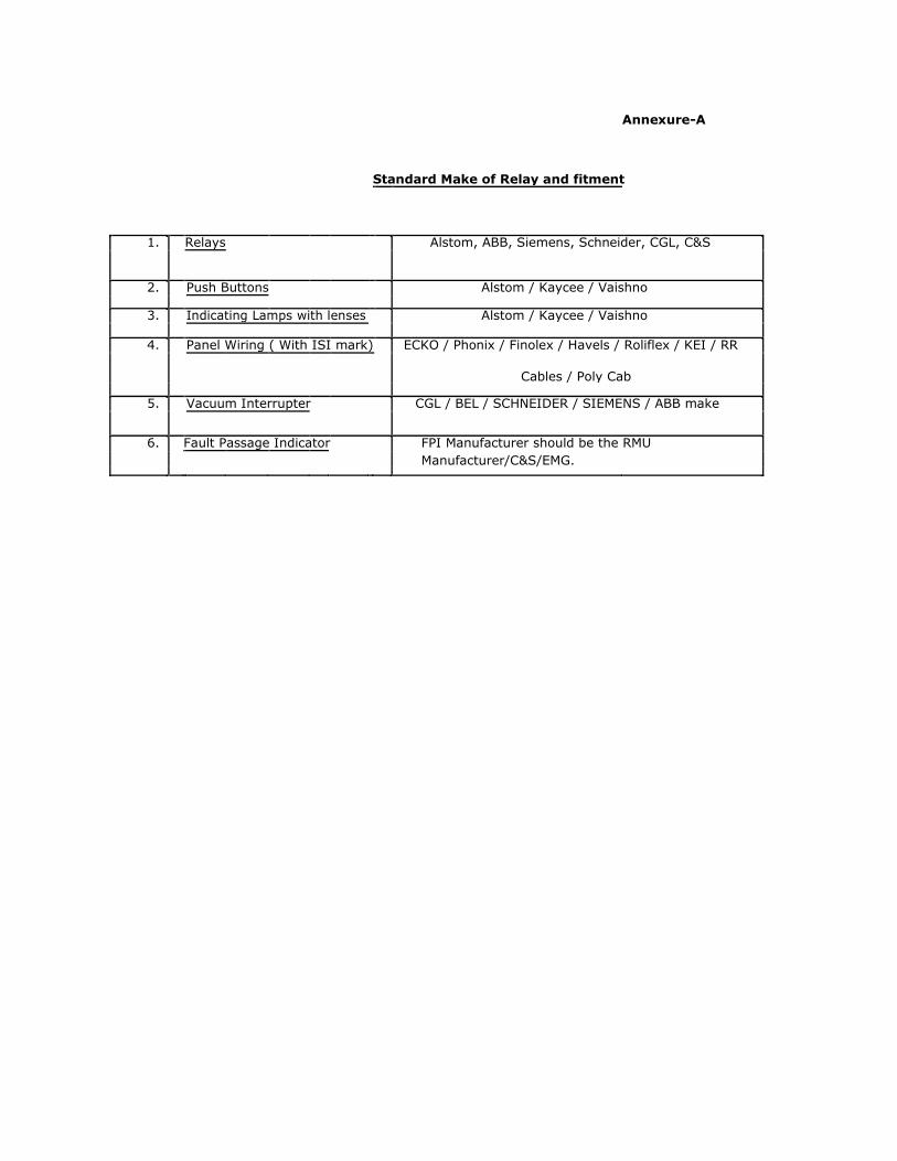
Annexure-A
Standard Make of Relay and fitment
1. Relays Alstom, ABB, Siemens, Schneider, CGL, C&S
2. Push Buttons Alstom / Kaycee / Vaishno
3. Indicating Lamps with lenses Alstom / Kaycee / Vaishno
4. Panel Wiring ( With ISI mark) ECKO / Phonix / Finolex / Havels / Roliflex / KEI / RR
Cables / Poly Cab
5. Vacuum Interrupter CGL / BEL / SCHNEIDER / SIEMENS / ABB make
6. Fault Passage Indicator FPI Manufacturer should be the RMU
Manufacturer/C&S/EMG.

MANDATORY PARAMETERS FOR OUTDOOR THREE PANEL RMU
A. General :
1. Applicable Standard. IEC : 62271-100, 62271-200, IEC60694, IS : 13118
2. Type Outdoor Metal enclosed Compact Non Extensible, Non SCADA, 3 panel RMU
3. Rated Voltage. 11 KV 4. Highest System Voltage 12 KV 5. Phase Three Phase 6. Frequency. 50 Hz 7. Rated Normal Current. 630 Amps 8. Rated Short Circuit Current Capacity Minimum 18.4 KA for 3 Sec. 9. Rated Breaking Current Capacity (min) 18.4 KA 10. Rated Making Capacity As per IS/IEC 11. Insulation Level : 12 KV/28 KV/ 75 KVp 12 Minimum Gas Pressure 1.3 bar at 20°C 13. Dimension of RMU ( H X W X D )(Maximum Limit) 2100mm X 1700mm X 1000 mm 14. Material
a) Tank Stain Less Steel b) Outer Structure Cold Rolled close annealed (CRCA) c) Outdoor enclosure Cold Rolled close annealed (CRCA) 15. Degree of Protection
a) High Voltage live parts, SF6, VCB IP67 b) Front Cover Mechanism IP54 c) Cable Compartment IP3X 16. Internal Arc for main Tank & Cable Chamber Minimum 18.4 KA for 1 Second 17. Temperature Category As per IS/IEC 18. Position of the Power Cable entry of the RMU Rear bottom/Front Bottom side B. Vacuum Circuit Breaker
1. Normal Voltage 11 KV 2. Highest System Voltage 12 KV 3. Frequency 50 Hz 4. No. of Poles Three 5. Rated Current 400 Amps 6. Short Time Current Minimum 18.4 KA for 3 Sec. 7. Breaking Capacity (min) 18.4 KA 8. Making Capacity As per IS 9. Single Phase Capacitor Breaking Capacity 400 A 10. Cable Charging Breaking Capacity 25 A 11. Duty Cycle O – 3 Min – CO – 3 Min - CO 12. Closing time < 50 milli Sec 13. Breaking time < 60 milli Sec 14. Type of operating mechanism Spring charged stored energy type 15. Mechanical Safety Interlock To be provided as per Technical Specification 16. No of Break per Phase One 17. Mechanical Endurance Capacity 2000 Operation 18. Thickness of the Steel Tank 2 mm minimum 19. Thickness of enclosures 2 mm minimum C. Load Break Switch(Three Position) 1. Reference Standard IEC60265, IEC62771-102, IEC62271-200,
IEC60129. 2. Rated Voltage 11000V
3. Highest System Voltage 12000V 4. Rated PF Withstand Voltage(To Earth & between Poles) 28 KV rms 5. Rated PF Withstand Voltage(Across the Isolating 32 KV rms
Distance ) 6. Rated Impulse Withstand Voltage(To Earth & between 75 KVp
Poles)
7. Rated Impulse Withstand Voltage(Across the Isolating 85 KVp Distance )
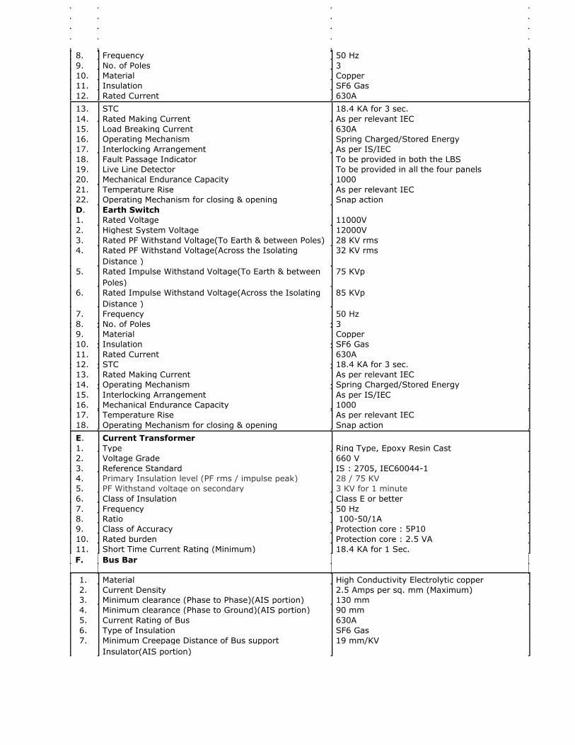
8. Frequency 50 Hz 9. No. of Poles 3 10. Material Copper 11. Insulation SF6 Gas 12. Rated Current 630A 13. STC 18.4 KA for 3 sec. 14. Rated Making Current As per relevant IEC 15. Load Breaking Current 630A 16. Operating Mechanism Spring Charged/Stored Energy 17. Interlocking Arrangement As per IS/IEC 18. Fault Passage Indicator To be provided in both the LBS 19. Live Line Detector To be provided in all the four panels 20. Mechanical Endurance Capacity 1000 21. Temperature Rise As per relevant IEC 22. Operating Mechanism for closing & opening Snap action D. Earth Switch
1. Rated Voltage 11000V 2. Highest System Voltage 12000V 3. Rated PF Withstand Voltage(To Earth & between Poles) 28 KV rms 4. Rated PF Withstand Voltage(Across the Isolating 32 KV rms
Distance )
5. Rated Impulse Withstand Voltage(To Earth & between 75 KVp Poles)
6. Rated Impulse Withstand Voltage(Across the Isolating 85 KVp Distance )
7. Frequency 50 Hz 8. No. of Poles 3 9. Material Copper 10. Insulation SF6 Gas 11. Rated Current 630A 12. STC 18.4 KA for 3 sec. 13. Rated Making Current As per relevant IEC 14. Operating Mechanism Spring Charged/Stored Energy 15. Interlocking Arrangement As per IS/IEC 16. Mechanical Endurance Capacity 1000 17. Temperature Rise As per relevant IEC 18. Operating Mechanism for closing & opening Snap action E. Current Transformer
1. Type Ring Type, Epoxy Resin Cast 2. Voltage Grade 660 V 3. Reference Standard IS : 2705, IEC60044-1 4. Primary Insulation level (PF rms / impulse peak) 28 / 75 KV 5. PF Withstand voltage on secondary 3 KV for 1 minute 6. Class of Insulation Class E or better 7. Frequency 50 Hz 8. Ratio 100-50/1A 9. Class of Accuracy Protection core : 5P10 10. Rated burden Protection core : 2.5 VA 11. Short Time Current Rating (Minimum) 18.4 KA for 1 Sec. F. Bus Bar
1. Material High Conductivity Electrolytic copper 2. Current Density 2.5 Amps per sq. mm (Maximum) 3. Minimum clearance (Phase to Phase)(AIS portion) 130 mm 4. Minimum clearance (Phase to Ground)(AIS portion) 90 mm 5. Current Rating of Bus 630A 6. Type of Insulation SF6 Gas 7. Minimum Creepage Distance of Bus support 19 mm/KV
Insulator(AIS portion)

G. Vacuum Interrupter
1. Make
2. Current Rating
3. Breaking Capacity 4. Mechanical Endurance Capacity
5. Electrical Endurance Capacity
6. Minimum Electrical Life at STC
H. Earth Bus
1. Material
2. Size (Minimum)
CGL / BEL / SCHNEIDER / SIEMENS / ABB 630 A 18.4 KA (min) 10000 Operation 10000 Operation 20 nos full Short Circuit Operation at STC
Electrolytic Copper 90 sq. mm

I. Numerical Relay
1. Make Alstom, ABB, Siemens, Schneider, CGL, C&S
2. Type Series Trip Self Powered
3. O/C & E/F Characteristic IDMTL & DT
4. Current setting range for Over Current(IDMTL) 20-200% in steps of 1%
5. Current setting range for Earth fault(IDMTL) 10-80% in steps of 1%
6. Instantaneous Current setting range for Over Current 100-3000% in steps of 100%
7. Instantaneous Current setting range for Earth fault 100-1200% in steps of 100%
8. No. of Element 3 O/C+1E/F
9. Secondary Current 1A
10. Display Unit LCD Display
11. Burden <2.5VA
12. Type of Case Flush Mounted
J. Painting Powder coating
a) Support Structure RAL 7032
b) Memic RAL 9003
c) Outdoor part RAL7032
d) Thickness Minimum 60 micron
K. Size, Voltage class & Colouring Scheme of Control Voltage Grade, Colour: As per relevant IS Wire standard
Size: CT Circuit–2.5 sq.mm, Control Circuit 1.5 sq.mm L. Accessories
1. Spring Charging Handle One no to be supplied with each unit
2. VCB operating Handle One no to be supplied with each unit
M. Guarantee of the complete Equipment Five Years

Schedule-A
GUARANTEED TECHNICAL PARTICULARS FOR 11 KV NON-EXTENSIBLE 4WAY OUTDOOR RMU
Sl No
A. General :
1. Applicable Standard
2. Type
3. Rated Voltage
4. Highest System Voltage
5. Phase
6. Frequency
7. Rated Normal Current
8. Rated Short Circuit Current Capacity
9. Rated Breaking Current Capacity (min)
10. Rated Making Capacity
11. Insulation Level :
13. Dimension of RMU ( H X W X D )(Maximum Limit)
14. Material and Thickness
a) Tank
b) Outer Structure
c) Outdoor enclosure
15. Degree of Protection
a) High Voltage live parts, SF6, VCB
b) Front Cover Mechanism
c) Cable Compartment
16. Internal Arc for main Tank & Cable Chamber
17. Temperature Category
18. Whether RMU has provision for sensors for
temperature compensated pressure measurement in
the relevant gas compartment to monitor the
pressure of SF6 gas
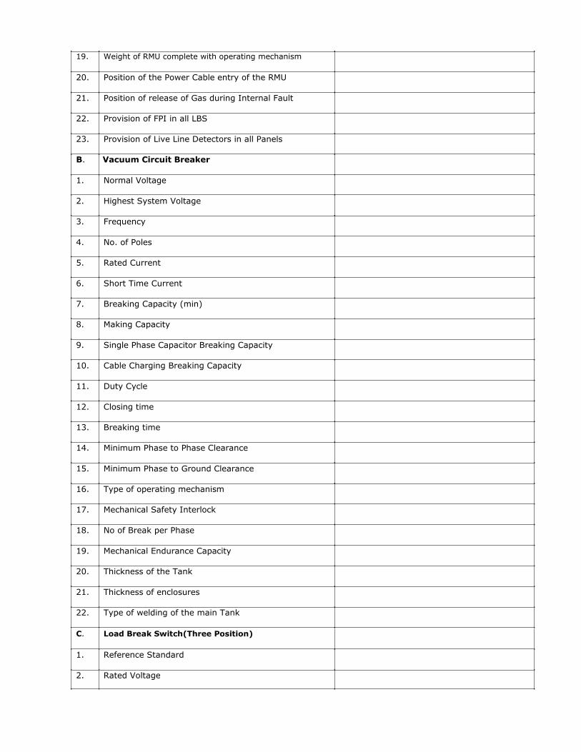
19. Weight of RMU complete with operating mechanism
20. Position of the Power Cable entry of the RMU
21. Position of release of Gas during Internal Fault
22. Provision of FPI in all LBS
23. Provision of Live Line Detectors in all Panels
B. Vacuum Circuit Breaker
1. Normal Voltage
2. Highest System Voltage
3. Frequency
4. No. of Poles
5. Rated Current
6. Short Time Current
7. Breaking Capacity (min)
8. Making Capacity
9. Single Phase Capacitor Breaking Capacity
10. Cable Charging Breaking Capacity
11. Duty Cycle
12. Closing time
13. Breaking time
14. Minimum Phase to Phase Clearance
15. Minimum Phase to Ground Clearance
16. Type of operating mechanism
17. Mechanical Safety Interlock
18. No of Break per Phase
19. Mechanical Endurance Capacity
20. Thickness of the Tank
21. Thickness of enclosures
22. Type of welding of the main Tank
C.
1.
2.
Load Break Switch(Three Position) Reference Standard Rated Voltage
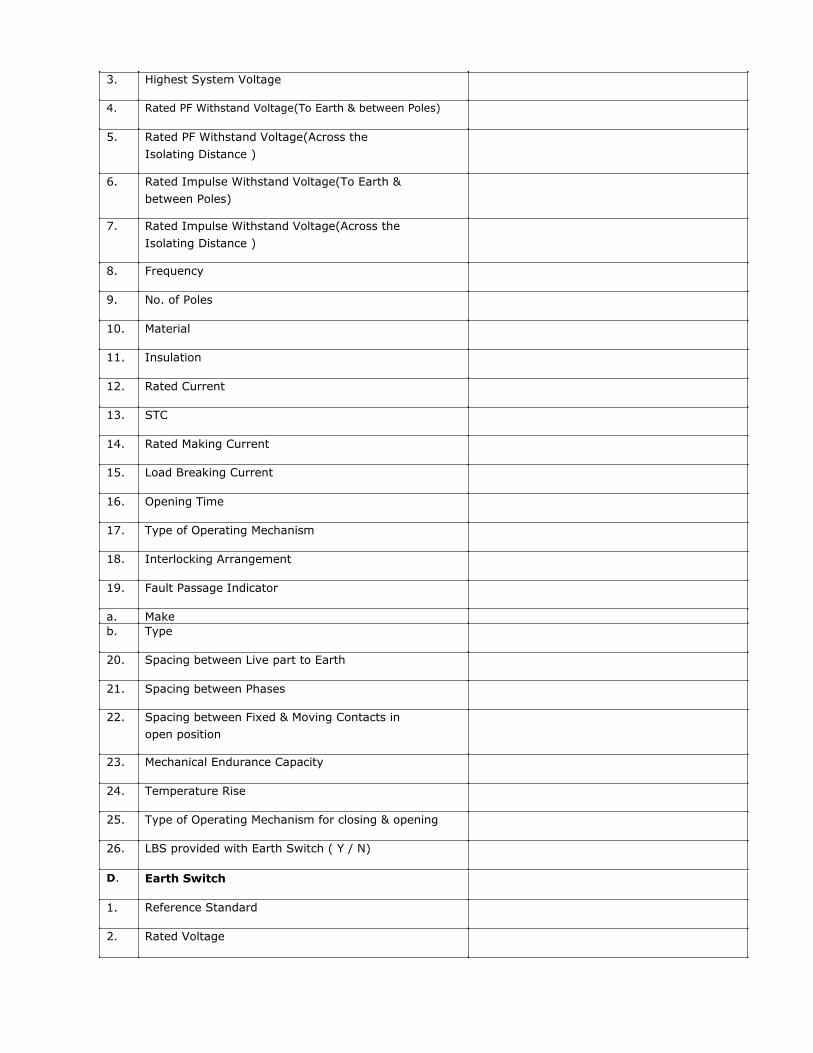
3. Highest System Voltage
4. Rated PF Withstand Voltage(To Earth & between Poles)
5. Rated PF Withstand Voltage(Across the
Isolating Distance )
6. Rated Impulse Withstand Voltage(To Earth &
between Poles)
7. Rated Impulse Withstand Voltage(Across the
Isolating Distance )
8. Frequency
9. No. of Poles
10. Material
11. Insulation
12. Rated Current
13. STC
14. Rated Making Current
15. Load Breaking Current
16. Opening Time
17. Type of Operating Mechanism
18. Interlocking Arrangement
19. Fault Passage Indicator
a. Make b. Type
20. Spacing between Live part to Earth
21. Spacing between Phases
22. Spacing between Fixed & Moving Contacts in
open position
23. Mechanical Endurance Capacity
24. Temperature Rise
25. Type of Operating Mechanism for closing & opening
26. LBS provided with Earth Switch ( Y / N)
D.
1.
2.
Earth Switch Reference Standard Rated Voltage

3. Highest System Voltage
4. Rated PF Withstand Voltage(To Earth & between Poles)
5. Rated PF Withstand Voltage(Across the
Isolating Distance )
6. Rated Impulse Withstand Voltage(To Earth &
between Poles)
7. Rated Impulse Withstand Voltage(Across the
Isolating Distance )
8. Frequency
9. No. of Poles
10. Material
11. Insulation
12. Rated Current
13. STC
14. Rated Making Current
15. Opening Time
16. Type of Operating Mechanism
17. Interlocking Arrangement
18. Spacing between Fixed & Moving Contacts in
open position
19. Mechanical Endurance Capacity
20. Temperature Rise
21. Type of Operating Mechanism for closing & opening
E. Current Transformer
1. Make
2. Type
3. Voltage Grade
4. Reference Standard
5. Primary Insulation level (PF rms / impulse peak)
6. One minute PF withstand Voltage on Secondary
7. Class of Insulation
8. Frequency
9. Ratio

10. Class of Accuracy
11. Rated burden
12. STC for 1 second
13. Continuous Over Load in percentage
F. Bus Bar
1. Material
3. Maximum Current Density
4. Minimum clearance (Phase to Phase)(AIS portion)
5. Minimum clearance (Phase to Ground)(AIS portion)
6. Cross sectional area of the Bus
7. Current Rating of Bus
8. Type of Insulation
9. Minimum Creepage Distance of Bus
support Insulator(AIS portion)
G. Vaccum Interrupter
1. Make
2. Type & Model
3. Current Rating
4. STC 5. Breaking Capacity
6. Mechanical Endurance Capacity
7. Electrical Endurance Capacity
8. Minimum Electrical Life at STC
H. Earth Bus
1. Material
2. Size (Minimum)
I. Numerical Relay
1. Applicable Standard
2. Make
3. Type
4. Model No
5. Current setting range for Over Current(IDMTL) 6. Current setting range for Earth fault(IDMTL)
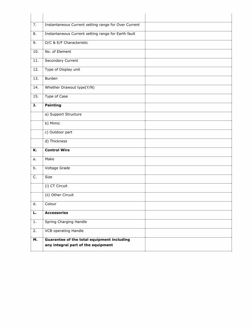
7. Instantaneous Current setting range for Over Current
8. Instantaneous Current setting range for Earth fault
9. O/C & E/F Characteristic
10. No. of Element
11. Secondary Current
12. Type of Display unit
13. Burden
14. Whether Drawout type(Y/N)
15. Type of Case
J. Painting
a) Support Structure
b) Mimic
c) Outdoor part
d) Thickness
K. Control Wire
a. Make
b. Voltage Grade
C. Size
(i) CT Circuit
(ii) Other Circuit
d. Colour
L. Accessories
1. Spring Charging Handle
2. VCB operating Handle
M. Guarantee of the total equipment including
any integral part of the equipment
Signature Not IST
Location: West Bengal
Copyright © 2022 FDOKUMEN