t. - WBSEDCL
24
WEST BF,NGAL STATE ELECTRICITY DISTRIBUTION COMPANY LIMITED Technical Specirication tor AC 3 Phase 4 Wire 240V LT CT Operated F`illy Static AM R Compatible liant Category CI Tri Vector Energy Meter of o.5s Accuracy Class and 200/SA CTR DLMS Comp I.0 SCOPE: This scope covei.s design, engiiieering, manufactui.e, assembly, inspection. testing at maiiufacturer's woi.ks before dispatch, supply and delivery at destination anywhei.e in the state ot` West Bengal of AC 3 Phase 4 Wire 240V LT CT Operated Fully Static AMR Com|)atible DLMS Compli<int Category CITri Vector Energy Meter of 0.5s Accuracy Class and 200/5A CTR with backlit LCD displa)J iiscd foi. balanced/unbalanced load. The meter shall be capable of measui.ing, recording and displaying difl`erent electrical parameters listed elsewhere in the document including Active Energy in kwh, Reactive Energy ill kvArh, Apparent Energy in ` kvAh over a Power Factoi. I.ange of` Zero Lag to Unity to Zei.o Lead Meter shall have facility of recording famper information & load survey data in nonvolatile memory. These meters shaH have comniunication port for remote meter reading. :;:S:::etrh:h'an,t,e::::osrpmec,Lfya:,°r::::tee(I:oh:::|ns:i]],tdhaerddset:i':n°gf„t`¥:,i:;',8:e::g¢`Ca°nn:trwu::k°J:a?,:h|;t::.dHs°h:I:V:: capable of perfoi.ming commercial operation coiitinuously in a manner acceptable to WBSEDCL, who will interpret the meanings of drawings &specification and shall have.the right to reject any woi.k c)r material which in its judgment is not in accoi.dance herewith. The meter shall be complete \`'ith all coiTiponents, accessories necessai.y for tlieir effective and trouble fi.ee operation for the pui.pose meii[ioned above. Such components shall be deemed to I)e within the scope ot` bidder's supply irl.espective of whetlier those are specifically mentioned or not in this specification or in the commercial order. 2.0 APPLICATION: ConsumerMeter 3.0 STANDARDS APPLICABLE: Unless specit-led elsewhere jn this specification, the perfoi.mance & testing of the meters shall conform to the following Indian / International standards, to be read with Its up-to-date and fhtd latest amendments / revisions thereof as on 90 days prior to [loating or the tenaei.. Sl.No.I Standard No.ls146`)7(1999) Title AC Static Transformei. Opei.ated Watt hour and VAR lioiir Metel.s 2 CBIP Repoil No. 325 & its latest Specification for AC Static Electi ical Energ}J MetersDataExchangefoi-Electricit)JMetci-ReadingTariffand amendments, i f any' ls 15959(2011 ) read with latest . amendments, if an,vCBIPTechnicalRepol.t No.Illls12346(1999)&itslatestamendments, Load Control Companion Specification 45 Specification for Commoii Meter Reading I nstrunient Testing Equipmeiit t`or AC Electrical Energy Meters ifa'|y 4.0 CLIMATIC CONDITIONS: The meters to be supplied shalt be capable ot` maintaining requirpd €`ccui.acy undei liot, tropical and dusty climatic coiiditions. The motel.s shall be siiitably designed and tl.cated for noiiT`al llfe and sa[isractory operation under hot and hazardous ti.opical climatic conditioiis and shall be dust and vermm proof. All the parts and surface, which are subject to coriosion. shall either be made ot` such matei.ial or shall be provided with such protective finish which provides suitable protection to tliem t`rom any injurioiis et`fect of excessive hiimidity. The meters to be siipplied shall be suitable foi. satisfactor}' continuous operation under the t`ollowlng tropical `conditions. 4. I Maximum Ambient Alr Temperatui.e lil `hnde. 55" C Minimuni Ambient Air Temperatul.i>: (-) 10" C 4.3 Maximum Relative Humidit}J: 95%(non-condensing) EEI,i l-S for A(I ..I I'Iiasc 4 Wlrc 240V I i C I ()pcriiled I-`ully Static ^MR ('oi`ii)iilihlc frtyz fry ,4# P:tEe I |'t-2J i`:.,. I)I MS C`umpltzii`l Czilegury tl. ,;t.-
-
Upload
khangminh22 -
Category
Documents
-
view
0 -
download
0
Transcript of t. - WBSEDCL
WEST BF,NGAL STATE ELECTRICITY DISTRIBUTION COMPANY LIMITED
Technical Specirication tor AC 3 Phase 4 Wire 240V LT CT Operated F`illy Static AM R Compatibleliant Category CI Tri Vector Energy Meter of o.5s Accuracy Class and 200/SA CTRDLMS Comp
I.0 SCOPE:This scope covei.s design, engiiieering, manufactui.e, assembly, inspection. testing at maiiufacturer's woi.ks
before dispatch, supply and delivery at destination anywhei.e in the state ot` West Bengal of AC 3 Phase 4 Wire
240V LT CT Operated Fully Static AMR Com|)atible DLMS Compli<int Category CITri Vector EnergyMeter of 0.5s Accuracy Class and 200/5A CTR with backlit LCD displa)J iiscd foi. balanced/unbalanced load.
The meter shall be capable of measui.ing, recording and displaying difl`erent electrical parameters listed
elsewhere in the document including Active Energy in kwh, Reactive Energy ill kvArh, Apparent Energy in` kvAh over a Power Factoi. I.ange of` Zero Lag to Unity to Zei.o Lead Meter shall have facility of recording
famper information & load survey data in nonvolatile memory. These meters shaH have comniunication port for
remote meter reading.
:;:S:::etrh:h'an,t,e::::osrpmec,Lfya:,°r::::tee(I:oh:::|ns:i]],tdhaerddset:i':n°gf„t`¥:,i:;',8:e::g¢`Ca°nn:trwu::k°J:a?,:h|;t::.dHs°h:I:V::capable of perfoi.ming commercial operation coiitinuously in a manner acceptable to WBSEDCL, who will
interpret the meanings of drawings &specification and shall have.the right to reject any woi.k c)r material which
in its judgment is not in accoi.dance herewith. The meter shall be complete \`'ith all coiTiponents, accessories
necessai.y for tlieir effective and trouble fi.ee operation for the pui.pose meii[ioned above. Such components shall
be deemed to I)e within the scope ot` bidder's supply irl.espective of whetlier those are specifically mentioned or
not in this specification or in the commercial order.
2.0 APPLICATION: ConsumerMeter
3.0 STANDARDS APPLICABLE: Unless specit-led elsewhere jn this specification, the perfoi.mance & testing of
the meters shall conform to the following Indian / International standards, to be read with Its up-to-date andfhtdlatest amendments / revisions thereof as on 90 days prior to [loating or the tenaei..
Sl.No.I Standard No.ls146`)7(1999) Title
AC Static Transformei. Opei.ated Watt hour and VARlioiir Metel.s
2CBIP Repoil No. 325 & its latest Specification for AC Static Electi ical Energ}J MetersDataExchangefoi-Electricit)JMetci-ReadingTariffandamendments, i f any'
ls 15959(2011 ) read with latest.amendments, if an,vCBIPTechnicalRepol.t No.Illls12346(1999)&itslatestamendments, Load Control Companion Specification
45 Specification for Commoii Meter Reading I nstrunient
Testing Equipmeiit t`or AC Electrical Energy Metersifa'|y
4.0 CLIMATIC CONDITIONS:The meters to be supplied shalt be capable ot` maintaining requirpd €`ccui.acy undei liot, tropical and dusty
climatic coiiditions. The motel.s shall be siiitably designed and tl.cated for noiiT`al llfe and sa[isractory operation
under hot and hazardous ti.opical climatic conditioiis and shall be dust and vermm proof. All the parts and
surface, which are subject to coriosion. shall either be made ot` such matei.ial or shall be provided with such
protective finish which provides suitable protection to tliem t`rom any injurioiis et`fect of excessive hiimidity.
The meters to be siipplied shall be suitable foi. satisfactor}' continuous operation under the t`ollowlng tropical`conditions.
4. I Maximum Ambient Alr Temperatui.e lil `hnde. 55" C
Minimuni Ambient Air Temperatul.i>: (-) 10" C
4.3 Maximum Relative Humidit}J: 95%(non-condensing)EEI,il-S for A(I ..I I'Iiasc 4 Wlrc 240V I i C I ()pcriiled I-`ully Static ^MR ('oi`ii)iilihlc
frtyz fry ,4# P:tEe I |'t-2J
i`:.,.
I)I MS C`umpltzii`l Czilegury
tl. ,;t.-

4.4 Minimum Relative llumidity: loo/o
4.5 Height above mean sea leve]: Up to 3000 meters
4.6 Average nuiTiber of months for Tropical Monsoon per Annum: 5
4.7 Annual Rainfall: loo mm to ]500 mm
4.8 Maximum Wind Pressure: 150 Kg/Sqm
5.0 SUPPLY SYSTEM:
SystemRatedVoltage (Vref) 3 Phase 4 Wire4]5V Ph-Ph or 240V Ph-N
Voltage Range forOperationRatedCuITent(li,) & CT70% to ]20% of Vrer
5A, balanced and unbalanced loadRatio CTR: 200/5A for LT CT(3P, 4W)Maximum ContinuousCurrent(lmax)RatedFi.equencyFrequencyvariation I
10A
50Hz50Hz +5%
6.0 POWER FACTOR RANGE: Power Factor Range shall be Zero (Lag) - Unity -Zero (Lead). The meter shaH
be lag only.
7.0 ACCURACY CLASS:7.1 Class of Accuracy of the metei. shall be o.5s.
7.2 Maximum error limit at 1%lb and UPF shall not exceed ±1%.
7.3 There shall be no diift in accuracy, at least for a period of ten years from the date of its supply. In case
any di.ift is noticed wtiich is beyond the permissible limits, the metei. shaH have to be replaced with a
new one f`ree of`cost.
8.0 POWERCONSUMPTION:8.1 Vollage Circuit: The active and apparent power consumption in the voltage circuit per phase at
reference voltage. reference temperature and refel.ei]ce fl.eqiiency shaH be within I .5W and 10VA as
per_ ls ]4697.8.2 Current Grcuit: The appal.ent power taken by ciliTent circuit phase wise at basic current` reference
frequency and I.eference temperature shall be within I.0 VA as per IS 14697.
9.0 STARTING CURRENT & RUNNING AT NO LOAD:• 9.I The meter shaH start I.egistering energy at 0.1% of lb(basic current) at UPF(Unity Power Factor) and
shall be f`ully functional within five secolids after the rated voltage js applied.
9.2 Running at No Load: When 70% & 120% of vref (Reference Voltage) is applied and no current flows
jn the current circuit, the test output of the metei. shaH not produce nioi.e than one pulse.
10.0 MAXIMUM CONTINUOUS CURRENT: The maximum continuous cun.ent ln meters shaH be the current at
which the meter purports to meet the accuracy requii.ement of the specification. The same is indicated ].n table in
Supply System clause of this specification.
11.0 CONSTRUCTloN:11.I The case, winding. voltage circuit, sealing arrangements, registers, termmal block. terminal cover &
name plate etc. shall be in accordance with the relevant standards. The meter shaH be compact &
reliable in design, easy to t].ansport & immune to vibration & shock involved in the transportation &
haridling. The construction of the meter shall ensure consjstence performance under all conditions
especially diiring he'avy rains / very hot weathers. The insulating materials used in the meter shall
be iion-hygl.oscopic, non-ageing & have tested quality.•\.i.` .
\ l;A(3Pl`dseJ#C;rdl#alic ^MR Compfltiblc
l`(`r B'JII| C`()I,sumer2 ot' 24
•:`'
frMscompi'dfc}goryc'q7r&Met2zIrth
I I.2 The meter shall be sealed in such a way that the internal parts of the meter becomes inaccessible
and attempts to open the meter shall I.esult in viable damage to the metei. cover i.e. of break-to-open
type. This is to be achieved by using continuous Ultrasoliic welcling on all the four sides of the
Meter base and covei-or any other technology which is either equally or moi.e efficacious.
I I.3 The meter shall comply with latest technolog}J siicli as Micl.ocoiitroller or Application Specific
Integrated Cii.ciiit (ASTC) to eiisui'F reliable performance. The mounting of the components on the
PCB shall compiilsorily be Surface Mounted Technology (SMT) type. Power supply component
may be of PTH type. The electronic components used in the meter shall be ot.high quality and there
shall be no drift in the accuracy ot` the meter for at least tell years. The cjrciiitry of the meter shall be
compatible with 16 Bit (or better) ASIC with compatible processor and meter shall be based on
Digital measuring and sampling technique.
I I.4 The meter shall be housed in a saf`e, high gi.ade, unbreakable, fire resistant, UV stabilized virgin
Polycarbonate/ High Grade Engineering plastic / Thermosetting Plastic casing of projection
mounting type. The meter cover shall be transparem / traiislucent. But the viewiiig portion sliall be
transparent for easy reading of displayed parametei`s and observation of operation indicators. The
meter base may not be transparent, but it shall not be black in color. The meter casing shall not
change in shape, color, size and djmeiisions when siibjected to 72hrs on UV test as pet. ASTMD
53.It shall withstand 650 deg. C. glow wire test and heat dcflection test as per lso 75 or as per IEC
60068 -2-5.
I I.5 ln additioii to the above, the meter cover shall be sealable to the meter base with at least 2 no. of
manufactui.er`s bar coded seals bi`aiing the identitlcation marks of the manufactui.er. Suitable
arrangement shall be iTiade for fitting/fixing ot` utility seal at two sjdes of metei. terminal cover in
such a manner that any access to the terminal cannot be made possible without removing the seal.
There sliall also be provision for sealing both the communication ports (Optical and RS232/RJ] I).
11.6 The polycarbonate material ofonl}J the followiiig manufacturci.s shall be used:
• 11.6.I G.E. PLASTIC: LEXAN 943A or eqiiivalent like 943,123R,143 t`or meter cover
&terminal cover / LEXAN 503R or equivalent liT(e 500,143R, 500R for meter base and
terniinal block.
11.6.2 BAYER:
11.6.3 DOwchemical:
11.6.4 M]TSUBISHl:
11.6.5 l`TEJ'N :
11.6.6 DUPONT:
Gi.ade corresponding to above--do--
--do--
--do--
--do-
12.0 METER CASE AND COVER:]2.I ln case, ultrasonic welding using plate / strii) is used, the malerial of plate / strip shall be same as
that of cover and base and the strip shall flush with meter body. I`he manufacturei-'s logo shall be
embossed on the strip / plate. The material of the meter bod case and cover shall be of
Enrineering Plastlc.
122 The ITieter cover shall be rixed to the nreter base (case) with Unidirectional Screws, so that the samecannot be opened by use of sci€wdrivers. These unidirectional screws shall be covered withtralispai€nt caps (not required t`or screw less desigii), ultrasonically welded with th€ meter body andthe screw' covers shall be embedded in the meter bocly in a groove. Tlie rrieter shall withstancldextemal magnetic infliience as per latest amendments ot` CBIP Technical Report No.325 including0 2T AC Magnet, 0 5T Permanent magnet.
13.0 TERMINAL BLOCK AND COYER:13.I The terminals slrall be groupe{l in a terminal block havii`g zidequnte insulating properties and
mechanical strength. The terminal block shall be made roni I)cs[ quality non-hygroscopic, flame
retardant material (capable of passing the flammability tests) with nickel plated bi-ass inserts / alloy
mEEPLF Pliiisc 4 V,'ire 240V L'r CT 0pcriiled l``ill,\ StMli` ^MR C.onii)iilible I)I MS C'umpllaiit (,I.ilt;g
fry/ fry dr# :tge 3 ot` 2,
&q3,E>,
} C` I TI I Vector I.:nerg} Meter

inserts for connecting termimals.1t shall be rigidly fixed to the base of the meter so that it cannot be
separated from the meter base without breaking either the meter base or the teminal block and thisfixing arrangement shall be in parallel to the meter base in such a way that it cannot be viewed or
approached from any part of the meter without breaking the meter.
132 The teminals in the terminal block shall be of adequate length in order to have proper grip of
conductor with the help of screw adjustable metal plates to increase the sui.face of contact andreduce the contact liesistance. The screws shall have thread size not less than M4 and head having 6
mm. diameters. The screws shall not have pointed ends at the end of threads. All terminals and
cormecting screws and washers shall be of tiniied / nickel plated brass materjal. Tlie terminal shall
withstand glow wire test at 960 + 15 °C and the terminal shall withstand at least 135 ac as per [S.
13.3 The internal diameter of terminal hole shall be minimum 5.5 mm and center to center distance shall
be 13 mm. The holes in the insufating materlal shall be of. sufficient size to accommodate the
insulahon of conductor also.
13.4 The terminal cover shall be transparent rerenforced Polycarbonate, Engineering Plastic with
minimum 2.0 mm thickness and the terminal cover shall be of extended type completely covermgthe terminal block and fixing holes. The space irisia:e the terminal cover shall be suffroient to
accommodate adequate length of external cables. The terminal cover shall orefdrablv be detachable.
13.5 The terminals and all cormecting sci.ews will be of suitable material capable of withstanding a
current of 150% of l„,ax for two hoius, continuously and the meter shall be capable of providing
phase to neutral protection up to 4] 5V for I (one) hour followed by accuracy testing as per relevantls.
14.0 MARKING OF THE METER:Every meter shall have a mamaplate clearly visible and indeltole and distinctly marked in accoi.dance with the
relevant Standard mentioning "Category -Cl ".
The marking on the meter shall be in accordance with relevant clauses of ls 14697 and stiall appear on anexternal plate attached to the meter cover. The basic marking on the meter nameplate shall be as follows. Allother markings as per ls shall also be there.
I 4.1 Manufacturer's name & trade mark
I 4.2 Type Designa.tion
14.3 No. of phases & wires
144 Serialnumber(Sizenotlessthan5mm)
14.5 Month & year of manufacture
14.6 Reference voltage
14.7 Rated secoTidary current (Il))
14.8 Rated Maximum current (Imax)
14.9 CT Ratio (200/5A)
14.10 Operating Frequency
14.11 Principal unit(s) ot`measurement
]4.12 Melercoilstant(inlpulse/kwh)
14.13 Classindexofmeter
;!-.i -
14.]4 "Property ofwBSEDCL"
14.15 PurchaseorderNo. & Date
14.I 6 Giiarantee (Guaranteed fo]. a period of`5 '/2 years fi.om the date of.delivery )
14.17 BIsmarking& Licenseno.
14.18 Placeot`maiiufacture
14.19 Barcode for meter serial no. in alpha numeiic foriii, date of manufacture, current
I.ating of the meter and PO refereiice` I.cadable by single layer barcodc reader.
TS for AC 3 Phase 4 WHe 240V lit CI Operated [`ul
Y fty'®'uJJr'#'#CJSl{`[ic ^MR C.oiiipatiblc I)I.MS C'ompliai`t Category C`l `rri Vector Energy Meter
ge 4 ``t` 24
`;.T.. `
EL P} VI€ c`th,
14.20 The reference temperatiire if different from 27 °C.
14.21 The sign ofDouble square for insulating encased meters.
14.22 Firmware version
15.0 CONNECTloN DIAGRAM AND TERMINAL MARKING: Ever}' meter shall be indelibly marked with a
diagram of connection. For the pol.yphase meteis, this diagi.am shall also show tlie phase sequence for which the
meter is intended lt is pemiissible to indrcale the connection diagi.am `)y an identification figiii.e in accordance
with relevant standards. The marking of meter terminals shall appear on this diagram
16.0 DISPLAY 0F MEASURED VALUES:16.I The meter shall have alphanumeric display wlth at least 7 full digits with LCD backlit display,
having minimum character helght of.10 mm. The liieter display shall have 7 digits(complete) for
energy counter with alphanumeric digits for parametel identifier and tamper indication.
]6.2 Visibility of display in poor ligllt conditioiis is an important criterioi`. STN oT TN or any better type
of advanced LCD to be used. Proper legends for the displayed parameters to be provided (Factory
programmable). Back lit provided for clear visibillty shan be unifom throughout all part ol` theLCD.
16.3 lt shall be possible to easily identify tlie siiigle`or multiple displayed parameters through
symbols/legends on the meter display itself or through display annunciation which shall be self
explanatory and symmetric.
16.4 1n addition to iiameplate` serial number of the meter shall have to be programmed into meter
memory for its Identification tlirough CMRI / Laptop / meter I.eadiiig printout where data shall be
downloaded through communication port.
16.5 The meters shall have auto-display mode for pre-selected parametei.s Push-Button mode of display
shall display all pal.ameters and it shall have priority over aiito mode.
16.6 Each paramete]. shall be on metei. display for 10 see aiid the time gap betweeli two`auto display
cycles shall be 20 see.
16.7 Meter shall have Scroll Lock facility to display any one desired parameter coi`tinuously t`rom
display parametei.s.
16.8 The meter shall give cleai. message on display to indicate that the metei-has experienced tampers
and the natui.e of` tamper with date and time ot` first occurrence. last occurrence and last restoration.
if the last tamper status is iiot restored, then meter w" iiidicate first occurrence. last restoration and
last occuiTence.
16.9 Connection check, Phase sequence and Se]fdiagnostic` shall give clear message on display.
16.10 The metel. shall have a test outpiit (blinking LED) accessible from the front and be capable of being
moi`itqred with suitable testiiig equipment. The operation iiidicator miist be visible.fi.om the front.
Test output device shall be pi.ovided in the form of orie comnion LED for active and reactive eiiergy
with the provision of selecting the parameter bemg tested (separate LED may also be used with
proper separation).
17.0 DISPLAY SEQUENCE: The meter shall display tlie ieqilired parameters in two different modes as follows.
Display sequence for both Aiito and Push Button must be maintained` no interchange in sequence or display
parameter will be accepted. AH tlie displa}' shall have proper legend to identify the same.17.I Auto Display Mode: The foHowingparameters shaH be displayed in auto cycle mode. in the following
sequence.
17.I.I LCDcheck(All segmentcheck on display)
17.I.2 Connection check /Phase sequence (Voltage & Current)
17.1.3 Metel. Sei-ial Number B]S
17.I.4 Real'Day/ Date (dd:mm:y}')
17.I.5 RealTime(hh:mm:ss)
17.I.6 Rising Demand witli elapsed time
17.I.7 R-Phase toNeuti.al vollage
17.I.8 Y-Phase to Neuti.al voltage
TS for A( `.t Pltiise 4 Wuc 240V Ill-` I ()per.lied I `ill} ``latle ^MR l`oiii|){itiblc I)I MS Compliai]i (`alegor\tcI I`ii Veclor rnerg} Meterr\
" 8, . bz 49 -W•.\t\.`
lhagr fry grth#
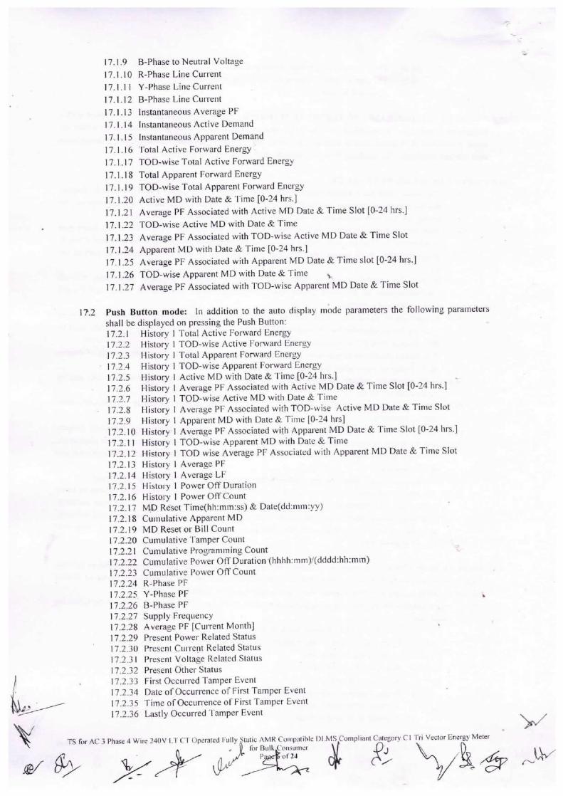
17.I.9 B-Phase toNeutral voltage
17.I.10 R-Phase Line Current
17.I.11 Y-Phase Line Gun.ent
17.I.12 B-Phase Line Current
17.I.13 Instantaneous Average PF
17.1.14 Instantaneous Active Demand
17`1.15 Instantaneous Apparent Demand
17. I .16 Total Active Forward Energy
17.1.17 TOD-wise Total Active Forward Energy
I 7.1.18 Total Apparent forward Energy
17.I .19 TOD-wise Total Apparent Forward Enei.gy
17. I .20 Active MD with Date & Time [0-24 hrs.I
17. I .21 Average PF Associated with Active MD Date & Time Slot [0-24 hrs.]
17. I .22 TOD-wise Active MD with Date & Time
17.I.23 Average PF Associated with TOD-wise Active MD Date & Time Slot
17. I .24 Appal.ent MD with Date & Time [0-24 hrs.]
17. I .25 Average PF Associated with Apparent MD Date & Time slot [0-24 hrs.]]7.I.26 TOD-wiseApparentMDwith Date&Time `
17. I .27 Average PF Associated with TOD-wise Apparent MD Date & Time Slot
17.2 Push Button mode: ln addition to the auto display made parameters the following parametersshall be displayed on pressirig the Push Button:17.2.I History I Total Active Forward Energy17.2.2 History I TOD-wise Active F`orward Energy17.2.3 History I Total Apparent Forward Enei.gy
I 17.2.4 History I TOD-wise ApparentForward Energy
17.2.5 History I Active MD with Date &Time [0-24 hrs.]17.2.6 mstory I Average PF Assc>ciated with Active MD Date & Time Slot [0-24 hrs.]i7.2.7 History I17.2.8 History I
17.2.9 History I
17.2.10 History I
]7.2.11 History I
17.2.12 History I
17.2.13 History I
17.2.14 History 1
17.2.15 Histoi'y 1
17.2.16 rlistory I
TOD-wise Active MD with Date & TimeAverage PF Associated with TOD-wise Active MD Date & Tinie S]otApparent MD with Date & Tiiiie [0-24 hrs]Average PF Associated with AppareTlt MD Date & Time Slot [0-24 hrs.]TOD-wise Apparent MD with Date & TimeTOD wise Average PF Associated with Apparent MD Date & Time SlotAverage PFAverage LFPower Off DurationPower Off Count
17.2.17 MD Re.set Time(hh:mm:ss) & Date(dd:mm:yy)17.2.I 8 Cumulative Apparent MD17.2.19 MD Reset or Bill Count17.2.20 Cumiilative Tamper Count17.2.21 Cumulative programming count17.2.22 Cumulative Power off Duration.(hhhh:mm)/(dddd:hh:mm)17.2.23 Cumulative Power offcoum17.2.24 R-Phase PF17.2.25 Y-Phase pF]7.2.26 B-Phase pF17.2.27 Supply Frequency17.2.28 Average PF [Cui.rent Month]17.2.29 Present Power Related Status17.2.30 Present CulTent Related Status17.2.31 Present Voltage Related Statiis
17.2.32 Present c)ther statusI 7.2.33 F`irst OcculTed Tamper Event17.2.34 Date ot`Occuri-ence of First Tamper Event17.2.35 Time of occun.ence of F`irst Tamper Event17.2.36 Lastly Occurred Tamper Event
TS for ^C 3 Phase 4 W'`re 240V I T C.T Operated
Of gyAy 2x rfu^MR Col`ii)iltlble I)lMS,C`ompliaiit Category. C 1 Tri Vector Ener.g}J Meter
`.-`
# f? fty&¢ r-IV
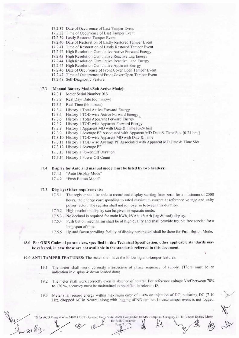
]7.2.37 Date of occurrence of Last Tamper F,vent17.2.38 Time of occurrence of I,ast Tamper F,vent]7.2.39 Lastly Restored Tamper Event17.2.40 Date of Restoration of Lastly Restored Tamper Event17.2.4] Time of Restoration of Lastly Restored Tamper Event]7.2.42 Higli Resoliition Culii\Ilative Active F`oi.wa].d Energy
17.2.43 [Iigh Resolution Cuiiiiilative Reactive Lag Energy17.2.44 High Resolutlon Cumulative Reactive Lead Enei.gy17.2.45 High Resoliition Cumulative Appal.eiit Energy
17.2.46 Date of occurrence of F`ront C`ovei. Open Tamper Event17.2.47 Time of Occui.rence of Front Cover Open Tamper Event17.2.48 Self-Diagnostic Feature
]7.3 |Manual Battery Mode/Sub Active Model:17.3.I Meterseiial NumberBIS
17.3.2 Real Day/ Date (dd:m"yy)
17.3.3 Real Time(hh:nim:ss)
17.3.4 History I Total Active Forward Energy
: ;:::: E:::::; : :9,E.X;speafecnttjvFeof;::ydarEdn:rngeyrgy `]7.3.7 History I TOD-wise Apparent Forward Energy]7.3.8 History I Apparent MD with Date & Time [0.-24 hrs]17.3.9 Llistoi.y I Average PF Associated with Apparent MD Date & Time Slot [0-24 lirs.]]7.3.]0 Histoi.y I TOD-wise Apparent MD with Date & Time17.3.11 Llistory I TOD wise Average PF Associated witll Apparent MD Date & Time Slot17.3.12 History I Average PF
17.3.13 History I Powel.Off Duration
17.3.14 History I Poweroffcount
17.4 Display for Aiitoand manual mode must be listed by two l`eaders:
17.4.I "Auto Display Mode"
17.4.2 .`Push Button Mode"
17.5 Display: Other requirements:
17.5. I The registel` shall be able to I-ecoi.d aiid display stai.ting fi.om zero, for a niinimum of 2500
hours, the energy corresponding to rated maximum current at ret`erence voltage and unity
power factor. The I.egister shall not roll over in between this dul.ation.17.5.2 High rcsoliition display can be given in sepai.ate niode.
I 7.5.3 I ` No `decimal is required for main kwh, kvAh, kvAi.h (lag & lead) display.
17.5.4 Push button mechanism shall be of high quality and shall provide trouble t`ree service for a
long span of time.
17.5.5 Up and Dowii scrolling facility ot`display pal.ameters shall be there for Push Bu.ttoii Mode.
18.0 For OBIS Codes of parameters, specified ill tliis Technical Specirication, otlier applicable standards maybe referred, in case those are not available in the standards referred in this document.
19.0 ANTI TAMPER FEATURES: Tlie meter sliall have lhL> following ailti-taniper fea[ui.es:
19.I The meter shall work correctly iri.espective of phase sequence of supply. (There must be anindication in display & down loaded data).
19.2 The liie[er shall uJork correctly even in absence ot`neiitral. F`or reference voltage Vi.ef between 70%to 120 %, accuracy must I)a maintained as specified in relevant ls.
19.3 Meter shall record eliei.gy wi[liin maximum ci.ror of.i 4°,7o on injection of DC, puls;ting DC (7-10Hz), chopped AC in Neutral along with loggiiig orND tamper. In case tamper cveiit is not logged,
•`\b:.` . .
TS for ^C 3 Phase 4 Wlrc 240V I I 1` 1 ()periited I..ill
fufty y orComi)i`tible T)I ,MS Compl iai`t {:alegor
l`(`r Biill C`(`Ii`imicr
•:i`." A?J,

i.e, meters are immune to neutral disturbance, acciiracy ot` the meters must not be affected.Maxiliium chopping for AC iiijection will be 25% to 30% at peak end.
19.4 The registratloii shan not be affected more than + 4% if high fi.equency (55Hz to loollz) or lowfrequency (45l-Iz to 30 Hz) AC signal w.I..to earth is applied to the meter neutral. Metei.s which areimmune oi. will maintain better accuracy, will be prefeTTed.
19.5 The meter shall be immune to Electro Static Discharge o]. Sparks of 35 KV (approx) induced byusing frequency-generating devices llaving very high output voltage.
Tests in this respect will be conducted by iising commonly available devices and during sparkdischarge test, spark will be applied directly at all vulnerable points of the meter for a period of 10minutes (at an interval of lminute (approx) between two consecutive strokes) and meter shallmaintain accuracy after the test under this condition. Accuracy will be checked during and after
application of spark discharge Test. Meter shall record correctly within the specjfied limits oferrors. Beyond 35 kv the meter shall record tamper if not immune.
19.6 The meter shaH be capable of recording occurrence and restoration with date &tjme and snapshot jnrespect to the following tamper events:
19.6.I Power failiire (Tanper count not to be increased) -as per tamper logic19.6.2 Invalid voltage-as per tamper logic `19.6.3 Missing potential (pliase wise) -as per tamper logic19.6.4
19.6.5
I 9.6.619.6.7
19.6.8
H igh Voltage -as per tamper logicVoltage Unbalance -as per tanipei. logicCT Open (phase wise)- as pei. tampei. logicCT Bypass/ CT Short -as per tamper logicCT Reversal (phase wiser Forwal-d energy Recording
19.6.9 Over current -as per tamper logic19.6.10 Neutral Distui.bances (lf it is logged) -as per tamper logic19.6. I I Magnetic Distui.bances - as per tamper logic19.6.12 Low voltage19.613 Invalid Phase Association19.6.14 Covet.Open
19.6.15 35 kv ESD19.6.16 Jammer
19.7 Threshold Values of all above occuiTence and I.estoration al-e attached in annexed Tamper LogicSnapshot values of Phase Voltage, Phase Ciirreiit &Phase wise Power Factor, Cumulative ActiveEnergy during occurrence & restoration to be provided in all the above specified tamper conditionsin BCS with date and time. (ln Event logging Snapshots shau be considered when the actual
phenometion occun.ed). The logging time for I.ecording occuiTence and restoration o.f an tamperevents except Magnetic & Neutral Disturbance tamper, shall be 5 min. Magnetic tamper shallappear instantaneously, Neutral Distui.bance within 3 min.
19.8 All authenticated commands shall be Base Computer Software (BCS) controlled. All transactionswith metei. shall be date and time logged, in the downloaded data (Last 12 moTiths' transactions).
19.9 Properly designed meter tamper logic shall t)e provided aiid clearly explained in the bid. The tamperlogic shall be capable of discriminatiiig the system abnormalities from source side and load side`andit shall not log/record tamper due to any soiirce side abnormalities.
19.10 More tlian one tampei. C'r ;-6J/a/ed/ Ptitt'..r r€/a/ecy ofAer,g shall not be logged at a time. A minimumof 300 events (one event means eithei. occurrence or restoratioii) of all types of taiT`per with date &time stamping and snapshot shaH be available in meter meniory compartment wise. The events willbe divided into three compal.[ments like C`7. re/a/c'd /J48 Evg„fs/, Pot% /.e/a/ec/ /'88 Eve#f.`/ o#da/Aerf /64 Eve"ts/` The togging will be on FIFO basis.
19.11 All the tamper information logged by the metel. shall be available in BCS with snapshot, Date &Time as per Table 39 of ls 15959.2011 with occurrelice and restoratioLi.
¢ Ts for#1abe4#CT 0peTa#
I:ilic ^MR Compatible I)I_,MS Compllallt Categor)' C I Tn Vector Erlffi}' Meter
e 8 of` 24
•,..`. `
#s comp,,a,#;egoD C,dynfi M£ ~ur
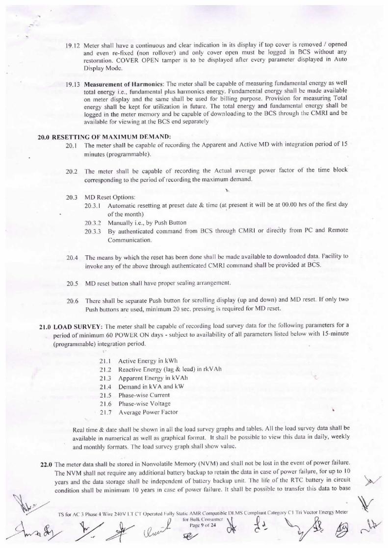
19.12 Meter shall have a coi`tinuous and clear indication in its display if top cover is removed / openedand even re-fixed (non rollover) and only cover open must be logged in BCS without anyrestoration. COVER OPEN tamper is to be displayed after every parametei. displayed in AutoDisplay Mode.
19.13 Measurement of Harmoiiics: The meter shall be capable of measuring fundamental energy as welltotal energy i.e„ fundamental. plus harmonics energy. Fundamental energy shall be made availableon meter display and the same shall be used for billing purpose. Provision foi. measuring Totalenergy shall be kept for utilization in future. The total energy and fundamental energy shall belogged in the meter memory and be capable of downloadjng to the BCS through the CMRI and beavailable for viewing at the BCS end separately
20.0 RESETTING OF MAXIMUM DEMAND:20.I The meter shall be capable of recordH`g the Apparent and Active MD with integration period of 15
mii`utes (programmable).
20.2 The meter shall be capable of recording the Actual average power factor ot` the time block
corresponding to the peliod of I ecording the maximum demand.
`20.3 MD Reset options:
20.3.I Automatic resetting at preset date & time (at present it will be at 00.00 Iii`s of.the first day
of the month)
20.3.2 Manually i.e., by push Button
20.3.3 By ai.ithenticated command t`i.om BCS through CMRl or direc'tly from PC and Remote
Communication.
20.4 The means by which the reset has been done shall be made available to dowiiloaded data. Facility to
invoke ally of the above through authenticated CMRl command shall be provided at B¢S.
20.5 MD reset button shall have proper si`aling ai.i.angement.
20.6 There shall be separate Push button for scrolling display (up and down) ancl MD reset. If only two
Push buttons are iised, minimum 20 see. pi.€ssing is required for MD reset.
21.0 LOAD SURVEY: The meter shall be capable of I.ecording load survey data for the following parameters for a
period of minimum 60 POWER Ow days -subject to availability of all pal.ameters listed below with 15-minute
(programmable) integration period.1'
21.I ActiveEnergyinkwh
21.2 Reactive Energy (lag& lead) in rkvAh
21.3 Apparent Energy ill kvAh
21.4 DemandinkvAandkw21.5 Phase-wise current
21.6 Phase-wisevoltage
21.7 Average power Factor
Real time & date shall be shown in all the load survey graphs and tables. All the load survey data shan be
available in nunierical as well as graphical foi.mat. It shall be possible to view this data in daily, weekly
and molilhly t`()rmats The load survey gi.apli sliall show value.
22.0 The meter data shall be stored lil Nonvolatile Memory (NVM) and shall not be lost in the eveiit of power failui-e.
The NVM shall not requil.e any additional battery backup to I.etain the data in case of power failure, for up to I 0
yeai.s and the data storage shall be independent of batteiy backup unit. The lire of tlie RTC battery in circuitcondition shall be minimum 10 years in case of powei. t`ailure. It shall be possible to transf`er this data to base
TS for ^C. 3 Pluse 4 Wlre 240V I rl C I ()perated riill>' Stallc ^MR Compa[ihle I)I MS CompLlam Calcgor}. C` I 'l`rl Vector Energy Meter
N 8}- W gfrotry y2¥ ul l`oJ Bulk Coiisul`1er
L'@ge , `,'` 2J
}t!:.,
.`\.
\b.
r`\ir
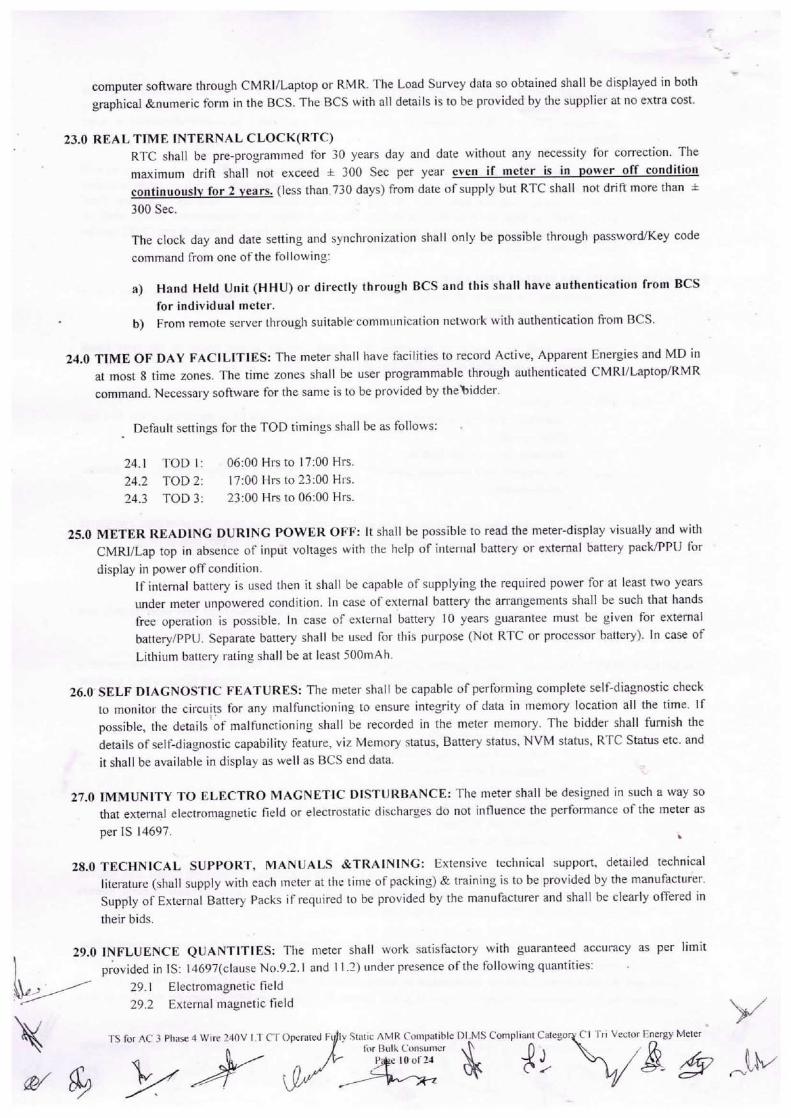
computer software through CMRI/Laptop or RMR. The Load Survey data so obtained shall be displayed in both
graphical &numeric form in the BCS. The BCS with all details is to be provided by the supplier at no extra cost.
23.0 REAL TIME INTBRNAL Cl.OCK(RTC)RTC shall be pre-programmed for 30 years day alid date without any necessity for correction. The
maximum drift shall not exceed ± 300 Sec per yeai` even if meter is in ower off condition
continuously for 2 Years. (less than.730 days) ftom date of supply but RTC shall not dnft more than ±300 See.
The clock day and date setting and synchronization shall only be possible through password/Key codecommand from one of. the fol lowing:
a) Hand Held Unit (HHIJ) or directly through BCS and this shall have authentication from BCSfor individual meter.
b) From remote server through suitable communieation netwoi.k with authent].cation from BCS.
24.0 TIME OF DAY FACILITIES: The meter shall have facilities to record Active, Apparent Energies and MD inat most 8 time zones. The time zones shall be user programmable throuch authenticated CMRl/Laptop/RMRcommand. Necessary software for the same is to be provided by thettidder.
Default settings for the TOD timings shall be as follows:
24.I TOD I: 06:00Hrsto l7:00Hrs.
242 TOD 2: 17:00 Hrsto23:00 llrs.
24.3 TOD3: 23:00Hrsto06:00Hrs.
25.0 METER READING DURING POWER OFF: It shall be possible to read the meter-display visually and withCMRI/Lap top in absence of input voltages with the help of interria] battery or external battery pack/PPU fordisplay in power off condition.
If internal battery is used then it shall be capable of siipplying the required power for at least two yearsunder meter unpowered condition. In case of external battery the arrangements shall be such that hands
free operation is possible. In case of external battery 10 years guarantee must be given for external
batteryppu. Separate battery shall be used for this purpose Ovot RTC or processor battery). In case ofLithium l>attery I.ating shall be at least 500mAh.
26.0' SELF I)lAGNOSTIC FEATURES: The nieter shall be capable of perfoming complete selfrdiagnostic checkto monitor the circuits for any malfunctloning to ensure integrity of data in memory location all the time. If
possible, the details';f malfunctionlng shall be recorded in the meter memory. The bidder shaH furnish thedetails of selfrdiagnostic capabiltry feature, viz Memory status, Battery status, NVM status, RTC Status etc. and
it shall be available in display as well as BCS end data.
27.0 IMMUNITY TO ELECTR0 MAGNETIC DISTURBANCE: The meter shall be designed in such a way sothat external electromagi`etic rield or electrostatic discharges do not influence the performance of the meter as
per IS 14697.
28.0 TECHNICAL. SUPPORT, MANUALS &TRAINING: Extensive technical support. detailed technicalliterature (shall supply with each ineter at the time of packing) & training is to be provided by the manufacturer
Supply of Extemal Battery Packs if required to be provided dy the manufacturer and shall be clearly offered intheir bids.
29.0 INFLUENCE QUANTITIES: The nieter shall work satisfactory with guaranteed accuracy as per limit
:..`\...: `
ty\
pr`ovided in TS: 14697(clause No.9.2. I and 11.2) under presence of the following quantities:29.I Electromagiietic field
29.2 External magnetic field
TS for ^C. 3 Phase 4 Wire 240V 1,T C`T Operated f`
Le`,.. !t, ;i.,..i..,
ly Static AMR Comi)at;ble Dl:MS Compllaiit Catego
I [T = mlz"`EIt
``,`.
W&-gyM2 -win
29.3 Radio frequency interfei€nce
29.4 Vibration
29.5 Voltage variation (70% -120% of vref.) in Oj lag and UPF both in 5% and 100% of lb
29.6 Frequency variation (+/-) 5% of 50 Hz in 0.5 lag and UPF both in 5% and 100% of l!
30.0 COMMUNICATION CAPABILITY:30.I The meter shall be provided with two ports for communroation of the measured and stored data. A
Serial Port (RS232 or RJl I) shall be used for remote access through suitable Modern and shall be
housed inside the meter terminal cover so that it can't be accessed without opening the sealed
terminal cover.
The other one shall be an Optical port complying with hal+dware specifications detailed in IEC-
62056-21. This Optical port shall be provided \i/ith proper sealing arrangement so that its cover
can't be opened \^rithout breaking its seal. This shall be used for local data downloading through a
DLMS compliant HHU or direct through BCS.
302 Both ports shall support the default and minimum baud rate of9600 bps.
30.3 Optical Cord (for connecting Optical Port of Metei. to PC) must be having USB connector.
30.4 Data downloading time from meter to HHU/PC shall be within 2 minutes for meter data (withoutload survey) and within 6 minutes for meter data (wiwhoad survey).
30.5 The stored data in the meter shall be available through CMRI even when the display of the meter is
not available.
30.6 No alteratloii shall be possjble without authenticated commands set by the BCS after scheduling themeters. Moreover, no alternation shall be possible using CMRI only, i.e. the control has to be with
the BCS as well.
30.7 Date in the meter shall be reset only through commands from the CMR[ or Laptop. Correction of`
RTC time, chalige of TOD Timings etc. shall be done thl.ough CMRl or Laptop utilizing
authenticated command set by BCS for particular meter Serial No & this shall be recorded as atransaction and to be recorded in meter memory and also shall be available at subsequent BCS data
with date & time stamping.
30.8 Billing parameters shall be factory programmable.
30.9 The BCS shall have multi-level password for data protection & secur]ty.
30.10 Bidder has to submit CMRl software ( eve format) also at the time of sample meter testing.
31.0 BASE COMPUTER SYSTEM & SOFTWARE REQUIREMENTS:31.I The common Meter Reading Instrument (CMRI) shall be loaoded with user-friendly software (MS-
DOS 5.0 or higher version compatible) for reading and/or do`^/nloading meter data.
312 Windo\t(s (Windows 7.0 and higher version) based Base Computer Softwai.e (BCS) shall be
provided for receiving data from CMRl and downloading insti-uctions from BCS to CMRI.31.3 The data stored in the meter memory including defrouded energy shall be available on the BCS.
31.4 Six no. of BCS shall be provided for downloading data fi.om CMRl and for authenticated command
from Laptop or for programming CMRl for any transaction.31.5 The BCS shall have facility to convert meler reading data into user defiinable ASCII file format so
that it can be integrated with the billing system or any other third party software. The user shallhave the flexibility to select the pal.ameters to be conveiled into AScll file.
31.6 All the data availal)le in the metci. including energy, MD etc. with date and timc stamp, new TOD
time zones aiid histoi.ical data shall be available in BCS after down loading.
31.7 The bidder shall supply the necessary CMRI software during sample meter testing.`.3] .8 The biddei has to supply the meter reading protocol and Apt fi.ee of cost. The bidder shall indicate
the relevant standarcl to whieh the protocol is compliant.
31.9 Transfer of data from the nieter to CMRI & then to tile BCS shall be easily executed.
31.10 Any change or up gradation of.CMRl software or BCS in future, requii.ed for any I.eason, has to be
done by the supplier at his own i:ost.
3lJ I The same soft\^/are shall be capat)lc of prepaling CMRl to read the metei` informatioTi or to
reconfigure the meter for change of l`OD timings and / or time setting of the meter etc. The
NleJ~TS for ^C 3 Phase 4 wire 240V I T Cl ()perated I-`illl}' S
•*., \J,11, < ........,;A. `
^MR Coiiip{ilible I)I MS C`ompliaiit (,`atcgor}J (` I ri I Vecto
l`(`r Bull (`()nsulncr- Page I I ot`24
<.a,.,.,
exhaustive online help shall be available with the software so that user can use all the features of the
software by just reading the help contents.31.12 ln BCS twelve months' data for kwh (Total & Fundamental), kvAh (Total & Fiindamental), MD in
kw & kvA (Total & Fundamental) [AII these parameters Cumulative & TOD wise i.e. kwh,kvAh. kvA], average load factor, average power factor must be available. Cumulative MD KVAdata must be available at BCS end.
3].13 Midnight Energy Parameters.Cumulative and TOD wise may be available at BCS end data (ForFundamental as well as total) as jt is required sometimes at the time of extrapolating provisionalbilling.
32.0 GENERAL REQUIREMENTS:32.I GUARANTEED TECHNICAL PARTICULARS: The bidder shall furnish all the necessary
jnforniation as desired in the Schedule ot` Guaranteed Technical Particulars and data, appended with
this Specification. I f the bidder desires to furnish any othei. information in addition to the details as
asked for, the same may be fumislied against the last item of this Annexure-I.
32.2 TECHNICAL DEVIATIONS: Any deviation in Technical Specification as specified in the
Specification shall be specifically and clearly indicated in the Schedule of deviation format.\
32.3 INSPECTloN & TESTING:32.3.I The meters manufactured as pei. requisite technical spec].fication along with accepted
changes I.ecorded ill iT`inutes of pre-bid meeting, shall be subject to tests as per relevant
Indian Standards.
;+-.
32.3.2 No change/ deviation/ modification in the technical specification of the meters offered for
inspection & testing in respect to the approved sample metei.s shall be entertained.
32.3.3 BCS and CMRl software version s]iall be the same as accepted during approval of the
related sample meter. In case any change in BCS aiid/or CMRI softwai.e is felt necessary
by the supplier` the Chief Engineer(DTD) shall have to be approached in writing for his
approval elaborately clarifying the necessity prior to commencement of inspection. Thedeviation(s) shall be accepted it` and only if the Chief Engineer(DTD) approves the
proposed deviation(s).
32.3.4 STAGE INSPECTION: Stage Inspection, if required may be conducted at manufacturers'works. For this. the supplier must give pi.ior intimation at least 15(fifteen) days before final
calibration (with RTC reset). The supplier shall extend all facilities for such in.spection and
tTe`sting for which no exti.a cost shall be charged and the physical inspection report,
containing observation agaiiist components, raw maten`als, display modules, push button,
iiameplate etc. shall have to be siglied jointly. Otherwise offer for final inspectiQri will not
be accepted.
32.3.5 ROUTINE TEST: Routine Tests as per relevant Indian Standards and requisite technicalspecification shall be conducted for each & every meter after its production.
32.3.6 LOT ACCEPTANCE TEST:32.3.6.I The supplier shall give prior intimation about the readiness of the mete`Ts at the works
for inspection and testiilg at least 15 (fifleeii) days before their proposed inspection
schedule. The supplier shall extend all facilities for such inspection and testing for
which no extra cost shall be charged and the inspection report sl]all have to be signed
jointly. Otherwise the ofTere(i lot(s) shall be treated as cancelled.
32.3.6.2 While off.ering inspection and testing, one hard copy & one soft copy of the test
reports indicating test results of each iiieter oftlie ot`fered lot contaiiiing its sequential
Egiv ftyTs forA;e4 W#;ope#:
y St{ttic ^MR Compatible .J)I,MS C.ompliaiit C{`tegory
&8}l`or Billk C()nsum€r
ge 12 Ot-24
meter serial no. and the serial no. of the two no. of body seals shall be submitted to
the Office of the Cliiet` Engineer (DTD), WBSEDCL, Abhikshan, Sector - V, SaltLake City, Kolkata -700091 with copies to the Office of tlie Clijef Engineer (P&C),
WBSEDCL. Otherwise inspection offer w]ll not be considei.ed.
32.3.6.3 However. WBSEDCL reserves the right to depute their Engji]eers for carrying out
inspection and testing on the offered lot as per relevant Indian Standards and requisite
technical speclfication. already notified and also reserves the right to reject either raw
materials or finished products found to be not conforming to the requisite technical
specifications and/or relevant lndjan Standards.
The Engjneeis of WBSEDCL shall witness the var].ous quality control measures
adopted in productioii line and satisfy themselves about the same. They shall also
inspect the protocol for iiiaiiitaining the accuracy of the meter testilig equipment at
the testing laboratoiy of the manufacturer with reference to the standard. Theinstruments and equipment required for Inspection & testing shall have valid
calibration cellificates as specified in relevant clause of this order.`
Physical examination of the meters on minimum 5°/o of offered quantity will be
carried out. If during physical I.nspection anomaly js found in more than 2% of the
offered quantity, no further test win be carried out and offered quantity will be
rejected.
After satisfactory result in physical examination, lot acceptance tests shall be carried
out by the representatives of WBSEDCL at the works of the manufacturer as statedhereunder:
32.3.6.6.1
32.3.6.6.2
The maximum no. of meters in each lot: 1000
No. of metei.s to be selected at I.andom from the lot: 32
32.3.6.4
32.3.6.5
32.3.6.6
32.3.6.7
32.3.6.8
32.3.6.9
After selection of sample meters, tlie following tests shall be carried oiit on all the 32
no. of meters selected at random.
32.3.6.7.1
32.3.6.7.2
32.3.6.7.3
32.3.6.7.4
32.3.6.7.5
32-`).6.7-6
mgh Voltage testlnsillation Resistance test
Test of Protection foi. withstanding 433V between Phase & Neutral
foi. I (one) hour
Test of Eiidurance at 150°/o of lmax for 2(two) hours
Test of Starting Curl.eiit at 0. I 0/o Tb at UPF
Tesl of No Load condition: At 70% ancl 120% of Vref at No Loadfor a period as mentioned jn clause 12.12 of ls 14697 i.e. 20 times
the actual test period of starting ciirrent. The ma^imum test period
shall bi' limited to 200 minutes. The Meter shall not emit moi.e than
one output pulse duling such test.
In the above tests, it` the liumber of defective meter is at most one, the lot shall be
considered conrormiiig to the tests.
Ifthc iiumber of defective meters is more than three, the lot shall be outright rejected.
32.3.6.10 However. if. the mimber of defective meters is within three, while `the lot shall be
considei.ed not coiiforming to the tests, further sampling from the lot at random shall
be made. It` the number ot` defective meters from two silch samples (i.e. from 64
meters) is less than l`our only then the lot shall be considered as conforming to the
test.
32.3.6. I I Further testiiig t`or 8 number of meters, selected from 32 number of s.ample IT}eters
will be carried out as follows:
¥*for^c±##pe#i#h::.rpfd::i`,{t:;``:p4:I::"'#SC°mp''d3:A;roryc*;r&rgya'

32.3 .6.11. I
32,3.6. I I.2
32.3 .6.1 1.3
Limits of error on all the sane 8 no. of sample meters for both active &reactive energy for balanced & unbalanced loads
Test of the Meter Constant and Meter Dial as per technical specification at
200% I basic, Power Factor 0.866(lag& lead)
Powei.. consumption on Voltage Circuit (through power analyzei.) arid
Current Circuit.
32.3.6.12 Further testing of3 number of sample meters will be carried out as follows:
32.3.6.12.I
32.3 .6.12.2
Repeatability of Error Testlt` any of the meters fails on any of the above tests, the lot will be rejected.
32.3.6.13 F`irther testing for I number of sample meter will be carried out as follows:32.3.6.13J Tamper & Fraud protection (Anti-tamper feature) as per relevant clause of
the specification.
32.3.6.13.2 Physical verification ofinterntl coniponeiits.
32.3.6.14 lfthe meter fails on any of the above tests, the lot will be rejected.
32.3.6.15 Few mention-worthy relevant points regarding tamper testing :
32.3.6.15.1 AC chopped signal may be generated through Regulator or Dimmer
32.3.6.15.2 In Discharge Test. meter performance will be checked applying 35 KV spark
32.3.6.15.3 Provision must be there for tamper logging in BCs in case the spark exceeds35KV
32.3.6.15.4 In BCS, Average PF & LF, kwli. kvAb, MD in kw & kvA, TOD-wisekwh and kvAh must be made available for last twelve (12) months.
32.3.6.15.5 ln Magnetic Tamper TestuT`agnetic influence shall be checked at lomT AC,0.27T DC` 0.2T AC and 0.5T Pemianent Magnet. Facility to measure thecapacity of these magnetic fields miist be available at manufacturers'
pi.emises and must be calibi.ated fi.om any N ABL accredited laboratory.
32.3.7 DRY HEATTEST:32.3.7.1 Facilities or a.rrangement for collducting ageing test shall be available with the
1`
32.3.7.2
manufacturer.
Dry heat test as per clause 12.6. I of ls: 14697(1999) -At least one sample selected
from ally lot of`the meters offered for first inspection will be sealed by the inspecting
authority of WBSEDCL and handed over to the supplier for testing at NABLaccredited laboratoi.y. In the test report, meter sel.ial no. & meter body seal nos. are to
be mentioned.
32.3.7.3 Test result must be submitted within 30 days after selecting the meter at themanufacturer's works. If not submitted within the stipulated time frame, no further
offer for inspection will be accepted.
32.3.7.4 lf the meter fails at dry heat tests. the particularly delivered lot will not be acceptedand the delivered meters are to be taken t)ack by the supplier at their own cost from
different site offices within 30 days fi.om the date of receipt of intimation in this
regard. Only after withdrawal of the delivered meters, further inspection shall be
conducted against subsequent offered lot of metei.s.
32.3.7.5 lf the meter, selected during inspection at first lot of meters. fails in dry beat test thesanie test is to be conducted for the coiisecutive offei.ed lots of metei.s followiTig the
above procedure, unless satisfactory performance on above test is observed.
:::l&M`Comp#n;;dtegS'.atn;Cr%¥fcft::```::::IiiLMS
TS for ^C 3 PI.ace 4 Wii`e 240V I T C. r Orlerated Fiill
L= i EJEE"±
C I TI I Vec' Energy Meter
`.`^
@r`W
32.4 REOFFER FOR INSPECTloN:32.4.I Materials shall have to be reoffei.ed foi. the following cases:
32.4. I . I Failure to present the offered materials during inspection & testing. i.e, in case of fake
oft'er.
32.4.I.2 Failure of<iny particiilar lot ot` offered materials in two consecutive I.nspections.
32.4.I.3 Inspected materia[s not delivered within one month after the stipulated period
specified in the order without any valid reason. [The dispatch clearance alreadyissued against the said lot shall be coiisidered to be withdrawn.I
32.4.1.4 The date of. reoft`er shall be the date of submission of reoffer along with WTC & copy
of` DC R-
32.5 RETESTING CHARGF,: Retesting fee for carrying out inspection of the lot of materials afterI.eoffei. shall be charged as pel. existing rate.
33.0 SUBMISSION OF SAMPLE METER:33L::u,:]edndt:r(X:ttp::bArn:tneh::rsea_:]vP;:o¥eatne;SJ:r;:na:e:k;a::nse:sccahrte°d°uiea::ns:b:I,tshs,:entesvpaenct,fit:t::
the related Tender Document, to the Office of the Chief Engjneei. (DTD). Abhikshan, See-V, Salt
Lake, Kolkata-91. The bidder will be given a receipt. jointly signed by the bidder and DTD officials,
mentioning the samples and papers submitted by the bidder as per check list.
33.I.I While submitting the samples and required documents as per Annexiire-lv` the bidder
shall submit three niimbei.s of sealed meters as per the specifications stated herein before.
two ultrasonic welded and one without weldiiig and anothel. dumm.v metel. case (for
checking ultrasonic welding).
33.1.2 They shall also submit one prototype of metei. base and cover (with body screw caps)
pi.operly welded.33.I.3 Tl]e date ot` testing ot` sample meters will be intimated to the bidders by CE(DTD) and
during such tesl other bidders will also be allowed to wimess the testing. Sample
submission schediile and Test procedure may be changed due to emergency requirement.
On the date of testing of. sample meters of a particular bidder, he shall come prepared with
the t`ollowing.
33.I.3.I BCS (as per specification)
33.I.3.2 CMRl compatible with BCS and loaded with CMRI software and laptop
compatible with BCS.
33.I.3.3 Modern and accessories for testing tlie remote meter reading.
33.I.3.4 Any other accessories required for observing the performance and capabilities ot`
the meters.
34.0 QUALITY ASSURANCE PLAN: The design life of the meter shall be minimum 20 years and to prove the
design life the firm shall have at least the following quality Assurance Plan.
34.I The factoly shall be completely clusl proof.
34.2 The test rooms shall be tempei.ature and humidity controlled as per relevant standards.
34.3 The test and calibrating equipment shall be automatic and all test equipment shall have their valid
calibration certificates.
34.4 Metei. will be. tested (in casi` of lot test) in fully automatic test bench with lcT. No human
intervention will be allowed durillg test.
34.5 Power supplies used ill test equipment shall be distortioli free with siiiusoidal wave forms and
maintainiiig coristant voltage, cut.I`ent and frequency as per the relevant standards.
TS for A(' 3 Phase 4 WHe 240V I T C I Opcritied
jz:,..| .i, i,Sttallc ^MR C`omi)atible i)I MS C'ompliam 'Czilcgor} C' I l`i i Vc
W gJ., iv/f(`r Biill` C`(`i`sumci
P#ge IS 0'-24
d9,
I:nergy Meter
4 c-ly
35.0 THE CHECKS T0 BE CARRIED OUT DURING MANUFACTURING OF THE METERS:35.I Meter frame dimensions tolerances shall be minimal.
35.2 The assenibly of parts shall be done with the help of jigs and fixtures so that human eITors areeliminated.
35.3 The meters shall be batch tested on automatic, computerized test bench and the results shall be
printed directly without ally human errors.
36.0 MANUFACTURER'S TESTING FACILITY: The laboi.atory of manufacturer must be well equipped fortesting of the meters. They must have computerized standard power source and standard equipment calibratednot later than a year (ol. as per standard pi.actice).
The bidder shall indicate the sources of all equipment / instruments. The standard meters used for
conducting tests shall be calibrated periodically at any NABL Accredited Test Laboratories and testcertificates shall be available at Works for verification by purchasers' representative.
The Bidder shall have at least the facilities to test the following to ensure accurate
calibration:AC high voltage testInsulation i.esistance measurementRunning at no loadStarting current testLim its of errorDial TestTest of meter constantPower loss in voltage and curreT`t circuitRepeatabi I ity of errorTTansportati on testTamper Test includimg test of magnetic influenceAgeing Tes.
37.0 MANUFACTURING ACTIVITIES:37.I All the materials, electronics and power components. ]Cs used in the manufactui.e of the meter shall
be of highest quality and reputed make to ensure higher reliability, longer life and sustained
accui.acy. The manufacturer shall use Application Specific Integrated Circuit (ASIC) or Miero
controller for metering t`unctions.
37.2 The electronic components shall be mounted on the printed circuit board using latest Surface
Mounted i;chnology (SMT) except power components by deploying automatic SMT pick and
place machine and re flow solder process. The electronic components used I.n the meter shall be ofhigh qualit}J and there shall be Ilo drift in the accuracy of the meter at least up to 10 years.
37.3 Fui.ther, the Bidder sliall owii or have assured access (through hire,lease or sub-contract) of thementioned facilities. The PCB material shall be of glass epoxy FR4 grade conforming to relevant
standards.
37.4 All insulatiiig materials iised in the constructioii of meters shall be non-hygroscopic, non-ageing and
tested quality. All parts that likely to develop corrosion shall be effectively protected against
corrosion by providing suitable protective coating. Quality shall be ensured at tlie following stages.
I,
`\-:......`
`*
37.4`1 At PCB manufacturing stage, each board shall be subjected to bare board testing.
37.4.2 At insertion stage, all coiTiponcnts shall undergo testing for confoi.ming to design
parameters and orientation. Complete assembled and soldered PCB shall undergofunctional testing using test equipment (testing j ig).
TS for AC 3 Phase 4 Wire 240V I T CT Operated r`
drthy y cz¥l}i Stdtic ^MR Comp.ilible I)I MS C`ompliaiit Category
#er A 8} g r`tw
37.5 Prior to final testlng and calibration, all meters shall be subjected to accelerated ageing test to
eliminate infaiit mortality` i.e., meters are to be kept ill ovens for 72 liours at 55 deg Centigrade
temperatiire & atmospheric liumid conditioii After 72 hours meters shall work coiTectly. Facilities /
arrangement for conducting ageing test shall be available with the manufacturer.
37.6 The calibration ot`meters shall be done in-house.
38.0 DOCUMENTATloN:38.I Twenty sets of opei-ating manuals shall be supplied to the office of the CE (DTD) f`or djstribution at
sites.
38.2 One set ofl.outine test ceilificates shall acconipany each dispatch consignment.
38.3 The acceptance test certificates in case pre-dispatch inspection or a routlne test certificate in cases
where inspection is waived shall be approved by the purchaser.
39.0 GUARANTEE: The Meters shan be guaianteed arising out or faulty design, nia[erials, bad woi.kmaliship for a
period of 5'/2 years t`rom the date of supply. Bidders shall guarantee to replace the meters, which are found to bedefective/inoperative at the tiiTie of installation, or become indyerative/ defective during guarantee period.
Replacements shall be efrectcd within I month from the date of intimation.
40.0 REPLACEMENT OF DEFECTIVE METERS: The meters declared defective within the above guarantee
period by the WBSEDCL shall be replaced by the supplier up to the full satisfaction of the WBSEDCL at thecost of supplier within one moiith on receipt of intimation. Failure to do so within the time limit prescribed, shall
lead to imposition of penalty of twice the cost of meter. The same may lead to black listing eve„ as decided by
WBSEDCL. In this connection the decision of WBSEDCL shall be final.
4].0 PACKING & FORWARDING:4].I The energy meteis shall have to be securely packed in transportable lots. If the energy meters are
found acceptable after Inspection and testing, the same shall have to be suitably sealed by the
Inspecting Ot`ficer. Due care shall have to be ensured during transportation to keep the packing and
seals intact for acceptance by consignee stores.
4] .2 The equipment shall be packed in cartons / crates suitable fol. vei.tical / horizontal transport as the
Case may be, and suitable to withstand handling during transport and outdooi. storage during transit.
The supplier shall be respoiisible for any damage to the equipment diiring transit, due to improper
and inadeciuate packing. The easily damageable material shall be carefully packed and marked with
the appropi-late cautlon symbol. wherever necessary` proper arrangement for liftiiig, such as lifting
hooks ete., shall be provided. Siipplier without any extra cost shall supply any material found short
inside the packing cases immediately.
41.3 The packing shall be done as per tlie standard practice as mentioned in ls 15707. 2006 Each
package shall clearly incljcate the marking details (for e.g, manufacturer's name, Sl. Nos. of` metersin the package. quantity of metei-, and other details as per supply order). However, the supplier shall
ensiire the packing is sucli that, the material shal] not get damaged during transit.
42.0 DELIVERY:42.I
42.2
.`.` `
:I,``.
Delivery of the meters shall be made only after receipt of the Dispatch Instruction (DI) to be
issued by the Chief Eiigineel. (DTD) upon approval of the supplier's test reports Tl`e supplier
shall send iiitimatioii regardiiig dispatch of tlie meters to the Offices of tlie Chief Engji`eer
(P&C) and Chiet` Engineer (DTD)` WBSEDC`L immediately after dispatch of the consignment.Prior to dispatch ot` the consignment the supplier shall ji`timate the consignee duly so that
consignee can acknowledge I.eceipt of information
The equipiiieiiL/malerials are lo be delivered as per "Delivery Schedule".clause given
hereunder. Allotmem of. sei.ial number ot` meters will be available f`rom the Distribution
Testing Department, Abhiksliai`` WBSEDCL, Salt Lake, Kolkata-91, on any working day after
issiiani`e of this ol.dci upon receipt ()f writteli requlsition for the same.
TS for AC. 3 Pliase 4 wile 240V I I C.I ()perated l`illl
fin 4y ky z# p:::LR,c;`o;::P4:I::lc ¥S C°mp!§;`d'e8°ry*;°&rgy Mf cgiv

42.3
42.6
42.7
The materials shall reach the destination stores within 21 (twenty one) working days from the
date of issue of` the Dispatch li`struction (DI). Failure to do so for reasons, solely attributable
to the supplier, shall attract LD as per relevant clause of this order.
Delay in offer beyond the Delivery Scliedule for reasons solely attiibutable to the supplier
shall attract imposition of LD as per relevant clause of this order.
In case the inspected materials are not delivered within one month after the stipulated period
specified in the order without any valid reason the Dispatch Instruction (Dl) already issued
against the said lot shall be considered to be withdrawn.
Delivery of the meters shall be made only after receipt of the Dispatch Instruction (DI) to be
issued by tlie Chief Eligineer (DTD) upon approval of the supplier's test reports. The supplier
shall send intimatlon regarding dispatch of the meters lo the Offices of. the Chief Engineer
(P&C) and Chief Engineer (DTD). WBSEDCL immediately after dispatch of the consignment.Prior to dispatch of the consignment the supplier shall intimate the consignee duly so thatconsignee can acknowledge receipt of information.
For every loo no. of metei.s and part thereof one HHU (DOS Based) with set ofcommiinication cord and accessories shall be supplied to the Office of the Chief Engineer
(DTD)` free of cost. The guai.antee period of HH/Tab will be of 66 months from the date ofsupply. `
43.0 DELIvnRY SCHEDIJLE: Shall be specified in LOA.
44.0 CHECKING OF METER AFTER DELIVERY:The mateiials delivered to the consignee stores will be subjected to re-inspection/re-testing in
presence of authorized representative of suppliers for which due notice in advance will befurnished by the Chief Engineer (DTD). Jf any discrepancy/dispute in quality arises in any
sample selected fi.om a lot, the supplier shall have to replace the entire lot at tlie supplier's
cost and WBSEDCL reserves the right to take any penal action whatsoever without anyfurther referen ce.
4S.0 INSPECTION AFTER RECEIPT AT STORES:45.I WBSEDCL shall carry out acceptance testing of the supplied meters (collected from consignee
stores) at their laboratory against DI of inspected lot. Advance intimation will be given to local
representatives of tlie supplier over telephone. Such testing of the meters will be commenced
within 10 days and completed within 20 days from the date of receipt ot` meters at consignee
45.2
45.3
46.0 SUBMISSION- 46.1
stores.
Acceptance Test as per "Inspection & Testing" clause of this order except dry .heat test &shunf test will be conducted at the laboratory of Distribution Testing Deparment or any ZonalTesting Unit on sample meters selected from meters delivered at consignee stores. Sampling
procediLre will be followed as per I.elevant Indian Standards. Date of testing will be intimatedto the suppliers and testing can be witnessed by authorized representatives of the suppliers. in
case, the authorized repi.esentatives are not present, WBSEDCL shall test the meters
unilaterally and the results obtalned during testing will be binding on the suppliers.
Tn case the meters are found "Not ln Order" as per observation during inspectioli and testing ofthe offered lot, the lot will be declared defective and in that event meters supplied are lobe
I.eplaced by the manufacturel.s free of cost including fi.ee transportation fi.om the site to their
works and back. Before delivery of the replaced meters Acceptance Test shall be conducted bythe siipplier as per ..Inspection and Testing" clause of this order in presence of WBSEDCL-
repi.esentatives Only if the test results are found to be satisfactory. replaced meters shan be
allowed to be delivered.
OF REPORTS AGAINST DEFECTIVE METERS:Afte.. delivei.y of the meters, if any defect is detected by the Testing Engineer / Site Office
Personnel, the same will be intimated to the supplier. After getting intimation. the supplier
TS for AC 3 Phase 4 Wire 240V L 1` CT Operated F.ully
•,.'',t,,.:i,.....--.i.-
atic ^MR Compalible rJLMS Compliarit C 1 Tri Vector_Energy Meter
l`or Bulk C`oiisiimcr
© c`ur
47.0 CONSIGNEE:
shall send their conipetent personnel to the consignee store to set right the problem with
intimation to Distribution Testing Department (DTD) and to the Consigiiee. In case of minor
defect, which can be set right at site, the same shall be taken up by the supplier without
affecting the activity of the consignee store, failing which the meters are to be lifted from the
consignee store for necessaiy rectification. If the detected defect is beyond repair, the meters
are to be replaced by newly tested metei.s and the defective meters will be handed over to the
supplier by the consignee stol.e. The replaced meters are to be sent to concei.lied Zonal Testing
unit or DTD, Abhikshan for fuilher testlng.
The metel-serial numbers for the metel.s. I.eplaced against defective meters, shall bear numbers
from the I-oHing stock serial iiiimbers aHotted by DTD against this order.
Regarding these defective meters. tlie supplier shall submit a report to DTD mentioning nature
of def`ects (like, fault at Current Elemem / Potential Divider / SMPS / Computing Chip /
Communication Modiile/ Display Module / NVM Module / Battery) against meter serial
number. A format in this regard shall be pi.ovided by DTD duly.
To be intimated by the Chief Engineer (DTD), Abhikshan, WBSEDCL, Kolkata -700091
through the Dispatch Instructions (DI).\.
48.0 CALIBRATION 0F MEASURING INSTRUMENTS / EQUIPMENT:The instruments/equipment required for Inspection & testing shall have valid calibration as per following
gui`de]ine:48.I Calibration Certificate issued by Laboratory accredited by NABL sliall be accepted
unconditionally pi`ovided the certificate beal.s an accredita[ion body logo. F`or testing
equipment, where NABL accreditation is not available, calibration ceilificate from
Educational lnstitutioi`s like llTs, NITs, JU, CU, BHU only shall be accepted provided
traceability can be ascertained.
Necessary confirmatioli I.egai.ding above is to be given along with inspection offer failing
which the Inspection of`fei. will not be accepted.
If during inspection & testing the supplier fails to produce valid Calibration Certificate as
indicated above the offered lot shall bc rejected.
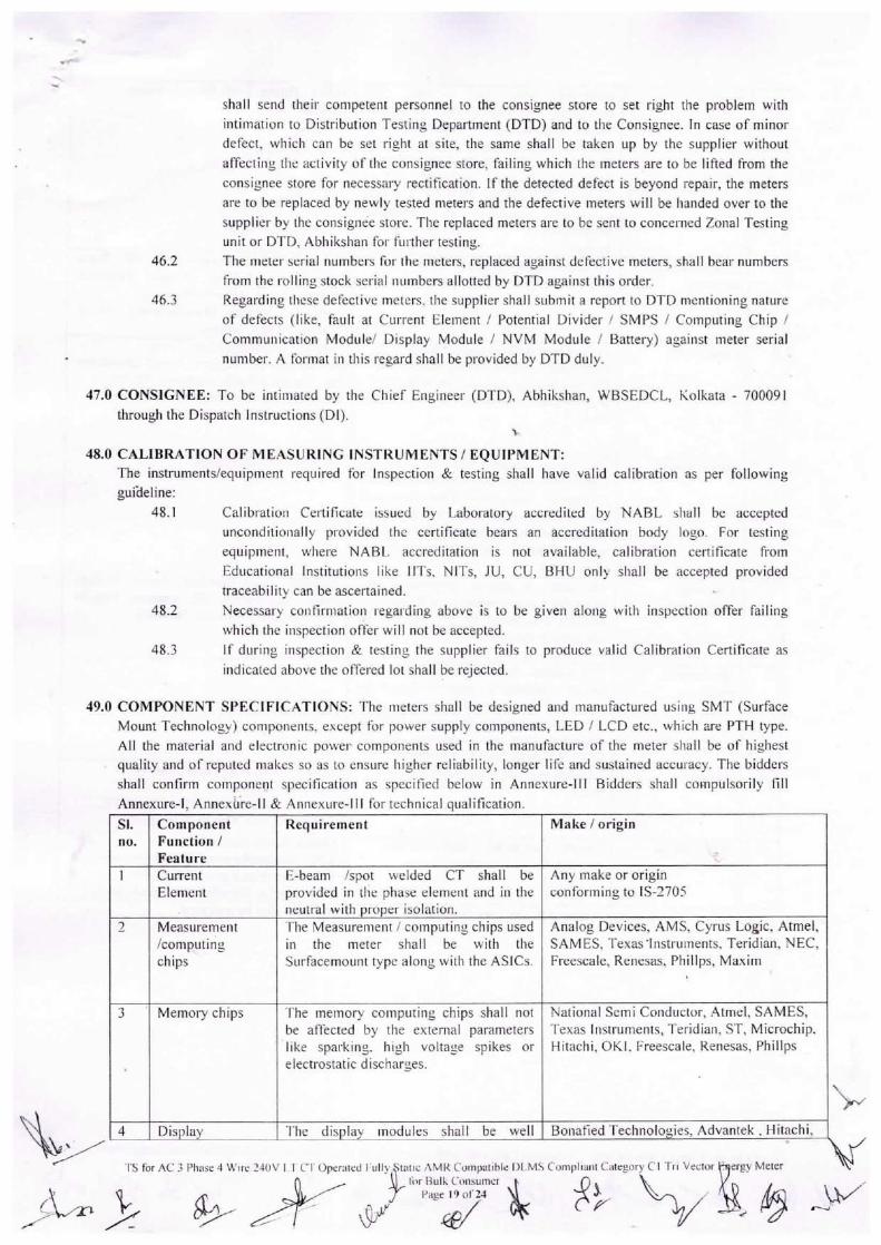
49.0 COMPONENT SPECIFICATIONS: '[1ie meters shall be designed and manufactured usjiig SMT (SurfaceMount Technology) compolients` except t`or power supply components, LED / LCD etc., which are PTH type.
All the material and electronic power components used in the manufacture of. the meter shall be ot` highest
quality and of reputed niakes so as to ensure higher reliability, longer life and sustained accuracy. The biddei.sshall confirm componerit specification as specified below in Annexure-lll Bidders shall compulsorily fill
Annexure-I, Annexh`re-I I & Annexure-I I I for techniczil qualification.
.. ,\. .{,
SI.no. ComponentFunction/Feature Requirement Make / origin
+
1 Cunent E-beam /spot we`ded CT shall be Any make or origmElement provided in the phase elemeiit and ill theneutralwithproperisolation. conforming to IS-2705
2 Measurement The Measurement / computing chips used Analog Devices, AMS, Cyrus Logic, Atmel,/comp`,ting in the meter shall be with the SAM ES, Texas -Instriiments, Teridian. NEC,chips Sui-facemount type along with the ASICs. Fi.eescale, Renesas, Phil lps, Maxim
3` Memory chips The memory computing chips shall not National Semi Conductor, Atmel, SAMES,be affected by the extemal parameters Texas Instruments, Teridian, ST, Microchip.like spai.king` high voltage spikes orelecti.ostaticdischarges. Hitachi, OKI` Freescale, Renesas, Phillps
4 Display The display modules shall be well Bonafied Technologies, Advantek , Hitachi,
Tsfoi I ^C 3 Phase 4 V\''Iie 240Vpr3-- comp¢n;A,egor>,c, Tn veLto, EL:yMS ~
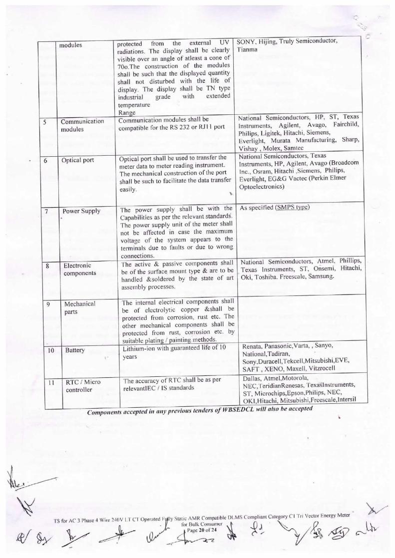
modules protected from the external UV SONY. Hijing, Truly Semiconductor,`-
radiations. The display shall be clearly TianmaNational Semicondiictors, HP, ST, TexasInstruments,Agilent,Avago,Fairchild,
visible over an angle of atleast a cone of70o.The construction of the modulesshall be such that the displayed quantityshall not disturbed with the life ofdisplay. The display shall be TN typeindustrialgradewithextended
temperatureRange
5 Communication Communication modules shall be
modules compatible for the RS 232 or RJl I portOpticalportshallbeusedtotransferthePhilips, Ligitek, Hitachi, Siemens,Everlight, Murata Manufacturing, Sharp,Vishay , Molex, SamtecNationalSemiconductors, TexasInstruments,HP,Agilent,Avago (Broadcom
6 Optical portmeter data to meter reading instrument.
lnc., Osram, Hitachi ,Siemens, Philips,Everlight,EG&GVactec(PerkjnElmerThe mechanical constri`ction of the portshall be such to facilitate the data transfereasily. ` Optoelectronics)
7 Power Supply The power supply shall be wlth the As speciried SMPS tvoeNationalSemiconductors, Atmel. Phillips,Texaslnstrunients,ST,Orisemi,Hitachi,
Capabilities as per the relevant standai.d5.Thepowersupplyunitofthemetershall
not be affected in case the maxlmumvoltage of the system appears to theterminals due to faiilts or due to wrongconnections.
8 Electroniccomponents The active & passive components shallbe of the sui.face mount pe & are to behandled &soldered _by the state of. art Oki, Toshiba. Freescale, Samsung.
assembly processes.
9 Mechanical The internal electrical components shall
Parts be ot` electrolytic copper &shall be
protected from corrosion, riist etc. Theother mechanical components shall be
protected from rust, corrosion etc. bysuitableplating/paintingmethods.Lithium-ionwithguaranteedlifeof10
Renata. Panasonic,Varta, , Sanyo,NationalTadiran10 Battery
1` yearsTheaccuracy of RTC shall be as perSony,Duracell,Tekcell,Mitsubishi,EVE,SAFT , XENO, Maxell, Vitzrocell11AtlMtorola
11 RTC / MicroDa as, me, oNEC,TeridianRenesas` Texas] nstruments,
controller relevantlEC / ls standardsST, Microchips,Epson,Philips, NEC,OKl,Hitachj, Mitsubishi,Freescale,lntersil?,LLalsobeaccer]ted
Com|)olienT{i[[ii{[JTiT;iiTprevious tenders Of WBSEDCL will also lie accep
at fry i,ly Statlc ^MR Compatible Dl,MS C`ompliant Category C`l Trl Vector F.ncTgy Meter
l`or Bulk CollsumerilaEE Hid Mu H
\.`
A f I, \/a @ c-W`
Annexure-I
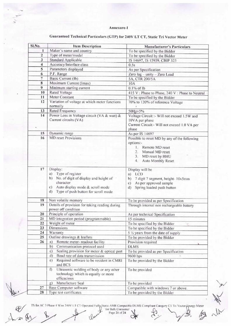
Guaranteed Technical Partic.ilars (GTP) for 240V LT CT, Static Tri Vector Meter
be
SI.No. Item Description Manufacturer's ParticularsI Maker's nanie and coiintry To be specified by the Bidder
2 Type of liietei./niodel To be specified by the Bidder3 Standard Ai)plicable ls 14697, ls 15959, CBIP 3254 Accuracy/I nterface c I ass 0.5s5 Pal.ameters displayed As per Specification6 P.F. Range Zero lag -unity -Zero Lead7 Basic Current (Ib) 5A, CTR 200/5A8 Maximum Curl.ent (lmax) 10A9 Minimum starling current 0. I % of` Ib10 Rated Voltage 4 I 5 V : Phase to Phase, 240 V : Phase to Neutral„ Meter Constant To be specified by the Bidder12 Variation of.voltage at which meter functions 70% to 120% of reference Voltage
nomlal'y '
13 Rated Freciuency 50Ltz±5%14 Power Loss in Voltage circuit (VA & watt) & Voltage Circuit :-Will not exceed I .5W and
Current circuits (VA) I OVA per phaseCurrent Grcuit:-Will not exceed I.0 VA perphase
15 Dynamic range As per IS 1469716 MD I.eset Provisions Possible to reset MD by any of the following
options:-I. RemoteMDreset2. Manual MDrese[3. MDrese[byHHU4. Aiito Monthly Reset
'7 Djsp'a-y: Display will bea) T}Jpe of.register a) LCDb) No. of.digit ofdisplay and heightof b) 7 digit 7 segment, height-I0x5mm
chai.acter c) As perapproved samplec) Auto display mode& scroll mode d) Spi.ing loaded push buttond) T}tpe of push buttoii for scroll mode
18 Non volatile memory To be provided as per Specif-ication19 Details of provision for taking reading dilring Through internal non rechargeable battery
power off coiidit ion20 Priiiciple of operation As per teclinical Specification21 MD integration period (programmable) I 5 minutes22 Weight of meter To be specified by the Bjddei.23 Dimensions To b€ specified by the Bidder24 Warranty 5 '/2 years t`rom the date of supply25 Outline di`awings & leaflets To be provided by the Bidder26 a) Remote meter-readout facility Provisioi] required
b) Communication protocol used DLMSc) Sealiiig provision for metel` & optical port To be provided as per Specificationd) Baud rate of`data transmissioii 9600 bpse) Required softwareto be resident in cMRl l`o be provided by the Bidder
and BCSf) Ultl.asonic welding ofbodyoranyother To be provided
technology` which is equally oi. moreefficacioiis
g) Manurac[ui-e seal To be provided27 Base Computer software Compatible with windows 7 or above.28 Type test celliticates To be provided by the Biddel.
TS for A(. 3 Phase 4 Wlre 240V I 1` 11 Oper{`led roll
/i= gr , #EEzil

SI.No. 29 Item DescriDtion Manufacturer's Particulars
Time of day zones (selectable) 3 TOD Zones to be pTovidecl with a provision for8 TOD Zones
30 Whether meter measures both fui`damental & As per Specification
harmonlc energy3132 Real time clock accuracyBatteryforrealtimeclock Maximum drift ± 5 minutes Per annum
lt shall be Lithium-ion battery having at least 10yeai.s of life
33343536373839 Anti tamper features As per Tampei. logic provided by WBSEDCL.
Effect of accuracy under tamper conditions As per technical specification
Drift in accuraey of measurement with timeNameplatedetails As per ls: ]4697 & CBIP 325As per specification
Type of cal ibration Software cal ibrated
Type of mountino Proiection mounting
Testing faci1ity Shall be available with manufacturer, details tobe provided
40 Data retention by NVM without battery backup As per specification
and un-poweTed conditionTypeofmaterialused:41a
Base As per specification
b.C Cover As pel. specification
Terminal block As per specification
•d.42 Terminal covei- As per speci fication
Screwi Material As per specification
ii Size As per specification
4344 ]ntemal diameter of terminal hole 5.5mm
Centre to centre clearances between adjacent As per ls: 14697
terminals4S Security profiles
a) Basic security To be provided
iiiiiiii b) Advaiice security To be provided
FTEEEEE`\-TS for AC 3 Plias¢ 4 Wiie 240V LT C'l` Operated I-`iil
al ty vy -z¥StaticAMRITompatibleDLMSC`ompliantcategorytH`HVcctorbnergyMeler
I`orB`ilkcoiisumer \ I r` . 0
`;.`.. .
sj4mer" AJ, -ty& ¢r-fry
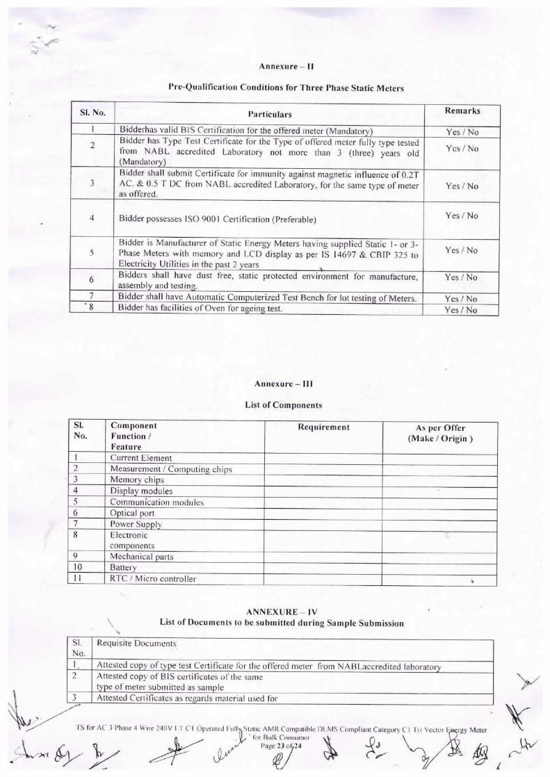
~-iFi=EnEziiLSI
Annexure -11
Pre-Qualification Conditions for Three Phase Static Meters
S]. No. Particulars Remarks
I ddei.has valid BIS Certification for the offered meter (Mandatory) Yes / No
2dder has Type Test Cellifica[e for the Type of offei-ed meter fully type tested
Yes / Nofrom NABL accredited Laboratory not niore thaii 3 (thl.ee) yea]s old
(Mandatory)
38 idder shall submit Certificate for immunity against magnetic influence of 0.2T
Yes / NoAC. & 0.5 T DC from NABL accredited Laboratory, for the same type of meteras offered.
4 Bidder possesses ISO 9001 Cellification (Preferable) Yes / No
5
Bidder is Manut`acturer of Static Eiiergy Meters having supplied Static I-or 3-Yes / NoPhase Meters with memory and LCD display as per ls 14697 & CBJP 325 to
E ectricity Utilities in the past 2 years
6a dders shall have dust free, static protected envii.onment for manufacture, Yes / Noassembly and testing.
7`8 81dder shall have Aiitomatic Computerized Test Bench for lot testing of Meters. Yes / NoBJ der has t`acilities of oven t`or ageing test. Yes / No
Annexure -I I I
List of Components
S]. Component Requirement As per OfferNo. Function / (Make / Origin )
Feature1 Current Element2 Measurenient / Computing cliips3 Memory chips4 Display modules5 Communi`cation modules6 Optical port7 Power Supply8 Electronic
components9 Mechanical parts10 Battery11 RTC / Micro controller
ANNEXURE -IV\ List of I)ocuments lo be submitted during sample submission
``
Sl.No. Requisite Documents
1. Attested copy ot` type test Certificate t`or the offered meter fi om NABLaccredited laboratory2 Attested copy of 81 S certificates ot` the same
type of` meter subm itted as sample3 Attested Certificates as regards material iised for
TS for A( .} PI"se 4 V`;ilc 240V I.'T C'l Oper!]ted r`ill
EEHEE=EE EESl{itic ^MR Compatiblc DI.MS C`ompliai`l Category C` I Ti I Ve.`tor'`"p::!#`:4m" & ?> h rgy Me,er
`'...`
`\`.-
(`\..
A
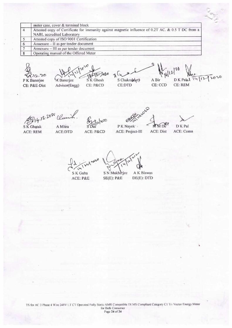
iii=meter case, cover & terminal block
4 Attested copy of Certificate for immunity against magnetic influence of 0.2T AC. & 0.5 T DC from aNABL accredited Laboratory
5 Attested copy of [SO 9001 Certificatjon6 Annexure -11 as per tender document7 Annexure - I I I as per tender document8 Operating manual of the Offered Meter
<ii-: 1t2-.T2JOP K Banerjee
•` ` -.,
CE: P&E-Dist Advisor(Engg) CE: P&CD
'€{i..:in
Scut,,VIMfy\D%KpaELFTroroS chakrarty A BirCE:DTD CE: CCD CE: REM
kJ¢~A# fro\,\cOcO pKN#`+p€ha D¥SKGhatak A Mitra. SDas` PKNayek' ` ` MM L)e- LJ KralACE: RPM ACE:DTD ACE: P&CD ACE: Project-Ill ACE: Dist ACE: Comn
B}J<v^ut,S K Guha SN Mukh jee AKBiswasACE: P&E SE(E): P&E DE(E): DTD
l`S for AC. 3 Pliase 4 Wire 240V I T CT Operated Fiilly Static AMR Compatible 1)I MS C`ompliaiit Category C 11`i I Vector Energy Meterfor Bull` Ct`iisumer
Page 24 ot` 24