
ITU-T Recommendation T.4
60
INTERNATIONAL TELECOMMUNICATION UNION ITU-T T.4 TELECOMMUNICATION STANDARDIZATION SECTOR OF ITU (07/96) SERIES T: TERMINAL EQUIPMENTS AND PROTOCOLS FOR TELEMATIC SERVICES Standardization of Group 3 facsimile terminals for document transmission ITU-T Recommendation T.4 (Previously “CCITT Recommendation”)
-
Upload
khangminh22 -
Category
Documents
-
view
2 -
download
0
Transcript of ITU-T Recommendation T.4

INTERNATIONAL TELECOMMUNICATION UNION
ITU-T T.4TELECOMMUNICATION STANDARDIZATION SECTOR OF ITU
(07/96)
SERIES T: TERMINAL EQUIPMENTS AND PROTOCOLS FOR TELEMATIC SERVICES
Standardization of Group 3 facsimile terminals for document transmission
ITU-T Recommendation T.4 (Previously “CCITT Recommendation”)

ITU-T T-SERIES RECOMMENDATIONS
TERMINAL EQUIPMENTS AND PROTOCOLS FOR TELEMATIC SERVICES
For further details, please refer to ITU-T List of Recommendations.

Recommendation T.4 (07/96) i
FOREWORD
The ITU Telecommunication Standardization Sector (ITU-T) is a permanent organ of the International Telecom-munication Union. The ITU-T is responsible for studying technical, operating and tariff questions and issuing Recommendations on them with a view to standardizing telecommunications on a worldwide basis.
The World Telecommunication Standardization Conference (WTSC), which meets every four years, established the topics for study by the ITU-T Study Groups which, in their turn, produce Recommendations on these topics.
ITU-T Recommendation T.4 was revised by the ITU-T Study Group VIII (1988-1993) and was approved by the WTSC (Helsinki, March 1-12, 1993). During 1993-1996, several amendments were approved.
The publication of ITU-T Recommendation T.4 (1996) is based on the following materials: T.4 (1993), T.4/Amd. 1 (1994), T.4/Amd. 2 (1995) and T.4/Amd. 3 (1996).
___________________
NOTE
In this Recommendation, the expression “Administration” is used for conciseness to indicate both a telecommunication administration and a recognized operating agency.
ITU 1997
All rights reserved. No part of this publication may be reproduced or utilized in any form or by any means, electronic or mechanical, including photocopying and microfilm, without permission in writing from the ITU.

ii Recommendation T.4 (07/96)
CONTENTS
Page Introduction ............................................................................................................................................................... 1
1 Scanning track................................................................................................................................................ 1
2 Dimensions of terminals................................................................................................................................. 1
3 Transmission time per total coded scan line................................................................................................... 2 3.1 Minimum transmission time of total coded scan line ....................................................................... 2 3.2 Maximum transmission time of total coded scan line....................................................................... 4 3.3 Error correction mode....................................................................................................................... 4
4 Coding scheme ............................................................................................................................................... 4 4.1 One-dimensional coding scheme ...................................................................................................... 4 4.2 Two-dimensional coding scheme ..................................................................................................... 7 4.3 Extended two-dimensional coding scheme....................................................................................... 13 4.4 Progressive bi-level image compression........................................................................................... 13
5 Modulation and demodulation ....................................................................................................................... 15
6 Power at the transmitter output ...................................................................................................................... 15
7 Power at the receiver input............................................................................................................................. 15
8 Implementation of terminals .......................................................................................................................... 16
9 File transfer mode .......................................................................................................................................... 16
10 Character mode .............................................................................................................................................. 16
11 Mixed mode ................................................................................................................................................... 16
12 64 kbit/s option............................................................................................................................................... 16
13 Continuous-tone colour and gray-scale modes .............................................................................................. 16
Annex A – Optional error correction mode............................................................................................................... 16 A.1 Introduction ...................................................................................................................................... 17 A.2 Definitions ........................................................................................................................................ 17 A.3 Message format................................................................................................................................. 17
Annex B – Optional file transfer mode ..................................................................................................................... 20 B.1 Introduction ...................................................................................................................................... 20 B.2 Definitions ........................................................................................................................................ 20 B.3 Normative references........................................................................................................................ 20 B.4 Definition of the different file transfer modes .................................................................................. 21 B.5 Coding of the file description ........................................................................................................... 21 B.6 Message format – Blocks structure................................................................................................... 24 B.7 Protocol aspects ................................................................................................................................ 24
Annex C – Optional character mode ......................................................................................................................... 25 C.1 Introduction ...................................................................................................................................... 26 C.2 Definitions ........................................................................................................................................ 26 C.3 Normative references........................................................................................................................ 26 C.4 Graphic character set – Repertoire and coding ................................................................................. 26 C.5 Page format....................................................................................................................................... 27 C.6 Control functions .............................................................................................................................. 27 C.7 Message format – Blocks structure................................................................................................... 29 C.8 Protocol aspects ................................................................................................................................ 29 C.9 Imaging process ................................................................................................................................ 31

Recommendation T.4 (07/96) iii
Page Annex D – Optional mixed mode.............................................................................................................................. 31
D.1 Introduction ...................................................................................................................................... 31 D.2 Definitions ........................................................................................................................................ 31 D.3 Facsimile Control Field (FCF).......................................................................................................... 31 D.4 Frame numbering.............................................................................................................................. 31 D.5 Facsimile data field........................................................................................................................... 32 D.6 Character coded data field ................................................................................................................ 32 D.7 Graphic character set ........................................................................................................................ 32 D.8 Page format....................................................................................................................................... 32 D.9 Control functions .............................................................................................................................. 33 D.10 End Of Retransmission (EOR) ......................................................................................................... 33
Annex E – Optional continuous tone colour mode.................................................................................................... 33 E.1 Introduction ...................................................................................................................................... 33 E.2 Definitions ........................................................................................................................................ 33 E.3 References ........................................................................................................................................ 34 E.4 Definition of different multi-level image transfer modes ................................................................. 34 E.5 Coding of the image description....................................................................................................... 34 E.6 Data format ....................................................................................................................................... 35
Annex F – Facsimile Group 3 64 kbit/s option F [G3F] ........................................................................................... 40 F.1 Introduction ...................................................................................................................................... 40 F.2 Terminal characteristics for G3F ...................................................................................................... 40 F.3 Protocol set ....................................................................................................................................... 41 F.4 Basic procedure for the interchange of Group 3 64 kbit/s option F facsimile document ................. 43 F.5 Interworking ..................................................................................................................................... 49
Appendix I – Guaranteed reproducible area for Group 3 terminals conforming to Recommendation T.4 ............... 50
Appendix II – Repertoire of box-drawing characters for character mode of Group 3 terminals............................... 54

iv Recommendation T.4 (07/96)
SUMMARY
This Recommendation defines the characteristics of Group 3 facsimile terminals which enable black and white documents and also optionally colour documents to be transmitted on the general switched telephone network, international leased circuits and the Integrated Services Digital Network (ISDN). Group 3 facsimile terminals may be operated manually or automatically and document transmission may be requested alternatively with telephone conversation. The procedures used by Group 3 facsimile terminals are defined in Recommendation T.30.

Recommendation T.4 (07/96) 1
Recommendation T.4 Recommendation T.4 (07/96)
STANDARDIZATION OF GROUP 3 FACSIMILE TERMINALS FOR DOCUMENT TRANSMISSION
(Geneva, 1980; amended at Malaga-Torremolinos, 1984, Melbourne, 1988 and at Helsinki, 1993; revised in 1996)
Introduction
This Recommendation defines the characteristics of Group 3 facsimile terminals which enable documents to be transmitted on the general switched telephone network, international leased circuits and the Integrated Services Digital Network (ISDN). These terminals enable black and white documents to be transmitted and also optionally colour documents. Group 3 facsimile terminals may be operated manually or automatically and document transmission may be requested alternatively with telephone conversation. The procedures to enable Group 3 facsimile terminals to communicate using the above capabilities are defined in Recommendation T.30.
1 Scanning track
The message area should be scanned in the same direction in the transmitter and receiver. Viewing the message area in a vertical plane, the picture elements should be processed as if the scanning direction were from left to right with subsequent scans adjacent and below the previous scan.
2 Dimensions of terminals NOTE – The tolerances on the factors of cooperation are subject to further study.
2.1 The following dimensions shall be used for ISO A4, ISO B4, ISO A3, North American Letter (215.9 × 279.4 mm) and Legal (215.9 × 355.6 mm):
a) a standard resolution of 3.85 line/mm ± 1% in vertical resolution;
b) optional higher resolution of 7.7 line/mm ± 1% and 15.4 line/mm ± 1% in vertical direction;
c) 1728 black and white picture elements along the standard scan line length of 215 mm ± 1%;
d) optionally, 2048 black and white picture elements along a scan line length of 255 mm ± 1%;
e) optionally, 2432 black and white picture elements along a scan line length of 303 mm ± 1%;
f) optionally, 3456 black and white picture elements along a scan line length of 215 mm ± 1%;
g) optionally, 4096 black and white picture elements along a scan line length of 255 mm ± 1%;
h) optionally, 4864 black and white picture elements along a scan line length of 303 mm ± 1%.
Optionally, continuous-tone and colour images may be transmitted using Group 3 facsimile terminals as described in Annex E. A subset of the dimensions listed above, namely those having vertical resolutions of 7.7 lines/mm and 15.4 lines/mm, may be used with the procedure in Annex E. A vertical resolution of 3.85 lines/mm is not supported by Annex E.
2.2 The following dimensions for inch based resolutions shall be used.
The optional inch based resolution requirements and their picture elements are given in Table 1. Specific values for the number of pels per line are given in Table 2 for all the Group 3 resolutions for ISO A4, ISO B4, ISO A3, North American Letter and Legal.

2 Recommendation T.4 (07/96)
An alternative standard resolution of 200 pels/25.4 mm horizontally × 100 lines/25.4 mm vertically may be implemented provided that one or more of 200 × 200 pels/25.4 mm, 300 × 300 pels/25.4 mm and 400 × 400 pels/25.4 mm are included.
2.3 Input documents up to a minimum of ISO A4 size should be accepted. NOTE – The size of the guaranteed reproducible area is shown in Appendix I.
3 Transmission time per total coded scan line The total coded scan line is defined as the sum of data bits plus any required fill bits plus the end-of-line (EOL) bits.
For the optional two-dimensional coding scheme as described in 4.2, the total coded scan line is defined as the sum of data bits plus any required fill bits plus the EOL bits plus a tag bit.
To handle various printing methods, several optional minimum total coded scan line times are possible in addition to the 20 milliseconds standard.
TABLE 1/T.4
3.1 Minimum transmission time of total coded scan line
The minimum transmission times of the total coded scan line should conform to the following:
1) Alternative 1, where the minimum transmission time of the total coded scan line is the same both for the standard resolution and for the optional higher resolution:
a) 20 milliseconds recommended standard;
b) 10 milliseconds recognized option with a mandatory fall-back to the 20 milliseconds standard;
c) 5 milliseconds recognized option with a mandatory fall-back to the 10 milliseconds option and the 20 milliseconds standard;
d) 0 millisecond recognized option with a mandatory fall-back to the 5 milliseconds option, the 10 milliseconds option and the 20 milliseconds standard, and an optional fall-back to the 40 milliseconds option;
e) 40 milliseconds recognized option.
2) Alternative 2, where the minimum transmission time of the total coded scan line for the optional higher resolution is half of that for the standard resolution (see Note). These figures refer to the standard resolution:
a) 10 milliseconds recognized option with a mandatory fall-back to the 20 milliseconds standard;
b) 20 milliseconds recommended standard;
c) 40 milliseconds recognized option.
Resolution Tolerance Number of picture elements along a scan line
(pels/25.4 mm) ISO A4, North American Letter/Legal ISO B4 ISO A3
Horizontal 200 Vertical 200
± 1%
1728/219.46 mm
2048/260.10 mm
2432/308.86 mm
Horizontal 300 Vertical 300
± 1%
2592/219.46 mm
3072/260.10 mm
3648/308.86 mm
Horizontal 400 Vertical 400
± 1%
3456/219.46 mm
4096/260.10 mm
4864/308.86 mm
NOTE – The resolutions 200 × 200 pels/25.4 mm and 8 × 7.7 lines/mm can be considered as being equivalent. Similarly, the resolutions 400 × 400 pels/25.4 mm and 16 × 15.4 lines/mm can be considered also as being equivalent. Consequently, conversion between mm based terminals and inch based terminals is not required for the communications in these cases. However, communication between these resolutions will cause the distortion and the reduction of reproducible area.

Recommendation T.4 (07/96) 3
The identification and choice of this minimum transmission time is to be made in the pre-message (phase B) portion of Recommendation T.30 control procedure.
NOTE – Alternative 2 applies to terminals with printing mechanisms which achieve the standard vertical resolution by printing two consecutive, identical higher resolution lines. In this case, the minimum transmission time of the total coded scan line for the standard resolution is double the minimum transmission time of the total coded scan line for the higher resolution. The minimum transmission time for the optional resolutions of 15.4 lines/mm and 400 lines/25.4 mm can be a quarter of that for the standard resolution.
3.2 Maximum transmission time of total coded scan line
The maximum transmission time of any total coded scan line should be less than 13 seconds. When this transmission time exceeds 13 seconds, the receiver must proceed to disconnect the line. However, a receiver conforming to the 1993 and previous versions of Recommendation T.4 may disconnect the line when the transmission time exceeds 5 seconds.
3.3 Error correction mode
For the optional error correction mode, an HDLC frame structure is utilized to transmit the total coded scan line. This error correction mode is defined in Annex A.
4 Coding scheme
4.1 One-dimensional coding scheme
The one-dimensional run length coding scheme recommended for Group 3 terminals is as follows.
4.1.1 Data
A line of data is composed of a series of variable length code words. Each code word represents a run length of either all white or all black. White runs and black runs alternate. A total of 1728 picture elements represent one horizontal scan line of 215 mm length.
In order to ensure that the receiver maintains colour synchronization, all data lines will begin with a white run length code word. If the actual scan line begins with a black run, a white run length of zero will be sent. Black or white run lengths, up to a maximum length of one scan line (1728 picture elements or pels) are defined by the code words in Tables 2 and 3. The code words are of two types: terminating code words and make-up code words. Each run length is represented by either one terminating code word or one make-up code word followed by a terminating code word.
Run lengths in the range of 0 to 63 pels are encoded with their appropriate terminating code word. Note that there is a different list of code words for black and white run lengths.
Run lengths in the range of 64 to 1728 pels are encoded first by the make-up code word representing the run length which is equal to or shorter than that required. This is then followed by the terminating code word representing the difference between the required run length and the run length represented by the make-up code.
4.1.2 End-of-line (EOL)
This code word follows each line of data. It is a unique code word that can never be found within a valid line of data; therefore, resynchronization after an error burst is possible.
In addition, this signal will occur prior to the first data line of a page.
Format: 000000000001

4 Recommendation T.4 (07/96)
TABLE 2/T.4
Terminating codes
White run length Code word Black run length Code word
0 00110101 0 0000110111 1 000111 1 010 2 0111 2 11 3 1000 3 10 4 1011 4 011 5 1100 5 0011 6 1110 6 0010 7 1111 7 00011 8 10011 8 000101 9 10100 9 000100
10 00111 10 0000100 11 01000 11 0000101 12 001000 12 0000111 13 000011 13 00000100 14 110100 14 00000111 15 110101 15 000011000 16 101010 16 0000010111 17 101011 17 0000011000 18 0100111 18 0000001000 19 0001100 19 00001100111 20 0001000 20 00001101000 21 0010111 21 00001101100 22 0000011 22 00000110111 23 0000100 23 00000101000 24 0101000 24 00000010111 25 0101011 25 00000011000 26 0010011 26 000011001010 27 0100100 27 000011001011 28 0011000 28 000011001100 29 00000010 29 000011001101 30 00000011 30 000001101000 31 00011010 31 000001101001 32 00011011 32 000001101010 33 00010010 33 000001101011 34 00010011 34 000011010010 35 00010100 35 000011010011 36 00010101 36 000011010100 37 00010110 37 000011010101 38 00010111 38 000011010110 39 00101000 39 000011010111 40 00101001 40 000001101100 41 00101010 41 000001101101 42 00101011 42 000011011010 43 00101100 43 000011011011 44 00101101 44 000001010100 45 00000100 45 000001010101 46 00000101 46 000001010110 47 00001010 47 000001010111 48 00001011 48 000001100100 49 01010010 49 000001100101 50 01010011 50 000001010010 51 01010100 51 000001010011 52 01010101 52 000000100100 53 00100100 53 000000110111 54 00100101 54 000000111000 55 01011000 55 000000100111 56 01011001 56 000000101000 57 01011010 57 000001011000 58 01011011 58 000001011001 59 01001010 59 000000101011 60 01001011 60 000000101100 61 00110010 61 000001011010 62 00110011 62 000001100110 63 00110100 63 000001100111

Recommendation T.4 (07/96) 5
TABLE 3a/T.4
Make-up codes
TABLE 3b/T.4
Make-up codes
White run length Code word Black run length Code word
64 11011 64 0000001111 128 10010 128 000011001000 192 010111 192 000011001001 256 0110111 256 000001011011 320 00110110 320 000000110011 384 00110111 384 000000110100 448 01100100 448 000000110101 512 01100101 512 0000001101100 576 01101000 576 0000001101101 640 01100111 640 0000001001010 704 011001100 704 0000001001011 768 011001101 768 0000001001100 832 011010010 832 0000001001101 896 011010011 896 0000001110010 960 011010100 960 0000001110011
1024 011010101 1024 0000001110100 1088 011010110 1088 0000001110101 1152 011010111 1152 0000001110110 1216 011011000 1216 0000001110111 1280 011011001 1280 0000001010010 1344 011011010 1344 0000001010011 1408 011011011 1408 0000001010100 1472 010011000 1472 0000001010101 1536 010011001 1536 0000001011010 1600 010011010 1600 0000001011011 1664 011000 1664 0000001100100 1728 010011011 1728 0000001100101 EOL 000000000001 EOL 000000000001
NOTE – It is recognized that terminals exist which accommodate larger paper widths maintaining the standard horizontal resolution. This option has been provided for by the addition of the make-up code set defined in this table.
Run length (black and white) Make-up codes
1792 00000001000 1856 00000001100 1920 00000001101 1984 000000010010 2048 000000010011 2112 000000010100 2176 000000010101 2240 000000010110 2304 000000010111 2368 000000011100 2432 000000011101 2496 000000011110 2560 000000011111
NOTE – Run lengths in the range of lengths longer than or equal to 2624 pels are coded first by the make-up code of 2560. If the remaining part of the run (after the first make-up code of 2560) is 2560 pels or greater, additional make-up code(s) of 2560 are issued until the remaining part of the run becomes less than 2560 pels. Then the remaining part of the run is encoded by terminating code or by make-up code plus terminating code according to the range as mentioned above.

6 Recommendation T.4 (07/96)
4.1.3 Fill
A pause may be placed in the message flow by transmitting “Fill”. Fill may be inserted between a line of Data and an EOL, but never within a line of Data. Fill must be added to ensure that the transmission time of Data, Fill and EOL is not less than the minimum transmission time of the total coded scan line established in the pre-message control procedure. The maximum transmission time of Fill bits shall be less than 5 seconds.
Format: variable length string of 0s.
4.1.4 Return To Control (RTC)
The end of a document transmission is indicated by sending six consecutive EOLs. Following the RTC signal, the transmitter will send the post message commands in the framed format and the data signalling rate of the control signals defined in Recommendation T.30.
Format: 000000000001 . . . . . . . . . . 000000000001 (total of 6 times)
Figures 1 and 2 clarify the relationship of the signals defined herein. Figure 1 shows several scan lines of data starting at the beginning of a transmitted page. Figure 2 shows the last coded scan line of a page.
The identification and choice of either the standard code table or the extended code table is to be made in the pre-message (phase B) portion of Recommendation T.30 control procedures.
≥ T < T≥ T T0814130-93/d01
Start of phase C
EOL EOLData Data DataEOL FILL
T Minimum transmission time of a total coded scan line
FIGURE 1/T.4
FIGURE 1/T.4...[D01]
T0814140-93/d02
Data DataEOL EOL EOL EOL EOL EOL EOL
RTC
End of phase C
FIGURE 2/T.4
FIGURE 2/T.4...[D02] = 3.5 CM
4.2 Two-dimensional coding scheme
The two-dimensional coding scheme is an optional extension of the one-dimensional coding scheme specified in 4.1 and is as follows:
4.2.1 Data
4.2.1.1 Parameter K
In order to limit the disturbed area in the event of transmission errors, after each line coded one-dimensionally, at most K-1 successive lines shall be coded two-dimensionally. A one-dimensionally coded line may be transmitted more frequently than every K lines. After a one-dimensional line is transmitted, the next series of K-1 two-dimensional lines is initiated. The maximum value of K shall be set as follows:
– Standard vertical resolution: K = 2.
– Optional higher vertical resolution: K = 4.

Recommendation T.4 (07/96) 7
NOTES
1 Some Administrations pointed out that for the optional higher vertical resolution, K may optionally be set to a lower value.
2 Some Administrations reserve the right to approve only such terminals for use in the facsimile service in their respective countries which will be able to produce a visible sign on its received facsimile message indicating that two-dimensional coding has been used in the transmission process.
4.2.1.2 One-dimensional coding
This conforms with the description of data in 4.1.1.
4.2.1.3 Two-dimensional coding
This is a line-by-line coding method in which the position of each changing picture element on the current or coding line is coded with respect to the position of a corresponding reference element situated on either the coding line or the reference line which lies immediately above the coding line. After the coding line has been coded, it becomes the reference line for the next coding line.
4.2.1.3.1 Definition of changing picture elements (see Figure 3)
changing element: Element whose “colour” (i.e. black or white) is different from that of the previous element along the same scan line.
a0 The reference or starting changing element on the coding line. At the start of the coding line a0 is set on an imaginary white changing element situated just before the first element on the line. During the coding of the coding line, the position of a0 is defined by the previous coding mode. (See 4.2.1.3.2.)
a1 The next changing element to the right of a0 on the coding line.
a2 The next changing element to the right of a1 on the coding line.
b1 The first changing element on the reference line to the right of a0 and of opposite colour to a0.
b2 The next changing element to the right of b1 on the reference line.
T0814150-93/d03
b1b2
a2a1a0
Reference lineCoding line
FIGURE 3/T.4Changing picture elements
FIGURE 3/T.4...[D03] = 3.5 CM
4.2.1.3.2 Coding modes
One of the three coding modes are chosen according to the coding procedure described in 4.2.1.3.3 to code the position of each changing element along the coding line. Examples of the three coding modes are given in Figures 4, 5 and 6.
T0814160-93/d04
b1 b2
a0 a1a′0
Reference line
Coding line
FIGURE 4/T.4Pass mode

8 Recommendation T.4 (07/96)
a) Pass mode
This mode is identified when the position of b2 lies to the left of a1. When this mode has been coded, a0 is set on the element of the coding line below b2 in preparation for the next coding (i.e. on a′0).
However, the state where b2 occurs just above a1, as shown in Figure 5, is not considered as a pass mode.
T0814170-93/d05
b1 b2
a0 a1
Reference lineCoding line
FIGURE 5/T.4An example not corresponding to a pass mode
FIGURE 5/T.4...[D05] = 3.5 CM
b) Vertical mode
When this mode is identified, the position of a1 is coded relative to the position of b1. The relative distance a1b1 can take on one of seven values V(0), VR(1), VR(2), VR(3), VL(1), VL(2) and VL(3), each of which is represented by a separate code word. The subscripts R and L indicate that a1 is to the right or left respectively of b1, and the number in brackets indicates the value of the distance a1b1. After vertical mode coding has occurred, the position of a0 is set on a1 (see Figure 6).
c) Horizontal mode
When this mode is identified, both the run-lengths a0a1 and a1a2 are coded using the code words H + M(a0a1) + M(a1a2). H is the flag code word 001 taken from the two-dimensional code table (Table 5). M(a0a1) and M(a1a2) are code words which represent the length and “colour” of the runs a0a1 and a1a2 respectively and are taken from the appropriate white or black one-dimensional code tables (Tables 3 and 4). After a horizontal mode coding, the position of a0 is set on a2 (see Figure 6).
T0814180-93/d06
a1 1b
1b b2
a0a 0 a1
a1a1 a2
a2
Reference lineCoding line
FIGURE 6/T.4Vertical mode and horizontal mode
Vertical mode
Horizontal mode
FIGURE 6/T.4...[D06] = 6 CM
4.2.1.3.3 Coding procedure
The coding procedure identifies the coding mode that is to be used to code each changing element along the coding line. When one of the three coding modes has been identified according to step 1 or step 2 mentioned below, an appropriate code word is selected from the code table given in Table 5. The coding procedure is as shown in the flow diagram of Figure 7.

Recommendation T.4 (07/96) 9
T0814190-93/d07
Start
Firstline of Klines?
Yes
EOL + 0EOL + 1
Put a0 justbefore the 1st
picture element
Detect a1
Detect b1
Detect b2
b2to the left
of a1?
No
Pass mode coding
Put a0 justunder b2
Detect a2
Horizontalmode coding
Put a0 on a2
Endof line?
Yes
Endof page?
RTC
End
One-dimensionalcoding
Verticalmode coding
Put a0 on a2
FIGURE 7/T.4Two-dimensional coding flow diagram
No
No
Yes
No
Yes
No
Yes
a1 b1 ≤ 3
FIGURE 7/T.4...[D07] = PAGE PLEINE

10 Recommendation T.4 (07/96)
NOTE – It does not affect compatibility to restrict the use of pass mode in the encoder to a single pass mode. Variations of the algorithm which do not affect compatibility should be the subject of further study.
Step 1
i) If a pass mode is identified, this is coded using the word 0001 (Table 4). After this processing, picture element a′0 just under b2 is regarded as the new starting picture element a0 for the next coding (see Figure 4).
ii) If a pass mode is not detected, then proceed to step 2.
Step 2
i) Determine the absolute value of the relative distance a1b1.
ii) If a1b1 ≤ 3, as shown in Table 4, a1b1 is coded by the vertical mode, after which position a1 is regarded as the new starting picture element a0 for the next coding.
iii) If a1b1 > 3, as shown in Table 4, following horizontal mode code 001, a0a1 and a1a2 are respectively coded by one-dimensional coding. After this processing position a2 is regarded as the new starting picture element a0 for the next coding.
TABLE 4/T.4
Two-dimensional code table
Mode Elements to be coded Notation Code word
Pass b1, b2 P 0001
Horizontal a0a1, a1a2 H 001 + M(a0a1) + M(a1a2) (Note 1)
a1 just under b1 a1b1 = 0 V(0) 1
a1b1 = 1 VR(1) 011
a1 to the right of b1 a1b1 = 2 VR(2) 000011
Vertical a1b1 = 3 VR(3) 0000011
a1b1 = 1 VL(1) 010
a1 to the left of b1 a1b1 = 2 VL(2) 000010
a1b1 = 3 VL(3) 0000010
Extension 2-D (extensions) 1-D (extensions)
0000001xxx 000000001xxx (Note 2)
NOTES 1 Code M() of the horizontal mode represents the code words in Tables 2 and 3. 2 It is suggested the uncompressed mode is recognized as an optional extension of two-dimensional coding scheme for Group 3 terminals. The bit assignment for the xxx bits is 111 for the uncompressed mode of operation whose code table is given in Table 5. 3 Further study is needed to define other unspecified xxx bit assignments and their use for any further extensions. 4 If the suggested uncompressed mode is used on a line designated to be one-dimensionally code, the coder must not switch into uncompressed mode following any code word ending in the sequence 000. This is because any code word ending in 000 followed by a switching code 000000001 will be mistaken for an end-of-line code.

Recommendation T.4 (07/96) 11
TABLE 5/T.4
Uncompressed mode code words
4.2.1.3.4 Processing the first and last picture elements in a line
a) Processing the first picture element
The first starting picture element a0 on each coding line is imaginarily set at a position just before the first picture element, and is regarded as a white picture element (see 4.2.1.3.1).
The first run length on a line a0a1 is replaced by a0a1 – 1. Therefore, if the first run is black and is deemed to be coded by horizontal mode coding, then the first code word M(a0a1) corresponds to a white run of zero length (see Figure 10, example 5).
b) Processing the last picture element
The coding of the coding line continues until the position of the imaginary changing element situated just after the last actual element has been coded. This may be coded as a1 or a2. Also, if b1 and/or b2 are not detected at any time during the coding of the line, they are positioned on the imaginary changing element situated just after the last actual picture element on the reference line.
4.2.2 Line synchronization code word
To the end of every coded line is added the end-of-line (EOL) code word 000000000001. The EOL code word is followed by a single tag bit which indicates whether one- or two-dimensional coding is used for the next line.
In addition, EOL plus the tag bit 1 signal will occur prior to the first data line of a page.
Format:
EOL + 1: one-dimensional coding of next line.
EOL + 0: two-dimensional coding of next line.
4.2.3 Fill
Fill is inserted between a line of Data and the line synchronization signal, EOL + tag bit, but is not inserted in Data. Fill must be added to ensure that the transmission time of Data, Fill and EOL plus tag bit is not less than the minimum transmission time of the total coded scan line.
Format: variable length string of 0s.
Entrance code to uncompressed mode
On one-dimensionally coded line: 000000001111 On two-dimensionally coded line: 0000001111
Image pattern Code word
Uncompressed mode code
1 01 001 0001 00001 00000
1 01 001 0001 00001 000001
Exit from uncompressed mode code
0 00 000 0000
0000001T 00000001T 000000001T 0000000001T 00000000001T
T Denotes a tag bit which tells the colour of the next run (black = 1, white = 0)
12 Recommendation T.4 (07/96)
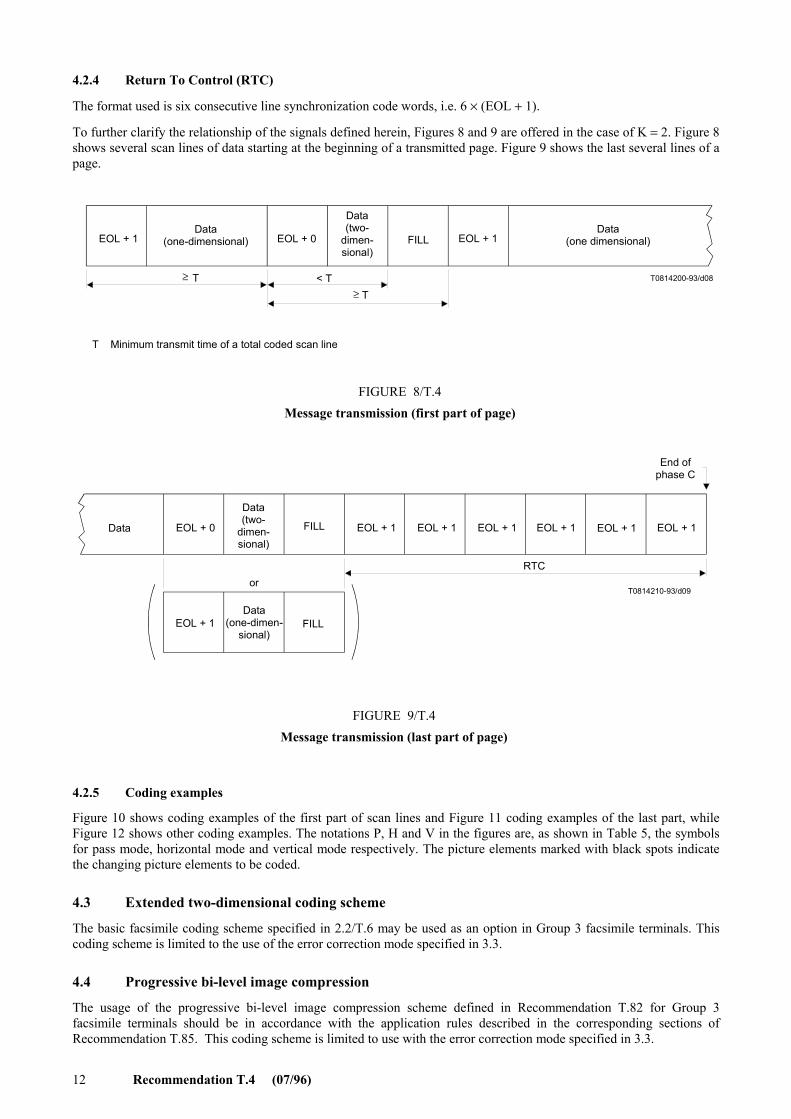
4.2.4 Return To Control (RTC)
The format used is six consecutive line synchronization code words, i.e. 6 × (EOL + 1).
To further clarify the relationship of the signals defined herein, Figures 8 and 9 are offered in the case of K = 2. Figure 8 shows several scan lines of data starting at the beginning of a transmitted page. Figure 9 shows the last several lines of a page.
< T T0814200-93/d08
≥ T
≥ T
EOL + 1 EOL + 0 EOL + 1Data
(one-dimensional)
Data(two-
dimen-sional)
FILLData
(one dimensional)
T Minimum transmit time of a total coded scan line
FIGURE 8/T.4Message transmission (first part of page)
FIGURE 8/T.4...[D08] = 6 CM
T0814210-93/d09
EOL + 0 EOL + 1 EOL + 1 EOL + 1 EOL + 1 EOL + 1 EOL + 1
EOL + 1
Data
Data(two-
dimen-sional)
Data(one-dimen-
sional)FILL
RTC
End ofphase C
FIGURE 9/T.4Message transmission (last part of page)
or
FILL
FIGURE 9/T.4...[D09] = 7.5 CM
4.2.5 Coding examples
Figure 10 shows coding examples of the first part of scan lines and Figure 11 coding examples of the last part, while Figure 12 shows other coding examples. The notations P, H and V in the figures are, as shown in Table 5, the symbols for pass mode, horizontal mode and vertical mode respectively. The picture elements marked with black spots indicate the changing picture elements to be coded.
4.3 Extended two-dimensional coding scheme
The basic facsimile coding scheme specified in 2.2/T.6 may be used as an option in Group 3 facsimile terminals. This coding scheme is limited to the use of the error correction mode specified in 3.3.
4.4 Progressive bi-level image compression
The usage of the progressive bi-level image compression scheme defined in Recommendation T.82 for Group 3 facsimile terminals should be in accordance with the application rules described in the corresponding sections of Recommendation T.85. This coding scheme is limited to use with the error correction mode specified in 3.3.

Recommendation T.4 (07/96) 13
2
4a′0
T0814220-93/d10
1
V(0)
1
VL (1)
VR (2)
1
1
P
10
VR (1)H(0,3)
1
3
5
FIGURE 10/T.4Coding examples: first part of scan line
FIGURE 10/T.4...[D10] = 7.5 CM
a′0
1728
V(0), VR (2)
H(2,6)
1728
V(0),V(0) VL (2),
1728
V(0), V(0)
1728
V(0), V(0)VL (2), VR (3)V(0),
1728
V(0)P,
1728
a0
1728
H(7,0)V(0),T0814230-93/d11
21
4
7
5
3
6
8
1728
FIGURE 11/T.4Coding examples: last part of scan line
FIGURE 11/T.4...[D11] = 8 CM
4.4.1 Normative references
[1] ITU-T Recommendation T.82 (1993), Information technology – Coded representation of picture and audio information – Progressive bi-level image compression.
[2] ITU-T Recommendation T.85 (1995), Application profile for Recommendation T.82 – Progressive bi-level image compression (JBIC coding scheme) for facsimile apparatus.
4.4.2 Single-progression sequential coding scheme
The usage of the single-progression sequential coding scheme described in 3.31/T.82 for Group 3 facsimile terminals should be in accordance with the application rules described in 2/T.85. This coding scheme is used as an option in Group 3 facsimile terminals.
4.4.3 Progressive-compatible sequential coding
For further study.

14 Recommendation T.4 (07/96)
T0814240-93/d12
V(0)VL (1)P
VL (2), V(0)VR (3),
a0H(7,2)
a0
H(3,4)
0 0 0 1 0 1 0 1
P
0 0 0 10 0 1 1 0 0 0 0 1 1
1
2
3
FIGURE 12/T.4Coding examples
Mode:
Code:
FIGURE 12/T.4...[D12] = 8.5 CM
4.4.4 Progressive coding
For further study.
5 Modulation and demodulation
Group 3 terminals operating on the general switched telephone network shall utilize the modulation, scrambler, equalization and timing signals defined in clauses 2, 3, 7, 8, 9 and 11/V.27 ter and in Appendix I/V.27 ter.
5.1 The training signal to be used shall be the long training sequence with protection against talker echo (see 2.5.1/V.27 ter and Table 3/V.27 ter).
5.2 The data signalling rates to be used are 4800 bit/s and 2400 bit/s as defined in Recommendation V.27 ter.
NOTES
1 Some Administrations pointed out that it would not be possible to guarantee the service at a data signalling rate higher than 2400 bit/s.
2 It should be noted that there are terminals in service using, inter alia, other modulation methods.
3 When quality of communication service can successfully support higher speed operation, such as may be possible on leased circuits or high-quality switched circuits, Group 3 terminals may optionally utilize the modulation, scrambler, equalization and timing signals defined in Recommendations V.29 and V.17. For Recommendation V.29, this specifically refers to clauses 1, 2, 3, 4, 7, 8, 9, 10 and 11. Under this option the data should be non-multiplexed and limited to the data signalling rates of 9600 bit/s and 7200 bit/s. For Recommendation V.17, this specifically refers to clauses 1 through 5. For Recommendation V.34, this specifically refers to clauses 1 through 12 and to Annex C/T.30 and Annex F/T.30.
4 When V.17 signalling is used, the training signal shall include the Talker Echo Protection (TEP) signal defined in 5.3/V.17.
5 Terminals operating in the V.34 modulation mode shall use the ECM (Error Correction Mode) defined in Annex A and in Annex A/T.30.
6 Power at the transmitter output
The average power should be adjustable from –15 dBm to 0 dBm but the terminal should be so designed that there is no possibility of this adjustment being tampered with by an operator.
NOTE – The power levels over the international circuits will conform to Recommendation V.2.

Recommendation T.4 (07/96) 15
7 Power at the receiver input
The receiving terminal should be capable of functioning correctly when the received signal level is within the range of 0 dBm to –43 dBm. No control of receiver sensitivity should be provided for operator use.
8 Implementation of terminals
Although paper sizes are referred to, this does not always require a physical paper scanner and/or printer to be implemented. Details may be defined by Administrations.
If the message is not generated from a physical scanner or displayed on paper, then the signals appearing across the network interface shall be identical to those which would be generated if paper input and/or output had been implemented.
9 File transfer mode
File transfer is an optional feature of Group 3 which permits to transmit any data file with or without additional information concerning the file to be transmitted, by using error correction mode specified in Annex A and in Annex A/T.30.
This file transfer is defined in Annex B.
10 Character mode
Character mode is an optional feature of Group 3 which permits to transmit character coded documents, by using error correction mode specified in Annex A and in Annex A/T.30.
This character mode is defined in Annex C.
11 Mixed mode
Mixed mode is an optional feature of Group 3 which permits to transmit pages containing both character coded and facsimile coded information, by using error correction mode specified in Annex A and in Annex A/T.30.
This mixed mode is defined in Annex D.
12 64 kbit/s option
For Group 3 facsimile terminals, a capability to operate at a rate of 64 kbit/s over the Integrated Services Digital Network (ISDN) is provided as a standardized option. There are two technical solutions for this option. One, based on Group 4 protocol, is defined in Annex F and called Group 3 64 kbit/s option F (G3F) which interworks with Group 4 terminals directly. The other, based upon T.30 ECM protocol, is defined in Annex C/T.30 and called Group 3 64 kbit/s option C (G3C) which does not interwork directly with Group 4/G3F.
NOTE – Interworking between G3C terminals and G3F/G4 terminals may be provided by multiple mode terminals using the procedure defined in Annex F/T.90.
13 Continuous-tone colour and gray-scale modes
Continuous-tone colour and gray-scale modes are optional features of Group 3 which enable transmission of colour or gray-scale images. These modes are specified in Annex E.

16 Recommendation T.4 (07/96)
Annex A
Optional error correction mode (This annex forms an integral part of this Recommendation)
A.1 Introduction
This annex specifies the message format required for document transmission incorporating the optional error correction capability.
A.2 Definitions
The definitions contained in this Recommendation and in Recommendation T.30 shall be applied unless explicitly amended.
A.3 Message format
An HDLC frame structure is utilized for all binary coded facsimile message procedures. The basic HDLC structure consists of a number of frames, each of which is subdivided into a number of fields. It provides for frame labelling and error checking.
Specific examples are given in Figures A.1 and A.2 of formats used for binary coded signalling. These examples show an initial Partial Page (PP) frame structure and a last PP frame structure.
In the following descriptions of the fields, the order in which the bits are transmitted is from the most to the least significant bit, i.e. from left to right as printed. The exception to this is the frame number (see A.3.6.1).
The equivalent between binary notation symbols and the significant condition of the signalling code should be in accordance with Recommendation V.1.
A.3.1 Synchronization
A synchronization sequence shall precede all binary coded information whenever a new transmission begins. The synchronization shall be a training sequence and a series of flag sequences for nominal 200 ms, tolerance + 100 ms.
NOTE – Continuous flags have two zeros as shown in the following diagram:
. . . 0111 1110 0111 1110 0111 1110 . . .
A.3.2 Flag sequence (F)
The eight bit HDLC flag sequence is used to denote the beginning and end of the frame for the facsimile message procedure. The flag sequence is also used to establish bit and frame synchronization. To facilitate this, the synchronization defined in A.3.1 should be used prior to the first frame. Subsequent frames and end of the last frame need one or more than one flag sequence.
Format: 0111 1110 NOTE – The leading flag of a frame may be the trailing flag of the previous frame.
A.3.3 Address field (A)
The eight bit HDLC address field is intended to provide identification of specific terminal(s) in a multi-point arrangement. In the case of transmission on the general switched telephone network, this field is limited to a single format.
Format: 1111 1111
A.3.4 Control field (C)
The eight bit HDLC control field provides the capability of encoding the command unique to the facsimile message procedure.
Format: 1100 X000
The X bit is set to 0 for the FCD frame (Facsimile Coded Data frame) and the RCP frame (return to control for partial page frame).
Recommendation T.4 (07/96) 17
T0814250-93/d13
0 1 n
F F A C FCD FCS F F
FCF FIF
F F F F F F FA A AC C CRCP RCP RCPFCS FCS FCS
F F A C FCS F F C
FCF FCF FCF
FCF FIF
RCP
A
Initial PP
SynchronizationFacsimile
coded data(FCD)
FCD frame FCD frame FCD frameRCP frame RCP frame RCP frame
nth FCD frame
FrameNo. n–1
Facsimilecoded data
(Note)
1st RCP frame 2nd RCP frame 3rd RCP frame
Maximum50 ms
End ofphase C
1st FCD frame
FrameNo. 0
Facsimilecoded data
FIGURE A.1/T.4Initial Partial Page (PP) frame structure
FCD
NOTE – See A.3.2.
FIGURE A.1/T.4...[D13] = 15 CM
A.3.5 Facsimile Control Field (FCF)
In order to distinguish between the FCD frame (facsimile coded data frame) and the RCP frame (return to control for partial page frame), the FCF for the in-message procedure is defined as follows:
1) FCF for the FCD frame
Format: 0110 0000
2) FCF for the RCP frame
Format: 0110 0001
A.3.6 Facsimile Information Field (FIF)
The facsimile information field is a length of 257 or 65 octets (see Note 1) and is divided into two parts, the frame number and the facsimile data field (see Note 2).
NOTES
1 This does not include bit stuffing to preclude non-valid flag sequences.
2 There is no information field in the RCP frame.

18 Recommendation T.4 (07/96)
T0814260-93/d14
RCP
0 1 m
F F
F FF F
F F
A
A
A
C
C
C
FCD RTC FCS
FCF FIF
RCP FCS F F A C RCP RCPFFFCS A C FCS F
FCF FCF FCF
FCD FCS F F A C
FCF FIF
Last PP
SynchronizationFacsimile
coded data RTCVariable lengthstring of zeros
FCD frame FCD frameFCD frame RCP frame RCP frame RCP frame
(Note)mth TCD frame
FrameNo. m–1
Facsimilecoded data
Variable lengthstring of zeros
1st RCP frame 2nd RCP frame 3rd RCP frame
1st FCD frame
End of phase CFrameNo. 0
Facsimilecoded data
NOTE – See A.3.2.
FIGURE A.2/T.4Last Partial Page (PP) frame structure
Maximum50 ms
FIGURE A.2/T.4...[D14] = 15 CM
A.3.6.1 Frame number
This is an eight bit binary number. The frame number is defined to be the first eight bits of the facsimile information field. The least significant bit is transmitted first.
The frame number 0-255 (maximum number is 255) is used to identify the facsimile data field (see Annex A/T.30).
The frame 0 is transmitted first in each block.
A.3.6.2 Facsimile data field
The coding schemes specified in clause 4 are valid with the following notes.
1) The facsimile data field is a length of 256 or 64 octets.
2) The total coded scan line is defined as the sum of data bits plus the EOL bits. For the optional two-dimensional coding scheme as described in 4.2, the total coded scan line is defined as the sum of data bits plus the EOL bits plus a tag bit.
3) At the end of facsimile data field, if necessary, pad bits may be used to align on octet boundaries and frame boundaries (see Notes 1 and 2). The format is a variable length string of zeros.
NOTES
1 The receiver is able to receive both pad bits and fill bits.
2 The facsimile data field length of the final frame including RTC signal may be less than 256 or 64 octets.

Recommendation T.4 (07/96) 19
A.3.7 Frame Checking Sequence (FCS)
The FCS shall be a 16 bit sequence (see 5.3.7/T.30).
A.3.8 Return to control for partial page (RCP)
The end of a partial page transmission is indicated by sending three consecutive RCP frames (see Note).
Following these RCP frames, the transmitter will send the post message commands in the framed format and the data signalling rate of the control signals defined in Annex A/T.30.
NOTE – The flag sequence following the last RCP frame shall be less than 50 ms.
Annex B
Optional file transfer mode (This annex forms an integral part of this Recommendation)
B.1 Introduction
This annex specifies the technical features of the file transfer for Group 3.
File transfer is an optional feature of Group 3 which permits to transmit any data file with or without additional information concerning the file to be transmitted.
The content of the data file itself may be of any kind of coding.
The file transfer applied to Group 3 terminals is based on Recommendation T.30 and on Annex A (error correction mode).
Because files must be reliably transferred, using error correction mode described in Annex A and in Annex A/T.30 is mandatory in the context of Annex C.
From the point of view of service, file transfer is defined in Recommendation F.551 where alignment between different telematic applications (Group 3, Group 4) is achieved.
B.2 Definitions
The definitions contained in this Recommendation and in Recommendation T.30 apply unless explicitly amended.
B.3 Normative references
In addition to this Recommendation and Recommendation T.30, the present annex contains references to other ITU-T and ISO Standards:
[1] CCITT Recommendation T.50 (1992), International Alphabet (IRA). (Formerly International Alphabet No. 5 or IA5) – Information technology – 7-bit coded character set for information interchange.
[2] CCITT Recommendation X.209 (1988), Specification of basic encoding rules for Abstract Syntax Notation One (ASN.1).
[3] ITU-T Recommendation T.434 (1996), Binary file transfer format for the telematic services.
[4] ISO 9735:1988, Electronic data interchange for administration, commerce and transport (EDIFACT) – Application level syntax rules.
[5] ITU-T Recommendation F.551 (1993), Service Recommendation for the telematic file transfer within telefax 3, telefax 4, teletex services and message handling services.

20 Recommendation T.4 (07/96)
[6] CCITT Recommendation T.51 (1992) Latin based coded characters sets for telematic services.
[7] ISO 8859-1:1987, Information processing – 8-bit single-byte coded graphic character sets – Part 1: Latin alphabet No. 1.
B.4 Definition of the different file transfer modes
At the time being, four file transfer modes exist:
– Basic Transfer Mode: (BTM),
– Document Transfer Mode: (DTM),
– Binary File Transfer: (BFT),
– EDIFACT transfer: (EDI).
For a comprehensive explanation, from the point of view of service, of the use of these four different file transfer modes, see Recommendation F.551 [5].
Additional file transfer modes besides these four modes may be issued in further versions of this Recommendation and Recommendation T.30.
B.4.1 basic transfer mode (BTM): Basic transfer mode provides the user of a Group 3 terminal with a means to exchange files of any kind (binary files, wordprocessor native format documents, bitmaps, etc.) without any additional information.
B.4.2 document transfer mode (DTM): Document transfer mode provides the user of a Group 3 terminal with a means to exchange files of any kind with additional information readable by the user and included in a file description.
The file description is a structured information regarding the file (e.g. file name, file type, file coding, etc.). On the receiving side, it can either be handled by automatic processing or read by the user.
The file description is transmitted ahead of the data file itself and concatenated with this latter.
B.4.3 binary file transfer (BFT): Binary file transfer provides the user of a Group 3 terminal with a means to exchange files of any kind with additional information included in a file description and automatically processed at the receiving side.
The file description is a structured document which contains information regarding the file (e.g. file name, contents types, etc.). It is mainly aimed to be automatically processed at the receiving side.
The coding rules which apply for the coding of the file description are technically aligned on those of FTAM (coding according to Recommendation X.209 [2]).
The file description is transmitted ahead of the data file itself and concatenated with this latter.
For technical description of the binary file transfer, see Recommendation T.434 [3], Annex B/T.30 and Appendix VI/T.30.
B.4.4 EDIFACT transfer: EDIFACT transfer provides the user of a Group 3 terminal with a means to exchange EDIFACT files coded according to ISO 9735 [4] rules.
B.5 Coding of the file description
B.5.1 Basic Transfer Mode (BTM)
BTM mode does not require to transmit any additional information. Then, no file description exists. Only the file itself is sent.

Recommendation T.4 (07/96) 21
B.5.2 Document Transfer Mode (DTM)
The character set which shall be used to code the file description is the primary set of graphic characters of Recommendation T.51 [6] plus character “SPACE” (this later in position 2/0 of the table).
NOTE 1 – This set is exactly the same as that of International Alphabet No. 5 (Recommendation T.50 [1]) and that of the left part of characters set ISO 8859-1 [7].
Coding of the file description sent by a Group 3 terminal
For details of the utility of the different fields of the file description listed below, see Recommendation F.551 [5].
CR FF 6.1 : ADDITIONAL INFORMATION :
CR LF 1 : FILE NAME :
CR LF [file name] (72 characters maximum)
CR LF 2 : APPLICATION REFERENCE :
CR LF [application reference] (72 characters maximum)
CR LF 3 : TYPE :
CR LF [coding] (72 characters maximum)
CR LF 4 : ENVIRONMENT :
CR LF 4.1 : TERMINAL:
CR LF [terminal] (72 characters maximum)
CR LF 4.2 : OPERATING SYSTEM :
CR LF [operating system] (72 characters maximum)
CR LF 4.3 : PROGRAM :
CR LF [program] (72 characters maximum)
CR LF 4.4 : CHARACTER SET :
CR LF [terminal character set] (72 characters maximum)
CR LF 5 : LAST REVISION :
CR LF [last revision] (72 characters maximum)
CR LF 6 : LENGTH :
CR LF [file length] (72 characters maximum)
CR LF 7 : PATH :
CR LF [path name] (72 characters maximum)
CR LF 8 : RESERVED :
CR LF [reserved] (72 characters maximum)
CR LF 9 : AUTHOR’S NAME :
CR LF [author’s name] (72 characters maximum)
CR LF 10 : USER VISIBLE STRING :
CR LF [[user’s comments]] (8 lines, 72 characters maximum per line)

22 Recommendation T.4 (07/96)
CR LF 11 : FUTUR FILE LENGTH :
CR LF [futur file length] (72 characters maximum)
CR LF 12 : STRUCTURE :
CR LF [structure] (72 characters maximum)
CR LF 13 : PERMITTED ACTIONS :
CR LF [permitted actions] (72 characters maximum)
CR LF 14 : LEGAL QUALIFICATIONS :
CR LF [legal qualification] (72 characters maximum)
CR LF 15 : CREATION :
CR LF [date and time of creation] (72 characters maximum)
CR LF 16 : LAST READ ACCESS :
CR LF [last read access] (72 characters maximum)
CR LF 17 : IDENTITY OF THE LAST MODIFIER :
CR LF [identity of the last modifier] (72 characters maximum)
CR LF 18 : IDENTITY OF THE LAST READER :
CR LF [identity of the last reader] (72 characters maximum)
CR LF 19 : RECIPIENT :
CR LF [recipient] (72 characters maximum)
CR LF 20 : TFT VERSION :
CR LF [TFT version] (72 characters maximum)
CR LF 21 : COMPRESSED :
CR LF [compression] (72 characters maximum)
CR LF
NOTE 2 – When only one [ ] is used, this element is included in one line. When [[ ]] is used, this element can be included
in several lines. NOTE 3 – Further additional information fields may be added in future versions of Annex C. A terminal shall not be
disturbed by unknown fields. NOTE 4 – The file description must contain at least the following information:
CR LF 6.1 : ADDITIONAL INFORMATION :
CR LF 1 : FILE NAME :
CR LF [file name] (72 characters maximum)
CR LF
CR LF
B.5.3 Binary File Transfer (BFT)
The structure of the additional information to be transmitted is described in Recommendation T.434 [3].
Recommendation T.4 (07/96) 23
B.5.4 EDIFACT transfer
To transfer EDIFACT files there is no need for a file description.
The structure of the information to be transmitted is described in the ISO 9735 specification [4].
B.6 Message format – Blocks structure
The structure of the data block sent by means of error correction mode is the same structure as when T.4 facsimile coded data is sent (see description in Annex A), except for the last block (see further).
The sequence of octets is transmitted beginning with the least significant bit of the first octet.
As normally, the sending terminal indicates the frame size by the DCS frame content (see Table 2/T.30). The values of frame size applicable are 256 or 64 octets.
At the end of the transmission of a file, the sending terminal may send a block the size of which is less than 256 frames. This block is called a short block.
This short block may have its last frame less than 256 or 64 octets.
Within the T.4 code exists an “end of page” (codeword RTC) which permits to delineate the pads bits which are usually inserted at the end of the last frame of the last block to match, either an octet boundary or the frame limit (see A.3.6.2).
As for file transfer, such a general “end of page” codeword cannot exist because files may be of different kinds, the last frame of the short block shall contain no pad bit.
Hence, a sender must be able to send the last frame containing less than 256 or 64 data octets.
Figure B.1 represents the structure of the short block.
B.7 Protocol aspects
B.7.1 Abbreviations
The abbreviations contained in Recommendation T.30 and used in this annex are:
DCS Digital Command Signal
DIS Digital Identification Signal
DTC Digital Transmit Command
PPS-EOM Partial Page Signal – End Of Message
PPS-EOP Partial Page Signal – End Of Procedure
PPS-MPS Partial Page Signal – Multi Page Signal
PPS-NULL Partial page boundary signal
B.7.2 Phase B of Recommendation T.30 (Pre-message procedure)
A Group 3 terminal negotiates a file transfer mode among the above mentioned modes (BTM, DTM, BFT, EDIFACT) by using the usual DIS/DTC/DCS frames of T.30 protocol.
The facsimile information field of the frames DIS/DTC/DCS contains specific bits for the file transfer modes, see bits allocation in Table 2/T.30.
NOTE – The use of Facsimile Service Info file (FSI) is for further study.
B.7.3 Specific application rules of T.30 protocol
This subclause is not applicable to binary file transfer. For precisions about specific application rules of T.30 protocol to BFT, see Annex B/T.30 and Appendix VI/T.30.

24 Recommendation T.4 (07/96)
T0814310-93/d15
FIGURE B.1/T.4Last block frame structure
NOTE – See A.3.2.
Last PP
Synchronization File data RCP
FCD frame0
FCD frame1 FCD frame
mRCP frame RCP frame RCP frame
F F A C FCDFrame
No. m–1 File data FCS F F
mth FCD frame (Note)
FCF FIF
F F A C RCP
FCF
1st RCP frame 2nd RCP frame 3rd RCP frame
FCF FCF Maximum50 ms
End ofphase C
FCS F F A C RCP FCS F F A C RCP FCS F
F F A C FCD
FCF
FrameNo. 0 File data
FIF
FCS F F A C
1st FCD frame
FIGURE B.1/T.4...[D15] = 16 CM
Specific application rules of T.30 protocol concerning T.30 post-message commands exist for file transfer:
– Procedure interrupt post-message commands (PPS-PRI-Q) shall not be used.
– As files must be entirely transmitted, EOR-Q signals are not allowed. When the transmitter receives PPR four times, the modem speed must fall back (by use of CTC command) or the Group 3 terminal has to switch to phase E (emission of DCN and call release). In case of failure, the file must be retransmitted as a whole.
Other post-message commands have largely their usual purpose as described in Annex A/T.30 (error correction mode):
– PPS-NULL commands are used normally to separate intermediate error correction mode blocks.
– Page boundary indications PPS-MPS commands are used in place of PPS-NULL commands at the end of intermediate files if several files are to be transmitted in the same communication.
– PPS-EOP command is sent at the end of the last block of the last file to be transmitted.
– PPS-EOM commands are sent at the end of intermediate files if several files are to be transmitted in the same communication and a change in the mode of the communication is desired.

Recommendation T.4 (07/96) 25
Annex C
Optional character mode (This annex forms an integral part of this Recommendation)
C.1 Introduction
This annex specifies the technical features of the character mode of Group 3.
Character mode is an optional feature of Group 3 which permits to transmit character coded documents by the means of T.30 protocol.
Character mode is based on Recommendation T.30 and on Annex A (error correction mode).
Because character coded documents must be reliably transferred, using error correction mode described in Annex A and in Annex A/T.30 is mandatory in the context of this annex.
C.2 Definitions
The definitions contained in this Recommendation and in Recommendation T.30 apply, unless explicitly amended.
C.3 Normative references
In addition to this Recommendation and Recommendation T.30, this annex contains references to other ITU-T and ISO Standards:
– ITU-T Recommendation T.51 (1992), Latin based coded characters sets for telematic services.
– ISO 8859-1:1987, Information processing – 8-bit single-byte coded graphic character sets – Part 1: Latin Alphabet No. 1.
C.4 Graphic character set – Repertoire and coding
C.4.1 Repertoire of graphic characters
The character repertoire which represents and describes the graphic characters allowed for character mode is that of ISO 8859-1 in addition with the box-drawing character repertoire which is a subset of registered ITU-T set ISO 72.
From the character mode of Group 3 terminals, the following character positions are excluded: 4/4...4/11, 4/13...4/15, 5/11...5/14, 6/0...6/13, 7/0...7/15.
A Group 3 terminal providing character mode shall not send any graphic character which is neither contained in repertoire ISO 8859-1 nor the box-drawing character repertoire.
Taking into account other graphic characters (e.g. national graphic characters) is for further study.
C.4.2 Coding of graphic characters
The coding of the graphic characters is not that of the code table given in ISO 8859-1; it shall follow the coding rules of Recommendation T.51.
The graphic characters are coded by bytes (8-bits environment of Recommendation T.51).
The left part of the table (bytes “0/0” to “7/15”) is fixed as the primary set of Recommendation T.51 (see Figure 1/T.51). That is fixed by default, then designation and invocation sequences as defined in Recommendation T.51 shall not be used prior to the transmission of these characters.
The “SPACE” character is coded “2/0”.

26 Recommendation T.4 (07/96)
The right part of the table (bytes “8/0” to “15/15”) is fixed as the supplementary set of Recommendation T.51 (see Figure 2/T.51). That is fixed by default, then designation and invocation sequences as defined in Recommendation T.51 shall not be used prior to the transmission of these characters.
To be coded, some graphic characters represented in ISO 8859-1 need two bytes of the 8-bits code table specified above. For example, diacritical characters require two bytes: the diacritical mark followed by the basic character.
For using a box-drawing character, a single shift function SS2 is necessary prior to the 8-bits code of the character itself. Then, each box-drawing character needs two octets for the transmission: SS2 followed by the character code.
SS2 is the “single shift two function” as described in Recommendation T.51. It is coded: “1/9”.
Then, following the T.51 rules, box-drawing character repertoire is the graphic character set “G2”.
This repertoire is fixed as G2 by default, then the designation sequence as defined in Recommendation T.51 shall not be used.
C.4.3 Fall-back in case of a graphic character of repertoire ISO 8859-1 not supported
When a character from repertoire ISO 8859-1 or from the box-drawing character repertoire is received by a Group 3 terminal which does not support it, a fall-back behaviour is required in order that the reception of the document can go on.
The fall-back behaviour may be the following:
– upon reception of a diacritical character not supported, the receiver considers it as a basic character and discards the diacritical mark;
– upon reception of a basic character not supported, the receiver considers it as another basic character.
C.5 Page format
The character coded pages have their format fixed:
– Vertical basic format with 55 lines of 77 characters.
NOTES
1 55 lines per page permit to print the text received at 6 LPI (Lines Per Inch).
2 55 lines are the maximum length of a page. Shorter pages are permitted.
3 Different page formats are for further study.
C.6 Control functions
Control functions act on the formatting of the document (go to next line, etc.) and permit to switch on or to switch off character attributes.
Some control functions are represented with a unique byte; some others (with parameters) are represented by a sequence beginning by CSI (“9/11”).
If the receiving terminal receives a control function it cannot handle, it must simply ignore it and proceed normally.
If the receiving terminal receives a control function it can handle but the parameters are unknown to it, it must also simply ignore the request.
NOTE – It is the responsibility of the sender to provide for correct sending format. If the sending terminal is providing an incorrect format, that will not necessarily be rejected by the receiving terminal, but the results of that cannot be predicted.

Recommendation T.4 (07/96) 27
C.6.1 Single byte control functions applicable to character mode
The single byte control functions (coded by a single byte) applicable to character mode are:
Escape sequences (beginning by the control character “ESC”) shall not be emitted by a Group 3 terminal.
NOTES
1 Other single byte control functions are for further study.
2 Coding values of LF, FF, CR, SS2 and CSI are in line with Recommendation T.51.
C.6.2 Control functions with parameters applicable to character mode
The character mode implements some control functions with parameters which are described further in this annex.
Control functions with parameters consist of control sequences beginning by Control Sequence Introducer (CSI) and followed by one or several bytes.
NOTE – The rules of coding of control functions within this annex are in line with Recommendation T.51.
C.6.3 Control functions for format effectors
C.6.3.1 Page initiator
The “page initiator” shall be used at the beginning of each page.
Coding: CR FF (0/13 0/12)
C.6.3.2 End of line
The “end of line” shall be used at the end of each line, except for the last line of the last character coded page.
Coding : CR LF (0/13 0/10) NOTE – “End of line” permits to send lines which contain less than 77 characters.
C.6.3.3 End of the last character coded page
The “end of the last character coded page” shall be used at the end of the last character coded page.
Coding : CR FF (0/13 0/12)
C.6.3.4 Horizontal tabulation
Horizontal tabulation moves the active position to the next horizontal tabulation stop. The horizontal tabulation stops are defined in fixed steps of 5 characters, the first one being at the fifth character of the line.
C.6.4 Control functions for characters attributes
Characters attributes permit to modify the rendition of the characters.
The graphic rendition is selected by the control function SGR.
LF : Line Feed : 0/10
FF : Form Feed : 0/12
CR : Carriage Return : 0/13
HT : Horizontal Tabulation : 0/9
SS2 : Single Shift two : 1/9
CSI : Control Sequence Introducer : 9/11

28 Recommendation T.4 (07/96)
Coding : CSI 3/X 6/13 (9/11 3/X 6/13),
X depends on the attribute, (see Table C.1).
The effect follows immediately the function and is cancelled by a new SGR function or by a page initiator.
The character attributes are not negotiated. If they are not supported at the receiving side, a fall-back behaviour is required (attribute ignored).
TABLE C.1/T.4
C.7 Message format – Blocks structure
The structure of the block of data sent by means of error correction mode is the same structure as when T.4 facsimile data is sent (see description in Annex A), except for the last block (see further).
A sequence of octets is transmitted beginning with the least significant bit of the first octet.
As normally, the sending terminal indicates the frame size by the DCS frame content (see Table 2/T.30). The values of frame size applicable are 256 or 64.
At the end of the transmission of a page, the sending terminal may send a block the size of which is less than 256 frames. This block is called a short block.
This short block may have its last frame less than 256 (or 64 octets). Within this last frame, pad bytes may be used to align frame boundary.
The format is a variable sequence of octets “0/0”.
These pad bytes are inserted between the last “end of line” of the document and the end of the frame (same principle as for T.4 data where pad bits may be inserted after RTC code).
The receiver must be able to receive pad bytes and to discard them.
Figure C.1 represents the structure of the short block.
C.8 Protocol aspects
C.8.1 Abbreviations
The abbreviations contained in Recommendation T.30 and used in this annex are:
DCS Digital Command Signal
DIS Digital Identification Signal
DTC Digital Transmit Command
PPS-EOM Partial Page Signal – End Of Message
PPS-EOP Partial Page Signal – End Of Procedure
PPS-MPS Partial Page Signal – Multi Page Signal
PPS-NULL Partial page boundary signal
EOR End Of Retransmission
Character attribute Coding Availability
Default rendition CSI 3/0 6/13 Optional
Bold intensity CSI 3/1 6/13 Optional
Italicized CSI 3/3 6/13 Optional
Singly underlined character CSI 3/4 6/13 Optional

Recommendation T.4 (07/96) 29
T0814320-93/d16
NOTE – See A.3.2.
Last PP
SynchronizationCharacterscoded data
RCP
FCD frame0
FCD frame1
FCD framem
RCP frame RCP frame RCP frame
F F A C FCD Characterscoded data
FCS F
mth FCD frame(Note)
FCF FIF
F F A C RCP
FCF
1st RCP frame 2nd RCP frame 3rd RCP frame
FCF FCF Maximum50 ms
End ofphase C
FCS F F A C RCP FCS F F A C RCP FCS F
F F A C FCD
FCF
FrameNo. 0
Characterscoded data
FIF
FCS F F A C
Variable lengthstring of “0/0”
Variable lengthstring of “0/0”
F
1st FCD frame
FIGURE C.1/T.4Last block frame structure
FrameNo. m-1
C.8.2 Phase B of Recommendation T.30 (Pre-message procedure)
A Group 3 terminal negotiates the character mode by using the usual DIS/DTC/DCS frames of T.30 protocol.
The facsimile information field of the frames DIS/DTC/DCS contains specific bits for the character mode. See bits allocation in Table 2/T.30.
NOTES
1 The use of control document to access facsimile enhanced service is for further study.
2 Future negotiation mechanism is for further study.
C.8.3 End of document, beginning of page, end of block
Post message commands have their usual purpose as described in Annex A/T.30 (error correction mode):
– PPS-NULL command is used normally to separate intermediate error correction mode blocks.
– PPS-MPS command is sent at the end of each page.
– In addition, the “page initiator” (see C.6.3.1) is present at the beginning of each page.

30 Recommendation T.4 (07/96)
– PPS-EOP command is sent at the end of the last block of the characters coded document if no further document is to be transmitted.
– PPS-EOM command is sent at the end of intermediate characters coded document if several are to be transmitted in the same communication.
The use of End Of Retransmission (EOR) command, defined in A.4.3/T.30, is not permitted with the character mode. If all frames have not been correctly received after the third transmission of the error frames, then the transmitter shall use the Continue To Correct (CTC) command (A.4.1/T.30).
C.9 Imaging process
The displaying of the coded characters is assumed to be from left to right.
The position of the first character line on the facsimile page is the 105th pel on the 131st scanning line (at 3.85 lines/mm).
The size of the character box is 20 pels wide by 16 lines / mm high and concatenated across the page. Since no gap is provided between the boxes, implementations should ensure that when the characters are displayed, there is a separation between the characters.
Annex D
Optional mixed mode (This annex forms an integral part of this Recommendation)
D.1 Introduction
This annex specifies the technical features of the optional Mixed Mode (MM) for Group 3 facsimile terminals.
MM allows pages containing both character coded and facsimile coded information to be transferred between compatible terminals. The use of the standardized error correction mode defined in Annex A and Annex A/T.30 is mandatory with MM.
With MM, the page is divided into slices horizontally across the page, each slice contains either facsimile or character coded information but not both.
The content of the information field is identified by means of the facsimile control field (see D.3). The first slice is either facsimile or character coded. Subsequent slices are alternatively character of facsimile coded.
D.2 Definitions
The definitions contained in this Recommendation and Recommendation T.30 apply unless explicitly amended by this annex.
D.3 Facsimile Control Field (FCF)
In order to distinguish between the Facsimile Coded Data (FCD), the return to control for partial page (RCP), and the Character Coded Data (CCD) frames, the FCF for the in-message procedure is defined as follows:
1) FCF for the FCD frame
0110 0000
2) FCF for the RCP frame
0110 0001
3) FCF for the CCD frame
0110 0010 NOTE – The FCF code 0110 0100 is reserved for future use.
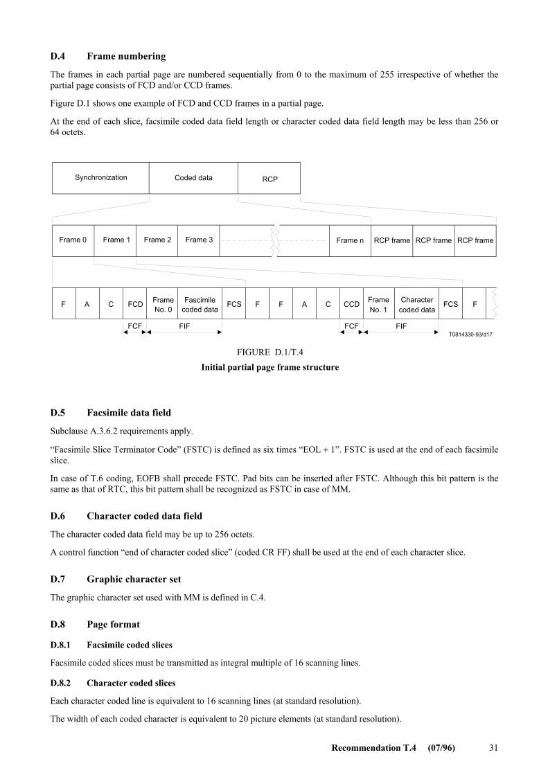
Recommendation T.4 (07/96) 31
D.4 Frame numbering
The frames in each partial page are numbered sequentially from 0 to the maximum of 255 irrespective of whether the partial page consists of FCD and/or CCD frames.
Figure D.1 shows one example of FCD and CCD frames in a partial page.
At the end of each slice, facsimile coded data field length or character coded data field length may be less than 256 or 64 octets.
T0814330-93/d17
Synchronization Coded data RCP
Frame 0 Frame 1 Frame 2 Frame 3 Frame n RCP frame RCP frame RCP frame
F A C FCD FrameNo. 0
FCF FIF
Fascimilecoded data
FCS F F A C CCD FrameNo. 1
FCF FIF
Charactercoded data
FCS F
FIGURE D.1/T.4Initial partial page frame structure
FIGURE D.1/T.4...[D17] = 9.5 cm
D.5 Facsimile data field
Subclause A.3.6.2 requirements apply.
“Facsimile Slice Terminator Code” (FSTC) is defined as six times “EOL + 1”. FSTC is used at the end of each facsimile slice.
In case of T.6 coding, EOFB shall precede FSTC. Pad bits can be inserted after FSTC. Although this bit pattern is the same as that of RTC, this bit pattern shall be recognized as FSTC in case of MM.
D.6 Character coded data field
The character coded data field may be up to 256 octets.
A control function “end of character coded slice” (coded CR FF) shall be used at the end of each character slice.
D.7 Graphic character set
The graphic character set used with MM is defined in C.4.
D.8 Page format
D.8.1 Facsimile coded slices
Facsimile coded slices must be transmitted as integral multiple of 16 scanning lines.
D.8.2 Character coded slices
Each character coded line is equivalent to 16 scanning lines (at standard resolution).
The width of each coded character is equivalent to 20 picture elements (at standard resolution).

32 Recommendation T.4 (07/96)
To ensure printing on an A4 page, a maximum of 77 characters per line should be transmitted.
If the first slice on a page is character coded, the first six character lines may not be reproduced; therefore, it is recommended that the transmitter sends 6 combinations of CR LF before the start of the information.
D.8.3 Page length
To ensure that the text can be reproduced on an A4 page, the total length of each page should not exceed 1024 scanning lines (at standard resolution). This means that the maximum length of a coded character slice is 64 character lines.
D.9 Control functions
The control functions used in simple MM are defined in C.6. The “page initiator” is used only if the first slice of the page is character coded. The “end of character coded slice” function shall be used at the end of each character coded slice.
No specific function exists to indicate the end of the last character coded page. “End of character coded slice” function is used at the end of the last character coded slice, as for the previous character slices.
D.10 End Of Retransmission (EOR)
The use of the End Of Retransmission (EOR) command defined in A.4.3/T.30 is not permitted with MM. If all the frames have not been correctly received after the third transmission of the error frames, then the transmitter shall use the Continue To Correct (CTC) command (see A.4.1/T.30).
Annex E
Optional continuous tone colour mode (This annex forms an integral part of this Recommendation)
E.1 Introduction
This annex specifies the technical features of continuous-tone colour and gray-scale mode for Group 3 facsimile. Continuous-tone and colour mode is an optional feature of Group 3 facsimile which enables gray-scale or colour images.
The method for image encoding is based upon Recommendation T.81 (JPEG), Digital compression and coding of continuous-tone still images, and Recommendation T.42, which specifies the colour space representation.
The method for image transfer applied to Group 3 facsimile is a subset of Recommendation T.81, consistent with this Recommendation.
The description of colour components and colorimetry for colour data is included in Recommendation T.42.
Together with Annex E/T.30, this annex provides specification of the telecommunication protocol and coding for transmission of continuous-tone colour and gray scale images via Group 3 facsimile service.
E.2 Definitions
The definitions contained in Recommendations T.4, T.30, T.81 and T.42 apply unless explicitly amended.
E.2.1 CIELAB; CIE 1976 (L* a* b*) space: A colour space defined by the CIE (Commission Internationale de l’Eclairage), having approximately equal visually perceptible difference between equispaced points throughout the space. The three components are L*, or Lightness, and a* and b* in chrominance.

Recommendation T.4 (07/96) 33
E.2.2 joint photographic experts group (JPEG), and also shorthand for the encoding method, described in Recommendation T.81, which was defined by this group.
E.2.3 baseline JPEG: A particular eight-bit sequential Discrete Cosine Transform (DCT) – based encoding and decoding process specified in Recommendation T.81.
E.2.4 quantisation table: A set of 64 values used to quantise the DCT coefficients in baseline JPEG.
E.2.5 huffman table: A set of variable length codes required in a Huffman encoder and a Huffman decoder.
E.3 References
– CIE Publication No. 15.2, Colorimetry, 2nd Ed., 1986.
– CCITT Recommendation T.81 (1992) | ISO/IEC 10918-1:1994, Information technology – Digital com-pression and coding of continuous-tone still images – Requirements and guidelines. (Commonly referred to as JPEG standard).
– ITU-T Recommendation T.42 (1994), Continuous-tone colour representation method for facsimile.
– ITU-T Recommendation T.30 (1993), Procedures for document facsimile transmission in the general switched telephone network.
E.4 Definition of different multi-level image transfer modes
The following different multi-level image transfer modes are defined:
Lossy Gray-scale Mode (LGM)
Lossy Colour Mode (LCM)
LossLess Gray-scale Mode (LLGM)
LossLess Colour Mode (LLCM)
At this time, only LGM and LCM are described. LLGM and LLCM, while available within the coding methods described in Recommendation T.81, are for further study.
E.4.1 lossy gray-scale mode: Lossy gray-scale mode provides the user of a Group 3 terminal with a means to transfer images with more than one bit/pel of monochrome image data. The method is not information conserving, and the amount of lossiness is determined by the quantisation tables described in Recommendation T.81. The appearances of the gray-scale levels are defined by the Lightness (L*) component of CIELAB space.
E.4.2 lossy Colour Mode: Lossy colour mode provides the user of a Group 3 terminal with a means to transfer images with more than one bit/pel of image data in each of three colour components. The colour components are explicitly defined in Recommendation T.42, and consist of CIELAB lightness and chrominance variables. The method is not information conserving, and the amount of lossiness is determined by the quantisation tables described in Recommendation T.81.
E.5 Coding of the image description
Sufficient image description is specified within the headers of Annex B/T.81, Compressed data format, to decode the image data. Other information, such as aspect ratio, orientation, and colour space are defined uniquely by the application. In addition, some information required to establish the availability of this service is transmitted as specified in Annex E/T.30. Specifically, the transfer of JPEG-coded data, the use of gray-scale or colour data, and the use of 8 or 12 bits/component/pel data is negotiated and specified in the DIS/DTC and DCS frames as stated in Annex E/T.30.
E.5.1 lossy gray-scale mode: The image description coding for gray-scale mode is accomplished by parameters specifying JPEG coding of a gray-scale image, as specified in Recommendation T.30 Annex E, as well as by specification of a single component as the number-of-components, Nf, in the Frame Header. The JPEG syntax is more thoroughly described in E.6.

34 Recommendation T.4 (07/96)
E.5.2 lossy colour mode: The image description coding for colour mode is accomplished by parameters specifying JPEG coding of a colour image and spatial resolution as specified in Annex E/T.30, as well as by specification of three components as the number-of-components, Nf, in the Frame Header. The colour data are block-interleaved, as specified in Recommendation T.81. In addition, the subsampling factors and correspondence of quantisation tables to colour components are specified within the Frame Header, as detailed in Recommendation T.81.
E.6 Data format
E.6.1 Overview
The JPEG-encoded image data consist of a series of markers, parameters, and scan data that specify the image coding parameters, image size, bit-resolution, and entropy-encoded block-interleaved data.
The data stream is encoded for facsimile transfer using the Error Correction Mode (ECM) specified in Annex A/T.30. Pad characters (X’00’, the ‘null’ character, or X’20’, the ‘space’ character) are added after EOI within the last ECM frame of the page to complete the last frame, in alignment with Annex A/T.4.
E.6.2 JPEG data structure
The JPEG data structure for this application has the following elements, as specified by Annex B/T.81: Parameters, markers, and entropy-encoded data segments. Parameters and markers are often organised into marker segments. Parameters are integers of length 1/2, 1, or 2 octets. Markers are assigned two-octet codes, an X’FF’ octet followed by an octet not equal to X’00’ or X’FF’.
The markers used in this application are characterised as follows:
1) The encoder shall insert these markers, and the decoder shall be able to carry out a corresponding process upon these marker segments:
SOI, APP1, DQT, DHT, SOF0, SOS, EOI
2) The encoder may insert these markers without negotiation, and the decoder shall be able to carry out a corresponding process upon these marker segments:
DRI, RSTn, DNL
3) The encoder may insert this marker without negotiation, and the decoder shall skip these marker segments and continue the decoding process:
COM, APPn (n not I)
4) The encoder may insert this marker when the decoder has the ability to carry out a process corresponding to this marker segment (negotiation is necessary). If used, it replaces SOF0 in the data stream:
SOF1
The definitions of the markers are precise, and given in detail in Annex B/T.81, except for the APPn markers. For example, SOI is a two-octet word X’FFD8’, in hexadecimal notation. APPn markers are undefined markers provided within Recommendation T.81 to facilitate the adaptation of that Recommendation to particular applications. Group 3 colour facsimile is one such application. The APPn markers are defined in E.6.5-E.6.8.
The DNL marker is a JPEG option that is critical to the function of this coding method in terminals that do not pre-scan the image. When the number of lines, Y, in the frame header is set to value 0, the number of lines in the frame remains open until defined by the DNL marker at the end of the scan. If the scanning terminates early, the DNL marker can also be used to reset the Y value to a smaller value.

Recommendation T.4 (07/96) 35
E.6.2.1 Example of JPEG data structure for a 4:1:1 subsampled colour image
SOI (start of image marker)
APP1, Lp (application marker one, marker segment length)
Api (application data octets: “G3FAX”-X’00’, X’07CA’(version), X’00C8’(200 dpi))
APP1, Lp (application marker one, marker segment length)
Api (application data octets: “G3FAX”-X’01’ [(gamut range option), X’0000’, X’0064’, X’0080’, X’00AA’, X’0060’, X’00C8’ (gamut range values)]
(COM,Lc,Cmi) (comment marker, marker segment length, comment octets)
DHT, Lh (define Huffman table marker, Huffman table length definition)
Tc, Th (table class Tc = 0 for DC, destination identifier Th = 0 for L*)
Li, Vij (number of codes for each of the 16 allowed code lengths, code values)
Tc, Th (table class Tc = 1 for AC, destination identifier Th = 0 for L*)
Li, Vij (number of codes for each of the 16 allowed code lengths, code values)
Tc, Th (table class Tc = 0 for DC, destination identifier Th = 1 for a*, b*)
Li, Vij (number of codes for each of the 16 allowed code lengths, code values)
Tc, Th (table class Tc = 1 for AC, destination identifier Th = 1 for a*, b*)
Li, Vij (number of codes for each of the 16 allowed lengths, code values)
DQT, Lq (define quantisation table marker, quantisation table length definition)
Pq, Tq (element precision Pq = 0 for 8-bit, destination identifier Tq = 0 for lightness)
Qk (64 quantisation table elements for quantisation table 0 (lightness))
Pq, Tq (element precision Pq = 0 for 8-bit, destination identifier Tq = 1 for chrominance)
Qk (64 quantisation table elements for quantisation table 0 (chrominance)
(DRI, Lr, Ri) (define restart interval marker, marker segment length, restart interval in MCUs)
SOF0, Lf (Start of frame marker for default 8-bit Huffman coded DCT, frame header length)
P,Y,X (sample precision P = 8, number of lines Y, number of samples per line X)
Nf (number of image components Nf = 3 for colour)
C1 (component identifier C1 = 0 for L* component)
H1,V1 (horizontal and vertical sampling factors: H1 = 2, V1 = 2 for L* in colour 4:1:1)

36 Recommendation T.4 (07/96)
Tq1 (quantisation table selector: Tq1 = 0)
C2 (component identifier C2 = 1 for a* component)
H2,V2 (horizontal and vertical sampling factors: H2 = 1, V2 = 1 for a* in colour 4:1:1)
Tq2 (quantisation table selector: Tq2 = 1)
C3 (component identifier C3 = 2 for b* component)
H3,V3 (horizontal and vertical sampling factors: H3 = 1, V3 = 1 for b* in colour 4:1:1)
Tq3 (quantisation table selector: Tq3 = 1)
SOS,Ls,Ns (Start of scan marker, scan header length, number of components Ns = 3 for colour)
Cs1 (scan component selector Cs1 = 0 for L*)
Td1,Ta1 (DC entropy coding table selector Td1 = 0, AC table selector Ta1 = 0 for L*)
Cs2 (scan component selector Cs2 = 1 for a*)
Td2,Ta2 (DC entropy coding table selector Td2 = 1, AC table selector Ta2 = 1 for a*)
Cs3 (scan component selector Cs3 = 2 for b*)
Td3,Ta3 (DC entropy coding table selector Td3 = 1, AC table selector Ta3 = 1 for b*)
Ss,Se (Ss = 0 for sequential DCT, Se = 63 for sequential DCT)
Ah,A1 (Ah = 0 for sequential DCT, A1 = 0 for sequential DCT)
Scan data (compressed image data)
(with RSTn) (restart marker between image data segments, with n = 0-7 repeating in sequence
(DNL,Ld,Y) (define number of lines marker, marker segment length, number of lines)
EOI (end of image marker)
NOTES
1 Parentheses around a marker indicate the marker is classified to (2), (3) or (4). All indented lines are single or multiple parameters.
2 The Huffman tables can be identified as the preferred Huffman tables during negotiation as described in Annex E/T.30. The preferred Huffman tables are Tables K.3 – K.6 in Annex K/T.81.
E.6.2.2 Scan data structure
The scan data consist of block interleaved L*, a*, and b* data. Blocks are entropy-encoded DCT-transformed 8 × 8 arrays of image data from a single image component. The L*, a* and b* components are assigned indices zero, one, and two respectively in the frame header. When a gray-scale image is transmitted, only the L* component is represented in the data structure. The number of image components is either one (for a gray-scale image) or three (for a colour image).
The data are block-interleaved when a colour image is transmitted, and only one scan is contained within the image data. The blocks are organised in Minimum Coding Units (MCUs) such that an MCU contains a minimum integral number of all image components. The interleaving has the following form in the default (4:1:1) subsampling case, as defined in A.2.3/T.81. In this case, an MCU consists of four blocks of L* data, one block of a* data, and one

Recommendation T.4 (07/96) 37
block of b* data. The data are ordered L*, L*, L*, L*, a*, b* in the MCU. The four L* blocks proceed in the same scan order as the page: left to right and top to bottom. Therefore the L* blocks are transmitted first upper left, then upper right, then lower left, then lower right.
E.6.3 Subsampling method
The default (4:1:1) subsampling is specified as a four coefficient (tap) filter with coefficients (1/4, 1/4, 1/4, 1/4). Thus a* and b* are computed from non-subsampled data by averaging the four values of chrominance at the lightness locations. The location of the subsampled chrominance pixels is shown in Figure E.1.
X
O
X
O
X
X
X
X
O
X
X
X
X
O
X
X
X
X
O
X
X
X
T0823320-95/d18
FIGURE E.1/T.4Position of lightness and chrominance samples
(4:1:1 subsampling) within the MCUs
Each small square represents an MCU
Represents lightness pel center
Represents chrominance pel center
FIGURE E.1/T.4...[D18] = 9.5 CM
E.6.4 Colour representation using the default gamut range
The following colour representation is in alignment with Recommendation T.42.
Colour data is represented using the CIELAB space. CIELAB colour data are acquired under a particular illuminant, and computed from spectral or colorimetric data using a particular white point. The basic illuminant is CIE Standard Illuminant D50. The white point is the perfectly diffused reflector associated with the D50 illuminant. In CIE XYZ colour space, this white point is specified as X0 = 96,422, Y0 = 100,000, Z0 = 82,521. Optional illuminants are for further study. The default range of CIELAB data which may be coded in eight bits/pel/component is (to the nearest integer):
L* = [0,100]
a* = [–85,85]
b* = [–75,125]
The default representations for encoding real CIELAB data as eight bit integers are:
L = (L*) * (255/100)
a = (a*) * (255/170) + 128
b = (b*) * (255/200) + 96,
where L, a, and b represent eight bit integers, and L*, a*, and b* represent real numbers. Rounding to the nearest integer is performed. If L, a, or b fall outside the range [0, 255], they are truncated to 0 or 255 as appropriate.
38 Recommendation T.4 (07/96)
The default representations for encoding real CIELAB data as twelve bit integers are:
L = (L*) * (4095/100)
a = (a*) * (4095/170) + 2048
b = (b*) * (4095/200) + 1536,
where L, a and b represent the twelve bit integers, and L*, a*, and b* represent the continuous numbers. Rounding to the nearest integer is performed. If L, a, or b fall outside the range [0, 4095], they are truncated to 0 or 4095 as appropriate.
E.6.5 Definition of the APPn Markers Defined for continuous-tone G3FAX
The application code APP1 initiates identification of the image as a G3FAX application and defines the spatial resolution and subsampling. This marker directly follows the SOI marker. The data format will be as follows:
X’FFE1’ (APP1), length, FAX identifier, version, spatial resolution.
The above terms are defined as follows:
Length: (Two octets) Total APP1 field octet count including the octet count itself, but excluding the APP1 marker.
FAX identifier: (Six octets) X’47’, X’33’, X’46’, X’41’, X’58’, X’00’. This X’00’-terminated string “G3FAX” uniquely identifies this APP1 marker.
Version: (Two octets) X’07CA’. This string specifies the year of approval of the standard, for identification in the case of future revision (for example, 1994).
Spatial Resolution: (Two octets) Lightness pixel density in pels/25.4 mm. The basic value is 200. Allowed values are 200, 300, and 400 pels/25.4 mm, with square (or equivalent) pels.
NOTE – The functional equivalence of inch-based and mm-based resolutions is maintained. For example, the 200 × 200 pels/25.4 mm and 8/7.7 line/mm resolutions are equivalent.
An example of the string including the SOI and APP1 codes for a baseline JPEG encoded 1994 G3FAX application at 200 pels/25.4 mm:
X’FFD8’, X’FFE1’, X’000C’, X’47’, X’33’, X’46’, X’41’, X’58’, X’00’, X’07CA’, X’00C8’.
E.6.6 FAX option identifier: G3FAX1 for gamut range
X’FFE1’ (APP1), length, G3FAX option identifier, gamut range data.
The above terms are defined as follows:
Length: (Two octets) Total APP1 field octet count including the octet count itself, but excluding the APP1 marker.
FAX identifier: (Six octets) X’47’, X’33’, X’46’, X’41’, X’58’, X’01’. This X’01’-terminated string “G3FAX” uniquely identifies this APP1 marker as containing FAX information about optional gamut range data. (The FAX option identifiers are referred to as G3FAX1-G3FAX255, meaning the octet-terminated string “G3FAX”, X’nn’).
Gamut range data: (Twelve octets) The data field contains six two-octet signed integers. For example, X’0064’ represents 100. The calculation from a real value L* to an eight bit value, L, is made as follows:
L = (255/Q) *L* + P
where the first integer of the first pair, P, contains the offset of the zero point in L* in the eight most significant bits. The second integer of the first pair, Q, contains the span of the gamut range in L*. Rounding to the nearest integer is performed. The second pair contains offset and range values for a*. The third pair contains offset and range values for b*. If the image is gray-scale (L* only), the field still contains six integers, but the last four are ignored.

Recommendation T.4 (07/96) 39
NOTE – This representation is in accord with Recommendation T.42. When the twelve bits/pel/component option is used, the range and offset are represented as above in eight bits. These represent the eight most significant bits of the zero-padded twelve-bit number in the offset, and the eight-bit integer range data as above. Appropriately higher precision calculation should be used.
For example, the gamut range L* = [0, 100], a* = [–85, 85], and b* = [–75, 125] would be selected by the code:
X’FFE1’, X’0014’, X’47’, X’33’, X’46’, X’41’, X’58’, X’01’, X’0000’, X’0064’, X’0080’, X’00AA’, X’0060’, X’00C8’.
E.6.7 FAX option identifier: G3FAX2 for illuminant data
X’FFE1’ (APP1), length, G3FAX option identifier, illuminant data. This option is for further study with the exception of the default case; the specification of the default illuminant, CIE Illuminant D50, may be added for information.
Length: (Two octets) Total APP1 field octet count including the octet count itself, but excluding the APP1 marker.
FAX identifier: (Six octets) X’47’, X’33’, X’46’, X’41’, X’58’, X’02’. This X’02’-terminated string “G3FAX” uniquely identifies this APP1 marker as containing optional illuminant data.
Illuminant data: (Four octets) The data consist of a four octet code identifying the illuminant. In the case of a standard illuminant, the four octets are one of the following:
CIE Illuminant D50: X’00’, X’44’, X’35’, X’30’
CIE Illuminant D65: X’00’, X’44’, X’36’, X’35’
CIE Illuminant D75: X’00’, X’44’, X’37’ X’35’
CIE Illuminant SA: X’00’, X’00’, X’53’, X’41’
CIE Illuminant SC: X’00’, X’00’, X’53’, X’43’
CIE Illuminant F2: X’00’, X’00’, X’46’, X’32’
CIE Illuminant F7: X’00’, X’00’, X’46’, X’37’
CIE Illuminant F11: X’00’, X’46’, X’31’, X’31’
In the case of a colour temperature alone, the four octets consist of the string ‘CT’, followed by the temperature of the source in degrees Kelvin represented by an unsigned two-octet integer. For example, a 75000K illuminant is indicated by the code:
X’FFE1’, X’000C’, X’47’, X’33’, X’46’, X’41’, X’58’, X’02’, X’43’, X’54’, X’1D4C’.
E.6.8 Future option identifiers: G3FAX3 to G3FAX255
In addition to the G3FAX1 and G3FAX2 identifiers used for specifying optional parameters, the identifiers G3FAX3 and G3FAX255 are reserved for future use.
Annex F
Facsimile Group 3 64 kbit/s option F [G3F] (This annex forms an integral part of this Recommendation)
F.1 Introduction
This annex describes the terminal characteristics, protocol set and Document Application Profile (DAP) used by 64 kbit/s option F of facsimile Group 3 [G3F] when operating over the Integrated Services Digital Network (ISDN).
40 Recommendation T.4 (07/96)
F.2 Terminal characteristics for G3F
F.2.1 Definitions
The subclauses and annexes of this Recommendation listed below shall not be applied:
– Clause 3 Transmission time per total coded scan line.
– Clause 5 Modulation and demodulation.
– Clause 6 Power at the transmitter output.
– Clause 7 Power at the receiver input.
– Annex A Optional error correction mode.
– Annex B Optional file transfer mode.
– Annex C Optional character mode.
– Annex D Optional mixed mode.
– Annex E Optional continuous tone colour mode.
F.2.2 Basic characteristics
Basic characteristics of G3F are given in Table F.1.
Printing capability of the Call Identification Line (CIL) is mandatory. Details of the CIL are covered in Recommendation T.563.
TABLE F.1/T.4
F.2.3 Optional characteristics
Optional characteristics of G3F are given in Table F.2.
F.3 Protocol set
The protocol set applied to the Group 3 64 kbit/s option F is described in this subclause.
F.3.1 Application rules of low layer protocols
F.3.1.1 General
The Group 3 facsimile terminals with 64 kbit/s option F shall be designed and operated according to Recommendation T.90 (1992) with the following application and implementation rules.
Values
Coding scheme T.4 one-dimensional coding and T.6 coding
Paper size ISO A4
Pels / scan line length 1728 pels/215 mm ± 1% and/or 1728 pels/219.46 mm ± 1%
Resolution in vertical direction 3.85 line/mm ± 1% and 200 pels/25.4 mm ± 1%
NOTE – T.6 coding scheme, ISO A4 paper size, 1728 pels along a scale line length of 219.46 mm ± 1% and the resolution of 200 pels 25.4 mm ± 1% in vertical direction in this table are basic characteristics of Group 4 facsimile. G3F should be designed and operated as the terminal supporting the dual characteristics of Group 3 facsimile and Group 4 facsimile.

Recommendation T.4 (07/96) 41
TABLE F.2/T.4
F.3.1.2 High Layer Compatibility (HLC)
HLC IE (Information Element), when encoded, shall be set to “Group 4 facsimile”. For further information, see 2.2.4./T.90.
Receipt of HLC IE set to “Group 4 facsimile” shall not cause the rejection of incoming call.
Interworking between Group 3 64 kbit/s option F and Group 4 facsimile is described in F.5.
The interoperability between facsimile terminals on the ISDN is for further study.
F.3.1.3 Clauses not to be referred in Recommendation T.90 (1992)
Recommendation T.90 (1992) clauses 7, 8 and 10 are not referred and are out of the scope of this annex.
F.3.2 Application rules of high layer protocols
F.3.2.1 General
The Group 3 64 kbit/s option F terminals shall be designed and operated according to the following Recommendations.
F.3.2.2 Transport layer
The transport end-to-end control procedure of Group 3 64 kbit/s option F shall be in accordance with Recommen-dation T.70:
– ITU-T Recommendation T.70 (1993), Network-independent basic transport service for the telematic services.
Values
Coding scheme T.4 two-dimensional coding
Paper size ISO B4 ISO A3
Pels/scan line length
3456 pels/215 mm ± 1% 2048 pels/255 mm ± 1% 4096 pels/255 mm ± 1% 2432 pels/303 mm ± 1% 4864 pels/303 mm ± 1% 2592 pels/219,46 mm ± 1% 3456 pels/219,46 mm ± 1% 2048 pels/260,10 mm ± 1% 3072 pels/260,10 mm ± 1% 4096 pels/260,10 mm ± 1% 2432 pels/308,86 mm ± 1% 3648 pels/308,86 mm ± 1% 4864 pels/308,86 mm ± 1%
Resolution in vertical direction 7.7 line/mm ± 1% 15.4 line/mm ± 1% 300 pels/25.4 mm ± 1% 400 pels/25.4 mm ± 1%
NOTE – The resolutions of 200 × 200 pels/25.4 mm and R8 × 7.7 lines/mm can be considered as being equivalent. Similarly, the resolutions of 400 × 400 pels/25.4 mm and R16 × 154 lines/mm can be considered also as being equivalent. Consequently, conversion between mm based terminals and inch based terminals is not required for the communications in these cases. However, communication between these resolutions will cause the distortion and the reduction of reproducible area.

42 Recommendation T.4 (07/96)
F.3.2.3 Session layer
Session layer control procedure of Group 3 64 kbit/s option F shall be in accordance with Recommendation T.62:
– ITU-T Recommendation T.62 (1993), Control procedures for teletex and Group 4 facsimile services.
F.3.2.4 Communication application profile
Communication application profile of Group 3 64 kbit/s option F shall be in accordance with Recommendation T.521:
– ITU-T Recommendation T.521 (1994), Communication application profile BT0 for document bulk transfer based on the session service. (According to the rules defined in Recommendation T.62 bis.)
F.4 Basic procedure for the interchange of Group 3 64 kbit/s option F facsimile document
This subclause defines a document application profile that is in conformance with Group 3 64 kbit/s option F.
F.4.1 Document architecture
The hierarchical structure of the document for Group 3 64 kbit/s option F is illustrated in the figure below.
. . . .
T0814340-93/d19
Document profile (Note)
Document layout root
Page Page Page
Contentportion
Contentportion
Contentportion
NOTE – Document profile is not transmitted. The respondingterminal may re-generate the document profile descriptor basedon the user data conveyed by SUD in CDS.
FIGURE ...[D19] = 6 CM
F.4.2 ASN.1 definition of user data conveyed by session PDU
Abstract syntax definition of APDUs conveyed by session PDU applicable to Group 3 64 kbit/s option F and encoding examples are described in this subclause.
F.4.2.1 D-INITIATE request/response APDUs conveyed by SUD in CSS/RSSP
D-INITIATE-REQ/RESP ::= CHOICE {
[4] IMPLICIT ApplicationCapabilities }
ApplicationCapabilities ::= SET {
documentApplicationProfileT73 [0] IMPLICIT OCTET STRING,
-- ’02’H document application profile T.503 -- ’0204’H document application profile T.503 and Group 3 64 kbit/s option F -- (see Note) documentArchitectureClass [1] IMPLICIT OCTET STRING,
-- ’00’H FDA }
NOTE – Group 3 64 kbit/s option F shall set this value

Recommendation T.4 (07/96) 43
Example (CSS)--------------------------------------------------------- A4 07 ApplicationCapabilities 80 02 0204 documentApplicationProfileT73 = T.503 and Group 3 64 kbit/s option F 81 01 00 documentArchitectureClass = FDA --------------------------------------------------------------------------- Example (RSSP) ------------------------------------------------------- A4 07 ApplicationCapabilities 80 02 0204 documentApplicationProfileT73 = T.503 and Group 3 64 kbit/s option F 81 01 00 documentArchitectureClass = FDA ---------------------------------------------------------------------------
F.4.2.2 D-CAPABILITY request/response APDUs conveyed by SUD in CDCL/RDCLP
D-CAPABILITY-REQ/RESP ::= CHOICE { [4] IMPLICIT ApplicationCapabilities }
ApplicationCapabilities ::= SET { documentApplicationProfileT73 [0] IMPLICIT OCTET STRING, -- ’04’H document application profile Group 3 64 kbit/s option F documentArchitectureClass [1] IMPLICIT OCTET STRING, -- ’00’H FDA nonBasicDocCharacteristics [2] IMPLICIT NonBasicDocCharacteristics OPTIONAL }
NonBasicDocCharacteristics ::= SET { page-dimensions [2] IMPLICIT SET OF Dimension-pair OPTIONAL, ra-gr-coding-attributes [3] IMPLICIT SET OF Ra-Gr-Coding-Attribute OPTIONAL, ra-gr-presentation-features [4] IMPLICIT SET OF Ra-Gr-Presentation-Feature OPTIONAL, types-of-coding [29] IMPLICIT SET OF Type-of-Coding OPTIONAL }
Dimension-pair ::= SEQUENCE { horizontal [0] IMPLICIT INTEGER, vertical CHOICE { fixed [0] IMPLICIT INTEGER, variable [1] IMPLICIT INTEGER }} -- ISO B4 = (11 811, 16 677 fixed or variable) -- ISO A3 = (14 030, 19 840 fixed or variable) -- ISO A4 = (9920, 14 030 fixed or variable) -- default value is ISO A4 = (9920, 14 030 fixed) -- basic default value is ISO A4 = (9920, 14 030 fixed or variable)
Ra-Gr-Coding-Attribute ::= CHOICE { compression [0] IMPLICIT Compression }
Compression ::= INTEGER { uncompressed (0), compressed (1) } -- default and basic value is compressed (1)
Ra-Gr-Presentation-Feature ::= CHOICE { pel-transmission-density [11] IMPLICIT Pel-Transmission-Density }
Pel-Transmission-Density ::= INTEGER { p6 (1), -- 6 BMU (200pels / 25.4 mm) p4 (3), -- 4 BMU (300pels / 25.4 mm) p3 (4), -- 3 BMU (400pels / 25.4 mm) R8 × 3.85 (5), R8 × 7.7 (6), R8 × 15.4 (7), R16 × 15.4 (8) } -- default and basic value is R8 × 3 .85 (5)
Type-of-Coding ::= CHOICE { [0] IMPLICIT INTEGER { T.6 coding (1), T.4 one dimensional coding (2), T.4 two dimensional coding (3) } -- default and basic value is T.4 one dimensional coding (2) }

44 Recommendation T.4 (07/96)
Example ----------------------------------------------------------------------------------------------------- A4 31 ApplicationCapabilities 80 01 04 documentApplicationProfileT73 = Group 3 64 kbit/s option F 81 01 00 documentArchitectureClass = FDA A2 29 nonBasicDocCharacteristics A2 14 page-dimensions 30 08 SEQUENCE 80 02 36CE horizontal = 14030 BMU 81 02 4D80 vertical = variable 19840 BMU (ISO A3 variable) 30 08 SEQUENCE 80 02 2E23 horizontal = 11811 BMU 81 02 4125 vertical = variable 16677 BMU (ISO B4 variable) A4 09 ra-gr-presentation-features 8B 01 01 pel-transmission-density = 1 (6 BMU) 8B 01 03 pel-transmission-density = 3 (4 BMU) 8B 01 06 pel-transmission-density = 6 (R8 × 7.7) BD 06 types-of-coding 80 01 01 Type-of-coding = 1 (T.6 coding) 80 01 03 Type-of-coding = 3 (T.4 two dimensional coding) ----------------------------------------------------------------------------------------------------------------
F.4.2.3 User data conveyed by SUD in CDS
S-ACTIVITY-START-user-data ::= CHOICE { [4] IMPLICIT DocumentCharacteristics }
DocumentCharacteristics ::= SET { documentApplicationProfile [0] IMPLICIT OCTET STRING, -- ’04’H document application profile Group 3 64 kbit/s option F documentArchitectureClass [1] IMPLICIT OCTET STRING -- ’00’H FDA nonBasicDocCharacteristics [2] IMPLICIT NonBasicDocCharacteristics OPTIONAL -- see F.4.2.2 }
Example ----------------------------------------------------------------------------------------------------- A4 2B DocumentCharacteristics 80 01 04 documentApplicationProfile = Group 3 64 kbit/s option F 81 01 00 documentArchitectureClass = FDA A2 23 nonBasicDocCharacteristics A2 14 page-dimensions 30 08 SEQUENCE 80 02 2E23 horizontal = 11811 BMU 81 02 4125 vertical = variable 16677 BMU (ISO B4 variable) 30 08 SEQUENCE 80 02 36CE horizontal = 14030 BMU 81 02 4D80 vertical = variable 19840 BMU (ISO A3 variable) A4 06 ra-gr-presentation-features 8B 01 06 pel-transmission-density = 6 (R8 × 7.7) 8B 01 07 pel-transmission-density = 7 (R8 × 15.4) BD 03 types-of-coding 80 01 03 Type-of-coding = 3 (T.4 two dimensional coding) ----------------------------------------------------------------------------------------------------------------
F.4.2.4 Layout object descriptor (document layout root) conveyed by CSUI/CDUI
Interchange-Data-Element ::= CHOICE { layout-object [2] IMPLICIT Layout-Object-Descriptor }

Recommendation T.4 (07/96) 45
Layout-Object-Descriptor ::= SEQUENCE { object-type Layout-Object-Type, descriptor-body Layout-Object-Descriptor-Body OPTIONAL }
Layout-Object-Type ::= INTEGER { document-layout-root (0) }
Layout-Object-Descriptor-Body ::= SET { object-identifier Object-or-Class-Identifier OPTIONAL, subordinates [0] IMPLICIT SEQUENCE OF NumericString OPTIONAL, default-value-lists [7] IMPLICIT Default-Value-Lists-Layout OPTIONAL }
Object-or-Class-Identifier ::= [APPLICATION 1] IMPLICIT PrintableString -- only digits and space are used in this present version -- of the Recommendation; other characters are reserved for extensions: -- a “null” value is represented by an empty string
Default-Value-Lists-Layout ::= SET { page-attributes [2] IMPLICIT Page-Attributes OPTIONAL }
Page-Attributes ::= SET { dimensions < Attribute OPTIONAL, presentation-attributes < Attribute OPTIONAL }
Attributes ::= CHOICE { dimensions [1] IMPLICIT Dimension-Pair, -- see F.4.2.2 presentation-attributes [3] IMPLICIT Presentation-Attributes -- see F.4.2.5 } Example ---------------------------------------------------------------- A2 03 Layout-Object-Descriptor 02 01 00 INTEGER = document-layout-root ---------------------------------------------------------------------------
F.4.2.5 Layout object descriptor (page) conveyed by CSUI/CDUI
Interchange-Data-Element ::= CHOICE { layout-object [2] IMPLICIT Layout-Object-Descriptor }
Layout-Object-Descriptor ::= SEQUENCE { object-type Layout-Object-Type, descriptor-body Layout-Object-Descriptor-Body OPTIONAL }
Layout-Object-Type ::= INTEGER { page (2) }
Layout-Object-Descriptor-Body ::= SET { object-identifier Object-or-Class-Identifier OPTIONAL, content-portions [1] IMPLICIT SEQUENCE OF NumericString OPTIONAL, dimensions [4] IMPLICIT Dimension-Pair OPTIONAL, -- see F.4.2.2 presentation-attributes [6] IMPLICIT Presentation-Attributes OPTIONAL }
Object-or-Class-Identifier ::= [APPLICATION 1] IMPLICIT PrintableString -- see F.4.2.4
Presentation-Attributes ::= SET { content-type Content-Type OPTIONAL, raster-graphics-attributes [1] IMPLICIT Raster-Graphics-Attributes OPTIONAL }
Content-Type ::= [APPLICATION 2] IMPLICIT INTEGER { formatted-raster-graphics (1) }
Raster-Graphics-Attributes ::= SET { pel-path [0] IMPLICIT One-of-Four-Angles OPTIONAL, line-progression [1] IMPLICIT One-of-Two-Angles OPTIONAL, pel-transmission-density [2] IMPLICIT Pel-Transmission-Density OPTIONAL -- see F.4.2.2 (See Note) }

46 Recommendation T.4 (07/96)
NOTE – The transmitter shall correctly indicate the resolution of the transmitted document. Consequently, the transmitter may use the resolution of 6 BMU when the receiver indicates the resolution of R8 × 7.7 or vice versa. Similarly, the transmitter may use the resolution of 3 BMU when the receiver indicates the resolution of R16 × 15.4 or vice versa.
One-of-Four-Angles ::= INTEGER { d0 (0) -- 0 } -- default and basic value is d0 (0)
One-of-Two-Angles ::= INTEGER { d270 (3) -- 270 } -- default and basic value is d270 (3) Example 1--------------------------------------------------------------- A2 03 Layout-Object-Descriptor 02 01 02 INTEGER = page -- This means ISO A4 fixed and R8 × 3.85 --------------------------------------------------------------------------- Example 2--------------------------------------------------------------- A2 16 Layout-Object-Descriptor 02 01 02 INTEGER = page 31 11 SET A4 08 dimensions 80 02 26C0 horizontal = 9920 BMU 81 02 36CE vertical = 14030 BMU (ISO A4 variable) A6 05 presentation-attributes A1 03 raster-graphics-attributes 82 01 06 pel-transmission-density = R8 × 7.7 ---------------------------------------------------------------------------
F.4.2.6 Content portion conveyed by CSUI/CDUI
Interchange-Data-Element ::= CHOICE { content-portion [3] IMPLICIT Text-Unit }
Text-Unit ::= SEQUENCE { content-portion-attributes Content-Portion-Attributes OPTIONAL, content-information Content-Information }
Content-Portion-Attributes ::= SET { content-identifier-layout Content-Portion-Identifier OPTIONAL, type-of-coding Type-of-Coding OPTIONAL, -- see F.4.2.2 coding-attributes CHOICE { raster-gr-coding-attributes [2] IMPLICIT Raster-Gr-Coding-Attributes } OPTIONAL }
Content-Portion-Identifier ::= [APPLICATION 0] IMPLICIT PrintableString -- only digits and space are used in this present version -- of the Recommendation; other characters are reserved for extensions
Raster-Gr-Coding-Attributes ::= SET { number-of-pels-per-line [0] IMPLICIT INTEGER OPTIONAL, -- ISO A4 R8 = 1728 -- R16 = 3456 -- 200 pels/25.4 mm = 1728 -- 300 pels/25.4 mm = 2592 -- 400 pels/25.4 mm = 3456 -- ISO B4 R8 = 2048 -- R16 = 4096 -- 200 pels/25.4 mm = 2048 -- 300 pels/25.4 mm = 3072 -- 400 pels/25.4 mm = 4096

Recommendation T.4 (07/96) 47
-- ISO A3 R8 = 2432 -- R16 = 4864 -- 200 pels/25.4 mm = 2432 -- 300 pels/25.4 mm = 3648 -- 400 pels/25.4 mm = 4864 -- default and basic value is 1728 (ISO A4 R8) compression [2] IMPLICIT Compression OPTIONAL, -- see F.4.2.2
Content-Information ::= OCTET STRING -- basic value is T.4 one dimensional coding string Example 1--------------------------------------------------------------------------------------------- A3 LI Text-Unit 04 LI XXXXX (T.4 one dimensional coding string) XXXXX OCTET STRING (primitive) --------------------------------------------------------------------------------------------------------- Example 2--------------------------------------------------------------------------------------------- A3 80 Text Unit 31 09 content-portion-attributes 80 01 01 Type-of-coding = 1 (T.6 coding) A2 04 coding-attributes 80 02 0800 number-of-pels-per-line = 2048 24 80 OCTET STRING (constructed) 04 LI XXXXXXXXX (T.6 coding string) XXXXXXXXXX OCTET STRING (primitive) 04.LI XXXXXXXXX (T.6 coding string) XXXXXXXXXX OCTET STRING (primitive) 0000 EOC 0000 EOC ---------------------------------------------------------------------------------------------------------
F.4.3 Communication concepts
F.4.3.1 General
A Group 3 64 kbit/s option F facsimile terminal may negotiate the capability to use the document application profile and the document architecture class within an association. This negotiation is accomplished with the DINQ/DINR APDUs (user data of CSS/RSSP) and DCPQ/DCPR APDUs (user data of CDCL/RDCLP) exchanges during the association establishment phase. However, only one type of document may be invoked at any given time during the document transfer phase. The negotiation and invocation are described below.
F.4.3.2 Negotiation
The application capabilities are negotiated as follows:
– For DINQ/DINR, the application capabilities, indicated within the Session User Data (SUD) parameter CSS/RSSP, shall only indicate which document application profile(s) and document architecture class(es) are available as receiving capabilities of the sender of the command/response.
– For DCPQ, the application capabilities indicated within the SUD of CDCL should include a list of non-basic document characteristics that may be needed at the receiver by the sender of this command.
– For DCPR, the non-basic document characteristics available should be indicated and are conveyed in the SUD of RDCLP.
F.4.3.3 Invocation
The document characteristics indicated within the SUD of CDS/CDC should include the non-basic document characteristics which are required for the document. The non-basic document characteristics are conveyed in the SUD, using the document characteristics protocol element. The document sender only sends documents which the sink has indicated it is capable of handling.

48 Recommendation T.4 (07/96)
F.4.3.4 Data transfer
The layout object descriptors and the text units are carried inside the session service data units (CSUI-CDUI T.62 commands). Within the data stream, the interchange data elements are ordered in accordance with “interchange format class B”, as defined in Recommendation T.415. Every text unit follows immediately the descriptor of the associated lowest-level object. When a document is transmitted, a synchronization point is set at each page boundary of the specific structure.
F.5 Interworking
The sequence diagrams of session establishment phase between Group 3 64 kbit/s option F and Group 4 facsimile are shown as follows.
F.5.1 In case of Group 3 64 kbit/s option F calling
See Figure F.1.
T0814350-93/d20
CSS (SUD: “0204”)RSSP (SUD: “0204”)
CDS (SUD: “02”) or (SUD: “04”)
CSS (SUD: “0204”)
RSSP (SUD: “02”)
CDS (SUD: “02”)
FIGURE F.1/T.4
Group 3 64 kbit/s option F or Group 4
Group 3 64 kbit/s option F Group 3 64 kbit/s option F
Group 3 64 kbit/s option F
Group 4
G.4
F.5.2 In case of Group 4 facsimile calling
See Figure F.2.
T0814360-93/d21
Group 3 64 kbit/s option FCSS (SUD: “02”)
RSSP (SUD: “0204”)
CDS (SUD: “02”)
G4
CSS (SUD: “02”)
RSSP (SUD: “02”)
CDS (SUD: “02”)
FIGURE F.2/T.4
G4
G4
- - (Note 1)
Group 4
FIGURE F.2/T.4...[D21] = 7 CM

Recommendation T.4 (07/96) 49
NOTES
1 In this case, called side may transmit only T.503 (“02”) in the SUD.
2 The document application profile in the session user data (SUD) of CSS indicates “0204” for T.503 and Group 3 64 kbit/s option F as described in F.4.2. The document application profile contained in the SUD of RSSP indicates the capability of the called side by using “0204” for T.503 and Group 3 64 kbit/s option F. CDS shall indicate one of the document application profiles T.503 (“02”) and Group 3 64 kbit/s option F (“04”) in the SUD.
3 When the calling side intends to use NonBasicDocCharacteristics, it emits CDCL command prior to CDS command and negotiates the capability of the called side according to T.62 procedures. The document application profile contained in the SUD of CDCL is either T.503 (“02”) or Group 3 64 kbit/s option F (“04”).
4 When both application profiles are available at both ends, the document transmitting side selects one of the two profiles by CDCL and/or CDS commands.
5 To support the terminal identification mechanism, Group 3 64 kbit/s option F transmits XID (FI = 84) commands. The structure and usage of XID (FI = 84) are defined in Annex F/T.90.

50 Recommendation T.4 (07/96)
Appendix I
Guaranteed reproducible area for Group 3 terminals conforming to Recommendation T.4
(This appendix does not form an integral part of this Recommendation)
210 mm
297
mm
4 m
m
T0814370-93/d22
196.6 mm
281.
46 m
m
FIGURE I.1/T.4Guaranteed reproducible area for Group 3 terminals for use on
facsimile services referring to ISO A4 paper size
NOTES1 Paper characteristics (i.e. weight) are important parameters. Lightweight paper may cause additional paperhandling errors and result in a reduced guaranteed reproducible area.2 Sheet feed mechanism may reduce the guaranteed reproducible area.3 All calculations were done using worst values. Using nominal values increases the reproducible area.4 The exact horizontal position of this area within the ISO A4 paper size as well as sizes larger than the aboveare subject to national recommendations and/or definitions.
FIGURE I.1/T.4...[D22] = 17 cm
TABLE I.1/T.4
Horizontal losses
Printer/scanner a ± 0.5 mm
Enlarging b ± 2.1 mm
Skew c ± 2.6 mm
Positioning errors d ± 1.5 mm

Recommendation T.4 (07/96) 51
a b c dabcd
210 mm
T0814380-93/d23
FIGURE I.2/T.4Horizontal loss
abcd
Printer/scanner tolerancesLoss caused by the enlarging effect due to TLL toleranceLoss caused by skewRecord medium positioning errors
FIGURE I.2/T.4..[D23] = 7.5 CM
T0814390-93/d24
f
ihg
FIGURE I.3/T.4Vertical loss (ISO A4 format)
fghi
Paper insertion lossLoss caused by skewScanning density toleranceGripping loss
FIGURE I.3/T.4...[D24] = 12.5 CM

52 Recommendation T.4 (07/96)
TABLE I.2/T.4
Vertical losses
Appendix II
Repertoire of box-drawing characters for character mode of Group 3 terminals (This appendix does not form an integral part of this Recommendation)
0 1 2 3 4 5 6 7
0123
56789
101112
4
131415
T0814400-93/d25
FIGURE II.1/T.4Repertoire of box-drawing characters
Paper insertion f 4.0 mm
Skew g ± 1.8 mm
Scanning density tolerance h ± 2.97 mm
Gripping loss I 2.0 mm
NOTE – Scanning density tolerance will reduce to 0 mm on roll-fed machines.


ITU-T RECOMMENDATIONS SERIES
Series A Organization of the work of the ITU-T
Series B Means of expression
Series C General telecommunication statistics
Series D General tariff principles
Series E Telephone network and ISDN
Series F Non-telephone telecommunication services
Series G Transmission systems and media
Series H Transmission of non-telephone signals
Series I Integrated services digital network
Series J Transmission of sound-programme and television signals
Series K Protection against interference
Series L Construction, installation and protection of cables and other elements of outside plant
Series M Maintenance: international transmission systems, telephone circuits, telegraphy, facsimile and leased circuits
Series N Maintenance: international sound-programme and television transmission circuits
Series O Specifications of measuring equipment
Series P Telephone transmission quality
Series Q Switching and signalling
Series R Telegraph transmission
Series S Telegraph services terminal equipment
Series T Terminal equipments and protocols for telematic services
Series U Telegraph switching
Series V Data communication over the telephone network
Series X Data networks and open system communication
Series Z Programming languages
*10024* Printed in Switzerland
Geneva, 1997