
IT5 T Recommendation Q.1204 - ITU
28
INTERNATIONAL TELECOMMUNICATION UNION )454 1 TELECOMMUNICATION (03/93) STANDARDIZATION SECTOR OF ITU ’%.%2!,2%#/--%.$!4)/.3/.4%,%0(/.% 37)4#().’!.$3)’.!,,).’ ).4%,,)’%.4.%47/2+ ).4%,,)’%.4.%47/2+$)342)"54%$ &5.#4)/.!,0,!.%!2#()4%#452% )4542ECOMMENDATION1 (Previously “CCITT Recommendation”)
-
Upload
khangminh22 -
Category
Documents
-
view
3 -
download
0
Transcript of IT5 T Recommendation Q.1204 - ITU
INTERNATIONAL TELECOMMUNICATION UNION
)45 4 1�����TELECOMMUNICATION (03/93)STANDARDIZATION SECTOROF ITU
'%.%2!,��2%#/--%.$!4)/.3��/.��4%,%0(/.%37)4#().'��!.$��3)'.!,,).'
).4%,,)'%.4��.%47/2+
).4%,,)'%.4��.%47/2+��$)342)"54%$&5.#4)/.!,��0,!.%��!2#()4%#452%
)45 4��2ECOMMENDATION��1�����
(Previously “CCITT Recommendation”)

FOREWORD
The ITU Telecommunication Standardization Sector (ITU-T) is a permanent organ of the International Telecom-munication Union. The ITU-T is responsible for studying technical, operating and tariff questions and issuingRecommendations on them with a view to standardizing telecommunications on a worldwide basis.
The World Telecommunication Standardization Conference (WTSC), which meets every four years, established thetopics for study by the ITU-T Study Groups which, in their turn, produce Recommendations on these topics.
ITU-T Recommendation Q.1204 was prepared by the ITU-T Study Group XI (1988-1993) and was approved by theWTSC (Helsinki, March 1-12, 1993).
___________________
NOTES
1 As a consequence of a reform process within the International Telecommunication Union (ITU), the CCITTceased to exist as of 28 February 1993. In its place, the ITU Telecommunication Standardization Sector (ITU-T) wascreated as of 1 March 1993. Similarly, in this reform process, the CCIR and the IFRB have been replaced by theRadiocommunication Sector.
In order not to delay publication of this Recommendation, no change has been made in the text to references containingthe acronyms “CCITT, CCIR or IFRB” or their associated entities such as Plenary Assembly, Secretariat, etc. Futureeditions of this Recommendation will contain the proper terminology related to the new ITU structure.
2 In this Recommendation, the expression “Administration” is used for conciseness to indicate both atelecommunication administration and a recognized operating agency.
ITU 1993
All rights reserved. No part of this publication may be reproduced or utilized in any form or by any means, electronic ormechanical, including photocopying and microfilm, without permission in writing from the ITU.
Recommendation Q.1204 (03/93) i
CONTENTSRecommendation Q.1204 (03/93)
Page
1 General ........................................................................................................................................................... 1
2 Distributed funtional plane model.................................................................................................................. 12.1 Explanation of diagram..................................................................................................................... 12.3 Definition of functional entities related to IN service execution ...................................................... 32.4 Definition of IN service creation/management related functional entities ....................................... 4
3 Functional entity call/service logic processing models .................................................................................. 43.1 General.............................................................................................................................................. 43.2 Modelling objectives/criteria ............................................................................................................ 53.3 General assumptions ......................................................................................................................... 63.4 Overview of call/service logic processing related functional entities............................................... 63.5 Call/service logic processing functional entity models..................................................................... 8
4 Relationship between functional entities........................................................................................................ 94.1 General.............................................................................................................................................. 94.2 Relationships..................................................................................................................................... 94.3 Information flows between functional entities ................................................................................. 9
5 Mapping the global functional plane to the distributed functional plane ....................................................... 105.1 Mapping requirements ...................................................................................................................... 105.2 Relationship to IN conceptual model................................................................................................ 105.3 An example of mapping some selected SIBs to functional entities .................................................. 10
Annex A – Example basic call state model (BCSM)................................................................................................. 12A.1 General.............................................................................................................................................. 12A.2 Example BCSM description ............................................................................................................. 13
Annex B – Object-oriented finite state machine modelling ...................................................................................... 22
Annex C – Call segment model................................................................................................................................. 23C.1 Call segment model components ...................................................................................................... 23C.2 Local/global SCF view of call/connection processing...................................................................... 23
ii Recommendation Q.1204 (03/93)
SUMMARY
This Recommendation defines a general intelligent network (IN) distributed functional plane (DFP) architecture withinthe overall framework of the IN conceptual model described in Recommendation I.312/Q.1201. As such, thisRecommendation provides the basis for developing the Q.12x4 Recommendations to specify the IN DFP for a givencapability set x (CS-x).
This Recommendation provides the basis for Q.12x4 Recommendations by:
– defining the IN DFP architecture in terms of groupings of functionality, referred to as functional entities,and the information that flows between functional entities, referred to as relationships;
– identifying study subjects for the modelling of functional entities related to IN-supported call/servicelogic processing to determine the nature of the relationships between them; and
– providing tools for the modelling of functional entities in a manner consistent with IN objectives, asappropriate for a given CS.
While the IN DFP architecture and modelling tools in this Recommendation have proven extremely useful in processingIN standardization, they do not necessarily represent an ultimate view of IN evolution. As such, this Recommendationrepresents a current understanding that may require future enhancements as the ultimate view of IN is refined.
Within the Q.120x-Series Recommendations, this Recommendation describes the distribution of global functional planefunctionality defined in Recommendation I.329/Q.1203 (i.e. service independent building blocks) in a service andvendor/implementation independent manner. This provides the flexibility to allocate distributed functionality intomultiple physical network configurations, as described in Recommendation Q.1205, and to evolve IN from an initial CS(e.g. CS-1) to some future CS-n. It also provides a framework from which IN protocols are specified, as described inRecommendation Q.1208.
Recommendation Q.1204 (03/93) 1
Recommendation Q.1204Recommendation Q.1204 (03/93)
INTELLIGENT NETWORK DISTRIBUTED FUNCTIONALPLANE ARCHITECTURE
(Helsinki, 1993)
1 General
The requirements and assumptions for the IN distributed functional plane (DFP) architecture are as follows:
a) The DFP architecture is consistent with the framework defined by the IN conceptual model:
– it identifies the specific elements and the relationship between them that are necessary to support theobjectives of IN;
– the DFP architecture models the functions to be performed in IN structured networks.
b) The DFP architecture provides the flexibility to support a large variety of services and facilitates theevolution of IN by organizing the functional capabilities in an open-ended and modular structure toachieve service independence.
c) The DFP architecture is vendor/implementation independent, thereby providing the flexibility for multiplephysical networking configuration and placing no constraints on national network architecture beyond thenetwork and interface standards which will be developed for IN structured networks.
d) The definition of the DFP architecture initially accommodates service execution capabilities and willaccommodate service creation and service and network management capabilities when they becomeavailable.
2 Distributed funtional plane model
Figure 2-1 identifies the IN DFP model.
2.1 Explanation of diagram
2.1.1 Functional entities
A functional entity is a unique group of functions in a single location and a subset of the total set of functions required toprovide a service. One or more functional entities can be located in the same physical entity. Different functional entitiescontain different functions, and may also contain one or more of the same functions. In addition, one functional entitycannot be split between two physical entities; the functional entity is mapped entirely within a single physical entity.Finally, duplicate instances of a functional entity can be mapped to different physical entities, though not the samephysical entity.
Functional entities are represented by ovals in the functional model diagram.
Functional entities are assigned unique FUNCTIONAL ENTITY IDENTIFIERS (e.g. CCF, for call control function).
Functional entity descriptions do not include utility/housekeeping functions which are not directly involved in providinga service. This explains why there is no functional entity identified to describe the communication between functionalentities.
The physical location of a function is not the only criteria for grouping functions into a functional entity. Functionalentity grouping criteria should take into consideration all technological and business requirements.

2 Recommendation Q.1204 (03/93)
T1145680-92/d01
SMF SMAF
SCF SDF
SRF
SCEF
CCAF CCAF
SSF
CCF
SSF
CCFCCF
All othernetwork functionsexcept CCAF
CCAFCCFSCEFSCFSDFSMAFSMFSRFSSF
Call control agent functionCall control functionService creation environment functionService control functionService data functionService management access functionService management functionSpecialised resource functionService switching function
NOTES
1 The two SSF/CCF have identical functionality and are only shown for some procedures like assist.
2 The definitions of CCAF and CCF are based on corresponding Q.71 ISDN definitions, but may be modified for use in IN.
FIGURE 2-1/Q.1204
IN distributed functional plane model
FIGURE 2-1/Q.1204...[D01] = 18 CM
2.1.2 Relationships
Each interaction between a communicating pair of functional entities in the model is termed an “information flow”. Therelationship between any communicating pair of functional entities in the model is defined by a set of information flows.
Functional entity relationships are the lines between functional entities in the functional model diagram.
Relationships may have TYPE identifiers assigned, which uniquely identify specific sets of information flows within themodel (e.g. r1, r2, etc.). The same relationship type may occur more than once in a functional model.

Recommendation Q.1204 (03/93) 3
If the model does not show a line between functional entities, there is no identified relationship which requiresstandardization between them.
If a communicating pair of functional entities is located in physically separate entities, the relationship between themdefines the information transfer requirements for a protocol between the physical entities.
2.3 Definition of functional entities related to IN service execution
The CCA function (CCAF): The CCAF is the call control agent (CCA) function that provides access for users. It is theinterface between user and network call control functions. It
a) provides for user access, interacting with the user to establish, maintain, modify and release, as required, acall or instance of service;
b) accesses the service-providing capabilities of the call control function (CCF), using service requests(e.g. setup, transfer, hold, etc.) for the establishment, manipulation and release of a call or instance ofservice;
c) receives indications relating to the call or service from the CCF and relays them to the user as required;
d) maintains call/service state information as perceived by this functional entity.
The CC function (CCF): The CCF is the call control (CC) function in the network that provides call/connectionprocessing and control. It
a) establishes, manipulates and releases call/connection instances as “requested” by the CCAF;
b) provides the capability to associate and relate CCAF functional entities that are involved in a particularcall and/or connection instance (that may be on SSF requests);
c) manages the relationship between CCAF functional entities involved in a call (e.g. supervises the overallperspective of the call and/or connection instance);
d) provides trigger mechanisms to access IN functionality (e.g. passes events to the SSF);
e) is managed, updated and/or otherwise administered for its IN-related functions (i.e. trigger mechanisms)by a service management function (SMF).
The SS function (SSF): The SSF is the service switching (SS) function, which, associated with the CCF, provides theset of functions required for interaction between the CCF and a service control function (SCF). It
a) extends the logic of the CCF to include recognition of service control triggers and to interact withthe SCF;
b) manages signalling between the CCF and the SCF;
c) modifies call/connection processing functions (in the CCF) as required to process requests for INprovided service usage under the control of the SCF;
d) is managed, updated and/or otherwise administered by an SMF.
The SC function (SCF): The SCF is a function that commands call control functions in the processing of IN providedand/or custom service requests. The SCF may interact with other functional entities to access additional logic or toobtain information (service or user data) required to process a call/service logic instance. It
a) interfaces and interacts with service switching function/call control function, specialized resourcefunction (SRF) and service data function (SDF) functional entities;
b) contains the logic and processing capability required to handle IN provided service attempts;
c) interfaces and interacts with other SCFs, if necessary;
d) is managed, updated and/or otherwise administered by an SMF.
4 Recommendation Q.1204 (03/93)
The SD function (SDF): The SDF contains customer and network data for real time access by the SCF in the executionof an IN provided service. It
a) interfaces and interacts with SCFs as required;
b) interfaces and interacts with other SDFs, if necessary;
c) is managed, updated and/or otherwise administered by an SMF.
NOTE – The SDF contains data relating directly to the provision or operation of IN provided services. Thus it does notnecessarily encompass data provided by a third party such as credit information, but may provide access to these data.
The SR function (SRF): The SRF provides the specialized resources required for the execution of IN provided services(e.g. digit receivers, announcements, conference bridges, etc.). It
a) interfaces and interacts with SCF and SSF (and with the CCF);
b) is managed, updated and/or otherwise administered by an SMF;
c) may contain the logic and processing capability to receive/send and convert information received fromusers;
d) may contain functionality similar to the CCF to manage bearer connections to the specialized resources.
2.4 Definition of IN service creation/management related functional entities
service creation environment function (SCEF): This function allows services provided in an intelligent network to bedefined, developed, tested and input to SMF. Output of this function would include service logic, service managementlogic, service data template and service trigger information.
service management access function (SMAF): This function provides an interface between service managers and theSMF.
It allows service managers to manage their services (through access to the SMF).
service management function (SMF): This function allows deployment and provision of IN provided services andallows the support of ongoing operation.
Particularly, for a given service, it allows coordination of different SCF and SDF instances, e.g.:
– billing and statistic information are received from the SCFs, and made available to authorized servicemanagers through the SMAF;
– modifications in service data are distributed in SDFs, and it keeps track of the reference service datavalues.
The SMF manages, updates and/or administers service related information in SRF, SSF and CCF.
NOTE – The relation between TMN (see Recommendation M.30), SMAF and SMF is for further study.
3 Functional entity call/service logic processing models
3.1 General
IN call/service logic processing encompasses call and connection processing in the SSF/CCF, service logic execution inthe SCF, and the use of supporting resources and data in the SRF and SDF, respectively. This subclause describes thisIN call/service logic processing in terms of call modelling and modelling of service logic processing.
– Call modelling provides a high-level service and vendor/implementation independent abstraction of INcall and connection processing in the SSF and CCF. This abstraction provides an observable view ofSSF/CCF activities and resources to the SCF, enabling the SCF to interact with the SSF in the course ofexecuting service logic.
Recommendation Q.1204 (03/93) 5
– The modelling of service logic processing provides an abstraction of SCF activities and resources neededto support this service logic execution, as well as an abstraction of SRF and SDF activities and resourcesaccessible to the SCF.
Since this modelling only provides an observable (i.e. external) view of SSF/CCF, SCF, SRF, and SDF activities andresources, this modelling does not imply an obligation to vendors to implement functional entities into products as a one-to-one mapping of functional entity model components.
3.2 Modelling objectives/criteria
3.2.1 Call modelling objectives/criteria
The general call modelling objectives/criteria are given below. The call model should:
a) provide a high-level vendor/implementation independent abstraction of call and connection processingthat implies:
– a generic call model supporting all user access technologies under consideration for a givencapability set; and
– uniformity of functions across multiple vendor products;
b) present an observable view of an SSF/CCF to an SCF;
c) take into account the existing base of evolvable network technology and the longer term need in itscontinuing evolution by providing an overall IN call and connection processing structure from whichuseable, coherent subsets of capabilities, as well as optional capabilities, can be defined as appropriate fora given capability set;
d) provide a framework for defining the information flows (relationships) between an SSF and an SCF,without any assumptions about the physical implementation or distribution of functions:
– this implies the need to support one or more concurrent instances of the SCF interacting with anSSF/CCF on a single call attempt (given in item g));
e) provide a framework for defining triggering requirements;
f) provide a framework for ensuring correct sequencing of functions within an SSF/CCF; and
g) provide rules of representing and handling service logic instance interactions to support:
– multiple concurrent instances of IN service logic on a single call;
– concurrent instances of IN service logic and non-IN service logic (e.g. existing switch-based featureslogic) on a single call.
3.2.2 Modelling of service logic processing objectives/criteria
The general objectives/criteria for modelling of service logic processing are given below. This modelling should:
a) provide a high-level vendor/implementation independent abstraction of service logic processing in theSCF, specialized resources in the SRF, and service data in the SDF that implies uniformity of functionsacross multiple vendor products;
b) characterize the capabilities of an SRF and SDF made available to an SCF;
c) take into account the existing base of evolvable network technology and the longer term need in itscontinuing evolution by providing an overall IN service logic processing structure from which useable,coherent subsets of capabilities, as well as optional capabilities, can be defined as appropriate for a givencapability set;
d) provide a framework for defining the information flows (relationships) between an SRF and an SCF andbetween an SDF and an SCF, without any assumptions about the physical implementation or distributionof functions.
6 Recommendation Q.1204 (03/93)
3.3 General assumptions
3.3.1 Scope of functional entity call/service logic processing models
The scope of call modelling will focus on SSF/CCF call/service processing functions, as well as other functions requiredto support an IN call (i.e. specialized resource functions, status monitoring functions, data management functions, andtraffic management functions). This functionality encompasses the management of IN service logic instances influencingSSF/CCF call and connection processing resources, SRF specialized resources, and SDF service data, as well as thefollowing SSF/CCF functions: basic connection management, call management, and the management of service logicinstance interactions in the SSF/CCF.
The call/service logic processing models, in their continuing evolution, should be able to support the needs describedin 3.1/Q.1201 (Evolution of IN).
3.3.2 Relation to IN conceptual model
Functional entity call/service logic processing models address functional entities and their relationships in the distributedfunctional plane. Their mapping to the SIBs in the global functional plane should be provided in the stage 2 descriptionof the SIBs.
3.3.3 Use of functional entity call/service logic processing models
Functional entity call/service logic processing models provide a tool used by IN architects to model a call and tounderstand and describe the distribution of functions between functional entities and functional entity relationships. Theobservable call/service processing functions described by functional entity modelling efforts can be used by servicedesigners to facilitate the creation of service logic. These functions are reusable (e.g. in the form of SIBs), in that thesame function can be reused for a variety of IN-supported service features. In addition, given that a robust servicefeature interaction mechanism can be supported by the call/service logic processing models, service designers would notbe constrained by previously defined IN-supported services/service features, and would also be able to reuse previouslydefined IN-supported service features to create new ones.
3.3.4 Other considerations
Taking into account the call modelling objectives/criteria described in 3.2, functional entity call/service logic processingmodels should also address the following needs:
a) understand and define the distributed functional plane architecture;
b) define the scope of modelling efforts for the various capability sets under study;
c) establish appropriate rules for representing and handling service logic instance interactions.
3.4 Overview of call/service logic processing related functional entities
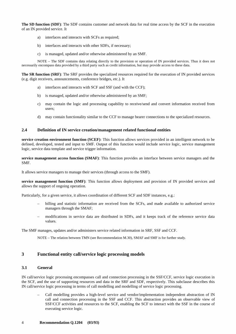
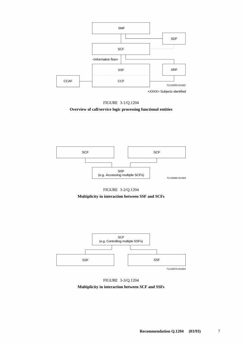
The distributed functional plane functional entities related to call modelling and service execution are shown in Figure 3-1. The relationships between these functional entities are also shown. The functional entities and relationships ofparticular concern to call modelling include the CCAF, the SSF/CCF, the SRF and the relationship between theSSF/CCF and the SCF. These functional entities and their relationships will be studied in terms of functional entitycall/service logic processing models to identify and define functional distribution and information flows between thesefunctional entities.
The SSF and CCF are being treated together. Since there is extensive mutual interaction between the two functionalentities, it is anticipated that they may both be mapped into the same physical entity. As such, it is assumed that therelationship between them (i.e. the information flows) is not externally visible.
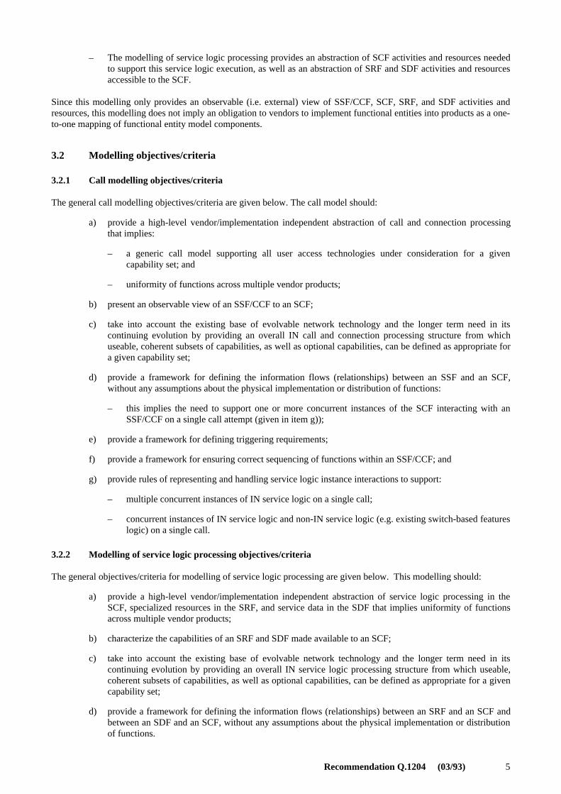
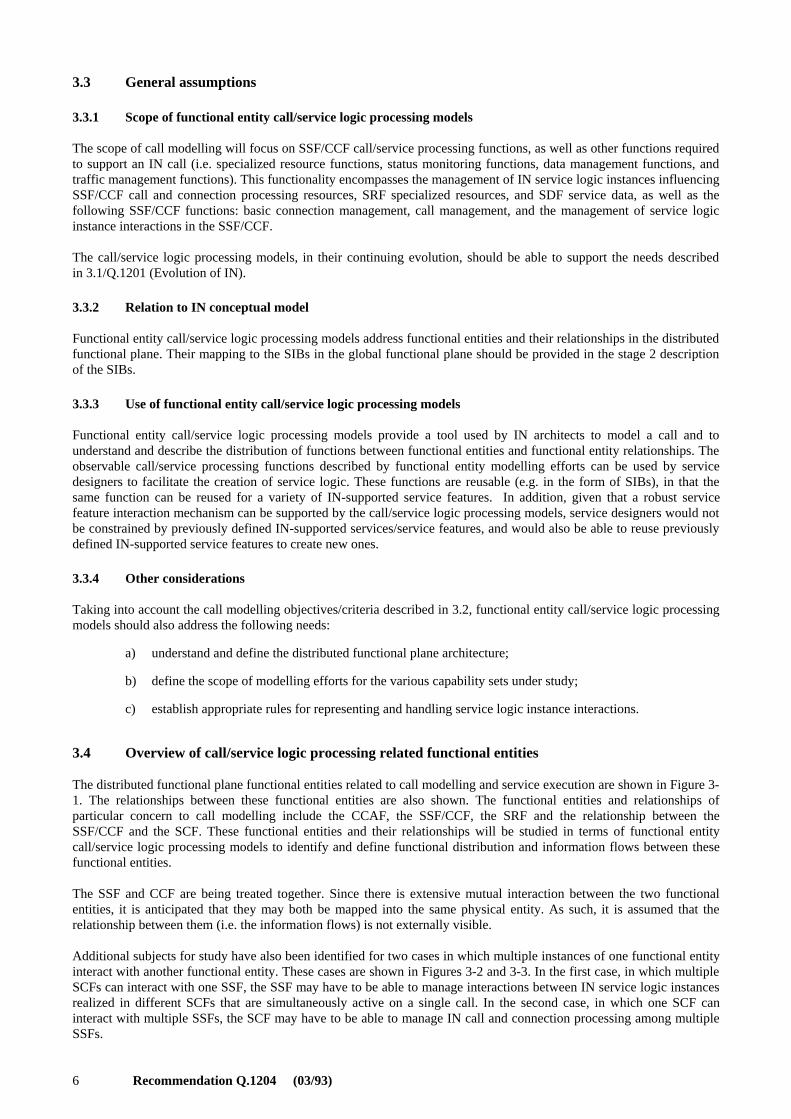
Additional subjects for study have also been identified for two cases in which multiple instances of one functional entityinteract with another functional entity. These cases are shown in Figures 3-2 and 3-3. In the first case, in which multipleSCFs can interact with one SSF, the SSF may have to be able to manage interactions between IN service logic instancesrealized in different SCFs that are simultaneously active on a single call. In the second case, in which one SCF caninteract with multiple SSFs, the SCF may have to be able to manage IN call and connection processing among multipleSSFs.
Recommendation Q.1204 (03/93) 7
T1133050-91/d02
SMF
SCF
CCAF
SDF
SRFSSF
CCF
<Information flow>
<XXXX> Subjects identified
FIGURE 3-1/Q.1204
Overview of call/service logic processing functional entities
FIGURE 3-1/Q.1204...[D02] = 8 CM
T1133060-91/d03
SCF
SSF(e.g. Accessing multiple SCFs)
SCF
FIGURE 3-2/Q.1204
Multiplicity in interaction between SSF and SCFs
FIGURE 3-2/Q.1204...[D03] = 5 CM
T1133070-91/d04
SCF(e.g. Controlling multiple SSFs)
SSF SSF
FIGURE 3-3/Q.1204
Multiplicity in interaction between SCF and SSFs
FIGURE 3-3/Q.1204...[D04] = 5 CM
8 Recommendation Q.1204 (03/93)
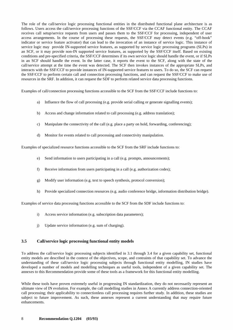
The role of the call/service logic processing functional entities in the distributed functional plane architecture is asfollows. Users access the call/service processing functions of the SSF/CCF via the CCAF functional entity. The CCAFreceives call setup/service requests from users and passes them to the SSF/CCF for processing, independent of useraccess arrangements. In the course of processing these requests, the SSF/CCF may detect events (e.g. “off-hook”indicator or service feature activator) that can lead to the invocation of an instance of service logic. This instance ofservice logic may provide IN-supported service features, as supported by service logic processing programs (SLPs) inan SCF, or it may provide non-IN supported service features, as supported by the SSF/CCF itself. Based on existingconditions and pre-specified criteria, the SSF/CCF determines if its own service logic should handle the event, or if SLPsin an SCF should handle the event. In the latter case, it reports the event to the SCF, along with the state of thecall/service attempt at the time the event was detected. The SCF then invokes instances of the appropriate SLPs, andinteracts with the SSF/CCF to provide instances of IN-supported service features to users. To do so, the SCF can requestthe SSF/CCF to perform certain call and connection processing functions, and can request the SSF/CCF to make use ofresources in the SRF. In addition, it can request the SDF to perform related service data processing functions.
Examples of call/connection processing functions accessible to the SCF from the SSF/CCF include functions to:
a) Influence the flow of call processing (e.g. provide serial calling or generate signalling events);
b) Access and change information related to call processing (e.g. address translation);
c) Manipulate the connectivity of the call (e.g. place a party on hold, forwarding, conferencing);
d) Monitor for events related to call processing and connectivity manipulation.
Examples of specialized resource functions accessible to the SCF from the SRF include functions to:
e) Send information to users participating in a call (e.g. prompts, announcements);
f) Receive information from users participating in a call (e.g. authorization codes);
g) Modify user information (e.g. text to speech synthesis, protocol conversion);
h) Provide specialized connection resources (e.g. audio conference bridge, information distribution bridge).
Examples of service data processing functions accessible to the SCF from the SDF include functions to:
i) Access service information (e.g. subscription data parameters);
j) Update service information (e.g. sum of charging).
3.5 Call/service logic processing functional entity models
To address the call/service logic processing subjects identified in 3.1 through 3.4 for a given capability set, functionalentity models are described in the context of the objectives, scope, and contraints of that capability set. To advance theunderstanding of these call/service logic processing subjects through functional entity modelling, IN studies havedeveloped a number of models and modelling techniques as useful tools, independent of a given capability set. Theannexes to this Recommendation provide some of these tools as a framework for this functional entity modelling.
While these tools have proven extremely useful in progressing IN standardization, they do not necessarily represent anultimate view of IN evolution. For example, the call modelling studies in Annex A currently address connection-orientedcall processing; their applicability to connectionless call processing requires further study. In addition, these studies aresubject to future improvement. As such, these annexes represent a current understanding that may require futureenhancements.
Recommendation Q.1204 (03/93) 9
Annex A provides an example of an overall basic call state model for existing switch processing of a basic two-partycall. This model can be analysed to identify points in basic call and connection processing when IN service logicinstances are permitted to interact with basic call and connection control capabilities.
Annex B describes an object-oriented finite state machine modelling approach for describing the dynamic aspects offunctional entities. This approach is useful in describing an external view of a functional entity and its relationships withother functional entities.
Annex C describes an overall representation of a call to understand how functional entities may view and manage thecall, and how interactions between multiple functional entities with respect to the same call may be managed.
4 Relationship between functional entities
4.1 General
In support of the execution of a specific IN-supported service feature, functional entities in the distributed functionalplane must invoke capabilities provided by other functional entities, (e.g. the SCF must invoke capabilities provided bythe SSF). In order for one functional entity (termed the client functional entity) to invoke the capabilities provided byanother functional entity (termed the server functional entity), a relationship must be established between the twofunctional entities concerned.
A relationship between two functional entities can only be established by the client functional entity, though bothfunctional entities can act as clients under different circumstances. In the former case, for example, the relationshipbetween the SCF and the SDF to retrieve or update information can only be established at the request of the SCF.However, in the latter case of the SCF-SSF relationship, this may be established at the request of either functional entity(e.g. by the SCF to request the SSF to initiate a call, or by the SSF to request call processing instructions from the SCF).A relationship between two functional entities can be terminated by either of the two functional entities concerned.
One functional entity may have more than one relationship established simultaneously with other functional entities.
4.2 Relationships
IN service control and service management relationships may be established between the following functional entities inthe distributed functional plane:
– SCF-SSF
– SCF-SRF
– SCF-SDF
– SCF-SCF
– SDF-SDF
– SMF-SSF
– SMF-CCF
– SMF-SRF
– SMF-SDF
– SMF-SCF
– SMF-SCEF
– SMF-SMAF
4.3 Information flows between functional entities
Information flows between two functional entities either consist of a client request/server response pair or of a clientrequest alone.
10 Recommendation Q.1204 (03/93)
5 Mapping the global functional plane to the distributed functional plane
5.1 Mapping requirements
– The mapping of the global functional plane to the distributed functional plane must be consistent with theIN conceptual model.
– The mapping of the global functional plane to the distributed functional plane must use the stage 2description methodology based on the Recommendation I.130.
– The mapping of the global functional plane to the distributed functional plane must allow for realizationof each SIB identified in the Global Functional Plane in at least one functional entity of the distributedfunctional plane.
– The mapping of the global functional plane to the distributed functional plane must allow for realizationof both network- and service Inter-working.
– The mapping of the global functional plane to the distributed functional plane must allow foraccommodation of the service execution capabilities (initially), as well as for the service creation, servicemanagement, and network management capabilities, when these are introduced in the future.
– The description of the basic call process (BCP) should be completely consistent with the BCSMs thatrepresent the call model in the distributed functional plane.
5.2 Relationship to IN conceptual model
A set of SLPs in the global functional plane is represented by a set of distributed SLPs located at the functional entities,which are summarized in the next subclauses.
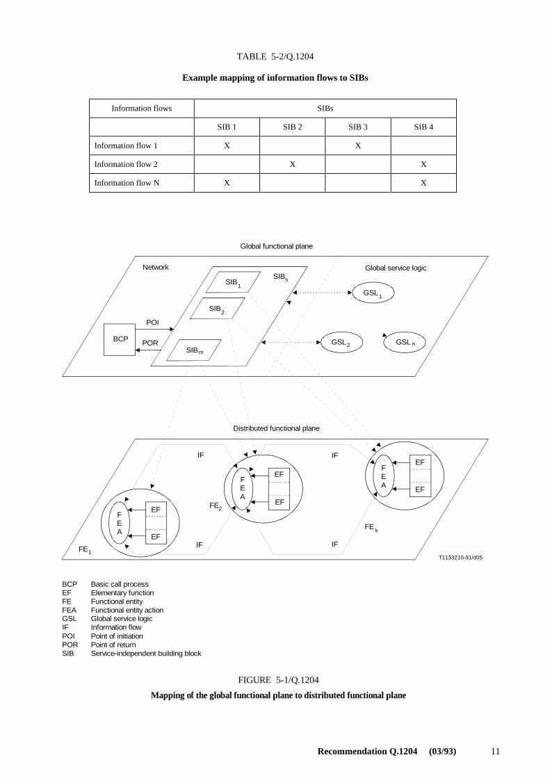
Particularly, each SIB is realized in the distributed functional plane by a sequence of specific functional entity actions(FEAs) performed by the functional entities. Some of these FEAs result in information flows between functional entities,which is illustrated in Figure 5-1.
In addition, an example that illustrates the mapping of several previously identified SIBs is presented in 5.3.
In the DFP, the BCP can be realized in a pair of BCSMs that consists of the originating BCSM and terminating BCSM.
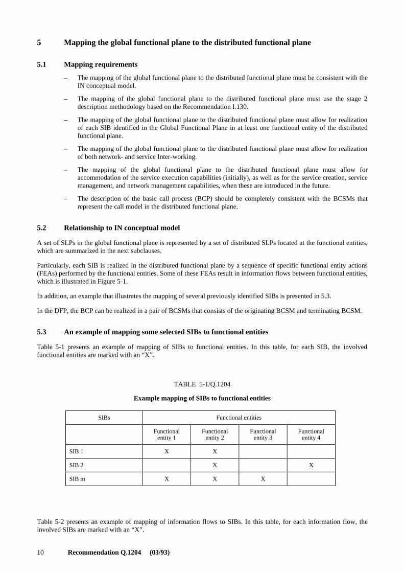
5.3 An example of mapping some selected SIBs to functional entities
Table 5-1 presents an example of mapping of SIBs to functional entities. In this table, for each SIB, the involvedfunctional entities are marked with an “X”.
TABLE 5-1/Q.1204
Example mapping of SIBs to functional entities
Table 5-2 presents an example of mapping of information flows to SIBs. In this table, for each information flow, theinvolved SIBs are marked with an “X”.
SIBs Functional entities
Functionalentity 1
Functionalentity 2
Functionalentity 3
Functionalentity 4
SIB 1 X X
SIB 2 X X
SIB m X X X
Recommendation Q.1204 (03/93) 11
TABLE 5-2/Q.1204
Example mapping of information flows to SIBs
T1133210-91/d05
Global functional plane
Distributed functional plane
Network Global service logic
BCP
SIB
SIB
SIB
GSL
GSLGSL
POI
POR
1
2
m
n
1
2
FEA
FEA
FEA
EF
EF
EF
EF
EF
EF
FE
FE
FE
IF
IF IF
IF1
2
BCPEFFEFEAGSLIFPOIPORSIB
Basic call processElementary functionFunctional entityFunctional entity actionGlobal service logicInformation flowPoint of initiationPoint of returnService-independent building block
FIGURE 5-1/Q.1204
Mapping of the global functional plane to distributed functional plane
SIBs
k
FIGURE 5-1/Q.1204...[D05] = 17.5 CM
Information flows SIBs
SIB 1 SIB 2 SIB 3 SIB 4
Information flow 1 X X
Information flow 2 X X
Information flow N X X
12 Recommendation Q.1204 (03/93)
Annex A
Example basic call state model (BCSM)
(This annex forms an integral part of this Recommendation)
A.1 General
The BCSM is a high-level finite state machine description of CCF activities required to establish and maintaincommunication paths for users. As such, it identifies a set of basic call and connection activities in a CCF and showshow these activities are joined together to process a basic call and connection (i.e. establish and maintain acommunication path for a user). The relationship between basic call and connection separation and the BCSM describedin this subclause is for further study.
Many aspects of the BCSM are not externally visible to IN service logic instances. However, aspects of the BCSM thatare reflected upward to the SSF are visible to IN service logic instances. Only these aspects of the BCSM will be thesubject of standardization. As such, the BCSM is primarily an explanatory tool for providing a representation of CCFactivities that can be analysed to determine which aspects of the BCSM will be visible to IN service logic instances, ifany, and what level of abstraction and granularity is appropriate for this visibility.
The BCSM identifies points in basic call and connection processing when IN service logic instances are permitted tointeract with basic call and connection control capabilities. In particular, it provides a framework for describing basiccall and connection events that can lead to the invocation of IN service logic instances or should be reported to active INservice logic instances, for describing those points in call and connection processing at which these events are detected,and for describing those points in call and connection processing when the transfer of control can occur.
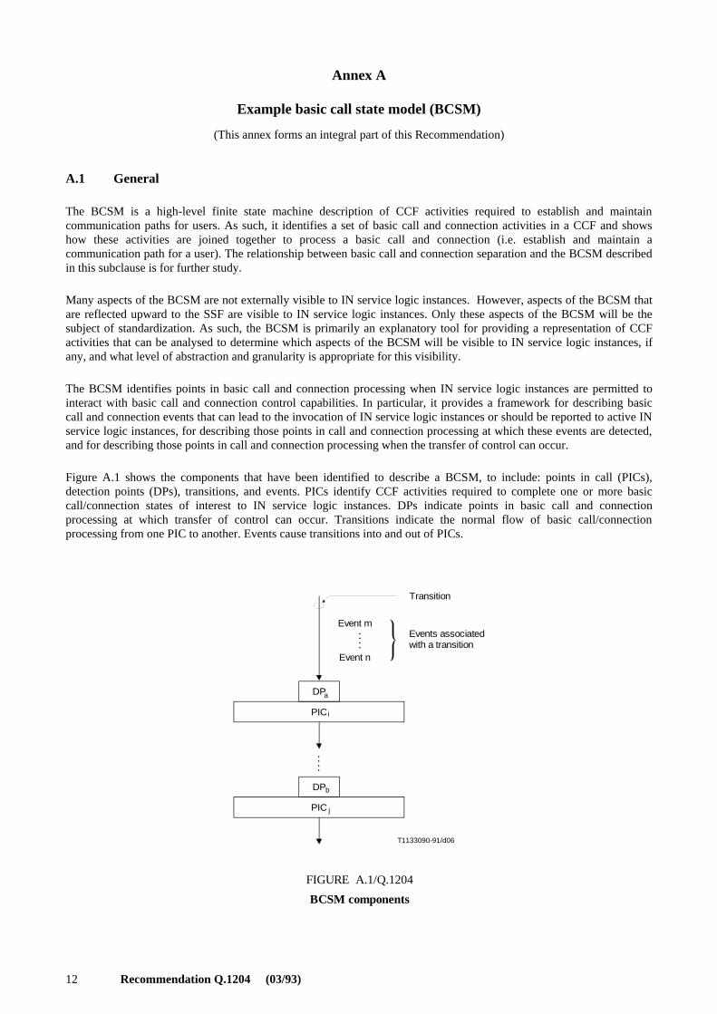
Figure A.1 shows the components that have been identified to describe a BCSM, to include: points in call (PICs),detection points (DPs), transitions, and events. PICs identify CCF activities required to complete one or more basiccall/connection states of interest to IN service logic instances. DPs indicate points in basic call and connectionprocessing at which transfer of control can occur. Transitions indicate the normal flow of basic call/connectionprocessing from one PIC to another. Events cause transitions into and out of PICs.
. . .
.
. . .
.
T1133090-91/d06
Transition
Event m
Event n
Events associatedwith a transition
DP
PIC
DP
PIC
a
b
i
j
FIGURE A.1/Q.1204
BCSM components
FIGURE A.1/Q.1204...[D06] = 9 CM
Recommendation Q.1204 (03/93) 13
Given a target description of a BCSM using these components, different subsets of PICs, DPs, transitions, and eventscan be identified to align with specific capability sets as they are defined. In addition, though CCAF functionality is notexplicitly modelled in the BCSM, a mapping is required between access signalling events and BCSM events, for eachaccess arrangement supported by a given capability set. Since the BCSM is generic, it may describe events that do notapply to certain access arrangements. It is important to understand how each access arrangement applies to the BCSM,and may be desirable to show in separate representations the aspects of the BCSM that apply to each arrangement.
An example of an overall BCSM for existing switch processing of a basic two-party call is described in this subclauseand is illustrated in Figures A.2 and A.3. The example does not imply the aspects of the BCSM that are visible to INservice logic instances, or the nature of the information flows between the SSF/CCF and SCF. This example may notrepresent the ultimate evolution of the BCSM for CS-N, but does provide a starting point for identifying PICs and DPsfor a given capability set, based on service requirements.
A.2 Example BCSM description
In the following descriptions, the PICs are related at a high level to Q.931 ISDN Call States. This is not intended to be adetailed formal definition of the relation between the PICs and Q.931 ISDN Call States, but is intended as a point ofreference to use in understanding the PICs. In particular, there are a number of possible ways in which the Q.931 callstates may be traversed in certain situations which are not considered below.
In order to maintain uniqueness of DP names between the originating and terminating half BCSMs, “O” and “T” isprefixed to certain originating and terminating DP names, respectively.
Certain PICs correspond to switch-based service feature functionality, and thus are not ubiquitous among all switchingsystems. They are denoted “optional” to reflect the current understanding. For future capability sets, it may be desirableto incorporate this functionality fully into the BCSM, depending on the benchmark set of services for given capabilitysets.
For ease of reference, the DPs associated with the transition implied by each entry and exit event for each PIC are listedalong with the PIC descriptions. Any exit event detected in PIC processing is for further study.
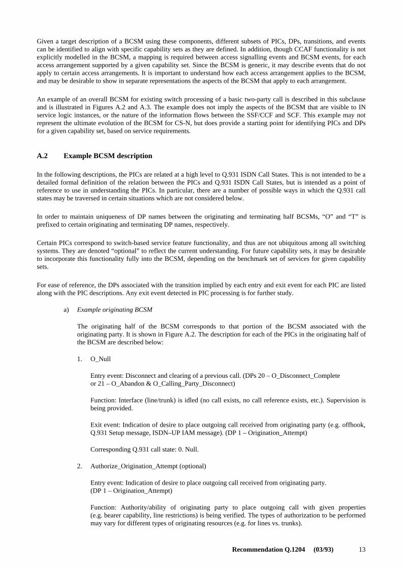
a) Example originating BCSM
The originating half of the BCSM corresponds to that portion of the BCSM associated with theoriginating party. It is shown in Figure A.2. The description for each of the PICs in the originating half ofthe BCSM are described below:
1. O_Null
Entry event: Disconnect and clearing of a previous call. (DPs 20 – O_Disconnect_Completeor 21 – O_Abandon & O_Calling_Party_Disconnect)
Function: Interface (line/trunk) is idled (no call exists, no call reference exists, etc.). Supervision isbeing provided.
Exit event: Indication of desire to place outgoing call received from originating party (e.g. offhook,Q.931 Setup message, ISDN–UP IAM message). (DP 1 – Origination_Attempt)
Corresponding Q.931 call state: 0. Null.
2. Authorize_Origination_Attempt (optional)
Entry event: Indication of desire to place outgoing call received from originating party.(DP 1 – Origination_Attempt)
Function: Authority/ability of originating party to place outgoing call with given properties(e.g. bearer capability, line restrictions) is being verified. The types of authorization to be performedmay vary for different types of originating resources (e.g. for lines vs. trunks).
14 Recommendation Q.1204 (03/93)
20
19
16
14
11
9
7
5
3
1
18
18
18
21
2
4
6
8
10
17
15
13
12
T1133100-91/d07
O_Calling_Party_Disc.& O_Abandon
1. O_Null
2. Auth._Orig._Att.
11. O_Exception
3. Collect_Info.
4. Analyse_Info.
5. Select_Route
6. Auth._Call_Setup
Orig. Attempt
Orig._Attempt_Auth.
Collected_Info.
Analysed_Info.
Orig._Denied
Collect_Timeout
Invalid_Info.
Route_Select_FailureRoute_Selected
7. Call_Sent
8. O_Alerting
9. O_Active
10. O_Disconnect
Orig._Auth.
O_Term_Seized
O_Answer
O_Disconnect
Auth._Failure
Route_Failure
O_Called_Party_Busy
O_No_Answer
O_Conn_Failure
O_Disc_Complete
Transition
Detection point (DP)
Point in call (PIC)
FIGURE A.2/Q.1204
Example originating BCSM
O_Mid_Call
O_Mid_Call
O_Mid_Call
FIGURE A.2/Q.1204...[D07] = 22 CM
Recommendation Q.1204 (03/93) 15
Exit events:
– Authority/ability to place outgoing call denied. (DP 2 – Origination_Denied)
– Authority/ability to place outgoing call verified. (DP 3 – Origination_Attempt_Authorized)
– Originating party abandons call. (DP 21 – O_Abandon & O_Calling_Party_Disconnect)NOTE – Originating party abandon may not be detected until the end of processing for this PIC, since this
PIC may be processed in an atomic manner (i.e. processing cannot be interrupted) for some implementations.
Corresponding Q.931 call state: Not Applicable.
3. Collect_Information
Entry event: Authority/ability to place outgoing call verified.(DP 3 – Origination_Attempt_Authorized)
Function: Initial information package/dialling string (e.g. service codes, prefixes, dialled addressdigits) being collected from originating party. Information being examined according to dialling planto determine end of collection. No further action may be required if an en bloc signalling method isin use (e.g. an ISDN user using en bloc signalling, an incoming SS No. 7 trunk).
Exit events:
– Information collection error has occurred (e.g. invalid dial string format, digit collectiontimeout). (DP 4 – Collect_Timeout)
– Availability of complete initial information package/dialling string from originating party. (Thisevent may have already occurred in the case of en bloc signalling, in which case the waitingduration in this PIC is zero.) (DP 5 – Collected_Info)
– Originating party abandons calls. (DP 21 – O_Abandon & O_Calling_Party_Disconnect)NOTE – Some digit analysis is required to determine the end of dialing. However, it is assumed that this
analysis may be modelled as separable from the rest of digit analysis, which occurs in PIC 4,Analyse_Information. There is no intention to specify an implementation. However, a switch should externallypresent the separable view described for closed numbering plans.1)
Corresponding Q.931 call state: 1. call initiated and (optionally) 2. Overlap sending.
4. Analyse_Information
Entry event: Availability of complete initial information package/dialling string from originatingparty. (DP 5 – Collected_Info)
Function: Information being analysed and/or translated according to dialling plan to determinerouting address and call type (e.g. local exchange call, transit exchange call, international exchangecall).
Exit events:
– Unable to analyse and translate dial string in the dialling plan (e.g. invalid dial string).(DP 6 – Invalid_Info)
– Availability of routing address and call type. (DP 7 – Analysed_Info)
– Originating party abandons call. (DP 21 – O_Abandon & O_Calling_Party_Disconnect)NOTE – The routing address does not necessarily mean that the final physical route has been determined
(e.g. route list has not been searched, hunt groups have not yet been searched, directory number has not yet beentranslated to physical port address), though this may be the case (e.g. when routing to a specific private facility).
Corresponding Q.931 call state: Not applicable.
_______________1) This separable view is provided by supporting distinct DPs for DP 5 (Collected_Info) and DP 7 (Analysed_Info), and by
populating information flows accordingly for corresponding TDP and EDP information flows to the SCF.

16 Recommendation Q.1204 (03/93)
5. Select_Route
Entry events:
– Availability of routing address and call type. (DP 7 – Analysed_Info)
– Unable to complete call using specified route (e.g. congestion). (DP 12 – Route_Failure)
Function: Routing address and call type being interpreted. The next route is being selected. This mayinvolve sequentially searching a route list, translating a directory number into physical port address,etc. The individual destination resource out of a resource group (e.g. a multi-line hunt group, a trunkgroup) is not selected. In some cases (e.g. an analogue line interface), a single resource (not a group)is selected.
Exit events:
– Unable to select a route (e.g. unable to determine a correct route, no more routes on route list).(DP 8 – Route_Select_Failure)
– Terminating resource (group) to which call should be routed has been identified.(DP 9 – Route_Selected)
– Originating party abandons call. (DP 21 – O_Abandon & O_Calling_Party_Disconnect)
Corresponding Q.931 sall state: Not applicable.
6. Authorize_Call_Setup (optional)
Entry event: Terminating resource (group) to which call should be routed has been identified.(DP 9 – Route_Selected)
Function: Authority of originating party to place this particular call being verified (e.g. checkingbusiness group restrictions, toll restrictions, route restrictions). The types of authorization checks tobe performed may depend upon the type of originating resource (e.g. line vs. trunk).
Exit events:
– Authority of originating party to place this call is denied (e.g. business group restrictionmismatch, toll restricted calling line). (DP 10 – Authorization_Failure)
– Authority of originating party to place this call verified. (DP 11 – Origination_Authorized)
– Originating party abandons call. (DP 21 – O_Abandon & O_Calling_Party_Disconnect)
Corresponding Q.931 call state: Not applicable.
7. Call_Sent
Entry event: Authority of originating party to place call verified. (DP 11 – Origination_Authorized)
Function: Call is being processed by the terminating half BCSM. The originating half BCSM isawaiting some indication that the call has been presented to the called party.
Exit events:
– Indication from terminating half BCSM that the call cannot be presented to the terminatingparty (e.g. network congestion). (DP 12 – Route_Failure)
– Indication from terminating half BCSM that the terminating party is busy.(DP 13 – O_Called_Party_Busy)
– Indication from terminating half BCSM that the terminating party is being alerted.(DP 14 – O_Term_Seized)
Recommendation Q.1204 (03/93) 17
– Indication from terminating half BCSM that the call is accepted and answered by terminatingparty (e.g. terminating party goes offhook, Q.931 connect message received, ISDN-UP answermessage received). (DP 16 – O_Answer)
– A service/service feature request is received from the originating party (e.g. hook flash, ISDNfeature activator, Q.931 HOLD or RETrieve message). (DP 18 – O_Mid_Call)
– Originating party abandons call. (DP 21 – O_Abandon & O_Calling_Party_Disconnect)
Corresponding Q.931 call state: Not applicable.
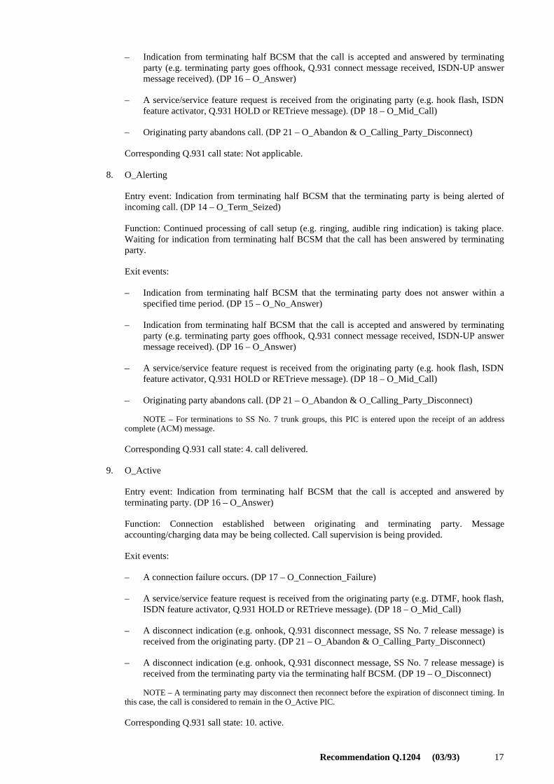
8. O_Alerting
Entry event: Indication from terminating half BCSM that the terminating party is being alerted ofincoming call. (DP 14 – O_Term_Seized)
Function: Continued processing of call setup (e.g. ringing, audible ring indication) is taking place.Waiting for indication from terminating half BCSM that the call has been answered by terminatingparty.
Exit events:
– Indication from terminating half BCSM that the terminating party does not answer within aspecified time period. (DP 15 – O_No_Answer)
– Indication from terminating half BCSM that the call is accepted and answered by terminatingparty (e.g. terminating party goes offhook, Q.931 connect message received, ISDN-UP answermessage received). (DP 16 – O_Answer)
– A service/service feature request is received from the originating party (e.g. hook flash, ISDNfeature activator, Q.931 HOLD or RETrieve message). (DP 18 – O_Mid_Call)
– Originating party abandons call. (DP 21 – O_Abandon & O_Calling_Party_Disconnect)
NOTE – For terminations to SS No. 7 trunk groups, this PIC is entered upon the receipt of an addresscomplete (ACM) message.
Corresponding Q.931 call state: 4. call delivered.
9. O_Active
Entry event: Indication from terminating half BCSM that the call is accepted and answered byterminating party. (DP 16 – O_Answer)
Function: Connection established between originating and terminating party. Messageaccounting/charging data may be being collected. Call supervision is being provided.
Exit events:
– A connection failure occurs. (DP 17 – O_Connection_Failure)
– A service/service feature request is received from the originating party (e.g. DTMF, hook flash,ISDN feature activator, Q.931 HOLD or RETrieve message). (DP 18 – O_Mid_Call)
– A disconnect indication (e.g. onhook, Q.931 disconnect message, SS No. 7 release message) isreceived from the originating party. (DP 21 – O_Abandon & O_Calling_Party_Disconnect)
– A disconnect indication (e.g. onhook, Q.931 disconnect message, SS No. 7 release message) isreceived from the terminating party via the terminating half BCSM. (DP 19 – O_Disconnect)
NOTE – A terminating party may disconnect then reconnect before the expiration of disconnect timing. Inthis case, the call is considered to remain in the O_Active PIC.
Corresponding Q.931 sall state: 10. active.
18 Recommendation Q.1204 (03/93)
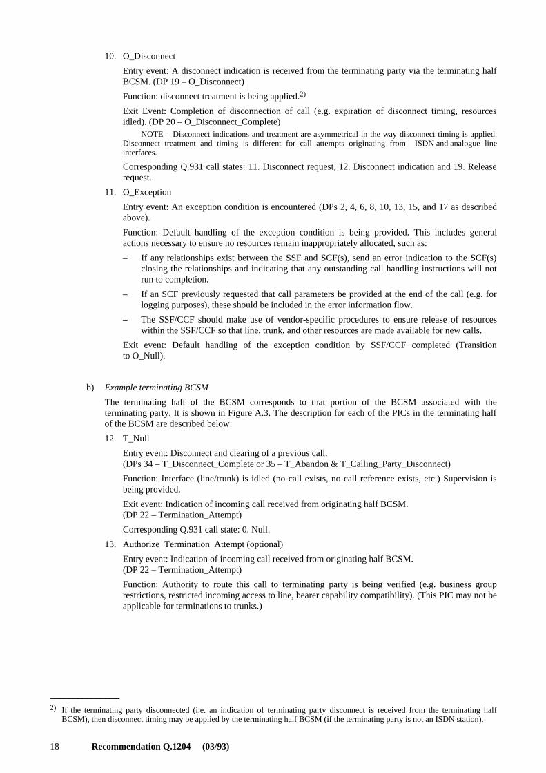
10. O_Disconnect
Entry event: A disconnect indication is received from the terminating party via the terminating halfBCSM. (DP 19 – O_Disconnect)
Function: disconnect treatment is being applied.2)
Exit Event: Completion of disconnection of call (e.g. expiration of disconnect timing, resourcesidled). (DP 20 – O_Disconnect_Complete)
NOTE – Disconnect indications and treatment are asymmetrical in the way disconnect timing is applied.Disconnect treatment and timing is different for call attempts originating from ISDN and analogue lineinterfaces.
Corresponding Q.931 call states: 11. Disconnect request, 12. Disconnect indication and 19. Releaserequest.
11. O_Exception
Entry event: An exception condition is encountered (DPs 2, 4, 6, 8, 10, 13, 15, and 17 as describedabove).
Function: Default handling of the exception condition is being provided. This includes generalactions necessary to ensure no resources remain inappropriately allocated, such as:
– If any relationships exist between the SSF and SCF(s), send an error indication to the SCF(s)closing the relationships and indicating that any outstanding call handling instructions will notrun to completion.
– If an SCF previously requested that call parameters be provided at the end of the call (e.g. forlogging purposes), these should be included in the error information flow.
– The SSF/CCF should make use of vendor-specific procedures to ensure release of resourceswithin the SSF/CCF so that line, trunk, and other resources are made available for new calls.
Exit event: Default handling of the exception condition by SSF/CCF completed (Transitionto O_Null).
b) Example terminating BCSM
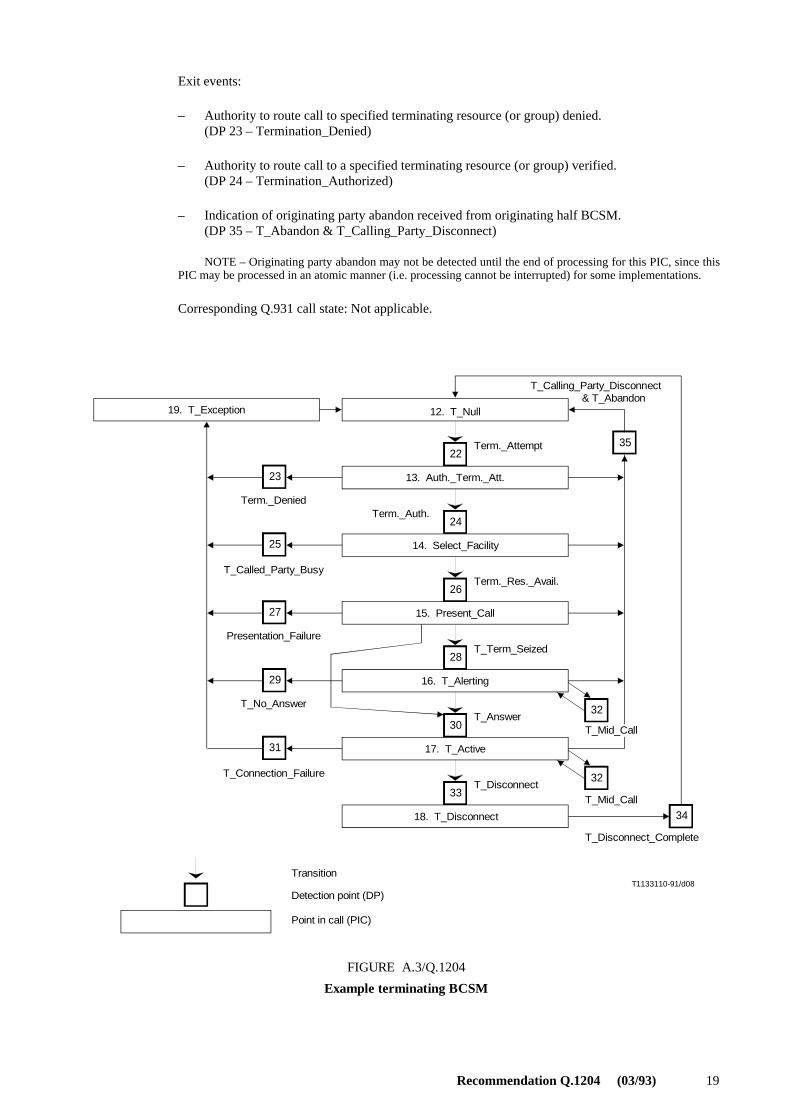
The terminating half of the BCSM corresponds to that portion of the BCSM associated with theterminating party. It is shown in Figure A.3. The description for each of the PICs in the terminating halfof the BCSM are described below:
12. T_Null
Entry event: Disconnect and clearing of a previous call.(DPs 34 – T_Disconnect_Complete or 35 – T_Abandon & T_Calling_Party_Disconnect)
Function: Interface (line/trunk) is idled (no call exists, no call reference exists, etc.) Supervision isbeing provided.
Exit event: Indication of incoming call received from originating half BCSM.(DP 22 – Termination_Attempt)
Corresponding Q.931 call state: 0. Null.
13. Authorize_Termination_Attempt (optional)
Entry event: Indication of incoming call received from originating half BCSM.(DP 22 – Termination_Attempt)
Function: Authority to route this call to terminating party is being verified (e.g. business grouprestrictions, restricted incoming access to line, bearer capability compatibility). (This PIC may not beapplicable for terminations to trunks.)
_______________2) If the terminating party disconnected (i.e. an indication of terminating party disconnect is received from the terminating half
BCSM), then disconnect timing may be applied by the terminating half BCSM (if the terminating party is not an ISDN station).
Recommendation Q.1204 (03/93) 19
Exit events:
– Authority to route call to specified terminating resource (or group) denied.(DP 23 – Termination_Denied)
– Authority to route call to a specified terminating resource (or group) verified.(DP 24 – Termination_Authorized)
– Indication of originating party abandon received from originating half BCSM.(DP 35 – T_Abandon & T_Calling_Party_Disconnect)
NOTE – Originating party abandon may not be detected until the end of processing for this PIC, since thisPIC may be processed in an atomic manner (i.e. processing cannot be interrupted) for some implementations.
Corresponding Q.931 call state: Not applicable.
T1133110-91/d08
3522
24
26
28
3032
3233
34
31
29
25
27
23
19. T_Exception 12. T_Null
13. Auth._Term._Att.
14. Select_Facility
15. Present_Call
16. T_Alerting
17. T_Active
T_Calling_Party_Disconnect & T_Abandon
Term._Attempt
Term._Auth.
Term._Res._Avail.
T_Term_Seized
T_Answer
Term._Denied
T_Called_Party_Busy
Presentation_Failure
T_No_Answer
T_Connection_Failure
18. T_Disconnect
T_Disconnect
T_Mid_Call
T_Mid_Call
T_Disconnect_Complete
Transition
Detection point (DP)
Point in call (PIC)
FIGURE A.3/Q.1204
Example terminating BCSM
FIGURE A.3/Q.1204...[D08] = 16.5 CM

20 Recommendation Q.1204 (03/93)
14. Select_Facility
Entry event: Authority to route call to specified terminating resource group verified.(DP 24 – Termination_Authorized)
Function: A particular available resource in the specified resource group is being selected. It ispossible that all resources in the group could be busy. A single resource is treated as a group ofsize 1.
Exit events:
– All resources in group busy or called party busy. (DP 25 – T_Called_Party_Busy)
– Available terminating resource in resource group identified.(DP 26 – Terminating_Resource_Available)
– Indication of originating party abandon received from originating half BCSM.(DP 35 – T_Abandon & T_Calling_Party_Disconnect)
Corresponding Q.931 call state: Not applicable.
15. Present_Call
Entry event: Available terminating resource identified. (DP 26 – Terminating_Resource_Available)
Function: Terminating resource informed of incoming call (e.g. line seizure, Q.931 Setup message,ISDN-UP IAM message). In the case of an analogue line, ringing is being applied.
Exit events:
– Cannot present call (e.g. ISDN user determined busy, ISDN-UP release message with busycause) (DP 27 – Presentation_Failure)
– Terminating party is being alerted (e.g. ringing being applied, Q.931 Alerting message,ISDN-UP ACM message). In the case of an analogue line, this event should occur almostinstantly after entering this PIC. (DP 28 – T_Termination_Seized)
– Call is accepted and answered by terminating party (e.g. terminating party goes offhook, Q.931connect message received, ISDN-UP answer message received). (DP 30 – T_Answer)
– Indication of originating party abandon. (DP 35 – T_Abandon & T_Calling_Party_Disconnect)
Corresponding Q.931 call state: 6. Call present.
16. T_Alerting
Entry event: Terminating party is being alerted of incoming call. (DP 28 – T_Termination_Seized)
Function: An indication is sent to the originating half BCSM that the terminating party is beingalerted. Continued processing of call setup (e.g. ringing, audible ring indication) is taking place.Supervision is waiting for the call to be answered by terminating party.
Exit events:
– Terminating party does not answer within a specified duration. (DP 29 – T_No_Answer)
– Call is accepted and answered by terminating party (e.g. terminating party goes offhook, Q.931connect message received, ISDN-UP answer message received). (DP 30 – T_Answer)
– A service/service feature request is received from the terminating party (e.g. hook flash, ISDNfeature activator, Q.931 HOLD or RETrieve message). (DP 32 – T_Mid_Call)
– Indication of originating party abandon received from originating half BCSM.(DP 35 – T_Abandon & T_Calling_Party_Disconnect)
Recommendation Q.1204 (03/93) 21
NOTE – This PIC is not applicable when terminating to a non-SS No. 7 trunk group. For terminations toSS No. 7 trunk groups, this PIC is entered upon the receipt of an address complete (ACM) message.
Corresponding Q.931 call states: 7. Call received and 8. Connect request.
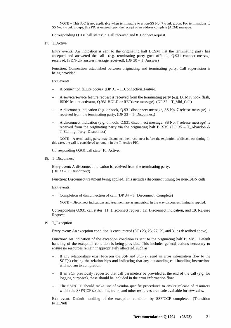
17. T_Active
Entry events: An indication is sent to the originating half BCSM that the terminating party hasaccepted and answered the call (e.g. terminating party goes offhook, Q.931 connect messagereceived, ISDN-UP answer message received). (DP 30 – T_Answer)
Function: Connection established between originating and terminating party. Call supervision isbeing provided.
Exit events:
– A connection failure occurs. (DP 31 – T_Connection_Failure)
– A service/service feature request is received from the terminating party (e.g. DTMF, hook flash,ISDN feature activator, Q.931 HOLD or RETrieve message). (DP 32 – T_Mid_Call)
– A disconnect indication (e.g. onhook, Q.931 disconnect message, SS No. 7 release message) isreceived from the terminating party. (DP 33 – T_Disconnect)
– A disconnect indication (e.g. onhook, Q.931 disconnect message, SS No. 7 release message) isreceived from the originating party via the originating half BCSM. (DP 35 – T_Abandon &T_Calling_Party_Disconnect)
NOTE – A terminating party may disconnect then reconnect before the expiration of disconnect timing. Inthis case, the call is considered to remain in the T_Active PIC.
Corresponding Q.931 call state: 10. Active.
18. T_Disconnect
Entry event: A disconnect indication is received from the terminating party.(DP 33 – T_Disconnect)
Function: Disconnect treatment being applied. This includes disconnect timing for non-ISDN calls.
Exit events:
– Completion of disconnection of call. (DP 34 – T_Disconnect_Complete)
NOTE – Disconnect indications and treatment are asymmetrical in the way disconnect timing is applied.
Corresponding Q.931 call states: 11. Disconnect request, 12. Disconnect indication, and 19. ReleaseRequest.
19. T_Exception
Entry event: An exception condition is encountered (DPs 23, 25, 27, 29, and 31 as described above).
Function: An indication of the exception condition is sent to the originating half BCSM. Defaulthandling of the exception condition is being provided. This includes general actions necessary toensure no resources remain inappropriately allocated, such as:
– If any relationships exist between the SSF and SCF(s), send an error information flow to theSCF(s) closing the relationships and indicating that any outstanding call handling instructionswill not run to completion.
– If an SCF previously requested that call parameters be provided at the end of the call (e.g. forlogging purposes), these should be included in the error information flow.
– The SSF/CCF should make use of vendor-specific procedures to ensure release of resourceswithin the SSF/CCF so that line, trunk, and other resources are made available for new calls.
Exit event: Default handling of the exception condition by SSF/CCF completed. (Transitionto T_Null).
22 Recommendation Q.1204 (03/93)
Annex B
Object-oriented finite state machine modelling(This annex forms an integral part of this Recommendation)
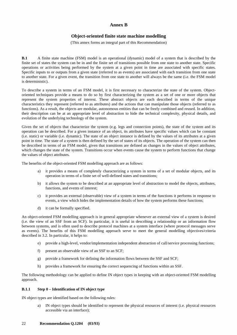
B.1 A finite state machine (FSM) model is an operational (dynamic) model of a system that is described by thefinite set of states the system can be in and the finite set of transitions possible from one state to another state. Specificoperations or activities being performed by the system at a given point in time are associated with specific states.Specific inputs to or outputs from a given state (referred to as events) are associated with each transition from one stateto another state. For a given event, the transition from one state to another will always be the same (i.e. the FSM modelis deterministic).
To describe a system in terms of an FSM model, it is first necessary to characterize the state of the system. Object-oriented techniques provide a means to do so by first characterizing the system as a set of one or more objects thatrepresent the system properties of interest. These abstract objects are each described in terms of the uniquecharacteristics they represent (referred to as attributes) and the actions that can manipulate those objects (referred to asfunctions). As a result, the objects are modular, autonomous entities that can be freely combined and reused. In addition,their description can be at an appropriate level of abstraction to hide the technical complexity, physical details, andevolution of the underlying technology of the system.
Given the set of objects that characterize the system (e.g. legs and connection points), the state of the system and itsoperation can be described. For a given instance of an object, its attributes have specific values which can be constant(i.e. static) or variable (i.e. dynamic). The state of an object instance is defined by the values of its attributes at a givenpoint in time. The state of a system is then defined by the set of states of its objects. The operation of the system can thenbe described in terms of an FSM model, given that transitions are defined as changes in the values of object attributes,which changes the state of the system. Transitions occur when events cause the system to perform functions that changethe values of object attributes.
The benefits of the object-oriented FSM modelling approach are as follows:
a) it provides a means of completely characterizing a system in terms of a set of modular objects, and itsoperation in terms of a finite set of well-defined states and transitions;
b) it allows the system to be described at an appropriate level of abstraction to model the objects, attributes,functions, and events of interest;
c) it provides an external (observable) view of a system in terms of the functions it performs in response toevents, a view which hides the implementation details of how the system performs these functions;
d) it can be formally specified.
An object-oriented FSM modelling approach is in general appropriate whenever an external view of a system is desired(i.e. the view of an SSF from an SCF). In particular, it is useful in describing a relationship or an information flowbetween systems, and is often used to describe protocol machines at a system interface (where protocol messages serveas events). The benefits of this FSM modelling approach serve to meet the general modelling objectives/criteriadescribed in 3.2. In particular, it helps to:
e) provide a high-level, vendor/implementation independent abstraction of call/service processing functions;
f) present an observable view of an SSF to an SCF;
g) provide a framework for defining the information flows between the SSF and SCF;
h) provides a framework for ensuring the correct sequencing of functions within an SSF.
The following methodology can be applied to define IN object types in keeping with an object-oriented FSM modellingapproach.
B.1.1 Step 0 – Identification of IN object type
IN object types are identified based on the following rules:
a) IN object types should be identified to represent the physical resources of interest (i.e. physical resourcesaccessible via an interface);
Recommendation Q.1204 (03/93) 23
b) separate IN object types should be identified for physical resources whose behaviour is represented bydifferent sets of IN object states and/or different IN object state transitions;
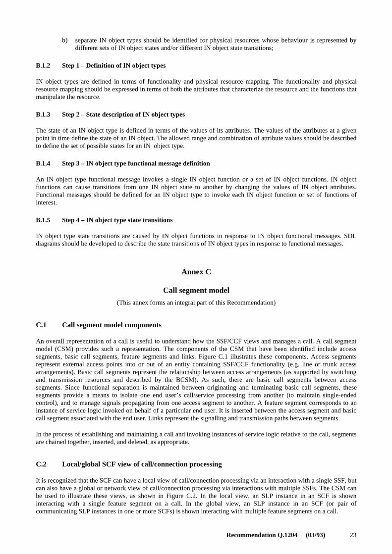
B.1.2 Step 1 – Definition of IN object types
IN object types are defined in terms of functionality and physical resource mapping. The functionality and physicalresource mapping should be expressed in terms of both the attributes that characterize the resource and the functions thatmanipulate the resource.
B.1.3 Step 2 – State description of IN object types
The state of an IN object type is defined in terms of the values of its attributes. The values of the attributes at a givenpoint in time define the state of an IN object. The allowed range and combination of attribute values should be describedto define the set of possible states for an IN object type.
B.1.4 Step 3 – IN object type functional message definition
An IN object type functional message invokes a single IN object function or a set of IN object functions. IN objectfunctions can cause transitions from one IN object state to another by changing the values of IN object attributes.Functional messages should be defined for an IN object type to invoke each IN object function or set of functions ofinterest.
B.1.5 Step 4 – IN object type state transitions
IN object type state transitions are caused by IN object functions in response to IN object functional messages. SDLdiagrams should be developed to describe the state transitions of IN object types in response to functional messages.
Annex C
Call segment model
(This annex forms an integral part of this Recommendation)
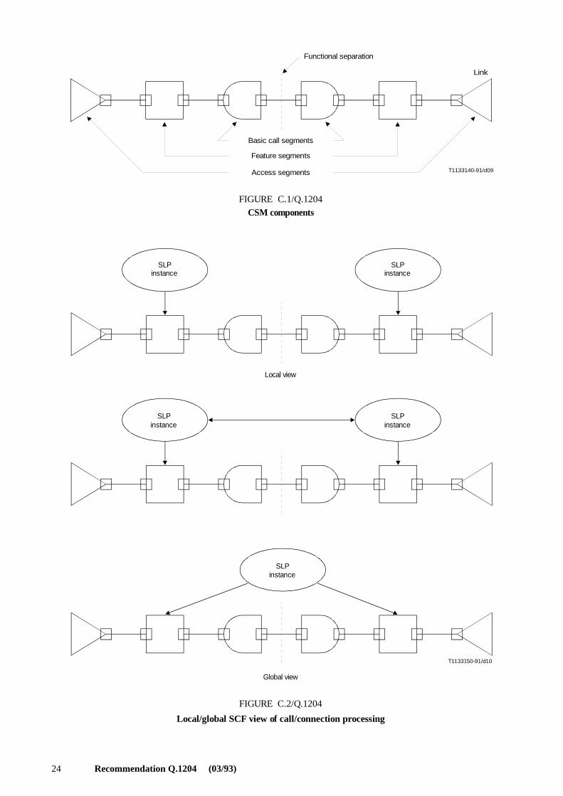
C.1 Call segment model components
An overall representation of a call is useful to understand how the SSF/CCF views and manages a call. A call segmentmodel (CSM) provides such a representation. The components of the CSM that have been identified include accesssegments, basic call segments, feature segments and links. Figure C.1 illustrates these components. Access segmentsrepresent external access points into or out of an entity containing SSF/CCF functionality (e.g. line or trunk accessarrangements). Basic call segments represent the relationship between access arrangements (as supported by switchingand transmission resources and described by the BCSM). As such, there are basic call segments between accesssegments. Since functional separation is maintained between originating and terminating basic call segments, thesesegments provide a means to isolate one end user’s call/service processing from another (to maintain single-endedcontrol), and to manage signals propagating from one access segment to another. A feature segment corresponds to aninstance of service logic invoked on behalf of a particular end user. It is inserted between the access segment and basiccall segment associated with the end user. Links represent the signalling and transmission paths between segments.
In the process of establishing and maintaining a call and invoking instances of service logic relative to the call, segmentsare chained together, inserted, and deleted, as appropriate.
C.2 Local/global SCF view of call/connection processing
It is recognized that the SCF can have a local view of call/connection processing via an interaction with a single SSF, butcan also have a global or network view of call/connection processing via interactions with multiple SSFs. The CSM canbe used to illustrate these views, as shown in Figure C.2. In the local view, an SLP instance in an SCF is showninteracting with a single feature segment on a call. In the global view, an SLP instance in an SCF (or pair ofcommunicating SLP instances in one or more SCFs) is shown interacting with multiple feature segments on a call.
24 Recommendation Q.1204 (03/93)
T1133140-91/d09
Functional separation
Basic call segments
Feature segments
Access segments
FIGURE C.1/Q.1204
CSM components
Link
FIGURE C.1/Q.1204...[D09] = 6.5 CM
T1133150-91/d10
SLPinstance
SLPinstance
SLPinstance
SLPinstance
Local view
SLPinstance
Global view
FIGURE C.2/Q.1204
Local/global SCF view of call/connection processing
IGURE C.2/Q.1204...[D10] = 17.5 CM